Embed Size (px)
Citation preview
1
Dear Customers,
We are proud to launch our new technical catalogue and weare convinced that it will soon be an essential tool to create yourhydraulic projects.
After a brief company profile that will be helpful to verify theresults that AS Aston Seals S.p.A. has obtained in the latestyears, results that have been achieved only trough your coopera-tion, the catalogue contains a section regarding general techni-cal info and six chapters that include detailed info on our alwaysmore complete production range.
We believe that the last among those chapters, about seals crea-ted with a turning machine and not with a normal moulding machi-ne, can be very interesting as it gives practically unlimited solutions,under both possible materials and shape of the profiles viewpoint.
The service that has characterized our company since fromthe beginning, has driven us to invest always in new machineryfor the production of seals and these new turning machines willallow our technical personnel to study new solutions in order tosupply you prototypes without tooling charges; the tools will beconstructed only after the test of the prototype.
We are therefore sure that the service we have supplied up tonow and that we strongly want to supply in the future is the keyand the reason of our company’s growth.
All of our products are made in Italy without the exploitationof child labour to increase competitiveness as done in the thirdworld.
Unlike our competitors, we want to deal with both big and smallcompanies, without making differences related to their economi-cal power supplying the same efficient and effective service.
This is the way we like to work……..
Thank for choosing AS Aston Seals S.p.A.
The management
Our numbers:*
- 2000: year of foundation
- 6000 m2: our building in Carpi
- over 5000: hydraulic and pneumatic moulds
- 60: our employees
- 10: injection moulding machines working on 3 shift per day allequipped with extraction robots
- € 10.000.000: our company’s turnover
- 60%: domestic turnover made with end users
- 6: continents (43 countries) where we are present with distri-butors
* data on 01-01-2008
06/2008

3
Wipers
Rod seals
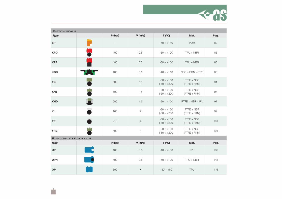
Piston seals
Rod and piston seals
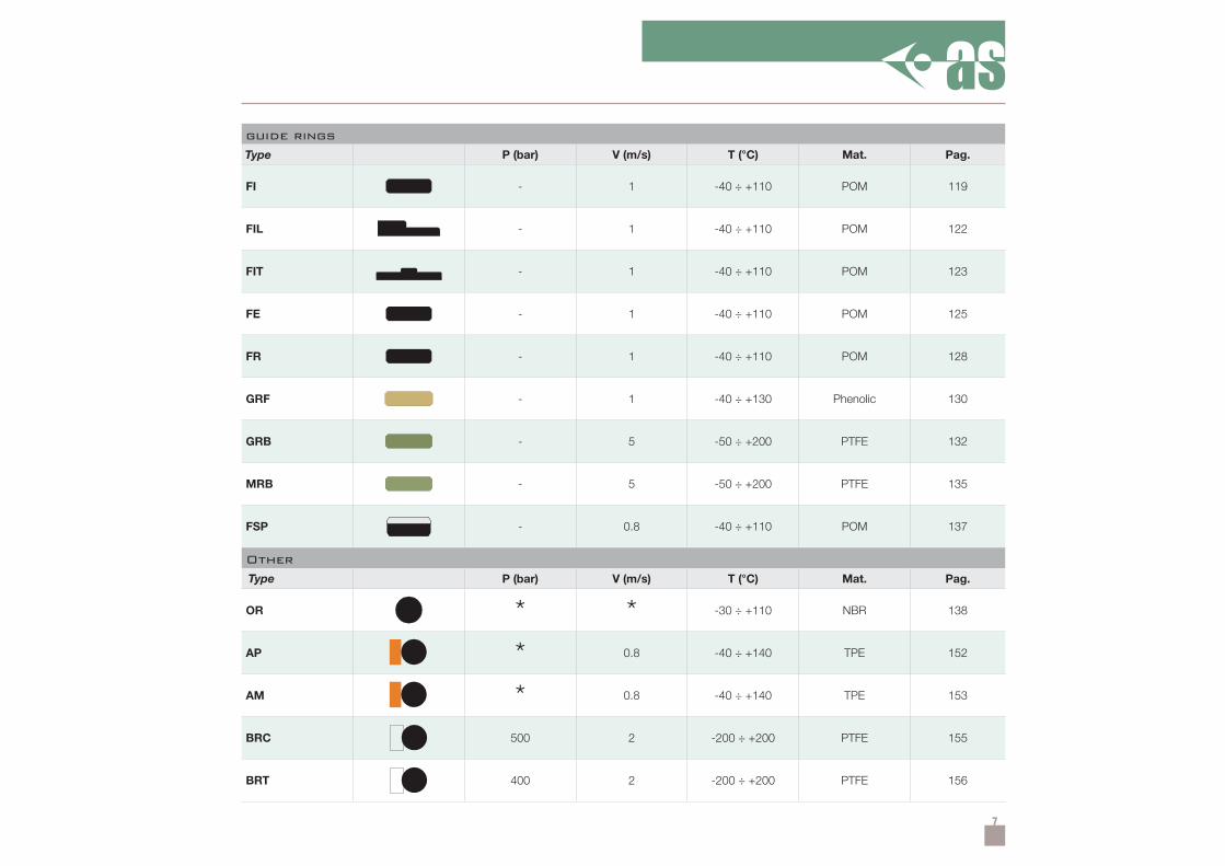
Guide rings
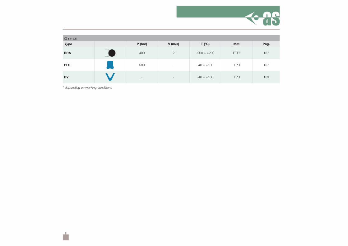
Other
Lathe-cut products
Technical information
4
P (bar) V (m/s) T (°C) Mat. Pag.
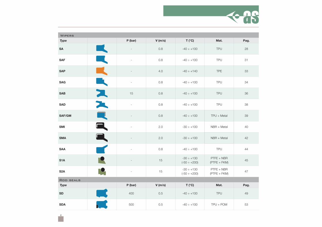
SA - 0.8 -40 ÷ +100 TPU 28
SAF - 0.8 -40 ÷ +100 TPU 31
SAP - 4.0 -40 ÷ +140 TPE 33
SAG - 0.8 -40 ÷ +100 TPU 34
SAB 15 0.8 -40 ÷ +100 TPU 36
SAD - 0.8 -40 ÷ +100 TPU 38
SAF/GM - 0.8 -40 ÷ +100 39
SMI - 2.0 -30 ÷ +100 40
SMA - 2.0 -30 ÷ +100 42
SAA - 0.8 -40 ÷ +100 TPU 44
S1A - 15-30 ÷ +130(-50 ÷ +200)
PTFE + NBR(PTFE + FKM)
45
S2A - 15-30 ÷ +130(-50 ÷ +200)
PTFE + NBR(PTFE + FKM)
47
P (bar) V (m/s) T (°C) Mat. Pag.
SD 400 0.5 -40 ÷ +100 TPU 49
SDA 500 0.5 -40 ÷ +100 TPU + POM 53
Wipers
Type
TPU + Metal
NBR + Metal
NBR + Metal
Rod seals
Type
5
P (bar) V (m/s) T (°C) Mat. Pag.
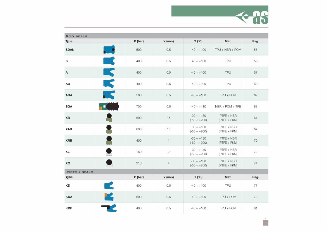
SDAN 500 0.5 -40 ÷ +100 TPU + NBR + POM 55
S 400 0.5 -40 ÷ +100 TPU 56
A 400 0.5 -40 ÷ +100 TPU 57
AD 400 0.5 -40 ÷ +100 TPU 60
ADA 500 0.5 -40 ÷ +100 TPU + POM 62
SGA 700 0.5 -40 ÷ +110 NBR + POM + TPE 63
XB 600 15-30 ÷ +130(-50 ÷ +200)
PTFE + NBR(PTFE + FKM)
64
XAB 600 15-30 ÷ +130(-50 ÷ +200)
PTFE + NBR(PTFE + FKM)
67
XRB 400 1-30 ÷ +130(-50 ÷ +200)
PTFE + NBR(PTFE + FKM)
70
XL 160 2-30 ÷ +130(-50 ÷ +200)
PTFE + NBR(PTFE + FKM)
72
XC 210 4-30 ÷ +130(-50 ÷ +200)
PTFE + NBR(PTFE + FKM)
74
P (bar) V (m/s) T (°C) Mat. Pag.
KD 400 0.5 -40 ÷ +100 TPU 77
KDA 500 0.5 -40 ÷ +100 TPU + POM 79
KDF 400 0.5 -40 ÷ +100 TPU + POM 81
Rod seals
Type
piston seals
Type
6
P (bar) V (m/s) T (°C) Mat. Pag.
SP - - -40 ÷ +110 POM 82
KPD 400 0.5 -30 ÷ +100 TPU + NBR 83
KPR 400 0.5 -30 ÷ +100 TPU + NBR 85
KGD 400 0.5 -40 ÷ +110 NBR + POM + TPE 86
YB 600 15-30 ÷ +130(-50 ÷ +200)
PTFE + NBR(PTFE + FKM)
91
YAB 600 15-30 ÷ +130(-50 ÷ +200)
PTFE + NBR(PTFE + FKM)
94
KHD 500 1.5 -20 ÷ +120 PTFE + NBR + PA 97
YL 160 2-30 ÷ +130(-50 ÷ +200)
PTFE + NBR(PTFE + FKM)
99
YP 210 4-30 ÷ +130(-50 ÷ +200)
PTFE + NBR(PTFE + FKM)
101
YRB 400 1-30 ÷ +130(-50 ÷ +200)
PTFE + NBR(PTFE + FKM)
104
P (bar) V (m/s) T (°C) Mat. Pag.
UP 400 0.5 -40 ÷ +100 TPU 106
UPN 400 0.5 -40 ÷ +100 TPU + NBR 112
OP 500 * -30 ÷ +80 TPU 116
Piston seals
Type
Rod and piston seals
Type
7
P (bar) V (m/s) T (°C) Mat. Pag.
FI - 1 -40 ÷ +110 POM 119
FIL - 1 -40 ÷ +110 POM 122
FIT - 1 -40 ÷ +110 POM 123
FE - 1 -40 ÷ +110 POM 125
FR - 1 -40 ÷ +110 POM 128
GRF - 1 -40 ÷ +130 Phenolic 130
GRB - 5 -50 ÷ +200 PTFE 132
MRB - 5 -50 ÷ +200 PTFE 135
FSP - 0.8 -40 ÷ +110 POM 137
P (bar) V (m/s) T (°C) Mat. Pag.
OR * * -30 ÷ +110 NBR 138
AP * 0.8 -40 ÷ +140 TPE 152
AM * 0.8 -40 ÷ +140 TPE 153
BRC 500 2 -200 ÷ +200 PTFE 155
BRT 400 2 -200 ÷ +200 PTFE 156
guide rings
Type
Other
Type
8
P (bar) V (m/s) T (°C) Mat. Pag.
BRA 400 2 -200 ÷ +200 PTFE 157
PFS 500 - -40 ÷ +100 TPU 157
DV - - -40 ÷ +100 TPU 159
Other
Type
* depending on working conditions
9
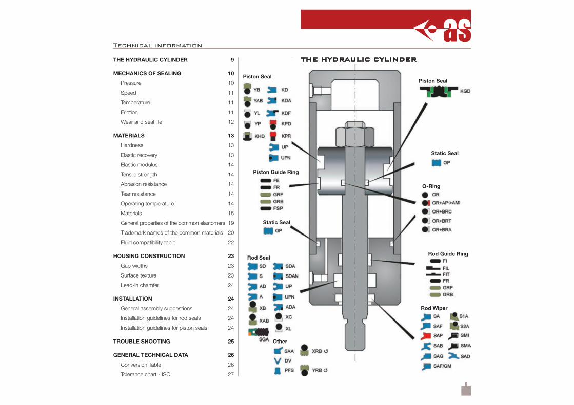
THE HYDRAULIC CYLINDER 9
MECHANICS OF SEALING 10
Pressure 10
Speed 11
Temperature 11
Friction 11
Wear and seal life 12
MATERIALS 13
Hardness 13
Elastic recovery 13
Elastic modulus 14
Tensile strength 14
Abrasion resistance 14
Tear resistance 14
Operating temperature 14
Materials 15
General properties of the common elastomers 19
Trademark names of the common materials 20
Fluid compatibility table 22
HOUSING CONSTRUCTION 23
Gap widths 23
Surface texture 23
Lead-in chamfer 24
INSTALLATION 24
General assembly suggestions 24
Installation guidelines for rod seals 24
Installation guidelines for piston seals 24
TROUBLE SHOOTING 25
GENERAL TECHNICAL DATA 26
Conversion Table 26
Tolerance chart - ISO 27
Piston Seal
Piston Guide Ring
Static Seal
Rod Seal
Other
Rod Wiper
Rod Guide Ring
O-Ring
Static Seal
Piston Seal
THE HYDRAULIC CYLINDER
Technical information
10
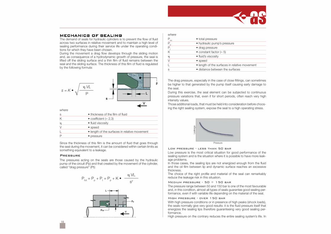
Ptot = Pp + Pt = Pp + K •η VL
s2
s = K •η VL
P
MECHANICS OF SEALINGThe demand of seals for hydraulic cylinders is to prevent the flow of fluidacross two surfaces in relative movement and to maintain a high level ofsealing performance during their service life under the operating condi-tions for which they have been chosen.During the movement a drag flow develops through the sliding motionand, as consequence of a hydrodynamic growth of pressure, the seal islifted off the sliding surface and a thin film of fluid remains between theseal and the sliding surface. The thickness of this film of fluid is regulatedby the following formula:
wheres • thickness of the film of fluidK • coefficient (≈ 2,3)η • fluid viscosityV • speedL • length of the surfaces in relative movementP • pressure
Since the thickness of this film is the amount of fluid that goes throughthe seal during the movement, it can be considered within certain limits assomething equivalent to a leakage.
PressureThe pressures acting on the seals are those caused by the hydraulicpump of the circuit (Pp) and that created by the movement of the cylinder,called “drag pressure” (Pt):
wherePtot • total pressurePp • hydraulic pump’s pressurePt • drag pressureK • constant factor (≈ 5)η • fluid’s viscosityV • speedL • length of the surfaces in relative movements • distance between the surfaces
The drag pressure, especially in the case of close fittings, can sometimesbe higher to that generated by the pump itself causing early damage tothe seal.During this exercise, the seal element can be subjected to continuouspressure variations that, even if for short periods, often reach very highintensity values.Those additional loads, that must be held into consideration before choos-ing the right sealing system, expose the seal to a high operating stress.
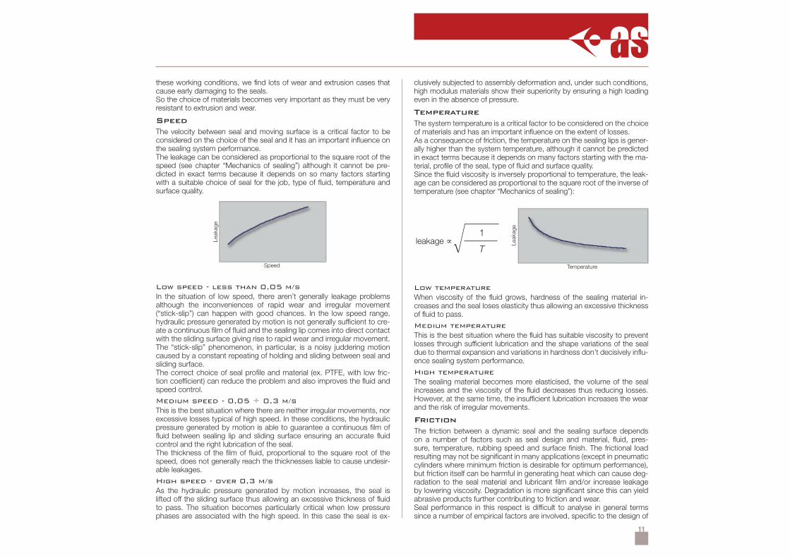
Low pressure - less than 50 barLow pressure is the most critical situation for good performance of thesealing system and is the situation where it is possible to have more leak-age problems.In those cases, the sealing lips are not energized enough from the fluidand the oil film between lip and dynamic surface reaches an excessivethickness.The choice of the right profile and material of the seal can remarkablyreduce the leakage risk in this situation.
Medium pressure - 50 ÷ 150 barThe pressure range between 50 and 150 bar is one of the most favourableand, in this condition, almost all types of seals guarantee good sealing per-formance, even if with variable life depending on the material of the seal.
High pressure - over 150 barWith high pressure conditions or in presence of high peaks (shock loads),the seals normally give very good results: it is the fluid pressure itself thatenergizes the sealing lips therefore guaranteeing very good sealing per-formance.High pressure on the contrary reduces the entire sealing system’s life. In
Pressure
Leak
age
11
these working conditions, we find lots of wear and extrusion cases thatcause early damaging to the seals.So the choice of materials becomes very important as they must be veryresistant to extrusion and wear.
SpeedThe velocity between seal and moving surface is a critical factor to beconsidered on the choice of the seal and it has an important influence onthe sealing system performance.The leakage can be considered as proportional to the square root of thespeed (see chapter “Mechanics of sealing”) although it cannot be pre-dicted in exact terms because it depends on so many factors startingwith a suitable choice of seal for the job, type of fluid, temperature andsurface quality.
Low speed - less than 0,05 m/sIn the situation of low speed, there aren’t generally leakage problemsalthough the inconveniences of rapid wear and irregular movement(“stick-slip”) can happen with good chances. In the low speed range,hydraulic pressure generated by motion is not generally sufficient to cre-ate a continuous film of fluid and the sealing lip comes into direct contactwith the sliding surface giving rise to rapid wear and irregular movement.The “stick-slip” phenomenon, in particular, is a noisy juddering motioncaused by a constant repeating of holding and sliding between seal andsliding surface.The correct choice of seal profile and material (ex. PTFE, with low fric-tion coefficient) can reduce the problem and also improves the fluid andspeed control.
Medium speed - 0,05 ÷ 0,3 m/sThis is the best situation where there are neither irregular movements, norexcessive losses typical of high speed. In these conditions, the hydraulicpressure generated by motion is able to guarantee a continuous film offluid between sealing lip and sliding surface ensuring an accurate fluidcontrol and the right lubrication of the seal.The thickness of the film of fluid, proportional to the square root of thespeed, does not generally reach the thicknesses liable to cause undesir-able leakages.
High speed - over 0,3 m/sAs the hydraulic pressure generated by motion increases, the seal islifted off the sliding surface thus allowing an excessive thickness of fluidto pass. The situation becomes particularly critical when low pressurephases are associated with the high speed. In this case the seal is ex-
Speed
Leak
age
clusively subjected to assembly deformation and, under such conditions,high modulus materials show their superiority by ensuring a high loadingeven in the absence of pressure.
TemperatureThe system temperature is a critical factor to be considered on the choiceof materials and has an important influence on the extent of losses.As a consequence of friction, the temperature on the sealing lips is gener-ally higher than the system temperature, although it cannot be predictedin exact terms because it depends on many factors starting with the ma-terial, profile of the seal, type of fluid and surface quality.Since the fluid viscosity is inversely proportional to temperature, the leak-age can be considered as proportional to the square root of the inverse oftemperature (see chapter “Mechanics of sealing”):
Low temperatureWhen viscosity of the fluid grows, hardness of the sealing material in-creases and the seal loses elasticity thus allowing an excessive thicknessof fluid to pass.
Medium temperatureThis is the best situation where the fluid has suitable viscosity to preventlosses through sufficient lubrication and the shape variations of the sealdue to thermal expansion and variations in hardness don’t decisively influ-ence sealing system performance.
High temperatureThe sealing material becomes more elasticised, the volume of the sealincreases and the viscosity of the fluid decreases thus reducing losses.However, at the same time, the insufficient lubrication increases the wearand the risk of irregular movements.
FrictionThe friction between a dynamic seal and the sealing surface dependson a number of factors such as seal design and material, fluid, pres-sure, temperature, rubbing speed and surface finish. The frictional loadresulting may not be significant in many applications (except in pneumaticcylinders where minimum friction is desirable for optimum performance),but friction itself can be harmful in generating heat which can cause deg-radation to the seal material and lubricant film and/or increase leakageby lowering viscosity. Degradation is more significant since this can yieldabrasive products further contributing to friction and wear.Seal performance in this respect is difficult to analyse in general termssince a number of empirical factors are involved, specific to the design of
Temperature
Leak
age
leakage ∝1
T
12
seal. However, as a basis, friction is obviously proportional to the pres-sure, although the co-efficient of friction involved may change with speed,temperature, material and surface finish.
Seal Friction = K • µ • (Pe)2 • V • A
whereK empirical factor specific to the design of seal
installed and working under design conditionsµ coefficient of frictionPe equivalent pressure equal to the interference
pressure plus the fluid pressureV speedA surface seal face contact (≈ π • Diameter • RadialSection)
Specific values of K factor are difficult to obtain unless evaluated onempirical lines or on the basis of comparative data. This formula canonly be used directly to investigate possible differences in performanceand friction on compression seals of the same type and material, butdifferent size.
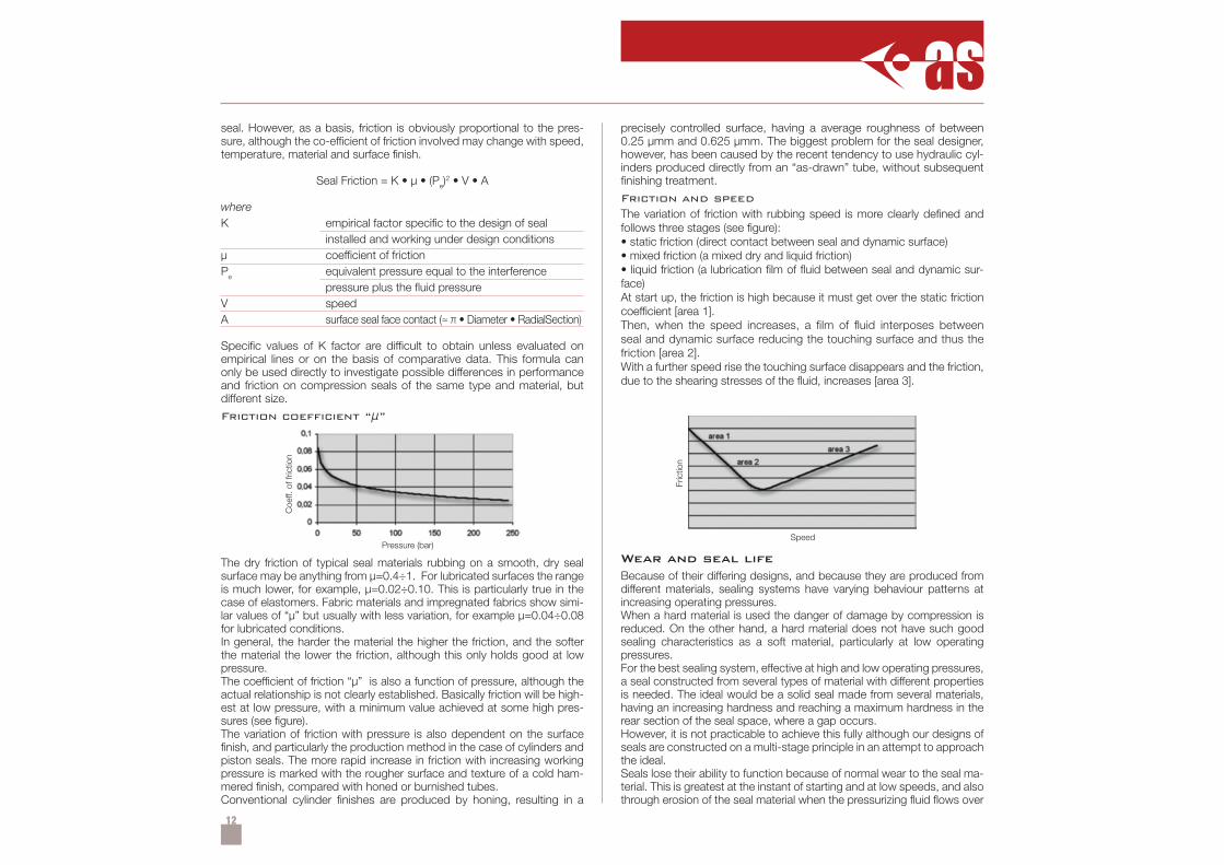
Friction coeffi cient “µ”
The dry friction of typical seal materials rubbing on a smooth, dry sealsurface may be anything from µ=0.4÷1. For lubricated surfaces the rangeis much lower, for example, µ=0.02÷0.10. This is particularly true in thecase of elastomers. Fabric materials and impregnated fabrics show simi-lar values of “µ” but usually with less variation, for example µ=0.04÷0.08for lubricated conditions.In general, the harder the material the higher the friction, and the softerthe material the lower the friction, although this only holds good at lowpressure.The coefficient of friction “µ” is also a function of pressure, although theactual relationship is not clearly established. Basically friction will be high-est at low pressure, with a minimum value achieved at some high pres-sures (see figure).The variation of friction with pressure is also dependent on the surfacefinish, and particularly the production method in the case of cylinders andpiston seals. The more rapid increase in friction with increasing workingpressure is marked with the rougher surface and texture of a cold ham-mered finish, compared with honed or burnished tubes.Conventional cylinder finishes are produced by honing, resulting in a
precisely controlled surface, having a average roughness of between0.25 µmm and 0.625 µmm. The biggest problem for the seal designer,however, has been caused by the recent tendency to use hydraulic cyl-inders produced directly from an “as-drawn” tube, without subsequentfinishing treatment.
Friction and speedThe variation of friction with rubbing speed is more clearly defined andfollows three stages (see figure):• static friction (direct contact between seal and dynamic surface)• mixed friction (a mixed dry and liquid friction)• liquid friction (a lubrication film of fluid between seal and dynamic sur-face)At start up, the friction is high because it must get over the static frictioncoefficient [area 1].Then, when the speed increases, a film of fluid interposes betweenseal and dynamic surface reducing the touching surface and thus thefriction [area 2].With a further speed rise the touching surface disappears and the friction,due to the shearing stresses of the fluid, increases [area 3].
Wear and seal lifeBecause of their differing designs, and because they are produced fromdifferent materials, sealing systems have varying behaviour patterns atincreasing operating pressures.When a hard material is used the danger of damage by compression isreduced. On the other hand, a hard material does not have such goodsealing characteristics as a soft material, particularly at low operatingpressures.For the best sealing system, effective at high and low operating pressures,a seal constructed from several types of material with different propertiesis needed. The ideal would be a solid seal made from several materials,having an increasing hardness and reaching a maximum hardness in therear section of the seal space, where a gap occurs.However, it is not practicable to achieve this fully although our designs ofseals are constructed on a multi-stage principle in an attempt to approachthe ideal.Seals lose their ability to function because of normal wear to the seal ma-terial. This is greatest at the instant of starting and at low speeds, and alsothrough erosion of the seal material when the pressurizing fluid flows over
Pressure (bar)
Coe
ff. o
f fric
tion
Speed
Fric
tion
13
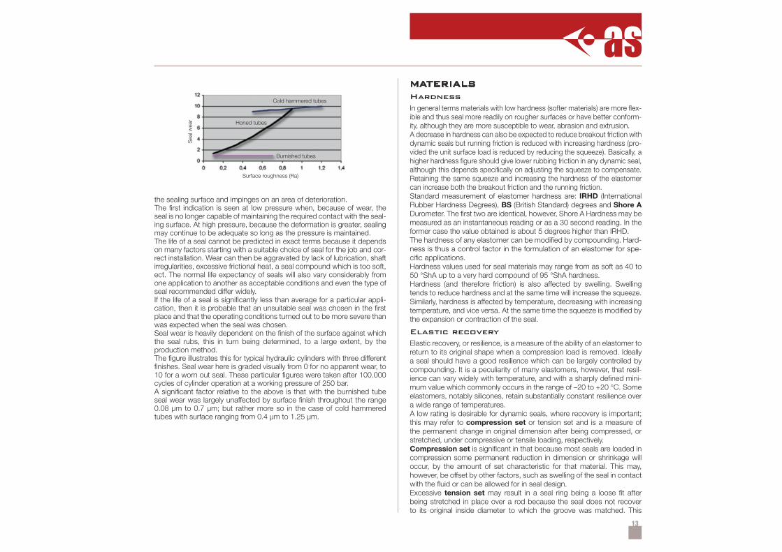
the sealing surface and impinges on an area of deterioration.The first indication is seen at low pressure when, because of wear, theseal is no longer capable of maintaining the required contact with the seal-ing surface. At high pressure, because the deformation is greater, sealingmay continue to be adequate so long as the pressure is maintained.The life of a seal cannot be predicted in exact terms because it dependson many factors starting with a suitable choice of seal for the job and cor-rect installation. Wear can then be aggravated by lack of lubrication, shaftirregularities, excessive frictional heat, a seal compound which is too soft,ect. The normal life expectancy of seals will also vary considerably fromone application to another as acceptable conditions and even the type ofseal recommended differ widely.If the life of a seal is significantly less than average for a particular appli-cation, then it is probable that an unsuitable seal was chosen in the firstplace and that the operating conditions turned out to be more severe thanwas expected when the seal was chosen.Seal wear is heavily dependent on the finish of the surface against whichthe seal rubs, this in turn being determined, to a large extent, by theproduction method.The figure illustrates this for typical hydraulic cylinders with three differentfinishes. Seal wear here is graded visually from 0 for no apparent wear, to10 for a worn out seal. These particular figures were taken after 100.000cycles of cylinder operation at a working pressure of 250 bar.A significant factor relative to the above is that with the burnished tubeseal wear was largely unaffected by surface finish throughout the range0.08 µm to 0.7 µm; but rather more so in the case of cold hammeredtubes with surface ranging from 0.4 µm to 1.25 µm.
Surface roughness (Ra)
Sea
l wea
r
Cold hammered tubes
Burnished tubes
Honed tubes
MATERIALSHardnessIn general terms materials with low hardness (softer materials) are more flex-ible and thus seal more readily on rougher surfaces or have better conform-ity, although they are more susceptible to wear, abrasion and extrusion.A decrease in hardness can also be expected to reduce breakout friction withdynamic seals but running friction is reduced with increasing hardness (pro-vided the unit surface load is reduced by reducing the squeeze). Basically, ahigher hardness figure should give lower rubbing friction in any dynamic seal,although this depends specifically on adjusting the squeeze to compensate.Retaining the same squeeze and increasing the hardness of the elastomercan increase both the breakout friction and the running friction.Standard measurement of elastomer hardness are: IRHD (InternationalRubber Hardness Degrees), BS (British Standard) degrees and Shore ADurometer. The first two are identical, however, Shore A Hardness may bemeasured as an instantaneous reading or as a 30 second reading. In theformer case the value obtained is about 5 degrees higher than IRHD.The hardness of any elastomer can be modified by compounding. Hard-ness is thus a control factor in the formulation of an elastomer for spe-cific applications.Hardness values used for seal materials may range from as soft as 40 to50 °ShA up to a very hard compound of 95 °ShA hardness.Hardness (and therefore friction) is also affected by swelling. Swellingtends to reduce hardness and at the same time will increase the squeeze.Similarly, hardness is affected by temperature, decreasing with increasingtemperature, and vice versa. At the same time the squeeze is modified bythe expansion or contraction of the seal.
Elastic recoveryElastic recovery, or resilience, is a measure of the ability of an elastomer toreturn to its original shape when a compression load is removed. Ideallya seal should have a good resilience which can be largely controlled bycompounding. It is a peculiarity of many elastomers, however, that resil-ience can vary widely with temperature, and with a sharply defined mini-mum value which commonly occurs in the range of –20 to +20 °C. Someelastomers, notably silicones, retain substantially constant resilience overa wide range of temperatures.A low rating is desirable for dynamic seals, where recovery is important;this may refer to compression set or tension set and is a measure ofthe permanent change in original dimension after being compressed, orstretched, under compressive or tensile loading, respectively.Compression set is significant in that because most seals are loaded incompression some permanent reduction in dimension or shrinkage willoccur, by the amount of set characteristic for that material. This may,however, be offset by other factors, such as swelling of the seal in contactwith the fluid or can be allowed for in seal design.Excessive tension set may result in a seal ring being a loose fit afterbeing stretched in place over a rod because the seal does not recoverto its original inside diameter to which the groove was matched. This
14
would probably be offset by compression set on completion of the as-sembly and so tension is normally ignored. The latter may be significantin plastomers which have low elongation and slow recovery, particularlyif over-stretched. Both elastomers and plastomers, however, if loaded intension, or with residual tensile stresses, will tend to contract with anincrease in temperature.
Elastic modulusElongation is a reciprocal indication of material stiffness. It is defined asthe increase in length as a percentage of the original length which, for theultimate case, is the elongation at the point of breaking. Elongation is alsoused to define an elastomer that is a material capable of 100% elonga-tion. Permissible elongation (the percentage stretch which can be appliedwithout permanent damage or permanent set) determines the amount bywhich a ring seal can be stretched to fit in place.The term modulus is also used in connection with elongation and is gen-erally taken to refer to the modulus (in tension) or the stress produced inthe material at a predetermined elongation, for example, 100 % elonga-tion. This can be used as a measure of quality control. Modulus can alsorefer to stress per specified distortion in shear and compression (modulusin shear and modulus in compression, respectively). A change of modu-lus of a material indicates a change in material characteristics, a loss ofmodulus, for example, indicates a degradation of the product.As a general safety rule elastomers seals should not permanently stretchedmore than about 5% as otherwise the resulting residual stresses cancause early deterioration further accelerated by any rise in temperature.This applies particularly to the more generally used elastomers such asNitrile and natural rubbers. Some elastomers, notably ethylene-propylene,can accommodate a relatively high amount of permanent stretch with noadverse effects.
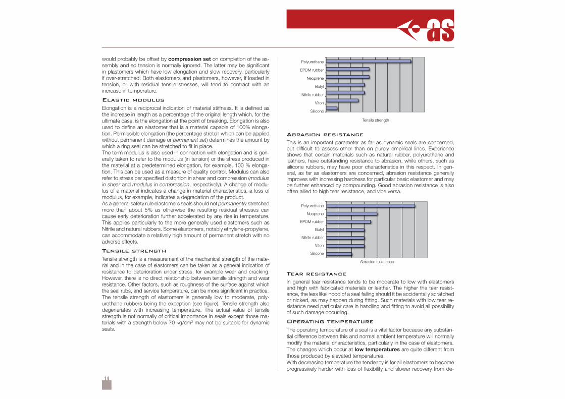
Tensile strengthTensile strength is a measurement of the mechanical strength of the mate-rial and in the case of elastomers can be taken as a general indication ofresistance to deterioration under stress, for example wear and cracking.However, there is no direct relationship between tensile strength and wearresistance. Other factors, such as roughness of the surface against whichthe seal rubs, and service temperature, can be more significant in practice.The tensile strength of elastomers is generally low to moderate, poly-urethane rubbers being the exception (see figure). Tensile strength alsodegenerates with increasing temperature. The actual value of tensilestrength is not normally of critical importance in seals except those ma-terials with a strength below 70 kg/cm2 may not be suitable for dynamicseals.
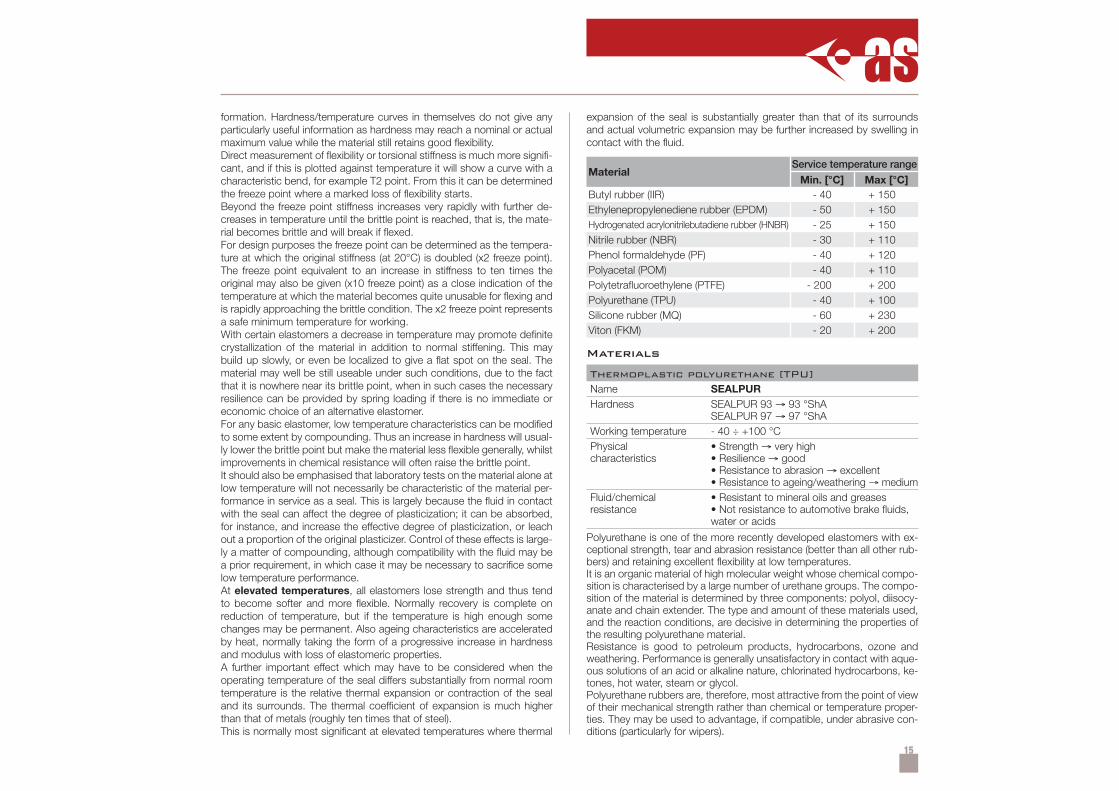
Abrasion resistanceThis is an important parameter as far as dynamic seals are concerned,but difficult to assess other than on purely empirical lines. Experienceshows that certain materials such as natural rubber, polyurethane andleathers, have outstanding resistance to abrasion, while others, such assilicone rubbers, may have poor characteristics in this respect. In gen-eral, as far as elastomers are concerned, abrasion resistance generallyimproves with increasing hardness for particular basic elastomer and maybe further enhanced by compounding. Good abrasion resistance is alsooften allied to high tear resistance, and vice versa.
Tear resistanceIn general tear resistance tends to be moderate to low with elastomersand high with fabricated materials or leather. The higher the tear resist-ance, the less likelihood of a seal failing should it be accidentally scratchedor nicked, as may happen during fitting. Such materials with low tear re-sistance need particular care in handling and fitting to avoid all possibilityof such damage occurring.
Operating temperatureThe operating temperature of a seal is a vital factor because any substan-tial difference between this and normal ambient temperature will normallymodify the material characteristics, particularly in the case of elastomers.The changes which occur at low temperatures are quite different fromthose produced by elevated temperatures.With decreasing temperature the tendency is for all elastomers to becomeprogressively harder with loss of flexibility and slower recovery from de-
Tensile strength
Polyurethane
EPDM rubber
Neoprene
Butyl
Nitrile rubber
Viton
Silicone
Abrasion resistance
Polyurethane
Neoprene
EPDM rubber
Butyl
Nitrile rubber
Viton
Silicone
15
formation. Hardness/temperature curves in themselves do not give anyparticularly useful information as hardness may reach a nominal or actualmaximum value while the material still retains good flexibility.Direct measurement of flexibility or torsional stiffness is much more signifi-cant, and if this is plotted against temperature it will show a curve with acharacteristic bend, for example T2 point. From this it can be determinedthe freeze point where a marked loss of flexibility starts.Beyond the freeze point stiffness increases very rapidly with further de-creases in temperature until the brittle point is reached, that is, the mate-rial becomes brittle and will break if flexed.For design purposes the freeze point can be determined as the tempera-ture at which the original stiffness (at 20°C) is doubled (x2 freeze point).The freeze point equivalent to an increase in stiffness to ten times theoriginal may also be given (x10 freeze point) as a close indication of thetemperature at which the material becomes quite unusable for flexing andis rapidly approaching the brittle condition. The x2 freeze point representsa safe minimum temperature for working.With certain elastomers a decrease in temperature may promote definitecrystallization of the material in addition to normal stiffening. This maybuild up slowly, or even be localized to give a flat spot on the seal. Thematerial may well be still useable under such conditions, due to the factthat it is nowhere near its brittle point, when in such cases the necessaryresilience can be provided by spring loading if there is no immediate oreconomic choice of an alternative elastomer.For any basic elastomer, low temperature characteristics can be modifiedto some extent by compounding. Thus an increase in hardness will usual-ly lower the brittle point but make the material less flexible generally, whilstimprovements in chemical resistance will often raise the brittle point.It should also be emphasised that laboratory tests on the material alone atlow temperature will not necessarily be characteristic of the material per-formance in service as a seal. This is largely because the fluid in contactwith the seal can affect the degree of plasticization; it can be absorbed,for instance, and increase the effective degree of plasticization, or leachout a proportion of the original plasticizer. Control of these effects is large-ly a matter of compounding, although compatibility with the fluid may bea prior requirement, in which case it may be necessary to sacrifice somelow temperature performance.At elevated temperatures, all elastomers lose strength and thus tendto become softer and more flexible. Normally recovery is complete onreduction of temperature, but if the temperature is high enough somechanges may be permanent. Also ageing characteristics are acceleratedby heat, normally taking the form of a progressive increase in hardnessand modulus with loss of elastomeric properties.A further important effect which may have to be considered when theoperating temperature of the seal differs substantially from normal roomtemperature is the relative thermal expansion or contraction of the sealand its surrounds. The thermal coefficient of expansion is much higherthan that of metals (roughly ten times that of steel).This is normally most significant at elevated temperatures where thermal
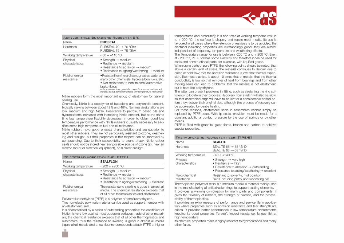
expansion of the seal is substantially greater than that of its surroundsand actual volumetric expansion may be further increased by swelling incontact with the fluid.
Materials
Thermoplastic polyurethane [TPU]Name SEALPURHardness SEALPUR 93 → 93 °ShA
SEALPUR 97 → 97 °ShAWorking temperature - 40 ÷ +100 °CPhysicalcharacteristics
• Strength → very high• Resilience → good• Resistance to abrasion → excellent• Resistance to ageing/weathering → medium
Fluid/chemicalresistance
• Resistant to mineral oils and greases• Not resistance to automotive brake fluids,water or acids
Polyurethane is one of the more recently developed elastomers with ex-ceptional strength, tear and abrasion resistance (better than all other rub-bers) and retaining excellent flexibility at low temperatures.It is an organic material of high molecular weight whose chemical compo-sition is characterised by a large number of urethane groups. The compo-sition of the material is determined by three components: polyol, diisocy-anate and chain extender. The type and amount of these materials used,and the reaction conditions, are decisive in determining the properties ofthe resulting polyurethane material.Resistance is good to petroleum products, hydrocarbons, ozone andweathering. Performance is generally unsatisfactory in contact with aque-ous solutions of an acid or alkaline nature, chlorinated hydrocarbons, ke-tones, hot water, steam or glycol.Polyurethane rubbers are, therefore, most attractive from the point of viewof their mechanical strength rather than chemical or temperature proper-ties. They may be used to advantage, if compatible, under abrasive con-ditions (particularly for wipers).
MaterialService temperature range
Min. [°C] Max [°C]Butyl rubber (IIR) - 40 + 150Ethylenepropylenediene rubber (EPDM) - 50 + 150Hydrogenated acrylonitrilebutadiene rubber (HNBR) - 25 + 150Nitrile rubber (NBR) - 30 + 110Phenol formaldehyde (PF) - 40 + 120Polyacetal (POM) - 40 + 110Polytetrafluoroethylene (PTFE) - 200 + 200Polyurethane (TPU) - 40 + 100Silicone rubber (MQ) - 60 + 230Viton (FKM) - 20 + 200
16
Acrylonitrile Butadiene Rubber [NBR]Name RUBSEALHardness RUBSEAL 70 → 70 °ShA
RUBSEAL 75 → 75 °ShAWorking temperature - 30 ÷ +110 °CPhysicalcharacteristics
• Strength → medium• Resilience → medium• Resistance to abrasion → medium• Resistance to ageing/weathering → medium
Fluid/chemicalresistance
•Resistanttomineraloilsandgreases,waterandmany other chemicals, hydrocarbon fuels, etc.• Not resistance to non-mineral automotivebrake fluidsnote: increase in acrylonitrile content improves resistance tomineral oil but adversely affects low temperature resistance
Nitrile rubbers form the most important group of elastomers for generalsealing use.Chemically, Nitrile is a copolymer of butadiene and acrylonitrile content,typically varying between about 18% and 48%. Nominal designations arelow, medium and high Nitrile. Resistance to petroleum based oils andhydrocarbons increases with increasing Nitrile content, but at the sametime low temperature flexibility decreases. In order to obtain good lowtemperature performance with Nitrile rubbers it usually necessary to sac-rifice some high temperature fuel and oil resistance.Nitrile rubbers have good physical characteristics and are superior tomost other rubbers. They are not particularly resistant to ozone, weather-ing and sunlight, but their properties in this respect can be improved bycompounding. Due to their susceptibility to ozone attack Nitrile rubberseals should not be stored near any possible source of ozone (ex. near anelectric motor or electrical equipment), or in direct sunlight.
Polytetrafluoroethylene [PTFE]Name SEALFLONWorking temperature - 200 ÷ +200 °CPhysicalcharacteristics
• Strength → medium• Resilience → medium• Resistance to abrasion → medium• Resistance to ageing/weathering → excellent
Fluid/chemicalresistance
The resistance to swelling is good in almost allmedia. The chemical resistance exceeds thatof all other thermoplastics and elastomers.
Polytetrafluoroethylene (PTFE) is a polymer of tetrafluoroethylene.This non-elastic polymeric material can be used as support member withan elastomeric seal.It is characterised by a series of outstanding properties: the coefficient offriction is very low against most opposing surfaces made of other materi-als; the chemical resistance exceeds that of all other thermoplastics andelastomers, thus the resistance to swelling is good in almost all media(liquid alkali metals and a few fluorine compounds attack PTFE at higher
temperatures and pressures); it is non-toxic at working temperatures upto + 200 °C; the surface is slippery and repels most media, its use isfavoured in all cases where the retention of residues is to be avoided; theelectrical insulating properties are outstandingly good, they are almostindependent of frequency, temperature and weathering effects.The Temperature range for use is between -200 °C and + 200 °C. Evenat - 200 °C, PTFE still has some elasticity and therefore it can be used forseals and constructional parts, for example, with liquified gases.When using parts of pure PTFE, the following points should be noted: thatabove a certain level of stress, the material continues to deform due tocreep or cold flow; that the abrasion resistance is low; that thermal expan-sion, like most plastics, is about 10 times that of metals; that the thermalconductivity is low so that removal of heat from bearings and from othermoving seals can lead to problems; that the material is not elastomericbut is hard like polyethylene.The latter can present problems in fitting, such as stretching the ring suf-ficiently to locate in their grooves. Recovery from stretch will also be slow,so that assembled rings will have to be left for a considerable period be-fore they recover their original size, although this process of recovery canbe accelerated by gentle heating.For these reasons, elastomeric seals in assemblies cannot simply bereplaced by PTFE seals. With lip seals, provision must be made for aconstant additional contact pressure by the use of springs or by othermeans.PTFE is filled with graphite, glass fibres, bronze and carbon to achievespecial properties.
Thermoplastic polyester resin [TPE-E]Name SEALITEHardness SEALITE 55 → 55 °ShD
SEALITE 63 → 63 °ShDWorking temperature - 40 ÷ +140 °CPhysicalcharacteristics
• Strength → very high• Resilience → high• Resistance to abrasion → outstanding• Resistance to ageing/weathering → excellent
Fluid/chemicalresistance
Resistant to solvents, hydrocarbonfluids including petrol and lubricating oils
Thermoplastic polyester resin is a medium modulus material mainly usedin the manufacturing of antiextrusion rings to support sealing elements.It provides a winning combination for many parts and components: itgives the flexibility of rubbers, the strength of plastics, and the proces-sibility of thermoplastics.It provides an extra measure of performance and service life in applica-tion where properties such as abrasion resistance and tear strength arecritical. It provides better performance in low temperature environmentskeeping its good properties (“creep”, impact resistance, fatigue life) athigh temperature.Its chemical properties make it highly resistant to hydrocarbons and manyother fluids.
17
Acetal resin [POM]Name BEARITEWorking temperature - 40 ÷ +110 °CPhysicalcharacteristics
• Strength → very high• Resistance to abrasion → excellent• Resistance to ageing/weathering → good
Fluid/chemicalresistance
• Resistant to gasoline, moisture, lubricatingoils, solvents and many other neutral chemicals• Not resistance to strong acids or bases out-side the range of pH 4 to 9, under constantexposure to pressurised hot water or vapour
Acetal resin with glass fibre is a high modulus material mainly used in themanufacturing of wear rings or antiextrusion rings (with glass fibre).Acetal resins are made by the polymerisation of formaldehyde.The homopolymer offers significantly better mechanical propertiesthan copolymer due to the highly crystalline structure of the acetalhomopolymer.They have built up a worldwide reputation for reliability in engineeringcomponents.They are characterised by a series of outstanding properties: high tensilestrength, impact resistance and stiffness; good fatigue resistance, un-matched by other plastics; excellent dimensional stability; “creep” resist-ance; low friction; wide working temperature range, down to very lowtemperatures.The low water absorption is especially significant because better dimen-sional stability in humid conditions is thus guaranteed, even when com-pared with polyammide.
Phenol-Formaldehyde [PF]Name PHENOLITEWorking temperature - 40 ÷ +120 °CPhysicalcharacteristics
• Strength → excellent• Resilience → excellent• Resistance to abrasion → excellent• Resistance to ageing/weathering → good
Fluid/chemicalresistance
Resistant to mineral oils, greases, organicsolvents, weak acids and alkalis, and salinesolutions
Phenol-Formaldehyde is a high modulus material mainly used in the man-ufacturing of wear rings.It is a synthetic resin formed from the elimination reaction of phenol withformaldehyde.It is characterised by a series of outstanding properties: excellent resist-ance to loads; high tensile strength, extended service life, low friction,wear-resistance, impact resistance and stiffness; “creep” resistance;flame retardant; wide working temperature range from -40°C to +120°C;excellent dimensional stability and accuracy of thickness.For short periods can tolerate temperatures up to +300°C.
At normal temperature phenol is pale yellowish; the colour stability ofphenol is decreased by the effects of light, air and iron oxides duringstorage.Due to its chemical structure it is not suitable for use with foodstuffs.
Ethylene-Propylene [EPDM]Working temperature - 50 ÷ +150 °CPhysicalcharacteristics
• Strength → medium• Resilience → medium• Resistance to abrasion → medium• Resistance to ageing/weathering → good
Fluid/chemicalresistance
• Resistant to non-mineral oils, automotivebrake fluids, phosphate ester fluid, water/steam and many chemicals• Not resistance to mineral oils and grease orhydrocarbon fuels
Ethylene-Propylene is one of the best general-purpose synthetic rubbers.Polymerisation and catalyst technologies in use today provide the abil-ity to design polymers to meet specific and demanding application andprocessing needs. EPDM rubbers are valuable for their excellent resist-ance to heat, oxidation, ozone and weather-ageing due to their stable,saturated polymer backbone structure.Compression set resistance is good, particularly at high temperatures.They have a good resistance to polar solvents such as water, acids, alka-lies, phosphate ester and many ketones and alcohols.
Fluoroelastomer [FKM]Trademark name VitonWorking temperature - 20 ÷ +200 °CPhysicalcharacteristics
• Strength → medium• Resilience → poor• Resistance to abrasion → poor• Resistance to ageing/weathering → excellent
Fluid/chemicalresistance
Excellent resistance to mineral oils andhydrocarbon fuels. Resistant to many chemi-cals except ketones, alcohols and acids
Fluoroelastomer rubber, well known for its excellent heat resistance(200 °C), offers excellent resistance to aggressive fuels and chemicalsMany types of Fluoroelastomer rubbers have been developed to meetspecific end-use and processing needs. There are differences betweenrubber types in terms of chemical resistance and mechanical proper-ties. The general purpose types differ primarily from the specialty typesin chemical resistance.The formulation of fluoroelastomer rubbers, can be tailored to a reason-able extent to meet the needs of high heat, oil and chemical resistancebut indifferent low temperature performance.They are one of the most resistant to high temperatures of all of the com-mercially available elastomers.
18
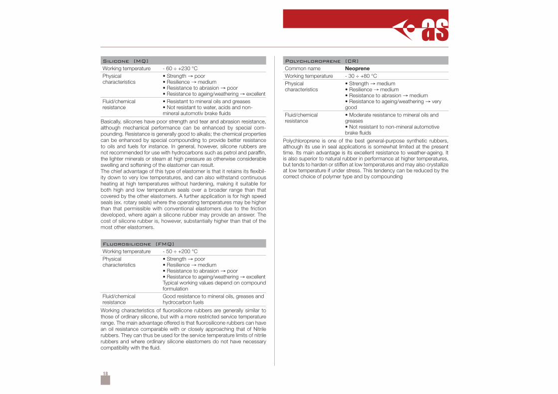
Silicone [MQ]Working temperature - 60 ÷ +230 °CPhysicalcharacteristics
• Strength → poor• Resilience → medium• Resistance to abrasion → poor• Resistance to ageing/weathering → excellent
Fluid/chemicalresistance
• Resistant to mineral oils and greases• Not resistant to water, acids and non-mineral automotiv brake fluids
Basically, silicones have poor strength and tear and abrasion resistance,although mechanical performance can be enhanced by special com-pounding. Resistance is generally good to alkalis; the chemical propertiescan be enhanced by special compounding to provide better resistanceto oils and fuels for instance. In general, however, silicone rubbers arenot recommended for use with hydrocarbons such as petrol and paraffin,the lighter minerals or steam at high pressure as otherwise considerableswelling and softening of the elastomer can result.The chief advantage of this type of elastomer is that it retains its flexibil-ity down to very low temperatures, and can also withstand continuousheating at high temperatures without hardening, making it suitable forboth high and low temperature seals over a broader range than thatcovered by the other elastomers. A further application is for high speedseals (ex. rotary seals) where the operating temperatures may be higherthan that permissible with conventional elastomers due to the frictiondeveloped, where again a silicone rubber may provide an answer. Thecost of silicone rubber is, however, substantially higher than that of themost other elastomers.
Fluorosilicone [FMQ]Working temperature - 50 ÷ +200 °CPhysicalcharacteristics
• Strength → poor• Resilience → medium• Resistance to abrasion → poor• Resistance to ageing/weathering → excellentTypical working values depend on compoundformulation
Fluid/chemicalresistance
Good resistance to mineral oils, greases andhydrocarbon fuels
Working characteristics of fluorosilicone rubbers are generally similar tothose of ordinary silicone, but with a more restricted service temperaturerange. The main advantage offered is that fluorosilicone rubbers can havean oil resistance comparable with or closely approaching that of Nitrilerubbers. They can thus be used for the service temperature limits of nitrilerubbers and where ordinary silicone elastomers do not have necessarycompatibility with the fluid.
Polychloroprene [CR]Common name NeopreneWorking temperature - 30 ÷ +80 °CPhysicalcharacteristics
• Strength → medium• Resilience → medium• Resistance to abrasion → medium• Resistance to ageing/weathering → verygood
Fluid/chemicalresistance
• Moderate resistance to mineral oils andgreases• Not resistant to non-mineral automotivebrake fluids
Polychloroprene is one of the best general-purpose synthetic rubbers,although its use in seal applications is somewhat limited at the presenttime. Its main advantage is its excellent resistance to weather-ageing. Itis also superior to natural rubber in performance at higher temperatures,but tends to harden or stiffen at low temperatures and may also crystallizeat low temperature if under stress. This tendency can be reduced by thecorrect choice of polymer type and by compounding
19
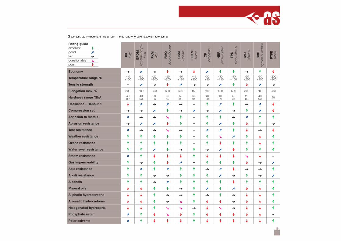
→ → ↓ → ↓ ↑ ↑ → ↑ ↓-40
+150-50
+150-20
+200-50
+200-20
+120-45
+300-30+80
-30+110
-40+100
-60+230
-50+100
-200+200
- → ↓ → → ↑ ↓ →800 600 300 600 500 150 600 600 500 800 600 250
4080
4090
5095
5080
5090
6595
4090
4090
4094
2580
4090 98
↓ → → - ↑ ↑ → ↓→ → ↑ → → → ↑ ↓
→ → ↑ - ↑ ↑ → ↑ ↑→ ↓ ↑ - ↑ ↑ ↓ ↑ →
→ → → - ↑ ↓ → ↓↑ ↑ ↑ ↑ ↑ - ↑ ↑ ↓ ↑↑ ↑ ↑ ↑ ↑ - ↑ ↓ ↑ ↑ ↓ ↑↑ ↑ ↑ → ↑ → ↓ ↑ ↑ ↑
↑ ↓ ↓ ↓ ↑ ↓ ↓ ↓ ↓ -↑ → ↑ ↓ - ↑ ↑ ↑ ↓ →↑ ↑ ↑ ↑ → ↓ → → ↑↑ ↑ → → ↑ ↑ ↑ → ↑ →↑ ↑ → ↑ ↑ ↑ ↑ ↓ ↑ ↑ ↑↓ ↓ ↑ ↑ → ↑ ↑ ↓ ↓ ↑↓ ↓ ↑ → → ↑ → ↑ → ↓ ↓ ↑↓ ↓ ↑ → ↑ ↓ ↓ → ↓ ↓ ↑↓ ↓ ↑ → ↓ → ↓ ↓ ↑
↑ ↓ ↓ ↑ ↓ ↓ ↓ ↓ ↓ -↑ ↓ ↓ ↓ ↑ ↓ ↓ ↓ ↓ ↓ ↑
↑
→
↓
IIR
buty
l
EP
DM
et
hyle
ne-p
ropy
-le
ne
FKM
vi
ton
FMQ
flu
oro-
silic
one
CS
M
hypa
lon
FFK
M
kalre
z
CR
neop
rene
NB
R
nitr
ile r
ubbe
r
TP
U
poly
uret
hane
MQ
silic
one
SB
R
styr
ene-
buta
dien
e
PT
FE
teflo
n
Economy
Temperature range °C
Tensile strength
Elongation max. %
Hardness range °ShA
Resilience - Rebound
Compression set
Adhesion to metals
Abrasion resistance
Tear resistance
Weather resistance
Ozone resistance
Water swell resistance
Steam resistance
Gas impermeability
Acid resistance
Alkali resistance
Alcohols
Mineral oils
Aliphatic hydrocarbons
Aromatic hydrocarbons
Halogenated hydrocarb.
Phosphate ester
Polar solvents
Rating guideexcellentgoodfairquestionablepoor
General properties of the common elastomers
20
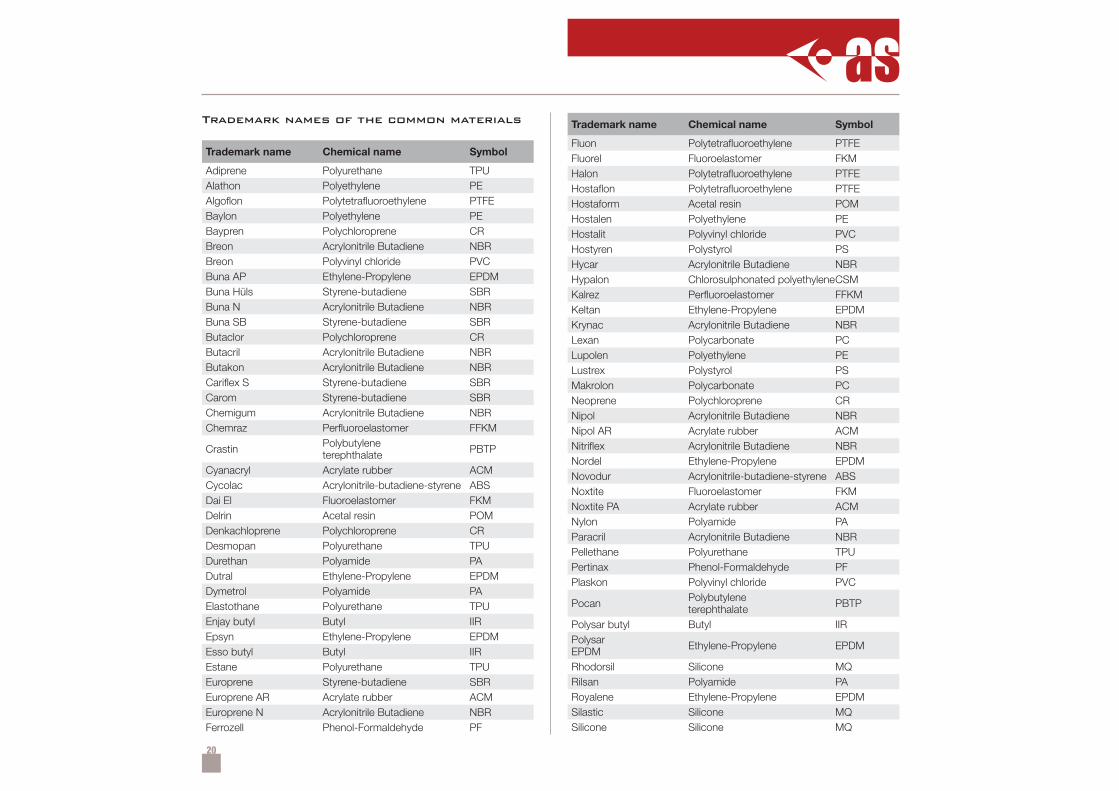
Trademark names of the common materials
Trademark name Chemical name Symbol
Adiprene Polyurethane TPUAlathon Polyethylene PEAlgoflon Polytetrafluoroethylene PTFEBaylon Polyethylene PEBaypren Polychloroprene CRBreon Acrylonitrile Butadiene NBRBreon Polyvinyl chloride PVCBuna AP Ethylene-Propylene EPDMBuna Hüls Styrene-butadiene SBRBuna N Acrylonitrile Butadiene NBRBuna SB Styrene-butadiene SBRButaclor Polychloroprene CRButacril Acrylonitrile Butadiene NBRButakon Acrylonitrile Butadiene NBRCariflex S Styrene-butadiene SBRCarom Styrene-butadiene SBRChemigum Acrylonitrile Butadiene NBRChemraz Perfluoroelastomer FFKM
Crastin Polybutyleneterephthalate PBTP
Cyanacryl Acrylate rubber ACMCycolac Acrylonitrile-butadiene-styrene ABSDai El Fluoroelastomer FKMDelrin Acetal resin POMDenkachloprene Polychloroprene CRDesmopan Polyurethane TPUDurethan Polyamide PADutral Ethylene-Propylene EPDMDymetrol Polyamide PAElastothane Polyurethane TPUEnjay butyl Butyl IIREpsyn Ethylene-Propylene EPDMEsso butyl Butyl IIREstane Polyurethane TPUEuroprene Styrene-butadiene SBREuroprene AR Acrylate rubber ACMEuroprene N Acrylonitrile Butadiene NBRFerrozell Phenol-Formaldehyde PF
Trademark name Chemical name Symbol
Fluon Polytetrafluoroethylene PTFEFluorel Fluoroelastomer FKMHalon Polytetrafluoroethylene PTFEHostaflon Polytetrafluoroethylene PTFEHostaform Acetal resin POMHostalen Polyethylene PEHostalit Polyvinyl chloride PVCHostyren Polystyrol PSHycar Acrylonitrile Butadiene NBRHypalon Chlorosulphonated polyethyleneCSMKalrez Perfluoroelastomer FFKMKeltan Ethylene-Propylene EPDMKrynac Acrylonitrile Butadiene NBRLexan Polycarbonate PCLupolen Polyethylene PELustrex Polystyrol PSMakrolon Polycarbonate PCNeoprene Polychloroprene CRNipol Acrylonitrile Butadiene NBRNipol AR Acrylate rubber ACMNitriflex Acrylonitrile Butadiene NBRNordel Ethylene-Propylene EPDMNovodur Acrylonitrile-butadiene-styrene ABSNoxtite Fluoroelastomer FKMNoxtite PA Acrylate rubber ACMNylon Polyamide PAParacril Acrylonitrile Butadiene NBRPellethane Polyurethane TPUPertinax Phenol-Formaldehyde PFPlaskon Polyvinyl chloride PVC
Pocan Polybutyleneterephthalate PBTP
Polysar butyl Butyl IIRPolysarEPDM Ethylene-Propylene EPDM
Rhodorsil Silicone MQRilsan Polyamide PARoyalene Ethylene-Propylene EPDMSilastic Silicone MQSilicone Silicone MQ
21
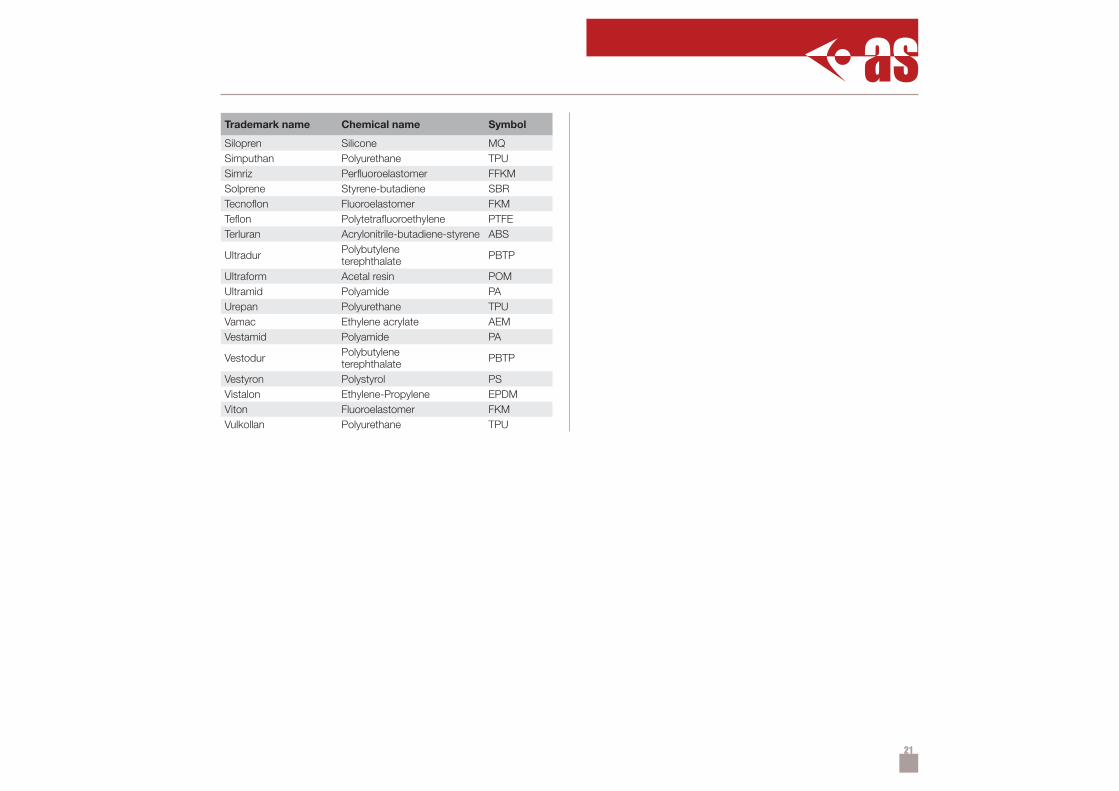
Trademark name Chemical name Symbol
Silopren Silicone MQSimputhan Polyurethane TPUSimriz Perfluoroelastomer FFKMSolprene Styrene-butadiene SBRTecnoflon Fluoroelastomer FKMTeflon Polytetrafluoroethylene PTFETerluran Acrylonitrile-butadiene-styrene ABS
Ultradur Polybutyleneterephthalate PBTP
Ultraform Acetal resin POMUltramid Polyamide PAUrepan Polyurethane TPUVamac Ethylene acrylate AEMVestamid Polyamide PA
Vestodur Polybutyleneterephthalate PBTP
Vestyron Polystyrol PSVistalon Ethylene-Propylene EPDMViton Fluoroelastomer FKMVulkollan Polyurethane TPU
22
↑
→↓
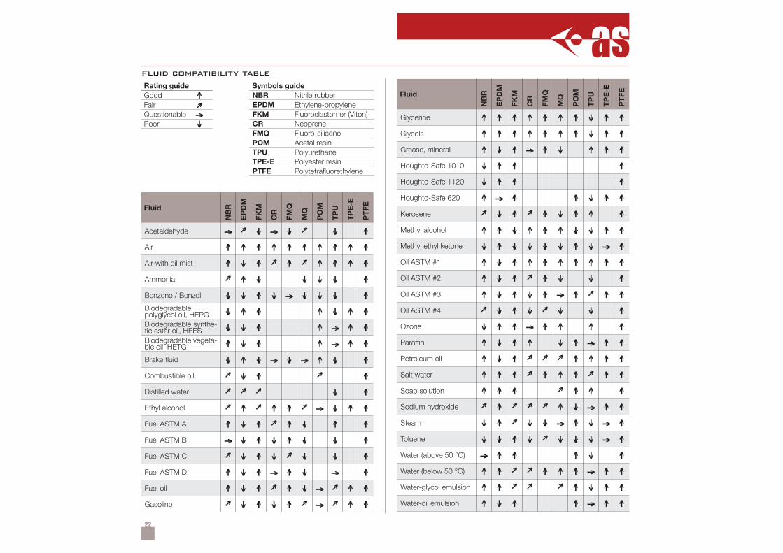
Symbols guideNBR Nitrile rubberEPDM Ethylene-propyleneFKM Fluoroelastomer (Viton)CR NeopreneFMQ Fluoro-siliconePOM Acetal resinTPU PolyurethaneTPE-E Polyester resinPTFE Polytetrafluorethylene
Rating guideGoodFairQuestionablePoor
Fluid compatibility table
Fluid
NB
R
EP
DM
FKM
CR
FMQ
MQ
PO
M
TP
U
TP
E-E
PT
FE
Acetaldehyde → ↓ → ↓ ↓ ↑Air ↑ ↑ ↑ ↑ ↑ ↑ ↑ ↑ ↑ ↑Air-with oil mist ↑ ↓ ↑ ↑ ↑ ↑ ↑ ↑Ammonia ↑ ↓ ↓ ↓ ↓ ↑Benzene / Benzol ↓ ↓ ↑ ↓ → ↓ ↓ ↓ ↑Biodegradablepolyglycol oil, HEPG ↓ ↑ ↑ ↑ ↓ ↑ ↑Biodegradable synthe-tic ester oil, HEES ↓ ↓ ↑ ↑ → ↑ ↑Biodegradable vegeta-ble oil, HETG ↑ ↓ ↑ ↑ → ↑ ↑Brake fluid ↓ ↑ ↓ → ↓ → ↑ ↓ ↑Combustible oil ↓ ↑ ↑Distilled water ↓ ↑Ethyl alcohol ↑ ↑ ↑ → ↓ ↑ ↑Fuel ASTM A ↑ ↓ ↑ ↑ ↓ ↑ ↑Fuel ASTM B → ↓ ↑ ↓ ↑ ↓ ↓ ↑Fuel ASTM C ↓ ↑ ↓ ↓ ↓ ↑Fuel ASTM D ↑ ↓ ↑ → ↑ ↓ → ↑Fuel oil ↑ ↓ ↑ ↑ ↓ → ↑ ↑Gasoline ↓ ↑ ↓ ↑ → ↑ ↑
Fluid
NB
R
EP
DM
FKM
CR
FMQ
MQ
PO
M
TP
U
TP
E-E
PT
FE
Glycerine ↑ ↑ ↑ ↑ ↑ ↑ ↑ ↓ ↑ ↑Glycols ↑ ↑ ↑ ↑ ↑ ↑ ↑ ↓ ↑ ↑Grease, mineral ↑ ↓ ↑ → ↑ ↓ ↑ ↑ ↑Houghto-Safe 1010 ↓ ↑ ↑ ↑Houghto-Safe 1120 ↓ ↑ ↑ ↑Houghto-Safe 620 ↑ → ↑ ↑ ↓ ↑ ↑Kerosene ↓ ↑ ↑ ↓ ↑ ↑ ↑Methyl alcohol ↑ ↑ ↓ ↑ ↑ ↑ ↓ ↓ ↑ ↑Methyl ethyl ketone ↓ ↑ ↓ ↓ ↓ ↓ ↑ ↓ → ↑Oil ASTM #1 ↑ ↓ ↑ ↑ ↑ ↑ ↑ ↑ ↑ ↑Oil ASTM #2 ↑ ↓ ↑ ↑ ↓ ↓ ↑Oil ASTM #3 ↑ ↓ ↑ ↓ ↑ → ↑ ↑ ↑Oil ASTM #4 ↓ ↑ ↓ ↓ ↓ ↑Ozone ↓ ↑ ↑ → ↑ ↑ ↑ ↑Paraffin ↑ ↓ ↑ ↑ ↓ ↑ → ↑ ↑Petroleum oil ↑ ↓ ↑ ↑ ↑ ↑ ↑Salt water ↑ ↑ ↑ ↑ ↑ ↑ ↑ ↑Soap solution ↑ ↑ ↑ ↑ ↑ ↑Sodium hydroxide ↑ ↑ ↓ → ↑ ↑Steam ↓ ↑ ↓ ↓ → ↑ ↓ → ↑Toluene ↓ ↓ ↑ ↓ ↓ ↓ ↓ → ↑Water (above 50 °C) → ↑ ↑ ↑ ↓ ↑Water (below 50 °C) ↑ ↑ ↑ ↑ ↑ → ↑ ↑Water-glycol emulsion ↑ ↑ ↑ ↓ ↑ ↑Water-oil emulsion ↑ ↓ ↑ ↑ → ↑ ↑
23
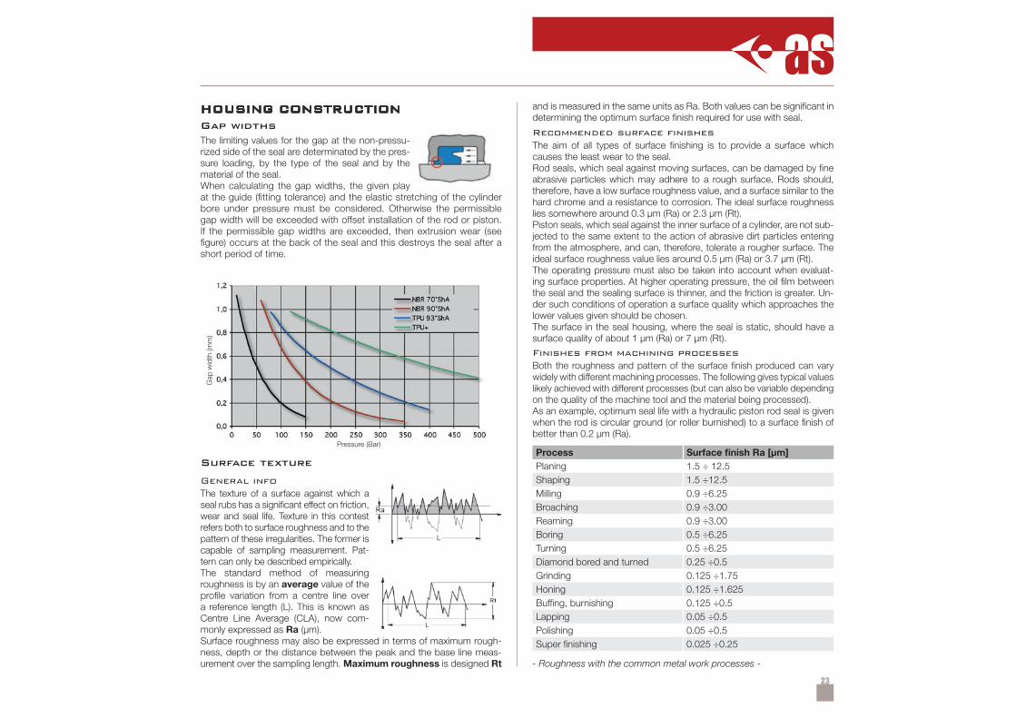
HOUSING CONSTRUCTIONGap widthsThe limiting values for the gap at the non-pressu-rized side of the seal are determinated by the pres-sure loading, by the type of the seal and by thematerial of the seal.When calculating the gap widths, the given playat the guide (fitting tolerance) and the elastic stretching of the cylinderbore under pressure must be considered. Otherwise the permissiblegap width will be exceeded with offset installation of the rod or piston.If the permissible gap widths are exceeded, then extrusion wear (seefigure) occurs at the back of the seal and this destroys the seal after ashort period of time.
Pressure (Bar)
Gap
wid
th (m
m)
Surface texture
General infoThe texture of a surface against which aseal rubs has a significant effect on friction,wear and seal life. Texture in this contestrefers both to surface roughness and to thepattern of these irregularities. The former iscapable of sampling measurement. Pat-tern can only be described empirically.The standard method of measuringroughness is by an average value of theprofile variation from a centre line overa reference length (L). This is known asCentre Line Average (CLA), now com-monly expressed as Ra (µm).Surface roughness may also be expressed in terms of maximum rough-ness, depth or the distance between the peak and the base line meas-urement over the sampling length. Maximum roughness is designed Rt
and is measured in the same units as Ra. Both values can be significant indetermining the optimum surface finish required for use with seal.
Recommended surface fi nishesThe aim of all types of surface finishing is to provide a surface whichcauses the least wear to the seal.Rod seals, which seal against moving surfaces, can be damaged by fineabrasive particles which may adhere to a rough surface. Rods should,therefore, have a low surface roughness value, and a surface similar to thehard chrome and a resistance to corrosion. The ideal surface roughnesslies somewhere around 0.3 µm (Ra) or 2.3 µm (Rt).Piston seals, which seal against the inner surface of a cylinder, are not sub-jected to the same extent to the action of abrasive dirt particles enteringfrom the atmosphere, and can, therefore, tolerate a rougher surface. Theideal surface roughness value lies around 0.5 µm (Ra) or 3.7 µm (Rt).The operating pressure must also be taken into account when evaluat-ing surface properties. At higher operating pressure, the oil film betweenthe seal and the sealing surface is thinner, and the friction is greater. Un-der such conditions of operation a surface quality which approaches thelower values given should be chosen.The surface in the seal housing, where the seal is static, should have asurface quality of about 1 µm (Ra) or 7 µm (Rt).
Finishes from machining processesBoth the roughness and pattern of the surface finish produced can varywidely with different machining processes. The following gives typical valueslikely achieved with different processes (but can also be variable dependingon the quality of the machine tool and the material being processed).As an example, optimum seal life with a hydraulic piston rod seal is givenwhen the rod is circular ground (or roller burnished) to a surface finish ofbetter than 0.2 µm (Ra).
Process Surface finish Ra [µm]Planing 1.5 ÷ 12.5Shaping 1.5 ÷12.5Milling 0.9 ÷6.25Broaching 0.9 ÷3.00Reaming 0.9 ÷3.00Boring 0.5 ÷6.25Turning 0.5 ÷6.25Diamond bored and turned 0.25 ÷0.5Grinding 0.125 ÷1.75Honing 0.125 ÷1.625Buffing, burnishing 0.125 ÷0.5Lapping 0.05 ÷0.5Polishing 0.05 ÷0.5Super finishing 0.025 ÷0.25
- Roughness with the common metal work processes -
24
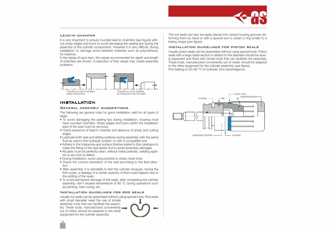
Lead-in chamferIt is very important to ensure rounded lead-in chamfers (see figure) with-out sharp edges and burrs to avoid damaging the sealing lips during theassembly of the cylinder components. However it is very difficult, duringinstallation, to damage some resistant materials such as polyurethane,for instance.In the tables of each item, the values recommended for depth and lengthof chamfers are shown. A reduction of that values may create assemblyproblems.
Chamfer on tube to facilitatepiston introduction
Chamfer on rod to facilitateits introduction into the head
INSTALLATIONGeneral assembly suggestionsThe following are general rules for good installation valid for all types ofseals:• To avoid damaging the sealing lips during installation, housing must
have rounded chamfers. Sharp edges and burrs within the installationarea of the seal must be removed
• Check presence of lead-in chamfer and absence of sharp and cuttingedges
• Lubricate both seal and silding surfaces during assembly with the samefluid as used in the hydraulic system, or with a compatible one
• Adhere to the tolerances and surface finishes stated in this catalogue tomake the fitting of the seal easier and to avoid assembly damages
• All parts must be perfectly clean, without metal particles, welding splat-ter or any kind of defect
• During installation, avoid using pointed or sharp metal tools• Check the correct orientation of the seal according to the fluid direc-
tion• After assembly, it is advisable to test the cylinder because, during the
first cycles, a leakage of a certain quantity of fluid could happen due tothe settling of the seals
• To avoid permanent damage of the seals, after completing the cylinderassembly, don’t exceed temperature of 80 °C during operations suchas painting, heat curing, etc.
Installation guidelines for rod sealsUsually rod seals can be assembled without using special tools. Rod sealswith small diameter need the use of simpleassembly tools that can facilitate the assem-bly. These tools, manufactured convenientlyout of metal, should be adapted to the otherequipment for the cylinder assembly.
The rod seals can also be easily placed into closed housing grooves de-forming them by hand or with a special tool to obtain a ring similar to akidney shape (see figure).
Installation guidelines for piston sealsUsually piston seals can be assembled without using special tools. Pistonseals with a large radial section in relation to the diameter should be slow-ly expanded and fitted with simple tools that can facilitate the assembly.These tools, manufactured conveniently out of metal, should be adaptedto the other equipment for the cylinder assembly (see figure).Pre-heating to 50÷60 °C in hydraulic oil is advantageous.
housing
piston sealexpanding jacket
expanding mandrel rounded
25
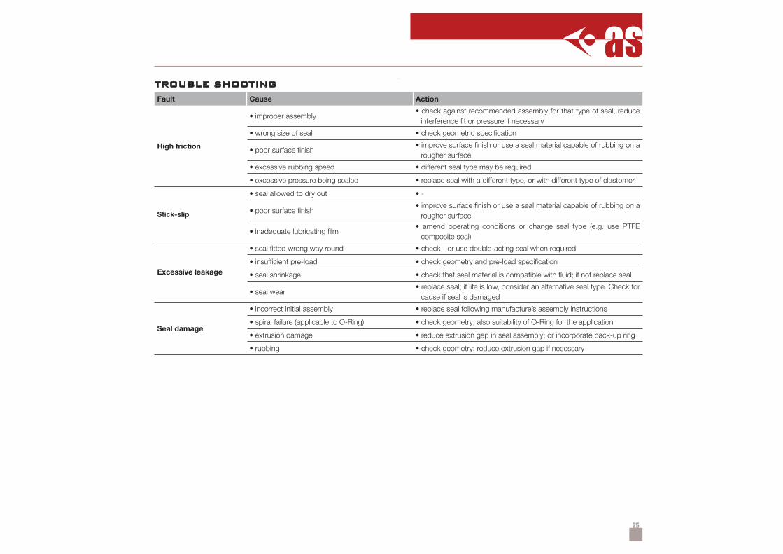
TROUBLE SHOOTING
Fault Cause Action
High friction
• improper assembly• check against recommended assembly for that type of seal, reduce
interference fit or pressure if necessary
• wrong size of seal • check geometric specification
• poor surface finish• improve surface finish or use a seal material capable of rubbing on a
rougher surface
• excessive rubbing speed • different seal type may be required
• excessive pressure being sealed • replace seal with a different type, or with different type of elastomer
Stick-slip
• seal allowed to dry out • -
• poor surface finish• improve surface finish or use a seal material capable of rubbing on a
rougher surface
• inadequate lubricating film• amend operating conditions or change seal type (e.g. use PTFE
composite seal)
Excessive leakage
• seal fitted wrong way round • check - or use double-acting seal when required
• insufficient pre-load • check geometry and pre-load specification
• seal shrinkage • check that seal material is compatible with fluid; if not replace seal
• seal wear• replace seal; if life is low, consider an alternative seal type. Check for
cause if seal is damaged
Seal damage
• incorrect initial assembly • replace seal following manufacture’s assembly instructions
• spiral failure (applicable to O-Ring) • check geometry; also suitability of O-Ring for the application
• extrusion damage • reduce extrusion gap in seal assembly; or incorporate back-up ring
• rubbing • check geometry; reduce extrusion gap if necessary
26
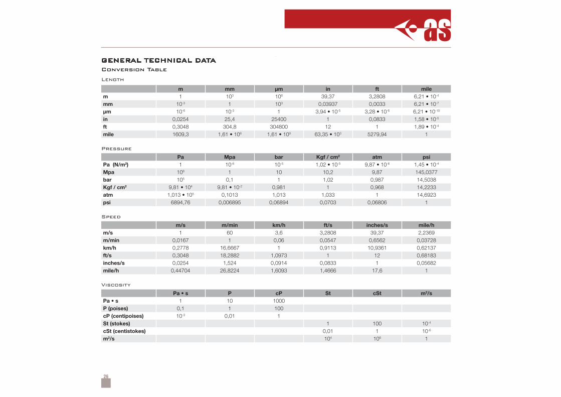
GENERAL TECHNICAL DATAConversion Table
Length
m mm µm in ft milem 1 103 106 39,37 3,2808 6,21 • 10-4
mm 10-3 1 103 0,03937 0,0033 6,21 • 10-7
µm 10-6 10-3 1 3,94 • 10-5 3,28 • 10-6 6,21 • 10-10
in 0,0254 25,4 25400 1 0,0833 1,58 • 10-5
ft 0,3048 304,8 304800 12 1 1,89 • 10-4
mile 1609,3 1,61 • 106 1,61 • 109 63,35 • 103 5279,94 1
Pressure
Pa Mpa bar Kgf / cm2 atm psiPa (N/m2) 1 10-6 10-5 1,02 • 10-5 9,87 • 10-6 1,45 • 10-4
Mpa 106 1 10 10,2 9,87 145,0377bar 105 0,1 1 1,02 0,987 14,5038Kgf / cm2 9,81 • 104 9,81 • 10-2 0,981 1 0,968 14,2233atm 1,013 • 105 0,1013 1,013 1,033 1 14,6923psi 6894,76 0,006895 0,06894 0,0703 0,06806 1
Speed
m/s m/min km/h ft/s inches/s mile/hm/s 1 60 3,6 3,2808 39,37 2,2369m/min 0,0167 1 0,06 0,0547 0,6562 0,03728km/h 0,2778 16,6667 1 0,9113 10,9361 0,62137ft/s 0,3048 18,2882 1,0973 1 12 0,68183inches/s 0,0254 1,524 0,0914 0,0833 1 0,05682mile/h 0,44704 26,8224 1,6093 1,4666 17,6 1
Viscosity
Pa • s P cP St cSt m2/sPa • s 1 10 1000P (poises) 0,1 1 100cP (centipoises) 10-3 0,01 1St (stokes) 1 100 10-4
cSt (centistokes) 0,01 1 10-6
m2/s 104 106 1
27
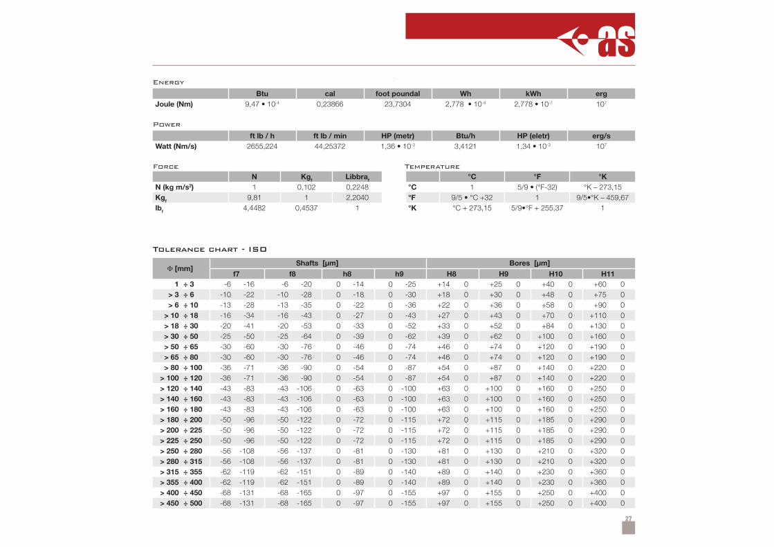
Energy
Btu cal foot poundal Wh kWh ergJoule (Nm) 9,47 • 10-4 0,23866 23,7304 2,778 • 10-4 2,778 • 10-7 107
Power
ft lb / h ft lb / min HP (metr) Btu/h HP (eletr) erg/sWatt (Nm/s) 2655,224 44,25372 1,36 • 10-3 3,4121 1,34 • 10-3 107
Force TemperatureN Kgf Libbraf °C °F °K
N (kg m/s2) 1 0,102 0,2248 °C 1 5/9 • (°F-32) °K – 273,15Kgf 9,81 1 2,2040 °F 9/5 • °C +32 1 9/5•°K – 459,67lbf 4,4482 0,4537 1 °K °C + 273,15 5/9•°F + 255,37 1
Tolerance chart - ISO
Φ [mm]Shafts [µm] Bores [µm]
f7 f8 h8 h9 H8 H9 H10 H111 ÷ 3 -6 -16 -6 -20 0 -14 0 -25 +14 0 +25 0 +40 0 +60 0
> 3 ÷ 6 -10 -22 -10 -28 0 -18 0 -30 +18 0 +30 0 +48 0 +75 0> 6 ÷ 10 -13 -28 -13 -35 0 -22 0 -36 +22 0 +36 0 +58 0 +90 0
> 10 ÷ 18 -16 -34 -16 -43 0 -27 0 -43 +27 0 +43 0 +70 0 +110 0> 18 ÷ 30 -20 -41 -20 -53 0 -33 0 -52 +33 0 +52 0 +84 0 +130 0> 30 ÷ 50 -25 -50 -25 -64 0 -39 0 -62 +39 0 +62 0 +100 0 +160 0> 50 ÷ 65 -30 -60 -30 -76 0 -46 0 -74 +46 0 +74 0 +120 0 +190 0> 65 ÷ 80 -30 -60 -30 -76 0 -46 0 -74 +46 0 +74 0 +120 0 +190 0> 80 ÷ 100 -36 -71 -36 -90 0 -54 0 -87 +54 0 +87 0 +140 0 +220 0
> 100 ÷ 120 -36 -71 -36 -90 0 -54 0 -87 +54 0 +87 0 +140 0 +220 0> 120 ÷ 140 -43 -83 -43 -106 0 -63 0 -100 +63 0 +100 0 +160 0 +250 0> 140 ÷ 160 -43 -83 -43 -106 0 -63 0 -100 +63 0 +100 0 +160 0 +250 0> 160 ÷ 180 -43 -83 -43 -106 0 -63 0 -100 +63 0 +100 0 +160 0 +250 0> 180 ÷ 200 -50 -96 -50 -122 0 -72 0 -115 +72 0 +115 0 +185 0 +290 0> 200 ÷ 225 -50 -96 -50 -122 0 -72 0 -115 +72 0 +115 0 +185 0 +290 0> 225 ÷ 250 -50 -96 -50 -122 0 -72 0 -115 +72 0 +115 0 +185 0 +290 0> 250 ÷ 280 -56 -108 -56 -137 0 -81 0 -130 +81 0 +130 0 +210 0 +320 0> 280 ÷ 315 -56 -108 -56 -137 0 -81 0 -130 +81 0 +130 0 +210 0 +320 0> 315 ÷ 355 -62 -119 -62 -151 0 -89 0 -140 +89 0 +140 0 +230 0 +360 0> 355 ÷ 400 -62 -119 -62 -151 0 -89 0 -140 +89 0 +140 0 +230 0 +360 0> 400 ÷ 450 -68 -131 -68 -165 0 -97 0 -155 +97 0 +155 0 +250 0 +400 0> 450 ÷ 500 -68 -131 -68 -165 0 -97 0 -155 +97 0 +155 0 +250 0 +400 0
28
SA15°÷20°
SdD
L
M
r max 0.4 r max 0.4
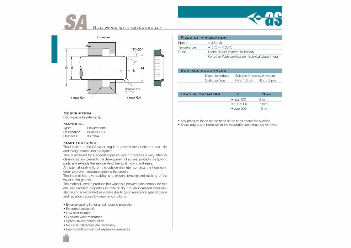
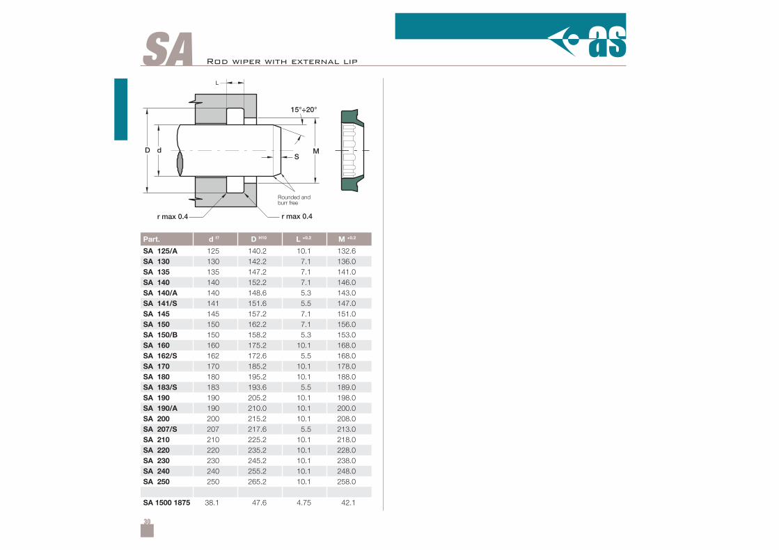
Rod wiper with external lip
DescriptionRod wiper with external lip
MaterialType: PolyurethaneDesignation: SEALPUR 93Hardness: 93 °ShA
Main featuresThe function of the SA wiper ring is to prevent introduction of dust, dirtand foreign matter into the system.This is achieved by a special wiper lip which produces a very effectivecleaning action, prevents the development of scores, protects the guidingparts and extends the service life of the axial moving rod seals.An external sealing lip on the outside diameter contacts the housing inorder to prevent moisture entering the groove.The internal ribs give stability and prevent twisting and sticking of thewiper in the groove.The material used to produce this wiper is a polyurethane compound thatensures excellent properties in case of dry run, an increased wear-resi-stance and an extended service life due to good resistance against ozoneand radiation caused by weather conditions.
• External sealing lip for a real housing protection• Extended service life• Low cost solution• Excellent wear-resistance• Space-saving construction• No close tolerances are necessary• Easy installation without expensive auxiliaries
Speed ≤ 0.8 m/sTemperature –40°C ÷ +100°CFluids Hydraulic oils (mineral oil based).
For other fluids contact our technical department
Dynamic surface Suitable for rod seal systemStatic surface Ra ≤ 1.6 µm Rt ≤ 6.3 µm
• less 100• 100÷200• over 200
5 mm7 mm10 mm
Field of application
Surface roughness
Lead-in chamfers d SMIN
• Any pressure loads on the back of the rings should be avoided• Sharp edges and burrs within the installation area must be removed
Rounded andburr free
29
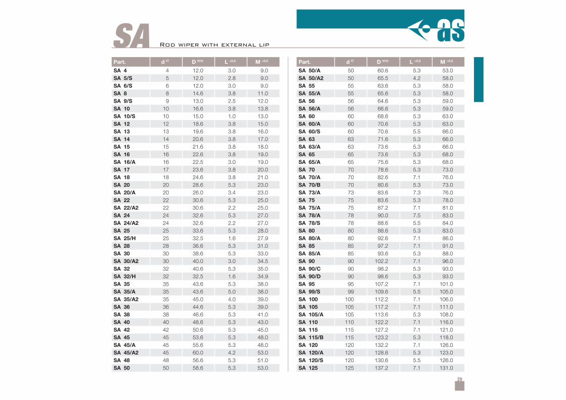
Part. d f7 D H10 L +0.2 M +0.2
SA 4 4 12.0 3.0 9.0SA 5/S 5 12.0 2.8 9.0SA 6/S 6 12.0 3.0 9.0SA 8 8 14.6 3.8 11.0SA 9/S 9 13.0 2.5 12.0SA 10 10 16.6 3.8 13.8SA 10/S 10 15.0 1.0 13.0SA 12 12 18.6 3.8 15.0SA 13 13 19.6 3.8 16.0SA 14 14 20.6 3.8 17.0SA 15 15 21.6 3.8 18.0SA 16 16 22.6 3.8 19.0SA 16/A 16 22.5 3.0 19.0SA 17 17 23.6 3.8 20.0SA 18 18 24.6 3.8 21.0SA 20 20 28.6 5.3 23.0SA 20/A 20 26.0 3.4 23.0SA 22 22 30.6 5.3 25.0SA 22/A2 22 30.6 2.2 25.0SA 24 24 32.6 5.3 27.0SA 24/A2 24 32.6 2.2 27.0SA 25 25 33.6 5.3 28.0SA 25/H 25 32.5 1.6 27.9SA 28 28 36.6 5.3 31.0SA 30 30 38.6 5.3 33.0SA 30/A2 30 40.0 3.0 34.5SA 32 32 40.6 5.3 35.0SA 32/H 32 32.5 1.6 34.9SA 35 35 43.6 5.3 38.0SA 35/A 35 43.6 5.0 38.0SA 35/A2 35 45.0 4.0 39.0SA 36 36 44.6 5.3 39.0SA 38 38 46.6 5.3 41.0SA 40 40 48.6 5.3 43.0SA 42 42 50.6 5.3 45.0SA 45 45 53.6 5.3 48.0SA 45/A 45 55.6 5.3 48.0SA 45/A2 45 60.0 4.2 53.0SA 48 48 56.6 5.3 51.0SA 50 50 58.6 5.3 53.0
Part. d f7 D H10 L +0.2 M +0.2
SA 50/A 50 60.6 5.3 53.0SA 50/A2 50 65.5 4.2 58.0SA 55 55 63.6 5.3 58.0SA 55/A 55 65.6 5.3 58.0SA 56 56 64.6 5.3 59.0SA 56/A 56 66.6 5.3 59.0SA 60 60 68.6 5.3 63.0SA 60/A 60 70.6 5.3 63.0SA 60/S 60 70.6 5.5 66.0SA 63 63 71.6 5.3 66.0SA 63/A 63 73.6 5.3 66.0SA 65 65 73.6 5.3 68.0SA 65/A 65 75.6 5.3 68.0SA 70 70 78.6 5.3 73.0SA 70/A 70 82.6 7.1 76.0SA 70/B 70 80.6 5.3 73.0SA 73/A 73 83.6 7.3 76.0SA 75 75 83.6 5.3 78.0SA 75/A 75 87.2 7.1 81.0SA 78/A 78 90.0 7.5 83.0SA 78/S 78 88.6 5.5 84.0SA 80 80 88.6 5.3 83.0SA 80/A 80 92.6 7.1 86.0SA 85 85 97.2 7.1 91.0SA 85/A 85 93.6 5.3 88.0SA 90 90 102.2 7.1 96.0SA 90/C 90 98.2 5.3 93.0SA 90/D 90 98.6 5.3 93.0SA 95 95 107.2 7.1 101.0SA 99/S 99 109.6 5.5 105.0SA 100 100 112.2 7.1 106.0SA 105 105 117.2 7.1 111.0SA 105/A 105 113.6 5.3 108.0SA 110 110 122.2 7.1 116.0SA 115 115 127.2 7.1 121.0SA 115/B 115 123.2 5.3 118.0SA 120 120 132.2 7.1 126.0SA 120/A 120 128.6 5.3 123.0SA 120/S 120 130.6 5.5 126.0SA 125 125 137.2 7.1 131.0
SA Rod wiper with external lip
30
Part. d f7 D H10 L +0.2 M +0.2
SA 125/A 125 140.2 10.1 132.6SA 130 130 142.2 7.1 136.0SA 135 135 147.2 7.1 141.0SA 140 140 152.2 7.1 146.0SA 140/A 140 148.6 5.3 143.0SA 141/S 141 151.6 5.5 147.0SA 145 145 157.2 7.1 151.0SA 150 150 162.2 7.1 156.0SA 150/B 150 158.2 5.3 153.0SA 160 160 175.2 10.1 168.0SA 162/S 162 172.6 5.5 168.0SA 170 170 185.2 10.1 178.0SA 180 180 195.2 10.1 188.0SA 183/S 183 193.6 5.5 189.0SA 190 190 205.2 10.1 198.0SA 190/A 190 210.0 10.1 200.0SA 200 200 215.2 10.1 208.0SA 207/S 207 217.6 5.5 213.0SA 210 210 225.2 10.1 218.0SA 220 220 235.2 10.1 228.0SA 230 230 245.2 10.1 238.0SA 240 240 255.2 10.1 248.0SA 250 250 265.2 10.1 258.0
SA 1500 1875 38.1 47.6 4.75 42.1
SA15°÷20°
SdD
L
M
r max 0.4 r max 0.4
Rod wiper with external lip
Rounded andburr free
31
SAF
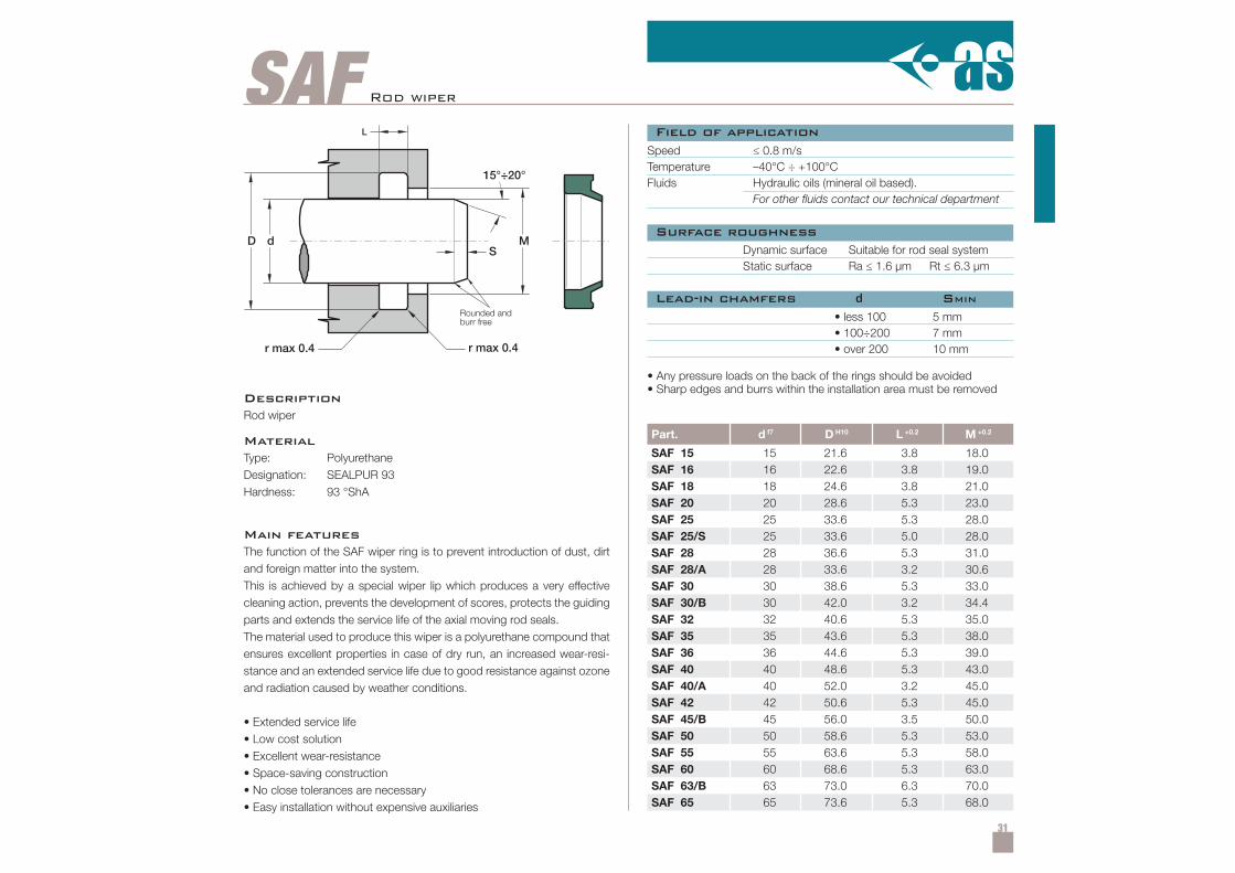
Part. d f7 D H10 L +0.2 M +0.2
SAF 15 15 21.6 3.8 18.0SAF 16 16 22.6 3.8 19.0SAF 18 18 24.6 3.8 21.0SAF 20 20 28.6 5.3 23.0SAF 25 25 33.6 5.3 28.0SAF 25/S 25 33.6 5.0 28.0SAF 28 28 36.6 5.3 31.0SAF 28/A 28 33.6 3.2 30.6SAF 30 30 38.6 5.3 33.0SAF 30/B 30 42.0 3.2 34.4SAF 32 32 40.6 5.3 35.0SAF 35 35 43.6 5.3 38.0SAF 36 36 44.6 5.3 39.0SAF 40 40 48.6 5.3 43.0SAF 40/A 40 52.0 3.2 45.0SAF 42 42 50.6 5.3 45.0SAF 45/B 45 56.0 3.5 50.0SAF 50 50 58.6 5.3 53.0SAF 55 55 63.6 5.3 58.0SAF 60 60 68.6 5.3 63.0SAF 63/B 63 73.0 6.3 70.0SAF 65 65 73.6 5.3 68.0
15°÷20°
SdD
L
M
r max 0.4 r max 0.4
Rod wiper
DescriptionRod wiper
MaterialType: PolyurethaneDesignation: SEALPUR 93Hardness: 93 °ShA
Main featuresThe function of the SAF wiper ring is to prevent introduction of dust, dirtand foreign matter into the system.This is achieved by a special wiper lip which produces a very effectivecleaning action, prevents the development of scores, protects the guidingparts and extends the service life of the axial moving rod seals.The material used to produce this wiper is a polyurethane compound thatensures excellent properties in case of dry run, an increased wear-resi-stance and an extended service life due to good resistance against ozoneand radiation caused by weather conditions.
• Extended service life• Low cost solution• Excellent wear-resistance• Space-saving construction• No close tolerances are necessary• Easy installation without expensive auxiliaries
Speed ≤ 0.8 m/sTemperature –40°C ÷ +100°CFluids Hydraulic oils (mineral oil based).
For other fluids contact our technical department
Dynamic surface Suitable for rod seal systemStatic surface Ra ≤ 1.6 µm Rt ≤ 6.3 µm
• less 100• 100÷200• over 200
5 mm7 mm10 mm
• Any pressure loads on the back of the rings should be avoided• Sharp edges and burrs within the installation area must be removed
Field of application
Surface roughness
Lead-in chamfers d SMIN
Rounded andburr free
32
Part. d f7 D H10 L +0.2 M +0.2
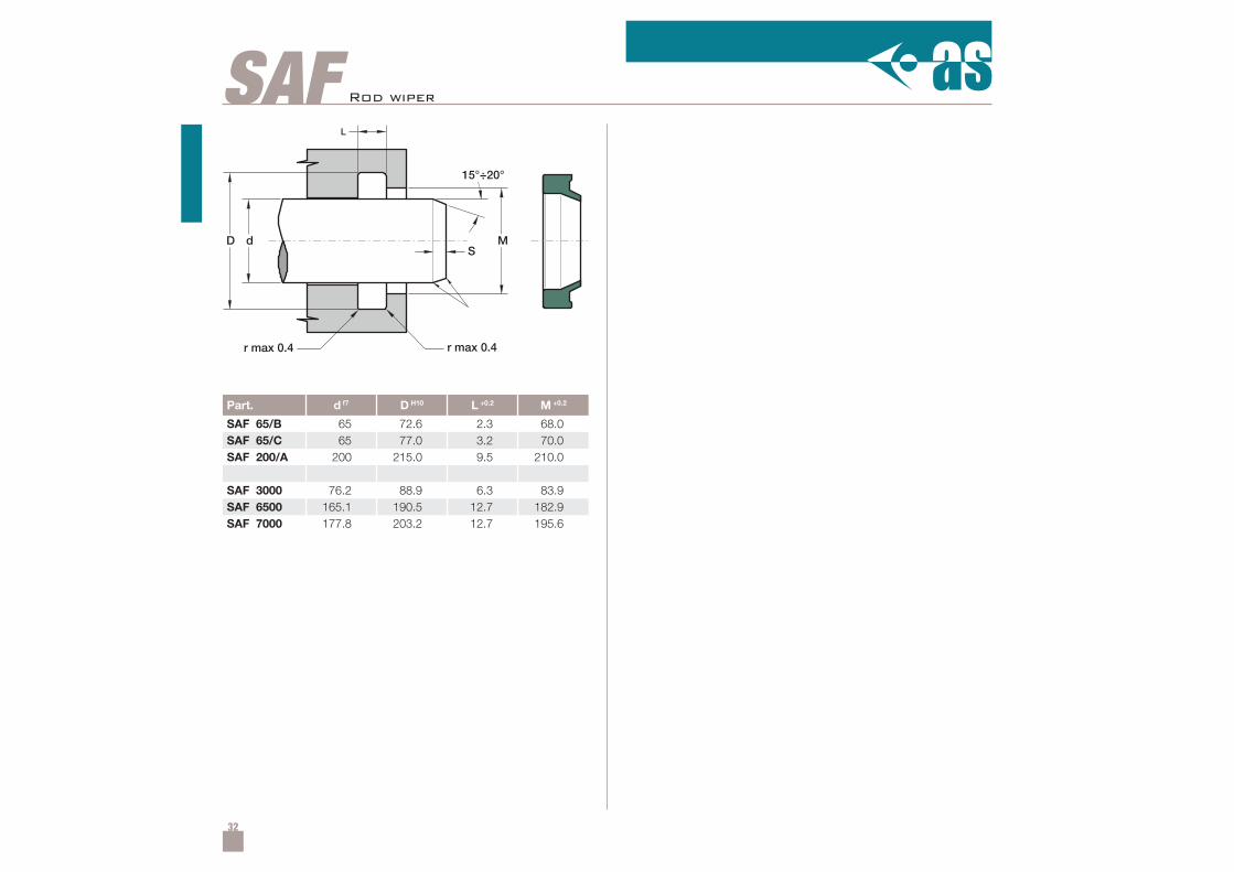
SAF 65/B 65 72.6 2.3 68.0SAF 65/C 65 77.0 3.2 70.0SAF 200/A 200 215.0 9.5 210.0
SAF 3000 76.2 88.9 6.3 83.9SAF 6500 165.1 190.5 12.7 182.9SAF 7000 177.8 203.2 12.7 195.6
15°÷20°
SdD
L
M
r max 0.4 r max 0.4
SAF Rod wiper
33
SAP
SdD
L
M
r max 0.4 r max 0.4
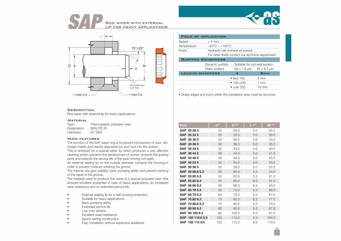
Part. d f7 D H10 L +0.2 M +0.2
SAP 20 28 5 20 28.0 5.0 25.5SAP 25 33 5 25 33.0 5.0 30.5SAP 28 36 5 28 36.0 5.0 33.5SAP 30 38 5 30 38.0 5.0 35.5SAP 35 43 5 35 43.0 5.0 40.5SAP 36 44 5 36 44.0 5.0 41.5SAP 40 48 5 40 48.0 5.0 45.5SAP 45 53 5 45 53.0 5.0 50.5SAP 50 58 5 50 58.0 5.0 55.5SAP 50 60.6 5.3 50 60.6 5.3 53.0SAP 55 65 5.3 55 65.0 5.3 61.0SAP 55 65 6.3 55 65.0 6.3 61.0SAP 56 66 6.3 56 66.0 6.3 63.0SAP 60 70 5.3 60 70.0 5.3 66.0SAP 60 70 6.3 60 70.0 6.3 67.0SAP 70 80 6.3 70 80.0 6.3 77.0SAP 70 80.6 5.3 70 80.6 5.3 73.0SAP 80 90 6.3 80 90.0 6.3 87.0SAP 90 100 6.3 90 100.0 6.3 97.0SAP 100 110.6 5.3 100 110.6 5.3 104.0SAP 100 115 9.5 100 115.0 9.5 110.0
Rod wiper with externallip for heavy applications
Speed ≤ 4 m/sTemperature –40°C ÷ +140°CFluids Hydraulic oils (mineral oil based).
For other fluids contact our technical department
Dynamic surface Suitable for rod seal systemStatic surface Ra ≤ 1.6 µm Rt ≤ 6.3 µm
• less 100• 100÷200• over 200
5 mm7 mm10 mm
• Sharp edges and burrs within the installation area must be removed
DescriptionRod wiper with external lip for heavy applications
MaterialType: Thermoplastic polyester resinDesignation: SEALITE 55Hardness: 55 °ShD
Main featuresThe function of the SAP wiper ring is to prevent introduction of dust, dirt,foreign matter and heavily deposited ice and mud into the system.This is achieved by a special wiper lip which produces a very effectivecleaning action, prevents the development of scores, protects the guidingparts and extends the service life of the axial moving rod seals.An external sealing lip on the outside diameter contacts the housing inorder to prevent moisture entering the groove.The internal ribs give stability, back pumping ability and prevent stickingof the wiper in the groove.The material used to produce this wiper is a special polyester resin thatensures excellent properties in case of heavy applications, an increasedwear-resistance and an extended service life.
• External sealing lip for a real housing protection• Suitable for heavy applications• Back pumping ability• Extended service life• Low cost solution• Excellent wear-resistance• Space-saving construction• Easy installation without expensive auxiliaries
Field of application
Surface roughness
Lead-in chamfers d SMIN
Rounded andburr free
34
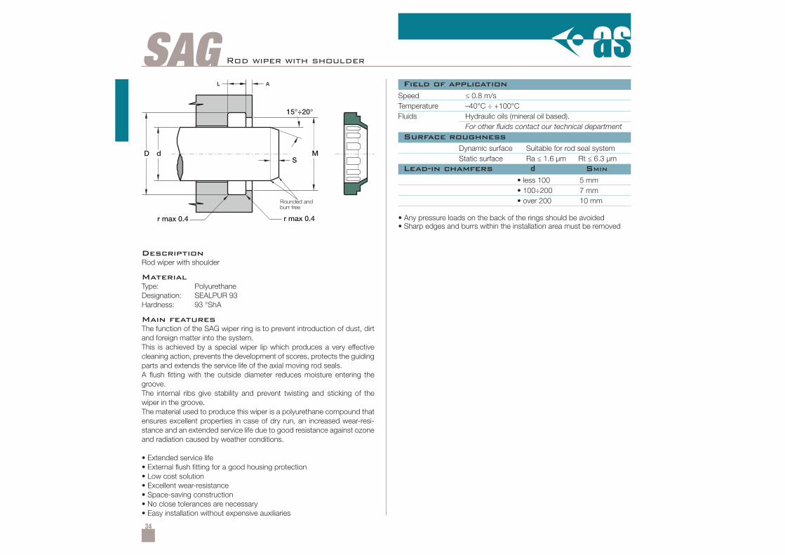
SAG Rod wiper with shoulder
Speed ≤ 0.8 m/sTemperature –40°C ÷ +100°CFluids Hydraulic oils (mineral oil based).
For other fluids contact our technical department
Dynamic surface Suitable for rod seal systemStatic surface Ra ≤ 1.6 µm Rt ≤ 6.3 µm
• less 100• 100÷200• over 200
5 mm7 mm10 mm
• Any pressure loads on the back of the rings should be avoided• Sharp edges and burrs within the installation area must be removed
DescriptionRod wiper with shoulder
MaterialType: PolyurethaneDesignation: SEALPUR 93Hardness: 93 °ShA
Main featuresThe function of the SAG wiper ring is to prevent introduction of dust, dirtand foreign matter into the system.This is achieved by a special wiper lip which produces a very effectivecleaning action, prevents the development of scores, protects the guidingparts and extends the service life of the axial moving rod seals.A flush fitting with the outside diameter reduces moisture entering thegroove.The internal ribs give stability and prevent twisting and sticking of thewiper in the groove.The material used to produce this wiper is a polyurethane compound thatensures excellent properties in case of dry run, an increased wear-resi-stance and an extended service life due to good resistance against ozoneand radiation caused by weather conditions.
• Extended service life• External flush fitting for a good housing protection• Low cost solution• Excellent wear-resistance• Space-saving construction• No close tolerances are necessary• Easy installation without expensive auxiliaries
Field of application
Surface roughness
Lead-in chamfers d SMIN
Rounded andburr free
35
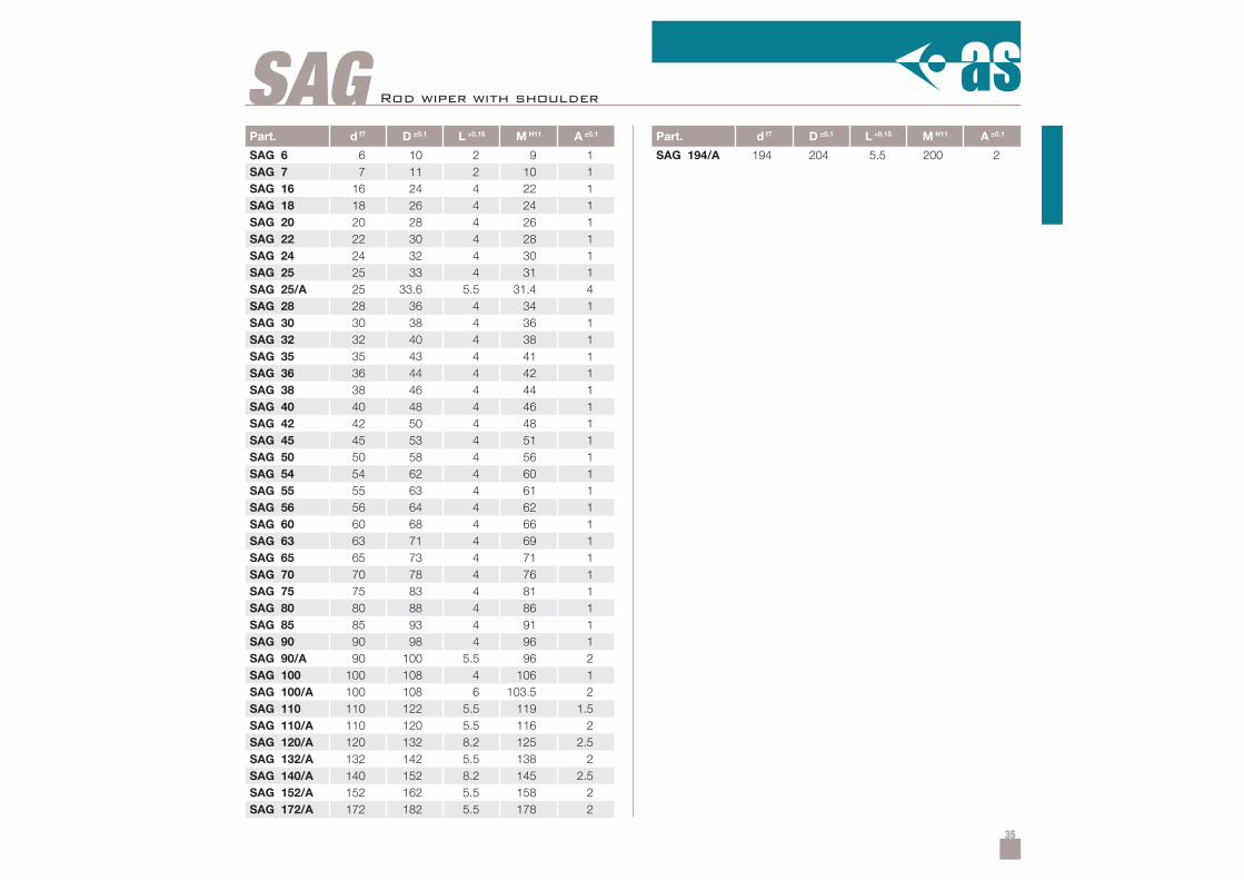
Part. d f7 D ±0.1 L +0.15 M H11 A ±0.1
SAG 6 6 10 2 9 1SAG 7 7 11 2 10 1SAG 16 16 24 4 22 1SAG 18 18 26 4 24 1SAG 20 20 28 4 26 1SAG 22 22 30 4 28 1SAG 24 24 32 4 30 1SAG 25 25 33 4 31 1SAG 25/A 25 33.6 5.5 31.4 4SAG 28 28 36 4 34 1SAG 30 30 38 4 36 1SAG 32 32 40 4 38 1SAG 35 35 43 4 41 1SAG 36 36 44 4 42 1SAG 38 38 46 4 44 1SAG 40 40 48 4 46 1SAG 42 42 50 4 48 1SAG 45 45 53 4 51 1SAG 50 50 58 4 56 1SAG 54 54 62 4 60 1SAG 55 55 63 4 61 1SAG 56 56 64 4 62 1SAG 60 60 68 4 66 1SAG 63 63 71 4 69 1SAG 65 65 73 4 71 1SAG 70 70 78 4 76 1SAG 75 75 83 4 81 1SAG 80 80 88 4 86 1SAG 85 85 93 4 91 1SAG 90 90 98 4 96 1SAG 90/A 90 100 5.5 96 2SAG 100 100 108 4 106 1SAG 100/A 100 108 6 103.5 2SAG 110 110 122 5.5 119 1.5SAG 110/A 110 120 5.5 116 2SAG 120/A 120 132 8.2 125 2.5SAG 132/A 132 142 5.5 138 2SAG 140/A 140 152 8.2 145 2.5SAG 152/A 152 162 5.5 158 2SAG 172/A 172 182 5.5 178 2
SAGPart. d f7 D ±0.1 L +0.15 M H11 A ±0.1
SAG 194/A 194 204 5.5 200 2
Rod wiper with shoulder
36
SAB15°÷20°
SMD d
L
r max 0.4 r max 0.4
Field of application
Surface roughness
Lead-in chamfers d SMIN
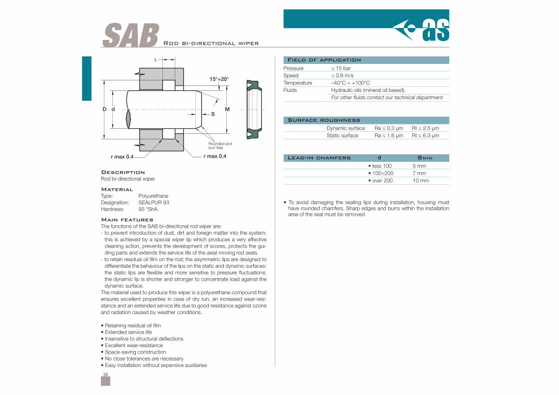
DescriptionRod bi-directional wiper
MaterialType: PolyurethaneDesignation: SEALPUR 93Hardness: 93 °ShA
Main featuresThe functions of the SAB bi-directional rod wiper are:- to prevent introduction of dust, dirt and foreign matter into the system;
this is achieved by a special wiper lip which produces a very effectivecleaning action, prevents the development of scores, protects the gui-ding parts and extends the service life of the axial moving rod seals.
- to retain residual oil film on the rod; the asymmetric lips are designed todifferentiate the behaviour of the lips on the static and dynamic surfaces:the static lips are flexible and more sensitive to pressure fluctuations;the dynamic lip is shorter and stronger to concentrate load against thedynamic surface.
The material used to produce this wiper is a polyurethane compound thatensures excellent properties in case of dry run, an increased wear-resi-stance and an extended service life due to good resistance against ozoneand radiation caused by weather conditions.
• Retaining residual oil film• Extended service life• Insensitive to structural deflections• Excellent wear-resistance• Space-saving construction• No close tolerances are necessary• Easy installation without expensive auxiliaries
Pressure ≤ 15 barSpeed ≤ 0.8 m/sTemperature –40°C ÷ +100°CFluids Hydraulic oils (mineral oil based).
For other fluids contact our technical department
Dynamic surface Ra ≤ 0.3 µm Rt ≤ 2.5 µmStatic surface Ra ≤ 1.6 µm Rt ≤ 6.3 µm
• less 100• 100÷200• over 200
5 mm7 mm10 mm
• To avoid damaging the sealing lips during installation, housing musthave rounded chamfers. Sharp edges and burrs within the installationarea of the seal must be removed
Rod bi-directional wiper
Rounded andburr free
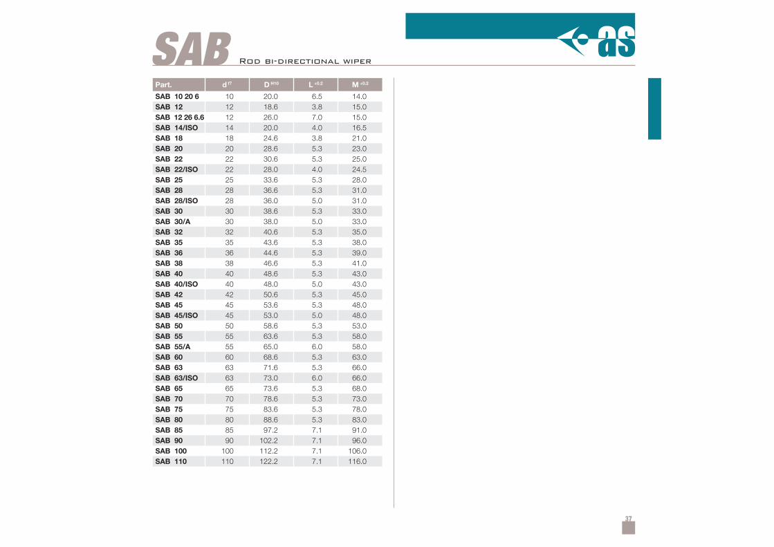
37
Part. d f7 D H10 L +0.2 M +0.2
SAB 10 20 6 10 20.0 6.5 14.0SAB 12 12 18.6 3.8 15.0SAB 12 26 6.6 12 26.0 7.0 15.0SAB 14/ISO 14 20.0 4.0 16.5SAB 18 18 24.6 3.8 21.0SAB 20 20 28.6 5.3 23.0SAB 22 22 30.6 5.3 25.0SAB 22/ISO 22 28.0 4.0 24.5SAB 25 25 33.6 5.3 28.0SAB 28 28 36.6 5.3 31.0SAB 28/ISO 28 36.0 5.0 31.0SAB 30 30 38.6 5.3 33.0SAB 30/A 30 38.0 5.0 33.0SAB 32 32 40.6 5.3 35.0SAB 35 35 43.6 5.3 38.0SAB 36 36 44.6 5.3 39.0SAB 38 38 46.6 5.3 41.0SAB 40 40 48.6 5.3 43.0SAB 40/ISO 40 48.0 5.0 43.0SAB 42 42 50.6 5.3 45.0SAB 45 45 53.6 5.3 48.0SAB 45/ISO 45 53.0 5.0 48.0SAB 50 50 58.6 5.3 53.0SAB 55 55 63.6 5.3 58.0SAB 55/A 55 65.0 6.0 58.0SAB 60 60 68.6 5.3 63.0SAB 63 63 71.6 5.3 66.0SAB 63/ISO 63 73.0 6.0 66.0SAB 65 65 73.6 5.3 68.0SAB 70 70 78.6 5.3 73.0SAB 75 75 83.6 5.3 78.0SAB 80 80 88.6 5.3 83.0SAB 85 85 97.2 7.1 91.0SAB 90 90 102.2 7.1 96.0SAB 100 100 112.2 7.1 106.0SAB 110 110 122.2 7.1 116.0
SAB Rod bi-directional wiper
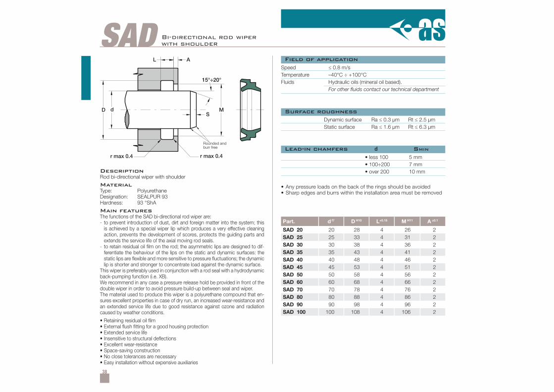
38
SADA
SdD
L
M
15°÷20°
r max 0.4 r max 0.4
Part. d f7 D H10 L+0.15 M H11 A ±0.1
SAD 20 20 28 4 26 2SAD 25 25 33 4 31 2SAD 30 30 38 4 36 2SAD 35 35 43 4 41 2SAD 40 40 48 4 46 2SAD 45 45 53 4 51 2SAD 50 50 58 4 56 2SAD 60 60 68 4 66 2SAD 70 70 78 4 76 2SAD 80 80 88 4 86 2SAD 90 90 98 4 96 2SAD 100 100 108 4 106 2
Bi-directional rod wiperwith shoulder
Rounded andburr free
Field of application
DescriptionRod bi-directional wiper with shoulder
MaterialType: PolyurethaneDesignation: SEALPUR 93Hardness: 93 °ShA
Main featuresThe functions of the SAD bi-directional rod wiper are:- to prevent introduction of dust, dirt and foreign matter into the system; this
is achieved by a special wiper lip which produces a very effective cleaningaction, prevents the development of scores, protects the guiding parts andextends the service life of the axial moving rod seals.
- to retain residual oil film on the rod; the asymmetric lips are designed to dif-ferentiate the behaviour of the lips on the static and dynamic surfaces: thestatic lips are flexible and more sensitive to pressure fluctuations; the dynamiclip is shorter and stronger to concentrate load against the dynamic surface.
This wiper is preferably used in conjunction with a rod seal with a hydrodynamicback-pumping function (i.e. XB).We recommend in any case a pressure release hold be provided in front of thedouble wiper in order to avoid pressure build-up between seal and wiper.The material used to produce this wiper is a polyurethane compound that en-sures excellent properties in case of dry run, an increased wear-resistance andan extended service life due to good resistance against ozone and radiationcaused by weather conditions.
• Retaining residual oil film• External flush fitting for a good housing protection• Extended service life• Insensitive to structural deflections• Excellent wear-resistance• Space-saving construction• No close tolerances are necessary• Easy installation without expensive auxiliaries
Speed ≤ 0.8 m/sTemperature –40°C ÷ +100°CFluids Hydraulic oils (mineral oil based).
For other fluids contact our technical department
Surface roughness
Lead-in chamfers d SMIN
Dynamic surface Ra ≤ 0.3 µm Rt ≤ 2.5 µmStatic surface Ra ≤ 1.6 µm Rt ≤ 6.3 µm
• less 100• 100÷200• over 200
5 mm7 mm10 mm
• Any pressure loads on the back of the rings should be avoided• Sharp edges and burrs within the installation area must be removed
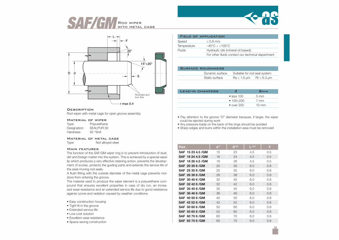
39
SAF/GM
Part. d f7 D H8 L +0.2 F
SAF 15 23 4.5 /GM 15 23 4.5 0.5SAF 16 24 4.5 /GM 16 24 4.5 0.5SAF 18 26 4.5 /GM 18 26 4.5 0.5SAF 20 30 6 /GM 20 30 6.0 0.8SAF 25 35 6 /GM 25 35 6.0 0.8SAF 28 38 6 /GM 28 38 6.0 0.8SAF 30 40 6 /GM 30 40 6.0 0.8SAF 32 42 6 /GM 32 42 6.0 0.8SAF 35 45 6 /GM 35 45 6.0 0.8SAF 36 46 6 /GM 36 46 6.0 0.8SAF 40 50 6 /GM 40 50 6.0 0.8SAF 42 52 6 /GM 42 52 6.0 0.8SAF 50 60 6 /GM 50 60 6.0 0.8SAF 55 65 6 /GM 55 65 6.0 0.8SAF 60 70 6 /GM 60 70 6.0 0.8SAF 65 75 6 /GM 65 75 6.0 0.8
DescriptionRod wiper with metal cage for open groove assembly
Material of wiperType: PolyurethaneDesignation: SEALPUR 93Hardness: 93 °ShA
Material of metal cageType: Not alloyed steel
Main featuresThe function of the SAF/GM wiper ring is to prevent introduction of dust,dirt and foreign matter into the system. This is achieved by a special wiperlip which produces a very effective cleaning action, prevents the develop-ment of scores, protects the guiding parts and extends the service life ofthe axial moving rod seals.A flush fitting with the outside diameter of the metal cage prevents moi-sture from entering the groove.The material used to produce the wiper element is a polyurethane com-pound that ensures excellent properties in case of dry run, an increa-sed wear-resistance and an extended service life due to good resistanceagainst ozone and radiation caused by weather conditions.
• Easy construction housing• Tight fit in the groove• Extended service life• Low cost solution• Excellent wear-resistance• Space-saving construction
Speed ≤ 0.8 m/sTemperature –40°C ÷ +100°CFluids Hydraulic oils (mineral oil based).
For other fluids contact our technical department
Dynamic surface Suitable for rod seal systemStatic surface Ra ≤ 1.6 µm Rt ≤ 6.3 µm
• less 100• 100÷200• over 200
5 mm7 mm10 mm
• Pay attention to the groove “D” diameter because, if larger, the wipercould be ejected during work
• Any pressure loads on the back of the rings should be avoided• Sharp edges and burrs within the installation area must be removed
Field of application
Surface roughness
Lead-in chamfers d SMIN
Rod wiperwith metal cage
Rounded andburr free
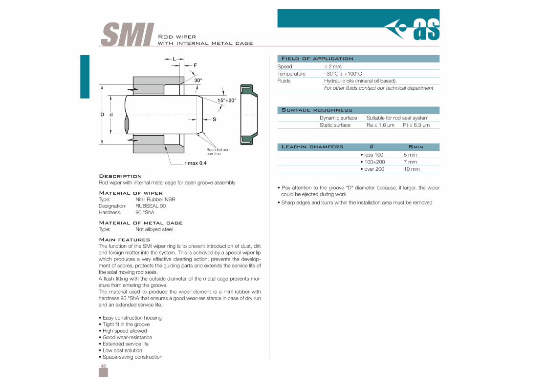
40
SMI Rod wiperwith internal metal cage
Speed ≤ 2 m/sTemperature –30°C ÷ +100°CFluids Hydraulic oils (mineral oil based).
For other fluids contact our technical department
Dynamic surface Suitable for rod seal systemStatic surface Ra ≤ 1.6 µm Rt ≤ 6.3 µm
• less 100• 100÷200• over 200
5 mm7 mm10 mm
• Pay attention to the groove “D” diameter because, if larger, the wipercould be ejected during work
• Sharp edges and burrs within the installation area must be removed
DescriptionRod wiper with internal metal cage for open groove assembly
Material of wiperType: Nitril Rubber NBRDesignation: RUBSEAL 90Hardness: 90 °ShA
Material of metal cageType: Not alloyed steel
Main featuresThe function of the SMI wiper ring is to prevent introduction of dust, dirtand foreign matter into the system. This is achieved by a special wiper lipwhich produces a very effective cleaning action, prevents the develop-ment of scores, protects the guiding parts and extends the service life ofthe axial moving rod seals.A flush fitting with the outside diameter of the metal cage prevents moi-sture from entering the groove.The material used to produce the wiper element is a nitril rubber withhardness 90 °ShA that ensures a good wear-resistance in case of dry runand an extended service life.
• Easy construction housing• Tight fit in the groove• High speed allowed• Good wear-resistance• Extended service life• Low cost solution• Space-saving construction
Field of application
Surface roughness
Lead-in chamfers d SMINRounded andburr free
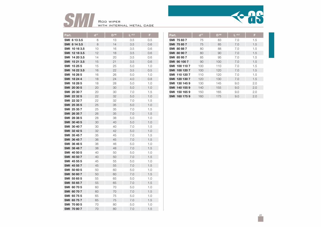
41
Part. d f7 D H8 L +0.2 F
SMI 6 13 3.5 6 13 3.5 0.5SMI 8 14 3.5 8 14 3.5 0.6SMI 10 16 3.5 10 16 3.5 0.6SMI 12 18 3.5 12 18 3.5 0.6SMI 14 20 3.5 14 20 3.5 0.6SMI 15 21 3.5 15 21 3.5 0.6SMI 15 25 5 15 25 5.0 1.0SMI 16 22 3.5 16 22 3.5 0.5SMI 16 26 5 16 26 5.0 1.0SMI 18 24 4 18 24 4.0 0.8SMI 18 28 5 18 28 5.0 1.0SMI 20 30 5 20 30 5.0 1.0SMI 20 30 7 20 30 7.0 1.5SMI 22 32 5 22 32 5.0 1.0SMI 22 32 7 22 32 7.0 1.5SMI 25 35 5 25 35 5.0 1.0SMI 25 35 7 25 35 7.0 1.5SMI 26 35 7 26 35 7.0 1.5SMI 28 38 5 28 38 5.0 1.0SMI 30 40 5 30 40 5.0 1.0SMI 30 40 7 30 40 7.0 1.5SMI 32 42 5 32 42 5.0 1.0SMI 35 45 7 35 45 7.0 1.5SMI 36 45 7 36 45 7.0 1.5SMI 36 46 5 36 46 5.0 1.0SMI 38 48 7 38 48 7.0 1.5SMI 40 50 5 40 50 5.0 1.0SMI 40 50 7 40 50 7.0 1.5SMI 45 55 5 45 55 5.0 1.0SMI 45 55 7 45 55 7.0 1.5SMI 50 60 5 50 60 5.0 1.0SMI 50 60 7 50 60 7.0 1.5SMI 55 65 5 55 65 5.0 1.0SMI 55 65 7 55 65 7.0 1.5SMI 60 70 5 60 70 5.0 1.0SMI 60 70 7 60 70 7.0 1.5SMI 65 75 5 65 75 5.0 1.0SMI 65 75 7 65 75 7.0 1.5SMI 70 80 5 70 80 5.0 1.0SMI 70 80 7 70 80 7.0 1.5
SMIPart. d f7 D H8 L +0.2 F
SMI 75 83 7 75 83 7.0 1.5SMI 75 85 7 75 85 7.0 1.5SMI 80 88 7 80 88 7.0 1.5SMI 80 90 7 80 90 7.0 1.5SMI 85 95 7 85 95 7.0 1.5SMI 90 100 7 90 100 7.0 1.5SMI 100 110 7 100 110 7.0 1.5SMI 100 120 7 100 120 7.0 1.5SMI 110 120 7 110 120 7.0 1.5SMI 120 130 7 120 130 7.0 1.5SMI 130 145 9 130 145 9.0 2.0SMI 140 155 9 140 155 9.0 2.0SMI 150 165 9 150 165 9.0 2.0SMI 160 175 9 160 175 9.0 2.0
Rod wiperwith internal metal cage
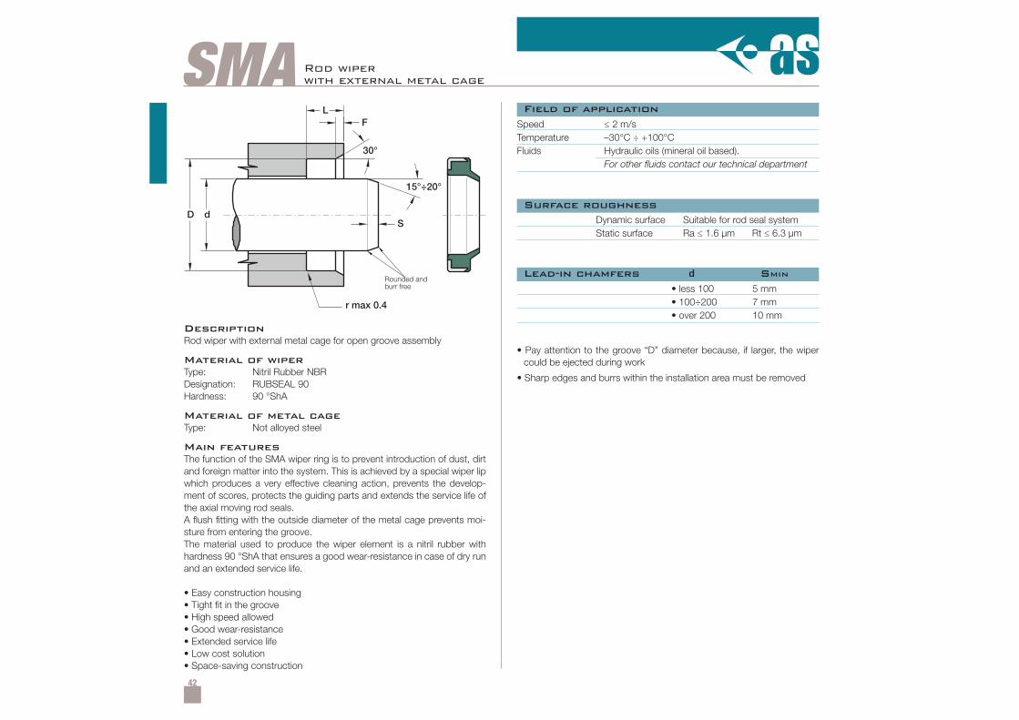
42
SMASpeed ≤ 2 m/sTemperature –30°C ÷ +100°CFluids Hydraulic oils (mineral oil based).
For other fluids contact our technical department
Dynamic surface Suitable for rod seal systemStatic surface Ra ≤ 1.6 µm Rt ≤ 6.3 µm
• less 100• 100÷200• over 200
5 mm7 mm10 mm
• Pay attention to the groove “D” diameter because, if larger, the wipercould be ejected during work
• Sharp edges and burrs within the installation area must be removed
DescriptionRod wiper with external metal cage for open groove assembly
Material of wiperType: Nitril Rubber NBRDesignation: RUBSEAL 90Hardness: 90 °ShA
Material of metal cageType: Not alloyed steel
Main featuresThe function of the SMA wiper ring is to prevent introduction of dust, dirtand foreign matter into the system. This is achieved by a special wiper lipwhich produces a very effective cleaning action, prevents the develop-ment of scores, protects the guiding parts and extends the service life ofthe axial moving rod seals.A flush fitting with the outside diameter of the metal cage prevents moi-sture from entering the groove.The material used to produce the wiper element is a nitril rubber withhardness 90 °ShA that ensures a good wear-resistance in case of dry runand an extended service life.
• Easy construction housing• Tight fit in the groove• High speed allowed• Good wear-resistance• Extended service life• Low cost solution• Space-saving construction
Field of application
Surface roughness
Lead-in chamfers d SMIN
Rod wiperwith external metal cage
Rounded andburr free
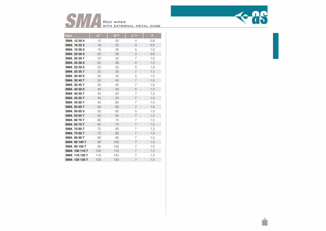
43
Part. d f7 D H8 L +0.2 F
SMA 12 20 4 12 20 4 0.8SMA 16 22 3 16 22 3 0.5SMA 16 26 5 16 26 5 1.0SMA 20 28 3 20 28 3 0.6SMA 20 30 7 20 30 7 1.5SMA 22 28 5 22 28 5 1.0SMA 22 32 5 22 32 5 1.0SMA 25 35 7 25 35 7 1.5SMA 30 40 5 30 40 5 1.0SMA 32 45 7 32 45 7 1.5SMA 35 45 7 35 45 7 1.5SMA 40 50 5 40 50 5 1.0SMA 40 50 7 40 50 7 1.5SMA 45 55 7 45 55 7 1.5SMA 45 60 7 45 60 7 1.5SMA 50 60 7 50 60 7 1.5SMA 50 65 5 50 65 5 1.0SMA 55 65 7 55 65 7 1.0SMA 60 70 7 60 70 7 1.5SMA 65 75 7 65 75 7 1.5SMA 70 80 7 70 80 7 1.5SMA 75 85 7 75 85 7 1.5SMA 80 90 7 80 90 7 1.5SMA 90 100 7 90 100 7 1.5SMA 95 105 7 95 105 7 1.5SMA 100 110 7 100 110 7 1.5SMA 110 120 7 110 120 7 1.5SMA 120 130 7 120 130 7 1.5
SMA Rod wiperwith external metal cage
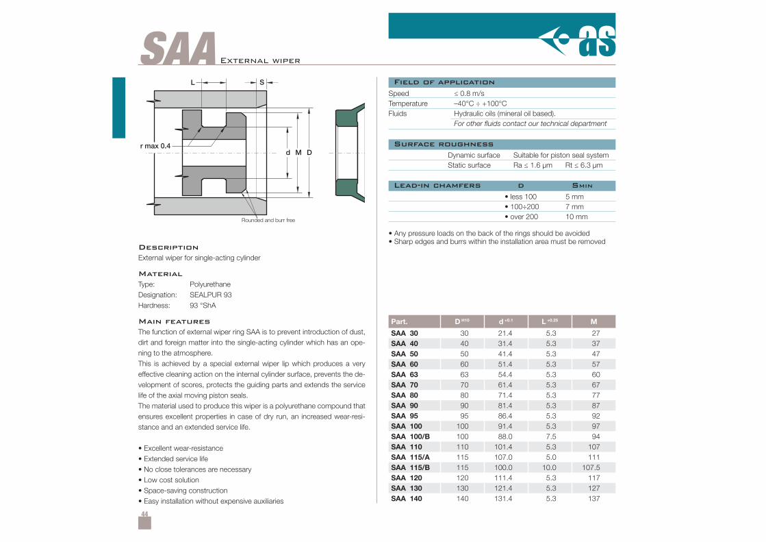
44
SAA
Part. D H10 d +0.1 L +0.25 M
SAA 30 30 21.4 5.3 27SAA 40 40 31.4 5.3 37SAA 50 50 41.4 5.3 47SAA 60 60 51.4 5.3 57SAA 63 63 54.4 5.3 60SAA 70 70 61.4 5.3 67SAA 80 80 71.4 5.3 77SAA 90 90 81.4 5.3 87SAA 95 95 86.4 5.3 92SAA 100 100 91.4 5.3 97SAA 100/B 100 88.0 7.5 94SAA 110 110 101.4 5.3 107SAA 115/A 115 107.0 5.0 111SAA 115/B 115 100.0 10.0 107.5SAA 120 120 111.4 5.3 117SAA 130 130 121.4 5.3 127SAA 140 140 131.4 5.3 137
r max 0.4
L
d M D
S
External wiper
Speed ≤ 0.8 m/sTemperature –40°C ÷ +100°CFluids Hydraulic oils (mineral oil based).
For other fluids contact our technical department
Dynamic surface Suitable for piston seal systemStatic surface Ra ≤ 1.6 µm Rt ≤ 6.3 µm
• less 100• 100÷200• over 200
5 mm7 mm10 mm
• Any pressure loads on the back of the rings should be avoided• Sharp edges and burrs within the installation area must be removed
DescriptionExternal wiper for single-acting cylinder
MaterialType: PolyurethaneDesignation: SEALPUR 93Hardness: 93 °ShA
Main featuresThe function of external wiper ring SAA is to prevent introduction of dust,dirt and foreign matter into the single-acting cylinder which has an ope-ning to the atmosphere.This is achieved by a special external wiper lip which produces a veryeffective cleaning action on the internal cylinder surface, prevents the de-velopment of scores, protects the guiding parts and extends the servicelife of the axial moving piston seals.The material used to produce this wiper is a polyurethane compound thatensures excellent properties in case of dry run, an increased wear-resi-stance and an extended service life.
• Excellent wear-resistance• Extended service life• No close tolerances are necessary• Low cost solution• Space-saving construction• Easy installation without expensive auxiliaries
Field of application
Surface roughness
Lead-in chamfers d SMIN
Rounded and burr free
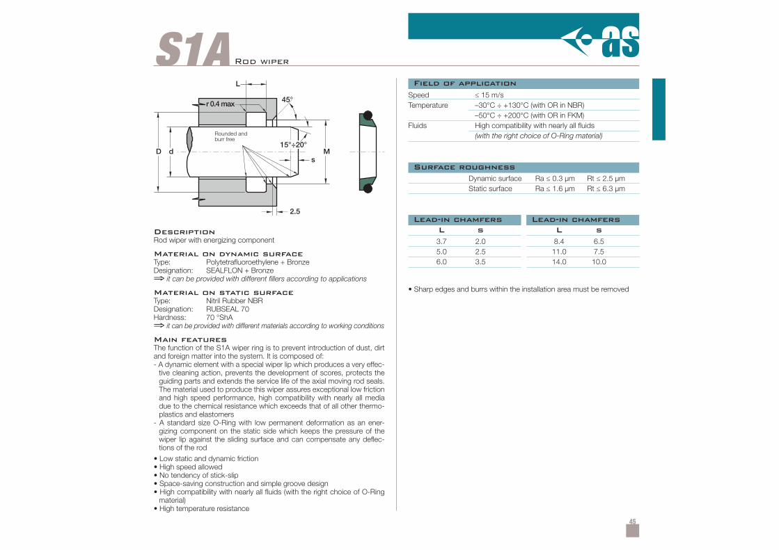
45
S1A Rod wiper
DescriptionRod wiper with energizing component
Material on dynamic surfaceType: Polytetrafluoroethylene + BronzeDesignation: SEALFLON + Bronze⇒ it can be provided with different fillers according to applications
Material on static surfaceType: Nitril Rubber NBRDesignation: RUBSEAL 70Hardness: 70 °ShA⇒ it can be provided with different materials according to working conditions
Main featuresThe function of the S1A wiper ring is to prevent introduction of dust, dirtand foreign matter into the system. It is composed of:- A dynamic element with a special wiper lip which produces a very effec-
tive cleaning action, prevents the development of scores, protects theguiding parts and extends the service life of the axial moving rod seals.The material used to produce this wiper assures exceptional low frictionand high speed performance, high compatibility with nearly all mediadue to the chemical resistance which exceeds that of all other thermo-plastics and elastomers
- A standard size O-Ring with low permanent deformation as an ener-gizing component on the static side which keeps the pressure of thewiper lip against the sliding surface and can compensate any deflec-tions of the rod
• Low static and dynamic friction• High speed allowed• No tendency of stick-slip• Space-saving construction and simple groove design• High compatibility with nearly all fluids (with the right choice of O-Ring
material)• High temperature resistance
Speed ≤ 15 m/sTemperature –30°C ÷ +130°C (with OR in NBR)
–50°C ÷ +200°C (with OR in FKM)Fluids High compatibility with nearly all fluids
(with the right choice of O-Ring material)
3.7 2.0 8.4 6.55.0 2.5 11.0 7.56.0 3.5 14.0 10.0
• Sharp edges and burrs within the installation area must be removed
L s L s
Field of application
Surface roughness
Lead-in chamfers
Dynamic surface Ra ≤ 0.3 µm Rt ≤ 2.5 µmStatic surface Ra ≤ 1.6 µm Rt ≤ 6.3 µm
Lead-in chamfers
Rounded andburr free
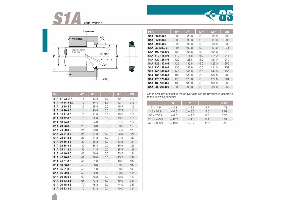
46
S1A
Part. d f8 D H9 L +0.2 M ±0.1 OR
S1A 8 12.8 3.7 8 12.8 3.7 10.7 012S1A 10 14.8 3.7 10 14.8 3.7 12.7 013S1A 12 18.8 5 12 18.8 5.0 15.5 113S1A 14 20.8 5 14 20.8 5.0 17.5 114S1A 15 21.8 5 15 21.8 5.0 18.5 115S1A 16 22.8 5 16 22.8 5.0 19.5 116S1A 18 24.8 5 18 24.8 5.0 21.5 117S1A 20 26.8 5 20 26.8 5.0 23.5 118S1A 24 30.8 5 24 30.8 5.0 27.5 120S1A 25 31.8 5 25 31.8 5.0 28.5 121S1A 28 34.8 5 28 34.8 5.0 31.5 123S1A 30 36.8 5 30 36.8 5.0 33.5 124S1A 32 38.8 5 32 38.8 5.0 35.5 126S1A 35 41.8 5 35 41.8 5.0 38.5 127S1A 40 46.8 5 40 46.8 5.0 43.5 131S1A 42 48.8 5 42 48.8 5.0 45.5 132S1A 45 51.8 5 45 51.8 5.0 48.5 134S1A 50 56.8 5 50 56.8 5.0 53.5 137S1A 55 61.8 5 55 61.8 5.0 58.5 140S1A 56 62.8 5 56 62.8 5.0 59.5 141S1A 60 66.8 5 60 66.8 5.0 63.5 143S1A 65 73.8 6 65 73.8 6.0 69.0 231S1A 70 78.8 6 70 78.8 6.0 74.0 233S1A 75 83.8 6 75 83.8 6.0 79.0 234
d D M L S. OR
4 ÷ 11.9 d + 4.8 d + 2.7 3.7 1.7812 ÷ 64.9 d + 6.8 d + 3.5 5.0 2.6265 ÷ 250.9 d + 8.8 d + 4.0 6.0 3.53251 ÷ 420.9 d + 12.2 d + 4.5 8.4 5.34421 ÷ 650.9 d + 16.0 d + 5.2 11.0 6.99
Part. d f8 D H9 L +0.2 M ±0.1 OR
S1A 80 88.8 6 80 88.8 6.0 84.0 236S1A 85 93.8 6 85 93.8 6.0 89.0 237S1A 90 98.8 6 90 98.8 6.0 94.0 239S1A 95 103.8 6 95 103.8 6.0 99.0 241S1A 100 108.8 6 100 108.8 6.0 104.0 242S1A 110 118.8 6 110 118.8 6.0 114.0 245S1A 120 128.8 6 120 128.8 6.0 124.0 249S1A 125 133.8 6 125 133.8 6.0 129.0 250S1A 130 138.8 6 130 138.8 6.0 134.0 252S1A 140 148.8 6 140 148.8 6.0 144.0 255S1A 160 168.8 6 160 168.8 6.0 164.0 260S1A 170 178.8 6 170 178.8 6.0 174.0 261S1A 180 188.8 6 180 188.8 6.0 184.0 263S1A 200 208.8 6 200 208.8 6.0 204.0 266
Other sizes not present in the above table can be provided in accordingto the following scheme:
Rod wiper
Rounded andburr free

47
S2A
dD
L
Ms
45°
2.5
r 0.4max
15°÷20°
Rod wiper
DescriptionRod wiper with energizing component
Material on dynamic surfaceType: Polytetrafluoroethylene + BronzeDesignation: SEALFLON + Bronze⇒ it can be provided with different fillers according to applications
Material on static surfaceType: Nitril Rubber NBRDesignation: RUBSEAL 70Hardness: 70 °ShA⇒ it can be provided with different materials according to working conditions
Main featuresThe function of the S2A wiper ring is to prevent introduction of dust, dirtand foreign matter into the system. This wiper can carry out good sealingaction if used in conjunction with a rod seal with hydrodynamic back-pumping function. It is composed of:- A dynamic element with a special wiper lip which produces a very effec-
tive cleaning action, prevents the development of scores, protects theguiding parts and extends the service life of the axial moving rod seals.The material used to produce this wiper assures exceptional low frictionand high speed performance, high compatibility with nearly all mediadue to the chemical resistance which exceeds that of all other thermo-plastics and elastomers
- A standard size O-Ring with low permanent deformation as an energizingcomponent on the static side which keeps the pressure of the wiper lipagainst the sliding surface and can compensate any deflections of the rod
• Low static and dynamic friction• High speed allowed• No tendency of stick-slip• Space-saving construction and simple groove design• High compatibility with nearly all fluids (with the right choice of O-Ring
material)• High temperature resistance
Speed ≤ 15 m/sTemperature –30°C ÷ +130°C (with OR in NBR)
–50°C ÷ +200°C (with OR in FKM)Fluids High compatibility with nearly all fluids
(with the right choice of O-Ring material)
Dynamic surface Ra ≤ 0.3 µm Rt ≤ 2.5 µmStatic surface Ra ≤ 1.6 µm Rt ≤ 6.3 µm
3.7 2.0 8.4 6.55.0 2.5 11.0 7.56.0 3.5 14.0 10.0
• Sharp edges and burrs within the installation area must be removed
L s L s
Field of application
Surface roughness
Lead-in chamfersLead-in chamfers
Rounded andburr free
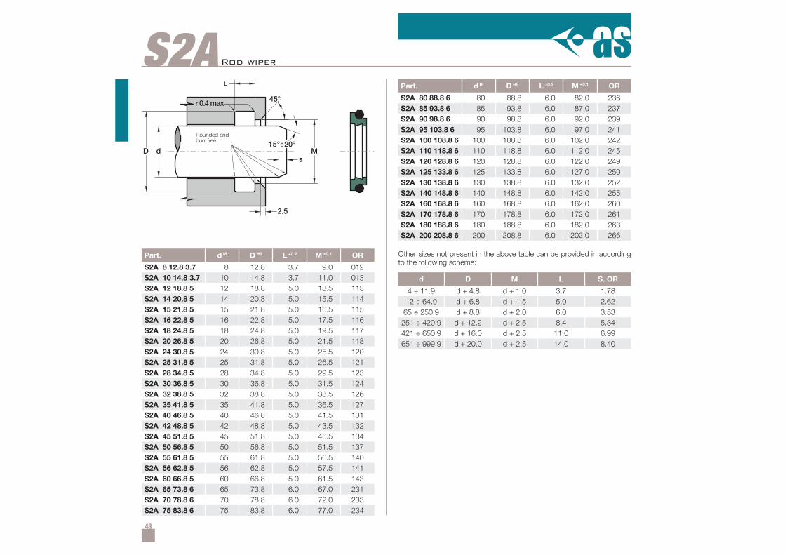
48
Part. d f8 D H9 L +0.2 M ±0.1 OR
S2A 8 12.8 3.7 8 12.8 3.7 9.0 012S2A 10 14.8 3.7 10 14.8 3.7 11.0 013S2A 12 18.8 5 12 18.8 5.0 13.5 113S2A 14 20.8 5 14 20.8 5.0 15.5 114S2A 15 21.8 5 15 21.8 5.0 16.5 115S2A 16 22.8 5 16 22.8 5.0 17.5 116S2A 18 24.8 5 18 24.8 5.0 19.5 117S2A 20 26.8 5 20 26.8 5.0 21.5 118S2A 24 30.8 5 24 30.8 5.0 25.5 120S2A 25 31.8 5 25 31.8 5.0 26.5 121S2A 28 34.8 5 28 34.8 5.0 29.5 123S2A 30 36.8 5 30 36.8 5.0 31.5 124S2A 32 38.8 5 32 38.8 5.0 33.5 126S2A 35 41.8 5 35 41.8 5.0 36.5 127S2A 40 46.8 5 40 46.8 5.0 41.5 131S2A 42 48.8 5 42 48.8 5.0 43.5 132S2A 45 51.8 5 45 51.8 5.0 46.5 134S2A 50 56.8 5 50 56.8 5.0 51.5 137S2A 55 61.8 5 55 61.8 5.0 56.5 140S2A 56 62.8 5 56 62.8 5.0 57.5 141S2A 60 66.8 5 60 66.8 5.0 61.5 143S2A 65 73.8 6 65 73.8 6.0 67.0 231S2A 70 78.8 6 70 78.8 6.0 72.0 233S2A 75 83.8 6 75 83.8 6.0 77.0 234
S2A
d D M L S. OR
4 ÷ 11.9 d + 4.8 d + 1.0 3.7 1.7812 ÷ 64.9 d + 6.8 d + 1.5 5.0 2.6265 ÷ 250.9 d + 8.8 d + 2.0 6.0 3.53251 ÷ 420.9 d + 12.2 d + 2.5 8.4 5.34421 ÷ 650.9 d + 16.0 d + 2.5 11.0 6.99651 ÷ 999.9 d + 20.0 d + 2.5 14.0 8.40
dD
L
Ms
45°
2.5
r 0.4max
15°÷20°
Part. d f8 D H9 L +0.2 M ±0.1 OR
S2A 80 88.8 6 80 88.8 6.0 82.0 236S2A 85 93.8 6 85 93.8 6.0 87.0 237S2A 90 98.8 6 90 98.8 6.0 92.0 239S2A 95 103.8 6 95 103.8 6.0 97.0 241S2A 100 108.8 6 100 108.8 6.0 102.0 242S2A 110 118.8 6 110 118.8 6.0 112.0 245S2A 120 128.8 6 120 128.8 6.0 122.0 249S2A 125 133.8 6 125 133.8 6.0 127.0 250S2A 130 138.8 6 130 138.8 6.0 132.0 252S2A 140 148.8 6 140 148.8 6.0 142.0 255S2A 160 168.8 6 160 168.8 6.0 162.0 260S2A 170 178.8 6 170 178.8 6.0 172.0 261S2A 180 188.8 6 180 188.8 6.0 182.0 263S2A 200 208.8 6 200 208.8 6.0 202.0 266
Other sizes not present in the above table can be provided in accordingto the following scheme:
Rod wiper
Rounded andburr free
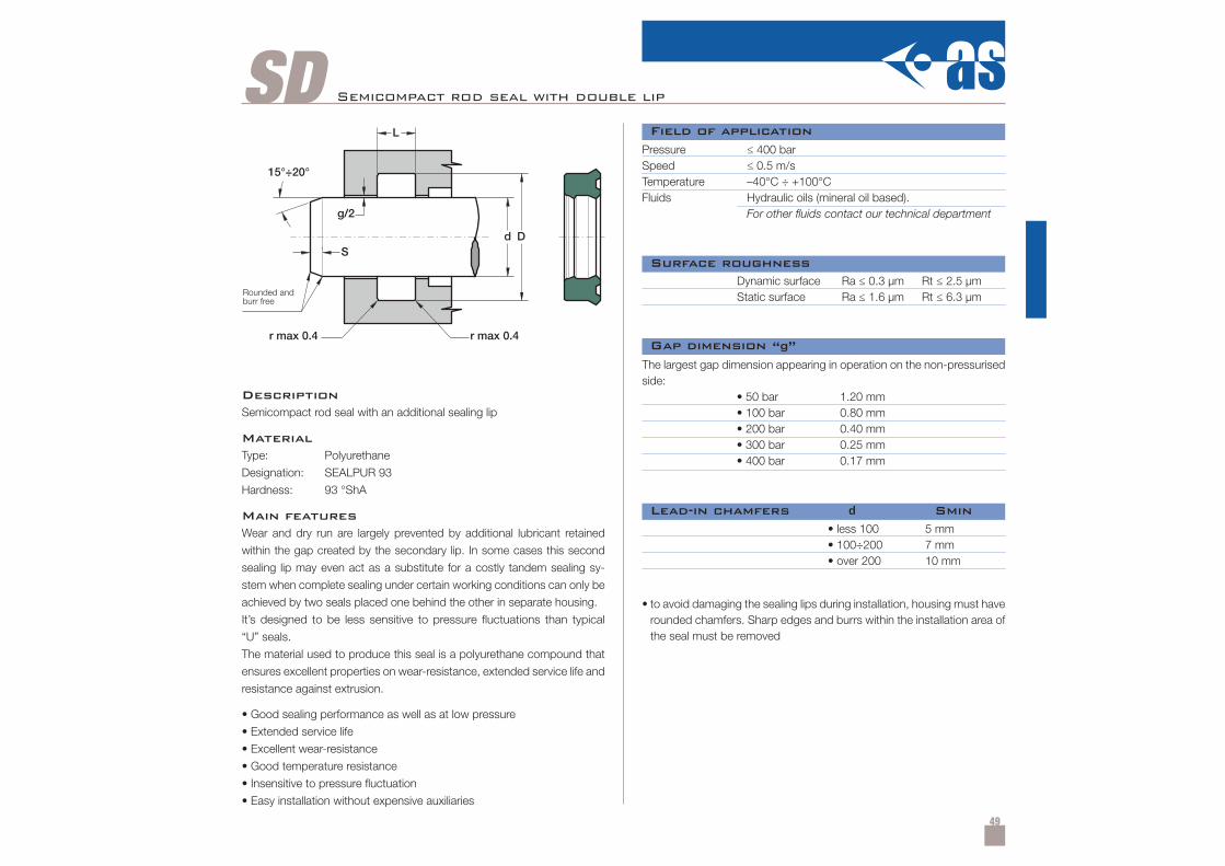
49
SD Semicompact rod seal with double lip
DescriptionSemicompact rod seal with an additional sealing lip
MaterialType: Polyurethane
Designation: SEALPUR 93
Hardness: 93 °ShA
Main featuresWear and dry run are largely prevented by additional lubricant retained
within the gap created by the secondary lip. In some cases this second
sealing lip may even act as a substitute for a costly tandem sealing sy-
stem when complete sealing under certain working conditions can only be
achieved by two seals placed one behind the other in separate housing.
It’s designed to be less sensitive to pressure fluctuations than typical
“U” seals.
The material used to produce this seal is a polyurethane compound that
ensures excellent properties on wear-resistance, extended service life and
resistance against extrusion.
• Good sealing performance as well as at low pressure
• Extended service life
• Excellent wear-resistance
• Good temperature resistance
• Insensitive to pressure fluctuation
• Easy installation without expensive auxiliaries
Pressure ≤ 400 barSpeed ≤ 0.5 m/sTemperature –40°C ÷ +100°CFluids Hydraulic oils (mineral oil based).
For other fluids contact our technical department
Dynamic surface Ra ≤ 0.3 µm Rt ≤ 2.5 µmStatic surface Ra ≤ 1.6 µm Rt ≤ 6.3 µm
• less 100• 100÷200• over 200
5 mm7 mm10 mm
• to avoid damaging the sealing lips during installation, housing must haverounded chamfers. Sharp edges and burrs within the installation area ofthe seal must be removed
The largest gap dimension appearing in operation on the non-pressurisedside:
• 50 bar 1.20 mm• 100 bar 0.80 mm• 200 bar 0.40 mm• 300 bar 0.25 mm• 400 bar 0.17 mm
Field of application
Surface roughness
Lead-in chamfers d Smin
Gap dimension “g”
Rounded andburr free
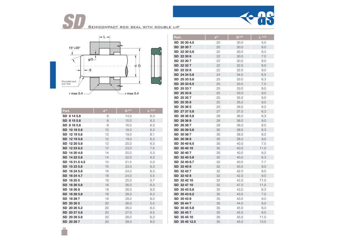
50
SD
Part. d f7 D H10 L +0.25
SD 6 14 5.8 6 14.0 6.3SD 8 15 5.8 8 15.0 6.3SD 8 16 5.8 8 16.0 6.3SD 10 18 5.8 10 18.0 6.3SD 12 19 5.6 12 19.0 6.1SD 12 19 5.8 12 19.0 6.3SD 12 20 5.8 12 20.0 6.3SD 12 23 6.5 12 23.0 7.5SD 14 20 4.8 14 20.0 5.3SD 14 22 5.8 14 22.0 6.3SD 15 21.5 4.2 15 21.5 5.0SD 15 23 5.8 15 23.0 6.3SD 16 24 5.8 16 24.0 6.3SD 18 24 4.7 18 24.0 5.5SD 18 25 5 18 25.0 5.7SD 18 26 5.8 18 26.0 6.3SD 18 26 8 18 26.0 9.0SD 18 28 5.8 18 28.0 6.3SD 18 28 7 18 28.0 8.0SD 20 26 5 20 26.0 5.5SD 20 26 5.2 20 26.0 6.0SD 20 27 5.8 20 27.0 6.5SD 20 28 5.8 20 28.0 6.3SD 20 28 7 20 28.0 8.0
Part. d f7 D H10 L +0.25
SD 20 30 4.5 20 30.0 5.0SD 20 30 7 20 30.0 8.0SD 22 30 5.8 22 30.0 6.3SD 22 30 6 22 30.0 7.0SD 22 30 7 22 30.0 8.0SD 22 32 7 22 32.0 8.0SD 22 32 8 22 32.0 9.0SD 24 34 5.8 24 34.0 6.5SD 25 33 5.8 25 33.0 6.3SD 25 33 6.5 25 33.0 7.5SD 25 33 7 25 33.0 8.0SD 25 33 8 25 33.0 9.0SD 25 35 7 25 35.0 8.0SD 25 35 8 25 35.0 9.0SD 25 36 5 25 36.0 6.0SD 27 37 5.8 27 37.0 6.3SD 28 36 5.8 28 36.0 6.3SD 28 36 8 28 36.0 9.0SD 28 38 7 28 38.0 8.0SD 30 38 5.8 30 38.0 6.3SD 30 38 7 30 38.0 8.0SD 30 38 8 30 38.0 9.0SD 30 40 6.5 30 40.0 7.5SD 30 40 10 30 40.0 11.0SD 30 40 7 30 40.0 8.0SD 32 40 5.8 32 40.0 6.3SD 32 40 6.7 32 40.0 7.7SD 32 40 8 32 40.0 9.0SD 32 42 7 32 42.0 8.0SD 32 42 8 32 42.0 9.0SD 32 42 10 32 42.0 11.0SD 32 47 10 32 47.0 11.0SD 35 43 5.8 35 43.0 6.3SD 35 43 6.2 35 43.0 7.0SD 35 43 8 35 43.0 9.0SD 35 44 7 35 44.0 8.0SD 35 45 5.8 35 45.0 6.3SD 35 45 7 35 45.0 8.0SD 35 45 10 35 45.0 11.0SD 35 45 12.5 35 45.0 13.5
Semicompact rod seal with double lip
Rounded andburr free
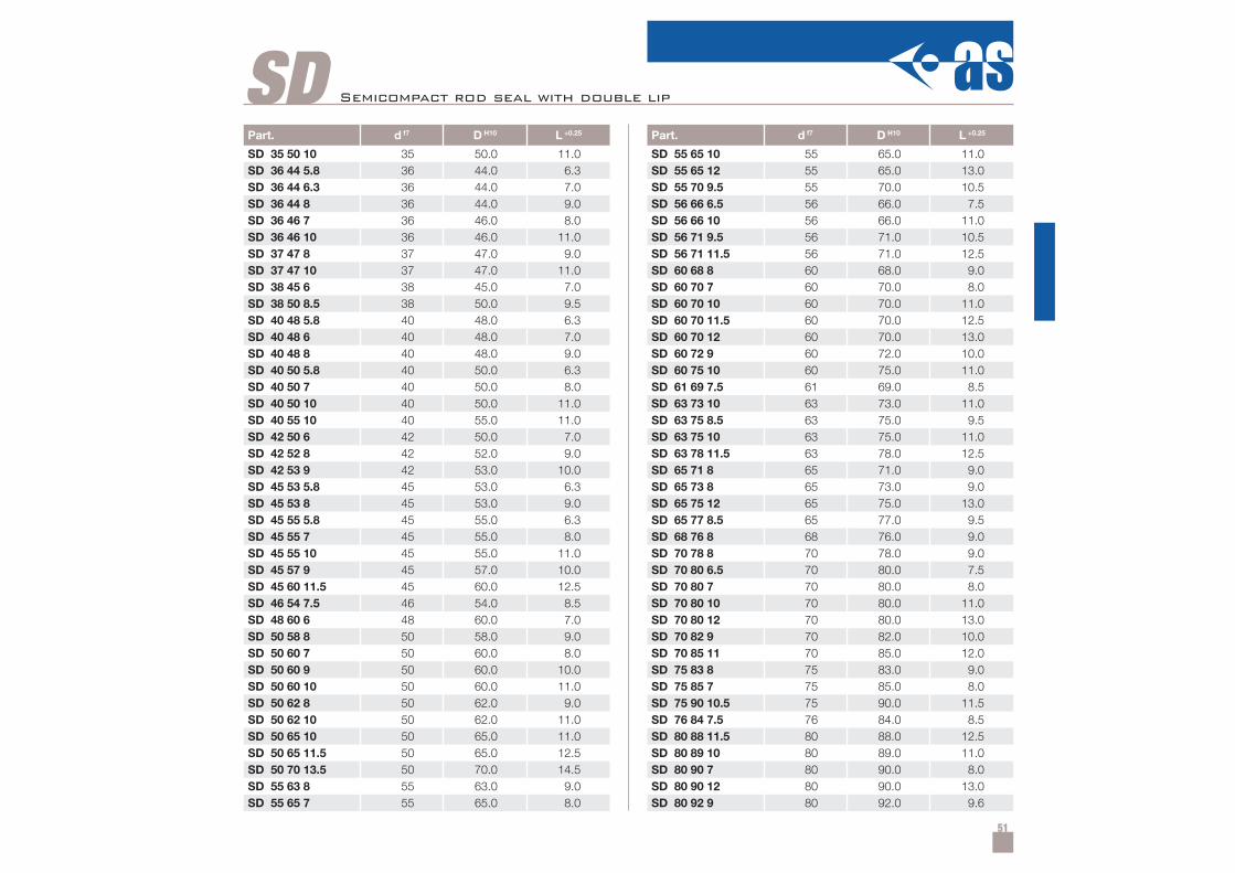
51
SDPart. d f7 D H10 L +0.25
SD 35 50 10 35 50.0 11.0SD 36 44 5.8 36 44.0 6.3SD 36 44 6.3 36 44.0 7.0SD 36 44 8 36 44.0 9.0SD 36 46 7 36 46.0 8.0SD 36 46 10 36 46.0 11.0SD 37 47 8 37 47.0 9.0SD 37 47 10 37 47.0 11.0SD 38 45 6 38 45.0 7.0SD 38 50 8.5 38 50.0 9.5SD 40 48 5.8 40 48.0 6.3SD 40 48 6 40 48.0 7.0SD 40 48 8 40 48.0 9.0SD 40 50 5.8 40 50.0 6.3SD 40 50 7 40 50.0 8.0SD 40 50 10 40 50.0 11.0SD 40 55 10 40 55.0 11.0SD 42 50 6 42 50.0 7.0SD 42 52 8 42 52.0 9.0SD 42 53 9 42 53.0 10.0SD 45 53 5.8 45 53.0 6.3SD 45 53 8 45 53.0 9.0SD 45 55 5.8 45 55.0 6.3SD 45 55 7 45 55.0 8.0SD 45 55 10 45 55.0 11.0SD 45 57 9 45 57.0 10.0SD 45 60 11.5 45 60.0 12.5SD 46 54 7.5 46 54.0 8.5SD 48 60 6 48 60.0 7.0SD 50 58 8 50 58.0 9.0SD 50 60 7 50 60.0 8.0SD 50 60 9 50 60.0 10.0SD 50 60 10 50 60.0 11.0SD 50 62 8 50 62.0 9.0SD 50 62 10 50 62.0 11.0SD 50 65 10 50 65.0 11.0SD 50 65 11.5 50 65.0 12.5SD 50 70 13.5 50 70.0 14.5SD 55 63 8 55 63.0 9.0SD 55 65 7 55 65.0 8.0
Part. d f7 D H10 L +0.25
SD 55 65 10 55 65.0 11.0SD 55 65 12 55 65.0 13.0SD 55 70 9.5 55 70.0 10.5SD 56 66 6.5 56 66.0 7.5SD 56 66 10 56 66.0 11.0SD 56 71 9.5 56 71.0 10.5SD 56 71 11.5 56 71.0 12.5SD 60 68 8 60 68.0 9.0SD 60 70 7 60 70.0 8.0SD 60 70 10 60 70.0 11.0SD 60 70 11.5 60 70.0 12.5SD 60 70 12 60 70.0 13.0SD 60 72 9 60 72.0 10.0SD 60 75 10 60 75.0 11.0SD 61 69 7.5 61 69.0 8.5SD 63 73 10 63 73.0 11.0SD 63 75 8.5 63 75.0 9.5SD 63 75 10 63 75.0 11.0SD 63 78 11.5 63 78.0 12.5SD 65 71 8 65 71.0 9.0SD 65 73 8 65 73.0 9.0SD 65 75 12 65 75.0 13.0SD 65 77 8.5 65 77.0 9.5SD 68 76 8 68 76.0 9.0SD 70 78 8 70 78.0 9.0SD 70 80 6.5 70 80.0 7.5SD 70 80 7 70 80.0 8.0SD 70 80 10 70 80.0 11.0SD 70 80 12 70 80.0 13.0SD 70 82 9 70 82.0 10.0SD 70 85 11 70 85.0 12.0SD 75 83 8 75 83.0 9.0SD 75 85 7 75 85.0 8.0SD 75 90 10.5 75 90.0 11.5SD 76 84 7.5 76 84.0 8.5SD 80 88 11.5 80 88.0 12.5SD 80 89 10 80 89.0 11.0SD 80 90 7 80 90.0 8.0SD 80 90 12 80 90.0 13.0SD 80 92 9 80 92.0 9.6
Semicompact rod seal with double lip
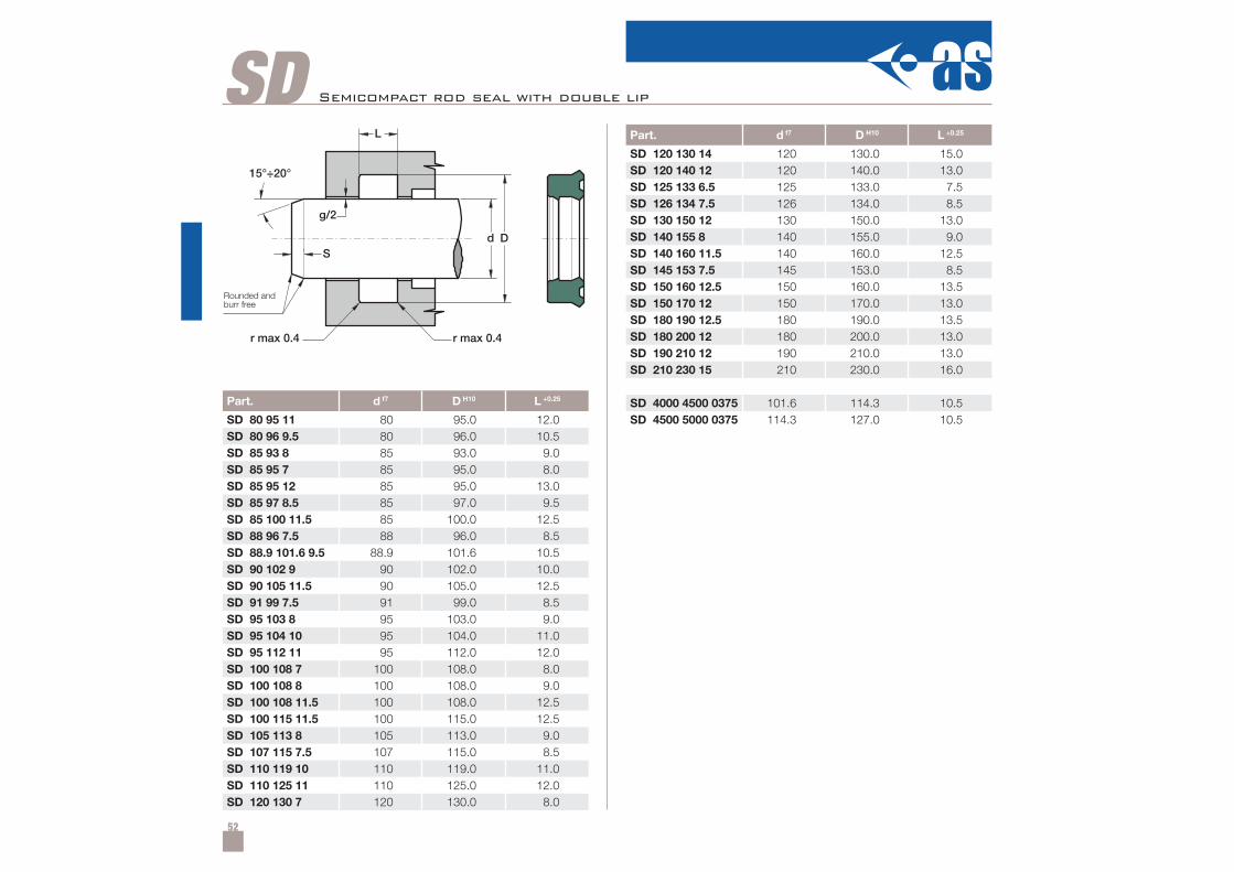
52
SD
Part. d f7 D H10 L +0.25
SD 80 95 11 80 95.0 12.0SD 80 96 9.5 80 96.0 10.5SD 85 93 8 85 93.0 9.0SD 85 95 7 85 95.0 8.0SD 85 95 12 85 95.0 13.0SD 85 97 8.5 85 97.0 9.5SD 85 100 11.5 85 100.0 12.5SD 88 96 7.5 88 96.0 8.5SD 88.9 101.6 9.5 88.9 101.6 10.5SD 90 102 9 90 102.0 10.0SD 90 105 11.5 90 105.0 12.5SD 91 99 7.5 91 99.0 8.5SD 95 103 8 95 103.0 9.0SD 95 104 10 95 104.0 11.0SD 95 112 11 95 112.0 12.0SD 100 108 7 100 108.0 8.0SD 100 108 8 100 108.0 9.0SD 100 108 11.5 100 108.0 12.5SD 100 115 11.5 100 115.0 12.5SD 105 113 8 105 113.0 9.0SD 107 115 7.5 107 115.0 8.5SD 110 119 10 110 119.0 11.0SD 110 125 11 110 125.0 12.0SD 120 130 7 120 130.0 8.0
Part. d f7 D H10 L +0.25
SD 120 130 14 120 130.0 15.0SD 120 140 12 120 140.0 13.0SD 125 133 6.5 125 133.0 7.5SD 126 134 7.5 126 134.0 8.5SD 130 150 12 130 150.0 13.0SD 140 155 8 140 155.0 9.0SD 140 160 11.5 140 160.0 12.5SD 145 153 7.5 145 153.0 8.5SD 150 160 12.5 150 160.0 13.5SD 150 170 12 150 170.0 13.0SD 180 190 12.5 180 190.0 13.5SD 180 200 12 180 200.0 13.0SD 190 210 12 190 210.0 13.0SD 210 230 15 210 230.0 16.0
SD 4000 4500 0375 101.6 114.3 10.5SD 4500 5000 0375 114.3 127.0 10.5
Semicompact rod seal with double lip
Rounded andburr free
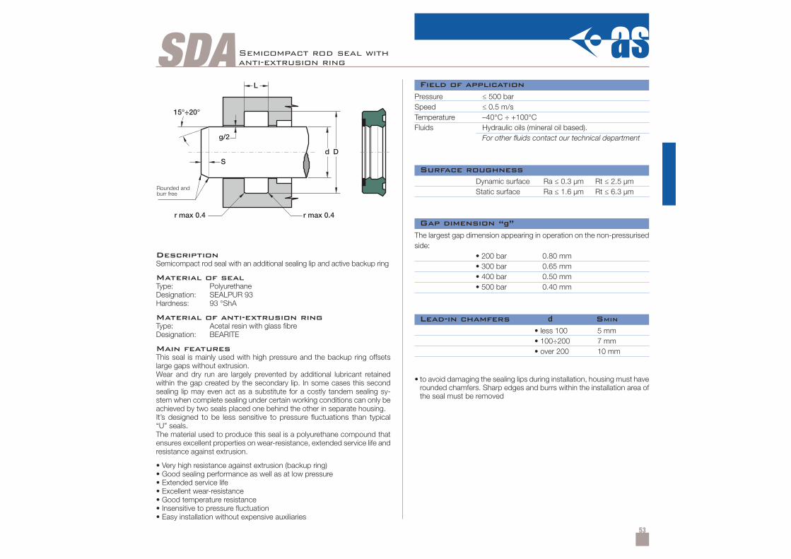
53
SDA
DescriptionSemicompact rod seal with an additional sealing lip and active backup ring
Material of sealType: PolyurethaneDesignation: SEALPUR 93Hardness: 93 °ShA
Material of anti-extrusion ringType: Acetal resin with glass fibreDesignation: BEARITE
Main featuresThis seal is mainly used with high pressure and the backup ring offsetslarge gaps without extrusion.Wear and dry run are largely prevented by additional lubricant retainedwithin the gap created by the secondary lip. In some cases this secondsealing lip may even act as a substitute for a costly tandem sealing sy-stem when complete sealing under certain working conditions can only beachieved by two seals placed one behind the other in separate housing.It’s designed to be less sensitive to pressure fluctuations than typical“U” seals.The material used to produce this seal is a polyurethane compound thatensures excellent properties on wear-resistance, extended service life andresistance against extrusion.
• Very high resistance against extrusion (backup ring)• Good sealing performance as well as at low pressure• Extended service life• Excellent wear-resistance• Good temperature resistance• Insensitive to pressure fluctuation• Easy installation without expensive auxiliaries
Semicompact rod seal withanti-extrusion ring
Pressure ≤ 500 barSpeed ≤ 0.5 m/sTemperature –40°C ÷ +100°CFluids Hydraulic oils (mineral oil based).
For other fluids contact our technical department
Dynamic surface Ra ≤ 0.3 µm Rt ≤ 2.5 µmStatic surface Ra ≤ 1.6 µm Rt ≤ 6.3 µm
• less 100• 100÷200• over 200
5 mm7 mm10 mm
• to avoid damaging the sealing lips during installation, housing must haverounded chamfers. Sharp edges and burrs within the installation area ofthe seal must be removed
The largest gap dimension appearing in operation on the non-pressurisedside:
• 200 bar 0.80 mm• 300 bar 0.65 mm• 400 bar 0.50 mm• 500 bar 0.40 mm
Field of application
Surface roughness
Lead-in chamfers d SMIN
Gap dimension “g”
Rounded andburr free
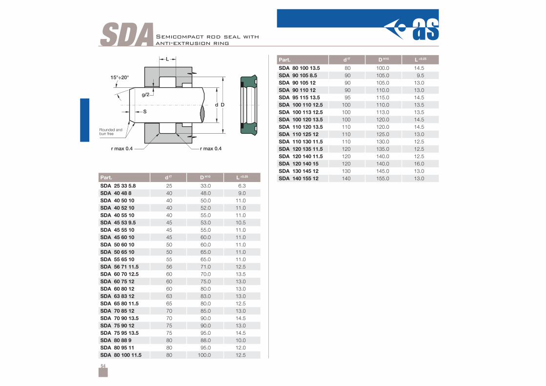
54
SDA
Part. d f7 D H10 L +0.25
SDA 25 33 5.8 25 33.0 6.3SDA 40 48 8 40 48.0 9.0SDA 40 50 10 40 50.0 11.0SDA 40 52 10 40 52.0 11.0SDA 40 55 10 40 55.0 11.0SDA 45 53 9.5 45 53.0 10.5SDA 45 55 10 45 55.0 11.0SDA 45 60 10 45 60.0 11.0SDA 50 60 10 50 60.0 11.0SDA 50 65 10 50 65.0 11.0SDA 55 65 10 55 65.0 11.0SDA 56 71 11.5 56 71.0 12.5SDA 60 70 12.5 60 70.0 13.5SDA 60 75 12 60 75.0 13.0SDA 60 80 12 60 80.0 13.0SDA 63 83 12 63 83.0 13.0SDA 65 80 11.5 65 80.0 12.5SDA 70 85 12 70 85.0 13.0SDA 70 90 13.5 70 90.0 14.5SDA 75 90 12 75 90.0 13.0SDA 75 95 13.5 75 95.0 14.5SDA 80 88 9 80 88.0 10.0SDA 80 95 11 80 95.0 12.0SDA 80 100 11.5 80 100.0 12.5
Part. d f7 D H10 L +0.25
SDA 80 100 13.5 80 100.0 14.5SDA 90 105 8.5 90 105.0 9.5SDA 90 105 12 90 105.0 13.0SDA 90 110 12 90 110.0 13.0SDA 95 115 13.5 95 115.0 14.5SDA 100 110 12.5 100 110.0 13.5SDA 100 113 12.5 100 113.0 13.5SDA 100 120 13.5 100 120.0 14.5SDA 110 120 13.5 110 120.0 14.5SDA 110 125 12 110 125.0 13.0SDA 110 130 11.5 110 130.0 12.5SDA 120 135 11.5 120 135.0 12.5SDA 120 140 11.5 120 140.0 12.5SDA 120 140 15 120 140.0 16.0SDA 130 145 12 130 145.0 13.0SDA 140 155 12 140 155.0 13.0
Semicompact rod seal withanti-extrusion ring
Rounded andburr free
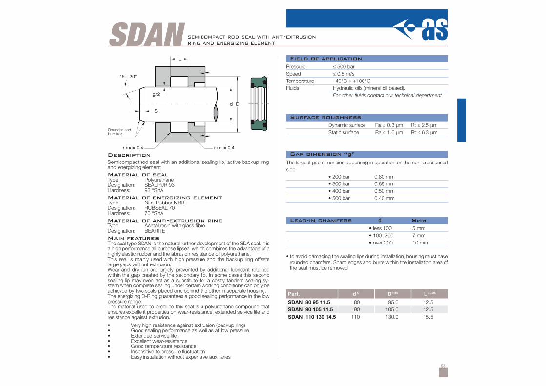
55
SDAN
S
L
g/2
d
r max 0.4
D
r max 0.4
15°÷20°
Part. d f7 D H10 L +0.25
SDAN 80 95 11.5 80 95.0 12.5SDAN 90 105 11.5 90 105.0 12.5SDAN 110 130 14.5 110 130.0 15.5
DescriptionSemicompact rod seal with an additional sealing lip, active backup ringand energizing elementMaterial of sealType: PolyurethaneDesignation: SEALPUR 93Hardness: 93 °ShAMaterial of energizing elementType: Nitril Rubber NBRDesignation: RUBSEAL 70Hardness: 70 °ShAMaterial of anti-extrusion ringType: Acetal resin with glass fibreDesignation: BEARITEMain featuresThe seal type SDAN is the natural further development of the SDA seal. It isa high performance all purpose lipseal which combines the advantage of ahighly elastic rubber and the abrasion resistance of polyurethane.This seal is mainly used with high pressure and the backup ring offsetslarge gaps without extrusion.Wear and dry run are largely prevented by additional lubricant retainedwithin the gap created by the secondary lip. In some cases this secondsealing lip may even act as a substitute for a costly tandem sealing sy-stem when complete sealing under certain working conditions can only beachieved by two seals placed one behind the other in separate housing.The energizing O-Ring guarantees a good sealing performance in the lowpressure range.The material used to produce this seal is a polyurethane compound thatensures excellent properties on wear-resistance, extended service life andresistance against extrusion.
• Very high resistance against extrusion (backup ring)• Good sealing performance as well as at low pressure• Extended service life• Excellent wear-resistance• Good temperature resistance• Insensitive to pressure fluctuation• Easy installation without expensive auxiliaries
semicompact rod seal with anti-extrusionring and energizing element
• to avoid damaging the sealing lips during installation, housing must haverounded chamfers. Sharp edges and burrs within the installation area ofthe seal must be removed
Field of application
Surface roughness
Lead-in chamfers d SMIN
Gap dimension “g”
Rounded andburr free
Pressure ≤ 500 barSpeed ≤ 0.5 m/sTemperature –40°C ÷ +100°CFluids Hydraulic oils (mineral oil based).
For other fluids contact our technical department
Dynamic surface Ra ≤ 0.3 µm Rt ≤ 2.5 µmStatic surface Ra ≤ 1.6 µm Rt ≤ 6.3 µm
• less 100• 100÷200• over 200
5 mm7 mm10 mm
The largest gap dimension appearing in operation on the non-pressurisedside:
• 200 bar 0.80 mm• 300 bar 0.65 mm• 400 bar 0.50 mm• 500 bar 0.40 mm
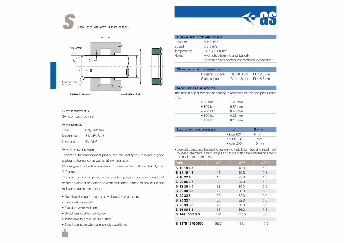
56
S
Part. d f7 D H10 L +0.25
S 12 18 4.5 12 18.0 5.0S 14 19 4.8 14 19.0 5.3S 16 22 4 16 22.0 4.5S 20 25 3.7 20 25.0 4.5S 22 28 4.5 22 28.0 5.5S 22 30 5.8 22 30.0 6.3S 22 32 8 22 32.0 9.0S 25 32 4 25 32.0 5.0S 25 33 5.8 25 33.0 6.3S 56 66 6.5 56 66.0 7.5S 140 155.5 5.8 140 155.5 6.3
S 3375 4375 0550 85.7 111.1 15.0
Semicompact rod seal
Description
Semicompact rod seal
Material
Type: Polyurethane
Designation: SEALPUR 93
Hardness: 93 °ShA
Main features
Thanks to its semicompact profile, the rod seal type S assures a good
sealing performance as well as at low pressure.
It’s designed to be less sensitive to pressure fluctuations than typical
“U” seals.
The material used to produce this seal is a polyurethane compound that
ensures excellent properties on wear-resistance, extended service life and
resistance against extrusion.
• Good sealing performance as well as at low pressure
• Extended service life
• Excellent wear-resistance
• Good temperature resistance
• Insensitive to pressure fluctuation
• Easy installation without expensive auxiliaries
Pressure ≤ 400 barSpeed ≤ 0.5 m/sTemperature –40°C ÷ +100°CFluids Hydraulic oils (mineral oil based).
For other fluids contact our technical department
Dynamic surface Ra ≤ 0.3 µm Rt ≤ 2.5 µmStatic surface Ra ≤ 1.6 µm Rt ≤ 6.3 µm
• less 100• 100÷200• over 200
5 mm7 mm10 mm
• to avoid damaging the sealing lips during installation, housing must haverounded chamfers. Sharp edges and burrs within the installation area ofthe seal must be removed
The largest gap dimension appearing in operation on the non-pressurisedside:
• 50 bar 1.20 mm• 100 bar 0.80 mm• 200 bar 0.40 mm• 300 bar 0.25 mm• 400 bar 0.17 mm
Field of application
Surface roughness
Lead-in chamfers d SMIN
Gap dimension “g”
Rounded andburr free
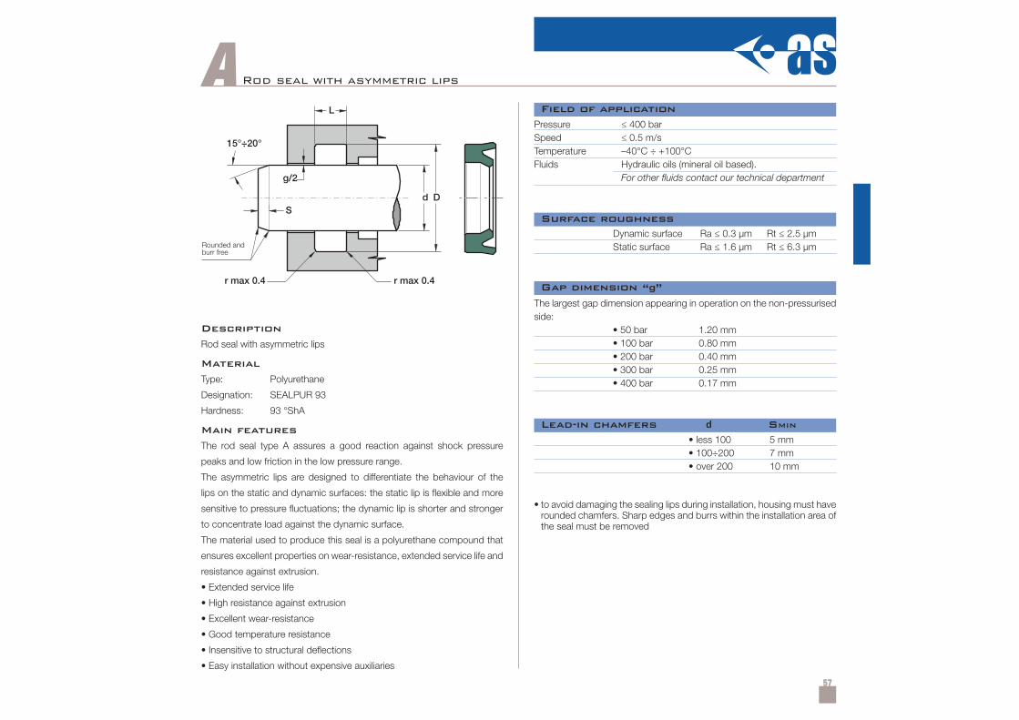
57
A Rod seal with asymmetric lips
Description
Rod seal with asymmetric lips
Material
Type: Polyurethane
Designation: SEALPUR 93
Hardness: 93 °ShA
Main features
The rod seal type A assures a good reaction against shock pressure
peaks and low friction in the low pressure range.
The asymmetric lips are designed to differentiate the behaviour of the
lips on the static and dynamic surfaces: the static lip is flexible and more
sensitive to pressure fluctuations; the dynamic lip is shorter and stronger
to concentrate load against the dynamic surface.
The material used to produce this seal is a polyurethane compound that
ensures excellent properties on wear-resistance, extended service life and
resistance against extrusion.
• Extended service life
• High resistance against extrusion
• Excellent wear-resistance
• Good temperature resistance
• Insensitive to structural deflections
• Easy installation without expensive auxiliaries
Pressure ≤ 400 barSpeed ≤ 0.5 m/sTemperature –40°C ÷ +100°CFluids Hydraulic oils (mineral oil based).
For other fluids contact our technical department
Dynamic surface Ra ≤ 0.3 µm Rt ≤ 2.5 µmStatic surface Ra ≤ 1.6 µm Rt ≤ 6.3 µm
• less 100• 100÷200• over 200
5 mm7 mm10 mm
• to avoid damaging the sealing lips during installation, housing must haverounded chamfers. Sharp edges and burrs within the installation area ofthe seal must be removed
The largest gap dimension appearing in operation on the non-pressurisedside:
• 50 bar 1.20 mm• 100 bar 0.80 mm• 200 bar 0.40 mm• 300 bar 0.25 mm• 400 bar 0.17 mm
Field of application
Surface roughness
Lead-in chamfers d SMIN
Gap dimension “g”
Rounded andburr free
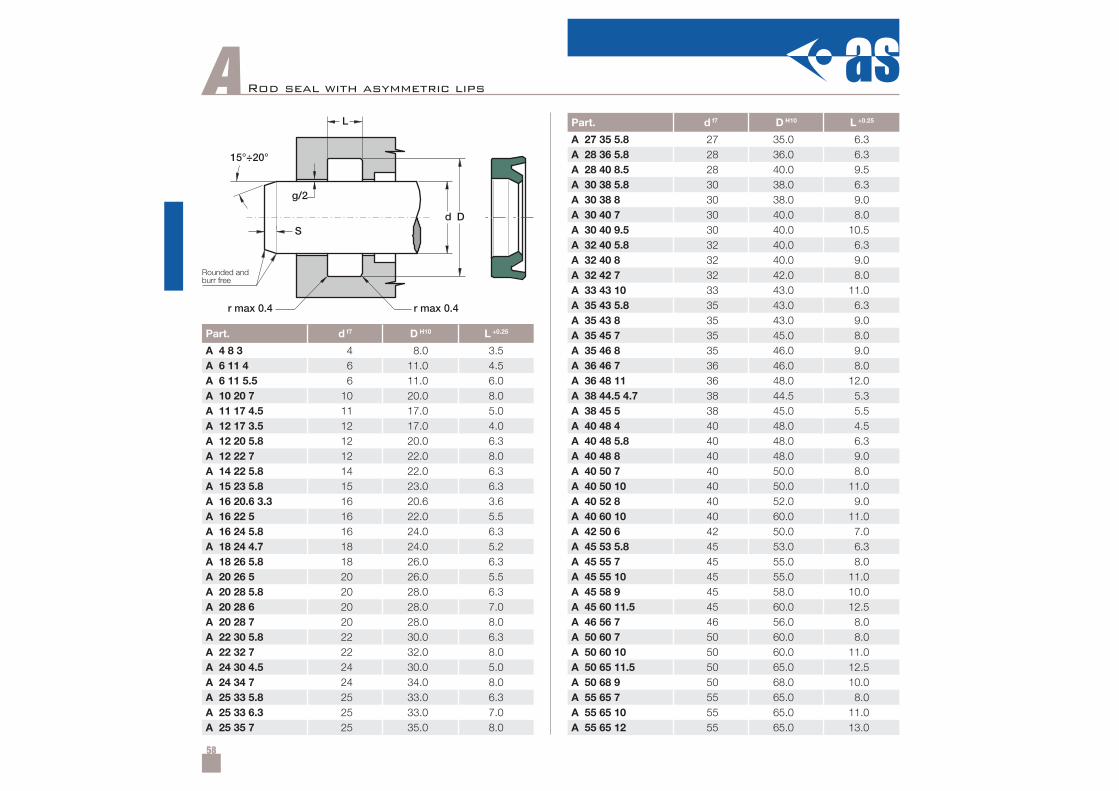
58
Part. d f7 D H10 L +0.25
A 4 8 3 4 8.0 3.5A 6 11 4 6 11.0 4.5A 6 11 5.5 6 11.0 6.0A 10 20 7 10 20.0 8.0A 11 17 4.5 11 17.0 5.0A 12 17 3.5 12 17.0 4.0A 12 20 5.8 12 20.0 6.3A 12 22 7 12 22.0 8.0A 14 22 5.8 14 22.0 6.3A 15 23 5.8 15 23.0 6.3A 16 20.6 3.3 16 20.6 3.6A 16 22 5 16 22.0 5.5A 16 24 5.8 16 24.0 6.3A 18 24 4.7 18 24.0 5.2A 18 26 5.8 18 26.0 6.3A 20 26 5 20 26.0 5.5A 20 28 5.8 20 28.0 6.3A 20 28 6 20 28.0 7.0A 20 28 7 20 28.0 8.0A 22 30 5.8 22 30.0 6.3A 22 32 7 22 32.0 8.0A 24 30 4.5 24 30.0 5.0A 24 34 7 24 34.0 8.0A 25 33 5.8 25 33.0 6.3A 25 33 6.3 25 33.0 7.0A 25 35 7 25 35.0 8.0
APart. d f7 D H10 L +0.25
A 27 35 5.8 27 35.0 6.3A 28 36 5.8 28 36.0 6.3A 28 40 8.5 28 40.0 9.5A 30 38 5.8 30 38.0 6.3A 30 38 8 30 38.0 9.0A 30 40 7 30 40.0 8.0A 30 40 9.5 30 40.0 10.5A 32 40 5.8 32 40.0 6.3A 32 40 8 32 40.0 9.0A 32 42 7 32 42.0 8.0A 33 43 10 33 43.0 11.0A 35 43 5.8 35 43.0 6.3A 35 43 8 35 43.0 9.0A 35 45 7 35 45.0 8.0A 35 46 8 35 46.0 9.0A 36 46 7 36 46.0 8.0A 36 48 11 36 48.0 12.0A 38 44.5 4.7 38 44.5 5.3A 38 45 5 38 45.0 5.5A 40 48 4 40 48.0 4.5A 40 48 5.8 40 48.0 6.3A 40 48 8 40 48.0 9.0A 40 50 7 40 50.0 8.0A 40 50 10 40 50.0 11.0A 40 52 8 40 52.0 9.0A 40 60 10 40 60.0 11.0A 42 50 6 42 50.0 7.0A 45 53 5.8 45 53.0 6.3A 45 55 7 45 55.0 8.0A 45 55 10 45 55.0 11.0A 45 58 9 45 58.0 10.0A 45 60 11.5 45 60.0 12.5A 46 56 7 46 56.0 8.0A 50 60 7 50 60.0 8.0A 50 60 10 50 60.0 11.0A 50 65 11.5 50 65.0 12.5A 50 68 9 50 68.0 10.0A 55 65 7 55 65.0 8.0A 55 65 10 55 65.0 11.0A 55 65 12 55 65.0 13.0
Rod seal with asymmetric lips
Rounded andburr free
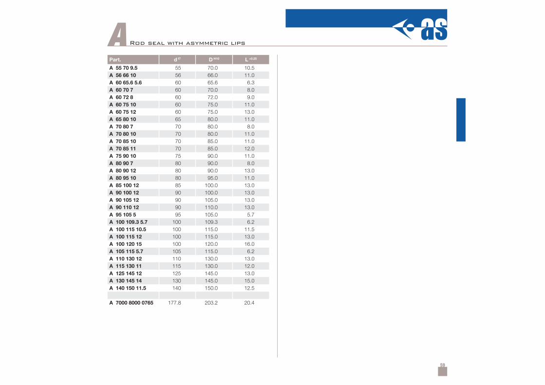
59
Part. d f7 D H10 L +0.25
A 55 70 9.5 55 70.0 10.5A 56 66 10 56 66.0 11.0A 60 65.6 5.6 60 65.6 6.3A 60 70 7 60 70.0 8.0A 60 72 8 60 72.0 9.0A 60 75 10 60 75.0 11.0A 60 75 12 60 75.0 13.0A 65 80 10 65 80.0 11.0A 70 80 7 70 80.0 8.0A 70 80 10 70 80.0 11.0A 70 85 10 70 85.0 11.0A 70 85 11 70 85.0 12.0A 75 90 10 75 90.0 11.0A 80 90 7 80 90.0 8.0A 80 90 12 80 90.0 13.0A 80 95 10 80 95.0 11.0A 85 100 12 85 100.0 13.0A 90 100 12 90 100.0 13.0A 90 105 12 90 105.0 13.0A 90 110 12 90 110.0 13.0A 95 105 5 95 105.0 5.7A 100 109.3 5.7 100 109.3 6.2A 100 115 10.5 100 115.0 11.5A 100 115 12 100 115.0 13.0A 100 120 15 100 120.0 16.0A 105 115 5.7 105 115.0 6.2A 110 130 12 110 130.0 13.0A 115 130 11 115 130.0 12.0A 125 145 12 125 145.0 13.0A 130 145 14 130 145.0 15.0A 140 150 11.5 140 150.0 12.5
A 7000 8000 0765 177.8 203.2 20.4
A Rod seal with asymmetric lips
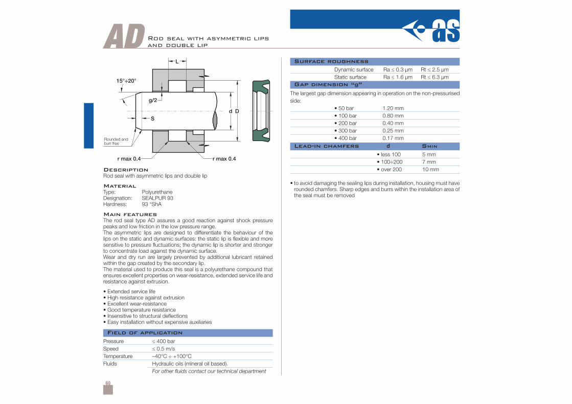
60
AD Rod seal with asymmetric lipsand double lip
DescriptionRod seal with asymmetric lips and double lip
MaterialType: PolyurethaneDesignation: SEALPUR 93Hardness: 93 °ShA
Main featuresThe rod seal type AD assures a good reaction against shock pressurepeaks and low friction in the low pressure range.The asymmetric lips are designed to differentiate the behaviour of thelips on the static and dynamic surfaces: the static lip is flexible and moresensitive to pressure fluctuations; the dynamic lip is shorter and strongerto concentrate load against the dynamic surface.Wear and dry run are largely prevented by additional lubricant retainedwithin the gap created by the secondary lip.The material used to produce this seal is a polyurethane compound thatensures excellent properties on wear-resistance, extended service life andresistance against extrusion.
• Extended service life• High resistance against extrusion• Excellent wear-resistance• Good temperature resistance• Insensitive to structural deflections• Easy installation without expensive auxiliaries
Pressure ≤ 400 barSpeed ≤ 0.5 m/sTemperature –40°C ÷ +100°CFluids Hydraulic oils (mineral oil based).
For other fluids contact our technical department
Dynamic surface Ra ≤ 0.3 µm Rt ≤ 2.5 µmStatic surface Ra ≤ 1.6 µm Rt ≤ 6.3 µm
• less 100• 100÷200• over 200
5 mm7 mm10 mm
• to avoid damaging the sealing lips during installation, housing must haverounded chamfers. Sharp edges and burrs within the installation area ofthe seal must be removed
The largest gap dimension appearing in operation on the non-pressurisedside:
• 50 bar 1.20 mm• 100 bar 0.80 mm• 200 bar 0.40 mm• 300 bar 0.25 mm• 400 bar 0.17 mm
Field of application
Surface roughness
Lead-in chamfers d SMIN
Gap dimension “g”
Rounded andburr free
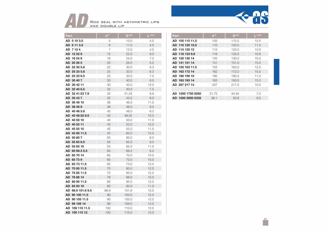
61
Part. d f7 D H10 L +0.25
AD 5 10 3.5 5 10.0 4.0AD 6 11 3.5 6 11.0 4.0AD 7 12 4 7 12.0 4.5AD 12 22 8 12 22.0 9.0AD 16 24 6 16 24.0 7.0AD 20 26 5 20 26.0 5.5AD 22 30 5.8 22 30.0 6.3AD 25 33 5.8 25 33.0 6.3AD 25 33 6.5 25 33.0 7.5AD 30 40 7 30 40.0 8.0AD 30 42 11 30 42.0 12.0AD 32 40 6.5 32 40.0 7.5AD 32 41.53 7.9 32 41.53 8.9AD 35 43 7 35 43.0 8.0AD 36 46 10 36 46.0 11.0AD 38 48 8 38 48.0 9.0AD 40 48 5.8 40 48.0 6.3AD 40 49.52 9.5 40 49.52 10.5AD 40 50 10 40 50.0 11.0AD 40 52 11 40 52.0 12.0AD 45 55 10 45 55.0 11.0AD 45 60 11.5 45 60.0 12.5AD 50 60 7 50 60.0 8.0AD 55 65 8.5 55 65.0 9.5AD 55 65 10 55 65.0 11.0AD 60 69.3 5.5 60 69.3 6.2AD 60 70 14 60 70.0 15.0AD 65 73 9 65 73.0 10.0AD 65 73 11.5 65 73.0 12.5AD 70 85 11.5 70 85.0 12.5AD 75 85 11.5 75 85.0 12.5AD 78 88 14 78 88.0 15.0AD 80 95 11.5 80 95.0 12.5AD 85 93 10 85 93.0 11.0AD 88.9 101.6 9.5 88.9 101.6 10.5AD 90 100 11.5 90 100.0 12.5AD 90 105 11.5 90 105.0 12.5AD 99 109 14 99 109.0 15.0AD 100 110 11.5 100 110.0 12.5AD 100 115 12 100 115.0 13.0
Part. d f7 D H10 L +0.25
AD 105 115 11.5 105 115.0 12.5AD 110 120 10.5 110 120.0 11.5AD 115 125 12 115 125.0 13.0AD 118 133 9.8 118 133.0 10.8AD 120 130 14 120 130.0 15.0AD 141 151 14 141 151.0 15.0AD 155 163 11.5 155 163.0 12.5AD 162 172 14 162 172.0 15.0AD 180 190 10 180 190.0 11.0AD 183 193 14 183 193.0 15.0AD 207 217 14 207 217.0 15.0
AD 1250 1750 0250 31.75 44.45 7.0AD 1500 2000 0335 38.1 50.8 9.5
AD Rod seal with asymmetric lipsand double lip
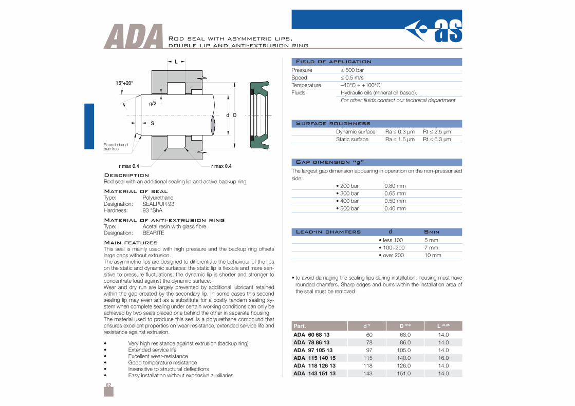
62
ADA
S
L
g/2
d
r max 0.4
D
r max 0.4
15°÷20°
Part. d f7 D H10 L +0.25
ADA 60 68 13 60 68.0 14.0ADA 78 86 13 78 86.0 14.0ADA 97 105 13 97 105.0 14.0ADA 115 140 15 115 140.0 16.0ADA 118 126 13 118 126.0 14.0ADA 143 151 13 143 151.0 14.0
Rod seal with asymmetric lips,double lip and anti-extrusion ring
Rounded andburr free
DescriptionRod seal with an additional sealing lip and active backup ring
Material of sealType: PolyurethaneDesignation: SEALPUR 93Hardness: 93 °ShA
Material of anti-extrusion ringType: Acetal resin with glass fibreDesignation: BEARITE
Main featuresThis seal is mainly used with high pressure and the backup ring offsetslarge gaps without extrusion.The asymmetric lips are designed to differentiate the behaviour of the lipson the static and dynamic surfaces: the static lip is flexible and more sen-sitive to pressure fluctuations; the dynamic lip is shorter and stronger toconcentrate load against the dynamic surface.Wear and dry run are largely prevented by additional lubricant retainedwithin the gap created by the secondary lip. In some cases this secondsealing lip may even act as a substitute for a costly tandem sealing sy-stem when complete sealing under certain working conditions can only beachieved by two seals placed one behind the other in separate housing.The material used to produce this seal is a polyurethane compound thatensures excellent properties on wear-resistance, extended service life andresistance against extrusion.
• Very high resistance against extrusion (backup ring)• Extended service life• Excellent wear-resistance• Good temperature resistance• Insensitive to structural deflections• Easy installation without expensive auxiliaries
Pressure ≤ 500 barSpeed ≤ 0.5 m/sTemperature –40°C ÷ +100°CFluids Hydraulic oils (mineral oil based).
For other fluids contact our technical department
Dynamic surface Ra ≤ 0.3 µm Rt ≤ 2.5 µmStatic surface Ra ≤ 1.6 µm Rt ≤ 6.3 µm
• less 100• 100÷200• over 200
5 mm7 mm10 mm
The largest gap dimension appearing in operation on the non-pressurisedside:
• 200 bar 0.80 mm• 300 bar 0.65 mm• 400 bar 0.50 mm• 500 bar 0.40 mm
Field of application
Surface roughness
Lead-in chamfers d SMIN
Gap dimension “g”
• to avoid damaging the sealing lips during installation, housing must haverounded chamfers. Sharp edges and burrs within the installation area ofthe seal must be removed
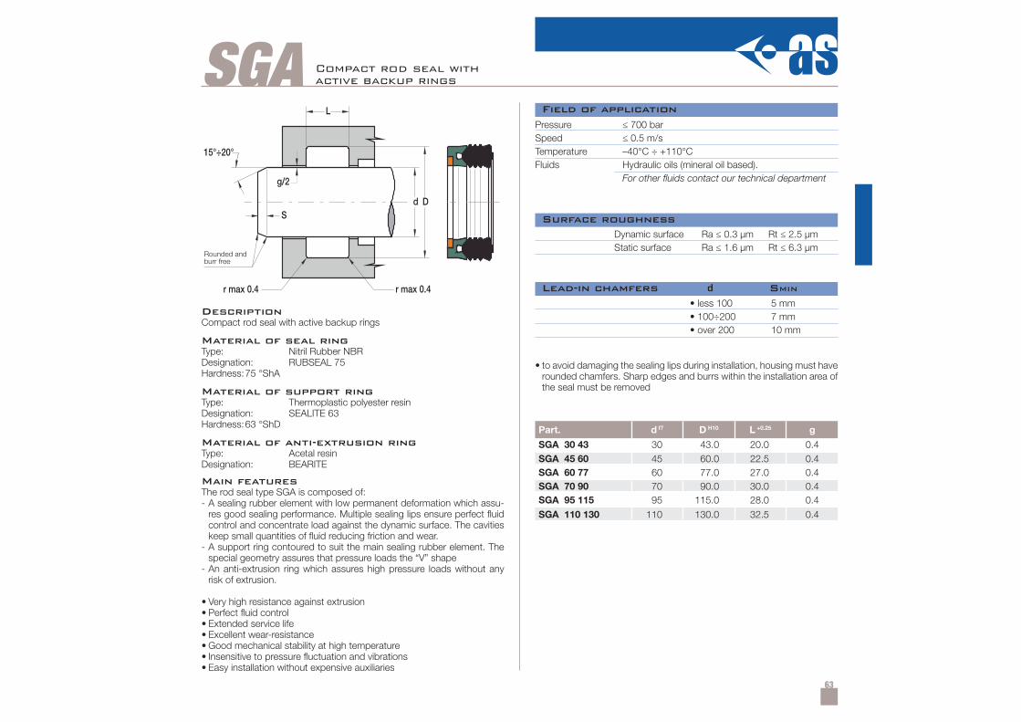
63
SGA15°÷20°
S
L
g/2
d
r max 0.4
D
r max 0.4
Part. d f7 D H10 L +0.25 g
SGA 30 43 30 43.0 20.0 0.4SGA 45 60 45 60.0 22.5 0.4SGA 60 77 60 77.0 27.0 0.4SGA 70 90 70 90.0 30.0 0.4SGA 95 115 95 115.0 28.0 0.4
SGA 110 130 110 130.0 32.5 0.4
Compact rod seal withactive backup rings
DescriptionCompact rod seal with active backup rings
Material of seal ringType: Nitril Rubber NBRDesignation: RUBSEAL 75Hardness:75 °ShA
Material of support ringType: Thermoplastic polyester resinDesignation: SEALITE 63Hardness:63 °ShD
Material of anti-extrusion ringType: Acetal resinDesignation: BEARITE
Main featuresThe rod seal type SGA is composed of:- A sealing rubber element with low permanent deformation which assu-
res good sealing performance. Multiple sealing lips ensure perfect fluidcontrol and concentrate load against the dynamic surface. The cavitieskeep small quantities of fluid reducing friction and wear.
- A support ring contoured to suit the main sealing rubber element. Thespecial geometry assures that pressure loads the “V” shape
- An anti-extrusion ring which assures high pressure loads without anyrisk of extrusion.
• Very high resistance against extrusion• Perfect fluid control• Extended service life• Excellent wear-resistance• Good mechanical stability at high temperature• Insensitive to pressure fluctuation and vibrations• Easy installation without expensive auxiliaries
Pressure ≤ 700 barSpeed ≤ 0.5 m/sTemperature –40°C ÷ +110°CFluids Hydraulic oils (mineral oil based).
For other fluids contact our technical department
Dynamic surface Ra ≤ 0.3 µm Rt ≤ 2.5 µmStatic surface Ra ≤ 1.6 µm Rt ≤ 6.3 µm
Field of application
Surface roughness
• less 100• 100÷200• over 200
5 mm7 mm10 mm
Lead-in chamfers d SMIN
Rounded andburr free
• to avoid damaging the sealing lips during installation, housing must haverounded chamfers. Sharp edges and burrs within the installation area ofthe seal must be removed
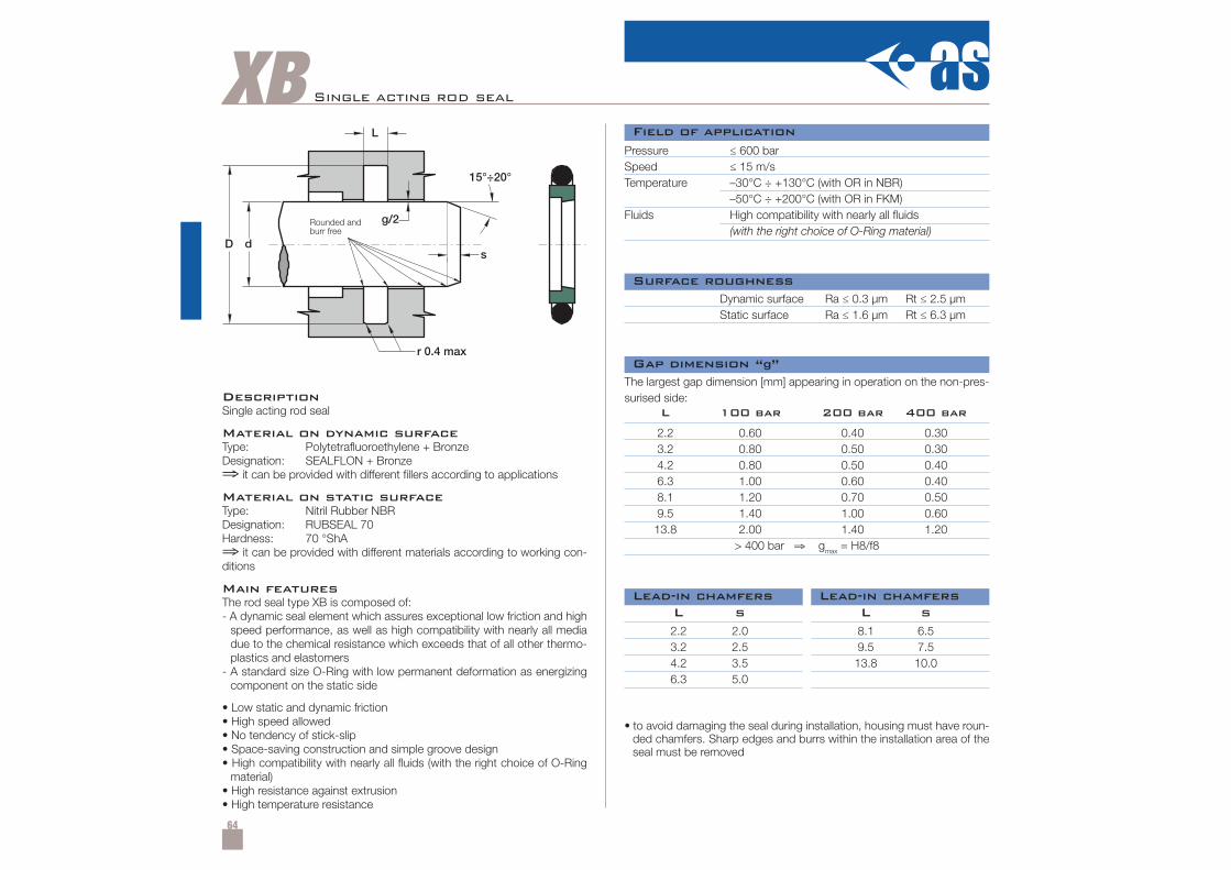
64
XB Single acting rod seal
DescriptionSingle acting rod seal
Material on dynamic surfaceType: Polytetrafluoroethylene + BronzeDesignation: SEALFLON + Bronze⇒ it can be provided with different fillers according to applications
Material on static surfaceType: Nitril Rubber NBRDesignation: RUBSEAL 70Hardness: 70 °ShA⇒ it can be provided with different materials according to working con-ditions
Main featuresThe rod seal type XB is composed of:- A dynamic seal element which assures exceptional low friction and high
speed performance, as well as high compatibility with nearly all mediadue to the chemical resistance which exceeds that of all other thermo-plastics and elastomers
- A standard size O-Ring with low permanent deformation as energizingcomponent on the static side
• Low static and dynamic friction• High speed allowed• No tendency of stick-slip• Space-saving construction and simple groove design• High compatibility with nearly all fluids (with the right choice of O-Ring
material)• High resistance against extrusion• High temperature resistance
Pressure ≤ 600 barSpeed ≤ 15 m/sTemperature –30°C ÷ +130°C (with OR in NBR)
–50°C ÷ +200°C (with OR in FKM)Fluids High compatibility with nearly all fluids
(with the right choice of O-Ring material)
Dynamic surface Ra ≤ 0.3 µm Rt ≤ 2.5 µmStatic surface Ra ≤ 1.6 µm Rt ≤ 6.3 µm
• to avoid damaging the seal during installation, housing must have roun-ded chamfers. Sharp edges and burrs within the installation area of theseal must be removed
The largest gap dimension [mm] appearing in operation on the non-pres-surised side:
2.2 2.0 8.1 6.53.2 2.5 9.5 7.54.2 3.5 13.8 10.06.3 5.0
L s L s
2.2 0.60 0.40 0.303.2 0.80 0.50 0.304.2 0.80 0.50 0.406.3 1.00 0.60 0.408.1 1.20 0.70 0.509.5 1.40 1.00 0.6013.8 2.00 1.40 1.20
> 400 bar ⇒ gmax = H8/f8
L 100 bar 200 bar 400 bar
Field of application
Surface roughness
Gap dimension “g”
Lead-in chamfersLead-in chamfers
Rounded andburr free
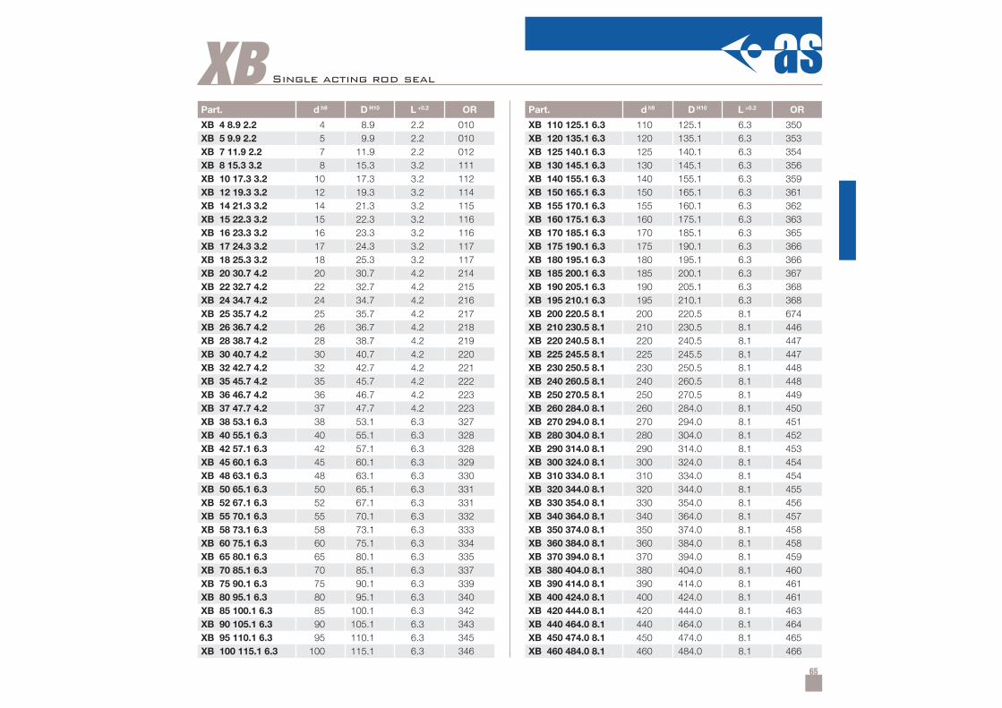
65
XBPart. d h9 D H10 L +0.2 OR
XB 4 8.9 2.2 4 8.9 2.2 010XB 5 9.9 2.2 5 9.9 2.2 010XB 7 11.9 2.2 7 11.9 2.2 012XB 8 15.3 3.2 8 15.3 3.2 111XB 10 17.3 3.2 10 17.3 3.2 112XB 12 19.3 3.2 12 19.3 3.2 114XB 14 21.3 3.2 14 21.3 3.2 115XB 15 22.3 3.2 15 22.3 3.2 116XB 16 23.3 3.2 16 23.3 3.2 116XB 17 24.3 3.2 17 24.3 3.2 117XB 18 25.3 3.2 18 25.3 3.2 117XB 20 30.7 4.2 20 30.7 4.2 214XB 22 32.7 4.2 22 32.7 4.2 215XB 24 34.7 4.2 24 34.7 4.2 216XB 25 35.7 4.2 25 35.7 4.2 217XB 26 36.7 4.2 26 36.7 4.2 218XB 28 38.7 4.2 28 38.7 4.2 219XB 30 40.7 4.2 30 40.7 4.2 220XB 32 42.7 4.2 32 42.7 4.2 221XB 35 45.7 4.2 35 45.7 4.2 222XB 36 46.7 4.2 36 46.7 4.2 223XB 37 47.7 4.2 37 47.7 4.2 223XB 38 53.1 6.3 38 53.1 6.3 327XB 40 55.1 6.3 40 55.1 6.3 328XB 42 57.1 6.3 42 57.1 6.3 328XB 45 60.1 6.3 45 60.1 6.3 329XB 48 63.1 6.3 48 63.1 6.3 330XB 50 65.1 6.3 50 65.1 6.3 331XB 52 67.1 6.3 52 67.1 6.3 331XB 55 70.1 6.3 55 70.1 6.3 332XB 58 73.1 6.3 58 73.1 6.3 333XB 60 75.1 6.3 60 75.1 6.3 334XB 65 80.1 6.3 65 80.1 6.3 335XB 70 85.1 6.3 70 85.1 6.3 337XB 75 90.1 6.3 75 90.1 6.3 339XB 80 95.1 6.3 80 95.1 6.3 340XB 85 100.1 6.3 85 100.1 6.3 342XB 90 105.1 6.3 90 105.1 6.3 343XB 95 110.1 6.3 95 110.1 6.3 345XB 100 115.1 6.3 100 115.1 6.3 346
Part. d h9 D H10 L +0.2 OR
XB 110 125.1 6.3 110 125.1 6.3 350XB 120 135.1 6.3 120 135.1 6.3 353XB 125 140.1 6.3 125 140.1 6.3 354XB 130 145.1 6.3 130 145.1 6.3 356XB 140 155.1 6.3 140 155.1 6.3 359XB 150 165.1 6.3 150 165.1 6.3 361XB 155 170.1 6.3 155 160.1 6.3 362XB 160 175.1 6.3 160 175.1 6.3 363XB 170 185.1 6.3 170 185.1 6.3 365XB 175 190.1 6.3 175 190.1 6.3 366XB 180 195.1 6.3 180 195.1 6.3 366XB 185 200.1 6.3 185 200.1 6.3 367XB 190 205.1 6.3 190 205.1 6.3 368XB 195 210.1 6.3 195 210.1 6.3 368XB 200 220.5 8.1 200 220.5 8.1 674XB 210 230.5 8.1 210 230.5 8.1 446XB 220 240.5 8.1 220 240.5 8.1 447XB 225 245.5 8.1 225 245.5 8.1 447XB 230 250.5 8.1 230 250.5 8.1 448XB 240 260.5 8.1 240 260.5 8.1 448XB 250 270.5 8.1 250 270.5 8.1 449XB 260 284.0 8.1 260 284.0 8.1 450XB 270 294.0 8.1 270 294.0 8.1 451XB 280 304.0 8.1 280 304.0 8.1 452XB 290 314.0 8.1 290 314.0 8.1 453XB 300 324.0 8.1 300 324.0 8.1 454XB 310 334.0 8.1 310 334.0 8.1 454XB 320 344.0 8.1 320 344.0 8.1 455XB 330 354.0 8.1 330 354.0 8.1 456XB 340 364.0 8.1 340 364.0 8.1 457XB 350 374.0 8.1 350 374.0 8.1 458XB 360 384.0 8.1 360 384.0 8.1 458XB 370 394.0 8.1 370 394.0 8.1 459XB 380 404.0 8.1 380 404.0 8.1 460XB 390 414.0 8.1 390 414.0 8.1 461XB 400 424.0 8.1 400 424.0 8.1 461XB 420 444.0 8.1 420 444.0 8.1 463XB 440 464.0 8.1 440 464.0 8.1 464XB 450 474.0 8.1 450 474.0 8.1 465XB 460 484.0 8.1 460 484.0 8.1 466
Single acting rod seal
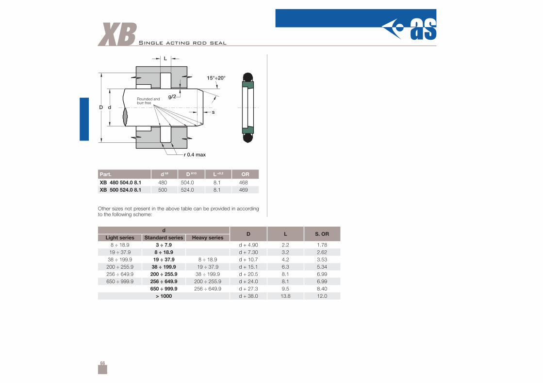
66
XB
Part. d h9 D H10 L +0.2 OR
XB 480 504.0 8.1 480 504.0 8.1 468XB 500 524.0 8.1 500 524.0 8.1 469
8 ÷ 18.9 3 ÷ 7.9 d + 4.90 2.2 1.7819 ÷ 37.9 8 ÷ 18.9 d + 7.30 3.2 2.6238 ÷ 199.9 19 ÷ 37.9 8 ÷ 18.9 d + 10.7 4.2 3.53200 ÷ 255.9 38 ÷ 199.9 19 ÷ 37.9 d + 15.1 6.3 5.34256 ÷ 649.9 200 ÷ 255.9 38 ÷ 199.9 d + 20.5 8.1 6.99650 ÷ 999.9 256 ÷ 649.9 200 ÷ 255.9 d + 24.0 8.1 6.99
650 ÷ 999.9 256 ÷ 649.9 d + 27.3 9.5 8.40> 1000 d + 38.0 13.8 12.0
Other sizes not present in the above table can be provided in accordingto the following scheme:
Single acting rod seal
dD L S. OR
Light series Standard series Heavy series
Rounded andburr free
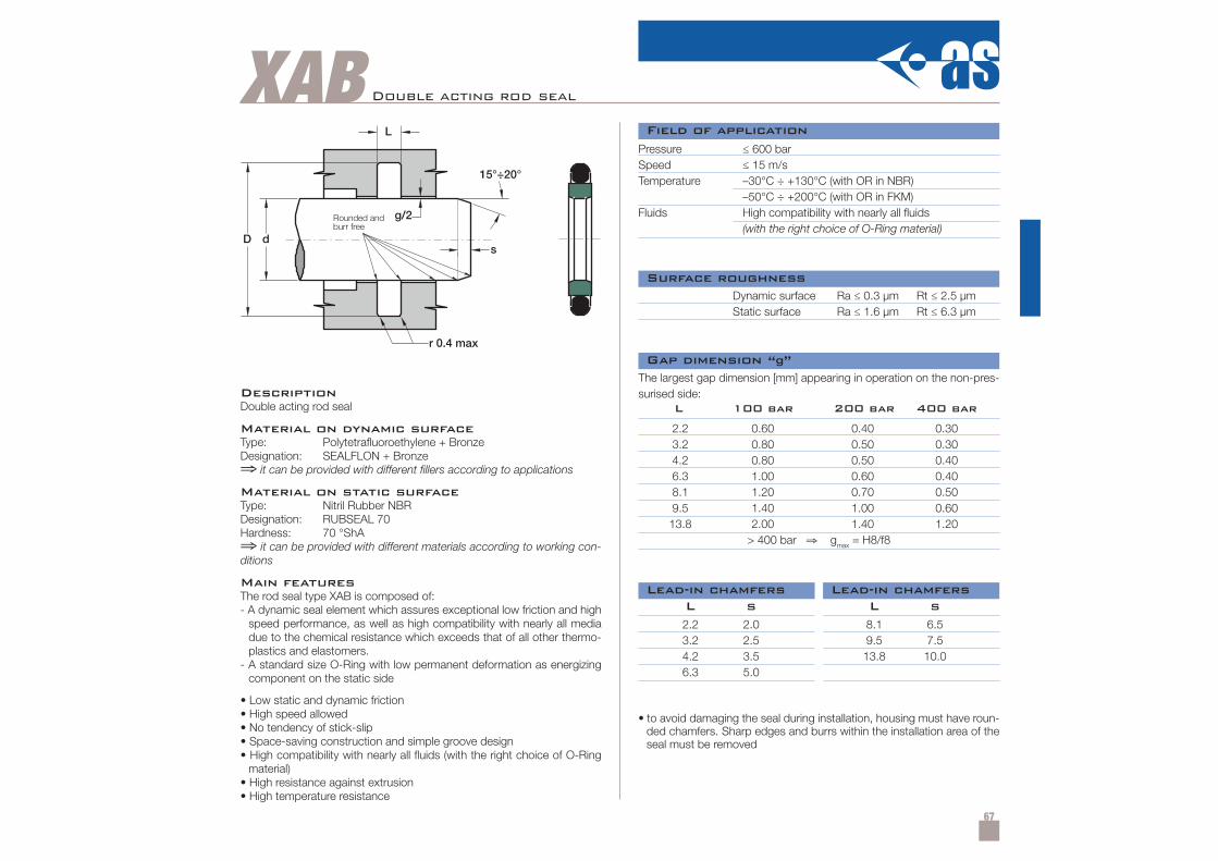
67
XAB Double acting rod seal
DescriptionDouble acting rod seal
Material on dynamic surfaceType: Polytetrafluoroethylene + BronzeDesignation: SEALFLON + Bronze⇒ it can be provided with different fillers according to applications
Material on static surfaceType: Nitril Rubber NBRDesignation: RUBSEAL 70Hardness: 70 °ShA⇒ it can be provided with different materials according to working con-ditions
Main featuresThe rod seal type XAB is composed of:- A dynamic seal element which assures exceptional low friction and high
speed performance, as well as high compatibility with nearly all mediadue to the chemical resistance which exceeds that of all other thermo-plastics and elastomers.
- A standard size O-Ring with low permanent deformation as energizingcomponent on the static side
• Low static and dynamic friction• High speed allowed• No tendency of stick-slip• Space-saving construction and simple groove design• High compatibility with nearly all fluids (with the right choice of O-Ring
material)• High resistance against extrusion• High temperature resistance
Pressure ≤ 600 barSpeed ≤ 15 m/sTemperature –30°C ÷ +130°C (with OR in NBR)
–50°C ÷ +200°C (with OR in FKM)Fluids High compatibility with nearly all fluids
(with the right choice of O-Ring material)
Dynamic surface Ra ≤ 0.3 µm Rt ≤ 2.5 µmStatic surface Ra ≤ 1.6 µm Rt ≤ 6.3 µm
The largest gap dimension [mm] appearing in operation on the non-pres-surised side:
2.2 2.0 8.1 6.53.2 2.5 9.5 7.54.2 3.5 13.8 10.06.3 5.0
L s L s
2.2 0.60 0.40 0.303.2 0.80 0.50 0.304.2 0.80 0.50 0.406.3 1.00 0.60 0.408.1 1.20 0.70 0.509.5 1.40 1.00 0.6013.8 2.00 1.40 1.20
> 400 bar ⇒ gmax = H8/f8
L 100 bar 200 bar 400 bar
• to avoid damaging the seal during installation, housing must have roun-ded chamfers. Sharp edges and burrs within the installation area of theseal must be removed
Field of application
Surface roughness
Gap dimension “g”
Lead-in chamfersLead-in chamfers
Rounded andburr free
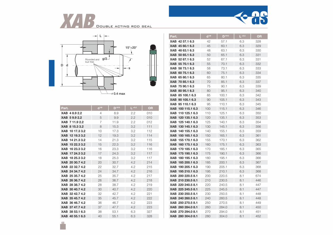
68
XAB
Part. d h9 D H10 L +0.2 OR
XAB 4 8.9 2.2 4 8.9 2.2 010XAB 5 9.9 2.2 5 9.9 2.2 010XAB 7 11.9 2.2 7 11.9 2.2 012XAB 8 15.3 3.2 8 15.3 3.2 111XAB 10 17.3 3.2 10 17.3 3.2 112XAB 12 19.3 3.2 12 19.3 3.2 114XAB 14 21.3 3.2 14 21.3 3.2 115XAB 15 22.3 3.2 15 22.3 3.2 116XAB 16 23.3 3.2 16 23.3 3.2 116XAB 17 24.3 3.2 17 24.3 3.2 117XAB 18 25.3 3.2 18 25.3 3.2 117XAB 20 30.7 4.2 20 30.7 4.2 214XAB 22 32.7 4.2 22 32.7 4.2 215XAB 24 34.7 4.2 24 34.7 4.2 216XAB 25 35.7 4.2 25 35.7 4.2 217XAB 26 36.7 4.2 26 36.7 4.2 218XAB 28 38.7 4.2 28 38.7 4.2 219XAB 30 40.7 4.2 30 40.7 4.2 220XAB 32 42.7 4.2 32 42.7 4.2 221XAB 35 45.7 4.2 35 45.7 4.2 222XAB 36 46.7 4.2 36 46.7 4.2 223XAB 37 47.7 4.2 37 47.7 4.2 223XAB 38 53.1 6.3 38 53.1 6.3 327XAB 40 55.1 6.3 40 55.1 6.3 328
Part. d h9 D H10 L +0.2 OR
XAB 42 57.1 6.3 42 57.1 6.3 328XAB 45 60.1 6.3 45 60.1 6.3 329XAB 48 63.1 6.3 48 63.1 6.3 330XAB 50 65.1 6.3 50 65.1 6.3 331XAB 52 67.1 6.3 52 67.1 6.3 331XAB 55 70.1 6.3 55 70.1 6.3 332XAB 58 73.1 6.3 58 73.1 6.3 333XAB 60 75.1 6.3 60 75.1 6.3 334XAB 65 80.1 6.3 65 80.1 6.3 335XAB 70 85.1 6.3 70 85.1 6.3 337XAB 75 90.1 6.3 75 90.1 6.3 339XAB 80 95.1 6.3 80 95.1 6.3 340XAB 85 100.1 6.3 85 100.1 6.3 342XAB 90 105.1 6.3 90 105.1 6.3 343XAB 95 110.1 6.3 95 110.1 6.3 345XAB 100 115.1 6.3 100 115.1 6.3 346XAB 110 125.1 6.3 110 125.1 6.3 350XAB 120 135.1 6.3 120 135.1 6.3 353XAB 125 140.1 6.3 125 140.1 6.3 354XAB 130 145.1 6.3 130 145.1 6.3 356XAB 140 155.1 6.3 140 155.1 6.3 359XAB 150 165.1 6.3 150 165.1 6.3 361XAB 155 170.1 6.3 155 170.1 6.3 362XAB 160 175.1 6.3 160 175.1 6.3 363XAB 170 185.1 6.3 170 185.1 6.3 365XAB 175 190.1 6.3 175 190.1 6.3 366XAB 180 195.1 6.3 180 195.1 6.3 366XAB 185 200.1 6.3 185 200.1 6.3 367XAB 190 205.1 6.3 190 205.1 6.3 368XAB 195 210.1 6.3 195 210.1 6.3 368XAB 200 220.5 8.1 200 220.5 8.1 674XAB 210 230.5 8.1 210 230.5 8.1 446XAB 220 240.5 8.1 220 240.5 8.1 447XAB 225 245.5 8.1 225 245.5 8.1 447XAB 230 250.5 8.1 230 250.5 8.1 448XAB 240 260.5 8.1 240 260.5 8.1 448XAB 250 270.5 8.1 250 270.5 8.1 449XAB 260 284.0 8.1 260 284.0 8.1 450XAB 270 294.0 8.1 270 294.0 8.1 451XAB 280 304.0 8.1 280 304.0 8.1 452
Double acting rod seal
Rounded andburr free
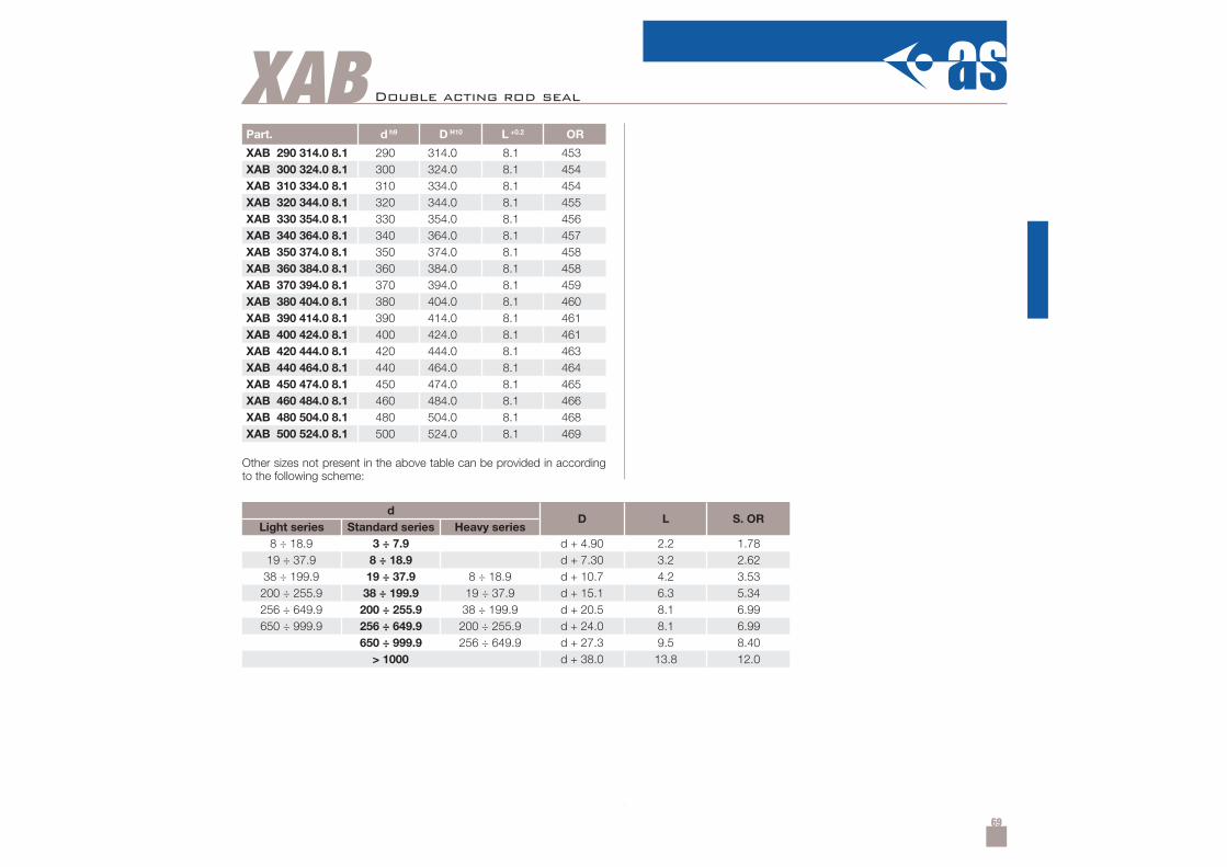
69
XABPart. d h9 D H10 L +0.2 OR
XAB 290 314.0 8.1 290 314.0 8.1 453XAB 300 324.0 8.1 300 324.0 8.1 454XAB 310 334.0 8.1 310 334.0 8.1 454XAB 320 344.0 8.1 320 344.0 8.1 455XAB 330 354.0 8.1 330 354.0 8.1 456XAB 340 364.0 8.1 340 364.0 8.1 457XAB 350 374.0 8.1 350 374.0 8.1 458XAB 360 384.0 8.1 360 384.0 8.1 458XAB 370 394.0 8.1 370 394.0 8.1 459XAB 380 404.0 8.1 380 404.0 8.1 460XAB 390 414.0 8.1 390 414.0 8.1 461XAB 400 424.0 8.1 400 424.0 8.1 461XAB 420 444.0 8.1 420 444.0 8.1 463XAB 440 464.0 8.1 440 464.0 8.1 464XAB 450 474.0 8.1 450 474.0 8.1 465XAB 460 484.0 8.1 460 484.0 8.1 466XAB 480 504.0 8.1 480 504.0 8.1 468XAB 500 524.0 8.1 500 524.0 8.1 469
8 ÷ 18.9 3 ÷ 7.9 d + 4.90 2.2 1.7819 ÷ 37.9 8 ÷ 18.9 d + 7.30 3.2 2.62
38 ÷ 199.9 19 ÷ 37.9 8 ÷ 18.9 d + 10.7 4.2 3.53200 ÷ 255.9 38 ÷ 199.9 19 ÷ 37.9 d + 15.1 6.3 5.34256 ÷ 649.9 200 ÷ 255.9 38 ÷ 199.9 d + 20.5 8.1 6.99650 ÷ 999.9 256 ÷ 649.9 200 ÷ 255.9 d + 24.0 8.1 6.99
650 ÷ 999.9 256 ÷ 649.9 d + 27.3 9.5 8.40> 1000 d + 38.0 13.8 12.0
Other sizes not present in the above table can be provided in accordingto the following scheme:
Double acting rod seal
dD L S. OR
Light series Standard series Heavy series
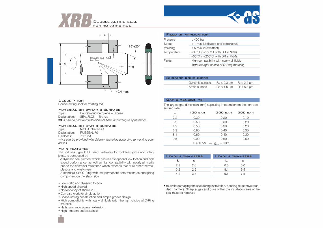
70
XRB Double acting sealfor rotating rod
DescriptionDouble acting seal for rotating rod
Material on dynamic surfaceType: Polytetrafluoroethylene + BronzeDesignation: SEALFLON + Bronze⇒ it can be provided with different fillers according to applications
Material on static surfaceType: Nitril Rubber NBRDesignation: RUBSEAL 70Hardness: 70 °ShA⇒ it can be provided with different materials according to working con-ditions
Main featuresThe rod seal type XRB, used preferably for hydraulic joints and rotaryjoints, is composed of:- A dynamic seal element which assures exceptional low friction and high
speed performance, as well as high compatibility with nearly all mediadue to the chemical resistance which exceeds that of all other thermo-plastics and elastomers
- A standard size O-Ring with low permanent deformation as energizingcomponent on the static side
• Low static and dynamic friction• High speed allowed• No tendency of stick-slip• Can also work for single action• Space-saving construction and simple groove design• High compatibility with nearly all fluids (with the right choice of O-Ring
material)• High resistance against extrusion• High temperature resistance
Pressure ≤ 400 barSpeed ≤ 1 m/s (lubricated and continuous)(rotating) ≤ 5 m/s (intermittent)Temperature –30°C ÷ +130°C (with OR in NBR)
–50°C ÷ +200°C (with OR in FKM)Fluids High compatibility with nearly all fluids
(with the right choice of O-Ring material)
Dynamic surface Ra ≤ 0.3 µm Rt ≤ 2.5 µmStatic surface Ra ≤ 1.6 µm Rt ≤ 6.3 µm
• to avoid damaging the seal during installation, housing must have roun-ded chamfers. Sharp edges and burrs within the installation area of theseal must be removed
The largest gap dimension [mm] appearing in operation on the non-pres-surised side:
2.2 2.0 6.3 5.03.2 2.5 8.1 6.54.2 3.5 9.5 7.5
L s L s
2.2 0.30 0.20 0.103.2 0.50 0.30 0.204.2 0.50 0.30 0.206.3 0.60 0.40 0.308.1 0.60 0.40 0.309.5 0.90 0.60 0.50
≥ 400 bar ⇒ gmax = H8/f8
L 100 bar 200 bar 300 bar
Field of application
Surface roughness
Gap dimension “g”
Lead-in chamfersLead-in chamfers
Rounded andburr free
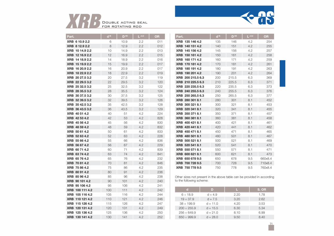
71
Part. d f8 D H9 L +0.2 OR
XRB 6 10.9 2.2 6 10.9 2.2 011XRB 8 12.9 2.2 8 12.9 2.2 012XRB 10 14.9 2.2 10 14.9 2.2 013XRB 12 16.9 2.2 12 16.9 2.2 015XRB 14 18.9 2.2 14 18.9 2.2 016XRB 15 19.9 2.2 15 19.9 2.2 017XRB 16 20.9 2.2 16 20.9 2.2 017XRB 18 22.9 2.2 18 22.9 2.2 019XRB 20 27.5 3.2 20 27.5 3.2 119XRB 22 29.5 3.2 22 29.5 3.2 120XRB 25 32.5 3.2 25 32.5 3.2 122XRB 28 35.5 3.2 28 35.5 3.2 124XRB 30 37.5 3.2 30 37.5 3.2 125XRB 32 39.5 3.2 32 39.5 3.2 126XRB 35 42.5 3.2 35 42.5 3.2 128XRB 36 43.5 3.2 36 43.5 3.2 129XRB 40 51 4.2 40 51 4.2 224XRB 42 53 4.2 42 53 4.2 828XRB 45 56 4.2 45 56 4.2 830XRB 48 59 4.2 48 59 4.2 832XRB 50 61 4.2 50 61 4.2 833XRB 52 63 4.2 52 63 4.2 228XRB 55 66 4.2 55 66 4.2 836XRB 56 67 4.2 56 67 4.2 229XRB 60 71 4.2 60 71 4.2 839XRB 63 74 4.2 63 74 4.2 841XRB 65 76 4.2 65 76 4.2 232XRB 70 81 4.2 70 81 4.2 846XRB 75 86 4.2 75 86 4.2 235XRB 80 91 4.2 80 91 4.2 236XRB 85 96 4.2 85 96 4.2 238XRB 90 101 4.2 90 101 4.2 240XRB 95 106 4.2 95 106 4.2 241XRB 100 111 4.2 100 111 4.2 242XRB 105 116 4.2 105 116 4.2 244XRB 110 121 4.2 110 121 4.2 246XRB 115 126 4.2 115 126 4.2 247XRB 120 131 4.2 120 131 4.2 249XRB 125 136 4.2 125 136 4.2 250XRB 130 141 4.2 130 141 4.2 252
XRBPart. d f8 D H9 L +0.2 OR
XRB 135 146 4.2 135 146 4.2 254XRB 140 151 4.2 140 151 4.2 255XRB 145 156 4.2 145 156 4.2 257XRB 150 161 4.2 150 161 4.2 258XRB 160 171 4.2 160 171 4.2 259XRB 170 181 4.2 170 181 4.2 261XRB 180 191 4.2 180 191 4.2 263XRB 190 201 4.2 190 201 4.2 264XRB 200 215.5 6.3 200 215.5 6.3 369XRB 210 225.5 6.3 210 225.5 6.3 371XRB 220 235.5 6.3 220 235.5 6.3 373XRB 240 255.5 6.3 240 255.5 6.3 376XRB 250 265.5 6.3 250 265.5 6.3 377XRB 280 301 8.1 280 301 8.1 452XRB 300 321 8.1 300 321 8.1 453XRB 320 341 8.1 320 341 8.1 455XRB 350 371 8.1 350 371 8.1 457XRB 360 381 8.1 360 381 8.1 458XRB 400 421 8.1 400 421 8.1 461XRB 420 441 8.1 420 441 8.1 462XRB 450 471 8.1 450 471 8.1 465XRB 480 501 8.1 480 501 8.1 467XRB 500 521 8.1 500 521 8.1 469XRB 520 541 8.1 520 541 8.1 470XRB 550 571 8.1 550 571 8.1 471XRB 600 621 8.1 600 621 8.1 473XRB 650 678 9.5 650 678 9.5 660x8.4XRB 700 728 9.5 700 728 9.5 710x8.4XRB 750 778 9.5 750 778 9.5 760x8.4
d D L S. OR
6 ÷ 18.9 d + 4.9 2.20 1.7819 ÷ 37.9 d + 7.5 3.20 2.6238 ÷ 199.9 d + 11.0 4.20 3.53200 ÷ 255.9 d + 15.5 6.30 5.34256 ÷ 649.9 d + 21.0 8.10 6.99650 ÷ 999.9 d + 28.0 9.50 8.40
Double acting sealfor rotating rod
Other sizes not present in the above table can be provided in accordingto the following scheme:
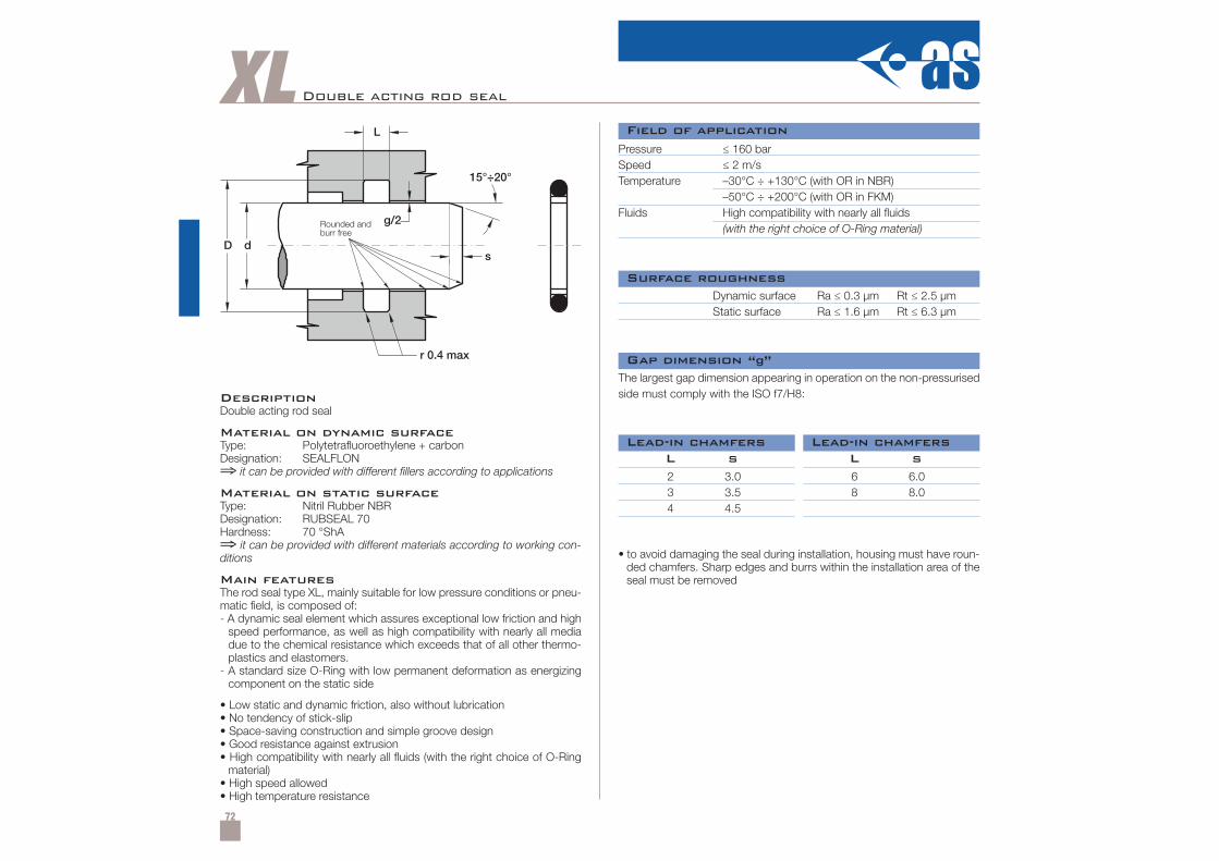
72
XL Double acting rod seal
DescriptionDouble acting rod seal
Material on dynamic surfaceType: Polytetrafluoroethylene + carbonDesignation: SEALFLON⇒ it can be provided with different fillers according to applications
Material on static surfaceType: Nitril Rubber NBRDesignation: RUBSEAL 70Hardness: 70 °ShA⇒ it can be provided with different materials according to working con-ditions
Main featuresThe rod seal type XL, mainly suitable for low pressure conditions or pneu-matic field, is composed of:- A dynamic seal element which assures exceptional low friction and high
speed performance, as well as high compatibility with nearly all mediadue to the chemical resistance which exceeds that of all other thermo-plastics and elastomers.
- A standard size O-Ring with low permanent deformation as energizingcomponent on the static side
• Low static and dynamic friction, also without lubrication• No tendency of stick-slip• Space-saving construction and simple groove design• Good resistance against extrusion• High compatibility with nearly all fluids (with the right choice of O-Ring
material)• High speed allowed• High temperature resistance
Pressure ≤ 160 barSpeed ≤ 2 m/sTemperature –30°C ÷ +130°C (with OR in NBR)
–50°C ÷ +200°C (with OR in FKM)Fluids High compatibility with nearly all fluids
(with the right choice of O-Ring material)
Dynamic surface Ra ≤ 0.3 µm Rt ≤ 2.5 µmStatic surface Ra ≤ 1.6 µm Rt ≤ 6.3 µm
• to avoid damaging the seal during installation, housing must have roun-ded chamfers. Sharp edges and burrs within the installation area of theseal must be removed
The largest gap dimension appearing in operation on the non-pressurisedside must comply with the ISO f7/H8:
2 3.0 6 6.03 3.5 8 8.04 4.5
L s L s
Field of application
Surface roughness
Gap dimension “g”
Lead-in chamfersLead-in chamfers
Rounded andburr free
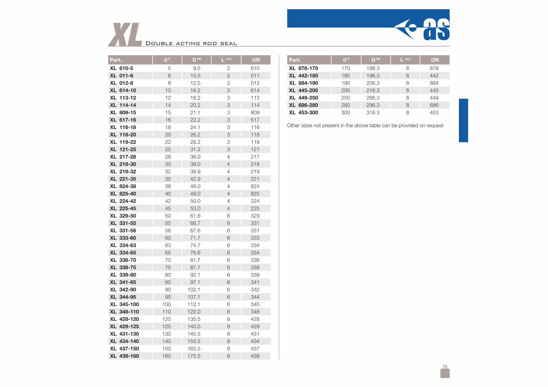
73
Part. d f7 D H9 L +0.2 OR
XL 610-5 5 9.5 2 610XL 011-6 6 10.5 2 011XL 012-8 8 12.5 2 012XL 614-10 10 16.2 3 614XL 113-12 12 18.2 3 113XL 114-14 14 20.2 3 114XL 809-15 15 21.1 3 809XL 617-16 16 22.2 3 617XL 116-18 18 24.1 3 116XL 118-20 20 26.2 3 118XL 119-22 22 28.2 3 119XL 121-25 25 31.2 3 121XL 217-28 28 36.0 4 217XL 218-30 30 38.0 4 218XL 219-32 32 39.9 4 219XL 221-35 35 42.9 4 221XL 824-38 38 46.0 4 824XL 825-40 40 48.0 4 825XL 224-42 42 50.0 4 224XL 225-45 45 53.0 4 225XL 329-50 50 61.6 6 329XL 331-55 55 66.7 6 331XL 331-56 56 67.6 6 331XL 333-60 60 71.7 6 333XL 334-63 63 74.7 6 334XL 334-65 65 76.6 6 334XL 336-70 70 81.7 6 336XL 338-75 75 87.1 6 338XL 339-80 80 92.1 6 339XL 341-85 85 97.1 6 341XL 342-90 90 102.1 6 342XL 344-95 95 107.1 6 344XL 345-100 100 112.1 6 345XL 348-110 110 122.0 6 348XL 428-120 120 135.5 8 428XL 429-125 125 140.5 8 429XL 431-130 130 145.5 8 431XL 434-140 140 155.5 8 434XL 437-150 150 165.5 8 437XL 439-160 160 175.5 8 439
XLPart. d f7 D H9 L +0.2 OR
XL 878-170 170 186.3 8 878XL 442-180 180 196.3 8 442XL 884-190 190 206.3 8 884XL 445-200 200 216.3 8 445XL 449-250 250 266.3 8 449XL 686-280 280 296.3 8 686XL 453-300 300 316.3 8 453
Other sizes not present in the above table can be provided on request
Double acting rod seal

74
XC Double acting rod seal
DescriptionDouble acting rod seal
Material on dynamic surfaceType: PolytetrafluoroethyleneDesignation: SEALFLON⇒ it can be provided with different fillers according to applications
Material on static surfaceType: Nitril Rubber NBRDesignation: RUBSEAL 70Hardness: 70 °ShA⇒ it can be provided with different materials according to working con-ditions
Main featuresThe rod seal type XC, mainly suitable for low pressure conditions or pneu-matic field, is composed of:- A dynamic seal element which assures exceptional low friction and high
speed performance, as well as high compatibility with nearly all mediadue to the chemical resistance which exceeds that of all other thermo-plastics and elastomers.
- A standard size O-Ring with low permanent deformation as energizingcomponent on the static side
• Low static and dynamic friction, also without lubrication• No tendency of stick-slip• Space-saving construction and simple groove design• Good resistance against extrusion• High compatibility with nearly all fluids (with the right choice of O-Ring
material)• High speed allowed• High temperature resistance
Pressure ≤ 210 barSpeed ≤ 4 m/sTemperature –30°C ÷ +130°C (with OR in NBR)
–50°C ÷ +200°C (with OR in FKM)Fluids High compatibility with nearly all fluids
(with the right choice of O-Ring material)
Dynamic surface Ra ≤ 0.3 µm Rt ≤ 2.5 µmStatic surface Ra ≤ 1.6 µm Rt ≤ 6.3 µm
• to avoid damaging the seal during installation, housing must have roun-ded chamfers. Sharp edges and burrs within the installation area of theseal must be removed
The largest gap dimension appearing in operation on the non-pressurisedside must comply with the ISO f7/H8:
2.5 2.0 7.0 4.03.5 2.5 9.5 5.04.5 3.0
L s L s
Field of application
Surface roughness
Gap dimension “g”
Lead-in chamfersLead-in chamfers
Rounded andburr free
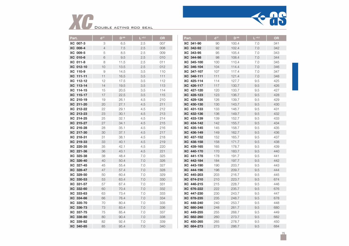
75
Part. d f7 D H9 L +0.2 OR
XC 007-3 3 6.5 2.5 007XC 008-4 4 7.5 2.5 008XC 009-5 5 8.5 2.5 009XC 010-6 6 9.5 2.5 010XC 011-8 8 11.5 2.5 011XC 012-10 10 13.5 2.5 012XC 110-9 9 14.5 3.5 110XC 111-11 11 16.5 3.5 111XC 112-12 12 17.5 3.5 112XC 113-14 14 19.5 3.5 113XC 114-15 15 20.5 3.5 114XC 115-17 17 22.5 3.5 115XC 210-19 19 26.1 4.5 210XC 211-20 20 27.1 4.5 211XC 212-22 22 29.1 4.5 212XC 213-23 23 30.1 4.5 213XC 214-25 25 32.1 4.5 214XC 215-27 27 34.1 4.5 215XC 216-28 28 35.1 4.5 216XC 217-30 30 37.1 4.5 217XC 218-31 31 38.1 4.5 218XC 219-33 33 40.1 4.5 219XC 220-35 35 42.1 4.5 220XC 221-36 36 43.1 4.5 221XC 325-38 38 48.4 7.0 325XC 326-40 40 50.4 7.0 326XC 327-45 45 55.4 7.0 327XC 328-47 47 57.4 7.0 328XC 329-50 50 60.4 7.0 329XC 330-53 53 63.4 7.0 330XC 331-57 57 67.4 7.0 331XC 332-60 60 70.4 7.0 332XC 333-63 63 73.4 7.0 333XC 334-66 66 76.4 7.0 334XC 335-70 70 80.4 7.0 335XC 336-73 73 83.4 7.0 336XC 337-75 75 85.4 7.0 337XC 338-80 80 90.4 7.0 338XC 339-82 82 92.4 7.0 339XC 340-85 85 95.4 7.0 340
XCPart. d f7 D H9 L +0.2 OR
XC 341-90 90 100.4 7.0 341XC 342-92 92 102.4 7.0 342XC 343-95 95 105.4 7.0 343XC 344-98 98 108.4 7.0 344XC 345-100 100 110.4 7.0 345XC 346-104 104 114.4 7.0 346XC 347-107 107 117.4 7.0 347XC 348-111 111 121.4 7.0 348XC 425-114 114 127.7 9.5 425XC 426-117 117 130.7 9.5 426XC 427-120 120 133.7 9.5 427XC 428-123 123 136.7 9.5 428XC 429-126 126 139.7 9.5 429XC 430-130 130 143.7 9.5 430XC 431-133 133 146.7 9.5 431XC 432-136 136 149.7 9.5 432XC 433-139 139 152.7 9.5 433XC 434-142 142 155.7 9.5 434XC 435-145 145 158.7 9.5 435XC 436-149 149 162.7 9.5 436XC 437-152 152 165.7 9.5 437XC 438-158 158 171.7 9.5 438XC 439-165 165 178.7 9.5 439XC 440-170 170 183.7 9.5 440XC 441-178 178 191.7 9.5 441XC 442-184 184 197.7 9.5 442XC 443-190 190 203.7 9.5 443XC 444-196 196 209.7 9.5 444XC 445-203 203 216.7 9.5 445XC 674-210 210 223.7 9.5 674XC 446-215 215 228.7 9.5 446XC 676-222 222 235.7 9.5 676XC 447-230 230 243.7 9.5 447XC 678-235 235 248.7 9.5 678XC 448-240 240 253.7 9.5 448XC 680-248 248 261.7 9.5 680XC 449-255 255 268.7 9.5 449XC 682-260 260 273.7 9.5 682XC 450-265 265 278.7 9.5 450XC 684-273 273 286.7 9.5 684
Double acting rod seal
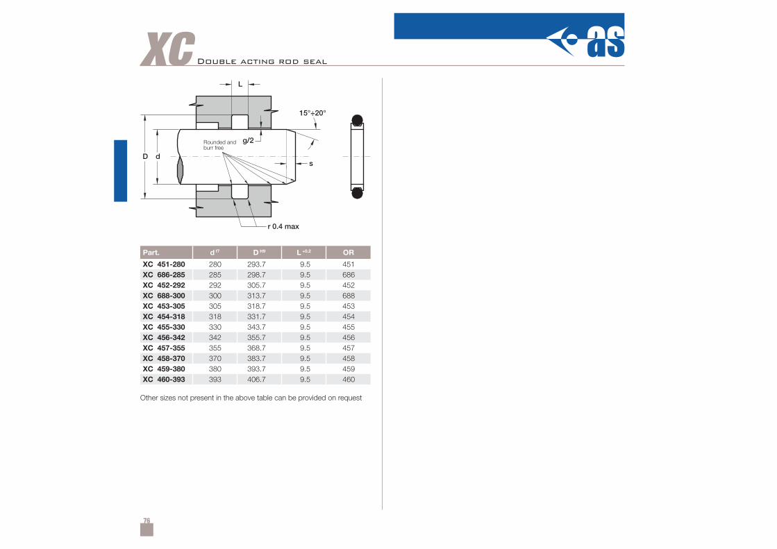
76
Part. d f7 D H9 L +0.2 OR
XC 451-280 280 293.7 9.5 451XC 686-285 285 298.7 9.5 686XC 452-292 292 305.7 9.5 452XC 688-300 300 313.7 9.5 688XC 453-305 305 318.7 9.5 453XC 454-318 318 331.7 9.5 454XC 455-330 330 343.7 9.5 455XC 456-342 342 355.7 9.5 456XC 457-355 355 368.7 9.5 457XC 458-370 370 383.7 9.5 458XC 459-380 380 393.7 9.5 459XC 460-393 393 406.7 9.5 460
XC Double acting rod seal
Other sizes not present in the above table can be provided on request
Rounded andburr free
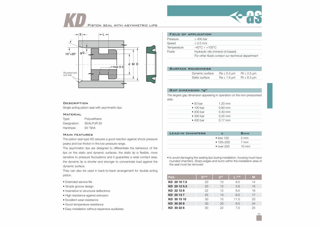
77
KD
Part. D H10 d f8 L +0.25 M
KD 20 10 7.5 20 10 8.5 14KD 20 12 5.3 20 12 5.8 15KD 22 12 8 22 12 9.0 16KD 25 13 7 25 13 8.0 17KD 30 15 10 30 15 11.0 20KD 30 20 8 30 20 9.0 24KD 30 22 6 30 22 7.0 25
Piston seal with asymmetric lips
DescriptionSingle acting piston seal with asymmetric lips
MaterialType: Polyurethane
Designation: SEALPUR 93
Hardness: 93 °ShA
Main featuresThe piston seal type KD assures a good reaction against shock pressure
peaks and low friction in the low pressure range.
The asymmetric lips are designed to differentiate the behaviour of the
lips on the static and dynamic surfaces: the static lip is flexible, more
sensitive to pressure fluctuations and it guaranties a wide contact area;
the dynamic lip is shorter and stronger to concentrate load against the
dynamic surface.
They can also be used in back-to-back arrangement for double acting
piston.
• Extended service life
• Simple groove design
• Insensitive to structural deflections
• High resistance against extrusion
• Excellent wear-resistance
• Good temperature resistance
• Easy installation without expensive auxiliaries
Pressure ≤ 400 barSpeed ≤ 0.5 m/sTemperature –40°C ÷ +100°CFluids Hydraulic oils (mineral oil based).
For other fluids contact our technical department
Dynamic surface Ra ≤ 0.3 µm Rt ≤ 2.5 µmStatic surface Ra ≤ 1.6 µm Rt ≤ 6.3 µm
• less 100• 100÷200• over 200
5 mm7 mm10 mm
• to avoid damaging the sealing lips during installation, housing must haverounded chamfers. Sharp edges and burrs within the installation area ofthe seal must be removed
The largest gap dimension appearing in operation on the non-pressurisedside:
• 50 bar 1.20 mm• 100 bar 0.80 mm• 200 bar 0.40 mm• 300 bar 0.25 mm• 400 bar 0.17 mm
Field of application
Surface roughness
Lead-in chamfers D SMIN
Gap dimension “g”
Rounded andburr free
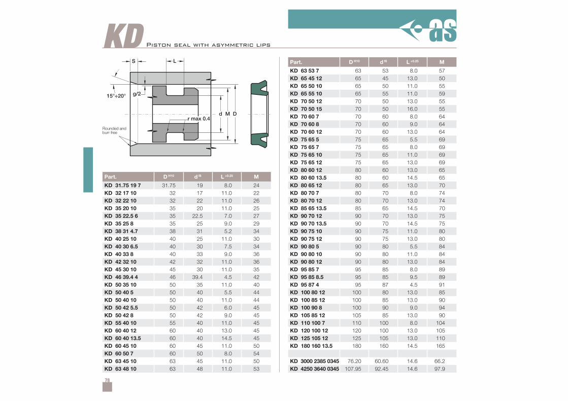
78
KD
Part. D H10 d f8 L +0.25 M
KD 31.75 19 7 31.75 19 8.0 24KD 32 17 10 32 17 11.0 22KD 32 22 10 32 22 11.0 26KD 35 20 10 35 20 11.0 25KD 35 22.5 6 35 22.5 7.0 27KD 35 25 8 35 25 9.0 29KD 38 31 4.7 38 31 5.2 34KD 40 25 10 40 25 11.0 30KD 40 30 6.5 40 30 7.5 34KD 40 33 8 40 33 9.0 36KD 42 32 10 42 32 11.0 36KD 45 30 10 45 30 11.0 35KD 46 39.4 4 46 39.4 4.5 42KD 50 35 10 50 35 11.0 40KD 50 40 5 50 40 5.5 44KD 50 40 10 50 40 11.0 44KD 50 42 5.5 50 42 6.0 45KD 50 42 8 50 42 9.0 45KD 55 40 10 55 40 11.0 45KD 60 40 12 60 40 13.0 45KD 60 40 13.5 60 40 14.5 45KD 60 45 10 60 45 11.0 50KD 60 50 7 60 50 8.0 54KD 63 45 10 63 45 11.0 50KD 63 48 10 63 48 11.0 53
Part. D H10 d f8 L +0.25 M
KD 63 53 7 63 53 8.0 57KD 65 45 12 65 45 13.0 50KD 65 50 10 65 50 11.0 55KD 65 55 10 65 55 11.0 59KD 70 50 12 70 50 13.0 55KD 70 50 15 70 50 16.0 55KD 70 60 7 70 60 8.0 64KD 70 60 8 70 60 9.0 64KD 70 60 12 70 60 13.0 64KD 75 65 5 75 65 5.5 69KD 75 65 7 75 65 8.0 69KD 75 65 10 75 65 11.0 69KD 75 65 12 75 65 13.0 69KD 80 60 12 80 60 13.0 65KD 80 60 13.5 80 60 14.5 65KD 80 65 12 80 65 13.0 70KD 80 70 7 80 70 8.0 74KD 80 70 12 80 70 13.0 74KD 85 65 13.5 85 65 14.5 70KD 90 70 12 90 70 13.0 75KD 90 70 13.5 90 70 14.5 75KD 90 75 10 90 75 11.0 80KD 90 75 12 90 75 13.0 80KD 90 80 5 90 80 5.5 84KD 90 80 10 90 80 11.0 84KD 90 80 12 90 80 13.0 84KD 95 85 7 95 85 8.0 89KD 95 85 8.5 95 85 9.5 89KD 95 87 4 95 87 4.5 91KD 100 80 12 100 80 13.0 85KD 100 85 12 100 85 13.0 90KD 100 90 8 100 90 9.0 94KD 105 85 12 105 85 13.0 90KD 110 100 7 110 100 8.0 104KD 120 100 12 120 100 13.0 105KD 125 105 12 125 105 13.0 110KD 180 160 13.5 180 160 14.5 165
KD 3000 2385 0345 76.20 60.60 14.6 66.2KD 4250 3640 0345 107.95 92.45 14.6 97.9
Piston seal with asymmetric lips
Rounded andburr free
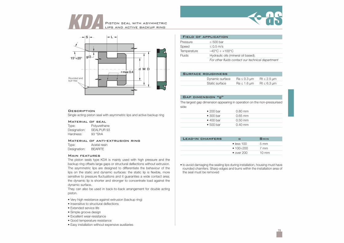
79
KDA
DescriptionSingle acting piston seal with asymmetric lips and active backup ring
Material of sealType: PolyurethaneDesignation: SEALPUR 93Hardness: 93 °ShA
Material of anti-extrusion ringType: Acetal resinDesignation: BEARITE
Main featuresThe piston seals type KDA is mainly used with high pressure and thebackup ring offsets large gaps or structural deflections without extrusion.The asymmetric lips are designed to differentiate the behaviour of thelips on the static and dynamic surfaces: the static lip is flexible, moresensitive to pressure fluctuations and it guaranties a wide contact area;the dynamic lip is shorter and stronger to concentrate load against thedynamic surface.They can also be used in back-to-back arrangement for double actingpiston.
• Very high resistance against extrusion (backup ring)• Insensitive to structural deflections• Extended service life• Simple groove design• Excellent wear-resistance• Good temperature resistance• Easy installation without expensive auxiliaries
Pressure ≤ 500 barSpeed ≤ 0.5 m/sTemperature –40°C ÷ +100°CFluids Hydraulic oils (mineral oil based).
For other fluids contact our technical department
Dynamic surface Ra ≤ 0.3 µm Rt ≤ 2.5 µmStatic surface Ra ≤ 1.6 µm Rt ≤ 6.3 µm
• less 100• 100÷200• over 200
5 mm7 mm10 mm
• to avoid damaging the sealing lips during installation, housing must haverounded chamfers. Sharp edges and burrs within the installation area ofthe seal must be removed
The largest gap dimension appearing in operation on the non-pressurisedside:
• 200 bar 0.80 mm• 300 bar 0.65 mm• 400 bar 0.50 mm• 500 bar 0.40 mm
Field of application
Surface roughness
Lead-in chamfers D SMIN
Gap dimension “g”
Piston seal with asymmetriclips and active backup ring
Rounded andburr free
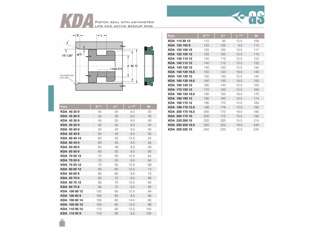
80
KDA
Part. D H10 d f8 L +0.25 M
KDA 40 25 9 40 25 9.5 35KDA 45 30 9 45 30 9.5 40KDA 45 35 9 45 35 9.5 40KDA 50 35 9 50 35 9.5 45KDA 50 40 9 50 40 9.5 45KDA 55 40 9 55 40 9.5 50KDA 60 40 14 60 40 14.5 54KDA 60 45 9 60 45 9.5 55KDA 63 48 9 63 48 9.5 58KDA 65 50 9 65 50 9.5 60KDA 70 50 12 70 50 12.5 64KDA 70 55 9 70 55 9.5 64KDA 75 55 12 75 55 12.5 69KDA 80 60 12 80 60 12.5 74KDA 80 65 9 80 65 9.5 75KDA 85 70 9 85 70 9.5 80KDA 90 70 12 90 70 12.5 84KDA 90 75 9 90 75 9.5 85KDA 100 80 12 100 80 12.5 94KDA 100 85 9 100 85 9.5 95KDA 100 85 14 100 85 14.5 95KDA 105 85 12 105 85 12.5 99KDA 110 90 12 110 90 12.5 104KDA 110 95 9 110 95 9.5 105
Part. D H10 d f8 L +0.25 M
KDA 115 95 12 115 95 12.5 109KDA 120 105 9 120 105 9.5 115KDA 125 100 15 125 100 15.5 117KDA 125 105 12 125 105 12.5 119KDA 130 110 12 130 110 12.5 124KDA 140 115 15 140 115 15.5 132KDA 140 120 12 140 120 12.5 134KDA 150 120 18.5 150 120 19.0 140KDA 150 130 12 150 130 12.5 144KDA 160 130 18.5 160 130 19.0 150KDA 160 140 12 160 140 12.5 154KDA 170 150 12 170 150 12.5 164KDA 180 150 18.5 180 150 19.0 170KDA 180 160 12 180 160 12.5 174KDA 190 170 12 190 170 12.5 184KDA 198 178 12.5 198 178 13.0 192KDA 200 170 18.5 200 170 19.0 190KDA 200 175 15 200 175 15.5 192KDA 220 200 15 220 200 15.5 214KDA 250 220 18.5 250 220 19.0 240KDA 250 225 15 250 225 15.5 242
Piston seal with asymmetriclips and active backup ring
Rounded andburr free
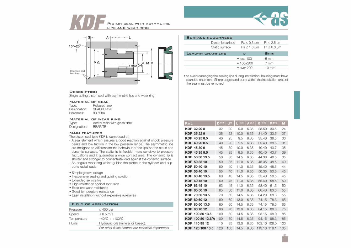
81
KDF
r max 0.4
15°÷20°
L
d M D
A
G
S
P
Part. D H10 d f8 L +0.25 A ±0.1 G –0.05 P ±0.2 M
KDF 32 20 8 32 20 9.0 6.35 28.50 30.5 24KDF 35 22 9 35 22 10.0 6.35 31.40 33.5 27KDF 40 25 8.5 40 25 9.5 6.35 35.40 38.5 30KDF 40 26 8.5 40 26 9.5 6.35 35.40 38.5 31KDF 45 30 9 45 30 10.0 6.35 40.40 43.7 35KDF 45 35 8.5 45 35 9.5 6.35 40.40 43.7 39KDF 50 30 13.5 50 30 14.5 6.35 44.30 48.5 35KDF 50 35 10 50 35 11.0 6.35 45.35 48.5 40KDF 50 40 10 50 40 11.0 6.35 45.40 48.5 44KDF 55 40 10 55 40 11.0 6.35 50.35 53.5 45KDF 60 40 13.5 60 40 14.5 6.35 55.40 58.5 45KDF 60 45 10 60 45 11.0 6.35 55.40 58.5 50KDF 63 45 10 63 45 11.0 6.35 58.40 61.5 50KDF 65 50 10 65 50 11.0 6.35 60.40 63.5 55KDF 70 50 13.5 70 50 14.5 6.35 64.20 68.3 55KDF 80 60 12 80 60 13.0 6.35 74.15 78.3 65KDF 80 60 13.5 80 60 14.5 6.35 74.15 78.3 65KDF 90 70 12 90 70 13.0 6.35 84.15 88.3 75KDF 100 80 13.5 100 80 14.5 6.35 93.15 98.0 85KDF 100 80 13.5/A 100 80 14.5 6.35 94.15 98.3 85KDF 110 95 12 110 95 13.0 6.35 103.10 108.0 100KDF 120 100 13.5 120 100 14.5 6.35 113.10 118.1 105
DescriptionSingle acting piston seal with asymmetric lips and wear ring
Material of sealType: PolyurethaneDesignation: SEALPUR 93Hardness: 93 °ShA
Material of wear ringType: Acetal resin with glass fibreDesignation: BEARITE
Main featuresThe piston seal type KDF is composed of:- A seal element which assures a good reaction against shock pressure
peaks and low friction in the low pressure range. The asymmetric lipsare designed to differentiate the behaviour of the lips on the static anddynamic surfaces. The static lip is flexible, more sensitive to pressurefluctuations and it guaranties a wide contact area. The dynamic lip isshorter and stronger to concentrate load against the dynamic surface
- An angular wear ring which guides the piston in the cylinder and sup-ports radial loads
• Simple groove design• Inexpensive sealing and guiding solution• Extended service life• High resistance against extrusion• Excellent wear-resistance• Good temperature resistance• Easy installation without expensive auxiliaries
Piston seal with asymmetriclips and wear ring
Pressure ≤ 400 barSpeed ≤ 0.5 m/sTemperature –40°C ÷ +100°CFluids Hydraulic oils (mineral oil based).
For other fluids contact our technical department
Dynamic surface Ra ≤ 0.3 µm Rt ≤ 2.5 µmStatic surface Ra ≤ 1.6 µm Rt ≤ 6.3 µm
• less 100• 100÷200• over 200
5 mm7 mm10 mm
• to avoid damaging the sealing lips during installation, housing must haverounded chamfers. Sharp edges and burrs within the installation area ofthe seal must be removed
Field of application
Surface roughness
Lead-in chamfers D SMIN
Rounded andburr free
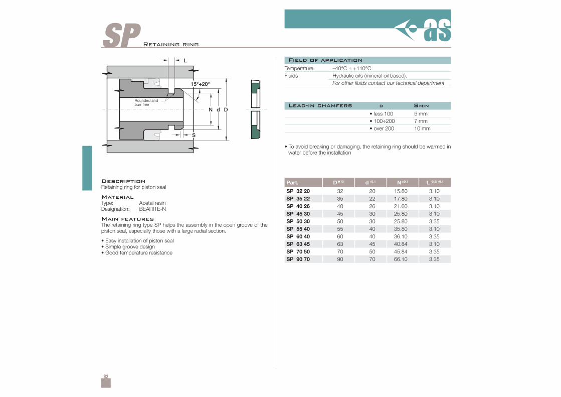
82
SP
Part. D H10 d +0.1 N ±0.1 L -0.2/+0.1
SP 32 20 32 20 15.80 3.10SP 35 22 35 22 17.80 3.10SP 40 26 40 26 21.60 3.10SP 45 30 45 30 25.80 3.10SP 50 30 50 30 25.80 3.35SP 55 40 55 40 35.80 3.10SP 60 40 60 40 36.10 3.35SP 63 45 63 45 40.84 3.10SP 70 50 70 50 45.84 3.35SP 90 70 90 70 66.10 3.35
Retaining ring
DescriptionRetaining ring for piston seal
MaterialType: Acetal resinDesignation: BEARITE-N
Main featuresThe retaining ring type SP helps the assembly in the open groove of thepiston seal, especially those with a large radial section.
• Easy installation of piston seal• Simple groove design• Good temperature resistance
Temperature –40°C ÷ +110°CFluids Hydraulic oils (mineral oil based).
For other fluids contact our technical department
• less 100• 100÷200• over 200
5 mm7 mm10 mm
• To avoid breaking or damaging, the retaining ring should be warmed inwater before the installation
Field of application
Lead-in chamfers D SMINRounded andburr free
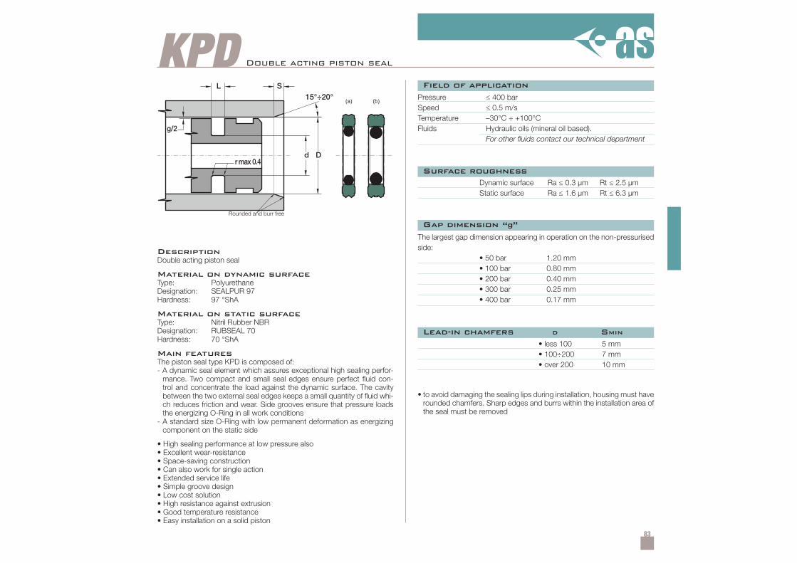
83
KPD
Dd
(a) (b)
L
g/2
S
rmax 0.4
15°÷20°
Double acting piston seal
DescriptionDouble acting piston seal
Material on dynamic surfaceType: PolyurethaneDesignation: SEALPUR 97Hardness: 97 °ShA
Material on static surfaceType: Nitril Rubber NBRDesignation: RUBSEAL 70Hardness: 70 °ShA
Main featuresThe piston seal type KPD is composed of:- A dynamic seal element which assures exceptional high sealing perfor-
mance. Two compact and small seal edges ensure perfect fluid con-trol and concentrate the load against the dynamic surface. The cavitybetween the two external seal edges keeps a small quantity of fluid whi-ch reduces friction and wear. Side grooves ensure that pressure loadsthe energizing O-Ring in all work conditions
- A standard size O-Ring with low permanent deformation as energizingcomponent on the static side
• High sealing performance at low pressure also• Excellent wear-resistance• Space-saving construction• Can also work for single action• Extended service life• Simple groove design• Low cost solution• High resistance against extrusion• Good temperature resistance• Easy installation on a solid piston
Pressure ≤ 400 barSpeed ≤ 0.5 m/sTemperature –30°C ÷ +100°CFluids Hydraulic oils (mineral oil based).
For other fluids contact our technical department
Dynamic surface Ra ≤ 0.3 µm Rt ≤ 2.5 µmStatic surface Ra ≤ 1.6 µm Rt ≤ 6.3 µm
• less 100• 100÷200• over 200
5 mm7 mm10 mm
• to avoid damaging the sealing lips during installation, housing must haverounded chamfers. Sharp edges and burrs within the installation area ofthe seal must be removed
The largest gap dimension appearing in operation on the non-pressurisedside:
• 50 bar 1.20 mm• 100 bar 0.80 mm• 200 bar 0.40 mm• 300 bar 0.25 mm• 400 bar 0.17 mm
Field of application
Surface roughness
Lead-in chamfers D SMIN
Gap dimension “g”Rounded and burr free
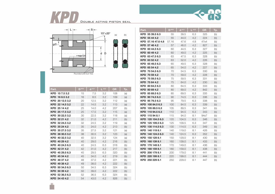
84
KPD
Part. D H10 d +0.1 L +0.2 OR Tp.
KPD 15 7.5 3.2 15 7.5 3.2 108 (a)KPD 16 8.5 3.2 16 8.5 3.2 109 (a)KPD 20 12.5 3.2 20 12.5 3.2 112 (a)KPD 22 14.5 3.2 22 14.5 3.2 113 (a)KPD 25 14 4.2 25 14.0 4.2 207 (b)KPD 25 17.5 3.2 25 17.5 3.2 115 (a)KPD 30 22.5 3.2 30 22.5 3.2 118 (a)KPD 32 21 4.2 32 21.0 4.2 211 (b)KPD 32 24.5 3.2 32 24.5 3.2 119 (a)KPD 35 24 4.2 35 24.0 4.2 213 (b)KPD 35 27.5 3.2 35 27.5 3.2 121 (a)KPD 38 30.5 3.2 38 30.5 3.2 123 (a)KPD 40 32.5 3.2 40 32.5 3.2 124 (a)KPD 40 29 4.2 40 29.0 4.2 216 (b)KPD 40 24.5 6.3 40 24.5 6.3 318 (b)KPD 42 31 4.2 42 31.0 4.2 217 (b)KPD 45 29.5 6.3 45 29.5 6.3 320 (b)KPD 45 34 4.2 45 34.0 4.2 219 (b)KPD 48 37 4.2 48 37.0 4.2 221 (b)KPD 49 38 4.2 49 38.0 4.2 222 (b)KPD 50 34.5 6.3 50 34.5 6.3 324 (b)KPD 50 39 4.2 50 39.0 4.2 222 (b)KPD 52 36.5 6.3 52 36.5 6.3 324 (b)KPD 54 43 4.2 54 43.0 4.2 826 (b)
Part. D H10 d +0.1 L +0.2 OR Tp.
KPD 55 39.5 6.3 55 39.5 6.3 325 (b)KPD 55 44 4.2 55 44.0 4.2 224 (b)KPD 57.16 47.6 4.8 57.16 47.6 4.8 47x4 (b)KPD 57 46 4.2 57 46.0 4.2 827 (b)KPD 60 44.5 6.3 60 44.5 6.3 327 (b)KPD 60 49 4.2 60 49.0 4.2 225 (b)KPD 63 47.5 6.3 63 47.5 6.3 328 (b)KPD 63 52 4.2 63 52.0 4.2 226 (b)KPD 65 49.5 6.3 65 49.5 6.3 328 (b)KPD 65 54 4.2 65 54.0 4.2 227 (b)KPD 70 54.5 6.3 70 54.5 6.3 330 (b)KPD 70 59 4.2 70 59.0 4.2 228 (b)KPD 75 59.5 6.3 75 59.5 6.3 331 (b)KPD 75 64 4.2 75 64.0 4.2 230 (b)KPD 80 64.5 6.3 80 64.5 6.3 333 (b)KPD 80 69 4.2 80 69.0 4.2 842 (b)KPD 85 69.5 6.3 85 69.5 6.3 335 (b)KPD 90 74.5 6.3 90 74.5 6.3 336 (b)KPD 95 79.5 6.3 95 79.5 6.3 338 (b)KPD 100 84.5 6.3 100 84.5 6.3 339 (b)KPD 105 89.5 6.3 105 89.5 6.3 341 (b)KPD 110 94.5 6.3 110 94.5 6.3 343 (b)KPD 115 94 8.1 115 94.0 8.1 94x7 (b)KPD 120 104.5 6.3 120 104.5 6.3 346 (b)KPD 125 109.5 6.3 125 109.5 6.3 347 (b)KPD 130 114.5 6.3 130 114.5 6.3 349 (b)KPD 140 119 8.1 140 119.0 8.1 426 (b)KPD 140 124.5 6.3 140 124.5 6.3 352 (b)KPD 150 129 8.1 150 129.0 8.1 430 (b)KPD 160 139 8.1 160 139.0 8.1 433 (b)KPD 170 149 8.1 170 149.0 8.1 436 (b)KPD 180 159 8.1 180 159.0 8.1 438 (b)KPD 200 179 8.1 200 179.0 8.1 441 (b)KPD 220 199 8.1 220 199.0 8.1 444 (b)KPD 250 229 8.1 250 229.0 8.1 447 (b)
Dd
(a) (b)
L
g/2
S
rmax 0.4
15°÷20°
Double acting piston seal
Rounded and burr free
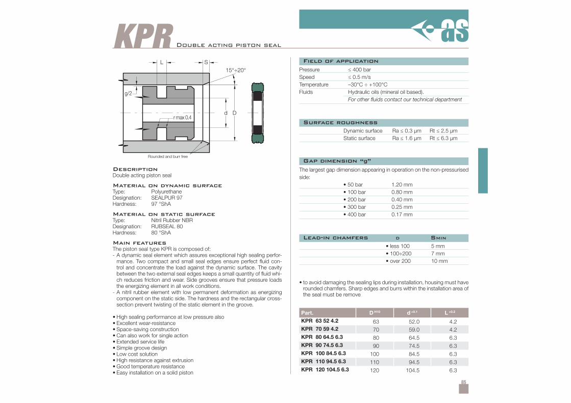
85
KPR
Dd
L
g/2
S
r max 0.4
15°÷20°
Part. D H10 d +0.1 L +0.2
KPR 63 52 4.2 63 52.0 4.2KPR 70 59 4.2 70 59.0 4.2KPR 80 64.5 6.3 80 64.5 6.3KPR 90 74.5 6.3 90 74.5 6.3KPR 100 84.5 6.3 100 84.5 6.3KPR 110 94.5 6.3 110 94.5 6.3KPR 120 104.5 6.3 120 104.5 6.3
Double acting piston seal
Rounded and burr free
DescriptionDouble acting piston seal
Material on dynamic surfaceType: PolyurethaneDesignation: SEALPUR 97Hardness: 97 °ShA
Material on static surfaceType: Nitril Rubber NBRDesignation: RUBSEAL 80Hardness: 80 °ShA
Main featuresThe piston seal type KPR is composed of:- A dynamic seal element which assures exceptional high sealing perfor-
mance. Two compact and small seal edges ensure perfect fluid con-trol and concentrate the load against the dynamic surface. The cavitybetween the two external seal edges keeps a small quantity of fluid whi-ch reduces friction and wear. Side grooves ensure that pressure loadsthe energizing element in all work conditions.
- A nitril rubber element with low permanent deformation as energizingcomponent on the static side. The hardness and the rectangular cross-section prevent twisting of the static element in the groove.
• High sealing performance at low pressure also• Excellent wear-resistance• Space-saving construction• Can also work for single action• Extended service life• Simple groove design• Low cost solution• High resistance against extrusion• Good temperature resistance• Easy installation on a solid piston
Pressure ≤ 400 barSpeed ≤ 0.5 m/sTemperature –30°C ÷ +100°CFluids Hydraulic oils (mineral oil based).
For other fluids contact our technical department
Dynamic surface Ra ≤ 0.3 µm Rt ≤ 2.5 µmStatic surface Ra ≤ 1.6 µm Rt ≤ 6.3 µm
• less 100• 100÷200• over 200
5 mm7 mm10 mm
• to avoid damaging the sealing lips during installation, housing must haverounded chamfers. Sharp edges and burrs within the installation area ofthe seal must be remove
The largest gap dimension appearing in operation on the non-pressurisedside:
• 50 bar 1.20 mm• 100 bar 0.80 mm• 200 bar 0.40 mm• 300 bar 0.25 mm• 400 bar 0.17 mm
Field of application
Surface roughness
Lead-in chamfers D SMIN
Gap dimension “g”
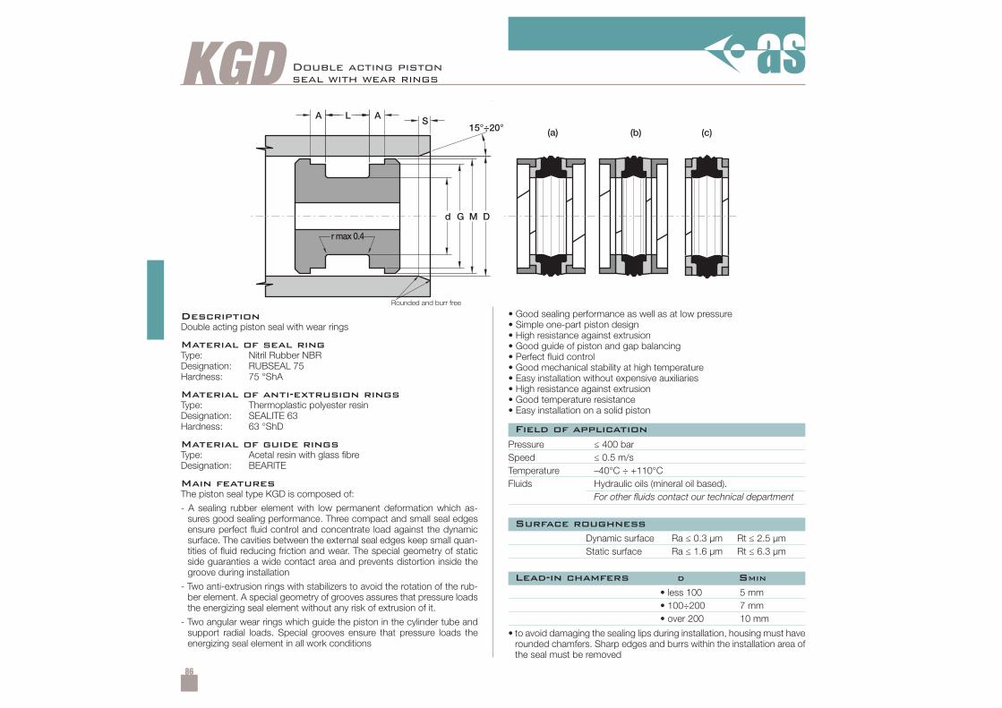
86
KGD
M D
(a) (b) (c)SL AA
d G
15°÷20°
rmax 0.4
Double acting pistonseal with wear rings
DescriptionDouble acting piston seal with wear rings
Material of seal ringType: Nitril Rubber NBRDesignation: RUBSEAL 75Hardness: 75 °ShA
Material of anti-extrusion ringsType: Thermoplastic polyester resinDesignation: SEALITE 63Hardness: 63 °ShD
Material of guide ringsType: Acetal resin with glass fibreDesignation: BEARITE
Main featuresThe piston seal type KGD is composed of:
- A sealing rubber element with low permanent deformation which as-sures good sealing performance. Three compact and small seal edgesensure perfect fluid control and concentrate load against the dynamicsurface. The cavities between the external seal edges keep small quan-tities of fluid reducing friction and wear. The special geometry of staticside guaranties a wide contact area and prevents distortion inside thegroove during installation
- Two anti-extrusion rings with stabilizers to avoid the rotation of the rub-ber element. A special geometry of grooves assures that pressure loadsthe energizing seal element without any risk of extrusion of it.
- Two angular wear rings which guide the piston in the cylinder tube andsupport radial loads. Special grooves ensure that pressure loads theenergizing seal element in all work conditions
Pressure ≤ 400 barSpeed ≤ 0.5 m/sTemperature –40°C ÷ +110°CFluids Hydraulic oils (mineral oil based).
For other fluids contact our technical department
Dynamic surface Ra ≤ 0.3 µm Rt ≤ 2.5 µmStatic surface Ra ≤ 1.6 µm Rt ≤ 6.3 µm
• less 100• 100÷200• over 200
5 mm7 mm10 mm
• to avoid damaging the sealing lips during installation, housing must haverounded chamfers. Sharp edges and burrs within the installation area ofthe seal must be removed
Field of application
Surface roughness
Lead-in chamfers D SMIN
• Good sealing performance as well as at low pressure• Simple one-part piston design• High resistance against extrusion• Good guide of piston and gap balancing• Perfect fluid control• Good mechanical stability at high temperature• Easy installation without expensive auxiliaries• High resistance against extrusion• Good temperature resistance• Easy installation on a solid piston
Rounded and burr free
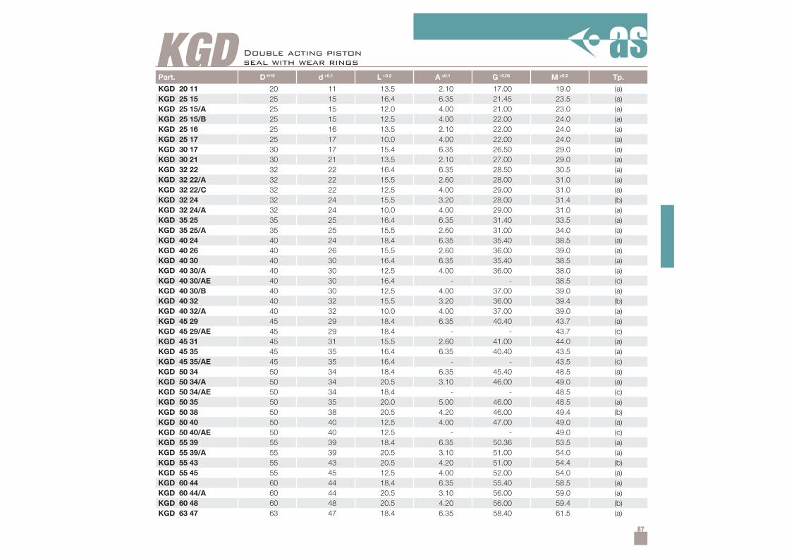
87
KGDPart. D H10 d +0.1 L +0.2 A ±0.1 G –0.05 M ±0.2 Tp.
KGD 20 11 20 11 13.5 2.10 17.00 19.0 (a)KGD 25 15 25 15 16.4 6.35 21.45 23.5 (a)KGD 25 15/A 25 15 12.0 4.00 21.00 23.0 (a)KGD 25 15/B 25 15 12.5 4.00 22.00 24.0 (a)KGD 25 16 25 16 13.5 2.10 22.00 24.0 (a)KGD 25 17 25 17 10.0 4.00 22.00 24.0 (a)KGD 30 17 30 17 15.4 6.35 26.50 29.0 (a)KGD 30 21 30 21 13.5 2.10 27.00 29.0 (a)KGD 32 22 32 22 16.4 6.35 28.50 30.5 (a)KGD 32 22/A 32 22 15.5 2.60 28.00 31.0 (a)KGD 32 22/C 32 22 12.5 4.00 29.00 31.0 (a)KGD 32 24 32 24 15.5 3.20 28.00 31.4 (b)KGD 32 24/A 32 24 10.0 4.00 29.00 31.0 (a)KGD 35 25 35 25 16.4 6.35 31.40 33.5 (a)KGD 35 25/A 35 25 15.5 2.60 31.00 34.0 (a)KGD 40 24 40 24 18.4 6.35 35.40 38.5 (a)KGD 40 26 40 26 15.5 2.60 36.00 39.0 (a)KGD 40 30 40 30 16.4 6.35 35.40 38.5 (a)KGD 40 30/A 40 30 12.5 4.00 36.00 38.0 (a)KGD 40 30/AE 40 30 16.4 - - 38.5 (c)KGD 40 30/B 40 30 12.5 4.00 37.00 39.0 (a)KGD 40 32 40 32 15.5 3.20 36.00 39.4 (b)KGD 40 32/A 40 32 10.0 4.00 37.00 39.0 (a)KGD 45 29 45 29 18.4 6.35 40.40 43.7 (a)KGD 45 29/AE 45 29 18.4 - - 43.7 (c)KGD 45 31 45 31 15.5 2.60 41.00 44.0 (a)KGD 45 35 45 35 16.4 6.35 40.40 43.5 (a)KGD 45 35/AE 45 35 16.4 - - 43.5 (c)KGD 50 34 50 34 18.4 6.35 45.40 48.5 (a)KGD 50 34/A 50 34 20.5 3.10 46.00 49.0 (a)KGD 50 34/AE 50 34 18.4 - - 48.5 (c)KGD 50 35 50 35 20.0 5.00 46.00 48.5 (a)KGD 50 38 50 38 20.5 4.20 46.00 49.4 (b)KGD 50 40 50 40 12.5 4.00 47.00 49.0 (a)KGD 50 40/AE 50 40 12.5 - - 49.0 (c)KGD 55 39 55 39 18.4 6.35 50.36 53.5 (a)KGD 55 39/A 55 39 20.5 3.10 51.00 54.0 (a)KGD 55 43 55 43 20.5 4.20 51.00 54.4 (b)KGD 55 45 55 45 12.5 4.00 52.00 54.0 (a)KGD 60 44 60 44 18.4 6.35 55.40 58.5 (a)KGD 60 44/A 60 44 20.5 3.10 56.00 59.0 (a)KGD 60 48 60 48 20.5 4.20 56.00 59.4 (b)KGD 63 47 63 47 18.4 6.35 58.40 61.5 (a)
Double acting pistonseal with wear rings
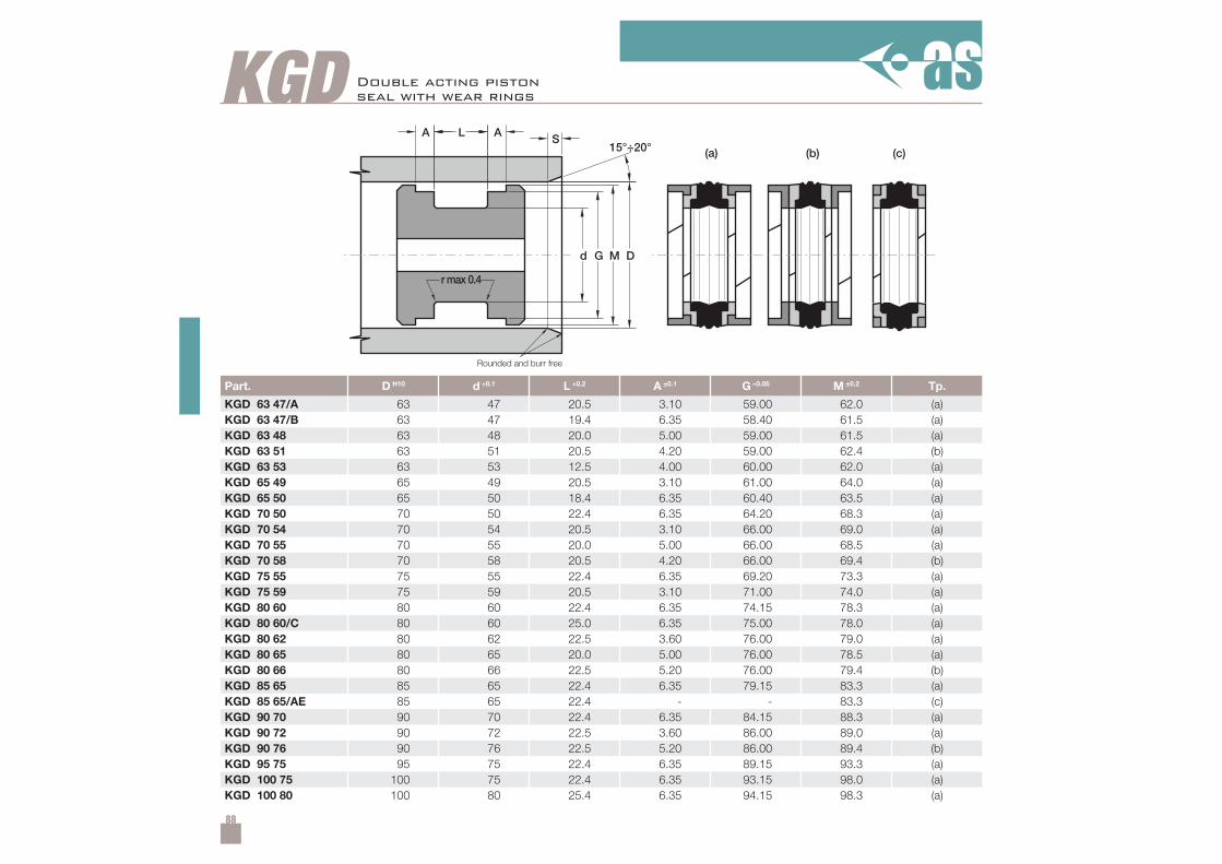
88
KGD
Part. D H10 d +0.1 L +0.2 A ±0.1 G –0.05 M ±0.2 Tp.
KGD 63 47/A 63 47 20.5 3.10 59.00 62.0 (a)KGD 63 47/B 63 47 19.4 6.35 58.40 61.5 (a)KGD 63 48 63 48 20.0 5.00 59.00 61.5 (a)KGD 63 51 63 51 20.5 4.20 59.00 62.4 (b)KGD 63 53 63 53 12.5 4.00 60.00 62.0 (a)KGD 65 49 65 49 20.5 3.10 61.00 64.0 (a)KGD 65 50 65 50 18.4 6.35 60.40 63.5 (a)KGD 70 50 70 50 22.4 6.35 64.20 68.3 (a)KGD 70 54 70 54 20.5 3.10 66.00 69.0 (a)KGD 70 55 70 55 20.0 5.00 66.00 68.5 (a)KGD 70 58 70 58 20.5 4.20 66.00 69.4 (b)KGD 75 55 75 55 22.4 6.35 69.20 73.3 (a)KGD 75 59 75 59 20.5 3.10 71.00 74.0 (a)KGD 80 60 80 60 22.4 6.35 74.15 78.3 (a)KGD 80 60/C 80 60 25.0 6.35 75.00 78.0 (a)KGD 80 62 80 62 22.5 3.60 76.00 79.0 (a)KGD 80 65 80 65 20.0 5.00 76.00 78.5 (a)KGD 80 66 80 66 22.5 5.20 76.00 79.4 (b)KGD 85 65 85 65 22.4 6.35 79.15 83.3 (a)KGD 85 65/AE 85 65 22.4 - - 83.3 (c)KGD 90 70 90 70 22.4 6.35 84.15 88.3 (a)KGD 90 72 90 72 22.5 3.60 86.00 89.0 (a)KGD 90 76 90 76 22.5 5.20 86.00 89.4 (b)KGD 95 75 95 75 22.4 6.35 89.15 93.3 (a)KGD 100 75 100 75 22.4 6.35 93.15 98.0 (a)KGD 100 80 100 80 25.4 6.35 94.15 98.3 (a)
M D
(a) (b) (c)SL AA
d G
15°÷20°
rmax 0.4
Double acting pistonseal with wear rings
Rounded and burr free

89
KGDPart. D H10 d +0.1 L +0.2 A ±0.1 G –0.05 M ±0.2 Tp.
KGD 100 80/D 100 80 25.0 6.30 95.00 98.0 (a)KGD 100 82 100 82 22.5 3.60 96.00 99.0 (a)KGD 100 85 100 85 20.0 5.00 96.00 98.5 (a)KGD 100 86 100 86 22.5 5.20 96.00 99.4 (b)KGD 105 80 105 80 22.4 6.35 98.10 103.0 (a)KGD 110 85 110 85 22.4 6.35 103.10 108.0 (a)KGD 110 85/A 110 85 25.4 6.35 103.10 108.0 (a)KGD 110 92 110 92 22.5 3.60 106.00 109.0 (a)KGD 110 96 110 96 22.5 5.20 106.00 109.4 (b)KGD 115 90 115 90 22.4 6.35 108.10 113.0 (a)KGD 120 95 120 95 22.4 6.35 113.10 118.1 (a)KGD 120 106 120 106 22.5 5.20 116.00 119.4 (b)KGD 125 100 125 100 25.4 6.35 118.10 123.0 (a)KGD 125 100/A 125 100 32.0 10.00 119.00 123.0 (a)KGD 125 103 125 103 26.5 5.10 121.00 124.0 (a)KGD 125 105 125 105 25.0 6.35 120.00 123.0 (a)KGD 125 105/A 125 105 25.4 6.35 119.10 123.3 (a)KGD 125 108 125 108 26.5 7.20 121.00 124.4 (b)KGD 130 105 130 105 25.4 9.50 122.60 127.5 (a)KGD 130 105/A 130 105 25.4 6.35 123.10 128.0 (a)KGD 135 110 135 110 25.4 9.50 127.60 132.5 (a)KGD 135 110/A 135 110 25.4 6.35 128.10 133.0 (a)KGD 140 115 140 115 25.4 9.50 132.60 137.5 (a)KGD 140 115/A 140 115 25.4 6.35 133.00 138.0 (a)KGD 140 118 140 118 26.5 5.10 136.00 139.0 (a)KGD 140 120 140 120 25.0 6.35 135.00 138.0 (a)KGD 140 123 140 123 26.5 7.20 136.00 139.4 (b)KGD 145 120 145 120 25.4 9.50 137.60 142.5 (a)KGD 145 120/A 145 120 25.4 6.35 138.30 142.95 (a)KGD 150 125 150 125 25.4 9.50 142.60 147.5 (a)KGD 150 125/A 150 125 25.4 6.35 143.00 148.0 (a)KGD 150 128 150 128 25.4 5.10 146.00 149.0 (a)KGD 160 130 160 130 25.4 6.35 153.00 157.5 (a)KGD 160 130/A 160 130 25.4 9.50 152.60 157.5 (a)KGD 160 135 160 135 25.4 9.50 152.60 157.5 (a)KGD 160 140 160 140 25.0 6.35 155.00 158.0 (a)KGD 165 140 165 140 25.4 9.52 157.60 162.5 (a)KGD 170 145 170 145 25.4 12.70 161.70 167.1 (a)KGD 175 150 175 150 25.4 12.70 166.70 172.1 (a)KGD 180 150 180 150 35.4 6.35 172.90 177.9 (a)KGD 180 155 180 155 25.4 12.70 171.70 177.1 (a)KGD 185 160 185 160 25.4 12.70 176.70 182.1 (a)KGD 190 165 190 165 25.4 12.70 181.70 187.0 (a)
Double acting pistonseal with wear rings
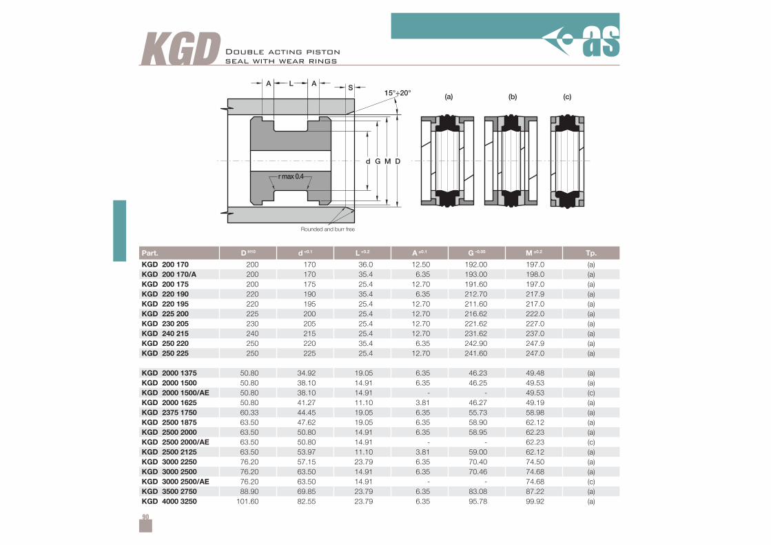
90
Part. D H10 d +0.1 L +0.2 A ±0.1 G –0.05 M ±0.2 Tp.
KGD 200 170 200 170 36.0 12.50 192.00 197.0 (a)KGD 200 170/A 200 170 35.4 6.35 193.00 198.0 (a)KGD 200 175 200 175 25.4 12.70 191.60 197.0 (a)KGD 220 190 220 190 35.4 6.35 212.70 217.9 (a)KGD 220 195 220 195 25.4 12.70 211.60 217.0 (a)KGD 225 200 225 200 25.4 12.70 216.62 222.0 (a)KGD 230 205 230 205 25.4 12.70 221.62 227.0 (a)KGD 240 215 240 215 25.4 12.70 231.62 237.0 (a)KGD 250 220 250 220 35.4 6.35 242.90 247.9 (a)KGD 250 225 250 225 25.4 12.70 241.60 247.0 (a)
KGD 2000 1375 50.80 34.92 19.05 6.35 46.23 49.48 (a)KGD 2000 1500 50.80 38.10 14.91 6.35 46.25 49.53 (a)KGD 2000 1500/AE 50.80 38.10 14.91 - - 49.53 (c)KGD 2000 1625 50.80 41.27 11.10 3.81 46.27 49.19 (a)KGD 2375 1750 60.33 44.45 19.05 6.35 55.73 58.98 (a)KGD 2500 1875 63.50 47.62 19.05 6.35 58.90 62.12 (a)KGD 2500 2000 63.50 50.80 14.91 6.35 58.95 62.23 (a)KGD 2500 2000/AE 63.50 50.80 14.91 - - 62.23 (c)KGD 2500 2125 63.50 53.97 11.10 3.81 59.00 62.12 (a)KGD 3000 2250 76.20 57.15 23.79 6.35 70.40 74.50 (a)KGD 3000 2500 76.20 63.50 14.91 6.35 70.46 74.68 (a)KGD 3000 2500/AE 76.20 63.50 14.91 - - 74.68 (c)KGD 3500 2750 88.90 69.85 23.79 6.35 83.08 87.22 (a)KGD 4000 3250 101.60 82.55 23.79 6.35 95.78 99.92 (a)
KGD
M D
(a) (b) (c)SL AA
d G
15°÷20°
rmax 0.4
Double acting pistonseal with wear rings
Rounded and burr free
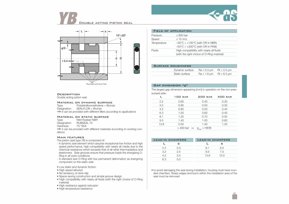
91
YB Double acting piston seal
DescriptionDouble acting piston seal
Material on dynamic surfaceType: Polytetrafluoroethylene + BronzeDesignation: SEALFLON + Bronze⇒ it can be provided with different fillers according to applications
Material on static surfaceType: Nitril Rubber NBRDesignation: RUBSEAL 70Hardness: 70 °ShA⇒ it can be provided with different materials according to working con-ditions
Main featuresThe piston seal type YB is composed of:- A dynamic seal element which assures exceptional low friction and high
speed performance, high compatibility with nearly all media due to thechemical resistance which exceeds that of all other thermoplastics andelastomers. Side grooves ensure that pressure loads the energizing O-Ring in all work conditions
- A standard size O-Ring with low permanent deformation as energizingcomponent on the static side
• Low static and dynamic friction• High speed allowed• No tendency of stick-slip• Space-saving construction and simple groove design• High compatibility with nearly all fluids (with the right choice of O-Ring
material)• High resistance against extrusion• High temperature resistance
Pressure ≤ 600 barSpeed ≤ 15 m/sTemperature –30°C ÷ +130°C (with OR in NBR)
–50°C ÷ +200°C (with OR in FKM)Fluids High compatibility with nearly all fluids
(with the right choice of O-Ring material)
Dynamic surface Ra ≤ 0.3 µm Rt ≤ 2.5 µmStatic surface Ra ≤ 1.6 µm Rt ≤ 6.3 µm
• to avoid damaging the seal during installation, housing must have roun-ded chamfers. Sharp edges and burrs within the installation area of theseal must be removed
The largest gap dimension appearing [mm] in operation on the non-pres-surised side:
2.2 2.0 8.1 6.53.2 2.5 9.5 7.54.2 3.5 13.8 10.06.3 5.0
L s L s
2.2 0.60 0.40 0.303.2 0.80 0.50 0.304.2 0.80 0.50 0.406.3 1.00 0.60 0.408.1 1.20 0.70 0.509.5 1.40 1.00 0.6013.8 2.00 1.40 1.20
> 400 bar ⇒ gmax = H8/f8
L 100 bar 200 bar 400 bar
Field of application
Surface roughness
Gap dimension “g”
Lead-in chamfersLead-in chamfers
Rounded and burr free
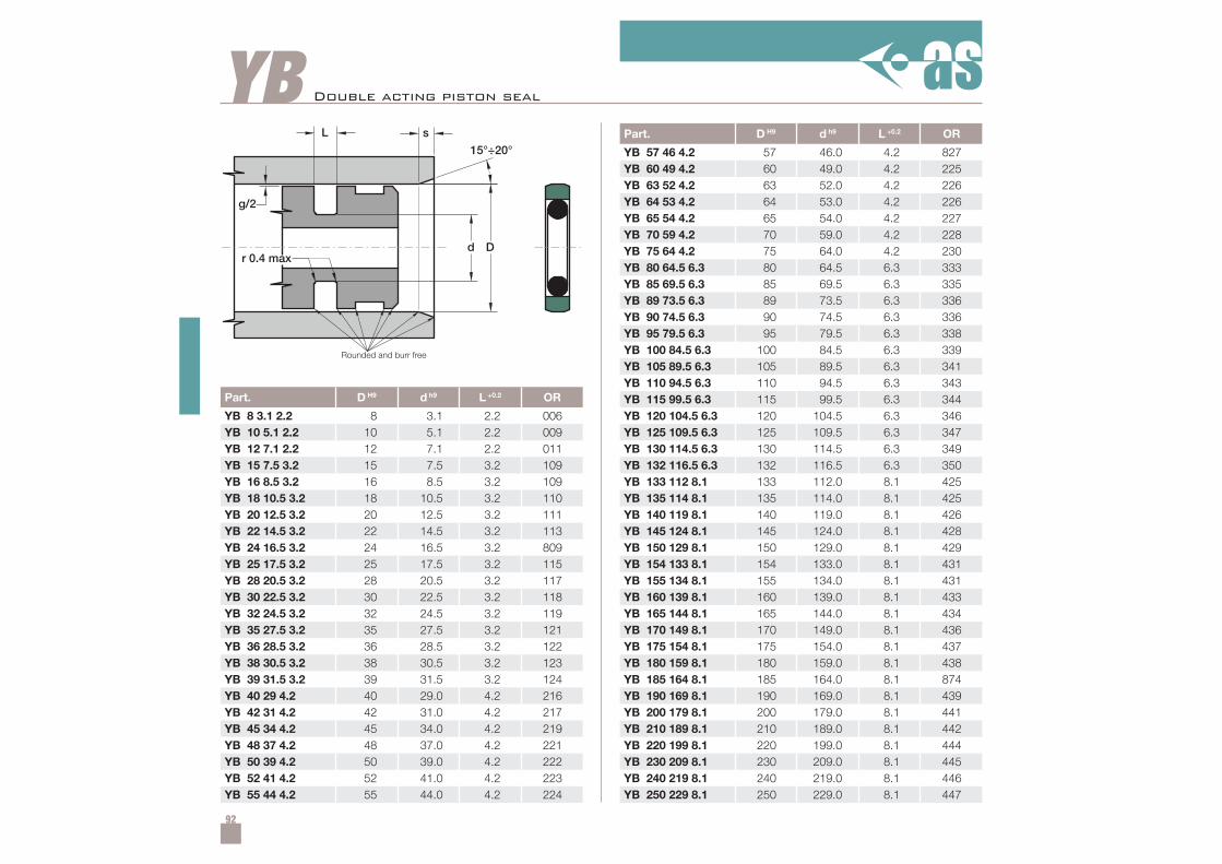
92
YB
Part. D H9 d h9 L +0.2 OR
YB 8 3.1 2.2 8 3.1 2.2 006YB 10 5.1 2.2 10 5.1 2.2 009YB 12 7.1 2.2 12 7.1 2.2 011YB 15 7.5 3.2 15 7.5 3.2 109YB 16 8.5 3.2 16 8.5 3.2 109YB 18 10.5 3.2 18 10.5 3.2 110YB 20 12.5 3.2 20 12.5 3.2 111YB 22 14.5 3.2 22 14.5 3.2 113YB 24 16.5 3.2 24 16.5 3.2 809YB 25 17.5 3.2 25 17.5 3.2 115YB 28 20.5 3.2 28 20.5 3.2 117YB 30 22.5 3.2 30 22.5 3.2 118YB 32 24.5 3.2 32 24.5 3.2 119YB 35 27.5 3.2 35 27.5 3.2 121YB 36 28.5 3.2 36 28.5 3.2 122YB 38 30.5 3.2 38 30.5 3.2 123YB 39 31.5 3.2 39 31.5 3.2 124YB 40 29 4.2 40 29.0 4.2 216YB 42 31 4.2 42 31.0 4.2 217YB 45 34 4.2 45 34.0 4.2 219YB 48 37 4.2 48 37.0 4.2 221YB 50 39 4.2 50 39.0 4.2 222YB 52 41 4.2 52 41.0 4.2 223YB 55 44 4.2 55 44.0 4.2 224
Part. D H9 d h9 L +0.2 OR
YB 57 46 4.2 57 46.0 4.2 827YB 60 49 4.2 60 49.0 4.2 225YB 63 52 4.2 63 52.0 4.2 226YB 64 53 4.2 64 53.0 4.2 226YB 65 54 4.2 65 54.0 4.2 227YB 70 59 4.2 70 59.0 4.2 228YB 75 64 4.2 75 64.0 4.2 230YB 80 64.5 6.3 80 64.5 6.3 333YB 85 69.5 6.3 85 69.5 6.3 335YB 89 73.5 6.3 89 73.5 6.3 336YB 90 74.5 6.3 90 74.5 6.3 336YB 95 79.5 6.3 95 79.5 6.3 338YB 100 84.5 6.3 100 84.5 6.3 339YB 105 89.5 6.3 105 89.5 6.3 341YB 110 94.5 6.3 110 94.5 6.3 343YB 115 99.5 6.3 115 99.5 6.3 344YB 120 104.5 6.3 120 104.5 6.3 346YB 125 109.5 6.3 125 109.5 6.3 347YB 130 114.5 6.3 130 114.5 6.3 349YB 132 116.5 6.3 132 116.5 6.3 350YB 133 112 8.1 133 112.0 8.1 425YB 135 114 8.1 135 114.0 8.1 425YB 140 119 8.1 140 119.0 8.1 426YB 145 124 8.1 145 124.0 8.1 428YB 150 129 8.1 150 129.0 8.1 429YB 154 133 8.1 154 133.0 8.1 431YB 155 134 8.1 155 134.0 8.1 431YB 160 139 8.1 160 139.0 8.1 433YB 165 144 8.1 165 144.0 8.1 434YB 170 149 8.1 170 149.0 8.1 436YB 175 154 8.1 175 154.0 8.1 437YB 180 159 8.1 180 159.0 8.1 438YB 185 164 8.1 185 164.0 8.1 874YB 190 169 8.1 190 169.0 8.1 439YB 200 179 8.1 200 179.0 8.1 441YB 210 189 8.1 210 189.0 8.1 442YB 220 199 8.1 220 199.0 8.1 444YB 230 209 8.1 230 209.0 8.1 445YB 240 219 8.1 240 219.0 8.1 446YB 250 229 8.1 250 229.0 8.1 447
Double acting piston seal
Rounded and burr free
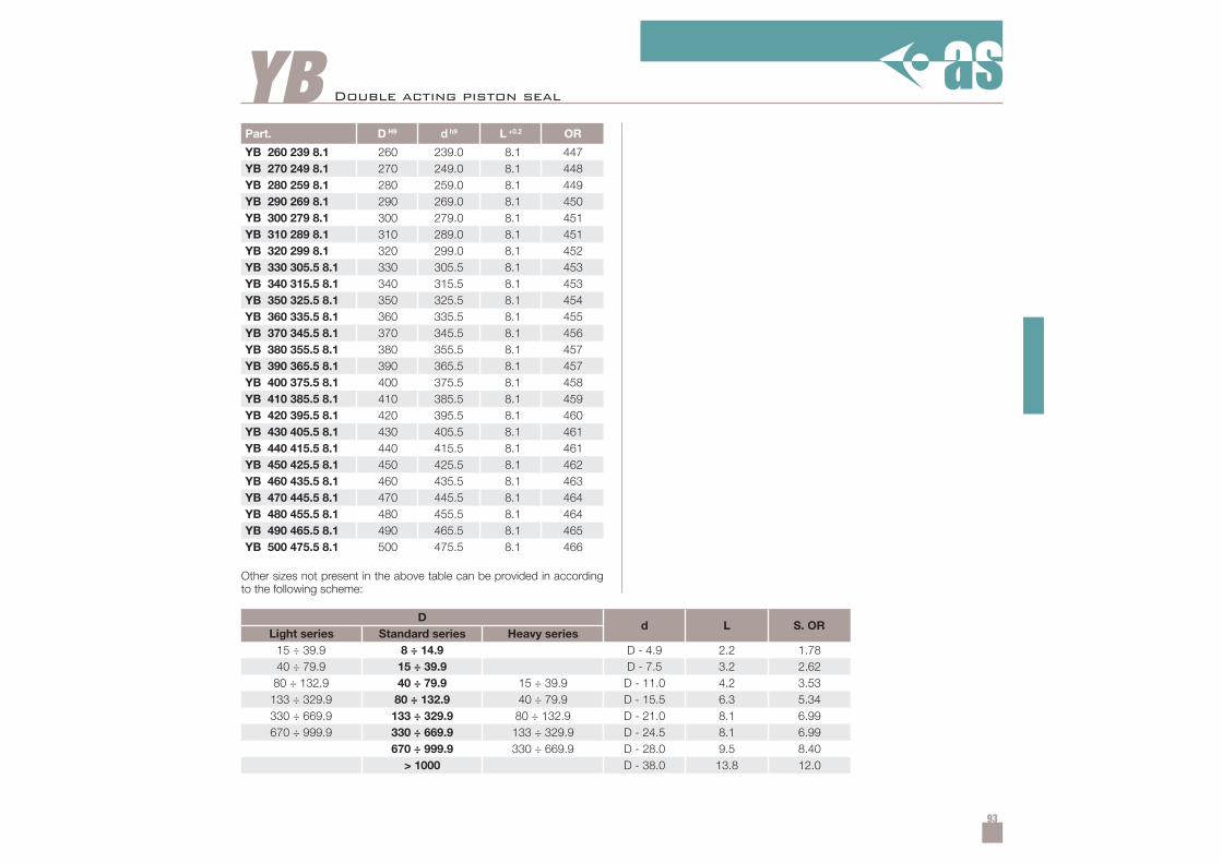
93
YBPart. D H9 d h9 L +0.2 OR
YB 260 239 8.1 260 239.0 8.1 447YB 270 249 8.1 270 249.0 8.1 448YB 280 259 8.1 280 259.0 8.1 449YB 290 269 8.1 290 269.0 8.1 450YB 300 279 8.1 300 279.0 8.1 451YB 310 289 8.1 310 289.0 8.1 451YB 320 299 8.1 320 299.0 8.1 452YB 330 305.5 8.1 330 305.5 8.1 453YB 340 315.5 8.1 340 315.5 8.1 453YB 350 325.5 8.1 350 325.5 8.1 454YB 360 335.5 8.1 360 335.5 8.1 455YB 370 345.5 8.1 370 345.5 8.1 456YB 380 355.5 8.1 380 355.5 8.1 457YB 390 365.5 8.1 390 365.5 8.1 457YB 400 375.5 8.1 400 375.5 8.1 458YB 410 385.5 8.1 410 385.5 8.1 459YB 420 395.5 8.1 420 395.5 8.1 460YB 430 405.5 8.1 430 405.5 8.1 461YB 440 415.5 8.1 440 415.5 8.1 461YB 450 425.5 8.1 450 425.5 8.1 462YB 460 435.5 8.1 460 435.5 8.1 463YB 470 445.5 8.1 470 445.5 8.1 464YB 480 455.5 8.1 480 455.5 8.1 464YB 490 465.5 8.1 490 465.5 8.1 465YB 500 475.5 8.1 500 475.5 8.1 466
15 ÷ 39.9 8 ÷ 14.9 D - 4.9 2.2 1.7840 ÷ 79.9 15 ÷ 39.9 D - 7.5 3.2 2.62
80 ÷ 132.9 40 ÷ 79.9 15 ÷ 39.9 D - 11.0 4.2 3.53133 ÷ 329.9 80 ÷ 132.9 40 ÷ 79.9 D - 15.5 6.3 5.34330 ÷ 669.9 133 ÷ 329.9 80 ÷ 132.9 D - 21.0 8.1 6.99670 ÷ 999.9 330 ÷ 669.9 133 ÷ 329.9 D - 24.5 8.1 6.99
670 ÷ 999.9 330 ÷ 669.9 D - 28.0 9.5 8.40> 1000 D - 38.0 13.8 12.0
Other sizes not present in the above table can be provided in accordingto the following scheme:
Double acting piston seal
Dd L S. OR
Light series Standard series Heavy series
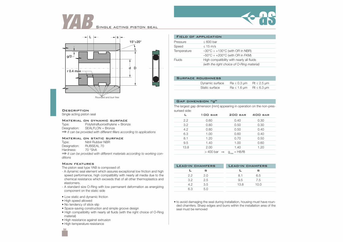
94
YAB Single acting piston seal
DescriptionSingle acting piston seal
Material on dynamic surfaceType: Polytetrafluoroethylene + BronzeDesignation: SEALFLON + Bronze⇒ it can be provided with different fillers according to applications
Material on static surfaceType: Nitril Rubber NBRDesignation: RUBSEAL 70Hardness: 70 °ShA⇒ it can be provided with different materials according to working con-ditions
Main featuresThe piston seal type YAB is composed of:- A dynamic seal element which assures exceptional low friction and high
speed performance, high compatibility with nearly all media due to thechemical resistance which exceeds that of all other thermoplastics andelastomers.
- A standard size O-Ring with low permanent deformation as energizingcomponent on the static side
• Low static and dynamic friction• High speed allowed• No tendency of stick-slip• Space-saving construction and simple groove design• High compatibility with nearly all fluids (with the right choice of O-Ring
material)• High resistance against extrusion• High temperature resistance
Pressure ≤ 600 barSpeed ≤ 15 m/sTemperature –30°C ÷ +130°C (with OR in NBR)
–50°C ÷ +200°C (with OR in FKM)Fluids High compatibility with nearly all fluids
(with the right choice of O-Ring material)
Dynamic surface Ra ≤ 0.3 µm Rt ≤ 2.5 µmStatic surface Ra ≤ 1.6 µm Rt ≤ 6.3 µm
• to avoid damaging the seal during installation, housing must have roun-ded chamfers. Sharp edges and burrs within the installation area of theseal must be removed
The largest gap dimension [mm] appearing in operation on the non-pres-surised side:
2.2 2.0 8.1 6.53.2 2.5 9.5 7.54.2 3.5 13.8 10.06.3 5.0
L s L s
2.2 0.60 0.40 0.303.2 0.80 0.50 0.304.2 0.80 0.50 0.406.3 1.00 0.60 0.408.1 1.20 0.70 0.509.5 1.40 1.00 0.6013.8 2.00 1.40 1.20
> 400 bar ⇒ gmax = H8/f8
L 100 bar 200 bar 400 bar
Field of application
Surface roughness
Gap dimension “g”
Lead-in chamfersLead-in chamfers
Rounded and burr free
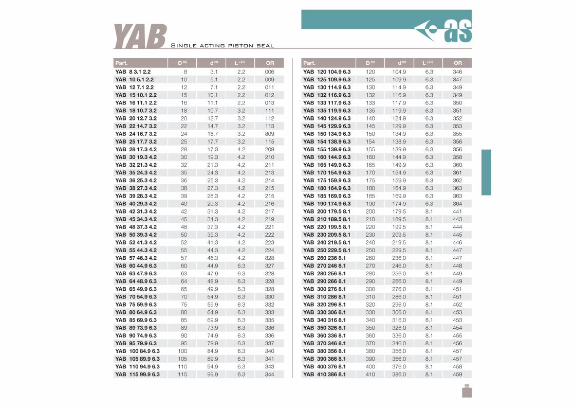
95
YABPart. D H9 d h9 L +0.2 OR
YAB 8 3.1 2.2 8 3.1 2.2 006YAB 10 5.1 2.2 10 5.1 2.2 009YAB 12 7.1 2.2 12 7.1 2.2 011YAB 15 10.1 2.2 15 10.1 2.2 012YAB 16 11.1 2.2 16 11.1 2.2 013YAB 18 10.7 3.2 18 10.7 3.2 111YAB 20 12.7 3.2 20 12.7 3.2 112YAB 22 14.7 3.2 22 14.7 3.2 113YAB 24 16.7 3.2 24 16.7 3.2 809YAB 25 17.7 3.2 25 17.7 3.2 115YAB 28 17.3 4.2 28 17.3 4.2 209YAB 30 19.3 4.2 30 19.3 4.2 210YAB 32 21.3 4.2 32 21.3 4.2 211YAB 35 24.3 4.2 35 24.3 4.2 213YAB 36 25.3 4.2 36 25.3 4.2 214YAB 38 27.3 4.2 38 27.3 4.2 215YAB 39 28.3 4.2 39 28.3 4.2 215YAB 40 29.3 4.2 40 29.3 4.2 216YAB 42 31.3 4.2 42 31.3 4.2 217YAB 45 34.3 4.2 45 34.3 4.2 219YAB 48 37.3 4.2 48 37.3 4.2 221YAB 50 39.3 4.2 50 39.3 4.2 222YAB 52 41.3 4.2 52 41.3 4.2 223YAB 55 44.3 4.2 55 44.3 4.2 224YAB 57 46.3 4.2 57 46.3 4.2 828YAB 60 44.9 6.3 60 44.9 6.3 327YAB 63 47.9 6.3 63 47.9 6.3 328YAB 64 48.9 6.3 64 48.9 6.3 328YAB 65 49.9 6.3 65 49.9 6.3 328YAB 70 54.9 6.3 70 54.9 6.3 330YAB 75 59.9 6.3 75 59.9 6.3 332YAB 80 64.9 6.3 80 64.9 6.3 333YAB 85 69.9 6.3 85 69.9 6.3 335YAB 89 73.9 6.3 89 73.9 6.3 336YAB 90 74.9 6.3 90 74.9 6.3 336YAB 95 79.9 6.3 95 79.9 6.3 337YAB 100 84.9 6.3 100 84.9 6.3 340YAB 105 89.9 6.3 105 89.9 6.3 341YAB 110 94.9 6.3 110 94.9 6.3 343YAB 115 99.9 6.3 115 99.9 6.3 344
Part. D H9 d h9 L +0.2 OR
YAB 120 104.9 6.3 120 104.9 6.3 346YAB 125 109.9 6.3 125 109.9 6.3 347YAB 130 114.9 6.3 130 114.9 6.3 349YAB 132 116.9 6.3 132 116.9 6.3 349YAB 133 117.9 6.3 133 117.9 6.3 350YAB 135 119.9 6.3 135 119.9 6.3 351YAB 140 124.9 6.3 140 124.9 6.3 352YAB 145 129.9 6.3 145 129.9 6.3 353YAB 150 134.9 6.3 150 134.9 6.3 355YAB 154 138.9 6.3 154 138.9 6.3 356YAB 155 139.9 6.3 155 139.9 6.3 356YAB 160 144.9 6.3 160 144.9 6.3 358YAB 165 149.9 6.3 165 149.9 6.3 360YAB 170 154.9 6.3 170 154.9 6.3 361YAB 175 159.9 6.3 175 159.9 6.3 362YAB 180 164.9 6.3 180 164.9 6.3 363YAB 185 169.9 6.3 185 169.9 6.3 363YAB 190 174.9 6.3 190 174.9 6.3 364YAB 200 179.5 8.1 200 179.5 8.1 441YAB 210 189.5 8.1 210 189.5 8.1 443YAB 220 199.5 8.1 220 199.5 8.1 444YAB 230 209.5 8.1 230 209.5 8.1 445YAB 240 219.5 8.1 240 219.5 8.1 446YAB 250 229.5 8.1 250 229.5 8.1 447YAB 260 236 8.1 260 236.0 8.1 447YAB 270 246 8.1 270 246.0 8.1 448YAB 280 256 8.1 280 256.0 8.1 449YAB 290 266 8.1 290 266.0 8.1 449YAB 300 276 8.1 300 276.0 8.1 451YAB 310 286 8.1 310 286.0 8.1 451YAB 320 296 8.1 320 296.0 8.1 452YAB 330 306 8.1 330 306.0 8.1 453YAB 340 316 8.1 340 316.0 8.1 453YAB 350 326 8.1 350 326.0 8.1 454YAB 360 336 8.1 360 336.0 8.1 455YAB 370 346 8.1 370 346.0 8.1 456YAB 380 356 8.1 380 356.0 8.1 457YAB 390 366 8.1 390 366.0 8.1 457YAB 400 376 8.1 400 376.0 8.1 458YAB 410 386 8.1 410 386.0 8.1 459
Single acting piston seal
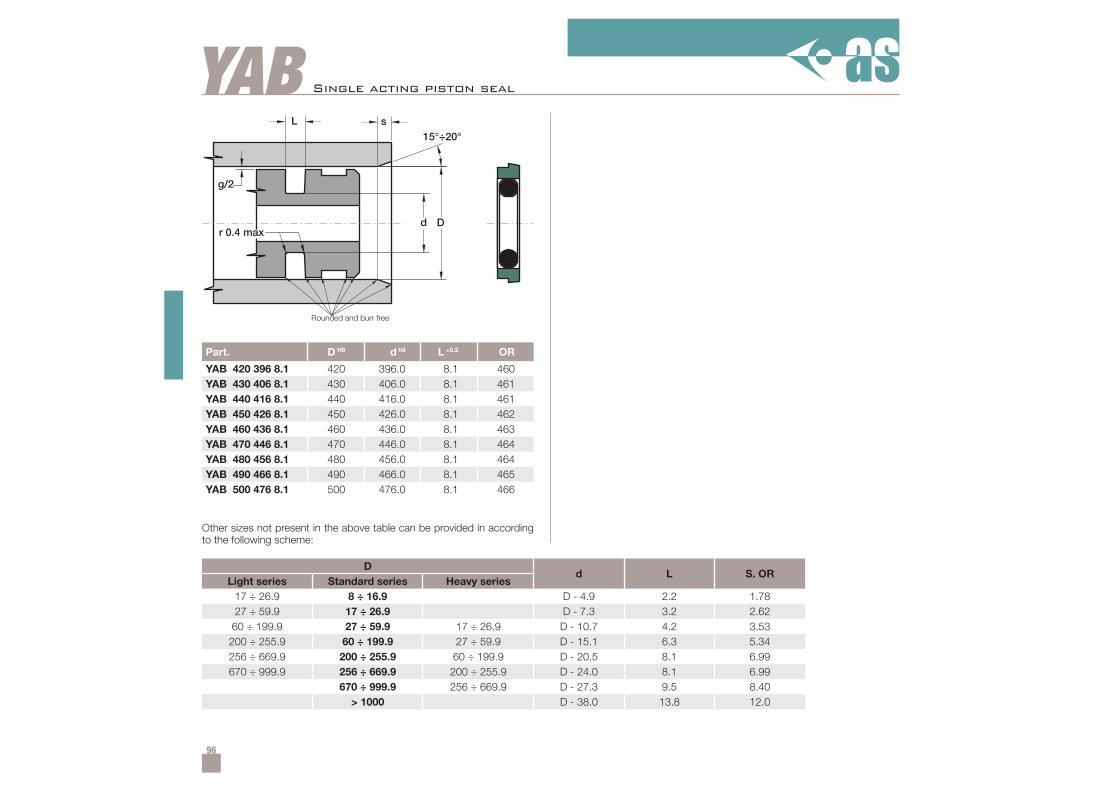
96
YAB
Part. D H9 d h9 L +0.2 OR
YAB 420 396 8.1 420 396.0 8.1 460YAB 430 406 8.1 430 406.0 8.1 461YAB 440 416 8.1 440 416.0 8.1 461YAB 450 426 8.1 450 426.0 8.1 462YAB 460 436 8.1 460 436.0 8.1 463YAB 470 446 8.1 470 446.0 8.1 464YAB 480 456 8.1 480 456.0 8.1 464YAB 490 466 8.1 490 466.0 8.1 465YAB 500 476 8.1 500 476.0 8.1 466
17 ÷ 26.9 8 ÷ 16.9 D - 4.9 2.2 1.7827 ÷ 59.9 17 ÷ 26.9 D - 7.3 3.2 2.62
60 ÷ 199.9 27 ÷ 59.9 17 ÷ 26.9 D - 10.7 4.2 3.53200 ÷ 255.9 60 ÷ 199.9 27 ÷ 59.9 D - 15.1 6.3 5.34256 ÷ 669.9 200 ÷ 255.9 60 ÷ 199.9 D - 20.5 8.1 6.99670 ÷ 999.9 256 ÷ 669.9 200 ÷ 255.9 D - 24.0 8.1 6.99
670 ÷ 999.9 256 ÷ 669.9 D - 27.3 9.5 8.40> 1000 D - 38.0 13.8 12.0
Other sizes not present in the above table can be provided in accordingto the following scheme:
Single acting piston seal
Dd L S. OR
Light series Standard series Heavy series
Rounded and burr free
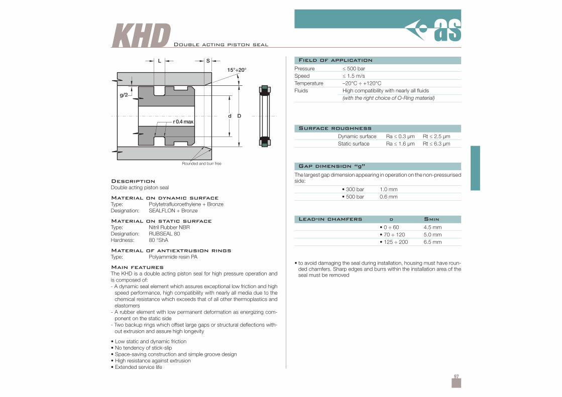
97
KHD Double acting piston seal
DescriptionDouble acting piston seal
Material on dynamic surfaceType: Polytetrafluoroethylene + BronzeDesignation: SEALFLON + Bronze
Material on static surfaceType: Nitril Rubber NBRDesignation: RUBSEAL 80Hardness: 80 °ShA
Material of antiextrusion ringsType: Polyammide resin PA
Main featuresThe KHD is a double acting piston seal for high pressure operation andis composed of:- A dynamic seal element which assures exceptional low friction and high
speed performance, high compatibility with nearly all media due to thechemical resistance which exceeds that of all other thermoplastics andelastomers
- A rubber element with low permanent deformation as energizing com-ponent on the static side
- Two backup rings which offset large gaps or structural deflections with-out extrusion and assure high longevity
• Low static and dynamic friction• No tendency of stick-slip• Space-saving construction and simple groove design• High resistance against extrusion• Extended service life
Pressure ≤ 500 barSpeed ≤ 1.5 m/sTemperature –20°C ÷ +120°CFluids High compatibility with nearly all fluids
(with the right choice of O-Ring material)
Dynamic surface Ra ≤ 0.3 µm Rt ≤ 2.5 µmStatic surface Ra ≤ 1.6 µm Rt ≤ 6.3 µm
• to avoid damaging the seal during installation, housing must have roun-ded chamfers. Sharp edges and burrs within the installation area of theseal must be removed
The largest gap dimension appearing in operation on the non-pressurisedside:
• 300 bar 1.0 mm• 500 bar 0.6 mm
• 0 ÷ 60 4.5 mm• 70 ÷ 120 5.0 mm• 125 ÷ 200 6.5 mm
Field of application
Surface roughness
Gap dimension “g”
Lead-in chamfers D SMIN
Rounded and burr free
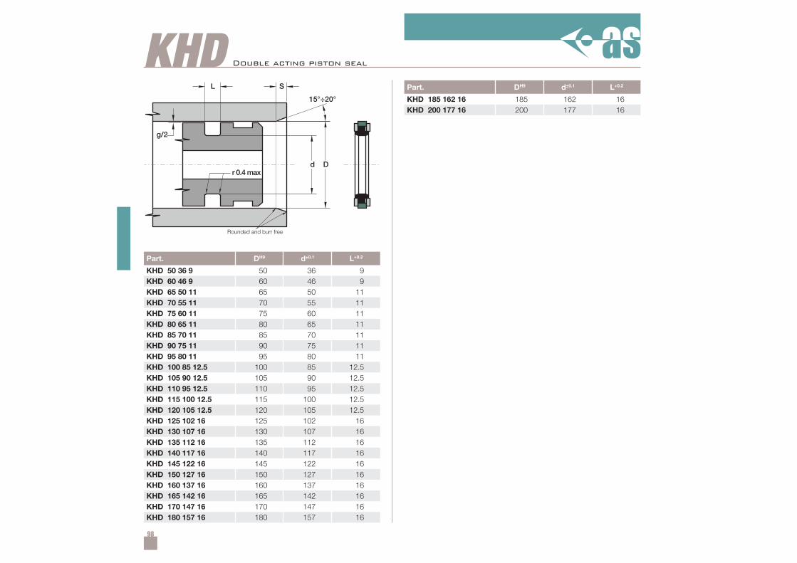
98
KHD
Part. DH9 d±0.1 L+0.2
KHD 50 36 9 50 36 9KHD 60 46 9 60 46 9KHD 65 50 11 65 50 11KHD 70 55 11 70 55 11KHD 75 60 11 75 60 11KHD 80 65 11 80 65 11KHD 85 70 11 85 70 11KHD 90 75 11 90 75 11KHD 95 80 11 95 80 11KHD 100 85 12.5 100 85 12.5KHD 105 90 12.5 105 90 12.5KHD 110 95 12.5 110 95 12.5KHD 115 100 12.5 115 100 12.5KHD 120 105 12.5 120 105 12.5KHD 125 102 16 125 102 16KHD 130 107 16 130 107 16KHD 135 112 16 135 112 16KHD 140 117 16 140 117 16KHD 145 122 16 145 122 16KHD 150 127 16 150 127 16KHD 160 137 16 160 137 16KHD 165 142 16 165 142 16KHD 170 147 16 170 147 16KHD 180 157 16 180 157 16
Part. DH9 d±0.1 L+0.2
KHD 185 162 16 185 162 16KHD 200 177 16 200 177 16
Double acting piston seal
Rounded and burr free
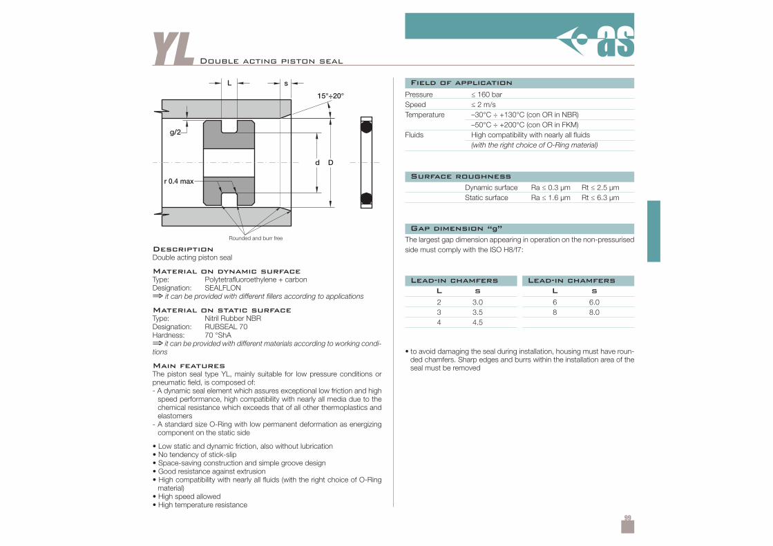
99
YL Double acting piston seal
DescriptionDouble acting piston seal
Material on dynamic surfaceType: Polytetrafluoroethylene + carbonDesignation: SEALFLON⇒ it can be provided with different fillers according to applications
Material on static surfaceType: Nitril Rubber NBRDesignation: RUBSEAL 70Hardness: 70 °ShA⇒ it can be provided with different materials according to working condi-tions
Main featuresThe piston seal type YL, mainly suitable for low pressure conditions orpneumatic field, is composed of:- A dynamic seal element which assures exceptional low friction and high
speed performance, high compatibility with nearly all media due to thechemical resistance which exceeds that of all other thermoplastics andelastomers
- A standard size O-Ring with low permanent deformation as energizingcomponent on the static side
• Low static and dynamic friction, also without lubrication• No tendency of stick-slip• Space-saving construction and simple groove design• Good resistance against extrusion• High compatibility with nearly all fluids (with the right choice of O-Ring
material)• High speed allowed• High temperature resistance
Pressure ≤ 160 barSpeed ≤ 2 m/sTemperature –30°C ÷ +130°C (con OR in NBR)
–50°C ÷ +200°C (con OR in FKM)Fluids High compatibility with nearly all fluids
(with the right choice of O-Ring material)
Dynamic surface Ra ≤ 0.3 µm Rt ≤ 2.5 µmStatic surface Ra ≤ 1.6 µm Rt ≤ 6.3 µm
• to avoid damaging the seal during installation, housing must have roun-ded chamfers. Sharp edges and burrs within the installation area of theseal must be removed
The largest gap dimension appearing in operation on the non-pressurisedside must comply with the ISO H8/f7:
2 3.0 6 6.03 3.5 8 8.04 4.5
L s L s
Field of application
Surface roughness
Gap dimension “g”
Lead-in chamfersLead-in chamfers
Rounded and burr free
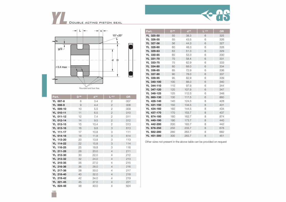
100
YL
Part. D H8 d h9 L +0.2 OR
YL 007-8 8 3.4 2 007YL 008-9 9 4.4 2 008YL 009-10 10 5.5 2 009YL 010-11 11 6.5 2 010YL 011-12 12 7.4 2 011YL 012-14 14 9.5 2 012YL 013-15 15 10.4 2 013YL 613-16 16 9.8 3 613YL 111-17 17 10.8 3 111YL 614-18 18 11.8 3 614YL 113-20 20 13.8 3 113YL 114-22 22 15.8 3 114YL 116-25 25 18.8 3 116YL 211-28 28 20.0 4 211YL 212-30 30 22.0 4 212YL 213-32 32 24.0 4 213YL 215-35 35 27.0 4 215YL 216-36 36 28.0 4 216YL 217-38 38 30.0 4 217YL 218-40 40 32.0 4 218YL 219-42 42 34.0 4 219YL 221-45 45 37.0 4 221YL 824-48 48 40.0 4 824
Part. D H8 d h9 L +0.2 OR
YL 325-50 50 38.3 6 325YL 326-55 55 43.5 6 326YL 327-56 56 44.3 6 327YL 328-60 60 48.3 6 328YL 329-63 63 51.3 6 329YL 330-65 65 53.3 6 330YL 331-70 70 58.4 6 331YL 333-75 75 62.9 6 333YL 334-80 80 68.0 6 334YL 336-85 85 72.9 6 336YL 337-90 90 78.0 6 337YL 339-95 95 82.9 6 339YL 340-100 100 88.0 6 340YL 344-110 110 97.9 6 344YL 347-120 120 107.9 6 347YL 348-125 125 112.5 6 348YL 860-130 130 117.5 6 860YL 428-140 140 124.5 8 428YL 431-150 150 134.5 8 431YL 434-160 160 144.5 8 434YL 437-170 170 153.7 8 437YL 874-180 180 163.7 8 874YL 440-190 190 173.7 8 440YL 442-200 200 183.7 8 442YL 678-250 250 233.7 8 678YL 682-280 280 263.7 8 682YL 451-300 300 283.7 8 451
Double acting piston seal
Other sizes not present in the above table can be provided on request
Rounded and burr free

101
YP Double acting piston seal
DescriptionDouble acting piston seal
Material on dynamic surfaceType: PolytetrafluoroethyleneDesignation: SEALFLON⇒ it can be provided with different fillers according to applications
Material on static surfaceType: Nitril Rubber NBRDesignation: RUBSEAL 70Hardness: 70 °ShA⇒ it can be provided with different materials according to working condi-tions
Main featuresThe piston seal type YP, mainly suitable for low pressure conditions orpneumatic field, is composed of:- A dynamic seal element which assures exceptional low friction and high
speed performance, high compatibility with nearly all media due to thechemical resistance which exceeds that of all other thermoplastics andelastomers.
- A standard size O-Ring with low permanent deformation as energizingcomponent on the static side
• Low static and dynamic friction, also without lubrication• No tendency of stick-slip• Space-saving construction and simple groove design• Good resistance against extrusion• High compatibility with nearly all fluids (with the right choice of O-Ring
material)• High speed allowed• High temperature resistance
Pressure ≤ 210 barSpeed ≤ 4 m/sTemperature –30°C ÷ +130°C (con OR in NBR)
–50°C ÷ +200°C (con OR in FKM)Fluids High compatibility with nearly all fluids
(with the right choice of O-Ring material)
Dynamic surface Ra ≤ 0.3 µm Rt ≤ 2.5 µmStatic surface Ra ≤ 1.6 µm Rt ≤ 6.3 µm
• to avoid damaging the seal during installation, housing must have roun-ded chamfers. Sharp edges and burrs within the installation area of theseal must be removed
The largest gap dimension appearing in operation on the non-pressurisedside must comply with the ISO H8/f7:
2.5 2.0 7.0 4.03.5 2.5 9.5 5.04.5 3.0
L s L s
Field of application
Surface roughness
Gap dimension “g”
Lead-in chamfersLead-in chamfers
Rounded and burr free
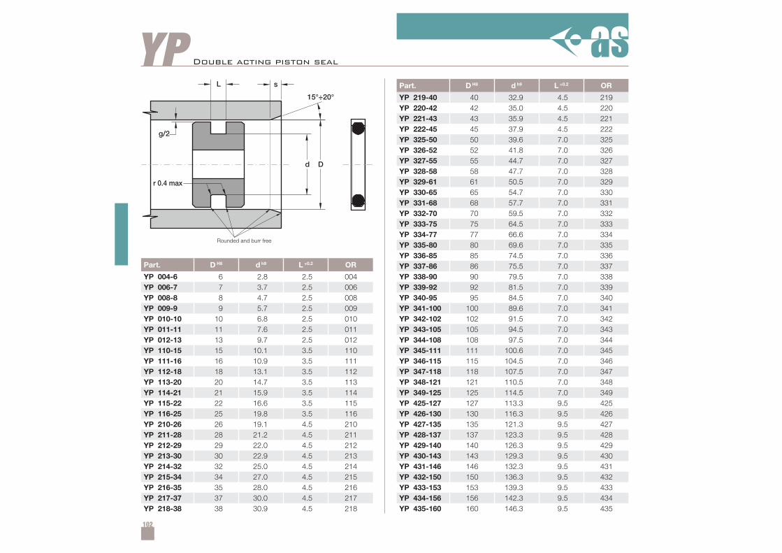
102
YP
Part. D H8 d h9 L +0.2 OR
YP 004-6 6 2.8 2.5 004YP 006-7 7 3.7 2.5 006YP 008-8 8 4.7 2.5 008YP 009-9 9 5.7 2.5 009YP 010-10 10 6.8 2.5 010YP 011-11 11 7.6 2.5 011YP 012-13 13 9.7 2.5 012YP 110-15 15 10.1 3.5 110YP 111-16 16 10.9 3.5 111YP 112-18 18 13.1 3.5 112YP 113-20 20 14.7 3.5 113YP 114-21 21 15.9 3.5 114YP 115-22 22 16.6 3.5 115YP 116-25 25 19.8 3.5 116YP 210-26 26 19.1 4.5 210YP 211-28 28 21.2 4.5 211YP 212-29 29 22.0 4.5 212YP 213-30 30 22.9 4.5 213YP 214-32 32 25.0 4.5 214YP 215-34 34 27.0 4.5 215YP 216-35 35 28.0 4.5 216YP 217-37 37 30.0 4.5 217YP 218-38 38 30.9 4.5 218
Part. D H8 d h9 L +0.2 OR
YP 219-40 40 32.9 4.5 219YP 220-42 42 35.0 4.5 220YP 221-43 43 35.9 4.5 221YP 222-45 45 37.9 4.5 222YP 325-50 50 39.6 7.0 325YP 326-52 52 41.8 7.0 326YP 327-55 55 44.7 7.0 327YP 328-58 58 47.7 7.0 328YP 329-61 61 50.5 7.0 329YP 330-65 65 54.7 7.0 330YP 331-68 68 57.7 7.0 331YP 332-70 70 59.5 7.0 332YP 333-75 75 64.5 7.0 333YP 334-77 77 66.6 7.0 334YP 335-80 80 69.6 7.0 335YP 336-85 85 74.5 7.0 336YP 337-86 86 75.5 7.0 337YP 338-90 90 79.5 7.0 338YP 339-92 92 81.5 7.0 339YP 340-95 95 84.5 7.0 340YP 341-100 100 89.6 7.0 341YP 342-102 102 91.5 7.0 342YP 343-105 105 94.5 7.0 343YP 344-108 108 97.5 7.0 344YP 345-111 111 100.6 7.0 345YP 346-115 115 104.5 7.0 346YP 347-118 118 107.5 7.0 347YP 348-121 121 110.5 7.0 348YP 349-125 125 114.5 7.0 349YP 425-127 127 113.3 9.5 425YP 426-130 130 116.3 9.5 426YP 427-135 135 121.3 9.5 427YP 428-137 137 123.3 9.5 428YP 429-140 140 126.3 9.5 429YP 430-143 143 129.3 9.5 430YP 431-146 146 132.3 9.5 431YP 432-150 150 136.3 9.5 432YP 433-153 153 139.3 9.5 433YP 434-156 156 142.3 9.5 434YP 435-160 160 146.3 9.5 435
Double acting piston seal
Rounded and burr free
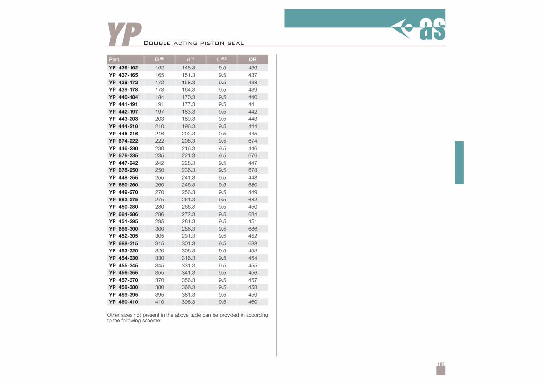
103
YPPart. D H8 d h9 L +0.2 OR
YP 436-162 162 148.3 9.5 436YP 437-165 165 151.3 9.5 437YP 438-172 172 158.3 9.5 438YP 439-178 178 164.3 9.5 439YP 440-184 184 170.3 9.5 440YP 441-191 191 177.3 9.5 441YP 442-197 197 183.3 9.5 442YP 443-203 203 189.3 9.5 443YP 444-210 210 196.3 9.5 444YP 445-216 216 202.3 9.5 445YP 674-222 222 208.3 9.5 674YP 446-230 230 216.3 9.5 446YP 676-235 235 221.3 9.5 676YP 447-242 242 228.3 9.5 447YP 678-250 250 236.3 9.5 678YP 448-255 255 241.3 9.5 448YP 680-260 260 246.3 9.5 680YP 449-270 270 256.3 9.5 449YP 682-275 275 261.3 9.5 682YP 450-280 280 266.3 9.5 450YP 684-286 286 272.3 9.5 684YP 451-295 295 281.3 9.5 451YP 686-300 300 286.3 9.5 686YP 452-305 305 291.3 9.5 452YP 688-315 315 301.3 9.5 688YP 453-320 320 306.3 9.5 453YP 454-330 330 316.3 9.5 454YP 455-345 345 331.3 9.5 455YP 456-355 355 341.3 9.5 456YP 457-370 370 356.3 9.5 457YP 458-380 380 366.3 9.5 458YP 459-395 395 381.3 9.5 459YP 460-410 410 396.3 9.5 460
Other sizes not present in the above table can be provided in accordingto the following scheme:
Double acting piston seal
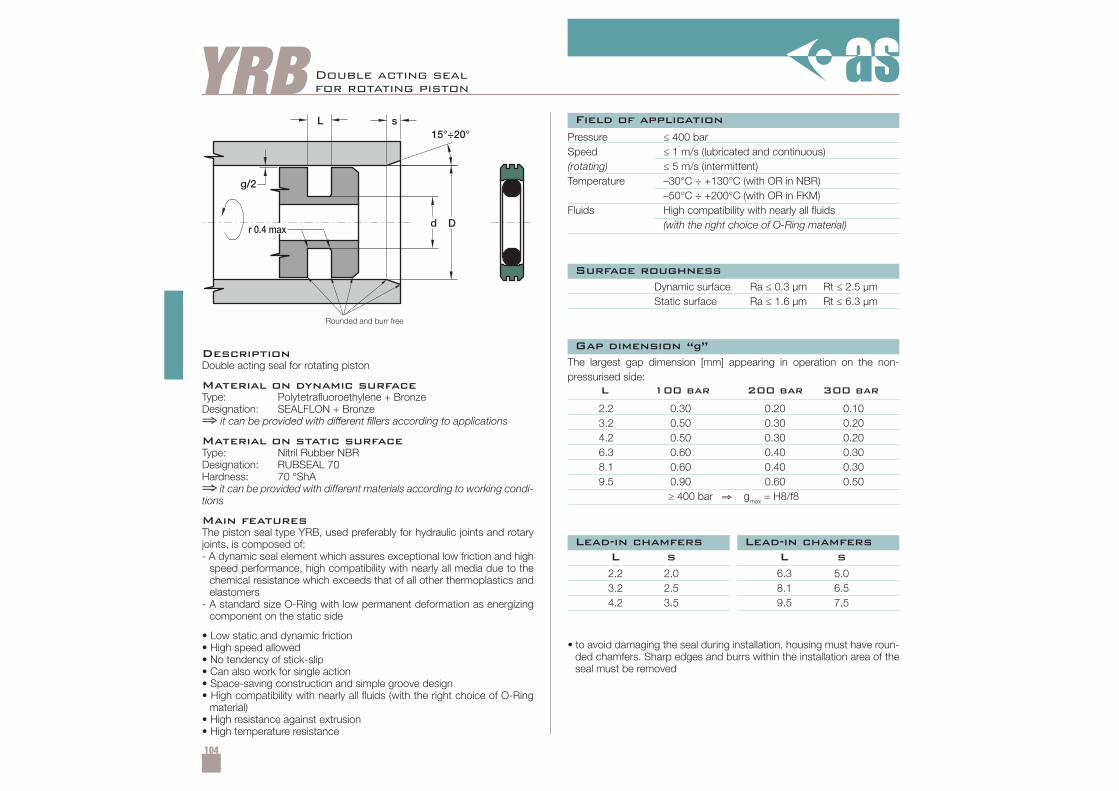
104
YRB Double acting sealfor rotating piston
DescriptionDouble acting seal for rotating piston
Material on dynamic surfaceType: Polytetrafluoroethylene + BronzeDesignation: SEALFLON + Bronze⇒ it can be provided with different fillers according to applications
Material on static surfaceType: Nitril Rubber NBRDesignation: RUBSEAL 70Hardness: 70 °ShA⇒ it can be provided with different materials according to working condi-tions
Main featuresThe piston seal type YRB, used preferably for hydraulic joints and rotaryjoints, is composed of:- A dynamic seal element which assures exceptional low friction and high
speed performance, high compatibility with nearly all media due to thechemical resistance which exceeds that of all other thermoplastics andelastomers
- A standard size O-Ring with low permanent deformation as energizingcomponent on the static side
• Low static and dynamic friction• High speed allowed• No tendency of stick-slip• Can also work for single action• Space-saving construction and simple groove design• High compatibility with nearly all fluids (with the right choice of O-Ring
material)• High resistance against extrusion• High temperature resistance
Pressure ≤ 400 barSpeed ≤ 1 m/s (lubricated and continuous)(rotating) ≤ 5 m/s (intermittent)Temperature –30°C ÷ +130°C (with OR in NBR)
–50°C ÷ +200°C (with OR in FKM)Fluids High compatibility with nearly all fluids
(with the right choice of O-Ring material)
Dynamic surface Ra ≤ 0.3 µm Rt ≤ 2.5 µmStatic surface Ra ≤ 1.6 µm Rt ≤ 6.3 µm
• to avoid damaging the seal during installation, housing must have roun-ded chamfers. Sharp edges and burrs within the installation area of theseal must be removed
2.2 2.0 6.3 5.03.2 2.5 8.1 6.54.2 3.5 9.5 7.5
L s L s
The largest gap dimension [mm] appearing in operation on the non-pressurised side:
2.2 0.30 0.20 0.103.2 0.50 0.30 0.204.2 0.50 0.30 0.206.3 0.60 0.40 0.308.1 0.60 0.40 0.309.5 0.90 0.60 0.50
≥ 400 bar ⇒ gmax = H8/f8
L 100 bar 200 bar 300 bar
Field of application
Surface roughness
Lead-in chamfers
Gap dimension “g”
Lead-in chamfers
Rounded and burr free
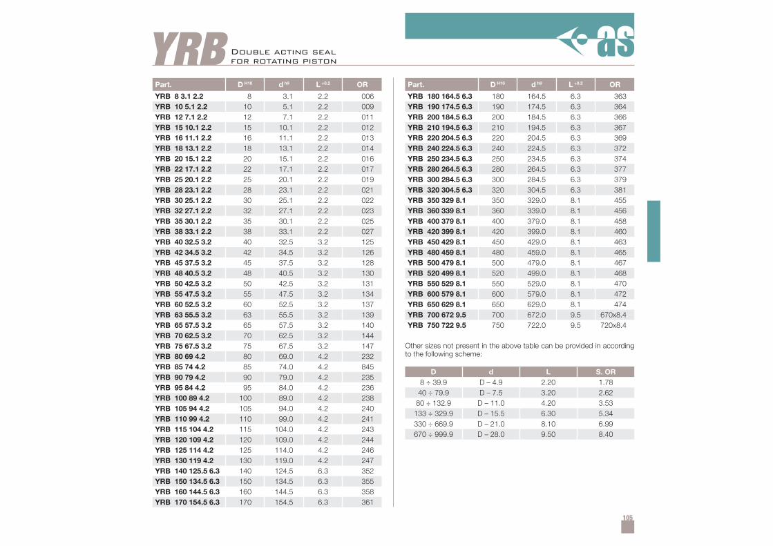
105
Part. D H10 d h9 L +0.2 OR
YRB 8 3.1 2.2 8 3.1 2.2 006YRB 10 5.1 2.2 10 5.1 2.2 009YRB 12 7.1 2.2 12 7.1 2.2 011YRB 15 10.1 2.2 15 10.1 2.2 012YRB 16 11.1 2.2 16 11.1 2.2 013YRB 18 13.1 2.2 18 13.1 2.2 014YRB 20 15.1 2.2 20 15.1 2.2 016YRB 22 17.1 2.2 22 17.1 2.2 017YRB 25 20.1 2.2 25 20.1 2.2 019YRB 28 23.1 2.2 28 23.1 2.2 021YRB 30 25.1 2.2 30 25.1 2.2 022YRB 32 27.1 2.2 32 27.1 2.2 023YRB 35 30.1 2.2 35 30.1 2.2 025YRB 38 33.1 2.2 38 33.1 2.2 027YRB 40 32.5 3.2 40 32.5 3.2 125YRB 42 34.5 3.2 42 34.5 3.2 126YRB 45 37.5 3.2 45 37.5 3.2 128YRB 48 40.5 3.2 48 40.5 3.2 130YRB 50 42.5 3.2 50 42.5 3.2 131YRB 55 47.5 3.2 55 47.5 3.2 134YRB 60 52.5 3.2 60 52.5 3.2 137YRB 63 55.5 3.2 63 55.5 3.2 139YRB 65 57.5 3.2 65 57.5 3.2 140YRB 70 62.5 3.2 70 62.5 3.2 144YRB 75 67.5 3.2 75 67.5 3.2 147YRB 80 69 4.2 80 69.0 4.2 232YRB 85 74 4.2 85 74.0 4.2 845YRB 90 79 4.2 90 79.0 4.2 235YRB 95 84 4.2 95 84.0 4.2 236YRB 100 89 4.2 100 89.0 4.2 238YRB 105 94 4.2 105 94.0 4.2 240YRB 110 99 4.2 110 99.0 4.2 241YRB 115 104 4.2 115 104.0 4.2 243YRB 120 109 4.2 120 109.0 4.2 244YRB 125 114 4.2 125 114.0 4.2 246YRB 130 119 4.2 130 119.0 4.2 247YRB 140 125.5 6.3 140 124.5 6.3 352YRB 150 134.5 6.3 150 134.5 6.3 355YRB 160 144.5 6.3 160 144.5 6.3 358YRB 170 154.5 6.3 170 154.5 6.3 361
YRBPart. D H10 d h9 L +0.2 OR
YRB 180 164.5 6.3 180 164.5 6.3 363YRB 190 174.5 6.3 190 174.5 6.3 364YRB 200 184.5 6.3 200 184.5 6.3 366YRB 210 194.5 6.3 210 194.5 6.3 367YRB 220 204.5 6.3 220 204.5 6.3 369YRB 240 224.5 6.3 240 224.5 6.3 372YRB 250 234.5 6.3 250 234.5 6.3 374YRB 280 264.5 6.3 280 264.5 6.3 377YRB 300 284.5 6.3 300 284.5 6.3 379YRB 320 304.5 6.3 320 304.5 6.3 381YRB 350 329 8.1 350 329.0 8.1 455YRB 360 339 8.1 360 339.0 8.1 456YRB 400 379 8.1 400 379.0 8.1 458YRB 420 399 8.1 420 399.0 8.1 460YRB 450 429 8.1 450 429.0 8.1 463YRB 480 459 8.1 480 459.0 8.1 465YRB 500 479 8.1 500 479.0 8.1 467YRB 520 499 8.1 520 499.0 8.1 468YRB 550 529 8.1 550 529.0 8.1 470YRB 600 579 8.1 600 579.0 8.1 472YRB 650 629 8.1 650 629.0 8.1 474YRB 700 672 9.5 700 672.0 9.5 670x8.4YRB 750 722 9.5 750 722.0 9.5 720x8.4
D d L S. OR8 ÷ 39.9 D – 4.9 2.20 1.78
40 ÷ 79.9 D – 7.5 3.20 2.6280 ÷ 132.9 D – 11.0 4.20 3.53
133 ÷ 329.9 D – 15.5 6.30 5.34330 ÷ 669.9 D – 21.0 8.10 6.99670 ÷ 999.9 D – 28.0 9.50 8.40
Double acting sealfor rotating piston
Other sizes not present in the above table can be provided in accordingto the following scheme:
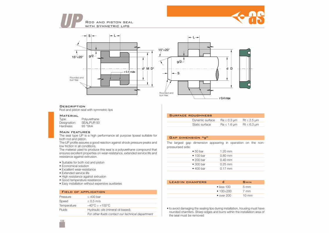
106
UP Rod and piston sealwith symmetric lips
DescriptionRod and piston seal with symmetric lips
MaterialType: PolyurethaneDesignation: SEALPUR 93Hardness: 93 °ShA
Main featuresThe seal type UP is a high performance all purpose lipseal suitable forboth rod and piston.The UP profile assures a good reaction against shock pressure peaks andlow friction in all conditions.The material used to produce this seal is a polyurethane compound thatensures excellent properties on wear-resistance, extended service life andresistance against extrusion.
• Suitable for both rod and piston• Economical solution• Excellent wear-resistance• Extended service life• High resistance against extrusion• Good temperature resistance• Easy installation without expensive auxiliaries
Pressure ≤ 400 barSpeed ≤ 0.5 m/sTemperature –40°C ÷ +100°CFluids Hydraulic oils (mineral oil based).
For other fluids contact our technical department
Dynamic surface Ra ≤ 0.3 µm Rt ≤ 2.5 µmStatic surface Ra ≤ 1.6 µm Rt ≤ 6.3 µm
• less 100• 100÷200• over 200
5 mm7 mm10 mm
• to avoid damaging the sealing lips during installation, housing must haverounded chamfers. Sharp edges and burrs within the installation area ofthe seal must be removed
The largest gap dimension appearing in operation on the non-pressurised side:
• 50 bar 1.20 mm• 100 bar 0.80 mm• 200 bar 0.40 mm• 300 bar 0.25 mm• 400 bar 0.17 mm
Field of application
Surface roughness
Lead-in chamfers d SMIN
Gap dimension “g”
Rounded andburr free
Rounded andburr free
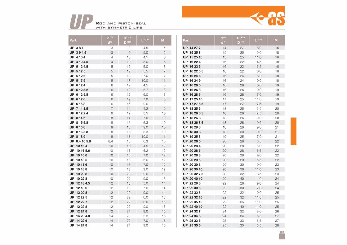
107
Part.d1 f8
d f7
D1 H10
D H10L +0.25 M
UP 3 8 4 3 8 4.5 5UP 3 9 4.5 3 9 5.0 5UP 4 10 4 4 10 4.5 6UP 4 10 4.5 4 10 5.0 6UP 5 12 4.5 5 12 5.0 7UP 5 12 5 5 12 5.5 7UP 5 12 6 5 12 7.0 7UP 5 17 9 5 17 10.0 11UP 6 12 4 6 12 4.5 8UP 6 12 5.2 6 12 5.7 8UP 6 12 5.5 6 12 6.0 8UP 6 12 6 6 12 7.0 8UP 6 15 8 6 15 9.0 9UP 7 14 3.5 7 14 4.2 9UP 8 12 2.4 8 12 3.5 10UP 8 14 6 8 14 7.0 10UP 8 15 5.8 8 15 6.3 10UP 8 15 8 8 15 9.0 10UP 8 16 5.8 8 16 6.3 10UP 8 18 9 8 18 10.0 11UP 8.4 16 5.8 8.4 16 6.3 10UP 10 16 4 10 16 4.5 12UP 10 16 5.6 10 16 6.2 12UP 10 16 6 10 16 7.0 12UP 10 18 5 10 18 6.0 12UP 10 18 6 10 18 7.0 12UP 10 18 8 10 18 9.0 12UP 10 20 8 10 20 9.0 12UP 10 22 8 10 22 9.0 13UP 12 18 4.5 12 18 5.0 14UP 12 18 6 12 18 7.0 14UP 12 20 8 12 20 9.0 14UP 12 22 5 12 22 6.0 15UP 12 22 7 12 22 8.0 15UP 12 22 8 12 22 9.0 15UP 12 24 8 12 24 9.0 15UP 14 20 4.8 14 20 5.3 16UP 14 22 6 14 22 7.0 16UP 14 24 8 14 24 9.0 16
Part.d1 f8
d f7
D1 H10
D H10L +0.25 M
UP 14 27 7 14 27 8.0 16UP 15 25 8 15 25 9.0 18UP 15 25 10 15 25 11.0 18UP 16 22 4 16 22 4.5 18UP 16 22 5 16 22 5.5 18UP 16 22 5.5 16 22 6.0 18UP 16 24 5 16 24 6.0 18UP 16 24 9 16 24 10.0 18UP 16 26 5 16 26 6.0 19UP 16 26 8 16 26 9.0 19UP 16 28 6 16 28 7.0 19UP 17 25 10 17 25 11.0 19UP 17 27 6.5 17 27 7.6 19UP 18 25 5 18 25 5.5 20UP 18 26 6.5 18 26 7.5 20UP 18 26 8 18 26 9.0 20UP 18 26 8.5 18 26 9.5 20UP 18 28 8 18 28 9.0 21UP 18 30 8 18 30 9.0 21UP 19 25 6 19 25 7.0 21UP 20 26 5 20 26 5.5 22UP 20 28 4 20 28 5.0 22UP 20 28 5 20 28 5.5 22UP 20 28 8 20 28 9.0 22UP 20 29 5 20 29 5.5 22UP 20 30 8 20 30 9.0 23UP 20 30 10 20 30 11.0 23UP 20 32 7.5 20 32 8.5 23UP 20 40 10 20 40 11.0 24UP 22 28 8 22 28 9.0 24UP 22 30 6 22 30 7.0 24UP 22 32 8 22 32 9.0 25UP 22 32 10 22 32 11.0 25UP 22 35 10 22 35 11.0 25UP 22 40 10 22 40 11.0 25UP 24 32 7 24 32 8.0 26UP 24 34 5 24 34 5.5 27UP 25 33 5 25 33 5.5 27UP 25 35 5 25 35 5.5 28
UP Rod and piston sealwith symmetric lips
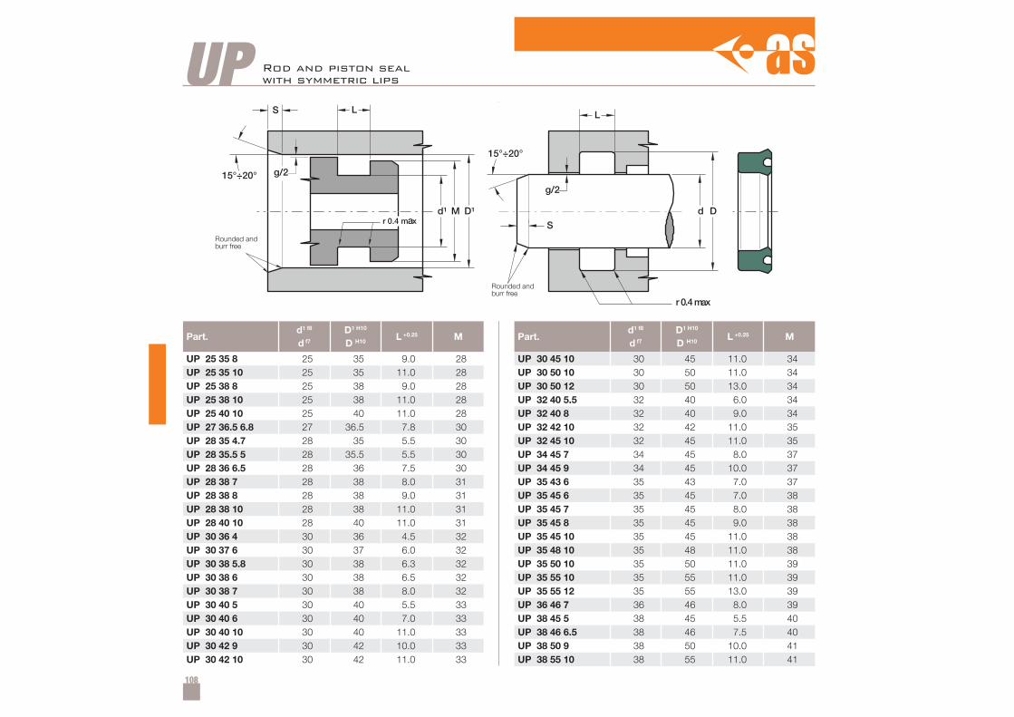
108
Part.d1 f8
d f7
D1 H10
D H10L +0.25 M
UP 25 35 8 25 35 9.0 28UP 25 35 10 25 35 11.0 28UP 25 38 8 25 38 9.0 28UP 25 38 10 25 38 11.0 28UP 25 40 10 25 40 11.0 28UP 27 36.5 6.8 27 36.5 7.8 30UP 28 35 4.7 28 35 5.5 30UP 28 35.5 5 28 35.5 5.5 30UP 28 36 6.5 28 36 7.5 30UP 28 38 7 28 38 8.0 31UP 28 38 8 28 38 9.0 31UP 28 38 10 28 38 11.0 31UP 28 40 10 28 40 11.0 31UP 30 36 4 30 36 4.5 32UP 30 37 6 30 37 6.0 32UP 30 38 5.8 30 38 6.3 32UP 30 38 6 30 38 6.5 32UP 30 38 7 30 38 8.0 32UP 30 40 5 30 40 5.5 33UP 30 40 6 30 40 7.0 33UP 30 40 10 30 40 11.0 33UP 30 42 9 30 42 10.0 33UP 30 42 10 30 42 11.0 33
Part.d1 f8
d f7
D1 H10
D H10L +0.25 M
UP 30 45 10 30 45 11.0 34UP 30 50 10 30 50 11.0 34UP 30 50 12 30 50 13.0 34UP 32 40 5.5 32 40 6.0 34UP 32 40 8 32 40 9.0 34UP 32 42 10 32 42 11.0 35UP 32 45 10 32 45 11.0 35UP 34 45 7 34 45 8.0 37UP 34 45 9 34 45 10.0 37UP 35 43 6 35 43 7.0 37UP 35 45 6 35 45 7.0 38UP 35 45 7 35 45 8.0 38UP 35 45 8 35 45 9.0 38UP 35 45 10 35 45 11.0 38UP 35 48 10 35 48 11.0 38UP 35 50 10 35 50 11.0 39UP 35 55 10 35 55 11.0 39UP 35 55 12 35 55 13.0 39UP 36 46 7 36 46 8.0 39UP 38 45 5 38 45 5.5 40UP 38 46 6.5 38 46 7.5 40UP 38 50 9 38 50 10.0 41UP 38 55 10 38 55 11.0 41
UP Rod and piston sealwith symmetric lips
Rounded andburr free
Rounded andburr free
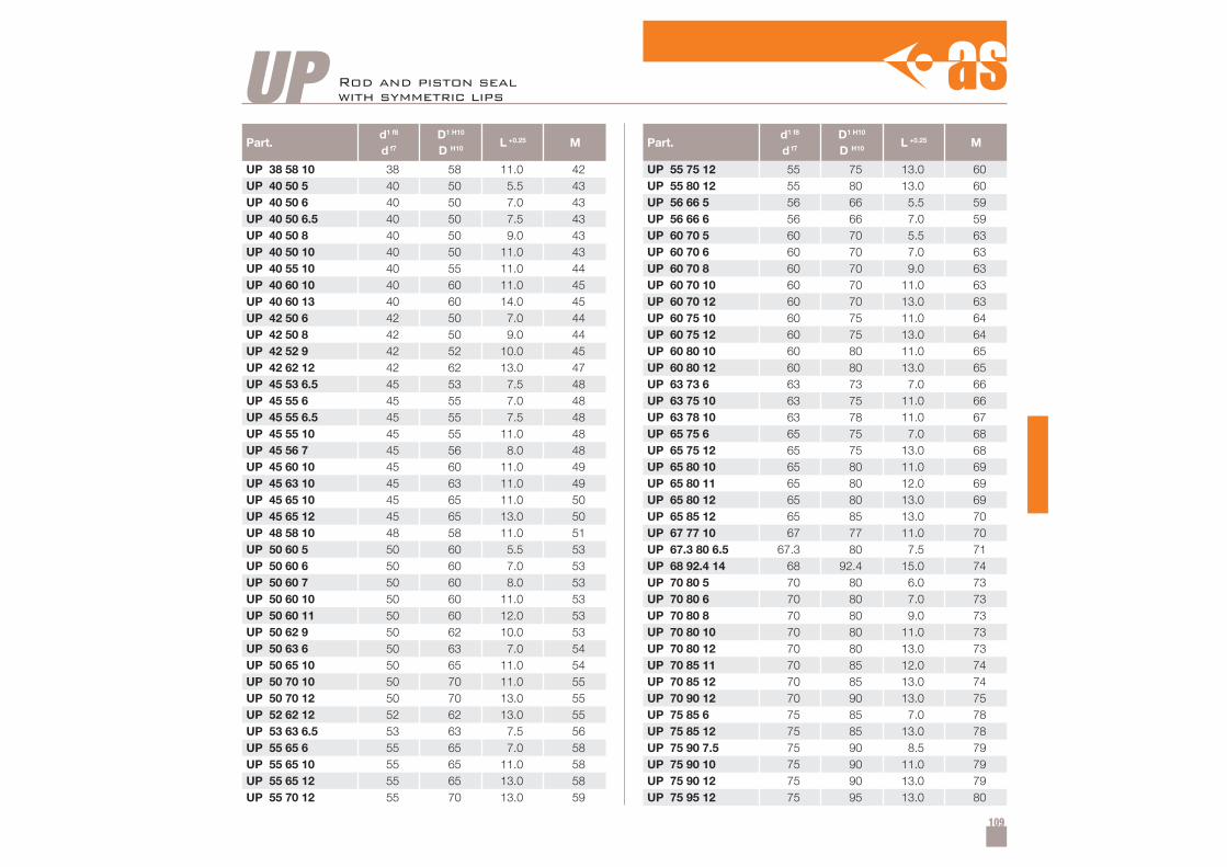
109
Part.d1 f8
d f7
D1 H10
D H10L +0.25 M
UP 38 58 10 38 58 11.0 42UP 40 50 5 40 50 5.5 43UP 40 50 6 40 50 7.0 43UP 40 50 6.5 40 50 7.5 43UP 40 50 8 40 50 9.0 43UP 40 50 10 40 50 11.0 43UP 40 55 10 40 55 11.0 44UP 40 60 10 40 60 11.0 45UP 40 60 13 40 60 14.0 45UP 42 50 6 42 50 7.0 44UP 42 50 8 42 50 9.0 44UP 42 52 9 42 52 10.0 45UP 42 62 12 42 62 13.0 47UP 45 53 6.5 45 53 7.5 48UP 45 55 6 45 55 7.0 48UP 45 55 6.5 45 55 7.5 48UP 45 55 10 45 55 11.0 48UP 45 56 7 45 56 8.0 48UP 45 60 10 45 60 11.0 49UP 45 63 10 45 63 11.0 49UP 45 65 10 45 65 11.0 50UP 45 65 12 45 65 13.0 50UP 48 58 10 48 58 11.0 51UP 50 60 5 50 60 5.5 53UP 50 60 6 50 60 7.0 53UP 50 60 7 50 60 8.0 53UP 50 60 10 50 60 11.0 53UP 50 60 11 50 60 12.0 53UP 50 62 9 50 62 10.0 53UP 50 63 6 50 63 7.0 54UP 50 65 10 50 65 11.0 54UP 50 70 10 50 70 11.0 55UP 50 70 12 50 70 13.0 55UP 52 62 12 52 62 13.0 55UP 53 63 6.5 53 63 7.5 56UP 55 65 6 55 65 7.0 58UP 55 65 10 55 65 11.0 58UP 55 65 12 55 65 13.0 58UP 55 70 12 55 70 13.0 59
Part.d1 f8
d f7
D1 H10
D H10L +0.25 M
UP 55 75 12 55 75 13.0 60UP 55 80 12 55 80 13.0 60UP 56 66 5 56 66 5.5 59UP 56 66 6 56 66 7.0 59UP 60 70 5 60 70 5.5 63UP 60 70 6 60 70 7.0 63UP 60 70 8 60 70 9.0 63UP 60 70 10 60 70 11.0 63UP 60 70 12 60 70 13.0 63UP 60 75 10 60 75 11.0 64UP 60 75 12 60 75 13.0 64UP 60 80 10 60 80 11.0 65UP 60 80 12 60 80 13.0 65UP 63 73 6 63 73 7.0 66UP 63 75 10 63 75 11.0 66UP 63 78 10 63 78 11.0 67UP 65 75 6 65 75 7.0 68UP 65 75 12 65 75 13.0 68UP 65 80 10 65 80 11.0 69UP 65 80 11 65 80 12.0 69UP 65 80 12 65 80 13.0 69UP 65 85 12 65 85 13.0 70UP 67 77 10 67 77 11.0 70UP 67.3 80 6.5 67.3 80 7.5 71UP 68 92.4 14 68 92.4 15.0 74UP 70 80 5 70 80 6.0 73UP 70 80 6 70 80 7.0 73UP 70 80 8 70 80 9.0 73UP 70 80 10 70 80 11.0 73UP 70 80 12 70 80 13.0 73UP 70 85 11 70 85 12.0 74UP 70 85 12 70 85 13.0 74UP 70 90 12 70 90 13.0 75UP 75 85 6 75 85 7.0 78UP 75 85 12 75 85 13.0 78UP 75 90 7.5 75 90 8.5 79UP 75 90 10 75 90 11.0 79UP 75 90 12 75 90 13.0 79UP 75 95 12 75 95 13.0 80
UP Rod and piston sealwith symmetric lips
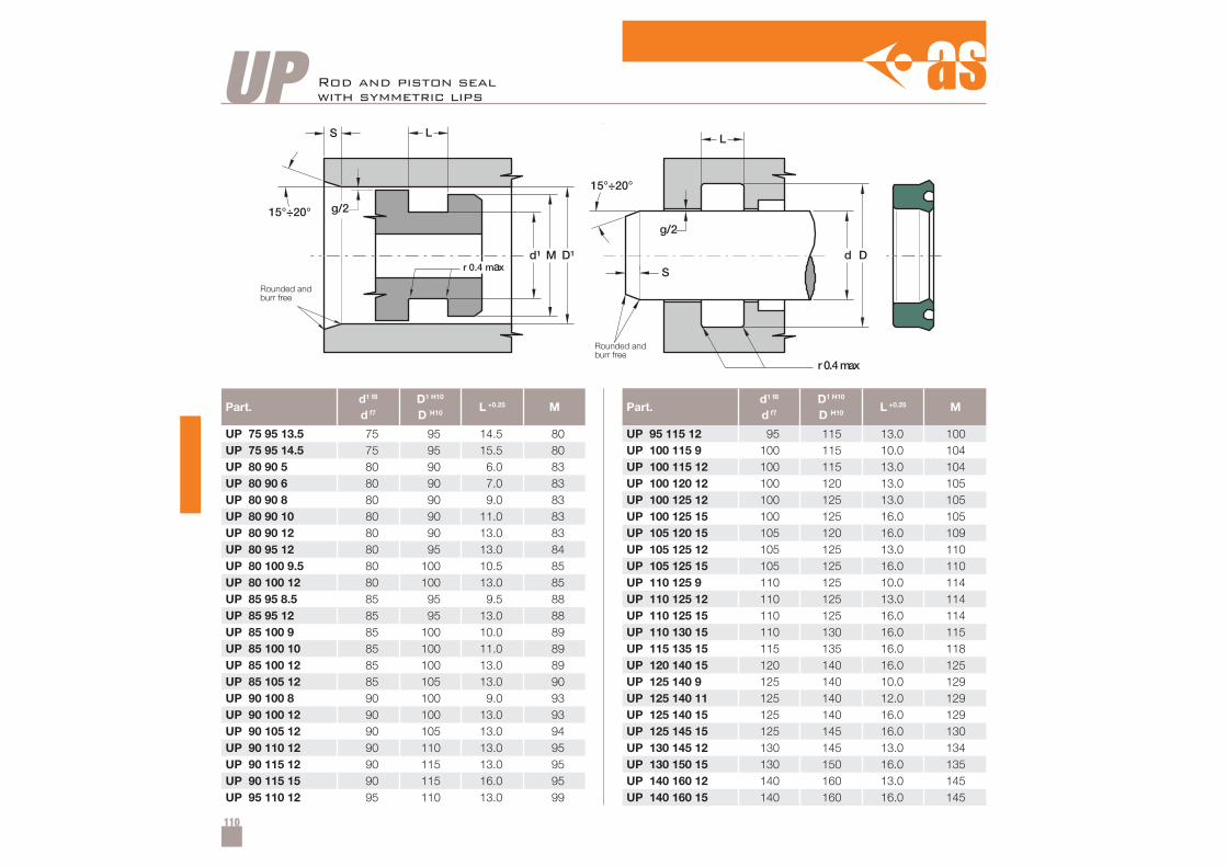
110
Part.d1 f8
d f7
D1 H10
D H10L +0.25 M
UP 75 95 13.5 75 95 14.5 80UP 75 95 14.5 75 95 15.5 80UP 80 90 5 80 90 6.0 83UP 80 90 6 80 90 7.0 83UP 80 90 8 80 90 9.0 83UP 80 90 10 80 90 11.0 83UP 80 90 12 80 90 13.0 83UP 80 95 12 80 95 13.0 84UP 80 100 9.5 80 100 10.5 85UP 80 100 12 80 100 13.0 85UP 85 95 8.5 85 95 9.5 88UP 85 95 12 85 95 13.0 88UP 85 100 9 85 100 10.0 89UP 85 100 10 85 100 11.0 89UP 85 100 12 85 100 13.0 89UP 85 105 12 85 105 13.0 90UP 90 100 8 90 100 9.0 93UP 90 100 12 90 100 13.0 93UP 90 105 12 90 105 13.0 94UP 90 110 12 90 110 13.0 95UP 90 115 12 90 115 13.0 95UP 90 115 15 90 115 16.0 95UP 95 110 12 95 110 13.0 99
UP
Part.d1 f8
d f7
D1 H10
D H10L +0.25 M
UP 95 115 12 95 115 13.0 100UP 100 115 9 100 115 10.0 104UP 100 115 12 100 115 13.0 104UP 100 120 12 100 120 13.0 105UP 100 125 12 100 125 13.0 105UP 100 125 15 100 125 16.0 105UP 105 120 15 105 120 16.0 109UP 105 125 12 105 125 13.0 110UP 105 125 15 105 125 16.0 110UP 110 125 9 110 125 10.0 114UP 110 125 12 110 125 13.0 114UP 110 125 15 110 125 16.0 114UP 110 130 15 110 130 16.0 115UP 115 135 15 115 135 16.0 118UP 120 140 15 120 140 16.0 125UP 125 140 9 125 140 10.0 129UP 125 140 11 125 140 12.0 129UP 125 140 15 125 140 16.0 129UP 125 145 15 125 145 16.0 130UP 130 145 12 130 145 13.0 134UP 130 150 15 130 150 16.0 135UP 140 160 12 140 160 13.0 145UP 140 160 15 140 160 16.0 145
Rod and piston sealwith symmetric lips
Rounded andburr free
Rounded andburr free
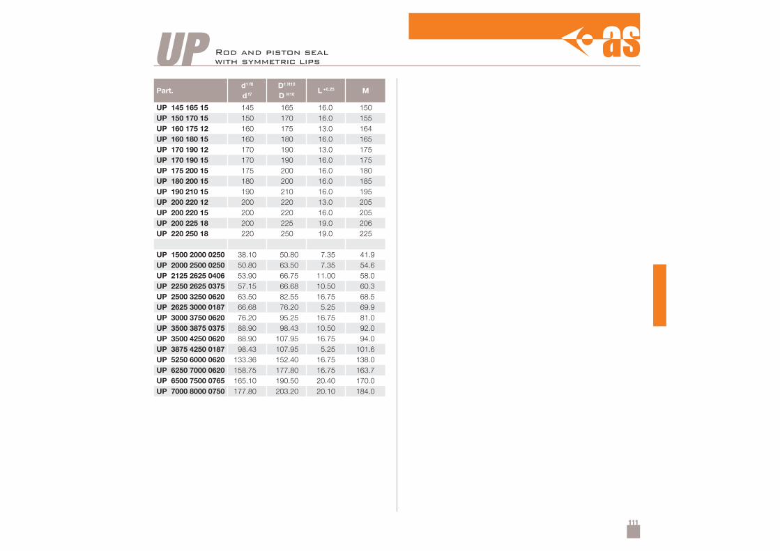
111
Part.d1 f8
d f7
D1 H10
D H10L +0.25 M
UP 145 165 15 145 165 16.0 150UP 150 170 15 150 170 16.0 155UP 160 175 12 160 175 13.0 164UP 160 180 15 160 180 16.0 165UP 170 190 12 170 190 13.0 175UP 170 190 15 170 190 16.0 175UP 175 200 15 175 200 16.0 180UP 180 200 15 180 200 16.0 185UP 190 210 15 190 210 16.0 195UP 200 220 12 200 220 13.0 205UP 200 220 15 200 220 16.0 205UP 200 225 18 200 225 19.0 206UP 220 250 18 220 250 19.0 225
UP 1500 2000 0250 38.10 50.80 7.35 41.9UP 2000 2500 0250 50.80 63.50 7.35 54.6UP 2125 2625 0406 53.90 66.75 11.00 58.0UP 2250 2625 0375 57.15 66.68 10.50 60.3UP 2500 3250 0620 63.50 82.55 16.75 68.5UP 2625 3000 0187 66.68 76.20 5.25 69.9UP 3000 3750 0620 76.20 95.25 16.75 81.0UP 3500 3875 0375 88.90 98.43 10.50 92.0UP 3500 4250 0620 88.90 107.95 16.75 94.0UP 3875 4250 0187 98.43 107.95 5.25 101.6UP 5250 6000 0620 133.36 152.40 16.75 138.0UP 6250 7000 0620 158.75 177.80 16.75 163.7UP 6500 7500 0765 165.10 190.50 20.40 170.0UP 7000 8000 0750 177.80 203.20 20.10 184.0
UP Rod and piston sealwith symmetric lips
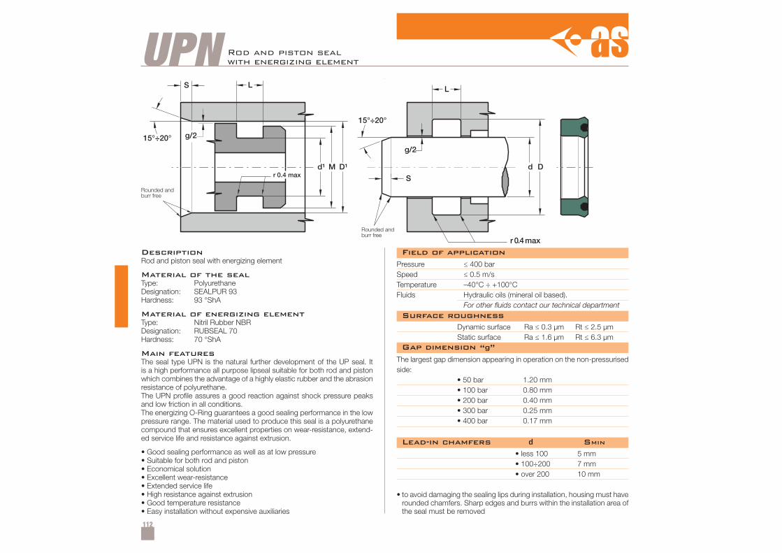
112
UPN Rod and piston sealwith energizing element
DescriptionRod and piston seal with energizing element
Material of the sealType: PolyurethaneDesignation: SEALPUR 93Hardness: 93 °ShA
Material of energizing elementType: Nitril Rubber NBRDesignation: RUBSEAL 70Hardness: 70 °ShA
Main featuresThe seal type UPN is the natural further development of the UP seal. Itis a high performance all purpose lipseal suitable for both rod and pistonwhich combines the advantage of a highly elastic rubber and the abrasionresistance of polyurethane.The UPN profile assures a good reaction against shock pressure peaksand low friction in all conditions.The energizing O-Ring guarantees a good sealing performance in the lowpressure range. The material used to produce this seal is a polyurethanecompound that ensures excellent properties on wear-resistance, extend-ed service life and resistance against extrusion.
• Good sealing performance as well as at low pressure• Suitable for both rod and piston• Economical solution• Excellent wear-resistance• Extended service life• High resistance against extrusion• Good temperature resistance• Easy installation without expensive auxiliaries
Pressure ≤ 400 barSpeed ≤ 0.5 m/sTemperature –40°C ÷ +100°CFluids Hydraulic oils (mineral oil based).
For other fluids contact our technical department
Dynamic surface Ra ≤ 0.3 µm Rt ≤ 2.5 µmStatic surface Ra ≤ 1.6 µm Rt ≤ 6.3 µm
• less 100• 100÷200• over 200
5 mm7 mm10 mm
• to avoid damaging the sealing lips during installation, housing must haverounded chamfers. Sharp edges and burrs within the installation area ofthe seal must be removed
The largest gap dimension appearing in operation on the non-pressurisedside:
• 50 bar 1.20 mm• 100 bar 0.80 mm• 200 bar 0.40 mm• 300 bar 0.25 mm• 400 bar 0.17 mm
Field of application
Surface roughness
Lead-in chamfers d SMIN
Gap dimension “g”
Rounded andburr free
Rounded andburr free
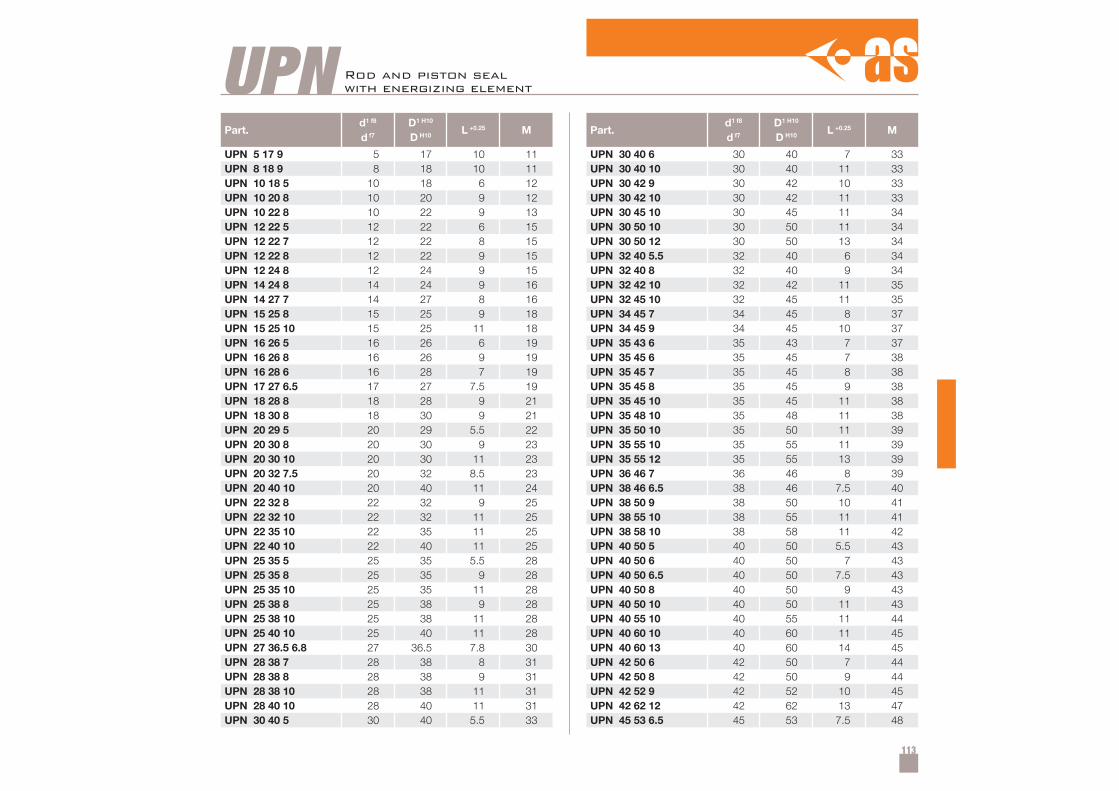
113
Part.d1 f8
d f7
D1 H10
D H10L +0.25 M
UPN 5 17 9 5 17 10 11UPN 8 18 9 8 18 10 11UPN 10 18 5 10 18 6 12UPN 10 20 8 10 20 9 12UPN 10 22 8 10 22 9 13UPN 12 22 5 12 22 6 15UPN 12 22 7 12 22 8 15UPN 12 22 8 12 22 9 15UPN 12 24 8 12 24 9 15UPN 14 24 8 14 24 9 16UPN 14 27 7 14 27 8 16UPN 15 25 8 15 25 9 18UPN 15 25 10 15 25 11 18UPN 16 26 5 16 26 6 19UPN 16 26 8 16 26 9 19UPN 16 28 6 16 28 7 19UPN 17 27 6.5 17 27 7.5 19UPN 18 28 8 18 28 9 21UPN 18 30 8 18 30 9 21UPN 20 29 5 20 29 5.5 22UPN 20 30 8 20 30 9 23UPN 20 30 10 20 30 11 23UPN 20 32 7.5 20 32 8.5 23UPN 20 40 10 20 40 11 24UPN 22 32 8 22 32 9 25UPN 22 32 10 22 32 11 25UPN 22 35 10 22 35 11 25UPN 22 40 10 22 40 11 25UPN 25 35 5 25 35 5.5 28UPN 25 35 8 25 35 9 28UPN 25 35 10 25 35 11 28UPN 25 38 8 25 38 9 28UPN 25 38 10 25 38 11 28UPN 25 40 10 25 40 11 28UPN 27 36.5 6.8 27 36.5 7.8 30UPN 28 38 7 28 38 8 31UPN 28 38 8 28 38 9 31UPN 28 38 10 28 38 11 31UPN 28 40 10 28 40 11 31UPN 30 40 5 30 40 5.5 33
Part.d1 f8
d f7
D1 H10
D H10L +0.25 M
UPN 30 40 6 30 40 7 33UPN 30 40 10 30 40 11 33UPN 30 42 9 30 42 10 33UPN 30 42 10 30 42 11 33UPN 30 45 10 30 45 11 34UPN 30 50 10 30 50 11 34UPN 30 50 12 30 50 13 34UPN 32 40 5.5 32 40 6 34UPN 32 40 8 32 40 9 34UPN 32 42 10 32 42 11 35UPN 32 45 10 32 45 11 35UPN 34 45 7 34 45 8 37UPN 34 45 9 34 45 10 37UPN 35 43 6 35 43 7 37UPN 35 45 6 35 45 7 38UPN 35 45 7 35 45 8 38UPN 35 45 8 35 45 9 38UPN 35 45 10 35 45 11 38UPN 35 48 10 35 48 11 38UPN 35 50 10 35 50 11 39UPN 35 55 10 35 55 11 39UPN 35 55 12 35 55 13 39UPN 36 46 7 36 46 8 39UPN 38 46 6.5 38 46 7.5 40UPN 38 50 9 38 50 10 41UPN 38 55 10 38 55 11 41UPN 38 58 10 38 58 11 42UPN 40 50 5 40 50 5.5 43UPN 40 50 6 40 50 7 43UPN 40 50 6.5 40 50 7.5 43UPN 40 50 8 40 50 9 43UPN 40 50 10 40 50 11 43UPN 40 55 10 40 55 11 44UPN 40 60 10 40 60 11 45UPN 40 60 13 40 60 14 45UPN 42 50 6 42 50 7 44UPN 42 50 8 42 50 9 44UPN 42 52 9 42 52 10 45UPN 42 62 12 42 62 13 47UPN 45 53 6.5 45 53 7.5 48
UPN Rod and piston sealwith energizing element
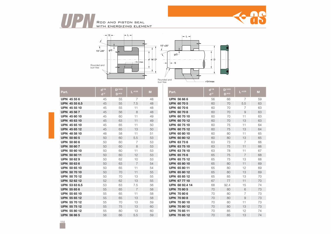
114
Part.d1 f8
d f7
D1 H10
D H10L +0.25 M
UPN 45 55 6 45 55 7 48UPN 45 55 6.5 45 55 7.5 48UPN 45 55 10 45 55 11 48UPN 45 56 7 45 56 8 48UPN 45 60 10 45 60 11 49UPN 45 63 10 45 63 11 49UPN 45 65 10 45 65 11 50UPN 45 65 12 45 65 13 50UPN 48 58 10 48 58 11 51UPN 50 60 5 50 60 5.5 53UPN 50 60 6 50 60 7 53UPN 50 60 7 50 60 8 53UPN 50 60 10 50 60 11 53UPN 50 60 11 50 60 12 53UPN 50 62 9 50 62 10 53UPN 50 63 6 50 63 7 54UPN 50 65 10 50 65 11 54UPN 50 70 10 50 70 11 55UPN 50 70 12 50 70 13 55UPN 52 62 12 52 62 13 55UPN 53 63 6.5 53 63 7.5 56UPN 55 65 6 55 65 7 58UPN 55 65 10 55 65 11 58UPN 55 65 12 55 65 13 58UPN 55 70 12 55 70 13 59UPN 55 75 12 55 75 13 60UPN 55 80 12 55 80 13 60UPN 56 66 5 56 66 5.5 59
Part.d1 f8
d f7
D1 H10
D H10L +0.25 M
UPN 56 66 6 56 66 7 59UPN 60 70 5 60 70 5.5 63UPN 60 70 6 60 70 7 63UPN 60 70 8 60 70 9 63UPN 60 70 10 60 70 11 63UPN 60 70 12 60 70 13 63UPN 60 75 10 60 75 11 64UPN 60 75 12 60 75 13 64UPN 60 80 10 60 80 11 65UPN 60 80 12 60 80 13 65UPN 63 73 6 63 73 7 66UPN 63 75 10 63 75 11 66UPN 63 78 10 63 78 11 67UPN 65 75 6 65 75 7 68UPN 65 75 12 65 75 13 68UPN 65 80 10 65 80 11 69UPN 65 80 11 65 80 12 69UPN 65 80 12 65 80 13 69UPN 65 85 12 65 85 13 70UPN 67 77 10 67 77 11 70UPN 68 92.4 14 68 92.4 15 74UPN 70 80 5 70 80 6 73UPN 70 80 6 70 80 7 73UPN 70 80 8 70 80 9 73UPN 70 80 10 70 80 11 73UPN 70 80 12 70 80 13 73UPN 70 85 11 70 85 12 74UPN 70 85 12 70 85 13 74
UPN Rod and piston sealwith energizing element
Rounded andburr free
Rounded andburr free
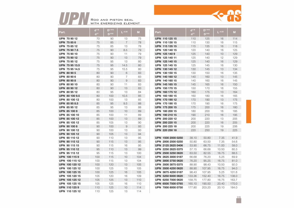
115
Part.d1 f8
d f7
D1 H10
D H10L +0.25 M
UPN 70 90 12 70 90 13 75UPN 75 85 6 75 85 7 78UPN 75 85 12 75 85 13 78UPN 75 90 7.5 75 90 8.5 79UPN 75 90 10 75 90 11 79UPN 75 90 12 75 90 13 79UPN 75 95 12 75 95 13 80UPN 75 95 13.5 75 95 14.5 80UPN 75 95 14.5 75 95 15.5 80UPN 80 90 5 80 90 6 83UPN 80 90 6 80 90 7 83UPN 80 90 8 80 90 9 83UPN 80 90 10 80 90 11 83UPN 80 90 12 80 90 13 83UPN 80 95 12 80 95 13 84UPN 80 100 9.5 80 100 10.5 85UPN 80 100 12 80 100 13 85UPN 85 95 8.5 85 95 9.5 88UPN 85 95 12 85 95 13 88UPN 85 100 9 85 100 10 89UPN 85 100 10 85 100 11 89UPN 85 100 12 85 100 13 89UPN 85 105 12 85 105 13 90UPN 90 100 8 90 100 9 93UPN 90 100 12 90 100 13 93UPN 90 105 12 90 105 13 94UPN 90 110 12 90 110 13 95UPN 90 115 12 90 115 13 95UPN 90 115 15 90 115 16 95UPN 95 110 12 95 110 13 99UPN 95 115 12 95 115 13 100UPN 100 115 9 100 115 10 104UPN 100 115 12 100 115 13 104UPN 100 120 12 100 120 13 105UPN 100 125 12 100 125 13 105UPN 100 125 15 100 125 16 105UPN 105 120 15 105 120 16 109UPN 105 125 12 105 125 13 110UPN 105 125 15 105 125 16 110UPN 110 125 9 110 125 10 114UPN 110 125 12 110 125 13 114
Part.d1 f8
d f7
D1 H10
D H10L +0.25 M
UPN 110 125 15 110 125 16 114UPN 110 130 15 110 130 16 115UPN 115 135 15 115 135 16 118UPN 120 140 15 120 140 16 125UPN 125 140 9 125 140 10 129UPN 125 140 11 125 140 12 129UPN 125 140 15 125 140 16 129UPN 125 145 15 125 145 16 130UPN 130 145 12 130 145 13 134UPN 130 150 15 130 150 16 135UPN 140 160 12 140 160 13 145UPN 140 160 15 140 160 16 145UPN 145 165 15 145 165 16 150UPN 150 170 15 150 170 16 155UPN 160 175 12 160 175 13 164UPN 160 180 15 160 180 16 165UPN 170 190 12 170 190 13 175UPN 170 190 15 170 190 16 175UPN 175 200 15 175 200 16 180UPN 180 200 15 180 200 16 185UPN 190 210 15 190 210 16 195UPN 200 220 12 200 220 13 205UPN 200 220 15 200 220 16 205UPN 200 225 18 200 225 19 206UPN 220 250 18 220 250 19 225
UPN 1500 2000 0250 38.10 50.80 7.35 41.9UPN 2000 2500 0250 50.80 63.50 7.35 54.6UPN 2125 2625 0406 53.90 66.75 11.00 58.0UPN 2250 2625 0375 57.15 66.68 10.50 60.3UPN 2500 3250 0620 63.50 82.55 16.75 68.5UPN 2625 3000 0187 66.68 76.20 5.25 69.9UPN 3000 3750 0620 76.20 95.25 16.75 81.0UPN 3500 3875 0375 88.90 98.43 10.50 92.0UPN 3500 4250 0620 88.90 107.95 16.75 94.0UPN 3875 4250 0187 98.43 107.95 5.25 101.6UPN 5250 6000 0620 133.36 152.40 16.75 138.0UPN 6250 7000 0620 158.75 177.80 16.75 163.7UPN 6500 7500 0765 165.10 190.50 20.40 170.0UPN 7000 8000 0750 177.80 203.20 20.10 184.0
UPN Rod and piston sealwith energizing element
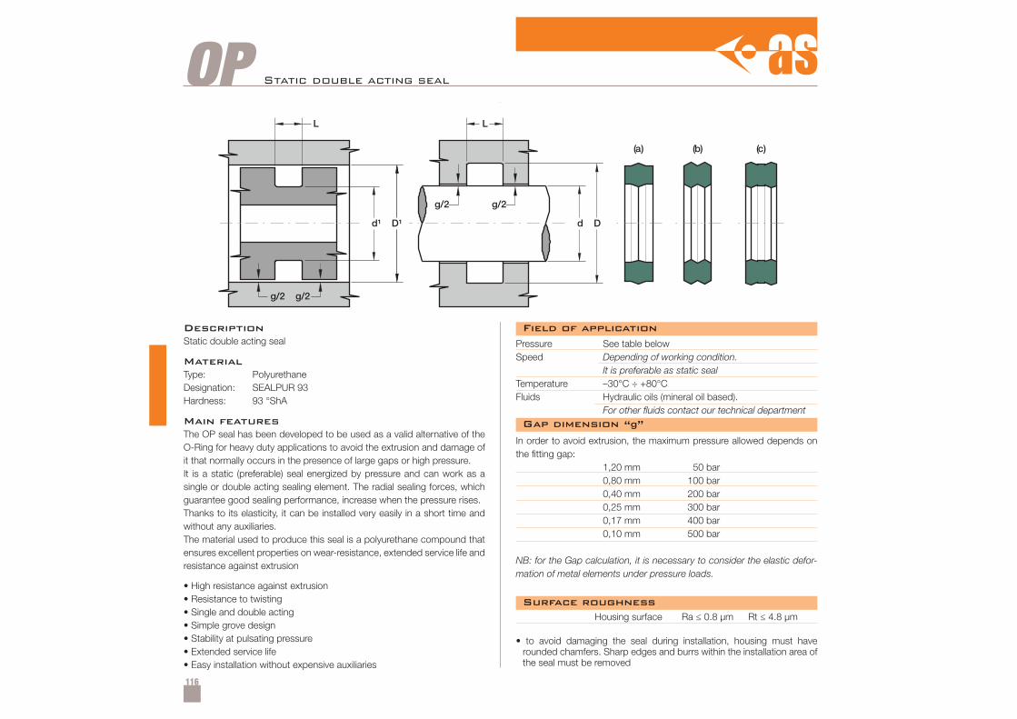
116
OP Static double acting seal
DescriptionStatic double acting seal
MaterialType: PolyurethaneDesignation: SEALPUR 93Hardness: 93 °ShA
Main featuresThe OP seal has been developed to be used as a valid alternative of theO-Ring for heavy duty applications to avoid the extrusion and damage ofit that normally occurs in the presence of large gaps or high pressure.It is a static (preferable) seal energized by pressure and can work as asingle or double acting sealing element. The radial sealing forces, whichguarantee good sealing performance, increase when the pressure rises.Thanks to its elasticity, it can be installed very easily in a short time andwithout any auxiliaries.The material used to produce this seal is a polyurethane compound thatensures excellent properties on wear-resistance, extended service life andresistance against extrusion
• High resistance against extrusion• Resistance to twisting• Single and double acting• Simple grove design• Stability at pulsating pressure• Extended service life• Easy installation without expensive auxiliaries
Pressure See table belowSpeed Depending of working condition.
It is preferable as static sealTemperature –30°C ÷ +80°CFluids Hydraulic oils (mineral oil based).
For other fluids contact our technical department
In order to avoid extrusion, the maximum pressure allowed depends onthe fitting gap:
1,20 mm 50 bar0,80 mm 100 bar0,40 mm 200 bar0,25 mm 300 bar0,17 mm 400 bar0,10 mm 500 bar
NB: for the Gap calculation, it is necessary to consider the elastic defor-mation of metal elements under pressure loads.
• to avoid damaging the seal during installation, housing must haverounded chamfers. Sharp edges and burrs within the installation area ofthe seal must be removed
Housing surface Ra ≤ 0.8 µm Rt ≤ 4.8 µm
Field of application
Gap dimension “g”
Surface roughness
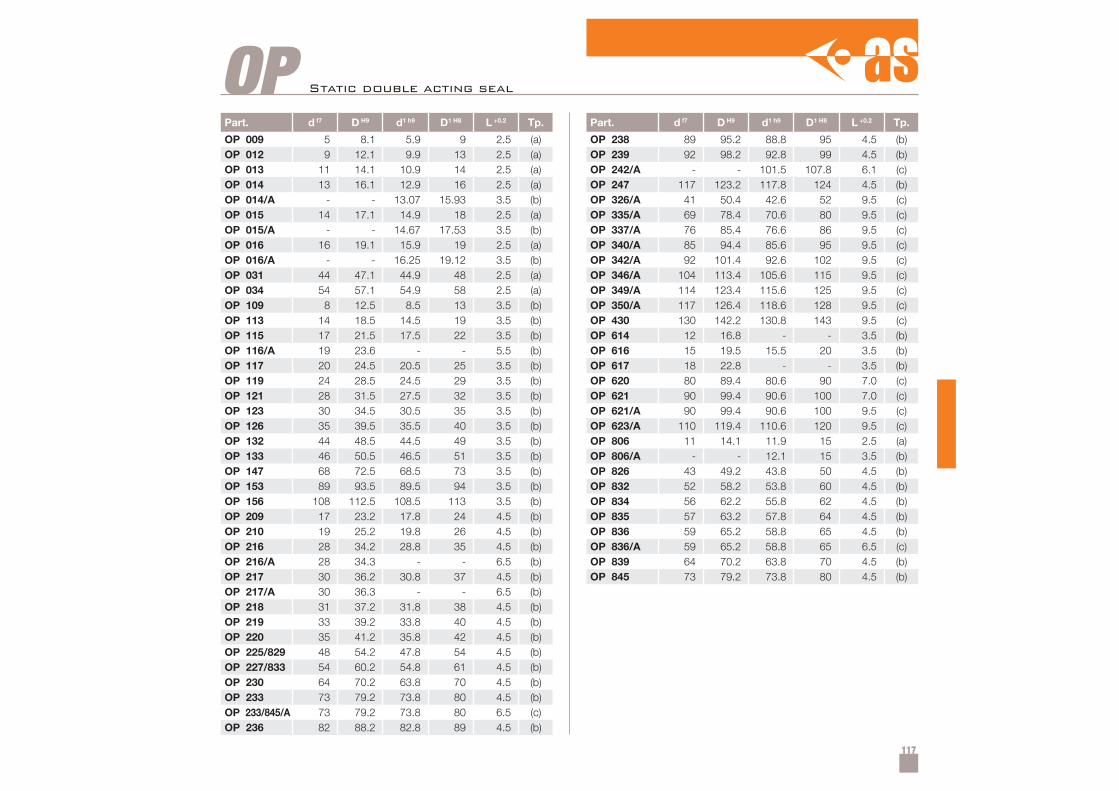
117
Part. d f7 D H9 d1 h9 D1 H8 L +0.2 Tp.
OP 009 5 8.1 5.9 9 2.5 (a)OP 012 9 12.1 9.9 13 2.5 (a)OP 013 11 14.1 10.9 14 2.5 (a)OP 014 13 16.1 12.9 16 2.5 (a)OP 014/A - - 13.07 15.93 3.5 (b)OP 015 14 17.1 14.9 18 2.5 (a)OP 015/A - - 14.67 17.53 3.5 (b)OP 016 16 19.1 15.9 19 2.5 (a)OP 016/A - - 16.25 19.12 3.5 (b)OP 031 44 47.1 44.9 48 2.5 (a)OP 034 54 57.1 54.9 58 2.5 (a)OP 109 8 12.5 8.5 13 3.5 (b)OP 113 14 18.5 14.5 19 3.5 (b)OP 115 17 21.5 17.5 22 3.5 (b)OP 116/A 19 23.6 - - 5.5 (b)OP 117 20 24.5 20.5 25 3.5 (b)OP 119 24 28.5 24.5 29 3.5 (b)OP 121 28 31.5 27.5 32 3.5 (b)OP 123 30 34.5 30.5 35 3.5 (b)OP 126 35 39.5 35.5 40 3.5 (b)OP 132 44 48.5 44.5 49 3.5 (b)OP 133 46 50.5 46.5 51 3.5 (b)OP 147 68 72.5 68.5 73 3.5 (b)OP 153 89 93.5 89.5 94 3.5 (b)OP 156 108 112.5 108.5 113 3.5 (b)OP 209 17 23.2 17.8 24 4.5 (b)OP 210 19 25.2 19.8 26 4.5 (b)OP 216 28 34.2 28.8 35 4.5 (b)OP 216/A 28 34.3 - - 6.5 (b)OP 217 30 36.2 30.8 37 4.5 (b)OP 217/A 30 36.3 - - 6.5 (b)OP 218 31 37.2 31.8 38 4.5 (b)OP 219 33 39.2 33.8 40 4.5 (b)OP 220 35 41.2 35.8 42 4.5 (b)OP 225/829 48 54.2 47.8 54 4.5 (b)OP 227/833 54 60.2 54.8 61 4.5 (b)OP 230 64 70.2 63.8 70 4.5 (b)OP 233 73 79.2 73.8 80 4.5 (b)OP 233/845/A 73 79.2 73.8 80 6.5 (c)OP 236 82 88.2 82.8 89 4.5 (b)
Part. d f7 D H9 d1 h9 D1 H8 L +0.2 Tp.
OP 238 89 95.2 88.8 95 4.5 (b)OP 239 92 98.2 92.8 99 4.5 (b)OP 242/A - - 101.5 107.8 6.1 (c)OP 247 117 123.2 117.8 124 4.5 (b)OP 326/A 41 50.4 42.6 52 9.5 (c)OP 335/A 69 78.4 70.6 80 9.5 (c)OP 337/A 76 85.4 76.6 86 9.5 (c)OP 340/A 85 94.4 85.6 95 9.5 (c)OP 342/A 92 101.4 92.6 102 9.5 (c)OP 346/A 104 113.4 105.6 115 9.5 (c)OP 349/A 114 123.4 115.6 125 9.5 (c)OP 350/A 117 126.4 118.6 128 9.5 (c)OP 430 130 142.2 130.8 143 9.5 (c)OP 614 12 16.8 - - 3.5 (b)OP 616 15 19.5 15.5 20 3.5 (b)OP 617 18 22.8 - - 3.5 (b)OP 620 80 89.4 80.6 90 7.0 (c)OP 621 90 99.4 90.6 100 7.0 (c)OP 621/A 90 99.4 90.6 100 9.5 (c)OP 623/A 110 119.4 110.6 120 9.5 (c)OP 806 11 14.1 11.9 15 2.5 (a)OP 806/A - - 12.1 15 3.5 (b)OP 826 43 49.2 43.8 50 4.5 (b)OP 832 52 58.2 53.8 60 4.5 (b)OP 834 56 62.2 55.8 62 4.5 (b)OP 835 57 63.2 57.8 64 4.5 (b)OP 836 59 65.2 58.8 65 4.5 (b)OP 836/A 59 65.2 58.8 65 6.5 (c)OP 839 64 70.2 63.8 70 4.5 (b)OP 845 73 79.2 73.8 80 4.5 (b)
OP Static double acting seal
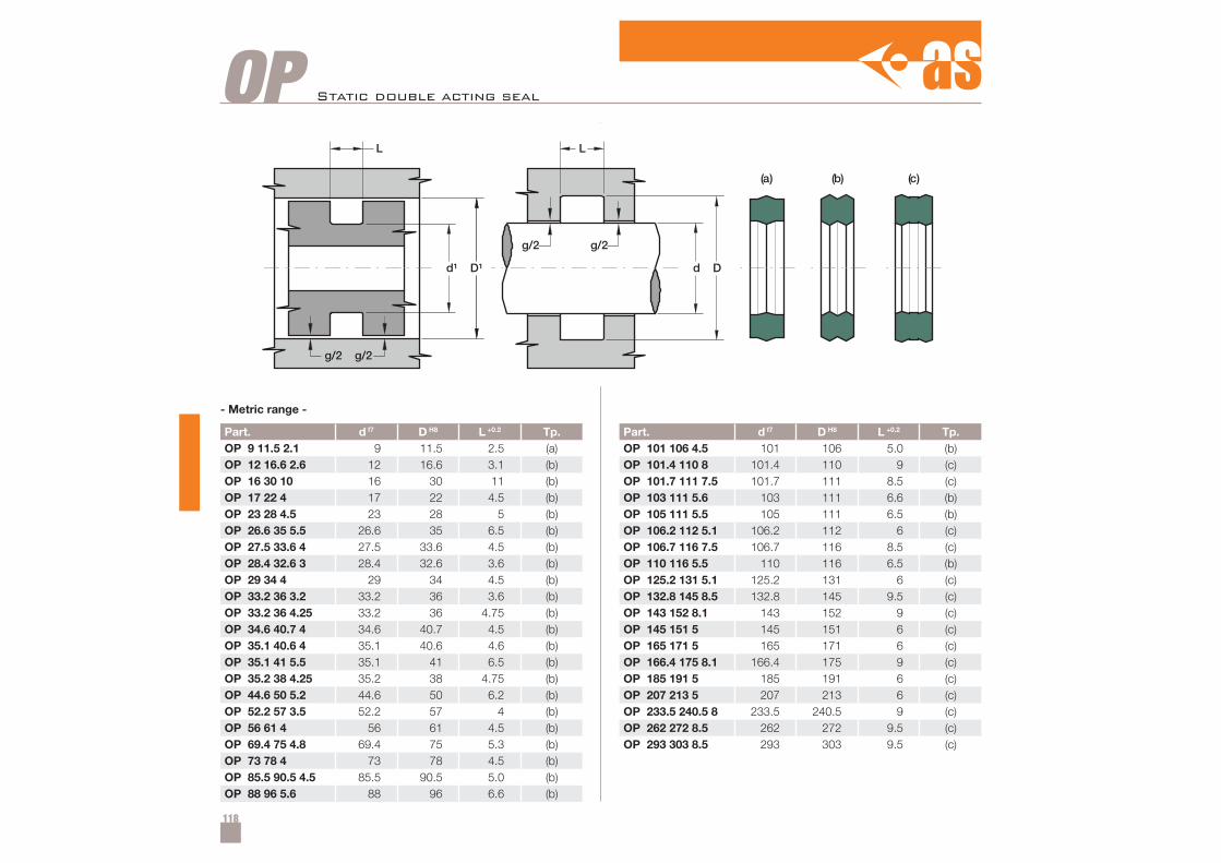
118
OP
Part. d f7 D H8 L +0.2 Tp.OP 101 106 4.5 101 106 5.0 (b)OP 101.4 110 8 101.4 110 9 (c)OP 101.7 111 7.5 101.7 111 8.5 (c)OP 103 111 5.6 103 111 6.6 (b)OP 105 111 5.5 105 111 6.5 (b)OP 106.2 112 5.1 106.2 112 6 (c)OP 106.7 116 7.5 106.7 116 8.5 (c)OP 110 116 5.5 110 116 6.5 (b)OP 125.2 131 5.1 125.2 131 6 (c)OP 132.8 145 8.5 132.8 145 9.5 (c)OP 143 152 8.1 143 152 9 (c)OP 145 151 5 145 151 6 (c)OP 165 171 5 165 171 6 (c)OP 166.4 175 8.1 166.4 175 9 (c)OP 185 191 5 185 191 6 (c)OP 207 213 5 207 213 6 (c)OP 233.5 240.5 8 233.5 240.5 9 (c)OP 262 272 8.5 262 272 9.5 (c)OP 293 303 8.5 293 303 9.5 (c)
Part. d f7 D H8 L +0.2 Tp.OP 9 11.5 2.1 9 11.5 2.5 (a)OP 12 16.6 2.6 12 16.6 3.1 (b)OP 16 30 10 16 30 11 (b)OP 17 22 4 17 22 4.5 (b)OP 23 28 4.5 23 28 5 (b)OP 26.6 35 5.5 26.6 35 6.5 (b)OP 27.5 33.6 4 27.5 33.6 4.5 (b)OP 28.4 32.6 3 28.4 32.6 3.6 (b)OP 29 34 4 29 34 4.5 (b)OP 33.2 36 3.2 33.2 36 3.6 (b)OP 33.2 36 4.25 33.2 36 4.75 (b)OP 34.6 40.7 4 34.6 40.7 4.5 (b)OP 35.1 40.6 4 35.1 40.6 4.6 (b)OP 35.1 41 5.5 35.1 41 6.5 (b)OP 35.2 38 4.25 35.2 38 4.75 (b)OP 44.6 50 5.2 44.6 50 6.2 (b)OP 52.2 57 3.5 52.2 57 4 (b)OP 56 61 4 56 61 4.5 (b)OP 69.4 75 4.8 69.4 75 5.3 (b)OP 73 78 4 73 78 4.5 (b)OP 85.5 90.5 4.5 85.5 90.5 5.0 (b)OP 88 96 5.6 88 96 6.6 (b)
Static double acting seal
- Metric range -
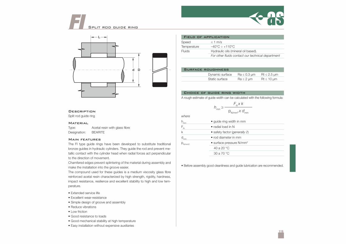
119
FI
hmm ≥FN x k
pN/mm2 x dmm
Split rod guide ring
DescriptionSplit rod guide ring
MaterialType: Acetal resin with glass fibreDesignation: BEARITE
Main featuresThe FI type guide rings have been developed to substitute traditionalbronze guides in hydraulic cylinders. They guide the rod and prevent me-tallic contact with the cylinder head when radial forces act perpendicularto the direction of movement.Chamfered edges prevent splintering of the material during assembly andmake the installation into the groove easier.The compound used for these guides is a medium viscosity glass fibrereinforced acetal resin characterized by high strength, rigidity, hardness,impact resistance, resilience and excellent stability to high and low tem-perature.
• Extended service life• Excellent wear-resistance• Simple design of groove and assembly• Reduce vibrations• Low friction• Good resistance to loads• Good mechanical stability at high temperature• Easy installation without expensive auxiliaries
Speed ≤ 1 m/sTemperature –40°C ÷ +110°CFluids Hydraulic oils (mineral oil based).
For other fluids contact our technical department
Dynamic surface Ra ≤ 0.3 µm Rt ≤ 2.5 µmStatic surface Ra ≤ 2 µm Rt ≤ 10 µm
• Before assembly good cleanliness and guide lubrication are recommended.
A rough estimate of guide width can be calculated with the following formula:
where
hmm • guide ring width in mm
FN • radial load in N
k • safety factor (generally 2)
dmm • rod diameter in mm
pN/mm2 • surface pressure N/mm2
40 a 20 °C
30 a 70 °C
Field of application
Surface roughness
Choice of guide ring width
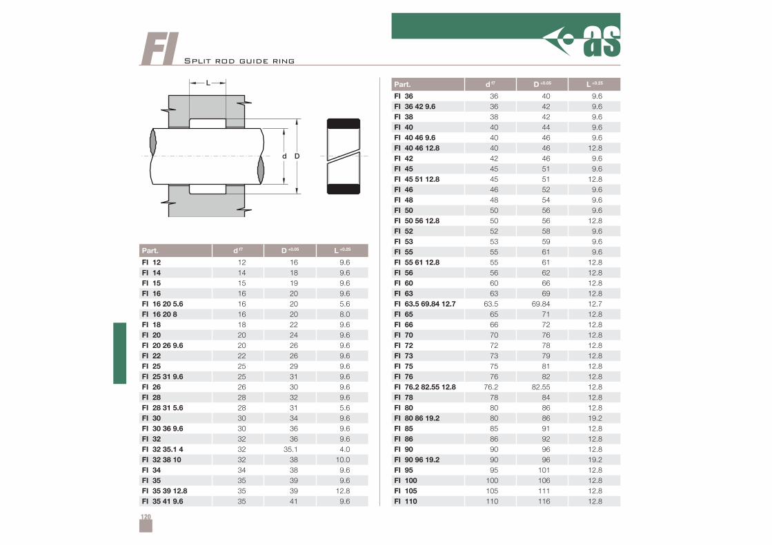
120
Part. d f7 D +0.05 L +0.25
FI 12 12 16 9.6FI 14 14 18 9.6FI 15 15 19 9.6FI 16 16 20 9.6FI 16 20 5.6 16 20 5.6FI 16 20 8 16 20 8.0FI 18 18 22 9.6FI 20 20 24 9.6FI 20 26 9.6 20 26 9.6FI 22 22 26 9.6FI 25 25 29 9.6FI 25 31 9.6 25 31 9.6FI 26 26 30 9.6FI 28 28 32 9.6FI 28 31 5.6 28 31 5.6FI 30 30 34 9.6FI 30 36 9.6 30 36 9.6FI 32 32 36 9.6FI 32 35.1 4 32 35.1 4.0FI 32 38 10 32 38 10.0FI 34 34 38 9.6FI 35 35 39 9.6FI 35 39 12.8 35 39 12.8FI 35 41 9.6 35 41 9.6
Part. d f7 D +0.05 L +0.25
FI 36 36 40 9.6FI 36 42 9.6 36 42 9.6FI 38 38 42 9.6FI 40 40 44 9.6FI 40 46 9.6 40 46 9.6FI 40 46 12.8 40 46 12.8FI 42 42 46 9.6FI 45 45 51 9.6FI 45 51 12.8 45 51 12.8FI 46 46 52 9.6FI 48 48 54 9.6FI 50 50 56 9.6FI 50 56 12.8 50 56 12.8FI 52 52 58 9.6FI 53 53 59 9.6FI 55 55 61 9.6FI 55 61 12.8 55 61 12.8FI 56 56 62 12.8FI 60 60 66 12.8FI 63 63 69 12.8FI 63.5 69.84 12.7 63.5 69.84 12.7FI 65 65 71 12.8FI 66 66 72 12.8FI 70 70 76 12.8FI 72 72 78 12.8FI 73 73 79 12.8FI 75 75 81 12.8FI 76 76 82 12.8FI 76.2 82.55 12.8 76.2 82.55 12.8FI 78 78 84 12.8FI 80 80 86 12.8FI 80 86 19.2 80 86 19.2FI 85 85 91 12.8FI 86 86 92 12.8FI 90 90 96 12.8FI 90 96 19.2 90 96 19.2FI 95 95 101 12.8FI 100 100 106 12.8FI 105 105 111 12.8FI 110 110 116 12.8
FI Split rod guide ring
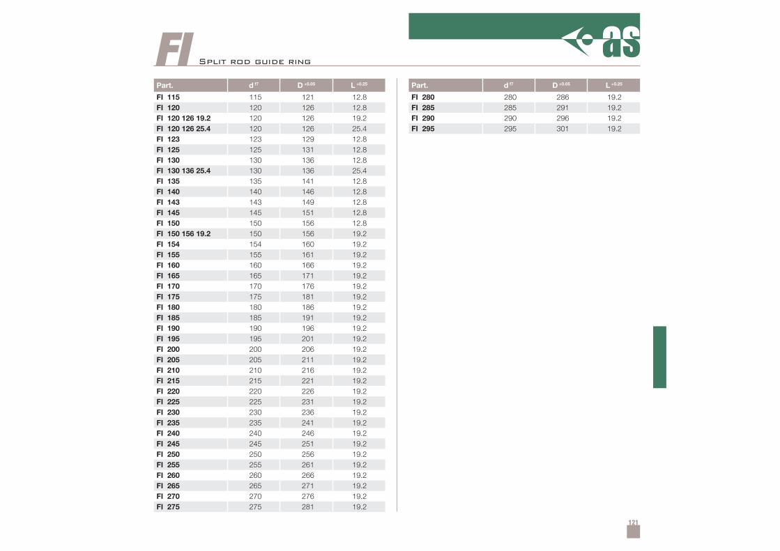
121
Part. d f7 D +0.05 L +0.25
FI 115 115 121 12.8FI 120 120 126 12.8FI 120 126 19.2 120 126 19.2FI 120 126 25.4 120 126 25.4FI 123 123 129 12.8FI 125 125 131 12.8FI 130 130 136 12.8FI 130 136 25.4 130 136 25.4FI 135 135 141 12.8FI 140 140 146 12.8FI 143 143 149 12.8FI 145 145 151 12.8FI 150 150 156 12.8FI 150 156 19.2 150 156 19.2FI 154 154 160 19.2FI 155 155 161 19.2FI 160 160 166 19.2FI 165 165 171 19.2FI 170 170 176 19.2FI 175 175 181 19.2FI 180 180 186 19.2FI 185 185 191 19.2FI 190 190 196 19.2FI 195 195 201 19.2FI 200 200 206 19.2FI 205 205 211 19.2FI 210 210 216 19.2FI 215 215 221 19.2FI 220 220 226 19.2FI 225 225 231 19.2FI 230 230 236 19.2FI 235 235 241 19.2FI 240 240 246 19.2FI 245 245 251 19.2FI 250 250 256 19.2FI 255 255 261 19.2FI 260 260 266 19.2FI 265 265 271 19.2FI 270 270 276 19.2FI 275 275 281 19.2
FIPart. d f7 D +0.05 L +0.25
FI 280 280 286 19.2FI 285 285 291 19.2FI 290 290 296 19.2FI 295 295 301 19.2
Split rod guide ring
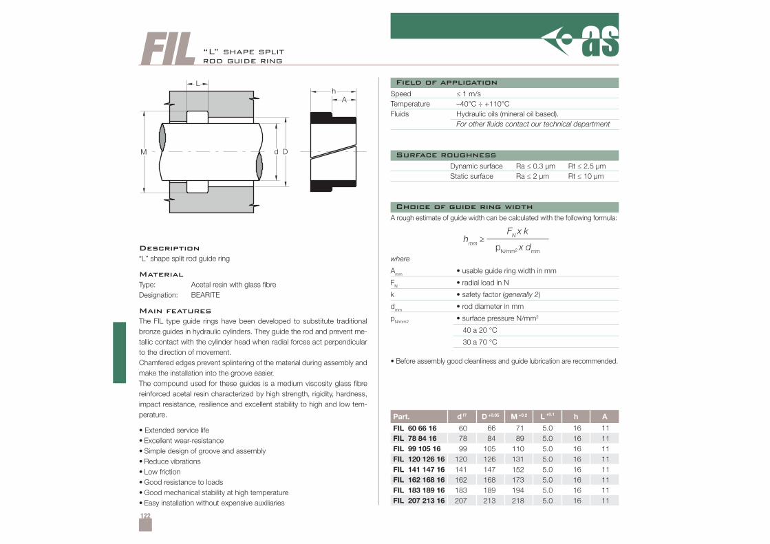
122
FIL
d DM
Lh
A
hmm ≥FN x k
pN/mm2 x dmm
Part. d f7 D +0.05 M +0.2 L +0.1 h A
FIL 60 66 16 60 66 71 5.0 16 11FIL 78 84 16 78 84 89 5.0 16 11FIL 99 105 16 99 105 110 5.0 16 11FIL 120 126 16 120 126 131 5.0 16 11FIL 141 147 16 141 147 152 5.0 16 11FIL 162 168 16 162 168 173 5.0 16 11FIL 183 189 16 183 189 194 5.0 16 11FIL 207 213 16 207 213 218 5.0 16 11
+0.2
“L” shape splitrod guide ring
Description“L” shape split rod guide ring
MaterialType: Acetal resin with glass fibreDesignation: BEARITE
Main featuresThe FIL type guide rings have been developed to substitute traditionalbronze guides in hydraulic cylinders. They guide the rod and prevent me-tallic contact with the cylinder head when radial forces act perpendicularto the direction of movement.Chamfered edges prevent splintering of the material during assembly andmake the installation into the groove easier.The compound used for these guides is a medium viscosity glass fibrereinforced acetal resin characterized by high strength, rigidity, hardness,impact resistance, resilience and excellent stability to high and low tem-perature.
• Extended service life• Excellent wear-resistance• Simple design of groove and assembly• Reduce vibrations• Low friction• Good resistance to loads• Good mechanical stability at high temperature• Easy installation without expensive auxiliaries
Speed ≤ 1 m/sTemperature –40°C ÷ +110°CFluids Hydraulic oils (mineral oil based).
For other fluids contact our technical department
Dynamic surface Ra ≤ 0.3 µm Rt ≤ 2.5 µmStatic surface Ra ≤ 2 µm Rt ≤ 10 µm
• Before assembly good cleanliness and guide lubrication are recommended.
A rough estimate of guide width can be calculated with the following formula:
where
Amm • usable guide ring width in mm
FN • radial load in N
k • safety factor (generally 2)
dmm • rod diameter in mm
pN/mm2 • surface pressure N/mm2
40 a 20 °C
30 a 70 °C
Field of application
Surface roughness
Choice of guide ring width
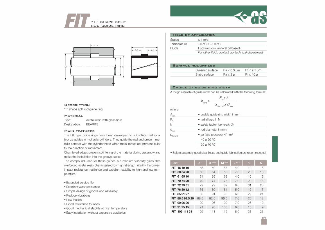
123
FITh
A/2 A/2
d DM
L
hmm ≥FN x k
pN/mm2 x dmm
Part. d f7 D +0.05 M +0.2 L +0.2 h A
FIT 45 49 10 45 49 53 4.0 10 6FIT 50 54 20 50 54 58 7.0 20 13FIT 61 65 10 61 65 69 4.0 10 6FIT 70 74 20 70 74 78 7.0 20 13FIT 72 79 31 72 79 82 8.0 31 23FIT 76 80 12 76 80 84 5.0 12 7FIT 85 91 27 85 91 95 6.0 27 21FIT 88.5 92.5 20 88.5 92.5 96.5 7.0 20 13FIT 90 96 26 90 96 100 7.0 26 19FIT 91 95 15 91 95 100 6.0 15 9FIT 105 111 31 105 111 115 8.0 31 23
“T” shape splitrod guide ring
Description“T” shape split rod guide ring
MaterialType: Acetal resin with glass fibreDesignation: BEARITE
Main featuresThe FIT type guide rings have been developed to substitute traditionalbronze guides in hydraulic cylinders. They guide the rod and prevent me-tallic contact with the cylinder head when radial forces act perpendicularto the direction of movement.Chamfered edges prevent splintering of the material during assembly andmake the installation into the groove easier.The compound used for these guides is a medium viscosity glass fibrereinforced acetal resin characterized by high strength, rigidity, hardness,impact resistance, resilience and excellent stability to high and low tem-perature.
• Extended service life• Excellent wear-resistance• Simple design of groove and assembly• Reduce vibrations• Low friction• Good resistance to loads• Good mechanical stability at high temperature• Easy installation without expensive auxiliaries
Speed ≤ 1 m/sTemperature –40°C ÷ +110°CFluids Hydraulic oils (mineral oil based).
For other fluids contact our technical department
Dynamic surface Ra ≤ 0.3 µm Rt ≤ 2.5 µmStatic surface Ra ≤ 2 µm Rt ≤ 10 µm
• Before assembly good cleanliness and guide lubrication are recommended.
A rough estimate of guide width can be calculated with the following formula:
where
Amm • usable guide ring width in mm
FN • radial load in N
k • safety factor (generally 2)
dmm • rod diameter in mm
pN/mm2 • surface pressure N/mm2
40 a 20 °C
30 a 70 °C
Field of application
Surface roughness
Choice of guide ring width
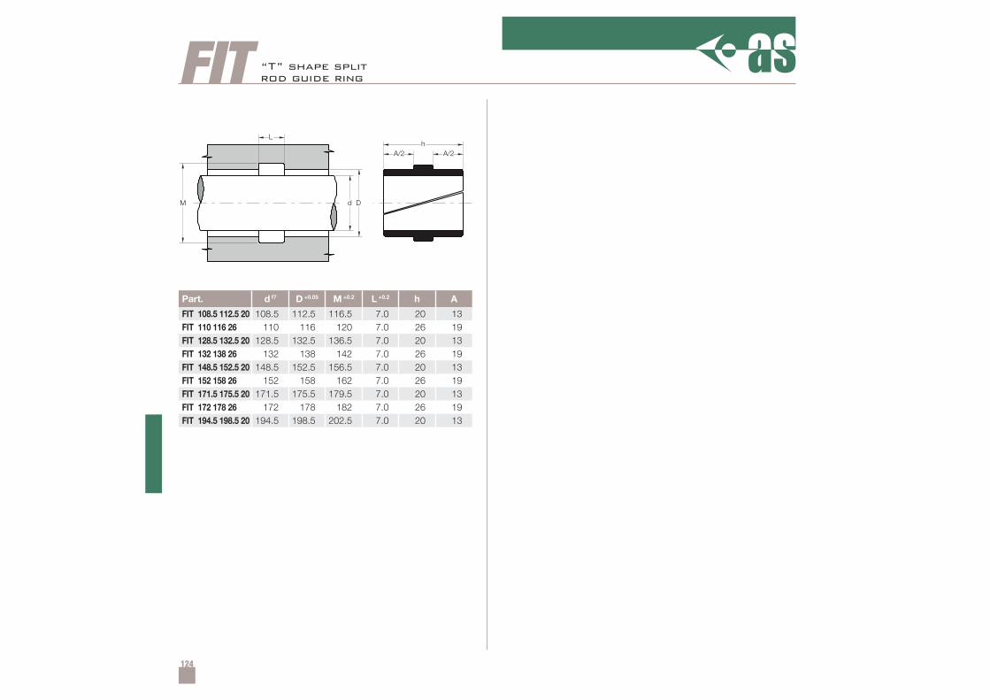
124
FITh
A/2 A/2
d DM
L
Part. d f7 D +0.05 M +0.2 L +0.2 h A
FIT 108.5 112.5 20 108.5 112.5 116.5 7.0 20 13FIT 110 116 26 110 116 120 7.0 26 19FIT 128.5 132.5 20 128.5 132.5 136.5 7.0 20 13FIT 132 138 26 132 138 142 7.0 26 19FIT 148.5 152.5 20 148.5 152.5 156.5 7.0 20 13FIT 152 158 26 152 158 162 7.0 26 19FIT 171.5 175.5 20 171.5 175.5 179.5 7.0 20 13FIT 172 178 26 172 178 182 7.0 26 19FIT 194.5 198.5 20 194.5 198.5 202.5 7.0 20 13
“T” shape splitrod guide ring
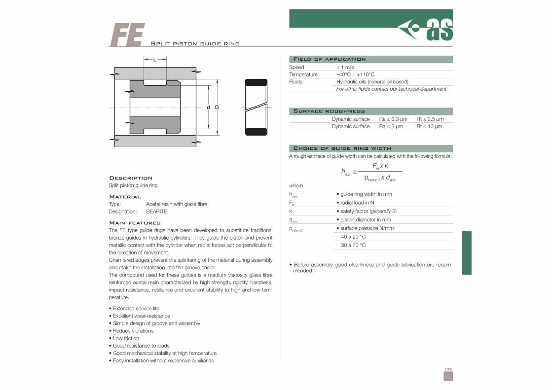
125
FE
hmm ≥FN x k
pN/mm2 x dmm
Split piston guide ring
DescriptionSplit piston guide ring
MaterialType: Acetal resin with glass fibreDesignation: BEARITE
Main featuresThe FE type guide rings have been developed to substitute traditionalbronze guides in hydraulic cylinders. They guide the piston and preventmetallic contact with the cylinder when radial forces act perpendicular tothe direction of movement.Chamfered edges prevent the splintering of the material during assemblyand make the installation into the groove easier.The compound used for these guides is a medium viscosity glass fibrereinforced acetal resin characterized by high strength, rigidity, hardness,impact resistance, resilience and excellent stability to high and low tem-perature.
• Extended service life• Excellent wear-resistance• Simple design of groove and assembly• Reduce vibrations• Low friction• Good resistance to loads• Good mechanical stability at high temperature• Easy installation without expensive auxiliaries
Speed ≤ 1 m/sTemperature –40°C ÷ +110°CFluids Hydraulic oils (mineral oil based).
For other fluids contact our technical department
Dynamic surface Ra ≤ 0.3 µm Rt ≤ 2.5 µmDynamic surface Ra ≤ 2 µm Rt ≤ 10 µm
• Before assembly good cleanliness and guide lubrication are recom-mended.
A rough estimate of guide width can be calculated with the following formula:
where
hmm • guide ring width in mm
FN • radial load in N
k • safety factor (generally 2)
dmm • piston diameter in mm
pN/mm2 • surface pressure N/mm2
40 a 20 °C
30 a 70 °C
Field of application
Surface roughness
Choice of guide ring width
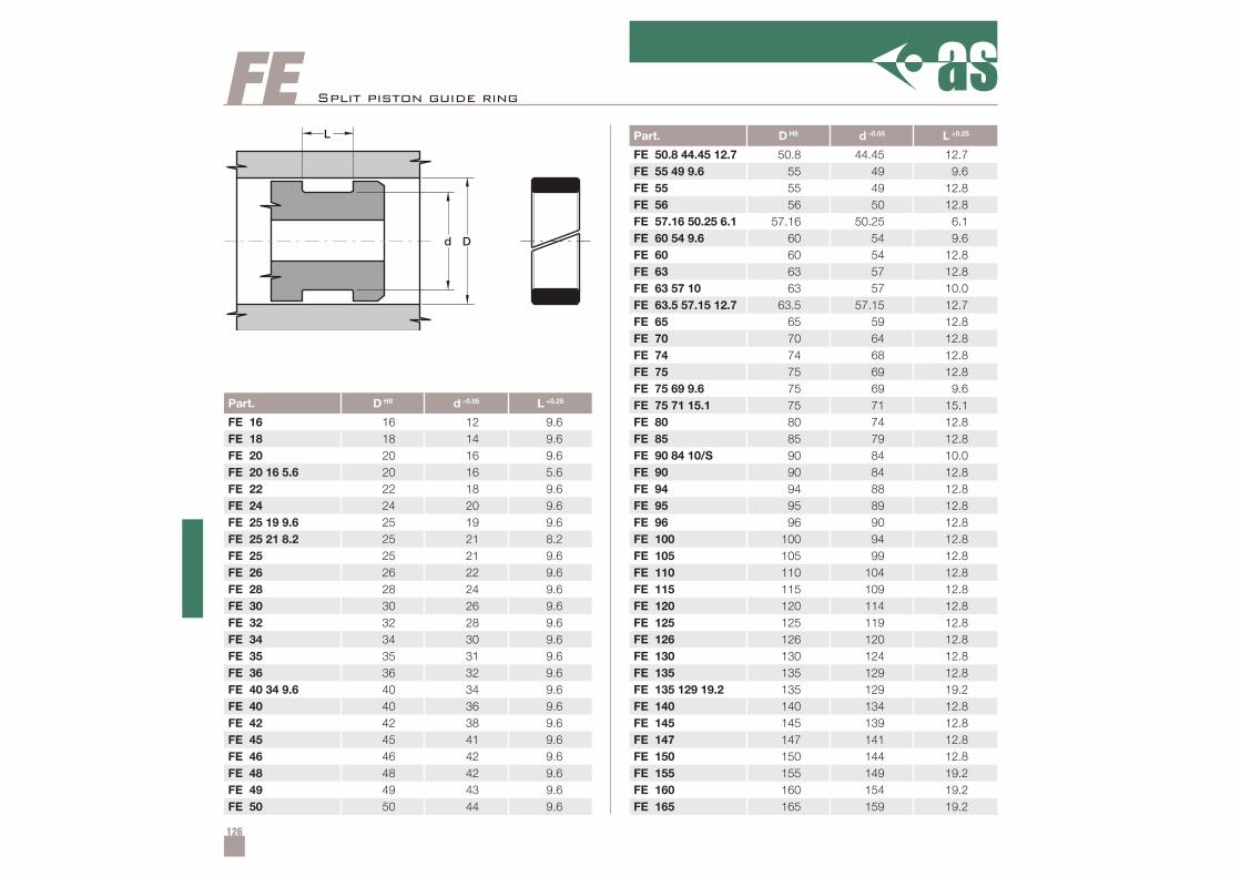
126
Part. D H8 d –0.05 L +0.25
FE 16 16 12 9.6FE 18 18 14 9.6FE 20 20 16 9.6FE 20 16 5.6 20 16 5.6FE 22 22 18 9.6FE 24 24 20 9.6FE 25 19 9.6 25 19 9.6FE 25 21 8.2 25 21 8.2FE 25 25 21 9.6FE 26 26 22 9.6FE 28 28 24 9.6FE 30 30 26 9.6FE 32 32 28 9.6FE 34 34 30 9.6FE 35 35 31 9.6FE 36 36 32 9.6FE 40 34 9.6 40 34 9.6FE 40 40 36 9.6FE 42 42 38 9.6FE 45 45 41 9.6FE 46 46 42 9.6FE 48 48 42 9.6FE 49 49 43 9.6FE 50 50 44 9.6
Part. D H8 d –0.05 L +0.25
FE 50.8 44.45 12.7 50.8 44.45 12.7FE 55 49 9.6 55 49 9.6FE 55 55 49 12.8FE 56 56 50 12.8FE 57.16 50.25 6.1 57.16 50.25 6.1FE 60 54 9.6 60 54 9.6FE 60 60 54 12.8FE 63 63 57 12.8FE 63 57 10 63 57 10.0FE 63.5 57.15 12.7 63.5 57.15 12.7FE 65 65 59 12.8FE 70 70 64 12.8FE 74 74 68 12.8FE 75 75 69 12.8FE 75 69 9.6 75 69 9.6FE 75 71 15.1 75 71 15.1FE 80 80 74 12.8FE 85 85 79 12.8FE 90 84 10/S 90 84 10.0FE 90 90 84 12.8FE 94 94 88 12.8FE 95 95 89 12.8FE 96 96 90 12.8FE 100 100 94 12.8FE 105 105 99 12.8FE 110 110 104 12.8FE 115 115 109 12.8FE 120 120 114 12.8FE 125 125 119 12.8FE 126 126 120 12.8FE 130 130 124 12.8FE 135 135 129 12.8FE 135 129 19.2 135 129 19.2FE 140 140 134 12.8FE 145 145 139 12.8FE 147 147 141 12.8FE 150 150 144 12.8FE 155 155 149 19.2FE 160 160 154 19.2FE 165 165 159 19.2
FE Split piston guide ring
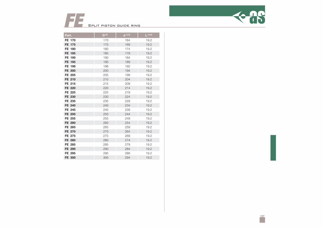
127
Part. D H8 d –0.05 L +0.25
FE 170 170 164 19.2FE 175 175 169 19.2FE 180 180 174 19.2FE 185 185 179 19.2FE 190 190 184 19.2FE 195 195 189 19.2FE 198 198 192 19.2FE 200 200 194 19.2FE 205 205 199 19.2FE 210 210 204 19.2FE 215 215 209 19.2FE 220 220 214 19.2FE 225 225 219 19.2FE 230 230 224 19.2FE 235 235 229 19.2FE 240 240 234 19.2FE 245 245 239 19.2FE 250 250 244 19.2FE 255 255 249 19.2FE 260 260 254 19.2FE 265 265 259 19.2FE 270 270 264 19.2FE 275 275 269 19.2FE 280 280 274 19.2FE 285 285 279 19.2FE 290 290 284 19.2FE 295 295 289 19.2FE 300 300 294 19.2
FE Split piston guide ring
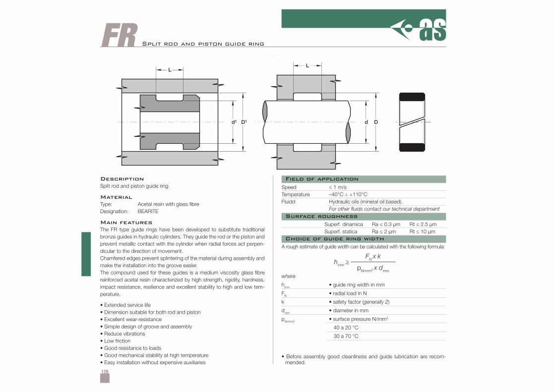
128
FR
hmm ≥FN x k
pN/mm2 x dmm
Split rod and piston guide ring
DescriptionSplit rod and piston guide ring
MaterialType: Acetal resin with glass fibreDesignation: BEARITE
Main featuresThe FR type guide rings have been developed to substitute traditionalbronze guides in hydraulic cylinders. They guide the rod or the piston andprevent metallic contact with the cylinder when radial forces act perpen-dicular to the direction of movement.Chamfered edges prevent splintering of the material during assembly andmake the installation into the groove easier.The compound used for these guides is a medium viscosity glass fibrereinforced acetal resin characterized by high strength, rigidity, hardness,impact resistance, resilience and excellent stability to high and low tem-perature.
• Extended service life• Dimension suitable for both rod and piston• Excellent wear-resistance• Simple design of groove and assembly• Reduce vibrations• Low friction• Good resistance to loads• Good mechanical stability at high temperature• Easy installation without expensive auxiliaries
Speed ≤ 1 m/sTemperature –40°C ÷ +110°CFluidd Hydraulic oils (mineral oil based).
For other fluids contact our technical department
Superf. dinamica Ra ≤ 0.3 µm Rt ≤ 2.5 µmSuperf. statica Ra ≤ 2 µm Rt ≤ 10 µm
• Before assembly good cleanliness and guide lubrication are recom-mended.
A rough estimate of guide width can be calculated with the following formula:
where
hmm • guide ring width in mm
FN • radial load in N
k • safety factor (generally 2)
dmm • diameter in mm
pN/mm2 • surface pressure N/mm2
40 a 20 °C
30 a 70 °C
Field of application
Surface roughness
Choice of guide ring width
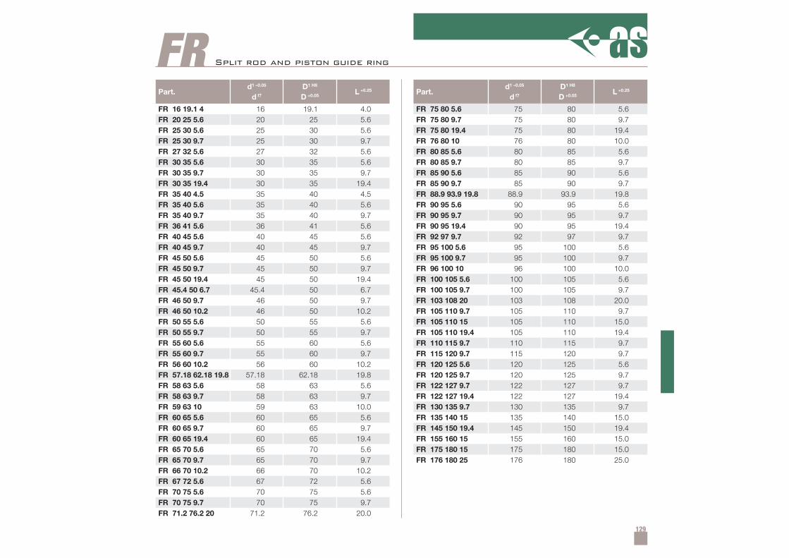
129
Part.d1 –0.05
d f7
D1 H8
D +0.05L +0.25
FR 16 19.1 4 16 19.1 4.0FR 20 25 5.6 20 25 5.6FR 25 30 5.6 25 30 5.6FR 25 30 9.7 25 30 9.7FR 27 32 5.6 27 32 5.6FR 30 35 5.6 30 35 5.6FR 30 35 9.7 30 35 9.7FR 30 35 19.4 30 35 19.4FR 35 40 4.5 35 40 4.5FR 35 40 5.6 35 40 5.6FR 35 40 9.7 35 40 9.7FR 36 41 5.6 36 41 5.6FR 40 45 5.6 40 45 5.6FR 40 45 9.7 40 45 9.7FR 45 50 5.6 45 50 5.6FR 45 50 9.7 45 50 9.7FR 45 50 19.4 45 50 19.4FR 45.4 50 6.7 45.4 50 6.7FR 46 50 9.7 46 50 9.7FR 46 50 10.2 46 50 10.2FR 50 55 5.6 50 55 5.6FR 50 55 9.7 50 55 9.7FR 55 60 5.6 55 60 5.6FR 55 60 9.7 55 60 9.7FR 56 60 10.2 56 60 10.2FR 57.18 62.18 19.8 57.18 62.18 19.8FR 58 63 5.6 58 63 5.6FR 58 63 9.7 58 63 9.7FR 59 63 10 59 63 10.0FR 60 65 5.6 60 65 5.6FR 60 65 9.7 60 65 9.7FR 60 65 19.4 60 65 19.4FR 65 70 5.6 65 70 5.6FR 65 70 9.7 65 70 9.7FR 66 70 10.2 66 70 10.2FR 67 72 5.6 67 72 5.6FR 70 75 5.6 70 75 5.6FR 70 75 9.7 70 75 9.7FR 71.2 76.2 20 71.2 76.2 20.0
Part.d1 –0.05
d f7
D1 H8
D +0.05L +0.25
FR 75 80 5.6 75 80 5.6FR 75 80 9.7 75 80 9.7FR 75 80 19.4 75 80 19.4FR 76 80 10 76 80 10.0FR 80 85 5.6 80 85 5.6FR 80 85 9.7 80 85 9.7FR 85 90 5.6 85 90 5.6FR 85 90 9.7 85 90 9.7FR 88.9 93.9 19.8 88.9 93.9 19.8FR 90 95 5.6 90 95 5.6FR 90 95 9.7 90 95 9.7FR 90 95 19.4 90 95 19.4FR 92 97 9.7 92 97 9.7FR 95 100 5.6 95 100 5.6FR 95 100 9.7 95 100 9.7FR 96 100 10 96 100 10.0FR 100 105 5.6 100 105 5.6FR 100 105 9.7 100 105 9.7FR 103 108 20 103 108 20.0FR 105 110 9.7 105 110 9.7FR 105 110 15 105 110 15.0FR 105 110 19.4 105 110 19.4FR 110 115 9.7 110 115 9.7FR 115 120 9.7 115 120 9.7FR 120 125 5.6 120 125 5.6FR 120 125 9.7 120 125 9.7FR 122 127 9.7 122 127 9.7FR 122 127 19.4 122 127 19.4FR 130 135 9.7 130 135 9.7FR 135 140 15 135 140 15.0FR 145 150 19.4 145 150 19.4FR 155 160 15 155 160 15.0FR 175 180 15 175 180 15.0FR 176 180 25 176 180 25.0
FR Split rod and piston guide ring
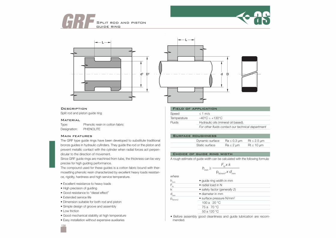
130
GRF
hmm ≥FN x k
pN/mm2 x dmm
Split rod and pistonguide ring
DescriptionSplit rod and piston guide ring
MaterialType: Phenolic resin in cotton fabricDesignation: PHENOLITE
Main featuresThe GRF type guide rings have been developed to substitute traditionalbronze guides in hydraulic cylinders. They guide the rod or the piston andprevent metallic contact with the cylinder when radial forces act perpen-dicular to the direction of movement.Since GRF guide rings are machined from tube, the thickness can be veryprecise for high guiding performance.The compound used for these guides is a cotton fabric bound with ther-mosetting phenolic resin characterized by excellent heavy loads resistan-ce, rigidity, hardness and high service temperature.
• Excellent resistance to heavy loads• High precision of guiding• Good resistance to “diesel effect”• Extended service life• Dimension suitable for both rod and piston• Simple design of groove and assembly• Low friction• Good mechanical stability at high temperature• Easy installation without expensive auxiliaries
Speed ≤ 1 m/sTemperature –40°C ÷ +130°CFluids Hydraulic oils (mineral oil based).
For other fluids contact our technical department
Dynamic surface Ra ≤ 0.3 µm Rt ≤ 2.5 µmStatic surface Ra ≤ 2 µm Rt ≤ 10 µm
• Before assembly good cleanliness and guide lubrication are recom-mended.
A rough estimate of guide width can be calculated with the following formula:
wherehmm • guide ring width in mmFN • radial load in Nk • safety factor (generally 2)dmm • diameter in mmpN/mm2 • surface pressure N/mm2
100 a 20 °C75 a 70 °C50 a 120 °C
Field of application
Surface roughness
Choice of guide ring width
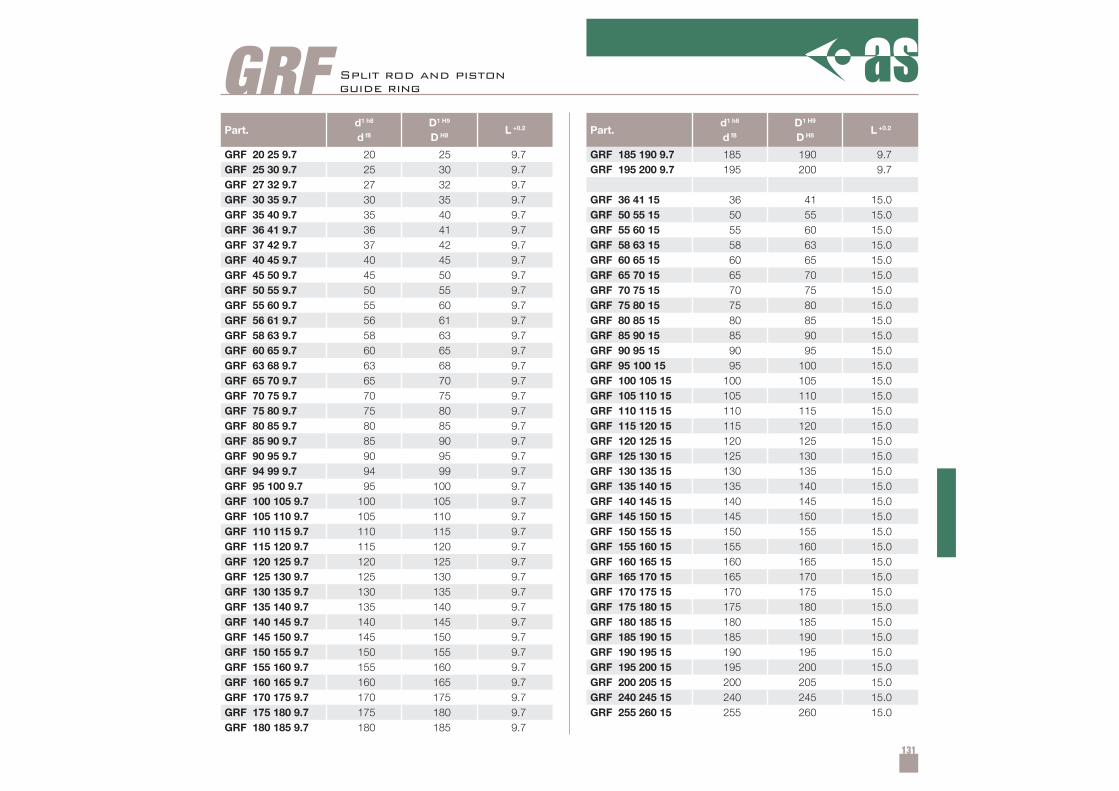
131
Part.d1 h8
d f8
D1 H9
D H8L +0.2
GRF 20 25 9.7 20 25 9.7GRF 25 30 9.7 25 30 9.7GRF 27 32 9.7 27 32 9.7GRF 30 35 9.7 30 35 9.7GRF 35 40 9.7 35 40 9.7GRF 36 41 9.7 36 41 9.7GRF 37 42 9.7 37 42 9.7GRF 40 45 9.7 40 45 9.7GRF 45 50 9.7 45 50 9.7GRF 50 55 9.7 50 55 9.7GRF 55 60 9.7 55 60 9.7GRF 56 61 9.7 56 61 9.7GRF 58 63 9.7 58 63 9.7GRF 60 65 9.7 60 65 9.7GRF 63 68 9.7 63 68 9.7GRF 65 70 9.7 65 70 9.7GRF 70 75 9.7 70 75 9.7GRF 75 80 9.7 75 80 9.7GRF 80 85 9.7 80 85 9.7GRF 85 90 9.7 85 90 9.7GRF 90 95 9.7 90 95 9.7GRF 94 99 9.7 94 99 9.7GRF 95 100 9.7 95 100 9.7GRF 100 105 9.7 100 105 9.7GRF 105 110 9.7 105 110 9.7GRF 110 115 9.7 110 115 9.7GRF 115 120 9.7 115 120 9.7GRF 120 125 9.7 120 125 9.7GRF 125 130 9.7 125 130 9.7GRF 130 135 9.7 130 135 9.7GRF 135 140 9.7 135 140 9.7GRF 140 145 9.7 140 145 9.7GRF 145 150 9.7 145 150 9.7GRF 150 155 9.7 150 155 9.7GRF 155 160 9.7 155 160 9.7GRF 160 165 9.7 160 165 9.7GRF 170 175 9.7 170 175 9.7GRF 175 180 9.7 175 180 9.7GRF 180 185 9.7 180 185 9.7
Part.d1 h8
d f8
D1 H9
D H8L +0.2
GRF 185 190 9.7 185 190 9.7GRF 195 200 9.7 195 200 9.7
GRF 36 41 15 36 41 15.0GRF 50 55 15 50 55 15.0GRF 55 60 15 55 60 15.0GRF 58 63 15 58 63 15.0GRF 60 65 15 60 65 15.0GRF 65 70 15 65 70 15.0GRF 70 75 15 70 75 15.0GRF 75 80 15 75 80 15.0GRF 80 85 15 80 85 15.0GRF 85 90 15 85 90 15.0GRF 90 95 15 90 95 15.0GRF 95 100 15 95 100 15.0GRF 100 105 15 100 105 15.0GRF 105 110 15 105 110 15.0GRF 110 115 15 110 115 15.0GRF 115 120 15 115 120 15.0GRF 120 125 15 120 125 15.0GRF 125 130 15 125 130 15.0GRF 130 135 15 130 135 15.0GRF 135 140 15 135 140 15.0GRF 140 145 15 140 145 15.0GRF 145 150 15 145 150 15.0GRF 150 155 15 150 155 15.0GRF 155 160 15 155 160 15.0GRF 160 165 15 160 165 15.0GRF 165 170 15 165 170 15.0GRF 170 175 15 170 175 15.0GRF 175 180 15 175 180 15.0GRF 180 185 15 180 185 15.0GRF 185 190 15 185 190 15.0GRF 190 195 15 190 195 15.0GRF 195 200 15 195 200 15.0GRF 200 205 15 200 205 15.0GRF 240 245 15 240 245 15.0GRF 255 260 15 255 260 15.0
GRF Split rod and pistonguide ring
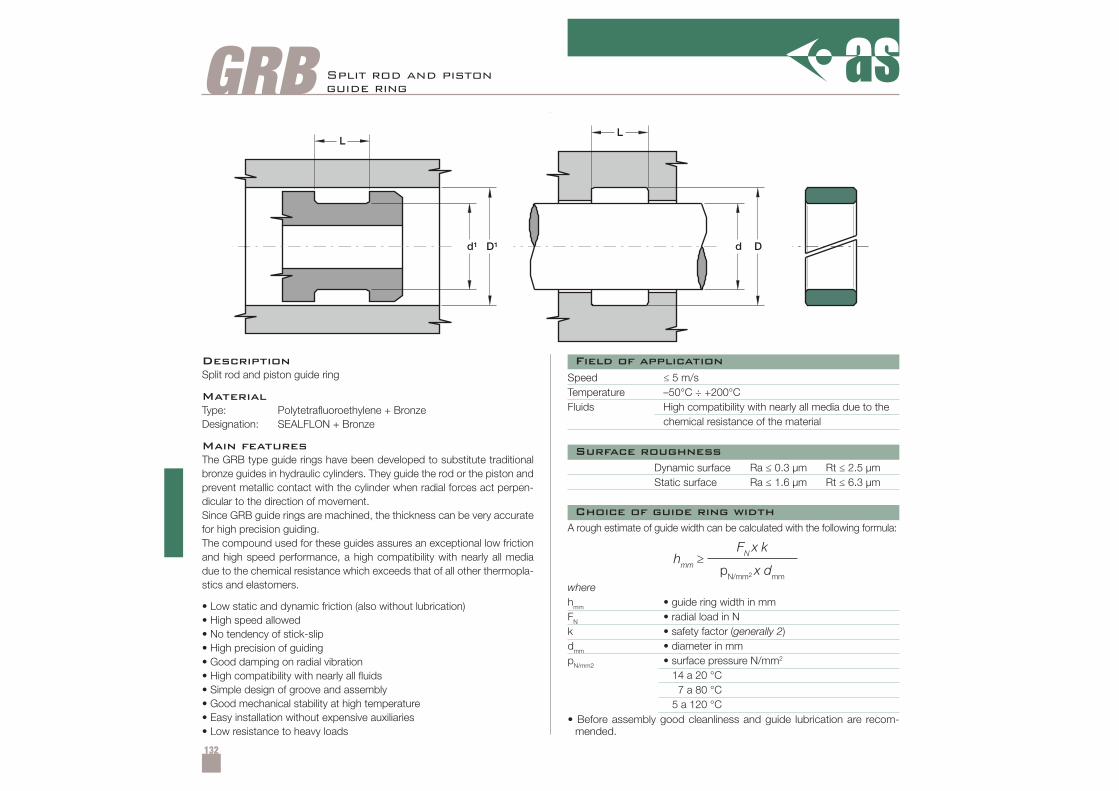
132
GRB
hmm ≥FN x k
pN/mm2 x dmm
Split rod and pistonguide ring
DescriptionSplit rod and piston guide ring
MaterialType: Polytetrafluoroethylene + BronzeDesignation: SEALFLON + Bronze
Main featuresThe GRB type guide rings have been developed to substitute traditionalbronze guides in hydraulic cylinders. They guide the rod or the piston andprevent metallic contact with the cylinder when radial forces act perpen-dicular to the direction of movement.Since GRB guide rings are machined, the thickness can be very accuratefor high precision guiding.The compound used for these guides assures an exceptional low frictionand high speed performance, a high compatibility with nearly all mediadue to the chemical resistance which exceeds that of all other thermopla-stics and elastomers.
• Low static and dynamic friction (also without lubrication)• High speed allowed• No tendency of stick-slip• High precision of guiding• Good damping on radial vibration• High compatibility with nearly all fluids• Simple design of groove and assembly• Good mechanical stability at high temperature• Easy installation without expensive auxiliaries• Low resistance to heavy loads
Speed ≤ 5 m/sTemperature –50°C ÷ +200°CFluids High compatibility with nearly all media due to the
chemical resistance of the material
Dynamic surface Ra ≤ 0.3 µm Rt ≤ 2.5 µmStatic surface Ra ≤ 1.6 µm Rt ≤ 6.3 µm
• Before assembly good cleanliness and guide lubrication are recom-mended.
A rough estimate of guide width can be calculated with the following formula:
wherehmm • guide ring width in mmFN • radial load in Nk • safety factor (generally 2)dmm • diameter in mmpN/mm2 • surface pressure N/mm2
14 a 20 °C7 a 80 °C
5 a 120 °C
Field of application
Surface roughness
Choice of guide ring width
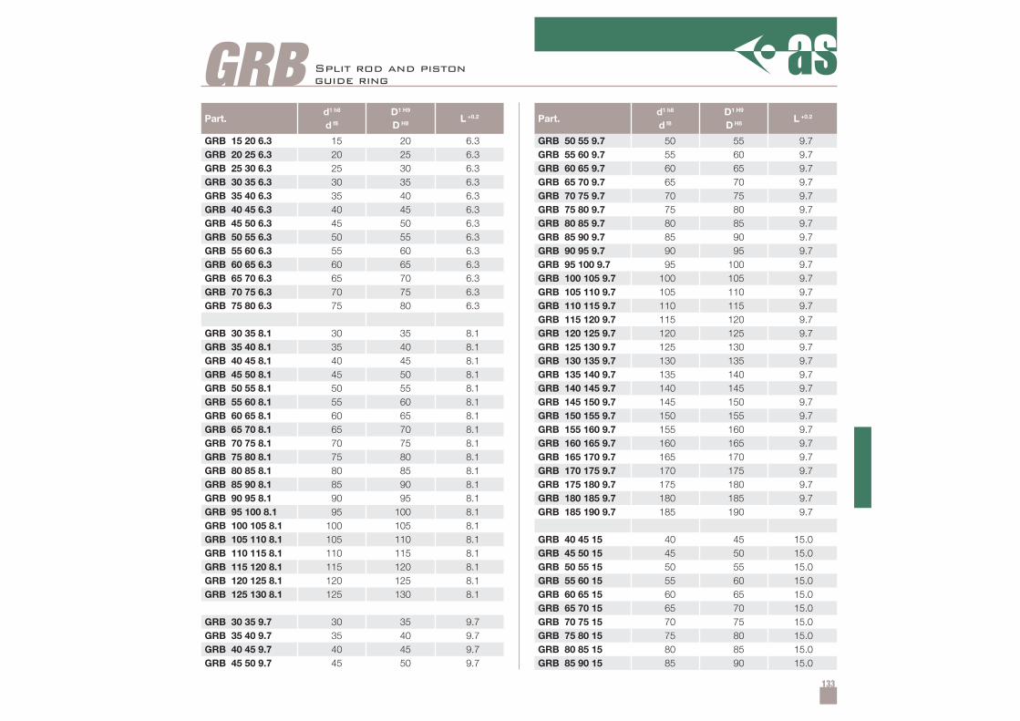
133
Part.d1 h8
d f8
D1 H9
D H8L +0.2
GRB 15 20 6.3 15 20 6.3GRB 20 25 6.3 20 25 6.3GRB 25 30 6.3 25 30 6.3GRB 30 35 6.3 30 35 6.3GRB 35 40 6.3 35 40 6.3GRB 40 45 6.3 40 45 6.3GRB 45 50 6.3 45 50 6.3GRB 50 55 6.3 50 55 6.3GRB 55 60 6.3 55 60 6.3GRB 60 65 6.3 60 65 6.3GRB 65 70 6.3 65 70 6.3GRB 70 75 6.3 70 75 6.3GRB 75 80 6.3 75 80 6.3
GRB 30 35 8.1 30 35 8.1GRB 35 40 8.1 35 40 8.1GRB 40 45 8.1 40 45 8.1GRB 45 50 8.1 45 50 8.1GRB 50 55 8.1 50 55 8.1GRB 55 60 8.1 55 60 8.1GRB 60 65 8.1 60 65 8.1GRB 65 70 8.1 65 70 8.1GRB 70 75 8.1 70 75 8.1GRB 75 80 8.1 75 80 8.1GRB 80 85 8.1 80 85 8.1GRB 85 90 8.1 85 90 8.1GRB 90 95 8.1 90 95 8.1GRB 95 100 8.1 95 100 8.1GRB 100 105 8.1 100 105 8.1GRB 105 110 8.1 105 110 8.1GRB 110 115 8.1 110 115 8.1GRB 115 120 8.1 115 120 8.1GRB 120 125 8.1 120 125 8.1GRB 125 130 8.1 125 130 8.1
GRB 30 35 9.7 30 35 9.7GRB 35 40 9.7 35 40 9.7GRB 40 45 9.7 40 45 9.7GRB 45 50 9.7 45 50 9.7
Part.d1 h8
d f8
D1 H9
D H8L +0.2
GRB 50 55 9.7 50 55 9.7GRB 55 60 9.7 55 60 9.7GRB 60 65 9.7 60 65 9.7GRB 65 70 9.7 65 70 9.7GRB 70 75 9.7 70 75 9.7GRB 75 80 9.7 75 80 9.7GRB 80 85 9.7 80 85 9.7GRB 85 90 9.7 85 90 9.7GRB 90 95 9.7 90 95 9.7GRB 95 100 9.7 95 100 9.7GRB 100 105 9.7 100 105 9.7GRB 105 110 9.7 105 110 9.7GRB 110 115 9.7 110 115 9.7GRB 115 120 9.7 115 120 9.7GRB 120 125 9.7 120 125 9.7GRB 125 130 9.7 125 130 9.7GRB 130 135 9.7 130 135 9.7GRB 135 140 9.7 135 140 9.7GRB 140 145 9.7 140 145 9.7GRB 145 150 9.7 145 150 9.7GRB 150 155 9.7 150 155 9.7GRB 155 160 9.7 155 160 9.7GRB 160 165 9.7 160 165 9.7GRB 165 170 9.7 165 170 9.7GRB 170 175 9.7 170 175 9.7GRB 175 180 9.7 175 180 9.7GRB 180 185 9.7 180 185 9.7GRB 185 190 9.7 185 190 9.7
GRB 40 45 15 40 45 15.0GRB 45 50 15 45 50 15.0GRB 50 55 15 50 55 15.0GRB 55 60 15 55 60 15.0GRB 60 65 15 60 65 15.0GRB 65 70 15 65 70 15.0GRB 70 75 15 70 75 15.0GRB 75 80 15 75 80 15.0GRB 80 85 15 80 85 15.0GRB 85 90 15 85 90 15.0
GRB Split rod and pistonguide ring
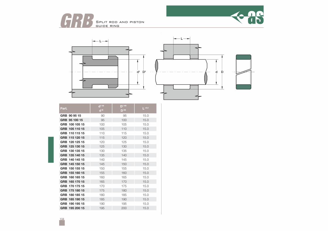
134
Part.d1 h8
d f8
D1 H9
D H8L +0.2
GRB 90 95 15 90 95 15.0GRB 95 100 15 95 100 15.0GRB 100 105 15 100 105 15.0GRB 105 110 15 105 110 15.0GRB 110 115 15 110 115 15.0GRB 115 120 15 115 120 15.0GRB 120 125 15 120 125 15.0GRB 125 130 15 125 130 15.0GRB 130 135 15 130 135 15.0GRB 135 140 15 135 140 15.0GRB 140 145 15 140 145 15.0GRB 145 150 15 145 150 15.0GRB 150 155 15 150 155 15.0GRB 155 160 15 155 160 15.0GRB 160 165 15 160 165 15.0GRB 165 170 15 165 170 15.0GRB 170 175 15 170 175 15.0GRB 175 180 15 175 180 15.0GRB 180 185 15 180 185 15.0GRB 185 190 15 185 190 15.0GRB 190 195 15 190 195 15.0GRB 195 200 15 195 200 15.0
GRB Split rod and pistonguide ring
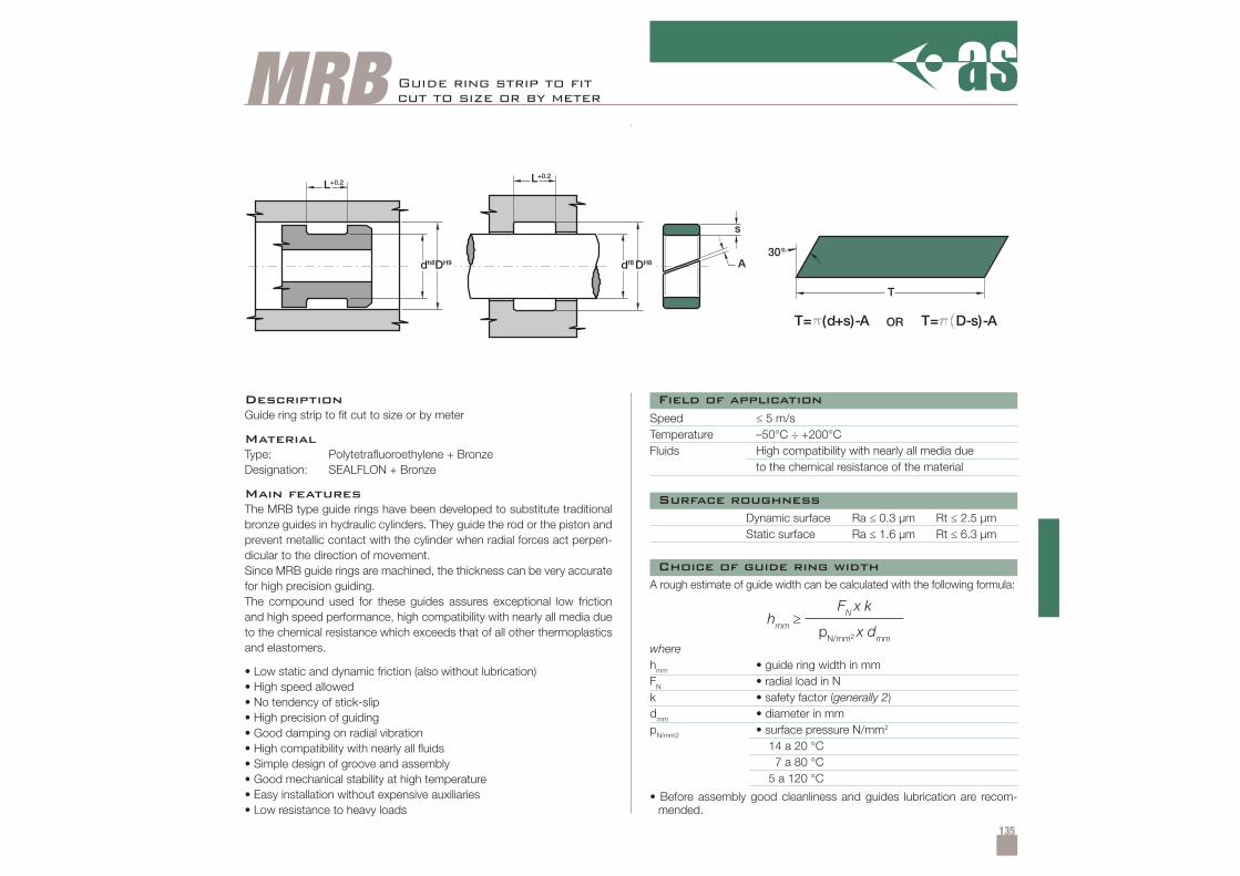
135
MRB
hmm ≥FN x k
pN/mm2 x dmm
T
30°
T= (d+s)-A o T= D-s)-A
A
s
df8DH8
L+0.2
dh8
L+0.2
DH9
Guide ring strip to fi tcut to size or by meter
DescriptionGuide ring strip to fit cut to size or by meter
MaterialType: Polytetrafluoroethylene + BronzeDesignation: SEALFLON + Bronze
Main featuresThe MRB type guide rings have been developed to substitute traditionalbronze guides in hydraulic cylinders. They guide the rod or the piston andprevent metallic contact with the cylinder when radial forces act perpen-dicular to the direction of movement.Since MRB guide rings are machined, the thickness can be very accuratefor high precision guiding.The compound used for these guides assures exceptional low frictionand high speed performance, high compatibility with nearly all media dueto the chemical resistance which exceeds that of all other thermoplasticsand elastomers.
• Low static and dynamic friction (also without lubrication)• High speed allowed• No tendency of stick-slip• High precision of guiding• Good damping on radial vibration• High compatibility with nearly all fluids• Simple design of groove and assembly• Good mechanical stability at high temperature• Easy installation without expensive auxiliaries• Low resistance to heavy loads
Speed ≤ 5 m/sTemperature –50°C ÷ +200°CFluids High compatibility with nearly all media due
to the chemical resistance of the material
Dynamic surface Ra ≤ 0.3 µm Rt ≤ 2.5 µmStatic surface Ra ≤ 1.6 µm Rt ≤ 6.3 µm
• Before assembly good cleanliness and guides lubrication are recom-mended.
A rough estimate of guide width can be calculated with the following formula:
wherehmm • guide ring width in mmFN • radial load in Nk • safety factor (generally 2)dmm • diameter in mmpN/mm2 • surface pressure N/mm2
14 a 20 °C7 a 80 °C
5 a 120 °C
Field of application
Surface roughness
Choice of guide ring width
OR
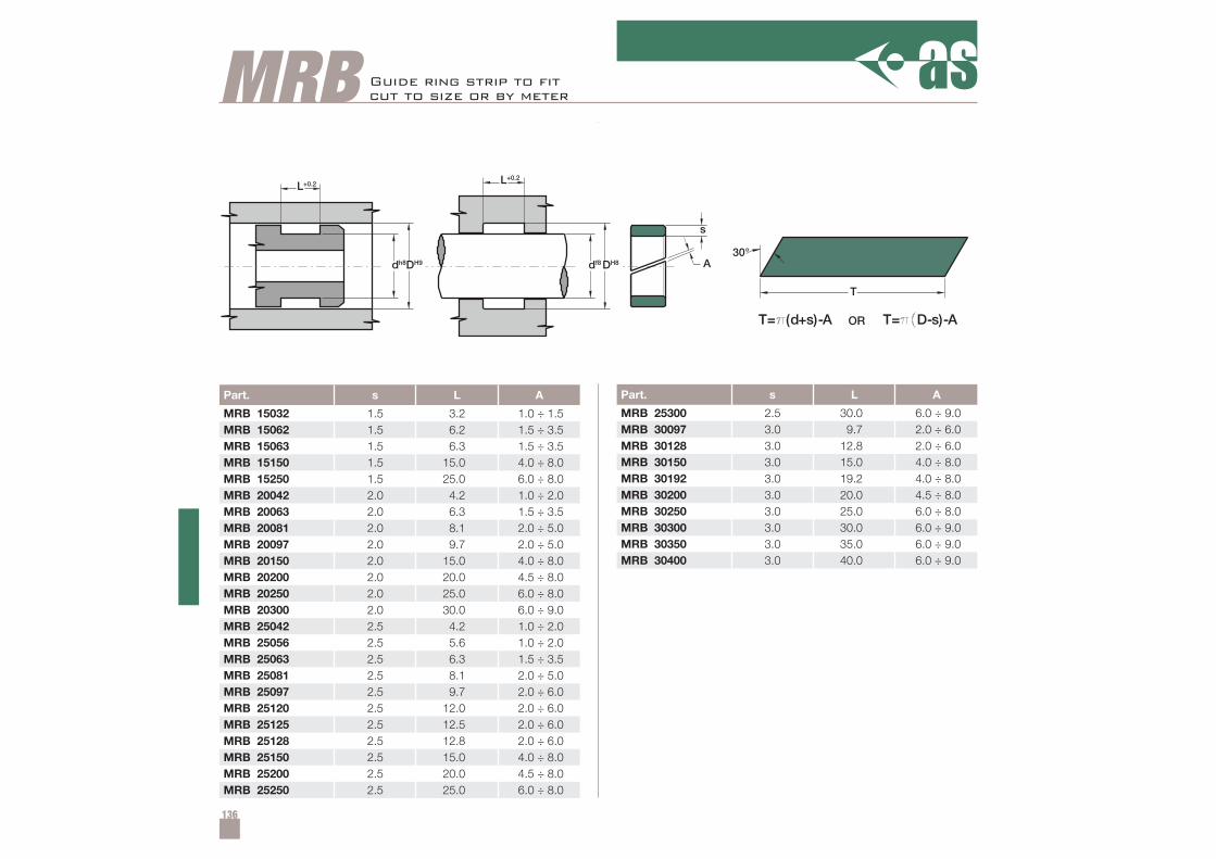
136
Part. s L A
MRB 15032 1.5 3.2 1.0 ÷ 1.5MRB 15062 1.5 6.2 1.5 ÷ 3.5MRB 15063 1.5 6.3 1.5 ÷ 3.5MRB 15150 1.5 15.0 4.0 ÷ 8.0MRB 15250 1.5 25.0 6.0 ÷ 8.0MRB 20042 2.0 4.2 1.0 ÷ 2.0MRB 20063 2.0 6.3 1.5 ÷ 3.5MRB 20081 2.0 8.1 2.0 ÷ 5.0MRB 20097 2.0 9.7 2.0 ÷ 5.0MRB 20150 2.0 15.0 4.0 ÷ 8.0MRB 20200 2.0 20.0 4.5 ÷ 8.0MRB 20250 2.0 25.0 6.0 ÷ 8.0MRB 20300 2.0 30.0 6.0 ÷ 9.0MRB 25042 2.5 4.2 1.0 ÷ 2.0MRB 25056 2.5 5.6 1.0 ÷ 2.0MRB 25063 2.5 6.3 1.5 ÷ 3.5MRB 25081 2.5 8.1 2.0 ÷ 5.0MRB 25097 2.5 9.7 2.0 ÷ 6.0MRB 25120 2.5 12.0 2.0 ÷ 6.0MRB 25125 2.5 12.5 2.0 ÷ 6.0MRB 25128 2.5 12.8 2.0 ÷ 6.0MRB 25150 2.5 15.0 4.0 ÷ 8.0MRB 25200 2.5 20.0 4.5 ÷ 8.0MRB 25250 2.5 25.0 6.0 ÷ 8.0
Part. s L A
MRB 25300 2.5 30.0 6.0 ÷ 9.0MRB 30097 3.0 9.7 2.0 ÷ 6.0MRB 30128 3.0 12.8 2.0 ÷ 6.0MRB 30150 3.0 15.0 4.0 ÷ 8.0MRB 30192 3.0 19.2 4.0 ÷ 8.0MRB 30200 3.0 20.0 4.5 ÷ 8.0MRB 30250 3.0 25.0 6.0 ÷ 8.0MRB 30300 3.0 30.0 6.0 ÷ 9.0MRB 30350 3.0 35.0 6.0 ÷ 9.0MRB 30400 3.0 40.0 6.0 ÷ 9.0
MRB
T
30°
T= (d+s)-A o T= D-s)-A
A
s
df8DH8
L+0.2
dh8
L+0.2
DH9
Guide ring strip to fi tcut to size or by meter
OR
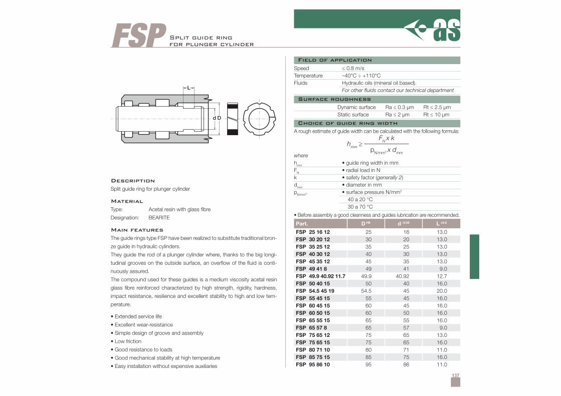
137
FSP
Part. D H8 d –0.05 L +0.5
FSP 25 16 12 25 16 13.0FSP 30 20 12 30 20 13.0FSP 35 25 12 35 25 13.0FSP 40 30 12 40 30 13.0FSP 45 35 12 45 35 13.0FSP 49 41 8 49 41 9.0FSP 49.9 40.92 11.7 49.9 40.92 12.7FSP 50 40 15 50 40 16.0FSP 54.5 45 19 54.5 45 20.0FSP 55 45 15 55 45 16.0FSP 60 45 15 60 45 16.0FSP 60 50 15 60 50 16.0FSP 65 55 15 65 55 16.0FSP 65 57 8 65 57 9.0FSP 75 65 12 75 65 13.0FSP 75 65 15 75 65 16.0FSP 80 71 10 80 71 11.0FSP 85 75 15 85 75 16.0FSP 95 86 10 95 86 11.0
L
d D
hmm ≥FN x k
pN/mm2 x dmm
Split guide ringfor plunger cylinder
DescriptionSplit guide ring for plunger cylinder
MaterialType: Acetal resin with glass fibre
Designation: BEARITE
Main featuresThe guide rings type FSP have been realized to substitute traditional bron-
ze guide in hydraulic cylinders.
They guide the rod of a plunger cylinder where, thanks to the big longi-
tudinal grooves on the outside surface, an overflow of the fluid is conti-
nuously assured.
The compound used for these guides is a medium viscosity acetal resin
glass fibre reinforced characterized by high strength, rigidity, hardness,
impact resistance, resilience and excellent stability to high and low tem-
perature.
• Extended service life
• Excellent wear-resistance
• Simple design of groove and assembly
• Low friction
• Good resistance to loads
• Good mechanical stability at high temperature
• Easy installation without expensive auxiliaries
Speed ≤ 0.8 m/sTemperature –40°C ÷ +110°CFluids Hydraulic oils (mineral oil based).
For other fluids contact our technical department
Dynamic surface Ra ≤ 0.3 µm Rt ≤ 2.5 µmStatic surface Ra ≤ 2 µm Rt ≤ 10 µm
• Before assembly a good cleanness and guides lubrication are recommended.
A rough estimate of guide width can be calculated with the following formula:
wherehmm • guide ring width in mmFN • radial load in Nk • safety factor (generally 2)dmm • diameter in mmpN/mm2 • surface pressure N/mm2
40 a 20 °C30 a 70 °C
Field of application
Surface roughness
Choice of guide ring width
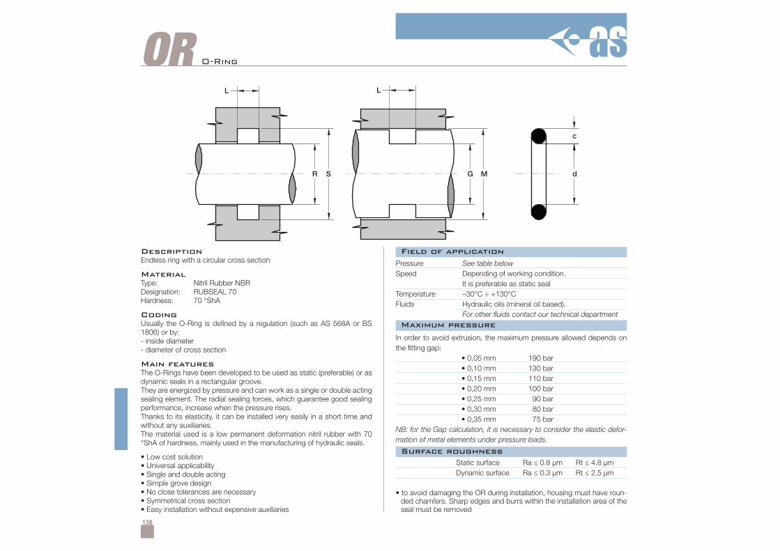
138
OR
Field of application
Surface roughness
Maximum pressure
DescriptionEndless ring with a circular cross section
MaterialType: Nitril Rubber NBRDesignation: RUBSEAL 70Hardness: 70 °ShA
CodingUsually the O-Ring is defined by a regulation (such as AS 568A or BS1806) or by:- inside diameter- diameter of cross section
Main featuresThe O-Rings have been developed to be used as static (preferable) or asdynamic seals in a rectangular groove.They are energized by pressure and can work as a single or double actingsealing element. The radial sealing forces, which guarantee good sealingperformance, increase when the pressure rises.Thanks to its elasticity, it can be installed very easily in a short time andwithout any auxiliaries.The material used is a low permanent deformation nitril rubber with 70°ShA of hardness, mainly used in the manufacturing of hydraulic seals.
• Low cost solution• Universal applicability• Single and double acting• Simple grove design• No close tolerances are necessary• Symmetrical cross section• Easy installation without expensive auxiliaries
Pressure See table belowSpeed Depending of working condition.
It is preferable as static sealTemperature –30°C ÷ +130°CFluids Hydraulic oils (mineral oil based).
For other fluids contact our technical department
Static surface Ra ≤ 0.8 µm Rt ≤ 4.8 µmDynamic surface Ra ≤ 0.3 µm Rt ≤ 2.5 µm
• to avoid damaging the OR during installation, housing must have roun-ded chamfers. Sharp edges and burrs within the installation area of theseal must be removed
In order to avoid extrusion, the maximum pressure allowed depends onthe fitting gap:
• 0,05 mm 190 bar• 0,10 mm 130 bar• 0,15 mm 110 bar• 0,20 mm 100 bar• 0,25 mm 90 bar• 0,30 mm 80 bar• 0,35 mm 75 bar
NB: for the Gap calculation, it is necessary to consider the elastic defor-mation of metal elements under pressure loads.
O-Ring
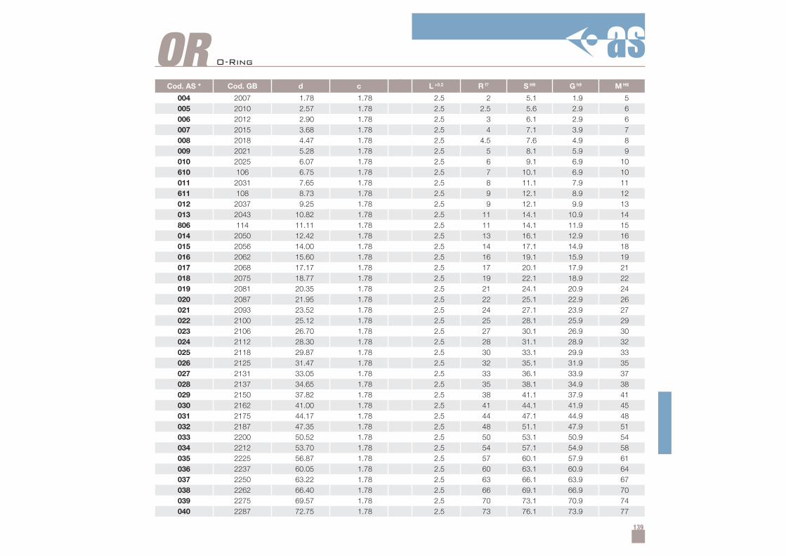
139
Cod. AS * Cod. GB d c L +0.2 R f7 S H9 G h9 M H8
004 2007 1.78 1.78 2.5 2 5.1 1.9 5005 2010 2.57 1.78 2.5 2.5 5.6 2.9 6006 2012 2.90 1.78 2.5 3 6.1 2.9 6007 2015 3.68 1.78 2.5 4 7.1 3.9 7008 2018 4.47 1.78 2.5 4.5 7.6 4.9 8009 2021 5.28 1.78 2.5 5 8.1 5.9 9010 2025 6.07 1.78 2.5 6 9.1 6.9 10610 106 6.75 1.78 2.5 7 10.1 6.9 10011 2031 7.65 1.78 2.5 8 11.1 7.9 11611 108 8.73 1.78 2.5 9 12.1 8.9 12012 2037 9.25 1.78 2.5 9 12.1 9.9 13013 2043 10.82 1.78 2.5 11 14.1 10.9 14806 114 11.11 1.78 2.5 11 14.1 11.9 15014 2050 12.42 1.78 2.5 13 16.1 12.9 16015 2056 14.00 1.78 2.5 14 17.1 14.9 18016 2062 15.60 1.78 2.5 16 19.1 15.9 19017 2068 17.17 1.78 2.5 17 20.1 17.9 21018 2075 18.77 1.78 2.5 19 22.1 18.9 22019 2081 20.35 1.78 2.5 21 24.1 20.9 24020 2087 21.95 1.78 2.5 22 25.1 22.9 26021 2093 23.52 1.78 2.5 24 27.1 23.9 27022 2100 25.12 1.78 2.5 25 28.1 25.9 29023 2106 26.70 1.78 2.5 27 30.1 26.9 30024 2112 28.30 1.78 2.5 28 31.1 28.9 32025 2118 29.87 1.78 2.5 30 33.1 29.9 33026 2125 31.47 1.78 2.5 32 35.1 31.9 35027 2131 33.05 1.78 2.5 33 36.1 33.9 37028 2137 34.65 1.78 2.5 35 38.1 34.9 38029 2150 37.82 1.78 2.5 38 41.1 37.9 41030 2162 41.00 1.78 2.5 41 44.1 41.9 45031 2175 44.17 1.78 2.5 44 47.1 44.9 48032 2187 47.35 1.78 2.5 48 51.1 47.9 51033 2200 50.52 1.78 2.5 50 53.1 50.9 54034 2212 53.70 1.78 2.5 54 57.1 54.9 58035 2225 56.87 1.78 2.5 57 60.1 57.9 61036 2237 60.05 1.78 2.5 60 63.1 60.9 64037 2250 63.22 1.78 2.5 63 66.1 63.9 67038 2262 66.40 1.78 2.5 66 69.1 66.9 70039 2275 69.57 1.78 2.5 70 73.1 70.9 74040 2287 72.75 1.78 2.5 73 76.1 73.9 77
OR O-Ring
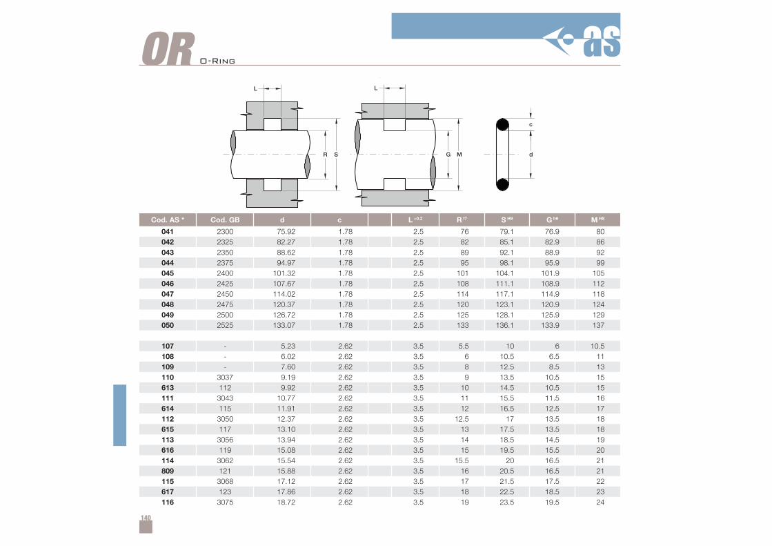
140
Cod. AS * Cod. GB d c L +0.2 R f7 S H9 G h9 M H8
041 2300 75.92 1.78 2.5 76 79.1 76.9 80042 2325 82.27 1.78 2.5 82 85.1 82.9 86043 2350 88.62 1.78 2.5 89 92.1 88.9 92044 2375 94.97 1.78 2.5 95 98.1 95.9 99045 2400 101.32 1.78 2.5 101 104.1 101.9 105046 2425 107.67 1.78 2.5 108 111.1 108.9 112047 2450 114.02 1.78 2.5 114 117.1 114.9 118048 2475 120.37 1.78 2.5 120 123.1 120.9 124049 2500 126.72 1.78 2.5 125 128.1 125.9 129050 2525 133.07 1.78 2.5 133 136.1 133.9 137
107 - 5.23 2.62 3.5 5.5 10 6 10.5108 - 6.02 2.62 3.5 6 10.5 6.5 11109 - 7.60 2.62 3.5 8 12.5 8.5 13110 3037 9.19 2.62 3.5 9 13.5 10.5 15613 112 9.92 2.62 3.5 10 14.5 10.5 15111 3043 10.77 2.62 3.5 11 15.5 11.5 16614 115 11.91 2.62 3.5 12 16.5 12.5 17112 3050 12.37 2.62 3.5 12.5 17 13.5 18615 117 13.10 2.62 3.5 13 17.5 13.5 18113 3056 13.94 2.62 3.5 14 18.5 14.5 19616 119 15.08 2.62 3.5 15 19.5 15.5 20114 3062 15.54 2.62 3.5 15.5 20 16.5 21809 121 15.88 2.62 3.5 16 20.5 16.5 21115 3068 17.12 2.62 3.5 17 21.5 17.5 22617 123 17.86 2.62 3.5 18 22.5 18.5 23116 3075 18.72 2.62 3.5 19 23.5 19.5 24
OR O-Ring
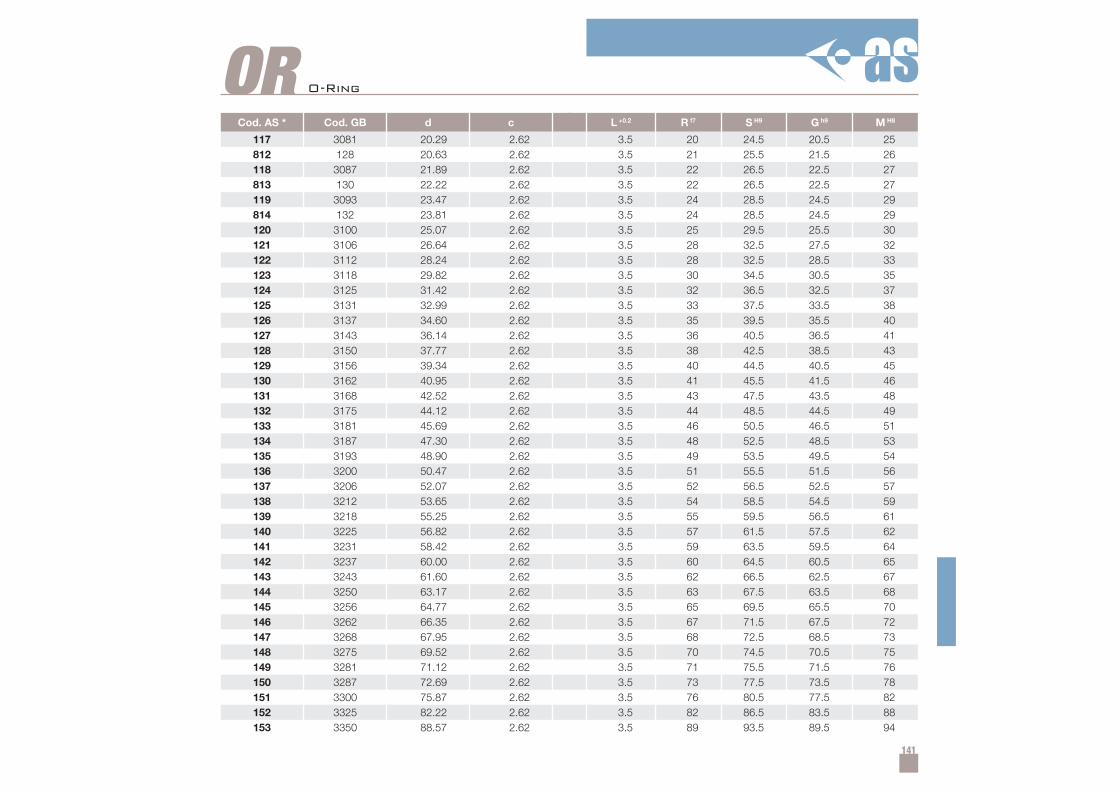
141
Cod. AS * Cod. GB d c L +0.2 R f7 S H9 G h9 M H8
117 3081 20.29 2.62 3.5 20 24.5 20.5 25812 128 20.63 2.62 3.5 21 25.5 21.5 26118 3087 21.89 2.62 3.5 22 26.5 22.5 27813 130 22.22 2.62 3.5 22 26.5 22.5 27119 3093 23.47 2.62 3.5 24 28.5 24.5 29814 132 23.81 2.62 3.5 24 28.5 24.5 29120 3100 25.07 2.62 3.5 25 29.5 25.5 30121 3106 26.64 2.62 3.5 28 32.5 27.5 32122 3112 28.24 2.62 3.5 28 32.5 28.5 33123 3118 29.82 2.62 3.5 30 34.5 30.5 35124 3125 31.42 2.62 3.5 32 36.5 32.5 37125 3131 32.99 2.62 3.5 33 37.5 33.5 38126 3137 34.60 2.62 3.5 35 39.5 35.5 40127 3143 36.14 2.62 3.5 36 40.5 36.5 41128 3150 37.77 2.62 3.5 38 42.5 38.5 43129 3156 39.34 2.62 3.5 40 44.5 40.5 45130 3162 40.95 2.62 3.5 41 45.5 41.5 46131 3168 42.52 2.62 3.5 43 47.5 43.5 48132 3175 44.12 2.62 3.5 44 48.5 44.5 49133 3181 45.69 2.62 3.5 46 50.5 46.5 51134 3187 47.30 2.62 3.5 48 52.5 48.5 53135 3193 48.90 2.62 3.5 49 53.5 49.5 54136 3200 50.47 2.62 3.5 51 55.5 51.5 56137 3206 52.07 2.62 3.5 52 56.5 52.5 57138 3212 53.65 2.62 3.5 54 58.5 54.5 59139 3218 55.25 2.62 3.5 55 59.5 56.5 61140 3225 56.82 2.62 3.5 57 61.5 57.5 62141 3231 58.42 2.62 3.5 59 63.5 59.5 64142 3237 60.00 2.62 3.5 60 64.5 60.5 65143 3243 61.60 2.62 3.5 62 66.5 62.5 67144 3250 63.17 2.62 3.5 63 67.5 63.5 68145 3256 64.77 2.62 3.5 65 69.5 65.5 70146 3262 66.35 2.62 3.5 67 71.5 67.5 72147 3268 67.95 2.62 3.5 68 72.5 68.5 73148 3275 69.52 2.62 3.5 70 74.5 70.5 75149 3281 71.12 2.62 3.5 71 75.5 71.5 76150 3287 72.69 2.62 3.5 73 77.5 73.5 78151 3300 75.87 2.62 3.5 76 80.5 77.5 82152 3325 82.22 2.62 3.5 82 86.5 83.5 88153 3350 88.57 2.62 3.5 89 93.5 89.5 94
OR O-Ring
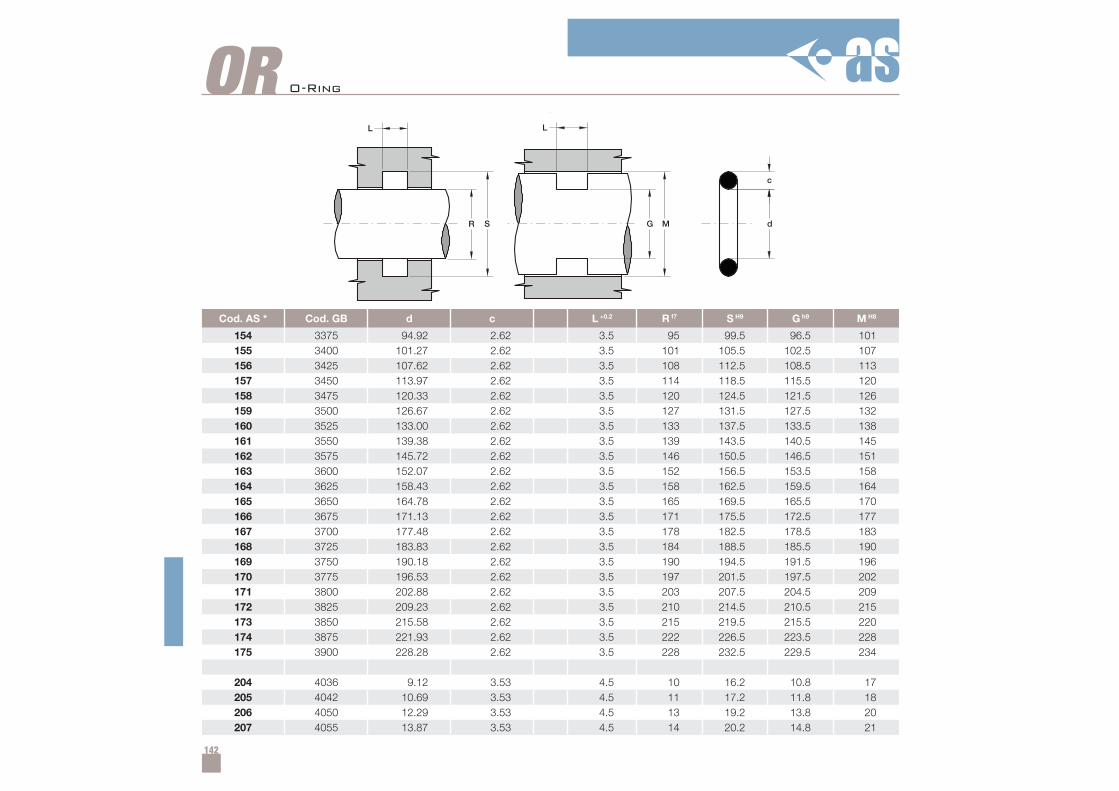
142
Cod. AS * Cod. GB d c L +0.2 R f7 S H9 G h9 M H8
154 3375 94.92 2.62 3.5 95 99.5 96.5 101155 3400 101.27 2.62 3.5 101 105.5 102.5 107156 3425 107.62 2.62 3.5 108 112.5 108.5 113157 3450 113.97 2.62 3.5 114 118.5 115.5 120158 3475 120.33 2.62 3.5 120 124.5 121.5 126159 3500 126.67 2.62 3.5 127 131.5 127.5 132160 3525 133.00 2.62 3.5 133 137.5 133.5 138161 3550 139.38 2.62 3.5 139 143.5 140.5 145162 3575 145.72 2.62 3.5 146 150.5 146.5 151163 3600 152.07 2.62 3.5 152 156.5 153.5 158164 3625 158.43 2.62 3.5 158 162.5 159.5 164165 3650 164.78 2.62 3.5 165 169.5 165.5 170166 3675 171.13 2.62 3.5 171 175.5 172.5 177167 3700 177.48 2.62 3.5 178 182.5 178.5 183168 3725 183.83 2.62 3.5 184 188.5 185.5 190169 3750 190.18 2.62 3.5 190 194.5 191.5 196170 3775 196.53 2.62 3.5 197 201.5 197.5 202171 3800 202.88 2.62 3.5 203 207.5 204.5 209172 3825 209.23 2.62 3.5 210 214.5 210.5 215173 3850 215.58 2.62 3.5 215 219.5 215.5 220174 3875 221.93 2.62 3.5 222 226.5 223.5 228175 3900 228.28 2.62 3.5 228 232.5 229.5 234
204 4036 9.12 3.53 4.5 10 16.2 10.8 17205 4042 10.69 3.53 4.5 11 17.2 11.8 18206 4050 12.29 3.53 4.5 13 19.2 13.8 20207 4055 13.87 3.53 4.5 14 20.2 14.8 21
OR O-Ring
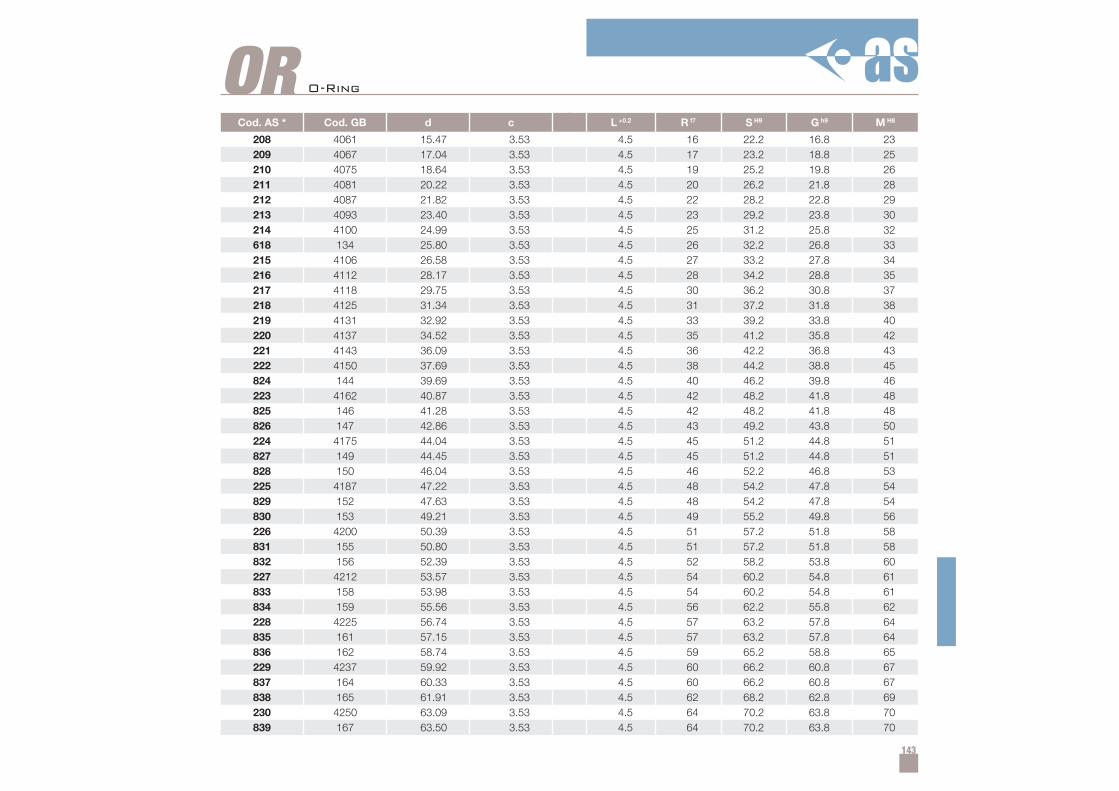
143
Cod. AS * Cod. GB d c L +0.2 R f7 S H9 G h9 M H8
208 4061 15.47 3.53 4.5 16 22.2 16.8 23209 4067 17.04 3.53 4.5 17 23.2 18.8 25210 4075 18.64 3.53 4.5 19 25.2 19.8 26211 4081 20.22 3.53 4.5 20 26.2 21.8 28212 4087 21.82 3.53 4.5 22 28.2 22.8 29213 4093 23.40 3.53 4.5 23 29.2 23.8 30214 4100 24.99 3.53 4.5 25 31.2 25.8 32618 134 25.80 3.53 4.5 26 32.2 26.8 33215 4106 26.58 3.53 4.5 27 33.2 27.8 34216 4112 28.17 3.53 4.5 28 34.2 28.8 35217 4118 29.75 3.53 4.5 30 36.2 30.8 37218 4125 31.34 3.53 4.5 31 37.2 31.8 38219 4131 32.92 3.53 4.5 33 39.2 33.8 40220 4137 34.52 3.53 4.5 35 41.2 35.8 42221 4143 36.09 3.53 4.5 36 42.2 36.8 43222 4150 37.69 3.53 4.5 38 44.2 38.8 45824 144 39.69 3.53 4.5 40 46.2 39.8 46223 4162 40.87 3.53 4.5 42 48.2 41.8 48825 146 41.28 3.53 4.5 42 48.2 41.8 48826 147 42.86 3.53 4.5 43 49.2 43.8 50224 4175 44.04 3.53 4.5 45 51.2 44.8 51827 149 44.45 3.53 4.5 45 51.2 44.8 51828 150 46.04 3.53 4.5 46 52.2 46.8 53225 4187 47.22 3.53 4.5 48 54.2 47.8 54829 152 47.63 3.53 4.5 48 54.2 47.8 54830 153 49.21 3.53 4.5 49 55.2 49.8 56226 4200 50.39 3.53 4.5 51 57.2 51.8 58831 155 50.80 3.53 4.5 51 57.2 51.8 58832 156 52.39 3.53 4.5 52 58.2 53.8 60227 4212 53.57 3.53 4.5 54 60.2 54.8 61833 158 53.98 3.53 4.5 54 60.2 54.8 61834 159 55.56 3.53 4.5 56 62.2 55.8 62228 4225 56.74 3.53 4.5 57 63.2 57.8 64835 161 57.15 3.53 4.5 57 63.2 57.8 64836 162 58.74 3.53 4.5 59 65.2 58.8 65229 4237 59.92 3.53 4.5 60 66.2 60.8 67837 164 60.33 3.53 4.5 60 66.2 60.8 67838 165 61.91 3.53 4.5 62 68.2 62.8 69230 4250 63.09 3.53 4.5 64 70.2 63.8 70839 167 63.50 3.53 4.5 64 70.2 63.8 70
OR O-Ring
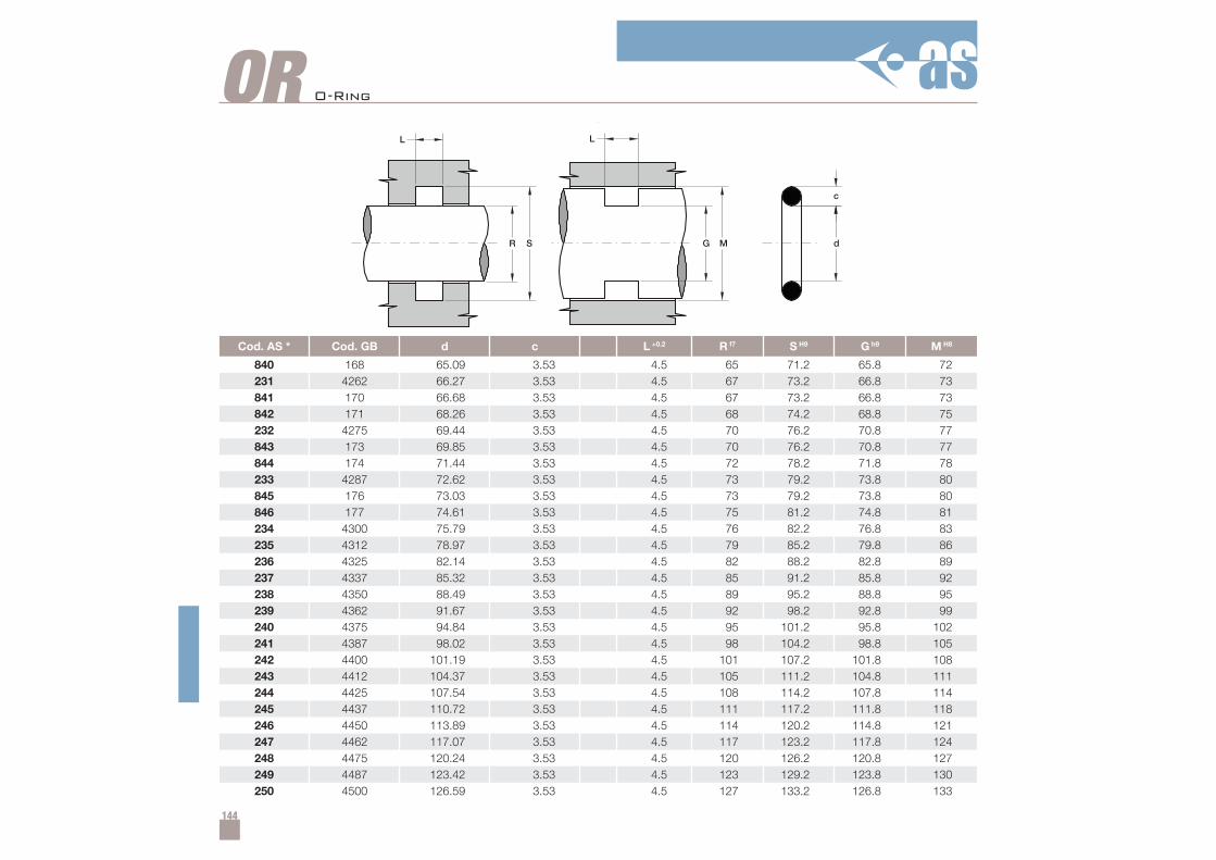
144
Cod. AS * Cod. GB d c L +0.2 R f7 S H9 G h9 M H8
840 168 65.09 3.53 4.5 65 71.2 65.8 72231 4262 66.27 3.53 4.5 67 73.2 66.8 73841 170 66.68 3.53 4.5 67 73.2 66.8 73842 171 68.26 3.53 4.5 68 74.2 68.8 75232 4275 69.44 3.53 4.5 70 76.2 70.8 77843 173 69.85 3.53 4.5 70 76.2 70.8 77844 174 71.44 3.53 4.5 72 78.2 71.8 78233 4287 72.62 3.53 4.5 73 79.2 73.8 80845 176 73.03 3.53 4.5 73 79.2 73.8 80846 177 74.61 3.53 4.5 75 81.2 74.8 81234 4300 75.79 3.53 4.5 76 82.2 76.8 83235 4312 78.97 3.53 4.5 79 85.2 79.8 86236 4325 82.14 3.53 4.5 82 88.2 82.8 89237 4337 85.32 3.53 4.5 85 91.2 85.8 92238 4350 88.49 3.53 4.5 89 95.2 88.8 95239 4362 91.67 3.53 4.5 92 98.2 92.8 99240 4375 94.84 3.53 4.5 95 101.2 95.8 102241 4387 98.02 3.53 4.5 98 104.2 98.8 105242 4400 101.19 3.53 4.5 101 107.2 101.8 108243 4412 104.37 3.53 4.5 105 111.2 104.8 111244 4425 107.54 3.53 4.5 108 114.2 107.8 114245 4437 110.72 3.53 4.5 111 117.2 111.8 118246 4450 113.89 3.53 4.5 114 120.2 114.8 121247 4462 117.07 3.53 4.5 117 123.2 117.8 124248 4475 120.24 3.53 4.5 120 126.2 120.8 127249 4487 123.42 3.53 4.5 123 129.2 123.8 130250 4500 126.59 3.53 4.5 127 133.2 126.8 133
OR O-Ring
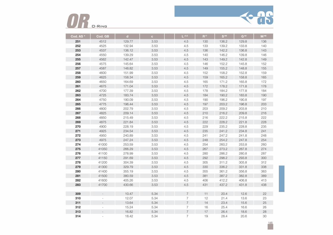
145
Cod. AS * Cod. GB d c L +0.2 R f7 S H9 G h9 M H8
251 4512 129.77 3.53 4.5 130 136.2 129.8 136252 4525 132.94 3.53 4.5 133 139.2 133.8 140253 4537 136.12 3.53 4.5 136 142.2 136.8 143254 4550 139.29 3.53 4.5 140 146.2 139.8 146255 4562 142.47 3.53 4.5 143 149.2 142.8 149256 4575 145.64 3.53 4.5 146 152.2 145.8 152257 4587 148.82 3.53 4.5 149 155.2 148.8 155258 4600 151.99 3.53 4.5 152 158.2 152.8 159259 4625 158.34 3.53 4.5 159 165.2 158.8 165260 4650 164.69 3.53 4.5 165 171.2 165.8 172261 4675 171.04 3.53 4.5 172 178.2 171.8 178262 4700 177.39 3.53 4.5 178 184.2 177.8 184263 4725 183.74 3.53 4.5 184 190.2 183.8 190264 4750 190.09 3.53 4.5 190 196.2 190.8 197265 4775 196.44 3.53 4.5 197 203.2 196.8 203266 4800 202.79 3.53 4.5 203 209.2 203.8 210267 4825 209.14 3.53 4.5 210 216.2 209.8 216268 4850 215.49 3.53 4.5 216 222.2 215.8 222269 4875 221.84 3.53 4.5 222 228.2 221.8 228270 4900 228.19 3.53 4.5 229 235.2 228.8 235271 4925 234.54 3.53 4.5 235 241.2 234.8 241272 4950 240.89 3.53 4.5 241 247.2 241.8 248273 4975 247.24 3.53 4.5 248 254.2 247.8 254274 41000 253.59 3.53 4.5 254 260.2 253.8 260275 41050 266.29 3.53 4.5 267 273.2 267.8 274276 41100 278.99 3.53 4.5 280 286.2 280.8 287277 41150 291.69 3.53 4.5 292 298.2 293.8 300278 41200 304.39 3.53 4.5 305 311.2 305.8 312279 41300 329.79 3.53 4.5 330 336.2 331.8 338280 41400 355.19 3.53 4.5 355 361.2 356.8 363281 41500 380.59 3.53 4.5 381 387.2 382.8 389282 41600 405.26 3.53 4.5 406 412.2 406.8 413283 41700 430.66 3.53 4.5 431 437.2 431.8 438
309 - 10.47 5.34 7 11 20.4 12.6 22310 - 12.07 5.34 7 12 21.4 13.6 23311 - 13.64 5.34 7 14 23.4 15.6 25312 - 15.24 5.34 7 16 25.4 16.6 26313 - 16.82 5.34 7 17 26.4 18.6 28314 - 18.42 5.34 7 19 28.4 20.6 30
OR O-Ring

146
Cod. AS * Cod. GB d c L +0.2 R f7 S H9 G h9 M H8
315 - 19.99 5.34 7 20 29.4 21.6 31316 - 21.99 5.34 7 22 31.4 23.6 33317 - 23.17 5.34 7 24 33.4 24.6 34318 - 24.77 5.34 7 26 35.4 26.6 36319 - 26.34 5.34 7 27 36.4 27.6 37320 - 27.97 5.34 7 28 37.4 29.6 39321 - 29.52 5.34 7 30 39.4 31.6 41322 - 31.12 5.34 7 31 40.4 32.6 42323 - 32.69 5.34 7 33 42.4 34.6 44324 - 34.29 5.34 7 35 44.4 35.6 45325 6150 37.47 5.34 7 38 47.4 38.6 48326 6162 40.65 5.34 7 41 50.4 42.6 52327 6175 43.82 5.34 7 44 53.4 45.6 55328 6187 47.00 5.34 7 47 56.4 48.6 58329 6200 50.16 5.34 7 50 59.4 51.6 61330 6212 53.34 5.34 7 53 62.4 54.6 64331 6225 56.52 5.34 7 57 66.4 58.6 68332 6237 59.69 5.34 7 60 69.4 60.6 70333 6250 62.87 5.34 7 63 72.4 63.6 73334 6262 66.04 5.34 7 66 75.4 67.6 77335 6275 69.22 5.34 7 69 78.4 70.6 80336 6287 72.39 5.34 7 73 82.4 73.6 83619 178 74.63 5.34 7 75 84.4 75.6 85337 6300 75.57 5.34 7 76 85.4 76.6 86338 6312 78.74 5.34 7 79 88.4 80.6 90620 181 79.77 5.34 7 80 89.4 80.6 90339 6325 81.92 5.34 7 82 91.4 82.6 92
OR O-Ring
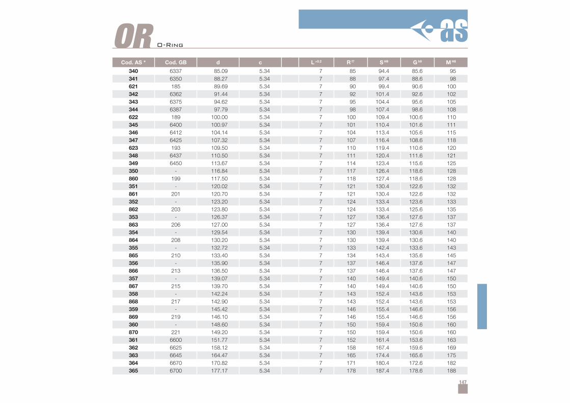
147
Cod. AS * Cod. GB d c L +0.2 R f7 S H9 G h9 M H8
340 6337 85.09 5.34 7 85 94.4 85.6 95341 6350 88.27 5.34 7 88 97.4 88.6 98621 185 89.69 5.34 7 90 99.4 90.6 100342 6362 91.44 5.34 7 92 101.4 92.6 102343 6375 94.62 5.34 7 95 104.4 95.6 105344 6387 97.79 5.34 7 98 107.4 98.6 108622 189 100.00 5.34 7 100 109.4 100.6 110345 6400 100.97 5.34 7 101 110.4 101.6 111346 6412 104.14 5.34 7 104 113.4 105.6 115347 6425 107.32 5.34 7 107 116.4 108.6 118623 193 109.50 5.34 7 110 119.4 110.6 120348 6437 110.50 5.34 7 111 120.4 111.6 121349 6450 113.67 5.34 7 114 123.4 115.6 125350 - 116.84 5.34 7 117 126.4 118.6 128860 199 117.50 5.34 7 118 127.4 118.6 128351 - 120.02 5.34 7 121 130.4 122.6 132861 201 120.70 5.34 7 121 130.4 122.6 132352 - 123.20 5.34 7 124 133.4 123.6 133862 203 123.80 5.34 7 124 133.4 125.6 135353 - 126.37 5.34 7 127 136.4 127.6 137863 206 127.00 5.34 7 127 136.4 127.6 137354 - 129.54 5.34 7 130 139.4 130.6 140864 208 130.20 5.34 7 130 139.4 130.6 140355 - 132.72 5.34 7 133 142.4 133.6 143865 210 133.40 5.34 7 134 143.4 135.6 145356 - 135.90 5.34 7 137 146.4 137.6 147866 213 136.50 5.34 7 137 146.4 137.6 147357 - 139.07 5.34 7 140 149.4 140.6 150867 215 139.70 5.34 7 140 149.4 140.6 150358 - 142.24 5.34 7 143 152.4 143.6 153868 217 142.90 5.34 7 143 152.4 143.6 153359 - 145.42 5.34 7 146 155.4 146.6 156869 219 146.10 5.34 7 146 155.4 146.6 156360 - 148.60 5.34 7 150 159.4 150.6 160870 221 149.20 5.34 7 150 159.4 150.6 160361 6600 151.77 5.34 7 152 161.4 153.6 163362 6625 158.12 5.34 7 158 167.4 159.6 169363 6645 164.47 5.34 7 165 174.4 165.6 175364 6670 170.82 5.34 7 171 180.4 172.6 182365 6700 177.17 5.34 7 178 187.4 178.6 188
OR O-Ring

148
Cod. AS * Cod. GB d c L +0.2 R f7 S H9 G h9 M H8
366 6720 183.52 5.34 7 184 193.4 185.6 195367 6745 189.87 5.34 7 190 199.4 190.6 200368 6775 196.22 5.34 7 196 205.4 197.6 207369 6795 202.57 5.34 7 202 211.4 203.6 213370 6820 208.92 5.34 7 209 218.4 210.6 220371 6850 215.27 5.34 7 215 224.4 216.6 226372 6870 221.62 5.34 7 222 231.4 222.6 232373 6895 227.97 5.34 7 228 237.4 229.6 239374 6920 234.32 5.34 7 234 243.4 235.6 245375 6945 240.67 5.34 7 241 250.4 242.6 252376 6975 247.02 5.34 7 247 256.4 248.6 258377 6995 253.37 5.34 7 253 262.4 255.6 265378 61050 266.07 5.34 7 266 275.4 267.6 277379 61100 278.77 5.34 7 280 289.4 280.6 290380 61150 291.47 5.34 7 292 301.4 293.6 303381 61200 304.17 5.34 7 304 313.4 305.6 315382 61300 329.57 5.34 7 330 339.4 330.6 340383 61400 354.97 5.34 7 355 364.4 355.6 365384 61500 380.37 5.34 7 380 389.4 382.6 392385 61600 405.26 5.34 7 405 414.4 406.6 416386 61700 430.66 5.34 7 431 440.4 432.6 442387 61800 456.06 5.34 7 456 465.4 458.6 468388 61900 481.40 5.34 7 482 491.4 484.6 494389 62000 506.80 5.34 7 507 516.4 509.6 519390 62100 532.20 5.34 7 532 541.4 534.6 544391 - 557.60 5.34 7 558 567.4 560.6 570392 - 582.68 5.34 7 585 594.4 585.6 595
OR O-Ring
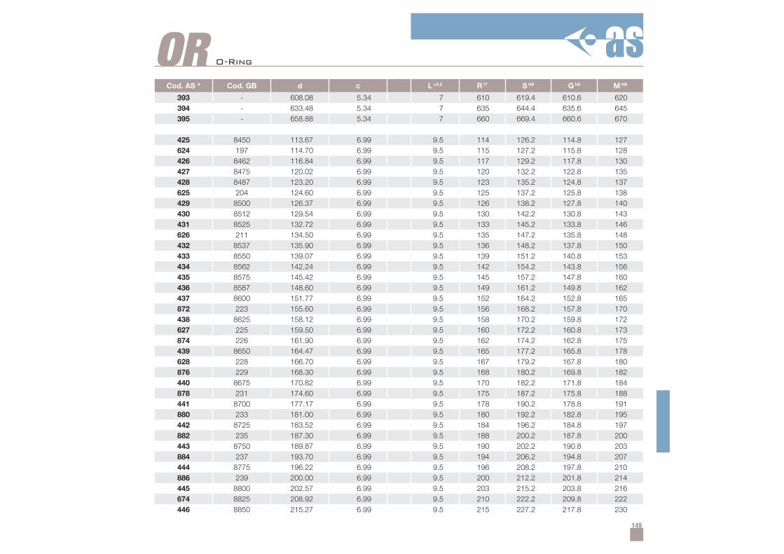
149
Cod. AS * Cod. GB d c L +0.2 R f7 S H9 G h9 M H8
393 - 608.08 5.34 7 610 619.4 610.6 620394 - 633.48 5.34 7 635 644.4 635.6 645395 - 658.88 5.34 7 660 669.4 660.6 670
425 8450 113.67 6.99 9.5 114 126.2 114.8 127624 197 114.70 6.99 9.5 115 127.2 115.8 128426 8462 116.84 6.99 9.5 117 129.2 117.8 130427 8475 120.02 6.99 9.5 120 132.2 122.8 135428 8487 123.20 6.99 9.5 123 135.2 124.8 137625 204 124.60 6.99 9.5 125 137.2 125.8 138429 8500 126.37 6.99 9.5 126 138.2 127.8 140430 8512 129.54 6.99 9.5 130 142.2 130.8 143431 8525 132.72 6.99 9.5 133 145.2 133.8 146626 211 134.50 6.99 9.5 135 147.2 135.8 148432 8537 135.90 6.99 9.5 136 148.2 137.8 150433 8550 139.07 6.99 9.5 139 151.2 140.8 153434 8562 142.24 6.99 9.5 142 154.2 143.8 156435 8575 145.42 6.99 9.5 145 157.2 147.8 160436 8587 148.60 6.99 9.5 149 161.2 149.8 162437 8600 151.77 6.99 9.5 152 164.2 152.8 165872 223 155.60 6.99 9.5 156 168.2 157.8 170438 8625 158.12 6.99 9.5 158 170.2 159.8 172627 225 159.50 6.99 9.5 160 172.2 160.8 173874 226 161.90 6.99 9.5 162 174.2 162.8 175439 8650 164.47 6.99 9.5 165 177.2 165.8 178628 228 166.70 6.99 9.5 167 179.2 167.8 180876 229 168.30 6.99 9.5 168 180.2 169.8 182440 8675 170.82 6.99 9.5 170 182.2 171.8 184878 231 174.60 6.99 9.5 175 187.2 175.8 188441 8700 177.17 6.99 9.5 178 190.2 178.8 191880 233 181.00 6.99 9.5 180 192.2 182.8 195442 8725 183.52 6.99 9.5 184 196.2 184.8 197882 235 187.30 6.99 9.5 188 200.2 187.8 200443 8750 189.87 6.99 9.5 190 202.2 190.8 203884 237 193.70 6.99 9.5 194 206.2 194.8 207444 8775 196.22 6.99 9.5 196 208.2 197.8 210886 239 200.00 6.99 9.5 200 212.2 201.8 214445 8800 202.57 6.99 9.5 203 215.2 203.8 216674 8825 208.92 6.99 9.5 210 222.2 209.8 222446 8850 215.27 6.99 9.5 215 227.2 217.8 230
OR O-Ring

150
Cod. AS * Cod. GB d c L +0.2 R f7 S H9 G h9 M H8
676 8875 221.62 6.99 9.5 222 234.2 222.8 235447 8900 227.97 6.99 9.5 230 242.2 229.8 242678 8925 234.32 6.99 9.5 235 247.2 237.8 250448 8950 240.67 6.99 9.5 240 252.2 242.8 255680 8975 247.00 6.99 9.5 248 260.2 247.8 260449 81000 253.30 6.99 9.5 255 267.2 257.8 270682 81025 259.70 6.99 9.5 260 272.2 262.8 275450 81050 266.07 6.99 9.5 265 277.2 267.8 280684 81075 272.40 6.99 9.5 273 285.2 273.8 286451 81100 278.77 6.99 9.5 280 292.2 282.8 295686 81125 285.10 6.99 9.5 285 297.2 287.8 300452 81150 291.47 6.99 9.5 292 304.2 292.8 305688 81175 297.80 6.99 9.5 300 312.2 302.8 315453 81200 304.17 6.99 9.5 305 317.2 307.8 320454 81250 316.87 6.99 9.5 318 330.2 317.8 330455 81300 329.57 6.99 9.5 330 342.2 332.8 345456 81350 342.27 6.99 9.5 342 354.2 342.8 355457 81400 354.97 6.99 9.5 355 367.2 357.8 370458 81450 367.67 6.99 9.5 370 382.2 367.8 380459 81500 380.37 6.99 9.5 380 392.2 382.8 395460 81550 393.07 6.99 9.5 393 405.2 397.8 410461 81600 405.26 6.99 9.5 405 417.2 407.8 420462 81650 417.96 6.99 9.5 418 430.2 419.8 432463 81700 430.66 6.99 9.5 431 443.2 432.8 445464 81750 443.36 6.99 9.5 445 457.2 447.8 460465 81800 456.06 6.99 9.5 458 470.2 457.8 470466 81850 468.76 6.99 9.5 470 482.2 467.8 480
OR O-Ring
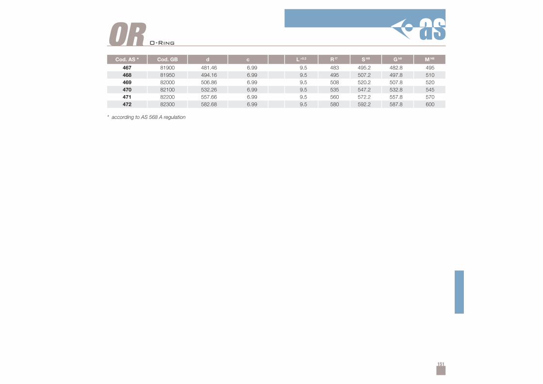
151
ORCod. AS * Cod. GB d c L +0.2 R f7 S H9 G h9 M H8
467 81900 481.46 6.99 9.5 483 495.2 482.8 495468 81950 494.16 6.99 9.5 495 507.2 497.8 510469 82000 506.86 6.99 9.5 508 520.2 507.8 520470 82100 532.26 6.99 9.5 535 547.2 532.8 545471 82200 557.66 6.99 9.5 560 572.2 557.8 570472 82300 582.68 6.99 9.5 580 592.2 587.8 600
* according to AS 568 A regulation
O-Ring
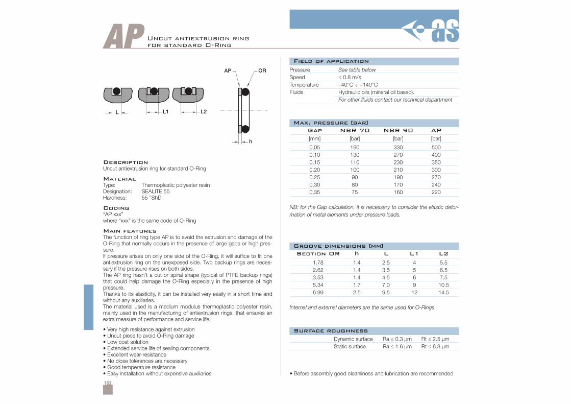
152
AP Uncut antiextrusion ringfor standard O-Ring
DescriptionUncut antiextrusion ring for standard O-Ring
MaterialType: Thermoplastic polyester resinDesignation: SEALITE 55Hardness: 55 °ShD
Coding“AP xxx”where “xxx” is the same code of O-Ring
Main featuresThe function of ring type AP is to avoid the extrusion and damage of theO-Ring that normally occurs in the presence of large gaps or high pres-sure.If pressure arises on only one side of the O-Ring, it will suffice to fit oneantiextrusion ring on the unexposed side. Two backup rings are neces-sary if the pressure rises on both sides.The AP ring hasn’t a cut or spiral shape (typical of PTFE backup rings)that could help damage the O-Ring especially in the presence of highpressure.Thanks to its elasticity, it can be installed very easily in a short time andwithout any auxiliaries.The material used is a medium modulus thermoplastic polyester resin,mainly used in the manufacturing of antiextrusion rings, that ensures anextra measure of performance and service life.
• Very high resistance against extrusion• Uncut piece to avoid O-Ring damage• Low cost solution• Extended service life of sealing components• Excellent wear-resistance• No close tolerances are necessary• Good temperature resistance• Easy installation without expensive auxiliaries
Pressure See table belowSpeed ≤ 0.8 m/sTemperature –40°C ÷ +140°CFluids Hydraulic oils (mineral oil based).
For other fluids contact our technical department
Dynamic surface Ra ≤ 0.3 µm Rt ≤ 2.5 µmStatic surface Ra ≤ 1.6 µm Rt ≤ 6.3 µm
• Before assembly good cleanliness and lubrication are recommended
[mm] [bar] [bar] [bar]
0,05 190 330 5000,10 130 270 4000,15 110 230 3500,20 100 210 3000,25 90 190 2700,30 80 170 2400,35 75 160 220
NB: for the Gap calculation, it is necessary to consider the elastic defor-mation of metal elements under pressure loads.
1.78 1.4 2.5 4 5.52.62 1.4 3.5 5 6.53.53 1.4 4.5 6 7.55.34 1.7 7.0 9 10.56.99 2.5 9.5 12 14.5
Internal and external diameters are the same used for O-Rings
Gap NBR 70 NBR 90 AP
Section OR h L L1 L2
Field of application
Surface roughness
Max. pressure [bar]
Groove dimensions [mm]
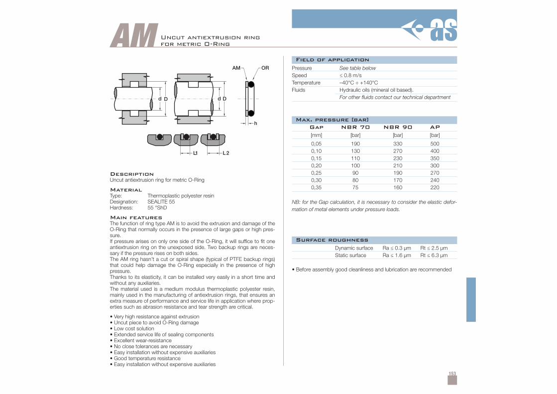
153
AM
d D d D
L1 L2
h
AM OR
Uncut antiextrusion ringfor metric O-Ring
DescriptionUncut antiextrusion ring for metric O-Ring
MaterialType: Thermoplastic polyester resinDesignation: SEALITE 55Hardness: 55 °ShD
Main featuresThe function of ring type AM is to avoid the extrusion and damage of theO-Ring that normally occurs in the presence of large gaps or high pres-sure.If pressure arises on only one side of the O-Ring, it will suffice to fit oneantiextrusion ring on the unexposed side. Two backup rings are neces-sary if the pressure rises on both sides.The AM ring hasn’t a cut or spiral shape (typical of PTFE backup rings)that could help damage the O-Ring especially in the presence of highpressure.Thanks to its elasticity, it can be installed very easily in a short time andwithout any auxiliaries.The material used is a medium modulus thermoplastic polyester resin,mainly used in the manufacturing of antiextrusion rings, that ensures anextra measure of performance and service life in application where prop-erties such as abrasion resistance and tear strength are critical.
• Very high resistance against extrusion• Uncut piece to avoid O-Ring damage• Low cost solution• Extended service life of sealing components• Excellent wear-resistance• No close tolerances are necessary• Easy installation without expensive auxiliaries• Good temperature resistance• Easy installation without expensive auxiliaries
Pressure See table belowSpeed ≤ 0.8 m/sTemperature –40°C ÷ +140°CFluids Hydraulic oils (mineral oil based).
For other fluids contact our technical department
Dynamic surface Ra ≤ 0.3 µm Rt ≤ 2.5 µmStatic surface Ra ≤ 1.6 µm Rt ≤ 6.3 µm
• Before assembly good cleanliness and lubrication are recommended
[mm] [bar] [bar] [bar]
0,05 190 330 5000,10 130 270 4000,15 110 230 3500,20 100 210 3000,25 90 190 2700,30 80 170 2400,35 75 160 220
NB: for the Gap calculation, it is necessary to consider the elastic defor-mation of metal elements under pressure loads.
Gap NBR 70 NBR 90 AP
Field of application
Surface roughness
Max. pressure [bar]
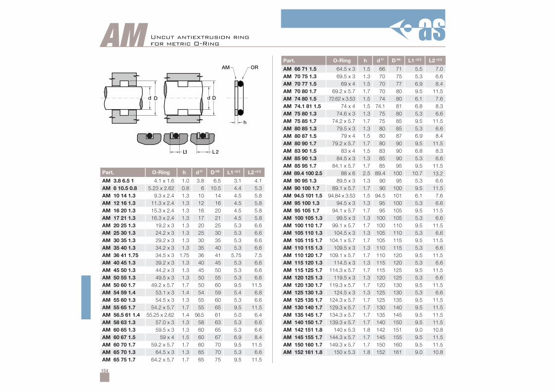
154
Part. O-Ring h d f7 D H9 L1 +0.2 L2 +0.2
AM 3.8 6.5 1 4.1 x 1.6 1.0 3.8 6.5 3.1 4.1AM 6 10.5 0.8 5.23 x 2.62 0.8 6 10.5 4.4 5.3AM 10 14 1.3 9.3 x 2.4 1.3 10 14 4.5 5.8AM 12 16 1.3 11.3 x 2.4 1.3 12 16 4.5 5.8AM 16 20 1.3 15.3 x 2.4 1.3 16 20 4.5 5.8AM 17 21 1.3 16.3 x 2.4 1.3 17 21 4.5 5.8AM 20 25 1.3 19.2 x 3 1.3 20 25 5.3 6.6AM 25 30 1.3 24.2 x 3 1.3 25 30 5.3 6.6AM 30 35 1.3 29.2 x 3 1.3 30 35 5.3 6.6AM 35 40 1.3 34.2 x 3 1.3 35 40 5.3 6.6AM 36 41 1.75 34.5 x 3 1.75 36 41 5.75 7.5AM 40 45 1.3 39.2 x 3 1.3 40 45 5.3 6.6AM 45 50 1.3 44.2 x 3 1.3 45 50 5.3 6.6AM 50 55 1.3 49.5 x 3 1.3 50 55 5.3 6.6AM 50 60 1.7 49.2 x 5.7 1.7 50 60 9.5 11.5AM 54 59 1.4 53.1 x 3 1.4 54 59 5.4 6.8AM 55 60 1.3 54.5 x 3 1.3 55 60 5.3 6.6AM 55 65 1.7 54.2 x 5.7 1.7 55 65 9.5 11.5AM 56.5 61 1.4 55.25 x 2.62 1.4 56.5 61 5.0 6.4AM 58 63 1.3 57.0 x 3 1.3 58 63 5.3 6.6AM 60 65 1.3 59.5 x 3 1.3 60 65 5.3 6.6AM 60 67 1.5 59 x 4 1.5 60 67 6.9 8.4AM 60 70 1.7 59.2 x 5.7 1.7 60 70 9.5 11.5AM 65 70 1.3 64.5 x 3 1.3 65 70 5.3 6.6AM 65 75 1.7 64.2 x 5.7 1.7 65 75 9.5 11.5
Part. O-Ring h d f7 D H9 L1 +0.2 L2 +0.2
AM 66 71 1.5 64.5 x 3 1.5 66 71 5.5 7.0AM 70 75 1.3 69.5 x 3 1.3 70 75 5.3 6.6AM 70 77 1.5 69 x 4 1.5 70 77 6.9 8.4AM 70 80 1.7 69.2 x 5.7 1.7 70 80 9.5 11.5AM 74 80 1.5 72.62 x 3.53 1.5 74 80 6.1 7.6AM 74.1 81 1.5 74 x 4 1.5 74.1 81 6.8 8.3AM 75 80 1.3 74.6 x 3 1.3 75 80 5.3 6.6AM 75 85 1.7 74.2 x 5.7 1.7 75 85 9.5 11.5AM 80 85 1.3 79.5 x 3 1.3 80 85 5.3 6.6AM 80 87 1.5 79 x 4 1.5 80 87 6.9 8.4AM 80 90 1.7 79.2 x 5.7 1.7 80 90 9.5 11.5AM 83 90 1.5 83 x 4 1.5 83 90 6.8 8.3AM 85 90 1.3 84.5 x 3 1.3 85 90 5.3 6.6AM 85 95 1.7 84.1 x 5.7 1.7 85 95 9.5 11.5AM 89.4 100 2.5 88 x 6 2.5 89.4 100 10.7 13.2AM 90 95 1.3 89.5 x 3 1.3 90 95 5.3 6.6AM 90 100 1.7 89.1 x 5.7 1.7 90 100 9.5 11.5AM 94.5 101 1.5 94.84 x 3.53 1.5 94.5 101 6.1 7.6AM 95 100 1.3 94.5 x 3 1.3 95 100 5.3 6.6AM 95 105 1.7 94.1 x 5.7 1.7 95 105 9.5 11.5AM 100 105 1.3 99.5 x 3 1.3 100 105 5.3 6.6AM 100 110 1.7 99.1 x 5.7 1.7 100 110 9.5 11.5AM 105 110 1.3 104.5 x 3 1.3 105 110 5.3 6.6AM 105 115 1.7 104.1 x 5.7 1.7 105 115 9.5 11.5AM 110 115 1.3 109.5 x 3 1.3 110 115 5.3 6.6AM 110 120 1.7 109.1 x 5.7 1.7 110 120 9.5 11.5AM 115 120 1.3 114.5 x 3 1.3 115 120 5.3 6.6AM 115 125 1.7 114.3 x 5.7 1.7 115 125 9.5 11.5AM 120 125 1.3 119.5 x 3 1.3 120 125 5.3 6.6AM 120 130 1.7 119.3 x 5.7 1.7 120 130 9.5 11.5AM 125 130 1.3 124.5 x 3 1.3 125 130 5.3 6.6AM 125 135 1.7 124.3 x 5.7 1.7 125 135 9.5 11.5AM 130 140 1.7 129.3 x 5.7 1.7 130 140 9.5 11.5AM 135 145 1.7 134.3 x 5.7 1.7 135 145 9.5 11.5AM 140 150 1.7 139.3 x 5.7 1.7 140 150 9.5 11.5AM 142 151 1.8 140 x 5.3 1.8 142 151 9.0 10.8AM 145 155 1.7 144.3 x 5.7 1.7 145 155 9.5 11.5AM 150 160 1.7 149.3 x 5.7 1.7 150 160 9.5 11.5AM 152 161 1.8 150 x 5.3 1.8 152 161 9.0 10.8
AM
d D d D
L1 L2
h
AM OR
Uncut antiextrusion ringfor metric O-Ring
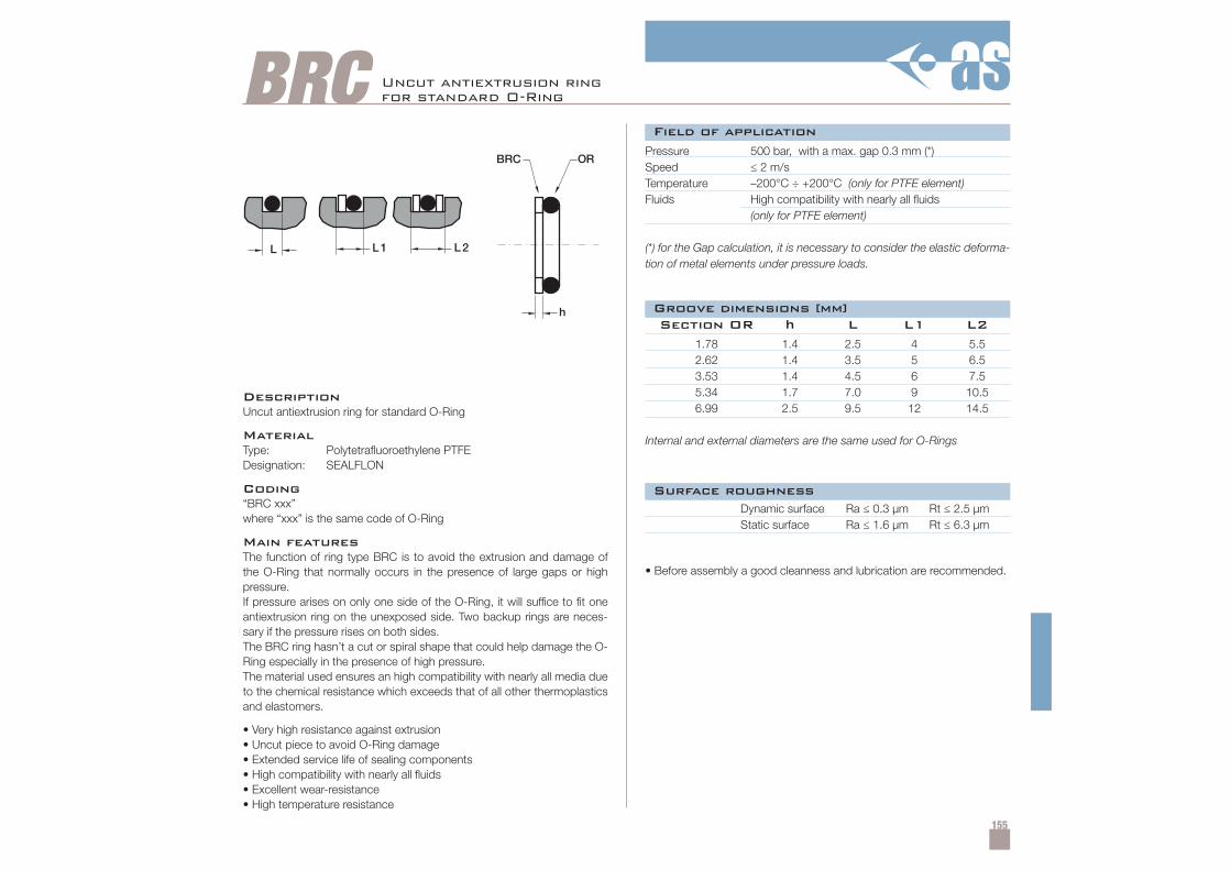
155
BRC Uncut antiextrusion ringfor standard O-Ring
DescriptionUncut antiextrusion ring for standard O-Ring
MaterialType: Polytetrafluoroethylene PTFEDesignation: SEALFLON
Coding“BRC xxx”where “xxx” is the same code of O-Ring
Main featuresThe function of ring type BRC is to avoid the extrusion and damage ofthe O-Ring that normally occurs in the presence of large gaps or highpressure.If pressure arises on only one side of the O-Ring, it will suffice to fit oneantiextrusion ring on the unexposed side. Two backup rings are neces-sary if the pressure rises on both sides.The BRC ring hasn’t a cut or spiral shape that could help damage the O-Ring especially in the presence of high pressure.The material used ensures an high compatibility with nearly all media dueto the chemical resistance which exceeds that of all other thermoplasticsand elastomers.
• Very high resistance against extrusion• Uncut piece to avoid O-Ring damage• Extended service life of sealing components• High compatibility with nearly all fluids• Excellent wear-resistance• High temperature resistance
Pressure 500 bar, with a max. gap 0.3 mm (*)Speed ≤ 2 m/sTemperature –200°C ÷ +200°C (only for PTFE element)Fluids High compatibility with nearly all fluids
(only for PTFE element)
(*) for the Gap calculation, it is necessary to consider the elastic deforma-tion of metal elements under pressure loads.
Dynamic surface Ra ≤ 0.3 µm Rt ≤ 2.5 µmStatic surface Ra ≤ 1.6 µm Rt ≤ 6.3 µm
• Before assembly a good cleanness and lubrication are recommended.
1.78 1.4 2.5 4 5.52.62 1.4 3.5 5 6.53.53 1.4 4.5 6 7.55.34 1.7 7.0 9 10.56.99 2.5 9.5 12 14.5
Internal and external diameters are the same used for O-Rings
Section OR h L L1 L2
Field of application
Surface roughness
Groove dimensions [mm]
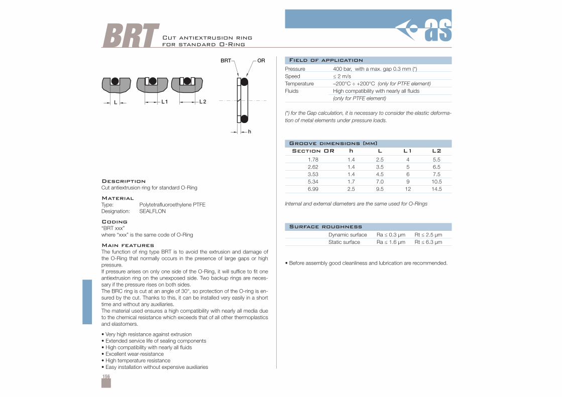
156
BRT Cut antiextrusion ringfor standard O-Ring
DescriptionCut antiextrusion ring for standard O-Ring
MaterialType: Polytetrafluoroethylene PTFEDesignation: SEALFLON
Coding“BRT xxx”where “xxx” is the same code of O-Ring
Main featuresThe function of ring type BRT is to avoid the extrusion and damage ofthe O-Ring that normally occurs in the presence of large gaps or highpressure.If pressure arises on only one side of the O-Ring, it will suffice to fit oneantiextrusion ring on the unexposed side. Two backup rings are neces-sary if the pressure rises on both sides.The BRC ring is cut at an angle of 30°, so protection of the O-ring is en-sured by the cut. Thanks to this, it can be installed very easily in a shorttime and without any auxiliaries.The material used ensures a high compatibility with nearly all media dueto the chemical resistance which exceeds that of all other thermoplasticsand elastomers.
• Very high resistance against extrusion• Extended service life of sealing components• High compatibility with nearly all fluids• Excellent wear-resistance• High temperature resistance• Easy installation without expensive auxiliaries
Pressure 400 bar, with a max. gap 0.3 mm (*)Speed ≤ 2 m/sTemperature –200°C ÷ +200°C (only for PTFE element)Fluids High compatibility with nearly all fluids
(only for PTFE element)
(*) for the Gap calculation, it is necessary to consider the elastic deforma-tion of metal elements under pressure loads.
Dynamic surface Ra ≤ 0.3 µm Rt ≤ 2.5 µmStatic surface Ra ≤ 1.6 µm Rt ≤ 6.3 µm
• Before assembly good cleanliness and lubrication are recommended.
1.78 1.4 2.5 4 5.52.62 1.4 3.5 5 6.53.53 1.4 4.5 6 7.55.34 1.7 7.0 9 10.56.99 2.5 9.5 12 14.5
Internal and external diameters are the same used for O-Rings
Section OR h L L1 L2
Field of application
Surface roughness
Groove dimensions [mm]
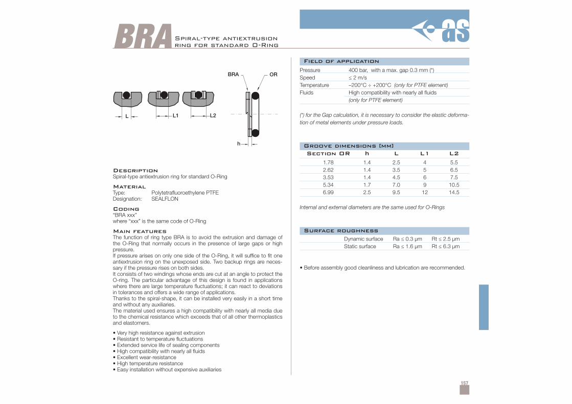
157
BRA Spiral-type antiextrusionring for standard O-Ring
DescriptionSpiral-type antiextrusion ring for standard O-Ring
MaterialType: Polytetrafluoroethylene PTFEDesignation: SEALFLON
Coding“BRA xxx”where “xxx” is the same code of O-Ring
Main featuresThe function of ring type BRA is to avoid the extrusion and damage ofthe O-Ring that normally occurs in the presence of large gaps or highpressure.If pressure arises on only one side of the O-Ring, it will suffice to fit oneantiextrusion ring on the unexposed side. Two backup rings are neces-sary if the pressure rises on both sides.It consists of two windings whose ends are cut at an angle to protect theO-ring. The particular advantage of this design is found in applicationswhere there are large temperature fluctuations; it can react to deviationsin tolerances and offers a wide range of applications.Thanks to the spiral-shape, it can be installed very easily in a short timeand without any auxiliaries.The material used ensures a high compatibility with nearly all media dueto the chemical resistance which exceeds that of all other thermoplasticsand elastomers.
• Very high resistance against extrusion• Resistant to temperature fluctuations• Extended service life of sealing components• High compatibility with nearly all fluids• Excellent wear-resistance• High temperature resistance• Easy installation without expensive auxiliaries
Pressure 400 bar, with a max. gap 0.3 mm (*)Speed ≤ 2 m/sTemperature –200°C ÷ +200°C (only for PTFE element)Fluids High compatibility with nearly all fluids
(only for PTFE element)
(*) for the Gap calculation, it is necessary to consider the elastic deforma-tion of metal elements under pressure loads.
Dynamic surface Ra ≤ 0.3 µm Rt ≤ 2.5 µmStatic surface Ra ≤ 1.6 µm Rt ≤ 6.3 µm
• Before assembly good cleanliness and lubrication are recommended.
1.78 1.4 2.5 4 5.52.62 1.4 3.5 5 6.53.53 1.4 4.5 6 7.55.34 1.7 7.0 9 10.56.99 2.5 9.5 12 14.5
Internal and external diameters are the same used for O-Rings
Section OR h L L1 L2
Field of application
Surface roughness
Groove dimensions [mm]
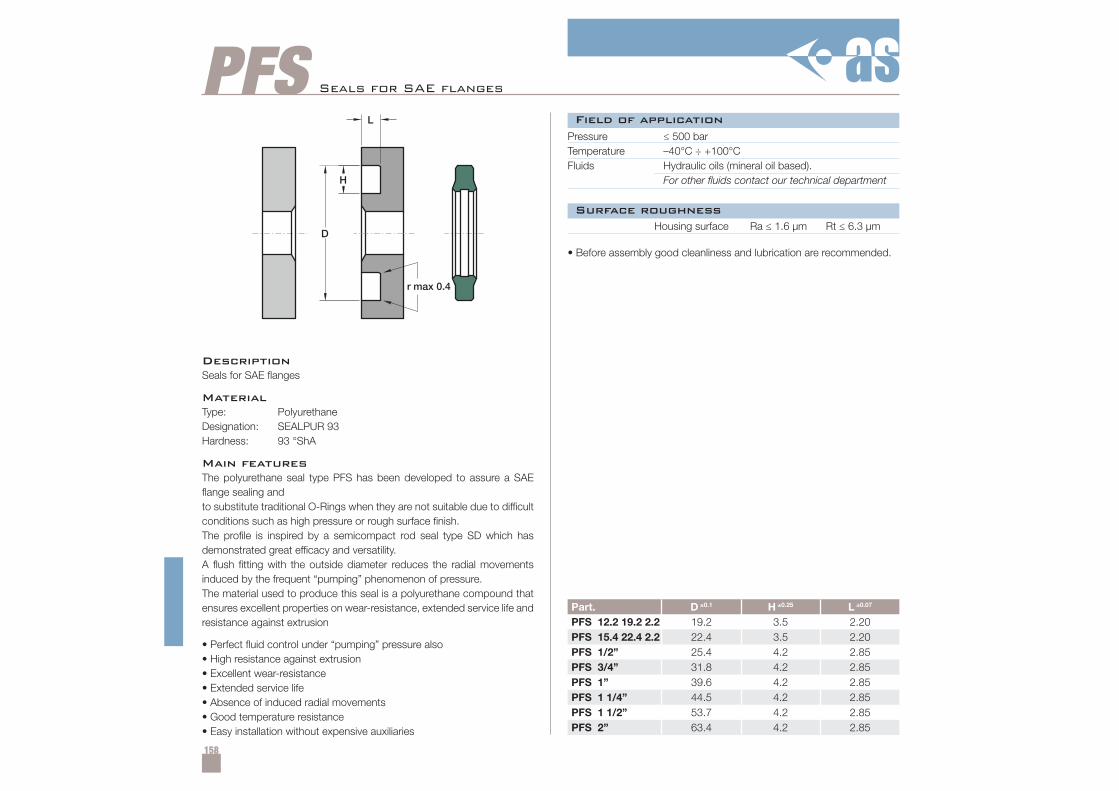
158
PFS
Part. D ±0.1 H ±0.25 L ±0.07
PFS 12.2 19.2 2.2 19.2 3.5 2.20PFS 15.4 22.4 2.2 22.4 3.5 2.20PFS 1/2” 25.4 4.2 2.85PFS 3/4” 31.8 4.2 2.85PFS 1” 39.6 4.2 2.85PFS 1 1/4” 44.5 4.2 2.85PFS 1 1/2” 53.7 4.2 2.85PFS 2” 63.4 4.2 2.85
Seals for SAE fl anges
DescriptionSeals for SAE flanges
MaterialType: PolyurethaneDesignation: SEALPUR 93Hardness: 93 °ShA
Main featuresThe polyurethane seal type PFS has been developed to assure a SAEflange sealing andto substitute traditional O-Rings when they are not suitable due to difficultconditions such as high pressure or rough surface finish.The profile is inspired by a semicompact rod seal type SD which hasdemonstrated great efficacy and versatility.A flush fitting with the outside diameter reduces the radial movementsinduced by the frequent “pumping” phenomenon of pressure.The material used to produce this seal is a polyurethane compound thatensures excellent properties on wear-resistance, extended service life andresistance against extrusion
• Perfect fluid control under “pumping” pressure also• High resistance against extrusion• Excellent wear-resistance• Extended service life• Absence of induced radial movements• Good temperature resistance• Easy installation without expensive auxiliaries
Pressure ≤ 500 barTemperature –40°C ÷ +100°CFluids Hydraulic oils (mineral oil based).
For other fluids contact our technical department
Housing surface Ra ≤ 1.6 µm Rt ≤ 6.3 µm
• Before assembly good cleanliness and lubrication are recommended.
Field of application
Surface roughness
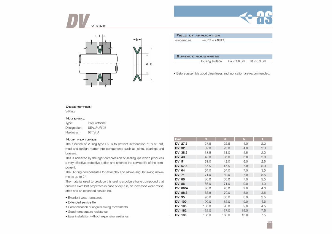
159
DV
Part. D d h LDV 27.5 27.5 22.5 4.0 2.0DV 32 32.0 26.0 4.0 2.0DV 38.5 38.5 31.0 4.5 2.0DV 43 43.0 36.0 5.0 2.0DV 51 51.0 42.0 6.0 2.5DV 57.5 57.5 47.5 7.0 3.0DV 64 64.0 54.0 7.0 3.5DV 71 71.0 59.0 7.0 3.5DV 80 80.0 65.0 7.0 3.5DV 86 86.0 71.0 9.0 4.0DV 86/A 86.0 70.0 9.0 4.0DV 88.8 88.8 70.0 8.0 3.5DV 95 95.0 85.0 6.0 2.5DV 100 100.0 82.0 9.0 4.5DV 105 105.0 90.0 9.0 4.5DV 162 162.0 137.0 15.0 7.5DV 186 186.0 160.0 16.0 7.5
V-Ring
DescriptionV-Ring
MaterialType: Polyurethane
Designation: SEALPUR 93
Hardness: 93 °ShA
Main featuresThe function of V-Ring type DV is to prevent introduction of dust, dirt,
mud and foreign matter into components such as joints, bearings and
brasses.
This is achieved by the right compression of sealing lips which produces
a very effective protective action and extends the service life of the com-
ponent.
The DV ring compensates for axial play and allows angular swing move-
ments up to 2°.
The material used to produce this seal is a polyurethane compound that
ensures excellent properties in case of dry run, an increased wear-resist-
ance and an extended service life.
• Excellent wear-resistance
• Extended service life
• Compensation of angular swing movements
• Good temperature resistance
• Easy installation without expensive auxiliaries
Temperature –40°C ÷ +100°C
Housing surface Ra ≤ 1.6 µm Rt ≤ 6.3 µm
• Before assembly good cleanliness and lubrication are recommended.
Field of application
Surface roughness
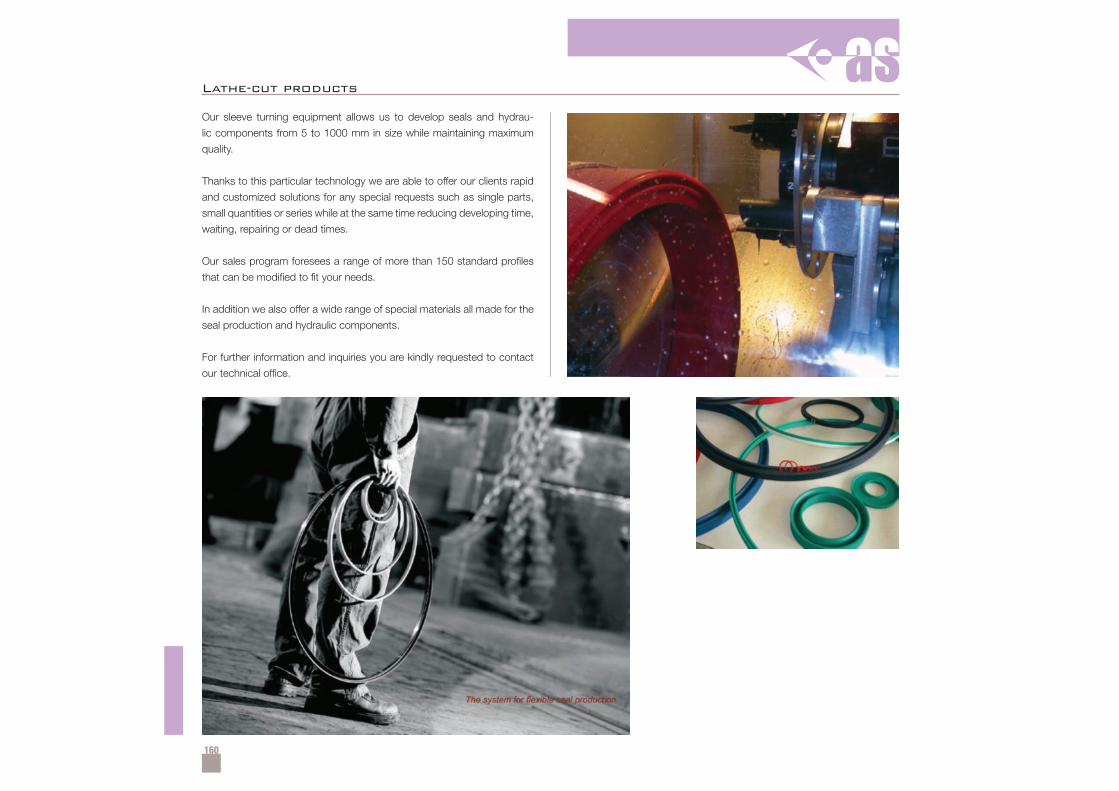
160
Our sleeve turning equipment allows us to develop seals and hydrau-
lic components from 5 to 1000 mm in size while maintaining maximum
quality.
Thanks to this particular technology we are able to offer our clients rapid
and customized solutions for any special requests such as single parts,
small quantities or series while at the same time reducing developing time,
waiting, repairing or dead times.
Our sales program foresees a range of more than 150 standard profiles
that can be modified to fit your needs.
In addition we also offer a wide range of special materials all made for the
seal production and hydraulic components.
For further information and inquiries you are kindly requested to contact
our technical office.
Lathe-cut products
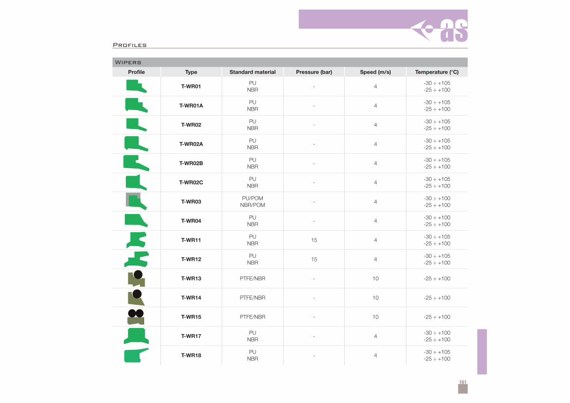
161
Profi les
Wipers
Profile Type Standard material Pressure (bar) Speed (m/s) Temperature (°C)
T-WR01PU
NBR- 4
-30 ÷ +105-25 ÷ +100
T-WR01APU
NBR- 4
-30 ÷ +105-25 ÷ +100
T-WR02PU
NBR- 4
-30 ÷ +105-25 ÷ +100
T-WR02APU
NBR- 4
-30 ÷ +105-25 ÷ +100
T-WR02BPU
NBR- 4
-30 ÷ +105-25 ÷ +100
T-WR02CPU
NBR- 4
-30 ÷ +105-25 ÷ +100
T-WR03PU/POM
NBR/POM- 4
-30 ÷ +100-25 ÷ +100
T-WR04PU
NBR- 4
-30 ÷ +100-25 ÷ +100
T-WR11PU
NBR15 4
-30 ÷ +105-25 ÷ +100
T-WR12PU
NBR15 4
-30 ÷ +105-25 ÷ +100
T-WR13 PTFE/NBR - 10 -25 ÷ +100
T-WR14 PTFE/NBR - 10 -25 ÷ +100
T-WR15 PTFE/NBR - 10 -25 ÷ +100
T-WR17PU
NBR- 4
-30 ÷ +100-25 ÷ +100
T-WR18PU
NBR- 4
-30 ÷ +105-25 ÷ +100
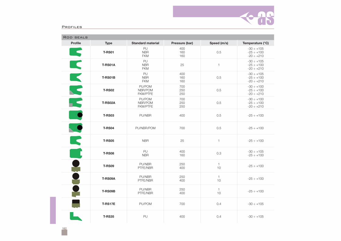
162
Rod seals
Profile Type Standard material Pressure (bar) Speed (m/s) Temperature (°C)
T-RS01PU
NBRFKM
400160160
0.5-30 ÷ +105-25 ÷ +100-20 ÷ +210
T-RS01APU
NBRFKM
25 1-30 ÷ +105-25 ÷ +100-20 ÷ +210
T-RS01BPU
NBRFKM
400160160
0.5-30 ÷ +105-25 ÷ +100-20 ÷ +210
T-RS02PU/POM
NBR/POMFKM/PTFE
700250250
0.5-30 ÷ +100-25 ÷ +100-20 ÷ +210
T-RS02APU/POM
NBR/POMFKM/PTFE
700250250
0.5-30 ÷ +100-25 ÷ +100-20 ÷ +210
T-RS03 PU/NBR 400 0.5 -25 ÷ +100
T-RS04 PU/NBR/POM 700 0.5 -25 ÷ +100
T-RS05 NBR 25 1 -25 ÷ +100
T-RS08 PUNBR
400160 0.3 -30 ÷ +105
-25 ÷ +100
T-RS09 PU/NBRPTFE/NBR
250400
110 -25 ÷ +100
T-RS09A PU/NBRPTFE/NBR
250400
110 -25 ÷ +100
T-RS09B PU/NBRPTFE/NBR
250400
110 -25 ÷ +100
T-RS17E PU/POM 700 0.4 -30 ÷ +105
T-RS35 PU 400 0.4 -30 ÷ +105
Profi les
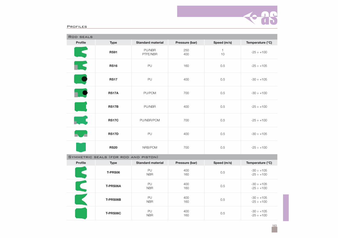
163
Rod seals
Profile Type Standard material Pressure (bar) Speed (m/s) Temperature (°C)
RS91PU/NBR
PTFE/NBR250400
110
-25 ÷ +100
RS16 PU 160 0.5 -25 ÷ +105
RS17 PU 400 0.5 -30 ÷ +105
RS17A PU/POM 700 0.5 -30 ÷ +100
RS17B PU/NBR 400 0.5 -25 ÷ +100
RS17C PU/NBR/POM 700 0.5 -25 ÷ +100
RS17D PU 400 0.5 -30 ÷ +105
RS20 NRB/POM 700 0.5 -25 ÷ +100
Symmetric seals (for rod and piston)
Profile Type Standard material Pressure (bar) Speed (m/s) Temperature (°C)
T-PRS06PU
NBR400160
0.5-30 ÷ +105-25 ÷ +100
T-PRS06APU
NBR400160
0.5-30 ÷ +105-25 ÷ +100
T-PRS06BPU
NBR400160
0.5-30 ÷ +105-25 ÷ +100
T-PRS06CPU
NBR400160
0.5-30 ÷ +105-25 ÷ +100
Profi les
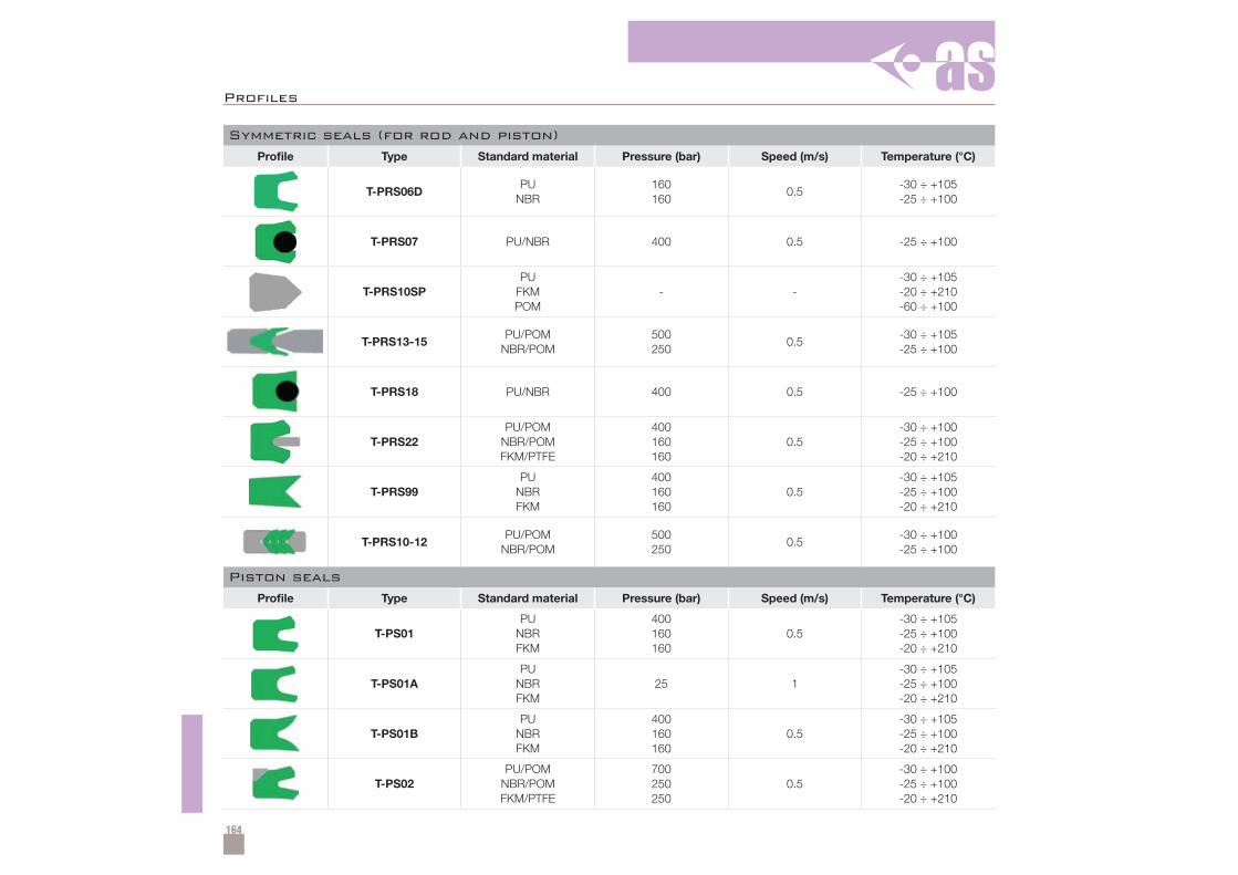
164
Profi les
Symmetric seals (for rod and piston)
Profile Type Standard material Pressure (bar) Speed (m/s) Temperature (°C)
T-PRS06DPU
NBR160160
0.5-30 ÷ +105-25 ÷ +100
T-PRS07 PU/NBR 400 0.5 -25 ÷ +100
T-PRS10SPPU
FKMPOM
- --30 ÷ +105-20 ÷ +210-60 ÷ +100
T-PRS13-15PU/POM
NBR/POM500250
0.5-30 ÷ +105-25 ÷ +100
T-PRS18 PU/NBR 400 0.5 -25 ÷ +100
T-PRS22PU/POM
NBR/POMFKM/PTFE
400160160
0.5-30 ÷ +100-25 ÷ +100-20 ÷ +210
T-PRS99PU
NBRFKM
400160160
0.5-30 ÷ +105-25 ÷ +100-20 ÷ +210
T-PRS10-12PU/POM
NBR/POM500250
0.5-30 ÷ +100-25 ÷ +100
Piston seals
Profile Type Standard material Pressure (bar) Speed (m/s) Temperature (°C)
T-PS01PU
NBRFKM
400160160
0.5-30 ÷ +105-25 ÷ +100-20 ÷ +210
T-PS01APU
NBRFKM
25 1-30 ÷ +105-25 ÷ +100-20 ÷ +210
T-PS01BPU
NBRFKM
400160160
0.5-30 ÷ +105-25 ÷ +100-20 ÷ +210
T-PS02PU/POM
NBR/POMFKM/PTFE
700250250
0.5-30 ÷ +100-25 ÷ +100-20 ÷ +210
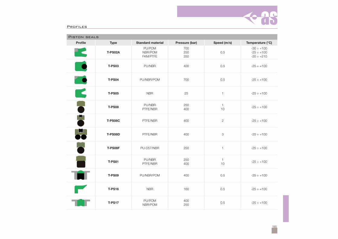
165
Piston seals
Profile Type Standard material Pressure (bar) Speed (m/s) Temperature (°C)
T-PS02APU/POM
NBR/POMFKM/PTFE
700250250
0.5-30 ÷ +100-25 ÷ +100-20 ÷ +210
T-PS03 PU/NBR 400 0.5 -25 ÷ +100
T-PS04 PU/NBR/POM 700 0.5 -25 ÷ +100
T-PS05 NBR 25 1 -25 ÷ +100
T-PS08PU/NBR
PTFE/NBR250400
110
-25 ÷ +100
T-PS08C PTFE/NBR 400 2 -25 ÷ +100
T-PS08D PTFE/NBR 400 3 -25 ÷ +100
T-PS08F PU-D57/NBR 250 1 -25 ÷ +100
T-PS81PU/NBR
PTFE/NBR250400
110
-25 ÷ +100
T-PS09 PU/NBR/POM 400 0.5 -25 ÷ +100
T-PS16 NBR 160 0.5 -25 ÷ +100
T-PS17PU/POM
NBR/POM400250
0.5 -25 ÷ +100
Profiles
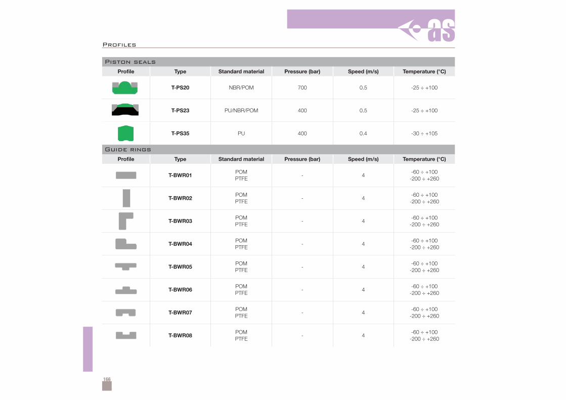
166
Profi les
Piston seals
Profile Type Standard material Pressure (bar) Speed (m/s) Temperature (°C)
T-PS20 NBR/POM 700 0.5 -25 ÷ +100
T-PS23 PU/NBR/POM 400 0.5 -25 ÷ +100
T-PS35 PU 400 0.4 -30 ÷ +105
Guide rings
Profile Type Standard material Pressure (bar) Speed (m/s) Temperature (°C)
T-BWR01POMPTFE
- 4-60 ÷ +100
-200 ÷ +260
T-BWR02POMPTFE
- 4-60 ÷ +100
-200 ÷ +260
T-BWR03POMPTFE
- 4-60 ÷ +100
-200 ÷ +260
T-BWR04POMPTFE
- 4-60 ÷ +100
-200 ÷ +260
T-BWR05POMPTFE
- 4-60 ÷ +100
-200 ÷ +260
T-BWR06POMPTFE
- 4-60 ÷ +100
-200 ÷ +260
T-BWR07POMPTFE
- 4-60 ÷ +100
-200 ÷ +260
T-BWR08POMPTFE
- 4-60 ÷ +100
-200 ÷ +260
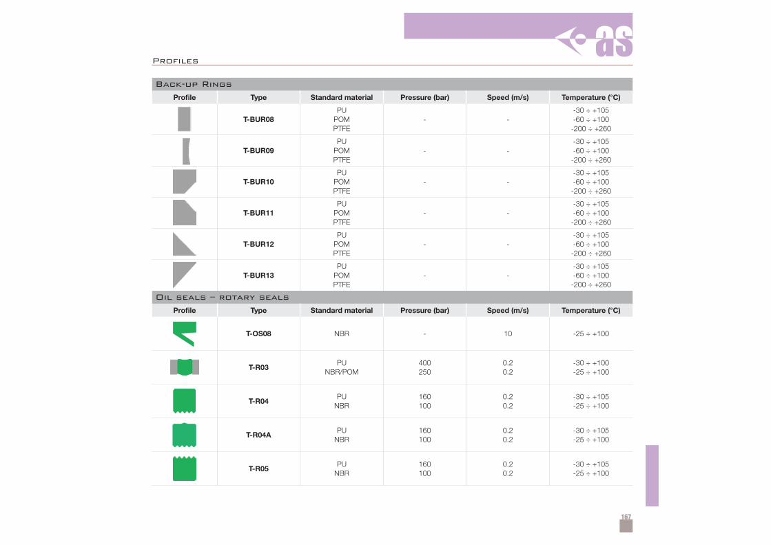
167
Back-up Rings
Profile Type Standard material Pressure (bar) Speed (m/s) Temperature (°C)
T-BUR08PU
POMPTFE
- --30 ÷ +105-60 ÷ +100
-200 ÷ +260
T-BUR09PU
POMPTFE
- --30 ÷ +105-60 ÷ +100
-200 ÷ +260
T-BUR10PU
POMPTFE
- --30 ÷ +105-60 ÷ +100
-200 ÷ +260
T-BUR11PU
POMPTFE
- --30 ÷ +105-60 ÷ +100
-200 ÷ +260
T-BUR12PU
POMPTFE
- --30 ÷ +105-60 ÷ +100
-200 ÷ +260
T-BUR13PU
POMPTFE
- --30 ÷ +105-60 ÷ +100
-200 ÷ +260
Oil seals – rotary seals
Profile Type Standard material Pressure (bar) Speed (m/s) Temperature (°C)
T-OS08 NBR - 10 -25 ÷ +100
T-R03PU
NBR/POM400250
0.20.2
-30 ÷ +100-25 ÷ +100
T-R04PU
NBR160100
0.20.2
-30 ÷ +105-25 ÷ +100
T-R04APU
NBR160100
0.20.2
-30 ÷ +105-25 ÷ +100
T-R05PU
NBR160100
0.20.2
-30 ÷ +105-25 ÷ +100
Profiles
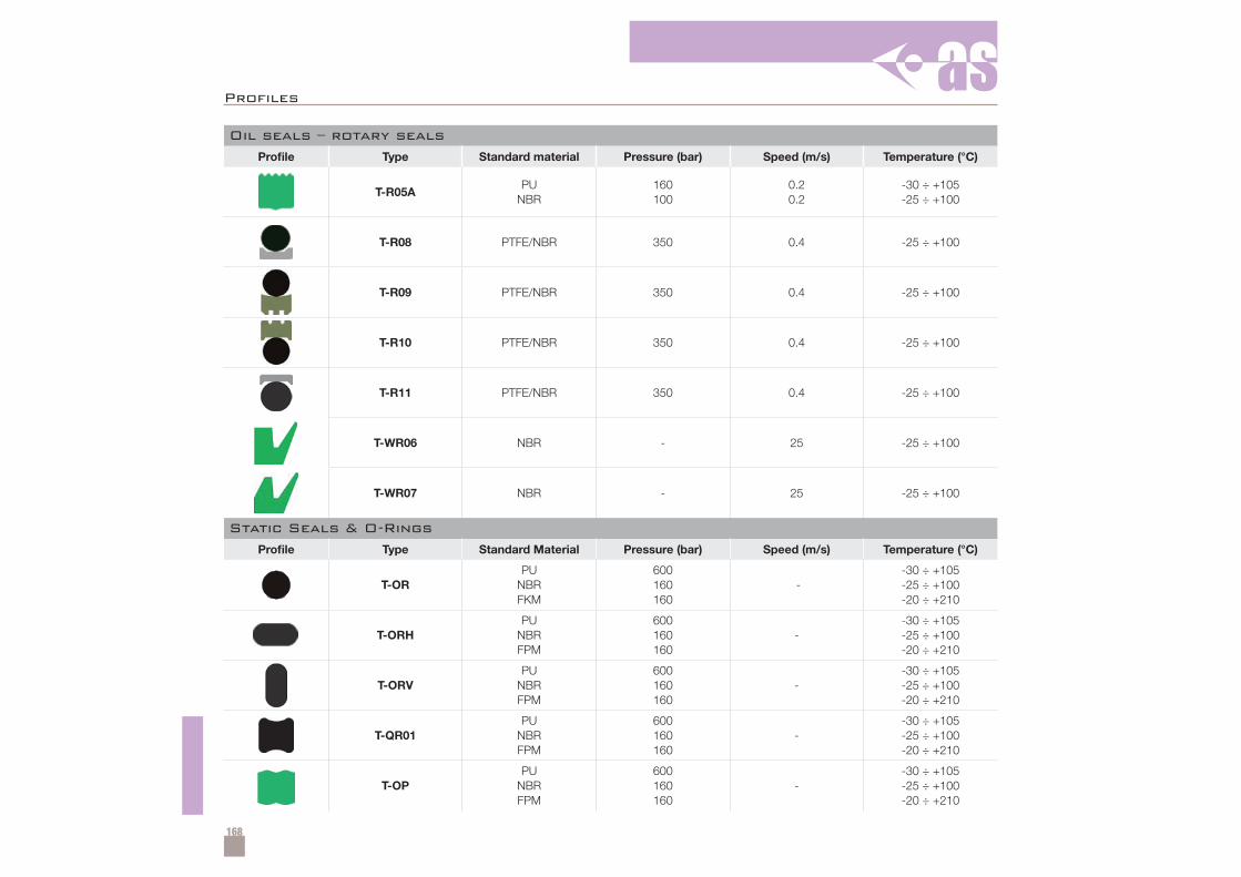
168
Profi les
Oil seals – rotary seals
Profile Type Standard material Pressure (bar) Speed (m/s) Temperature (°C)
T-R05APU
NBR160100
0.20.2
-30 ÷ +105-25 ÷ +100
T-R08 PTFE/NBR 350 0.4 -25 ÷ +100
T-R09 PTFE/NBR 350 0.4 -25 ÷ +100
T-R10 PTFE/NBR 350 0.4 -25 ÷ +100
T-R11 PTFE/NBR 350 0.4 -25 ÷ +100
T-WR06 NBR - 25 -25 ÷ +100
T-WR07 NBR - 25 -25 ÷ +100
Static Seals & O-Rings
Profile Type Standard Material Pressure (bar) Speed (m/s) Temperature (°C)
T-ORPU
NBRFKM
600160160
--30 ÷ +105-25 ÷ +100-20 ÷ +210
T-ORHPU
NBRFPM
600160160
--30 ÷ +105-25 ÷ +100-20 ÷ +210
T-ORVPU
NBRFPM
600160160
--30 ÷ +105-25 ÷ +100-20 ÷ +210
T-QR01PU
NBRFPM
600160160
--30 ÷ +105-25 ÷ +100-20 ÷ +210
T-OPPU
NBRFPM
600160160
--30 ÷ +105-25 ÷ +100-20 ÷ +210
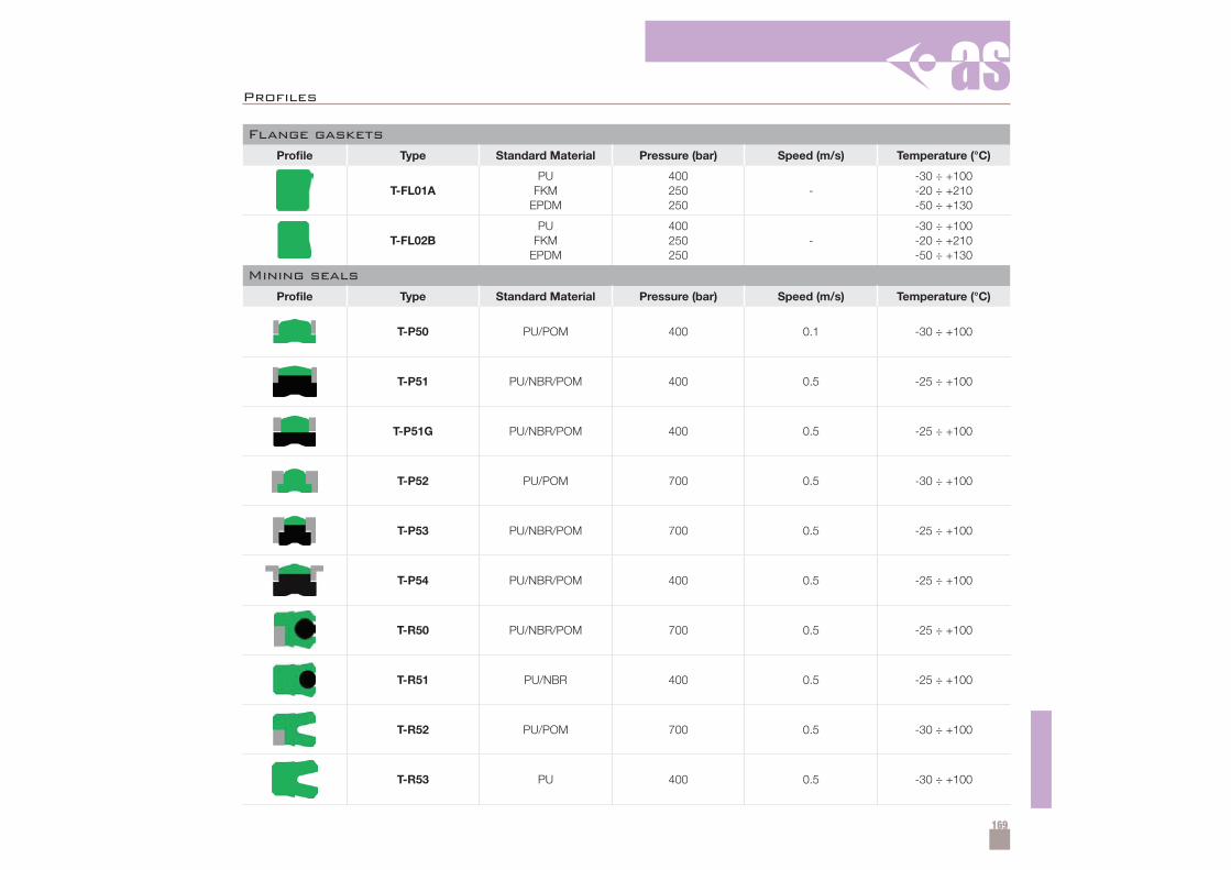
169
Flange gaskets
Profile Type Standard Material Pressure (bar) Speed (m/s) Temperature (°C)
T-FL01APU
FKMEPDM
400250250
--30 ÷ +100-20 ÷ +210-50 ÷ +130
T-FL02BPU
FKMEPDM
400250250
--30 ÷ +100-20 ÷ +210-50 ÷ +130
Mining seals
Profile Type Standard Material Pressure (bar) Speed (m/s) Temperature (°C)
T-P50 PU/POM 400 0.1 -30 ÷ +100
T-P51 PU/NBR/POM 400 0.5 -25 ÷ +100
T-P51G PU/NBR/POM 400 0.5 -25 ÷ +100
T-P52 PU/POM 700 0.5 -30 ÷ +100
T-P53 PU/NBR/POM 700 0.5 -25 ÷ +100
T-P54 PU/NBR/POM 400 0.5 -25 ÷ +100
T-R50 PU/NBR/POM 700 0.5 -25 ÷ +100
T-R51 PU/NBR 400 0.5 -25 ÷ +100
T-R52 PU/POM 700 0.5 -30 ÷ +100
T-R53 PU 400 0.5 -30 ÷ +100
Profi les
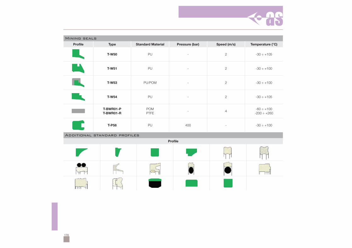
170
Mining seals
Profile Type Standard Material Pressure (bar) Speed (m/s) Temperature (°C)
T-W50 PU - 2 -30 ÷ +105
T-W51 PU - 2 -30 ÷ +100
T-W53 PU/POM - 2 -30 ÷ +100
T-W54 PU - 2 -30 ÷ +105
T-BWR01-PT-BWR01-R
POMPTFE
- 4-60 ÷ +100
-200 ÷ +260
T-P58 PU 400 - -30 ÷ +100
Additional standard profiles
Profile
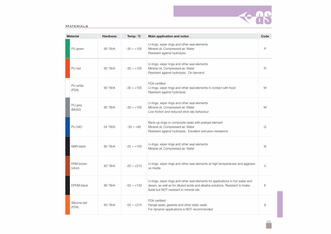
171
Materials
Material Hardness Temp. °C Main application and notes Code
PU green 95 °ShA -30 ÷ +105U-rings, wiper rings and other seal elementsMineral oil, Compressed air, WaterResistant against hydrolysis.
P
PU red 95 °ShA -30 ÷ +105U-rings, wiper rings and other seal elementsMineral oil, Compressed air, WaterResistant against hydrolysis. On demand
R
PU white(FDA)
95 °ShA -30 ÷ +100FDA certifiedU-rings, wiper rings and other seal elements in contact with foodResistant against hydrolysis
W
PU grey(MoS2)
95 °ShA -30 ÷ +105U-rings, wiper rings and other seal elementsMineral oil, Compressed air, WaterLow friction and reduced stick-slip behaviour
M
PU 54D 54 °ShD -30 ÷ +90Back-up rings or composite seals with preload elementMineral oil, Compressed air, WaterResistant against hydrolysis. Excellent extrusion resistance
Q
NBR black 85 °ShA -25 ÷ +100U-rings, wiper rings and other seal elementsMineral oil, Compressed air, Water
N
FKM brown(viton)
83 °ShA -20 ÷ +210U-rings, wiper rings and other seal elements at high temperatures and aggressi-ve media
V
EPDM black 86 °ShA -50 ÷ +130U-rings, wiper rings and other seal elements for applications in hot water andsteam, as well as for diluted acids and alkaline solutions. Resistant to brakefluids but NOT resistant to mineral oils
E
Silicone red(FDA)
83 °ShA -55 ÷ +210FDA certifiedFlange seals, gaskets and other static sealsFor dynamic applications is NOT recommended
S
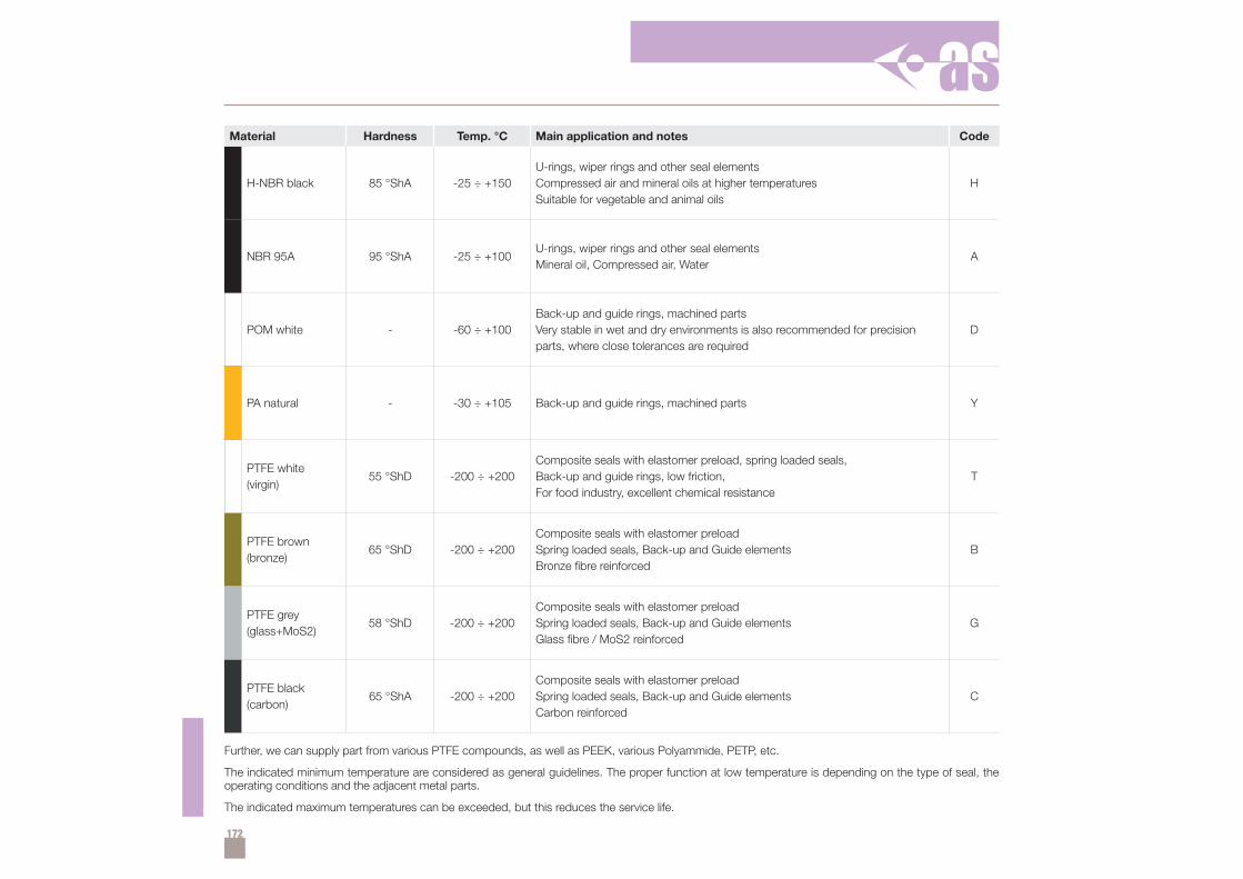
172
Material Hardness Temp. °C Main application and notes Code
H-NBR black 85 °ShA -25 ÷ +150U-rings, wiper rings and other seal elementsCompressed air and mineral oils at higher temperaturesSuitable for vegetable and animal oils
H
NBR 95A 95 °ShA -25 ÷ +100U-rings, wiper rings and other seal elementsMineral oil, Compressed air, Water
A
POM white - -60 ÷ +100Back-up and guide rings, machined partsVery stable in wet and dry environments is also recommended for precisionparts, where close tolerances are required
D
PA natural - -30 ÷ +105 Back-up and guide rings, machined parts Y
PTFE white(virgin)
55 °ShD -200 ÷ +200Composite seals with elastomer preload, spring loaded seals,Back-up and guide rings, low friction,For food industry, excellent chemical resistance
T
PTFE brown(bronze)
65 °ShD -200 ÷ +200Composite seals with elastomer preloadSpring loaded seals, Back-up and Guide elementsBronze fibre reinforced
B
PTFE grey(glass+MoS2)
58 °ShD -200 ÷ +200Composite seals with elastomer preloadSpring loaded seals, Back-up and Guide elementsGlass fibre / MoS2 reinforced
G
PTFE black(carbon)
65 °ShA -200 ÷ +200Composite seals with elastomer preloadSpring loaded seals, Back-up and Guide elementsCarbon reinforced
C
Further, we can supply part from various PTFE compounds, as well as PEEK, various Polyammide, PETP, etc.
The indicated minimum temperature are considered as general guidelines. The proper function at low temperature is depending on the type of seal, theoperating conditions and the adjacent metal parts.
The indicated maximum temperatures can be exceeded, but this reduces the service life.