Embed Size (px)
Citation preview
OBJECTIVES
1. To operate vapor – liquid separation process using aPacked Column Gas Absorption Process Unit.
2. To analyze the sample using the method of directTitration in order to determine the amount ofunreacted NaOH in the sample.
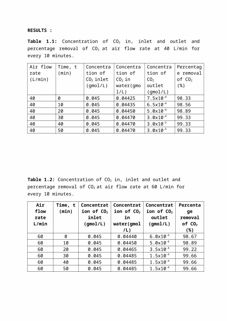
RESULTS :
Table 1.1: Concentration of CO2 in, inlet and outlet andpercentage removal of CO2 at air flow rate at 40 L/min forevery 10 minutes.
Air flowrate (L/min)
Time, t (min)
Concentration of CO2 inlet (gmol/L)
Concentration of CO2 in water(gmol/L)
Concentration of CO2 outlet (gmol/L)
Percentage removalof CO2
(%)
40 0 0.045 0.04425 7.5x10⁻⁴ 98.3340 10 0.045 0.04435 6.5x10⁻⁴ 98.5640 20 0.045 0.04450 5.0x10⁻⁴ 98.8940 30 0.045 0.04470 3.0x10⁻⁴ 99.3340 40 0.045 0.04470 3.0x10⁻⁵ 99.3340 50 0.045 0.04470 3.0x10⁻⁵ 99.33
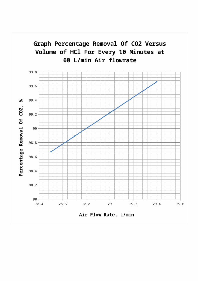
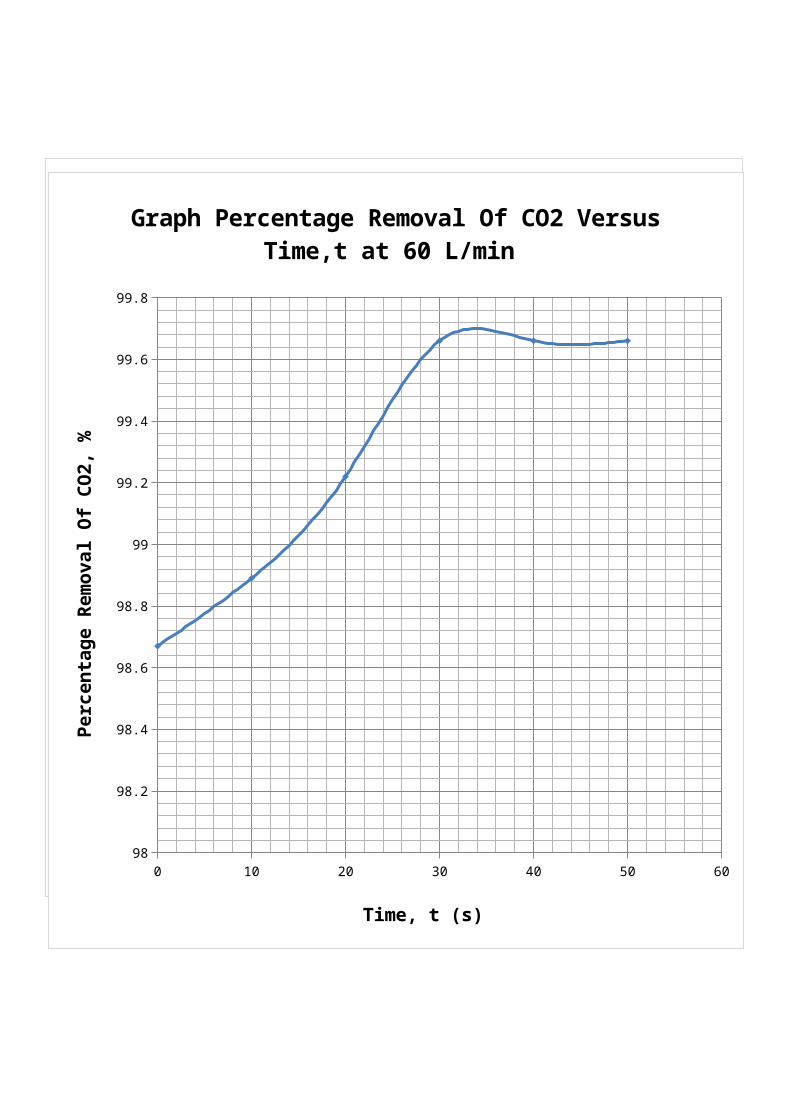
Table 1.2: Concentration of CO2 in, inlet and outlet and percentage removal of CO2 at air flow rate at 60 L/min for every 10 minutes.
AirflowrateL/min
Time, t(min)
Concentration of CO2
inlet(gmol/L)
Concentration of CO2
inwater(gmol
/L)
Concentration of CO2
outlet(gmol/L)
Percentage
removalof CO2
(%)60 0 0.045 0.04440 6.0x10⁻⁴ 98.6760 10 0.045 0.04450 5.0x10⁻⁴ 98.8960 20 0.045 0.04465 3.5x10⁻⁴ 99.2260 30 0.045 0.04485 1.5x10⁻⁴ 99.6660 40 0.045 0.04485 1.5x10⁻⁴ 99.6660 50 0.045 0.04485 1.5x10⁻⁴ 99.66
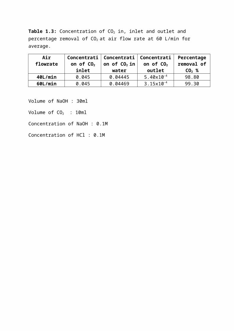
Table 1.3: Concentration of CO2 in, inlet and outlet and percentage removal of CO2 at air flow rate at 60 L/min for average.
Airflowrate
Concentration of CO2
inlet
Concentration of CO2 in
water
Concentration of CO2
outlet
Percentageremoval of
CO2 %40L/min 0.045 0.04445 5.40x10⁻⁴ 98.8060L/min 0.045 0.04469 3.15x10⁻⁴ 99.30
Volume of NaOH : 30ml
Volume of CO2 : 10ml
Concentration of NaOH : 0.1M
Concentration of HCl : 0.1M
28.4 28.6 28.8 29 29.2 29.4 29.697.8
98
98.2
98.4
98.6
98.8
99
99.2
99.4
99.6
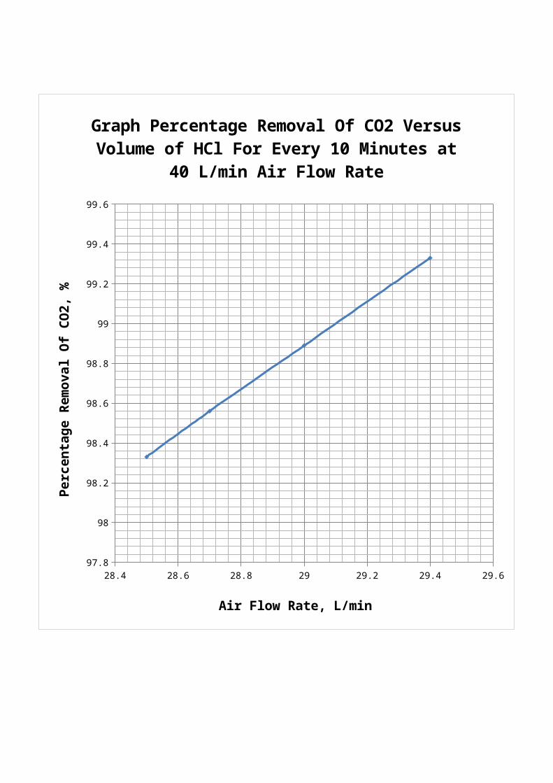
Graph Percentage Removal Of CO2 Versus Volume of HCl For Every 10 Minutes at
40 L/min Air Flow Rate
Air Flow Rate, L/min
Percentage Removal Of CO2, %
28.4 28.6 28.8 29 29.2 29.4 29.698
98.2
98.4
98.6
98.8
99
99.2
99.4
99.6
99.8
Graph Percentage Removal Of CO2 Versus Volume of HCl For Every 10 Minutes at
60 L/min Air flowrate
Air Flow Rate, L/min
Percentage Removal Of CO2, %

0 10 20 30 40 50 6097.8
98
98.2
98.4
98.6
98.8
99
99.2
99.4
99.6
Graph Percentage Removal Of CO2 Versus Time,t at 40 L/min
Time, t (s)
Percentage Removal Of CO2, %
0 10 20 30 40 50 6098
98.2
98.4
98.6
98.8
99
99.2
99.4
99.6
99.8
Graph Percentage Removal Of CO2 Versus Time,t at 60 L/min
Time, t (s)
Percentage Removal Of CO2, %
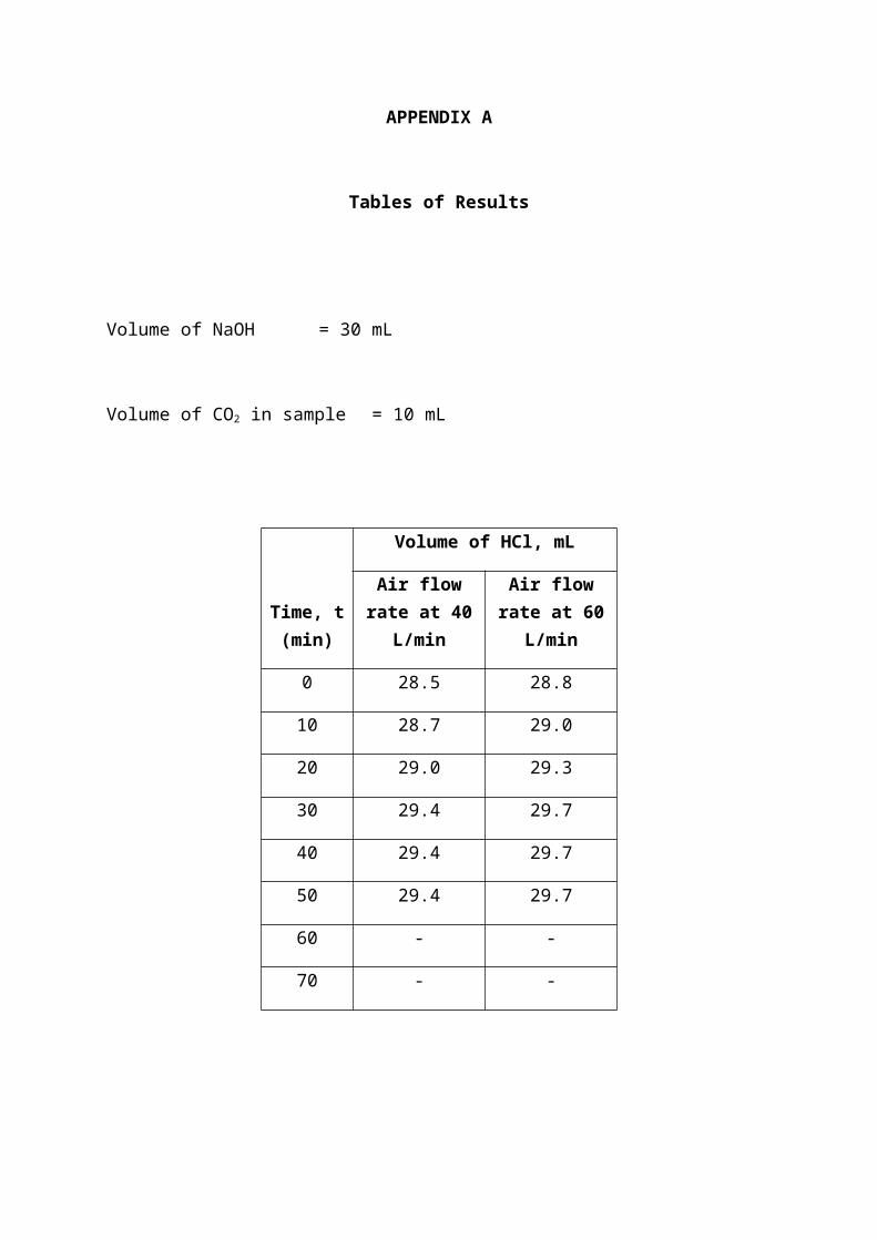
APPENDIX A
Tables of Results
Volume of NaOH = 30 mL
Volume of CO2 in sample = 10 mL
Time, t(min)
Volume of HCl, mL
Air flowrate at 40
L/min
Air flowrate at 60
L/min
0 28.5 28.8
10 28.7 29.0
20 29.0 29.3
30 29.4 29.7
40 29.4 29.7
50 29.4 29.7
60 - -
70 - -
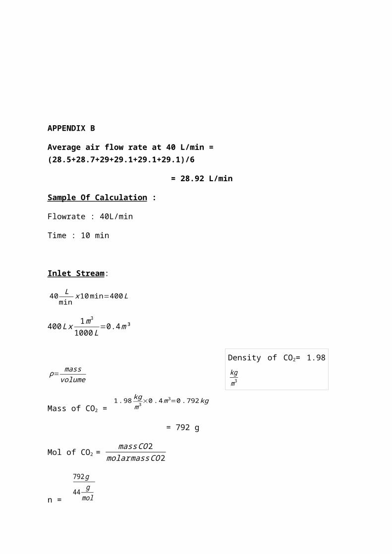
APPENDIX B
Average air flow rate at 40 L/min = (28.5+28.7+29+29.1+29.1+29.1)/6
= 28.92 L/min
Sample Of Calculation :
Flowrate : 40L/min
Time : 10 min
Inlet Stream:
40 Lmin
x10min=400L
400Lx 1m3
1000L=0.4m³
ρ=mass
volume
Mass of CO2 = 1.98 kg
m3×0.4m3=0.792kg
= 792 g
Mol of CO2 = massCO2
molarmassCO2
n =
792g
44 gmol
Density of CO2= 1.98kgm3
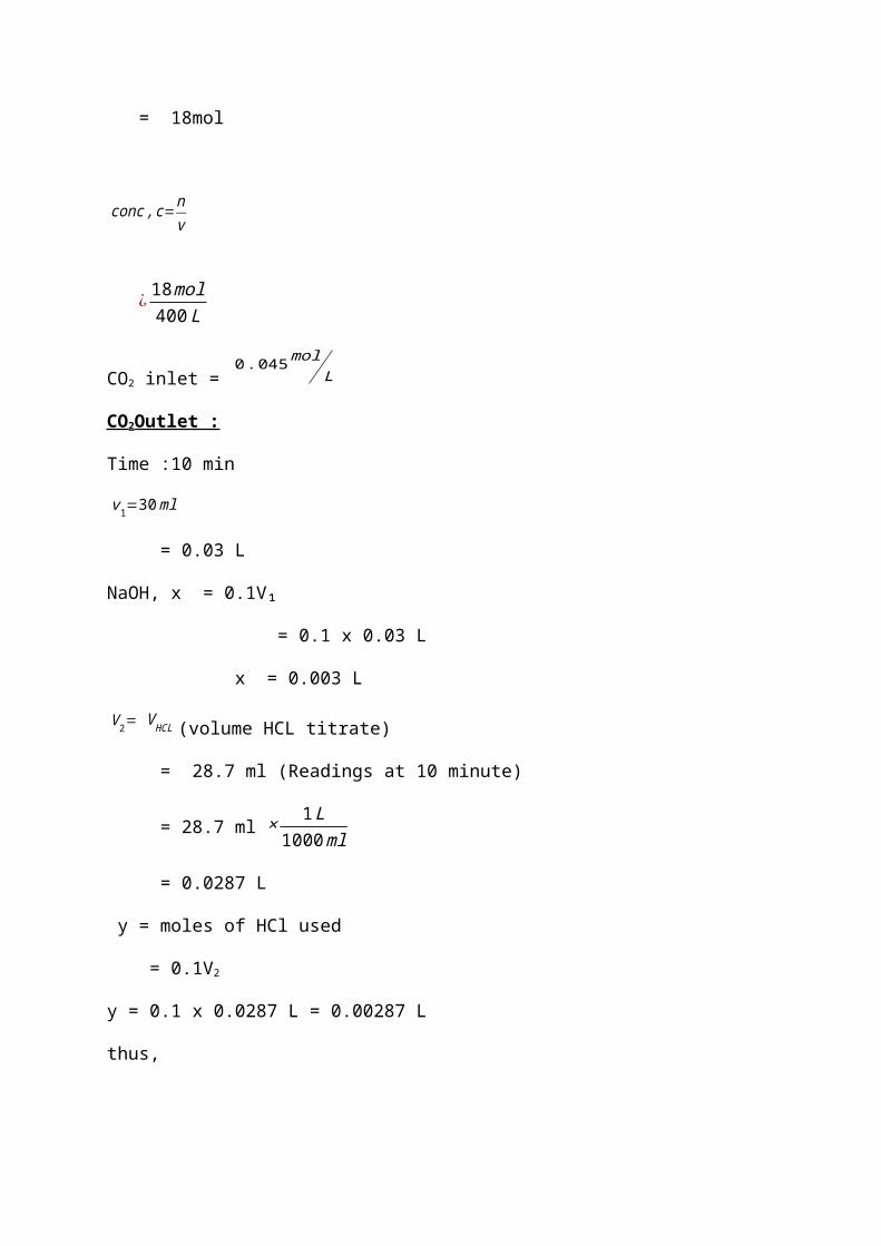
= 18mol
¿ 18mol400L
CO2 inlet = 0.045mol
L
CO2Outlet :
Time :10 min
v1=30ml
= 0.03 L
NaOH, x = 0.1V₁
= 0.1 x 0.03 L
x = 0.003 L
V2= VHCL (volume HCL titrate)
= 28.7 ml (Readings at 10 minute)
= 28.7 ml × 1L1000ml
= 0.0287 L
y = moles of HCl used
= 0.1V2
y = 0.1 x 0.0287 L = 0.00287 L
thus,
conc,c=nv
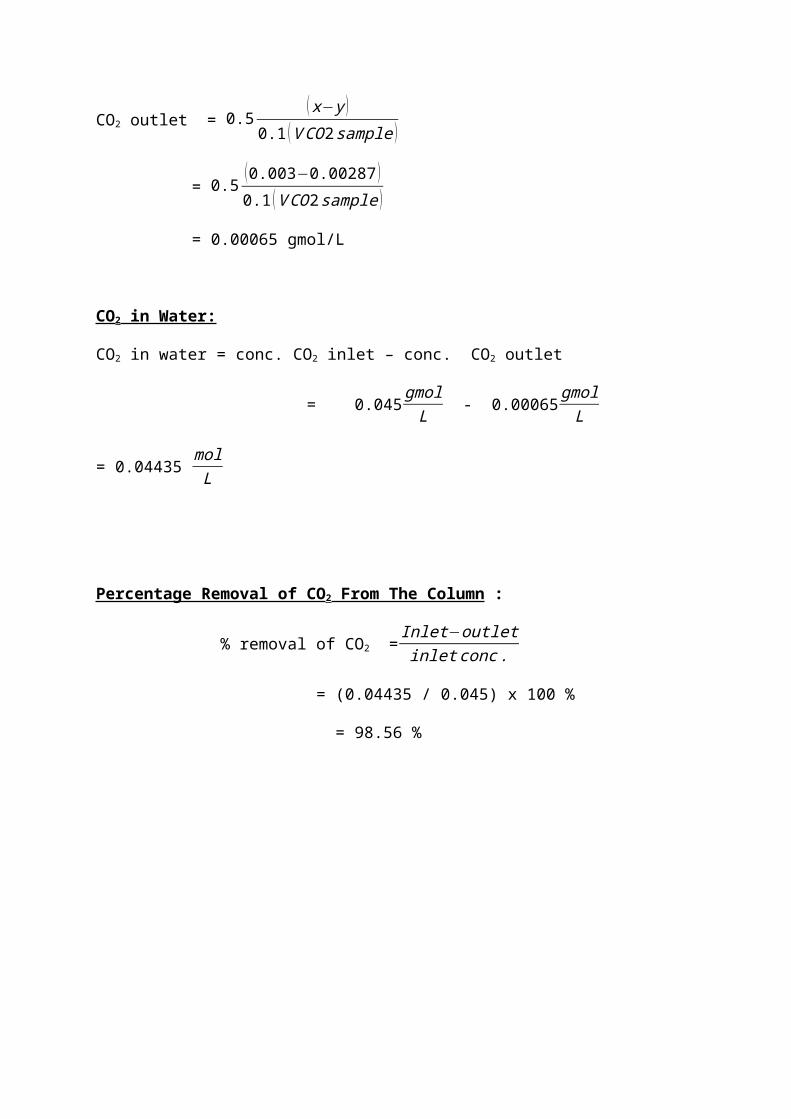
CO2 outlet = 0.5(x−y )
0.1 (VCO2sample )
= 0.5(0.003−0.00287 )0.1 (VCO2sample )
= 0.00065 gmol/L
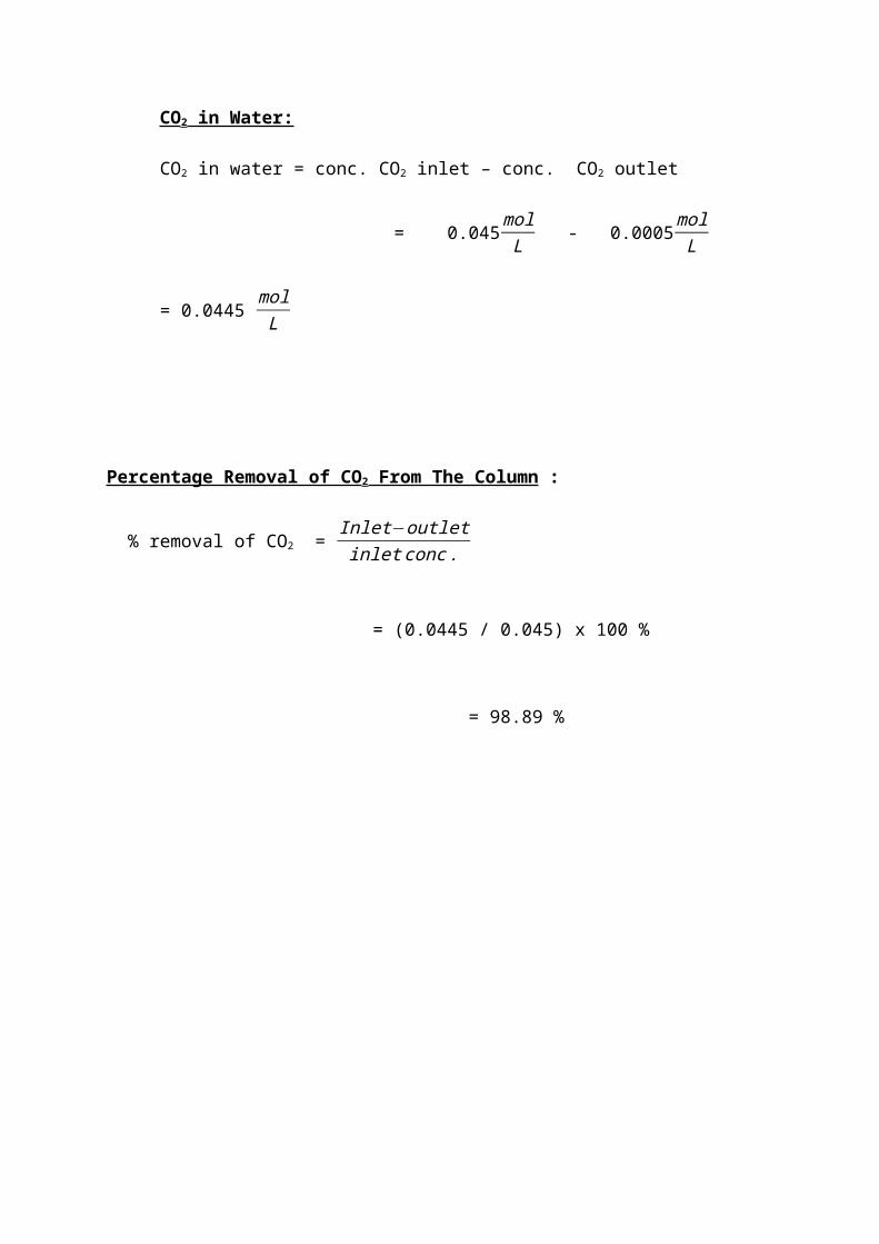
CO2 in Water:
CO2 in water = conc. CO2 inlet – conc. CO2 outlet
= 0.045gmolL - 0.00065gmolL
= 0.04435 molL
Percentage Removal of CO2 From The Column :
% removal of CO2 =Inlet−outletinletconc.
= (0.04435 / 0.045) x 100 %
= 98.56 %

Average air flow rate at 60 L/min =
(28.8+29+29.3+29.7+2.97+29.7) / 6
= 29.37
L/min
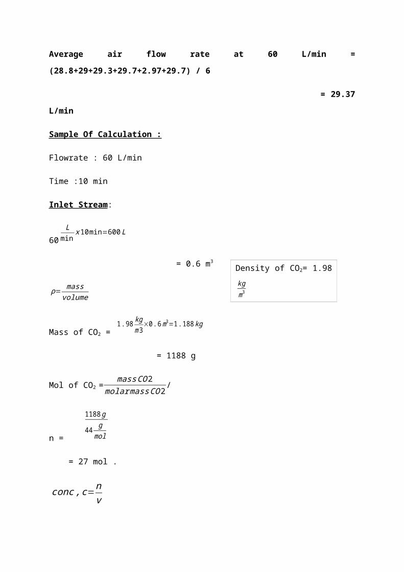
Sample Of Calculation :
Flowrate : 60 L/min
Time :10 min
Inlet Stream:
60L
minx10min=600L
= 0.6 m3
ρ=mass
volume
Mass of CO2 = 1.98 kg
m3×0.6m3=1.188kg
= 1188 g
Mol of CO2 =massCO2
molarmassCO2/
n =
1188g
44 gmol
= 27 mol .
conc,c=nv
Density of CO2= 1.98kgm3
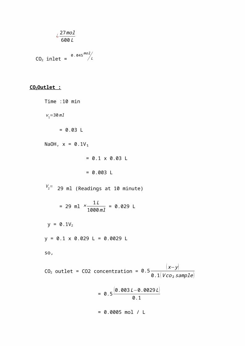
¿ 27mol600L
CO2 inlet = 0.045mol
L
CO2Outlet :
Time :10 min
v1=30ml
= 0.03 L
NaOH, x = 0.1V₁
= 0.1 x 0.03 L
= 0.003 L
V2= 29 ml (Readings at 10 minute)
= 29 ml × 1L1000ml = 0.029 L
y = 0.1V2
y = 0.1 x 0.029 L = 0.0029 L
so,
CO2 outlet = CO2 concentration = 0.5(x−y)
0.1 (Vco₂sample )
= 0.5 (0.003L−0.0029L)0.1
= 0.0005 mol / L
CO2 in Water:
CO2 in water = conc. CO2 inlet – conc. CO2 outlet
= 0.045molL - 0.0005molL
= 0.0445 molL
Percentage Removal of CO2 From The Column :
% removal of CO2 = Inlet−outletinletconc.
= (0.0445 / 0.045) x 100 %
= 98.89 %
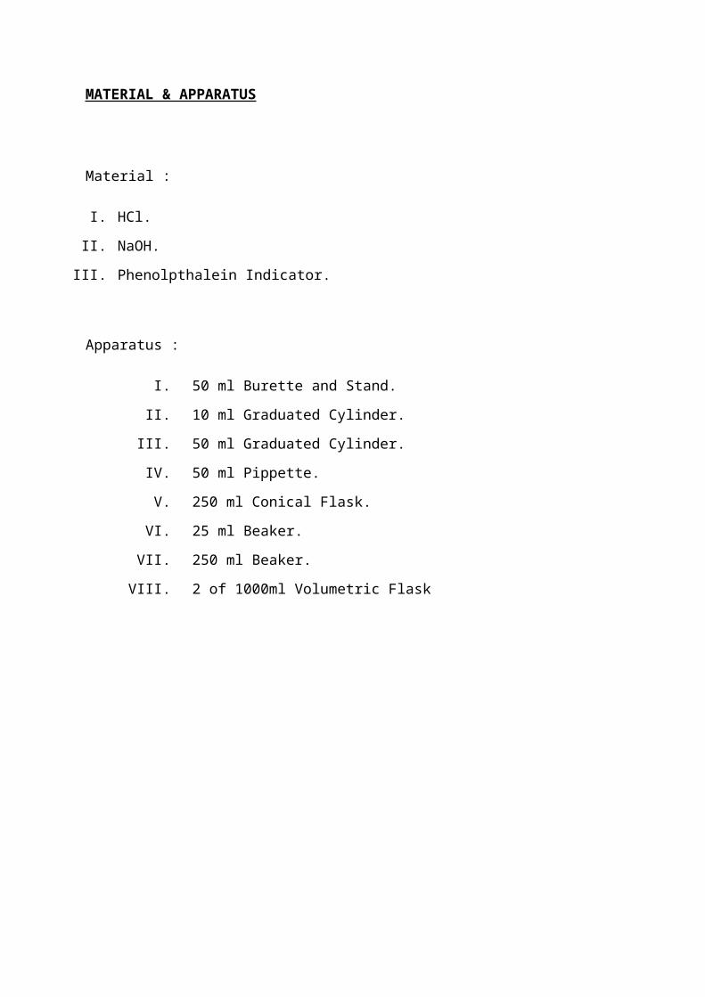
MATERIAL & APPARATUS
Material :
I. HCl.
II. NaOH.
III. Phenolpthalein Indicator.
Apparatus :
I. 50 ml Burette and Stand.
II. 10 ml Graduated Cylinder.
III. 50 ml Graduated Cylinder.
IV. 50 ml Pippette.
V. 250 ml Conical Flask.
VI. 25 ml Beaker.
VII. 250 ml Beaker.
VIII. 2 of 1000ml Volumetric Flask
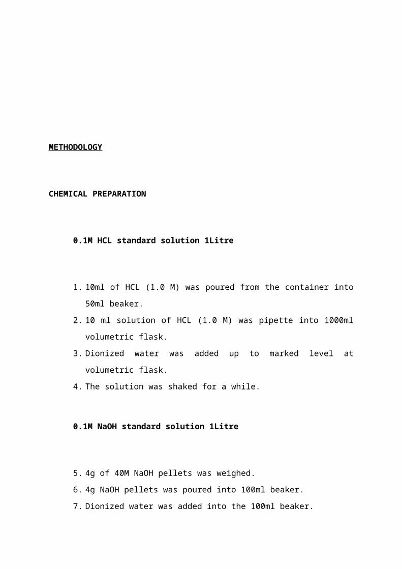
METHODOLOGY
CHEMICAL PREPARATION
0.1M HCL standard solution 1Litre
1. 10ml of HCL (1.0 M) was poured from the container into
50ml beaker.
2. 10 ml solution of HCL (1.0 M) was pipette into 1000ml
volumetric flask.
3. Dionized water was added up to marked level at
volumetric flask.
4. The solution was shaked for a while.
0.1M NaOH standard solution 1Litre
5. 4g of 40M NaOH pellets was weighed.
6. 4g NaOH pellets was poured into 100ml beaker.
7. Dionized water was added into the 100ml beaker.
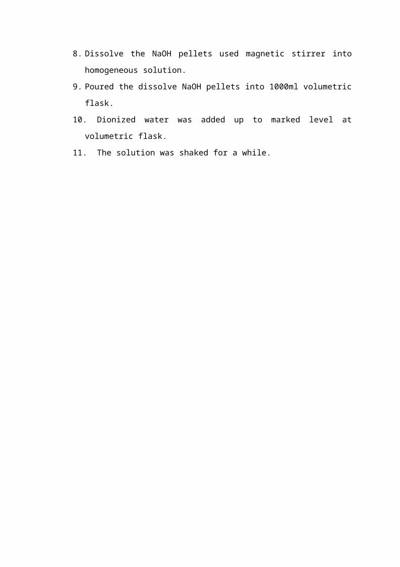
8. Dissolve the NaOH pellets used magnetic stirrer into
homogeneous solution.
9. Poured the dissolve NaOH pellets into 1000ml volumetric
flask.
10. Dionized water was added up to marked level at
volumetric flask.
11. The solution was shaked for a while.
GENERAL START-UP PROCEDURES
1. The equipment was checked visually for any damaged
components or glass breakage.
2. Cylindrical Re-circulation Vessel is charged with pipe
water and that the liquid level is satisfactory.
3. Closed valve V7 before Cylindrical Re-circulation
Vessel is charged with pipe water.
4. Valve SV1 was switched to connect to the column chosen.
5. Adjusted the following valves depend on the column
desired to be used.
SETTING UP OF LIQUID FLOW
1. Closed valves V11, V12 and FCV3 and valves V7 was
opened.
2. Turned on the power switch of recirculation pump.
3. Open valve FCV4 slowly to give the required flow rate
of 0.5 L/min as indicated by F13.
4. Ensured that the liquid overflow from the unit is
connected to a suitable drain.
5. Valve V11 was opened and V7 closed.
6. The liquid inlet valve of the column, i.e. V4, V5 or V6
depended on the column to be used is opened.

EXPERIMENT: ABSORPTION OF CO2 INTO WATER FROM AIR / CO2
MIXTURE.
1. The water feed valve opened gradually until the desired
flow rate 1.5 L/min is achieved as indicated in FI3.
The water flow rate is allowed to stable for about 10
minutes after each change until the desired value is
reached.
2. The Compressed Air Valve was opened and the pressure is
1.5 bar gauge.
3. Valve V1, V2, or V3 was opened.
4. Opened the feed valve FCV1 gradually for air flow until
the desired flow rate about 40 L/min is indicated in
the flow meter FI1. Ensured that the water flow rate is
allowed to stable for about 10 minutes.
5. Valve FCV2 was opened gently until CO2 rate is 2 L/min
is achieved, After steady state conditions are reached.
6. Allowed further period of 10 minutes for the Absorption
process to attain steady state.
7. For every 10 minutes 10 ml sample from the outlet
valve, V12 was draw.
8. 30 ml of prepared 0.1 NaOH solution was added to the
sample. The volume of NaOH is in excess to ensure that
all CO2 has reacted with NaOH in the mixture.
9. A few drops of an indicator (Phenolpthalein) was added
to the solution.
10. The mixture with 0.1 HCl was titrated to the
solution. The amount of unreacted NaOH with CO2 in the
sample mixture can be determine.
11. Repeated the measurements for every 10 minutes and
carry out the titration with fresh samples until
constant concentration of NaOH has been achieved.
12. The results was recorded in the provided table in
the next page.
13. Repeated the experiments for 60 L/min air flowrate.
GENERAL SHUT – DOWN PROCEDURES.
1. CO2 supply at valve SG was closed.
2. Compressed Air flow at CA was closed.
3. The Circulation Pump was stopped.
4. Valve V11 are opened.
5. Fresh Water was allowed to enter the column for a few
minutes to drain off the water.
6. The Fresh Water Flow at FW are closed.
7. Closed the drain valve V11 when the flow of water has
stopped.


