Embed Size (px)
Citation preview
109
SESSION II
PARTITIONING
CHAIRMAN: C. MADIC
CO-CHAIRMAN: Z. KOLARIK

111
SESSION I I
CHAIRMAN: C. MADIC
The field of hydrometallurgical processes continues to be very active.
• The MA partitioning at JNC comprises an improved version of the PUREX process and theTRUEX process for extraction and separation of the trivalent MAs from the high activeraffinate issued from the PUREX process.
• In the four-group partitioning process at JAERI, the first active test of the process has beenperformed successfully in the BECKY hot-cell facility in NUCEF (Tokai-mura).
• The work in the field of partitioning in Europe is carried out within the European researchprogramme “NEWPART” and at the CEA.
• A two-step partitioning process is under study within the NEWPART programme co-ordinated by the CEA. The first step is the co-extraction of the trivalent MAs and thetrivalent lanthanide (Ln(III)) from a high active effluent issuing from the PUREX processusing a malonamide extractant (DIAMEX process). The second step is the selectiveextraction of the trivalent MAs over the Ln(III). Important results include: (i) the first hottest of the DIAMEX process using centrifugal extractors at the ITU, Karlsruhe (Germany);(ii) the first inactive test of the DIAMEX process using an optimised malonamide extractantat the CEA/Marcoule; (iii) the first test using synthetic spiked solutions of an An(III)/Ln(III)group separation process using new aromatic diorganyldithiophosphinic acids at Jülich,Germany. For the first time successful separation performances were obtained for a feedwith a high nitric acid concentration.
• The SESAME process at the CEA aims at Am/Cm or Am/Cm and Ln separations, and basedon the extraction of oxidised form(s) of Am. Hot tests were carried out successfully atMarcoule in 1998.
The field of pyrometallurgy has recently been attracting more and more attention.
• The results of a study in CRIEPI were presented. The mass balance of TRUs during theimplementation of the partitioning process was shown based on the distribution of MAsbetween a LiCl, KCl eutectic fused salt and fused metal.
• A new concept for nuclear fuel cycle in Russia was presented. The concept involves amolten salt reactor which is compatible with P&T strategy.
• In the Czech Republic, the experience of dry reprocessing based on fluoride salt volatilitywas accumulated in collaboration with the former SSSR. This can be useful for futurestrategies of nuclear waste management.
It can be concluded that the lectures presented in Session II reflected the important world-wideactivities in the field of partitioning.

113
A NEW REPROCESSING SYSTEM COMPOSED OF PUREX AND TRUEX PROCESSESFOR TOTAL SEPARATION OF LONG-LIVED RADIONUCLIDES
M. Ozawa, Y. Sano, K. Nomura, Y. Koma, M. TakanashiJapan Nuclear Cycle Development Institute (JNC)
Akasaka, TokyoJapan
Abstract
Actinides-FP separation technologies based on the TRUEX and PUREX processes were summarised.Minor actinides were recovered from HLLW by ADvanced TRUEX flowsheet adopting salt-freereagents. Np was recovered by ADvanced PUREX flowsheet into the Pu-product fraction. Electrolyticextraction was prospective to separate several rare metals including some LLFPs from HLLW.CMPO/TBP/n-dodecane was decomposed by mediatory electrochemical oxidation, where majorproducts of them were identified to be CO2 and phosphoric acid. Medium and long term (~2030)scenario for TRU-LLFP recycling has been newly considered.
114
Long-lived nuclides separation system
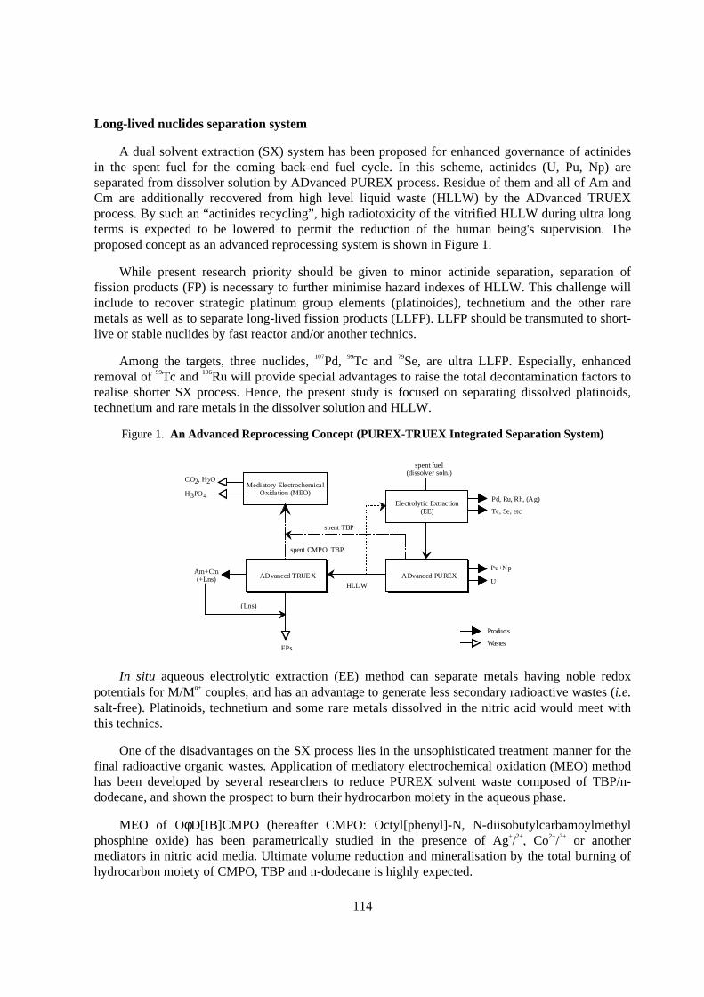
A dual solvent extraction (SX) system has been proposed for enhanced governance of actinidesin the spent fuel for the coming back-end fuel cycle. In this scheme, actinides (U, Pu, Np) areseparated from dissolver solution by ADvanced PUREX process. Residue of them and all of Am andCm are additionally recovered from high level liquid waste (HLLW) by the ADvanced TRUEXprocess. By such an “actinides recycling” , high radiotoxicity of the vitrified HLLW during ultra longterms is expected to be lowered to permit the reduction of the human being's supervision. Theproposed concept as an advanced reprocessing system is shown in Figure 1.
While present research priority should be given to minor actinide separation, separation offission products (FP) is necessary to further minimise hazard indexes of HLLW. This challenge willinclude to recover strategic platinum group elements (platinoides), technetium and the other raremetals as well as to separate long-lived fission products (LLFP). LLFP should be transmuted to short-live or stable nuclides by fast reactor and/or another technics.
Among the targets, three nuclides, 107Pd, 99Tc and 79Se, are ultra LLFP. Especially, enhancedremoval of 99Tc and 106Ru will provide special advantages to raise the total decontamination factors torealise shorter SX process. Hence, the present study is focused on separating dissolved platinoids,technetium and rare metals in the dissolver solution and HLLW.
Figure 1. An Advanced Reprocessing Concept (PUREX-TRUEX Integrated Separation System)
ADvanced TRUEX ADvanced PUREX
HLL W
Am+Cm(+Lns)
(Lns)
FPs
Pu+Np
U
Electrolytic Extraction(EE)
Mediatory ElectrochemicalOxidation (MEO)
spent TBP
CO2, H2O
H3PO4 Pd, Ru, Rh, (Ag)
Tc, Se, etc.
spent fuel(dissolver soln.)
Products
Wastes
spent CMPO, TBP
In situ aqueous electrolytic extraction (EE) method can separate metals having noble redoxpotentials for M/Mn+ couples, and has an advantage to generate less secondary radioactive wastes (i.e.salt-free). Platinoids, technetium and some rare metals dissolved in the nitric acid would meet withthis technics.
One of the disadvantages on the SX process lies in the unsophisticated treatment manner for thefinal radioactive organic wastes. Application of mediatory electrochemical oxidation (MEO) methodhas been developed by several researchers to reduce PUREX solvent waste composed of TBP/n-dodecane, and shown the prospect to burn their hydrocarbon moiety in the aqueous phase.
MEO of OφD[IB]CMPO (hereafter CMPO: Octyl[phenyl]-N, N-diisobutylcarbamoylmethylphosphine oxide) has been parametrically studied in the presence of Ag+/2+, Co2+/3+ or anothermediators in nitric acid media. Ultimate volume reduction and mineralisation by the total burning ofhydrocarbon moiety of CMPO, TBP and n-dodecane is highly expected.
115
The-state-of-the-ar t of the JNC’s separation techniques
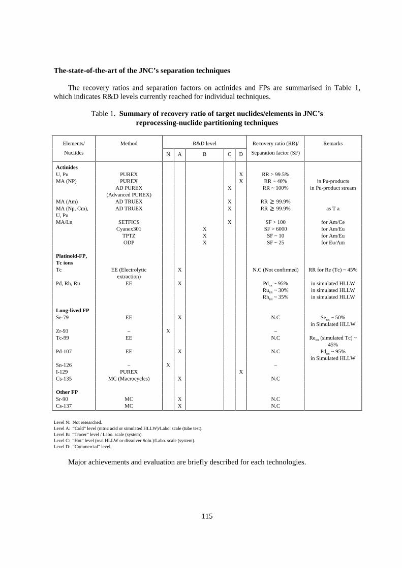
The recovery ratios and separation factors on actinides and FPs are summarised in Table 1,which indicates R&D levels currently reached for individual techniques.
Table 1. Summary of recovery ratio of target nuclides/elements in JNC’sreprocessing-nuclide par titioning techniques
Elements/ Method R&D level Recovery ratio (RR)/ Remarks
Nuclides N A B C D Separation factor (SF)
ActinidesU, Pu PUREX X RR > 99.5%MA (NP) PUREX X RR ~ 40% in Pu-products
AD PUREX(Advanced PUREX)
X RR ~ 100% in Pu-product stream
MA (Am) AD TRUEX X RR ≥ 99.9%MA (Np, Cm),U, Pu
AD TRUEX X RR ≥ 99.9% as T a
MA/Ln SETFICS X SF > 100 for Am/CeCyanex301 X SF > 6000 for Am/Eu
TPTZ X SF ~ 10 for Am/EuODP X SF ~ 25 for Eu/Am
Platinoid-FP,Tc ionsTc EE (Electrolytic
extraction)X N.C (Not confirmed) RR for Re (Tc) ~ 45%
Pd, Rh, Ru EE X PdRR ~ 95% in simulated HLLWRuRR ~ 30% in simulated HLLWRhRR ~ 35% in simulated HLLW
Long-lived FPSe-79 EE X N.C SeRR ~ 50%
in Simulated HLLWZr-93 – X –Tc-99 EE N.C ReRR (simulated Tc) ~
45%Pd-107 EE X N.C PdRR ~ 95%
in Simulated HLLWSn-126 – X –I-129 PUREX XCs-135 MC (Macrocycles) X N.C
Other FPSr-90 MC X N.CCs-137 MC X N.C
Level N: Not researched.Level A: “Cold” level (nitric acid or simulated HLLW)/Labo. scale (tube test).Level B: “Tracer” level / Labo. scale (system).Level C: “Hot” level (real HLLW or dissolver Soln.)/Labo. scale (system).Level D: “Commercial” level.
Major achievements and evaluation are briefly described for each technologies.
116
Solvent extraction systems
ADvanced TRUEX
The requirements for the newly developing SX process for radionuclides are summarised asfollows:
a. Ligands should have properly excellent extractability (10 < DM < 102) for the target metalswith effective stripping method (in view of process design).
b. Material transfer rate should be properly fast (in view of process and equipment design).
c. Hydrolytic and radiolytic stability should be tolerable (in view of process and safetydesign).
d. Good compatibility and interface with the counter process (in view of process design).
e. Minimum amount of secondary radioactive effluents (in view of process design, wastetreatment design).
f. Low biological toxicity (in view of process handling and environmental safety).
Requirements of a. to e. are closely related to process economy. Among more than 20 methodsdeveloped so far, CMPO-TRUEX was primarily nominated because it will meet with therequirements a., b. and d. CMPO’s advantage is definitely well because it will not require the dilutionof HLLW due to its high extractability in highly concentrated nitric acid media, hence helpful to thesimple reprocessing process design.
Actual R&Ds have been pursued at the hot lab. in the CPF (JNC’s Chemical Processing Facilityin Tokai-mura) using real HLLW (HAR from PUREX tests with “Joyo” FR spent fuels, andconcentrated HLLW from commercial reprocessing at “TRP (Tokai Reprocessing Plant)” with LWRspent fuels [1]). Five TRUEX runs and two An(III)/Ln separation (SETFICS) runs were carried out sofar. Major lessons from the process flowsheet study are summarised as follows:
i) An and Ln were successfully separated from highly active raffinates by ADvanced TRUEXprocess with S.F. > 103, and they were fractionally stripped by contacting with salt-freereagents in series [1,4,8].
ii) Pu and RuNO3+ were satisfactorily controlled in the flowsheet, while some portion of multi-valent transition elements, Zr4+, Mo6+ and TcO4
-, were extracted and contaminated MAproducts with Lns [1,4].
iii) Separation of An(III) from light Ln3+ (La ~ Nd) was achieved by the SETFICS method usingDTPA with SF more than several tens. About 80% of Lns was separated from Am [6,8].
iv) Some sort of “soft” donor ligands, purified Cyanex301[7] and ODP (octyl diphenylphosphoric acid) [5], proved excellent Am/Eu separation.
The SETFICS parameter will be polished to increase the recovery of An(III) in the productsolution.
117
ADvanced PUREX
Two ADvanced PUREX runs were carried out aiming at enhancing extraction of Np by salt-freemethods [2].
i) Quantitative extraction of Np was confirmed by increasing acidity (e.g. up to 5.6 M H+) andtemperature (e.g. 100ºC) in the dissolver solution without adding any chemical reagents,whilst allowing the formation of some portion of Pu (VI).
ii) Co-extracted Np(VI) and Pu(IV, VI) were reductively stripped by contacting with HAN. Npwas split into one fraction of Pu/Np/U product and was not detected in U fraction.
As a total assessment of the ADvanced PUREX and ADvanced TRUEX studies, no redoxreagents was necessary to extract TRU (especially on Np (V)), and the recovery ratio of >> 99.9% forNp will be possible when two SX processes are combined. SF > 103 for MA (Am, Cm) by laboratorytest would be feasible in the industrial plant provided that the experienced scale-up factor ca. 6000(CPF → TRP) with mixer-settler contactor. Recovery ratio of U and Pu will also be >> 99.9% if all ofeffluents will be gathered to one HLLW effluent.
Requirements of c., e. and f. are currently focused in the JNC, and very prospective data havebeen obtained. Flowsheet simplification is one of the issues to consider process economy.Mathematical modelling and simulation of MA and FP extraction with CMPO-TBP-n-dodecanesystem is in progress with precisely evaluating water activity and activity coefficient of nitric acid,which are necessary for calculating distribution coefficients of them.
Electrochemical separation steps
Electrolytic extraction of fission products
Among ca. 35 fission products in spent fuel, target rare elements and platinoids are specified bytheir noble redox potentials for Mn+/M couples in acidic media. Incentives on FP separation are thatelement recovery of rare metals (Ru, Rh, Pd, Se, Tc, Te) for resource, radionuclide separation (107Ru,99Tc) for increasing DFs for SX, and pre-element separation of LLFP (107Pd, 79Se, 99Tc) followed byisotope separation.
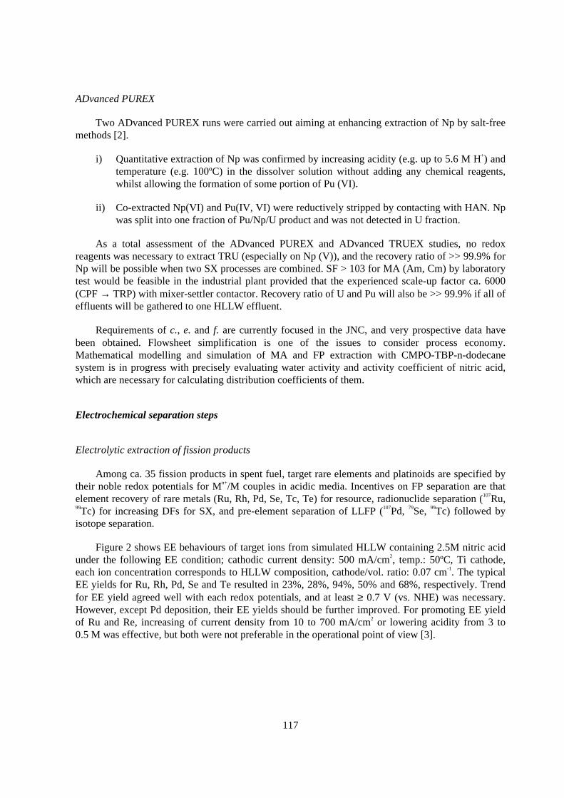
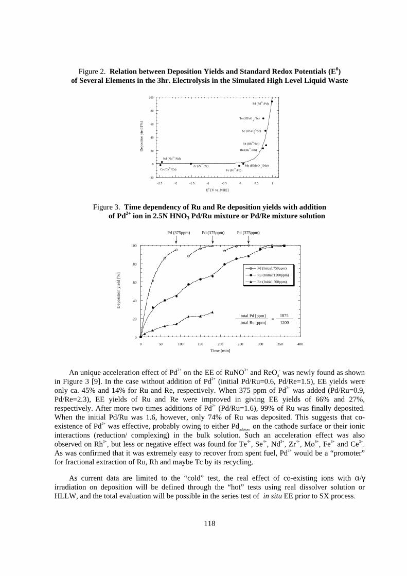
Figure 2 shows EE behaviours of target ions from simulated HLLW containing 2.5M nitric acidunder the following EE condition; cathodic current density: 500 mA/cm2, temp.: 50ºC, Ti cathode,each ion concentration corresponds to HLLW composition, cathode/vol. ratio: 0.07 cm-1. The typicalEE yields for Ru, Rh, Pd, Se and Te resulted in 23%, 28%, 94%, 50% and 68%, respectively. Trendfor EE yield agreed well with each redox potentials, and at least ≥ 0.7 V (vs. NHE) was necessary.However, except Pd deposition, their EE yields should be further improved. For promoting EE yieldof Ru and Re, increasing of current density from 10 to 700 mA/cm2 or lowering acidity from 3 to0.5 M was effective, but both were not preferable in the operational point of view [3].
118
Figure 2. Relation between Deposition Yields and Standard Redox Potentials (E0)of Several Elements in the 3hr . Electrolysis in the Simulated High Level L iquid Waste
-20
0
20
40
60
80
100
-2.5 -2 -1.5 -1 -0.5 0 0.5 1
Dep
ositi
on y
ield
[%
]
E0 [V vs. NHE]
Rh (Rh3+
/Rh)
Pd (Pd2+
/Pd)
Te (HTeO4
-/Te)
Se (HSeO3
-/Se)
Ru (Ru3+
/Ru)
Mo (HMoO4
-/Mo)
Fe (Fe3+
/Fe)Zr (Zr
4+/Zr)
Ce (Ce3+
/Ce)
Nd (Nd3+
/Nd)
Figure 3. Time dependency of Ru and Re deposition yields with additionof Pd2+ ion in 2.5N HNO3 Pd/Ru mixture or Pd/Re mixture solution
0
20
40
60
80
100
0 50 100 150 200 250 300 350 400
Pd (Initial:750ppm)
Ru (Initial:1200ppm)
Re (Initial:500ppm)
Dep
osit
ion
yiel
d [%
]
Time [min]
Pd (375ppm)
total Pd [ppm]
total Ru [ppm]=
1875
1200
Pd (375ppm) Pd (375ppm)
An unique acceleration effect of Pd2+ on the EE of RuNO3+ and ReO4
- was newly found as shownin Figure 3 [9]. In the case without addition of Pd2+ (initial Pd/Ru=0.6, Pd/Re=1.5), EE yields wereonly ca. 45% and 14% for Ru and Re, respectively. When 375 ppm of Pd2+ was added (Pd/Ru=0.9,Pd/Re=2.3), EE yields of Ru and Re were improved in giving EE yields of 66% and 27%,respectively. After more two times additions of Pd2+ (Pd/Ru=1.6), 99% of Ru was finally deposited.When the initial Pd/Ru was 1.6, however, only 74% of Ru was deposited. This suggests that co-existence of Pd2+ was effective, probably owing to either Pdadatom on the cathode surface or their ionicinteractions (reduction/ complexing) in the bulk solution. Such an acceleration effect was alsoobserved on Rh3+, but less or negative effect was found for Te4+, Se4+, Nd3+, Zr4+, Mo6+, Fe3+ and Ce3+.As was confirmed that it was extremely easy to recover from spent fuel, Pd2+ would be a “promoter”for fractional extraction of Ru, Rh and maybe Tc by its recycling.
As current data are limited to the “cold” test, the real effect of co-existing ions with α/γirradiation on deposition will be defined through the “hot” tests using real dissolver solution orHLLW, and the total evaluation will be possible in the series test of in situ EE prior to SX process.
119
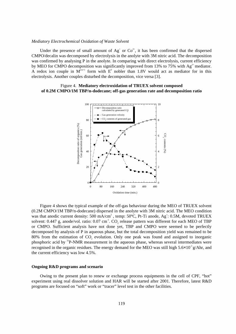
Mediatory Electrochemical Oxidation of Waste Solvent
Under the presence of small amount of Ag+ or Co2+, it has been confirmed that the dispersedCMPO/decalin was decomposed by electrolysis in the anolyte with 3M nitric acid. The decompositionwas confirmed by analysing P in the anolyte. In comparing with direct electrolysis, current efficiencyby MEO for CMPO decomposition was significantly improved from 13% to 75% with Ag2+ mediator.A redox ion couple in Mn/n+1 form with E0 nobler than 1.8V would act as mediator for in thiselectrolysis. Another couples disturbed the decomposition, vice versa [3].
Figure 4. Mediatory electroxidation of TRUEX solvent composedof 0.2M CMPO/1M TBP/n-dodecane; off-gas generation rate and decomposition ratio
0
20
40
60
80
100
0
2
4
6
8
10
0 80 160 240 320 400 480
Decomposition ratio calculated by generated CO
2
Gas generation velosity
CO2 contents of generated gas
Dec
ompo
sitio
n ra
tio o
f or
gani
cs (
%)
Gas
gen
erat
ion
(ml/m
in.)
CO
2 contents (%)
Oxidation time (min.)
Figure 4 shows the typical example of the off-gas behaviour during the MEO of TRUEX solvent(0.2M CMPO/1M TBP/n-dodecane) dispersed in the anolyte with 3M nitric acid. The MEO conditionwas that anodic current density: 500 mA/cm2 , temp: 50ºC, Pt-Ti anode, Ag+: 0.5M, devoted TRUEXsolvent: 0.447 g, anode/vol. ratio: 0.07 cm-1. CO2 release pattern was different for each MEO of TBPor CMPO. Sufficient analysis have not done yet, TBP and CMPO were seemed to be perfectlydecomposed by analysis of P in aqueous phase, but the total decomposition yield was remained to be80% from the estimation of CO2 evolution. Only one peak was found and assigned to inorganicphosphoric acid by 31P-NMR measurement in the aqueous phase, whereas several intermediates wererecognised in the organic residues. The energy demand for the MEO was still high 5.6×10⁻³ g/Ahr, andthe current efficiency was low 4.5%.
Ongoing R& D programs and scenar io
Owing to the present plan to renew or exchange process equipments in the cell of CPF, “hot”experiment using real dissolver solution and HAR will be started after 2001. Therefore, latest R&Dprograms are focused on “soft” work or “ tracer” level test in the other facilities.
120
During 1998-2005, (i) TRUEX mathematical modelling and simulation on MA extractionfollowed by process design code, (ii) basic An(III)/Ln separation using DTPA or novel ligands, and(iii) organic waste decomposition, will be more active in JNC. Separation of fission rare metals,including LLFP will be continued. MA separation in pyrochemical process will be also considered.
As a long-term scenario, engineering scale tests will be expected in the phase 2005-2010 forprecise evaluation of the system safety and cost on the TRU-LLFP recovery. In the next phase 2010-2030, “ tracer/hot” engineering test should be carried out probably in the JNC’s existing facility. LLFPseparation from real waste will be carried out in this period. After 2015, TRU and LLFP will berecovered from real HLLW and be fed to the fast reactor MONJU via TRU/FP target fabricationprocess.
Conclusion
Present TRU/FP separation technology based on the TRUEX process was summarised. TRUwould be recovered from spent fuel by ADvanced PUREX and TRUEX process flowsheets.Electrolytic extraction was prospective to separate several rare metals including some LLFPs.Organic waste composed of CMPO/TBP/n-dodecane was decomposed to CO2 and phosphoric acid bymediatory electrochemical oxidation. Medium and long-term (~2030) scenario for TRU-LLFPrecycling using existing facility is under consideration in JNC.
REFERENCES
[1] M.Ozawa, et al., Global’95 Proceeding, 1 (1995) 585.
[2] T.Koyama, et al., Global’97 Proceeding, 2 (1997) 1495.
[3] M.Ozawa, et al., ibid., 2 (1997) 1232.
[4] M.Ozawa, et al., OECD/NEA Proceeding, (1997) 261.
[5] M.Goto, et al., Global’97 Proceeding, 2 (1997) 1466.
[6] Y.Koma, et al., J. Nucl. Sci. Eng., 35(2) (1998) 130.
[7] C.Hill, et al., Journal of Alloys and Compounds 271-273 (1998) 159.
[8] M.Ozawa, et al., ibid., 271-273 (1998) 538.
[9] Y.Sano, et al., RECOD’98 Proceeding, 3 (1998) 717.
121
SEPARATION OF MINOR ACTINIDES FROM GENUINE HLLWUSING THE DIAMEX PROCESS
O. Courson, R. MalmbeckG. Pagliosa, K. RömerB. Sätmark, J.-P. Glatz
European Commission, DG-JRCInstitute for Transuranium Elements
Technical PhysicsPostfach 2340, 76125 Karlsruhe
Germany
P. Baron, C. MadicCEA, Valrhô-Marcoule
BP 171, 30207 Bagnols-sur-CèzeFrance
Abstract
In the present work a counter-current extraction experiment, MA separation from real high-levelPUREX raffinate, is reported. HLLW feed, obtained from small scale PUREX reprocessing ofcommercial LWR fuel (45.2 GWd/tM) in a centrifugal extractor battery, was used without furthertreatment for the DIAMEX process which was carried out in the same 16-stage centrifugal extractorset-up.
With up to six extraction stages, feed decontamination factors above 400 for lanthanides and above1 000 for minor actinides were reached. Co-extraction of Mo and Zr was efficiently prevented usingoxalic scrubbing. The back-extraction proved to be very efficient, yielding in four stages more than99.9% recovery of MA and lanthanides. Co-extracted Tc, Ru and Pd were less efficiently stripped
122
Introduction
The potential harmfulness of the wastes generated by reprocessing are primarily due to thepresence of minor actinides, MA, and they are of special concern regarding separation andtransmutation.
Two step processes are at present considered necessary combining i) a separation oflanthanides and actinides from high acidi ty HLLW, i i ) a separation of actinides fromlanthanides at lower acidi ty. Several extraction processes have been investigated for use in thef irst step, the best known being the TRUEX process based on CMPO, n-octyl(phenyl) N,Ndiisobutyl carbamoylmethylphosphine oxide [1]. The TRPO process developed in China utilises atrialkyl (C6-C8) phosphine oxide extractant [2]. DIDPA, diisodecyl phosphoric acid, extractsactinides from feed solutions from 0.5 M nitric acid and offers thereby also the potential to be used ina one-stage process [3,4]. Of these three the TRPO process is the best compromise between extractionand back-extraction and CMPO is the only one capable to extract from a high acidity feed. However,due to a strong complexation, the CMPO shows accumulation in the back-extraction section of acontinuous multistage process [5].
The French DIAMEX process uses at present dimethyl-dibutyl-tetradecyl malonamide,(DMBDTDMA) as reference molecule [6] in a completely combustible solvent (CHON principle).Similar to CMPO, actinides and lanthanides are extracted from a high acidity PUREX raffinate(3-4 M HNO3). Batch experiments have indicated [5] that also the back-extraction is very efficient,similar to TRPO.
In the present work, the DIAMEX process has been tested in continuous counter-currentextraction experiments, using a centrifugal extractor battery installed in a hot cell. The feed was agenuine HLLW obtained from small scale PUREX reprocessing of commercial LWR fuel(45.2 GWd/tM).
The high radiation dose delivered, especially from alpha decay, as well as the complex chemicalcomposition with respect to the speciation of a large number of elements, necessitates the verificationof the process using a genuine HLLW solution.
Exper imental
Fuel
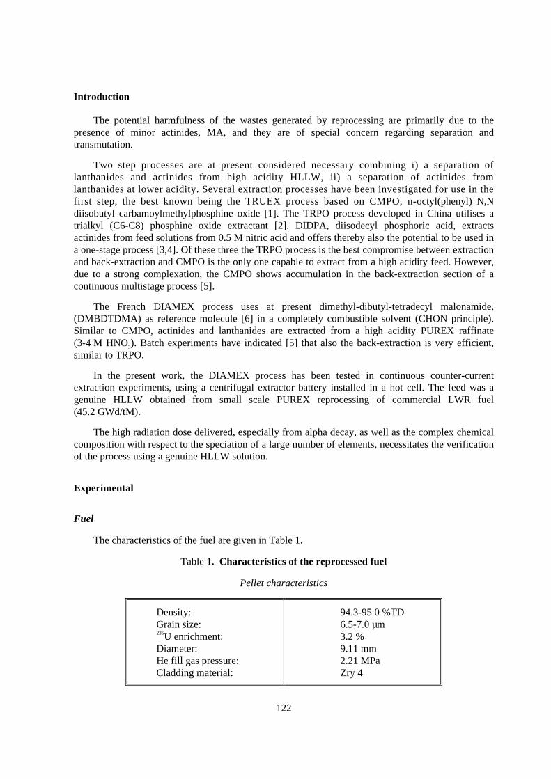
The characteristics of the fuel are given in Table 1.
Table 1. Character istics of the reprocessed fuel
Pellet characteristics
Density:Grain size:235U enrichment:Diameter:He fill gas pressure:Cladding material:
94.3-95.0 %TD6.5-7.0 µm3.2 %9.11 mm2.21 MPaZry 4
123
Irradiation conditions
Average burn-up:Average cycle powerCycle 1:Cycle 2Cycle 3
45.2 GW/tM
35.8 kW/m28.8 kW/m23.9 kW/m
Chemicals
All reagents and chemicals were of analytical grade. Tributylphosphate >99%, TBP, usedwithout further treatment, and dodecane >99% were obtained from MERCK (Germany). The nitricacid solutions were prepared either from dilution of concentrated nitric acid or from Titrisolampoules. MQ grade water (18 MΩ/cm) was used for all dilutions.
The diamide, DMDBTDMA, of ca. 98% purity and TPH were obtained from PANCHIM(France). It was diluted with pentane and purified in an Alumina-B (ICN Biomedicals, grade super I)filled column. The pentane was removed by vacuum evaporation and the pure DMDBTDMA (2.1 M)was diluted into TPH (hydrogenated tetrapropene) to an approximate concentration of 0.5 M. Theexact concentration was determined by titration using perchloric acid in acetic anhydride media.
Equipment and Procedures
The centrifugal extractor equipment installed in the hot cells is described elsewhere [2]. For thepresent study, it was extended from 12 to 16 stages, divided into four batteries with four extractors each.Two different sampling techniques were used. When the system had reached steady-state conditions (ca.1.5 h), samples were taken on-line from each stage. At the end of the experiment, usually three hoursafter introducing the feed, the centrifuges and pumps were switched off simultaneously and sampleswere taken from the mixing chambers (wells). In addition, the feed and all collected fractions weresampled.
All concentrations in the aqueous samples were determined by a quadrupole ICP-MS (Perkin-Elmer, ELAN250). Samples taken from the organic phase were back-extracted twice with 0.1 M HNO3
prior to the analysis. The acidity profile was determined for the aqueous phase by titration.
PUREX process
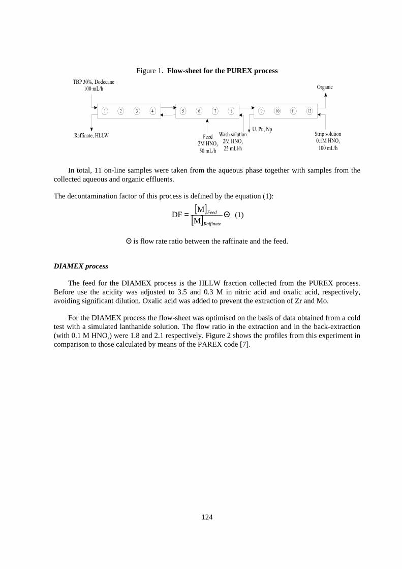
The PUREX process flow-sheet is shown in Figure 1. The feed for the PUREX process wasproduced by dissolving 60 g of fuel (see Table 1) in 300 mL 4 M HNO3.
124
Figure 1. Flow-sheet for the PUREX process
In total, 11 on-line samples were taken from the aqueous phase together with samples from thecollected aqueous and organic effluents.
The decontamination factor of this process is defined by the equation (1):
[ ][ ] Θ=
Raffinate
Feed
M
MDF (1)
Θ is flow rate ratio between the raffinate and the feed.
DIAMEX process
The feed for the DIAMEX process is the HLLW fraction collected from the PUREX process.Before use the acidity was adjusted to 3.5 and 0.3 M in nitric acid and oxalic acid, respectively,avoiding significant dilution. Oxalic acid was added to prevent the extraction of Zr and Mo.
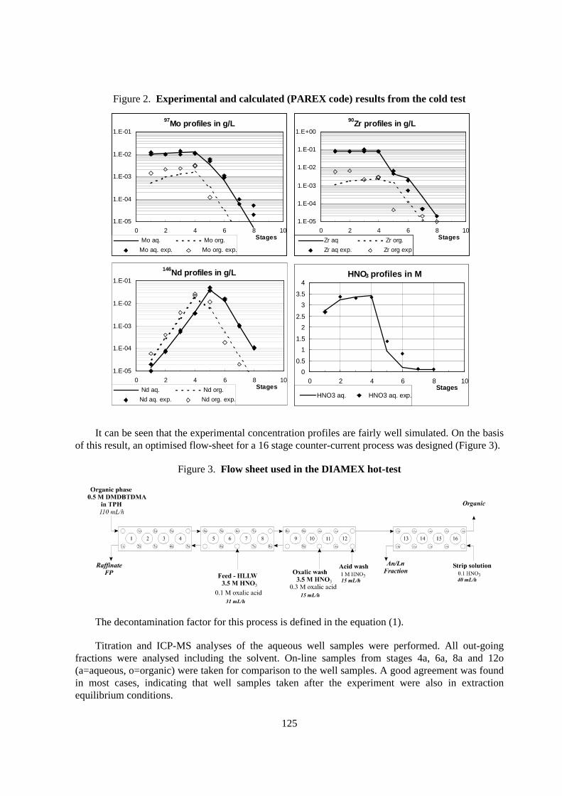
For the DIAMEX process the flow-sheet was optimised on the basis of data obtained from a coldtest with a simulated lanthanide solution. The flow ratio in the extraction and in the back-extraction(with 0.1 M HNO3) were 1.8 and 2.1 respectively. Figure 2 shows the profiles from this experiment incomparison to those calculated by means of the PAREX code [7].
125
Figure 2. Exper imental and calculated (PAREX code) results from the cold test
97Mo profiles in g/L
1.E-05
1.E-04
1.E-03
1.E-02
1.E-01
0 2 4 6 8 10Stages Mo aq. Mo org.
Mo aq. exp. Mo org. exp.
90Zr profiles in g/L
1.E-05
1.E-04
1.E-03
1.E-02
1.E-01
1.E+00
0 2 4 6 8 10StagesZr aq Zr org.
Zr aq exp. Zr org exp
146Nd profiles in g/L
1.E-05
1.E-04
1.E-03
1.E-02
1.E-01
0 2 4 6 8 10Stages Nd aq. Nd org.
Nd aq. exp. Nd org. exp.
HNO3 profiles in M
0
0.5
1
1.5
2
2.5
3
3.5
4
0 2 4 6 8 10Stages
HNO3 aq. HNO3 aq. exp.
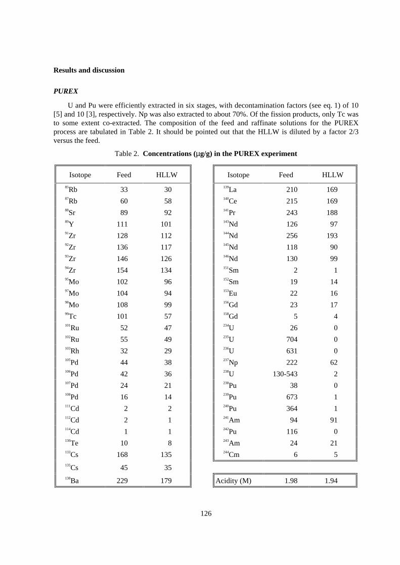
It can be seen that the experimental concentration profiles are fairly well simulated. On the basisof this result, an optimised flow-sheet for a 16 stage counter-current process was designed (Figure 3).
Figure 3. Flow sheet used in the DIAMEX hot-test
The decontamination factor for this process is defined in the equation (1).
Titration and ICP-MS analyses of the aqueous well samples were performed. All out-goingfractions were analysed including the solvent. On-line samples from stages 4a, 6a, 8a and 12o(a=aqueous, o=organic) were taken for comparison to the well samples. A good agreement was foundin most cases, indicating that well samples taken after the experiment were also in extractionequilibrium conditions.
126
Results and discussion
PUREX
U and Pu were efficiently extracted in six stages, with decontamination factors (see eq. 1) of 10[5] and 10 [3], respectively. Np was also extracted to about 70%. Of the fission products, only Tc wasto some extent co-extracted. The composition of the feed and raffinate solutions for the PUREXprocess are tabulated in Table 2. It should be pointed out that the HLLW is diluted by a factor 2/3versus the feed.
Table 2. Concentrations (µg/g) in the PUREX exper iment
Isotope Feed HLLW Isotope Feed HLLW
85Rb 33 30 139La 210 16987Rb 60 58 140Ce 215 16988Sr 89 92 141Pr 243 18889Y 111 101 143Nd 126 9791Zr 128 112 144Nd 256 19392Zr 136 117 145Nd 118 9093Zr 146 126 146Nd 130 9994Zr 154 134 151Sm 2 195Mo 102 96 152Sm 19 1497Mo 104 94 153Eu 22 1698Mo 108 99 156Gd 23 1799Tc 101 57 158Gd 5 4101Ru 52 47 234U 26 0102Ru 55 49 235U 704 0103Rh 32 29 236U 631 0105Pd 44 38 237Np 222 62106Pd 42 36 238U 130-543 2107Pd 24 21 238Pu 38 0108Pd 16 14 239Pu 673 1111Cd 2 2 240Pu 364 1112Cd 2 1 241Am 94 91114Cd 1 1 242Pu 116 0130Te 10 8 243Am 24 21133Cs 168 135 244Cm 6 5135Cs 45 35138Ba 229 179 Acidity (M) 1.98 1.94
127
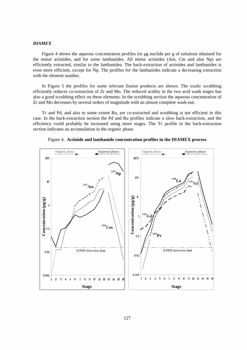
DIAMEX
Figure 4 shows the aqueous concentration profiles (in µg nuclide per g of solution) obtained forthe minor actinides, and for some lanthanides. All minor actinides (Am, Cm and also Np) areefficiently extracted, similar to the lanthanides. The back-extraction of actinides and lanthanides iseven more efficient, except for Np. The profiles for the lanthanides indicate a decreasing extractionwith the element number.
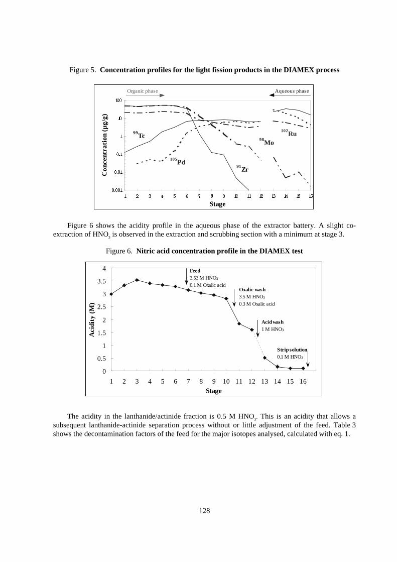
In Figure 5 the profiles for some relevant fission products are shown. The oxalic scrubbingefficiently reduces co-extraction of Zr and Mo. The reduced acidity in the two acid wash stages hasalso a good scrubbing effect on these elements. In the scrubbing section the aqueous concentration ofZr and Mo decreases by several orders of magnitude with an almost complete wash-out.
Tc and Pd, and also to some extent Ru, are co-extracted and scrubbing is not efficient in thiscase. In the back-extraction section the Pd and Ru profiles indicate a slow back-extraction, and theefficiency could probably be increased using more stages. The Tc profile in the back-extractionsection indicates an accumulation in the organic phase.
Figure 4. Actinide and lanthanide concentration profiles in the DIAMEX process
Stage
Con
cent
rati
on (
µg/
g)
244Cm
243Am
237Np
ICPMS detection limit
Organic phase Aqueous phase
Stage
Con
cent
rati
on (
µg/
g)
ICPMS detection limit
139La
141Pr
156Gd
146Nd
Organic phase Aqueous phase
128
Figure 5. Concentration profiles for the light fission products in the DIAMEX process
Stage
Con
cent
rati
on (
µg/
g)
91Zr
98Mo
99Tc
105Pd
102Ru
Organic phase Aqueous phase
Figure 6 shows the acidity profile in the aqueous phase of the extractor battery. A slight co-extraction of HNO3 is observed in the extraction and scrubbing section with a minimum at stage 3.
Figure 6. Nitr ic acid concentration profile in the DIAMEX test
0
0.5
1
1.5
2
2.5
3
3.5
4
1 2 3 4 5 6 7 8 9 10 11 12 13 14 15 16Stage
Aci
dity
(M
)
Feed3.53 M HNO3
0.1 M Oxalic acidOxalic wash3.5 M HNO3
0.3 M Oxalic acid
Acid wash1 M HNO3
Str ip solution0.1 M HNO3
The acidity in the lanthanide/actinide fraction is 0.5 M HNO3. This is an acidity that allows asubsequent lanthanide-actinide separation process without or little adjustment of the feed. Table 3shows the decontamination factors of the feed for the major isotopes analysed, calculated with eq. 1.
129
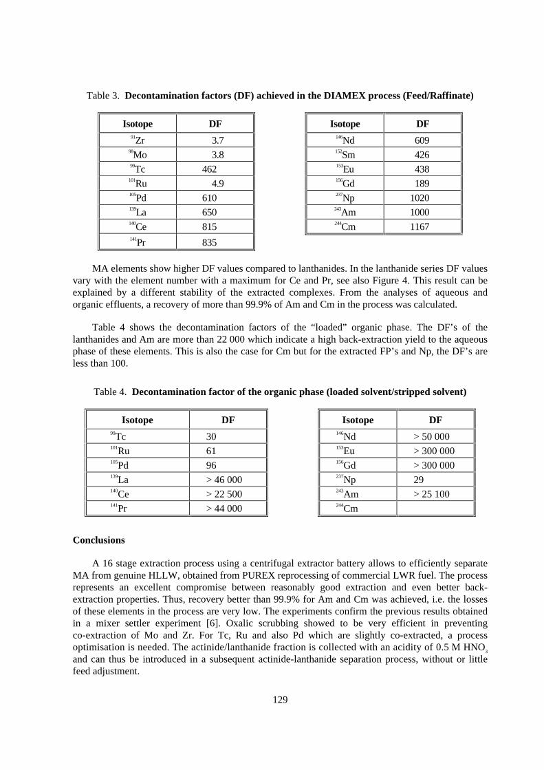
Table 3. Decontamination factors (DF) achieved in the DIAMEX process (Feed/Raffinate)
Isotope DF Isotope DF91Zr 3.7 146Nd 609
98Mo 3.8 152Sm 42699Tc 462 153Eu 438
101Ru 4.9 156Gd 189105Pd 610 237Np 1020139La 650 243Am 1000140Ce 815 244Cm 1167141Pr 835
MA elements show higher DF values compared to lanthanides. In the lanthanide series DF valuesvary with the element number with a maximum for Ce and Pr, see also Figure 4. This result can beexplained by a different stability of the extracted complexes. From the analyses of aqueous andorganic effluents, a recovery of more than 99.9% of Am and Cm in the process was calculated.
Table 4 shows the decontamination factors of the “ loaded” organic phase. The DF’s of thelanthanides and Am are more than 22 000 which indicate a high back-extraction yield to the aqueousphase of these elements. This is also the case for Cm but for the extracted FP’s and Np, the DF’s areless than 100.
Table 4. Decontamination factor of the organic phase (loaded solvent/str ipped solvent)
Isotope DF Isotope DF99Tc 30 146Nd > 50 000101Ru 61 153Eu > 300 000105Pd 96 156Gd > 300 000139La > 46 000 237Np 29140Ce > 22 500 243Am > 25 100141Pr > 44 000 244Cm
Conclusions
A 16 stage extraction process using a centrifugal extractor battery allows to efficiently separateMA from genuine HLLW, obtained from PUREX reprocessing of commercial LWR fuel. The processrepresents an excellent compromise between reasonably good extraction and even better back-extraction properties. Thus, recovery better than 99.9% for Am and Cm was achieved, i.e. the lossesof these elements in the process are very low. The experiments confirm the previous results obtainedin a mixer settler experiment [6]. Oxalic scrubbing showed to be very efficient in preventingco-extraction of Mo and Zr. For Tc, Ru and also Pd which are slightly co-extracted, a processoptimisation is needed. The actinide/lanthanide fraction is collected with an acidity of 0.5 M HNO3
and can thus be introduced in a subsequent actinide-lanthanide separation process, without or littlefeed adjustment.
130
REFERENCES
[1] E.P. Horwitz, D.G. Kalina, H. Diamond, G. Vandegrift, W.W. Schultz, Solvent Extr. Ion Exch.,3, (1985), 75.
[2] J.-P. Glatz, C. Song, X. He, H. Bokelund, L. Koch, Partitioning of Actinides from HAW in aContinuous Process by Centrifugal Extractors, Proc. of the Special Symposium on EmergingTechnologies in Hazardous Waste Management, September 27-29, (1993), Atlanta, Georgia,D.W. Tedder Ed., ACS, Washington DC.
[3] M. Kubota, I. Yamaguchi, Y. Morita, Y. Kondo, K. Shirahashi, I. Yamagishi, T. Fujiwara,Developement of Partitioning Process for the Management of High Level Waste” , Proceedingsof Global’93, (1993), 588.
[4] Y. Morita, J.-P. Glatz , M. Kubota, L. Koch, G. Pagliosa, K. Römer, A. Nicholl, ActinidePartitioning from HLLW in a Continuous DIDPA Extraction Process by Means of CentrifugalExtractors, Solvent Extr. Ion Exch. 14 (3). (1996), 385.
[5] J.-P. Glatz, A. Nicholl, G. Pagliosa, K. Römer, B. Sätmark, L. Koch, Group Separation ofRadiotoxic Elements from HLLW by Continuous Solvent Extraction: a Comparative Study,OECD Proc. of the Workshop on Long-Lived Radionuclide Chemistry in Nuclear WasteTreatment, 18-20 June, (1997), Avignon, France.
[6] C. Madic, P. Blanc, N. Condamines, P. Baron, L. Berthon, C. Nicol, C. Pozo, M. Lecomte,M. Philippe, M. Masson, C. Hequet, M.J. Hudson, Actinide Partitioning from HLLW Using theDIAMEX Process, Proc. of the Fourth Intl. Conf. on Nuclear Fuel Reprocessing and WasteManagement, RECOD’94, 24-28 April, (1994), London, UK.
[7] B. Dinh, B. Mauborgne, P. Baron, Dynamic Simulation of Extraction Operations: Applicationin Nuclear Fuel Reprocessing ESCAPE 2, (1992), Toulouse, France.
131
DEVELOPMENT OF THE FOUR GROUP PARTITIONING PROCESS AT JAERI
M. Kubota, Y. Mor ita, I . Yamaguchi, I . Yamagishi, T. Fuj iwara, M. Watanabe,Department of Materials Science, Japan Atomic Energy Research Institute
Tokai-mura, Ibaraki-ken, 319-1195,Japan
K. Mizoguchi and R. TatsugaeIshikawajima-Harima Heavy Industries Co., Ltd.
Japan
Abstract
At the Japan Atomic Energy Research Institute (JAERI), a partitioning process has been developed toseparate elements in a high-level liquid waste (HLLW) into four groups; transuranium elements(TRU), Tc-platinum group metals (PGM), Sr-Cs and the others. The present paper deals with objectsof the partitioning, main characteristics of four group partitioning process, generation of solidmaterials after the partitioning and its positive effects on the management of high-level waste (HLW),and recent study on the four group partitioning process.
132
Objectives
The first objective of the partitioning is the reduction of long-term radiotoxicity of HLW to bedisposed of into deep underground. The second one is the volume reduction of HLW by separatetreatment of heat generating nuclides such as 90Sr and 137Cs. The third objective is the development ofadvanced waste management methods because the other groups containing about 70wt% of fissionand corrosion products in HLLW might be disposed of directly without long-term cooling. The fourthobjective is resourcefication of HLW by promoting beneficial uses of radioisotopes and noble metalsin HLLW.
Basic way of thinking for the construction of the par titioning process
For the satisfaction of above objects the four group partitioning process has been developed atJAERI since 1985.
Following items have been considered for the construction of the partitioning process.
1. First priority separation of the TRU group because of its long-term and dominantradiotoxicity and suppressing its dispersion into other groups.
2. Waste minimisation, especially for the separation of the Tc-PGM and the Sr-Cs groups.
3. Use of reagents with high radiation durability and chemical stability.
4. No possibility of firing and explosion of the reagent and its degradation products. No use ofreagent with phenyl group which has a possibility of forming explosive compounds such asnitrobenzene as its degradation product.
5. Compatibility to a fuel reprocessing plant. No use of reagent such as hydrochloric acid andorganic reagent with chlorine which causes corrosion of stainless steel. Increasing apossibility of using a waste treatment facility in the fuel reprocessing plant for the treatmentof the wastes generated from partitioning.
Four group par titioning process
Through the fundamental study, the four group partitioning process has been constructed asshown in Figures 1 and 2. Main characteristics of the four group partitioning process are as follows:
1. All TRU elements including pentavalent Np are extracted with DIDPA after the denitrationof HLLW, reducing the nitric acid concentration from 2 M to 0.5 M.
2. Tc and PGM are separated by precipitation through denitration or by adsorption with anactive carbon.
3. Sr and Cs are separated by adsorption with inorganic ion exchangers, titanic acid and zeolite,respectively.
4. The TRU elements extracted in the DIDPA solvent are sequentially back-extracted with 4 Mnitric acid for Am, Cm and lanthanides, 0.8 M oxalic acid solution for Np and Pu, and 1.5Msodium carbonate solution for U.
133
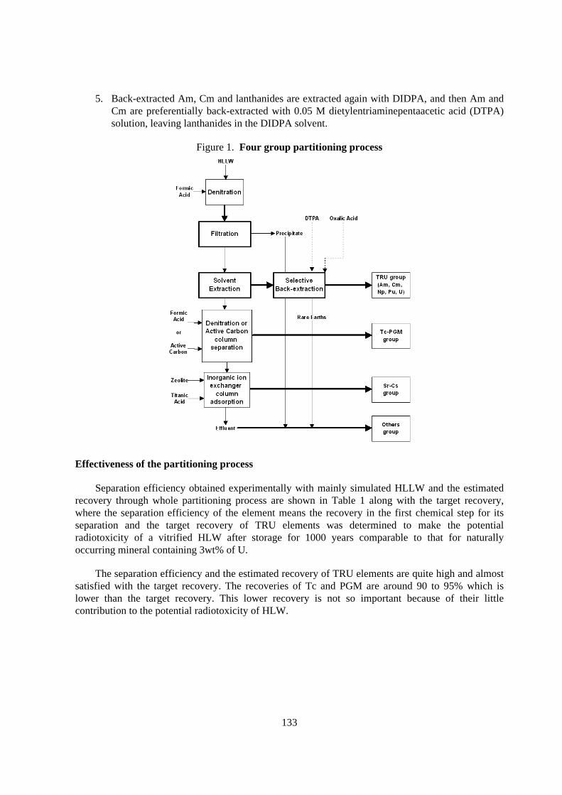
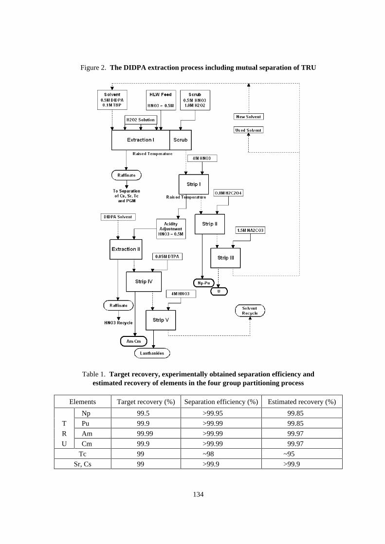
5. Back-extracted Am, Cm and lanthanides are extracted again with DIDPA, and then Am andCm are preferentially back-extracted with 0.05 M dietylentriaminepentaacetic acid (DTPA)solution, leaving lanthanides in the DIDPA solvent.
Figure 1. Four group par titioning process
Effectiveness of the par titioning process
Separation efficiency obtained experimentally with mainly simulated HLLW and the estimatedrecovery through whole partitioning process are shown in Table 1 along with the target recovery,where the separation efficiency of the element means the recovery in the first chemical step for itsseparation and the target recovery of TRU elements was determined to make the potentialradiotoxicity of a vitrified HLW after storage for 1000 years comparable to that for naturallyoccurring mineral containing 3wt% of U.
The separation efficiency and the estimated recovery of TRU elements are quite high and almostsatisfied with the target recovery. The recoveries of Tc and PGM are around 90 to 95% which islower than the target recovery. This lower recovery is not so important because of their littlecontribution to the potential radiotoxicity of HLW.
134
Figure 2. The DIDPA extraction process including mutual separation of TRU
Table 1. Target recovery, exper imentally obtained separation efficiency andestimated recovery of elements in the four group par titioning process
Elements Target recovery (%) Separation efficiency (%) Estimated recovery (%)
Np 99.5 >99.95 99.85
T Pu 99.9 >99.99 99.85
R Am 99.99 >99.99 99.97
U Cm 99.9 >99.99 99.97
Tc 99 ~98 ~95
Sr, Cs 99 >99.9 >99.9
135
As for the separation of actinides, Am and Cm, from lanthanides, it is possible to reduce thelanthanide content less than 25wt% under the condition of 99.99% separation efficiency of actinides,which is fully satisfied with the purification suitable for nuclide transmutation.
The radiation durability of the DIDPA solvent is about 7 times higher than TBP and itsdegradation products give hardly drawback effects on the TRU extraction because most of theproducts are organophosphoric acid compound like DIDPA. Thus there is no frequent need to purifythe DIDPA solvent prior to its recycle use, which greatly contributes to the reduction of a secondarywaste generation.
Generation of solid mater ials after the par titioning and its positive effects on the managementof HLW
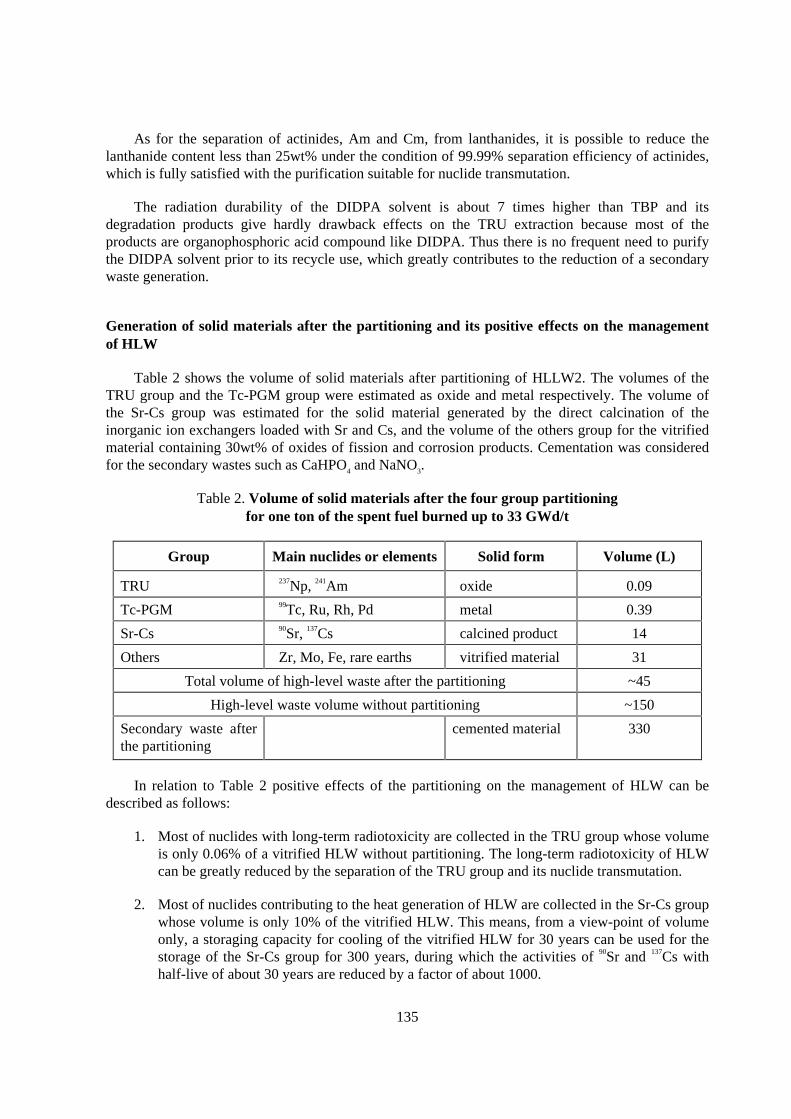
Table 2 shows the volume of solid materials after partitioning of HLLW2. The volumes of theTRU group and the Tc-PGM group were estimated as oxide and metal respectively. The volume ofthe Sr-Cs group was estimated for the solid material generated by the direct calcination of theinorganic ion exchangers loaded with Sr and Cs, and the volume of the others group for the vitrifiedmaterial containing 30wt% of oxides of fission and corrosion products. Cementation was consideredfor the secondary wastes such as CaHPO4 and NaNO3.
Table 2. Volume of solid mater ials after the four group par titioningfor one ton of the spent fuel burned up to 33 GWd/t
Group Main nuclides or elements Solid form Volume (L)
TRU 237Np, 241Am oxide 0.09
Tc-PGM 99Tc, Ru, Rh, Pd metal 0.39
Sr-Cs 90Sr, 137Cs calcined product 14
Others Zr, Mo, Fe, rare earths vitrified material 31
Total volume of high-level waste after the partitioning ~45
High-level waste volume without partitioning ~150
Secondary waste afterthe partitioning
cemented material 330
In relation to Table 2 positive effects of the partitioning on the management of HLW can bedescribed as follows:
1. Most of nuclides with long-term radiotoxicity are collected in the TRU group whose volumeis only 0.06% of a vitrified HLW without partitioning. The long-term radiotoxicity of HLWcan be greatly reduced by the separation of the TRU group and its nuclide transmutation.
2. Most of nuclides contributing to the heat generation of HLW are collected in the Sr-Cs groupwhose volume is only 10% of the vitrified HLW. This means, from a view-point of volumeonly, a storaging capacity for cooling of the vitrified HLW for 30 years can be used for thestorage of the Sr-Cs group for 300 years, during which the activities of 90Sr and 137Cs withhalf-live of about 30 years are reduced by a factor of about 1000.
136
3. The solid materials obtained from a direct calcination of inorganic ion exchangers loadedwith Sr and Cs over 1 000 C possess extremely higher thermal stability and lowerleachability by a factor of about three orders of magnitude than the vitrified HLW.
4. In the vitrification of the others group, it is possible to increase an elemental concentration ascompared with that in the vitrified HLW because of no presence of heat generating nuclidessuch as 90Sr and 137Cs, thus contributing to the volume reduction of the other group, about20vol% of the vitrified HLW. For the others group it might be possible to dispose of directlyinto deep underground without any long-term cooling.
5. Total volume of the four groups is estimated to be 45 L for one ton of the spent fuel, which issmaller by a factor of 3.3 compared with that of the vitrified HLW. Extremely higher volumereduction of HLW might be expected by the four group partitioning.
6. Volume of the cemented waste is only about 20% of that generated in a reprocessing plant.
Moreover, an alpha activity concentration of the cemented waste becomes lower than 1 GBq/tonand its shallow land disposal might be expected.
Recent Study on the four group par titioning process
Prevention of colloid formation and removal of the colloid in the pre-treatment step for thepartitioning
Studies on pre-treatment of HLLW for the DIDPA extraction in the four group partitioningprocess showed that colloid was formed at denitration step when a simulated HLLW was heatedbefore denitration. The heating step was added to make the precipitate easy-to-filter, which is veryimportant from the chemical engineering point of view. Since the colloid disturbs the extraction withDIDPA by forming emulsion, the prevention of the colloid formation and the removal of the colloidwas studied using simulated HLLW.
The main component of the colloid was Zr, which remains in the pre-treated HLLW in a yield ofabout 50%. Modification of heating and denitration condition in the pre-treatment could not preventthe formation of either the colloid or the very fine particles which is very difficult to filtrate. Additionof phosphoric acid, which is one of the reagents for Zr precipitation, was found to be effective. Toprevent the emulsification in the DIDPA extraction, amount ratio of phosphoric acid to the initial Zrshould be more than 0.8.
As for the removal of the colloid formed in the denitrated HLLW addition of reagents for Zrprecipitation also is the most effective among the various methods examined except very directmethod of ultra filtration. Four reagents of phosphoric acid, ammonium para-molybdate, sodiumortho-molybdate and telluric acid were examined for the colloid removal and all the reagents couldconvert the colloid to precipitate by heating the solution after the addition. It was concluded thatammonium para-molybdate would be the best reagent among the four reagents because Mo is alreadyincluded in HLLW, ammonium para-molybdate does not induce extra salts, it makes easiest-to-filterprecipitate and it does not change the acid concentration.
137
Construction of optimum separation process for Tc-PGM Group by precipitation throughdenitration
For the purpose of constructing the optimum separation process for Tc and PGM by precipitationthrough denitration, the acid concentration of the denitrated solution and the precipitation ratio ofelements were examined using simulated DIDPA raffinates at the various concentrations of elementsand nitric acid and in the various heating conditions.
When the simulated DIDPA raffinate was heated strongly at the denitration, the several-timesconcentration of the raffinate was required for efficient separation of PGM. If the twice concentratedraffinate was denitrated by the addition of formic acid with the ratio of [HCOOH] / [HNO3] > 2.4, orif the 4-times concentrated raffinate was denitrated with the ratio of [HCCOH] / [HNO3] > 2, pH ofthe denitrated solution increased to neutral region and then PGM was separated as precipitates.
In case the denitration was performed without the concentration of the simulated DIDPAraffinate, the temperature rising rate of the solution was found to be an important parameter. In orderto increase the pH of the denitrated solution to neutral region and to separate PGM as precipitates bythe denitration at [HCOOH] / [HNO3] = 2.2, the temperature rising rate should be slower than athreshold value and the solution temperature after the rising should be over 95 C.
Tc behaviour in the four group partitioning process
A small scale partitioning test on the four group partitioning was performed using simulatedHLLW with addition of a macro amount of Tc as a total test that summarises the previous studies onTc separation and as a final confirmation about Tc behaviour before the partitioning test with realHLLW at the Nuclear Fuel Cycle Safety Engineering Research Facility (NUCEF).
At the pre-treatment step including denitration step and newly-introduced colloid removal stepby addition of Mo, Tc remained in the solution. Ratios of Tc found in the precipitates was 0.23% atthe denitration and 0.21% at the colloid removal. The loss of Tc to the precipitate was negligible.
At the DIDPA extraction step, 99.93% of Tc transferred to the raffinate. Calculated distributionratio was 0.013.
At the precipitation step by denitration of the raffinate after concentration, 98.2% of Tc wereprecipitated. It was confirmed that the Tc precipitates even at a macro amount.
At the dissolution step for Tc from the precipitate with hydrogen peroxide, 84.6% of Tc wererecovered as a solution. By repeated dissolution, the recovery can be increased.
Back-extraction of actinides from organophosphoric acid with hydrazine carbonate
Back-extraction of actinides from organophosphoric acid solvent with hydrazine carbonate is anattractive method to separate actinide from other actinides and lanthanides from the standpoint ofreducing secondary waste because it is so-called salt-free. The back-extraction from HDEHP(di(2-ethylhexyl)phosphoric acid) and DIDPA was studied to elucidate its behaviour of actinides andlanthanides.
138
In the case of HDEHP, the separation factor of Am(III) and Eu(III) was about three and Ammight be separated from lanthanides in an appropriate hydrazine carbonate concentration from 0.6 Mto 1.0 M.
Np(IV) and Pu(IV) were back-extracted with 0.6 M hydrazine carbonate solution from HDEHPwith the distribution ratios of 0.11 and 0.47, respectively, whereas Am(III), Eu(III) and U(VI) werehardly back-extracted, whose distribution ratios were 2.3, 7.3 and 13.6 respectively.
Therefore, it is possible to separate actinides each other and to separate trivalent actinides fromlanthanides by changing the hydrazine carbonate concentration.
Partitioning tests with simulated HLLW at NUCEF
Partitioning tests with simulated HLLW have been performed in the partitioning test facility atNUCEF which was constructed for the demonstration of the four group partitioning process with realHLLW. One of the purposes was to obtain the data on elemental behaviour to be compared with theresults of the tests with real HLLW. Another purpose was to check the operability of the facility.
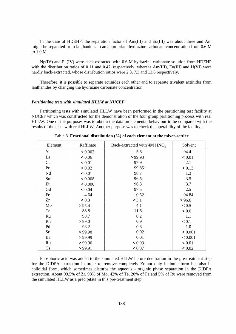
Table 3. Fractional distr ibution (%) of each element at the mixer-settler
Element Raffinate Back-extracted with 4M HNO3 Solvent
Y < 0.002 5.6 94.4La < 0.06 > 99.93 < 0.01Ce < 0.01 97.9 2.1Pr < 0.02 99.85 < 0.13Nd < 0.01 98.7 1.3Sm < 0.008 96.5 3.5Eu < 0.006 96.3 3.7Gd < 0.04 97.5 2.5Fe 4.64 0.52 94.84Zr < 0.3 < 3.1 > 96.6Mo > 95.4 4.1 < 0.5Te 88.8 11.6 < 0.6Ru 98.7 0.2 1.1Rh > 99.0 0.9 < 0.1Pd 98.2 0.8 1.0Sr > 99.98 0.02 < 0.001Ba > 99.99 0.01 < 0.001Rb > 99.96 < 0.03 < 0.01Cs > 99.91 < 0.07 < 0.02
Phosphoric acid was added to the simulated HLLW before denitration in the pre-treatment stepfor the DIDPA extraction in order to remove completely Zr not only in ionic form but also incolloidal form, which sometimes disturbs the aqueous - organic phase separation in the DIDPAextraction. About 99.5% of Zr, 98% of Mo, 42% of Te, 20% of Fe and 5% of Ru were removed fromthe simulated HLLW as a precipitate in this pre-treatment step.
139
In the DIDPA extraction a 16 stages mixer-settler was used and 7 stages used for extraction ofTRU, 4 stages for scrubbing and 5 stages for back-extraction of Am and Cm. The fractionaldistribution of each element in this DIDPA extraction steps is shown in Table 3. Lanthanides could bealmost completely extracted with DIDPA and back-extracted with 4 M HNO3. Further complete back-extraction of lanthanides might be easily accomplished by increasing the number of the back-extraction stage. Other elements except Fe, Zr and Y were not extracted and therefore Sr and Cs werewell separated from lanthanides. About 99.8% of Fe, 80% of Zr and 0.5% of Y were back-extractedwith the oxalic acid solution.
The raffinate of the DIDPA extraction was fed to the separation step for PGM and Tc byprecipitation through denitration. More than 90% of PGM was precipitated and almost all Cs wasremained in the solution, but 20-30% of Sr was coprecipitated. These results well agreed with theresults of previous experiments in a small scale. Recovery of Sr from the precipitate should bestudied.
Partitioning tests with real HLLW at NUCEF
As the first step of the four group partitioning test with real HLLW, semi-hot test with tracerlevel of real HLLW has been performed at NUCEF. In this test more than 99.99% extraction of Amwith DIDPA was confirmed and 99.92% was back-extracted with 4 M nitric acid. Chemicalbehaviours of other elements were also almost consistent with those in the partitioning test withsimulated HLLW.
Conclusion
The four group partitioning greatly contributes to the reduction of the high-level waste volumeand the establishment of an advanced HLW management technology as well as the promotion of thetransmutation of long-lived nuclides which contributes to the reduction of long-term burden of HLWinto natural environment.
Demonstration of the four group partitioning process with real HLLW is now in progress, theeffectiveness of the process will be verified and the process will be optimised for its practicalutilisation.
REFERENCES
[1] M. Kubota, Proceedings, Vol.1 of RECOD’94 (1994).
[2] M. Kubota and Y. Morita, Proceedings of GLOBAL’97 (1997) 458.

141
ACTINIDES(I I I )-LANTHANIDES GROUP SEPARATION FROM NITRIC ACID USINGNEW AROMATIC DIORGANYLDITHIOPHOSPHINIC ACIDS
Giuseppe Modolo and Reinhard OdojInstitut für Sicherheitsforschung und Reaktortechnik,
Forschungszentrum Jülich GmbH, 52425 Jülich,Germany
Abstract
In this paper, extractants are presented which made it possible to separate actinides(III) andlanthanides from strong nitric acid solutions (0.05 - 1 mol/L). For this purpose, new aromaticdithiophosphinic acids were synthesised and characterised, and the distribution ratios of Am(III),Eu(III) and all relevant lanthanides were determined in batch extraction experiments. The extractantused was a mixture of aromatic dithiophosphinic acid + synergist in an aromatic solvent. In particular,the influence of the synergist and solvent is described. With the aid of a 12-step flowsheet it was alsopossible for the first time to continuously partition actinides/lanthanides at an acid concentration of0.5 mol/L HNO3.
142
Introduction
Isolation of the trivalent Am and Cm actinides from liquid high-level waste is the aim of variouspartitioning strategies. However, the desirable selective extraction from high-level nitric acidsolutions produced by the PUREX process and containing over 30 fission products has not beenpossible to date. After U, Pu, Np and the majority of undesirable fission products have beenseparated, an actinide(III) fraction arises in all the partitioning processes so far known (e.g. TRUEX,TRPO, DIDPA and DIAMEX) [1]. The trivalent actinides are so far always accompanied by thetrivalent lanthanides, which are abundantly present in HLLW, due to their comparable chemical andphysical properties. Since they impair the transmutation of Am and Cm due to their high neutronabsorption cross-sections, the two element groups should be partitioned again in a subsequent step.This actinide/lanthanide partitioning is still one of the most difficult operations in any partitioningprocess.
In the recent past, several interesting extractants have been presented in the literature foractinide/lanthanide partitioning by liquid/liquid extraction. Of particular interest are studies byChinese scientists [2] who achieved incredibly high Am/Eu separation factors > 5000 with purifiedCyanex 301.
Since we have recently [3] confirmed the excellent results of Zhu et al., we considered that itwould be interesting to extend our studies to the selective extraction of trivalent actinides fromlanthanides using this class of sulphur-containing extractants. According to Zhu et al. the followingextraction mechanism is proposed for the extraction of Am(III) and Eu(III) with Cyanex 301 (HA)where the subscripts aq and org refer to the aqueous and organic phases.
M3+
aq + 2 (HA)2org ↔ MA3(HA)org + 3 H+
aq M = Am, Eu (1)
It can be seen from Equation 1 that the extraction equilibrium also depends on acid strength.Three protons are released during extraction. Since previous research on Cyanex 301 indicated that itsacidity is too low and that it only becomes an effective extractant in the higher pH regions of aqueoussolutions (i.e. pH > 3), it was necessary to attempt to increase the acidity of such ligands as R2PSSHsby attaching electron-withdrawing substituents (R) so that they could extract in lower pH regions. Theideal acidity of the aqueous phase for the actinide(III) extraction should fall in the range below pH 2.Otherwise the pH value must be controlled or stabilised by a buffer during separation, especially ifreal waste solutions and Am(III) concentrations > 10-3 mol/L are involved.
Recently we have shown that aromatic dithiophosphinic acids (Figure 1) synthesised in ourlaboratory are more powerful extractants than Cyanex 301 and first results have already beenpublished [4,5]. A detailed description of the synthesis and characterisation of the extractants and theexperimental description of batch extraction studies are to be found in reference [6], where studies onthe radiolytic stability of the new extractants are also reported, featuring high resistance to gammaradiation. The present paper describes the latest results on actinide/lanthanide partitioning with the aidof aromatic dithiophosphinic acids and, for the first time, also presents the promising results of acontinuous extraction procedure.
143
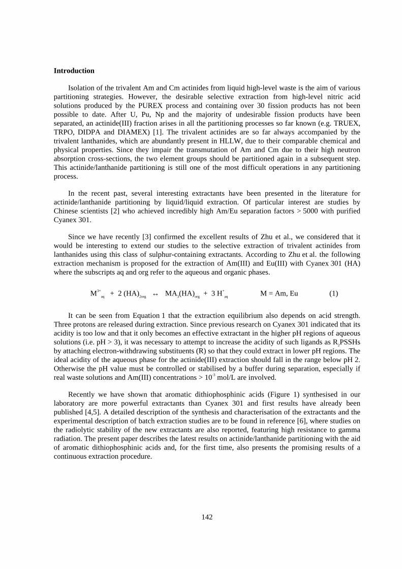
Figure 1. Structure of the synthesised aromatic dithiophosphinic acids
P
S
SH
X
X
X = HX = CH3X = ClX = F
Results and discussion
Effect of the synergist
The extraction results with bisphenyl-, bis(chlorophenyl)- and bis(fluorophenyl)-dithiophosphinic acid using TBP as the synergist from 0.01 to 0.4 mol/L nitric acid are shown inFigure 2. It can be seen that the extraction ratios of Am(III) and also Eu(III) increase strongly in theorder (C6H5)2PS(SH) < (F-C6H4)2PS(SH) < (Cl-C6H4)2PS(SH). However, the selectivity in theinvestigated acidity range decreases in the same order with Am/Eu separation factors of 230 - 280,41 - 57 and 28 - 31. This suggests that the extraction can be improved by incorporating evenstronger electron-attracting groups (such as NO2 or two Cl groups), whereas selectivity decreasesinversely. The influence of TBP and the extractant concentration on the extraction of Am and Eu hasalso been examined. The results of a slope analysis are reported in reference [6]. It was found that theoptimum extractant concentration was 0.5 mol/L and that of the TBP synergist ranged between 0.1and 0.25 mol/L. No extraction has been observed without TBP.
Figure 2. Extraction of Am(I I I ) and Eu(I I I ) with different 0.5 M dithiophosphinic acids+ 0.25 M TBP in toluene from HNO3
0.01 0.05 0.1 0.5Initial HNO3 concentration (mol/L)
10-4
10-3
10-2
10-1
100
101
102
103
104
Dis
trib
utio
n R
atio
D
Am, (Cl-C6H4)2PS(SH)Am, (Cl-C6H4)2PS(SH)Eu, (Cl-C6H4)2PS(SH)Eu, (Cl-C6H4)2PS(SH)
Am, (C6H5)2PS(SH)Am, (C6H5)2PS(SH)Eu, (C6H5)2PS(SH)Eu, (C6H5)2PS(SH)Am, (F-C6H4)2PS(SH)Am, (F-C6H4)2PS(SH)Eu, (F-C6H4)2PS(SH)Eu, (F-C6H4)2PS(SH)
144
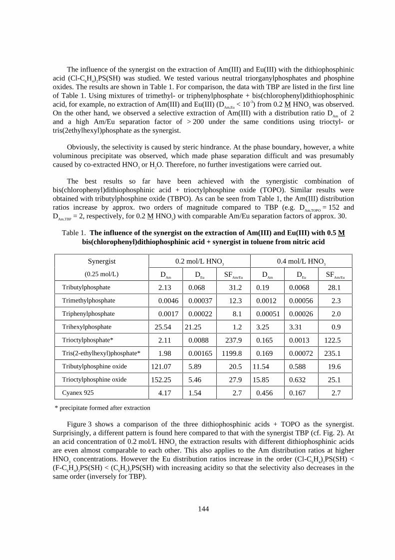
The influence of the synergist on the extraction of Am(III) and Eu(III) with the dithiophosphinicacid (Cl-C6H4)2PS(SH) was studied. We tested various neutral triorganylphosphates and phosphineoxides. The results are shown in Table 1. For comparison, the data with TBP are listed in the first lineof Table 1. Using mixtures of trimethyl- or triphenylphosphate + bis(chlorophenyl)dithiophosphinicacid, for example, no extraction of Am(III) and Eu(III) (DAm,Eu < 10-3) from 0.2 M HNO3 was observed.On the other hand, we observed a selective extraction of Am(III) with a distribution ratio DAm of 2and a high Am/Eu separation factor of > 200 under the same conditions using trioctyl- ortris(2ethylhexyl)phosphate as the synergist.
Obviously, the selectivity is caused by steric hindrance. At the phase boundary, however, a whitevoluminous precipitate was observed, which made phase separation difficult and was presumablycaused by co-extracted HNO3 or H2O. Therefore, no further investigations were carried out.
The best results so far have been achieved with the synergistic combination ofbis(chlorophenyl)dithiophosphinic acid + trioctylphosphine oxide (TOPO). Similar results wereobtained with tributylphosphine oxide (TBPO). As can be seen from Table 1, the Am(III) distributionratios increase by approx. two orders of magnitude compared to TBP (e.g. DAm,TOPO = 152 andDAm,TBP = 2, respectively, for 0.2 M HNO3) with comparable Am/Eu separation factors of approx. 30.
Table 1. The influence of the synergist on the extraction of Am(I I I ) and Eu(I I I ) with 0.5 Mbis(chlorophenyl)dithiophosphinic acid + synergist in toluene from nitr ic acid
Synergist 0.2 mol/L HNO3 0.4 mol/L HNO3
(0.25 mol/L) DAm DEu SFAm/Eu DAm DEu SFAm/Eu
Tributylphosphate 2.13 0.068 31.2 0.19 0.0068 28.1
Trimethylphosphate 0.0046 0.00037 12.3 0.0012 0.00056 2.3
Triphenylphosphate 0.0017 0.00022 8.1 0.00051 0.00026 2.0
Trihexylphosphate 25.54 21.25 1.2 3.25 3.31 0.9
Trioctylphosphate* 2.11 0.0088 237.9 0.165 0.0013 122.5
Tris(2-ethylhexyl)phosphate* 1.98 0.00165 1199.8 0.169 0.00072 235.1
Tributylphosphine oxide 121.07 5.89 20.5 11.54 0.588 19.6
Trioctylphosphine oxide 152.25 5.46 27.9 15.85 0.632 25.1
Cyanex 925 4.17 1.54 2.7 0.456 0.167 2.7
* precipitate formed after extraction
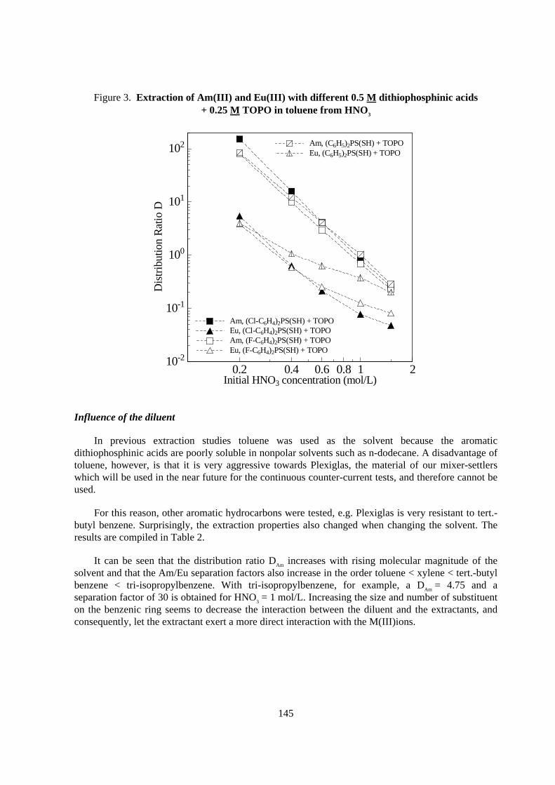
Figure 3 shows a comparison of the three dithiophosphinic acids + TOPO as the synergist.Surprisingly, a different pattern is found here compared to that with the synergist TBP (cf. Fig. 2). Atan acid concentration of 0.2 mol/L HNO3 the extraction results with different dithiophosphinic acidsare even almost comparable to each other. This also applies to the Am distribution ratios at higherHNO3 concentrations. However the Eu distribution ratios increase in the order (Cl-C6H4)2PS(SH) <(F-C6H4)2PS(SH) < (C6H5)2PS(SH) with increasing acidity so that the selectivity also decreases in thesame order (inversely for TBP).
145
Figure 3. Extraction of Am(I I I ) and Eu(I I I ) with different 0.5 M dithiophosphinic acids+ 0.25 M TOPO in toluene from HNO3
0.2 0.4 0.6 0.8 1 2Initial HNO3 concentration (mol/L)
10-2
10-1
100
101
102
Dis
trib
utio
n R
atio
D
Am, (Cl-C6H4)2PS(SH) + TOPOAm, (Cl-C6H4)2PS(SH) + TOPOEu, (Cl-C6H4)2PS(SH) + TOPOEu, (Cl-C6H4)2PS(SH) + TOPOAm, (F-C6H4)2PS(SH) + TOPOAm, (F-C6H4)2PS(SH) + TOPOEu, (F-C6H4)2PS(SH) + TOPOEu, (F-C6H4)2PS(SH) + TOPO
Am, (C6H5)2PS(SH) + TOPOAm, (C6H5)2PS(SH) + TOPOEu, (C6H5)2PS(SH) + TOPOEu, (C6H5)2PS(SH) + TOPO
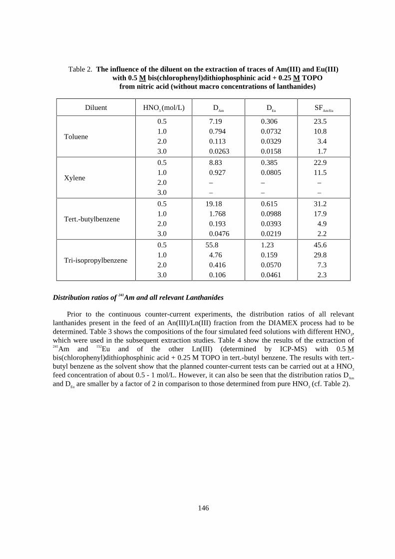
Influence of the diluent
In previous extraction studies toluene was used as the solvent because the aromaticdithiophosphinic acids are poorly soluble in nonpolar solvents such as n-dodecane. A disadvantage oftoluene, however, is that it is very aggressive towards Plexiglas, the material of our mixer-settlerswhich will be used in the near future for the continuous counter-current tests, and therefore cannot beused.
For this reason, other aromatic hydrocarbons were tested, e.g. Plexiglas is very resistant to tert.-butyl benzene. Surprisingly, the extraction properties also changed when changing the solvent. Theresults are compiled in Table 2.
It can be seen that the distribution ratio DAm increases with rising molecular magnitude of thesolvent and that the Am/Eu separation factors also increase in the order toluene < xylene < tert.-butylbenzene < tri-isopropylbenzene. With tri-isopropylbenzene, for example, a DAm = 4.75 and aseparation factor of 30 is obtained for HNO3 = 1 mol/L. Increasing the size and number of substituenton the benzenic ring seems to decrease the interaction between the diluent and the extractants, andconsequently, let the extractant exert a more direct interaction with the M(III)ions.
146
Table 2. The influence of the diluent on the extraction of traces of Am(I I I ) and Eu(I I I )with 0.5 M bis(chlorophenyl)dithiophosphinic acid + 0.25 M TOPO
from nitr ic acid (without macro concentrations of lanthanides)
Diluent HNO3 (mol/L) DAm DEu SFAm/Eu
Toluene
0.51.02.03.0
7.190.7940.1130.0263
0.3060.07320.03290.0158
23.510.83.41.7
Xylene
0.51.02.03.0
8.830.927––
0.3850.0805––
22.911.5––
Tert.-butylbenzene
0.51.02.03.0
19.181.7680.1930.0476
0.6150.09880.03930.0219
31.217.94.92.2
Tri-isopropylbenzene
0.51.02.03.0
55.84.760.4160.106
1.230.1590.05700.0461
45.629.87.32.3
Distribution ratios of 241Am and all relevant Lanthanides
Prior to the continuous counter-current experiments, the distribution ratios of all relevantlanthanides present in the feed of an An(III)/Ln(III) fraction from the DIAMEX process had to bedetermined. Table 3 shows the compositions of the four simulated feed solutions with different HNO3,which were used in the subsequent extraction studies. Table 4 show the results of the extraction of241Am and 152Eu and of the other Ln(III) (determined by ICP-MS) with 0.5 Mbis(chlorophenyl)dithiophosphinic acid + 0.25 M TOPO in tert.-butyl benzene. The results with tert.-butyl benzene as the solvent show that the planned counter-current tests can be carried out at a HNO3
feed concentration of about 0.5 - 1 mol/L. However, it can also be seen that the distribution ratios DAm
and DEu are smaller by a factor of 2 in comparison to those determined from pure HNO3 (cf. Table 2).
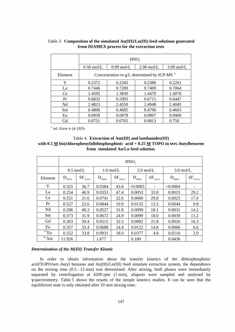
147
Table 3. Composition of the simulated An(I I I )/Ln(I I I ) feed solutions generatedfrom DIAMEX process for the extraction tests
HNO3
0.50 mol/L 0.99 mol/L 2.06 mol/L 3.09 mol/L
Element Concentration in g/L determined by ICP-MS 1)
Y 0.2372 0.2345 0.2380 0.2261La 0.7446 0.7200 0.7409 0.7064Ce 1.4595 1.3830 1.4470 1.4070Pr 0.6832 0.5993 0.6715 0.6447Nd 2.4823 2.4550 2.4948 2.4045Sm 0.4806 0.4685 0.4796 0.4603Eu 0.0939 0.0878 0.0907 0.0900Gd 0.0751 0.0765 0.0813 0.750
1) rel. Error ± (4-10)%
Table 4. Extraction of Am(I I I ) and lanthanides(I I I )with 0.5 M bis(chlorophenyl)dithiophosphinic acid + 0.25 M TOPO in ter t.-butylbenzene
from simulated An/Ln feed solution.
HNO3
0.5 mol/L 1.0 mol/L 2.0 mol/L 3.0 mol/L
Element DM(III) SFAm/Ln DM(III) SFAm/Ln DM(III) SFAm/Ln DM(III) SFAm/Ln
Y 0.325 36.7 0.0384 43.6 <0.0005 - <0.0004 -La 0.254 46.9 0.0353 47.4 0.0053 33.8 0.0015 29.2Ce 0.551 21.6 0.0741 22.6 0.0060 29.8 0.0025 17.0Pr 0.527 22.6 0.0844 19.9 0.0135 13.3 0.0044 9.8Nd 0.296 40.3 0.0527 31.8 0.0099 18.1 0.0031 14.2Sm 0.373 31.9 0.0672 24.9 0.0099 18.0 0.0039 11.2Gd 0.303 39.4 0.0515 32.5 0.0082 21.8 0.0026 16.3Eu 0.357 33.4 0.0688 24.4 0.0122 14.8 0.0066 6.6
152Eu 0.352 33.8 0.0931 18.0 0.0377 4.8 0.0216 2.0241Am 11.926 1.677 0.180 0.0436
Determination of the M(III) Transfer Kinetic
In order to obtain information about the transfer kinetics of the dithiophosphinicacid/TOPO/tert.-butyl benzene and An(III)/Ln(III) feed simulate extraction system, the dependenceon the mixing time (0.5 - 12 min) was determined. After mixing, both phases were immediatelyseparated by centrifugation at 4200 rpm (1 min), aliquots were sampled and analysed byγ-spectrometry. Table 5 shows the results of the simple kinetics studies. It can be seen that theequilibrium state is only obtained after 10 min mixing time.
148
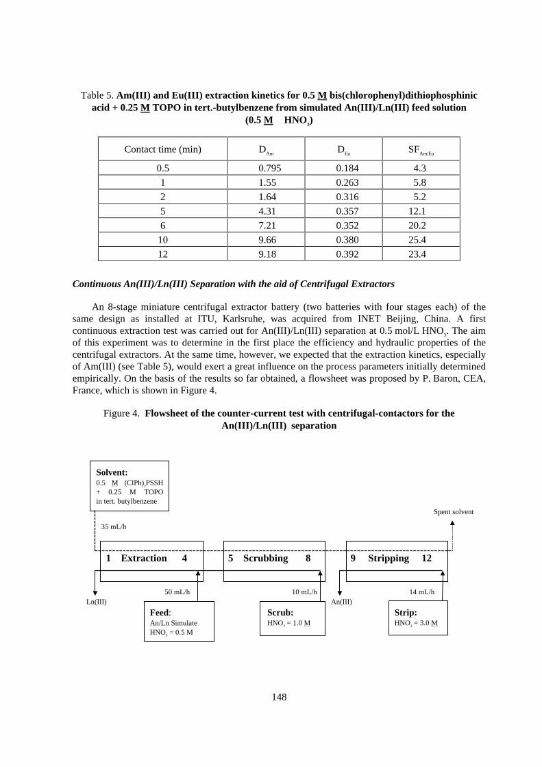
Table 5. Am(I I I ) and Eu(I I I ) extraction kinetics for 0.5 M bis(chlorophenyl)dithiophosphinicacid + 0.25 M TOPO in ter t.-butylbenzene from simulated An(I I I )/Ln(I I I ) feed solution
(0.5 M HNO3)
Contact time (min) DAm DEu SFAm/Eu
0.5 0.795 0.184 4.3
1 1.55 0.263 5.8
2 1.64 0.316 5.2
5 4.31 0.357 12.1
6 7.21 0.352 20.2
10 9.66 0.380 25.4
12 9.18 0.392 23.4
Continuous An(III)/Ln(III) Separation with the aid of Centrifugal Extractors
An 8-stage miniature centrifugal extractor battery (two batteries with four stages each) of thesame design as installed at ITU, Karlsruhe, was acquired from INET Beijing, China. A firstcontinuous extraction test was carried out for An(III)/Ln(III) separation at 0.5 mol/L HNO3. The aimof this experiment was to determine in the first place the efficiency and hydraulic properties of thecentrifugal extractors. At the same time, however, we expected that the extraction kinetics, especiallyof Am(III) (see Table 5), would exert a great influence on the process parameters initially determinedempirically. On the basis of the results so far obtained, a flowsheet was proposed by P. Baron, CEA,France, which is shown in Figure 4.
Figure 4. Flowsheet of the counter -cur rent test with centr ifugal-contactors for theAn(I I I )/Ln(I I I ) separation
Feed:An/Ln SimulateHNO3 = 0.5 M
Scrub:HNO3 = 1.0 M
Str ip:HNO3 = 3.0 M
Solvent:0.5 M (ClPh)2PSSH+ 0.25 M TOPOin tert. butylbenzene
1 Extraction 4 5 Scrubbing 8 9 Str ipping 12
35 mL/h
50 mL/h 10 mL/h 14 mL/hAn(III)Ln(III)
Spent solvent
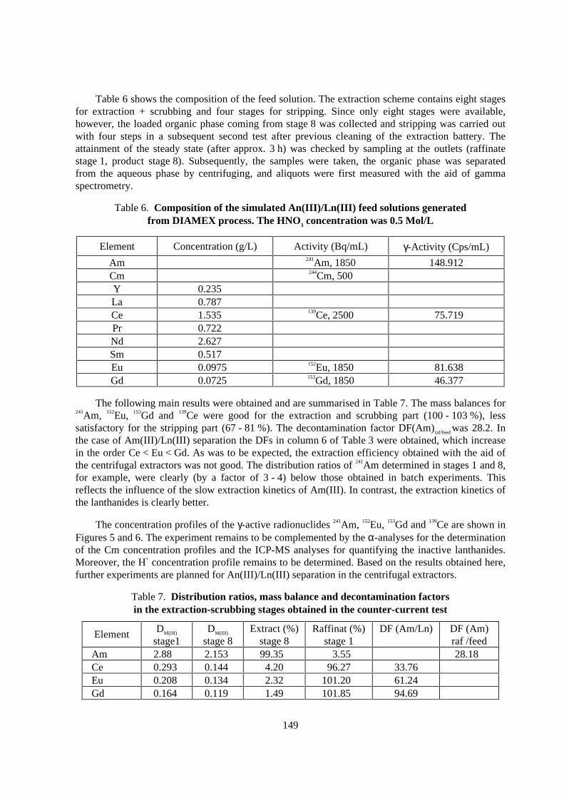
149
Table 6 shows the composition of the feed solution. The extraction scheme contains eight stagesfor extraction + scrubbing and four stages for stripping. Since only eight stages were available,however, the loaded organic phase coming from stage 8 was collected and stripping was carried outwith four steps in a subsequent second test after previous cleaning of the extraction battery. Theattainment of the steady state (after approx. 3 h) was checked by sampling at the outlets (raffinatestage 1, product stage 8). Subsequently, the samples were taken, the organic phase was separatedfrom the aqueous phase by centrifuging, and aliquots were first measured with the aid of gammaspectrometry.
Table 6. Composition of the simulated An(I I I )/Ln(I I I ) feed solutions generatedfrom DIAMEX process. The HNO3 concentration was 0.5 Mol/L
Element Concentration (g/L) Activity (Bq/mL) γ-Activity (Cps/mL)
Am 241Am, 1850 148.912Cm 244Cm, 500Y 0.235La 0.787Ce 1.535 139Ce, 2500 75.719Pr 0.722Nd 2.627Sm 0.517Eu 0.0975 152Eu, 1850 81.638Gd 0.0725 153Gd, 1850 46.377
The following main results were obtained and are summarised in Table 7. The mass balances for241Am, 152Eu, 153Gd and 139Ce were good for the extraction and scrubbing part (100 - 103 %), lesssatisfactory for the stripping part (67 - 81 %). The decontamination factor DF(Am)raf/feed was 28.2. Inthe case of Am(III)/Ln(III) separation the DFs in column 6 of Table 3 were obtained, which increasein the order Ce < Eu < Gd. As was to be expected, the extraction efficiency obtained with the aid ofthe centrifugal extractors was not good. The distribution ratios of 241Am determined in stages 1 and 8,for example, were clearly (by a factor of 3 - 4) below those obtained in batch experiments. Thisreflects the influence of the slow extraction kinetics of Am(III). In contrast, the extraction kinetics ofthe lanthanides is clearly better.
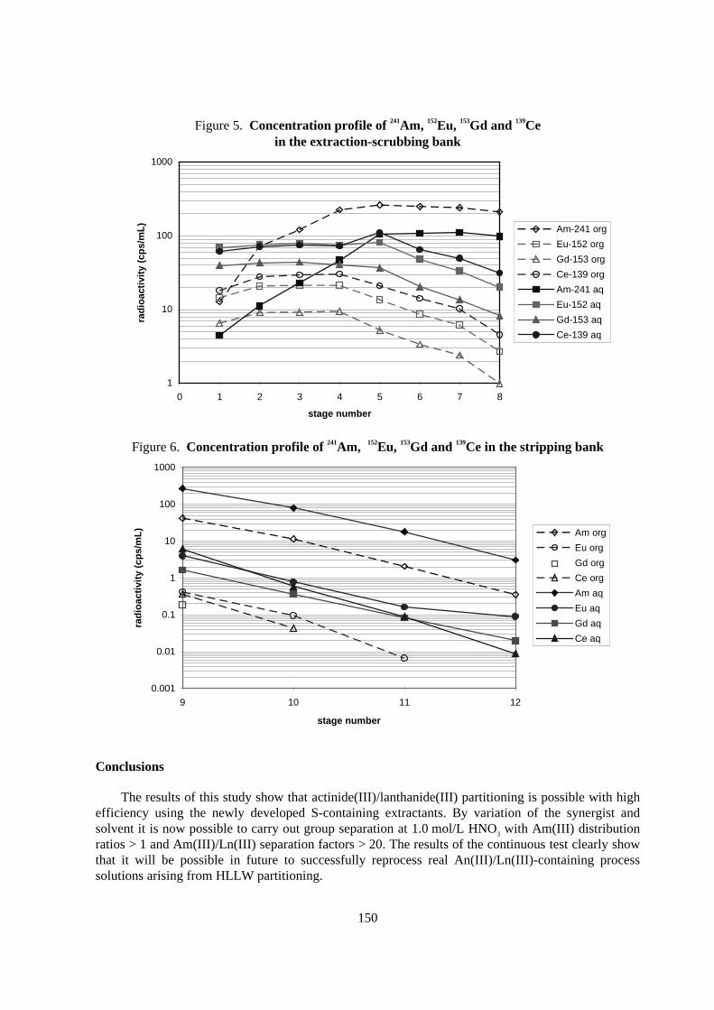
The concentration profiles of the γ-active radionuclides 241Am, 152Eu, 153Gd and 139Ce are shown inFigures 5 and 6. The experiment remains to be complemented by the α-analyses for the determinationof the Cm concentration profiles and the ICP-MS analyses for quantifying the inactive lanthanides.Moreover, the H+ concentration profile remains to be determined. Based on the results obtained here,further experiments are planned for An(III)/Ln(III) separation in the centrifugal extractors.
Table 7. Distr ibution ratios, mass balance and decontamination factorsin the extraction-scrubbing stages obtained in the counter -cur rent test
Element DM(III)
stage1DM(III)
stage 8Extract (%)
stage 8Raffinat (%)
stage 1DF (Am/Ln) DF (Am)
raf /feedAm 2.88 2.153 99.35 3.55 28.18Ce 0.293 0.144 4.20 96.27 33.76Eu 0.208 0.134 2.32 101.20 61.24Gd 0.164 0.119 1.49 101.85 94.69
150
Figure 5. Concentration profile of 241Am, 152Eu, 153Gd and 139Cein the extraction-scrubbing bank
1
10
100
1000
0 1 2 3 4 5 6 7 8
stage number
rad
ioac
tivi
ty (
cps/
mL
)
Am-241 org
Eu-152 org
Gd-153 org
Ce-139 org
Am-241 aq
Eu-152 aq
Gd-153 aq
Ce-139 aq
Figure 6. Concentration profile of 241Am, 152Eu, 153Gd and 139Ce in the str ipping bank
0.001
0.01
0.1
1
10
100
1000
9 10 11 12
stage number
rad
ioac
tivi
ty (
cps/
mL
) Am org
Eu org
Gd org
Ce org
Am aq
Eu aq
Gd aq
Ce aq
Conclusions
The results of this study show that actinide(III)/lanthanide(III) partitioning is possible with highefficiency using the newly developed S-containing extractants. By variation of the synergist andsolvent it is now possible to carry out group separation at 1.0 mol/L HNO3 with Am(III) distributionratios > 1 and Am(III)/Ln(III) separation factors > 20. The results of the continuous test clearly showthat it will be possible in future to successfully reprocess real An(III)/Ln(III)-containing processsolutions arising from HLLW partitioning.
151
Acknowledgements
This work was performed under EC Contract No. FI4I-CT96-0010. Financial support from theCommission of the European Communities is gratefully acknowledged. The authors would like tothank Mr. K. Scharf for assistance in preparation of the extractants.
REFERENCES
[1] Bush, A.L. Mills, M.L. Stearn, in Global 95, International Conference on Evaluation ofEmerging Nuclear Fuel Cycle Systems, Sept. 11-14, Versailles, France, 1995, p.232
[2] Zhu, J. Chen, R. Jiao, Solvent Extr. Ion Exch. 14 (1), (1996) 61.
[3] Modolo, R. Odoj, Influence of the Purity and Irradiation Stability of Cyanex 301 on theSeparation of Trivalent Actinides from Lanthanides by Solvent Extraction, J. Radioanal. Nucl.Chem., Vol. 228, Nos 1-2 (1998) 83-88.
[4] Modolo, R. Odoj, Selective Extraction of trivalent Actinides from Lanthanides withDithiophosphinic Acids,OECD NEA proccedings of the Workshop on Long-Lived RadionuclideChemistry in Nuclear Waste Treatment, Villeneuve-lès-Avignon, France, 18-20 June 1997,OECD (998) 197.
[5] Modolo, R. Odoj ,The Separation of Trivalent Actinides from Lanthanides by DithiophosphinicAcids from HNO3 Acid Medium, Actinides’97 Conference in Baden-Baden, Germany, 21-26 September 1997, Journal of Alloys and Compounds 271-273 (1998) 248-251.
[6] Modolo, R. Odoj , Synergistic Selective Extraction of Actinides(III) over lanthanides fromnitric acid using new aromatic Diorganyldithiophosphinic acids and neutralOrganophosphorus compounds, accepted for publication in Solvent Extraction and IonExchange, in press, Issue 1, Volume 17, January 1999.
153
INACTIVE DIAMEX TEST WITH THE OPTIMIZED EXTRACTION AGENT DMDOHEMA
I. Bisel, C. Nicol, M.C. Charbonnel, P. Blanc, P. BaronDCC/DRRV/SEMP, Commissariat à l’Energie Atomique, B.P. 171,
30207 Bagnols-sur-Cèze Cedex,France
F. BelnetDER/DEM, EDF, Centre des Renardières, B.P. 1
77250 Moret-sur-Loing,France
Abstract
In the frame of the development of the DIAMEX process, first studies including counter-current hottests were performed, with the DiMethyl-DiButylTetraDecylMAlonamide as reference extractant. Inparallel, the diamide formula has been optimised so that a new extractant was proposed: theDiMethylDiOctylHexylEthoxyMAlonamide. This new reference extractant was used in two inactiveflowsheets. The performances obtained were satisfying and confirmed the choice of DMDOHEMA asthe new reference extractant for the DIAMEX process
154
Introduction
As part of the SPIN program, the CEA has undertaken the development of the DIAMEX process,which uses diamide extractants to separate minor actinides from fission products in High LevelLiquid Waste. DIAMEX is the first step of the strategy adopted and leads to the coextraction ofactinides(III) and lanthanides(III). Actinide/lanthanide separation will be achieved by another specificprocess.
Preliminary counter-current hot tests had confirmed the feasibility of the concept with theDMDBTDMA (DiMethyl-DiButyl-TetraDecyl-MalonAmide) [1].
Then, two routes have been studied to prevent from zirconium and molybdenum extraction ; twoinactive flowsheets were performed with DMDBTDMA as extractant and finally oxalic scrubbingwas preferred [2].
In parallel, studies have then been undertaken to optimise the diamide formula, so thatperformances would be improved. Distribution coefficients of actinides and lanthanides(III) havebeen enhanced, third phase boudary occurs at higher acidities and metal concentrations anddegradation products are shorter and then easier to manage. Two inactive tests using mixer-settlerswere carried out in order to qualify the DIAMEX reference flow-sheet with the new proposedDiMethyl-DiOctyl-HexaEthoxy-MalonAmide molecule (DMDOHEMA).
The objectives of the first test were to check :
− The quantitative extraction of lanthanides (simulating actinides).
− The high values of the decontamination factors towards Zr and Mo.
− The high value of the decontamination factor towards Fe.
The objective of the second test was to study the behaviour of Ruthenium.
Flow-sheet elaboration
The “ reference flow-sheet” was adapted to the new organic solvent, thanks to the PAREX code.The possible improvements of the “ reference” flow-sheet using the DMDBTDMA were related to thebetter affinity of DMDOHEMA towards An(III) and Ln(III) :
− Decrease of nitric acidity in extraction and scrubbing sections (3 mol/L instead of3.5 mol/L), to prevent from iron extraction.
− Decrease of the organic/aqueous flowrate ratio, so that solvent consumption wasreduced.
In addition, concerning the stripping section, aqueous flowrate has been optimised (reduced), sothat “An, Ln product” is recovered more concentrated.
The flow-sheet tested is presented in figure 1.
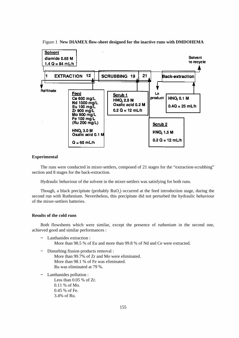
155
Figure 1 New DIAMEX flow-sheet designed for the inactive runs with DMDOHEMA
Exper imental
The runs were conducted in mixer-settlers, composed of 21 stages for the “extraction-scrubbing”section and 8 stages for the back-extraction.
Hydraulic behaviour of the solvent in the mixer-settlers was satisfying for both runs.
Though, a black precipitate (probably RuO2) occurred at the feed introduction stage, during thesecond run with Ruthenium. Nevertheless, this precipitate did not perturbed the hydraulic behaviourof the mixer-settlers batteries.
Results of the cold runs
Both flowsheets which were similar, except the presence of ruthenium in the second one,achieved good and similar performances :
− Lanthanides extraction :More than 98.5 % of Eu and more than 99.8 % of Nd and Ce were extracted.
− Disturbing fission products removal :More than 99.7% of Zr and Mo were eliminated.More than 98.1 % of Fe was eliminated.Ru was eliminated at 79 %.
− Lanthanides pollution :Less than 0.05 % of Zr.0.11 % of Mo.0.45 % of Fe.3.4% of Ru.
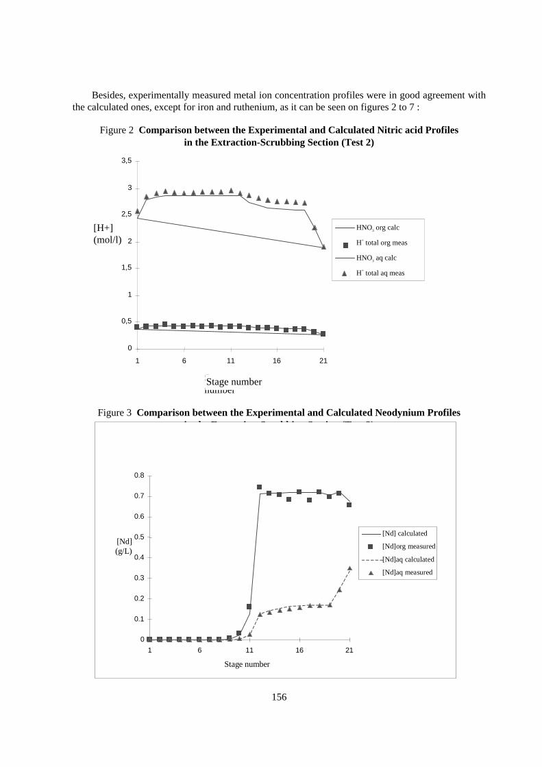
156
Besides, experimentally measured metal ion concentration profiles were in good agreement withthe calculated ones, except for iron and ruthenium, as it can be seen on figures 2 to 7 :
Figure 2 Compar ison between the Exper imental and Calculated Nitr ic acid Profilesin the Extraction-Scrubbing Section (Test 2)
Figure 3 Compar ison between the Exper imental and Calculated Neodynium Profilesin the Extraction-Scrubbing Section (Test 2)
0
0.1
0.2
0.3
0.4
0.5
0.6
0.7
0.8
1 6 11 16 21
Stage number
[Nd](g/L)
[Nd] calculated
[Nd]org measured
[Nd]aq calculated
[Nd]aq measured
0
0,5
1
1,5
2
2,5
3
3,5
1 6 11 16 21
Stagenumber
[H+](mol/l)
HNO3 org calc
H+ total org meas
HNO3 aq calc
H+ total aq meas
Stage number
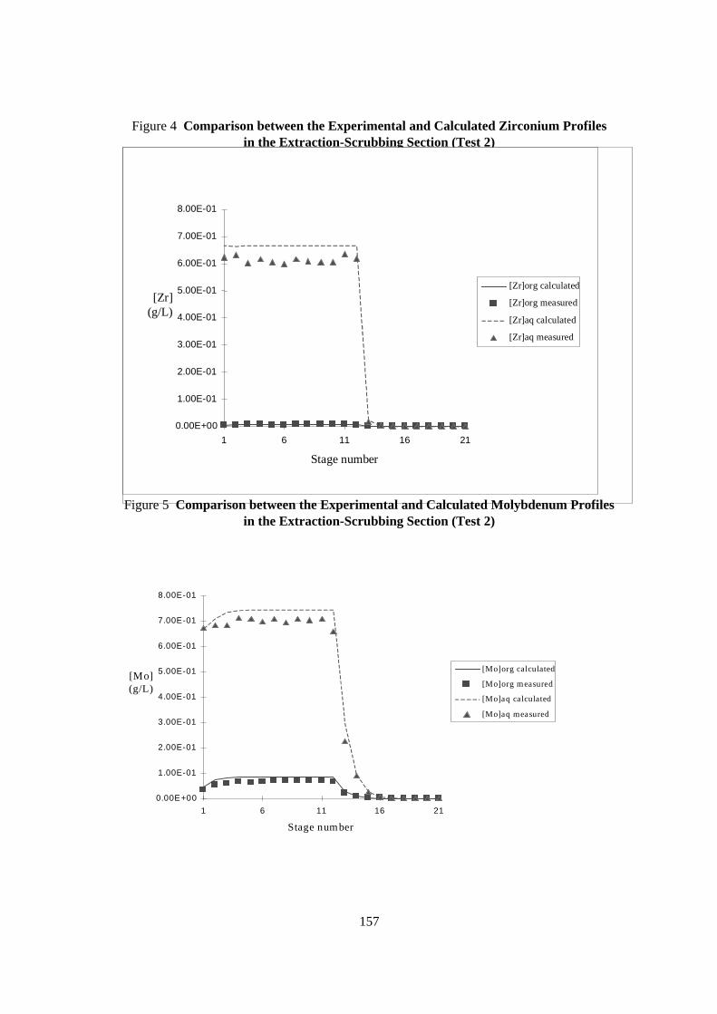
157
Figure 4 Compar ison between the Exper imental and Calculated Zirconium Profilesin the Extraction-Scrubbing Section (Test 2)
0.00E+00
1.00E-01
2.00E-01
3.00E-01
4.00E-01
5.00E-01
6.00E-01
7.00E-01
8.00E-01
1 6 11 16 21
Stage number
[Zr](g/L)
[Zr]org calculated
[Zr]org measured
[Zr]aq calculated
[Zr]aq measured
Figure 5 Compar ison between the Exper imental and Calculated Molybdenum Profiles in the Extraction-Scrubbing Section (Test 2)
0.00E+00
1.00E-01
2.00E-01
3.00E-01
4.00E-01
5.00E-01
6.00E-01
7.00E-01
8.00E-01
1 6 11 16 21
Stage number
[M o](g/L )
[M o]org calculated
[M o]org measured
[M o]aq calculated
[M o]aq measured
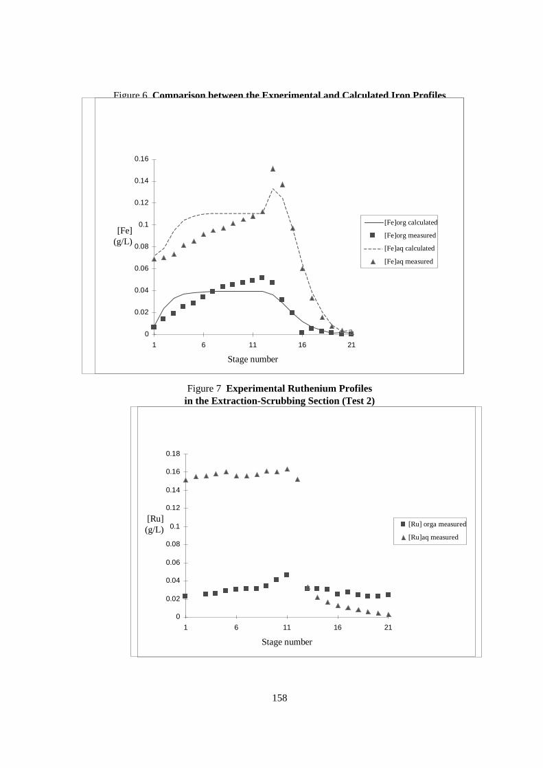
158
Figure 6 Compar ison between the Exper imental and Calculated I ron Profilesin the Extraction-Scrubbing Section (Test 2)
0
0.02
0.04
0.06
0.08
0.1
0.12
0.14
0.16
1 6 11 16 21
Stage number
[Fe](g/L)
[Fe]org calculated
[Fe]org measured
[Fe]aq calculated
[Fe]aq measured
Figure 7 Exper imental Ruthenium Profilesin the Extraction-Scrubbing Section (Test 2)
0
0.02
0.04
0.06
0.08
0.1
0.12
0.14
0.16
0.18
1 6 11 16 21
Stage number
[Ru](g/L)
[Ru] orga measured
[Ru]aq measured
159
Conclusion
The inactive runs enabled us to confirm the choice of DMDOHEMA as a new extracting agentfor the DIAMEX process, because :
− The hydrolytic behaviour was correct,
− The performances regarding lanthanides extraction were excellent and as good as thoseobtained with DMDBTDMA.
− The elimination of Zirconium was quantitative as with DMDBTDMA.
− The elimination of both Molybdenum and Iron was improved :
- 99.7 % for Molybdenum (to be compared to 95 % for DMDBTDMA)
- 98.1 % for Iron (to be compared to 27 % for DMDBTDMA)
− The efficiency to remove ruthenium was encouraging ; it is better than in the case of the runperformed in the CYRANO hot cell (50 % of Ru only were eliminated in the CYRANO run,whereas 79 % of Ru were eliminated in these runs).
Nevertheless, these runs have also shown that the chemistry of Iron, and most of all that ofRuthenium, still had to be investigated and our knowledge deepened, because a good simulation oftheir chemical behaviour was not yet obtained for synthetic solutions.
Acknowledgements
This work was partially financed by the EC-Contract N.FI4I-CT96-0010. Our grateful thanks to theCommission of the European Communities.
REFERENCES
[1] C. Madic, P. Blanc, N. Condamines, P. Baron, L. Berthon, C. Nicol, C. Pozo, M. Lecomte,M. Philippe, M. Masson, C. Hequet, M.J. Hudson, RECOD ’94, 24-28 April, LONDON UK.
[2] P. Baron, L. Berthon, M.C. Charbonnel, C. Nicol, GLOBAL ’97, 5-10 October, YOKOHAMA,Japan.

161
DEVELOPMENT OF THE SESAME PROCESS
L. Donnet, J. M. Adnet, N. Faure, P. Bros, Ph. Brossard, F. JossoCE/Valrho/Marcoule, CEA/DCC/DRRV/SPHA, BP 171
30207 Bagnols-sur-Cèze CedexFrance
Abstract
The main goal of the SPIN program developed by CEA is to improve the management of high activitywaste containing minor actinides and long-lived fission products. In that field, americium has beenpointed out as the main hazardous element to be firstly recovered. With the aim to extract more than99% of the americium contained in high level liquid waste (HLLW), the SESAME process, whichconsists in the selective extraction of oxidised Am, is foreseen as a promising way to succeed in Ammanagement. Dealing with the americium selective recovery from HLLW, many studies concerningthe electrochemical oxidation of Am to its hexavalent state in the presence of lacunary polyanionicligands (LHPA) have been carried out. The main results of several laboratory scale tests of theSESAME process are presented and the further process development is discussed.
162
Introduction
As a part of the SPIN program launched by CEA, ACTINEX program is more precisely devotedto the definition of new processes for minor actinides and long-lived fission products recovery fromHLLW. Among minor actinides, americium has been defined as the prior element to recover. In thatfield, SESAME process has been proposed to remove selectively americium from high activity liquideffluents. This process is based on the electrochemical oxidation of Am(III) to oxidation state (IV) or(VI) followed by the selective extraction of oxidised Am [1]. This process is especially interesting asit is not concerned with the actinide(III) to lanthanide(III) group separation.
Three possibilities exist to apply SESAME at the backend of the PUREX process. The simpler isthe solution to treat, the easier the SESAME process is to implement. Thus, when going fromSESAME A to SESAME C, the difficulty to remove Am from the solution increases. When dealingwith SESAME C, many interfering elements have to be managed and Ru, Mo, Zr, Cs are the mosttroublesome ones for Am oxidation in the presence of LHPA.
If americium is coming from the stripping solution of DIAMEX process, many interferingelements have been removed and Am oxidation is easy to achieve.
This way corresponding to SESAME B, has been selected as the reference scheme and has beenrecently described2. The main steps of that scheme are listed below:
− Concentration of the DIAMEX stripping solution to increase the acidity of the solution to ca[HNO3] = 5 M.
− Electrochemical oxidation of Ce(III) to Ce(IV) and extraction of Ce(IV) with TBP.
− Electrolysis of the solution after adjustment of the LHPA and AgNO3 concentrations.
− Extraction of Am(VI) by TBP using a solvent extraction technique (centrifugal contactors).
− Recovery of the silver mediator using an electrodeposition technique (H2O2 is used as anantinitrite agent).
This paper is essentially focused on the R&D studies concerning the Am(III) to Am(VI)electrochemical oxidation mechanism and results dealing with the solvent extraction of Am(VI).
Electrochemical oxidation of Am(I I I ) to Am(VI)
The electrochemical oxidation of Am(III) in nitric media is well known and has been describedin several papers [1,5]. The quantitative oxidation can be carry out using complexants such aslacunary heteropolyanions which are specific for tetravalent species.
The stability constants of Am(III) and Am(IV) complexes with the relevant LHPA have beendescribed by [6,8] and presented in Table 1.
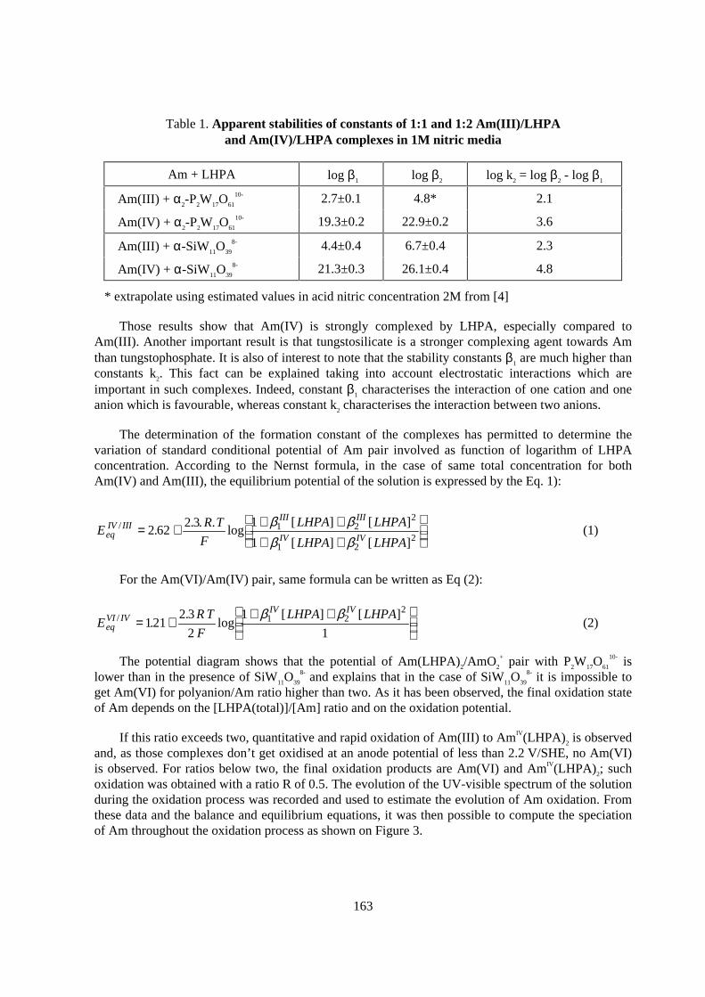
163
Table 1. Apparent stabilities of constants of 1:1 and 1:2 Am(I I I )/LHPAand Am(IV)/LHPA complexes in 1M nitr ic media
Am + LHPA log β1 log β2 log k2 = log β2 - log β1
Am(III) + α2-P2W17O61
10- 2.7±0.1 4.8* 2.1
Am(IV) + α2-P2W17O61
10- 19.3±0.2 22.9±0.2 3.6
Am(III) + α-SiW11O39
8- 4.4±0.4 6.7±0.4 2.3
Am(IV) + α-SiW11O39
8- 21.3±0.3 26.1±0.4 4.8
* extrapolate using estimated values in acid nitric concentration 2M from [4]
Those results show that Am(IV) is strongly complexed by LHPA, especially compared toAm(III). Another important result is that tungstosilicate is a stronger complexing agent towards Amthan tungstophosphate. It is also of interest to note that the stability constants β1 are much higher thanconstants k2. This fact can be explained taking into account electrostatic interactions which areimportant in such complexes. Indeed, constant β1 characterises the interaction of one cation and oneanion which is favourable, whereas constant k2 characterises the interaction between two anions.
The determination of the formation constant of the complexes has permitted to determine thevariation of standard conditional potential of Am pair involved as function of logarithm of LHPAconcentration. According to the Nernst formula, in the case of same total concentration for bothAm(IV) and Am(III), the equilibrium potential of the solution is expressed by the Eq. 1):
ER T
F
LHPA LHPA
LHPA LHPAeqIV III
III III
IV IV/ .
. . .log
[ ] [ ]
[ ] [ ]= + + +
+ +
262
23 1
11 2
2
1 22
β ββ β
(1)
For the Am(VI)/Am(IV) pair, same formula can be written as Eq (2):
ERT
F
LHPA LHPAeqVI IV
IV IV/ .
.log
[ ] [ ]= +
+ +
121
23
2
1
11 2
2β β(2)
The potential diagram shows that the potential of Am(LHPA)2/AmO2
+ pair with P2W17O61
10- islower than in the presence of SiW11O39
8- and explains that in the case of SiW11O39
8- it is impossible toget Am(VI) for polyanion/Am ratio higher than two. As it has been observed, the final oxidation stateof Am depends on the [LHPA(total)]/[Am] ratio and on the oxidation potential.
If this ratio exceeds two, quantitative and rapid oxidation of Am(III) to AmIV(LHPA)2 is observedand, as those complexes don’ t get oxidised at an anode potential of less than 2.2 V/SHE, no Am(VI)is observed. For ratios below two, the final oxidation products are Am(VI) and AmIV(LHPA)2; suchoxidation was obtained with a ratio R of 0.5. The evolution of the UV-visible spectrum of the solutionduring the oxidation process was recorded and used to estimate the evolution of Am oxidation. Fromthese data and the balance and equilibrium equations, it was then possible to compute the speciationof Am throughout the oxidation process as shown on Figure 3.
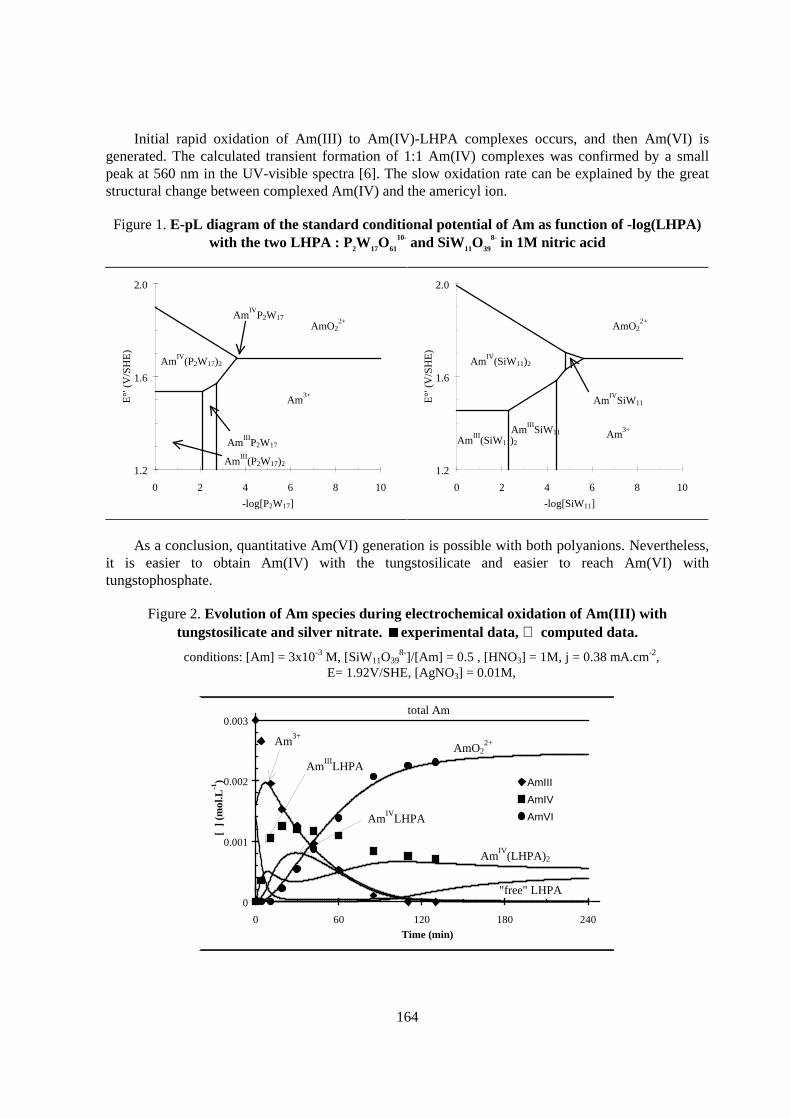
164
Initial rapid oxidation of Am(III) to Am(IV)-LHPA complexes occurs, and then Am(VI) isgenerated. The calculated transient formation of 1:1 Am(IV) complexes was confirmed by a smallpeak at 560 nm in the UV-visible spectra [6]. The slow oxidation rate can be explained by the greatstructural change between complexed Am(IV) and the americyl ion.
Figure 1. E-pL diagram of the standard conditional potential of Am as function of -log(LHPA)with the two LHPA : P2W17O61
10- and SiW11O39
8- in 1M nitr ic acid
1.2
1.6
2.0
0 2 4 6 8 10
-log[P2W17]
E°'
(V
/SH
E)
Am3+
AmIII
P2W17
AmIV
(P2W17)2
AmIV
P2W17AmO2
2+
AmIII
(P2W17)21.2
1.6
2.0
0 2 4 6 8 10
-log[SiW11]
E°'
(V
/SH
E)
AmIII
SiW11
AmIV
(SiW11)2
AmIV
SiW11
AmO22+
AmIII
(SiW11)2Am
3+
As a conclusion, quantitative Am(VI) generation is possible with both polyanions. Nevertheless,it is easier to obtain Am(IV) with the tungstosilicate and easier to reach Am(VI) withtungstophosphate.
Figure 2. Evolution of Am species dur ing electrochemical oxidation of Am(I I I ) withtungstosilicate and silver nitrate.
exper imental data, computed data.
conditions: [Am] = 3x10⁻³ M, [SiW11O398-]/[Am] = 0.5 , [HNO3] = 1M, j = 0.38 mA.cm-2,
E= 1.92V/SHE, [AgNO3] = 0.01M,
0
0.001
0.002
0.003
0 60 120 180 240
Time (min)
[ ]
(m
ol.L
-1) AmIII
AmIV
AmVI
AmO22+Am
3+
AmIII
LHPA
AmIV
LHPA
AmIV
(LHPA)2
"free" LHPA
total Am
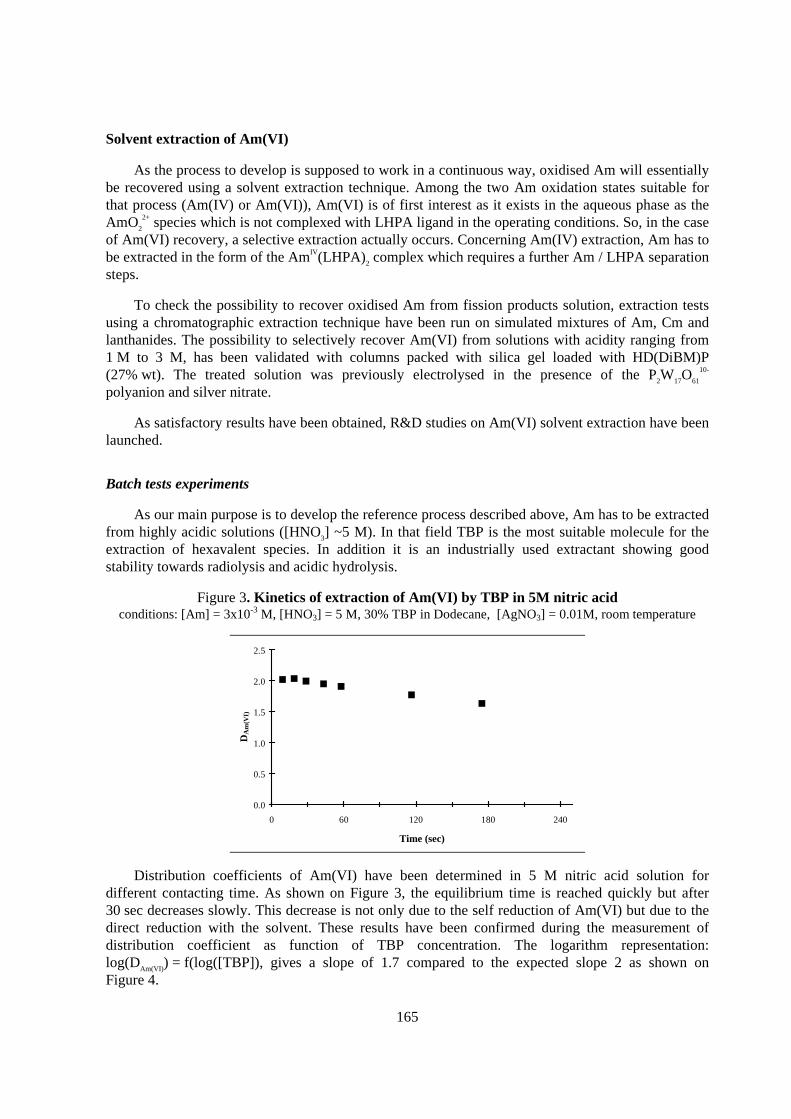
165
Solvent extraction of Am(VI)
As the process to develop is supposed to work in a continuous way, oxidised Am will essentiallybe recovered using a solvent extraction technique. Among the two Am oxidation states suitable forthat process (Am(IV) or Am(VI)), Am(VI) is of first interest as it exists in the aqueous phase as theAmO2
2+ species which is not complexed with LHPA ligand in the operating conditions. So, in the caseof Am(VI) recovery, a selective extraction actually occurs. Concerning Am(IV) extraction, Am has tobe extracted in the form of the AmIV(LHPA)2 complex which requires a further Am / LHPA separationsteps.
To check the possibility to recover oxidised Am from fission products solution, extraction testsusing a chromatographic extraction technique have been run on simulated mixtures of Am, Cm andlanthanides. The possibility to selectively recover Am(VI) from solutions with acidity ranging from1 M to 3 M, has been validated with columns packed with silica gel loaded with HD(DiBM)P(27% wt). The treated solution was previously electrolysed in the presence of the P2W17O61
10-
polyanion and silver nitrate.
As satisfactory results have been obtained, R&D studies on Am(VI) solvent extraction have beenlaunched.
Batch tests experiments
As our main purpose is to develop the reference process described above, Am has to be extractedfrom highly acidic solutions ([HNO3] ~5 M). In that field TBP is the most suitable molecule for theextraction of hexavalent species. In addition it is an industrially used extractant showing goodstability towards radiolysis and acidic hydrolysis.
Figure 3. K inetics of extraction of Am(VI) by TBP in 5M nitr ic acidconditions: [Am] = 3x10⁻³ M, [HNO3] = 5 M, 30% TBP in Dodecane, [AgNO3] = 0.01M, room temperature
0.0
0.5
1.0
1.5
2.0
2.5
0 60 120 180 240
Time (sec)
DA
m(V
I)
Distribution coefficients of Am(VI) have been determined in 5 M nitric acid solution fordifferent contacting time. As shown on Figure 3, the equilibrium time is reached quickly but after30 sec decreases slowly. This decrease is not only due to the self reduction of Am(VI) but due to thedirect reduction with the solvent. These results have been confirmed during the measurement ofdistribution coefficient as function of TBP concentration. The logarithm representation:log(DAm(VI)) = f(log([TBP]), gives a slope of 1.7 compared to the expected slope 2 as shown onFigure 4.
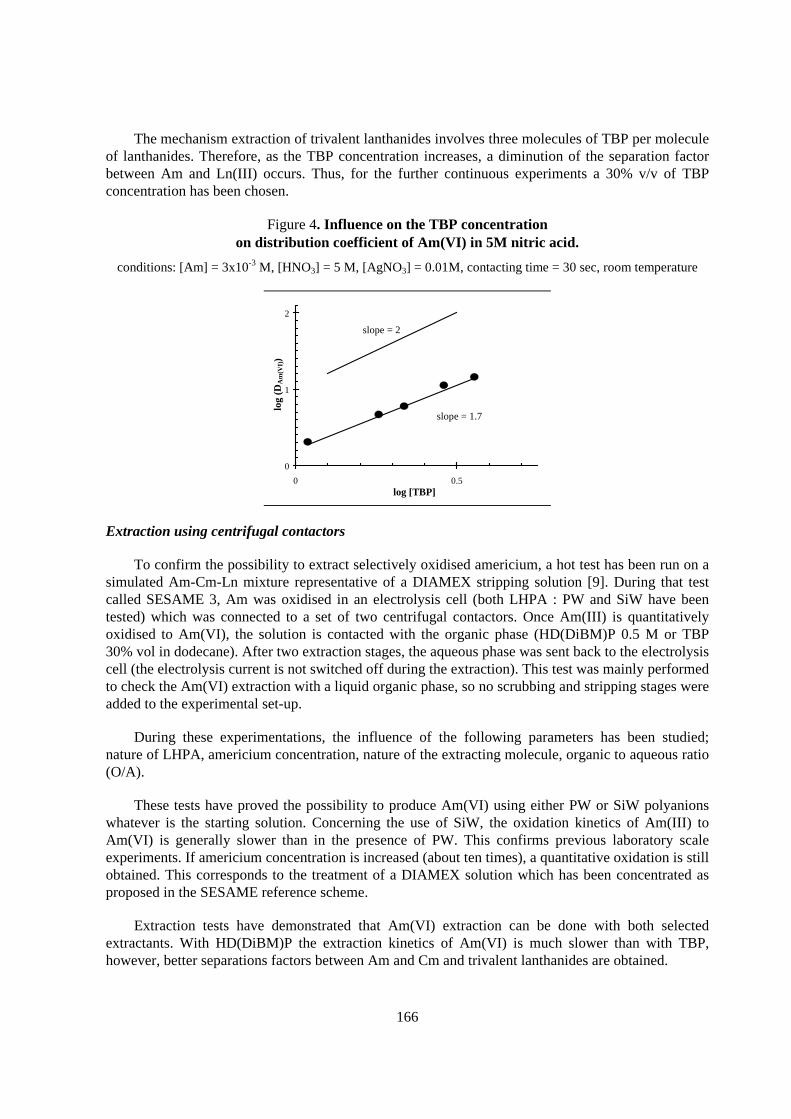
166
The mechanism extraction of trivalent lanthanides involves three molecules of TBP per moleculeof lanthanides. Therefore, as the TBP concentration increases, a diminution of the separation factorbetween Am and Ln(III) occurs. Thus, for the further continuous experiments a 30% v/v of TBPconcentration has been chosen.
Figure 4. Influence on the TBP concentrationon distr ibution coefficient of Am(VI) in 5M nitr ic acid.
conditions: [Am] = 3x10⁻³ M, [HNO3] = 5 M, [AgNO3] = 0.01M, contacting time = 30 sec, room temperature
slope = 1.7
0
1
2
0 0.5log [TBP]
log
(DA
m(V
I))
slope = 2
Extraction using centrifugal contactors
To confirm the possibility to extract selectively oxidised americium, a hot test has been run on asimulated Am-Cm-Ln mixture representative of a DIAMEX stripping solution [9]. During that testcalled SESAME 3, Am was oxidised in an electrolysis cell (both LHPA : PW and SiW have beentested) which was connected to a set of two centrifugal contactors. Once Am(III) is quantitativelyoxidised to Am(VI), the solution is contacted with the organic phase (HD(DiBM)P 0.5 M or TBP30% vol in dodecane). After two extraction stages, the aqueous phase was sent back to the electrolysiscell (the electrolysis current is not switched off during the extraction). This test was mainly performedto check the Am(VI) extraction with a liquid organic phase, so no scrubbing and stripping stages wereadded to the experimental set-up.
During these experimentations, the influence of the following parameters has been studied;nature of LHPA, americium concentration, nature of the extracting molecule, organic to aqueous ratio(O/A).
These tests have proved the possibility to produce Am(VI) using either PW or SiW polyanionswhatever is the starting solution. Concerning the use of SiW, the oxidation kinetics of Am(III) toAm(VI) is generally slower than in the presence of PW. This confirms previous laboratory scaleexperiments. If americium concentration is increased (about ten times), a quantitative oxidation is stillobtained. This corresponds to the treatment of a DIAMEX solution which has been concentrated asproposed in the SESAME reference scheme.
Extraction tests have demonstrated that Am(VI) extraction can be done with both selectedextractants. With HD(DiBM)P the extraction kinetics of Am(VI) is much slower than with TBP,however, better separations factors between Am and Cm and trivalent lanthanides are obtained.
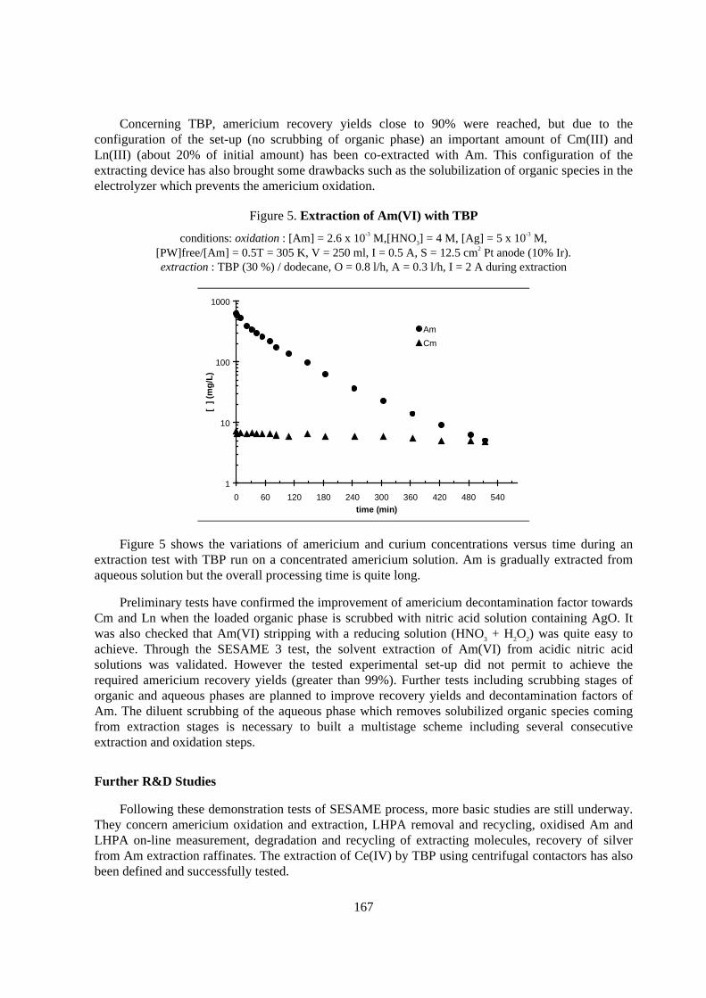
167
Concerning TBP, americium recovery yields close to 90% were reached, but due to theconfiguration of the set-up (no scrubbing of organic phase) an important amount of Cm(III) andLn(III) (about 20% of initial amount) has been co-extracted with Am. This configuration of theextracting device has also brought some drawbacks such as the solubilization of organic species in theelectrolyzer which prevents the americium oxidation.
Figure 5. Extraction of Am(VI) with TBP
conditions: oxidation : [Am] = 2.6 x 10⁻³ M,[HNO3] = 4 M, [Ag] = 5 x 10⁻³ M,[PW]free/[Am] = 0.5T = 305 K, V = 250 ml, I = 0.5 A, S = 12.5 cm2 Pt anode (10% Ir).extraction : TBP (30 %) / dodecane, O = 0.8 l/h, A = 0.3 l/h, I = 2 A during extraction
1
10
100
1000
0 60 120 180 240 300 360 420 480 540time (min)
[ ]
(m
g/L
)
Am
Cm
Figure 5 shows the variations of americium and curium concentrations versus time during anextraction test with TBP run on a concentrated americium solution. Am is gradually extracted fromaqueous solution but the overall processing time is quite long.
Preliminary tests have confirmed the improvement of americium decontamination factor towardsCm and Ln when the loaded organic phase is scrubbed with nitric acid solution containing AgO. Itwas also checked that Am(VI) stripping with a reducing solution (HNO3 + H2O2) was quite easy toachieve. Through the SESAME 3 test, the solvent extraction of Am(VI) from acidic nitric acidsolutions was validated. However the tested experimental set-up did not permit to achieve therequired americium recovery yields (greater than 99%). Further tests including scrubbing stages oforganic and aqueous phases are planned to improve recovery yields and decontamination factors ofAm. The diluent scrubbing of the aqueous phase which removes solubilized organic species comingfrom extraction stages is necessary to built a multistage scheme including several consecutiveextraction and oxidation steps.
Fur ther R& D Studies
Following these demonstration tests of SESAME process, more basic studies are still underway.They concern americium oxidation and extraction, LHPA removal and recycling, oxidised Am andLHPA on-line measurement, degradation and recycling of extracting molecules, recovery of silverfrom Am extraction raffinates. The extraction of Ce(IV) by TBP using centrifugal contactors has alsobeen defined and successfully tested.
168
A new hot cell experiment using benches of centrifugal contactors is planned in the beginning ofnext year. It consists in the test of separation scheme including extraction, scrubbing and strippingsteps. A diluent scrubbing of the raffinate will be added to enhance the electrochemical oxidationefficiency of further stages. Results of these experiments will allow to implement the separationflowsheet achieving the required performances.
Conclusion
The feasibility demonstration of SESAME principle is now achieved. Much attention is still tobe paid on the extraction of Am(VI) which needs to be improved. Next hot tests should involve amore complete separation scheme as proposed in the reference scheme and take into account the mainobservations of SESAME 3 test. Especially, no extraction loop is expected to be used. Other studiesconcerning the alternative route (extraction of Am(IV)) are also underway but to a lesser extent.
REFERENCES
[1] J.M. Adnet, L. Donnet, Ph. Brossard and J. Bourges, US Patent N°5609, 11 March 1997.
[2] J.M. Adnet, L. Donnet, N. Faure, P. Bros, Ph. Brossard and F. Josso, Proceedings ofRECOD’98, Nice, 1998.
[3] M.S. Milyukova, M.N. Litvina, B.F. Myasoedov, Radiokhimya, 25, 1983.
[4] J.M. Adnet, Thesis, Rapport CEA-R-5615, 1992.
[5] A.S. Saprykin, V.P. Shilov, V.I. Spitsyn, N.N. Krot, Dokl. Akad. Nauk SSSR, 226(4), 1976.
[6] J.M. Adnet, L. Donnet, D. Chartier, N. Faure, P. Bros, Ph. Brossard, Proceedings of OECDNEA workshop, Villeneuve-lès-Avignon, 1996.
[7] D. Chartier, L. Donnet and J.M. Adnet, submitted.
[8] D. Chartier, L. Donnet and J.M. Adnet, Radiochimica Acta, accepted NS-122.
[9] C. Madic, P. Blanc, N. Condamines, P. Baron, L. Berthon, C. Nicol, C. Pozzo, M. Lecomte,M. Philippe, M. Masson, C. Hecquet, M.J. Hudson, Proceedings of RECOD’94, London, 1994.
169
ESTIMATION OF MATERIAL BALANCE IN PYROMETALLURGICALPARTITIONING PROCESS FOR TRUs FROM HLLW
Kensuke K inoshita, Masaki Kurata, Koichi Uozumi, and Tadashi InoueCentral Research Institute of Electric Power Industry (CRIEPI)
Komae-shi, Tokyo 201-8511Japan
Abstract
A pyrometallurgical partitioning process has been proposed and studied by CRIEPI. In this process,more than 98% of alkali metals were separated in a denitration step. Almost all of the anotherelements were converted to chlorides from oxides in a chlorination step. Separation experiments bymeans of multiple batch extraction was also carried out in the LiCl-KCl/Bi system, and more than99% of each TRU was recovered. The material balance of solutes and solvents in the partitioningprocess was estimated from the experimental results of each step in the process. The refining salt, Cd,Bi, and Pb as solvent, Li as reductant, and generated chlorine gas can be recycled to the process. Thisprocess is, therefore, expected to generate less secondary radioactive waste in comparison with anaqueous process and should require relatively compact facilities.
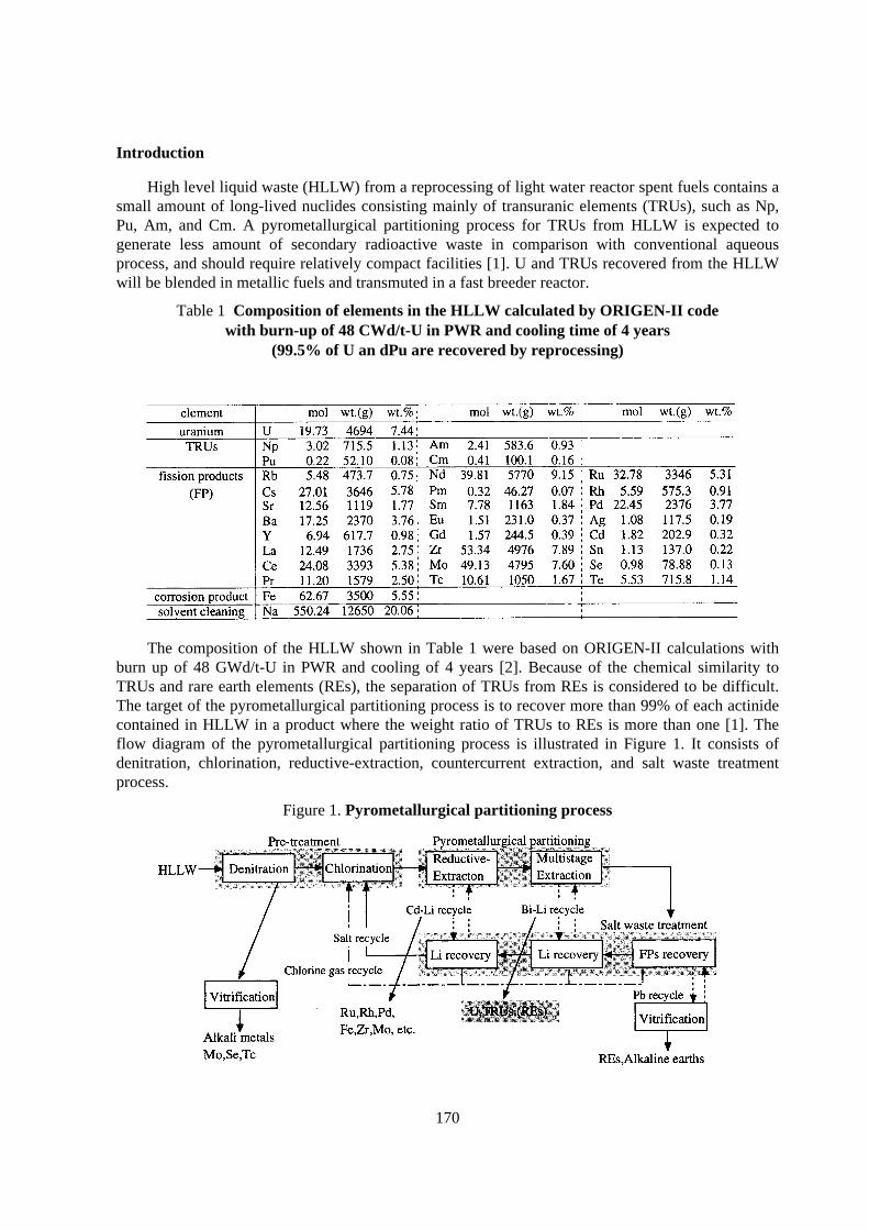
170
Introduction
High level liquid waste (HLLW) from a reprocessing of light water reactor spent fuels contains asmall amount of long-lived nuclides consisting mainly of transuranic elements (TRUs), such as Np,Pu, Am, and Cm. A pyrometallurgical partitioning process for TRUs from HLLW is expected togenerate less amount of secondary radioactive waste in comparison with conventional aqueousprocess, and should require relatively compact facilities [1]. U and TRUs recovered from the HLLWwill be blended in metallic fuels and transmuted in a fast breeder reactor.
Table 1 Composition of elements in the HLLW calculated by ORIGEN-I I codewith burn-up of 48 CWd/t-U in PWR and cooling time of 4 years
(99.5% of U an dPu are recovered by reprocessing)
The composition of the HLLW shown in Table 1 were based on ORIGEN-II calculations withburn up of 48 GWd/t-U in PWR and cooling of 4 years [2]. Because of the chemical similarity toTRUs and rare earth elements (REs), the separation of TRUs from REs is considered to be difficult.The target of the pyrometallurgical partitioning process is to recover more than 99% of each actinidecontained in HLLW in a product where the weight ratio of TRUs to REs is more than one [1]. Theflow diagram of the pyrometallurgical partitioning process is illustrated in Figure 1. It consists ofdenitration, chlorination, reductive-extraction, countercurrent extraction, and salt waste treatmentprocess.
Figure 1. Pyrometallurgical par titioning process
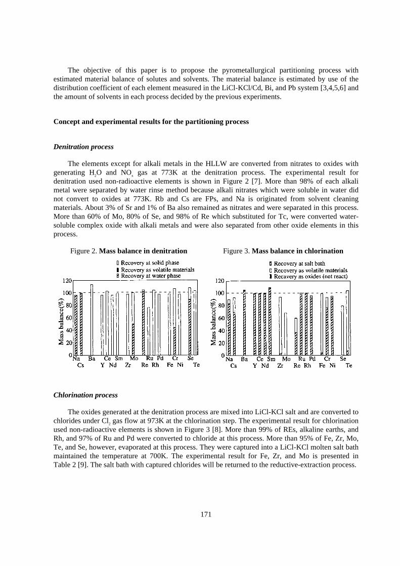
171
The objective of this paper is to propose the pyrometallurgical partitioning process withestimated material balance of solutes and solvents. The material balance is estimated by use of thedistribution coefficient of each element measured in the LiCl-KCl/Cd, Bi, and Pb system [3,4,5,6] andthe amount of solvents in each process decided by the previous experiments.
Concept and exper imental results for the par titioning process
Denitration process
The elements except for alkali metals in the HLLW are converted from nitrates to oxides withgenerating H2O and NOx gas at 773K at the denitration process. The experimental result fordenitration used non-radioactive elements is shown in Figure 2 [7]. More than 98% of each alkalimetal were separated by water rinse method because alkali nitrates which were soluble in water didnot convert to oxides at 773K. Rb and Cs are FPs, and Na is originated from solvent cleaningmaterials. About 3% of Sr and 1% of Ba also remained as nitrates and were separated in this process.More than 60% of Mo, 80% of Se, and 98% of Re which substituted for Tc, were converted water-soluble complex oxide with alkali metals and were also separated from other oxide elements in thisprocess.
Figure 2. Mass balance in denitration Figure 3. Mass balance in chlor ination
Chlorination process
The oxides generated at the denitration process are mixed into LiCl-KCl salt and are converted tochlorides under Cl2 gas flow at 973K at the chlorination step. The experimental result for chlorinationused non-radioactive elements is shown in Figure 3 [8]. More than 99% of REs, alkaline earths, andRh, and 97% of Ru and Pd were converted to chloride at this process. More than 95% of Fe, Zr, Mo,Te, and Se, however, evaporated at this process. They were captured into a LiCl-KCl molten salt bathmaintained the temperature at 700K. The experimental result for Fe, Zr, and Mo is presented inTable 2 [9]. The salt bath with captured chlorides will be returned to the reductive-extraction process.
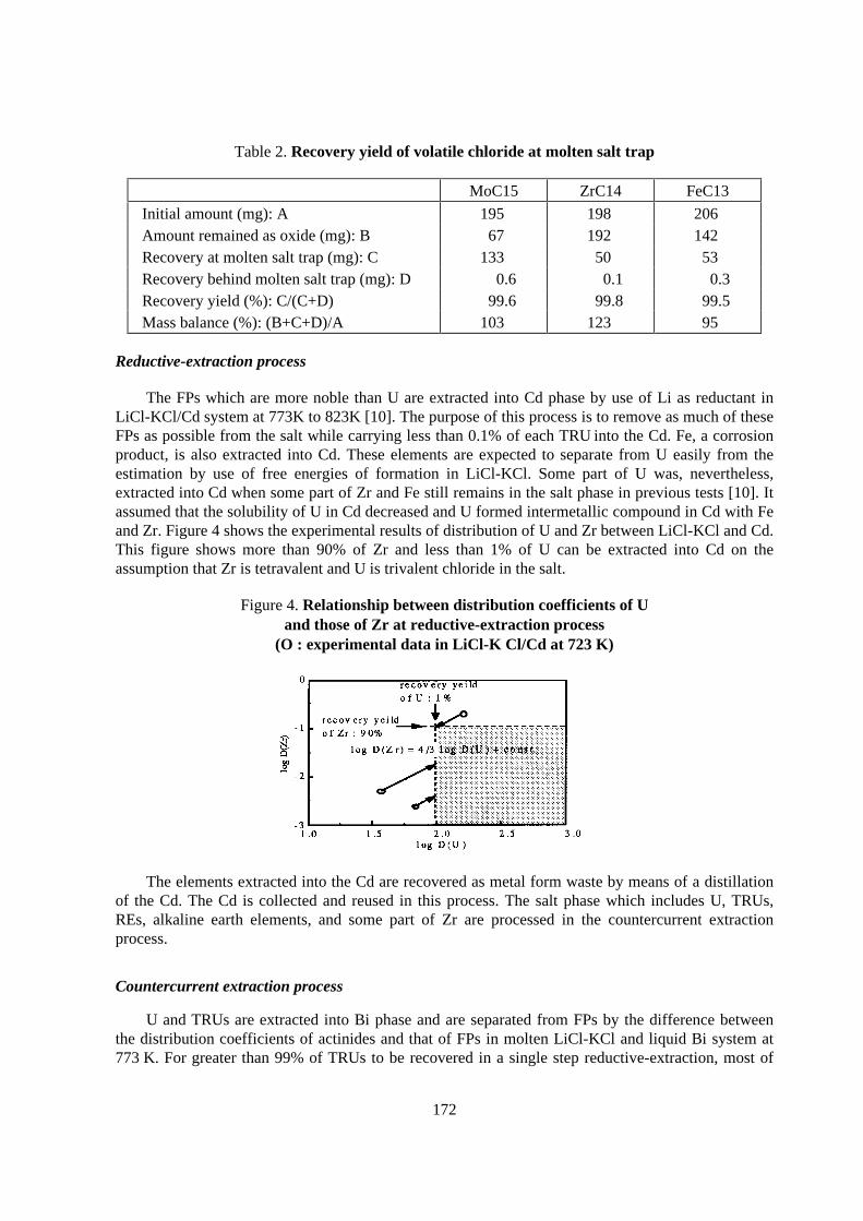
172
Table 2. Recovery yield of volatile chlor ide at molten salt trap
MoC15 ZrC14 FeC13
Initial amount (mg): A 195 198 206Amount remained as oxide (mg): B 67 192 142Recovery at molten salt trap (mg): C 133 50 53Recovery behind molten salt trap (mg): D 0.6 0.1 0.3Recovery yield (%): C/(C+D) 99.6 99.8 99.5Mass balance (%): (B+C+D)/A 103 123 95
Reductive-extraction process
The FPs which are more noble than U are extracted into Cd phase by use of Li as reductant inLiCl-KCl/Cd system at 773K to 823K [10]. The purpose of this process is to remove as much of theseFPs as possible from the salt while carrying less than 0.1% of each TRU into the Cd. Fe, a corrosionproduct, is also extracted into Cd. These elements are expected to separate from U easily from theestimation by use of free energies of formation in LiCl-KCl. Some part of U was, nevertheless,extracted into Cd when some part of Zr and Fe still remains in the salt phase in previous tests [10]. Itassumed that the solubility of U in Cd decreased and U formed intermetallic compound in Cd with Feand Zr. Figure 4 shows the experimental results of distribution of U and Zr between LiCl-KCl and Cd.This figure shows more than 90% of Zr and less than 1% of U can be extracted into Cd on theassumption that Zr is tetravalent and U is trivalent chloride in the salt.
Figure 4. Relationship between distr ibution coefficients of Uand those of Zr at reductive-extraction process
(O : exper imental data in L iCl-K Cl/Cd at 723 K)
The elements extracted into the Cd are recovered as metal form waste by means of a distillationof the Cd. The Cd is collected and reused in this process. The salt phase which includes U, TRUs,REs, alkaline earth elements, and some part of Zr are processed in the countercurrent extractionprocess.
Countercurrent extraction process
U and TRUs are extracted into Bi phase and are separated from FPs by the difference betweenthe distribution coefficients of actinides and that of FPs in molten LiCl-KCl and liquid Bi system at773 K. For greater than 99% of TRUs to be recovered in a single step reductive-extraction, most of
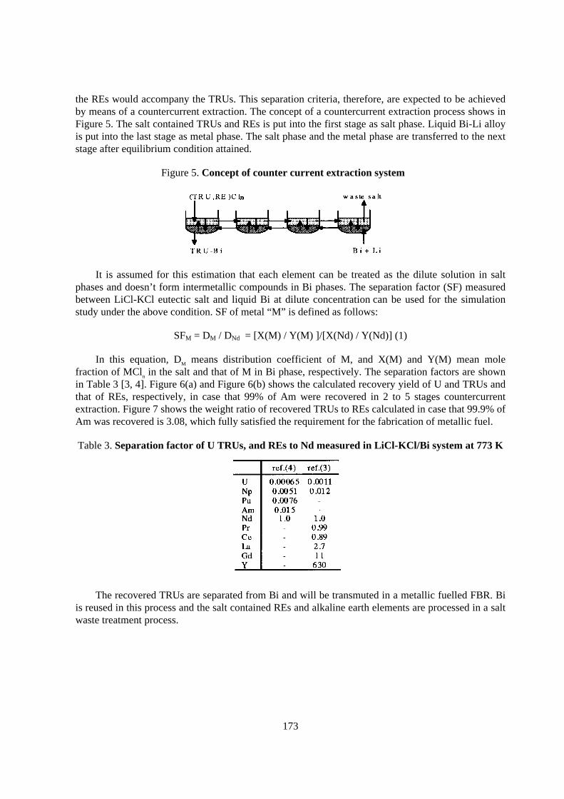
173
the REs would accompany the TRUs. This separation criteria, therefore, are expected to be achievedby means of a countercurrent extraction. The concept of a countercurrent extraction process shows inFigure 5. The salt contained TRUs and REs is put into the first stage as salt phase. Liquid Bi-Li alloyis put into the last stage as metal phase. The salt phase and the metal phase are transferred to the nextstage after equilibrium condition attained.
Figure 5. Concept of counter cur rent extraction system
It is assumed for this estimation that each element can be treated as the dilute solution in saltphases and doesn’ t form intermetallic compounds in Bi phases. The separation factor (SF) measuredbetween LiCl-KCl eutectic salt and liquid Bi at dilute concentration can be used for the simulationstudy under the above condition. SF of metal “M” is defined as follows:
SFM = DM / DNd = [X(M) / Y(M) ]/[X(Nd) / Y(Nd)] (1)
In this equation, DM means distribution coefficient of M, and X(M) and Y(M) mean molefraction of MCln in the salt and that of M in Bi phase, respectively. The separation factors are shownin Table 3 [3, 4]. Figure 6(a) and Figure 6(b) shows the calculated recovery yield of U and TRUs andthat of REs, respectively, in case that 99% of Am were recovered in 2 to 5 stages countercurrentextraction. Figure 7 shows the weight ratio of recovered TRUs to REs calculated in case that 99.9% ofAm was recovered is 3.08, which fully satisfied the requirement for the fabrication of metallic fuel.
Table 3. Separation factor of U TRUs, and REs to Nd measured in L iCl-KCl/Bi system at 773 K
The recovered TRUs are separated from Bi and will be transmuted in a metallic fuelled FBR. Biis reused in this process and the salt contained REs and alkaline earth elements are processed in a saltwaste treatment process.
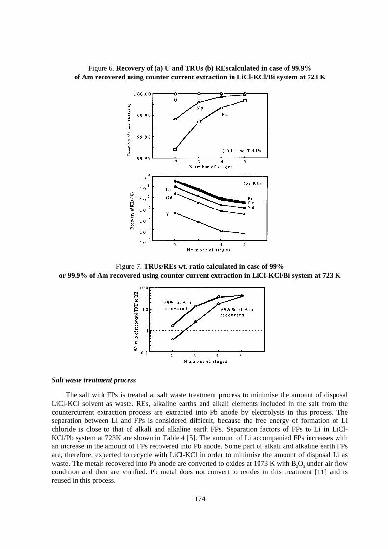
174
Figure 6. Recovery of (a) U and TRUs (b) REscalculated in case of 99.9%of Am recovered using counter cur rent extraction in L iCl-KCl/Bi system at 723 K
Figure 7. TRUs/REs wt. ratio calculated in case of 99%or 99.9% of Am recovered using counter cur rent extraction in L iCl-KCl/Bi system at 723 K
Salt waste treatment process
The salt with FPs is treated at salt waste treatment process to minimise the amount of disposalLiCl-KCl solvent as waste. REs, alkaline earths and alkali elements included in the salt from thecountercurrent extraction process are extracted into Pb anode by electrolysis in this process. Theseparation between Li and FPs is considered difficult, because the free energy of formation of Lichloride is close to that of alkali and alkaline earth FPs. Separation factors of FPs to Li in LiCl-KCl/Pb system at 723K are shown in Table 4 [5]. The amount of Li accompanied FPs increases withan increase in the amount of FPs recovered into Pb anode. Some part of alkali and alkaline earth FPsare, therefore, expected to recycle with LiCl-KCl in order to minimise the amount of disposal Li aswaste. The metals recovered into Pb anode are converted to oxides at 1073 K with B2O3 under air flowcondition and then are vitrified. Pb metal does not convert to oxides in this treatment [11] and isreused in this process.
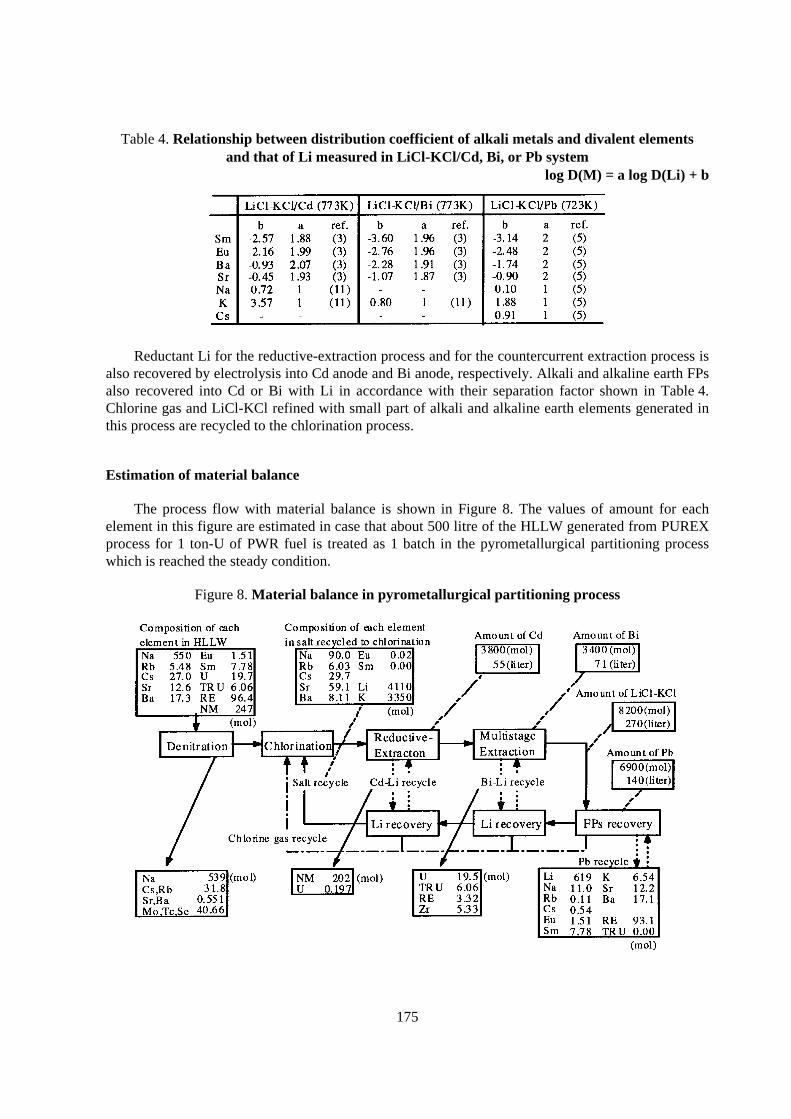
175
Table 4. Relationship between distr ibution coefficient of alkali metals and divalent elementsand that of L i measured in L iCl-KCl/Cd, Bi, or Pb system
log D(M) = a log D(Li) + b
Reductant Li for the reductive-extraction process and for the countercurrent extraction process isalso recovered by electrolysis into Cd anode and Bi anode, respectively. Alkali and alkaline earth FPsalso recovered into Cd or Bi with Li in accordance with their separation factor shown in Table 4.Chlorine gas and LiCl-KCl refined with small part of alkali and alkaline earth elements generated inthis process are recycled to the chlorination process.
Estimation of mater ial balance
The process flow with material balance is shown in Figure 8. The values of amount for eachelement in this figure are estimated in case that about 500 litre of the HLLW generated from PUREXprocess for 1 ton-U of PWR fuel is treated as 1 batch in the pyrometallurgical partitioning processwhich is reached the steady condition.
Figure 8. Mater ial balance in pyrometallurgical par titioning process
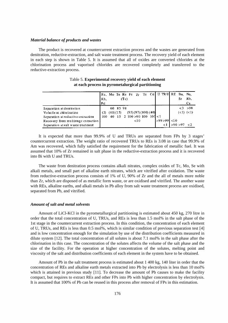
176
Material balance of products and wastes
The product is recovered at countercurrent extraction process and the wastes are generated fromdenitration, reductive-extraction, and salt waste treatment process. The recovery yield of each elementin each step is shown in Table 5. It is assumed that all of oxides are converted chlorides at thechlorination process and vaporised chlorides are recovered completely and transferred to thereductive-extraction process.
Table 5. Exper imental recovery yield of each elementat each process in pyrometalurgical par titioning
It is expected that more than 99.9% of U and TRUs are separated from FPs by 3 stages’countercurrent extraction. The weight ratio of recovered TRUs to REs is 3.08 in case that 99.9% ofAm was recovered, which fully satisfied the requirement for the fabrication of metallic fuel. It wasassumed that 10% of Zr remained in salt phase in the reductive-extraction process and it is recoveredinto Bi with U and TRUs.
The waste from denitration process contains alkali nitrates, complex oxides of Tc, Mo, Se withalkali metals, and small part of alkaline earth nitrates, which are vitrified after oxidation. The wastefrom reductive-extraction process consists of 1% of U, 90% of Zr and the all of metals more noblethan Zr, which are disposed of as metallic form waste, or are oxidised and vitrified. The another wastewith REs, alkaline earths, and alkali metals in Pb alloy from salt waste treatment process are oxidised,separated from Pb, and vitrified.
Amount of salt and metal solvents
Amount of LiCl-KCl in the pyrometallurgical partitioning is estimated about 450 kg, 270 litre inorder that the total concentration of U, TRUs, and REs is less than 1.5 mol% in the salt phase of the1st stage in the countercurrent extraction process. In this condition, the concentration of each elementof U, TRUs, and REs is less than 0.5 mol%, which is similar condition of previous separation test [4]and is low concentration enough for the simulation by use of the distribution coefficients measured indilute system [12]. The total concentration of all solutes is about 7.1 mol% in the salt phase after thechlorination in this case. The concentration of the solutes affects the volume of the salt phase and thesize of the facility. For the operation at higher concentration of the solutes, melting point andviscosity of the salt and distribution coefficients of each element in the system have to be obtained.
Amount of Pb in the salt treatment process is estimated about 1 400 kg, 140 liter in order that theconcentration of REs and alkaline earth metals extracted into Pb by electrolysis is less than 10 mol%which is attained in previous study [11]. To decrease the amount of Pb causes to make the facilitycompact, but requires to extract REs and other FPs into Pb with higher concentration by electrolysis.It is assumed that 100% of Pb can be reused in this process after removal of FPs in this estimation.
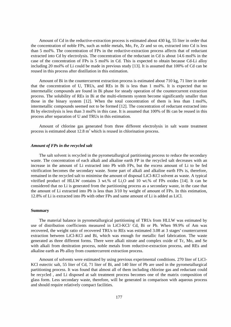
177
Amount of Cd in the reductive-extraction process is estimated about 430 kg, 55 liter in order thatthe concentration of noble FPs, such as noble metals, Mo, Fe, Zr and so on, extracted into Cd is lessthan 5 mol%. The concentration of FPs in the reductive-extraction process affects that of reductantextracted into Cd by electrolysis. The concentration of the reductant in Cd is about 14.6 mol% in thecase of the concentration of FPs is 5 mol% in Cd. This is expected to obtain because Cd-Li alloyincluding 20 mol% of Li could be made in previous study [13]. It is assumed that 100% of Cd can bereused in this process after distillation in this estimation.
Amount of Bi in the countercurrent extraction process is estimated about 710 kg, 71 liter in orderthat the concentration of U, TRUs, and REs in Bi is less than 1 mol%. It is expected that nointermetallic compounds are found in Bi phase for steady operation of the countercurrent extractionprocess. The solubility of REs in Bi at the multi-elements system become significantly smaller thanthose in the binary system [12]. When the total concentration of them is less than 1 mol%,intermetallic compounds seemed not to be formed [12]. The concentration of reductant extracted intoBi by electrolysis is less than 3 mol% in this case. It is assumed that 100% of Bi can be reused in thisprocess after separation of U and TRUs in this estimation.
Amount of chlorine gas generated from three different electrolysis in salt waste treatmentprocess is estimated about 12.8 m3 which is reused in chlorination process.
Amount of FPs in the recycled salt
The salt solvent is recycled in the pyrometallurgical partitioning process to reduce the secondarywaste. The concentration of each alkali and alkaline earth FP in the recycled salt decreases with anincrease in the amount of Li extracted into Pb with FPs, but the excess amount of Li to be fedvitrification becomes the secondary waste. Some part of alkali and alkaline earth FPs is, therefore,remained in the recycled salt to minimise the amount of disposal LiCl-KCl solvent as waste. A typicalvitrified product of HLLW contains 3 wt.% of Li2O and 10 wt.% of FPs oxides [14]. It can beconsidered that no Li is generated from the partitioning process as a secondary waste, in the case thatthe amount of Li extracted into Pb is less than 3/10 by weight of amount of FPs. In this estimation,12.8% of Li is extracted into Pb with other FPs and same amount of Li is added as LiCl.
Summary
The material balance in pyrometallurgical partitioning of TRUs from HLLW was estimated byuse of distribution coefficients measured in LiCl-KCl/ Cd, Bi or Pb. When 99.9% of Am wasrecovered, the weight ratio of recovered TRUs to REs was estimated 3.08 at 3 stages’ countercurrentextraction between LiCl-KCl and Bi, which was enough for metallic fuel fabrication. The wastegenerated as three different forms. There were alkali nitrate and complex oxide of Tc, Mo, and Sewith alkali from denitration process, noble metals from reductive-extraction process, and REs andalkaline earth as Pb alloy from countercurrent extraction process.
Amount of solvents were estimated by using previous experimental conditions. 270 liter of LiCl-KCl eutectic salt, 55 liter of Cd, 71 liter of Bi, and 140 liter of Pb are used in the pyrometallurgicalpartitioning process. It was found that almost all of them including chlorine gas and reductant couldbe recycled , and Li disposed at salt treatment process becomes one of the matrix composition ofglass form. Less secondary waste, therefore, will be generated in comparison with aqueous processand should require relatively compact facilities.
178
REFERENCES
[1] T. Inoue, M. Sakata, Y. Sakamura, T. Hijikata, and K. Kinoshita, IAEA-TECDOC-783 (1995)117.
[2] T. Inoue, M. Sakata, H. Miyashiro, M. Matsumoto, A. Sasahara, and N. Yoshiki, Nucl. Technol.93(1991)206.
[3] M. Kurata, Y. Sakamura, T. Hijikata, and K. Kinoshita, J. Nucl. Mater. 227(1995)110.
[4] K. Kinoshita, T. Inoue, S.P. Fusselman, R.L. Gay, C.L. Krueger, T.S. Storvick, and N. Takahashi,Proc. of Global ’97 vol. 2 (Yokohama, Japan, 1997) p.820.
[5] K. Kinoshita and T. Inoue, CRIEPI Report T97015, Central Research Institute of Electric PowerIndustry (1998) [in Japanese].
[6] Y. Sakamura, T. Inoue, T.S. Storvick, and L.F. Grantham, Proc. of the Twenty-sixth Symposium onMolten Salt Chemistry (Sapporo, Japan, 1994) p.101 [in Japanese].
[7] M. Kurata, CRIEPI Report T98002, Central Research Institute of Electric Power Industry (1998) [inJapanese].
[8] H. Konagaya, M. Kurata, T. Hijikata, and K. Nakamura, CRIEPI Report T97076, Central ResearchInstitute of Electric Power Industry (1998) [in Japanese].
[9] T. Hijikata, K. Nakamura, M. Kurata, and H. Konagaya, CRIEPI Report T96068, Central ResearchInstitute of Electric Power Industry (1997) [in Japanese].
[10] S.P. Fusselman, R.L. Gay, D.L. Grimmett, J.J. Roy, C.L. Krueger, C.R. Nabelek, T.S. Storvick,T. Inoue, K. Kinoshita, and N. Takahashi, Proc. of Global ‘97 vol. 2 (Yokohama, Japan, 1997) p.816.
[11] Y. Sakamura, T. Inoue, T. Shimizu, and K. Kobayashi, Proc. of Global ‘97 vol. 2 (Yokohama, Japan,1997) p.1222.
[12] M. Kurata, Y. Sakamura, T. Hijikata, K. Kinoshita, and T. Inoue, CRIEPI Report ET96001, CentralResearch Institute of Electric Power Industry (1997).
[13] T. Kato, Y. Sakamura, and T. Inoue, Proc. of Global ‘97 vol. 2 (Yokohama, Japan, 1997) p.806.
[14] H. Igarashi,H, NEW GLASS 11[3](1996)11 [in Japanese].
179
MOLTEN SALT REACTOR TECHNOLOGY FOR PARTITIONING & TRANSMUTATIONAND HARMONISATION OF THE FUTURE NUCLEAR FUEL CYCLE
V. V. Ignatiev, S. A. Konakov,S. A. Subbotine, R. Y. Zakirov
RRC - Kurchatov Institute, I.V. Kurchatov Sq., 123182, Moscow,Russian Federation
K. GrebenkineCheljabinsk-70, Snezinsk,
Russian Federation
Abstract
The most important developments regarding the available options to reduce actinide inventory will bediscussed.
The relation between necessary single cycle transmuted fraction, fuel cycle processing losses andtotal losses to waste will be defined. An attempt is made to arrange the possible systems on orderperformance with regard to their potential to reduce the actinide inventory and actinide losses towastes.
The objective of this paper is to illustrate clearly the potential advantages of molten salt fluoridebased reactor technology integrated with innovative processing methods including reductiveextraction, electro-refining and electro-deposition relative to traditional ones.
Also, this contribution aims to review the status of molten salt reactor technology, (including Russianexperience), to evaluate the importance of remaining uncertainties and to identify the additional workneeded.
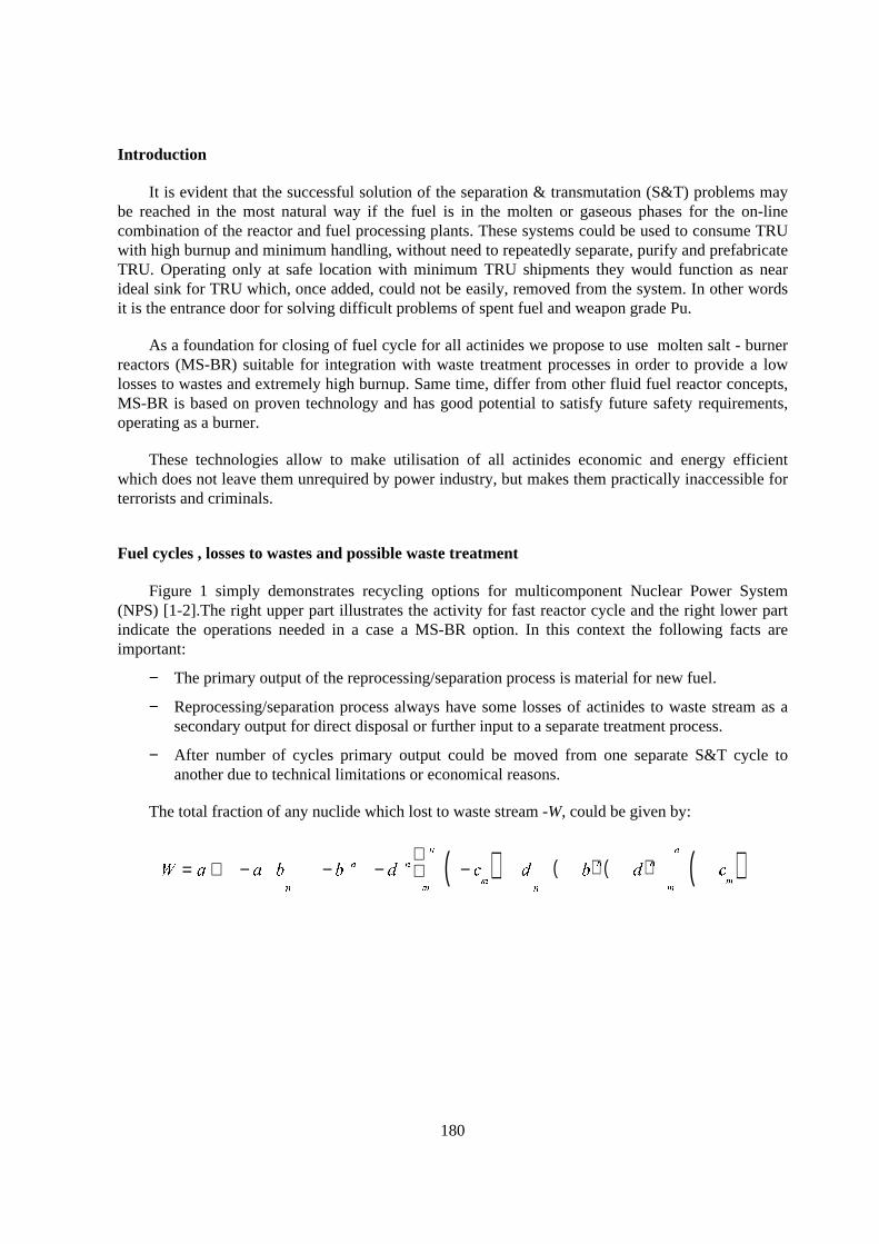
180
Introduction
It is evident that the successful solution of the separation & transmutation (S&T) problems maybe reached in the most natural way if the fuel is in the molten or gaseous phases for the on-linecombination of the reactor and fuel processing plants. These systems could be used to consume TRUwith high burnup and minimum handling, without need to repeatedly separate, purify and prefabricateTRU. Operating only at safe location with minimum TRU shipments they would function as nearideal sink for TRU which, once added, could not be easily, removed from the system. In other wordsit is the entrance door for solving difficult problems of spent fuel and weapon grade Pu.
As a foundation for closing of fuel cycle for all actinides we propose to use molten salt - burnerreactors (MS-BR) suitable for integration with waste treatment processes in order to provide a lowlosses to wastes and extremely high burnup. Same time, differ from other fluid fuel reactor concepts,MS-BR is based on proven technology and has good potential to satisfy future safety requirements,operating as a burner.
These technologies allow to make utilisation of all actinides economic and energy efficientwhich does not leave them unrequired by power industry, but makes them practically inaccessible forterrorists and criminals.
Fuel cycles , losses to wastes and possible waste treatment
Figure 1 simply demonstrates recycling options for multicomponent Nuclear Power System(NPS) [1-2].The right upper part illustrates the activity for fast reactor cycle and the right lower partindicate the operations needed in a case a MS-BR option. In this context the following facts areimportant:
− The primary output of the reprocessing/separation process is material for new fuel.
− Reprocessing/separation process always have some losses of actinides to waste stream as asecondary output for direct disposal or further input to a separate treatment process.
− After number of cycles primary output could be moved from one separate S&T cycle toanother due to technical limitations or economical reasons.
The total fraction of any nuclide which lost to waste stream -W, could be given by:
( ) ( ) ( ) ( )
= + − − − −î
+ − − −î
= ==
∞
=
∞
∏ ∏∑∑! " ! "#! "$ $ $ $ $ $ $% %&%
where a,b and d are the single cycle fractions of element lost to wastes in normal reprocessing,fabrication and separate processing steps, cm is the fraction transmuted in recycle pass m (c0 = 0).
Using this equation it is possible to analyse various S&T cycles with regard to their ability toreach actinide reduction goals with reasonable losses. It is important that losses in normalreprocessing occur only once in the equation. This term in optimal case should be balanced with otherpart of the equation. Simple demonstration of the fact that extremely high ratios of c/d in each recyclewhere (c = cm = const.) could provide reasonable total losses is given on Figure 1.
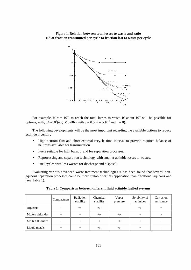
181
Figure 1. Relation between total losses to waste and ratioc/d of fraction transmuted per cycle to fraction lost to waste per cycle
' ')( ')(*( ')(*(*( ')(*(*(*((,+ (*(*(-'
(,+ (*(-'
(,+ (-'
(,+ '
'
.0/1(.0/2')(*354 6.0/1(.0/0')(*374 6
8 /2')(*374 6
8 /2')(*354 9
8 /2')(*374 :
8 /2')(*354 '
;
< = >
For example, if a = 10-4, to reach the total losses to waste W about 10-3 will be possible foroptions, with, c/d=103 (e.g. MS-BRs with c = 0.5, d = 5⋅10-4 and b = 0).
The following developments will be the most important regarding the available options to reduceactinide inventory:
• High neutron flux and short external recycle time interval to provide required balance ofneutrons available for transmutation.
• Fuels suitable for high burnup and for separation processes.
• Reprocessing and separation technology with smaller actinide losses to wastes.
• Fuel cycles with less wastes for discharge and disposal.
Evaluating various advanced waste treatment technologies it has been found that several non-aqueous separation processes could be more suitable for this application than traditional aqueous one(see Table 1).
Table 1. Compar ison between different fluid actinide fuelled systems
CompactnessRadiationstability
Chemicalstability
Vaporpressure
Solubility ofactinides
Corrosionresistance
Aqueous - +/- +/- - +/- +
Molten chlorides + + +/- +/- + -
Molten fluorides + + + + + +
Liquid metals + + +/- +/- + -
182
The following features of these processes are important:
− The processing media is extremely radiation resistant.
− The working mechanisms are relatively simple and short cooling time is accepted.
− The actinides (An) and lanthanides (Ln) are separated good between groups but poorlywithin groups.
− Only a few reagents are needed which are mostly used to substitute carrier components.
− The materials are recycled to avoid waste disposal charges.
Some forms of engineering implementation of these processes are partially successful in Oak-Ridge National Laboratory (ORNL) [3], Argonne National Laboratory (ANL) [4], Los-AlamosNational Laboratory (LANL) [5], Russian Research Center - Kurchatov Institute (RRC-KI), Instituteof High Temperature Electrochemistry (IVTEX) [6] and Russian Institute of Atomic Reactors (RIAR)[7]. The basic processes include reductive extraction, electro-deposition and electro-refining. Thecarrier and processing media are liquid metals (e.g. Bi) and molten salts (chlorides, fluorides).
Important parameters for reductive extraction and electro-refining are electrochemicalpotential/free energy of formation ∆Go
f(T) of chlorides (fluorides) and separation factors of elementsbetween molten salt and liquid metal θ [8]. These separation factors for different elements with thesame valency could be given by:
lnθ = ∆Go
f(Ln, T) - ∆Go
f(An,T) /(RT),
where T - temperature (K), R - molar gas constant (J⋅mol -1⋅K -1).
Thermodynamic consideration predicts to need more efforts for separating Am and Cm from Ceand La in chloride system in comparison with fluoride one (see Table 2).The calculated separationfactors of various elements in fluoride and chloride systems suggest for fluorides a better separationability between actinides and lanthanides groups but poorly within groups.
Bi-Li reductive extraction flowsheet developed in ORNL [3] for LiF - BeF2 solvent system couldprovide negligible losses of TRU ( d ≈ 10-4 ) by use of several counter current stages. For fluoridebased systems alongside with this method other method of TRU/lanthanides separation could beconsidered. This is electrochemical deposition of elements as metals on liquid or solid electrodes inelectrochemical cells, filled with fuel salt and bismuth or lead. It is found that the recovery of 99.9%of TRU could be attained by combination of electro-refining and counter current extraction in theLiCl-KCl/Bi system by using Li as reductunt with satisfying the separation ratio between TRU andrare earths of over 1.0 [9].
The applicability of the given method for fluoride based systems is defined by that the fuel salt attemperature 800-1100K is good electrolyte, the conductivity of which is comparable to conductivityof liquid electrolytes. In fluoride systems based on LiF- BeF2 and LiF-NaF-KF the potentials ofdecomposition for components are higher than that for An and Ln trifluorides.
As on account (see Table 2) the difference of potentials of deposition Am and Ce in fluoridesystems reaches 0.2V, it is possible to assert, that at electrolysis of fuel salt there will be the selectiveseparation of these elements. The degree of separation will depends on value of an over-voltage on
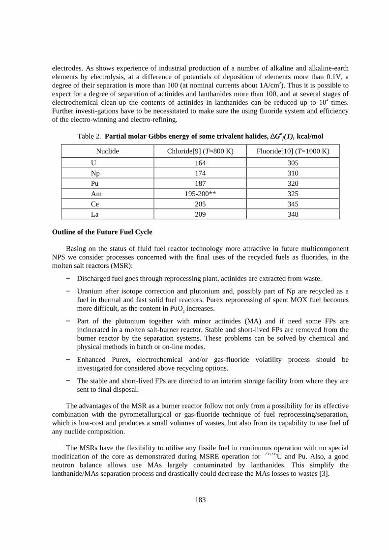
183
electrodes. As shows experience of industrial production of a number of alkaline and alkaline-earthelements by electrolysis, at a difference of potentials of deposition of elements more than 0.1V, adegree of their separation is more than 100 (at nominal currents about 1A/cm2). Thus it is possible toexpect for a degree of separation of actinides and lanthanides more than 100, and at several stages ofelectrochemical clean-up the contents of actinides in lanthanides can be reduced up to 104 times.Further investi-gations have to be necessitated to make sure the using fluoride system and efficiencyof the electro-winning and electro-refining.
Table 2. Par tial molar Gibbs energy of some tr ivalent halides, ∆Gof(T), kcal/mol
Nuclide Chloride[9] (T=800 K) Fluoride[10] (T=1000 K)
U 164 305
Np 174 310
Pu 187 320
Am 195-200** 325
Ce 205 345
La 209 348
Outline of the Future Fuel Cycle
Basing on the status of fluid fuel reactor technology more attractive in future multicomponentNPS we consider processes concerned with the final uses of the recycled fuels as fluorides, in themolten salt reactors (MSR):
− Discharged fuel goes through reprocessing plant, actinides are extracted from waste.
− Uranium after isotope correction and plutonium and, possibly part of Np are recycled as afuel in thermal and fast solid fuel reactors. Purex reprocessing of spent MOX fuel becomesmore difficult, as the content in PuO2 increases.
− Part of the plutonium together with minor actinides (MA) and if need some FPs areincinerated in a molten salt-burner reactor. Stable and short-lived FPs are removed from theburner reactor by the separation systems. These problems can be solved by chemical andphysical methods in batch or on-line modes.
− Enhanced Purex, electrochemical and/or gas-fluoride volatility process should beinvestigated for considered above recycling options.
− The stable and short-lived FPs are directed to an interim storage facility from where they aresent to final disposal.
The advantages of the MSR as a burner reactor follow not only from a possibility for its effectivecombination with the pyrometallurgical or gas-fluoride technique of fuel reprocessing/separation,which is low-cost and produces a small volumes of wastes, but also from its capability to use fuel ofany nuclide composition.
The MSRs have the flexibility to utilise any fissile fuel in continuous operation with no specialmodification of the core as demonstrated during MSRE operation for 233,235U and Pu. Also, a goodneutron balance allows use MAs largely contaminated by lanthanides. This simplify thelanthanide/MAs separation process and drastically could decrease the MAs losses to wastes [3].
184
The MS-BRs further require a minimum of special fuel preparation and can tolerate denaturingand dilution of the fuel.
In addition, there is a possibility to eliminate reactivity accidents in the reactor, providing it isoperated at subcritical mode with acceptable, economical external neutron source. The subcriticalmode could be important for the MS-BR because of the decrease of the delayed neutrons down to0.1% due to composition of the fuel and its circulation through the core, as well as use of various fuelcompositions.
The proposed strategy of Nuclear Power development is not an alternative to fossil-fired power,but represents its essential supplement. Different types of reactors do not compete with, butcomplement, each other allowing the best manifestation of the advantages of every type of plantdesigns. In this case accelerators are considered as neutron sources required to ensure the safeconditions for the functioning of Nuclear Power and to arrange more flexible fuel cycles for largescale Nuclear Power as well as to reduce and then to incinerate the equilibrium quantities of TRU andFPs at the stage of termination of Nuclear Power, if required, when more efficient and acceptablesources of energy appear or when the human kind’s way of life and demands change.
Conclusion
MSR technology has been proved by multi-years international efforts. The MSR-Programperformed in Russia, mainly at RRC - Kurchatov Institute, covered a wide range of theoretical andexperimental studies. The main finding of experimental studies is that neither physical nor technicalobstacles on a way to implement MSR and related fuel cycle technologies in the future Nuclear PowerSystem were observed.
There is a good basis for the construction of MSR-based DEMO-facility in Russia. As the firststep, the ISTC Project #698 devoted to the molten salt test facility construction could provide keydata on the way toward the practical implementation of the accelerator-based transmutation and wastemanagement technology.
REFERENCES
[1] S. A. Subbotine et al., Harmonization of Fuel Cycles for Long-Range and Wide-Scale NuclearEnergy System, Proceedings of the Global’95 Conference, 1995, vol. 1, pp. 199-206.
[2] V. V. Ignatiev et al., Molten Salt Technology for Long-Range and Wide Scale Nuclear EnergySystem, Proceedings. of Second International Conference on Accelerator Driven TransmutationTechnologies and Applications, Kalmar, Sweden, 1996, pp. 193-201.
[3] J. R. Engel et al., Development Status and Potential Program Development of Proliferation-Resistant Molten Salt Reactors, Report ORNL/TM-6415,1979.
[4] T.R. Johnson et al., Treatment of HLW’s from IFR Fuel Cycle. In.: Chemical Pre-treatment ofNuclear Waste for Disposal, Eds. W.W Schulz and E.P. Horwitz, Plenum Press, N.Y., 1995,pp. 133-144.
185
[5] F. Venneri et al., Los Alamos Accelerator-Driven Transmutation of Nuclear Waste ConceptDevelopment of ATW Target/Blanket System, Proceedings of Second Internat. Conference onAccelerator Driven Transmutation Technologies and Applications, Kalmar, Sweden, 1996,pp. 758-782.
[6] K.F. Grebenkine, Review of Activities on Accelerator-Based Transmutation at Cheljabinsk-70:Results of the ISTC Project and Prospects, ibid, pp.221-227.
[7] V.S. Naumov et al., Interaction of Actinide and Rare-Earth Element Fluorides with MoltenFluoride Salts and Possibility of their Separation for ADTT Fuel Reprocessing, ibid, pp. 1144-1153.
[8] V.A. Lebedev, Standard Potentials of Actinides and their Alloys in Molten Fluoride Solutions,J. Melts, 1997, pp. 91-102.
[9] T. Inoue and H. Tanaka, Recycling of Actinides Produced in LWR and FBR Fuel Cycles byApplying Pyrometallurgical Process. Proceedings of the Global’97 Conference, 1997, vol. 1,pp. 646-652.
[10] R.Y. Zakirov, V.N. Prusakov, Role Of Electrochemistry for Fuel Processing in Molten SaltReactors, Preprint IAE-6061/13, RRC-KI, Moscow, 1998.

187
AN EXPERIENCE ON DRY NUCLEAR FUEL REPROCESSINGIN THE CZECH REPUBLIC
Jan UhlirNuclear Research Institute Rez plc
250 68 RezCzech Republic
Abstract
Experience of Czech research and industrial organisations in the development and realisation of pilot-plant technological line FREGAT-2 for dry reprocessing of fast reactor spent fuel is presented. TheFREGAT-2 line is based on the fluoride volatility method. The possibility of using this experience ofCzech organisations for developing technologies for selected areas of the transmutation process andthe first results of technological research in this field in the Czech Republic are discussed.
188
Introduction
The development of dry reprocessing methods for spent fuel was motivated in the past by theassumed commercial utilisation of fast breeder reactors. Their application in the power industry canbe economically efficient only in the case of a closed fuel cycle. However, reprocessing of fastreactor spent fuel brings about a number of specific difficulties in comparison to the reprocessing ofspent fuel from thermal reactors. They are caused, for example, by higher burn-up, shorter coolingtime resulting in a higher amount of energy released by the fuel, higher concentration and amount ofplutonium, different cladding material, presence of metallic sodium, different fission productscomposition etc. Therefore, countries which were planning the introduction of fast reactors also wereattempting to develop suitable methods for reprocessing, because the hydrometallurgical PUREXprocess was not suited to the fast reactor spent fuel.
One of the alternative processes, also being developed in the former Czechoslovakia in the 1970sand 1980s was the fluoride volatility process based on the separation of uranium and plutonium in theform of volatile hexafluorides from fission products, the majority of which form non-volatilefluorides. The process was developed in Czechoslovakia in co-operation with the former SovietUnion.
Fluor ide reprocessing technology line FREGAT-2
The fluoride reprocessing consists of the following main operations:
1) Fuel elements decladding.2) Transformation of the fuel to a powder.3) Fluorination of the fuel.4) Separation of uranium and plutonium fluorides.5) Purification of the products obtained.
According to the agreement between the former Czechoslovak Atomic Energy Commission (nowState Office for Nuclear Safety) and State Commission for Atomic Energy of the USSR it was agreedthat the Soviet organisations will develop the technology and apparatus for items 1 and 2 and theCzechoslovak organisations for items 3 and 4. Item 5 will be worked out together, the purification ofuranium on the Czechoslovak side and the purification of plutonium on the Soviet side.
The Nuclear Research Institute Rez was the contractor for the Czechoslovak side.
The Nuclear Research Institute Rez had a good qualification for the development of the fluoridereprocessing. It was at that time the only institution in the former Eastern bloc, except for the SovietUnion, where the fluorine gas production by anhydrous hydrogen fluoride electrolysis from potassiumhydrogenfluoride melt had been managed.
Basic research in the field of volatile fluorides – for example of niobium, ruthenium,molybdenum, plutonium and wolfram, was the main subject studied in the Fluorine ChemistryDepartment of the Nuclear Research Institute Rez in the 1960s and early 1970s.
In the second half of the 1970s, the work on development and realisation of the pilot-planttechnological line called FREGAT-2 was started. This line was intended for the fluoride technologyverification by the way of experimental reprocessing of spent fuel from the Russian research fastreactor BOR 60.
189
The development and realisation of FREGAT 2 line was carried out in co-operation of theNuclear Research Institute Rez with a number of Czechoslovak research and industrial organisations.
The most significant of them were:
• Chemoprojekt, Praha – design and engineering organisation which worked out the project ofthe entire technology including the measurement and control of the process.
• Institute of Nuclear Fuels, Zbraslav – design of special measuring and controlinstrumentation (manometers, pressure-vacuum gauges, flowmeters, closing and controlvalves). These instruments were designed for the fluorine, fluorides and hydrogen fluoridecontaining media.
• Research Institute of Chemical Equipment, Brno - design of all technological apparatusesand auxiliary equipment and manufacture of some of the apparatuses. Most of theapparatuses of the FREGAT-2 line which were in contact with fluorine, were made fromnickel or Monel metal.
• Kovohute, Rokycany – production of nickel and Monel metal materials for the production ofapparatuses.
Most of the technological apparatuses were manufactured in the engineering shop of the NuclearResearch Institute Rez. The work with nickel and its alloys as well as the necessary flaw detectionmethods were to be mastered in order to make products of required quality.
Spent fuel reprocessing in the FREGAT-2 line was based on the following principles.
Powdered ceramic spent fuel is dosed in the nitrogen atmosphere by a worm doser into thepreheated reactor R11 – fluorinator and at the same time fluorine gas also is fed. A reaction takesplace in the flame, during which the uranium oxides react to form gaseous UF6, mostly plutonium togaseous PuF6, a great majority of fission products form solid fluorides dropping to the fluorinatorbottom and only a small part of fission products (Nb, Ru, Tc, Mo, I) reacts with fluorine undergaseous fluorides formation and will accompany uranium and plutonium together with rare gases.
Three condensers are situated after the fluorinator. The first one, K12, is intended for uptakingniobium and ruthenium. Uranium and plutonium fluorides should condensate in condensers K13 andK14 at -60 and -80 °C. It was assumed that a complete fluorination of Pu will not take place.Therefore, secondary fluorination of fuel in the reactor R11 was introduced by the way of fluorinecirculation in a part of the apparatus by means of a circulating pump.
After the K13 and K14 condensers are filled with uranium and plutonium hexafluorides, thecondensers are heated and the evaporated fluorides are introduced into the reactor R31, where thermaldecomposition of PuF6 to solid PuF4 is taking place, whereas volatile UF6 passes through the reactor.In this way, uranium is separated from plutonium.
UF6 is then purified by column distillation to remove molybdenum, iodine and technetiumfluorides.
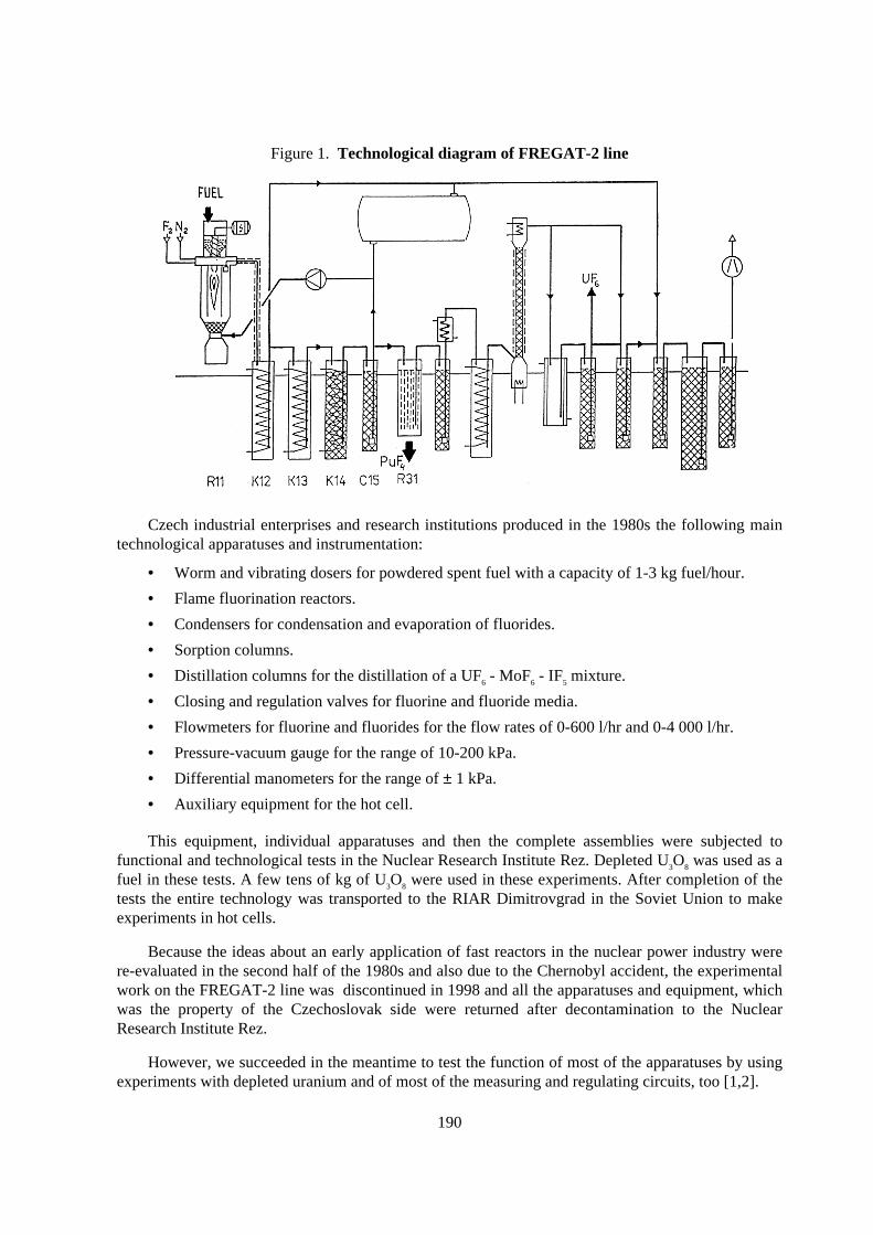
190
Figure 1. Technological diagram of FREGAT-2 line
Czech industrial enterprises and research institutions produced in the 1980s the following maintechnological apparatuses and instrumentation:
• Worm and vibrating dosers for powdered spent fuel with a capacity of 1-3 kg fuel/hour.
• Flame fluorination reactors.
• Condensers for condensation and evaporation of fluorides.
• Sorption columns.
• Distillation columns for the distillation of a UF6 - MoF6 - IF5 mixture.
• Closing and regulation valves for fluorine and fluoride media.
• Flowmeters for fluorine and fluorides for the flow rates of 0-600 l/hr and 0-4 000 l/hr.
• Pressure-vacuum gauge for the range of 10-200 kPa.
• Differential manometers for the range of ± 1 kPa.
• Auxiliary equipment for the hot cell.
This equipment, individual apparatuses and then the complete assemblies were subjected tofunctional and technological tests in the Nuclear Research Institute Rez. Depleted U3O8 was used as afuel in these tests. A few tens of kg of U3O8 were used in these experiments. After completion of thetests the entire technology was transported to the RIAR Dimitrovgrad in the Soviet Union to makeexperiments in hot cells.
Because the ideas about an early application of fast reactors in the nuclear power industry werere-evaluated in the second half of the 1980s and also due to the Chernobyl accident, the experimentalwork on the FREGAT-2 line was discontinued in 1998 and all the apparatuses and equipment, whichwas the property of the Czechoslovak side were returned after decontamination to the NuclearResearch Institute Rez.
However, we succeeded in the meantime to test the function of most of the apparatuses by usingexperiments with depleted uranium and of most of the measuring and regulating circuits, too [1,2].
191
Although the experimental programme on the FREGAT-2 line was discontinued in 1998, thefunctionality of the majority of apparatuses and equipment and of the remote control wasdemonstrated and the soundness of most of the technological operations was confirmed. Czechresearch and industrial organisations acquired during the execution of the project FREGAT-2 goodexperience in the field of a complex development of a special radiochemical technology.
Fluor ide technology for the transmutation programme
At present, Czech research and industrial organisations intend to use the above experience in theplanned national programme of transmutation technology development. Study of various aspects ofthe ADTT and a research and development programme in this field is being carried out in the CzechRepublic for 3 years already, most of all within the scope of the national programme of deepgeological repository development. This programme is financially subsidised by the State anddevelopment of transmutation technologies within this programme represents to some extent thesupport of an alternative technology.
Some of the Czech research and industrial organisations take part in the preparation of the fullyindependent national programme of transmutation technologies development. First of all, it is theNuclear Research Institute Rez plc, SKODA – Nuclear Machinery, Czech Power Company, Instituteof Nuclear Physics of the Czech Academy of Sciences and other organisations that were participatingin the development of the FREGAT-2 fluoride reprocessing technology.
Establishment of an experimental laboratory for research and development in the field oftransmutation technologies is assumed within the Nuclear Research Institute Rez plc. Experimentalstudies of a limited extent on the determination of physico-chemical properties of melts of selectedfluoride salts mixtures were carried out at this place. At present, assembly of the first experimentalloop filled with a fluoride salt melt is carried out together with the SKODA - Nuclear Machinerycompany. Three of such loops are planned to be realised. They will be used, first of all, for thematerial and design studies of the transmutation technology. The laboratory experiments in the fieldof suitable fluoride melt preparation and its behaviour has been started and technological experimentsof the first main separation steps of the spent fuel before transmutation are planned and prepared.Selected parts of FREGAT-2 equipment will be used for this investigation.
Conclusion
The Czech Republic as a country operating and constructing nuclear power plants and treatingproblems of spent nuclear fuel is interested in the international co-operation in the field oftransmutation technologies development. A co–operation already exists at the level of individualinstitutions and is directed to the information exchange between the Czech organisations mentionedand research institutes in the U. S. A., France, Sweden, Italy, Russia, Korea and others.
Development and realisation of transmutation technology can be considered practicable atpresent within the scope of a wide international co-operation. It cannot be figured that the CzechRepublic, as a relatively small country, could participate financially to a deciding extent on thisresearch. However, within the international co-operation at the level of government and researchinstitutions the tasks could be allocated in a way that each of the participants will take part on theinvestigation of some selected problems. Czech research and industrial organisations are prepared toparticipate in such a co-operation. Experience from the fluoride reprocessing technology developmentis a good basis for this co-operation.
192
REFERENCES
[1] P. Novy et al., Verification of the Fluoride Reprocessing Technology-Final Report RU 159-113(in Czech), NRI Report - 9062 Ch, NRI Rez (1989), Czech Republic.
[2] P. Novy, I. Peka, I. Chochlovsky, The Technological Project of the Fluoride Volatility Processfor the Reprocessing of the Spent Fuel from FBR (in Czech), NRI Report-9081 Ch, T, NRI Rez(1989), Czech Republic.


