Embed Size (px)
Citation preview

Patterning-induced surface chirality and modulation of director
twist in a nematic cell
Yoonseuk Choi, Timothy Atherton, Sameh
Ferjani, Rolfe G. Petschek, and Charles Rosenblatt
Department of Physics,
Case Western Reserve University,
Cleveland, Ohio 44106-7079 USA
A substrate coated with a polyimide alignment layer is scribed bidirectionally
with the stylus of an atomic force microscope to create an easy axis for liquid crystal
orientation. The resulting non-centrosymmetric topography breaks 2D inversion
symmetry and results in a spatial amplitude modulation of an imposed twisted ne-
matic state. This is observed optically as spatially periodic light and dark stripes.
When the alignment layer is scribed unidirectionally the centrosymmetric topogra-
phy maintains inversion symmetry, and no stripes are observed. The appearance of
the twist modulation is consistent with a chiral term in the free energy.
To whom correspondence should be addressed. Email [email protected]
PACS numbers: 61.30Hn

2
Chirality plays a central role in the behavior of soft materials, particularly in liquid
crystals [1, 2] and at interfaces [3]. Over the years a number of spectacular effects have
been discovered that owe their existence to broken inversion symmetry. For example, some
thirty-five years ago Meyer, et al, demonstrated the existence of a spontaneous electric
polarization in a chiral smectic- phase composed of chiral molecules [4]. A dozen years
ago Link, et al, demonstrated the existence of chiral smectic domains formed from bent-
shaped, inherently achiral molecules [5], which in turn can give rise to macroscopic electric
polarizations. Supramolecular organization of molecules has been shown to create two
dimensional chiral domains in small clusters and thin films [3, 6], where “2D (surface)
chirality” means that an object cannot be rotated into its mirror image when confined to
a plane; the letter “F” is chiral in 2D, whereas the letter “E” is achiral. In this paper
we demonstrate that 2D chirality can be induced by appropriate patterning of an achiral
polymer-coated substrate by means of scribing with the stylus of an atomic force microscope.
When covered with a thin layer of nematic liquid crystal, we observe a signature of this 2D
chirality, viz., the appearance of a striped optical texture when a twist is imposed externally
on the liquid crystal, e.g., using a standard “twisted nematic” cell.
The cell was composed of two glass microscope slides. Both substrates were cleaned in
detergent, acetone, and ethanol, and spin-coated with a thin layer of the achiral polyamic
acid RN-1175 (Nissan Chemical Industries, Ltd.), which is used for low pretilt planar align-
ment. The slides subsequently were prebaked for 5 min at 80 ◦C and then fully baked for 60
min at 230 ◦C to achieve a high degree of imidization. After baking, the polyimide-coated
substrates were rubbed unidirectionally using a cotton cloth with a strength = 46× 105
cm−1; details are given elsewhere [7, 9]. One of the substrates then was scribed [7, 8] with
the stylus (TAP-300 Si) of a Topometrix Explorer AFM. Schematic representations of the
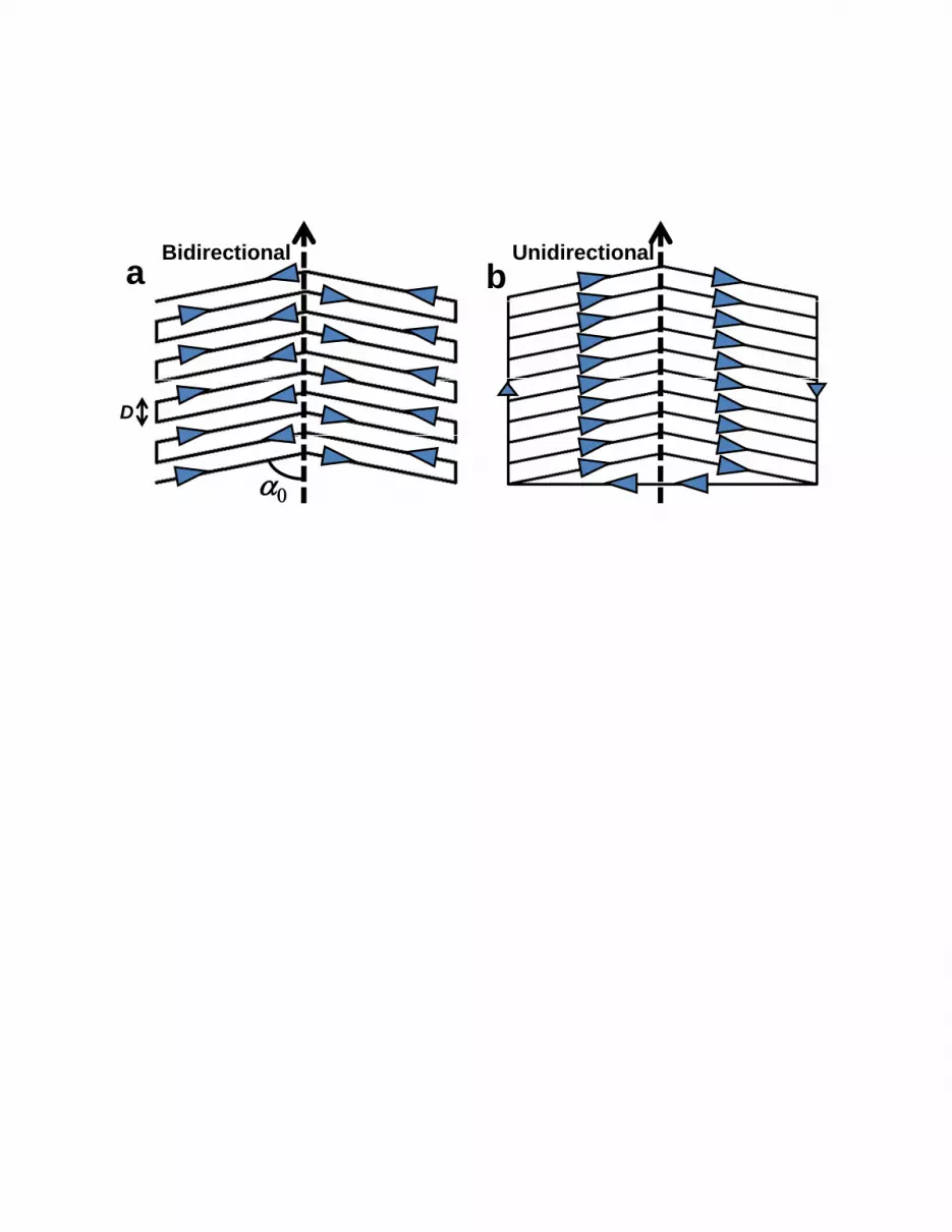
AFM scribing patterns (each covering an area of 100 m × 100 m) are depicted in Figs.
1a and b. The spine of the chevron is denoted by dashed arrows in the Fig. 1, with angles
0 = ±30, ±45, ±60, and ±75◦ between the scribing directions and the spine. The can-
tilever remains parallel to the chevron spine when scribing the patterns; thus the movement
of the cantilever is oblique to its orientation. For each pattern scribed at angle 0, we pre-
pared two types of nanopatterned surfaces, viz., bidirectional (Fig. 1a) and unidirectional
scribing (Fig. 1b). For bidirectional scribing, adjacent lines were scribed in an antiparallel
fashion with the stylus moving back and forth, whereas for undirectional scribing the adja-

3
cent lines are parallel. We fixed the distance (shown in Fig. 1a) at 200 nm and used a
scribing force of (44± 01) . Note that the actual separation between adjacent lines is = sin0 and that the AFM-scribed surface always corresponds to the bottom substrate
of the cell, i.e., the side of the cell for which the microscope illumination is incident.
Before preparing the closed cell, we investigated the topography of the scribed surface in
non-contact AFM mode. Figures 2a and b show two-dimensional images of the topography
for bidirectional and unidirectional scribing, respectively. Figure 2c shows the topography
across the line shown in the bidirectionally-scribed pattern (Fig. 2a), where the sequential
“pulling” and “pushing” actions of the AFM in scribing mode and the resulting movement
of material gouged out by the stylus results in a non-centrosymmetric topography. On
the other hand, unidirectional scribing (Fig. 2d) results in a centrosymmetric topography,
whether it involves pulling or pushing of the stylus. A more detailed study of the differences
between pulling and pushing the AFM stylus and the resulting topographies can be found
in Ref. [10]. Thus, the only non-trivial difference between the two types of scribing is the
absence of centrosymmetry of the bidirectional topography vs. the centrosymmetry of the
unidirectional topography. In fact, because of the different effects of pulling and pushing in
the bidirectional case, the topographically non-centrosymmetric axis that is perpendicular
to the scribing axis (i.e., the white lines in Figs. 2a) and the scribing axis itself form a
two-dimensional coordinate system that lacks 2D inversion symmetry. In other words, it
is two dimensionally chiral. Moreover, the chiral handedness of one wing of a chevron is
opposite that of the other. It is important to note, however, that although we measure the
topography, the shape of the surface itself may not be the primary driver of the observed
stripes. Rather, the topography is related to the induced orientation of the polyimide
backbone [11], and thus to the interaction potential between the substrate and the liquid
crystal [12]. Thus, the symmetry of the topography corresponds to the symmetry of the
interaction potential.
The AFM-scribed bottom substrate and the cloth-rubbed-only top substrate were ce-
mented together, separated by a mylar spacer of nominal thickness 3 m, with the top and
bottom substrate axes parallel to each other, i.e., their relative azimuthal angle = 0. This
creates a twist structure within the two “wings”of the chevron, where the rubbing/scribing
directions of the top and bottom substrates are rotated with respect to each other by an
angle +0 in one wing and −0 in the other. The thickness of the cell was measured to

4
be = 42± 01 m by interferometry. The cell was placed into an oven, heated to a tem-
perature of 85 ◦C (well above the nematic-isotropic transition temperature of 74 ◦C), and
filled with the achiral liquid crystal heptyloxy cyanobiphenyl (7OCB; Merck) in its isotropic
phase. The sample then was cooled into the nematic phase and stabilized at a temperature
of 65 ◦C. [We note that several experiments also were performed with the achiral liquid
crystal pentyl cyanobiphenyl (5CB; Merck), with results qualitatively consistent with those
using 7OCB].
The cell was observed using a polarizing optical microscope. Figure 3 shows the cell
with bidirectional AFM scribing, where the orientation of the analyzer (A) is parallel to the
rubbing direction of the top substrate and that of the polarizer (P) is at 90◦ with respect
to the analyzer. Dark and light stripes can be seen for all 0. For each of the four scribing
orientations 0, we then rotated the incident polarizer while keeping the analyzer fixed to
minimize the total light intensity for one wing; this condition is met when the polarizer is
approximately parallel to the scribing direction 0. Then, on rotating the polarizer by angles
±∆, we observed that the dark and light stripes are interchanged. This indicates that the
director twist is modulated spatially, where the twist is a little smaller in one stripe and larger
in the adjacent stripe, with a modulation amplitude of ∆. Note that such a modulation
also requires the presence of splay and/or bend. ∆ was found to have no systematic
dependence on 0, and has a typical value of approximately 5◦ [13]. Additionally, we found
that the wavelength of the stripes could be varied by changing the angle 0 between the
rubbing directions of the two substrates, such that decreases with increasing 0 up to
0 ∼ 60◦, beyond which it apparently begins to increase; this behavior can be seen in Fig.3. Importantly, for 0 = 90
◦ – this corresponds to the cantilever moving perpendicular to
its axis, where there no longer is a distinction between “pushing” and “pulling” and thus no
chirality – the stripes vanish completely. It also is important to reiterate that stripes were
not observed in any of the unidirectionally-scribed cells.
We also examined qualitatively the effects of varying the scribed line spacing = sin0,
cell thickness , temperature, and introducing a nonzero angle between the rubbing di-
rection of the top substrate and chevron spine of the bottom (scribed) substrate. With
increasing out to = 600 nm, we found that the period of the stripes becomes larger (
is approximately ∝ ) and that the twist amplitude ∆ becomes smaller. This correlates
with a less asymmetric topography associated with a decoupling of the push- and pull-

5
created grooves and the associated material displaced from the grooves when becomes
large. Although such a large value of might suggest that the push- and pull-created
grooves should be decoupled completely, in reality the sequential scribing of each line and
material carried by the stylus results in a small degree of non-centrosymmetry, even for large
. Turning to cell thickness and temperature , we found the wavelength to be nearly
independent of for = 30, 53, 85, and 134 m and ∆ to be a very weakly decreasing
function of . Very little, if any, variation was found with temperature throughout most
of the nematic range, 56 74 ◦C, although we did not examine the behavior close to
the smectic- phase transition. That the stripes appeared unchanged on cycling through
the nematic - isotropic phase transition suggests that they are either pinned or controlled
by the director orientation b just outside the scribed regions. As for , we found that thestripe pattern in the two wings were similar for = 0; in fact, that stripes are observed
in both wings (having opposite handedness) is due to the fact that the sense of the twist
rotation also is interchanged in the two wings. For 6= 0 we found that the stripe patternsin each of the two wings become less similar with increasing . This is as expected, as
the angle between the rubbing direction of the top substrate and the scribing direction in
one wing is 0 + and that in the other wing is 0 − . For = 0, i.e., when the cloth
rubbing direction of the top substrate was parallel to the scribing direction in one of the
wings (no macroscopically imposed twist), stripes were not observed. However, we do not
believe that the absence of observed stripes is due to the absence of an imposed twist. To
show this, we fabricated a cell in which the top surface was coated with an unrubbed layer
of the planar-degenerate alignment material polymethyl methacrylate [14]. The cell was
filled in the nematic phase along the bidirectional scribing axis, and the resulting average
alignment was parallel to this axis, with no macroscopic twist. However, a striped pattern
with moderately long was observed.
Stripe patterns in liquid crystals generally have been explained using a continuum ap-
proach. Although a surface-like saddle-splay mechanism [15—17] involving the surface elastic
constant24 (which can be different at the two surfaces) in principle can play a role in stripe
formation, the stripes’ disappearance when 0 = 90◦ and mirror symmetry is restored argues
against this mechanism being responsible for the observed stripes in the chirally-patterned
cell. Selinger, et al have suggested [18], and Maclennan and Seul experimentally [19], that
modulated patterns can appear as a result of a coupling between bend or splay on a sur-

6
face and a scalar soft mode. The required soft mode may exist in our system, viz., the
(small) projection of the director b onto the surface normal b, which is resisted only by thepolar anchoring as characterized by the quadratic polar anchoring strength coefficient
2
[20]. Given the absence of any symmetry in our surface, this soft mode can couple to some
surface specific combination of bend and splay, e.g., there should be an energy term of the
form Z b · b³b ·∇× b+ ∇ · b´ 2 (1)
where the first term is chiral term and therefore requires either a chiral liquid crystal or a
chiral surface or both, while the second term is nonchiral and also is allowed. For our case we
believe that the first term, i.e., the chiral term, is dominant, as on purely empirical grounds
the stripes are absent when the surface is achiral after being scribed unidirectionally. It is
important to note, however, that we are not certain of the actual interactions responsible for
the chiral term. Specifically such a term can arise from direct interactions at the surface. On
the other hand, intricate chiral surface patterning may result in complicated director textures
in a region near the surface of thickness comparable to . In general, the free energy of such
a texture will depend on its nature far from the surface, and can be expanded in powers of
gradients of the order parameter far from the surface. Terms having no gradient correspond
to the usual anchoring terms [20] and terms proportional to the first power of the gradient are
those in Eq. 1. Assuming that the usual elastic free energy applies in this surface region, the
interaction between the elastic distortions in the surface region due to the periodic scribing
and the twist due to the large scale modulation implies that ∼ 22 hb ·∇× bi, where hicorresponds to an average of the integral of the argument through the surface layer. Similarly,
from the interaction between the corresponding bend distortions, ∼ 33
Db · b×∇× bE.Here 22 and 33 are the twist and bend elastic moduli. Note that macroscopic twist or
bend distortions, such as our imposed uniform twist, will result in changes in these averages,
i.e., in the magnitudes of and/or , and thus in , consistent with our observations. As the
perturbations associated with the surface pattern extend a distance approximately into
the bulk, we expect that ∼ 22 hb ·∇× bi ∼ 22, where is the standard deviation
of the director about its average orientation ∆. Here ∆ is the chirality-induced angle
between the average director orientation at the surface and the scribing direction, even in
the absence of an imposed twist, i.e., = 0 [21, 22]. For a fixed surface anchoring, will
(generally) grow with increasing .

7
Consistent with Selinger, et al, we consider the possibility of a modulation of b bothparallel and perpendicular to the surface normal and decaying over a distance −1 (∝ )
into the bulk. We assume that this modulation decays into the bulk slowly, which oc-
curs when is more or less comparable to . When is significantly larger than
the modulation no longer is expected, as its elastic cost falls off more slowly with de-
creasing . In our observations and are comparable, consistent with a modulation
but requiring, in principle, a more detailed theory that accounts for these parameters.
Using Eq. 1 with = 0 and the usual bulk elastic [1] and quadratic surface anchor-
ing [20] energies, one can show that the energy per unit area favors a modulated state
when [+ 22 (0 ±∆)]2
h
2 +
2 +
¡2
2
2
¢12i, where
2 is the
azimuthal quadratic anchoring strength coefficient, is a constant of order unity when is
not much larger than , 0±∆ is the actual azimuthal twist through the cell – note that
for most cases 0 À ∆ (see Fig. 3) unless the imposed 0 is small or zero, for which stripes
are not observed – and and are appropriate combinations of, and of the same mag-
nitude as, 22 and 33. Inclusion of a nonzero complicates this inequality somewhat but
qualitatively adds a constant multiplied by 2 to the left hand side. We remark that while a
nonzero value for would be expected for our system, the observation that the modulation
vanishes when the surface is nonchiral suggests that the chiral term in Eq. 1 dominates in
our system. It is also the case that an imposed uniform twist in the sample will, depending
on its sign, linearly increase or decrease the tendency for modulation. This is because the
modulation has a particular sense of helicity that couples with a uniform twist. In principle,
if the modulation is in equilibrium and not controlled by the boundaries of the scribed area,
then the angle the modulation direction makes with the director is controlled by the ratio
, as the term favors bend and favors splay. We do not believe this to be the case
in our situation: rather we believe that the modulation direction is controlled by boundary
conditions of the scribed area.
To summarize, we demonstrated that an inherently achiral alignment layer can be pat-
terned with a non-centrosymmetric topography, and thus a non-centrosymmetric interaction
potential, which is the key ingredient in the creation of a chiral surface environment. We
observed a signature of this chiral environment, viz., a striped texture that arises from a
modulation of the twist angle in a twisted nematic cell. On an empirical basis we find
that the observed phenomenon cannot be due solely to a coupling with 2D splay, nor with

8
saddle-splay elasticity. Rather, a chiral term associated with bend distortion plays the
dominant role. To be sure, there are many other patterns that can be scribed and that lack
centrosymmetry symmetry, such as a zig-zag pattern where the lengths of the “zigs” and
“zags” are unequal, or a repeating series of parallel lines where the line spacing increases
from one line to the next to some maximum value. The relationship between such patterns,
chirality, and their effect on liquid crystals will be the subject of future investigation.
Acknowledgments: The authors thank C. Zannoni for useful discussions. Y.C. and
S.F. were supported by the National Science Foundation under grant DMR-0804111, T.J.A.
and C.R. by the Department of Energy’s Office of Science under grant DE-FG02-01ER45934,
and R.G.P. by the Ohio Research Scholars Program.
9
[1] P.G. DeGennes and J. Prost, Physics of Liquid Crystals, Clarendon, Oxford (1994).
[2] H.-S. Kitzerow and Ch. Bahr, Chirality in Liquid Crystals, Springer (2001)
[3] N. Katsonis, E. Lacaze, and B.L. Feringa, J. Mater. Chem. 18, 2065 (2008).
[4] R.B. Meyer, L. Liebert, L. Strzelecki, and P. Keller, J. Phys. (Paris) 36, L69 (1975).
[5] D.R. Link, G. Natale, R. Shao, J.E. Maclennan, N.A. Clark, E. Körblova, and D.M. Walba,
Science 278, 1924 (1997).
[6] V. Humblot, S.M. Barlow, and R. Raval, Prog. Surf. Sci. 76, 1 (2004).
[7] A.J. Pidduck, G.P. Bryan-Brown, S.D. Haslam, and R. Bannister, Liq. Cryst. 21, 759 (1996).
[8] M. Rüetschi, P. Grütter, J. Fünfschilling, and H.-J. Güntherodt, Science, 265, 512 (1994).
[9] Z. Huang and C. Rosenblatt, Appl. Phys. Lett. 86, 011908 (2005).
[10] V. Barna, A. De Luca, and C. Rosenblatt, Nanotechnology 19, 325709 (2008).
[11] M.P. Mahajan and C. Rosenblatt, J. Appl. Phys. 83, 7649 (1998)
[12] J.-H. Kim and C. Rosenblatt, J. Appl. Phys. 84, 6027 (1998)
[13] The actual angles between polarizer and analyzer are less than 0 because: i) non-rigid
anchoring results in a total director twist less than 0 and ii) the polarization cannot fully
“follow” the director rotation because of the thinness of the cell. Nevertheless, the polarizer
orientation for which the stripe contrast was negligible was within a few degrees of 0.
[14] I.M. Syed, G. Carbone, and C. Rosenblatt, J. Appl. Phys. 98, 034303 (2005).
[15] A.L. Alexe-Ionescu, G. Barbero, and I Lelidis, Phys. Rev. E 66, 061705 (2002).
[16] O.D. Lavrentovich and V.M. Pergamenshchik, Intl. J. Mod. Phys. B 9, 251 (1995).
[17] S. Faetti, Phys. Rev. E 49, 4192 (1994).
[18] J.V. Selinger, Z.-G. Wang, R.F. Bruinsma, and C.M. Knobler, Phys. Rev. Lett. 70, 1139
(1993)
[19] J. Maclennan and M. Seul, Phys. Rev. Lett. 69, 2082 (1992)
[20] A. Rapini and M. Papoular, J. Physique Colloq. 30, C4-54 (1969)
[21] D. Harrison, M.R. Fisch, R.G. Petschek, J.-F. Li, F. Harris, and H. Korns, Jpn. J. Appl. Phys.
41, 2183 (2002).
[22] M. Nakata, G. Zanchetta, M. Buscaglia, T. Bellini, N.A. Clark, Langmuir 24, 10390 (2008).

10
FIG. 1: Schematic representation of scribing pattern of bottom substrate for a) bidirectional scrib-
ing and b) unidirectional scribing. = sin0, where is the gap between the centers of adjacent
lines and 0 is the angle between the scribing and the “spine” of the chevron.
FIG. 2: a) 2D topographical image of bidirectional scribing and b) 2D topographical image of
unidirectional scribing. c) and d) Topographical profiles along the lines indicated in (a) and (b),
respectively.
FIG. 3: Polarized microscope images of the twisted cell for angles 0 = 30◦ (a), 45◦ (b), 60◦ (c),
and 75◦ (d) between the scribing directions and the symmetry axes. Exit polarizer (analyzer A)
is parallel to the chevrons’ spine and the incident polarizer (P) is rotated by 90◦.
Bidirectional
Unidirectionala b
D

Lateral Position (m) Lateral Position (m)
Hei
gh
t (n
m)
y-a
xis
(
m)
x-axis (m) x-axis (m)
a b
c d
5
4
3
2
1
5
4
3
2
1
1 2 3 4 5 1 2 3 4 5
90
60
30
60
40
20
0 1 2 0 1 2