Embed Size (px)
Citation preview
YCE26PC Programming Software
Reference Manual
This software is used to program the GX2400GPS VHF FM Marine Transceiver. With this software, the GX2400GPS operating channels can be quickly and easily programed from a personal computer.
1
Table of ContentsBefore Using .................................... 2
System Requirements .................... 2Installation and Removal of the Pro-gram .................................................. 2
Installing the “YCE26 PC Program-ming Software” ............................... 2To remove the “Programming Soft-ware” from the computer ................ 2
Startup of the Program ................... 2To close the YCE26 ........................ 2
Connecting GX2400GPS to the Computer and Entering CP Mode .. 3Main Screen ..................................... 5“Setup Menu” Category ..................... 5
“DSC Setup” ................................... 5“Individual Directory” ..............................7“Group Directory” ...................................9
“GM (Group Monitoring) Setup” .... 10“Waypoint Setup” .......................... 12
“Waypoint Directory” ............................12“Route Directory” .................................14
“Channels Setup” .......................... 16“General” tab........................................16“CH Group 1”, “CH Group 2”, “CH Group 3” Tab Setting .......................................17“Channel Name” & “SCAN Memory” Set-up for: “CH Group 1[USA]”,..................18“CH Group 2[INTL]”, “CH Group 3[CAN]” and “WX CH Group” ............................18
“GPS Setup” ................................. 19Internal GPS Setup ..............................20
“AIS Setup” ................................... 21CPA/TCPA Alarm Ignore Vessels .........22
“NMEA2000 Setup” ...................... 23“ATIS Setup” ................................. 23“Configuration” .............................. 24
“DSC Log Data” Category ............... 27“Transmitted Logs” ...............................28“RX Distress Logs”...............................28“RX Other Call Logs” ...........................28
Important Notice: User assumes full responsibility for the utilization of the YCE26 Programming Software.
The company and product names in this manual are trademarks and/or registered trademarks of their respective companies.
“GPS Log Data” Category ............... 29“File” ................................................ 30
“New” ............................................ 30“Open” .......................................... 30“Save” ........................................... 30“Save As...” ................................... 30“Print” ► “Print” ............................ 30“Print” ► “Print Option” ................. 30“Print to File” ................................. 31“Exit” ............................................. 31
“Transfer” ......................................... 32“Read from Radio” ........................ 32“Program to Radio” ....................... 32
“Region” ........................................... 33“Option”............................................ 33
“Port” ............................................. 33“Help” ............................................... 33
2
Before UsingSystem Requirements Supported Operating System • Microsoft® Windows® 10 (32 bit/64 bit) • Microsoft® Windows® 8.1 (32 bit/64 bit) Up to 20 Megabytes of free hard disk drive space USB port (USB 1.1/ USB 2.2) NET Framework 3.5 or 4.0 USB Cable (supplied with the GX2400GPS)This reference manual was created using the Windows 10® operating system. Op-erations and screen examples may vary based on another operating system.
Installation and Removal of the ProgramInstalling the “YCE26 PC Programming Software”1. Download the YCE26 PC Programming Software from the YAESU Dealer website,
then decompress and save the files to a folder on the computer. Note that all the files must remain in the same folder.
2. Run “YCE26_*.*.*.*_setup.exe” in the same folder as the decompressed files.3. Follow the instructions on the computer screen.
If the YCE26 programmer is successfully installed, a shortcut icon “YCE26” will appear on the computer desktop. The instruction screen for installing the GX2400GPS device driver will also appear.
4. Follow the instructions on the computer screen.The device driver will be installed.
To remove the “Programming Software” from the computer1. Click [Start] and then “Control Panel”.2. Click “Programs” and then “Remove Programs”.3. Select “YCE26” then click the menu item “Remove”.
Startup of the ProgramDouble-click the “YCE26” icon on the desktop of your computer, or click “YCE26” in the Start menu displayed by click [Start].To close the YCE26Click [X] in the top right corner of the YCE26 window, or click “Exit” in the “File” menu of the YCE26.
3
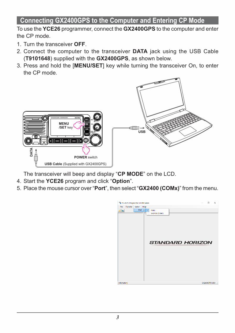
Connecting GX2400GPS to the Computer and Entering CP ModeTo use the YCE26 programmer, connect the GX2400GPS to the computer and enter the CP mode.1. Turn the transceiver OFF.2. Connect the computer to the transceiver DATA jack using the USB Cable
(T9101648) supplied with the GX2400GPS, as shown below.3. Press and hold the [MENU/SET] key while turning the transceiver On, to enter
the CP mode.
USB Cable (Supplied with GX2400GPS)
POWER switch
USB
DAT
A
MENU/SET key
The transceiver will beep and display “CP MODE” on the LCD.4. Start the YCE26 program and click “Option”.5. Place the mouse cursor over “Port”, then select “GX2400 (COMx)” from the menu.
4
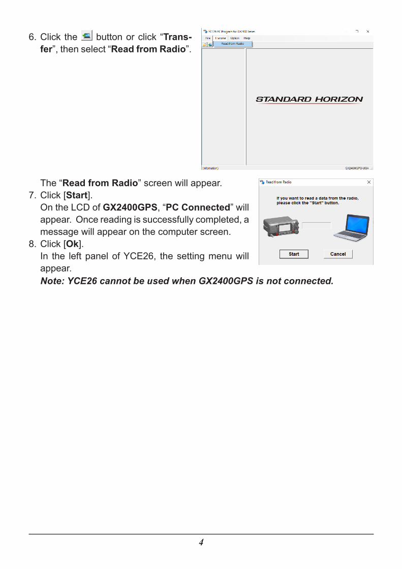
6. Click the button or click “Trans-fer”, then select “Read from Radio”.
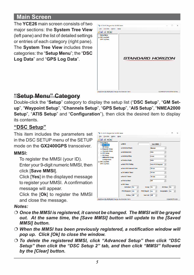
The “Read from Radio” screen will appear.7. Click [Start].
On the LCD of GX2400GPS, “PC Connected” will appear. Once reading is successfully completed, a message will appear on the computer screen.
8. Click [Ok].In the left panel of YCE26, the setting menu will appear.Note: YCE26 cannot be used when GX2400GPS is not connected.
5
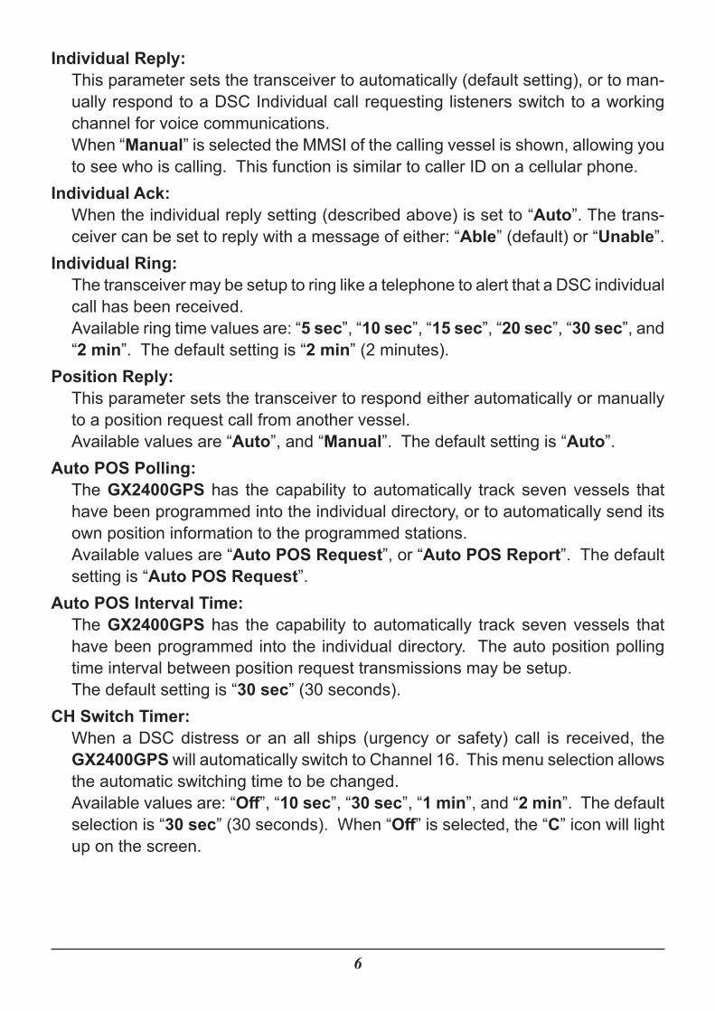
Main ScreenThe YCE26 main screen consists of two major sections: the System Tree View (left pane) and the list of detailed settings or entries of each category (right pane).The System Tree View includes three categories: the “Setup Menu”; the “DSC Log Data” and “GPS Log Data”.
“Setup Menu” CategoryDouble-click the “Setup” category to display the setup list (“DSC Setup”, “GM Set-up”, “Waypoint Setup”, “Channels Setup”, “GPS Setup”, “AIS Setup”, “NMEA2000 Setup”, “ATIS Setup” and “Configuration”), then click the desired item to display its contents.“DSC Setup”This item includes the parameters set in the DSC SETUP menu of the SETUP mode on the GX2400GPS transceiver.MMSI:
To register the MMSI (your ID).Enter your 9-digit numeric MMSI, then click [Save MMSI].Click [Yes] in the displayed message to register your MMSI. A confirmation message will appear.Click the [Ok] to register the MMSI and close the message.
Notes: �� Once the MMSI is registered, it cannot be changed. The MMSI will be grayed out. At the same time, the [Save MMSI] button will update to the [Saved MMSI] button.��When the MMSI has been previously registered, a notification window will pop up. Click [Ok] to close the window.�� To delete the registered MMSI, click “Advanced Setup” then click “DSC Setup” then click the “DSC Setup 2” tab, and then click “MMSI” followed by the [Clear] button.
6
Individual Reply:This parameter sets the transceiver to automatically (default setting), or to man-ually respond to a DSC Individual call requesting listeners switch to a working channel for voice communications.When “Manual” is selected the MMSI of the calling vessel is shown, allowing you to see who is calling. This function is similar to caller ID on a cellular phone.
Individual Ack:When the individual reply setting (described above) is set to “Auto”. The trans-ceiver can be set to reply with a message of either: “Able” (default) or “Unable”.
Individual Ring:The transceiver may be setup to ring like a telephone to alert that a DSC individual call has been received.Available ring time values are: “5 sec”, “10 sec”, “15 sec”, “20 sec”, “30 sec”, and “2 min”. The default setting is “2 min” (2 minutes).
Position Reply:This parameter sets the transceiver to respond either automatically or manually to a position request call from another vessel.Available values are “Auto”, and “Manual”. The default setting is “Auto”.
Auto POS Polling:The GX2400GPS has the capability to automatically track seven vessels that have been programmed into the individual directory, or to automatically send its own position information to the programmed stations.Available values are “Auto POS Request”, or “Auto POS Report”. The default setting is “Auto POS Request”.
Auto POS Interval Time:The GX2400GPS has the capability to automatically track seven vessels that have been programmed into the individual directory. The auto position polling time interval between position request transmissions may be setup.The default setting is “30 sec” (30 seconds).
CH Switch Timer:When a DSC distress or an all ships (urgency or safety) call is received, the GX2400GPS will automatically switch to Channel 16. This menu selection allows the automatic switching time to be changed.Available values are: “Off”, “10 sec”, “30 sec”, “1 min”, and “2 min”. The default selection is “30 sec” (30 seconds). When “Off” is selected, the “C” icon will light up on the screen.
7
No ACT Timer:If no key is pressed during the “MENU” or “DSC CALL” screen, the GX2400GPS will automatically return to radio operation.Available values are: “1 min”, “3 min”, “5 min”, “10 min”, and “15 min”. The default selection is “10 min” (10 minutes).
POS Fix Wait:This menu allows setting the maximum time to wait for position information when receiving a distress call, a POS Report call, or an acknowledgment to a POS request call.Available values are: “Off”, “15 sec”, “30 sec”, “1 min”, “1.5 min”, and “2 min”. The default selection is “Off”.
DSC Beep:This feature allows the alarm beeps to be turned “On” or “Off” when a DSC call is received. DSC call selections are as follows.
• Individual, •Group, •All Ships, •POS Request, •POS Report •Geographic, •Polling, •Test Call
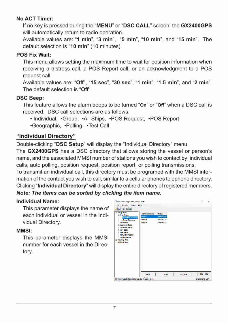
“Individual Directory”Double-clicking “DSC Setup” will display the “Individual Directory” menu.The GX2400GPS has a DSC directory that allows storing the vessel or person’s name, and the associated MMSI number of stations you wish to contact by: individual calls, auto polling, position request, position report, or polling transmissions.To transmit an individual call, this directory must be programed with the MMSI infor-mation of the contact you wish to call, similar to a cellular phones telephone directory.Clicking “Individual Directory” will display the entire directory of registered members.Note: The items can be sorted by clicking the item name.Individual Name:
This parameter displays the name of each individual or vessel in the Indi-vidual Directory.
MMSI:This parameter displays the MMSI number for each vessel in the Direc-tory.
8
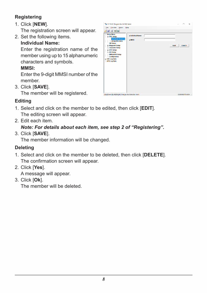
Registering1. Click [NEW].
The registration screen will appear.2. Set the following items.
Individual Name:Enter the registration name of the member using up to 15 alphanumeric characters and symbols.MMSI:Enter the 9-digit MMSI number of the member.
3. Click [SAVE].The member will be registered.
Editing1. Select and click on the member to be edited, then click [EDIT].
The editing screen will appear.2. Edit each item.
Note: For details about each item, see step 2 of “Registering”.3. Click [SAVE].
The member information will be changed.Deleting1. Select and click on the member to be deleted, then click [DELETE].
The confirmation screen will appear.2. Click [Yes].
A message will appear.3. Click [Ok].
The member will be deleted.
9
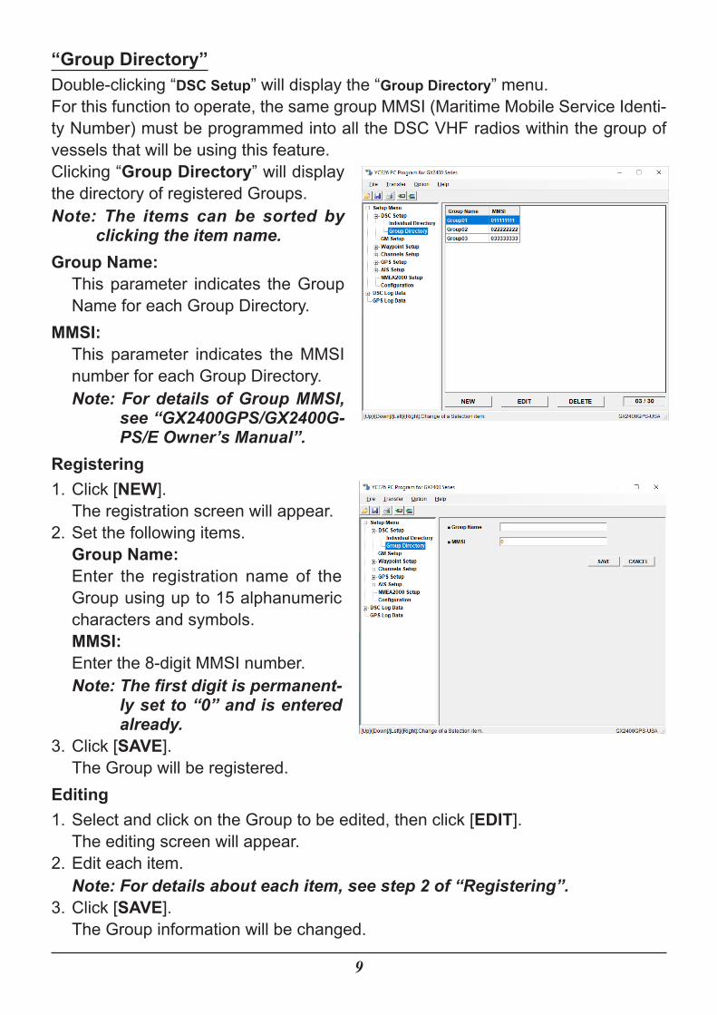
“Group Directory”Double-clicking “DSC Setup” will display the “Group Directory” menu.For this function to operate, the same group MMSI (Maritime Mobile Service Identi-ty Number) must be programmed into all the DSC VHF radios within the group of vessels that will be using this feature.Clicking “Group Directory” will display the directory of registered Groups.Note: The items can be sorted by
clicking the item name.Group Name:
This parameter indicates the Group Name for each Group Directory.
MMSI:This parameter indicates the MMSI number for each Group Directory.Note: For details of Group MMSI,
see “GX2400GPS/GX2400G-PS/E Owner’s Manual”.
Registering1. Click [NEW].
The registration screen will appear.2. Set the following items.
Group Name:Enter the registration name of the Group using up to 15 alphanumeric characters and symbols.MMSI:Enter the 8-digit MMSI number.Note: The first digit is permanent-
ly set to “0” and is entered already.
3. Click [SAVE].The Group will be registered.
Editing1. Select and click on the Group to be edited, then click [EDIT].
The editing screen will appear.2. Edit each item.
Note: For details about each item, see step 2 of “Registering”.3. Click [SAVE].
The Group information will be changed.
10
Deleting1. Select and click on the Group to be deleted, then click [DELETE].
The confirmation screen will appear.2. Click [Yes].
A message will appear.3. Click [Ok].
The Group will be deleted.
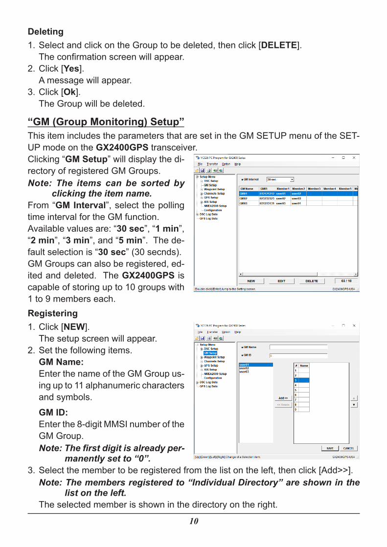
“GM (Group Monitoring) Setup”This item includes the parameters that are set in the GM SETUP menu of the SET-UP mode on the GX2400GPS transceiver.Clicking “GM Setup” will display the di-rectory of registered GM Groups.Note: The items can be sorted by
clicking the item name.From “GM Interval”, select the polling time interval for the GM function.Available values are: “30 sec”, “1 min”, “2 min”, “3 min”, and “5 min”. The de-fault selection is “30 sec” (30 secnds).GM Groups can also be registered, ed-ited and deleted. The GX2400GPS is capable of storing up to 10 groups with 1 to 9 members each.Registering1. Click [NEW].
The setup screen will appear.2. Set the following items.
GM Name:Enter the name of the GM Group us-ing up to 11 alphanumeric characters and symbols.GM ID:Enter the 8-digit MMSI number of the GM Group.Note: The first digit is already per-
manently set to “0”.3. Select the member to be registered from the list on the left, then click [Add>>].
Note: The members registered to “Individual Directory” are shown in the list on the left.
The selected member is shown in the directory on the right.
11
�� To unregister, select the member from the directory on the right, then click [<<Delete].�� To change the registration order, select the member from the directory on the right, then click [▲] / [▼].
4. Click [SAVE].The GM Group will be registered.
Editing1. Select and click on the GM Group to be edited, then click [EDIT].
The editing screen will appear.2. Edit each item.
Note: For details about each item, see step 2 of “Registering”.3. If necessary, follow step 3 of “Registering”.4. Click [SAVE].
The GM Group information will be changed.Deleting1. Select and click the GM Group to be deleted, and then click [DELETE].
The confirmation screen will appear.2. Click [Yes].
A message will appear.3. Click [Ok].
The GM Group will be deleted.
12
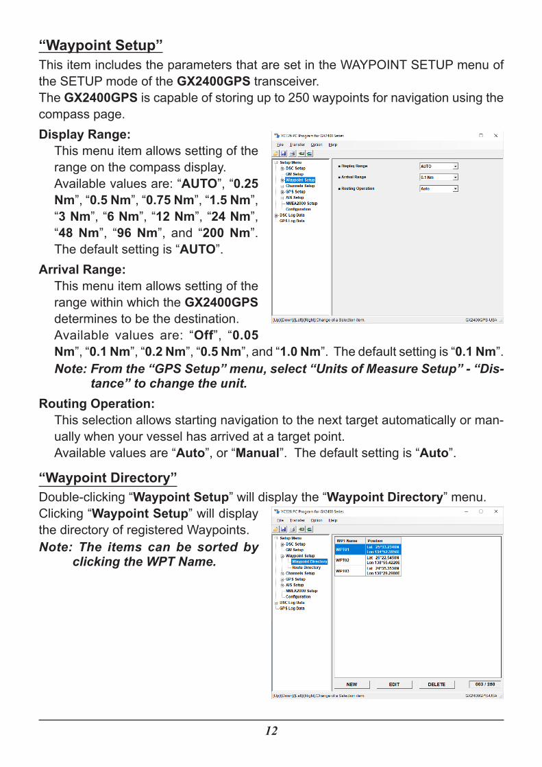
“Waypoint Setup”This item includes the parameters that are set in the WAYPOINT SETUP menu of the SETUP mode of the GX2400GPS transceiver.The GX2400GPS is capable of storing up to 250 waypoints for navigation using the compass page.Display Range:
This menu item allows setting of the range on the compass display.Available values are: “AUTO”, “0.25 Nm”, “0.5 Nm”, “0.75 Nm”, “1.5 Nm”, “3 Nm”, “6 Nm”, “12 Nm”, “24 Nm”, “48 Nm”, “96 Nm”, and “200 Nm”. The default setting is “AUTO”.
Arrival Range:This menu item allows setting of the range within which the GX2400GPS determines to be the destination.Available values are: “Off”, “0.05 Nm”, “0.1 Nm”, “0.2 Nm”, “0.5 Nm”, and “1.0 Nm”. The default setting is “0.1 Nm”.Note: From the “GPS Setup” menu, select “Units of Measure Setup” - “Dis-
tance” to change the unit.Routing Operation:
This selection allows starting navigation to the next target automatically or man-ually when your vessel has arrived at a target point.Available values are “Auto”, or “Manual”. The default setting is “Auto”.
“Waypoint Directory”Double-clicking “Waypoint Setup” will display the “Waypoint Directory” menu.Clicking “Waypoint Setup” will display the directory of registered Waypoints.Note: The items can be sorted by
clicking the WPT Name.
13
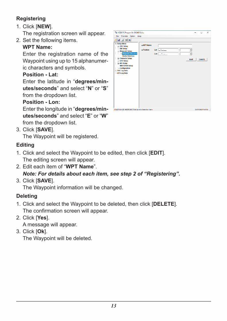
Registering1. Click [NEW].
The registration screen will appear.2. Set the following items.
WPT Name:Enter the registration name of the Waypoint using up to 15 alphanumer-ic characters and symbols.Position - Lat:Enter the latitude in “degrees/min-utes/seconds” and select “N” or “S” from the dropdown list.Position - Lon:Enter the longitude in “degrees/min-utes/seconds” and select “E” or “W” from the dropdown list.
3. Click [SAVE].The Waypoint will be registered.
Editing1. Click and select the Waypoint to be edited, then click [EDIT].
The editing screen will appear.2. Edit each item of “WPT Name”.
Note: For details about each item, see step 2 of “Registering”.3. Click [SAVE].
The Waypoint information will be changed.Deleting1. Click and select the Waypoint to be deleted, then click [DELETE].
The confirmation screen will appear.2. Click [Yes].
A message will appear.3. Click [Ok].
The Waypoint will be deleted.
14
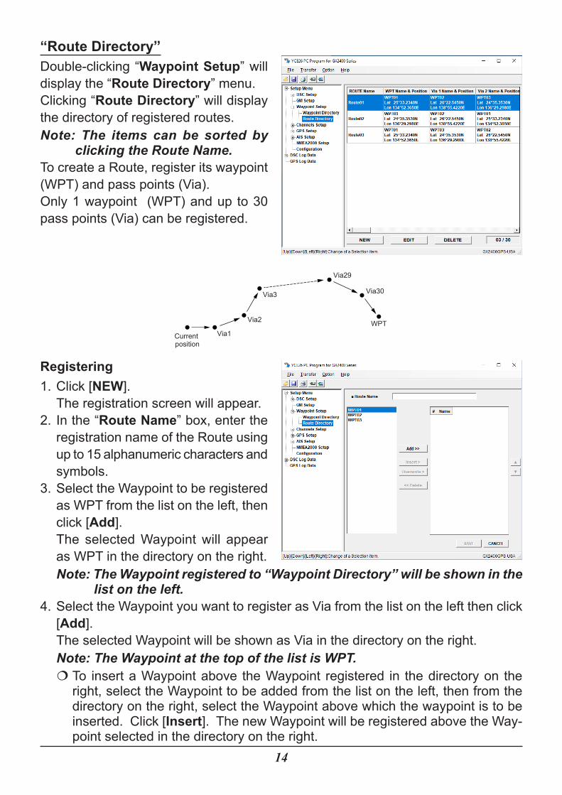
“Route Directory”Double-clicking “Waypoint Setup” will display the “Route Directory” menu.Clicking “Route Directory” will display the directory of registered routes.Note: The items can be sorted by
clicking the Route Name.To create a Route, register its waypoint (WPT) and pass points (Via).Only 1 waypoint (WPT) and up to 30 pass points (Via) can be registered.
Current position
WPTVia1
Via2
Via3
Via29
Via30
Registering1. Click [NEW].
The registration screen will appear.2. In the “Route Name” box, enter the
registration name of the Route using up to 15 alphanumeric characters and symbols.
3. Select the Waypoint to be registered as WPT from the list on the left, then click [Add].The selected Waypoint will appear as WPT in the directory on the right.Note: The Waypoint registered to “Waypoint Directory” will be shown in the
list on the left.4. Select the Waypoint you want to register as Via from the list on the left then click
[Add].The selected Waypoint will be shown as Via in the directory on the right.Note: The Waypoint at the top of the list is WPT.�� To insert a Waypoint above the Waypoint registered in the directory on the right, select the Waypoint to be added from the list on the left, then from the directory on the right, select the Waypoint above which the waypoint is to be inserted. Click [Insert]. The new Waypoint will be registered above the Way-point selected in the directory on the right.
15
�� To overwrite the Waypoint shown in the directory on the right with another Waypoint, select a Waypoint from the list on the left followed by the Waypoint to be overwritten from the directory on the right, and then click [Overwrite]. The Waypoint selected in the directory on the right will be overwritten with the Waypoint selected from the list on the left.�� To unregister the Waypoint shown in the directory on the right, select the Way-point, and then click [Delete].�� To change the Waypoint registration order, select the Waypoint from the direc-tory on the right, then click [▲] / [▼].
5. Click [SAVE].The Route will be registered.
Editing1. Click and select the Route to be edited, then click [EDIT].
The editing screen will appear.2. Edit “Route Name”.3. If necessary, follow steps 3 to 4 of “Registering”.4. Click [SAVE].
The Route information will be changed.Deleting1. Select and click on the Route to be deleted, then click [DELETE].
The confirmation screen will appear.2. Click [Yes].
A message will appear.3. Click [Ok].
The Route will be deleted.
16
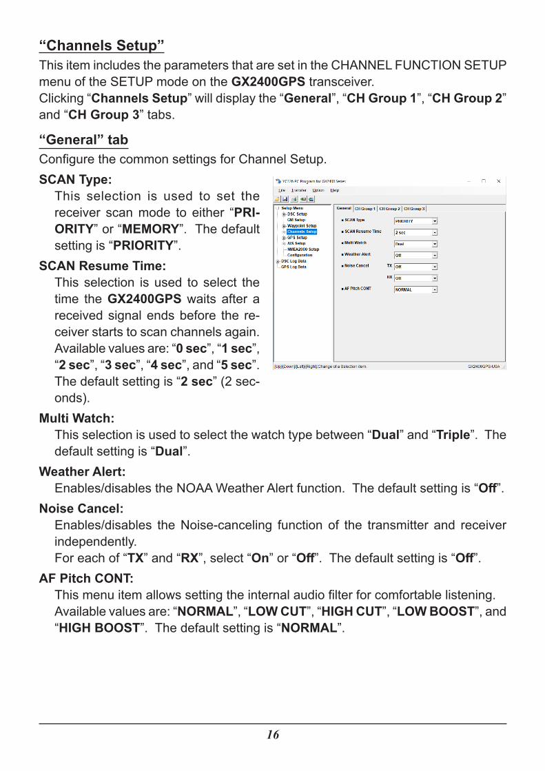
“Channels Setup”This item includes the parameters that are set in the CHANNEL FUNCTION SETUP menu of the SETUP mode on the GX2400GPS transceiver.Clicking “Channels Setup” will display the “General”, “CH Group 1”, “CH Group 2” and “CH Group 3” tabs.
“General” tabConfigure the common settings for Channel Setup.SCAN Type:
This selection is used to set the receiver scan mode to either “PRI-ORITY” or “MEMORY”. The default setting is “PRIORITY”.
SCAN Resume Time:This selection is used to select the time the GX2400GPS waits after a received signal ends before the re-ceiver starts to scan channels again.Available values are: “0 sec”, “1 sec”, “2 sec”, “3 sec”, “4 sec”, and “5 sec”. The default setting is “2 sec” (2 sec-onds).
Multi Watch:This selection is used to select the watch type between “Dual” and “Triple”. The default setting is “Dual”.
Weather Alert:Enables/disables the NOAA Weather Alert function. The default setting is “Off”.
Noise Cancel:Enables/disables the Noise-canceling function of the transmitter and receiver independently.For each of “TX” and “RX”, select “On” or “Off”. The default setting is “Off”.
AF Pitch CONT:This menu item allows setting the internal audio filter for comfortable listening.Available values are: “NORMAL”, “LOW CUT”, “HIGH CUT”, “LOW BOOST”, and “HIGH BOOST”. The default setting is “NORMAL”.
17
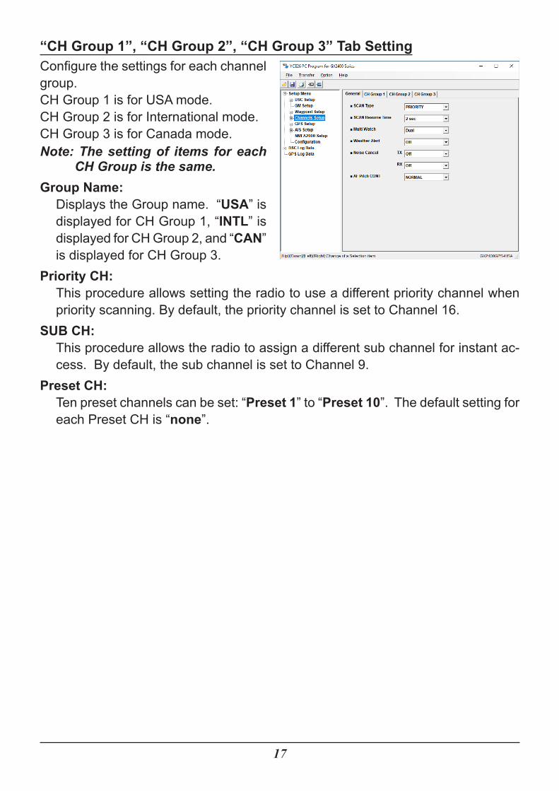
“CH Group 1”, “CH Group 2”, “CH Group 3” Tab SettingConfigure the settings for each channel group.CH Group 1 is for USA mode.CH Group 2 is for International mode.CH Group 3 is for Canada mode.Note: The setting of items for each
CH Group is the same.Group Name:
Displays the Group name. “USA” is displayed for CH Group 1, “INTL” is displayed for CH Group 2, and “CAN” is displayed for CH Group 3.
Priority CH:This procedure allows setting the radio to use a different priority channel when priority scanning. By default, the priority channel is set to Channel 16.
SUB CH:This procedure allows the radio to assign a different sub channel for instant ac-cess. By default, the sub channel is set to Channel 9.
Preset CH:Ten preset channels can be set: “Preset 1” to “Preset 10”. The default setting for each Preset CH is “none”.
18
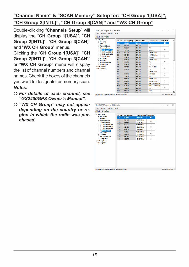
“Channel Name” & “SCAN Memory” Setup for: “CH Group 1[USA]”,“CH Group 2[INTL]”, “CH Group 3[CAN]” and “WX CH Group”Double-clicking “Channels Setup” will display the “CH Group 1[USA]”, “CH Group 2[INTL]”, “CH Group 3[CAN]” and “WX CH Group” menus.Clicking the “CH Group 1[USA]”, “CH Group 2[INTL]”, “CH Group 3[CAN]” or “WX CH Group” menu will display the list of channel numbers and channel names. Check the boxes of the channels you want to designate for memory scan.Notes:�� For details of each channel, see “GX2400GPS Owner’s Manual”.�� “WX CH Group” may not appear depending on the country or re-gion in which the radio was pur-chased.
19
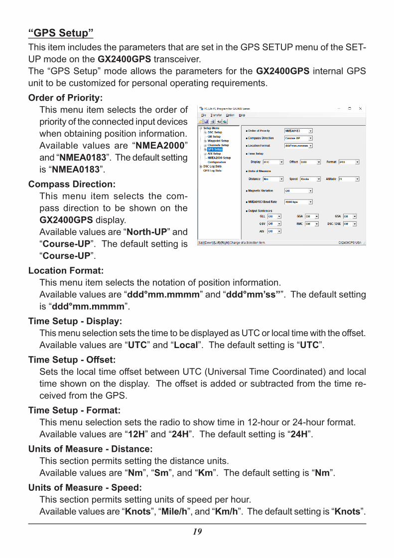
“GPS Setup”This item includes the parameters that are set in the GPS SETUP menu of the SET-UP mode on the GX2400GPS transceiver.The “GPS Setup” mode allows the parameters for the GX2400GPS internal GPS unit to be customized for personal operating requirements.Order of Priority:
This menu item selects the order of priority of the connected input devices when obtaining position information.Available values are “NMEA2000” and “NMEA0183”. The default setting is “NMEA0183”.
Compass Direction:This menu item selects the com-pass direction to be shown on the GX2400GPS display.Available values are “North-UP” and “Course-UP”. The default setting is “Course-UP”.
Location Format:This menu item selects the notation of position information.Available values are “ddd°mm.mmmm” and “ddd°mm’ss””. The default setting is “ddd°mm.mmmm”.
Time Setup - Display:This menu selection sets the time to be displayed as UTC or local time with the offset.Available values are “UTC” and “Local”. The default setting is “UTC”.
Time Setup - Offset:Sets the local time offset between UTC (Universal Time Coordinated) and local time shown on the display. The offset is added or subtracted from the time re-ceived from the GPS.
Time Setup - Format:This menu selection sets the radio to show time in 12-hour or 24-hour format.Available values are “12H” and “24H”. The default setting is “24H”.
Units of Measure - Distance:This section permits setting the distance units.Available values are “Nm”, “Sm”, and “Km”. The default setting is “Nm”.
Units of Measure - Speed:This section permits setting units of speed per hour.Available values are “Knots”, “Mile/h”, and “Km/h”. The default setting is “Knots”.
20
Units of Measure - Altitude:This section permits setting the altitude units.Available values are “Ft” and “m”. The default setting is “Ft”.
Magnetic Variation:Enables/disables the magnetic variation function.Available values are “Off” and “On”. The default setting is “Off”.
NMEA0183 Baud Rate:This section permits setting the NMEA0183 baud rate.Available values are “4800 bps” and “38400 bps”. The default setting is “4800 bps”.
Output Sentences:This selection is used to setup the NMEA output sentences of the GX2400GPS. The settable Output Sentences are as follows.
• GLL, •GGA, •GSA, •GSV, •RMC, •DSC/DSE, •AISBy default, all the NMEA sentences are turned “OFF”.
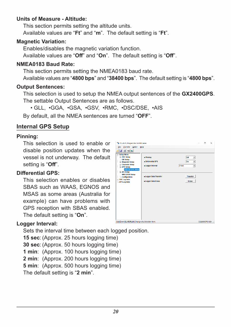
Internal GPS SetupPinning:
This selection is used to enable or disable position updates when the vessel is not underway. The default setting is “Off”.
Differential GPS:This selection enables or disables SBAS such as WAAS, EGNOS and MSAS as some areas (Australia for example) can have problems with GPS reception with SBAS enabled. The default setting is “On”.
Logger Interval:Sets the interval time between each logged position.15 sec: (Approx. 25 hours logging time)30 sec: (Approx. 50 hours logging time)1 min: (Approx. 100 hours logging time)2 min: (Approx. 200 hours logging time)5 min: (Approx. 500 hours logging time)The default setting is “2 min”.
21
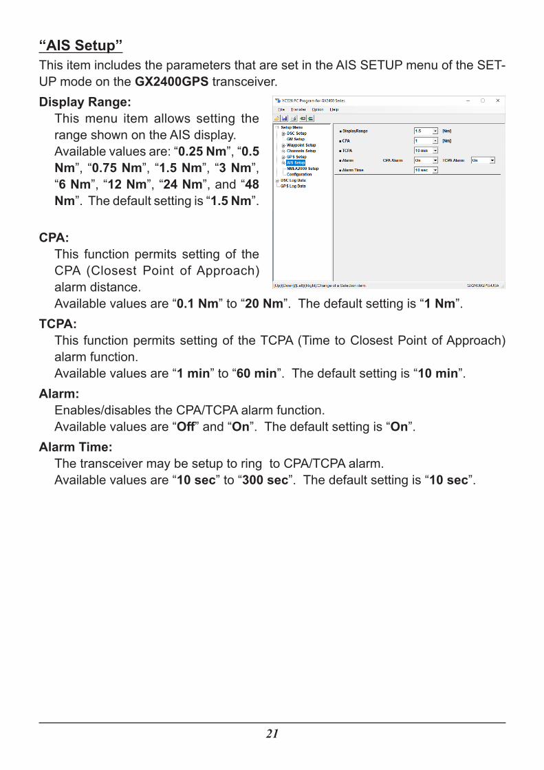
“AIS Setup”This item includes the parameters that are set in the AIS SETUP menu of the SET-UP mode on the GX2400GPS transceiver.Display Range:
This menu item allows setting the range shown on the AIS display.Available values are: “0.25 Nm”, “0.5 Nm”, “0.75 Nm”, “1.5 Nm”, “3 Nm”, “6 Nm”, “12 Nm”, “24 Nm”, and “48 Nm”. The default setting is “1.5 Nm”.
CPA:This function permits setting of the CPA (Closest Point of Approach) alarm distance.Available values are “0.1 Nm” to “20 Nm”. The default setting is “1 Nm”.
TCPA:This function permits setting of the TCPA (Time to Closest Point of Approach) alarm function.Available values are “1 min” to “60 min”. The default setting is “10 min”.
Alarm:Enables/disables the CPA/TCPA alarm function.Available values are “Off” and “On”. The default setting is “On”.
Alarm Time:The transceiver may be setup to ring to CPA/TCPA alarm.Available values are “10 sec” to “300 sec”. The default setting is “10 sec”.
22
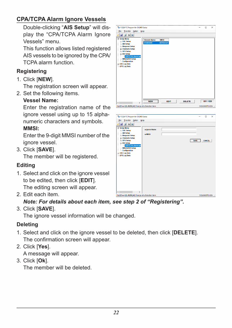
CPA/TCPA Alarm Ignore VesselsDouble-clicking “AIS Setup” will dis-play the “CPA/TCPA Alarm Ignore Vessels” menu.This function allows listed registered AIS vessels to be ignored by the CPA/TCPA alarm function.
Registering1. Click [NEW].
The registration screen will appear.2. Set the following items.
Vessel Name:Enter the registration name of the ignore vessel using up to 15 alpha-numeric characters and symbols.MMSI:Enter the 9-digit MMSI number of the ignore vessel.
3. Click [SAVE].The member will be registered.
Editing1. Select and click on the ignore vessel
to be edited, then click [EDIT].The editing screen will appear.
2. Edit each item.Note: For details about each item, see step 2 of “Registering”.
3. Click [SAVE].The ignore vessel information will be changed.
Deleting1. Select and click on the ignore vessel to be deleted, then click [DELETE].
The confirmation screen will appear.2. Click [Yes].
A message will appear.3. Click [Ok].
The member will be deleted.
23
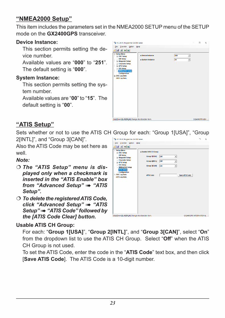
“NMEA2000 Setup”This item includes the parameters set in the NMEA2000 SETUP menu of the SETUP mode on the GX2400GPS transceiver.Device Instance:
This section permits setting the de-vice number.Available values are “000” to “251”. The default setting is “000”.
System Instance:This section permits setting the sys-tem number.Available values are “00” to “15”. The default setting is “00”.
“ATIS Setup”Sets whether or not to use the ATIS CH Group for each: “Group 1[USA]”, “Group 2[INTL]”, and “Group 3[CAN]”.Also the ATIS Code may be set here as well.Note:�� The “ATIS Setup” menu is dis-played only when a checkmark is inserted in the “ATIS Enable” box from “Advanced Setup” à “ATIS Setup”.�� To delete the registered ATIS Code, click “Advanced Setup” à “ATIS Setup” à “ATIS Code” followed by the [ATIS Code Clear] button.
Usable ATIS CH Group:For each: “Group 1[USA]”, “Group 2[INTL]”, and “Group 3[CAN]”, select “On” from the dropdown list to use the ATIS CH Group. Select “Off” when the ATIS CH Group is not used.To set the ATIS Code, enter the code in the “ATIS Code” text box, and then click [Save ATIS Code]. The ATIS Code is a 10-digit number.
24
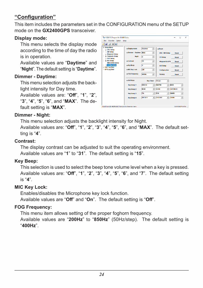
“Configuration”This item includes the parameters set in the CONFIGURATION menu of the SETUP mode on the GX2400GPS transceiver.Display mode:
This menu selects the display mode according to the time of day the radio is in operation.Available values are “Daytime” and “Night”. The default setting is “Daytime”.
Dimmer - Daytime:This menu selection adjusts the back-light intensity for Day time.Available values are: “Off”, “1”, “2”, “3”, “4”, “5”, “6”, and “MAX”. The de-fault setting is “MAX”.
Dimmer - Night:This menu selection adjusts the backlight intensity for Night.Available values are: “Off”, “1”, “2”, “3”, “4”, “5”, “6”, and “MAX”. The default set-ting is “4”.
Contrast:The display contrast can be adjusted to suit the operating environment.Available values are “1” to “31”. The default setting is “15”.
Key Beep:This selection is used to select the beep tone volume level when a key is pressed.Available values are: “Off”, “1”, “2”, “3”, “4”, “5”, “6”, and “7”. The default setting is “4”.
MIC Key Lock:Enables/disables the Microphone key lock function.Available values are “Off” and “On”. The default setting is “Off”.
FOG Frequency:This menu item allows setting of the proper foghorn frequency.Available values are “200Hz” to “850Hz” (50Hz/step). The default setting is “400Hz”.
25
Reset:The memory and settings of the setup categories may be initialized independently, or the transceiver may be returned to the original factory setting.Click [Reset] of the desired category to initialize the settings or to erase the data.The resettable setting items are as follows.• DSC / GM Setup• CH Setup• Waypoint & GPS• AIS Setup• Configuration• Factory�� If a reset is started before connecting the radio to the computer, the settings that have been entered on the YCE26 programmer will be cleared.�� If a reset is started after connecting the radio to the computer, the radio’s set-tings and data will be cleared.
Note: See Page 3 for details about the connection between the radio and the computer.
�� Clicking [Reset] will display the confirmation message. Clicking [Yes] will reset the settings and cause a confirmation message to appear. Click [Ok] in the displayed message.
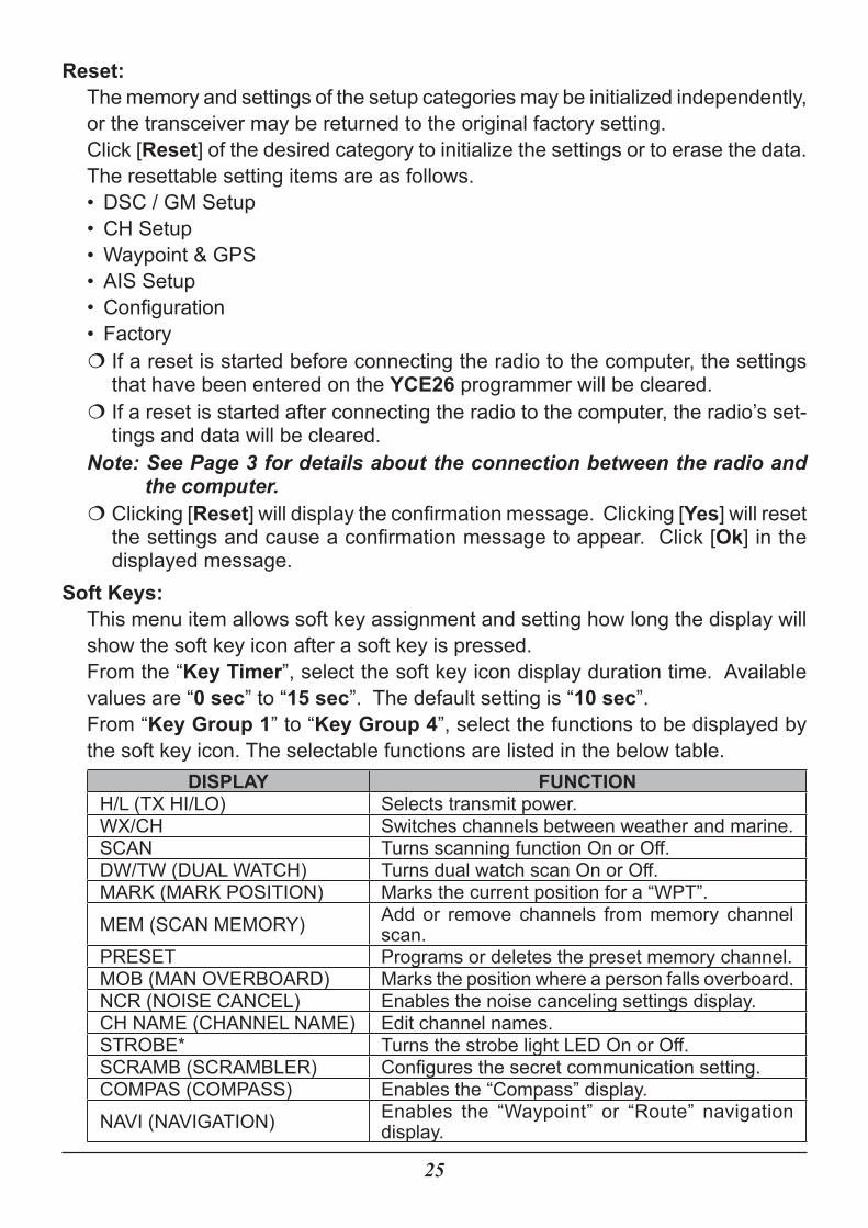
Soft Keys:This menu item allows soft key assignment and setting how long the display will show the soft key icon after a soft key is pressed.From the “Key Timer”, select the soft key icon display duration time. Available values are “0 sec” to “15 sec”. The default setting is “10 sec”.From “Key Group 1” to “Key Group 4”, select the functions to be displayed by the soft key icon. The selectable functions are listed in the below table.
DISPLAY FUNCTIONH/L (TX HI/LO) Selects transmit power.WX/CH Switches channels between weather and marine.SCAN Turns scanning function On or Off.DW/TW (DUAL WATCH) Turns dual watch scan On or Off.MARK (MARK POSITION) Marks the current position for a “WPT”.MEM (SCAN MEMORY) Add or remove channels from memory channel
scan.PRESET Programs or deletes the preset memory channel.MOB (MAN OVERBOARD) Marks the position where a person falls overboard.NCR (NOISE CANCEL) Enables the noise canceling settings display.CH NAME (CHANNEL NAME) Edit channel names.STROBE* Turns the strobe light LED On or Off.SCRAMB (SCRAMBLER) Configures the secret communication setting.COMPAS (COMPASS) Enables the “Compass” display.NAVI (NAVIGATION) Enables the “Waypoint” or “Route” navigation
display.
26
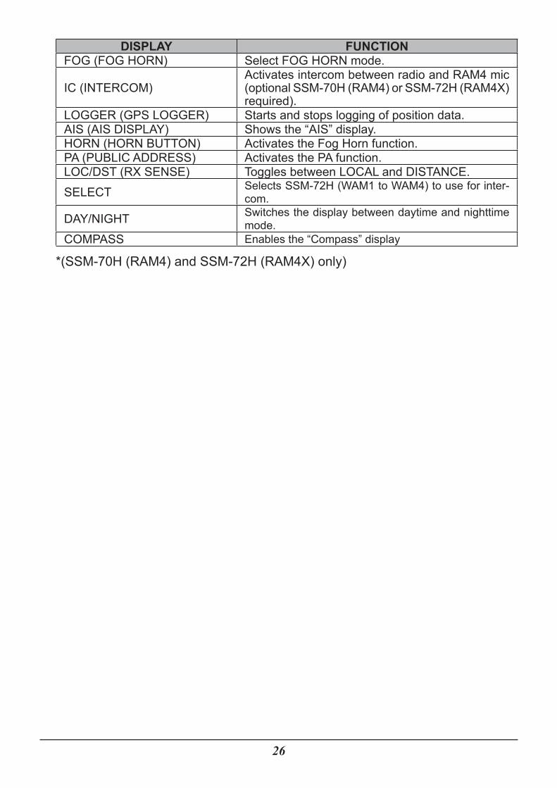
DISPLAY FUNCTIONFOG (FOG HORN) Select FOG HORN mode.
IC (INTERCOM)Activates intercom between radio and RAM4 mic (optional SSM-70H (RAM4) or SSM-72H (RAM4X) required).
LOGGER (GPS LOGGER) Starts and stops logging of position data.AIS (AIS DISPLAY) Shows the “AIS” display.HORN (HORN BUTTON) Activates the Fog Horn function.PA (PUBLIC ADDRESS) Activates the PA function.LOC/DST (RX SENSE) Toggles between LOCAL and DISTANCE.SELECT Selects SSM-72H (WAM1 to WAM4) to use for inter-
com.
DAY/NIGHT Switches the display between daytime and nighttime mode.
COMPASS Enables the “Compass” display
*(SSM-70H (RAM4) and SSM-72H (RAM4X) only)
27
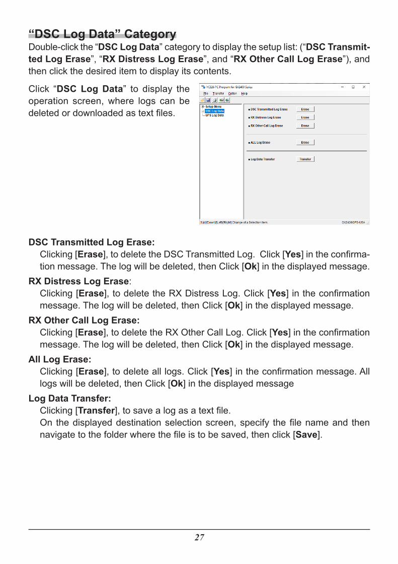
“DSC Log Data” CategoryDouble-click the “DSC Log Data” category to display the setup list: (“DSC Transmit-ted Log Erase”, “RX Distress Log Erase”, and “RX Other Call Log Erase”), and then click the desired item to display its contents.
Click “DSC Log Data” to display the operation screen, where logs can be deleted or downloaded as text files.
DSC Transmitted Log Erase:Clicking [Erase], to delete the DSC Transmitted Log. Click [Yes] in the confirma-tion message. The log will be deleted, then Click [Ok] in the displayed message.
RX Distress Log Erase:Clicking [Erase], to delete the RX Distress Log. Click [Yes] in the confirmation message. The log will be deleted, then Click [Ok] in the displayed message.
RX Other Call Log Erase:Clicking [Erase], to delete the RX Other Call Log. Click [Yes] in the confirmation message. The log will be deleted, then Click [Ok] in the displayed message.
All Log Erase:Clicking [Erase], to delete all logs. Click [Yes] in the confirmation message. All logs will be deleted, then Click [Ok] in the displayed message
Log Data Transfer:Clicking [Transfer], to save a log as a text file.On the displayed destination selection screen, specify the file name and then navigate to the folder where the file is to be saved, then click [Save].
28
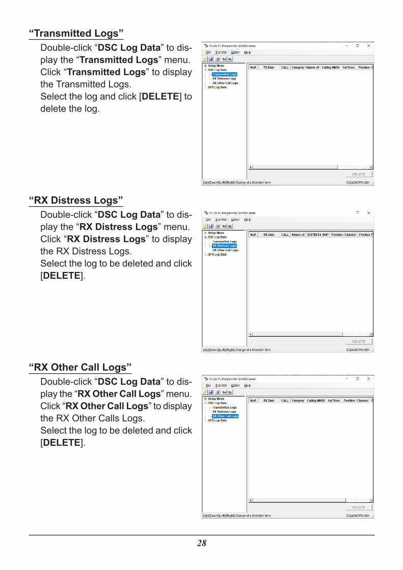
“Transmitted Logs”Double-click “DSC Log Data” to dis-play the “Transmitted Logs” menu.Click “Transmitted Logs” to display the Transmitted Logs.Select the log and click [DELETE] to delete the log.
“RX Distress Logs”Double-click “DSC Log Data” to dis-play the “RX Distress Logs” menu.Click “RX Distress Logs” to display the RX Distress Logs.Select the log to be deleted and click [DELETE].
“RX Other Call Logs”Double-click “DSC Log Data” to dis-play the “RX Other Call Logs” menu.Click “RX Other Call Logs” to display the RX Other Calls Logs.Select the log to be deleted and click [DELETE].
29
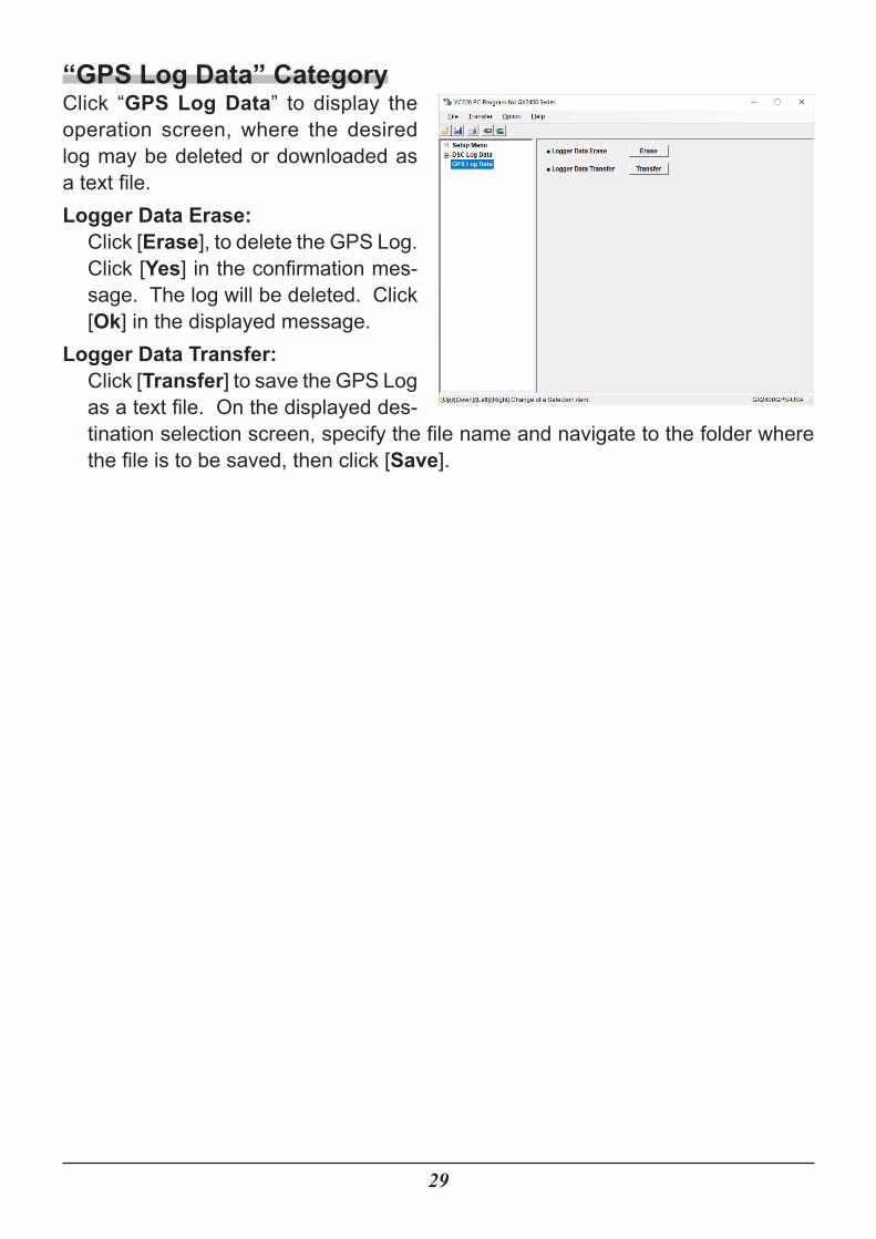
“GPS Log Data” CategoryClick “GPS Log Data” to display the operation screen, where the desired log may be deleted or downloaded as a text file.Logger Data Erase:
Click [Erase], to delete the GPS Log. Click [Yes] in the confirmation mes-sage. The log will be deleted. Click [Ok] in the displayed message.
Logger Data Transfer:Click [Transfer] to save the GPS Log as a text file. On the displayed des-tination selection screen, specify the file name and navigate to the folder where the file is to be saved, then click [Save].
30
“File”This menu performs opening, saving, and printing of files with a “.dat” extension; these files contain the settings and channel memory of the radio.“New”This selection opens a new file. Click the left mouse button on the “New” parameter in the “File” menu, open the default configuration of the YCE26 programming software.“Open”This selection opens a previously-saved configuration from the computer. Click the left mouse button on the “Open” parameter in the “File” menu, a pop-up window will display all the current files saved in the specified path. Double click the left mouse button on the desired configuration file to open it.“Save”This selection saves the programming file to the computer with the same name and directory. Click the left mouse button on the “Save” parameter in the “File” menu, a caution message appears. To agree and over-write the current file, click the left mouse button on the “OK” box.“Save As...”This selection saves the programming session to the computer with a new name. Click the left mouse button on the “Save As” parameter in the File menu, a pop-up window will show all the current files saved to the specified path. To save the pro-gramming session with a new name, type a filename in the bottom box, then click the left mouse button on the “OK” box.“Print” ► “Print”This selection prints a programming configuration to hard copy. Click the left mouse button on the “Print” parameter in the “File” menu, the “Printer” window will open.
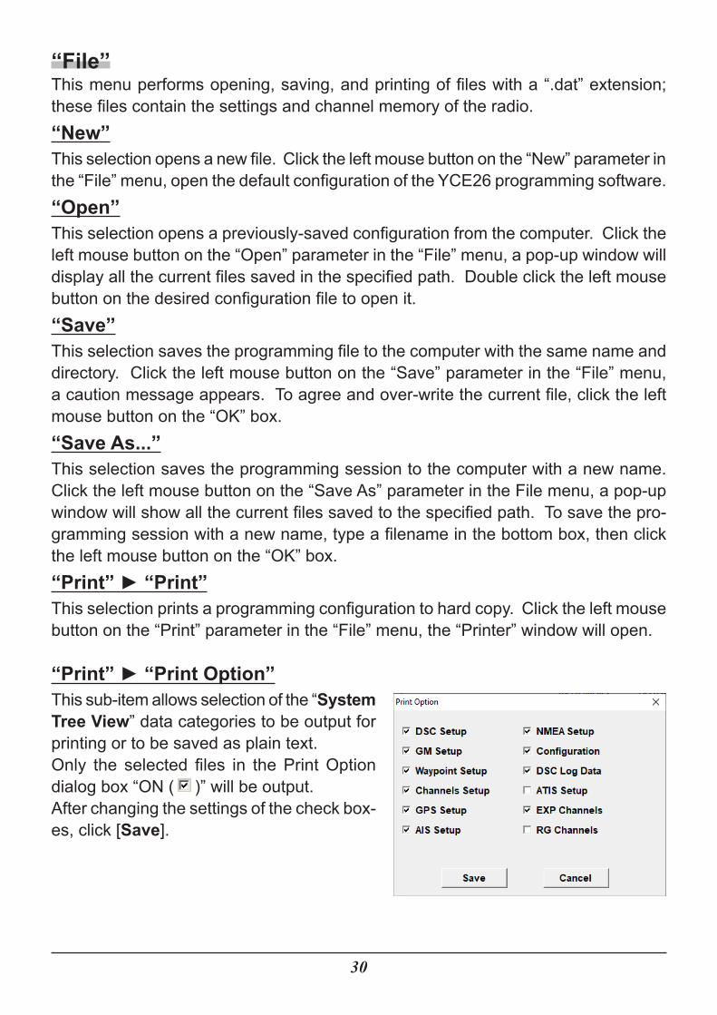
“Print” ► “Print Option”This sub-item allows selection of the “System Tree View” data categories to be output for printing or to be saved as plain text.Only the selected files in the Print Option dialog box “ON ( )” will be output.After changing the settings of the check box-es, click [Save].
31
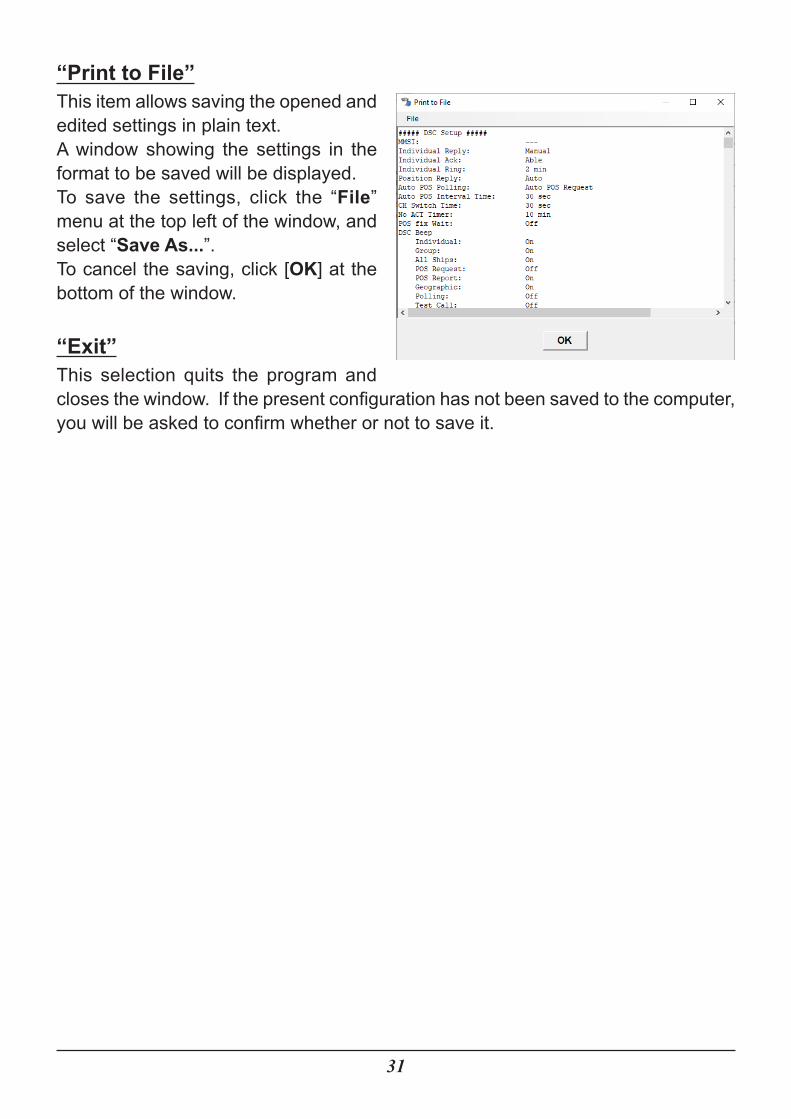
“Print to File”This item allows saving the opened and edited settings in plain text.A window showing the settings in the format to be saved will be displayed.To save the settings, click the “File” menu at the top left of the window, and select “Save As...”.To cancel the saving, click [OK] at the bottom of the window.
“Exit”This selection quits the program and closes the window. If the present configuration has not been saved to the computer, you will be asked to confirm whether or not to save it.
32
“Transfer”This menu facilitates uploading and downloading information to or from a radio. To transfer data to or from the radio, make a proper connection between the computer and the radio (see Page 3 “Connecting GX2400GPS to the Computer and Entering CP Mode”), and then select the “Transfer” menu.Note: The Radio must be in CP mode to download or upload data. Press and
hold the MENU button on the radio while powering it On, “CP MODE” will be displayed.
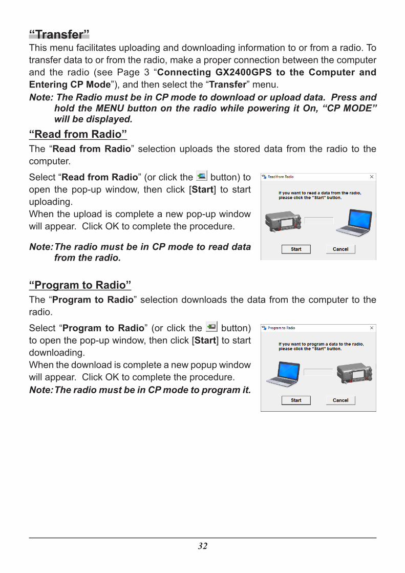
“Read from Radio”The “Read from Radio” selection uploads the stored data from the radio to the computer.Select “Read from Radio” (or click the button) to open the pop-up window, then click [Start] to start uploading.When the upload is complete a new pop-up window will appear. Click OK to complete the procedure.
Note: The radio must be in CP mode to read data from the radio.
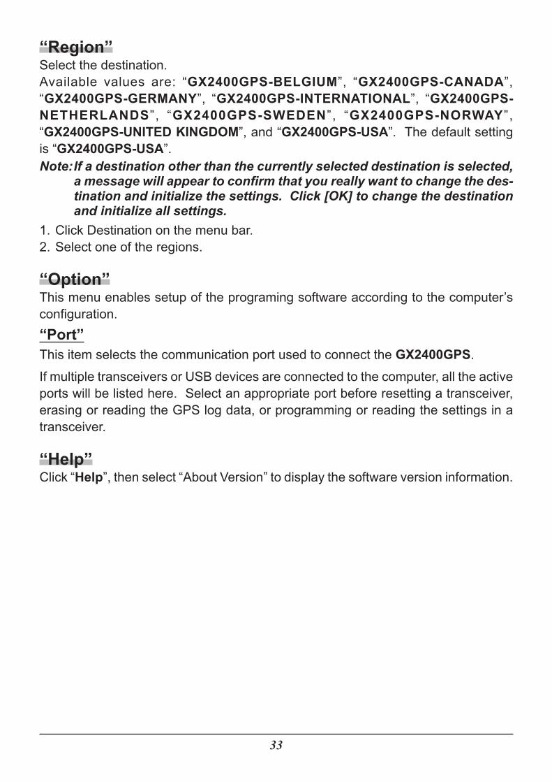
“Program to Radio”The “Program to Radio” selection downloads the data from the computer to the radio.Select “Program to Radio” (or click the button) to open the pop-up window, then click [Start] to start downloading.When the download is complete a new popup window will appear. Click OK to complete the procedure.Note: The radio must be in CP mode to program it.
33
“Region”Select the destination.Available values are: “GX2400GPS-BELGIUM”, “GX2400GPS-CANADA”, “GX2400GPS-GERMANY”, “GX2400GPS-INTERNATIONAL”, “GX2400GPS-NETHERLANDS”, “GX2400GPS-SWEDEN”, “GX2400GPS-NORWAY”, “GX2400GPS-UNITED KINGDOM”, and “GX2400GPS-USA”. The default setting is “GX2400GPS-USA”.Note: If a destination other than the currently selected destination is selected,
a message will appear to confirm that you really want to change the des-tination and initialize the settings. Click [OK] to change the destination and initialize all settings.
1. Click Destination on the menu bar.2. Select one of the regions.
“Option”This menu enables setup of the programing software according to the computer’s configuration.“Port”This item selects the communication port used to connect the GX2400GPS.If multiple transceivers or USB devices are connected to the computer, all the active ports will be listed here. Select an appropriate port before resetting a transceiver, erasing or reading the GPS log data, or programming or reading the settings in a transceiver.
“Help”Click “Help”, then select “About Version” to display the software version information.

YAESU MUSEN CO., LTD.All rights reserved.No portion of this manual may be reproduced without the permission of YAESU MUSEN CO., LTD.
YAESU MUSEN CO., LTD.Tennozu Parkside Building2-5-8 Higashi-Shinagawa, Shinagawa-ku, Tokyo 140-0002 JapanYAESU USA6125 Phyllis Drive, Cypress, CA 90630, U.S.A.YAESU UKUnit 12, Sun Valley Business Park, Winnall CloseWinchester, Hampshire, SO23 0LB, U.K. 2006-A
Copyright 2020


