Embed Size (px)
Citation preview

PCN-Based Measured Rate Termination
Michael Menth and Frank Lehrieder
University of Würzburg, Institute of Computer Science, Germany
Abstract
Overload in a packet-based network can be prevented by admitting or blocking new flowsdepending on its load conditions. However, overload can occur in spite ofadmission controldue to unforseen events, e.g., when admitted traffic is rerouted in the network after a failure.To restore quality of service for the majority of admitted flows in such cases, flow termi-nation has been proposed as a novel control function. We present several flow terminationalgorithms that measure so-called pre-congestion notification (PCN) feedback. We analyzetheir advantages and shortcomings in particular under challenging conditions. The resultsimprove the understanding of PCN technology which is currently being standardized bythe Internet Engineering Task Force (IETF).
Key words: Flow termination, admission control, resilience, QoS, Differentiated Services
1 Introduction
DiffServ networks [1] offer preferred treatment of high-priority traffic so that pre-mium traffic like voice or video do not suffer packet loss or delay caused by othertraffic which is carried over the same transmission links. However, if the rate ofprioritized traffic is too large, overload of high-prioritytraffic may occur and leadto extensive packet loss and delay for prioritized traffic, too. This can happen sincenormal DiffServ networks lack an admission control (AC) function which admitshigh-priority flows to the network only if sufficient free capacity is still availablefor this traffic class.
This work is funded by Nortel Networks, Ottawa, and Deutsche Forschungsgemeinschaft(DFG) under grant TR257/18-2. The authors alone are responsible for the content of thepaper.
Preprint submitted to Elsevier Science 3 February 2010

The Internet Engineering Task Force (IETF) currently standardizes pre-congestionnotification (PCN) [2]. PCN gives warnings to egress nodes nodes of a DiffServdomain [1] if the load of high-priority traffic has exceeded acritical level on somelink. This information is used to implement a lightweight ACin the sense that per-flow states need to be kept only where flows enter and leave the domain.
Under normal conditions, PCN-based AC can enforce quality ofservice (QoS) inDiffServ networks. However, overload can occur in spite of AC due to unforseenevents. For instance, admitted PCN traffic may be rerouted in case of a network fail-ure and cause overload on backup links, or the rate of multiple admitted PCN flowsmay suddenly increase. To restore then a “controlled load” situation [3], flow ter-mination (FT) has been proposed in the PCN context as an additional flow controlfunction.
In [4] we have presented a survey of PCN-based AC and FT. In thispaper, we inves-tigate the performance of FT methods that rely on measured PCNfeedback (mea-sured rate termination, MRT). We show that some of them terminate more trafficthan desired under certain conditions while others take quite a while to remove ex-cess traffic. In addition, we propose countermeasures that improve the performance.This study covers in particular the FT algorithms that are eventually standardized.Our analytical and simulation results explain why these algorithms were chosenand reveal which conditions need to be met for proper operation.
The paper is structured as follows. Section 2 explains PCN, metering and mark-ing algorithms as well as various FT algorithms. Section 3 reviews related work.Section 4 studies MRT methods under challenging conditions. Finally, Section 5summarizes our findings and Section 6 draws conclusions. Theappendix containsa list of frequently used acronyms.
2 Flow Termination Based on Pre-Congestion Notification (PCN)
In this section we explain the general idea of PCN-based admission control (AC)and flow termination (FT) and illustrate their application in a DiffServ domain inthe Internet. We explain the metering and marking algorithms briefly and the FTalgorithms in more detail.
2.1 Pre-Congestion Notification (PCN)
PCN defines a new traffic class for DiffServ networks that receives preferred for-warding treatment. Moreover, PCN provides feedback information from inside aDiffServ domain for AC and FT decisions at the borders to support QoS. To that
2

end, PCN introduces an admissible and a supportable rate threshold (ARl , SRl )for each linkl of the DiffServ domain. This implies three different load regimesas illustrated in Figure 1. If the PCN traffic rater l is belowARl , there is no pre-congestion and further flows may be admitted. If the PCN trafficrate r l is aboveARl , the link is AR-pre-congested and the rate aboveARl is AR-overload. In thisstate, no further PCN flows should be admitted that would be carried over this link.If the PCN traffic rater l is aboveSRl , the link is SR-pre-congested and the rateaboveSRl is SR-overload. In this state, some already admitted flows that are car-ried over this link should be terminated to reduce the PCN rater l belowSRl .
0
Pre-congestion
type
Impact on
AC and FT
No pre-congestion
ARl
Admit new flows
AR-pre-congestion
SRl
Block new flows
AR-overload
SR-pre-congestion
Block new flows
Terminate someadmitted flows
SR-overload
PCN
rate rl
on link l
Fig. 1. The admissible and the supportable rate (ARl ,SRl ) define three types of pre-conges-tion on link l .
2.2 Application of PCN in the Internet
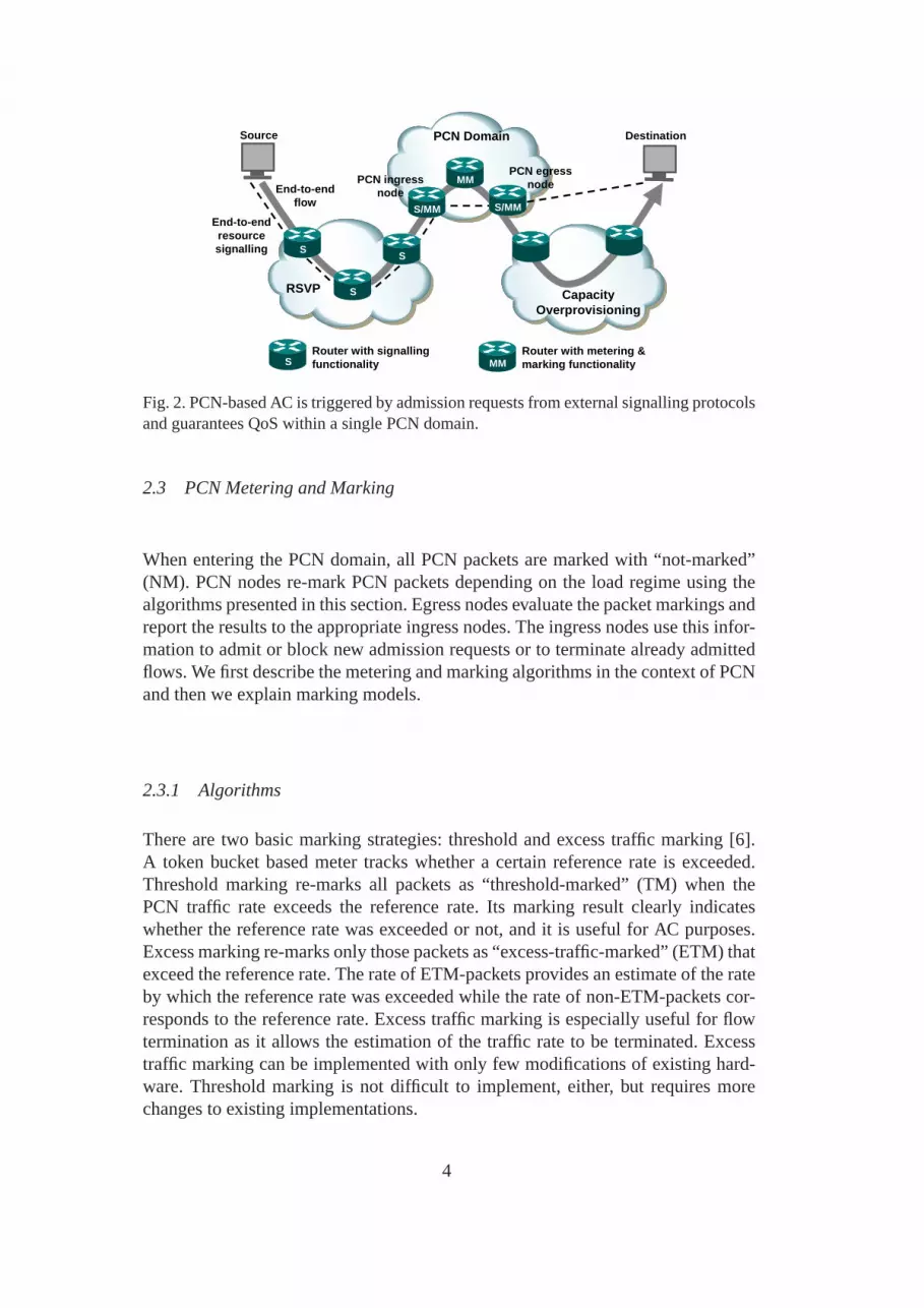
PCN-based flow control assumes that some end-to-end signalling protocol (e.g.RSVP or SIP) or a similar mechanism requests admission for a new flow to crossa so-called PCN domain which is similar to the IntServ-over-DiffServ concept [5].Thus, PCN-based AC and FT are per-domain QoS mechanisms and present an al-ternative to RSVP clouds or extreme capacity overprovisioning. This is illustratedin Figure 2. Traffic enters a PCN domain only through PCN ingressnodes andleaves it only through PCN egress nodes. Ingress nodes set a special header code-point to make the packets distinguishable from other trafficand the egress nodesclear the codepoint. The nodes within a PCN domain are PCN nodes. They monitorthe PCN traffic rate on their links and possibly re-mark the traffic in case of AR-or SR-pre-congestion. PCN egress nodes evaluate the markingsof the traffic andsend the results to the AC and FT entities of the PCN domain. In the following, weassume for simplicity reasons that the AC and FT entities arecollocated with theingress nodes of the traffic. Centralized AC and FT entities are also discussed forwhich the findings of this study are also valid.
3
PCN Domain
RSVP Capacity Overprovisioning
Source Destination
End-to-end flow
PCN ingress node
PCN egress node
Router with signallingfunctionality
Router with metering & marking functionalityMMS
S/MM
MM
S
End-to-end resource signalling
S/MM
S
S
Fig. 2. PCN-based AC is triggered by admission requests from external signalling protocolsand guarantees QoS within a single PCN domain.
2.3 PCN Metering and Marking
When entering the PCN domain, all PCN packets are marked with “not-marked”(NM). PCN nodes re-mark PCN packets depending on the load regime using thealgorithms presented in this section. Egress nodes evaluate the packet markings andreport the results to the appropriate ingress nodes. The ingress nodes use this infor-mation to admit or block new admission requests or to terminate already admittedflows. We first describe the metering and marking algorithms in the context of PCNand then we explain marking models.
2.3.1 Algorithms
There are two basic marking strategies: threshold and excess traffic marking [6].A token bucket based meter tracks whether a certain reference rate is exceeded.Threshold marking re-marks all packets as “threshold-marked” (TM) when thePCN traffic rate exceeds the reference rate. Its marking result clearly indicateswhether the reference rate was exceeded or not, and it is useful for AC purposes.Excess marking re-marks only those packets as “excess-traffic-marked” (ETM) thatexceed the reference rate. The rate of ETM-packets providesan estimate of the rateby which the reference rate was exceeded while the rate of non-ETM-packets cor-responds to the reference rate. Excess traffic marking is especially useful for flowtermination as it allows the estimation of the traffic rate tobe terminated. Excesstraffic marking can be implemented with only few modifications of existing hard-ware. Threshold marking is not difficult to implement, either, but requires morechanges to existing implementations.
4

2.3.2 Marking Models
PCN can be deployed with dual and single marking. We explain them in the fol-lowing.
2.3.2.1 Dual Marking Dual marking uses both threshold and excess trafficmarking per link in a PCN domain [7]. Threshold marking configured with theadmissible rate as reference rate re-marks NM-packets to TM. Thus, all packetsare re-marked to TM in case of AR-overload which gives a clear signal for ACdecisions. In addition, excess traffic marking configured with the supportable rateas reference rate re-marks NM- or TM-packets to ETM. ETM-packets must neverbe re-marked to NM or TM. In case of SR-overload, exactly the SR-overload ismarked with ETM which serves as a good rate estimate for flow termination unlessETM-packets are lost. For FT, NM- and TM-packets are equallytreated and wedenote them in the following also as non-ETM.
2.3.2.2 Single Marking Single marking uses only excess traffic marking [8].Its reference rate is set to the admissible rate and it re-marks NM-packets to ETM.Hence, an amount of traffic equivalent to AR-overload is ETM. AC should stopadmission of further flows as soon as some ETM-packets arriveat the egress node.The supportable rates are related to the admissible rates and are calculated by
SR= u·AR (1)
whereu > 1 is a network-wide unique and configurable parameter. In case of SR-pre-congestion, more thanu−1
u of the PCN traffic is ETM, and all ETM PCN trafficabove that fraction should be terminated. The advantage of single marking com-pared to dual marking is that only two (NM, ETM) instead of three PCN codepoints(NM, TM, ETM) are needed for PCN marking which facilitates theencoding ofPCN marks in IP headers. Furthermore, systems can be built almost with off-the-shelf components as excess traffic marking is already implemented in routers. How-ever, dual marking solutions work more accurately than single marking solutions.This has been shown for AC in [9] and we will show it for FT in this study.
2.4 Algorithms for PCN-Based Flow Termination
We review measured rate termination (MRT) methods in detailand briefly describethe idea of marked packet termination (MPT) which is a non-preferred alternativefor the implementation of PCN-based FT. We describe them for dual and singlemarking. We omit the description of PCN-based AC algorithms and refer the inter-ested reader to [4].
5

2.4.1 Measured Rate Termination (MRT)
MRT requires the notion of an ingress-egress aggregate (IEA) which is the set offlows between a specific ingress and egress node. With MRT, thePCN egress nodemeasures the rates of NM-, TM-, and ETM-traffic (NMR, TMR, EMR) per IEAbased on intervals of durationDMI and signals them as so-called PCN feedback tothe corresponding ingress node. When the ingress node receives these measurementreports, it carries out the procedures explained in the following to perform FT. Wereview different MRT types which can be adapted to dual and single marking. All ofthem assume that ingress nodes know signalled maximum ratesfor admitted flows.They need them to configure policers so that only admitted PCN traffic can enterthe PCN domain. Ingress nodes can also use this information toselect appropriatesets of flows for termination.
2.4.1.1 MRT with Directly Measured Termination Rates (MRT-DTR) WithMRT-DTR, the ingress node calculates per IEA an estimate of the terminationrate TR that needs to be terminated. It chooses a set of flows with an overallrate ofTR from the corresponding IEA and terminates them. With dual marking,the egress node takes the rateEMR of ETM-traffic as a direct estimate forTR.With single marking,TRis calculated byTR= max(0,NMR+EMR−u·NMR) =max(0,EMR− (u−1) ·NMR).
2.4.1.2 MRT with Measured Sustainable Aggregate Rates (MRT-SAR)With MRT-SAR, the ingress node calculates an estimate of the sustainable aggre-gate rate (SAR) per IEA which is the traffic rate that can be carried without causingSR-pre-congestion. The ingress node chooses a set of flows with an overall rate ofSARfrom the corresponding IEA and terminates all other flows of the IEA. Withdual marking, the rate of non-ETM-traffic (NMR+TMR) is taken as a direct esti-mate forSAR. With single marking, the sustainable aggregate rate is calculated bySAR= u·NMR.
2.4.1.3 MRT with Indirectly Measured Termination Rates (MRT-I TR)With MRT-ITR, the ingress node first decides whether termination is required. Incase of dual marking, this is indicated byEMR> 0 and in case of single marking,this is indicated byu·NMR< NMR+EMR. If termination is required, the ingressnode computesSARvalues like in Section 2.4.1.2 and performs local rate measure-ment of the sent PCN traffic, the so-called sent PCN ingress rate(IR). Then, thetermination rate is calculated byTR= max(0, IR−SAR) and a set of flows with atraffic rate equal toTR is chosen for termination.
6

2.4.2 Marked Packet Termination (MPT)
MPT works without rate measurement by ingress and egress nodes. Various propos-als exist. For instance, the egress node maintains a credit counter for each admittedflow which is reduced by the amount of marked bytes received for that flow. Whenthe counter becomes negative, the flow is terminated. Another version of MPT usesexcess traffic marking with marking frequency reduction andterminates a flow assoon as one of its packets is ETM. These and other methods havebeen proposedin [10], their performance has been evaluated, and recommendations have beengiven for configuration.
3 Related Work
We first review related work regarding other marking mechanisms and statelesscore concepts for AC because they can be viewed as historic roots of PCN. Thenwe give a short summary of related PCN studies.
3.1 Related Marking Mechanisms
We present RED and ECN because they can be seen as precursors of PCN marking.
3.1.1 Random Early Detection (RED)
RED was originally presented in [11], and in [12] it was recommended for de-ployment in the Internet. RED detects incipient congestion by measuring a time-dependent average buffer occupationavg in routers and randomly drops packets.The probability for packet drops increases with the measured buffer occupationavg. This is done to indicate congestion to TCP senders. The valueof avgrelates tothe physical queue size which is unlike PCN metering that relates to the configuredadmissible or supportable rate.
3.1.2 Explicit Congestion Notification
Explicit congestion notification (ECN) is built on the idea ofRED to signal in-cipient congestion to TCP senders in order to reduce their sending window [13].Packets of non-ECN-capable flows can be differentiated by a “not-ECN-capabletransport” (not-ECT, ‘00’) codepoint from packets of a ECN-capable flow whichhave an “ECN-capable transport” (ECT) codepoint. In case of incipient congestion,RED gateways possibly drop not-ECT packets while they just switch the code-point of ECT packets to “congestion experienced” (CE, ‘11’) instead of discarding
7

them. This improves the TCP throughput since retransmissionof such packets isno longer needed. Both the ECN encoding in the packet header andthe behaviorof ECN-capable senders and receivers after the reception of amarked packet aredefined in [13]. ECN comes with two different codepoints for ECT: ECT(0) (‘10’)and ECT(1) (‘01’). They serve as nonces to detect cheating network equipmentor receivers [14] that do not conform to the ECN semantics. Thefour codepointsare encoded in the (currently unused) bits of the Differentiated Services codepoint(DSCP) in the IP header which is a redefinition of the type of service octet [15].The ECN bits can be redefined by other protocols and [16] gives guidelines for that.They are also reused for the encoding of PCN codepoints [17–20].
3.2 Admission Control
We briefly review some AC methods that can be seen as forerunners of the PCN-based AC principle.
3.2.1 Admission Control Based on Reservation Tickets
To keep a reservation for a flow across a network alive, ingress routers send reserva-tion tickets in regular intervals to the egress routers. Intermediate routers estimatethe rate of the tickets and can thereby estimate the expectedload. If a new reser-vation sends probe tickets, intermediate routers forward them to the egress routerif they have still enough capacity to support the new flow and the egress routerbounces them back to the ingress router indicating a successful reservation; other-wise, the intermediate routers discard the probe tickets and the reservation requestis denied. The tickets can also be marked by a packet state. Several stateless coremechanisms work according to this idea [21–23].
3.2.2 Admission Control Based on Packet Marking
Gibbens and Kelly [24–26] theoretically investigated AC based on the feedback ofmarked packets whereby packets are marked by routers based on a virtual queuewith configurable bandwidth. This core idea is adopted by PCN.Marking based ona virtual instead of a physical queue also allows to limit theutilization of the linkbandwidth by premium traffic to arbitrary values between 0 and 100%. Karsten andSchmitt [27,28] integrated these ideas into the IntServ framework and implementeda prototype. They point out that the marking can also be basedon the CPU usage ofthe routers instead of the link utilization if this turns outto be the limiting resourcefor packet forwarding.
8

3.2.3 Resilient Admission Control
Resilient admission control admits only so much traffic that it still can be carriedafter rerouting in a protected failure scenario [29]. It is necessary since overloadin wide area networks mostly occurs due to link failures and not due to increaseduser activity [30]. It can be implemented with PCN by setting the admissible ratethresholdsARl low enough such that the PCN rater l on a link l is lower than thesupportable rate thresholdSRl after rerouting.
3.3 Related Studies in PCN
An overview of PCN including a multitude of different PCN-based AC and FTmechanisms is given in [4]. Ramp marking is an implementationalternative tothreshold marking. The impact of both marking schemes on packet marking proba-bilities has been investigated in [31]. It turned out that threshold marking is as goodas ramp marking which excluded ramp marking from further consideration becauseit is more complex than threshold marking. A two-layer architecture for PCN-basedAC and FT was presented in [32] and flow blocking probabilities have been studiedfor single aggregates and static load conditions. In [9], various AC methods havebeen studied under challenging conditions. The authors of [33] have investigatedthe applicability of PCN-based admission control for video services in access net-works. [10] proposes various algorithms for PCN-based marked packet termination(MPT) and gives recommendations for their configuration. Asthey were proposedonly for use with dual marking, they were adapted for use withsingle markingin [34] and their performance was evaluated. Overtermination due to multiple bot-tlenecks is investigated in [35]. [36] gives a high level summary about a large set ofsimulation results regarding PCN-based AC and FT and shows that these methodswork well in most studied cases. In contrast to that work, we investigate in thispaper especially those situations where PCN-based MRT does not work that well.We provide an understanding of these problems which helps todiscern whetherthese methods are applicable in specific application scenarios. [37] evaluates theefficiency of resilient PCN-based AC with flow termination andother resilient ACmethods without flow termination in optimally dimensioned networks. [38] studieshow ARandSRthresholds should be set in PCN domains with resilience require-ments and how link weights should be set in IP networks in order to maximize theadmissible traffic rates. [39] investigates the impact of admissible and supportablerate thresholds on the admission and termination of on/off traffic.
9

4 Performance of Measured Rate Termination
In this section we study the three MRT methods MRT-DTR, MRT-SAR, and MRT-ITR with dual and single marking. We describe challenging conditions, investigatethem by case-based analysis, mathematical analysis, or simulation, and present im-provements.
4.1 Impact of Overestimated Traffic Descriptors
Traffic descriptors are usually communicated by end-to-endsignalling protocolsand used for the configuration of per-flow policers at ingressnodes. Therefore,they indicate rather an upper bound of expected flow rates than a reliable estimateof expected average flow rates. As they are the only information about rates ofindividual flows at the ingress nodes, they are used as rate estimates to chooseflows for termination.
With MRT-DTR and MRT-ITR, flow termination chooses a set of PCN flows fortermination such that their overall rates equal the termination rateTR. When trafficdescriptors are larger than the actual flow rates, too littletraffic is terminated so thatundertermination occurs. As a consequence, another termination step is required.
With MRT-SAR, flow termination chooses a set of PCN flows whose overall ratesequal the sustainable aggregate rateSARand the set of all other flows is termi-nated. When traffic descriptors are larger than the actual flowrates, too little trafficremains after termination so that overtermination occurs.This is not acceptable andrules MRT-SAR out from further consideration.
4.2 Impact of Biased Measurement Results
The results of rate measurements are representative only ifthe measured rate isstable within a measurement interval. If it increases or decreases, the measurementresults easily over- or underestimate the rate of the observed traffic at the end ofthe measurement interval. We identify two different sources for SR-overload on alink: (1) the PCN traffic rates of IEAs carried over the SR-pre-congested link haveincreased or (2) the number of IEAs carried over the SR-pre-congested link hasincreased. We further study these scenarios.
The first case may occur when multiple admitted flows sharing acommon link syn-chronously start transmission or increase their traffic rates. Figure 3(a) shows therate increase of the overall PCN traffic, the ETM-traffic, and the non-ETM-trafficof a particular IEA under these conditions. When traffic is terminated from the IEA,
10

PCN
rate
TimeDMIDMI
ETM-
traffic
NM- &
TM-
traffic
(a) Increase of ETM- and non-ETM-trafficrates for an IEA due to rate increase (mea-surement at egress).
PCN
rate
TimeDMIDMI
ETM-
traffic
NM- &
TM-
traffic
(b) Decrease of ETM- and non-ETM-trafficrates for an IEA due to rate reduction (mea-surement at egress).
PCN
rate
TimeDMIDMI
ETM-
traffic
NM- &
TM-
traffic
(c) Increase of ETM- and decrease of non-ETM-traffic rates for an IEA while the over-all PCN traffic rate remains stable (measure-ment at egress).
PCN
rate
TimeDMIDMI
ETM-
traffic
NM- &
TM-
traffic
(d) Decrease of ETM- and increase of non-ETM-traffic rates for an IEA while the over-all PCN traffic rate remains stable (measure-ment at egress).
Fig. 3. Measurement intervals with incipient and ceasing SR-pre-congestion lead tonon-representative estimations of ETM- and non-ETM-traffic rates forIEAs.
its rates of overall PCN traffic, the ETM-traffic, and non-ETM-traffic decrease likein Figure 3(b).
The second case may occur, e.g., when traffic from other IEAs is rerouted to aconsidered link which then becomes SR-pre-congested. Unlike in the first case,the overall PCN rate of IEAs sharing this link may stay the samewhile the SR-overload on the considered link increases. However, the rates of ETM-traffic ofthe involved IEAs increase while the rates of non-ETM-traffic decrease. This isillustrated in Figure 3(c). Figure 3(d) shows the development of ETM- and non-ETM-traffic rates of an IEA when SR-overload is removed without terminatingflows of this particular IEA. This can happen when SR-pre-congestion is removed,e.g., by backup traffic flapping back to its primary path or by the termination offlows belonging other IEAs.
The presented changes of differently marked PCN traffic ratesof an IEA may beobserved during the measurement intervals ofNMR, TMR, andEMRat the egress
11

node and during the measurement intervals of the sent PCN ingress rateIR at theingress node. They lead to biased measurement results whichmay cause over- orundertermination. In the following we discuss this for MRT-DTR and MRT-ITRwith dual and single marking. We do not derive quantitative results as our intentionis only to point out what can go wrong if mechanisms are not well designed and topresent potential solutions if possible.
4.2.1 Analysis of MRT-DTR
We consider MRT-DTR with dual and single marking when the rate of ETM-trafficincreases like in Figures 3(a) and 3(c). The egress node’s first measurement reportcovering ETM-packets is most likely to underestimate the rate of ETM-traffic. Itis sent to the ingress node which uses it as an estimate for thetermination rateTR. As a result, the first termination step results in undertermination and anothertermination step is needed.
We propose two different improvements. First, the ingress node should wait for asecond PCN feedback indicating SR-pre-congestion because this is likely to capturethe full SR-overload so that sufficient traffic can be terminated at once. This methodworks well for single and dual marking but introducesDMI additional delay untiltermination starts. Second, the egress node may restart themeasurement intervalwhen a first ETM-packet arrives so that the rates are measuredonly during SR-pre-congestion. Then, the first measurement report is likely to reflect the full SR-overload so that the ingress node can terminate enough traffic in one shot. For singlemarking the arrival of ETM-packets at the egress node can be asign for AR- or forSR-pre-congestion so that the restart of the measurement interval with beginningSR-pre-congestion cannot be enforced.
When the rate of ETM-traffic decreases like in Figures 3(b) and3(d), the egressnode is likely to overestimateEMR. As a result, the ingress node also overesti-mates the termination rate which holds for both dual and single marking. With dualmarking, the termination rate is calculated byTR= EMR and with single mark-ing by TR= max(0,EMR− (u− 1) ·NMR). As NMR does not decrease in thesame way asEMR through the removal of SR-overload, MRT-DTR with singlemarking causes less overtermination than MRT-DTR with dualmarking when theEMR is overestimated. When flows within the observed IEA are terminated, theETM-traffic rate decreases like in Figure 3(b). This source of overtermination canbe eliminated by enforcing a minimum inter-termination time (ITT) between twoconsecutive termination steps. The minimum ITT must cover at least the time toterminate a flow (flow termination time, FTT), one round trip time (RTT) from theingress to the egress and back, and the duration of one measurement intervalDMI ,i.e., ITT = FTT +RTT+DMI . The latter is needed to avoid that termination usesan egress node’s measurement report that still covers traffic from previously termi-nated flows. In Section 4.3 we show how larger ITTs avoid overtermination if the
12

ETM-traffic rate decreases like in Figure 3(d) where traffic from other IEAs hasbeen terminated. Other causes for the removal of SR-overloadlike rerouted trafficflapping back to its primary paths can also be sources for thistype of overtermina-tion, but they are difficult to eliminate.
4.2.2 Analysis of MRT-ITR
We consider MRT-ITR with dual and single marking when the rate of ETM-trafficincreases like in Figures 3(a) and 3(c). When the ingress nodereceives a mea-surement report from the egress node, it first examines it forSR-pre-congestion.With dual marking,EMR> 0 is a sign for SR-pre-congestion while with singlemarking u ·NMR< NMR+ EMR indicates SR-pre-congestion. Note that singlemarking possibly cannot recognize incipient SR-pre-congestion if the measuredEMR is too small which delays the termination process. If the ingress node rec-ognizes SR-pre-congestion, it starts the measurement of thesent PCN ingress rateIR. When the measuredIR is available, the ingress node calculates the terminationrate byTR= IR−SARwith the sustainable aggregate rateSAR= NMR+ TMR.The ingress node is likely to under- or overestimateSARbased on the data of thefirst measurement report indicating SR-pre-congestion. Therefore, the ingress nodeshould use the data from the second measurement report whichprovides a moreaccurate value forSAR. This report normally has arrived already at the end of themeasurement interval ofIR so that this rule does not induce additional delay for thetermination process. Then, the ingress node terminates an appropriate set of flowsto reduce the PCN traffic rate of the IEA byTR, but only if the new report stillindicates SR-pre-congestion.
If the PCN traffic rate increases during the measurement ofIR at the ingress nodelike in Figure 3(a), theIR is likely to be underestimated as well asTRso that theingress node possibly terminates too little traffic and another termination step isneeded.
When the rate of non-ETM-traffic decreases like in Figure 3(b)where the ob-served IEA has terminated traffic, then the ingress node overestimatesSAR=NMR+ TMR. This possibly – but not necessarily – leads to undertermination. Incontrast, when the rate of non-ETM-traffic increases like inFigure 3(d) becauseother IEAs have reduced their traffic on the shared bottleneck link, then the ingressnode possibly underestimatesSAR= NMR+TMR. This is likely to cause overter-mination because the sustainable aggregate rateSARis lower than the ingress rateIR measured by the ingress node. If the rate reduction of the other IEAs is due toa termination event, sufficiently long ITTs can help to avoidovertermination (seeSection 4.3). As mentioned above, rerouted traffic of other IEAs flapping back tothe primary path can also reduce traffic on the bottleneck link, but this source ofovertermination is rather difficult to eliminate.
13
When the sent overall PCN traffic rate decreases within a measurement interval atthe ingress node like in Figure 3(b), the ingress node overestimatesIR andTRandterminates too much traffic. If the rate decrease is due to a termination event of theconsidered IEA, overtermination can be avoided by startingthe measurement inter-val only after all previous termination steps are finished. This leads to a minimuminter-termination timeITT = FTT +DMI .
4.3 Impact of Multiple IEAs with Different RTTs
We consider multiple IEAs on a SR-pre-congested link and showthat over-termination can occur when the IEAs have different RTTs. This phenomenon hasbeen reported first in [40]. We quantify the strength of potential overterminationand propose a method to avoid it. We consider only MRT-ITR with dual markingin our analysis, but the results also apply to MRT-DTR and to single marking.
4.3.1 Experiment Setup
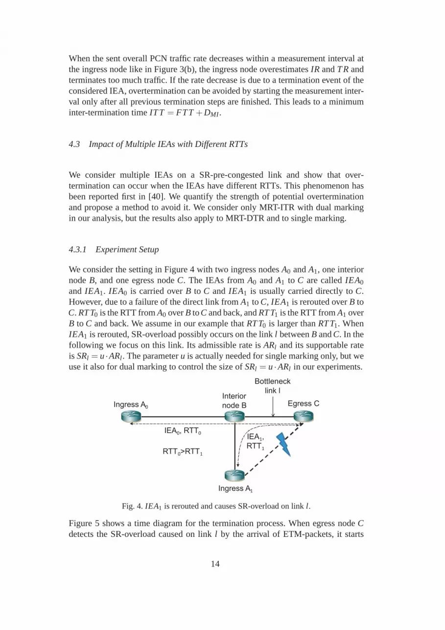
We consider the setting in Figure 4 with two ingress nodesA0 andA1, one interiornodeB, and one egress nodeC. The IEAs fromA0 andA1 to C are calledIEA0
and IEA1. IEA0 is carried overB to C and IEA1 is usually carried directly toC.However, due to a failure of the direct link fromA1 toC, IEA1 is rerouted overB toC. RTT0 is the RTT fromA0 overB toC and back, andRTT1 is the RTT fromA1 overB to C and back. We assume in our example thatRTT0 is larger thanRTT1. WhenIEA1 is rerouted, SR-overload possibly occurs on the linkl betweenB andC. In thefollowing we focus on this link. Its admissible rate isARl and its supportable rateis SRl = u·ARl . The parameteru is actually needed for single marking only, but weuse it also for dual marking to control the size ofSRl = u·ARl in our experiments.
Ingress A0Egress C
IEA0, RTT0
IEA1,
RTT1
Bottleneck
link lInterior
node B
Ingress A1
RTT0>RTT1
Fig. 4. IEA1 is rerouted and causes SR-overload on linkl .
Figure 5 shows a time diagram for the termination process. When egress nodeCdetects the SR-overload caused on linkl by the arrival of ETM-packets, it starts
14

continuously measuring the ratesNMRi, TMRi, andEMRi for i ∈ {0,1}, and sendsthese values at the end of the measurement intervals toA0 andA1, respectively.Ingress nodeAi sees thatEMRi is larger than zero and measures the sent PCNingress rateIRi. At the end of the measurement interval, it calculates the terminationrate byTRi = IRi −SARi with SARi = NMRi + TMRi using the latest values forNMRi andTMRi. Then, it terminates an appropriate number of flows. SinceIEA1
has a shorter RTT thanIEA0, the termination effect ofA1 is visible earlier than theone ofA0 both at linkl and at egress nodeC. When the effect ofA1’s terminationis visible at the linkl , the SR-overload is not yet fully removed until the effect ofA0’s termination is visible, too. Within that time, some traffic of IEA1 is still ETMalthough the rate ofIEA1 has already been sufficiently reduced. As a result, ingressnodeA1 underestimates the sustainable aggregated rateSAR1 of IEA1 and performsanother termination step which finally leads to overtermination.
Time
A0
Distance to C (in time)
RTT0/2
DMI for
NMR0,TMR0,EMR0
Start of SR
overload
R11
A1 B C
R02
R01
R12
RTT0
RTT1
Overter-
minationvisible
DMI for
NMR1,TMR1,EMR1
DMI for
IR01
DMI for
IR11
DMI for
IR02
DMI for
IR12
R13
Fig. 5. Time diagram: different RTTs forIEA0 andIEA1 lead to asynchronous terminationand possibly to overtermination. The variables are explained in Section 4.3.2.
4.3.2 Analysis
We propose an analysis to quantify the presented kind of overtermination underchallenging conditions. First, we explain the considered networking scenario andclarify some notation. The measurement intervals at the ingress and egress nodesareDMI long. The measurement intervals at egress nodeC are numbered byj =0,1, ..., starting with the one that covers SR-overload for the first time. Correspond-
15

ing measured rates are denotedNMRji , TMRj
i , andEMRji for IEAi. The measure-
ment intervals at the ingress nodes are numbered bym= 1,2, ... and the measuredsent PCN ingress rates are denotedIRm
i . At the end of these measurement intervals,the ingress nodes possibly terminate traffic and the corresponding termination stepis numbered bym. The rates ofIEAi before potential termination stepmare namedRm
i . We assume in our settingR10 = ARl = 1/u·SRl , i.e.,ARl is fully utilized by the
PCN traffic ofIEA0. We choose the initial rateR11 of IEA1 so that it causes a rela-
tive SR-overload ofq on the bottleneck linkl after reroute. A value ofq = 0 meansno SR-overload. Hence, we haveR1
1 = (1+q) ·SRl −R10 = (1+q−1/u) ·SRl . For
the sake of simplicity, we assume that ingress nodes immediately terminate flowsafter heaving computedTRm
i . That means, the flow termination time (FTT) is zeroso that ingress nodes can start the measurement ofIRm+1
i immediately after the oneof IRm
i if needed.
We now analyze the termination process. We assume 0≤ RTT1 ≤ RTT0 ≤ DMI tosimplify the analysis. Immediately after the reroute, the initial ratesR1
0 andR11 cause
SR-overload on the common bottleneck linkl so that only the fraction SRlR1
0+R11
=
11+q of the PCN traffic remains non-ETM. As soon as egress nodeC sees the firstETM-packet, it starts measurement intervalj = 0. We choose this optimizationof MRT-DTR (see Section 4.2.1) to simplify our analysis, otherwise the start ofthe measurement interval is random. The resulting measuredrates areNMR0
i = 0,TMR0
i = R1i ·
SRlR1
0+R11, andEMR0
i = R1i −TMR0
i . The egress nodeC sends them to
the ingress nodesA0 andA1, and continues measuring. The ingress nodesA0 andA1 receive the measurement reports and measureIR1
i . In the meanwhile, the ingressnodes receive from egress nodeC another measurement report withNMR1
i , TMR1i ,
andEMR1i , which resemble very much the previous ones since no traffic has been
terminated, yet. The ingress nodes calculate the sustainable aggregate rate
SAR1i = NMR1
i +TMR1i = R1
i ·SRl
R10 +R1
1
(2)
and terminateTR1i = IR1
i −SAR1i traffic. The effect of both termination steps be-
comes visible at the egress nodeRTTi +2 ·DMI time after egress nodeC observedthe first ETM-packet, i.e., in the third considered measurement interval which hasnumber j = 2. The newly measured rates are reported to the ingress nodesA0 andA1. As EMR2
i > 0, the ingress nodes calculateSAR2i . If the RTTs of both IEAs are
the same, thenSAR2i equalsSAR1
i for i ∈ {0,1} so that no additional terminationstep is performed provided that enough traffic has been removed in the first termina-tion step. However, if we haveRTT0 > RTT1, thenSAR2
0 > SAR10 andSAR2
1 < SAR11
hold so thatA1 terminates traffic again. The exact value forSAR21 can be calculated
as follows:
16

SAR21 = NMR2
1 +TMR21 =
1DMI
·
(
RTT1 ·R11 ·
SRl
R10 +R1
1
+
(RTT0−RTT1) ·R21 ·
SRl
R10 +R2
1
+(DMI −RTT0) ·R21 ·
SRl
R20 +R2
1
)
(3)
whereby the ratesR2i equalSAR1
i . This equation basically weights the PCN trafficof IEA1 observed by the egress node in the third measurement interval with the dif-ferent probabilities for non-ETM-packets experienced on link l . After A1’s secondtermination step is visible at the bottleneck linkl , the relative overtermination on
that link isOT =SAR1
1−SAR21
SRl.
4.3.3 Analytical Results
We quantify the caused overtermination for measurement intervals of durationDMI = 100 ms. Figure 6(a) shows it forRTT0 = 100 ms,RTT1 = 10 ms, and dif-ferent values ofu and relative SR-overloadq. Overtermination strongly increaseswith the relative SR-overloadq and is larger for smalleru-values that control therelation betweenARl andSRl . Overtermination in the order of 15% – 20 % can beeasily achieved in this setting.
0
0.05
0.1
0.15
0.2
0.25
0 0.5 1 1.5 2
Ove
rter
min
atio
n re
lativ
e to
SR
l
Relative SR-overload q
u=1.5u=2.0u=2.5
(a) RTT0 = 100 ms,RTT1 = 10 ms.
0
0.05
0.1
0.15
0.2
0.25
0 20 40 60 80 100
Ove
rter
min
atio
n re
lativ
e to
SR
l
RTT0 (ms)
RTT1=10 msRTT1=50 msRTT1=75 ms
(b) Relative SR-overloadq = 2.0, u = SRlARl
=2.0.
Fig. 6. Overtermination on linkl relative toSRl .
Figure 6(b) illustrates the overtermination for a relativeSR-overloadq = 2.0,SRl = 2.0·ARl (u = 2.0), and differentRTT0 andRTT1. Overtermination increasesabout linearly withRTT0 and is smaller for largerRTT1. The overtermination effectvanishes ifRTT0 andRTT1 are equally long.
4.3.4 Prevention of Overtermination due to Different RTTs
We propose a method to avoid or reduce overtermination that is due to differentRTTs. Overtermination can be prevented if subsequent termination steps are de-
17

layed until new PCN feedback reflects the effects of all previous terminations. Wederive the appropriate inter-termination time for MRT-DTRand MRT-ITR.
The presented example and the analysis apply for MRT when a common egressnode starts measurement intervals with the receipt of the first ETM-packet. How-ever, the egress nodes for IEAs sharing a common bottleneck link may be differ-ent and they may measure PCN feedback periodically. As a consequence, ETM-packets may be reported to the ingress node already shortly after their arrival at theegress node or almostDMI time later. The ITT needs to account for that uncertainty.The interval starting with the egress node sending the PCN feedback until the ef-fect of the termination becomes visible at the egress node ismaxi(RTTi + FTTi)for MRT-DTR and maxi(RTTi + FTTi) + DMI for MRT-ITR. Then, the ongoingmeasurement interval at the egress node must be finished before PCN feedbackmay be collected. This adds anotherDMI delay. Finally, the actual data collectiontakes anotherDMI time. Hence, to avoid overtermination due to different RTTs,MRT-DTR requiresITT = maxi(RTTi + FTTi) + 3 ·DMI and MRT-ITR requiresITT = maxi(RTTi +FTTi)+4·DMI .
4.4 Impact of Packet Loss and Packet Drop Policies
Packet loss reduces the rates of NM-, TM-, or ETM-traffic received by the PCNegress node. ETM- or non-ETM-packets may be preferentiallydropped, or packetsmay be dropped independently of their markings. We show thatthe packet drop pol-icy affects the termination process of MRT-DTR and MRT-ITR in different ways.
4.4.1 Experiment Setup
We assume that packet loss inside a node occurs before packets are metered andmarked. Therefore, ETM-packets can be lost only at a downstream node relative tothe node which marked them with ETM. Hence, two SR-pre-congested links areneeded to provoke a situation where ETM-packets are lost: one SR-pre-congestedlink that marks packets with ETM and another SR-pre-congested link that evendrops PCN packets.
Bottleneck link l0AR0= 3 Mbit/s
SR0= 6 Mbit/s
c0= 14 Mbit/s
Bottleneck link l1AR1= 4 Mbit/s
SR1= 8 Mbit/s
c1= 11 Mbit/s
IEA with inital 25 Mbit/s
Fig. 7. Experiment setup to evaluate the impact of packet loss.
To keep things simple, we consider the experiment setup depicted in Figure 7. Asingle IEA with initial 25 Mbit/s is transmitted over the twoadjacent linksl0 and
18

l1. The configured admissible and supportable ratesARi andSRi of link l i as wellas its capacityci are given in the figure. We chose the values in the experiment sothat all interesting phenomena can be shown with a single parameter set.
We study the reduction of the PCN rate of the IEA due to termination for MRT-DTR and MRT-ITR, dual and single marking, and for the three packet drop poli-cies: drop ETM-packets (DEP), drop non-ETM packets (DNP), and drop randompackets (DRP). We assume that DRP drops the same fraction of ETM- and non-ETM-traffic.
4.4.2 Analysis
To investigate the termination process, we use a step-by-step analysis, i.e., we cal-culate the rates of ETM- and non-ETM-traffic of the considered IEA on link l0before marking, on linkl0 after marking, on linkl1 after packet loss but beforemarking, and on linkl1 after marking. Based on that information, the rate of theIEA after the next termination step is calculated and the analysis is repeated withthe new initial rate. This analysis is straightforward but cumbersome so that wedo not show any equations. When cross traffic appears on multiple pre-congestedlinks, a more sophisticated analysis is needed. Then, overtermination can occur forall termination methods even without packet loss [35]. However, this phenomenonis orthogonal to the observations reported in this section.The results of the analysisare summarized in Figures 8(a)–8(d) and discussed in the following.
4.4.3 MRT-DTR with Dual Marking
Figure 8(a) shows for MRT-DTR with dual marking the rate of the IEA aftermtermination steps. We observe that several termination steps are needed to reducethe PCN rate down to the expected 6 Mbit/s. In the absence of packet loss, the rateof ETM-traffic exactly corresponds to SR-overload and equalsthe amount of traf-fic that needs to be terminated. When ETM-packets are lost, thetermination rateis underestimated and undertermination occurs so that additional termination stepsare required. Since DEP loses more ETM-packets than DRP and DNP, the corre-sponding termination process takes longer for DEP. The question arises whetherDEP possibly loses so much traffic that termination does not work anymore. Thegap between theSRand the bandwidthc of a link determines the minimum amountof ETM-traffic that leaves the link with DEP in case of packet loss. Based on thisdifference, a lower bound for the termination speed can be calculated. As long asSR< c holds for all links of a PCN domain, traffic is still terminated. Hence, DEPand DRP cannot prevent termination for MRT-DTR with dual marking, but theydelay the termination process if several steps are needed toremove SR-overload.
19

0
5
10
15
20
25
0 1 2 3 4
Tra
ffic
rate
afte
r m
term
inat
ions
(M
bit/s
)
Termination step m
DEPDRPDNP
(a) MRT-DTR with dual marking.
0
5
10
15
20
25
0 1 2 3 4
Tra
ffic
rate
afte
r m
term
inat
ions
(M
bit/s
)
Termination step m
DEPDRPDNP
(b) MRT-DTR with single marking.
0
5
10
15
20
25
0 1 2 3 4
Tra
ffic
rate
afte
r m
term
inat
ions
(M
bit/s
)
Termination step m
DEPDRPDNP
(c) MRT-ITR with dual marking.
0
5
10
15
20
25
0 1 2 3 4
Tra
ffic
rate
afte
r m
term
inat
ions
(M
bit/s
)
Termination step m
DEPDRPDNP
(d) MRT-ITR with single marking.
Fig. 8. PCN traffic rate after several termination steps for MRT-DTR and MRT-ITR withdual and single marking.
4.4.4 MRT-DTR with Single Marking
Figure 8(b) illustrates the termination process for MRT-DTR and single marking.With DEP and DRP, the termination process is the same as for dual marking. How-ever, in case of DNP, overtermination occurs as only 3 Mbit/sinstead of the ex-pected 6 Mbit/s PCN traffic remain after the second termination step. This hap-pens because MRT-DTR with single marking calculates the termination rate byTR= NMR+EMR−u ·NMRand if the rate of non-ETM-trafficNMR is too low,TR is overestimated which possibly leads to overtermination.This cannot happenwith DEP. Overtermination neither occurs with DRP because itdrops the samefraction of ETM- and non-ETM-traffic which just reduces the termination rate ac-cordingly. Hence, MRT-DTR with single marking should be deployed only withDEP or DRP.
4.4.5 MRT-ITR with Dual Marking
Figure 8(c) shows the termination process for MRT-ITR and dual marking. Thetermination is already completed after a single termination step. We observe thatovertermination occurs with DRP and DNP as only 4.7 Mbit/s and3 Mbit/s in-
20
stead of 6 Mbit/s PCN traffic remain after termination. This happens because DRPand DNP drop non-ETM-packets which leads to an underestimation of the sustain-able aggregate rateSARwith MRT-ITR. As a consequence, the termination rateTR= IR−SARis overestimated and too much traffic is terminated. With DEP,overtermination does not occur since non-ETM-packets are not lost so that a correctestimate forSARis obtained. Hence, MRT-ITR with dual marking works correctlyonly with DEP.
4.4.6 MRT-ITR with Single Marking
Figure 8(d) visualizes the termination process for MRT-ITRand single marking.Again, overtermination occurs in case of DRP and DNP for the same reason as withdual marking. DNP even fully removes the PCN traffic so that thefigure misses thecorresponding bars. This can also be achieved for dual marking when differentparameter settings are chosen in the experiment. Hence, also MRT-ITR with singlemarking should be deployed only with DEP.
4.5 Impact of Packet Loss on the Number of Required Termination Steps for MRT-DTR
In the absence of packet loss, MRT-DTR requires only a singletermination stepto remove SR-overload. However, in Section 4.4 we have shown that MRT-DTRneeds multiple termination steps to fully remove SR-overload in the presence ofpacket loss. This delays the termination process and is the major disadvantage ofMRT-DTR compared to MRT-ITR. We analytically calculate the number of re-quired termination steps to remove SR-overload and discuss the results. They arevalid for MRT-DTR with dual and single marking.
4.5.1 Analysis
We consider a single link with bandwidthc and supportable rateSR. The link isfaced with so much PCN traffic that a PCN packet loss probabilityof p occurs. Theoverall PCN traffic rate offered to the link can be written asc
1−p and the overall rateto be terminated is thenc
1−p −SR. In a single termination step,c−SRtraffic can beterminated. Therefore, the number of required terminationstepsm to fully removeSR-overload in the presence of an initial packet lossp is
m=
⌈
c1−p −SR
c−SR
⌉
=
⌈
11−p −
SRc
1− SRc
⌉
. (4)
Since packet loss is not an intuitive measure for SR-overload, we also consider theinitial relative SR-overloadq, i.e., the initial SR-overload in multiples ofSR. Then,
21
then number of required termination steps is
m=
⌈
q·SRc−SR
⌉
=
⌈
qc
SR−1
⌉
. (5)
0
0.2
0.4
0.6
0.8
1
0 0.2 0.4 0.6 0.8 1
Initi
al p
acke
t los
s p
Relative supportable rate SR/c
m=2
m=3
m=4
4<m≤10
10<m≤20m>20
(a) Initial load given as packet lossp.
0
2
4
6
8
10
0 0.2 0.4 0.6 0.8 1
Initi
al r
elat
ive
SR
-ove
rload
qRelative supportable rate SR/c
m=1 m=2
m=3
m=4
4<m≤10
10<m≤20
m>20
(b) Initial load given as relative SR-overloadq (SR-overload in multiples ofSR).
Fig. 9. The area in the figures indicates the number of required termination steps m for ascenario where the initial load and the relative supportable rateSR
c are given.
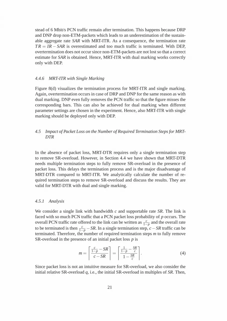
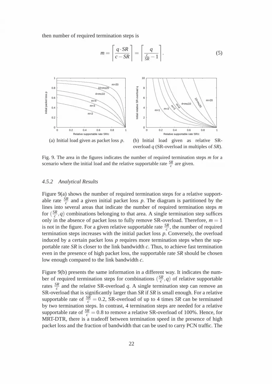
4.5.2 Analytical Results
Figure 9(a) shows the number of required termination steps for a relative support-able rateSR
c and a given initial packet lossp. The diagram is partitioned by thelines into several areas that indicate the number of required termination stepsmfor (SR
c ,q) combinations belonging to that area. A single termination step sufficesonly in the absence of packet loss to fully remove SR-overload. Therefore,m= 1is not in the figure. For a given relative supportable rateSR
c , the number of requiredtermination steps increases with the initial packet lossp. Conversely, the overloadinduced by a certain packet lossp requires more termination steps when the sup-portable rateSRis closer to the link bandwidthc. Thus, to achieve fast terminationeven in the presence of high packet loss, the supportable rate SRshould be chosenlow enough compared to the link bandwidthc.
Figure 9(b) presents the same information in a different way. It indicates the num-ber of required termination steps for combinations(SR
c ,q) of relative supportableratesSR
c and the relative SR-overloadq. A single termination step can remove anSR-overload that is significantly larger thanSRif SRis small enough. For a relativesupportable rate ofSR
c = 0.2, SR-overload of up to 4 timesSRcan be terminatedby two termination steps. In contrast, 4 termination steps are needed for a relativesupportable rate ofSR
c = 0.8 to remove a relative SR-overload of 100%. Hence, forMRT-DTR, there is a tradeoff between termination speed in thepresence of highpacket loss and the fraction of bandwidth that can be used to carry PCN traffic. The
22

question whether MRT-DTR is fast enough boils down to the question whether sur-viving flows can afford a certain duration of QoS disruption,i.e. until SR-overloadis removed, when many other flows are terminated.
4.6 Impact of a Small Number of Flows per IEA
PCN-based AC and FT are intended for networks with a sufficiently high PCNtraffic rate per link [2]. This can be achieved when links carry a large number ofsmall IEAs which is a likely scenario in future networks. If PCN domains are verylarge in terms of the number of ingress and egress nodes, onlya very small numberof realtime flows is expected per IEA [41]. Then, flow termination might have thefollowing granularity problem. If MRT is expected to terminate 25% of the trafficof an IEA, but the IEA has only two flows, either 0 or 1 flow can be terminated. Wepropose several flow termination policies to handle this situation and investigatetheir impact using packet-based simulation.
4.6.1 Flow Termination Policies
We propose new flow termination policies.
• Aggressive terminationterminates so many flows that their overall rate is at leastthe termination rateTR.
• Careful terminationterminates a set of flows whose overall rate is at mostTR.• Proportional terminationfirst terminates a set of flows whose overall rate is at
mostTR. Let the difference betweenTRand the rates of the terminated flows be∆R. Then another flowf with rater f is chosen for potential termination as wellas a random number 0< y < 1. If y < ∆R
r fholds, flow f is terminated.
• Safe terminationreduces the termination rate by some safety margin and thenuses proportional termination to terminate that rate. The margin is given as afraction x ≥ 0 of the traffic that should remain after termination. For MRT-ITR this means that the ingress node calculates the termination rate byTR=max(0, IR− (1+x) ·SAR). With MRT-DTR and dual marking, the ingress nodecalculates the termination rate byTR= max(0,EMR−x·(NMR+TMR)). WithMRT-DTR and single marking, the ingress node calculates thetermination rateby TR= max(0,NMR+EMR− (1+x) ·u·NMR).
4.6.2 Experiment Setup
We consider a single bottleneck link with a supportable rateof SR= 12 Mbit/s.Initially, it carries nIEA = 50 IEAs and some time laternIEA = 100 IEAs due toa rerouting event. Each of the IEAs hasnf lows
IEA = 2 flows with r f = 80 kbit/s at
23

simulation start. Then, 16 Mbit/s run over the bottleneck link which correspondsto an SR-overload of 33%. Hence, 25% of the flows should be removed so thatonly 12 Mbit/s PCN traffic remain on the bottleneck link. However, each IEA canremove either 0, 1, or 2 flows. Thus, there is a granularity problem.
We use a packet-based simulation to study the time-dependent PCN traffic rate onthe bottleneck link. We assume periodic voice traffic with constant packet inter-arrival timesIAT = 20 ms and constant packet sizesB= 200 bytes. To avoid simu-lation artifacts due to overly exact arrival times, we add some uniformly distributedjitter to the packet transmission times of at mostDmax
pkt = 1 ms. The excess markeron the bottleneck link is configured with reference rateSRand a bucket size of0.05 s·SR, i.e. 0.6 Mbit. The measurement intervals areDMI = 100 ms long. Werun 100 simulations and average the obtained time-dependent traffic rates. The 95%confidence intervals are smaller than 1% of the obtained meanvalues. We omit theconfidence intervals in the figures for the sake of clarity.
We simulate MRT-DTR with dual marking where the egress node restarts the mea-surement of PCN feedback with the receipt of the first ETM-packet. We obtainalmost the same results for MRT-ITR and dual marking when theegress node pe-riodically measures PCN feedback; in that case, the termination process is at mostDMI time delayed. Similar results also apply for single marking. However, the re-sults for single marking are overlaid by additional problems that are studied inSection 4.7.
4.6.3 Simulation Results
8
10
12
14
16
0 0.2 0.4 0.6 0.8 1 1.2 1.4 1.6 1.8 2
Tra
ffic
rate
(M
bit/s
)
Time (s)
Aggressive
Proportional
Safe (x=0.1)
Careful
SR
Fig. 10. Time-dependent PCN traffic rate on the bottleneck link with MRT-DTRand dualmarking: various flow termination policies may cause over- or undertermination.
Figure 10 shows how the PCN traffic rate on the SR-pre-congestedlink evolveswith the four different flow termination policies. Aggressive termination leads tosignificant overtermination. After termination only 8 Mbit/s out of the 16 Mbit/sremain on the link because every IEA removes one flow which corresponds to 50%termination instead of the required 25% termination. This is an overtermination of33%. Careful termination leads to significant undertermination on the bottleneck
24

link because it does not terminate any flow on most IEAs. As thenumber of ETM-packets per IEA is subject to statistical fluctuations, the amount sometimes sufficesthat an IEA terminates a flow. Proportional termination mostly terminates no or oneflow per IEA. The figure shows that the PCN traffic rate on the bottleneck link isreduced to a bit less than the desiredSR. Safe termination with a margin of 10%terminates exactly as much traffic as needed so that the PCN traffic rate eventuallymeets the desiredSRon the bottleneck link. Thus, proportional or safe terminationshould be used in practice to avoid over- and underterminaiton in the presence of asmall number of flows per IEA.
Another aspect is fairness for which we do not provide any simulation data. Dif-ferent IEAs may receive different rates of ETM-traffic as PCN feedback which canlead to different fractions of terminated flows among IEAs. This is unfair and notdesirable but acceptable in exceptional situations where traffic is terminated.
4.7 Impact of a Small Number of Packets per Measurement Interval
The number of ETM-packets per IEA is subject to statistical fluctuations. As singlemarking marks packets with ETM already in the presence of AR-overload, it ispossible that the fraction of ETM-packets in a measurement interval is so large thatflows are terminated even in the absence of SR-pre-congestion. We quantify thiseffect, propose countermeasures, and show their effectiveness.
4.7.1 Experiment Setup
We use a similar simulation setup as in the previous section.Due to single mark-ing instead of dual marking, the excess marker is configured with the admissiblerate instead of the supportable rate. The simulation startswith nIEA
2 IEAs on thebottleneck link. The resulting PCN traffic rate corresponds to the admissible rateof the link. After 1 s, additionalnIEA
2 IEAs are carried over the link which mayhappen due to a rerouting event. The supportable rate of the link is configured sothat it corresponds to the rate of thesenIEA ·n
f lowsIEA flows, i.e., no flow needs to be
terminated.
We consider two different versions of MRT-DTR. In the one version, the egressnode restarts measuring PCN feedback with the first received ETM-packet and theingress node terminates traffic as soon as signalled PCN feedback indicates termi-nation. In the second version, the egress node periodicallymeasures PCN feedback,but the ingress node terminates traffic only if the previous PCN feedback also re-quired termination. We have proposed this second version also in Section 4.2.1. Inthe absence of packet loss, it leads to the same termination process as MRT-ITR. Inthe following, we denote the first MRT version by MRT-DTR and the second MRTversion by MRT-ITR.
25

4
5
6
7
8
9
0 1 2 3 4 5 6 7 8 9 10
Tra
ffic
rate
(M
bit/s
)
Time (s)
Proportional
Safe (x=0.2)
AR
SR
MRT-DTR MRT-ITR
(a) 50 PCN packets per measurement inter-val (nf lows
IEA = 10 voice flows per IEA).
40
50
60
70
80
90
0 1 2 3 4 5 6 7 8 9 10
Tra
ffic
rate
(M
bit/s
)
Time (s)
Proportional
Safe (x=0.2)
AR
SR
MRT-DTR MRT-ITR
(b) 500 PCN packets per measurement inter-val (nf lows
IEA = 100 voice flows per IEA).
Fig. 11. Time-dependent PCN traffic rate on the bottleneck link for MRT-DTR andMRT-ITR with single marking: flows are terminated in the absence of SR-pre-congestion(nIEA = 10 IEAs on the link after rerouting).
4.7.2 Simulation Results
Figure 11(a) shows the PCN traffic rate on the link fornf lowsIEA = 10 voice flows per
IEA and two different flow termination policies. Initially,nIEA2 = 5 IEAs are car-
ried over the link, but after 1 s additionalnIEA2 = 5 IEAs appear due to rerouting.
Therefore, AR-overload occurs, packets are marked with ETM,and flows are ter-minated. Flow termination happens in spite of the absence ofSR-overload becausethe number of observed ETM-packets per measurement interval fluctuates and ifit is sufficiently large, the ingress node terminates traffic. With proportional termi-nation we observe overtermination of up to 30% for MRT-DTR and of up to 23%for MRT-ITR. The difference is due to the fact that MRT-ITR requires two con-secutive PCN feedback per IEA indicating SR-overload to terminate traffic whilefor MRT-DTR a single PCN feedback indicating SR-overload is enough. Safetymargins are intuitive countermeasures. However, safe termination with a large mar-gin of 20% reduces overtermination only to about 20% for MRT-DTR and to 10%for MRT-ITR which is still not acceptable. The experiment isdesigned such that ameasurement interval initially covers 50 PCN packets. The severity of the problemdiminishes with an increasing number of PCN packets per measurement interval.Figure 11(b) illustrates the termination process with 10 times more flows per IEA,i.e. with 500 PCN packets per measurement interval. Proportional termination stillleads to about 10% overtermination for MRT-DTR and to 6% for MRT-ITR, butsafe termination with 20% safety margin fully avoids it.
Nearly the same relative evolution of the PCN traffic rate can be observed withnf lows
IEA = 2 andnf lowsIEA = 20 video flows (without figures). The packet inter-arrival
time of these flows is 4 ms so that the experiment with video traffic leads to 50and 500 PCN packets per measurement interval like in the experiment with voicetraffic. As the packet size is set to 1500 instead of 200 bytes,the overall rate on theconsidered link carries 60 and 600 Mbit/s instead of 8 and 80 Mbit/s andcl , ARl ,
26

andSRl are adapted accordingly in the simulation runs. The fact that almost thesame relative evolution of the time-dependent PCN traffic rates is obtained showsthat the observed overtermination is due to a low number of packets per measure-ment interval and not due to a low number of flows or a small traffic rate per IEA.Thus, another method to reduce potential overtermination is the prolongation of themeasurement interval. This increases the number of PCN packets per measurementinterval, but it also leads to a larger termination delay which is again undesirable.
These overtermination phenomena can be observed in simulations only if multipleIEAs are concurrently carried over a link. When only a single IEA is simulated, theratio of the measuredNMR andEMR, which are reported to the ingress node, isstable, AR-pre-congestion is correctly recognized, and flows are not unintention-ally terminated. With multiple IEAs carried over a bottleneck link, PCN packetsare marked with ETM on the pre-congested link independentlyof whether preced-ing packets of the same IEA have recently been marked with ETM. This leads tofluctuations ofNMR and EMR which are a prerequisite for the observed overt-ermination. Furthermore, care must be taken to avoid that overly periodic packettransmissions lead to combinatoric effects and simulationartifacts. With dual mark-ing, the reported problem cannot occur because packets become ETM only in thepresence of SR-overload. Hence, termination cannot be triggered in the absence ofSR-overload.
4.8 Impact of Multipath Routing
Multipath routing is frequently applied in IP networks in the form of the equal-costmultipath (ECMP) option [42]. Therefore, the applicabilityof PCN to networkswith multipath routing is an important issue. The termination decisions of MRTmethods are based on rate measurements of differently marked PCN traffic perIEA. This information is used to infer the pre-congestion state of the path belong-ing to the IEA which is meaningful only in case of single-pathrouting. In caseof multipath routing, the obtained feedback stems from all partial (parallel) pathsof the multipath carrying active flows. In addition, there isno information aboutwhich flows of an IEA are carried over an SR-pre-congested partial path and arecandidates for termination. As a result, MRT with dual marking causes overtermi-nation in case of multiple partial paths. MRT with single marking may cause notonly overtermination but also undertermination, i.e., SR-pre-congestion is possi-bly not detected or not fully removed. In the following, we derive a mathematicalmodel to quantify these effects of over- and undertermination and illustrate themfor MRT with dual and single marking. The analysis and its results are valid forboth MRT-DTR and MRT-ITR.
27

4.8.1 Analysis
We model the termination process assuming equal flow rates and denote the ad-mitted traffic by the number of flows. The model states= (s0, ...,sk−1) (0≤ i < k)indicates the number of current flows onk partial paths of an IEA. Admissible orsupportable rates are assigned to links within a PCN domain, but in our analysisARi andSRi indicate the number of admissible and supportable flows on each par-tial path. In reality, several flows are removed simultaneously at the end of eachmeasurement interval. Our model neglects the time component which is here notof interest. Flows of an IEA are successively randomly chosen for terminationand removed. The probability that a flow from pathi is chosen for terminationis p(s, i) = si
∑0≤ j<k sjwhich yields the probability for the transition steps of a simple
stochastic process
(s0, ...,si, ...,sk−1)p(s,i)−−−→ (s0, ...,si −1, ...,sk−1) (6)
The process starts withsi = ni flows. We compute the probabilityp(s) of all statess with 0≤ si ≤ ni by an iterative algorithm. The stop condition of the terminationprocess depends on dual or single marking. In case of dual marking, the terminationprocess stops if the SR-overload has been removed on all partial paths, i.e., if thecondition
si ≤ SRi ∀i : 0≤ i < k (7)
is met. In case of single marking, the termination process stops if the overall re-ceived traffic rate is at most the rate of the non-ETM traffic (min(si,ARi)) multipliedby u, i.e., if the condition
∑0≤i<k
si ≤ u· ∑0≤i<k
min(si ,ARi) (8)
is met. The setT contains all statess in which the stochastic process terminatesbecause the stop condition is met. The probability of the states in the terminatingsetT sums up to 1. Hence, we can calculate the average relative amount of overt-ermination and undertermination by
OT =∑s∈T ∑0≤i<k max(0,min(ni ,SRi)−si) · p(s)
∑0≤i<k min(ni ,SRi)and (9)
UT =∑s∈T ∑0≤i<k max(0,si −SRi) · p(s)
∑0≤i<k min(ni ,SRi). (10)
4.8.2 MRT with Dual Marking and Multipath Routing
In this section we study MRT with dual marking and multipath routing. In case ofSR-pre-congestion, flows are terminated from the IEA until nomore ETM-packetsarrive, i.e., until SR-overload is removed from all partial paths. Thereby, flows from
28

non-SR-pre-congested partial paths are possibly also terminated and, therefore,overtermination occurs. We study the impact of several factors on overterminationand discuss signalling of additional information to reduceovertermination.
4.8.2.1 Impact of the Number of Flows per Partial Path We perform the fol-lowing symmetric experiment setup. An IEA carries traffic overnpaths
IEA ∈ {2,3} par-tial paths and each of them has the same supportable rateSRi (in terms of numberof flows) which is a variable parameter in our study. The initial number of flowsni = f OL
SR ·SRi is also the same on all partial paths and controlled by the overloadfactor f OL
SR = 2.0. Figure 12(a) shows the analytically computed average overtermi-nation after the termination process stopped depending on the number of support-able flowsSRi per partial path. Withnpaths
IEA = 2 parallel paths per IEA, the averageovertermination ranges between 4% and 10% and diminishes significantly with in-creasing numbers of supportable flowsSRi. With npaths
IEA = 3 parallel paths per IEA,the average overtermination is larger but also decreases with increasing number ofsupportable flowsSRi. The figure also shows the results for an asymmetric experi-ment setup where only one partial path experiences an overload factor off OL
SR = 2.0and the others are loaded withSRi flows. In that case, the overtermination is about25% for npaths
IEA = 2 parallel paths per IEA and about 33% fornpathsIEA = 3 parallel
paths. In particular, the overtermination does not decrease with increasing numbersof supportable flowsSRi.
0
0.05
0.1
0.15
0.2
0.25
0.3
0.35
10 20 30 40 50 60 70 80 90 100
Rel
ativ
e ov
erte
rmin
atio
n
Number of supportable flows per path SRi
Symmetric experiment setup
Asymmetric experiment setup
npathsIEA
23
(a) Overload factorf OLSR = 2.0.
0
0.1
0.2
0.3
0.4
0.5
1 1.5 2 2.5 3 3.5 4
Rel
ativ
e ov
erte
rmin
atio
n
Overload factor fOLSR
Symmetric experiment setup
Asymmetric experiment setup
npathsIEA
23
(b) Number of supportable flows per pathSRi = 50 flows.
Fig. 12. Overtermination due to multipath routing with symmectric and asymmetric exper-iment setup.
4.8.2.2 Impact of the Overload Factor We keep the number of supportableflows per partial path fixed atSRi = 50 and vary the overload factorf OL
SR. Fig-ure 12(b) shows that the overtermination for the symmetric experiment is ratherindependent of the overload factor, lower than 6% fornpaths
IEA = 2 partial paths per
IEA and lower than 10% fornpathsIEA = 3. Thus, it has only minor impact. In contrast,
in the experiment with only one SR-pre-congested partial path, the overtermination
29

increases significantly with the overload factorf OLSR and reaches large values of up
to 50%.
4.8.2.3 Impact of the Relative Size of the SR-Pre-CongestedPath We set thenumber of supportable flows per partial path on the non-SR-pre-congested pathsto SRi = 50. The overload factor for the SR-pre-congested path isf OL
SR = 2 andwe study the impact of the number of supportable flows on this path. The resultsare presented in Figure 13. The x-axis shows the supportablenumber of flows onthe SR-pre-congested path relative to the other paths. For a relative size ofx = 1all partial paths have the same supportable rate and the observed overterminationequals the values in Figures 12(a) and 12(b) which are about 25% overterminationfor npaths
IEA = 2 partial paths per IEA and about 33% fornpathsIEA = 3. When the SR-
pre-congested partial path is smaller than the others, the overtermination can besignificantly larger, i.e., 39% and 44% fornpaths
IEA = 2 andnpathsIEA = 3 when theSRof
the SR-pre-congested path is only 20% of theSRof its parallel paths. When theSRof the SR-pre-congested partial path is larger than theSRof its parallel paths, theovertermination can be significantly smaller.
0
0.1
0.2
0.3
0.4
0.5
0 1 2 3 4 5
Rel
ativ
e ov
erte
rmin
atio
n
Relative size x of the SR-pre-congested partial path
npathsIEA
23
Fig. 13. Overtermination due to multipath routing depending on the supportable rate of theSR-pre-congested partial path relative to the rate of the other non-SR-pre-congested partialpaths (f OL
SR = 2.0, SRi = 50 flows).
4.8.2.4 Mitigating Overtermination by Additional Signalli ng Overtermina-tion due to multipath routing can be avoided for dual markingif egress nodes sendinformation about flows with ETM-packets to the ingress nodes. As these flowsare carried over SR-pre-congested paths, they are appropriate candidates for termi-nation. If only a single partial path is SR-pre-congested, this method is obviouslycorrect. If several partial paths are SR-pre-congested, this method helps to termi-nate traffic only from SR-pre-congested paths. However, overtermination can stilloccur in this case.
30

4.8.3 MRT with Single Marking and Multipath Routing
We illustrate over- and undertermination for MRT with single marking and multi-path routing by analytical results and discuss signalling of additional informationto improve the performance.
4.8.3.1 Analytical Results In case of single marking, flows are terminated fromthe IEA until the fraction of ETM-packets is sufficiently small (see Equation (8)).This does not necessarily mean that SR-overload is removed from all partial paths.Thus, undertermination may occur. Note that one path may reveal overterminationand another undertermination after termination stops. Moreover, flows may not beterminated at all in spite of SR-pre-congestion on at least one partial path of themultipath since the IEA does not indicate SR-pre-congestionas Equation (8) ismet. We perform some experiments that show how different butalso how largethe amount of over- and undertermination can be. We considera single IEA withnpaths
IEA = 2 parallel paths, each of them having an admissible rate ofARi = 20 flows,and u = 2. Thus, each partial path can carry up to 40 flows without being SR-pre-congested. We set the initial number of flows on the first partial path ton0 ∈{20,40,60}. Figure 14 shows the average relative over- and undertermination aswell as their sum depending on the initial number of flowsn1 on the second partialpath.
0 0.1 0.2 0.3 0.4 0.5
Rel
ativ
e ov
er-
and
unde
rter
min
atio
n n0=20OTUTSum
0 0.1 0.2 0.3 0.4 0.5
n0=40OTUTSum
0 0.1 0.2 0.3 0.4 0.5
0 20 40 60 80 100 120 140 160Number of flows on second partial path n1
n0=60OTUTSum
Fig. 14. Average relative overtermination, undertermination, and their sumfor single mark-ing; npaths
IEA = 2 parallel paths,AR0 = 20,AR1 = 20,u = 2, n0 ∈ {20,40,60}, andn1 varies.
Forn0 = 20 initial flows on the first partial path, flows are not terminated forn1≤ 60initial flows on the second partial path although the second partial path is alreadySR-pre-congested for more than 40< n1 initial flows. Therefore, we observe upto 33% undertermination. Forn1 > 60, flows are terminated on both partial paths.With increasingn1, undertermination decreases and overtermination increases, theyoccur simultaneously on both paths and sum up to about 33%. For n0 = 40, none ofthe partial paths is SR-pre-congested forn1≤ 40 and flows are not terminated. Fromn1 > 40 on, SR-pre-congestion is indicated for the IEA and flows areterminated.The amount of over- and undertermination is the same up to a certain value ofn1.
31

For n0 = 60, the IEA indicates SR-pre-congestion forn1 < 20 andn1 > 20 andhence flows are terminated in these ranges. Forn1 = 20, the IEA does not indicateSR-pre-congestion although the first partial path is SR-pre-congested. For smallvalues ofn1 < 40, there is more under- than overtermination. Forn1 ≥ 40, theamount of over- and undertermination is the same up to a certain value when over-termination prevails. This is of course not an in-depth analysis, but the experimentsshow that over- and undertermination can be quite large and they are very sensitiveto the load on the partial paths of a multipath.
4.8.3.2 Mitigating Overtermination by Additional Signalli ng When only asingle partial path is AR- or SR-pre-congested, overtermination can also be avoidedwith single marking. To that end, the egress node informs theingress node aboutflows with ETM-packets. However, SR-overload is not necessarily detected so thatundertermination may still occur. Furthermore, this method does not work whenmultiple partial paths are AR- or SR-pre-congested. ETM-packets can result fromother AR-pre-congested paths whose flows should not be terminated. Therefore, itis not possible to reliably remove overtermination for single marking by additionalsignalling.
5 Summary
We have investigated three different flow termination methods that rely on mea-sured PCN feedback: flow termination with directly measured termination rates(MRT-DTR), flow termination with indirectly measured termination rates (MRT-ITR), and flow termination with sustainable aggregate rates (MRT-SAR). They canbe applied with dual and single marking.
In Section 4.1 MRT-SAR revealed to be extremely prone to overtermination whentraffic descriptors are overestimated so that we excluded this method from furtherstudy. MRT-DTR and MRT-ITR suffer only from delayed termination when trafficdescriptors are overestimated because then multiple termination steps are required.
In Section 4.2 we showed that incipient and ceasing SR-overload can lead to over-and underestimation of the rates of differently marked PCN traffic and to over- andundertermination. However, undertermination can be repaired by additional termi-nation steps and overtermination can mostly be avoided by respecting sufficientlylong inter-termination times and by calculating termination rates based on appro-priate measurement reports. In Section 4.3 showed that overtermination can occurin particular if IEAs carried over a SR-pre-congested bottleneck link have signifi-cantly different RTTs. Sufficiently long ITTs again help to avoid overtermination.
In Section 4.4 we showed that packet loss can lead to overtermination. MRT-
32

DTR with dual marking does not suffer from overtermination at all and is fastestwhen non-ETM-packets are preferentially dropped. MRT-DTRwith single mark-ing avoids overtermination when ETM-packets are preferentially dropped or whenpackets are dropped independently of their marking. MRT-ITR methods requirepreferential dropping of ETM-packets to avoid overtermination. While MRT-ITRcan basically remove SR-overload in one shot, MRT-DTR requires several termina-tion steps. Section 4.5 derived the number of required termination steps dependingon various parameters.
Section 4.6 illustrated that extensive overtermination possibly occurs in the pres-ence of IEAs with only a few flows because termination rates can be smaller thanentire flows. We proposed the new proportional flow termination policy, possiblywith a safety margin, that avoids this problem for dual marking. Section 4.7 showsthat with single marking, traffic is already terminated in the presence of AR-pre-congestion without any SR-overload. The effect is significant when measurementintervals cover only a small number of PCN packets (∼ 50). Proportional flow ter-mination with a safety margin clearly reduces the overtermination but can hardlyavoid it. Therefore, single marking is applicable only for IEAs with high trafficaggregation in terms of packets per second.
We demonstrated in Section 4.8 that all MRT methods – MRT-DTRor MRT-ITRwith either dual or single marking – do not work well with multipath routing be-cause the terminating ingress node does not know which flow ofan IEA belongsto a SR-pre-congested path. Therefore, dual marking may leadto overterminationwhich can be mitigated when egress nodes signal informationabout marked flowsto ingress nodes. Single marking may lead to both overtermination and under-termination in case of multipath routing and it cannot reliably detect and removeSR-overload under certain circumstances. This cannot be prevented by additionalsignalling.
MRT-ITR with preferential dropping of ETM-packets was adopted for standard-ization mainly because it terminates traffic faster than MRT-DTR. FT with singlemarking is simpler than FT with dual marking, but it possiblyterminates flowswithout SR-pre-congestion and cannot be applied for networks with multipath rout-ing. Therefore, both dual and single marking are currently standardized in IETF.MRT-ITR with dual marking is defined in [7] while MRT-ITR withsingle markingis standardized in [8].
6 Conclusion
Admission control (AC) and flow termination (FT) serve to achieve QoS for highpriority traffic in the future Internet. Pre-congestion notification (PCN) is a load-dependent packet marking mechanism that supports simple feedback-based AC and
33

FT for DiffServ domains. In this paper we have investigated multiple FT methodsthat are based on measured rates of differently marked PCN traffic. We documentedpitfalls and challenging conditions that lead to overtermination and termination de-lay, thereby limiting the applicability of these methods. This leads to a better under-standing of the tradeoffs in the design options and of PCN technology in general.We also proposed improvements to the FT algorithms to reduceoverterminationunder challenging conditions.
The current standardization process suggests FT with dual and single marking. Sin-gle marking is simpler from a technical and standardizationpoint of view. However,FT with single marking causes overtermination in more situations than FT with dualmarking. The results of this paper help operators to decide whether the simple FTwith single marking satisfies their needs or whether they require the more complexFT with dual marking for their purposes.
Acknowledgements
The authors would like to thank Anna Charny, Bob Briscoe, Daisuke Satoh, PhilipEardley, and Joy (Xinyang) Zhang for fruitful discussions and valuable feedback.
34

Appendix
Table 1List of frequently used acronyms.
Acronym Meaning
AC admission control
AR admissible rate
DEP preferential dropping of ETM-packets
DNP preferential dropping of non-ETM-packets
DRP dropping of random packets
ECMP equal-cost multipath
EMR rate of ETM-traffic measured by the egress node
ETM excess-traffic marked (PCN codepoint)
FT flow termination
FTT flow termination time
IEA ingress-egress aggregate
IR rate of PCN traffic sent and measured by the ingress node
ITT inter-termination time
MRT measured rate termination
MRT-DTR MRT with directly measured termination rates
MRT-ITR MRT with indirectly measured termination rates
MRT-SAR MRT with measured sustainable aggregate rates
NM not-marked (PCN codepoint)
NMR rate of NM-traffic measured by the egress node
PCN pre-congestion notification
RTT round trip time
SAR sustainable aggregate rate
SR supportable rate
TM threshold-marked (PCN codepoint)
TMR rate of TM-traffic measured by the egress node
TR termination rate
35

References
[1] S. Blake, D. L. Black, M. A. Carlson, E. Davies, Z. Wang, W. Weiss, RFC2475: AnArchitecture for Differentiated Services (Dec. 1998).
[2] P. Eardley (Ed.), RFC5559: Pre-Congestion Notification (PCN) Architecture (Jun.2009).
[3] J. Wroclawski, RFC2211: Specification of the Controlled-Load Network ElementService (Sep. 1997).
[4] M. Menth, F. Lehrieder, B. Briscoe, P. Eardley, T. Moncaster, J. Babiarz, A. Charny,X. J. Zhang, T. Taylor, K.-H. Chan, D. Satoh, R. Geib, G. Karagiannis, ASurvey of PCN-Based Admission Control and Flow Termination, accepted for IEEECommunications Surveys & Tutorials.
[5] Y. Bernet, P. Ford, R. Yavatkar, F. Baker, L. Zhang, M. Speer, R. Braden, B. Davie,J. Wroclawski, E. Felstaine, RFC2998: A Framework for Integrated ServicesOperation over Diffserv Networks (Nov. 2000).
[6] P. Eardley (Ed.), RFC5670: Metering and Marking Behaviour of PCN Nodes (Nov.2009).
[7] A. Charny,F. Huang, G. Karagiannis, M. Menth, T. Taylor, PCN Boundary Node Behavior forthe Controlled Load (CL) Mode of Operation, http://tools.ietf.org/html/draft-ietf-pcn-cl-edge-behaviour (Oct. 2009).
[8] A. Charny,J. Zhang, G. Karagiannis, M. Menth, T. Taylor, PCN Boundary Node Behavior forthe Single-Marking (SM) Mode of Operation, http://tools.ietf.org/html/draft-ietf-pcn-sm-edge-behaviour (Oct. 2009).
[9] M. Menth, F. Lehrieder, Applicability of PCN-Based Admission Control,currentlyunder submission.
[10] M. Menth, F. Lehrieder, PCN-Based Marked Flow Termination, currently undersubmission.
[11] S. Floyd, V. Jacobson, Random Early Detection Gateways for Congestion Avoidance,IEEE/ACM Transactions on Networking 1 (4) (1993) 397–413.
[12] B. Braden et al., RFC2309: Recommendations on Queue Managementand CongestionAvoidance in the Internet (Apr. 1998).
[13] K. Ramakrishnan, S. Floyd, D. Black, RFC3168: The Addition of Explicit CongestionNotification (ECN) to IP (Sep. 2001).
[14] N. Spring, D. Wetherall, D. Ely, RFC3540: Robust Explicit Congestion Notification(ECN) (Jun. 2003).
[15] K. Nichols, S. Blake, F. Baker, D. L. Black, RFC2474: Definition of the DifferentiatedServices Field (DS Field) in the IPv4 and IPv6 Headers (Dec. 1998).
36

[16] S. Floyd, RFC4774: Specifying Alternate Semantics for the Explicit CongestionNotification (ECN) Field (Feb. 2007).
[17] T. Moncaster, B. Briscoe, M. Menth, RFC5696: Baseline Encoding and Transport ofPre-Congestion Information (Nov. 2009).
[18] T. Moncaster, B. Briscoe, M. Menth, A PCN Encoding Using 2 DSCPs to Provide 3Or More States, http://tools.ietf.org/html/draft-ietf-pcn-3-state-encoding (Apr. 2009).
[19] B. Briscoe, T. Moncaster, PCN 3-State Encoding Extension in a single DSCP,http://www.ietf.org/internet-drafts/draft-ietf-pcn-3-in-1-encoding-00.txt(Jul. 2009).
[20] M. Menth, J. Babiarz, T. Moncaster, B. Briscoe, PCN Encoding for Packet-SpecificDual Marking (PSDM), http://tools.ietf.org/html/draft-ietf-pcn-psdm-encoding(Jun.2009).
[21] W. Almesberger, T. Ferrari, J.-Y. Le Boudec, SRP: A Scalable Resource Reservationfor the Internet, Computer Communications 21 (14) (1998) 1200–1211.
[22] I. Stoica, H. Zhang, Providing Guaranteed Services without per Flow Management,in: ACM SIGCOMM, Boston, MA, 1999.
[23] R. Szábó, T. Henk, V. Rexhepi, G. Karagiannis, Resource Management inDifferentiated Services (RMD) IP Networks, in: International Conference onEmerging Telecommunications Technologies and Applications (ICETA 2001),Kosice,Slovak Republic, 2001.
[24] R. J. Gibbens, F. P. Kelly, Resource Pricing and the Evolution of Congestion Control,Automatica 35 (12) (1999) 1969–1985.
[25] R. J. Gibbens, F. P. Kelly, Distributed Connection Acceptance Control for aConnectionless Network, in: 16th International Teletraffic Congress (ITC), Edinburgh,UK, 1999, pp. 941 – 952.
[26] F. Kelly, P. Key, S. Zachary, Distributed Admission Control, IEEE Journal on SelectedAreas in Communications 18 (12) (2000) 2617–2628.
[27] M. Karsten, J. Schmitt, Admission Control based on Packet Marking and FeedbackSignalling – Mechanisms, Implementation and Experiments, Technical Report03/2002, Darmstadt University of Technology (2002).
[28] M. Karsten, J. Schmitt, Packet Marking for Integrated Load Control, in: IFIP/IEEESymposium on Integrated Management (IM), 2005.
[29] M. Menth, R. Martin, J. Charzinski, Capacity Overprovisioning forNetworks withResilience Requirements, in: ACM SIGCOMM, Pisa, Italy, 2006.
[30] S. Iyer, S. Bhattacharyya, N. Taft, C. Diot, An Approach to Alleviate Link Overloadas Observed on an IP Backbone, in: IEEE Infocom, San Francisco, CA, 2003.
[31] M. Menth, F. Lehrieder, Comparison of Marking Algorithms for PCN-BasedAdmission Control, in: 14th GI/ITG Conference on Measuring, Modelling andEvaluation of Computer and Communication Systems (MMB), Dortmund, Germany,2008, pp. 77–91.
37

[32] M. Menth, F. Lehrieder, Performance Evaluation of PCN-Based Admission Control,in: International Workshop on Quality of Service (IWQoS), Enschede,TheNetherlands, 2008.
[33] S. Latre, B. Vleeschauwer, W. Van de Meerssche, S. Perrault,F. De Turck,P. Demeester, K. De Schepper, C. Hublet, W. Rogiest, S. Custers, W. Van Leekwijck,An Autonomic PCN based Admission Control Mechanism for Video Services inAccess Networks, in: 4th IEEE Workshop on Autonomic Communications andNetwork Management (ACNM, Long Island, NY, USA, 2009.
[34] F. Lehrieder, M. Menth, Marking Conversion for Pre-Congestion Notification, in:IEEE International Conference on Communications (ICC), Dresden, Germany, 2009.
[35] F. Lehrieder, M. Menth, PCN-Based Flow Termination with Multiple BottleneckLinks, in: IEEE International Conference on Communications (ICC), Dresden,Germany, 2009.
[36] X. Zhang, A. Charny, Performance Evaluation of Pre-Congestion Notification, in:International Workshop on Quality of Service (IWQoS), Enschede, The Netherlands,2008.
[37] M. Menth, Efficiency of PCN-Based Network Admission Control with FlowTermination, Praxis der Informationsverarbeitung und Kommunikation (PIK)30 (2)(2007) 82 – 87.
[38] M. Menth, M. Hartmann, Threshold Configuration and Routing Optimization forPCN-Based Resilient Admission Control, Computer Networks 53 (11) (2009) 1771– 1783.
[39] J. Jiang, R. Jain, A Simple Analytical Model of Pre-Congestion Notification, in:currently under submission, 2008.
[40] D. Satoh, H. Ueno, M. Menth, Performance Evaluation of Terminationin CL-Algorithm, http://tools.ietf.org/html/draft-satoh-pcn-performance-termination (Jul.2009).
[41] P. Eardley, Traffic Matrix Scenario,http://www.ietf.org/mail-archive/web/pcn/current/msg00831.html (Oct. 2007).
[42] ISO, ISO 10589: Intermediate System to Intermediate System Routing ExchangeProtocol for Use in Conjunction with the Protocol for Providing the Connectionless-Mode Network Service (1992/2002).
38


