Embed Size (px)
Citation preview
Page 1
Tormach Inc.1071 Uniek Drive, Waunakee, WI 53597Phone: 608.849.8381 / Fax: 209.885.4534
©Tormach® 2015. All rights reserved.Specifications subject to change without notice.
SB0047_PCNC1100_SpindleRebuild_0316A
PCNC 1100 Spindle RebuildPurpose: This document details removal and rebuilding of the PCNC 1100 stock R8 spindle.
Required Tools:
• Pliers • RubberMallet • PinSpannerWrench • 55-62mmHookSpanner
• MetricHexWrenchSet • PhillipsScrewdriver • LatexGloves • NGLI2BearingGrease
• HydraulicPress • BenchVise • WD-40® (optional) • BearingPacker(optional)
R8 Spindle Removal
NOTE: Retain all R8 spindle assembly parts removed in this procedure for future re-install.
1. Jog spindle nose to within 6” of machine table.
2. Power off mill according to Power Off/On Procedure below.
WARNING! Electrical Shock Hazard: Be sure to power off machine before making any electrical modifications. Failure to do so may result in serious injury or death.
Power Off/On Procedure
Power Off
1.PushredE-stopbuttonin
2.ClickExitonscreen;whenpromptedclickOKtopoweroff
3.TurnMainDisconnectOff(seeimageatright)
Power On
1.TurnMainDisconnectOn(seeimageatright)
2.Aftersoftwareloads,turnredE-stopclockwisetorelease
3.PressgreenStartbutton
4.ClickResetonscreen
3. Remove all tooling, fixtures, workpieces, and/or parts from mill so nothing impedes lowering of spindle later in this document.
Page 2
Tormach Inc.1071 Uniek Drive, Waunakee, WI 53597Phone: 608.849.8381 / Fax: 209.885.4534
©Tormach® 2015. All rights reserved.Specifications subject to change without notice.
SB0047_PCNC1100_SpindleRebuild_0316A
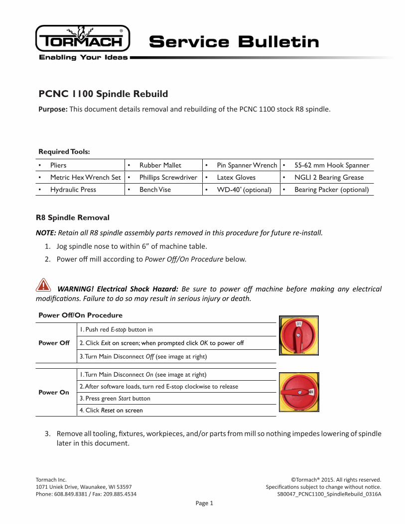
4. Remove Tormach Tooling System (TTS) collet or tool holder from R8 Spindle (see Figure 1).
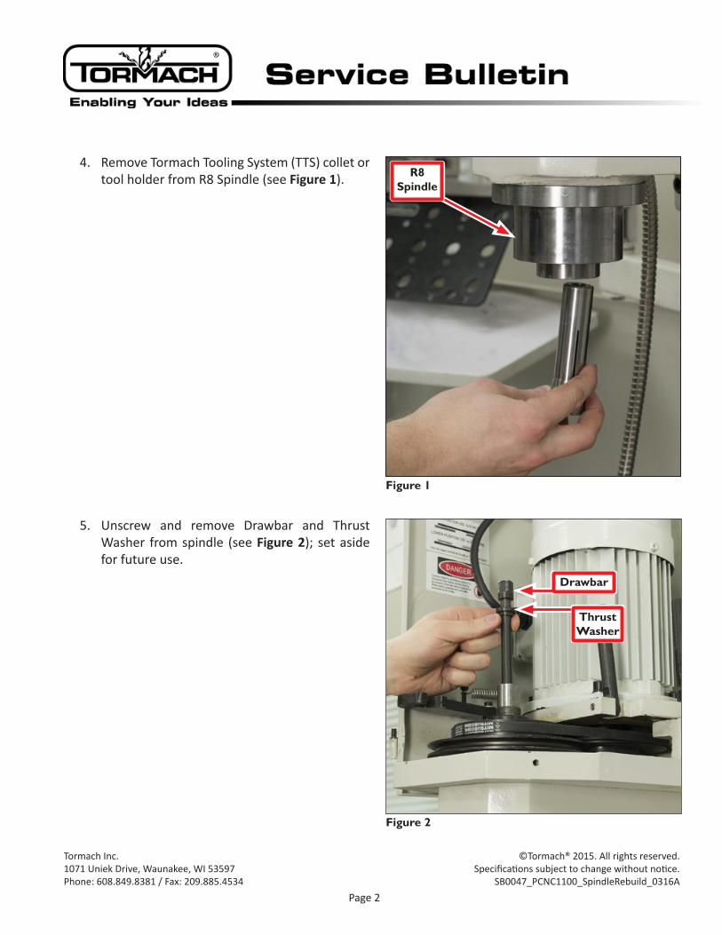
5. Unscrew and remove Drawbar and Thrust Washer from spindle (see Figure 2); set aside for future use.
Figure 1
R8 Spindle
Figure 2
Drawbar
Thrust Washer
Page 3
Tormach Inc.1071 Uniek Drive, Waunakee, WI 53597Phone: 608.849.8381 / Fax: 209.885.4534
©Tormach® 2015. All rights reserved.Specifications subject to change without notice.
SB0047_PCNC1100_SpindleRebuild_0316A
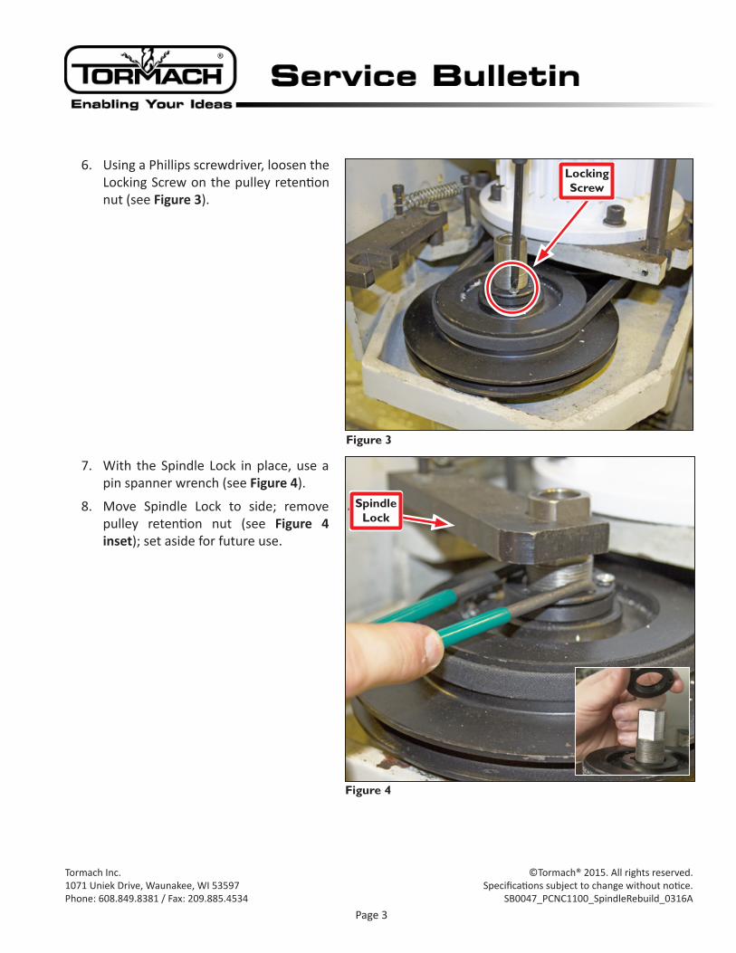
6. Using a Phillips screwdriver, loosen the Locking Screw on the pulley retention nut (see Figure 3).
7. With the Spindle Lock in place, use a pin spanner wrench (see Figure 4).
8. Move Spindle Lock to side; remove pulley retention nut (see Figure 4 inset); set aside for future use.
Figure 3
Locking Screw
Figure 4
Spindle Lock
Page 4
Tormach Inc.1071 Uniek Drive, Waunakee, WI 53597Phone: 608.849.8381 / Fax: 209.885.4534
©Tormach® 2015. All rights reserved.Specifications subject to change without notice.
SB0047_PCNC1100_SpindleRebuild_0316A
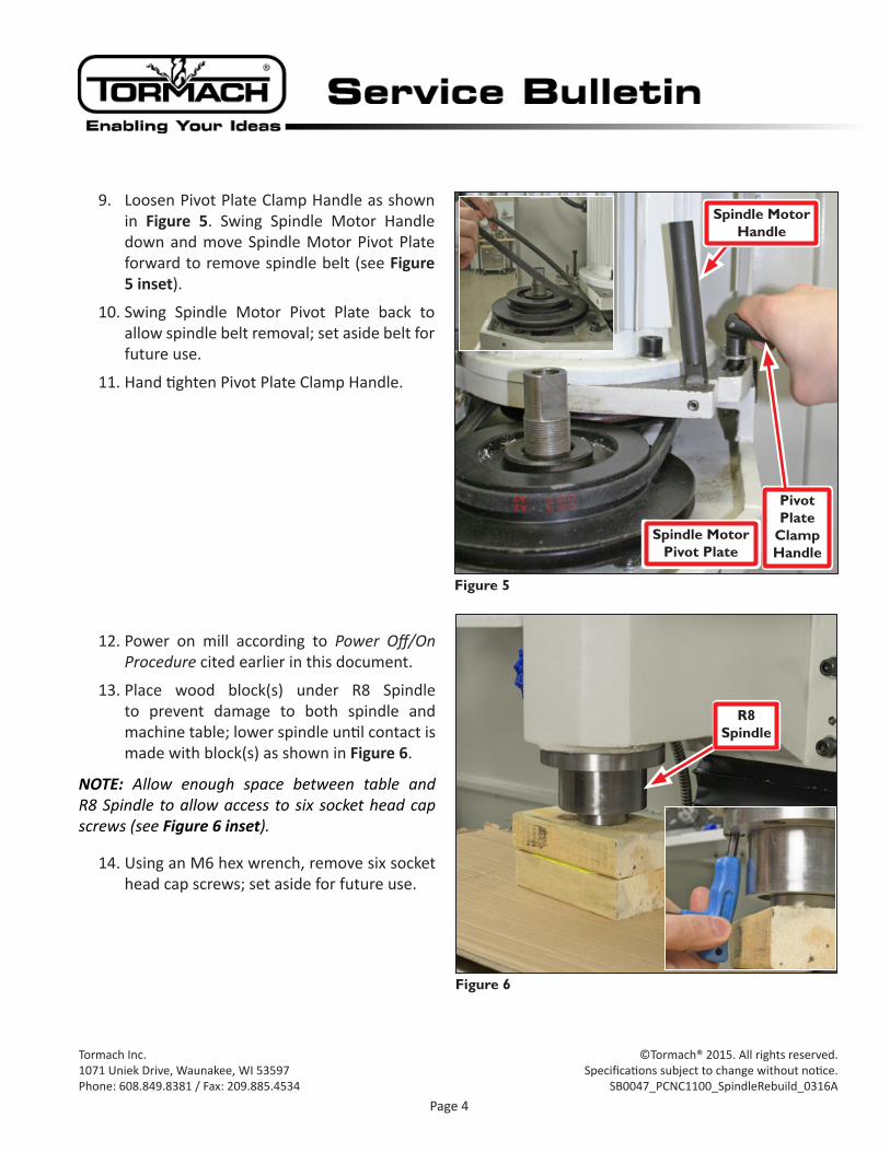
9. Loosen Pivot Plate Clamp Handle as shown in Figure 5. Swing Spindle Motor Handle down and move Spindle Motor Pivot Plate forward to remove spindle belt (see Figure 5 inset).
10. Swing Spindle Motor Pivot Plate back to allow spindle belt removal; set aside belt for future use.
11. Hand tighten Pivot Plate Clamp Handle.
12. Power on mill according to Power Off/On Procedure cited earlier in this document.
13. Place wood block(s) under R8 Spindle to prevent damage to both spindle and machine table; lower spindle until contact is made with block(s) as shown in Figure 6.
NOTE: Allow enough space between table and R8 Spindle to allow access to six socket head cap screws (see Figure 6 inset).
14. Using an M6 hex wrench, remove six socket head cap screws; set aside for future use.
Figure 5
Pivot Plate
Clamp Handle
Spindle Motor Handle
Spindle Motor Pivot Plate
Figure 6
R8 Spindle
Page 5
Tormach Inc.1071 Uniek Drive, Waunakee, WI 53597Phone: 608.849.8381 / Fax: 209.885.4534
©Tormach® 2015. All rights reserved.Specifications subject to change without notice.
SB0047_PCNC1100_SpindleRebuild_0316A
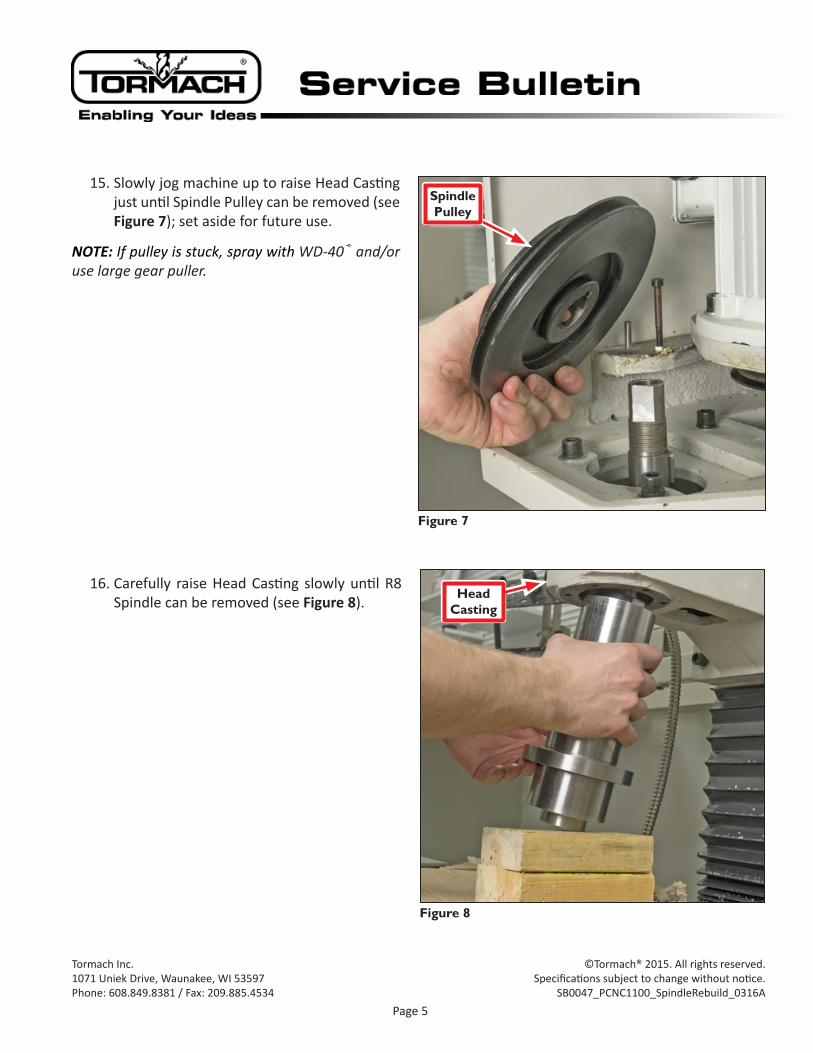
15. Slowly jog machine up to raise Head Casting just until Spindle Pulley can be removed (see Figure 7); set aside for future use.
NOTE: If pulley is stuck, spray with WD-40® and/or use large gear puller.
16. Carefully raise Head Casting slowly until R8 Spindle can be removed (see Figure 8).
Figure 7
Spindle Pulley
Figure 8
Head Casting
Page 6
Tormach Inc.1071 Uniek Drive, Waunakee, WI 53597Phone: 608.849.8381 / Fax: 209.885.4534
©Tormach® 2015. All rights reserved.Specifications subject to change without notice.
SB0047_PCNC1100_SpindleRebuild_0316A
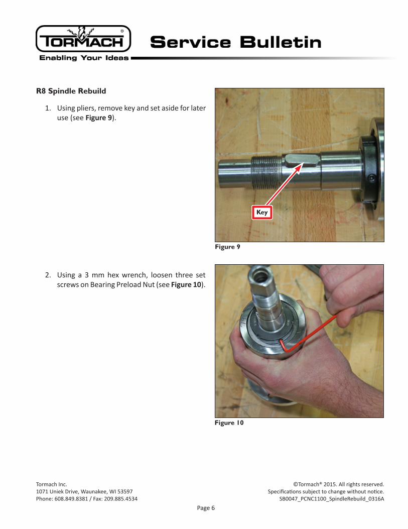
R8 Spindle Rebuild
1. Using pliers, remove key and set aside for later use (see Figure 9).
2. Using a 3 mm hex wrench, loosen three set screws on Bearing Preload Nut (see Figure 10).
Figure 10
Figure 9
Key
Page 7
Tormach Inc.1071 Uniek Drive, Waunakee, WI 53597Phone: 608.849.8381 / Fax: 209.885.4534
©Tormach® 2015. All rights reserved.Specifications subject to change without notice.
SB0047_PCNC1100_SpindleRebuild_0316A
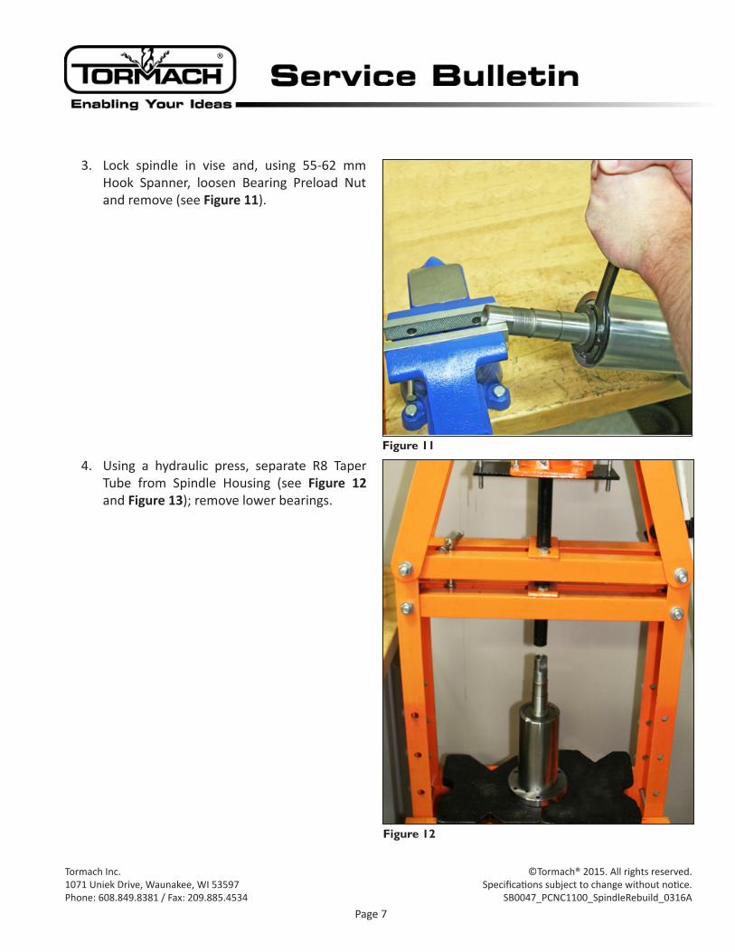
3. Lock spindle in vise and, using 55-62 mm Hook Spanner, loosen Bearing Preload Nut and remove (see Figure 11).
4. Using a hydraulic press, separate R8 Taper Tube from Spindle Housing (see Figure 12 and Figure 13); remove lower bearings.
Figure 11
Figure 12
Page 8
Tormach Inc.1071 Uniek Drive, Waunakee, WI 53597Phone: 608.849.8381 / Fax: 209.885.4534
©Tormach® 2015. All rights reserved.Specifications subject to change without notice.
SB0047_PCNC1100_SpindleRebuild_0316A
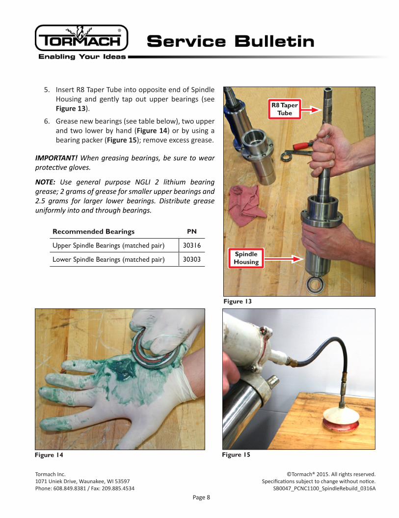
5. Insert R8 Taper Tube into opposite end of Spindle Housing and gently tap out upper bearings (see Figure 13).
6. Grease new bearings (see table below), two upper and two lower by hand (Figure 14) or by using a bearing packer (Figure 15); remove excess grease.
IMPORTANT! When greasing bearings, be sure to wear protective gloves.
NOTE: Use general purpose NGLI 2 lithium bearing grease; 2 grams of grease for smaller upper bearings and 2.5 grams for larger lower bearings. Distribute grease uniformly into and through bearings.
Recommended Bearings PN
UpperSpindleBearings(matchedpair) 30316
LowerSpindleBearings(matchedpair) 30303
Figure 13
R8 Taper Tube
Spindle Housing
Figure 14 Figure 15
Page 9
Tormach Inc.1071 Uniek Drive, Waunakee, WI 53597Phone: 608.849.8381 / Fax: 209.885.4534
©Tormach® 2015. All rights reserved.Specifications subject to change without notice.
SB0047_PCNC1100_SpindleRebuild_0316A
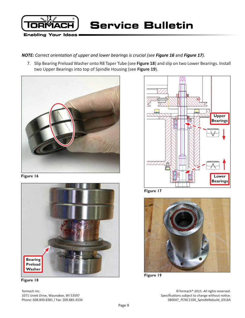
NOTE: Correct orientation of upper and lower bearings is crucial (see Figure 16 and Figure 17).
7. Slip Bearing Preload Washer onto R8 Taper Tube (see Figure 18) and slip on two Lower Bearings. Install two Upper Bearings into top of Spindle Housing (see Figure 19).
Figure 16
Figure 17
Upper Bearings
Lower Bearings
Figure 18
Bearing Preload Washer
Figure 19
Page 10
Tormach Inc.1071 Uniek Drive, Waunakee, WI 53597Phone: 608.849.8381 / Fax: 209.885.4534
©Tormach® 2015. All rights reserved.Specifications subject to change without notice.
SB0047_PCNC1100_SpindleRebuild_0316A
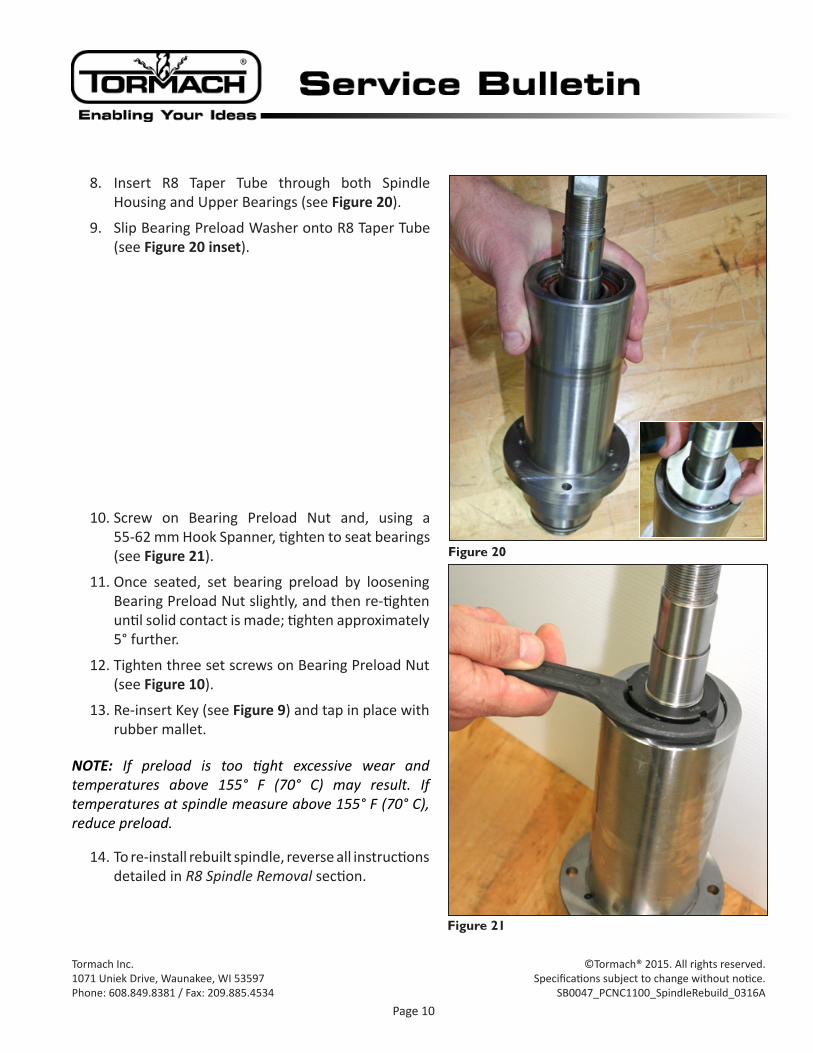
8. Insert R8 Taper Tube through both Spindle Housing and Upper Bearings (see Figure 20).
9. Slip Bearing Preload Washer onto R8 Taper Tube (see Figure 20 inset).
10. Screw on Bearing Preload Nut and, using a 55-62 mm Hook Spanner, tighten to seat bearings (see Figure 21).
11. Once seated, set bearing preload by loosening Bearing Preload Nut slightly, and then re-tighten until solid contact is made; tighten approximately 5° further.
12. Tighten three set screws on Bearing Preload Nut (see Figure 10).
13. Re-insert Key (see Figure 9) and tap in place with rubber mallet.
NOTE: If preload is too tight excessive wear and temperatures above 155° F (70° C) may result. If temperatures at spindle measure above 155° F (70° C), reduce preload.
14. To re-install rebuilt spindle, reverse all instructions detailed in R8 Spindle Removal section.
Figure 20
Figure 21


