Embed Size (px)
Citation preview
PDF Download
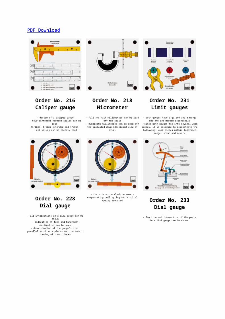
Order No. 216Caliper gauge- design of a caliper gauge
- four different vernier scales can beread
(1/10mm, 1/20mm extended and 1/50mm)- all values can be clearly read
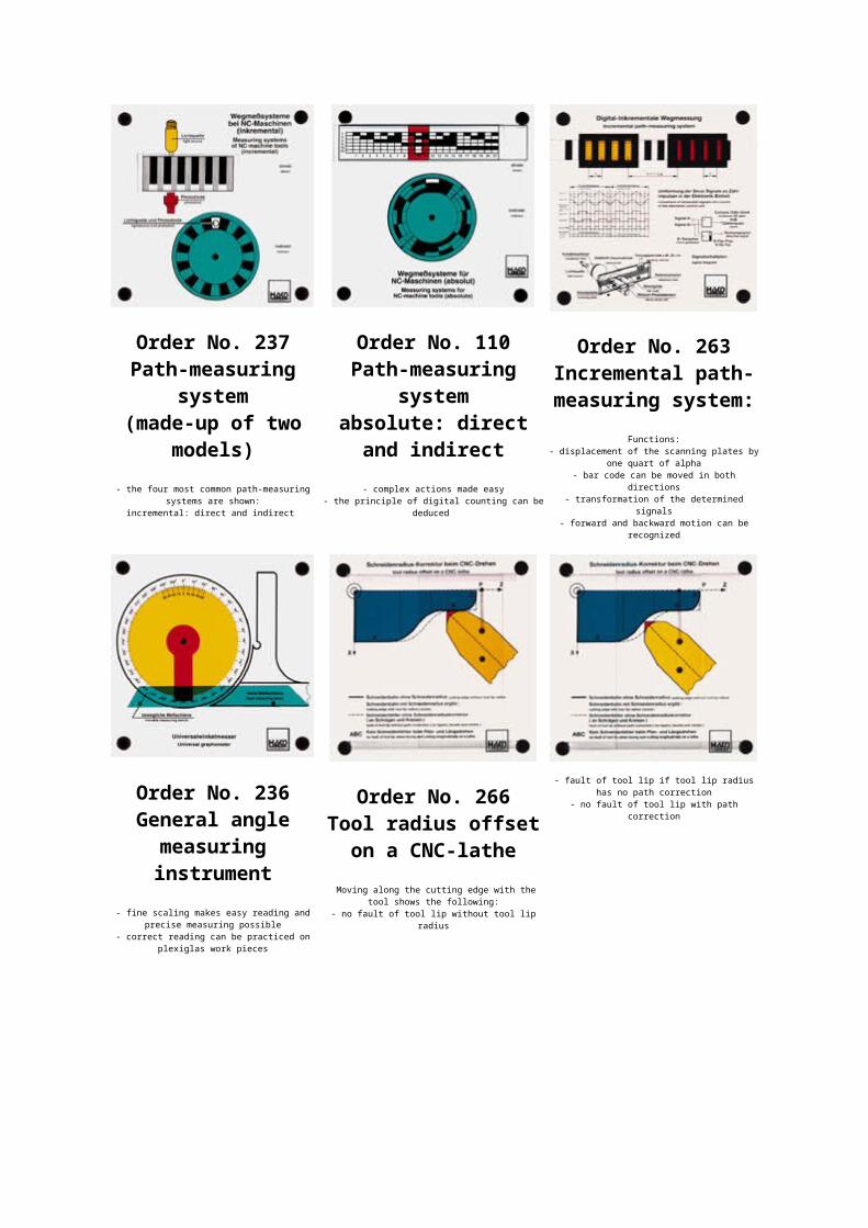
Order No. 218Micrometer
- full and half millimetres can be readoff the scale
- hundredth millimetres can be read offthe graduated drum (developed view of
drum)
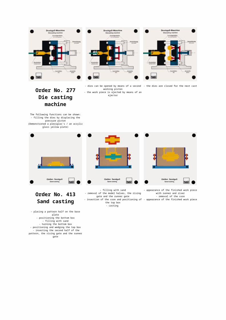
Order No. 231Limit gauges
- both gauges have a go end and a no-goend and are marked accordingly
- since both gauges fit into several workpieces, it is possible to demonstrate thefollowing: work pieces within tolerance
range, scrap and rework
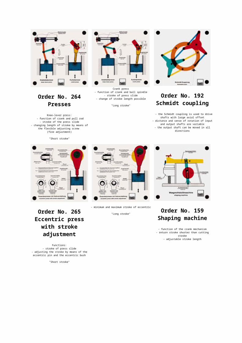
Order No. 228Dial gauge
- all interactions in a dial gauge can beshown
- indication of full and hundredthmillimetres can be seen
- demonstration of the gauge's uses:parallelism of work pieces and concentric
running of round pieces
- there is no backlash because acompensating pull spring and a spiral
spring are used Order No. 233Dial gauge
- function and interaction of the partsin a dial gauge can be shown
Order No. 237Path-measuring
system(made-up of two
models)- the four most common path-measuring
systems are shown:incremental: direct and indirect
Order No. 110Path-measuring
systemabsolute: directand indirect- complex actions made easy
- the principle of digital counting can bededuced
Order No. 263Incremental path-measuring system:
Functions:- displacement of the scanning plates by
one quart of alpha- bar code can be moved in both
directions- transformation of the determined
signals- forward and backward motion can be
recognized
Order No. 236General anglemeasuringinstrument
- fine scaling makes easy reading andprecise measuring possible
- correct reading can be practiced onplexiglas work pieces
Order No. 266Tool radius offseton a CNC-lathe
Moving along the cutting edge with thetool shows the following:
- no fault of tool lip without tool lipradius
- fault of tool lip if tool lip radiushas no path correction
- no fault of tool lip with pathcorrection
Order No. 277Die castingmachine
The following functions can be shown:- filling the dies by displacing the
pressure piston(Demonstrated a plexiglas's / an acrylic
glass yellow plate)
- dies can be opened by means of a secondworking piston
- the work piece is ejected by means of anejector
- the dies are closed for the next cast
Order No. 413Sand casting
- placing a pattern half on the baseplate
- positioning the bottom box- filling with sand
- turning the bottom box- positioning and wedging the top box - inserting the second half of the
pattern, the rising gate and the runnergate
- filling with sand- removal of the model halves, the rising
gate and the runner gate- insertion of the core and positioning of
the top box- casting
- appearance of the finished work piecewith runner and riser- removal of the core
- appearance of the finished work piece
Order No. 264PressesKnee-lever press:
- function of crank and pull rod- stroke of the press slide
- changing length of stroke by means ofthe flexible adjusting screw
(fine adjustment)
"Short stroke"
Crank press- function of crank and ball spindle
- stroke of press slide- change of stroke length possible
"Long stroke"
Order No. 192Schmidt coupling
- the Schmidt coupling is used to driveshafts with large axial offset
- distance and sense of rotation of inputand output shafts are variable
- the output shaft can be moved in alldirections
Order No. 265Eccentric press
with strokeadjustment
Functions:- stroke of press slide
- adjusting the stroke by means of theeccentric pin and the eccentric bush
"Short stroke"
- minimum and maximum stroke of eccentric
"Long stroke" Order No. 159
Shaping machine- function of the crank mechanism
- return stroke shorter than cuttingstroke
- adjustable stroke length
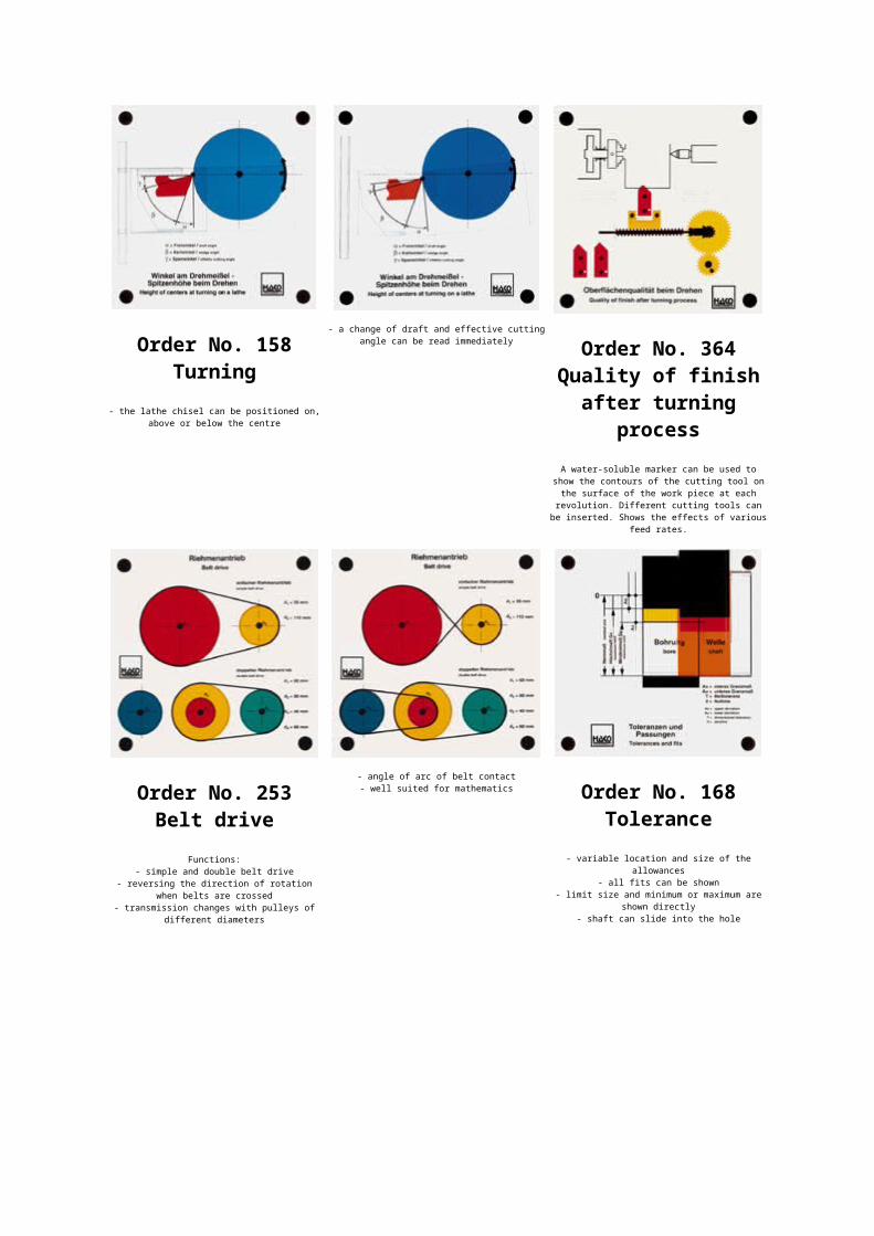
Order No. 158Turning
- the lathe chisel can be positioned on,above or below the centre
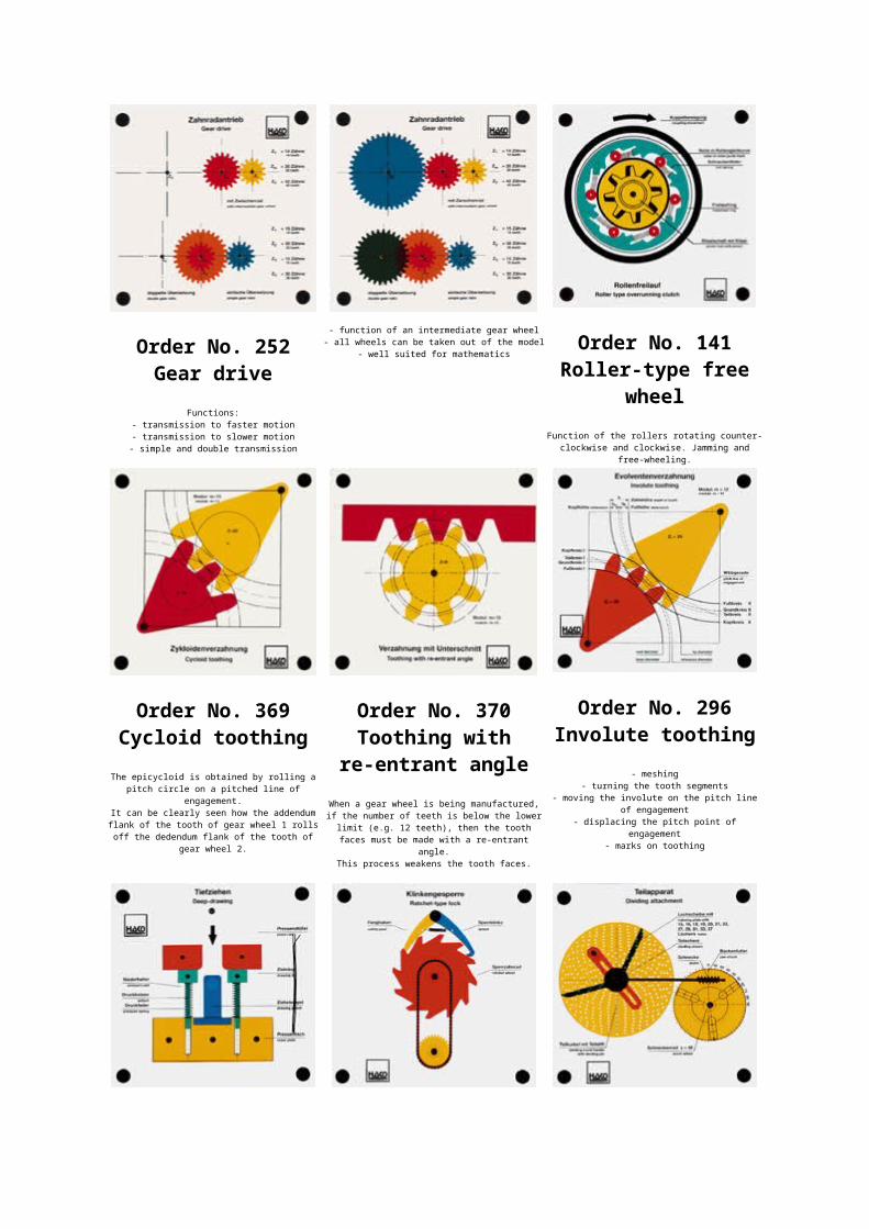
- a change of draft and effective cuttingangle can be read immediately Order No. 364
Quality of finishafter turning
processA water-soluble marker can be used to
show the contours of the cutting tool onthe surface of the work piece at each
revolution. Different cutting tools canbe inserted. Shows the effects of various
feed rates.
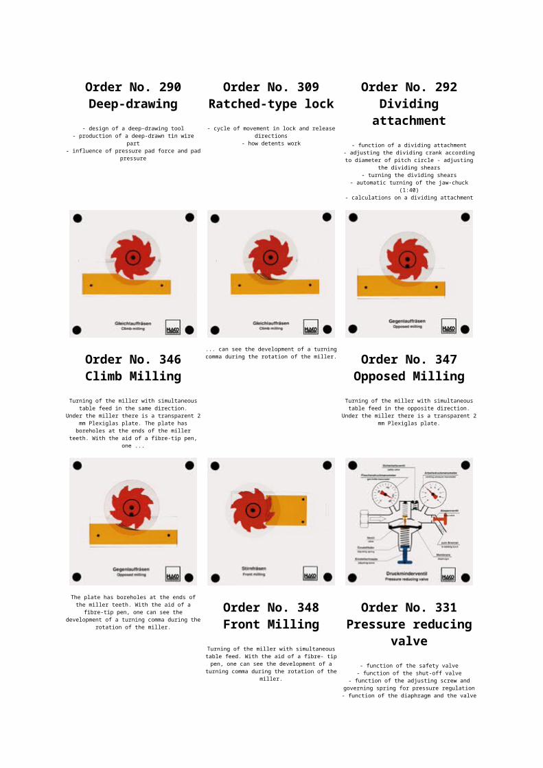
Order No. 253Belt drive
Functions:- simple and double belt drive
- reversing the direction of rotationwhen belts are crossed
- transmission changes with pulleys ofdifferent diameters
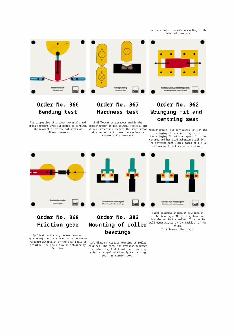
- angle of arc of belt contact- well suited for mathematics Order No. 168
Tolerance- variable location and size of the
allowances- all fits can be shown
- limit size and minimum or maximum areshown directly
- shaft can slide into the hole
Order No. 252Gear drive
Functions:- transmission to faster motion- transmission to slower motion- simple and double transmission
- function of an intermediate gear wheel- all wheels can be taken out of the model
- well suited for mathematicsOrder No. 141
Roller-type freewheel
Function of the rollers rotating counter-clockwise and clockwise. Jamming and
free-wheeling.
Order No. 369Cycloid toothing
The epicycloid is obtained by rolling apitch circle on a pitched line of
engagement.It can be clearly seen how the addendumflank of the tooth of gear wheel 1 rollsoff the dedendum flank of the tooth of
gear wheel 2.
Order No. 370Toothing with
re-entrant angleWhen a gear wheel is being manufactured,if the number of teeth is below the lowerlimit (e.g. 12 teeth), then the toothfaces must be made with a re-entrant
angle.This process weakens the tooth faces.
Order No. 296Involute toothing
- meshing- turning the tooth segments
- moving the involute on the pitch lineof engagement
- displacing the pitch point ofengagement
- marks on toothing
Order No. 290Deep-drawing
- design of a deep-drawing tool- production of a deep-drawn tin wire
part- influence of pressure pad force and pad
pressure
Order No. 309Ratched-type lock- cycle of movement in lock and release
directions- how detents work
Order No. 292Dividing
attachment- function of a dividing attachment
- adjusting the dividing crank accordingto diameter of pitch circle - adjusting
the dividing shears- turning the dividing shears
- automatic turning of the jaw-chuck(1:40)
- calculations on a dividing attachment
Order No. 346Climb Milling
Turning of the miller with simultaneoustable feed in the same direction.
Under the miller there is a transparent 2mm Plexiglas plate. The plate hasboreholes at the ends of the miller
teeth. With the aid of a fibre-tip pen,one ...
... can see the development of a turningcomma during the rotation of the miller.
Order No. 347Opposed Milling
Turning of the miller with simultaneoustable feed in the opposite direction.
Under the miller there is a transparent 2mm Plexiglas plate.
The plate has boreholes at the ends ofthe miller teeth. With the aid of a
fibre-tip pen, one can see thedevelopment of a turning comma during the
rotation of the miller.
Order No. 348Front Milling
Turning of the miller with simultaneoustable feed. With the aid of a fibre- tippen, one can see the development of a
turning comma during the rotation of themiller.
Order No. 331Pressure reducing
valve- function of the safety valve
- function of the shut-off valve- function of the adjusting screw and
governing spring for pressure regulation- function of the diaphragm and the valve
- movement of the needle according to thelevel of pressure
Order No. 366Bending test
The properties of various materials andcross-sections when subjected to bending.
The properties of the materials atdifferent sweeps.
Order No. 367Hardness test
3 different penetrators enable thedemonstration of the Brinell-Rockwell andVickers processes. Before the penetrationof a second test piece the surface is
automatically smoothed.
Order No. 362Wringing fit and
centring seatDemonstration: The difference between the
wringing fit and centring seat.The wringing fit with a taper of 1 : 50centres and has good adhesion qualities.The centring seat with a taper of 1 : 10centres well, but is self-releasing.
Order No. 368Friction gear
Application for e.g. screw presses.By sliding the drive shaft an infinitely-variable alteration of the gear ratio ispossible. The power flow is obtained by
friction.
Order No. 383Mounting of roller
bearingsLeft diagram: Correct mounting of rollerbearings. The force for pressing togetherthe outer ring (left) and the inner ring(right) is applied directly to the ring
which is firmly fixed.
Right diagram: incorrect mounting ofroller bearings. The joining force ostransferred to the roller. This can be
well demonstrated by the backlash of theballs.
This damages the rings.
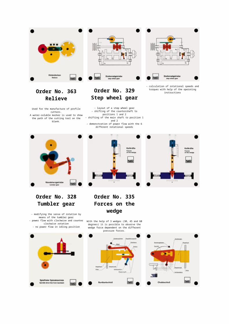
Order No. 363Relieve
Used for the manufacture of profilecutters.
A water-soluble marker is used to showthe path of the cutting tool on the
blank.
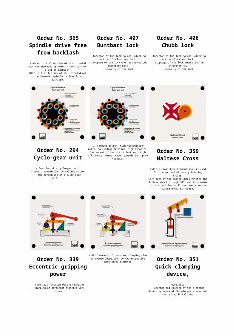
Order No. 329Step wheel gear
- layout of a step wheel gear- shifting of the countershaft to
positions 1 and 2- shifting of the main shaft to position 1
and 2- demonstration of power flow with the 6
different rotational speeds
- calculation of rotational speeds andtorques with help of the operating
instructions
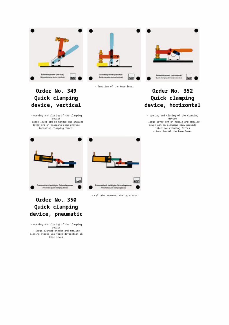
Order No. 328Tumbler gear
- modifying the sense of rotation bymeans of the tumbler gear
- power flow with clockwise and counterclockwise rotation
- no power flow in idling position
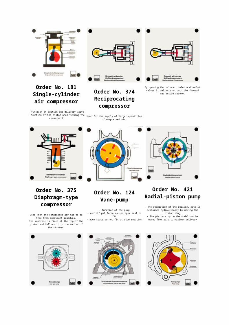
Order No. 335Forces on the
wedgeWith the help of 3 wedges (30, 45 and 60degrees) it is possible to observe thewedge force dependent on the different
pressure forces.
Order No. 365Spindle drive free
from backlashWithout initial tension of the threadednut the threaded spindle is seen to have
a lot of backlash.With initial tension of the threaded nut
the threaded spindle is free frombacklash.
Order No. 407Buntbart lock
- function of the locking and unlockingaction of a Buntbart lock
- stoppage of the lock when using variousincorrect keys
- security of the lock
Order No. 406Chubb lock
- function of the locking and unlockingaction of a Chubb lock
- stoppage of the lock when using anincorrect key
- security of the lock
Order No. 294Cyclo-gear unit- function of a cyclo-gear unit
- power transmission by rolling motion- the advantages of a cyclo-gear
unit: ...
... compact design, high transmissionratio, no sliding friction, high dynamics,low moment of inertia, silent run, high
efficiency, three-stage transmission up to428285:1
Order No. 359Maltese Cross
Maltese cross-type transmission is usedfor the control of rotary indexing
tables.Each turn of the curved wheel rotates theMaltese wheel through 90°, and it remainsit this position until the next time the
curved wheel is turned.
Order No. 339Eccentric gripping
power- eccentric function during clamping- clamping of different diameter work
pieces
- displacement of stand and clamping clawto ensure adaptation to the respective
work piece diameter Order No. 351Quick clamping
device,hydraulic
- opening and closing of the clampingdevice by means of the plunger stroke and
the hydraulic cylinder
Order No. 349Quick clampingdevice, vertical- opening and closing of the clamping
device- large lever arm on handle and smaller
lever arm on clamping claw provideintensive clamping forces
- function of the knee lever
Order No. 352Quick clamping
device, horizontal- opening and closing of the clamping
device- large lever arm on handle and smaller
lever arm on clamping claw provideintensive clamping forces
- function of the knee lever
Order No. 350Quick clamping
device, pneumatic- opening and closing of the clamping
device- large plunger stroke and smaller
closing stroke via force deflection inknee lever
- cylinder movement during stroke
Order No. 181Single-cylinderair compressor
- function of suction and delivery valve- function of the piston when turning the
crankshaft
Order No. 374Reciprocatingcompressor
Used for the supply of larger quantitiesof compressed air.
By opening the relevant inlet and outletvalves it delivers on both the forward
and return stroke.
Order No. 375Diaphragm-type
compressorUsed when the compressed air has to be
free from lubricant residues.The membrane is fixed at the top of thepiston and follows it in the course of
the strokes.
Order No. 124Vane-pump- function of the pump
- centrifugal force causes apex seal tofit
- apex seals do not fit at slow rotation
Order No. 421Radial-piston pump- The regulation of the delivery rate isperformed hydraulically by moving the
piston ring- The piston ring on the model can bemoved from zero to maximum delivery
Order No. 128External gear pump
- oil flow through the pump- function of the pump
Order No. 206Internal gear pump
- function of an internal gear pump:increasing and decreasing the volume of
suction and pressure chamber- internal gear pumps are used as engine-
oil pumps and oil pumps in automatictransmissions
Order No. 129Rotor pump
- an increase or decrease in volume ofthe chambers between inner and outer
rotor causes suction or pressure
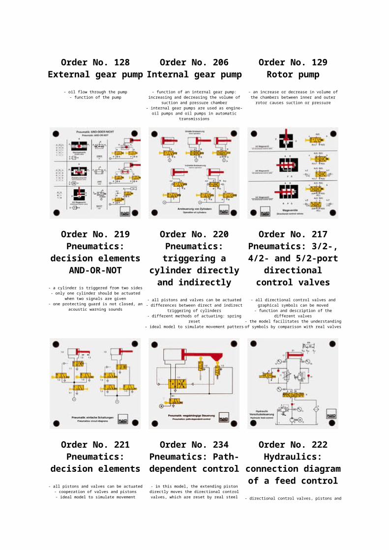
Order No. 219Pneumatics:
decision elementsAND-OR-NOT
- a cylinder is triggered from two sides- only one cylinder should be actuated
when two signals are given- one protecting guard is not closed, an
acoustic warning sounds
Order No. 220Pneumatics:triggering a
cylinder directlyand indirectly
- all pistons and valves can be actuated- differences between direct and indirect
triggering of cylinders- different methods of actuating: spring
reset- ideal model to simulate movement patters
Order No. 217Pneumatics: 3/2-,4/2- and 5/2-port
directionalcontrol valves
- all directional control valves andgraphical symbols can be moved
- function and description of thedifferent valves
- the model facilitates the understandingof symbols by comparison with real valves
Order No. 221Pneumatics:
decision elements- all pistons and valves can be actuated
- cooperation of valves and pistons- ideal model to simulate movement
Order No. 234Pneumatics: Path-dependent control- in this model, the extending pistondirectly moves the directional controlvalves, which are reset by real steel
Order No. 222Hydraulics:
connection diagramof a feed control
- directional control valves, pistons and
patterns (back and forth) springs- the model is especially suited to
introduce the functions of model #221
check valve can be moved- simulation of all movement patterns
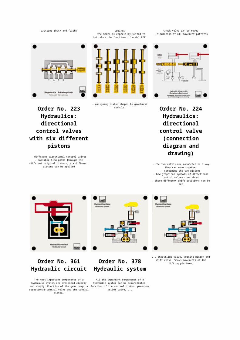
Order No. 223Hydraulics:directional
control valveswith six different
pistons- different directional control valves
- possible flow paths through thedifferent original pistons, six different
pistons can be applied
- assigning piston shapes to graphicalsymbols Order No. 224
Hydraulics:directional
control valve(connectiondiagram anddrawing)
- the two valves are connected in a waythey can move together
- combining the two pistons- how graphical symbols of directional
control valves come about- three different shift positions can be
set
Order No. 361Hydraulic circuit
The most important components of ahydraulic system are presented clearlyand simply: Function of the gear pump, adirectional-control valve and the control
piston.
Order No. 378Hydraulic systemAll the important components of a
hydraulic system can be demonstrated:Function of the control piston, pressure
relief valve, ...
... throttling valve, working piston andshift valve. Shows movements of the
lifting platform.
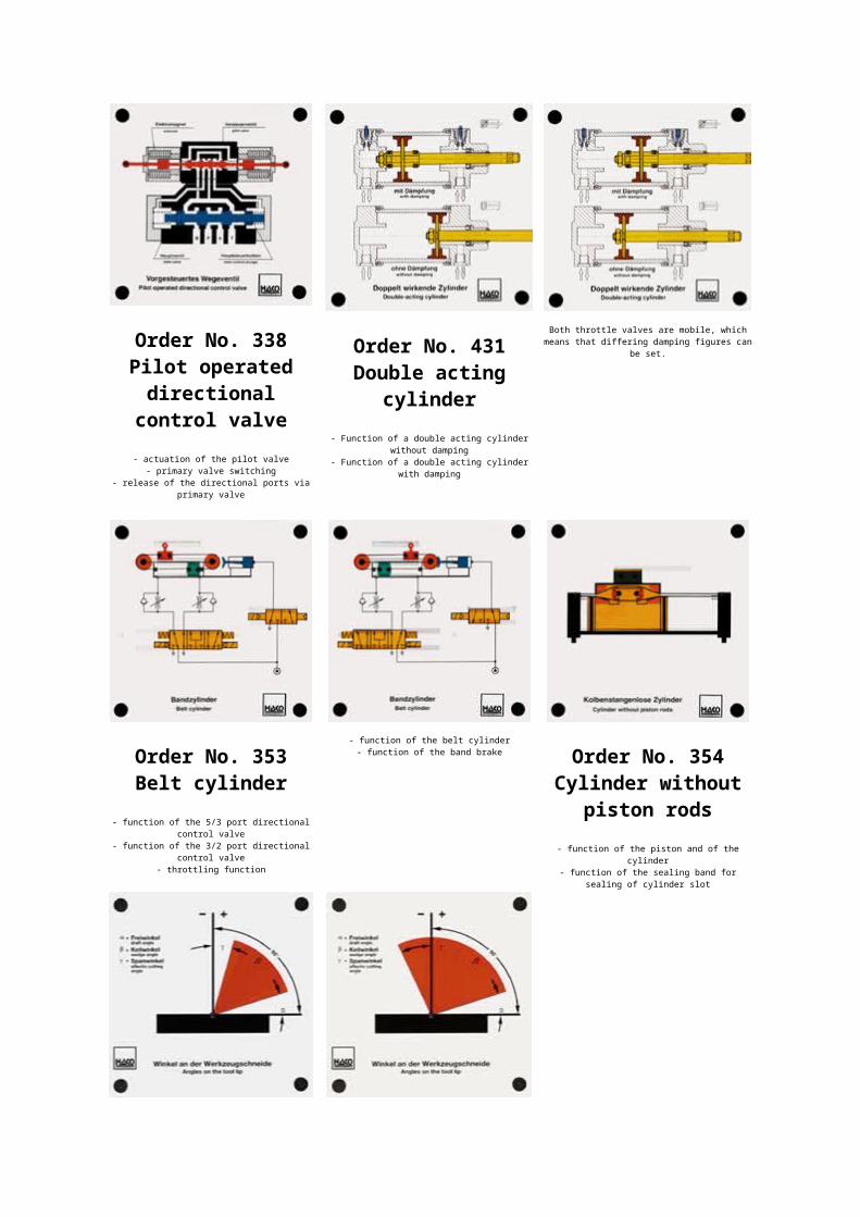
Order No. 338Pilot operateddirectionalcontrol valve- actuation of the pilot valve
- primary valve switching- release of the directional ports via
primary valve
Order No. 431Double acting
cylinder- Function of a double acting cylinder
without damping- Function of a double acting cylinder
with damping
Both throttle valves are mobile, whichmeans that differing damping figures can
be set.
Order No. 353Belt cylinder
- function of the 5/3 port directionalcontrol valve
- function of the 3/2 port directionalcontrol valve
- throttling function
- function of the belt cylinder- function of the band brake
Order No. 354Cylinder without
piston rods- function of the piston and of the
cylinder- function of the sealing band for
sealing of cylinder slot
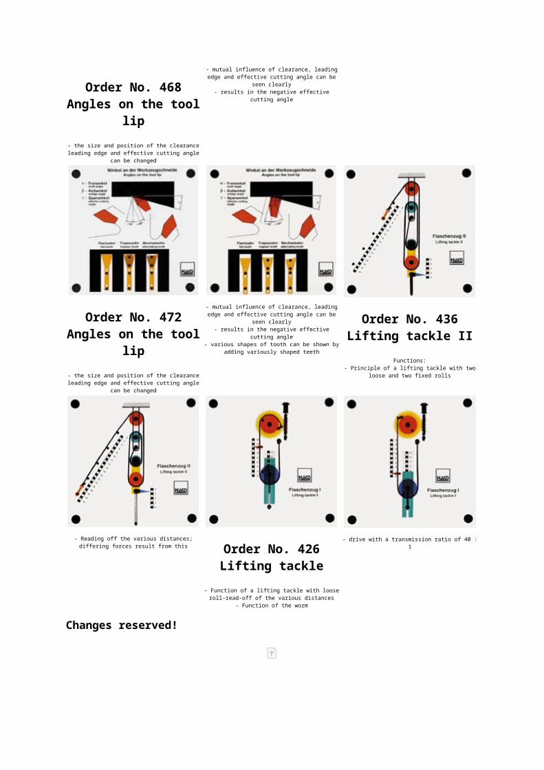
Order No. 468Angles on the tool
lip- the size and position of the clearanceleading edge and effective cutting angle
can be changed
- mutual influence of clearance, leadingedge and effective cutting angle can be
seen clearly- results in the negative effective
cutting angle
Order No. 472Angles on the tool
lip- the size and position of the clearanceleading edge and effective cutting angle
can be changed
- mutual influence of clearance, leadingedge and effective cutting angle can be
seen clearly- results in the negative effective
cutting angle- various shapes of tooth can be shown by
adding variously shaped teeth
Order No. 436Lifting tackle II
Functions:- Principle of a lifting tackle with two
loose and two fixed rolls
- Reading off the various distances;differing forces result from this Order No. 426
Lifting tackle - Function of a lifting tackle with looseroll-read-off of the various distances
- Function of the worm
- drive with a transmission ratio of 40 :1
Changes reserved!