Embed Size (px)
Citation preview
I
بسم هللا الرحمن الرحيم
AL NEELAIN UNIVERSITY
Faculty of Engineering
Department of Electrical &Electronic Engineering
A thesis submitted as partial fulfillment for the
requirement of the M.Sc in Data and Communication
Networks
Performance analysis of voice over IP over
WLAN
Prepared By:
Ahmed EltyebMohmed Ahmed
Supervised By:
Prof.Khalid Hamid Bilal
August 2017

II
االيه
وأخفض لهما ":تعالي هللا قال
الرحمة جناح الذل من
وُقل ربي أرحمهما كما
( 24ربياني صغيرا")
اإلسراء

III
الهداءا
إلــى والدتي العزيزة ... وإلى والدي العزير أطـــال هللا
’’’’والعافية صحهــي ُعمـــركما وأمــدكم بالفـ
يه والصحهفإلــى اخواتي واخوتي امدكم بالعا
الي زمالئـــــي...
إلـــى األيادي المخلصة التـي ساعدتني .......... أساتذتي
الكــرام
فلكم مني الود في زمن يصعب فيه الود ويندر فيه الوفاء
الشكر والعرفان الشكر أوله هلل سبحانه وتعالي
رحاب

IV
إلـــــــى الذين مهدوا لنا طريق العلم والمعرفة
...
بجامعه النيلين إلــــــى جميع أساتذتنا األفاضل
...
الي جميع اساتذتنا بكليه الهندسه جامعة
النيلين.....
الي كل العاملين بكليه الهندسه جامعة النيلين
.....
خالد حامد بالل وأخص بالتقدير والشكرالبروفيسور/
على ما بذله من جهد متواصل ودءوب ، وما قدمه عبدهللا
ن صبر من توجيهات وإرشادات سديدة ،وما أبداه م
وتفهم كبيرين في سبيل إعداد هذا البحث فله مني
عظيم الشكر ووافر اإلمتنان.
وكذلك أشكر كل من ساعد على إتمام هذا البحث وقدم
لي العون ومد لي يد المساعدة وزودني بالمعلومات
/المهندسالالزمة ألتمام هذا البحث وخاصة
زمالئنا وأخواننا ورفاق ،وكلمحمد الطاهرالطاهر
.الدرب
سائالً المولى عز وجل أن يجزي
.الجميع عني خير الجزاء
V
المستخلص
المشروع هو دراسة وتحليل وتخطيط وتصميم ومحاكاة نقل الصوت عبر هذه الهدف من
برتكول اإلنترنت خالل الشبكة المحلية الالسلكية بإستخدام برنامج األوبنيت ثم تقييم جودة الخدمة
( في الشبكة. معدل التاخيرر،اإلنتاجية، )التأخي
معدل اإلرسال، عدد األجهزة المتصلة بالشبكة و لتقيم االداء هى العوامل التى اخذت فى االعتبار
زمن المحاكاة وذلك لتقييم جودة الشبكة.
ارسال المحاكاةأنالزيادةفيمعدالنتايج وأظهرت
ومعدل التاخير .تؤديإلىانخفاضفيالتأخيرفيحينتنخفضاإلنتاجيةالبيانات
Abstract
The objectives of this project is to study, analyze, plan, design and
simulate voice over internet protocol over WLAN network using OPNET
simulation software program, to evaluate the Quality Of Service
VI
performance (delay, throughput, and jitter ) of the network. The
parameters which were taken into consideration of the evaluation were data
rate, number of nodes and simulation time.
The results of the simulated network indicated that as in data rate increase
delay decrease while the throughput and jitter decrease.
List Contents:
Page Title Index
VII
I 1 االية
II 2 االهداء
III 3 الشكر والعرفان
IV 4 المستخلص
V Abstract 5
IV Abbreviation 6
VI List Content 7
VIII List Figure 8
IX List Tables 9
X Abbreviations 10
Chapter One: Introduction
1 Background 1-1
2 Problem Definition 1-2
2 Motivations 1-3
2 Objective 1-4
2 Methodology 1-5
3 Thesis layout 1-6
Chapter two: Literature Review
4 ConceptWireless LAN 2-1
4 Types of network according to Geographic scale 2-2
5 Wireless Local Area Networks 2-3
5 IEEE Wireless Networking Specifications 2-4
8 Types of Wireless LAN 2-5
9 WLAN Applications 2-6
9 Wireless LAN architectures 2-7
11 Hardware 2-8
12 Software requirements 2-9
13 Advantages and Disadvantages of WLAN 2-10
14 Concept of voice over IP 2-11
14 Voice over IP architecture 2-12
16 VoIP System 2-13
17 VOIP components 2-14
18 Protocols 2-15
20 Quality of serves 2-16
21 Factors that affect quality of service 2-17
23 Advantages of VoIP 2-18
25 Disadvantages of VoIP 2-18
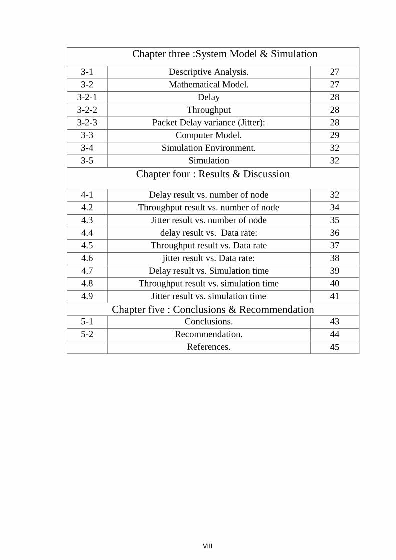
VIII
Chapter three :System Model & Simulation
27 Descriptive Analysis. 3-1
27 Mathematical Model. 3-2
28 Delay 3-2-1
28 Throughput 3-2-2
28 Packet Delay variance (Jitter): 3-2-3
29 Computer Model. 3-3
32 Simulation Environment. 3-4
32 Simulation 3-5
Chapter four : Results & Discussion
32 Delay result vs. number of node 4-1
34 Throughput result vs. number of node 4.2
35 Jitter result vs. number of node 4.3
36 delay result vs. Data rate: 4.4
37 Throughput result vs. Data rate 4.5
38 jitter result vs. Data rate: 4.6
39 Delay result vs. Simulation time 4.7
40 Throughput result vs. simulation time 4.8
41 Jitter result vs. simulation time 4.9
Chapter five : Conclusions & Recommendation
43 Conclusions. 5-1
44 Recommendation. 5-2
45 References.
IX
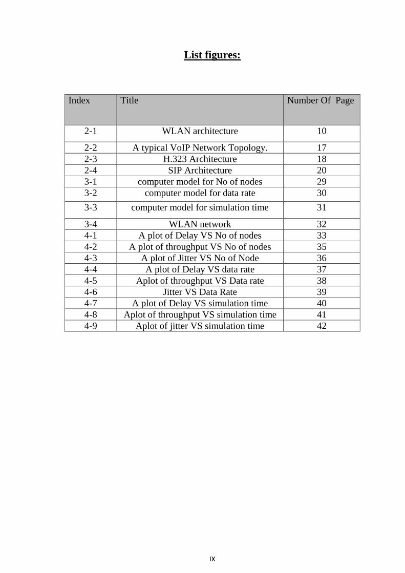
List figures:
Index Title Number Of Page
2-1 WLAN architecture 10
2-2 A typical VoIP Network Topology. 17
2-3 H.323 Architecture 18
2-4 SIP Architecture 20
3-1 computer model for No of nodes 29
3-2 computer model for data rate 30
3-3 computer model for simulation time 31
3-4 WLAN network 32
4-1 A plot of Delay VS No of nodes 33
4-2 A plot of throughput VS No of nodes 35
4-3 A plot of Jitter VS No of Node 36
4-4 A plot of Delay VS data rate 37
4-5 Aplot of throughput VS Data rate 38
4-6 Jitter VS Data Rate 39
4-7 A plot of Delay VS simulation time 40
4-8 Aplot of throughput VS simulation time 41
4-9 Aplot of jitter VS simulation time 42
X
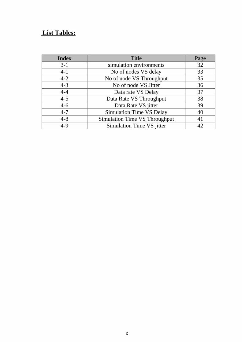
List Tables:
Index Title Page
3-1 simulation environments 32
4-1 No of nodes VS delay 33
4-2 No of node VS Throughput 35
4-3 No of node VS Jitter 36
4-4 Data rate VS Delay 37
4-5 Data Rate VS Throughput 38
4-6 Data Rate VS jitter 39
4-7 Simulation Time VS Delay 40
4-8 Simulation Time VS Throughput 41
4-9 Simulation Time VS jitter 42
XI
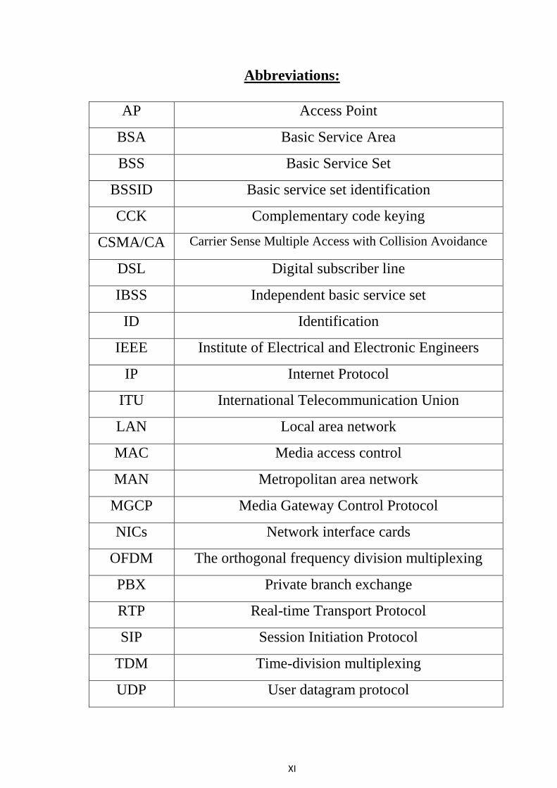
Abbreviations:
AP Access Point
BSA Basic Service Area
BSS Basic Service Set
BSSID Basic service set identification
CCK Complementary code keying
CSMA/CA Carrier Sense Multiple Access with Collision Avoidance
DSL Digital subscriber line
IBSS Independent basic service set
ID Identification
IEEE Institute of Electrical and Electronic Engineers
IP Internet Protocol
ITU International Telecommunication Union
LAN Local area network
MAC Media access control
MAN Metropolitan area network
MGCP Media Gateway Control Protocol
NICs Network interface cards
OFDM The orthogonal frequency division multiplexing
PBX Private branch exchange
RTP Real-time Transport Protocol
SIP Session Initiation Protocol
TDM Time-division multiplexing
UDP User datagram protocol
XII
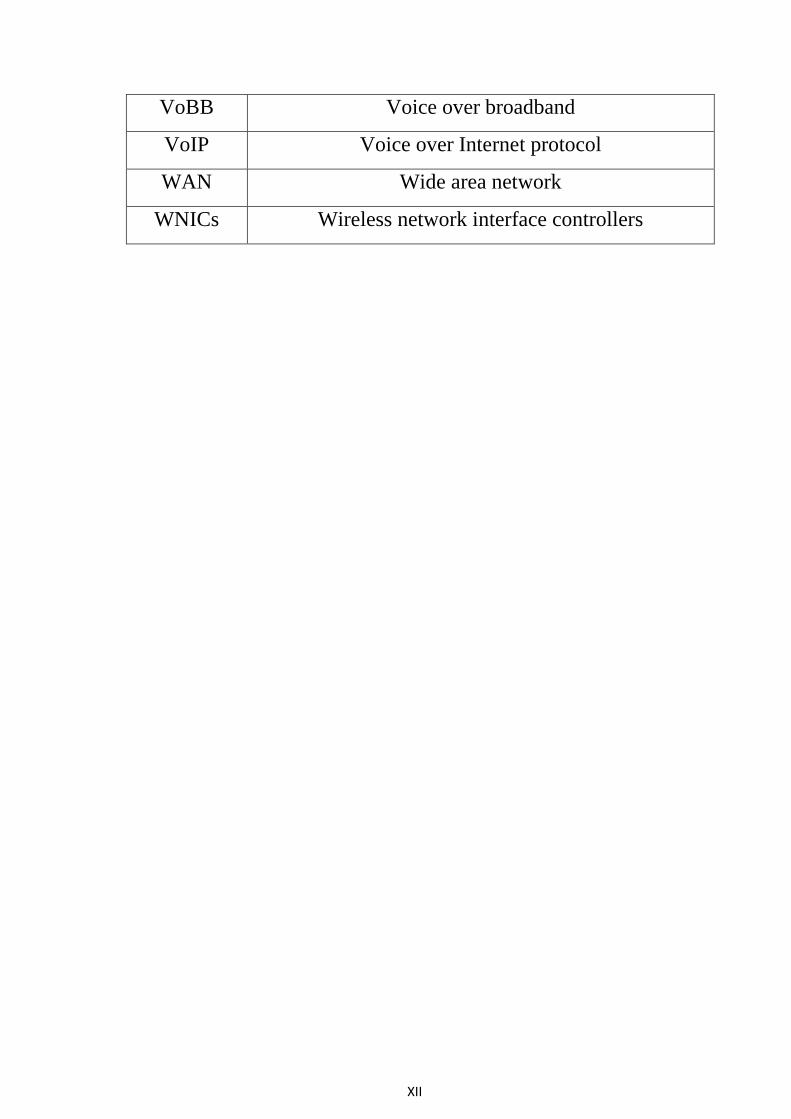
VoBB Voice over broadband
VoIP Voice over Internet protocol
WAN Wide area network
WNICs Wireless network interface controllers
1
Chapter one
Introduction
1.1Background:
Voice over Internet Protocol (VoIP) is a form of voice communication
that uses audio data to transmit voice signals to the end user. VoIP is one
of the most important technologies in the World of communication.
Around, 10 years of research on VoIP, some problems of VoIP are still
remaining. During the pastdecade and with growing of wireless. VoIP over
Wireless LAN (WLAN) faces many challenges due to the loose nature of
wireless network. Issues like providing Quality of Service (QoS) at a good
level, dedicating capacity for calls and having secure calls is more difficult
rather than wired LAN. Therefore VoIP over WLAN (Vo IP WLAN)
remains a challenging research topic. The Voice over IP (VoIP)
technology has become prevalent today due to its lower cost than
increasing availability of wireless internet access has led to research
studies examining the combination of wireless network access with voice
over IP. With the widespread availability of advanced mobile phones and
Pocket PCs, the need for VoIP applications on these mobile[1].
1.2 Problem definition:
The Voice transmitted to the receiver through the channel over WLAN
over IP network is impaired by noise, fading, and multiple access
interference which degrade the QoS performance such as delay, jitter and
throughput.
1.3 Motivation:
The significance of VoIP reduce the cost and increase the capacity and
wider the coverage.
2
1.4 Objectives:
To study WLAN network comprehensively
To analyze hardware and software requirement of VoIPover WLAN
network.
To simulate voice over IP over WLAN network
To evaluate the performance of VOIP over WLAN in terms of
delay, jitter and throughput
1.5 Methodology:
Consists of two phases:
Phase one: Buildmathematical and computer model to describe QoS
parameter of WLAN over IP.
Phase two: Simulation model using OPNET and MATLAB software
program.
1.6 Thesis layouts:
Chapter two: Present the detailed study of the WLAN and the
hardware and soft requirement for VOIP and QoS parameter
Chapter three: apply the methodology and setup experiment
which includes the descriptive analysis, mathematical and computer
model and simulation software program.
Chapter four:provides results and the discussion for the QoSsuch
asdelay, jitter and throughput in the WLAN network.
Chapter five:introduce the conclusion and suggests some
recommendations for future work.
3
Chapter Two
Literature Review
2.1ConceptWireless LAN:
A computer network or data network is a telecommunications network that allows
computers to exchange data. In computer networks, networked computing devices
pass data to each other along data connections. Data is transferred in the form of
packets. The connections (network links) between nodes are established using
either cable media or wireless media. The best-known computer network is the
Internet. [2]
Network computer devices that originate, route and terminate the data are called
network nodes. Nodes can include hosts such as personal computers, phones,
servers as well as networking hardware. Two such devices are said to be
networked together when one device is able to exchange information with the other
device, whether or not they have a direct connection to each other.[3]
2.2 Types of Networks:
A network can be characterized by its physical capacity or its organizational
purpose. Use of the network, including user authorization and access rights, differ
accordingly:
Local area network:
A local area network (LAN) is a network that connects computers and devices in a
limited geographical area such as a home, school, office building, or closely
positioned group of buildings. Each computer or device on the network is a node.
Metropolitan area network:
A Metropolitan area network (MAN) is a large computer network that usually
spans a city or a large campus.
4
Wide area network:
A wide area network (WAN) is a computer network that covers a large
geographic area such as a city, country, or spans even intercontinental
distances.
2.3 Wireless Local Area Networks:
A Wireless Local Area Network (WLAN) links two or more devices using a
wireless communication method. It usually provides a connection through an
Access Point (AP) to the wider internet [4].
This gives users the ability to move around within a local coverage area and still be
connected to the network. Just as the cordless telephone frees people to make a
phone call from anywhere in their home, a WLAN permits people to use their
computers anywhere in the network area, such as an office building or corporate
campus. Due to their ease of installation and the increasing popularity of laptop
computers, WLANs have been widely deployed in the past two decades.
2.4 IEEE Wireless Networking Specifications:
The IEEE (Institute of Electrical and Electronic Engineers) released the 802.11
specifications in June 1999. The initial specification, known as 802.11, used the
2.4 GHz frequency and supported a maximum data rate of 1 to 2 Mbps. In late
1999, two new addenda were released .The 802.11b specification increased the
performance to 11 Mbps in the 2.4 GHz range while the 802.11a specification
utilized the5 GHz range and supported up to 54 Mbps .Unfortunately, the two new
specifications were incompatible because they used different frequencies. This
means that 802.11a network interface cards (NICs) and access points cannot
communicate with 802.11b NICs and access points. This incompatibility forced
thecreation of the new draft standard known as802.11g. 802.11g supports up to 54
Mbps and is interoperable with 802.11b products on the market today. The concern
5
is that the 802.11g specification is currently in development and products will not
be available until a later date[5].D[4]5Dج
Specifications
The 802.11 specifications were developed specifically for Wireless Local
Area Networks (WLANs) by the IEEE and include four subsets of Ethernet-based
protocol standards: 802.11, 802.11a, 802.11b, and 802.11g.
802.11
802.11 operated in the 2.4 GHz range and was the original specification of the
802.11 IEEE standards. This specification delivered 1 to 2 Mbps using a
technology known as phase-shift keying (PSK) modulation. This specification is
no longer used and has largely been replaced by other forms of the 802.11
standard.
802.11a
802.11a operates in the 5 - 6 GHz range with data rates commonly in the 6 Mbps,
12 Mbps, or 24 Mbps range. Because 802.11a uses the orthogonal frequency
division multiplexing (OFDM) standard, data transfer rates can be as high as 54
Mbps. OFDM breaks up fast serial information signals into several slower sub-
signals that are transferred at the same time via different frequencies, providing
more resistance to radio frequency interference. The 802.11a specification is also
known as Wi-Fi5, and though regionally deployed, it is not a global standard like
802.11b.
802.11b
The 802.11b standard (also known as Wi-Fi) operates in the 2.4 GHz range
with up to 11 Mbps data rates and is backward compatible with the 802.11
standard. 802.11b uses a technology known as complementary code keying (CCK)
6
modulation, which allows for higher data rates with less chance of multi-path
propagation interference (duplicate signals bouncing off walls).
802.11g
802.11g is the most recent IEEE 802.11 draft standard and operates in the
2.4 GHz range with data rates as high as 54 Mbps over a limited distance. It is also
backward compatible with 802.11b and will work with both 11 and 22 Mbps
802.11g offers the best features of both 802.11a and 802.11b, but as of the
publication date of this document, this standard has not yet beenAll four standards
are based on the CSMA/CA (Carrier Sense Multiple Access with Collision
Avoidance) Ethernet protocol for path sharing.
802.11n
Bandwidth up to 300 Mbps supported by utilizing multiple wireless signals and
antennas (MIMO technology) Compatible with 802.11b/g.
Advantage
Fastest maximum speed and best signal range; more resistant to signal interference
from outside sources
Disadvantage
Costs more than 802.11g; the use of multiple signals may greatly interfere with
nearby 802.11b/g based networks.[6]
7
2.5 Types of Wireless LAN:
The Project 802.11 committee distinguished between two types of wireless LAN
"ad-hoc" and "infrastructure" networks.
Ad-hoc Networks
This network can be set up by a number mobile users meeting in a small
room. It does not need any support from a wired/wireless backbone. There are two
ways to implement this network.
Broadcasting/Flooding
Suppose that a mobile user A wants to send data to another user B in the
same area. When the packets containing the data are ready, user A
broadcasts the packets. On receiving the packets, the receiver checks the
identification on the packet. If that receiver was not the correct
destination, then it rebroadcasts the packets. This process is repeated until
user B gets the data.
TemporaryInfrastructure
In this method, the mobile users set up a temporary infrastructure. But
this method is complicated and it introduces overheads. It is useful only
when there is a small number of a mobile user.
Infrastructure Networks
This type of network allows users to move in a building while they are connected
to computer resources. The IEEE Project 802.11 specified the components in a
wireless LAN architecture. In an infrastructure network, a cell is also known as a
Basic Service Area (BSA). It contains a number of wireless stations. The size of a
BSA depends on the power of the transmitter and receiver units; it also depends on
the environment. A number of BSAs are connected to each other and to a
8
distribution system by Access Points (APs). A group of stations belonging to an
AP is called a Basic Service Set (BSS). [7]
2.6 WLAN Applications:
Home Usage: Wireless networks save time and money.
Small business: entrepreneurs focus on growing their businesses, the WLAN can
grow with them.
Services industry: Wireless internet access for customers
Urban access: Wireless hotspots create a public space.
LAN to LAN Bridging: WLAN are a quick and reliable solution to link a
campus WAN.
2.7Wireless LAN architectures:
Stations:
All components that can connect into a wireless medium in a network are referred
to as stations. All stations are equipped with wireless network interface controllers
(WNICs). Wireless stations fall into one of two categories: wireless access points,
and clients. Access points (APs), normally wireless routers, are base stations for
the wireless network. They transmit and receive radio frequencies for wireless
enabled devices to communicate with. Wireless clients can be mobile devices such
as laptops, personal digital assistants, IP phones and other smart phones, or fixed
devices such as desktops and workstations that are equipped with a wireless
network interface.
9
Basic service set:
The basic service set (BSS) is a set of all stations that can communicate with
each other. Every BSS has an identification (ID) called the BSSID, which is the
MAC address of the access point servicing the BSS.
There are two types of BSS: Independent BSS (also referred to as IBSS), and
infrastructure BSS. An independent BSS (IBSS) is an ad hoc network that contains
no access points, which means they can't connect to any other basic service set.
Extended service set:
An extended service set (ESS) is a set of connected BSSs. Access points in
an ESS are connected by a distribution system. Each ESS has an ID called the
SSID which is a 32-byte (maximum) character string.
Distribution system:
A distribution system (DS) connects access points in an extended service set.
The concept of a DS can be used to increase network coverage through roaming
between cells [8] .
Fig (2.1) WLAN architecture
10
2.8 Hardware:
Hardware requirement:
Adapters:
Wireless network adapters (also known as wireless NICs or wireless network
cards) are required for each device on a wireless network. All newer laptop
computers incorporate wireless adapters as a built-in feature of the system.
Separate add-on adapters must be purchased for older laptop PCs; these exist in
either PCMCIA "credit card" or USB form factors.
No wireless hardware other than adapters is required to build a small local
network. However, to increase the performance of network connections,
accommodate more computers, and increase the network's range, additional types
of hardware can be deployed.
Wireless Routers:
Wireless routers function comparably to traditional routers for wired
Ethernet networks. One generally deploys wireless routers when building an all-
wireless network from the ground up.
Similar to routers, access points allow wireless networks to join an existing wired
network. One typically deploys access points when growing a network that already
has routers installed. In home networking, a single access point (or router)
possesses sufficient range to span most residential buildings. Businesses in office
buildings often must deploy multiple access points and/or routers.
Wireless Antennas:
Access points and routers often utilize a Wi-Fi wireless antenna that significantly
increases the communication range of the wireless radio signal. These antennas are
optional and removable on most equipment. It's also possible to mount aftermarket
add-on antennas on wireless clients to increase the range of wireless adapters. Add-
11
ons antennas are usually not required on typical wireless networks, although it's
common practice for war drivers to use them.
Wireless Repeaters:
A wireless repeater connects to a router or access point. Often called signal
boosters or range expanders, repeaters serve as a two-way relay station for wireless
radio signals, helping clients otherwise unable to receive a network's wireless
signal to join.
The key hardware components of a wireless computer network include adapters,
routers and access points, antennas and repeaters. [9]
2.9 Software requirements:-
Medium Access Control Protocols for WLANs
As mentioned before WLAN is like any other LAN categorized by the MAC
protocol used for sharing the medium. One of the most used protocols is the so
called Carrier Sense Multiple Access with Collision Avoidance (CSMA/CA). This
protocol is adopted in many products in the market and is the one chosen for the
IEEE 802.11 standards.
CSMA / CA is trying to prevent a collision, and so that each computer sends a
signal indicating his intention to send data, and that before he actually sending
data, and it does so by sending a signal Reservation Burst data before transmission,
the signal that tells the rest of the devices that are sending data to not about to
happen to the other device to send data at the same time and this reduces the
likelihood of a collision, but it does not prevent him fully.
12
2.10 Advantages and Disadvantages of WLAN:
Advantages of WLAN:
Mobility: Wireless LANs allow users real-time access to information from
anywhere in their organization, without having to find a place to connect to
the network via an Ethernet connection, thereby increasing productivity.
Reliability: fewer wires and connectors translate to fewer Problems for
users and network administrators.
Ease of Installation: Wireless LANs do not require expensive and time-
consuming cable installation of particular benefit in difficult to-wire areas.
Affordability: Wireless LAN installation and costs over the life of
The product can be significantly lower than those incurred with wired
Networks, especially in environments that require frequent moves
And modifications.
Scalability:Wireless LAN systems are easy to configure and
Rearrange to accommodate a wide variety of office settings and
Number of users.
Disadvantages of WLAN:
Wireless channel losses: The loss probability experienced by packet
transmission is in general higher on the wireless medium rather than on
wired links: while Bit Error Rate (BER) varies from 10-8
to 10-6
for wired
channels, it varies from 10-3
up to 10-1
for wireless channels [10]. Such error
rates are unacceptable for the TCP [11], designed for wired networks.
As the number of computers using the network increases, the data transfer
rate to each computer will decrease accordingly.
As standards change, it may be necessary to replace wireless cards and/or
access points.
13
Lower wireless bandwidth means some applications such as video streaming
will be more effective on a wired LAN.
Security is more difficult to guarantee and requires configuration.
2.11 Concept of voice over IP:
Voice over Internet Protocol (VoIP) is a methodology and group of technologies
for the delivery of voice communications and multimedia sessions over Internet
Protocol (IP) networks, such as the Internet. Other terms commonly associated
with VoIP are IP telephony, Internet telephony, voice over broadband (VOBB),
broadband telephony, IP communications, and broadband phone service.
The term Internet telephony specifically refers to the provisioning of
communications services (voice, fax, SMS, voice-messaging) over the public
Internet, rather than via the public switched telephone network (PSTN). The steps
and principals involved in originating VoIP telephone calls are similar to
traditional digital telephony and involve signaling, channel setup, digitization of
the analog voice signals, and encoding. Instead of being transmitted over a circuit-
switched network, however, the digital information is packetized, and transmission
occurs as Internet Protocol (IP) packets over a packet-switched network. Such
transmission entails careful considerations about resource management different
from time-division multiplexing (TDM) networks [12]
2.12 Types of VoIP:
There are several different types of VoIP service depending on the infrastructure
used for the communication: computer-to-computer based VoIP (VoIP device to
another VoIP device); computer-to-Phone based VoIP (VoIP device to a PSTN
device); and Phone-to-Phone based VoIP (PSTN device to another PSTN device)
14
[13]. Each type of them has different set of requirements. This section describes
the three broad categories of VoIP service.
Computer to Computer
Internet telephony services via computers are totally free VoIP services. This type
of VoIP services via specialized software applications (softphone software) such as
Skype, AOL Instant Messenger, and MSN Messenger etc. These services require
users to download their software and get them installed on PC, Caller and receiver
need to use same VoIP software application (For instance, Skype to Skype, MSN
to MSN etc), caller and receiver are communicated based on peer-to-peer approach
through the Internet.
The requirements for computer to computer Internet telephony include:
Softphone software,
A sound card
Internet access
Computer to Phone Because the Internet and conventional circuit switched
telephone systems use different systems. Thus, softphone software need to routes
the call through internet protocol and hands it off to a conventional telephone
network. Skype, MSN, and Google Talk also provide services to users make phone
calls from computers to typical landline phones.
Equipment requirements:
VoIP service subscription
Internet access
A modem
An Analog Terminal Adapter (ATA) that converts the analog call signal to digital
signal (and vice versa).
15
Phone to Computer Users can make phone calls from traditional landline phones
to computers with this service. A phone number will be assigned to a computer’s
IP address. A user can dial this number just like making normal phone calls.
Therefore, wherever you are, you can receive phone calls on your computer from
landline phones via the number assigned. Skype now allows users to purchase
phone to computer VoIP services [14].
Phone to Phone this is the ultimate step of VoIP services. Currently, many
telephone companies already use this service to handle long distance calls. In the
future, telephone companies will be able to use the internet to handle all the
telephone calls. Therefore, VoIP services completely do not need the traditional
PSTN for both call origination and termination.
2.13 VoIP System:
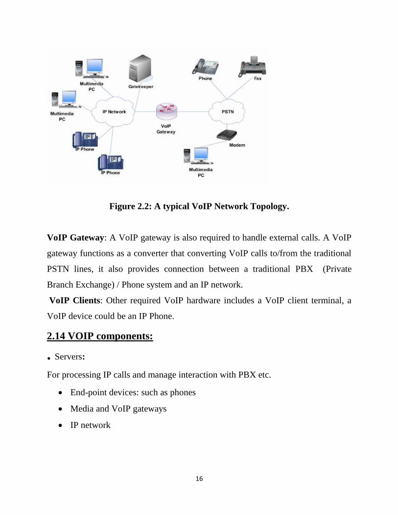
Figure 2.2 shows a typical VoIP network topology that includes following
equipment’s:
Gatekeeper: A gatekeeper or call manager node is optional for a VoIP network. In
an H.323 IP telephony environment, a gatekeeper works as a routing manager and
central manager that manage all the end nodes in a zone. A gatekeeper is useful for
handling VoIP call connections includes managing terminals, gateways and MCU's
(multipoint control units). A VoIP gatekeeper also provides address translation,
bandwidth control, access control [15]. Therefore, A VoIP gatekeeper can improve
security and Quality of Service (QoS)
16
Figure 2.2: A typical VoIP Network Topology.
VoIP Gateway: A VoIP gateway is also required to handle external calls. A VoIP
gateway functions as a converter that converting VoIP calls to/from the traditional
PSTN lines, it also provides connection between a traditional PBX (Private
Branch Exchange) / Phone system and an IP network.
VoIP Clients: Other required VoIP hardware includes a VoIP client terminal, a
VoIP device could be an IP Phone.
2.14 VOIP components:
. Servers:
For processing IP calls and manage interaction with PBX etc.
End-point devices: such as phones
Media and VoIP gateways
IP network
17
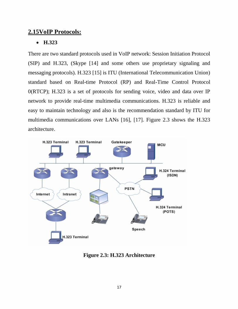
2.15VoIP Protocols:
H.323
There are two standard protocols used in VoIP network: Session Initiation Protocol
(SIP) and H.323, (Skype [14] and some others use proprietary signaling and
messaging protocols). H.323 [15] is ITU (International Telecommunication Union)
standard based on Real-time Protocol (RP) and Real-Time Control Protocol
0(RTCP); H.323 is a set of protocols for sending voice, video and data over IP
network to provide real-time multimedia communications. H.323 is reliable and
easy to maintain technology and also is the recommendation standard by ITU for
multimedia communications over LANs [16], [17]. Figure 2.3 shows the H.323
architecture.
Figure 2.3: H.323 Architecture
18
There are four basic entities in a default H.323 network [17], [18]: terminal,
gateways (GW), gatekeepers (GK) and multipoint control units (MCU): H.323
terminal also called H.323 client is the end-user device. It could be IP telephone or
a multimedia PC with another H.323 client. That provides real-time two-way
media communication. A Gateway (GW) is an optional component that provides
inter-network translation between terminals. A Gatekeeper (GK) is an optional
component provides address translations and access control services. A Multipoint
Control Unit (MCU) functions as a bridge or switch that enables three or more
terminals and gateways in a multipoint conference.
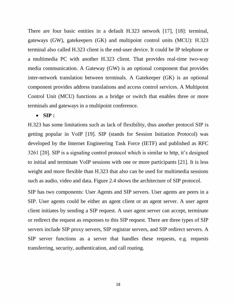
SIP :
H.323 has some limitations such as lack of flexibility, thus another protocol SIP is
getting popular in VoIP [19]. SIP (stands for Session Initiation Protocol) was
developed by the Internet Engineering Task Force (IETF) and published as RFC
3261 [20]. SIP is a signaling control protocol which is similar to http, it’s designed
to initial and terminate VoIP sessions with one or more participants [21]. It is less
weight and more flexible than H.323 that also can be used for multimedia sessions
such as audio, video and data. Figure 2.4 shows the architecture of SIP protocol.
SIP has two components: User Agents and SIP servers. User agents are peers in a
SIP. User agents could be either an agent client or an agent server. A user agent
client initiates by sending a SIP request. A user agent server can accept, terminate
or redirect the request as responses to this SIP request. There are three types of SIP
servers include SIP proxy servers, SIP registrar servers, and SIP redirect servers. A
SIP server functions as a server that handles these requests, e.g. requests
transferring, security, authentication, and call routing.
19
Figure 2.4: SIP Architecture
SIP is not only popular in VoIP applications but also widely used in applications
include instant messaging and some other commercial applications, e.g. Microsoft
MSN Messenger, Apple iChat.
2.16 Quality of serves:
When you pick up a telephone, you expect to converse in a clear and
understandable way. The ever-present public system telephone network provides
this service. A voice over IP system needs to provide the same. Anything less
would provide an excuse to avoid the technology. The public Internet is
notoriously haphazard.
Watching a Web page stall as it loads is a fine example of the pitfalls of this
complex technology. Quality of service is an issue with voice over IP and is
usually listed as one factor in the slow adoption of the technology. In the case of
VoIP, QoS means that the telephone conversation sounds as close to real life as
possible, or at least similar to a conversation over the public telephone network.
20
This chapter looks at the factors that affect quality of service for VoIP and then
examines the techniques that may be applied to a VoIP system that can give the
users a true high-quality telephone experience. Chapter 16, “Implementing QoS,”
looks at these same factors but from a technical and packet level viewpoint.
2.17 Factors that affect quality of service:
1. Bandwidth:
Bandwidth refers to the amount of data that can pass over a network in a time
frame, usually measured in bits per second (bps). If many services are using the
network, then bandwidth must be shared among them. If there is not enough
bandwidth, then “something’s gotta give.” Either packets can’t get onto the
network in a reasonable time or excess packets are discarded. Bandwidth is listed
as a contributing cause of quality of service problems because it affects the other
factors discussed here: delay, jitter, and packet loss.[22]
2. Delay:
High QoS should be assured by control delay so that one-way communication
delay should be less than 150 ms. (ITU states that one-way, end-to-end telephony
applications should have less than150 ms delay in echo-free environments to
ensure user satisfaction [23]). Delay mainly comes from three components [24]:
(1) delay caused by voice codec algorithms (2) delay caused by queuing algorithms
of communications equipment (3) variable delay caused by various factors (i.e.
network conditions, VoIP equipment’s, weathers etc.). It is very important to
minimize the voice traffic delay. Thus, a codec algorithm and queuing algorithm
needs to be carefully considered. Although traditionally think the end-to-end delay
of 150 ms was considered as acceptable for most applications. However, in
reference [25], the authors state that a delay of up to 200ms is considered as
acceptable. Moreover, a one way end-to-end delay between 150ms to 400ms is
considered as acceptable for planning purposes. In this study, 200ms will be
21
considered as the maximum acceptable one way end-to-end delay, high end-to-end
delay can cause bad voice quality perceived by the end user.
3. Jitter:
Delay variation also called Jitter. Jitter is the difference value between the delays
of two queuing packets. Root causes of jitter including network conditions and
packet loss; it is very difficult to deliver voice traffic at a constant rate. In order to
minimize jitter a jitter buffer (also known as play out buffers) is needed. A jitter
buffer is used to trade off delay and the probability of packet interruption play out.
Jitter value is considered acceptable between 0ms and 50 MS and above this is
considered as unacceptable [21].
4. Packet loss:
Packet loss is also an important factor VoIP QoS. Packet loss Occurs when more
transmitted packets on the network then causes dropped packets. VoIP packets are
very time sensitive. Therefore, packet loss can significantly affect VoIP quality.
For instance, a dropped conversation, delay between communicating clients, or
noise on a VoIP call. Acceptable packet loss rate is 1 % and it will be considered
as unacceptable if above this ratio [26]. However, an early study shows that the
tolerable packet loss rates are within 1-3% and the voice quality becomes
intolerable when voice packet loss rate is more than 3% [27].
Therefore, all these factors need to be properly controlled by QoS mechanisms.
When these factors are properly controlled, VoIP voice quality can be even better
through lower speed connections. In the meantime, data applications in the
network can be also prioritized and assured with limited and shared network
resources. The quality VoIP is the key factor of VoIP service to achieve success.
5-Echo:
Echo in a telephone circuit refers to the speaker’s voice bouncing back from
certain disjunctions of the circuit such that the speaker can hear parts of his
22
conversation. Echo occurs even in a traditional switched telephone circuit, but
since the round-trip time is less than 50 ms, the effect is masked and not
noticeable. When the round trip is longer than 50 ms, such as in a long distance
call, echo canceling techniques need to be used.[22]
2.18 Advantages of VoIP:
VoIP phone service providers offer many advantages to the residential and small
office/home office user. If you have a high speed internet connection then choosing
a VoIP phone service might be right for you.
Low Cost:
This technology leads to greater financial savings. This happens because
There exists only one network carrying the voice and data provided by only one
supplier. If you have a broadband Internet connection (DSL or cable),
You can make PC-to-PC phone calls anywhere in the world for free. If you wish to
make a PC-to-phone connection, there's usually a charge for this but probably
much cheaper than your regular phone service.
You can pay as you go or you can sign up with a VOIP service provider and pay a
monthly fee in return for unlimited calls within a certain geographic area. For
example, some VOIP services in the United States allow you to call anywhere in
North America at no extra charge.
Low Taxes:
Since the calls are being carried over the Internet, governments have not heavily
taxed VoIP phone services. Compare that to your local telephone bill (go ahead
and take a close look) and you will see you are spending quite a bit on taxes each
month. Therefore, choosing a VoIP provider could add up to significant savings for
you and your family.
23
Portability:
One important concept to understand about VoIP is that unlike it’s forefathers
(let’s call them PSTN for now), it is not distance or location dependent. As far as
VoIP is concerned, you could be calling your supplier 1,000 miles away in
Indonesia or calling your business partner on the other end of town, and it doesn’t
make any difference at all, in terms of connectivity and cost.
You can make and receive phone calls wherever there is a broadband connection
simply by signing in to your VoIP account. This makes VoIP as convenient as e-
mail – if you are traveling, simply pack a headset or Internet phone and you can
talk to your family or business associates for almost nothing.
Features:
Unlike regular phone service which usually charges more for extra features, VOIP
comes with a host of advanced communication features. For example, call
forwarding, call waiting, voicemail, caller ID and three-way calling are some of the
many services included with VOIP telephone service at no extra charge. You can
also send data such as pictures and documents at the same time you are talking on
the phone.
VoIP phones can integrate with other services available over the Internet, including
video conversation, message or data file exchange in parallel with the
conversation, audio conferencing, managing address books and passing
information about whether others (e.g. friends or colleagues) are available online to
interested parties.
Flexibility:
When you choose a VoIP phone service provider, you will be sent a converter to
allow a regular phone to use the VoIP phone service. Your phone number is
programmed into the converter. This means that you can take your phone converter
24
and phone number and use them wherever you travel in the world, just as long as
you have access to a high-speed Internet connection. Because your telephone
number is based in your converter (and not your home/office), you have the option
of choosing any area code for your phone number. Some carriers will allow you to
have more than 1 phone number in different area codes for a small additional fee
(called a virtual phone number).
2.19 Disadvantages of VoIP:
If VOIP is starting to sound really good to you, make sure you understand the
following downsides as well.
No service during a power outage:
During a blackout a regular phone is kept in service by the current supplied
through the phone line. This is not possible with IP phones, so when the power
goes out, there is no VOIP phone service. In order to use VoIP during a power
outage, an uninterruptible power supply or a generator must be installed on the
premises. It should be noted that many early adopters of VoIP are also users of
other phone equipment such as PBX and cordless phone bases that also rely on
power not provided by the telephone company.
Emergency calls:
Another major concern with VOIP involves emergency 911 calls. Traditional
phone equipment can trace your location. Emergency calls are diverted to the
nearest call center where the operator can see your location in case you can't talk.
However, because a voice-over-IP call is essentially a transfer of data between two
IP addresses, not physical addresses, with VOIP there is currently no way to
determine where your VOIP phone call is originating from.
Although many companies are making an effort to provide for emergency calls in
their service, this issue remains an important deterrent against VoIP.
25
Reliability:
Because VOIP relies on an Internet connection, your VOIP service will be affected
by the quality and reliability of your broadband Internet service and sometimes by
the limitations of your PC. Poor Internet connections and congestion can result in
garbled or distorted voice quality. If you are using your computer at the same time
as making a computer VOIP call, you may find that voice quality deteriorates
dramatically. This is more noticeable in highly congested networks and/or where
there are long distances and/or internetworking between end points. [28]
Security:
As VoIP becomes more and more popular, the security issues relate to VoIP
network systems are also increasingly arising [29]. W. Chou [30] analysis the
different aspects of VoIP security and gives some suggested strategies to these
issues. In reference [31], the authors also outline the challenges of securing VoIP,
and provide guidelines for adopting VoIP technology
26
Chapter three
System Model & Simulation
3-1 Descriptive:-
We create a virtual WLAN network by using opnet software program,The
following specifications well use two applications with profile voice it contains a
number of nodes varies between 10 to30, it covers an office with area 100x100
meter,with data rate varies between 1Mbps up to 11 Mbps, simulation time varies
between 10min to 50 min and tested the fixed nodes.
3.2 Mathematical model:
The performance metrical to evaluate voice over IP over Wi-Fi is given by:
3.2.1 Delay:
D tot= Q (D proc+D queue +D trans +D prop) ……………… (3.1)
Where:
Q: is the number of network elements (routers, switches and firewalls) between the
sender and receiver
D pro : is the processing delay at a given network element
D queue : is the queuing delay at given network element
D Trans : is the transmission time of a packet on a given link
D prop : is the propagation delay across a given network link
27
3.2.2 Throughput:
Throughput is the number of packets effectively transferred in a network, other
words, throughput is data transfer rate that are delivered to all terminals in a
network. It is measured in terms of packets per second or per time slot It is a
measure of the data rate (bits per second) generated by the application. Equation 1
shows the calculation for throughput (TP).
𝑻𝑷 = ∑𝒑𝒂𝒄𝒌𝒆𝒕𝒔𝒊𝒛𝒆𝒊
𝒑𝒂𝒄𝒌𝒆𝒕𝒂𝒓𝒓𝒊𝒗𝒂𝒍𝒏−𝒑𝒂𝒄𝒌𝒆𝒕𝒔𝒕𝒂𝒓𝒕𝟎……………… (3.2)
Where:
Packet Size I: is the packet size of the packet reaching the destination.
Packet Start o: is the time when the first packet left the source.
Packet Arrival n: is the time when the last packet arrived.
3.2.3Packet Delay variance (Jitter):
Packet Delay variance (Jitter) could be termed as the variation in delay or packet
delay variation. The value of jitter is calculated from the end to end delay.
Measuring jitter is critical element to determining the performance of network and
the QOS the network offers. It is the variation in the time between packets arriving.
Jitter is commonly used as an indicator of consistency and stability of a network.
Equation 2 shows how to calculate jitter.
AJ=∑ (𝒑𝒂𝒄𝒌𝒆𝒕 𝒂𝒓𝒓𝒊𝒗𝒂𝒍𝒊+𝟏−𝒑𝒂𝒄𝒌𝒆𝒕 𝒔𝒕𝒂𝒓𝒕𝒊+𝟏)−(𝒑𝒂𝒌𝒆𝒕 𝒂𝒓𝒓𝒊𝒗𝒂𝒍 𝒊−𝒑𝒂𝒄𝒌𝒆𝒕 𝒔𝒕𝒂𝒓𝒕𝒊)𝒊
𝒏−𝟏. (3.3)
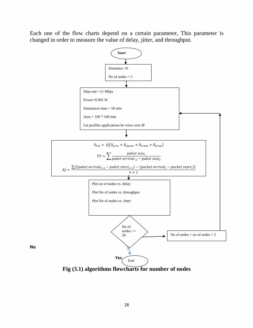
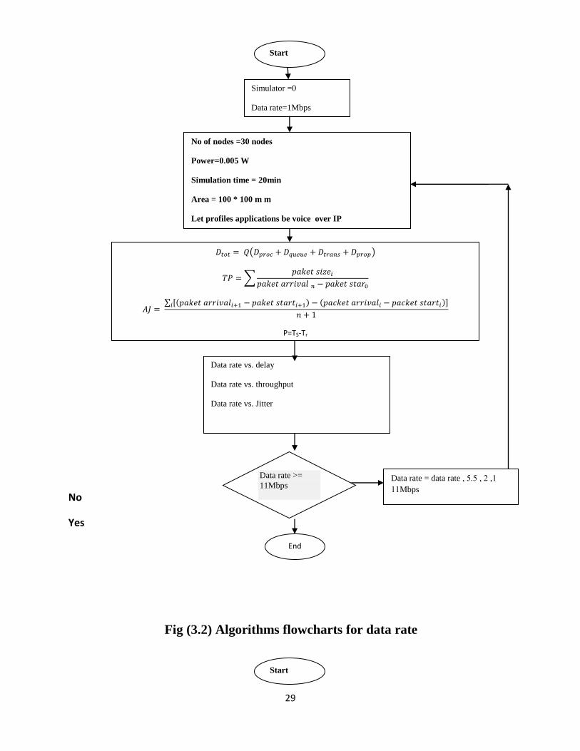
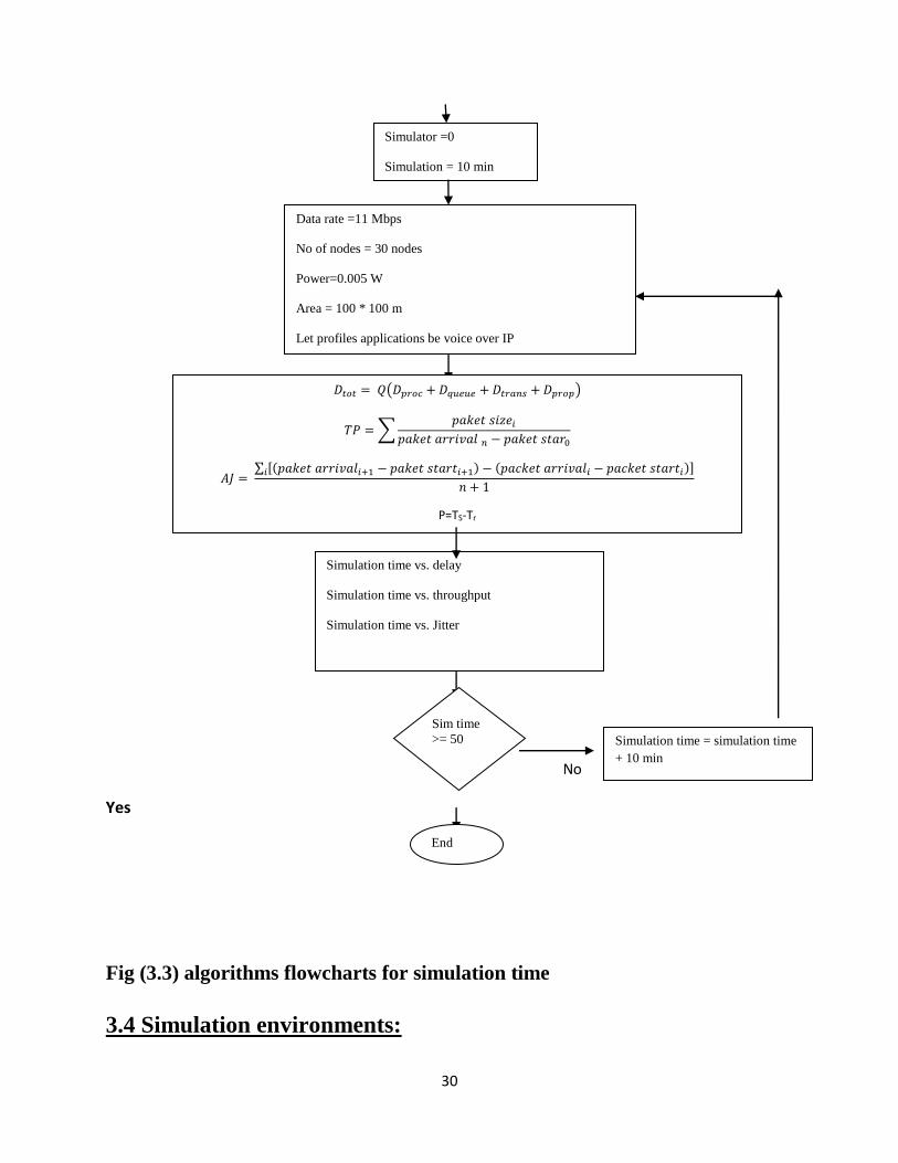
3.3 Algorithms flowcharts :
28
Each one of the flow charts depend on a certain parameter, This parameter is
changed in order to measure the value of delay, jitter, and throughput.
No
Yes
Fig (3.1) algorithms flowcharts for number of nodes
Start
Data rate =11 Mbps
Power=0.005 W
Simulation time = 50 min
Area = 100 * 100 mm
Let profiles applications be voice over IP
𝐷𝑡𝑜𝑡 = 𝑄(𝐷𝑝𝑟𝑜𝑐 + 𝐷𝑞𝑢𝑒𝑢𝑒 + 𝐷𝑡𝑟𝑎𝑛𝑠 + 𝐷𝑝𝑟𝑜𝑝)
𝑇𝑃 = ∑𝑝𝑎𝑘𝑒𝑡 𝑠𝑖𝑧𝑒𝑖
𝑝𝑎𝑘𝑒𝑡 𝑎𝑟𝑟𝑖𝑣𝑎𝑙 𝑛 − 𝑝𝑎𝑘𝑒𝑡 𝑠𝑡𝑎𝑟0
𝐴𝐽 = ∑ [(𝑝𝑎𝑘𝑒𝑡 𝑎𝑟𝑟𝑖𝑣𝑎𝑙𝑖+1 − 𝑝𝑎𝑘𝑒𝑡 𝑠𝑡𝑎𝑟𝑡𝑖+1) − (𝑝𝑎𝑐𝑘𝑒𝑡 𝑎𝑟𝑟𝑖𝑣𝑎𝑙𝑖 − 𝑝𝑎𝑐𝑘𝑒𝑡 𝑠𝑡𝑎𝑟𝑡𝑖)]𝑖
𝑛 + 1
P=TS-Tr
No of
nodes >=
30
End
No of nodes = no of nodes + 5
Plot no of nodes vs. delay
Plot No of nodes vs. throughput
Plot No of nodes vs. Jitter
Simulator =0
No of nodes = 5
29
No
Yes
Fig (3.2) Algorithms flowcharts for data rate
Start
No of nodes =30 nodes
Power=0.005 W
Simulation time = 20min
Area = 100 * 100 m m
Let profiles applications be voice over IP
𝐷𝑡𝑜𝑡 = 𝑄(𝐷𝑝𝑟𝑜𝑐 + 𝐷𝑞𝑢𝑒𝑢𝑒 + 𝐷𝑡𝑟𝑎𝑛𝑠 + 𝐷𝑝𝑟𝑜𝑝)
𝑇𝑃 = ∑𝑝𝑎𝑘𝑒𝑡 𝑠𝑖𝑧𝑒𝑖
𝑝𝑎𝑘𝑒𝑡 𝑎𝑟𝑟𝑖𝑣𝑎𝑙 𝑛 − 𝑝𝑎𝑘𝑒𝑡 𝑠𝑡𝑎𝑟0
𝐴𝐽 = ∑ [(𝑝𝑎𝑘𝑒𝑡 𝑎𝑟𝑟𝑖𝑣𝑎𝑙𝑖+1 − 𝑝𝑎𝑘𝑒𝑡 𝑠𝑡𝑎𝑟𝑡𝑖+1) − (𝑝𝑎𝑐𝑘𝑒𝑡 𝑎𝑟𝑟𝑖𝑣𝑎𝑙𝑖 − 𝑝𝑎𝑐𝑘𝑒𝑡 𝑠𝑡𝑎𝑟𝑡𝑖)]𝑖
𝑛 + 1
P=TS-Tr
Data rate >=
11Mbps
End
Data rate = data rate 1 ,2 ,5.5 ,
11Mbps
Data rate vs. delay
Data rate vs. throughput
Data rate vs. Jitter
Simulator =0
Data rate=1Mbps
Start
30
No
Yes
Fig (3.3) algorithms flowcharts for simulation time
3.4 Simulation environments:
Data rate =11 Mbps
No of nodes = 30 nodes
Power=0.005 W
Area = 100 * 100 m
Let profiles applications be voice over IP
𝐷𝑡𝑜𝑡 = 𝑄(𝐷𝑝𝑟𝑜𝑐 + 𝐷𝑞𝑢𝑒𝑢𝑒 + 𝐷𝑡𝑟𝑎𝑛𝑠 + 𝐷𝑝𝑟𝑜𝑝)
𝑇𝑃 = ∑𝑝𝑎𝑘𝑒𝑡 𝑠𝑖𝑧𝑒𝑖
𝑝𝑎𝑘𝑒𝑡 𝑎𝑟𝑟𝑖𝑣𝑎𝑙 𝑛 − 𝑝𝑎𝑘𝑒𝑡 𝑠𝑡𝑎𝑟0
𝐴𝐽 = ∑ [(𝑝𝑎𝑘𝑒𝑡 𝑎𝑟𝑟𝑖𝑣𝑎𝑙𝑖+1 − 𝑝𝑎𝑘𝑒𝑡 𝑠𝑡𝑎𝑟𝑡𝑖+1) − (𝑝𝑎𝑐𝑘𝑒𝑡 𝑎𝑟𝑟𝑖𝑣𝑎𝑙𝑖 − 𝑝𝑎𝑐𝑘𝑒𝑡 𝑠𝑡𝑎𝑟𝑡𝑖)]𝑖
𝑛 + 1
P=TS-Tr
Sim time
>= 50
End
Simulation time = simulation time
+ 10 min
Simulation time vs. delay
Simulation time vs. throughput
Simulation time vs. Jitter
Simulator =0
Simulation = 10 min
31
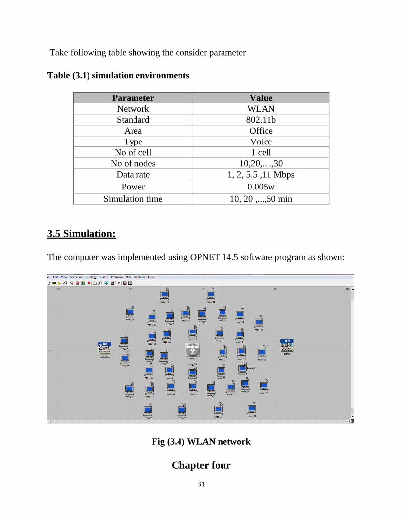
Take following table showing the consider parameter
Table (3.1) simulation environments
Parameter Value
Network WLAN
Standard 802.11b
Area Office
Type Voice
No of cell 1 cell
No of nodes 10,20,....,30
Data rate 1, 2, 5.5 ,11 Mbps
Power 0.005w
Simulation time 10, 20 ,...,50 min
3.5 Simulation:
The computer was implemented using OPNET 14.5 software program as shown:
Fig (3.4) WLAN network
Chapter four
32
Results & Discussion
After simulating the following tables and charts showing the results that taken:
4.1 delay result vs.number of node:
The time of simulation con = 20 min , data rate =11 mbps
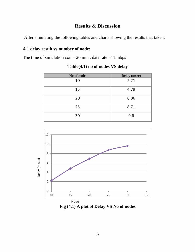
Table(4.1) no of nodes VS delay
Fig (4.1) A plot of Delay VS No of nodes
0
2
4
6
8
10
12
10 15 20 25 30 35
No of node Delay (msec)
10 2.21
15 4.79
20 6.86
25 8.71
30 9.6
Del
ay (
m s
ec)
Node
33
As the number of nodes increase delayincrease.due to increase process delay
in the network and increase thenumber of network elements (routers,
switches and firewalls) between the sender and receiver,due to increase the
transmission time of a packet on a given link,due to increase the propagation
delay across a given network link, due to increase the queuing delay at given
network element
4.2 Throughput result vs. number of node:
34
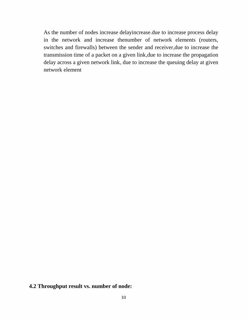
Table (4.2) No of node VS Throughput
No of node Throughput(bit /msec)
10 235,199.2
15 73,475.6
20 47,398.5
25 36,894.1
30
26,799.2
Fig (4.2) A plot of throughput VS No of nodes.
Throughputdecreaseexponential as the number of node increase
At the beginning of the simulation, the change in throughput was rapid but
as the number of devicesincrease, the change became almost stable.
As the number of nodes increase the packet arrival delayed time increase
4.3 Jitter result vs. number of node:
0.00
50,000.00
100,000.00
150,000.00
200,000.00
250,000.00
10 15 20 25 30 35
No of nodes
Th
rou
gh
(b
it /
mse
c)
909
kk
kgg
ggg
gg
fgff
gg
g90
sss(
sec)
pu
t

35
Table (4.3) No of node VS Jitter
No of nodes Jitter(sec)
10 0.00074773569286
15 0.00416508639004
20 0.0112127201649
25 0.0246758614288
30 0.0272019657545
Fig (4.3) A plot of Jitter VS No of Node
As the number of nodes increasejitter increase exponentially up to 30
nodes and then it approximately become constant stable at 0.0275msec.
4.4delay result vs.Data rate:
No of Node
Jitt
er(m
sec)
36
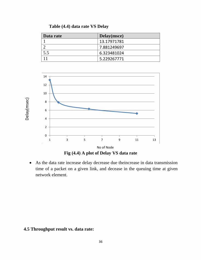
Table (4.4) data rate VS Delay
Data rate Delay(msce)
1 13.17971781 2 7.881249697 5.5 6.323481024 11 5.229267771
Fig (4.4) A plot of Delay VS data rate
As the data rate increase delay decrease due theincrease in data transmission
time of a packet on a given link, and decease in the queuing time at given
network element.
4.5 Throughput result vs. data rate:
0
2
4
6
8
10
12
14
1 3 5 7 9 11 13
No of Node
Del
ay(m
sec)
37
Table (4.5) Data Rate VS Throughput
Data rate throughput(bit /msec) 1 18,616.38
2 34,303.46
5.5 41,715.37 11 66,443.44
Fig (4.5) Aplot of throughput VS Data rate
As the data rate increase throughput increasedue todecrease oftime
packetloos and increases the packet arrival time.
4.6jitter result vs. data rate:
0
10000
20000
30000
40000
50000
60000
70000
1 3 5 7 9 11 13
Data rate mbp sec
Thro
ugh
pu
t (b
it /
mse
c)
38
Table (3.7) Data Rate VS jitter
Data rate Jitter(sce)
1 0.116643991
2 0.042403654
5.5 0.026814928
11 0.015397091
Fig (4.6) Jitter VS Data Rate
As data rate increase the jitter decreaseexponentially and become constant
stable after 11MHz with 0.01sec.
4.7Delay result vs.simulation time:
0
0.02
0.04
0.06
0.08
0.1
0.12
0.14
1 3 5 7 9 11 13
Data rate Mbp sce
0)
Jitt
er(s
ec)
39
Table (4.7) Simulation Time VS Delay
Simulation Time (min) Delay (msec) 10 13.1797178144
20 15.4995046282
30 16.3106162944 40 16.5719831677
50 16.7617689646
Fig (4.7) A plot of Delay VS simulation time
As increase the simulation time delay increase, increase will be stable as the
time in increase.
4.8 Throughput result vs. simulation time:
13
13.5
14
14.5
15
15.5
16
16.5
17
10 20 30 40 50 60
Simulation time (min)
Del
ay(m
sec)
40
Table (4.8) Simulation Time VS Throughput
Time of simulation Throughput (bits/msec)
10 18,616.3809635 20 24,260.7930446
30 26,626.2447057 40 27,984.1293875
50 28,870.8695715
Fig (4.8) Aplot of throughput VS simulation time
As increase the simulation time throughput increase
4.9 Jitter result vs. simulation time:
17015
19015
21015
23015
25015
27015
29015
31015
10 20 30 40 50 60
Simulation time(min)
Thro
ugh
pu
t (b
it /
sec)
41
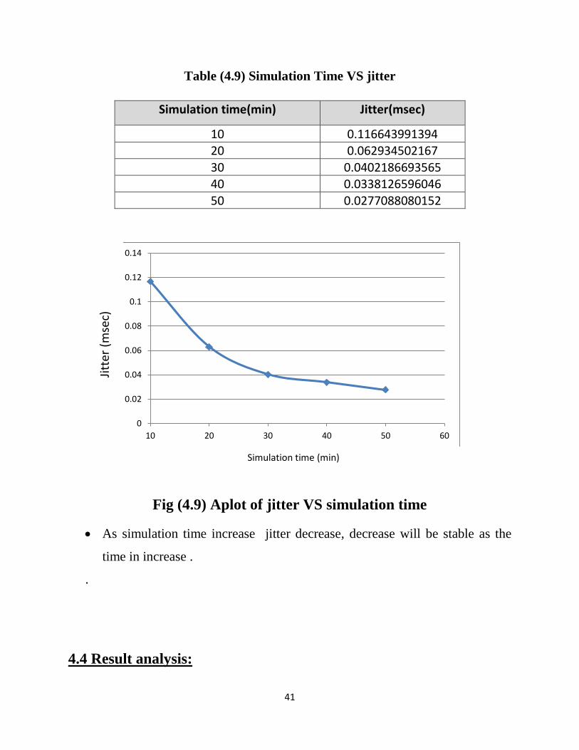
Table (4.9) Simulation Time VS jitter
Simulation time(min) Jitter(msec)
10 0.116643991394 20 0.062934502167
30 0.0402186693565 40 0.0338126596046
50 0.0277088080152
Fig (4.9) Aplot of jitter VS simulation time
As simulation time increase jitter decrease, decrease will be stable as the
time in increase .
.
4.4 Result analysis:
0
0.02
0.04
0.06
0.08
0.1
0.12
0.14
10 20 30 40 50 60
Simulation time (min)
Jitt
er (
mse
c)
42
From the result obtained we observe the following:
As the number of nodes increase delay increase.due to increase process
delay in the network and increase the number of network elements (routers,
switches and firewalls) between the sender and receiver, due to increase the
transmission time of a packet on a given link , due to increase the
propagation delay across a given network link , due to increase the queuing
delay at given network element .
Throughput decrease exponential as the number of node increase
At the beginning of the simulation, the change in throughput was rapid but
as the number of devices increase, the change became almost stable.
As the number of nodes increase the packet arrival delayed time increase
As the number of nodes increase jitter increase exponentially up to 30
nodes and then it approximately become constant stable at 0.0275msec.
As the data rate increase delay decrease due the increase in data transmission
time of a packet on a given link, and decease in the queuing time at given
network element.
As the data rate increase throughput increase due to decrease of time packet
loos and increases the packet arrival time.
As data rate increase the jitter decrease exponentially and become constant
stable after 11MHz with 0.01sec.
As increase the simulation time delayincrease.
As increase the simulation time the throughput increase.
As the simulation time increase the jitter decrease.
Conclusion and Recommendation
43
5.1 Conclusion:
The study, analysis, plans and design of the software program to simulate and
perform performance analyzes for voice and video over WLAN Network and
evaluates the performance of the system using OPNET software program.
The parameter which was taken into consideration was: data rate, simulation time,
number of nodes, with profile VOIP.
In general concepts of wireless networks were studied. Voice over IP service that
is supported in WLAN was discussed in details. Voice traffic analyzed using a
simulation based on network simulator OPNET software program. The effect of
different service on QOS parameters like throughput, packet loss, jitter and delay
were studied. As the number of nodes increases the throughput, delay, jitter.
For maximum data rate theValuethroughput ( 66,4 bit /sec) the delay (5.22
sec) and jitter( 0.015 sec).
For maximum number of nodestheValueof throughput (26,799bits /sec) ,
delay (9.598 sec) and jitter (0.027sec )
For maximum time of simulation the value of throughput (28,870bit /sec) ,
delay (16.76sec) and jitter 0.0277(sec)
The best design to decrease the delay, packet loss and jitter and increasing the
throughput is increase the data rate with appropriate number of subscriber and long
simulation time.
5.2 Recommendation:
44
From the results obtained we suggest the following recommendation for future
work:
Using wide area like campus and other type of standers IEEE to design
WLAN Network.
Using this design in WIMAX network and then compare it with WLAN
network.
Using mobile devices and other type of data like text or text and voice in
same time.
To increase the simulation time for further inspection.
References:
45
[1]https://www.researchgate.net/publication/290076175_A_survey_on_voice_over
_IP_over_wireless_LANs, (2010).
[2] Networking courses, ipsr solutions ltd redefining excellence,(2017).
[3] Behrouz A. Forouzan. Data communications and Networking. 5nd ed.
William Stallings. Data and Computer Communications. (2012).
[4] Byron W. Putman. 802.11 WLAN Hands-On Analysis. AuthorHouse, (2005).
[5]https://www.ieee.org/index.html-(2014).
[6] Matthew S. Gast. 802.11 Wireless networks. O'Reilly, (2002).
[7] Sunghyunchoi ,sch.of Electr.Eng.,seoul Nat. Univ, south korea IEEE 802.11 e
contention-based access (EDCF) performance evaluation ,ANSI/IEEE std 802.11
Edition,(2003).
[8] waynecaswell.”HomeRFArchieves”,( November 17,2010) Retrieved July
16,2011.
[9]http/smartrouter.wordpress.com/tag/wireless-network/
[10] W. C. Y. Lee, Mobile Communication Design Fundamentals, 2nd Edition,
John Wiley and Sons, (1993)).
[11] D. Vardalis and V. Tsaoussidis, “On the Efficiency and Fair-ness of Protocol
Recovery Strategies in Networks with Wire-less Components,” in Proc. of
International Conference on Internet Computing, CSREA Press, Las Vegas, (June
2001).
[12]VOIPfundamentals,ssd-tech,(2015)https//ssd-tech.com/knowledge-
base/networking/VoIP-fundamentals
46
[13]. D. Rizzetto, & C. Catania , A Voice over IP Service Architecture for
Integrated Communications. IEEE Internet Computing, Volume 3, Issue 3, Pages:
53 – 62. (1999).
[14]. Skype official website, communication,2017: http://about.skype.com .
[15] https://developers.google.com/talk/jep_extensions/extensions. )2013(
[16]. S. K. Das, E. Lee, K. Basu, & S. K. Sen , Performance Optimization of VoIP
Calls over Wireless Links Using H.323 Protocol Computers. IEEE Transactions,
Vol. 52, No. 6 Page(s):742 – 752 (2003).
[17]. G. A. Thom ,H.323: the multimedia communications standard for local area
networks. Communications Magazine, IEEE, Volume 34, Issue 12, page(s): 52-56
(1996).
[18]. L. Hong, & P. Mouchtaris , Voice over IP signaling: H.323 and beyond.
Communications Magazine, IEEE, Volume 38, Issue 10, Page(s):142 – 148.
(2000).
[19]. B. Goode , Voice Over Internet Protocol (VOIP). Proceedings of three IEEE,
Volume 90, Issue 9, Page(s): 1495 – 1517. (2002).
[20]. J. Rosenberg, H. Schulzrinne, G. Camarillo, A.Johnston, J. Peterson, R.
Sparks, M. Handley, & E. Schooler , SIP: Session Initiation Protocol. RFC 3261,
IETF. (2002).
[21]. L. Milandinovic, & J. Stadler , Multiparty Conference Signaling using SIP.
International Network Conference, (2002) .
[22] nickwittenberg, Understanding voice over IP technology ,Vice President,
Career and Professional, Editorial: Dave Garza,Delmar, Cengage Learning.( 2009)
47
[23] L. Zheng, L. Zhang, & D. Xu , Characteristics of network delay and delay
jitter and its effect on voice over IP (VoIP). ICC 2001. IEEE International
Conference, Volume 1, Page(s):122 – 126. (2001).
[24]. Han-Chieh Chao, Y. M. Chu, & G. Tsuei ,Codec Schemes Selection for
Wireless Voice over IP (VoIP). Proceedings of the Second IEEE Pacific 63 (2001).
[25] J. H. James, C. Bing, & L. Garrison, Implementing VoIP: a voice transmission
performance progress report. Communications Magazine, IEEE, Volume 42, Issue
7, page(s): 36- 41(2004)
[26]. Net beez, impact of packet loss, jitter, and latency on VOIP ,(2017)
http://netbeez.net/2016/08/18/impact-of-packet-loss-jitter-and-latency-on-voip/
[27]. C. N. Chuah, Providing End-to-End QoS for IP based Latency sensitive
Applications”. Technical Report, Dept. of Electrical Engineering and Computer
Science, University of California at Berkeley. (2000)
[28] http//faq.programmerworld.net/voip/voip-advantages-disadvantages.html
2013.
[29] P.C.K. Hung, & M.V. Martin, Security Issues in VOIP Applications.
Electrical and Computer Engineering, CCECE '06, Page(s):2361 – 2364 (2006).
[30]. W. Chou, Strategies to Keep Your VoIP Network Secure. IT Professional
Published by IEEE Computer Society, Volume 9, Issue 5, Pages 42-46. (2007).
[31]. T.J. Walsh, & D.R. Kuhn, Challenges in securing voice over IP. IEEE
Security & Privacy, vol. 3, no. 3, pp. 44- 49. (2005).

48


