Embed Size (px)
Citation preview
K_BAKHTAR_International Journal of Rock Mechanics Page 1 of 22
International Journal of Rock Mechanics
and Mining Sciences International Journal of Rock Mechanics and Mining Sciences 37 (2000) 369-384
Accepted 7 October 1999 www.elsevier.com/locate/ijrmms 1365-1609/OO/S - see front matter © 2000 Elsevier Science Ltd. All rights reserved. PI1: 51365-1609(99)001 12-4
Performance assessment of underground munitions storage
facilities
K. Bakhtar*
Bakhtar Technologies, LLC, 3420 Via Oporto, Suite 201, Newport Beach, CA 92663, USA _____________________________________________________________________________ Abstract A set of empirical expressions has been developed for performance assessment of underground munitions storage structures. These expressions, with the associated site characterization methodology, provide cost-effective techniques for siting, design and construction, loading density optimization, performance assessment, and risk analysis of sub-surface facilities. The developed technology uses site specific data on characteristics of the geologic and engineered systems. Using this approach, quantity-distance (Q-D) and maximum range for blast-induced hazardous fragments for accidental detonation of the magazine can be predicted. The mathematical expressions were validated in the field through a series of 1-g explosion experiments on scaled-models of tunnels. Their applications were successfully verified through several full-scale prototype cases in the United States and Europe. This paper provides detail of the test program and steps taken to formulate and validate the empirical models. Finally, predictive capability of the models is compared with the results from full-scale magazine explosion tests. ______________________________________________________________________
1. Introduction
The main concern of the US military and other government agencies with their ammunition storage program has been protection of personnel, property, and equipment. Available reports and standards have identified five principle hazards associated with a given situation [1]: 1. Blast pressure. 2. Fragments (primary and secondary). 3. Chemical hazards. 4. Thermal hazards. 5. Ground shocks. Extensive studies have been performed in the past on hazardous effects of blast __________________________________ *Tel.: +1-949-675-2800; fax: +1-949-675-2233. E-mail address: [email protected]
pressure, induced thermal and chemical environments, and ground shocks. However, the degree and extent of fragment-induced hazard associated with accidental detonation of explosives stored in rock/soil structures (underground magazines) are still not fully verified. The empirical relationships used are too general and do not account for the site-specific characteristics of geologic and engineered (underground structure) systems. Observations made from the KLOTZ Tunnel Explosion Tests, conducted in China Lake, California, confirmed the importance of rock mass and tunnel characteristics on the blast-induced fragments [2-4]. Based on the limited number of tests conducted, it is clear that additional research is needed to develop more accurate quantity-

K_BAKHTAR_International Journal of Rock Mechanics Page 2 of 22
distance (Q-D) relationships that account for site specific characteristics of host media, underground structure, and the quantity of explosives stored. As is evident from the KLOTZ Tunnel experience in China Lake, conducting such prototype tests would require extensive planning and coordination, in addition to extremely high capital expenditure and time requirements. Furthermore, site conditions cannot be reproduced in order to perform parametric studies on the blast-induced fragments. The difficulties and high costs associated with conducting prototype tests warrant the need for reliable alternative approaches. For cases where the pertinent parameters influencing underground structural response to blast-loading can be identified, physical modeling at 1-g can provide an attractive alternative. In this approach, low-strength rock simulants are developed in such a way that geometry and strength-related parameters are scaled while density scale-factor is kept at unity. Laboratory tests are performed on representative samples of rock simulant to verify their rock-like behavior under different loading conditions. In general, realistic simulation of a tunnel explosion test using a physical modeling approach is contingent on maintaining the dynamic and static similitude relationships between the model experiment and its pro-totype. A recent study [5] outlined how a series of physical modeling tests can be used for development of safety criterion to predict the hazardous effects of blast-induced fragments based on the loading density and site specific properties of the geologic and engineered systems. 2. Feasibility study A feasibility study is needed to identify pertinent parameters influencing an underground structure's response to
explosive loading. The KLOTZ Tunnel Ex-plosion Test [2] was considered as the prototype for the feasibility study [5]. Results of the feasibility study indicated that properties of the geologic system can be defined by the Barton Q-values and index test data, which account for the characteristics of intact and jointed rock mass. The overall properties of the geologic system are subsequently lumped into a single parameter referred to as the "Equivalent Stiffness" (E), for inclusion in the explosive safety criterion. The pertinent properties of the engineered system are defined by the initial venting characteristics (S) and the chamber loading density (K). Dimensional analysis is used to formulate a generalized safety criterion, Bakhtar Explosives Safety Criterion (BESC). In its functional form it is: D = f (E a, K b, Z c, S d, V e, g f) (1) where D is the distance, m, E is the equivalent stiffness characteristics of geologic system, MPa, K is the loading density, kg/m3, Z is the overburden thickness above chamber, m, S is the initial venting characteristics of the engineering system, m2, V is the P-wave (seismic) velocity of the geologic system, m/s, g is gravity acceleration, m/s2, and a, b, c, d, e, and f are constants. The parameters are identified as those influencing the response of the underground structure to blast loading. They are easily obtained in the field [3,4] and used to describe the Bakhtar's formulation. The dimensional analysis technique or the Buckingham Pi theorem can be used to derive the final form of Eq. (1). Values of exponents a, b, c, d, e, and f are determined by conducting physical modeling experiments and forming auxiliary equations by the method of dimensional analysis for different sets of test parameters.

K_BAKHTAR_International Journal of Rock Mechanics Page 3 of 22
3. Background Studies relative to the explosive safety Q-D effects from detonations of shallow underground magazines in hard rock have been underway since early 1970 [6]. The overall objective of the test program is to determine the hazardous effects of debris, air-blast, and ground motion produced by accidental detonation of explosives magazines which rupture the overhead cover of the underground chamber. Based on data from near surface bursts, many empirical relationships have been developed to determine the free-field air-blast pressure and induced ground motion. However, estimates of the debris thrown and the associated kinetic energy are much harder to make in the absence of detailed information on site-specific rock mass characteristics. In order to study the explosive safety Q-D, a shallow-underground -- tunnel/chamber -- explosion test was performed in California. The test consisted of a 20,000 kg (44,000 Ib.) net explosive weight detonation inside a half-scale tunnel/chamber system constructed in a highly weathered granitic rock mass. Prior to shotcreting and emplacement of explosives, rock mass characterization (using Barton's Q-system) was performed in the tunnel and associated explosives chamber and relevant geologic and geo-engineering information were documented [3]. Data obtained from China Lake tunnel explosion test, provided a unique opportunity to physically construct a series of scale model experiments and to validate more precise "Scaling Laws" for the current Q-D standards for underground storage of munitions. 4. Physical modeling concept The difficulties encountered with testing full-scale (prototype) sub-surface structures
warrant the need for scale models in which the linear dimension, or geometry, of the prototype is reduced by a certain scale. Because the geometry is scaled down, the strength-related parameters also need to be scaled down, in order to maintain dimensional homogeneity between the model and prototype structure. The design of synthetic geologic materials, herein called "rock-simulants", for scaled model testing needs to be done in such a way that similarity in material behavior (i.e., prototype and model behavior) is conserved and the important dimensionless strength related ratios remain unchanged for the model and prototype. For geologic materials, scaling plays an important role and affects the material response, particularly the mechanical behavior. In general, the choice of the model depends on: 1. Nature of the investigation; 2. Limitations of the testing facility; 3. Economic constraints. In order to physically model a particular geology with associated discontinuities at the reduced scale, the proper ingredients need to be mixed in appropriate proportions to produce low strength "rock-like" ma-terials. Because no standard low-strength rock-simulants exist, the method developed in [7], and described in detail by [8], can be employed to identify and formulate low-strength synthetic geologic material that have dimensionless strength properties similar to those of the prototype rock. The candidate material models should exhibit rock-like behavior at reduced scale, not only under uniaxial but triaxial and hydrostatic loading conditions. For realistic simulation, the following conditions must be satisfied: (c / E)prototype = (c / E)model (2)

K_BAKHTAR_International Journal of Rock Mechanics Page 4 of 22
prototype = model (3) Øprototype = Ømodel (4) where c is the unconfined compressive strength, MPa, E is the elastic (Young's) modulus, MPa, v is Poisson's ratio, and Ø is the internal friction angle. The most important initial step in planning a physical modeling experiment is the identification of the pertinent parameters. Results of almost two decades of research [9] indicate that physical modeling in geomechanics and structural engineering may be performed under 1-g by choosing two different approaches, as outlined below: 1. Material Scaling -- in which the geometry and strength related properties of the model materials are scaled. In such cases, the load required to cause deformation in the model must be reduced in order to maintain the similitude conditions with its prototype. 2. Replica Scaling -- in which the geometry is scaled; however, the strength related properties of the model material are matched with those of its respective prototype. In such cases, the load causing deformation in the model must be increased to maintain similitude conditions with its prototype. The emphasis in this paper is directed toward adherence to the theory and application of the scale-model testing under normal gravity (1-g) using the material scaling approach. Replica scaling is more costly. In many cases, in geomechanics and structural engineering, its application becomes distorted during the construction phase of the models. 5. Similitude conditions The derivation of the general theory of similarity between a rock model and its
prototype can best be discussed in terms of a purely mechanical system. Complete mechanical similarity requires that con-ditions of geometric and dynamic similarities be satisfied between a model and its prototype within the range of loading of interest in a particular investigation. Geometric similarity means that the model is true to scale in length, area, and volume. Dynamic similarity means that the ratios of all types of forces are equal. These forces result from inertia, gravity, viscosity, elas-ticity (fluid compressibility), plasticity, surface tension and pressure. Magnetic forces are not considered in blast loading investigation. It can be argued that complete mechanical similarity also requires kinematics and thermal similarity, which is not discussed in the present paper. However, it is believed [8] that within the scope of most experimental investigations, dynamic similarity coupled with geometric similarity provide the necessary conditions for solving problems related to the load response of geologic and engineered systems. Pertinent variables for modeling an elastic-brittle rock to failure initiation are length, stress, unit weight, angle of internal friction, modulus of elasticity, Poisson's ratio, and time. By modeling all or a selected number of these parameters, the researcher will have the necessary tools for studies related to performance and load response (static or dynamic) of structures designed in a rock mass. For static problems, only two fundamental dimensions are involved: force F and linear dimension L. The similitude requirements governing dynamic relationships between the model and its prototype depend on the geometric and material properties of the structure and on the type of loading. In general, the dynamics of structures are governed by the equilibrium balance of time-dependent forces. These are the inertia forces that are the product of the local mass

K_BAKHTAR_International Journal of Rock Mechanics Page 5 of 22
and acceleration, the resistance forces that are a function of stiffness of the structure in the particular direction in which motion is occurring, and the energy dissipation of the damping forces, whether material or construction related. For modeling structures in hard rocks, the following basic conditions of similarity must be satisfied: 1. Geometric Similarity - requires ratio of the distance between any two points in the prototype to the corresponding distance in its model to be constant. 2. Kinematics Similarity - requires movement of particles in the model follow those of its prototype with respect to time and space. Geometrically and kinematically similar structures are dynamically similar if the ratios of various similar mechanical forces that act on any two corresponding particles in the prototype and its model are constant. These parameters are those of elastic, plastic, viscous, gravity, inertia, and friction related forces. Assuming F* is the force scale factor, the above conditions can be mathematically represented by:
*F=pf)(Fm)f(F
=pe)(Fm)e(F
=pv)(Fm)v(F
=pi)(Fm)i(F
=pg)(F
m)g(F
(5) where Fg is the gravity force, Fi, is the inertia force, Fv is the viscous force, Fe is the elastic force, and Ff is the friction force. Thermal properties are important parts of similarity modeling in geomechanics. However, the emphasis in our discussion is on the application of physical modeling for scale-model testing of structures in rock, not dynamic treatment of tectonic evolution. For the latter [10] and [11] are possible references. Therefore, the similitude conditions are discussed by using the KLOTZ Tunnel tested in China Lake [2] as the prototype and constructing its l:20th models [12]. Furthermore, results of model
tests, which form the basis for the Bakhtar Explosives Safety Criterion, are compared with those from the prototype to show the applicability of the modeling approach and the predictive capabilities of the empirical expression. Table 1 Scale factors for mechanical quantities____ Quantity Dimensional form Scale factor* Linear dimension L l*
Area L2 l*2 Volume L3 l*3 Density ML-3 m* l* -3 Time T l*1/2 Stress ML-1M -2 m* l* -2 = m*l -1t* - 2 Force MLMT -2 m*l*t* -2 = m* Velocity LT -1 l*l/2 Acceleration LT
-2 l*t* -2=1
Angular velocity T -1 t* -1 Mass M m* = *l*3 Energy ML2T -2 m* l*2t*-2 Impulse MLT -1 m* l*t* -1 Strain LL-' 1 Friction angle L° 1 Poisson's ratio Alt/L]/Al2/L2 1 Frequency T -1 t* -1 Curvature L1 l* -1 __________________________________ The derivation of similarity conditions between a prototype and its model can be shown based on the "stress equation of motion" and the "conservation of angular momentum" [12]. The mechanical properties of the model can be completely specified if the properties of its prototype are known in terms of the fundamental scale factors mass (m*), length (/*), and time (t*). Several scale factors of interest for model testing, that relates mechanical properties of the model to those of its prototype, are shown in Table 1. The remaining scale factors can be derived using the fundamentals of mechanics [12]. 6. Test bed preparation The results of the feasibility study conducted
K_BAKHTAR_International Journal of Rock Mechanics Page 6 of 22
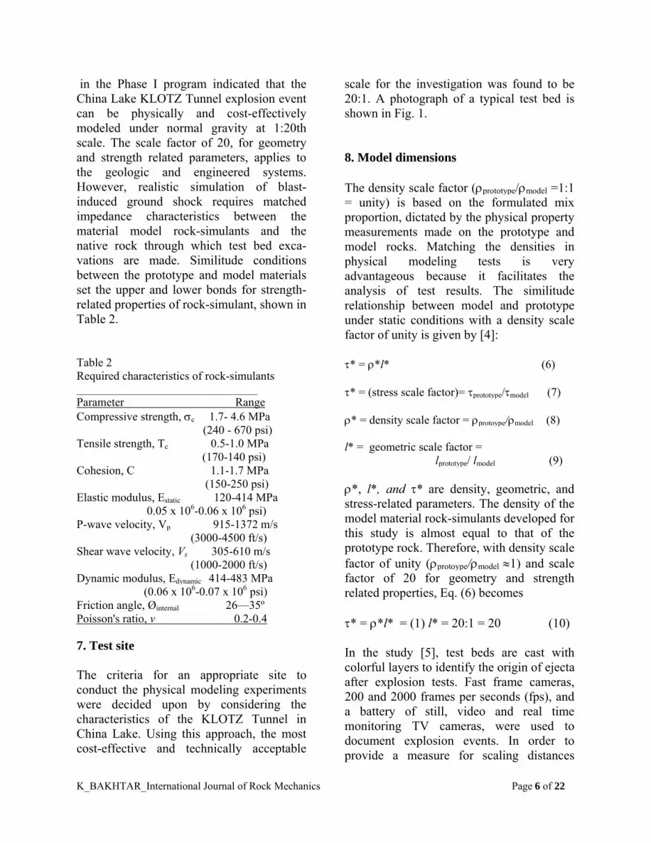
in the Phase I program indicated that the China Lake KLOTZ Tunnel explosion event can be physically and cost-effectively modeled under normal gravity at 1:20th scale. The scale factor of 20, for geometry and strength related parameters, applies to the geologic and engineered systems. However, realistic simulation of blast-induced ground shock requires matched impedance characteristics between the material model rock-simulants and the native rock through which test bed exca-vations are made. Similitude conditions between the prototype and model materials set the upper and lower bonds for strength-related properties of rock-simulant, shown in Table 2. Table 2 Required characteristics of rock-simulants __________________________________ Parameter Range Compressive strength, c 1.7- 4.6 MPa (240 - 670 psi) Tensile strength, Tc 0.5-1.0 MPa (170-140 psi) Cohesion, C 1.1-1.7 MPa (150-250 psi) Elastic modulus, Estatic 120-414 MPa 0.05 x 10⁶-0.06 x 10⁶ psi) P-wave velocity, Vp 915-1372 m/s (3000-4500 ft/s) Shear wave velocity, Vs 305-610 m/s (1000-2000 ft/s) Dynamic modulus, Edynamic 414-483 MPa (0.06 x 10⁶-0.07 x 10⁶ psi) Friction angle, Øinternal 26—35º Poisson's ratio, v 0.2-0.4 7. Test site The criteria for an appropriate site to conduct the physical modeling experiments were decided upon by considering the characteristics of the KLOTZ Tunnel in China Lake. Using this approach, the most cost-effective and technically acceptable
scale for the investigation was found to be 20:1. A photograph of a typical test bed is shown in Fig. 1. 8. Model dimensions The density scale factor (prototype/model =1:1 = unity) is based on the formulated mix proportion, dictated by the physical property measurements made on the prototype and model rocks. Matching the densities in physical modeling tests is very advantageous because it facilitates the analysis of test results. The similitude relationship between model and prototype under static conditions with a density scale factor of unity is given by [4]: * = *l* (6) * = (stress scale factor)= prototype/model (7) * = density scale factor = protoype/model (8) l* = geometric scale factor = lprototype/ lmodel (9) *, l*, and * are density, geometric, and stress-related parameters. The density of the model material rock-simulants developed for this study is almost equal to that of the prototype rock. Therefore, with density scale factor of unity (protoype/model 1) and scale factor of 20 for geometry and strength related properties, Eq. (6) becomes * = *l* = (1) l* = 20:1 = 20 (10) In the study [5], test beds are cast with colorful layers to identify the origin of ejecta after explosion tests. Fast frame cameras, 200 and 2000 frames per seconds (fps), and a battery of still, video and real time monitoring TV cameras, were used to document explosion events. In order to provide a measure for scaling distances

K_BAKHTAR_International Journal of Rock Mechanics Page 7 of 22
(fragment throw) in the fast frame films, a series of range poles with red and white graduations were installed along the scaled model tunnels. Fig.2 shows a sectional view through a typical test bed. 9. Wall roughness It is important to determine the smoothness of the tunnel wall in order to have some way to quantify the frictional characteristics associated with the post-blast air-flow, and air-blast within the structure. The technique developed by [13] based on roughness standards can be used to determine the wall roughness profile and assign numerical values. Typical wall roughness measured for scaled model tunnels is shown in Fig. 3.
Fig.3. A typical tunnel wall roughness 10. Explosives charge scaling Literature dealing with scaling of explosive weight for model testing indicates that existing empirical formulas are based on geometric similitude. The formulas are modified by factors obtained from experiments or through experience to account for explosive type, charge weight, and typical parameters for rock properties.
The models based on scaling of the geometric dimensions using prototype materials do not follow similitude conditions, and are distorted. In addition, the rock parameters used are those representing strength-related properties obtained from laboratory testing of intact, dry, cylindrical specimens. They do not account for the geologic features or moisture contents of in situ rock. These laboratory tests are best used to investigate performance characteristics, coupling, and calibration of "passive" and "active" instruments for ground shock propagation and monitoring studies. They do not provide a reliable foundation for prototype load response evaluation. Testing scaled-models using prototype materials and geometric similitude are inadequate because kinematics similarity between model and prototype has not been preserved and dynamic similarity is not satisfied. The similitude conditions are satisfied if the material properties are scaled and conditions represented by Eq. (5) are satisfied. In replica approach, the load required to maintain the dynamic similarity would be much higher, resulting in a more costly test program and, in the majority of cases, distortion of the similitude laws. Should such situations arise, it is advisable to increase gravity by using a centrifuge and perform component testing instead of system response evaluation. The initial shock waves produced in an underground explosion are similar to those in air that have short duration pulses close to the source. However, when reflections of shock waves from the surface and within internal boundaries occurs before their energy is consumed through rock fragmentation, frequency multiplication takes place and results in longer load duration. This is observed in the China Lake test [2]. In addition, frequency response and locations of the sensing instruments play

K_BAKHTAR_International Journal of Rock Mechanics Page 8 of 22
Fig.1. Photograph of a typical test bed
Fig.2. Sectional view through a test bed
K_BAKHTAR_International Journal of Rock Mechanics Page 9 of 22
important roles for the event monitoring and documentation. Therefore, as the records obtained from the China Lake test indicate, amplitude, frequency content, and duration are all subject to the location and distance of the sensing instruments from the explosion source. This is similar to the case for an earthquake. When examining underground storage structures, two general classes of magazines are considered; "responding" and "non-responding" installations. Responding magazines are those facilities in which the structural integrity of the cover rock/soil is impaired following an accidental detonation within the underground storage chamber. The overlying geologic materials break into fragments and ejecta are produced. Non-responding magazines are those in which structural integrity of the cover is maintained following an accidental detonation within the storage chamber. By and large, the overall performance of an underground facility subjected to an internal detonation is determined by the conditions affecting the stresses and displacements developed under intense loading. These conditions include strength-deformability properties and in situ stress and moisture (water pressure distribution), in addition to explosive weight and type. Results of studies reported on behavior of Tuffs [14,15], and on load-deformation studies of rock [16], indicate that the strain rate or dynamic response of the geologic materials is directly related to the porosity and degree of saturation. In addition, for non-respond-ing tunnels, although internal detonation within an underground chamber results in transient loading, the type of loading condition can either be dynamic or pseudo-static. As explained by [18], the type of loading to be considered depends on the ratio (/D) of the wavelength of the stress or velocity waveform () to the excavation diameter (D). When the duration of loading
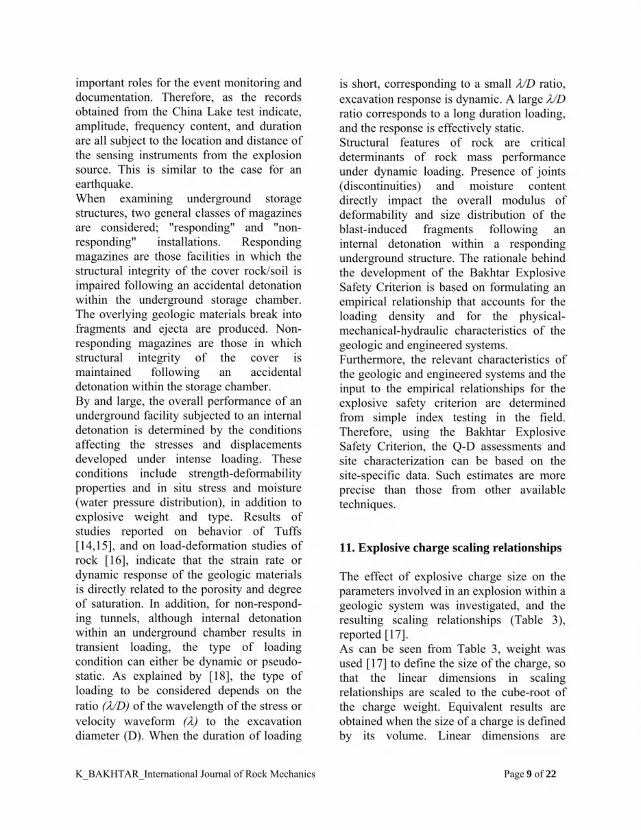
is short, corresponding to a small /D ratio, excavation response is dynamic. A large /D ratio corresponds to a long duration loading, and the response is effectively static. Structural features of rock are critical determinants of rock mass performance under dynamic loading. Presence of joints (discontinuities) and moisture content directly impact the overall modulus of deformability and size distribution of the blast-induced fragments following an internal detonation within a responding underground structure. The rationale behind the development of the Bakhtar Explosive Safety Criterion is based on formulating an empirical relationship that accounts for the loading density and for the physical-mechanical-hydraulic characteristics of the geologic and engineered systems. Furthermore, the relevant characteristics of the geologic and engineered systems and the input to the empirical relationships for the explosive safety criterion are determined from simple index testing in the field. Therefore, using the Bakhtar Explosive Safety Criterion, the Q-D assessments and site characterization can be based on the site-specific data. Such estimates are more precise than those from other available techniques. 11. Explosive charge scaling relationships The effect of explosive charge size on the parameters involved in an explosion within a geologic system was investigated, and the resulting scaling relationships (Table 3), reported [17]. As can be seen from Table 3, weight was used [17] to define the size of the charge, so that the linear dimensions in scaling relationships are scaled to the cube-root of the charge weight. Equivalent results are obtained when the size of a charge is defined by its volume. Linear dimensions are
K_BAKHTAR_International Journal of Rock Mechanics Page 10 of 22
scaled to the cube root of the charge volume, and are dimensionless. For the 1-g physical modeling of a tunnel explosion scenario based on material scaling, it is best to match the loading density of the prototype and model. Also, in order to facilitate comparison, the net weight of the explosive compounds should be converted to the TNT equivalency base using the equivalent sensitivity factors and, where applicable, the density and percent voids parameters. The TNT equivalency values can be found for different charge type Table 3 Scaling relationship for explosions of differing charge weight [17]____________________ Quantity Symbol Scaled quantities Length L L / W 1/3 Time T T W1/3 Mass M M / W Area A A / W2/3 Volume V V/ W Force F F/ W2/3 Energy E E / W Pressure P P Stress S S Strain Displacement u u / W 2/3 Velocity V V Acceleration a a W 2/3 including composition B and plastic C-4 explosives, which are used extensively in military from the Explosive Handbook [19], published by the Lawrence Livermore National Laboratory. The overall dimensions for the prototype and the respective model structures are given in Table 4. The minimum size of the model is determined by considering the strength characteristics and joint spacing of the geologic system within which the prototype tunnel has been constructed. These considerations lead to a material model with
Table 4 Prototype-model dimensions at 20:1 scale Prototype Model dimensions dimensions__ Chamber Chamber 5 x 4 x 18-m 0.25 x 0.2 x 0.9-m Tunnel Tunnel 2.4 x 2.4 x 25-m 0.12 x 0.12 x 1.2-m scaled compressive strength ranging from 1 to 5 MPa at a stress scale factor of 20:1 (*-stress scale factor = prototype / model). The explosive material used for the KLOTZ Tunnel test consisted of palletized, reclaimed composition B packaged in 22.7 and 27.2 kg cardboard boxes. The total weight of composition B explosive was 20,003.8 kg placed at the center of the chamber. For the TNT equivalent (1.1 equivalence factor), the corresponding weight is 22,004.18 kg. The resulting loading density is calculated to be: ( )
3
prototype
m / kg 66.4 [332] / ] 22,004.18 [ =
chamber prototype of Volume
weightexplosive TNTNet
=density Loading
=
The loading density for the model structure should have the same value ( )
( )
TNT kg 2.988 = ) m-0.9 x 0.2 x 0.25 ( x 66.4 =
] weight explsoive TNTNet [
chamber] of [volume / wt]explosive TNT[Net =
m / kg 66.4=density Loading
=density Loading
model
3prototype
model
The TNT equivalence factor for the composition C-4 plastic explosive is 1.35 [19] under normal density and void ratio; therefore, the equivalent weight for C-4 is calculated as follows:

K_BAKHTAR_International Journal of Rock Mechanics Page 11 of 22
(Net explosive weight)model =2.988/1.35 = 2.213 kg, C-4 plastic explosive 12. Explosives charge weight In calculating the weight of an explosives charge, adjustments should be made to account for the over-break in the prototype, which increases the actual volume of the chamber. Tables 4 and 5 show the overall dimensions of model and prototype struc-tures and loading densities of the explosives charge used for the scale model tests 1 to 5. 13. Explosives assembly Fig. 4 shows the general arrangement employed for charge detonation [5]. Exploding Bridge Wires (EBW) are glued and taped to a booster and subsequently to the Comp-B for each case. A Reynolds Industries System (RISI) model FS-10 is used as the firing device. The firing device is synchronized with the camera-triggering mechanism to facilitate photography and prevent excessive loss of films. 14. Explosion tests For the scaled model tunnel explosion tests [5], results of the material characterization tests coupled with previous experience with a similar mix [20] indicated that under dry (no humidity) conditions, the model materials exhibited stable mechanical properties for at least 15 days. Therefore, following the curing period of about 20 days all the planned tests were completed within 15 days. Climatic conditions are important considerations in conducting scaled model
experiments using explosives. The wind speed should be less than 1 m/s and lighting should be sufficient to match the fast-frame camera aperture and speed settings. Following the charge emplacement, the wind velocity and light around the model test beds were continuously monitored until test requirement conditions were met. At that time, a 10 s countdown was announced and the charge detonation was initiated using the remote firing circuit device. 15. Fragment recovery A hazardous fragment is defined as one having an impact energy of 79 joules (58 ft-lb) or greater. This criterion can be used to determine the minimum size of the hazardous fragment from the scaled model tests. Furthermore, for each test a complete (100%) fragment recovery within 20° sector, a mid-portal location along the extended axis of the engineered system, is required. This procedure was followed for the tests reported in [5]. 16. Fragment analysis - scaled model tests The goals of fragment (debris) analysis are to determine hazardous fragment distribution (density) and maximum debris thrown range. Post event fragment recovery is made by measuring the bearings and dis-tances of all the observed fragments within the 20° sector. The "count" numbers used for analysis represent the observed not the actual frequencies of the fragments recovered. For the majority of cases, mech-anical breakage of fragments occurred upon impact on the ground and resulted in multiplication of the fragment frequency by one or more magnitudes. Such occurrences should be taken into account in the Q-D analyses.

K_BAKHTAR_International Journal of Rock Mechanics Page 12 of 22
Table 5 Details of explosive charge used for Bakhtar model tests [5] ____________________________________________________________________________________________ Test no. Weight of Comp-B (kg) Shape Density (g/cc) Diameter (cm) Length (cm) 1 2.213 Cylindrical 1.67 5.1 66.1 2 2.213 Cylindrical 1.67 5.1 66.1 3 2.213 Cylindrical 1.67 5.1 66.1 4 0.553 Cylindrical 1.67 5.1 (2.0) 16.4 5 0.139 Cylindrical 1.67 5.1 4.1
Fig. 4. Explosive charge assembly [5]
Table 6.
*- Average size 1.3 mm Density scale factor = 1, therefore, model = prototype = 1.55 g/cc
**

K_BAKHTAR_International Journal of Rock Mechanics Page 13 of 22
The minimum debris mass and terminal velocity that induces a kinetic energy of 79 joules (58 ft-lb) dictates the maximum range for the prototype fragment recovery upon impact. For the model tests [5], these requirements led to calculation of a cut off distance in which a fragment average size of 1.3-mm is found. As shown in Table 1, the impact energy of a fragment is scaled using the following relationship
(11) *t*l*m=[Energy]
[Energy] 2-
model
prototype
Using the above equation, the minimum kinetic energy associated with a lethal ejecta originating from the model tests can be determined as follows:
1-2-2prototype
model
}*t*l*}{menergy) {(Kinetic
=energy) (Kinetic
or -12-*2*3
model }t*l )l 79{(ρ =energy] [Kinetic
(12) But, *, the density scale factor, is unity, and the geometric scale factor, l*, is 20, mass scale factor expressed in terms of density and geometric scale factors is *l*3
(= l*3), time scale factor in terms of geometric scale factor (t* = l*1/2); therefore, the expression represented by Eq. (12) becomes (Kinetic energy)model = 0.0005 joules that means that for the scaled-model tests, fragments having kinetic energy upon impact of 0.0005 joules and above are lethal or hazardous based on the US DOD Ammunition and Explosives Safety Standards [1]. Volumes and weights of fragments recovered from Tests 1 to 5, at cut-off
ranges were calculated from Eq. (13) [9], and are shown in Table 6. Also, included in this table are corresponding values for the volume and weight of the respective prototype fragments scaled up using appropriate scale factors: df = (2.2Uf)
1/3 = 1.3(Uf)1/3 (13)
where df is the average size of the fragment, and Uf is the volume of the fragment. The kinetic energies of impacting materials is given by Eq. (14) Kinetic energy = 1/2{(m)(v2)} (14) With a fragment mass of 27.28 g (0.02728 kg) the impact velocity at the maximum fragment range is 76 m/s. 17. Quantity-distance (Q-D) analysis The US DOD Explosives Safety Standards [1] criterion for fragment hazard range is the distance to a fragment or debris density of one hazardous particle per 56 m2 (600 ft2). All the fragments recovered within the 20° sectors, used for subsequent analysis, are considered to be lethal and hazardous at the scale-factor of investigation. The Jacob technique [21] is used for analysis and interpretation of the hazardous fragment density (more than 1 hazardous debris per 56 m2, 600 ft2). This method is illustrated in Fig. 5. In the fragment recovery scheme followed in this study, the data was bounded by 20° sectors angle θ. According to Jacobs [21], a sector of length d, 3-m in this analysis, is moved away from the ground zero in increments of i (1-m in this analysis). The analysis starts at distance a representing the outer border in the closed-in region where 100% fragment recovery is initiated. For

K_BAKHTAR_International Journal of Rock Mechanics Page 14 of 22
each increment, the area of the sector is calculated, the number of fragments in the sector is counted, and the number of fragments per 0.14-m2 equivalent to 56-m2 prototype is determined. This process is continued until the furthest fragment (distance b) is included in the fragment distance calculations. The distance from GZ (Ground Zero) to the center of the sector is the distance reported for the hazardous fragment density. For example, use a sector length d of 3-m and start the analysis at 7.6-m. The first calculation would involve the sector from 7.6 to 10.6-m and the hazardous fragment density for that sector would be recorded at 9.1-m. The Jacobs method, shown schematically in Fig. 5, was applied to the 20:1 scaled model tests 1-5 [5]. The results are subsequently scaled up by 20 to predict the fragment density distribution for the prototype. Fur-thermore, to determine the Q-D [1], a curve fitting technique based on an exponential function with a generalized form given by f(x) = a* exp(b*x) (15) is used. For such statistical analysis, values of constants are calculated so that sum of the square of the errors given by [g(xi)-ln(yi)]
2 is minimized. Fig. 6 represents a typical result of the Q-D analysis and Table 7 shows the summary of fragment analysis results. The Decision to use an exponential curve fitting for statistical analysis in this study was based on the manner in which spread of data was reported. Other techniques, such as logarithmic fit, may also be employed. The model values for the Q-D and maximum fragment range are scaled up by the geometric scale factor of 20 to get the prototype response as shown in Table 7. The maximum fragment range and the Q-D values for Tests 1 and 2 compare very closely with values reported [2,22] for the KLOTZ China Lake Test. These two tests (1
and 2) were conducted under identical conditions to check the reproducibility of the data by simulating the KLOTZ 1988 China Lake Tunnel Explosion test under normal gravity at 20:1 scale. The prototype test post blast fragment recovery [2] reported maximum fragment range distances in excess of 2012-m from the portal. Similarly, analysis of Q-D within the 20° revealed a single value of 656 m for the Q-D based on the "one strike per 56 square meter standard" [22]. The results of physical model tests predicted the fragment maximum range and the Q-D values within 8 and 6% of those reported by the others [2,22]. The test results presented in Table 7 are unique in terms of the size, model materials, and mix proportions used to construct the test beds. They clearly reaffirm the importance and applicability of physical modeling based on material scaling for prediction of the response of such structures subjected to explosives loading. They also confirm the importance of obtaining site specific data on geologic and engineered systems by conducting a site charac-terization. This data directly influences the choice of the model size, properties of the model materials, and ultimately, test con-ditions. The data obtained was used to solve the auxiliary equations derived from Eq. (1) and validate a new Q-D expression. 18. Bakhtar Explosives Safety Criterion The functional form of the Bakhtar Explosive Safety Criteria was presented earlier, Eq. (1), for the assessment of Q-D. The criterion was formulated for "responding" magazines to determine: 1. Fragment density or Q-D. 2. Hazardous fragment range.

K_BAKHTAR_International Journal of Rock Mechanics Page 15 of 22
Fig.5. Schematic representation of Jacob’s method [21] Fig.6. A typical results showing variations of fragment
impact density with horizontal Distance from portal within 20º sector for Test 1
Table 7 Results of fragment analysis*
Test Model observed maximum fragment range
Model Q-D range
Prototype observed maximum fragment range
Prototype Q-D range
(m) (m) (m) (m) 1 100.5 35.1 2005 702.0 2 113.6 35.5 2261 709.7 3 1018 26.4 2036 527.3 4 47.8 23.8 957 476.4 5 18.9 17.5 378 350.5
Note: All horizontal distances not slopes

K_BAKHTAR_International Journal of Rock Mechanics Page 16 of 22
Based on this formulation, development of a reliable safety criterion for storage of explosives in geologic repositories is contingent on the ability to assess the site-specific characteristics of the engineered and geologic systems. For the Q-D formulation, five parameters of the geologic-engineered systems were identified as pertinent to such assessments. They included: equivalent stiffness characteristics of the two systems; loading density of the chamber; seismic wave velocity in the host geologic system; and the initial venting characteristics of the engineered system. Experience gained during the recent scaled-model tests for the US Air Force [20] prompted the Principal Investigator to introduce additional terms into the criteria; namely, thickness of overburden at the chamber location (Z) and the gravity term “g.” These parameters are combined into a single functional form which provides a more complete expression for the formulations: D = f (E a, K b, Z c, S d, V e, g f ) (16) where D is the hazardous fragment range, m, E is the equivalent stiffness characteristics of the geologic system, MPa, K is the loading density [(explosives wt) / (chamber vol.)], kg/m3 , Z is the overburden thickness above the chamber, m, S is the initial venting characteristics of the engineering system, m3, V is the P-wave velocity in the geologic system, m/s, g is the acceleration due to gravity = 9.8146 m/s2, and a, b, c, d, e, f are constants. The seven parameters chosen to describe the Bakhtar's formulation are easily obtained in the field [4, 20] using non-destructive index testing or site specific available data on the host geologic system coupled with information on the engineered (underground structure) system. Dimensional analysis or
the Buckingham Pi theorem can be used to derive the final form of Eq. (16). 19. Dimensional analysis The first step in using the dimensional analysis technique is to select the fundamental or primary dimensions. Usually, mass, length, time, and temperature are used as the primary dimensions and others are derived from these variables. Newton's second law is extensively used for such analysis. A dimension conversion factor (gc) and an energy conversion factor (J) may be required to obtain results expressed in the primary dimensions noted above. The second step is to write a functional relationship between the dependent variable (y) and independent variables (xi). Y = f(x1, x2, x3, x4, ..., xn ) (17) The function represented in Eq. (17) can be expressed as an exponential series
...... + x.................
+.....xxxxc
+.....xxxxc =y
z2m
z2m
c23
b22
a212
z1m
c13
b12
a111
(18) The quantities c1, a1, b1,…….z1 in Eq. (18) are the unknown constants. 20. Bakhtar formulation of Explosive Safety Criteria The seven parameters chosen to describe the Bakhtar's formulation, Eq. (16), are easily obtained in the field using non-destructive index testing, as described in several recent reports [9,12,20] including the final report

K_BAKHTAR_International Journal of Rock Mechanics Page 17 of 22
on the China Lake Tunnel Explosion Test [3,4]. The final form of Eq. (16) may be derived using the Buckingham's Pi Theorem or dimensional analysis in which the dimensions of the various parameters are re-lated to the fundamental dimensions of length, time, and mass through the Newton's second Law.
(19) ]LT
M[ =]
TL
ML[=
Area
Force = E
222
(20) ]TL
M[ =]
TL
ML[=
Volume
Weight =K
2223
(21) [L] = thicknessOverburden=Z
(22) ]T
L[ =Gravity =g
2
(23) ][L = tunnel)(venting area Sectional =S 2
(24) ]T
L[ = velocity waveSeismic =V
Two additional terms are introduced and expressed in terms of the above variables; namely: 1. Dynamic Response Factor (R) - - defined as the ratio of the "equivalent modulus of deformability" to "seismic wave velocity" in the geologic system. 2. Load Capacity Factor (C) — defined as the ratio of the "chamber loading density" to "overburden thickness." In terms of dimensional quantities, R and C are expressed as:
]TL
M[=}
]T
L[
]LT
M[
{=V
E=R
2
2 (25)
] TL
M [ =
Z
K = C
3 2 (26)
Eq. (16) can now be written in terms of above parameters as D = Cα (R, C, S, g) (27) D = f (R a, C b, S c, g d) (28) Eq. (28) can be written in terms of dimensions of variables
d2
c2b23
a2
100 ]T
L[][L]
TL
M[ ]
TL
M[ F=LTM
(29) Since L on the left-hand-side of Eq. (29) has an implied exponent of one, and T and M have implied exponents of zero, required and necessary equations are: -2a -2b -2d = 1 (30) -a - 2b – 2d = 0 (31) a + b = 0 (32) Solving the above auxiliary equations in terms of d reveal a = 2d b = -2d c = (1 - 3d)/2 Using the above parameters, the Bakhtar's criteria, Eq. (28) can be presented in its generalized form as:
]g S)C
R[( β = D dd)/23 - (12d (33)
where β and d are constants, they are determined from the results of the physical

K_BAKHTAR_International Journal of Rock Mechanics Page 18 of 22
modeling experiments conducted in the field for simulation of tunnel explosion tests at normal gravity [23]. Results reported for the field wave velocity measurements [5], post-blast fragment survey investigation [5], and the Q-D and fragment range presented in Table 6 are used to determine the constants β and d in Eq. (33). These constants are determined for purposes of formulating expressions for: 1. Prediction of fragment density or
quantity-distance at a given site;
2. Prediction of maximum hazardous fragment range; for "responding" magazines. The criteria have several other important applications for both "responding" and "non-responding" underground magazines, which will be elaborated upon later. Both expressions accept site specific data on the characteristics of the geologic and engineered systems. Therefore, site characterization tasks, which reveal site specific data on the geologic and engineered systems, constitute the basis for the Bakhtar Explosives Safety Criteria. 21. Bakhtar quantity-distance (Q-D) relationship In order to determine the Bakhtar Q-D relationship, the general expression given by (33) is rewritten as Eq. (34)
]g S)C
R[( β = D d /23d)- (12d
D-Q (34)
Values for two different sets of data from physical modeling explosion tests on Q-D are substituted into the above to form a set of auxiliary equations. The constants β and d in Eq. (34) can be determined by solving
these auxiliary equations simultaneously. Therefore, the final form of the Bakhtar expression for Q-D based on site specific characteristics of the geologic and engineered system can be represented by:
]g S)C
R[( 90 = D 0.11-0.670.22-
D-Q
(35) The above equation can be used to determine Q-D at a given site. Examples are provided later in this paper to demonstrate the applications of the above formula. 22. Bakhtar fragment range — loading density expression Another important expression developed during the course of the research is the Bakhtar fragment range-explosives weight or loading density relationship. The derivation is similar to the Q-D formulation, with the exception that DQ-D is replaced with Dmax-range in Eqs. (34) and (35). The values of Dmax-range are obtained from explosion tests on model underground structures. The approach is particularly useful for estimation of the TNT equivalent weight of explosives that causes the rock cover to break. The calculation is based on the maximum range of hazardous fragment recovered and the site specific characteristics of the geologic and en-gineered systems. In order to show the formulation of the "Bakhtar fragment range - - loading density" relationship, the general expression given by (33) is rewritten as shown in Eq. (36)
]g S)C
R[( β = D d /23d)-(12d
range-max
(36)

K_BAKHTAR_International Journal of Rock Mechanics Page 19 of 22
Values of the various parameters in Eq. (36) are obtained from the model explosion tests and used in the auxiliary equations needed to solve for d and β. The final form of the Bakhtar criteria for prediction of maximum hazardous fragment range, in Metric or SI (International) Systems, is derived as shown in Eq. (37)
]g S)C
R[( 150 = D 0.25-0.870.5
range-max
(37) where S is the "venting characteristic" or equivalent cross-sectional area of the tunnel through which venting takes place. The acceleration due to gravity is g in SI or Metric System (9.8146 m/s2 in the metric system and 32.2 ft/s2 in the SI system), R and C are the "dynamic response factor" and the "load capacity factor," respectively. 23. Remarks The Bakhtar Explosive Safety Criterion (BESC) for underground storage of munitions, Eqs. (35) and (37) have been applied to real cases in the United States and Switzerland. Using these expressions, Q-D and maximum ranges for hazardous fragments were predicted to better than 8% for KLOTZ China Lake explosion tests and the Steingletscher accident in the Swiss Alps. 24. Conclusions It is shown that the "physical modeling" technique, based on geometric and material scaling at normal gravity, can be used for performance assessment of underground
munitions storage structures. The formulated predictive equations, Bakhtar Explosives Safety Criteria (BESC), can be used with confidence to determine the Q-D and the hazardous range of blast-induced fragments originating from a "potential explosion site" (PES) such as a "responding" magazine. The observations made during the scaled-model testing combined with results obtained from several site-specific applications of the developed safety criteria lead to the following conclusions. 1. Physical modeling -- the approach was proven to be applicable for performance assessment of munitions storage structures and prediction of hazardous effects of blast-induced fragments. Results of scale model tests compare very well (better than 8%) with those from the prototype tests. Further-more, it was shown that realistic simulation of the prototype event would require: 1.1. Site specific data on geologic and en-gineered systems and explosives characteri-stics. This information was obtained during prototype site characterization methodology [3, 4] by index testing [13]. 1.2. Development of "rock simulant" (model materials) to simulate prototype geologic and engineered materials. It was found that matching the densities between the model and its prototype and scaling the geometric and strength-related properties would facilitate the ease of test bed construction and subsequent analysis of the data. However, attention must be directed towards fulfillment of dynamic and static similitude conditions [9]. In addition, the following conclusions, about the physical modeling explosion tests reported in this paper, can be made: 1. The majority of fragments were

K_BAKHTAR_International Journal of Rock Mechanics Page 20 of 22
accumulated in front of the portal within the 20° sector with reference to the extended axis of the engineered system. Large pieces of debris were observed around the portal area and behind the original chamber lo-cation from Tests 1-4. 2. Maximum observed range from Tests 1 and 2 simulated that of the prototype at 20:1 to within 6%. Similar results were obtained for the calculated Q-D ranges between the China Lake prototype [22] and those obtained from the scaled model tests. 3. Site characterization — was found to be one of the most important elements of the program in defining the overall site specific characteristics of the geologic and engineered systems. The information from site characterization at KLOTZ Tunnel in China Lake, USA [4], KLOTZ Tunnel in Älvdalen, Sweden [24], and Steingletscher, Switzerland [23], provided the necessary input data for construction of the scale model test series, assessment of the site conditions, and successful calculation of TNT equivalent weight of explosives causing the mishap at the three locations. 4. Bakhtar Explosives Safety Criterion (BESC) — the general formulation is based on dimensional analysis. Results of the scale model tests, conducted under normal gravity, were used to solve the auxiliary equations. The relevant constants were used to derive the final mathematical expressions for the Q-D and fragment range represented by Eqs. (35) and (37), respectively. The validation and predictive verification of the derived equations were made using prototype scaled model input data. In all cases, predicted results fall within 8% or better of the observed data. 5. Further applications of the Bakhtar Explosives Safety Criterion (BESC) — in
addition to predicting the Q-D and hazardous fragment range, the formulated methodology, coupled with its site characterization technique, has the following uses in the development of "responding" and "non-responding" magazines: (i). Responding magazines: siting for facility location; design and construction with emphasis on the best choice for support scheme; estimation of clear zone around the storage facilities based on site specific conditions of the geologic and engineered systems and quantity of stored explosives; accident (mishap) investigation and post-event fragment analysis [3, 4, 23, 24]. (ii). Non-responding magazines: siting for facility location; design and construction with emphasis on the best choice for support scheme; estimation of required depth of cover for a given loading density based on site specific characteristics of geologic and engineered systems; optimization of loading density, based on site specific characteristics of geologic and engineered systems and a given depth of cover; communication between adjacent magazines in complex underground facilities; estimation of pillar thickness between adjacent magazines for a given loading density, cover depth, and other site specific conditions. (iii). Validation of numerical codes: The proposed physical modeling technique and developed safety criterion provide novel and cost effective methods for numerical code validation and calibration In conclusion, it must be pointed out that scale model tests in which similitude conditions between the model and its prototype are maintained can replace many other large scale tests for magazine response prediction and performance assessment.

K_BAKHTAR_International Journal of Rock Mechanics Page 21 of 22
This approach is advantageous because tests can be conducted under controlled conditions. Ease of instrumentation, ease of performing parametric studies, and ease of fragment recovery and post test analysis are facilitated. This leads to tremendous cost savings in terms of planning efforts, direct materials, and labor requirements. Acknowledgements The funding for the research investigation reported in this paper was provided by the United States Air Force under SBIR Phase II Contract F08635-92-C-0078. Mr. Joseph Jenus, Jr, from AAC/WGB (HER) Eglin Air Force Base, Florida, is the Program Man-ager. Ms Ellen Sagal, Senior Engineer from Bakhtar Associates reviewed the manuscript. Professor Richard White, Department of Civil and Environmental Engineering, Cornell University, is the sole consultant to the project. Peer Review Team consisted of Professor Neville Cook, University of California, Berkeley; Professor Ronald Scott, California Institute of Technology (Cal-Tech); Professor Anthony Ingraffea, Cornell University; Professor Hon-Yim Ko, University of Colorado, and Professor Richard White, Cornell University. References [1]. Department of Defense. Ammunition and Safety Standards, DOD 6055.9 STD, 1984. [2] Halsey C, Durbin WF, Berry SL. KLOTZ underground magazine trial Data Report. Naval Weapons Center, Conventional Weapons Division, Ordnance
Systems Department, NCW TM 6562, China Lake, CA, 1989. [3] Bakhtar K. Rock mass characterization at tunnel explosion test site. Norwegian Defence Construction Service, Norwegian Ministry of Defence, Oslo, Norway, August 16, 1988. [4] Bakhtar K. Rock mechanics at tunnel explosion test site, Norwegian Defence Construction Service, Norwegian Ministry of Defence, Oslo, Norway, 1988. [5] Bakhtar K. Development of safety criteria for explosive storage structures. United States Air Force, Air Force Operability Syst. Management Office, Contract No.: F08635-C-0187, Eglin Air Force Base, Florida, 1991. [6] Jenssen A. KLOTZ Test Program. Personal Communication, 1988. [7] Bakhtar K. Derivation of similitude conditions based on stress equation of motion. Progress Report submitted to Defense Nuclear Agency, Strategic Structures Division, Contract No. DNA001-84-C-0144, Washington, DC, 1984. [8] Bakhtar K. Physical modeling of gravity and inertia forces for scale-model tunnel explosion tests. Presented at Air Force Safety Agency, Explosives Safety Division, Norton Air Force Base, California, January 30, 1992. [9] Bakhtar K. Theory of material scaling law and its application in model testing at 1-g. United States Air Force, Air Force Material Command, Aeronautical Systems Center, Eglin Air Force Base, ASC-TR-93-1005, Florida, 1993.

K_BAKHTAR_International Journal of Rock Mechanics Page 22 of 22
[10] Ramberg H. Gravity, deformation and the Earth crust. 2nd ed. Academic Press, 1981. [11] Hubbert MK. Theory of scale models as applied to the study of geologic structures. Bulletin of the Geologic Society of America 1937;48:1459-520. [12] Bakhtar K. United States Air Force test program — scaled model test for underground storage of munitions. The Fifth Tri-Service Symposium on Explosives Testing, White Oakes Detachment, Dahlgren Division/Naval Surface Warfare Center, Silver Spring, Maryland, 14-15 April, 1993. [13] Barton N, Choubey V. The shear strength of rock joints in theory and practice. Rock Mechanics 1977;10:l-54. [14] Crowley BK. Effects of porosity and saturation on shock-wave response in tuffs. International Journal of Rock Mechanics, Mining Science and Geomechanics Abstracts 1973; 10:437-64. [15] Fogel M, Patch D, Swan C. Material response model and ground response calculations for high explosive tests in G-tun-nel tuff. In: Response of geologic materials to blast loading and impact, vol. 69. New York: ASME/AMD, 1985. p. 39-53. [16] Froula NH, Suenaga EL, Bryson RL. Shock compression and release behavior of two Nevada test site tuffs. Defense Nuclear Agency, DNA001-71-C-0080, 1988. [17] Lampson CW. Final Report on effects of underground explosions. Office of the Scientific Research and Development Report 6645, 1946:5-10.
[18] Perkin BR. In: A review of similitude theory in ground shock problems RM-2173, vol. 49. The Rand Corporation, 1958. [19] Dobratz BM, Crawford PC. LLNL explosive handbook. Properties of chemical explosives and explosive simulants, Lawrence Livermore National Laboratory, UCRL-52997 Change 2, 1985. [20] Bakhtar K. Development of safety criteria for explosive storage structures. United States Air Force, Air Force Operability Systems Management Office, Contract No. F08635-92-C-0978, Phase II SBIR, Eglin Air Force Base, Florida, 1997. [21] Jacobs E. Hazardous Fragment Distance from Hardened Aircraft Shelter. 26th Explosives Safety Seminar, US Department of Defense, Miami, FL, 16-18 August, 1994. [22] Joachim CE. Shallow underground tunnel/chamber explosion test program summary report. Structures Laboratory, Technical Report SL-90-10, Department of The Army, Waterways Experiment Station, Corps of Engineers, Vicksburg, Mississippi, 1990. [23] Bakhtar K. Steingletscher installation accident — TNT equivalency based on the Bakhtar criteria. United States Air Force, Air Force Material Command, Aeronautical Systems Center, Eglin Air Force Base, ASC-TR-94-1015, Florida, 1994. [24] Bakhtar K, Jenus J Jr. Characterization of geologic and engineered systems at KLOTZ tunnel explosion site Älvdalen, Sweden. United States Air Force, Air Force Material Command, Aeronautical Systems Center, Eglin Air Force Base, ASC-TR-94-7014, Florida, 1994.


