Embed Size (px)
Citation preview
Dr. Naveed AnwarExecutive Director, AIT Consulting
Affiliated Faculty, Structural Engineering
Director, ACECOMS
Performance-based DesignModeling for Nonlinear Analysis

Primer on Performance-based Design, Dr. Naveed Anwar, AIT Thailand
• Structures are Damaged in Earthquakes– Not because of large forces, but because of large deformations
• Structures do not behave linearly or elastically– Infinite load can produce infinite deformation
– Capacity of member is not accounted for in analysis
• Reinforced Concrete is a highly nonlinear–inelastic material
• The Performance Determination requires either Nonlinear Static Pushover Analysis or Non-linear Dynamic Analysis
•
Primer on Performance-based Design, Dr. Naveed Anwar, AIT Thailand
• Stress-strain relationship must be linear and elastic. Most materials exhibit a change in stiffness or modulus before inelastic or plastic behavior starts.
• Displacements and rotations must be small such that the assumption “plane remain plane after deformation” is still valid. Mathematically, it is being approximated as sin(θ) = θ or tan(θ) = 0.
• The magnitude, orientation or direction and distribution of loads must not change.
Primer on Performance-based Design, Dr. Naveed Anwar, AIT Thailand
• Stress levels approach the yield point.– Most materials exhibit a significant range of nonlinear elastic behavior
long before the yield stress is reached.
– When a material is strained beyond its proportional limit, the stress-strain relationship is no longer linear.
– Yield stress value after 0.2% offsetting the linear slope of the stress-strain curve may be higher or lower than the elastic limit.
• However, maximum stress approaching and/or exceeding yield point may be highly localized, which can be redistributed and dissipated to less stressed geometry around it, thus nonlinear analysis may not be necessary. It needs engineering judgment and expertise.
Primer on Performance-based Design, Dr. Naveed Anwar, AIT Thailand
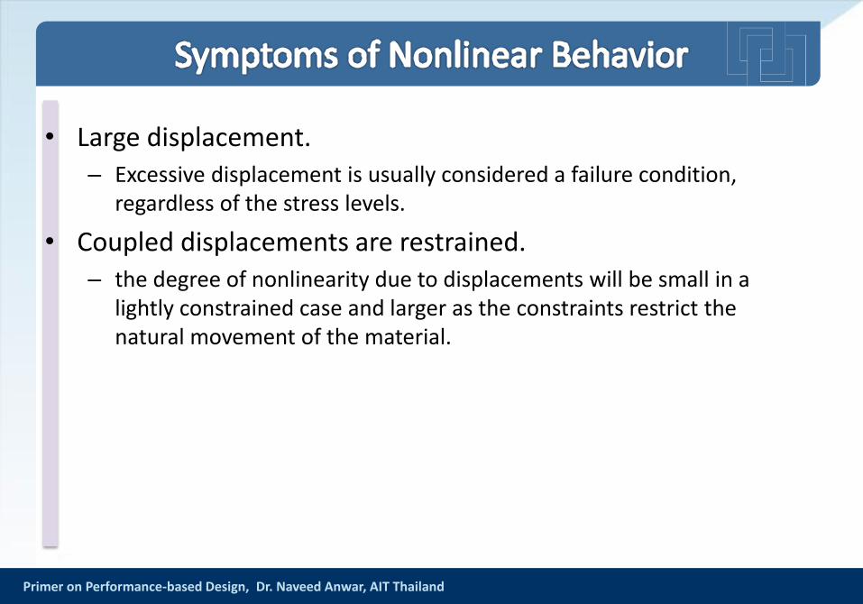
• Large displacement.– Excessive displacement is usually considered a failure condition,
regardless of the stress levels.
• Coupled displacements are restrained.– the degree of nonlinearity due to displacements will be small in a
lightly constrained case and larger as the constraints restrict the natural movement of the material.
Primer on Performance-based Design, Dr. Naveed Anwar, AIT Thailand
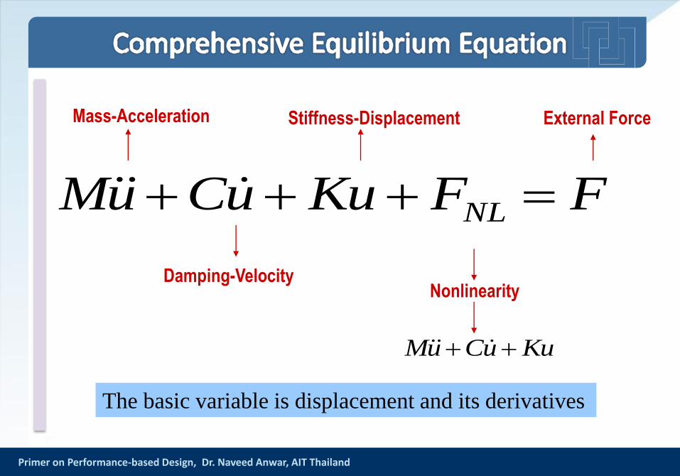
FFKuuCuM NL
Damping-Velocity
Mass-Acceleration Stiffness-Displacement
Nonlinearity
External Force
KuuCuM
The basic variable is displacement and its derivatives
Primer on Performance-based Design, Dr. Naveed Anwar, AIT Thailand
Deformation
Fo
rce
Curvature
Mo
me
nt
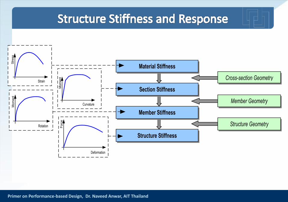
Section Stiffness
Member Stiffness
Structure Stiffness
Material Stiffness
Structure Geometry
Member Geometry
Cross-section Geometry
Rotation
Mo
me
nt
Strain
Str
ess
Primer on Performance-based Design, Dr. Naveed Anwar, AIT Thailand 9
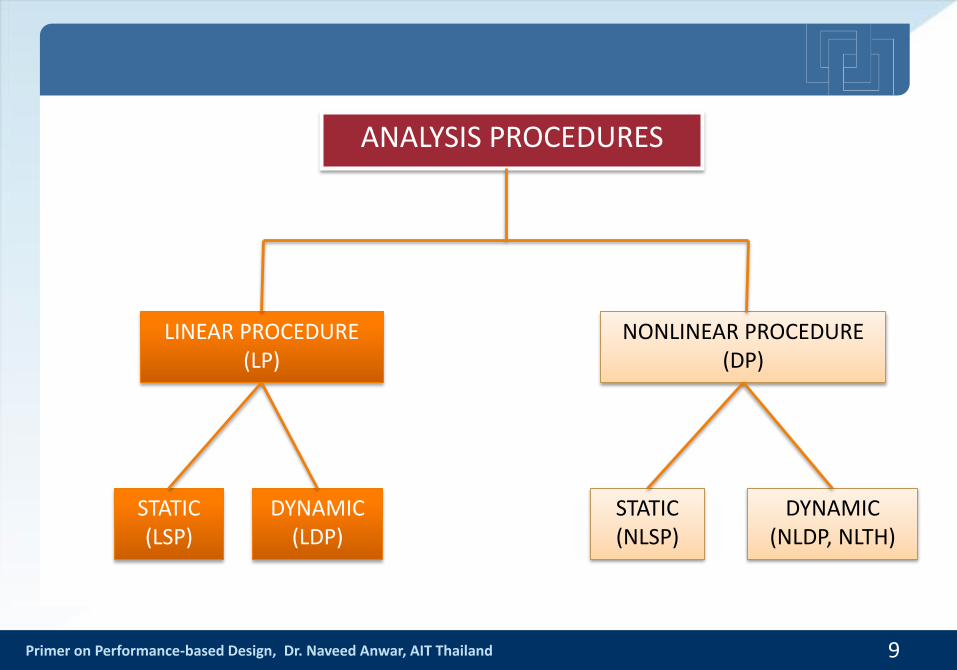
ANALYSIS PROCEDURES
NONLINEAR PROCEDURE(DP)
LINEAR PROCEDURE (LP)
STATIC(LSP)
DYNAMIC(LDP)
STATIC(NLSP)
DYNAMIC(NLDP, NLTH)

Primer on Performance-based Design, Dr. Naveed Anwar, AIT Thailand
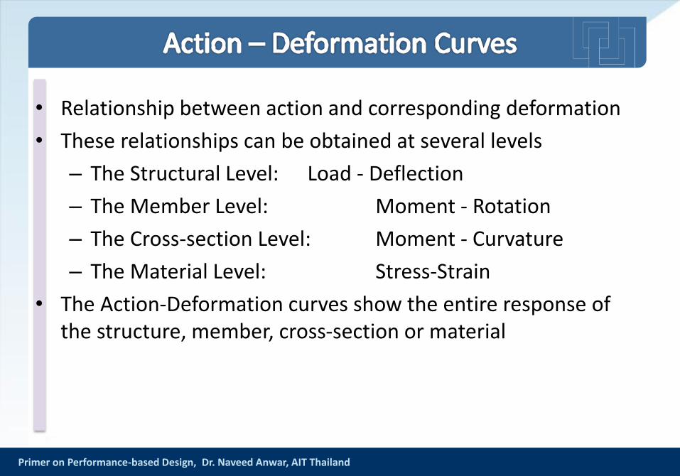
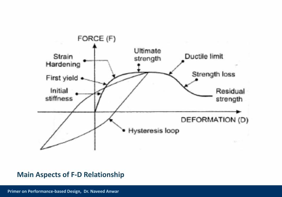
• Relationship between action and corresponding deformation
• These relationships can be obtained at several levels
– The Structural Level: Load - Deflection
– The Member Level: Moment - Rotation
– The Cross-section Level: Moment - Curvature
– The Material Level: Stress-Strain
• The Action-Deformation curves show the entire response of the structure, member, cross-section or material
Primer on Performance-based Design, Dr. Naveed Anwar, AIT Thailand
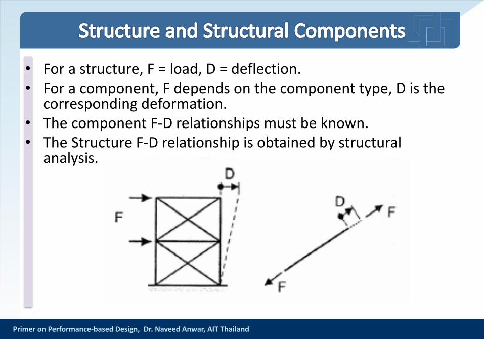
• For a structure, F = load, D = deflection.• For a component, F depends on the component type, D is the
corresponding deformation.• The component F-D relationships must be known.• The Structure F-D relationship is obtained by structural
analysis.
Primer on Performance-based Design, Dr. Naveed Anwar, AIT Thailand
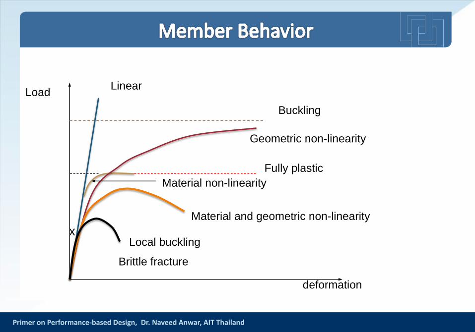
x
Brittle fracture
Local buckling
Material and geometric non-linearity
Material non-linearity
Fully plastic
Geometric non-linearity
Buckling
deformation
LoadLinear
Primer on Performance-based Design, Dr. Naveed Anwar, AIT Thailand
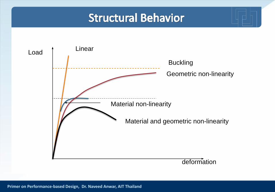
Material and geometric non-linearity
Material non-linearity
Geometric non-linearity
Buckling
deformation
LoadLinear
Primer on Performance-based Design, Dr. Naveed Anwar
Main Aspects of F-D Relationship
Primer on Performance-based Design, Dr. Naveed Anwar
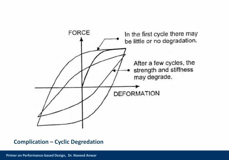
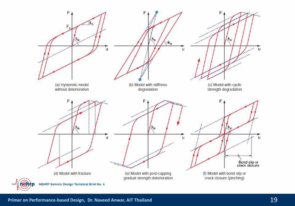
Complication – Cyclic Degredation
Primer on Performance-based Design, Dr. Naveed Anwar
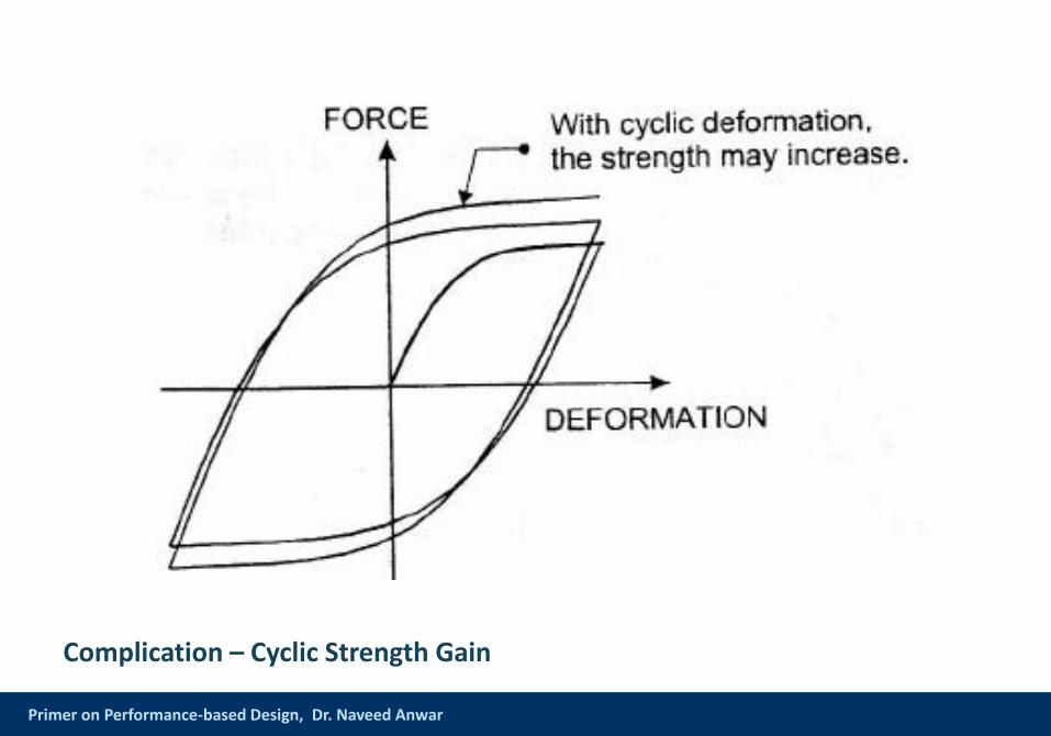
Complication – Cyclic Strength Gain
Primer on Performance-based Design, Dr. Naveed Anwar
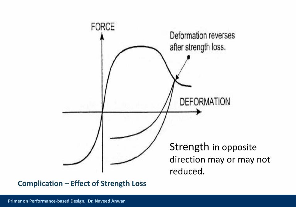
Complication – Effect of Strength Loss
Strength in opposite direction may or may not reduced.
Primer on Performance-based Design, Dr. Naveed Anwar, AIT Thailand 19
Primer on Performance-based Design, Dr. Naveed Anwar, AIT Thailand 20
Primer on Performance-based Design, Dr. Naveed Anwar, AIT Thailand 21
Primer on Performance-based Design, Dr. Naveed Anwar, AIT Thailand
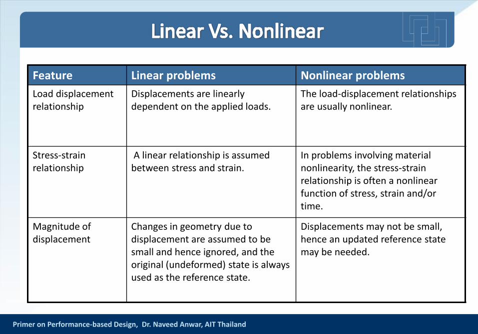
Feature Linear problems Nonlinear problems
Load displacement relationship
Displacements are linearly dependent on the applied loads.
The load-displacement relationships are usually nonlinear.
Stress-strain relationship
A linear relationship is assumed between stress and strain.
In problems involving material nonlinearity, the stress-strain relationship is often a nonlinear function of stress, strain and/or time.
Magnitude of displacement
Changes in geometry due to displacement are assumed to be small and hence ignored, and the original (undeformed) state is always used as the reference state.
Displacements may not be small, hence an updated reference state may be needed.
Primer on Performance-based Design, Dr. Naveed Anwar, AIT Thailand
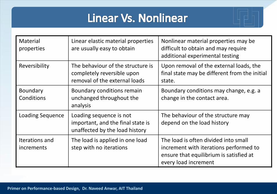
Material properties
Linear elastic material properties are usually easy to obtain
Nonlinear material properties may be difficult to obtain and may require additional experimental testing
Reversibility The behaviour of the structure is completely reversible upon removal of the external loads
Upon removal of the external loads, the final state may be different from the initial state.
Boundary Conditions
Boundary conditions remain unchanged throughout the analysis
Boundary conditions may change, e.g. a change in the contact area.
Loading Sequence Loading sequence is not important, and the final state is unaffected by the load history
The behaviour of the structure may depend on the load history
Iterations and increments
The load is applied in one load step with no iterations
The load is often divided into small increment with iterations performed to ensure that equilibrium is satisfied at every load increment
Primer on Performance-based Design, Dr. Naveed Anwar, AIT Thailand
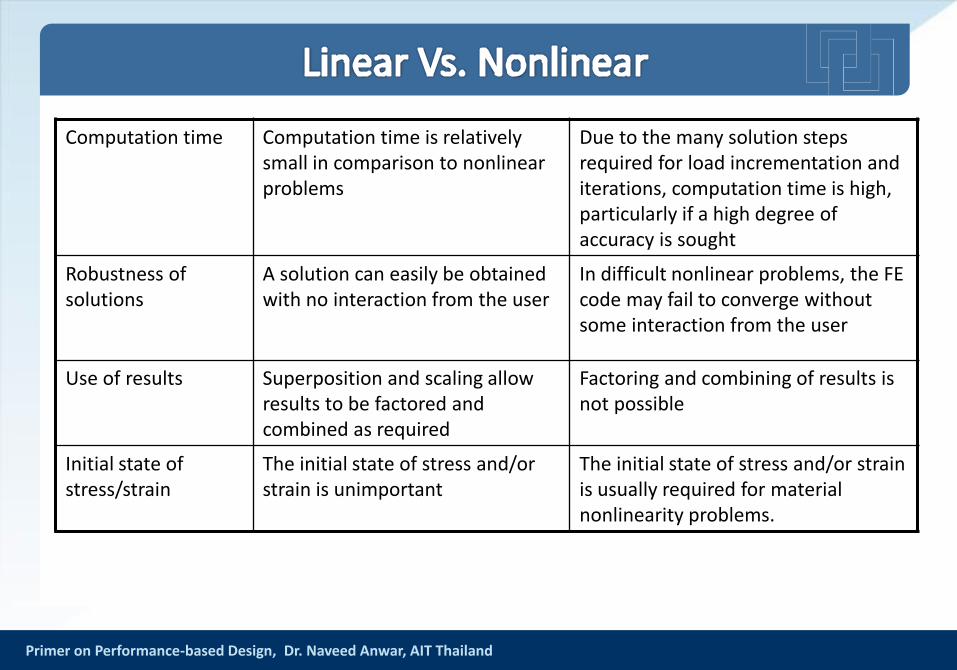
Computation time Computation time is relatively small in comparison to nonlinear problems
Due to the many solution steps required for load incrementation and iterations, computation time is high, particularly if a high degree of accuracy is sought
Robustness of solutions
A solution can easily be obtained with no interaction from the user
In difficult nonlinear problems, the FE code may fail to converge without some interaction from the user
Use of results Superposition and scaling allow results to be factored and combined as required
Factoring and combining of results is not possible
Initial state of stress/strain
The initial state of stress and/or strain is unimportant
The initial state of stress and/or strain is usually required for material nonlinearity problems.
Primer on Performance-based Design, Dr. Naveed Anwar, AIT Thailand
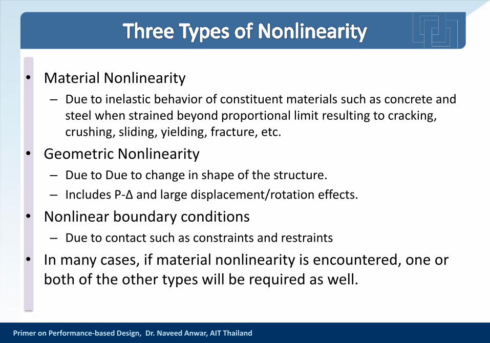
• Material Nonlinearity– Due to inelastic behavior of constituent materials such as concrete and
steel when strained beyond proportional limit resulting to cracking, crushing, sliding, yielding, fracture, etc.
• Geometric Nonlinearity – Due to Due to change in shape of the structure.
– Includes P-Δ and large displacement/rotation effects.
• Nonlinear boundary conditions– Due to contact such as constraints and restraints
• In many cases, if material nonlinearity is encountered, one or both of the other types will be required as well.
Primer on Performance-based Design, Dr. Naveed Anwar, AIT Thailand
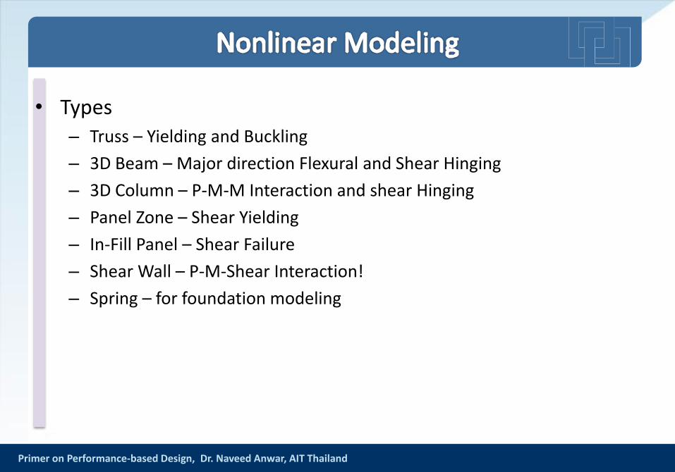
• Types– Truss – Yielding and Buckling
– 3D Beam – Major direction Flexural and Shear Hinging
– 3D Column – P-M-M Interaction and shear Hinging
– Panel Zone – Shear Yielding
– In-Fill Panel – Shear Failure
– Shear Wall – P-M-Shear Interaction!
– Spring – for foundation modeling
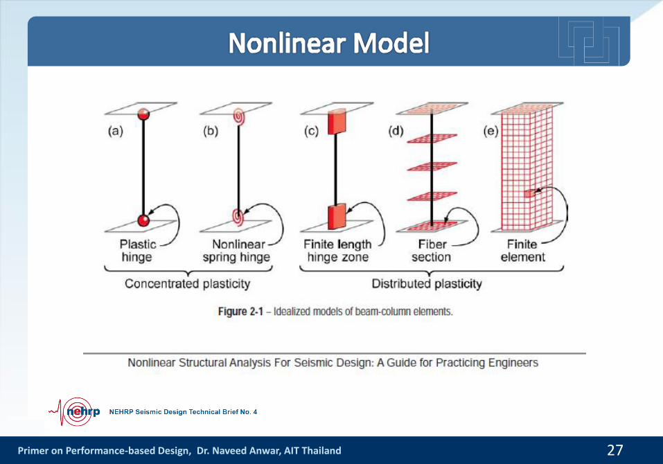
Primer on Performance-based Design, Dr. Naveed Anwar, AIT Thailand 27
Primer on Performance-based Design, Dr. Naveed Anwar, AIT Thailand 28
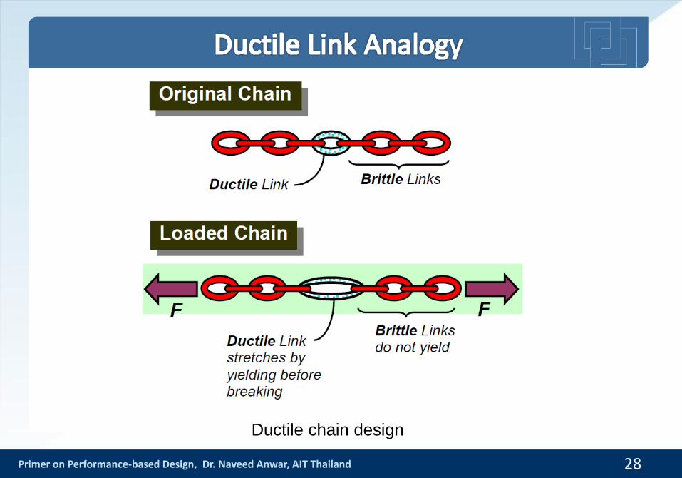
Ductile chain design
Primer on Performance-based Design, Dr. Naveed Anwar, AIT Thailand
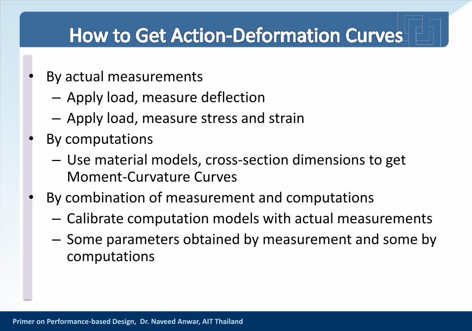
• By actual measurements
– Apply load, measure deflection
– Apply load, measure stress and strain
• By computations
– Use material models, cross-section dimensions to get Moment-Curvature Curves
• By combination of measurement and computations
– Calibrate computation models with actual measurements
– Some parameters obtained by measurement and some by computations

Primer on Performance-based Design, Dr. Naveed Anwar, AIT Thailand
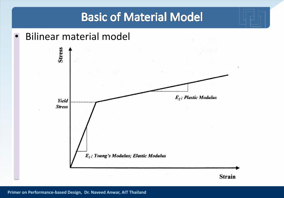
• Bilinear material model
Primer on Performance-based Design, Dr. Naveed Anwar, AIT Thailand 32
Primer on Performance-based Design, Dr. Naveed Anwar, AIT Thailand
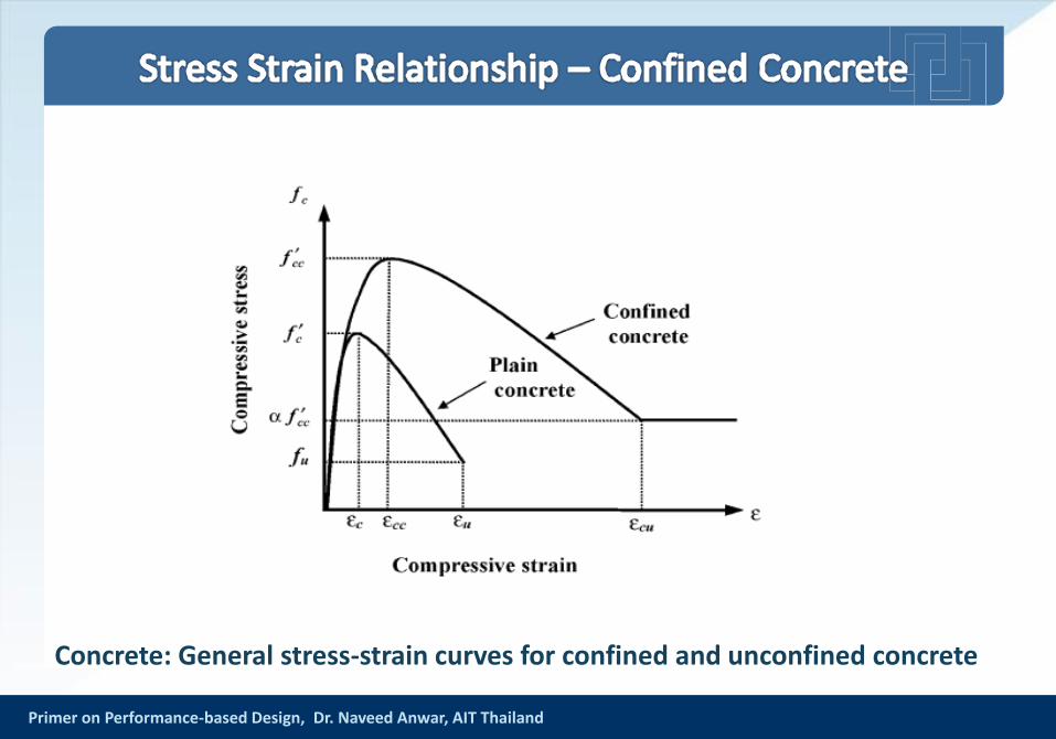
Concrete: General stress-strain curves for confined and unconfined concrete
Primer on Performance-based Design, Dr. Naveed Anwar, AIT Thailand
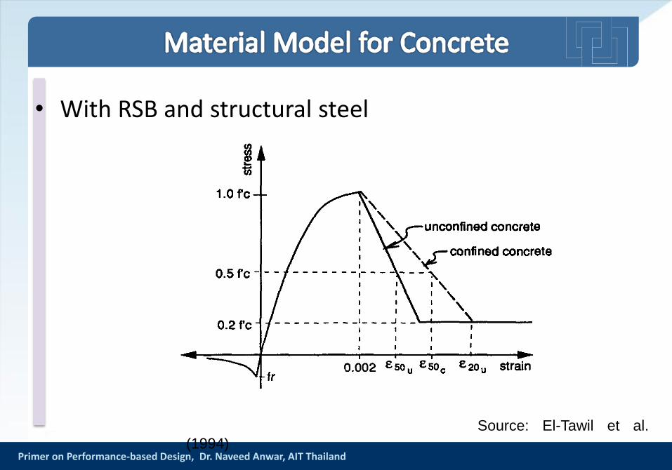
• With RSB and structural steel
Source: El-Tawil et al.
(1994)
Primer on Performance-based Design, Dr. Naveed Anwar, AIT Thailand
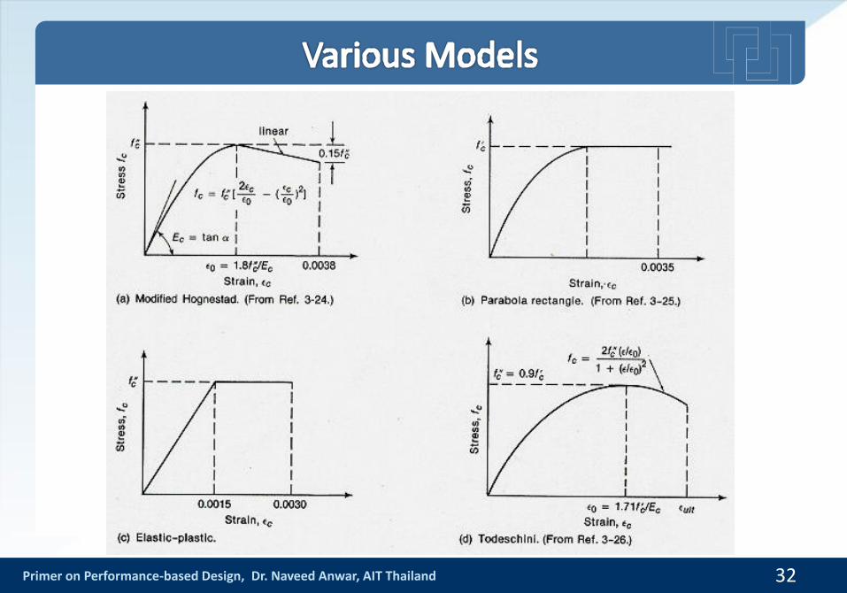
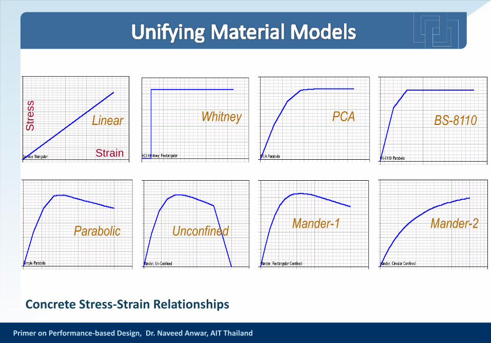
Concrete Stress-Strain Relationships
Strain
Str
ess
Linear Whitney PCA BS-8110
Parabolic UnconfinedMander-1 Mander-2
Primer on Performance-based Design, Dr. Naveed Anwar, AIT Thailand
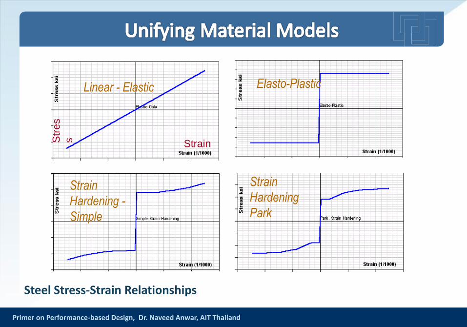
Steel Stress-Strain Relationships
StrainStr
es
s
Linear - Elastic Elasto-Plastic
Strain
Hardening -
Simple
Strain
Hardening
Park
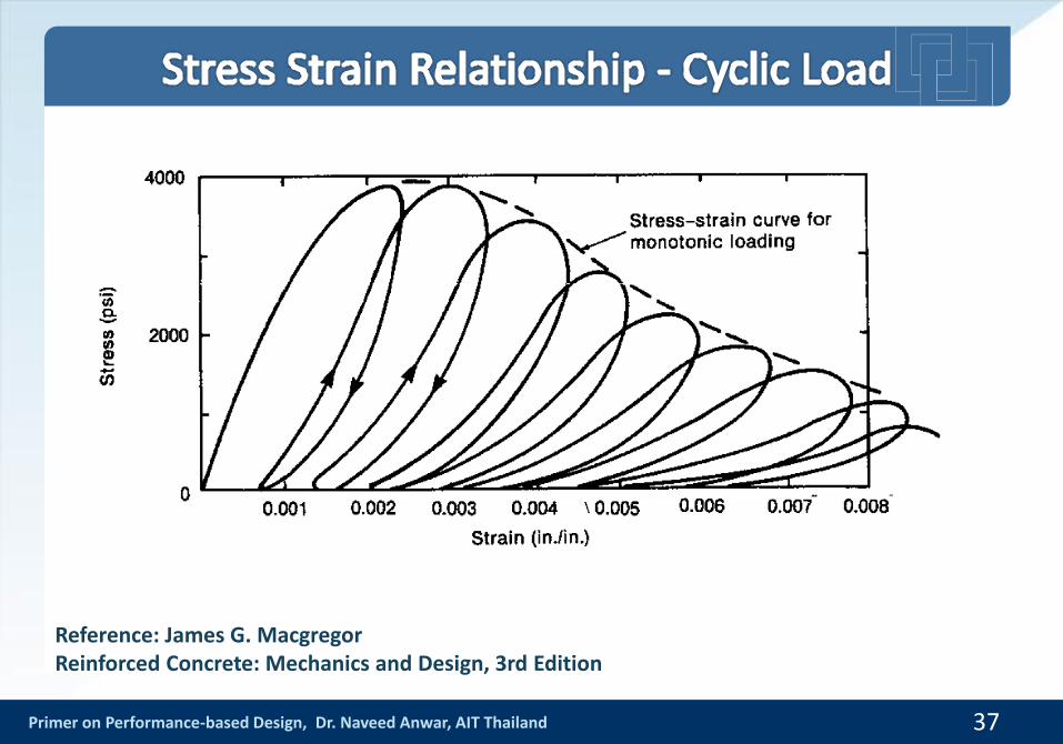
Primer on Performance-based Design, Dr. Naveed Anwar, AIT Thailand 37
Reference: James G. MacgregorReinforced Concrete: Mechanics and Design, 3rd Edition
Primer on Performance-based Design, Dr. Naveed Anwar, AIT Thailand
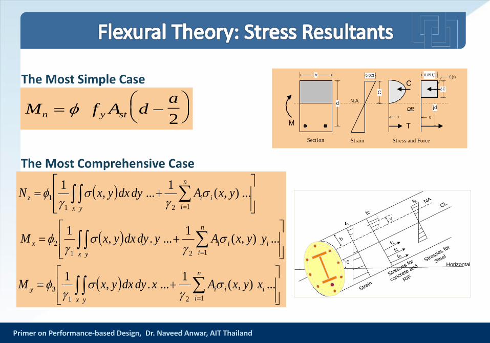
The Most Comprehensive Case
The Most Simple Case
M f A da
n y st
2
0.003 fc()
C
Strain Stress and Force
N.A.
OR
0
C
0
0.85 fc'
jd
C
T
b
d
Section
M
...),(1
....,1
...),(1
....,1
...),(1
...,1
121
3
121
2
121
1
i
n
i
ii
x y
y
i
n
i
ii
x y
x
x y
n
i
iiz
xyxAxdydxyxM
yyxAydydxyxM
yxAdydxyxN
y
h
c
fc
Strain
Stresses fo
r
concrete and
R/F
Stresses fo
r
Steel
f1
f2
fn
fs NACL
Horizontal
Primer on Performance-based Design, Dr. Naveed Anwar, AIT Thailand
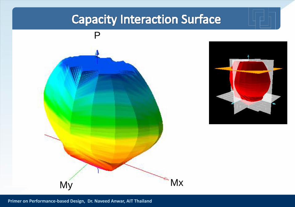
MxMy
P
Primer on Performance-based Design, Dr. Naveed Anwar, AIT Thailand
Primer on Performance-based Design, Dr. Naveed Anwar, AIT Thailand
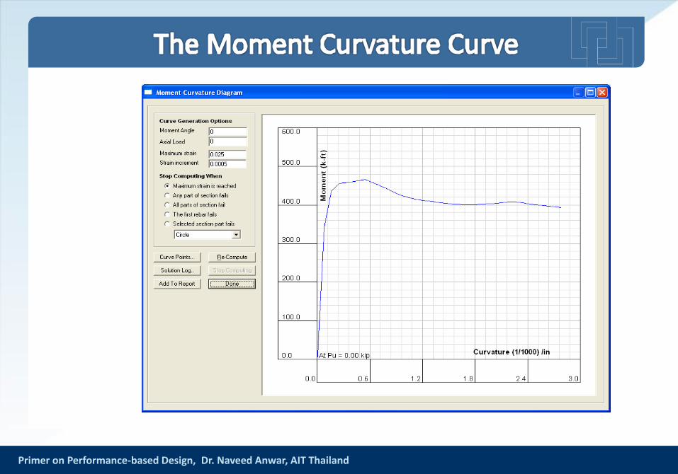
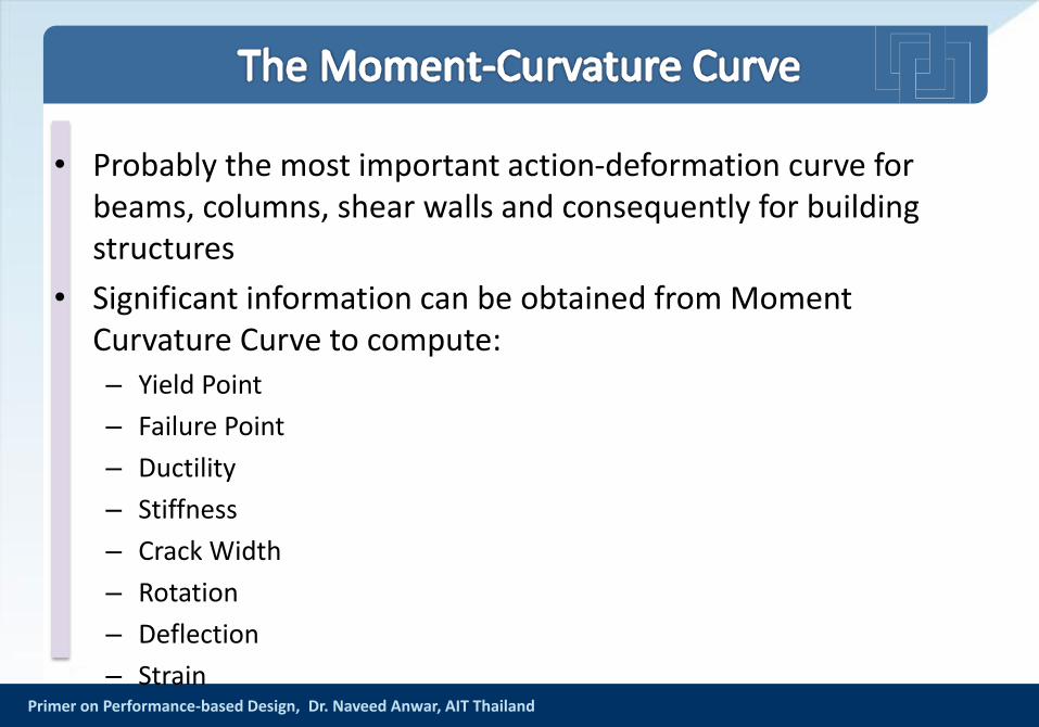
• Probably the most important action-deformation curve for beams, columns, shear walls and consequently for building structures
• Significant information can be obtained from Moment Curvature Curve to compute:– Yield Point
– Failure Point
– Ductility
– Stiffness
– Crack Width
– Rotation
– Deflection
– Strain
Primer on Performance-based Design, Dr. Naveed Anwar
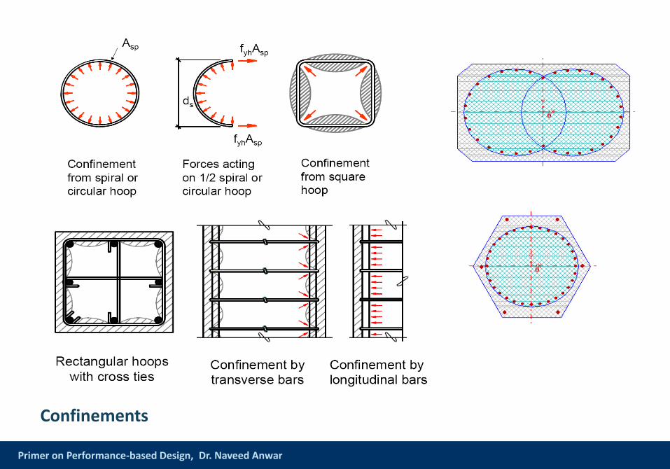
Confinements
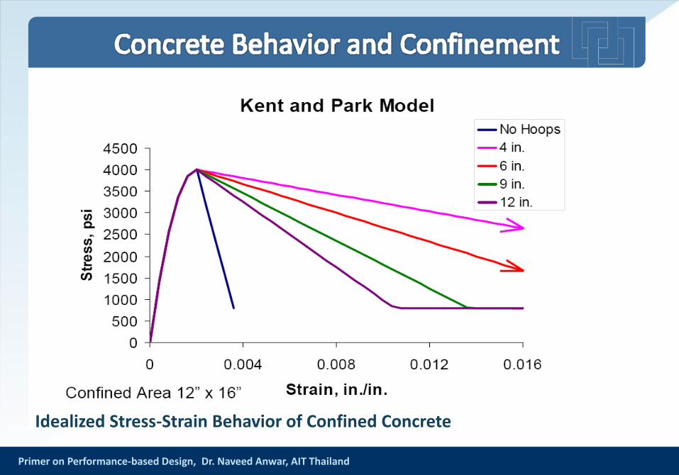
Primer on Performance-based Design, Dr. Naveed Anwar, AIT Thailand
Idealized Stress-Strain Behavior of Confined Concrete
Primer on Performance-based Design, Dr. Naveed Anwar, AIT Thailand
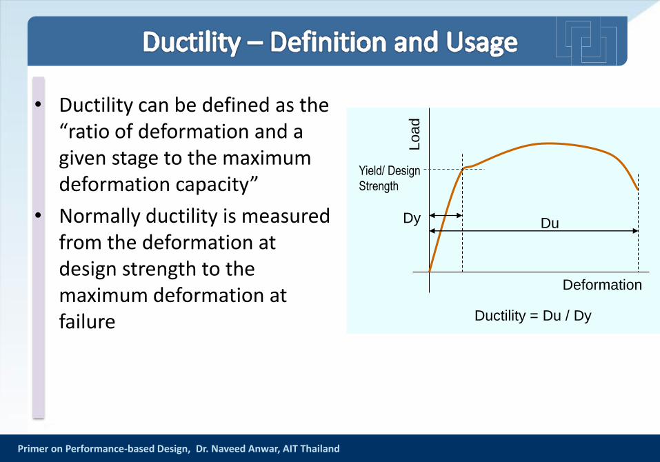
• Ductility can be defined as the “ratio of deformation and a given stage to the maximum deformation capacity”
• Normally ductility is measured from the deformation at design strength to the maximum deformation at failure
Yield/ Design
Strength
Lo
ad
Deformation
Dy Du
Ductility = Du / Dy
Primer on Performance-based Design, Dr. Naveed Anwar, AIT Thailand
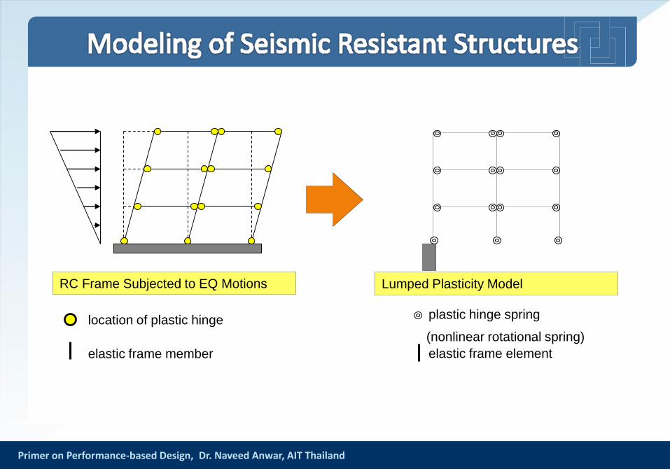
RC Frame Subjected to EQ Motions Lumped Plasticity Model
location of plastic hinge
elastic frame member
plastic hinge spring
(nonlinear rotational spring)
elastic frame element
Primer on Performance-based Design, Dr. Naveed Anwar, AIT Thailand
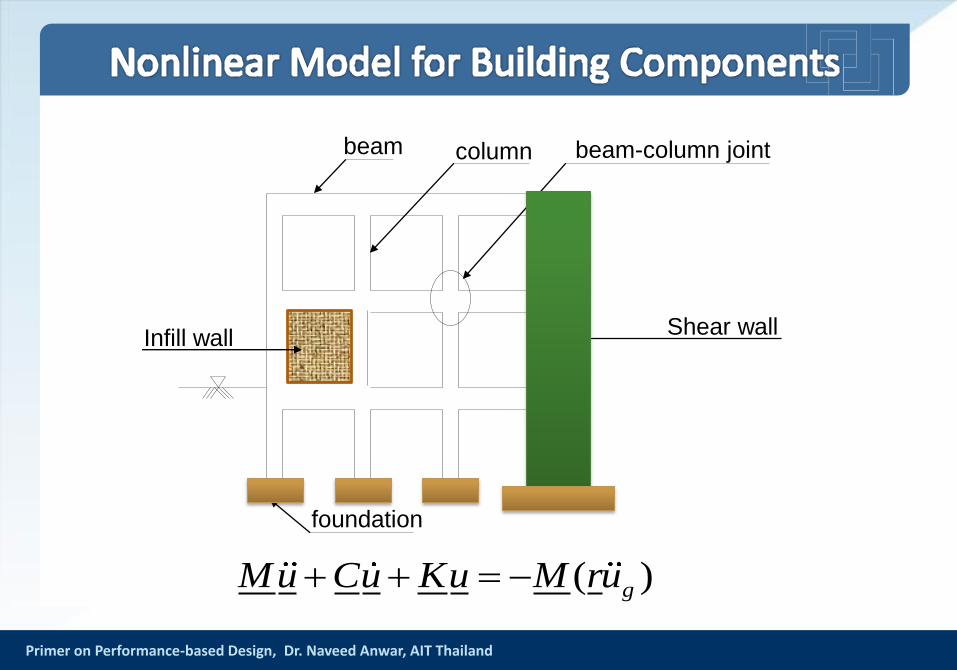
( )gMu Cu Ku M ru
beam column
Infill wall
foundation
beam-column joint
Shear wall
Primer on Performance-based Design, Dr. Naveed Anwar, AIT Thailand
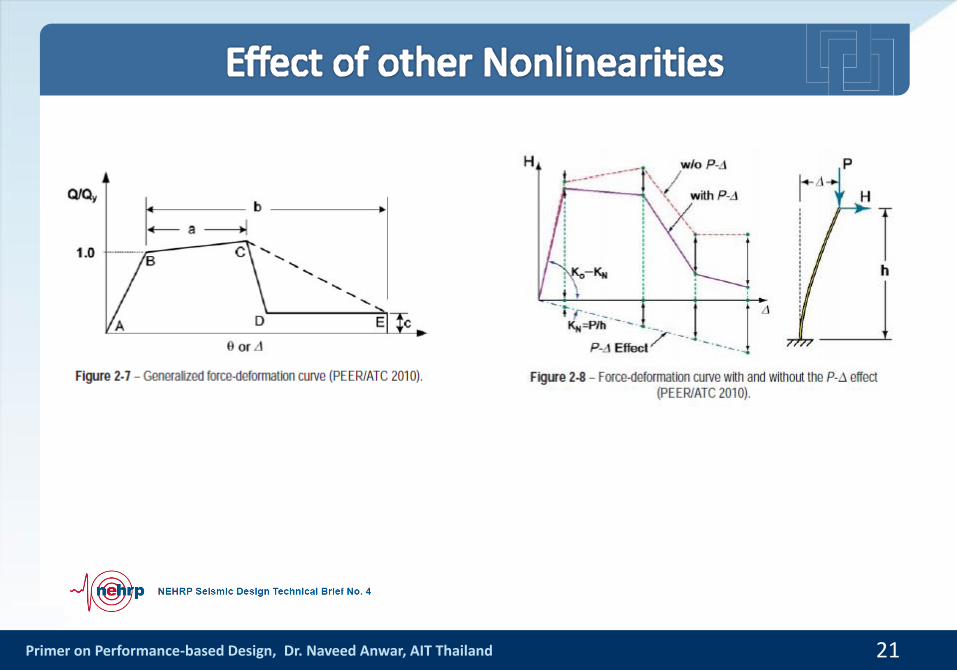
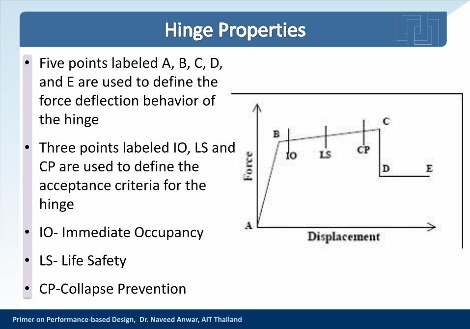
• Five points labeled A, B, C, D, and E are used to define the force deflection behavior of the hinge
• Three points labeled IO, LS and CP are used to define the acceptance criteria for the hinge
• IO- Immediate Occupancy
• LS- Life Safety
• CP-Collapse Prevention

Primer on Performance-based Design, Dr. Naveed Anwar, AIT Thailand
• Point A is always the origin
• Point B represents yielding. No deformation occurs in the hinge up to point B, regardless of the deformation value specified for point B. The displacement (rotation) at point B will be subtracted from the deformations at points C, D, and E. Only the plastic deformation beyond point B will be exhibited by the hinge
• Point C represents the ultimate capacity for Pushover analysis
• Point D represents a residual strength for Pushover analysis
• Point E represents total failure. Beyond point E the hinge will drop load down to point F (not shown) directly below point E on the horizontal axis. To prevent this failure in the hinge, specify a large value for the deformation at point E
Primer on Performance-based Design, Dr. Naveed Anwar, AIT Thailand
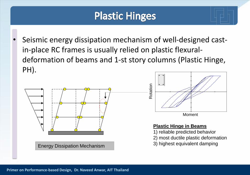
• Seismic energy dissipation mechanism of well-designed cast-in-place RC frames is usually relied on plastic flexural-deformation of beams and 1-st story columns (Plastic Hinge, PH).
Energy Dissipation Mechanism
Plastic Hinge in Beams
1) reliable predicted behavior
2) most ductile plastic deformation
3) highest equivalent damping
Moment
Rota
tio
n
Primer on Performance-based Design, Dr. Naveed Anwar, AIT Thailand
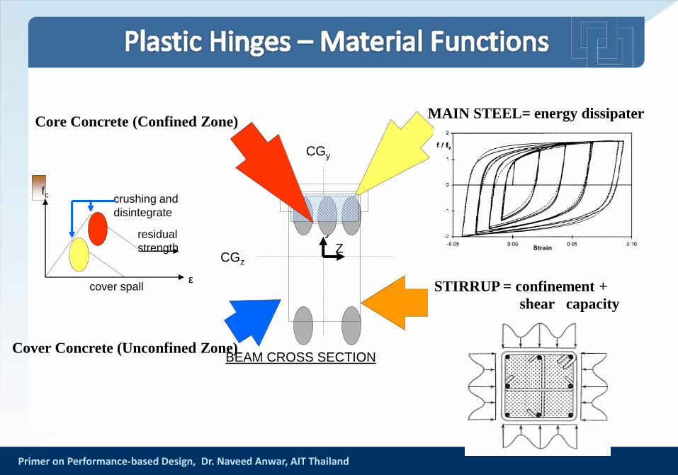
CGz
CGy
Z
y
BEAM CROSS SECTION
MAIN STEEL= energy dissipaterCore Concrete (Confined Zone)
Cover Concrete (Unconfined Zone)
cover spall
crushing and
disintegrate
ε
fc
residual
strength
STIRRUP = confinement +
shear capacity
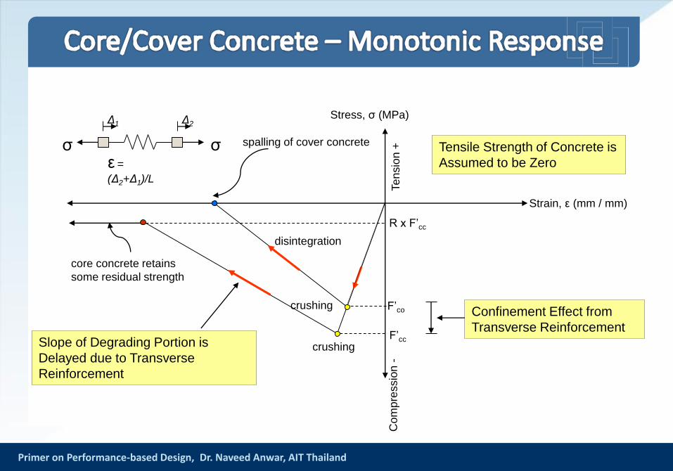
Primer on Performance-based Design, Dr. Naveed Anwar, AIT Thailand
Stress, σ (MPa)
Te
nsio
n +
Co
mp
ressio
n -
crushing
Strain, ε (mm / mm)
spalling of cover concrete
core concrete retains
some residual strength
F’cc
R x F’cc
Tensile Strength of Concrete is
Assumed to be Zero
F’co Confinement Effect from
Transverse ReinforcementSlope of Degrading Portion is
Delayed due to Transverse
Reinforcement
σσ
Δ1 Δ2
ε =
(Δ2+Δ1)/L
disintegration
crushing
Primer on Performance-based Design, Dr. Naveed Anwar, AIT Thailand
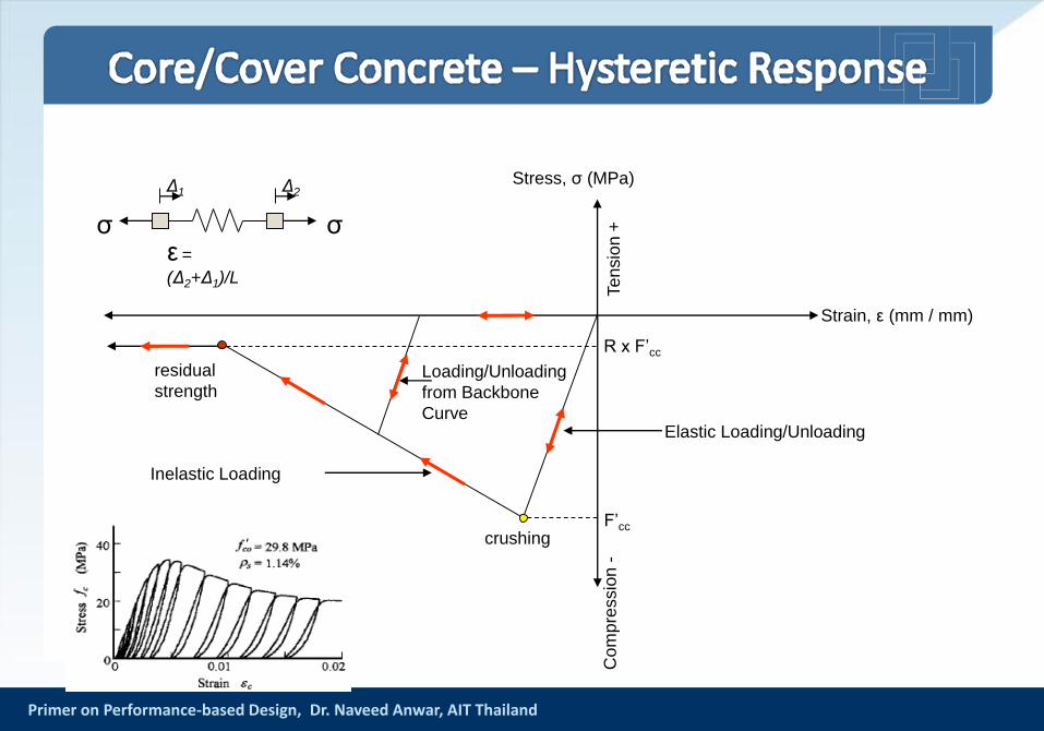
Stress, σ (MPa)
Te
nsio
n +
Co
mp
ressio
n -
crushing
Strain, ε (mm / mm)
F’cc
R x F’cc
σσ
Δ1 Δ2
ε =
(Δ2+Δ1)/L
residual
strength
Elastic Loading/Unloading
Inelastic Loading
Loading/Unloading
from Backbone
Curve
Primer on Performance-based Design, Dr. Naveed Anwar, AIT Thailand
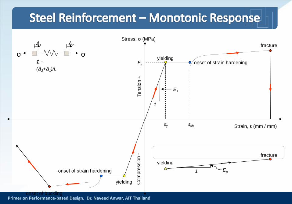
Te
nsio
n +
Co
mp
ressio
n -
yielding
Stress, σ (MPa)
Strain, ε (mm / mm)
σσ
Δ1 Δ2
ε =
(Δ2+Δ1)/L
εsh
onset of strain hardening
Ep1
fracture
yielding
onset of strain hardening
fracture
onset of buckling
Fy
1
Es
εy
yielding
Primer on Performance-based Design, Dr. Naveed Anwar, AIT Thailand
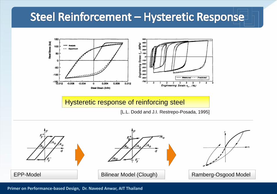
Hysteretic response of reinforcing steel
[L.L. Dodd and J.I. Restrepo-Posada, 1995]
EPP-Model Bilinear Model (Clough) Ramberg-Osgood Model
Primer on Performance-based Design, Dr. Naveed Anwar, AIT Thailand
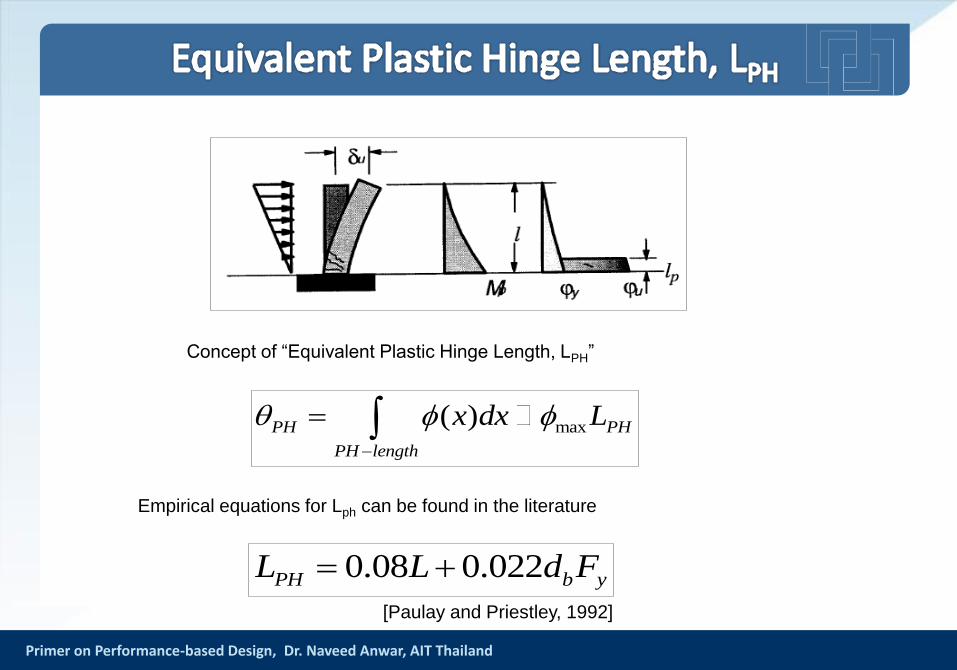
max( )PH PH
PH length
x dx L
Empirical equations for Lph can be found in the literature
Concept of “Equivalent Plastic Hinge Length, LPH”
0.08 0.022PH b yL L d F
[Paulay and Priestley, 1992]
Primer on Performance-based Design, Dr. Naveed Anwar, AIT Thailand
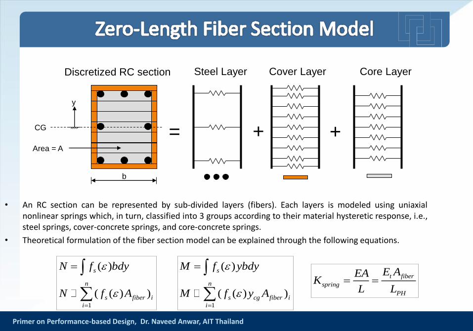
• An RC section can be represented by sub-divided layers (fibers). Each layers is modeled using uniaxialnonlinear springs which, in turn, classified into 3 groups according to their material hysteretic response, i.e.,steel springs, cover-concrete springs, and core-concrete springs.
• Theoretical formulation of the fiber section model can be explained through the following equations.
Discretized RC section Steel Layer Cover Layer Core Layer
+ +=
1
( )
( ( ) )
s
n
s cg fiber i
i
M f ybdy
M f y A
1
( )
( ( ) )
s
n
s fiber i
i
N f bdy
N f A
b
CG
y
Area = A
t fiber
spring
PH
E AEAK
L L
Primer on Performance-based Design, Dr. Naveed Anwar, AIT Thailand
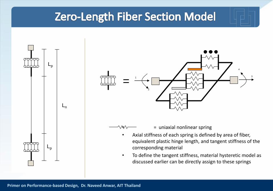
• = uniaxial nonlinear spring
• Axial stiffness of each spring is defined by area of fiber, equivalent plastic hinge length, and tangent stiffness of the corresponding material
• To define the tangent stiffness, material hysteretic model as discussed earlier can be directly assign to these springs
1
2
3
4
=
Lp
Lp
Ln
Primer on Performance-based Design, Dr. Naveed Anwar, AIT Thailand
-600
-400
-200
0
200
400
600
-0.012 -0.008 -0.004 0 0.004 0.008 0.012
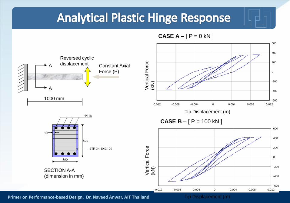
1000 mm
Reversed cyclic
displacementA
A
Constant Axial
Force (P)
SECTION A-A
(dimension in mm)
Tip Displacement (m)
-600
-400
-200
0
200
400
600
-0.012 -0.008 -0.004 0 0.004 0.008 0.012
Ve
rtic
al F
orc
e
(kN
)
Tip Displacement (m)
CASE A – [ P = 0 kN ]
CASE B – [ P = 100 kN ]
Ve
rtic
al F
orc
e
(kN
)
Primer on Performance-based Design, Dr. Naveed Anwar, AIT Thailand
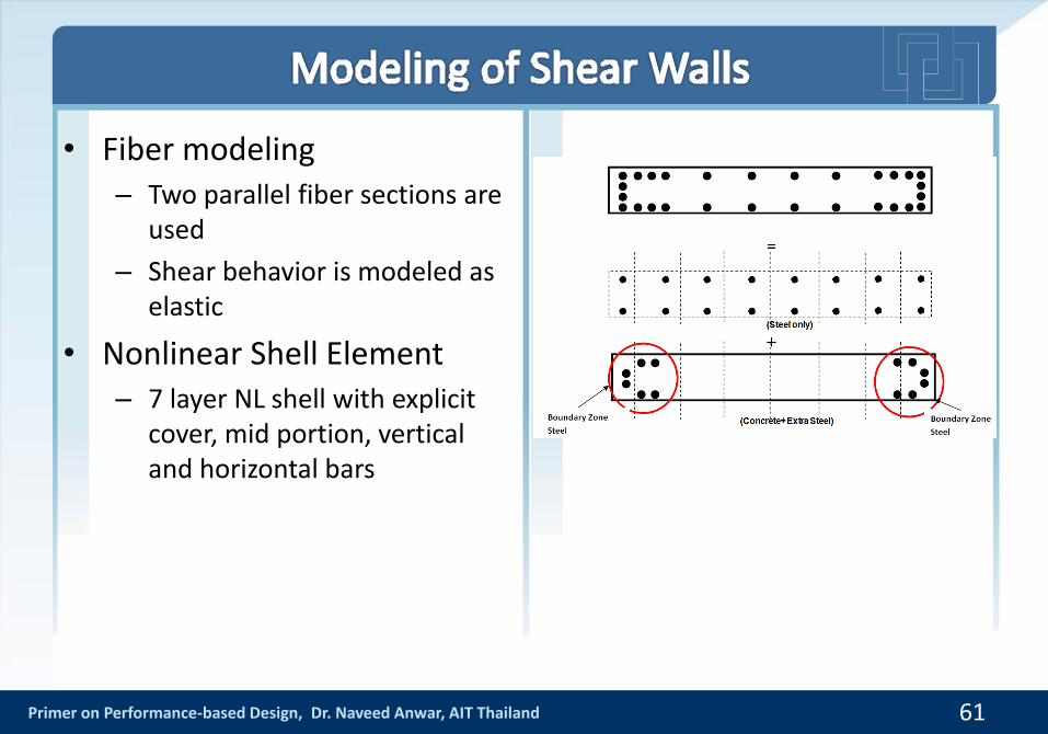
• Fiber modeling– Two parallel fiber sections are
used
– Shear behavior is modeled as elastic
• Nonlinear Shell Element– 7 layer NL shell with explicit
cover, mid portion, vertical and horizontal bars
61
Primer on Performance-based Design, Dr. Naveed Anwar, AIT Thailand
• Masonry infill walls are typically used in reinforced concrete buildings and are considered by engineers as nonstructural components
• Even if they are relatively weak when compared with structural components, they can drastically alter the response of structure.
• The presence of masonry infill walls can modify lateral stiffness, strength, and ductility of structure
Primer on Performance-based Design, Dr. Naveed Anwar, AIT Thailand
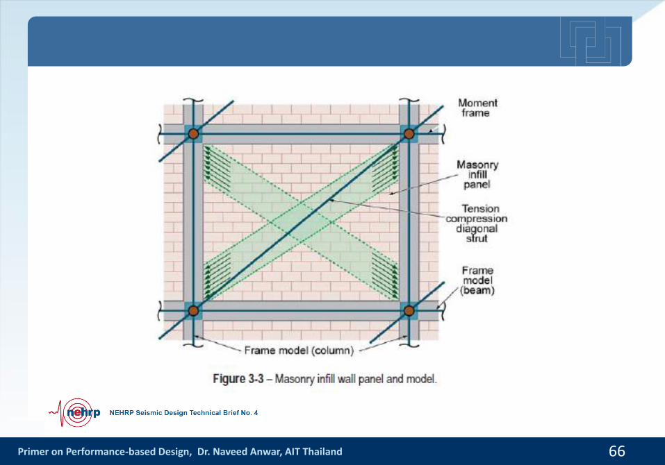
• At low level of in-plane lateral force, the frame and infill panel will act in a fully composite fashion, as a structural wall with boundary elements
• When lateral deformations increase, frame attempts to deform in a flexural mode. But, infill panel attempts to deform in a shear mode.
• These lead to separation between frame and panel at the corners on the tension diagonal, and the development of a diagonal compression strut on the compression diagonal.
Primer on Performance-based Design, Dr. Naveed Anwar, AIT Thailand
Primer on Performance-based Design, Dr. Naveed Anwar, AIT Thailand
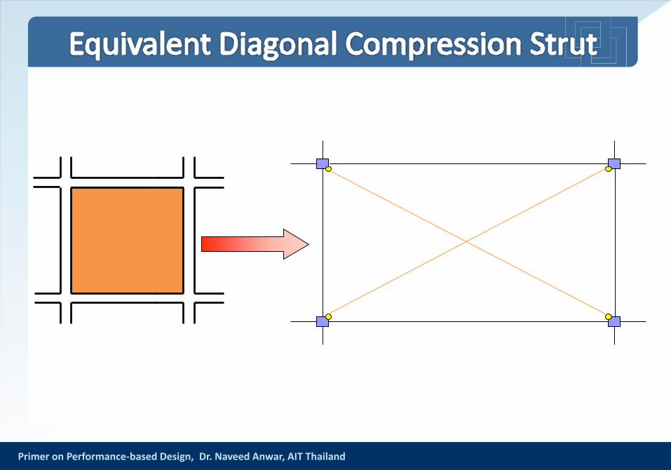
• Masonry infill walls are modeled using equivalent strut concept based on recommendations of FEMA-273 (1997)
• Based on this concept, the stiffness contribution of infill wall is represented by an equivalent diagonal compression strut
Primer on Performance-based Design, Dr. Naveed Anwar, AIT Thailand 66
Primer on Performance-based Design, Dr. Naveed Anwar, AIT Thailand
Primer on Performance-based Design, Dr. Naveed Anwar, AIT Thailand
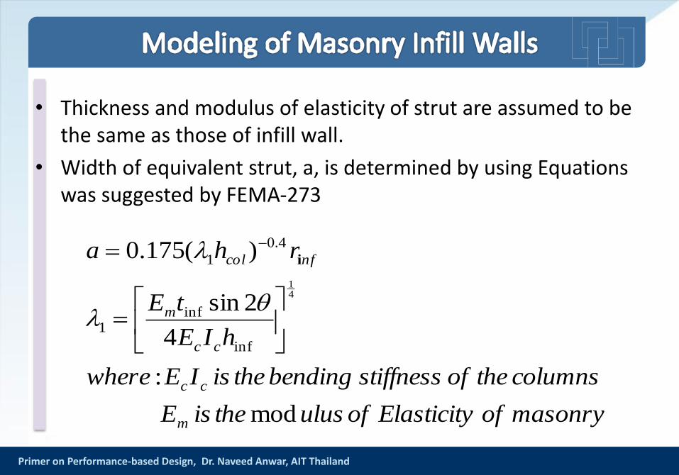
• Thickness and modulus of elasticity of strut are assumed to be the same as those of infill wall.
• Width of equivalent strut, a, is determined by using Equations was suggested by FEMA-273
masonryofElasticityofulustheisE
columnstheofstiffnessbendingtheisIEwhere
hIE
tE
rha
m
cc
cc
m
nfcol
mod
:
4
2sin
)(175.0
41
inf
inf1
4.0
1
i
Primer on Performance-based Design, Dr. Naveed Anwar, AIT Thailand
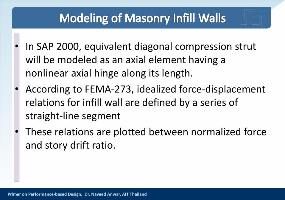
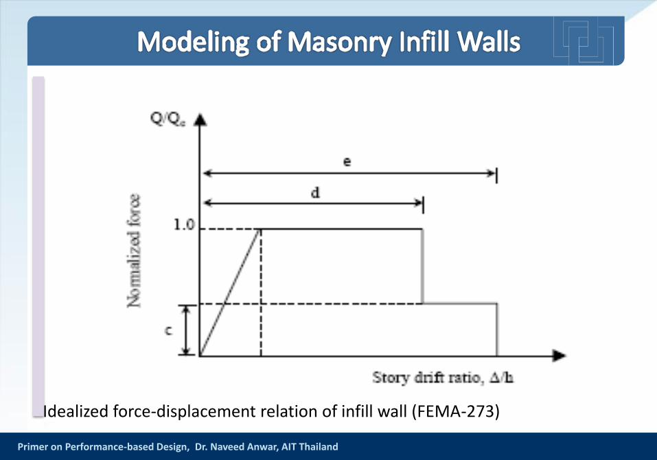
• In SAP 2000, equivalent diagonal compression strut will be modeled as an axial element having a nonlinear axial hinge along its length.
• According to FEMA-273, idealized force-displacement relations for infill wall are defined by a series of straight-line segment
• These relations are plotted between normalized force and story drift ratio.
Primer on Performance-based Design, Dr. Naveed Anwar, AIT Thailand
Idealized force-displacement relation of infill wall (FEMA-273)
Primer on Performance-based Design, Dr. Naveed Anwar, AIT Thailand
• Second order analysis combines two effects to reach a solution:-– Large displacement theory; the resulting forces and moments take full
account of the effects due to the deformed shape of both the structure and its members.
– “Stress stiffening”; the effect of element axial loads on structure stiffness, tensile loads stiffening an element and compressive loads softening an element.
Primer on Performance-based Design, Dr. Naveed Anwar, AIT Thailand
• P-Delta is a non-linear (second order) effect that occurs in every structure where elements are subject to axial load. It is a genuine “effect” that is associated with the magnitude of the applied axial load (P) and a displacement (delta).
• The magnitude of the P-delta effect is related to the:-– Magnitude of axial load P
– Stiffness/slenderness of the structure as a whole.
– Slenderness of individual elements
Primer on Performance-based Design, Dr. Naveed Anwar, AIT Thailand
Primer on Performance-based Design, Dr. Naveed Anwar, AIT Thailand
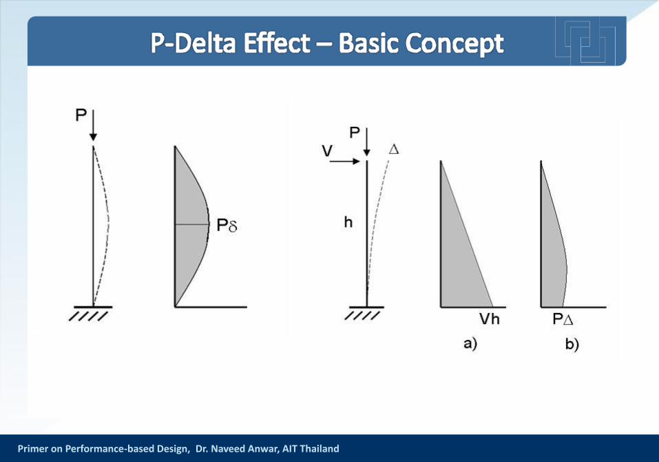
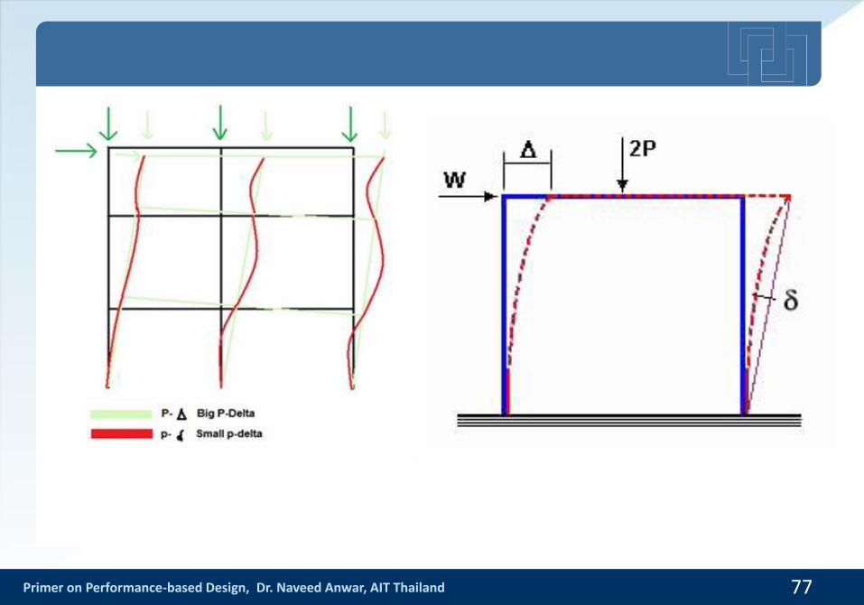
• When P-Delta results are presented, two effects are incorporated into the results,– P-big-Delta (P-Δ), and
– P-little-delta (P-δ).
• The P-Δ effect applies to members only and involves a modified bending moment acting along the length of the member. The columns experiences not only an axial loads (1st order) but also a moment equal to the vertical force, P, multiplied by the displacement, Δ.
• The P- δ effect is generally less important and results from the bent shape of a member that is carrying an axial force.
Primer on Performance-based Design, Dr. Naveed Anwar, AIT Thailand
• Most people understand P-Delta as -– Frame deflects; Delta,
– Load P is then eccentric to the base, this introduces further moments or ‘second order effects’
• However, this only illustrates the P-“BIG” delta effect (P-Δ) which is only part of the second order effect.
• P Delta effect occurs at both an overall structural level and an element level.
Primer on Performance-based Design, Dr. Naveed Anwar, AIT Thailand 77
Primer on Performance-based Design, Dr. Naveed Anwar, AIT Thailand
• To obtain true design forces and moments, which accommodate all the P-Delta effects, then the analysis method used should account for both P-Δ and P-δ; both the deltas (Δ and δ) are inextricably linked – an increase in one brings about an increase in the other.
• The columns no longer remain straight after the initial analysis, resulting in not just the P-Δ moment, but also a P- δ moment that varies over the length of the member.
• In all cases when δ or Δ are “large”, the results should be carefully examined.
Primer on Performance-based Design, Dr. Naveed Anwar, AIT Thailand
• Analysis does not calculate p-δ directly, but this is not a serious problem because the largest moments in a frame under lateral force sway generally occur at the column ends where p-δ is zero.
• The Analysis Procedure for P-Delta Analysis– First, a standard first-order analysis is performed to calculate the
deflection, D. Then, additional passes of "deflected" analyses are made with the deflected shape of the structure, resulting in potentially more moments.
– The iterative process is continued until either results converge, some maximum iteration limit is reached, or results start to diverge (some element's stiffness goes 'negative' indicating buckling).
– The results are based on the final "deflected" run.
Primer on Performance-based Design, Dr. Naveed Anwar, AIT Thailand
• The program can include the P-Delta effects in almost all Non-linear analysis types
• Specific P-Delta analysis can also be carried out
• The P-Delta analysis basically considers the geometric nonlinear effects directly
• The material nonlinear effects can be handled by modification of cross-section properties
• The Buckling Analysis is not the same as P-Delta Analysis
• No magnification of moments is needed if P-Delta Analysis has been carried out
Primer on Performance-based Design, Dr. Naveed Anwar, AIT Thailand
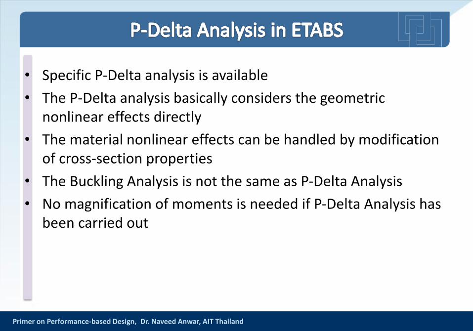
• Specific P-Delta analysis is available
• The P-Delta analysis basically considers the geometric nonlinear effects directly
• The material nonlinear effects can be handled by modification of cross-section properties
• The Buckling Analysis is not the same as P-Delta Analysis
• No magnification of moments is needed if P-Delta Analysis has been carried out
Primer on Performance-based Design, Dr. Naveed Anwar, AIT Thailand
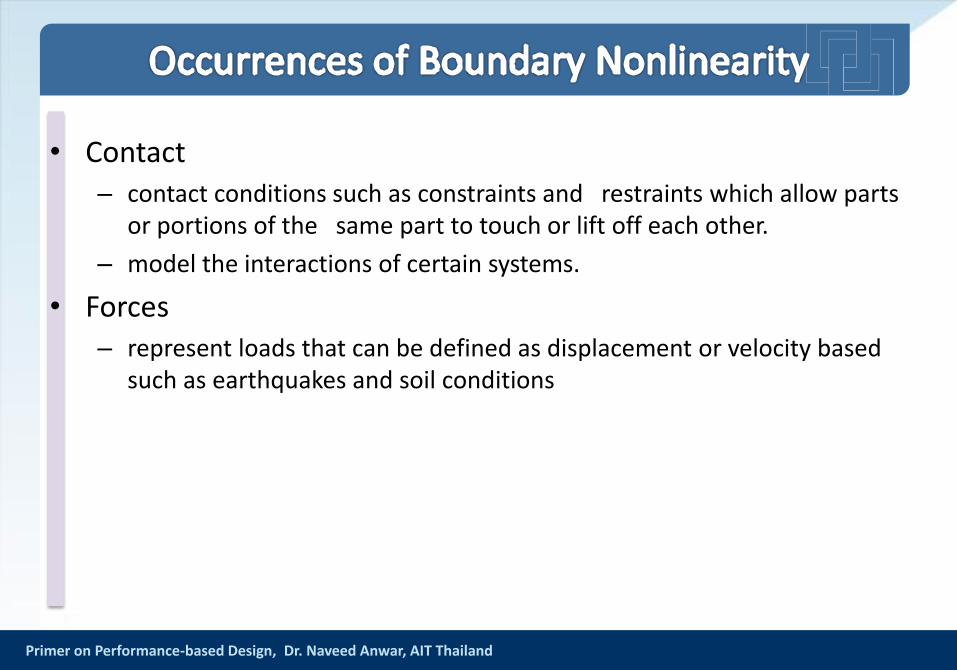
• Contact – contact conditions such as constraints and restraints which allow parts
or portions of the same part to touch or lift off each other.
– model the interactions of certain systems.
• Forces– represent loads that can be defined as displacement or velocity based
such as earthquakes and soil conditions
Dr. Naveed AnwarExecutive Director, AIT Consulting
Affiliated Faculty, Structural Engineering
Director, ACECOMS
Capacity based Design of
Structural ComponentsSeminar on Performance Based Design of RC
Buildings
l 84
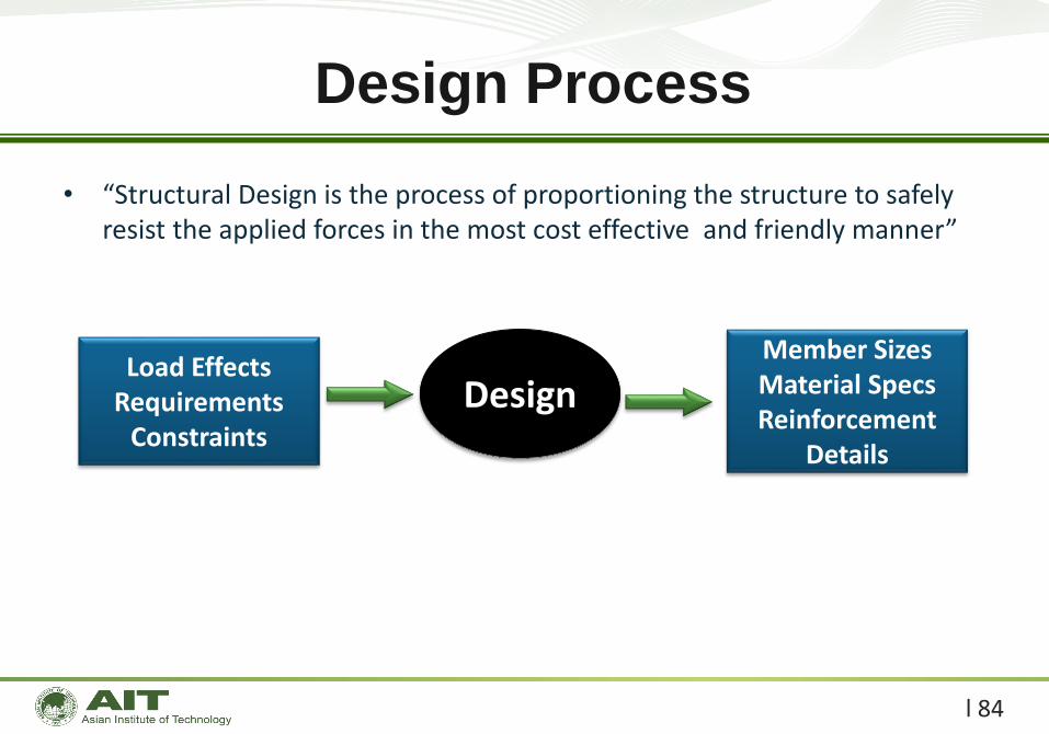
• “Structural Design is the process of proportioning the structure to safely resist the applied forces in the most cost effective and friendly manner”
Design Process
Load EffectsRequirements
Constraints
DesignMember SizesMaterial SpecsReinforcement
Details
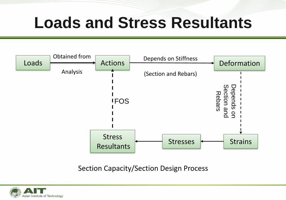
Obtained from
Analysis
Actions
Loads and Stress Resultants
Section Capacity/Section Design Process
Loads
StressesStress
Resultants
DeformationDepends on Stiffness
(Section and Rebars)
Strains
Depends o
n
Sectio
n a
nd
Rebars
FOS
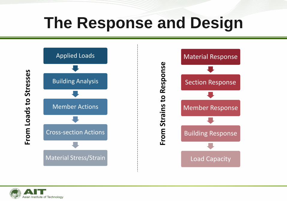
The Response and DesignFr
om
Lo
ads
to S
tre
sse
s
Fro
m S
trai
ns
to R
esp
on
se
Applied Loads
Building Analysis
Member Actions
Cross-section Actions
Material Stress/Strain
Material Response
Section Response
Member Response
Building Response
Load Capacity
l 87
• Satisfying one design level does not ensure that other design levels will be satisfied– Serviceability design only ensures that deflections and vibrations, etc.,
for service loads are within limits but says nothing about strength.
– Strength design ensures that a certain factor of safety against overload is available within a member or a cross-section but says nothing about what happens if the load exceeds the design level.
– Performance design ensures that the structure as a whole reaches a specified demand level. Performance design can include both service and strength design levels.
From Serviceability to Performance
l 88
• This is most common seismic design approach adopted nowadays.
• It is based on providing the structure with the minimum lateral strength to resist seismic loads, assuming that the structure will behave adequately in the non-linear range.
• For this reason only some simple construction detail rules are needed to be satisfied.
Lateral Strength Based Design
l 89
• In this method the structure is designed to possess adequate ductility so that it can dissipate energy by yielding and survive the shock.
• This method operates directly with deformation quantities hence gives better insight on the expected performance of the structures.
• The displacement based design approach has been adopted by the seismic codes of many countries.
Displacement Based Design
l 90
• In this design approach the structures are designed in such a way so that plastic hinges can form only in predetermined positions and in predetermined sequences.
• The concept of this method is to avoid brittle mode of failure.
• This is achieved by designing the brittle modes of failure to have higher strength than ductile modes.
Capacity Based Design
l 91
• This is the most promising and futuristic approach of earthquake resistant design.
• In this approach it is assume that the total energy input is collectively resisted by kinetic energy, the elastic strain energy and energy dissipated through plastic deformations and damping.
Energy Based Design
92

l 93
• Capacity Design is a design process in which it is decided which objectswithin a structural system will be permitted to yield (ductile components)and which objects will remain elastic (brittle components).
• Once ductile and brittle systems are decided upon, design proceedsaccording to the following guidelines:
– Ductile components are designed with sufficient deformation capacity suchthat they may satisfy displacement-based demand-capacity ratio.
– Brittle components are designed to achieve sufficient strength levels such thatthey may satisfy strength-based demand-capacity ratio.
What is Capacity Design?
l 94
• It is best to implement Capacity Design because structural performance isthen a deliberate intention of the designer, and not revealed in asecondary manner by computational tools.
• Further, because of the many sources of uncertainty inherent to structuralmodeling and analysis, unless ductile systems are predetermined, acomputational tool may not accurately indicate which systems will achieveinelastic response.
• In summary, Capacity Design enables the creation of a more reliablecomputational model, which should lead to better structural design.
Why Capacity Design?
l 95
• Capacity Design also comes to the relief of computational time. When anengineer knows which objects will behave elastically, and which will bepermitted to yield, material nonlinearity need only be modeled for ductilecomponents, while components which will not yield need only consider elasticstiffness properties. These relationships are linear, which provides for a moresimple formulation of less computational demand.
• Brittle components are redesigned such that strength capacity exceeds thatdemanded. A level of complexity comes with the redesign of ductilecomponents, however, in that ductile components may satisfy nonlineardemand-capacity criteria through a balance of both strength and deformationcapacity.
• While Capacity Design should lead to more reliable modeling and more accurateresults, engineers should note that computational models only represent amathematical simulation of physical phenomena, and cannot exactly predictstructural behavior.
• Too many sources of uncertainty exist, and it is up to the designer to bestcharacterize as many behavioral parameters as is practical.
Why Capacity Design?
l 96
Capacity Design Philosophy
• Structures are designed for many limit states
• Load Design = all limit states must occur beyond a minimum load level• Capacity Design = same as above, except now we choose that one limit state
is to occur before any other
• Difficult part is choosing the Limit State that should govern
l 97
• Seismic Design Guidelines– Seismic design guidelines (UBC) are written with a specific intent of capacity
design
• Special Moment Resisting Frame = hinges should form in beam• Special Concentric Braced Frame = braces should yield in tension• Eccentric Braced Frame = link region of beam to yield in shear
Where is Capacity Design Used?
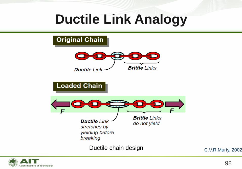
Ductile Link Analogy
98
Ductile chain design C.V.R.Murty, 2002
99
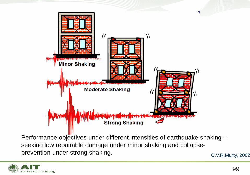
Performance objectives under different intensities of earthquake shaking –
seeking low repairable damage under minor shaking and collapse-
prevention under strong shaking. C.V.R.Murty, 2002
100
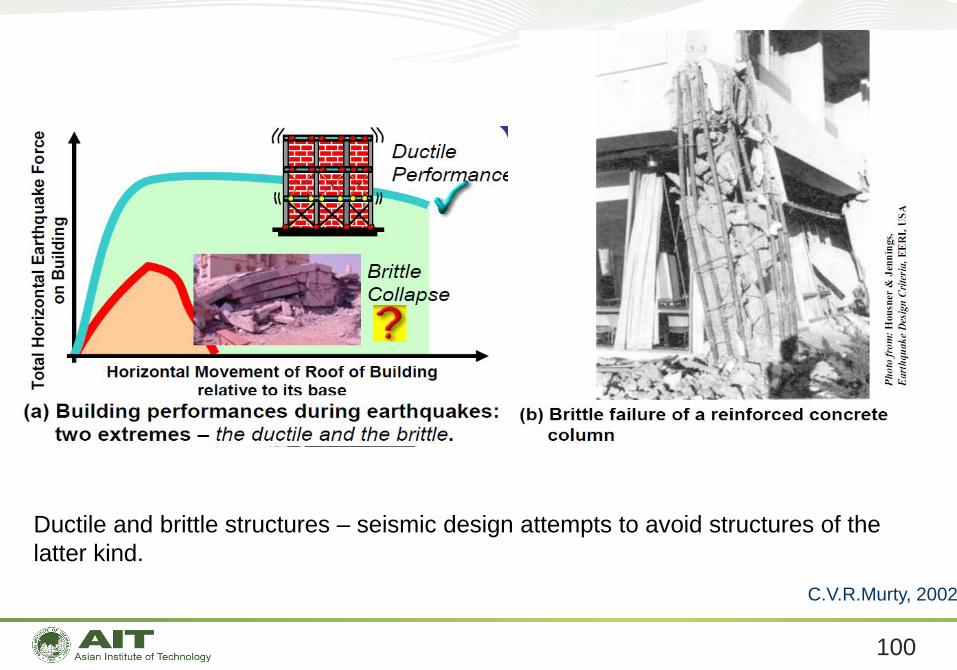
Ductile and brittle structures – seismic design attempts to avoid structures of the
latter kind.
C.V.R.Murty, 2002
101
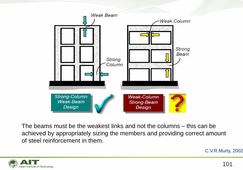
The beams must be the weakest links and not the columns – this can be
achieved by appropriately sizing the members and providing correct amount
of steel reinforcement in them.
C.V.R.Murty, 2002
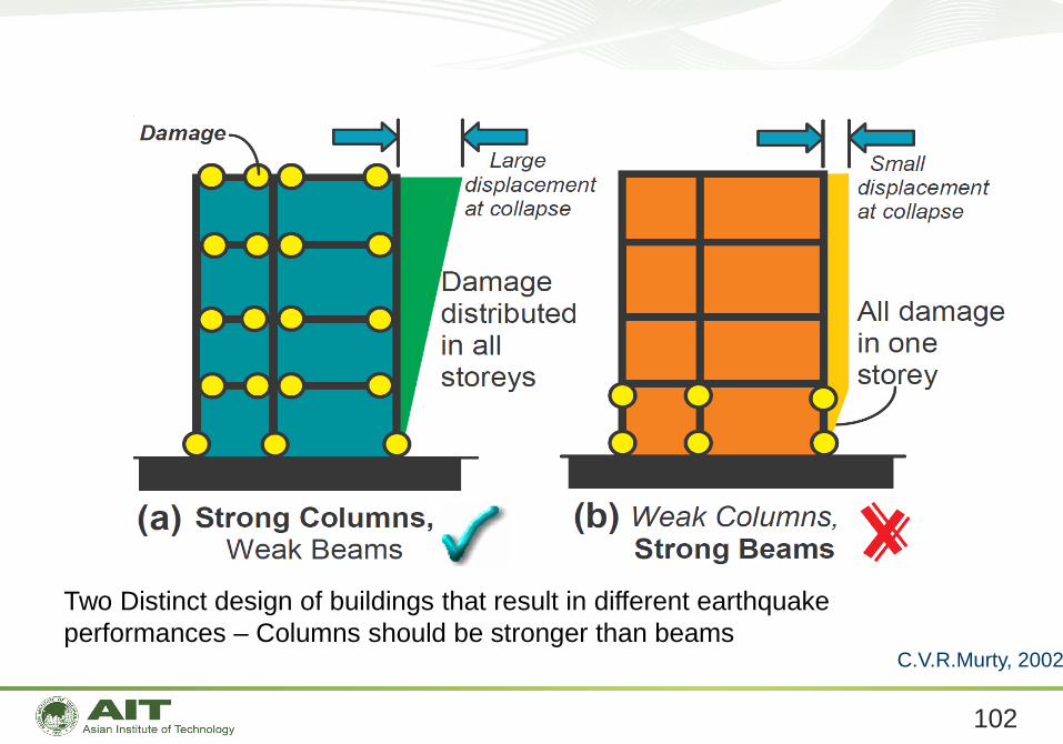
102
Two Distinct design of buildings that result in different earthquake
performances – Columns should be stronger than beamsC.V.R.Murty, 2002
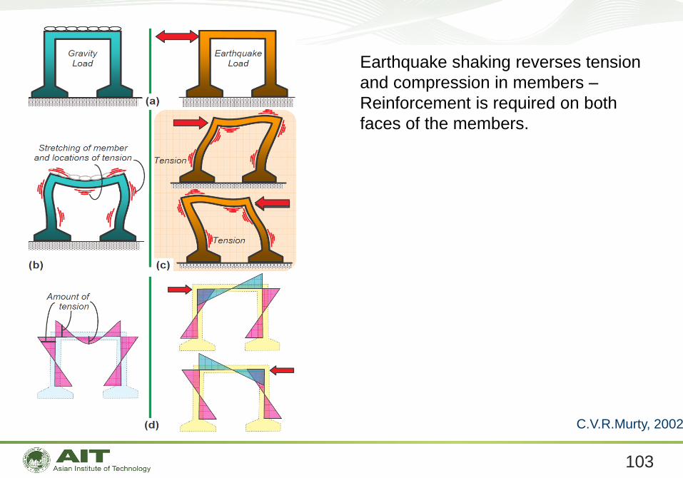
103
Earthquake shaking reverses tension
and compression in members –
Reinforcement is required on both
faces of the members.
C.V.R.Murty, 2002
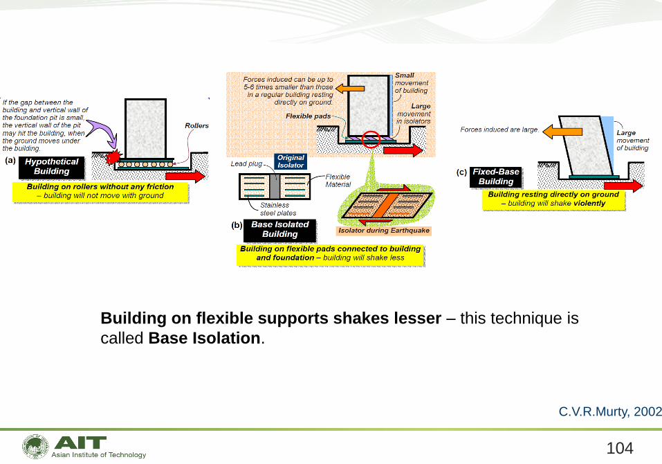
104
Building on flexible supports shakes lesser – this technique is
called Base Isolation.
C.V.R.Murty, 2002
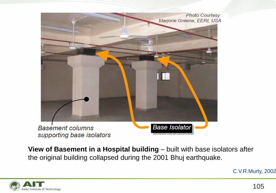
105
View of Basement in a Hospital building – built with base isolators after
the original building collapsed during the 2001 Bhuj earthquake.
C.V.R.Murty, 2002
106
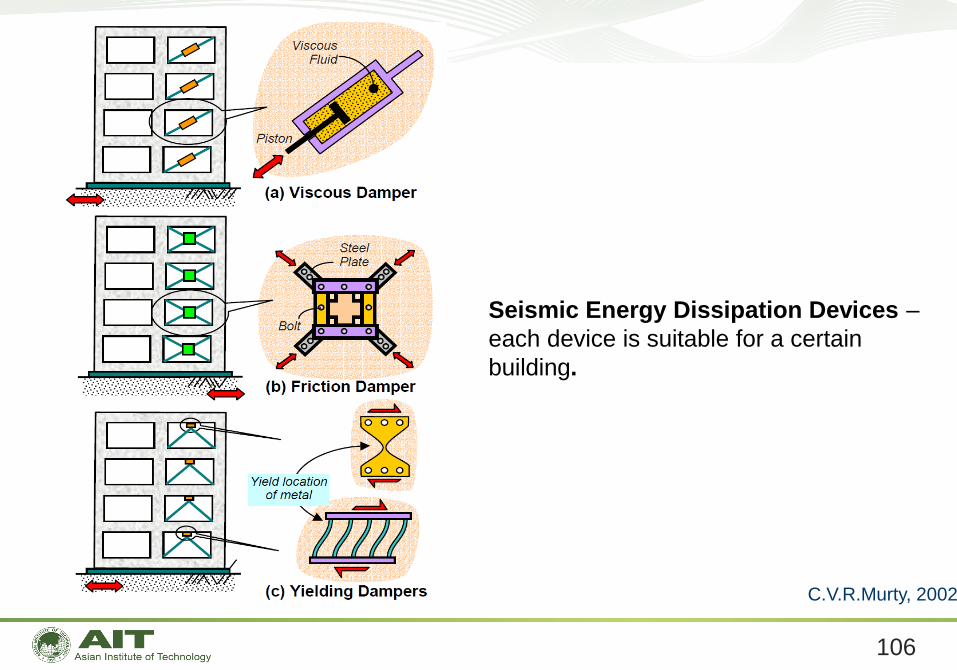
Seismic Energy Dissipation Devices –
each device is suitable for a certain
building.
C.V.R.Murty, 2002
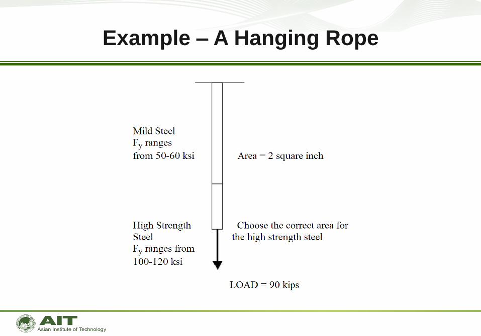
Example – A Hanging Rope
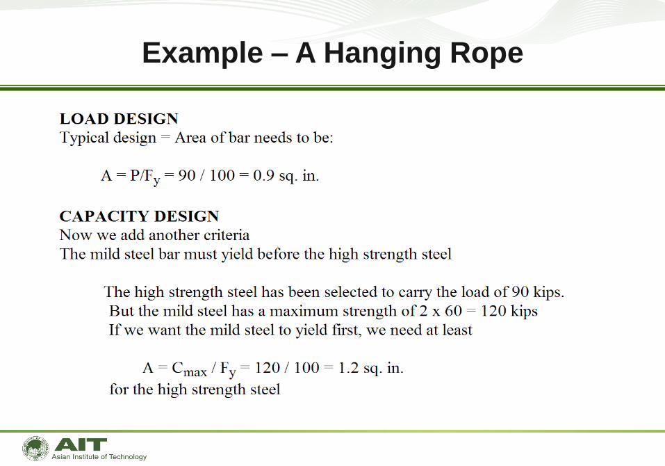
Example – A Hanging Rope