Embed Size (px)
Citation preview

Pv
Ia
ilrlpicotcgtmcl[ac
0d
Journal of Power Sources 184 (2008) 9–15
Contents lists available at ScienceDirect
Journal of Power Sources
journa l homepage: www.e lsev ier .com/ locate / jpowsour
erformance evaluation of passive direct methanol fuel cell with methanolapour supplied through a flow channel
a b c c b,∗
kwhang Chang , Seungbum Ha , Jinho Kim , JaeYong Lee , Suk Won Cha6-1, Si56-1,gin-Sifect oDMFC
chat air tambchanand
e bes. Und
nseque flownnelr.
Interdisciplinary Program in Automotive Engineering, Seoul National University, San 5b Department of Mechanical and Aerospace Engineering, Seoul National University, Sanc Samsung Advanced Institute of Technology, San 14-1, Nongseo-Dong, Giheung-Gu, Yon
a r t i c l e i n f o
Article history:Received 13 April 2008Received in revised form 20 May 2008Accepted 2 June 2008Available online 21 June 2008
Keywords:Direct methanol fuel cellPassiveVapour feedAir-breathingFlow channelHumidified membrane electrode assembly
a b s t r a c t
This work examines the efdirect methanol fuel cell (is supplied through a flowsupplied from the ambienconfigurations or open chflow channel and the flowthe area of the inlet portoptimum fuel feeding. Ththe chamber configurationand ambient pressure. Covapour feeding through tha passive DMFC with a chasupply of methanol vapou
1. Introduction
The direct methanol fuel cell (DMFC) is one of the most promis-ng portable power sources for mobile electronic devices (e.g.,aptops, cellular phones, and PDAs). The advantages of DMFCs areeasonably high specific energy, convenient storage of fuel, andow temperature operation [1,2]. Nevertheless, DMFCs have severalroblems and technological issues that still need to be addressed to
mprove their performances for example: methanol crossover, highatalyst loading and low power density [3–5]. In a DMFC, a fractionf methanol fuel at the anode is transported to the cathode underhe influence of a concentration gradient. This is called ‘methanolrossover’. The transported methanol reacts directly with the oxy-en at the cathode. In this situation, no current is produced evenhough the fuel cell consumes the methanol fuel. The rate of
ethanol crossover is strongly proportional to the methanol con-entration at the anode [6]. Additionally, methanol, which is toxic,owers the activity of the catalyst and degrades the cell performance7]. In DMFCs, the methanol fuel is delivered to the anode eitherctively or passively. The same applies to the delivery of air to theathode. Active feeding requires auxiliary devices, such as pumps
∗ Corresponding author. Tel.: +82 2 880 8050; fax: +82 2 883 1513.E-mail address: [email protected] (S.W. Cha).
378-7753/$ – see front matter. Crown Copyright © 2008 Published by Elsevier B.V. All rioi:10.1016/j.jpowsour.2008.06.036
llim9-dong, Kwanak-gu, Seoul 151-744, Republic of KoreaSillim9-dong, Kwanak-gu, Seoul 151-744, Republic of Korea, Gyeonggi-do 449-712, Republic of Korea
f fuel delivery configuration on the performance of a passive air-breathing). The performance of a single cell is evaluated while the methanol vapournnel from a methanol reservoir connected to the anode. The oxygen is
o the cathode via natural convection. The fuel cell employs parallel channeler configurations for methanol vapour feeding. The opening ratio of thenel configuration is changed. The opening ratio is defined as that betweenthe area of the outlet port. The chamber configuration is preferred for
t performance of the fuel cell is obtained when the opening ratio is 0.8 iner these conditions, the peak power is 10.2 mW cm−2 at room temperatureently, passive DMFCs using methanol vapour require sufficient methanolchannel at the anode for best performance. The mediocre performance of
configuration is attributed to the low differential pressure and insufficient
Crown Copyright © 2008 Published by Elsevier B.V. All rights reserved.
or blowers, to deliver the fuel and oxygen to the gas-diffusion layerof the respective electrode. Conversely, passive systems do not needany power to supply fuel and oxygen. Therefore, passive DMFCs canminimize the auxiliary system volume, parasitic losses and system
control. Although passive DMFCs are preferred for mobile powersources because of these advantages, their power outputs do notsatisfy the power demands of various electrical devices. To improvethe performance of passive DMFCs, the following factors must beconsidered: methanol concentration, membrane properties such asthickness, the structure of membrane electrode assembly (MEA),and overall details of the system configuration [8].Bae et al. [9] reported the evaluation of passive DMFCs fedwith liquid methanol. The optimum methanol concentration was5 M at the anode, and the catalyst loading of each electrode was8 mg cm−2. Kim [10] proposed a MEA that passively fed water tothe anode by itself. It utilized pure methanol as fuel and could pro-duce around 20–30 mW cm−2 for 15 days. The system adopted aporous buffer to control the water supply at the anode passively.For characterization of the passive DMFC, the power was measuredunder a fixed voltage of 0.3–0.35 V (potentiostat mode), at whichthe cell generated maximum power [10]. Typically, the power out-put of a DMFC fluctuates widely during long-term operation. In apassive DMFC, the required water at the anode is supplied from thecathode by back-diffusion. Therefore, the supply of water is unsta-ble. This instability lowers the performance of a passive DMFC. To
ghts reserved.

10 I. Chang et al. / Journal of Power
Fig. 2. Schematic assembly of single cell.
methanol reservoir is 2.45 cm2. A port of 1.5 mm diameter is drilledfor methanol delivery to the reservoir. Pure methanol from a syringepump is supplied to the reservoir through a port at a fixed rate of0.4 ml h−1. Inside the reservoir, the methanol is absorbed in foamtemporarily, before it evaporates.
2.2. Flow channel
In designing the flow channels, the following factors have beeninvestigated: the ratio between the inlet and outlet ports of the
Fig. 1. Schematic of passive DMFC fuelled by methanol vapour from reservoir toMEA: (a) central inlet and (b) side inlet.
obtain maximum power, in spite of MEA degradation, low-voltageoperation could be preferred [11–13].
One approach to improve the performance of a passive DMFC isto use methanol vapour as fuel. Schematic diagrams of examplesof such passive DMFCs are shown in Fig. 1. The methanol is tem-porarily stored in a reservoir adjacent to the flow channel. Afterthe methanol vapourizes in the reservoir, the vapour progressesthrough the flow channel and then the gas-diffusion layer of theanode. After the electrochemical reaction, carbon dioxide and anyremaining methanol vapour exit from the system.
The work presented here examines the effect of various flowchannel configurations on a performance of a DMFC using puremethanol vapour as the fuel at the anode. In particular, to improve
the power density, the optimum opening ratio between the inletand outlet ports of the flow channel has been investigated. The per-formance of a single cell at room temperature and ambient pressurehas been evaluated as a passive air-breathing system. This exper-iment follows the typical requirements of portable fuel cells formobile application [14–16].2. Fuel cell design and experimental set-up
The design of the fuel-cell assembly comprises the followingcomponents: methanol reservoir, flow channel (Figs. 2–4), gasket,MEA, and upper plate for air-breathing (Fig. 5). The overall dimen-sions of the assembly are 60 mm (W) × 60 mm (B) × 20 mm (H). Thefollowing sections describe each component in detail.
2.1. Methanol reservoir
To obtain both strength and simplicity of manufacturing, poly-carbonate has been chosen for the frame material. The key factorin making this selection is rigidity to maintain the tightness ofsealing between the MEA and the frame. The total area of the
Sources 184 (2008) 9–15
Fig. 3. Position details of inlet and outlet in chamber configuration: (a) side inletand (b) central inlet.

I. Chang et al. / Journal of Power Sources 184 (2008) 9–15 11
Fig. 5. Upper plate design for air-breathing in cathode.
Table 1Specifications of flow channels
Channel type Channellength (mm)
Channel/ribwidth (mm)
Openingratio
Position ofinlet
Parallel 26 l 0.8 Central inletParallel 25 l 0.5 Side inletParallel 25 l 0.3 Side inletParallel 26 2 0.8 Central inletParallel 25 2 0.3 Side inletChamber 26 – 0.8 Central inletChamber 25 – 0.5 Side inletChamber 25 – 0.3 Side inlet
Fig. 4. Position details of inlet and outlet in parallel-channel configuration: (a) sideinlet and (b) central inlet.
anode channel, the actual shape of the channel, and the area of theair-breathing element at the cathode. Various flow channel shapesand opening ratios at the anode have been investigated. Serpen-tine channel design, however, was dismissed due to insufficientfuel delivery resulting from excessive pressure drop along the flowchannel. The position of the inlet was specifically divided into twotypes, namely, central and side inlet types, and the area of eachwas 1.2 and 1.5 cm2, respectively. Also, the area of the outlet was0.47 cm2 for both cases. The height and depth of the flow chan-nel is 1 mm, and two widths of the flow channel are employed;namely: parallel channel 2 mm and parallel channel 1 mm. Thespecifications of each flow channel are listed in Table 1, such asflow channel length, opening ratio, channel/rib width, and positionof inlet. Among these parameters, the opening ratio is defined asfollows (Figs. 6 and 7):
Opening ratio = area of outlet portarea of inlet port
(1)
The flow channel, which has an exit for carbon dioxide, is quitedifferent from other passive DMFCs, because almost all passive fuelfeeding DMFC systems do not have an exit for the carbon dioxide
Fig. 6. Schematic design of opening ratio in chamber configuration: (a) side inletand (b) central inlet.

12 I. Chang et al. / Journal of Power
Fig. 9 shows how different flow channel configurations affect the
Fig. 7. Schematic design of opening ratio in parallel-channel configuration: (a) sideinlet and (b) central inlet.
at the anode, namely, they are closed systems [9,10,17]. Therefore,the effect of the carbon dioxide exit on cell performance may nothave been estimated in other designs.
2.3. Upper plate
The important role of the upper plate is to expose the cathode tothe ambient environment for the air-breathing element. It has beenreported [18] that optimum opening ratio at the cathode for a pas-sive fuel cell is around 71% and the opening shape is square. In the
present design, an opening ratio of 69% is employed. The dimen-sions of air-breathing at the cathode are 36 mm (W) × 36 mm (B).The air-breathing holes have a square shape, and the dimension ofsquare hole is 10 mm (W) × 10 mm (B). The gap between the squareholes is 2 mm (Fig. 5).2.4. Gasket
In order to prevent leakage of fuel and oxidation of the catalystby ambient air, good sealing of the MEA is critical problem in pas-sive DMFCs [19]. In particular, since the compressibility of gasketmaterial and compression force inside the cell strongly affect thecontact resistance and the gas diffusivity of MEA, selecting a goodgasket material is important. A high compression force preventsproper fuel supply through the gas-diffusion layer. Conversely, alow compression force increases the contact resistance betweenthe current-collector and the electrode. Teflon sheet of 230 �m wasselected as the gasket material, and the optimum compression wasobtained by controlling the tightening torque of the assembly boltsat 120 N cm−2.
Sources 184 (2008) 9–15
2.5. Membrane electrode assembly
The dimensions of the MEA was 9 cm2 (3 cm × 3 cm). The elec-trolyte membrane was fabricated by a solution-casting methodand had a thickness of 50 �m [10]. PtRu black and Pt black wereused as the catalyst for the anode and cathode, respectively. Thecatalyst loadings for the anode and cathode were 8 mg cm−2 forboth. The anode diffusion layer was made of a carbon-backing layerwith silica particles of 4–5 nm and polyvilyldiene fluoride (PVDF).For the cathode diffusion layer, a mixture of carbon particles andpolytetrafluoro ethylene (PTFE) was first sprayed on to the carbon-backing layer with a loading of 2 mg cm−2. SGL plain paper andToray 090 carbon paper were used for the anode-backing layer andthe cathode-backing layer, respectively. Gold-coated nickel-meshintegrated with the MEA served as a current-collector [10,20].
2.6. Experiment setup
Before the main experiments, the cell went through an activa-tion process at room temperature. The open-circuit voltage (OCV)was measured over 30 min, and the cell was operated for about24 h at 0.35 V. Polarization curves were obtained by mean of aSolartron 1287 potentiostat. The liquid methanol was supplied tothe reservoir by a syringe pump at 0.4 ml h−1 continuously and themethanol in the reservoir evaporated into the flow channels. Thewater required at the anode was back-diffused from the cathode.The temperature was measured on the cathode surface using ther-mocouples in only long-term operation to identify the relationshipbetween performance fluctuations and temperature variations. Forpolarization curves, the temperature was not measured due to theintended purpose for mobile application, and ambient pressure aswell as room temperature were the conditions for the air-breathingpassive DMFC.
3. Experimental results and discussions
3.1. Influence of flow channel
Fig. 8 gives a comparison of the open-circuit voltage obtainedfrom different flow channel configurations, i.e., parallel channel(2 mm), parallel channel (1 mm), and chamber. The parallel chan-nel (1 mm) and the parallel channel (2 mm) have the same openingratio of 0.3. The opening ratio of chamber is 0.8. The OCV was stabi-lized around 0.46 V, regardless of the flow channel types, in 30 min.
cell performance. The chamber configuration achieved the high-est power density of 8.5 mW cm−2. Conversely, the power densityof the parallel channel (1 mm) and the parallel channel (2 mm) areless than 5.4 mW cm−2. The low performance of the parallel channelconfigurations can be attributed to insufficient methanol supply inthe flow channel that diffuses to the anode catalyst layer. Comparedwith forced methanol feeding in an active cell, methanol vapour istransported more slowly from the flow channel to the gas-diffusionlayer, and the low differential pressure does not force methanolvapour to travel to the catalyst layer. Also, since the dividing rib inparallel channels blocks methanol diffusion for the electrochem-ical reactions, the transport of methanol vapour in the chamberconfiguration is more effective in passive DMFC’s (Fig. 10).
3.2. Influence of opening ratio
The dimensions of the outlet port control the carbon dioxideexhaust from the flow channels of the anode. When a low open-ing ratio chamber is used, the performance of the cell decreasescompared with using a high opening ratio. Low cell performance

I. Chang et al. / Journal of Power Sources 184 (2008) 9–15 13
Fig. 8. Open-circuit voltage (OCV) and polarization curves in different channels:parallel channel (1 mm), parallel channel (2 mm), and chamber.
is obtained for channels with low opening ratios regardless of thechannel shapes (Fig. 9). Therefore, the opening ratio is the key factorthat affects the performance in these experiments. The peak per-formance is achieved when the chamber opening ratio is 0.8. Theoutput power is 10.2 mW cm−2. It is considered that the openingratio affects the removal of product and by-product such as car-bon dioxide and carbon monoxide in the anode. Carbon monoxideweakens catalyst activity and decrease the life-cycle of the cata-lyst [21–23]. It is concluded that a higher opening ratio leads toa more active electrochemical reaction between the reactants andthe catalyst by proper venting of these products.
Fig. 9. Performance comparison of different flow channels in same opening ratio0.3.
Fig. 10. Performance comparison of flow channels with different opening ratios: (a)different opening ratios in same chamber channel and (b) different opening ratiosin same.
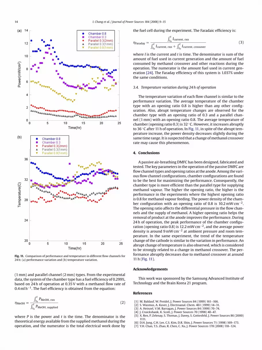
3.3. Performance variation during 24 h operation
The variation in the performance of passive DMFCs during 24 his presented in Fig. 11. The cell was operated at 0.35 V, with a liquidmethanol flow rate of 0.4 ml h−1 supplied by a syringe pump. Thecell current was monitored without interruption during the test.On average, the performance of chamber type of opening ratio 0.8is higher than any other type of flow channel. The performance ofparallel channels is lower than that of a chamber type with an open-ing ratio 0.3. Parallel channels with low opening ratio have evenlower performance. The chamber type (opening ratio 0.8) showsan abrupt performance drop at around 5 and 22 h. The performancedrop of chamber type (opening ratio 0.8) is similar to the temper-ature drop. The performance of the cell with a low opening ratio(0.3) was poor during 24 h of operation for both parallel channel
14 I. Chang et al. / Journal of Power
density is around 9 mW cm at ambient pressure and room tem-
Fig. 11. Comparison of performance and temperature in different flow channels for24 h: (a) performance variation and (b) temperature variation.
(1 mm) and parallel channel (2 mm) types. From the experimentaldata, the system of the chamber type has a fuel efficiency of 0.299%,based on 24 h of operation at 0.35 V with a methanol flow rate of0.4 ml h−1. The fuel efficiency is obtained from the equation:
�MeOH =∫ t
toPMeOH, rxn
∫ t
toPMeOH, supplied
(2)
where P is the power and t is the time. The denominator is thetheoretical energy available from the supplied methanol during theoperation, and the numerator is the total electrical work done by
Sources 184 (2008) 9–15
the fuel cell during the experiment. The Faradaic efficiency is:
�Faraday =∫ t
toIcurrent, rxn
∫ t
toIcurrent, rxn +
∫ t
toIcurrent, crossover
(3)
where I is the current and t is time. The denominator is sum of theamount of fuel used in current generation and the amount of fuelconsumed by methanol crossover and other reactions during theoperation. The numerator is the amount fuel used in current gen-eration [24]. The Faraday efficiency of this system is 1.037% underthe same conditions.
3.4. Temperature variation during 24 h of operation
The temperature variation of each flow channel is similar to theperformance variation. The average temperature of the chambertype with an opening ratio 0.8 is higher than any other config-uration. Also, abrupt temperature changes are observed for thechamber type with an opening ratio of 0.3 and a parallel chan-nel (1 mm) with an opening ratio 0.8. The average temperature ofchamber (opening ratio 0.3) is 32 ◦C. However, it increases abruptlyto 36 ◦C after 11 h of operation. In Fig. 11, in spite of the abrupt tem-perature increase, the power density decreases slightly during thesame time range. It is suspected that a change of methanol crossoverrate may cause this phenomenon.
4. Conclusions
A passive air-breathing DMFC has been designed, fabricated andtested. The key parameters in the operation of the passive DMFC areflow channel types and opening ratios at the anode. Among the vari-ous flow channel configurations, chamber configurations are foundto be the best for maximizing the performance. Consequently, thechamber type is more efficient than the parallel type for supplyingmethanol vapour. The higher the opening ratio, the higher is theperformance in the experiments where the highest opening ratiois 0.8 for methanol vapour feeding. The power density of the cham-ber configuration with an opening ratio of 0.8 is 10.2 mW cm−2.The opening ratio affects the differential pressure in the flow chan-nels and the supply of methanol. A higher opening ratio helps theremoval of product at the anode improves the performance. During24 h of operation, the peak performance of the chamber configu-ration (opening ratio 0.8) is 12.2 mW cm−2, and the average power
−2
perature. In the same experiment, the trend of the temperaturechange of the cathode is similar to the variation in performance. Anabrupt change of temperature is also observed, which is consideredto be strongly related to a change in methanol crossover. The per-formance abruptly decreases due to methanol crossover at around11 h (Fig. 11).
Acknowledgements
This work was sponsored by the Samsung Advanced Institute ofTechnology and the Brain Korea 21 program.
References
[1] M. Baldauf, W. Preidel, J. Power Sources 84 (1999) 161–166.[2] S. Wasmus, A. Kuver, J. Electroanal. Chem. 461 (1999) 14–31.[3] A. Heinzel, V.M. Barragan, J. Power Sources 84 (1999) 70–74.[4] J. Cruickshank, K. Scott, J. Power Sources 70 (1998) 40–47.[5] X. Ren, P. Zelenay, S. Thomas, J. Davey, S. Gottesfeld, J. Power Sources 86 (2000)
1111.[6] D.H. Jung, C.H. Lee, C.S. Kim, D.R. Shin, J. Power Sources 71 (1998) 169–173.[7] Y.H. Chan, T.S. Zhao, R. Chen, C. Xu, J. Power Sources 178 (2008) 118–124.

[
[
[
[
[
I. Chang et al. / Journal of Power
[8] Y.J. Kim, B. Bae, M. Aulice Scibioh, E.A. Cho, H.Y. Ha, J. Power Sources 157 (2006)253–259.
[9] B. Bae, B.K. Kho, T.H. Lim, I.H. Oh, S.A. Hong, H.Y. Ha, J. Power Sources 158 (2006)1256–1261.
10] H.K. Kim, J. Power Sources 162 (2006) 1232–1235.[11] L.S. Sarma, C.H. Chen, G.R. Wang, K.L. Hsueh, C.P. Huang, H.S. Sheu, D.G. Liu, J.F.
Lee, B.J. Hwang, J. Power Sources 167 (2007) 358–365.12] M.K. Jeon, K.R. Lee, K.S. Oh, D.S. Hong, J.Y. Won, S. Li, S.I. Woo, J. Power Sources
158 (2006) 1344–1347.13] M. Inaba, M. Sugishita, J. Wada, K. Matsuzawa, H. Yamada, A. Tasaka, J. Power
Sources 178 (2008) 699–705.14] J.J. Hwang, S.D. Wu, L.K. Lai, C.K. Chen, D.Y. Lai, J. Power Sources 161 (2006)
240–249.15] Y.H. Pan, J. Power Sources 161 (2006) 282–289.
[[
[
[[[
[[
[
Sources 184 (2008) 9–15 15
16] C.Y. Chen, P. Yang, J. Power Sources 123 (2003) 37–42.17] J.J. Martin, W. Qian, H. Wang, V. Neburchilov, J. Zhang, D.P. Wilkinson, Z. Chang,
J. Power Sources 164 (2007) 287–292.18] H.Y. Cha, S.H. Kim, J.H. Jang, C. Miesse, J.H. Gil, H.R. Lee, A. Kundu, C.R. Jung, B.
Ku, K.S. Chae, Y.S. Oh, Meet. Abstr. Electochem. Soc. 701 (2007) 187.19] Z. Qi, C. He, A. Kaufman, J. Power Sources 111 (2002) 239–247.20] W. Lee, H. Kim, T.K. Kim, H. Chang, J. Membr. Sci. 292 (2007) 29–34.21] T. Matsui, K. Fujiwara, T. Okanish, R. Kikuchi, T. Takeguchi, K. Eguchi, J. Power
Sources 155 (2006) 152–156.22] A.A. Shah, P.C. Sui, G.-S. Kim, S. Ye, J. Power Sources 166 (2007) 198–204.23] H.S. Chu, C.P. Wang, W.C. Liao, W.M. Yan, J. Power Sources 159 (2006) 1071–
1077.24] J.Y. Park, J.H. Lee, S.K. Kang, J.H. Sauk, I. Song, J. Power Sources 178 (2008)
181–187.


