Embed Size (px)
Citation preview
Performance Simulation of Pyramidal and Wedge Microwave Absorbers
H. Nornikman, P.J Soh, A.A.H Azremi, M.S Anuar School of Computer and Communication Engineering,
Universiti Malaysia Perlis (UniMAP) [email protected], {pjsoh, azremi, anuarms}@unimap.edu.my
Abstract
Anechoic chambers signal absorption capability is
directly correlated to its performance. One of the main components in enabling signal absorption is the design and material used in designing the absorbers. Two of the main types are pyramidal and wedge-shaped ones. In this work, truncated pyramidal and truncated wedge absorbers for anechoic chamber application have been designed to operate effectively in the microwave frequencies from 1 - 10 GHz. The absorbers were simulated using a fusion of carbon-based material with different features and coating thickness to improve their performance and significant material cost savings. Material consideration for the basic pyramidal and wedge structure has also been taken into account. The designs are simulated using CST Microwave Studio. Simulated results showed that the coating of half the absorber height produced the best performance in terms of signal absorption. 1. Introduction
One of the most important types of anechoic chamber available in the commercial market is the RF anechoic chamber. It is built using a shielded room, whose walls have been covered with a material that absorb so most of the incident energy, so much so that it can simulate a perfect free space, with the absence of signal reflection and scattering. [1] The RF anechoic chamber is typically used to house the equipment for performing measurements of antenna radiation patterns, electromagnetic compatibility (EMC) and radar cross section measurements. [2]
Nowadays, absorbers were typically manufactured by impregnating conductive carbon into a foamed plastic medium, such as polyurethane or polystyrene. These carbon-impregnated materials were fashioned into tapering various shapes to provide a suitable impedance match between free space and the resistive absorber medium. Balancing the carbon content with the shape of the tapering material provided efficient
and predictable absorption of RF energy from microwave frequencies to below 0.5 GHz, where the tapered length of the absorber would be greater than one wavelength. [3] There are many types of absorber in market like pyramidal, wedge, hybrid-type, resonant, ferrite, walkway, convoluted, multi-layered, oblique, and other types.
A proper model of RF absorber must be developed based on information such as absorber reflectivity, in magnitude and phase, for various angles of incidence, and for parallel and perpendicular polarizations. [4] The reflectivity, R can express the absorbing performance of the material and is a function of the complex permittivity and permeability of the material, and the frequency of the wave. [5] The reflectivity in dB unit is defined in equation (1).
Γlog20R = (1)
In telecommunications, the reflection coefficient is the ratio of the amplitude of the reflected wave to the amplitude of the incident wave. Equation (2) showed the formula for the reflection coefficient, Γ.
1Zi1Zi
+−=Γ (2)
A material is classified as dielectric if it has the ability to store energy when an external electric field is applied. ε (epsilon) is the absolute permittivity of the dielectric, which is a measure of the electrostatic energy stored within it and therefore dependent on the material. Dielectric constant is equivalent to relative permittivity (εr) or the absolute permittivity (ε) relative to the permittivity of free space (ε0). [6][7] The dielectric constant of a material affects how electromagnetic signals move through the material. A high value of dielectric constant makes the signal like radio waves or light travel more slowly. [8]
Permeability in general is symbolized µ, and is a constant of proportionality that exists between magnetic flux density and magnetic field strength in a
2009 Third Asia International Conference on Modelling & Simulation
978-0-7695-3648-4/09 $25.00 © 2009 IEEE
DOI 10.1109/AMS.2009.13
649
given medium. The constant value μ0 is known as the magnetic constant or the permeability of free space [9, 10]. Equation (3) to equation (7) shows how to define the epsilon.
0rεεε = (3)
1120 Fm1085.8 −−×=ε (4)
0
20 c1μ
ε = (5)
c = speed of light (6)
18 ms103 −×=
μ0 = permeability of free space (7) 117 mWbA104 −−−×= π
116 mWbA102566.1 −−×= Where Wb is an abbreviation for Webers
and A for amps. 2. Design Truncated Pyramidal Microwave Absorber
In geometry, a square pyramid is a polyhedron that has a regular polygon for a base and sides (the lateral faces) that are isosceles triangles [11]. A truncated pyramid or pyramidal frustum is a frustum made by chopping the top off a pyramid [12]. The absorber designed using CST Microwave Studio 2008 simulation software. The truncated pyramidal microwave absorber design concept is based on TDK ICT 030 [13-15], which is an ultra wide-band, thin and lightweight absorber.
The dimension of the truncated pyramidal microwave absorber is 10 cm width x 10 cm length x 30 cm height. However the dimension of truncated pyramidal microwave absorber in this paper has been miniaturized to be only 5 cm width x 5 cm length x 14 cm height due to. With smaller design of absorber, the cost of mould fabrication can be reduced significantly. This is because the absorber mould is a hollowed-out block that is filled with costly metal.
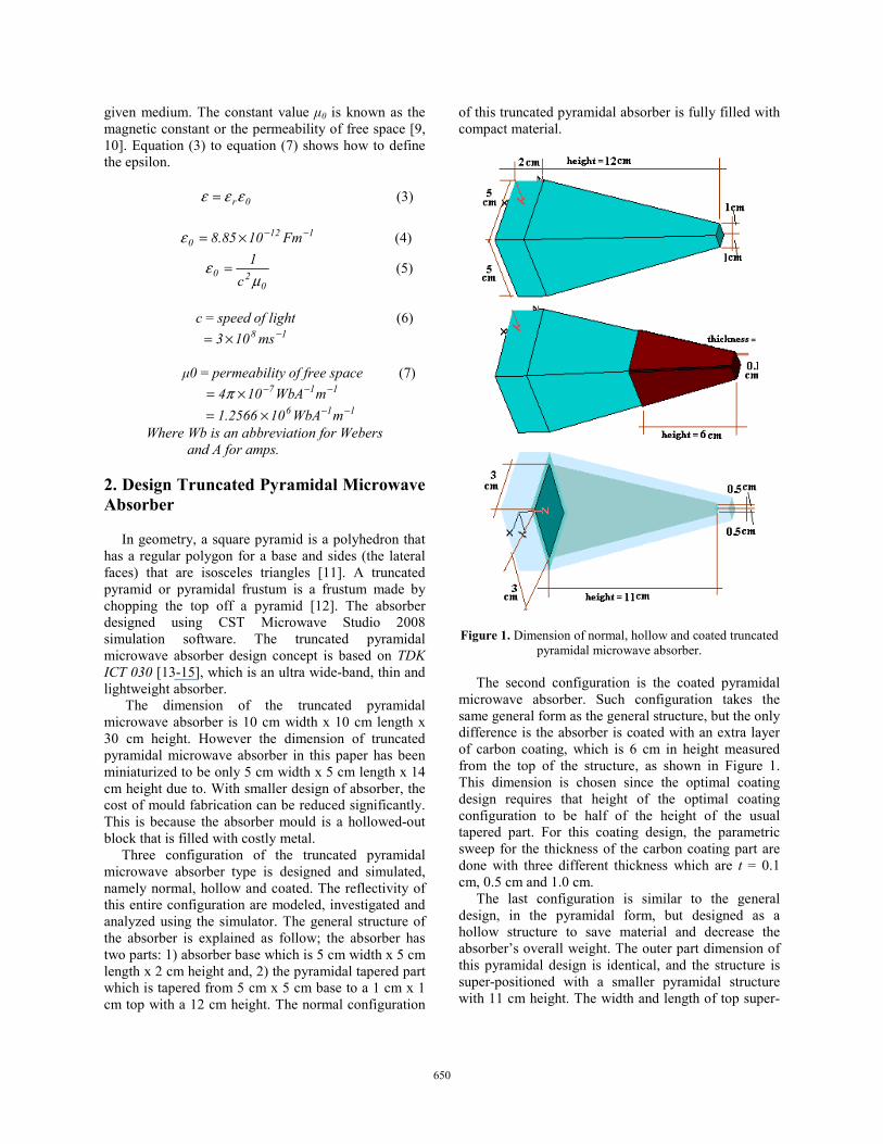
Three configuration of the truncated pyramidal microwave absorber type is designed and simulated, namely normal, hollow and coated. The reflectivity of this entire configuration are modeled, investigated and analyzed using the simulator. The general structure of the absorber is explained as follow; the absorber has two parts: 1) absorber base which is 5 cm width x 5 cm length x 2 cm height and, 2) the pyramidal tapered part which is tapered from 5 cm x 5 cm base to a 1 cm x 1 cm top with a 12 cm height. The normal configuration
of this truncated pyramidal absorber is fully filled with compact material.
Figure 1. Dimension of normal, hollow and coated truncated
pyramidal microwave absorber. The second configuration is the coated pyramidal
microwave absorber. Such configuration takes the same general form as the general structure, but the only difference is the absorber is coated with an extra layer of carbon coating, which is 6 cm in height measured from the top of the structure, as shown in Figure 1. This dimension is chosen since the optimal coating design requires that height of the optimal coating configuration to be half of the height of the usual tapered part. For this coating design, the parametric sweep for the thickness of the carbon coating part are done with three different thickness which are t = 0.1 cm, 0.5 cm and 1.0 cm.
The last configuration is similar to the general design, in the pyramidal form, but designed as a hollow structure to save material and decrease the absorber’s overall weight. The outer part dimension of this pyramidal design is identical, and the structure is super-positioned with a smaller pyramidal structure with 11 cm height. The width and length of top super-
650
positioned hollow part is only 0.5 cm x 0.5 cm compare to normal pyramid that has 1 cm width x 1 cm length. 3. Design of a Truncated Wedge Absorber
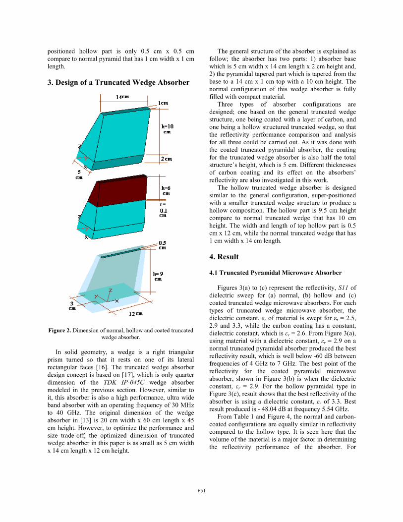
Figure 2. Dimension of normal, hollow and coated truncated wedge absorber.
In solid geometry, a wedge is a right triangular
prism turned so that it rests on one of its lateral rectangular faces [16]. The truncated wedge absorber design concept is based on [17], which is only quarter dimension of the TDK IP-045C wedge absorber modeled in the previous section. However, similar to it, this absorber is also a high performance, ultra wide band absorber with an operating frequency of 30 MHz to 40 GHz. The original dimension of the wedge absorber in [13] is 20 cm width x 60 cm length x 45 cm height. However, to optimize the performance and size trade-off, the optimized dimension of truncated wedge absorber in this paper is as small as 5 cm width x 14 cm length x 12 cm height.
The general structure of the absorber is explained as follow; the absorber has two parts: 1) absorber base which is 5 cm width x 14 cm length x 2 cm height and, 2) the pyramidal tapered part which is tapered from the base to a 14 cm x 1 cm top with a 10 cm height. The normal configuration of this wedge absorber is fully filled with compact material.
Three types of absorber configurations are designed; one based on the general truncated wedge structure, one being coated with a layer of carbon, and one being a hollow structured truncated wedge, so that the reflectivity performance comparison and analysis for all three could be carried out. As it was done with the coated truncated pyramidal absorber, the coating for the truncated wedge absorber is also half the total structure’s height, which is 5 cm. Different thicknesses of carbon coating and its effect on the absorbers’ reflectivity are also investigated in this work.
The hollow truncated wedge absorber is designed similar to the general configuration, super-positioned with a smaller truncated wedge structure to produce a hollow composition. The hollow part is 9.5 cm height compare to normal truncated wedge that has 10 cm height. The width and length of top hollow part is 0.5 cm x 12 cm, while the normal truncated wedge that has 1 cm width x 14 cm length. 4. Result 4.1 Truncated Pyramidal Microwave Absorber
Figures 3(a) to (c) represent the reflectivity, S11 of dielectric sweep for (a) normal, (b) hollow and (c) coated truncated wedge microwave absorbers. For each types of truncated wedge microwave absorber, the dielectric constant, εr of material is swept for εr = 2.5, 2.9 and 3.3, while the carbon coating has a constant, dielectric constant, which is εr = 2.6. From Figure 3(a), using material with a dielectric constant, εr = 2.9 on a normal truncated pyramidal absorber produced the best reflectivity result, which is well below -60 dB between frequencies of 4 GHz to 7 GHz. The best point of the reflectivity for the coated pyramidal microwave absorber, shown in Figure 3(b) is when the dielectric constant, εr = 2.9. For the hollow pyramidal type in Figure 3(c), result shows that the best reflectivity of the absorber is using a dielectric constant, εr of 3.3. Best result produced is - 48.04 dB at frequency 5.54 GHz.
From Table 1 and Figure 4, the normal and carbon-coated configurations are equally similar in reflectivity compared to the hollow type. It is seen here that the volume of the material is a major factor in determining the reflectivity performance of the absorber. For
651
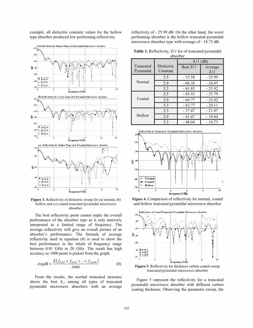
example, all dielectric constant values for the hollow type absorber produced low performing reflectivity.
Figure 3. Reflectivity of dielectric sweep for (a) normal, (b)
hollow and (c) coated truncated pyramidal microwave absorber.
The best reflectivity point cannot imply the overall performance of the absorber type as it only narrowly interpreted in a limited range of frequency. The average reflectivity will give an overall picture of an absorber’s performance. The formula of average reflectivity used in equation (8) is used to show the best performance in the whole of frequency range between 0.01 GHz to 20 GHz. The result has high accuracy as 1000 point is picked from the graph.
( )
1000f...ff
AvgdB 00.2004.002.0 +++=
Σ (8)
From the results, the normal truncated structure shows the best S11 among all types of truncated pyramidal microwave absorbers with an average
reflectivity of - 25.99 dB. On the other hand, the worst performing absorber is the hollow truncated pyramidal microwave absorber type with average of - 18.73 dB.
Table 1. Reflectivity, S11 for of truncated pyramidal absorber
Truncated Pyramidal
Dielectric Constant
S11 (dB) Best S11 Average
S11
Normal 2.5 - 53.58 - 25.99 2.9 - 66.38 - 24.85 3.3 - 61.85 - 23.92
Coated
2.5 - 45.43 - 25.79 2.9 - 69.77 - 25.02 3.3 - 63.77 - 24.11
Hollow
2.5 - 37.47 - 21.07 2.9 - 41.47 - 19.44 3.3 - 48.04 - 18.73
Figure 4. Comparison of reflectivity for normal, coated and hollow truncated pyramidal microwave absorber
Figure 5. Reflectivity for thickness carbon coated sweep
truncated pyramidal microwave absorber Figure 5 represent the reflectivity for a truncated pyramidal microwave absorber with different carbon coating thickness. Observing the parameter sweep, the
652
coated absorber with coating thickness, t of 0.1 cm showed the best reflectivity, compared to coating thickness, t = 0.5 cm and t = 1.0 cm. It also maintained a stable level of reflectivity, maintaining the value below - 22 dB between frequencies of 0.76 GHz to 10 GHz. The thickness, t = 1.0 cm produced the worst result as the satisfactory reflectivity level of - 10 dB can only be marginally achieved. 4.2 Truncated Wedge Microwave Absorber
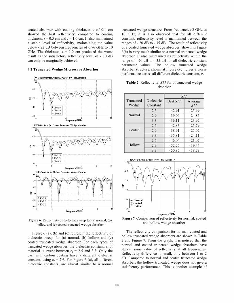
Figure 6. Reflectivity of dielectric sweep for (a) normal, (b)
hollow and (c) coated truncated wedge absorber Figure 6 (a), (b) and (c) represent the reflectivity of
dielectric sweep for (a) normal, (b) hollow and (c) coated truncated wedge absorber. For each types of truncated wedge absorber, the dielectric constant, εr of material is swept between εr = 2.5 and 3.3. Only the part with carbon coating have a different dielectric constant, using εr = 2.6. For Figure 6 (a), all different dielectric constants, are almost similar to a normal
truncated wedge structure. From frequencies 2 GHz to 10 GHz, it is also observed that for all different constant, reflectivity level is maintained between the ranges of - 20 dB to - 35 dB. The result of reflectivity of a coated truncated wedge absorber, shown in Figure 6(b) is very much similar to a normal truncated wedge absorber. It also maintained its reflectivity within the range of - 20 dB to - 35 dB for all dielectric constant parameter values. The hollow truncated wedge absorber structure, shown at Figure 6(c), gives a worse performance across all different dielectric constant, εr.
Table 2. Reflectivity, S11 for of truncated wedge
absorber
Truncated
Wedge
Dielectric Constant
S11 Best S11 Average
S11
Normal 2.5 - 42.91 - 25.99 2.9 - 39.06 - 24.85 3.3 - 36.11 - 23.92
Coated
2.5 - 42.83 - 25.79 2.9 - 38.91 - 25.02 3.3 - 35.81 - 24.11
Hollow
2.5 - 46.04 - 21.07 2.9 - 52.25 - 19.44 3.3 - 50.85 - 18.73
Figure 7. Comparison of reflectivity for normal, coated
and hollow wedge absorber The reflectivity comparison for normal, coated and hollow truncated wedge absorbers are shown in Table 2 and Figure 7. From the graph, it is noticed that the normal and coated truncated wedge absorbers have almost same value of reflectivity at all frequencies. Reflectivity difference is small, only between 1 to 2 dB. Compared to normal and coated truncated wedge absorber, the hollow truncated wedge does not give a satisfactory performance. This is another example of
653
how different volume for each absorber can affect the reflectivity. Like truncated pyramidal microwave absorber, the average power formula can be use for truncated wedge microwave absorber by applying equation (8). So, the best average dB is shown by normal truncated wedge with - 25.99 dB. The worst performance is shown by the hollow wedge microwave absorber type with only -18.73 dB.
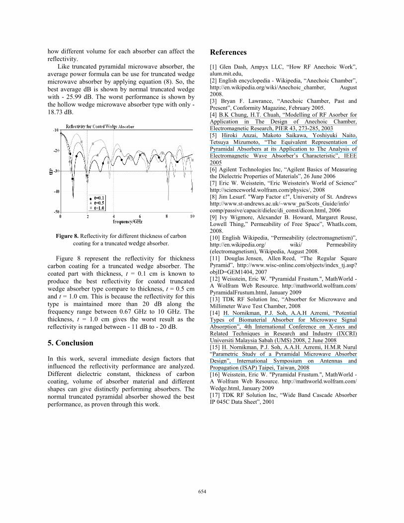
Figure 8. Reflectivity for different thickness of carbon coating for a truncated wedge absorber.
Figure 8 represent the reflectivity for thickness carbon coating for a truncated wedge absorber. The coated part with thickness, t = 0.1 cm is known to produce the best reflectivity for coated truncated wedge absorber type compare to thickness, t = 0.5 cm and t = 1.0 cm. This is because the reflectivity for this type is maintained more than 20 dB along the frequency range between 0.67 GHz to 10 GHz. The thickness, t = 1.0 cm gives the worst result as the reflectivity is ranged between - 11 dB to - 20 dB. 5. Conclusion In this work, several immediate design factors that influenced the reflectivity performance are analyzed. Different dielectric constant, thickness of carbon coating, volume of absorber material and different shapes can give distinctly performing absorbers. The normal truncated pyramidal absorber showed the best performance, as proven through this work.
References [1] Glen Dash, Ampyx LLC, “How RF Anechoic Work”, alum.mit.edu, [2] English encyclopedia - Wikipedia, “Anechoic Chamber”, http://en.wikipedia.org/wiki/Anechoic_chamber, August 2008. [3] Bryan F. Lawrance, “Anechoic Chamber, Past and Present”, Conformity Magazine, February 2005. [4] B.K Chung, H.T. Chuah, “Modelling of RF Asorber for Application in The Design of Anechoic Chamber, Electromagnetic Research, PIER 43, 273-285, 2003 [5] Hiroki Anzai, Makoto Saikawa, Yoshiyuki Naito, Tetsuya Mizumoto, “The Equivalent Representation of Pyramidal Absorbers at its Application to The Analysis of Electromagnetic Wave Absorber’s Characteristic”, IEEE 2005 [6] Agilent Technologies Inc, “Agilent Basics of Measuring the Dielectric Properties of Materials”, 26 June 2006 [7] Eric W. Weisstein, “Eric Weisstein's World of Science” http://scienceworld.wolfram.com/physics/, 2008 [8] Jim Lesurf. "Warp Factor ε!", University of St. Andrews http://www.st-andrews.ac.uk/~www_pa/Scots_Guide/info/ comp/passive/capacit/dielec/di_const/dicon.html, 2006 [9] Ivy Wigmore, Alexander B. Howard, Margaret Rouse, Lowell Thing,” Permeability of Free Space”, WhatIs.com, 2008. [10] English Wikipedia, “Permeability (electromagnetism)”, http://en.wikipedia.org/ wiki/ Permeability (electromagnetism), Wikipedia, August 2008. [11] Douglas Jensen, Allen Reed, “The Regular Square Pyramid”, http://www.wisc-online.com/objects/index_tj.asp? objID=GEM1404, 2007 [12] Weisstein, Eric W. "Pyramidal Frustum.", MathWorld - A Wolfram Web Resource. http://mathworld.wolfram.com/ PyramidalFrustum.html, January 2009 [13] TDK RF Solution Inc, “Absorber for Microwave and Millimeter Wave Test Chamber, 2008 [14] H. Nornikman, P.J. Soh, A.A.H Azremi, “Potential Types of Biomaterial Absorber for Microwave Signal Absorption”, 4th International Conference on X-rays and Related Techniques in Research and Industry (IXCRI) Universiti Malaysia Sabah (UMS) 2008, 2 June 2008 [15] H. Nornikman, P.J. Soh, A.A.H. Azremi, H.M.R Nurul “Parametric Study of a Pyramidal Microwave Absorber Design”, International Symposium on Antennas and Propagation (ISAP) Taipei, Taiwan, 2008 [16] Weisstein, Eric W. "Pyramidal Frustum.", MathWorld - A Wolfram Web Resource. http://mathworld.wolfram.com/ Wedge.html, January 2009 [17] TDK RF Solution Inc, “Wide Band Cascade Absorber IP 045C Data Sheet”, 2001
654


