Embed Size (px)
Citation preview
WORKSHOPMANUAL
50 cc INJECTIONENGINE
SALES DIVISIONNETWORK TECHNICAL INFORMATION
CONTENTS
Page: 2Reproduction or translation, even partial, are forbidden without the written consent of Peugeot Motocycles
CONTENTSCONTENTS.......................................................................................................................................... 2CHARACTERISTICS......................................................................................................................... 4
Characteristics ................................................................................................................................................ 4Capacities ....................................................................................................................................................... 4Engine markings............................................................................................................................................. 4SPECIAL IMPORTANT POINTS .................................................................................................... 5
Oil and fuel:.................................................................................................................................................... 5Starting: .......................................................................................................................................................... 5Electricity: ...................................................................................................................................................... 5Special features............................................................................................................................................... 5TIGHTENING TORQUES................................................................................................................. 6
Tightening torques:......................................................................................................................................... 6SPECIAL TOOLS ............................................................................................................................... 7
Introduction .................................................................................................................................................... 9DISASSEMBLY................................................................................................................................... 9
To remove the engine from the machine........................................................................................................ 9Putting the engine on the stand..................................................................................................................... 10To remove the cooling system...................................................................................................................... 10To remove the magneto flywheel ................................................................................................................. 11To remove the stator and sensor assembly................................................................................................... 12To remove the primary transmission cover .................................................................................................. 12To remove the drive pulley .......................................................................................................................... 12To remove the driven pulley ........................................................................................................................ 13To remove the secondary transmission cover .............................................................................................. 13To remove the secondary transmission ........................................................................................................ 14To remove the starter motor ......................................................................................................................... 14To remove the cylinder head/cylinder assembly.......................................................................................... 14To remove the air injector ............................................................................................................................ 15To remove the piston.................................................................................................................................... 15To remove the inlet manifold and valve....................................................................................................... 16Opening the casings...................................................................................................................................... 17To remove the crankshaft ............................................................................................................................. 18Checking the crank....................................................................................................................................... 19REFITTING SPECIFIC COMPONENTS...................................................................................... 20
To fit bearings .............................................................................................................................................. 20Assembling the casings ................................................................................................................................ 21To fit the piston ............................................................................................................................................ 23To fit the cylinder ......................................................................................................................................... 24To fit the cylinder head ................................................................................................................................ 24To fit the magneto flywheel ......................................................................................................................... 25To remove the cooling system...................................................................................................................... 25To fit the injection manifold and compressor .............................................................................................. 26To fit the drive pulley assembly ................................................................................................................... 26MISCELLANEOUS OPERATIONS ............................................................................................... 27
To remove the starter system........................................................................................................................ 27To fit starter system...................................................................................................................................... 27To remove/refit the drive pulley rollers ....................................................................................................... 28To remove the clutch lining assembly.......................................................................................................... 29To refit the clutch lining assembly ............................................................................................................... 29To remove the fuel tank................................................................................................................................ 30
CONTENTS
Page: 3Reproduction or translation, even partial, are forbidden without the written consent of Peugeot Motocycles
Procedure used to lower the pressure in the fuel system instruction 1 ....................................................... 31Fuel circuit bleeding procedure instruction 2 ............................................................................................. 32To remove the Injection rail ......................................................................................................................... 32To remove the air injector ............................................................................................................................ 33To remove the air compressor ...................................................................................................................... 34To remove the throttle unit ........................................................................................................................... 35To remove the fuel pump ............................................................................................................................. 37To remove the strainer.................................................................................................................................. 38To remove the ECU...................................................................................................................................... 39To remove the temperature sensor ............................................................................................................... 39To remove the HT coil ................................................................................................................................. 40Setting the spark plug electrode gap............................................................................................................. 40To remove the oil pump ............................................................................................................................... 41Parameter reading ............................................................................................................................. 42
CHARACTERISTICS
Page: 4Reproduction or translation, even partial, are forbidden without the written consent of Peugeot Motocycles
CHARACTERISTICS
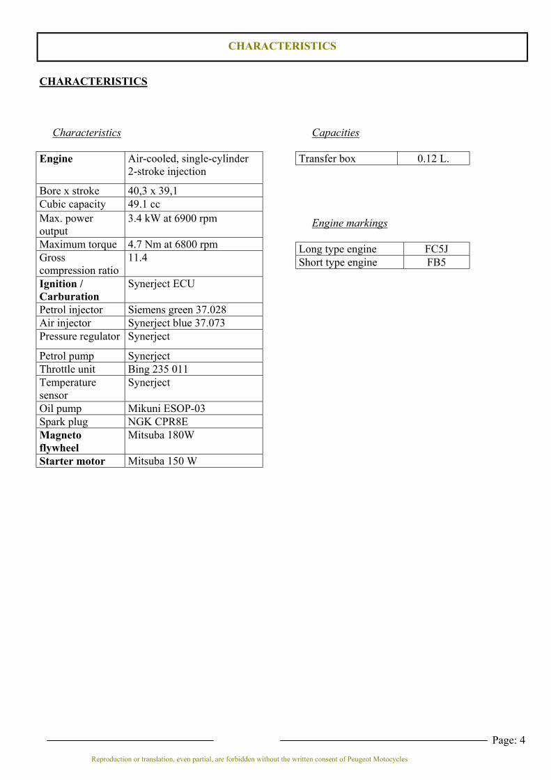
Characteristics
Engine Air-cooled, single-cylinder2-stroke injection
Bore x stroke 40,3 x 39,1Cubic capacity 49.1 ccMax. poweroutput
3.4 kW at 6900 rpm
Maximum torque 4.7 Nm at 6800 rpmGrosscompression ratio
11.4
Ignition /Carburation
Synerject ECU
Petrol injector Siemens green 37.028Air injector Synerject blue 37.073Pressure regulator Synerject
Petrol pump SynerjectThrottle unit Bing 235 011Temperaturesensor
Synerject
Oil pump Mikuni ESOP-03Spark plug NGK CPR8EMagnetoflywheel
Mitsuba 180W
Starter motor Mitsuba 150 W
Capacities
Transfer box 0.12 L.
Engine markings
Long type engine FC5JShort type engine FB5

SPECIAL IMPORTANT POINTS
Page: 5Reproduction or translation, even partial, are forbidden without the written consent of Peugeot Motocycles
SPECIAL IMPORTANT POINTS
Oil and fuel:This engine is designed to run on 95 or 98 unleaded fuel onlyThe oil used for the separate lubrication system is Esso 2T special, approved by the machine manufacturer.The oil is injected directly into the inlet manifold as the engine requires.Never run the machine with a petrol/oil mixture.
Starting:Bleed of the oil circuit must be tested with the diagnostic tool: check if there are fault codes and clear themwhere necessary.
Starting should not be with a 2-stroke mixture, as the fuel pump and injectors are not designed to operatewith oil.Do not accelerate when hot or cold starting
Electricity:All components of the electrical system are powered with 12 volts DC.The battery is essential to operate the petrol pump and the ECU which are used for engine starting.The battery must not be disconnected while the engine is running.The battery voltage must be a minimum of 8.5 volts for the ECU to able to function and authorise starting.
Special featuresThe ignition is controlled by the ECU which determines the advance based on the information given by:- the engine speed sensor located opposite a pulse wheel fitted to the magneto flywheel- the quantity of air intake into the engine, measured by the throttle unit, is transmitted to the ECU whichwill define just the right quantities of oil and petrol necessary for engine optimum running.The throttle unit must be re-initialised after disconnecting or changing the ECU.The oil pump controlled by the ECU must be bled before restarting the engine using the procedure describedin the relevant chapter.The fuel pump controlled by the ECU must be bled before restarting the engine using the proceduredescribed in the relevant chapter.The ECU has a diagnostic function enabling the mechanic to test the injection system using the LED on theinstrument panel or the diagnostic tool.
The fuel inlet and injection manifold return pipes must only be replaced by genuine service parts. Thefuel pressure of 8 bars requires special pipes.The fuel pipes must be changed if they show signs of wear, cracks, etc.The fuel pipe clips are also specific, other clips must never be used.
Note:Before carrying out any work, leave the engine to cool for a minimum of 2 hours.Petrol is highly inflammable, do not smoke in the working area and avoid proximity to flames or sparks.Work in a clear and well-ventilated area.
TIGHTENING TORQUES
Page: 6Reproduction or translation, even partial, are forbidden without the written consent of Peugeot Motocycles
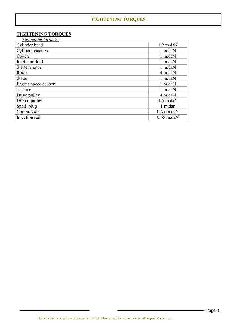
TIGHTENING TORQUESTightening torques:
Cylinder head 1.2 m.daNCylinder casings 1 m.daNCovers 1 m.daNInlet manifold 1 m.daNStarter motor 1 m.daNRotor 4 m.daNStator 1 m.daNEngine speed sensor. 1 m.daNTurbine 1 m.daNDrive pulley 4 m.daNDriven pulley 4.5 m.daNSpark plug 1 m.danCompressor 0.65 m.daNInjection rail 0.65 m.daN
SPECIAL TOOLS
Page: 7Reproduction or translation, even partial, are forbidden without the written consent of Peugeot Motocycles
SPECIAL TOOLS
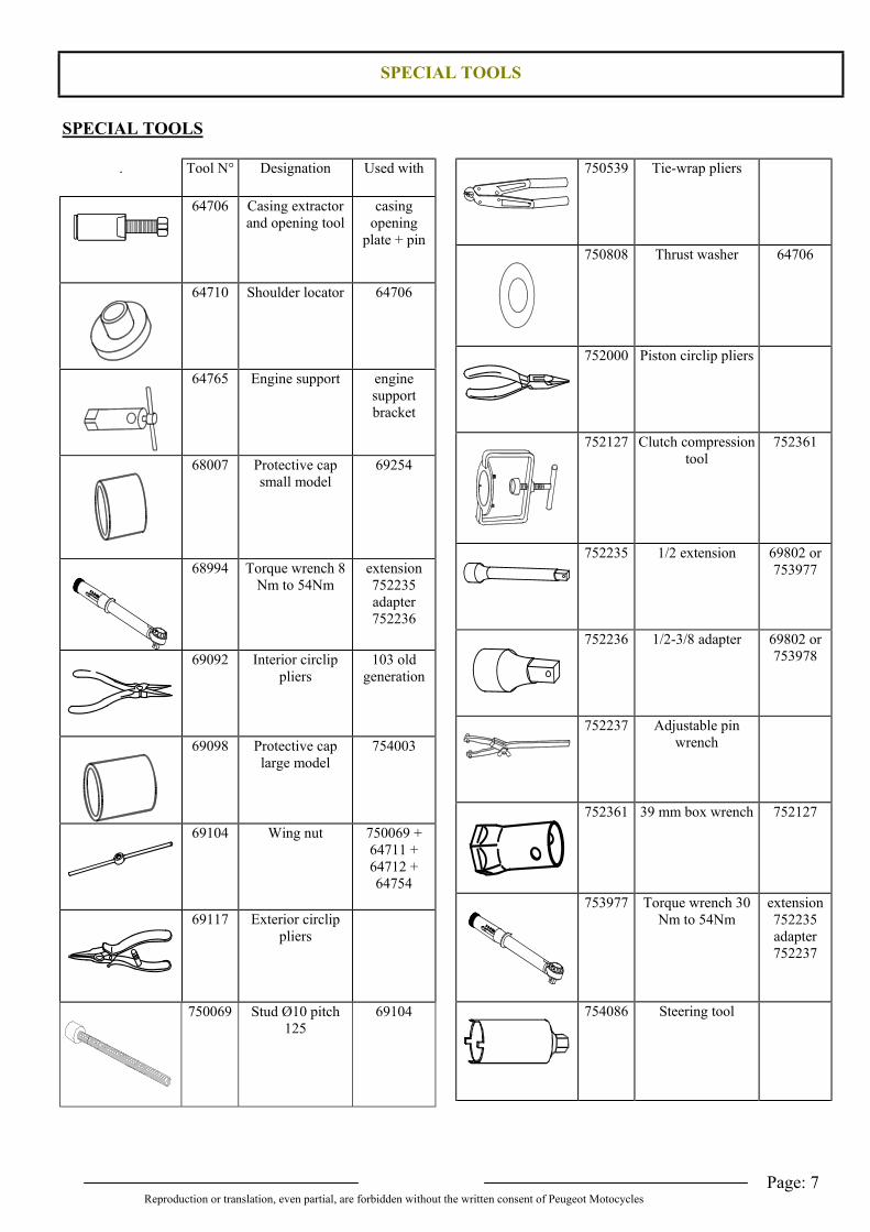
. Tool N° Designation Used with
64706 Casing extractorand opening tool
casingopening
plate + pin
64710 Shoulder locator 64706
64765 Engine support enginesupportbracket
68007 Protective capsmall model
69254
68994 Torque wrench 8Nm to 54Nm
extension752235adapter752236
69092 Interior circlippliers
103 oldgeneration
69098 Protective caplarge model
754003
69104 Wing nut 750069 +64711 +64712 +64754
69117 Exterior circlippliers
750069 Stud Ø10 pitch125
69104
750539 Tie-wrap pliers
750808 Thrust washer 64706
752000 Piston circlip pliers
752127 Clutch compressiontool
752361
752235 1/2 extension 69802 or753977
752236 1/2-3/8 adapter 69802 or753978
752237 Adjustable pinwrench
752361 39 mm box wrench 752127
753977 Torque wrench 30Nm to 54Nm
extension752235adapter752237
754086 Steering tool
SPECIAL TOOLS
Page: 8Reproduction or translation, even partial, are forbidden without the written consent of Peugeot Motocycles
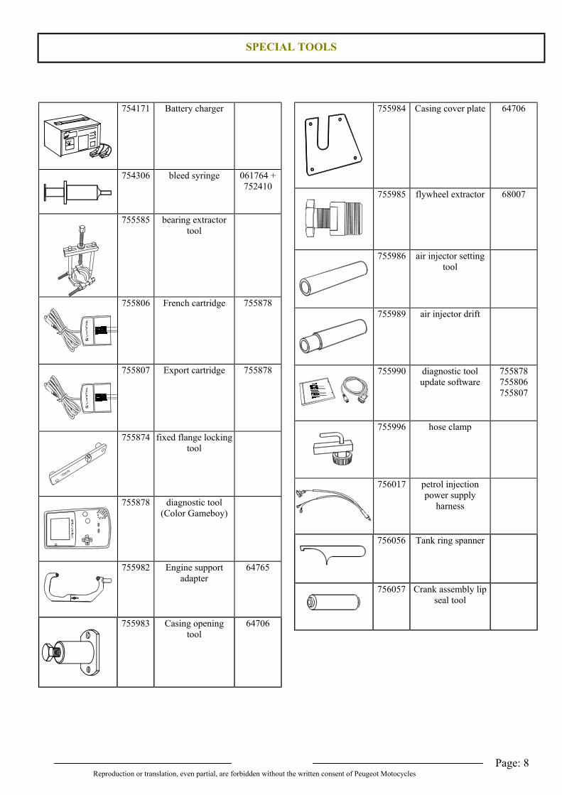
754171 Battery charger
754306 bleed syringe 061764 +752410
755585 bearing extractortool
755806 French cartridge 755878
755807 Export cartridge 755878
755874 fixed flange lockingtool
755878 diagnostic tool(Color Gameboy)
755982 Engine supportadapter
64765
755983 Casing openingtool
64706
755984 Casing cover plate 64706
755985 flywheel extractor 68007
755986 air injector settingtool
755989 air injector drift
755990 diagnostic toolupdate software
755878755806755807
755996 hose clamp
756017 petrol injectionpower supply
harness
756056 Tank ring spanner
756057 Crank assembly lipseal tool
DISASSEMBLY
Page: 9Reproduction or translation, even partial, are forbidden without the written consent of Peugeot Motocycles
IntroductionThe injection system is composed of precision components and cannot withstand impurities. Perfectlyclean working conditions are therefore essential.
DISASSEMBLY
To remove the engine from the machineCompulsory: wash the power unit - Disconnect and remove the battery - Remove the saddle/locker assembly, the grab handle, mud-flap and rear panelling assembly - Remove the injection manifold soundproofing - Raise the fuel tank in order to withdraw the injection manifold soundproofing. - Remove the injection manifold without disconnecting the fuel supply pipes (see relevant chapter), - Move the injection manifold clear and protect from impurities with a clean rag. - Disconnect the air injector - Put a clean rag over the air injector to protect it from impurities - Remove the upper handlebar fairing, the rear panel and floor panel - Disconnect the flywheel output harness and the starter motor - Remove the air intake, the air filter box with the throttle unit - Disconnect the throttle unit - Move the air filter box clear with the throttle valve without disconnecting the throttle cable - Disconnect the temperature sensor - Disconnect the inlet manifold oil inlet pipe - Unclip the harness assembly from the cylinder cover - Disconnect the suppressor and rear brake cable - Remove the exhaust - Slacken the rear wheel nut - Suspend the machine - Remove the shock absorber lower mount and the engine linkrod fixing bolt - Remove the power unit - Remove the rear wheel - Remove the stand with its bracket
DISASSEMBLY
Page: 10Reproduction or translation, even partial, are forbidden without the written consent of Peugeot Motocycles
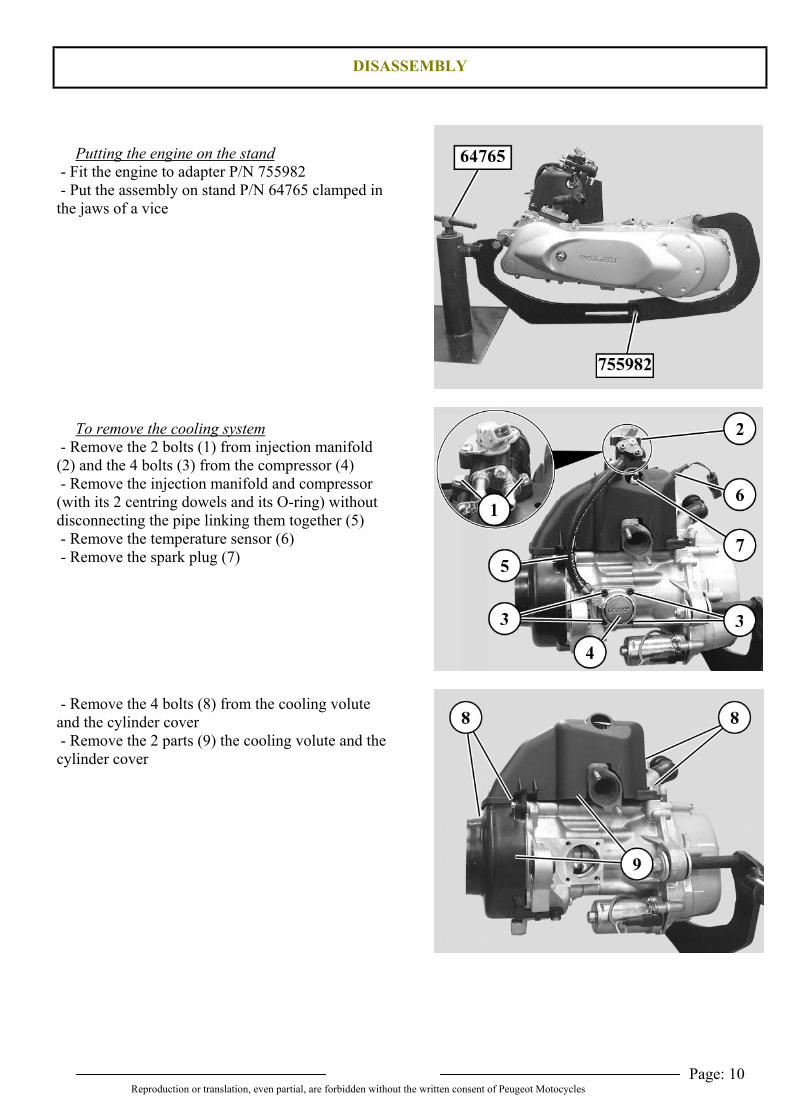
Putting the engine on the stand - Fit the engine to adapter P/N 755982 - Put the assembly on stand P/N 64765 clamped inthe jaws of a vice
To remove the cooling system - Remove the 2 bolts (1) from injection manifold(2) and the 4 bolts (3) from the compressor (4) - Remove the injection manifold and compressor(with its 2 centring dowels and its O-ring) withoutdisconnecting the pipe linking them together (5) - Remove the temperature sensor (6) - Remove the spark plug (7)
- Remove the 4 bolts (8) from the cooling voluteand the cylinder cover - Remove the 2 parts (9) the cooling volute and thecylinder cover
DISASSEMBLY
Page: 11Reproduction or translation, even partial, are forbidden without the written consent of Peugeot Motocycles
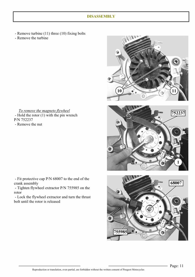
- Remove turbine (11) three (10) fixing bolts - Remove the turbine
To remove the magneto flywheel - Hold the rotor (1) with the pin wrenchP/N 752237 - Remove the nut
- Fit protective cap P/N 68007 to the end of thecrank assembly - Tighten flywheel extractor P/N 755985 on therotor - Lock the flywheel extractor and turn the thrustbolt until the rotor is released
DISASSEMBLY
Page: 12Reproduction or translation, even partial, are forbidden without the written consent of Peugeot Motocycles
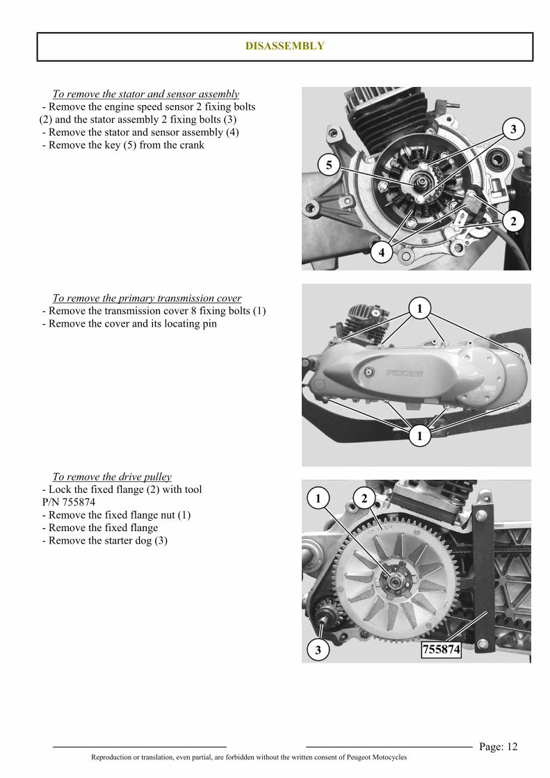
To remove the stator and sensor assembly - Remove the engine speed sensor 2 fixing bolts(2) and the stator assembly 2 fixing bolts (3) - Remove the stator and sensor assembly (4) - Remove the key (5) from the crank
To remove the primary transmission cover - Remove the transmission cover 8 fixing bolts (1) - Remove the cover and its locating pin
To remove the drive pulley - Lock the fixed flange (2) with tool P/N 755874 - Remove the fixed flange nut (1) - Remove the fixed flange - Remove the starter dog (3)
DISASSEMBLY
Page: 13Reproduction or translation, even partial, are forbidden without the written consent of Peugeot Motocycles
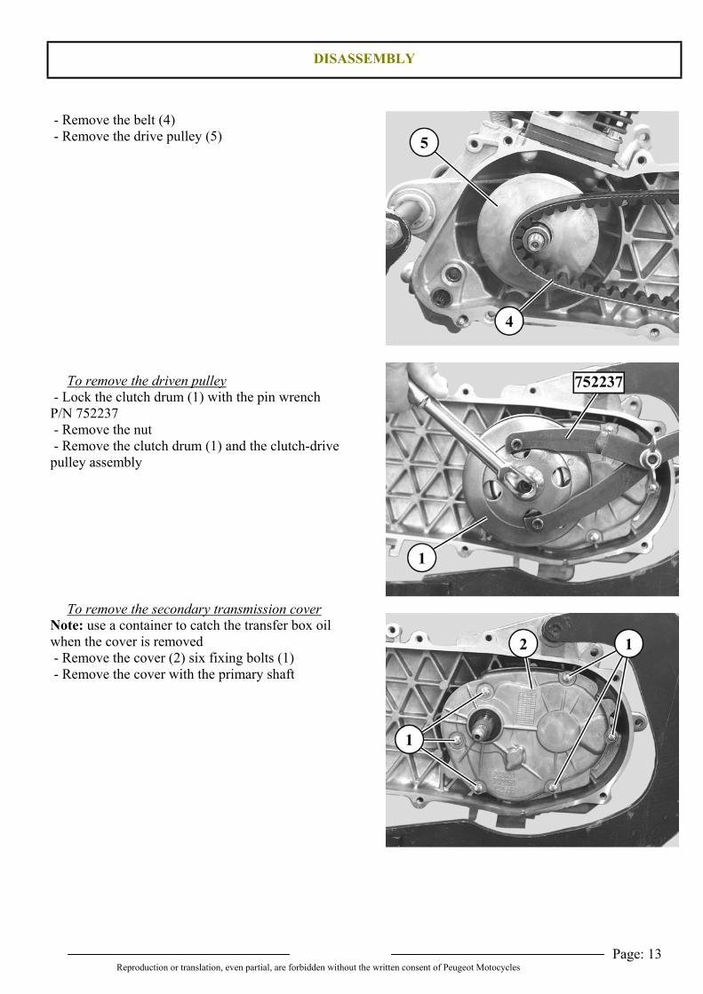
- Remove the belt (4) - Remove the drive pulley (5)
To remove the driven pulley - Lock the clutch drum (1) with the pin wrenchP/N 752237 - Remove the nut - Remove the clutch drum (1) and the clutch-drivepulley assembly
To remove the secondary transmission coverNote: use a container to catch the transfer box oilwhen the cover is removed - Remove the cover (2) six fixing bolts (1) - Remove the cover with the primary shaft
DISASSEMBLY
Page: 14Reproduction or translation, even partial, are forbidden without the written consent of Peugeot Motocycles
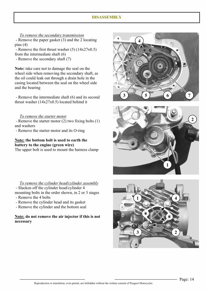
To remove the secondary transmission - Remove the paper gasket (3) and the 2 locatingpins (4) - Remove the first thrust washer (5) (14x27x0.5)from the intermediate shaft (6) - Remove the secondary shaft (7)
Note: take care not to damage the seal on thewheel side when removing the secondary shaft, asthe oil could leak out through a drain hole in thecasing located between the seal on the wheel sideand the bearing
- Remove the intermediate shaft (6) and its secondthrust washer (14x27x0.5) located behind it
To remove the starter motor - Remove the starter motor (2) two fixing bolts (1)and washers - Remove the starter motor and its O-ring
Note: the bottom bolt is used to earth thebattery to the engine (green wire)The upper bolt is used to mount the harness clamp
To remove the cylinder head/cylinder assembly - Slacken off the cylinder head/cylinder 4mounting bolts in the order shown, in 2 or 3 stages - Remove the 4 bolts - Remove the cylinder head and its gasket - Remove the cylinder and the bottom seal
Note: do not remove the air injector if this is notnecessary
DISASSEMBLY
Page: 15Reproduction or translation, even partial, are forbidden without the written consent of Peugeot Motocycles
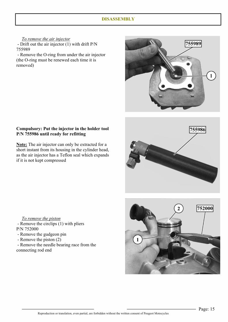
To remove the air injector - Drift out the air injector (1) with drift P/N755989 - Remove the O-ring from under the air injector(the O-ring must be renewed each time it isremoved)
Compulsory: Put the injector in the holder toolP/N 755986 until ready for refitting
Note: The air injector can only be extracted for ashort instant from its housing in the cylinder head,as the air injector has a Teflon seal which expandsif it is not kept compressed
To remove the piston - Remove the circlips (1) with pliersP/N 752000 - Remove the gudgeon pin - Remove the piston (2) - Remove the needle bearing race from theconnecting rod end
DISASSEMBLY
Page: 16Reproduction or translation, even partial, are forbidden without the written consent of Peugeot Motocycles
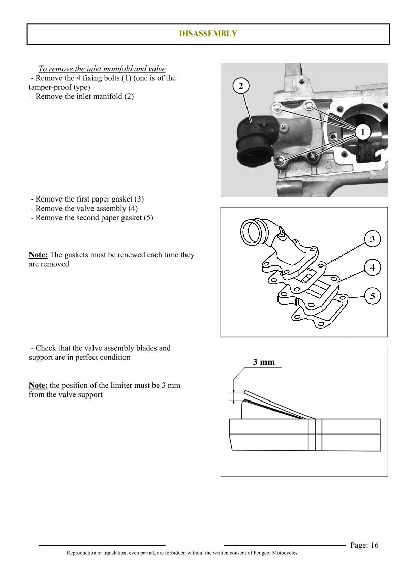
To remove the inlet manifold and valve - Remove the 4 fixing bolts (1) (one is of thetamper-proof type) - Remove the inlet manifold (2)
- Remove the first paper gasket (3) - Remove the valve assembly (4) - Remove the second paper gasket (5)
Note: The gaskets must be renewed each time theyare removed
- Check that the valve assembly blades andsupport are in perfect condition
Note: the position of the limiter must be 3 mmfrom the valve support
DISASSEMBLY
Page: 17Reproduction or translation, even partial, are forbidden without the written consent of Peugeot Motocycles
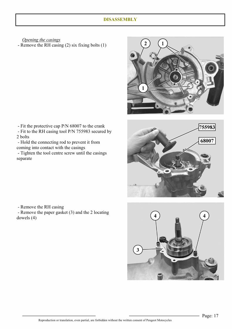
Opening the casings - Remove the RH casing (2) six fixing bolts (1)
- Fit the protective cap P/N 68007 to the crank - Fit to the RH casing tool P/N 755983 secured by2 bolts - Hold the connecting rod to prevent it fromcoming into contact with the casings - Tighten the tool centre screw until the casingsseparate
- Remove the RH casing - Remove the paper gasket (3) and the 2 locatingdowels (4)
DISASSEMBLY
Page: 18Reproduction or translation, even partial, are forbidden without the written consent of Peugeot Motocycles
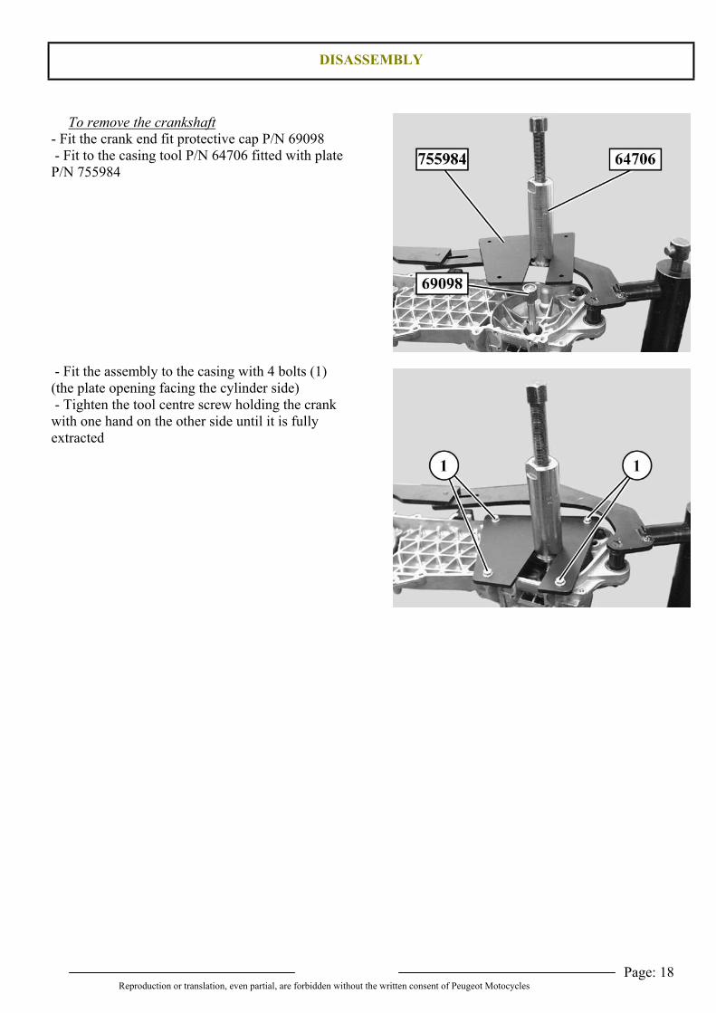
To remove the crankshaft- Fit the crank end fit protective cap P/N 69098 - Fit to the casing tool P/N 64706 fitted with plateP/N 755984
- Fit the assembly to the casing with 4 bolts (1)(the plate opening facing the cylinder side) - Tighten the tool centre screw holding the crankwith one hand on the other side until it is fullyextracted
DISASSEMBLY
Page: 19Reproduction or translation, even partial, are forbidden without the written consent of Peugeot Motocycles
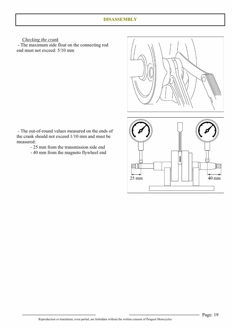
Checking the crank - The maximum side float on the connecting rodend must not exceed: 5/10 mm
- The out-of-round values measured on the ends ofthe crank should not exceed 1/10 mm and must bemeasured:
- 25 mm from the transmission side end- 40 mm from the magneto flywheel end
REFITTING SPECIFIC COMPONENTS
Page: 20Reproduction or translation, even partial, are forbidden without the written consent of Peugeot Motocycles
REFITTING SPECIFIC COMPONENTS
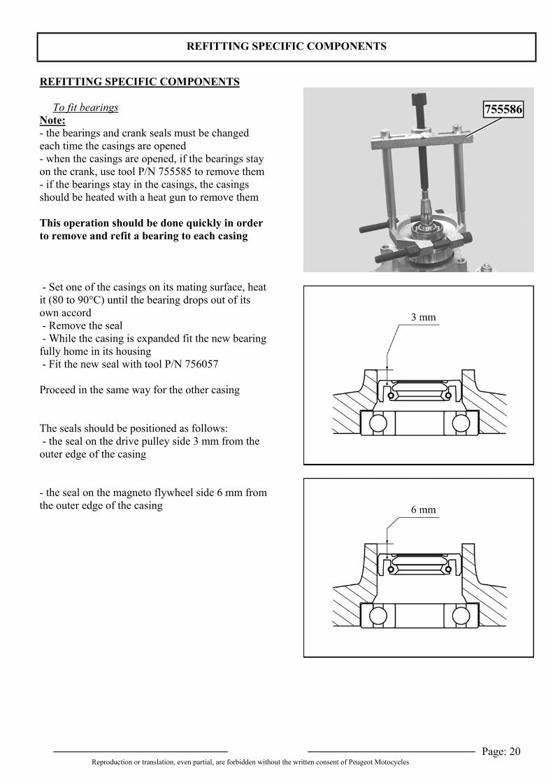
To fit bearingsNote:- the bearings and crank seals must be changedeach time the casings are opened- when the casings are opened, if the bearings stayon the crank, use tool P/N 755585 to remove them- if the bearings stay in the casings, the casingsshould be heated with a heat gun to remove them
This operation should be done quickly in orderto remove and refit a bearing to each casing
- Set one of the casings on its mating surface, heatit (80 to 90°C) until the bearing drops out of itsown accord - Remove the seal - While the casing is expanded fit the new bearingfully home in its housing - Fit the new seal with tool P/N 756057
Proceed in the same way for the other casing
The seals should be positioned as follows: - the seal on the drive pulley side 3 mm from theouter edge of the casing
- the seal on the magneto flywheel side 6 mm fromthe outer edge of the casing
REFITTING SPECIFIC COMPONENTS
Page: 21Reproduction or translation, even partial, are forbidden without the written consent of Peugeot Motocycles
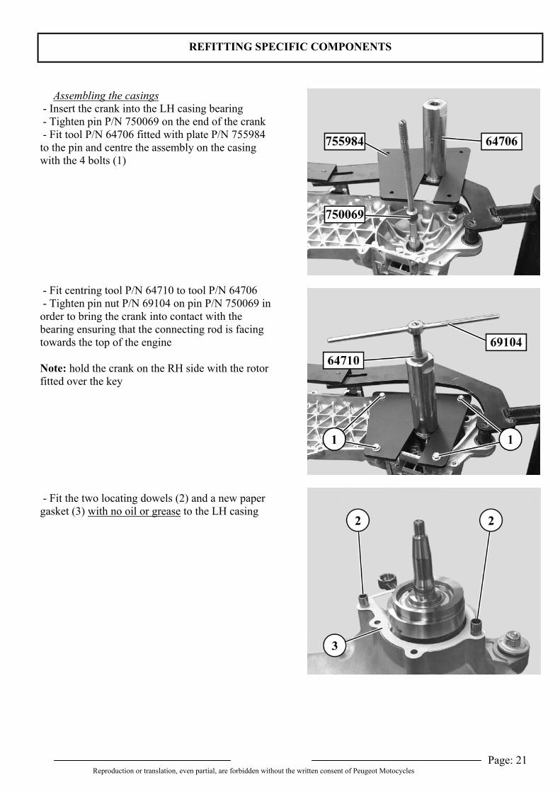
Assembling the casings - Insert the crank into the LH casing bearing - Tighten pin P/N 750069 on the end of the crank - Fit tool P/N 64706 fitted with plate P/N 755984to the pin and centre the assembly on the casingwith the 4 bolts (1)
- Fit centring tool P/N 64710 to tool P/N 64706 - Tighten pin nut P/N 69104 on pin P/N 750069 inorder to bring the crank into contact with thebearing ensuring that the connecting rod is facingtowards the top of the engine
Note: hold the crank on the RH side with the rotorfitted over the key
- Fit the two locating dowels (2) and a new papergasket (3) with no oil or grease to the LH casing
REFITTING SPECIFIC COMPONENTS
Page: 22Reproduction or translation, even partial, are forbidden without the written consent of Peugeot Motocycles
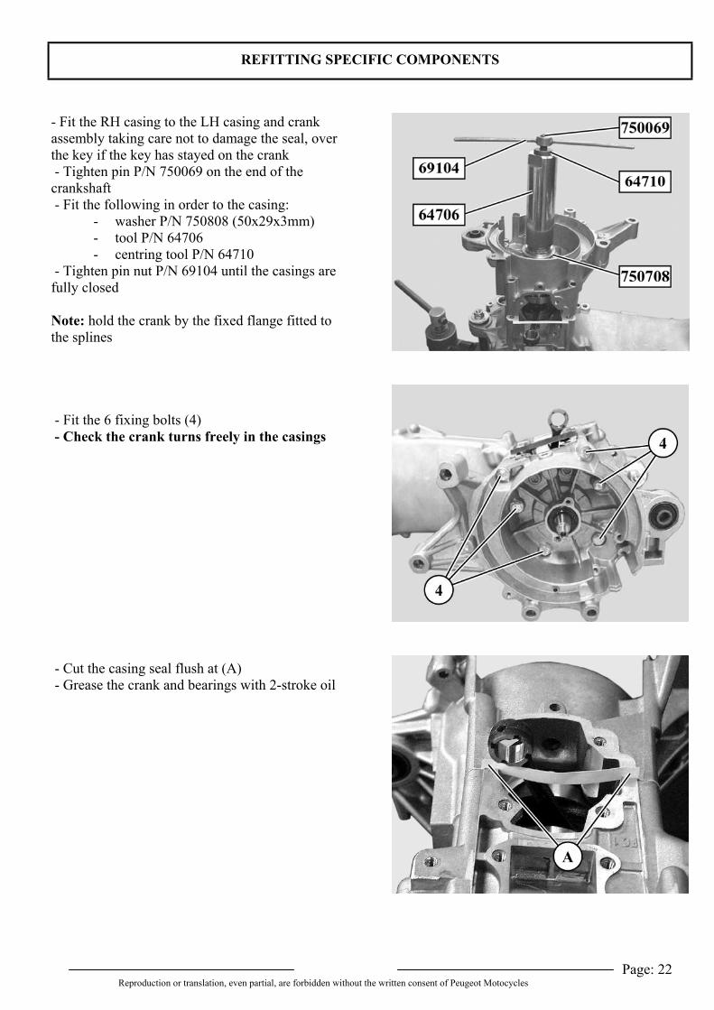
- Fit the RH casing to the LH casing and crankassembly taking care not to damage the seal, overthe key if the key has stayed on the crank - Tighten pin P/N 750069 on the end of thecrankshaft - Fit the following in order to the casing:
- washer P/N 750808 (50x29x3mm)- tool P/N 64706- centring tool P/N 64710
- Tighten pin nut P/N 69104 until the casings arefully closed
Note: hold the crank by the fixed flange fitted tothe splines
- Fit the 6 fixing bolts (4) - Check the crank turns freely in the casings
- Cut the casing seal flush at (A) - Grease the crank and bearings with 2-stroke oil
REFITTING SPECIFIC COMPONENTS
Page: 23Reproduction or translation, even partial, are forbidden without the written consent of Peugeot Motocycles
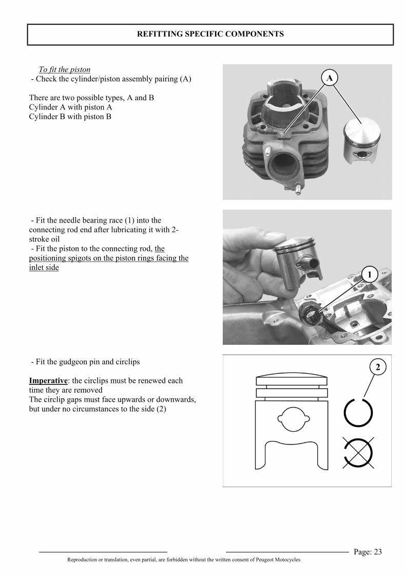
To fit the piston - Check the cylinder/piston assembly pairing (A)
There are two possible types, A and BCylinder A with piston ACylinder B with piston B
- Fit the needle bearing race (1) into theconnecting rod end after lubricating it with 2-stroke oil - Fit the piston to the connecting rod, thepositioning spigots on the piston rings facing theinlet side
- Fit the gudgeon pin and circlips
Imperative: the circlips must be renewed eachtime they are removedThe circlip gaps must face upwards or downwards,but under no circumstances to the side (2)
REFITTING SPECIFIC COMPONENTS
Page: 24Reproduction or translation, even partial, are forbidden without the written consent of Peugeot Motocycles
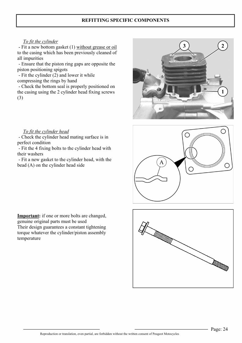
To fit the cylinder - Fit a new bottom gasket (1) without grease or oilto the casing which has been previously cleaned ofall impurities - Ensure that the piston ring gaps are opposite thepiston positioning spigots - Fit the cylinder (2) and lower it whilecompressing the rings by hand - Check the bottom seal is properly positioned onthe casing using the 2 cylinder head fixing screws(3)
To fit the cylinder head - Check the cylinder head mating surface is inperfect condition - Fit the 4 fixing bolts to the cylinder head withtheir washers - Fit a new gasket to the cylinder head, with thebead (A) on the cylinder head side
Important: if one or more bolts are changed,genuine original parts must be usedTheir design guarantees a constant tighteningtorque whatever the cylinder/piston assemblytemperature
REFITTING SPECIFIC COMPONENTS
Page: 25Reproduction or translation, even partial, are forbidden without the written consent of Peugeot Motocycles
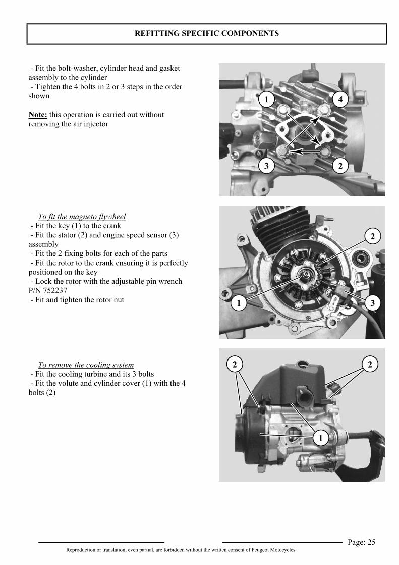
- Fit the bolt-washer, cylinder head and gasketassembly to the cylinder - Tighten the 4 bolts in 2 or 3 steps in the ordershown
Note: this operation is carried out withoutremoving the air injector
To fit the magneto flywheel - Fit the key (1) to the crank - Fit the stator (2) and engine speed sensor (3)assembly - Fit the 2 fixing bolts for each of the parts - Fit the rotor to the crank ensuring it is perfectlypositioned on the key - Lock the rotor with the adjustable pin wrenchP/N 752237 - Fit and tighten the rotor nut
To remove the cooling system - Fit the cooling turbine and its 3 bolts - Fit the volute and cylinder cover (1) with the 4bolts (2)
REFITTING SPECIFIC COMPONENTS
Page: 26Reproduction or translation, even partial, are forbidden without the written consent of Peugeot Motocycles
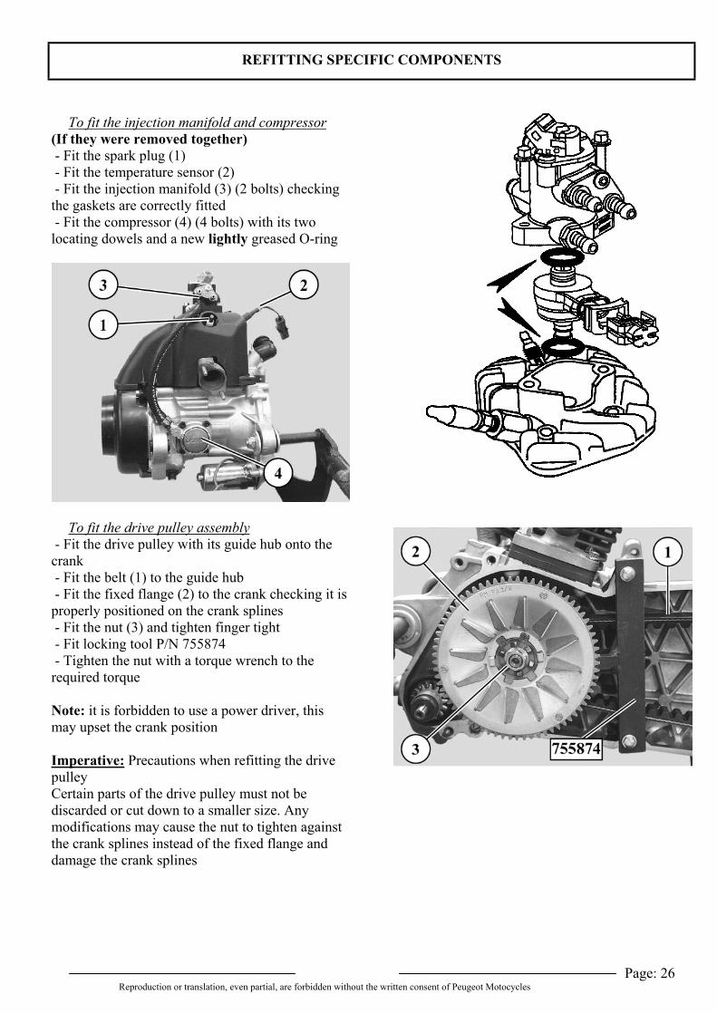
To fit the injection manifold and compressor(If they were removed together) - Fit the spark plug (1) - Fit the temperature sensor (2) - Fit the injection manifold (3) (2 bolts) checkingthe gaskets are correctly fitted - Fit the compressor (4) (4 bolts) with its twolocating dowels and a new lightly greased O-ring
To fit the drive pulley assembly - Fit the drive pulley with its guide hub onto thecrank - Fit the belt (1) to the guide hub - Fit the fixed flange (2) to the crank checking it isproperly positioned on the crank splines - Fit the nut (3) and tighten finger tight - Fit locking tool P/N 755874 - Tighten the nut with a torque wrench to therequired torque
Note: it is forbidden to use a power driver, thismay upset the crank position
Imperative: Precautions when refitting the drivepulleyCertain parts of the drive pulley must not bediscarded or cut down to a smaller size. Anymodifications may cause the nut to tighten againstthe crank splines instead of the fixed flange anddamage the crank splines
MISCELLANEOUS OPERATIONS
Page: 27Reproduction or translation, even partial, are forbidden without the written consent of Peugeot Motocycles
MISCELLANEOUS OPERATIONS
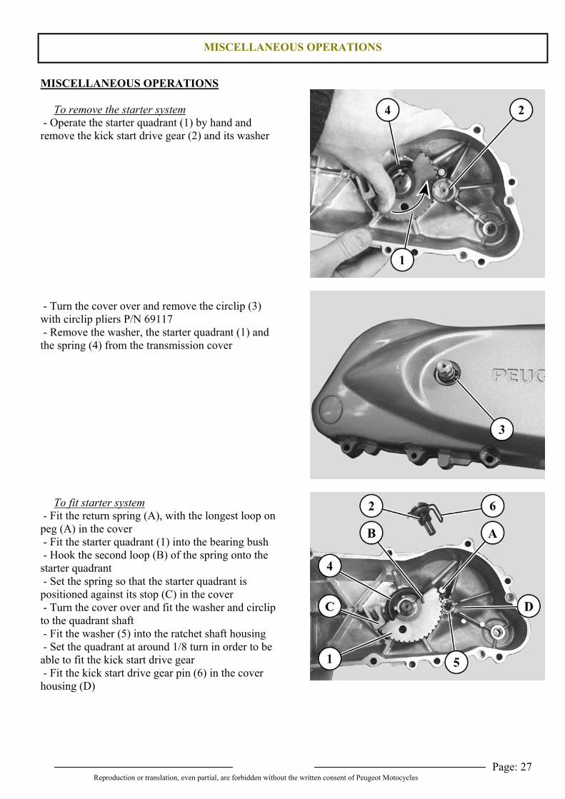
To remove the starter system - Operate the starter quadrant (1) by hand andremove the kick start drive gear (2) and its washer
- Turn the cover over and remove the circlip (3)with circlip pliers P/N 69117 - Remove the washer, the starter quadrant (1) andthe spring (4) from the transmission cover
To fit starter system - Fit the return spring (A), with the longest loop onpeg (A) in the cover - Fit the starter quadrant (1) into the bearing bush - Hook the second loop (B) of the spring onto thestarter quadrant - Set the spring so that the starter quadrant ispositioned against its stop (C) in the cover - Turn the cover over and fit the washer and circlipto the quadrant shaft - Fit the washer (5) into the ratchet shaft housing - Set the quadrant at around 1/8 turn in order to beable to fit the kick start drive gear - Fit the kick start drive gear pin (6) in the coverhousing (D)
MISCELLANEOUS OPERATIONS
Page: 28Reproduction or translation, even partial, are forbidden without the written consent of Peugeot Motocycles
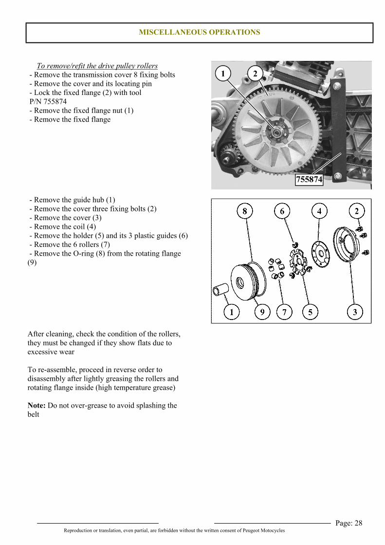
To remove/refit the drive pulley rollers - Remove the transmission cover 8 fixing bolts - Remove the cover and its locating pin - Lock the fixed flange (2) with tool P/N 755874 - Remove the fixed flange nut (1) - Remove the fixed flange
- Remove the guide hub (1) - Remove the cover three fixing bolts (2) - Remove the cover (3) - Remove the coil (4) - Remove the holder (5) and its 3 plastic guides (6) - Remove the 6 rollers (7) - Remove the O-ring (8) from the rotating flange(9)
After cleaning, check the condition of the rollers,they must be changed if they show flats due toexcessive wear
To re-assemble, proceed in reverse order todisassembly after lightly greasing the rollers androtating flange inside (high temperature grease)
Note: Do not over-grease to avoid splashing thebelt
MISCELLANEOUS OPERATIONS
Page: 29Reproduction or translation, even partial, are forbidden without the written consent of Peugeot Motocycles
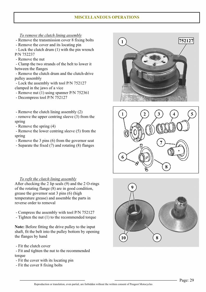
To remove the clutch lining assembly - Remove the transmission cover 8 fixing bolts - Remove the cover and its locating pin - Lock the clutch drum (1) with the pin wrenchP/N 752237 - Remove the nut - Clamp the two strands of the belt to lower itbetween the flanges - Remove the clutch drum and the clutch-drivepulley assembly - Lock the assembly with tool P/N 752127clamped in the jaws of a vice - Remove nut (1) using spanner P/N 752361 - Decompress tool P/N 752127
- Remove the clutch lining assembly (2) - remove the upper centring sleeve (3) from thespring - Remove the spring (4) - Remove the lower centring sleeve (5) from thespring - Remove the 3 pins (6) from the governor seat - Separate the fixed (7) and rotating (8) flanges
To refit the clutch lining assemblyAfter checking the 2 lip seals (9) and the 2 O-ringsof the rotating flange (8) are in good condition,grease the governor seat 3 pins (6) (hightemperature grease) and assemble the parts inreverse order to removal
- Compress the assembly with tool P/N 752127 - Tighten the nut (1) to the recommended torque
Note: Before fitting the drive pulley to the inputshaft, fit the belt into the pulley bottom by openingthe flanges by hand
- Fit the clutch cover - Fit and tighten the nut to the recommendedtorque - Fit the cover with its locating pin - Fit the cover 8 fixing bolts
SPECIAL WORK AND PROCEDURES
Page: 30Reproduction or translation, even partial, are forbidden without the written consent of Peugeot Motocycles
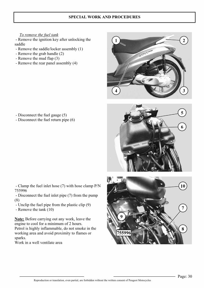
To remove the fuel tank - Remove the ignition key after unlocking thesaddle - Remove the saddle/locker assembly (1) - Remove the grab handle (2) - Remove the mud flap (3) - Remove the rear panel assembly (4)
- Disconnect the fuel gauge (5) - Disconnect the fuel return pipe (6)
- Clamp the fuel inlet hose (7) with hose clamp P/N755996 - Disconnect the fuel inlet pipe (7) from the pump(8) - Unclip the fuel pipe from the plastic clip (9) - Remove the tank (10)
Note: Before carrying out any work, leave theengine to cool for a minimum of 2 hours.Petrol is highly inflammable, do not smoke in theworking area and avoid proximity to flames orsparks.Work in a well ventilate area
SPECIAL WORK AND PROCEDURES
Page: 31Reproduction or translation, even partial, are forbidden without the written consent of Peugeot Motocycles
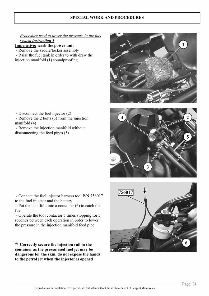
Procedure used to lower the pressure in the fuelsystem instruction 1
Imperative: wash the power unit - Remove the saddle/locker assembly - Raise the fuel tank in order to with draw theinjection manifold (1) soundproofing.
- Disconnect the fuel injector (2) - Remove the 2 bolts (3) from the injectionmanifold (4) - Remove the injection manifold withoutdisconnecting the feed pipes (5)
- Connect the fuel injector harness tool P/N 756017to the fuel injector and the battery - Put the manifold into a container (6) to catch thefuel - Operate the tool contactor 5 times stopping for 5seconds between each operation in order to lowerthe pressure in the injection manifold feed pipe
Correctly secure the injection rail in thecontainer as the pressurised fuel jet may bedangerous for the skin, do not expose the handsto the petrol jet when the injector is opened
SPECIAL WORK AND PROCEDURES
Page: 32Reproduction or translation, even partial, are forbidden without the written consent of Peugeot Motocycles
Fuel circuit bleeding procedure instruction 2 - After refitting the assembly, operate the fuel pumpby turning on the ignition key (turning on theignition operates the fuel pump for 3 seconds) - Carry out this operation twice
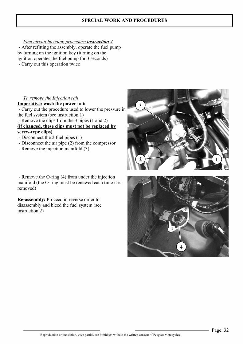
To remove the Injection railImperative: wash the power unit - Carry out the procedure used to lower the pressure inthe fuel system (see instruction 1) - Remove the clips from the 3 pipes (1 and 2)(if changed, these clips must not be replaced byscrew-type clips) - Disconnect the 2 fuel pipes (1) - Disconnect the air pipe (2) from the compressor - Remove the injection manifold (3)
- Remove the O-ring (4) from under the injectionmanifold (the O-ring must be renewed each time it isremoved)
Re-assembly: Proceed in reverse order todisassembly and bleed the fuel system (seeinstruction 2)
SPECIAL WORK AND PROCEDURES
Page: 33Reproduction or translation, even partial, are forbidden without the written consent of Peugeot Motocycles
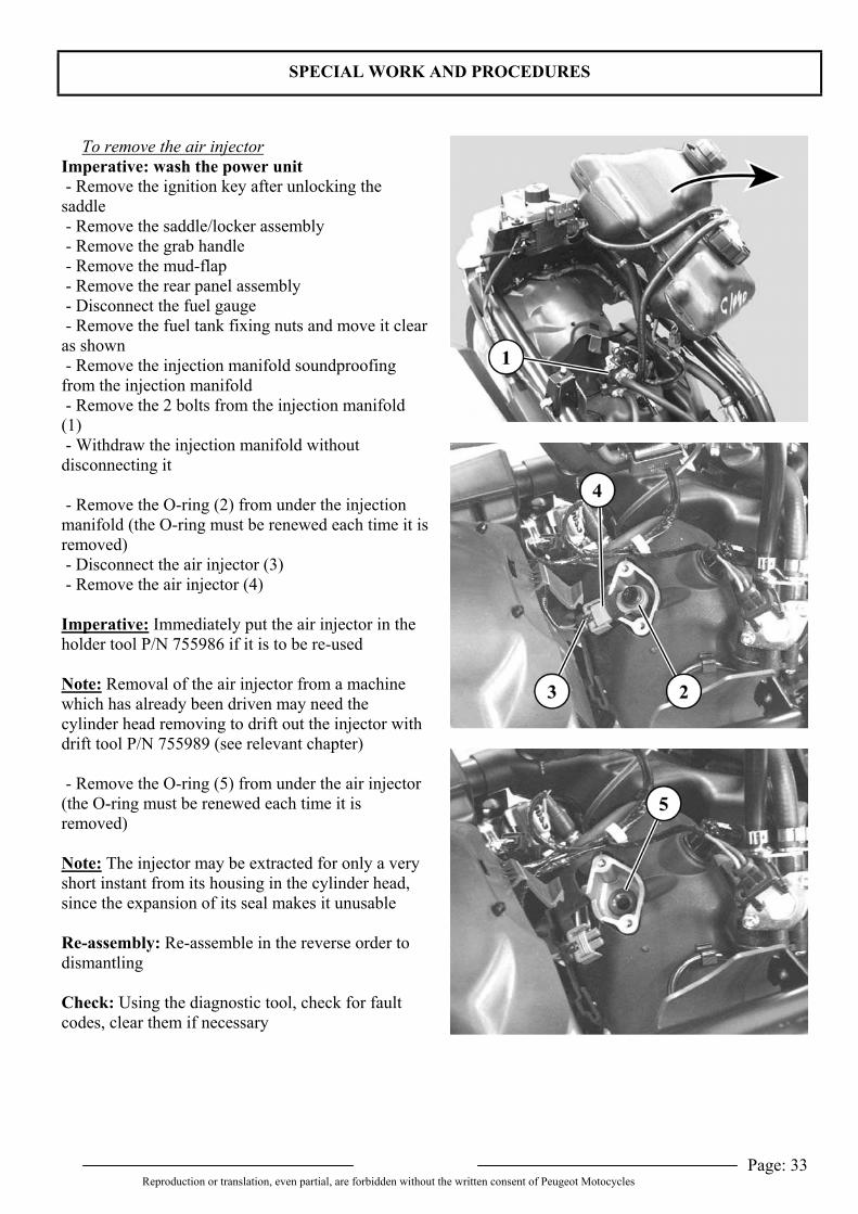
To remove the air injectorImperative: wash the power unit - Remove the ignition key after unlocking thesaddle - Remove the saddle/locker assembly - Remove the grab handle - Remove the mud-flap - Remove the rear panel assembly - Disconnect the fuel gauge - Remove the fuel tank fixing nuts and move it clearas shown - Remove the injection manifold soundproofingfrom the injection manifold - Remove the 2 bolts from the injection manifold(1) - Withdraw the injection manifold withoutdisconnecting it
- Remove the O-ring (2) from under the injectionmanifold (the O-ring must be renewed each time it isremoved) - Disconnect the air injector (3) - Remove the air injector (4)
Imperative: Immediately put the air injector in theholder tool P/N 755986 if it is to be re-used
Note: Removal of the air injector from a machinewhich has already been driven may need thecylinder head removing to drift out the injector withdrift tool P/N 755989 (see relevant chapter)
- Remove the O-ring (5) from under the air injector(the O-ring must be renewed each time it isremoved)
Note: The injector may be extracted for only a veryshort instant from its housing in the cylinder head,since the expansion of its seal makes it unusable
Re-assembly: Re-assemble in the reverse order todismantling
Check: Using the diagnostic tool, check for faultcodes, clear them if necessary
SPECIAL WORK AND PROCEDURES
Page: 34Reproduction or translation, even partial, are forbidden without the written consent of Peugeot Motocycles
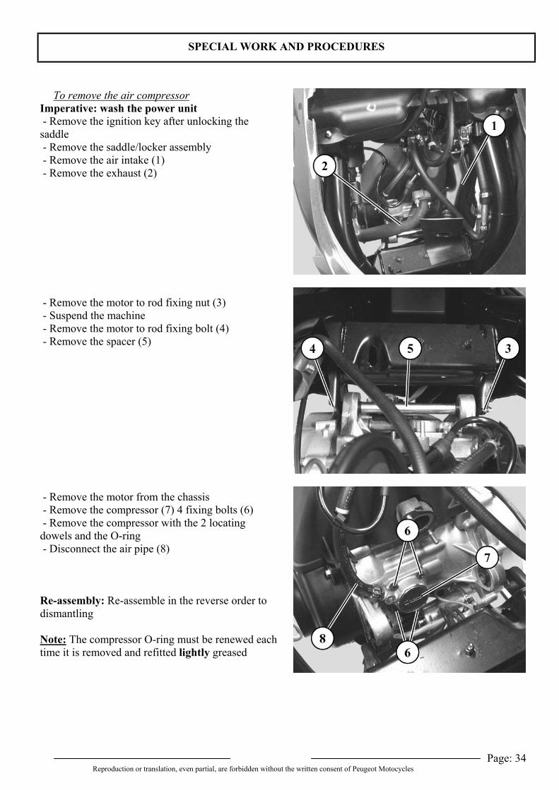
To remove the air compressorImperative: wash the power unit - Remove the ignition key after unlocking thesaddle - Remove the saddle/locker assembly - Remove the air intake (1) - Remove the exhaust (2)
- Remove the motor to rod fixing nut (3) - Suspend the machine - Remove the motor to rod fixing bolt (4) - Remove the spacer (5)
- Remove the motor from the chassis - Remove the compressor (7) 4 fixing bolts (6) - Remove the compressor with the 2 locatingdowels and the O-ring - Disconnect the air pipe (8)
Re-assembly: Re-assemble in the reverse order todismantling
Note: The compressor O-ring must be renewed eachtime it is removed and refitted lightly greased
SPECIAL WORK AND PROCEDURES
Page: 35Reproduction or translation, even partial, are forbidden without the written consent of Peugeot Motocycles
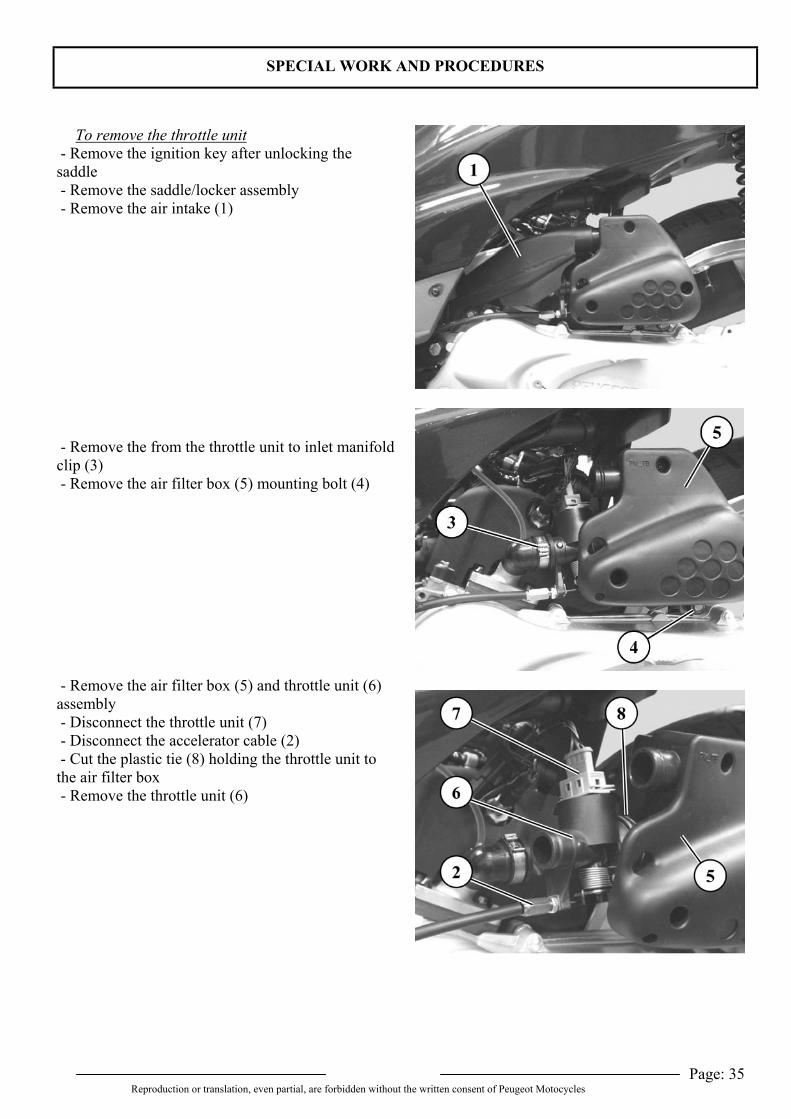
To remove the throttle unit - Remove the ignition key after unlocking thesaddle - Remove the saddle/locker assembly - Remove the air intake (1)
- Remove the from the throttle unit to inlet manifoldclip (3) - Remove the air filter box (5) mounting bolt (4)
- Remove the air filter box (5) and throttle unit (6)assembly - Disconnect the throttle unit (7) - Disconnect the accelerator cable (2) - Cut the plastic tie (8) holding the throttle unit tothe air filter box - Remove the throttle unit (6)
SPECIAL WORK AND PROCEDURES
Page: 36Reproduction or translation, even partial, are forbidden without the written consent of Peugeot Motocycles
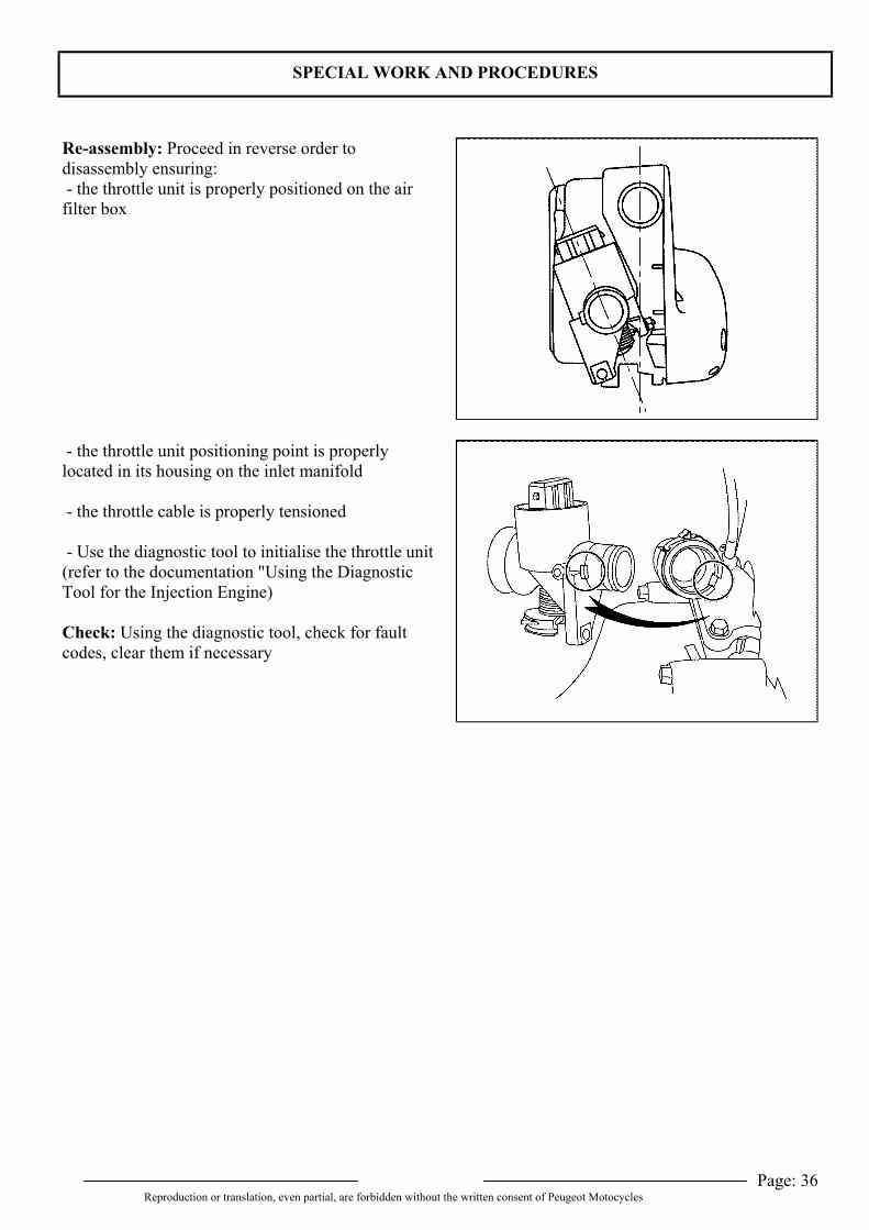
Re-assembly: Proceed in reverse order todisassembly ensuring: - the throttle unit is properly positioned on the airfilter box
- the throttle unit positioning point is properlylocated in its housing on the inlet manifold
- the throttle cable is properly tensioned
- Use the diagnostic tool to initialise the throttle unit(refer to the documentation "Using the DiagnosticTool for the Injection Engine)
Check: Using the diagnostic tool, check for faultcodes, clear them if necessary
SPECIAL WORK AND PROCEDURES
Page: 37Reproduction or translation, even partial, are forbidden without the written consent of Peugeot Motocycles
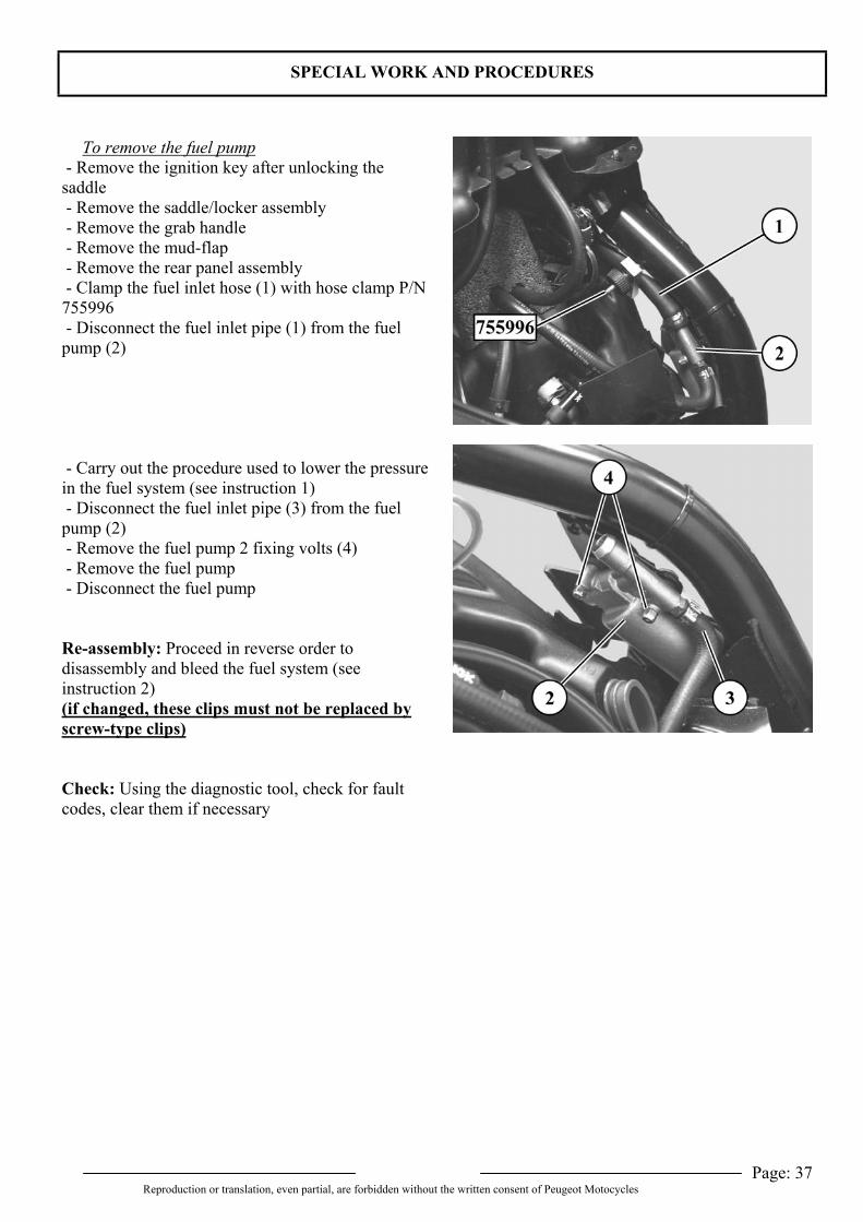
To remove the fuel pump - Remove the ignition key after unlocking thesaddle - Remove the saddle/locker assembly - Remove the grab handle - Remove the mud-flap - Remove the rear panel assembly - Clamp the fuel inlet hose (1) with hose clamp P/N755996 - Disconnect the fuel inlet pipe (1) from the fuelpump (2)
- Carry out the procedure used to lower the pressurein the fuel system (see instruction 1) - Disconnect the fuel inlet pipe (3) from the fuelpump (2) - Remove the fuel pump 2 fixing volts (4) - Remove the fuel pump - Disconnect the fuel pump
Re-assembly: Proceed in reverse order todisassembly and bleed the fuel system (seeinstruction 2)(if changed, these clips must not be replaced byscrew-type clips)
Check: Using the diagnostic tool, check for faultcodes, clear them if necessary
SPECIAL WORK AND PROCEDURES
Page: 38Reproduction or translation, even partial, are forbidden without the written consent of Peugeot Motocycles
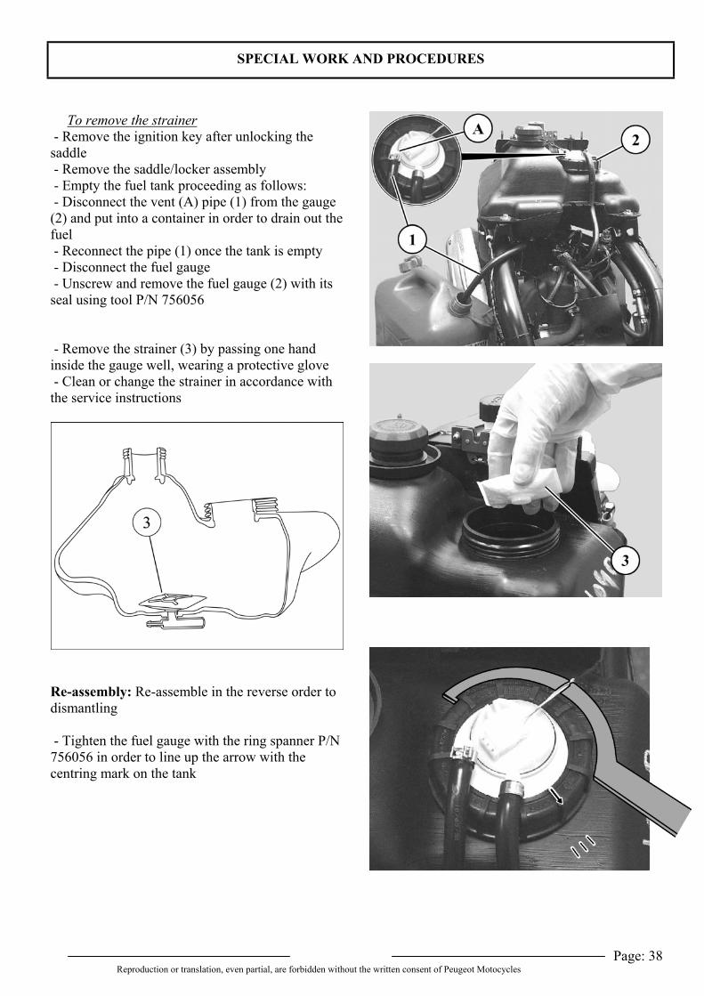
To remove the strainer - Remove the ignition key after unlocking thesaddle - Remove the saddle/locker assembly - Empty the fuel tank proceeding as follows: - Disconnect the vent (A) pipe (1) from the gauge(2) and put into a container in order to drain out thefuel - Reconnect the pipe (1) once the tank is empty - Disconnect the fuel gauge - Unscrew and remove the fuel gauge (2) with itsseal using tool P/N 756056
- Remove the strainer (3) by passing one handinside the gauge well, wearing a protective glove - Clean or change the strainer in accordance withthe service instructions
Re-assembly: Re-assemble in the reverse order todismantling
- Tighten the fuel gauge with the ring spanner P/N756056 in order to line up the arrow with thecentring mark on the tank
SPECIAL WORK AND PROCEDURES
Page: 39Reproduction or translation, even partial, are forbidden without the written consent of Peugeot Motocycles
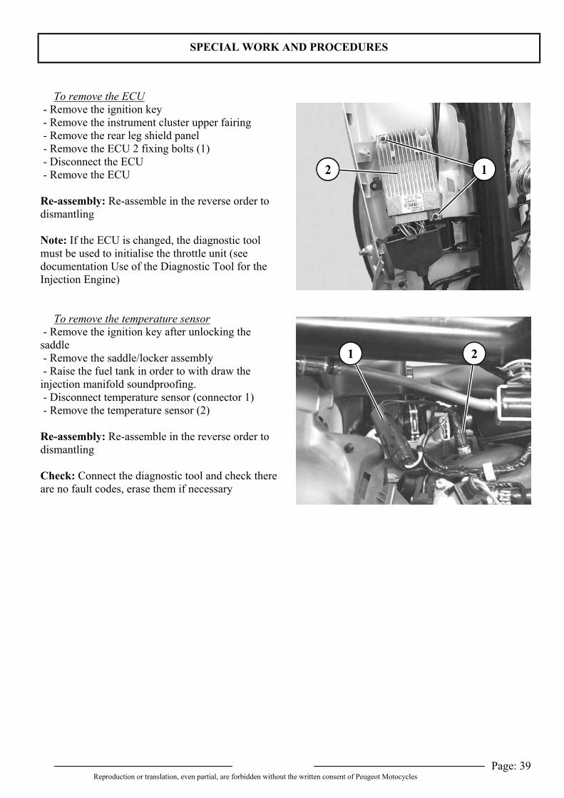
To remove the ECU - Remove the ignition key - Remove the instrument cluster upper fairing - Remove the rear leg shield panel - Remove the ECU 2 fixing bolts (1) - Disconnect the ECU - Remove the ECU
Re-assembly: Re-assemble in the reverse order todismantling
Note: If the ECU is changed, the diagnostic toolmust be used to initialise the throttle unit (seedocumentation Use of the Diagnostic Tool for theInjection Engine)
To remove the temperature sensor - Remove the ignition key after unlocking thesaddle - Remove the saddle/locker assembly - Raise the fuel tank in order to with draw theinjection manifold soundproofing. - Disconnect temperature sensor (connector 1) - Remove the temperature sensor (2)
Re-assembly: Re-assemble in the reverse order todismantling
Check: Connect the diagnostic tool and check thereare no fault codes, erase them if necessary
SPECIAL WORK AND PROCEDURES
Page: 40Reproduction or translation, even partial, are forbidden without the written consent of Peugeot Motocycles
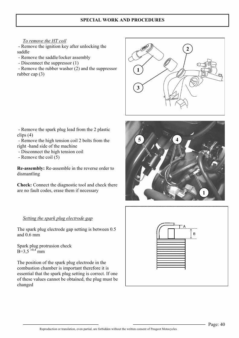
To remove the HT coil - Remove the ignition key after unlocking thesaddle - Remove the saddle/locker assembly - Disconnect the suppressor (1) - Remove the rubber washer (2) and the suppressorrubber cap (3)
- Remove the spark plug lead from the 2 plasticclips (4) - Remove the high tension coil 2 bolts from theright -hand side of the machine - Disconnect the high tension coil - Remove the coil (5)
Re-assembly: Re-assemble in the reverse order todismantling
Check: Connect the diagnostic tool and check thereare no fault codes, erase them if necessary
Setting the spark plug electrode gap
The spark plug electrode gap setting is between 0.5and 0.6 mm
Spark plug protrusion checkB=3,5 ±0,4 mm
The position of the spark plug electrode in thecombustion chamber is important therefore it isessential that the spark plug setting is correct. If oneof these values cannot be obtained, the plug must bechanged
SPECIAL WORK AND PROCEDURES
Page: 41Reproduction or translation, even partial, are forbidden without the written consent of Peugeot Motocycles
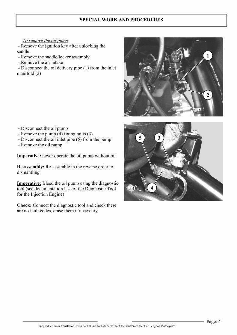
To remove the oil pump - Remove the ignition key after unlocking thesaddle - Remove the saddle/locker assembly - Remove the air intake - Disconnect the oil delivery pipe (1) from the inletmanifold (2)
- Disconnect the oil pump - Remove the pump (4) fixing bolts (3) - Disconnect the oil inlet pipe (5) from the pump - Remove the oil pump
Imperative: never operate the oil pump without oil
Re-assembly: Re-assemble in the reverse order todismantling
Imperative: Bleed the oil pump using the diagnostictool (see documentation Use of the Diagnostic Toolfor the Injection Engine)
Check: Connect the diagnostic tool and check thereare no fault codes, erase them if necessary
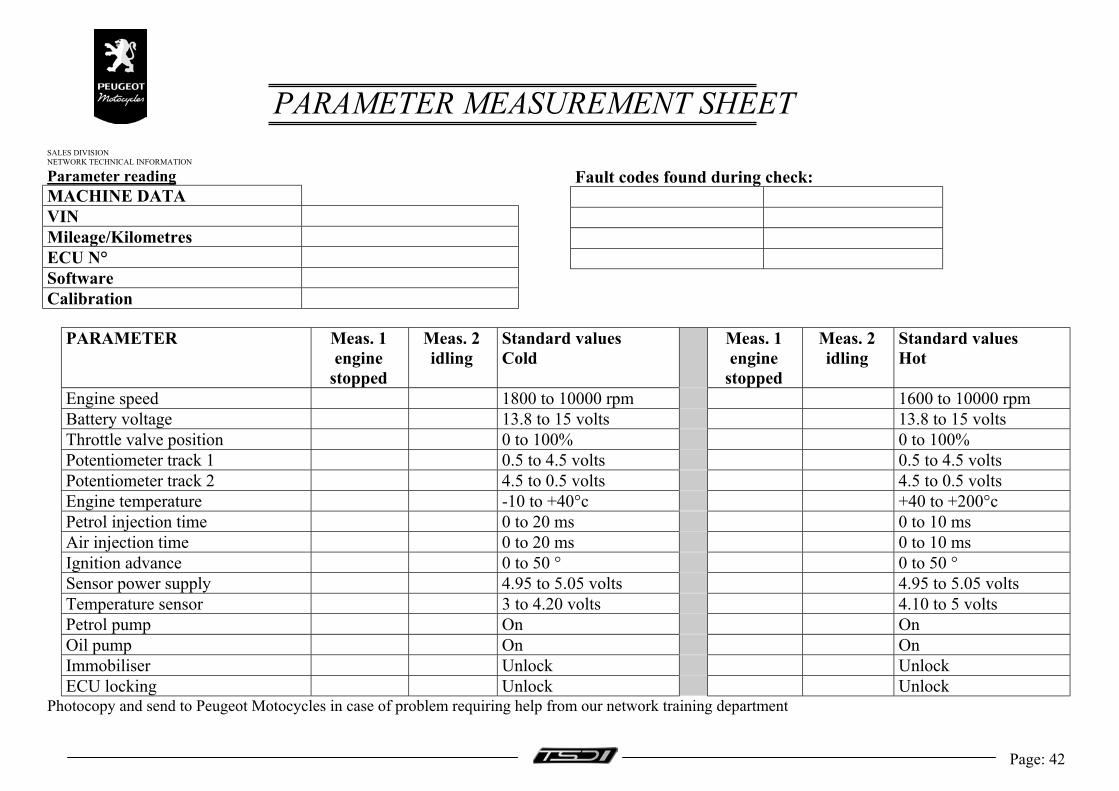
PARAMETER MEASUREMENT SHEETSALES DIVISIONNETWORK TECHNICAL INFORMATION
Page: 42
Parameter readingMACHINE DATAVINMileage/KilometresECU N°SoftwareCalibration
Fault codes found during check:
PARAMETER Meas. 1engine
stopped
Meas. 2idling
Standard valuesCold
Meas. 1engine
stopped
Meas. 2idling
Standard valuesHot
Engine speed 1800 to 10000 rpm 1600 to 10000 rpmBattery voltage 13.8 to 15 volts 13.8 to 15 voltsThrottle valve position 0 to 100% 0 to 100%Potentiometer track 1 0.5 to 4.5 volts 0.5 to 4.5 voltsPotentiometer track 2 4.5 to 0.5 volts 4.5 to 0.5 voltsEngine temperature -10 to +40°c +40 to +200°cPetrol injection time 0 to 20 ms 0 to 10 msAir injection time 0 to 20 ms 0 to 10 msIgnition advance 0 to 50 ° 0 to 50 °Sensor power supply 4.95 to 5.05 volts 4.95 to 5.05 voltsTemperature sensor 3 to 4.20 volts 4.10 to 5 voltsPetrol pump On OnOil pump On OnImmobiliser Unlock UnlockECU locking Unlock Unlock
Photocopy and send to Peugeot Motocycles in case of problem requiring help from our network training department

Page: 43Reproduction or translation, even partial, are forbidden without the written consent of Peugeot Motocycles
RECOMMENDS
REF: 756012
With a constant concern for improvement Peugeot Motocycles reserves the right to delete, modify, or add any quoted referenceDC/PS/ATR printed in E.U. 02/2002 (photos non-contractual)