Embed Size (px)
Citation preview

Phenomena governing uni-axial tensile behaviour of
paperboard and corrugated cardboard
Samir Allaoui, Zoheir Aboura, Malk Benzeggagh
To cite this version:
Samir Allaoui, Zoheir Aboura, Malk Benzeggagh. Phenomena governing uni-axial tensile be-haviour of paperboard and corrugated cardboard. Composite Structures, Elsevier, 2009, 87(1), pp.80-92. <hal-00636962>
HAL Id: hal-00636962
https://hal.archives-ouvertes.fr/hal-00636962
Submitted on 14 Jan 2013
HAL is a multi-disciplinary open accessarchive for the deposit and dissemination of sci-entific research documents, whether they are pub-lished or not. The documents may come fromteaching and research institutions in France orabroad, or from public or private research centers.
L’archive ouverte pluridisciplinaire HAL, estdestinee au depot et a la diffusion de documentsscientifiques de niveau recherche, publies ou non,emanant des etablissements d’enseignement et derecherche francais ou etrangers, des laboratoirespublics ou prives.

1
Phenomena governing uni-axial tensile behaviour of paperboard
and corrugated cardboard
S.ALLAOUI
*, Z.ABOURA
** and M.L.BENZEGGAGH
***
* LMSP, UMR 8106, Polytech d�Orléans, 8 rue Leonard de Vinci 45072 Orléans Cedex2, France.
Mel: [email protected] .fax: 0033(0)238417329 ** L3M, IUT de Tremblay en France Paris 8 Rue de la Râperie 93290 Tremblay-en-France, France
*** LRM, FRE2833, UTC, Centre de Recherche Royallieu B.P 20529 F- 60205 Compiègne Cedex, France
Abstract
Paperboard exhibits a complex mechanical behaviour, which is governed by several
phenomena. This work proposes a contribution to the identification of these phenomena. Uni-
axial tensile tests under various configurations were carried out on the paperboard and
corrugated cardboard. Observations under scanning electron microscopy were thereafter done in
order to identify the microscopic phenomena produced in the structure. These observations made
possible to highlight the presence of damage and its various appearance mechanisms.
Keywords
Paperboard, corrugated cardboard, behaviour, damage, coating.

2
Introduction
Paper materials are widely used in packing industry, media platform and number of other
applications. They are made from chemical and mechanical pulp in a continuous process. The
pulp is sprayed through the head box into a filter screen and dried under tension and pressure.
Due to the continuous nature of the materials process, two main directions characterize paper and
paperboard (figure1): transverse or cross direction denoted CD and machine direction denoted
MD that corresponds to the feel orientation of the filter, therefore the privileged orientation of
the cellulose fibres. To refer to out-of-plane direction (through-thickness), a third direction
denoted ZD is introduced as depicted by figure 1. We observe the same directions for the
corrugated cardboard. Let us note that the manufacture direction of the sandwich coincides with
the machine direction of the corrugated cardboard and the paperboards (figure 2).
Due to its various virtues, corrugated cardboard sandwich is the paper family the most
used in packing. The more utilized configuration is the simple wall. It is composed by three
paperboard components: upper layer, core and lower layer. Therefore, for a better optimization
of its use, previous studies were restricted to model its elastic behaviour. Corrugated cardboard is
regarded as structure [1, 2], sandwich [3, 4] or monolithic material [5]. All these approaches
need the knowledge of mechanical properties of the corrugated cardboard components, indeed
the sandwich behaviour is governed by those of its constituents.
Paper and paperboard are fibrous materials. They are built from cellulose fibres jointed
by hydrogen bonds and some additional elements like talc. Due to the non-homogeneous and
anisotropic nature of the paper materials, it is difficult to predict accurately the materials
responses. Therefore, they exhibit complex mechanical behaviour, commonly characterized by a
highly anisotropic linear elastic response (under moderate mechanical loading) and non-linear
response (attributed to a plastic response) under high loading [6].

3
Under cyclic tensile test, when the paper is cycled at low strain there was little evidence
of non-linear elastic behaviour. Beyond the yield stress, wide hysteresis loops appear and stress
relaxation phenomena is highlighted [7]. Unloading from some point of the non-linear part of the
stress strain curve further results in a permanent deformation. Tryding shows that the unloading
stiffness generally coincides well with the elastic modulus [8]. Sawyer and al. [7] suggest that
the molecular structure deformation mechanics are dominating the inelastic flow of paper.
This work purposes a contribution to a better comprehension of phenomena governing
uni-axial tensile behaviour of the paperboard and corrugated cardboard. It will use in next works
to model the global corrugated cardboard behaviour.
Material
Corrugated cardboard used in this study is single wall of type �C�. An upper and lower
layer and a core compose it. They are respectively denoted Recto, Verso and Well. All the
constituents are composed with 100% cellulose recycled fibres. Their thicknesses are 0.26 mm,
for the Recto and the Verso and 0.21 mm for the Well. The total sandwich thickness is 4.1 mm
and the flute step is P=8 mm.
Static tensile tests
Static tensile tests were carried out on corrugated cardboard and its constituents in the
two-plane direction (MD and CD). The aim of these tests is to identify elastic and failure
properties and highlight the different stages of their uni-axial tensile behaviour. The specimens
were inspired from ISO type NF T51-034 and NF Q03-002 on the mechanical characterization of
plastic materials, paper and cardboard. The most important difficulty of the tensile tests on the

4
corrugated cardboard resides in the bruising of the specimen heads at the griping time. To
increase the rigidity of the specimen heads, a polyester resin was injected between flutings and
the cardboard skins to fill the existing emptiness. With regard to the paperboard preparation, the
specimen extremities were rigidified by impregnating in the resin. This technique allows
consequently avoiding the use of the special bits recommended by the norm NF Q03-002 [5].
All the specimens were conditioned at 23°C and 50% RH for at least 24 hours before
testing. The tests were conducted under 2 mm/min crosshead speed using a sensitive load cell of
500 N. The instrumentation used is a camera which makes possible to follow the displacements
of four points positioned, on each specimen, as shown in figure 3 [9]. We note that these
specimen preparations before testing were used during the various tests of this work.
Table 1 shows the elastic and failure properties obtained. For all tested materials, Young
modulus and failure loads are more significant in machine direction that corresponds to the
cellulose fibres and flute orientations. In the case of paperboard layers, they are twice more
significant than those measured in CD.
Concerning the corrugated cardboard, it appears that the failure load in MD is equal to
the sum of the maximum failure loadings of the two main layers (Recto and Verso). On the other
hand, it is equal to the sum of those of the three constituent�s failures loads (layers and flute) in
cross direction. The failure strain is twice more significant in CD than MD. In each direction,
we note the quasi equivalence of the strains between the various constituents and the sandwich.
Characteristic stress-strain curves (figure 4 for layers and figure 5 for corrugated
cardboard) show that mechanical behaviour in the two in-plane directions is composed by linear
part followed-up by non-linear part. This phenomenon depends on the cellulose fibres, the
hydrogen bonds and the rate of the moisture content. The nonlinearity is accentuated in the cross
direction. This more marked non-linearity can be due to the fact that the paperboard mechanical

5
behaviour is more governed by hydrogen bonds that are more requested in CD than the cellulose
fibres.
To investigate this effect and to better understand phenomena that govern mechanical
behaviour of paperboard, other mechanical tests are necessary. Therefore, the following tests
were first carried out on the paperboard in order to best apprehend its behaviour. Thereafter, this
permits to better understand the global uni-axial behaviour of the sandwich.
a) Strain rate effect
The viscous behaviour of paperboard can be highlighted by uni-axial tensile tests at
different strain rate (ε& ). The tests were conducted on tensile testing machine INSTRON 4411
using speed strain range going from 6*10-5 s-1
to 12*10-3 s-1
, which correspond to different
displacement speeds as illustrated in table 2. For each rate strain, ten specimens were tested for
each paperboard in the two directions MD and CD. Two instrumentations were used:
extensometer and camera (figure 3).
Figures 6 to 9 present examples of stress-strain curves obtained at various strain rates
request. In all cases (Well, Recto and Verso), the effect of the strain rate (ε& ) is not negligible in
both directions MD and CD. Indeed, failure and yield stress increase according to strain rate.
This confirms well the presence of a viscous behaviour of paperboard that appears rather at high
strains rates.
This tendency is quantified in tables 3 and 4. We note that the standard deviations are less
than 7% for all the results.
At the strain rate 12*10-3
s-1
, the maximum evolution of the failure stress (σf ) compared
to strain rate 6*10-5
s-1
is obtained for the skins Recto and Verso. It is about 24.92% and 30.43%
respectively for the Recto skin in the machine direction and Verso skin in the cross direction.

6
The smallest evolutions (about 19%) are obtained for the Well paperboard in the two directions.
The more significant evolution in the case of the skins Recto and Verso can be attributed to the
behaviour of the coating used to treat the skins surfaces and which, undoubtedly, interferes on
the material behaviour. Indeed, the paperboards Recto and Verso underwent a more significant
coating than the Well paperboard as we will see it further.
The Young modulus evolution is more marked in the case of the Well paperboard in both
directions (about 22% between minimum and maximum rates strains request). The same rate of
evolution is raised in the case of the Verso skin in the cross direction (table 4). Therefore, the
linear part of the paperboard behaviour is also governed by a viscous phenomenon. If the viscous
effect is well highlighted, we can wonder whether the non-linearity beyond yield stress is due
only to this phenomenon, or other additional phenomena intervene in the process. In order to
answer this interrogation, other tests are necessary.
b) Strain recovery
The goal of the strain recoveries tests is to check the existence or not of a permanent
deformation after unloading. The tests were carried out on uni-axial dynamic testing machine
INSTRON 1341, with a cell of 1KN. This machine controls either in strain or in stress rates.
The specimens were loaded in stress controlled with a stress rate of sMPa /5,0=σ& .
Once in non-linear part, the specimens were unloaded to a value near zero without reaching zero
(in order to avoid the buckling) with the same stress rate. Then, they were heeded at a fixed
stress during 24 hours. Throughout the test, the strain was measured by an optical method.
Figures 10 and 11 present examples of loading-unloading-holding response of the Verso
skin in MD and Recto layer in CD. Specimen of Verso skin was requested, until a strain of 2.8%
(Figure 10). After unloading and load holding, the material covers a strain of 1.53% in 3 hours of

7
time. Beyond, the strain covers is unimportant, less than 0.03% during 21 hours (Figure 12). At
the end of the test, the residual strain is about 1.27%. Therefore, paperboard recovers 55% of the
initial strain.
For the skin Recto, it was requested in the direction CD until a deformation of 2.05%
(Figure 11). After unloading and load holding, the strain recovered is about 1.47%, during 3
hours. After 24 hours of holding, the residual strain is about 0.59% and the covers strain
represents 71% of the initial strain. Note that the recovered strain is more important in the Cross
direction, due to the fact that the phenomenon is mainly managed by the connections inter fibres,
whereas in the machine direction the fibres govern the behaviour.
Loading-unloading-holding tensile tests carried out on the skins, in the two directions,
revealed a residual plastic strain. Thus, non-linearity of the paperboard is governed by a
viscoplastic phenomenon. The slopes of unloading are curved. This indicates the presence of
energy dissipation, so a loss of stiffness. This dissipation can be due to the presence of a damage
coupled with the viscoplastic phenomenon. The next step of this study concerns the checking and
quantification of the damage presence by using cycling loading tests.
Cyclic loading tensile tests
Generally, the quantitative evaluation of damage is done through the evolution of an
elastic variable, which characterizes the studied phenomenon. For the needs for this study, this
variable is the Young modulus. Cyclic tensile tests were carried out on ten specimens for each
paperboard in the two directions. The specimens were loading and unloading at the same strain
rate (ƾ = 24*10-5
s-1
). The increments of loading were fixed at 20N for the machine direction and
10N for the cross direction. Once the data acquisition made, the parameter D was established for
each level of loading as follows:

8
100)1(0
xE
ED d−=
Where E0 is the Young modulus measured in initial linear part and Ed the Young modulus
measured for each level of loading, during the unloading beyond the zones with stronger non-
linearity. The measurement domain was established between 0.85% and 0.25% of the reached
load.
Parameter D allows following the evolution of the material behaviour. It includes the
damage parameter, but also taking into account the presence of a viscous phenomenon. This
parameter cannot be used as a damage parameter in a modelling approach.
Figures 13 and 14 illustrate the examples of Verso skin behaviour, in machine and cross
directions, during the loading-unloading tensile tests. During the first cycles, at low stress, there
is no evidence of non-linear elastic behaviour and residual strains. Thus, the skins have a
reversible linear behaviour. By increasing the increment of the load, in nonlinear field, loops of
hysteresis appear synonymous with energy dissipation. These loops become more open while
advancing in the nonlinear field.
An average of the evolution curves of the parameter D is represented on Figure 15. The
stiffness loss occurs earlier in the cross direction than in MD. This phenomenon starts at a stress
of 10 MPa in MD and 3 MPa in CD (Figure 15). Moreover, the evolution of parameter D, which
is represented by the curves shape, is more significant in cross direction than in machine
direction.
The maximum value reached by the parameter D in the case of Recto and Verso skins
(Upper and Lower layers) is about 15% in both in-plane directions. On the other hand, in the
case of Well paperboard used for the flute, stiffness loss is twice more significant in the machine
direction than the cross direction (respectively 16.6% and 7.4%).
This difference in the behaviour between the skins (upper and lower) and the paperboard
of the flute can be due to the coating treatment undergone by the upper and lower skins. This

9
surface coating improves printing quality on external skins of the corrugated cardboard packing.
Therefore, it is little used for the flute paperboard. Indeed, it is denoted that the coating on the
Recto and Verso skins, is about few tens of microns and is present on all the skins surfaces
(Figure 16). A perpendicular sight of the treated surface reveals this facing with the detriment of
the cellulose fibres that are not visible. On the other hand, this coating is weak (< 10µm) for the
Well paperboard and its presence is not homogeneous on all the skin face (Figure 17). The
cellulose fibres are well distinguished on the treated face. This film used for coating is made up
of polymeric materials. It probably attenuates the damage of the two skins Recto and Verso,
which is not the case of the paperboard Well that arrived at failure rather quickly.
Nevertheless, whatever the components of the sandwich, a significant loss of rigidity is
observed contrary to precedent works [8] where the stiffness under unloading, from each point
on the non-linear field, coincides well with the elastic modulus. This pushes us to believe that
there is presence of damage phenomenon that occurs in material. In order to confirm this
presence and the moment of its apparition, uni-axial tensile tests under scanning electron
microscopy (SEM) were carried out.
Relaxation tensile tests under SEM
To be able to note the damage presence and its coupling with viscoplasticity, in-situ
tensile tests with holding at fixes strains under SEM were carried out on the paperboard (figure
18). The load cell capacity is 300 N. It was assembled inside the SEM and then connected to an
acquisition system. The minimal length between the two jaws of the device is 10mm and the
maximum race is 10mm. Micro specimens were cut out for the three paperboards in the two
directions MD and CD. The Length of the useful part between jaws of specimens is 10mm and
their width is 5mm. Paperboard being a no conducting material, the specimens underwent a

10
metallization with a film of gold before testing in order to ensure conductivity. Thereafter, they
were assembled on the device inside the SEM, and tested with rate strain control of 12*10-6
s-1
. In
order to highlight the effect of stress relaxation and its appearance, each test was carried out with
holding at various strain levels. During these material relaxations, fractographies were taken to
show the nature of damage. Mechanical parameters obtained by theses tests will not be exploited
because of the scale effect. Only physical phenomena will be considered.
a) Results and discussions
Figure 19 illustrates the example of Well paperboard behaviour during relaxation test
under SEM according to cross direction. Fractographies corresponding at each strain holding are
shown. At the first one, corresponding to the linear field of curve, stress falls synonymous of
relaxation. On the other hand, the stress relaxation in linear part is weak in the machine direction
(Figure 20). This observation consolidates the results of precedents tensile tests at various rates
strains control. It confirms the presence of viscoelastic phenomenon at the elastic phase. This
phenomenon is more significant in the cross direction than in the machine direction. This is due
to the fact that the hydrogen bonds between fibres, which can have a viscous behaviour, are
requested more in CD.
Stress relaxation of paperboard increases with the increase of load level. This is due to
the viscoplastic behaviour, which becomes more important in the nonlinear phase. As previously,
these stress relaxations are more significant in the cross direction than in the machine one.
For the Well paperboard in CD, the damage intervenes with the second strain holding
(ε=0.23%) beyond the linear part. Microscopic cracks appear locally. By increasing load level,
microscopic cracks appear in greater number on the entire specimen surface as we can notice it
at strain ε=0.89% on Figure 19. In fifth holding, the starting of macroscopic crack appears

11
between the diffuse microscopic cracks. This crack increases and another one appears with the
following holding. The final failure of material occurs according to the macroscopic crack
appeared in first and according to a cross-section.
Like in the cross direction, microscopic cracks appear at the second strain holding
(ε=0.36%) beyond the linear phase on specimens loaded in machine direction. We note a
presence of few microscopic cracks located in only some areas of the specimen in spite of the
strain holding in the nonlinear part (Figure 20). The material failure intervenes abruptly in an
area, which is not very reached by the damage, other that which saw germinating the most
microscopic cracks.
b) Damage mechanisms
This part of the article relates the damage phenomena observed under the microscope and
consequently details the preceding phenomenological explanations. At first holdings, the areas
where appear first microscopic cracks were located. Thereafter, pictures of these areas were
taken at each holding, in order to follow the microstructure evolution.
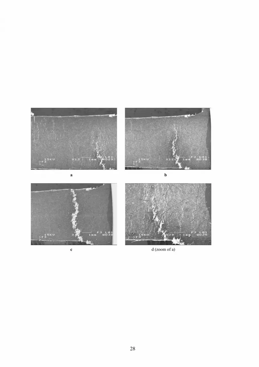
Figure 21 presents an example of damage evolution of specimen until failure in CD. The
first photography (figure 21 a) shows many and diffuses microscopic cracks on the specimen.
One of the explanations to this phenomenon is that damage, in direction CD, occurs in the form
of failure of the bonds between fibres. These bonds control the behaviour of paperboard in cross
direction and are less rigid than cellulose fibres. These micro cracks coalesce to generate a macro
crack, which appears in bottom of the sample. It is obvious that the edge effect is partly
responsible for the localization of this macro crack. The figure 21d, zoom of the figure 21a,
confirms this report and brings an additional explanation. Indeed, it appears that the effect of
cutting and the radius curvature of the specimen take part in the failure initiation. This

12
macroscopic crack becomes extensive until causing the failure (figure 21 b and c). On all the
tested specimens, failure intervened according to the first appeared macroscopic crack.
Figure 22 shows an example of crack from its appearance to the failure for specimen
tested in cross direction. Evolution of the crack occurs while skirting fibres. Badly directed fibres
being on its trajectory are broken (figure 22 b ε=1.01%). Figure 22d shows an example of the
presence of badly directed fibres broken or torn off in-depth of the paperboard. The final failure
intervenes according to a cross-section of the specimen. These failure facieses are in agreement
with those found during tensile tests off-axis carried out in precedent study [10].
Contrary to the paperboard behaviour in cross direction, where the microscopic cracks are
diffuse, in the case MD they are really localized near the edges of the specimen (figure 23). Here
again, the effect of the specimen size and the nature of the cutting play a part in the crack
initiation. (figure 23b). The first macroscopic crack (high part of photography b) appears in one
of these zones and extends along the section. At the same time, another crack starts (down part of
photography b). This second crack is propagated more quickly than the first one until causing the
failure (figure 23 c and d). The final failure occurs according to a crack, which found the most
direct way of fibres skirting therefore requiring less energy. This phenomenon is due to the
damage mechanisms governing the behaviour of paperboard in this direction. Indeed, the crack is
propagated in the transverse direction of cellulose fibres. Therefore, fibres failure is the prevalent
damage mechanism in paperboard tested in machine direction. Crack develops by first
circumventing the fibres and then after by breaking them. That is what explains its sinuous shape
[10]. On the whole of the tested specimens, the section where occurs the final failure could not
be predicted precisely.
Therefore, damage of the paperboard intervenes in several forms. We can note fibre
skirting (Figure 24a), fibres failures (figure 24b) or even the coating damage (figure 24c). These

13
mechanisms are found in the two in-plane directions (MD and CD), but with more or less
significant proportions.
Cyclic loading tensile tests on corrugated cardboard
Several complex phenomena coexist on paperboard behaviour. Therefore, after having
highlighted them, it would be interesting to know their influence on the corrugated cardboard
behaviour. For this reason, cyclic tensile tests were carried out on the sandwich. Static tensile
machine INSTRON 4411 is used.
Ten specimens were tested in each in-plane direction of the material. To measure strains,
each specimen was instrumented by extensometer and camera and then loaded and unloaded
with the same strain rate (ƾ = 24*10-5
s-1
). Increments of loading were fixed at 20N for the
machine direction and 10N for the cross direction. For each test, load-strain tensile was plotted.
Thereafter parameter D, considering previously, was established for each load level.
The Corrugated cardboard behaviour during these tests is similar to that of the paperboard
in the two directions (Figure 25 and 26). During the first unloading, at low strains, there is not
evidence of non-linear elastic behaviour and residuals strains. By increasing increment of load,
in nonlinear field, loops of hysteresis appear synonymous with energy dissipation. These loops
become more open while advancing in the nonlinear domain.
Evolution of the parameter D, representing the evolution of mechanical behaviour of the
sandwich, was established for each test. An average of these evolutions in the two directions is
represented on figure 27. The stiffness lost is earlier and its evolution is more significant in the
cross direction. Its starting occurs towards a stress of 0.4MPa in this direction and 0.7MPa in
MD. The value of D in the direction MD is about 20%. It is very near to that of the paperboards
(around 16%). The request of the corrugated cardboard in this direction is distributed primarily
14
on the external skins [6], which explains this report. The small difference can be due to the
interference of the interfaces skin-flute on sandwich behaviour. The damage of these interfaces,
which are rigid, generates a local damage of the paperboard. These interfaces intervene more in
cross direction, where they are requested at the same time than the skins and the flute. This
explains why the parameter D is twice more significant than those of paperboards, because their
damage is added to that of the rigid interfaces.
These observations carry out us to think that mechanical behaviour of corrugated
cardboard, in uni-axial tensile, is controlled by the skins behaviour, even if it would be
appropriate to add a small effect of the core and the interfaces skin-flute.
Conclusions
Due to its particular microstructure, paperboard presents a complex tensile behaviour
governed by several phenomena. Tests carried out in this study confirm the presence of
viscoelastic phenomenon, in the linear part, and viscoplastic one in the non-linear part. In
addition, damage of paperboard was highlighted through cyclic and relaxation tensile tests. The
behaviour of this material is thus more complex compared to what is described in literature,
since this coexistence is synonymous with a coupling of viscosity-plasticity-damage.
The damage, whose evolution and importance are more increased in the cross direction,
was highlighted very early during the tests. It is governed mainly by hydrogen bonds between
cellulose fibres but also by fibres skirting. Moreover, cyclic tests showed the effect of the coating
on damage evolution. In the case of corrugated cardboard sandwich, this complexity is increased
with the interference of the rigid interface skin-flute. Nevertheless, it is not aberrant to think that
the global behaviour remains to be controlled by the skins that reduce the structure effect on
tensile test.

15
From a phenomenological point of view, the works in progress relate to the
environmental effect on the mechanical behaviour. Whereas, from a modelling point of view,
future works will try to approach, with the sight of the results of this study, the prediction of
tensile behaviour beyond elasticity of corrugated cardboard, by taking into account the complex
mechanical behaviour of its constituents. .
References
1 M. E. Biancolini, Evaluation of equivalent stiffness properties of corrugated board,
Composite structures, 2005, Vol. 69(3), p.322-328.
2 L. Beldie, G. Sandberg, L. Sandberg, Paperboard packages exposed to static loads-finite
element modelling and experiments, Packaging technology and science, 2001, Vol. 14,
p.171-178.
3 T. Nordstrand, Parametric study of the post-buckling strength of structural core sandwich
panels, Composite structures, 1995, Vol. 30(4), p.441-451.
4 A. Allansson, B. Svärd, Stability and collapse of corrugated cardboard; numerical and
experimental analysis, Masters dissertation, Lund University, Sweden, 2001.
5 Z. Aboura, N. Talbi, S. Allaoui, M.L.Benzeggagh, Elastic behavior of corrugated
cardboard: experiments and modeling, Composite Structures, 2004, Volume 63, Issue 1, p.
53-62.
6 Baum, G. A., Subfacture mechanical properties. In Transactions of the Fundamental
Research Symposium, ed. C. F. Baker. Pira International, 1993, Vol. 1, pp. 1-127
7 Sawyer J. P. G., Jones R., Mc Kinlay P., An experimental description of the response of
Paper, Composite Structures, 1996, Vol 36, pp. 101-111

16
8 Tryding, J., In-Plane Fracture of Paper, Dissertation, Division of Structural Mechanics,
Lund University, Lund, Sweden. , 1996
9 S.Allaoui, Z.Aboura, M.L.Benzeggagh, Effect of the environmental conditions on the
mechanical behaviour of the corrugated cardboard, Composite Science and Technologie,
2006, Special issue JNC14, accepted.
10 S. Allaoui, Study and modelling of behaviour of the corrugated cardboard sandwich
structure, Phd report, Université de technologie de Compiègne, Compiègne, France, 2005.

17
CD MD
ZD

18
30
20
10
Str
ess (
MP
a)
25x10-3
2015105Strain
Machine Direction
Cross Direction
Camera
Specimen

19
4
3
2
1
0
Stress (M
Pa)
30x10-3
2520151050
Strain
Machine Direction
Cross Direction
50
40
30
20
10
0
Str
es
s (
MP
a)
16x10-3
121086420
Strain
6*10e-5 s-1
12*10e-5 s-1
6*10e-4 s-1
12*10e-4 s-1
6*10e-3 s-1
12*10e-3 s-1
Well in MD

20
40
30
20
10
0
Str
es
s (
MP
a)
16x10-3
121086420
Strain
6*10e-5 s-1
12*10e-5 s-1
6*10e-4 s-1
12*10e-4 s-1
6*10e-3 s-1
12*10e-3 s-1
Recto in MD
15
10
5
0
Str
ess (
MP
a)
20x10-3
151050
Strain
6*10e-5 s-1
12*10e-5 s-1
6*10e-4 s-1
12*10e-4 s-1
6*10e-3 s-1
12*10e-3 s-1
Well in CD

21
15
10
5
0
Str
es
s (
MP
a)
30x10-3
2520151050
Strain
6*10e-5 s-1
12*10e-5 s-1
6*10e-4 s-1
12*10e-4 s-1
6*10e-3 s-1
12*10e-3 s-1
Recto in CD
20
15
10
5
Str
ess (
MP
a)
25x10-3
2015105Strain
Verso in MD

22
10
8
6
4
2
0
Str
ess (
MP
a)
20x10-3
151050 Strain
Recto in CD
30x10-3
25
20
15
10
5
0
Str
ain
12x103 1086420
Time (s)
Verso MD
Recto CD

23
50
40
30
20
10
0
Load (
N)
30x10-3
2520151050Strain
Verso in CD
140
120
100
80
60
40
20
0
Load (
N)
14x10-3
121086420Strain
Verso in MD

24
Treated Face
Zoom
Untreated face
-0.5%
1.5%
3.5%
5.5%
7.5%
9.5%
11.5%
13.5%
15.5%
17.5%
0 5 10 15 20 25 30 35 40
Stress (Mpa)
D (
%)
Recto MD
Verso MD
Well MD
Recto CD
Verso CD
Well CD

25
Specimen
Treated face Zoom
Untreated face

26
First crack initiation Failure
Appearance of the first
microscopic cracks
Failure beginning
35
30
25
20
15
10
5
0
Str
es
s (
Mp
a)
300025002000150010005000
Time (s)
Propagation of
Microscopic cracks
___ Relaxation tensile test
___ Shape of tensile curve
ε=0.43%
ε=1.01%
ε=0.89%
ε=1.52%ε=1.58%
ε=0.23%
ε=0.17%

27
80
60
40
20
0
Str
es
s
(MP
a)
40003000200010000
Time (s)
Appearance of the first
microscopic cracks
Propagation of
microscopic cracks
First macroscopic crack
Failure
___ Relaxation tensile test
___ Shape of tensile test
ε=0.78%
ε=0.62%
ε=0.46%
ε=0.36%
ε=1.06% ε=1.02%
ε=0.19%
28
a
c d (zoom of a)
b

29
(c): Holding at ε=1.52%
(a) : Holding at ε=0.43% (b): Holding at ε=1.01%
(d) : Failure
Zoom : Fibre failure Zoom

30
a b
c d

31
(a) : Fibres skirting (b) : Fibres failure
(c ) : Coating damage
300
250
200
150
100
50
0
Load (
N)
14x10-3
12108642
Strain
Corrugated cardboard in MD

32
150
100
50
0
Load (
N)
30x10-3
2520151050
Strain
Corrugated cardboard in CD
-0.5%
4.5%
9.5%
14.5%
19.5%
24.5%
29.5%
34.5%
39.5%
44.5%
0 0.5 1 1.5 2 2.5 3 3.5 4 4.5 5
Stress (Mpa)
D (
%)
Machine direction
Cross direction

33
Material
Direction Corrugated cardboard Upper layer (Recto) Lower layer (Verso) Flute (Well)
Young Modulus (MPa)
MD 644.45 4322.20 4433.48 5106.67
CD 433.10 2048.27 2032.91 1962.35
Load (N)
MD 285.35 134.83 146.81 123.75
CD 185.79 60.710 61.87 43.58
Strain failure (%)
MD 1.71 1.66 1.83 1.60
CD 4.12 3.68 3.16 3.51
Strain rate ε& (s-1) 6 * 10-5 12 * 10-5 6 * 10-4 12 * 10-4 6 * 10-3 12 * 10-3
Control displacement (mm/min) 0.5 1 5 10 50 100

34
Strain rates ε& (s-1)
Direction 6 * 10-5 12 * 10-5 6 * 10-4 12 * 10-4 6 * 10-3 12 * 10-3
E (MPa)
MD
4718 ±125 4868 ±112 5265 ±166 5191 ±83 5292 ±186 5408 ±99
R
ecto
E (MPa)
CD
1944 ±148 2017 ±77 2123 ±68 2137 ±64 2213 ±76 2255 ±79
E (MPa)
MD
5086 ±184 5065 ±190 4952 ±207 5468 ±129 5323 ±125 5246 ±380
V
erso
E (MPa)
CD
2056 ±99 2062 ±108 2072 ±73 2306 ±66 2389 ±83 2518 ±84
E (MPa)
MD
5122 ±168 5155 ±244 5336 ±198 5609 ±194 5771 ±121 6259 ±185
Wel
l
E (MPa)
CD
2067 ±78 2203 ±54 2223 ±82 2291 ±124 2355 ±108 2529 ±146
Strain rates ε& (s-1)
Direction 6 * 10-5 12 * 10-5 6 * 10-4 12 * 10-4 6 * 10-3 12 * 10-3
σf (MPa)
MD
36.24 ±2.40 35.94 ±2.50 42.77 ±1.54 42.03 ±2.20 43.01 ±3.26 45.27 ±1.57
R
ecto
σf (MPa)
CD
14.72 ±0.93 15.77 ±1.27 17.09 ±0.61 16.95 ±0.55 17.28 ±1.10 17.949 ±0.81
σf (MPa)
MD
36.02 ±1.19 40.51 ±1.95 41.61 ±0.71 43.01 ±1.87 44.24 ±1 .92 43.86 ±2.12
V
erso
σf (MPa)
CD
15.15 ±0.85 15.86 ±0.80 16.42 ±0.74 17.85 ±1.22 18.02 ±0.70 19.76 ±0.56
σf (MPa)
MD
41.02 ±2.32 42.35 ±2.53 45.61 ±1.62 46.83 ±0.92 46.12 ±2.19 48.97 ±3.58
Wel
l
σf (MPa)
CD
15.83 ±0.75 16.24 ±0.65 16.67 ±0.51 17.52 ±0.96 18.82 ±0.44 18.83 ±065

35
Figure 1: Principal directions of paperboard
Figure 2: Principal directions of corrugated cardboard
Figure 3: Video tensile test
Figure 4: Tensile curves of paperboard in his in-plane directions
Figure 5: Tensile curves of cardboard in his in-plane directions
Figure 6: Stress-strain curves of the paperboard Well in MD according to ε& solicitation
Figure 7: Stress-strain curves of the paperboard Well in CD according to ε& solicitation
Figure 8: Stress-strain curves of the paperboard Recto in MD according to ε& solicitation
Figure 9: Stress-strain curves of the paperboard Recto in CD according to ε& solicitation
Figure 10: Loading-unloading-held tensile response of the paperboard Verso in MD
Figure 11: Loading-unloading-held tensile response of the paperboard Recto in CD
Figure 12: Strain covers of paperboard according to time
Figure 13: Machine direction cyclic loading of the paperboard Verso
Figure 14: Cross direction cyclic loading of the paperboard Verso
Figure 15: Evolution of the parameter D
Figure 16: Coating on the Recto paperboard
Figure 17: Coating on the Well paperboard
Figure 18: Tensile device under SEM
Figure 19: Cross direction relaxation tensile test
Figure 20: Machine direction relaxation tensile test
Figure 21: Failure photography of paperboard in cross direction
Figure 22: Follow-up of a paperboard crack in the cross direction
Figure 23: Failure photography of paperboard in machine direction
Figure 24: Damage mechanisms of paperboard

36
Figure 25: Machine direction cyclic loading of the corrugated cardboard
Figure 26: Cross direction cyclic loading of the corrugated cardboard
Figure 27: Evolution of the parameter D of the corrugated cardboard
Table 1: Elastic and failure parameters of the materials
Table 2: Range strain rates
Table 3: Evolution of the failure stress (MPa) according to strain rate request
Table 4: Evolution of the Young modulus (MPa) according to strain rate request


