Embed Size (px)
Citation preview
Page 0 of 38
Photo Reviver Colorizing grayscale photos and applying
photo-editing Filters
BY: Rayan Al Arab & Sarah Renata El Hindy
Fall 2014
El Hindy & Al Arab
Page 1 of 38
1. Introduction
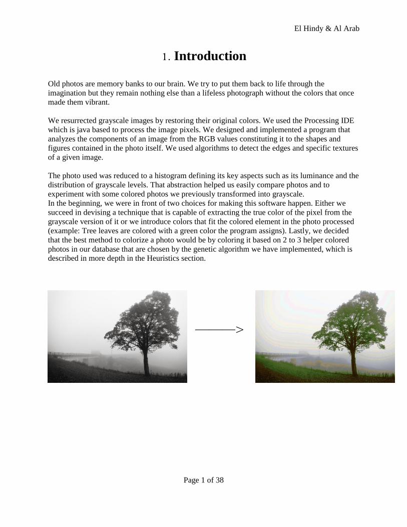
Old photos are memory banks to our brain. We try to put them back to life through the
imagination but they remain nothing else than a lifeless photograph without the colors that once
made them vibrant.
We resurrected grayscale images by restoring their original colors. We used the Processing IDE
which is java based to process the image pixels. We designed and implemented a program that
analyzes the components of an image from the RGB values constituting it to the shapes and
figures contained in the photo itself. We used algorithms to detect the edges and specific textures
of a given image.
The photo used was reduced to a histogram defining its key aspects such as its luminance and the
distribution of grayscale levels. That abstraction helped us easily compare photos and to
experiment with some colored photos we previously transformed into grayscale.
In the beginning, we were in front of two choices for making this software happen. Either we
succeed in devising a technique that is capable of extracting the true color of the pixel from the
grayscale version of it or we introduce colors that fit the colored element in the photo processed
(example: Tree leaves are colored with a green color the program assigns). Lastly, we decided
that the best method to colorize a photo would be by coloring it based on 2 to 3 helper colored
photos in our database that are chosen by the genetic algorithm we have implemented, which is
described in more depth in the Heuristics section.
———>
El Hindy & Al Arab
Page 2 of 38
2. On Color Theory and Edge Detection
2.1 The Color Theory : There are two known color models; the additive color model (RGB - red, green, blue -
known as the light primaries), and the subtractive color model (CMYK - cyan, magenta, yellow,
black).The RGB color model is used in computer monitors and television sets, where red, green
and blue dots of light create the image. Whereas the CMYK model is used in the printing
industry (hardcopy printed color illustrations), in which the four-color printing process uses four
printing plates; one for cyan, one for magenta, one for yellow and one for black. When the colors
are combined on paper (they are actually printed as small dots), the human eye sees the final
image. So, when a user generates graphics on a computer for printing, or wishes to print images
from a digital camera, it is a common mistake to assume that the colors seen on the screen will
look the same in print. As a result of this mistake, files for printing are often erroneously sent in
the Red-Green-Blue (RGB) format for printing. The issue lies in the fact that the computer
screen and many photo editing programs show colors in RGB mode, while images are printed on
paper in CMYK format.
When two RGB colors are mixed equally they produce the colors of the CMYK model,
known as subtractive primaries. Green and blue create cyan (C), red and blue create magenta
(M), and red and green create yellow (Y). Black is added to the model because it cannot be
created with the 3 subtractive primaries (when combined they create a dark brown). The K, or
“key,” stands for black.
The CMYK model works by partially or entirely masking colors on a lighter, usually
white, background. The ink reduces the light that would otherwise be reflected. Such a model is
called subtractive because inks “subtract” brightness from white. In additive color models such
as RGB, white is the “additive” combination of all primary colored lights, while black is the
absence of light. In the CMYK model, it is the opposite: white is the natural color of the paper or
other background, while black results from a full combination of colored inks. To save money on
ink, and to produce deeper black tones, unsaturated and dark colors are produced by using black
ink instead of the combination of cyan, magenta and yellow.
The RGB scheme has a greater range of colors than CMYK and can produce colors that
are more vivid and vibrant. These colors are beyond the range of CMYK to reproduce and will
come out darker and more dull in print than what is seen on the monitor or display. Because the
RGB color mode has the full range of colors, documents shown in CMYK mode will always
show up precisely on-screen. RGB colors, however, will not necessarily appear in print as they
do on-screen.
El Hindy & Al Arab
Page 3 of 38
2.2 Luminance, Saturation, Hue :
The luminance of an image can be described in terms of intensity, lightness/brightness
and value. It is the intensity of light reflected by a color, or in simpler terms "how much black is
mixed in the color", since it is known that black absorbs all visible colors and reflects none. The
terms lightness and brightness refer to the reflection or emission of light from objects and
sources of light present, whereas value describes the relative lightness or darkness of the color
itself.
Hue and saturation are both aspects of color in the RGB scheme. These terms are most
often used in reference to the color of each pixel in a cathode ray tube ( CRT ) display. As
saturation increases, colors appear more "pure." As saturation decreases, colors appear more
"washed-out." Hue refers to the pure spectrum colors - red, orange, yellow, blue, green violet -
which appear in the hue circle or rainbow. Theoretically, all hues can be mixed from three basic
hues, known as primary colors (red, yellow, and blue). When pigment primaries are all mixed
together, the theoretical result is black; therefore, pigment mixture is sometimes referred to as
subtractive mixture.
2.3 Edge Detection & Shape Detection :
Edge detection algorithms are used to highlight the brightness difference between the
different elements constituting the image. Sharp changes in color intensity are detected in
grayscale images and hence all edges are configured.
The first of those algorithms uses a convolution filter mask which is a 3x3 matrix of
weights. The first row of that matrix contains positive weights , the middle row is filled with
zeros and the third and last row consists of the negative weights. When the grayscale image is
processed and traversed via a raster scan technique each pixel and the 8 pixels surrounding it
whether from the top, top right, top left, bottom,bottom right and bottom left each is multiplied
with its corresponding weight in the mask. The sum of all those multiplications replaces the
original color of the pixel. The outcome of this algorithms is a black image with the horizontal
edges illustrated in white. To achieve a vertical edge detection the matrix is transposed and the
image is processed as the procedures described above. To achieve a full edge detection for a
given grayscale image both masks are applied simultaneously. The values of the weights is what
distinguishes an algorithm from another.For example when 1,2, and 1 are used in the first row
(or column in case of vertical detection) and their corresponding negations in the third row the
technique is called “Sobel's Operator”. However when (1,2,1) is replaced in the previous
algorithm is replaced by (1,1,1) it is named “Prewitt's Operator”.
In a similar approach the “Robert's Cross” algorithm detects edges. This method uses a
2x2 matrix instead with the first row of the matrix containing 0 and +1 value while the last low
containing -1 and 0. There exists a second mask that’s the same as the first but with its columns
El Hindy & Al Arab
Page 4 of 38
reversed. This method recognizes 45 degree brightness variations which signifies that such
algorithm detects diagonal edges in a certain image.
The third procedure is laplacian edge detection that makes use of the derivative of a
fluctuating function. The monotone points in the graph that are perpendicular to the X-axis are
translated to a constant number when derived while those points located where the graph shifts
depend on an unknown variable when derived. The same concept is applied to the image as the
pixels of a smooth surface are not detected by the derivative of the image. Only the edges are
revealed upon derivation. This algorithm is sensitive to noise ,which are impurities, in the image
and thus a Gaussian filter must be applied before the processing begins. The Guassian filter ,
again, is a 3x3 mask of weights that is applied to each pixel in an image so that the its color is
blended with that of the surrounding 8 pixels. The Guassian filter smoothens the picture
eliminating noise without blurring the image. The mask used for deriving the color of a pixel and
that for smoothing it are often merged into one and applied directly to the image.
Shape detection techniques rely mainly on edge detection to recognize specific shapes.
The image is smoothened by a Guassian operator to extract the noise and edge recognition is
applied to search for sudden intensity differences that define an object’s boundary. Edge points
are first computed and each receive a descriptor consisting of the value of the pixel gradient
surrounding these points and their corresponding orientation. This descriptor data is represented
in a vector and displayed via a histogram. Edge points that adhere to one another ,logically,
should have the same histograms because the region from which their data was collected is
almost the same. Those similar histograms are then clustered together in a group. Differentiating
between one object and another then requires the comparison by a descriptor that best shows
their differences and not their similarities. This way we can secure a shape recognition technique
that is both reliable and efficient in discriminating between two objects in a grayscale image.
El Hindy & Al Arab
Page 5 of 38
2.4 On Processing: Considering the nature of our project, we will be dealing mainly with 2D images that will be
processed by a set of predefined operations. This requires a programming language that would
simplify this task for us. Processing (2.0) is such language that has a built in image object that is
represented as an array of pixels which we could smoothly scan by the means of a nested for
loop. Processing assigns color channels to each pixel that could refer to either modes : RGB or
HSB. RGB refers to Red , Green and Blue while HSB stands for Hue, Saturation and
Brightness. This language also comes with an array of operations that are applied to a PImage
object. For example , resizing a given photo needs nothing more than one line of code to call the
resize() function and supplying it with the needed length and width. In addition to that we can
make use of some of the data structures suggested such as dictionaries that are helpful in
mapping grayscale colors to their corresponding RGB values. Another advantage we can make
use of are the open-source libraries that we can download from the IDE. One of those libraries is
the openCV library which implements some of the “hard" algorithms that we are in need of ,such
as “face-detection”.
We chose Processing because it offered a programing language as well as an IDE to our project.
We chose it because it is a simplified version of a language we are more familiar with , which is
Java. This clarified version satisfies readability as the vocabulary used to name the incorporated
functions describes what they actually do. It also satisfies Brevity because , as we stated earlier, a
simple statement can replace several lines of code. This will help the programmer do much in a
limited amount of time. Another aspect ,this language fulfills, is portability because it is based on
java which in turn runs on each device that has a Java Virtual Machine. Since we are aiming to
introduce our software on the Java-based Android platform, then the Java-based Processing will
make this migration possible.
Those are some of the reasons why we are convinced that Processing (2.0) is the preferable
language and IDE to use. If it were to be implemented in any other language , our ambitions
wouldn’t be that high, but given such tools and functions we believe that we could achieve and
implement what others are still researching.
El Hindy & Al Arab
Page 6 of 38
*
!
*
!
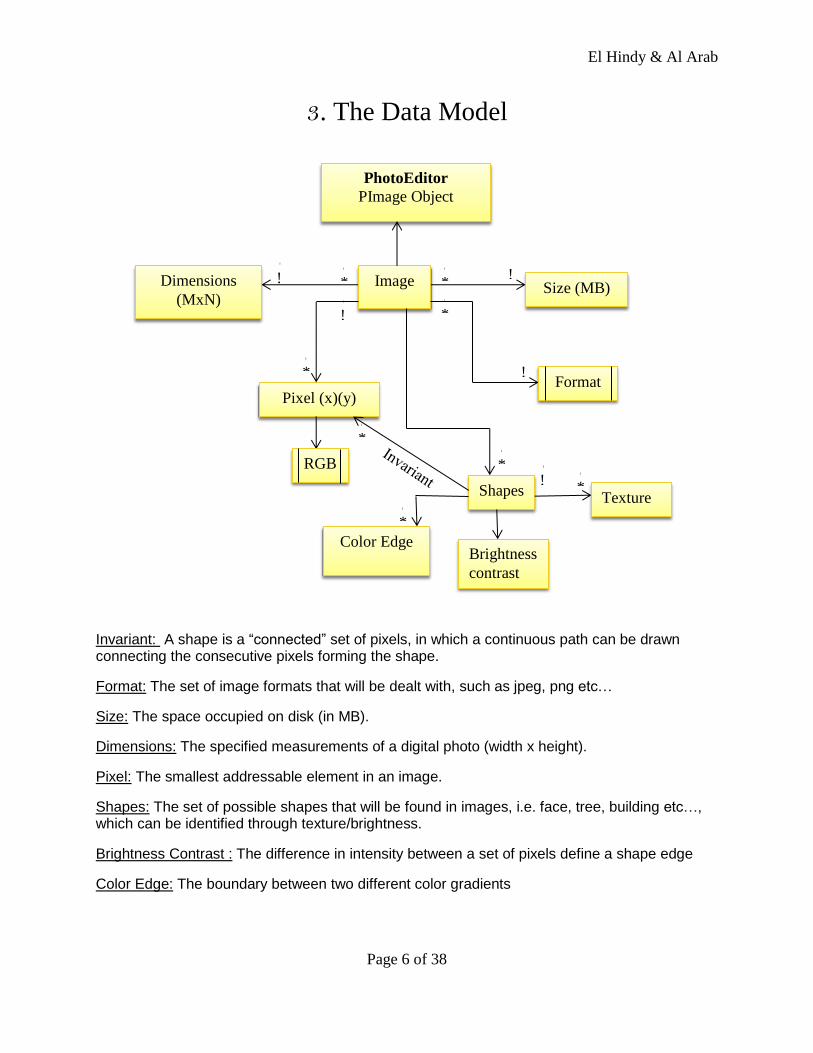
3. The Data Model
Invariant: A shape is a “connected” set of pixels, in which a continuous path can be drawn connecting the consecutive pixels forming the shape.
Format: The set of image formats that will be dealt with, such as jpeg, png etc…
Size: The space occupied on disk (in MB).
Dimensions: The specified measurements of a digital photo (width x height).
Pixel: The smallest addressable element in an image.
Shapes: The set of possible shapes that will be found in images, i.e. face, tree, building etc…, which can be identified through texture/brightness.
Brightness Contrast : The difference in intensity between a set of pixels define a shape edge
Color Edge: The boundary between two different color gradients
PhotoEditor
PImage Object
*
!
!
! *
!
!
! *
!
*
!
*
!
! *
!
!
!
! !
!
Image Dimensions
(MxN) Size (MB)
Pixel (x)(y) Format
RGB
Shapes Texture
Brightness
contrast
Color Edge
El Hindy & Al Arab
Page 7 of 38
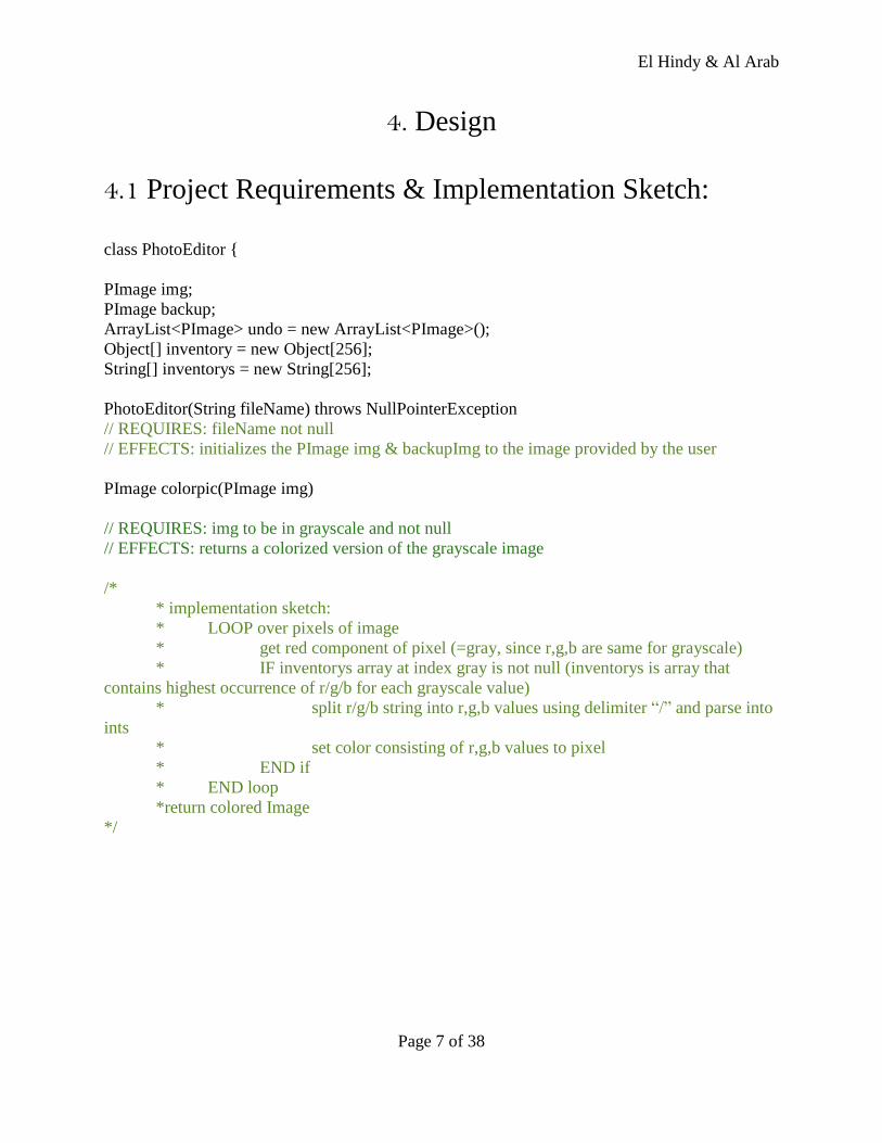
4. Design
4.1 Project Requirements & Implementation Sketch:
class PhotoEditor {
PImage img;
PImage backup;
ArrayList<PImage> undo = new ArrayList<PImage>();
Object[] inventory = new Object[256];
String[] inventorys = new String[256];
PhotoEditor(String fileName) throws NullPointerException
// REQUIRES: fileName not null
// EFFECTS: initializes the PImage img & backupImg to the image provided by the user
PImage colorpic(PImage img)
// REQUIRES: img to be in grayscale and not null
// EFFECTS: returns a colorized version of the grayscale image
/*
* implementation sketch:
* LOOP over pixels of image
* get red component of pixel (=gray, since r,g,b are same for grayscale)
* IF inventorys array at index gray is not null (inventorys is array that
contains highest occurrence of r/g/b for each grayscale value)
* split r/g/b string into r,g,b values using delimiter “/” and parse into
ints
* set color consisting of r,g,b values to pixel
* END if
* END loop
*return colored Image
*/
El Hindy & Al Arab
Page 8 of 38
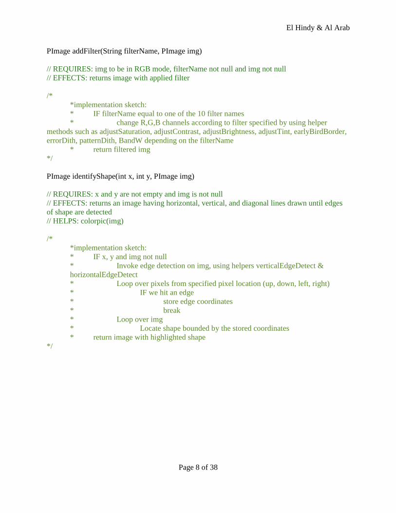
PImage addFilter(String filterName, PImage img)
// REQUIRES: img to be in RGB mode, filterName not null and img not null
// EFFECTS: returns image with applied filter
/*
*implementation sketch:
* IF filterName equal to one of the 10 filter names
* change R,G,B channels according to filter specified by using helper
methods such as adjustSaturation, adjustContrast, adjustBrightness, adjustTint, earlyBirdBorder,
errorDith, patternDith, BandW depending on the filterName
* return filtered img
*/
PImage identifyShape(int x, int y, PImage img)
// REQUIRES: x and y are not empty and img is not null
// EFFECTS: returns an image having horizontal, vertical, and diagonal lines drawn until edges
of shape are detected
// HELPS: colorpic(img)
/*
*implementation sketch:
* IF x, y and img not null
* Invoke edge detection on img, using helpers verticalEdgeDetect &
horizontalEdgeDetect
* Loop over pixels from specified pixel location (up, down, left, right)
* IF we hit an edge
* store edge coordinates
* break
* Loop over img
* Locate shape bounded by the stored coordinates
* return image with highlighted shape
*/
El Hindy & Al Arab
Page 9 of 38
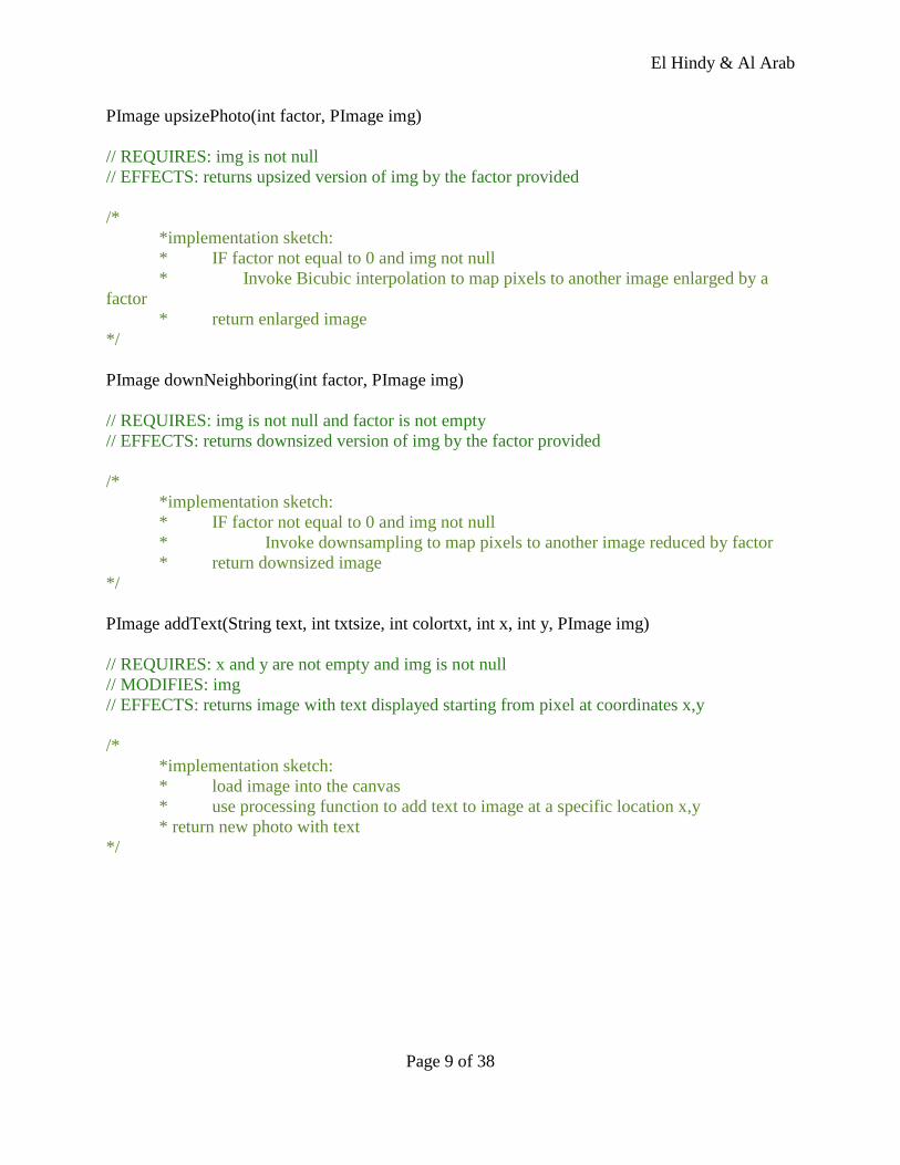
PImage upsizePhoto(int factor, PImage img)
// REQUIRES: img is not null
// EFFECTS: returns upsized version of img by the factor provided
/*
*implementation sketch:
* IF factor not equal to 0 and img not null
* Invoke Bicubic interpolation to map pixels to another image enlarged by a
factor
* return enlarged image
*/
PImage downNeighboring(int factor, PImage img)
// REQUIRES: img is not null and factor is not empty
// EFFECTS: returns downsized version of img by the factor provided
/*
*implementation sketch:
* IF factor not equal to 0 and img not null
* Invoke downsampling to map pixels to another image reduced by factor
* return downsized image
*/
PImage addText(String text, int txtsize, int colortxt, int x, int y, PImage img)
// REQUIRES: x and y are not empty and img is not null
// MODIFIES: img
// EFFECTS: returns image with text displayed starting from pixel at coordinates x,y
/*
*implementation sketch:
* load image into the canvas
* use processing function to add text to image at a specific location x,y
* return new photo with text
*/
El Hindy & Al Arab
Page 10 of 38
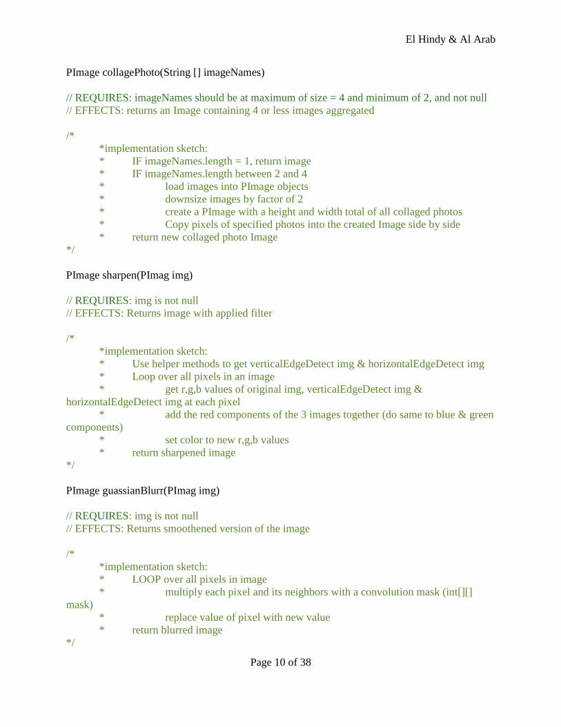
PImage collagePhoto(String [] imageNames)
// REQUIRES: imageNames should be at maximum of size = 4 and minimum of 2, and not null
// EFFECTS: returns an Image containing 4 or less images aggregated
/*
*implementation sketch:
* IF imageNames.length = 1, return image
* IF imageNames.length between 2 and 4
* load images into PImage objects
* downsize images by factor of 2
* create a PImage with a height and width total of all collaged photos
* Copy pixels of specified photos into the created Image side by side
* return new collaged photo Image
*/
PImage sharpen(PImag img)
// REQUIRES: img is not null
// EFFECTS: Returns image with applied filter
/*
*implementation sketch:
* Use helper methods to get verticalEdgeDetect img & horizontalEdgeDetect img
* Loop over all pixels in an image
* get r,g,b values of original img, verticalEdgeDetect img &
horizontalEdgeDetect img at each pixel
* add the red components of the 3 images together (do same to blue & green
components)
* set color to new r,g,b values
* return sharpened image
*/
PImage guassianBlurr(PImag img)
// REQUIRES: img is not null
// EFFECTS: Returns smoothened version of the image
/*
*implementation sketch:
* LOOP over all pixels in image
* multiply each pixel and its neighbors with a convolution mask (int[][]
mask)
* replace value of pixel with new value
* return blurred image
*/
El Hindy & Al Arab
Page 11 of 38
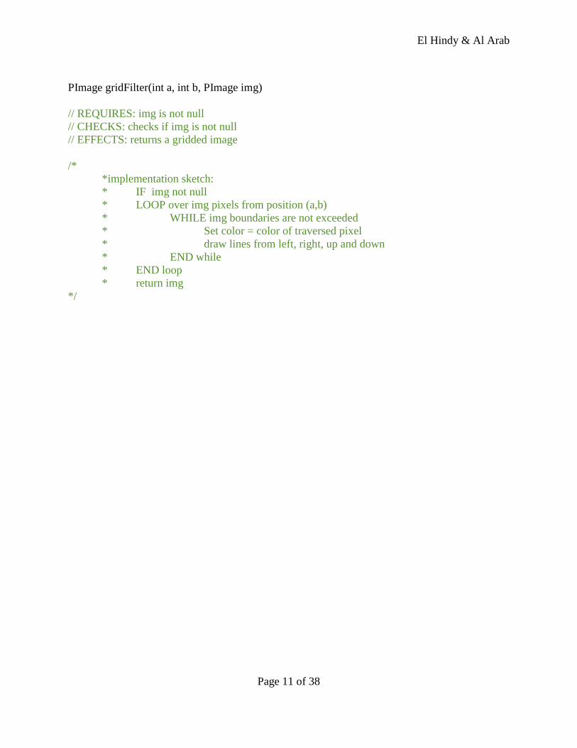
PImage gridFilter(int a, int b, PImage img)
// REQUIRES: img is not null
// CHECKS: checks if img is not null
// EFFECTS: returns a gridded image
/*
*implementation sketch:
* IF img not null
* LOOP over img pixels from position (a,b)
* WHILE img boundaries are not exceeded
* Set color = color of traversed pixel
* draw lines from left, right, up and down
* END while
* END loop
* return img
*/
El Hindy & Al Arab
Page 12 of 38
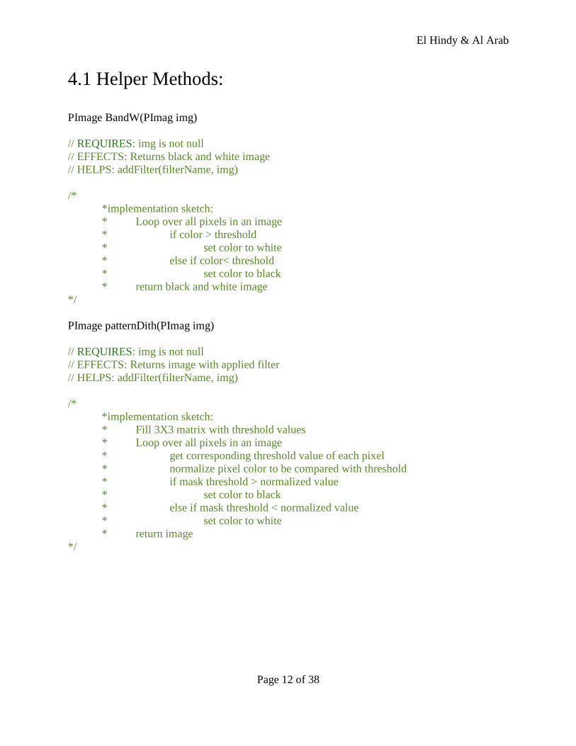
4.1 Helper Methods:
PImage BandW(PImag img)
// REQUIRES: img is not null
// EFFECTS: Returns black and white image
// HELPS: addFilter(filterName, img)
/*
*implementation sketch:
* Loop over all pixels in an image
* if color > threshold
* set color to white
* else if color< threshold
* set color to black
* return black and white image
*/
PImage patternDith(PImag img)
// REQUIRES: img is not null
// EFFECTS: Returns image with applied filter
// HELPS: addFilter(filterName, img)
/*
*implementation sketch:
* Fill 3X3 matrix with threshold values
* Loop over all pixels in an image
* get corresponding threshold value of each pixel
* normalize pixel color to be compared with threshold
* if mask threshold > normalized value
* set color to black
* else if mask threshold < normalized value
* set color to white
* return image
*/
El Hindy & Al Arab
Page 13 of 38
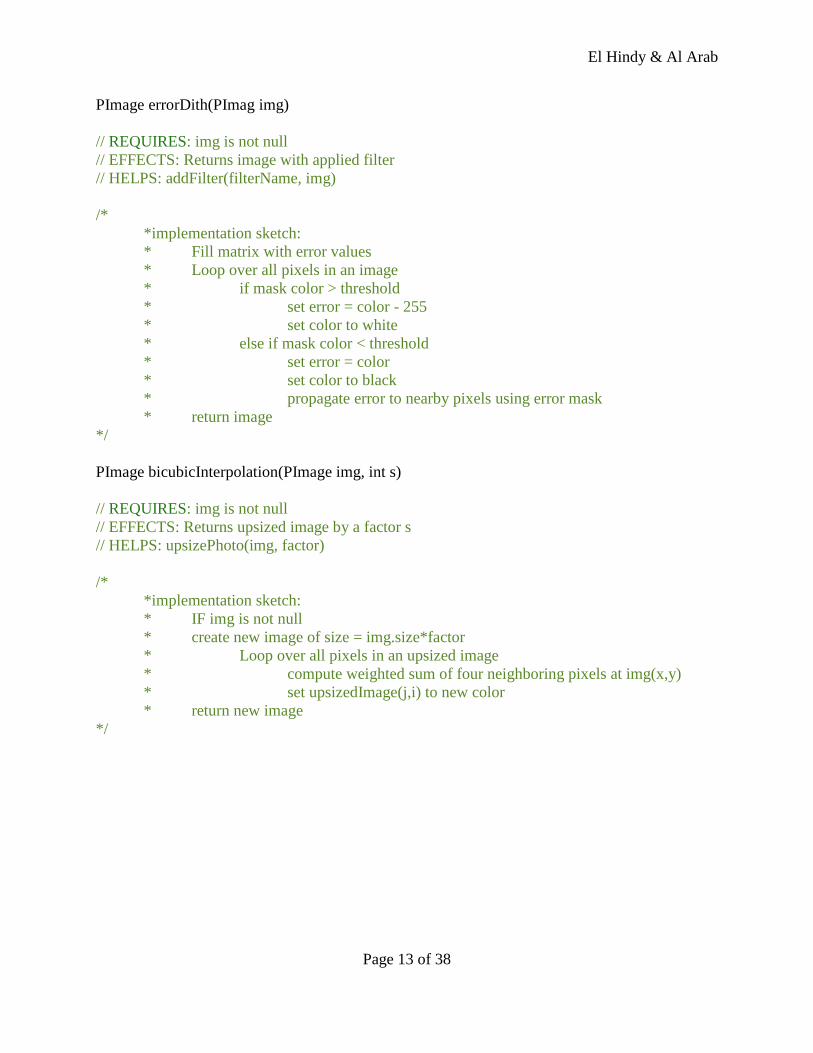
PImage errorDith(PImag img)
// REQUIRES: img is not null
// EFFECTS: Returns image with applied filter
// HELPS: addFilter(filterName, img)
/*
*implementation sketch:
* Fill matrix with error values
* Loop over all pixels in an image
* if mask color > threshold
* set error = color - 255
* set color to white
* else if mask color < threshold
* set error = color
* set color to black
* propagate error to nearby pixels using error mask
* return image
*/
PImage bicubicInterpolation(PImage img, int s)
// REQUIRES: img is not null
// EFFECTS: Returns upsized image by a factor s
// HELPS: upsizePhoto(img, factor)
/*
*implementation sketch:
* IF img is not null
* create new image of size = img.size*factor
* Loop over all pixels in an upsized image
* compute weighted sum of four neighboring pixels at img(x,y)
* set upsizedImage(j,i) to new color
* return new image
*/
El Hindy & Al Arab
Page 14 of 38
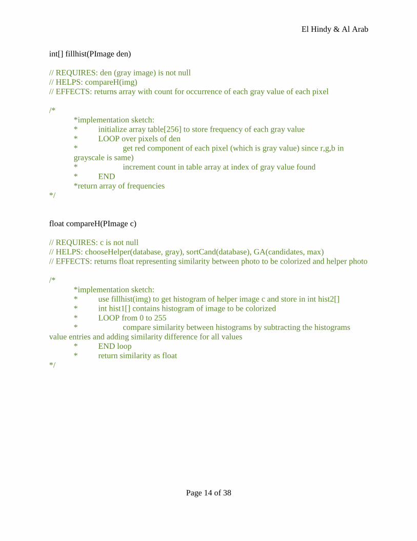
int[] fillhist(PImage den)
// REQUIRES: den (gray image) is not null
// HELPS: compareH(img)
// EFFECTS: returns array with count for occurrence of each gray value of each pixel
/*
*implementation sketch:
* initialize array table[256] to store frequency of each gray value
* LOOP over pixels of den
* get red component of each pixel (which is gray value) since r,g,b in
grayscale is same)
* increment count in table array at index of gray value found
* END
*return array of frequencies
*/
float compareH(PImage c)
// REQUIRES: c is not null
// HELPS: chooseHelper(database, gray), sortCand(database), GA(candidates, max)
// EFFECTS: returns float representing similarity between photo to be colorized and helper photo
/*
*implementation sketch:
* use fillhist(img) to get histogram of helper image c and store in int hist2[]
* int hist1[] contains histogram of image to be colorized
* LOOP from 0 to 255
* compare similarity between histograms by subtracting the histograms
value entries and adding similarity difference for all values
* END loop
* return similarity as float
*/
El Hindy & Al Arab
Page 15 of 38
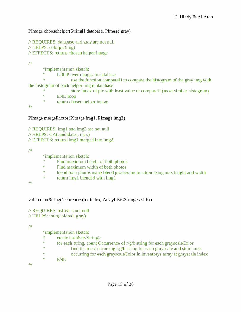
PImage choosehelper(String[] database, PImage gray)
// REQUIRES: database and gray are not null
// HELPS: colorpic(img)
// EFFECTS: returns chosen helper image
/*
*implementation sketch:
* LOOP over images in database
* use the function compareH to compare the histogram of the gray img with
the histogram of each helper img in database
* store index of pic with least value of compareH (most similar histogram)
* END loop
* return chosen helper image
*/
PImage mergePhotos(PImage img1, PImage img2)
// REQUIRES: img1 and img2 are not null
// HELPS: GA(candidates, max)
// EFFECTS: returns img1 merged into img2
/*
*implementation sketch:
* Find maximum height of both photos
* Find maximum width of both photos
* blend both photos using blend processing function using max height and width
* return img1 blended with img2
*/
void countStringOccurences(int index, ArrayList<String> asList)
// REQUIRES: asList is not null
// HELPS: train(colored, gray)
/*
*implementation sketch:
* create hashSet<String>
* for each string, count Occurrence of r/g/b string for each grayscaleColor
* find the most occurring r/g/b string for each grayscale and store most
* occurring for each grayscaleColor in inventorys array at grayscale index
* END
*/
El Hindy & Al Arab
Page 16 of 38
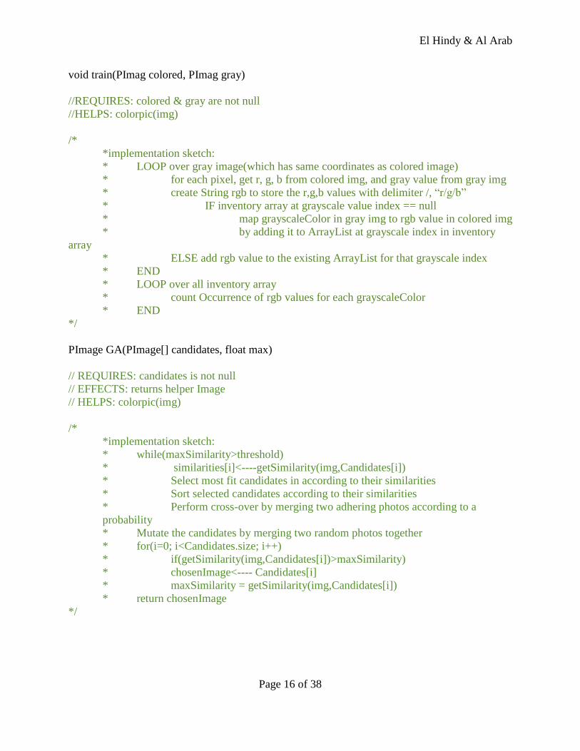
void train(PImag colored, PImag gray)
//REQUIRES: colored & gray are not null
//HELPS: colorpic(img)
/*
*implementation sketch:
* LOOP over gray image(which has same coordinates as colored image)
* for each pixel, get r, g, b from colored img, and gray value from gray img
* create String rgb to store the r,g,b values with delimiter /, “r/g/b”
* IF inventory array at grayscale value index == null
* map grayscaleColor in gray img to rgb value in colored img
* by adding it to ArrayList at grayscale index in inventory
array
* ELSE add rgb value to the existing ArrayList for that grayscale index
* END
* LOOP over all inventory array
* count Occurrence of rgb values for each grayscaleColor
* END
*/
PImage GA(PImage[] candidates, float max)
// REQUIRES: candidates is not null
// EFFECTS: returns helper Image
// HELPS: colorpic(img)
/*
*implementation sketch:
* while(maxSimilarity>threshold)
* similarities[i]<----getSimilarity(img,Candidates[i])
* Select most fit candidates in according to their similarities
* Sort selected candidates according to their similarities
* Perform cross-over by merging two adhering photos according to a
probability
* Mutate the candidates by merging two random photos together
* for(i=0; i<Candidates.size; i++)
* if(getSimilarity(img,Candidates[i])>maxSimilarity)
* chosenImage<---- Candidates[i]
* maxSimilarity = getSimilarity(img,Candidates[i])
* return chosenImage
*/
El Hindy & Al Arab
Page 17 of 38
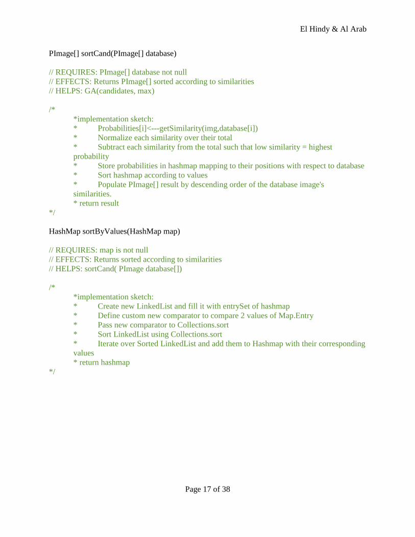
PImage[] sortCand(PImage[] database)
// REQUIRES: PImage[] database not null
// EFFECTS: Returns PImage[] sorted according to similarities
// HELPS: GA(candidates, max)
/*
*implementation sketch:
* Probabilities[i]<---getSimilarity(img,database[i])
* Normalize each similarity over their total
* Subtract each similarity from the total such that low similarity = highest
probability
* Store probabilities in hashmap mapping to their positions with respect to database
* Sort hashmap according to values
* Populate PImage[] result by descending order of the database image's
similarities.
* return result
*/
HashMap sortByValues(HashMap map)
// REQUIRES: map is not null
// EFFECTS: Returns sorted according to similarities
// HELPS: sortCand( PImage database[])
/*
*implementation sketch:
* Create new LinkedList and fill it with entrySet of hashmap
* Define custom new comparator to compare 2 values of Map.Entry
* Pass new comparator to Collections.sort
* Sort LinkedList using Collections.sort
* Iterate over Sorted LinkedList and add them to Hashmap with their corresponding
values
* return hashmap
*/
El Hindy & Al Arab
Page 18 of 38
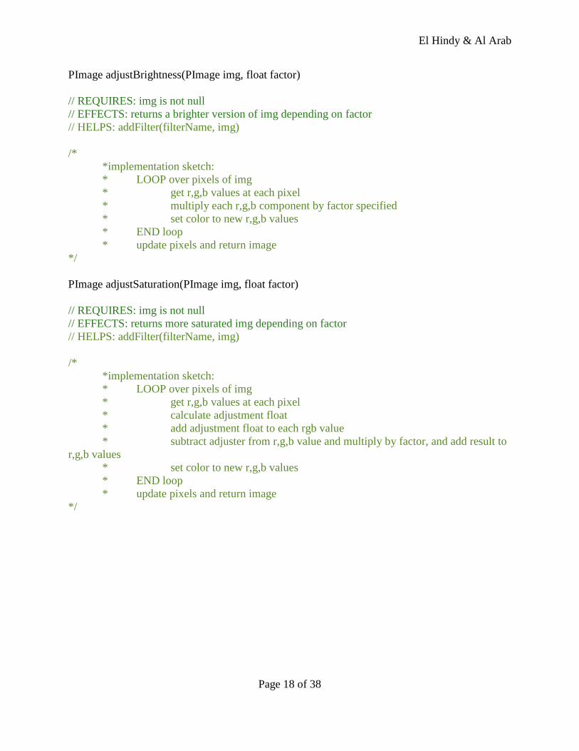
PImage adjustBrightness(PImage img, float factor)
// REQUIRES: img is not null
// EFFECTS: returns a brighter version of img depending on factor
// HELPS: addFilter(filterName, img)
/*
*implementation sketch:
* LOOP over pixels of img
* get r,g,b values at each pixel
* multiply each r,g,b component by factor specified
* set color to new r,g,b values
* END loop
* update pixels and return image
*/
PImage adjustSaturation(PImage img, float factor)
// REQUIRES: img is not null
// EFFECTS: returns more saturated img depending on factor
// HELPS: addFilter(filterName, img)
/*
*implementation sketch:
* LOOP over pixels of img
* get r,g,b values at each pixel
* calculate adjustment float
* add adjustment float to each rgb value
* subtract adjuster from r,g,b value and multiply by factor, and add result to
r,g,b values
* set color to new r,g,b values
* END loop
* update pixels and return image
*/
El Hindy & Al Arab
Page 19 of 38
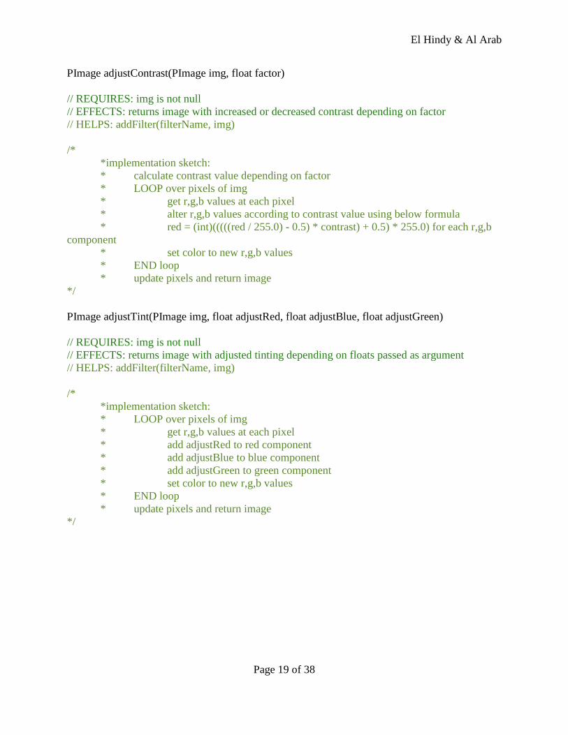
PImage adjustContrast(PImage img, float factor)
// REQUIRES: img is not null
// EFFECTS: returns image with increased or decreased contrast depending on factor
// HELPS: addFilter(filterName, img)
/*
*implementation sketch:
* calculate contrast value depending on factor
* LOOP over pixels of img
* get r,g,b values at each pixel
* alter r,g,b values according to contrast value using below formula
* red = (int)(((((red / 255.0) - 0.5) * contrast) + 0.5) * 255.0) for each r,g,b
component
* set color to new r,g,b values
* END loop
* update pixels and return image
*/
PImage adjustTint(PImage img, float adjustRed, float adjustBlue, float adjustGreen)
// REQUIRES: img is not null
// EFFECTS: returns image with adjusted tinting depending on floats passed as argument
// HELPS: addFilter(filterName, img)
/*
*implementation sketch:
* LOOP over pixels of img
* get r,g,b values at each pixel
* add adjustRed to red component
* add adjustBlue to blue component
* add adjustGreen to green component
* set color to new r,g,b values
* END loop
* update pixels and return image
*/
El Hindy & Al Arab
Page 20 of 38
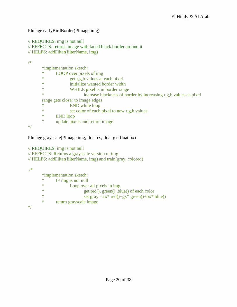
PImage earlyBirdBorder(PImage img)
// REQUIRES: img is not null
// EFFECTS: returns image with faded black border around it
// HELPS: addFilter(filterName, img)
/*
*implementation sketch:
* LOOP over pixels of img
* get r,g,b values at each pixel
* initialize wanted border width
* WHILE pixel is in border range
* increase blackness of border by increasing r,g,b values as pixel
range gets closer to image edges
* END while loop
* set color of each pixel to new r,g,b values
* END loop
* update pixels and return image
*/
PImage grayscale(PImage img, float rx, float gx, float bx)
// REQUIRES: img is not null
// EFFECTS: Returns a grayscale version of img
// HELPS: addFilter(filterName, img) and train(gray, colored)
/*
*implementation sketch:
* IF img is not null
* Loop over all pixels in img
* get red(), green() ,blue() of each color
* set gray = rx* red()+gx* green()+bx* blue()
* return grayscale image
*/
El Hindy & Al Arab
Page 21 of 38
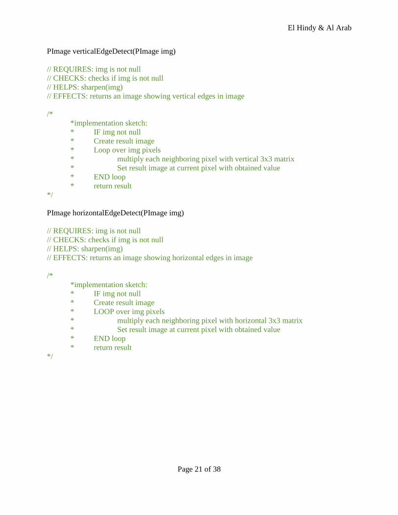
PImage verticalEdgeDetect(PImage img)
// REQUIRES: img is not null
// CHECKS: checks if img is not null
// HELPS: sharpen(img)
// EFFECTS: returns an image showing vertical edges in image
/*
*implementation sketch:
* IF img not null
* Create result image
* Loop over img pixels
* multiply each neighboring pixel with vertical 3x3 matrix
* Set result image at current pixel with obtained value
* END loop
* return result
*/
PImage horizontalEdgeDetect(PImage img)
// REQUIRES: img is not null
// CHECKS: checks if img is not null
// HELPS: sharpen(img)
// EFFECTS: returns an image showing horizontal edges in image
/*
*implementation sketch:
* IF img not null
* Create result image
* LOOP over img pixels
* multiply each neighboring pixel with horizontal 3x3 matrix
* Set result image at current pixel with obtained value
* END loop
* return result
*/
El Hindy & Al Arab
Page 22 of 38
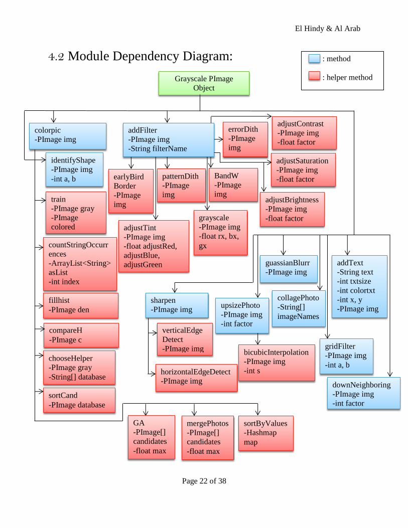
4.2 Module Dependency Diagram:
Grayscale PImage
Object
colorpic
-PImage img
addFilter
-PImage img
-String filterName
adjustSaturation
-PImage img
-float factor
upsizePhoto
-PImage img
-int factor
downNeighboring
-PImage img
-int factor
adjustBrightness
-PImage img
-float factor
addText
-String text
-int txtsize
-int colortxt
-int x, y
-PImage img
collagePhoto
-String[]
imageNames
BandW
-PImage
img
earlyBird
Border
-PImage
img
guassianBlurr
-PImage img
countStringOccurr
ences
-ArrayList<String>
asList
-int index
identifyShape
-PImage img
-int a, b
bicubicInterpolation
-PImage img
-int s
sharpen
-PImage img
patternDith
-PImage
img
errorDith
-PImage
img
grayscale
-PImage img
-float rx, bx,
gx
adjustContrast
-PImage img
-float factor
adjustTint
-PImage img
-float adjustRed,
adjustBlue,
adjustGreen
verticalEdge
Detect
-PImage img
horizontalEdgeDetect
-PImage img
gridFilter
-PImage img
-int a, b
train
-PImage gray
-PImage
colored
fillhist
-PImage den
compareH
-PImage c
chooseHelper
-PImage gray
-String[] database
sortCand
-PImage database
GA
-PImage[]
candidates
-float max
mergePhotos
-PImage[]
candidates
-float max
sortByValues
-Hashmap
map
: method
: helper method
El Hindy & Al Arab
Page 23 of 38
5. Work Update:
1. We replaced bilinear interpolation for upsizing images with bicubic interpolation since it gives
a smoother result when applied to an image
2. We implemented collagePhoto() function that joins multiple images into one.
3. We implemented the downSize() function that reduces the size of an image by a given factor.
4. We implemented sharpen() function along with an algorithm to detect both vertical and
horizontal edges.
5. We implemented adjustBrightness() function that changes the brightness of a photo depending
on the horizontal position of the mouse cursor.
6. We implemented adjustSaturation() function that changes saturation of photo depending on
the vertical position of the mouse curser.
7. We implemented a adjustContrast() function that will adjust the contrast of the colors in an
image.
9. We implemented addText() function that adds a text of specific font and color and of unique
position. Used fonts are files of “vlw" format that should be placed in a Data folder along with
the sketch to be then loaded and used by Processing.
10. In order to colorize a photo, we need a helper image that has similar color plates or gradients
in order to map each gray color to its corresponding RGB value.
i. Since a single grayscale value can have up to 3000 and more matches in a color
image we need a way to choose what color offers the appropriate mapping. Therefore
we counted the occurrence of each color in the array of colors each of the 255
grayscale values map to.
ii. Then we sorted this array based on the number of occurrences and chose the last
value in it which is now assumably the most occurrent. Then we composed another
map that associates each grayscale value to the most occurring RGB color.
iii. We used this map to color the grayscale image we have and the results are pleasing
when a visually similar helper image is used.
iv. Upon further inspection of the relation that connects a “Good helper Image
Candidate” to the grayscale image to be colorized we obtained the Histogram
representation of both images.
v. What we concluded was interesting. The color distribution between the two
histograms were nearly identical. The slopes of both graphs were synchronized as
well as for their inclines. We believed that this may be key for the application to pick
from a populated database of images the best candidate that would help obtain a
correct mapping.
El Hindy & Al Arab
Page 24 of 38
vi. We tested more images to find other heuristics that would improve the colorization
process.
11. We implemented the identifyShape() function.
12. We implemented a compareHistograms() function.
13. We implemented the Valencia filter
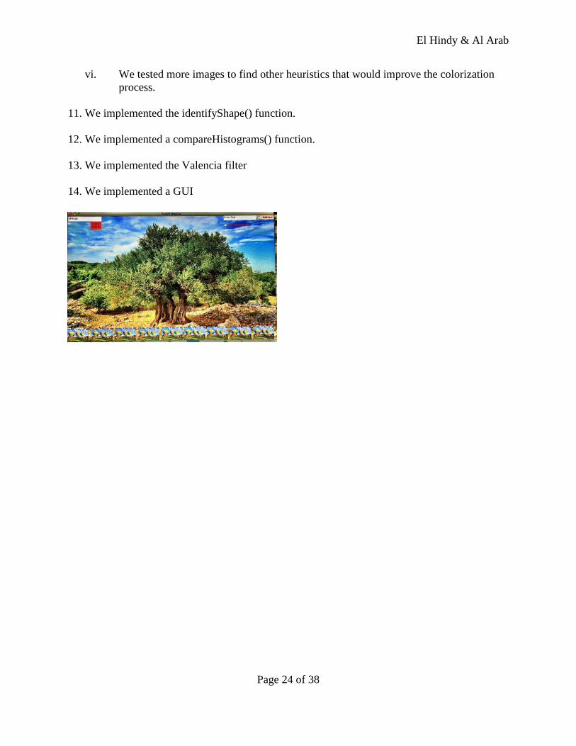
14. We implemented a GUI
El Hindy & Al Arab
Page 25 of 38
6. Heuristics:
The transformation of an image from its original colored mode to the grayscale mode is very
easy as all we need is to substitute the Red, Green and Blue channels with one value derived
from those 3. On the other hand, reversing this transition is difficult because the lost information
in each pixel is hard to retrieve if not impossible. It is as if we are trying to map a 1 dimensional
line into a 3 dimensional cube without any information about the depth and height.
Therefore we are in need of a helper colored photo to aid us in guessing the RGB color each
grayscale value maps to. Whenever a grayscale image is processed to be colorized, a helper
image is chosen from a database (or a folder) to be then transformed into grayscale. After this
transformation we populate an array Inventory:
Inventory[x] 0 —> 255
Such that : size(Inventory) = 256
x—> Grayscale value {0,1,….. 255}
Inventory[x] = Arraylist<String> Such That: entry(Arraylist<String>) = “R/G/B“
The results of such algorithm vary depending on how “appropriate" the helper photo was to
derive a proper mapping. The better the computed map was the better it reflected the original
RGB colors of the grayscale image to be colorized. However , determining a good candidate
photo is something tricky and error prone. We devised two techniques in picking a helper image
that proved at times to be successful and in others to be unsuitable.
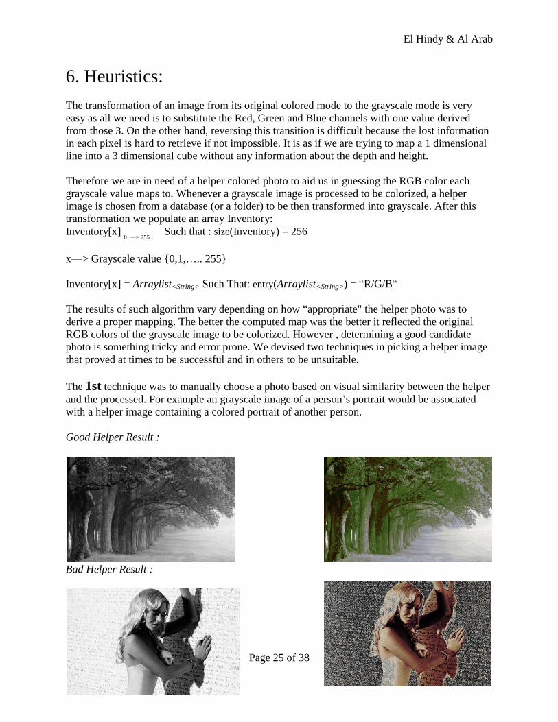
The 1st technique was to manually choose a photo based on visual similarity between the helper
and the processed. For example an grayscale image of a person’s portrait would be associated
with a helper image containing a colored portrait of another person.
Good Helper Result :
Bad Helper Result :
El Hindy & Al Arab
Page 26 of 38
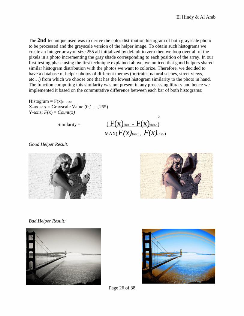
The 2nd technique used was to derive the color distribution histogram of both grayscale photo
to be processed and the grayscale version of the helper image. To obtain such histograms we
create an Integer array of size 255 all initialized by default to zero then we loop over all of the
pixels in a photo incrementing the gray shade corresponding to each position of the array. In our
first testing phase using the first technique explained above, we noticed that good helpers shared
similar histogram distribution with the photos we want to colorize. Therefore, we decided to
have a database of helper photos of different themes (portraits, natural scenes, street views,
etc…) from which we choose one that has the lowest histogram similarity to the photo in hand.
The function computing this similarity was not present in any processing library and hence we
implemented it based on the commutative difference between each bar of both histograms:
Histogram = F(x)0 —> 255
X-axis: x = Grayscale Value (0,1….,255)
Y-axis: F(x) = Count(x) 2
Similarity = ( F(x)Hist1 - F(x)Hist2 )
MAX( F(x)Hist1 , F(x)Hist2)
Good Helper Result:
Bad Helper Result:
El Hindy & Al Arab
Page 27 of 38
7. Genetic Algorithm:
We are well aware that there is no formal algorithm to transfer an grayscale image to RGB that is
both strait forward and efficient. This obliges us to invoke some of the algorithms that will
provide us with the best approximation of the “good helper” that we will be using to get this
transformation done.
One of those algorithms is the Genetic algorithm and as the name suggests it is derived from the
field of biology. In the process of natural evolution, the fittest genes are selected from a specific
DNA pool to produce the offsprings. The genes located on both segments of the same DNA
complex are susceptible to crossover. The genes themselves can undergo mutation under specific
circumstances.
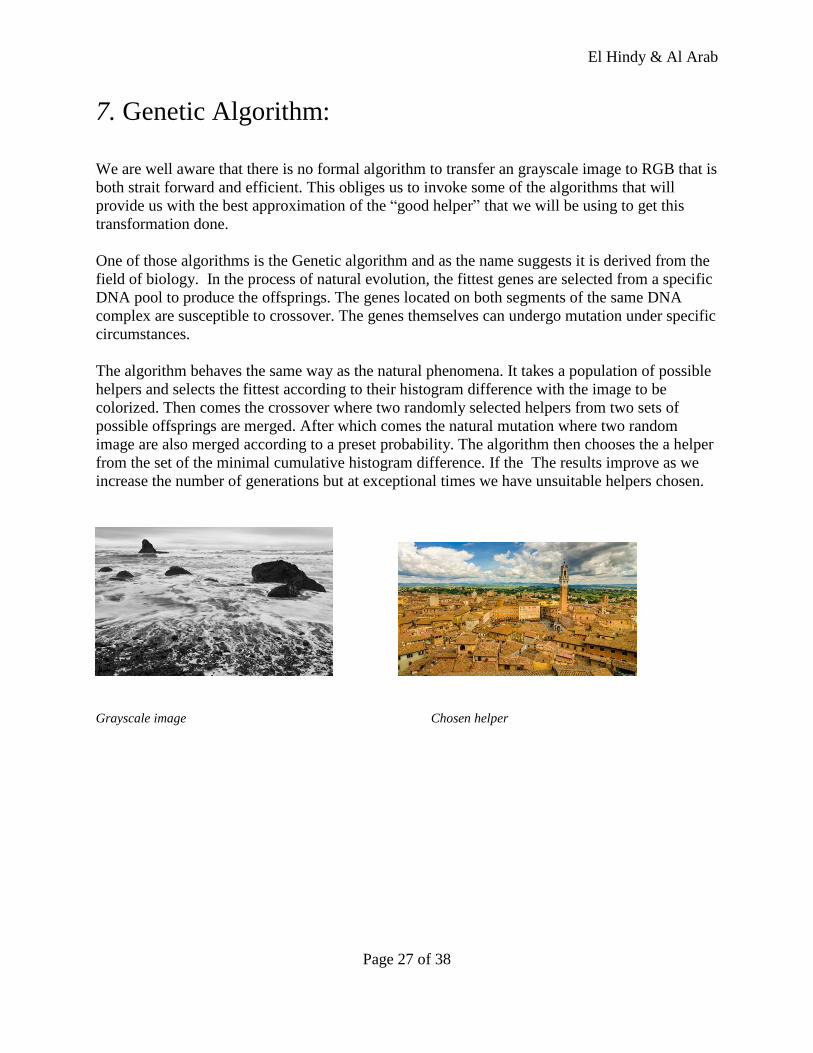
The algorithm behaves the same way as the natural phenomena. It takes a population of possible
helpers and selects the fittest according to their histogram difference with the image to be
colorized. Then comes the crossover where two randomly selected helpers from two sets of
possible offsprings are merged. After which comes the natural mutation where two random
image are also merged according to a preset probability. The algorithm then chooses the a helper
from the set of the minimal cumulative histogram difference. If the The results improve as we
increase the number of generations but at exceptional times we have unsuitable helpers chosen.
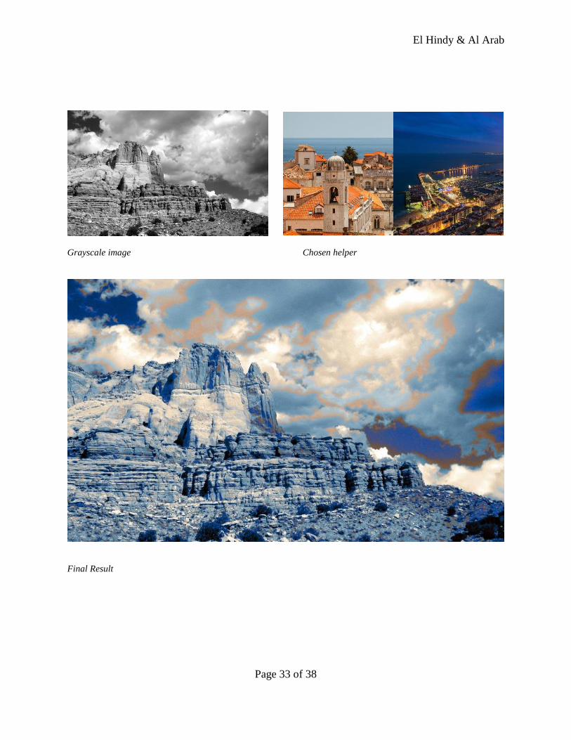
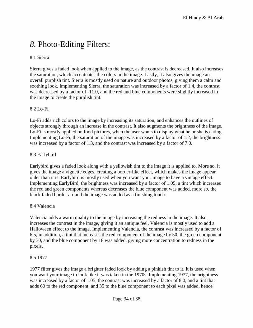
Grayscale image Chosen helper
El Hindy & Al Arab
Page 28 of 38
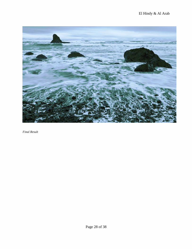
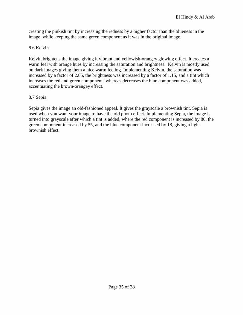
Final Result
El Hindy & Al Arab
Page 29 of 38
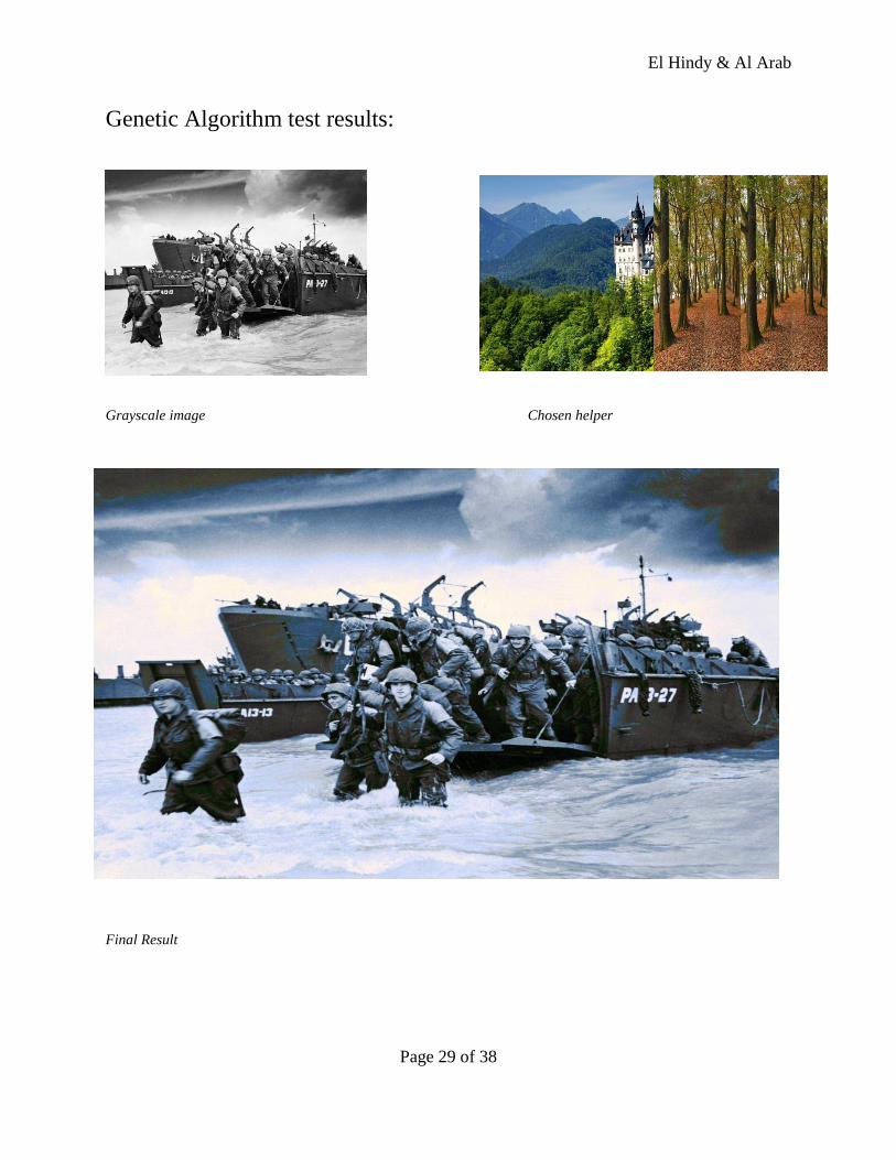
Genetic Algorithm test results:
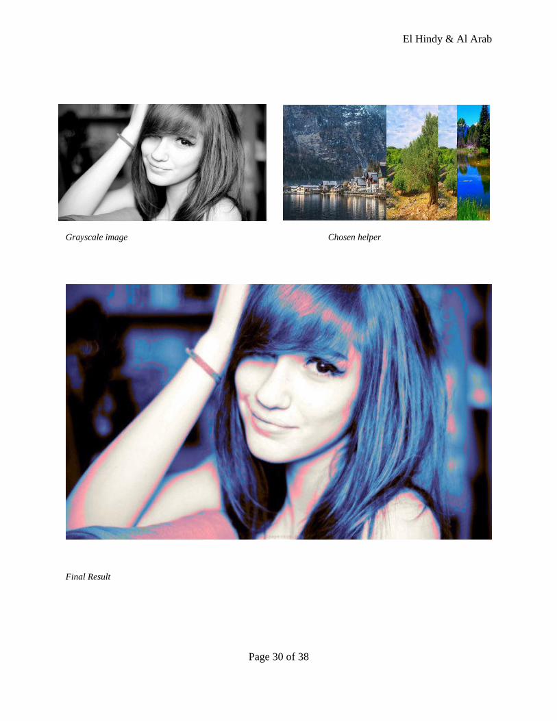
Grayscale image Chosen helper
Final Result
El Hindy & Al Arab
Page 30 of 38
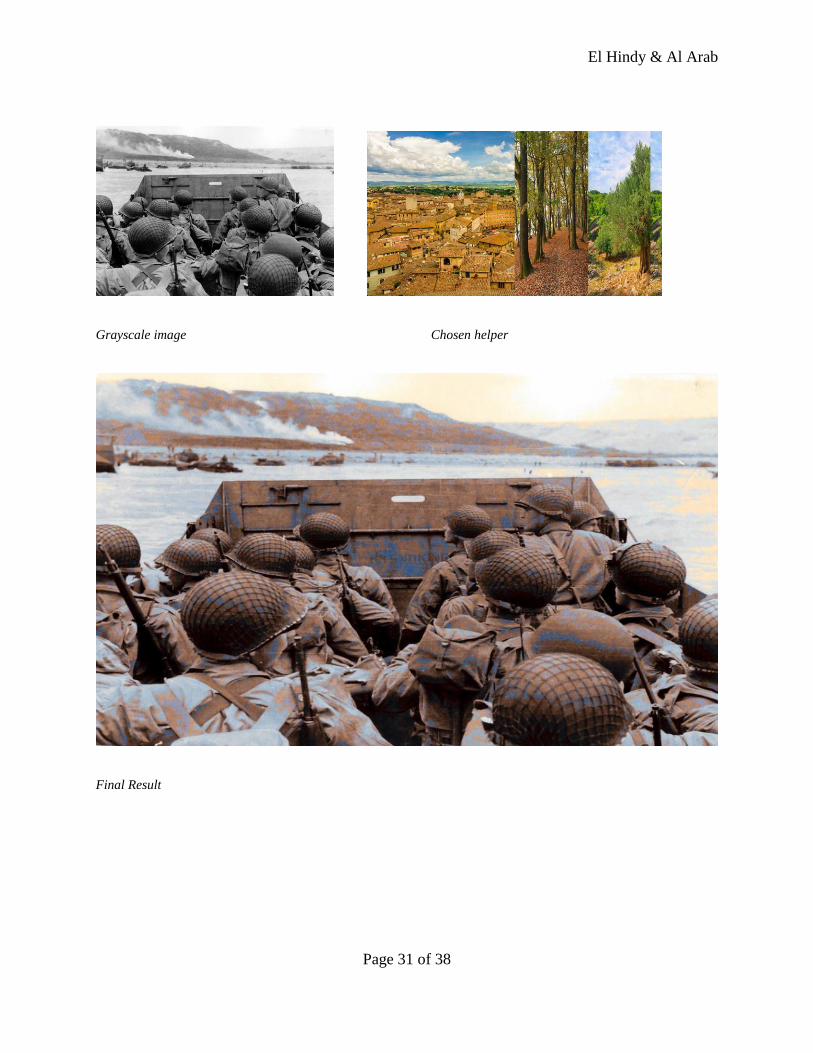
Grayscale image Chosen helper
Final Result
El Hindy & Al Arab
Page 31 of 38
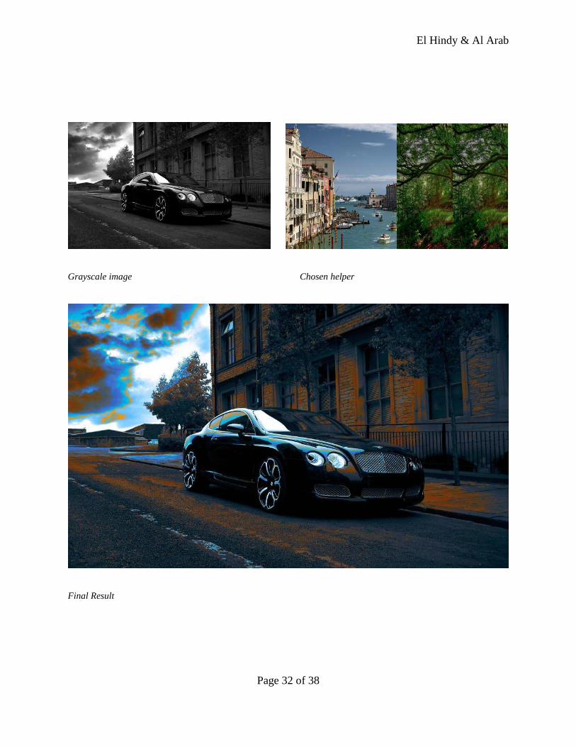
Grayscale image Chosen helper
Final Result
El Hindy & Al Arab
Page 32 of 38
Grayscale image Chosen helper
Final Result
El Hindy & Al Arab
Page 33 of 38
Grayscale image Chosen helper
Final Result
El Hindy & Al Arab
Page 34 of 38
8. Photo-Editing Filters:
8.1 Sierra
Sierra gives a faded look when applied to the image, as the contrast is decreased. It also increases
the saturation, which accentuates the colors in the image. Lastly, it also gives the image an
overall purplish tint. Sierra is mostly used on nature and outdoor photos, giving them a calm and
soothing look. Implementing Sierra, the saturation was increased by a factor of 1.4, the contrast
was decreased by a factor of -11.0, and the red and blue components were slightly increased in
the image to create the purplish tint.
8.2 Lo-Fi
Lo-Fi adds rich colors to the image by increasing its saturation, and enhances the outlines of
objects strongly through an increase in the contrast. It also augments the brightness of the image.
Lo-Fi is mostly applied on food pictures, when the user wants to display what he or she is eating.
Implementing Lo-Fi, the saturation of the image was increased by a factor of 1.2, the brightness
was increased by a factor of 1.3, and the contrast was increased by a factor of 7.0.
8.3 Earlybird
Earlybird gives a faded look along with a yellowish tint to the image it is applied to. More so, it
gives the image a vignette edges, creating a border-like effect, which makes the image appear
older than it is. Earlybird is mostly used when you want your image to have a vintage effect.
Implementing EarlyBird, the brightness was increased by a factor of 1.05, a tint which increases
the red and green components whereas decreases the blue component was added, more so, the
black faded border around the image was added as a finishing touch.
8.4 Valencia
Valencia adds a warm quality to the image by increasing the redness in the image. It also
increases the contrast in the image, giving it an antique feel. Valencia is mostly used to add a
Halloween effect to the image. Implementing Valencia, the contrast was increased by a factor of
6.5, in addition, a tint that increases the red component of the image by 50, the green component
by 30, and the blue component by 18 was added, giving more concentration to redness in the
pixels.
8.5 1977
1977 filter gives the image a brighter faded look by adding a pinkish tint to it. It is used when
you want your image to look like it was taken in the 1970s. Implementing 1977, the brightness
was increased by a factor of 1.05, the contrast was increased by a factor of 8.0, and a tint that
adds 60 to the red component, and 35 to the blue component to each pixel was added, hence
El Hindy & Al Arab
Page 35 of 38
creating the pinkish tint by increasing the redness by a higher factor than the blueness in the
image, while keeping the same green component as it was in the original image.
8.6 Kelvin
Kelvin brightens the image giving it vibrant and yellowish-orangey glowing effect. It creates a
warm feel with orange hues by increasing the saturation and brightness. Kelvin is mostly used
on dark images giving them a nice warm feeling. Implementing Kelvin, the saturation was
increased by a factor of 2.85, the brightness was increased by a factor of 1.15, and a tint which
increases the red and green components whereas decreases the blue component was added,
accentuating the brown-orangey effect.
8.7 Sepia
Sepia gives the image an old-fashioned appeal. It gives the grayscale a brownish tint. Sepia is
used when you want your image to have the old photo effect. Implementing Sepia, the image is
turned into grayscale after which a tint is added, where the red component is increased by 80, the
green component increased by 55, and the blue component increased by 18, giving a light
brownish effect.
El Hindy & Al Arab
Page 36 of 38
9. Project Potentials:
We cannot deny the fact that there are many great photo editing softwares out there such as
Adobe’s photoshop and Paintshop Pro (PSP). We aim not to compete with such well designed
editing tools because of our limited resources and capabilities. However , what makes our idea
revolutionary and desired is the automatic color restoration of grayscale images option which no
other software does automatically and without any user intervention. We are aiming to make this
available on smartphones and PCs so that it will be accessed by a wider array of users on
different platforms. Our project also offers , in addition to its main functionality, a range of basic
photo editing tools found in each and every application in its category. We are providing the user
with a photo processing program that is different from the conventional ones that all provide ,one
way or another, the same editing options. Once we succeed in implementing and testing this
product we will introduce it to the mobile apps market with a reasonable price and to the PC’s
software market for free.
El Hindy & Al Arab
Page 37 of 38
10. Project Challenges
Throughout the work on this project we faced obstacles that we were able to bypass and
perhaps the most challenging of them all was the runtime dilemma. The colorize function was
taking 6 minutes on average to traverse and map all colors present in a 1 MB image file. That
limited the number of result samples that we were able to generate and was a real setback to the
program.
At first we were using the processing built in StringDict data structure to map each
grayscale value to a corresponding string containing all possible combinations of RGB values.
We found out that adding to such Dictionary was relatively slow and we decided to replace it
with a Hashmap that provided faster put and get implementations. However the runtime didn’t
improve by much as it only reduced it to 5 minutes. Therefore we considered a different
approach and implemented an array of strings that had the fastest indexed access compared to all
other data structures. Again , the runtime dropped to 3 minutes but that wasn’t acceptable for a
software that would be introduced to smartphones in the future.
Then after further investigations done by inserting timers in the code we were able to
reach the source of the delay. We were concatenating the RGB combinations in a string. The
string grew in length as we mapped over 3000 combinations to one grayscale value. String
concatenation turned out to be of high time complexity O(n2) and that was costing us most of
the time. Once we replaced the string with an Arraylist of strings the runtime dropped to just 57
seconds. It was a tremendous improvement that really restored our progress.
El Hindy & Al Arab
Page 38 of 38
Citations:
1. http://whatis.techtarget.com/definition/hue-saturation-and-brightness
2. http://char.txa.cornell.edu/language/element/color/color.htm (+pdf)
3. http://graphicdesign.about.com/od/colorbasics/a/cmyk.htm
4. http://www.umiacs.umd.edu/~hankyu/shape_html/shape_html.html
5. https://www.princeton.edu/~achaney/tmve/wiki100k/docs/CMYK_color_model.html
6. http://www.overnightprints.com/difference-between-cmyk-rgb
7. Study and Comparison of Various Image Edge Detection Technique By Raman Maini &
Himanshu Aggarwal ( http://www.math.tau.ac.il/~turkel/notes/Maini.pdf)
8. Edge-based rich representation for vehicle classification By Xiaoxu Ma & W. Eric L. Grimson
(http://people.csail.mit.edu/xiaoxuma/proj/vehi_reco/MaGrimson_ICCV05_VehicleReco.pdf)
9. Shape recognition with edge-based features By K. Mikolajczyk , A. Zisserman and C. Schmid
(http://www.robots.ox.ac.uk/~vgg/publications/2003/Mikolajczyk03a/mikolajczyk03a.pdf)