Embed Size (px)
Citation preview
Photoaddressable Alignment Layers for Fluorescent Polymersin Polarized Electroluminescence Devices**
By Dessislava Sainova, Achmad Zen, Heinz-Georg Nothofer, Udom Asawapirom, Ullrich Scherf,Rainer Hagen, Thomas Bieringer, Serguei Kostromine, and Dieter Neher*
1. Introduction
Organic electroluminescence enables the realization of lightsources combining the advantages of low driving voltage, highbrightness and efficiency, simple preparation, and low cost.[1±7]
Consequently, there is a strong interest in the application of or-ganic light-emitting diodes (OLEDs) as light-sources in the fastdeveloping field of liquid crystal display (LCD) technologies,which are based on the manipulation of light polarization by anelectric field. An approach to constructing LEDs that emit lin-early polarized light is the alignment of the emitting moietiesin ultra-thin layers. In the case of organic materials, this hasbeen achieved by several methods.[8] Orientation has been in-duced directly via mechanical techniques by means of stretch-ing,[9,10] and direct rubbing.[11±14] Far more sophisticated proce-dures involve Langmuir±Blodgett (LB) deposition realizing alayer-by-layer molecular control of the film alignment. TheLB-technique was first applied to the alignment of emissionlayers of conjugated light-emitting polymers by Neher and co-
workers,[15,16] followed by other groups,[17,18] but the fabricationof these devices is time consuming and incompatible withlarge-scale production. Alternatively, liquid-crystalline fluores-cent materials can be aligned on suitable alignment layers. Thefirst demonstration of this concept for the construction of po-larized LEDs was published by Luessem et al.[19] In this case, aconjugated rigid rod/flexible spacer LC polymer was alignedon a rubbed polyimide layer. For this system, the polarizationratio of the polarized EL was »6, but no details about deviceefficiency and brightness were provided. Recently, liquid crys-talline polyfluorenes (PFs) have been demonstrated to alignwell on a rubbed polyimide.[20±24] Polyfluorenes represent aclass of thermotropic LC polymers with remarkable potentialfor electro-optical applications.[1±7,11,20±24] LEDs based onaligned PF-layers exhibit large polarization ratios and reason-able brightness.[11,20±24] In the first reports, the polyimide wasdoped with hole-transporting molecules, in order to allow forsufficient hole transport through the alignment layer.[11,21] Re-cently, the device efficiency and EL polarization ratio havebeen improved by using poly(p-phenylenevinylene) (PPV),rubbed after partial conversion, as the alignment and hole-transporting layer.[22] The preparation of both the polyimideand PPV alignment layers, however, involves high tempera-tures and long annealing times, which can, e.g., not be appliedin the case of flexible plastic substrates. In addition, certaindrawbacks of this method arise from the mechanical damage ofthe alignment layers and the induction of electrostatic charges.Therefore, the search for alternative alignment materials andprocedures is of crucial importance for further improvementsin device performance.
Photo-orientation and/or angular-selective photochemicalreactions offer a way for non-contact and dust free preparationof oriented polymer layers, thus avoiding the disadvantages ofthe alignment techniques described above. During the last tenyears, several types of techniques utilizing polarized light have
±[*] Prof. D. Neher, D. Sainova, A. Zen
Institute of Physics, University of PotsdamAm Neuen Palais 10, D-14469 Potsdam (Germany)Email: [email protected]
Dr. H.-G. NothoferSONY International (Europe) GmbH, Materials Science LaboratoriesHedelfinger Strasse 61, D-70327 Stuttgart (Germany)
U. Asawapirom, Prof. U. ScherfInstitute of Chemistry, University of PotsdamKarl-Liebknecht-Str. 24±25, D-14476 Golm (Germany)
Dr. R. Hagen, Dr. T. Bieringer, Dr. S. KostromineBayer AGD-51368 Leverkusen (Germany)
[**] We acknowledge Prof. G. Wegner, Prof. K. Müllen, and Prof. W. Knoll(MPI-P in Mainz) for their generous support and fruitful discussions.D. Sainova has in part been supported by a fellowship from the Max-PlanckSociety. We also acknowledge the financial support provided by the VWfoundation.
Liquid-crystalline (LC) polyfluorenes have been successfully aligned on photoaddressable polymers (PAPs). This is the firstexample of the alignment of a LC main chain polymer on a photoaligned layer. The degree of molecular alignment in the fluo-rescent polyfluorene layer on top of an ultra-thin PAP layer is shown to depend strongly on the chemical nature of the PAP.Good alignment with dichroic ratios of more than 10 was only achieved with PAPs containing liquid-crystalline side chains. Pat-terning with laterally structured alignment was realized in several ways, utilizing reorientation with orthogonally polarizedlight. Thin PAP layers have further been utilized as hole-conducting alignment layers in polymer light-emitting diodes (LEDs)with polarized emission. In order to facilitate hole transport through the alignment layer, different concentrations of a hole-transporting molecule (HTM) have been mixed into the PAP layer. These hole-conducting alignment layers retained theiraligning abilities even at HTM concentrations of 20 wt.-%. LEDs with photometric polarization ratios in emission of up to 14at a brightness of up to 200 cd/m2 and an efficiency of 0.3 cd/A could be realized.
Adv. Funct. Mater. 2002, 12, No. 1, January Ó WILEY-VCH Verlag GmbH, D-69469 Weinheim, 2002 1616-301X/02/0101-0049 $ 17.50+.50/0 49
FULL
PAPER
been developed for the fabrication of LC alignment layers.[25]
The earliest approaches[26] were based on the photoisomeriza-tion of azobenzene compounds doped in polymeric materials.Others involved anisotropic photoreactions of poly(vinyl cin-namate) (PVCi) derivatives by linearly polarized UV light.[27,28]
Also, the photoinduced crosslinking of coumarin side chainpolymers has been used for the preparation of LC alignmentlayers.[29] An electroluminescent device involving a photocross-linked layer based on polymers with coumarin side chains asthe alignment layer and an aligned fluorescent layer preparedby photopolymerization of a nematic network of reactive fluo-rescent mesogens has recently been reported.[30] Depending onthe concentration of the hole-transporting molecules dopedinto the alignment layer to facilitate the hole transport, a lumi-nance up to 90 cd/m2 and a polarization ratio of 11:1 wereachieved. Further, the preparation of alignment layers by irra-diation of thin polyimide films with polarized UV light hasbeen reported.[31,32] Natansohn and co-workers reported a uni-form LC alignment utilizing a surface relief grating formed inan azobenzene containing polymer by non-uniform illumina-tion.[33] Very recently, a novel non-contact alignment process,which uses low-energy ion beams impinging at a glancing angleon an amorphous inorganic layer, has been presented.[34] In allcases discussed above, however, alignment has been demon-strated only for low molecular weight LCs and only a few havebeen utilized to orient fluorescent mesogens.
In this work, we present the successful alignment of liquid-crystalline polyfluorenes on photoaligned layers of photoad-dressable polymers (PAPs). These polymers had originallybeen developed for optical data storage.[35] They comprise non-mesogenic and mesogenic azobenzene side chains, which act asphotoaddressable moieties. The degree of molecular alignmentin the fluorescent polyfluorene layer is shown to depend on thechemical nature of the PAPs. Good alignment is only achievedwith PAPs containing liquid-crystalline side chains that havebeen reported to enhance and stabilize photoinduced anisotro-py.[35,36] The applicability of this approach to obtaining a pat-tern with a laterally-structured direction of alignment and toconstruct polymer LEDs with polarized emission are demon-strated.
2. Results and Discussion
2.1. Photoinduced Orientation of the PhotoaddressableAlignment Layers
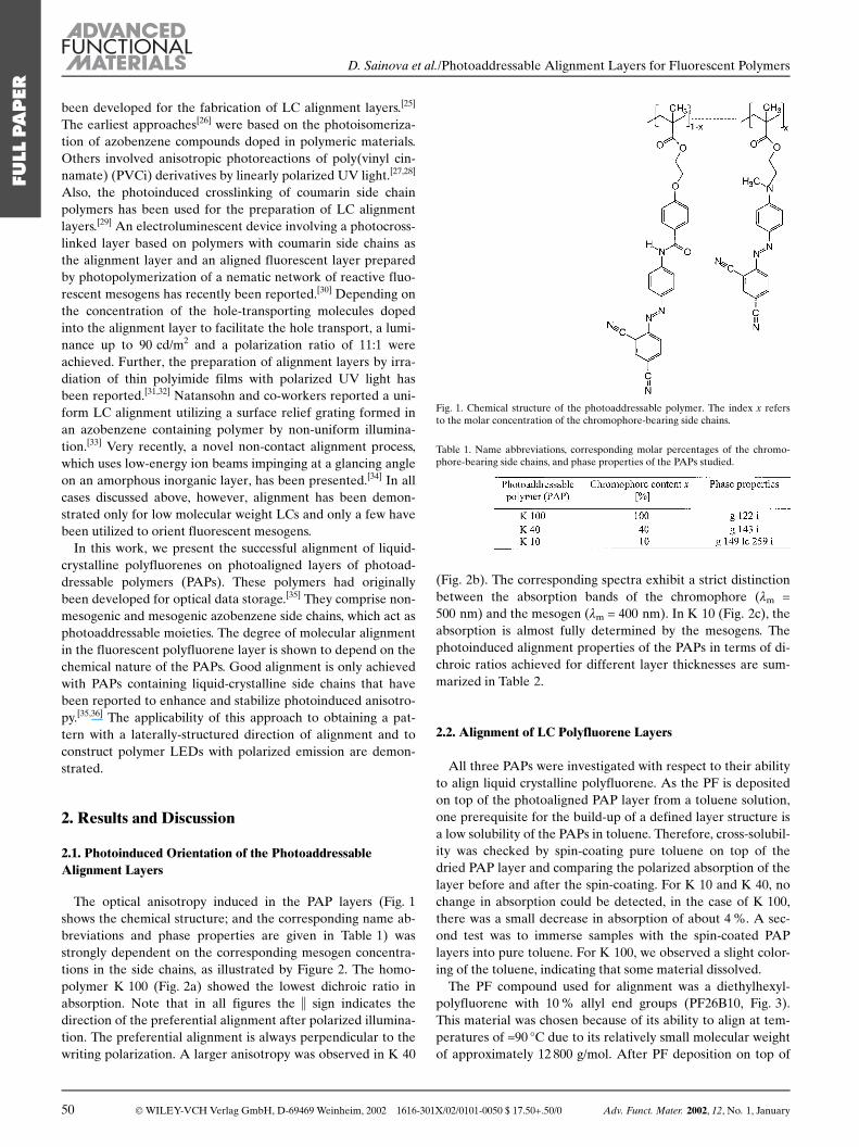
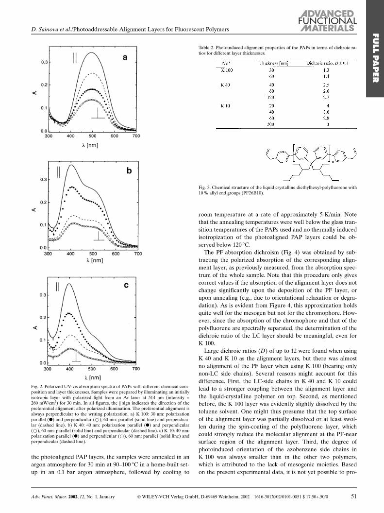
The optical anisotropy induced in the PAP layers (Fig. 1shows the chemical structure; and the corresponding name ab-breviations and phase properties are given in Table 1) wasstrongly dependent on the corresponding mesogen concentra-tions in the side chains, as illustrated by Figure 2. The homo-polymer K 100 (Fig. 2a) showed the lowest dichroic ratio inabsorption. Note that in all figures the i sign indicates thedirection of the preferential alignment after polarized illumina-tion. The preferential alignment is always perpendicular to thewriting polarization. A larger anisotropy was observed in K 40
(Fig. 2b). The corresponding spectra exhibit a strict distinctionbetween the absorption bands of the chromophore (km =500 nm) and the mesogen (km = 400 nm). In K 10 (Fig. 2c), theabsorption is almost fully determined by the mesogens. Thephotoinduced alignment properties of the PAPs in terms of di-chroic ratios achieved for different layer thicknesses are sum-marized in Table 2.
2.2. Alignment of LC Polyfluorene Layers
All three PAPs were investigated with respect to their abilityto align liquid crystalline polyfluorene. As the PF is depositedon top of the photoaligned PAP layer from a toluene solution,one prerequisite for the build-up of a defined layer structure isa low solubility of the PAPs in toluene. Therefore, cross-solubil-ity was checked by spin-coating pure toluene on top of thedried PAP layer and comparing the polarized absorption of thelayer before and after the spin-coating. For K 10 and K 40, nochange in absorption could be detected, in the case of K 100,there was a small decrease in absorption of about 4 %. A sec-ond test was to immerse samples with the spin-coated PAPlayers into pure toluene. For K 100, we observed a slight color-ing of the toluene, indicating that some material dissolved.
The PF compound used for alignment was a diethylhexyl-polyfluorene with 10 % allyl end groups (PF26B10, Fig. 3).This material was chosen because of its ability to align at tem-peratures of »90 �C due to its relatively small molecular weightof approximately 12 800 g/mol. After PF deposition on top of
Fig. 1. Chemical structure of the photoaddressable polymer. The index x refersto the molar concentration of the chromophore-bearing side chains.
Table 1. Name abbreviations, corresponding molar percentages of the chromo-phore-bearing side chains, and phase properties of the PAPs studied.
50 Ó WILEY-VCH Verlag GmbH, D-69469 Weinheim, 2002 1616-301X/02/0101-0050 $ 17.50+.50/0 Adv. Funct. Mater. 2002, 12, No. 1, January
FULL
PAPER
D. Sainova et al./Photoaddressable Alignment Layers for Fluorescent Polymers
the photoaligned PAP layers, the samples were annealed in anargon atmosphere for 30 min at 90±100 �C in a home-built set-up in an 0.1 bar argon atmosphere, followed by cooling to
room temperature at a rate of approximately 5 K/min. Notethat the annealing temperatures were well below the glass tran-sition temperatures of the PAPs used and no thermally inducedisotropization of the photoaligned PAP layers could be ob-served below 120 �C.
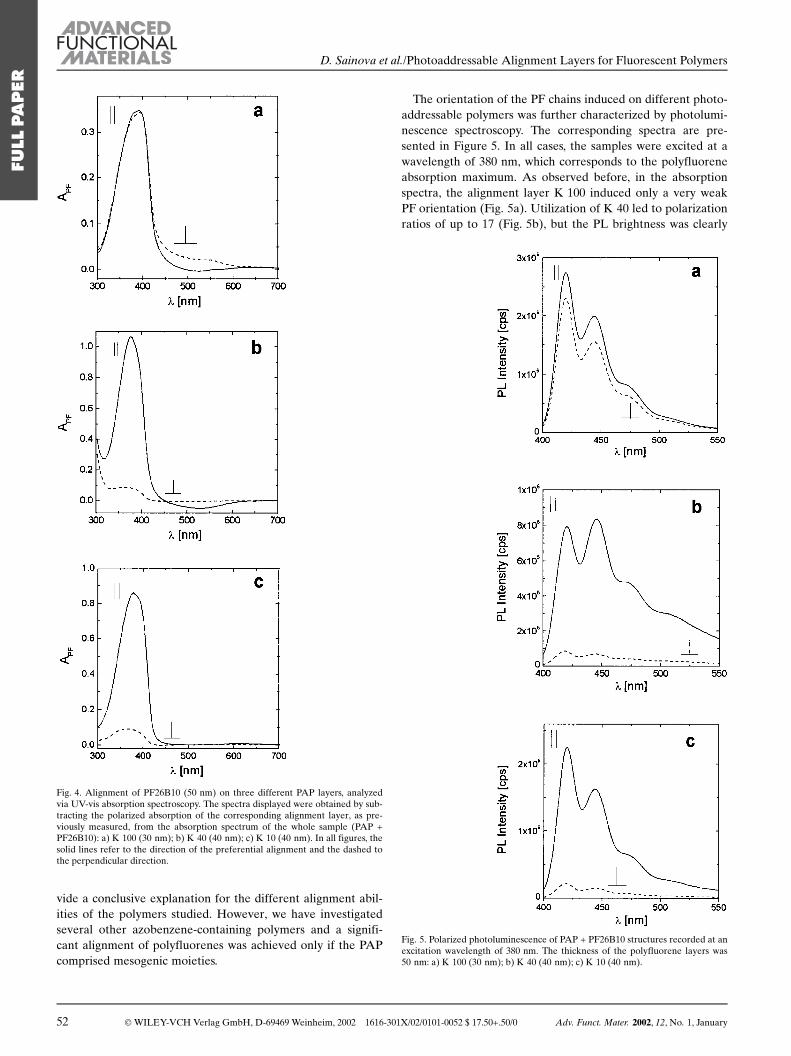
The PF absorption dichroism (Fig. 4) was obtained by sub-tracting the polarized absorption of the corresponding align-ment layer, as previously measured, from the absorption spec-trum of the whole sample. Note that this procedure only givescorrect values if the absorption of the alignment layer does notchange significantly upon the deposition of the PF layer, orupon annealing (e.g., due to orientational relaxation or degra-dation). As is evident from Figure 4, this approximation holdsquite well for the mesogen but not for the chromophore. How-ever, since the absorption of the chromophore and that of thepolyfluorene are spectrally separated, the determination of thedichroic ratio of the LC layer should be meaningful, even forK 100.
Large dichroic ratios (D) of up to 12 were found when usingK 40 and K 10 as the alignment layers, but there was almostno alignment of the PF layer when using K 100 (bearing onlynon-LC side chains). Several reasons might account for thisdifference. First, the LC-side chains in K 40 and K 10 couldlead to a stronger coupling between the alignment layer andthe liquid-crystalline polymer on top. Second, as mentionedbefore, the K 100 layer was evidently slightly dissolved by thetoluene solvent. One might thus presume that the top surfaceof the alignment layer was partially dissolved or at least swol-len during the spin-coating of the polyfluorene layer, whichcould strongly reduce the molecular alignment at the PF-nearsurface region of the alignment layer. Third, the degree ofphotoinduced orientation of the azobenzene side chains inK 100 was always smaller than in the other two polymers,which is attributed to the lack of mesogenic moieties. Basedon the present experimental data, it is not yet possible to pro-
Fig. 2. Polarized UV-vis absorption spectra of PAPs with different chemical com-position and layer thicknesses. Samples were prepared by illuminating an initiallyisotropic layer with polarized light from an Ar laser at 514 nm (intensity =280 mW/cm2) for 30 min. In all figures, the i sign indicates the direction of thepreferential alignment after polarized illumination. The preferential alignment isalways perpendicular to the writing polarization. a) K 100: 30 nm: polarizationparallel (l) and perpendicular (*); 60 nm: parallel (solid line) and perpendicu-lar (dashed line). b) K 40: 40 nm: polarization parallel (l) and perpendicular(*), 60 nm: parallel (solid line) and perpendicular (dashed line). c) K 10: 40 nm:polarization parallel (l) and perpendicular (*), 60 nm: parallel (solid line) andperpendicular (dashed line).
Table 2. Photoinduced alignment properties of the PAPs in terms of dichroic ra-tios for different layer thicknesses.
Fig. 3. Chemical structure of the liquid crystalline diethylhexyl-polyfluorene with10 % allyl end groups (PF26B10).
Adv. Funct. Mater. 2002, 12, No. 1, January Ó WILEY-VCH Verlag GmbH, D-69469 Weinheim, 2002 1616-301X/02/0101-0051 $ 17.50+.50/0 51
FULL
PAPER
D. Sainova et al./Photoaddressable Alignment Layers for Fluorescent Polymers
vide a conclusive explanation for the different alignment abil-ities of the polymers studied. However, we have investigatedseveral other azobenzene-containing polymers and a signifi-cant alignment of polyfluorenes was achieved only if the PAPcomprised mesogenic moieties.
The orientation of the PF chains induced on different photo-addressable polymers was further characterized by photolumi-nescence spectroscopy. The corresponding spectra are pre-sented in Figure 5. In all cases, the samples were excited at awavelength of 380 nm, which corresponds to the polyfluoreneabsorption maximum. As observed before, in the absorptionspectra, the alignment layer K 100 induced only a very weakPF orientation (Fig. 5a). Utilization of K 40 led to polarizationratios of up to 17 (Fig. 5b), but the PL brightness was clearly
Fig. 4. Alignment of PF26B10 (50 nm) on three different PAP layers, analyzedvia UV-vis absorption spectroscopy. The spectra displayed were obtained by sub-tracting the polarized absorption of the corresponding alignment layer, as pre-viously measured, from the absorption spectrum of the whole sample (PAP +PF26B10): a) K 100 (30 nm); b) K 40 (40 nm); c) K 10 (40 nm). In all figures, thesolid lines refer to the direction of the preferential alignment and the dashed tothe perpendicular direction.
Fig. 5. Polarized photoluminescence of PAP + PF26B10 structures recorded at anexcitation wavelength of 380 nm. The thickness of the polyfluorene layers was50 nm: a) K 100 (30 nm); b) K 40 (40 nm); c) K 10 (40 nm).
52 Ó WILEY-VCH Verlag GmbH, D-69469 Weinheim, 2002 1616-301X/02/0101-0052 $ 17.50+.50/0 Adv. Funct. Mater. 2002, 12, No. 1, January
FULL
PAPER
D. Sainova et al./Photoaddressable Alignment Layers for Fluorescent Polymers

reduced when compared to samples with K 100 and K 10. Thiseffect is not yet understood. Photoluminescence of the samplesaligned via K 10 exhibited high brightness and polarizationratios of about 10 (Fig. 5c), which increased slightly with align-ment layer thickness. The anisotropic optical properties ofpolyfluorene on the three different PAPs are summarized inTable 3.
Table 3. Alignment properties of polyfluorenes on top of photoaligned PAPs asdeduced from polarized UV-vis absorption and photoluminescence spectroscopy.
2.3. Stability of Alignment
One major requirement for the application of PAPs asaligning materials in polarized photoluminescence and elec-troluminescence devices is that the alignment of the fluores-cent molecules must not be affected by the subsequent expo-sure of the samples to light at room temperature. Therefore,the photoinduced re-alignment of the PAP and the aligned PFlayer on top was investigated after subsequent 30 min re-illu-mination of the multilayer (PAP + PF) sample with light ofthe same wavelength and power, but perpendicular to the ini-tial polarization. The absorption spectrum of a sample of PFaligned on top of a 40 nm thick K 10 alignment layer, beforeand after re-illumination, is presented in Figure 6a. Eventhough there is a small, noticeable change in the total dichroicratio, the preferential orientation of the PF molecules waswell preserved. In order to characterize the reorientation ofthe azobenzenes in the PAP layer only, the polyfluorenelayers were washed-off after reorientation and absorptionspectra of the remaining PAP layers were recorded and com-pared to the initial spectra (Fig. 6b). The results are summar-ized in Table 4. In all cases, the index (R) refers to the re-illu-minated samples. It was found that the photoaddressablelayers were able to reorient even with the aligned polyfluo-rene layer on top. In all cases, however, re-illumination causeda considerable decrease in absorption corresponding to thenew preferential alignment direction, whereas the perpendicu-lar direction was only slightly changed (Figs. 2c and 6b, andTable 4). This is indicative of a photoinduced out-of-planealignment of the azo-side chains. Note that the thickest layershowed the highest dichroic ratio after re-illumination. Mostlikely, the reorientation of the chromophores was hindered tosome extent by the aligned polyfluorene layer on top.
2.4. Patterned Alignment
One attractive application of the photoaddressable align-ment layers is the lateral control of the alignment direction ofthe LC layer via subsequent illumination steps with orthogon-ally polarized light. Two different re-illumination procedureswere applied, using K 10 as the alignment layer. One in-volved re-aligning the PAP layer via subsequent illuminationthrough a shadow mask (an electron microscopy net of
Fig. 6. Comparison of absorption spectra of PF26B10 (50 nm) on top of aK 10 alignment layer before and after re-illumination with UV light of thesame wavelength and power, but perpendicular to the initial polarization. Thei sign indicates the direction of the preferential alignment before re-illumina-tion. a) Polarized absorption of the double layer structure (K 10 + PF26B10)before re-illumination: polarization parallel (solid line) and perpendicular(dashed line); and after re-illumination: polarization parallel (l) and perpen-dicular (*). The K 10 layer was 40 nm thick. b) Polarized absorption of K 10layers after re-illumination (measured after removal of the PF26B10 layer byrinsing with toluene) for two different thicknesses: 200 nm: polarization paral-lel (solid line) and perpendicular (dashed line); and 40 nm: polarization paral-lel (l) and perpendicular (*) to the alignment before re-illumination.
Table 4. Alignment and re-alignment characteristics of K 10 at three differentthicknesses, as obtained from UV-vis absorption experiments. Symbols i and ^refer to the direction of preferential alignment before illumination.
Adv. Funct. Mater. 2002, 12, No. 1, January Ó WILEY-VCH Verlag GmbH, D-69469 Weinheim, 2002 1616-301X/02/0101-0053 $ 17.50+.50/0 53
FULL
PAPER
D. Sainova et al./Photoaddressable Alignment Layers for Fluorescent Polymers
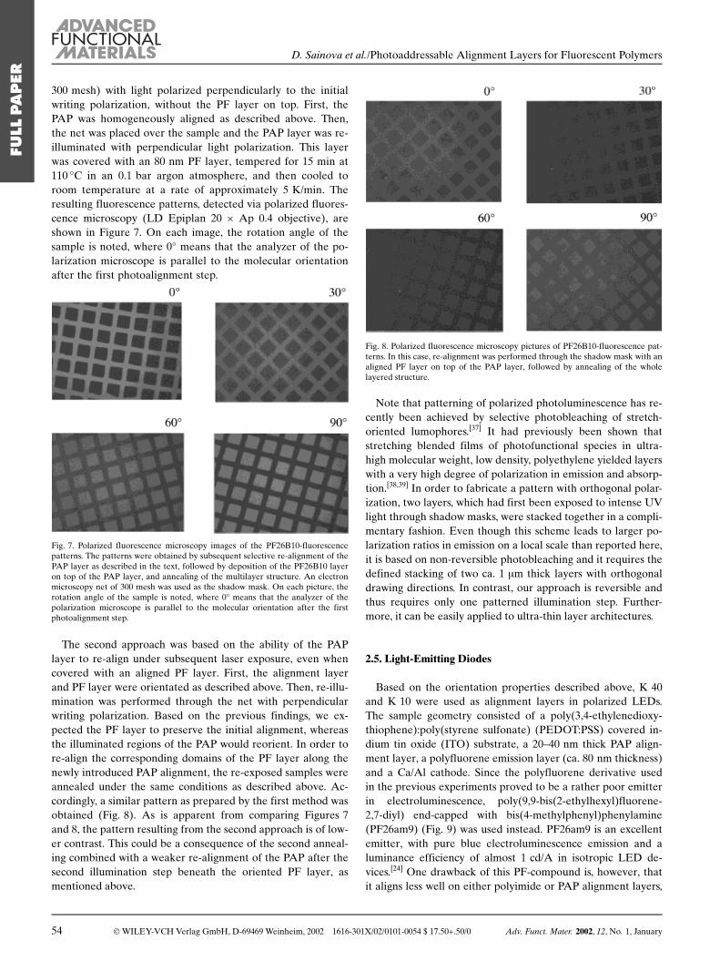
300 mesh) with light polarized perpendicularly to the initialwriting polarization, without the PF layer on top. First, thePAP was homogeneously aligned as described above. Then,the net was placed over the sample and the PAP layer was re-illuminated with perpendicular light polarization. This layerwas covered with an 80 nm PF layer, tempered for 15 min at110 �C in an 0.1 bar argon atmosphere, and then cooled toroom temperature at a rate of approximately 5 K/min. Theresulting fluorescence patterns, detected via polarized fluores-cence microscopy (LD Epiplan 20 � Ap 0.4 objective), areshown in Figure 7. On each image, the rotation angle of thesample is noted, where 0� means that the analyzer of the po-larization microscope is parallel to the molecular orientationafter the first photoalignment step.
Fig. 7. Polarized fluorescence microscopy images of the PF26B10-fluorescencepatterns. The patterns were obtained by subsequent selective re-alignment of thePAP layer as described in the text, followed by deposition of the PF26B10 layeron top of the PAP layer, and annealing of the multilayer structure. An electronmicroscopy net of 300 mesh was used as the shadow mask. On each picture, therotation angle of the sample is noted, where 0� means that the analyzer of thepolarization microscope is parallel to the molecular orientation after the firstphotoalignment step.
The second approach was based on the ability of the PAPlayer to re-align under subsequent laser exposure, even whencovered with an aligned PF layer. First, the alignment layerand PF layer were orientated as described above. Then, re-illu-mination was performed through the net with perpendicularwriting polarization. Based on the previous findings, we ex-pected the PF layer to preserve the initial alignment, whereasthe illuminated regions of the PAP would reorient. In order tore-align the corresponding domains of the PF layer along thenewly introduced PAP alignment, the re-exposed samples wereannealed under the same conditions as described above. Ac-cordingly, a similar pattern as prepared by the first method wasobtained (Fig. 8). As is apparent from comparing Figures 7and 8, the pattern resulting from the second approach is of low-er contrast. This could be a consequence of the second anneal-ing combined with a weaker re-alignment of the PAP after thesecond illumination step beneath the oriented PF layer, asmentioned above.
Note that patterning of polarized photoluminescence has re-cently been achieved by selective photobleaching of stretch-oriented lumophores.[37] It had previously been shown thatstretching blended films of photofunctional species in ultra-high molecular weight, low density, polyethylene yielded layerswith a very high degree of polarization in emission and absorp-tion.[38,39] In order to fabricate a pattern with orthogonal polar-ization, two layers, which had first been exposed to intense UVlight through shadow masks, were stacked together in a compli-mentary fashion. Even though this scheme leads to larger po-larization ratios in emission on a local scale than reported here,it is based on non-reversible photobleaching and it requires thedefined stacking of two ca. 1 lm thick layers with orthogonaldrawing directions. In contrast, our approach is reversible andthus requires only one patterned illumination step. Further-more, it can be easily applied to ultra-thin layer architectures.
2.5. Light-Emitting Diodes
Based on the orientation properties described above, K 40and K 10 were used as alignment layers in polarized LEDs.The sample geometry consisted of a poly(3,4-ethylenedioxy-thiophene):poly(styrene sulfonate) (PEDOT:PSS) covered in-dium tin oxide (ITO) substrate, a 20±40 nm thick PAP align-ment layer, a polyfluorene emission layer (ca. 80 nm thickness)and a Ca/Al cathode. Since the polyfluorene derivative usedin the previous experiments proved to be a rather poor emitterin electroluminescence, poly(9,9-bis(2-ethylhexyl)fluorene-2,7-diyl) end-capped with bis(4-methylphenyl)phenylamine(PF26am9) (Fig. 9) was used instead. PF26am9 is an excellentemitter, with pure blue electroluminescence emission and aluminance efficiency of almost 1 cd/A in isotropic LED de-vices.[24] One drawback of this PF-compound is, however, thatit aligns less well on either polyimide or PAP alignment layers,
Fig. 8. Polarized fluorescence microscopy pictures of PF26B10-fluorescence pat-terns. In this case, re-alignment was performed through the shadow mask with analigned PF layer on top of the PAP layer, followed by annealing of the wholelayered structure.
54 Ó WILEY-VCH Verlag GmbH, D-69469 Weinheim, 2002 1616-301X/02/0101-0054 $ 17.50+.50/0 Adv. Funct. Mater. 2002, 12, No. 1, January
FULL
PAPER
D. Sainova et al./Photoaddressable Alignment Layers for Fluorescent Polymers
even though its molecular weight (Mw = 12 000 g/mol) is com-parable to that of PF26B10.
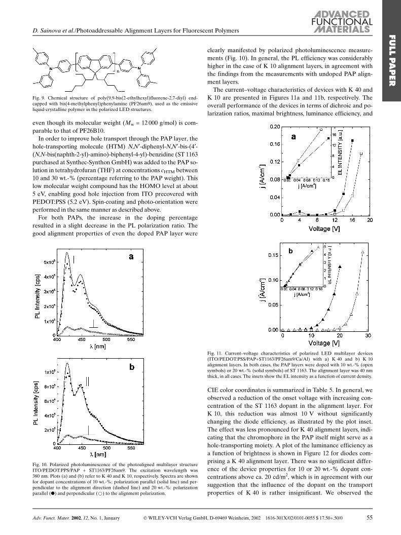
In order to improve hole transport through the PAP layer, thehole-transporting molecule (HTM) N,N¢-diphenyl-N,N¢-bis-(4¢-(N,N-bis(naphth-2-yl)-amino)-biphenyl-4-yl)-benzidine (ST 1163purchased at Synthec-Synthon GmbH) was added to the PAP so-lution in tetrahydrofuran (THF) at concentrations cHTM between10 and 30 wt.-% (percentage referring to the PAP weight). Thislow molecular weight compound has the HOMO level at about5 eV, enabling good hole injection from ITO precovered withPEDOT:PSS (5.2 eV). Spin-coating and photo-orientation wereperformed in the same manner as described above.
For both PAPs, the increase in the doping percentageresulted in a slight decrease in the PL polarization ratio. Thegood alignment properties of even the doped PAP layer were
clearly manifested by polarized photoluminescence measure-ments (Fig. 10). In general, the PL efficiency was considerablyhigher in the case of K 10 alignment layers, in agreement withthe findings from the measurements with undoped PAP align-ment layers.
The current±voltage characteristics of devices with K 40 andK 10 are presented in Figures 11a and 11b, respectively. Theoverall performance of the devices in terms of dichroic and po-larization ratios, maximal brightness, luminance efficiency, and
CIE color coordinates is summarized in Table 5. In general, weobserved a reduction of the onset voltage with increasing con-centration of the ST 1163 dopant in the alignment layer. ForK 10, this reduction was almost 10 V without significantlychanging the diode efficiency, as illustrated by the plot inset.The effect was less pronounced for K 40 alignment layers, indi-cating that the chromophore in the PAP itself might serve as ahole-transporting moiety. A plot of the luminance efficiency asa function of brightness is shown in Figure 12 for diodes com-prising a K 40 alignment layer. There was no significant differ-ence of the device properties for 10 or 20 wt.-% dopant con-centrations above ca. 20 cd/m2, which is in agreement with oursuggestion that the influence of the dopant on the transportproperties of K 40 is rather insignificant. We observed the
Fig. 9. Chemical structure of poly(9,9-bis(2-ethylhexyl)fluorene-2,7-diyl) end-capped with bis(4-methylphenyl)phenylamine (PF26am9), used as the emissiveliquid-crystalline polymer in the polarized LED structures.
Fig. 10. Polarized photoluminescence of the photoaligned multilayer structureITO/PEDOT:PPS/PAP + ST1163/PF26am9. The excitation wavelength was380 nm. Plots (a) and (b) refer to K 40 and K 10, respectively. Spectra are shownfor dopant concentrations of 10 wt.-%: polarization parallel (solid line) and per-pendicular to the alignment direction (dashed line) and 20 wt.-%: polarizationparallel (l) and perpendicular (*) to the alignment polarization.
Fig. 11. Current±voltage characteristics of polarized LED multilayer devices(ITO/PEDOT:PSS/PAP+ST1163/PF26am9/Ca/Al) with a) K 40 and b) K 10alignment layers. In both cases, the PAP layers were doped with 10 wt.-% (opensymbols) or 20 wt.-% (solid symbols) of ST 1163. The alignment layer was 40 nmthick, in all cases. The insets show the EL intensity as a function of current density.
Adv. Funct. Mater. 2002, 12, No. 1, January Ó WILEY-VCH Verlag GmbH, D-69469 Weinheim, 2002 1616-301X/02/0101-0055 $ 17.50+.50/0 55
FULL
PAPER
D. Sainova et al./Photoaddressable Alignment Layers for Fluorescent Polymers
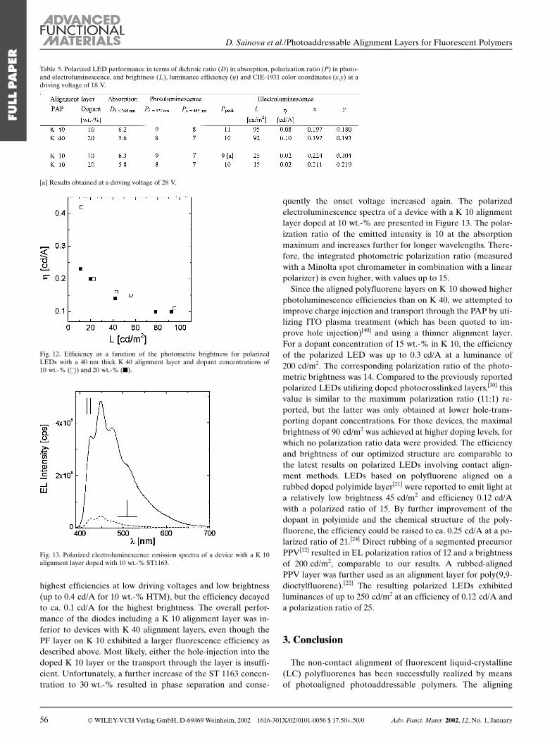
highest efficiencies at low driving voltages and low brightness(up to 0.4 cd/A for 10 wt.-% HTM), but the efficiency decayedto ca. 0.1 cd/A for the highest brightness. The overall perfor-mance of the diodes including a K 10 alignment layer was in-ferior to devices with K 40 alignment layers, even though thePF layer on K 10 exhibited a larger fluorescence efficiency asdescribed above. Most likely, either the hole-injection into thedoped K 10 layer or the transport through the layer is insuffi-cient. Unfortunately, a further increase of the ST 1163 concen-tration to 30 wt.-% resulted in phase separation and conse-
quently the onset voltage increased again. The polarizedelectroluminescence spectra of a device with a K 10 alignmentlayer doped at 10 wt.-% are presented in Figure 13. The polar-ization ratio of the emitted intensity is 10 at the absorptionmaximum and increases further for longer wavelengths. There-fore, the integrated photometric polarization ratio (measuredwith a Minolta spot chromameter in combination with a linearpolarizer) is even higher, with values up to 15.
Since the aligned polyfluorene layers on K 10 showed higherphotoluminescence efficiencies than on K 40, we attempted toimprove charge injection and transport through the PAP by uti-lizing ITO plasma treatment (which has been quoted to im-prove hole injection)[40] and using a thinner alignment layer.For a dopant concentration of 15 wt.-% in K 10, the efficiencyof the polarized LED was up to 0.3 cd/A at a luminance of200 cd/m2. The corresponding polarization ratio of the photo-metric brightness was 14. Compared to the previously reportedpolarized LEDs utilizing doped photocrosslinked layers,[30] thisvalue is similar to the maximum polarization ratio (11:1) re-ported, but the latter was only obtained at lower hole-trans-porting dopant concentrations. For those devices, the maximalbrightness of 90 cd/m2 was achieved at higher doping levels, forwhich no polarization ratio data were provided. The efficiencyand brightness of our optimized structure are comparable tothe latest results on polarized LEDs involving contact align-ment methods. LEDs based on polyfluorene aligned on arubbed doped polyimide layer[21] were reported to emit light ata relatively low brightness 45 cd/m2 and efficiency 0.12 cd/Awith a polarized ratio of 15. By further improvement of thedopant in polyimide and the chemical structure of the poly-fluorene, the efficiency could be raised to ca. 0.25 cd/A at a po-larized ratio of 21.[24] Direct rubbing of a segmented precursorPPV[12] resulted in EL polarization ratios of 12 and a brightnessof 200 cd/m2, comparable to our results. A rubbed-alignedPPV layer was further used as an alignment layer for poly(9,9-dioctylfluorene).[22] The resulting polarized LEDs exhibitedluminances of up to 250 cd/m2 at an efficiency of 0.12 cd/A anda polarization ratio of 25.
3. Conclusion
The non-contact alignment of fluorescent liquid-crystalline(LC) polyfluorenes has been successfully realized by meansof photoaligned photoaddressable polymers. The aligning
Table 5. Polarized LED performance in terms of dichroic ratio (D) in absorption, polarization ratio (P) in photo-and electroluminescence, and brightness (L), luminance efficiency (g) and CIE-1931 color coordinates (x,y) at adriving voltage of 18 V.
[a] Results obtained at a driving voltage of 28 V.
Fig. 12. Efficiency as a function of the photometric brightness for polarizedLEDs with a 40 nm thick K 40 alignment layer and dopant concentrations of10 wt.-% (&) and 20 wt.-% (n).
Fig. 13. Polarized electroluminescence emission spectra of a device with a K 10alignment layer doped with 10 wt.-% ST1163.
56 Ó WILEY-VCH Verlag GmbH, D-69469 Weinheim, 2002 1616-301X/02/0101-0056 $ 17.50+.50/0 Adv. Funct. Mater. 2002, 12, No. 1, January
FULL
PAPER
D. Sainova et al./Photoaddressable Alignment Layers for Fluorescent Polymers

properties of the PAPs showed a strong dependence upontheir chemical nature. The molecular weight of the polymercan affect the degree of alignment, but the effect is weak forMw < 120 000 g/mol. It was concluded that the presence ofliquid-crystalline side chains significantly improved the abil-ity of the PAP layer to align the fluorescent polyfluorenelayer deposited on top. In contrast to rubbing, this methodallowed for the fabrication of a lateral pattern with orthogo-nal direction of alignment. Because of the good re-alignmentproperties of the PAPs, those patterns could be generated ina two-step illumination process with only one utilization of ashadow mask. This is superior to photostructured alignmentlayers, which are prepared by irreversible polarization-selec-tive photoreactions.
LEDs with polarized emission have been fabricated utilizingPAP alignment layers doped at different concentrations with ahole-transporting molecule. Addition of the HTMs was shownto reduce the aligning abilities only slightly, even at dopingconcentrations of 20 wt.-%. By improving hole injection andtransport through the PAP layers, we were able to achieve abrightness of up to 200 cd/m2 at an efficiency of 0.3 cd/A andphotometric polarization ratios of up to 14.
4. Experimental
The alignment layers were prepared using three different types of azoben-zene-containing copolymers with different concentrations of liquid-crystallineside chains. This class of polymers was originally developed for optical data stor-age applications [35]. After illumination with polarized light, stable light-inducedalignment of the azobenzene-moieties in the polymer side chain with order pa-rameters in excess of 0.3 and maximum values of the in-plane birefringence of0.23 were achieved [35,41]. The presence of the liquid-crystalline moieties bothenhances and stabilizes the light-induced orientation.
Polymer films were prepared via spin-coating from a tetrahydrofuran (THF)solution on glass substrates. Variation of the solution concentration (30, 40,60 mg/mL) and spinning speed (3000±9500 rpm) resulted in different layer thick-nesses (from 20 to 200 nm). After spin-coating, the samples were dried in a vacu-um oven at 60 �C for 3 h.
Optical anisotropy was induced by 30 min irradiation with linearly polarizedlight of an argon laser at 514 nm with an intensity of 280 mW/cm2. The photoin-duced changes were detected thereafter by polarized absorption measured with aPerkin-Elmer Lambda 9 spectrometer.
Layers of liquid-crystalline PF were spin-coated on top from a toluene solu-tion (10 mg/mL) at a speed of 1200 rpm. Spinning with these parameters resultedin a PF layer thickness of about 50 nm, as measured by a Tencor a-step profil-ometer. Monodomain alignment was induced by annealing at appropriate tem-peratures in an 0.1 bar argon atmosphere in a home-built setup.
Polarized photoluminescence spectra were recorded with a SPEX Fluorolog 2(F212) spectrometer equipped with double monochromators for excitation andemission. The excitation wavelength was 380 nm and the light beam was incident tothe PF film side. Detection was at 90� with respect to the excitation light and 30�corresponding to the sample surface normal. Excitation was always s-polarized andparallel to the PF chain alignment. The spectra were recorded with the analyzer at0� and 90�, parallel and perpendicular, to the PF chain alignment, respectively.
For LED fabrication, patterned ITO substrates (Balzers) were covered with20 nm thick layers of PEDOT:PSS. The samples were dried at room temperaturein a vacuum oven for 8 h. After deposition of the alignment and emission layers,the LEDs were completed by evaporation of a Ca/Al top cathode at a pressure<5 � 10±6 mbar. The alignment and emission layers were 40 and 80 nm thick, re-spectively. The overlap between the two electrodes resulted in typical diode areas
of 5 mm2. The device characterization was carried out in an evacuated samplechamber. Current±voltage characteristics of the LEDs were measured with aKeithley 236 source measure unit.
Received: May 16, 2001Final version: August 2, 2001
±[1] A. W. Grice, D. D. C. Bradley, M. T. Bernuis, M. Ibasekaran, W. W. Wu,
E. P. Woo, Appl. Phys. Lett. 1998, 73, 629.[2] Y. Yang, Q. Pei, J. Appl. Phys. 1997, 81, 3294.[3] K. H. Weinfurtner, H. Fujikawa, S. Takito, Y. Taga, Appl. Phys. Lett. 2000,
76, 2502.[4] M. Gross, D. C. Mueller, H.-G. Nothofer, U. Scherf, D. Neher, C. Bräuchle,
K. Meerholz, Nature 2000, 405, 661.[5] J. P. Chen, G. Klaener, J. I. Lee, D. Markiewicz, V. Y. Lee, R. D. Miller,
J. P. Scott, Synth. Met. 1999, 107, 129.[6] W. L. Yu, J. Pei, W. Huang, A. J. Heeger, Adv. Mater. 2000, 21, 828.[7] D. Sainova, T. Miteva, H.-G. Nothofer, H. Fujikawa, I. Glowacki, J. Ulans-
ki, U. Scherf, D. Neher, Appl. Phys. Lett. 2000, 76, 1810.[8] M. Grell, D. D. C. Bradley, Adv. Mater. 1999, 11, 895.[9] P. Dyreklev, M. Berggren, O. Inganäs, M. R. Andersson, O. Wennerstroem,
T. Hjertberg, Adv. Mater. 1995, 7, 43.[10] M. Granström, Polym. Adv. Technol. 1997, 8, 424.[11] T. Miteva, A. Meisel, M. Grell, H.-G. Nothofer, D. Lupo, A. Yasuda, W.
Knoll, L. Kloppenburg, U. H. F. Bunz, U. Scherf, D. Neher, Synth. Met.2000, 111, 173.
[12] M. Jandke, P. Strohriegl, J. Gmeiner, W. Bruetting, M. Schwoerer, Adv. Ma-ter. 1999, 18, 1518.
[13] M. Hamaguchi, K. Yoshino, Appl. Phys. Lett. 1995, 67, 3381.[14] M. Hamaguchi, K. Yoshino, Polym. Adv. Technol. 1997, 8, 399.[15] D. Neher, Adv. Mater. 1995, 7, 691.[16] V. Cimrova, M. Remmers, D. Neher, G. Wegner, Adv. Mater. 1996, 8, 146.[17] M. Era, T. Tsutsui, S. Saito, Appl. Phys. Lett. 1995, 67, 2436.[18] A. Bolognesi, G. Bajo, J. Paloheimo, T. Östergård, H. Stubb, Adv. Mater.
1997, 9, 121.[19] G. Luessem, F. Geffart, A. Greiner, W. Heitz, M. Hopmeier, M. Oberski, C.
Unterlechner, J. H. Wendorff, Liq. Cryst. 1996, 21, 903.[20] M. Grell, D. D. C. Bradley, M. Inbasekaran, E. P. Woo, Adv. Mater. 1997, 9,
798.[21] M. Grell, W. Knoll, D. Lupo, A. Meisel, T. Miteva, D. Neher, H.-G. Notho-
fer, U. Scherf, A. Yasuda, Adv. Mater. 1999, 11, 671.[22] K. S. Whitehead, M. Grell, D. D. C. Bradley, M. Jandke, P. Strohriegl, Appl.
Phys. Lett. 2000, 76, 2946.[23] M. Grell, D. D. C. Bradley, Adv. Mater. 1999, 11, 895.[24] T. Miteva, A. Meisel, W. Knoll, H.-G. Nothofer, U. Scherf, D. C. Mueller,
K. Meerholz, A. Yasuda, D. Neher, Adv. Mater. 2001, 13, 565.[25] M. O'Neill, S. M. Kelly, J. Phys. D: Appl. Phys. 2000, 33, R67.[26] W. M. Gibbons, P. J. Shannon, S.-T. Sun, B. J. Swetlin, Nature 1991, 351, 49.[27] M. Schadt, K. Schmitt, V. Kozinkov, V. Chigrinov, Jpn. J. Appl. Phys. 1992,
31, 2155.[28] Y. Iimura, S. Kobayashi, T. Hashimoto, T. Sugiyama, K. Katoh, IEICE
Trans. Electron 1996, E79C, 1040.[29] M. Schadt, H. Sieberle, A. Schuster, Nature 1996, 381, 212.[30] A. E. A. Contoret, S. R. Farrar, P. O. Jackson, S. Khan, L. May, M. O'Neill,
J. E. Nicholls, S. M. Kelly, G. J. Richards, Adv. Mater. 2000, 12, 971.[31] M. Hasegawa, Y. Taira, J. Photopolym. Sci. Technol. 1995, 8, 241.[32] Y. Wang, A. Kanazawa, T. Shiono, T. Ikeda, Appl. Phys. Lett. 1998, 72, 545.[33] X. T. Li, A. Natansohn, P. Rochon, Appl. Phys. Lett 1999, 74, 3791.[34] P. Chaudhari, J. Lacey, J. Doyle, E. Galligan, S. C. A. Lien, A. Callegari, G.
Hougham, N. D. Lang, P. S. Andry, R. John, K. H. Yang, M. H. Lu, C. Cai,J. Speidell, S. Purushothaman, J. Ritsko, M. Samant, J. Stohr, Y. Nakagawa,Y. Katoh, Y. Saitoh, K. Sakai, H. Satoh, S. Odahara, H. Nakano, J. Nakaga-ki, Y. Shiota, Nature 2001, 411, 56
[35] S. J. Zilker, T. Bieringer, D. Haarer, R. S. Stein, J. W. van Egmond, S. Kos-tromine, Adv. Mater. 1998, 10, 855.
[36] X. Meng, A. Natansohn, C. Barrett, P. Rochon, Macromolecules 1996, 29, 946.[37] C. Kocher, A. Montali, P. Smith, C. Weder, Adv. Funct. Mater. 2001, 11, 31.[38] C. Weder, C. Sarwa, C. Bastiaansen, P. Smith, Adv. Mater. 1997, 9, 1035.[39] A. Montali, C. Bastiaansen, P. Smith, C. Weder, Nature 1998, 392, 261.[40] J. S. Kim, R. H. Friend, F. Cacialli, Appl. Phys. Lett. 1999, 74, 3084.[41] V. Cimrova, D. Neher, K. Kostromine, T. Bieringer, Macromolecules 1999,
32, 8496.
______________________
Adv. Funct. Mater. 2002, 12, No. 1, January Ó WILEY-VCH Verlag GmbH, D-69469 Weinheim, 2002 1616-301X/02/0101-0057 $ 17.50+.50/0 57
FULL
PAPER
D. Sainova et al./Photoaddressable Alignment Layers for Fluorescent Polymers


