Embed Size (px)
Citation preview

Physical Database Design for Relational
Databases
Watch video: https://youtu.be/nTWEyZEqPY4?t=33m13s

Logical v. Physical Database Design
• Sources of information for physical design process
includes logical data model and documentation that
describes model.
• Logical database design is concerned with the what,
physical database design is concerned with the how.

Physical Database Design
• Process of producing a description of the
implementation of the database on secondary
storage.
• It describes the base relations, file organisations, and
indexes used to achieve efficient access to the data,
and any associated integrity constraints and security
measures.

Overview Database Design Methodology
• Step 1 Build conceptual data model.
• Step 2 Build and validate logical data model.
• Step 3 Translate logical data model for target DBMS.
• Step 4 Design file organisations and indexes.
• Step 5 Design user views.
• Step 6 Design security mechanisms.
• Step 7 Consider the introduction of controlled
redundancy.
• Step 8 Monitor and tune the operational system.

Overview of Physical Database Design
Methodology
• Step 3 Translate logical data model for target DBMS
• Step 3.1 Design base relations
• Step 3.2 Design representation of derived data
• Step 3.3 Design general constraints

Overview of Physical Database Design
Methodology
• Step 4 Design file organisations and indexes
• Step 4.1 Analyse transactions
• Step 4.2 Choose file organisations
• Step 4.3 Choose indexes
• Step 4.4 Estimate disk space requirements

Overview of Physical Database Design
Methodology
• Step 5 Design user views
• Step 6 Design security mechanisms
• Step 7 Consider the introduction of controlled
redundancy
• Step 8 Monitor and tune operational system
Step 3 Translate Logical Data Model for Target
DBMS
Objective: To produce a relational database schema from the logical data model that can be implemented in the target DBMS.
• Need to know functionality of target DBMS such as how to create base relations and whether the system supports the definition of: • Primary Keys, Foreign Keys, and Alternate Keys; • required data – i.e. whether system supports NOT
NULL; • Domain definition; • relational integrity constraints; • general constraints.

Step 3.1 Design base relations
Objective: To decide how to represent base relations
identified in logical model in target DBMS.
• For each relation, need to define:
• the name of the relation;
• a list of simple attributes in brackets;
• the Primary Key and, where appropriate, Alternate
Keys and Foreign Keys;
• referential integrity constraints for any Foreign Keys
identified.

Step 3.1 Design base relations
• From data dictionary, we have for each attribute:
• its domain, consisting of a data type, length, and any
constraints on the domain;
• an optional default value for the attribute;
• whether it can hold nulls;
• whether it is derived, and if so, how it should be
computed.

Step 3.2 Design representation of derived data
Objective: To decide how to represent any derived data present in logical data model in target DBMS.
• Recall a derived attribute is an attribute whose value can be found by examining the values of other attributes (or performing some calculation).
• Examine logical data model and data dictionary, and produce list of all derived attributes.
• Derived attribute can be stored in database or calculated every time it is needed.

Step 3.2 Design representation of derived data
• Option selected is based on:
• additional cost to store the derived data and keep
it consistent with operational data from which it is
derived;
• cost to calculate it each time it is required.
• Less expensive option is chosen subject to
performance constraints.

PropertyforRent Relation and Staff Relation with
Derived Attribute noOfProperties

Step 3.3 Design general constraints
Objective: To design the general constraints for target
DBMS.
• Some DBMS provide more facilities than others for
defining enterprise constraints. Example:
CONSTRAINT StaffNotHandlingTooMuch
CHECK (NOT EXISTS (SELECT staffNo
FROM PropertyForRent
GROUP BY staffNo
HAVING COUNT(*) > 100))

Step 3.3 Design general constraints
• If you cannot implement the constraint in the DBMS
chosen you could use Triggers or implement the
constraint in the application used as a front end to the
DBMS.

Step 4 Design File Organisations and
Indexes
Objective: To determine optimal file organisations to
store the base relations and the indexes that are
required to achieve acceptable performance; that is,
the way in which relations and tuples will be held on
secondary storage.
• One of the main objectives of physical database
design is to store and access data in an efficient way.
• Must understand the typical workload that the
database must support.

Step 4.1 Analyse transactions
Objective: To understand the functionality of the
transactions that will run on the database and to
analyse the important transactions.
• Attempt to identify performance criteria, such as:
• transactions that run frequently and will have a
significant impact on performance;
• transactions that are critical to the business;
• times during the day/week when there will be a high
demand made on the database (called the peak
load).

Step 4.1 Analyse transactions
• Use this information to identify the parts of the
database that may cause performance problems.
• Also need to know high-level functionality of the
transactions, such as:
• attributes that are updated;
• search criteria used in a query.

Step 4.1 Analyse transactions
• Often not possible to analyse all transactions, so
investigate most ‘important’ ones.
• To help identify these can use:
• transaction/relation cross-reference matrix,
showing relations that each transaction accesses,
and/or
• transaction usage map, indicating which relations
are potentially heavily used.

Step 4.1 Analyse transactions
• To focus on areas that may be problematic:
1. Map all transaction paths to relations.
2. Determine which relations are most frequently
accessed by transactions.
3. Analyze the data usage of selected transactions
that involve these relations.

Step 4.1 Analyse transactions
Map all transaction paths to relations
• Sample transactions:
A. Enter the details for a new property and the owner.
B. Update/delete the details of a property.
C. Identify the total number of staff in each position at branches in Glasgow.
D. List the property number, address, type, and rent of all properties in Glasgow, order by rent.
E. List the details of properties for rent managed by a named member of staff.
F. Identify the total number of properties assigned to each member of staff at a given branch.

Cross-referencing transactions and relations

Step 4.1 Analyse transactions
Map all transaction paths to relations
• The matrix shows that both the Staff and
PropertyForRent relations are accessed by five of the
six transactions, and so efficient access to these
relations may be important to avoid performance
problems.
• A closer inspection of these transactions and relations
are necessary.

Step 4.1 Analyse transactions
Determine which relations are most frequently
accessed by transactions
• Suppose we know that there are 100,000 properties
for rent and 2000 staff distributed over 100 branch
offices, with an average of 1000 and a maximum of
3000 properties at each branch.
• The following transaction usage map is for
transactions C, D, E, and F, which all access at least
one of the Staff and PropertyForRent relations, with
these numbers added.

Example Transaction Usage Map

Step 4.1 Analyse transactions
Analyze the data usage of selected transactions that
involve these relations
• Having identified the important transactions, we now
analyse each one in more detail. For each transaction,
determine
• The relations and attributes accessed by the
transaction and the type of access; (i.e. insert,
update, delete, select transaction).
• The attributes used in any predicates/conditions.
Check whether predicates involve:
• Pattern matching;
• Range searches;
• Exact-match key retrieval.

Step 4.1 Analyse transactions
Analyze the data usage of selected transactions that
involve these relations
• For each transaction, determine (continued):
• For a query, the attributes that are involved in the join of two or more relations.
• The expected frequency at which the transaction will run.
• The performance goals for the transation; for example, the transaction must complete within 1 second.
• The following image shows an example of a transaction analysis form for transaction D. It shows the average frequency of this transaction, and peak loading. It also shows the SQL statement and the transaction usage map.

Example Transaction Analysis Form

Step 4.2 Choose file organisations
Objective: To determine an efficient file
organisation for each base relation.
• Store and access data in an efficient way.
• File organisations include Heap, Hash, Indexed
Sequential Access Method (ISAM), B+-Tree, and
Clusters.
• Some DBMSs may not allow selection of file
organisations.
Step 4.2 Choose file organisations
• InnoDB is a general-purpose storage engine that balances
high reliability and high performance. InnoDB is the default
MySQL storage engine in MySQL 8.0.
• InnoDB tables arrange your data on disk to optimise queries
based on primary keys. Each InnoDB table has a primary
key index called a clustered index that organises the data to
minimise I/O for primary key lookups.
• InnoDB data and indexes for a given table are stored in the
same physical tablespace file.

Step 4.3 Choose indexes
Objective: To determine whether adding indexes
will improve the performance of the system.
• One approach is to keep tuples unordered and
create as many secondary indexes as necessary.

Step 4.3 Choose indexes
• Another approach is to order tuples in the relation by
specifying a primary or clustering index.
• In this case, choose the attribute for ordering or
clustering the tuples as:
• attribute that is used most often for join operations -
this makes join operation more efficient, or
• attribute that is used most often to access the
tuples in a relation in order of that attribute.

Step 4.3 Choose indexes
• If ordering attribute chosen is key of relation, index will
be a primary index; otherwise, index will be a
clustering index.
• Each relation can only have either a primary index or a
clustering index.
• Secondary indexes provide a mechanism for
specifying an additional key for a base relation that
can be used to retrieve data more efficiently.
Step 4.3 Choose indexes
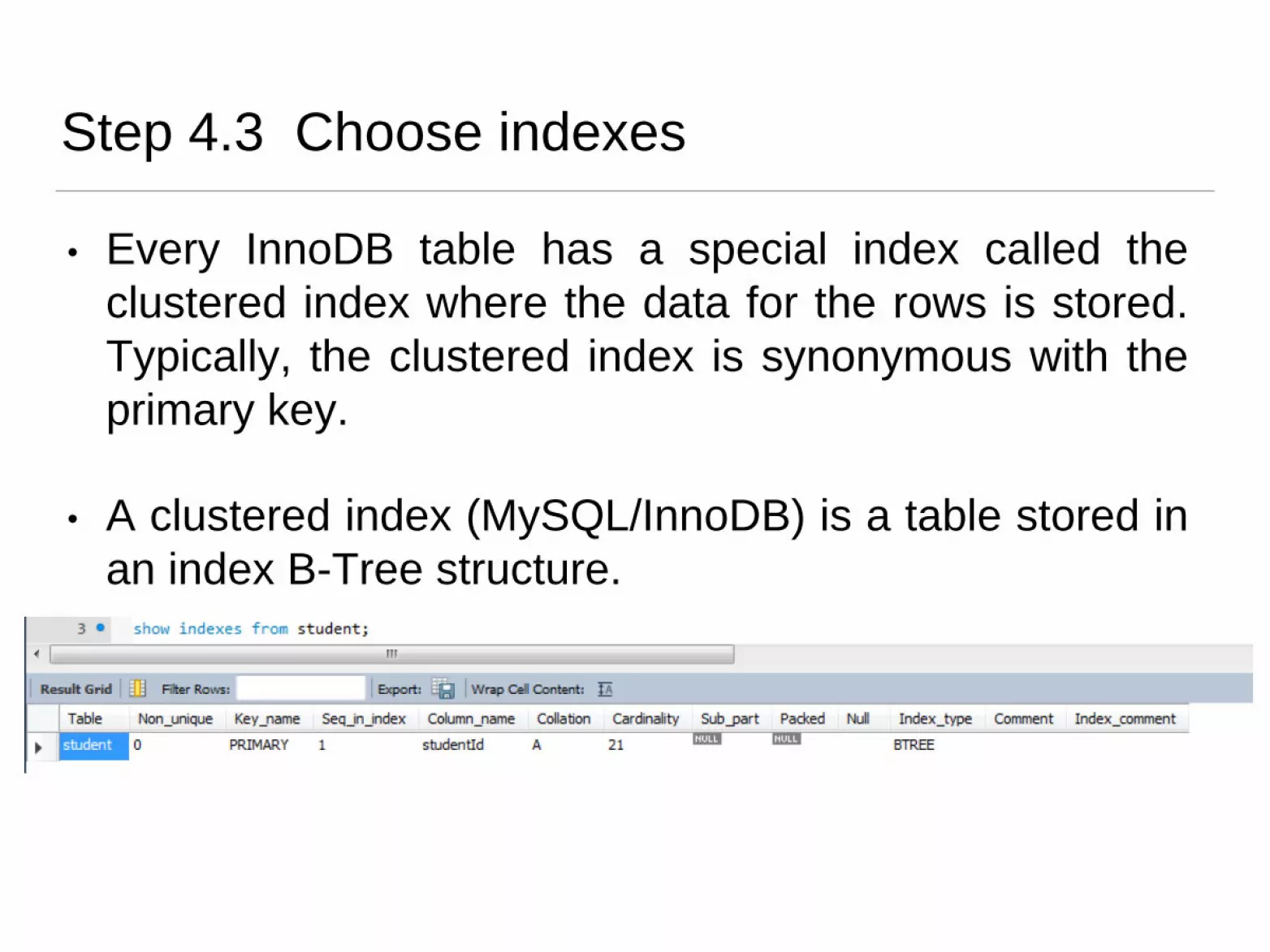
• Every InnoDB table has a special index called the
clustered index where the data for the rows is stored.
Typically, the clustered index is synonymous with the
primary key.
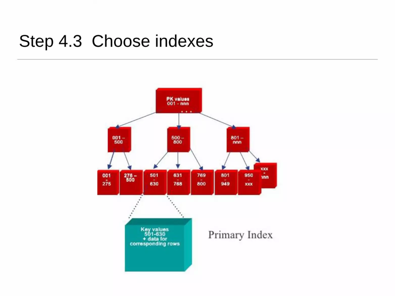
• A clustered index (MySQL/InnoDB) is a table stored in
an index B-Tree structure.
Step 4.3 Choose indexes

Step 4.3 Choose indexes
• All indexes other than the clustered index are known
as secondary indexes. In InnoDB, each record in a
secondary index contains the primary key columns for
the row, as well as the columns specified for the
secondary index. InnoDB uses this primary key value
to search for the row in the clustered index.

Step 4.3 Choose indexes
• Have to balance overhead involved in maintenance and use of secondary indexes against performance improvement gained when retrieving data.
• This includes:
• adding an index record to every secondary index whenever a tuple is inserted;
• updating secondary index when the corresponding tuple is updated;
• increase in disk space needed to store secondary index;
• possible performance degradation during query optimisation to consider all secondary indexes.
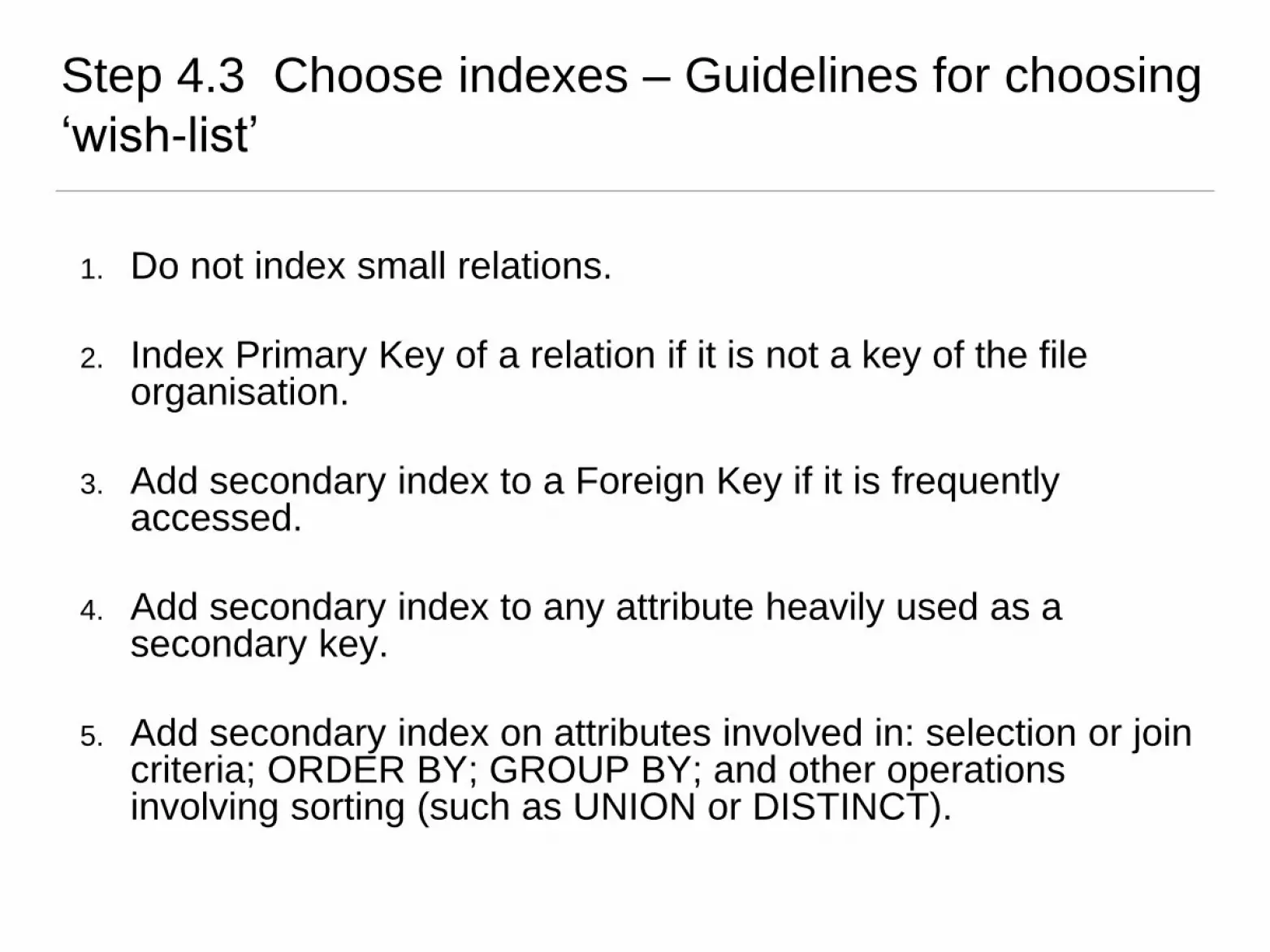
Step 4.3 Choose indexes – Guidelines for choosing
‘wish-list’
1. Do not index small relations.
2. Index Primary Key of a relation if it is not a key of the file organisation.
3. Add secondary index to a Foreign Key if it is frequently accessed.
4. Add secondary index to any attribute heavily used as a secondary key.
5. Add secondary index on attributes involved in: selection or join criteria; ORDER BY; GROUP BY; and other operations involving sorting (such as UNION or DISTINCT).

Step 4.3 Choose indexes – Guidelines for choosing
‘wish-list’
6. Add secondary index on attributes involved in built-in
aggregate functions.
7. Add secondary index on attributes that could result in an
index-only plan.
8. Avoid indexing an attribute or relation that is frequently
updated.
9. Avoid indexing an attribute if the query will retrieve a significant
proportion of the relation.
10. Avoid indexing attributes that consist of long character strings.

Step 4.4 Estimate disk space requirements
Objective: To estimate the amount of disk space that
will be required by the database.
• For each table, add up the field sizes for each record and
multiply the total field size by the estimated number of
records/tuples in the table.

Step 5 Design User Views
Objective: To design the user views that were
identified during the Requirements Collection and
Analysis stage of the database system development
lifecycle.

Step 6 Design Security Measures
Objective: To design the security measures for the
database as specified by the users.


