Embed Size (px)
Citation preview
PIPE SOLUTIONSPIPE SOLUTIONSSolving thermal expansion, building settlement movement, noise,
vibration, de-aeration & dirt problems in pipes and plant
Pipe Solutions Ltd., Head Office, Hornbeam Park Oval, Harrogate, HG2 8RBTel:01423-878888 Fax:01423-878880 Email:[email protected]
Website:www.pipesolutions.co.uk
TECHNICAL REFERENCE GUIDE
THERMAL PIPE EXPANSION
HURLSTONES
Solletico House 6 Potters Lane Wednesbury West Midlands WS10 0AS
Tel: 0121 502 2517 Fax: 0121 502 5718
Email: [email protected]
www.hurlstones.net
CONTENTS
THERMAL EXPANSION 4PROBLEMS TO OVERCOME 5METHODICAL APPROACH 6NATURAL FLEXIBILITY SOLUTION 7PIPE BRANCH & OFFSET FLEXIBILITY 8PIPE LOOP FLEXIBILITY 9
EXPANSION JOINT SOLUTION 10TYPICAL ‘AXIAL’ INSTALLATIONS 11TYPICAL ‘LATERAL’ INSTALLATIONS 12TYPICAL ‘HINGED’ INSTALLATIONS 13TYPICAL ‘GIMBAL’ INSTALLATIONS 14
PIPE ANCHORS - FRICTION FORCE 15BENDING FORCE + SPRING RATE FORCE 16PRESSURE THRUST FORCE + CENTRIFUGAL FORCE 17WIND LOAD FORCE + DEAD WEIGHT FORCE 18
PIPE GUIDES - CALCULATION OF SPACINGS 19PIPE GUIDES - USED WITH UNRESTRAINED EXPANSION JOINTS 20PIPE GUIDES - USED WITH RESTRAINED EXPANSION JOINTS 21
TYPICAL ANCHORS, GUIDES & SUPPORTS 22
COLD PULL (COLD DRAW) 23OTHER CONSIDERATION - INSULATION, INSTALLATION, COMMISSIONING, OPERATION & MAINTENANCE 24
STEAM DATA 25PIPE DATA 26
This publication contains general information.If you require more detailed data then please contact us.
Nothing herein constitutes a warranty of any kind, expressed or implied.
© Pipe Solutions Ltd
2Tel 01423 878888 PIPE SOLUTIONS LTDTel: 0121 502 2517 www.hurlstones.net
INTRODUCTION
Pipe Solutions Ltd are a wholly independent company established with the aim of providing the engineering industry with a one stop shop for solving the problems of thermal expansion,
building settlement movement, noise, vibration, de-aeration and dirt removal in pipes and plant, whilst providing an unequaled portfolio of expansion joints, flexible connectors, flexible hoses
and couplings, vibration isolators and air removal equipment.
Technical expertise, quality products, professional market support and a value led pricing policy enable Pipe Solutions Ltd to achieve success in the mechanical engineering industry.
A Quality Management System approved by Lloyd's Register Quality Assurance and certified to BS EN ISO 9001:2000 enables all in house operations to be completed to the satisfaction of all Pipe Solutions Ltd clients. From a ‘helping hand’ to a 'complete solution', you are assured of the
highest standard.
Specially developed computer software enable the whole support team to accurately deliver exactly what is required; from providing prompt product proposals and technical data to timely
product despatches and invoicing.
Pipe Solutions Ltd guarantee customer care. Every team member is committed to the customer. If you are made a promise, it will be honoured. Tasks that are clearly not achievable will not be
taken on and you will be told immediately. We build our reputation on integrity and honesty.
Pipe Solutions - put us to the test !
3 PIPE SOLUTIONS LTD
PLEASE CONTACT SOON:
PIPE SOLUTIONSPIPE SOLUTIONSSolving thermal expansion, building settlement movement, noise,
vibration, de-aeration & dirt problems in pipes and plant
Pipe Solutions Ltd, Head Office, Hornbeam Park Oval, Harrogate, HG2 8RBTel:01423-878888 Fax:01423-878880
Email:[email protected] Website:www.pipesolutions.co.uk
Tel 01423 878888Tel: 0121 502 2517 HURLSTONESwww.hurlstones.net
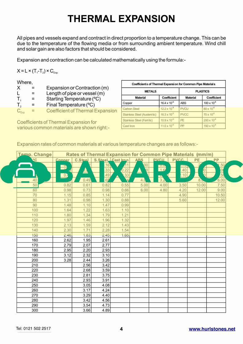
THERMAL EXPANSION
All pipes and vessels expand and contract in direct proportion to a temperature change. This can be due to the temperature of the flowing media or from surrounding ambient temperature. Wind chill and solar gain are also factors that should be considered.
Expansion and contraction can be calculated mathematically using the formula:-
X = L × (T -T ) × C1 2 Exp
Where,X = Expansion or Contraction (m)L = Length of pipe or vessel (m)T = Starting Temperature (ºC)1
T = Final Temperature (ºC)2
C = Coefficient of Thermal ExpansionExp
Coefficients of Thermal Expansion forvarious common materials are shown right:-
4
Coefficients of Thermal Expansion for Common Pipe Materials
METALS PLASTICS
Material Coefficient Material Coefficient
Copper 16.4 x 10⁻⁶ ABS 100 x 10-6
Carbon Steel 12.2 x 10⁻⁶ PVCU 80 x 10-6
Stainless Steel (Austeni tic) 16.3 x 10⁻⁶ PVCC 70 x 10-6
Stainless Steel (Ferri tic) 10.9 x 10⁻⁶ PE 200 x 10-6
Cast Iron 11.0 x 10⁻⁶ PP 150 x 10-6
Expansion rates of common materials at various temperature changes are as follows:-
Temp. Change Rates of Thermal Expansion for Common Pipe Materials (mm/m)ºC Copper C.Steel S.Steel Cast Iron ABS PVCU PVCC PE PP
10 0.16 0.12 0.16 0.11 1.00 0.80 0.70 2.00 1.50
20 0.33 0.24 0.33 0.22 2.00 1.60 1.40 4.00 3.00
30 0.49 0.37 0.49 0.33 3.00 2.40 2.10 6.00 4.50
40 0.66 0.49 0.65 0.44 4.00 3.20 2.80 8.00 6.00
50 0.82 0.61 0.82 0.55 5.00 4.00 3.50 10.00 7.50
60 0.98 0.73 0.98 0.66 6.00 4.80 4.20 12.00 9.00
70 1.15 0.85 1.14 0.77 4.90 10.50
80 1.31 0.98 1.30 0.88 5.60 12.00
90 1.48 1.10 1.47 0.99
100 1.64 1.22 1.63 1.10
110 1.80 1.34 1.79 1.21
120 1.97 1.46 1.96 1.32
130 2.13 1.59 2.12 1.43
140 2.30 1.71 2.28 1.54
150 2.46 1.83 2.45 1.65
160 2.62 1.95 2.61
170 2.79 2.07 2.77
180 2.95 2.20 2.93
190 3.12 2.32 3.10
200 3.28 2.44 3.26
210 2.56 3.42
220 2.68 3.59
230 2.81 3.75
240 2.93 3.91
250 3.05 4.08
260 3.17 4.24
270 3.29 4.40
280 3.42 4.56
290 3.54 4.73
300 3.66 4.89
Tel 01423 878888 PIPE SOLUTIONS LTDTel: 0121 502 2517 HURLSTONESwww.hurlstones.net
PROBLEMS TO OVERCOME
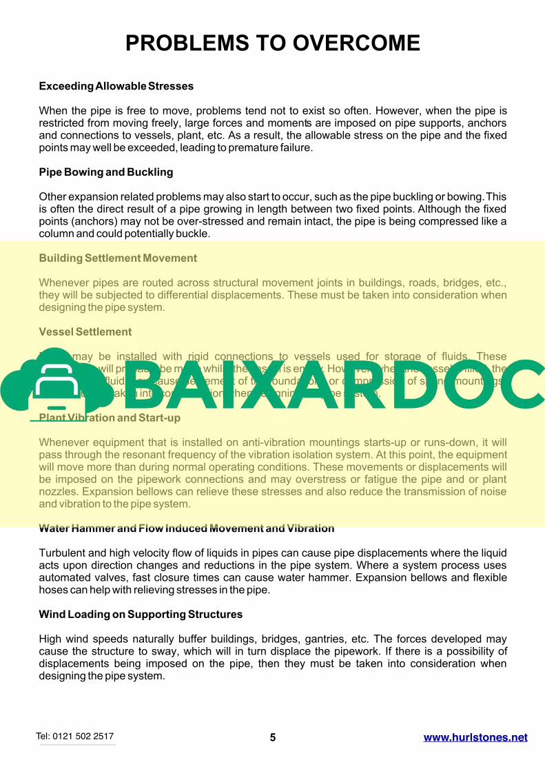
Exceeding Allowable Stresses
When the pipe is free to move, problems tend not to exist so often. However, when the pipe is restricted from moving freely, large forces and moments are imposed on pipe supports, anchors and connections to vessels, plant, etc. As a result, the allowable stress on the pipe and the fixed points may well be exceeded, leading to premature failure.
Pipe Bowing and Buckling
Other expansion related problems may also start to occur, such as the pipe buckling or bowing. This is often the direct result of a pipe growing in length between two fixed points. Although the fixed points (anchors) may not be over-stressed and remain intact, the pipe is being compressed like a column and could potentially buckle.
Building Settlement Movement
Whenever pipes are routed across structural movement joints in buildings, roads, bridges, etc., they will be subjected to differential displacements. These must be taken into consideration when designing the pipe system.
Vessel Settlement
Pipes may be installed with rigid connections to vessels used for storage of fluids. These installations will probably be made whilst the vessel is empty. However, when the vessel is filled, the weight of the fluid may cause settlement of the foundations or compression of spring mountings. These must be taken into consideration when designing the pipe system.
Plant Vibration and Start-up
Whenever equipment that is installed on anti-vibration mountings starts-up or runs-down, it will pass through the resonant frequency of the vibration isolation system. At this point, the equipment will move more than during normal operating conditions. These movements or displacements will be imposed on the pipework connections and may overstress or fatigue the pipe and or plant nozzles. Expansion bellows can relieve these stresses and also reduce the transmission of noise and vibration to the pipe system.
Water Hammer and Flow Induced Movement and Vibration
Turbulent and high velocity flow of liquids in pipes can cause pipe displacements where the liquid acts upon direction changes and reductions in the pipe system. Where a system process uses automated valves, fast closure times can cause water hammer. Expansion bellows and flexible hoses can help with relieving stresses in the pipe.
Wind Loading on Supporting Structures
High wind speeds naturally buffer buildings, bridges, gantries, etc. The forces developed may cause the structure to sway, which will in turn displace the pipework. If there is a possibility of displacements being imposed on the pipe, then they must be taken into consideration when designing the pipe system.
5Tel 01423 878888 PIPE SOLUTIONS LTDTel: 0121 502 2517 HURLSTONESwww.hurlstones.net
NATURAL PIPE FLEXING
METHODICAL APPROACH
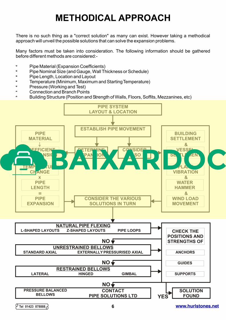
There is no such thing as a "correct solution" as many can exist. However taking a methodical approach will unveil the possible solutions that can solve the expansion problems.
Many factors must be taken into consideration. The following information should be gathered before different methods are considered:-
Pipe Material (Expansion Coefficients)Pipe Nominal Size (and Gauge, Wall Thickness or Schedule)Pipe Length, Location and LayoutTemperature (Minimum, Maximum and Starting Temperature)Pressure (Working and Test)Connection and Branch PointsBuilding Structure (Position and Strength of Walls, Floors, Soffits, Mezzanines, etc)
ANCHORS
CHECK THE
POSITIONS AND
STRENGTHS OF
UNRESTRAINED BELLOWS
STANDARD AXIAL EXTERNALLY PRESSURISED AXIAL
RESTRAINED BELLOWS
PRESSURE BALANCED
BELLOWS
CONTACT
PIPE SOLUTIONS LTD
LATERAL HINGED GIMBAL
GUIDES
SUPPORTS
PIPE
LENGTH
PIPE LOOPS
PLANT
VIBRATION
COEFFICIENT
OF EXPANSION
L-SHAPED LAYOUTS
PIPE
MATERIAL
BUILDING
SETTLEMENT
TEMPERATURE
CHANGE
Z-SHAPED LAYOUTS
VESSEL
SETTLEMENT
PIPE
EXPANSION
WIND LOAD
MOVEMENT
WATER
HAMMER
ESTABLISH PIPE MOVEMENT
DETERMINE
EXPANSION
CONSIDER
ALSO
PIPE SYSTEM
LAYOUT & LOCATION
CONSIDER THE VARIOUS
SOLUTIONS IN TURN
SOLUTION
FOUND
x
x
&
&
= &
&
NO
NO
YES
NO
Tel 01423 878888 PIPE SOLUTIONS LTD6 HURLSTONESwww.hurlstones.net
NATURAL FLEXIBILITY SOLUTION
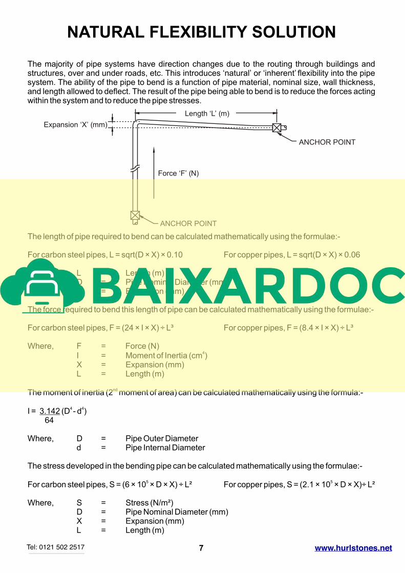
The majority of pipe systems have direction changes due to the routing through buildings and structures, over and under roads, etc. This introduces ‘natural’ or ‘inherent’ flexibility into the pipe system. The ability of the pipe to bend is a function of pipe material, nominal size, wall thickness, and length allowed to deflect. The result of the pipe being able to bend is to reduce the forces acting within the system and to reduce the pipe stresses.
The length of pipe required to bend can be calculated mathematically using the formulae:-
For carbon steel pipes, L = sqrt(D × X) × 0.10 For copper pipes, L = sqrt(D × X) × 0.06
Where, L = Length (m)D = Pipe Nominal Diameter (mm)X = Expansion (mm)
The force required to bend this length of pipe can be calculated mathematically using the formulae:- For carbon steel pipes, F = (24 × I × X) ÷ L³ For copper pipes, F = (8.4 × I × X) ÷ L³
Where, F = Force (N)
4I = Moment of Inertia (cm )X = Expansion (mm)L = Length (m)
ndThe moment of inertia (2 moment of area) can be calculated mathematically using the formula:-
4 4I = 3.142 (D - d ) 64
Where, D = Pipe Outer Diameterd = Pipe Internal Diameter
The stress developed in the bending pipe can be calculated mathematically using the formulae:-
5 5For carbon steel pipes, S = (6 × 10 × D × X) ÷ L² For copper pipes, S = (2.1 × 10 × D × X)÷ L²
Where, S = Stress (N/m²)D = Pipe Nominal Diameter (mm)X = Expansion (mm)L = Length (m)
Tel 01423 878888 PIPE SOLUTIONS LTD
Expansion ‘X’ (mm)
Force ‘F’ (N)
ANCHOR POINT
ANCHOR POINT
Length ‘L’ (m)
7Tel: 0121 502 2517 HURLSTONESwww.hurlstones.net
Tel 01423 878888 PIPE SOLUTIONS LTD
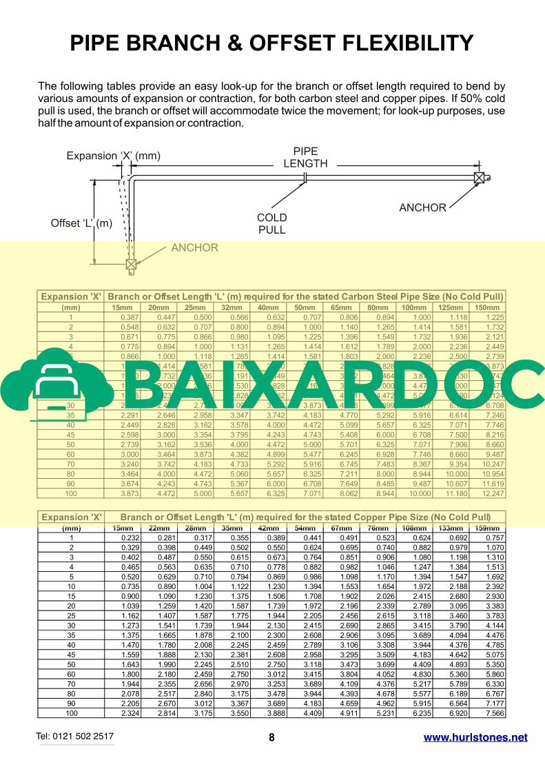
PIPE BRANCH & OFFSET FLEXIBILITY
The following tables provide an easy look-up for the branch or offset length required to bend by various amounts of expansion or contraction, for both carbon steel and copper pipes. If 50% cold pull is used, the branch or offset will accommodate twice the movement; for look-up purposes, use half the amount of expansion or contraction.
ANCHOR
ANCHOR
COLDPULL
Offset ‘L’ (m)
PIPELENGTH
Expansion ‘X’ (mm)
Expansion 'X' Branch or Offset Length 'L' (m) required for the stated Carbon Steel Pipe Size (No Cold Pull)(mm) 15mm 20mm 25mm 32mm 40mm 50mm 65mm 80mm 100mm 125mm 150mm
1 0.387 0.447 0.500 0.566 0.632 0.707 0.806 0.894 1.000 1.118 1.225
2 0.548 0.632 0.707 0.800 0.894 1.000 1.140 1.265 1.414 1.581 1.732
3 0.671 0.775 0.866 0.980 1.095 1.225 1.396 1.549 1.732 1.936 2.121
4 0.775 0.894 1.000 1.131 1.265 1.414 1.612 1.789 2.000 2.236 2.449
5 0.866 1.000 1.118 1.265 1.414 1.581 1.803 2.000 2.236 2.500 2.739
10 1.225 1.414 1.581 1.789 2.000 2.236 2.550 2.828 3.162 3.536 3.873
15 1.500 1.732 1.936 2.191 2.449 2.739 3.122 3.464 3.873 4.330 4.743
20 1.732 2.000 2.236 2.530 2.828 3.162 3.606 4.000 4.472 5.000 5.477
25 1.936 2.236 2.500 2.828 3.162 3.536 4.031 4.472 5.000 5.590 6.124
30 2.121 2.449 2.739 3.098 3.464 3.873 4.416 4.899 5.477 6.124 6.708
35 2.291 2.646 2.958 3.347 3.742 4.183 4.770 5.292 5.916 6.614 7.246
40 2.449 2.828 3.162 3.578 4.000 4.472 5.099 5.657 6.325 7.071 7.746
45 2.598 3.000 3.354 3.795 4.243 4.743 5.408 6.000 6.708 7.500 8.216
50 2.739 3.162 3.536 4.000 4.472 5.000 5.701 6.325 7.071 7.906 8.660
60 3.000 3.464 3.873 4.382 4.899 5.477 6.245 6.928 7.746 8.660 9.487
70 3.240 3.742 4.183 4.733 5.292 5.916 6.745 7.483 8.367 9.354 10.247
80 3.464 4.000 4.472 5.060 5.657 6.325 7.211 8.000 8.944 10.000 10.954
90 3.674 4.243 4.743 5.367 6.000 6.708 7.649 8.485 9.487 10.607 11.619
100 3.873 4.472 5.000 5.657 6.325 7.071 8.062 8.944 10.000 11.180 12.247
Expansion 'X' Branch or Offset Length 'L' (m) required for the stated Copper Pipe Size (No Cold Pull)(mm) 15mm 22mm 28mm 35mm 42mm 54mm 67mm 76mm 108mm 133mm 159mm
1 0.232 0.281 0.317 0.355 0.389 0.441 0.491 0.523 0.624 0.692 0.757
2 0.329 0.398 0.449 0.502 0.550 0.624 0.695 0.740 0.882 0.979 1.070
3 0.402 0.487 0.550 0.615 0.673 0.764 0.851 0.906 1.080 1.198 1.310
4 0.465 0.563 0.635 0.710 0.778 0.882 0.982 1.046 1.247 1.384 1.513
5 0.520 0.629 0.710 0.794 0.869 0.986 1.098 1.170 1.394 1.547 1.692
10 0.735 0.890 1.004 1.122 1.230 1.394 1.553 1.654 1.972 2.188 2.392
15 0.900 1.090 1.230 1.375 1.506 1.708 1.902 2.026 2.415 2.680 2.930
20 1.039 1.259 1.420 1.587 1.739 1.972 2.196 2.339 2.789 3.095 3.383
25 1.162 1.407 1.587 1.775 1.944 2.205 2.456 2.615 3.118 3.460 3.783
30 1.273 1.541 1.739 1.944 2.130 2.415 2.690 2.865 3.415 3.790 4.144
35 1.375 1.665 1.878 2.100 2.300 2.608 2.906 3.095 3.689 4.094 4.476
40 1.470 1.780 2.008 2.245 2.459 2.789 3.106 3.308 3.944 4.376 4.785
45 1.559 1.888 2.130 2.381 2.608 2.958 3.295 3.509 4.183 4.642 5.075
50 1.643 1.990 2.245 2.510 2.750 3.118 3.473 3.699 4.409 4.893 5.350
60 1.800 2.180 2.459 2.750 3.012 3.415 3.804 4.052 4.830 5.360 5.860
70 1.944 2.355 2.656 2.970 3.253 3.689 4.109 4.376 5.217 5.789 6.330
80 2.078 2.517 2.840 3.175 3.478 3.944 4.393 4.678 5.577 6.189 6.767
90 2.205 2.670 3.012 3.367 3.689 4.183 4.659 4.962 5.915 6.564 7.177
100 2.324 2.814 3.175 3.550 3.888 4.409 4.911 5.231 6.235 6.920 7.566
8Tel: 0121 502 2517 HURLSTONESwww.hurlstones.net
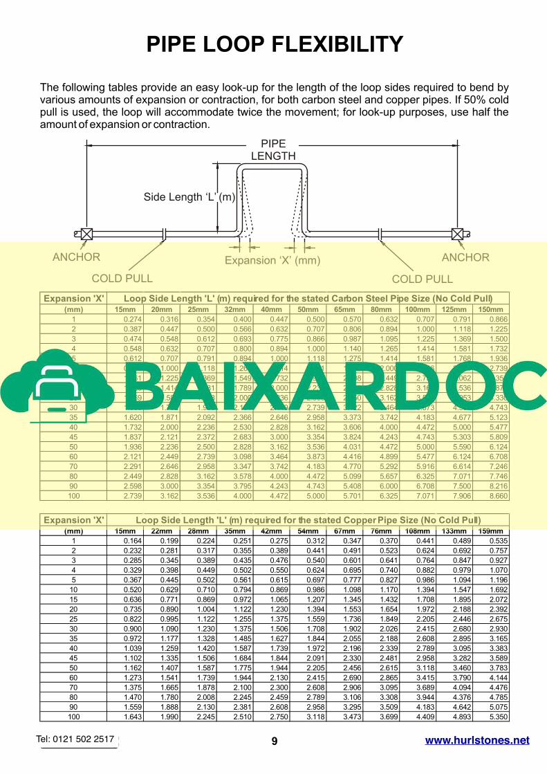
Expansion 'X' Loop Side Length 'L' (m) required for the stated Carbon Steel Pipe Size (No Cold Pull)(mm) 15mm 20mm 25mm 32mm 40mm 50mm 65mm 80mm 100mm 125mm 150mm
1 0.274 0.316 0.354 0.400 0.447 0.500 0.570 0.632 0.707 0.791 0.866
2 0.387 0.447 0.500 0.566 0.632 0.707 0.806 0.894 1.000 1.118 1.225
3 0.474 0.548 0.612 0.693 0.775 0.866 0.987 1.095 1.225 1.369 1.500
4 0.548 0.632 0.707 0.800 0.894 1.000 1.140 1.265 1.414 1.581 1.732
5 0.612 0.707 0.791 0.894 1.000 1.118 1.275 1.414 1.581 1.768 1.936
10 0.866 1.000 1.118 1.265 1.414 1.581 1.803 2.000 2.236 2.500 2.739
15 1.061 1.225 1.369 1.549 1.732 1.936 2.208 2.449 2.739 3.062 3.354
20 1.225 1.414 1.581 1.789 2.000 2.236 2.550 2.828 3.162 3.536 3.873
25 1.369 1.581 1.768 2.000 2.236 2.500 2.850 3.162 3.536 3.953 4.330
30 1.500 1.732 1.936 2.191 2.449 2.739 3.122 3.464 3.873 4.330 4.743
35 1.620 1.871 2.092 2.366 2.646 2.958 3.373 3.742 4.183 4.677 5.123
40 1.732 2.000 2.236 2.530 2.828 3.162 3.606 4.000 4.472 5.000 5.477
45 1.837 2.121 2.372 2.683 3.000 3.354 3.824 4.243 4.743 5.303 5.809
50 1.936 2.236 2.500 2.828 3.162 3.536 4.031 4.472 5.000 5.590 6.124
60 2.121 2.449 2.739 3.098 3.464 3.873 4.416 4.899 5.477 6.124 6.708
70 2.291 2.646 2.958 3.347 3.742 4.183 4.770 5.292 5.916 6.614 7.246
80 2.449 2.828 3.162 3.578 4.000 4.472 5.099 5.657 6.325 7.071 7.746
90 2.598 3.000 3.354 3.795 4.243 4.743 5.408 6.000 6.708 7.500 8.216
100 2.739 3.162 3.536 4.000 4.472 5.000 5.701 6.325 7.071 7.906 8.660
Tel 01423 878888 PIPE SOLUTIONS LTD
PIPE LOOP FLEXIBILITY
The following tables provide an easy look-up for the length of the loop sides required to bend by various amounts of expansion or contraction, for both carbon steel and copper pipes. If 50% cold pull is used, the loop will accommodate twice the movement; for look-up purposes, use half the amount of expansion or contraction.
ANCHORANCHOR
COLD PULLCOLD PULL
Side Length ‘L’ (m)
PIPELENGTH
Expansion ‘X’ (mm)
Expansion 'X' Loop Side Length 'L' (m) required for the stated Copper Pipe Size (No Cold Pull)(mm) 15mm 22mm 28mm 35mm 42mm 54mm 67mm 76mm 108mm 133mm 159mm
1 0.164 0.199 0.224 0.251 0.275 0.312 0.347 0.370 0.441 0.489 0.535
2 0.232 0.281 0.317 0.355 0.389 0.441 0.491 0.523 0.624 0.692 0.757
3 0.285 0.345 0.389 0.435 0.476 0.540 0.601 0.641 0.764 0.847 0.927
4 0.329 0.398 0.449 0.502 0.550 0.624 0.695 0.740 0.882 0.979 1.070
5 0.367 0.445 0.502 0.561 0.615 0.697 0.777 0.827 0.986 1.094 1.196
10 0.520 0.629 0.710 0.794 0.869 0.986 1.098 1.170 1.394 1.547 1.692
15 0.636 0.771 0.869 0.972 1.065 1.207 1.345 1.432 1.708 1.895 2.072
20 0.735 0.890 1.004 1.122 1.230 1.394 1.553 1.654 1.972 2.188 2.392
25 0.822 0.995 1.122 1.255 1.375 1.559 1.736 1.849 2.205 2.446 2.675
30 0.900 1.090 1.230 1.375 1.506 1.708 1.902 2.026 2.415 2.680 2.930
35 0.972 1.177 1.328 1.485 1.627 1.844 2.055 2.188 2.608 2.895 3.165
40 1.039 1.259 1.420 1.587 1.739 1.972 2.196 2.339 2.789 3.095 3.383
45 1.102 1.335 1.506 1.684 1.844 2.091 2.330 2.481 2.958 3.282 3.589
50 1.162 1.407 1.587 1.775 1.944 2.205 2.456 2.615 3.118 3.460 3.783
60 1.273 1.541 1.739 1.944 2.130 2.415 2.690 2.865 3.415 3.790 4.144
70 1.375 1.665 1.878 2.100 2.300 2.608 2.906 3.095 3.689 4.094 4.476
80 1.470 1.780 2.008 2.245 2.459 2.789 3.106 3.308 3.944 4.376 4.785
90 1.559 1.888 2.130 2.381 2.608 2.958 3.295 3.509 4.183 4.642 5.075
100 1.643 1.990 2.245 2.510 2.750 3.118 3.473 3.699 4.409 4.893 5.350
9Tel: 0121 502 2517 HURLSTONESwww.hurlstones.net
Tel 01423 878888 PIPE SOLUTIONS LTD
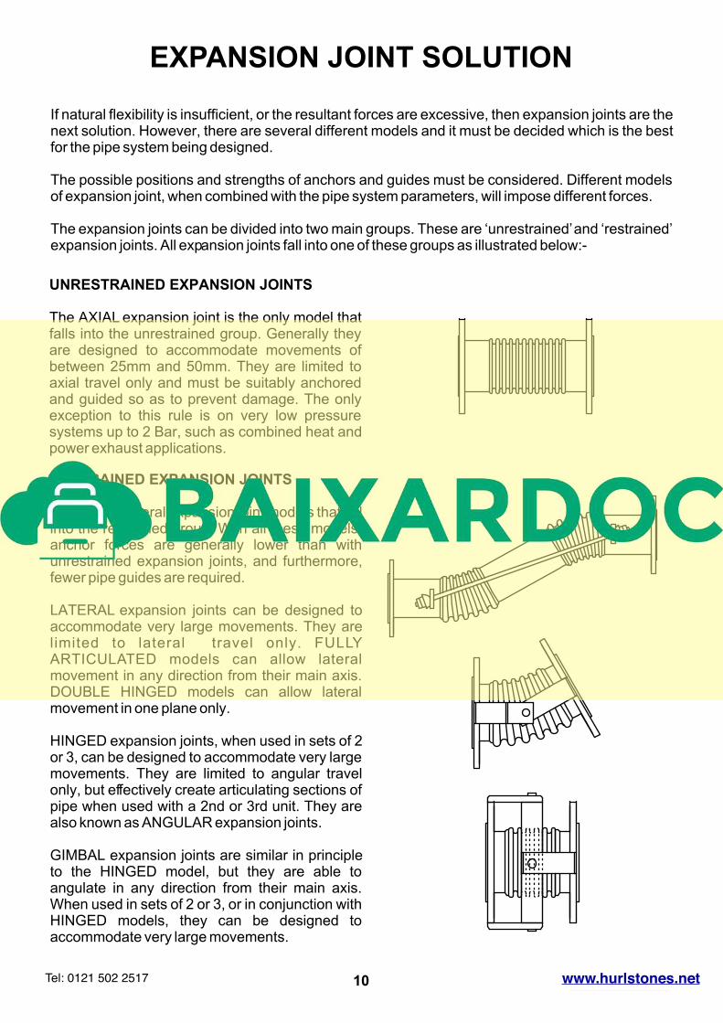
EXPANSION JOINT SOLUTION
If natural flexibility is insufficient, or the resultant forces are excessive, then expansion joints are the next solution. However, there are several different models and it must be decided which is the best for the pipe system being designed.
The possible positions and strengths of anchors and guides must be considered. Different models of expansion joint, when combined with the pipe system parameters, will impose different forces.
The expansion joints can be divided into two main groups. These are ‘unrestrained’ and ‘restrained’ expansion joints. All expansion joints fall into one of these groups as illustrated below:-
UNRESTRAINED EXPANSION JOINTS
The AXIAL expansion joint is the only model that falls into the unrestrained group. Generally they are designed to accommodate movements of between 25mm and 50mm. They are limited to axial travel only and must be suitably anchored and guided so as to prevent damage. The only exception to this rule is on very low pressure systems up to 2 Bar, such as combined heat and power exhaust applications.
RESTRAINED EXPANSION JOINTS
There are several expansion joint models that fall into the restrained group. With all these models, anchor forces are generally lower than with unrestrained expansion joints, and furthermore, fewer pipe guides are required.
LATERAL expansion joints can be designed to accommodate very large movements. They are limited to lateral travel only. FULLY ARTICULATED models can allow lateral movement in any direction from their main axis. DOUBLE HINGED models can allow lateral movement in one plane only.
HINGED expansion joints, when used in sets of 2 or 3, can be designed to accommodate very large movements. They are limited to angular travel only, but effectively create articulating sections of pipe when used with a 2nd or 3rd unit. They are also known as ANGULAR expansion joints.
GIMBAL expansion joints are similar in principle to the HINGED model, but they are able to angulate in any direction from their main axis. When used in sets of 2 or 3, or in conjunction with HINGED models, they can be designed to accommodate very large movements.
10Tel: 0121 502 2517 HURLSTONESwww.hurlstones.net


