Embed Size (px)
Citation preview
PIR SENSORBASED SECURITY SYSTEM
June
2012
This PIR Sensor based Security System can switch on a lamp or alarm when it detects the heat from an object like a moving person in the secured area.

ELECTRICAL & ELECTRONICS ENGINEERING
Authors: Sreeraj CR, Usman P, Visakh Chandran ,Vishnu P, Yelsin A Y
S6EB , NSSCE
N.S.S COLLEGE OF ENGINEERING
PALAKKAD, KERALA-678008
UNIVERSITY OF CALICUT
DEPARTMENT OF
ELECTRICAL & ELECTRONICS ENGINEERINGMINI PROJECT REPORT

JUNE-2012
PIR SENSOR BASEDSECURITY SYSTEM
SUBMITTED BY
SREERAJ CR –NSAJEEE087
USMAN P -NSAJEEE093
VISAKH CHANDRAN –NSAJEEE097
VISHNU P –NSAJEEE098
YELSIN A Y –NSAJEEE099
GUIDED BY
Mr SAJU N
ASST. PROFESSOR
NSS COLLEGE OF ENGINEERING PALAKKAD – 678008
KERALA

CERTIFICATE
This is to certify that Minor Project Report titled
PIR SENSOR BASED SECURITY SYSTEMis a bonafide account of the work done by “Sreeraj C R , Usman P , Visakh Chandran , Vishnu P & Yelsin A Y” of Semester VI Electrical and Electronics Engineering in partial fulfillment of the requirement for the award of Bachelor of Technology in Electrical and Electronics Engineering , during the academic year 2011-2012 under our guidance at NSS COLLEGE OF ENGINEERING , PALAKKAD.
Place: Akathethara Date:

Staff in Charge Internal Examiner Head of Department Contents.......Abstract................................................................... 5
Acknowledgements................................................. 6
List of Figures......................................................... 7
Introduction............................................................ 8
Block Diagram........................................................ 10
PIR Sensor............................................................... 11
Timer IC NE555...................................................... 15
Power supply.......................................................... 19
Transistor............................................................... 20
Relay........................................................................ 21
LED........................................................................... 22
Buzzer....................................................................... 23
7805 Regulator........................................................ 23
Components............................................................. 25
Circuit Diagram..................................................... 26
Apparatus................................................................ 27
Pros.......................................................................... 30
Cons......................................................................... 31
Conclusion............................................................... 32
Appendix................................................................. 33
Bibliography........................................................... 34
Abstract
The development of an inexpensive and effective electronicsecurity system employing PIR sensor is detailed in this report.This sensor based security system can be used in household aswell as domestic applications & even in other high securityareas.
A normal electronic security system which is commonly usedconsists of a transmitter and a receiver. The transmitter sectionsends out an IR beam which is being continuously received bythe receiver section. When an intruder walks past the device,the IR beam gets disrupted and thus the alarm is activated.Major disadvantages of the system include limited range andpoor line of sight.
This PIR Sensor based Security System can switch on a lamp oralarm when it detects the heat from an object like a movingperson. The name Passive Infrared Sensor is called so because

it receives the infrared rays passively and do not emit anyinfrared ray. The alarm that goes off can be manually reset.

Acknowledgements
We extend our sincere gratitude towards Professor KI Geetha, Head of Department for providing the required facilities for the successful completion of the work.
We would like to thank Asst Prof. Saju N, from the depth of our hearts, for his cooperation and resourceful guidance without which this work would have been impossible.
Finally, yet importantly, we would like to express my heartfelt thanks to all faculty members of the department and our friends/classmates for their help, inputs and wishes for the successful completion of this project.


List of Figures….
Sl.No Name of
figure
Page
No.1. Block Diagram of Security System 10
2. PIR Sensor 11
3. IC NE555 15
4. Power Supply 19
5. Relay 21
6. LED 22
7. 7805 Regulator 23

8. Circuit Diagram 26
9. Apparatus 27
Introduction A PIR Sensor is a pyroelectric device that can sense infrared
(IR) radiation changes within its viewing range. These sensors are sensitive to moving objects radiating IR. A PIR sensor creates temporary electric potential whenever a change of IR radiation occurs on the viewing range of the sensor, but the electric potential generated is very small in amplitude and must be amplified significantly. That is because PIR sensors cannot be used alone, instead they become one of the key components of a passive infrared device (PID) with some othercircuitry. The basic structure of a PID consists of a Fresnel lens,a PIR sensor, an amplifier circuitry and a comparator plus time delayer circuitry.
Fresnel lens focuses IR radiation on PIR sensor and PIR sensor measures the change in the IR rate and creates an electric potential difference corresponding to the variation in the IR radiation. However, this potential difference is very small and must be amplified without introducing noise. The amplifier circuitry aims to have a large gain for the sensor signal and suppress the ambient noise at the same time. So, generally a two stage bandpass amplifier is used. The amplified sensor signal is then compared with a threshold. If the signal stays in
the range determined by the threshold then it is assumed thatno motion is observed, otherwise it is assumed that there is a moving target. Therefore ordinary PIR sensors are simple and give an output of logical one when they detect a motion and alogical zero when there is no moving object within their viewing ranges.
The PIDs are low-cost, easy to use and widely available commercially. These practical features made them used in many indoor and outdoor applications including the security systems.
IR RadiationInfrared (IR) radiation is a type of electromagnetic radiation. Infrared light has a longer wavelength than visible light. The infrared has a wavelength of 750 nm to 100 µm. The infrared radiation is invisible to humans but we can feel it as heat. Infrared region can further be divided into sub-regions as follows:
Near Infrared (NIR): 750 nm to 1:5 µm. Short Wavelength Infrared (SWIR): 1.5 µm to 3 µm. Mid Wavelength Infrared (MWIR): 3 µm to 8 µm. Long Wavelength Infrared (LWIR): 8 µm to 15 µm. Far Infrared (FIR): Longer than 15 µm.
The MWIR and LWIR is known as the thermal infrared. All oobjects emit what µis known as black body radiation (thermal radiation). This is emitted from the surface of an object which is

due to the its temperature. Human body at normal body temperature radiates IR approximately at wavelengths around 9.4 µm.
Pyroelectricity (from the Greek pyro, fire, and electricity) is the ability of certain materials to generate a temporary electrical potential when they are heated or cooled. It is a migration of positive and negative charge to opposite ends of acrystal's polar axis as a result of a change in temperature, and this causes an electrical polarization. This polarization change gives rise to a temporary electric potential, although this disappears after the dielectric relaxation time
Block Diagram
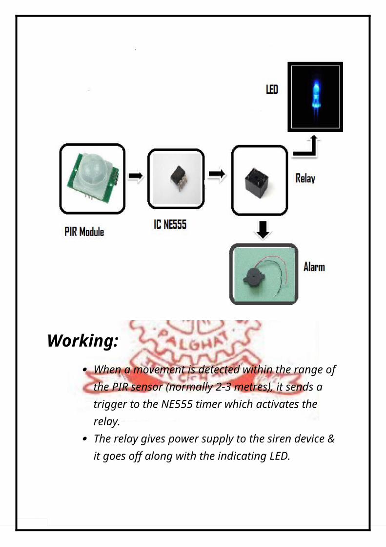
Working: When a movement is detected within the range of
the PIR sensor (normally 2-3 metres), it sends a trigger to the NE555 timer which activates the relay.
The relay gives power supply to the siren device & it goes off along with the indicating LED.
PIR Sensor PIR sensors allow you to sense motion, almost always used
to detect whether a human has moved in or out of the sensors range. They are small, inexpensive, low-power, easy to use and don't wear out. For that reason they are commonly found in appliances and gadgets used in homes or businesses. They are often referred to as PIR, "Passive" or “Pyroelectric" IR motion sensors.
PIRs are basically made of a pyroelectric sensor (which can be seen as the round metal can with a rectangular crystal in the center ) , which can detect levels of infrared radiation. Everything emits some low level radiation, and the hotter something is, the more radiation is emitted. The sensor in a motion detector is actually split in two halves. The reason forthat is that we are looking to detect motion (change) not average IR levels. The two halves are wired up so that they cancel each other out. If one half sees more or less IR radiation than the other, the output will swing high or low.
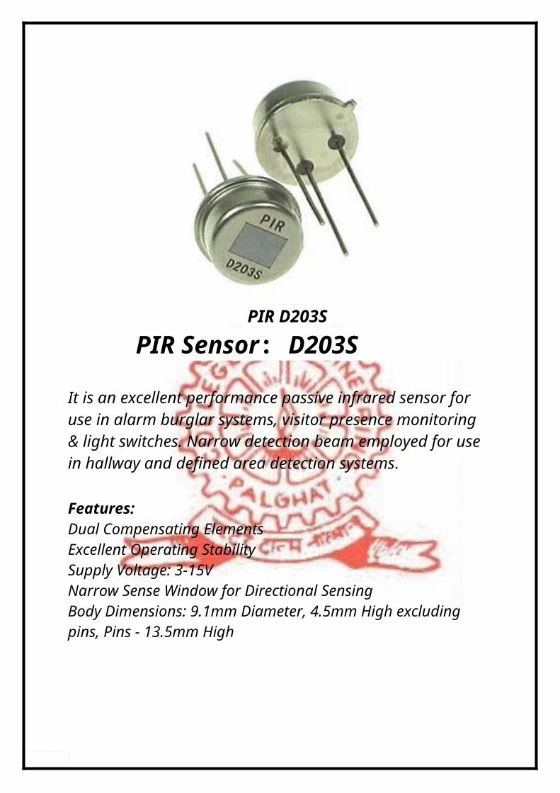
PIR D203S
PIR Sensor: D203S
It is an excellent performance passive infrared sensor for use in alarm burglar systems, visitor presence monitoring & light switches. Narrow detection beam employed for usein hallway and defined area detection systems.
Features: Dual Compensating ElementsExcellent Operating StabilitySupply Voltage: 3-15VNarrow Sense Window for Directional SensingBody Dimensions: 9.1mm Diameter, 4.5mm High excluding pins, Pins - 13.5mm High
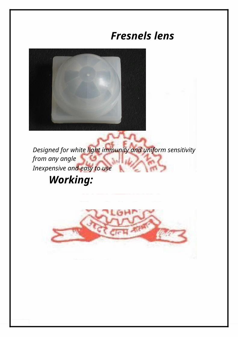
Fresnels lens
Designed for white light immunity and uniform sensitivity from any angle Inexpensive and easy to use
Working:
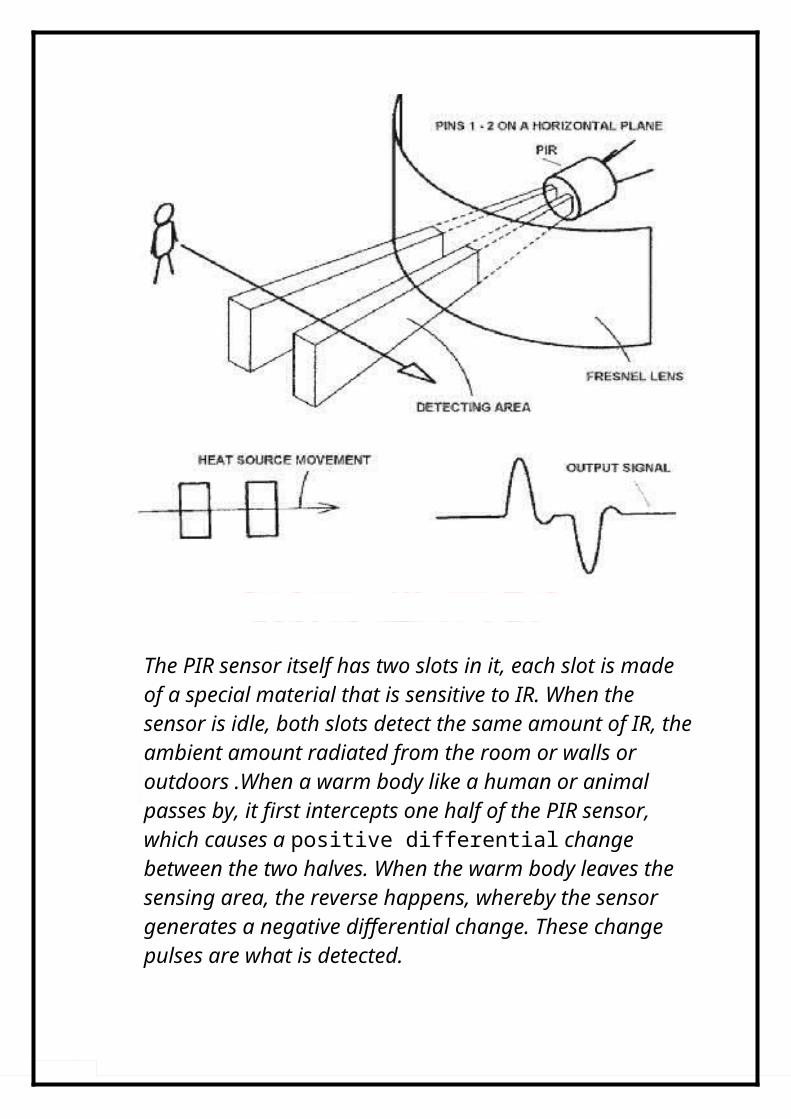
The PIR sensor itself has two slots in it, each slot is made of a special material that is sensitive to IR. When the sensor is idle, both slots detect the same amount of IR, theambient amount radiated from the room or walls or outdoors .When a warm body like a human or animal passes by, it first intercepts one half of the PIR sensor, which causes a positive differential change between the two halves. When the warm body leaves the sensing area, the reverse happens, whereby the sensor generates a negative differential change. These change pulses are what is detected.
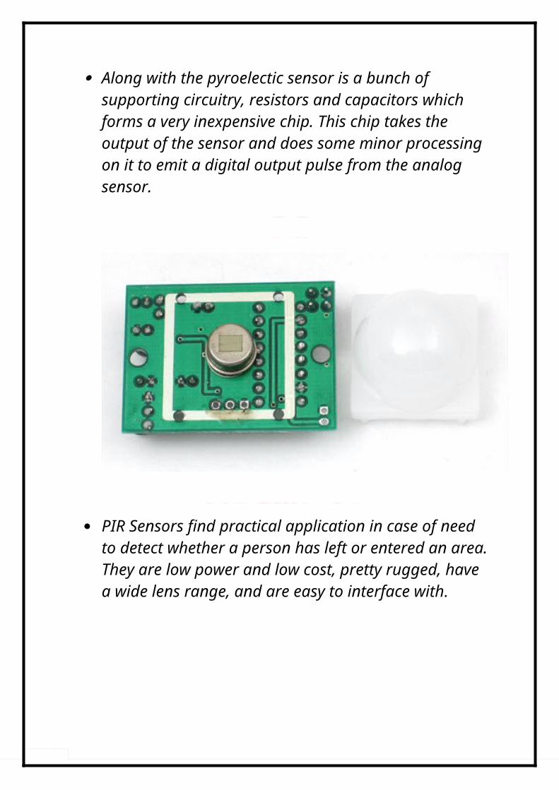
Along with the pyroelectic sensor is a bunch of supporting circuitry, resistors and capacitors which forms a very inexpensive chip. This chip takes the output of the sensor and does some minor processing on it to emit a digital output pulse from the analog sensor.
PIR Sensors find practical application in case of need to detect whether a person has left or entered an area.They are low power and low cost, pretty rugged, have a wide lens range, and are easy to interface with.
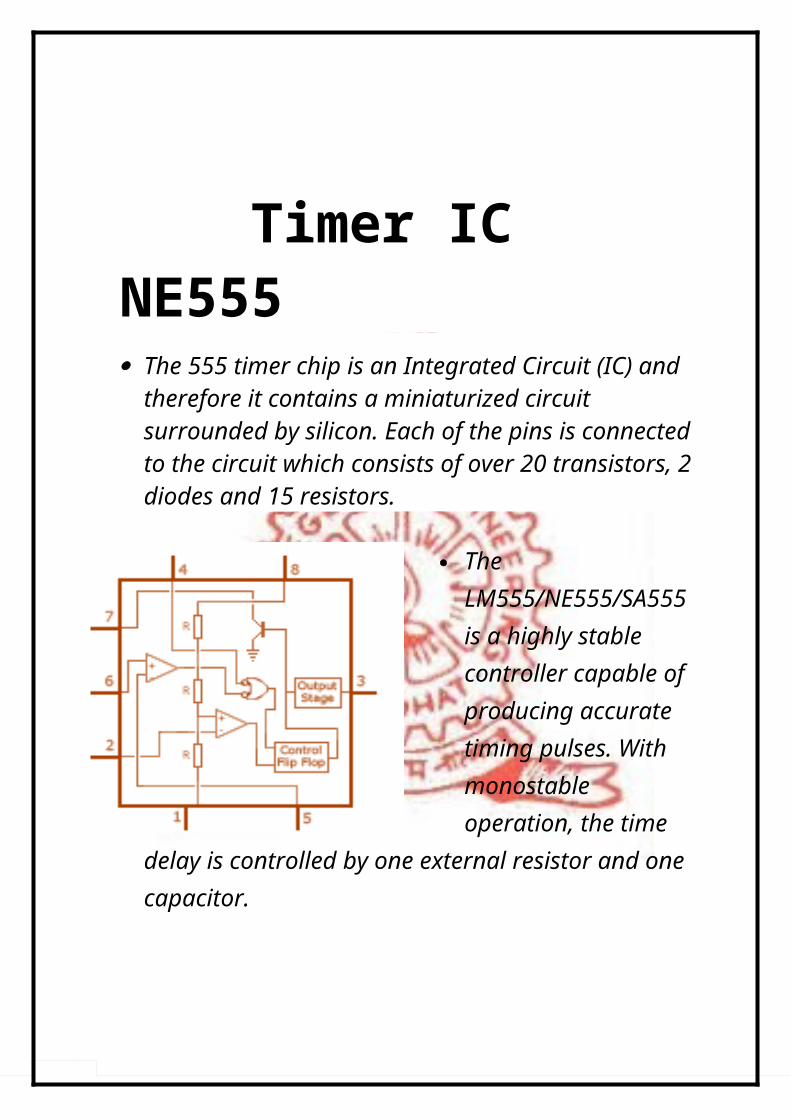
Timer IC NE555 The 555 timer chip is an Integrated Circuit (IC) and
therefore it contains a miniaturized circuit surrounded by silicon. Each of the pins is connectedto the circuit which consists of over 20 transistors, 2diodes and 15 resistors.
The LM555/NE555/SA555 is a highly stable controller capable of producing accurate timing pulses. With monostable operation, the time
delay is controlled by one external resistor and one capacitor.

With astable operation, the frequency and duty cycle are accurately controlled with two external resistors and one capacitor.
Pin Description:1. Ground: input pin of the source of the negative DC voltage 2. Trigger: negative input from the lower comparators
(comparator B) that maintain oscillation capacitor voltage inthe lowest 1 / 3 Vcc and set RS flip-flop
3. Output: the output pin of the IC 555. 4. Reset: the pin that serves to reset the latch inside the IC to
be influential to reset the IC work. This pin is connected to a PNP-type transistor gate, so the transistor will be active if given a logic low. Normally this pin is connected directly to Vcc to prevent reset
5. Control voltage: this pin serves to regulate the stability of the reference voltage negative input (comparator A). This pincan be left hanging.
6. Threshold: this pin is connected to the positive input (comparator A) which will reset the RS flip-flop when the voltage on the capacitor from exceeding 2 / 3 Vcc
7. Discharge: this pin is connected to an open collector transistor Q1 is connected to ground emitter. Switching transistor serves to clamp the corresponding node to groundon the timing of certain
8. Vcc: pin to receive a DC voltage supply. (5-15V, 10-15mA).
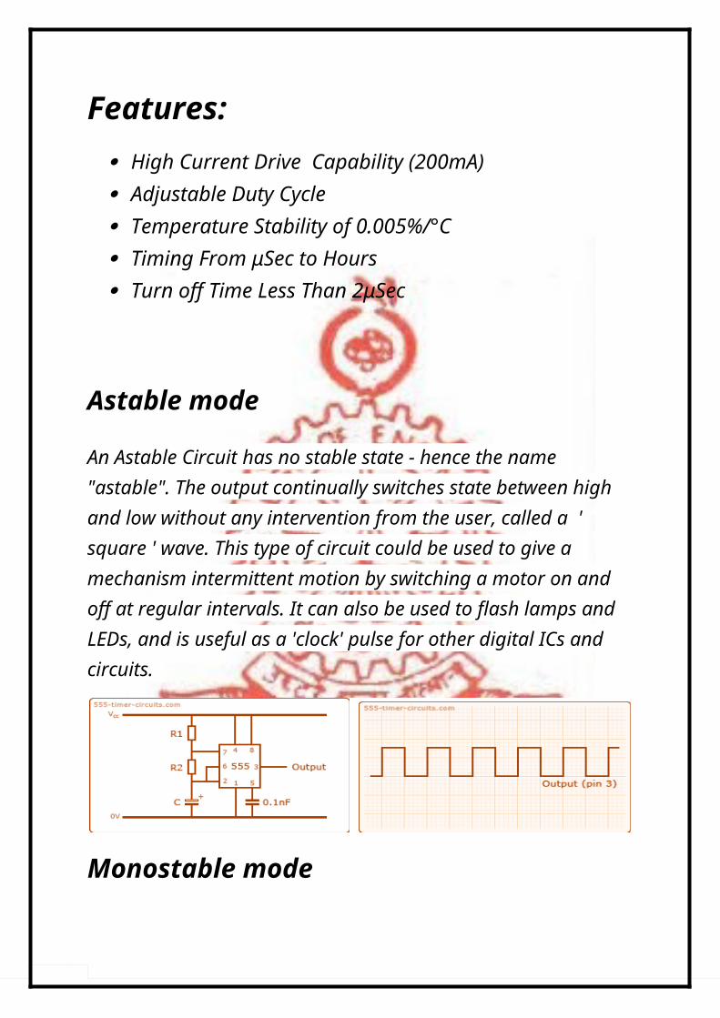
Features: High Current Drive Capability (200mA) Adjustable Duty Cycle Temperature Stability of 0.005%/°C Timing From μSec to Hours Turn off Time Less Than 2μSec
Astable mode
An Astable Circuit has no stable state - hence the name "astable". The output continually switches state between high and low without any intervention from the user, called a ' square ' wave. This type of circuit could be used to give a mechanism intermittent motion by switching a motor on and off at regular intervals. It can also be used to flash lamps and LEDs, and is useful as a 'clock' pulse for other digital ICs and circuits.
Monostable mode
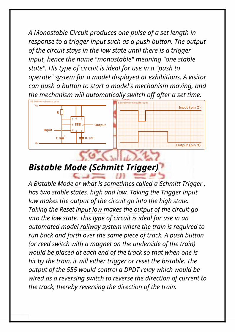
A Monostable Circuit produces one pulse of a set length in response to a trigger input such as a push button. The outputof the circuit stays in the low state until there is a trigger input, hence the name "monostable" meaning "one stable state". His type of circuit is ideal for use in a "push to operate" system for a model displayed at exhibitions. A visitorcan push a button to start a model's mechanism moving, andthe mechanism will automatically switch off after a set time.
Bistable Mode (Schmitt Trigger) A Bistable Mode or what is sometimes called a Schmitt Trigger ,has two stable states, high and low. Taking the Trigger input low makes the output of the circuit go into the high state. Taking the Reset input low makes the output of the circuit go into the low state. This type of circuit is ideal for use in an automated model railway system where the train is required to run back and forth over the same piece of track. A push button (or reed switch with a magnet on the underside of the train) would be placed at each end of the track so that when one is hit by the train, it will either trigger or reset the bistable. The output of the 555 would control a DPDT relay which would be wired as a reversing switch to reverse the direction of current tothe track, thereby reversing the direction of the train.

Applications• Precision Timing
• Pulse Generation
• Time Delay Generation
• Sequential Timing
Power Supply Block Diagram
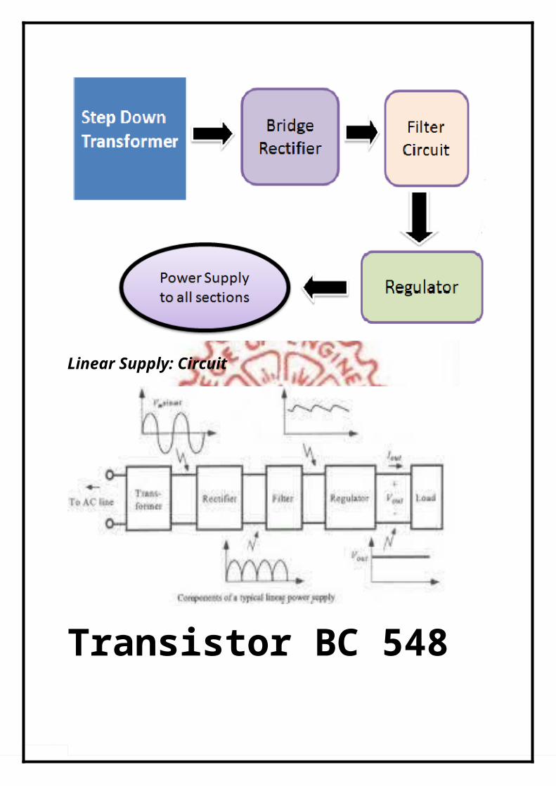
Linear Supply: Circuit
Transistor BC 548
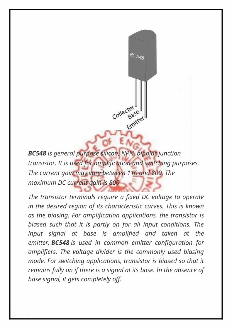
BC548 is general purpose silicon, NPN, bipolar junction transistor. It is used for amplification and switching purposes. The current gain may vary between 110 and 800. The maximum DC current gain is 800
The transistor terminals require a fixed DC voltage to operatein the desired region of its characteristic curves. This is knownas the biasing. For amplification applications, the transistor isbiased such that it is partly on for all input conditions. Theinput signal at base is amplified and taken at theemitter. BC548 is used in common emitter configuration foramplifiers. The voltage divider is the commonly used biasingmode. For switching applications, transistor is biased so that itremains fully on if there is a signal at its base. In the absence ofbase signal, it gets completely off.
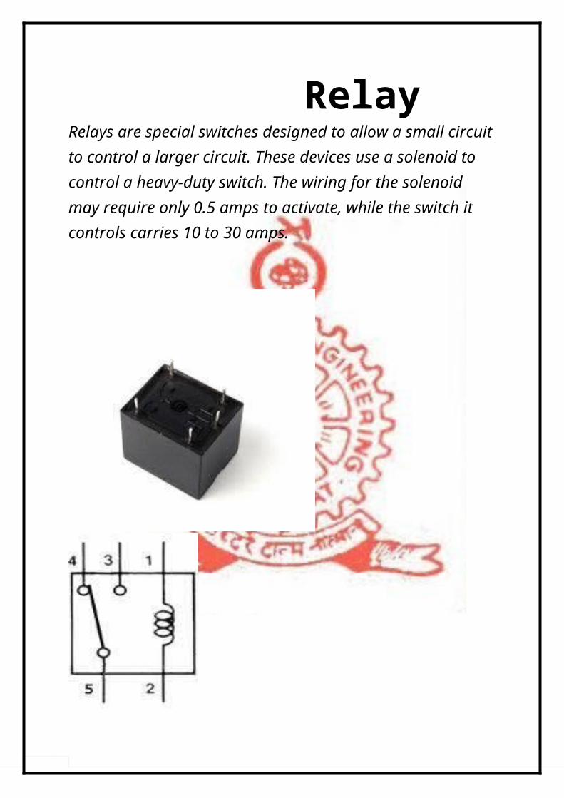
RelayRelays are special switches designed to allow a small circuitto control a larger circuit. These devices use a solenoid to control a heavy-duty switch. The wiring for the solenoid may require only 0.5 amps to activate, while the switch it controls carries 10 to 30 amps.
Connect the control device to the two solenoid pin soft here lay. Supplying a small 12- volt voltage to these two pins will turn the relay switch on or off.
Locate the other three pins. These pins form a SPDT switch
Here a 12 V relay is used.
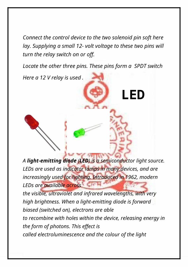
LED
A light-emitting diode (LED) is a semiconductor light source.LEDs are used as indicator lamps in many devices, and are increasingly used for lighting. Introduced in 1962, modern LEDs are available across the visible, ultraviolet and infrared wavelengths, with very high brightness. When a light-emitting diode is forward biased (switched on), electrons are able to recombine with holes within the device, releasing energy inthe form of photons. This effect is called electroluminescence and the colour of the light
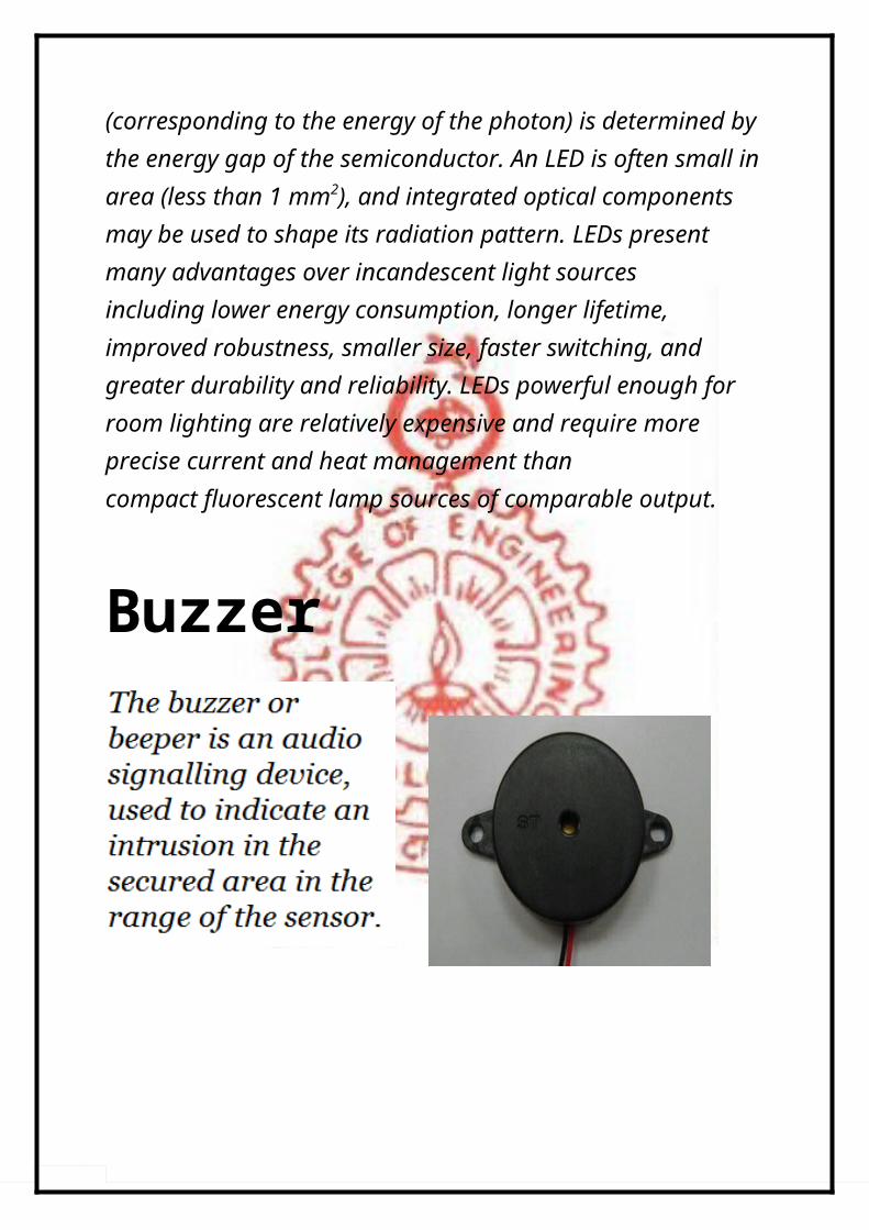
(corresponding to the energy of the photon) is determined by the energy gap of the semiconductor. An LED is often small inarea (less than 1 mm2), and integrated optical components may be used to shape its radiation pattern. LEDs present many advantages over incandescent light sources including lower energy consumption, longer lifetime, improved robustness, smaller size, faster switching, and greater durability and reliability. LEDs powerful enough for room lighting are relatively expensive and require more precise current and heat management than compact fluorescent lamp sources of comparable output. Buzzer

7805 RegulatorThe 7805 voltage regulators employ built-in current limiting, thermal shutdown, and safe-operating area protection which makes them virtually immune to damage from output overloads. 7805 is a three-terminal positive voltage regulator.
7805 regulator comes from the 78xx family of self-contained fixed linear voltage regulator integrated circuits. The 78xx family is a very popular choice for many electroniccircuits which require a regulated power supply, due to their ease of use and relative cheapness. When specifying individual ICs within this family, the xx is replaced with a

two-digit number, which indicates the output voltage the particular device is designed to provide (for example, the 7805 voltage regulator has a 5 volt output, while the 7812 produces 12 volts). The 78xx line are positive voltage regulators, meaning that they are designed to produce a voltage that is positive relative to a common ground.
7805 series ICs do not require any additional components to provide a constant, regulated source ofpower, making them easy to use, as well as economical, and also efficient uses of circuit board real estate.
7805 series ICs have built-in protection against a circuit drawing too much power. They also have protection against overheating and short-circuits, making them quite robust in most applications.
Components....

RESISTOR
1. R1 ________100K2. R2 ________10K3. R3 ________4.7K4. R4 ________4.7K5. R5________1K6. R6________1K
CAPACITOR
7. C1 ________220µF8. C2 ________100µF
9. POWER TRANSFORMER 230V/12V10. PIR SENSOR MODULE11. 7805 REGULATOR12. IC NE55513. 12V RELAY14. Q1 BC54815. Q2 BC54816. LED ( 2 no )17. BUZZER18. ON/OFF SWITCH
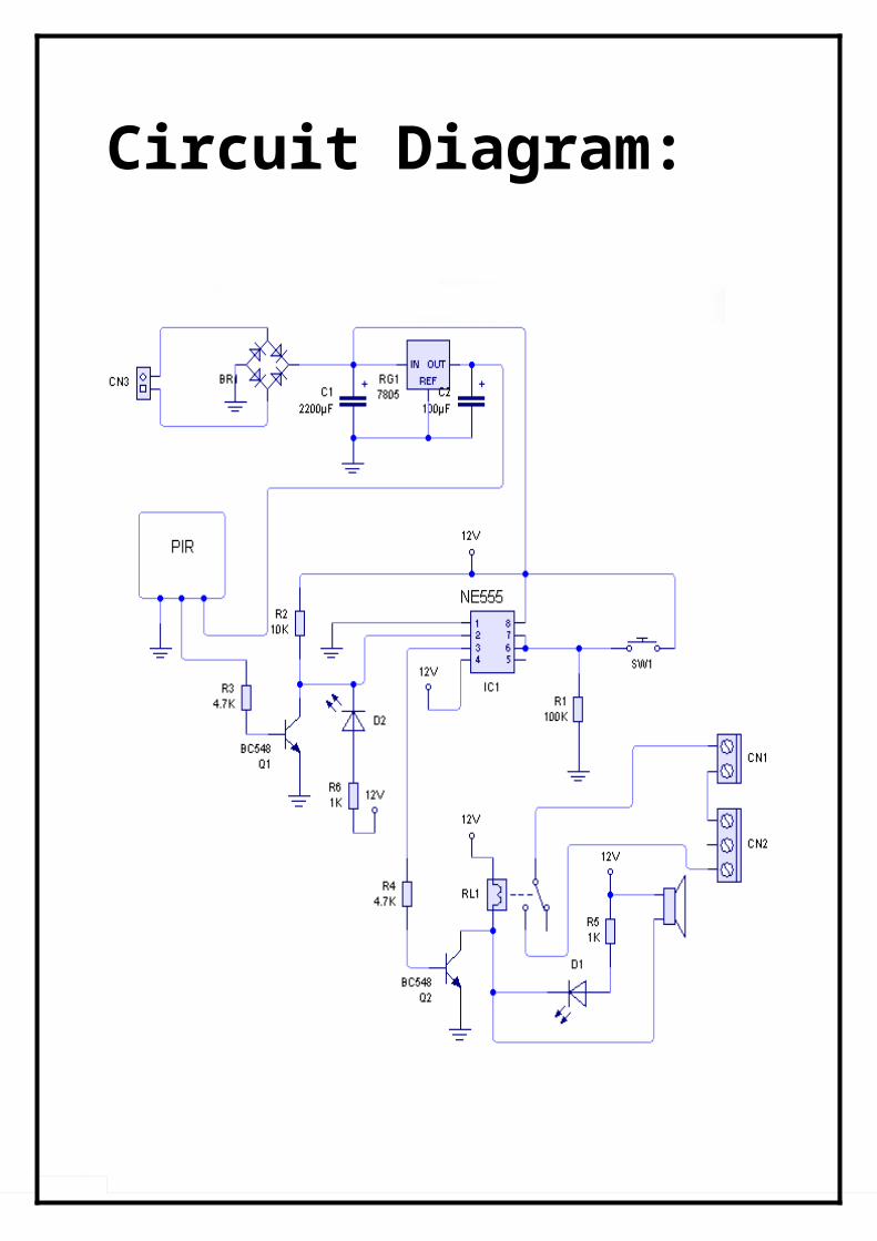
Circuit Diagram:

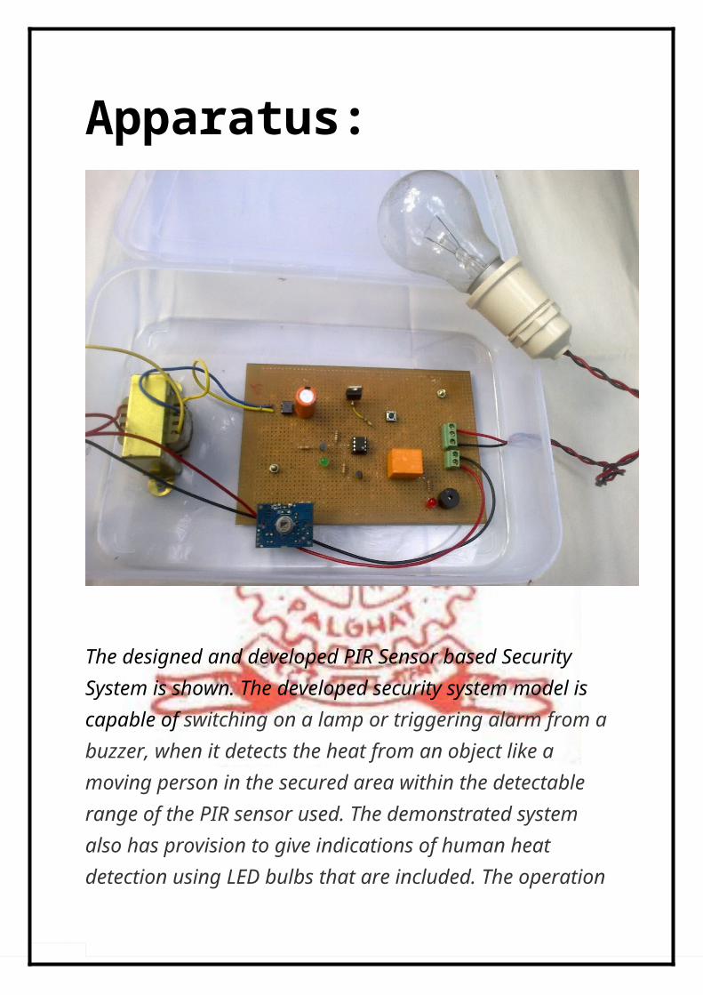
Apparatus:
The designed and developed PIR Sensor based Security System is shown. The developed security system model is capable of switching on a lamp or triggering alarm from a buzzer, when it detects the heat from an object like a moving person in the secured area within the detectable range of the PIR sensor used. The demonstrated system also has provision to give indications of human heat detection using LED bulbs that are included. The operation

of the security system is accomplished by operation the timer IC in the bistable mode of operation.
The actual operating range of the sensor circuit can be dependent on the conditions prevalent. The operation of the system can be improvised by including higher quality industrial grade sensors to increase the detectable range.
Bistable Operation:
In bistable mode, the 555 timer acts as a basic flip-flop. The trigger and reset inputs (pins 2 and 4 respectively on a NE555) are held high via pull-up resistors while the threshold input (pin6) is simply grounded. Thus configured, pulling the trigger momentarily to ground acts as a 'set' and transitions the output pin (pin 3) to Vcc (high state). Pulling the reset input to ground acts as a 'reset' and transitions the output pin to
ground (low state). No capacitors are required in a bistable configuration. Pin 5 (control) is connected to ground via a small-value capacitor (usually 0.01 to 0.1 uF); pin 7 (discharge) is left floating.
Working:For the bistable mode of operation, initially the trigger pin 2 remains high and the output pin 3 remains low. When the PIR sensor detects motion and gets activated by sudden change in IR energy transistor Q1 gets switched on and the trigger pin 2 gets grounded (ie.. low). This leads the output pin 3 to the high state which further drives the transistor switch Q2 on. This leads the relay getting switched on and the buzzer becomes on thus sounding the alarm along with an indication using an LED.
Once the alarm goes off to reset the circuit by stopping the buzzer we provide an on/off switch. On pressing the reset switch the reset pin 4 goes low and again the output pin 3 also goes low thus switching off the buzzer and returning the system to the initial state.
Relevance:
The Pyro-electric Infra-Red (PIR) sensor is an extremely useful device for detecting the presence of a moving body. This is due

to its ability to sense the infrared radiation that every living body emits.
While a number of technologies for motion detection exist,including ultrasonic and microwave radiation sensors, the PIRsensor is popular for its ease-of-setup and high performance.In addition, PIR sensors are inexpensive and has little powerconsumption.In the future world of electronics expects the rate of adoptionof PIR sensors to grow fast, with applications such assurveillance and alarm systems, as well as power savingdevices, driving increased usage of PIR sensors.
Applications:
The PIR Sensor based Security System provides application ofunauthorised intruder detection in household, commercial &industrial premises......promising relatively lower cost ofinstallation and maintenance compared to other existing safetysystems.
The same system can act as an Automatic Energy SavingSystem by switching on the lights along with the buzzer whenhuman presence is detected.....
The applications of the systems include Public doorways in grocery stores

Hospitals Libraries Hotels Staircases Military application.....
The future of ectronics industry guarantees the use of PIRsensors integrated with telecommunication and GPS systems toprovide sophisticated safety solutions....
Pros........
The system is single ended, unlike light beam/laser barriers, which require aligned transmitters and receivers.
The system is passive: Intruders can't detect the presence and location of the detectors (unlike radarsystems).
The detectors consume less power than IR- or radar-based units.
They are unaffected by light, with the detectors working equally well day or night.
Precision optics enable detectors to cover narrow areas accurately.
The detectors complement cameras, allowing fewer cameras to cover the area.
Small size and unobtrusive design help the detectors blend in with their surroundings.
Cons........
Can be fooled by someone moving especially slowly.
If the sensor was set to the required sensitivity, it would be activated by the cooling of a nearby wall in the evening, or by very small animals.
Someone walking straight towards a PIR sensor, will not be detected until they are very close by.
PIR sensors are temperature sensitive - they work optimally at ambient air temperatures of around 15-20 degrees Celsius. If the temperatureis over 30 degrees, the field of view narrows and the sensor will be less sensitive. Alternatively, if the temperature is below 15 degrees, the field of
view widens and smaller or more distant objects will activate the sensor.
Conclusions:The primary objective of this project was the development of an effective & inexpensive security system that could have applications in households as well as commercial premises, workable in both day and night conditions. Wireless sensor networks for surveillance systems in home, office, or factory environment require correct tracking of intruders. For such systems, passive infrared motion sensors (PIR sensors) are ideal because they do not require any signal or devices on the object to be tracked and they can work in dark environment also.
Through well directed efforts a PIR Sensor based Security System has been developed, which is capable of detecting motion of humans or live beings in the range of the sensor used & to trigger a buzzer circuit thus acting as an effective burglar alarm. In the model developed as part of the

project provisions are also provided to act as an automatic lighting circuit that switches on a bulb when intruder is detected. In the event of risk of theft or vandalism from domestic property, such effective PIR sensor security systems can be implemented.
Further study in the direction could help develop more sophisticated security solutions as 24-hr monitoring system that would alert a few phone nos or a call centre if the alarm is triggered. Overall the developed system provides abasic solution for the primary one among growing security concerns................................
Appendix: D203S - Datasheet
General-Purpose Dual Element Pyroelectric Infrared Radial Sensor- The pyroelectric infrared sensor detects infrared radiation on the basis of the characteristics that the polarization of pyroelectric material changes with temperature.Dual compensated sensing elements are applied to suppress the interference resulting from temperature variation. As a result, the operating stability of the sensor is greatly improved. Our products can be used in many applications. Such as in

security systems, burglar alarms, visitor acknowledgement, light switch control and intellectualized toy,etc.
Recommended Model : D203SEncapsulation Type : TO-5IR Receiving Electrode : 2×1mm, 2 elementsWindow Size : 4×3mmSpectral Response : 5-14μmTransmittance 75%≥Signal Output [Vp-p] 3500mV≥Sensitivity 3300V/W≥Detectivity (D*) 1.4 ×10⁸ cmHz1/2/W≥Noise[Vp-p] <70mVOutput Balance <10%Offset Voltage : 0.3-1.2VSupply Voltage : 3-15VOperating Temperature : -30-70ºCStorage Temperature : -40-80ºC

Bibliography:
1) J.B GUPTA ; ELECTRONIC CIRCUITS & DEVICES ; KatsonPublishers
2) Dr.ROY CHOUDHARY, S B JAIN ;LINEAR INTEGRATEDCIRCUITS; New Age Publishers
3) WINEYARD TECHNOLOGIES , Hyderabad
4) www.future-mag.com5) www.circuitstoday.com6) www.engineersgarage.com7) www.ladyada.net8) www.fadooengineers.com9) www.avaricetechnologies.com
10) D203S, Pyroelectric IR Sensor Datasheet , http://www.micropik.com/PDF/D203S-e.pdf,PIR SENSOR CO.,LTD..
11) www.ehow.com12) www.google.com