Embed Size (px)
Citation preview

Reference Manual - English - Version 5.7A
Piranha
RTI article number: 9629053-00

Welcome to the Piranha
The Piranha is an X-ray Analyser/Multimeter foreverybody work ing with Quality Assurance andService of X-ray systems.
NOTICE
Microsof t, Windows, Win32, Windows XP, 2003, Vista, 7, 8, and 10 are either registered
trademarks or trademarks of Microsof t Corporation in the United States and/or other countries.
BLUETOOTH is a trademark owned by Bluetooth SIG, Inc., USA.
Notice
RTI Electronics Inc.33 Jacksonville Road, Bldg. 1,Towaco, NJ 07082,USA
Phone: 800-222-7537 (Toll free)
Int. +1-973-439-0242Fax: Int. +1-973-439-0248
E-mailSales: [email protected]: [email protected]: [email protected]
Contact Information - United States
RTI Group AB reserves all rights to make changes in the Piranha and theinformation in this document without prior notice.RTI Group AB assumes no responsibility for any errors or consequentialdamages that may result from the use or misinterpretation of any informationcontained in this document.
Copyright © 2001-2019 by RTI Group AB. All rights reserved.Content of this document may not be reproduced for any other purpose thansupporting the use of the product without prior permission from RTI Group AB.
RTI Group ABFlöjelbergsgatan 8 CSE-431 37 MÖLNDALSweden
Phone: Int. +46 31 7463600
E-mailSales: [email protected]: [email protected]: [email protected]
Contact Information - World-Wide
Piranha Reference M anual2019-12/5.7A
III
http://www.rtigroup.comWeb site: Web site: http://www.rtigroup.com

Intended Use of the Piranha System
Together w ith external probes the Piranha System it intended to be used for independent
service and quality control, including measurements of kerma, kerma rate, kVp, tube current,
exposure time, luminance, illuminance, and dose area product, w ithin limitations stated below .
If installed according to accompanying documents, the product is intended to be used together
w ith all diagnostic X-ray equipment except for:
- therapeutical X-ray sources.
- X-ray equipment w ith tube potential below 18 kV or above 160 kV.
- X-ray equipment on w hich the instrument cannot be mounted properly.
- specif ic types of X-ray equipment listed in the instructions for use or in additional information
from the manufacturer.
With the X-ray installation w ithout patient present, the product is intended to be used:
- for assessing the performance of the X-ray equipment.
- for evaluation of examination techniques and procedures.
- for service and maintenance of the X-ray equipment.
- for quality control of the X-ray equipment.
- for educational purposes, authority supervision etc.
The product is intended to be used by hospital physicists, X-ray engineers, manufacturer's
service teams, and other professionals w ith similar tasks and competencies. The operator
needs training to be able to use the product as intended. This training can be achieved either by
study of the manual, study of the built-in help function in measurement softw are or, on request,
by a course ordered from the manufacturer.
The product is intended to be used inside X-ray rooms ready for clinical use and can safely be
left sw itched on and in any measuring mode in the vicinity of patients.
The product is NOT intended to be used:
- for direct control of diagnostic X-ray equipment performance during irradiation of a patient.
- so that patients or other unqualif ied persons can change settings of operating parameters
during, immediately before, or after measurements.
- for any guidance to diagnosis of patients.
Piranha Reference M anual 2019-12/5.7A
Intended UseIV
Piranha Reference M anual2019-12/5.7A
Contents 1
Table of Contents
1. ..................................................................................................... 3Introduction.................................................................................................................. 41.1 About this Manual
.................................................................................................................. 41.2 Introduction to the Piranha
.................................................................................................................. 51.3 PC Requirements
2. ..................................................................................................... 6Description of the Piranha.................................................................................................................. 72.1 Indicators and Connectors
.................................................................................................................. 102.2 Setting Up the Piranha for the First Time
.................................................................................................................. 102.3 Setting Up the Piranha
.................................................................................................................. 112.4 Hardware and Specifications ..................................................................................................................112.4.1 Piranha internal detector (Internal detector)
..........................................................................................................112.4.1.1 General
..........................................................................................................122.4.1.2 Pow er & Communication Specif ications
..........................................................................................................122.4.1.3 Specif ications, Piranha
..........................................................................................................202.4.1.4 Typical Response, Piranha
..........................................................................................................232.4.1.5 Angular Sensitivity, Piranha
..................................................................................................................252.4.2 Piranha External Probes
.................................................................................................................. 292.5 Standards and Compliances ..................................................................................................................292.5.1 Waste Electrical and Electronic Equipment (WEEE)
..................................................................................................................302.5.2 Manufacturer's Declaration of Conformity
..................................................................................................................312.5.3 FCC Certif ication
.................................................................................................................. 312.6 Maintenance ..................................................................................................................312.6.1 Updating the Piranha Firmw are
..................................................................................................................342.6.2 Managing Detector Calibrations
.................................................................................................................. 352.7 Measurement Settings ..................................................................................................................362.7.1 Settings - Conditions
..................................................................................................................382.7.2 Settings - Piranha
..................................................................................................................402.7.3 Settings - Internal detector
..................................................................................................................412.7.4 Settings - Other Detectors
3. ..................................................................................................... 42Measurement Principles & Theory.................................................................................................................. 433.1 Overview of Capability for Measurement Modes
.................................................................................................................. 433.2 Update Modes ..................................................................................................................443.2.1 Using Timed Update Mode
..................................................................................................................443.2.2 Using Free Run Update Mode
.................................................................................................................. 453.3 Display Messages and Active Messages ..................................................................................................................453.3.1 Active Messages
..................................................................................................................463.3.2 Display Messages
.................................................................................................................. 473.4 Waveforms and Triggers
.................................................................................................................. 483.5 Measurement Principle for the Piranha
4. ..................................................................................................... 49Measurements with the Piranha System.................................................................................................................. 504.1 Introduction
.................................................................................................................. 504.2 Radiography
Piranha Reference M anual 2019-12/5.7A
Contents2..................................................................................................................504.2.1 kVp, Time, Dose, and Dose Rate
..................................................................................................................514.2.2 Dose Measurements w ith Piranha Dose Probe
..................................................................................................................514.2.3 Quick-HVL and Total Filtration
.................................................................................................................. 514.3 Cine/Pulsed Radiography ..................................................................................................................514.3.1 kVp, Time, Dose, and Dose Rate
..................................................................................................................514.3.2 Pulse Measurements w ith Piranha Dose Probe
..................................................................................................................524.3.3 HVL, Quick-HVL, and Total Filtration
.................................................................................................................. 524.4 Fluoroscopy and Pulsed Fluoroscopy ..................................................................................................................534.4.1 Image Intensif ier Input Dose Rate
..................................................................................................................534.4.2 Pulsed Fluoroscopy
.................................................................................................................. 544.5 Mammography ..................................................................................................................544.5.1 General
..................................................................................................................554.5.2 Setting Up the Piranha for Mammography
..................................................................................................................564.5.3 kVp, Time, and Dose Measurements w ith the Internal detector
..................................................................................................................564.5.4 Dose Measurements w ith the Piranha Dose Probe
..................................................................................................................574.5.5 Quick-HVL
..................................................................................................................574.5.6 Mammo Compensations and Corrections
..........................................................................................................584.5.6.1 Corrections for the Compression Paddle
..........................................................................................................584.5.6.2 Normalization
..........................................................................................................594.5.6.3 Beam Correction Factor
..........................................................................................................594.5.6.4 Corrections for Angular Sensitivity
..................................................................................................................604.5.7 Average Glandular Dose, AGD (MGD)
..................................................................................................................604.5.8 Mammographic Pre-pulses
..................................................................................................................614.5.9 Scanning Beam Mammography
.................................................................................................................. 614.6 Dental and Panoramic Dental ..................................................................................................................634.6.1 Waveforms
.................................................................................................................. 634.7 CT ..................................................................................................................634.7.1 CT kVp
.................................................................................................................. 654.8 Tube Current Probes ..................................................................................................................664.8.1 MAS-1, Invasive mAs Probe
..................................................................................................................674.8.2 MAS-2, Non-invasive mAs Probe
.................................................................................................................. 684.9 Light Measurement ..................................................................................................................694.9.1 Luminance - Monitor/View box (cd/m²)
..................................................................................................................694.9.2 Illuminance - Ambient Light (lx)
5. ..................................................................................................... 70Problems and Solutions.................................................................................................................. 715.1 Troubleshooting
.................................................................................................................. 725.2 Bluetooth ..................................................................................................................735.2.1 Bluetooth Passkey
..................................................................................................................735.2.2 Enable Bluetooth Passkey
.................................................................................................................. 745.3 Windows Restricted User Accounts ..................................................................................................................745.3.1 Which Applications are Needed?
..................................................................................................................755.3.2 Installing the Softw are
..................................................................................................................755.3.3 Setting Necessary Rights
.................................................................................................................. 765.4 How To Report a Problem
6. ..................................................................................................... 77Glossary
............................................................................................................. 91Index

Introduction
Chapter 1

1. IntroductionAbout this Manual
Piranha Reference M anual 2019-12/5.7A
4
1 Introduction
About this Manual1.1
This manual is divided into a few main parts.
1. A general description of the Piranha.2. Some theoretical background and basic principles.3-4. Descriptions on performing measurements with the system for different
modalities.5. Description of different accessories for the Piranha.6. Troubleshooting tips, an FAQ, and a glossary.
This manual is w ritten for Piranha w ith product version 5.7 (black top label), but
can in general also be used for older Piranhas. Note how ever, that specif ications
may be more specif ic, and you should verify the specif ications w ith those given in
the manual delivered w ith your meter (corresponding to your Piranha product
version on the bottom label).
Users who use the Piranha with only a PC and Ocean are recommended to read atleast the following topics:
· Introduction· Description of the Piranha· Measurements with the Piranha System
For the Piranha system, calibration data is stored inside the system. See sectionManaging Detector Calibrations for more information.
Typographical RulesTerms in bold face are references to texts on screenshots, like buttons and texts, andmenu items. Other terms are italicized.
Introduction to the Piranha1.2
Congratulations to your purchase of a Piranha. You have now in your hand the mostpowerful tool for X-ray analysis. It has been carefully designed to meet the needs ofboth standard QA applications as well as advanced service/repair/calibration ofmodern X-ray systems, while still being very simple and intuitive to use. It canmeasure all the required parameters such as kVp, exposure time, dose, HVL, TotalFiltration, dose/pulse, dose rate, tube current, mAs, waveforms, and much more.The Piranha can be used in two different ways:
· As a "meter" with a PC and the Ocean Quick-Check software.· As a complete "QA-system" with a PC and the Ocean software.
This manual describes the Piranha. The PC software, Ocean, and the olderQABrowser are described in detail in separate manuals.
The Piranha system's main features are:
34
1. IntroductionIntroduction to the Piranha
2019-12/5.7A
5
Piranha Reference M anual
· Very easy and intuitive to use· Accurate· Active Compensation - No manual corrections are needed· Measures on all modalities with one detector· Specially designed measuring modes for pulsed waveforms· Compact· Ocean is used for control and data processing· Waveform analyser· USB and Bluetooth interface· Free upgrade of firmware· Unique design
Free upgrades of the firmware (the software resident in the cabinet and measuringmodules) are available on RTI Web site at http://www.rtigroup.com.If you have questions, comments, or feel that some functionality is missing, you arewelcome to contact us at RTI at [email protected]. You can of course also call(see notice section for details).
PC Requirements1.3
To run the RTI Updater, the RTI Detector Manager, and Ocean the following isrequired:
Minimum requirementsWindows XP, 2003, Vista, 7/8/10 32-bit, or 7/8/10 64-bit.Pentium class 300 MHz, 64 MB RAM (24 MB free), 60 MB of HD 1
USB portDisplay and graphics card with at least 800×600 resolution
Recommended requirementsWindows 7/8/10 32-bit or 8/10 64-bitPentium class 500 MHz, 128 MB RAM (32 MB free), 100 MB HDUSB portCD/DVD-ROM for installationInternet connection for updates (Recommended)
1: Virtual memory and available hard drive space. Microsoft recommends that you have at least 20 % of your total HDspace free for virtual memory.

Description of the Piranha
Chapter 2
2. Description of the PiranhaIndicators and Connectors
2019-12/5.7A
7
Piranha Reference M anual
2 Description of the Piranha
Indicators and Connectors2.1
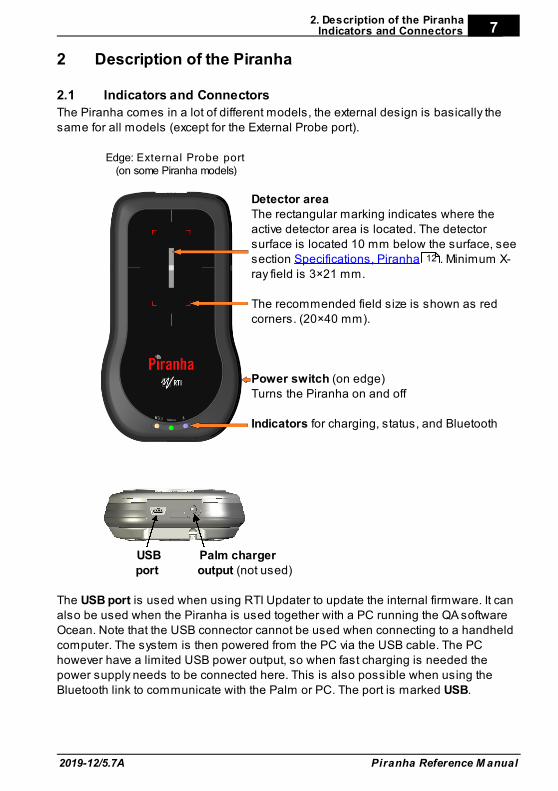
The Piranha comes in a lot of different models, the external design is basically thesame for all models (except for the External Probe port).
Edge: External Probe port(on some Piranha models)
Detector areaThe rectangular marking indicates where theactive detector area is located. The detectorsurface is located 10 mm below the surface, seesection Specifications, Piranha . Minimum X-ray field is 3×21 mm.
The recommended field size is shown as redcorners. (20×40 mm).
Power switch (on edge)Turns the Piranha on and off
Indicators for charging, status, and Bluetooth
USB Palm chargerport output (not used)
The USB port is used when using RTI Updater to update the internal firmware. It canalso be used when the Piranha is used together with a PC running the QA softwareOcean. Note that the USB connector cannot be used when connecting to a handheldcomputer. The system is then powered from the PC via the USB cable. The PChowever have a limited USB power output, so when fast charging is needed thepower supply needs to be connected here. This is also possible when using theBluetooth link to communicate with the Palm or PC. The port is marked USB.
12
2. Description of the PiranhaIndicators and Connectors
Piranha Reference M anual 2019-12/5.7A
8
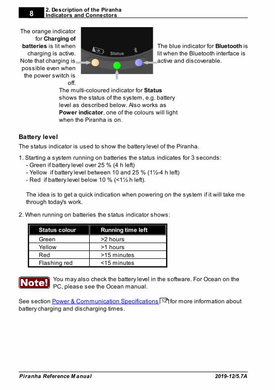
The orange indicatorfor Charging of
batteries is lit whencharging is active.
Note that charging ispossible even whenthe power switch is
off.
The blue indicator for Bluetooth islit when the Bluetooth interface isactive and discoverable.
The multi-coloured indicator for Statusshows the status of the system, e.g. batterylevel as described below. Also works asPower indicator, one of the colours will lightwhen the Piranha is on.
Battery level
The status indicator is used to show the battery level of the Piranha.
1. Starting a system running on batteries the status indicates for 3 seconds:- Green if battery level over 25 % (4 h left)- Yellow if battery level between 10 and 25 % (1½-4 h left)- Red if battery level below 10 % (<1½ h left).
The idea is to get a quick indication when powering on the system if it will take methrough today's work.
2. When running on batteries the status indicator shows:
Status colour Running time left
Green >2 hours
Yellow >1 hours
Red >15 minutes
Flashing red <15 minutes
You may also check the battery level in the software. For Ocean on thePC, please see the Ocean manual.
See section Power & Communication Specifications for more information aboutbattery charging and discharging times.
12
2. Description of the PiranhaIndicators and Connectors
2019-12/5.7A
9
Piranha Reference M anual
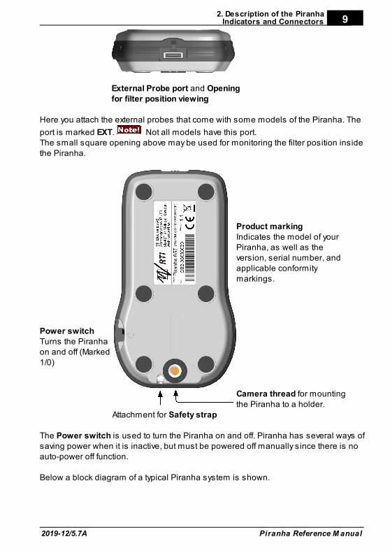
External Probe port and Openingfor filter position viewing
Here you attach the external probes that come with some models of the Piranha. The
port is marked EXT. Not all models have this port.The small square opening above may be used for monitoring the filter position insidethe Piranha.
Power switch Turns the Piranhaon and off (Marked1/0)
Product markingIndicates the model of yourPiranha, as well as theversion, serial number, andapplicable conformitymarkings.
Camera thread for mountingthe Piranha to a holder.
Attachment for Safety strap
The Power switch is used to turn the Piranha on and off. Piranha has several ways ofsaving power when it is inactive, but must be powered off manually since there is noauto-power off function.
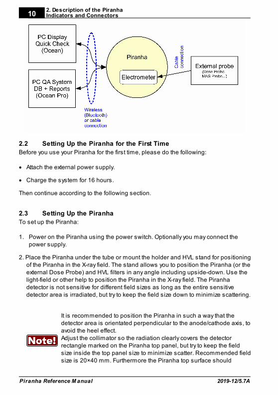
Below a block diagram of a typical Piranha system is shown.
2. Description of the PiranhaIndicators and Connectors
Piranha Reference M anual 2019-12/5.7A
10
Setting Up the Piranha for the First Time2.2
Before you use your Piranha for the first time, please do the following:
· Attach the external power supply.
· Charge the system for 16 hours.
Then continue according to the following section.
Setting Up the Piranha2.3
To set up the Piranha:
1. Power on the Piranha using the power switch. Optionally you may connect thepower supply.
2. Place the Piranha under the tube or mount the holder and HVL stand for positioningof the Piranha in the X-ray field. The stand allows you to position the Piranha (or theexternal Dose Probe) and HVL filters in any angle including upside-down. Use thelight-field or other help to position the Piranha in the X-ray field. The Piranhadetector is not sensitive for different field sizes as long as the entire sensitivedetector area is irradiated, but try to keep the field size down to minimize scattering.
It is recommended to position the Piranha in such a way that thedetector area is orientated perpendicular to the anode/cathode axis, toavoid the heel effect.Adjust the collimator so the radiation clearly covers the detectorrectangle marked on the Piranha top panel, but try to keep the fieldsize inside the top panel size to minimize scatter. Recommended fieldsize is 20×40 mm. Furthermore the Piranha top surface should
2. Description of the PiranhaSetting Up the Piranha
2019-12/5.7A
11
Piranha Reference M anual
optimally be placed perpendicular to the focal spot, see also AngularSensitivity, Piranha
3. Connect with Ocean via included USB cable or via Bluetooth.
Hardware and Specifications2.4
Specifications are valid after a warm-up time of one minute and presuming referenceconditions. All specifications are for use together with the Piranha unless otherwisestated. All specifications can be changed without prior notice. RTI Group AB assumesno responsibility for any errors or consequential damages that may result from themisuse or misinterpretation of any information contained in these specifications.
2.4.1 Piranha internal detector (Internal detector)
2.4.1.1 General
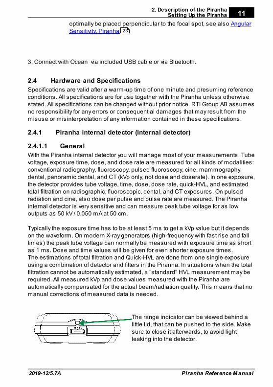
With the Piranha internal detector you will manage most of your measurements. Tubevoltage, exposure time, dose, and dose rate are measured for all kinds of modalities:conventional radiography, fluoroscopy, pulsed fluoroscopy, cine, mammography,dental, panoramic dental, and CT (kVp only, not dose and doserate). In one exposure,the detector provides tube voltage, time, dose, dose rate, quick-HVL, and estimatedtotal filtration on radiographic, fluoroscopic, dental, and CT exposures. On pulsedradiation and cine, also dose per pulse and pulse rate are measured. The Piranhainternal detector is very sensitive and can measure peak tube voltage for as lowoutputs as 50 kV / 0.050 mA at 50 cm.
Typically the exposure time has to be at least 5 ms to get a kVp value but it dependson the waveform. On modern X-ray generators (high-frequency with fast rise and falltimes) the peak tube voltage can normally be measured with exposure time as shortas 1 ms. Dose and time values will be given for even shorter exposure times. The estimations of total filtration and Quick-HVL are done from one single exposureusing a combination of detector and filters in the Piranha. In situations when the totalfiltration cannot be automatically estimated, a "standard" HVL measurement may berequired. All measured kVp and dose values measured with the Piranha areautomatically compensated for the actual beam/radiation quality. This means that nomanual corrections of measured data is needed.
The range indicator can be viewed behind alittle lid, that can be pushed to the side. Makesure to close it afterwards, to avoid lightleaking into the detector.
23
2. Description of the PiranhaHardware and Specifications
Piranha Reference M anual 2019-12/5.7A
12
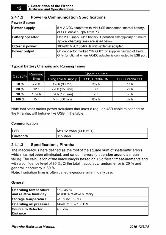
2.4.1.2 Power & Communication Specifications
Power Source
Power supply 5 V AC/DC adapter w ith Mini-USB connector, internal battery,
or USB cable supply from PC.
Battery operated One 2000 mAh Li-Ion battery. Operation time typically 15 hours.
Typical charging times are listed below .
External power 100-240 V AC 50/60 Hz w ith external adapter.
Power output On connector marked "5V OUT" for supply/charging of Palm.
Only functional w hen AC/DC adapter is connected to USB port.
Typical Battery Charging and Running Times
CapacityRunning
time
Charging time
Using Pow er supply USB, Piranha ON USB, Piranha OFF
50 % 7½ h 1½ h (90 min) 3½ h 17 h
80 % 12 h 2½ h (150 min) 6 h 27 h
90 % 13½ h 3¼ h (195 min) 7 h 30 h
100 % 15 h 5 h (300 min) 8½ h 32 h
Note that other mains power solutions that uses a regular USB cable to connect tothe Piranha, will behave like USB in the table.
Communication
USB Max 12 Mbit/s (USB v1.1)
Bluetooth 115 kbit/s
2.4.1.3 Specifications, Piranha
The inaccuracy is here defined as the root of the square sum of systematic errors,which has not been eliminated, and random errors (dispersion around a meanvalue). The calculation of the inaccuracy is based on 15 different measurements andwith a confidence level of 95 %. Of the total inaccuracy, random error is 20 % andgeneral inaccuracy is 80 %.Note: Irradiation time is often called exposure time in daily use.
General
Operating temperature
and relative humidity
15 – 35 °C
at <80 % relative humidity
Storage temperature –10 °C to +50 °C
Operating air pressure Minimum 80 – 106 kPa
Source to Detector
Distance
>30 cm
2. Description of the PiranhaHardware and Specifications
2019-12/5.7A
13
Piranha Reference M anual
Reference conditions
Temperature 20 °C
Relative humidity 50 %
Air pressure 101.3 kPa
X-ray field size Inside the Piranha top panel.
Calibration is done w ith f ield size typically 5 mm less than the size of
the top panel.
Radiation quality
Radiography
Mammography
CT
70 kV, 2.5 mm Al
28 kV, 30 µm Mo
120 kV, 2.5 mm Al
Note: The reference conditions are given in reference to the IEC61674 standard.
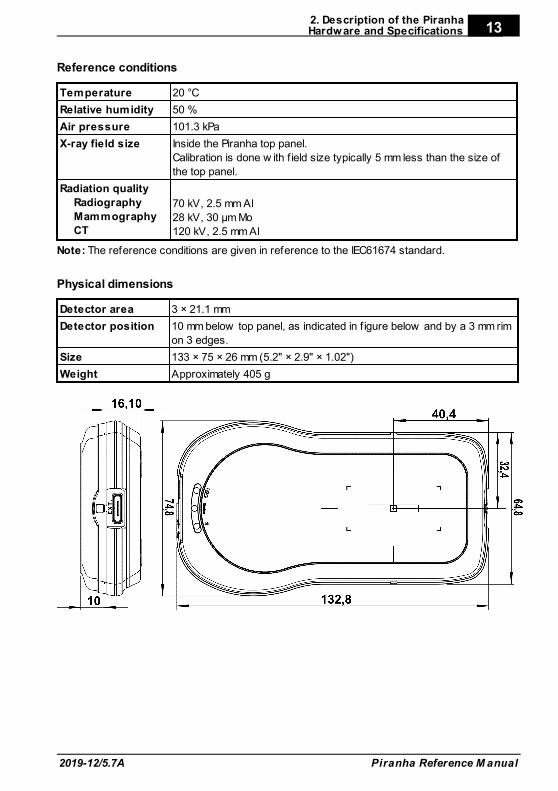
Physical dimensions
Detector area 3 × 21.1 mm
Detector position 10 mm below top panel, as indicated in f igure below and by a 3 mm rim
on 3 edges.
Size 133 × 75 × 26 mm (5.2" × 2.9" × 1.02")
Weight Approximately 405 g
2. Description of the PiranhaHardware and Specifications
Piranha Reference M anual 2019-12/5.7A
14
Parameters
Tube voltage (kVp) The average of all samples w ith compensation for the ripple
(default method)
Time Irradiation time (Exposure time)
Air kerma (Dose) Measured air kerma (may be called dose or air kerma in this
manual)
Air kerma rate
(Dose rate)
Average air kerma rate (may be called dose rate or air kerma rate
in this manual)
Total Filtration Estimation of total f iltration (for conventional radiography,
f luoroscopy, dental, and CT)
Quick-HVL Estimation of Half Value Layer (for conventional radiography,
f luoroscopy, dental, mammography, and CT)
Half Value Layer Standard HVL using f ilters for evaluation on radiography,
f luoroscopy, dental, and mammography (all for both pulsed and
conventional)
kV waveform Waveform is calculated based on detector signals measured
after different thickness of f iltration.
Dose rate waveform Signal measured from radiation detector (ionization chamber or
solid-state detector).
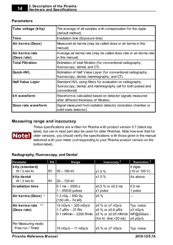
Measuring range and inaccuracy
These specif ications are w ritten for Piranha w ith product version 5.7 (black top
label), but can in most part also be used for older Piranhas. Note how ever that for
older versions, you should verify the specif ications w ith those given in the manual
delivered w ith your meter (corresponding to your Piranha product version on the
bottom label).
Radiography, Fluoroscopy, and Dental
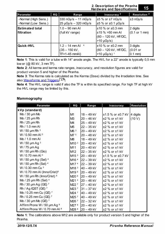
Parameter RQ Range Inaccuracy 2 Resolution 2
kVp (standard)
W / 3 mm Al
R1
35 – 160 kV ±1.5 %
4 digits
(10 or 100 V)
kVp dental
W / 3 mm Al
R1
35 – 125 kV
±1.5 % As above
Irradiation time 0.1 ms – 2000 s
1 – 65535 pulses
±0.5 % or ±0.5 ms
±1 pulse
0.5 ms
1 pulse
Air kerma (Dose) 2 1.3 nGy – 650 Gy
(150 nR – 74 kR)
±5 % –
Air kerma rate 2 3
(Dose rate)
15 nGy/s – 320 mGy/s
1.7 µR/s – 37 R/s
0.1 mR/min – 2200 R/min
±5 % or ±7 nGy/s
±5 % or ±0.8 µR/s
±5 % or ±0.05 mR/min
(for Irr. time >20 ms)
Typ. noise:
±3 nGy/s
WF@2kSa/s :
±4 µGy/s
Per Measuring mode:
-Free run / Timed 15 nGy/s – 11 mGy/s ±5 % or ±7 nGy/s Typ. noise:
2. Description of the PiranhaHardware and Specifications
2019-12/5.7A
15
Piranha Reference M anual
Parameter RQ Range Inaccuracy 2 Resolution 2
-Normal (High Sens.)
-Normal (Low Sens.)
330 nGy/s – 11 mGy/s
25 µGy/s – 320 mGy/s
±5 % or ±7 nGy/s
±5 % or ±0.1 µGy/s
±3 nGy/s
Estimated total
filtration
1.0 – 90 mm Al
(full kV range)
±10 % or ±0.3 mm
±15 % >50 mm Al
(60 – 120 kV, HF/DC,
>10 µGy/s)
2 digits
(0.1 or 1 mm)
Quick-HVL 1.2 – 14 mm Al 4
(35 – 150 kV,
TF=1-45 mmAl)
±10 % or ±0.2 mm
(60 – 120 kV, HF/DC,
>10 µGy/s) 1
3 digits
(0.01 or
0.1 mm)
Note 1: This is valid for a tube w ith 14° anode angle. The HVL for a 22° anode is typically 0,5 mm
low er (@ 80 kV, 3 mm TF).
Note 2: All kerma and kerma rate ranges, inaccuracy, and resolution f igures are valid for
product version 5 and higher of the Piranha.
Note 3: The Kerma rate is calculated as the Kerma (Dose) divided by the Irradiation time. See
also Waveforms and Triggers .
Note 4: The HVL range is valid if also the TF is w ithin its specif ied range. For high TF at high kV
the HVL range may be limited by this.
Mammography
Parameter RQ Range Inaccuracy Resolution
kVp (standard)
Mo / 30 µm Mo
Mo / 25 µm Rh
Rh / 25 µm Rh
Rh / 1.0 mm Al
W / 50 µm Rh 3
W / 0.50 mm Al 5
Mo / 1.0 mm Al
W / 50 µm Ag 3
W / 75 µm Ag
W / 50 µm Rh (Gio)
W / 0.70 mm Al 3
W / 50 µ m Ag (Sel) 4
W / 50 µ m Rh (Sel) 4
W / 0.30 mm Cu 3
W / 0.70 mm Al (Inno/Crist)6
W / 50 µ m Rh (Inno/Crist) 6
Mo / 25 µ m Rh (Sel) 4
Rh / 30 µm Ag (GE) 7
Rh / Ag IQST (GE) 7
Mo / 0.25 mm Cu (GE) 7
Rh / 0.25 mm Cu (GE) 7
Mo / 30 µm Mo (GE) 7
Affirm Prone W / 50 µm Ag 8
Affirm Prone W / 0.70 mm Al 8
M1
M3
M4
M5
M6 3
M7 5
M8
M10 3
M11
M12
M15 3
M16 4
M17 4
M18 3
M19 6
M20 6
M21 4
M22 7
M23 7
M24 7
M25 7
M26 7
M27 8
M28 8
18 – 49 kV
20 – 46 kV
25 – 49 kV
22 – 35 kV
20 – 49 kV
20 – 48 kV
18 – 49 kV
20 – 40 kV
20 – 40 kV
22 – 35 kV
20 – 49 kV
22 – 39 kV
22 – 39 kV
40 – 49 kV
20 – 49 kV
20 – 49 kV
20 – 46 kV
27 – 40 kV
31 – 37 kV
40 – 49 kV
40 – 49 kV
22 – 32 kV
20 – 40 kV
20 – 49 kV
±1.5 % or ±0.7 kV
±2 % or ±1 kV
±2 % or ±1 kV
±2 % or ±1 kV
±2 % or ±1 kV
±2 % or ±1 kV
±2 % or ±1 kV
±2 % or ±1 kV
±2 % or ±1 kV
±2 % or ±1 kV
±1.5 % or ±0.7 kV
±2 % or ±1 kV
±2 % or ±1 kV
±2 % or ±1 kV
±2 % or ±1 kV
±2 % or ±1 kV
±2 % or ±1 kV
±2 % or ±1 kV
±2 % or ±1 kV
±2 % or ±1 kV
±2 % or ±1 kV
±2 % or ±1 kV
±2 % or ±1 kV
±2 % or ±1 kV
4 digits
(10 V)
Note 1: The calibrations above M12 are available only for product version 5 and higher of the
Piranha.
47
2. Description of the PiranhaHardware and Specifications
Piranha Reference M anual 2019-12/5.7A
16
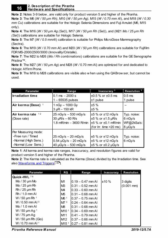
Note 2: Notes 3-9 below , are valid only for product version 5 and higher of the Piranha.
Note 3: The M6 (W / 50 µ m Rh), M10 (W / 50 µ m Ag), M15 (W / 0.70 mm Al), and M18 (W / 0.30
mm Cu) calibrations are suitable for the Hologic Selenia Dimensions and Fuji Amulet (M6, M15
only).
Note 4: The M16 (W / 50 µ m Ag (Sel)), M17 (W / 50 µ m Rh (Sel)), and (M21 Mo / 25 µ m Rh
(Sel)) calibrations are suitable for Hologic Selenia.
Note 5: The M7 (W / 0.5 mmAl) calibration is suitable for Philips MicroDose Mammography
(Sectra).
Note 6: The M19 (W / 0.70 mm Al) and M20 (W / 50 µ m Rh) calibrations are suitable for Fujif ilm
FDR MS-2000/2500/3000 (Innovality/Cristalle).
Note 7: The M22 to M26 (Mo / Rh combinations) calibrations are suitable for the GE Senographe
Pristina™.
Note 8: The M27 (W / 50 µ m Ag) and M28 (W / 0.70 mm Al) are optimized for and dedicated to
Hologic Aff irm Prone.
Note 9: The M18 to M28 calibrations are visible also w hen using the QABrow ser, but cannot be
used.
Parameter Range Inaccuracy 1 Resolution 1
Irradiation time 0.1 ms – 2000 s
1 – 65535 pulses
±0.5 % or ±0.5 ms
±1 pulse
0.5 ms
1 pulse
Air kerma (Dose) 1 1 nGy – 1000 Gy
3 µR – 150 kR
±5 %
±5 %
–
Air kerma rate 1 2
(Dose rate)
25 nGy/s – 530 mGy/s
30 µR/s – 60 R/s
1.8 mR/min – 3600 R/min
±5 % or ±12 nGy/s
±5 % or ±1.5 µR/s
±5 % or ±0.1 mR/min
(for Irr. time >20 ms)
Typ. noise:
6 nGy/s
WF@2kSa/s:
8 µGy/s
Per Measuring mode:
-Free run / Timed
-Normal (High Sens.)
-Normal (Low Sens.)
25 nGy/s – 20 mGy/s
0.54 µGy/s – 20 mGy/s
40 µGy/s – 530 mGy/s
±5 % or ±12 nGy/s
±5 % or ±12 nGy/s
±5 % or ±0.2 µGy/s
Typ. noise:
6 nGy/s
Note 1: All kerma and kerma rate ranges, inaccuracy, and resolution f igures are valid for
product version 5 and higher of the Piranha.
Note 2: The Kerma rate is calculated as the Kerma (Dose) divided by the Irradiation time. See
also Waveforms and Triggers .
Parameter RQ Range Inaccuracy Resolution
Quick-HVL 7 8
Mo / 30 µm Mo
Mo / 25 µm Rh
Rh / 25 µm Rh
Rh / 1.0 mm Al
W / 50 µm Rh 1
W / 0.50 mm Al 3
Mo / 1.0 mm Al
W / 50 µm Ag 1
W / 75 µm Ag
W / 50 µm Rh (Gio)
W / 0.70 mm Al 1
M1
M3
M4
M5
M6 1
M7 3
M8
M10 1
M11
M12
M15 1
0.19 – 0.47 mm Al
0.31 – 0.52 mm Al
0.33 – 0.60 mm Al
0.31 – 0.68 mm Al
0.37 – 0.75 mm Al
0.24 – 0.64 mm Al
0.31 – 0.68 mm Al
0.34 – 0.69 mm Al
0.41 – 0.79 mm Al
0.37 – 0.66 mm Al
0.27 – 0.81 mm Al
±10 % 3 digits
(0.001 mm)
47
2. Description of the PiranhaHardware and Specifications
2019-12/5.7A
17
Piranha Reference M anual
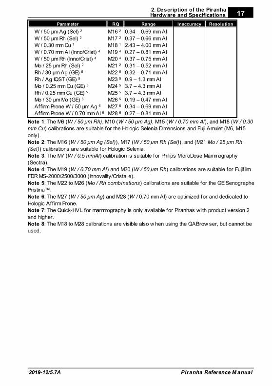
Parameter RQ Range Inaccuracy Resolution
W / 50 µ m Ag (Sel) 2
W / 50 µ m Rh (Sel) 2
W / 0.30 mm Cu 1
W / 0.70 mm Al (Inno/Crist) 4
W / 50 µ m Rh (Inno/Crist) 4
Mo / 25 µ m Rh (Sel) 2
Rh / 30 µm Ag (GE) 5
Rh / Ag IQST (GE) 5
Mo / 0.25 mm Cu (GE) 5
Rh / 0.25 mm Cu (GE) 5
Mo / 30 µm Mo (GE) 5
Affirm Prone W / 50 µm Ag 6
Affirm Prone W / 0.70 mm Al 6
M16 2
M17 2
M18 1
M19 4
M20 4
M21 2
M22 5
M23 5
M24 5
M25 5
M26 5
M27 6
M28 6
0.34 – 0.69 mm Al
0.37 – 0.66 mm Al
2.43 – 4.00 mm Al
0.27 – 0.81 mm Al
0.37 – 0.75 mm Al
0.31 – 0.52 mm Al
0.32 – 0.71 mm Al
0.9 – 1.3 mm Al
3.7 – 4.3 mm Al
3.7 – 4.3 mm Al
0.19 – 0.47 mm Al
0.34 – 0.69 mm Al
0.27 – 0.81 mm Al
Note 1: The M6 (W / 50 µ m Rh), M10 (W / 50 µ m Ag), M15 (W / 0.70 mm Al), and M18 (W / 0.30
mm Cu) calibrations are suitable for the Hologic Selenia Dimensions and Fuji Amulet (M6, M15
only).
Note 2: The M16 (W / 50 µ m Ag (Sel)), M17 (W / 50 µ m Rh (Sel)), and (M21 Mo / 25 µ m Rh
(Sel)) calibrations are suitable for Hologic Selenia.
Note 3: The M7 (W / 0.5 mmAl) calibration is suitable for Philips MicroDose Mammography
(Sectra).
Note 4: The M19 (W / 0.70 mm Al) and M20 (W / 50 µ m Rh) calibrations are suitable for Fujif ilm
FDR MS-2000/2500/3000 (Innovality/Cristalle).
Note 5: The M22 to M26 (Mo / Rh combinations) calibrations are suitable for the GE Senographe
Pristina™.
Note 6: The M27 (W / 50 µ m Ag) and M28 (W / 0.70 mm Al) are optimized for and dedicated to
Hologic Aff irm Prone.
Note 7: The Quick-HVL for mammography is only available for Piranhas w ith product version 2
and higher.
Note 8: The M18 to M28 calibrations are visible also w hen using the QABrow ser, but cannot be
used.
2. Description of the PiranhaHardware and Specifications
Piranha Reference M anual 2019-12/5.7A
18
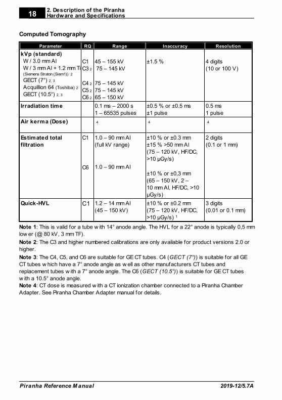
Computed Tomography
Parameter RQ Range Inaccuracy Resolution
kVp (standard)
W / 3.0 mm Al
W / 3 mm Al + 1.2 mm Ti(Siemens Straton (Siem1)) 2
GECT (7°) 2, 3
Acquillion 64 (Toshiba) 2
GECT (10.5°) 2, 3
C1
C3 2
C4 2
C5 2
C6 2
45 – 155 kV
75 – 145 kV
75 – 145 kV
75 – 145 kV
65 – 150 kV
±1.5 % 4 digits
(10 or 100 V)
Irradiation time 0.1 ms – 2000 s
1 – 65535 pulses
±0.5 % or ±0.5 ms
±1 pulse
0.5 ms
1 pulse
Air kerma (Dose) 4 4 4
Estimated total
filtration
C1
C6
1.0 – 90 mm Al
(full kV range)
1.0 – 90 mm Al
±10 % or ±0.3 mm
±15 % >50 mm Al
(75 – 120 kV, HF/DC,
>10 µGy/s)
±10 % or ±0,3 mm
(65 – 150 kV, 2 –
10 mm Al, HF/DC, >10
µGy/s)
2 digits
(0.1 or 1 mm)
Quick-HVL C1 1.2 – 14 mm Al
(45 – 150 kV)
±10 % or ±0.2 mm
(75 – 120 kV, HF/DC,
>10 µGy/s) 1
3 digits
(0.01 or 0.1 mm)
Note 1: This is valid for a tube w ith 14° anode angle. The HVL for a 22° anode is typically 0,5 mm
low er (@ 80 kV, 3 mm TF).
Note 2: The C3 and higher numbered calibrations are only available for product versions 2.0 or
higher.
Note 3: The C4, C5, and C6 are suitable for GE CT tubes. C4 (GECT (7°)) is suitable for all GE
CT tubes w hich have a 7° anode angle as w ell as other manufacturers CT tubes and
replacement tubes w ith a 7° anode angle. The C6 (GECT (10.5°)) is suitable for GE CT tubes
w ith a 10.5° anode angle.
Note 4: CT dose is measured w ith a CT ionization chamber connected to a Piranha Chamber
Adapter. See Piranha Chamber Adapter manual for details.
2. Description of the PiranhaHardware and Specifications
2019-12/5.7A
19
Piranha Reference M anual
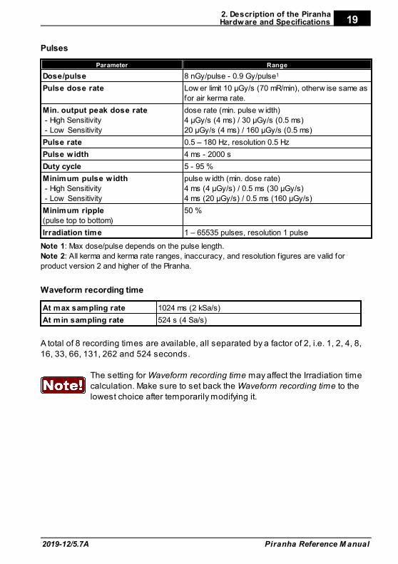
Pulses
Parameter Range
Dose/pulse 8 nGy/pulse - 0.9 Gy/pulse1
Pulse dose rate Low er limit 10 µGy/s (70 mR/min), otherw ise same as
for air kerma rate.
Min. output peak dose rate
- High Sensitivity
- Low Sensitivity
dose rate (min. pulse w idth)
4 µGy/s (4 ms) / 30 µGy/s (0.5 ms)
20 µGy/s (4 ms) / 160 µGy/s (0.5 ms)
Pulse rate 0.5 – 180 Hz, resolution 0.5 Hz
Pulse w idth 4 ms - 2000 s
Duty cycle 5 - 95 %
Minimum pulse w idth
- High Sensitivity
- Low Sensitivity
pulse w idth (min. dose rate)
4 ms (4 µGy/s) / 0.5 ms (30 µGy/s)
4 ms (20 µGy/s) / 0.5 ms (160 µGy/s)
Minimum ripple
(pulse top to bottom)
50 %
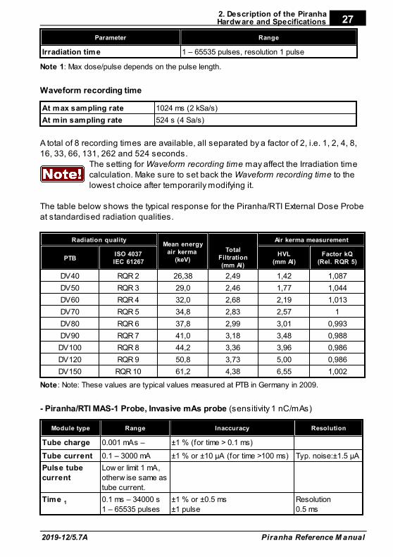
Irradiation time 1 – 65535 pulses, resolution 1 pulse
Note 1: Max dose/pulse depends on the pulse length.
Note 2: All kerma and kerma rate ranges, inaccuracy, and resolution f igures are valid for
product version 2 and higher of the Piranha.
Waveform recording time
At max sampling rate 1024 ms (2 kSa/s)
At min sampling rate 524 s (4 Sa/s)
A total of 8 recording times are available, all separated by a factor of 2, i.e. 1, 2, 4, 8,16, 33, 66, 131, 262 and 524 seconds.
The setting for Waveform recording time may affect the Irradiation timecalculation. Make sure to set back the Waveform recording time to thelowest choice after temporarily modifying it.
2. Description of the PiranhaHardware and Specifications
Piranha Reference M anual 2019-12/5.7A
20
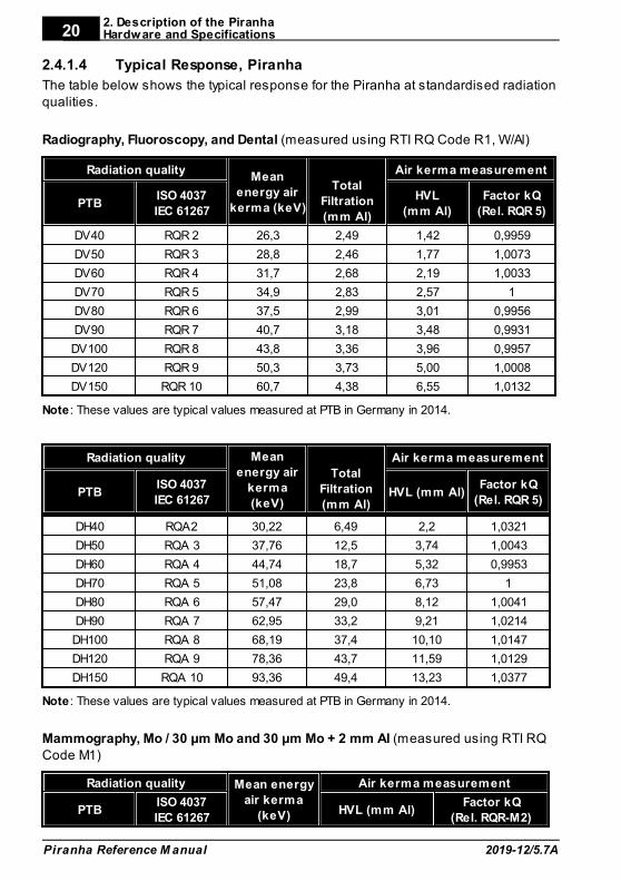
2.4.1.4 Typical Response, Piranha
The table below shows the typical response for the Piranha at standardised radiationqualities.
Radiography, Fluoroscopy, and Dental (measured using RTI RQ Code R1, W/Al)
Radiation qualityMean
energy air
kerma (keV)
Total
Filtration
(mm Al)
Air kerma measurement
PTBISO 4037
IEC 61267
HVL
(mm Al)
Factor kQ
(Rel. RQR 5)
DV40 RQR 2 26,3 2,49 1,42 0,9959
DV50 RQR 3 28,8 2,46 1,77 1,0073
DV60 RQR 4 31,7 2,68 2,19 1,0033
DV70 RQR 5 34,9 2,83 2,57 1
DV80 RQR 6 37,5 2,99 3,01 0,9956
DV90 RQR 7 40,7 3,18 3,48 0,9931
DV100 RQR 8 43,8 3,36 3,96 0,9957
DV120 RQR 9 50,3 3,73 5,00 1,0008
DV150 RQR 10 60,7 4,38 6,55 1,0132
Note: These values are typical values measured at PTB in Germany in 2014.
Radiation quality Mean
energy air
kerma
(keV)
Total
Filtration
(mm Al)
Air kerma measurement
PTBISO 4037
IEC 61267HVL (mm Al)
Factor kQ
(Rel. RQR 5)
DH40 RQA2 30,22 6,49 2,2 1,0321
DH50 RQA 3 37,76 12,5 3,74 1,0043
DH60 RQA 4 44,74 18,7 5,32 0,9953
DH70 RQA 5 51,08 23,8 6,73 1
DH80 RQA 6 57,47 29,0 8,12 1,0041
DH90 RQA 7 62,95 33,2 9,21 1,0214
DH100 RQA 8 68,19 37,4 10,10 1,0147
DH120 RQA 9 78,36 43,7 11,59 1,0129
DH150 RQA 10 93,36 49,4 13,23 1,0377
Note: These values are typical values measured at PTB in Germany in 2014.
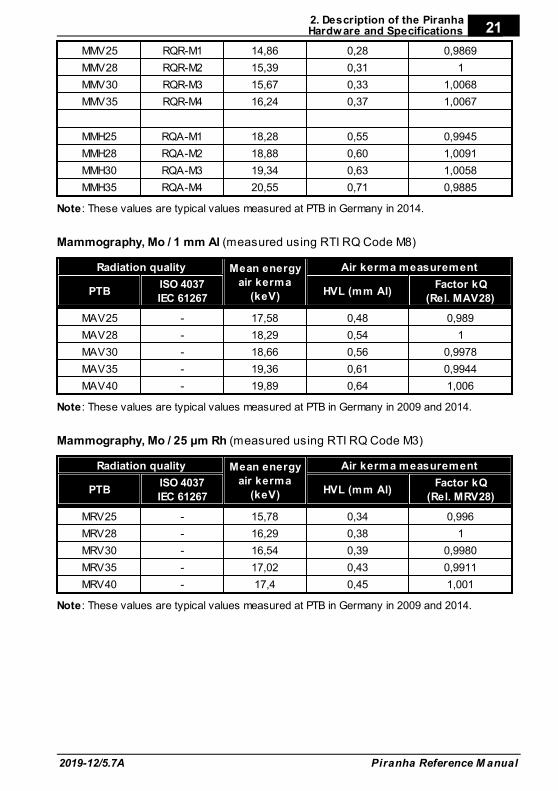
Mammography, Mo / 30 µm Mo and 30 µm Mo + 2 mm Al (measured using RTI RQCode M1)
Radiation quality Mean energy
air kerma
(keV)
Air kerma measurement
PTBISO 4037
IEC 61267HVL (mm Al)
Factor kQ
(Rel. RQR-M2)
2. Description of the PiranhaHardware and Specifications
2019-12/5.7A
21
Piranha Reference M anual
MMV25 RQR-M1 14,86 0,28 0,9869
MMV28 RQR-M2 15,39 0,31 1
MMV30 RQR-M3 15,67 0,33 1,0068
MMV35 RQR-M4 16,24 0,37 1,0067
MMH25 RQA-M1 18,28 0,55 0,9945
MMH28 RQA-M2 18,88 0,60 1,0091
MMH30 RQA-M3 19,34 0,63 1,0058
MMH35 RQA-M4 20,55 0,71 0,9885
Note: These values are typical values measured at PTB in Germany in 2014.
Mammography, Mo / 1 mm Al (measured using RTI RQ Code M8)
Radiation quality Mean energy
air kerma
(keV)
Air kerma measurement
PTBISO 4037
IEC 61267HVL (mm Al)
Factor kQ
(Rel. MAV28)
MAV25 - 17,58 0,48 0,989
MAV28 - 18,29 0,54 1
MAV30 - 18,66 0,56 0,9978
MAV35 - 19,36 0,61 0,9944
MAV40 - 19,89 0,64 1,006
Note: These values are typical values measured at PTB in Germany in 2009 and 2014.
Mammography, Mo / 25 µm Rh (measured using RTI RQ Code M3)
Radiation quality Mean energy
air kerma
(keV)
Air kerma measurement
PTBISO 4037
IEC 61267HVL (mm Al)
Factor kQ
(Rel. MRV28)
MRV25 - 15,78 0,34 0,996
MRV28 - 16,29 0,38 1
MRV30 - 16,54 0,39 0,9980
MRV35 - 17,02 0,43 0,9911
MRV40 - 17,4 0,45 1,001
Note: These values are typical values measured at PTB in Germany in 2009 and 2014.
2. Description of the PiranhaHardware and Specifications
Piranha Reference M anual 2019-12/5.7A
22
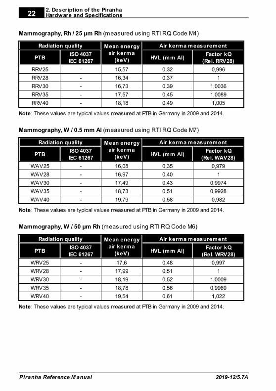
Mammography, Rh / 25 µm Rh (measured using RTI RQ Code M4)
Radiation quality Mean energy
air kerma
(keV)
Air kerma measurement
PTBISO 4037
IEC 61267HVL (mm Al)
Factor kQ
(Rel. RRV28)
RRV25 - 15,57 0,32 0,996
RRV28 - 16,34 0,37 1
RRV30 - 16,73 0,39 1,0036
RRV35 - 17,57 0,45 1,0089
RRV40 - 18,18 0,49 1,005
Note: These values are typical values measured at PTB in Germany in 2009 and 2014.
Mammography, W / 0.5 mm Al (measured using RTI RQ Code M7)
Radiation quality Mean energy
air kerma
(keV)
Air kerma measurement
PTBISO 4037
IEC 61267HVL (mm Al)
Factor kQ
(Rel. WAV28)
WAV25 - 16,08 0,35 0,979
WAV28 - 16,97 0,40 1
WAV30 - 17,49 0,43 0,9974
WAV35 - 18,73 0,51 0,9928
WAV40 - 19,79 0,58 0,982
Note: These values are typical values measured at PTB in Germany in 2009 and 2014.
Mammography, W / 50 µm Rh (measured using RTI RQ Code M6)
Radiation quality Mean energy
air kerma
(keV)
Air kerma measurement
PTBISO 4037
IEC 61267HVL (mm Al)
Factor kQ
(Rel. WRV28)
WRV25 - 17,6 0,48 0,997
WRV28 - 17,99 0,51 1
WRV30 - 18,19 0,52 1,0009
WRV35 - 18,78 0,56 0,9969
WRV40 - 19,54 0,61 1,022
Note: These values are typical values measured at PTB in Germany in 2009 and 2014.
2. Description of the PiranhaHardware and Specifications
2019-12/5.7A
23
Piranha Reference M anual
Mammography, W / 50 µm Ag (measured using RTI RQ Code M10)
Radiation quality Mean energy
air kerma
(keV)
Air kerma measurement
PTBISO 4037
IEC 61267HVL (mm Al)
Factor kQ
(Rel. WSV28)
WSV25 - 17,87 0,50 0,991
WSV28 - 18,66 0,56 1
WSV30 - 18,92 0,58 0,9983
WSV35 - 19,57 0,63 0,9963
WSV40 - 20,22 0,68 1,015
Note: These values are typical values measured at PTB in Germany in 2009 and 2014.
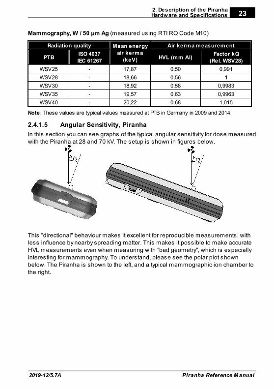
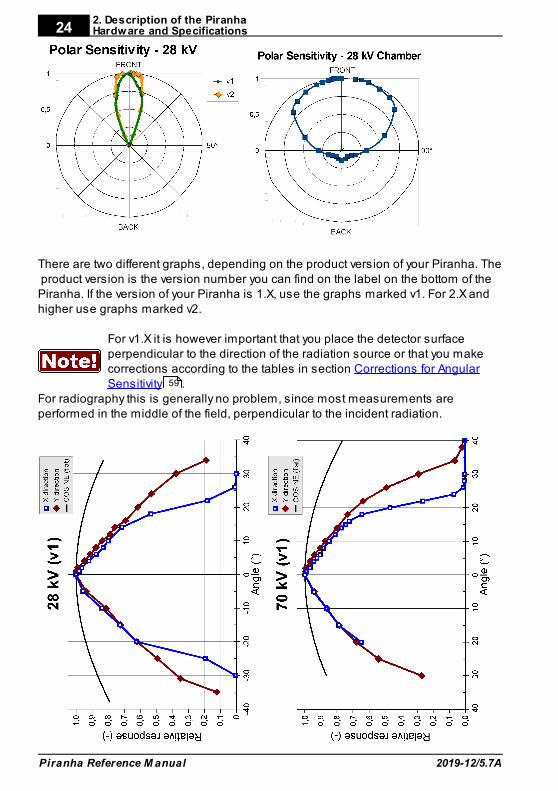
2.4.1.5 Angular Sensitivity, Piranha
In this section you can see graphs of the typical angular sensitivity for dose measuredwith the Piranha at 28 and 70 kV. The setup is shown in figures below.
This "directional" behaviour makes it excellent for reproducible measurements, withless influence by nearby spreading matter. This makes it possible to make accurateHVL measurements even when measuring with "bad geometry", which is especiallyinteresting for mammography. To understand, please see the polar plot shownbelow. The Piranha is shown to the left, and a typical mammographic ion chamber tothe right.
2. Description of the PiranhaHardware and Specifications
Piranha Reference M anual 2019-12/5.7A
24
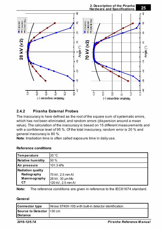
There are two different graphs, depending on the product version of your Piranha. The product version is the version number you can find on the label on the bottom of thePiranha. If the version of your Piranha is 1.X, use the graphs marked v1. For 2.X andhigher use graphs marked v2.
For v1.X it is however important that you place the detector surfaceperpendicular to the direction of the radiation source or that you makecorrections according to the tables in section Corrections for AngularSensitivity .
For radiography this is generally no problem, since most measurements areperformed in the middle of the field, perpendicular to the incident radiation.
59
2. Description of the PiranhaHardware and Specifications
2019-12/5.7A
25
Piranha Reference M anual
2.4.2 Piranha External Probes
The inaccuracy is here defined as the root of the square sum of systematic errors,which has not been eliminated, and random errors (dispersion around a meanvalue). The calculation of the inaccuracy is based on 15 different measurements andwith a confidence level of 95 %. Of the total inaccuracy, random error is 20 % andgeneral inaccuracy is 80 %.Note: Irradiation time is often called exposure time in daily use.
Reference conditions
Temperature 20 °C
Relative humidity 50 %
Air pressure 101.3 kPa
Radiation quality
Radiography
Mammography
CT
70 kV, 2.5 mm Al
28 kV, 30 µm Mo
120 kV, 2.5 mm Al
Note: The reference conditions are given in reference to the IEC61674 standard.
General
Connector type Hirose ST40X-10S w ith built-in detector identif ication.
Source to Detector
Distance
>30 cm
2. Description of the PiranhaHardware and Specifications
Piranha Reference M anual 2019-12/5.7A
26
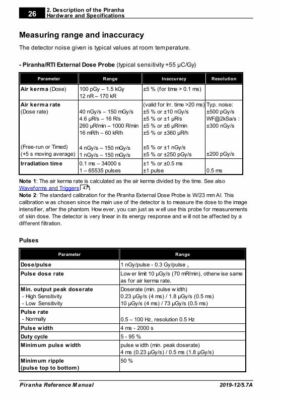
Measuring range and inaccuracy
The detector noise given is typical values at room temperature.
- Piranha/RTI External Dose Probe (typical sensitivity +55 µC/Gy)
Parameter Range Inaccuracy Resolution
Air kerma (Dose) 100 pGy – 1.5 kGy
12 nR – 170 kR
±5 % (for time > 0.1 ms)
Air kerma rate
(Dose rate)
(Free-run or Timed)
(+5 s moving average)
40 nGy/s – 150 mGy/s
4.6 µR/s – 16 R/s
260 µR/min – 1000 R/min
16 mR/h – 60 kR/h
4 nGy/s – 150 mGy/s
1 nGy/s – 150 mGy/s
(valid for Irr. time >20 ms)
±5 % or ±10 nGy/s
±5 % or ±1 µR/s
±5 % or ±6 µR/min
±5 % or ±360 µR/h
±5 % or ±1 nGy/s
±5 % or ±250 pGy/s
Typ. noise:
±500 pGy/s
WF@2kSa/s :
±300 nGy/s
±200 pGy/s
Irradiation time 0.1 ms – 34000 s
1 – 65535 pulses
±1 % or ±0.5 ms
±1 pulse
0.5 ms
Note 1: The air kerma rate is calculated as the air kerma divided by the time. See also
Waveforms and Triggers .
Note 2: The standard calibration for the Piranha External Dose Probe is W/23 mm Al. This
calibration w as chosen since the main use of the detector is to measure the dose to the image
intensif ier, after the phantom. How ever, you can just as w ell use this probe for measurements
of skin dose. The detector is very linear in its energy response and w ill not be affected by a
different f iltration.
Pulses
Parameter Range
Dose/pulse 1 nGy/pulse - 0.3 Gy/pulse 1
Pulse dose rate Low er limit 10 µGy/s (70 mR/min), otherw ise same
as for air kerma rate.
Min. output peak doserate
- High Sensitivity
- Low Sensitivity
Doserate (min. pulse w idth)
0.23 µGy/s (4 ms) / 1.8 µGy/s (0.5 ms)
10 µGy/s (4 ms) / 73 µGy/s (0.5 ms)
Pulse rate
- Normally 0.5 – 100 Hz, resolution 0.5 Hz
Pulse w idth 4 ms - 2000 s
Duty cycle 5 - 95 %
Minimum pulse w idth pulse w idth (min. peak doserate)
4 ms (0.23 µGy/s) / 0.5 ms (1.8 µGy/s)
Minimum ripple
(pulse top to bottom)
50 %
47
2. Description of the PiranhaHardware and Specifications
2019-12/5.7A
27
Piranha Reference M anual
Parameter Range
Irradiation time 1 – 65535 pulses, resolution 1 pulse
Note 1: Max dose/pulse depends on the pulse length.
Waveform recording time
At max sampling rate 1024 ms (2 kSa/s)
At min sampling rate 524 s (4 Sa/s)
A total of 8 recording times are available, all separated by a factor of 2, i.e. 1, 2, 4, 8,16, 33, 66, 131, 262 and 524 seconds.
The setting for Waveform recording time may affect the Irradiation timecalculation. Make sure to set back the Waveform recording time to thelowest choice after temporarily modifying it.
The table below shows the typical response for the Piranha/RTI External Dose Probeat standardised radiation qualities.
Radiation qualityMean energy
air kerma (keV)
TotalFiltration(mm Al)
Air kerma measurement
PTBISO 4037IEC 61267
HVL(mm Al)
Factor kQ(Rel. RQR 5)
DV40 RQR 2 26,38 2,49 1,42 1,087
DV50 RQR 3 29,0 2,46 1,77 1,044
DV60 RQR 4 32,0 2,68 2,19 1,013
DV70 RQR 5 34,8 2,83 2,57 1
DV80 RQR 6 37,8 2,99 3,01 0,993
DV90 RQR 7 41,0 3,18 3,48 0,988
DV100 RQR 8 44,2 3,36 3,96 0,986
DV120 RQR 9 50,8 3,73 5,00 0,986
DV150 RQR 10 61,2 4,38 6,55 1,002
Note: Note: These values are typical values measured at PTB in Germany in 2009.
- Piranha/RTI MAS-1 Probe, Invasive mAs probe (sensitivity 1 nC/mAs)
Module type Range Inaccuracy Resolution
Tube charge 0.001 mAs – ±1 % (for time > 0.1 ms)
Tube current 0.1 – 3000 mA ±1 % or ±10 µA (for time >100 ms) Typ. noise:±1.5 µA
Pulse tube
current
Low er limit 1 mA,
otherw ise same as
tube current.
Time 1 0.1 ms – 34000 s
1 – 65535 pulses
±1 % or ±0.5 ms
±1 pulse
Resolution
0.5 ms
2. Description of the PiranhaHardware and Specifications
Piranha Reference M anual 2019-12/5.7A
28
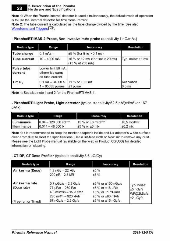
Note 1: When the Piranha internal detector is used simultaneously, the default mode of operation
is to use the internal detector for time measurement.
Note 2: The tube current is calculated as the tube charge divided by the time. See also
Waveforms and Triggers .
- Piranha/RTI MAS-2 Probe, Non-invasive mAs probe (sensitivity 1 nC/mAs)
Module type Range Inaccuracy Resolution
Tube charge 0.1 mAs – ±5 % (for time > 0.1 ms)
Tube current 10 – 4000 mA ±5 % or ±2 mA (for time > 20 ms)
(±3 % at 250 mA)
Typ. noise: ±1 mA
Pulse tube
current
Low er limit 50 mA,
otherw ise same
as tube current.
Time 1 0.1 ms – 34000 s
1 – 65535 pulses
±1 % or ±0.5 ms
±1 pulse
Resolution
0.5 ms
Note 1: See also note 1 and 2 for the Piranha/RTI MAS-1.
- Piranha/RTI Light Probe, Light detector (typical sensitivity 62.5 pA/(cd/m²) or 167pA/lx)
Module type Range Inaccuracy Resolution
Luminance
Illuminance
0.04 – 128 000 cd/m²
0.014 – 48 000 lx
±5 % or ±8 mcd/m²
±5 % or ±3 mlx
±0,5 mcd/m²
±0.2 mlx
Note 1: It is recommended to keep the monitor adapter's inside and lux adapter's w hite surface
clean from dust to meet the specif ications. Use a lint-free cloth or blow air to remove any dust.
Please see the Light Probe manual (available on the w eb or Product CD/USB) for detailed
information on cleaning.
- CT-DP, CT Dose Profiler (typical sensitivity 3.6 µC/Gy)
Module type Range Inaccuracy Resolution
Air kerma (Dose)
Air kerma rate
(Dose rate)
(Free-run or Timed)
1,8 nGy – 22 kGy
200 nR – 2.5 MR
0.7 µGy/s – 2.2 Gy/s
77 µR/s – 260 R/s
4.6 mR/min – 15 kR/min
280 mR/h – 920 kR/h
67 nGy/s – 2.2 Gy/s
±5 %
±5 %
±5 % or ±150 nGy/s
±5 % or ±16 µR/s
±5 % or ±1 mR/min
±5 % or ±60 mR/h
±5 % or ±15 nGy/s
Typ. noise:
±5 nGy/s
WF@2kSa/s:
±2 µGy/s
47

2. Description of the PiranhaStandards and Compliances
2019-12/5.7A
29
Piranha Reference M anual
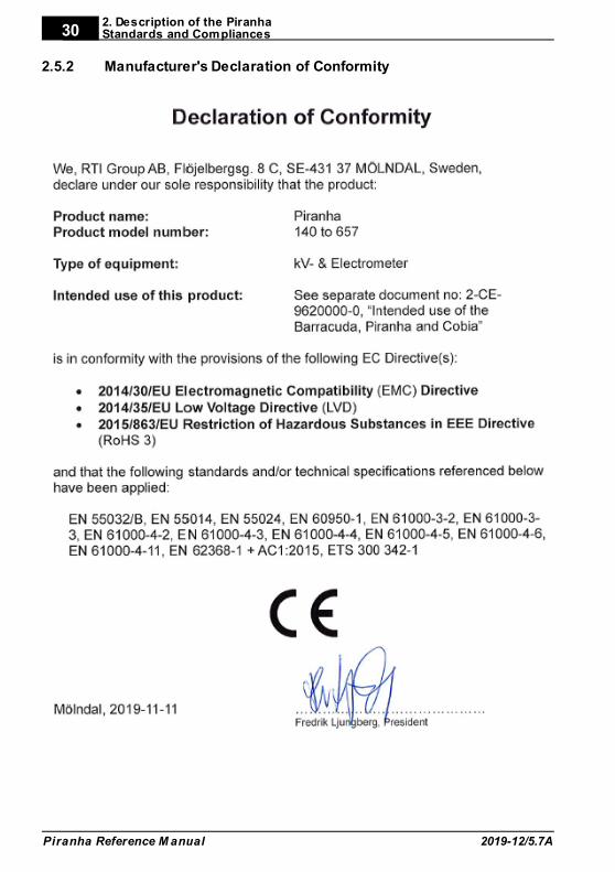
Standards and Compliances2.5
Hereafter you can find declarations of conformity for the Piranha system.
2.5.1 Waste Electrical and Electronic Equipment (WEEE)
The European Union Directive 2002/96/EC on Waste from Electrical and ElectronicEquipment (WEEE) places an obligation on manufacturers, distributors, and retailersto take back electronics products at the end of their useful life.The WEEE directive covers all RTI products being sold into the European Union (EU)as of August 13, 2005. Manufacturers, distributors, and retailers are obliged to financethe cost of recovery from municipal collection points, reuse, and recycling of specifiedpercentages per the WEEE requirements.
Instructions for disposal of WEEE by Users in the European Union
The symbol, shown left, is marked on the product, which indicates thatthis product must not be disposed of with other waste. Instead, it is theuser's responsibility to dispose of the user's waste equipment by handingit over to a designated collection point for the recycling of waste electricaland electronic equipment. The separate collection and recycling of wasteequipment at the time of disposal will help to conserve
natural resources and ensure that it is recycled in a manner that protects humanhealth and the environment. For more information about where you can drop off yourwaste equipment for recycling, please contact your local distributor from whom youpurchased the product.
2. Description of the PiranhaStandards and Compliances
Piranha Reference M anual 2019-12/5.7A
30
2.5.2 Manufacturer's Declaration of Conformity
2. Description of the PiranhaStandards and Compliances
2019-12/5.7A
31
Piranha Reference M anual
2.5.3 FCC Certification
Piranhas of product version 3.1 and newer contains FCC certified transmitter module(Bluetooth).
FCC ID R47F2M03GXThis device has been tested and found to comply with the limits for a Class-B digitaldevice, pursuant to part 15 of the FCC rules. These limits are designed to providereasonable protection against harmful interference when the equipment is operatedin commercial environment. This equipment generates, uses and can radiate radiofrequency energy and, if not installed and used according with the instruction manual,may cause harmful interference to radio communication. Operation of this equipmentin a residential area is likely to cause harmful interference, in which case the user willbe required to correct the interference at his own expense.
Maintenance2.6
2.6.1 Updating the Piranha Firmware
All firmware that is controlling the function of the Piranha is stored in flash memory toallow quick and easy update. The RTI Updater with the latest firmware is alwaysavailable free of charge on the RTI Web site at http://www.rtigroup.com. To updateyour Piranha you must first download the latest version and install it on a PC. The PCneeds to have an USB port.
You will need to have access to an administrative account to install the software.To update the Piranha firmware (or bootloader):
1. First download the latest version of the RTI Updater Setup from RTI Web site(http://www.rtigroup.com).
2. Unzip the file and run the file "RTI Updater Setup.exe" to install it on your PC. In theend of the installation process you will get the question if you want to run thatupdater immediately. If you have your Piranha available you can connect it asdescribed in step #3. Answer "Yes" and continue with step #6.
3. Connect the Piranha. Use the USB cable that came with your Piranha to connectyour Piranha to one of the USB ports on the PC. Power on the Piranha. Use thepower supply to ensure that no power failure occur during the update process. Ifyou do not have a power supply available, make sure you have fresh batteries inthe Piranha. You will get a notice about that.
2. Description of the PiranhaMaintenance
Piranha Reference M anual 2019-12/5.7A
32
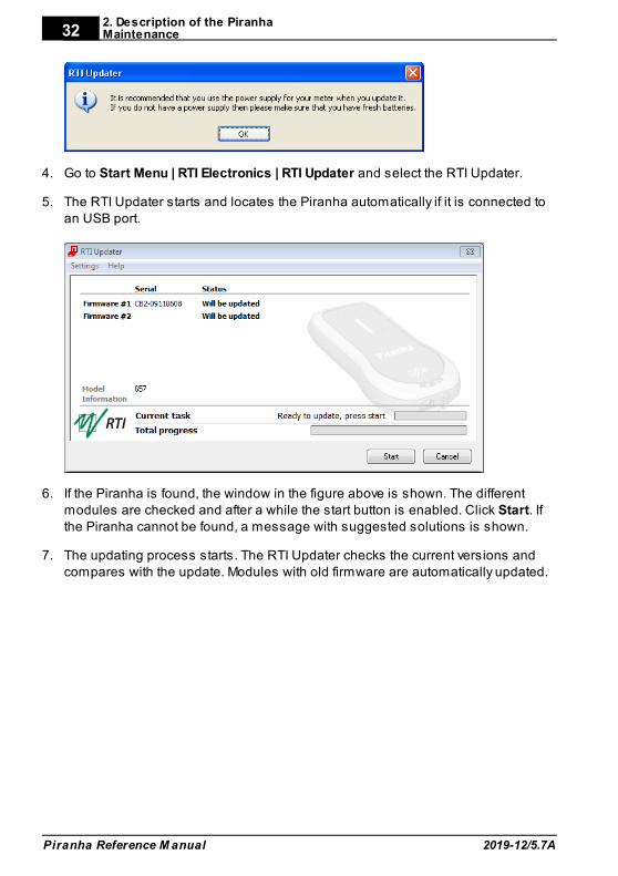
4. Go to Start Menu | RTI Electronics | RTI Updater and select the RTI Updater.
5. The RTI Updater starts and locates the Piranha automatically if it is connected toan USB port.
6. If the Piranha is found, the window in the figure above is shown. The differentmodules are checked and after a while the start button is enabled. Click Start. Ifthe Piranha cannot be found, a message with suggested solutions is shown.
7. The updating process starts. The RTI Updater checks the current versions andcompares with the update. Modules with old firmware are automatically updated.
2. Description of the PiranhaMaintenance
2019-12/5.7A
33
Piranha Reference M anual
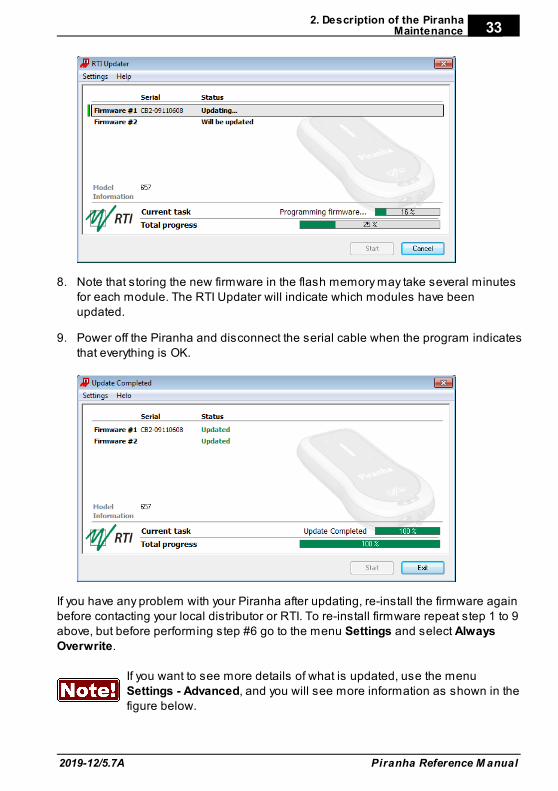
8. Note that storing the new firmware in the flash memory may take several minutesfor each module. The RTI Updater will indicate which modules have beenupdated.
9. Power off the Piranha and disconnect the serial cable when the program indicatesthat everything is OK.
If you have any problem with your Piranha after updating, re-install the firmware againbefore contacting your local distributor or RTI. To re-install firmware repeat step 1 to 9above, but before performing step #6 go to the menu Settings and select AlwaysOverwrite.
If you want to see more details of what is updated, use the menuSettings - Advanced, and you will see more information as shown in thefigure below.
2. Description of the PiranhaMaintenance
Piranha Reference M anual 2019-12/5.7A
34
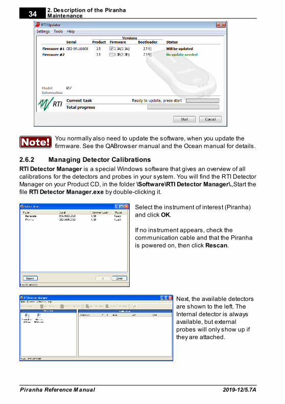
You normally also need to update the software, when you update thefirmware. See the QABrowser manual and the Ocean manual for details.
2.6.2 Managing Detector Calibrations
RTI Detector Manager is a special Windows software that gives an overview of allcalibrations for the detectors and probes in your system. You will find the RTI DetectorManager on your Product CD, in the folder \Software\RTI Detector Manager\.,Start thefile RTI Detector Manager.exe by double-clicking it.
Select the instrument of interest (Piranha)and click OK.
If no instrument appears, check thecommunication cable and that the Piranhais powered on, then click Rescan.
Next, the available detectorsare shown to the left. TheInternal detector is alwaysavailable, but externalprobes will only show up ifthey are attached.
2. Description of the PiranhaMaintenance
2019-12/5.7A
35
Piranha Reference M anual
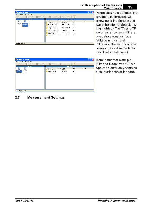
When clicking a detector, theavailable calibrations willshow up to the right (In thiscase the Internal detector ishighlighted). The TV and TFcolumns show an × if thereare calibrations for TubeVoltage and/or TotalFiltration. The factor columnshows the calibration factor(for dose in this case).
Here is another example(Piranha Dose Probe). This type of detector only containsa calibration factor for dose.
Measurement Settings2.7
2. Description of the PiranhaMeasurement Settings
Piranha Reference M anual 2019-12/5.7A
36
2.7.1 Settings - Conditions
Here general conditions for the measurements are shown. Different values can beshown depending on selected measured parameter.
Conditions - TF and Waveform
Total Filtr. Shows actual total filtration value. Estimate means that a newestimation will be performed at next exposure and the values will bedisplayed on screen.
Waveform The waveform types supported are: - DC/HF - Single Phase - 3-Phase 6-Pulse - 3-Phase 12-Pulse - AMX-4 - Pulsed
In Ocean using Quick-Check you need to select thegenerator waveform type for each measurement session. Default isHF/Constant potential.
AMX-4
The difficulties when measuring tube voltage on a GE AMX-4 is a well-knownproblem. Due to high kV ripple at a frequency of 2 kHz it is hard for most non-invasivekVp-meters to follow the kV waveform correctly.
This waveform type has an agreement with measurements made with the KeithleyTriad System 37946C mobile filter pack (50-135 kV), which is the only filter packagerecommended by GE. According to GE, the use of the standard Keithley 37617C W-Rfilter pack (50-150 kV) is not good enough. The results have further been verified withmeasurements with a traceable high voltage divider that has sufficient bandwidth toaccurately follow the kV ripple from the AMX-4.Therefore it is important to select the AMX-4 waveform (underMeter Settings).More about the AMX-4 correction can be found in the Application Note 1-AN-52020-1from RTI Group AB.
2. Description of the PiranhaMeasurement Settings
2019-12/5.7A
37
Piranha Reference M anual
PulsedThis waveform type should be used for pulsed fluoroscopy especially when thepulses do not have a "good" square waveform shape. The exposure time must belonger than the selected recording time when using this waveform type. (Pulsedwaveform type is selected under Settings | Conditions in the same way as the AMX-4waveform type.)
Conditions - TP-factor
If an ion chamber is used, temperature and pressure can be specified to get correctdose measurements.
The Internal detector and other semiconductor detectors are virtually notaffected by temperature and pressure.
The TP Factor is calculated as follows:
TP = P0/P × T/T
0
where: P0 and T0 are the reference air pressure and absolute air temperature
(normally P0=101.3 kPa and T0=293 K [20 °C])
T and P are the actual absolute air temperature and pressure in the sameunits (kPa and K)
Temperature This value is used to calculate the TP-factor when ion chambersare used. Temperature can be specified in Kelvin, degreesCelsius, or degrees Fahrenheit. Unit is chosen in Ocean underOptions | Default Units.
Pressure This value is used to calculate the TP-factor when ion chambersare used. Air pressure can be specified in several different units.Unit is chosen in Ocean under Options | Default Units.
Please note that the pressure easily changes by 10 %. For the same effect fromtemperature, it must change 30 °C (or 54 °F).
Pulse rate
If a pulsed mode is used, like pulsed fluoroscopy or pulsed radiography (cine) thepulse rate can be specified in pulses per second (same as Hz). This allows you toget a dose/pulse reading even if the detector used (e.g. ion chamber) is too slow forthe Piranha electrometer to detect the pulses. A solid-state detector, like the PiranhaDose Probe, is however fast enough to detect the frequency even for very low-levelsignals.
2. Description of the PiranhaMeasurement Settings
Piranha Reference M anual 2019-12/5.7A
38
Compression paddle
For mammography, it is sometimes easier to do measurements with thecompression paddle in the field. The compression paddle will however affect thePiranha kV and dose reading. With this setting, all the measured values (kV, doseand HVL) will be corrected according to what the user has selected.When selected you will see the settings for Scatter factor and Equivalent thickness.The thickness is given in "mm Al". If you do not know, ask the manufacturer or make acomparison with Aluminium filters.
Scatter factor If an ion chamber is positioned just below the compressionpaddle, the measured dose will rise, because of side scatteringfrom the compression paddle material. The effect of this isdepending on the ion chambers angular dependence. Since thePiranha is almost insensitive to this, you can put a number hereto compare readings from the Piranha with readings from an ionchamber. See also section Average Glandular Dose, AGD(MGD) .
Equiv. thickness The given equivalent compression paddle thickness is used toincrease the accuracy of dose measurements when dose ismeasured below the compression paddle. It is given inequivalent thickness of aluminium.
This feature can also be used if you have additionalfiltration in the beam. Add the equivalent thickness of aluminium.
Beam Correction Sometimes you may want to make comparable measurementswith known mechanical setup. For instance if you want toemulate ion chamber measurements in a particular scatteringsituation. Then you can set a Beam Correction factor to get thatreading. In this case the ion chamber measures an extra 25 %from side and back-scatter. Using this factor makes the readingsto be the same. It is of course important that the mechanicalsetup in these cases are the same.
2.7.2 Settings - Piranha
Here general measurement settings for the Piranha are shown.
Post Delay The post delay time defines how long time the Piranha shall waitand "look for more" after detecting what can be considered to be"the end of the exposure". Default value is 250 ms. The post-delay is necessary when measuring on units with some kind ofpre-pulse or for pulsed exposures.
60
2. Description of the PiranhaMeasurement Settings
2019-12/5.7A
39
Piranha Reference M anual
Trig source This setting makes it possible to define the trig source for theelectrometer module. Available settings are:
· Individually, each detector starts to measure individuallywhen it detects a signal.
· Internal detector, the measurement of all parameters (allmodules) start when the Internal detector starts to measure.
Default value is always Internal detector when it is used. This isthe recommended trig source.
In Ocean Quick-Check this setting is not available.
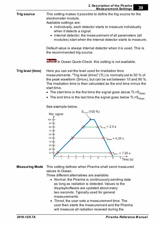
Trig level (time) Here you can set the level used for irradiation timemeasurements. "Trig level (time)" (TL) is normally set to 50 % ofthe peak waveform (SPEAK), but can be set between 10 and 90 %.The irradiation time is then calculated as the end time minus thestart time. · The start time is the first time the signal goes above TL×SPEAK.
· The end time is the last time the signal goes below TL×SPEAK.
See example below.
Measuring Mode This setting defines when Piranha shall send measuredvalues to Ocean. Three different alternatives are available:
· Normal, the Piranha is continuously sending dataas long as radiation is detected. Values to thedisplay/software are updated about everytwo seconds. Typically used for generalmeasurements.
· Timed, the user sets a measurement time. Theuser then starts the measurement and the Piranhawill measure all radiation received during the
2. Description of the PiranhaMeasurement Settings
Piranha Reference M anual 2019-12/5.7A
40
measurement time, without any trig levels. Whenthe time has passed, a reading will be presented.
· Free run, the Piranha will continuously measure theradiation without any trig levels.
Default value is set according to selected type ofmeasurement and this parameter normally never needsto be manually changed, unless really low-levelmeasurements are to be accomplished.
Waveformrec. time
The Piranha can sample a maximum of 2048 samples.Ocean supports the full depth, but the QABrowser is onlyable to show a total of 640 samples. The samplinginterval is normally 0.5 ms, giving a total measurementwindow of 1024 ms in Ocean and 320 ms when usingthe QABrowser. By increasing the sampling interval, amuch longer sampling window can however beselected. This is very handy when longer exposure timesare used and the waveforms need to be viewed.
Start after delay When this is selected, the waveform recoding will startafter the set delay. This can be useful if you want to studya phenomenon that occurs after the normal waveformrecording time. When this is selected the electrometerwaveform will not show simultaneously and you will geta warning that the irradiation time measurement isinaccurate. The reason for this is that the Piranha needsthe waveform from start to be able to accurately calculatethe irradiation time.
2.7.3 Settings - Internal detector
Here general measurement settings for the Internal detector are shown. You can findinformation about the different parameters below.
SensitivityDose/TF
This is used to set the dose and TF sensitivity for the Internaldetector. The sensitivity can be set to: Low, High, and Very High.
Sensitivity kV This is used to set the kV sensitivity for the Internal detector.The sensitivity can be set to: Low and High.
Delay The delay time defines how long time the Piranha shall wait beforestarting to measure kVp after that radiation has been detected.
Window This gives the possibility to define a fixed time that Piranhameasures kVp after that the delay time has expired. Default value isalways "Infinite".
2. Description of the PiranhaMeasurement Settings
2019-12/5.7A
41
Piranha Reference M anual
2.7.4 Settings - Other Detectors
Sensitivity This is used to set the sensitivity for the electrometer module. Thesensitivity can be set to: Low and High.
Threshold This is used to set the trig level. It can be set to Low (½×), Normal,2×, 4×, and 8×. The default value is "Normal". The setting "Low" canbe used if low signals are measured and a lower trig level isrequired. However, the risk for false triggering increases when "Low"is used. To avoid false triggering in a noisy environment use one ofthe "higher" threshold levels.
In Ocean Quick-Check this setting is not available.
Normalizedexposure
Note: Only for dose detectors!If Normalized exposure is checked, you have the option to normalizethe dose reading to any given distance. Here you can enter yourSource to Detector Distance (SDD) and a normalizing distance (SDDNorm), that you want the dose normalized to.

Measurement Principles &Theory
Chapter 3
3. Measurement Principles & Theory
2019-12/5.7A
43
Piranha Reference M anual
3 Measurement Principles & Theory
The Ocean software has a number of measurement algorithms and applicationsbuilt-in. This section describes some about the principles, how some values arecalculated, and the basic use of such measurements.
Overview of Capability for Measurement Modes3.1
The following graph shows an overview of some common capabilities the different X-ray measurement types have in the Piranha.
Modality Estimated TF Quick-HVL
Radiography OK OK
Cine/Pulsed exposure OK OK
Fluoroscopy OK OK
Pulsed Fluoroscopy OK OK
Mammography – OK
CT OK OK
Dental OK OK
Panoramic Dental (OPG) OK OK
Update Modes3.2
The following three update modes are available:· Normal, the Piranha is continuously sending data as long as radiation is
detected. Displays in the PC are updated about every seconds. Typically used formost circumstances. Reset time is one second.
· Timed, the user sets a measurement time. The user then starts themeasurement and the Piranha will measure all radiation received during themeasurement time, without any trig levels or background compensation. Whenthe time has passed, a reading will be presented. It has a long reset time forincreased accuracy, which varies with the sensitivity, as seen in the table below.
· Free run, the Piranha will continuously measure the radiation without any triglevels or background compensations. No applications are available when usingthis mode. The mode has a feature called moving average which calculates theaverage of the measured values during a defined time, to increase accuracy bylowering the time resolution. This function gives a larger stability to themeasurements. Free run also has a long reset time for increased accuracy, seethe table below.
Default value is set according to selected type of measurement and this parameternormally never needs to be manually changed, unless really low-level measurementsare to be accomplished.However, to measure on real low-level signals the Timed or Free run update modemay be used.
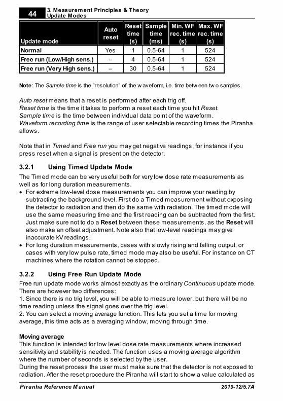
3. Measurement Principles & TheoryUpdate Modes
Piranha Reference M anual 2019-12/5.7A
44
Update mode
Autoreset
Resettime(s)
Sampletime(ms)
Min. WFrec. time
(s)
Max. WFrec. time
(s)
Normal Yes 1 0.5-64 1 524
Free run (Low/High sens.) – 4 0.5-64 1 524
Free run (Very High sens.) – 30 0.5-64 1 524
Note: The Sample time is the "resolution" of the w aveform, i.e. time betw een tw o samples.
Auto reset means that a reset is performed after each trig off.Reset time is the time it takes to perform a reset each time you hit Reset.Sample time is the time between individual data point of the waveform.Waveform recording time is the range of user selectable recording times the Piranhaallows.
Note that in Timed and Free run you may get negative readings, for instance if youpress reset when a signal is present on the detector.
3.2.1 Using Timed Update Mode
The Timed mode can be very useful both for very low dose rate measurements aswell as for long duration measurements.· For extreme low-level dose measurements you can improve your reading by
subtracting the background level. First do a Timed measurement without exposingthe detector to radiation and then do the same with radiation. The timed mode willuse the same measuring time and the first reading can be subtracted from the first.Just make sure not to do a Reset between these measurements, as the Reset willalso make an offset adjustment. Note also that low-level readings may giveinaccurate kV readings.
· For long duration measurements, cases with slowly rising and falling output, orcases with very low pulse rate, timed mode may also be useful. For instance on CTmachines where the rotation cannot be stopped.
3.2.2 Using Free Run Update Mode
Free run update mode works almost exactly as the ordinary Continuous update mode.There are however two differences:1. Since there is no trig level, you will be able to measure lower, but there will be notime reading unless the signal goes over the trig level.2. You can select a moving average function. This lets you set a time for movingaverage, this time acts as a averaging window, moving through time.
Moving averageThis function is intended for low level dose rate measurements where increasedsensitivity and stability is needed. The function uses a moving average algorithmwhere the number of seconds is selected by the user. During the reset process the user must make sure that the detector is not exposed toradiation. After the reset procedure the Piranha will start to show a value calculated as
3. Measurement Principles & TheoryUpdate Modes
2019-12/5.7A
45
Piranha Reference M anual
the sum of the last X values divided by X (X is the number of seconds chosen by theuser). For each new second that passes the last value in the stack will be discardedand a new value added. This means of course that it will take X seconds before thePiranha starts to show a valid value when the detector attached is exposed to asteady radiation level. In the same way it will take X seconds for the Piranha to show azero value after the radiation has ended. Great care must be taken into choosing atime constant fitted to the nature of the signal.
ExampleIf you set the time to 8 seconds, each reading, will be the mean of the reading of thelast 8 seconds. This means that it will take 8 seconds until the reading reaches astarted set radiation level.
Display Messages and Active Messages3.3
Even though the range of the Piranha measurement system is quite wide, sometimesthe signal may get too low or too high. To inform you of this, there are displaymessages. These are mainly of two types, Active or Passive. Active messages areshown when the hardware settings can be adjusted to adapt the measurementranges. The active message will just inform you that it is making an automaticadjustment and you can simply do another exposure/measurement. The activemessages can be disabled, see the following section.
The passive display messages indicate what the problem is and possible remediesfor them. These will show if there are no active messages, the active messages aredisabled, or when no more automatic adjustment can be done.
3.3.1 Active Messages
In some rare occasions it might be helpful to disable the active messages, forinstance if the detector signal is very noisy or there are pre-pulses that makes thesystem auto-adjust erroneously.
Below the various active messages are shown. Make sure to follow the text shown,since reset may be performed automatically. Otherwise do a Reset again.
High signal One or several detectors have too high signal.
Low signal The Piranha detects a signal but it is too low topresent a reliable result.
High kVp Measured tube voltage is higher than that of theselected kV-range.
Low kVp Measured tube voltage is lower than that of theselected kV-range.
3. Measurement Principles & TheoryDisplay Messages and Active Messages
Piranha Reference M anual 2019-12/5.7A
46
3.3.2 Display Messages
High signalOne or several detectors have too high signal.· Lower the set sensitivity under settings. · Reduce the mA and/or increase the distance from tube to detector.
Exp. < Delay The exposure time is too short compared to the delay time.· Increase the exposure time and/or reduce the values of delay and/or window time.
Keep in mind that for Ocean, some settings are automatically set by the type ofmeasurement chosen.
High kVpMeasured tube voltage is higher than that of the selected kV-range.· Change to a higher kV-range.
Low kVp Measured tube voltage is lower than that of the selected kV-range.· Change to a lower kV-range.
Low SignalThe Piranha detects a signal but it is too low to present a reliable result.· Increase the mA and/or decrease the distance from X-ray tube to detector or
change the sensitivity for the dose parameter to High sensitivity or even Very Highsensitivity. Also the kV sensitivity can be changed. You find these settings underMeter Settings.
Reposition DetectorThe radiation signal on D2 and D1 is not within 5 % (quota not between 0.95 to 1.05).The most common reason for this is that the detector area is only partially irradiated,the detector is tilted, or the filtration differs between D2 and D1 (e.g. heel effect).· Change the field size or move the detector into the central beam.
Negative SignalThe electrometer module detects a negative signal.· Most common is that the mAs-probe have been connected in the opposite direction
on the HV cable. Change the polarity of the current probe. · Also small negative drift created from the detector source, typically initially after
reset can give this message. Special care should be taken when using ionizationchambers, since it may take a few minutes before the initial drift of the electrometerand detector has stabilized.
· Do a Reset to clear the message.· This message does not appear in the Timed and Free run update modes.
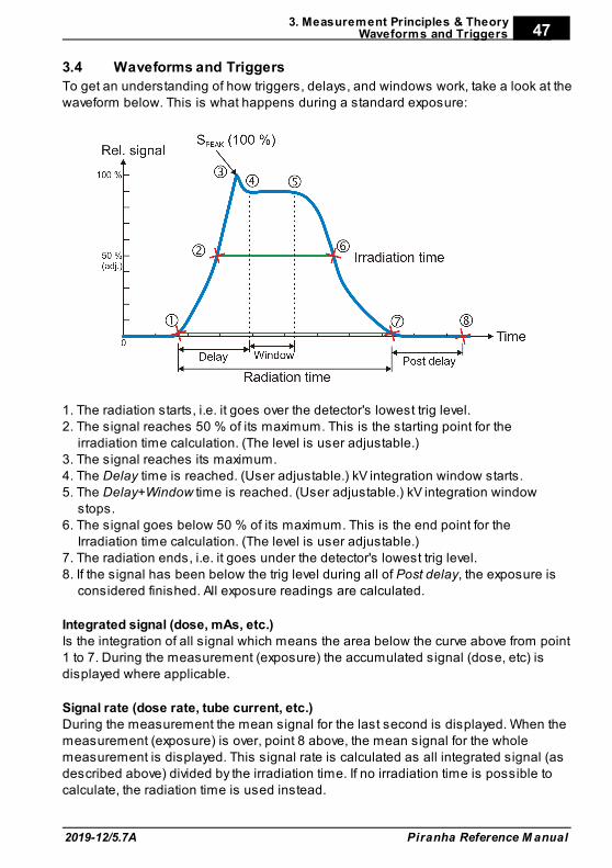
3. Measurement Principles & TheoryWaveforms and Triggers
2019-12/5.7A
47
Piranha Reference M anual
Waveforms and Triggers3.4
To get an understanding of how triggers, delays, and windows work, take a look at thewaveform below. This is what happens during a standard exposure:
1. The radiation starts, i.e. it goes over the detector's lowest trig level.2. The signal reaches 50 % of its maximum. This is the starting point for the
irradiation time calculation. (The level is user adjustable.)3. The signal reaches its maximum.4. The Delay time is reached. (User adjustable.) kV integration window starts.5. The Delay+Window time is reached. (User adjustable.) kV integration window
stops.6. The signal goes below 50 % of its maximum. This is the end point for the
Irradiation time calculation. (The level is user adjustable.)7. The radiation ends, i.e. it goes under the detector's lowest trig level.8. If the signal has been below the trig level during all of Post delay, the exposure is
considered finished. All exposure readings are calculated.
Integrated signal (dose, mAs, etc.)Is the integration of all signal which means the area below the curve above from point1 to 7. During the measurement (exposure) the accumulated signal (dose, etc) isdisplayed where applicable.
Signal rate (dose rate, tube current, etc.)During the measurement the mean signal for the last second is displayed. When themeasurement (exposure) is over, point 8 above, the mean signal for the wholemeasurement is displayed. This signal rate is calculated as all integrated signal (asdescribed above) divided by the irradiation time. If no irradiation time is possible tocalculate, the radiation time is used instead.
3. Measurement Principles & TheoryWaveforms and Triggers
Piranha Reference M anual 2019-12/5.7A
48
This means that for long measurements you may see a change in the rate value(dose rate, etc) when the measurement is finished, if the signal level was changedduring the measurement.
Measurement Principle for the Piranha3.5
The following are the key features of the Piranha design:· Small size· Optimized filter packages for five different kV ranges· Very sensitive and wide dynamic range· Check filter for measurement geometry verification· Single exposure estimation of total filtration and Quick-HVL· Single exposure estimation of generator waveform type
The design of the detector package is very important to be able to measure kV anddose correctly in the whole range of 20 to 155 kV.The Piranha design makes it possible to measure small field sizes, less than 3 mmwidth, and low output levels down to approximately 1 µGy/s. Basically the detectorpackages consist of four separate electrometer channels connected to detectors D1,D2, D3, and D4 and a moveable filter package that can change to one of six positions,each a combination of different filters for the detectors. One of these positions is usedas a "check-filter". It has the same filter thicknesses for both D1 and D2. When thedetector is perfectly positioned and both detectors have the same radiation the ratiobetween the two signals should thus be exactly "1.000". This is very usefulinformation, and testing this makes sure that your measurement geometry is fine,giving reproducible readings. The other 5 filter pairs have different thicknesses alloptimized for different ranges of the tube voltage; two (1 and 2) are used for the lowmammography energy range 20 to 45 kV, and three filters (3 - 5) are used for theradiography range 35 to 155 kV (35 - 75, 55 - 105, and 80 - 155 kV).
Using these four signals S1-S4 (from detectors D1 to D4) the Piranha can accuratelycalculate the corresponding tube voltage. The signal S3 is not affected by themoveable filters and is designed to measure the dose. This detector is marked by asquare inside the rectangular detector area on the top panel. The reference depth forthe sensitive area of the dose detector is 10 mm under the Piranha top panelsurface. The detector D4 is placed directly under D3 with additional filter in between. The ratiobetween S3 and S4 is used to estimate the total filtration for the radiography range.Using these signals together more accurate dose and tube voltage readings can beobtained.
Since all signals is measured simultaneously and with a relative high speed, thePiranha can thus automatically compensate the kV and dose for the dependence ofthe waveform and inherent/added tube filtration.
Measurements with thePiranha System
Chapter 4
4. Measurements w ith the Piranha SystemIntroduction
Piranha Reference M anual 2019-12/5.7A
50
4 Measurements with the Piranha System
Introduction4.1
The Piranha system can, depending on model, measure up to eight parameterssimultaneously plus three waveforms from a single exposure:
· kVp· Dose and dose rate· Exposure time· HVL· Estimated total filtration and determined waveform type· mAs and mA· pulses· kV waveform· Dose rate waveform· mA waveform· various pulsed fluoroscopy parameters
Radiography4.2
Measuring the kVp on a radiographic units is straightforward since the Piranha canautomatically detect and compensate for variation in the radiation quality. It is alsoeasy to check that the detector area is fully and uniformly irradiated. Practically thismeans that the kVp value can be measured in the range 1.0 to 50 mm of totalfiltration.Therefore the Piranha can be placed in the beam wherever you want, as long as itpasses the Position Check. It also has a very wide dynamic range so it very rarelyhappens that the signal level is not enough to get a correct kVp value. Theradiography kV range is 35 to 155 kV.The displayed dose value has no energydependence since it is automatically compensated for each exposure since both thekV, estimated filtration, and the waveform are measured.
4.2.1 kVp, Time, Dose, and Dose Rate
To measure on radiographic units:
1. Set up the Piranha and the handheld computer according to the description inSetting Up the Piranha .
2. Place the detector on the table at the distance that is clinically relevant.
3. It is recommended to make a check measurement at 70 kV to confirm that thedetector area is uniformly radiated.The Piranha automatically changes back to the previous selected kV range.
4. Set kVp and mAs (or mA/time) to the desired values.
5. Make an exposure.
10
4. Measurements w ith the Piranha SystemRadiography
2019-12/5.7A
51
Piranha Reference M anual
6. Read the values.
4.2.2 Dose Measurements with Piranha Dose Probe
1. Place the Piranha Dose Probe in the field and connect the cable to the Piranhainput.
2. Set kVp and mAs (or mA/time) to the desired values.
3. Make an exposure.
4. Read the values.
4.2.3 Quick-HVL and Total Filtration
Total filtration
The estimated Total filtration is measured with the Piranha internal detector, in oneexposure, simultaneously with all other parameters.The estimated Total filtration is also in use for internal compensation of kV and dosevalues.
Quick-HVL
The Quick-HVL is measured with the Piranha internal detector, in one exposure,simultaneously with all other parameters.
Cine/Pulsed Radiography4.3
For under-table cine measurement turn the Piranha upside-down.The Position Check should be used to confirm the position. To be able to protect theimage intensifier from the relative high output cine pulses a lead apron can be placedover the image intensifier input screen. The Piranha automatically measures thenumber of pulses based on information from the radiation waveform. It uses a 50 %trig level based on the maximum signal level.
4.3.1 kVp, Time, Dose, and Dose Rate
Use the same procedure as for the normal radiography measurement.Note that if it is difficult to get a good pulse rate reading, you may use a manual pulserate setting, as described under Measurement Settings to get a dose per pulsereading.
4.3.2 Pulse Measurements with Piranha Dose Probe
Use the same procedure as for the normal radiography measurement. Note that if itis difficult to get a good pulse rate reading, you may use a manual pulse rate setting,as described under Measurement Settings to get a dose per pulse reading.
35
35
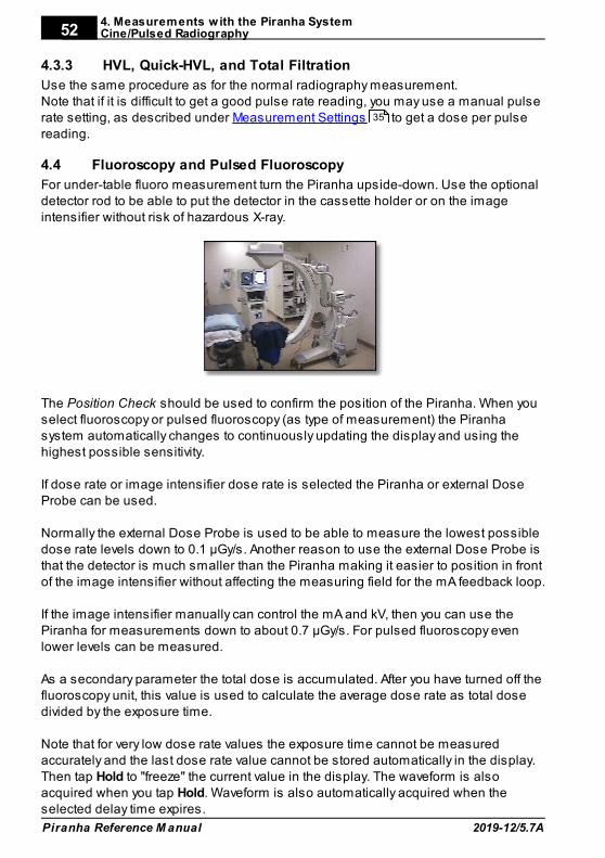
4. Measurements w ith the Piranha SystemCine/Pulsed Radiography
Piranha Reference M anual 2019-12/5.7A
52
4.3.3 HVL, Quick-HVL, and Total Filtration
Use the same procedure as for the normal radiography measurement.Note that if it is difficult to get a good pulse rate reading, you may use a manual pulserate setting, as described under Measurement Settings to get a dose per pulsereading.
Fluoroscopy and Pulsed Fluoroscopy4.4
For under-table fluoro measurement turn the Piranha upside-down. Use the optionaldetector rod to be able to put the detector in the cassette holder or on the imageintensifier without risk of hazardous X-ray.
The Position Check should be used to confirm the position of the Piranha. When youselect fluoroscopy or pulsed fluoroscopy (as type of measurement) the Piranhasystem automatically changes to continuously updating the display and using thehighest possible sensitivity.
If dose rate or image intensifier dose rate is selected the Piranha or external DoseProbe can be used.
Normally the external Dose Probe is used to be able to measure the lowest possibledose rate levels down to 0.1 µGy/s. Another reason to use the external Dose Probe isthat the detector is much smaller than the Piranha making it easier to position in frontof the image intensifier without affecting the measuring field for the mA feedback loop.
If the image intensifier manually can control the mA and kV, then you can use thePiranha for measurements down to about 0.7 µGy/s. For pulsed fluoroscopy evenlower levels can be measured.
As a secondary parameter the total dose is accumulated. After you have turned off thefluoroscopy unit, this value is used to calculate the average dose rate as total dosedivided by the exposure time.
Note that for very low dose rate values the exposure time cannot be measuredaccurately and the last dose rate value cannot be stored automatically in the display.Then tap Hold to "freeze" the current value in the display. The waveform is alsoacquired when you tap Hold. Waveform is also automatically acquired when theselected delay time expires.
35
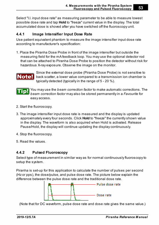
4. Measurements w ith the Piranha SystemFluoroscopy and Pulsed Fluoroscopy
2019-12/5.7A
53
Piranha Reference M anual
Select "I.I. input dose rate" as measuring parameter to be able to measure lowestpossible dose rate and tap Hold to "freeze" current value in the display. The totalaccumulated dose is shoved after you have switched off the fluoroscopy unit.
4.4.1 Image Intensifier Input Dose Rate
Use patient equivalent phantom to measure the image intensifier input dose rateaccording to manufacturer's specification:
1. Place the Piranha Dose Probe in front of the image intensifier but outside themeasuring field for the mA feedback loop. You may use the optional detector rodthat can be attached to Piranha Dose Probe to position the detector without risk forhazardous X-ray exposure. Observe the image on the monitor.
Since the external dose probe (Piranha Dose Probe) is not sensitive toback scatter, a lower value compared to a transmission ion chamber istypically detected (typically in the range of 5 - 20 %).
You may use the beam correction factor to make automatic corrections. Thebeam correction factor may also be stored permanently in a Favourite foreasy access.
2. Start the fluoroscopy.
3. The image intensifier input dose rate is measured and the display is updatedapproximately every four seconds. Click Hold to "freeze" the currently shown valuein the display. The waveform is also acquired when Hold is activated. ReleasePause/Hold, the display will continue updating the display continuously.
4. Stop the fluoroscopy.
5. Read the values.
4.4.2 Pulsed Fluoroscopy
Select type of measurement in similar way as for normal continuously fluoroscopy tosetup the system.
Piranha is set-up for this application to calculate the number of pulses per second(Hz or pps), the dose/pulse, and pulse dose rate. The picture below explain thedifference between the pulse dose rate and the traditional dose rate.
(Note that for DC waveform, pulse dose rate and dose rate gives the same value.)
4. Measurements w ith the Piranha SystemFluoroscopy and Pulsed Fluoroscopy
Piranha Reference M anual 2019-12/5.7A
54
When measuring tube voltage on pulsed fluoroscopy there is an additional waveformtype available. This waveform type is called pulsed and is recommended for pulsedfluoroscopy measurements, especially if the pulses are not square wave shaped,since this can result in low tube voltage readings.
Mammography4.5
This topic will describe how to measure kVp, dose, HVL, AGD (MGD), and time on amammography unit using the Piranha.
4.5.1 General
To measure kVp on a mammography unit is straightforward. This is true since thePiranha automatically can detect whether the detector area is not fully uniformlyirradiated, by means of the Position Check. The mammography kV calibrationsavailable for the Piranha is ranging from 18 to 49 kV.
To be able to trust the kVp reading it is always very important to make thePosition Check to verify that the whole detector area is uniformlyirradiated. The Position Check is normally started automatically everytime you change Radiation Quality, but please make sure to do aPosition Check every time the Piranha is repositioned.
The kV and radiation waveform is always stored together with the RTD values and canbe displayed by tapping the Wave button. The kVp calibration for Piranha is madewithout the compression paddle in place.
The purpose of dose measurement is often to determine the ESAK, Entrance SurfaceAir Kerma (or ESE, Entrance Skin Exposure).
It is recommended to perform dose measurements according to a mammographyprotocol. One is the "European Protocol on dosimetry in mammography EUR 16263EN from the European commission". Chapter 3 in this protocol describes in detail thedetermination of AGD, Average Glandular Dose (or MGD, Mean Glandular Dose). TheAGD is derived from measurements of the HVL and of the ESAK. Make use oftabulated conversion factors from ESAK to AGD. See Average Glandular Dose, AGD(MGD) .60
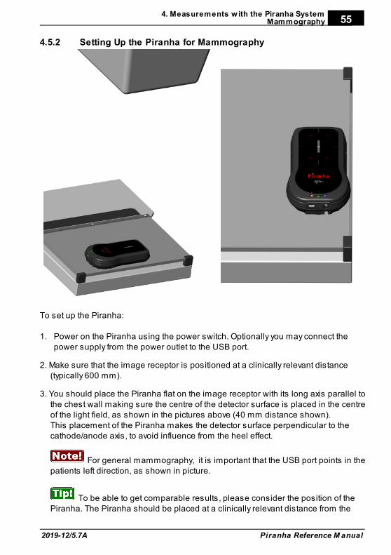
4. Measurements w ith the Piranha SystemMammography
2019-12/5.7A
55
Piranha Reference M anual
4.5.2 Setting Up the Piranha for Mammography
To set up the Piranha:
1. Power on the Piranha using the power switch. Optionally you may connect thepower supply from the power outlet to the USB port.
2. Make sure that the image receptor is positioned at a clinically relevant distance(typically 600 mm).
3. You should place the Piranha flat on the image receptor with its long axis parallel tothe chest wall making sure the centre of the detector surface is placed in the centreof the light field, as shown in the pictures above (40 mm distance shown).This placement of the Piranha makes the detector surface perpendicular to thecathode/anode axis, to avoid influence from the heel effect.
For general mammography, it is important that the USB port points in thepatients left direction, as shown in picture.
To be able to get comparable results, please consider the position of thePiranha. The Piranha should be placed at a clinically relevant distance from the
4. Measurements w ith the Piranha SystemMammography
Piranha Reference M anual 2019-12/5.7A
56
chest wall. Recommendations for this varies, typically between 40 and 60 mm. ForEurope, 60 mm is the recommended distance (Ref. ECR 16263 EU).
4. Connect the devices.Handheld: For Bluetooth (wireless) nothing is needed.PC: connect the USB cable. For Bluetooth (wireless) attach the Bluetooth adapter tothe PC (if not built-in).
5. Power on the handheld computer or the PC.
Now everything is set up with the hardware. Please continue in one of the followingsections, depending on what you want to measure.
4.5.3 kVp, Time, and Dose Measurements with the Internal detector
Set up the Piranha and the handheld computer according to the description in SettingUp the Piranha for Mammography .
1. Select Type of Measurement and Parameter, as shown below.
2. Select the correct radiation (beam) quality.
3. Make a Position Check, as shown above. It is recommended to make the check at28 kV. After the check the Piranha automatically changes back to the previouslyselected kV range.
4. Set kVp and mAs (or mA/time) to the desired values.
5. Make an exposure. The RTI logo flashes to indicate that the Piranha has detectedthe exposure.
6. Read the values.
There are some mammographic units that are bit peculiar when itcomes to kV measurements, for instance The Hologic Selenia and IMSGiotto. In those cases, RTI have updated Application Notes, and theremay be some even for other units. Please check the RTI website(www.rtigroup.com) for the latest info. For Sectra MDM, FischerSenoscan and other scanning beam units, please see the sectionScanning Beam Mammography .
4.5.4 Dose Measurements with the Piranha Dose Probe
It is often more convenient to use the Piranha to measure dose for amammography tube since no manual energy compensation has to be done,as is the case with the Piranha Dose Probe (or TP compensation for anionization chamber).
Measuring procedure
55
61
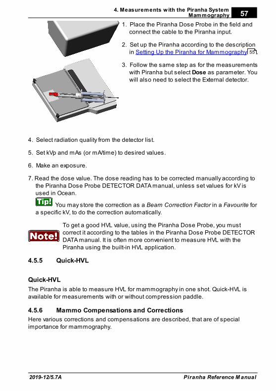
4. Measurements w ith the Piranha SystemMammography
2019-12/5.7A
57
Piranha Reference M anual
1. Place the Piranha Dose Probe in the field andconnect the cable to the Piranha input.
2. Set up the Piranha according to the descriptionin Setting Up the Piranha for Mammography .
3. Follow the same step as for the measurementswith Piranha but select Dose as parameter. Youwill also need to select the External detector.
4. Select radiation quality from the detector list.
5. Set kVp and mAs (or mA/time) to desired values.
6. Make an exposure.
7. Read the dose value. The dose reading has to be corrected manually according tothe Piranha Dose Probe DETECTOR DATA manual, unless set values for kV isused in Ocean.
You may store the correction as a Beam Correction Factor in a Favourite fora specific kV, to do the correction automatically.
To get a good HVL value, using the Piranha Dose Probe, you mustcorrect it according to the tables in the Piranha Dose Probe DETECTORDATA manual. It is often more convenient to measure HVL with thePiranha using the built-in HVL application.
4.5.5 Quick-HVL
Quick-HVL
The Piranha is able to measure HVL for mammography in one shot. Quick-HVL isavailable for measurements with or without compression paddle.
4.5.6 Mammo Compensations and Corrections
Here various corrections and compensations are described, that are of specialimportance for mammography.
55

4. Measurements w ith the Piranha SystemMammography
Piranha Reference M anual 2019-12/5.7A
58
4.5.6.1 Corrections for the Compression Paddle
The Piranha is well collimated above its small detector area, and will measure thesame whether the compression paddle is placed directly on top of the Piranha or highabove. This is NOT true for an ion chamber.
A factor has been introduced which enables the Piranha to take the scatteredradiation into consideration and produce measurement results as if it was an ionchamber which senses the scattered radiation directly.
When an ion chamber is placed directly below the compression paddle, a relativelyconstant scatter factor of 6 % is found. The factor is typical for ion chambers such asRadcal 6M, PTW N23344, and Standard Imaging Magna 1cc.
When using Ocean, a 0.10 or 0.12 mm Al equivalent compression paddle is used.That is equal to approximately 3 mm of plexiglass (PMMA). Please see the Oceanmanual for details.
When comparing with typical mammographic ion chambers listedabove, you should multiply the Piranha dose value with a scatter factor of1.06 to make it measure as an ion chamber directly below thecompression paddle.
More info about the correction for compression paddle can be found in ApplicationNote 1-AN-52020-2 from RTI Group AB. Please also see section Angular Sensitivity,Piranha for details on sensitivity in different directions.
4.5.6.2 Normalization
A normalization function is available which enables all measurements to be virtuallyperformed at the same distance, increasing productivity. According to Europeanprotocol (ECR 16263 EU, 1996), ESAK should be measured 45 mm above the breastsupport.
A practical consequence of usage of the normalizing function and scatter factor is thatthe Piranha can be kept at the same position on the breast support all the time whendata is collected for AGD.For an ion chamber it is not quite as easy because of the scatter contribution that isnot allowed during HVL measurement. The ion chamber and/or the compressionpaddle must be moved to support good geometry.
More info about the correction and normalization function can be found in ApplicationNote 1-AN-52020-2 from RTI Group AB.
23
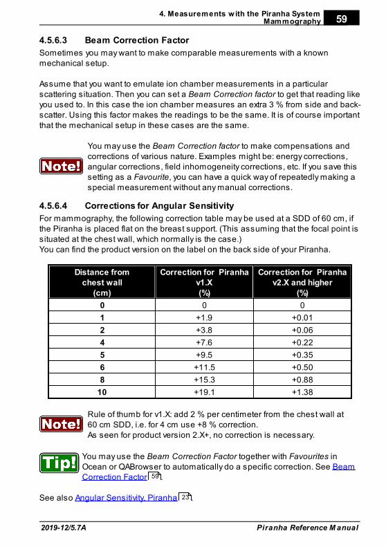
4. Measurements w ith the Piranha SystemMammography
2019-12/5.7A
59
Piranha Reference M anual
4.5.6.3 Beam Correction Factor
Sometimes you may want to make comparable measurements with a knownmechanical setup.
Assume that you want to emulate ion chamber measurements in a particularscattering situation. Then you can set a Beam Correction factor to get that reading likeyou used to. In this case the ion chamber measures an extra 3 % from side and back-scatter. Using this factor makes the readings to be the same. It is of course importantthat the mechanical setup in these cases are the same.
You may use the Beam Correction factor to make compensations andcorrections of various nature. Examples might be: energy corrections,angular corrections, field inhomogeneity corrections, etc. If you save thissetting as a Favourite, you can have a quick way of repeatedly making aspecial measurement without any manual corrections.
4.5.6.4 Corrections for Angular Sensitivity
For mammography, the following correction table may be used at a SDD of 60 cm, ifthe Piranha is placed flat on the breast support. (This assuming that the focal point issituated at the chest wall, which normally is the case.)You can find the product version on the label on the back side of your Piranha.
Distance fromchest wall
(cm)
Correction for Piranhav1.X(%)
Correction for Piranhav2.X and higher
(%)
0 0 0
1 +1.9 +0.01
2 +3.8 +0.06
4 +7.6 +0.22
5 +9.5 +0.35
6 +11.5 +0.50
8 +15.3 +0.88
10 +19.1 +1.38
Rule of thumb for v1.X: add 2 % per centimeter from the chest wall at60 cm SDD, i.e. for 4 cm use +8 % correction.As seen for product version 2.X+, no correction is necessary.
You may use the Beam Correction Factor together with Favourites inOcean or QABrowser to automatically do a specific correction. See BeamCorrection Factor .
See also Angular Sensitivity, Piranha .
59
23
4. Measurements w ith the Piranha SystemMammography
Piranha Reference M anual 2019-12/5.7A
60
4.5.7 Average Glandular Dose, AGD (MGD)
The AGD (average glandular dose) is derived from measurements of the HVL and ofthe ESAK, entrance surface kerma (or ESE) making use of tabulated conversionfactors from ESAK (or ESE) to AGD (or MGD). The tabulated data has been derivedfrom Monte Carlo calculations and has been verified experimentally.
To determine the AGD a standard phantom should also be used when the ESAK (orESE) value is measured with the Piranha.
Correct measurement of the Average Glandular Dose (AGD) with thePiranhaIn most situations you can perform measurements for a mammographic unit with thePiranha instead of a dedicated ion chamber. Since the Piranha compensates forenergy dependence, the readings are in direct comparison with readings from areference class ion chamber. When measuring the AGD you should always have thecompression paddle in place.
Important quantities to measureThe most common measurements for a mammographic system are conducted todetermine the average glandular dose (AGD). The AGD values are based onmeasurements of ESAK (entrance surface air kerma) and HVL. To do themeasurements correctly and according to standards, the radiation detectors shouldbe placed directly below the compression paddle. This introduces extra scatteredradiation due to the compression paddle which is important to include whendetermining ESAK. On the other hand, the HVL measurement should be done withoutany scatter contribution and with good geometry.
HVLThe Piranha is well collimated above its small detector area. Due to this fact itregisters a narrower angle of the X-ray field and thus much less scattered radiationcompared to an ion chamber. It has built-in good geometry and is therefore ideal forHVL measurements. Hence, the HVL filter can be placed on top of the compressionpaddle without any extra collimation even at close distance to the Piranha. ThePiranha has a built-in HVL application which should be used to get accurate HVLreadings.
4.5.8 Mammographic Pre-pulses
Some mammography systems (e.g. GE DMR system) use a pre-pulse to determinewhat radiation quality to use for a specific patient.
The time elapsing between the pre-pulse and the real exposure is usually about onesecond. Therefore the default post-delay of 250 ms will not cover both the pre-pulseand the real exposure. To get an overview of the signal output, set the post-delay to atleast 1 s and the waveform recording time to a corresponding time. It is important tocover both signals. In this measurement setup, the Piranha will add the dose fromboth pulses. This is OK if the radiation quality is not changed between the signals.
4. Measurements w ith the Piranha SystemMammography
2019-12/5.7A
61
Piranha Reference M anual
If the Mammography unit changes the radiation quality after the pre-pulse however,the kV and dose is affected and the pulses should be treated separately. To collectdata from real exposure, set the delay (not the post-delay) to exclude the pre-pulse.
4.5.9 Scanning Beam Mammography
When measuring on scanning beam mammographic equipment, like for instanceSectra MDM or Fischer Senoscan, two factors are very important.1. You should place the Piranha flat on the image receptor. Then position it as
described in section Setting Up the Piranha for Mammography .2. Always perform a position check. This makes sure than any field imbalances are
corrected for.3. If you use the compression paddle, make sure that you use the correct settings,
see section Corrections for the Compression Paddle .
Please also see the CT section for measurement tips on scanning beams.For Sectra L30, see special application note on the RTI website (www.rtigroup.com).
Dental and Panoramic Dental4.6
This topic will describe how to measure kVp, dose, and time for a Dental andPanoramic Dental X-ray units using the Piranha only. Set up the Piranha and the handheld computer according to the description in SettingUp the Piranha . To measure kVp for a dental unit is similar to measuring for aradiography units with the difference that the output level is much lower and the totalfiltration is normally around 2 mm Al.
The setup is straightforward and also to get the measured value. Most dental units isstill single phase self-rectified and has 100 % radiation and kV ripple. In the case ofone-phase dental units it is common that only the exposure time can be changed. Inmost cases the set tube voltage and current is fixed to about 65 kVp and 8 mA. Achallenge can exist how to find a definition what measured value should be used.Furthermore the radiation output and the kV waveform are not stable for the first200 ms or so, because that the tube filament current in most cases is not regulated.
The definition of both what is the true kVp and exposure time cannot be as easilydetermined without study the waveform and select appropriate measurementparameters as delay and window. Introducing small CCD detectors instead of filmalso demands carefully calibration of single phase dental systems. The tube voltagewaveform is collected from 200 ms after start trig and the kVp is calculated based onthe measuring window equal the remaining part of the exposure time.The dose value is collected for the whole exposure time. If you need to change thesensitivity, delay, or/and measuring window, tapto show the settings and make yourchoices.
In the case of dental panoramic system the situation is somewhat different. Here thekV and radiation waveform often is very well regulated.
55
58
10
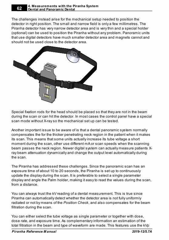
4. Measurements w ith the Piranha SystemDental and Panoramic Dental
Piranha Reference M anual 2019-12/5.7A
62
The challenges instead arise for the mechanical setup needed to position thedetector in right position. The small and narrow field is only a few millimetres. ThePiranha detector has very narrow detector area and is very thin and a special holder(optional) can be used to position the Piranha without any problem. Panoramic unitsthat use digital detectors have much smaller detector area and magnets cannot andshould not be used close to the detector area.
Special fixation rods for the head should be placed so that they are not in the beamduring the scan or can hit the detector. In most cases the control panel have a specialscan mode without X-ray so the mechanical set up can be tested.
Another important issue to be aware of is that a dental panoramic system normallycompensates the for the thicker penetrating neck region in the patient when it makesits scan. This means that some units actually increase its tube voltage a shortmoment during the scan, other use different mA or scan speeds when the scanningbeam passes the neck region. Newer digital system can actually measure patients X-ray beam attenuation dynamically and change the output level automatically duringthe scan.
The Piranha has addressed these challenges. Since the panoramic scan has anexposure time of about 10 to 20 seconds, the Piranha is set up to continuouslyupdate the display during the scan. It is preferable to select a single parameterdisplay and angle the Palm holder, making it easy to read the values during the scan,from a distance.
You can always trust the kV reading of a dental measurement. This is true sincePiranha can automatically detect whether the detector area is not fully uniformlyradiated or not by means of the Position Check, and also compensates for the beamfiltration during the scan.
You can either select the tube voltage as single parameter or together with dose,dose rate, and exposure time. As complementary information an estimation of thetotal filtration in the beam and type of waveform are made. This features use the kVp
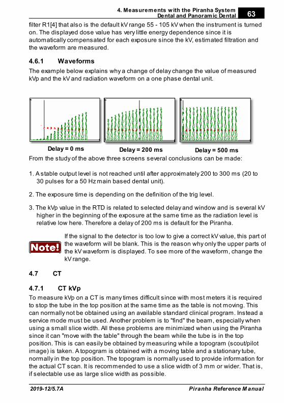
4. Measurements w ith the Piranha SystemDental and Panoramic Dental
2019-12/5.7A
63
Piranha Reference M anual
filter R1[4] that also is the default kV range 55 - 105 kV when the instrument is turnedon. The displayed dose value has very little energy dependence since it isautomatically compensated for each exposure since the kV, estimated filtration andthe waveform are measured.
4.6.1 Waveforms
The example below explains why a change of delay change the value of measuredkVp and the kV and radiation waveform on a one phase dental unit.
Delay = 0 ms Delay = 200 ms Delay = 500 ms
From the study of the above three screens several conclusions can be made:
1. A stable output level is not reached until after approximately 200 to 300 ms (20 to30 pulses for a 50 Hz main based dental unit).
2. The exposure time is depending on the definition of the trig level.
3. The kVp value in the RTD is related to selected delay and window and is several kVhigher in the beginning of the exposure at the same time as the radiation level isrelative low here. Therefore a delay of 200 ms is default for the Piranha.
If the signal to the detector is too low to give a correct kV value, this part ofthe waveform will be blank. This is the reason why only the upper parts ofthe kV waveform is displayed. To see more of the waveform, change thekV range.
CT4.7
4.7.1 CT kVp
To measure kVp on a CT is many times difficult since with most meters it is requiredto stop the tube in the top position at the same time as the table is not moving. Thiscan normally not be obtained using an available standard clinical program. Instead aservice mode must be used. Another problem is to "find" the beam, especially whenusing a small slice width. All these problems are minimized when using the Piranhasince it can "move with the table" through the beam while the tube is in the topposition. This is can easily be obtained by measuring while a topogram (scout/pilotimage) is taken. A topogram is obtained with a moving table and a stationary tube,normally in the top position. The topogram is normally used to provide information forthe actual CT scan. It is recommended to use a slice width of 3 mm or wider. That is,if selectable use as large slice width as possible.
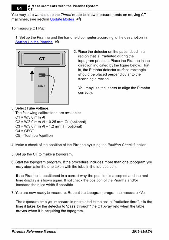
4. Measurements w ith the Piranha SystemCT
Piranha Reference M anual 2019-12/5.7A
64
You may also want to use the Timed mode to allow measurements on moving CTmachines, see section Update Modes .
To measure CT kVp:
1. Set up the Piranha and the handheld computer according to the description inSetting Up the Piranha .
2. Place the detector on the patient bed in aregion that is irradiated during thetopogram process. Place the Piranha in thedirection indicated by the figure below. Thatis, the Piranha detector surface rectangleshould be placed perpendicular to thescanning direction.
You may use the lasers to align the Piranhacorrectly.
3. Select Tube voltage.The following calibrations are available:C1 = W/3.0 mm AlC2 = W/3.0 mm Al + 0.25 mm Cu (optional)C3 = W/3.0 mm Al + 1.2 mm Ti (optional)C4 = GECTC5 = Toshiba Aquillion
4. Make a check of the position of the Piranha by using the Position Check function.
5. Set up the CT to make a topogram.
6. Start the topogram program. If the procedure includes more than one topogram youmay abort after the one taken with the tube in the top position.
If the Piranha is positioned in a correct way, the position is accepted and the real-time display is shown again. If not check the position of the Piranha and/orincrease the slice width if possible.
7. You are now ready to measure. Repeat the topogram program to measure kVp.
The exposure time you measure is not related to the actual "radiation time". It is thetime it takes for the detector to "pass through" the CT X-ray field when the tablemoves when it is acquiring the topogram.
43
10
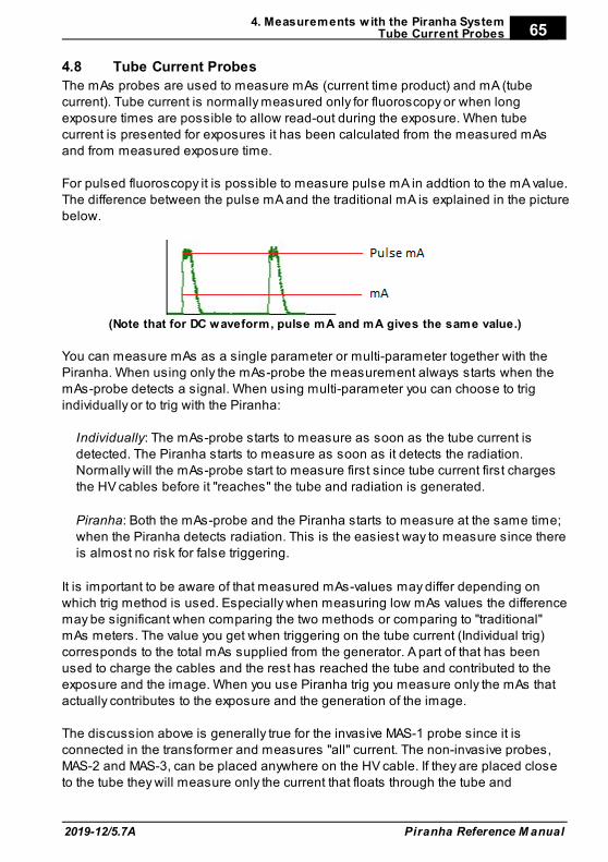
4. Measurements w ith the Piranha SystemTube Current Probes
2019-12/5.7A
65
Piranha Reference M anual
Tube Current Probes4.8
The mAs probes are used to measure mAs (current time product) and mA (tubecurrent). Tube current is normally measured only for fluoroscopy or when longexposure times are possible to allow read-out during the exposure. When tubecurrent is presented for exposures it has been calculated from the measured mAsand from measured exposure time.
For pulsed fluoroscopy it is possible to measure pulse mA in addtion to the mA value.The difference between the pulse mA and the traditional mA is explained in the picturebelow.
(Note that for DC waveform, pulse mA and mA gives the same value.)
You can measure mAs as a single parameter or multi-parameter together with thePiranha. When using only the mAs-probe the measurement always starts when themAs-probe detects a signal. When using multi-parameter you can choose to trigindividually or to trig with the Piranha:
Individually: The mAs-probe starts to measure as soon as the tube current isdetected. The Piranha starts to measure as soon as it detects the radiation.Normally will the mAs-probe start to measure first since tube current first chargesthe HV cables before it "reaches" the tube and radiation is generated.
Piranha: Both the mAs-probe and the Piranha starts to measure at the same time;when the Piranha detects radiation. This is the easiest way to measure since thereis almost no risk for false triggering.
It is important to be aware of that measured mAs-values may differ depending onwhich trig method is used. Especially when measuring low mAs values the differencemay be significant when comparing the two methods or comparing to "traditional"mAs meters. The value you get when triggering on the tube current (Individual trig)corresponds to the total mAs supplied from the generator. A part of that has beenused to charge the cables and the rest has reached the tube and contributed to theexposure and the image. When you use Piranha trig you measure only the mAs thatactually contributes to the exposure and the generation of the image.
The discussion above is generally true for the invasive MAS-1 probe since it isconnected in the transformer and measures "all" current. The non-invasive probes,MAS-2 and MAS-3, can be placed anywhere on the HV cable. If they are placed closeto the tube they will measure only the current that floats through the tube and
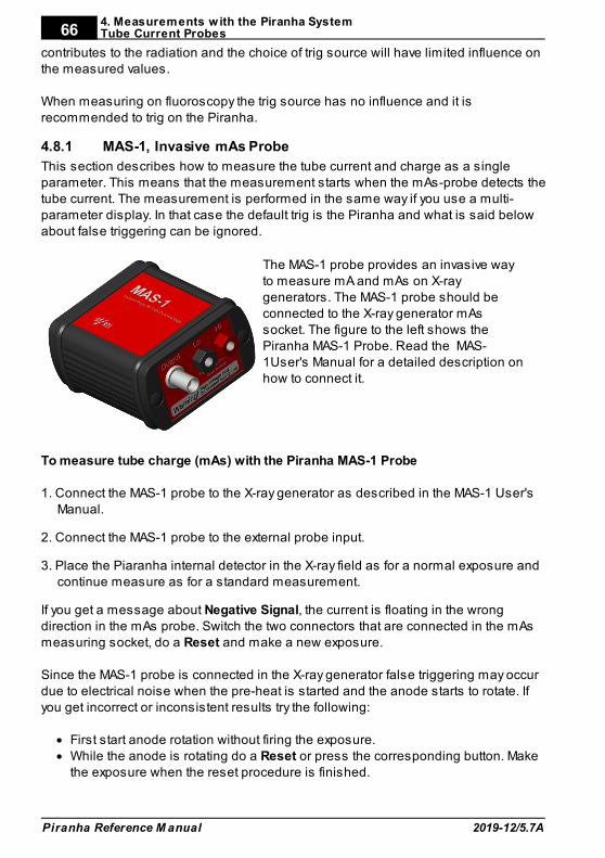
4. Measurements w ith the Piranha SystemTube Current Probes
Piranha Reference M anual 2019-12/5.7A
66
contributes to the radiation and the choice of trig source will have limited influence onthe measured values.
When measuring on fluoroscopy the trig source has no influence and it isrecommended to trig on the Piranha.
4.8.1 MAS-1, Invasive mAs Probe
This section describes how to measure the tube current and charge as a singleparameter. This means that the measurement starts when the mAs-probe detects thetube current. The measurement is performed in the same way if you use a multi-parameter display. In that case the default trig is the Piranha and what is said belowabout false triggering can be ignored.
The MAS-1 probe provides an invasive wayto measure mA and mAs on X-raygenerators. The MAS-1 probe should beconnected to the X-ray generator mAssocket. The figure to the left shows thePiranha MAS-1 Probe. Read the MAS-1User's Manual for a detailed description onhow to connect it.
To measure tube charge (mAs) with the Piranha MAS-1 Probe
1. Connect the MAS-1 probe to the X-ray generator as described in the MAS-1 User'sManual.
2. Connect the MAS-1 probe to the external probe input.
3. Place the Piaranha internal detector in the X-ray field as for a normal exposure andcontinue measure as for a standard measurement.
If you get a message about Negative Signal, the current is floating in the wrongdirection in the mAs probe. Switch the two connectors that are connected in the mAsmeasuring socket, do a Reset and make a new exposure.
Since the MAS-1 probe is connected in the X-ray generator false triggering may occurdue to electrical noise when the pre-heat is started and the anode starts to rotate. Ifyou get incorrect or inconsistent results try the following:
· First start anode rotation without firing the exposure.· While the anode is rotating do a Reset or press the corresponding button. Make
the exposure when the reset procedure is finished.
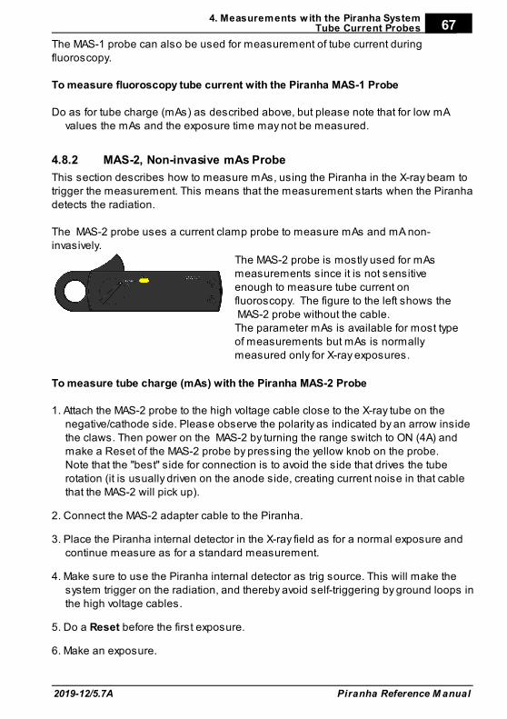
4. Measurements w ith the Piranha SystemTube Current Probes
2019-12/5.7A
67
Piranha Reference M anual
The MAS-1 probe can also be used for measurement of tube current duringfluoroscopy.
To measure fluoroscopy tube current with the Piranha MAS-1 Probe
Do as for tube charge (mAs) as described above, but please note that for low mAvalues the mAs and the exposure time may not be measured.
4.8.2 MAS-2, Non-invasive mAs Probe
This section describes how to measure mAs, using the Piranha in the X-ray beam totrigger the measurement. This means that the measurement starts when the Piranhadetects the radiation.
The MAS-2 probe uses a current clamp probe to measure mAs and mA non-invasively.
The MAS-2 probe is mostly used for mAsmeasurements since it is not sensitiveenough to measure tube current onfluoroscopy. The figure to the left shows the MAS-2 probe without the cable.The parameter mAs is available for most typeof measurements but mAs is normallymeasured only for X-ray exposures.
To measure tube charge (mAs) with the Piranha MAS-2 Probe
1. Attach the MAS-2 probe to the high voltage cable close to the X-ray tube on thenegative/cathode side. Please observe the polarity as indicated by an arrow insidethe claws. Then power on the MAS-2 by turning the range switch to ON (4A) andmake a Reset of the MAS-2 probe by pressing the yellow knob on the probe.Note that the "best" side for connection is to avoid the side that drives the tuberotation (it is usually driven on the anode side, creating current noise in that cablethat the MAS-2 will pick up).
2. Connect the MAS-2 adapter cable to the Piranha.
3. Place the Piranha internal detector in the X-ray field as for a normal exposure andcontinue measure as for a standard measurement.
4. Make sure to use the Piranha internal detector as trig source. This will make thesystem trigger on the radiation, and thereby avoid self-triggering by ground loops inthe high voltage cables.
5. Do a Reset before the first exposure.
6. Make an exposure.
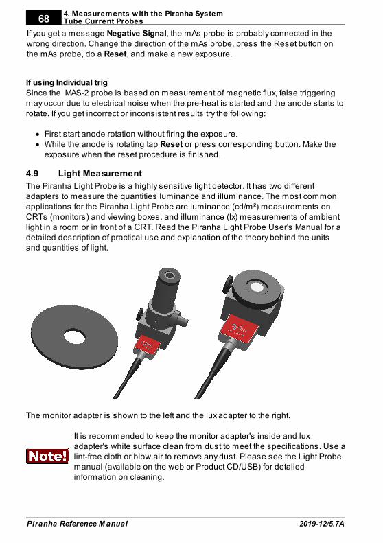
4. Measurements w ith the Piranha SystemTube Current Probes
Piranha Reference M anual 2019-12/5.7A
68
If you get a message Negative Signal, the mAs probe is probably connected in thewrong direction. Change the direction of the mAs probe, press the Reset button onthe mAs probe, do a Reset, and make a new exposure.
If using Individual trigSince the MAS-2 probe is based on measurement of magnetic flux, false triggeringmay occur due to electrical noise when the pre-heat is started and the anode starts torotate. If you get incorrect or inconsistent results try the following:
· First start anode rotation without firing the exposure.· While the anode is rotating tap Reset or press corresponding button. Make the
exposure when the reset procedure is finished.
Light Measurement4.9
The Piranha Light Probe is a highly sensitive light detector. It has two differentadapters to measure the quantities luminance and illuminance. The most commonapplications for the Piranha Light Probe are luminance (cd/m²) measurements onCRTs (monitors) and viewing boxes, and illuminance (lx) measurements of ambientlight in a room or in front of a CRT. Read the Piranha Light Probe User's Manual for adetailed description of practical use and explanation of the theory behind the unitsand quantities of light.
The monitor adapter is shown to the left and the lux adapter to the right.
It is recommended to keep the monitor adapter's inside and luxadapter's white surface clean from dust to meet the specifications. Use alint-free cloth or blow air to remove any dust. Please see the Light Probemanual (available on the web or Product CD/USB) for detailedinformation on cleaning.
4. Measurements w ith the Piranha SystemLight Measurement
2019-12/5.7A
69
Piranha Reference M anual
4.9.1 Luminance - Monitor/Viewbox (cd/m²)
Read the Piranha Light Probe User's Manual to get information about how to dodifferent type of measurements and how to use the different adapters.
To measure luminance (cd/m²):
1. Attach the monitor adapter to the Piranha Light Probe as described in the PiranhaLight Probe User's Manual.
2. Connect the Piranha Light Probe to the Piranha.
3. Set up the Piranha and the handheld computer according to the description inSetting Up the Piranha .
4. Make a Reset. Place the Piranha Light Probe onto the surface where you want tomeasure the luminance.
5. Press and hold the shutter. Read the value. You can now move the Piranha LightProbe to other points and continue measuring the light.
4.9.2 Illuminance - Ambient Light (lx)
Read the Piranha Light Probe User's Manual to get information about how to dodifferent type of measurements and how to use the different adapters.
To measure illuminance (lx):
1. Attach the lux adapter to the Piranha Light Probe as described in the Piranha LightProbe User's Manual.
2. Connect the Piranha Light Probe to the Piranha.
3. Set up the Piranha and the handheld computer according to the description inSetting Up the Piranha .
4. Cover the white light-sensitive area of the Piranha Light Probe to shield off all light(you may use the rubber part that comes with the Piranha Light Probe-M ifavailable). It is very important that you shield off all light. Then make a Reset. Afterthat you can remove the shield and place the light detector where you want tomeasure the ambient light.
5. Read the value. You can now move the Piranha Light Probe-L to other points andmeasure the ambient light.
10
10

Problems and Solutions
Chapter 5
5. Problems and Solutions
2019-12/5.7A
71
Piranha Reference M anual
5 Problems and Solutions
Troubleshooting5.1
Before contacting your distributor or RTI, please check the following tips.
A. Check the RTI web page for updates http://www.rtigroup.com.
B. Run through the checklist below.
The Piranha does not workCheck that the motor moves properly or can beep. (QABrowser: Setup | SystemTest).
The Piranha moving filter seem to have stuckTry the following suggestions:1. Make sure to attach the external power supply, that will give extra power to themotor.2. If you have a QABrowser, start it and run the filter test. (QABrowser:Setup | System Test)3. Hold the Piranha in you right hand by the cable edge.4. When the motor is trying to move, tap the Piranha's left long edge in the palm ofyour left hand until it comes free.
The electrometer does not give a readingCheck:1. That the correct input connector is used and connected.2. That probe cables look healthy.3. If using the Chamber Adapter and an ion chamber, check that the power and biasindicators on the Chamber Adapter are lit.
The electrometer gives numerous trig indicationsIf you get the trig indicator ("play" symbol) when there is no signal:1. Press reset.2. If it comes over and over you may need to increase the trig level, by raising thethreshold, see topic Measurement Settings .
The electrometer or Piranha gives too low dose rateIf you get to low dose rate readings or too short irradiation times for shortexposures:1. Check that you are measuring with a good geometry, where the incomingradiation is perpendicular to the detector surface. See Specifications, Piranha fordetails.
Installation or upgrade of RTI Updater failed
35
12
5. Problems and SolutionsTroubleshooting
Piranha Reference M anual 2019-12/5.7A
72
Make sure you are not having a restricted user account (on Windows XP, 2000, ornewer). You will need to have access to an administrative account to install thesoftware, see section Windows Restricted User Accounts for details.
My Piranha cycles its status indicator quickly between colours and does notmeasureYour system is in Bootloader mode. Please run RTI Updater to correct this.
My Piranha beeps twice quickly when startingThe Piranha normally beeps once when starting. If it beeps twice quickly whenpowering on, run RTI Updater to correct this.
Bluetooth only shows "Unknown device" when trying to connectDepending on Palm model it may take a little while for the serial number to appear,the Piranha will appear as "Unknown device". Normally it will show the serialnumber if you wait a while.
How do I change from Gray to Röntgen units?You can set this for all tests (pull-down menu | Setup | Units), see Units Setup.It is also possible to set mixed units for a test and save as Favourites. Allmeasurements settings, QABrowser settings, set values, and selected units will besaved with the Favourite.
C. Contact your local representative or see Notice for contact information to RTI GroupAB. The more information you supply will help us to get a quick solution to yourproblem. Examples of useful information is screen dump pictures, exact errormessage texts, log files, etc. You may also use the auto-report function described inthe section How To Report a Problem.
Bluetooth5.2
Bluetooth is a wireless way of communication between your PC/handheld and yourmeter. The Piranha has built-in support for this. A Palm OS handheld also has built-insupport for Bluetooth but a PC may or may not have built-in support for Bluetooth. Ifthe PC does not have built-in Bluetooth support you will need a Bluetooth adapter(that you connect to the USB port) for instance the D-Link DBT-120 or DBT-122.
The range of Bluetooth is about 10 meters (32 feet) in free air for a class 2 Bluetoothadapter (like the D-Link DBT-122), for a class 1 Bluetooth adapter (like the TargusACB20EU) the theoretical range is up to 100 metres. This can be significantly shorterif there are walls and other objects obstructing the signal.
Bluetooth and a Palm OS handheld works out of right out of the box, while usingBluetooth and PC may, depending on your PC, the BT drivers, and the Windowsversion, requires some work. If it is possible for you to use a USB cable with your PCand meter then that will often be more robust (but less convenient).
74
5. Problems and SolutionsBluetooth
2019-12/5.7A
73
Piranha Reference M anual
5.2.1 Bluetooth Passkey
There are two different ways to use Bluetooth with you meter, without a passkey andwith a passkey (also called PIN code, authentication, and Bluetooth security code). Allmeters and accessories that are delivered from RTI from the first quarter of 2010 areconfigured to use a passkey (0000).
Drawbacks of using a Passkey
If you enable a passkey you might experience some drawbacks.· If you use your meter (with Bluetooth communication) with more than one PC or
with a PC and a Palm OS handheld you might need (depending on your hardware)to add the meter (also called to pair a device, or to add as a trusted device) with thePC/handheld every time you have used another PC or handheld with the meter.
· With a Palm OS handheld you cannot just simply start the QABrowser withBluetooth. You need to first add the meter as a trusted device. And if you have usedthe meter with another handheld or PC (using Bluetooth) you will need to add themeter as a trusted device again.
New hardware which supports multiple devicesPiranha with product version 3.0 (which started shipping around spring 2009) andhigher, and product version 2.5.4 supports multiple Bluetooth devices, which meansthat you can use it with both a PC and handheld without additional steps.
Advantages of using a Passkey
· Works with Windows Vista and Windows 7,8,10.· Increased security
The main reason to change so that you use a passkey is if you are going to useBluetooth communication and Windows 7-10, Vista, or Windows XP and a Bluetoothadapter where you cannot disable authentication. But we recommend that you use aUSB cable if you can.
If you want to use a passkey and have previously not been using one, you need toreconfigure your Piranha. Detailed instructions are available later on in this manual.
5.2.2 Enable Bluetooth Passkey
Before you enable the use of a Bluetooth passkey please read the section aboutBluetooth passkeys and the drawbacks of using a passkey.
You enable and disable passkeys by using the RTI Updater application (requiresversion 2008.6A or later) which is available on your RTI Software & DocumentationMedia and the RTI website (www.rtigroup.com).
1. Connect your meter using the USB cable.2. Launch RTI Updater from the "RTI Electronics" folder in the Windows start menu.
5. Problems and SolutionsBluetooth
Piranha Reference M anual 2019-12/5.7A
74
3. Select the USB connection. You cannot use a Bluetooth connection when youwant to change the Bluetooth configuration. A Bluetooth connection is shown asCOMxx.
4. Wait for RTI Updater to finish with the startup procedure. After a while when it isready the Start button will be enabled.
5. Select Settings | Advanced from the menu.6. Now select the Tools menu.7. If you want to enable the use of a passkey select Enable Bluetooth Passkey. If you
experience problems with this, then you probably need to update you meterfirmware before you can enable the Bluetooth passkey. Please run the availableupdates (by pressing Start) and then restart the application again to enable theBluetooth passkey.
8. Follow the onscreen instructions.
If you want to disable the Bluetooth passkey do the same thing but select DisableBluetooth Passkey instead. If you are asked for a PIN code during the startup do notenter a PIN code, just cancel instead. Because if you do, you will have activated yourBluetooth and RTI Updater cannot reconfigure the Bluetooth module when it is active.
Windows Restricted User Accounts5.3
If you only have a restricted user account (e.g. not an account with administratorprivileges) for your computer you will need to contact your network administrator sothat the administrator can help you with installing the software needed for yourPiranha.
If you are an administrator trying to install the software for a user, read the instructionsbelow in order to find out what you need to do in order to enable the restricted user tobe able to run the RTI applications.
5.3.1 Which Applications are Needed?
The necessary applications differs depending on the user's needs.
Ocean (Windows platform)Ocean use only requires that you install the Ocean software, but also note that thereis another utility (RTI Updater) that the user may need in the future, in order to updatethe software located in the Piranha instrument (firmware).
RTI UpdaterThe RTI Updater application is used for updating the built-in software (firmware) of thePiranha. This is needed if the user is going to update either Ocean software in thefuture, since updates to that applications usually also requires that the firmware of thePiranha is updated.. Software updates for the different applications are available fordownload from the RTI website (www.rtigroup.com).
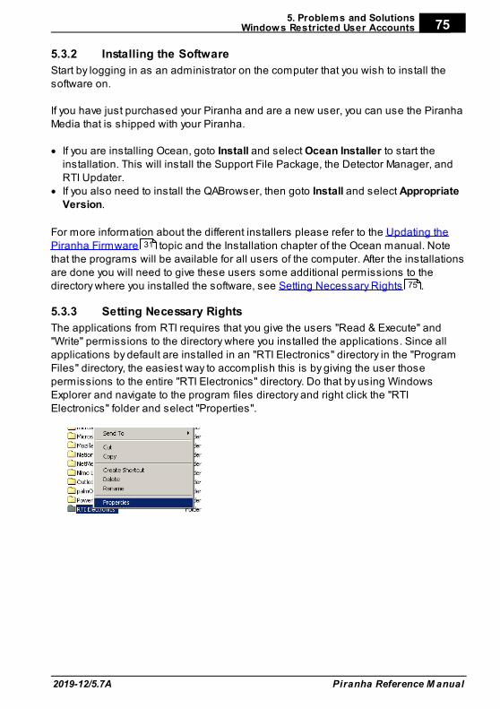
5. Problems and SolutionsWindows Restricted User Accounts
2019-12/5.7A
75
Piranha Reference M anual
5.3.2 Installing the Software
Start by logging in as an administrator on the computer that you wish to install thesoftware on.
If you have just purchased your Piranha and are a new user, you can use the PiranhaMedia that is shipped with your Piranha.
· If you are installing Ocean, goto Install and select Ocean Installer to start theinstallation. This will install the Support File Package, the Detector Manager, andRTI Updater.
· If you also need to install the QABrowser, then goto Install and select AppropriateVersion.
For more information about the different installers please refer to the Updating thePiranha Firmware topic and the Installation chapter of the Ocean manual. Notethat the programs will be available for all users of the computer. After the installationsare done you will need to give these users some additional permissions to thedirectory where you installed the software, see Setting Necessary Rights .
5.3.3 Setting Necessary Rights
The applications from RTI requires that you give the users "Read & Execute" and"Write" permissions to the directory where you installed the applications. Since allapplications by default are installed in an "RTI Electronics" directory in the "ProgramFiles" directory, the easiest way to accomplish this is by giving the user thosepermissions to the entire "RTI Electronics" directory. Do that by using WindowsExplorer and navigate to the program files directory and right click the "RTIElectronics" folder and select "Properties".
31
75
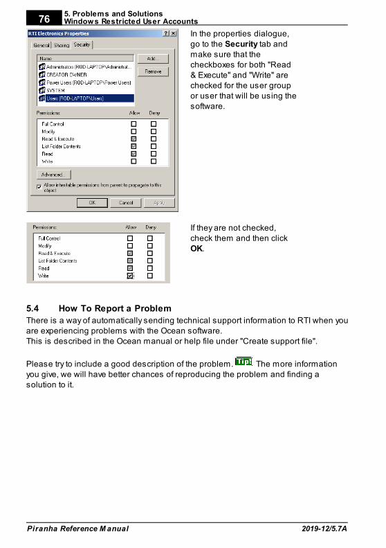
5. Problems and SolutionsWindows Restricted User Accounts
Piranha Reference M anual 2019-12/5.7A
76
In the properties dialogue,go to the Security tab andmake sure that thecheckboxes for both "Read& Execute" and "Write" arechecked for the user groupor user that will be using thesoftware.
If they are not checked,check them and then clickOK.
How To Report a Problem5.4
There is a way of automatically sending technical support information to RTI when youare experiencing problems with the Ocean software.This is described in the Ocean manual or help file under "Create support file".
Please try to include a good description of the problem. The more informationyou give, we will have better chances of reproducing the problem and finding asolution to it.

Glossary
Chapter 6
6. Glossary
Piranha Reference M anual 2019-12/5.7A
78
6 Glossary
Absorbed dose (D)
The energy imparted per unit mass by ionizing radiation to matter at a specified point.The SI unit of absorbed dose is joule per kilogram (J/kg). The special name for thisunit is gray (Gy). The previously used special unit of absorbed dose was the rad. 1 rad= 0.01 Gy. 1 Gy = 100 rad. (See Report No. 82, NCRP, 1985b.)SI unit: Gy = J/kg
Absorbed dose rate (D')
absorbed dose per unit time. Absorbed dose rate is determined as the quotient of dDby dt, where dD is the increment of absorbed dose in the time interval dt: D'=dD/dt. Aunit of absorbed dose rate is any quotient of the gray or its multiples or submultiplesby a suitable unit of time (Gy/s, mGy/h, etc.).SI unit: Gy/s = J/kg·s
Absorption, energy
Phenomenon in which incident radiation transfers to the matter which it traversessome or all of its energy.
Activity
The number of nuclear transitions occurring in a given quantity of radioactive materialper unit time. The SI unit of activity is s -1. The special name for the unit of activity isbecquerel (Bq). The previously used special unit of activity was the curie (Ci). 1 Bq =2.7 x 10¹⁰ Ci. 1 Ci = 3.7 x 10¹⁰ Bq. (See Report No. 82, NCRP, 1985b.)SI unit: Bq = s -1
Additional filtration
ADDED FILTERS and other removable materials in the RADIATION BEAM which arebetween the RADIATION SOURCE and the PATIENT or a specified plane.See also filter.
Air kerma
See kerma.
Aluminium equivalent or Aluminium Attenuation Equivalent (AAE)
The thickness of aluminum affording the same attenuation, under specifiedconditions, as the material in question.
Anode
In a X-ray tube, electrode to which electrons forming a beam are accelerated andwhich usually contains the target.
Aperture
(e.g., for computed tomography) - the opening in the collimation that allows radiationto reach the detector.
6. Glossary
2019-12/5.7A
79
Piranha Reference M anual
Area exposure product
Product of the area of a cross-section of a radiation beam and the averaged exposureover that cross-section.SI unit: Gy·m²
Attenuation
The reduction of radiation intensity upon passage of radiation through matter.
Automatic exposure control (AEC)
In an X-ray generator, mode of operation in which one or more loading factors arecontrolled automatically in order to obtain at a preselected location a desired quantityof radiation.
Automatic exposure rate control
In an X-ray generator, mode of operation in which the rate of emitted radiation iscontrolled automatically by control of one or more loading factors in order to obtain ata preselected location and in a preselected loading time a desired quantity ofradiation.
Beam limiting device
Device to limit the radiation field.
Becquerel (Bq)
The special name for the SI unit of activity. One becquerel is one reciprocal second or1 s -1. 3.7 × 10¹⁰ Bq = 1 Ci.
Bootloader
General: a program that does the job of loading the OS kernel of a computer.Piranha bootloader: Miniature program stored in cabinet and modules which normallyjust starts the Firmware. It is used more when the Firmware is updated. SeeFirmware.
Centigray
0.01 gray. 1 cGy equals one rad.
Cinefluorography
The production of motion picture photographic records of the image formed on theoutput phosphor of an image intensifier by the action of X-rays transmitted through thepatient (often called cineradiography).
Cineradiography
Indirect radiography of moving objects usually in rapid series on cine film.
Collimator
See beam limiting device.
Compensating filter
Filter used in order to modify the distribution of absorbed dose rate over the radiationfield.
6. Glossary
Piranha Reference M anual 2019-12/5.7A
80
Computed tomography (CT)
An imaging procedure that uses multiple X-ray transmission measurements and acomputer program to generate tomographic images of the patient.
Continuous mode
For an X-ray generator, mode of loading an X-ray tube continuously as in radiotherapyor in radioscopy.
Conversion factor (of an image intensifier)
The quotient of the luminance of the output phosphor of the image intensifier dividedby the kerma rate at the input phosphor.SI unit: cd/m² / Gy/s = cd·s/Gy·m²
CT
See Computed Tomography
CT number
One of a set of numbers on a linear scale which are related to the linear attenuationcoefficients calculated by a computed tomographic device. One of the specific set ofCT numbers on a scale from -1000 for air to +1000 for bone, with water equal to zero,which is called a Hounsfield unit.
Curie (Ci)
The previously used special unit of activity equal to 3.7 × 10¹⁰ per second. 1 Ci =3.7 × 10¹⁰ Bq.
Dead man switch
A switch so constructed that a circuit-closing contact can be maintained only bycontinuous pressure on the switch.
Dental panoramic radiographic
Direct radiography of a part of or the complete dentition by the use of an intra-oral X-ray tube. See also Orthopantomography.
Diagnostic source assembly
A diagnostic source housing (X-ray tube housing) assembly with a beam limitingdevice attached. This assembly shall be so constructed that the leakage radiation airkerma measured at a distance of one meter from the source does not exceed 1 mGy(0.1 rad) in one hour when the source is operated at its leakage technique factors.(See definition).
Digital radiography
A diagnostic procedure using an appropriate radiation source and an imaging systemwhich collects processes, stores, recalls, and presents image information in a digitalrather than analogue fashion.
Digital subtraction
An image processing procedure used to improve image contrast by subtracting onedigitized image from another.
6. Glossary
2019-12/5.7A
81
Piranha Reference M anual
Dose equivalent (H)
A quantity, defined for radiation protection purposes, which is the product of theabsorbed dose to the tissue and a quality factor "Q" determined by the properties ofthe radiation that produced the absorbed dose. For X-rays, gamma rays, andelectrons, Q = 1 and dose equivalent values are numerically equal to absorbed dosevalues when consistent units are used for both quantities. The SI unit for doseequivalent is joule per kilogram. The special name for the SI unit of dose equivalent issievert (Sv). The previous special unit of dose equivalent was the rem. One sievertequals 100 rem.SI unit: Sv = J/kg
Dose rate meter
Radiation meter intended to measure absorbed dose per unit time.
Dosemeter
Radiation meter intended to measure absorbed dose.
Effective dose equivalent (HE)
Quantity used to express the weighted DOSE EQUIVALENT to the whole body when itis irradiated non uniformly or partially.
Exposure (X)
A measure of the quantity of X-ray or gamma radiation based upon its ability to ionizeair through which it passes. The SI unit of exposure is coulomb per kilogram. Thepreviously used special unit of exposure was röntgen (R). 1 R = 2.58 × 10⁻⁴ C·kg-1
(exactly). The physical quantity exposure is now replaced by the quantity kerma in air. An exposure of 114.1 R is equal to an Air Kerma of 1 Gy. Thatmeans that the value in R should be multiplied by 8.76 to get the Air Kerma in mGy.SI unit: C/kg
Exposure rate (X')
Exposure per unit time. Exposure rate is determined as the quotient of dX by dt, wheredX is the increment of exposure in the time interval dt: X' = dX/dt. A unit of exposurerate is any quotient of the unit of exposure or its multiples or submultiples by asuitable unit of time ((C/kg)/s, (mC/kg)/h, etc.).SI unit: C/kg·s
Filter
In radiological equipment, material or device provided to effect filtration of the radiationbeam. SI unit: mm
Filter: Inherent filter
The filter permanently in the useful beam; it includes the window of the X-ray tube andany permanent enclosure for the tube or source. Replaced by term Permanent filter
Filter: Added filter
Filter in addition to the inherent filtration.
6. Glossary
Piranha Reference M anual 2019-12/5.7A
82
Filter: Permanent filter
The filter permanently in the useful beam; it includes the window of the X-ray tube andany permanent enclosure for the tube or source.
Filter: Total filter
The sum of the permanent and added filters.
Firmware
General: The operating system and software installed on a small device. Sometimescalled embedded software.Piranha firmware: Program stored in cabinet and modules which handles all controlof measurement electronics. Can be updated, then a special part of the firmwarecalled bootloader, is used. See Bootloader.
Fluorography
The production of a photographic record of the image formed on the output phosphorof an image intensifier by the action of X-rays transmitted through the patient.
Fluoroscopy
Technique of radioscopy by means of a fluorescent screen.
Focal spot, effective
The apparent size of the radiation source region in a source assembly when viewedfrom the central axis of the useful radiation beam.SI unit: dimensionless (corresponding to a dimension in mm)
Framing
In cinefluorography, the registration of the circular image of the output phosphor onthe rectangular film element or frame.
Gantry
The moveable patient table used for CT.
Geometric unsharpness
Unsharpness of the recorded image due to the combined optical effect of finite size ofthe radiation source and geometric separation of the anatomic area of interest fromthe image receptor and the collimator.
Gray (Gy)
The special name for the SI unit of absorbed dose, kerma, and specific energyimparted equal to one joule per kilogram. One gray equals one joule per kilogram.The previous unit of absorbed dose, rad, has been replaced by the gray. One grayequals 100 rad.
Half-value layer (HVL)
Thickness of a specified substance which, when introduced into the path of a givenbeam of radiation, reduces the kerma rate by one-half.SI unit: mm
6. Glossary
2019-12/5.7A
83
Piranha Reference M anual
Heel effect
Non-uniform intensity observed because a small fraction of the X-ray beam emitted ina direction nearly parallel to the angled target surface must pass through more targetmaterial before escaping from the target than does the major portion of the beamwhich is emitted more perpendicularly. (Note: In addition to the non-uniform intensity the angled target also produces non-uniform image resolution due to variations inapparent focal spot size as viewed from various positions on the film).
Hounsfield units
See CT number.
Image intensifier
An X-ray image receptor which increases the brightness of a fluoroscopic image byelectronic amplification and image minification.
Image receptor
A system for deriving a diagnostically usable image from the X-rays transmitted by thepatient. Examples: screen film system; stimulable phosphor; solid state detector.
Inherent filtration
Filter between the radiation source and the output window of the X-ray equipment.See filter.
Initial X-ray tube voltage
In a capacitor discharge X-ray generator, X-ray tube voltage at the beginning of theloading of the X-ray tube.
Installation
A radiation source with associated equipment, and the space in which it is located.
Interlock
A device used to assure proper and safe use of a radiation installation by monitoring(usually by electrical devices) the status, presence or position of various associateddevices such as source position, collimator opening, beam direction, door closure,filter presence, and preventing the production or emission of radiation if the potential for an unsafe condition is detected.
Ionization
Formation of ions by the division of molecules or by the addition or removal ofelectrons from atoms or molecules.SI unit: C, Coloumb
Ionization chamber
Ionization detector consisting of a chamber filled with a suitable gas, in which anelectric field, insufficient to induce gas multiplication, is provide for the collection at theelectrodes of charges associated with ions and the electrons produced in thesensitive volume of the detector by ionizing radiation.
6. Glossary
Piranha Reference M anual 2019-12/5.7A
84
Ionization constant
For air the ionization constant W/e = 33,97 J/C. The ionization constant is used to getthe correspondence between exposure and air kerma. See Roentgen and Gray formore information.
Ionization detector
Radiation detector based on the use of ionization in the sensitive volume of thedetector.
Irradiation time
Irradiation time is usually the time a rate of a RADIATION QUANTITY exceeds aspecified level. Irradiation time is sometimes called Exposure time.SI unit: s, second
Kerma (K)
The sum of the initial kinetic energies of all the charged ionizing particles liberated byuncharged ionizing particles per unit mass of a specified material. Kerma ismeasured in the same unit as absorbed dose. The SI unit of kerma is joule perkilogram and its special name is gray (Gy). Kerma can be quoted for any specifiedmaterial at a point in free space or in an absorbing medium. Typically the kerma isspecified in air.SI unit: Gy = J/kg
Kerma rate (K')
Kerma per unit time. Kerma rate is determined as the quotient of dK by dt, where dk isthe increment of kerma in the time interval dt: K'=dK/dt. A unit of kerma rate is anyquotient of the Gray or its multiples or submultiples by a suitable unit of time (Gy/s,mGy/h, etc.).SI unit: Gy/s = J/kg·s
Kilovolt (kV)
A unit of electrical potential difference equal to 1000 volts.
kVp
See Peak tube voltage
Lead equivalent
The thickness of lead affording the same attenuation, under specified conditions, asthe material in question.
Leakage radiation
All radiation coming from within the source assembly except for the useful beam.(Note: Leakage radiation includes the portion of the radiation coming directly from thesource and not absorbed by the source assembly, as well as the scattered radiationproduced within the source assembly).
Magnification imaging
An imaging procedure carried out with magnification usually produced by purposefulintroduction of distance between the subject and the image receptor.
6. Glossary
2019-12/5.7A
85
Piranha Reference M anual
Measured value
Estimate of the true value of a quantity, derived from the indicated value of a meterafter applying all relevant correction factors.
Medical diagnostic radiology
Medical diagnosis using ionizing radiation.
Modulation transfer function (MTF)
A mathematical entity that expresses the relative response of an imaging system orsystem component to sinusoidal inputs as a function of varying spatial frequency,which is often expressed in linepairs per millimetre (lp/mm), the correct unit ishowever m -1 (or often mm -1). The reference value most commonly used is that for zerofrequency. The MTF can be thought of as a measure of spatial resolution of thedetector system.SI unit: m -1
Monitor, personnel
See personnel monitor.
Occupancy factor (T)
The factor by which the workload should be multiplied to correct for the degree ofoccupancy (by any one person) of the area in question while the source is in the "ON"condition and emitting radiation. This multiplication is carried out for radiationprotection purposes to determine compliance with the dose equivalent limits.
Operator
Any individual who personally utilizes or manipulates a source of radiation.
Orthopantomography
Orthopantomography (also called OPG or Panorama) is a radiographic procedurethat produces a single image of facial structures including the upper and lowerdentition jaws and their supporting structures and bones. Mostly used in dentalapplications. An OPG ("orthopantomogram") gives a panoramic view of the mouth,giving information on the teeth and the bones of the upper and lower jaw.
Particle fluence
Number of particles incident on a sphere, divided by the cross-sectional area of thesphere.SI unit: m -2
Personnel monitor
Also known as personal monitor. An appropriately sensitive device used to estimatethe absorbed dose received by an individual.
Peak tube voltage Ûo (kVp)
The peak value of the tube voltage (corresponding to the highest available radiationenergy).
6. Glossary
Piranha Reference M anual 2019-12/5.7A
86
Phantom
In medical radiology, object behaving in essentially the same manner as tissue, withrespect to absorption or scattering of the ionizing radiation in question. Phantom areused, for example, for simulating practical conditions of measurement:- for purposes of radiation protection,- for evaluating the performances to the diagnostic systems with respect to theradiation or to the object,- for dosimetry.
Pixel
A two-dimensional picture element in the presented image.
Practical Peak Voltage (PPV)
The PPV is the constant potential producing the same image contrast as thewaveform under test. PPV is defined in the IEC 61676 standard as: "The PRACTICALPEAK VOLTAGE is based on the concept that the radiation generated by a highvoltage of any waveform produces the same AIR KERMA contrast behind a specifiedPHANTOM as a radiation generated by an equivalent constant potential. The constantpotential producing the same contrast as the waveform under test is defined asPRACTICAL PEAK VOLTAGE".
Primary protective barrier
See protective barrier
Protective apron
An apron made of radiation absorbing materials, used to reduce radiation exposure.
Protective barrier
A barrier of radiation absorbing material(s) used to reduce radiation exposure.
Protective glove
A glove made of radiation absorbing materials used to reduce radiation exposure.
Rad
The previously used special unit of absorbed dose. It is equal to 100 ergs per gram. 1rad = 0.01 Gy (10-2 gray).
Radiation (ionizing)
Any electromagnetic or particulate radiation capable of producing ions, directly orindirectly, by interaction with matter. Examples are X-ray photons, charged atomicparticles and other ions, and neutrons.
Ripple factor
The variation in the high-voltage expressed as the percentage of the maximum high-voltage across the X-ray tube during X-ray production: Ripple factor (%) = 100 x (Vmax- Vmin)/Vmax
Radiation protection survey
An evaluation of the radiation safety in and around an installation, that includesradiation measurements, inspections, evaluations, and recommendations.
6. Glossary
2019-12/5.7A
87
Piranha Reference M anual
Radiation receptor
Any device that absorbs a portion of the incident radiation energy and converts thisportion into another form of energy which can be more easily used to produce desiredresults (e.g., production of an image). See image receptor.
Radiation source
The region and/or material from which the radiation emanates.
Radiogram
A film or other record produced by the action of X-rays on a sensitized surface.
Radiography
The production of images on film/image detector by the action of X-rays transmittedthrough the patient.
Receptor
See radiation receptor.
Receptor assembly
A radiation receptor in the specialized container necessary for the proper operation ofthe receptor.
Rem
The previously used special unit of dose equivalent. One rem equals 10-2 sievert (Sv).
Resolution
In the context of an image system, the output of which is finally viewed by the eye, itrefers to the smallest size or highest spatial frequency of an object of given contrastthat is just perceptible. The intrinsic resolution, or resolving power, of an imagingsystem is measured in mm -1 or line pairs per millimeter (lp/mm), ordinarily using aresolving power target. The resolution actually achieved when imaging lower contrastobjects is normally much less, and depends upon many variables such as subjectcontrast levels and noise of the overall imaging system.
Roentgen (R) (or Röntgen)
The previously used special unit of exposure. 1 R = 2.58 × 10⁻⁴ C/kg. – Originally(Stockholm 1928) defined as "international R." (Symbol: r) and later (Chicago 1937)modified to: Roentgen- or g-ray, that gives a charge of 1 esE from secondary emissionin 0,001293 g of air.This means that an exposure of one Roentgen will produce 2,58 × 10⁻⁴ coulomb ofions of either sign per kilogram in air. Here the previously used physical quantityexposure has been replaced by kerma in air. See kerma. One R does not equal 1 cGyas the units C/kg and J/kg are different. To do this conversion the ionization constantfor air must be used, which is 33,97 J/C. This is how its calculated: 1 Gy = 1 J/kg Û 1J/kg/(2,58 × 10-4 C/kgR × 33,97 J/C) = 114,1 R. An exposure of 114,1 R thus equals anAir Kerma of 1 Gy. That also means that the value in R should be multiplied by 8,76 toget the Air Kerma in mGy. (See also Exposure.)
6. Glossary
Piranha Reference M anual 2019-12/5.7A
88
Scattered radiation
Radiation that, during passage through matter is changed in direction. (It is usuallyaccompanied by a decrease in energy.)
Serial radiography
A radiographic procedure in which a sequence of radiographs is made rapidly byusing an automatic cassette changer, image intensifier/TV chain, etc.
Shutter
In beam therapy equipment, a device, attached to the X-ray or gamma-ray sourcehousing to control the "ON" or "OFF" condition of the useful beam.
Sievert (Sv)
The special name for the SI unit of dose equivalent. One sievert equals one joule perkilogram. The previously used unit was the rem. One sievert is equal to 100 rem.
Signal-to-noise ratio
For video cameras, the ratio of input signal to background interference. The greaterthe ratio, the clearer the image.
Simulator
Diagnostic energy X-ray equipment used to simulate a therapy treatment plan outsidethe treatment room.
Slice
The single body section imaged in a tomography procedure.
Source
See radiation source.
Source-detector distance (SDD)
The distance measured along the central ray from the centre of the front surface of thesource (X-ray focal spot or sealed radioactive source) to the active surface of thedetector.
Source-to-image-distance (SID)
The distance measured along the central ray from the centre of the front of the surfaceof the source (X-ray focal spot of sealed radioactive source) to the surface of theimage detector.
Source-surface distance (source-skin distance) (SSD)
The distance measured along the central ray from the centre of the front surface of thesource (X-ray focal spot or sealed radioactive source) to the surface of the irradiatedobject or patient.
Spot film
A radiograph taken during a fluoroscopic examination for the purpose of providing apermanent record of an area of interest of to verify the filling of a void with contrastmedia.
6. Glossary
2019-12/5.7A
89
Piranha Reference M anual
Stray radiation
The sum of leakage and scattered radiation.
Survey
See radiation protection survey.
Target
The part of an X-ray tube anode assembly impacted by the electron beam to producethe useful X-ray beam.
Tenth value layer (TVL)
Thickness of a specified substance which, when introduced into the path of a givenbeam of radiation, reduces the kerma rate to one-tenth of its original rate.
Tomography
A special technique to show in detail images of structures lying in a predeterminedplane of tissue, while blurring or eliminating detail in images of structures in otherplanes.
Topogram
For CT, prior to making the cross-sectional scans, the CT scanner is normally used toobtain one or more radiograph-like reference images, as a way of identifying anddocumenting where the scans are to be made. These so-called topograms areprepared by keeping the X-ray source and the detectors stationary, and dragging thespecimen through the fan-beam by moving the table. Also called scout scans, pilotscans, or scanograms.
Total filtration
The total of inherent filtration and additional filtration.
Useful beam
The radiation which passes through the opening in the beam limiting device andwhich is used for imaging or treatment.
User
Physicians and other responsible for the radiation exposure of patients.
Voxel
A volume element in the object being imaged. The mean attenuation coefficient of thevoxel determines the CT (Hounsfield) number of the pixel.
Whole body dose equivalent (Hwb)
The dose equivalent associated with the uniform irradiation of the whole body.
Workload (W)
The degree of use of a radiation source. For X-ray machines operating at tubepotentials below 500 kV, the workload is usually expressed in milliampere minutesper week. For gammabeam therapy sources and for photon-emitting equipmentoperation at 500 kV or above, the workload is usually stated in terms of the weekly

6. Glossary
Piranha Reference M anual 2019-12/5.7A
90
kerma of the useful beam at one meter from the source and is expressed in grays perweek at one meter.
Xeroradiography
The production of an image on a xerographic plate (e.g., electrically chargedselenium) by the action of X-rays transmitted through the patient. (xeromammography:Mammography carried out by the xeroradiographic process.)
X-ray tube
Evacuated vessel for the production of x-radiation by the bombardment of a target,usually contained in an anode, with electrons accelerated from a cathode by anelectric field. Thus: Rotating anode X-ray tube. Double focus X-ray tube.
Piranha Reference M anual2019-12/5.7A
Index 91
IndexNote!
Page references in this Index points to the
first page of the section it is mentioned, not
the exact page.
- 2 -2002/96/EC 29
- A -About 4Absorbed dose 78Absorption 78Active display messages 45Active Messages 45Activity 78Additional f iltration 78Additional f iltration (mammo) 38Administrative user 74Advantages of using a Passkey 73AEC 78After exposure 43After exposure update mode 38AGD 56, 60Air kerma 78Air kerma (Dose) 14, 15, 18Air kerma rate (Dose rate) 14, 15, 18Aluminium equivalent 78Ambient light 69AMX-4 36Analogue Out 50Anode 78Anode/Filter combination 54
Mo/Mo 54Mo/Rh 54Rh/Rh 54W/Rh 54
Aperture 78Atmospheric pressure 37Authentication, Bluetooth 73Auto reset 43Automatic exposure control 78Auto-pow er off 71Autoscaling 71Average Glandular Dose 56, 60
- B -Battery
charging times 12level 8, 12
running time 8, 12status 8
Battery charging indicator 8Beam Correction Factor 38, 59Beam limiting device 79Beam quality 50, 54Becquerel 79Blank screen 71Bluetooth 71, 72
Indicator 7Passkey 73Passkey advantages 73Passkey disadvantages 73PIN code advantages 73PIN code disadvantages 73Security code 73
Bootloader 31, 79
- C -Calibrations
View 34Camera thread 7CAS-6 10CAS-7 10cd/m² 69CE Declaration 30CE Mark 30Centigray 79Charging Times 12Chest w all distance 54Cine 51, 52
HVL 52Quick-HVL 52Total f iltration 52
Cinefluorography 79Cineradiography 79Collimator 79Communication
Bluetooth 12USB 12
Compensating f ilter 79Compensation 50Compliances 29Compression paddle 38
Equivalent thickness 36, 58Computed tomography 63Computed tomography (CT) 79Conditions 36, 50
TP-factor 37Conformity Declaration 30Connector
External probe 7Palm charging 7USB 7
Piranha Reference M anual 2019-12/5.7A
Index92Connectors 7Continuous 43Continuous mode 79Continuous update mode 38Conversion factor (of an image
intensif ier) 79CT 63, 79
kVp 63CT Dose Profiler 28CT number 79CT specif ications 18CT topogram 63CT-DP 28Curie (Ci) 79
- D -Dead man sw itch 80Declaration of Conformity 30Default Unit 71Delay 38, 40, 41, 47, 63
Start efter 38Waveform 38
Delay time 46Dental 61Dental panoramic radiographic 80Dental specif ications 14Dental w aveforms 63Detector area 12Detector Manager 34Detector settings 41Detector surface 7Detectors
Managing 34View ing 34
Diagnostic source assembly 80Digital radiography 80Digital subtraction 80Direct radiography of a part of or the
complete dentition by the use of an
intra-oral X-ray tube. See also
Orthopantomography. 80Disable Bluetooth passkey 73Display messages 45
Active 45Passive 46
Dose 51Mammography 56
Dose equivalent (H) 80Dose Probe 7Dose Probe Specif ications 26Dose rate meter 80Dose Sensitivity 40Dose/Pulse 19, 51Dosemeter 80
Draw backs of using a Passkey 73
- E -Effective dose equivalent (HE) 81Enable Bluetooth passkey 73Entrance Skin Exposure 56, 60Entrance Surface Air Kerma 56, 60Equivalent thickness
Compression paddle 36, 58Error 71Error messages 45ESAK 56, 60ESE 56, 60Estimated total f iltration 14, 15, 18EU Directive 29, 30Exp. < Delay 46Exposure (X) 81Exposure rate (X') 81External probe connector 7
- F -FCC 31Filter 81Filter: Added f ilter 81Filter: Inherent f ilter 81Filter: Permanent f ilter 81Filter: Total f ilter 81Filtration Additional(mammo) 38Firmw are 4, 31, 81Fluorography 81Fluoroscopy 52, 81Fluoroscopy specif ications 14Focal spot, effective 81Framing 81Free run 43, 44Free run update mode 38
Using 44
- G -Gantry 82Geometric unsharpness 82Good geometry
HVL 58Gray (Gy) 82
- H -Half-value layer (HVL) 82Handheld Reset 71Heel effect 10, 82Help 50High kVp 45, 46High signal 45, 46
Piranha Reference M anual2019-12/5.7A
Index 93Holder
Piranha 10HotSync 71Hounsfield units 82How To
Report a Problem 76HVL
Cine 52Good geometry 58Stand 10
- I -IEC 61267 20II dose rate 53Illuminance 69Image intensif ier 53, 83Image receptor 83Indicator
Battery charging 7Bluetooth 7Status 7
Inherent f iltration 83Initial X-ray tube voltage 83Input dose rate 53Installation 83Interlock 83Internal detector settings 35, 40Introduction 4Ionization 83Ionization chamber 83Ionization constant 83Ionization detector 83Irradiation time 14, 15, 18, 47, 83ISO 4037 20
- K -Kerma 84Kerma rate 84Kilovolt (kV) 84kV Sensitivity 40kVp 14, 15, 18, 84
- L -Lead equivalent 84Leakage radiation 84Light measurment 68Light probe 69Light Probe Specif ication 28Low kVp 45, 46Low Signal 45, 46Luminance 69lux 69lx 69
- M -Magnif ication imaging 84Maintenance 31Mammography 54
Dose 56Positioning Piranha 54Quick-HVL 57
Mammography specif ications 15Manufacturer's Declaration of Conformity
30mAs 66, 67MAS-1 Probe Specif ications 27MAS-2 Current Probe 67MAS-2 Probe Specif ications 28Mean Glandular Dose 56, 60Measured value 84Measurement 51, 53
Cine 51Dose 51Dose per pulse 51, 53Fluoroscopy 52Image intensif ier 53Mammography 56Number of pulses 51Pulse rate 53Pulsed f luoroscopy 53Pulsed radiography 51Radiography 50
Measurement Modes Overview 43
Measurement settings 35Measuring principle
Piranha 48Medical diagnostic radiology 84MGD 56, 60Min. output peak dose rate 19Minimum pulse w idth 19Minimum ripple 19Mo/Mo Anode/Filter combination 54Mo/Rh Anode/Filter combination 54Modes
Of Measurement 43Modulation transfer function (MTF) 84Monitor 69Monitor, personnel 84Moving average 44
- N -Necessary Rights 75Negative Signal 46Normalization distance 36, 58
Piranha Reference M anual 2019-12/5.7A
Index94
- O -Occupancy factor (T) 85Operating air pressure 12Operating temperature 12Operator 85OPG 61Orthopantomography 85Oscilloscope 50Overview of Measurement Modes 43
- P -Panoramic dental 61Particle f luence 85Passive display messages 46Passkey advantages 73Passkey draw backs, Bluetooth 73PC requirements 5Peak tube voltage Ûo (kVp) 85Personnel monitor 85Phantom 85Physical dimensions
Piranha 13PIN code advantages 73PIN code draw backs, Bluetooth 73PIN code, Bluetooth 73Piranha 10, 48
Cable 10Holder 10Mammography positioning 54Physical dimensions 13Specif ications 12
Piranha internal detector 48Piranha Light Probe 68, 69Piranha MAS-1 Probe 66Piranha settings 35, 38Pixel 85Position check 51, 56, 61Post delay 38, 47Pow er sw itch 7Practical Peak Voltage (PPV) 85Prefixes, Unit 71Pre-pulse mammography 60Pressure
Atmospheric 37Primary protective barrier 85Probes
Managing 34View ing 34
Problem Report 71, 76Protective apron 85Protective barrier 85Protective glove 85
Pulse Measurements 51Pulse Rate 19, 37, 51Pulsed f luoroscopy 52, 53Pulsed radiography 51
- Q -Quick-HVL
Cine 52Mammography 57Radiography 51
- R -Rad 86Radiation (ionizing) 86Radiation protection survey 86Radiation quality 20Radiation receptor 86Radiation source 86Radiation time 47Radiogram 86Radiography 50, 51, 86
Quick-HVL 51Total f iltration 51
Radiography specif ications 14Receptor 86Receptor assembly 86Recording time 43Reference conditions 12Rem 86Report a Problem 76Reposition Detector 46Requirements, PC 5Reset
Bluetooth 71Handheld 71
Reset time 43Resolution 86Restricted user 74Rh/Rh Anode/Filter combination 54Ripple factor 86Roentgen (R) (or Röntgen) 86Röntgen Unit 71RTI Detector Manager 34RTI Updater 31Running time 8, 12
- S -Safety strap 7Scanning Beam Mammography 61Scatter factor 36, 58Scattered radiation 88SDD
Normalization 36, 58
Piranha Reference M anual2019-12/5.7A
Index 95Send Support Information 76Sensitivity 40, 41
Dose/TF 40kV 40
Serial radiography 88Settings 35, 38, 40, 41, 50
Beam correction factor 38Compression paddle 38Conditions 35, 36Delay 40, 41Detector 41Internal detector 35, 40Piranha 35, 38Post delay 38Pulse rate 37Sensitivity 40, 41Threshold 41Total Filtration 36Trig level (time) 38Trig source 38Update mode 38Waveform recording time 38Waveform type 36Window 40, 41
Shutter 88Sievert (Sv) 88Signal Extension Module 50Signal-to-noise ratio 88Simulator 88Size 13Slice 88Source 88Source-detector distance (SDD) 88Source-surface distance (source-skin
distance) (SSD) 88Source-to-image-distance (SID) 88Specif ications
Air kerma (Dose) 14, 15, 18Air kerma rate (Dose rate) 14, 15,
18Battery Charging 12Bluetooth 12Communication 12CT 18Dental 14Dose Probe 26Dose/pulse 19Estimated total f iltration 14, 15Fluoroscopy 14Irradiation time 14, 15, 18kVp 14, 15, 18Light Probe 28Mammography 15MAS-1 Probe 27MAS-2 Probe 28
Min. output peak dose rate 19Minimum pulse w idth 19Minimum ripple 19Piranha 12Pow er Source 12Pulse rate 19Radiography 14Size 13USB 12Waveform recording time 19, 27Weight 13
Spot f ilm 88Stand 10Standards and Compliances 29Start 31Start after delay 38Status indicator 7Storage temperature 12Stray radiation 88Support 71Support Information 76Survey 88
- T -Target 89Temperature 37Tenth value layer (TVL) 89TF Sensitivity 40Theory
Current reading 47Delay 47Dose rate reading 47Irradiation time 47Post delay 47Radiation time 47Waveform 47Window 47
Threshold 41Timed 43, 44Timed update mode 38
Using 44Tomography 89Topogram 63, 89Total f iltration 36, 50, 89
Cine 52Radiography 51
TP-factor 37Trig level (time) 38Trig source 38Trigger 47Troubleshooting 71Tube current
Invasive 66Non-invasive 67
Piranha Reference M anual 2019-12/5.7A
Index96Tube current measurements 65Typical Response 20Typographical Rules 4
- U -Unit
Default 71Gray 71Prefixes 71Röntgen 71
Units 71Unknow n device 71Update Firmw are 31Update Mode 38, 44Update modes 43Update of Piranha 31USB connector 7Useful beam 89User 89
- V -View Calibrations 34View box 69Voxel 89
- W -W/Rh Anode/Filter combination 54Waste Electrical and Electronic Equipment
29Waveform 47
Dental 63Waveform delay 38Waveform recording time 38, 43Waveform recording time Specif ications
19, 27Waveform type 36, 50WEEE 29Weight 13White screen 71Whole body dose equivalent (Hw b) 89Window 40, 41, 47Window time 46Workload (W) 89
- X -Xeroradiography 90X-ray tube 90

2019-12/5.7A Piranha Reference M anual
Notes
Notes 97

Notes
Piranha Reference M anual 2019-12/5.7A
Notes 98

Notes
2019-12/5.7A Piranha Reference M anual
Notes 99


