Embed Size (px)
Citation preview
arX
iv:c
ond-
mat
/970
2033
v1 [
cond
-mat
.sup
r-co
n] 4
Feb
199
7
Plasma Waves in Anisotropic Superconducting Films Below and
Above the Plasma Frequency
Mauro M. Doriaa, Gilberto Hollauerb, F. Paragec, and O. Buissonc
a Instituto de Fısica, Universidade Federal Fluminense, C.P. 100.093
Niteroi 24001-970 RJ, Brazil.
b Departamento de Fısica, Pontifıcia Universidade Catolica do Rio de Janeiro, Rio de Janeiro
22452-970 RJ, Brazil.
c Centre de Recherches sur les Tres Basses Temperatures, Laboratoire Associe a l’Universite
Joseph Fourier, C.N.R.S., BP 166, 38042 Grenoble-Cedex 9, France.
Abstract
We consider wave propagation inside an anisotropic superconducting film
sandwiched between two semi-infinite non-conducting bounding dieletric me-
dia such that along the c-axis, perpendicular to the surfaces, there is a plasma
frequency ωp below the superconducting gap. Propagation is assumed to be
parallel to the surfaces in the dielectric medium, where amplitudes decay ex-
ponentially. Below ωp, the amplitude also evanesces inside the film, and we re-
trieve the experimentally measured lower dispersion relation branch, ω ∝√
β,
and the recently proposed higher frequency branch, ω ∝ 1/√
β. Above ωp,
propagation is of the guided wave type, i.e., a dispersive plane wave confined
inside the film that reflects into the dielectric interfaces, and the modes are
approximately described by ω ≈ ωp
√
1 + (β/β0)2, where β0 is discussed here.
1
I. INTRODUCTION
The experimental measurement of a plasma edge in the infrared reflectivity of High-
Tc bulk superconductors1–3 La2−xSrxCuO4, Y Ba2Cu3O8−x4, and Bi2Sr2CaCu2O8
5–8 has
brought a renewed interest in collective oscillations with the Cooper pair density. Previ-
ously, such studies were hampered by the well-known argument9 that the Coulomb interac-
tion shifts the frequency of such oscilations to above the gap frequency. Recent theoretical
studies10–14 support the view of a plasma oscillations along the c-axis, the direction orthog-
onal to the CuO2 planes, caused by a large superconducting gap and a high anisotropy in
these materials.
In superconducting films, plasma oscillations have distinct properties. They exist in films
regardless of their anisotropy or layered structure, and regardless of the type of pairing or
even of the critical temperature value. This mode was predicted15,17,16 some time ago and
was bothly observed in thin granular aluminium films, in the hundreds of MHz range18,
and in thin Y Ba2Cu3O8−x films19, in the higher frequency range of hundreds of GHz.
The study of propagating modes in films is not a new research field, they have been
measured since long ago, in several materials ranging from metals20–22 to semiconductors23,
and also discussed in the theoretical literature25,24,26. The novelty for the superconducting
film is the very low frequency where these modes are observed and the strong temperature
dependence, explained by a collective oscillation with the Cooper pair density. Recently27 it
has been proposed that, similarly to metals and semiconductors, two branches of propagat-
ing modes should be observed in highly anisotropic superconducting films, e.g., the High-Tc
compounds. The experimental observation of these two modes can provide a method to
independently measure the London penetration lengths, parallel and perpendicular to the
film surface.
In this paper we include into the study of mode propagation in films the existence of a
c-axis plasma frequency, ωp, inside the superconducting state. We only consider the c-axis
perpendicular to the surfaces since this configuration is the most easily grown nowadays.
2
The propagation of plasma modes above and below ωp, their dispersion relations are our
goals in the present paper. We restrict our study to waves that propagate along the surfaces
of the superconducting film and evanesce in the dielectric medium perpendicularly to the
surfaces. Two very distinct behaviors are predicted, namely, field amplitudes that also
evanesce inside the film away from the interfaces (ω < ωp), and confined propagation, i.e.,
waves propagate inside the superconductor along an oblique direction and reflect at the
dielectric-superconductor interfaces (ω > ωp)29. In many aspects this last case resembles
propagation in optic fibers. In conclusion this paper considers a plasma frequency ωp inside
the superconducting state and studies its effects into wave propagation in films.
The study of plasma modes in superconducting films with a plasma frequency ωp has
been previously considered by Artemenko and Kobel’kov28 in the context of kinetic equations
for Green functions generalized to the case of layered superconductors with weak interlayer
coupling. The present paper provides a more complete study of such modes than theirs
because it shows that there are symmetric and antisymmetric modes for ω < ωp and dis-
cusses their several distinct regimes. The antisymmetric mode is intimately connected to
the transverse current component, thus being highly sensitive to the transverse London pen-
etration length, in the same fashion that the symmetric mode depends on the longitudinal
London penetration length. We claim that these properties can be used to gain a better
understanding of the transverse and longitudinal supercurrent components in anisotropic
and layered films. Besides, the present study is done in a framework distinct from those
authors, we take the simplest possible theory, the London-Maxwell theory for anisotropic
materials, supposedly valid when all lengths are larger than the inter-layer separation a.
In the context of this theory we determine exactly the mode frequency, ω, as a function
of its wavelength along the surfaces, β, and of the remaining parameters: the two London
penetration lengths, transverse (λ⊥) and longitudinal (λ‖) to the surfaces; the dielectric
constant of the non-conducting medium exterior to the film, ε; the film thickness d; and
the isotropy and frequency independent εs, the simplest phenomenological choice for the
superconductor’s static dieletric constant.
3
This paper is organized as follows. In the next section, (II), we derive the dispersion
relation equations, above and below the plasma frequency, using the London-Maxwell the-
ory, and solve them exactly. Our study is restricted to identical top and bottom dielectric
media. Similar conclusions should also apply to the most general asymmetric case. Section
III deals with the ω < ωp case, where we study the two possible branches, the so-called
symmetric (lower) and antisymmetric (upper) branches, and their three possible regimes:
optical, coupled, and asymptotic. For each branch we derive, from our exact solution, useful
approximated expressions for each of the above regimes. In this fashion many of the previous
film studies are shown to be suitable approximations of our exact solutions. In section IV
we study wave propagation above ωp and, obtain, from our exact dispersion relation, the
several dispersion relation branches found by Artemenko and Kobel’kov28. We show that
symmetry still plays an important role and the two branches below ωp split into several
ones, the symmetry of the state being determined by the number of half-wavelengths that
fit perpendicularly to the film. In section V we apply the present theory to the High-Tc
superconductors, suitably choosing the parameter values. Finally in section VI we summa-
rize our major results. The proof of some of results from our exact solution, such as the
approximated expressions, are the subject of appendix VII.
II. THE LONDON-MAXWELL THEORY APPLIED TO ANISOTROPIC
SUPERCONDUCTING FILMS
In this section we apply the London-Maxwell theory to describe wave propagation in a
superconducting film sandwiched between two identical non-conducting dielectric media30.
An external electromagnetic wave of frequency ω, and wavenumber k ≡ ω/c, is absorbed by
the superconducting film, producing a mode whose dispersion relation is ω(β). We choose
a coordinate system where the two plane parallel surfaces separating the superconducting
film to the dielectric medium are at x = d/2 and x = −d/2 . Propagation takes place along
the z axis such that all fields can be expressed as Fi(x) exp [−i(β z − ω t)]. At this point
4
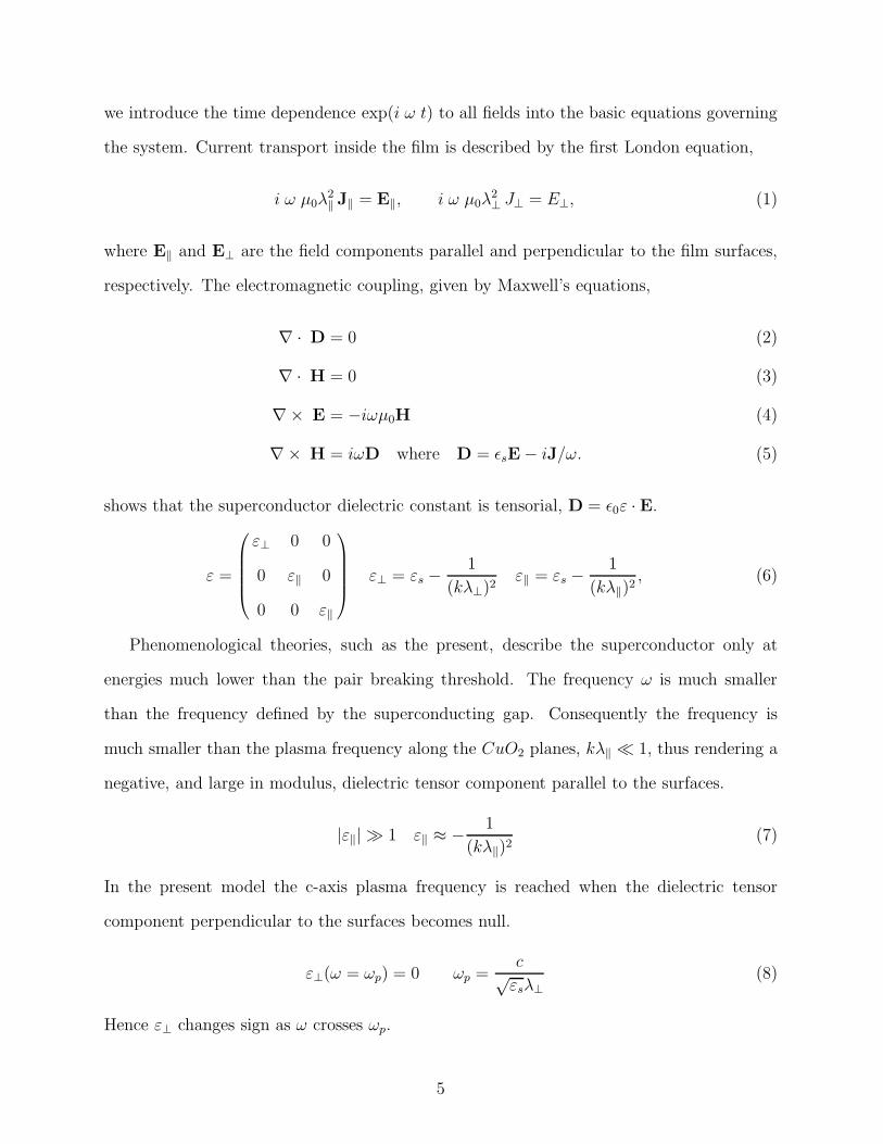
we introduce the time dependence exp(i ω t) to all fields into the basic equations governing
the system. Current transport inside the film is described by the first London equation,
i ω µ0λ2‖ J‖ = E‖, i ω µ0λ
2⊥ J⊥ = E⊥, (1)
where E‖ and E⊥ are the field components parallel and perpendicular to the film surfaces,
respectively. The electromagnetic coupling, given by Maxwell’s equations,
∇ · D = 0 (2)
∇ · H = 0 (3)
∇× E = −iωµ0H (4)
∇× H = iωD where D = ǫsE − iJ/ω. (5)
shows that the superconductor dielectric constant is tensorial, D = ǫ0ε · E.
ε =
ε⊥ 0 0
0 ε‖ 0
0 0 ε‖
ε⊥ = εs −1
(kλ⊥)2ε‖ = εs −
1
(kλ‖)2, (6)
Phenomenological theories, such as the present, describe the superconductor only at
energies much lower than the pair breaking threshold. The frequency ω is much smaller
than the frequency defined by the superconducting gap. Consequently the frequency is
much smaller than the plasma frequency along the CuO2 planes, kλ‖ ≪ 1, thus rendering a
negative, and large in modulus, dielectric tensor component parallel to the surfaces.
|ε‖| ≫ 1 ε‖ ≈ − 1
(kλ‖)2(7)
In the present model the c-axis plasma frequency is reached when the dielectric tensor
component perpendicular to the surfaces becomes null.
ε⊥(ω = ωp) = 0 ωp =c√
εsλ⊥(8)
Hence ε⊥ changes sign as ω crosses ωp.
5
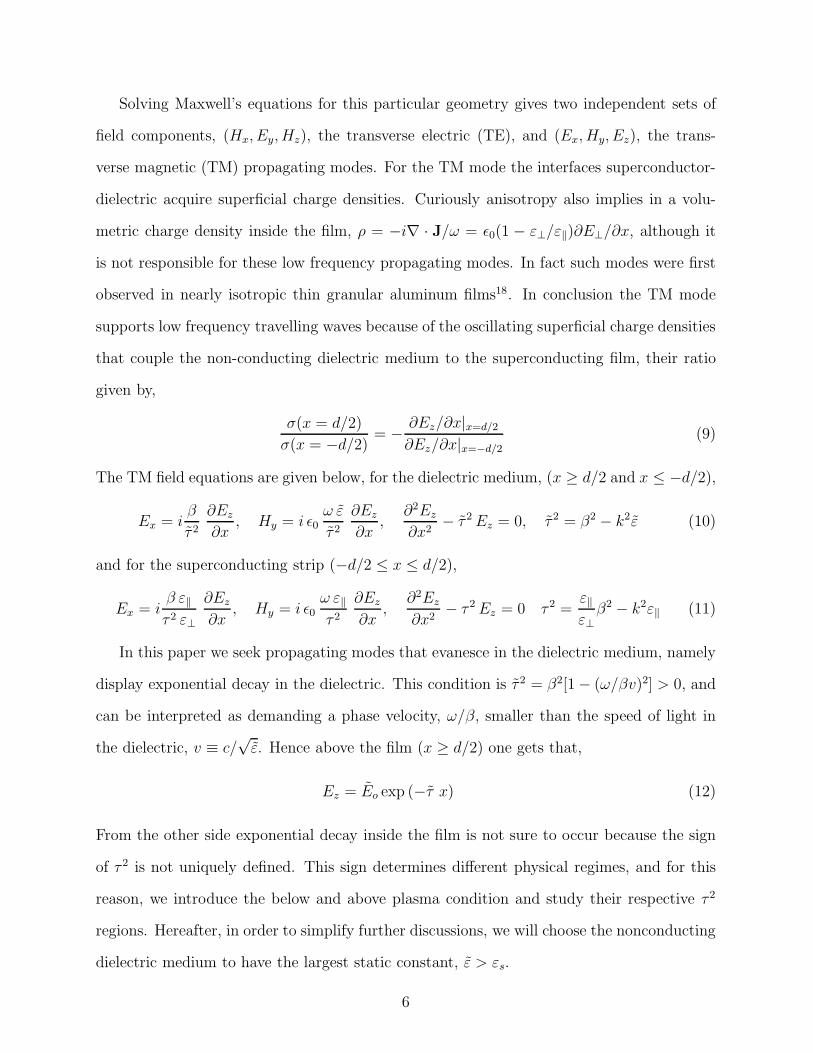
Solving Maxwell’s equations for this particular geometry gives two independent sets of
field components, (Hx, Ey, Hz), the transverse electric (TE), and (Ex, Hy, Ez), the trans-
verse magnetic (TM) propagating modes. For the TM mode the interfaces superconductor-
dielectric acquire superficial charge densities. Curiously anisotropy also implies in a volu-
metric charge density inside the film, ρ = −i∇ · J/ω = ǫ0(1 − ε⊥/ε‖)∂E⊥/∂x, although it
is not responsible for these low frequency propagating modes. In fact such modes were first
observed in nearly isotropic thin granular aluminum films18. In conclusion the TM mode
supports low frequency travelling waves because of the oscillating superficial charge densities
that couple the non-conducting dielectric medium to the superconducting film, their ratio
given by,
σ(x = d/2)
σ(x = −d/2)= − ∂Ez/∂x|x=d/2
∂Ez/∂x|x=−d/2
(9)
The TM field equations are given below, for the dielectric medium, (x ≥ d/2 and x ≤ −d/2),
Ex = iβ
τ 2
∂Ez
∂x, Hy = i ǫ0
ω ε
τ 2
∂Ez
∂x,
∂2Ez
∂x2− τ 2 Ez = 0, τ 2 = β2 − k2ε (10)
and for the superconducting strip (−d/2 ≤ x ≤ d/2),
Ex = iβ ε‖τ 2 ε⊥
∂Ez
∂x, Hy = i ǫ0
ω ε‖τ 2
∂Ez
∂x,
∂2Ez
∂x2− τ 2 Ez = 0 τ 2 =
ε‖ε⊥
β2 − k2ε‖ (11)
In this paper we seek propagating modes that evanesce in the dielectric medium, namely
display exponential decay in the dielectric. This condition is τ 2 = β2[1 − (ω/βv)2] > 0, and
can be interpreted as demanding a phase velocity, ω/β, smaller than the speed of light in
the dielectric, v ≡ c/√
ε. Hence above the film (x ≥ d/2) one gets that,
Ez = Eo exp (−τ x) (12)
From the other side exponential decay inside the film is not sure to occur because the sign
of τ 2 is not uniquely defined. This sign determines different physical regimes, and for this
reason, we introduce the below and above plasma condition and study their respective τ 2
regions. Hereafter, in order to simplify further discussions, we will choose the nonconducting
dielectric medium to have the largest static constant, ε > εs.
6
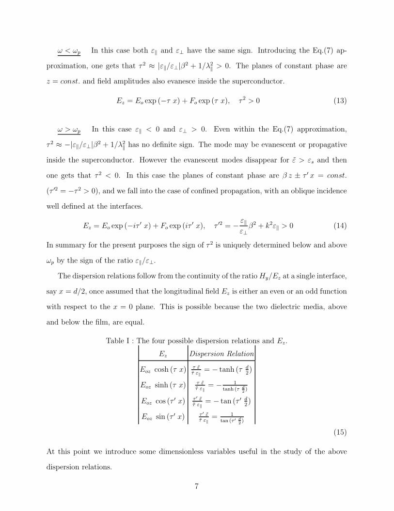
ω < ωp In this case both ε‖ and ε⊥ have the same sign. Introducing the Eq.(7) ap-
proximation, one gets that τ 2 ≈ |ε‖/ε⊥|β2 + 1/λ2‖ > 0. The planes of constant phase are
z = const. and field amplitudes also evanesce inside the superconductor.
Ez = Eo exp (−τ x) + Fo exp (τ x), τ 2 > 0 (13)
ω > ωp In this case ε‖ < 0 and ε⊥ > 0. Even within the Eq.(7) approximation,
τ 2 ≈ −|ε‖/ε⊥|β2 + 1/λ2‖ has no definite sign. The mode may be evanescent or propagative
inside the superconductor. However the evanescent modes disappear for ε > εs and then
one gets that τ 2 < 0. In this case the planes of constant phase are β z ± τ ′ x = const.
(τ ′2 = −τ 2 > 0), and we fall into the case of confined propagation, with an oblique incidence
well defined at the interfaces.
Ez = Eo exp (−iτ ′ x) + Fo exp (iτ ′ x), τ ′2 = − ε‖ε⊥
β2 + k2ε‖ > 0 (14)
In summary for the present purposes the sign of τ 2 is uniquely determined below and above
ωp by the sign of the ratio ε‖/ε⊥.
The dispersion relations follow from the continuity of the ratio Hy/Ez at a single interface,
say x = d/2, once assumed that the longitudinal field Ez is either an even or an odd function
with respect to the x = 0 plane. This is possible because the two dielectric media, above
and below the film, are equal.
Table I : The four possible dispersion relations and Ez.
Ez Dispersion Relation
Eoz cosh (τ x) τ ετ ε‖
= − tanh (τ d2)
Eoz sinh (τ x) τ ετ ε‖
= − 1tanh (τ d
2)
Eoz cos (τ ′ x) τ ′ ετ ε‖
= − tan (τ ′ d2)
Eoz sin (τ ′ x) τ ′ ετ ε‖
= 1tan (τ ′ d
2)
(15)
At this point we introduce some dimensionless variables useful in the study of the above
dispersion relations.
7
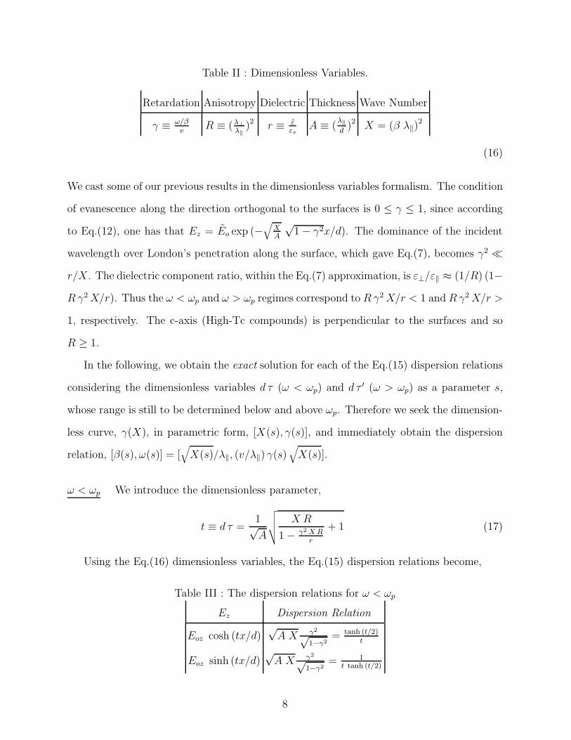
Table II : Dimensionless Variables.
Retardation Anisotropy Dielectric Thickness Wave Number
γ ≡ ω/βv
R ≡ (λ⊥
λ‖)2 r ≡ ε
εsA ≡ (
λ‖
d)2 X = (β λ‖)
2
(16)
We cast some of our previous results in the dimensionless variables formalism. The condition
of evanescence along the direction orthogonal to the surfaces is 0 ≤ γ ≤ 1, since according
to Eq.(12), one has that Ez = Eo exp (−√
XA
√1 − γ2x/d). The dominance of the incident
wavelength over London’s penetration along the surface, which gave Eq.(7), becomes γ2 ≪
r/X. The dielectric component ratio, within the Eq.(7) approximation, is ε⊥/ε‖ ≈ (1/R) (1−
R γ2 X/r). Thus the ω < ωp and ω > ωp regimes correspond to R γ2 X/r < 1 and R γ2 X/r >
1, respectively. The c-axis (High-Tc compounds) is perpendicular to the surfaces and so
R ≥ 1.
In the following, we obtain the exact solution for each of the Eq.(15) dispersion relations
considering the dimensionless variables d τ (ω < ωp) and d τ ′ (ω > ωp) as a parameter s,
whose range is still to be determined below and above ωp. Therefore we seek the dimension-
less curve, γ(X), in parametric form, [X(s), γ(s)], and immediately obtain the dispersion
relation, [β(s), ω(s)] = [√
X(s)/λ‖, (v/λ‖) γ(s)√
X(s)].
ω < ωp We introduce the dimensionless parameter,
t ≡ d τ =1√A
√
√
√
√
X R
1 − γ2 X Rr
+ 1 (17)
Using the Eq.(16) dimensionless variables, the Eq.(15) dispersion relations become,
Table III : The dispersion relations for ω < ωp
Ez Dispersion Relation
Eoz cosh (tx/d)√
A X γ2√1−γ2
= tanh (t/2)t
Eoz sinh (tx/d)√
A X γ2√1−γ2
= 1t tanh (t/2)
8
(18)
To find their solution, first obtain X(t, γ) from Eq.(17), and then introduce it into Eq.(18).
We obtain a second degree equation for γ(t)2 with two roots: one negative the other positive.
The negative root does not correspond to propagating modes and only the positive is left.
γI(t)2 =
(A t2 − 1) − r +√
[(A t2 − 1) + r]2 + 4 A r2
R(A t2 − 1) gI(t)
2(A t2 − 1)[1 + A rR
gI(t)](19)
X(t) =r
R
A t2 − 1
γI(t)2 (A t2 − 1) + r(20)
I = {S, A} labels the Ez symmetry: gA(t) = t2 tanh2 (t/2) and gS(t) = t2/ tanh2 (t/2) are
associated to the antisymmetric and the symmetric modes, respectively. According to the
above equations the parameter t range is [1/√
A,∞].
ω > ωp Through Eq.(14) we define a new dimensionless parameter.
t′ ≡ d τ ′ =1√A
√
√
√
√
X Rγ2 X R
r− 1
− 1 (21)
Introducing the Eq.(16) dimensionless variables into the Eq.(15) dispersion relations gives
that,
Table IV : The dispersion relations ω > ωp
Ez Dispersion Relation
Eoz cos (t′x/d)√
A X γ2√1−γ2
= tan (t′/2)t′
Eoz sin (t′x/d)√
A X γ2√1−γ2
= − 1t′ tan (t′/2)
(22)
To solve them, express Eq.(21) as X(t′, γ) and introduce it back into Eq.(22) obtaining a
second degree equation for γ(t′)2, whose solution is,
γI(t′)2 =
(A t′2 + 1) + r ±√
[(A t′2 + 1) − r]2 − 4 A r2
R(A t′2 + 1) hI(t′)
2(A t′2 + 1)[1 + A rR
hI(t′)](23)
XI(t′) =
r
R
A t′2 + 1
γI(t′)2 (A t′2 + 1) − r(24)
9
Like in the previous case, I = {S, A} gives the Ez parity: hA(t′) = t′2 tan2 (t′/2) and
hS(t′) = t′2/ tan2 (t′/2) for the antisymmetric and symmetric modes, respectively.
The discussion of the suitable parameter range is more involving in the present case.
According to Eq.(22) the function t′ tan (t′/2) must remain negative for the antisymmetric
problem whereas tan (t′/2)/t′ must be positive for the symmetric case. This restricts the
parameter range t′ to the intervals, [2 N π, (2 N +1) π] for symmetric and [(2 N +1) π, 2 (N +
1) π] for antisymmetric, where N is an integer larger or equal to zero.
Our exact parametrized solutions ω(β) are ready for applications, just requiring the
numerical parameters. Before doing so in section V, we find convenient to describe their
physical properties in the next two sections.
III. DISPERSION RELATION BELOW THE PLASMA FREQUENCY
In this section we study the properties of propagating modes below ωp. We find con-
venient to summarize their major physical properties and introduce some approximated
expressions, each describing a different regime of the exact ω < ωp dispersion curve. We
leave to the appendix VII the proof that the previous section exact results do justify our
picture and yield the approximated expressions. Below the plasma frequency the field ampli-
tudes inside the film evanesce from the surfaces, and this exponential decay is characterized
by τ , according to Eq.(13). The choice of film thickness, d, is very important in order to
assure sufficient coupling between the two surfaces. For extremely thick films the surfaces
decouple and the symmetric and the antisymmetric modes are the same, only independent
surface plasma modes exist in this situation. Indeed, in case of strong coupling between
the two surfaces three distinct regimes are possible for both symmetric and antisymmet-
ric modes. In sequence of increasing β we call them optical, coupled and asymptotic (see
Fig.(2)).
Close to the origin β ≈ 0, the modes are optical, that is, they are essentially plane waves
travelling in a dielectric medium. There is almost no exponential decay in the surrounding
10
dielectric semi-spaces up to appreciable distances, τ ≈ 0, according to Eq.(12). Propaga-
tion occurs with the speed of light in the dielectric, (γ ≈ 1). The kinetic energy of the
superconducting carriers is negligible compared to the magnetic energy of the mode. The
superconducting film contributes very weakly to this regime. In the optical regime one has,
approximately, the linear behavior ω ≈ v β.
Slowly the condensate’s kinetic energy increases with β until finally both energies become
comparable and a first cross-over takes place. This is the onset of the coupled regime, a
slow mode (γ < 1), where the condensate’s kinetic energy dominates over the magnetic
energy, the film and the dielectric are strongly coupled. This is the true plasma mode
regime. Such evanescent propagating modes are known15–17,27, here we discuss the effects
of a c-axis plasma frequency ωp below the gap28. In the coupled regime inside the film, the
fields evanesce from the surfaces very smoothly resulting into two types of coupling between
the superficial plasmons, which are the antisymmetric and the symmetric modes. For the
symmetric mode its dispersion relation has been theoretically studied by many authors15–17
and experimentally observed18,19 in the past:
ωs ≈ v
λ‖
√
d β
2(25)
Recently27 it has been proposed that the symmetric mode is just the lowest frequency branch.
In fact, there is an upper (antisymmetric) branch mode, that can also be experimentally
observed for highly anisotropic High-Tc superconducting films:
ωa ≈ v
λ⊥
√
1
d β/2 + εs/ε(26)
Because the antisymmetric branch is the highest in frequency, it is more sensitive to the
effects of the plasma frequency ωp. For dβ/2 comparable (or smaller) to εs/ε, this branch
becomes difficult to observe since ωa ≈ ωp. For dβ/2 dominant over εs/ε, the symmetric
and antisymmetric relations are proportional to√
β and 1/√
β, respectively.
The cross-over frequency between the optical and the symmetric regime is obtained at
the intersection of the two branches:
11
ωcross,s =vd
2λ2‖
(27)
The cross-over between optical and antisymmetric modes is implicitly given by the unique
real solution:
(d
2v) ω3
cross,a + (εs
ε) ω2
cross,a − (v
λ⊥)2 = 0 (28)
For the antisymmetric mode, the optical and the coupled frequencies are, respectively, an
increasing and a decreasing function of β. Thus the cross-over ωcross,a also gives an estimate
of the maximum frequency, associated to the peak seen in the antisymmetric curve (Fig.(2)).
By increasing β, evanescence inside the superconductor becomes stronger (τ is large), up
to the point where the surfaces are nearly decoupled. We have just reached the asymptotic
regime. Thus for sufficiently high β, symmetric and antisymmetric modes converge to the
same asymptotic frequency,
ωas = ωp
√
√
√
√
√
√
√
(1 +
√
1 + 4 (ε λ‖
εs λ⊥)2
1 + 2(ε λ‖
εs λ⊥)2 +
√
1 + 4(ε λ‖
εs λ⊥)2
) (29)
Notice that it is always true that ωas < ωp. It is easy to check in the following extreme cases
of a very high dieletric constant (ε/εs ≫ λ⊥/λ‖ ), and of the opposite case, namely, when
anisotropy plays a more important role than the dielectric constant, (ε/εs ≪ λ⊥/λ‖ ). In
the former case we obtain27 ωas = v/√
λ⊥λ‖, and in the latter ωas = ωp. In summary we
have just reviewed the major features of the three possible regimes for both the symmetric
and the antisymmetric dispersion relations.
We find that the dielectric constant ratio r must be sufficiently high in order to prevent
that the β range be extremely limited for the coupled regime. In the next section (V) we study
such crossovers in case of the High-Tc parameter values. The criterion for the disapperance of
the coupled antisymmetric and symmetric regimes is just given by an asymptotic frequency
ωas smaller than ωcross,s and ωcross,a, respectively. As an example consider the case of an
extremely large anisotropy (λ⊥ → ∞), where we get that ωas ≈ ωp → 0, eventually smaller
12
than the crossover frequencies of Eq.(27) and Eq.(28). In this limit the dispersion relation
goes almost directly from the optical to the asymptotic regime.
IV. DISPERSION RELATION ABOVE THE PLASMA FREQUENCY
In this section propagating modes inside the superconducting film with the frequency
larger than ωp are considered. We summarize their major physical properties, and leave
to the appendix VII their derivation from the exact parametrized dispersion relation. We
are again interested in modes that evanesce in the dieletric medium. As discussed before,
τ ′ is always real with the experimental parameter choice of ε > εs. The propagation of
light inside the film can be understood by a superposition of two dispersive plane waves,
exp {−i[±τ ′(β)x + βz − ω(β)t]}, regarded as incident and reflected waves, thus with a well
defined angle of incidence at the interfaces superconductor-dielectric. Thus while outside
the film light is still evanescent, in its interior the propagation can be pictured through ray
optics (see Fig.(1)), similarly to an optical fiber.
The exact parametrized plasma relation, given by Eq.(23) and Eq.(24), leads to the
simple approximated dispersion relation, in the vicinity of ω/β ≈ v,
ωM = ωp
√
√
√
√1 +(β d)2
(πM)2 + (d/λ‖)2(λ⊥
λ‖
)2 (30)
where M is a positive integer, odd for the symmetric modes (M = 2N + 1) and even for the
antisymmetric modes (M = 2(N + 1)). This approximated expression was first obtained by
Artemenko and Kobel’kov28. The M th curve satisfies the evanescence condition, γ ≤ 1, for
β > βinit(M).
βinit(M) =1
λ⊥
√
εs
ε− 1
(πM)2( d
λ‖)2
(31)
At the particular value β = βinit(M), the wave vector along the x-direction is given by
τ ′ d = M π where M is exactly the number of half-wavelength that fit perpendicularly to
the film. For β > βinit(M), the relation between τ ′ and M is not so simple because the wave
13
is also in the dielectric medium. In this case M just determines the number of Ez extrema
along the x-direction (see Fig.(1)). For instance, when just one half-wavelength fits into
the film we are facing the M = 1 symmetric mode, which has just a single Ez extremum
(maximum). We notice that the frequency of the plasma modes decreases for increasing M.
For β < βinit(M) we have that γ > 1 and the modes are not evanescent, they are plane
waves travelling in the dielectric medium. They have an oblique incidence at the surfaces
and to see this just take the plane wave exp {−i[τ x + βz − ωt]} with the speed of light in
the dielectric, v = ω/√
τ 2 + β2. One obtains that τ = β√
γ2 − 1, showing that we are in a
γ regime not studied here.
The present theory eventually breaks down because large τ ′ means an infinitesimally
small wavelength inside the film along the x axis. For this reason a physical cut-off must be
put into this theory, the inter-plane separation a. The upper limit τ ′max is determined when
a x-direction half-wavelength fits into the interplane distance a.
τ ′max = π/a = Mmaxπ/d (32)
Introducing Mmax in the approximated dispersion relation Eq.(30), gives the lowest fre-
quency plasma mode: ωmin = ωp
√
1 + (βλJ/π)2, where λJ ≡ aλ⊥/λ‖ is the Josephson
penetration depth.
Beyond τ ′max more elaborate models should provide a description of the condensate in
such scale. This can render the theory’s usage quite limited, in case the ratio d/a is small,
because for very few half-wavelengths inside the film we reach the cut-off limit. However
the applicability of this model above ωp is not restricted to a small ratio d/a because the
propagating mode has constant amplitude inside the film, and so, no matter how far apart
the surfaces are, there will always be waves reflected at the surfaces. For this reason the
major conclusions of this section, namely, the existence of slow modes above the plasma
frequency, corresponding to dispersive plane waves inside the film, must remain valid even
near the cut-off limit.
In the next section we take the standard parameter values for the high-Tc material and
14
discuss the properties of such propagating modes below and above the plasma frequency.
V. APPLICATIONS
For our applications we choose the following set of parameters for the High-Tc ceramic
superconductors. The static dielectric constant1 is εs ≈ 30. The zero-temperature London
penetration length along the CuO2 planes is λCO = 0.15µm31. While the anisotropy, λ⊥/λ‖,
is 5 for Y Ba2Cu3O8−x31, it has been changing in the past for Bi2Sr2CaCu2Ox, ranging
from 102, mainly from torque measurements studies31, to much higher values33. We show
here that choosing the anisotropy between these two values can have important effects
on the properties of the dispersion relations for ω < ωp. There is also the compound
T l2Ba2CaCuOx compound32 with λ⊥/λ‖ ≈ 90.
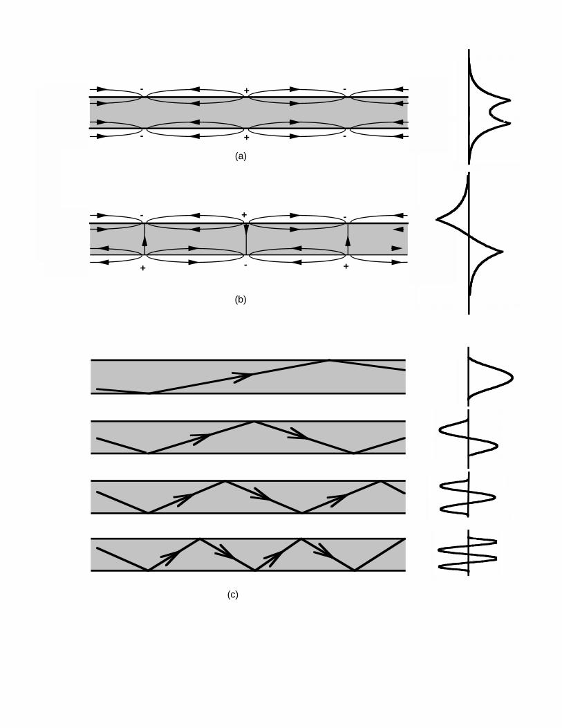
Fig.(1) provides a pictorial intuitive view of wave propagation in the film below and above
the plasma frequency. Below ωp the instantaneous electric field, as well as the component
Ez, are shown for both symmetric and antisymmetric fields. The surface charges are the
sole sources of propagating electric fields. The superficial charge arrangement has strong
consequences for the electric field distribuiton inside the film, leading to symmetric and
antisymmetric modes, found at distinct frequency ranges, the latter being an upper mode.
To understand the effects of anisotropy, or a layered structure, into these modes, where the
CuO2 planes are parallel to the film surface, consider the transverse and longitudinal field
and supercurrent components. Ex and Jx are very intense for the antisymmetric mode and
nearly zero for the symmetric one, and Ez and Jz, are the dominant components for the
symmetric mode but not for the antisymmetric one. Thus the relevant penetration depths
for the symmetric and the antisymmetric modes must be λ‖ and λ⊥, respectively. The
anisotropy λ⊥ > λ‖ hardens the system along the c-axis thus making the antisymmetric
mode lower in frequency. Above ωp a dispersive plane waves travels inside the film that
undergoes total reflection at the interfaces. This Figure also depicts the number of extrema
for the electric component Ez, which determines the symmetry of the mode.
15
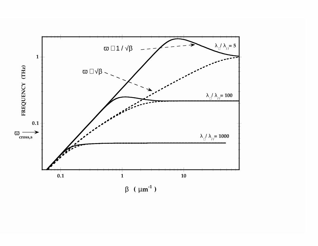
In Fig.(2), the symmetric and antisymmetric dispersion relations are shown for a very
thin film d = 10nm and the three anisotropies, λ⊥/λ‖ = 5, 102 and 103. In order to
slow down as much as possible light in the dielectric, and so, lower the coupled regime
frequency range, we choose SrT iO3 as the exterior non-conducting dielectric medium. At
low temperatures its dielectric constant is known to be high up to the GHz frequency18,
ε ≈ 20000. All curves in this Figure were directly obtained from the parametrized solution of
Eq.(19) and Eq.(20). The symmetric state crossover frequency, ωcross,s, between the optical
and the square root regimes is found to be 75 GHz for the three anisotropies displayed
here. The antisymmetric state crossover frequency, ωcross,a, between the optical and the
coupled regime, depends on the anisotropy, being 2.3 THz, 290 GHz and 48 GHz for
λ⊥/λ‖ = 5, 102 and 103, respectively. Because of this anisotropy dependence they are not
indicated in this Figure. Notice that the symmetric mode (dashed lines) is always found at a
frequency range lower than its corresponding antisymmetric mode (continuous lines). In the
low wave vector limit, all the dispersions collapse into the same linear (optical) regime. In
the opposite limit, β very large, both symmetric and antisymmetric curves converge to the
same asymptotic frequency. This asymptotic frequency is just the surface plasma frequency,
strongly affected by anisotropy: 1 THz for Y BCO, 200 GHz for BSSCO and 50 GHz
for λ⊥/λ‖=103. This saturation frequency is independent on film thickness, as expected,
according to Eq.(29). Notice that the wave vector signaling the onset of the asymptotic
regime decreases for increasing anisotropy, ranging from 10µm−1 for YBCO to 100mm−1 for
the maximum anisotropy considered here. Between the optical and the asymptotic is the
coupled regime, the true plasma mode, found to extend over a large range of frequency and
wavenumber for an Y BCO thin film, according to this Figure. In this regime the symmetric
plasma mode follows a square root and the antisymmetric mode clearly shows the inverse
square root dependence. For BSCCO, the coupled regime is shorter than in Y BCO, ranging
between 0.1 to 5µm−1. For the maximum anisotropy of 103, the coupled regime disappears
thus only surviving the optical and the asymptotic regimes. We conclude that an extremely
large anisotropy inhibits coupling between the two surfaces and enhances the surface plasma
16
modes.
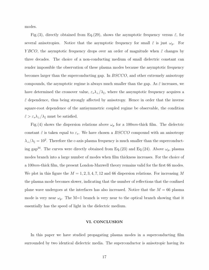
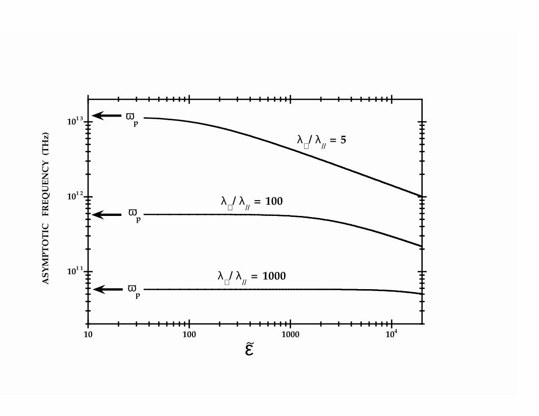
Fig.(3), directly obtained from Eq.(29), shows the asymptotic frequency versus ε, for
several anisotropies. Notice that the asymptotic frequency for small ε is just ωp. For
Y BCO, the asymptotic frequency drops over an order of magnitude when ε changes by
three decades. The choice of a non-conducting medium of small dielectric constant can
render impossible the observation of these plasma modes because the asymptotic frequency
becomes larger than the superconducting gap. In BSCCO, and other extremely anisotropy
compounds, the asymptotic regime is always much smaller than the gap. As ε increases, we
have determined the crossover value, εsλ⊥/λ‖, where the assymptotic frequency acquires a
ε dependence, thus being strongly affected by anisotropy. Hence in order that the inverse
square-root dependence of the antisymmetric coupled regime be observable, the condition
ε > εsλ⊥/λ‖ must be satisfied.
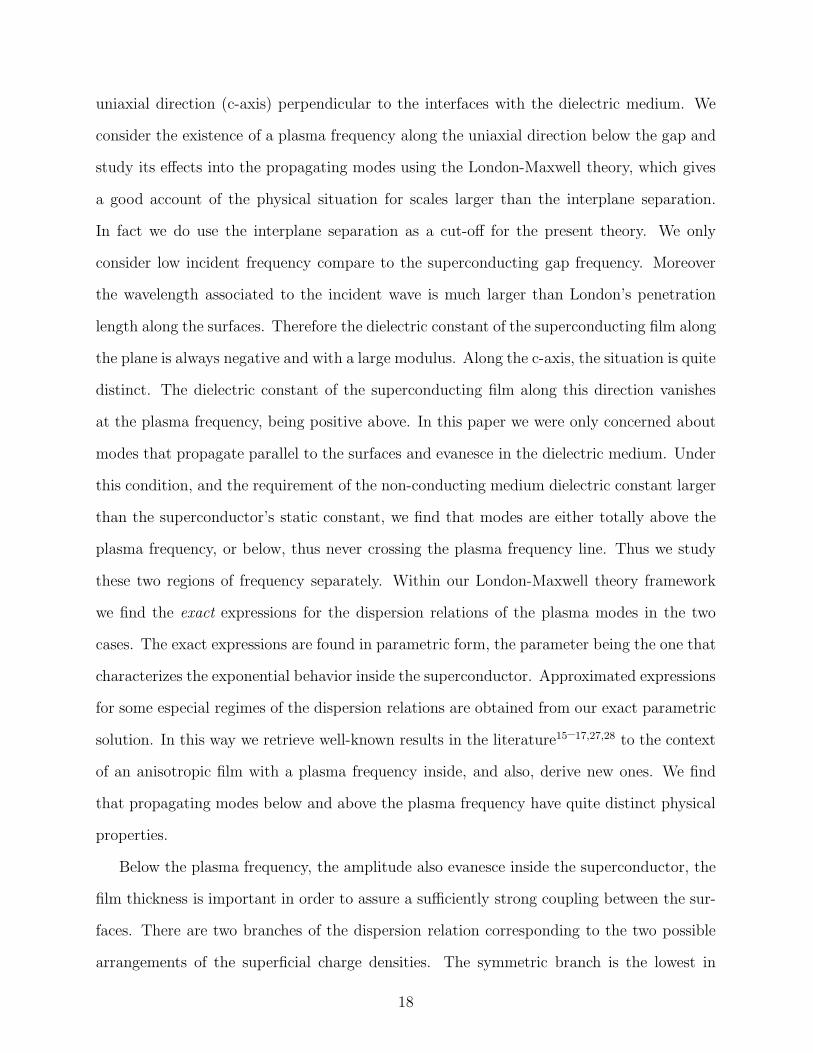
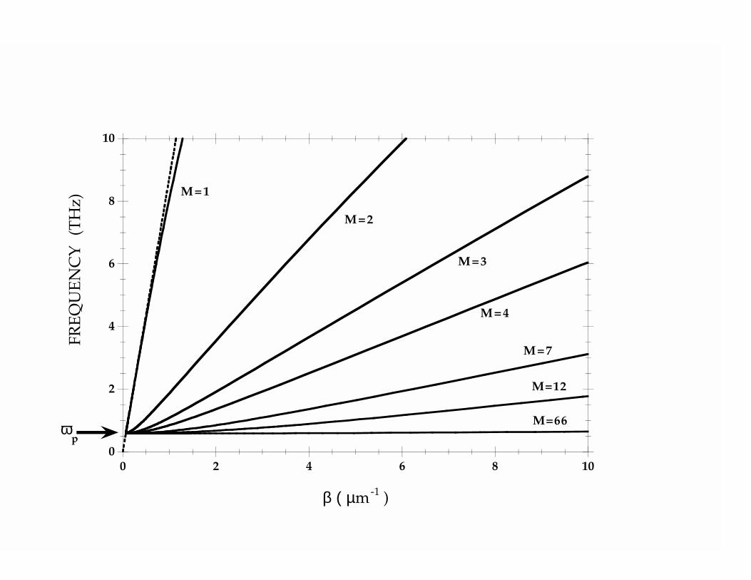
Fig.(4) shows the dispersion relations above ωp for a 100nm-thick film. The dielectric
constant ε is taken equal to εs. We have chosen a BSCCO compound with an anisotropy
λ⊥/λ‖ = 102. Therefore the c-axis plasma frequency is much smaller than the superconduct-
ing gap34. The curves were directly obtained from Eq.(23) and Eq.(24). Above ωp, plasma
modes branch into a large number of modes when film thickness increases. For the choice of
a 100nm-thick film, the present London-Maxwell theory remains valid for the first 66 modes.
We plot in this figure the M = 1, 2, 3, 4, 7, 12 and 66 dispersion relations. For increasing M
the plasma mode becomes slower, indicating that the number of reflections that the confined
plane wave undergoes at the interfaces has also increased. Notice that the M = 66 plasma
mode is very near ωp. The M=1 branch is very near to the optical branch showing that it
essentially has the speed of light in the dielectric medium.
VI. CONCLUSION
In this paper we have studied propagating plasma modes in a superconducting film
surrounded by two identical dielectric media. The superconductor is anisotropic having its
17
uniaxial direction (c-axis) perpendicular to the interfaces with the dielectric medium. We
consider the existence of a plasma frequency along the uniaxial direction below the gap and
study its effects into the propagating modes using the London-Maxwell theory, which gives
a good account of the physical situation for scales larger than the interplane separation.
In fact we do use the interplane separation as a cut-off for the present theory. We only
consider low incident frequency compare to the superconducting gap frequency. Moreover
the wavelength associated to the incident wave is much larger than London’s penetration
length along the surfaces. Therefore the dielectric constant of the superconducting film along
the plane is always negative and with a large modulus. Along the c-axis, the situation is quite
distinct. The dielectric constant of the superconducting film along this direction vanishes
at the plasma frequency, being positive above. In this paper we were only concerned about
modes that propagate parallel to the surfaces and evanesce in the dielectric medium. Under
this condition, and the requirement of the non-conducting medium dielectric constant larger
than the superconductor’s static constant, we find that modes are either totally above the
plasma frequency, or below, thus never crossing the plasma frequency line. Thus we study
these two regions of frequency separately. Within our London-Maxwell theory framework
we find the exact expressions for the dispersion relations of the plasma modes in the two
cases. The exact expressions are found in parametric form, the parameter being the one that
characterizes the exponential behavior inside the superconductor. Approximated expressions
for some especial regimes of the dispersion relations are obtained from our exact parametric
solution. In this way we retrieve well-known results in the literature15–17,27,28 to the context
of an anisotropic film with a plasma frequency inside, and also, derive new ones. We find
that propagating modes below and above the plasma frequency have quite distinct physical
properties.
Below the plasma frequency, the amplitude also evanesce inside the superconductor, the
film thickness is important in order to assure a sufficiently strong coupling between the sur-
faces. There are two branches of the dispersion relation corresponding to the two possible
arrangements of the superficial charge densities. The symmetric branch is the lowest in
18
frequency and has the two superficial charge density symmetrically disposed. The highest
branch has opposite charge facing each other at the interfaces thus being antisymmetric. We
have studied here in details the three possible regimes that can exist for these two branches,
their cross-over, and the conditions for the existence of the coupled regime, the most interest-
ing of the three regimes. In the so-called coupled regime both symmetric and antisymmetric
dispersion relation branch provides independent information on the two London penetration
lengths. The antisymmetric mode is intimately connected to the transverse current compo-
nent, thus being highly sensitive to the transverse London penetration length, in the same
fashion that the symmetric mode depends on the longitudinal London penetration length.
We believe that this remarkable property can be used to gain further understanding of the
transverse current component in anisotropic and layered films.
Above the plasma frequency the amplitudes do not evanesce inside the film, propagation
is geometrically understood, and an oblique ray can represent the plane wave inside the
superconductor which is totally reflected at the interfaces (see Fig.(1)). However outside the
film, in the dielectric medium, the wave remains evanescent, and we conclude that above
the plasma frequency the superconducting film displays confined propagation, similar to an
optic fiber. Notice that the film thickness is not a crucial parameter because no matter how
apart the surfaces are, there will always be plane waves travelling in its interior. Contrary
to below the plasma frequency, above there are many modes corresponding essentially to
the number of half-wavelengths that fit inside the film along the c-axis.
In summary we have shown in this paper that superconducting films surrounded by a
dielectric medium displays very interesting plasma modes propagation properties at fre-
quencies below the gap frequency and such properties are quite distinct below and above
the c-axis plasma frequency.
This work was done under a CNRS(France)-CNPq(Brasil) collabotation program.
19
VII. APPENDIX
In this appendix we provide further details on how the exact parametrized solutions of
section IV leads the the pictures developed in sections III and section IV for below and
above the plasma frequency, respectively.
ω < ωp
The three possible regimes, optical coupled and assymptotic follow from the exact
parametrized solution. In particular we show that Eq.(25) and Eq.(26), for the coupled
regime, and Eq.(29), for the asymptotic regime, follow from the Eq.(19) and Eq.(20). We
derive both Eq.(25) and Eq.(26) within the following approximations: (i) retardation effects
are neglected (γ ≪ 1) (√
1 − γ2 ≈ 1); (ii) fields evanesce slowly inside the film, t ≪ 1.
Therefore the Eq.(18) dispersion relations become√
A Xγ2 ≈ 1/2 and√
A Xγ2 ≈ 2/t2 for
the symmetric and for the antisymmetric modes, respectively; and (iii) the film thickness
is much smaller than the London penetration length along the surfaces A ≫ 1 so that
even though t is small we can approximate Eq.(17) by A t2 ≈√
X R/(1 − γ2 X R/r). Di-
rect elimination of the parameter t leads to both Eq.(25) and Eq.(26). In the asymptotic
regime fields inside the superconductor fade away very quickly from the surfaces , thus cor-
responding to t ≫ 1. The surface decoupling is seen from the antisymmetric and symmetric
dispersion relations which converge to the same asymptotic frequency ωas. According to
Eq.(19) gA(t → ∞) = gS(t → ∞) → t2 and Eq.(29) follows in a straighforward way from
this argument.
ω > ωp
To derive Eq.(30) from the exact parametrized solution is in fact very simple, because it
does not demand a detailed study of the γ(t′) curve. To do so we reparametrize the exact
solution of Eq.(23), replacing t′ by a new parameter t1, t′ = tI − t1 where tS = (2 N + 1)π,
and tA = 2 (N + 1) π. The advantages are two-fold: both symmetric and antisymmetric
modes are now defined in the same interval 0 ≤ t1 ≤ π; and the approximation is under
20
control, corresponding to the limit t1/tI ≪ 1. Notice that at t1 = 0 all curves satisfy
the condition γ = 1, thus justifying our claim that Eq.(30) is a good approximation for
the exact parametrized dispersion relation of Eq.(23) and Eq.(24) when the phase velocity
is approximately given by the speed of light in the dielectric. Indeed to obtain Eq.(30)
from Eq.(23) and Eq.(24), notice that γ(tI − t1) can be Taylor expanded in powers of t1
because the functions hI(t′), introduced in section IV, are well behaved in this neighborhood:
hI(t′) = (tI − t1)
2 tan2 (t1/2). We introduce the approximation t1/tI ≪ 1 into Eq.(24)
obtaining that XI ≈ (r/R)/{γ2I − r/[A(tI)
2 + 1)]}. The key issue here is that all the
parametric dependence of X is now on γ, because the last term was approximated by
a constant, r/A(tI − t1)2 ≈ r/At2I . Therefore we obtain the approximated parametrized
dispersion relation,
ω(t1) ≈ ωp
√
√
√
√
γI(t1)2
γI(t1)2 − rA t2
I
(33)
β(t1) ≈ βc
√
√
√
√
1
γI(t1)2 − rA t2
I
(34)
from where the family of curves ω(β) of Eq.(30) follow, by suitably removing the function
γ(t1).
Finally we would like to get some more detailed information about the parametrized exact
solution, in particular the two following issues:(i) ω(β) is always an increasing function of
β; (ii) near ωp it suffices to consider the positive root of Eq.(23) because the positive and
negative roots of Eq.(23) are just parts of the same curve and meet where the square root
vanishes. The claims are of general validity but we derive them under some further working
assumptions on Eq.(23), that in leading order, acquires a very simple form,
A (tI − t1)2 ≫ r ≫ 1, γI(t1)
2 =1 ±
√
1 − 4 r2
Rtan2 ( t1
2)
2[1 + A rR
(tI − t1)2 tan2 ( t12)]
(35)
To have the condition r ≫ 1 satisfied one must choose a dielectric medium of sufficiently
high constant: ε ≫ εs. To have at least one mode described by the above inequality, one
must require that the minimal frequency satisfies the inequality: t′max ≫√
r/A, which is
21
√
ε/εs ≪ 2πλ‖/a. To show that the curve never saturates, take t1 = 0, where one finds
that γ = 1 and γ = 0 for the positive and negative roots, respectively. Obviously the
positive root is the low frequency part of the curve. Notice that the negative root is not
physical because for γ = 0 β(X) is negative according to Eq.(24). This just means that
the negative square root curve must end at a finite non-zero γ, where the denominator of
Eq.(24) vanishes and so X diverges. γ is limited between zero and one, so it must also be
finite at this point. Consequently ω must also diverge, and so, we conclude from this that
the curve never saturates in ω or β.
22
REFERENCES
1 K. Tamasaku, Y. Nakamura, and U. Uchida, Phys. Rev. Lett. 69, 1455 (1992).
2 A.M. Gerrits, A. Wittlin, V.H.M. Duijn, A.A. Menovsky, J.J.M. Franse, and P.J.M. van
Bentum, Physica C 235-240, 1117 (1994).
3 J.H. Kim, H.S. Somal, M.T. Czyzyk, D. van der Marel, A. Wittlin, A.M. Gerrits,
V.H.M. Duijn, N.T. Hien, and A.A. Menovsky, Physica C 247, 297 (1995).
4 C.C. Homes, T. Timusk, R. Liang, D.A. Bonn, and W.N. Hardy, Phys. Rev. Lett. 71,
1645 (1993).
5 S. Tajima, G.D. Gu, S. Miyamoto, A. Odagawa, and N. Koshizuka, Phys. Rev. B 48,
16164 (1993).
6 Ophelia K.C. Tsui, N.P. Ong, Y. Matsuda, Y.F. Yan, and J.B. Peterson, Phys. Rev.
Lett., 73, 724 (1994).
7 Ophelia K.C. Tsui, N.P. Ong, and J.B. Peterson, Phys. Rev. Lett., 76, 819 (1995).
8 Y. Matsuda, M.B. Gaifullin, K. Kumagai, K. Kadowaki, and T. Mochiku, Phys. Rev.
Lett., 75, 4512 (1995).
9 P.W. Anderson, Phys. Rev. 112, 1900 (1958).
10 T. Mishonov, Phys. Rev. B 44, 12033 (1991); 50, 4004 (1994).
11 S.N. Artemenko and A.G. Kobelkov, JETP Lett. 58, 445 (1993);
12 H.A. Fertig and S. Das Sarma, Phys. Rev. Lett. 65, 1482 (1990), and Phys. Rev. B 44,
4480 (1991).
13 Y.B. Kim and X.G. Wen, Phys. Rev. B 48, 6319 (1993).
14 L.N. Bulaevskii, M. Zamora, D. Baeriswyl, H. Beck, and J.R. Clem, Phys. Rev. B 50,
12831 (1994).
23
15 J.E. Mooij and G. Schon, Phys. Rev. Lett. 55, 114 (1985).
16 B. Mirhashem and R. Ferrell, Physica C 161, 354 (1989).
17 T. Mishonov and A. Groshev, Phys. Rev. Lett. 64, 2199 (1990).
18 O. Buisson, P. Xavier, and J. Richard, Phys. Rev. Lett. 73, 3153 (1994); Phys. Rev. Lett.
74E, 1493 (1995).
19 F.J. Dunmore, D.Z. Liu, H.D. Drew, and S. Das Sarma, Phys. Rev. B 52, R731 (1995).
20 H. Boersch, J. Geiger, A. Imbush, and N. Niedrig, Phys. Lett. 22, 146 (1966).
21 M. Fukui, V.C.Y. So, and R. Normandin, Phys. Stat. Sol. 91, K61 (1979).
22 D. Sarid, Phys. Rev. Lett. 47, 1927 (1981).
23 S. Ushioda and R. Loudon, in Surface Polaritons, edited by V.M. Agranovich and A.A.
Maradudin (North-Holland P.Co., New York, 1982), p.573.
24 E.N. Economou, Phys. Rev. 182, 539 (1969).
25 K.L. Kliewer and R. Fuchs, Phys. Rev. 153, 498 (1966).
26 P.K. Tien and R. Ulrich, J. Opt. Soc. Amer. 60, 1325 (1970).
27 M.M. Doria, F. Parage, and O. Buisson, Europhys. Lett. 35, 445 (1996).
28 S.N. Artemenko and A.G. Kobelkov, Physica C 253, 373 (1995).
29 P. Yeh, Optical Waves in Layered Media (John Wiley & Sons, New York, NY, 1988).
30 O. Buisson, F. Parage, and J. Richard in Macroscopic Quantum Phenomena and Coher-
ence in Superconducting Networks ed. C. Giovannella, M. Tinhkam (World Scientific,
1995) p25.
31 G. Blatter et al., Rev. Mod. Phys. 66, 1125 (1994).
32 K.E. Gray, R.T. Kampwirth, and D.E. Farrel, Phys. Rev. B 41, 819 (1990).
24
33 E.H. Brandt, Rep. Prog. Phys. 58, 1465 (1995).
34 Tunneling and proximity effect studies give the frequency gaps 5.0 1012 Hz, and
7.5 1012 Hz, for Y BCO and BSCCO, respectively. See, for instance, M.R. Beasley,
Physica C 185, 227 (1991).
25
FIGURES
FIG. 1. A pictorial view of wave propagation in a superconducting film surrounded by two
equivalent non-conducting media. For ω < ωp the instantaneous electric field and the superficial
charges are shown for symmetric (a) and antisymmetric (b) modes. For ω > ωp the optical ray
associated to the plane wave travelling inside the film is shown here (c) for M=1,2,3 and 4. The
symmetry of each state is also shown here, for both cases (a), (b) and (c), through the diagram Ez
versus x.
FIG. 2. The symmetric and antisymmetric ω < ωp dispersion relations are shown for three
anisotropies. A very thin superconducting film, d = 10nm-thick, surrounded by SrT iO3, is con-
sidered.
FIG. 3. This Figure shows the asymptotic frequency versus ε, for three anisotropies. For small
ε the asymptotic frequency is just ωp. The asymptotic frequency for Y BCO is the most sensitive
to changes in the susbstrate dielectric constant.
FIG. 4. The dispersion relations above ωp is shown for a 100nm-thick film and anisotropy
λ⊥/λ‖ = 100. The M = 1 mode propagates with speed v and at the M = 66 mode is the upper
limit for the validity of the present theory.
26
(a)
- -
++
+
-
(c)
- -
--
+
+
(b)
0.1
1
0.1 1 10
FR
EQ
UE
NC
Y
(TH
z)
β ( µm-1 )
λ⊥/ λ
/ /= 5
λ⊥/ λ
/ /= 100
λ⊥/ λ
/ /= 1000
ω ∼ 1 / √β
ω ∼ √β
ωcross,s
101 1
101 2
101 3
10 100 1000 104
AS
YM
PT
OT
IC
FR
EQ
UE
NC
Y
(TH
z)
ε
λ⊥/ λ
// = 5
λ⊥/ λ
// = 100
λ⊥/ λ
// = 1000
~
ωp
ωp
ωp
0
2
4
6
8
10
0 2 4 6 8 10
FR
EQ
UE
NC
Y
(TH
z)
β ( µm-1
)
ωp
M=1
M=66
M=12
M=7
M=4
M=3
M=2


