Embed Size (px)
Citation preview
PLEASE SCROLL DOWN FOR ARTICLE
This article was downloaded by: [University of Toronto]On: 31 October 2010Access details: Access Details: [subscription number 926345689]Publisher Taylor & FrancisInforma Ltd Registered in England and Wales Registered Number: 1072954 Registered office: Mortimer House, 37-41 Mortimer Street, London W1T 3JH, UK
International Journal of CrashworthinessPublication details, including instructions for authors and subscription information:http://www.informaworld.com/smpp/title~content=t778188386
Influence of cellular imperfections on mechanical response of metallicfoamsM. S. Attiaa; S. A. Meguida; K. T. Tanb; S. C. Yeob
a Mechanics and Aerospace Design Laboratory, University of Toronto, Toronto, ON, Canada b DSONational Laboratories, Singapore
Online publication date: 01 October 2010
To cite this Article Attia, M. S. , Meguid, S. A. , Tan, K. T. and Yeo, S. C.(2010) 'Influence of cellular imperfections onmechanical response of metallic foams', International Journal of Crashworthiness, 15: 4, 357 — 367To link to this Article: DOI: 10.1080/13588260903457748URL: http://dx.doi.org/10.1080/13588260903457748
Full terms and conditions of use: http://www.informaworld.com/terms-and-conditions-of-access.pdf
This article may be used for research, teaching and private study purposes. Any substantial orsystematic reproduction, re-distribution, re-selling, loan or sub-licensing, systematic supply ordistribution in any form to anyone is expressly forbidden.
The publisher does not give any warranty express or implied or make any representation that the contentswill be complete or accurate or up to date. The accuracy of any instructions, formulae and drug dosesshould be independently verified with primary sources. The publisher shall not be liable for any loss,actions, claims, proceedings, demand or costs or damages whatsoever or howsoever caused arising directlyor indirectly in connection with or arising out of the use of this material.
International Journal of CrashworthinessVol. 15, No. 4, August 2010, 357–367
Influence of cellular imperfections on mechanical response of metallic foams
M.S. Attiaa, S.A. Meguida∗, K.T. Tanb and S.C. Yeob
aMechanics and Aerospace Design Laboratory, University of Toronto, Toronto, ON, Canada; bDSO National Laboratories, Singapore
(Received 31 March 2009; final version received 1 November 2009)
In this paper, we develop and implement high-resolution, computationally efficient multi-cell finite-element (FE) models ofmetallic foams in order to more accurately investigate the collapse behaviour of these emerging materials. The main objectiveis to investigate the effect of morphological imperfections at the cellular scale on the global response of the cellular material.Attention was therefore devoted to three related aspects of the work. The first is concerned with the development of FE modelsof metallic foams accounting for morphological imperfections at the cellular level. The second is concerned with conductingparametric studies of different model parameters and examining their effect on the instantaneous load-deformation history,peak collapse loads and energy absorption levels of the foam. The third is devoted to a thorough comparison of the numericalsimulations with experimental results. Results revealed the influence of these imperfections on low-density foams, and to amuch lesser extent on high-density ones.
Keywords: cellular solids; foam; energy absorption; morphological imperfections; finite-element (FE) modelling
IntroductionCellular materials have received increasing attention re-cently due to their excellent specific mechanical, physicaland chemical properties. Typically, the foam density rangesbetween 3% and 35% of its solid surrogates. This makesfoam materials an excellent candidate for innovative de-signs in which low weight and high strength are desirabledesign parameters. Polymeric foams made from polystyreneand polyvinyl chloride are well established in applicationssuch as packaging and sound insulation. Metallic foamshave received increased attention over the past decade, anda number of foaming techniques have been devised forfabricating metallic foams from aluminium, zinc and steelalloys [2].
Existing work in the literature concerning the mechani-cal characterisation of foam behaviour can be broadly clas-sified into the following: (1) continuum-based approach,which employs continuum mechanics to characterise thefoam, (2) unit-cell-based approach, which relies on dis-cretising the foam structure into space-filling periodic self-repeating cells, and (3) multi-cell models, which makeuse of unit cells to build the cellular structure of thefoam.
Continuum-based models [3,5,13] provide means forsimplified treatment of foam materials through evaluatingaverage field variables over the domain. They are charac-terised by their dependence on the hydrostatic componentof the stress tensor due to the existence of plastic com-
∗Corresponding author. Email: [email protected]
pressibility resulting from gaseous pores. The accuracyof different continuum-based foam material models wasexamined using LS-DYNA and ABAQUS explicit finite-element (FE) solvers [11,14]. The models were calibratedagainst multi-axial experimental results. It was concludedthat none of the existing models was completely capable ofrepresenting the behaviour of metallic foams under gener-alised loading conditions. It was also indicated in [14] thatcontinuum-based models are not applicable for cases wherethe model size is comparable with the cell size of the foam,and that unit-cell-based analyses should be adopted in suchcases.
Unit-cell-based models, on the other hand, are charac-terised by their direct interpretation of the cellular natureof the foam. Gibson and Ashby [6] developed analyticalsolutions for a simple skeletal model for open-cell foambased on plastic hinge analysis of beams. They highlightedthe dependence of mechanical properties of the foam onits relative density ρ∗. They further extended their modelto account for closed-cell foams [18] by incorporatingmembrane-stretching terms into the constitutive relationsof the unit cell. Further investigations into the solidificationmechanisms and considerations of minimum surface energyled to the development of tetrakaidecahedral cells as themost accurate representation of closed-cell metallic foams[6,7,17,18]. Alternatively, Santosa and Wierzbicki [15] de-veloped a simpler representative unit-cell model basedon examination of the foam morphology and presented
ISSN: 1358-8265 print / ISSN: 1754-2111 onlineC© 2010 Taylor & Francis
DOI: 10.1080/13588260903457748http://www.informaworld.com
Downloaded By: [University of Toronto] At: 05:46 31 October 2010
358 M.S. Attia et al.
analytical expressions for the load-deformation behaviourof a single cell under uniaxial loads. This model waslater enhanced by Meguid et al. [12] to better reflect thefoam morphology. In their work, they conducted bothexperimental and FE investigations to evaluate the ef-fect of non-uniform density distribution on the mechan-ical behaviour and the associated deformation localisa-tion phenomenon in the foam. It was concluded in [12]that uniform-density idealised models over-estimated theexperimental results by factors up to 45%, thus reveal-ing the importance of quantifying the effect of imper-fections on the behaviour of the foam. These imperfec-tions can be categorised into macro-scale or unit-cellscale imperfections. Missing cells, fractured cell wallsand non-uniform cell size represent the former type.Unit-cell scale imperfections include the following: cor-rugated cell walls, curved cell walls and non-uniform wallthickness.
Existing continuum-based constitutive models of metal-lic foams do not provide explicit quantitative analysis ofthe effect of these imperfections on the deformation, col-lapse mechanisms and energy absorption characteristics.Unit-cell models, on the other hand, provide explicit meansfor evaluating the effect of these imperfections [9,17],yet the majority of these models are restricted to theunit-cell scale and are not linked to macro-scale. Giouxet al. [8] conducted a comparative study between the mod-els presented by Miller [13], Deshpande and Fleck [5],and Triantafillou [18] under multi-axial loads. They con-cluded the phenomenological yield surfaces in Miller [13]and Deshpande and Fleck [5] are in good agreement withthe experiments, while the idealised unit-cell-based yieldsurface presented by Triantafillou [18] over-estimates thefailure surfaces due to the existence of morphological im-perfections, mainly curved cell walls, which significantly
lower the hydrostatic strength of the foam. Finally, multi-cell approaches possess the bridging capability betweenthe unit-cell scale and the macro-scale. Silva and Gibson[16] investigated the effect of non-periodic structure andmissing cell walls on the behaviour of two-dimensionalfoam using Voronoi tessellations method. Nevertheless,restrictions on computational resources have limited thisapproach for long. Meguid et al. [12] employed multi-cell models to investigate strain localisation in metal-lic foams. However, they used highly idealised modelsand no consideration was made of the influence of cel-lular defects upon the behaviour of the material underload.
In this study, we investigate the quasi-static collapse ofmetallic foam structures using a multi-cell approach. Unlikethe earlier work of Meguid et al. [12], this work aims atidentifying the effect of morphological imperfections on thecollapse of closed-cell aluminium foams. Focus is placed oninvestigating the effect of curved and corrugated cell wallson the collapse load and energy absorption characteristicsof the cellular structure.
Theoretical considerations
In this section, we present the pertinent aspects related tothe unit-cell model used in the current study, along with themost prominent morphological imperfections.
Representative unit-cell model
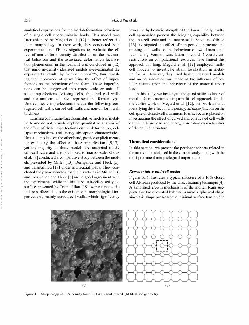
Figure 1(a) illustrates a typical structure of a 10% closedcell Al-foam produced by the direct foaming technique [4].A simplified growth mechanism of the molten foam sug-gests that the nucleated bubbles assume a spherical shapesince this shape possesses the minimal surface tension and
Figure 1. Morphology of 10% density foam. (a) As manufactured. (b) Idealised geometry.
Downloaded By: [University of Toronto] At: 05:46 31 October 2010
International Journal of Crashworthiness 359
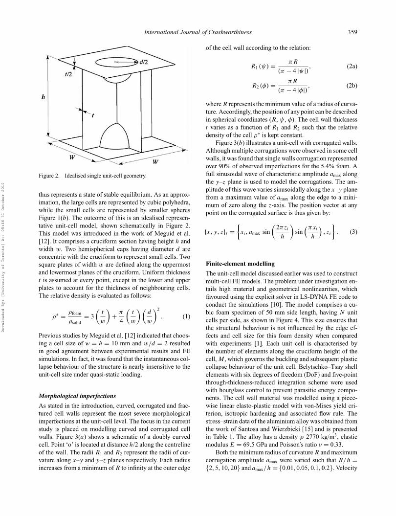
Figure 2. Idealised single unit-cell geometry.
thus represents a state of stable equilibrium. As an approx-imation, the large cells are represented by cubic polyhedra,while the small cells are represented by smaller spheresFigure 1(b). The outcome of this is an idealised represen-tative unit-cell model, shown schematically in Figure 2.This model was introduced in the work of Meguid et al.[12]. It comprises a cruciform section having height h andwidth w. Two hemispherical caps having diameter d areconcentric with the cruciform to represent small cells. Twosquare plates of width w are defined along the uppermostand lowermost planes of the cruciform. Uniform thicknesst is assumed at every point, except in the lower and upperplates to account for the thickness of neighbouring cells.The relative density is evaluated as follows:
ρ∗ = ρfoam
ρsolid= 3
(t
w
)+ π
4
(t
w
) (d
w
)2
. (1)
Previous studies by Meguid et al. [12] indicated that choos-ing a cell size of w = h = 10 mm and w/d = 2 resultedin good agreement between experimental results and FEsimulations. In fact, it was found that the instantaneous col-lapse behaviour of the structure is nearly insensitive to theunit-cell size under quasi-static loading.
Morphological imperfections
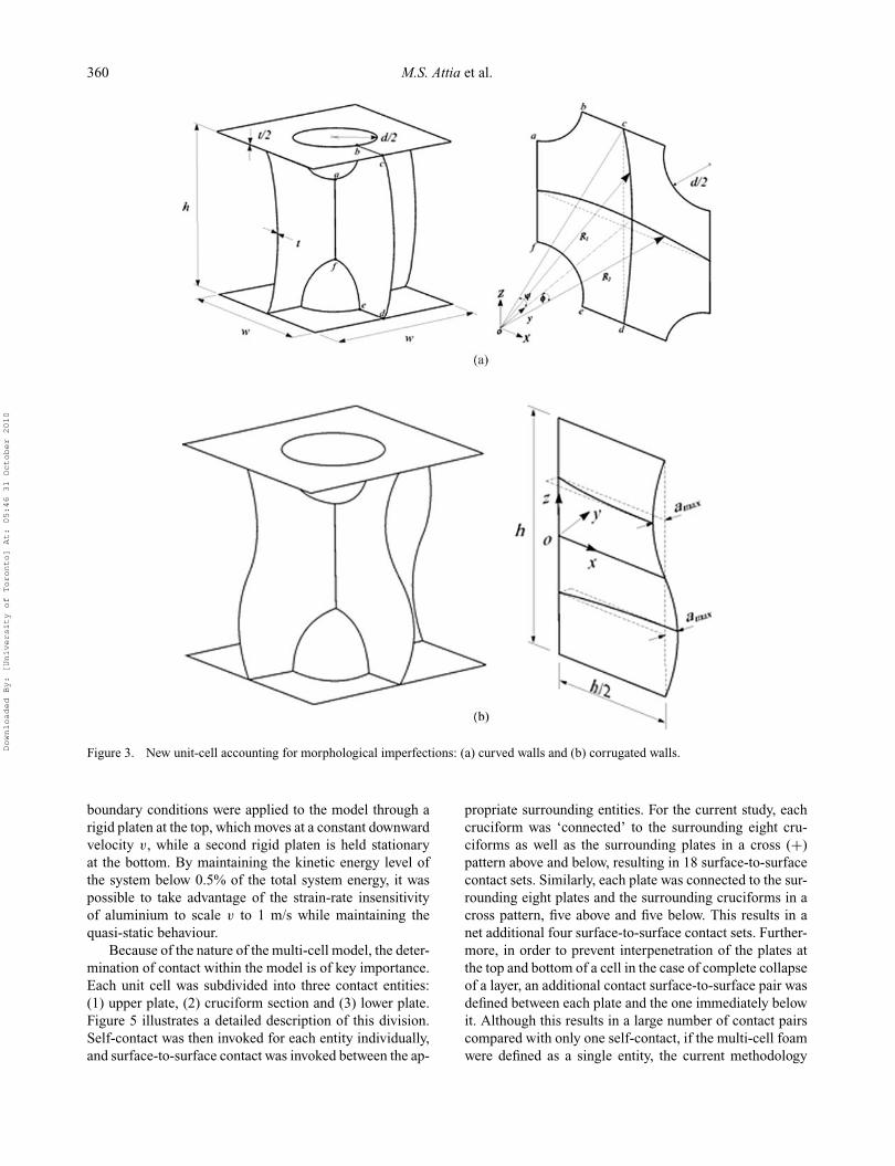
As stated in the introduction, curved, corrugated and frac-tured cell walls represent the most severe morphologicalimperfections at the unit-cell level. The focus in the currentstudy is placed on modelling curved and corrugated cellwalls. Figure 3(a) shows a schematic of a doubly curvedcell. Point ‘o’ is located at distance h/2 along the centrelineof the wall. The radii R1 and R2 represent the radii of cur-vature along x–y and y–z planes respectively. Each radiusincreases from a minimum of R to infinity at the outer edge
of the cell wall according to the relation:
R1 (ψ) = πR
(π − 4 |ψ |) , (2a)
R2 (φ) = πR
(π − 4 |φ|) , (2b)
where R represents the minimum value of a radius of curva-ture. Accordingly, the position of any point can be describedin spherical coordinates (R, ψ , φ). The cell wall thicknesst varies as a function of R1 and R2 such that the relativedensity of the cell ρ∗ is kept constant.
Figure 3(b) illustrates a unit-cell with corrugated walls.Although multiple corrugations were observed in some cellwalls, it was found that single walls corrugation representedover 90% of observed imperfections for the 5.4% foam. Afull sinusoidal wave of characteristic amplitude amax alongthe y–z plane is used to model the corrugations. The am-plitude of this wave varies sinusoidally along the x–y planefrom a maximum value of amax along the edge to a mini-mum of zero along the z-axis. The position vector at anypoint on the corrugated surface is thus given by:
{x, y, z}i ={xi, amax sin
(2πzi
h
)sin
(πxi
h
), zi
}. (3)
Finite-element modelling
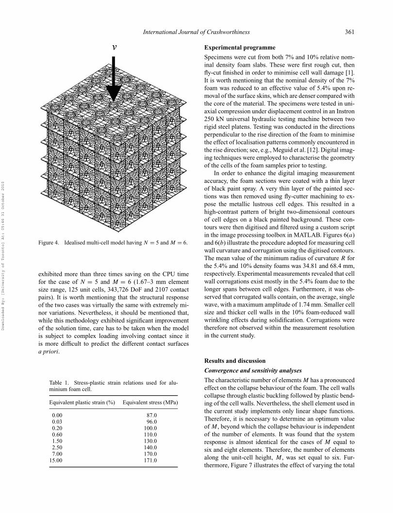
The unit-cell model discussed earlier was used to constructmulti-cell FE models. The problem under investigation en-tails high material and geometrical nonlinearities, whichfavoured using the explicit solver in LS-DYNA FE code toconduct the simulations [10]. The model comprises a cu-bic foam specimen of 50 mm side length, having N unitcells per side, as shown in Figure 4. This size ensures thatthe structural behaviour is not influenced by the edge ef-fects and cell size for this foam density when comparedwith experiments [1]. Each unit cell is characterised bythe number of elements along the cruciform height of thecell, M , which governs the buckling and subsequent plasticcollapse behaviour of the unit cell. Belytschko–Tsay shellelements with six degrees of freedom (DoF) and five-pointthrough-thickness-reduced integration scheme were usedwith hourglass control to prevent parasitic energy compo-nents. The cell wall material was modelled using a piece-wise linear elasto-plastic model with von-Mises yield cri-terion, isotropic hardening and associated flow rule. Thestress–strain data of the aluminium alloy was obtained fromthe work of Santosa and Wierzbicki [15] and is presentedin Table 1. The alloy has a density ρ 2770 kg/m3, elasticmodulus E = 69.5 GPa and Poisson’s ratio ν = 0.33.
Both the minimum radius of curvature R and maximumcorrugation amplitude amax were varied such that R/h ={2, 5, 10, 20} and amax/h = {0.01, 0.05, 0.1, 0.2}. Velocity
Downloaded By: [University of Toronto] At: 05:46 31 October 2010
360 M.S. Attia et al.
Figure 3. New unit-cell accounting for morphological imperfections: (a) curved walls and (b) corrugated walls.
boundary conditions were applied to the model through arigid platen at the top, which moves at a constant downwardvelocity v, while a second rigid platen is held stationaryat the bottom. By maintaining the kinetic energy level ofthe system below 0.5% of the total system energy, it waspossible to take advantage of the strain-rate insensitivityof aluminium to scale v to 1 m/s while maintaining thequasi-static behaviour.
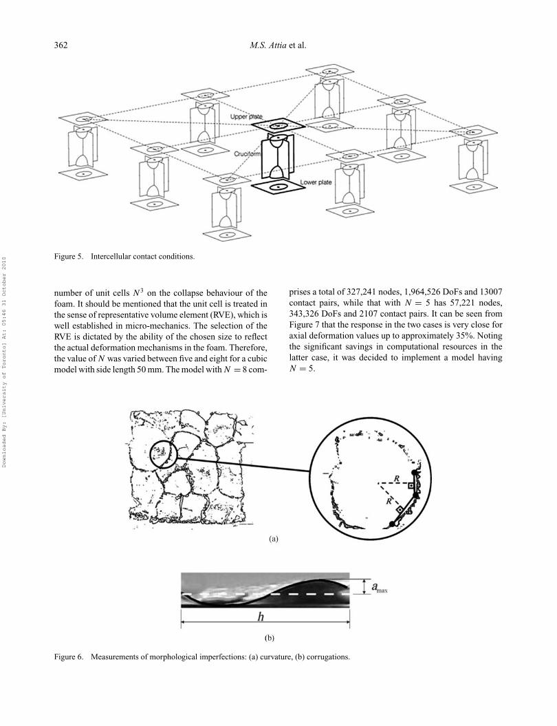
Because of the nature of the multi-cell model, the deter-mination of contact within the model is of key importance.Each unit cell was subdivided into three contact entities:(1) upper plate, (2) cruciform section and (3) lower plate.Figure 5 illustrates a detailed description of this division.Self-contact was then invoked for each entity individually,and surface-to-surface contact was invoked between the ap-
propriate surrounding entities. For the current study, eachcruciform was ‘connected’ to the surrounding eight cru-ciforms as well as the surrounding plates in a cross (+)pattern above and below, resulting in 18 surface-to-surfacecontact sets. Similarly, each plate was connected to the sur-rounding eight plates and the surrounding cruciforms in across pattern, five above and five below. This results in anet additional four surface-to-surface contact sets. Further-more, in order to prevent interpenetration of the plates atthe top and bottom of a cell in the case of complete collapseof a layer, an additional contact surface-to-surface pair wasdefined between each plate and the one immediately belowit. Although this results in a large number of contact pairscompared with only one self-contact, if the multi-cell foamwere defined as a single entity, the current methodology
Downloaded By: [University of Toronto] At: 05:46 31 October 2010
International Journal of Crashworthiness 361
Figure 4. Idealised multi-cell model having N = 5 and M = 6.
exhibited more than three times saving on the CPU timefor the case of N = 5 and M = 6 (1.67–3 mm elementsize range, 125 unit cells, 343,726 DoF and 2107 contactpairs). It is worth mentioning that the structural responseof the two cases was virtually the same with extremely mi-nor variations. Nevertheless, it should be mentioned that,while this methodology exhibited significant improvementof the solution time, care has to be taken when the modelis subject to complex loading involving contact since itis more difficult to predict the different contact surfacesa priori.
Table 1. Stress-plastic strain relations used for alu-minium foam cell.
Equivalent plastic strain (%) Equivalent stress (MPa)
0.00 87.00.03 96.00.20 100.00.60 110.01.50 130.02.50 140.07.00 170.0
15.00 171.0
Experimental programme
Specimens were cut from both 7% and 10% relative nom-inal density foam slabs. These were first rough cut, thenfly-cut finished in order to minimise cell wall damage [1].It is worth mentioning that the nominal density of the 7%foam was reduced to an effective value of 5.4% upon re-moval of the surface skins, which are denser compared withthe core of the material. The specimens were tested in uni-axial compression under displacement control in an Instron250 kN universal hydraulic testing machine between tworigid steel platens. Testing was conducted in the directionsperpendicular to the rise direction of the foam to minimisethe effect of localisation patterns commonly encountered inthe rise direction; see, e.g., Meguid et al. [12]. Digital imag-ing techniques were employed to characterise the geometryof the cells of the foam samples prior to testing.
In order to enhance the digital imaging measurementaccuracy, the foam sections were coated with a thin layerof black paint spray. A very thin layer of the painted sec-tions was then removed using fly-cutter machining to ex-pose the metallic lustrous cell edges. This resulted in ahigh-contrast pattern of bright two-dimensional contoursof cell edges on a black painted background. These con-tours were then digitised and filtered using a custom scriptin the image processing toolbox in MATLAB. Figures 6(a)and 6(b) illustrate the procedure adopted for measuring cellwall curvature and corrugation using the digitised contours.The mean value of the minimum radius of curvature R forthe 5.4% and 10% density foams was 34.81 and 68.4 mm,respectively. Experimental measurements revealed that cellwall corrugations exist mostly in the 5.4% foam due to thelonger spans between cell edges. Furthermore, it was ob-served that corrugated walls contain, on the average, singlewave, with a maximum amplitude of 1.74 mm. Smaller cellsize and thicker cell walls in the 10% foam-reduced wallwrinkling effects during solidification. Corrugations weretherefore not observed within the measurement resolutionin the current study.
Results and discussion
Convergence and sensitivity analyses
The characteristic number of elements M has a pronouncedeffect on the collapse behaviour of the foam. The cell wallscollapse through elastic buckling followed by plastic bend-ing of the cell walls. Nevertheless, the shell element used inthe current study implements only linear shape functions.Therefore, it is necessary to determine an optimum valueof M , beyond which the collapse behaviour is independentof the number of elements. It was found that the systemresponse is almost identical for the cases of M equal tosix and eight elements. Therefore, the number of elementsalong the unit-cell height, M , was set equal to six. Fur-thermore, Figure 7 illustrates the effect of varying the total
Downloaded By: [University of Toronto] At: 05:46 31 October 2010
362 M.S. Attia et al.
Figure 5. Intercellular contact conditions.
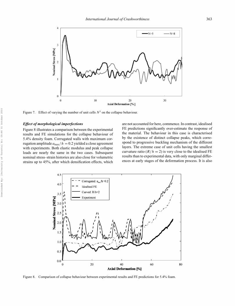
number of unit cells N3 on the collapse behaviour of thefoam. It should be mentioned that the unit cell is treated inthe sense of representative volume element (RVE), which iswell established in micro-mechanics. The selection of theRVE is dictated by the ability of the chosen size to reflectthe actual deformation mechanisms in the foam. Therefore,the value of N was varied between five and eight for a cubicmodel with side length 50 mm. The model with N = 8 com-
prises a total of 327,241 nodes, 1,964,526 DoFs and 13007contact pairs, while that with N = 5 has 57,221 nodes,343,326 DoFs and 2107 contact pairs. It can be seen fromFigure 7 that the response in the two cases is very close foraxial deformation values up to approximately 35%. Notingthe significant savings in computational resources in thelatter case, it was decided to implement a model havingN = 5.
Figure 6. Measurements of morphological imperfections: (a) curvature, (b) corrugations.
Downloaded By: [University of Toronto] At: 05:46 31 October 2010
International Journal of Crashworthiness 363
Figure 7. Effect of varying the number of unit cells N3 on the collapse behaviour.
Effect of morphological imperfections
Figure 8 illustrates a comparison between the experimentalresults and FE simulations for the collapse behaviour of5.4% density foam. Corrugated walls with maximum cor-rugation amplitude amax/h = 0.2 yielded a close agreementwith experiments. Both elastic modulus and peak collapseloads are nearly the same in the two cases. Subsequentnominal stress–strain histories are also close for volumetricstrains up to 45%, after which densification effects, which
are not accounted for here, commence. In contrast, idealisedFE predictions significantly over-estimate the response ofthe material. The behaviour in this case is characterisedby the existence of distinct collapse peaks, which corre-spond to progressive buckling mechanism of the differentlayers. The extreme case of unit cells having the smallestcurvature ratio (R/h = 2) is very close to the idealised FEresults than to experimental data, with only marginal differ-ences at early stages of the deformation process. It is also
Figure 8. Comparison of collapse behaviour between experimental results and FE predictions for 5.4% foam.
Downloaded By: [University of Toronto] At: 05:46 31 October 2010
364 M.S. Attia et al.
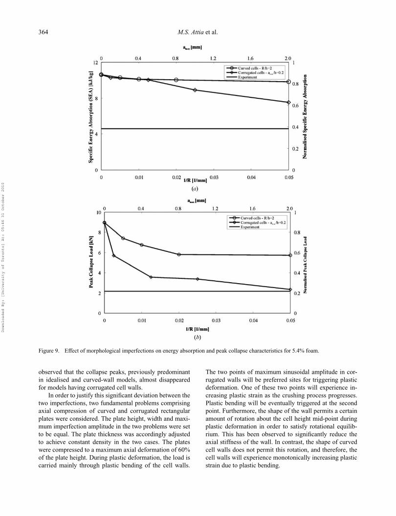
Figure 9. Effect of morphological imperfections on energy absorption and peak collapse characteristics for 5.4% foam.
observed that the collapse peaks, previously predominantin idealised and curved-wall models, almost disappearedfor models having corrugated cell walls.
In order to justify this significant deviation between thetwo imperfections, two fundamental problems comprisingaxial compression of curved and corrugated rectangularplates were considered. The plate height, width and maxi-mum imperfection amplitude in the two problems were setto be equal. The plate thickness was accordingly adjustedto achieve constant density in the two cases. The plateswere compressed to a maximum axial deformation of 60%of the plate height. During plastic deformation, the load iscarried mainly through plastic bending of the cell walls.
The two points of maximum sinusoidal amplitude in cor-rugated walls will be preferred sites for triggering plasticdeformation. One of these two points will experience in-creasing plastic strain as the crushing process progresses.Plastic bending will be eventually triggered at the secondpoint. Furthermore, the shape of the wall permits a certainamount of rotation about the cell height mid-point duringplastic deformation in order to satisfy rotational equilib-rium. This has been observed to significantly reduce theaxial stiffness of the wall. In contrast, the shape of curvedcell walls does not permit this rotation, and therefore, thecell walls will experience monotonically increasing plasticstrain due to plastic bending.
Downloaded By: [University of Toronto] At: 05:46 31 October 2010
International Journal of Crashworthiness 365
Figure 10. Comparison of collapse behaviour between experi-ments and FE results for 10% foam.
This is further illustrated in Figure 9(a), which depictsthe effect of imperfections on the total energy absorption Et
and peak collapse load Fp of the foam, compared with theexperimental results. A maximum reduction of 29.5% is ob-served in Et in corrugated cell models with amax/h = 0.2,while the corresponding drop in curved walls model did notexceed 5% for R/h = 2. Furthermore, Figure 9(b) showsa drop of 77% in Fp for amax/h = 0.2, compared with only31% drop for curved cells with R/h = 2. It is also observedthat 65% of the drop in Et occurred for amax/h > 0.05. Incontrast, Fp witnessed a comparable drop of 61% withinamax/h < 0.05. This can be attributed to the fact that Fp isthe critical elastic buckling load of the cell walls, which isvery sensitive to the smallest perturbations in the geomet-rical configuration of the wall. On the other hand, Et is ab-sorbed through the extended plateau regime during plastichinge formation, and is therefore affected by imperfectionshaving larger sizes. Finally, both curved and corrugated cell
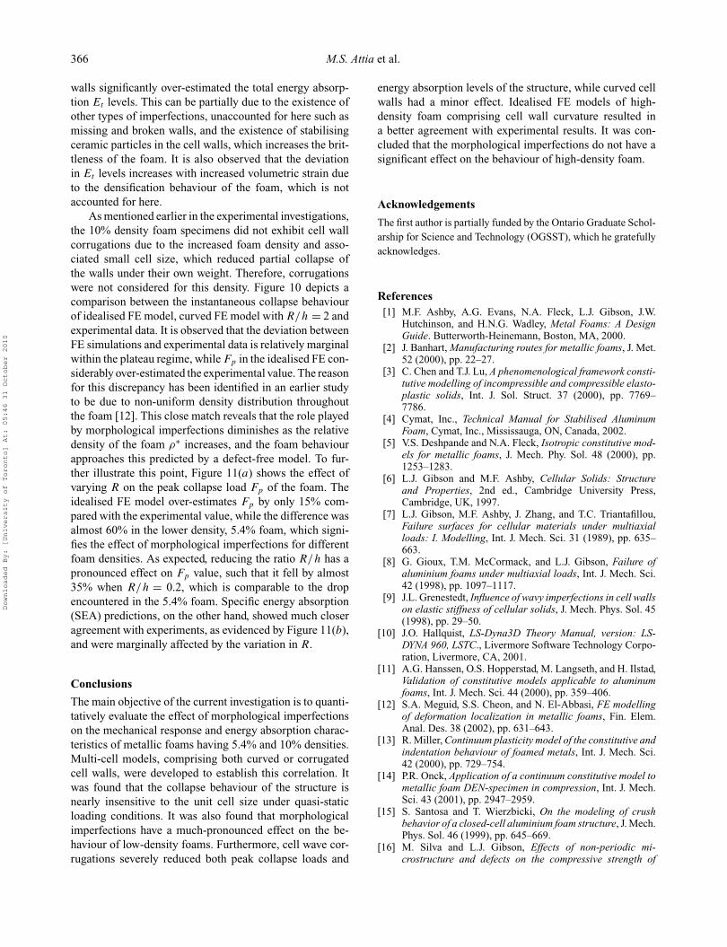
Figure 11. Effect of morphological imperfections on energy absorption and peak collapse load characteristics for 10% foam.
Downloaded By: [University of Toronto] At: 05:46 31 October 2010
366 M.S. Attia et al.
walls significantly over-estimated the total energy absorp-tion Et levels. This can be partially due to the existence ofother types of imperfections, unaccounted for here such asmissing and broken walls, and the existence of stabilisingceramic particles in the cell walls, which increases the brit-tleness of the foam. It is also observed that the deviationin Et levels increases with increased volumetric strain dueto the densification behaviour of the foam, which is notaccounted for here.
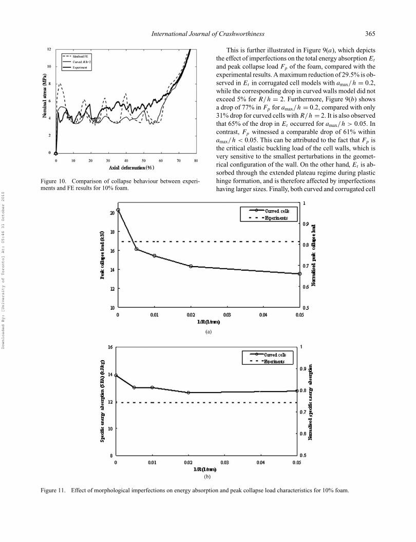
As mentioned earlier in the experimental investigations,the 10% density foam specimens did not exhibit cell wallcorrugations due to the increased foam density and asso-ciated small cell size, which reduced partial collapse ofthe walls under their own weight. Therefore, corrugationswere not considered for this density. Figure 10 depicts acomparison between the instantaneous collapse behaviourof idealised FE model, curved FE model with R/h = 2 andexperimental data. It is observed that the deviation betweenFE simulations and experimental data is relatively marginalwithin the plateau regime, while Fp in the idealised FE con-siderably over-estimated the experimental value. The reasonfor this discrepancy has been identified in an earlier studyto be due to non-uniform density distribution throughoutthe foam [12]. This close match reveals that the role playedby morphological imperfections diminishes as the relativedensity of the foam ρ∗ increases, and the foam behaviourapproaches this predicted by a defect-free model. To fur-ther illustrate this point, Figure 11(a) shows the effect ofvarying R on the peak collapse load Fp of the foam. Theidealised FE model over-estimates Fp by only 15% com-pared with the experimental value, while the difference wasalmost 60% in the lower density, 5.4% foam, which signi-fies the effect of morphological imperfections for differentfoam densities. As expected, reducing the ratio R/h has apronounced effect on Fp value, such that it fell by almost35% when R/h = 0.2, which is comparable to the dropencountered in the 5.4% foam. Specific energy absorption(SEA) predictions, on the other hand, showed much closeragreement with experiments, as evidenced by Figure 11(b),and were marginally affected by the variation in R.
Conclusions
The main objective of the current investigation is to quanti-tatively evaluate the effect of morphological imperfectionson the mechanical response and energy absorption charac-teristics of metallic foams having 5.4% and 10% densities.Multi-cell models, comprising both curved or corrugatedcell walls, were developed to establish this correlation. Itwas found that the collapse behaviour of the structure isnearly insensitive to the unit cell size under quasi-staticloading conditions. It was also found that morphologicalimperfections have a much-pronounced effect on the be-haviour of low-density foams. Furthermore, cell wave cor-rugations severely reduced both peak collapse loads and
energy absorption levels of the structure, while curved cellwalls had a minor effect. Idealised FE models of high-density foam comprising cell wall curvature resulted ina better agreement with experimental results. It was con-cluded that the morphological imperfections do not have asignificant effect on the behaviour of high-density foam.
Acknowledgements
The first author is partially funded by the Ontario Graduate Schol-arship for Science and Technology (OGSST), which he gratefullyacknowledges.
References[1] M.F. Ashby, A.G. Evans, N.A. Fleck, L.J. Gibson, J.W.
Hutchinson, and H.N.G. Wadley, Metal Foams: A DesignGuide. Butterworth-Heinemann, Boston, MA, 2000.
[2] J. Banhart, Manufacturing routes for metallic foams, J. Met.52 (2000), pp. 22–27.
[3] C. Chen and T.J. Lu, A phenomenological framework consti-tutive modelling of incompressible and compressible elasto-plastic solids, Int. J. Sol. Struct. 37 (2000), pp. 7769–7786.
[4] Cymat, Inc., Technical Manual for Stabilised AluminumFoam, Cymat, Inc., Mississauga, ON, Canada, 2002.
[5] V.S. Deshpande and N.A. Fleck, Isotropic constitutive mod-els for metallic foams, J. Mech. Phy. Sol. 48 (2000), pp.1253–1283.
[6] L.J. Gibson and M.F. Ashby, Cellular Solids: Structureand Properties, 2nd ed., Cambridge University Press,Cambridge, UK, 1997.
[7] L.J. Gibson, M.F. Ashby, J. Zhang, and T.C. Triantafillou,Failure surfaces for cellular materials under multiaxialloads: I. Modelling, Int. J. Mech. Sci. 31 (1989), pp. 635–663.
[8] G. Gioux, T.M. McCormack, and L.J. Gibson, Failure ofaluminium foams under multiaxial loads, Int. J. Mech. Sci.42 (1998), pp. 1097–1117.
[9] J.L. Grenestedt, Influence of wavy imperfections in cell wallson elastic stiffness of cellular solids, J. Mech. Phys. Sol. 45(1998), pp. 29–50.
[10] J.O. Hallquist, LS-Dyna3D Theory Manual, version: LS-DYNA 960, LSTC., Livermore Software Technology Corpo-ration, Livermore, CA, 2001.
[11] A.G. Hanssen, O.S. Hopperstad, M. Langseth, and H. Ilstad,Validation of constitutive models applicable to aluminumfoams, Int. J. Mech. Sci. 44 (2000), pp. 359–406.
[12] S.A. Meguid, S.S. Cheon, and N. El-Abbasi, FE modellingof deformation localization in metallic foams, Fin. Elem.Anal. Des. 38 (2002), pp. 631–643.
[13] R. Miller, Continuum plasticity model of the constitutive andindentation behaviour of foamed metals, Int. J. Mech. Sci.42 (2000), pp. 729–754.
[14] P.R. Onck, Application of a continuum constitutive model tometallic foam DEN-specimen in compression, Int. J. Mech.Sci. 43 (2001), pp. 2947–2959.
[15] S. Santosa and T. Wierzbicki, On the modeling of crushbehavior of a closed-cell aluminium foam structure, J. Mech.Phys. Sol. 46 (1999), pp. 645–669.
[16] M. Silva and L.J. Gibson, Effects of non-periodic mi-crostructure and defects on the compressive strength of
Downloaded By: [University of Toronto] At: 05:46 31 October 2010
International Journal of Crashworthiness 367
two-dimensional cellular solids, Int. J. Mech. Sci. 39 (1997),pp. 549–563.
[17] A.E. Simone and L.J. Gibson, The effects of cell face cur-vature and corrugations on the stiffness and strength ofmetallic foams, Acta Mater. 46 (1998), pp. 3929–3935.
[18] T.C. Triantafillou, J. Zhang, T.L. Shercliff, L.J. Gibson,and M.F. Ashby, Failure surfaces for cellular materi-als under multiaxial loads: II. Comparison of modelswith experiment, Int. J. Mech. Sci. 31 (1989), pp. 665–678.
Downloaded By: [University of Toronto] At: 05:46 31 October 2010