Embed Size (px)
Citation preview
APPENDIX D
Plumbing Fixtures

[PAGE LEFT INTENTIONALLY BLANK]
Swan • (800)325-7008 • swanstone.com • [email protected] | 095-05-19
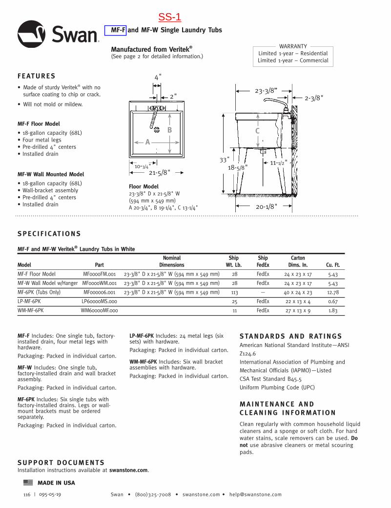
MF-F and MF-W Single Laundry Tubs
WARRANTYLimited 1-year – ResidentialLimited 1-year – Commercial
Manufactured from Veritek® (See page 2 for detailed information.)
SPEC I F I CAT IONS
MF-F and MF-W Veritek® Laundry Tubs in White Nominal Ship Ship Carton Model Part Dimensions Wt. Lb. FedEx Dims. In. Cu. Ft.
MF-F Floor Model MF0000FM.001 23-3/8" D x 21-5/8" W (594 mm x 549 mm) 28 FedEx 24 x 23 x 17 5.43
MF-W Wall Model w/Hanger MF0000WM.001 23-3/8" D x 21-5/8" W (594 mm x 549 mm) 28 FedEx 24 x 23 x 17 5.43
MF-6PK (Tubs Only) MF000006.001 23-3/8" D x 21-5/8" W (594 mm x 549 mm) 113 — 40 x 24 x 23 12.78
LP-MF-6PK LP60000MS.000 25 FedEx 22 x 13 x 4 0.67
WM-MF-6PK WM60000MF.000 11 FedEx 27 x 13 x 9 1.83
MF-F Includes: One single tub, factory-installed drain, four metal legs with hardware.
Packaging: Packed in individual carton.
MF-W Includes: One single tub, factory-installed drain and wall bracket assembly.
Packaging: Packed in individual carton.
MF-6PK Includes: Six single tubs with factory-installed drains. Legs or wall-mount brackets must be ordered separately.
Packaging: Packed in individual carton.
LP-MF-6PK Includes: 24 metal legs (six sets) with hardware.
Packaging: Packed in individual carton.
WM-MF-6PK Includes: Six wall bracket assemblies with hardware.
Packaging: Packed in individual carton.
F EATURES
• Made of sturdy Veritek® with no surface coating to chip or crack.
• Will not mold or mildew.
• 18-gallon capacity (68L)• Four metal legs• Pre-drilled 4" centers• Installed drain
MF-F Floor Model
MF-W Wall Mounted Model
• 18-gallon capacity (68L)• Wall-bracket assembly• Pre-drilled 4" centers• Installed drain
Floor Model23-3/8" D x 21-5/8" W(594 mm x 549 mm)A 20-3/4", B 19-1/4", C 13-1/4"
18-5/8"33"
23-3/8”2-3/8"
11-1/2"
20-1/8"
C
2"
21-5/8"10-3/4"
4"
B
A
STANDARDS AND RAT INGSAmerican National Standard Institute—ANSI
Z124.6
International Association of Plumbing and
Mechanical Officials (IAPMO)—Listed
CSA Test Standard B45.5
Uniform Plumbing Code (UPC)
MA INTENANCE AND C L EAN ING I N FORMAT ION
Clean regularly with common household liquid cleaners and a sponge or soft cloth. For hard water stains, scale removers can be used. Do not use abrasive cleaners or metal scouring pads.
SUPPORT DOCUMENTSInstallation instructions available at swanstone.com.
SS-1
A87© 2014 AS America Inc.
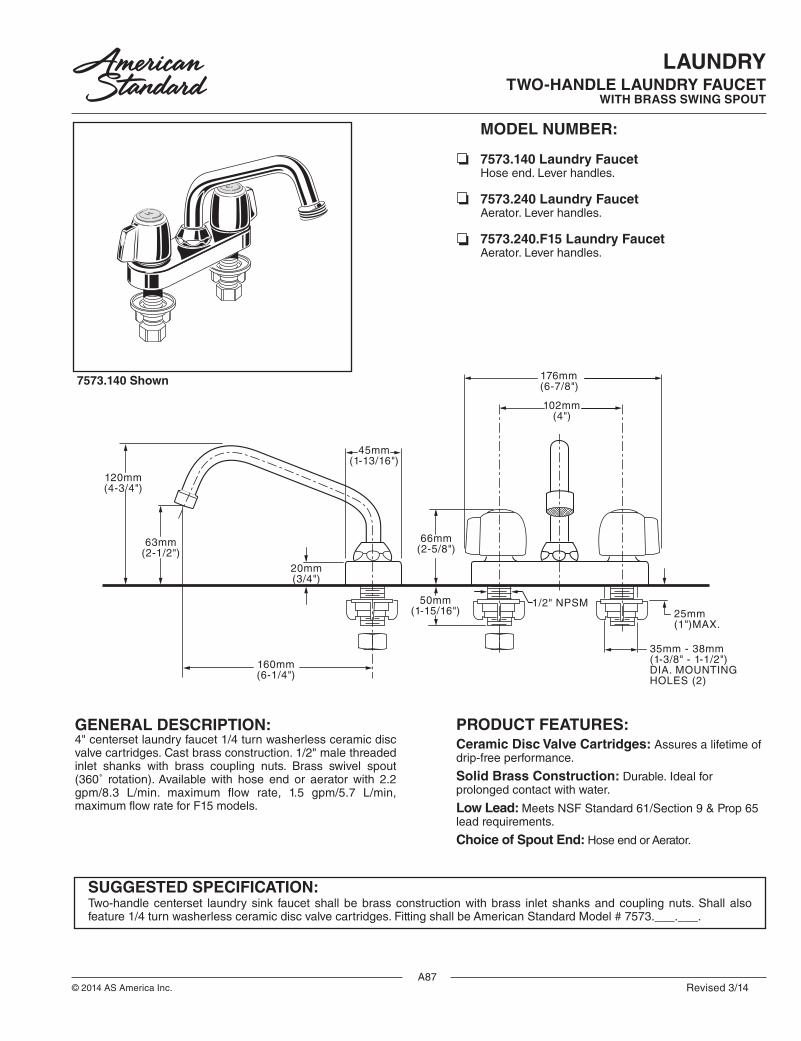
LAUNDRYTWO-HANDLE LAUNDRY FAUCET
WITH BRASS SWING SPOUT
GENERAL DESCRIPTION: 4" centerset laundry faucet 1/4 turn washerless ceramic disc valve cartridges. Cast brass construction. 1/2" male threaded inlet shanks with brass coupling nuts. Brass swivel spout (360˚ rotation). Available with hose end or aerator with 2.2 gpm/8.3 L/min. maximum flow rate, 1.5 gpm/5.7 L/min, maximum flow rate for F15 models.
SUGGESTED SPECIFICATION:Two-handle centerset laundry sink faucet shall be brass construction with brass inlet shanks and coupling nuts. Shall also feature 1/4 turn washerless ceramic disc valve cartridges. Fitting shall be American Standard Model # 7573.___.___.
7573.140 Shown
PRODUCT FEATURES:Ceramic Disc Valve Cartridges: Assures a lifetime of drip-free performance.
Solid Brass Construction: Durable. Ideal for prolonged contact with water.
Low Lead: Meets NSF Standard 61/Section 9 & Prop 65 lead requirements.
Choice of Spout End: Hose end or Aerator.
MODEL NUMBER:
7573.140 Laundry Faucet Hose end. Lever handles.
7573.240 Laundry Faucet Aerator. Lever handles.
7573.240.F15 Laundry Faucet Aerator. Lever handles.
7573.140
ProductNumber Description
Laundry Faucet. Hose End. Lever handles - 2.2 gpm/8.3 L/min. maximum flow rate
Finish
7573.240
PolishedChrome
002
Laundry Faucet. Aerator. Lever handles - 2.2 gpm/8.3 L/min. maximum flow rate
7573.240.F15 Laundry Faucet. Aerator. Lever handles - 1.5 gpm/5.7 L/min. maximum flow rate
*Flow rates shown are for mixed hot and cold.- Model 7573.240 only.
120mm(4-3/4")
20mm(3/4")
50mm(1-15/16") 25mm
(1")MAX.
45mm(1-13/16")
1/2" NPSM
35mm - 38mm(1-3/8" - 1-1/2")DIA. MOUNTINGHOLES (2)
102mm(4")
176mm(6-7/8")
63mm(2-1/2")
66mm(2-5/8")
160mm(6-1/4")
FLOW RATE*
GA
LLO
NS
PE
R M
INU
TE
I N L E T P R E S S U R E ( P S I )
0.0
0.5
1.0
1.5
2.0
2.5
3.0
10080604020
CODES AND STANDARDS
These products meet or exceed the following codes and standards:
ASME A112.18.1CSA B 125
2.2gpm/8.3L/min. FLOW RATE
FLOW RATE*
GA
LLO
NS
PE
R M
INU
TE
I N L E T P R E S S U R E ( P S I ) *Flow rates shown are for mixed hot and cold.
0.0
0.5
1.0
1.5
2.0
10080604020
1.5 gpm/5.7 L/min. FLOW RATE
Revised 3/14
*REGULARLY FURNISHED UNLESS OTHERWISE SPECIFIED
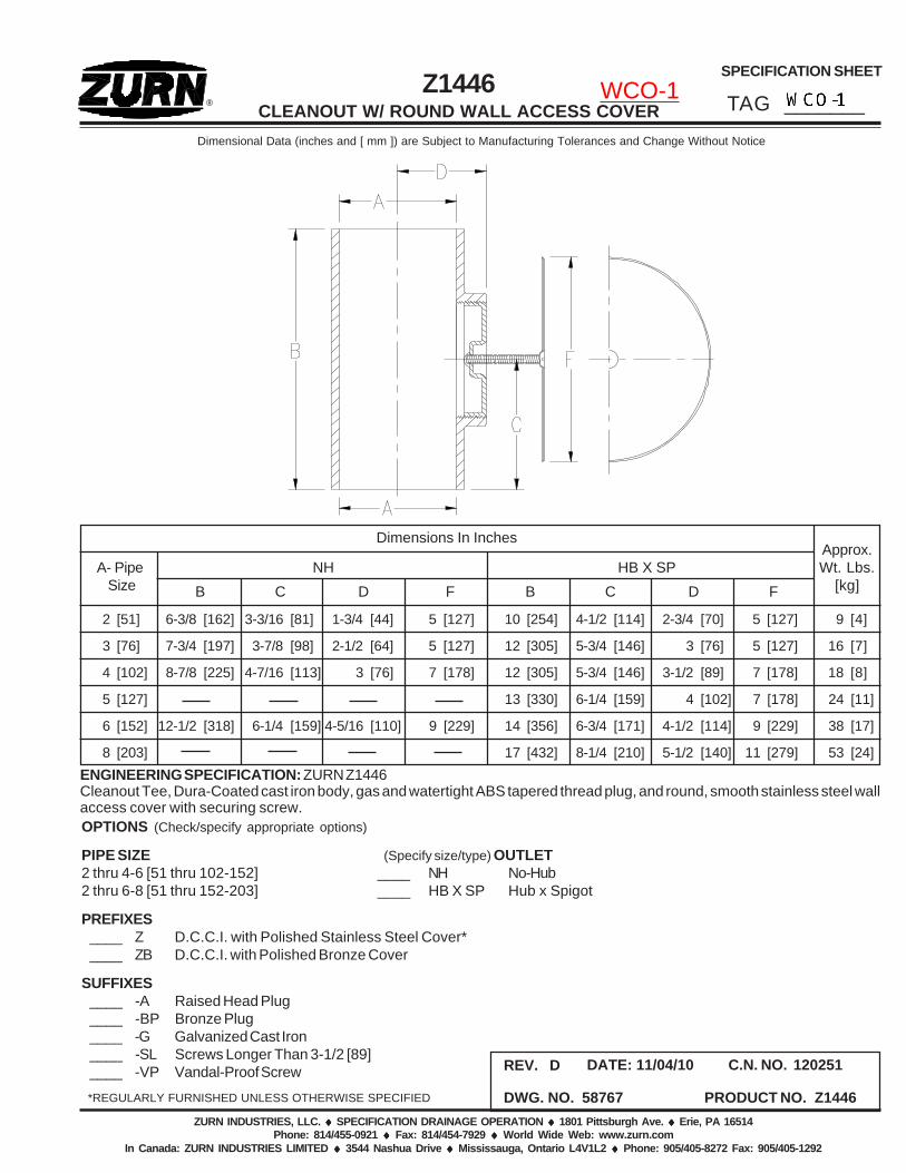
Dimensional Data (inches and [ mm ]) are Subject to Manufacturing Tolerances and Change Without Notice
®
SPECIFICATION SHEET
TAG _______
ZURN INDUSTRIES, LLC. ♦♦♦♦♦ SPECIFICATION DRAINAGE OPERATION ♦♦♦♦♦ 1801 Pittsburgh Ave. ♦♦♦♦♦ Erie, PA 16514Phone: 814/455-0921 ♦♦♦♦♦ Fax: 814/454-7929 ♦♦♦♦♦ World Wide Web: www.zurn.com
In Canada: ZURN INDUSTRIES LIMITED ♦♦♦♦♦ 3544 Nashua Drive ♦♦♦♦♦ Mississauga, Ontario L4V1L2 ♦♦♦♦♦ Phone: 905/405-8272 Fax: 905/405-1292
OPTIONS (Check/specify appropriate options)
PIPE SIZE (Specify size/type) OUTLET2 thru 4-6 [51 thru 102-152] ____ NH No-Hub2 thru 6-8 [51 thru 152-203] ____ HB X SP Hub x Spigot
PREFIXES____ Z D.C.C.I. with Polished Stainless Steel Cover*____ ZB D.C.C.I. with Polished Bronze Cover
SUFFIXES____ -A Raised Head Plug____ -BP Bronze Plug____ -G Galvanized Cast Iron____ -SL Screws Longer Than 3-1/2 [89]____ -VP Vandal-Proof Screw
Z1446CLEANOUT W/ ROUND WALL ACCESS COVER
DWG. NO. 58767
REV. D
PRODUCT NO. Z1446
DATE: 11/04/10 C.N. NO. 120251
ENGINEERING SPECIFICATION: ZURN Z1446Cleanout Tee, Dura-Coated cast iron body, gas and watertight ABS tapered thread plug, and round, smooth stainless steel wallaccess cover with securing screw.
Dimensions In InchesApprox.Wt. Lbs.
[kg]A- Pipe Size
NH HB X SPB C D F B C D F
2 [51] 6-3/8 [162] 3-3/16 [81] 1-3/4 [44] 5 [127] 10 [254] 4-1/2 [114] 2-3/4 [70] 5 [127] 9 [4]
3 [76] 7-3/4 [197] 3-7/8 [98] 2-1/2 [64] 5 [127] 12 [305] 5-3/4 [146] 3 [76] 5 [127] 16 [7]
4 [102] 8-7/8 [225] 4-7/16 [113] 3 [76] 7 [178] 12 [305] 5-3/4 [146] 3-1/2 [89] 7 [178] 18 [8]
5 [127] 13 [330] 6-1/4 [159] 4 [102] 7 [178] 24 [11]
6 [152] 12-1/2 [318] 6-1/4 [159] 4-5/16 [110] 9 [229] 14 [356] 6-3/4 [171] 4-1/2 [114] 9 [229] 38 [17]
8 [203] 17 [432] 8-1/4 [210] 5-1/2 [140] 11 [279] 53 [24]
WCO-1

COMBUSTION
416
Natural Gas
F - 237
����������������
��� �� ���� ���� �� �������� ��������
FF
������������
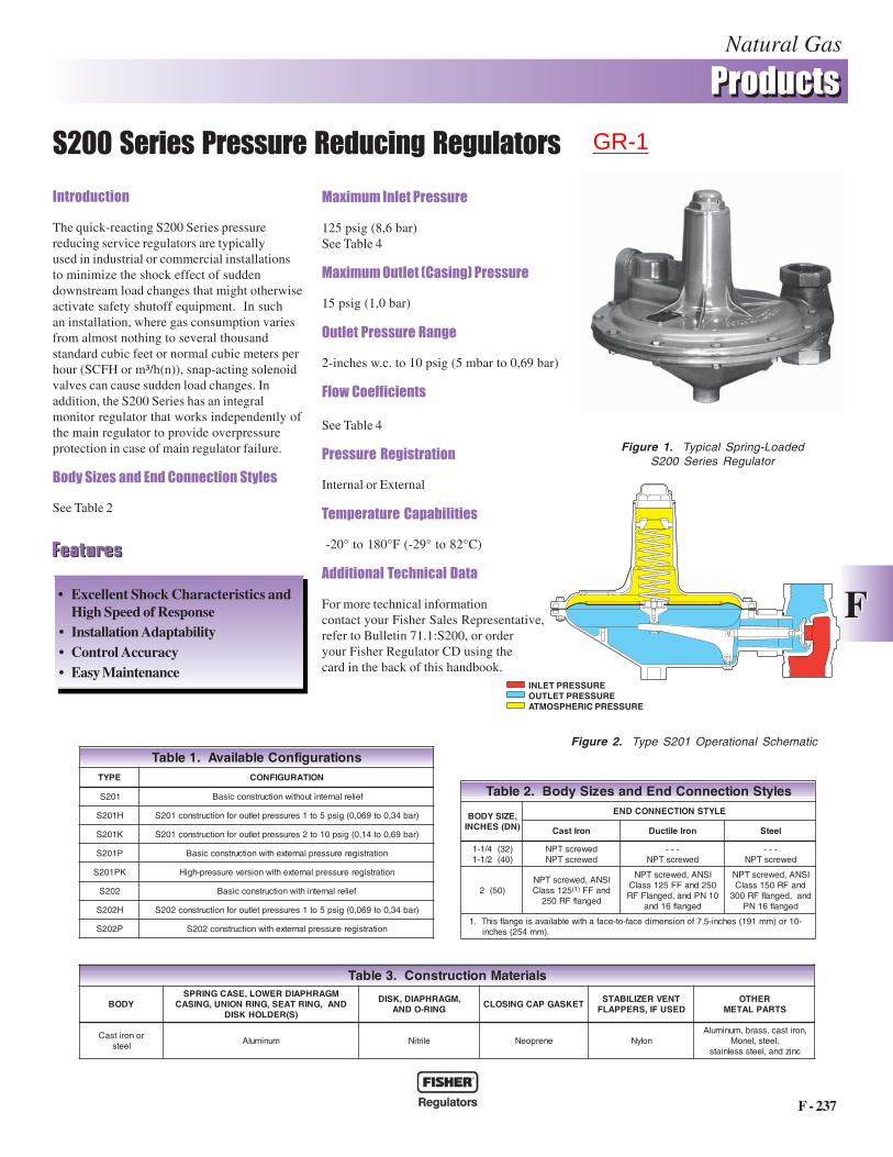
The quick-reacting S200 Series pressurereducing service regulators are typicallyused in industrial or commercial installationsto minimize the shock effect of suddendownstream load changes that might otherwiseactivate safety shutoff equipment. In suchan installation, where gas consumption variesfrom almost nothing to several thousandstandard cubic feet or normal cubic meters perhour (SCFH or m³/h(n)), snap-acting solenoidvalves can cause sudden load changes. Inaddition, the S200 Series has an integralmonitor regulator that works independently ofthe main regulator to provide overpressureprotection in case of main regulator failure.
������� �������������� ��������� �
See Table 2
Figure 1. Typical Spring-LoadedS200 Series Regulator
����������� ���� ����
125 psig (8,6 bar)See Table 4
������������ ������������� ����
15 psig (1,0 bar)
���� ���� ���� �����
2-inches w.c. to 10 psig (5 mbar to 0,69 bar)
��!��� ""��� ���
See Table 4
�� ���� �� ����������
Internal or External
# �$ ����� ���$�%����� �
-20° to 180°F (-29° to 82°C)
&����������# �'������(���
For more technical informationcontact your Fisher Sales Representative,refer to Bulletin 71.1:S200, or orderyour Fisher Regulator CD using thecard in the back of this handbook.
��������
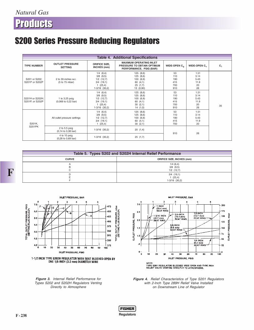
Figure 2. Type S201 Operational Schematic
��������
• Excellent Shock Characteristics andHigh Speed of Response
• Installation Adaptability• Control Accuracy• Easy Maintenance
slairetaMnoitcurtsnoC.3elbaT
YDOBMGARHPAIDREWOL,ESACGNIRPS
DNA,GNIRTAES,GNIRNOINU,GNISAC)S(REDLOHKSID
,MGARHPAID,KSIDGNIR-ODNA
TEKSAGPACGNISOLCTNEVREZILIBATSDESUFI,SREPPALF
REHTOSTRAPLATEM
ronoritsaCleets
munimulA elirtiN enerpoeN nolyN,noritsac,ssarb,munimulA
,leets,lenoMcnizdna,leetssselniats
snoitarugifnoCelbaliavA.1elbaTEPYT NOITARUGIFNOC
102S feilerlanretnituohtiwnoitcurtsnoccisaB
H102S )rab43,0ot960,0(gisp5ot1serusserpteltuorofnoitcurtsnoc102S
K102S )rab96,0ot41,0(gisp01ot2serusserpteltuorofnoitcurtsnoc102S
P102S noitartsigererusserplanretxehtiwnoitcurtsnoccisaB
KP102S noitartsigererusserplanretxehtiwnoisreverusserp-hgiH
202S feilerlanretnihtiwnoitcurtsnoccisaB
H202S )rab43,0ot960,0(gisp5ot1serusserpteltuorofnoitcurtsnoc202S
P202S noitartsigererusserplanretxehtiwnoitcurtsnoc202S
INLET PRESSUREOUTLET PRESSUREATMOSPHERIC PRESSURE
selytSnoitcennoCdnEdnaseziSydoB.2elbaT
,EZISYDOB)ND(SEHCNI
ELYTSNOITCENNOCDNE
norItsaC norIelitcuD leetS
)23(4/1-1)04(2/1-1
dewercsTPNdewercsTPN
---dewercsTPN
---dewercsTPN
)05(2ISNA,dewercsTPN
521ssalC )1( dnaFFdegnalfFR052
ISNA,dewercsTPN052dnaFF521ssalC01NPdna,degnalFFR
degnalf61dna
ISNA,dewercsTPNdnaFR051ssalC
dna,degnalfFR003degnalf61NP
-01ro)mm191(sehcni-5.7fonoisnemidecaf-ot-ecafahtiwelbaliavasiegnalfsihT.1.)mm452(sehcni
GR-1
Natural Gas
F - 238
����������������
��� �� ���� ���� �� �������� ��������
FF
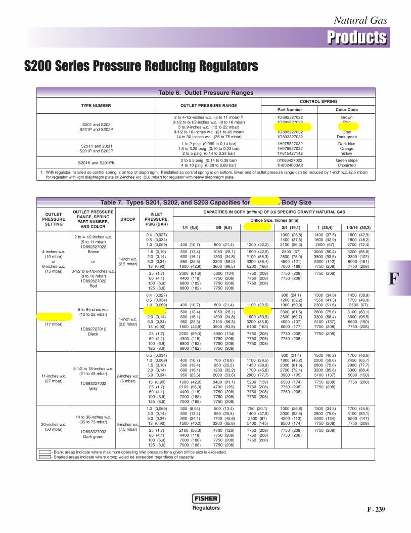
Figure 3. Internal Relief Performance forTypes S202 and S202H Regulators Venting
Directly to Atmosphere
Figure 4. Relief Characteristics of Type S201 Regulatorswith 2-Inch Type 289H Relief Valve Installed
on Downstream Line of Regulator
ecnamrofrePfeileRlanretnIH202Sdna202SsepyT.5elbaTEVRUC (SEHCNI,EZISECIFIRO )mm
ABC
)4,6(4/1)5,9(8/3)7,21(2/1
DEF
)1,91(4/3)4,52(1
)2,03(61/3-1
snoitacificepSlanoitiddA.4elbaT
REBMUNEPYTERUSSERPTELTUO
GNITTES,EZISECIFIRO
SEHCNI )mm(
TELNIGNITAREPOMUMIXAMMUMITPONIATBOOTERUSSERP
)RAB(GISP,ECNAMROFREPCNEPO-EDIW g CNEPO-EDIW v C1
;202Sro102SP202SroP102S
.c.wsehcni-03ot2)rabm57ot5(
)4,6(4/1)5,9(8/3)7,21(2/1)1,91(4/3
)4,52(1)2,03(61/3-1
)6,8(521)6,8(521)9,6(001
)1,4(06)7,1(52)09,0(31
35011091514007019
15.141.334.59.11
0262
53
;H202SroH102SP202Sro,P102S
gisp52.3ot1)rab22,0ot960,0(
)4,6(4/1)5,9(8/3)7,21(2/1)1,91(4/3
)4,52(1)2,03(61/3-1
)6,8(521)6,8(521)9,6(001
)1,4(06)1,2(03)0,1(41
35011091514007019
15.141.334.59.11
0262
,K102SKP102S
sgnitteserusserpteltuollA
)4,6(4/1)5,9(8/3)7,21(2/1)1,91(4/3
)4,52(1
)6,8(521)6,8(521)9,6(001
)1,4(06)1,2(03
35011091514007
15.141.334.59.11
02
gisp5.5ot2)rab83,0ot41,0(
)2,03(61/3-1 )4,1(02
019 62gisp01ot4
)rab96,0ot82,0()2,03(61/3-1 )7,1(52
Natural Gas
F - 239
����������������
��� �� ���� ���� �� �������� ��������
FF
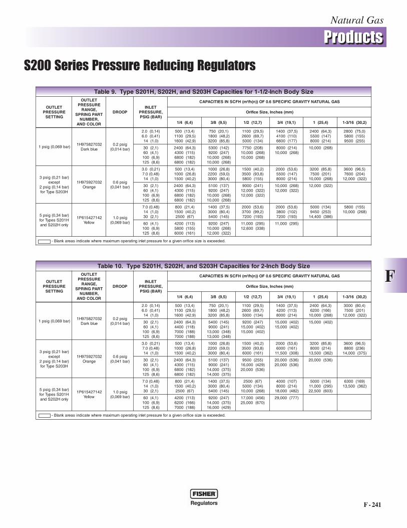
eziSydoBhcnI-2/1-1rofseiticapaC302Sdna,202S,102SsepyT.7elbaT
TELTUOERUSSERP
GNITTES
ERUSSERPTELTUOGNIRPS,EGNAR,REBMUNTRAP
ROLOCDNA
POORDTELNI
,ERUSSERP)RAB(GISP
SAGLARUTANYTIVARGCIFICEPS6.0FO))n(h/³m(HFCSNISEITICAPAC
)mm(sehcnI,eziSecifirO
)4,6(4/1 )5,9(8/3 )7,21(2/1 )1,91(4/3 )4,52(1 )2,03(61/3-1
.c.wsehcni-4)rabm01(
ro.c.wsehcni-6
)rabm51(
.c.wsehcni-2/1-4ot2)rabm11ot5(220725298D1
nworB
ro
.c.wsehcni-2/1-6ot2/1-3)rabm61ot9(220726298D1
deR
.c.whcni-1)rabm5,2(
)720,0(4.0)430,0(5.0)960,0(0.1 )7,01(004 008 )4,12( 0021 )2,23(
0001 )8,62(0041 )5,73(0012 )3,65(
0041 )5,73(0061 )9,24(0052 )76(
0061 )9,24(0081 )2,84(0072 )4,27(
)01,0(5.1)41,0(0.2)43,0(0.5)09,0(31
)4,31(005)1,61(006)5,52(059)9,24(0061
0501 )1,82(0031 )8,43(0022 )0,95(0063 )5,69(
0061 )9,24(0012 )3,65(0033 )4,88(0026 )661(
0052 )76(0082 )0,57(0054 )121(0007 )881(
0003 )4,08(0053 )8,39(0035 )241(0577 )802(
0023 )8,58(0083 )201(0006 )161(0577 )802(
)7,1(52)1,4(06)9,6(001)6,8(521
0032 )6,16(0044 )811(0086 )281(0086 )281(
0005 )431(0577 )802(0577 )802(0577 )802(
0577 )802(0577 )802(0577 )802(
0577 )802(0577 )802(
0577 )802(
.c.wsehcni-7)rabm71(
.c.wsehcni-9ot5)rabm22ot21(
210727298D1kcalB
.c.whcni-1)rabm5,2(
)720,0(4.0)430,0(5.0)960,0(0.1 )7,01(004 008 )4,12( 0011 )5,92(
009 )1,42(0021 )2,23(0091 )9,05(
0031 )8,43(0551 )5,14(0032 )6,16(
0541 )9,83(0571 )9,64(0052 )76(
)01,0(5.1)41,0(0.2)43,0(0.5)09,0(31
)4,31(005)1,61(006)5,52(059)9,24(0061
0501 )1,82(0031 )8,43(0012 )3,65(0053 )8,39(
0051 )2,04(0091 )9,05(0023 )8,58(0016 )361(
0032 )6,16(0062 )7,96(0004 )701(0066 )771(
0082 )0,57(0033 )4,88(0015 )731(0577 )802(
0013 )1,38(0063 )5,69(0065 )051(0577 )802(
)7,1(52)1,4(06)9,6(001)6,8(521
0022 )0,95(0034 )511(0086 )281(0086 )281(
0005 )431(0577 )802(0577 )802(0577 )802(
0577 )802(0577 )802(0577 )802(
0577 )802(0577 )802(
0577 )802(
.c.wsehcni-11)rabm72(
.c.wsehcni-81ot2/1-8)rabm54ot12(
230722398D1yarG
.c.wsehcni-2)rabm5(
)430,0(5.0)960,0(0.1
)01,0(5.1)41,0(0.2)43,0(0.5
)7,01(004)4,31(005)1,61(006)5,52(059
007 )8,81(059 )5,52(0021 )2,23(0002 )6,35(
0011 )5,92(0541 )9,83(0071 )6,54(0092 )7,77(
008 )4,12(0081 )2,84(0032 )6,16(0072 )4,27(0093 )501(
0051 )2,04(0022 )0,95(0082 )0,57(0023 )8,58(0015 )731(
0071 )6,64(0542 )7,56(0092 )7,77(0033 )4,88(0065 )051(
)09,0(31)7,1(52)1,4(06)9,6(001)6,8(521
0061 )9,24(0012 )3,65(0044 )811(0007 )881(0007 )881(
0043 )1,19(0074 )621(0577 )802(0577 )802(0577 )802(
0025 )931(0577 )802(0577 )802(0577 )802(
0056 )471(0577 )802(0577 )802(
0577 )802(0577 )802(
0577 )802(
.c.wsehcni-02)rabm05(
.c.wsehcni-03ot41)rabm57ot53(
230723398D1neergkraD
.c.wsehcni-3)rabm5,7(
)960,0(0.1)41,0(0.2)43,0(0.5)09,0(31
003 )40,8(005 )4,31(009 )1,42(0051 )2,04(
005 )4,31(059 )5,52(0071 )6,54(0023 )8,58(
057 )1,02(0041 )5,73(0052 )76(
0045 )541(
0001 )8,62(0002 )6,35(0024 )311(0056 )471(
0031 )8,43(0082 )0,57(0005 )431(0577 )802(
0071 )6,54(0013 )1,38(0055 )741(0577 )802(
)7,1(52)1,4(06)9,6(001)6,8(521
0012 )3,65(0044 )811(0007 )881(0007 )881(
0074 )621(0577 )802(0577 )802(0577 )802(
0577 )802(0577 )802(0577 )802(
0577 )802(0577 )802(
0577 )802(
.dedeecxesiezisecifironevigaroferusserptelnignitarepomumixamerehwetacidnisaeraknalB-.yticapacfosseldragerdedeecxeebdluowpoorderehwetacidnisaeradedahS-
segnaRerusserPteltuO.6elbaT
REBMUNEPYT EGNARERUSSERPTELTUOGNIRPSLORTNOC
rebmuNtraP edoCroloC
202Sdna102SP202SdnaP102S
)rabm11ot5(.c.wsehcni-2/1-4ot2 )1(
)rabm61ot9(.c.wsehcni-2/1-6ot2/1-3)rabm22ot21(.c.wsehcni-9ot5
)rabm54ot12(.c.wsehcni-81ot2/1-8)rabm57ot53(.c.wsehcni-03ot41
220725298D1220726298D1210727298D1230722398D1230723398D1
nworBdeRkcalByarG
neergkraD
H202dnaH102SP202SdnaP102S
)rab41,0ot960,0(gisp2ot1)rab22,0ot01,0(gisp52.3ot5.1
)rab43,0ot41,0(gisp5ot2
230728579H1230729579H1241724516P1
eulbkraDegnarO
wolleY
KP102SdnaK102S)rab83,0ot41,0(gisp5.5ot2)rab96,0ot82,0(gisp01ot4
220724660Y02A0004208H1
epirtsneerGdetniapnU
)rabm5,2(.c.whcni-1ybdecuderebnacegnarerusserpteltuofodnerewol,mottobnosignirpslortnocosdellatsnifI.mgarhpaidfopotnosignirpslortnocosdellatsnirotalugerhtiW.1.etalpmgarhpaidyvaehhtiwrotalugerrof)rabm0,5(.c.wsehcni-2roetalpmgarhpaidthgilhtiwrotalugerrof
Natural Gas
F - 240
����������������
��� �� ���� ���� �� �������� ��������
FF
eziSydoBhcnI-2rofseiticapaC302Sdna,202S,102SsepyT.8elbaT
TELTUOERUSSERP
GNITTES
TELTUOERUSSERP
,EGNARTRAPGNIRPS
,REBMUNROLOCDNA
POORDTELNI
,ERUSSERP)RAB(GISP
SAGLARUTANYTIVARGCIFICEPS6.0FO))n(h/³m(HFCSNISEITICAPAC
)mm(sehcnI,eziSecifirO
)4,6(4/1 )5,9(8/3 )7,21(2/1 )1,91(4/3 )4,52(1 )2,03(61/3-1
.c.wsehcni-4)rabm01(
ro.c.wsehcni-6
)rabm51(
220725298D1nworB
ro220726298D1
deR
.c.whcni-1)rabm5,2(
)720,0(4.0)430,0(5.0)960,0(0.1 )7,01(004 )1,42(009 )8,43(0031
)2,23(0021)6,54(0071)0,57(0082
)9,24(0061)0,95(0022)8,58(0023
)2,84(0081)3,46(0042)201(0083
)01,0(5.1)41,0(0.2)43,0(0.5)09,0(31
)4,31(005)1,61(006)8,62(0001)2,44(0561
)5,92(0011)5,73(0041)6,16(0032)2,99(0073
)6,54(0071)0,95(0022)2,99(0073)471(0056
)5,69(0063)121(0054)902(0087)862(000,01
)511(0034)741(0055)552(0059)862(000,01
)431(0005)271(0046)862(000,01)862(000,01
)7,1(52)1,4(06)9,6(001)6,8(521
)3,46(0042)911(0544)881(0007)881(0007
)931(0025)142(0009)862(000,01)862(000,01
)742(0029)862(000,01)862(000,01
000,01 )862(000,01 )862(
)862(000,01
.c.wsehcni-7)rabm71(
210727298D1kcalB
.c.whcni-1)rabm5,2(
)720,0(4.0)430,0(5.0)960,0(0.1 )7,01(004 )4,12(008 )2,23(0021
059 )5,52(0051 )2,04(0032 )6,16(
)5,73(0041)2,84(0081)0,57(0082
)9,24(0061)6,35(0002)4,88(0033
)01,0(5.1)41,0(0.2)43,0(0.5)09,0(31
)4,31(005)1,61(006)8,62(0001)2,44(0561
)1,82(0501)8,43(0031)3,65(0012)8,39(0053
)9,24(0061)6,35(0002)8,39(0053)271(0046
)1,38(0013)701(0004)602(0077)862(000,01
)5,69(0063)121(0054)742(0029)862(000,01
)121(0054)161(0006)862(000,01)862(000,01
)7,1(52)1,4(06)9,6(001)6,8(521
)3,46(0042)911(0544)881(0007)881(0007
)931(0025)142(0009)862(000,01)862(000,01
)442(0019)862(000,01)862(000,01
)862(000,01)862(000,01
)862(000,01
.c.wsehcni-11)rabm72(
230722398D1yarG
.c.wsehcni-2)rabm5(
)430,0(5.0)960,0(0.1
)01,0(5.1)41,0(0.2)43,0(0.5
)7,01(004)4,31(005)1,61(006)8,62(0001
)1,02(057)8,62(0001)2,23(0021)6,35(0002
)5,92(0011)9,83(0541)6,54(0071)4,08(0003
)4,12(008)2,84(0081
)76(0052)1,38(0013)691(0037
)2,04(0051)76(0052)1,19(0043)311(0024)412(0008
)6,54(0071)7,77(0092)701(0004)431(0005)552(0059
)09,0(31)7,1(52)1,4(06)9,6(001)6,8(521
)9,24(0061)3,46(0042)911(0544)881(0007)881(0007
)1,19(0043)921(0084)932(0098)862(000,01)862(000,01
)661(0026)932(0098)862(000,01)862(000,01
)862(000,01)862(000,01)862(000,01
)862(000,01)862(000,01
)862(000,01
.c.wsehcni-02)rabm05(
230723398D1neergkraD
.c.wsehcni-3)rabm5,7(
)960,0(0.1)41,0(0.2)43,0(0.5)09,0(31
)40,8(003)4,31(005)1,42(009)2,04(0051
)4,31(005)5,52(059)6,54(0071)8,58(0023
)1,02(057)5,73(0041
)76(0052)741(0055
)8,62(0001)6,35(0002)241(0035)552(0059
)8,43(0031)4,08(0003)051(0065)862(000,01
)6,54(0071)8,39(0053)471(0056)862(000,01
)7,1(52)1,4(06)9,6(001)6,8(521
)6,16(0032)811(0044)881(0007)881(0007
)921(0084)552(0059)862(000,01)862(000,01
)142(0009)862(000,01)862(000,01
)862(000,01)862(000,01
)862(000,01
.dedeecxesiezisecifironevigaroferusserptelnignitarepomumixamerehwetacidnisaeraknalB-.yticapacfosseldragerdedeecxeebdluowpoorderehwetacidnisaeradedahS-
Fisher Tips
34. Do not use needle valves in control lines; use full-open ball valves. Needle valves can cause instablility.
Natural Gas
F - 241
����������������
��� �� ���� ���� �� �������� ��������
FFeziSydoBhcnI-2rofseiticapaCH302Sdna,H202S,H102SepyT.01elbaT
TELTUOERUSSERP
GNITTES
TELTUOERUSSERP
,EGNARTRAPGNIRPS
,REBMUNROLOCDNA
POORDTELNI
,ERUSSERP)RAB(GISP
SAGLARUTANYTIVARGCIFICEPS6.0FO))n(h/³m(HFCSNISEITICAPAC
)mm(sehcnI,eziSecifirO
)4,6(4/1 )5,9(8/3 )7,21(2/1 )1,91(4/3 )4,52(1 )2,03(61/3-1
)rab960,0(gisp1230728579H1
eulbkraDgisp2.0
)rab410,0(
)41,0(0.2)14,0(0.6
)0,1(41
)4,31(005)5,92(0011)9,24(0061
)1,02(057)2,84(0081)8,58(0023
)5,92(0011)7,96(0062)431(0005
)5,73(0041)311(0024)412(0008
)3,46(0042)661(0026)862(000,01
)4,08(0003)102(0057)223(000,21
)1,2(03)1,4(06)9,6(001)6,8(521
)3,46(0042)811(0044)881(0007)881(0007
)541(0045)142(0009)843(000,31)843(000,31
)742(0029)204(000,51)204(000,51
)204(000,51)204(000,51
)204(000,51
)rab12,0(gisp3tpecxe
)rab41,0(gisp2H302SepyTrof
230729579H1egnarO
gisp6.0)rab140,0(
)12,0(0.3)84,0(0.7)0,1(41
)4,31(005)8,62(0001)2,04(0051
)8,62(0001)0,95(0022)4,08(0003
)2,04(0051)8,39(0053)161(0006
)6,35(0002)161(0006)803(005,11
)8,58(0023)412(0008)263(005,31
)5,69(0063)632(0088)573(000,41
)1,2(03)1,4(06)9,6(001)6,8(521
)3,46(0042)511(0034)281(0086)281(0086
)731(0015)142(0009)573(000,41)573(000,41
)552(0059)924(000,61)635(000,02
)635(000,02)635(000,02
)635(000,02
)rab43,0(gisp5H102SsepyTrofylnoH202Sdna
241724516P1wolleY
gisp0.1)rab960,0(
)84,0(0.7)0,1(41)1,2(03
)4,12(008)2,04(0051
)76(0052
)5,73(0041)4,08(0003)541(0045
)76(0052)431(0005)862(000,01
)701(0004)412(0008)284(000,81
)431(0005)592(000,11)306(005,22
)961(0036)263(005,31
)1,4(06)9,6(001)6,8(521
)311(0024)661(0026)881(0007
)742(0029)573(000,41)924(000,61
)654(000,71)076(000,52
)777(000,92
.dedeecxesiezisecifironevigaroferusserptelnignitarepomumixamerehwetacidnisaeraknalB-
eziSydoBhcnI-2/1-1rofseiticapaCH302Sdna,H202S,H102SepyT.9elbaT
TELTUOERUSSERP
GNITTES
TELTUOERUSSERP
,EGNARTRAPGNIRPS
,REBMUNROLOCDNA
POORDTELNI
,ERUSSERP)RAB(GISP
SAGLARUTANYTIVARGCIFICEPS6.0FO))n(h/³m(HFCSNISEITICAPAC
)mm(sehcnI,eziSecifirO
)4,6(4/1 )5,9(8/3 )7,21(2/1 )1,91(4/3 )4,52(1 )2,03(61/3-1
)rab960,0(gisp1230728579H1
eulbkraDgisp2.0
)rab410,0(
)41,0(0.2)14,0(0.6
)0.1(41
)4,31(005)5,92(0011)9,24(0061
)1,02(057)2,84(0081)8,58(0023
)5,92(0011)7,96(0062)431(0005
)5,73(0041)011(0014)771(0066
)3,46(0042)741(0055)412(0008
)0,57(0082)551(0085)552(0059
)1,2(03)1,4(06)9,6(001)6,8(521
)3,46(0042)511(0034)281(0086)281(0086
)241(0035)742(0029)862(000,01)862(000,01
)802(0577)862(000,01)862(000,01
)412(0008)862(000,01
)862(000,01
)rab12,0(gisp3tpecxe
)rab41,0(gisp2H302SepyTrof
230729579H1egnarO
gisp6.0)rab140,0(
)12,0(0.3)84,0(0.7)0,1(41
)4,31(005)8,62(0001)2,04(0051
)8,62(0001)0,95(0022)4,08(0003
)2,04(0051)8,39(0053)551(0085
)6,35(0002)741(0055)412(0008
)8,58(0023)102(0057)862(000,01
)5,69(0063)402(0067)223(000,21
)1,2(03)1,4(06)9,6(001)6,8(521
)3,46(0042)511(0034)281(0086)281(0086
)731(0015)742(0029)862(000,01)862(000,01
)142(0009)223(000,21)223(000,21
)862(000,01)223(000,21
)223(000,21
)rab43,0(gisp5H102SsepyTrofylnoH202Sdna
241724516P1wolleY
gisp0.1)rab960,0(
)84,0(0.7)0,1(41)1,2(03
)4,12(008)2,04(0051
)76(0052
)5,73(0041)4,08(0003)541(0045
)6,35(0002)2,99(0073)391(0027
)6,35(0002)201(0083)391(0027
)431(0005)352(0549)683(004,41
)551(0085)862(000,01
)1,4(06)9,6(001)6,8(521
)311(0024)551(0085)161(0006
)742(0029)862(000,01)223(000,21
)592(000,11)833(006,21
)592(000,11
.dedeecxesiezisecifironevigaroferusserptelnignitarepomumixamerehwetacidnisaeraknalB-
Natural Gas
F - 242
����������������
��� �� ���� ���� �� �������� ��������
FF
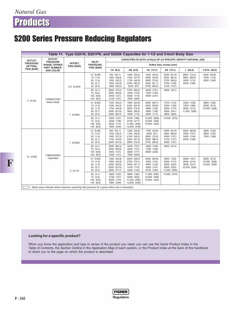
eziSydoBhcnI-2dna2/1-1rofseiticapaCK202Sdna,KP102S,K102SepyT.11elbaT
TELTUOERUSSERP,GNITTES)RAB(GISP
TELTUOERUSSERP
GNIRPS,EGNAR,REBMUNTRAP
ROLOCDNA
,TESFFO)RAB(GISP
TELNI,ERUSSERP
)RAB(GISP
SAGLARUTANYTIVARGCIFICEPS6.0FO))n(h/³m(HFCSNISEITICAPAC
)mm(sehcnI,eziSecifirO
)4,6(4/1 )5,9(8/3 )7,21(2/1 )1,91(4/3 )4,52(1 )2,03(61/3-1
)43,0(5220724660Y0
epirtsneerG
)430,0(5.0
)96,0(01)0,1(51)4,1(02)1,2(03)4,2(53
)1,02(057)8,62(0001)2,23(0021)9,24(0061)2,84(0081
)2,23(0021)5,73(0041)9,64(0571)3,06(0522
)76(0052
)2,04(0051)6,35(0002)0,57(0082)1,19(0043)2,99(0073
)6,16(0032)4,08(0003)2,99(0073)621(0074)731(0015
)0,57(0082)5,69(0063)311(0024)661(0026
)8,39(0053)311(0024)661(0026
)1,4(06)2,5(57)9,6(001)6,8(521
)0,57(0082)8,39(0053)121(0054)731(0015
)2,99(0073)811(0044)471(0056)902(0087
)161(0006)391(0027)142(0009
)142(0009
)960,0(1
)96,0(01)0,1(51)4,1(02)1,2(03)4,2(53
)2,23(0021)2,04(0051)9,64(0571)6,16(0032)7,96(0062
)9,05(0091)3,46(0042)0,57(0082)5,69(0063)311(0024
)7,96(0062)8,39(0053)921(0084)851(0095)471(0056
)011(0014)931(0025)471(0056)142(0009)362(0089
)931(0025)881(0007)412(0008)592(000,11
)281(0086)412(0008)862(000,01
)1,4(06)2,5(57)9,6(001)6,8(521
)701(0004)931(0025)471(0056)902(0087
)081(0076)712(0018)592(000,11)843(000,31
)862(000,01)843(000,31)204(000,51
)573(000,41
)96,0(012A0004208H1
detniapnU
)960,0(1
)96,0(01)0,1(51)4,1(02)1,2(03)4,2(53
)1,42(009)2,23(0021)5,73(0041)6,54(0071)6,16(0032
)8,43(0031)9,64(0571)3,65(0012)6,16(0032)0,57(0082
)6,54(0071)76(0052)0,57(0082)4,88(0033)2,99(0073
)6,16(0032)4,88(0033)701(0004)731(0015)161(0006
)8,58(0023)701(0004)541(0045)661(0026
)201(0083)551(0085)881(0007
)1,4(06)2,5(57)9,6(001)6,8(521
)4,08(0003)8,39(0053)121(0054)741(0055
)701(0004)121(0054)771(0066)902(0087
)851(0095)391(0027)822(0058
)412(0008
)41,0(2
)96,0(01)0,1(51)4,1(02)1,2(03)4,2(53
)8,43(0031)9,24(0061)6,35(0002)6,16(0032)7,77(0092
)0,95(0022)4,27(0072)1,19(0043)011(0014)241(0035
)8,58(0023)511(0034)921(0084)741(0055)081(0076
)321(0064)471(0056)022(0028)552(0059)592(000,11
)161(0006)412(0008)142(0009)223(000,21
)412(0008)862(000,01)843(000,31
)1,4(06)2,5(57)9,6(001)6,8(521
)201(0083)731(0015)471(0056)902(0087
)281(0086)222(0038)592(000,11)843(000,31
)592(000,11)843(000,31)204(000,51
)573(000,41
.dedeecxesiezisecifironevigaroferusserptelnignitarepomumixamerehwetacidnisaeraknalB-
Looking for a specific product?
When you know the application and type or series of the product you need, you can use the Quick Product Index in theTable of Contents, the Section Outline in the Application Map of each section, or the Product Index at the back of this handbookto direct you to the page on which the product is described.
Natural Gas
F - 243
����������������
��� �� ���� ���� �� �������� ��������
FF
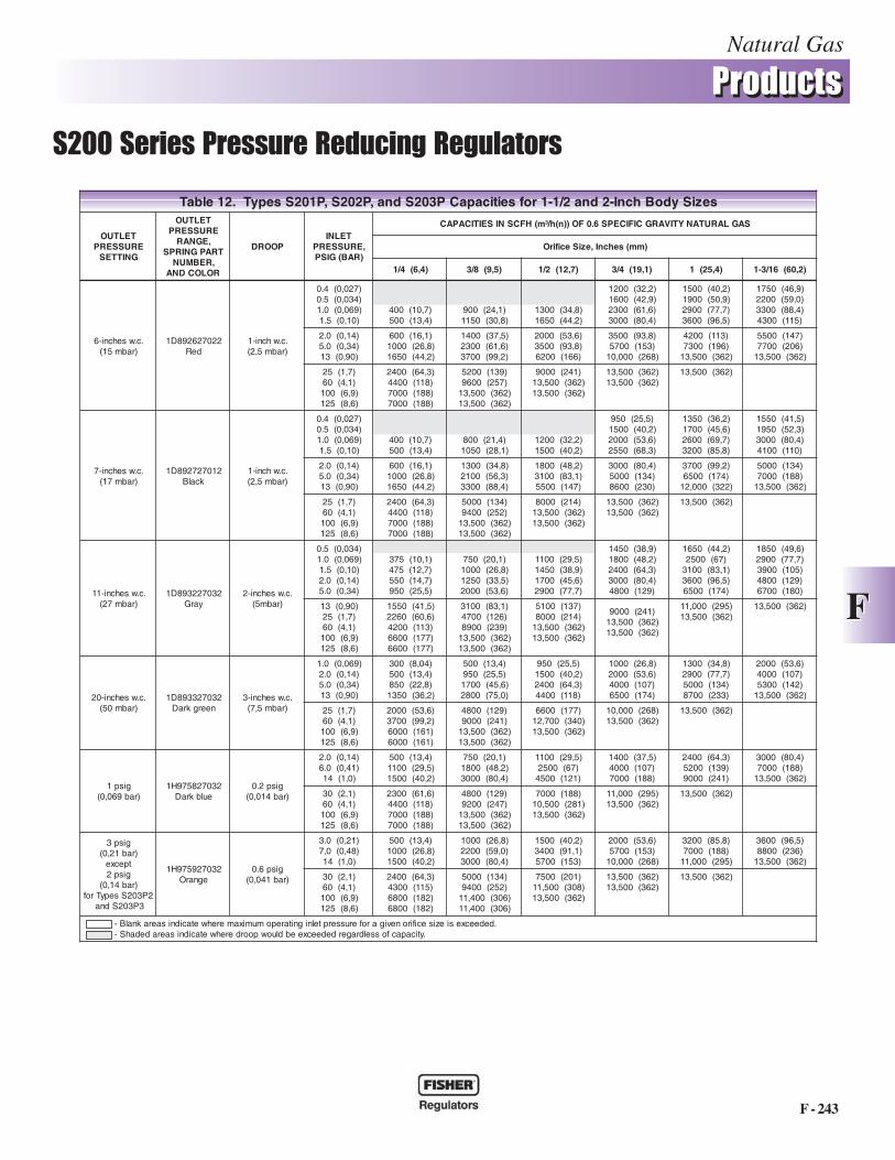
seziSydoBhcnI-2dna2/1-1rofseiticapaCP302Sdna,P202S,P102SsepyT.21elbaT
TELTUOERUSSERP
GNITTES
TELTUOERUSSERP
,EGNARTRAPGNIRPS
,REBMUNROLOCDNA
POORDTELNI
,ERUSSERP)RAB(GISP
HFCSNISEITICAPAC ))n(h/³m( SAGLARUTANYTIVARGCIFICEPS6.0FO
)mm(sehcnI,eziSecifirO
)4,6(4/1 )5,9(8/3 )7,21(2/1 )1,91(4/3 )4,52(1 )2,06(61/3-1
.c.wsehcni-6)rabm51(
220726298D1deR
.c.whcni-1)rabm5,2(
)720,0(4.0)430,0(5.0)960,0(0.1
)01,0(5.1)7,01(004)4,31(005
)1,42(009)8,03(0511
)8,43(0031)2,44(0561
)2,23(0021)9,24(0061)6,16(0032)4,08(0003
)2,04(0051)9,05(0091)7,77(0092)5,69(0063
)9,64(0571)0,95(0022)4,88(0033)511(0034
)41,0(0.2)43,0(0.5)09,0(31
)1,61(006)8,62(0001)2,44(0561
)5,73(0041)6,16(0032)2,99(0073
)6,35(0002)8,39(0053)661(0026
)8,39(0053)351(0075)862(000,01
)311(0024)691(0037)263(005,31
)741(0055)602(0077)263(005,31
)7,1(52)1,4(06)9,6(001)6,8(521
)3,46(0042)811(0044)881(0007)881(0007
)931(0025)752(0069)263(005,31)263(005,31
)142(0009)263(005,31)263(005,31
)263(005,31)263(005,31
)263(005,31
.c.wsehcni-7)rabm71(
210727298D1kcalB
.c.whcni-1)rabm5,2(
)720,0(4.0)430,0(5.0)960,0(0.1
)01,0(5.1)7,01(004)4,31(005
)4,12(008)1,82(0501
)2,23(0021)2,04(0051
)5,52(059)2,04(0051)6,35(0002)3,86(0552
)2,63(0531)6,54(0071)7,96(0062)8,58(0023
)5,14(0551)3,25(0591)4,08(0003)011(0014
)41,0(0.2)43,0(0.5)09,0(31
)1,61(006)8,62(0001)2,44(0561
)8,43(0031)3,65(0012)4,88(0033
)2,84(0081)1,38(0013)741(0055
)4,08(0003)431(0005)032(0068
)2,99(0073)471(0056)223(000,21
)431(0005)881(0007)263(005,31
)7,1(52)1,4(06)9,6(001)6,8(521
)3,46(0042)811(0044)881(0007)881(0007
)431(0005)252(0049)263(005,31)263(005,31
)412(0008)263(005,31)263(005,31
)263(005,31)263(005,31
)263(005,31
.c.wsehcni-11)rabm72(
230722398D1yarG
.c.wsehcni-2)rabm5(
)430,0(5.0)960,0(0.1
)01,0(5.1)41,0(0.2)43,0(0.5
)1,01(573)7,21(574)7,41(055)5,52(059
)1,02(057)8,62(0001)5,33(0521)6,35(0002
)5,92(0011)9,83(0541)6,54(0071)7,77(0092
)9,83(0541)2,84(0081)3,46(0042)4,08(0003)921(0084
)2,44(0561)76(0052)1,38(0013)5,69(0063)471(0056
)6,94(0581)7,77(0092)501(0093)921(0084)081(0076
)09,0(31)7,1(52)1,4(06)9,6(001)6,8(521
)5,14(0551)6,06(0622)311(0024)771(0066)771(0066
)1,38(0013)621(0074)932(0098)263(005,31)263(005,31
)731(0015)412(0008)263(005,31)263(005,31
)142(0009)263(005,31)263(005,31
)592(000,11)263(005,31
)263(005,31
.c.wsehcni-02)rabm05(
230723398D1neergkraD
.c.wsehcni-3)rabm5,7(
)960,0(0.1)41,0(0.2)43,0(0.5)09,0(31
)40,8(003)4,31(005)8,22(058)2,63(0531
)4,31(005)5,52(059)6,54(0071)0,57(0082
)5,52(059)2,04(0051)3,46(0042)811(0044
)8,62(0001)6,35(0002)701(0004)471(0056
)8,43(0031)7,77(0092)431(0005)332(0078
)6,35(0002)701(0004)241(0035)263(005,31
)7,1(52)1,4(06)9,6(001)6,8(521
)6,35(0002)2,99(0073)161(0006)161(0006
)921(0084)142(0009)263(005,31)263(005,31
)771(0066)043(007,21)263(005,31
)862(000,01)263(005,31
)263(005,31
gisp1)rab960,0(
230728579H1eulbkraD
gisp2.0)rab410,0(
)41,0(0.2)14,0(0.6
)0,1(41
)4,31(005)5,92(0011)2,04(0051
)1,02(057)2,84(0081)4,08(0003
)5,92(0011)76(0052)121(0054
)5,73(0041)701(0004)881(0007
)3,46(0042)931(0025)142(0009
)4,08(0003)881(0007)263(005,31
)1,2(03)1,4(06)9,6(001)6,8(521
)6,16(0032)811(0044)881(0007)881(0007
)921(0084)742(0029)263(005,31)263(005,31
)881(0007)182(005,01)263(005,31
)592(000,11)263(005,31
)263(005,31
gisp3)rab12,0(
tpecxegisp2
)rab41,0(2P302SsepyTrof
3P302Sdna
230729579H1egnarO
gisp6.0)rab140,0(
)12,0(0.3)84,0(0,7
)0,1(41
)4,31(005)8,62(0001)2,04(0051
)8,62(0001)0,95(0022)4,08(0003
)2,04(0051)1,19(0043)351(0075
)6,35(0002)351(0075)862(000,01
)8,58(0023)881(0007)592(000,11
)5,69(0063)632(0088)263(005,31
)1,2(03)1,4(06)9,6(001)6,8(521
)3,46(0042)511(0034)281(0086)281(0086
)431(0005)252(0049)603(004,11)603(004,11
)102(0057)803(005,11)263(005,31
)263(005,31)263(005,31
)263(005,31
.dedeecxesiezisecifironevigaroferusserptelnignitarepomumixamerehwetacidnisaeraknalB-.yticapacfosseldragerdedeecxeebdluowpoorderehwetacidnisaeradedahS-
Natural Gas
F - 244
����������������
��� �� ���� ���� �� �������� ��������
FF
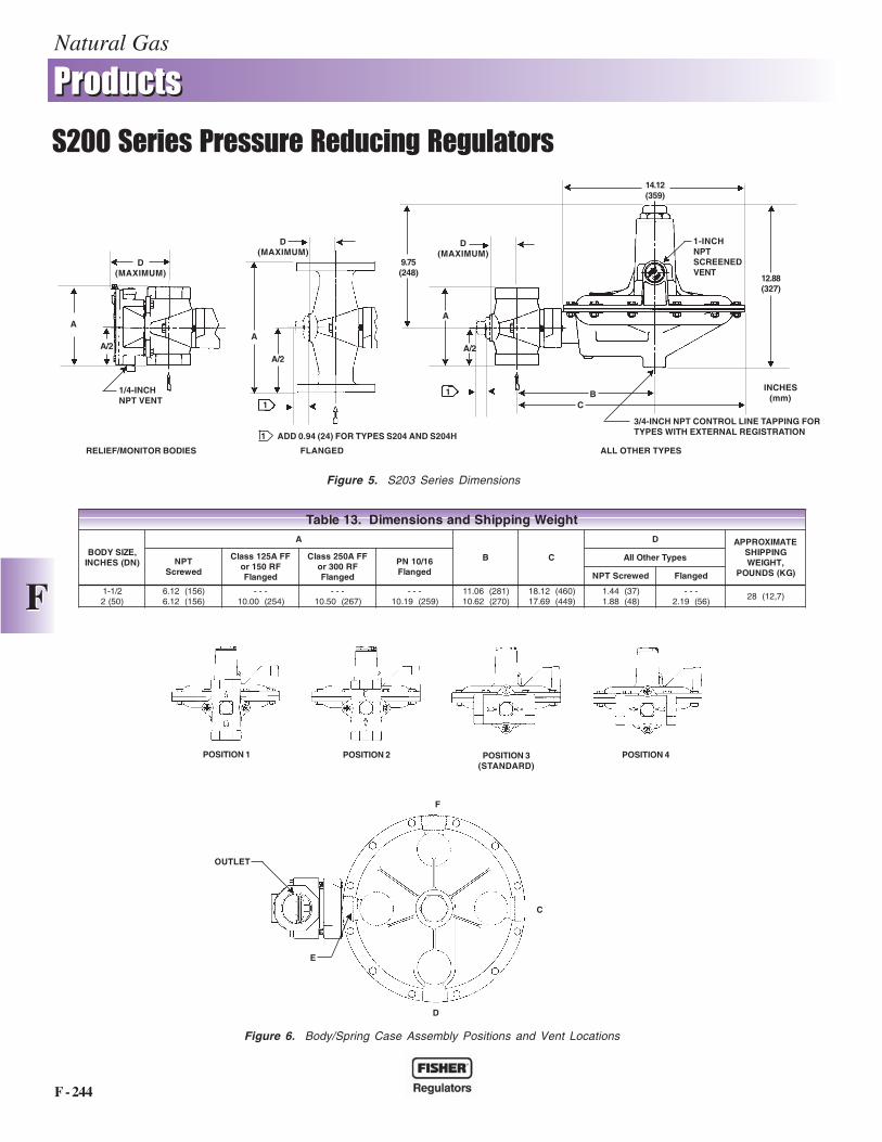
thgieWgnippihSdnasnoisnemiD.31elbaT
,EZISYDOB)ND(SEHCNI
A
B C
D ETAMIXORPPAGNIPPIHS,THGIEW
)GK(SDNUOPTPN
dewercS
FFA521ssalCFR051ro
degnalF
FFA052ssalCFR003ro
degnalF
61/01NPdegnalF
sepyTrehtOllA
dewercSTPN degnalF
2/1-1)05(2
)651(21.6)651(21.6
---)452(00.01
---)762(05.01
---)952(91.01
)182(60.11)072(26.01
)064(21.81)944(96.71
)73(44.1)84(88.1
---)65(91.2
)7,21(82
Figure 6. Body/Spring Case Assembly Positions and Vent Locations
POSITION 1 POSITION 2 POSITION 3(STANDARD)
POSITION 4
Figure 5. S203 Series Dimensions
FLANGED
1/4-INCHNPT VENT
A
A/2
D(MAXIMUM)
A
A/2
RELIEF/MONITOR BODIES ALL OTHER TYPES
D(MAXIMUM)
3/4-INCH NPT CONTROL LINE TAPPING FORTYPES WITH EXTERNAL REGISTRATION
A
A/2
D(MAXIMUM)
1-INCHNPTSCREENEDVENT
CB
12.88(327)
14.12(359)
9.75(248)
E
D
F
OUTLET
C
1
1
1 ADD 0.94 (24) FOR TYPES S204 AND S204H
INCHES(mm)
Natural Gas
F - 245
����������������
��� �� ���� ���� �� �������� ��������
FF
��� �����)���
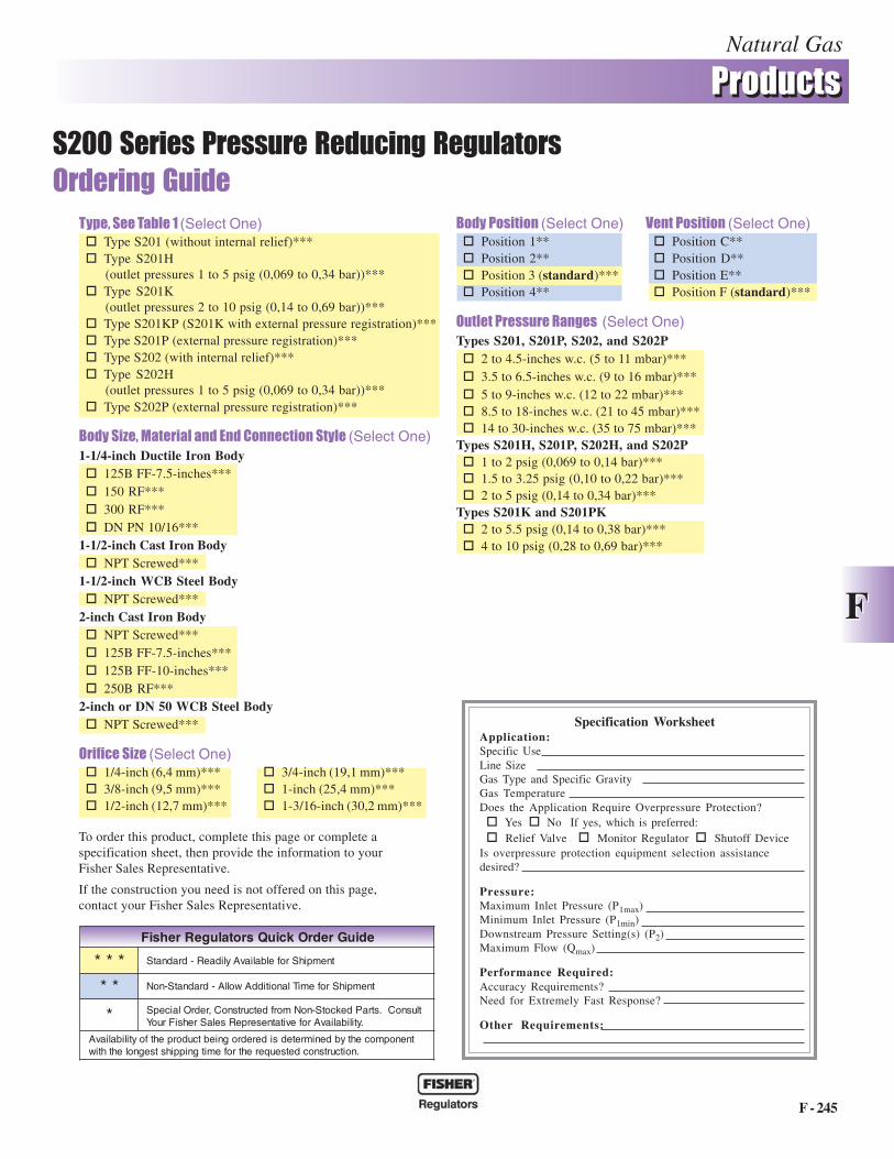
#�$ *� �#�%� �+�(Select One)� Type S201 (without internal relief)***� Type S201H
(outlet pressures 1 to 5 psig (0,069 to 0,34 bar))***� Type S201K
(outlet pressures 2 to 10 psig (0,14 to 0,69 bar))***� Type S201KP (S201K with external pressure registration)***� Type S201P (external pressure registration)***� Type S202 (with internal relief)***� Type S202H
(outlet pressures 1 to 5 psig (0,069 to 0,34 bar))***� Type S202P (external pressure registration)***
������� *���� ����������������� ��������� �(Select One)1-1/4-inch Ductile Iron Body� 125B FF-7.5-inches***� 150 RF***� 300 RF***� DN PN 10/16***
1-1/2-inch Cast Iron Body� NPT Screwed***
1-1/2-inch WCB Steel Body� NPT Screwed***
2-inch Cast Iron Body� NPT Screwed***� 125B FF-7.5-inches***� 125B FF-10-inches***� 250B RF***
2-inch or DN 50 WCB Steel Body� NPT Screwed***
���"�� ��� �(Select One)� 1/4-inch (6,4 mm)*** � 3/4-inch (19,1 mm)***� 3/8-inch (9,5 mm)*** � 1-inch (25,4 mm)***� 1/2-inch (12,7 mm)*** � 1-3/16-inch (30,2 mm)***
��������������(Select One) , ������������(Select One)� Position 1** � Position C**� Position 2** � Position D**� Position 3 (standard)*** � Position E**� Position 4** � Position F (standard)***
���� ���� ���� ����� ���(Select One)Types S201, S201P, S202, and S202P� 2 to 4.5-inches w.c. (5 to 11 mbar)***� 3.5 to 6.5-inches w.c. (9 to 16 mbar)***� 5 to 9-inches w.c. (12 to 22 mbar)***� 8.5 to 18-inches w.c. (21 to 45 mbar)***� 14 to 30-inches w.c. (35 to 75 mbar)***
Types S201H, S201P, S202H, and S202P� 1 to 2 psig (0,069 to 0,14 bar)***� 1.5 to 3.25 psig (0,10 to 0,22 bar)***� 2 to 5 psig (0,14 to 0,34 bar)***
Types S201K and S201PK� 2 to 5.5 psig (0,14 to 0,38 bar)***� 4 to 10 psig (0,28 to 0,69 bar)***
Specification WorksheetApplication:Specific UseLine SizeGas Type and Specific GravityGas TemperatureDoes the Application Require Overpressure Protection?� Yes � No If yes, which is preferred:� Relief Valve � Monitor Regulator � Shutoff Device
Is overpressure protection equipment selection assistancedesired?
Pressure:Maximum Inlet Pressure (P1max)Minimum Inlet Pressure (P1min)Downstream Pressure Setting(s) (P2)Maximum Flow (Qmax)
Performance Required:Accuracy Requirements?Need for Extremely Fast Response?
Other Requirements:
To order this product, complete this page or complete aspecification sheet, then provide the information to yourFisher Sales Representative.
If the construction you need is not offered on this page,contact your Fisher Sales Representative.
ediuGredrOkciuQsrotalugeRrehsiF
*** tnempihSrofelbaliavAylidaeR-dradnatS
** tnempihSrofemiTlanoitiddAwollA-dradnatS-noN
* epS tlusnoC.straPdekcotS-noNmorfdetcurtsnoC,redrOlaic.ytilibaliavArofevitatneserpeRselaSrehsiFruoY
tnenopmocehtybdenimretedsideredrogniebtcudorpehtfoytilibaliavA.noitcurtsnocdetseuqerehtrofemitgnippihstsegnolehthtiw
1800C and 1800C-HC Series Service Regulators
Technical Bulletin
GR-2
Spring Range Part Number7.5 - 24“ W.C. 70017P123
20 - 32” W.C. 70017P124
24 - 44” W.C. 70017P125
40 - 84” W.C. 70017P126
3 - 5 PSIG 70017P127
4 - 7 PSIG 70017P128
1800C and 1800C-HC Series Service Regulators 02 Elster American Meter
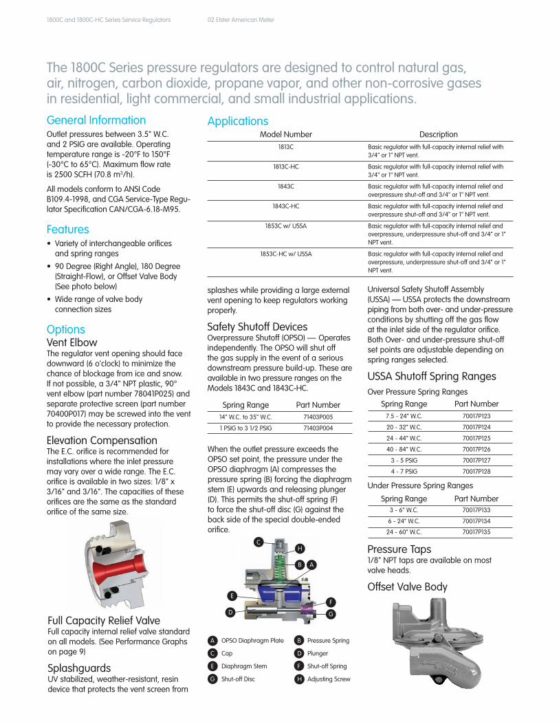
General InformationOutlet pressures between 3.5" W.C. and 2 PSIG are available. Operating temperature range is -20°F to 150°F (-30°C to 65°C). Maximum flow rate is 2500 SCFH (70.8 m3/h).
All models conform to ANSI Code B109.4-1998, and CGA Service-Type Regu-lator Specification CAN/CGA-6.18-M95.
Features• Varietyofinterchangeableorifices and spring ranges
• 90Degree(RightAngle),180Degree (Straight-Flow),orOffsetValveBody (See photo below)
• Widerangeofvalvebody connection sizes
OptionsVentElbow The regulator vent opening should face downward (6 o'clock) to minimize the chance of blockage from ice and snow. If not possible, a 3/4" NPT plastic, 90° vent elbow (part number 78041P025) and separate protective screen (part number 70400P017) may be screwed into the vent to provide the necessary protection.
ElevationCompensation TheE.C.orificeisrecommendedforinstallations where the inlet pressure mayvaryoverawiderange.TheE.C.orifice is available in two sizes: 1/8" x 3/16" and 3/16". The capacities of these orifices are the same as the standard orifice of the same size.
The 1800C Series pressure regulators are designed to control natural gas, air, nitrogen, carbon dioxide, propane vapor, and other non-corrosive gases in residential, light commercial, and small industrial applications.
ApplicationsModel Number Description
1813C Basic regulator with full-capacity internal relief with 3/4" or 1" NPT vent.
1813C-HC Basic regulator with full-capacity internal relief with 3/4" or 1" NPT vent.
1843C Basic regulator with full-capacity internal relief and overpressure shut-off and 3/4" or 1" NPT vent.
1843C-HC Basic regulator with full-capacity internal relief and overpressure shut-off and 3/4" or 1" NPT vent.
1853C w/ USSA Basic regulator with full-capacity internal relief and overpressure, underpressure shut-off and 3/4" or 1" NPT vent.
1853C-HC w/ USSA Basic regulator with full-capacity internal relief and overpressure, underpressure shut-off and 3/4" or 1" NPT vent.
FullCapacityReliefValve Full capacity internal relief valve standard on all models. (See Performance Graphs on page 9)
Splashguards UVstabilized,weather-resistant,resindevice that protects the vent screen from
splashes while providing a large external vent opening to keep regulators working properly.
SafetyShutoffDevicesOverpressure Shutoff (OPSO) — Operates independently. The OPSO will shut off the gas supply in the event of a serious downstream pressure build-up. These are available in two pressure ranges on the Models 1843C and 1843C-HC.
When the outlet pressure exceeds the OPSO set point, the pressure under the OPSO diaphragm (A) compresses the pressure spring (B) forcing the diaphragm stem(E)upwardsandreleasingplunger(D).Thispermitstheshut-offspring(F)to force the shut-off disc (G) against the back side of the special double-ended orifice.
Spring Range Part Number14" W.C. to 35" W.C. 71403P005
1 PSIG to 3 1/2 PSIG 71403P004
Universal Safety Shutoff Assembly (USSA) — USSA protects the downstream piping from both over- and under-pressure conditions by shutting off the gas flow at the inlet side of the regulator orifice. Both Over- and under-pressure shut-off set points are adjustable depending on spring ranges selected.
USSA Shutoff Spring RangesOver Pressure Spring Ranges
Under Pressure Spring Ranges Spring Range Part Number
3 - 6“ W.C. 70017P133
6 - 24” W.C. 70017P134
24 - 60” W.C. 70017P135
Pressure Taps 1/8" NPT taps are available on most valve heads.
OffsetValveBody
A OPSODiaphragmPlate B Pressure Spring
C Cap D Plunger
E DiaphragmStem F Shut-off Spring
G Shut-offDisc H Adjusting Screw
C
E
B A
G
F
D
H
1800C and 1800C-HC Series Service Regulators 03 Elster American Meter
Material Specifications
Outlet Pressure
Color Code
Part Number
3.5" to 6" W.C. Blue 70017P043
3.5" to 7.5" W.C. Tan 70017P089
5.5" to 8.5" W.C. Yellow 70017P044
6" to 12" W.C. Brown 70017P137
6" to 15" W.C. Purple 70017P042
12" to 28" W.C. White 70017P060
24" to 48" W.C. Red 70017P082
42" W.C. to 2 PSIG Red - Red 70017P049
Orifice Size
Standard Part
NumberPart Number with OPSO
9/16" 72494P026 72751P019
1/2" 72494P025 72751P016
3/8" 72494P023 72751P014
5/16" 72494P022 72751P013
1/4" 72494P021 72751P012
3/16" 72494P020 72751P011
1/8" x 3/16" 72494P030 72751P020
1/8" 72494P019 N/A
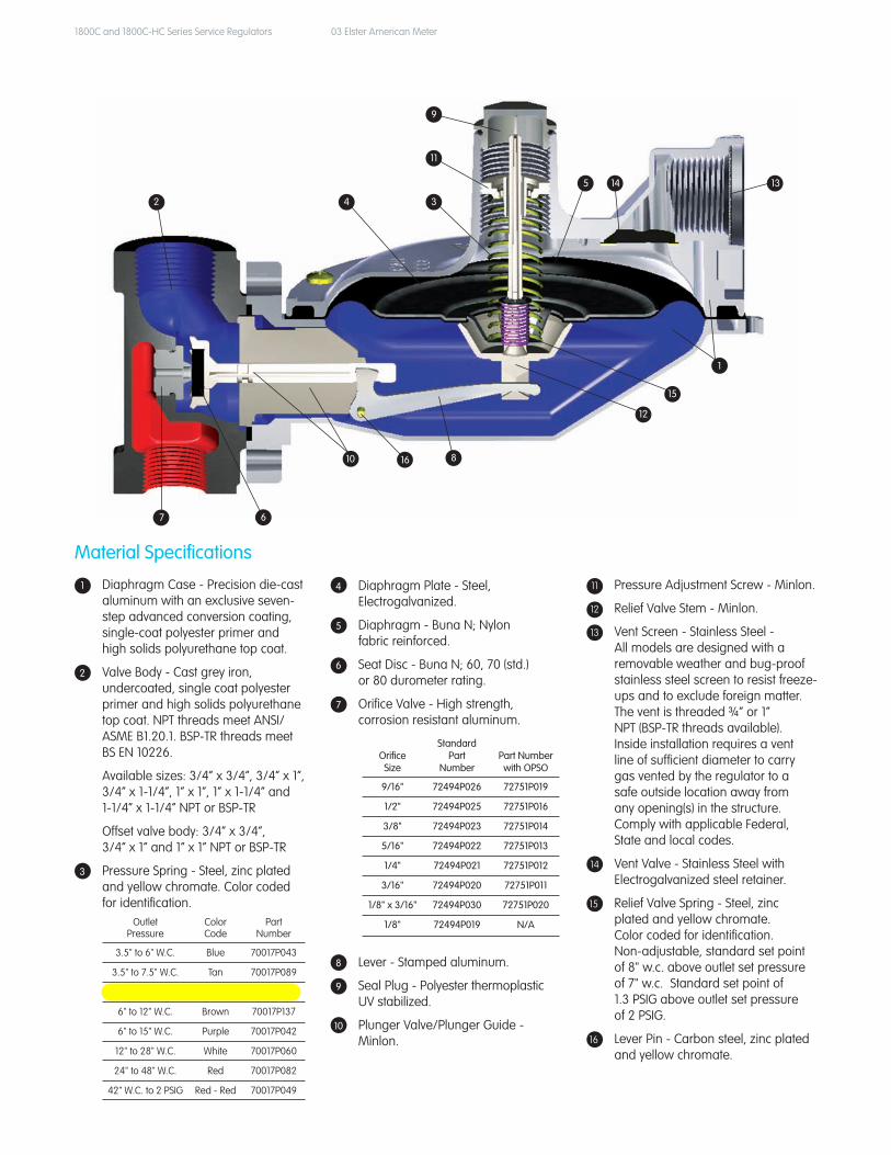
1 Diaphragm Case - Precision die-cast aluminum with an exclusive seven- step advanced conversion coating, single-coat polyester primer and high solids polyurethane top coat.
2 Valve Body - Cast grey iron, undercoated, single coat polyester primer and high solids polyurethane top coat. NPT threads meet ANSI/ ASME B1.20.1. BSP-TR threads meet BS EN 10226.
Available sizes: 3/4” x 3/4”, 3/4” x 1”, 3/4” x 1-1/4”, 1” x 1”, 1” x 1-1/4” and 1-1/4” x 1-1/4” NPT or BSP-TR
Offset valve body: 3/4” x 3/4”, 3/4” x 1” and 1” x 1” NPT or BSP-TR
3 Pressure Spring - Steel, zinc plated and yellow chromate. Color coded for identification.
4 Diaphragm Plate - Steel, Electrogalvanized.
5 Diaphragm - Buna N; Nylon fabric reinforced.
6 Seat Disc - Buna N; 60, 70 (std.) or 80 durometer rating.
7 Orifice Valve - High strength, corrosion resistant aluminum.
2
7 6
4 3
11
9
5 13
1
12
810
14
15
16
8 Lever - Stamped aluminum.
9 Seal Plug - Polyester thermoplastic UV stabilized.
10 Plunger Valve/Plunger Guide - Minlon.
11 Pressure Adjustment Screw - Minlon.
12 Relief Valve Stem - Minlon.
13 Vent Screen - Stainless Steel - All models are designed with a removable weather and bug-proof stainless steel screen to resist freeze- ups and to exclude foreign matter. The vent is threaded ¾” or 1” NPT (BSP-TR threads available). Inside installation requires a vent line of sufficient diameter to carry gas vented by the regulator to a safe outside location away from any opening(s) in the structure. Comply with applicable Federal, State and local codes.
14 Vent Valve - Stainless Steel with Electrogalvanized steel retainer.
15 Relief Valve Spring - Steel, zinc plated and yellow chromate. Color coded for identification. Non-adjustable, standard set point of 8" w.c. above outlet set pressure of 7" w.c. Standard set point of 1.3 PSIG above outlet set pressure of 2 PSIG.
16 Lever Pin - Carbon steel, zinc plated and yellow chromate.
1800C Series Regulator Capacity Performance
1800C and 1800C-HC Series Service Regulators 04 Elster American Meter
Inlet PSIG (bar)
1/8" x 3/16"Orifice
3/16"Orifice
1/4"Orifice
5/16"Orifice
3/8"Orifice
1/2"Orifice
9/16"Orifice
1(0.07) — 175
(5.0)250(7.1)
325(9.2)
350(9.9)
400(11.3)
400(11.3)
2(0.14) — 300
(8.5)425
(12.0)475
(13.5)550
(15.6)650
(18.4)650
(18.4)
3(0.21) — 375
(10.6)500
(14.2)600
(17.0)700
(19.8)800
(22.7)800
(22.7)
5(0.34)
275(7.8)
500(14.2)
700(19.8)
800(22.7)
950(26.9)
1000(28.3)
1200(34.0)
10(0.70)
375(10.6)
750(21.2)
1100(31.2)
1200(34.0)
1400(39.6)
1500(42.5)
1700(48.1)
15(1.00)
450(12.7)
950(26.9)
1400(39.6)
1500(42.5)
1600(45.3)
1900(53.8)
2000(56.6)
20(1.40)
500(14.2)
1100(31.2)
1700(48.1)
1700(48.1)
1900(53.8)
2200(62.3)
2300(65.1)
30(2.10)
700(19.8)
1400(39.6)
2000(56.6)
2200(62.3)
2400(68.0)
2500(70.8) —
40(2.80)
800(22.7)
1700(48.1)
2400(68.0)
2500(70.8)
2500(70.8) — —
60(4.10)
1100(31.2)
2300(65.1)
2500(70.8)
2500(70.8) — — —
100(6.90)
1700(48.1)
2500(70.8)
2500(70.8) — — — —
125(8.60)
2100(59.5) — — — — — —
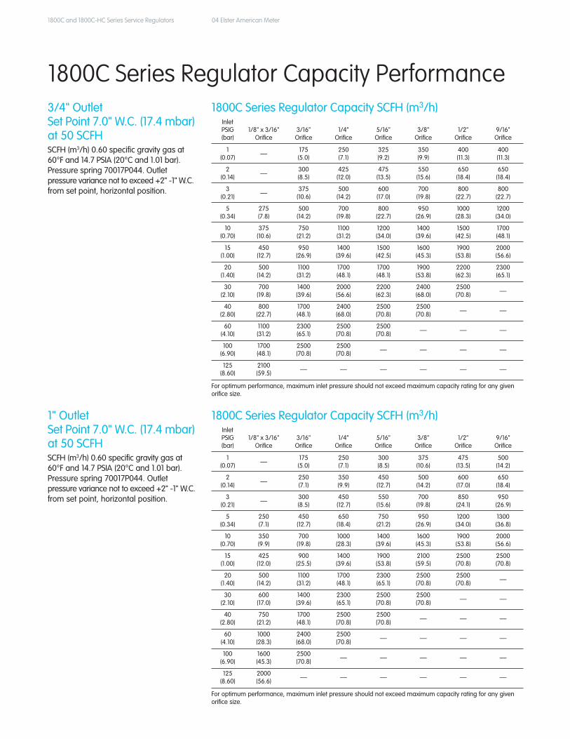
3/4" OutletSet Point 7.0" W.C. (17.4 mbar)at 50 SCFHSCFH (m3/h) 0.60 specific gravity gas at 60°F and 14.7 PSIA (20°C and 1.01 bar).Pressure spring 70017P044. Outlet pressure variance not to exceed +2" -1" W.C. from set point, horizontal position.
1800C Series Regulator Capacity SCFH (m3/h)
Inlet PSIG (bar)
1/8" x 3/16"Orifice
3/16"Orifice
1/4"Orifice
5/16"Orifice
3/8"Orifice
1/2"Orifice
9/16"Orifice
1(0.07) — 175
(5.0)250(7.1)
300(8.5)
375(10.6)
475(13.5)
500(14.2)
2(0.14) — 250
(7.1)350(9.9)
450(12.7)
500(14.2)
600(17.0)
650(18.4)
3(0.21) — 300
(8.5)450
(12.7)550
(15.6)700
(19.8)850
(24.1)950
(26.9)
5(0.34)
250(7.1)
450(12.7)
650(18.4)
750(21.2)
950(26.9)
1200(34.0)
1300(36.8)
10(0.70)
350(9.9)
700(19.8)
1000(28.3)
1400(39.6)
1600(45.3)
1900(53.8)
2000(56.6)
15(1.00)
425(12.0)
900(25.5)
1400(39.6)
1900(53.8)
2100(59.5)
2500(70.8)
2500(70.8)
20(1.40)
500(14.2)
1100(31.2)
1700(48.1)
2300(65.1)
2500(70.8)
2500(70.8) —
30(2.10)
600(17.0)
1400(39.6)
2300(65.1)
2500(70.8)
2500(70.8) — —
40(2.80)
750(21.2)
1700(48.1)
2500(70.8)
2500(70.8) — — —
60(4.10)
1000(28.3)
2400(68.0)
2500(70.8) — — — —
100(6.90)
1600(45.3)
2500(70.8) — — — — —
125(8.60)
2000(56.6) — — — — — —
1" Outlet Set Point 7.0" W.C. (17.4 mbar) at 50 SCFHSCFH (m3/h) 0.60 specific gravity gas at 60°F and 14.7 PSIA (20°C and 1.01 bar).Pressure spring 70017P044. Outlet pressure variance not to exceed +2" -1" W.C. from set point, horizontal position.
1800C Series Regulator Capacity SCFH (m3/h)
For optimum performance, maximum inlet pressure should not exceed maximum capacity rating for any given orifice size.
For optimum performance, maximum inlet pressure should not exceed maximum capacity rating for any given orifice size.
1800C and 1800C-HC Series Service Regulators 05 Elster American Meter
Inlet PSIG (bar)
1/8" x 3/16"Orifice
3/16"Orifice
1/4"Orifice
5/16"Orifice
3/8"Orifice
1/2"Orifice
9/16"Orifice
1(0.07)
— 200(5.7)
325(9.2)
350(9.9)
375(10.6)
475(13.5)
500(14.2)
2(0.14)
— 325(9.2)
500(14.2)
600(17.0)
700(19.8)
950(26.9)
1400(39.6)
3(0.21)
— 425(12.0)
650(18.4)
950(26.9)
1200(34.0)
1700(48.1)
1900(53.8)
5(0.34)
275(7.8)
550(15.6)
1000(28.3)
1600(45.3)
2100(59.5)
2500(70.8)
2500(70.8)
10(0.70)
375(10.6)
850(24.1)
1500(42.5)
2400(68.0)
2500(70.8)
2500(70.8)
2500(70.8)
15(1.00)
450(12.7)
1000(28.3)
1800(51.0)
2500(70.8) — — —
20(1.40)
550(15.6)
1200(34.0)
2100(59.5) — — — —
30(2.10)
700(19.8)
1600(45.3) — — — — —
40(2.80)
800(22.7) — — — — — —
60(4.10)
1100(31.2) — — — — — —
100(6.90)
1400(39.6) — — — — — —
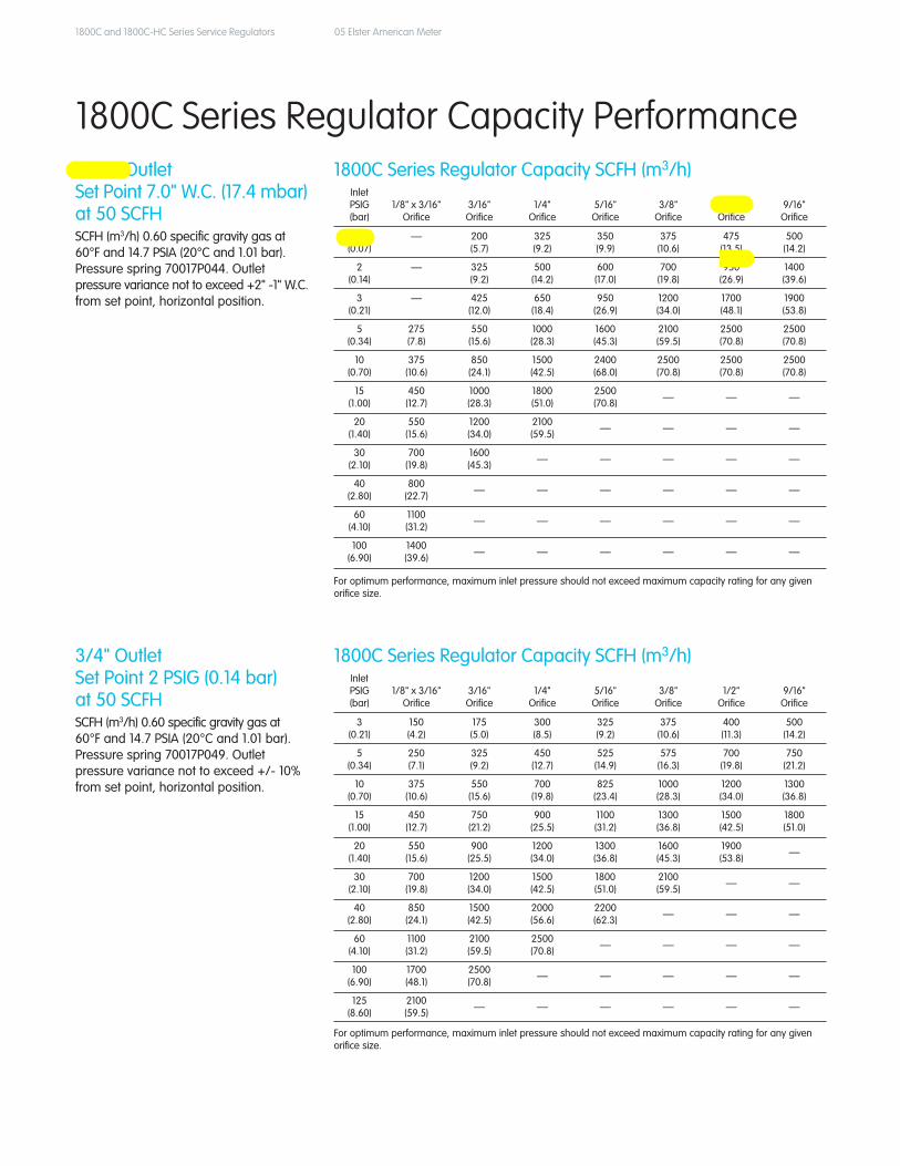
1-1/4" Outlet Set Point 7.0" W.C. (17.4 mbar) at 50 SCFHSCFH (m3/h) 0.60 specific gravity gas at 60°F and 14.7 PSIA (20°C and 1.01 bar). Pressure spring 70017P044. Outlet pressure variance not to exceed +2" -1" W.C. from set point, horizontal position.
1800C Series Regulator Capacity SCFH (m3/h)
Inlet PSIG (bar)
1/8" x 3/16"Orifice
3/16"Orifice
1/4"Orifice
5/16"Orifice
3/8"Orifice
1/2"Orifice
9/16"Orifice
3(0.21)
150(4.2)
175(5.0)
300(8.5)
325(9.2)
375(10.6)
400(11.3)
500(14.2)
5(0.34)
250(7.1)
325(9.2)
450(12.7)
525(14.9)
575(16.3)
700(19.8)
750(21.2)
10(0.70)
375(10.6)
550(15.6)
700(19.8)
825(23.4)
1000(28.3)
1200(34.0)
1300(36.8)
15(1.00)
450(12.7)
750(21.2)
900(25.5)
1100(31.2)
1300(36.8)
1500(42.5)
1800(51.0)
20(1.40)
550(15.6)
900(25.5)
1200(34.0)
1300(36.8)
1600(45.3)
1900(53.8) —
30(2.10)
700(19.8)
1200(34.0)
1500(42.5)
1800(51.0)
2100(59.5) — —
40(2.80)
850(24.1)
1500(42.5)
2000(56.6)
2200(62.3) — — —
60(4.10)
1100(31.2)
2100(59.5)
2500(70.8) — — — —
100(6.90)
1700(48.1)
2500(70.8) — — — — —
125(8.60)
2100(59.5) — — — — — —
3/4" Outlet Set Point 2 PSIG (0.14 bar) at 50 SCFHSCFH (m3/h) 0.60 specific gravity gas at 60°F and 14.7 PSIA (20°C and 1.01 bar). Pressure spring 70017P049. Outlet pressure variance not to exceed +/- 10% from set point, horizontal position.
1800C Series Regulator Capacity SCFH (m3/h)
For optimum performance, maximum inlet pressure should not exceed maximum capacity rating for any given orifice size.
For optimum performance, maximum inlet pressure should not exceed maximum capacity rating for any given orifice size.
1800C Series Regulator Capacity Performance
1800C and 1800C-HC Series Service Regulators 06 Elster American Meter
Inlet PSIG (bar)
1/8" x 3/16"Orifice
3/16"Orifice
1/4"Orifice
5/16"Orifice
3/8"Orifice
1/2"Orifice
9/16"Orifice
3(0.21)
150(4.2)
225(6.4)
250(7.1)
350(9.9)
425(12.0)
550(15.6)
550(15.6)
5(0.34)
225(6.4)
350(9.9)
450(12.7)
500(14.2)
650(18.4)
750(21.2)
900(25.5)
10(0.70)
350(9.9)
600(17.0)
750(21.2)
850(24.1)
1000(28.3)
1300(36.8)
1500(42.5)
15(1.00)
425(12.0)
800(22.7)
1000(28.3)
1100(31.2)
1400(39.6)
1700(48.1)
2000(56.6)
20(1.40)
500(14.2)
1000(28.3)
1200(34.0)
1400(39.6)
1800(51.0)
2100(59.5) —
30(2.10)
650(18.4)
1300(36.8)
1700(48.1)
2000(56.6)
2500(70.8) — —
40(2.80)
800(22.7)
1700(48.1)
2200(62.3)
2500(70.8) — — —
60(4.10)
1100(31.2)
2500(70.8)
2500(70.8) — — — —
100(6.90)
1700(48.1)
2500(70.8) — — — — —
125(8.60)
2100(59.5) — — — — — —
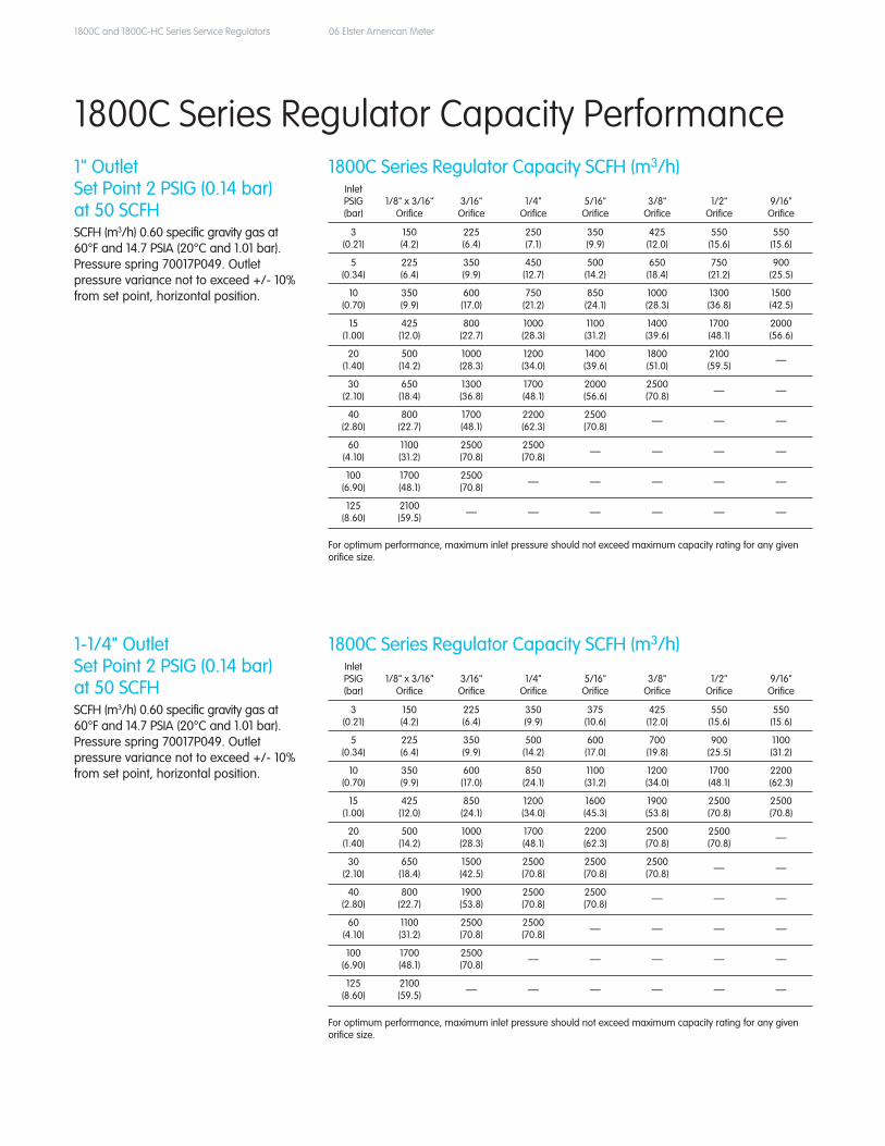
1" Outlet Set Point 2 PSIG (0.14 bar) at 50 SCFHSCFH (m3/h) 0.60 specific gravity gas at 60°F and 14.7 PSIA (20°C and 1.01 bar). Pressure spring 70017P049. Outlet pressure variance not to exceed +/- 10% from set point, horizontal position.
1800C Series Regulator Capacity SCFH (m3/h)
Inlet PSIG (bar)
1/8" x 3/16"Orifice
3/16"Orifice
1/4"Orifice
5/16"Orifice
3/8"Orifice
1/2"Orifice
9/16"Orifice
3(0.21)
150(4.2)
225(6.4)
350(9.9)
375(10.6)
425(12.0)
550(15.6)
550(15.6)
5(0.34)
225(6.4)
350(9.9)
500(14.2)
600(17.0)
700(19.8)
900(25.5)
1100(31.2)
10(0.70)
350(9.9)
600(17.0)
850(24.1)
1100(31.2)
1200(34.0)
1700(48.1)
2200(62.3)
15(1.00)
425(12.0)
850(24.1)
1200(34.0)
1600(45.3)
1900(53.8)
2500(70.8)
2500(70.8)
20(1.40)
500(14.2)
1000(28.3)
1700(48.1)
2200(62.3)
2500(70.8)
2500(70.8) —
30(2.10)
650(18.4)
1500(42.5)
2500(70.8)
2500(70.8)
2500(70.8) — —
40(2.80)
800(22.7)
1900(53.8)
2500(70.8)
2500(70.8) — — —
60(4.10)
1100(31.2)
2500(70.8)
2500(70.8) — — — —
100(6.90)
1700(48.1)
2500(70.8) — — — — —
125(8.60)
2100(59.5) — — — — — —
1-1/4" Outlet Set Point 2 PSIG (0.14 bar) at 50 SCFHSCFH (m3/h) 0.60 specific gravity gas at 60°F and 14.7 PSIA (20°C and 1.01 bar). Pressure spring 70017P049. Outlet pressure variance not to exceed +/- 10% from set point, horizontal position.
1800C Series Regulator Capacity SCFH (m3/h)
For optimum performance, maximum inlet pressure should not exceed maximum capacity rating for any given orifice size.
For optimum performance, maximum inlet pressure should not exceed maximum capacity rating for any given orifice size.
1800C Series Regulator Capacity Performance

1800C and 1800C-HC Series Service Regulators 07 Elster American Meter
Inlet PSIG (bar)
1/8" x 3/16"Orifice
3/16"Orifice
1/4"Orifice
5/16"Orifice
3/8"Orifice
1/2"Orifice
9/16"Orifice
1(0.07) — 175
(5.0)200(5.7)
250(7.1)
350(9.9)
475(13.5)
525(14.9)
2(0.14) — 275
(7.8)350(9.9)
450(12.7)
525(14.9)
675(19.1)
800(22.7)
3(0.21) — 350
(9.9)450
(12.7)600
(17.0)750
(21.2)800
(22.7)1100(31.2)
5(0.34)
275(7.8)
450(12.7)
700(19.8)
850(24.1)
1000(28.3)
1500(42.5)
1600(45.3)
10(0.70)
350(9.9)
600(17.0)
1100(31.2)
1500(42.5)
1600(45.3)
2500(70.8)
2700(76.5)
15(1.00)
425(12.0)
950(26.9)
1300(36.8)
2300(65.1)
2600(73.6)
3300(93.5)
3300(93.5)
20(1.40)
475(13.5)
1100(31.2)
1900(53.8)
2900(82.1)
3400(96.3)
4200(118.9)
3900(110.4)
30(2.10)
600(17.0)
1500(42.5)
2500(70.8)
4000(113.3)
4600(130.3)
4900(138.8) —
40(2.80)
750(21.2)
1800(51.0)
3200(90.6)
4900(138.8)
4900(138.8) — —
60(4.10)
1100(31.2)
2500(70.8)
4400(124.6)
4900(138.8) — — —
100(6.90)
1600(45.3)
3800(107.6) — — — — —
125(8.60)
2000(56.6) — — — — — —
1-1/4" Outlet Set Point 7.0" W.C. (17.4 mbar) at 50 SCFHSCFH (m3/h) 0.60 specific gravity gas at 60°F and 14.7 PSIA (20°C and 1.01 bar). Pressure spring 70017P044. Outlet pressure variance not to exceed +2" -1" W.C. from set point, horizontal position.
1800C Series Regulator Capacity SCFH (m3/h)
For optimum performance, maximum inlet pressure should not exceed maximum capacity rating for any given orifice size.
1800C-HC Series Regulator Capacity Performance
General InformationThe 1800C-HC Series regulator’s lightweight design features high-capacity capabilities for 1-1/4" NPT connections and flow capacities up to 4900 SCFH depending on inlet pressure and orifice selection. It complements the 1800C Series family of regulators.
Ideal for light commercial and industrial use, the 1-1/4" 1800C-HC Series regulator is designed to increase output capacity during medium to high inlet pressure operations.
1800C-HC Series Regulators
AC-630 Meter with 1813C-HC Regulator
1800C and 1800C-HC Series Service Regulators 08 Elster American Meter
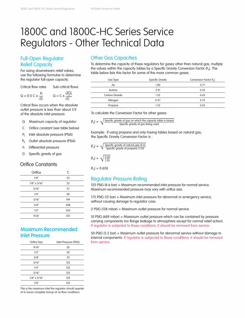
1800C and 1800C-HC Series Service Regulators - Other Technical Data
Orifice C1/8" 25
1/8" x 3/16" 25
3/16" 57
1/4" 98
5/16" 149
3/8" 208
1/2" 353
9/16" 421
Full-Open Regulator Relief Capacity For sizing downstream relief valves, use the following formulas to determine the regulator full-open capacity:
Critical flow rates Sub-critical flows
Q = 0.5 C x Q = C x√G
P1 √P2h√G
Critical flow occurs when the absolute outlet pressure is less than about 1/2 of the absolute inlet pressure.
Q Maximum capacity of regulator
C Orifice constant (see table below)
P1 Inlet absolute pressure (PSIA)
P2 Outlet absolute pressure (PSIA)
h Differentialpressure
G Specific gravity of gas
Regulator Pressure Rating 125 PSIG (8.6 bar) = Maximum recommended inlet pressure for normal service. Maximum recommended pressure may vary with orifice size.
175 PSIG (12 bar) = Maximum inlet pressure for abnormal or emergency service, without causing damage to regulator case.
2 PSIG (138 mbar) = Maximum outlet pressure for normal service.
10 PSIG (689 mbar) = Maximum outlet pressure which can be contained by pressure carrying components (no flange leakage to atmosphere except for normal relief action). If regulator is subjected to these conditions, it should be removed from service.
50 PSIG (3.5 bar) = Maximum outlet pressure for abnormal service without damage to internal components. If regulator is subjected to these conditions, it should be removed from service.
Other Gas CapacitiesTo determine the capacity of these regulators for gases other than natural gas, multiplythe values within the capacity tables by a Specific Gravity Conversion Factor (Fg). The table below lists this factor for some of the more common gases.
To calculate the Conversion Factor for other gases:
Gas Type Specific Gravity Conversion Factor (Fg)
Air 1.00 0.77
Butane 2.01 0.55
CarbonDioxide 1.52 0.63
Nitrogen 0.97 0.79
Propane 1.53 0.63
Maximum Recommended Inlet Pressure
Orifice Size Inlet Pressure (PSIG)
9/16" 20
1/2" 50
3/8" 70
5/16" 125
1/4" 125
3/16" 125
1/8" x 3/16" 125
1/8" 125
This is the maximum inlet the regulator should operate at to insure complete lockup at no-flow conditions.
Maximum Recommended Inlet Pressure
Orifice Constants
(Fg) = √ Specific gravity of gas on which the capacity table is basedSpecific gravity of gas being used
Example:Ifusingpropaneandonlyhavingtablesbasedonnaturalgas, the Specific Gravity Conversion Factor is :
(Fg) = √ Specific gravity of natural gas (0.6)Specific gravity of propane (1.53)
(Fg) = √ 0.601.53
(Fg) = 0.626
1800C and 1800C-HC Series Service Regulators 09 Elster American Meter
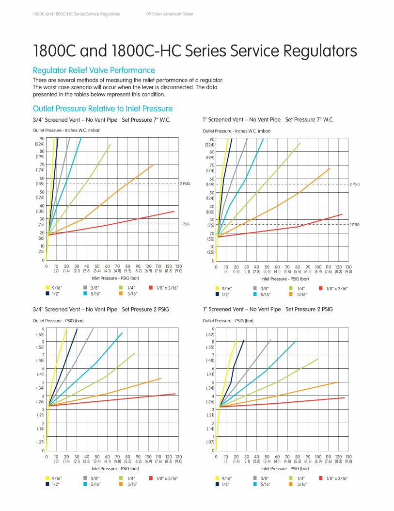
RegulatorReliefValvePerformanceThere are several methods of measuring the relief performance of a regulator. The worst case scenario will occur when the lever is disconnected. The data presented in the tables below represent this condition.
90(224)
80(199)
70(174)
60(149)
50(124)
40(100)
30(75)
20(50)
10(25)
00 10 20 30 40 50 60 70 80 90 100 110 120 130 (.7) (1.4) (2.1) (2.8) (3.4) (4.1) (4.8) (5.5) (6.2) (6.9) (7.6) (8.3) (9.0)
9/16” 3/8” 1/4” 1/8“ x 3/16”1/2” 5/16” 3/16”
Outlet Pressure - Inches W.C. (mbar)
Inlet Pressure - PSIG (bar)
Outlet Pressure Relative to Inlet Pressure3/4"ScreenedVent–NoVentPipeSetPressure7"W.C.
9(.62)
8(.55)
7(.48)
6(.41)
5(.34)
4(.26)
3(.21)
2(.14)
1(.07)
00 10 20 30 40 50 60 70 80 90 100 110 120 130 (.7) (1.4) (2.1) (2.8) (3.4) (4.1) (4.8) (5.5) (6.2) (6.9) (7.6) (8.3) (9.0)
9/16” 3/8” 1/4” 1/8“ x 3/16”1/2” 5/16” 3/16”
Outlet Pressure - PSIG (bar)
Inlet Pressure - PSIG (bar)
3/4"ScreenedVent–NoVentPipeSetPressure2PSIG
9(.62)
8(.55)
7(.48)
6(.41)
5(.34)
4(.26)
3(.21)
2(.14)
1(.07)
00 10 20 30 40 50 60 70 80 90 100 110 120 130 (.7) (1.4) (2.1) (2.8) (3.4) (4.1) (4.8) (5.5) (6.2) (6.9) (7.6) (8.3) (9.0)
9/16” 3/8” 1/4” 1/8“ x 3/16”1/2” 5/16” 3/16”
Outlet Pressure - PSIG (bar)
Inlet Pressure - PSIG (bar)
1"ScreenedVent–NoVentPipeSetPressure2PSIG
90(224)
80(199)
70(174)
60(149)
50(124)
40(100)
30(75)
20(50)
10(25)
00 10 20 30 40 50 60 70 80 90 100 110 120 130 (.7) (1.4) (2.1) (2.8) (3.4) (4.1) (4.8) (5.5) (6.2) (6.9) (7.6) (8.3) (9.0)
9/16” 3/8” 1/4” 1/8“ x 3/16”1/2” 5/16” 3/16”
Outlet Pressure - Inches W.C. (mbar)
Inlet Pressure - PSIG (bar)
1"ScreenedVent–NoVentPipeSetPressure7"W.C.
1800C and 1800C-HC Series Service Regulators
2 PSIG
1 PSIG
2 PSIG
1 PSIG
1800C and 1800C-HC Series Service Regulators 10 Elster American Meter
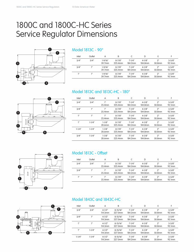
Model 1813C - 90°Inlet Outlet A B C D E F
3/4" 3/4" 1-9/16" 39.7mm
8-7/8"225.4mm
7-1/4"184.2mm
4-1/8"104.8mm
2"50.8mm
3-5/8"92.1mm
3/4" 1" 1-9/16" 39.7mm
8-7/8"225.4mm
7-1/4"184.2mm
4-1/8"104.8mm
2"50.8mm
3-5/8"92.1mm
1" 1" 1-9/16" 39.7mm
8-7/8"225.4mm
7-1/4"184.2mm
4-1/8"104.8mm
2"50.8mm
3-5/8"92.1mm
C
F
D
E
A B
Model 1813C and 1813C-HC - 180°Inlet Outlet A B C D E F
3/4" 3/4" 1" 25.4mm
8-7/8"225.4mm
7-1/4"184.2mm
4-1/8"104.8mm
2"50.8mm
3-5/8"92.1mm
3/4" 1" 1" 25.4mm
8-7/8"225.4mm
7-1/4"184.2mm
4-1/8"104.8mm
2"50.8mm
3-5/8"92.1mm
1" 1" 1" 25.4mm
8-7/8"225.4mm
7-1/4"184.2mm
4-1/8"104.8mm
2"50.8mm
3-5/8"92.1mm
1" 1-1/4" 1-1/8"28.6mm
8-7/8"225.4mm
7-1/4"184.2mm
4-1/8"104.8mm
2"50.8mm
3-5/8"92.1mm
1-1/4" 1-1/4" 1-1/8"28.6mm
8-7/8"225.4mm
7-1/4"184.2mm
4-1/8"104.8mm
2"50.8mm
3-5/8"92.1mm
3/4" 1-1/4" 1-1/8"28.6mm
8-7/8"225.4mm
7-1/4"184.2mm
4-1/8"104.8mm
2"50.8mm
3-5/8"92.1mm
C
F
D
E
A B
Model 1813C - OffsetInlet Outlet A B C D E F
3/4" 3/4" 1" 25.4mm
8-7/8"225.4mm
7-1/4"184.2mm
4-1/8"104.8mm
2"50.8mm
3-5/8"92.1mm
3/4" 1" 1" 25.4mm
8-7/8"225.4mm
7-1/4"184.2mm
4-1/8"104.8mm
2"50.8mm
3-5/8"92.1mm
1" 1" 1" 25.4mm
8-7/8"225.4mm
7-1/4"184.2mm
4-1/8"104.8mm
2"50.8mm
3-5/8"92.1mm
C
F
D
E
A B
Model 1843C and 1843C-HCInlet Outlet A B C D E F
3/4" 3/4" 4-1/2" 114.3mm
8-15/16"227.0mm
7-1/4"184.2mm
4-1/8"104.8mm
2"50.8mm
3-5/8"92.1mm
3/4" 1" 4-1/2" 114.3mm
8-15/16"227.0mm
7-1/4"184.2mm
4-1/8"104.8mm
2"50.8mm
3-5/8"92.1mm
1" 1" 4-1/2" 114.3mm
8-15/16"227.0mm
7-1/4"184.2mm
4-1/8"104.8mm
2"50.8mm
3-5/8"92.1mm
1" 1-1/4" 4-1/2" 114.3mm
8-15/16"227.0mm
7-1/4"184.2mm
4-1/8"104.8mm
2"50.8mm
3-5/8"92.1mm
1-1/4" 1-1/4" 4-1/2" 114.3mm
8-15/16"227.0mm
7-1/4"184.2mm
4-1/8"104.8mm
2"50.8mm
3-5/8"92.1mm
C
F
D
E
A B
1800C and 1800C-HC Series Service Regulator Dimensions
C
F
D
E
A B
CF
D
E
A B
CF
D
E
A B
CF
D
E
A B
1800C and 1800C-HC Series Service Regulators 11 Elster American Meter
StandardVent Position
StandardVent Position
2
4
31
2
4
31
StandardVent Position
Valve Head Position "D"
StandardVent Position
Valve Head Position "C"
Valve Head Position "B"Valve Head Position "A"
4
2
13
2
4
31
StandardVent Position
Valve Head Position "D"
1
3
24
StandardVent Position
4
2
13
Valve Head Position "B"
StandardVent Position
2
4
31
Valve Head Position "A"
StandardVent Position
Valve Head Position "C"
2
4
31
StandardVent Position
VENT
Valve Head Position "D"
2
4
31
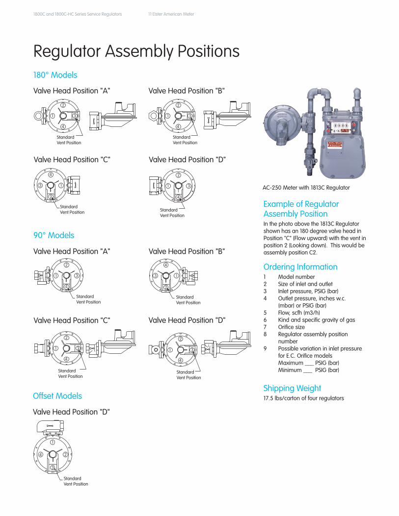
ExampleofRegulator Assembly PositionIn the photo above the 1813C Regulator shown has an 180 degree valve head in Position "C" (Flow upward) with the vent in position 2 (Looking down). This would be assembly position C2.
Ordering Information1 Model number 2 Size of inlet and outlet 3 Inlet pressure, PSIG (bar) 4 Outlet pressure, inches w.c. (mbar) or PSIG (bar) 5 Flow, scfh (m3/h) 6 Kind and specific gravity of gas 7 Orifice size 8 Regulator assembly position number 9 Possible variation in inlet pressure forE.C.Orificemodels Maximum ___ PSIG (bar) Minimum ___ PSIG (bar)
Shipping Weight17.5 lbs/carton of four regulators
180° Models
90° Models
Offset Models
Regulator Assembly Positions
AC-250 Meter with 1813C Regulator
ElsterAmericanMeter 2221 Industrial RoadNebraskaCity,NE68410USA
T +1 402 873 8200F +1 402 873 7616
www.elster-americanmeter.com
ElsterCanadianMeter
T +1 519 650 1900F +1 519 650 1917
www.elster-canadianmeter.com
©2008ElsterAmericanMeter.Allrightsreserved
Information contained herein is subject to changewithout notice. Product specifications may change.ContactyourElsterAmericanMeterrepresentative for the most current product information. Printed in the United States.
EAM-TB8515.11-EN-P-June2008SupersedesEAM-TB8515.10-EN-P
AboutElsterGroupA world leader in advanced metering infrastructure, integrated metering, and utilization solutions to the gas, electricity andwaterindustries,Elster’ssystemsand solutions reflect over 170 years of knowledge and experience in measuring precious resources and energy. Elsterprovidessolutionsandadvancedtechnologies to help utilities more easily, efficiently and reliably obtain and use advanced metering intelligence to improve customer service, enhance operational efficiency, and increase revenues.Elster'sAMIsolutionsenable utilities to cost-effectively generate, deliver, manage, and conserve the life-essential resources of gas, electricity, and water. Elsterhasover7,500staffand operations in 38 countries in North andSouthAmerica,Europe,andAsia.
7.1
8"
6"
Flo
w D
irec
tio
nA
rro
wLe
vel
Ind
icat
or
Vis
ual
Stat
us
Win
do
w
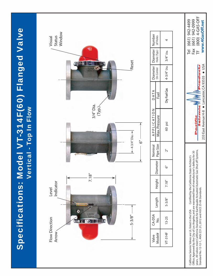
Spe
cifi
cati
ons:
Mod
el V
T-31
4F(6
0) F
lang
ed V
alve
V
erti
cal -
Top
In
Flow
5-3/
8"
Cal
iforn
ia S
eism
ic V
alve
s ar
e U
L lis
ted
in t
he
USA
C
erti
fied
by
the
Cal
iforn
ia S
tate
Arc
hit
ect's
O
ffic
e, A
pp
rove
d b
y th
e C
ity
of L
os
An
gel
es, a
nd
are
war
ran
ted
free
of m
anu
fact
ure
r's d
efec
ts fo
r 30
year
s. A
ll va
lves
mee
t C
alifo
rnia
Sta
nd
ard
s fo
r Ear
thq
uak
e A
ctu
ated
Au
tom
atic
Gas
Sh
ut
off
Sys
tem
s, St
and
ard
No.
12-
12-1
, A
NSI
Z21
.21,
201
2 an
d A
SCE
25-0
6 St
and
ard
s.
Val
veM
od
el#
VT-
314F
CA
-DSA
N
o.
13-2
5
Len
gth
5-3/
8"
Hei
gh
t
7.1
8"
Dia
met
er
6"
No
min
alPi
pe
Size
2"
AP
PL
ICA
TIO
N
D
AT
A
60 p
siD
ry F
uel G
as
Max
. Pre
ssu
reFu
el
Res
et4-
3/4"
Dia
.
Dia
met
er O
n C
ente
r
4-3/
4" D
ia.
3/4"
Dia
.
(Typ
.)
Dia
met
er H
ole
(Ty
p.)
3/4"
Dia
.
Nu
mb
er o
f Ho
les
4
Tel
(66
1) 9
42-4
499
Fax
(66
1) 9
42-0
999
TF
(80
0) 4
-GA
S-O
FF w
ww
.4G
asO
ff.n
et23
3 Ea
st A
ven
ue
H-8
Lan
cast
er, C
A 9
3535
USA
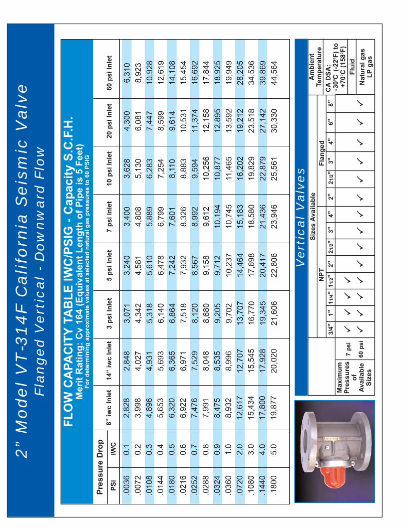
FLO
W C
APA
CIT
YTA
BLE
IWC
/PSI
G -
Cap
acity
S.C
.F.H
.M
erit
Rat
ing:
Cv
164
(Equ
ival
ent L
engt
h of
Pip
e is
5 F
eet)
For d
eter
min
ing
appr
oxim
ate
valu
es a
t sel
ecte
d na
tura
l gas
pre
ssur
es to
60
PSIG
0.1
0.2
0.3
0.4
0.5
0.6
0.7
0.8
0.9
1.0
2.0
3.0
4.0
5.0
.0036
.0072
.0108
.0144
.0180
.0216
.0252
.0288
.0324
.0360
.0720
.1080
.1440
.1800
2,828
3,998
4,896
5,653
6,320
6,922
7,476
7,991
8,475
8,932
12,617
15,434
17,800
19,877
Pres
sure
Dro
pPS
IIW
C8”
iwc
Inle
t
2,848
4,027
4,931
5,693
6,365
6,971
7,529
8,048
8,535
8,996
12,707
15,545
17,928
20,020
14”
iwc
Inle
t
3,071
4,342
5,318
6,140
6,864
7,518
8,120
8,680
9,205
9,702
13,707
16,770
19,345
21,606
3 ps
i Inl
et
3,240
4,581
5,610
6,478
7,242
7,932
8,567
9,158
9,712
10,237
14,464
17,698
20,417
22,806
5 ps
i Inl
et
3,400
4,808
5,889
6,799
7,601
8,326
8,992
9,612
10,194
10,745
15,183
18,580
21,436
23,946
7 ps
i Inl
et
3,628
5,130
6,283
7,254
8,110
8,883
9,594
10,256
10,877
11,465
16,202
19,829
22,879
25,561
10 p
si In
let
4,300
6,081
7,447
8,599
9,614
10,531
11,374
12,158
12,895
13,592
19,212
23,518
27,142
30,330
20 p
si In
let
6,310
8,923
10,928
12,619
14,108
15,454
16,692
17,844
18,925
19,949
28,205
34,536
39,869
44,564
60 p
si In
let
2”
Mo
de
l V
T-3
14
F C
ali
forn
ia S
eis
mic
Va
lve
Fla
ng
ed
Ve
rtic
al
- D
ow
nw
ard
Flo
w
Max
imum
Pres
sure
sof
Avai
labl
eSi
zes
7 ps
i
60 p
si
Ve
rtic
al
Va
lve
sSi
zes
Avai
labl
eFl
ange
dN
PTA
mbi
ent
Tem
pera
ture
CA
DSA
:-3
00 C(-2
20 F) t
o+7
00 C (1
580 F
)Fl
uid
Nat
ural
gas
LPga
s
3/4"
1"11
/4"
11/2
"2"
21/2
"3"
4"2"
21/2
"3"
4"6"
8"

Utility Safety Controls Since 2000
ISIMET® 1 or 2 Switch Utility Controller (LAv2)
(for school science labs)
• Allows the instructor to control 1 or 2 utilities (gas, water, electric) or fan.
• Programmable timer automatically turns off utilities when classroom is not in use.
• Emergency shut-off button deactivates utilities.
• Utilities default OFF until emergency has been resolved and teacher activates system.
• Up to four diagnostic LED’s.
• Available in keyed and non-keyed options.
• Integrates with Building Energy Management system.
• Dimensons: - Cover - 5.25” x 9.75” - Box - 4.75” x 9.25” x 3” D• UL Listed.
#1 Utility Controllers
in U.S.5-YEAR
Warranty
see website for details
Helps keep students, teachers and facilities safe.
Non-keyed
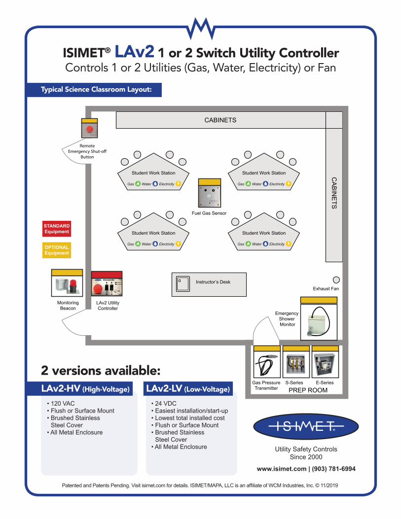
Typical Commercial Kitchen Layout:
2 versions available:
www.isimet.com | (903) 781-6994
CABINETS
LAv2 UtilityController
CA
BIN
ETS
Emergency Shower Monitor
Exhaust FanInstructor’s Desk
Student Work Station Student Work Station
Student Work Station Student Work Station
MonitoringBeacon
Fuel Gas Sensor
S-SeriesGas PressureTransmitter
E-Series
RemoteEmergency Shut-o�
Button
PREP ROOM
Gas Water Electricity
Gas Water Electricity
Gas Water Electricity
Gas Water Electricity
STANDARDEquipment
Utility Safety ControlsSince 2000
• 120 VAC • Flush or Surface Mount • Brushed Stainless
Steel Cover• All Metal Enclosure
• 24 VDC• Easiest installation/start-up• Lowest total installed cost• Flush or Surface Mount • Brushed Stainless
Steel Cover• All Metal Enclosure
LAv2-HV (High-Voltage) LAv2-LV (Low-Voltage)
Typical Science Classroom Layout:
OPTIONALEquipment
ISIMET® LAv2 1 or 2 Switch Utility ControllerControls 1 or 2 Utilities (Gas, Water, Electricity) or Fan
Patented and Patents Pending. Visit isimet.com for details. ISIMET/MAPA, LLC is an affiliate of WCM Industries, Inc. © 11/2019
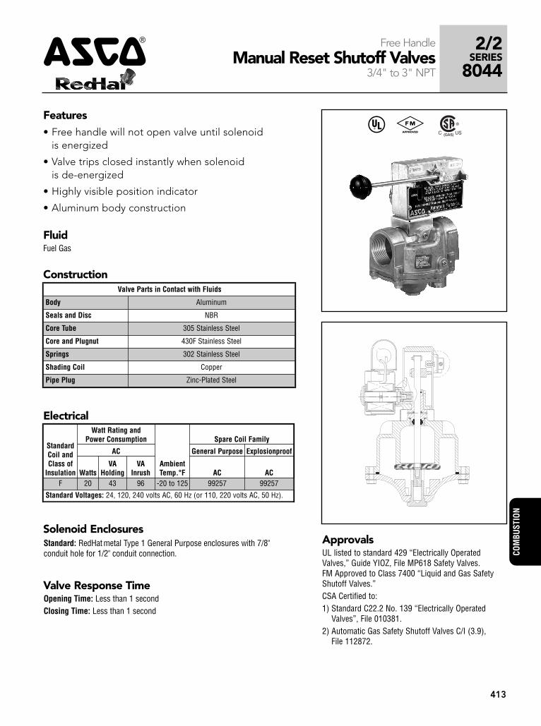
42/2
SERIES
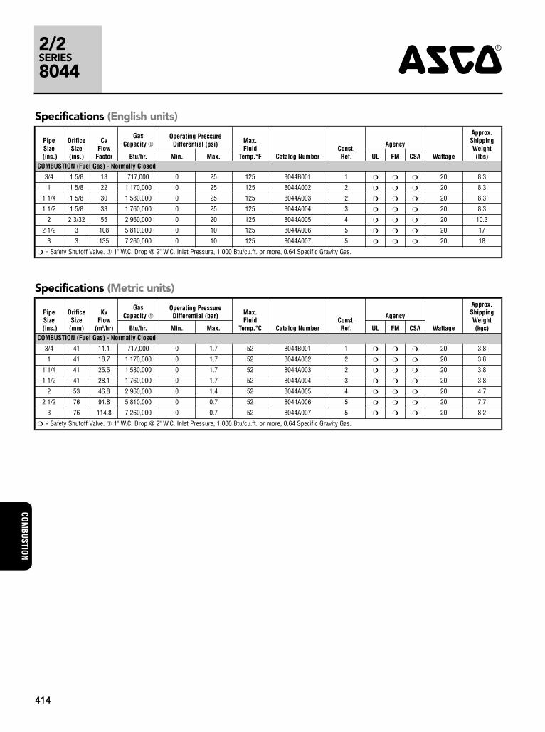
8044
COM
BUST
ION
413
Features• Free handle will not open valve until solenoid
is energized
• Valve trips closed instantly when solenoid is de-energized
• Highly visible position indicator
• Aluminum body construction
Free HandleManual Reset Shutoff Valves
3/4" to 3" NPT
Solenoid EnclosuresStandard: RedHatmetal Type 1 General Purpose enclosures with 7/8"conduit hole for 1/2" conduit connection.
ApprovalsUL listed to standard 429 “Electrically OperatedValves,” Guide YIOZ, File MP618 Safety Valves.FM Approved to Class 7400 “Liquid and Gas SafetyShutoff Valves.”CSA Certified to:1) Standard C22.2 No. 139 “Electrically Operated
Valves”, File 010381.2) Automatic Gas Safety Shutoff Valves C/I (3.9),
File 112872.
Valve Parts in Contact with Fluids
Body Aluminum
Seals and Disc NBR
Core Tube 305 Stainless Steel
Core and Plugnut 430F Stainless Steel
Springs 302 Stainless Steel
Shading Coil Copper
Pipe Plug Zinc-Plated Steel
StandardCoil andClass of
Insulation
Watt Rating andPower Consumption
AmbientTemp.°F
Spare Coil Family
AC General Purpose Explosionproof
WattsVA
HoldingVA
Inrush AC ACF 20 43 96 -20 to 125 99257 99257
Standard Voltages: 24, 120, 240 volts AC, 60 Hz (or 110, 220 volts AC, 50 Hz).
Electrical
Construction
^ #
Valve Response TimeOpening Time: Less than 1 secondClosing Time: Less than 1 second
FluidFuel Gas
2/2SERIES
8044 4
COMBUSTION
414
Specifications (English units)
PipeSize(ins.)
OrificeSize(ins.)
CvFlow
Factor
GasCapacity �
Operating PressureDifferential (psi) Max.
FluidTemp.°F Catalog Number
Const.Ref.
Agency
Wattage
Approx.ShippingWeight(lbs)Btu/hr. Min. Max. UL FM CSA
COMBUSTION (Fuel Gas) - Normally Closed
3/4 1 5/8 13 717,000 0 25 125 8044B001 1 � � � 20 8.3
1 1 5/8 22 1,170,000 0 25 125 8044A002 2 � � � 20 8.3
1 1/4 1 5/8 30 1,580,000 0 25 125 8044A003 2 � � � 20 8.3
1 1/2 1 5/8 33 1,760,000 0 25 125 8044A004 3 � � � 20 8.3
2 2 3/32 55 2,960,000 0 20 125 8044A005 4 � � � 20 10.3
2 1/2 3 108 5,810,000 0 10 125 8044A006 5 � � � 20 17
3 3 135 7,260,000 0 10 125 8044A007 5 � � � 20 18
� = Safety Shutoff Valve. � 1" W.C. Drop @ 2" W.C. Inlet Pressure, 1,000 Btu/cu.ft. or more, 0.64 Specific Gravity Gas.
Specifications (Metric units)
PipeSize(ins.)
OrificeSize(mm)
KvFlow
(m3/hr)
GasCapacity �
Operating PressureDifferential (bar) Max.
FluidTemp.°C Catalog Number
Const.Ref.
Agency
Wattage
Approx.ShippingWeight(kgs)Btu/hr. Min. Max. UL FM CSA
COMBUSTION (Fuel Gas) - Normally Closed
3/4 41 11.1 717,000 0 1.7 52 8044B001 1 � � � 20 3.8
1 41 18.7 1,170,000 0 1.7 52 8044A002 2 � � � 20 3.8
1 1/4 41 25.5 1,580,000 0 1.7 52 8044A003 2 � � � 20 3.8
1 1/2 41 28.1 1,760,000 0 1.7 52 8044A004 3 � � � 20 3.8
2 53 46.8 2,960,000 0 1.4 52 8044A005 4 � � � 20 4.7
2 1/2 76 91.8 5,810,000 0 0.7 52 8044A006 5 � � � 20 7.7
3 76 114.8 7,260,000 0 0.7 52 8044A007 5 � � � 20 8.2
� = Safety Shutoff Valve. � 1" W.C. Drop @ 2" W.C. Inlet Pressure, 1,000 Btu/cu.ft. or more, 0.64 Specific Gravity Gas.
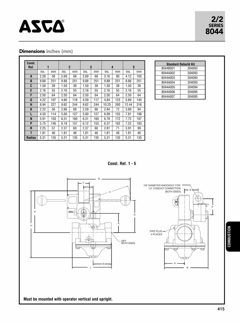
2/2SERIES
80444
COM
BUST
ION
415
LR
H
P
B
K
G
T
C
V
N
A
F
E
NPTBOTH ENDS
PIPE PLUG4 PLACES
(BOTH SIDES)
7/8" DIAMETER KNOCKOUT FOR1/2" CONDUIT CONNECTION
Dimensions inches (mm)
Const. Ref. 1 - 5
Must be mounted with operator vertical and upright.
Const. Ref. 1 2 3 4 5
ins. mm ins. mm ins. mm ins. mm ins. mmA 2.28 58 2.69 68 2.69 68 3.16 80 4.12 105B 9.88 251 9.88 251 9.88 251 9.88 251 9.88 251C 1.50 38 1.50 38 1.50 38 1.50 38 1.50 38E 2.16 55 2.16 55 2.16 55 2.16 55 2.16 55F 2.50 64 2.50 64 2.50 64 2.50 64 2.50 64G 4.22 107 4.66 118 4.59 117 4.84 123 5.69 145H 8.94 227 9.62 244 9.62 244 10.25 260 12.44 316K 2.22 56 2.66 68 2.59 66 2.84 72 3.69 94L 4.50 114 5.00 127 5.00 127 6.09 155 7.81 198N 5.91 150 6.31 160 6.31 160 6.78 172 7.75 197P 5.75 146 6.19 157 6.12 155 6.37 162 7.22 183R 2.25 57 2.37 60 2.37 60 2.81 71 3.91 99T 1.81 46 1.81 46 1.81 46 1.81 46 1.81 46
Radius 5.31 135 5.31 135 5.31 135 5.31 135 5.31 135
Standard Rebuild Kit8044B001 3040938044A002 3040938044A003 3040938044A004 3040938044A005 3040948044A006 3040958044A007 304095


