Embed Size (px)
Citation preview
Development unit
1bin unit
D1475237
D1495333
Fan Harness Inserted
D1495322
Toner supply unit
Toner supply unit
Toner supply unit
Toner supply unit
D1475340
D1495307
D1495308
ImagingIOB2/2
D1495324
D1495371(mini CT:D1495398)
PTR unit
Harness(Units)
Harness(Main)
D1495341(100V models)
D1475340
Fusing unit
D1475301
D1755329
CN
1
D1495328
CN
1
JC
N2
CN
2
D1755326
D1475308
D1495302
Registration unit
Paper Exit unit
Paper Transport
IOB
Duplex Entrance Motor M1
CNPTR Open/Close Sensor
CN
161
CNFusing Entrance Sensor
CNRight Door Open/Close Switch
CNPaper Exit Solenoid
CNInversion Motor
CNPaper Exit Sensor
CN
CN
14
CN
11
CN
5
SOL2
M3
CN
2JC
N2
CNLift Motor / Tray lift Sensor (1st Feed Tray)
CNTray set switch(1st Feed Tray)
CN
6C
N7
M9
CNRegistration Sensor
Registration Motor
CN
CN
157
CN
5
CN
CN
6
M4
Paper Exit / Pressure Release Motor
M5
Paper Feed Motor
CN
CN
7
CN
CN
8
M6
Transport Motor M7
CNFusing Exhaust Heat Fan
Ozone Exhaust Fan
CN
153
CN
161
CN
162
CN
159
CN
157
CN
153
CN***Bridge unit / Shift Tray /
Exit TrayCN
19
CN*** Bridge unit / Exit Tray
CN
20
CN
251
CN***
1bin Tray
CN
251
Imaging IOB1/2
2Piece FFC40pin
CN
163
CN578 IPU
CN
578
CN
163
CN
164
PCU Motor: CMYM16
CN Development Motor: CMY
CN
200
CN
CN
2
HST Sensor: KCN***
Toner End Sensor: K
CN
CN
205
CN
Toner End Sensor: C
CN Temperature/Humidity Sensor K
CN Developing Air Intake Fan:Right
CN Developing Air Intake Fan:Left
CN
209
M17
ITB Contact and Release Sensor
CN PTR Separation Sensor
CN
CN
**
CNPaper Transfer Contact
MotorM19
CN Toner Bottle Drive Motor: C
CN
203
CN
2JC
N2
ID Chip: KCN
M13
CN Toner Bottle Drive Motor: KCN
1JC
N1
M12
CN Toner Bottle Drive Motor: Y
JC
N4
M15
CN Toner Bottle Drive Motor: MCN
3JC
N3
M14
Toner End Sensor: M
CN
CN
Toner End Sensor: Y
CN Paper Exit Cooling Fan
CN800 HVP CB
CN
211
CN
205
CN
203
CN
207
CN
207
CN
209
CN
200
CN
211
Thermopile (edge)
CN
CN
Thermopile (center) CN Controller Box Cooling FanC
N216
CN
4
CN Toner supply cooling Fan
CN
156
CN
216
CN Key-counter
CN
254
CN
254
CN750 MKB
CN
253
CN
253
CN994 PSU (AC Controller Board)
CN
3
Fusing Motor CNM8
JC
N*
CN
10
JC
N9
CN
9
CN
*
CN
750
CN
1C
N5
JC
N2
JC
N3
CN
3C
N2
JC
N5
CN
1 (D
raw
er)
Dra
wer
(11029782)
Dra
wer
CN
*C
N*
*
CT miniCT MiⅡ miniMiⅡ JST Other
[5]
CN
1
JC
N17
CN
2
CN
2
JC
N1
CN
1
CN
4
CN
162
CN
160
CN
160
CN
155
CN
155
JC
N1
CN
1
D1495306
CN
256
CN
256
CN
1C
N2
CN914 PSU: DC
CN
914
CN***
Bank
CN***
Dra
wer
(11028534)
Dra
wer C
N*
CN
**
CN
1C
N2
CN913 PSU: DC
CN
913
CN***
Finisher
CN***
Lat
tice
(11028502)
Lat
ticeC
N*
CN
**
[1]
CN
164
CN
201
CN
201
CN
9
CN
5
JC
N14
CN
**
CN
14
CN
204
CN
204
JC
N13
CN
13
CN
2C
N3
CN
4C
N5
JC
N2
JC
N3
JC
N4
JC
N5
CN
1
CN
3
CN
3
JC
N18
CN
1
CN
6C
N5
CN985
PSUAC Controller Board
CN986
CN
7 (D
raw
er)
T1
CN
985
CN
986
4pin
1pin
[2]
[9]
[10]
(1/3)
CNInversion Sensor CN
4
See the diagram 1/2
Interlock Switch: Front Cover (LD Safety Switch)
Interlock Switch: Duplex Unit (LD Safety Switch)
CN
213
CN
213
CN
*
2pinCN917 PSU: DC
CN
917
[8]
Paper feed unit
Lift Motor / Tray lift Sensor (2nd Feed Tray)
CN
CN
158
CNSize Switch
(2nd Feed Tray)
CNTransport Sensor (2nd Feed Tray)
CNPaper End Sensor (2nd Feed Tray)
CNLimit Sensor
(2nd Feed Tray)
CN
1
CN
CN
2C
N3
CN
3C
N5
M10
CN
4
CN
158
JC
N5
CN
1
CN
5
[17]
See the diagram 1/2
CN
152
CN911
CN
251
CN912
PSU: DC
CN
252 C
N152
[3]
GND
AMPminiCT
18pin
AMPminiCT
40pin
AMPminiCT
28pin
AMPminiCT
30pin
AMPminiCT
7pin
AMPminiCT
14pin
AMPminiCT
32pin
AMPminiCT
19pin
AMPminiCT
17pin
MolexminiMi
Ⅱ
7pin
AMPminiCT
6pin
Molex3.5mm4pin
AMPminiCT
10pin
HF512S
40pin
AMPminiCT
18pin
AMPminiCT
17pin
AMPminiCT
26pin
AMPminiCT
19pin
AMPminiCT
20pin
AMPminiCT
40pin
AMPminiCT
32pin
AMPminiCT
32pin
Molex3.5mm
2pin
JSTCZ
36pin
AMPminiCT
14pin
AMPminiCT
4pin
MolexminiMi
Ⅱ
13pin
CT/3pin
AMP
CT/3pin
AMP
AMP
AMP
AMP
AMP
CT/2pin
AMP
CT/10pin
AMP
CT/10pin
AMP
CT/10pin
AMP
JC
N1
CT/3pin
AMP
CT/2pin
AMP
CT/5pin
AMP
CT/5pin
AMP
CT/3pin
AMP
AMP
CT/2pin
AMP
MiⅡ/5pin
Molex
CT/2pin
AMP
AMP
CT/3pin
AMP
CT/4pin
AMP
CZHR/8pin
JST
CT/2pin
AMP
CT/3pin
AMP
CT/3pin
AMP
CT/2pin
AMP
AMP
AMP
AMP
CT/3pin
AMP
AMP
AMP
AMP
1mm/6pin
JST
CT/4pin
AMP
CT/3pin
AMP
CT/3pin
AMP
miniCT/4pin
AMP
Power supply connecter/4pin
Molex
MiⅡ/13pin
Molex
CT/4pin
AMP
CT/4pin
AMP
CT/3pin
AMP
Unknown
Turning point
JC
N1
CN
2
CN
1
CN
10
ID Chip: CCN
ID Chip: MCN
ID Chip: YCN
CN Imaging Temperature SensorCT/2pin
AMP
HVP TTSCN802 [19]miniCT/10pin
AMP
CN
219AMP
miniCT
13pin
CN Fusing Exit Sensor
CN
2
CT/3pin
AMP
CN
151
CN
221
Waste toner bottle unitCN Waste toner capacity sensor
CN
2
CN Waste toner bottle set switch
JC
N1
CN
1
CN
5
CT/3pin
AMP
CT/2pin
AMP
CN
4C
N6
CN
7C
N8
CN
**
CN
218
CN
218
CN
217
CN
217
MolexminiMi
Ⅱ
18pin
MolexminiMi
Ⅱ
4pin
Laser Unit
CN
220
Skew Motor: Y
CN Skew Motor: M
CN
4
CN
CN
5
M24
M25
CN
220
Skew Motor: C
CN
6
CN M26
JC
N4
CN
4
CN
220
MiⅡ/5pin
Molex
Molex
Molex
D1495372 (mini CT:D1495399)BCU
2 piece FFC50pin
CN
214
[7]CN103HF512S
50pin
1st Paper Feed Tray
CNTransport Sensor(1st Feed Tray)
CNPaper End Sensor(1st Feed Tray)
CNLimit Sensor (1st Feed Tray)
CN
3C
N5
CN
4
JC
N9
CN
1
miniCT/3pin
AMP
CT/3pin
AMP
CT/3pin
AMP
CN PSU Cooling Fan
JC
N2
CT/3pin
AMP
CN
2
CN
156
CN
159
CZHR/8pin
JST
CZHR/8pin
JST
CZHR/8pin
JST
CZHR/8pin
JST
CN Pressure Roller HP SensorCT/3pin
AMP
CN
18
JC
N*
miniCT/11pin
AMP
CN
*JC
N*
AMP
AMP
AMP
D1495330
CN
10
CN
13
CN
17
JC
N2
CN
1
CN
2JC
N2
CN
2JC
N2
CN
2
CN
1
JC
N2
CN
2
CN
1C
N1
CN
18
JC
N18
D1495334
D1495334
D1495334
D1495334
4.2mm/8pin
Molex
4.2mm/6pin
Molex
CNPCU: Black / Image Transfer
MotorCN
7
M18CT/15pin
AMP
CN***
CN
2
JC
N3
CN
3 CN*** 1bin LED
(1/4)
HF512S
40pin
(2/4)
CN
167 AMP
miniCT
4pinCN
167
CN
CN
Fusing Shield Position Sensor 1CN
4C
N3
CT/3pin
AMP
CT/3pin
AMP
(1/2)
(2/2)
CN
168AMP
miniCT
5pin CN
168
CN
CN
3
CT/4pin
AMP
Fusing Shield Drive Motor
JC
N19
CN
1
CN
19
CN
994
CN
154AMP
CT
4pin CN
1C
N166
CN
166AMP
miniCT
3pin
D1495325
CN
222
Toner Transport Motor: K
CNToner Transport Motor: C
CN
1
CN
CN
2
M20
M21
Toner Transport Motor: M
CN Toner Transport Motor: Y
CN
3
CN
CN
4
M22
M23
CN
222AMP
miniCT
16pin
CT/4pin
AMP
AMP
AMP
AMP
CN
1C
N11
CN
12
CN
800
CN
3C
N802
Fusing Shield Position Sensor 2
MiⅡ/7pin
Molex
CT/3pin
AMP
miniCT/3pin
AMP
CN
151
CN
221
miniCT/14pin
AMP
miniCT/3pin
CT/3pin
miniCT/10pin
AMP
MiⅡ/8pin
Molex
MiⅡ/7pin
Molex
miniCT/6pin
AMP
miniCT/2pin
AMP
CT/2pin
AMP
CZ/36pin
JST
miniCT/4pin
AMP
7.92mm/2pin
6.5mm/2pin (200V models: Not used)
Molex
CT/2pin
CT/2pin
CT/2pin
miniCT/4pin
miniCT/4pin
miniCT/4pin
CT/3pin
AMP
CT/3pin
AMP
CT/3pin
AMP
CT/3pin
AMP
CT/3pin
CT/3pin
CT/3pin
CT/3pin
AMP
miniMiⅡ/10pin
Molex
miniMiⅡ/9pin
Molex
miniMiⅡ/8pin
Molex
miniMiⅡ/9pin
Molex
MiⅡ/8pin
Molex
CT/3pin
AMP
miniCT/11pin
AMP
CT/3pin
CT/3pin
miniCT/32pin
AMP
miniCT/32pin
AMP
CZHR/8pin
JST
CZHR/8pinJST
CZHR/8pinJST
CZHR/8pinJST
CT/3pin
CT/3pin
CT/4pin
CT/4pin
CT/4pin
CN
214
CN
103
CT/15pin
AMP
MiⅡ/5pin
MiⅡ/5pin
Molex
4.2mm/4pin
HF512S/50pin
Development unitHST Sensor: CCN***
CN
1
CN
3
1mm/6pin
JST
Quenching Lamp
Development unitHST Sensor: MCN***
CN
1
CN
3
1mm/6pin
JST
Development unitHST Sensor: YCN***C
N1
CN
3
1mm/6pin
JST
D1495342(200V models)
CN
3
CN
*
CN
*
D1754499
D1473472
D1473472
D1473472
D1473472
D1752708
D1752708
CN
3JC
N3
D1476237
D1492556
(1/2) D1475235 (1/2)
AMPminiCT
15pin
CS/13pin
JST
CS/11pin
JST
CT/4pin
AMP
CN
*
CN
*
CN
219
CN Development SolenoidSOL
5CN
8JC
N8
CT/2pin
AMP
CN
AMP
CT/2pin
CN
6
Quenching LampCN
AMP
CT/2pin
CN
6
Quenching LampCN
AMP
CT/2pin
CN
6
Quenching LampCN
AMP
CT/2pin
CN
6
CN
15JC
N15
CN
16JC
N16
miniCT/18pin
AMP
CT/14pinAMP
Duplex unit
By-pass unit
By-pass unit
Duplex unit
CNBy-pass/Duplex Motor
CNDuplex Entrance Sensor
CNDuplex Exit Sensor
CNDuplex Unit Open/Close Sensor
By-pass Pick-up Solenoid SOL1
CNBy-pass Paper End Sensor
CNBy-pass Paper length Sensor
CNBy-pass Paper Size Sensor
CN
2C
N6
CN
5
CN
CN
3C
N2
CN
3C
N3
CT/3pin
AMP
CT/3pin
AMP
CT/3pin
AMP
CT/3pin
AMP
CT/2pin
AMP
CT/3pin
AMP
CT/7pin
AMP
CZHR/8pin
JST
D1474698
D1494743
CN
1JC
N1
CN
1JC
N1
D1492659
By-pass unit
CN
2C
N3
D1492661
CN
1
D1494696
CN
1
CN
4JC
N4
CN
1
miniCT/5pin
AMP
CT/9pin
AMP
CT/5pinAMP
CN
2
CN
9C
N17
Tray Set switch (2nd Feed Tray)
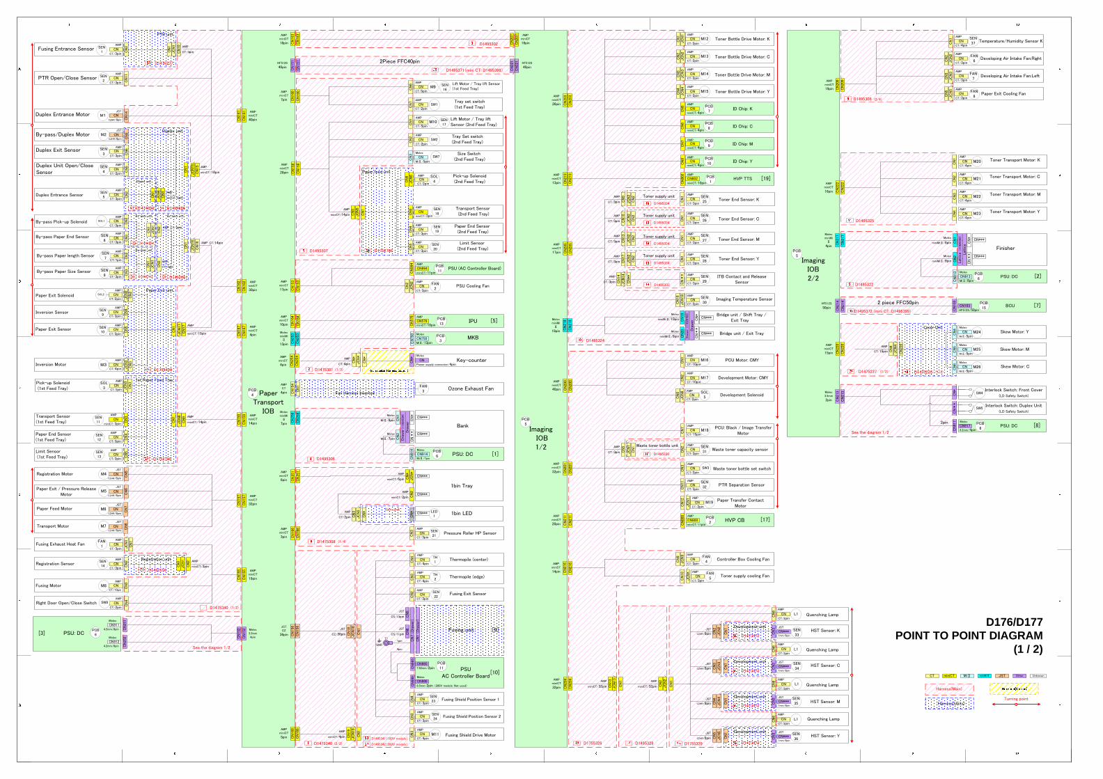
D176/D177 POINT TO POINT DIAGRAM
(1 / 2)
AMP
miniCT/15pin
AMP
miniCT/14pin
63
64
65 55
54
JC
N6
CN
6 SOL4
AMP
CT/2pinCN
CNPick-up Solenoid(1st Feed Tray)
SOL3 CT/2pin
AMP
CN
3JC
N3
Pick-up Solenoid (2nd Feed Tray)
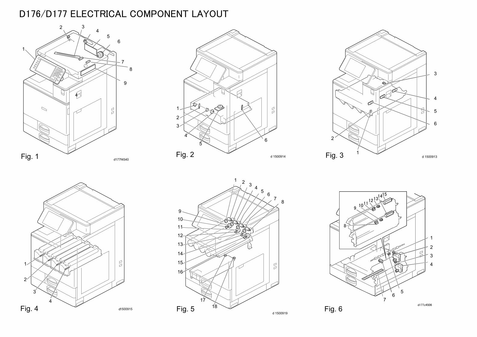
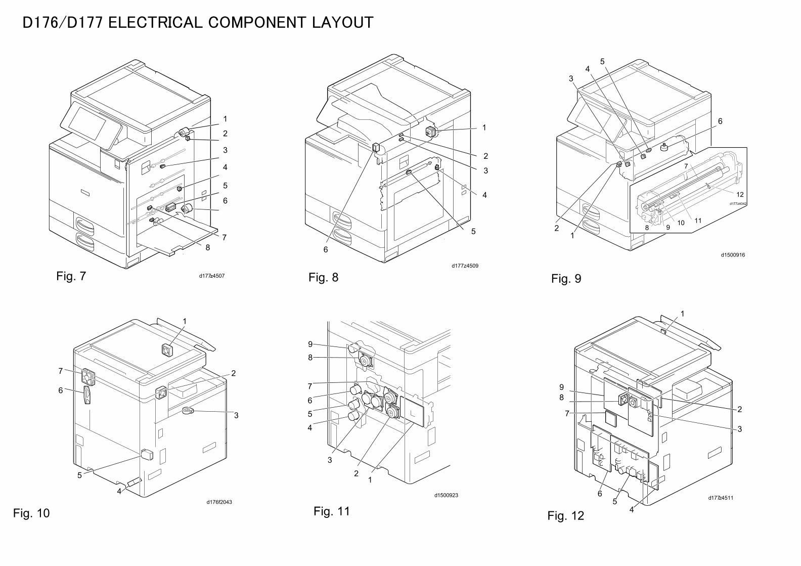
M2
M11
SEN1
SEN2
SEN3
SEN4
SEN5
SEN6
SEN7
SEN8
SEN9
SEN10
SEN11
SEN12
SEN13
SEN14
SW8
SEN16
SEN17
SW7
SEN18
SEN19
SEN20
SEN21
SEN22
SEN23
SEN24
SEN25
SEN26
SEN27
SEN28
SEN29
SEN30
SEN31
SEN37
SEN33
SEN32
SEN34
SEN35
SEN36
SW1
SW2
SW3
SW4
SW5
FAN4
FAN5
FAN1
FAN2
FAN3
FAN6
FAN7
FAN8
PCB1
PCB2
PCB3
PCB13
PCB11
PCB6
PCB11
LED1
TH1
TH2
PCB7
PCB8
PCB9
PCB10
L1
L1
L1
L1
PCB6
PCB15
PCB6
PCB6
PCB4
PCB5
PCB5
Laser unit
Laser unit
D1495235 (2/2)D1475237
D1496205
WBG685710
D1495361
D1495392
Fusing unit
Pressure Thermistor: End
Pressure Thermistor: Full-Bleed Edge
CNNon-Contact Thermistor
(Center)
Non-Contact Thermistor (Edge)
CN New unit Detection fuse
JC
N5
JC
N8
JC
N7
JC
N6
CN
5C
N8
CN
7C
N6
Heating Roller: Center/N
Pressure Roller: Center/L
Heating Roller: End/N
T4
T1
GND
See the diagram 1/2
[9]
For Paper Transport
IOB
[10]
CN
1(D
raw
er)
CN
3C
N2
CN Pressure Thermistor: Center
JC
N4
CN
4
miniCT/2pin
AMP
Set Detection: GND
Set Detection: NA
Short-curcuit to each destination
Set Detection: EU
Set Detection: Sub(JPN)
Set Detection: Sub(TWN)
For PSU:AC
CN
5C
N6
[9]
For Paper Transport
IOB
CN
1(D
raw
er)
AMPminiCT10pin
Scanner Harness
D1495347
Harness (Unit)Harness (Main)
Wire Contact
Wire Contact
D1475365
D1475301
D1475308BCU
D1475308
D1495356
PSU (AC controller
board)
HVP:CB
HVP:TTS
IPU
Controller Board
SIO
Inlet
T900
CN
577
Main Power Switch C
N
T1 Power Cord
CN
577
PCU: DC
D1495358
CN
988
CN
988
CN
901
CN
901
See the diagram 1/2
CN
914
CN
914
[1]
See the diagram 1/2
CN
913
CN
913
[2]
For Bank
For Finisher
CN
912
CN
915
CN
915
CN
911
CN
911
CN
576
ID Sensor
CN
105
CN
CN
105
CN
2
ID SensorCN
CN
3
ID SensorCN
CN
4
See the diagram 1/2
For Imaging IOB [7]FFC50pin
CN
103
D1495345
CN
575
CN
575
CN
101
CN
101
D1495370(mini CT:D1495397)
2pieceFFC50pin
CN
574
CN
100
PTR IOBCN
152
CN
310
See the diagram 1/2
10pin
CN
578
CN
578
⑤ For PTR IOB
[3]
See the diagram 1/2
CN
994
CN
994
[11]For Paper Transport IOB
See the diagram 1/2
CN
986
CN
986
[10]For Fusing unit
CN
802
CN
802
[19]Imaging IOB
Terminal Blocks(Toner)
T6
T7
T8
T9
T10
ITB unit
PCDU: K (Charge unit)**
**
PCDU: K (Development unit)*
**
*
See the diagram 1/2
20pin
CN
800
CN
800
[17]For Imaging IOB
PTR unit
PCDU: C (Charge unit)
PCDU: M (Charge unit)
PCDU: Y (Charge unit)
CN
*
CN
*
Board to Board
AMPminiCT22pin
AMPminiCT
3pin
AMPminiCT
10pin
AMPminiCT22pin
AMPminiCT15pin
AMPminiCT20pin
AMPminiCT
10pin
AMPminiCT11pin
CN
985
CN
9857.92mm
2pin
Molex6.5mm2pin
JST3.96mm
6pin
JST3.96mm
8pin
JST7.92mm
2pin
MolexMiⅡ
8pin
MolexMiⅡ
7pin
Molex4.2mm
6pin
Molex3.5mm
4pin
JST3.96mm
4pin
miniCT/5pin
AMP
miniCT/5pin
AMP
miniCT/5pin
AMP
CTminiC
TMiⅡ miniMiⅡ JST Other Unknown
CN
1
JC
N2
CN
2
CN
11
JST7.92mm
2pin
D1475301
CN
997
CN
997
CN
1AMPCT2pin
2pin
2pin
CN
152
CN
912
AMPCT
2pinTools for Fusing RelayJC
N1
(3/3)
CN
5
CN
576
(4/4)
CN
310
Note to the position of 1-N pin
CT/2pin
AMP
CN
564
CN
566
CN
564
CN
566
CN
***
CN
1C
N3
CN
2
CN
***
CN
2
CN
***
CN
1
CN
11
CN
***
CN
***
CN
2
CN
1
CN
***Molex
miniMiⅡ
15pin
T901
T900
T90
1
JSTPS-250
1pin
JSTPS-250
1pin
CN
***
BA
CN
***USB A
4pin
USBminiB5pin
CN
574
CN
100HF512S
50pinHF512S
50pin
CN
589
CN
589 AMP
CT
2pin(3/4)
(2/3)
miniCT/15pin
AMP
CT/2pin
AMP
Turning pointHeater Board
(Option)
CN
998
CN
998
CN
922
CN
922
D1495394
Molex3.5mm
3pin
Molex3.5mm
3pin
CN
999
CN
999
CN
930
CN
930
D1495395
AMPCT3pin
AMPCT3pin
CN
989
CN
989
CN
2
Molex4.2mm
6pin
CN
989
CN
989
CN
1C
N2
Molex4.2mm
6pin
D1495393
CN4.2mm/2pin
AMP
CN4.2mm/2pin
AMP
Bank HeaterCN
4.2mm/2pin
AMP
Paper Feed HeaterCN4.2mm/2pin
AMPPaper Feed Heater (Option)Bank Heater (Option)
CN
1
CN
2
CN
1
D1494321 (NA)
CN
9
ELR-02V/2pin
JST
CN
5
miniCT/4pin
AMP
MiⅡ/4pin
Molex
CNMolex
MiⅡ/3pin
Molex
MiⅡ/2pin
JC
N2
MolexminiMi
Ⅱ15pin
Spring plate Contact
D1495209
CN
1
XLR-04V/
4pin
JST
D1495202
CN
318
CN
318
CN
**
AMPminiCT6pin C
N1
CN
**
CN
2
D1495204CN
314
CN
314
CN
**AMP
miniCT6pin C
N1
CN
311AMP
miniCT30pin C
N311
CN
579AMP
miniCT30pin C
N579
D1775321
CN
1
ImagingIOB[8]
CN
213
Interlock Switch: Front Cover (LD Safety Switch)
Interlock Switch: Duplex Unit (LD Safety Switch)
2pinMolex3.5mm
2pin
CN
2
4pin
CN
917
JST3.96mm
4pinC
N917
D1495206
CN
313
CN
313 C
N**
AMPminiCT6pin
Auto Paper Size detection Sensor 2
CN
2
CN
**
CN
1
CN
315
CN
315
CN
301AMP
miniCT13pin C
N301
DF Position Sensor
Scanner Home Position Sensor
Scanner Motor
SBU
Auto Paper Size detection Sensor 1
HF512S
50pin
(2/2)
AMPminiCT
34pin
AMPminiCT
11pin JC
N3
JC
N1
miniCT/32pin
AMP
CT/11pin
AMP
CN
*** Synchronizing
Detector Board: M/Y-SC
N1
CN
***
Polygon Mirror MotorC
N3
Synchronizing Detector Board: Bk/C-S
D1475236
AMPminiCT
15pin
AMPminiCT
14pin
CT/3pin
AMP
CT/3pin
AMP
MiⅡ/5pin
Molex
CT/3pin
AMP
CT/3pin
AMP
CT/3pin
AMP
CT/3pin
AMP
miniCT/13pin
AMP
miniCT/6pin
AMP
CN
213
T1
T2
T3
T4
T5
No.1
No.2
No.3
No.4
PCU Anti-condensation Heater
Scanner Anti-condensation Heater
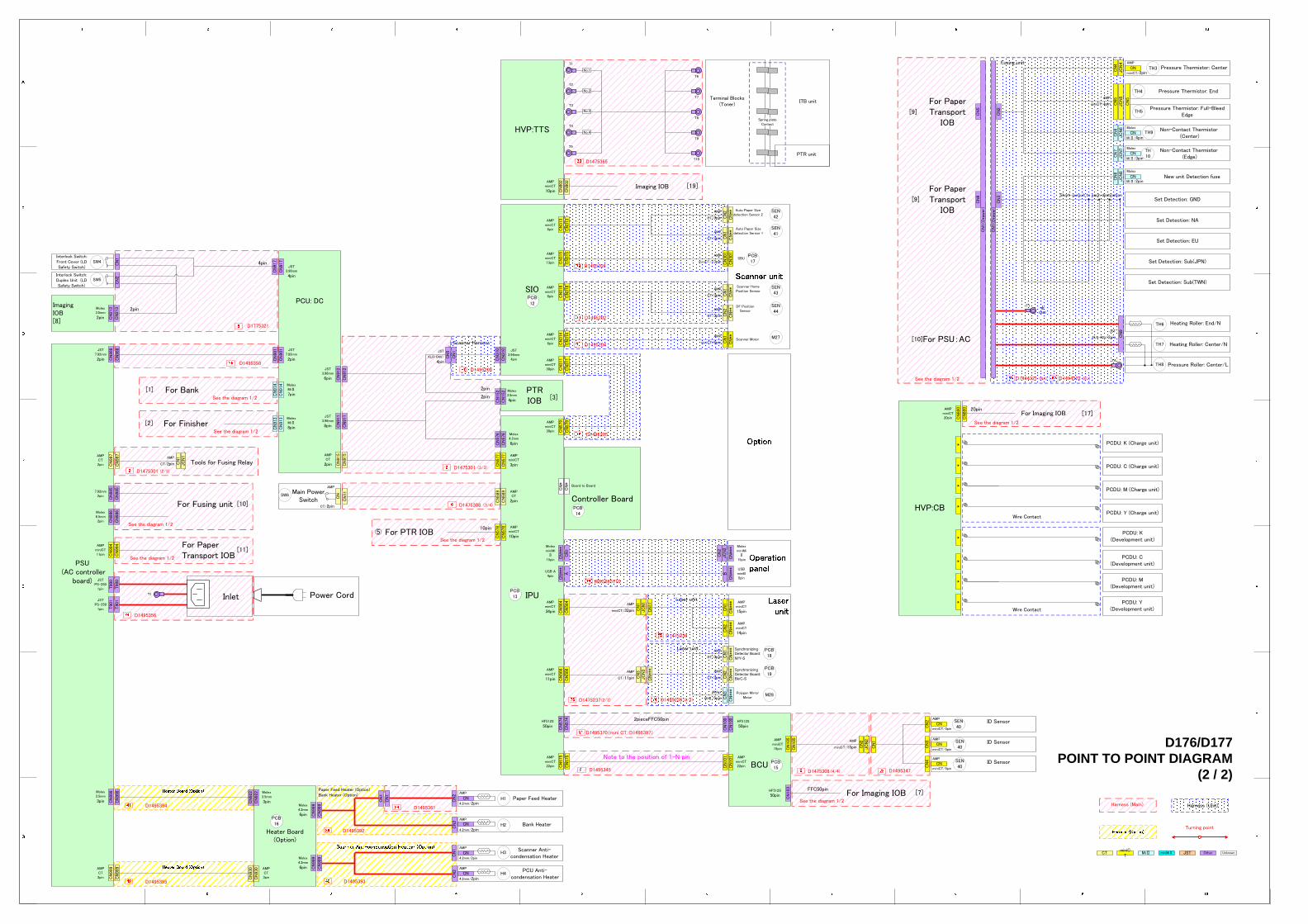
D176/D177 POINT TO POINT DIAGRAM
(2 / 2)
D1494322 (EU)
TH9
TH10
SEN40
PCB16
PCB14
PCB12
PCB15
TH6
TH7
TH8
TH3
TH4
TH5
H1
H2
H3
H4
SEN40
SEN40
SW4
SW5
PCDU: C (Development unit)
PCDU: M (Development unit)
PCDU: Y (Development unit)
SEN42
SEN41
SEN43
SEN44
SW6
PCB13
PCB17
PCB18
PCB19
M27
M28
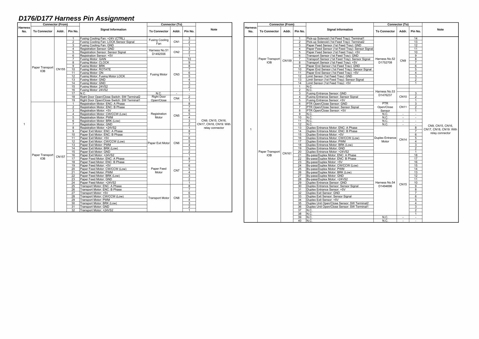
D176/D177 Harness Pin Assignment
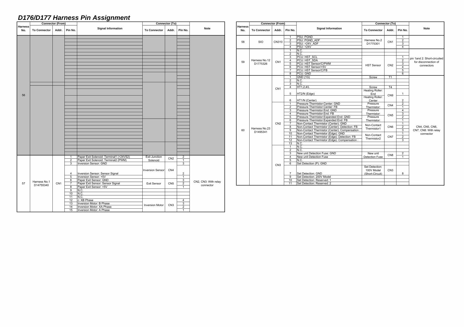
1 Fusing Cooling Fan: +24V (CTRL) 3 1 Pick-up Solenoid (1st Feed Tray): Terminal1 142 Fusing Cooling Fan: LOCK Sensor Signal 2 2 Pick-up Solenoid (1st Feed Tray): Terminal2 133 Fusing Cooling Fan: GND 1 3 Paper Feed Sensor (1st Feed Tray): GND 124 Registration Sensor: GND 3 4 Paper Feed Sensor (1st Feed Tray): Sensor Signal 115 Registration Sensor: Sensor Signal 2 5 Paper Feed Sensor (1st Feed Tray): +5V 106 Registration Sensor: +5V 1 6 Transport Sensor (1st Feed Tray): GND 97 Fusing Motor: GAIN 10 7 Transport Sensor (1st Feed Tray): Sensor Signal 88 Fusing Motor: CLOCK 9 8 Transport Sensor (1st Feed Tray): +5V 79 Fusing Motor: BRK 8 9 Paper End Sensor (1st Feed Tray): GND 6
10 Fusing Motor: ROTATE 7 10 Paper End Sensor (1st Feed Tray): Sensor Signal 511 Fusing Motor: ON 6 11 Paper End Sensor (1st Feed Tray): +5V 412 Fusing Motor: Fusing Motor LOCK 5 12 Limit Sensor (1st Feed Tray): GND 313 Fusing Motor: GND 4 13 Limit Sensor (1st Feed Tray): Sensor Signal 214 Fusing Motor: GND 3 14 Limit Sensor (1st Feed Tray): +5V 115 Fusing Motor: 24VS2 2 1 N.C.16 Fusing Motor: 24VS2 1 2 N.C.17 N.C. N.C. - - 3 Fusing Entrance Sensor: GND 318 Right Door Open/Close Switch: SW Terminal2 2 4 Fusing Entrance Sensor: Sensor Signal 219 Right Door Open/Close Switch: SW Terminal1 1 5 Fusing Entrance Sensor: +5V 11 Registration Motor: ENC: A Phase 8 6 PTR Open/Close Sensor: GND 32 Registration Motor: ENC: B Phase 7 7 PTR Open/Close Sensor: Sensor Signal 23 Registration Motor: +5V 6 8 PTR Open/Close Sensor: +5V 14 Registration Motor: CW/CCW (Low) 5 9 N.C. N.C. - -5 Registration Motor: PWM 4 10 N.C. N.C. - -6 Registration Motor: BRK (Low) 3 11 N.C. N.C. - -7 Registration Motor: GND 2 12 N.C. N.C. - -8 Registration Motor: +24VS2 1 13 Duplex Entrance Motor: ENC: A Phase 89 Paper Exit Motor: ENC: A Phase 8 14 Duplex Entrance Motor: ENC: B Phase 7
10 Paper Exit Motor: ENC: B Phase 7 15 Duplex Entrance Motor: +5V 611 Paper Exit Motor: +5V 6 16 Duplex Entrance Motor: CW/CCW (Low) 512 Paper Exit Motor: CW/CCW (Low) 5 17 Duplex Entrance Motor: PWM 413 Paper Exit Motor: PWM 4 18 Duplex Entrance Motor: BRK (Low) 314 Paper Exit Motor: BRK (Low) 3 19 Duplex Entrance Motor: GND 215 Paper Exit Motor: GND 2 20 Duplex Entrance Motor: +24VS2 116 Paper Exit Motor: +24VS2 1 21 By-pass/Duplex Motor: ENC: A Phase 1817 Paper Feed Motor: ENC: A Phase 8 22 By-pass/Duplex Motor: ENC: B Phase 1718 Paper Feed Motor: ENC: B Phase 7 23 By-pass/Duplex Motor: +5V 1619 Paper Feed Motor: +5V 6 24 By-pass/Duplex Motor: CW/CCW (Low) 1520 Paper Feed Motor: CW/CCW (Low) 5 25 By-pass/Duplex Motor: PWM 1421 Paper Feed Motor: PWM 4 26 By-pass/Duplex Motor: BRK (Low) 1322 Paper Feed Motor: BRK (Low) 3 27 By-pass/Duplex Motor: GND 1223 Paper Feed Motor: GND 2 28 By-pass/Duplex Motor: +24VS2 1124 Paper Feed Motor: +24VS2 1 29 Duplex Entrance Sensor: GND 1025 Transport Motor: ENC: A Phase 8 30 Duplex Entrance Sensor: Sensor Signal 926 Transport Motor: ENC: B Phase 7 31 Duplex Entrance Sensor: +5V 827 Transport Motor: +5V 6 32 Duplex Exit Sensor: GND 728 Transport Motor: CW/CCW (Low) 5 33 Duplex Exit Sensor: Sensor Signal 629 Transport Motor: PWM 4 34 Duplex Exit Sensor: +5V 530 Transport Motor: BRK (Low) 3 35 Duplex Unit Open/Close Sensor: SW Terminal2 431 Transport Motor: GND 2 36 Duplex Unit Open/Close Sensor: SW Terminal1 332 Transport Motor: +24VS2 1 37 N.C. 2
38 N.C. 139 N.C. N.C. - -40 N.C. N.C. - -
Note
Paper TransportIOB CN155
Paper TransportIOB CN157
CN7
CN8
CN5
CN6
Paper FeedMotor
Paper TransportIOB
CN10
CN11
CN14
CN15
CN9
CN3
CN4
1
HarnessNo. Signal Information
Connector (From)
To Connector Addr. Pin No.
PTROpen/Close
Sensor
Right DoorOpen/Close
RegistrationMotor
Paper Exit Motor
Duplex EntranceMotor
1
Fusing Motor
CN159
Paper TransportIOB CN161
Transport Motor
CN1
CN2
Pin No.To Connector
Fusing CoolingFan
Harness No.51D1492556
Addr. Pin No.
Harness No.54D1494696
Harness No.52D1752708
Harness No.53D1476237
CN9, CN15, CN16,CN17, CN18, CN19: With
relay connector
Connector (From)Signal Information
Connector (To)NoteTo Connector Addr. Pin No. To Connector
HarnessNo.
CN9, CN15, CN16,CN17, CN18, CN19: With
relay connector
Connector (To)
Addr.
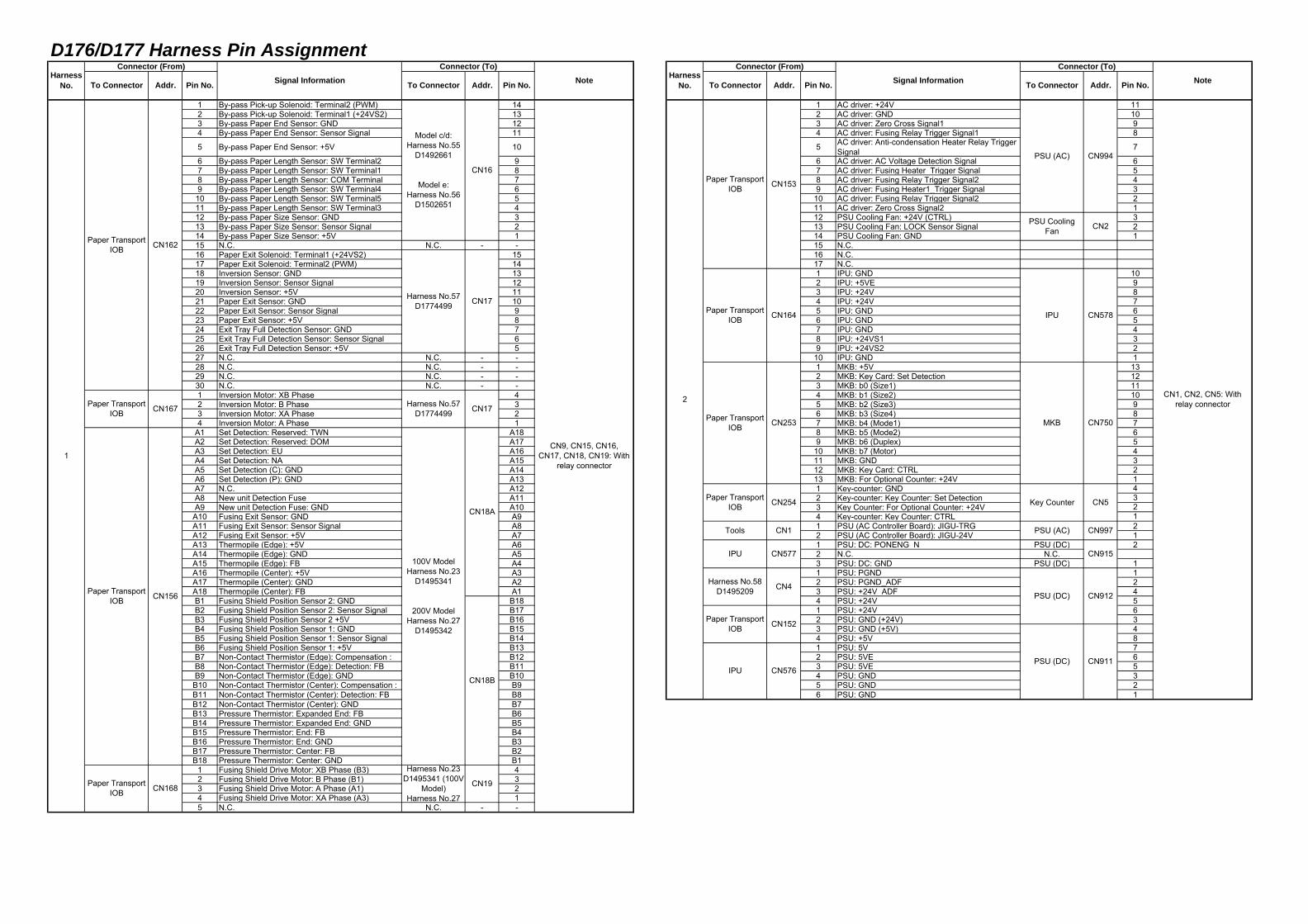
D176/D177 Harness Pin Assignment
1 By-pass Pick-up Solenoid: Terminal2 (PWM) 14 1 AC driver: +24V 112 By-pass Pick-up Solenoid: Terminal1 (+24VS2) 13 2 AC driver: GND 103 By-pass Paper End Sensor: GND 12 3 AC driver: Zero Cross Signal1 94 By-pass Paper End Sensor: Sensor Signal 11 4 AC driver: Fusing Relay Trigger Signal1 8
5 By-pass Paper End Sensor: +5V 10 5 AC driver: Anti-condensation Heater Relay TriggerSignal 7
6 By-pass Paper Length Sensor: SW Terminal2 9 6 AC driver: AC Voltage Detection Signal 67 By-pass Paper Length Sensor: SW Terminal1 8 7 AC driver: Fusing Heater_Trigger Signal 58 By-pass Paper Length Sensor: COM Terminal 7 8 AC driver: Fusing Relay Trigger Signal2 49 By-pass Paper Length Sensor: SW Terminal4 6 9 AC driver: Fusing Heater1_Trigger Signal 3
10 By-pass Paper Length Sensor: SW Terminal5 5 10 AC driver: Fusing Relay Trigger Signal2 211 By-pass Paper Length Sensor: SW Terminal3 4 11 AC driver: Zero Cross Signal2 112 By-pass Paper Size Sensor: GND 3 12 PSU Cooling Fan: +24V (CTRL) 313 By-pass Paper Size Sensor: Sensor Signal 2 13 PSU Cooling Fan: LOCK Sensor Signal 214 By-pass Paper Size Sensor: +5V 1 14 PSU Cooling Fan: GND 115 N.C. N.C. - - 15 N.C.16 Paper Exit Solenoid: Terminal1 (+24VS2) 15 16 N.C.17 Paper Exit Solenoid: Terminal2 (PWM) 14 17 N.C.18 Inversion Sensor: GND 13 1 IPU: GND 1019 Inversion Sensor: Sensor Signal 12 2 IPU: +5VE 920 Inversion Sensor: +5V 11 3 IPU: +24V 821 Paper Exit Sensor: GND 10 4 IPU: +24V 722 Paper Exit Sensor: Sensor Signal 9 5 IPU: GND 623 Paper Exit Sensor: +5V 8 6 IPU: GND 524 Exit Tray Full Detection Sensor: GND 7 7 IPU: GND 425 Exit Tray Full Detection Sensor: Sensor Signal 6 8 IPU: +24VS1 326 Exit Tray Full Detection Sensor: +5V 5 9 IPU: +24VS2 227 N.C. N.C. - - 10 IPU: GND 128 N.C. N.C. - - 1 MKB: +5V 1329 N.C. N.C. - - 2 MKB: Key Card: Set Detection 1230 N.C. N.C. - - 3 MKB: b0 (Size1) 111 Inversion Motor: XB Phase 4 4 MKB: b1 (Size2) 102 Inversion Motor: B Phase 3 5 MKB: b2 (Size3) 93 Inversion Motor: XA Phase 2 6 MKB: b3 (Size4) 84 Inversion Motor: A Phase 1 7 MKB: b4 (Mode1) 7
A1 Set Detection: Reserved: TWN A18 8 MKB: b5 (Mode2) 6A2 Set Detection: Reserved: DOM A17 9 MKB: b6 (Duplex) 5A3 Set Detection: EU A16 10 MKB: b7 (Motor) 4A4 Set Detection: NA A15 11 MKB: GND 3A5 Set Detection (C): GND A14 12 MKB: Key Card: CTRL 2A6 Set Detection (P): GND A13 13 MKB: For Optional Counter: +24V 1A7 N.C. A12 1 Key-counter: GND 4A8 New unit Detection Fuse A11 2 Key-counter: Key Counter: Set Detection 3A9 New unit Detection Fuse: GND A10 3 Key Counter: For Optional Counter: +24V 2
A10 Fusing Exit Sensor: GND A9 4 Key-counter: Key Counter: CTRL 1A11 Fusing Exit Sensor: Sensor Signal A8 1 PSU (AC Controller Board): JIGU-TRG 2A12 Fusing Exit Sensor: +5V A7 2 PSU (AC Controller Board): JIGU-24V 1A13 Thermopile (Edge): +5V A6 1 PSU: DC: PONENG_N PSU (DC) 2A14 Thermopile (Edge): GND A5 2 N.C. N.C.A15 Thermopile (Edge): FB A4 3 PSU: DC: GND PSU (DC) 1A16 Thermopile (Center): +5V A3 1 PSU: PGND 1A17 Thermopile (Center): GND A2 2 PSU: PGND_ADF 2A18 Thermopile (Center): FB A1 3 PSU: +24V_ADF 4B1 Fusing Shield Position Sensor 2: GND B18 4 PSU: +24V 5B2 Fusing Shield Position Sensor 2: Sensor Signal B17 1 PSU: +24V 6B3 Fusing Shield Position Sensor 2 +5V B16 2 PSU: GND (+24V) 3B4 Fusing Shield Position Sensor 1: GND B15 3 PSU: GND (+5V) 4B5 Fusing Shield Position Sensor 1: Sensor Signal B14 4 PSU: +5V 8B6 Fusing Shield Position Sensor 1: +5V B13 1 PSU: 5V 7B7 Non-Contact Thermistor (Edge): Compensation : B12 2 PSU: 5VE 6B8 Non-Contact Thermistor (Edge): Detection: FB B11 3 PSU: 5VE 5B9 Non-Contact Thermistor (Edge): GND B10 4 PSU: GND 3B10 Non-Contact Thermistor (Center): Compensation : B9 5 PSU: GND 2B11 Non-Contact Thermistor (Center): Detection: FB B8 6 PSU: GND 1B12 Non-Contact Thermistor (Center): GND B7B13 Pressure Thermistor: Expanded End: FB B6B14 Pressure Thermistor: Expanded End: GND B5B15 Pressure Thermistor: End: FB B4B16 Pressure Thermistor: End: GND B3B17 Pressure Thermistor: Center: FB B2B18 Pressure Thermistor: Center: GND B1
1 Fusing Shield Drive Motor: XB Phase (B3) 42 Fusing Shield Drive Motor: B Phase (B1) 33 Fusing Shield Drive Motor: A Phase (A1) 24 Fusing Shield Drive Motor: XA Phase (A3) 15 N.C. N.C. - -
CN253
Paper TransportIOB CN254
CN167
Paper TransportIOB CN162
Paper TransportIOB CN168
Harness No.23D1495341 (100V
Model)Harness No.27
Paper TransportIOB CN156
100V ModelHarness No.23
D1495341
200V ModelHarness No.27
D1495342
Paper TransportIOB
Tools CN1
CN4
Paper TransportIOB CN152
IPU CN576
CN1, CN2, CN5: Withrelay connector2
Paper TransportIOB CN153
Paper TransportIOB CN164
Paper TransportIOB
IPU CN577
Harness No.58D1495209
CN5
CN997
CN915
CN912
CN911
CN18A
CN18B
CN19
CN16
CN17
CN17
CN994
CN2
CN578
CN750
Model c/d:Harness No.55
D1492661
Model e:Harness No.56
D1502651
Harness No.57D1774499
Harness No.57D1774499
PSU (DC)
PSU (DC)
PSU (AC)
PSU CoolingFan
IPU
MKB
NotePin No. To Connector Addr. Pin No.
Connector (From)Signal InformationTo Connector Addr.
HarnessNo.
Connector (From)Signal Information
Connector (To)NoteTo Connector Addr.
Connector (To)
Key Counter
PSU (AC)
CN9, CN15, CN16,CN17, CN18, CN19: With
relay connector1
Pin No. To Connector Addr. Pin No.Harness
No.
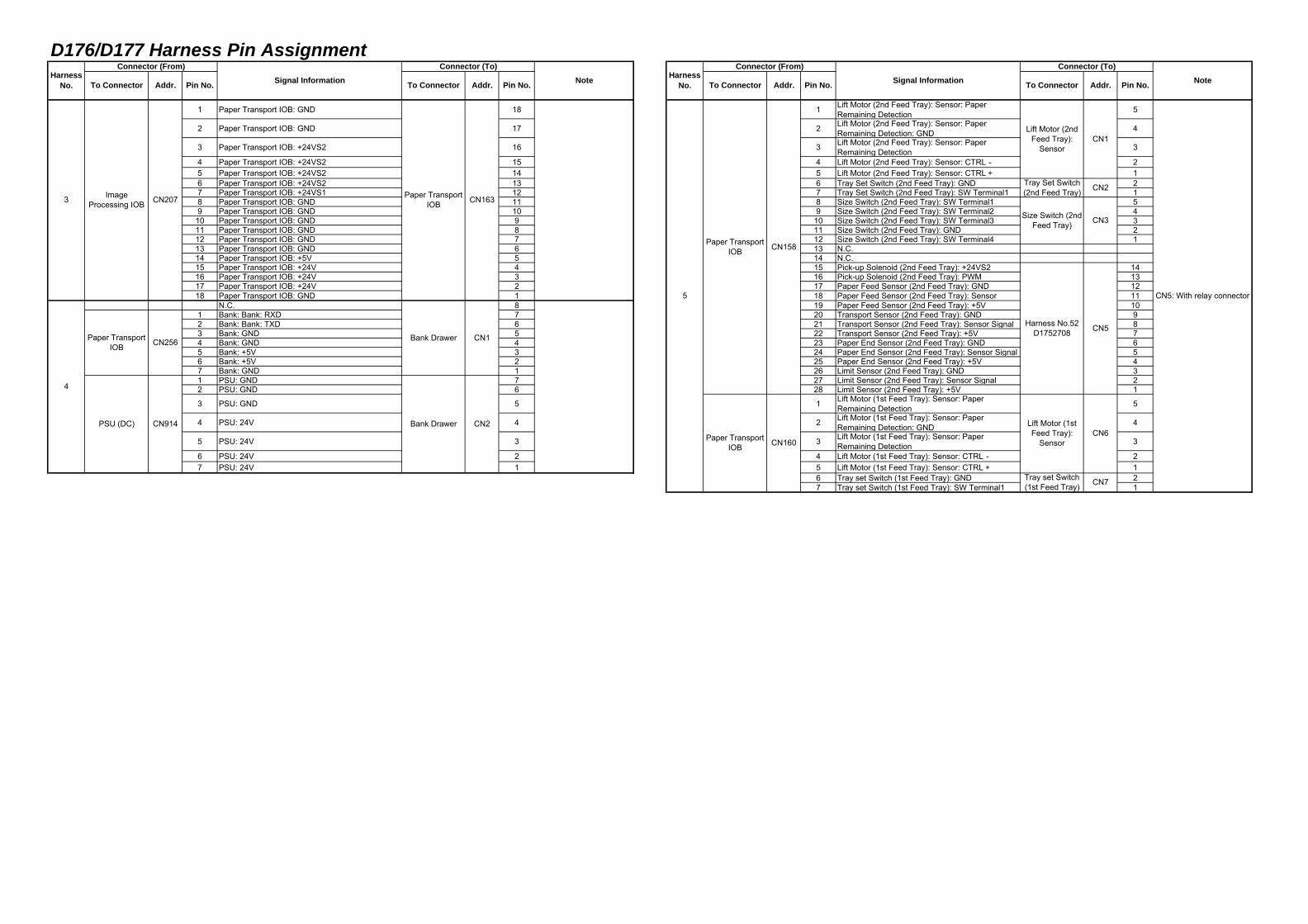
D176/D177 Harness Pin Assignment
1 Paper Transport IOB: GND 18 1 Lift Motor (2nd Feed Tray): Sensor: PaperRemaining Detection 5
2 Paper Transport IOB: GND 17 2 Lift Motor (2nd Feed Tray): Sensor: PaperRemaining Detection: GND 4
3 Paper Transport IOB: +24VS2 16 3 Lift Motor (2nd Feed Tray): Sensor: PaperRemaining Detection 3
4 Paper Transport IOB: +24VS2 15 4 Lift Motor (2nd Feed Tray): Sensor: CTRL- 25 Paper Transport IOB: +24VS2 14 5 Lift Motor (2nd Feed Tray): Sensor: CTRL+ 16 Paper Transport IOB: +24VS2 13 6 Tray Set Switch (2nd Feed Tray): GND 27 Paper Transport IOB: +24VS1 12 7 Tray Set Switch (2nd Feed Tray): SW Terminal1 18 Paper Transport IOB: GND 11 8 Size Switch (2nd Feed Tray): SW Terminal1 59 Paper Transport IOB: GND 10 9 Size Switch (2nd Feed Tray): SW Terminal2 4
10 Paper Transport IOB: GND 9 10 Size Switch (2nd Feed Tray): SW Terminal3 311 Paper Transport IOB: GND 8 11 Size Switch (2nd Feed Tray): GND 212 Paper Transport IOB: GND 7 12 Size Switch (2nd Feed Tray): SW Terminal4 113 Paper Transport IOB: GND 6 13 N.C.14 Paper Transport IOB: +5V 5 14 N.C.15 Paper Transport IOB: +24V 4 15 Pick-up Solenoid (2nd Feed Tray): +24VS2 1416 Paper Transport IOB: +24V 3 16 Pick-up Solenoid (2nd Feed Tray): PWM 1317 Paper Transport IOB: +24V 2 17 Paper Feed Sensor (2nd Feed Tray): GND 1218 Paper Transport IOB: GND 1 18 Paper Feed Sensor (2nd Feed Tray): Sensor 11
N.C. 8 19 Paper Feed Sensor (2nd Feed Tray): +5V 101 Bank: Bank: RXD 7 20 Transport Sensor (2nd Feed Tray): GND 92 Bank: Bank: TXD 6 21 Transport Sensor (2nd Feed Tray): Sensor Signal 83 Bank: GND 5 22 Transport Sensor (2nd Feed Tray): +5V 74 Bank: GND 4 23 Paper End Sensor (2nd Feed Tray): GND 65 Bank: +5V 3 24 Paper End Sensor (2nd Feed Tray): Sensor Signal 56 Bank: +5V 2 25 Paper End Sensor (2nd Feed Tray): +5V 47 Bank: GND 1 26 Limit Sensor (2nd Feed Tray): GND 31 PSU: GND 7 27 Limit Sensor (2nd Feed Tray): Sensor Signal 22 PSU: GND 6 28 Limit Sensor (2nd Feed Tray): +5V 1
3 PSU: GND 5 1 Lift Motor (1st Feed Tray): Sensor: PaperRemaining Detection 5
4 PSU: 24V 4 2 Lift Motor (1st Feed Tray): Sensor: PaperRemaining Detection: GND 4
5 PSU: 24V 3 3 Lift Motor (1st Feed Tray): Sensor: PaperRemaining Detection 3
6 PSU: 24V 2 4 Lift Motor (1st Feed Tray): Sensor: CTRL- 27 PSU: 24V 1 5 Lift Motor (1st Feed Tray): Sensor: CTRL+ 1
6 Tray set Switch (1st Feed Tray): GND 27 Tray set Switch (1st Feed Tray): SW Terminal1 1
5
Paper TransportIOB
3 ImageProcessing IOB CN207 Paper Transport
IOB
4
Paper TransportIOB CN256
PSU (DC) CN914
Bank Drawer
Bank Drawer CN2
CN5: With relay connector
Size Switch (2ndFeed Tray)
Harness No.52D1752708
Lift Motor (1stFeed Tray):
Sensor
Tray set Switch(1st Feed Tray)
CN158
Paper TransportIOB CN160
CN1
CN2
CN3
CN5
CN6
CN7
Lift Motor (2ndFeed Tray):
Sensor
Tray Set Switch(2nd Feed Tray)
CN163
CN1
Note HarnessNo. NotePin No.
Connector (From)Signal Information
Connector (To)
To Connector Addr. Pin No.Harness
No.
Connector (From)Signal Information
Connector (To)
To Connector Addr. Pin No. To Connector Addr. Pin No. To Connector Addr.
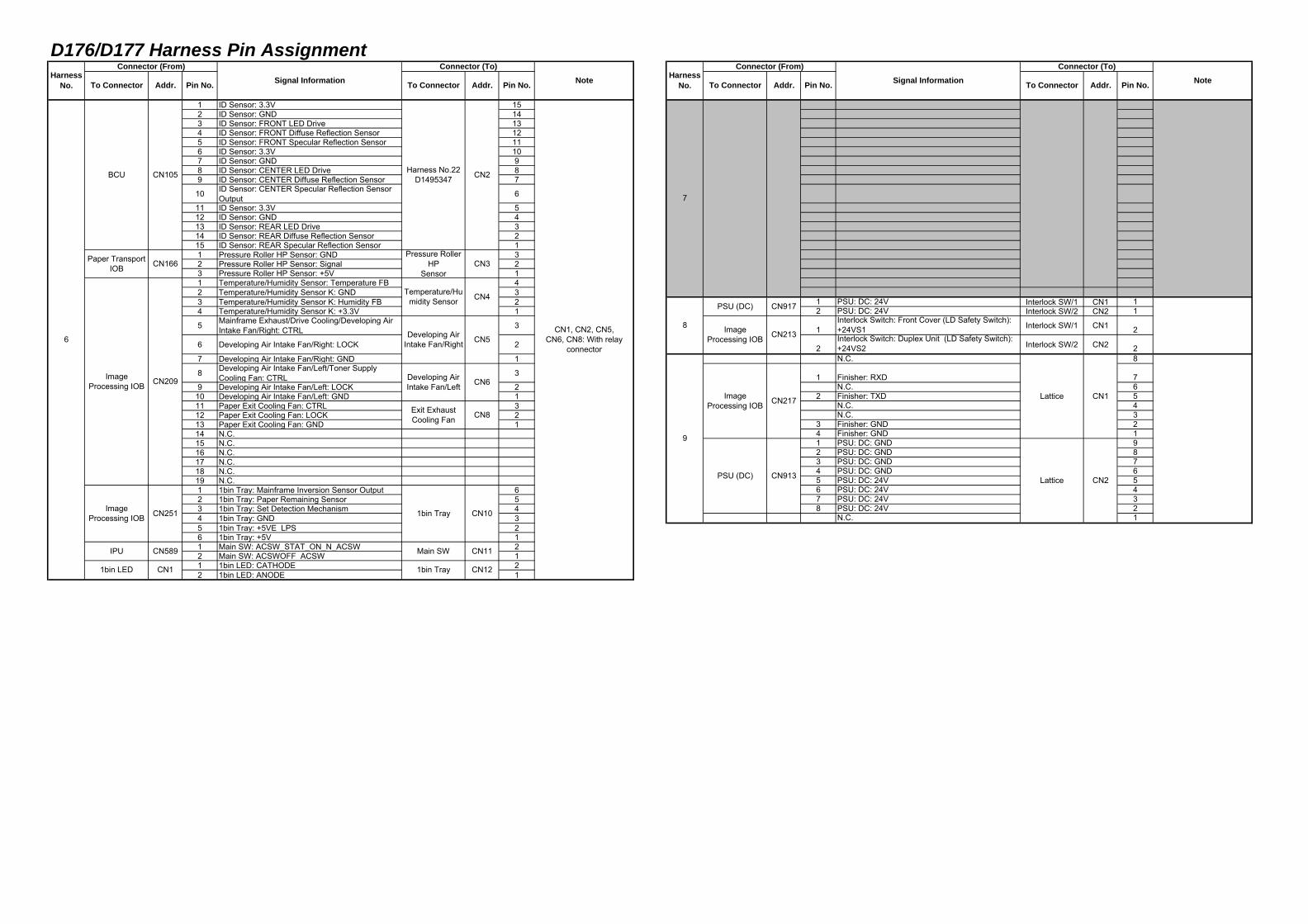
D176/D177 Harness Pin Assignment
1 ID Sensor: 3.3V 152 ID Sensor: GND 143 ID Sensor: FRONT LED Drive 134 ID Sensor: FRONT Diffuse Reflection Sensor 125 ID Sensor: FRONT Specular Reflection Sensor 116 ID Sensor: 3.3V 107 ID Sensor: GND 98 ID Sensor: CENTER LED Drive 89 ID Sensor: CENTER Diffuse Reflection Sensor 7
10 ID Sensor: CENTER Specular Reflection SensorOutput 6
11 ID Sensor: 3.3V 512 ID Sensor: GND 413 ID Sensor: REAR LED Drive 314 ID Sensor: REAR Diffuse Reflection Sensor 215 ID Sensor: REAR Specular Reflection Sensor 11 Pressure Roller HP Sensor: GND 32 Pressure Roller HP Sensor: Signal 23 Pressure Roller HP Sensor: +5V 11 Temperature/Humidity Sensor: Temperature FB 42 Temperature/Humidity Sensor K: GND 33 Temperature/Humidity Sensor K: Humidity FB 2 1 PSU: DC: 24V Interlock SW/1 CN1 14 Temperature/Humidity Sensor K: +3.3V 1 2 PSU: DC: 24V Interlock SW/2 CN2 1
5 Mainframe Exhaust/Drive Cooling/Developing AirIntake Fan/Right: CTRL 3 1
Interlock Switch: Front Cover (LD Safety Switch):+24VS1 Interlock SW/1 CN1 2
6 Developing Air Intake Fan/Right: LOCK 2 2Interlock Switch: Duplex Unit (LD Safety Switch):+24VS2 Interlock SW/2 CN2 2
7 Developing Air Intake Fan/Right: GND 1 N.C. 8
8 Developing Air Intake Fan/Left/Toner SupplyCooling Fan: CTRL 3 1 Finisher: RXD 7
9 Developing Air Intake Fan/Left: LOCK 2 N.C. 610 Developing Air Intake Fan/Left: GND 1 2 Finisher: TXD 511 Paper Exit Cooling Fan: CTRL 3 N.C. 412 Paper Exit Cooling Fan: LOCK 2 N.C. 313 Paper Exit Cooling Fan: GND 1 3 Finisher: GND 214 N.C. 4 Finisher: GND 115 N.C. 1 PSU: DC: GND 916 N.C. 2 PSU: DC: GND 817 N.C. 3 PSU: DC: GND 718 N.C. 4 PSU: DC: GND 619 N.C. 5 PSU: DC: 24V 51 1bin Tray: Mainframe Inversion Sensor Output 6 6 PSU: DC: 24V 42 1bin Tray: Paper Remaining Sensor 5 7 PSU: DC: 24V 33 1bin Tray: Set Detection Mechanism 4 8 PSU: DC: 24V 24 1bin Tray: GND 3 N.C. 15 1bin Tray: +5VE_LPS 26 1bin Tray: +5V 11 Main SW: ACSW_STAT_ON_N_ACSW 22 Main SW: ACSWOFF_ACSW 11 1bin LED: CATHODE 22 1bin LED: ANODE 1
Harness No.22D1495347
Pressure RollerHP
Sensor
Temperature/Humidity Sensor
ImageProcessing IOB CN251
Developing AirIntake Fan/Right
Developing AirIntake Fan/Left
CN1 1bin Tray
6
BCU CN105
IPU CN589
Paper TransportIOB CN166
ImageProcessing IOB CN209
1bin LED
CN5
CN6
Exit ExhaustCooling Fan
1bin Tray
Main SW
CN4
8
PSU (DC) CN917
ImageProcessing IOB CN213
7
ImageProcessing IOB CN217
PSU (DC) CN913
Lattice
Lattice CN2
CN8
CN10
CN1, CN2, CN5,CN6, CN8: With relay
connector
9
CN3
CN2
CN11
CN12
Note HarnessNo. NoteTo Connector Addr. Pin No.
Connector (From)Signal Information
Connector (To)
To ConnectorHarness
No.
Connector (From)Signal Information
Connector (To)
To Connector Addr. Pin No. To Connector Addr. Pin No. Addr. Pin No.
CN1
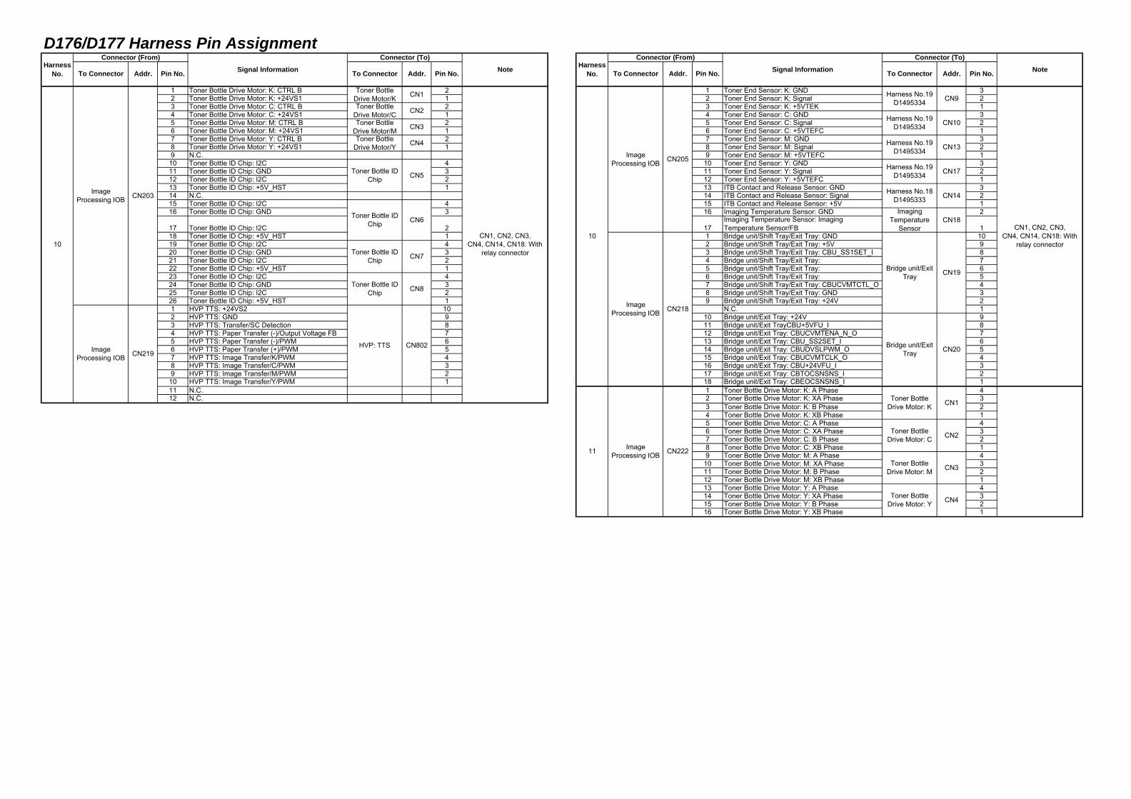
D176/D177 Harness Pin Assignment
1 Toner Bottle Drive Motor: K: CTRL B 2 1 Toner End Sensor: K: GND 32 Toner Bottle Drive Motor: K: +24VS1 1 2 Toner End Sensor: K: Signal 23 Toner Bottle Drive Motor: C: CTRL B 2 3 Toner End Sensor: K: +5VTEK 14 Toner Bottle Drive Motor: C: +24VS1 1 4 Toner End Sensor: C: GND 35 Toner Bottle Drive Motor: M: CTRL B 2 5 Toner End Sensor: C: Signal 26 Toner Bottle Drive Motor: M: +24VS1 1 6 Toner End Sensor: C: +5VTEFC 17 Toner Bottle Drive Motor: Y: CTRL B 2 7 Toner End Sensor: M: GND 38 Toner Bottle Drive Motor: Y: +24VS1 1 8 Toner End Sensor: M: Signal 29 N.C. 9 Toner End Sensor: M: +5VTEFC 1
10 Toner Bottle ID Chip: I2C 4 10 Toner End Sensor: Y: GND 311 Toner Bottle ID Chip: GND 3 11 Toner End Sensor: Y: Signal 212 Toner Bottle ID Chip: I2C 2 12 Toner End Sensor: Y: +5VTEFC 113 Toner Bottle ID Chip: +5V_HST 1 13 ITB Contact and Release Sensor: GND 314 N.C. 14 ITB Contact and Release Sensor: Signal 215 Toner Bottle ID Chip: I2C 4 15 ITB Contact and Release Sensor: +5V 116 Toner Bottle ID Chip: GND 3 16 Imaging Temperature Sensor: GND 2
17 Toner Bottle ID Chip: I2C 2 17Imaging Temperature Sensor: ImagingTemperature Sensor/FB 1
18 Toner Bottle ID Chip: +5V_HST 1 1 Bridge unit/Shift Tray/Exit Tray: GND 1019 Toner Bottle ID Chip: I2C 4 2 Bridge unit/Shift Tray/Exit Tray: +5V 920 Toner Bottle ID Chip: GND 3 3 Bridge unit/Shift Tray/Exit Tray: CBU_SS1SET_I 821 Toner Bottle ID Chip: I2C 2 4 Bridge unit/Shift Tray/Exit Tray: 722 Toner Bottle ID Chip: +5V_HST 1 5 Bridge unit/Shift Tray/Exit Tray: 623 Toner Bottle ID Chip: I2C 4 6 Bridge unit/Shift Tray/Exit Tray: 524 Toner Bottle ID Chip: GND 3 7 Bridge unit/Shift Tray/Exit Tray: CBUCVMTCTL_O 425 Toner Bottle ID Chip: I2C 2 8 Bridge unit/Shift Tray/Exit Tray: GND 326 Toner Bottle ID Chip: +5V_HST 1 9 Bridge unit/Shift Tray/Exit Tray: +24V 21 HVP TTS: +24VS2 10 N.C. 12 HVP TTS: GND 9 10 Bridge unit/Exit Tray: +24V 93 HVP TTS: Transfer/SC Detection 8 11 Bridge unit/Exit TrayCBU+5VFU_I 84 HVP TTS: Paper Transfer (-)/Output Voltage FB 7 12 Bridge unit/Exit Tray: CBUCVMTENA_N_O 75 HVP TTS: Paper Transfer (-)/PWM 6 13 Bridge unit/Exit Tray: CBU_SS2SET_I 66 HVP TTS: Paper Transfer (+)/PWM 5 14 Bridge unit/Exit Tray: CBUDVSLPWM_O 57 HVP TTS: Image Transfer/K/PWM 4 15 Bridge unit/Exit Tray: CBUCVMTCLK_O 48 HVP TTS: Image Transfer/C/PWM 3 16 Bridge unit/Exit Tray: CBU+24VFU_I 39 HVP TTS: Image Transfer/M/PWM 2 17 Bridge unit/Exit Tray: CBTOCSNSNS_I 210 HVP TTS: Image Transfer/Y/PWM 1 18 Bridge unit/Exit Tray: CBEOCSNSNS_I 111 N.C. 1 Toner Bottle Drive Motor: K: A Phase 412 N.C. 2 Toner Bottle Drive Motor: K: XA Phase 3
3 Toner Bottle Drive Motor: K: B Phase 24 Toner Bottle Drive Motor: K: XB Phase 15 Toner Bottle Drive Motor: C: A Phase 46 Toner Bottle Drive Motor: C: XA Phase 37 Toner Bottle Drive Motor: C: B Phase 28 Toner Bottle Drive Motor: C: XB Phase 19 Toner Bottle Drive Motor: M: A Phase 4
10 Toner Bottle Drive Motor: M: XA Phase 311 Toner Bottle Drive Motor: M: B Phase 212 Toner Bottle Drive Motor: M: XB Phase 113 Toner Bottle Drive Motor: Y: A Phase 414 Toner Bottle Drive Motor: Y: XA Phase 315 Toner Bottle Drive Motor: Y: B Phase 216 Toner Bottle Drive Motor: Y: XB Phase 1
ImageProcessing IOB CN218
Toner Bottle IDChip CN6
CN7
Toner BottleDrive Motor/K
ImageProcessing IOB CN203
ImageProcessing IOB CN219
11 ImageProcessing IOB CN222
Toner BottleDrive Motor: C
Toner BottleDrive Motor: M
Toner BottleDrive Motor: Y
CN1
CN2
CN3
CN19
CN20
CN4
Harness No.19D1495334
Harness No.18D1495333
Addr. Pin No. To Connector
Harness No.19D1495334
CN205ImageProcessing IOB
Connector (From)Signal Information
Connector (To)
To ConnectorHarness
No.
CN1
CN2
CN3
CN4
CN5
Toner Bottle IDChip
Note
CN8
CN802
Toner Bottle IDChip
Toner BottleDrive Motor/C
ImagingTemperature
Sensor
Bridge unit/ExitTray
Bridge unit/ExitTray
1010CN1, CN2, CN3,
CN4, CN14, CN18: Withrelay connector
Toner Bottle IDChip
HVP: TTS
Toner BottleDrive Motor/MToner Bottle
Drive Motor/Y
NoteAddr. Pin No.
CN1, CN2, CN3,CN4, CN14, CN18: With
relay connector
CN9
CN10
CN13
CN17
CN14
CN18
HarnessNo.
Connector (From)Signal Information
Connector (To)
To Connector Addr. Pin No. To Connector Addr. Pin No.
Toner BottleDrive Motor: K
Harness No.19D1495334
Harness No.19D1495334
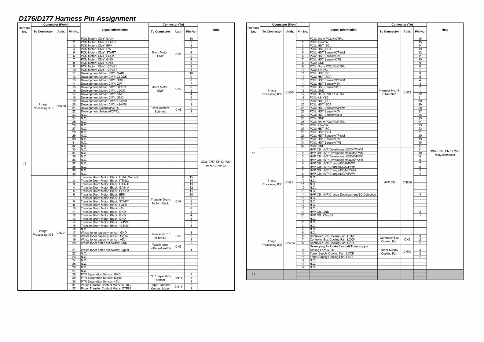
D176/D177 Harness Pin Assignment
1 PCU Motor: CMY: GAIN 10 1 PCU: Drum PCL/K/CTRL 162 PCU Motor: CMY: CLOCK 9 2 PCU: +24VS2 153 PCU Motor: CMY: BRK 8 3 PCU: HST_SCL 144 PCU Motor: CMY: CW 7 4 PCU: HST_SDA 135 PCU Motor: CMY: START 6 5 PCU: HST Sensor/K/PWM 126 PCU Motor: CMY: LOCK 5 6 PCU: HST Sensor/+5V 117 PCU Motor: CMY: GND 4 7 PCU: HST Sensor/K/FB 108 PCU Motor: CMY: GND 3 8 PCU: GND 99 PCU Motor: CMY: +24VS1 2 9 PCU: Drum PCL/FC/CTRL 8
10 PCU Motor: CMY: +24VS1 1 10 PCU: +24VS2 711 Development Motor: CMY: GAIN 10 11 PCU: HST_SCL 612 Development Motor: CMY: CLOCK 9 12 PCU: HST_SDA 513 Development Motor: CMY: BRK 8 13 PCU: HST Sensor/C/PWM 414 Development Motor: CMY: CW 7 14 PCU: HST Sensor/+5V 315 Development Motor: CMY: START 6 15 PCU: HST Sensor/C/FB 216 Development Motor: CMY: LOCK 5 16 PCU: GND 117 Development Motor: CMY: GND 4 17 PCU: Drum PCL/FC/CTRL 3218 Development Motor: CMY: GND 3 18 PCU: +24VS2 3119 Development Motor: CMY: +24VS1 2 19 PCU: HST_SCL 3020 Development Motor: CMY: +24VS1 1 20 PCU: HST_SDA 2921 Development Solenoid/CTRL 2 21 PCU: HST Sensor/M/PWM 2822 Development Solenoid/CTRL 1 22 PCU: HST Sensor/+5V 2723 N.C. 23 PCU: HST Sensor/M/FB 2624 N.C. 24 PCU: GND 2525 N.C. 25 PCU: Drum PCL/FC/CTRL 2426 N.C. 26 PCU: +24VS2 2327 N.C. 27 PCU: HST_SCL 2228 N.C. 28 PCU: HST_SDA 2129 N.C. 29 PCU: HST Sensor/Y/PWM 2030 N.C. 30 PCU: HST Sensor/+5V 1931 N.C. 31 PCU: HST Sensor/Y/FB 1832 N.C. 32 PCU: GND 1733 N.C. 1 HVP CB: HVP/Development/DC/Y/PWM 1134 N.C. 2 HVP CB: HVP/Development/DC/M/PWM 1035 N.C. 3 HVP CB: HVP/Development/DC/C/PWM 936 N.C. 4 HVP CB: HVP/Development/DC/K/PWM 837 N.C. 5 HVP CB: HVP/Charge/DC/K/PWM 738 N.C. 6 HVP CB: HVP/Charge/DC/C/PWM 639 N.C. 7 HVP CB: HVP/Charge/DC/M/PWM 540 N.C. 8 HVP CB: HVP/Charge/DC/Y/PWM 41 Transfer Drum Motor: Black: CTRL Method 15 9 N.C.2 Transfer Drum Motor: Black: ITENC: 14 10 N.C.3 Transfer Drum Motor: Black: GAIN B 13 11 N.C.4 Transfer Drum Motor: Black: GAIN A 12 12 N.C.5 Transfer Drum Motor: Black: CLOCK 11 13 N.C.6 Transfer Drum Motor: Black: BRK 10 14 HVP CB: HVP/Charge Development/SC Detection 37 Transfer Drum Motor: Black: CW 9 15 N.C.8 Transfer Drum Motor: Black: START 8 16 N.C.9 Transfer Drum Motor: Black: LOCK 7 17 N.C.10 Transfer Drum Motor: Black: +5V 6 18 N.C.11 Transfer Drum Motor: Black: GND 5 19 HVP CB: GND 212 Transfer Drum Motor: Black: GND 4 20 HVP CB: +24VS2 113 Transfer Drum Motor: Black: GND 3 1 N.C.14 Transfer Drum Motor: Black: +24VS1 2 2 N.C.15 Transfer Drum Motor: Black: +24VS1 1 3 N.C.16 N.C. 4 N.C.17 Waste toner capacity sensor: GND 3 5 N.C.18 Waste toner capacity sensor: Signal 2 6 Controller Box Cooling Fan: CTRL 319 Waste toner capacity sensor: +5V 1 7 Controller Box Cooling Fan: LOCK 220 Waste toner bottle set switch: GND 2 8 Controller Box Cooling Fan: GND 1
21 Waste toner bottle set switch: Signal 1 9Developing Air Intake Fan:Left/Toner supplycooling Fan: CTRL 3
22 N.C. 10 Toner Supply Cooling Fan: LOCK 223 N.C. 11 Toner Supply Cooling Fan: GND 124 N.C. 12 N.C.25 N.C. 13 N.C.26 N.C. 14 N.C.27 N.C.28 PTR Separation Sensor: GND 329 PTR Separation Sensor: Signal 230 PTR Separation Sensor: +5V 131 Paper Transfer Contact Motor: CTRL2 232 Paper Transfer Contact Motor: CTRL1 1
CN204
Addr.
CN1
ImageProcessing IOB
13
CN2
CN8
Pin No.
ImageProcessing IOB CN200
CN211
ImageProcessing IOB
Transfer DrumMotor: Black CN7
12
ImageProcessing IOB CN201
CN5
CN3
Note HarnessNo.
Connector (From)Signal InformationTo Connector
CN9
CN10
CN8, CN9, CN13: Withrelay connector
CN13
CN800
Harness No.14D1495328
HVP CB
DevelopmentSolenoid
Addr. Pin No.
Controller BoxCooling Fan
Toner SupplyCooling Fan
ImageProcessing IOB CN216
12 CN8, CN9, CN13: Withrelay connector
Harness No.16D1495330
Waste tonerbottle set switch
PTR SeparationSensor
Paper TransferContact Motor
Drum Motor:CMY
Drum Motor:CMY
CN11
CN12
HarnessNo.
Connector (From)Signal Information
Connector (To)
To Connector Addr. Pin No. To Connector NoteConnector (To)
To Connector Addr. Pin No.
D176/D177 Harness Pin Assignment
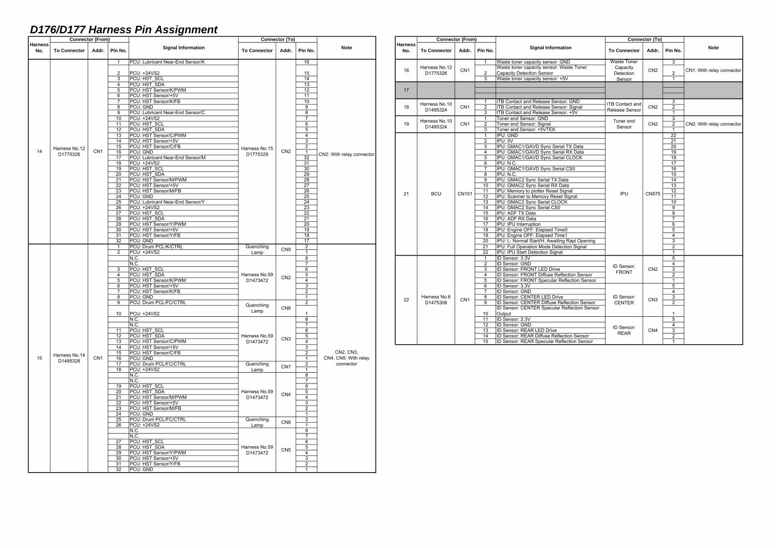
1 PCU: Lubricant Near-End Sensor/K 16 1 Waste toner capacity sensor: GND 3
2 PCU: +24VS2 15 2Waste toner capacity sensor: Waste TonerCapacity Detection Sensor 2
3 PCU: HST_SCL 14 3 Waste toner capacity sensor: +5V 14 PCU: HST_SDA 135 PCU: HST Sensor/K/PWM 126 PCU: HST Sensor/+5V 117 PCU: HST Sensor/K/FB 10 1 ITB Contact and Release Sensor: GND 38 PCU: GND 9 2 ITB Contact and Release Sensor: Signal 29 PCU: Lubricant Near-End Sensor/C 8 3 ITB Contact and Release Sensor: +5V 1
10 PCU: +24VS2 7 1 Toner end Sensor: GND 311 PCU: HST_SCL 6 2 Toner end Sensor: Signal 212 PCU: HST_SDA 5 3 Toner end Sensor: +5VTEK 113 PCU: HST Sensor/C/PWM 4 1 IPU: GND 2214 PCU: HST Sensor/+5V 3 2 IPU: 5V 2115 PCU: HST Sensor/C/FB 2 3 IPU: GMAC1/GAVD Sync Serial TX Data 2016 PCU: GND 1 4 IPU: GMAC1/GAVD Sync Serial RX Data 1917 PCU: Lubricant Near-End Sensor/M 32 5 IPU: GMAC1/GAVD Sync Serial CLOCK 1818 PCU: +24VS2 31 6 IPU: N.C. 1719 PCU: HST_SCL 30 7 IPU: GMAC1/GAVD Sync Serial CS0 1620 PCU: HST_SDA 29 8 IPU: N.C. 1521 PCU: HST Sensor/M/PWM 28 9 IPU: GMAC2 Sync Serial TX Data 1422 PCU: HST Sensor/+5V 27 10 IPU: GMAC2 Sync Serial RX Data 1323 PCU: HST Sensor/M/FB 26 11 IPU: Memory to plotter Reset Signal 1224 PCU: GND 25 12 IPU: Scanner to Memory Reset Signal 1125 PCU: Lubricant Near-End Sensor/Y 24 13 IPU: GMAC2 Sync Serial CLOCK 1026 PCU: +24VS2 23 14 IPU: GMAC2 Sync Serial CS0 927 PCU: HST_SCL 22 15 IPU: ADF TX Data 828 PCU: HST_SDA 21 16 IPU: ADF RX Data 729 PCU: HST Sensor/Y/PWM 20 17 IPU: IPU Interruption 630 PCU: HST Sensor/+5V 19 18 IPU: Engine OFF: Elapsed Time0 531 PCU: HST Sensor/Y/FB 18 19 IPU: Engine OFF: Elapsed Time1 432 PCU: GND 17 20 IPU: L: Normal Start/H: Awaiting Rapi Opening 31 PCU: Drum PCL/K/CTRL 2 21 IPU: Full Operation Mode Detection Signal 22 PCU: +24VS2 1 22 IPU: IPU Start Detection Signal 1
N.C. 8 1 ID Sensor: 3.3V 5N.C. 7 2 ID Sensor: GND 4
3 PCU: HST_SCL 6 3 ID Sensor: FRONT LED Drive 34 PCU: HST_SDA 5 4 ID Sensor: FRONT Diffuse Reflection Sensor 25 PCU: HST Sensor/K/PWM 4 5 ID Sensor: FRONT Specular Reflection Sensor 16 PCU: HST Sensor/+5V 3 6 ID Sensor: 3.3V 57 PCU: HST Sensor/K/FB 2 7 ID Sensor: GND 48 PCU: GND 1 8 ID Sensor: CENTER LED Drive 39 PCU: Drum PCL/FC/CTRL 2 9 ID Sensor: CENTER Diffuse Reflection Sensor 2
10 PCU: +24VS2 1 10ID Sensor: CENTER Specular Reflection SensorOutput 1
N.C. 8 11 ID Sensor: 3.3V 5N.C. 7 12 ID Sensor: GND 4
11 PCU: HST_SCL 6 13 ID Sensor: REAR LED Drive 312 PCU: HST_SDA 5 14 ID Sensor: REAR Diffuse Reflection Sensor 213 PCU: HST Sensor/C/PWM 4 15 ID Sensor: REAR Specular Reflection Sensor 114 PCU: HST Sensor/+5V 315 PCU: HST Sensor/C/FB 216 PCU: GND 117 PCU: Drum PCL/FC/CTRL 218 PCU: +24VS2 1
N.C. 8N.C. 7
19 PCU: HST_SCL 620 PCU: HST_SDA 521 PCU: HST Sensor/M/PWM 422 PCU: HST Sensor/+5V 323 PCU: HST Sensor/M/FB 224 PCU: GND 125 PCU: Drum PCL/FC/CTRL 226 PCU: +24VS2 1
N.C. 8N.C. 7
27 PCU: HST_SCL 628 PCU: HST_SDA 529 PCU: HST Sensor/Y/PWM 430 PCU: HST Sensor/+5V 331 PCU: HST Sensor/Y/FB 232 PCU: GND 1
CN8
CN5
CN7
14 Harness No.12D1775326 CN1 CN2: With relay connectorCN2Harness No.15
D1775329
15 Harness No.14D1495328 CN1
Harness No.59D1473472
QuenchingLamp
Harness No.59D1473472
QuenchingLamp
Harness No.59D1473472
QuenchingLamp
Harness No.59D1473472
17
16 Harness No.12D1775326 CN1 CN1: With relay connector
Waste TonerCapacityDetectionSensor
CN2
CN2ITB Contact andRelease Sensor
CN2: With relay connector
CN575
Toner endSensor CN2
IPU
CN3
ID Sensor:REAR
ID Sensor:FRONT
ID Sensor:CENTER
CN4
18
22 Harness No.6D1475308 CN1
Harness No.10D1495324 CN1
CN1Harness No.10D1495324
21 BCU
CN9
CN4
CN2
CN2, CN3,CN4, CN5: With relay
connector
CN6
CN3
19
QuenchingLamp
CN101
Note Pin No.Harness
No.
Connector (From)Signal Information
Connector (To)
To Connector Addr. Pin No. To Connector Addr. Pin No. Note
CN2
HarnessNo.
Connector (From)Signal Information
Connector (To)
To Connector Addr. Pin No. To Connector Addr.
D176/D177 Harness Pin Assignment
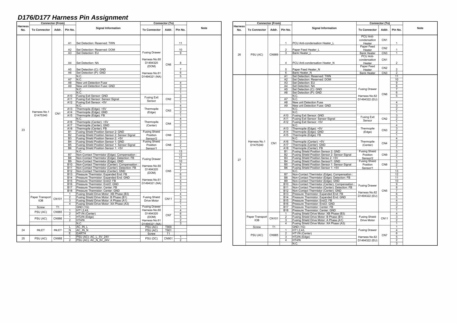
A1 Set Detection: Reserved: TWN 11 1 PCU Anti-condensation Heater_L
PCU Anti-condensation
HeaterCN1
1
A2 Set Detection: Reserved: DOM 10 2 Paper Feed Heater_LPaper Feed
Heater CN2 1A3 Set Detection: EU 9 3 Bank Heater_L Bank Heater CN3 1
A4 Set Detection: NA 8 4 PCU Anti-condensation Heater_N
PCU Anti-condensation
HeaterCN1
2
A5 Set Detection (C): GND 7 5 Paper Feed Heater_NPaper Feed
Heater CN2 2A6 Set Detection (P): GND 6 6 Bank Heater_N Bank Heater CN3 2
N.C. 5 A1 Set Detection: Reserved: TWN 11A7 N.C. A2 Set Detection: Reserved: DOM 10A8 New unit Detection Fuse 4 A3 Set Detection: EU 9A9 New unit Detection Fuse: GND 3 A4 Set Detection: NA 8
N.C. 2 A5 Set Detection (C): GND 7N.C. 1 A6 Set Detection (P): GND 6
A10 Fusing Exit Sensor: GND 3 N.C. 5A11 Fusing Exit Sensor: Sensor Signal 2 A7 N.C.A12 Fusing Exit Sensor: +5V 1 A8 New unit Detection Fuse 4
N.C. 4 A9 New unit Detection Fuse: GND 3A13 Thermopile (Edge): +5V 3 N.C. 2A14 Thermopile (Edge): GND 2 N.C. 1A15 Thermopile (Edge): FB 1 A10 Fusing Exit Sensor: GND 3
N.C. 4 A11 Fusing Exit Sensor: Sensor Signal 2A16 Thermopile (Center): +5V 3 A12 Fusing Exit Sensor: +5V 1A17 Thermopile (Center): GND 2 N.C. 4A18 Thermopile (Center): FB 1 A13 Thermopile (Edge): +5V 3B1 Fusing Shield Position Sensor 2: GND 3 A14 Thermopile (Edge): GND 2B2 Fusing Shield Position Sensor 2: Sensor Signal 2 A15 Thermopile (Edge): FB 1B3 Fusing Shield Position Sensor 2: +5V 1 N.C. 4B4 Fusing Shield Position Sensor 1: GND 3 A16 Thermopile (Center): +5V 3B5 Fusing Shield Position Sensor 1: Sensor Signal 2 A17 Thermopile (Center): GND 2B6 Fusing Shield Position Sensor 1: +5V 1 A18 Thermopile (Center): FB 1
N.C. 13 B1 Fusing Shield Position Sensor 2: GND 3B7 Non-Contact Thermistor (Edge): Compensation : 12 B2 Fusing Shield Position Sensor 2: Sensor Signal 2B8 Non-Contact Thermistor (Edge): Detection: FB 11 B3 Fusing Shield Position Senso 2: +5V 1B9 Non-Contact Thermistor (Edge): GND 10 B4 Fusing Shield Position Sensor/1: GND 3
B10 Non-Contact Thermistor (Center): Compensation : 9 B5 Fusing Shield Position Sensor 1: Sensor Signal 2B11 Non-Contact Thermistor (Center): Detection: FB 8 B6 Fusing Shield Position Sensor 1: +5V 1B12 Non-Contact Thermistor (Center): GND 7 N.C. 13B13 Pressure Thermistor: Expanded End: FB 6 B7 Non-Contact Thermistor (Edge): Compensation : 12B14 Pressure Thermistor: Expanded End: GND 5 B8 Non-Contact Thermistor (Edge): Detection: FB 11B15 Pressure Thermistor: End/2: FB 4 B9 Non-Contact Thermistor (Edge): GND 10B16 Pressure Thermistor: End/2: GND 3 B10 Non-Contact Thermistor (Center): Compensation : 9B17 Pressure Thermistor: Center: FB 2 B11 Non-Contact Thermistor (Center): Detection: FB 8B18 Pressure Thermistor: Center: GND 1 B12 Non-Contact Thermistor (Center): GND 7
1 Fusing Shield Drive Motor: XB Phase (B3) 4 B13 Pressure Thermistor: Expanded End: FB 62 Fusing Shield Drive Motor: B Phase (B1) 3 B14 Pressure Thermistor: Expanded End: GND 53 Fusing Shield Drive Motor: A Phase (A1) 2 B15 Pressure Thermistor: End/2: FB 44 Fusing Shield Drive Motor: XA Phase (A3) 1 B16 Pressure Thermistor: End/2: GND 3
Screw T1 GND (1G) 1 B17 Pressure Thermistor: Center: FB 21 HT1,2,4/L 4 B18 Pressure Thermistor: Center: GND 12 HT1/N (Center) 6 1 Fusing Shield Drive Motor: XB Phase (B3) 41 HT2/N (Edge) 5 2 Fusing Shield Drive Motor: B Phase (B1) 32 HT4/N 2 3 Fusing Shield Drive Motor: A Phase (A1) 2
N.C. 3 4 Fusing Shield Drive Motor: XA Phase (A3) 1L AC_IN_L PSU (AC) T900 Screw T1 GND (1G) 1N AC_IN_N PSU (AC) T901 1 HT1,2,4/L 4E EARTH Screw T1 2 HT1/N (Center) 61 PSU (AC): AC_L_5V_24V 1 3 HT2/N (Edge) 52 PSU (AC): AC_N_5V_24V 2 4 HT4/N 2
N.C. 3
CN8
CN9
CN4
CN3
CN2
23
Harness No.1D1475340 CN1
Paper TransportIOB CN101
PSU (AC)
Thermopile(Edge)
CN6
CN11
25 PSU (AC) CN988 PSU (DC)
CN7
CN901
Fusing Drawer
Harness No.60D1494320
(DOM)
Harness No.61D1494321 (NA)
Fusing ExitSensor
26 PSU (AC) CN989
Fusing Drawer
Harness No.62D1494322 (EU)
PSU (AC)
27
24 INLET INLET
CN985
PSU (AC) CN986
Fusing Drawer
Harness No.62D1494322 (EU)
Fusing ExitSensor
Thermopile(Edge)
CN6
CN985
Thermopile(Center)
Fusing ShieldPositionSensor/2
Thermopile(Center)
Fusing ShieldPositionSensor/2
Fusing ShieldDrive Motor
Fusing DrawerHarness No.60
D1494320(DOM)
Harness No.61D1494321 (NA)
Fusing ShieldPositionSensor/1
Fusing Drawer
Harness No.60D1494320
(DOM)
Harness No.61D1494321 (NA)
Fusing ShieldPositionSensor/1
Fusing Drawer
Harness No.62D1494322 (EU)
Fusing ShieldDrive Motor
CN8
CN5
CN11
CN2
CN3
CN4
CN9
CN7
Pin No.
Paper TransportIOB CN101
Harness No.1D1475340 CN1
CN5
Addr. Pin No. To Connector Addr.To Connector Addr. Pin No. To ConnectorHarness
No.
Connector (From)Signal Information
Connector (To)Note Harness
No.
Connector (From)Signal Information To Connector Addr. Pin No.
Connector (To)Note
D176/D177 Harness Pin Assignment
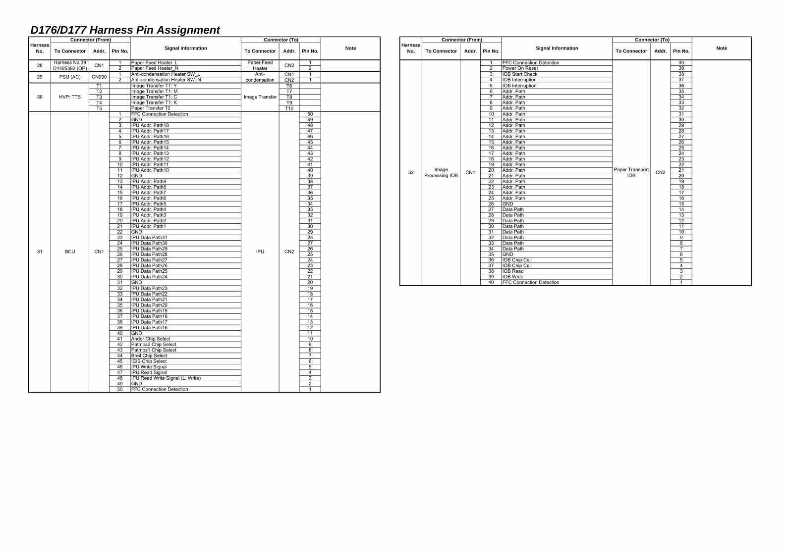
1 Paper Feed Heater_L 1 1 FFC Connection Detection 402 Paper Feed Heater_N 2 2 Power On Reset 391 Anti-condensation Heater SW_L CN1 1 3 IOB Start Check 382 Anti-condensation Heater SW_N CN2 1 4 IOB Interruption 37
T1 Image Transfer T1: Y T6 5 IOB Interruption 36T2 Image Transfer T1: M T7 6 Addr. Path 35T3 Image Transfer T1: C T8 7 Addr. Path 34T4 Image Transfer T1: K T9 8 Addr. Path 33T5 Paper Transfer T2 T10 9 Addr. Path 32
1 FFC Connection Detection 50 10 Addr. Path 312 GND 49 11 Addr. Path 303 IPU Addr. Path18 48 12 Addr. Path 294 IPU Addr. Path17 47 13 Addr. Path 285 IPU Addr. Path16 46 14 Addr. Path 276 IPU Addr. Path15 45 15 Addr. Path 267 IPU Addr. Path14 44 16 Addr. Path 258 IPU Addr. Path13 43 17 Addr. Path 249 IPU Addr. Path12 42 18 Addr. Path 23
10 IPU Addr. Path11 41 19 Addr. Path 2211 IPU Addr. Path10 40 20 Addr. Path 2112 GND 39 21 Addr. Path 2013 IPU Addr. Path9 38 22 Addr. Path 1914 IPU Addr. Path8 37 23 Addr. Path 1815 IPU Addr. Path7 36 24 Addr. Path 1716 IPU Addr. Path6 35 25 Addr. Path 1617 IPU Addr. Path5 34 26 GND 1518 IPU Addr. Path4 33 27 Data Path 1419 IPU Addr. Path3 32 28 Data Path 1320 IPU Addr. Path2 31 29 Data Path 1221 IPU Addr. Path1 30 30 Data Path 1122 GND 29 31 Data Path 1023 IPU Data Path31 28 32 Data Path 924 IPU Data Path30 27 33 Data Path 825 IPU Data Path29 26 34 Data Path 726 IPU Data Path28 25 35 GND 627 IPU Data Path27 24 36 IOB Chip Cell 528 IPU Data Path26 23 37 IOB Chip Cell 429 IPU Data Path25 22 38 IOB Read 330 IPU Data Path24 21 39 IOB Write 231 GND 20 40 FFC Connection Detection 132 IPU Data Path23 1933 IPU Data Path22 1834 IPU Data Path21 1735 IPU Data Path20 1636 IPU Data Path19 1537 IPU Data Path18 1438 IPU Data Path17 1339 IPU Data Path16 1240 GND 1141 Ander Chip Select 1042 Patmos2 Chip Select 943 Patmos1 Chip Select 844 Breit Chip Select 745 ICIB Chip Select 646 IPU Write Signal 547 IPU Read Signal 448 IPU Read Write Signal (L: Write) 349 GND 250 FFC Connection Detection 1
28 Harness No.39D1495392 (OP) CN1
29 PSU (AC) CN990 Anti-condensation
31 BCU CN1
30 HVP: TTS
IPU
Paper TransportIOB CN232 Image
Processing IOB CN1
Connector (To)
To Connector Addr.
Image Transfer
Paper FeedHeater CN2
CN2
Note HarnessNo.
Connector (From)Signal Information Pin No. NoteTo Connector Addr. Pin No. To Connector Addr. Pin No. To Connector Addr. Pin No.
HarnessNo.
Connector (From)Signal Information
Connector (To)
D176/D177 Harness Pin Assignment
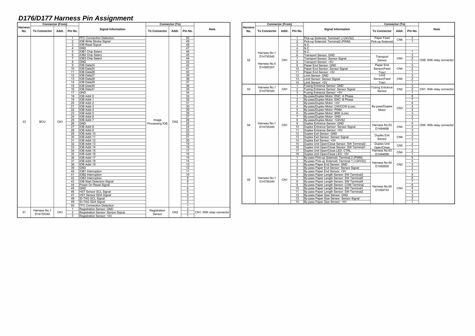
1 FFC Connection Detection 50 1 Pick-up Solenoid: Terminal1 (+24VS2) 22 IOB Write Strobe Signal 49 2 Pick-up Solenoid: Terminal2 (PWM) 13 IOB Read Signal 48 3 N.C.4 GND 47 4 N.C.5 IOB1 Chip Select 46 5 N.C. 16 IOB2 Chip Select 45 6 Transport Sensor: GND 37 IOB3 Chip Select 44 7 Transport Sensor: Sensor Signal 28 GND 43 8 Transport Sensor: +5V 19 IOB Data24 42 9 Paper End Sensor: GND 3
10 IOB Data25 41 10 Paper End Sensor: Sensor Signal 211 IOB Data26 40 11 Paper End Sensor: +5V 112 IOB Data27 39 12 Limit Sensor: GND 313 IOB Data28 38 13 Limit Sensor: Sensor Signal 214 IOB Data29 37 14 Limit Sensor: +5V 115 IOB Data30 36 1 Fusing Entrance Sensor: GND 316 IOB Data31 35 2 Fusing Entrance Sensor: Sensor Signal 217 GND 34 3 Fusing Entrance Sensor: +5V 118 IOB Addr.0 33 1 By-pass/Duplex Motor: ENC: A Phase 819 IOB Addr.1 32 2 By-pass/Duplex Motor: ENC: B Phase 720 IOB Addr.2 31 3 By-pass/Duplex Motor: +5V 621 IOB Addr.3 30 4 By-pass/Duplex Motor: CW/CCW (Low) 522 IOB Addr.4 29 5 By-pass/Duplex Motor: PWM 423 IOB Addr.5 28 6 By-pass/Duplex Motor: BRK (Low) 324 IOB Addr.6 27 7 By-pass/Duplex Motor: GND 225 IOB Addr.7 26 8 By-pass/Duplex Motor: +24VS2 126 GND 25 9 Duplex Entrance Sensor: GND 527 IOB Addr.8 24 10 Duplex Entrance Sensor: Sensor Signal 428 IOB Addr.9 23 11 Duplex Entrance Sensor: +5V 329 IOB Addr.10 22 12 Duplex Exit Sensor: GND 330 IOB Addr.11 21 13 Duplex Exit Sensor: Sensor Signal 231 IOB Addr.12 20 14 Duplex Exit Sensor: +5V 132 IOB Addr.13 19 15 Duplex Unit Open/Close Sensor: SW Terminal2 233 IOB Addr.14 18 16 Duplex Unit Open/Close Sensor: SW Terminal1 134 IOB Addr.15 17 17 Duplex Unit Open/Close LED: CTRL 235 IOB Addr.16 16 18 Duplex Unit Open/Close LED: +5V 136 IOB Addr.17 15 1 By-pass Pick-up Solenoid: Terminal 2 (PWM) 537 IOB Addr.18 14 2 By-pass Pick-up Solenoid: Terminal 1 (+24VS2) 438 IOB Addr.19 13 3 By-pass Paper End Sensor: GND 339 GND 12 4 By-pass Paper End Sensor: Sensor Signal 240 IOB1 Interruption 11 5 By-pass Paper End Sensor: +5V 141 IOB2 Interruption 10 6 By-pass Paper Length Sensor: SW Terminal3 942 IOB3 Interruption 9 7 By-pass Paper Length Sensor: SW Terminal5 843 IOB Start Detection Signal 8 8 By-pass Paper Length Sensor: SW Terminal4 744 Power On Reset Signal 7 9 By-pass Paper Length Sensor: COM Terminal 645 GND 6 10 By-pass Paper Length Sensor: SW Terminal1 546 HST Sensor SCL Signal 5 11 By-pass Paper Length Sensor: SW Terminal2 447 HST Sensor SDA Signal 4 12 By-pass Paper Size Sensor: GND 348 ID-TAG SCL Signal 3 13 By-pass Paper Size Sensor: Sensor Signal 249 ID-TAG SDA Signal 2 14 By-pass Paper Size Sensor: +5V 150 FFC Connection Detection 11 Registration Sensor: GND 32 Registration Sensor: Sensor Signal 23 Registration Sensor: +5V 1
CN1
CN1: With relay connector
33 BCU ImageProcessing IOB
RegistrationSensor
CN2
CN251 Harness No.1D14755340 CN1
CN1 Fusing EntranceSensor
CN6: With relay connector52
Harness No.1D14755340
Harness No.5D14955307
CN1
Paper FeedPick-up Solenoid
TransportSensor
Paper EndSensor(Feed
Tray)Limit
Sensor(FeedTray)
CN1: With relay connector
54 Harness No.1D14755340 CN1 CN4: With relay connectorCN4
CN6
CN5
53 Harness No.1D14755340
Harness No.63D1494698
Harness No.64D1492659
Harness No.1D14755340 CN1
Harness No.65D1494743
CN4
CN2
CN3
55
Duplex ExitSensor
Duplex UnitOpen/Close
CN4
Pin No. Note HarnessNo.
CN6
CN3
CN5
CN2
CN3By-pass/DuplexMotor
Harness No.63D1494698
NoteAddr. Pin No. To Connector Addr. Pin No.Harness
No.
Connector (From)Signal Information
Connector (To)
To Connector Addr. Pin No. To Connector Addr.
Connector (From)Signal Information
Connector (To)
To Connector
D176/D177 Harness Pin Assignment
1 PSU: PGND 12 PSU: PGND_ADF 23 PSU: +24V_ADF 34 PSU: +24V 41 N.C.2 N.C.3 PCU: HST_SCL 14 PCU: HST_SDA 25 PCU: HST Sensor/C/PWM 36 PCU: HST Sensor/+5V 47 PCU: HST Sensor/C/FB 58 PCU: GND 61 GND (1G) Screw T12 N.C.3 N.C.4 HT1,2,4/L Screw T4
5 HT2/N (Edge)Heating Roller:
End 1
6 HT1/N (Center)Heating Roller:
Center 21 Pressure Thermistor:Center: GND 22 Pressure Thermistor:Center: FB 13 Pressure Thermistor:End: GND 44 Pressure Thermistor:End: FB 35 Pressure Thermistor:Expanded End: GND 26 Pressure Thermistor:Expanded End: FB 17 Non-Contact Thermistor (Center): GND 18 Non-Contact Thermistor (Center): Detection: FB 29 Non-Contact Thermistor (Center): Compensation : 3
10 Non-Contact Thermistor (Edge): GND 111 Non-Contact Thermistor (Edge): Detection: FB 212 Non-Contact Thermistor (Edge): Compensation : 313 N.C.1 N.C.2 N.C.3 New unit Detection Fuse: GND 2
1 Paper Exit Solenoid: Terminal1 (+24VS2) 2 4 New unit Detection Fuse 12 Paper Exit Solenoid: Terminal2 (PWM) 1 5 N.C.3 Inversion Sensor: GND 3 6 Set Detection (P): GND
4 Inversion Sensor: Sensor Signal 2 7 Set Detection: GND
Set Detection:100V Model
(Short-Circuit)CN3
85 Inversion Sensor: +5V 1 9 Set Detection: 200V Model6 Paper Exit Sensor: GND 3 10 Set Detection: Reserved: 17 Paper Exit Sensor: Sensor Signal 2 11 Set Detection: Reserved: 28 Paper Exit Sensor: +5V 19 N.C.
10 N.C.11 N.C.12 c: XB Phase 413 Inversion Motor: B Phase 314 Inversion Motor: XA Phase 215 Inversion Motor: A Phase 1
56
CN1
Exit JunctionSolenoid
Inversion Sensor
Exit Sensor
Inversion Motor
CN1
CN2
CN310
59 Harness No.12D1775326 CN1
pin 1and 2: Short-circuitedfor disconnection of
connectors
Non-ContactThermistor2
New unitDetection Fuse CN8
Non-ContactThermistor1
CN2
CN4
CN5
CN4, CN5, CN6,CN7, CN8: With relay
connector
CN2
CN9
CN4
CN3
PressureThermistor:
58
CN3
57 Harness No.1D14755340
Harness No.2D1775301
HST Sensor
PressureThermistor:Pressure
Thermistor:
Note HarnessNo. Addr.
Connector (From)
SIO
Harness No.23D1495341
CN1
CN2, CN3: With relayconnector
Pin No. To Connector
CN5
CN6
CN7
60
Pin No.Harness
No.
Connector (From)Signal Information
Connector (To)
To Connector Addr. Pin No. To Connector Addr. Pin No. NoteAddr.Signal InformationConnector (To)
To Connector
D176/D177 Harness Pin Assignment
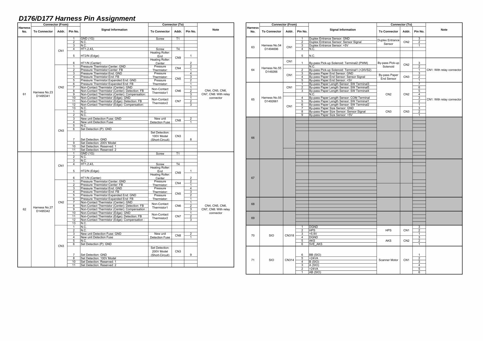
1 GND (1G) Screw T1 1 Duplex Entrance Sensor: GND 32 N.C. 2 Duplex Entrance Sensor: Sensor Signal 23 N.C. 3 Duplex Entrance Sensor: +5V 14 HT1,2,4/L Screw T4 4 N.C.
5 HT2/N (Edge)Heating Roller:
End 1 5 N.C.
6 HT1/N (Center)Heating Roller:
Center 2 CN1 1 By-pass Pick-up Solenoid: Terminal2 (PWM) 31 Pressure Thermistor:Center: GND 2 N.C. 22 Pressure Thermistor:Center: FB 1 2 By-pass Pick-up Solenoid: Terminal1 (+24VS2) 13 Pressure Thermistor:End: GND 4 3 By-pass Paper End Sensor: GND 34 Pressure Thermistor:End: FB 3 4 By-pass Paper End Sensor: Sensor Signal 25 Pressure Thermistor:Expanded End: GND 2 5 By-pass Paper End Sensor: +5V 16 Pressure Thermistor:Expanded End: FB 1 1 By-pass Paper Length Sensor: SW Terminal3 77 Non-Contact Thermistor (Center): GND 1 2 By-pass Paper Length Sensor: SW Terminal5 68 Non-Contact Thermistor (Center): Detection: FB 2 3 By-pass Paper Length Sensor: SW Terminal4 59 Non-Contact Thermistor (Center): Compensation: 3 N.C. 4
10 Non-Contact Thermistor (Edge): GND 1 4 By-pass Paper Length Sensor: COM Terminal 311 Non-Contact Thermistor (Edge): Detection: FB 2 5 By-pass Paper Length Sensor: SW Terminal1 212 Non-Contact Thermistor (Edge): Compensation: 3 6 By-pass Paper Length Sensor: SW Terminal2 113 N.C. 7 By-pass Paper Size Sensor: GND 31 N.C. 8 By-pass Paper Size Sensor: Sensor Signal 22 N.C. 9 By-pass Paper Size Sensor: +5V 13 New unit Detection Fuse: GND 24 New unit Detection Fuse 15 N.C.6 Set Detection (P): GND
7 Set Detection: GND
Set Detection:100V Model
(Short-Circuit)CN3
89 Set Detection: 200V Model
10 Set Detection: Reserved: 111 Set Detection: Reserved: 21 GND (1G) Screw T12 N.C.3 N.C.4 HT1,2,4/L Screw T4
5 HT2/N (Edge)Heating Roller:
End 1
6 HT1/N (Center)Heating Roller:
Center 21 Pressure Thermistor:Center: GND 22 Pressure Thermistor:Center: FB 13 Pressure Thermistor:End: GND 44 Pressure Thermistor:End: FB 35 Pressure Thermistor:Expanded End: GND 26 Pressure Thermistor:Expanded End: FB 17 Non-Contact Thermistor (Center): GND 18 Non-Contact Thermistor (Center): Detection: FB 29 Non-Contact Thermistor (Center): Compensation : 3
10 Non-Contact Thermistor (Edge): GND 111 Non-Contact Thermistor (Edge): Detection: FB 212 Non-Contact Thermistor (Edge): Compensation : 313 N.C.1 N.C. 1 DGND 32 N.C. 2 HPS 23 New unit Detection Fuse: GND 2 3 +5.9V 14 New unit Detection Fuse 1 4 DGND 35 N.C. 5 AKS 26 Set Detection (P): GND 6 5VE_AKS 1
7 Set Detection: GND
Set Detection:200V Model
(Short-Circuit)CN3
9 6 BB (SIO) 18 Set Detection: 100V Model 5 +24VA 2
10 Set Detection: Reserved: 1 4 B (SIO) 311 Set Detection: Reserved: 2 3 A (SIO) 4
2 +24VA 51 AB (SIO) 6
CN1
CN3
CN2
CN9
CN4
CN5
CN661 Harness No.23
D1495341
PressureThermistor:
CN7
CN8
CN4, CN5, CN6,CN7, CN8: With relay
connector
PressureThermistor:
Non-ContactThermistor1
Non-ContactThermistor2
New unitDetection Fuse
Non-ContactThermistor2
CN8
62 Harness No.27D1495342
CN1
CN3
Harness No.54D1494696 CN1
Duplex EntranceSensor
By-pass Pick-upSolenoid
CN1
CN1
CN2
CN3
CN1
CN2
CN3
66
CN1: With relay connector
CN1: With relay connector
CN2
69
68
CN1
CN2
CN314
CN4, CN5, CN6,CN7, CN8: With relay
connector
CN2
CN9
CN4
CN5
CN6
67
63
SIO
70 SIO
71
PressureThermistor:Pressure
Thermistor:
65 Harness No.55D1492661
64 Harness No.55D149266
Non-ContactThermistor1
CN7
CN3
HPS
New unitDetection Fuse
PressureThermistor:Pressure
Thermistor:
CN318
CN2
To Connector
By-pass PaperEnd Sensor
AKS
Scanner Motor CN1
Addr. Pin No. NoteTo Connector Addr. Pin No. To Connector Addr. Pin No. To Connector Addr. Pin No.Harness
No.
Connector (From)Signal Information
Connector (To)Note Harness
No.
Connector (From)Signal Information
Connector (To)
D176/D177 Harness Pin Assignment
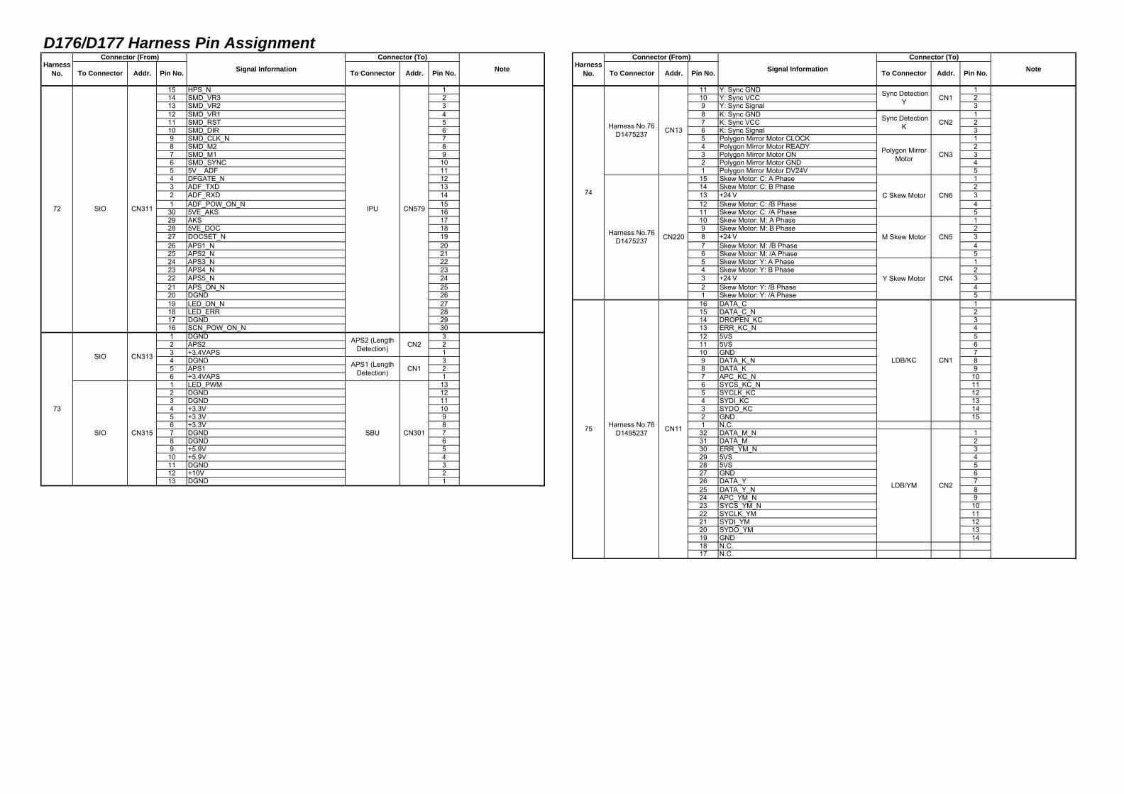
15 HPS_N 1 11 Y: Sync GND 114 SMD_VR3 2 10 Y: Sync VCC 213 SMD_VR2 3 9 Y: Sync Signal 312 SMD_VR1 4 8 K: Sync GND 111 SMD_RST 5 7 K: Sync VCC 210 SMD_DIR 6 6 K: Sync Signal 39 SMD_CLK_N 7 5 Polygon Mirror Motor CLOCK 18 SMD_M2 8 4 Polygon Mirror Motor READY 27 SMD_M1 9 3 Polygon Mirror Motor ON 36 SMD_SYNC 10 2 Polygon Mirror Motor GND 45 5V__ADF 11 1 Polygon Mirror Motor DV24V 54 DFGATE_N 12 15 Skew Motor: C: A Phase 13 ADF_TXD 13 14 Skew Motor: C: B Phase 22 ADF_RXD 14 13 +24V 31 ADF_POW_ON_N 15 12 Skew Motor: C: /B Phase 430 5VE_AKS 16 11 Skew Motor: C: /A Phase 529 AKS 17 10 Skew Motor: M: A Phase 128 5VE_DOC 18 9 Skew Motor: M: B Phase 227 DOCSET_N 19 8 +24V 326 APS1_N 20 7 Skew Motor: M: /B Phase 425 APS2_N 21 6 Skew Motor: M: /A Phase 524 APS3_N 22 5 Skew Motor: Y: A Phase 123 APS4_N 23 4 Skew Motor: Y: B Phase 222 APS5_N 24 3 +24V 321 APS_ON_N 25 2 Skew Motor: Y: /B Phase 420 DGND 26 1 Skew Motor: Y: /A Phase 519 LED_ON_N 27 16 DATA_C 118 LED_ERR 28 15 DATA_C_N 217 DGND 29 14 DROPEN_KC 316 SCN_POW_ON_N 30 13 ERR_KC_N 41 DGND 3 12 5VS 52 APS2 2 11 5VS 63 +3.4VAPS 1 10 GND 74 DGND 3 9 DATA_K_N 85 APS1 2 8 DATA_K 96 +3.4VAPS 1 7 APC_KC_N 101 LED_PWM 13 6 SYCS_KC_N 112 DGND 12 5 SYCLK_KC 123 DGND 11 4 SYDI_KC 134 +3.3V 10 3 SYDO_KC 145 +3.3V 9 2 GND 156 +3.3V 8 1 N.C.7 DGND 7 32 DATA_M_N 18 DGND 6 31 DATA_M 29 +5.9V 5 30 ERR_YM_N 3
10 +5.9V 4 29 5VS 411 DGND 3 28 5VS 512 +10V 2 27 GND 613 DGND 1 26 DATA_Y 7
25 DATA_Y_N 824 APC_YM_N 923 SYCS_YM_N 1022 SYCLK_YM 1121 SYDI_YM 1220 SYDO_YM 1319 GND 1418 N.C.17 N.C.
72 SIO CN311
CN5
Addr. Pin No. To ConnectorSignal Information
IPU CN579
73
SIO CN313
SIO CN315
APS2 (LengthDetection)
M Skew Motor
CN1
75 Harness No.76D1495237 CN11
LDB/KC
LDB/YM
Y Skew Motor
Harness No.76D1475237 CN220
Sync DetectionY
Sync DetectionK
Polygon MirrorMotor
C Skew Motor
CN2
CN3
CN6
CN301
74
Harness No.76D1475237 CN13
APS1 (LengthDetection)
SBU
CN2
CN1
Addr.
CN4
CN1
CN2
NoteTo Connector Addr. Pin No. To Connector Addr. Pin No. To Connector Pin No.
Connector (To)Harness
No.
Connector (From)Signal Information
Connector (To)Note Harness
No.
Connector (From)
D176/D177 Harness Pin Assignment
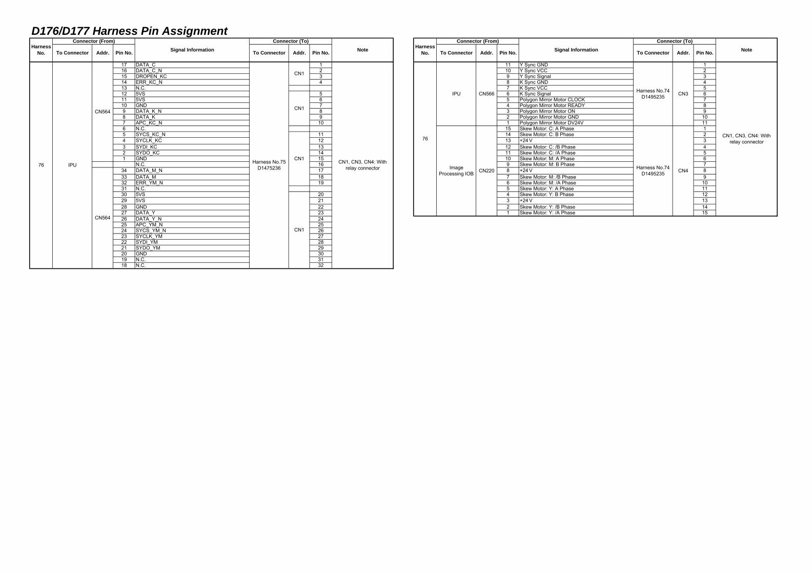
17 DATA_C 1 11 Y Sync GND 116 DATA_C_N 2 10 Y Sync VCC 215 DROPEN_KC 3 9 Y Sync Signal 314 ERR_KC_N 4 8 K Sync GND 413 N.C. 7 K Sync VCC 512 5VS 5 6 K Sync Signal 611 5VS 6 5 Polygon Mirror Motor CLOCK 710 GND 7 4 Polygon Mirror Motor READY 89 DATA_K_N 8 3 Polygon Mirror Motor ON 98 DATA_K 9 2 Polygon Mirror Motor GND 107 APC_KC_N 10 1 Polygon Mirror Motor DV24V 116 N.C. 15 Skew Motor: C: A Phase 15 SYCS_KC_N 11 14 Skew Motor: C: B Phase 24 SYCLK_KC 12 13 +24V 33 SYDI_KC 13 12 Skew Motor: C: /B Phase 42 SYDO_KC 14 11 Skew Motor: C: /A Phase 51 GND 15 10 Skew Motor: M: A Phase 6
N.C. 16 9 Skew Motor: M: B Phase 734 DATA_M_N 17 8 +24V 833 DATA_M 18 7 Skew Motor: M: /B Phase 932 ERR_YM_N 19 6 Skew Motor: M: /A Phase 1031 N.C. 5 Skew Motor: Y: A Phase 1130 5VS 20 4 Skew Motor: Y: B Phase 1229 5VS 21 3 +24V 1328 GND 22 2 Skew Motor: Y: /B Phase 1427 DATA_Y 23 1 Skew Motor: Y: /A Phase 1526 DATA_Y_N 2425 APC_YM_N 2524 SYCS_YM_N 2623 SYCLK_YM 2722 SYDI_YM 2821 SYDO_YM 2920 GND 3019 N.C. 3118 N.C. 32
CN1
CN1
IPU
CN564
CN1, CN3, CN4: Withrelay connector76
ImageProcessing IOB CN220
Harness No.74D1495235
Harness No.74D1495235
CN3
Pin No.
76 CN1, CN3, CN4: Withrelay connector
CN1
CN4
CN564
IPU CN566
Harness No.75D1475236
CN1
NoteTo Connector Addr. Pin No. To Connector Addr. Pin No.Harness
No.
Connector (From)Signal Information
Connector (To)
Pin No. To Connector Addr.Harness
No.
Connector (From)Signal Information
Connector (To)
To Connector Addr. Note
D176/D177 ELECTRICAL COMPONENT LAYOUT
d 1500914
1
4
2
3
56
d 1500913
2
3
4
5
6
1
2
3
4
56
7
91011
12131415
8
d 1500919
1
18
9
17
2 3 45 6
78
1011
12
13
14
15
16
d1500915
1
4
2
3
2 3
d177f4540
1
45
6
7
9
8
4
1
d177z4506
D176/D177 ELECTRICAL COMPONENT LAYOUT
d177z4509
1
2
3
4
5
6
d177z4507
1
2
3
4
5
6
78
d1500923
12
3
4
5
6
7
89
d177z4511
1
2
3
45
6
7
89
d176f2043
1
3
4
5
6
7 2
8
d1500916
34
5
6
12
d177z4042
8
7
12
10 119
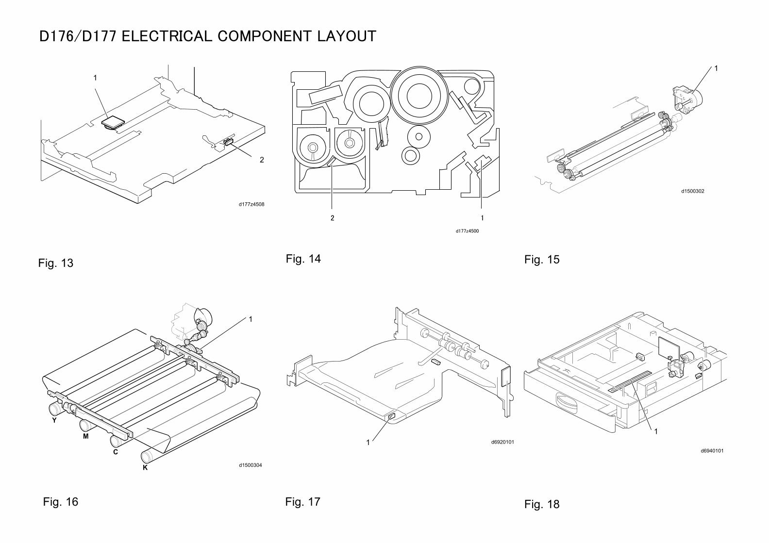
D176/D177 ELECTRICAL COMPONENT LAYOUT
d69201011d6940101
1
d1500302
1
d1500304
1
d177z4508
1
2
12
d177z4500
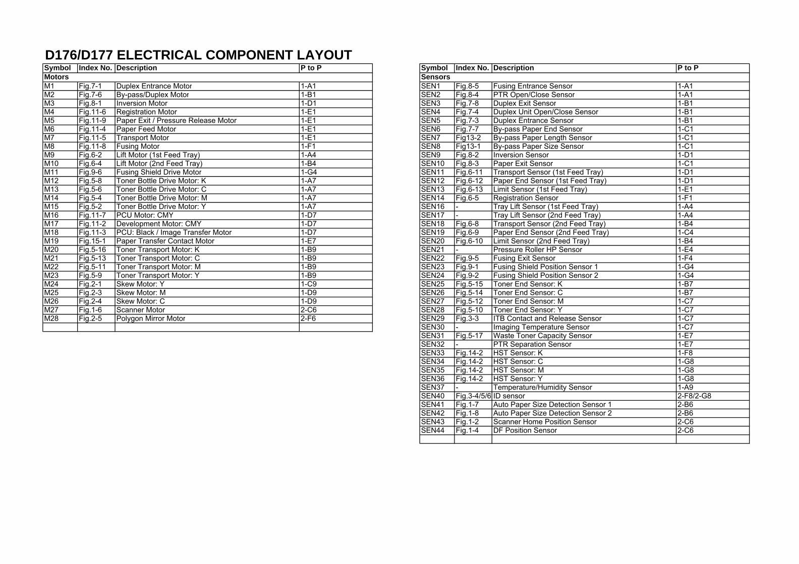
D176/D177 ELECTRICAL COMPONENT LAYOUTSymbol Index No. Description P to P Symbol Index No. Description P to P
M1 Fig.7-1 Duplex Entrance Motor 1-A1 SEN1 Fig.8-5 Fusing Entrance Sensor 1-A1M2 Fig.7-6 By-pass/Duplex Motor 1-B1 SEN2 Fig.8-4 PTR Open/Close Sensor 1-A1M3 Fig.8-1 Inversion Motor 1-D1 SEN3 Fig.7-8 Duplex Exit Sensor 1-B1M4 Fig.11-6 Registration Motor 1-E1 SEN4 Fig.7-4 Duplex Unit Open/Close Sensor 1-B1M5 Fig.11-9 Paper Exit / Pressure Release Motor 1-E1 SEN5 Fig.7-3 Duplex Entrance Sensor 1-B1M6 Fig.11-4 Paper Feed Motor 1-E1 SEN6 Fig.7-7 By-pass Paper End Sensor 1-C1M7 Fig.11-5 Transport Motor 1-E1 SEN7 Fig13-2 By-pass Paper Length Sensor 1-C1M8 Fig.11-8 Fusing Motor 1-F1 SEN8 Fig13-1 By-pass Paper Size Sensor 1-C1M9 Fig.6-2 Lift Motor (1st Feed Tray) 1-A4 SEN9 Fig.8-2 Inversion Sensor 1-D1M10 Fig.6-4 Lift Motor (2nd Feed Tray) 1-B4 SEN10 Fig.8-3 Paper Exit Sensor 1-C1M11 Fig.9-6 Fusing Shield Drive Motor 1-G4 SEN11 Fig.6-11 Transport Sensor (1st Feed Tray) 1-D1M12 Fig.5-8 Toner Bottle Drive Motor: K 1-A7 SEN12 Fig.6-12 Paper End Sensor (1st Feed Tray) 1-D1M13 Fig.5-6 Toner Bottle Drive Motor: C 1-A7 SEN13 Fig.6-13 Limit Sensor (1st Feed Tray) 1-E1M14 Fig.5-4 Toner Bottle Drive Motor: M 1-A7 SEN14 Fig.6-5 Registration Sensor 1-F1M15 Fig.5-2 Toner Bottle Drive Motor: Y 1-A7 SEN16 - Tray Lift Sensor (1st Feed Tray) 1-A4M16 Fig.11-7 PCU Motor: CMY 1-D7 SEN17 - Tray Lift Sensor (2nd Feed Tray) 1-A4M17 Fig.11-2 Development Motor: CMY 1-D7 SEN18 Fig.6-8 Transport Sensor (2nd Feed Tray) 1-B4M18 Fig.11-3 PCU: Black / Image Transfer Motor 1-D7 SEN19 Fig.6-9 Paper End Sensor (2nd Feed Tray) 1-C4M19 Fig.15-1 Paper Transfer Contact Motor 1-E7 SEN20 Fig.6-10 Limit Sensor (2nd Feed Tray) 1-B4M20 Fig.5-16 Toner Transport Motor: K 1-B9 SEN21 - Pressure Roller HP Sensor 1-E4M21 Fig.5-13 Toner Transport Motor: C 1-B9 SEN22 Fig.9-5 Fusing Exit Sensor 1-F4M22 Fig.5-11 Toner Transport Motor: M 1-B9 SEN23 Fig.9-1 Fusing Shield Position Sensor 1 1-G4M23 Fig.5-9 Toner Transport Motor: Y 1-B9 SEN24 Fig.9-2 Fusing Shield Position Sensor 2 1-G4M24 Fig.2-1 Skew Motor: Y 1-C9 SEN25 Fig.5-15 Toner End Sensor: K 1-B7M25 Fig.2-3 Skew Motor: M 1-D9 SEN26 Fig.5-14 Toner End Sensor: C 1-B7M26 Fig.2-4 Skew Motor: C 1-D9 SEN27 Fig.5-12 Toner End Sensor: M 1-C7M27 Fig.1-6 Scanner Motor 2-C6 SEN28 Fig.5-10 Toner End Sensor: Y 1-C7M28 Fig.2-5 Polygon Mirror Motor 2-F6 SEN29 Fig.3-3 ITB Contact and Release Sensor 1-C7
SEN30 - Imaging Temperature Sensor 1-C7SEN31 Fig.5-17 Waste Toner Capacity Sensor 1-E7SEN32 - PTR Separation Sensor 1-E7SEN33 Fig.14-2 HST Sensor: K 1-F8SEN34 Fig.14-2 HST Sensor: C 1-G8SEN35 Fig.14-2 HST Sensor: M 1-G8SEN36 Fig.14-2 HST Sensor: Y 1-G8SEN37 - Temperature/Humidity Sensor 1-A9SEN40 Fig.3-4/5/6 ID sensor 2-F8/2-G8SEN41 Fig.1-7 Auto Paper Size Detection Sensor 1 2-B6SEN42 Fig.1-8 Auto Paper Size Detection Sensor 2 2-B6SEN43 Fig.1-2 Scanner Home Position Sensor 2-C6SEN44 Fig.1-4 DF Position Sensor 2-C6
Motors Sensors
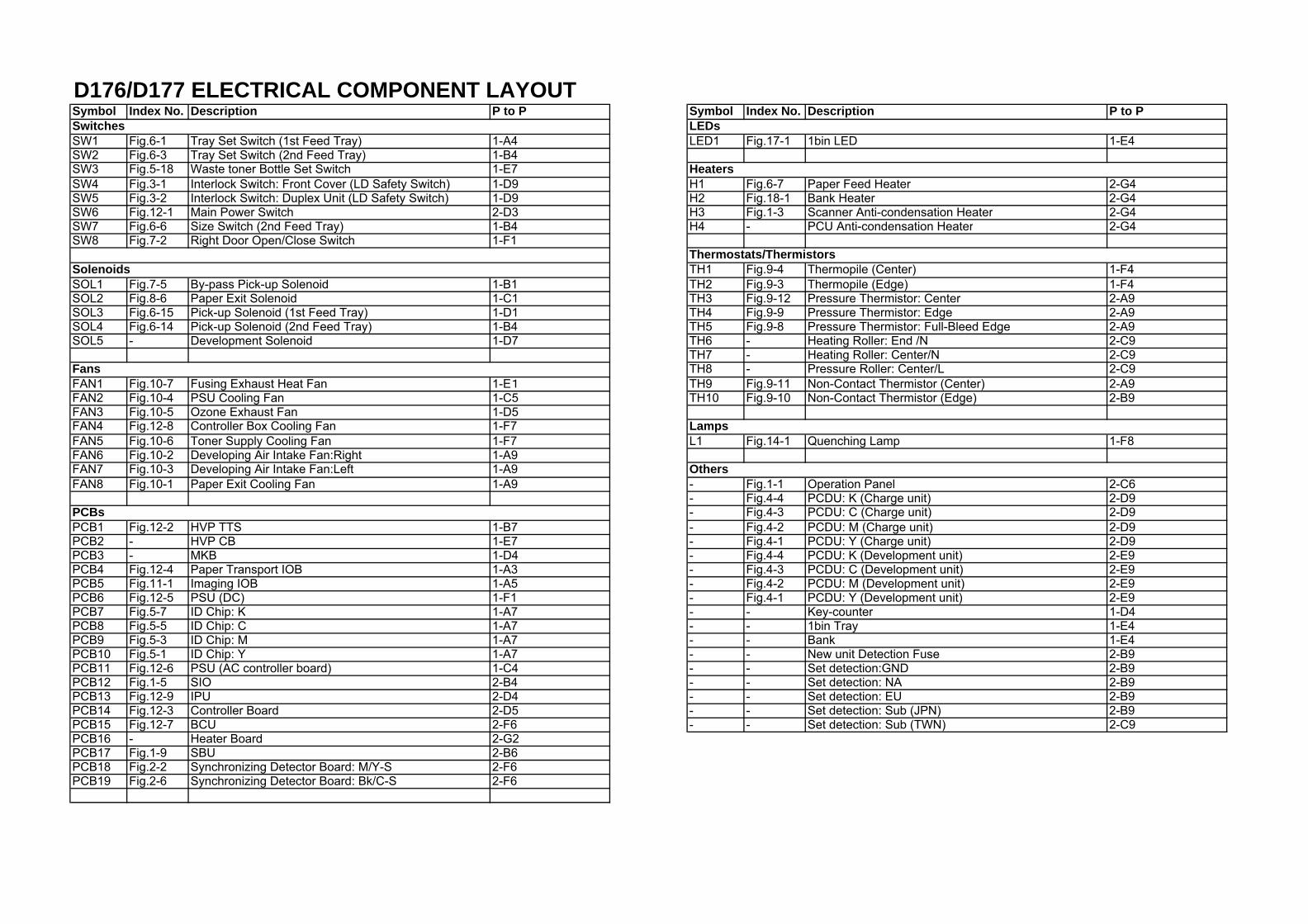
D176/D177 ELECTRICAL COMPONENT LAYOUTSymbol Index No. Description P to P Symbol Index No. Description P to P
SW1 Fig.6-1 Tray Set Switch (1st Feed Tray) 1-A4 LED1 Fig.17-1 1bin LED 1-E4SW2 Fig.6-3 Tray Set Switch (2nd Feed Tray) 1-B4SW3 Fig.5-18 Waste toner Bottle Set Switch 1-E7SW4 Fig.3-1 Interlock Switch: Front Cover (LD Safety Switch) 1-D9 H1 Fig.6-7 Paper Feed Heater 2-G4SW5 Fig.3-2 Interlock Switch: Duplex Unit (LD Safety Switch) 1-D9 H2 Fig.18-1 Bank Heater 2-G4SW6 Fig.12-1 Main Power Switch 2-D3 H3 Fig.1-3 Scanner Anti-condensation Heater 2-G4SW7 Fig.6-6 Size Switch (2nd Feed Tray) 1-B4 H4 - PCU Anti-condensation Heater 2-G4SW8 Fig.7-2 Right Door Open/Close Switch 1-F1
TH1 Fig.9-4 Thermopile (Center) 1-F4SOL1 Fig.7-5 By-pass Pick-up Solenoid 1-B1 TH2 Fig.9-3 Thermopile (Edge) 1-F4SOL2 Fig.8-6 Paper Exit Solenoid 1-C1 TH3 Fig.9-12 Pressure Thermistor: Center 2-A9SOL3 Fig.6-15 Pick-up Solenoid (1st Feed Tray) 1-D1 TH4 Fig.9-9 Pressure Thermistor: Edge 2-A9SOL4 Fig.6-14 Pick-up Solenoid (2nd Feed Tray) 1-B4 TH5 Fig.9-8 Pressure Thermistor: Full-Bleed Edge 2-A9SOL5 - Development Solenoid 1-D7 TH6 - Heating Roller: End /N 2-C9
TH7 - Heating Roller: Center/N 2-C9TH8 - Pressure Roller: Center/L 2-C9
FAN1 Fig.10-7 Fusing Exhaust Heat Fan 1-E1 TH9 Fig.9-11 Non-Contact Thermistor (Center) 2-A9FAN2 Fig.10-4 PSU Cooling Fan 1-C5 TH10 Fig.9-10 Non-Contact Thermistor (Edge) 2-B9FAN3 Fig.10-5 Ozone Exhaust Fan 1-D5FAN4 Fig.12-8 Controller Box Cooling Fan 1-F7FAN5 Fig.10-6 Toner Supply Cooling Fan 1-F7 L1 Fig.14-1 Quenching Lamp 1-F8FAN6 Fig.10-2 Developing Air Intake Fan:Right 1-A9FAN7 Fig.10-3 Developing Air Intake Fan:Left 1-A9FAN8 Fig.10-1 Paper Exit Cooling Fan 1-A9 - Fig.1-1 Operation Panel 2-C6
- Fig.4-4 PCDU: K (Charge unit) 2-D9- Fig.4-3 PCDU: C (Charge unit) 2-D9
PCB1 Fig.12-2 HVP TTS 1-B7 - Fig.4-2 PCDU: M (Charge unit) 2-D9PCB2 - HVP CB 1-E7 - Fig.4-1 PCDU: Y (Charge unit) 2-D9PCB3 - MKB 1-D4 - Fig.4-4 PCDU: K (Development unit) 2-E9PCB4 Fig.12-4 Paper Transport IOB 1-A3 - Fig.4-3 PCDU: C (Development unit) 2-E9PCB5 Fig.11-1 Imaging IOB 1-A5 - Fig.4-2 PCDU: M (Development unit) 2-E9PCB6 Fig.12-5 PSU (DC) 1-F1 - Fig.4-1 PCDU: Y (Development unit) 2-E9PCB7 Fig.5-7 ID Chip: K 1-A7 - - Key-counter 1-D4PCB8 Fig.5-5 ID Chip: C 1-A7 - - 1bin Tray 1-E4PCB9 Fig.5-3 ID Chip: M 1-A7 - - Bank 1-E4PCB10 Fig.5-1 ID Chip: Y 1-A7 - - New unit Detection Fuse 2-B9PCB11 Fig.12-6 PSU (AC controller board) 1-C4 - - Set detection:GND 2-B9PCB12 Fig.1-5 SIO 2-B4 - - Set detection: NA 2-B9PCB13 Fig.12-9 IPU 2-D4 - - Set detection: EU 2-B9PCB14 Fig.12-3 Controller Board 2-D5 - - Set detection: Sub (JPN) 2-B9PCB15 Fig.12-7 BCU 2-F6 - - Set detection: Sub (TWN) 2-C9PCB16 - Heater Board 2-G2PCB17 Fig.1-9 SBU 2-B6PCB18 Fig.2-2 Synchronizing Detector Board: M/Y-S 2-F6PCB19 Fig.2-6 Synchronizing Detector Board: Bk/C-S 2-F6
Switches
Solenoids
Others
Fans
PCBs
LEDs
Heaters
Thermostats/Thermistors
Lamps
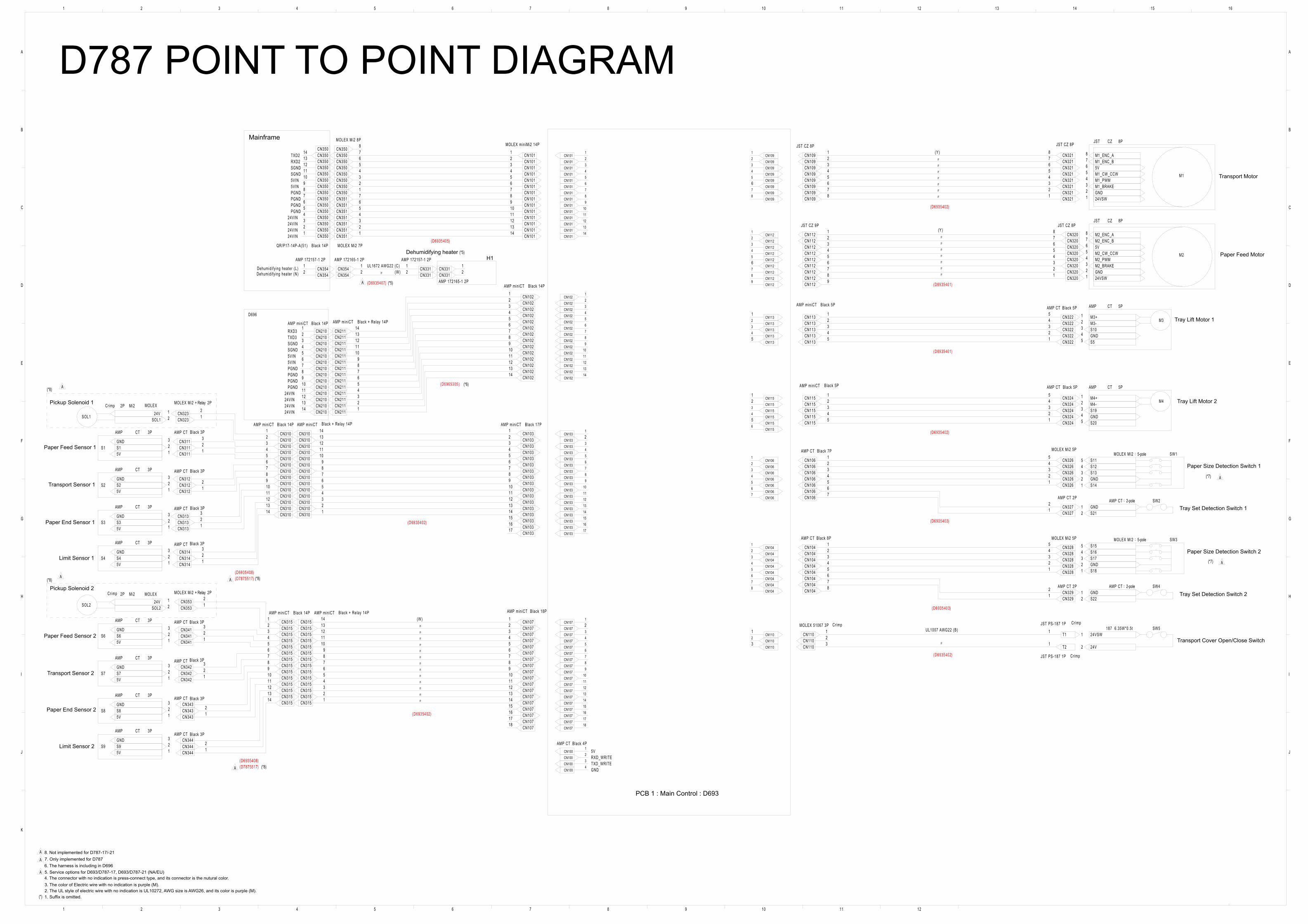
D
C
B
A
121110987654321
16151413121110987654321
J
I
H
G
F
E
D
C
B
A
K
J
I
H
G
F
E
CN1001
CN1004
CN1033
CN1034
CN1035
CN1036
CN1037
CN1038
CN1039
CN10310
CN10311
CN10312
CN10313
CN10314
CN10315
CN10316
CN10317
CN1011
CN1012
CN1013
CN1014
CN1015
CN1016
CN1017
CN1018
CN1019
CN10110
CN10111
CN10112
CN10113
CN10114
CN1002
CN1003
CN1041
CN1042
CN1043
CN1044
CN1045
CN1046
CN1047
CN1048
CN1061
CN1062
CN1063
CN1064
CN1065
CN1066
CN1067
CN1073
CN1074
CN1075
CN1076
CN1077
CN1078
CN1079
CN10710
CN10711
CN10712
CN10713
CN10714
CN10715
CN10716
CN10717
CN10718
CN1021
CN1022
CN1023
CN1024
CN1025
CN1026
CN1027
CN1028
CN1029
CN10210
CN10211
CN10212
CN10213
CN10214
CN1102
CN1031
CN1091
CN1092
CN1093
CN1094
CN1095
CN1097
CN1098
CN1121
CN1122
CN1123
CN1124
CN1125
CN1127
CN1128
CN1129
CN1071
CN1132
CN1133
CN1134
CN1153
CN1154
CN1156
CN1012
CN1013
CN1014
CN1015
CN1016
CN1017
CN1018
CN1019
CN10110
CN10111
CN10112
CN10113
CN10114
CN1011
CN3512
CN3513
CN3514
CN3515
CN3516
CN3517
CN3511
CN3501
CN3502
CN3503
CN3504
CN3505
CN3506
CN3508
CN1022
CN1023
CN1024
CN1025
CN1026
CN1027
CN1028
CN1029
CN10210
CN10211
CN10212
CN10213
CN10214
CN1021
CN2111
CN2112
CN2113
CN2114
CN2115
CN2116
CN2117
CN2118
CN2119
CN21110
CN21111
CN21112
CN21113
CN3501
CN3502
CN3503
CN3504
CN3505
CN3506
CN3507
CN3508
CN3509
CN35010
CN35011
CN35012
CN35013
CN350
CN1031
CN1033
CN1035
CN1036
CN1038
CN1039
CN10311
CN10312
CN10314
CN10315
CN10317
CN3101
CN3103
CN3104
CN3106
CN3107
CN3109
CN31010
CN31012
CN31014
CN1034
CN1037
CN10310
CN10313
CN31011
CN3108
CN3105
CN3102
CN3101
CN3103
CN3105
CN3106
CN3108
CN3109
CN31011
CN31012
CN31014
CN3104
CN3107
CN31010
CN31013
SOL1
Mi22P124V2SOL1
CN3232
CN3141
CN3143
CN3131
CN3133
CN3121
CN312
CN3111
CN3113
S1
AMP
Crimp
D696
CT 3P
15V
2S1
3GND
S2
AMP CT 3P
15V
2S2
3GND
S3
AMP CT 3P
15V
2S3
3GND
S4
AMP CT 3P
15V
2S4
3GND
CN1071
CN1073
CN1075
CN1076
CN1078
CN1079
CN10711
CN10712
CN10714
CN10715
CN10717
CN10718
CN1074
CN1077
CN10710
CN10713
CN10716
CN3155
CN3158
CN31510
CN31510
CN3153
CN3156
CN31514
CN3152
CN3151
CN3159
CN31512
CN31513
CN31511
CN3155
CN3157
CN3154
CN3151
CN3153
CN31511
CN3158
CN3156
CN3159
CN3157
CN3154
CN31512
CN31514
S9
AMP CT 3P
15V
2S9
3GND
CN3423
CN343
S6
AMP CT 3P
15V
2S6
3GND
CN344
CN3532
CN3411
CN3421
S7
AMP CT 3P
15V
2S7
3GND
CN3431
CN3441
SOL2
Mi22P124V2SOL2
S8
AMP CT 3P
15V
2S8
3GND
CN3413
M2
JST 8P
1 24VSW
2 GND
3 M2_BRAKE
4 M2_PWM
5 M2_CW_CCW
6 5V
7 M2_ENC_B
8 M2_ENC_A
M1
JST 8P
1 24VSW
2 GND
3 M1_BRAKE
4 M1_PWM
5 M1_CW_CCW
6 5V
7 M1_ENC_B
8 M1_ENC_ACN109
2
CN1097
CN3216
CN1094
CN3214
CN3211
CN3215
CN1098
CN1095
CN1093
CN1091
CN3212
CN1132
CN1134
CN1133
CN3222
CN3224
CN3225
M3
AMP CT 5P
1 M3+2 M3-3 S104 GND5 S5
M4
AMP CT 5P
1 M4+2 M4-3 S194 GND5 S20
CN1153
CN1152
CN3244
CN1154
CN3242
CN3245
CN1061
CN1062
CN1063
CN1065
CN1067
CN1064
CN1066
CN3261
CN3263
CN3264
CN3265
CN3271
SW1MOLEX MI2 5-pole
1 S142 GND3 S134 S125 S11
CN3262
CN3272
SW2AMP CT 2-pole1 GND2 S21
CN1041
CN1042
CN1043
CN1045
CN1047
CN1044
CN1046
CN1048
CN3284
CN3282
CN3285
CN3281
CN3292
CN3291
CN3283
SW4AMP CT 2-pole1 GND2 S22
SW3MOLEX MI2 5-pole
1 S182 GND3 S174 S165 S15
CN1102
T21
SW5187 6.35W*0.5t1 24VSW
2 24V
CN3507
CN35014
CN21114
CN2102
CN2103
CN2104
CN2105
CN2106
CN2107
CN2108
CN2109
CN21010
CN21011
CN21012
CN21013
CN21014
CN2101
CN3541
CN3542
CN3541
CN3542
CN3311
CN3312
CN3312
CN3311
CN1123
CN1124
CN1125
CN1127
CN1128
CN1129
CN1122
CN1121
CN3201
CN3202
CN3206
CN3205
CN3204
CN10316
CN3213
CN3217
CN3218
CN1096
CN3203
CN3207
CN3208
CN1126
CN1126
CN3221
CN3223
CN1131
CN1131
CN1135
CN1135
CN3241
CN3243
CN1151
CN1155
CN1151
CN1152
CN1155
T11
CN1101
CN1103
CN1103
CN1101
CN3231
CN3102
CN31013
CN3112
CN3122
CN3132
CN3142
CN1032
CN1032
CN3531
CN3152
CN31513
CN1072
CN1072
CN3412
CN3422
CN3432
CN3442
CN1096
A
A
A
A
A
A
A
A
A
A
MOLEX Mi2 8P
MOLEX
MOLEX
MOLEX Mi2 7P
MOLEX miniMi2 14P
AMP miniCT Black + Relay 14P
Black + Relay 14P
(D6935405)
(D6965305)
QR/P17-14P-A(51) Black 14P
AMP miniCT AMP miniCT Black 14P AMP miniCT Black 17P
MOLEX Mi2 + Relay 2P
AMP CT
AMP CT
AMP CT
AMP CT
AMP miniCT Black 14P
(D6935402)
(D6935408)
(D6935402)
(D6935408)
AMP CT
AMP CT
AMP CT Black 3P
Black 3P
Black 3P
Black 3P
Black 3P
Black 3P
Black 3P
Black 3P
MOLEX Mi2 + Relay 2P
AMP CT
AMP miniCT Black 14P AMP miniCT AMP miniCT Black 18P
JST CZ 8P JST CZ 8P
JST CZ 9P
(D6935402)
(D6935401)
AMP miniCT Black 5P
Black 5P
AMP CT Black 5P
AMP miniCT AMP CT Black 5P
(D6935402)
(D6935401)
AMP CT Black 7P MOLEX Mi2 5P
AMP CT 2P
AMP CT 2P
MOLEX Mi2 5PAMP CT Black 8P
MOLEX 51067 3P JST PS-187 1P
JST PS-187 1P
AMP miniCT Black 14P
24VIN24VIN24VIN24VIN
PGNDPGNDPGNDPGND5VIN5VINSGNDSGNDRXD2TXD2
SGNDSGNDTXD3RXD3
PGND
24VIN
5VIN
PGND5VIN
PGND
24VIN
PGND24VIN
24VIN
(W)
(Y)
UL1007 AWG22 (B)
(D6935403)
(D6935402)
Dehumidi fy ing heater (L)Dehumidi fy ing heater (N)
(D6935407)
AMP 172165-1 2P AMP 172157-1 2PAMP 172157-1 2P
AMP 172165-1 2P
(D6935403)
UL1672 AWG22 (C) (W)
5VRXD_WRITETXD_WRITEGND
JST CZ 8P(Y)
AMP CT Black 4P
CZ
CZ
(D7875517)
(D7875517) (*8)
Mainframe
Crimp
PCB 1 : Main Control : D693
Crimp
Crimp
Black + Relay 14P
Crimp
8. Not implemented for D787-17/-217. Only implemented for D7876. The harness is including in D696 5. Service options for D693/D787-17, D693/D787-21 (NA/EU)4. The connector with no indication is press-connect type, and its connector is the nutural color.
1. Suffix is omitted.2. The UL style of electric wire with no indication is UL10272, AWG size is AWG26, and its color is purple (M).3. The color of Electric wire with no indication is purple (M).
(*)
(*8)
(*8)
(*8)
(*7)
(*7)
(*5)
(*5)
(*6)
Pickup Solenoid 1
Dehumidifying heaterH1
Pickup Solenoid 2
Paper Feed Sensor 1
Paper Feed Sensor 2
Transport Sensor 1
Transport Sensor 2
Paper End Sensor 1
Limit Sensor 1
Limit Sensor 2
Paper End Sensor 2
Paper Feed Motor
Tray Lift Motor 1
Tray Lift Motor 2
Tray Set Detection Switch 1
Tray Set Detection Switch 2
Transport Cover Open/Close Switch
Paper Size Detection Switch 1
Paper Size Detection Switch 2
Transport Motor
D787 POINT TO POINT DIAGRAM
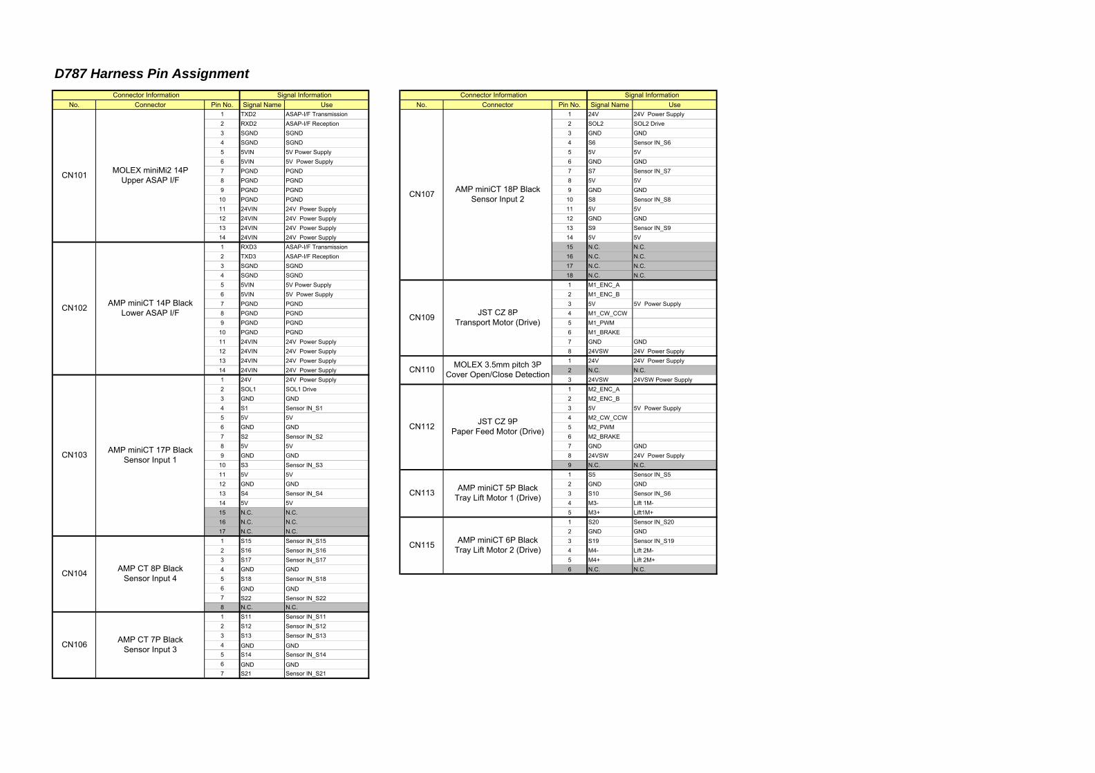
D787 Harness Pin Assignment
No. Connector Pin No. Signal Name Use No. Connector Pin No. Signal Name Use1 TXD2 ASAP-I/F Transmission 1 24V 24V Power Supply2 RXD2 ASAP-I/F Reception 2 SOL2 SOL2 Drive3 SGND SGND 3 GND GND4 SGND SGND 4 S6 Sensor IN_S65 5VIN 5V Power Supply 5 5V 5V6 5VIN 5V Power Supply 6 GND GND7 PGND PGND 7 S7 Sensor IN_S78 PGND PGND 8 5V 5V9 PGND PGND 9 GND GND10 PGND PGND 10 S8 Sensor IN_S811 24VIN 24V Power Supply 11 5V 5V12 24VIN 24V Power Supply 12 GND GND13 24VIN 24V Power Supply 13 S9 Sensor IN_S914 24VIN 24V Power Supply 14 5V 5V1 RXD3 ASAP-I/F Transmission 15 N.C. N.C.2 TXD3 ASAP-I/F Reception 16 N.C. N.C.3 SGND SGND 17 N.C. N.C.4 SGND SGND 18 N.C. N.C.5 5VIN 5V Power Supply 1 M1_ENC_A6 5VIN 5V Power Supply 2 M1_ENC_B7 PGND PGND 3 5V 5V Power Supply8 PGND PGND 4 M1_CW_CCW9 PGND PGND 5 M1_PWM10 PGND PGND 6 M1_BRAKE11 24VIN 24V Power Supply 7 GND GND12 24VIN 24V Power Supply 8 24VSW 24V Power Supply13 24VIN 24V Power Supply 1 24V 24V Power Supply14 24VIN 24V Power Supply 2 N.C. N.C.1 24V 24V Power Supply 3 24VSW 24VSW Power Supply2 SOL1 SOL1 Drive 1 M2_ENC_A3 GND GND 2 M2_ENC_B4 S1 Sensor IN_S1 3 5V 5V Power Supply5 5V 5V 4 M2_CW_CCW6 GND GND 5 M2_PWM7 S2 Sensor IN_S2 6 M2_BRAKE8 5V 5V 7 GND GND9 GND GND 8 24VSW 24V Power Supply10 S3 Sensor IN_S3 9 N.C. N.C.11 5V 5V 1 S5 Sensor IN_S512 GND GND 2 GND GND13 S4 Sensor IN_S4 3 S10 Sensor IN_S614 5V 5V 4 M3- Lift 1M-15 N.C. N.C. 5 M3+ Lift1M+16 N.C. N.C. 1 S20 Sensor IN_S2017 N.C. N.C. 2 GND GND1 S15 Sensor IN_S15 3 S19 Sensor IN_S192 S16 Sensor IN_S16 4 M4- Lift 2M-3 S17 Sensor IN_S17 5 M4+ Lift 2M+4 GND GND 6 N.C. N.C.5 S18 Sensor IN_S186 GND GND7 S22 Sensor IN_S228 N.C. N.C.1 S11 Sensor IN_S112 S12 Sensor IN_S123 S13 Sensor IN_S134 GND GND5 S14 Sensor IN_S146 GND GND7 S21 Sensor IN_S21
JST CZ 9PPaper Feed Motor (Drive)
AMP miniCT 5P BlackTray Lift Motor 1 (Drive)
AMP miniCT 6P BlackTray Lift Motor 2 (Drive)
CN107
CN109
CN110
CN112
CN113
CN115
Connector Information Signal Information
MOLEX miniMi2 14PUpper ASAP I/F
AMP miniCT 14P BlackLower ASAP I/F
AMP miniCT 18P BlackSensor Input 2
JST CZ 8PTransport Motor (Drive)
MOLEX 3.5mm pitch 3PCover Open/Close Detection
CN101
Connector Information Signal Information
CN102
CN103
CN104
CN106
AMP miniCT 17P BlackSensor Input 1
AMP CT 8P BlackSensor Input 4
AMP CT 7P BlackSensor Input 3
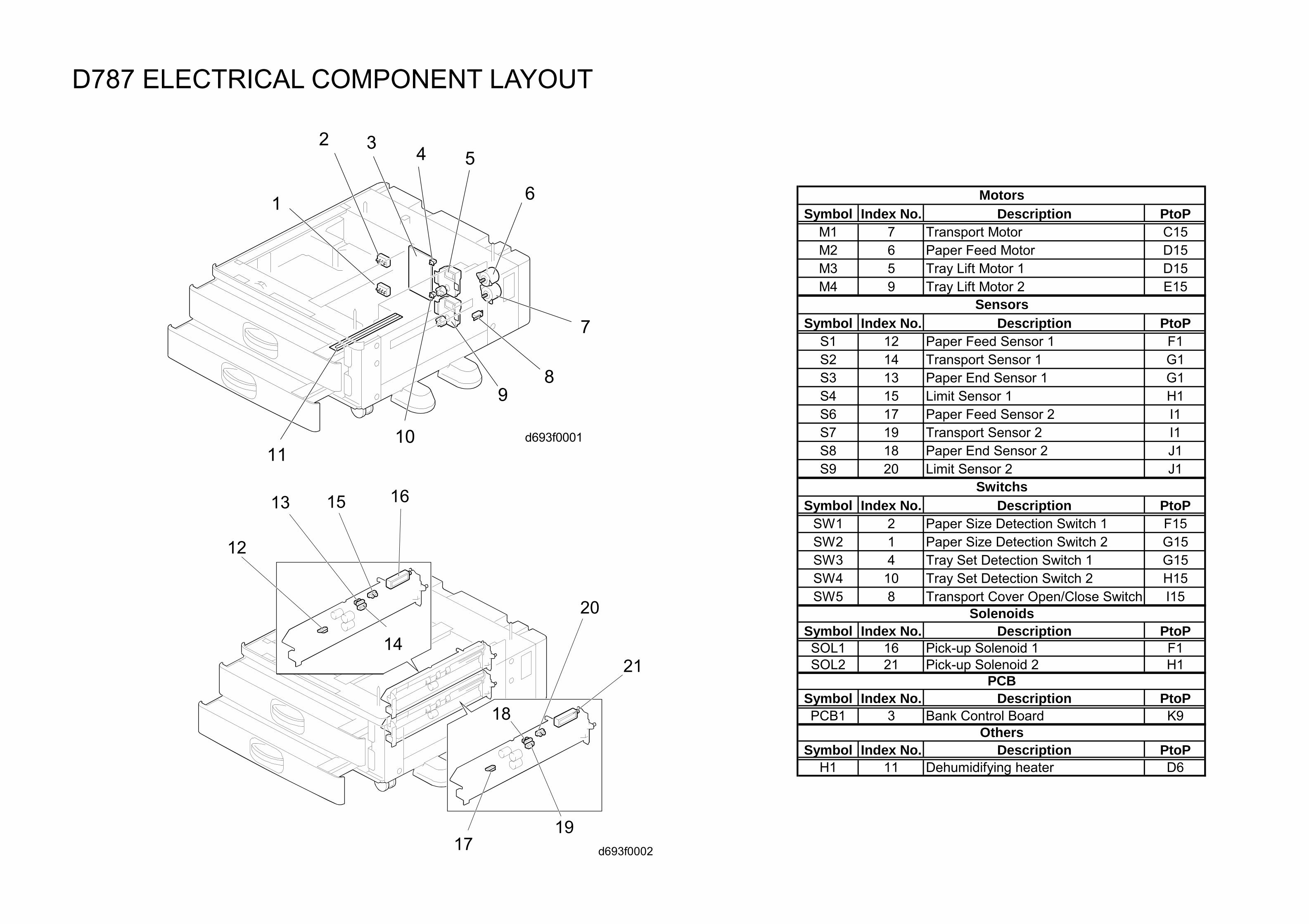
D787 ELECTRICAL COMPONENT LAYOUT
Symbol Index No. Description PtoPM1 7 Transport Motor C15M2 6 Paper Feed Motor D15M3 5 Tray Lift Motor 1 D15M4 9 Tray Lift Motor 2 E15
Symbol Index No. Description PtoPS1 12 Paper Feed Sensor 1 F1S2 14 Transport Sensor 1 G1S3 13 Paper End Sensor 1 G1S4 15 Limit Sensor 1 H1S6 17 Paper Feed Sensor 2 I1S7 19 Transport Sensor 2 I1S8 18 Paper End Sensor 2 J1S9 20 Limit Sensor 2 J1
Symbol Index No. Description PtoPSW1 2 Paper Size Detection Switch 1 F15SW2 1 Paper Size Detection Switch 2 G15SW3 4 Tray Set Detection Switch 1 G15SW4 10 Tray Set Detection Switch 2 H15SW5 8 Transport Cover Open/Close Switch I15
Symbol Index No. Description PtoPSOL1 16 Pick-up Solenoid 1 F1SOL2 21 Pick-up Solenoid 2 H1
Symbol Index No. Description PtoPPCB1 3 Bank Control Board K9
Symbol Index No. Description PtoPH1 11 Dehumidifying heater D6
Others
Motors
Sensors
Switchs
PCB
Solenoids
d693f0001
2
1
3 4 5
6
7
89
1011
d693f0002
12
13
14
15 16
17
18
20
21
19
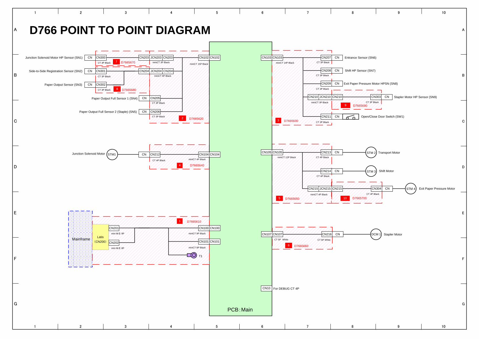
A
B
C
D
E
F
G
1 2 3 4 5 6 7 8 9 10
A
B
C
D
E
F
G
1 2 3 4 5 6 7 8 9 10
D7665650
D7665690
D7665680
D7665670
D7665640
D7665620
PCB:Main
D7665630
Mainframe
CT 3P Black
miniCT 14P Black
CN103 CN
CN209 CN
3
D7665610
miniCT 3P Black
miniCT 6P Black
CT 3P Black
CT 3P Black
miniCT 4P BlackCT 4P Black
miniCT 15P Black
For DEBUG CT 4P
CN
CN
CN
CN104CN104CN212CN
CN102CN102
Side-to-Side Registration Sensor (SN2)
CN205CN
CN206CN
4
CN10
1
T1
CN103
CN100
miniCT 3P Black
STM1 Junction Solenoid Motor
STM 3 Shift Motor
STM 4 Exit Paper Pressure Motor
STM 2 Transport Motor
D7665660
CT 5P White CT 6P White
CN107 CN216 DCM 1 Stapler MotorCN
Paper Output Full Sensor 1 (SN4)
Paper Output Full Sensor 2 (Staple) (SN5)
Paper Output Sensor (SN3)
CN203
CN204
JCN203
JCN204
CN300
CN301
CN302
Entrance Sensor (SN6)
CN Shift HP Sensor (SN7)
CN Stapler Motor HP Sensor (SN9)
Exit Paper Pressure Motor HPSN (SN8)
CN210 JCN210
CN
CN
CN
CN303
CT 4P BlackminiCT 12P Black
CN105
5
CN105 CN213
CT 4P Black
CN101
miniCT 9P Black
miniCT 8P Black
CN100
CN101
CN201
Latis
CN202
2
CN207
CN208
CT 3P Black
CT 3P Black
9
CN214
CN107
6
CT 3P Black
7
CT 3P Black
CT 3P Black
CT 3P Black
8
Junction Solenoid Motor HP Sensor (SN1)
CN211 CN Open/Close Door Switch (SW1)
CT 2P Black
D7665700
JCN215 CN304
10
CT 4P Black
(CN200)
mini MiⅡ 9P
mini MiⅡ 8P
miniCT 4P Black
CN215
CN203
CN204
CN210
CN215
D766 POINT TO POINT DIAGRAM
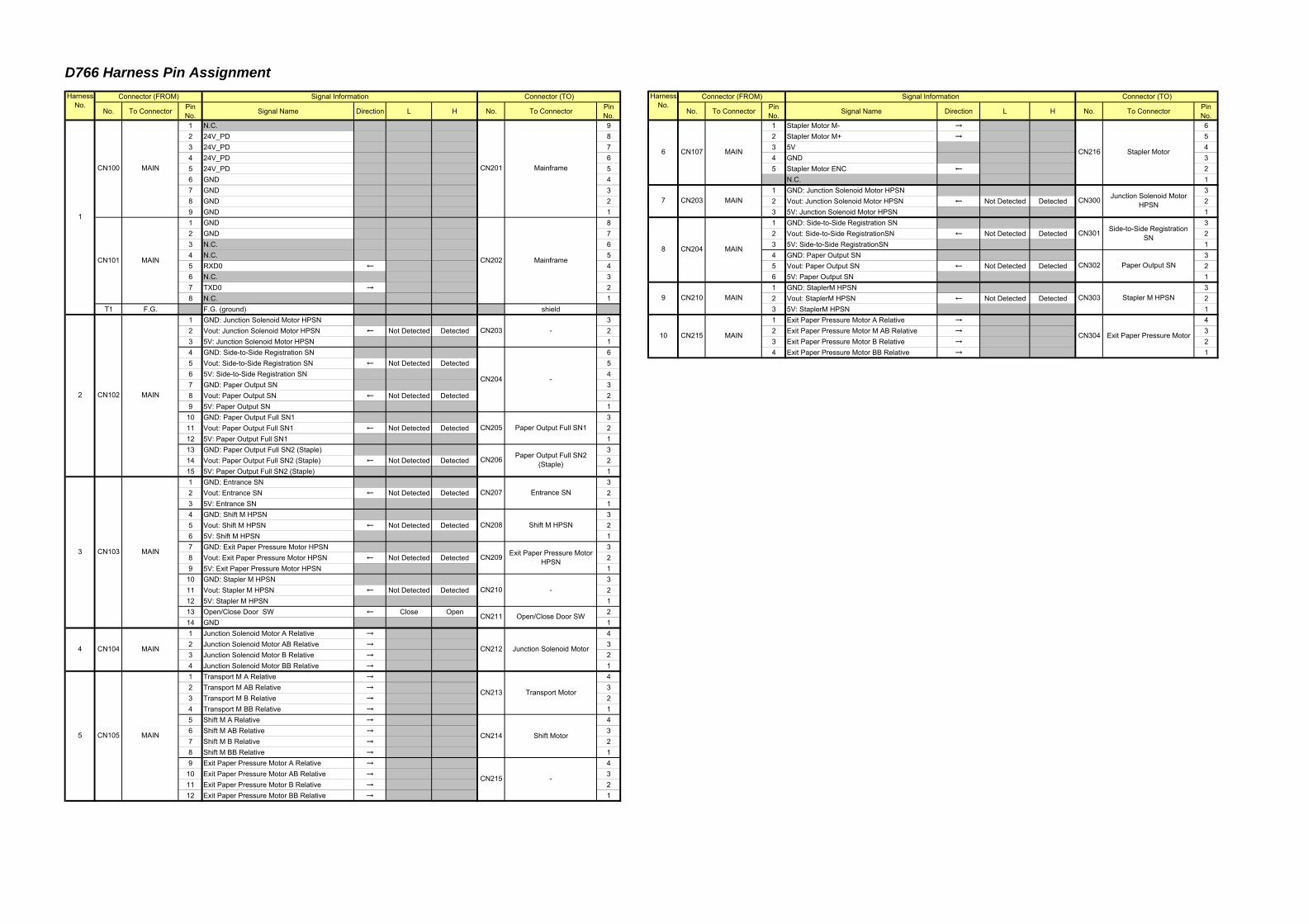
D766 Harness Pin Assignment
No. To Connector PinNo. Signal Name Direction L H No. To Connector Pin
No. No. To Connector PinNo. Signal Name Direction L H No. To Connector Pin
No.1 N.C. 9 1 Stapler Motor M- → 62 24V_PD 8 2 Stapler Motor M+ → 53 24V_PD 7 3 5V 44 24V_PD 6 4 GND 35 24V_PD 5 5 Stapler Motor ENC ← 26 GND 4 N.C. 17 GND 3 1 GND: Junction Solenoid Motor HPSN 38 GND 2 2 Vout: Junction Solenoid Motor HPSN ← Not Detected Detected 29 GND 1 3 5V: Junction Solenoid Motor HPSN 11 GND 8 1 GND: Side-to-Side Registration SN 32 GND 7 2 Vout: Side-to-Side RegistrationSN ← Not Detected Detected 23 N.C. 6 3 5V: Side-to-Side RegistrationSN 14 N.C. 5 4 GND: Paper Output SN 35 RXD0 ← 4 5 Vout: Paper Output SN ← Not Detected Detected 26 N.C. 3 6 5V: Paper Output SN 17 TXD0 → 2 1 GND: StaplerM HPSN 38 N.C. 1 2 Vout: StaplerM HPSN ← Not Detected Detected 2
T1 F.G. F.G. (ground) shield 3 5V: StaplerM HPSN 11 GND: Junction Solenoid Motor HPSN 3 1 Exit Paper Pressure Motor A Relative → 42 Vout: Junction Solenoid Motor HPSN ← Not Detected Detected 2 2 Exit Paper Pressure Motor M AB Relative → 33 5V: Junction Solenoid Motor HPSN 1 3 Exit Paper Pressure Motor B Relative → 24 GND: Side-to-Side Registration SN 6 4 Exit Paper Pressure Motor BB Relative → 15 Vout: Side-to-Side Registration SN ← Not Detected Detected 56 5V: Side-to-Side Registration SN 47 GND: Paper Output SN 38 Vout: Paper Output SN ← Not Detected Detected 29 5V: Paper Output SN 1
10 GND: Paper Output Full SN1 311 Vout: Paper Output Full SN1 ← Not Detected Detected 212 5V: Paper Output Full SN1 113 GND: Paper Output Full SN2 (Staple) 314 Vout: Paper Output Full SN2 (Staple) ← Not Detected Detected 215 5V: Paper Output Full SN2 (Staple) 11 GND: Entrance SN 32 Vout: Entrance SN ← Not Detected Detected 23 5V: Entrance SN 14 GND: Shift M HPSN 35 Vout: Shift M HPSN ← Not Detected Detected 26 5V: Shift M HPSN 17 GND: Exit Paper Pressure Motor HPSN 38 Vout: Exit Paper Pressure Motor HPSN ← Not Detected Detected 29 5V: Exit Paper Pressure Motor HPSN 1
10 GND: Stapler M HPSN 311 Vout: Stapler M HPSN ← Not Detected Detected 212 5V: Stapler M HPSN 113 Open/Close Door SW ← Close Open 214 GND 11 Junction Solenoid Motor A Relative → 42 Junction Solenoid Motor AB Relative → 33 Junction Solenoid Motor B Relative → 24 Junction Solenoid Motor BB Relative → 11 Transport M A Relative → 42 Transport M AB Relative → 33 Transport M B Relative → 24 Transport M BB Relative → 15 Shift M A Relative → 46 Shift M AB Relative → 37 Shift M B Relative → 28 Shift M BB Relative → 19 Exit Paper Pressure Motor A Relative → 4
10 Exit Paper Pressure Motor AB Relative → 311 Exit Paper Pressure Motor B Relative → 212 Exit Paper Pressure Motor BB Relative → 1
Junction Solenoid Motor
5 CN105 MAIN
4
-CN215
Connector (TO)HarnessNo.
Connector (FROM) Signal Information
2
CN104 MAIN
3
1
MAINCN102
Mainframe
Mainframe
CN201
CN202
-
CN205
CN206
CN100 MAIN
CN101 MAIN
CN203
CN204
Paper Output Full SN1
Paper Output Full SN2(Staple)
MAINCN103
CN207
CN208
CN209
CN210
CN211
Entrance SN
CN212
CN213
CN214 Shift Motor
Transport Motor
-
Open/Close Door SW
Exit Paper Pressure MotorHPSN
Shift M HPSN
6
7
8
9
-
CN107 MAIN CN216 Stapler Motor
CN203 MAIN CN300 Junction Solenoid MotorHPSN
MAIN CN303 Stapler M HPSN
CN204 MAIN
CN301 Side-to-Side RegistrationSN
CN302 Paper Output SN
CN304 Exit Paper Pressure Motor
HarnessNo.
Connector (FROM) Signal Information Connector (TO)
10 CN215 MAIN
CN210
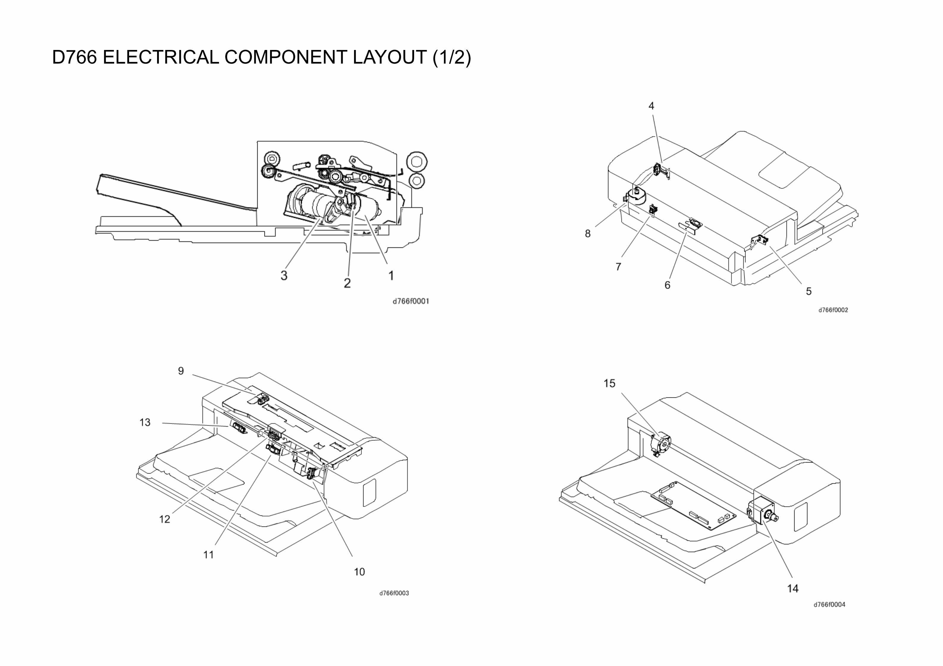
D766 ELECTRICAL COMPONENT LAYOUT (1/2)
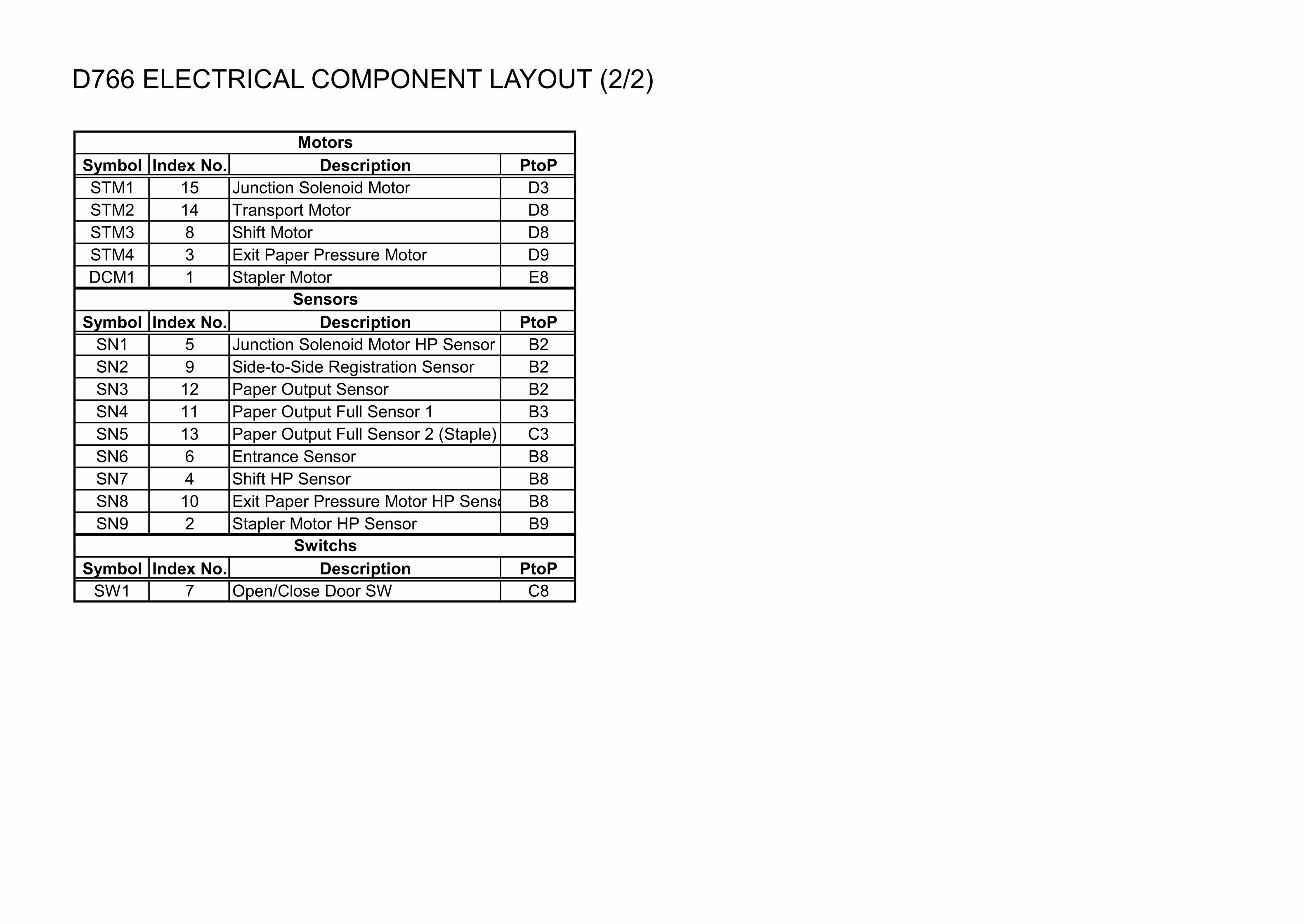
D766 ELECTRICAL COMPONENT LAYOUT (2/2)
Symbol Index No. Description PtoPSTM1 15 Junction Solenoid Motor D3STM2 14 Transport Motor D8STM3 8 Shift Motor D8STM4 3 Exit Paper Pressure Motor D9DCM1 1 Stapler Motor E8
Symbol Index No. Description PtoPSN1 5 Junction Solenoid Motor HP Sensor B2SN2 9 Side-to-Side Registration Sensor B2SN3 12 Paper Output Sensor B2SN4 11 Paper Output Full Sensor 1 B3SN5 13 Paper Output Full Sensor 2 (Staple) C3SN6 6 Entrance Sensor B8SN7 4 Shift HP Sensor B8SN8 10 Exit Paper Pressure Motor HP Sensor B8SN9 2 Stapler Motor HP Sensor B9
Symbol Index No. Description PtoPSW1 7 Open/Close Door SW C8
Motors
Sensors
Switchs