Embed Size (px)
Citation preview
Polyester Composites ReinforcedwithNoncrimp StitchedCarbon Fabrics:Mechanical Characterization of Compositesand Investigation on the Interaction between Polyesterand Carbon Fiber
Volkan Cecen,1 Mehmet Sarikanat,2 Yoldas Seki,3 Tugrul Govsa,4 Hasan Yildiz,2
Ismail H. Tavman1
1Department of Mechanical Engineering, Dokuz Eylul University, 35100 Bornova, Izmir, Turkey2Department of Mechanical Engineering, Ege University, 35100 Bornova, Izmir, Turkey3Department of Chemistry, Dokuz Eylul University, 35160 Buca, _Izmir, Turkey4Govsa Composites Ltd., 35060 Pinarbasi, Izmir, Turkey
Received 12 February 2006; accepted 19 June 2006DOI 10.1002/app.24983Published online in Wiley InterScience (www.interscience.wiley.com).
ABSTRACT: The primary purpose of the study is to in-vestigate the anisotropic behavior of different noncrimpstitched fabric (NCF) reinforced polyester composites. Car-bon fiber composite laminates were manufactured by vac-uum infusion of polyester resin into two commonly usedadvanced noncrimp stitched carbon fabric types, unidirec-tional and biaxial carbon fabric. The effects of geometric var-iables on composite structural integrity and strength wereillustrated. Hence, tensile and three-point bending flexuraltests were conducted up to failure on specimens strength-ened with different layouts of fibrous plies in NCF. In thisarticle an important practical problem in fibrous composites,interlaminar shear strength as measured in short beam sheartests, is discussed. The fabric composites were tested in three
directions: at 08, 458, and 908. Extensive photomicrographsof multilayered composites resulting from a variety of uni-axial loading conditions were presented. It was observedthat broken fibers recede within the matrix in compositeswith weak interfacial bond. Another aim of the present workwas to investigate the interaction between carbon fiber andpolyester matrix. The experiments, in conjunction with scan-ning electron photomicrographs of fractured surfaces ofcomposites, were interpreted in an attempt to explain theinstability of polyester-resin–carbon-fiber interfaces. � 2006Wiley Periodicals, Inc. J Appl Polym Sci 102: 4554–4564, 2006
Key words: carbon fiber; anisotropy; scanning electronmicroscopy; vacuum-assisted resin transfer molding
INTRODUCTION
Carbon-fiber-reinforced epoxy resins are widely usedin the aerospace applications and defense industriesbecause of the superior combination of stiffness,strength, and fatigue resistance that these materialsoffer, whereas polyester resins that command thegreatest attention in the field of glass reinforcementcomprise a major part of the reinforced plastics mar-ket today. The combination of carbon fibers and poly-ester matrix is becoming more important as the cost ofcarbon fibers is decreasing, and because of the devel-opment of new composites manufacturing technolo-gies.1 The vacuum-assisted resin transfer molding(VARTM) process allows a greater degree of automa-tion than does hand lay-up, provides an improvedwork environment (fewer volatile emissions), im-proves product quality, and is more cost-effective.
The VARTM or the patented SCRIMP (Seemann com-posite resin infusion molding process)2,3 processeshave been developed as alternative low cost methodsfor the manufacture of composite structures. The resininfusion processes lend themselves to the use of nearnet shape textile preforms manufactured through avariety of automated textile processes such as knittingand braiding.4 The challenge facing the resin infusiontechniques is to design a robust process that will con-sistently ensure complete infiltration and cure of ageometrically complex shape preform with the highfiber volume fraction needed for structural applica-tions. One major disadvantage of the resin infusionprocesses is that they require long duration and hightemperature cure cycles to cure the resin-saturatedperforms fully.
Relatively little research has been reported on themechanical performance of carbon fiber/unsaturatedpolyester composites despite its importance in manydynamically loaded structures.5,6 Although the num-ber of combinations of carbon fabrics and unsatu-rated polyester resin are popular among designers,relatively small amount of data is available.
Correspondence to: M. Sarikanat ([email protected]).
Journal of Applied Polymer Science, Vol. 102, 4554–4564 (2006)VVC 2006 Wiley Periodicals, Inc.
The textile industry has developed the ability toproduce net-shape/near-net-shape fabrics using highlyautomated techniques such as stitching, weaving,braiding, and knitting. Multiaxial multiply fabrics(MMF), also called ‘‘noncrimp fabrics’’ (NCF) are apromising class of composite preforms that consists ofunidirectional (UD) plies arranged in a number of pos-sible orientations relative to the fabric warp direction;the individual plies are stitched together by warp knit-ting process by stitching yarns piercing through the fi-brous plies.
During NCF-based composites manufacturing, pre-forms are laid up with desired stacking sequence onthe mold tool and infiltrated by a thermoset resin toform the composite. Compared with the time-con-suming and expensive UD tape layout, the MMFs areproduced in one step, and so the lay-up time is dras-tically reduced. The use of this preforms overcomesthe disadvantages of the wrinkling that is normallyexperienced with standard woven fabric and prepregtape. For this reason, the use of composites reinforcedwith NCF is growing rapidly in complex structuralcomponents.
All of the variables that affect the performance ofcomposite structures have been the subject of numer-ous investigations.7–14 The success of these studies isindicated by the constantly increasing strength levelsobtained in reinforced plastic systems.
The relationship between the mechanical propertiesand the process in which the MMF and composite aremanufactured has received considerable attention inrecent years. Many of these studies, both theoreticaland experimental, the individual properties of multi-axial multilayer warp knit (noncrimp) fabric reinforcedpolymer composites, and some of the predictive mod-els available for determining them have been exten-sively reviewed elsewhere15 and will be discussed fur-ther only where directly applicable to this study.
The effect of through-the-thickness stitching on thein-plane mechanical properties of fiber-reinforcedpolymer composites has been studied from manyviewpoints using both empirical and theoretical meth-ods. In spite of the difficulties of correlation and thedifferences of test conditions between the classicalmodels and reinforced composites, many of the con-trolling parameters should be common to both sys-
tems. Mouritz et al.16 gave an excellent review of thestitching problems encountered in the fiber-reinforcedpolymer (FRP) composites.
Recent articles by Drapier and Wisnom8,9 attemptedto investigate and model the behavior of MMF com-posites subjected to compression and shear loading.
It is unfortunate that very few significant workefforts are based upon experiments carried out withdamage development in MMF composites.12,17 Biboet al.18 have shown how crimp in the tows has a pro-nounced effect on the mechanisms of failure in theNCFs, but with subtle differences driving failure intension and compression.
The work of Truong et al.,19 where the mechanicalproperties of the composites were measured in a num-ber of orientations relative to the stitching directionfor different NCF-based laminates, had shown thatthe stitching has limitations on stiffness of MMCF. Onthe other hand, when the damage development isinvestigated by C-scan and X-ray imaging, the relationbetween stitching and damage (as a result of crack ini-tiating resin rich pockets created by stitching) patternsis observed.
The major goal of the research described in this arti-cle has been to study the anisotropy of the carbonnoncrimp fabric reinforced polyester composites. Thestudy of anisotropy was carried out to investigate theeffects of geometric variables, such as directions offiber orientation, on structural integrity and strengthof the quasi-isotropic (QI) laminate built from biaxialcarbon NCF blankets and UD carbon fabric laminates.Hence, tensile, three-point bending and short beamshear tests were conducted at different off-axial angles(08, 458, and 908) with respect to the longitudinaldirection. Another aim of this study was to identify
TABLE ISpecifications of Multiaxial Multiply Carbon Fabrics
PreformID Description
Fibrous layers Stitching
Arealdensity(g/m2) Fiber
Fibercountin tow
Orientation(8) Stitch
Lineardensity(tex)
Knitpattern
Gauge(needles/in.)
UDCF Unidirectional carbon fabric 200 Toray T700 50E 12K 0 PES 5 Tricot 5BACF Biaxial carbon fabric 400 Toray T700 50E 12K þ45; �45 PES 5 Tricot/chain 5
TABLE IICompositions of Noncrimp Stitched Fabric Composites
Composite Layup
Numberof fabriclayers
Laminatethickness(mm)
Unidirectionalcarbon fabric [0]12 12 5.78 6 0.02
Quasi-isotropiccarbon fabric [45/�45/90/0]6 12 6.10 6 0.03
POLYESTER COMPOSITES REINFORCED WITH CARBON FABRICS 4555
the dependence of fracture surface on this off-axialvariation. In addition to the extensive efforts in eluci-dating the variation in the mechanical properties ofUD and quasi-isotropic laminate, the work presentedhere focuses, also, on the type of interactions that areestablished between polyester and carbon fiber. Scan-ning electron microscope (SEM) was also helpful andadditionally used to describe the morphological fea-tures of fractured surfaces of carbon–polyester com-posites.
EXPERIMENTAL
Materials and sample preparation
Unidirectional (UD) and biaxial (BA) carbon fabricprovided by Metyx Telateks Tekstil Urunleri San. veTic. A.S. (Turkey) using a Liba multiaxial warp-knit-ting machine was used for experimental characteriza-tion. The carbon fabric parameters, as specified by themanufacturer, are shown in Table I. In the quasi-iso-
tropic carbon fabric laminates, the fabric layers wereseparated, giving twelve layers, the first layer being(0/90) orientated (BA fabric turned by 458), the second(þ45/�45), the third (0/90), and the fourth layerbeing (þ45/�45) orientated. This sequence is repeatedthree more times to make up the twelve layers. Thecompositions of these materials, which in this articlewill be referred to as the noncrimp stitched fabriccomposites, are given in Table II.
Polipol polyester 383-T resin system was used asresin in the composite. The resin (specific gravity,1.11; viscosity brookfield, 950), which is isophthalicacid type resin, was mixed before VARTM with thecatalyst cobalt octoate (0.35 pph, of a 41% solution inwhite spirit), the retarder 2.4-pentanedione (0.10 pph),and methylethylketone peroxide (2.2 pph, of a 40%dimethyl phthalate solution).
The VARTM equipment and a hot press at theGOVSA Composites Ltd. were used to manufacturecomposite plates. Two types of composite plates hav-ing different fiber volume fractions, shown in Table III
TABLE IIIMechanical Properties of Carbon Fiber/Polyester Composites in Different Directionsa
Testdirection
Fiber volumefractionVf (%)
Tensilemodulus(GPa)
Tensilestrength(MPa)
Elongationat break
(%)
Flexuremodulus(GPa)
Flexurestrength(MPa)
ILSS(MPa)
Unidirectional carbon fabricMachine 71.345 6 2.6 641.07 6 14.1 0.866 6 0.04 50.445 6 1.3 542.27 6 12.8 21.545 6 0.73Bias 23.1 6 1.1 6.7401 6 0.4 23.480 6 0.8 0.387 6 0.03 6.6410 6 0.4 57.530 6 1.5 4.3530 6 0.24Cross 4.5440 6 0.3 9.8980 6 0.5 0.203 6 0.03 4.3770 6 0.3 22.068 6 0.76 2.1940 6 0.1
Quasi-isotropic carbon fabricMachine 35.248 6 1.1 353.17 6 11.5 1.293 6 0.06 21.674 6 0.7 200.68 6 10.5 5.2290 6 0.34Bias 44.5 6 1.8 38.324 6 1.2 386.63 6 13.1 1.039 6 0.04 21.682 6 0.7 172.85 6 8.76 8.4630 6 0.52Cross 39.615 6 1.1 391.12 6 13.6 1.032 6 0.03 22.306 6 0.7 211.76 6 10.8 7.4230 6 0.45
a The data quoted are all average results taken from a minimum of six tests.
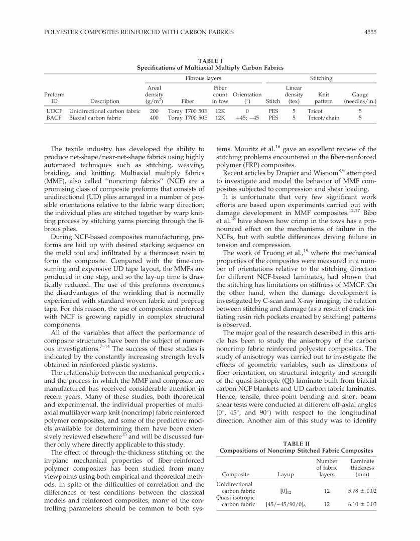
Figure 1 Location of test pieces cut from the laminates used for mechanical testing and directions of measurements.
4556 CECEN ET AL.
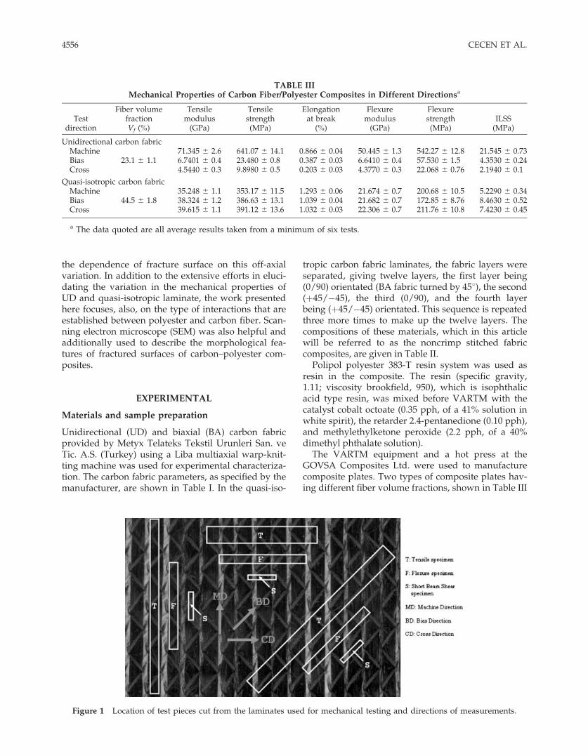
(the data obtained by a resin burn-off method arethe reported mean values from the manufacturer),were used for the test specimens. The testing speci-mens were cut as illustrated in Figure 1. The finaldimensions of each test specimen are identified as inFigure 2.
Figure 1 illustrates the test directions performed onthe specimens where machine direction (MD) is theflow direction of fabric in the machine during produc-
tion, while bias (BD) and cross direction (CD) are 458and 908 relative to MD, respectively.
Tensile strength testing
The tensile experiments were conducted by longitudi-nal (08), transverse (908), and balanced crossply (458)tension (ASTM D 3039) on a Shimadzu AUTOGRAPHAG-G Series universal testing machine with a videoextensometer system (SHIMADZU noncontact video
Figure 2 Schematic diagrams of the testing geometries: (a) longitudinal, (b) off-axis, and (c) transverse tension; (d) flex-ure; (e) short beam shear.
POLYESTER COMPOSITES REINFORCED WITH CARBON FABRICS 4557
extensometer DVE-101/201), with Trapezium (ad-vanced software for materials testing) for machinecontrol and data acquisition. Four rectangular tabs tobe used with the tensile specimens were producedfrom carbon fiber reinforced epoxy with the lay-up[0/90]s and were bonded to the griping length of eachtest specimen using a cold hardening epoxy resin.Tensile tests were performed at a constant cross-headspeed of 2 mm/min at room temperature under air.Six tests were made for each material per orientation.
Flexure test
One of the most common experiments to characterizematerials in flexural conditions is the three-pointbending test. Specimens were machined from flat pan-els with a high-speed diamond saw with a 50/50 mixof water and ethylene glycol coolant. This machiningoperation resulted in constant width specimens hav-ing very smooth cuts. The gauge lengths for the three-point bend test were determined according to ASTMD 790 standard, and were set to 100 mm for all of thecomposite specimens. Flexural strength is derivedfrom the simple beam theory as follows:
sf ¼ 3PL
2wt2(1)
where sf denotes the flexural strength, P the appliedload that leads the specimen to rupture, L the supportspan, w the specimen width, and t specimen thick-ness.
For the case where the three-point flexure specimenis not strain-gauged, flexural modulus may be deter-mined from the slope of the initial straight-line part ofthe load–deflection curve by means of this equation:
Ef ¼ L3
4wt3DPDd
(2)
where DP/Dd represents the slope of the force–dis-placement curve, and Ef the flexural modulus.
Short beam shear test
To determine the interlaminar shear strength of thecomposites, short beam shear tests were performedfollowing ASTM 2344 ‘‘Apparent interlaminar shearstrength of parallel fiber composites by short-beammethod.’’ A sliding roller three-point bending fixture,which included a loading pin (diameter, 6.4 mm) andtwo support pins (diameter, 3.2 mm), was used for theroom temperature short beam shear tests. The test fix-ture was mounted in a 5-kN capacity, screw-drivenload frame. The apparent interlaminar shear strengthof composites was determined from samples that
were tested with a support span/sample thicknessratio of 5 : 1. The simply supported specimens allowlateral motion and a line load is applied at the midspan of the specimens. The apparent shear strengthwas then calculated as follows:
V ¼ 0:75Pmax
wt
� �(3)
where V is the apparent shear strength, Pmax is thefailure load, and w and t are the width and thicknessof the specimen respectively. Further details of the testprocedures are given in the ASTM 2344.
Scanning electron microscopy observation
The fracture surfaces of tensile-tested specimens wereexamined using the SEM (JEOL JSM 6060) at excita-tion voltage equal to 20 keV in the secondary electronmode. To reduce the extent of sample arcing, the sam-ples were coated with a thin layer of metallic gold in
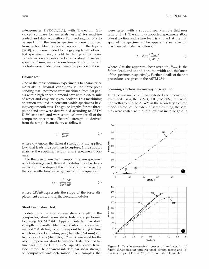
Figure 3 Tensile stress–strain curves of laminates in dif-ferent directions: (a) unidirectional carbon fabric and (b)quasi-isotropic þ45/�45/90/08 carbon fabric laminate.
4558 CECEN ET AL.
an automatic sputter coater (Polaran SC7620) prior toexamination by SEM.
RESULTS AND DISCUSSION
Experimental results and discussions on themechanical properties
Tensile properties
Comparisons of the values of tensile strength deter-mined experimentally with the tensile specimen cut atdifferent angles from the same UD glass/polyesterlaminate are shown in Table III. These results for a[0]12 UD carbon/polyester composite, given in Figure3(a), show that the strength falls rapidly when thefiber orientation is not parallel to tensile loading direc-
tion. The variation in stiffness in a highly anisotropicUD carbon fabric/polyester and the decrease in stiff-ness over that of the laminate, even at right angles tothe lay of the fibers, are shown in Table III.
Laboratory tests have long established that the lami-nate ply stacking sequence and the ply fiber orienta-tions greatly influence the onset and growth of freeedge delamination.20,21 Under tensile loading, the de-lamination in most laminates, especially those con-taining 908 plies, is preceded by a number of trans-verse cracks.22 The stacking sequence of [08]12, wherethere is no an abrupt change in the various laminatingplies, produces an interlaminar normal stress at thefree edge under applied uniaxial tension. Because ofthe absence of transverse cracks in the [08]12 specimenof carbon/polyester under tension in MD, a delamina-
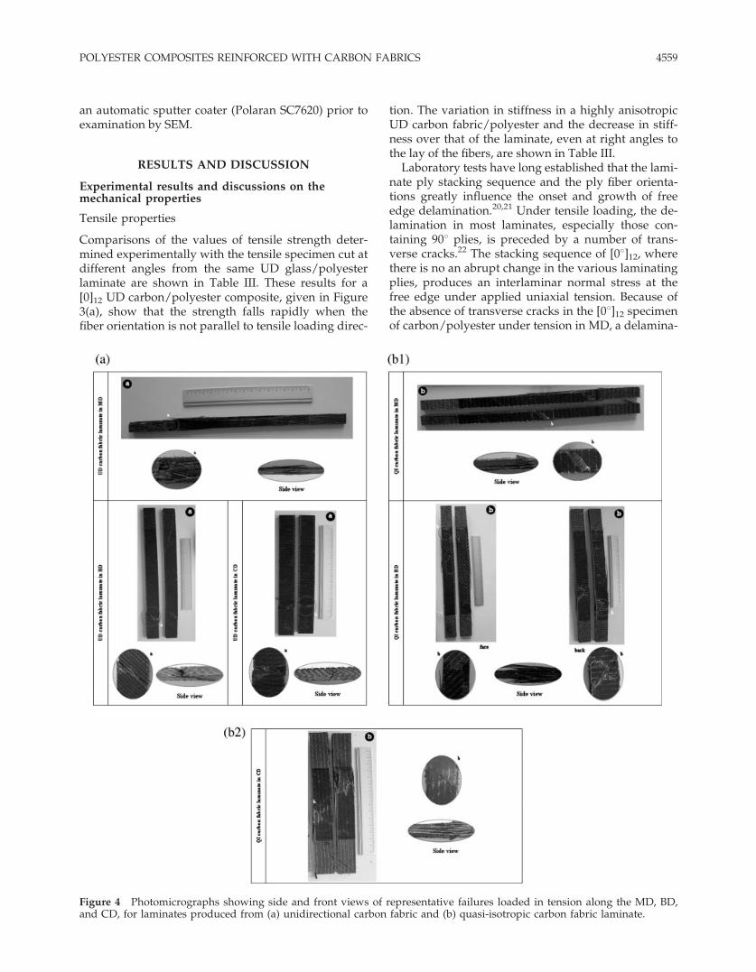
Figure 4 Photomicrographs showing side and front views of representative failures loaded in tension along the MD, BD,and CD, for laminates produced from (a) unidirectional carbon fabric and (b) quasi-isotropic carbon fabric laminate.
POLYESTER COMPOSITES REINFORCED WITH CARBON FABRICS 4559
tion crack cannot propagate in the interface of thelaminating plies. Consequently, this specimen did notshow any evidence of delamination at an applied axialtension of 641.1 MPa. Figure 4(a) is the photomicro-graph of fractured tensile specimen with intermediatebond strength. This fracture surface of UD compositeis irregular and has some fiber pullout.
In the case of UD laminate of carbon/polyester sub-jected to transverse tensile loading, a number of longi-tudinal fractures of matrix and debonding of fiber–matrix interface were formed in the laminating plies[Fig. 4(a)]. Note that each of the fracture planes was,macroscopically speaking, parallel to the fibers andnormal to the applied tension. Each longitudinal frac-ture is formed and arrested at the 08/08 interfaceswherein a series of localized longitudinal cracks canbe developed as the applied load advances to higherlevels; and consequently, carbon–polyester laminatesubjected to transverse tension failed without exhibit-ing delamination.
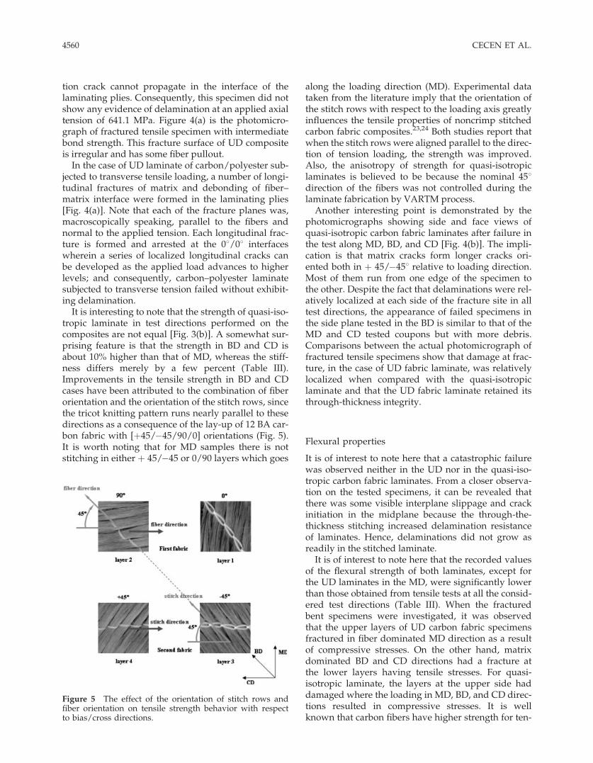
It is interesting to note that the strength of quasi-iso-tropic laminate in test directions performed on thecomposites are not equal [Fig. 3(b)]. A somewhat sur-prising feature is that the strength in BD and CD isabout 10% higher than that of MD, whereas the stiff-ness differs merely by a few percent (Table III).Improvements in the tensile strength in BD and CDcases have been attributed to the combination of fiberorientation and the orientation of the stitch rows, sincethe tricot knitting pattern runs nearly parallel to thesedirections as a consequence of the lay-up of 12 BA car-bon fabric with [þ45/�45/90/0] orientations (Fig. 5).It is worth noting that for MD samples there is notstitching in either þ 45/�45 or 0/90 layers which goes
along the loading direction (MD). Experimental datataken from the literature imply that the orientation ofthe stitch rows with respect to the loading axis greatlyinfluences the tensile properties of noncrimp stitchedcarbon fabric composites.23,24 Both studies report thatwhen the stitch rows were aligned parallel to the direc-tion of tension loading, the strength was improved.Also, the anisotropy of strength for quasi-isotropiclaminates is believed to be because the nominal 458direction of the fibers was not controlled during thelaminate fabrication by VARTM process.
Another interesting point is demonstrated by thephotomicrographs showing side and face views ofquasi-isotropic carbon fabric laminates after failure inthe test along MD, BD, and CD [Fig. 4(b)]. The impli-cation is that matrix cracks form longer cracks ori-ented both in þ 45/�458 relative to loading direction.Most of them run from one edge of the specimen tothe other. Despite the fact that delaminations were rel-atively localized at each side of the fracture site in alltest directions, the appearance of failed specimens inthe side plane tested in the BD is similar to that of theMD and CD tested coupons but with more debris.Comparisons between the actual photomicrograph offractured tensile specimens show that damage at frac-ture, in the case of UD fabric laminate, was relativelylocalized when compared with the quasi-isotropiclaminate and that the UD fabric laminate retained itsthrough-thickness integrity.
Flexural properties
It is of interest to note here that a catastrophic failurewas observed neither in the UD nor in the quasi-iso-tropic carbon fabric laminates. From a closer observa-tion on the tested specimens, it can be revealed thatthere was some visible interplane slippage and crackinitiation in the midplane because the through-the-thickness stitching increased delamination resistanceof laminates. Hence, delaminations did not grow asreadily in the stitched laminate.
It is of interest to note here that the recorded valuesof the flexural strength of both laminates, except forthe UD laminates in the MD, were significantly lowerthan those obtained from tensile tests at all the consid-ered test directions (Table III). When the fracturedbent specimens were investigated, it was observedthat the upper layers of UD carbon fabric specimensfractured in fiber dominated MD direction as a resultof compressive stresses. On the other hand, matrixdominated BD and CD directions had a fracture atthe lower layers having tensile stresses. For quasi-isotropic laminate, the layers at the upper side haddamaged where the loading in MD, BD, and CD direc-tions resulted in compressive stresses. It is wellknown that carbon fibers have higher strength for ten-
Figure 5 The effect of the orientation of stitch rows andfiber orientation on tensile strength behavior with respectto bias/cross directions.
4560 CECEN ET AL.
sile loading than compressive while polyester shownbetter strength properties in compressive directionsthan tensile. The specimens under pure tensile loadhad higher strength than did the specimens subjectedto bending which showed compressive failure. Thespecimens tested for bending and failed in tensile sidehad higher strength than did the specimens tested inpure tension.
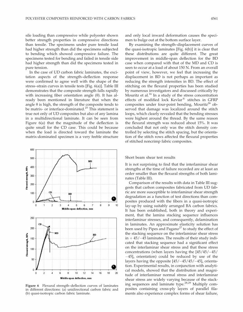
In the case of UD carbon fabric laminates, the exci-tation aspects of the strength–deflection responsewere confirmed to agree well with the shape of thestress–strain curves in tensile tests [Fig. 6(a)]. Table IIIdemonstrates that the composite strength falls rapidlywith increasing fiber orientation angle (y). It has al-ready been mentioned in literature that when theangle y is high, the strength of the composite tends tobe matrix- or interface-dominated.25 This statement istrue not only of UD composites but also of any laminain a multidirectional laminate. It can be seen fromFigure 6(a) that the magnitude of the deflection isquite small for the CD case. This could be becausewhen the load is directed toward the laminate thematrix-dominated specimen is a very feeble structure
and only local inward deformation causes the speci-men to bulge out at the bottom surface layer.
By examining the strength–displacement curves ofthe quasi-isotropic laminates [Fig. 6(b)] it is clear thatthese distributions are quite different. The greatimprovement in middle-span deflection for the BDcase when compared with that of the MD and CD isseen to occur at a load of about 150 N. From an overallpoint of view, however, we feel that increasing thedisplacement in BD is not perhaps as important asreducing the strength intensities in BD. The effect ofstitching on the flexural properties has been studiedby numerous investigators and discussed critically byMouritz et al.16 In a study of the stress concentrationeffects of modified lock Kevlar1 stitches in GFRPcomposites under four-point bending, Mouritz26 ob-served that damage was localized around the stitchloops, which clearly revealed that the bending stresseswere highest around the thread. By the same reasonthe flexural strength was reduced about 15%. It wasconcluded that not only was the stitch density con-trolled by selecting the stitch spacing, but the orienta-tion of the stitch rows affected the flexural propertiesof stitched noncrimp fabric composites.
Short beam shear test results
It is not surprising to find that the interlaminar shearstrengths at the time of failure recorded are at least anorder smaller than the flexural strengths of both lami-nates (Table III).
Comparison of the results with data in Table III sug-gests that carbon composites fabricated from UD fab-ric are more susceptible to interlaminar shear strengthdegradation as a function of test directions than com-posites produced with the fibers in a quasi-isotropiclay-up by using suitably arranged BA carbon fabrics.It has been established, both in theory and experi-ment, that the lamina stacking sequence influencesinterlaminar stresses, and consequently, delaminationin laminates. An approximate elasticity solution hasbeen used by Pipes and Pagano27 to study the effect ofthe stacking sequence on the interlaminar shear stressin þ 45/�45 laminates. The results of their study indi-cated that stacking sequence had a significant effecton the interlaminar shear stress and that these stressconcentrations (when layers having the [45/45/�45/�45]s orientation) could be reduced by use of thelayers having the opposite [45/�45/45/�45]s orienta-tion. Experimental results, in conjunction with analyti-cal models, showed that the distribution and magni-tude of interlaminar normal stress and interlaminarshear stress are widely varying because of the stack-ing sequences and laminate type.28,29 Multiply com-posites containing cross-ply layers of parallel fila-ments also experience complex forms of shear failure,
Figure 6 Flexural strength–deflection curves of laminatesin different directions: (a) unidirectional carbon fabric and(b) quasi-isotropic carbon fabric laminate.
POLYESTER COMPOSITES REINFORCED WITH CARBON FABRICS 4561
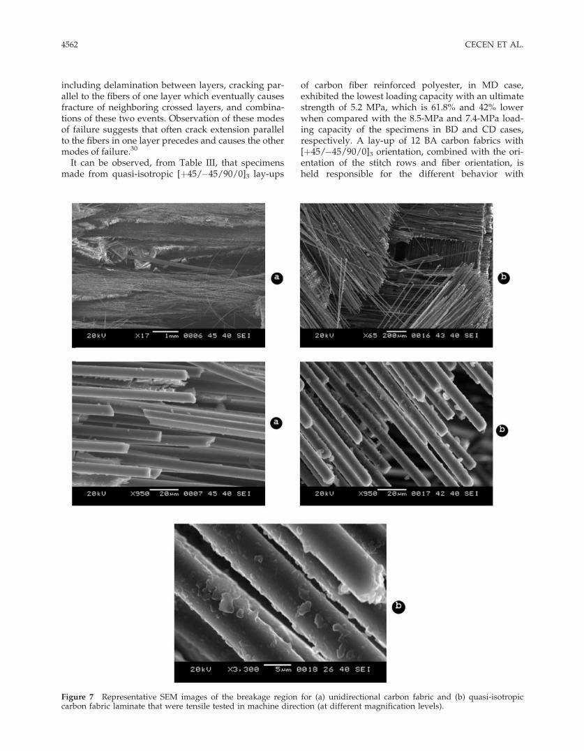
including delamination between layers, cracking par-allel to the fibers of one layer which eventually causesfracture of neighboring crossed layers, and combina-tions of these two events. Observation of these modesof failure suggests that often crack extension parallelto the fibers in one layer precedes and causes the othermodes of failure.30
It can be observed, from Table III, that specimensmade from quasi-isotropic [þ45/�45/90/0]3 lay-ups
of carbon fiber reinforced polyester, in MD case,exhibited the lowest loading capacity with an ultimatestrength of 5.2 MPa, which is 61.8% and 42% lowerwhen compared with the 8.5-MPa and 7.4-MPa load-ing capacity of the specimens in BD and CD cases,respectively. A lay-up of 12 BA carbon fabrics with[þ45/�45/90/0]3 orientation, combined with the ori-entation of the stitch rows and fiber orientation, isheld responsible for the different behavior with
Figure 7 Representative SEM images of the breakage region for (a) unidirectional carbon fabric and (b) quasi-isotropiccarbon fabric laminate that were tensile tested in machine direction (at different magnification levels).
4562 CECEN ET AL.
respect to the BD/CDs (Fig. 5). The effect of stitchingon interlaminar shear strength has been studied byDu et al.31 for a prepreg CFRP tape laminate, andimprovements in the shear strength due to stitchingwere recorded to be 14.4 or 25.6% depending on theorientation of the stitch rows.
Fractographic analysis
It is possible to observe clear local differences in therepresentative images of the breakage region for UDcarbon fabric specimens [Fig. 7(a)]. In the upper inseta general view is presented showing ductile deforma-tion of the matrix but a poor matrix–carbon fiber ad-hesion. In the lower photomicrograph, a higher mag-nification image clearly shows a clean fiber surface,although a small amount of polymer can be seenbetween fibers. These observations suggest an adhe-sive failure in the interface after fiber fracture.Although the UD carbon sample shows adhesive fail-ure [Fig. 7(a)], its relatively high tensile strength canbe explained taking into consideration a highly or-dered carbon structure along the fiber axis, whilechemical breakage takes place. Pullout effect of fiberswas observed from these images.
In Figure 7(b) the 11th and 12th reinforcementlayers are shown, which are (þ45/�45) and (0/90) ori-entated, respectively. Although none of the 458 towsare fully fractured, there is evidence of considerabledamage to one tow on the right hand side micro-graphs, corresponding to the side of the coupon thathad the visible surface damage. None of the 458and908 tows are fractured and there is little or no evidenceof individual fiber fracture. It should be noted that onthe micrographs the exposed reinforcements are not‘‘clean’’; there are flaky deposits on the reinforcementsurface, which are remnants of the resin that was notfully decomposed.
CONCLUSIONS
We would like to draw attention to the fact that someconclusions of this study are of general applicability,while some others refer to the special problem dis-cussed. So it has been pointed out that when the fiberorientation angle in UD composites is high, thestrength of the composite tends to be matrix- or inter-face-dominated. Having recognized the nature of thisproblem, it was noted that a continuous decrease instrength of multidirectional composites can beachieved by deviating the test angles y from 08. Thisbehavior is quite general. On the other hand, it hasbeen pointed out that for quasi-isotropic laminate theexperimental data do not allow for an adequatedescription of the quasi-isotropic model. Improve-ments in tensile strength in BD and CD cases arebelieved to be due to the fact that the combination of
fiber orientation and the stitch rows run nearly paral-lel to these directions as a consequence of the lay-upof BA carbon NCF blankets with [þ45/�45/90/0]orientations.
Perhaps the most significant result of this investiga-tion is the strong correlation between the changes ininterlaminar shear strength values and fiber orienta-tion angle, in the case of UD carbon fabric laminates.In addition, the lamina stacking sequence and lami-nate type have a significant effect on the recorded val-ues of the interlaminar shear strengths.
The interlaminar shear strengths at the time of fail-ure recorded were significantly lower than those ob-tained from three-point bending tests at all the con-sidered test direction.
Photomicrographs of fracture surfaces of multiaxialcomposites loaded in tension along the fiber directionexhibit pronounced irregularity and fiber pullout.
Composites broken in tension and observed underdifferent moderate magnification levels will showobvious differences between good bonding rarely andpoor bonding commonly at the interface. A chemicallynoncoupled composite showed uncoated clean fiberends pulled from the polymer. Even the highest mag-nification could not show the presence of a monolayerof polyester resin on fiber.
The authors thank Mr. Bulent Onay of the Department ofMetallurgical and Materials Engineering for providing elec-tron microscopy services, and Miss. Esra Dokumaci for hertechnical assistance with several of the SEM observations.
References
1. Gamstedt, E. K.; Skrifvarsb, M.; Jacobsenc, T. K.; Pyrzd, R.Compos A 2002, 33, 1239.
2. Seemann, W. H. U.S. Pat. 4,902,215 (1990).3. Seemann, W. H. U.S. Pat. 5,316,462 (1994).4. Dexter, H. B. In Proceedings of 28th International SAMPE
Technical Conference, Seattle, WA, 1996; p 404.5. Xu, M. X.; Liu, W. G.; Gao, Z. X.; Fang, L. P.; Yao, K. D. J Appl
Polym Sci 1996, 60, 1595.6. Yu, J. L.; Liu, Y. M.; Jang, B. Z. Polym Compos 1994, 15, 488.7. Wang, Y.; Li, J.; Do, B. P. J Compos Mater 1995, 29, 2317.8. Drapier, S.; Wisnom, R. M. Compos Sci Technol 1999, 59, 1287.9. Drapier, S.; Wisnom, R. M. Compos Sci Technol 1999, 59, 2351.10. Crookston, J. J.; Long, A. C.; Jones, I. A. Presented at The
ECCM-10, Brugge, Belgium, 2002.11. Roth, Y. C.; Himmel, N. In The ECCM-10, Brugge, Belgium,
2002; p 321.12. Sjogren, A.; Edgren, F.; Aps, L. E. Presented at The ECCM-11,
Rhodos, Greece, 2004.13. Mikael, J.; Peter, G. Compos Sci Technol 2000, 60, 2803.14. Huang, Y.; Young, R. J. Carbon 1995, 33, 97.15. Leong, K. H.; Ramakrishna, S.; Huang, Z. M.; Bibo, G. A. Com-
pos A 2000, 31, 197.16. Mouritz, A. P.; Leong, K.H.; Herszberg, I. ComposA 1997, 28, 979.17. Edgren, F.; Matsson, D.; Asp, L.; Varna, J. Compos Sci Technol
2004, 64, 675.18. Bibo, G. A.; Hogg, P. J.; Kemp, M. Compos Sci Technol 1997,
57, 1221.
POLYESTER COMPOSITES REINFORCED WITH CARBON FABRICS 4563
19. Truong, T. C.; Vettori, M.; Lomov, S.; Verpoest, I. Compos A2005, 36, 1.
20. Pagano, N. J.; Pipes, R. B. J Compos Mater 1971, 5, 50.21. Bjeletich, J. G.; Crossman, F. W.; Warren, W. J. In Failure
Modes in Composites-IV; Cornie, J. R.; Crossman, F. W., Eds.;American Institute of Mining, Metallurgical, and PetroleumEngineers: New York, 1979; p 118.
22. Kim, R. Y. In Interlaminar Response of Composite Materials;Pagano, N. J., Ed.; Elsevier: Amsterdam, 1989; p 111.
23. Harris, H.; Schinske, N.; Krueger, R.; Swanson, B. In Proceed-ings of the 36th International SAMPE Symposium, Sandiego,1991; p 521.
24. Herszberg, I.; Bannister, M. K. In Proceedings of the 5th Austra-lian Aeronautical Conference, Melbourne, Australia, 1993; p 213.
25. Jang, B. Z. Advanced Polymer Composites; ASM International:USA, 1994; p 120.
26. Mouritz, A. P. Compos A 1996, 27, 525.27. Pipes, R. B.; Pagano, N. J. J Appl Mech 1974, 41E, 668.28. Whitney, J. M.; Browning, C. E. J Compos Mater 1972, 6,
300.29. Whitney, J. M.; Kim, R. Y. Composite Materials: Testing and
Design (Fourth Conference), Lisbon, Portugal, 1977; p 229.30. Corten, H. T. In Fundamental Aspect of Fiber Reinforced Plas-
tic Composites; Schwartz, R. T.; Schwartz, H. S., Eds.; WileyInterscience: New York, 1968; p 89.
31. Du, X.; Xue, F.; Gu, Z. In Proceedings of the InternationalSymposium on Composite Materials and Structure, Beijing,China; 1986; p 912.
4564 CECEN ET AL.


