Embed Size (px)
Citation preview

US 20120015066A1
(19) United States (12) Patent Application Publication (10) Pub. No.: US 2012/0015066 A1
White (43) Pub. Date: Jan. 19, 2012
(54)
(75)
(73)
(21)
(22)
(62)
(60)
POLYMER MORTAR COMPOSITE PIPE MATERIAL AND MANUFACTURING METHOD
Inventor: David J. White, Ames, IA (US)
Assignee: Iowa State University Research Foundation, Inc.
Appl. No.: 13/200,298
Filed: Sep. 22, 2011
Related US. Application Data
Division of application No. 12/657,681, ?led on Jan. 26, 2010, noW Pat. No. 8,043,548, Which is a division of application No. 11/029,184, ?led on Jan. 4, 2005, noW abandoned.
Provisional application No. 60/534,440, ?led on Jan. 6, 2004.
Publication Classi?cation
(51) Int. Cl. B29C 47/20 (2006.01)
(52) us. c1. ................................................... .. 425/3761
(57) ABSTRACT
Composite material and plunger-cast pipe manufacturing method and system Wherein the composite material includes Waste, chemically unmodi?ed PET material, one or more Waste ?ller materials (eg rock crusher ?nes, lime sludge or Waste coal combustion by-products), and ?ber reinforcement (e.g. glass, metal, ceramic, carbon, organic, and polymer ?bers) and Wherein the PET material is melted and mixed in a container to disperse ?ller material and ?ber reinforcement in the PET material. The resulting mixture can be formed into a tubular pipe shape using the plunger-cast manufacturing method and system Wherein a plunger piston and inner col lapsible mold are pushed into the melted composite material contained in an outer mold. When cooled and solidi?ed in the mold, a composite material having a matrix comprising PET With ?ller material and ?ber reinforcement distributed in the matrix is formed in the shape of a tubular body.
T—I:
Patent Application Publication Jan. 19, 2012 Sheet 1 0f 14 US 2012/0015066 A1
Patent Application Publication Jan. 19, 2012 Sheet 2 0f 14 US 2012/0015066 A1

Patent Application Publication Jan. 19, 2012 Sheet 3 0f 14 US 2012/0015066 A1
22
22
22a
FIG. 3A
FIG. 3P FIG. 3B
14
.C Q... E F
FIG.3E

Patent Application Publication Jan. 19, 2012 Sheet 4 0f 14 US 2012/0015066 A1
FIG.4E
FIG.4C

Patent Application Publication Jan. 19, 2012 Sheet 5 0f 14 US 2012/0015066 A1

Patent Application Publication Jan. 19, 2012 Sheet 6 0f 14
2
US 2012/0015066 A1
22

Patent Application Publication Jan. 19, 2012 Sheet 7 0f 14 US 2012/0015066 A1
3
FIG.7 /30
‘I113
| l ,,%__24
14-\__
U?’
12 ....»//
12f 12f
1 1 i i 1 1

Patent Application Publication Jan. 19, 2012 Sheet 8 0f 14 US 2012/0015066 A1
“12
12f.

Patent Application Publication Jan. 19, 2012 Sheet 9 0f 14 US 2012/0015066 A1
F|G.9
A / // y
\y /

Patent Application Publication Jan. 19, 2012 Sheet 10 0f 14 US 2012/0015066 A1
FIG. 10 /30

Patent Application Publication
80
Applied Load per Unit Length (kNfm)
Applied Lead eel’ Unit Length (kNKm) Applied Lead per Unit Length (kNfm)
Jan. 19, 2012 Sheet 11 0f 14
-— AFAZ 50% Filler. 3% Fibers
0.030 0 | v v 1 .
0.000 0.005 0.010 0.015 0.020 0.025
Strain (AD/D) FIG. 1 1A
100 - o
4' r-‘sc: 50% Filler. 3% Fibers . , ‘1 FBC: 60% Filler. 3% Fibers
80 _ ~—- F561 07% Filler. 0% Fibem
6O -
40 -
2o -
0 . . . . . .
0.00 0.01 0.02 0.03 0.04 0.05 0.06
Strain(AD/D) FIG. 1 1B
00
0 L8: 50% Filler, 3% Fibers —-- L5: 50% Filler. 3.5% Fibers
,/ “‘ h *- -- “A — L5: 50% Filler. 4% Fibers
so ~ // ,‘ __ / I‘ \ ‘ _ ‘ ‘ w
/ .
/ //, 40 -
ll ’ , /
/ / 1' o l/ / 3 A
20 - ,' / / / /
’ / ’ /
I / /
O I l | v I i
0.00 0.01 0.02 0.03 0.04 0.05 0.05
Strain (AD/D) FIG. 11C
US 2012/0015066 A1

Patent Application Publication Jan. 19, 2012 Sheet 12 0f 14 US 2012/0015066 A1
60
Apllied Lnad per Unit Length (kNlm)
10 ~
— PFA: 50% Filer. 3% Fibers
0 I I .
0.00 0.01 0.02 0.03 0.04 0.05
Strain (AD/D) 1
50
E. -— RCF: 50% Filler, 3% Fibers \
g 40~ 5 U)
‘.3 _.| 30 -
‘E 3 \
‘3i ,0 2o -
(\‘l O -| U .Q "g 10 ~ <
0 . . . . . .
0.00 0.01 0.02 0.03 0.04 0.05 0.06 0.07
Strain (AD/D)
FIG. 1 1E 60
H
.25. so - £5 5 E‘ 40 - q) _J
‘E I‘) 30 ~ \ fl) 0.
1% 3 20 *
‘D .9 a 10 — ‘i — CFBBA: 50% Filler. 3% Fibers
0 . . . . .
0.000 0.002 0.004 0.000 0.000 0.010 0.012
Strain (AD/D)
FIG. 11F.

Patent Application Publication Jan. 19, 2012 Sheet 13 0f 14 US 2012/0015066 A1
100
— CFBFA‘. 50% Filler. 3% Fibers
80 ~
0 I I
0.000 0.005 0.010 0.015 0.020 0.025 0.030 0.035
Strain (AD/D)
FIG. 1 1 G
Appiied Load per Unit Length (RN/m)
— SFA: 50% Filler. 3% Fibers I 25 ~
20
Appiied Load per Unit Length (kN/m) :
0 | | 1
0.00 0.01 0.02 0.03 0.04
Strain (AD/D) FIG. 11H so
40 J
Applied Load per Unit Length (kNim) a0 - 20 -
10 ~
0 h .
0.000 0.005 0.010 0.015 0.020 0.025 0.030 0.035
Strain (AD/D)
FIG. 11I

US 2012/0015066 A1
P|ast1c:0% FiNer. 3% Fibers
Jan. 19, 2012 Sheet 14 0f 14
0.01
I m ‘
5 0 5
2 1 1
E05“ 593 E5 an 33 Big
Patent Application Publication
25
0
0.05 0.04 0.02 0.03
Strain (ADID)
0.00
FIG. 11J

US 2012/0015066 A1
POLYMER MORTAR COMPOSITE PIPE MATERIAL AND MANUFACTURING
METHOD
[0001] This application claims bene?ts and priority of pro visional application Ser. No. 60/534,440 ?led Jan. 6, 2004.
FIELD OF THE INVENTION
[0002] The present invention provides polymer mortar composite materials including recycled, post-consumer Waste polyethylene terephthalate (PET) With Waste ?ller materials and ?ber reinforcement and methods of their manu facture and methods of their use as pipe in the construction industry.
BACKGROUND OF THE INVENTION
[0003] Diverting solid Waste from land?lls is increasingly important due to limited availability of land?ll space, rapidly increasing land?ll cost, and environmental threats. The U8. is the largest global producer of PET containers at nearly 70 percent of the supply [reference 1]. In the U.S., estimates indicate that annual production of PET containers Will reach more than 2 million tons [reference 2]. The recycling rate for PET is about 25 percent [reference 3]. Production of the Waste ?ller materials is about 500 million tons for rock quarry crusher ?nes, 10 million tons of lime sludge, and 100 million tons for coal-combustion by-products. Recycling has emerged as the most practical method to deal With these high-volume Waste problems. [0004] In addition, the Us. has about 19,782 seWerage systems serving about 170 million people or about 75 percent of the population [reference 4]. As With much infrastructure in this country, this subterranean component has also deterio rated due to normal aging, sulfuric acid degradation, under design, poor initial design, and minimal maintenance. It is estimated that 800,000 miles of sanitary seWer line in the Us. are in need of rehabilitation and that We are currently making repairs at the rate of 2 percent per year [reference 5]. Sixteen thousand miles of rehabilitation With an estimated 8 thousand miles of neW construction create a need for improved pipe material.
[0005] An object of the invention is to provide a polymer mortar composite pipe material that has several bene?cial material properties over conventional Portland cement con crete (PCC) pipe and vitri?ed extra strength clay tile includ ing high structural capacity, excellent acid resistance; and loW density. Equally important is the fact that the material com ponents of the polymer mortar composite formulation consist of recycled plastic and Waste ?ller materials (rock quarry crusher ?nes, lime sludge or various coal combustion by products). By using recycled, post-consumer Waste polyeth ylene terephthalate (PET) instead of virgin plastic, Which is petroleum derived material; use of a signi?cant volume of crude oil can be reduced.
[0006] Another object of the invention is to provide a plunger-cast manufacturing method and system than can increase recycling through production of polymer mortar composite pipe using the composite material mixtures described herein.
Jan. 19, 2012
[0007] Still another bene?t of the invention derives from production of the polymer mortar pipe to provide a strong, lightWeight, and durable pipe product for Which there is cur rently tremendous need.
SUMMARY OF THE INVENTION
[0008] The present invention provides a compo site material and plunger-cast pipe manufacturing method and system Wherein the composite material comprises Waste, chemically unmodi?ed PET material, one or more Waste ?ller materials (eg rock crusher ?nes, lime sludge or Waste coal combustion by-products), and ?ber reinforcement (e. g. glass, metal, ceramic, carbon, organic, and polymer ?bers). The PET mate rial is melted and mixed With the other constituents in a container to disperse the Waste ?ller material and the rein forcement ?bers in the PET material. The resulting mixture can be formed into a tubular pipe shape using the plunger-cast manufacturing method and system pursuant to an embodi ment of the invention Wherein a piston and an inner collaps ible mold thereon are pushed into the melted composite mate rial contained in an outer mold. When cooled and solidi?ed in the mold, a composite material having a matrix comprising PET With ?ller material and ?ber reinforcement distributed in the matrix is formed in the shape of a tubular body. The plunger-cast pipe manufacturing method and system can be used With other materials as Well and is not limited to the composite material described above. [0009] In one embodiment of the invention, the solid Waste, chemically unmodi?ed PET material, Waste ?ller particles and ?ber reinforcement are premixed and placed in a melting container for melting of the PET material While the mixture is mixed or stirred. Alternately, the solid Waste, chemically unmodi?ed PET material can be melted in the container, and pre-heated Waste ?ller particles introduced to the melted PET material With the mixture stirred or mixed. Once the PET/ ?ller mixture is homogenized, the ?ber reinforcement is incrementally added to the mixture and stirred or mixed. The mixture of melted PET material, Waste ?ller particles and ?ber reinforcement can be molded, extruded or otherWise formed. [0010] The invention envisions use of Waste PET material from recycled beverage bottles and other sources. In practice of the invention, the recycled Waste PET material is not chemically modi?ed in any Way prior to melting. The solid recycled Waste PET material may be Washed in tap Water and shredded or otherWise comminuted prior to melting. [0011] The invention envisions use of different types of one or more Waste ?ller materials including rock quarry crusher ?nes, lime sludge and/ or coal-combustion byproducts and/or other Waste ?ller materials With comparable morphological characteristics. [0012] Various amounts of ?ller material up to about 70 percent (based on Weight of PET) in combination With vari ous amounts of ?ber reinforcement up to about 6 percent (based on Weight of PET and Waste ?ller) can be included in the composite material. Preferably, the Waste ?ller content of the composite material is at least about 50 percent and ?ber content preferably from about 1 to about 4 percent. [0013] In another illustrative embodiment of the invention, the melted and mixed composite material (or other ?oWable material) is formed into a tubular pipe using a plunger-cast manufacturing method and system. In practice of an illustra tive method embodiment of the invention, a piston plunger, base plate, outer rigid cylinder mold, and inner collapsible

US 2012/0015066 A1
mold are ?rst preheated in an oven to about 2700 C. The plunger piston preferably is a specially shaped, beveled plunger piston attached to a hydraulic piston. The inner col lapsible mold is attached to the plunger piston. The base plate and outer rigid mold are placed under the piston and the melted composite material is introduced into the outer rigid mold and base plate. The inner mold includes a transverse dimension, such as diameter, that is smaller than that of the outer mold so as to form a space therebetWeen When the inner mold is positioned in the outer mold. The plunger piston With the inner collapsible mold thereon are hydraulically pushed doWn into the melted composite material, thus forcing the melted composite material outWard into the space betWeen the inner and outer molds to form a tubular pipe shape. After the inner mold is fully positioned or inserted into the outer mold, the plunger piston is removed leaving the inner collaps ible mold in place forming the inner Wall of the pipe. During curing of the composite material, the inner mold can collapse, thus alloWing for thermodynamic shrinkage of the composite material. Fiber reinforcement signi?cantly reduces deleteri ous shrinkage cracks from forming during the cooling pro cess. Once the pipe has cooled enough to solidify, it is removed from the mold and further cooled at room tempera ture. The plunger-cast manufacturing method and system is then reused to manufacture additional tubular pipe sections. [0014] The above objects and advantages of the invention Will become more readily apparent from the folloWing detailed description taken With the folloWing draWings.
DETAILED DESCRIPTION OF THE DRAWINGS
[0015] FIGS. 1A, 1B, and 1C are photographs of three forms of solid Waste, post-consumer recycled PET beverage bottle material. [0016] FIGS. 2A, 2B are photomicrographs of ?ber rein forcement With Waste ?ller material (rock quarry crusher ?nes designated RCF) and FIG. 2C is a photomicrograph of the particle distributions of the Waste ?ller material (RCF). [0017] FIG. 3A is a side elevation of the plunger piston. FIG. 3B is a side elevation of the collapsible inner mold. FIG. 3C is a plan vieW of the inner mold. FIG. 3D is a perspective vieW of the piston. FIG. 3E is a schematic perspective vieW shoWing the inner collapsible mold. FIG. 3F is a schematic partial enlarged perspective vieW of the inner collapsible mold edges overlapped and encircled in FIG. 3E. [0018] FIG. 4A is a schematic elevational vieW of outer rigid mold. FIG. 4B is a schematic elevational vieW of the bottom plate on Which the outer mold sits. FIG. 4C is a plan vieW of the bottom plate. FIG. 4D is a perspective vieW of the outer mold. FIG. 4E is a perspective of the bottom plate. [0019] FIG. 5A is an exploded schematic vieW of compo nents of the plunger-cast manufacturing system. FIG. 5B is an exploded schematic vieW of the plunger piston having the inner mold thereon and the outer rigid mold located beloW the assembled plunger piston and inner collapsible mold. [0020] FIG. 6 is a side elevation of the plunger piston con nected to hydraulic ram
[0021] FIG. 7 is a side elevation of the inner collapsible mold attached to plunger piston and base plate With outer mold [0022] FIG. 8 is a perspective vieW of the plunger-cast mold after the plunger piston has been extracted [0023] FIG. 9 is a perspective vieW of the plunger cast composite pipe specimen
Jan. 19, 2012
[0024] FIG. 10 is a perspective vieW of the ultimate three edge bearing test setup. [0025] FIGS. 11A through 11] are graphs of applied load versus strain of the ultimate three-edge bearing strength tests.
DETAILED DESCRIPTION OF THE INVENTION
[0026] The present invention Will be described ?rst With respect to making a composite material using solid Waste, post-consumer recycled PET material and Waster ?ller mate rials and discontinuous reinforcement ?bers. Next the engi neering properties of the composite material Will be described, and ?nally the plunger-cast manufacturing process and ultimate three-edge bearing strength tests for pipe speci mens Will be presented, all for purposes of illustration and not limitation.
Post-Consumer Recycled PET
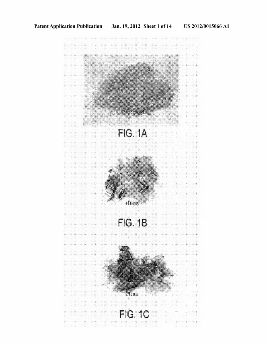
[0027] Solid Waste, post-consumer recycled PET beverage bottle materials are used as the binder material in the com posite material and are available in three forms: (Type 1) sorted, Washed and processed; (Type 2) unsorted and shred ded; and (Type 3) partially-sorted, shredded and Washed. Flaked or pelletiZed PET commonly available from plastic recycled facilities is referred to as “Type I’’. PET collected in the form of Waste beverage containers that have been shred ded Without removing the labels or caps and no Washing is referred to as “Type 2”. PET collected in the form of Waste beverage containers that have been shredded after removing some of the labels and caps and Washing in a Water bath is referred to as “Type 3”. FIGS. 1A, 1B, and 1C shoW the three forms Type 1, Type 2, Type 3, respectively, of post-consumer recycled PET beverage bottle material used in the production of composite material pursuant to an illustrative embodiment of the invention offered for purposes of illustration and not limitation.
Waste Filler Materials
[0028] Several types of Waste ?ller materials can be used in the composite material mixture including: (1) rock quarry crusher ?nes (RCF); (2) coal-combustion by-products (CCBs); and (3) lime sludge from Water treatment plants (LS). Table 1 summarizes the chemical constituents and physical properties for all Waste ?ller materials used in examples described beloW.
Rock Quarry Crusher Fines
[0029] Of the 2-billion tons of aggregate produced per year in the US. [reference 6], it is estimated that an additional 25 percent to 30 percent is Wasted due to crushing and screening operations. The screening materials (typically 100 percent passing 9.5 mm sieve and up to about 30 percent passing the 0.075 mm sieve) are often stockpiled or put back into the quarry as ?ll, resulting in Zero or negative value. The rock quarry crusher ?nes used in the examples beloW comprised crushed quartzite. 100 percent of the particles Were smaller than 0.15 mm and 74 percent smaller than 0.075 mm. Min erals identi?ed in the rock quarry crusher ?nes consisted of quartz, kaolinite, and talc.
Lime Sludge
[0030] Most drinking Water is softened and most com monly lime softening is used, introducing slaked lime to

US 2012/0015066 A1
remove hardness as calcium carbonate and magnesium hydroxide. About 10 million tons of lime sludge is generated in the US. annually, Which creates disposal problems. Lime sludge has very similar chemical composition as limestone. 100 percent of the lime sludge used in the examples beloW Was smaller than 0.075 mm. The only mineral identi?ed in the lime Was calcite. Coal Combustion by-Products [0031] Coal combustion by-products are produced/ from burning coal in energy production facilities and exist in a Wide range of gradations and chemical compositions. About 100 million tons of coal combustion by-products are produced in the US. annually [reference 7]. Six different coal combustion by-products Were evaluated in this study including: (1) Prairie Creek ?y ash (PFA); (2) Ames ?y ash (AFA); (3) IoWa State University (ISU) circulating ?uidized bed ?y ash (CFBFA); (4) ISU stoker ?y ash (SFA); (5) ISU circulating ?uidized bed bottom ash (CFBBA); (6) ISU stoker bottom ash (SBA); and (6) University of Northern IoWa (UNI) ?uidized bed combus tion residue (FBC). [0032] PFA is produced form burning coal originating from the PoWder River Basin in Wyoming and is burned in pulver ized boilers. All particles are smaller than 0.85 mm and 93 percent are smaller than 0.075 mm. PFA classi?es as an ASTM C618 class C ?y ash. AFA is also produced from burning PoWder River Basin coal in pulverized boilers. About 10 percent by Weight of municipal solid Waste is also burned With AFA coal. All particles are smaller than 0.85 mm and 95 percent are smaller than 0.075 mm. This material cannot be classi?ed as ASTM class C ?y ash since municipal solid Waste is burned With the coal. Minerals identi?ed in the ash are quartz, anhydrite, broWnmillerite, lime, periclase, and tricalcium aluminate. [0033] CFBFA and SFA Were both supplied by ISU PoWer Plant, Which burns a mixture of coal from Illinois and Ken tucky. The same mixture of coal is burned in tWo different types of boilers. The ashes receive their names from the boilers in Which they are produced, circulating ?uidized bed and stoker boilers, respectively. SFA has the highest loss on ignition (LOI) at 42.4 percent due to ine?icient combustion. All CFBFA particles are smaller than 0.25 mm and 89 percent are smaller than 0.075 mm. All particles in SFA are smaller than 2.00 mm and 93 percent are smaller than 0.075 mm. Minerals identi?ed in the CFBFA are quartz, anhydrite, lime, hematite, and illite. Minerals identi?ed in the SFA are quartz, mullite, hematite, and albite. [0034] CFBBA material has particles With 99 percent smaller than 4.75 mm and only 1 percent smaller than 0.075 mm. Quartz, anhydrite, lime, hematite, calcite, and portland ite are the minerals identi?ed in the CFBBA. [0035] Due to large particle sizes, SBA Was ?rst crushed so that all particles are smaller than 2.0 mm and 28 percent are smaller than 0.075 mm. Quartz, mullite, Magnetite, and hematite are the minerals identi?ed in the SBA. [0036] FBC Was supplied by the UNI PoWer Plant, Which burns a mixture of coal from Kentucky and West Virginia. A pyropoWer boiler is used to burn the coal at this location. All particles are smaller than 2.0 mm and 64 percent are smaller than 0.075 mm. Minerals identi?ed in the FBC are lime, anhydrite, quartz, and hematite.
Fiber Reinforcement
[0037] Fiber reinforcement is added to the composite mate rial to improve its engineering properties and control thermo
Jan. 19, 2012
dynamic shrinkage. Fiber reinforcement can include one or more of glass, metal, ceramic, carbon, organic, and polymer ?bers. For the examples described beloW, discontinuous ?berglass ?bers of different lengths (6 mm and 13 mm) Were used. The ?bers Were both chopped strand 919-4 CT ?ber glass ?bers produced by Vetrotex America, Inc. (Product Nos. CA4J919022 and CA4J919053, respectively). Fiber rein forcement is an essential component of the composite mate rial for production of the plunger-cast tubular pipe specimens, as Without ?bers, thermodynamic shrinkage cracks develop during the cooling process. Further, the ?ber reinforcement enhances uniform distribution of air voids.
Manufacturing Process for Composite Material
[0038] Manufacturing of the composite material is initialed by Weighting out the desired post-consumer PET material (Type 1, 2 or 3), the Waste ?ller material, and ?ber reinforce ment. The post-consumer PET is introduced into an electric melting pot and then pre-heated Waste ?ller material is added and mixed With the melted PET. The post-consumer PET, Which is a thermoplastic, melts at about 2700 C. The ?ller material can alternately be added to the melted PET prior to heating. A mechanical stirring device (steel rod or spatula) is used to mix the PET and Waste ?ller materials. Once mixed, the ?ber reinforcement is incrementally added and mixed until evenly dispersed in the mixture. [0039] Specimens for engineering property evaluation are prepared by transferring the composite mixture into pre heated mold of the desired geometry and allowing the mixture to cool at room temperature.
Engineering Properties of Composite Material Mixtures
[0040] Table 2 summarizes engineering properties includ ing density, compressive strength, tensile strength, and elastic modulus of the composite mixture. Statistical analyses shoW that the compressive strength, tensile strength and elastic modulus increase With increased ?ller content and ?ber con tent.
Compressive Strength [0041] ASTM C 39/C 39M-99 Standard Test Method for Compressive Strength of Cylindrical Concrete Specimens [reference 8] Was used as a guide to test the compressive strength for the composite cylinder specimens. A Soiltest machine Was used to produce the compressive force. The smallest division on the testing machine Was 0.2 kN. Loading rate Was calculated by measuring the elapsed time for incre ment 2 kN. The load of 2 kN Was then divided by the initial cross-sectional area to determine the compressive strength. Compressive strength Was then divided by the elapsed time in seconds to determine the loading rate. [0042] Test specimens Were constructed from different composite mixtures. TWo cylinder specimens from every composite design mix Were tested. Test specimens had a diameter of about 50.8 mm and a length of 101.6 mm. Load rate Was continuous and Without shock and Within the range of 0. 1 5 to 0.35 MPa/ s. The diameter of the cylinder specimens Was determined by averaging tWo diameters in the middle of the specimen at right angles from each other. Lengths of the cylinder specimens Were determined by averaging tWo lengths. [0043] Cylinder specimens Were positioned by centering them vertically on one of their ends in the middle of the

US 2012/0015066 A1
bearing block. The ram Was then lowered so that it came into contact With the top end of the cylinder specimen. The testing machine Was set to controlled test, Which started the loading. Loading continued until the load indicator decreased signi? cantly. This decrease indicated that the cylinder specimen failed. The maximum load Was then recorded to the nearest 0.2 kN division. The testing machine Was then unloaded and the sample removed. This process continued until all of the cylinder specimens Were tested. [0044] Results indicate that the average compressive strength for 96 specimens is 38.8 MPa, Which is slightly greater than the ordinary PCC strength of 15 to 35 MPa. Elastic modulus varied from 1300 MPa to 5700 MPa. The average elastic modulus Was 3300 MPa (24 specimens), Which is 7 to 10 times loWer than ordinary PCC. Density of the composite ranged from 1 .2 to 1.8 g/cm3 With an average of 1.6 g/cm3, Which is loWer than ordinary PCC densities of 1.9 to 2.5 g/cm3. Statistical analyses shoW that compressive strength, elastic modulus and density increase With increased ?ller and ?ber reinforcement content.
Tensile Strength
[0045] ASTM C 496-96 Standard Test Method for Splitting Tensile Strength of Cylindrical Concrete Specimens [refer ence 9] Was used as a guide to test the tensile strength for the composite cylinder specimens. A Soiltest machine Was used to produce the compressive force. [0046] Bearing strips Were constructed from 6.4 mm thick oak plyWood. Widths of the plyWood bearing strips Were 25 mm and the lengths Were 114.3 mm. Supplementary bearing bar Was constructed from a 12.7 mm thick aluminum bar. Aluminum bar had a Width of 38 mm and the length of the bar Was 1 14.3 mm. Test specimens Were constructed from differ ent composite mixtures and had diameters of 50.8 mm and lengths of 101.6 mm. 152 mm diameter steel spacer blocks Were used as the loWer bearing platform.
[0047] Loading rate Was constant and Within the range of 689 to 1380 kPa/min. A centerline Was draWn on one end of the cylinder specimens and the diameter of the cylinder speci mens Was determined by averaging three diameters along the centerline. Three diameter measurements Were taken, 25 mm from each end and one in the middle of the cylinder speci mens. Lengths of the cylinder specimens Were determined by averaging tWo lengths. [0048] Cylinder specimens Were positioned by centering one plyWood strip on the loWer bearing platform lengthWise and placing the cylinder specimen lengthWise so that the centerline Was vertically over the center of the Width of the plyWood strip. Then the top plyWood strip Was placed over the cylinder specimen lengthWise and centered over the center line. The upper bearing bar Was then centered over the top plyWood strip. The ram Was loWered so that it came in con tacted With the upper bearing bar. The cylinder specimen, plyWood strips, and upper bearing bar Were then aligned and centered.
[0049] The testing machine Was then set to controlled test, Which started the loading. Loading continued until the load indicator decreased signi?cantly. This decrease indicated that the cylinder specimen failed. Maximum load Was then recorded to the nearest 0.2 kN division. The testing machine Was unloaded and the sample removed. PlyWood strips Were then disposed. This process continued until all of the cylinder specimens Were tested.
Jan. 19, 2012
[0050] Results indicate that the average splitting tensile strengths for 96 specimens is 4.3 MPa, Which is greater than the ordinary PCC strength of 1.5 to 3.5 MPa. Further, statis tical analyses indicate that tensile strength increases With increased ?ller content and ?ber reinforcement content.
Durability Testing [0051] TWo durability tests Were conducted to evaluate the composite mixtures under various environmental conditions similar to Which seWer pipes are subjectediWater absorption and sulfuric acid resistance. Specimens for the Water absorp tion and acidresistance tests Were made by cutting discs off of cylinder specimens. [0052] Water absorption tests Were conducted to indicate the amount of Water the various composite mixtures absorbed. ASTM D 570-98 Standard Test Method for Water Absorption of Plastics [reference 10] Was used as a guide to test the Water absorption of the composite specimens. 50.8 mm diameter specimen discs Were cut off of the cylinders using a poWer miter saW With a masonry blade to a thickness of 6 mm.
[0053] One disc for each composite mixture Was tested for Water absorption. Discs Were placed in the same container of tap Water. The disc’s Weight, thickness, and tWo diameters at a right angle from each other Were measured prior to sub merging them into the Water. Discs Were placed into the Water so a section of one part of the circumference touched the side of the container and another section of the same edge touched the bottom of the Water container. The specimen discs Were then left alone for a period of one Week at room temperature. After one Week, discs Were removed from the Water one at a time. Surfaces of the specimen discs Were then dried With a cotton cloth rag. Their Weights Were recorded to the nearest 0.01 g and then the discs Were immediately placed back into the Water container. The Water absorption test Was conducted after the ?rst Week and every tWo Weeks thereafter for a period of seven Weeks.
[0054] Results are presented in Table 3. The A symbol is the percent difference in Water absorption betWeen composites With ?ller and pure plastic. Positive numbers indicated that the composites With ?ller absorbed more Water than the pure plastic. All specimens With sulfur trioxide contents higher than 12% had high Water absorption. Specimens With CFBBA, Which has a sulfur trioxide content of 30.7%, exhib ited Water absorption of approximately 12%. The RCF mate rial absorbed the least Water. [0055] Sulfuric acid, Which can be produced from bacteria in seWage, is responsible for destroying PCC seWer pipes. For this reason, the composite mixtures Were tested in a 10 per cent by volume sulfuric acid and Water solution. ASTM D 543-95 Standard Practices for Evaluating the Resistance of Plastics to Chemical Reagents [reference 11] Was used as a guide for this procedure. Specimen discs Weights, thicknesses at the center, and tWo diameters at right angles to each other Were measured prior to introducing them into the acid. Dimensions Were measured to at least 0.025 mm and the Weights Were measured to the nearest 0.01 grams. [0056] Sulfuric acid Was placed into Mason canning jars and the discs Were then submerged into the acid. Each disc Was placed in a separate jar. After placing the discs into jars, the lids Were screWed on and the jars Were left alone at room temperature for a period of one Week. After one Week, the lids of the jars Were removed and specimens Were taken out of the jar using tongs. Specimens Were rinsed under running tap

US 2012/0015066 A1
Water to remove the sulfuric acid. Then, the surfaces of the specimen Were Wiped dry using a cotton cloth rag. The Weight, thickness, and diameters of the specimen Were then recorded. The specimen Was placed back into the jar and the lid screWed doWn. Observations Were recorded on the appear ance of the specimen. These procedures Were folloWed again at tWo Week intervals for a period of seven Weeks.
[0057] Summary of the results for the acid resistance tests are provided in Table 4. The positive numbers indicate speci mens absorbed sulfuric acid solution. The RCF and pure PET plastic specimens shoWed the greatest resistance to a solution of 10% sulfuric acid in these accelerated laboratory tests.
Microstructure Analysis
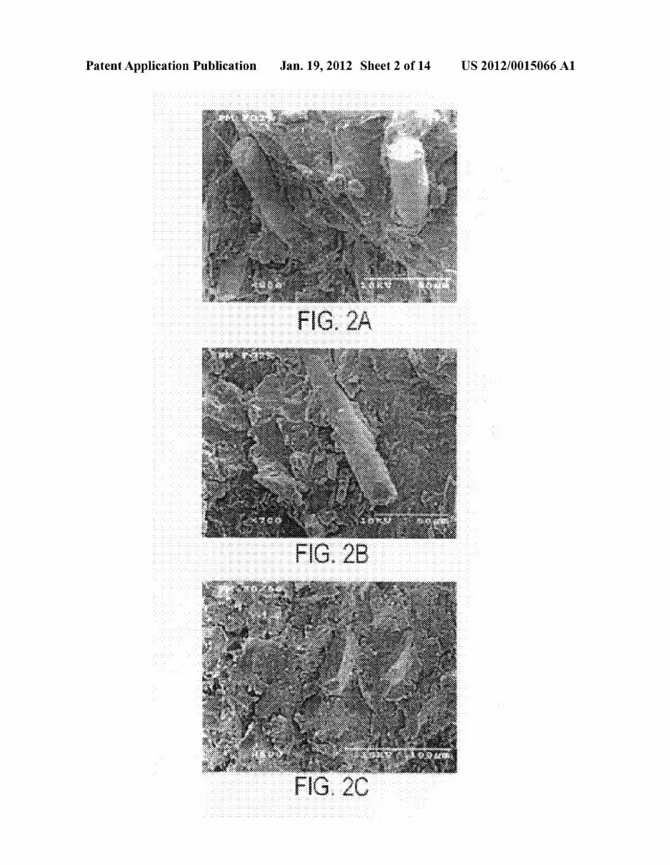
[0058] FIGS. 2A, 2B, and 2C shoW a sheared surface for the composite mixture including RCF (rock quarry crusher ?nes) ?ller particles and indicates that the ?ller particles are unifor mity dispersed in the mixture and that the ?ber reinforcement is breaking rather than pulling out indicating that the ?ber tensile strength is fully mobiliZed and tightly bound to the matrix.
Plunger-Cast Pipe Manufacturing Method and Apparatus
[0059] Polymer mortar composite pipe specimens Were manufactured from the aforementioned composite material mixtures for purposes of illustration and not limitation. Equipment used to produce the pipe specimens included: a hydraulic ram R, plunger piston 22, inner collapsible mold 14 having an overlapping region R at a longitudinal slit, outer mold 12 held on a base plate 10 by tWo bolts 11 securing outer mold ?anges 12f on the base plate, and concrete or steel spacers BL to rest the base plate 10 on during cooling. The inner mold 14 has an outer diameter smaller than that of the outer mold 12 so as to de?ne an annular space therebetWeen When the inner mold is inserted in the outer mold as described beloW. About 18,000 grams of material Was used to produce one pipe specimen With dimensions of: Wall thickness 38 mm; length 260 mm; outside diameter 306 mm.
[0060] Before the pipe is to be manufactured, the ?ller material and molds are preheated. The desired amount of ?ller is Weighed out then placed into an oven (not shoWn) at approximately 270° C. Preheating the Waste ?ller shortens the mixing time and decreases the moisture content. The plunger cast base orbottom plate 10, outer cylinder mold 12, and inner cylinder collapsible mold 14 (see FIG. 3A-3F, FIG. 4A-4E, and FIG. 5A-5B) can be sprayed With a release agent, such as silicone spray, to ensure the pipe separates easily from the molds. The outer mold on the base plate and the inner mold are also preheated in the oven at 2700 C.
[0061] Similar to the process for preparing composite material specimens for the aforementioned engineering prop erty testing, post-consumer, Waste PET is Weighed to the desired amount then introduced into an electric melting pot (not shoWn). For the lab-scale testing described herein not all of the PET Would ?t into the electric melting pot for most of the mixes, so PET Was added occasionally as it melted. The melted PET Was mixed by hand using a metal stirring rod. [0062] Pre-heated Waste ?ller material is added to the melt ing PET. After placing Waste ?ller material into the electric melting pot, the composite is stirred a feW minutes and left to melt. The mixture is stirred every 15 to 30 minutes to increase melting and composite uniformity.
Jan. 19, 2012
[0063] Once the composite has a uniform consistency, the desired amount of ?ber reinforcement is incrementally added to the mixture. The addition of ?bers increases viscosity and requires increased mixing effort. [0064] To prepare the plunger-cast manufacturing system, the plunger piston 22 is attached to the hydraulic ram and centered as shoWn in FIG. 6. Once the composite mixture is ready, the inner collapsible cylinder mold 14 is taken out of the oven and attached at the top end to the plunger piston 22 With a hose clamp 24, FIG. 7. The bottom end of the inner mold 14 is held in place by hoop stresses that result from the plunger piston diameter being slightly larger than the inside diameter of the inner mold. The overlapping region R of the slit of the inner cylinder mold 14 is placed at the back of the piston 22. [0065] After the inner cylinder mold 14 and the piston 22 are positioned, the outer cylinder mold 12 and base plate 10 are removed from the oven. The melted composite mixture is transferred into the outer mold 12 and base plate 10 by directly pouring from the melting pot into the outer mold on the base plate that are centered in position in the load frame for insertion of the inner mold 14 and plunger piston 22. About one third to one half of the outer mold is ?lled prior to inserting the plunger piston and inner mold. The plunger piston 22, With a special shaped beveled end 22a to force material outWard, and inner mold 14 on the piston is then loWered slightly on hydraulic ram 30 and centered.
[0066] Once centered, the plunger piston and inner mold are lowered into the composite material With the hydraulic ram 30. As the plunger piston comes into contact With the composite material, the piston presses the composite material M outWard betWeen the inner and outer cylinder molds 12, 14. The pipe thickness is then equal to the distance betWeen the molds 12, 14, in this example approximately 38 mm. Once the piston comes in contact With the base plate 10, the hose clamp 24 is loosened to detach the inner cylinder mold 14 from the piston 22. The plunger piston 22 is WithdraWn and removed from the hydraulic ram 3 0, leaving the inner cylinder mold 14 in place as shoWn in FIG. 8.
[0067] The ?nal step of the plunger-cast manufacturing process is the cooling of the composite material. The molds 12, 14 on base plate 10 are placed on concrete or steel spacer blocks BL beneath the base plate 10 to promote uniform cooling. The inner cylinder mold diameter is reduced by tightening hose clamp 24 periodically. This is done to reduce development of residual stresses from thermodynamic shrinkage Within the composite material. The pipe P formed by the composite material M and molds are alloWed to cool at room temperature for about 30 minutes or until the composite material solidi?es. The pipe P, FIG. 9, is then extracted from the outer and inner molds 12, 14 by further tightening the hose clamp 24 until the inner mold 14 is loose enough to slide out by hand and unbolting the outer mold 12 to alloW it to be lifted off. The pipe P is then alloWed to completely cool at room temperature. The above method and apparatus can be used to make a tubular body using a ?oWable material other than the composite material described in detail above.
Pipe Three-Point Load Test Results
[0068] ASTM C 497-98 Standard Test Method for Con crete Pipe, Manhole Sections, or Tile [reference 12] Was used as a guide to test the tensile strength for the composite pipe specimens, FIG. 9. An MTS machine Was used to produce the


