Embed Size (px)
Citation preview

Power System Dynamics
Prof. M. L. Kothari
Department of Electrical Engineering
Indian Institute of Technology, Delhi
Lecture - 08
Modelling of Synchronous Machine
Friends, we should study today the modeling of synchronous machine.
(Refer Slide Time: 01:05)
Till now the synchronous machine was model as a constant voltage behind direct axis transient
reactance. The synchronous machine modeling has been a challenge all through and lot of work
has been done over the years to develop more accurate models of the synchronous machine.
Today in our study we will develop the basic equations of synchronous machine and then we will
go to dqO transformation which is also commonly known as park’s transformation.

(Refer Slide Time: 02:05)
Now this synchronous machine has two major parts, stator and rotor. We shall represent stator
has provided with 3 windings and we assume that these windings are sinusoidally distributed. On
the rotor, we have a field winding on the direct axis and we have amortisseur or damper
windings. In a synchronous generator we provide dampers and these dampers can be represented
by considering considering the amortisseurs located on the d axis and on the quadrature axis.
Now here in my presentation we will presume or we will assume one amortisseur on the d axis
and another amortisseur on the q axis. The convention which we will follow here is that the q
axis leads d axis by 90 degrees, although there are some some you know cases where the q axis
has been taken as lagging the d axis but in IEEE standards consider the q axis leading the d axis
by 90 degrees.
Now here the d axis is along the axis of north pole, it coincides with the axis of north pole then
we will measure the angular position of the, angular position of the direct axis with respect to the
axis of phase A of the stator that is here this straight lines shows the axis of phase A and the the
angular position of the rotor is measured with respect to the axis of phase A and we call this
angle as theta. Further we will be following the generator convention there is the stator currents
are leaving the terminals of the machine that is ia, ib and ic are leaving the machine terminals. The
rotor is rotating in the anticlockwise direction this is direction of rotation of the rotor which we
are presuming.
Now the currents in the rotor circuits are entering the rotor circuit, if you just see here this field
winding the current is entering the field winding and the applied voltage is efd the damper
windings are closed circuits amortisseurs are closed circuits. The current flowing is again into
the amortisseur windings closed circuit.

(Refer Slide Time: 06:05)
(Refer Slide Time: 06:46)
Some of the important nomenclature are ah will be use here, a, b, c stands for the stator phase
windings, fd stands for field winding, kd stands for d axis amortisseur circuit, kq stands for q
axis amortisseur circuit, this K stands for 1, 2, 3, n, the number of amortisseur circuits that is if I
put one amortisseur circuit on the d axis, k becomes 1 I can say 1 d if there is one amortisseur on
the q axis it is 1q. Okay therefore in general the amortisseurs are represented by putting
substitute kd or kq, theta is the angle by which the d axis leads the magnetic axis of the phase a
winding in the electrical radians and omega r is rotor angular velocity is electrical radians.

(Refer Slide Time: 06:59)
The ea, eb and ec are the instantaneous stator phase to neutral voltages that is the voltages which
are shown here these are the instantaneous values and they are with respect to phase to neutral
there is a raise from neutral to phase, instantaneous stator currents are shown as ia, ib and ic.
(Refer Slide Time: 07:22)
The field voltage is efd, the field and amortisseur circuit currents are denoted as ifd, ikd and ikq the
rotor circuit resistances will be denoted by Rfd, Rkd, Rkq with Rfd is the resistance of the field

winding, Rkd is the resistance of direct axis amortisseur circuit and Rkq is the resistance of the
quadrature axis amortisseur circuit.
Now here, we will see that we have stator windings, we have windings on the rotor and rotor is
rotating and because because of this we will find actually that the, we come across various types
of inductances in the synchronous machine, the inductances are the self- inductances of the stator
windings, the mutual inductance between the windings of the stator then mutual inductances
between the stator winding in the rotor circuits and self-inductances of the rotor circuits and
mutual inductances between the rotor circuits therefore we come across different types of
inductances in the stator in the synchronous machine.
The, we represent this by double circuit same circuit laa to denote that it is a self laa, lbb and lcc
stand for self-inductances of stator windings that is we will use double circuit notation to denote
the self-inductances or mutual inductances if there are self-inductances the two circuits will be
same if they are mutual inductances the two circuits will be different, like say lab lbc and lca stands
for mutual inductances between stator winding that is lab is the mutual inductance between stator
a phase and stator b phase, so on.
(Refer Slide Time: 09:35)
Then lafd, lakd and lakq represents the mutual inductances between the stator a phase and rotor
windings that is lafd is the mutual inductance between the stator a phase and field winding lakd is
the mutual inductance between the stator a phase and amortisseur on the d axis and similarly, lakd
then lffd, lkkd and lkkq represents the self-inductances of rotor circuit. Ra is armature resistance per
phase and we will represent this differential operator P which is your d by dt by the symbol P, P
is the differential operator.

Now in the case of synchronous machine, the self-inductances of the stator winding and the
mutual inductances between the stator windings and they they they are affected because of the
the non-uniform air gap. As we know that the magnetic field produced by the stator winding it
passes through passes through the stator core, through the air gap, through the rotor iron then air
gap and again return backs through the stator core right and therefore the flux produced by the
stator winding will be affected by the position of the rotor.
(Refer Slide Time: 11:15)
Now here in this diagram we saw the variation of permeance with rotor position means you
know that permeance is the reciprocal of reluctance. Okay now here I am considering a salient
pole machine and these are the pole location and we are just showing the expanded version. Now
the permeance is maximum when the, when the permeance is maximum along the d axis or we
can say the reluctance is minimum. This graph shows the variation of permeance as with respect
to the position that is angle alpha which is measured with respect to the d axis which coincides
with the North Pole axis okay.
We can easily see that this is maximum position, when it coincide with the Q axis it is minimum
and it again coincides with the d axis it is maximum and this variation is of the form P equal to
Po plus P2 cos 2 alpha that is when alpha is 0, alpha is 0 its value is Po plus P2 and when alpha is
ninety degrees its value is Po minus P2 right that is cos2 alpha becomes minus 1 and it is this
variation of this permeance right is having a strong bearing on the variation of self-inductances
mutual inductances and so on.

(Refer Slide Time: 12:59)
Now to understand the whole thing what we start with this we first write down the stator circuit
equations. The basic stator circuit equations are ea is equal to p, psi a minus Ra ia, eb equal to p
psi b minus Ra ib and ec equal to p psi c minus Ra ic, ia ib and ic are the instantaneous value of the
phase currents and p psi a stands for d by dt of psi a, psi a, psi b and psi c are the flux linking
phase a phase b and phase c respectively. Okay that means straight forward that the induced emf
is d by dt of psi a and this will be equal to the terminal voltage plus the resistance drop or now
this equation is drawn considering the generator action okay.
(Refer Slide Time: 13:59)

Now here, let us see actually that what determines the flux linkage in the stator phase winding
the flux linkage in the stator phase winding can be written as psi a equal to minus laa ia, now here
I will explain this minus terms but laa is the self-inductance of phase a la into ia minus mutual
inductance between a and b and multiplied by ib minus iac ic plus lafd ifd where lafd is the mutual
inductance between a phase and field winding ifd is the field current similarly lakd, ikd, lakq, ikq.
(Refer Slide Time: 14:59)
Now since we have assumed in the basic model here that the flux linkages are shown in the
direction opposite to the current and that is why actually the negative signs are appearing here
that is in these terms you can just see these are the negative signs while the currents are entering
the other three rotor windings therefore they are the positive signs. Now we will see that that
these self-inductances mutual inductances these are not constant these depend upon the position
of the rotor with respect to the windings, the stator windings and we will show that these depend
upon the angular position of the rotor and since the rotor is rotating the angular position of rotor
keeps on changing and therefore these inductances are going to be a function of angular position
theta. Okay now to understand this let us first start with the stator self-inductances, the stator
self-inductances.
Now here the stator self-inductance is denoted by the symbol laa okay and how when we define
this stator self-inductance, the basic definition is the flux linking the phase a winding divided by
the current that is the self-inductance of phase a winding with no currents on other windings that
is when only current ia is flowing and we find out what is the total flux linking the stator winding
a that is the self-inductance of stator winding a laa.

(Refer Slide Time: 16:05)
Now when the current ia is flowing okay then the MMF, MMF which is produced due to the flow
of current is Na into ia and this MMF is sinusoidally distributed along the surface of the stator or
along the air gap okay because the stator is suppose to produce a sinusoidally distributed MMF
okay and this MMF has the maximum value along the d axis right it is it is peak is along the d
axis and when you go away from the d axis both sides this is going to decrease.
(Refer Slide Time: 17:39)

Now here this diagram shows, this diagram shows the MMF produced by the stator phase a that
is the I am just showing this is the this is the axis of phase a okay and the MMF produced by the
axis of phase a MMF produced by the phase a or stator phase a is having its peak along the d
axis, this is the d axis. I am sorry, this is the not d axis, I am sorry this is the axis of the phase a,
the axis of the phase a. Okay it is a little correction this is the axis of phase a.
Now what we do is we split this MMF into two components both are having the sinusoidal
distribution, one having its peak along d axis another having its peak along q axis therefore this
this graph red graph which I have shown here, this shows the sinusoidal distribution having its
peak coinciding the d axis, this is the again sinusoidal distribution its peak is coinciding with q
axis and the q axis is leading d axis by 90 degrees okay.
(Refer Slide Time: 19:04)
Now this can be seen here in this diagram that the MMF produced by the stator right along its
own axis that is the MMF produced by a stator winding of phase a right is having its maximum
value along its own axis that is axis of phase a. Now we have assumed likely that the rotor is
rotating in the anti clockwise direction therefore axis of, now the d axis is shown here and q axis
is leading points and what we do is that this MMF is resolved into two components one along d
axis another along q axis. The d axis component is Na ia cos theta and q axis component is minus
Na ia sin theta, okay.
Now with this MMF’s then we can find out what will be the flux produced at the air gap along
this d and q axis. Okay, now here we are showing that the MMFad that is MMF due to due to
current flowing in the stator a phase and it is component along d axis ad is equal to Na ia cos theta
and these are the peak values therefore when ia attains its peak value this will also become this
varying this is varying along as the ia is varying, then the along the q is minus ia Na sin theta
okay.

(Refer Slide Time: 20:59)
Now the flux produced long these two axis because of these MMF can be written as MMF into
Pd that is phi gad, g stand for air gap or gap flux okay the phi gad is equal to Na ia cos theta into
Pd and phi gaq is equal to minus Na ia sin theta into Pq. Now here this is the MMF and to relate
this MMF to the flux we are using this term Pd therefore, Pd is in general a permeance coefficient
we call it it is not only the absolute value of permeance but all other parameters which relate
flux to MMF because this is the MMF only this is the flux okay.
(Refer Slide Time: 21:53)

Now what is done is we again make use of this phasor diagram, the flux which is produced along
d axis in the air gap, flux which is produced along q axis in the air gap, we resolve them back
along the axis of phase a. that is when you resolve this right then this component will come out
to be equal to phi gad cos theta and the second component comes out to be phi gaq sin theta with
negative sign because there was negative sign already attached with it and therefore we can say
that the air gap flux due to current flowing in the stator winding a only comes out to be equal to
Na ia substituting these values on the previous equations in this form.
The Na ia Pd cos square theta plus Pq sin square theta and this expression when simplified it can
be put in the form Na ia into Pd plus Pq by 2 plus Pd minus Pq by 2 cos 2 theta.
(Refer Slide Time: 22:09)
Now here this is very important point to understand that the air gap flux produced, air gap flux
produced by current flowing in the stator winding of phase a is equal to is proportional to a term
Pd plus Pq by 2 and another term Pd minus Pq by 2, cos 2 theta that is this term does not depend
upon angular position, while this term depends upon the angular position. Now we define the
inductance.

(Refer Slide Time: 23:44)
The inductance, the self-inductance of the stator phase a due to gap flux only the flux which is
produced in the air gap, lgaa is equal to Na affective number of terms into the gap air gap flux
divided by ia and this comes out to be we substitute the value of phi gaa it comes out to be Na
square Pd plus Pq by 2 plus Pd minus Pq by 2 cos 2 theta okay therefore this can be put in the form
that is this is your Lgaa is the self-inductance of phase a due to gap flux only which can be put as
a constant terms Lg0 plus another term Laa2 cos 2 theta right because as I have seen the I have told
you that the permanence of the air gap varies as a with the position of the rotor and there we
found actually that it has a second harmonic variation. Here, also you find there is a constant
term plus a quantity varying as a function of cosine 2 theta okay.
Now to make the whole thing more complete there is some a leakage flux which does not cross
the air gap. Okay and this leakage flux also contributes the self-inductance of the stator phase
and therefore, when you account for the leakage flux then we can say that the self-inductance Laa
of the stator phase is equal to self-inductance due to leakage flux plus lgaa which I have obtained
in the previous equation that is due to the gap flux and then when you combine these two terms.
We can see here that this mutual inductance or the this second term will not be affected by the
leakage and therefore this leakage term is combined and you find here that the self-inductance
can be written as Laao plus Laa2 cos 2 theta.

(Refer Slide Time: 25:30)
Now this is the most important equation to understand that how the self-inductance of stator
phase varies as the position of the rotor varies the angular position of the rotor. Now this angular
position is measured with respect to axis of phase a.
(Refer Slide Time: 26:44)
Now this graph shows the plot for the variation of the self-inductance of stator phase a as
function of theta okay and you can identify here that this is the term Laa2 which varies this Laa2 is
constant and this is another term which we call Laao and the total inductance of the stator phase is

now written as Laa equal to Laao plus Laa2. These two terms are constant these constants these are
constant they do not depend upon the angular position that mean the total self-inductance
depends upon the angular position but these two coefficients are constant. Now when we
perform the similar exercise for phase b and phase c, since the the axis of the phase b and phase c
are displaced by 120 degrees with respect to axis of phase a right.
(Refer Slide Time: 27:52)
(Refer Slide Time: 28:26)

Therefore, the expressions which we have written here for self-inductance of phase b right will
be of the same form except theta is replaced by theta minus 2 phi by 3 and since these the
everything remains same therefore these terms are also same therefore it is not Lbbo but Lbbo is
same as Laao okay similarly, we write down lcc as Lao plus Laa2 cos 2 times theta plus 2 phi by 3
okay very straight forward.
Now next very important point we have to understand is the stator mutual inductances, the stator
winding mutual inductances again we will see that the stator winding mutual inductances also are
function of rotor position that will be function of theta. Now here, here when the when the axis
of the rotor is in the middle of the axis of stator phase a and stator phase b then at that position
the mutual inductance between a and b will be maximum for example the mutual inductance
between phase b and c when you try to see it will be maximum when theta is theta is 30 degree
minus 30 degrees and 150 degrees these they are the positions which we have to see. Okay, using
this information the flux linkage is, flux linkage is of phase b.
When current is flowing in phase a is are obtained that is we want to to find out the flux mutual
flux right that the flux linking flux, linking phase b due to current flowing in phase a okay and
then once you find out this flux. Okay, we can find out the mutual inductance because the the
inductance is the flux linkage by the current mutual inductance will be the flux linking phase b
due to current in phase a and then you divide by the current you will get the mutual inductance.
Here here following the same approach as we have done for done for obtaining the self-
inductance the, the air gap flux flux again the gap flux linking phase b with when current is
flowing in phase a is obtained in this form that is this is obtained in terms of these 2 components
phi gad and phi gaq that is this is the air gap flux along d axis this is the air gap flux along q axis
and after making the substitutions we find actually that mutual flux comes out to be equal to Na ia
minus Pd plus Pq by 4 plus Pd minus Pq by 2 cos 2 theta minus 2 phi by 3, okay.
(Refer Slide Time: 32:33)

Now you can easily see here actually that if you substitute here to make this quantity one to
make this quantity one. You can find it out actually ah what should be the value of theta right
and since this term is minus here Pd is always greater than Pq permanence along the d axis is
more then the permanence along q axis and therefore this is minus to have this also minus so that
the total quantity is added up. Okay you can find out the value of this angle theta and you will
find actually that when theta occupies either 30 degrees or 150 degrees it will be maximum. Now
this, this mutual inductance can be obtained as lgba divided by after dividing the the expression
for phi gba by ia okay.
Therefore, the expression for Lgba comes out to be in this form. Okay, now again it can be written
as minus 1 by 2 Lgo, Lg0 plus Lab2, now if you very carefully examine then this Lab2, Lab2 will be
of the same amplitude as Laa2, Laa2 right.
(Refer Slide Time: 33:08)
Similarly, you can find out the mutual inductance between b and a and we this ba mutual
inductance between the phase a and b that is equal ba or ab, they are always equal okay and the
expressions are written in the form minus Labo minus, now here actually when you have written
in this form what we have done is that we have accounted for some some leakage flux which also
leaks to windings right because there are, there is a air gap flux and there is some flux which
does not cross the air gap and once you account that we can write down these mutual inductances
in this form, okay again you can see that this depends upon theta. Similarly, you can write down
for bc and cb it comes out to be in the similar form and similarly lac and lca can be written like this
okay.

(Refer Slide Time: 34:02)
(Refer Slide Time: 34:10)
(Refer Slide Time: 34:18)
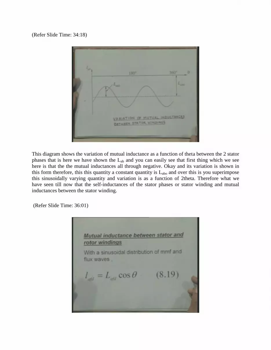
This diagram shows the variation of mutual inductance as a function of theta between the 2 stator
phases that is here we have shown the Lab and you can easily see that first thing which we see
here is that the the mutual inductances all through negative. Okay and its variation is shown in
this form therefore, this this quantity a constant quantity is Labo and over this is you superimpose
this sinusoidally varying quantity and variation is as a function of 2theta. Therefore what we
have seen till now that the self-inductances of the stator phases or stator winding and mutual
inductances between the stator winding.
(Refer Slide Time: 36:01)

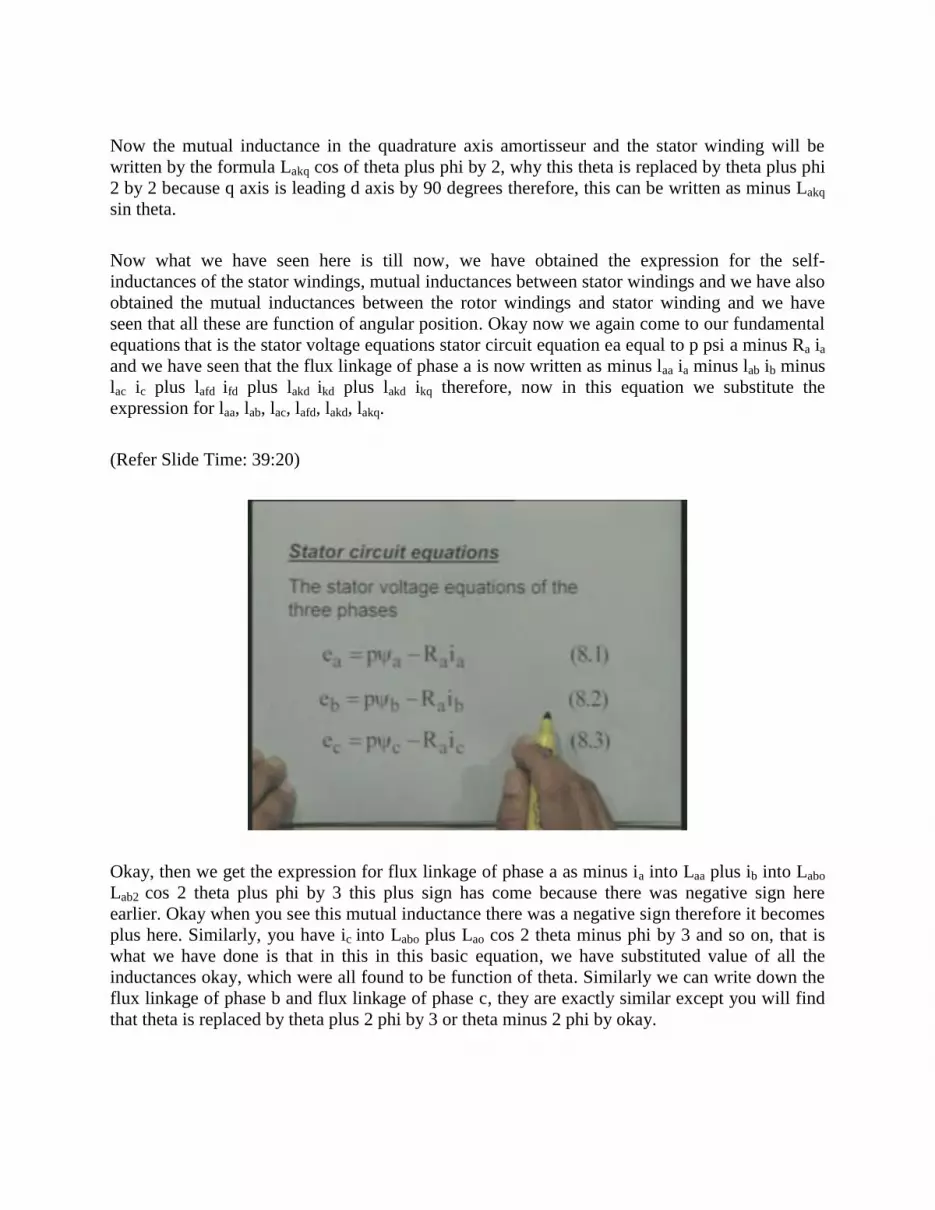
Now we will consider the mutual inductances between stator and rotor windings, stator and rotor
winding. Now so far the mutual inductances between stator rotor windings are concerned that
they are function of angular position but they are not because of the variation in permanence here
because so far the rotor is concerned, rotor will always see the same permanence because the
stator stator is having the ah a uniform shape right and therefore, so far the so far actually the
rotor is concerned, rotor windings are concerned right the the there will be no variation in
permanence.
Now here the mutual inductances between stator and rotor windings vary because of angular
position. Now for example, if you take take the stator phase a and field winding in case the axis
of these windings coincide they will have maximum mutual inductance in case the axis of stator
winding of phase a and the field winding they are in quadrature, the mutual inductance will be 0
right and since the rotor is having rotating it occupies different positions therefore, when it
coincides where the direct axis of the rotor coincide with the stator phase a axis or b axis or c
axis they will have maximum mutual inductance and when the quadrature axis of the rotor
coincides with the stator phase axis, okay phase a axis or phase b axis or phase c axis then the
mutual inductance will be 0. Okay therefore, we can write down this mutual inductance Lafd
equal to L, Lafd into cos theta.
(Refer Slide Time: 37:39)
When suppose as we know that the theta is measured right considering the axis of phase a as
reference and theta is the angle between the d axis and axis of phase a. Okay therefore when
theta is 0, the mutual inductance between stator stator winding and the field winding is
maximum. Okay and 90 degrees it is now, so the the amortisseur on the direct axis is is also
going to have the inductance, mutual inductance in the form Lakd cos theta right because this the
the direct axis amortisseur is having axis coinciding with the field winding right and therefore
the variation is going to be similar.
Now the mutual inductance in the quadrature axis amortisseur and the stator winding will be
written by the formula Lakq cos of theta plus phi by 2, why this theta is replaced by theta plus phi
2 by 2 because q axis is leading d axis by 90 degrees therefore, this can be written as minus Lakq
sin theta.
Now what we have seen here is till now, we have obtained the expression for the self-
inductances of the stator windings, mutual inductances between stator windings and we have also
obtained the mutual inductances between the rotor windings and stator winding and we have
seen that all these are function of angular position. Okay now we again come to our fundamental
equations that is the stator voltage equations stator circuit equation ea equal to p psi a minus Ra ia
and we have seen that the flux linkage of phase a is now written as minus laa ia minus lab ib minus
lac ic plus lafd ifd plus lakd ikd plus lakd ikq therefore, now in this equation we substitute the
expression for laa, lab, lac, lafd, lakd, lakq.
(Refer Slide Time: 39:20)
Okay, then we get the expression for flux linkage of phase a as minus ia into Laa plus ib into Labo
Lab2 cos 2 theta plus phi by 3 this plus sign has come because there was negative sign here
earlier. Okay when you see this mutual inductance there was a negative sign therefore it becomes
plus here. Similarly, you have ic into Labo plus Lao cos 2 theta minus phi by 3 and so on, that is
what we have done is that in this in this basic equation, we have substituted value of all the
inductances okay, which were all found to be function of theta. Similarly we can write down the
flux linkage of phase b and flux linkage of phase c, they are exactly similar except you will find
that theta is replaced by theta plus 2 phi by 3 or theta minus 2 phi by okay.

(Refer Slide Time: 39:31)
(Refer Slide Time: 40:01)

(Refer Slide Time: 41:04)
(Refer Slide Time: 41:09)
Now after having written the equations for the stator windings, voltage equation for the stator
windings we can write down the rotor circuit voltage equations. The, in the rotors on the rotor we
have considered 3windings, 1 filed winding and 2 amortisseurs. Okay therefore efd the voltage
applied to the field winding is equal to P psi fd plus Rfd ifd. Now here, since we have assumed
that the current is entering the field winding and therefore the term here is P psi fd plus this is a
simple Rl circuit.

Suppose you have Rl circuit, then the applied voltage is equal to the rate of change of flux
linkages plus voltage drop in the resistance. Okay then the other 2 equations these relate to the
direct axis amortisseur, winding amortisseur circuit and quadrature at the amortisseur circuit here
since there is no external applied voltage therefore we have 0 term here. Okay therefore, there
are 3 basic rotor circuit voltage equations we have 3 basic stator circuit voltages equations. Now
let us write down the expression for these flux linkages psi fd psi kd and psi kq.
(Refer Slide Time: 42:47)
Now psi fd can be written as Lffd that is the self-inductance of field winding into ifd plus mutual
inductance of the mutual inductance between between field winding and amortisseur that is Lakd
into ikd okay and there will be no there will be no flux linking the field winding due to the
quadrature axis amortisseur because the the 2 axis are that that the the displacement of 90
degrees between the 2 axis okay and therefore there is no flux linkage contributed by by
amortisseur on the quadrature axis to field axis flux linkage.
Then these 3 terms are here Lafd into ia cos theta Lafd into ib cos theta minus 2 phi by 3and Lafd
plus ic into cos theta plus 2 phi by 3 that is when the 3 stator currents are carrying the values ia, ib
and ic and depending upon their mutual inductances this will be the flux linkage in the stator
winding. Now one point which I wanted to mention here is the so far the self-inductances of the
rotor circuits are concerned that is self-inductance of field winding, self inductance of
amortisseurs they do not depend upon the angular position because because so far actually the
the the magnetic circuit is concerned for computing the self-inductances of rotor circuits are
concerned, these the self-inductances are constant and the since that we have assumed like with
uniform internal surface of the stator okay and therefore no variation of reluctance so far actually
the rotor circuits are concerned.

Similarly, similarly the mutual inductance between the rotor circuits there is mutual inductance
between the field winding and amortisseur on the d axis they will be fixed, they do not depend
upon the rotor position right. Therefore for example, Lfkd is a mutual inductance between field
winding and direct axis amortisseur this is a constant quantity they will not depend upon the
rotor position.
(Refer Slide Time: 45:42)
(Refer Slide Time: 45:59)

Now this similarly you can write down the flux linkage of amortisseur on d axis and flux linkage
of amortisseur in the q axis okay.
(Refer Slide Time: 45:55)
Now with this with this we have developed the complete mathematical model that we have
written three stator circuit equations, we have written the rotor circuit equations we have
expressed all the inductances as function of currents and I am sorry ,not all the flux linkages as
function of currents and the self and mutual inductances.
Now this that is ah this is what is called complete model of the system however the basic
problems which arise are due to due to the variation of these inductances with the variation of
rotor angular position and to overcome this problem and seeing very carefully the expression for,
you see the expression for psi fd, we find here a term Lafd that is the along with this term where
ia cos theta plus ib cos theta minus 2 phi by 3 therefore, this has prompted us to obtain a
transformation and once we go we use this transformation, we will find that the equations can be
simplified and we can make these equations equations where they do not exclusively depend
upon or the inductances do not depend upon the angular position.
Okay the the transformation is of this form that is we define, we define this term ia cos theta plus
ib cos theta minus 2 phi 3 plus ic cos theta 2 phi by 3 multiplied by some constant kd as id that is
these 3 terms ia cos theta ib cos theta minus 2 phi by 3, ic cos theta plus 2 by 3 this complete term
multiplied with some constant kd is denoted by a term id.
Similarly we denote another term iq as minus ikq multiplied by ia sin theta plus ib sin theta minus
2 phi by 3, now this with this with this assumption or this transformation if we consider balance
three phase currents that is ia equal to Im sin omega s t, ib equal to Im sin omega s t minus 2 phi

by 3 ic equal to Im sin omega st plus 2 phi by 3. Okay that is, we are assuming that the 3 stator
currents are balanced with this 3 stator currents to be balanced, okay what we do is if you
substitute and find out the expression for id, the id will come out to be as kd into 3 by 2 Im sin
omega st minus theta. This is very important term that is with this transformation, this id current
id is equal to kd into 3 by 2 Im sin omega st minus theta.
(Refer Slide Time: 48:32)
(Refer Slide Time: 49:02)

Now if you assume kd equal to 2 by 3, if you assume kd equal to 2 by 3 then the the peak value of
id will be same as Im okay and therefore in the Park’s transformation, Park’s transformation kd
and kq are taken equal to 2 by 3, that is iq will also be taking the same minus iq into 3 by 2 Im cos
omega st minus theta.
(Refer Slide Time: 49:56)
(Refer Slide Time: 50:36)
Okay and therefore, if I take kq equal to 2 by 3 then the peak value of iq will be same as Im.
Okay now to make this model complete complete and assuming that suppose the 3 currents are

not symmetrical right then we can define one, 0 sequence current io as 1 by 3 ia plus ib plus ic and
with this definition the transformation looks like this it is very interesting thing this
transformation looks likes this that we can say id, iq, io, a vector consisting of d axis current, q
axis current and i0.
These 3 currents can be written in terms of the phase currents ia, ib and ic in terms of this matrix
and this is called transformation matrix that is transformation matrix is 2 by 3 the first row is cos
theta cos theta minus 2 phi by 3, cos theta plus 2 phi by 3. Okay similarly similarly the second
term and third term.
(Refer Slide Time: 51:17)
With this now inverse transformation that is if you write down the expression for phase currents
in terms of the dqO currents then this can be written in this form cos theta minus sin theta 1like
this this is called inverse that is sometimes if you know the value of id, iq, io we can find out the
phase currents.
Now interesting thing which happens is that if I substitute the values of the phase currents in
terms of dqO components right then I get the expression for flux linkage in the d axis called psi d
that is if the the all these fluxes flux linking phase a phase b and phase c right they are also
transformed currents are also transformed that is by applying this transformation. We find that
the flux linkage is can be written in terms of ah the constant coefficients that is psi d is equal to
minus Lao plus Labo plus 3 by 2 Lao Laa2 okay then Lafd ifd plus Lakd ikd that is here the coefficient
of id is a constant term it does not depend upon angular position theta similarly, for psi q and psi
o right we define we define these terms Ld equal to Lao plus Labo plus 3 by 2 Lao similarly Lq and
L0 are defined.

(Refer Slide Time: 51:39)
(Refer Slide Time: 52:44)

(Refer Slide Time: 53:01)
(Refer Slide Time: 53:12)
When you make this substitution we can write down the flux linkage psi d as minus Ld id plus
Lafd ifd plus like this. Similarly, when you apply the dqO transformation the flux linking the
rotor circuits are also expressed in terms of the rotor currents rotor currents rotor circuit currents
and the dqO components of currents and again you find actually that these flux linkages as well
as these 3flux linkages with the transform quantities are are independent of rotor angular position
and this is what it helps the whole thing and once you substitute these expressions in our stator
circuit equations.

(Refer Slide Time: 54:01)
We get these equation in the form ed equal to P psi d minus psi q p theta minus Ra ideq is equal to
P psi q minus psi d p theta minus Ra iq and eo equal to P psi o psi 0 minus Ra io. Now these are
the 3 basic equations which are written in terms of transform quantities or dqO terms or
sometimes in case in dq of frame of presentation. Okay today I have discussed the basic circuit
equations of the synchronous machine and discuss the dqO transformation and its importance.
Ultimately, we have obtained the stator circuit equations in terms of the transform quantities.
Thank you!


