Embed Size (px)
Citation preview
t e c q u i p m e n t. c o mTecQuipment Ltd, Bonsall Street, Long Eaton, Nottingham NG10 2AN, UK
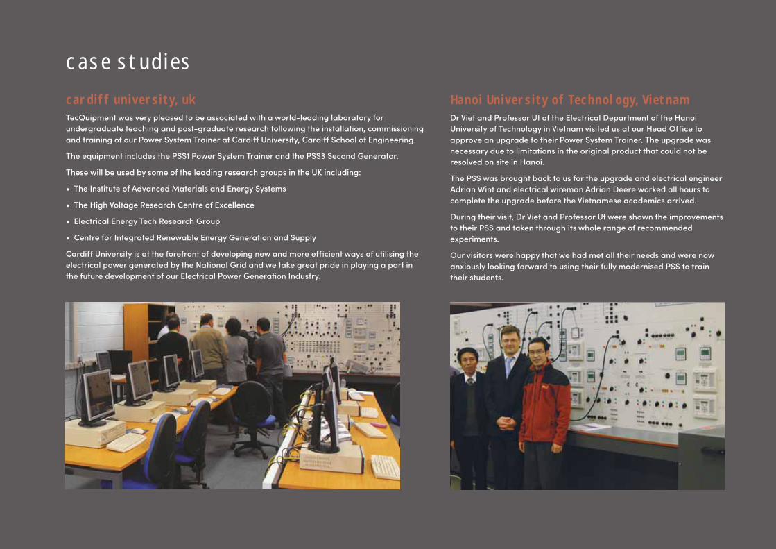
c a s e s t u d i e sc a r d i f f u n i v e r s i t y, u kTecQuipment was very pleased to be associated with a world-leading laboratory for
undergraduate teaching and post-graduate research following the installation, commissioning
and training of our Power System Trainer at Cardiff University, Cardiff School of Engineering.
The equipment includes the PSS1 Power System Trainer and the PSS3 Second Generator.
These will be used by some of the leading research groups in the UK including:
• The Institute of Advanced Materials and Energy Systems
• The High Voltage Research Centre of Excellence
• Electrical Energy Tech Research Group
• Centre for Integrated Renewable Energy Generation and Supply
Cardiff University is at the forefront of developing new and more effi cient ways of utilising the
electrical power generated by the National Grid and we take great pride in playing a part in
the future development of our Electrical Power Generation Industry.
H a n o i U n i v e r s i t y o f T e c h n o l o g y, V i e t n a mDr Viet and Professor Ut of the Electrical Department of the Hanoi
University of Technology in Vietnam visited us at our Head Offi ce to
approve an upgrade to their Power System Trainer. The upgrade was
necessary due to limitations in the original product that could not be
resolved on site in Hanoi.
The PSS was brought back to us for the upgrade and electrical engineer
Adrian Wint and electrical wireman Adrian Deere worked all hours to
complete the upgrade before the Vietnamese academics arrived.
During their visit, Dr Viet and Professor Ut were shown the improvements
to their PSS and taken through its whole range of recommended
experiments.
Our visitors were happy that we had met all their needs and were now
anxiously looking forward to using their fully modernised PSS to train
their students.
+ 4 4 1 1 5 9 7 2 2 6 1 1 i n f o @ t e c q u i p m e n t. c o m 1
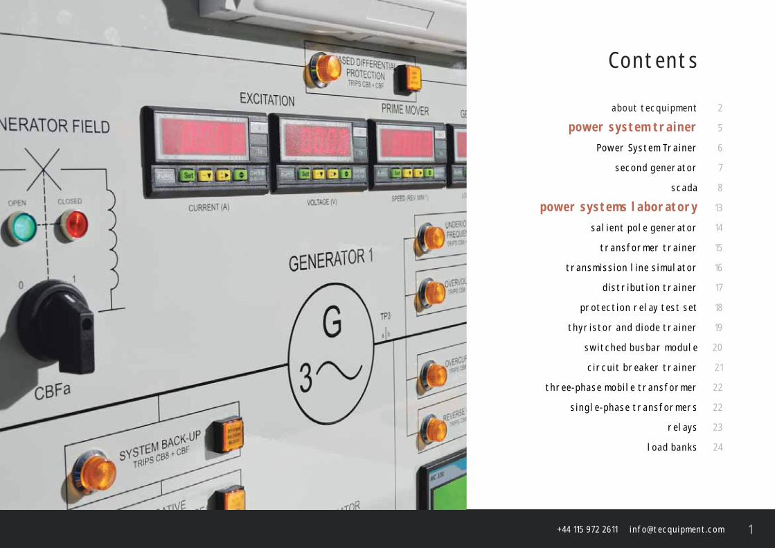
C o n t e n t s
a b o u t t e c q u i p m e n t 2
p o w e r s y s t e m t r a i n e r 5
P o w e r S y s t e m T r a i n e r 6
s e c o n d g e n e r at o r 7
s c a d a 8
p o w e r s y s t e m s l a b o r at o r y 1 3
s a l i e n t p o l e g e n e r at o r 1 4
t r a n s f o r m e r t r a i n e r 1 5
t r a n s m i s s i o n l i n e s i m u l at o r 1 6
d i s t r i b u t i o n t r a i n e r 1 7
p r o t e c t i o n r e l ay t e s t s e t 1 8
t h y r i s t o r a n d d i o d e t r a i n e r 1 9
s w i t c h e d b u s b a r m o d u l e 2 0
c i r c u i t b r e a k e r t r a i n e r 2 1
t h r e e - p h a s e m o b i l e t r a n s f o r m e r 2 2
s i n g l e - p h a s e t r a n s f o r m e r s 2 2
r e l ay s 2 3
l o a d b a n k s 2 4
t e c q u i p m e n t. c o m2
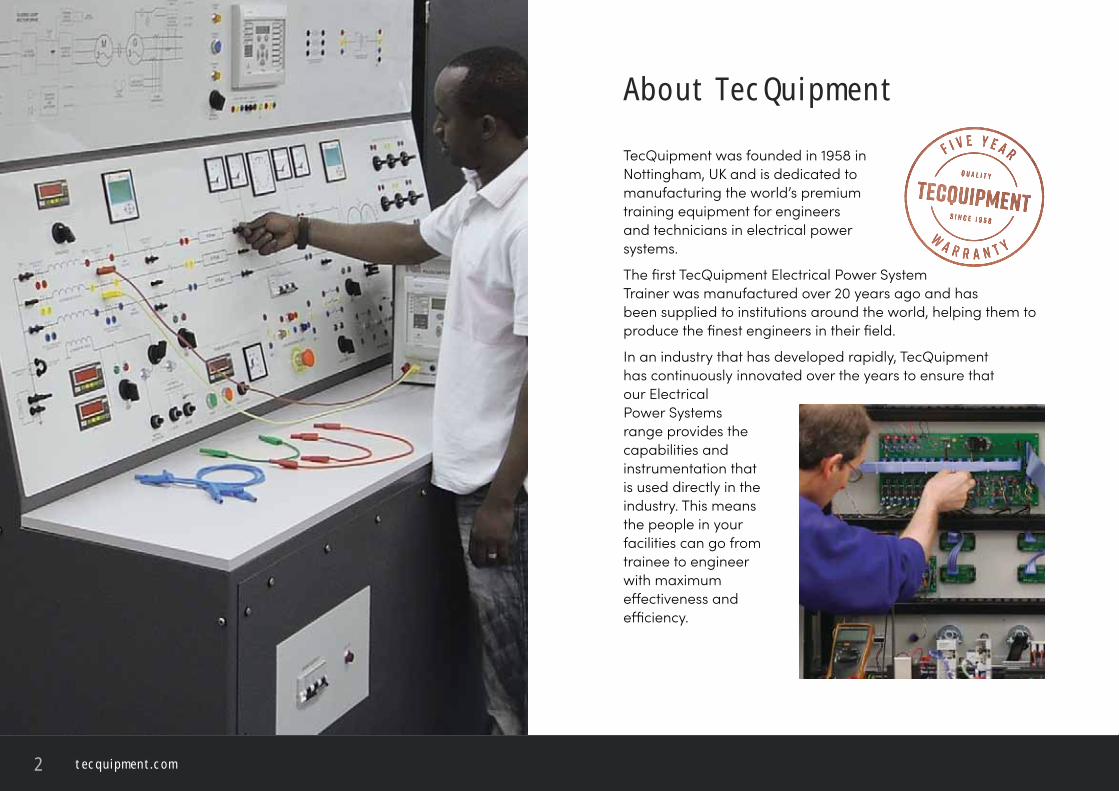
A b o u t T e c Q u i p m e n t
TecQuipment was founded in 1958 in Nottingham, UK and is dedicated to manufacturing the world’s premium training equipment for engineers and technicians in electrical power systems.
The fi rst TecQuipment Electrical Power System Trainer was manufactured over 20 years ago and has been supplied to institutions around the world, helping them to produce the fi nest engineers in their fi eld.
In an industry that has developed rapidly, TecQuipment has continuously innovated over the years to ensure that our Electrical Power Systems range provides the capabilities and instrumentation that is used directly in the industry. This means the people in your facilities can go from trainee to engineer with maximum eff ectiveness and effi ciency.
+ 4 4 1 1 5 9 7 2 2 6 1 1 i n f o @ t e c q u i p m e n t. c o m 3
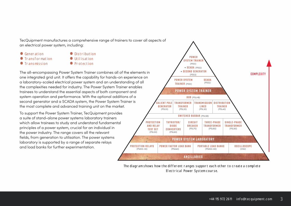
TecQuipment manufactures a comprehensive range of trainers to cover all aspects of an electrical power system, including:
• G e n e r at i o n • D i s t r i b u t i o n• T r a n s f o r m at i o n • U t i l i s at i o n• T r a n s m i s s i o n • P r o t e c t i o n
The all-encompassing Power System Trainer combines all of the elements in one integrated grid unit. It off ers the capability for hands-on experience on a laboratory-scaled electrical power system and an understanding of all the complexities needed for industry. The Power System Trainer enables trainees to understand the essential aspects of both component and system operation and performance. With the optional additions of a second generator and a SCADA system, the Power System Trainer is the most complete and advanced training unit on the market.
To support the Power System Trainer, TecQuipment provides a suite of stand-alone power systems laboratory trainers which allow trainees to study and understand fundamental principles of a power system, crucial for an individual in the power industry. The range covers all the relevant fi elds, from generation to utilisation. The power systems laboratory is supported by a range of separate relays and load banks for further experimentation.
T h e d i a g r a m s h o w s h o w t h e d i f f e r e n t r a n g e s s u p p o r t e a c h o t h e r t o c r e at e a c o m p l e t e E l e c t r i c a l P o w e r S y s t e m c o u r s e .
p r o t e c t i o n r e l ay s(PSA10-30)
p r o t e c t i o n a n d r e l ayt e s t s e t
(PSL50)
t h y r i s t o r /d i o d e
c o n v e r t e r s(PSL60)
S a l i e n t p o l e G e n e r at o r
(PSL10)
t r a n s f o r m e rt r a i n e r
(PSL20)
t r a n s m i s s i o nl i n e s(PSL30)
d i s t r i b u t i o nt r a i n e r
(PSL40)
c i r c u i tb r e a k e r
(PSL70)
s w i t c h e d b u s b a r (PSLSB)
t h r e e - p h a s et r a n s f o r m e r
(PSL80)
s i n g l e - p h a s et r a n s f o r m e r
(PSL90)
P o w e r S y s t e mT r a i n e r (PSS1)
P o w e rS y s t e m T r a i n e r
(PSS1) + S C A D A (PSS2)
+ S e c o n d G e n e r at o r(PSS3)
S C A D A(PSS2)
p o w e r fa c t o r l o a d b a n k(PSA40)
h u b (PSLHB)
c o m p l e x i t y
p o r ta b l e l o a d b a n k s(PSA50-60)
o s c i l l o s c o p e(OS2)
A N C I L L A R I E S
p o w e r s y s t e m l a b o r at o r y
p o w e r s y s t e m t r a i n e r
t e c q u i p m e n t. c o m4
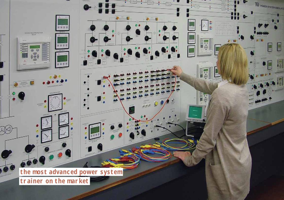
t h e m o s t a d va n c e d p o w e r s y s t e m t r a i n e r o n t h e m a r k e t
+ 4 4 1 1 5 9 7 2 2 6 1 1 i n f o @ t e c q u i p m e n t. c o m 5
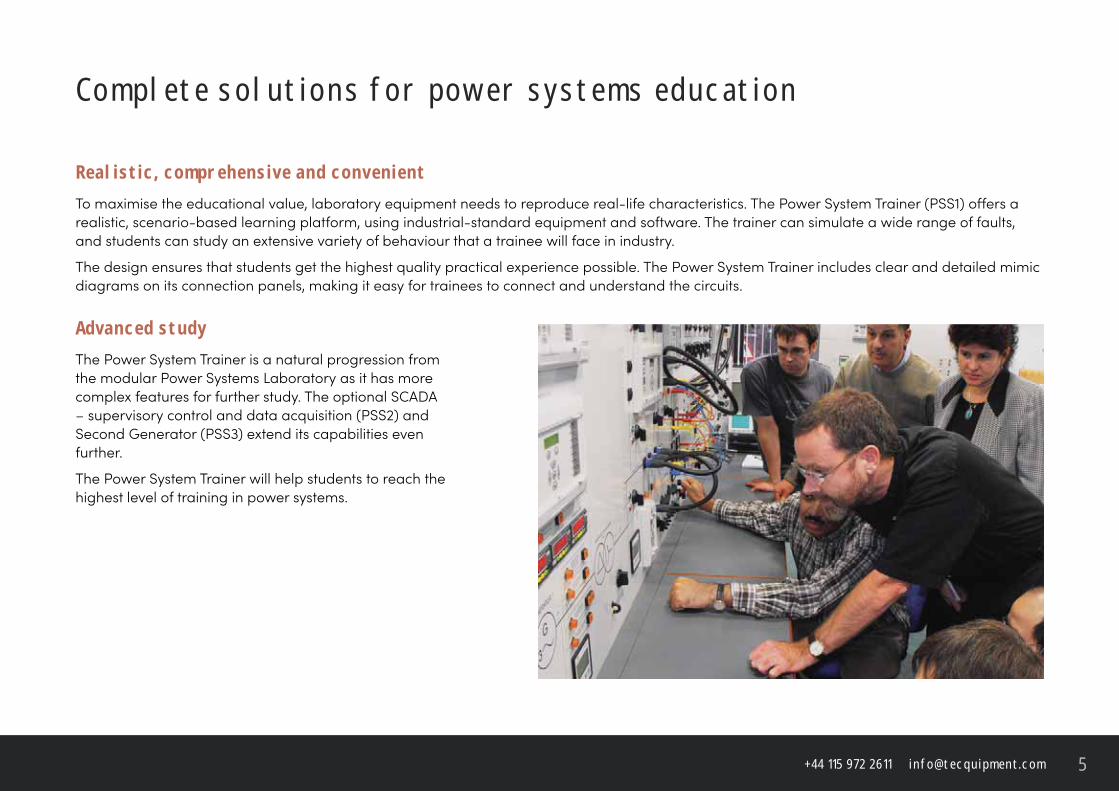
C o m p l e t e s o l u t i o n s f o r p o w e r s y s t e m s e d u c at i o n
R e a l i s t i c , c o m p r e h e n s i v e a n d c o n v e n i e n tTo maximise the educational value, laboratory equipment needs to reproduce real-life characteristics. The Power System Trainer (PSS1) off ers a realistic, scenario-based learning platform, using industrial-standard equipment and software. The trainer can simulate a wide range of faults, and students can study an extensive variety of behaviour that a trainee will face in industry.
The design ensures that students get the highest quality practical experience possible. The Power System Trainer includes clear and detailed mimic diagrams on its connection panels, making it easy for trainees to connect and understand the circuits.
A d va n c e d s t u d yThe Power System Trainer is a natural progression from the modular Power Systems Laboratory as it has more complex features for further study. The optional SCADA – supervisory control and data acquisition (PSS2) and Second Generator (PSS3) extend its capabilities even further.
The Power System Trainer will help students to reach the highest level of training in power systems.
t e c q u i p m e n t. c o m6
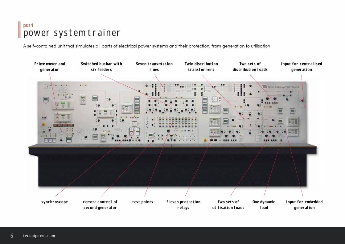
S e v e n t r a n s m i s s i o n l i n e s
S w i t c h e d b u s b a r w i t h s i x f e e d e r s
p s s 1
p o w e r s y s t e m t r a i n e rA self-contained unit that simulates all parts of electrical power systems and their protection, from generation to utilisation
T w i n d i s t r i b u t i o n t r a n s f o r m e r s
r e m o t e c o n t r o l o f s e c o n d g e n e r at o r
P r i m e m o v e r a n d g e n e r at o r
s y n c h r o s c o p e t e s t p o i n t s
T w o s e t s o f d i s t r i b u t i o n l o a d s
T w o s e t s o f u t i l i s at i o n l o a d s
O n e d y n a m i c l o a d
i n p u t f o r c e n t r a l i s e d g e n e r at i o n
i n p u t f o r e m b e d d e d g e n e r at i o n
E l e v e n p r o t e c t i o n r e l ay s
+ 4 4 1 1 5 9 7 2 2 6 1 1 i n f o @ t e c q u i p m e n t. c o m 7
t r a i n i n g o u t c o m e s• Power transmission, distribution and utilisation
• Load fl ow, circuit interruption and diff erential protection
• Symmetrical, unsymmetrical and unbalanced faults and loads
• Generator synchronisation and performance, including stability and voltage regulation and control
• Using protection relays for overcurrent, distance protection, phase and earth faults
• Using protection relays for diff erential protection, under and overvoltage and frequency protection
• Transformer tappings and impedances
• Using relays for protection of a busbar, transformers and generators
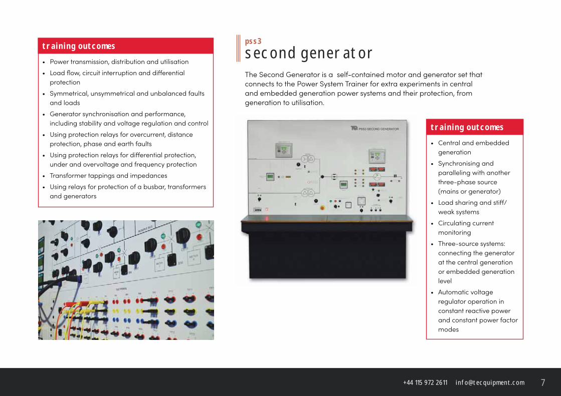
p s s 3
s e c o n d g e n e r at o rThe Second Generator is a self-contained motor and generator set that connects to the Power System Trainer for extra experiments in central and embedded generation power systems and their protection, from generation to utilisation.
t r a i n i n g o u t c o m e s• Central and embedded
generation
• Synchronising and paralleling with another three-phase source (mains or generator)
• Load sharing and stiff /weak systems
• Circulating current monitoring
• Three-source systems: connecting the generator at the central generation or embedded generation level
• Automatic voltage regulator operation in constant reactive power and constant power factor modes
t e c q u i p m e n t. c o m8
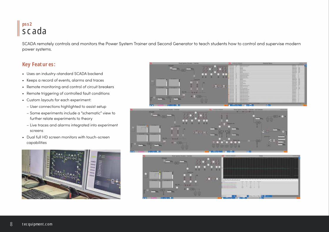
p s s 2
s c a d aSCADA remotely controls and monitors the Power System Trainer and Second Generator to teach students how to control and supervise modern power systems.
K e y F e at u r e s :• Uses an industry-standard SCADA backend
• Keeps a record of events, alarms and traces
• Remote monitoring and control of circuit breakers
• Remote triggering of controlled fault conditions
• Custom layouts for each experiment:
– User connections highlighted to assist setup
– Some experiments include a “schematic” view to further relate experiments to theory
– Live traces and alarms integrated into experiment screens
• Dual full HD screen monitors with touch-screen capabilities
+ 4 4 1 1 5 9 7 2 2 6 1 1 i n f o @ t e c q u i p m e n t. c o m 9
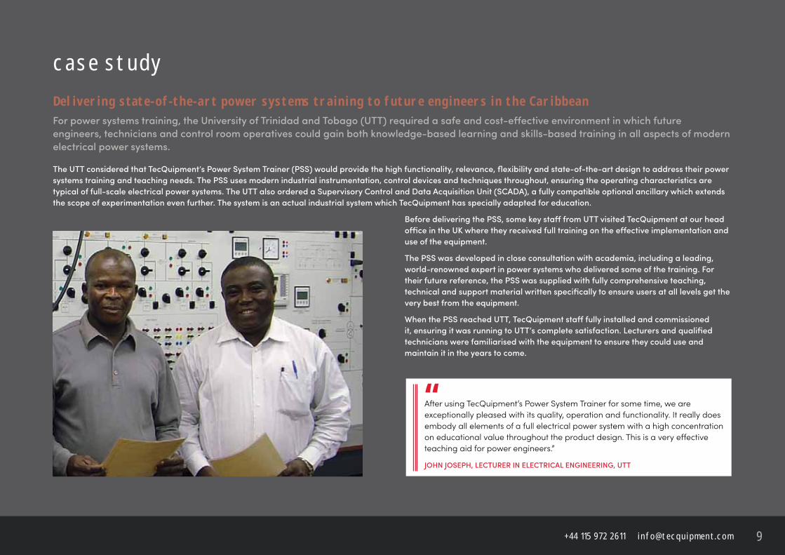
c a s e s t u d yD e l i v e r i n g s tat e - o f -t h e -a r t p o w e r s y s t e m s t r a i n i n g t o f u t u r e e n g i n e e r s i n t h e C a r i b b e a nFor power systems training, the University of Trinidad and Tobago (UTT) required a safe and cost-eff ective environment in which future
engineers, technicians and control room operatives could gain both knowledge-based learning and skills-based training in all aspects of modern
electrical power systems.
The UTT considered that TecQuipment’s Power System Trainer (PSS) would provide the high functionality, relevance, fl exibility and state-of-the-art design to address their power
systems training and teaching needs. The PSS uses modern industrial instrumentation, control devices and techniques throughout, ensuring the operating characteristics are
typical of full-scale electrical power systems. The UTT also ordered a Supervisory Control and Data Acquisition Unit (SCADA), a fully compatible optional ancillary which extends
the scope of experimentation even further. The system is an actual industrial system which TecQuipment has specially adapted for education.
Before delivering the PSS, some key staff from UTT visited TecQuipment at our head
offi ce in the UK where they received full training on the eff ective implementation and
use of the equipment.
The PSS was developed in close consultation with academia, including a leading,
world-renowned expert in power systems who delivered some of the training. For
their future reference, the PSS was supplied with fully comprehensive teaching,
technical and support material written specifi cally to ensure users at all levels get the
very best from the equipment.
When the PSS reached UTT, TecQuipment staff fully installed and commissioned
it, ensuring it was running to UTT’s complete satisfaction. Lecturers and qualifi ed
technicians were familiarised with the equipment to ensure they could use and
maintain it in the years to come.
After using TecQuipment’s Power System Trainer for some time, we are exceptionally pleased with its quality, operation and functionality. It really does embody all elements of a full electrical power system with a high concentration on educational value throughout the product design. This is a very eff ective teaching aid for power engineers.”
JOHN JOSEPH, LECTURER IN ELECTRICAL ENGINEERING, UTT
“
t e c q u i p m e n t. c o m10
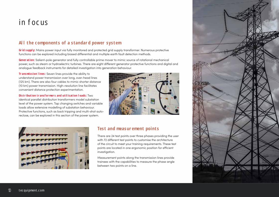
i n f o c u s
A l l t h e c o m p o n e n t s o f a s ta n d a r d p o w e r s y s t e mG r i d s u p p ly: Mains power input via fully monitored and protected grid supply transformer. Numerous protective functions can be explored including biased diff erential and multiple earth fault detection methods.
G e n e r at i o n : Salient-pole generator and fully controllable prime mover to mimic source of rotational mechanical power, such as steam or hydroelectric turbines. There are eight diff erent generator protective functions and digital and analogue feedback instruments for detailed investigation into generation behaviour.
T r a n s m i s s i o n l i n e s : Seven lines provide the ability to understand power transmission over long, over-head lines (125 km). There are also four cables to mimic shorter distance (10 km) power transmission. High-resolution line facilitates convenient distance protection experimentation.
D i s t r i b u t i o n t r a n s f o r m e r s a n d u t i l i s at i o n l o a d s : Two identical parallel distribution transformers model substation level of the power system. Tap changing switches and variable loads allow extensive modelling of substation behaviour. Protective functions, such as back tripping and multi-shot auto-reclose, can be explored in this section of the power system.
T e s t a n d m e a s u r e m e n t p o i n t s There are 24 test points over three phases providing the user with 72 diff erent test points to customise the architecture of the circuit to meet your training requirements. These test points are located in one ergonomic position for effi cient investigation.
Measurement points along the transmission lines provide trainees with the capabilities to measure the phase angle between two points on a line.
+ 4 4 1 1 5 9 7 2 2 6 1 1 i n f o @ t e c q u i p m e n t. c o m 11
P r o t e c t i o n R e l ay sIndustrial-standard numerical protection relays are utilised throughout the power system to protect the components in a variety of methods. The protection relays cover simple techniques such as over-current protection, to more complex concepts including 100 per cent stator earth fault generator protection.
B u s b a rThe Power System Trainer includes a switched busbar section, comprising of a main bus and stand-by “reserve” bus. This allows for the training of zonal protection and contingency planning in the event of a system fault.
The measurement centres provide the option for custom circuits to be created and investigated utilising sections of the bus matrix.
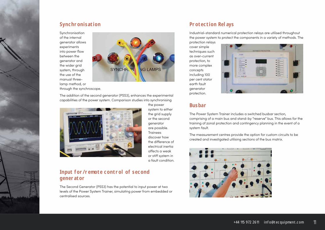
S y n c h r o n i s at i o nSynchronisation of the internal generator allows experiments into power fl ow between the generator and the wider grid system, through the use of the manual three-lamp method, or through the synchroscope.
The addition of the second generator (PSS3), enhances the experimental capabilities of the power system. Comparison studies into synchronising
the power system to either the grid supply or the second generator are possible. Trainees discover how the diff erence of electrical inertia aff ects a weak or stiff system in a fault condition.
I n p u t f o r / r e m o t e c o n t r o l o f s e c o n d g e n e r at o r The Second Generator (PSS3) has the potential to input power at two levels of the Power System Trainer, simulating power from embedded or centralised sources.
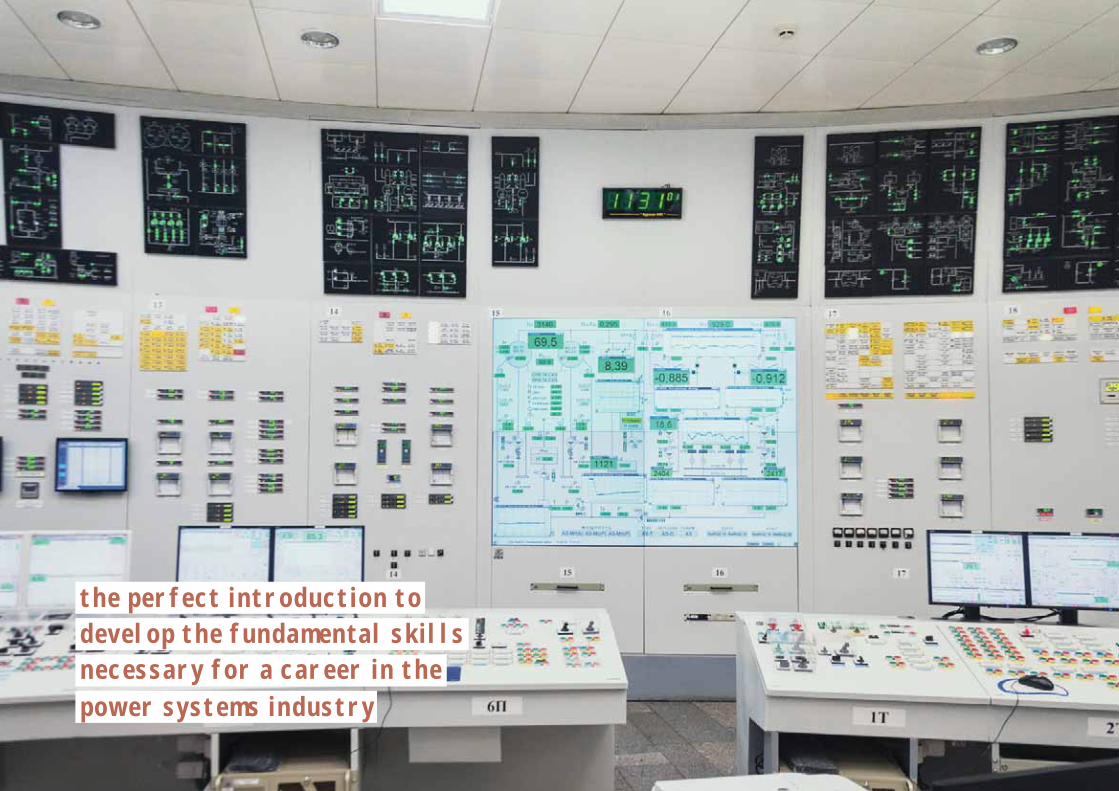
t h e p e r f e c t i n t r o d u c t i o n t o d e v e l o p t h e f u n d a m e n ta l s k i l l s n e c e s s a r y f o r a c a r e e r i n t h e p o w e r s y s t e m s i n d u s t r y
+ 4 4 1 1 5 9 7 2 2 6 1 1 i n f o @ t e c q u i p m e n t. c o m 13
p o w e r s y s t e m s l a b o r at o r y
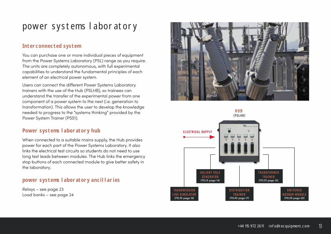
I n t e r c o n n e c t e d s y s t e mYou can purchase one or more individual pieces of equipment from the Power Systems Laboratory (PSL) range as you require. The units are completely autonomous, with full experimental capabilities to understand the fundamental principles of each element of an electrical power system.
Users can connect the diff erent Power Systems Laboratory trainers with the use of the Hub (PSLHB), so trainees can understand the transfer of the experimental power from one component of a power system to the next (i.e. generation to transformation). This allows the user to develop the knowledge needed to progress to the “systems thinking” provided by the Power System Trainer (PSS1).
P o w e r s y s t e m s l a b o r at o r y h u bWhen connected to a suitable mains supply, the Hub provides power for each part of the Power Systems Laboratory. It also links the electrical test circuits so students do not need to use long test leads between modules. The Hub links the emergency stop buttons of each connected module to give better safety in the laboratory.
p o w e r s y s t e m s l a b o r at o r y a n c i l l a r i e sRelays – see page 23Load banks – see page 24
H u b ( P S L H B )
e l e c t r i c a l s u p p ly
t r a n s m i s s i o nl i n e s i m u l at o r
( P S L 3 0 page 16)
s a l i e n t p o l eg e n e r at o r
( P S L1 0 page 14)
t r a n s f o r m e rt r a i n e r
( P S L 2 0 page 15)
s w i t c h e db u s b a r m o d u l e
( P S L s b page 20)
d i s t r i b u t i o nt r a i n e r
( P S L4 0 page 17)
t e c q u i p m e n t. c o m14
p s l1 0
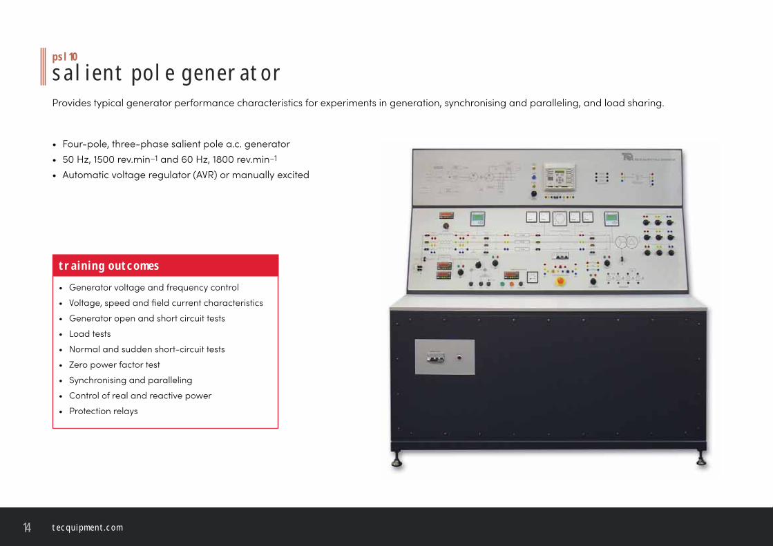
s a l i e n t p o l e g e n e r at o rProvides typical generator performance characteristics for experiments in generation, synchronising and paralleling, and load sharing.
• Four-pole, three-phase salient pole a.c. generator• 50 Hz, 1500 rev.min–1 and 60 Hz, 1800 rev.min–1
• Automatic voltage regulator (AVR) or manually excited
t r a i n i n g o u t c o m e s• Generator voltage and frequency control
• Voltage, speed and fi eld current characteristics
• Generator open and short circuit tests
• Load tests
• Normal and sudden short-circuit tests
• Zero power factor test
• Synchronising and paralleling
• Control of real and reactive power
• Protection relays
+ 4 4 1 1 5 9 7 2 2 6 1 1 i n f o @ t e c q u i p m e n t. c o m 15
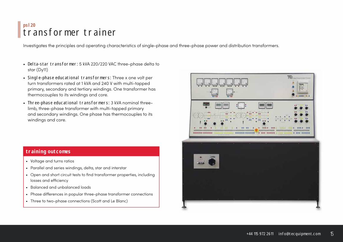
p s l 2 0
t r a n s f o r m e r t r a i n e rInvestigates the principles and operating characteristics of single-phase and three-phase power and distribution transformers.
• D e lta - s ta r t r a n s f o r m e r : 5 kVA 220/220 VAC three-phase delta to star (Dy11)
• S i n g l e - p h a s e e d u c at i o n a l t r a n s f o r m e r s : Three x one volt per turn transformers rated at 1 kVA and 240 V with multi-tapped primary, secondary and tertiary windings. One transformer has thermocouples to its windings and core.
• T h r e e - p h a s e e d u c at i o n a l t r a n s f o r m e r s : 3 kVA nominal three-limb, three-phase transformer with multi-tapped primary and secondary windings. One phase has thermocouples to its windings and core.
t r a i n i n g o u t c o m e s• Voltage and turns ratios
• Parallel and series windings, delta, star and interstar
• Open and short circuit tests to fi nd transformer properties, including losses and effi ciency
• Balanced and unbalanced loads
• Phase diff erences in popular three-phase transformer connections
• Three to two-phase connections (Scott and Le Blanc)
t e c q u i p m e n t. c o m16
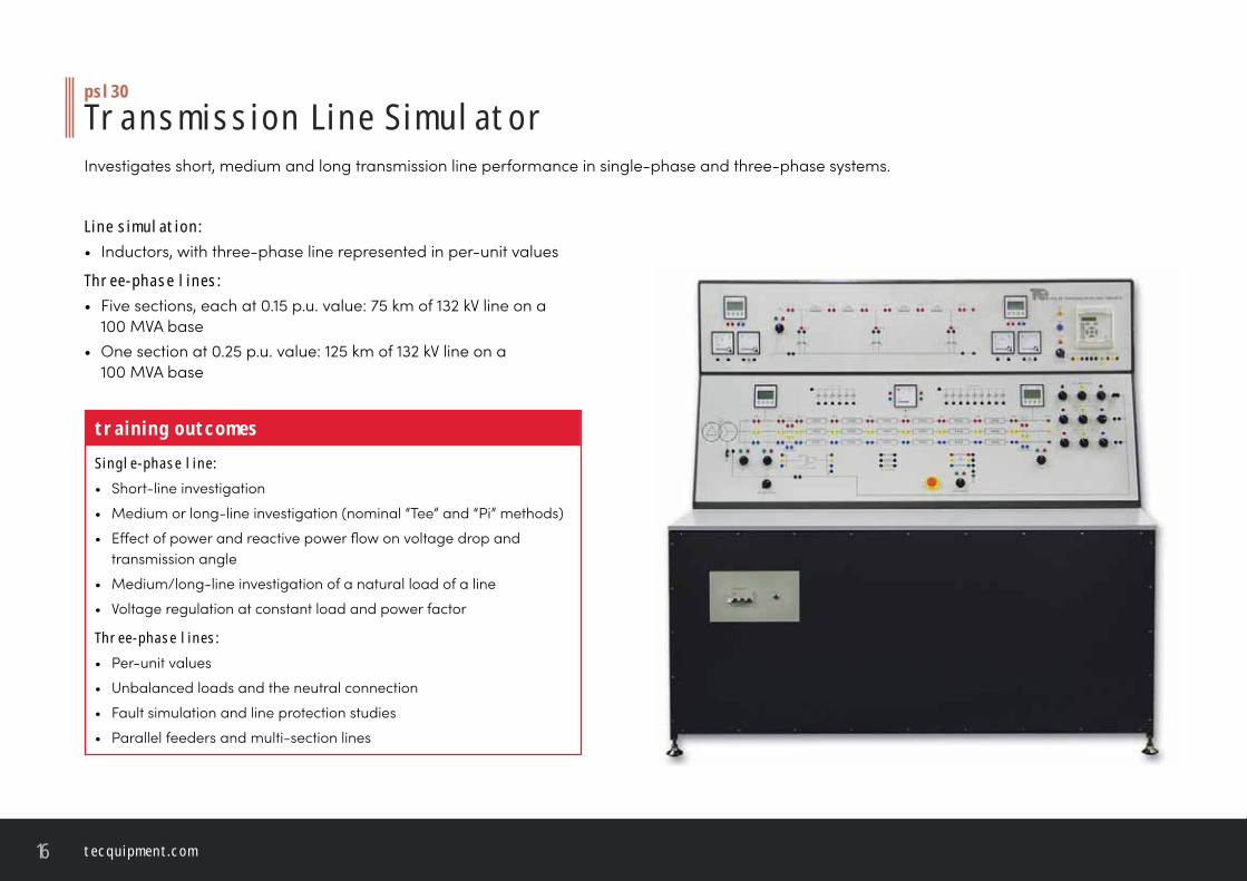
p s l 3 0
T r a n s m i s s i o n L i n e S i m u l at o rInvestigates short, medium and long transmission line performance in single-phase and three-phase systems.
L i n e s i m u l at i o n : • Inductors, with three-phase line represented in per-unit values
T h r e e - p h a s e l i n e s :• Five sections, each at 0.15 p.u. value: 75 km of 132 kV line on a
100 MVA base• One section at 0.25 p.u. value: 125 km of 132 kV line on a
100 MVA base
t r a i n i n g o u t c o m e sS i n g l e - p h a s e l i n e :• Short-line investigation
• Medium or long-line investigation (nominal “Tee” and “Pi” methods)
• Eff ect of power and reactive power fl ow on voltage drop and transmission angle
• Medium/long-line investigation of a natural load of a line
• Voltage regulation at constant load and power factor
T h r e e - p h a s e l i n e s :• Per-unit values
• Unbalanced loads and the neutral connection
• Fault simulation and line protection studies
• Parallel feeders and multi-section lines
+ 4 4 1 1 5 9 7 2 2 6 1 1 i n f o @ t e c q u i p m e n t. c o m 17
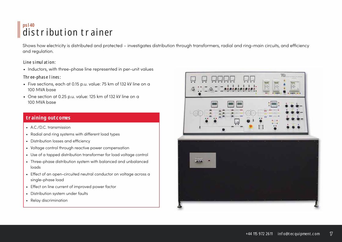
p s l4 0
d i s t r i b u t i o n t r a i n e rShows how electricity is distributed and protected – investigates distribution through transformers, radial and ring-main circuits, and effi ciency and regulation.
L i n e s i m u l at i o n :• Inductors, with three-phase line represented in per-unit values
T h r e e - p h a s e l i n e s :• Five sections, each at 0.15 p.u. value: 75 km of 132 kV line on a
100 MVA base• One section at 0.25 p.u. value: 125 km of 132 kV line on a
100 MVA base
t r a i n i n g o u t c o m e s• A.C./D.C. transmission
• Radial and ring systems with diff erent load types
• Distribution losses and effi ciency
• Voltage control through reactive power compensation
• Use of a tapped distribution transformer for load voltage control
• Three-phase distribution system with balanced and unbalanced loads
• Eff ect of an open-circuited neutral conductor on voltage across a single-phase load
• Eff ect on line current of improved power factor
• Distribution system under faults
• Relay discrimination
t e c q u i p m e n t. c o m18
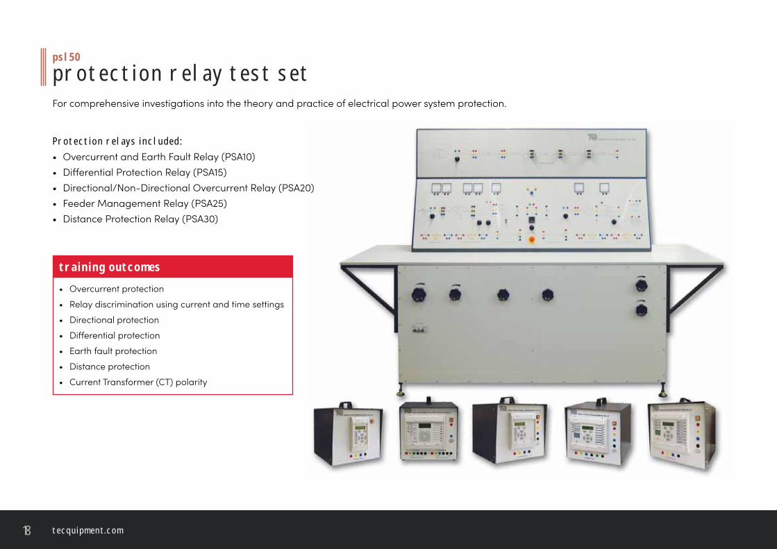
p s l 5 0
p r o t e c t i o n r e l ay t e s t s e tFor comprehensive investigations into the theory and practice of electrical power system protection.
P r o t e c t i o n r e l ay s i n c l u d e d :• Overcurrent and Earth Fault Relay (PSA10)• Diff erential Protection Relay (PSA15)• Directional/Non-Directional Overcurrent Relay (PSA20)• Feeder Management Relay (PSA25)• Distance Protection Relay (PSA30)
t r a i n i n g o u t c o m e s• Overcurrent protection
• Relay discrimination using current and time settings
• Directional protection
• Diff erential protection
• Earth fault protection
• Distance protection
• Current Transformer (CT) polarity
+ 4 4 1 1 5 9 7 2 2 6 1 1 i n f o @ t e c q u i p m e n t. c o m 19
p s l 6 0
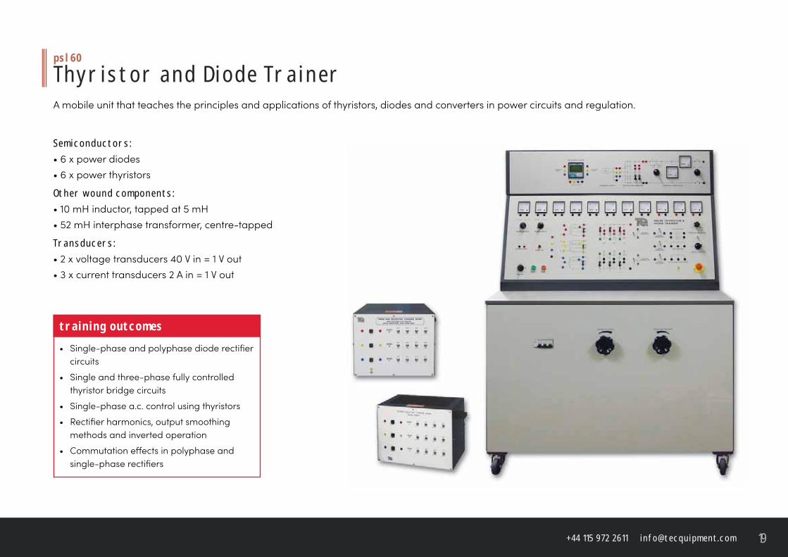
T h y r i s t o r a n d D i o d e T r a i n e r A mobile unit that teaches the principles and applications of thyristors, diodes and converters in power circuits and regulation.
S e m i c o n d u c t o r s :• 6 x power diodes• 6 x power thyristors
O t h e r w o u n d c o m p o n e n t s :• 10 mH inductor, tapped at 5 mH• 52 mH interphase transformer, centre-tapped
T r a n s d u c e r s :• 2 x voltage transducers 40 V in = 1 V out• 3 x current transducers 2 A in = 1 V out
t r a i n i n g o u t c o m e s• Single-phase and polyphase diode rectifi er
circuits
• Single and three-phase fully controlled thyristor bridge circuits
• Single-phase a.c. control using thyristors
• Rectifi er harmonics, output smoothing methods and inverted operation
• Commutation eff ects in polyphase and single-phase rectifi ers
t e c q u i p m e n t. c o m20
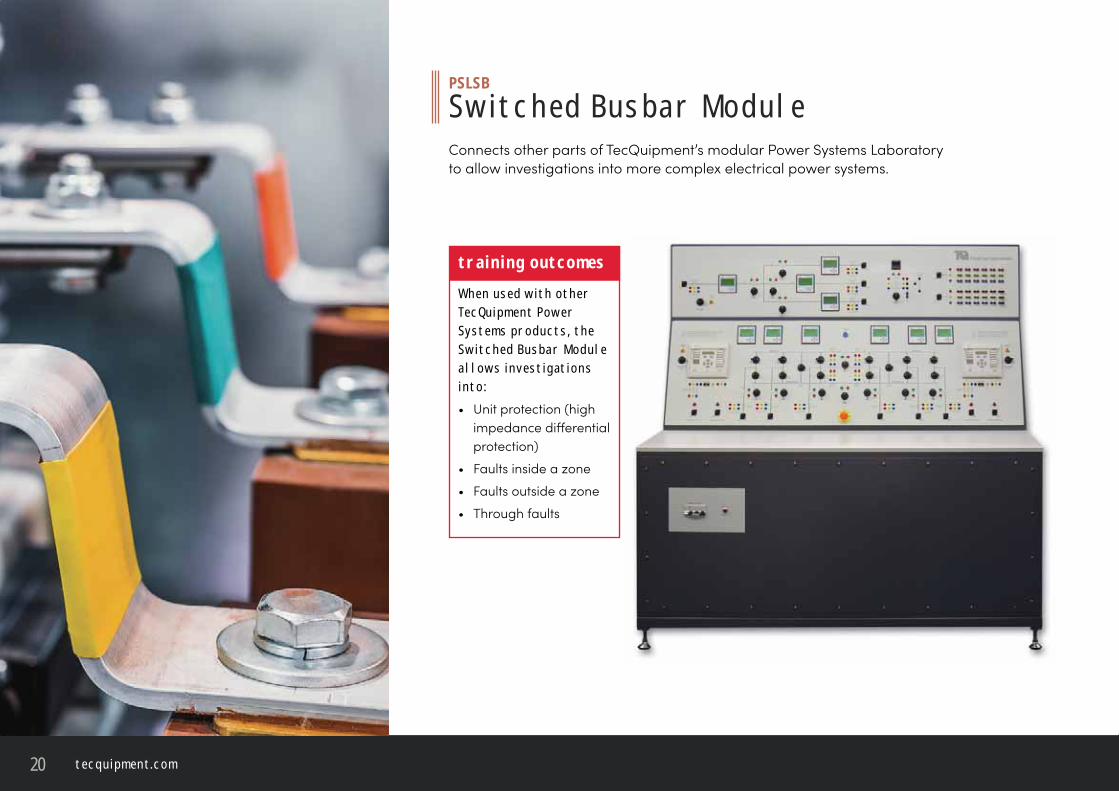
P S L S B
S w i t c h e d B u s b a r M o d u l e Connects other parts of TecQuipment’s modular Power Systems Laboratory to allow investigations into more complex electrical power systems.
t r a i n i n g o u t c o m e sW h e n u s e d w i t h o t h e r T e c Q u i p m e n t P o w e r S y s t e m s p r o d u c t s , t h e S w i t c h e d B u s b a r M o d u l e a l l o w s i n v e s t i g at i o n s i n t o :• Unit protection (high
impedance diff erential protection)
• Faults inside a zone
• Faults outside a zone
• Through faults
+ 4 4 1 1 5 9 7 2 2 6 1 1 i n f o @ t e c q u i p m e n t. c o m 21
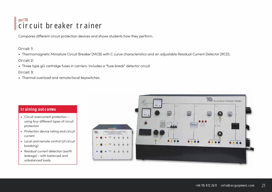
p s l7 0
c i r c u i t b r e a k e r t r a i n e rCompares diff erent circuit protection devices and shows students how they perform.
C i r c u i t 1 :• Thermomagnetic Miniature Circuit Breaker (MCB) with C curve characteristics and an adjustable Residual Current Detector (RCD).
C i r c u i t 2 : • Three type gG cartridge fuses in carriers. Includes a “fuse break” detector circuit.
C i r c u i t 3 :• Thermal overload and remote/local keyswitches.
t r a i n i n g o u t c o m e s• Circuit overcurrent protection -
using four diff erent types of circuit protection
• Protection device rating and circuit current
• Local and remote control (of circuit breaking)
• Residual current detection (earth leakage) - with balanced and unbalanced loads
t e c q u i p m e n t. c o m22
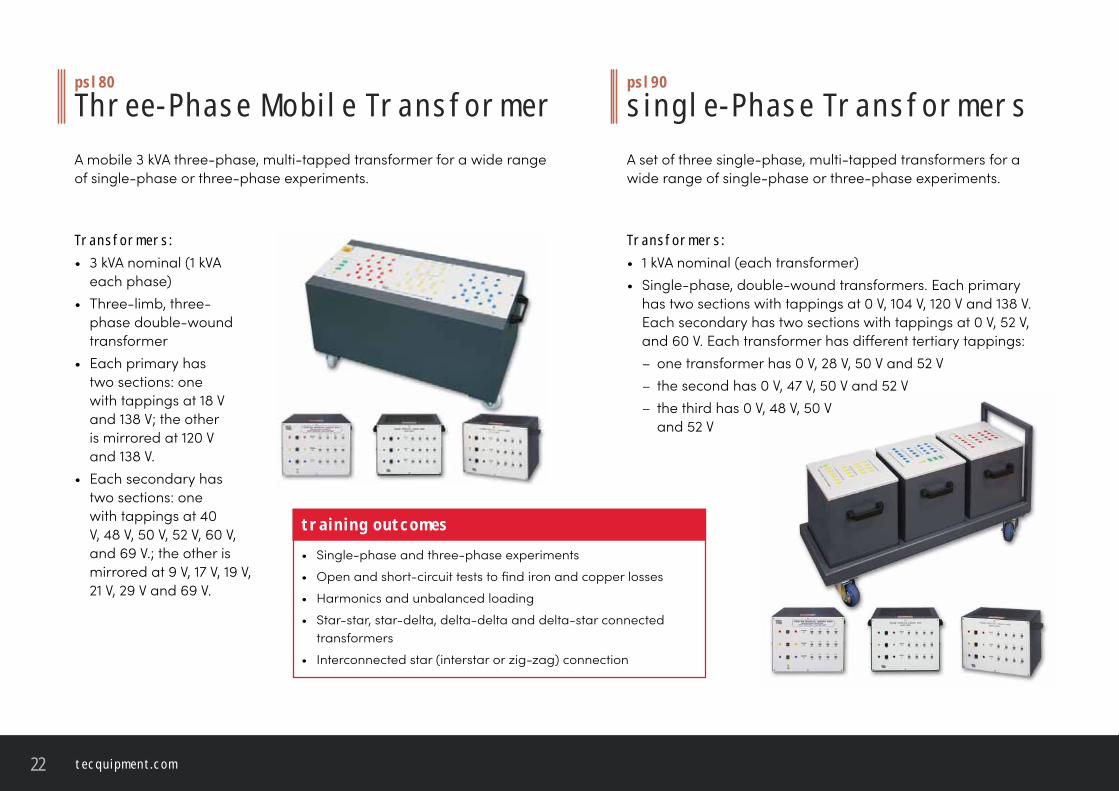
T r a n s f o r m e r s :• 3 kVA nominal (1 kVA
each phase)• Three-limb, three-
phase double-wound transformer
• Each primary has two sections: one with tappings at 18 V and 138 V; the other is mirrored at 120 V and 138 V.
• Each secondary has two sections: one with tappings at 40 V, 48 V, 50 V, 52 V, 60 V, and 69 V.; the other is mirrored at 9 V, 17 V, 19 V, 21 V, 29 V and 69 V.
p s l 8 0
T h r e e - P h a s e M o b i l e T r a n s f o r m e r A mobile 3 kVA three-phase, multi-tapped transformer for a wide range of single-phase or three-phase experiments.
t r a i n i n g o u t c o m e s• Single-phase and three-phase experiments
• Open and short-circuit tests to fi nd iron and copper losses
• Harmonics and unbalanced loading
• Star-star, star-delta, delta-delta and delta-star connected transformers
• Interconnected star (interstar or zig-zag) connection
p s l 9 0
s i n g l e - P h a s e T r a n s f o r m e r sA set of three single-phase, multi-tapped transformers for a wide range of single-phase or three-phase experiments.
T r a n s f o r m e r s :• 1 kVA nominal (each transformer)• Single-phase, double-wound transformers. Each primary
has two sections with tappings at 0 V, 104 V, 120 V and 138 V. Each secondary has two sections with tappings at 0 V, 52 V, and 60 V. Each transformer has diff erent tertiary tappings:– one transformer has 0 V, 28 V, 50 V and 52 V– the second has 0 V, 47 V, 50 V and 52 V– the third has 0 V, 48 V, 50 V
and 52 V
+ 4 4 1 1 5 9 7 2 2 6 1 1 i n f o @ t e c q u i p m e n t. c o m 23
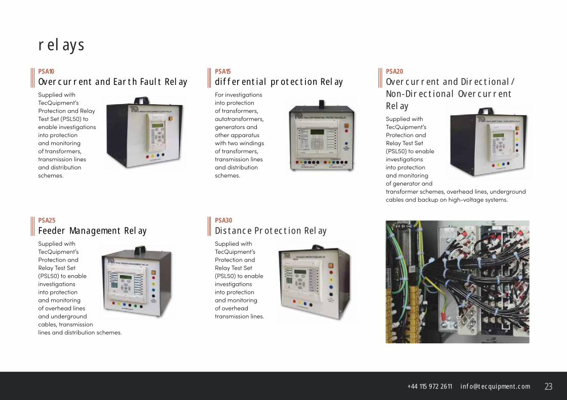
P S A1 0O v e r c u r r e n t a n d E a r t h Fa u lt R e l aySupplied with TecQuipment’s Protection and Relay Test Set (PSL50) to enable investigations into protection and monitoring of transformers, transmission lines and distribution schemes.
P S A 2 0O v e r c u r r e n t a n d D i r e c t i o n a l /N o n - D i r e c t i o n a l O v e r c u r r e n t R e l aySupplied with TecQuipment’s Protection and Relay Test Set (PSL50) to enable investigations into protection and monitoring of generator and transformer schemes, overhead lines, underground cables and backup on high-voltage systems.
P S A 3 0D i s ta n c e P r o t e c t i o n R e l aySupplied with TecQuipment’s Protection and Relay Test Set (PSL50) to enable investigations into protection and monitoring of overhead transmission lines.
P S A1 5d i f f e r e n t i a l p r o t e c t i o n R e l ayFor investigations into protection of transformers, autotransformers, generators and other apparatus with two windings of transformers, transmission lines and distribution schemes.
P S A 2 5F e e d e r M a n a g e m e n t R e l ay Supplied with TecQuipment’s Protection and Relay Test Set (PSL50) to enable investigations into protection and monitoring of overhead lines and underground cables, transmissionlines and distribution schemes.
r e l ay s
t e c q u i p m e n t. c o m24
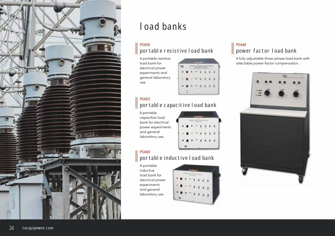
P S A 5 0p o r ta b l e r e s i s t i v e l o a d b a n kA portable resistive load bank for electrical power experiments and general laboratory use.
P S A 6 0p o r ta b l e i n d u c t i v e l o a d b a n kA portable inductive load bank for electrical power experiments and general laboratory use.
P S A 5 5p o r ta b l e c a pa c i t i v e l o a d b a n kA portable capacitive load bank for electrical power experiments and general laboratory use.
P S A 4 0p o w e r fa c t o r l o a d b a n kA fully adjustable three-phase load bank with selectable power factor compensation.
l o a d b a n k s
c a s e s t u d i e sc a r d i f f u n i v e r s i t y, u kTecQuipment was very pleased to be associated with a world-leading laboratory for
undergraduate teaching and post-graduate research following the installation, commissioning
and training of our Power System Trainer at Cardiff University, Cardiff School of Engineering.
The equipment includes the PSS1 Power System Trainer and the PSS3 Second Generator.
These will be used by some of the leading research groups in the UK including:
• The Institute of Advanced Materials and Energy Systems
• The High Voltage Research Centre of Excellence
• Electrical Energy Tech Research Group
• Centre for Integrated Renewable Energy Generation and Supply
Cardiff University is at the forefront of developing new and more effi cient ways of utilising the
electrical power generated by the National Grid and we take great pride in playing a part in
the future development of our Electrical Power Generation Industry.
H a n o i U n i v e r s i t y o f T e c h n o l o g y, V i e t n a mDr Viet and Professor Ut of the Electrical Department of the Hanoi
University of Technology in Vietnam visited us at our Head Offi ce to
approve an upgrade to their Power System Trainer. The upgrade was
necessary due to limitations in the original product that could not be
resolved on site in Hanoi.
The PSS was brought back to us for the upgrade and electrical engineer
Adrian Wint and electrical wireman Adrian Deere worked all hours to
complete the upgrade before the Vietnamese academics arrived.
During their visit, Dr Viet and Professor Ut were shown the improvements
to their PSS and taken through its whole range of recommended
experiments.
Our visitors were happy that we had met all their needs and were now
anxiously looking forward to using their fully modernised PSS to train
their students.
t e c q u i p m e n t. c o mTecQuipment Ltd, Bonsall Street, Long Eaton, Nottingham NG10 2AN, UK