Embed Size (px)
Citation preview
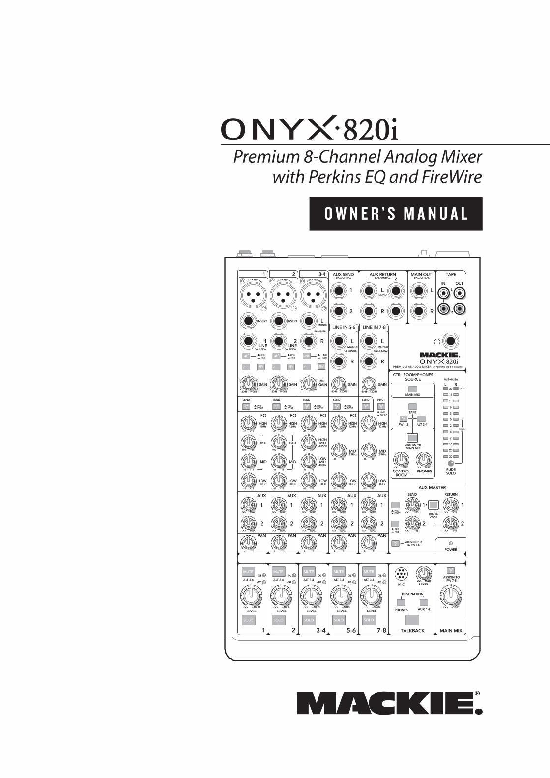
O W N E R ’ S M A N U A L
Premium 8-Channel Analog Mixerwith Perkins EQ and FireWire
MUTE
SOLO
48V
MUTE
SOLO
48V
MUTE
SOLO
48V
LINE
MUTE
SOLO
MUTE
SOLO
TAPE
PAN
2
1
MID
FREQ
MID
FREQ
BAL/UNBAL BAL/UNBAL
ALT 3-4 ALT 3-4 ALT 3-4 ALT 3-4 ALT 3-4
LOWMID400Hz
ONYX MIC PRE
HIGH12kHz
LOW80Hz
EQ
INSERT INSERT
ONYX MIC PRE
HIGH12kHz
LOW80Hz
EQ
ONYX MIC PRE
HIGH12kHz
HIGHMID
2.5KHz
LOW80Hz
EQ
AUX MASTER
2
1
SEND RETURN
2
1
EQ
MAIN MIX
(MONO)L
R
L
R
L(MONO)
R
BAL/UNBAL
L(MONO)
R
BAL/UNBAL
L(MONO)
R
BAL/UNBAL
TAPE
IN OUT
L
R
AUX RETURN
1
21
2
AUX SEND MAIN OUT
CTRL ROOM/PHONESSOURCE
PHONESCONTROLROOM
MID2.5kHz
LOW80Hz
U
+15-15
U
+15-15
U
+15-15
U
+15-15
U
+15-15
U
+15-15
U
+15-15
U
+15-15
U
+15-15
U
+15-15
U
+15-15
U
+15-15
U
+15-15
U
+15-15
U
+15-15
U
+15-15
HIGH12kHz
MID2.5kHz
LOW80Hz
HIGH12kHz
RUDESOLO
20
15
10
6
3
0
2
4
7
10
20
30
L R0dB=0dBu
LEVELSET
CLIP
MIC
PREPOST
PREPOST
FW 1-2LINE
HI-ZLINE
-10dB+4dB
HI-ZLINE
PREMIUM ANALOG MIXER w/ PERKINS EQ & FIREWIRE
PREPOST
PREPOST
PREPOST
PREPOST
LEVELLEVELLEVEL LEVEL LEVEL+10dBOO
U
+10dBOO
U
+10dBOO
U
+10dBOO
U
+10dBOO
U
+10dBOO
U
1 2 3-4
LINE IN 5-6 LINE IN 7-8
AUX
PAN
2
1
AUX
PAN
2
1
AUX
PAN
2
1
AUX
PAN
2
1
AUX
RTN TOAUX1
AUX SEND 1-2TO FW 5-6
ASSIGN TOFW 7-8
MAIN MIX
AUX 1-2PHONES
DESTINATION
LEVELOO MAX
OL
- 20
OL
- 20 - 20
OLOL
- 20
OL
- 20
1 2 TALKBACK
BAL/UNBAL BAL/UNBAL BAL/UNBAL
SEND SEND SEND SEND SEND INPUT
POWER
ALT 3-4FW 1-2
ASSIGN TOMAIN MIX
3-4 5-6 7-8
GAIN
+20dB-20dB
U
GAINMIC
GAINGAIN
+20dB-20dB
U
U
20
30
40
60+40dB
U
-20dBU
20
30
40
60
GAIN
+40dB
U
-20dBU
20
30
40
60
1LINE
2LINE
1k
100 8k
1k
100 8k
MAXOOMAXOO
MAXOO
MAXOO
+15OO
+15OO
+10OO
+10OO
MAXOO
MAXOO
MAXOO
MAXOO
MAXOO
MAXOO
MAXOO
MAXOO
L R L R L R L R L R
2 Onyx 820i
1. Read these instructions. 2. Keep these instructions.3. Heed all warnings.4. Follow all instructions.5. Do not use this apparatus near water.6. Clean only with a dry cloth.7. Do not block any ventilation openings. Install in accordance with the
manufacturer’s instructions.8. Do not install near any heat sources such as radiators, heat registers,
stoves, or other apparatus (including amplifi ers) that produce heat.9. Do not defeat the safety purpose of the polarized or grounding-type
plug. A polarized plug has two blades with one wider than the other. A grounding-type plug has two blades and a third grounding prong. The wide blade or the third prong are provided for your safety. If the provided plug does not fi t into your outlet, consult an electrician for replacement of the obsolete outlet.
10. Protect the power cord from being walked on or pinched particularly at plugs, convenience receptacles, and the point where they exit from the apparatus.
11. Only use attachments/accessories specifi ed by the manufacturer.12. Use only with a cart, stand, tripod, bracket, or
table specifi ed by the manufacturer, or sold with the apparatus. When a cart is used, use caution when moving the cart/apparatus combination to avoid injury from tip-over.
13. Unplug this apparatus during lightning storms or when unused for long periods of time.
14. Refer all servicing to qualifi ed service personnel. Servicing is required when the apparatus has been damaged in any way, such as power-supply cord or plug is damaged, liquid has been spilled or objects have fallen into the apparatus, the apparatus has been exposed to rain or moisture, does not operate normally, or has been dropped.
15. Do not overload wall outlets and extension cords as this can result in a risk of fi re or electric shock.
16. This apparatus shall not be exposed to dripping or splashing, and no object fi lled with liquids, such as vases or beer glasses, shall be placed on the apparatus.
17. This apparatus has been designed with Class-I construction and must be connected to a mains socket outlet with a protective earthing con-nection (the third grounding prong).
18. This apparatus has been equipped with a rocker-style AC mains power switch. This switch is located on the rear panel and should remain readily accessible to the user.
19. The MAINS plug or an appliance coupler is used as the disconnect device, so the disconnect device shall remain readily operable.
20. NOTE: This equipment has been tested and found to comply with the limits for a Class B digital device, pursuant to part 15 of the FCC Rules. These limits are designed to provide reasonable protection against harmful interference in a residential installation. This equip-ment generates, uses, and can radiate radio frequency energy and, if not installed and used in accordance with the instructions, may cause harmful interference to radio communications. However, there is no guarantee that interference will not occur in a particular installation. If this equipment does cause harmful interference to radio or television reception, which can be determined by turning the equipment off and on, the user is encouraged to try to correct the interference by one or more of the following measures:
• Reorient or relocate the receiving antenna.• Increase the separation between the equipment and the
receiver.• Connect the equipment into an outlet on a circuit different from
that to which the receiver is connected.• Consult the dealer or an experienced radio/TV technician for
help. CAUTION: Changes or modifi cations to this device not expressly
approved by LOUD Technologies Inc. could void the user's authority to operate the equipment under FCC rules.
21. This apparatus does not exceed the Class A/Class B (whichever is applicable) limits for radio noise emissions from digital apparatus as set out in the radio interference regulations of the Canadian Department of Com mu ni ca tions.
ATTENTION — Le présent appareil numérique n’émet pas de bruits radioélectriques dépassant las limites applicables aux appareils numériques de class A/de class B (selon le cas) prescrites dans le réglement sur le brouillage radioélectrique édicté par les ministere des com mu ni ca tions du Canada.
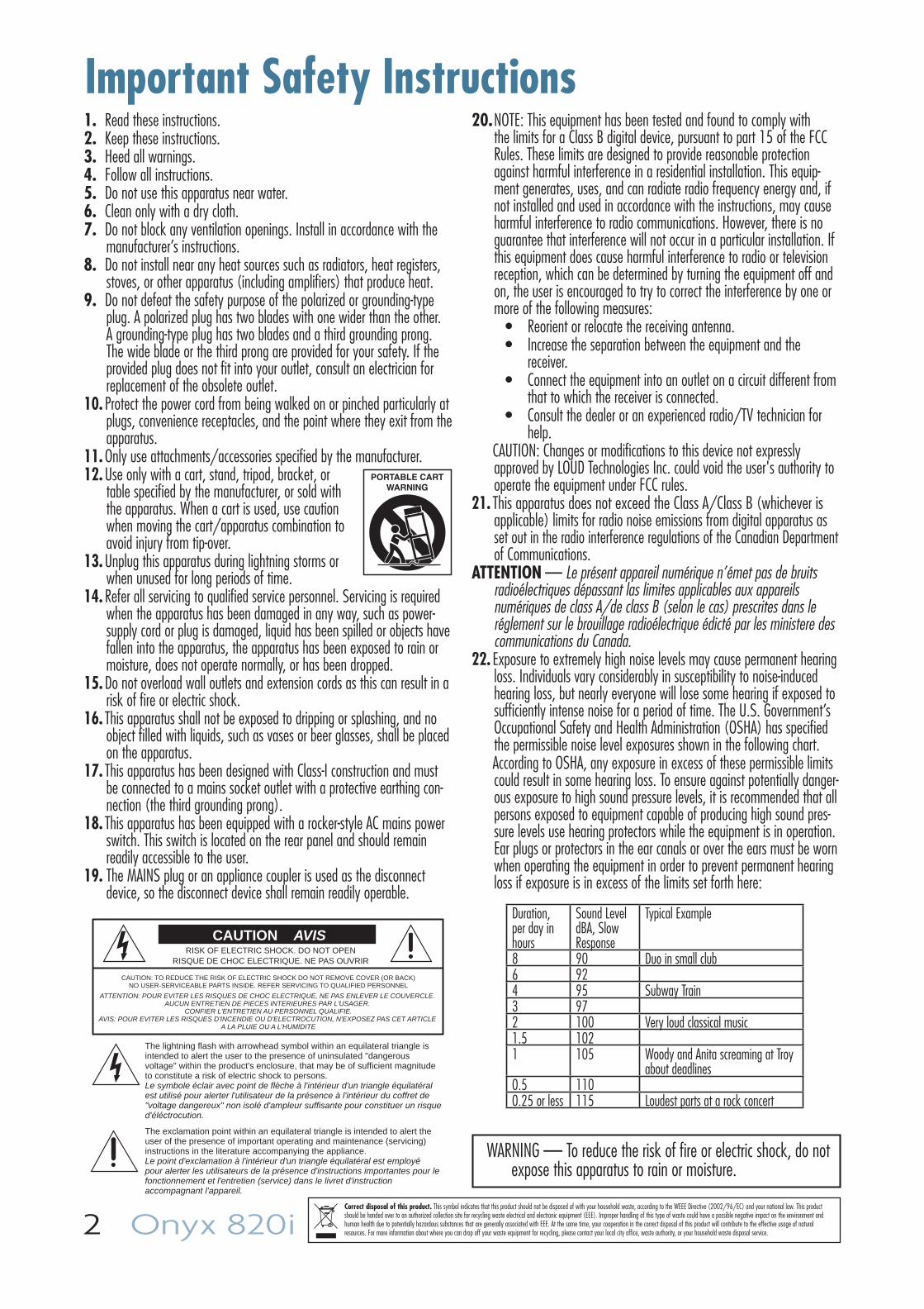
22. Exposure to extremely high noise levels may cause permanent hearing loss. Individuals vary considerably in susceptibility to noise-induced hearing loss, but nearly everyone will lose some hearing if exposed to suffi ciently intense noise for a period of time. The U.S. Government’s Occupational Safety and Health Administration (OSHA) has specifi ed the permissible noise level exposures shown in the following chart.
According to OSHA, any exposure in excess of these permissible limits could result in some hearing loss. To ensure against potentially danger-ous exposure to high sound pressure levels, it is recommended that all persons exposed to equipment capable of producing high sound pres-sure levels use hearing protectors while the equipment is in operation. Ear plugs or protectors in the ear canals or over the ears must be worn when operating the equipment in order to prevent permanent hearing loss if exposure is in excess of the limits set forth here:
Important Safety Instructions
PORTABLE CARTWARNING
CAUTION AVISRISK OF ELECTRIC SHOCK. DO NOT OPEN
RISQUE DE CHOC ELECTRIQUE. NE PAS OUVRIR
CAUTION: TO REDUCE THE RISK OF ELECTRIC SHOCK DO NOT REMOVE COVER (OR BACK)NO USER-SERVICEABLE PARTS INSIDE. REFER SERVICING TO QUALIFIED PERSONNEL
ATTENTION: POUR EVITER LES RISQUES DE CHOC ELECTRIQUE, NE PAS ENLEVER LE COUVERCLE. AUCUN ENTRETIEN DE PIECES INTERIEURES PAR L'USAGER.
CONFIER L'ENTRETIEN AU PERSONNEL QUALIFIE.AVIS: POUR EVITER LES RISQUES D'INCENDIE OU D'ELECTROCUTION, N'EXPOSEZ PAS CET ARTICLE
A LA PLUIE OU A L'HUMIDITE
The lightning flash with arrowhead symbol within an equilateral triangle is intended to alert the user to the presence of uninsulated "dangerous voltage" within the product's enclosure, that may be of sufficient magnitude to constitute a risk of electric shock to persons.Le symbole éclair avec point de flèche à l'intérieur d'un triangle équilatéral est utilisé pour alerter l'utilisateur de la présence à l'intérieur du coffret de "voltage dangereux" non isolé d'ampleur suffisante pour constituer un risque d'éléctrocution.
The exclamation point within an equilateral triangle is intended to alert the user of the presence of important operating and maintenance (servicing) instructions in the literature accompanying the appliance.Le point d'exclamation à l'intérieur d'un triangle équilatéral est employé pour alerter les utilisateurs de la présence d'instructions importantes pour le fonctionnement et l'entretien (service) dans le livret d'instruction accompagnant l'appareil.
WARNING — To reduce the risk of fi re or electric shock, do not expose this apparatus to rain or moisture.
Duration, per day in hours
Sound Level dBA, Slow Response
Typical Example
8 90 Duo in small club6 924 95 Subway Train3 972 100 Very loud classical music1.5 1021 105 Woody and Anita screaming at Troy
about deadlines0.5 1100.25 or less 115 Loudest parts at a rock concert
Correct disposal of this product. This symbol indicates that this product should not be disposed of with your household waste, according to the WEEE Directive (2002/96/EC) and your national law. This product should be handed over to an authorized collection site for recycling waste electrical and electronic equipment (EEE). Improper handling of this type of waste could have a possible negative impact on the environment and human health due to potentially hazardous substances that are generally associated with EEE. At the same time, your cooperation in the correct disposal of this product will contribute to the effective usage of natural resources. For more information about where you can drop off your waste equipment for recycling, please contact your local city offi ce, waste authority, or your household waste disposal service.
Owner's Manual 3
Part No. SW0718 Rev. D 02/2010 ©2010 LOUD Technologies Inc. All Rights Reserved.Loosely based on a dream sequence in which the technical writer is given keys to a sports car of his choice, unlimited gas, and closed roads. The dream suddenly ends and reality kicks in. A mixer manual to write, a mixer manual to write!
Set the levels
It’s not even necessary to hear what you’re doing to set optimal levels. But if you’d like to: Plug headphones into the phones output jack, then turn up the phones knob just a little.
1. Turn on the mixer by pressing the top edge of the power switch.
2. For one channel, press the solo switch in, and the rude solo light will turn on.
3. Play something into that input at real-world levels.
4. Adjust that channel's gain control until the right main meter stays around the 0 dB LED (marked "level set").
5. Disengage the channel's solo switch.
6. Repeat steps 2 to 5 for the remaining channels.
7. Turn up the channel level to the "U" mark.
8. Slowly turn up the main mix level until you hear the signals in your speakers.
9. If needed, apply some channel EQ wisely.
10. Adjust the channel levels to get the best mix. Keep the gain controls and levels fully down on unused channels.
11. During the performance, if you notice a channel OL LED turning on during peaks, carefully turn down that channel's gain control until OL does not turn on.
FireWire
• See page 35 for details of getting started with FireWire.
• PC drivers are on the supplied CD-ROM. Mac OS X contains built-in drivers, so no software installation is required.
Other Notes
• When shutting down, turn off any power amplifi ers or powered speakers fi rst. When owering up, turn them on last. This will reduce the chance of turn-on or turn-off thumps.
• Always turn down the phones level when making connections, pressing solo, or doing anything that may cause loudness in the headphones. This will help protect your hearing.
• Always turn down the main mix level and control room level when making connections to the mixer. Better yet, turn off the power.
• Save the shipping box!
Quick StartWe realize that you must be really keen to try out your new mixer. Please read the safety instructions on page 2 and this page, and then have a look through some
of the features and details in this manual.
Setup
Use the mixer in a nice clean and dry environment, free from dryer lint and dust bunnies.
Zero the controls
1. Fully turn down all the knobs to minimum, except for the channel EQ and pan controls, which should be centered.
2. Make sure all buttons are in the out position.
Connections
1. Make sure the AC power switch is off before making any connections.
2. Push the linecord securely into the IEC connector on the rear panel, and plug it into a 3-prong AC outlet. The mixer can accept any AC voltage ranging from 100 VAC to 240 VAC.
3. Plug a balanced microphone into one of the mic XLR (3-pin) connectors. Or connect any line-level signal (keyboard, or guitar preamp) to a line input jack using a TS or a TRS 1/4" plug.
4. If your microphone requires phantom power, press in the 48V phantom power button.
5. You can connect a guitar directly to line inputs 1 or 2 without needing a DI box, if you fi rst engage the hi-z switch on these channels.
6. The insert jacks of channels 1 and 2 can be used to connect an external effects or dynamics processor into the signal chain.
7. Connect the main outputs of the mixer (either XLR or TRS 1/4") to the line level inputs of your amplifi er (with speakers already attached) or to the line level inputs of powered speakers.
4 Onyx 820i
IntroductionThank you for choosing a Mackie Onyx 820i
professional compact mixer. The Onyx i series of mixers offer built-in FireWire, along with the newest features and latest technologies for live sound reinforcement and analog or digital studio recording, all in a durable, road-worthy package.
The Onyx 820i is equipped with three of our premium precision-engineered studio-grade Onyx mic preamps. Mackie is renowned for the high-quality mic preamps used in our mixers, and the Onyx mic pre’s are better than ever, with specifi cations rivaling expensive stand-alone mic preamplifi ers.
Channels 1 and 2 feature high-impedance instrument/line-level inputs so you can connect an acoustic, electric, or bass guitar directly into the mixer, eliminating the need for an external direct box.
Extremely adaptable DAW integration
Recording and MixingChannels, aux sends or the master L/R can be sent
straight to your computer via FireWire for recording. Pre/post EQ taps on every channel allow you to integrate our renowned Perkins EQ into the record path. Plus, a stereo return from your DAW, or iTunes® is assignable to the control room section or straight back into channels 7 and 8 for mix integration.
Powerful Effects Engine With both aux sends routable to your DAW, the 820i
allows you to use your favorite plug-in as a realtime effect. Just route an aux send to your DAW, apply the plug-in and assign your DAW outputs to the control room or to a channel strip for instant integration into the mix.
Live RecordingLive sound recording could not be simpler with the
820i. The ability to record individual channels either wet or dry allows for studio quality multi-track recordings for later editing and mixdown. Or simply record the main mix, allowing for immediate creation of CDs right at the gig.
Features
• Premium 8-channel super-compact analog mixer with integrated Fire wire I/O
• 2 mono channels (mono mic and mono line inputs)
• 1 hybrid channel (mono mic and stereo line inputs)
• 2 stereo channels (stereo line inputs)
• 3 Onyx mic preamps with sound comparable to boutique preamps
• 3-band Perkins EQ with sweepable mids on mono channels
• 4-band Perkins EQ on hybrid channels
• 3-band Perkins EQ on stereo line channels
• Flexible FireWire routing with up to 8 channels pre/post EQ, aux sends and master L/R routable to computer
• 2 channels of FireWire monitoring routable to either the control room or channels 7 and 8
• 2 independent aux sends with separate pre/post switches
• Selectable instrument inputs on fi rst two channels – no DI box is needed
• Individual 48v phantom power switches on all mic inputs
• Talkback section with built in mic and fl exible routing
• "Planet-Earth" switching power supply for worldwide use
• Optional rack kit available
Owner's Manual 5
How To Use This Manual
The fi rst pages after the table of contents are the hookup diagrams. These show typical setups for fun times with your mixer.
Next is a detailed tour of the entire mixer. The descriptions are divided into sections, just as your mixer is organized into distinct zones:
• Back panel
• Connection section
• Channel controls
• Master controls
Throughout these sections you’ll fi nd illustrations with each feature numbered and described in nearby paragraphs.
This icon marks infor mation that is critically important or unique to the mixer. For your own good, read them and remember them.
This icon will lead you to some explanations of features and practical tips. Go ahead and skip these if you need to leave the room in a hurry.
Appendix A: Service information.
Appendix B: Connectors.
Appendix C: Technical information.
Appendix D: Rack ear installation.
Appendix E: FireWire.
Appendix F: Modifi cations.
Need help with your new mixer?• Visit www.mackie.com and click
Support to fi nd: FAQs, manuals, addendums, and other useful information.
• Email us at: [email protected].
• Telephone 1-800-898-3211 to speak with one of our splendid technical support chaps (Monday through Friday, normal business hours, PST).
6 Onyx 820i
ContentsIMPORTANT SAFETY INSTRUCTIONS ........................ 2QUICK START .......................................................... 3INTRODUCTION ...................................................... 4YOU ARE HERE ....................................................... 6HOOKUP DIAGRAMS............................................... 7FEATURES ............................................................. 12 REAR PANEL ...................................................... 12
1. POWER CONNECTION ............................. 122. POWER SWITCH ..................................... 123. FIREWIRE CONNECTIONS ........................ 124. LEFT/RIGHT XLR MAIN OUTPUTS ........... 135. MAIN OUTPUT LEVEL .............................. 136. CTRL-RM OUT ........................................ 137. ALT 3–4 OUT ......................................... 13
CONNECTION SECTION ....................................... 148. MIC INPUTS ........................................... 149. INSERT (CH. 1 AND 2) ............................ 1410. MONO LINE INPUTS (CH. 1 AND 2) ......... 1511. STEREO LINE INPUTS (CH. 3-8) ............... 1512. AUX SEND 1 AND 2 ................................ 1513. AUX RETURN 1 AND 2 ........................... 1514. LEFT/RIGHT 1/4" MAIN OUTPUTS ......... 1515. TAPE INPUTS ......................................... 1616. TAPE OUTPUTS ...................................... 1617. HEADPHONE OUTPUT ............................ 16
CHANNEL CONTROLS ......................................... 1718. HI-Z SWITCH (CH. 1 AND 2 ONLY) .......... 1819. LOW CUT (CH.1–4 ONLY) ....................... 1820. 48V PHANTOM POWER (CH. 1-4 ONLY).. 1821. LINE +4 DB/-10 DB (CH. 3 AND 4 ONLY) 1922. INPUT (LINE OR FW 1-2) ........................ 1923. GAIN CONTROL ...................................... 1924. SEND FIREWIRE PRE/POST ..................... 1925. HIGH EQ ................................................ 2026. MID EQ FREQUENCY (CH. 1 AND 2) ......... 2027. MID EQ LEVEL (CH. 1 AND 2) .................. 2028. HIGH MID EQ LEVEL (CH. 3 AND 4) ......... 2029. LOW MID EQ LEVEL (CH. 3 AND 4) .......... 2030. MID EQ LEVEL (CH. 5/6 AND 7/8) ......... 2031. LOW EQ ................................................. 2032. AUX SEND 1 AND 2 ................................ 2133. PAN....................................................... 2134. MUTE SWITCH AND ALT 3–4 ................... 2135. –20 AND OL LEDS .................................. 2236. LEVEL .................................................... 2237. SOLO ..................................................... 22
CONTROL ROOM/PHONES AND METERS ............ 2338. MAIN MIX .............................................. 2339. TAPE, FW 1-2, ALT 3-4 ............................ 2340. ASSIGN TO MAIN MIX ............................. 2341. CONTROL ROOM KNOB ........................... 2342. PHONES KNOB ........................................ 2443. LEFT/RIGHT LEVEL METERS ...................... 2444. RUDE SOLO LIGHT ................................... 24
AUX MASTER ..................................................... 2545. MASTER AUX SEND 1 AND 2 .................... 2546. PRE/POST .............................................. 2547. MASTER AUX RETURN 1 AND 2 ............... 2548. RTN TO AUX 1 ........................................ 2549. AUX SEND 1-2 TO FW 5-6 ....................... 2550. POWER LED ............................................. 26
TALKBACK ......................................................... 2651. TALKBACK MIC ........................................ 2652. TALKBACK LEVEL ..................................... 2653. DESTINATION: PHONES, AUX 1-2 ............. 2654. TALKBACK SWITCH .................................. 27
MAIN MIX ......................................................... 2755. MAIN MIX ............................................. 2756. ASSIGN TO FW 7–8 ............................... 27
APPENDIX A: SERVICE INFORMATION .................... 28APPENDIX B: CONNECTIONS.................................. 29APPENDIX C: TECHNICAL INFORMATION ................ 31APPENDIX D: RACK EAR INSTALLATION ................. 34APPENDIX E: FIREWIRE ......................................... 35APPENDIX F: MODIFICATIONS ............................... 39LIMITED WARRANTY ............................................. 41
Owner's Manual 7
Hookup Diagrams
1-2 Man Coffeehouse Gig
MUTE
SOLO
48V
MUTE
SOLO
48V
MUTE
SOLO
48V
LINE
MUTE
SOLO
MUTE
SOLO
TAPE
PAN
2
1
MID
FREQ
MID
FREQ
BAL/UNBAL BAL/UNBAL
ALT 3-4 ALT 3-4 ALT 3-4 ALT 3-4 ALT 3-4
LOWMID400Hz
ONYX MIC PRE
HIGH12kHz
LOW80Hz
EQ
INSERT INSERT
ONYX MIC PRE
HIGH12kHz
LOW80Hz
EQ
ONYX MIC PRE
HIGH12kHz
HIGHMID
2.5KHz
LOW80Hz
EQ
AUX MASTER
2
1
SEND RETURN
2
1
EQ
MAIN MIX
(MONO)L
R
L
R
L(MONO)
R
BAL/UNBAL
L(MONO)
R
BAL/UNBAL
L(MONO)
R
BAL/UNBAL
TAPE
IN OUT
L
R
AUX RETURN
1
21
2
AUX SEND MAIN OUT
CTRL ROOM/PHONESSOURCE
PHONESCONTROLROOM
MID2.5kHz
LOW80Hz
U
+15-15
U
+15-15
U
+15-15
U
+15-15
U
+15-15
U
+15-15
U
+15-15
U
+15-15
U
+15-15
U
+15-15
U
+15-15
U
+15-15
U
+15-15
U
+15-15
U
+15-15
U
+15-15
HIGH12kHz
MID2.5kHz
LOW80Hz
HIGH12kHz
RUDESOLO
20
15
10
6
3
0
2
4
7
10
20
30
L R0dB=0dBu
LEVELSET
CLIP
MIC
PREPOST
PREPOST
R/4 L/3
BAL/UNBAL
BAL/UNBALALT 3-4 OUT
R LCNTL - RM OUT
POWERON
FW 1-2LINE
HI-ZLINE
-10dB+4dB
HI-ZLINE
PREMIUM ANALOG MIXER w/ PERKINS EQ & FIREWIRE
PREPOST
PREPOST
PREPOST
PREPOST
LEVELLEVELLEVEL LEVEL LEVEL+10dBOO
U
+10dBOO
U
+10dBOO
U
+10dBOO
U
+10dBOO
U
+10dBOO
U
1 2 3-4
LINE IN 5-6 LINE IN 7-8
AUX
PAN
2
1
AUX
PAN
2
1
AUX
PAN
2
1
AUX
PAN
2
1
AUX
RTN TOAUX1
AUX SEND 1-2TO FW 5-6
ASSIGN TOFW 7-8
MAIN MIX
AUX1-2
PHONES
DESTINATION
LEVELOO MAX
OL
- 20
OL
- 20 - 20
OLOL
- 20
OL
- 20
1 2 TALKBACK
BAL/UNBAL BAL/UNBAL BAL/UNBAL
SEND SEND SEND SEND SEND INPUT
MAIN OUT
LRBALANCED
POWER
DESIGNED BY MACKOIDS IN WOODINVILLE, WA, USA • MANUFACTURED IN CHINA • FABRIQUE EN CHINE"MACKIE" & "ONYX" ARE TRADEMARKS OF LOUD TECHNOLOGIES INC. • COPYRIGHT ©2008
FIREWIRE
ALT 3-4FW 1-2
ASSIGN TOMAIN MIX
3-4 5-6 7-8
GAIN
+20dB-20dB
U
GAINMIC
GAINGAIN
+20dB-20dB
U
U
20
30
40
60+40dB
U
-20dBU
20
30
40
60
GAIN
+40dB
U
-20dBU
20
30
40
60
1LINE
2LINE
1k
100 8k
1k
100 8k
MAXOOMAXOO
MAXOO
MAXOO
+15OO
+15OO
+10OO
+10OO
MAXOO
MAXOO
MAXOO
MAXOO
MAXOO
MAXOO
MAXOO
MAXOO
L R L R L R L R L R
MAIN OUTPUT LEVEL MIC
+4dB
Mackie SRM450v2
Powered Speaker
Mackie SRM450v2
Powered Speaker
Laptop withaudio production
software
Microphone
Stereo Effects Processor
Acoustic Guitarand Mic
Guitar Processor
Send
Return
SRM150 Powered Monitor
DrumMachine
Aux 1set toPOST
Aux 2set toPRE
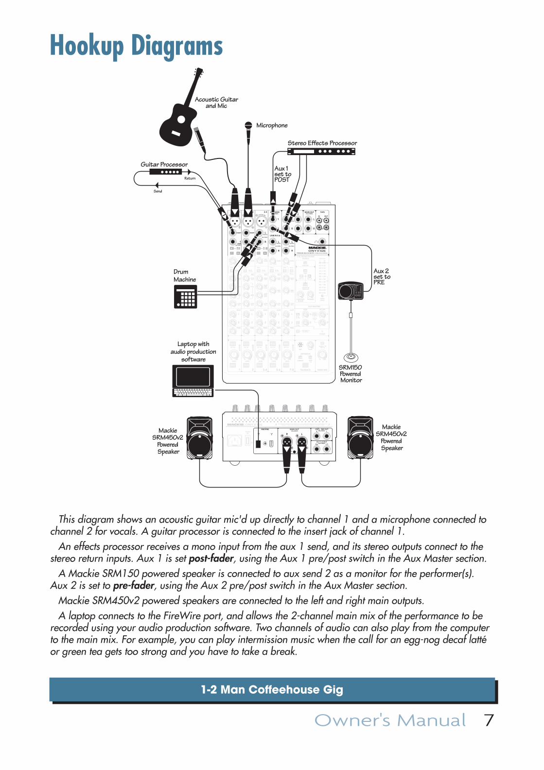
This diagram shows an acoustic guitar mic'd up directly to channel 1 and a microphone connected to channel 2 for vocals. A guitar processor is connected to the insert jack of channel 1.
An effects processor receives a mono input from the aux 1 send, and its stereo outputs connect to the stereo return inputs. Aux 1 is set post-fader, using the Aux 1 pre/post switch in the Aux Master section.
A Mackie SRM150 powered speaker is connected to aux send 2 as a monitor for the performer(s). Aux 2 is set to pre-fader, using the Aux 2 pre/post switch in the Aux Master section.
Mackie SRM450v2 powered speakers are connected to the left and right main outputs.A laptop connects to the FireWire port, and allows the 2-channel main mix of the performance to be
recorded using your audio production software. Two channels of audio can also play from the computer to the main mix. For example, you can play intermission music when the call for an egg-nog decaf latté or green tea gets too strong and you have to take a break.
8 Onyx 820i
Home Studio System: Straight to stereo
MUTE
SOLO
48V
MUTE
SOLO
48V
MUTE
SOLO
48V
LINE
MUTE
SOLO
MUTE
SOLO
TAPE
PAN
2
1
MID
FREQ
MID
FREQ
BAL/UNBAL BAL/UNBAL
ALT 3-4 ALT 3-4 ALT 3-4 ALT 3-4 ALT 3-4
LOWMID400Hz
ONYX MIC PRE
HIGH12kHz
LOW80Hz
EQ
INSERT INSERT
ONYX MIC PRE
HIGH12kHz
LOW80Hz
EQ
ONYX MIC PRE
HIGH12kHz
HIGHMID
2.5KHz
LOW80Hz
EQ
AUX MASTER
2
1
SEND RETURN
2
1
EQ
MAIN MIX
(MONO)L
R
L
R
L(MONO)
R
BAL/UNBAL
L(MONO)
R
BAL/UNBAL
L(MONO)
R
BAL/UNBAL
TAPE
IN OUT
L
R
AUX RETURN
1
21
2
AUX SEND MAIN OUT
CTRL ROOM/PHONESSOURCE
PHONESCONTROLROOM
MID2.5kHz
LOW80Hz
U
+15-15
U
+15-15
U
+15-15
U
+15-15
U
+15-15
U
+15-15
U
+15-15
U
+15-15
U
+15-15
U
+15-15
U
+15-15
U
+15-15
U
+15-15
U
+15-15
U
+15-15
U
+15-15
HIGH12kHz
MID2.5kHz
LOW80Hz
HIGH12kHz
RUDESOLO
20
15
10
6
3
0
2
4
7
10
20
30
L R0dB=0dBu
LEVELSET
CLIP
MIC
PREPOST
PREPOST
R/4 L/3
BAL/UNBAL
BAL/UNBALALT 3-4 OUT
R LCNTL - RM OUT
POWERON
FW 1-2LINE
HI-ZLINE
-10dB+4dB
HI-ZLINE
PREMIUM ANALOG MIXER w/ PERKINS EQ & FIREWIRE
PREPOST
PREPOST
PREPOST
PREPOST
LEVELLEVELLEVEL LEVEL LEVEL+10dBOO
U
+10dBOO
U
+10dBOO
U
+10dBOO
U
+10dBOO
U
+10dBOO
U
1 2 3-4
LINE IN 5-6 LINE IN 7-8
AUX
PAN
2
1
AUX
PAN
2
1
AUX
PAN
2
1
AUX
PAN
2
1
AUX
RTN TOAUX1
AUX SEND 1-2TO FW 5-6
ASSIGN TOFW 7-8
MAIN MIX
AUX1-2
PHONES
DESTINATION
LEVELOO MAX
OL
- 20
OL
- 20 - 20
OLOL
- 20
OL
- 20
1 2 TALKBACK
BAL/UNBAL BAL/UNBAL BAL/UNBAL
SEND SEND SEND SEND SEND INPUT
MAIN OUT
LRBALANCED
POWER
DESIGNED BY MACKOIDS IN WOODINVILLE, WA, USA • MANUFACTURED IN CHINA • FABRIQUE EN CHINE"MACKIE" & "ONYX" ARE TRADEMARKS OF LOUD TECHNOLOGIES INC. • COPYRIGHT ©2008
FIREWIRE
ALT 3-4FW 1-2
ASSIGN TOMAIN MIX
3-4 5-6 7-8
GAIN
+20dB-20dB
U
GAINMIC
GAINGAIN
+20dB-20dB
U
U
20
30
40
60+40dB
U
-20dBU
20
30
40
60
GAIN
+40dB
U
-20dBU
20
30
40
60
1LINE
2LINE
1k
100 8k
1k
100 8k
MAXOOMAXOO
MAXOO
MAXOO
+15OO
+15OO
+10OO
+10OO
MAXOO
MAXOO
MAXOO
MAXOO
MAXOO
MAXOO
MAXOO
MAXOO
L R L R L R L R L R
MAIN OUTPUT LEVEL MIC
+4dB
Laptop withaudio production
software
Mackie MR8 Powered
Reference Monitors for Control Room
Headphones
Headphone Amp
AmplifierModeler
ElectricGuitar
BassGuitar
Recorder
press HI-Zbutton
CondenserMicrophone
DrumMachine
Keyboard
Stereo Effects Processor
Digital Delay
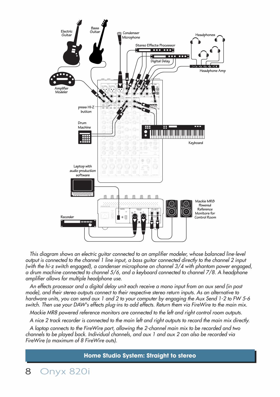
This diagram shows an electric guitar connected to an amplifi er modeler, whose balanced line-level output is connected to the channel 1 line input, a bass guitar connected directly to the channel 2 input (with the hi-z switch engaged), a condenser microphone on channel 3/4 with phantom power engaged, a drum machine connected to channel 5/6, and a keyboard connected to channel 7/8. A headphone amplifi er allows for multiple headphone use.
An effects processor and a digital delay unit each receive a mono input from an aux send (in post mode), and their stereo outputs connect to their respective stereo return inputs. As an alternative to hardware units, you can send aux 1 and 2 to your computer by engaging the Aux Send 1-2 to FW 5-6 switch. Then use your DAW's effects plug-ins to add effects. Return them via FireWire to the main mix.
Mackie MR8 powered reference monitors are connected to the left and right control room outputs.A nice 2 track recorder is connected to the main left and right outputs to record the main mix directly.A laptop connects to the FireWire port, allowing the 2-channel main mix to be recorded and two
channels to be played back. Individual channels, and aux 1 and aux 2 can also be recorded via FireWire (a maximum of 8 FireWire outs).
Owner's Manual 9
Home Studio System: Recording each channel
MUTE
SOLO
48V
MUTE
SOLO
48V
MUTE
SOLO
48V
LINE
MUTE
SOLO
MUTE
SOLO
TAPE
PAN
2
1
MID
FREQ
MID
FREQ
BAL/UNBAL BAL/UNBAL
ALT 3-4 ALT 3-4 ALT 3-4 ALT 3-4 ALT 3-4
LOWMID400Hz
ONYX MIC PRE
HIGH12kHz
LOW80Hz
EQ
INSERT INSERT
ONYX MIC PRE
HIGH12kHz
LOW80Hz
EQ
ONYX MIC PRE
HIGH12kHz
HIGHMID
2.5KHz
LOW80Hz
EQ
AUX MASTER
2
1
SEND RETURN
2
1
EQ
MAIN MIX
(MONO)L
R
L
R
L(MONO)
R
BAL/UNBAL
L(MONO)
R
BAL/UNBAL
L(MONO)
R
BAL/UNBAL
TAPE
IN OUT
L
R
AUX RETURN
1
21
2
AUX SEND MAIN OUT
CTRL ROOM/PHONESSOURCE
PHONESCONTROLROOM
MID2.5kHz
LOW80Hz
U
+15-15
U
+15-15
U
+15-15
U
+15-15
U
+15-15
U
+15-15
U
+15-15
U
+15-15
U
+15-15
U
+15-15
U
+15-15
U
+15-15
U
+15-15
U
+15-15
U
+15-15
U
+15-15
HIGH12kHz
MID2.5kHz
LOW80Hz
HIGH12kHz
RUDESOLO
20
15
10
6
3
0
2
4
7
10
20
30
L R0dB=0dBu
LEVELSET
CLIP
MIC
PREPOST
PREPOST
R/4 L/3
BAL/UNBAL
BAL/UNBALALT 3-4 OUT
R LCNTL - RM OUT
POWERON
FW 1-2LINE
HI-ZLINE
-10dB+4dB
HI-ZLINE
PREMIUM ANALOG MIXER w/ PERKINS EQ & FIREWIRE
PREPOST
PREPOST
PREPOST
PREPOST
LEVELLEVELLEVEL LEVEL LEVEL+10dBOO
U
+10dBOO
U
+10dBOO
U
+10dBOO
U
+10dBOO
U
+10dBOO
U
1 2 3-4
LINE IN 5-6 LINE IN 7-8
AUX
PAN
2
1
AUX
PAN
2
1
AUX
PAN
2
1
AUX
PAN
2
1
AUX
RTN TOAUX1
AUX SEND 1-2TO FW 5-6
ASSIGN TOFW 7-8
MAIN MIX
AUX1-2
PHONES
DESTINATION
LEVELOO MAX
OL
- 20
OL
- 20 - 20
OLOL
- 20
OL
- 20
1 2 TALKBACK
BAL/UNBAL BAL/UNBAL BAL/UNBAL
SEND SEND SEND SEND SEND INPUT
MAIN OUT
LRBALANCED
POWER
DESIGNED BY MACKOIDS IN WOODINVILLE, WA, USA • MANUFACTURED IN CHINA • FABRIQUE EN CHINE"MACKIE" & "ONYX" ARE TRADEMARKS OF LOUD TECHNOLOGIES INC. • COPYRIGHT ©2008
FIREWIRE
ALT 3-4FW 1-2
ASSIGN TOMAIN MIX
3-4 5-6 7-8
GAIN
+20dB-20dB
U
GAINMIC
GAINGAIN
+20dB-20dB
U
U
20
30
40
60+40dB
U
-20dBU
20
30
40
60
GAIN
+40dB
U
-20dBU
20
30
40
60
1LINE
2LINE
1k
100 8k
1k
100 8k
MAXOOMAXOO
MAXOO
MAXOO
+15OO
+15OO
+10OO
+10OO
MAXOO
MAXOO
MAXOO
MAXOO
MAXOO
MAXOO
MAXOO
MAXOO
L R L R L R L R L R
MAIN OUTPUT LEVEL MIC
+4dB
Laptop Computerwith audio production
software
Mackie MR8 Powered
Reference Monitors for Control Room
Headphones
Headphone Amp
ElectricGuitar
BassGuitar
press HI-Zbuttons
CondenserMicrophone
DrumMachine
Keyboard
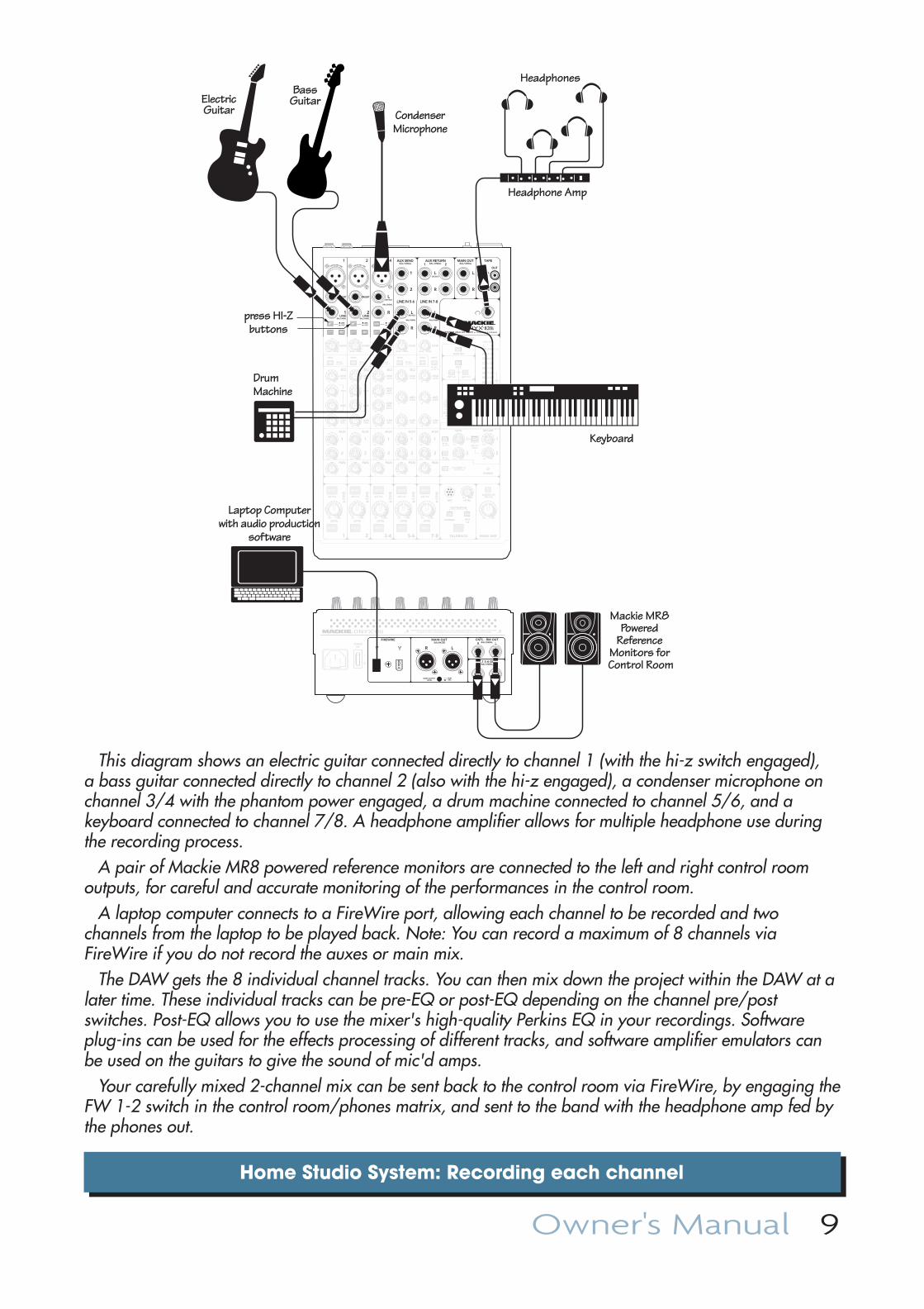
This diagram shows an electric guitar connected directly to channel 1 (with the hi-z switch engaged), a bass guitar connected directly to channel 2 (also with the hi-z engaged), a condenser microphone on channel 3/4 with the phantom power engaged, a drum machine connected to channel 5/6, and a keyboard connected to channel 7/8. A headphone amplifi er allows for multiple headphone use during the recording process.
A pair of Mackie MR8 powered reference monitors are connected to the left and right control room outputs, for careful and accurate monitoring of the performances in the control room.
A laptop computer connects to a FireWire port, allowing each channel to be recorded and two channels from the laptop to be played back. Note: You can record a maximum of 8 channels via FireWire if you do not record the auxes or main mix.
The DAW gets the 8 individual channel tracks. You can then mix down the project within the DAW at a later time. These individual tracks can be pre-EQ or post-EQ depending on the channel pre/post switches. Post-EQ allows you to use the mixer's high-quality Perkins EQ in your recordings. Software plug-ins can be used for the effects processing of different tracks, and software amplifi er emulators can be used on the guitars to give the sound of mic'd amps.
Your carefully mixed 2-channel mix can be sent back to the control room via FireWire, by engaging the FW 1-2 switch in the control room/phones matrix, and sent to the band with the headphone amp fed by the phones out.
10 Onyx 820i
Club System
MUTE
SOLO
48V
MUTE
SOLO
48V
MUTE
SOLO
48V
LINE
MUTE
SOLO
MUTE
SOLO
TAPE
PAN
2
1
MID
FREQ
MID
FREQ
BAL/UNBAL BAL/UNBAL
ALT 3-4 ALT 3-4 ALT 3-4 ALT 3-4 ALT 3-4
LOWMID400Hz
ONYX MIC PRE
HIGH12kHz
LOW80Hz
EQ
INSERT INSERT
ONYX MIC PRE
HIGH12kHz
LOW80Hz
EQ
ONYX MIC PRE
HIGH12kHz
HIGHMID
2.5KHz
LOW80Hz
EQ
AUX MASTER
2
1
SEND RETURN
2
1
EQ
MAIN MIX
(MONO)L
R
L
R
L(MONO)
R
BAL/UNBAL
L(MONO)
R
BAL/UNBAL
L(MONO)
R
BAL/UNBAL
TAPE
IN OUT
L
R
AUX RETURN
1
21
2
AUX SEND MAIN OUT
CTRL ROOM/PHONESSOURCE
PHONESCONTROLROOM
MID2.5kHz
LOW80Hz
U
+15-15
U
+15-15
U
+15-15
U
+15-15
U
+15-15
U
+15-15
U
+15-15
U
+15-15
U
+15-15
U
+15-15
U
+15-15
U
+15-15
U
+15-15
U
+15-15
U
+15-15
U
+15-15
HIGH12kHz
MID2.5kHz
LOW80Hz
HIGH12kHz
RUDESOLO
20
15
10
6
3
0
2
4
7
10
20
30
L R0dB=0dBu
LEVELSET
CLIP
MIC
PREPOST
PREPOST
R/4 L/3
BAL/UNBAL
BAL/UNBALALT 3-4 OUT
R LCNTL - RM OUT
POWERON
FW 1-2LINE
HI-ZLINE
-10dB+4dB
HI-ZLINE
PREMIUM ANALOG MIXER w/ PERKINS EQ & FIREWIRE
PREPOST
PREPOST
PREPOST
PREPOST
LEVELLEVELLEVEL LEVEL LEVEL+10dBOO
U
+10dBOO
U
+10dBOO
U
+10dBOO
U
+10dBOO
U
+10dBOO
U
1 2 3-4
LINE IN 5-6 LINE IN 7-8
AUX
PAN
2
1
AUX
PAN
2
1
AUX
PAN
2
1
AUX
PAN
2
1
AUX
RTN TOAUX1
AUX SEND 1-2TO FW 5-6
ASSIGN TOFW 7-8
MAIN MIX
AUX1-2
PHONES
DESTINATION
LEVELOO MAX
OL
- 20
OL
- 20 - 20
OLOL
- 20
OL
- 20
1 2 TALKBACK
BAL/UNBAL BAL/UNBAL BAL/UNBAL
SEND SEND SEND SEND SEND INPUT
MAIN OUT
LRBALANCED
POWER
DESIGNED BY MACKOIDS IN WOODINVILLE, WA, USA • MANUFACTURED IN CHINA • FABRIQUE EN CHINE"MACKIE" & "ONYX" ARE TRADEMARKS OF LOUD TECHNOLOGIES INC. • COPYRIGHT ©2008
FIREWIRE
ALT 3-4FW 1-2
ASSIGN TOMAIN MIX
3-4 5-6 7-8
GAIN
+20dB-20dB
U
GAINMIC
GAINGAIN
+20dB-20dB
U
U
20
30
40
60+40dB
U
-20dBU
20
30
40
60
GAIN
+40dB
U
-20dBU
20
30
40
60
1LINE
2LINE
1k
100 8k
1k
100 8k
MAXOOMAXOO
MAXOO
MAXOO
+15OO
+15OO
+10OO
+10OO
MAXOO
MAXOO
MAXOO
MAXOO
MAXOO
MAXOO
MAXOO
MAXOO
L R L R L R L R L R
MAIN OUTPUT LEVEL MIC
+4dB
HD1531Powered SpeakerMain Left
SRM350v2PoweredSpeakers
HD1531Powered Speaker
Main Right
Mackie SRM450v2 Powered Speakers (Stage Monitors)
iPodDocking Station
Headphones
Microphone
press HI-Zbutton
AcousticGuitar with
pickup
Keyboard
DrumMachine
Stereo Effects Processor
Aux 1set toPOST
Aux 2set toPRE
Dynamics Processor
Laptop Computerwith audio
production software
HD1801 Powered
Subwoofers
HD1801 Powered
Subwoofers
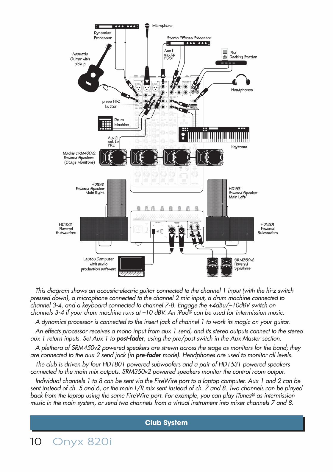
This diagram shows an acoustic-electric guitar connected to the channel 1 input (with the hi-z switch pressed down), a microphone connected to the channel 2 mic input, a drum machine connected to channel 3-4, and a keyboard connected to channel 7-8. Engage the +4dBu/–10dBV switch on channels 3-4 if your drum machine runs at –10 dBV. An iPod® can be used for intermission music.
A dynamics processor is connected to the insert jack of channel 1 to work its magic on your guitar.An effects processor receives a mono input from aux 1 send, and its stereo outputs connect to the stereo
aux 1 return inputs. Set Aux 1 to post-fader, using the pre/post switch in the Aux Master section.A plethora of SRM450v2 powered speakers are strewn across the stage as monitors for the band; they
are connected to the aux 2 send jack (in pre-fader mode). Headphones are used to monitor all levels. The club is driven by four HD1801 powered subwoofers and a pair of HD1531 powered speakers
connected to the main mix outputs. SRM350v2 powered speakers monitor the control room output.Individual channels 1 to 8 can be sent via the FireWire port to a laptop computer. Aux 1 and 2 can be
sent instead of ch. 5 and 6, or the main L/R mix sent instead of ch. 7 and 8. Two channels can be played back from the laptop using the same FireWire port. For example, you can play iTunes® as intermission music in the main system, or send two channels from a virtual instrument into mixer channels 7 and 8.
Owner's Manual 11
Post-Production System
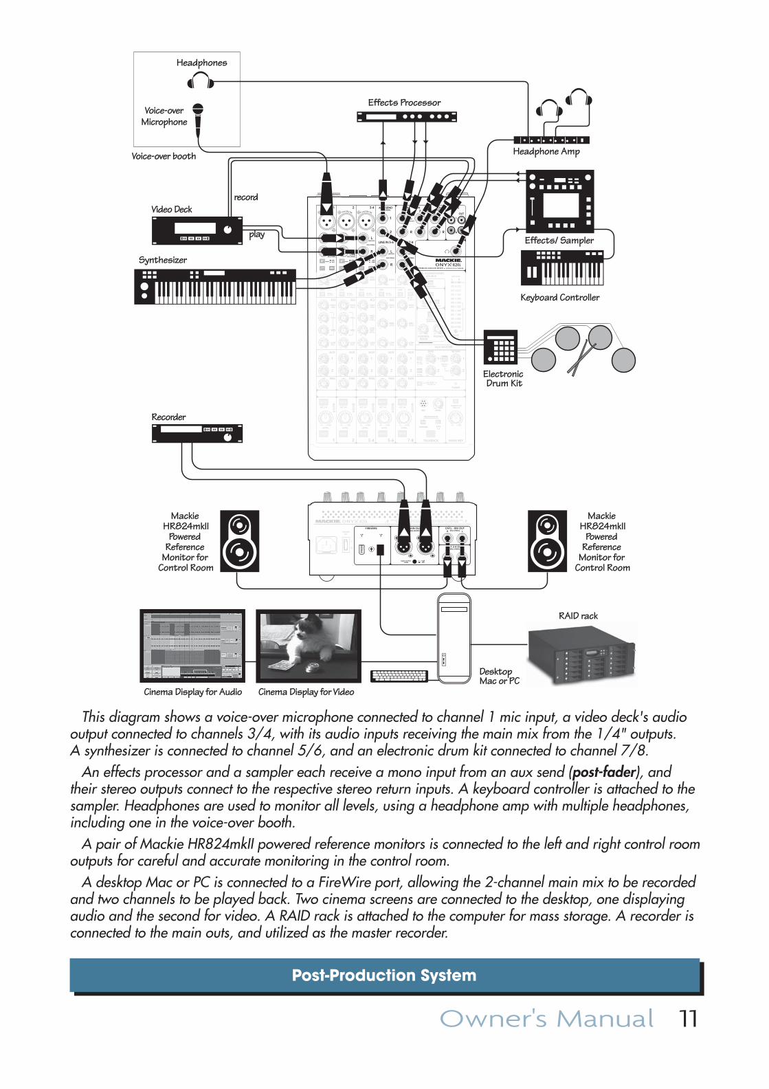
This diagram shows a voice-over microphone connected to channel 1 mic input, a video deck's audio output connected to channels 3/4, with its audio inputs receiving the main mix from the 1/4" outputs. A synthesizer is connected to channel 5/6, and an electronic drum kit connected to channel 7/8.
An effects processor and a sampler each receive a mono input from an aux send (post-fader), and their stereo outputs connect to the respective stereo return inputs. A keyboard controller is attached to the sampler. Headphones are used to monitor all levels, using a headphone amp with multiple headphones, including one in the voice-over booth.
A pair of Mackie HR824mkII powered reference monitors is connected to the left and right control room outputs for careful and accurate monitoring in the control room.
A desktop Mac or PC is connected to a FireWire port, allowing the 2-channel main mix to be recorded and two channels to be played back. Two cinema screens are connected to the desktop, one displaying audio and the second for video. A RAID rack is attached to the computer for mass storage. A recorder is connected to the main outs, and utilized as the master recorder.
MUTE
SOLO
48V
MUTE
SOLO
48V
MUTE
SOLO
48V
LINE
MUTE
SOLO
MUTE
SOLO
TAPE
PAN
2
1
MID
FREQ
MID
FREQ
BAL/UNBAL BAL/UNBAL
ALT 3-4 ALT 3-4 ALT 3-4 ALT 3-4 ALT 3-4
LOWMID400Hz
ONYX MIC PRE
HIGH12kHz
LOW80Hz
EQ
INSERT INSERT
ONYX MIC PRE
HIGH12kHz
LOW80Hz
EQ
ONYX MIC PRE
HIGH12kHz
HIGHMID
2.5KHz
LOW80Hz
EQ
AUX MASTER
2
1
SEND RETURN
2
1
EQ
MAIN MIX
(MONO)L
R
L
R
L(MONO)
R
BAL/UNBAL
L(MONO)
R
BAL/UNBAL
L(MONO)
R
BAL/UNBAL
TAPE
IN OUT
L
R
AUX RETURN
1
21
2
AUX SEND MAIN OUT
CTRL ROOM/PHONESSOURCE
PHONESCONTROLROOM
MID2.5kHz
LOW80Hz
U
+15-15
U
+15-15
U
+15-15
U
+15-15
U
+15-15
U
+15-15
U
+15-15
U
+15-15
U
+15-15
U
+15-15
U
+15-15
U
+15-15
U
+15-15
U
+15-15
U
+15-15
U
+15-15
HIGH12kHz
MID2.5kHz
LOW80Hz
HIGH12kHz
RUDESOLO
20
15
10
6
3
0
2
4
7
10
20
30
L R0dB=0dBu
LEVELSET
CLIP
MIC
PREPOST
PREPOST
R/4 L/3
BAL/UNBAL
BAL/UNBALALT 3-4 OUT
R LCNTL - RM OUT
POWERON
FW 1-2LINE
HI-ZLINE
-10dB+4dB
HI-ZLINE
PREMIUM ANALOG MIXER w/ PERKINS EQ & FIREWIRE
PREPOST
PREPOST
PREPOST
PREPOST
LEVELLEVELLEVEL LEVEL LEVEL+10dBOO
U
+10dBOO
U
+10dBOO
U
+10dBOO
U
+10dBOO
U
+10dBOO
U
1 2 3-4
LINE IN 5-6 LINE IN 7-8
AUX
PAN
2
1
AUX
PAN
2
1
AUX
PAN
2
1
AUX
PAN
2
1
AUX
RTN TOAUX1
AUX SEND 1-2TO FW 5-6
ASSIGN TOFW 7-8
MAIN MIX
AUX1-2
PHONES
DESTINATION
LEVELOO MAX
OL
- 20
OL
- 20 - 20
OLOL
- 20
OL
- 20
1 2 TALKBACK
BAL/UNBAL BAL/UNBAL BAL/UNBAL
SEND SEND SEND SEND SEND INPUT
MAIN OUT
LRBALANCED
POWER
DESIGNED BY MACKOIDS IN WOODINVILLE, WA, USA • MANUFACTURED IN CHINA • FABRIQUE EN CHINE"MACKIE" & "ONYX" ARE TRADEMARKS OF LOUD TECHNOLOGIES INC. • COPYRIGHT ©2008
FIREWIRE
ALT 3-4FW 1-2
ASSIGN TOMAIN MIX
3-4 5-6 7-8
GAIN
+20dB-20dB
U
GAINMIC
GAINGAIN
+20dB-20dB
U
U
20
30
40
60+40dB
U
-20dBU
20
30
40
60
GAIN
+40dB
U
-20dBU
20
30
40
60
1LINE
2LINE
1k
100 8k
1k
100 8k
MAXOOMAXOO
MAXOO
MAXOO
+15OO
+15OO
+10OO
+10OO
MAXOO
MAXOO
MAXOO
MAXOO
MAXOO
MAXOO
MAXOO
MAXOO
L R L R L R L R L R
MAIN OUTPUT LEVEL MIC
+4dB
Voice-overMicrophone
Voice-over booth
Synthesizer
Electronic Drum Kit
Effects Processor
Effects/ Sampler
Mackie HR824mkII
Powered Reference
Monitor for Control Room
Mackie HR824mkII
Powered Reference
Monitor for Control Room
DesktopMac or PC
Keyboard Controller
Cinema Display for Audio Cinema Display for Video
RAID rack
Headphones
Headphone Amp
Recorder
Video Deckrecord
play
12 Onyx 820i
Onyx 820i Features
Rear Panel1. POWER CONNECTION
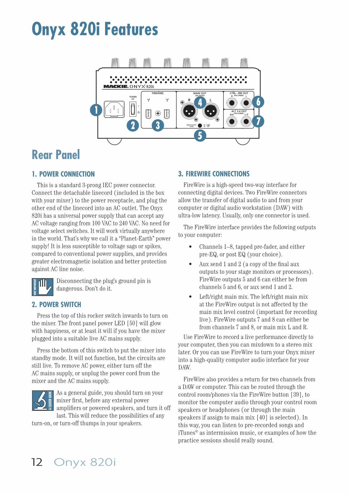
This is a standard 3-prong IEC power connector. Connect the detachable linecord (included in the box with your mixer) to the power receptacle, and plug the other end of the linecord into an AC outlet. The Onyx 820i has a universal power supply that can accept any AC voltage ranging from 100 VAC to 240 VAC. No need for voltage select switches. It will work virtually anywhere in the world. That’s why we call it a “Planet-Earth” power supply! It is less susceptible to voltage sags or spikes, compared to conventional power supplies, and provides greater electromagnetic isolation and better protection against AC line noise.
Disconnecting the plug’s ground pin is dangerous. Don’t do it.
2. POWER SWITCHPress the top of this rocker switch inwards to turn on
the mixer. The front panel power LED [50] will glow with happiness, or at least it will if you have the mixer plugged into a suitable live AC mains supply.
Press the bottom of this switch to put the mixer into standby mode. It will not function, but the circuits are still live. To remove AC power, either turn off the AC mains supply, or unplug the power cord from the mixer and the AC mains supply.
As a general guide, you should turn on your mixer fi rst, before any external power amplifi ers or powered speakers, and turn it off last. This will reduce the possibilities of any
turn-on, or turn-off thumps in your speakers.
3. FIREWIRE CONNECTIONSFireWire is a high-speed two-way interface for
connecting digital devices. Two FireWire connectors allow the transfer of digital audio to and from your computer or digital audio workstation (DAW) with ultra-low latency. Usually, only one connector is used.
The FireWire interface provides the following outputs to your computer:
• Channels 1–8, tapped pre-fader, and either pre-EQ, or post EQ (your choice).
• Aux send 1 and 2 (a copy of the fi nal aux outputs to your stage monitors or processors). FireWire outputs 5 and 6 can either be from channels 5 and 6, or aux send 1 and 2.
• Left/right main mix. The left/right main mix at the FireWire output is not affected by the main mix level control (important for recording live). FireWire outputs 7 and 8 can either be from channels 7 and 8, or main mix L and R.
Use FireWire to record a live performance directly to your computer, then you can mixdown to a stereo mix later. Or you can use FireWire to turn your Onyx mixer into a high-quality computer audio interface for your DAW.
FireWire also provides a return for two channels from a DAW or computer. This can be routed through the control room/phones via the FireWire button [39], to monitor the computer audio through your control room speakers or headphones (or through the main speakers if assign to main mix [40] is selected). In this way, you can listen to pre-recorded songs and iTunes® as intermission music, or examples of how the practice sessions should really sound.
R/4 L/3
BAL/UNBAL
BAL/UNBALALT 3-4 OUT
R LCTRL - RM OUT
POWERON
MAIN OUT
LRBALANCED
FIREWIRE
MAIN OUTPUT LEVEL MIC
+4dB
16
2
4
3 75
Owner's Manual 13
These same two channels from the computer can also be chosen as inputs to channels 7 and 8, allowing you to adjust the gain, EQ, level, and pan, as well as to solo, and add to aux send 1 and 2. This is routed using the FW/line input selector [22] on channels 7 and 8. This is useful for live performances, where those 2 channels might have, for example, a software synthesizer you are triggering from a MIDI keyboard, and you want to treat the softsynth as "just another instrument," with equal processing and routing options as the hardware keyboards coming into the other channels.
The FireWire interface works with both PC (using ASIO for Windows XP and Vista) and Mac (Core Audio for Mac OS 10.4.11 or higher).
4. LEFT/RIGHT XLR MAIN OUTPUTSThese male XLR connectors provide a balanced line-
level signal that represents the end of the mixer chain, where your fully mixed stereo signal enters the real world. Connect these to the inputs of your main power amplifi ers, powered speakers, or serial effects processor (like a graphic equalizer or compressor/ limiter). It provides a fully balanced signal that is the same level as the 1/4" TRS main out jacks [14] on the top panel.
5. MAIN OUTPUT LEVELWhen this switch is out (+4 dB), the XLR main
outputs [4] provide a "+4 dBu" line-level signal. You can then connect these outputs to the line-level inputs of power amplifi ers, powered loudspeakers, or serial processors.
When the switch is pushed in (mic), the XLR main outputs are attenuated to microphone level. You can then connect these outputs safely to the microphone inputs of another mixer, providing a submix for keyboards or drums, for example, in a live sound application. The main outputs can then be plugged directly into a stage snake, and appear back at the front of house console like any other microphone level source.
When mic is engaged, you can safely plug the XLR main output into a mixer's microphone input, even if it provides 48 V phantom power.
The switch is recessed, to reduce the chance of accidently turning it on or off when plugging things in.
6. CTRL-RM OUTThese 1/4" TRS jacks provide balanced left and right-
line-level outputs to run a studio monitors in the control room. Connect these outputs to the inputs of an amplifi er, powered speakers, or recording device.
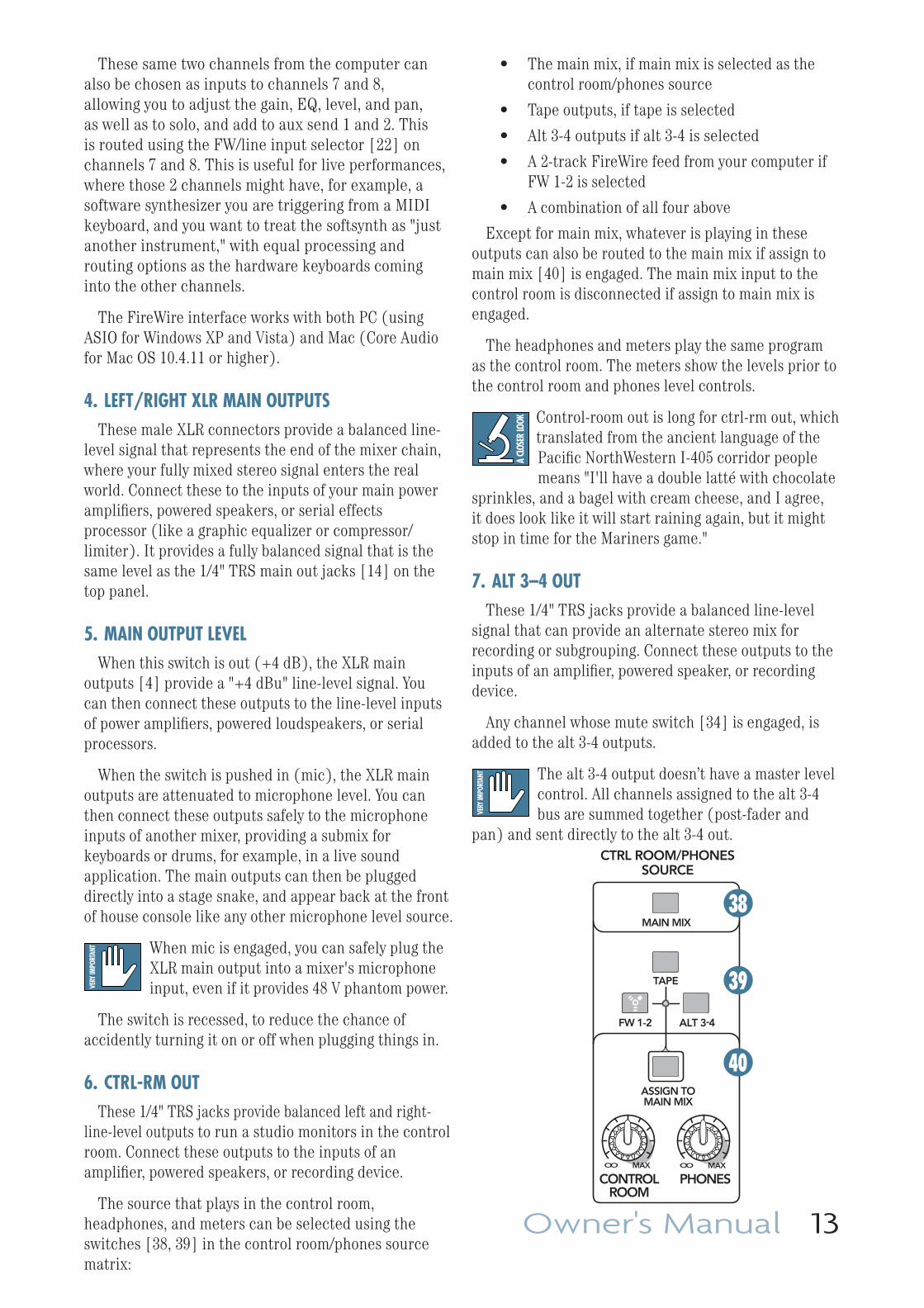
The source that plays in the control room, headphones, and meters can be selected using the switches [38, 39] in the control room/phones source matrix:
• The main mix, if main mix is selected as the control room/phones source
• Tape outputs, if tape is selected
• Alt 3-4 outputs if alt 3-4 is selected
• A 2-track FireWire feed from your computer if FW 1-2 is selected
• A combination of all four above
Except for main mix, whatever is playing in these outputs can also be routed to the main mix if assign to main mix [40] is engaged. The main mix input to the control room is disconnected if assign to main mix is engaged.
The headphones and meters play the same program as the control room. The meters show the levels prior to the control room and phones level controls.
Control-room out is long for ctrl-rm out, which translated from the ancient language of the Pacifi c NorthWestern I-405 corridor people means "I'll have a double latté with chocolate
sprinkles, and a bagel with cream cheese, and I agree, it does look like it will start raining again, but it might stop in time for the Mariners game."
7. ALT 3–4 OUTThese 1/4" TRS jacks provide a balanced line-level
signal that can provide an alternate stereo mix for recording or subgrouping. Connect these outputs to the inputs of an amplifi er, powered speaker, or recording device.
Any channel whose mute switch [34] is engaged, is added to the alt 3-4 outputs.
The alt 3-4 output doesn’t have a master level control. All channels assigned to the alt 3-4 bus are summed together (post-fader and
pan) and sent directly to the alt 3-4 out.
TAPE
CTRL ROOM/PHONESSOURCE
PHONESCONTROLROOM
MAIN MIX
ALT 3-4FW 1-2
ASSIGN TOMAIN MIX
MAXOOMAXOO
38
39
40
14 Onyx 820i
PHANTOM POWERMost modern professional condenser mics require
48V phantom power, which lets the mixer send low-current DC voltage to the mic’s electronics through the same wires that carry audio. (Semi-pro condenser mics often have batteries to accomplish the same thing.) “Phantom” owes its name to an ability to be “unseen” by dynamic mics (Shure SM57/SM58, for instance), which don’t need external power and aren’t affected by it anyway.
Phantom power for each channel can be selected using that channel's phantom [20] switch.
Never plug single-ended (unbalanced) micro phones, or ribbon mics into the mic input jacks if phantom power is on. Do not
plug instrument outputs into the mic XLR input jacks with phantom power on, unless you are certain it is safe.
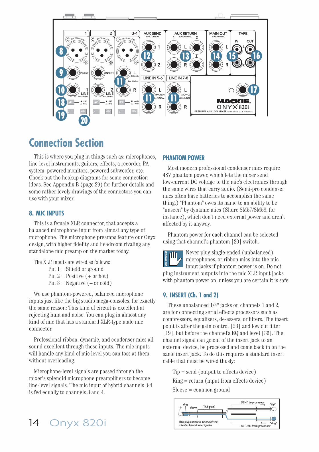
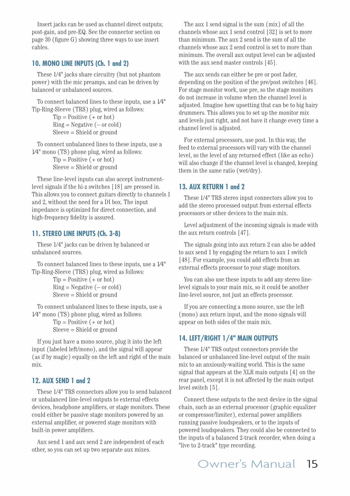
9. INSERT (Ch. 1 and 2)These unbalanced 1/4" jacks on channels 1 and 2,
are for connecting serial effects processors such as compressors, equalizers, de-essers, or fi lters. The insert point is after the gain control [23] and low cut fi lter [19], but before the channel’s EQ and level [36]. The channel signal can go out of the insert jack to an external device, be processed and come back in on the same insert jack. To do this requires a standard insert cable that must be wired thusly:
Tip = send (output to effects device)
Ring = return (input from effects device)
Sleeve = common ground
Connection SectionThis is where you plug in things such as: microphones,
line-level instruments, guitars, effects, a recorder, PA system, powered monitors, powered subwoofer, etc. Check out the hookup diagrams for some connection ideas. See Appendix B (page 29) for further details and some rather lovely drawings of the connectors you can use with your mixer.
8. MIC INPUTSThis is a female XLR connector, that accepts a
balanced microphone input from almost any type of microphone. The microphone preamps feature our Onyx design, with higher fi delity and headroom rivaling any standalone mic preamp on the market today.
The XLR inputs are wired as follows: Pin 1 = Shield or ground Pin 2 = Positive (+ or hot) Pin 3 = Negative (– or cold)
We use phantom-powered, balanced microphone inputs just like the big studio mega-consoles, for exactly the same reason: This kind of circuit is excellent at rejecting hum and noise. You can plug in almost any kind of mic that has a standard XLR-type male mic connector.
Professional ribbon, dynamic, and condenser mics all sound excellent through these inputs. The mic inputs will handle any kind of mic level you can toss at them, without overloading.
Microphone-level signals are passed through the mixer's splendid microphone preamplifi ers to become line-level signals. The mic input of hybrid channels 3-4 is fed equally to channels 3 and 4.
“tip”
This plug connects to one of the mixer’s Channel Insert jacks. “ring”
tipring
sleeve
SEND to processor
RETURN from processor
(TRS plug)
48V 48V 48V
LINE
BAL/UNBAL BAL/UNBAL
ONYX MIC PRE
INSERT INSERT
ONYX MIC PRE ONYX MIC PRE
(MONO)L
R
L
R
L(MONO)
R
BAL/UNBAL
L(MONO)
R
BAL/UNBAL
L(MONO)
R
BAL/UNBAL
TAPE
IN OUT
L
R
AUX RETURN
1
21
2
AUX SEND MAIN OUT
HI-ZLINE
-10dB+4dB
HI-ZLINE
PREMIUM ANALOG MIXER w/ PERKINS EQ & FIREWIRE
1 2 3-4
LINE IN 5-6 LINE IN 7-8
BAL/UNBAL BAL/UNBAL BAL/UNBAL
1LINE
2LINE
8
9
1011
12
11
13
11
14 15 16
171819 20
Owner's Manual 15
Insert jacks can be used as channel direct outputs; post-gain, and pre-EQ. See the connector section on page 30 (fi gure G) showing three ways to use insert cables.
10. MONO LINE INPUTS (Ch. 1 and 2)These 1/4" jacks share circuitry (but not phantom
power) with the mic preamps, and can be driven by balanced or unbalanced sources.
To connect balanced lines to these inputs, use a 1⁄4" Tip-Ring-Sleeve (TRS) plug, wired as follows: Tip = Positive (+ or hot) Ring = Negative (– or cold) Sleeve = Shield or ground
To connect unbalanced lines to these inputs, use a 1⁄4" mono (TS) phone plug, wired as follows: Tip = Positive (+ or hot) Sleeve = Shield or ground
These line-level inputs can also accept instrument-level signals if the hi-z switches [18] are pressed in. This allows you to connect guitars directly to channels 1 and 2, without the need for a DI box. The input impedance is optimized for direct connection, and high-frequency fi delity is assured.
11. STEREO LINE INPUTS (Ch. 3-8)These 1/4" jacks can be driven by balanced or
unbalanced sources.
To connect balanced lines to these inputs, use a 1⁄4" Tip-Ring-Sleeve (TRS) plug, wired as follows: Tip = Positive (+ or hot) Ring = Negative (– or cold) Sleeve = Shield or ground
To connect unbalanced lines to these inputs, use a 1⁄4" mono (TS) phone plug, wired as follows: Tip = Positive (+ or hot) Sleeve = Shield or ground
If you just have a mono source, plug it into the left input (labeled left/mono), and the signal will appear (as if by magic) equally on the left and right of the main mix.
12. AUX SEND 1 and 2These 1/4" TRS connectors allow you to send balanced
or unbalanced line-level outputs to external effects devices, headphone amplifi ers, or stage monitors. These could either be passive stage monitors powered by an external amplifi er, or powered stage monitors with built-in power amplifi ers.
Aux send 1 and aux send 2 are independent of each other, so you can set up two separate aux mixes.
The aux 1 send signal is the sum (mix) of all the channels whose aux 1 send control [32] is set to more than minimum. The aux 2 send is the sum of all the channels whose aux 2 send control is set to more than minimum. The overall aux output level can be adjusted with the aux send master controls [45].
The aux sends can either be pre or post fader, depending on the position of the pre/post switches [46]. For stage monitor work, use pre, so the stage monitors do not increase in volume when the channel level is adjusted. Imagine how upsetting that can be to big hairy drummers. This allows you to set up the monitor mix and levels just right, and not have it change every time a channel level is adjusted.
For external processors, use post. In this way, the feed to external processors will vary with the channel level, so the level of any returned effect (like an echo) will also change if the channel level is changed, keeping them in the same ratio (wet/dry).
13. AUX RETURN 1 and 2These 1/4" TRS stereo input connectors allow you to
add the stereo processed output from external effects processors or other devices to the main mix.
Level adjustment of the incoming signals is made with the aux return controls [47].
The signals going into aux return 2 can also be added to aux send 1 by engaging the return to aux 1 switch [48]. For example, you could add effects from an external effects processor to your stage monitors.
You can also use these inputs to add any stereo line-level signals to your main mix, so it could be another line-level source, not just an effects processor.
If you are connecting a mono source, use the left (mono) aux return input, and the mono signals will appear on both sides of the main mix.
14. LEFT/RIGHT 1/4" MAIN OUTPUTS These 1/4" TRS output connectors provide the
balanced or unbalanced line-level output of the main mix to an anxiously-waiting world. This is the same signal that appears at the XLR main outputs [4] on the rear panel, except it is not affected by the main output level switch [5].
Connect these outputs to the next device in the signal chain, such as an external processor (graphic equalizer or compressor/limiter), external power amplifi ers running passive loudspeakers, or to the inputs of powered loudspeakers. They could also be connected to the inputs of a balanced 2-track recorder, when doing a "live to 2-track" type recording.
16 Onyx 820i
15. TAPE INPUTS These stereo unbalanced RCA inputs allow you to play
a tape, CD player, iPod® dock, or other line-level source. The tape in jacks accept an unbalanced signal using standard hi-fi hookup cables.
Push in the tape button [39] to route the tape input to the control room and phones outputs [6, 17]. This allows you to play back recordings of your mixes.
Push in the assign to main mix button [40] to route the tape input to the main outs [4, 14]. This allows you to play back music between sets over the main PA speakers.
Pushing tape in the source matrix and pushing assign to main mix can create a feedback path between tape in and tape out.
Make sure your tape deck is not in record, record pause, or input monitor mode when you engage these switches, or make sure the control room level control is turned all the way down fi rst.
16. TAPE OUTPUTS These stereo unbalanced RCA outputs allow you to
record the main stereo mix onto a tape deck, hard disk recorder, or automatic CD burner, for example. This lets you make a recording for posterity/archive/legal purposes whenever the band gets back together again.
The tape output is the stereo main mix, and it is affected by the main mix level control [55]. The output could also be used as an extra set of main outputs for feeding another zone.
17. HEADPHONE OUTPUT This 1/4" TRS connector supplies the output to your
stereo headphones. It is the same signal that is routed to the control room outputs [6], as determined by the control room/phones source matrix [38, 39]. The volume is controlled with the phones knob [42], right next to the control room knob [41].
Whenever a solo switch [37] is engaged, you will only hear the soloed channel(s) in the headphones. This gives you the opportunity to audition the channels before they are added to the main mix. (Solo signals reaching the headphones are not affected by the channel level or main level, therefore turn down the phones level fi rst, as soloed channels may be loud.)
The phones output follows standard conventions:
Tip = Left channel
Ring = Right channel
Sleeve = Common ground
WARNING: The headphone amp is loud, and can cause permanent hearing damage. Even intermediate levels may be painfully loud
with some headphones. BE CAREFUL! Always turn the phones level control [42] all the way down before connecting headphones or pressing a solo switch, or doing anything new that may affect the headphone volume. Then turn it up slowly as you listen carefully.
Owner's Manual 17
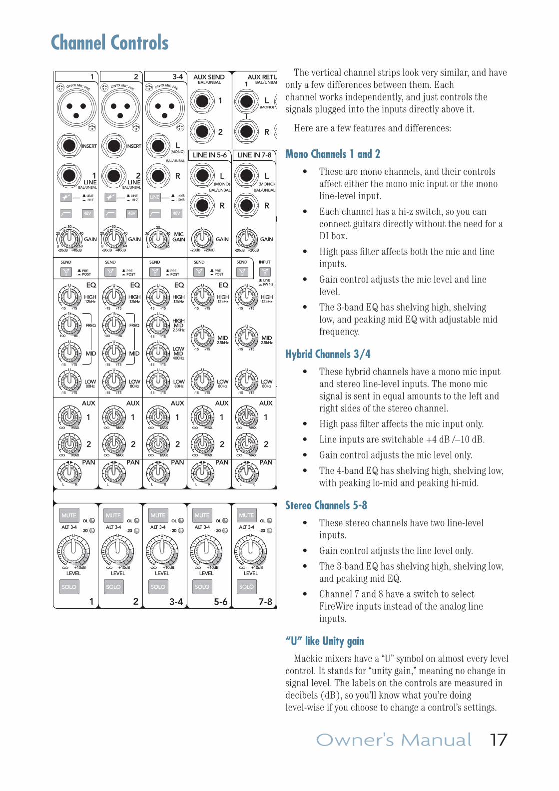
Channel ControlsThe vertical channel strips look very similar, and have
only a few differences between them. Each channel works independently, and just controls the signals plugged into the inputs directly above it.
Here are a few features and differences:
Mono Channels 1 and 2• These are mono channels, and their controls
affect either the mono mic input or the mono line-level input.
• Each channel has a hi-z switch, so you can connect guitars directly without the need for a DI box.
• High pass fi lter affects both the mic and line inputs.
• Gain control adjusts the mic level and line level.
• The 3-band EQ has shelving high, shelving low, and peaking mid EQ with adjustable mid frequency.
Hybrid Channels 3/4• These hybrid channels have a mono mic input
and stereo line-level inputs. The mono mic signal is sent in equal amounts to the left and right sides of the stereo channel.
• High pass fi lter affects the mic input only.
• Line inputs are switchable +4 dB /–10 dB.
• Gain control adjusts the mic level only.
• The 4-band EQ has shelving high, shelving low, with peaking lo-mid and peaking hi-mid.
Stereo Channels 5-8• These stereo channels have two line-level
inputs.
• Gain control adjusts the line level only.
• The 3-band EQ has shelving high, shelving low, and peaking mid EQ.
• Channel 7 and 8 have a switch to select FireWire inputs instead of the analog line inputs.
“U” like Unity gainMackie mixers have a “U” symbol on almost every level
control. It stands for “unity gain,” meaning no change in signal level. The labels on the controls are measured in decibels (dB), so you’ll know what you’re doing level-wise if you choose to change a control’s settings.
MUTE
SOLO
48V
MUTE
SOLO
48V
MUTE
SOLO
48V
LINE
MUTE
SOLO
MUTE
SOLO
PAN
2
1
MID
FREQ
MID
FREQ
BAL/UNBAL BAL/UNBAL
ALT 3-4 ALT 3-4 ALT 3-4 ALT 3-4 ALT 3-4
LOWMID400Hz
ONYX MIC PRE
HIGH12kHz
LOW80Hz
EQ
INSERT INSERT
ONYX MIC PRE
HIGH12kHz
LOW80Hz
EQ
ONYX MIC PRE
HIGH12kHz
HIGHMID
2.5KHz
LOW80Hz
EQ EQ
(MONO)L
R
L(MONO)
R
BAL/UNBAL
L(MONO)
R
BAL/UNBAL
L(MONO)
R
BAL/UNBAL
AUX RETU
1
1
2
AUX SEND
MID2.5kHz
LOW80Hz
U
+15-15
U
+15-15
U
+15-15
U
+15-15
U
+15-15
U
+15-15
U
+15-15
U
+15-15
U
+15-15
U
+15-15
U
+15-15
U
+15-15
U
+15-15
U
+15-15
U
+15-15
U
+15-15
HIGH12kHz
MID2.5kHz
LOW80Hz
HIGH12kHz
FW 1-2LINE
HI-ZLINE
-10dB+4dB
HI-ZLINE
PREPOST
PREPOST
PREPOST
PREPOST
LEVELLEVELLEVEL LEVEL LEVEL+10dBOO
U
+10dBOO
U
+10dBOO
U
+10dBOO
U
+10dBOO
U
1 2 3-4
LINE IN 5-6 LINE IN 7-8
AUX
PAN
2
1
AUX
PAN
2
1
AUX
PAN
2
1
AUX
PAN
2
1
AUX
OL
- 20
OL
- 20 - 20
OLOL
- 20
OL
- 20
1 2
BAL/UNBAL BAL/UNBAL
SEND SEND SEND SEND SEND INPUT
3-4 5-6 7-8
GAIN
+20dB-20dB
U
GAINMIC
GAINGAIN
+20dB-20dB
U
U
20
30
40
60+40dB
U
-20dBU
20
30
40
60
GAIN
+40dB
U
-20dBU
20
30
40
60
1LINE
2LINE
1k
100 8k
1k
100 8k
MAXOO
MAXOO
MAXOO
MAXOO
MAXOO
MAXOO
MAXOO
MAXOO
MAXOO
MAXOO
L R L R L R L R L R
18 Onyx 820i
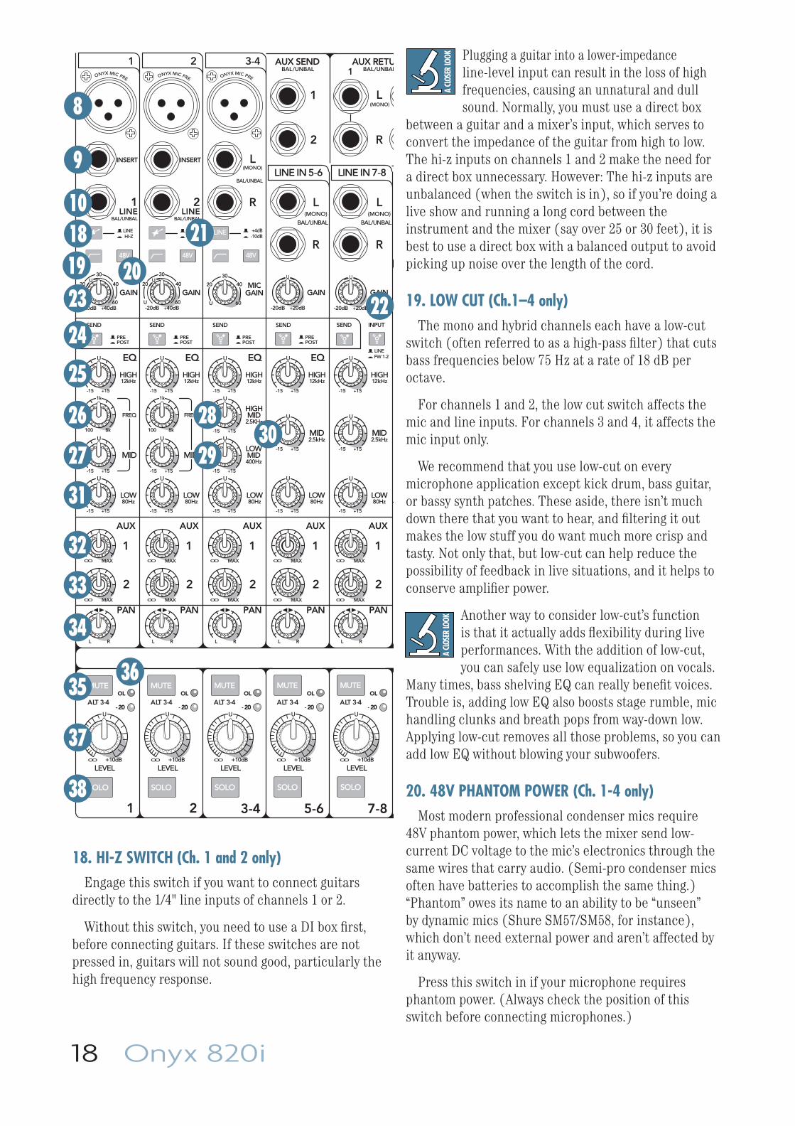
Plugging a guitar into a lower-impedance line-level input can result in the loss of high frequencies, causing an unnatural and dull sound. Normally, you must use a direct box
between a guitar and a mixer’s input, which serves to convert the impedance of the guitar from high to low. The hi-z inputs on channels 1 and 2 make the need for a direct box unnecessary. However: The hi-z inputs are unbalanced (when the switch is in), so if you’re doing a live show and running a long cord between the instrument and the mixer (say over 25 or 30 feet), it is best to use a direct box with a balanced output to avoid picking up noise over the length of the cord.
19. LOW CUT (Ch.1–4 only)The mono and hybrid channels each have a low-cut
switch (often referred to as a high-pass fi lter) that cuts bass frequencies below 75 Hz at a rate of 18 dB per octave.
For channels 1 and 2, the low cut switch affects the mic and line inputs. For channels 3 and 4, it affects the mic input only.
We recommend that you use low-cut on every microphone application except kick drum, bass guitar, or bassy synth patches. These aside, there isn’t much down there that you want to hear, and fi ltering it out makes the low stuff you do want much more crisp and tasty. Not only that, but low-cut can help reduce the possibility of feedback in live situations, and it helps to conserve amplifi er power.
Another way to consider low-cut’s function is that it actually adds fl exibility during live performances. With the addition of low-cut, you can safely use low equalization on vocals.
Many times, bass shelving EQ can really benefi t voices. Trouble is, adding low EQ also boosts stage rumble, mic handling clunks and breath pops from way-down low. Applying low-cut removes all those problems, so you can add low EQ without blowing your subwoofers.
20. 48V PHANTOM POWER (Ch. 1-4 only)Most modern professional condenser mics require
48V phantom power, which lets the mixer send low-current DC voltage to the mic’s electronics through the same wires that carry audio. (Semi-pro condenser mics often have batteries to accomplish the same thing.) “Phantom” owes its name to an ability to be “unseen” by dynamic mics (Shure SM57/SM58, for instance), which don’t need external power and aren’t affected by it anyway.
Press this switch in if your microphone requires phantom power. (Always check the position of this switch before connecting microphones.)
MUTE
SOLO
48V
MUTE
SOLO
48V
MUTE
SOLO
48V
LINE
MUTE
SOLO
MUTE
SOLO
PAN
2
1
MID
FREQ
MID
FREQ
BAL/UNBAL BAL/UNBAL
ALT 3-4 ALT 3-4 ALT 3-4 ALT 3-4 ALT 3-4
LOWMID400Hz
ONYX MIC PRE
HIGH12kHz
LOW80Hz
EQ
INSERT INSERT
ONYX MIC PRE
HIGH12kHz
LOW80Hz
EQ
ONYX MIC PRE
HIGH12kHz
HIGHMID
2.5KHz
LOW80Hz
EQ EQ
(MONO)L
R
L(MONO)
R
BAL/UNBAL
L(MONO)
R
BAL/UNBAL
L(MONO)
R
BAL/UNBAL
AUX RETU
1
1
2
AUX SEND
MID2.5kHz
LOW80Hz
U
+15-15
U
+15-15
U
+15-15
U
+15-15
U
+15-15
U
+15-15
U
+15-15
U
+15-15
U
+15-15
U
+15-15
U
+15-15
U
+15-15
U
+15-15
U
+15-15
U
+15-15
U
+15-15
HIGH12kHz
MID2.5kHz
LOW80Hz
HIGH12kHz
FW 1-2LINE
HI-ZLINE
-10dB+4dB
HI-ZLINE
PREPOST
PREPOST
PREPOST
PREPOST
LEVELLEVELLEVEL LEVEL LEVEL+10dBOO
U
+10dBOO
U
+10dBOO
U
+10dBOO
U
+10dBOO
U
1 2 3-4
LINE IN 5-6 LINE IN 7-8
AUX
PAN
2
1
AUX
PAN
2
1
AUX
PAN
2
1
AUX
PAN
2
1
AUX
OL
- 20
OL
- 20 - 20
OLOL
- 20
OL
- 20
1 2
BAL/UNBAL BAL/UNBAL
SEND SEND SEND SEND SEND INPUT
3-4 5-6 7-8
GAIN
+20dB-20dB
U
GAINMIC
GAINGAIN
+20dB-20dB
U
U
20
30
40
60+40dB
U
-20dBU
20
30
40
60
GAIN
+40dB
U
-20dBU
20
30
40
60
1LINE
2LINE
1k
100 8k
1k
100 8k
MAXOO
MAXOO
MAXOO
MAXOO
MAXOO
MAXOO
MAXOO
MAXOO
MAXOO
MAXOO
L R L R L R L R L R
18. HI-Z SWITCH (Ch. 1 and 2 only)Engage this switch if you want to connect guitars
directly to the 1/4" line inputs of channels 1 or 2.
Without this switch, you need to use a DI box fi rst, before connecting guitars. If these switches are not pressed in, guitars will not sound good, particularly the high frequency response.
8
9
101819 2023
24
25
26
27
31
32
33
34
3536
37
38
28
2930
21
22
Owner's Manual 19
This 20 dB of attenuation can be very handy when you are inserting a hot signal, or when you want to add EQ gain, or both. Without this “virtual pad,” there is more chance of channel clipping.
24. SEND FIREWIRE PRE/POSTEach channel of the mixer can send a FireWire output
to your computer or DAW. The FireWire output from each channel can be tapped before (pre) or after (post) the channel EQ. (The output is always pre-fader.)
If you want the mixer EQ to affect the FireWire recording, then set this switch to post. This is useful in recording channels in a studio (where the recording includes the benefi cial effect of our Perkins EQ).
If you would rather record the straight signals from a live performance, and EQ them later in your DAW, then set this switch to pre. This is good for live work, where you may have added EQ to adjust for the room, and yet not want this added to your recording.
CHANNEL EQUALIZATION (EQ)There are three different fl avors of EQ:
Mono Channels 1 and 2
3-band EQ with shelving high, shelving low, and peaking mid EQ with adjustable mid frequency.
Hybrid Channels 3/4
4-band EQ with shelving high, shelving low, with peaking lo-mid and peaking hi-mid.
Stereo Channels 5/6 and 7/8
3-band EQ with shelving high, shelving low, and peaking mid EQ.
Shelving means that the circuitry boosts or cuts all frequencies past the specifi ed frequency. For example, the low EQ boosts bass frequencies below 80 Hz and continuing down to the lowest note you never heard. Peaking means that certain frequencies form a “hill” around the center frequency.
With too much EQ, you can really upset things. We’ve designed a lot of boost and cut into each equalizer circuit because we know
that everyone will occasionally need that. But if you max the EQ on every channel, you’ll get mix mush. Equalize subtly and use the left sides of the knobs (cut), as well as the right (boost). If you fi nd yourself repeatedly using a lot of boost or cut, consider altering the sound source, such as placing a mic differently, trying a different kind of mic, a different vocalist, changing the strings, or gargling.
Never plug single-ended (unbalanced) micro phones, or ribbon mics into the mic input jacks if phantom power is on. Do not
plug instrument outputs into the mic XLR input jacks with phantom power on, unless you know for certain it is safe to do so. Be sure the main level [55] is turned down when connecting microphones to the mic inputs when phantom power is turned on, to prevent pops from getting through to the speakers.
21. LINE +4 dB/-10 dB (Ch. 3 and 4 only)This switch affects channel 3 and 4 line inputs only
(not the mic input), and allows them to be connected to professional sources (+4 dBu) or consumer sources (–10 dBV). This helps adjust the channels for the right operating range, so the input is not too hot, or too cold.
For example, leave this switch out if you connect a +4 dBu recorder source to channels 3 and 4. Press this switch in if you connect a –10 dBV source.
If your line-level source seems a bit high, make sure this switch is out (+4dBu).
22. INPUT (LINE or FW 1-2)Channel 7 and 8 can either be fed from the 1/4" line
level inputs, or by two outputs from a computer via FireWire. This switch lets you choose which to use. Either way, the channels receive line-level analog audio signals just prior to the gain control, so channel setup, gain adjustment and EQ adjustment are the same for line or FireWire. This is useful for virtual instruments that want to be "just another channel" among hardware instruments.
23. GAIN CONTROLIf you haven’t already, please read the level-setting
procedure on page 3.
The gain knobs adjust the input sensitivity of the mic and line inputs. This allows signals from the outside world to be adjusted to run through each channel at optimal internal operating levels.
If the signal originates through the mic XLR jack, there will be 0 dB of gain with the knob fully down, ramping to 60 dB of gain fully up. (Ch 3/4 gain affects the Mic input only.)
Through the 1⁄4" line input of channels 1 and 2, there is 20 dB of attenuation fully down and 40 dB of gain fully up, with unity gain "U" at 11:00.
Through the 1⁄4" line input of channels 5/6 and 7/8, there is 20 dB of attenuation fully down and 20 dB of gain fully up, with unity gain "U" at 11:00.

20 Onyx 820i
26. MID EQ FREQUENCY (Ch. 1 and 2)This knob sets the center frequency of the mid EQ
level control [27]. This is sweepable from 100 Hz to 8 kHz.
Once this is set, the mid EQ level can be adjusted with the mid EQ level control.
Most of the root and lower harmonics that defi ne a sound are located in the 100 Hz–8 kHz frequency range, and you can create drastic changes with these two knobs. Many engineers use mid EQ to cut midrange frequencies, not boost them. One popular trick is to set the mid fully up, turn the frequency knob until you fi nd a point where it sounds just terrible, then back the mid down into the cut range, causing those terrible frequencies to disappear. Sounds silly, but it works. Sometimes.
27. MID EQ LEVEL (Ch. 1 and 2)The mid EQ provides up to
15 dB of boost or cut, and it is also fl at (no boost or cut) at the detent. The frequency at which the cut or boost occurs is set by the mid EQ frequency control [26].
28. HIGH MID EQ LEVEL (Ch. 3 and 4)The high mid EQ provides up to 15 dB of boost or cut
at 2.5 kHz, and it is fl at at the detent.
29. LOW MID EQ LEVEL (Ch. 3 and 4)The low mid EQ provides up to 15 dB of boost or cut at
400 Hz, and is fl at at the detent.
30. MID EQ LEVEL (Ch. 5/6 and 7/8)The mid EQ provides up to 15 dB of boost or cut at
2.5 kHz, and is fl at at the detent.
31. LOW EQThe low EQ provides up to
15 dB of boost or cut below 80 Hz. The circuit is fl at at the center detent position. This frequency represents the punch in bass drums, bass guitar, fat synth patches, and some really serious male singers who eat raw beef for breakfast.
20Hz 100Hz 1kHz 10kHz 20kHz
–15
–10
–5
0
+5
+10
+15
20Hz 100Hz 1kHz 10kHz 20kHz
–15
–10
–5
0
+5
+10
+15
20Hz 100Hz 1kHz 10kHz 20kHz
–15
–10
–5
0
+5
+10
+15
MUTE
SOLO
48V
MUTE
SOLO
48V
MUTE
SOLO
48V
LINE
MUTE
SOLO
MUTE
SOLO
PAN
2
1
MID
FREQ
MID
FREQ
BAL/UNBAL BAL/UNBAL
ALT 3-4 ALT 3-4 ALT 3-4 ALT 3-4 ALT 3-4
LOWMID400Hz
ONYX MIC PRE
HIGH12kHz
LOW80Hz
EQ
INSERT INSERT
ONYX MIC PRE
HIGH12kHz
LOW80Hz
EQ
ONYX MIC PRE
HIGH12kHz
HIGHMID
2.5KHz
LOW80Hz
EQ EQ
(MONO)L
R
L(MONO)
R
BAL/UNBAL
L(MONO)
R
BAL/UNBAL
L(MONO)
R
BAL/UNBAL
AUX RETU
1
1
2
AUX SEND
MID2.5kHz
LOW80Hz
U
+15-15
U
+15-15
U
+15-15
U
+15-15
U
+15-15
U
+15-15
U
+15-15
U
+15-15
U
+15-15
U
+15-15
U
+15-15
U
+15-15
U
+15-15
U
+15-15
U
+15-15
U
+15-15
HIGH12kHz
MID2.5kHz
LOW80Hz
HIGH12kHz
FW 1-2LINE
HI-ZLINE
-10dB+4dB
HI-ZLINE
PREPOST
PREPOST
PREPOST
PREPOST
LEVELLEVELLEVEL LEVEL LEVEL+10dBOO
U
+10dBOO
U
+10dBOO
U
+10dBOO
U
+10dBOO
U
1 2 3-4
LINE IN 5-6 LINE IN 7-8
AUX
PAN
2
1
AUX
PAN
2
1
AUX
PAN
2
1
AUX
PAN
2
1
AUX
OL
- 20
OL
- 20 - 20
OLOL
- 20
OL
- 20
1 2
BAL/UNBAL BAL/UNBAL
SEND SEND SEND SEND SEND INPUT
3-4 5-6 7-8
GAIN
+20dB-20dB
U
GAINMIC
GAINGAIN
+20dB-20dB
U
U
20
30
40
60+40dB
U
-20dBU
20
30
40
60
GAIN
+40dB
U
-20dBU
20
30
40
60
1LINE
2LINE
1k
100 8k
1k
100 8k
MAXOO
MAXOO
MAXOO
MAXOO
MAXOO
MAXOO
MAXOO
MAXOO
MAXOO
MAXOO
L R L R L R L R L R
25. HIGH EQThe high EQ provides up to
15 dB of boost or cut above 12 kHz, and it is also fl at (no boost or cut) at the detent. Use it to add sizzle to cymbals, an overall sense of transparency, or an edge to keyboards, vocals, guitar and bacon frying. Turn it down a little to reduce sibilance or to mask tape hiss.
8
9
101819 2023
24
25
26
27
31
32
33
3435
36
37
28
2930
21
22
12 13
Owner's Manual 21
32. AUX SEND 1 and 2These controls allow you to set up two independent
mixes, typically for running stage monitors or external effects processors.
The controls are off when turned fully down, deliver unity gain at the center, and can provide up to 15 dB of gain turned fully up. Chances are that you will never need this extra gain, but it’s nice to know it’s there if you do.
Aux Send 1 and 2 [12] are line-level outputs, and are used if you want to connect external processors, powered stage monitors, or external power amps with passive stage monitors. Aux Return 1 and 2 [13] are line-level inputs, typically used to return the output from external processors back to the main mix.
Carefully adjust how much of each channel appears in your aux mixes. For example, if you are running stage monitors, and someone wants "more me, and less them," adjust these carefully.
The aux sends can either be pre or post fader, depending on the position of the aux pre/post switches [46]. For stage monitor work, use pre, so the stage monitors do not increase in volume when the channel level is adjusted. For external processors, use post. In this way, the feed to external processors will vary with the channel level, keeping them in the same ratio (wet/dry).
33. PANFor mono channels 1 and 2, this control allows you to
adjust how much of the channel signal goes to the left main mix, and how much goes to the right main mix. It has no effect on the aux, as these are mono. In the center position, the mono channel is split equally to the left and right.
Pan also affects the channel output to the Alt 3–4 mix if a channel mute switch is engaged.
For channels 3 to 8, pan acts in a similar way to a home stereo balance control (panning left turns down the right channel, and panning right turns down the left channel).
If you have a stereo source and the mixer's stereo inputs are already taken, connect the source's left output into channel 1, and the right into channel 2. Pan the channel 1 fully left, and channel 2 fully right, then the source will appear in the main mix in full stereo.
The pan control employs a design called “Constant Loudness.” If you have a channel panned hard left (or right) and then pan to the center, the signal is attenuated about 3 dB to maintain the same apparent loudness. Otherwise, it would make the sound appear much louder when panned center.
This is not to be confused with pan, the famous steel drums of the tropical island paradise of Woodinville.
34. MUTE switch and ALT 3–4The dual-purpose mute/alt 3-4 switch is a Mackie
signature. When Greg was designing our fi rst product, he had to include a mute switch for each channel. Mute switches do just what they sound like they do. They turn off the signal by “routing” it into oblivion. “Gee, what a waste,” he reasoned. “Why not have the mute button route the signal somewhere else useful, like a separate stereo bus?”
So mute/alt 3-4 really serves two functions—muting (often used during mixdown or live shows), and signal routing (for multitrack and live work) where it acts as an extra stereo bus.
To use this as a mute switch, all you have to do is not use the alt 3-4 outputs [7]. Then, whenever you assign a channel to these unused outputs, you’ll also be disconnecting it from the main mix, effectively muting the channel. The mute switch also disconnects the channel from the post-fader aux send bus. The channel’s signal is still present on the pre-fader aux send bus, so muting a channel does not affect your stage monitors.
To use this as an alt 3-4 switch, all you have to do is connect the alt 3-4 outputs to whatever destination you desire. Here are two popular examples:
When doing multitrack recording, you can use the alt 3-4 outputs as a stereo or dual-mono feed to your multitrack.
When doing live sound or mixdown, it’s often handy to control the level of several channels with one knob. That’s called subgrouping. Simply assign these channels to the alt 3-4 mix, engage alt 3-4 in the control room/phones source matrix [39], and the signals will appear at the control room [6] and phones [17] outputs. If you want the alt 3-4 signals to go back into the main mix, engage the assign to main mix switch [40] and the control room knob [41] controls the levels of all the channels assigned to alt 3-4.
Another way to do the same thing is to assign the channels to the alt 3-4 mix, then patch out of the alt 3-4 out (left/3 and right/4) back into an unused stereo channel (5-6, or 7-8). If that’s your choice, don’t ever engage the mute/alt 3-4 switch on that stereo channel, or you’ll have every dog in the neighborhood howling at your feedback loop.
Another benefi t of the alt 3-4 feature is that it can act as an “afl ” (after fader listen). Just engage a channel’s mute/alt 3-4 switch and the alt 3-4 switch in the source matrix and you’ll get that channel, all by itself, in the control room and headphones.
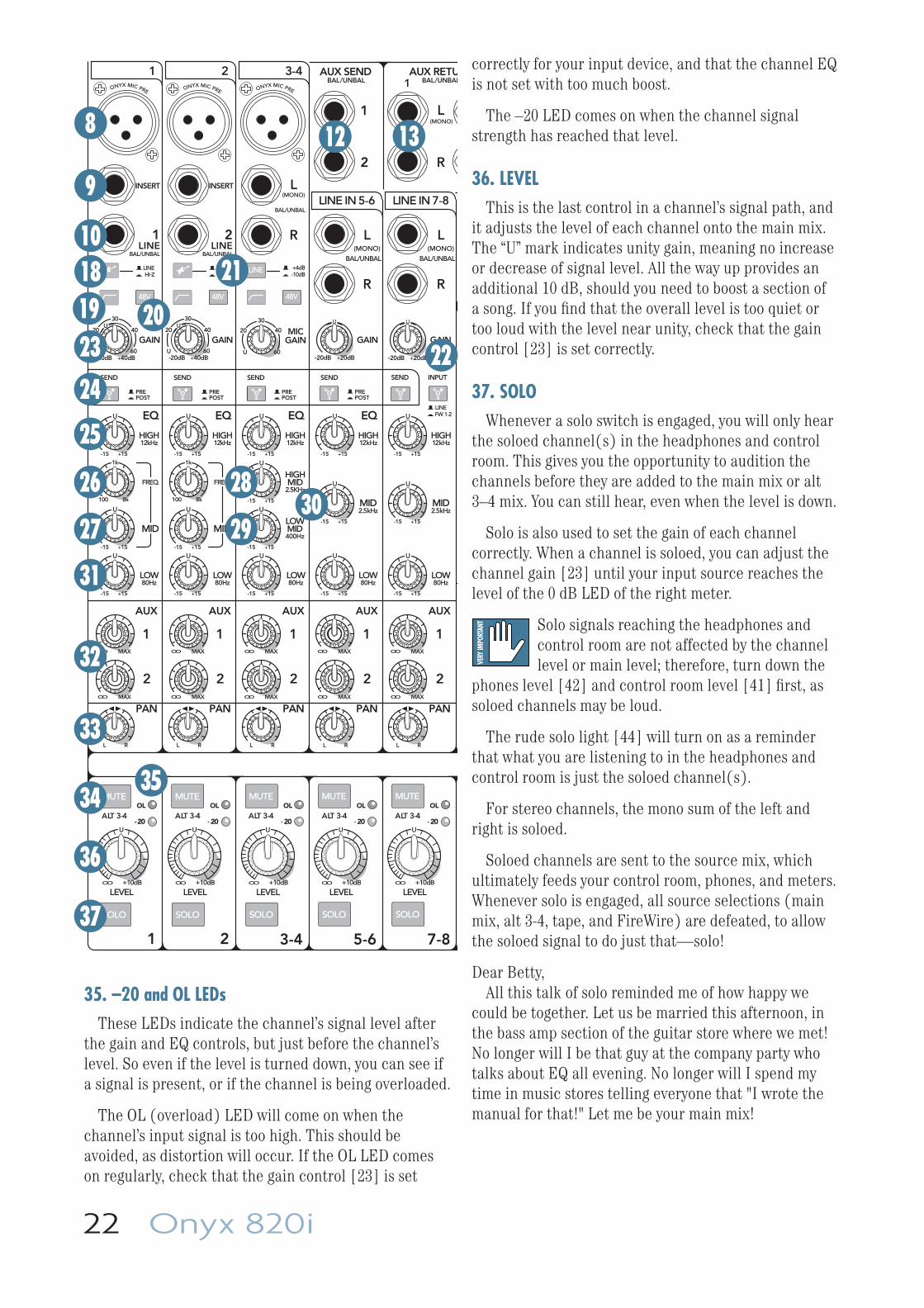
22 Onyx 820i
35. –20 and OL LEDsThese LEDs indicate the channel’s signal level after
the gain and EQ controls, but just before the channel’s level. So even if the level is turned down, you can see if a signal is present, or if the channel is being overloaded.
The OL (overload) LED will come on when the channel’s input signal is too high. This should be avoided, as distortion will occur. If the OL LED comes on regularly, check that the gain control [23] is set
correctly for your input device, and that the channel EQ is not set with too much boost.
The –20 LED comes on when the channel signal strength has reached that level.
36. LEVELThis is the last control in a channel’s signal path, and
it adjusts the level of each channel onto the main mix. The “U” mark indicates unity gain, meaning no increase or decrease of signal level. All the way up provides an additional 10 dB, should you need to boost a section of a song. If you fi nd that the overall level is too quiet or too loud with the level near unity, check that the gain control [23] is set correctly.
37. SOLOWhenever a solo switch is engaged, you will only hear
the soloed channel(s) in the headphones and control room. This gives you the opportunity to audition the channels before they are added to the main mix or alt 3–4 mix. You can still hear, even when the level is down.
Solo is also used to set the gain of each channel correctly. When a channel is soloed, you can adjust the channel gain [23] until your input source reaches the level of the 0 dB LED of the right meter.
Solo signals reaching the headphones and control room are not affected by the channel level or main level; therefore, turn down the
phones level [42] and control room level [41] fi rst, as soloed channels may be loud.
The rude solo light [44] will turn on as a reminder that what you are listening to in the headphones and control room is just the soloed channel(s).
For stereo channels, the mono sum of the left and right is soloed.
Soloed channels are sent to the source mix, which ultimately feeds your control room, phones, and meters. Whenever solo is engaged, all source selections (main mix, alt 3-4, tape, and FireWire) are defeated, to allow the soloed signal to do just that—solo!
Dear Betty,All this talk of solo reminded me of how happy we
could be together. Let us be married this afternoon, in the bass amp section of the guitar store where we met! No longer will I be that guy at the company party who talks about EQ all evening. No longer will I spend my time in music stores telling everyone that "I wrote the manual for that!" Let me be your main mix!
MUTE
SOLO
48V
MUTE
SOLO
48V
MUTE
SOLO
48V
LINE
MUTE
SOLO
MUTE
SOLO
PAN
2
1
MID
FREQ
MID
FREQ
BAL/UNBAL BAL/UNBAL
ALT 3-4 ALT 3-4 ALT 3-4 ALT 3-4 ALT 3-4
LOWMID400Hz
ONYX MIC PRE
HIGH12kHz
LOW80Hz
EQ
INSERT INSERT
ONYX MIC PRE
HIGH12kHz
LOW80Hz
EQ
ONYX MIC PRE
HIGH12kHz
HIGHMID
2.5KHz
LOW80Hz
EQ EQ
(MONO)L
R
L(MONO)
R
BAL/UNBAL
L(MONO)
R
BAL/UNBAL
L(MONO)
R
BAL/UNBAL
AUX RETU
1
1
2
AUX SEND
MID2.5kHz
LOW80Hz
U
+15-15
U
+15-15
U
+15-15
U
+15-15
U
+15-15
U
+15-15
U
+15-15
U
+15-15
U
+15-15
U
+15-15
U
+15-15
U
+15-15
U
+15-15
U
+15-15
U
+15-15
U
+15-15
HIGH12kHz
MID2.5kHz
LOW80Hz
HIGH12kHz
FW 1-2LINE
HI-ZLINE
-10dB+4dB
HI-ZLINE
PREPOST
PREPOST
PREPOST
PREPOST
LEVELLEVELLEVEL LEVEL LEVEL+10dBOO
U
+10dBOO
U
+10dBOO
U
+10dBOO
U
+10dBOO
U
1 2 3-4
LINE IN 5-6 LINE IN 7-8
AUX
PAN
2
1
AUX
PAN
2
1
AUX
PAN
2
1
AUX
PAN
2
1
AUX
OL
- 20
OL
- 20 - 20
OLOL
- 20
OL
- 20
1 2
BAL/UNBAL BAL/UNBAL
SEND SEND SEND SEND SEND INPUT
3-4 5-6 7-8
GAIN
+20dB-20dB
U
GAINMIC
GAINGAIN
+20dB-20dB
U
U
20
30
40
60+40dB
U
-20dBU
20
30
40
60
GAIN
+40dB
U
-20dBU
20
30
40
60
1LINE
2LINE
1k
100 8k
1k
100 8k
MAXOO
MAXOO
MAXOO
MAXOO
MAXOO
MAXOO
MAXOO
MAXOO
MAXOO
MAXOO
L R L R L R L R L R
8
9
101819 2023
24
25
26
27
31
32
33
3435
36
37
28
2930
21
22
12 13
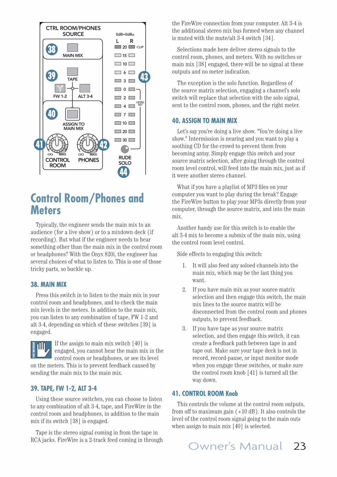
Owner's Manual 23
the FireWire connection from your computer. Alt 3-4 is the additional stereo mix bus formed when any channel is muted with the mute/alt 3-4 switch [34].
Selections made here deliver stereo signals to the control room, phones, and meters. With no switches or main mix [38] engaged, there will be no signal at these outputs and no meter indication.
The exception is the solo function. Regardless of the source matrix selection, engaging a channel’s solo switch will replace that selection with the solo signal, sent to the control room, phones, and the right meter.
40. ASSIGN TO MAIN MIXLet’s say you’re doing a live show. "You're doing a live
show." Intermission is nearing and you want to play a soothing CD for the crowd to prevent them from becoming antsy. Simply engage this switch and your source matrix selection, after going through the control room level control, will feed into the main mix, just as if it were another stereo channel.
What if you have a playlist of MP3 fi les on your computer you want to play during the break? Engage the FireWire button to play your MP3s directly from your computer, through the source matrix, and into the main mix.
Another handy use for this switch is to enable the alt 3-4 mix to become a submix of the main mix, using the control room level control.
Side effects to engaging this switch:
1. It will also feed any soloed channels into the main mix, which may be the last thing you want.
2. If you have main mix as your source matrix selection and then engage this switch, the main mix lines to the source matrix will be disconnected from the control room and phones outputs, to prevent feedback.
3. If you have tape as your source matrix selection, and then engage this switch, it can create a feedback path between tape in and tape out. Make sure your tape deck is not in record, record-pause, or input monitor mode when you engage these switches, or make sure the control room knob [41] is turned all the way down.
41. CONTROL ROOM KnobThis controls the volume at the control room outputs,
from off to maximum gain (+10 dB). It also controls the level of the control room signal going to the main outs when assign to main mix [40] is selected.
TAPE
CTRL ROOM/PHONESSOURCE
PHONESCONTROLROOM
RUDESOLO
20
15
10
6
3
0
2
4
7
10
20
30
L R0dB=0dBu
LEVELSET
CLIP
MAIN MIX
ALT 3-4FW 1-2
ASSIGN TOMAIN MIX
MAXOOMAXOO
Control Room/Phones and Meters
Typically, the engineer sends the main mix to an audience (for a live show) or to a mixdown deck (if recording). But what if the engineer needs to hear something other than the main mix in the control room or headphones? With the Onyx 820i, the engineer has several choices of what to listen to. This is one of those tricky parts, so buckle up.
38. MAIN MIXPress this switch in to listen to the main mix in your
control room and headphones, and to check the main mix levels in the meters. In addition to the main mix, you can listen to any combination of tape, FW 1-2 and alt 3-4, depending on which of these switches [39] is engaged.
If the assign to main mix switch [40] is engaged, you cannot hear the main mix in the control room or headphones, or see its level
on the meters. This is to prevent feedback caused by sending the main mix to the main mix.
39. TAPE, FW 1-2, ALT 3-4Using these source switches, you can choose to listen
to any combination of alt 3-4, tape, and FireWire in the control room and headphones, in addition to the main mix if its switch [38] is engaged.
Tape is the stereo signal coming in from the tape in RCA jacks. FireWire is a 2-track feed coming in through
38
39
40
41
43
42
44
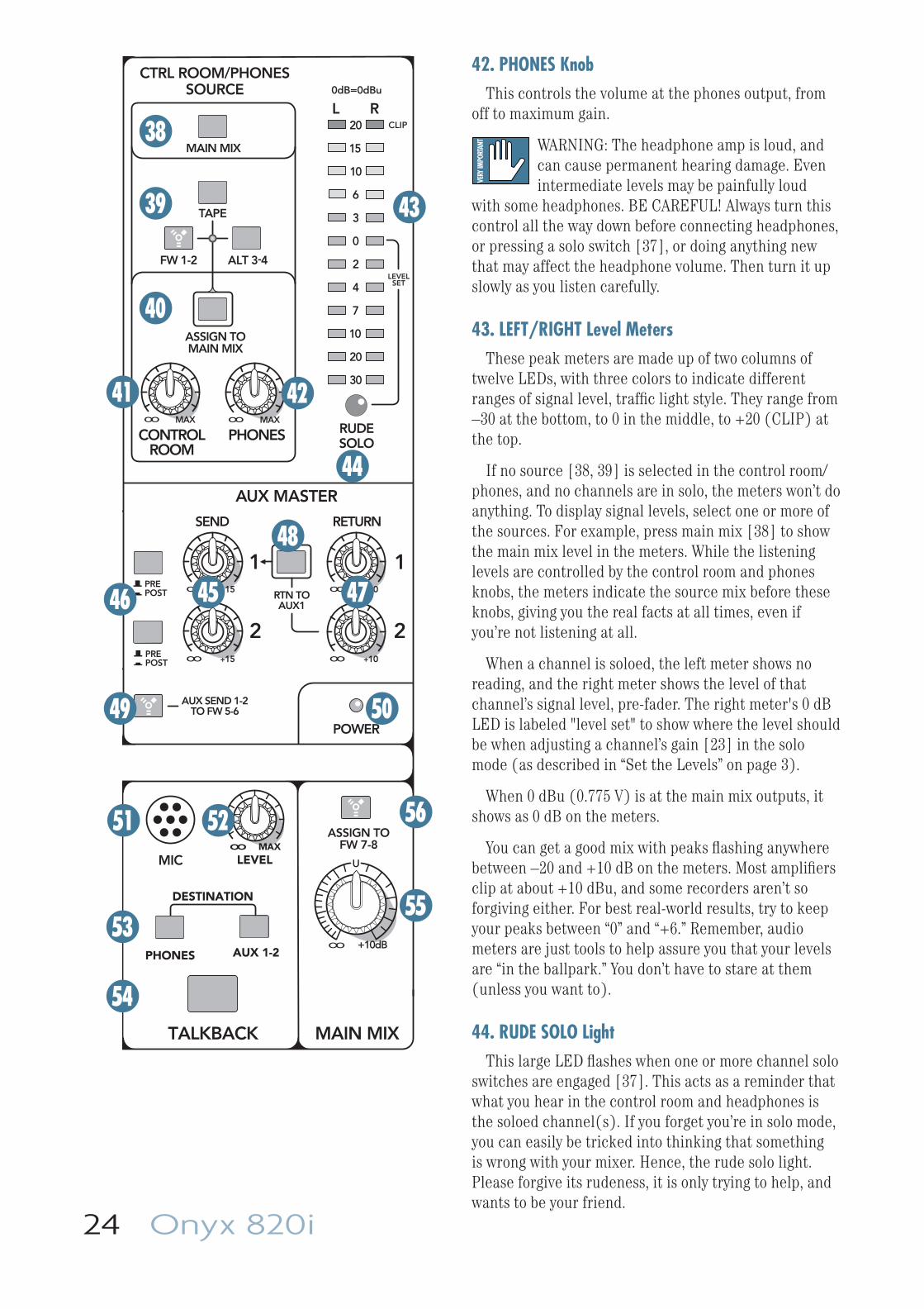
24 Onyx 820i
42. PHONES KnobThis controls the volume at the phones output, from
off to maximum gain.
WARNING: The headphone amp is loud, and can cause permanent hearing damage. Even intermediate levels may be painfully loud
with some headphones. BE CAREFUL! Always turn this control all the way down before connecting headphones, or pressing a solo switch [37], or doing anything new that may affect the headphone volume. Then turn it up slowly as you listen carefully.
43. LEFT/RIGHT Level MetersThese peak meters are made up of two columns of
twelve LEDs, with three colors to indicate different ranges of signal level, traffi c light style. They range from –30 at the bottom, to 0 in the middle, to +20 (CLIP) at the top.
If no source [38, 39] is selected in the control room/phones, and no channels are in solo, the meters won’t do anything. To display signal levels, select one or more of the sources. For example, press main mix [38] to show the main mix level in the meters. While the listening levels are controlled by the control room and phones knobs, the meters indicate the source mix before these knobs, giving you the real facts at all times, even if you’re not listening at all.
When a channel is soloed, the left meter shows no reading, and the right meter shows the level of that channel’s signal level, pre-fader. The right meter's 0 dB LED is labeled "level set" to show where the level should be when adjusting a channel’s gain [23] in the solo mode (as described in “Set the Levels” on page 3).
When 0 dBu (0.775 V) is at the main mix outputs, it shows as 0 dB on the meters.
You can get a good mix with peaks fl ashing anywhere between –20 and +10 dB on the meters. Most amplifi ers clip at about +10 dBu, and some recorders aren’t so forgiving either. For best real-world results, try to keep your peaks between “0” and “+6.” Remember, audio meters are just tools to help assure you that your levels are “in the ballpark.” You don’t have to stare at them (unless you want to).
44. RUDE SOLO LightThis large LED fl ashes when one or more channel solo
switches are engaged [37]. This acts as a reminder that what you hear in the control room and headphones is the soloed channel(s). If you forget you’re in solo mode, you can easily be tricked into thinking that something is wrong with your mixer. Hence, the rude solo light. Please forgive its rudeness, it is only trying to help, and wants to be your friend.
TAPE
AUX MASTER
2
1
SEND RETURN
2
1
MAIN MIX
CTRL ROOM/PHONESSOURCE
PHONESCONTROLROOM
RUDESOLO
20
15
10
6
3
0
2
4
7
10
20
30
L R0dB=0dBu
LEVELSET
CLIP
MIC
PREPOST
PREPOST
+10dBOO
U
RTN TOAUX1
AUX SEND 1-2TO FW 5-6
ASSIGN TOFW 7-8
MAIN MIX
AUX 1-2PHONES
DESTINATION
LEVELOO MAX
TALKBACK
POWER
ALT 3-4FW 1-2
ASSIGN TOMAIN MIX
MAXOOMAXOO
+15OO
+15OO
+10OO
+10OO
38
39
40
41
43
42
45
44
47
48
46
49 50
51 52
53
54
55
56
Owner's Manual 25
Aux MasterThis section includes the aux sends and the aux
returns. Aux sends tap signals off the channels, via the aux knobs [32], mix these signals from each channel together, then sends them out the aux send jacks [12] and FireWire outputs 7 and 8. The aux sends can be pre-fader or post-fader (both are post-EQ, but see page 39).
Post-fader aux sends can be fed to the inputs of an external processor like a reverb or digital delay. From there, the outputs of this external processor are fed back to the mixer’s aux return jacks [13]. Then these signals are sent through the aux return level controls [47], and fi nally delivered to the main mix.
So, the original unprocessed “dry” signals go from the channels to the main mix, and the processed “wet” signals go from the aux returns to the main mix, and once mixed together, the dry and wet signals combine to create a glorious sound!
Pre-fader aux sends are typically used to provide another mix for stage monitors. In this case, the aux returns aren’t used to return the signal. Instead, they can be used as additional stereo inputs, or not used at all.
45. MASTER AUX SEND 1 and 2These knobs provide overall control over the aux send
levels, just before they are delivered to the aux send outputs [12]. These knobs go from off to +15 db when turned all the way up.
The aux sends can either be pre or post fader, depending on the position of the aux pre/post switches [46].
This is usually the knob you turn up when the lead singer glares at you, points at his stage monitor, and sticks his thumb up in the air. (It would follow that if the singer stuck his thumb down, you’d turn the knob down, but that never happens.)
The aux sends can also be sent to FireWire output 7 and 8 for recording. The levels to FireWire are affected by these send controls and the pre/post switch.
46. PRE/POSTThe pre/post switches determine whether the aux
send signal is tapped from the channels before the channel level controls (pre-fader) or after (post-fader). Having a separate pre/post switch for each aux is a super-useful feature as it allows the use of one effects processor and one stage monitor chain, at the same time.
For stage monitor work, use pre, so the stage monitors do not increase in volume when the channel level is adjusted.
For external processors, use post. In this way, the feed to external processors will vary with the channel level, keeping them in the same ratio, so that the “wet” signal level follows the “dry” signal level.
47. MASTER AUX RETURN 1 and 2These two controls set the overall level of effects
received from the stereo aux return 1 and 2 inputs [13]. These controls range from off to +10 db of gain when fully clockwise, to compensate for low-level effects.
Signals passing through these controls go directly to the main mix bus where they are combined with the other channels. Alternatively, the aux 2 return can be routed to aux 1 send instead, using the rtn to aux 1 switch [48].
48. RTN TO AUX 1This switch routes the signal from aux return 2 to the
aux 1 send mix instead of to the main mix bus.
For example, this allows you to use an external effects device, like a reverb or delay, exclusively for the monitors. When this switch is pushed in, the effects signals coming into the aux return 2 jacks are added to your aux 1 stage monitor mix. Adjust the effects level coming in with the aux 2 return controls [47], until it sounds just right in your monitors.
49. AUX SEND 1-2 to FW 5-6This switch allows you to send a copy of the aux
send 1 and 2 outputs via FireWire to a computer. The FireWire output is affected by the channel aux send and master aux send controls.
For example, you can set up a software effects processor as follows:
• Set up an aux send in post mode.
• Engage this switch to make aux send FireWire outputs 5 and 6 available to your computer.
• Pass this through a software effects processor or plug-in of your choice.
• Return the processed output from the effects processor to mixer channels 7 and 8 (input switch set to FW 1-2).
• Alternatively bring the processed sounds into the control room matrix (engage FW 1-2) and add it to the main mix (engage assign to main mix).
• You can even use the computer as two separate independent mono in, stereo out processors. Have aux 1 go into one plug-in, and aux 2 go into a different one. The stereo outputs of both plug-ins are combined back into the stereo stream coming back to the mixer.
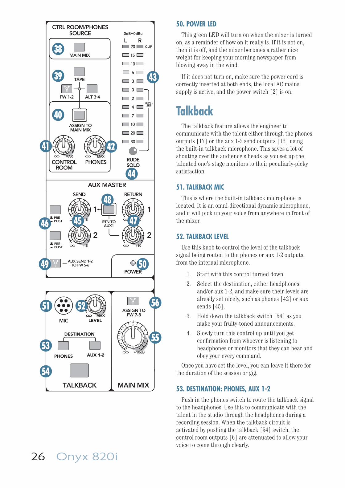
26 Onyx 820i
50. POWER LEDThis green LED will turn on when the mixer is turned
on, as a reminder of how on it really is. If it is not on, then it is off, and the mixer becomes a rather nice weight for keeping your morning newspaper from blowing away in the wind.
If it does not turn on, make sure the power cord is correctly inserted at both ends, the local AC mains supply is active, and the power switch [2] is on.
TalkbackThe talkback feature allows the engineer to
communicate with the talent either through the phones outputs [17] or the aux 1-2 send outputs [12] using the built-in talkback microphone. This saves a lot of shouting over the audience's heads as you set up the talented one's stage monitors to their peculiarly-picky satisfaction.
51. TALKBACK MICThis is where the built-in talkback microphone is
located. It is an omni-directional dynamic microphone, and it will pick up your voice from anywhere in front of the mixer.
52. TALKBACK LEVELUse this knob to control the level of the talkback
signal being routed to the phones or aux 1-2 outputs, from the internal microphone.
1. Start with this control turned down.
2. Select the destination, either headphones and/or aux 1-2, and make sure their levels are already set nicely, such as phones [42] or aux sends [45].
3. Hold down the talkback switch [54] as you make your fruity-toned announcements.
4. Slowly turn this control up until you get confi rmation from whoever is listening to headphones or monitors that they can hear and obey your every command.
Once you have set the level, you can leave it there for the duration of the session or gig.
53. DESTINATION: PHONES, AUX 1-2Push in the phones switch to route the talkback signal
to the headphones. Use this to communicate with the talent in the studio through the headphones during a recording session. When the talkback circuit is activated by pushing the talkback [54] switch, the control room outputs [6] are attenuated to allow your voice to come through clearly.
TAPE
AUX MASTER
2
1
SEND RETURN
2
1
MAIN MIX
CTRL ROOM/PHONESSOURCE
PHONESCONTROLROOM
RUDESOLO
20
15
10
6
3
0
2
4
7
10
20
30
L R0dB=0dBu
LEVELSET
CLIP
MIC
PREPOST
PREPOST
+10dBOO
U
RTN TOAUX1
AUX SEND 1-2TO FW 5-6
ASSIGN TOFW 7-8
MAIN MIX
AUX 1-2PHONES
DESTINATION
LEVELOO MAX
TALKBACK
POWER
ALT 3-4FW 1-2
ASSIGN TOMAIN MIX
MAXOOMAXOO
+15OO
+15OO
+10OO
+10OO
38
39
40
41
43
42
45
44
47
48
46
49 50
51 52
53
54
55
56
Owner's Manual 27
The aux 1-2 switch routes the talkback signal to the aux send 1 and 2 outputs [12]. Use this to communicate with the musicians through their stage monitors when you are setting up a live performance.
It is fi ne to have both destination switches pushed in at the same time, so the talkback signal will be routed to both destinations. But if you don’t have either of the destination switches pushed in, the talkback signal won’t go anywhere. You might as well be talking to a brick wall.
54. TALKBACK SwitchThis is a momentary switch, and as long as you hold
it down, talkback is activated. You can talk into the built-in microphone and be heard in the headphones and/or stage monitors.
Release the switch so you can talk about the band without them hearing you.
Main Mix55. MAIN MIX
This stereo control allows you to adjust the levels of the main mix signals sent to the XLR and 1/4" main line-level outputs [4, 14], and the tape outputs [16].
This gives you the ultimate feeling of power and control over the sound levels sent to your audience. If you press the main mix switch [38], you can see the main mix levels in the meters [43]. Adjust this control carefully, with your good eye on the meters to check against overloading, and your good ear to the levels to make sure your audience (if any) is happy.
This control does not affect the aux outputs [12], alt 3-4 outputs [7], or the main mix FireWire outputs 7-8. It affects the control room or headphones if the main mix switch [38] is engaged.
The main mix signals are off with the knob fully down, the “U” marking is unity gain, and fully up provides 10 dB of additional gain. This additional gain will typically never be needed, but once again, it’s nice to know that it’s there. The fader is stereo, as it affects both the left and right of the main mix equally. This is the ideal control to slowly bring down at the end of a song (or quickly in the middle of a song if the need ever arises).
56. ASSIGN TO FW 7–8This switch allows you to assign the left and right
main mix to FireWire outputs 7 and 8. For example, you can record the live performance main mix onto your computer. This does not affect the analog main mix outputs.
The output level to your computer is not affected by the main mix level control [55].
When this switch is disengaged, then mixer channels 7 and 8 are assigned to FireWire outputs 7 and 8 instead.
Congratulations! You’ve just read about all the features of your mixer. Time for a frosty beverage.
28 Onyx 820i
Appendix A: Service Information
If you think your mixer has a problem, please check out the following troubleshooting tips and do your best to confi rm the problem. Visit the Support section of our website (www.mackie.com) where you will fi nd lots of useful information such as FAQs, documentation and any updated PC drivers etc. You may fi nd the answer to the problem without having to send your mixer away.
Troubleshooting
Bad Channel
• Is the channel EQ set up nicely?
• Is the channel gain set correctly?
• Is the channel level up enough?
• Is the channel OL led on?
• Is the channel pan set in the middle?
• Are the hi-z instrument switches set OK for any guitars connected to channels 1 or 2?
• Try unplugging any insert devices from the insert jacks on channels 1 or 2.
• Try the same source signal in another channel, set up exactly like the suspect channel.
• Is phantom power required for your microphone?
Bad Output
• Is the main level turned up?
• Are the EQs set to reasonable levels?
• Are any aux returns maxed out?
• Unplug anything from the other line-level outputs, such as alt 3-4, control room out, just in case one of your external pieces has a problem.
• Make sure that you are not overdriving your amplifi ers. Check the loudspeaker average load impedance is not less than the minimum your amplifi er can handle. Check the speaker wiring.
Noise
• Turn the channel gains down, one by one. If the sound disappears, it’s either that channel or whatever is plugged into it, so unplug whatever that is. If the noise disappears, it’s from your whatever.
Power
• The power LED should come on if the mixer is connected to a suitable live AC mains outlet, and the power switch is on. Check to make sure that the power cord is securely plugged in.
RepairFor warranty service, refer to the warranty
information on page 41.
Non-warranty service for Mackie products is available at a factory-authorized service center. To locate your nearest service center, visit www.mackie.com, click “Support” and select “Locate a Service Center.” Service for Mackie products living outside the United States can be obtained through local dealers or distributors.
If you do not have access to our website, you can call our Tech Support department at 1-800-898-3211, Monday-Friday, normal business hours, Pacifi c Time, to explain the problem. Tech Support will tell you where the nearest factory-authorized service center is located in your area.
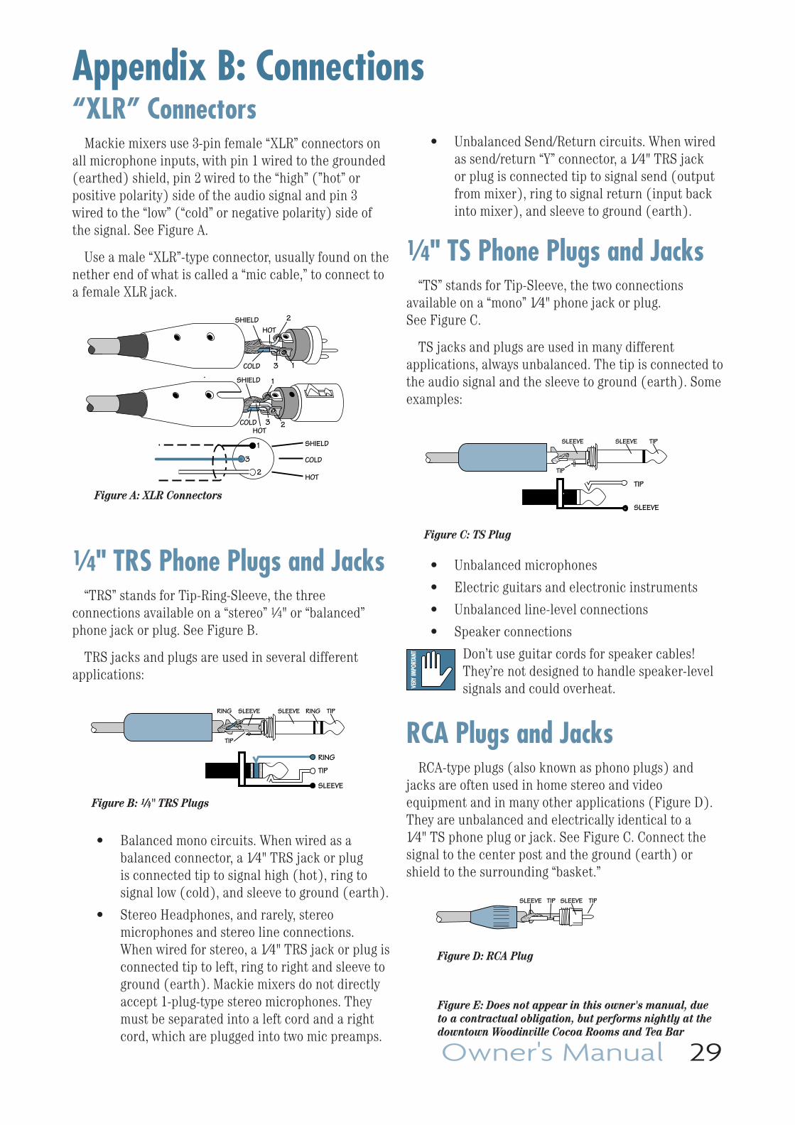
Owner's Manual 29
“XLR” ConnectorsMackie mixers use 3-pin female “XLR” connectors on
all microphone inputs, with pin 1 wired to the grounded (earthed) shield, pin 2 wired to the “high” (”hot” or positive polarity) side of the audio signal and pin 3 wired to the “low” (“cold” or negative polarity) side of the signal. See Figure A.
Use a male “XLR”-type connector, usually found on the nether end of what is called a “mic cable,” to connect to a female XLR jack.
1⁄4" TRS Phone Plugs and Jacks“TRS” stands for Tip-Ring-Sleeve, the three
connections available on a “stereo” 1⁄4" or “balanced” phone jack or plug. See Figure B.
TRS jacks and plugs are used in several different applications:
• Balanced mono circuits. When wired as a balanced connector, a 1⁄4" TRS jack or plug is connected tip to signal high (hot), ring to signal low (cold), and sleeve to ground (earth).
• Stereo Headphones, and rarely, stereo microphones and stereo line connections. When wired for stereo, a 1⁄4" TRS jack or plug is connected tip to left, ring to right and sleeve to ground (earth). Mackie mixers do not directly accept 1-plug-type stereo micro phones. They must be separated into a left cord and a right cord, which are plugged into two mic preamps.
Appendix B: Connections
• Unbalanced Send/Return circuits. When wired as send/return “Y” connector, a 1⁄4" TRS jack or plug is connected tip to signal send (output from mixer), ring to signal return (input back into mixer), and sleeve to ground (earth).
1⁄4" TS Phone Plugs and Jacks“TS” stands for Tip-Sleeve, the two connections
available on a “mono” 1⁄4" phone jack or plug. See Figure C.
TS jacks and plugs are used in many different applications, always unbalanced. The tip is connected to the audio signal and the sleeve to ground (earth). Some examples:
• Unbalanced microphones
• Electric guitars and electronic instruments
• Unbalanced line-level connections
• Speaker connections
Don’t use guitar cords for speaker cables! They’re not designed to handle speaker-level signals and could overheat.
RCA Plugs and JacksRCA-type plugs (also known as phono plugs) and
jacks are often used in home stereo and video equipment and in many other applications (Figure D). They are unbalanced and electrically identical to a 1⁄4" TS phone plug or jack. See Figure C. Connect the signal to the center post and the ground (earth) or shield to the surrounding “basket.”
SLEEVE
TIP
TIPSLEEVE
TIP
SLEEVE
Figure C: TS Plug
2
2
3 1
1
SHIELD
COLD
HOT
SHIELD
COLD
HOT
3
SHIELD
COLDHOT
3
2
1
Figure A: XLR Connectors
SLEEVE
TIPSLEEVE
TIP
RING
RING
TIP
SLEEVERING
Figure B: 1⁄4" TRS Plugs
TIPSLEEVETIPSLEEVE
Figure D: RCA Plug
Figure E: Does not appear in this owner's manual, due to a contractual obligation, but performs nightly at the downtown Woodinville Cocoa Rooms and Tea Bar
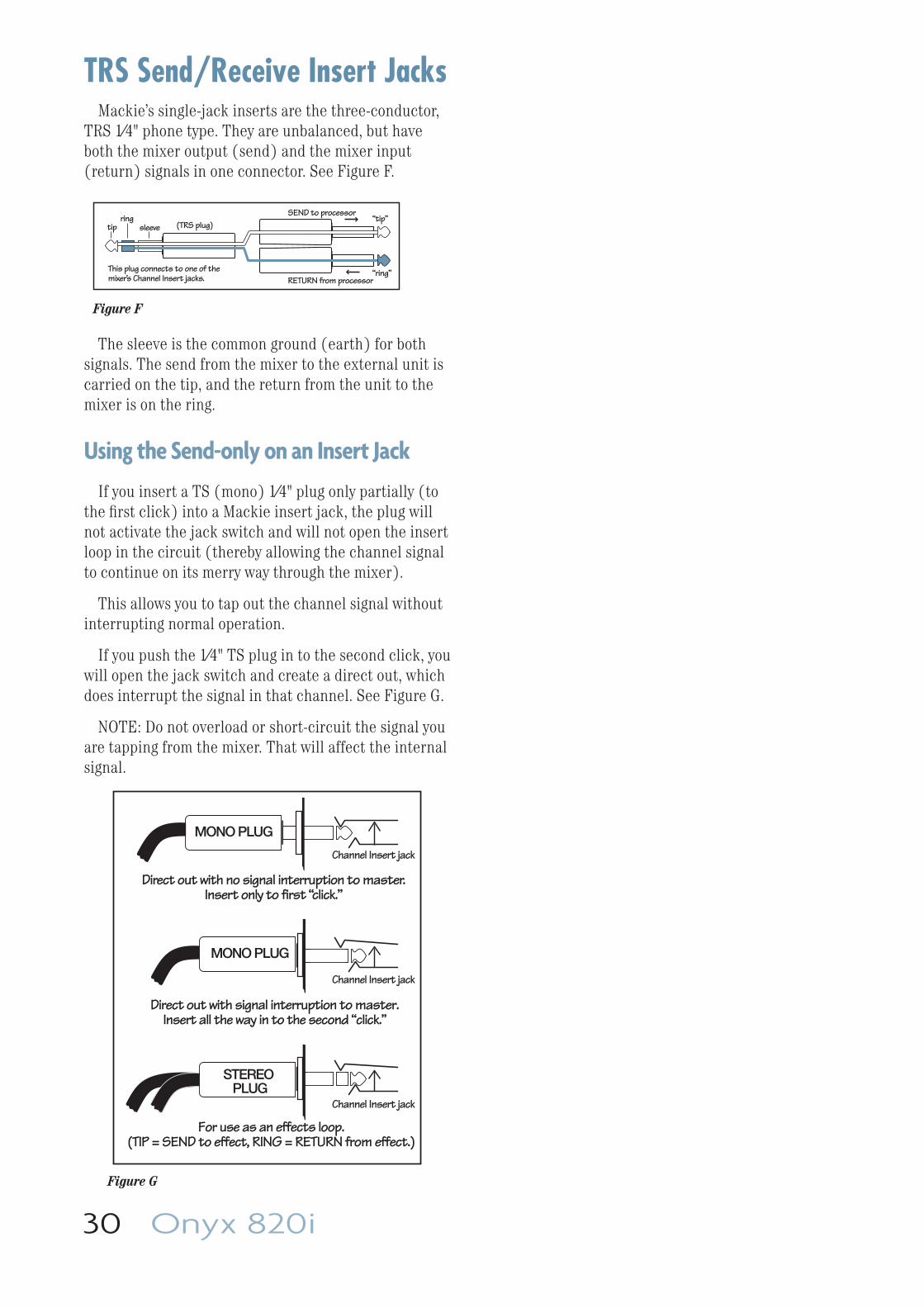
30 Onyx 820i
TRS Send/Receive Insert JacksMackie’s single-jack inserts are the three- conductor,
TRS 1⁄4" phone type. They are unbalanced, but have both the mixer output (send) and the mixer input (return) signals in one connector. See Figure F.
The sleeve is the common ground (earth) for both signals. The send from the mixer to the external unit is carried on the tip, and the return from the unit to the mixer is on the ring.
Using the Send-only on an Insert Jack
If you insert a TS (mono) 1⁄4" plug only partially (to the fi rst click) into a Mackie insert jack, the plug will not activate the jack switch and will not open the insert loop in the circuit (thereby allowing the channel signal to continue on its merry way through the mixer).
This allows you to tap out the channel signal without interrupting normal operation.
If you push the 1⁄4" TS plug in to the second click, you will open the jack switch and create a direct out, which does interrupt the signal in that channel. See Figure G.
NOTE: Do not overload or short-circuit the signal you are tapping from the mixer. That will affect the internal signal.
“tip”
This plug connects to one of the mixer’s Channel Insert jacks. “ring”
tipring
sleeve
SEND to processor
RETURN from processor
(TRS plug)
Figure F
Direct out with no signal interruption to master.Insert only to first “click.”
Channel Insert jack
Channel Insert jack
Channel Insert jack
Direct out with signal interruption to master.Insert all the way in to the second “click.”
For use as an effects loop.(TIP = SEND to effect, RING = RETURN from effect.)
MONO PLUG
MONO PLUG
STEREO PLUG
Figure G
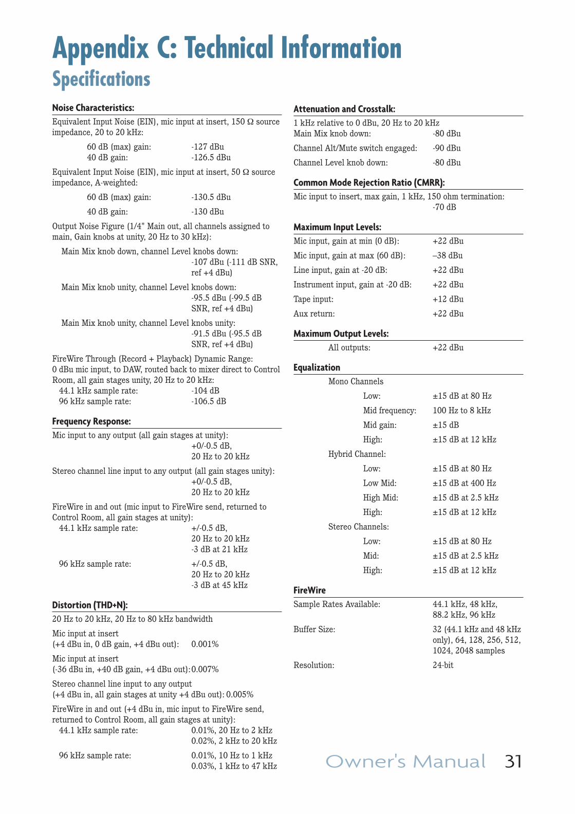
Owner's Manual 31
Appendix C: Technical InformationSpecifi cationsNoise Characteristics: Equivalent Input Noise (EIN), mic input at insert, 150 Ω source impedance, 20 to 20 kHz:
60 dB (max) gain: -127 dBu 40 dB gain: -126.5 dBu
Equivalent Input Noise (EIN), mic input at insert, 50 Ω source impedance, A-weighted:
60 dB (max) gain: -130.5 dBu
40 dB gain: -130 dBu
Output Noise Figure (1/4" Main out, all channels assigned to main, Gain knobs at unity, 20 Hz to 30 kHz):
Main Mix knob down, channel Level knobs down: -107 dBu (-111 dB SNR, ref +4 dBu)
Main Mix knob unity, channel Level knobs down: -95.5 dBu (-99.5 dB SNR, ref +4 dBu)
Main Mix knob unity, channel Level knobs unity: -91.5 dBu (-95.5 dB SNR, ref +4 dBu)
FireWire Through (Record + Playback) Dynamic Range: 0 dBu mic input, to DAW, routed back to mixer direct to Control Room, all gain stages unity, 20 Hz to 20 kHz: 44.1 kHz sample rate: -104 dB 96 kHz sample rate: -106.5 dB
Frequency Response: Mic input to any output (all gain stages at unity): +0/-0.5 dB, 20 Hz to 20 kHz
Stereo channel line input to any output (all gain stages unity): +0/-0.5 dB, 20 Hz to 20 kHz
FireWire in and out (mic input to FireWire send, returned to Control Room, all gain stages at unity): 44.1 kHz sample rate: +/-0.5 dB, 20 Hz to 20 kHz -3 dB at 21 kHz
96 kHz sample rate: +/-0.5 dB, 20 Hz to 20 kHz -3 dB at 45 kHz
Distortion (THD+N): 20 Hz to 20 kHz, 20 Hz to 80 kHz bandwidth
Mic input at insert (+4 dBu in, 0 dB gain, +4 dBu out): 0.001%
Mic input at insert (-36 dBu in, +40 dB gain, +4 dBu out): 0.007%
Stereo channel line input to any output (+4 dBu in, all gain stages at unity +4 dBu out): 0.005%
FireWire in and out (+4 dBu in, mic input to FireWire send, returned to Control Room, all gain stages at unity): 44.1 kHz sample rate: 0.01%, 20 Hz to 2 kHz 0.02%, 2 kHz to 20 kHz
96 kHz sample rate: 0.01%, 10 Hz to 1 kHz 0.03%, 1 kHz to 47 kHz
Attenuation and Crosstalk: 1 kHz relative to 0 dBu, 20 Hz to 20 kHz Main Mix knob down: -80 dBu
Channel Alt/Mute switch engaged: -90 dBu
Channel Level knob down: -80 dBu
Common Mode Rejection Ratio (CMRR): Mic input to insert, max gain, 1 kHz, 150 ohm termination: -70 dB
Maximum Input Levels: Mic input, gain at min (0 dB): +22 dBu
Mic input, gain at max (60 dB): –38 dBu
Line input, gain at -20 dB: +22 dBu
Instrument input, gain at -20 dB: +22 dBu
Tape input: +12 dBu
Aux return: +22 dBu
Maximum Output Levels: All outputs: +22 dBu
Equalization Mono Channels
Low: ±15 dB at 80 Hz
Mid frequency: 100 Hz to 8 kHz
Mid gain: ±15 dB
High: ±15 dB at 12 kHz
Hybrid Channel:
Low: ±15 dB at 80 Hz
Low Mid: ±15 dB at 400 Hz
High Mid: ±15 dB at 2.5 kHz
High: ±15 dB at 12 kHz
Stereo Channels:
Low: ±15 dB at 80 Hz
Mid: ±15 dB at 2.5 kHz
High: ±15 dB at 12 kHz
FireWire Sample Rates Available: 44.1 kHz, 48 kHz, 88.2 kHz, 96 kHz
Buffer Size: 32 (44.1 kHz and 48 kHz only), 64, 128, 256, 512, 1024, 2048 samples
Resolution: 24-bit
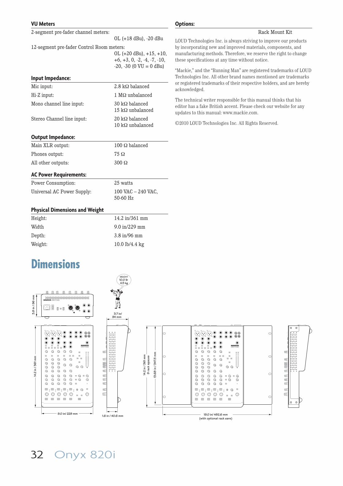
32 Onyx 820i
14.2
in /
361 m
m
9.0 in/ 229 mm
3.7 in/94 mm
WEIGHT10.0 lb 4.5 kg
3.8
in /
96 m
m
1.6 in / 40.6 mm
MUTE
SOLO
48V
MUTE
SOLO
48V
MUTE
SOLO
48V
LINE
MUTE
SOLO
MUTE
SOLO
19.0 in/ 482.6 mm(with optional rack ears)
MUTE
SOLO
48V
MUTE
SOLO
48V
MUTE
SOLO
48V
LINE
MUTE
SOLO
MUTE
SOLO
13.6
8 in
/ 34
7.5
mm
14.2
in /
361 m
m9
rack
spa
ces
VU Meters 2-segment pre-fader channel meters: OL (+18 dBu), -20 dBu
12-segment pre-fader Control Room meters: OL (+20 dBu), +15, +10, +6, +3, 0, -2, -4, -7, -10, -20, -30 (0 VU = 0 dBu)
Input Impedance: Mic input: 2.8 kΩ balanced
Hi-Z input: 1 MΩ unbalanced
Mono channel line input: 30 kΩ balanced 15 kΩ unbalanced
Stereo Channel line input: 20 kΩ balanced 10 kΩ unbalanced
Output Impedance: Main XLR output: 100 Ω balanced
Phones output: 75 Ω
All other outputs: 300 Ω
AC Power Requirements: Power Consumption: 25 watts
Universal AC Power Supply: 100 VAC – 240 VAC, 50-60 Hz
Physical Dimensions and Weight Height: 14.2 in/361 mm
Width 9.0 in/229 mm
Depth: 3.8 in/96 mm
Weight: 10.0 lb/4.4 kg
Options: Rack Mount Kit
LOUD Technologies Inc. is always striving to improve our products by incorporating new and improved materials, components, and manufacturing methods. Therefore, we reserve the right to change these specifi cations at any time without notice.
“Mackie,” and the “Running Man” are registered trademarks of LOUD Technologies Inc. All other brand names mentioned are trademarks or registered trademarks of their respective holders, and are hereby acknowledged.
The technical writer responsible for this manual thinks that his editor has a fake British accent. Please check our website for any updates to this manual: www.mackie.com.
©2010 LOUD Technologies Inc. All Rights Reserved.
Dimensions
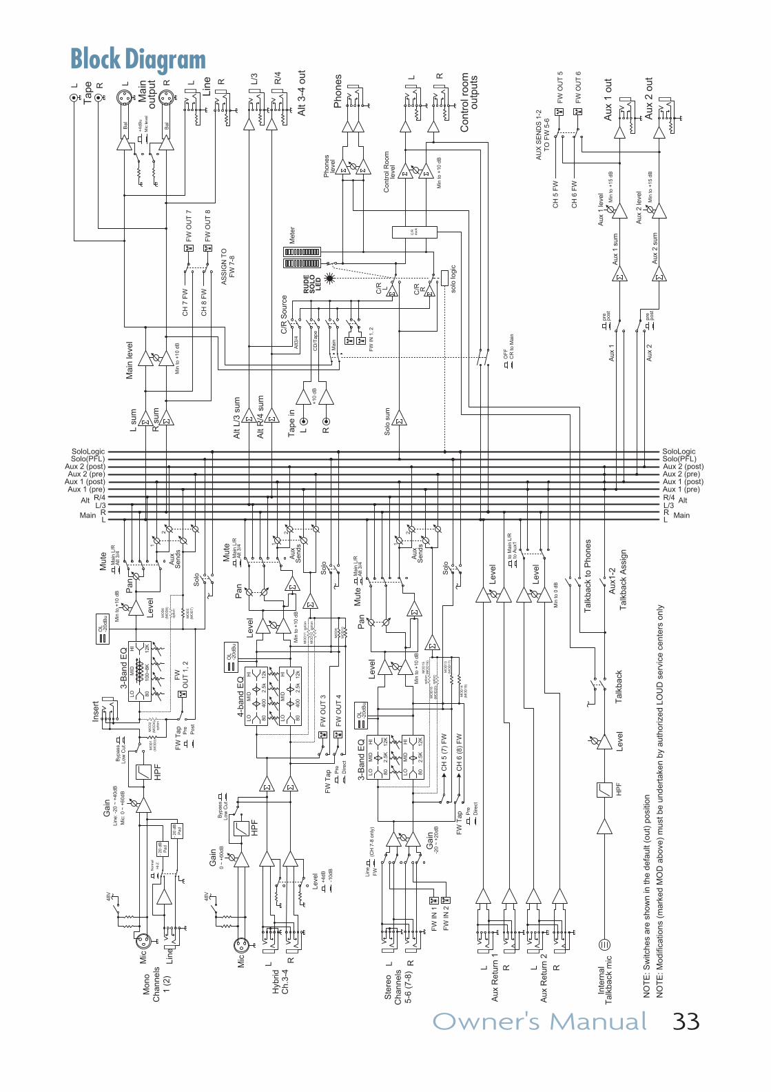
Owner's Manual 33
Block Diagram
solo
logi
c
Co
ntro
l Roo
m
leve
l
Mai
n le
vel
Au
x R
etur
n 2
L R
Inse
rt
HP
FLe
vel
Pan S
olo
Aux
Sen
ds
Leve
l
Tap
eL R L/3
R/4
Aux
1 o
ut
Aux
2 o
ut
Aux
1 le
vel
Pho
nes
Con
trol
roo
mou
tput
s L R
L su
m
R s
um
Alt
L/3
sum
Alt
R/4
sum
Aux
1 s
um
Aux
2 s
um
Sol
o su
m
Leve
l
Aux
Re
turn
1
L R
LOM
ID
8010
0~8K
12KHI
Aux
1
Met
erT
ape
in
L R
RUDE
SOLO
LED
Line
Bal
Tal
kbac
k A
ssig
n
Alt3
/4
CD
/Tap
e+
10 d
B
Mai
n
C/R
Sou
rce
3-B
and
EQ
Pho
nes
leve
l
LR
Aux 1 (post)
Aux 2 (post)Solo(PFL)SoloLogic
MainL/3R/4Alt
Aux 1 (pre)
Aux 2 (pre)
LR
Aux 1 (post)
Aux 2 (post)Solo(PFL)SoloLogic
MainL/3R/4 Alt
Aux 1 (pre)
Aux 2 (pre)
Aux
2 le
vel
Aux
2
Tal
kbac
k to
Ph
ones
Aux
1-2
Alt
3/4
Ma
in L
/R
to A
ux1
to M
ain
L/R
pos
tpr
e
pos
tpr
e
CR
to M
ain
OF
F
Tal
kba
ck
NO
TE
: Mod
ifica
tions
(m
arke
d M
OD
abo
ve)
mus
t be
und
erta
ken
by a
utho
rized
LO
UD
ser
vice
cen
ters
onl
y
NO
TE
: Sw
itche
s ar
e sh
ow
n in
the
defa
ult (
out
) po
sitio
n
C/R
L
C/R
R
Alt
3-4
out
Mai
nou
tput
48V
Mon
oC
hann
els
1 (2
)
Mic
Line
Gai
n
Mic
: 0
~ +
60d
B
Line
: -2
0 ~
+4
0dB
3-B
and
EQ
Inte
rnal
T
alkb
ack
mic
Leve
l
Ste
reo
Cha
nnel
s5
-6 (
7-8)
L R
FW
Line
(CH
7-8
on
ly)
FW
O
UT
1, 2
Hyb
rid
Ch
.3-4
L RMic
-20
~ +
20d
B
Ga
in0
~ +
60dB G
ain
4-ba
nd E
Q
HI-
Z
No
rmal
LO 80
400
2.5
k
HI
MID
12k
LO 80
400
2.5
k
HI
MID
12k
FW
Leve
l+
4dB
-10d
B
HP
F
Low
Cu
tB
ypas
s
Low
Cut
Byp
ass
Pos
t
FW
Tap Pre
HP
F
LO 80
2.5
K12
K
HI
MID
LO 80
2.5
K12
K
HI
MID
Mut
e
1
2
48V
Leve
lP
an
Sol
o
Aux
S
ends
Alt
3/4
Ma
in L
/RO
L-2
0dB
uM
ute 1
2
FW
Tap
FW
OU
T 3
FW
FW
OU
T 4
FW
Pre
Dire
ct
FW
IN 1
FW
FW
IN 2
FW
Leve
lP
an
Sol
o
Aux
Sen
ds
Alt
3/4
Ma
in L
/RM
ute
1
2
OL
-20d
Bu
FW
Tap P
re
Dire
ct
L R L R
Bal
Mic
leve
l
+4d
Bu
C/R
du
ck
FW
OU
T 5
FW
FW
OU
T 6
FW
FW
IN
1, 2
FW
FW
CH
5 (
7) F
W
CH
6 (
8) F
W
CH
5 F
W
CH
6 F
W
Min
to +
10 d
B
Min
to
+1
0 dB
Min
to +
10 d
B
Min
to 0
dB
Min
to +
15 d
B
Min
to +
15 d
B
Min
to +
10 d
B
Min
to +
10
dB
AU
X S
EN
DS
1-2
T
O F
W 5
-6
FW
OU
T 7
FW
FW
OU
T 8
FW
CH
7 F
W
CH
8 F
W
AS
SIG
N T
O
FW
7-8
OL
-20
dBu
-2
0 dB
P
ad
-2
0 d
B
Pa
d
MO
D1
(MO
D3
)
MO
D2
(MO
D4)
optio
n
optio
n
MO
D6
(MO
D8
)
MO
D5
(MO
D7
)
MO
D9
MO
D10
MO
D11
MO
D12
optio
n
optio
n
MO
D13
(M
OD
17)
MO
D14
(MO
D18
)
MO
D15
(MO
D1
9)
MO
D16
(MO
D20
)
optio
n
optio
n
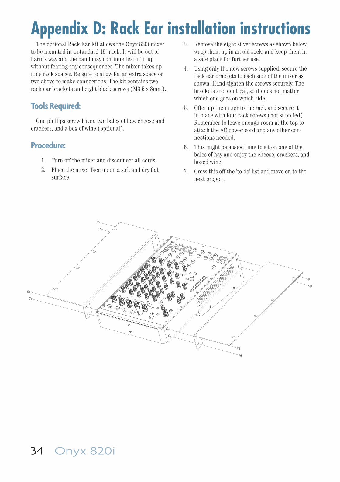
34 Onyx 820i
The optional Rack Ear Kit allows the Onyx 820i mixer to be mounted in a standard 19” rack. It will be out of harm’s way and the band may continue tearin’ it up without fearing any consequences. The mixer takes up nine rack spaces. Be sure to allow for an extra space or two above to make connections. The kit contains two rack ear brackets and eight black screws (M3.5 x 8mm).
Tools Required:
One phillips screwdriver, two bales of hay, cheese and crackers, and a box of wine (optional).
Procedure:
1. Turn off the mixer and disconnect all cords.
2. Place the mixer face up on a soft and dry fl at surface.
Appendix D: Rack Ear installation instructions3. Remove the eight silver screws as shown below,
wrap them up in an old sock, and keep them in a safe place for further use.
4. Using only the new screws supplied, secure the rack ear brackets to each side of the mixer as shown. Hand-tighten the screws securely. The brackets are identical, so it does not matter which one goes on which side.
5. Offer up the mixer to the rack and secure it in place with four rack screws (not supplied). Remember to leave enough room at the top to attach the AC power cord and any other con-nections needed.
6. This might be a good time to sit on one of the bales of hay and enjoy the cheese, crackers, and boxed wine!
7. Cross this off the ‘to do’ list and move on to the next project.
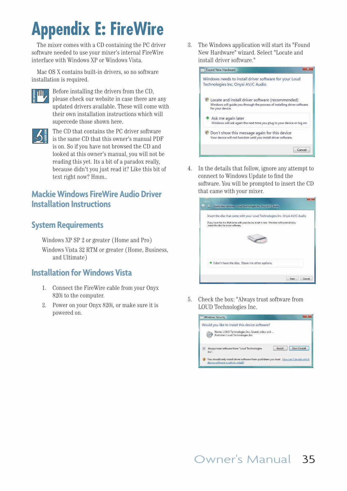
Owner's Manual 35
Appendix E: FireWireThe mixer comes with a CD containing the PC driver
software needed to use your mixer's internal FireWire interface with Windows XP or Windows Vista.
Mac OS X contains built-in drivers, so no software installation is required.
Before installing the drivers from the CD, please check our website in case there are any updated drivers available. These will come with their own installation instructions which will supercede those shown here.
The CD that contains the PC driver software is the same CD that this owner's manual PDF is on. So if you have not browsed the CD and looked at this owner's manual, you will not be reading this yet. Its a bit of a paradox really, because didn't you just read it? Like this bit of text right now? Hmm..
Mackie Windows FireWire Audio Driver Installation Instructions
System Requirements
Windows XP SP 2 or greater (Home and Pro)
Windows Vista 32 RTM or greater (Home, Business, and Ultimate)
Installation for Windows Vista
1. Connect the FireWire cable from your Onyx 820i to the computer.
2. Power on your Onyx 820i, or make sure it is powered on.
3. The Windows application will start its "Found New Hardware" wizard. Select "Locate and install driver software."
4. In the details that follow, ignore any attempt to connect to Windows Update to fi nd the software. You will be prompted to insert the CD that came with your mixer.
5. Check the box: "Always trust software from LOUD Technologies Inc.
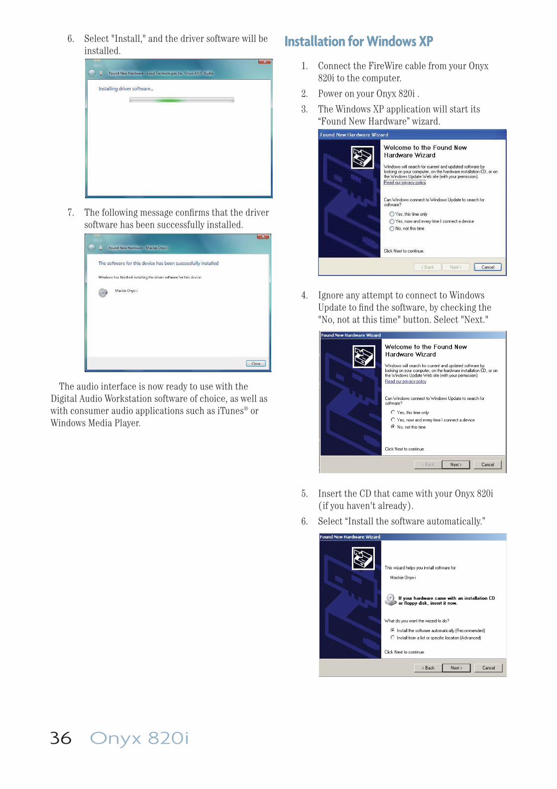
36 Onyx 820i
6. Select "Install," and the driver software will be installed.
7. The following message confi rms that the driver software has been successfully installed.
The audio interface is now ready to use with the Digital Audio Workstation software of choice, as well as with consumer audio applications such as iTunes® or Windows Media Player.
Installation for Windows XP
1. Connect the FireWire cable from your Onyx 820i to the computer.
2. Power on your Onyx 820i .
3. The Windows XP application will start its “Found New Hardware” wizard.
4. Ignore any attempt to connect to Windows Update to fi nd the software, by checking the "No, not at this time" button. Select "Next."
5. Insert the CD that came with your Onyx 820i (if you haven't already).
6. Select “Install the software automatically.”
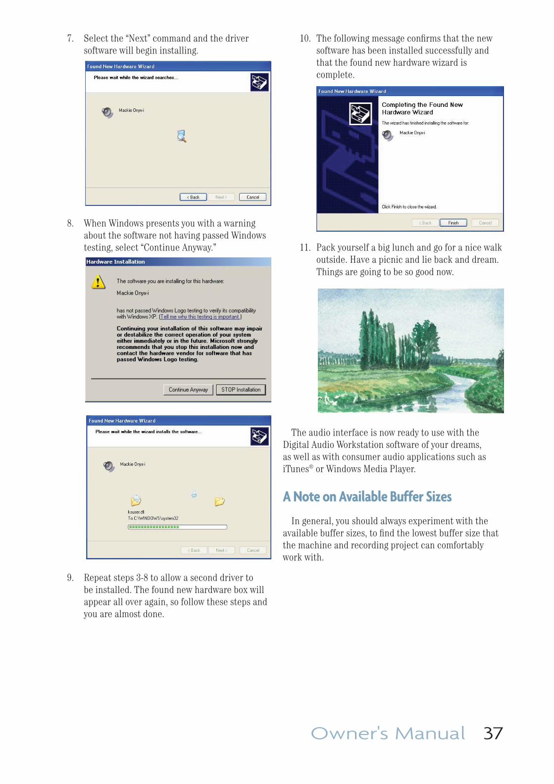
Owner's Manual 37
7. Select the “Next” command and the driver software will begin installing.
8. When Windows presents you with a warning about the software not having passed Windows testing, select “Continue Anyway.”
9. Repeat steps 3-8 to allow a second driver to be installed. The found new hardware box will appear all over again, so follow these steps and you are almost done.
10. The following message confi rms that the new software has been installed successfully and that the found new hardware wizard is complete.
11. Pack yourself a big lunch and go for a nice walk outside. Have a picnic and lie back and dream. Things are going to be so good now.
The audio interface is now ready to use with the Digital Audio Workstation software of your dreams, as well as with consumer audio applications such as iTunes® or Windows Media Player.
A Note on Available Buffer Sizes
In general, you should always experiment with the available buffer sizes, to fi nd the lowest buffer size that the machine and recording project can comfortably work with.
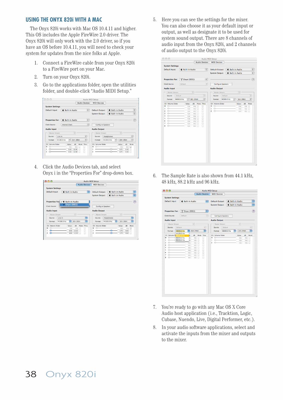
38 Onyx 820i
USING THE ONYX 820i WITH A MACThe Onyx 820i works with Mac OS 10.4.11 and higher.
This OS includes the Apple FireWire 2.0 driver. The Onyx 820i will only work with the 2.0 driver, so if you have an OS before 10.4.11, you will need to check your system for updates from the nice folks at Apple.
1. Connect a FireWire cable from your Onyx 820i to a FireWire port on your Mac.
2. Turn on your Onyx 820i.
3. Go to the applications folder, open the utilities folder, and double-click “Audio MIDI Setup.”
4. Click the Audio Devices tab, and select Onyx i in the “Properties For” drop-down box.
5. Here you can see the settings for the mixer. You can also choose it as your default input or output, as well as designate it to be used for system sound output. There are 8 channels of audio input from the Onyx 820i, and 2 channels of audio output to the Onyx 820i.
6. The Sample Rate is also shown from 44.1 kHz, 48 kHz, 88.2 kHz and 96 kHz.
7. You’re ready to go with any Mac OS X Core Audio host application (i.e., Tracktion, Logic, Cubase, Nuendo, Live, Digital Performer, etc.).
8. In your audio software applications, select and activate the inputs from the mixer and outputs to the mixer.
Owner's Manual 39
Appendix F: Modifi cationsThe following modifi cations can be carried out on the
Onyx 820i by an authorized service center. Authorized service centers may be found online at: www.mackie.com/scripts/service_centers/search.asp Please contact our technical support department if you are having trouble fi nding an authorized service center in your area.
The block diagram on page 33 shows these modifi cations as dotted lines in the channel signal fl ow.
Modifi cations: Post-Insert FireWire Sends
The pre-EQ channel FireWire sends are pre-insert, but the circuit board can be modifi ed so that they are post-insert instead.
For example, this allows for the use of an external processor on the mic signal, sending the result to the FireWire, while still being pre-EQ.
Modifi cations: Post-Fader FireWire Sends
The post-EQ channel FireWire sends are pre-fader, but the circuit board can be modifi ed so that they are post-fader instead.
This allows the channel level to control the level of the FireWire sends.
Modifi cation: Pre-EQ Aux Sends
The pre-fader aux sends are post-EQ, so they are affected by the channel EQ controls. The circuit board can be modifi ed so the pre-fader aux sends are pre-EQ instead of post-EQ.
For example, your stage monitors will not be affected by any channel EQ adjustments.
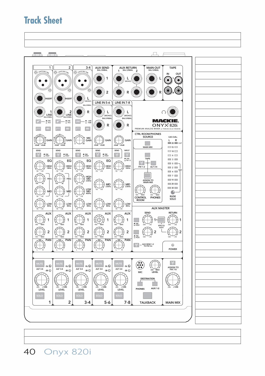
40 Onyx 820i
MUTE
SOLO
48V
MUTE
SOLO
48V
MUTE
SOLO
48V
LINE
MUTE
SOLO
MUTE
SOLO
TAPE
PAN
2
1
MID
FREQ
MID
FREQ
BAL/UNBAL BAL/UNBAL
ALT 3-4 ALT 3-4 ALT 3-4 ALT 3-4 ALT 3-4
LOWMID400Hz
ONYX MIC PRE
HIGH12kHz
LOW80Hz
EQ
INSERT INSERT
ONYX MIC PRE
HIGH12kHz
LOW80Hz
EQ
ONYX MIC PRE
HIGH12kHz
HIGHMID
2.5KHz
LOW80Hz
EQ
AUX MASTER
2
1
SEND RETURN
2
1
EQ
MAIN MIX
(MONO)L
R
L
R
L(MONO)
R
BAL/UNBAL
L(MONO)
R
BAL/UNBAL
L(MONO)
R
BAL/UNBAL
TAPE
IN OUT
L
R
AUX RETURN
1
21
2
AUX SEND MAIN OUT
CTRL ROOM/PHONESSOURCE
PHONESCONTROLROOM
MID2.5kHz
LOW80Hz
U
+15-15
U
+15-15
U
+15-15
U
+15-15
U
+15-15
U
+15-15
U
+15-15
U
+15-15
U
+15-15
U
+15-15
U
+15-15
U
+15-15
U
+15-15
U
+15-15
U
+15-15
U
+15-15
HIGH12kHz
MID2.5kHz
LOW80Hz
HIGH12kHz
RUDESOLO
20
15
10
6
3
0
2
4
7
10
20
30
L R0dB=0dBu
LEVELSET
CLIP
MIC
PREPOST
PREPOST
FW 1-2LINE
HI-ZLINE
-10dB+4dB
HI-ZLINE
PREMIUM ANALOG MIXER w/ PERKINS EQ & FIREWIRE
PREPOST
PREPOST
PREPOST
PREPOST
LEVELLEVELLEVEL LEVEL LEVEL+10dBOO
U
+10dBOO
U
+10dBOO
U
+10dBOO
U
+10dBOO
U
+10dBOO
U
1 2 3-4
LINE IN 5-6 LINE IN 7-8
AUX
PAN
2
1
AUX
PAN
2
1
AUX
PAN
2
1
AUX
PAN
2
1
AUX
RTN TOAUX1
AUX SEND 1-2TO FW 5-6
ASSIGN TOFW 7-8
MAIN MIX
AUX 1-2PHONES
DESTINATION
LEVELOO MAX
OL
- 20
OL
- 20 - 20
OLOL
- 20
OL
- 20
1 2 TALKBACK
BAL/UNBAL BAL/UNBAL BAL/UNBAL
SEND SEND SEND SEND SEND INPUT
POWER
ALT 3-4FW 1-2
ASSIGN TOMAIN MIX
3-4 5-6 7-8
GAIN
+20dB-20dB
U
GAINMIC
GAINGAIN
+20dB-20dB
U
U
20
30
40
60+40dB
U
-20dBU
20
30
40
60
GAIN
+40dB
U
-20dBU
20
30
40
60
1LINE
2LINE
1k
100 8k
1k
100 8k
MAXOOMAXOO
MAXOO
MAXOO
+15OO
+15OO
+10OO
+10OO
MAXOO
MAXOO
MAXOO
MAXOO
MAXOO
MAXOO
MAXOO
MAXOO
L R L R L R L R L R
Track Sheet
Owner's Manual 41
Onyx 820i Limited Warranty
Please keep your sales receipt in a safe place.
This Limited Product Warranty (“Product Warranty”) is provided by LOUD Technologies Inc. (“LOUD”) and is applicable to products purchased in the United States or Canada through a LOUD-authorized reseller or dealer. The Product Warranty will not extend to anyone other than the original purchaser of the product (hereinafter, “Customer,” “you” or “your”).
For products purchased outside the U.S. or Canada, please visit www.mackie.com/warranty to fi nd contact information for your local distributor, and information on any warranty coverage provided by the distributor in your local market.
LOUD warrants to Customer that the product will be free from defects in materials and workmanship under normal use during the Warranty Period. If the product fails to conform to the warranty then LOUD or its authorized service representative will at its option, either repair or replace any such nonconforming product, provided that Customer gives notice of the noncompliance within the Warranty Period to the Company at: www.mackie.com/support or by calling LOUD technical support at 1.800.898.3211 (toll-free in the U.S. and Canada) during normal business hours Pacifi c Time, excluding weekends or LOUD holidays. Please retain the original dated sales receipt as evidence of the date of purchase. You will need it to obtain any warranty service.
For full terms and conditions, as well as the specifi c duration of the Warranty for this product, please visit www.mackie.com/warranty.
The Product Warranty, together with your invoice or receipt, and the terms and conditions located at www.mackie.com/warranty constitutes the entire agreement, and supersedes any and all prior agreements between LOUD and Customer related to the subject matter hereof. No amendment, modifi cation or waiver of any of the provisions of this Product Warranty will be valid unless set forth in a written instrument signed by the party to be bound thereby.

16220 Wood-Red Road NE • Woodinville, WA 98072 • USA
United States and Canada: 800.898.3211
Europe, Asia, Central and South America: 425.487.4333
Middle East and Africa: 31.20.654.4000
Fax: 425.487.4337 • www.mackie.com
E-mail: [email protected]


