Embed Size (px)
Citation preview
Journal of Membrane Science 207 (2002) 143–156
Preparation of composite hollow fiber membranes: co-extrusion ofhydrophilic coatings onto porous hydrophobic support structures
T. He, M.H.V. Mulder, H. Strathmann, M. Wessling∗Membrane Technology Group, Department of Chemical Engineering, University of Twente, P.O. Box 217, 7500 AE Enschede, The Netherlands
Received 19 February 2002; received in revised form 18 March 2002; accepted 21 March 2002
Abstract
Coating a layer onto a support membrane can serve as a means of surface functionalization of membranes. Frequently, thisprocedure is a two-step process. In this paper, we describe a concept of membrane preparation in which a coating layer formsin situ onto a support membrane in one step by a co-extrusion process. Our aim is to apply a thin ion exchange layer (sulfonatedpolyethersulfone, SPES) onto a polysulfone support. The mechanical stability and adhesion of the ion-exchange material tothe hydrophobic support membrane (polysulfone) has been studied by a systematic approach of initial proof-of-principleexperiments, followed by single layer and double-layer flat sheet casting. Critical parameters quantified by the latter ex-periments are translated into the co-extrusion spinning process. The composite hollow fiber membrane has low flux as asupported liquid membrane for the copper removal due to the low ion exchange capacity of the SPES. The coating layer ofthe composite membrane is porous as indicated by gas pair selectivity close to unity. However, our new composite membranehas good nanofiltration properties: it passes mono and bivalent inorganic salts but rejects larger charged organic molecules.The experimental work demonstrates that co-extrusion can be a viable process to continuously prepare surface tailored hol-low fiber membranes in a one-step process, even if the support and coating material differ significantly in hydrophilicity.© 2002 Elsevier Science B.V. All rights reserved.
Keywords:Co-extrusion; Co-casting; Composite hollow fiber membranes; Salt retention; Adhesion
1. Introduction
Composite membranes emerged right after the dis-covery of asymmetric RO membranes[1]. This devel-opment opened the door for tailor-made membranesto a much wider range of applications. Several meth-ods can be used to prepare composite membranes[2,3]: lamination of a pre-formed film, interfacialpolymerisation, in situ polymerisation, dip coating,plasma deposition and dynamic membrane formation.In general, fabrication of such a composite membrane
∗ Corresponding author. Tel.:+31-53-4894675;fax: +31-53-4894611.E-mail address:[email protected] (M. Wessling).
consists of at least two separate steps: manufacturingof the support and subsequent coating. The advantageof this sequential processing includes flexibility inadjusting a variety of parameters and immense knowl-edge is today available. However, such multi-stepfabrication processes are more expensive and timeconsuming. In addition, the composite membranesproduced by these processes can experience failureand poor performance due to an increasing risk ofintroducing defects in the substrate and separatinglayer with the increasing number of processing stepsinvolved.
Co-extrusion is a fabrication method to make amulti-layer configuration in the form of film, sheet,or fiber by simultaneous extrusion of two or more
0376-7388/02/$ – see front matter © 2002 Elsevier Science B.V. All rights reserved.PII: S0376-7388(02)00118-7
144 T. He et al. / Journal of Membrane Science 207 (2002) 143–156
polymers through a single die[4]. Co-extrusion avoidsmany of the manufacturing steps required by conven-tional lamination and coating processes, such as mak-ing and handling of individual films, application ofcoating primers, and solvent drying. Because of theseeconomic and technical advantages, the applicationof co-extrusion is growing rapidly[5–10].
Co-extrusion in membrane technology is challeng-ing, with only a few patents and publications[11–24].Basically, co-extruded membranes include two types:dense and porous. Co-extruded dense membranes in-clude dialysers[15] and gas separation membranes[11–14,17]. Most of the work published deals withthe co-extrusion of similar polymers for both thecoating and support membranes. Porous membranes,both for ultrafiltration and microfiltration, are madefrom the same polymers, i.e. polypropylene[20,21],polysulfone (PSf)[22,23]and polytetrafluoroethylene[24]. To our knowledge, there are only two patentsdescribing the spinning of sulfonated polymers onPSf or polyethersulfone (PES)[18,19]. Sulfonatedpolysulfone (SPSf) with an ion exchange capacityof about 0.8 meq./g is coated on a PSf solution[18];and this is used as an anti-fouling membrane in theseparation of an emulsion solution. The other patent[19] describes the use of blends of SPSf and PSf orPES to hydrophilize the membrane surface.
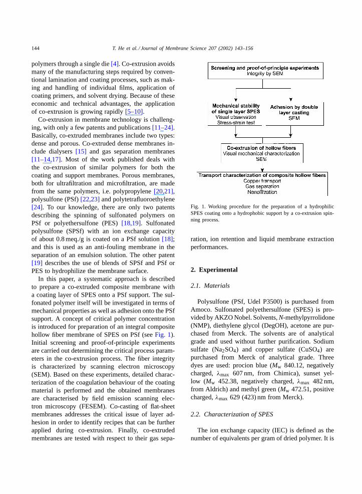
In this paper, a systematic approach is describedto prepare a co-extruded composite membrane witha coating layer of SPES onto a PSf support. The sul-fonated polymer itself will be investigated in terms ofmechanical properties as well as adhesion onto the PSfsupport. A concept of critical polymer concentrationis introduced for preparation of an integral compositehollow fiber membrane of SPES on PSf (seeFig. 1).Initial screening and proof-of-principle experimentsare carried out determining the critical process param-eters in the co-extrusion process. The fiber integrityis characterized by scanning electron microscopy(SEM). Based on these experiments, detailed charac-terization of the coagulation behaviour of the coatingmaterial is performed and the obtained membranesare characterised by field emission scanning elec-tron microscopy (FESEM). Co-casting of flat-sheetmembranes addresses the critical issue of layer ad-hesion in order to identify recipes that can be furtherapplied during co-extrusion. Finally, co-extrudedmembranes are tested with respect to their gas sepa-
Fig. 1. Working procedure for the preparation of a hydrophilicSPES coating onto a hydrophobic support by a co-extrusion spin-ning process.
ration, ion retention and liquid membrane extractionperformances.
2. Experimental
2.1. Materials
Polysulfone (PSf, Udel P3500) is purchased fromAmoco. Sulfonated polyethersulfone (SPES) is pro-vided by AKZO Nobel. Solvents,N-methylpyrrolidone(NMP), diethylene glycol (DegOH), acetone are pur-chased from Merck. The solvents are of analyticalgrade and used without further purification. Sodiumsulfate (Na2SO4) and copper sulfate (CuSO4) arepurchased from Merck of analytical grade. Threedyes are used: procion blue (Mw 840.12, negativelycharged,λmax 607 nm, from Chimica), sunset yel-low (Mw 452.38, negatively charged,λmax 482 nm,from Aldrich) and methyl green (Mw 472.51, positivecharged,λmax 629 (423) nm from Merck).
2.2. Characterization of SPES
The ion exchange capacity (IEC) is defined as thenumber of equivalents per gram of dried polymer. It is
T. He et al. / Journal of Membrane Science 207 (2002) 143–156 145
Table 1Properties of sulfonated poylethersulfone
Polymer Ion exchange capacity(meq./g dry polymer)
Degree of swelling(DS, %)
PES – 3.1SPES 0.36 9.1
SD, substitution degree. Swelling is determined at 250◦C in purewater.
determined by elemental analysis. The water sorptionis measured by soaking two pieces of SPES films inpure water at 25◦C for 7 days. The swollen filmsare weighed and then dried in vacuum oven at 30◦Cfor another 7 days. The degree of swelling (DS) isdetermined from the difference in weight (W) betweendry and swollen films according to
DS =(
Wswollen− Wdry
Wdry
)100
The degree of swelling and the IEC of SPES are listedin Table 1. The properties of PES are listed as wellfor comparison. SPES has an ion exchange capacityof 0.36 meq./g, which is low compared to other ionexchange materials. SPES shows a water uptake of9.1 wt.%, which is significantly higher than that ofPES (3.1 wt.%).
2.3. Single film casting
Before solution preparation, SPES is pre-dried inan oven at 80◦C for 1 week and in a vacuum oven at30◦C for another week. SPES solutions are preparedby dissolving a certain amount of polymer in NMPor acetone and NMP mixtures at room temperature.After filtering by a 15�m metal filter, the solutionsare allowed to degas for at least 24 h, and then castonto pre-cleaned glass plates using a casting knife ofa certain thickness (50�m). After 2 s of exposure toambient air with a relative humidity of 45–55%, theinitial films are immersed into an aqueous coagulationbath. The prepared films are stored in ultra-pure water(MilliQ, Millipore) to rinse residual solvent for 24 hat room temperature.
2.4. Stress-tensile test
Mechanical stress–strain experiments are performedon a Zwick Tensile Machine (Materialprufung Z020)
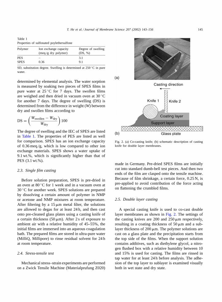
Fig. 2. (a) Co-casting knife; (b) schematic description of castingknife for double layer membranes.
made in Germany. Pre-dried SPES films are initiallycut into standard dumb-bell test pieces. And then twoends of the film are clasped onto the tensile machine.Because of film shrinkage, a certain force, 0.25 N, ispre-applied to avoid contribution of the force actingon flattening the crumbled films.
2.5. Double layer casting
A special casting knife is used to co-cast doublelayer membranes as shown inFig. 2. The settings ofthe casting knives are 200 and 250�m respectively,resulting in a coating thickness of 50�m and a sub-layer thickness of 200�m. The polymer solutions arecast on a glass plate and the precipitation starts fromthe top side of the films. When the support solutioncontains additives, such as diethylene glycol, a nitro-gen flushed box with a relative humidity between 10and 15% is used for casting. The films are rinsed intap water for at least 24 h before analysis. The adhe-sion of the top layer to sublayer is examined visuallyboth in wet state and dry state.
146 T. He et al. / Journal of Membrane Science 207 (2002) 143–156
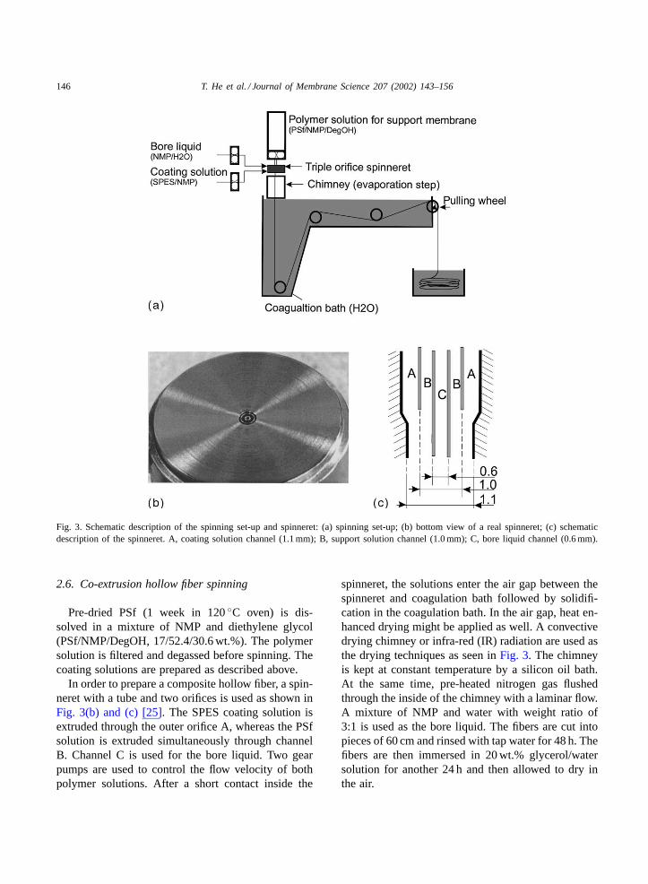
Fig. 3. Schematic description of the spinning set-up and spinneret: (a) spinning set-up; (b) bottom view of a real spinneret; (c) schematicdescription of the spinneret. A, coating solution channel (1.1 mm); B, support solution channel (1.0 mm); C, bore liquid channel (0.6 mm).
2.6. Co-extrusion hollow fiber spinning
Pre-dried PSf (1 week in 120◦C oven) is dis-solved in a mixture of NMP and diethylene glycol(PSf/NMP/DegOH, 17/52.4/30.6 wt.%). The polymersolution is filtered and degassed before spinning. Thecoating solutions are prepared as described above.
In order to prepare a composite hollow fiber, a spin-neret with a tube and two orifices is used as shown inFig. 3(b) and (c) [25]. The SPES coating solution isextruded through the outer orifice A, whereas the PSfsolution is extruded simultaneously through channelB. Channel C is used for the bore liquid. Two gearpumps are used to control the flow velocity of bothpolymer solutions. After a short contact inside the
spinneret, the solutions enter the air gap between thespinneret and coagulation bath followed by solidifi-cation in the coagulation bath. In the air gap, heat en-hanced drying might be applied as well. A convectivedrying chimney or infra-red (IR) radiation are used asthe drying techniques as seen inFig. 3. The chimneyis kept at constant temperature by a silicon oil bath.At the same time, pre-heated nitrogen gas flushedthrough the inside of the chimney with a laminar flow.A mixture of NMP and water with weight ratio of3:1 is used as the bore liquid. The fibers are cut intopieces of 60 cm and rinsed with tap water for 48 h. Thefibers are then immersed in 20 wt.% glycerol/watersolution for another 24 h and then allowed to dry inthe air.
T. He et al. / Journal of Membrane Science 207 (2002) 143–156 147
2.7. Characterization of permeation properties
All permeation properties are measured for twomembrane samples. For gas permeation characteri-sation, six co-extruded hollow fibers are dried in airand potted at the end with one side open at a lengthof 20 cm. Helium, nitrogen and carbon dioxide per-meation is measured at room temperature (22◦C) ata pressure of 0.4–1.0 bar gauge.
For ion retention permeation experiments, two wetfibers of 38 cm are potted into a glass housing. Testsolutions are circulated through the lumen of the fiberand the permeation is collected from the outside. Thesolutions are sodium sulfate, copper sulfate, methylgreen, sunset yellow, and procion blue at a concentra-tion of 500 ppm, respectively.
To perform the supported liquid membrane experi-ment (set-up is described in detail in[26]), two driedhollow fibers of 38 cm are potted into a glass housing.LIX84-I diluted in dodecane at 20 vol.% is used as or-ganic extractant. A 0.025 M CuSO4 solution is usedas the feed and a 2 M H2SO4 solution as the strip. Thetotal volume of both feed and strip is 200 ml. Theaqueous phases flow parallel along the fiber with thestrip solution at the shell side and the feed at the lu-men side. The flow velocity of feed and strip is 1.86and 0.094 m/s, respectively. The temperature is keptat 25◦C. The concentration of the feed and strip isdetermined by taking seven samples in 7 or 8 h inter-val and analysed by atomic absorption spectrometry
Table 2Screening and proof-of-principle experiments
SPES (wt.%) Drying method Outside surface Adhesion
Process Temperature (◦C)
4 IR radiation (–) Uneven surface, holes Separated52 Numerous holes Separated
6 Chimney 70 Cracks, dispersed holes Separated90 Uneven, less cracks Separated
IR radiation (–) Uneven, less cracks Separated(–)a Big cracks and holes Separated
(–) (–) Numerous holes Separated10 IR radiation (–) Holes, small cracks Small part attached16 IR radiation (–)b Smooth with dispersed holes Partly separated
(–) not available. Spinning parameters: coating solution, SPES/NMP/acetone; NMP/acetone ration, 50/50; coating solution flow rate,1.3 ml/min; air gap, 200 mm; spinning rate, 6 m/min; chimney length, 200 mm; IR radiation, IR lamp.
a Without acetone.b The membrane became brittle after drying. All other membranes showed brittleness of the coating layer but the hollow fibers were
still tough.
(Spectra 10, Varian, Houten, The Netherlands). Thecopper flux is calculated from the slope of the copperconcentration versus time.
2.8. Scanning electron microscopy
Samples for SEM (JEOL JSM-T220A) are preparedby cryogenic breaking of the fresh wet films or fibers.Samples are allowed to dry under vacuum at 30◦Cfor overnight and then coated with a thin gold layer.Samples for FESEM (Hitachi S800) are coated withan Au/Pd layer at a thickness of approximately 4 nm.
3. Results and discussion
3.1. Screening and proof-of-principle experiments
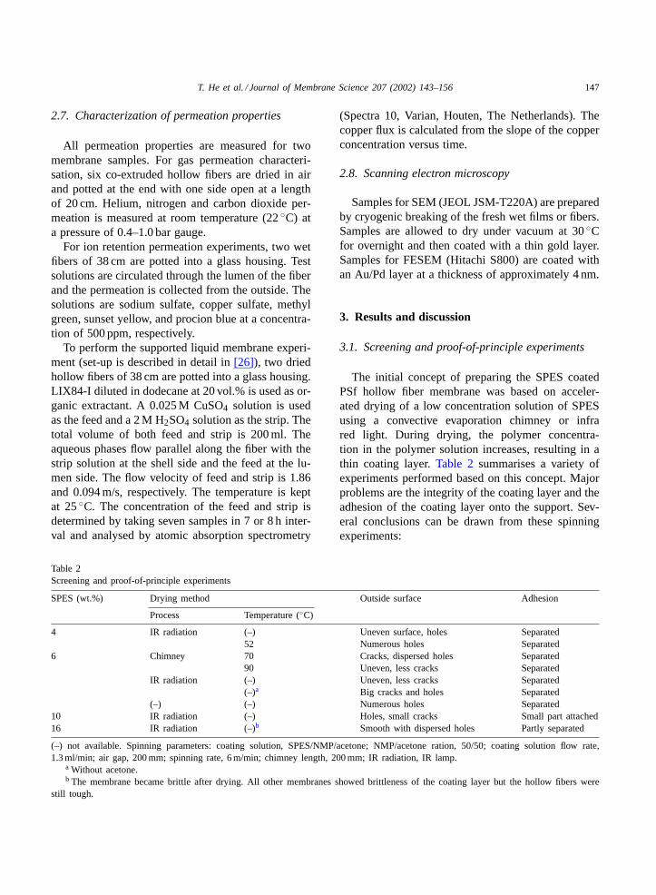
The initial concept of preparing the SPES coatedPSf hollow fiber membrane was based on acceler-ated drying of a low concentration solution of SPESusing a convective evaporation chimney or infrared light. During drying, the polymer concentra-tion in the polymer solution increases, resulting in athin coating layer.Table 2 summarises a variety ofexperiments performed based on this concept. Majorproblems are the integrity of the coating layer and theadhesion of the coating layer onto the support. Sev-eral conclusions can be drawn from these spinningexperiments:
148 T. He et al. / Journal of Membrane Science 207 (2002) 143–156
• increasing the chimney temperature results in acoating layer with less mechanical defects;
• infra-red radiation results in an improved layer, butthe surface smoothness is still insufficient;
• addition of volatile solvent (acetone) improves thesurface integrity;
• increase of the SPES concentration improves adhe-sion and integrity of the coating layer, however, thefiber becomes brittle upon drying.
From these screening experiments, we encountertwo major problems related to co-extrusion of SPESonto PSf solution: (a) the mechanical property andintegrity of the SPES thin coating layer; and (b) theinsufficient adhesion between the coating layer andthe support. The first problem results in cracks andholes on the outer fiber surface (SPES). For the sec-ond problem, the thin layer tends to separate from thesupport layer in some cases. In the following parts,we address both problems separately: firstly, the me-chanical properties of the SPES film is investigatedto find a relationship between mechanical propertiesand casting solution composition; secondly, adhesionof SPES layer onto the PSf layer is investigated with aco-casting process. Finally, co-extrusion experimentsare carried out based on the knowledge gained fromthe experimental series.
3.2. Mechanical stability of SPES films
In general, the hydrophilic SPES films coagulatedin a water bath show mechanical instability upondrying. Initially, the films are soft because of thegel-like structure containing water. Upon drying, wa-ter slowly evaporates from the membrane resulting ina brittle structure. Visual observation of these filmsgives qualitative information (seeTable 3). In the wet
Table 3Observation of SPES films in wet and dry state
SPES concen-tration (wt.%)
Wet state Dry state
10 Opalescent, soft Clear, brittle15 Opalescent, soft Clear, brittle20 Opalescent, flexible Clear, brittle25 Opaque, flexible Clear with droplets, rigid30 Opaque, tough Clear with droplets, rigid35 Opaque, tough Clear with droplets, tough
state, the films cast from a solution with a concentra-tion less than 20 wt.% are opalescent and extremelysoft. It is rather difficult to remove these films fromthe glass plate without breaking. Upon drying in anambient environment, these films become so brittlethat they break into small pieces upon a gentle touch.By increasing the polymer content above 20 wt.%,tough and flexible films are obtained when the filmsremain wet. However, at dry state, a SPES concen-tration up to 35% is necessary to obtain a tough film.This information is significant for the spinning pro-cess: the coating is located on the outside of the fiberand therefore it should be strong enough to withstandthe friction from conducting rollers and possiblestretching. On the other hand, it is required that thecomposite fiber should be mechanically stable at drystate. As indicated by the initial experiments, thecomposite fibers become brittle when the coating lay-ers are brittle and show good adhesion to the support.Therefore, the coating layer itself needs mechanicalstability. These experimental considerations indicatethat a high SPES content is required.
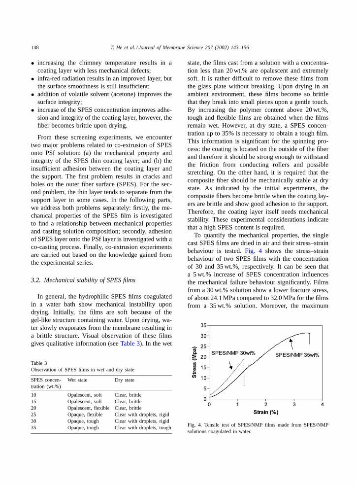
To quantify the mechanical properties, the singlecast SPES films are dried in air and their stress–strainbehaviour is tested.Fig. 4 shows the stress–strainbehaviour of two SPES films with the concentrationof 30 and 35 wt.%, respectively. It can be seen thata 5 wt.% increase of SPES concentration influencesthe mechanical failure behaviour significantly. Filmsfrom a 30 wt.% solution show a lower fracture stress,of about 24.1 MPa compared to 32.0 MPa for the filmsfrom a 35 wt.% solution. Moreover, the maximum
Fig. 4. Tensile test of SPES/NMP films made from SPES/NMPsolutions coagulated in water.
T. He et al. / Journal of Membrane Science 207 (2002) 143–156 149
strain before film rupture increases from 1.23 to3.56%. The initial stress for the 30 wt.% film is higherthan that of the 35 wt.% film because of difference inthickness. The significant change of mechanical prop-erties indicates that concentration increase transformsan extremely brittle film to a more flexible one.
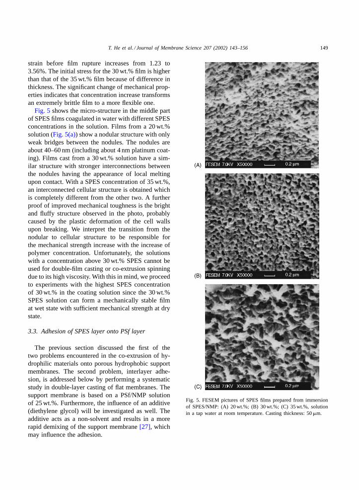
Fig. 5 shows the micro-structure in the middle partof SPES films coagulated in water with different SPESconcentrations in the solution. Films from a 20 wt.%solution (Fig. 5(a)) show a nodular structure with onlyweak bridges between the nodules. The nodules areabout 40–60 nm (including about 4 nm platinum coat-ing). Films cast from a 30 wt.% solution have a sim-ilar structure with stronger interconnections betweenthe nodules having the appearance of local meltingupon contact. With a SPES concentration of 35 wt.%,an interconnected cellular structure is obtained whichis completely different from the other two. A furtherproof of improved mechanical toughness is the brightand fluffy structure observed in the photo, probablycaused by the plastic deformation of the cell wallsupon breaking. We interpret the transition from thenodular to cellular structure to be responsible forthe mechanical strength increase with the increase ofpolymer concentration. Unfortunately, the solutionswith a concentration above 30 wt.% SPES cannot beused for double-film casting or co-extrusion spinningdue to its high viscosity. With this in mind, we proceedto experiments with the highest SPES concentrationof 30 wt.% in the coating solution since the 30 wt.%SPES solution can form a mechanically stable filmat wet state with sufficient mechanical strength at drystate.
3.3. Adhesion of SPES layer onto PSf layer
The previous section discussed the first of thetwo problems encountered in the co-extrusion of hy-drophilic materials onto porous hydrophobic supportmembranes. The second problem, interlayer adhe-sion, is addressed below by performing a systematicstudy in double-layer casting of flat membranes. Thesupport membrane is based on a PSf/NMP solutionof 25 wt.%. Furthermore, the influence of an additive(diethylene glycol) will be investigated as well. Theadditive acts as a non-solvent and results in a morerapid demixing of the support membrane[27], whichmay influence the adhesion.
Fig. 5. FESEM pictures of SPES films prepared from immersionof SPES/NMP: (A) 20 wt.%; (B) 30 wt.%; (C) 35 wt.%, solutionin a tap water at room temperature. Casting thickness: 50�m.
150 T. He et al. / Journal of Membrane Science 207 (2002) 143–156
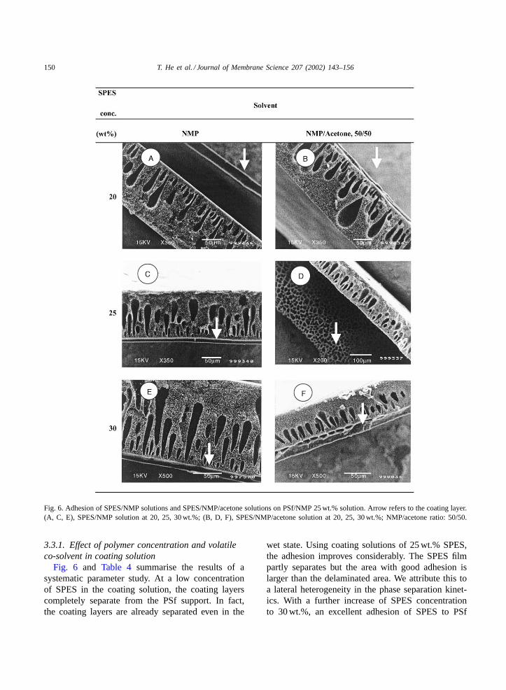
Fig. 6. Adhesion of SPES/NMP solutions and SPES/NMP/acetone solutions on PSf/NMP 25 wt.% solution. Arrow refers to the coating layer.(A, C, E), SPES/NMP solution at 20, 25, 30 wt.%; (B, D, F), SPES/NMP/acetone solution at 20, 25, 30 wt.%; NMP/acetone ratio: 50/50.
3.3.1. Effect of polymer concentration and volatileco-solvent in coating solution
Fig. 6 and Table 4 summarise the results of asystematic parameter study. At a low concentrationof SPES in the coating solution, the coating layerscompletely separate from the PSf support. In fact,the coating layers are already separated even in the
wet state. Using coating solutions of 25 wt.% SPES,the adhesion improves considerably. The SPES filmpartly separates but the area with good adhesion islarger than the delaminated area. We attribute this toa lateral heterogeneity in the phase separation kinet-ics. With a further increase of SPES concentrationto 30 wt.%, an excellent adhesion of SPES to PSf
T. He et al. / Journal of Membrane Science 207 (2002) 143–156 151
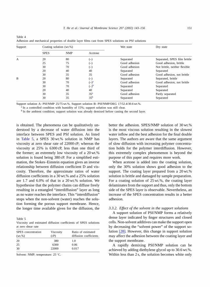
Table 4Adhesion and mechanical properties of double layer films cast from SPES solutions on PSf solutions
Support Coating solution (wt.%) Wet state Dry state
SPES NMP Acetone
A 20 80 (–) Separated Separated, SPES film brittle25 75 (–) Good adhesion Good adhesion, brittle30 70 (–) Good adhesion Not brittle, neither flexible20 40 40 Separated Separated30 35 35 Good adhesion Good adhesion, not brittle
B 20 80 (–) Separated Separated, brittle30 70 (–)a Good adhesion Good adhesion, not brittle30 70 (–)b Separated Separated20 40 40 Separated Separated30 35 35a Good adhesion Partly separated30 35 35b Separated Separated
Support solution A: PSf/NMP 25/75 wt.%. Support solution B: PSf/NMP/DEG 17/52.4/30.6 wt.%.a In a controlled condition with humidity of 15%; support solution was still clear.b In the ambient condition; support solution was already demixed before casting the second layer.
is obtained. The phenomena can be qualitatively un-derstood by a decrease of water diffusion into theinterface between SPES and PSf solution. As listedin Table 5, a SPES 30 wt.% solution in NMP hasviscosity at zero shear rate of 22000 cP; whereas theviscosity at 25% is 6300 cP, less than one third ofthe former; an extremely low viscosity of a 20 wt.%solution is found being 380 cP. For a simplified esti-mation, the Stokes–Einstein equation gives an inverserelationship between diffusion coefficient D and vis-cosity. Therefore, the approximate ratios of waterdiffusion coefficients in a 30 wt.% and a 25% solutionare 1.7 and 6.0% of that in a 20 wt.% solution. Wehypothesise that the polymer chains can diffuse freelyresulting in a entangled “interdiffusion” layer as longas no water reaches the interface. This “interdiffusion”stops when the non-solvent (water) reaches the solu-tion forming the porous support membrane. Hence,the longer time available given for the diffusion, the
Table 5Viscosity and estimated diffusion coefficients of SPES solutionsat zero shear rate
SPES concentration(wt.%)
Viscosity(cP)
Ratio of estimateddiffusion coefficients
20 380 1.025 6300 0.0630 22000 0.017
Solvent: NMP; temperature: 25◦C.
better the adhesion. SPES/NMP solution of 30 wt.%is the most viscous solution resulting in the slowestwater inflow and the best adhesion for the final doublelayers. The authors are aware that the same argumentof slow diffusion with increasing polymer concentra-tion holds for the polymer interdiffusion. However,this extremely complex phenomenon is beyond thepurpose of this paper and requires more work.
When acetone is added into the coating solution,only the 30% solution shows good adhesion to thesupport. The coating layer prepared from a 20 wt.%solution is brittle and damaged by sample preparation.For a coating solution of 25 wt.%, the coating layerdelaminates from the support and thus, only the bottomside of the SPES layer is observable. Nevertheless, anincrease of the SPES concentration results in a betteradhesion.
3.3.2. Effect of the solvent in the support solutionsA support solution of PSf/NMP forms a relatively
dense layer indicated by finger structures and closedcells. Non-solvent additives can make the support openby decreasing the “solvent power” of the support so-lution [28]. However, this change in support solutionmay affect the adhesion between the coating layer andthe support membrane.
A rapidly demixing PSf/NMP solution can beachieved by adding diethylene glycol up to 30.6 wt.%.Within less than 2 s, the solution becomes white only
152 T. He et al. / Journal of Membrane Science 207 (2002) 143–156
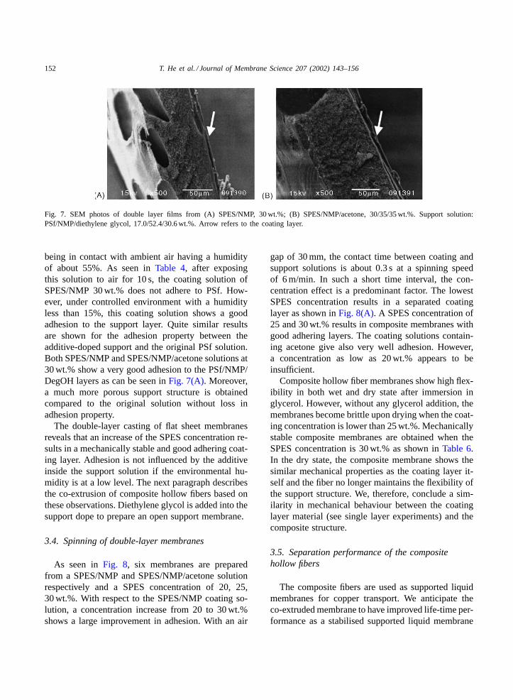
Fig. 7. SEM photos of double layer films from (A) SPES/NMP, 30 wt.%; (B) SPES/NMP/acetone, 30/35/35 wt.%. Support solution:PSf/NMP/diethylene glycol, 17.0/52.4/30.6 wt.%. Arrow refers to the coating layer.
being in contact with ambient air having a humidityof about 55%. As seen inTable 4, after exposingthis solution to air for 10 s, the coating solution ofSPES/NMP 30 wt.% does not adhere to PSf. How-ever, under controlled environment with a humidityless than 15%, this coating solution shows a goodadhesion to the support layer. Quite similar resultsare shown for the adhesion property between theadditive-doped support and the original PSf solution.Both SPES/NMP and SPES/NMP/acetone solutions at30 wt.% show a very good adhesion to the PSf/NMP/DegOH layers as can be seen inFig. 7(A). Moreover,a much more porous support structure is obtainedcompared to the original solution without loss inadhesion property.
The double-layer casting of flat sheet membranesreveals that an increase of the SPES concentration re-sults in a mechanically stable and good adhering coat-ing layer. Adhesion is not influenced by the additiveinside the support solution if the environmental hu-midity is at a low level. The next paragraph describesthe co-extrusion of composite hollow fibers based onthese observations. Diethylene glycol is added into thesupport dope to prepare an open support membrane.
3.4. Spinning of double-layer membranes
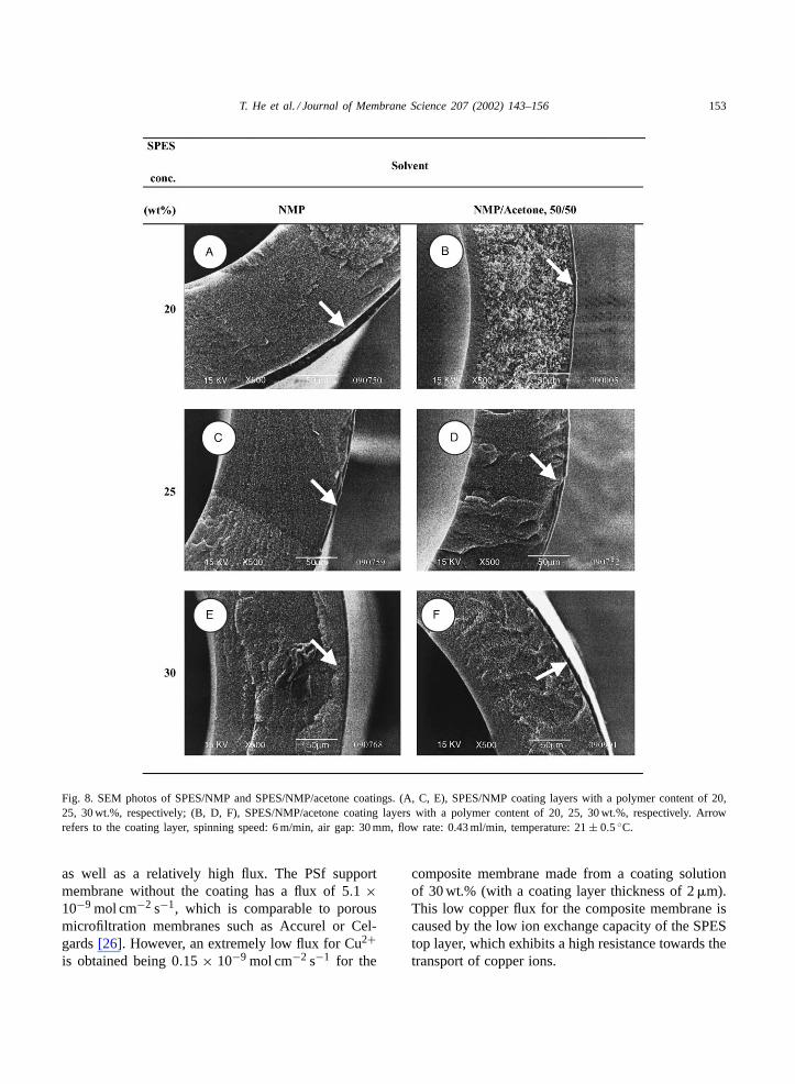
As seen inFig. 8, six membranes are preparedfrom a SPES/NMP and SPES/NMP/acetone solutionrespectively and a SPES concentration of 20, 25,30 wt.%. With respect to the SPES/NMP coating so-lution, a concentration increase from 20 to 30 wt.%shows a large improvement in adhesion. With an air
gap of 30 mm, the contact time between coating andsupport solutions is about 0.3 s at a spinning speedof 6 m/min. In such a short time interval, the con-centration effect is a predominant factor. The lowestSPES concentration results in a separated coatinglayer as shown inFig. 8(A). A SPES concentration of25 and 30 wt.% results in composite membranes withgood adhering layers. The coating solutions contain-ing acetone give also very well adhesion. However,a concentration as low as 20 wt.% appears to beinsufficient.
Composite hollow fiber membranes show high flex-ibility in both wet and dry state after immersion inglycerol. However, without any glycerol addition, themembranes become brittle upon drying when the coat-ing concentration is lower than 25 wt.%. Mechanicallystable composite membranes are obtained when theSPES concentration is 30 wt.% as shown inTable 6.In the dry state, the composite membrane shows thesimilar mechanical properties as the coating layer it-self and the fiber no longer maintains the flexibility ofthe support structure. We, therefore, conclude a sim-ilarity in mechanical behaviour between the coatinglayer material (see single layer experiments) and thecomposite structure.
3.5. Separation performance of the compositehollow fibers
The composite fibers are used as supported liquidmembranes for copper transport. We anticipate theco-extruded membrane to have improved life-time per-formance as a stabilised supported liquid membrane
T. He et al. / Journal of Membrane Science 207 (2002) 143–156 153
Fig. 8. SEM photos of SPES/NMP and SPES/NMP/acetone coatings. (A, C, E), SPES/NMP coating layers with a polymer content of 20,25, 30 wt.%, respectively; (B, D, F), SPES/NMP/acetone coating layers with a polymer content of 20, 25, 30 wt.%, respectively. Arrowrefers to the coating layer, spinning speed: 6 m/min, air gap: 30 mm, flow rate: 0.43 ml/min, temperature: 21± 0.5◦C.
as well as a relatively high flux. The PSf supportmembrane without the coating has a flux of 5.1 ×10⁻⁹ mol cm−2 s−1, which is comparable to porousmicrofiltration membranes such as Accurel or Cel-gards[26]. However, an extremely low flux for Cu2+is obtained being 0.15 × 10⁻⁹ mol cm−2 s−1 for the
composite membrane made from a coating solutionof 30 wt.% (with a coating layer thickness of 2�m).This low copper flux for the composite membrane iscaused by the low ion exchange capacity of the SPEStop layer, which exhibits a high resistance towards thetransport of copper ions.
154 T. He et al. / Journal of Membrane Science 207 (2002) 143–156
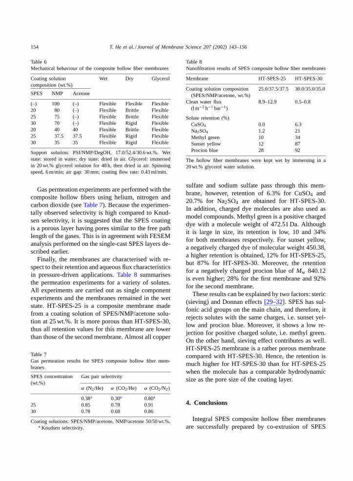
Table 6Mechanical behaviour of the composite hollow fiber membranes
Coating solutioncomposition (wt.%)
Wet Dry Glycerol
SPES NMP Acetone
(–) 100 (–) Flexible Flexible Flexible20 80 (–) Flexible Brittle Flexible25 75 (–) Flexible Brittle Flexible30 70 (–) Flexible Rigid Flexible20 40 40 Flexible Brittle Flexible25 37.5 37.5 Flexible Rigid Flexible30 35 35 Flexible Rigid Flexible
Support solution: PSf/NMP/DegOH, 17.0/52.4/30.6 wt.%. Wetstate: stored in water; dry state: dried in air. Glycerol: immersedin 20 wt.% glycerol solution for 48 h, then dried in air. Spinningspeed, 6 m/min; air gap: 30 mm; coating flow rate: 0.43 ml/min.
Gas permeation experiments are performed with thecomposite hollow fibers using helium, nitrogen andcarbon dioxide (seeTable 7). Because the experimen-tally observed selectivity is high compared to Knud-sen selectivity, it is suggested that the SPES coatingis a porous layer having pores similar to the free pathlength of the gases. This is in agreement with FESEManalysis performed on the single-cast SPES layers de-scribed earlier.
Finally, the membranes are characterised with re-spect to their retention and aqueous flux characteristicsin pressure-driven applications.Table 8 summarisesthe permeation experiments for a variety of solutes.All experiments are carried out as single componentexperiments and the membranes remained in the wetstate. HT-SPES-25 is a composite membrane madefrom a coating solution of SPES/NMP/acetone solu-tion at 25 wt.%. It is more porous than HT-SPES-30,thus all retention values for this membrane are lowerthan those of the second membrane. Almost all copper
Table 7Gas permeation results for SPES composite hollow fiber mem-branes
SPES concentration(wt.%)
Gas pair selectivity
α (N2/He) α (CO2/He) α (CO2/N2)
0.38a 0.30a 0.80a
25 0.85 0.78 0.9130 0.78 0.68 0.86
Coating solutions: SPES/NMP/acetone, NMP/acetone 50/50 wt.%.a Knudsen selectivity.
Table 8Nanofiltration results of SPES composite hollow fiber membranes
Membrane HT-SPES-25 HT-SPES-30
Coating solution composition(SPES/NMP/acetone, wt.%)
25.0/37.5/37.5 30.0/35.0/35.0
Clean water flux(l m−2 h−1 bar−1)
8.9–12.9 0.5–0.8
Solute retention (%)CuSO4 0.0 6.3Na2SO4 1.2 21Methyl green 10 34Sunset yellow 12 87Procion blue 28 92
The hollow fiber membranes were kept wet by immersing in a20 wt.% glycerol water solution.
sulfate and sodium sulfate pass through this mem-brane, however, retention of 6.3% for CuSO4 and20.7% for Na2SO4 are obtained for HT-SPES-30.In addition, charged dye molecules are also used asmodel compounds. Methyl green is a positive chargeddye with a molecule weight of 472.51 Da. Althoughit is large in size, its retention is low, 10 and 34%for both membranes respectively. For sunset yellow,a negatively charged dye of molecular weight 450.38,a higher retention is obtained, 12% for HT-SPES-25,but 87% for HT-SPES-30. Moreover, the retentionfor a negatively charged procion blue ofMw 840.12is even higher; 28% for the first membrane and 92%for the second membrane.
These results can be explained by two factors: steric(sieving) and Donnan effects[29–32]. SPES has sul-fonic acid groups on the main chain, and therefore, itrejects solutes with the same charges, i.e. sunset yel-low and procion blue. Moreover, it shows a low re-jection for positive charged solute, i.e. methyl green.On the other hand, sieving effect contributes as well.HT-SPES-25 membrane is a rather porous membranecompared with HT-SPES-30. Hence, the retention ismuch higher for HT-SPES-30 than for HT-SPES-25when the molecule has a comparable hydrodynamicsize as the pore size of the coating layer.
4. Conclusions
Integral SPES composite hollow fiber membranesare successfully prepared by co-extrusion of SPES
T. He et al. / Journal of Membrane Science 207 (2002) 143–156 155
solutions onto PSf solutions. In terms of mechanicaland adhesion properties, the SPES concentration in thecoating solution is of key importance to obtain a goodcomposite membrane. A nodular to cellular structureis observed when the SPES concentration changesfrom 20 to 35 wt.% and this corresponds to an im-provement in mechanical properties. Adhesion of thecoating to the PSf support is also improved by increas-ing the SPES concentration of the coating solutions.
The composite hollow fiber shows an extremely lowcopper ion transport in supported liquid membranesystem and no selectivity for He/N2, He/CO2 andN2/CO2 in gas separation. The membrane shows lowinorganic salt retention and high retention for chargedorganic dye molecules. The concept of a co-extrudedmembrane with a ion exchange functionality in thecoating layer shows potential to be used as a nanofil-tration membrane as well as a tight hydrophilic ultra-filtration membrane.
Acknowledgements
This work is financed by EET program (Economy,Ecology, and Technology) from Dutch government.The authors appreciate the interesting discussions withProfessor H. Meijer and technical support from Mr.M. Smithers.
References
[1] S. Loeb, S. Sourirajan (Eds.), Sea water demineralizationby means of an osmotic membrane, Advances in ChemistrySeries 38: Saline Water conversion-II, American ChemicalSociety, 1963.
[2] J.E. Cadotte, R.J. Petersen, in: A.F. Turbak (Ed.), SyntheticMembranes, Vol. I. Desalination, ACS Symposium Series No.153, American Chemical Society, Washington, DC, 1981.
[3] R.J. Petersen, Composite reverse osmosis and nanofiltrationmembranes, J. Membr. Sci. 83 (1993) 81–150.
[4] W.J. Schrenk, T.J. Alfrey, Co-extruded multilayer polymerfilms and sheets, in: D.R. Paul, S. Newman (Eds.), PolymerBlends, Vol. 2, Academic Press, New York, 1978, p. 129.
[5] W.C. Chen, J.H. Chen, S.Y. Yang, J.Y. Cherng, Y.H. Chang,B.C. Ho, Preparation of gradient-index (GRIN) polymer fibersfor imaging applications, J. Appl. Polym. Sci. 60 (1996)1379–1383.
[6] B.-T. Liu, W.-C. Chen, J.-P. Hsu, Mathematical modeling ofa co-extrusion process for preparing gradient-index polymeroptical fibers, Polymer 40 (1999) 1451–1457.
[7] C.-C. Tsai, T.-J. Liu, Y.-H. Chang, W.T.W. Tseng, Numericalsimulation of an optical fiber-forming process, Chem. Eng.Sci. 52 (1997) 221–223.
[8] J.-Y. Chiou, P.-Y. Wu, C.-C. Tsai, T.-J. Liu, An integralanalysis for a co-extrusion process, Polym. Eng. Sci. 38(1998) 49–59.
[9] W.A. Gifford, A three-dimensional analysis of co-extrusion,Polym. Eng. Sci. 37 (1997) 315–320.
[10] C.-C. Ji, J.-C. Yang, W.-S. Lee, Mechanics of steady flowin coextrusion fiber spinning, Polym. Eng. Sci. 36 (1996)1399–1409.
[11] O.M. Ekiner, R.A. Hayes, P. Manos, US Patent 5,085,676(1992).
[12] Y. Kusuki, T. Yoshinaga, H. Shimazaki, US Patent 5,141,642(1992).
[13] Y. Kusuki, K. Nakagawa, T. Yoshinaga, Preparation ofasymmetric polyimide hollow fiber membrane, in: Procee-dings of the International Congress on Membrane andMembrane Processes, Chicago, USA, 1990, p. 1025.
[14] H. Suzuki, K. Tanaka, H. Kita, K. Okamoto, H. Hoshino, T.Yoshinaga, Y. Kusuki, Preparation of composite hollow fibermembranes of poly(ethylene oxide)-containing polyimide andtheir CO2/N2 separation properties, J. Membr. Sci. 146 (1998)31–37.
[15] W. Henne, G. Dunwey, W. Schmitz, R. Rohle, F. Lawitzki,US Patent 4,267,047 (1981).
[16] K. Li, D.L. Wang, D.F. Li, W.K. Teo, Internally stagedpermeator prepared from annular hollow fibers for gasseparation, AIChE 44 (1998) 849–858.
[17] M. Sakashita, T. Sakamoto, Y. Harada, Japanese Patent63-218213 (1988).
[18] T. Yanamoto, Japanese Patent 6219205 (1987).[19] S. Li, Z. Liu, CN 1103814A (1995).[20] S. Nago, Y. Mizutani, Microporous polypropylene hollow
fiber with double layers, J. Appl. Polym. Sci. 56 (1995)253–261.
[21] S. Nago, Y. Mizutani, Microporous polypropylene hollowfiber with double layers, J. Membr. Sci. 116 (1996) 1–7.
[22] K. Komatsu, N. Okamoto, Japanese Patent 4-45830 (1992).[23] U. Holzki, H.J. Muller, T. Renner, US Patent 5,620,790
(1997).[24] S. Tamaru, K. Yamamoto, O. Tanaka, H. Nishibayashi, O.
Inoue, US Patent 5,225,131 (1993).[25] S.-G. Li, G.H. Koops, M.H.V. Mulder, T.v.d. Boomgaard, C.A.
Smolders, Wet spinning of integrally skinned hollow fibermembranes by a modified dual-bath coagulation method usinga triple orifice spinneret, J. Membr. Sci. 94 (1994) 329–340.
[26] M.C. Wijers, M. Jin, M. Wessling, H. Strathmann, Supportedliquid membranes modification with sulphonated poly(etherether ketone): permeability, selectivity and stability, J.Membr. Sci. 147 (1998) 117–130.
[27] T. He, PES Microfiltration Membranes: Effect of SmallOrganic Molecules in Membrane Formation, Masters Thesis,Dalian Institute of Chemical Physics, Dalian, 1997.
[28] T.P. Hou, S.H. Dong, L.Y. Zheng, The study of mechanismof organic additives action in the polysulfone membranecasting solution, Desalination 83 (1991) 343–360.
156 T. He et al. / Journal of Membrane Science 207 (2002) 143–156
[29] L.P. Raman, M. Cheryan, N. Rajagopalan, Consider nano-filtration for membrane separations, Chem. Eng. Prog. 90(1994) 68–74.
[30] T. Tsuru, S. Nakao, S. Kimura, Calculation of ion rejectionby extended Nernst–Planck equation with charged reverseosmosis membranes for single and mixed electrolytesolutions, J. Chem. Eng. Jpn. 24 (1991) 511–517.
[31] W.R. Bowen, H. Mukhtar, Characterization and predictionof separation performance of nanofiltration membranes,J. Membr. Sci. 112 (1996) 263–274.
[32] J.M.M. Peeters, J.P. Boom, M.H.V. Mulder, H. Strathmann,Retention measurements of nanofiltration membranes withelectrolyte solutions, J. Membr. Sci. 145 (1998) 199–209.


