Embed Size (px)
Citation preview

Operating Operating Procedures:Procedures: Pressure Sensors Pressure SensorsOperating Procedures: Pressure SensorsCSM_Pressure_operation_TG_E_3_1
1
E8F2
Reading the Digital Display
The E8F2 displays alphanumeric characters, such as measurement values and menu items, on a 7-segment display. Examples are shown below.
The following abbreviations are used by the digital display.
Modes
The E8F2 has a variety of functions in addition to a measurement value display function. These functions are divided in four modes, with the measurement mode branching into three subordinate modes. The relationship among each mode and switching methods is shown in the following figure.
Display Meaning
Output type: Operation
Unit: kPa
Width
Abbreviation Meaning Abbreviation MeaningUnt Unit DSP DisplayM-A Manual/Auto AVE AverageOPE Operation BAR BarPRT Protect AUT AutoHYS Hysteresis ECO EchoWID Width
A B C D E F G H I J K L M N O P Q R S T U V W X Y Z
Power ON
Pressure setting mode
Auto teaching
: OUT1 2-point teaching
: OUT1 1-point teaching: OUT1 OFF point setting
: OUT1 ON point setting
: OUT2 OFF point setting
: OUT2 ON point setting : OUT2 2-point teaching
: OUT2 1-point teaching
Manual setting
Initial setting mode
: Unit setting
: Pressure setting method
: Output type setting
Special setting mode
: Key protect setting
: Hysteresis width setting
: Window width setting
: Display refresh speed setting
: Measurement averaging times setting
: Bar display range setting
Energy-saving (1)Zero reset
Confirmation of ON/OFF setting point Energy-saving (2)Measurement mode
No operation
No operation
or
SET
or
*2*1
SET
SET
SET
SET
SET
SET
SET
SET
SET
3
2orSET 2
SET 2 or SET
SET 2
Note 1. means to press a key for approximately two seconds. ( means to press for three seconds.) 2. The following conditions exist when returning from a setting mode to the measurement mode.
: The setting value is saved. + : The setting value is not saved. (Previous setting remains.)
*1. Moves when the pressure setting method in the initial setting mode is set to m (manual). *2. Moves when the pressure setting method in the initial setting mode is set to a (auto teaching).
2 3
SET 2

Operating Procedures: Pressure Sensors
2
Zero ResetNote: Perform the zero reset with the Sensor open to atmospheric pressure.
Initial Setting Mode Set the unit, pressure setting method, and output type in the initial setting mode.
Unit Setting (Reference)
Press and at the same time to reset the displayed measurement value to zero. The zero reset must be within ±5% FS of the rated pressure. If this range is exceeded, the zero reset will be invalid.
Note: This menu item is prohibited in Japan due to revisions to the Measurement Law that prohibit the use of non-SI units. Leave the setting at the initial setting of (kPa) and do not change the setting to other units.
RESET
SET
RESET
SET
RESET
SET
Measurement mode Normal operation
Error
RESET
SET
RESET
SET
RESET
SET
RESET
SET
Measurement mode
SET 2
Setting items
Unit setting Pressure setting method Output type setting
Setting items
1. When is pressed for approx. 2 s, the system will enter initial setting mode, and the setting item will be displayed.
2. Select the setting items ( , , ), using and .
SET
RESET
SET
RESET
SET
RESET
SET
RESET
SET
or
SET
SET
kPaSetting item mmHg kgf
Unit setting (E8F2-AN0@ only)
1. Press when is displayed, and the set unit will be displayed.2. Select the unit using and . 3. Press to select the displayed unit, and the system will return to the setting item
display ( ).4. Press and at the same time to return to the setting item display ( ) without
changing the selection. Note: The unit mmHg can be set only with he E8F2-AN0@.
SET
SET

Operating Procedures: Pressure Sensors
3
Pressure Setting Method
Output Type Setting
RESET
SET
RESET
SET
RESET
SET
or
SET
SET
Pressure setting
Manual settingSetting item Auto teaching
: Manual setting (The ON point and OFF point are set manually.) : Auto teaching (The ON point and OFF point are automatically set to match the actual object.)
1. Press when is displayed, and the set pressure setting method will be displayed.2. Select the pressure setting method using and . 3. Press to select the displayed pressure setting method, and the system will return to the setting item
display ( ). 4. Press and at the same time to return to the setting item display without changing the
selection.
SET
SET
RESET
SET
RESET
SET
RESET
SET
RESET
SET
RESET
SET
SETSET
orSET
Output type setting
Setting item
or or
OUT1 NO OUT2 NO
OUT1 NC OUT2 NC
1. Press when is displayed, and the set output type for OUT1 will be displayed. 2. Select the output type using and .3. Press to select the displayed output type, and the set output type for OUT2 will be displayed. 4. Select the output type using and .5. Press to select the displayed output type for OUT2, and the system will return to the setting item display
( ).6. Press and at the same time to return to the setting item display ( ) without changing the selection.
SET
SET
SET
: Normally open: Normally closed
RESET
SET
RESET
SET
RESET
SET
Measurement mode
Unit setting
or or
Pressure setting
Setting items
Output type
(to not set)
(to set)SET 2
To save the setting:Press the for approx. 2 s when the setting item is displayed.
To not save the setting:Press and at the same time when the setting item is displayed.
SET
Returning to Measurement Mode

Operating Procedures: Pressure Sensors
4
Pressure Setting Mode The E8F2 outputs signals based on the measurement values and can be used to control external devices, such as valves and vacuum equipment.To control external devices, a reference value is set, and settings are made so that the output turns ON if the measurement value exceeds the reference value, and OFF if it falls below the reference value. (This relationship can also be reversed.)Pressure setting mode is used to set the point at which output
turns ON (ON point) and the point at which output turns OFF (the OFF point). There are two setting methods: manual and auto-teaching.This section describes these setting methods for the ON points and OFF points. (Note: The following description applies when the output type is set to normally open.)Also, the hysteresis mode and window mode are determined by the relation between the ON point and the OFF point.(Refer to the following table for details.)
Note: Standard default settings: ON point = (-)30 kPa, OFF point = (-)27 kPa. Negative values are for the E8F2-AN0C only.
Manual SettingNote: Manual setting can be performed if is selected for the pressure setting method in the initial settings.
Mode Relation between ON/OFF set values Operating mode
Normally open Normally closed
Hysteresis mode ON-point set value > OFF-point set value
Window mode ON-point set value < OFF-point set value
ON-point set value = OFF-point set value The output will be unstable. Use hysteresis mode or window mode.
OFF SV ON SVPressure value
ON
OFF
0
Output
OFF SV ON SVPressure value
OFF
0
ON
Output
OFF SVON SVPressure value
OFF
0
ON
Output
OFF SVON SVPressure value
OFF
0
ON
Output
RESET
SET
RESET
SET
RESET
SET
RESET
SET
RESET
SET
RESET
SET
RESET
SET
RESET
SET
Measurement modeSET 2
Manual setting
OUT1-OFF point OUT2-ON point OUT2-OFF pointOUT1-ON point
(alternately displayed)
(alternately displayed)
(alternately displayed)
(alternately displayed)
or
SETSET SET
SET
SET
Change the SV using and .
1. Press to enter the pressure setting mode, and and the set ON point for OUT1 will be alternately displayed.2. Change the ON point (for OUT1) using and .3. Press to select the displayed ON point, and and the set OFF point for OUT1 will be alternately displayed.4. Change the OFF point (for OUT1) using and .5. Press to select the displayed OFF point, and and the set ON point for OUT2 will be alternately displayed.6. Change the ON point (for OUT2) using and .7. Press to select the displayed ON point, and and the set OFF point for OUT2 will be alternately displayed.8. Change the OFF point (for OUT2) using and .9. Press to select the displayed OFF point, and and the set ON point for OUT1 will be alternately displayed.
SET
SET
SET
SET
SET
Returning to Measurement ModeSaving the set value·············Press for approx. 2 s. (Valid for any set value display.)Not saving the set value······Press and at the same time. (Valid for any set value display.)
SET

Operating Procedures: Pressure Sensors
5
Auto Teaching
By using auto teaching, measurement values can be input as set values for the ON point and OFF point rather than by using key entry. There are two types of teaching: one-point teaching to set one point and two-point teaching to set two points. Note: Auto-teaching can be performed if is selected for the pressure setting
method in the initial settings.
• Two-point Teaching (Hysteresis Mode Teaching) OUT1
TEACH1Pressure value
ON
OFF
0
Output
TEACH1 TEACH2Pressure value
ON
OFF
0
Output
One-point Teaching Two-point Teaching
RESET
SET
RESET
SET
RESET
SET
RESET
SET
RESET
SET
SET
Setting item
Two-point teaching for OUT1 One-point teaching for OUT1 One-point teaching for OUT2Two-point teaching for OUT2
Auto teaching setting
Measurement mode
1. Press to enter pressure setting mode. The OUT1 indicator light and the will be displayed.
2. Select one-point teaching or two-point teaching for OUT1 or OUT2 using and .
SET
: Teaching, hysteresis mode, first point: Teaching, window mode
RESET
SET
RESET
SET
RESET
SET
RESET
SET
Displays the current measurement value
SET
SET SET SET
Displays the current measurement value
1. Press at condition 1 in the following figure when is displayed, and the present measurement value will be displayed.
2. Check the measurement value, and press . Teaching for the first point will be completed when teaching is executed.
3. Press at condition 2 in the following figure to display the present measurement value.
4. Check the measurement value, and press . Teaching for the second point will be completed when teaching is executed.
5. Press for approx. 2 s when is displayed, the set value will be set using teaching, and the system will return to measurement mode.
6. Press and at the same time to return to measurement mode without changing the selection.
Note: Hysteresis mode will be set automatically if 2-point teaching is performed.
This function is convenient for applications for checking a vacuum pressure.
SET
SET
SET
TEACH1 TEACH2ON pointOFF point
Pressure value
ON
OFF
0
OutputCondition 2
Condition 1There will be no problem if the order or size of TEACH 1 and TEACH 2 are reversed.
ON point = (TEACH1 + TEACH2) ÷ 2OFF point = ON point − 3% FSDefault: 3% FS (Can be changed.)
Two-point Teaching
SET
SET
RESET
SET
Measurement mode
SET 2
or
(to not save)
(to save)

Operating Procedures: Pressure Sensors
6
Auto Teaching
• One-point Teaching (Window Mode Teaching)OUT1
• Teaching Errors
RESET
SET
RESET
SET
RESET
SET
SET
SET
Displays the current measurement value
Measurement mode
SET 2
or
(to not save)
(to save)
1. Press at condition 3 in the following figure when is displayed, and the present measurement value will be displayed.
2. Check the measurement value and press . Teaching will be completed when teaching is executed.
3. Press for approx. 2 s when is displayed. The set value will be set using teaching, and the system will return to measurement mode.
4. Press and at the same time to return to measurement mode without changing the selection.
Note: Window mode will be set automatically if 1-point teaching is performed.
This function is convenient for applications to confirm source pressure.
SET
Condition 3
TEACH1ON point OFF point
Pressure value
ON
OFF
0
Output
ON point = TEACH1 - 30% FS OFF point = TEACH1 + 30% FS Default: 10% FS (Can be changed)
One-point Teaching
SET
SET
RESET
SET
RESET
SET
Error is displayed for 1 s.
SET
The current value is out of the setting range.
Meaning of display: Er.t (error teaching)
• Pressing will not be enabled if the present value is outside the setting range or the calculation result after teaching is outside the setting range. In that case, an error message will be displayed for 1 s if teaching is executed.
SET

Operating Procedures: Pressure Sensors
7
Special Setting Mode Set the key protection, hysteresis width, window width, display refresh speed, measurement averaging times, and bar display range in special setting mode.
Key Protect Setting
Hysteresis Width Setting
The hysteresis width can be changed as shown in the following figure.(The hysteresis mode, however, can be changed only if it is set using teaching.)
RESET
SET
RESET
SET
RESET
SET
RESET
SET
RESET
SET
RESET
SET
RESET
SET
Key protect Hysteresis width Window width Display refresh speedMeasurement averaging
times Bar display range
Measurement mode
Setting item
SET
Setting items
1. Press and at the same time. The system will enter special setting mode, and setting item will be displayed.
2. Select the setting items ( , , , , , and ) using the and .
SET
RESET
SET
RESET
SET
No key protection
or
Change the set value using and .
SET
SET
1. Press when is displayed, and the set key protect set value will be displayed.
2. Change the set value using and . 3. Press to select the displayed set value, and the system will return to the
setting item display ( ).4. Press and at the same time to return to the setting item display
( ) without changing the selection.
SET
SET
Key Protection Status 0: No key protection will be set.1: Initial setting and pressure setting will be prohibited. 2: Moving to any function other than pressure setting confirmation, special settings, and the energy saving function will be prohibited.
ON pointOFF pointPressure value
Changing the hysteresis width
ON
OFF
0
Output
ON point OFF pointPressure value
Changing the hysteresis width
ON
OFF
0
OutputWindow mode
Hysteresis mode
RESET
SET
RESET
SET
RESET
SET
OUT1 OUT2
SETSET
Change the set value using and .
orSET
1. Press when is displayed, and the hysteresis width set value set for OUT1 will be displayed. 2. Change the set value using and . The setting range is 0% to 10% FS. 3. Press to select the displayed set value, and the hysteresis width set value set for OUT2 will be displayed.4. Change the set value using and . 5. Press to select the displayed set value, and the system will return to the setting item display ( ).6. Press and at the same time to return to the setting item display ( ) without changing the selection.Note 1. Hysteresis Mode
The hysteresis width setting is not valid if the set values were set manually. It is valid only if auto-teaching was used. Window Mode The hysteresis width setting is valid for the measurement values.
2. In hysteresis mode, the width between the ON point and OFF point becomes the hysteresis width. It cannot be changed with the hysteresis mode setting.
SET
SET
SET

Operating Procedures: Pressure Sensors
8
Window Width Setting
Display Refresh Speed Setting
The following refresh speeds can be set. 0.1: Displays the average of a 0.1-s interval.0.5: Displays the average of a 0.5-s interval.1.0: Displays the average of a 1.0-s interval.
Measurement Averaging Times Setting
Any of the following number of measurement times can be set: 1, 8, 32, or 256.
RESET
SET
RESET
SET
RESET
SET
OUT1 OUT2
SETSET
Change the set value using and .
orSET
Reference value (TEACH1)
Pressure value
(0 to 30%)ON
OFF
0
Output
1. Press when is displayed, and the window set value set for OUT1 will be displayed.
2. Change the set value using and . The setting range relative to the reference value is 0% to 30% FS.
3. Press to select the displayed set value, and the window width set value set for OUT2 will be displayed.
4. Change the set value using and . 5. Press to select the displayed set value, and the system will return to the
setting item display ( ). 6. Press and at the same time to return to the setting item display ( )
without changing the selection. Note: This setting is not valid if hysteresis mode is used.
SET
SET
SET
RESET
SET
RESET
SET
or
SET
SET
Change the set value using and .
1. Press when is displayed, and the set value set for the display refresh speed will be displayed.
2. Change the set value using and .3. Press to select the displayed set value, and the system will return to the
setting item display ( ).4. Press and at the same time to return to the setting item display ( )
without changing the selection.Note: The number of measurements to average is set with the Measurement Averaging Times Setting
(AVE).
SET
SET
RESET
SET
RESET
SET
or
SET
SET
Change the set value using and .
1. Press when is displayed to display the set value set for the measurement averaging times.
2. Change the set value using and . 3. Press to select the displayed number of times, and the system will return to
the setting item display ( ).4. Press and at the same time to return to the setting item display ( )
without changing the selection. Note: If the Display Refresh Speed is set to 0.5 s and the Measurement Averaging Times is set to 32, 32
measurements will be averaged as one block and then the block average over 0.5 s will be displayed. This will be repeated every 0.5 s.
SET
SET

Operating Procedures: Pressure Sensors
9
Bar Display Range Setting
The setting range for set values is 1% to 20% FS of the display range per bar. If the setting is AUT, the best display range will be calculated from the set ON point, and that will be used as the set value.
Bar Display
The bar display enables intuitively reading the level of the measured pressure relative to the ON point and OFF point. The bar displays shows data only for OUT1. Also, the display method is different in hysteresis mode and window mode.
• Hysteresis Mode The size of the present measurement value is expressed using five bars with the point between the second and third bars from the left as the ON point.
1-MPa Model, ON Point: 300 kPa
• Window Mode The space between the ON point and the OFF point is divided into five parts, and the position of the present measurement value is expressed using one lit bar. Also, if the measurement value is at or below the ON point or at or above the OFF point, the left and right bars will flash.
1-MPa Mode, ON Point: 300 kPa, OFF Point: 600 kPa
RESET
SET
RESET
SET
or
SET
SET
Change the set value using and .
1. Press when is displayed, and the set value set for the bar display range will be displayed.
2. Change the set value using and . 3. Press to select the displayed set value, and the system will return to the
setting item display ( ). 4. Press and at the same time to return to the setting item display ( )
without changing the selection. Note: The bar display function only for output 1. This setting is valid only in Hysteresis Mode.
SET
SET
300(ON point)
Pressure value(kPa)
ON
OFF
0
Ouput
Condition 1 (350 kPa)
Display range per bar:
300 kPa ≤ 1 MPa × , so,
300 kPa × = 100 kPa21
31
At condition 1, all three bars on the left will be lit. The display range per bar will be the set value for the bar display range in the special setting mode. The range will be as follows if the set value is .
If ON point ≤ Rated pressure × :
Display range per bar = ON point ×
If ON point > Rated pressure × :
Display range per bar = (Rated pressure − ON point) ×
21
31
21
31
300 kPa(ON point)
600 kPa(OFF point)
Pressure value(kPa)
ON
OFF
0
Output
Condition 2(450 kPa)
Condition 3(700 kPa)
a b At condition 2, only bar (a) will be lit.At condition 3, only bar (b) will be lit.The display range per bar: (Difference between ON point and OFF point) × Note: Setting the bar display range for special setting mode is invalid.
51
RESET
SET
RESET
SET
RESET
SET
RESET
SET
RESET
SET
RESET
SET
Key protect Hysteresis width Window width Display refresh speed Measurement averaging time Bar LED display range
Measurement mode(to not set)
(to set)
or or or or or
SET 2
Setting items
To save the set value:Press for approx. 2 s when the setting item is displayed.
To not save the set value:Press and at the same time when the setting itemis displayed.
SET
Returning to Measurement Mode

Operating Procedures: Pressure Sensors
10
Energy-saving FunctionThe E8F2 has a function to reduce power consumption by displaying the pressure measurement value with the bars only (i.e., turning OFF the digital display).
Energy-saving 1
Energy-saving 2
In window mode, the measurement value (digital display) will flash to signify an alarm if the measurement value is outside the setting range.
RESET
SET
RESET
SET
Normal measurementmode
SET
SET
1. Press and at the same time in measurement mode, to turn OFF the digital display.
2. Press and again at the same time to return to the normal display.
SET
SET
RESET
SET
RESET
SET
RESET
SET
RESET
SET
(displayed for 1 s) (measurement value flashing)
Applied pressure outside setting range
3SET
SET
1. Press and at the same time for approx. 3 s to display , and after 1 s only the digital display will turn OFF.
2. The digital display will flash along with the bars if the measurement value is at or below the ON point or at or above the OFF point only if the system is set to window mode.
3. Press and at the same time to return to the normal display.
SET
SET

Operating Procedures: Pressure Sensors
11
Confirmation of ON/OFF Point Set Value
Error DisplayLED display Error Reset method
(flashing) Sensor errorContact OMRON.
(flashing) Sensor error
Pressure value flashing
Input upper limit error Set the applied pressure to the rated pressure or lower.
Input lower limit error Do not apply a reverse pressure. Apply pressure within the rated range.
Output load short-circuitThe load is short-circuited or incorrect wiring is causing overcurrent to flow. Check the wiring and attach an appropriate load if required.
Teaching input out of rangePerform teaching at pressure within the rated range. If required, change the hysteresis width and window width in special setting mode so that the ON/OFF set values are within the rating.
Zero reset error Set the applied pressure to 0 (i.e., atmosphere released).
RESET
SET
RESET
SET
RESET
SET
RESET
SET
RESET
SET
RESET
SET
RESET
SET
RESET
SET
Measurement mode
ON/OFF point set values
OUT1-OFF point OUT2-ON point OUT2-OFF pointOUT1-ON point
(alternately displayed)
(alternately displayed)
(alternately displayed)
(alternately displayed)
or or or
or
or
The currently set ON point and OFF point can be checked. Press or in measurement mode, and and ON point set for OUT1 will be displayed alternately. Press the buttons again to alternately display and the OFF point set for OUT1. After OUT1 is displayed, press or to proceed to displaying OUT2.The display will automatically return to the measurement value if there is no key input for approx. 2 s while the set value is displayed.

Operating Procedures: Pressure Sensors
12
E8MS/E8M
Setting Methods Setting Procedure
Initial Settings
Press the button to select the channel to be set, and press the button for at least 2 s. Initialization will start. Initialization is performed for each channel. 1. Pressure Range Setting• The appropriate pressure range for the Sensor to be
connected can be selected. • Press the or button to select the
range to be used, and then press the button.
2. Output Type Setting 1) Set the output type for OUT1.
Press the or button to select either non-reverse output mode or reverse output mode, and then press the button.(Non-reverse output mode) 1nO ⇔ 1nC (Reverse output mode)
2) Set the output type for OUT2 in the same way (CH1 only). As with OUT1, press the or button to make the selection, and then press the button.(Non-reverse mode) 2nO ⇔ 2nC (Reverse mode)
Output Modes
• The description and figure above uses OUT1 as an example. OUT2 is the same as OUT1, but n_1 and n_2 will be n_3 and n_4, and P_1 and P_2 will be P_3 and P_4.
• In hysteresis mode, the control output may chatter when the input pressure changes near the set point if the hysteresis is set to 2 digits or less.
• The hysteresis is always 3 digits in window mode. Allow a spacing of at least 7 digits when setting the pressure. Operation will not be performed if there are less than 7 digits.
Response Time Setting
• Set the response time for switch output. Switch chattering can be prevented by using this setting.
• Press the or button to select the displayed response time (ms), and then press the button.Response time: 5 ⇔ 20 ⇔ 160 ⇔ 640
Pressure Setting Method Selection
• Manual setting or auto presetting can be selected as the pressure setting method. Auto presetting is used to automatically achieve the best settings by using the target workpiece when the switch output will be used to check vacuum.
• Press the or button to select the setting method, and then press the button.(Manual setting) An ⇔ AUt (Auto presetting)
• All settings will be completed, and the system will enter measurement mode.
Pressure settings
Measurement mode
Initial settings
Special settings
Set the range, output type, response time, and select auto or manual.
Enter the set values for the pressure for which switch outputs are to be performed.
Perform fine adjustment of display values, set copying, and select and set the autoshift and the display refresh speed.
The pressure is measured and display and switch operations are performed. Zero reset and other functions can be set as needed.
in0Micro (differential
pressure)−1 kPa
(default)
in1Positivepressure1 MPa
in2Low
presure100 kPa
in3Vacuumpressure−101 kPa
⇔ ⇔ ⇔
Hysteresis mode
Window mode Reverse output mode
Hysteresis mode
Window mode Non-reverse output
Switchoutput
(default)
ON
OFF
Switch output
n_1 n_3
n_2 n_4
High pressureHigh vacuum
ON
OFF
n_2 n_4
n_1 n_3
Switch output
Hysteresis
Hysteresis Hysteresis
Hysteresis
Hysteresis Hysteresis
ON
OFF
P_1 P_3
P_2 P_4
ON
OFF
P_2 P_4
P_1 P_3
Switch output
Switch output
High pressureHigh vacuum
High pressureHigh vacuum
High pressure High vacuum
n-
Operating Procedures: Pressure Sensors
13
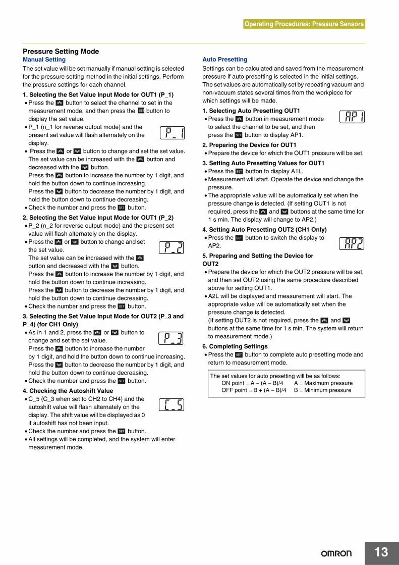
Pressure Setting Mode Manual Setting
The set value will be set manually if manual setting is selected for the pressure setting method in the initial settings. Perform the pressure settings for each channel.
1. Selecting the Set Value Input Mode for OUT1 (P_1)• Press the button to select the channel to set in the
measurement mode, and then press the button to display the set value.
• P_1 (n_1 for reverse output mode) and the present set value will flash alternately on the display.
• Press the or button to change and set the set value.The set value can be increased with the button and decreased with the button. Press the button to increase the number by 1 digit, and hold the button down to continue increasing. Press the button to decrease the number by 1 digit, and hold the button down to continue decreasing.
• Check the number and press the button.
2. Selecting the Set Value Input Mode for OUT1 (P_2)• P_2 (n_2 for reverse output mode) and the present set
value will flash alternately on the display.• Press the or button to change and set
the set value.The set value can be increased with the button and decreased with the button.Press the button to increase the number by 1 digit, and hold the button down to continue increasing.Press the button to decrease the number by 1 digit, and hold the button down to continue decreasing.
• Check the number and press the button.
3. Selecting the Set Value Input Mode for OUT2 (P_3 and P_4) (for CH1 Only) • As in 1 and 2, press the or button to
change and set the set value.Press the button to increase the number by 1 digit, and hold the button down to continue increasing.Press the button to decrease the number by 1 digit, and hold the button down to continue decreasing.
• Check the number and press the button.
4. Checking the Autoshift Value • C_5 (C_3 when set to CH2 to CH4) and the
autoshift value will flash alternately on the display. The shift value will be displayed as 0 if autoshift has not been input.
• Check the number and press the button.• All settings will be completed, and the system will enter
measurement mode.
Auto Presetting
Settings can be calculated and saved from the measurement pressure if auto presetting is selected in the initial settings. The set values are automatically set by repeating vacuum and non-vacuum states several times from the workpiece for which settings will be made.
1. Selecting Auto Presetting OUT1 • Press the button in measurement mode
to select the channel to be set, and then press the button to display AP1.
2. Preparing the Device for OUT1 • Prepare the device for which the OUT1 pressure will be set.
3. Setting Auto Presetting Values for OUT1 • Press the button to display A1L.• Measurement will start. Operate the device and change the
pressure. • The appropriate value will be automatically set when the
pressure change is detected. (If setting OUT1 is not required, press the and buttons at the same time for 1 s min. The display will change to AP2.)
4. Setting Auto Presetting OUT2 (CH1 Only)• Press the button to switch the display to
AP2.
5. Preparing and Setting the Device for OUT2 • Prepare the device for which the OUT2 pressure will be set,
and then set OUT2 using the same procedure described above for setting OUT1.
• A2L will be displayed and measurement will start. The appropriate value will be automatically set when the pressure change is detected.(If setting OUT2 is not required, press the and buttons at the same time for 1 s min. The system will return to measurement mode.)
6. Completing Settings • Press the button to complete auto presetting mode and
return to measurement mode.
The set values for auto presetting will be as follows: ON point = A − (A − B)/4 A = Maximum pressureOFF point = B + (A − B)/4 B = Minimum pressure

Operating Procedures: Pressure Sensors
14
Special Settings Display Value Fine Tuning
This function can be used to match display values by eliminating variation in the output values of CH1 to CH4. Fine tuning can be performed on the pressure sensor display values within ±5% FS. • Press the and buttons at the same
time for 2 s min. to display FSt. If fine tuning is not required, press the button when FSt is displayed. The system will move the copying function.
• Press the or button to select the channel, and then press the button.
• FSt and the present pressure set value will be displayed alternately.
• Press the or button to increase or decrease the number as desired. (Increase or decrease of ±5% R.D. possible.)
• Check the number, and then press the button. FSC and the adjusted amount of change (percent) will be displayed alternately.
• Press the button to return to the FSt display. Press the or button, and perform the settings at the FSt display
for other channels in the same way.• After completing the settings at the FSt display for the other
channels, press the button when FSt is displayed. The system will proceed to the copying function.
* The pressure set value may change ± 1 digit when fine adjustment of display values is performed.
Copying
1) Four items are copied: pressure set value, range setting, output type, and response time.
2) If copying is performed from CH1 to CH2, CH3, or CH4, the OUT1 data for CH1 will be copied. If copying is performed from CH2, CH3, or CH4 to CH1, the OUT1 data or CH2, CH3, or CH4 will be copied to OUT1 of CH1.
• CPy will be displayed. • If copy mode setting is not required, press
the button. The system will proceed to the autoshift function.
• Press the or button to select the copy source displayed on the channel display section.
• Press the button to switch the copy source channel display from flashing to lit.
• After CPy and the copy source channel will be displayed alternately, press the or button to select the copy source channel. C_11 (CH1) ⇔ C_22 (CH2) ⇔ C_3 (CH3) ⇔ C_4 (CH4)
• Press the button to return to the CPy display. • To copy other channels, press the or button again
and repeat the same procedure. • After the setting has been completed, CPy will be displayed,
and the system will proceed to autoshift mode.* The pressure set value of the copied channel may change ±1 digit when copying is used.
Autoshift
Autoshift is a function to correct the set values of each switch output according to the change in source pressure. This enables proper judgment of switch output even if the source output changes. Refer to the following details for autoshift. • Press the or button when SH1 is
displayed, and CH1 and “on” or “oF” will be displayed alternately. Press the button when SH1 is displayed to proceed to the display refresh speed setting. (Autoshift ON) on ⇔ oF (Autoshift OFF)
• Press the or button to select autoshift mode, and then press the button.
• For CH2, CH3, or CH4, press the or button in the same way to select autoshift mode.
• After autoshift mode settings have been completed for all channels, press the button to proceed to the display refresh speed setting.
Display Refresh Speed Setting
Set the display refresh speed for the measurement value. • Press the or button when dSP is
displayed, select “s” for the display refresh speed, and then press the button.
• All settings will be completed, and the system will enter measurement mode. Display refresh speeds: 0.1 ⇔ 0.5 ⇔ 1.0
About Autoshift
The switch may not operate correctly if the change in the source pressure is large. Autoshift is a function that corrects the change in the source pressure and corrects the switch set value using the measurement pressure when the autoshift is input as the reference pressure.
Correcting Set Values Using Autoshift
Setting Range Using Autoshift Input
Source pressure normal
Pre
ssur
e
P_1(P_3)
P_2(P_4)
C_5(C_3) C_5 (C_3)
ON
OFF
Switch outputs 1 and 2
Hi
Lo
Autoshift input
Hysteresis
10 ms min.
Source pressure decreased
15 ms min.
Source pressure increased
Switch output response time at autoshift input
Setting range
−1 MPa −100 kPa 0 100 kPa 1 MPa
Pressure range
Vacuumpressure
Micro (differentialpressure)
Low pressure
Positive pressure
Setting pressure range
−101 kPa
100 kPa
−100 kPa−100 kPa
1 MPa
−1 kPa
−101 kPa
100 kPa
1 MPa
−1 kPa
10 kPa10 kPa
−10 kPa−10 kPa
0.1 kPa0.1 kPa

Operating Procedures: Pressure Sensors
15
Autoshift Setting
• Maintain constant pressure for 10 ms min. after the autoshift signal is input.
• The display will show “ooo” for approx. 1 s when the autoshift signal is input, and the pressure at that point will be saved at C_5 or C_3 as the correction value. By using the saved correction value, the switch set in response to autoshift in initial settings will operate with the correction value added to the set value.
• Responding to CH1For the operating value of OUT1 and OUT2, correction value C_5 will be added to P_1 to P_4 or n_1 to n_4.
• Responding to CH2 to CH4For the operating value of OUT1, correction value C_3 will be added to P_1 and P_2 or n_1 and n_2.
• A time of 15 ms max. is required until the switch operates immediately after autoshift is input.
• If the measurement pressure exceeds the setting pressure range when the autoshift is input, it will be corrected to within the setting pressure range.
• The correction value will be zero is autoshift is set to “oF.” • “ooo” will not be displayed if autoshift for all channels is set
to oF even if the autoshift input is set to Lo (no-voltage input).
• Correction values after autoshift input will be lost if the power supply is turned OFF and will be reset to zero (initial values) when the power supply is turned ON again.
* EEPROM is not used as the memory location for correction values.
Other Functions Peak Hold and Bottom Hold
These functions detect and update the maximum and minimum values during normal measurement. The display values can be held. • Press the button for 2 s min. • Press the or button to select the peak
mode or bottom mode, and then press the button.
• When _P (peak mode) is selected, the peak value will flash on the display.
• When _b (bottom mode) is selected, the bottom value will flash on the display.
• When _n is selected (neither peak mode nor bottom mode), the system will return to measurement mode.
• Press either the or button to release the hold (i.e., clear the peak and hold values.
Key Lock
This function can be used to prevent incorrect operation, such as inadvertently changing the set value. Set to LoC (lock mode) to disable the buttons. Lock• Press the button for 4 s min., and release
the button when the present setting UnL is displayed.
• Set the display to LoC using the or button.• Press the button to return to measurement mode.
Release • Press the button for 4 s min., and release
the button when the present setting LoC is displayed.
• Set the display to UnL using the or button.• Press the button to return to measurement mode.
Zero Clear
The measurement pressure display can be adjusted to zero within ±5% FS of the atmospheric pressure. • Press the and buttons at the same time for 1 s min.
to clear the display to zero when the measurement pressure display is within ±5% FS, regardless of the measurement pressure at that point. When pressing the buttons, press the
button before the button. If the button is pressed first, the channel select function may operate.
• The system will automatically return to measurement mode.
Channel Select
• The channel can be selected in the following order by pressing the button: 1→2→3→4→1→···. The display section will show measurement pressure value for each selected channel.
Channel Scan
• Press the button for 2 s min. The channel to be displayed and the corresponding measurement pressure will be displayed at intervals of approx. 2 s.
• Press the button again for 2 s min. to release the function.
n-
n-
n-
n-_P(peak mode)
n-_n(neither peak mode nor bottom mode)
n-_b(bottom mode)
⇔ ⇔

Operating Procedures: Pressure Sensors
16
Error Messages
Error messages show the error location and category when an error occurs.
* Contact your OMRON representative if the system does not reset even if the corrective actions described above are performed.
Default Set Values
Error Error message Description Corrective action
Overcurrenterror
OUT1
Overcurrent is flowing to the switch output load.
Turn OFF the power supply, remove the cause of the error on the output where the overcurrent occurred, and then turn ON the power supply again.
OUT2
Residual pressure error
Pressure of at least ±5% FS is applied to the pressure sensor when the value is cleared to zero.Note: The error will be displayed for approx. 2 s, and then the system will reset to measurement mode.
Return the applied pressure to the atmosphere and then clear the value again to zero.
Applied pressure error
Pressure in excess of the upper limit of the setting pressure range is applied.
Check that the sensor is connected and wired properly, or return the applied pressure to within the setting pressure range.
The sensor may not be connected or it may be wired incorrectly. Alternatively, pressure in excess of the lower limit of the setting pressure range may be applied.
System error
This message is displayed when an internal data error occurs.
Cycle the power supply.
This message is displayed when an internal data error occurs.This message is displayed when an internal data error occurs.This message is displayed when an internal data error occurs.
Mode Details Setting LCD display
Initial setting
Pressure range 0.0 to −101.0 [kPa]
Output type Normally open
Response time 5 ms
Pressure setting method Manual
Pressure setting Set value −75.8 [kPa]
Special setting Autoshift OFF
Display refresh speed 0.1 [s]
Other modes Key lock Released


