Embed Size (px)
Citation preview
15th INTERNATIONALPLANSEE SEMINAR
2 0 0 1
AT0100434
INIS-AT--0021
Powder MetallurgicalHigh Performance Materials
ProceedingsVolume 2: P/M Hard Materials
3 2 / 5 0PLANSEE
Editors: Gunter Kneringer, Peter Rodhammer and Heiko Wildner m m^^^m V w h l i

The authors themselves are responsible for the contents of their paper.All rights reserved by Plansee Holding AG, Reutte, Tyrol, Austria
Copyright 2001 by Plansee Holding AG, Reutte, Tyrol, AustriaPrinted by RWF, Werbegesellschaft m.b.H., Wattens, Tyrol, Austria
PrefaceATO100434
On the eve of the 15th Plansee Seminar we look back on half a century j f thisconference series founded by Professor Paul Schwarzkopf in 1951/TheProceedings of these Seminars form an impressive chronicle of the continuedprogress in the understanding of refractory metals and cemented carbides and intheir manufacture and application. There the ingenuity and assiduous work ofthousands of scientists and engineers striving for progress in the field of powdermetallurgy is documented in more than 2000 contributions covering some 30 000pages, f
As we enter the new millennium the basic needs of the markets we are servingremain the same: improved material properties and designs translating intoimproved product performance and reliability. In view of ever shorter product lifecycles, however, the pressure on material scientists and engineers to introducethese new products at reduced time-to-market and with improved benefit/cost ratiois continuously mounting.
Since 1951 the means to meet these demands have greatly improved: novelequipment with improved process control, faster computers for simulation as well asfor data acquisition and reduction, analytical tools with undreamed-of accuracy; allcoupled with the shrinkage of distances brought about by the revolution in globalcommunication.
The 15th Plansee Seminar was convened under the general theme "PowderMetallurgical High Performance Materials". Under this broadened perspective theSeminar will strive to look beyond the refractory metals and cemented carbides,
I which remain at its focus, to novel classes of materials, such as intermetallicL compounds, with potential for high temperature applications.
It is with great pleasure that I welcome you in the name of Plansee Holding AGhere in Reutte/Tyrol and extend to you my sincere wishes for a fruitful, inspiringseminar. Thank you in advance for your personal contribution to making the 15th
Plansee Seminar a successful, memorable event.
Reutte, May 2001 Fcrthe Executive Board
Dr. Michael Schwarzkopf

OrganisationOrganized by: Plansee Holding AG, Reutte, Tyrol, Austria
International Liaison Board:
BelgiumBrazilPeoples Republic of China
Czech RepublicGermany
Great Britain
HungaryIndiaIsraelItalyJapanLiechtensteinThe Netherlands
PolandRussian FederationSouth AfricaSouth KoreaSwedenUSA
EPMA EuropeMPIF USA
0. Van der Biest, HeverleeH. R. Z. Sandim, LorenaG. Shiju, BeijingW. Yin, BaojiJ. Spacil, SumperkH. E. Exner, DarmstadtD. Stover, JulichM. Loretto, BirminghamB. Roebuck, TeddingtonL. Bartha, BudapestP. Ramakrishnan, BombayA. Rosen, HaifaM. Rosso, TorinoR. Watanabe, SendaiW. J. Huppmann, SchaanJ. Bressers, PettenF. Mertens, MaarheezeS. Stolarz, GliwiceV. 1. Trefilov, KievS. B. Luyckx, Johannesburg1. H. Moon, SeoulB. Uhrenius, StockholmA. M. Alper, Brant RockR. M. German, University ParkB. North, LatrobeL. Albano-Muller, ShrewsburyT.E. Friday, Princeton
Scientific Committee:
Local Organization:
B. Kieback, DresdenG. Kneringer, ReutteG. Leichtfried, ReutteP. Rodhammer, ReutteW. Schintlmeister, ReutteU. Schleinkofer, ReutteW. D. Schubert, WienR. F. Singer, Erlangen
G. KneringerP. RodhammerH. Wildner
Powder Metallurgical High Performance Materials VII
Contents
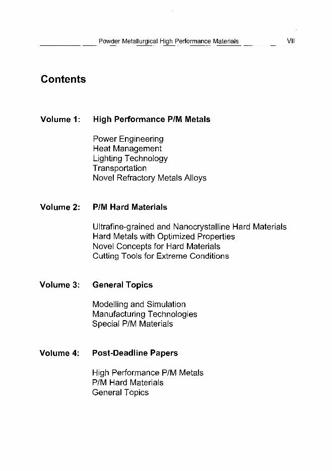
Volume 1: High Performance P/M Metals
Power EngineeringHeat ManagementLighting TechnologyTransportationNovel Refractory Metals Alloys
Volume 2: P/M Hard Materials
Ultrafine-grained and Nanocrystalline Hard MaterialsHard Metals with Optimized PropertiesNovel Concepts for Hard MaterialsCutting Tools for Extreme Conditions
Volume 3: General Topics
Modelling and SimulationManufacturing TechnologiesSpecial P/M Materials
Volume 4: Post-Deadline Papers
High Performance P/M MetalsP/M Hard MaterialsGeneral Topics
VIII Powder Metallurgical High Performance Materials
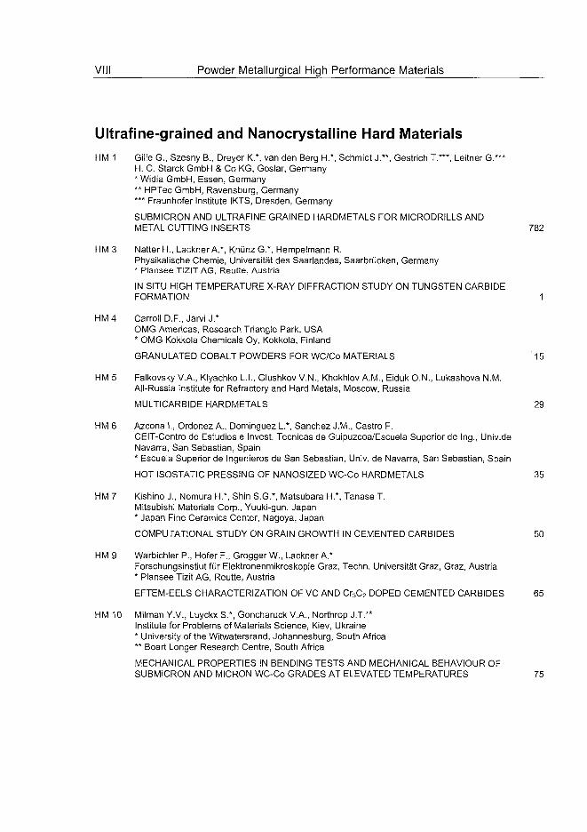
Ultrafine-grained and Nanocrystalline Hard MaterialsHM 1 Gille G., Szesny B., Dreyer K.*, van den Berg H.*, Schmidt J.**, Gestrich T.***, Leitner G.***
H. C. Starck GmbH & Co KG, Goslar, Germany* Widia GmbH, Essen, Germany** HPTec GmbH, Ravensburg, Germany*** Fraunhofer Institute IKTS, Dresden, Germany
SUBMICRON AND ULTRAFINE GRAINED HARDMETALS FOR MICRODRILLS ANDMETAL CUTTING INSERTS 782
HM 3 Natter H., Lackner A.*, Knünz G.*, Hempelmann R.Physikalische Chemie, Universität des Saarlandes, Saarbrücken, Germany* Plansee TiZIT AG, Reutte, Austria
IN SITU HIGH TEMPERATURE X-RAY DIFFRACTION STUDY ON TUNGSTEN CARBIDEFORMATION 1
HM 4 Carroll D.F., Järvi J.*OMG Americas, Research Triangle Park, USA* OMG Kokkola Chemicals Oy, Kokkola, Finland
GRANULATED COBALT POWDERS FOR WC/Co MATERIALS 15
HM 5 Falkovsky V.A., Klyachko L.I., Glushkov V.N., Khokhlov A.M., Eiduk O.N., Lukashova N.M.All-Russia Institute for Refractory and Hard Metals, Moscow, Russia
MULTICARBIDE HARDMETALS 29
HM 6 Azcona I., Ordonez A., Dominguez L.*, Sanchez J.M., Castro F.CEIT-Centro de Estúdios e Invest. Técnicas de Guipuzcoa/Escuela Superior de Ing., Univ.deNavarra, San Sebastian, Spain* Escuela Superior de Ingenieros de San Sebastian, Univ. de Navarra, San Sebastian, Spain
HOT ISOSTATIC PRESSING OF NANOSIZED WC-Co HARDMETALS 35
HM 7 Kishino J., Nomura H.*, Shin S.G.*, Matsubara H.*, Tanase T.Mitsubishi Materials Corp., Yuuki-gun, Japan* Japan Fine Ceramics Center, Nagoya, Japan
COMPUTATIONAL STUDY ON GRAIN GROWTH IN CEMENTED CARBIDES 50
HM 9 Warbichler P., Hofer F., Grogger W., Lackner A.*Forschungsinstiut für Elektronenmikroskopie Graz, Techn. Universität Graz, Graz, Austria* Plansee Tizit AG, Reutte, Austria
EFTEM-EELS CHARACTERIZATION OF VC AND Cr3C2 DOPED CEMENTED CARBIDES 65
HM 10 Milman Y.V., Luyckx S.*, Goncharuck V.A., Northrop J.T.**Institute for Problems of Materials Science, Kiev, Ukraine* University of the Witwatersrand, Johannesburg, South Africa** Boart Longer Research Centre, South Africa
MECHANICAL PROPERTIES IN BENDING TESTS AND MECHANICAL BEHAVIOUR OFSUBMICRON AND MICRON WC-Co GRADES AT ELEVATED TEMPERATURES 75
Powder Metallurgical High Performance Materials IX
Poster Session: P/M Hard Materials (HM1, HM2)
HM 11 Falkovsky V., Blagoveschenski Y.*, Glushkov V.N., Klyachko L, Khokhlov A.All-Russia Institute for Refractory and Hard Metals, Moscow, Russia* Institute of Metallurgy and Materials Science RAS, Moscow, Russia
NANOCRYSTALLINE WC-Co HARDMETALS PRODUCED BY PLASMOCHEMICALMEHTOD 91
HM 13 Bartha L, Kotsis I.*, Laczko L.*, Harmat P.Research Institute for Technical Physics and Material Sciences, Budapest, Hungary* Inst. f. Silicate and Materials Engineering, University of Veszprem, Veszprem, Hungary
HIGH TEMPERATURE REACTIONS OF WC-Co NANOPOWDERS IN VARIOUSATMOSPHERES 97
HM 15 Lay S., Hamar-Thibault S., Lackner A.*LTPCM, INPG/CNRS/UJF, St. Martin d'Heres cedex, France* Plansee TIZIT AG, Reutte, Austria
HREM CHARACTERISATION OF VC IN DOPED WC-Co CERMETS 106
HM 16 Cha S.I., Hong S.H., Ha G.H.*, Kim B.K.*Korea Advanced Institute of Science and Technology, Dept. of Materials Science andEngineering, Taejon, South Korea* Korea Institute of Machinery & Materials, Kyungnam, South Korea
MICROSTRUCTURE AND MECHANICAL PROPERTIES OF ULTRA-FINE WC-10CoHARDMETALS 119
HM 17 Zgalat-Lozynskyy O.B., Ragulya A.V., Herrmann M.*Institute for Problems of Materials Science, Ukrainian National Academy of Science, Kiev,Ukraine* Fraunhofer Institute of Ceramics Technology and Sintering, Germany
HIGH MELTING POINT NANOCRYSTALLINE CERAMICS 131
HM18 MoritaS., Shimizu H., Sayama Y.Japan New Metals Co. Ltd., Osaka, Japan
SYNTHESIS OF CHROMIUM NITRIDE POWDER BY CARBO-THERMAL NITRIDING 139
HM 21 Vasile T., Sfat C, Vasilescu M., Zafiu G.Physical Metallurgy Dept., Politehnica University of Bucharest, Bucharest, Romania
THE IMPROVEMENT OF THE WC-TiC-Co ALLOY PERFORMANCES, REALISED BYADDITION OF (Ta,Nb)C 152
HM 22 Vasile T., Zafiu G., Vasilescu M., Vasilescu I., Sfat C.Physical Metallurgy Dept., Politehnica University of Bucharest, Bucharest, Romania
THE IMPROVEMENT OF CLASSICAL ALLOYS BY ADDING Cr3C2 CARBIDES 160
HM23 LisovskyA.F.Institute for Superhard Materials, Kiev, Ukraine
PROPERTIES OF CEMENTED CARBIDES ALLOYED BY METAL MELT TREATMENT 168
Powder Metallurgical High Performance Materials
HM 25 Chen H., Zhang D., Li Y., Chen J.Central Iron & Steel Research Institute, Beijing, Peoples Republic of China
HIGH PERFORMANCE SINTER-HIP FOR HARD METALS 180
HM 26 Bondarenko V., Pavlotskaya E., Martynova L., Epik I.V. Bakul Institute for Superhard Materials of the National Academy, Kiev, Ukraine
ADVANCED TECHNOLOGIES OF PRODUCTION OF CEMENTED CARBIDES ANDCOMPOSITE MATERIALS BASED ON THEM 189
HM 27 Vleugels J., Volders I., Put S., Zhao C, Van der Biest O., Groffils C.*, Luypaert P.J.*,Barbier G.**, Bourgeois L.**Katholieke Universiteit Leuven, Dept. of Metallurgy and Materials Engineering, Leuven,Belgium* Microwave Energy Applications Company, MEAC, Leuven, Belgium** Cerametal Sari, Mamer, Luxembourg
HYBRID-MICROWAVE SINTERING OF HARDMETALS AND GRADED OXIDECOMPOSITES 204
HM 28 Zhou J.C., Huang B.Y.State Key Laboratory for Powder Metallurgy, Central South University, Changsha,Peoples Republic of China
A NOVEL PLASTIFICATION AGENT FOR CEMENTED CARBIDES EXTRUSIONMOLDING 216
HM 29 Mori G., Zitter H., Lackner A.*, Schretter M.*Dept. for General and Analytical Chemistry, University of Leoben, Leoben, Austria* Plansee Tizit AG, Reutte, Austria
INFLUENCING THE CORROSION RESISTANCE OF CEMENTED CARBIDES BYADDITION OF CR2C3, TiC AND TaC 222
HM 30 Roebuck B., Stewart M., Gee M.G., Bennett E.G.NPL Materials Centre, National Physical Laboratory, Teddington, United Kingdom
A SCANNING DEPTH SENSING HARDNESS TEST SYSTEM TO CHARACTERISEHARDMETALS 237
HM 31 Missiaen J.M., Lackner A.*, Schmid L*Lab. de Thermodynamique et de Physico-Chimie Metallurgiques, St. Martin d'Heres, France* Plansee Tizit AG, Reutte, Austria
QUANTITATIVE ANALYSIS OF BIMODAL GRAIN SIZE DISTRIBUTIONS IN WC-CO HARDMATERIALS 252
HM 32 Engqvist H., Ederyd S., Hogmark S.*, Uhrenius B.AB Sandvik Hard Materials, Stockholm, Sweden* Dept. of Materials Science, Uppsala, Sweden
SLIDING WEAR OF CEMENTED CARBIDES 267
Powder Metallurgical High Performance Materials XI
Novel Concepts for Hard MaterialsHM 34 Kitamura K., Kobayashi M., Hayashi K.*
Toshiba Tungaloy Co. Ltd., Iwaki, Japan* Institute of Industrial Science, The University of Tokyo, Tokyo, Japan
PROPERTIES OF: WC-Co BASE HARDMETAL PREPARED FROM CoxWyCz COMPLEXCARBIDES POWDER INSTEAD OF WC+Co MIXED POWDER 279
HM 36 Kim S., Han S.H.*, Park J.K.*, Kim H.E.Center for Microstructure Science of Materials, School of Materials Science & Engineering,Seoul, South Korea* Ceramic Processing Research Center, Div. of Materials, Korea Institute of Science andTechnology, Seoul, South Korea
OBSERVATION OF WC GRAIN SHAPES DETERMINED BY CARBON CONTENT DURINGLIQUID PHASE SINTERING OF WC-Co ALLOYS 294
HM 37 Toth R.E., Smid I.*, Sherman A.", Ettmayer P.***, Kladler G.*, Korb G.*TCHP Inventor, En Dur Aloy Corp., Savannah, USA* Austrian Research Center Seibersdorf, High Performance Materials, Seibersdorf, Austria** Powdermet Inc., Sun Valley, USA*** Institute for Chemical Technology of Inorganic Materials, TU Vienna, Vienna, Austria
TOUGH-COATED HARD POWDERS FOR HARDMETALS OF NOVEL PROPERTIES 306
HM 38 Moriguchi H., Tsuzuki K., Ikegaya A.Itami Research Laboratories, Sumitomo Electric Industries Ltd., Itami, Hyogo, Japan
DIAMOND DISPERSED CEMENTED CARBIDE PRODUCED WITHOUT USING ULTRAHIGH PRESSURE EQUIPMENT 326
HM 39 Scrivani A.* **, Rosso M.***, Salvarani L***** Turbocoating S.p.A., Parma, Italy** Universita di Parma, Dipartimento di Ingegneria Industriale, Parma, Italy*** Politecnico di Torino, Dipart. di Scienze dei Materiali e Ingegneria Chimica, Torino, Italy**** Flametal S.p.A., Parma, Italy
PERFORMANCES AND RELIABILITY OF WC BASED THERMAL SPRAY COATINGS 337
HM 40 Dreyer K., Kassel D., Daub H.W., van der Berg H., Lengauer W.*, Garcia J.*, Ucakar V.*Widia GmbH, Essen, Germany* Institute for Chemical Technology of Inorganic Materials, TU Vienna, Vienna, Austria
FUNCTIONALLY GRADED HARDMETALS AND CERMETS: PREPARATION,PERFORMANCE AND PRODUCTION SCALE UP 817
HM 41 Gasik M.M., Zhang B., Kaskiala M., Ylikerala J.Helsinki University of Technology, Espoo, Finland
SINTERING OF HARDMETALS IN DIFFERENT CONDITIONS: EXPERIMENTALRESULTS OF 2-D DILATOMETRY AND COMPUTER SIMULATIONS 351
HM 42 Put S., Vleugels J., Van der Biest O.Katholieke Universiteit Leuven, Dept. of Metallurgy and Materials Engineering, Leuven,Belgium
FUNCTIONALLY GRADED WC-Co HARDMETALS 364
XII Powder Metallurgical High Performance Materials
HM 43 UcakarV., Krai C, Dreyer K.*, Lengauer W.Institute for Chemical Technology of Inorganic Materials, TU Vienna, Vienna, Austria* Widia GmbH, Essen, Germany
NEAR-SURFACE MICROSTRUCTURAL MODIFICATION OF (TI,W)(C,N)-BASEDCOMPACTS WITH NITROGEN 833
Poster Session: P/M Hard Materials (HM3, HM4)
HM47 WuA.,CaoW., GeC, Li J.Lab. of Special Ceramic and P/M, University of Science and Technology Beijing, Beijing,Peoples Republic of China
FABRICATION OF Alpha/Beta-SIALON SYMMETRICALLY COMPOSITIONAL FGM 375
HM 48 Li J.T., Djuricic B.*, Korb G.*, Ge C.C.Lab. of Special Ceramic and P/M, University of Science and Technology Beijing, Beijing,Peoples Republic of China* Austrian Research Center Seibersdorf, Seibersdorf, Austria
ALPHA-SiAION - NEW OPPORTUNITIES VIA NEW MICROSTRUCTURE 383
HM 50 Vallauri D., De Cola P., Piscone F., Amato I.Department of Materials Science and Chemical Engineering, Politecnico di Torino, Torino,Italy
SELF PROPAGATING HIGH TEMPERATURE SYNTHESIS OF MIXED CARBIDE ANDBORIDE POWDER SYSTEMS FOR CUTTING TOOLS MANUFACTURING 389
HM 52 Takagi K.I., Yonetsu M., Yamasaki Y.Toyo Kohan Co. Ltd., Kudamatsu, Japan
NOVEL BORIDE BASE CERMETS WITH VERY HIGH STRENGTH 403
HM 53 Richter V., von Ruthendorf M.Fraunhofer Institut IKTS, Dresden, Germany
GRADIENT STRUCTURES IN HARDMETALS 849
HM 55 Chen L., Lengauer W.*, Ettmayer P.*, Dreyer K.**, Daub H.W.", Kassel D.**Austrian Research Center Seibersdorf, Div. of Materials Technology, Seibersdorf, Austria* Institute for Chemical Technology of Inorganic Materials, TU Vienna, Vienna, Austria** Widia GmbH, Essen, Germany
FUNDAMENTALS OF LIQUID PHASE SINTERING FOR MODERN CERMETS ANDFUNCTIONALLY GRADED CEMENTED CARBON1TR1DES (FGCC) 412
HM 58 Ordanyan S.S., Zalite I.*, Andronova T.E., Vladimirova M.A., Pantelejev I.B.St.-Petersburg State Institute of Technology, St.-Petersburg, Russia* Riga Technical University, Institute of Inorganic Chemistry, Salaspils, Latvia
PROPERTIES OF HARD ALLOYS ON THE BASIS OF WC-Co WITH THE ADDITIVES OFNANODISPERSE 434
HM 59 Garcia J., Lengauer L.Institute for Chemical Technology of Inorganic Materials, TU Vienna, Vienna, Austria
QUANTITATIVE MASS SPECTROMETRY OF DECABURISATION AND DENITRIDATIONOF CEMENTED CARBONITRIDES DURING SINTERING 863
Powder Metallurgical High Performance Materials XIII
HM 62 Holzschuh H.Walter AG, Tubingen, Germany
CHEMICAL-VAPOR DEPOSITION OF WEAR RESISTANT HARD COATINGS IN THETi-B-C-N SYSTEM: PROPERTIES AND METAL-CUTTING TESTS 441
HM 63 Borisova A., Borisov Y., Shavlovsky E., Mits I., Castermans L.*, Jongbloed R.*E.O. Paton Electric Welding Institute, Kiev, Ukraine* Chromin Maastricht bv., Maastricht, The Netherlands
VANADIUM CARBIDE COATINGS: DEPOSITION PROCESS AND PROPERTIES 452
HM 69 Shevchenko A.D.Institute of Metal Physics Ukrainian AS, Kyiv, Ukraine
PRODUCTION OF MATERIAL WITH HIGHER DAMPING ABILITY FOR SUPERHARDCUTTING TOOLS 469
HM 70 Rosso M., Ugues D., Valle A.*Politecnico di Torino, Torino, Italy* MG Utensili Diamantati, Torino, Italy
ADVANCES IN DIAMOND TOOLS FOR WORKING LITHOID MATERIALS 475
HM 72 Liu S., Yu Z., Yi D., Li Y.*Dept. of Materials Science & Engineering, Central South University, Hunan,Peoples Republic of China* Hunan Yin Zhou Nonferrous Metals Hi-Tech. Ltd. Company, Hunan,Peoples Republic of China
CHEMICAL PRETREATMENTS AT THE SURFACE OF WC-15 wt% Co FOR DIAMONDCOATINGS 490
HM 73 Zhou K.S., Dai M.J., Song J.B., Kuang T.C.*, Liu Z.Y.*Guangzhou Research Institute of Non-Ferrous Metals, Guangzhou,Peoples Republic of China* South China University of Technology, Guangzhou, Peoples Republic of China
THE STUDY ON DIAMOND-COATED INSERT BY DC PLASMA JET CVD 498
HM74 Kopf A., HaubnerR., Lux B.Institute for Chemical Technology of Inorganic Materials, TU Vienna, Vienna, Austria
MULTILAYER COATINGS CONTAINING DIAMOND AND OTHER HARD MATERIALS ONHARDMETAL SUBSTRATES 509
HM 75 Haubner R., Lux B.Institute for Chemical Technology of Inorganic Materials, TU Vienna, Vienna, Austria
DEPOSITION OF BALLAS DIAMOND AND NANO-CRYSTALLINE DIAMOND 523
HM 76 Buck V., Deuerler F.*, Kluwe H., Schmiler B.Universitat GH Essen, Essen, Germany* Bergische Universitat GH Wuppertal, Wuppertal, Germany
INFLUENCE OF CHEMICAL PRETREATMENTS OF HARD METAL SUBSTRATES FORDIAMOND 537
XIV Powder Metallurgical High Performance Materials
HM 77 Dittrich K.H., Oelsner D.*Roth & Rau Oberflächentechnik GmbH, Wüstenbrand, Germany* Hochschule für Technik und Wirtschaft Mittweida, Mittweida, Germany
HERSTELLUNG UND CHARAKTERISIERUNG VON TROCKENSCHMIERSTOFF-SCHICHTEN FÜR WERKZEUGE AUF DER BASIS VON KOHLENSTOFF 549
HM 78 Yedave S.N., Sundaram N., Brown W.D., Russell W.C.*MRL, Dept. of Mechanical Engineering, University of Arkansas, Fayetteville, USA* Valenite Inc., Troy, USA
A NOVEL COMBINATORIAL APPROACH FOR THE REALIZATION OF ADVANCED cBNCOMPOSITE 564
HM 79 Weissenbacher R., Haubner R.Institute for Chemical Technology of Inorganic Materials, TU Vienna, Vienna, Austria
DEPOSITION OF BCN LAYERS FROM B-C-N-H SINGLE SOURCE PRECURSORS 579
HM 80 Fleischer W., Baranski N., van der Kolk G.J.*, Stockmann Y.*, Kunen H.**, Hoppe S.***Bodycote Coating Centrum BV, Venlo, The Netherlands* Hauzer Techno Coating Europe BV, Venlo, The Netherlands** Jabro Tools BV, Lottum, The Netherlands*** WZL, Aachen, Germany
HARD MACHINING UNDER DRY CONDITIONS WITH HARD PVD COATINGS ONCEMENTED CARBIDE ENDMILLS 593
HM 82 Richter V.Fraunhofer Institut IKTS, Dresden, Germany
VERSCHLEISSMECHANISMEN BEI DER BEARBEITUNG VON GRAUGUSS 605
HM 83 Mertens T., Engering G., Lahres M., Pecher U.*, Damm S.*, Dörr J.**, Hühsam A.***DaimlerChrysler AG, Ulm, Germany* Institute of Production Engineering and Logistics (IPL), Kassel, Germany** Institute of Production Engineering and Machine Tools (PtW), Darmstadt, Germany*** Institute of Machine Tools and Production Science (wbk), Karlsruhe, Germany
1N-SITU TEMPERATURE MEASUREMENT TO DETERMINE THE MACHININGBEHAVIOUR OF DIFFERENT TOOL COATINGS 620
Powder Metallurgical High Performance Materials XV
Hard Metals with Optimized Properties
HM 85 Upadhyaya A., Sarathy D.*, Wagner G.*Materials & Metallurgical Engineering Dept., Indian Inst. of Technology, Kanpur, India* Widia (India) Ltd., Bangalore, India
IMPROVEMENT IN PROCESSING OF METAL-CUTTING INSERTS THROUGHSINTERING TIME REDUCTION AND ALLOY DESIGN 634
HM 86 Schwenke G.K.Osram Sylvania Inc., Chemical & Metallurgical Products, Towanda, USA
THERMODYNAMICS OF THE HYDROGEN-CARBON-OXYGEN-TUNGSTEN SYSTEM, ASAPPLIED TO THE MANUFACTURE OF TUNGSTEN AND TUNGSTEN CARBIDE 647
HM 87 Andersson G., Jansson B.AB Sandvik Coromant, Stockholm, Sweden
THE SOLUBILITY OF CUBIC CARBIDE FORMERS IN LIQUID COBALT 662
HM 90 Agrawal D.K., Papworth A.J.*, Cheng J., Jain H.*, Williams D.B.*Pennsylvania State University, Materials Research Laboratory, University Park, USA* Lehigh University, Dept. of Materials Science and Engineering, Betheleham, USA
MICROSTRUCTURAL EXAMINATION BY TEM OF WC/Co COMPOSITES PREPARED BYCONVENTIONAL AND MICROWAVE PROCESSES 677
HM 92 Beste U., Engqvist H., Jacobson S.Tribomaterials Group at the Angstrom Laboratory, Uppsala University, Uppsala, Sweden
PRESSURE CYCLING INDUCED MODIFICATION OF A CEMENTED CARBIDE 685
XVI Powder Metallurgical High Performance Materials
Cutting Tools for Extreme ConditionsHM 93 Klocke F., Bausch S.
Fraunhofer-lnstitute of Production Technology IPT, Aachen, Germany
LASER-ASSISTED TURNING OF COMPONENTS MADE OF SILICON-NITRIDECERAMICS 698
HM 94 Collins J.LDe Beers Industrial Diamonds (UK) Ltd., Ascot, United Kingdom
HIGH SPEED DRY MACHINING OF MMCs WITH DIAMOND TOOLS 711
HM 98 Kathrein M., Heiss M., Rofner R., Schleinkofer U., Schintlmeister W., Schatte J., Mitterer C*Plansee TIZIT AG, Reutte, Austria* Department of Physical Metallurgy and Materials Testing, University of Leoben, Leoben,Austria
WEAR PROTECTION IN CUTTING TOOL APPLICATIONS BY PACVD (Ti,AI)N AND Ai2O3
COATINGS 726
HM 99 Giushkov V.N., Anikeev A.I., Anikin V.N., Vereschaka A.*Unitary State-Owned Enterprise (GUP) VNIITS, Moscow, Russia* State Technological University "Stankin", Moscow, Russia
MULTILAYERED AND COMPOSITE PVD-CVD COATINGS IN CEMENTED CARBIDESMANUFACTURE 740
HM 100 Russell W.C., Malshe A.P.*, Yedave S.N.*, Brown W.D.*Valenite Inc., Troy, USA* MRL-MEEG, University of Arkansas, Fayetteville, USA
NOVEL COMPOSITE cBN-TiN COATING DEPOSITION METHOD: STRUCTURE ANDPERFORMANCE IN METAL CUTTING 754
HM 103 Lugscheider E., Hornig T., Kienitz S., Klocke F.', Krieg T.*RWTH Aachen, Lehr- u. Forschungsgebiet Werkstoffwissenschaften, Aachen, Germany* RWTH Aachen, Lab. f. Werkzeugmaschinen, Lehrst.f.Techn. d. Fertigungsverfahren,Aachen, Germany
WEITERENTWICKLUNG UMWELTVERTRAGLICHER TRIBOSYSTEME IN DERZERSPANUNG MITTELS PVD-TECHNOLOGIE 766

Powder Metallurgical High Performance Materials XVII
XVIII Powder Metallurgical High Performance Materials
List of Authors
Agrawal D.K.Amato 1.Andersson G.Andronova T.E.Anikeev A.I.Anikin V.N.Azcona 1.
Baranski N.Barbier G.Bartha L.Bausch S.Bennett E.G.Beste U.Blagoveschertski Y.Bondarenko V.Borisov Y.Borisova A.Bourgeois L.Brown W.D.
BuckV.
CaoW.Carroll D.F.Castermans L.Castro F.Cha S.I.Chen H.Chen J.Chen LCheng J.Collins J.L.
Dai M.J.Damm S.Daub H.W.
De Cola P.Deuerler F.Dittrich K.H.Djuricic B.Dominguez L.Dörr J.Dreyer K.
Ederyd S.EidukO.N.Engering G.Engqvist H.
Epik 1.
HMHMHMHMHMHMHM
HMHMHMHMHMHMHMHMHMHMHMHMHMHM
HMHMHMHMHMHMHMHMHMHM
HMHMHMHMHMHMHMHMHMHMHMHMHMHM
HMHMHMHMHMHM
9050875899996
80271393309211266363271007876
474636162525559094
73834055507677486831404355
32583329226
Ettmayer P.
Falkovsky V.A.
Fleischer W.
Garcia J.
GasikM.M.Ge C.C.
GeeM.G.Gestrich T.Gille G.GlushkovV.N.
Goncharuck V.A.Groffils C.Grogger W.
HaG.H.Hamar-Thibault S.HanS.H.Harmat P.Haubner R.
Hayashi K.Heiss M.Hempelmann R.Herrmann M.Hofer F.Hogmark S.Holzschuh H.Hong S.H.Hoppe S.Hornig T.Huang B.Y.Hühsam A.
Ikegaya A.
Jacobson S.Jain H.Jansson B.Järvi J.Jongbloed R.
Kaskiala M.Kassel D.
Kathrein M.KhokhlovA.M.
HMHM
HMHMHM
HMHMHMHMHMHMHMHMHMHMHMHMHMHM
HMHMHMHMHMHMHMHMHMHMHMHMHMHMHMHMHMHMHM
HM
HMHMHMHMHM
HMHMHMHMHMHM
3755
51180
405941474830111159910279
1615361374757934983179326216801032883
38
929087463
41405598511
Kienitz S.Kim B.K.Kim H.E.KimS.Kishino J.Kitamura K.Kladler G.Klocke F.
Kluwe H.Klyachko L.l.
KnünzG.Kobayashi M.Köpf A.Korb G.
Kotsis I.Kral C.Krieg T.Kuang T.C.Kunen H.
Lackner A.
Laczko L.Lahres M.LayS.Leitner G.Lengauer W.
Li J.T.
LiY.
Lisovsky A.F.LiuS.Liu Z.Y.Lugscheider E.Lukashova N.M.LuxB.
Luyckx S.Luypaert P.J.
Malshe A.P.
Martynova L.Matsubara H.Mertens T.Milman Y.V.
HMHMHMHMHMHMHMHMHMHMHMHMHMHMHMHMHMHMHMHMHMHM
HMHMHMHMHMHMHMHMHMHMHMHMHMHMHMHMHMHMHMHMHMHMHMHMHMHM
HMHMHMHMHMHM
10316363673437103937651133474374813431037380
1529331913831514043555947482572237273103574751027
100782678310
Powder Metallurgical High Performance Materials XIX
List of Authors
Missiaen J.M.Mits 1.Mitterer C.Mori G.Moriguchi H.Morita S.
Natter H.Nomura H.Northrop J.T.
Oelsner D.Ordanyan S.S.Ordonez A.
Pantelejev I.B.Papworth A.J.ParkJ.K.Pavlotskaya E.Pecher U.Piscone F.PutS.
Ragulya A.V.Richter V.
Roebuck B.Rofner R.Rosso M.
Russell W.C.
Salvarani L.Sanchez J.M.Sarathy D.Sayama Y.Schatte J.Schleinkofer U.Schintlmeister W.Schmid L.Schmidt J.Schmiler B.Schretter M.Schwenke G.K.Scrivani A.Sfat C.
Shavlovsky E.Sherman A.Shevchenko A.D.Shimizu H.Shin S.G.Smid 1.Song J.B.
HMHMHMHMHMHM
HMHMHM
HMHMHM
HMHMHMHMHMHMHMHM
HMHMHMHMHMHMHMHMHM
HMHMHMHMHMHMHMHMHMHMHMHMHMHMHMHMHMHMHMHMHMHM
316398293818
3710
77586
5890362683502742
1753823098397010078
39685189898983117629863921226337691873773
Stewart M.Stockmann Y.Sundaram N.Szesny B.
Takagi K.I.Tanase T.Toth R.E.Tsuzuki K.
Ucakar V.
Ugues D.Uhrenius B.Upadhyaya A.
Vallauri D.Valle A.van den Berg H.
van der Biest O.
van der Kolk G.J.von RuthendorfVasile T.
Vasilescu I.Vasilescu M.
Vereschaka A.Vladimirova M.A.Vleugels J.
Volders I.
Wagner G.Warbichler P.Weissenbacher R.Williams D.B.Wu A.
Yamasaki Y.Yedave S.N.
YiD.Ylikerälä J.Yonetsu M.YuZ.
Zafiu G.
Zalite I.
HMHMHMHM
HMHMHMHM
HMHMHMHMHM
HMHMHMHMHMHMHMHMHMHMHMHMHMHMHMHMHMHM
HMHMHMHMHM
HMHMHMHMHMHMHM
HMHMHM
Zgalat-Lozynskyy O. HMZhang B.Zhang D.Zhao C.
HMHMHM
3080781
5273738
4043703285
50701402742805321222221229958274227
859799047
521007872415272
21225817412527
Zhou J.C.Zhou K.S.Zitter H.
HM 28HM 73HM 29

AT0100435H. Natter et al. HM 3
15th International Plansee Seminar, Eds. G. Kneringer, P. Rodhammer and H. Wildner, Plansee Holding AG, Reutte (2001), Vol. 2
In situ high temperature X-ray diffraction study
on Tungsten Carbide formation
Harald Natter+, Andreas Lackner *, Gerhard Knunz *, Rolf Hempelmann +
+ Physikalische Chemie, Universitat des Saarlandes, Saarbrucken, Germany
* PLANSEE TIZIT AG, Reutte, Tyrol, Austria
Summary
In-situ high temperature X-ray diffraction (HT-XRD) was used to measurecarburisation processes of tungsten/carbon mixtures. The high time resolution(2-5 min/scan) of the experimental setup enables the observation of any stateof the carburisation. We discuss the influence of different experimentalparameters on the carburisation process:• sample preparation parameter (milling intensity)• particle size and morphology of the carbon black powders• impurities in the W and C mixture
We propose phase transition mechanisms resulting from the evaluation of theisochronal XRD-pattern. The effect of grain growth inhibitors on the rate of theW2C-transformation was measured in dependence of the grain growthinhibitor concentration (e.g. Cr3C2). The grain size and the grain sizedistribution of the resulting tungsten carbide was determined by scanningelectron microscopy.
KeywordsTungsten carbide, carburisation, grain growth inhibitor, x-ray diffraction
1. Introduction
The detailed understanding of the carburisation process of tungsten powderis the prerequisite for the production of high quality WC powder. A literaturesurvey (1-5) revealed a couple of studies all saying that carbon diffusionthrough the carbide was the rate determining step but disagreed as towhether the carbide was WC or W2C. Furthermore the diffusion rates
HM 3 H. Natter et al.15" International Plansee Seminar, Eds. G. Kneringer, P. Rodhammer and H. Wildner, Plansee Holding AG, Reutte (2001), Vol. 2
measured in these studies differed markedly essentially the same methodwas used giving many different activation energies.Andrews and Dushman (3) were first to study carbon diffusion throughtungsten. They carburised tungsten filaments with different grain structures ina hydrogen atmosphere and related the carbide layer thickness to theresistance of the filament. They concluded that the process did not depend onthe microstructure of the metal and that the formation of W2C was the rate-determining step, with an activation energy of 108 kcal/mol.Pi rani and Sandor (6) carburised tungsten beads by packing them incarbon black and heating this packed bed in a dry hydrogen atmosphere attemperatures from 1535° to 1805° C. The carbide layer growth wasmeasured microscopically on cross sections of the carburised tungstenbeads. They concluded that the carbide phase formed was WC, that theactivation energy for the process was 59 kcal/mol, and that the grainboundary diffusion was unimportant.Kreimer et a l . (4) used essentially the same methods as Pirani et al.except that tungsten rod samples were used. The temperature range studiedwas 1525° to 1850° The authors concluded that a skin of WC first forms onthe surface of the tungsten, after which the W2C phase forms between thetungsten and the WC; the W2C layer then grows at a much faster rate thanthe WC. Furthermore, if the tungsten is carburised while packed in carbon,but in a vacuum rather than a hydrogen atmosphere, only W2C is formed.The activation energy for the diffusion of carbon through W2C layer was foundto be 111 kcal/mol.Zhengji (2), however, claims saying that carburisation of tungsten particlesalways starts with the formation of a thin layer of tungsten carbide on thesurface of the particles. According to his model the carbon in the W2C phasediffuses continuously to the tungsten phase and the carbon in the WC phasediffuses continuously to the W2C phase. The carbon deficiency causes by thetransfer of the carbon atoms in WC phase to the inner layer is compensatedcontinuously by the carbon atoms supplied from the outside. Therefore, withthe proceeding of carburisation, the tungsten phase is attracted continuouslyand converts to W2C, which in turn is attracted constantly and converts to WCuntil the whole particle is carburised.Recently McCarty et al. (5) has found a mathematical model for thecarburisation kinetics of tungsten carbon mixes that describes a steady statediffusion across a growing shell of WC on spherical particles. The model isrestricted to mono disperse particles in the temperature range between 1056and 1833X.
H. Natter et al. HM315" International Plansee Seminar, Eds. G. Kneringer, P. Rodhammer and H. Wildner, Plansee Holding AG, Reutte (2001), Vol. 2
In this work we demonstrate that in situ x-ray diffraction is an efficient methodmeasuring the effect of process parameter on the carburisation of tungsten.The evaluation of temperature dependent experiments allows also kineticconclusions.
2. Experimental DetailsIn the present study we use tungsten powders with grain sizes from 0.5 urnup to several urn and carbon black powders with different morphologies, BETsurfaces and chemical impurities (Tab. 1).
Tab. 1: Specification of the carbon black powders
Carbonblack
,,A"
,,B"
,,C"
BET-surface[m2/g]
25.88
20.60
10.19
c(Ca)
[ug/g]
b.d.
b.d.
< 10
c(Fe)
[ug/g]b.d.
b.d.
<5
c(Mg)
[ug/g]
b.d.
b.d.
<5
c(S)
[ug/g]
5552
10
<5
b.d.: below determination limit
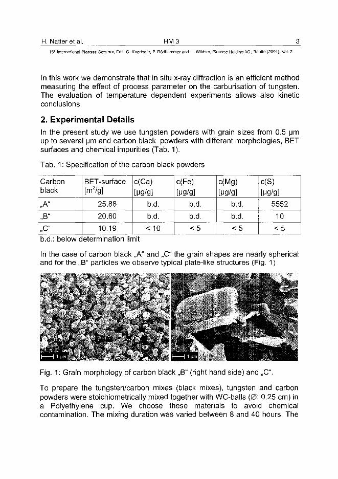
In the case of carbon black ,,A" and ,,C" the grain shapes are nearly sphericaland for the ,,B" particles we observe typical plate-like structures (Fig. 1)
Fig. 1: Grain morphology of carbon black ,,B" (right hand side) and ,,C".
To prepare the tungsten/carbon mixes (black mixes), tungsten and carbonpowders were stoichiometrically mixed together with WC-balls (0: 0.25 cm) ina Polyethylene cup. We choose these materials to avoid chemicalcontamination. The mixing duration was varied between 8 and 40 hours. The
HM3 H. Natter et al.15'" International Plansee Seminar, Eds. G. Kneringer, P. Rodhammer and H. Wildner, Plansee Holding AG, Reutte (2001), Vol. 2
finished mixture separates from the carbide balls and presses for 3 hours(pressure: 105 N/cm2) to a pellet of approximately 1 gram.
3. X-ray measurements and data evolution
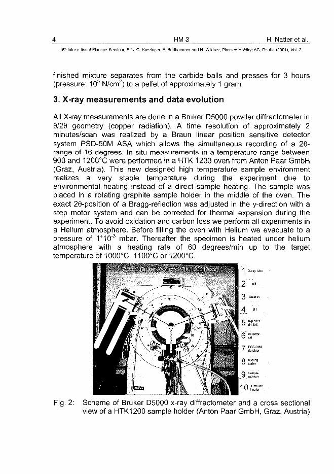
All X-ray measurements are done in a Bruker D5000 powder diffractometer in6/20 geometry (copper radiation). A time resolution of approximately 2minutes/scan was realized by a Braun linear position sensitive detectorsystem PSD-50M ASA which allows the simultaneous recording of a 29-range of 16 degrees. In situ measurements in a temperature range between900 and 1200°C were performed in a HTK 1200 oven from Anton Paar GmbH(Graz, Austria). This new designed high temperature sample environmentrealizes a very stable temperature during the experiment due toenvironmental heating instead of a direct sample heating. The sample wasplaced in a rotating graphite sample holder in the middle of the oven. Theexact 26-position of a Bragg-reflection was adjusted in the y-direction with astep motor system and can be corrected for thermal expansion during theexperiment. To avoid oxidation and carbon loss we perform all experiments ina Helium atmosphere. Before filling the oven with Helium we evacuate to apressure of 1*10'3 mbar. Thereafter the specimen is heated under heliumatmosphere with a heating rate of 60 degrees/min up to the targettemperature of 1000°C, 1100°C or 1200°C.
1 X-ray tube
Fig. 2: Scheme of Bruker D5000 x-ray diffractometer and a cross sectionalview of a HTK1200 sample holder (Anton Paar GmbH, Graz, Austria)
H. Natter et al. HM315" International Plansee Seminar, Eds. G. Kneringer, P. Rodhammer and H. Wildner, Plansee Holding AG, Reutte (2001), Vol. 2
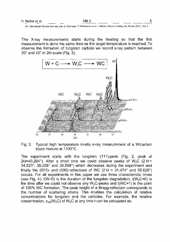
The X-ray measurements starts during the heating so that the firstmeasurement is done the same time as the target temperature is reached. Toobserve the formation of tungsten carbide we record x-ray pattern between30° and 42° in 20-scale (Fig. 3).
WC W2C WC W,C
Fig. 3: Typical high temperature in-situ x-ray measurement of a W/carbonblack mixture at 1100°C.
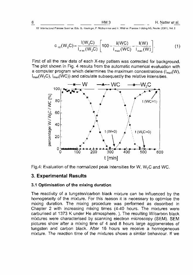
The experiment starts with the tungsten (111)-peak (Fig. 2, peak at20=40.264°). After a short time we could observe peaks of W2C (2 0 =34.523°, 38.028° and 39.568°) which decreases during the experiment andfinally the (001)- and (100)-reflections of WC (2 0 = 31.474° and 35.626°)occurs. For all experiments in this paper we use three characteristic times(see Fig. 4): t(W=0) is the duration of the tungsten degradation, t(W2C=0) isthe time after we could not observe any W2C-peaks and t(WC=1) is the pointof 100% WC formation. The peak height of a Bragg-reflection corresponds tothe number of scattering atoms. This enables the calculation of relativeconcentrations for tungsten and the carbides. For example, the relativeconcentration, crei(W2C) of W2C at any time t can be calculated as:
HM3 H. Natter et al.15" International Plansee Seminar, Eds. G. Kneringer, P. Rodhammer and H. Wildner, Plansee Holding AG, Reutte (2001), Vol. 2
I(W2C)
Lax(W2C)100-
I(WC)lmax(WC) lmax(W) (1)
First of all the raw data of each X-ray pattern was corrected for background.The plot shown in Fig. 4 results from the automatic numerical evaluation witha computer program which determines the maximum concentrations (lmax(W),lmax(W2C), lmax(WC)) and calculate subsequently the relative intensities.
w we100
-w,c
o 80
<•£• 6 0
20)Ui_
0Q.
40
20-
t(WC=1)
t (W=0)
100 200 300 400
t (W2C=0)
500 600t [min]
Fig.4: Evaluation of the normalized peak intensities for W, W2C and WC.
3. Experimental Results
3.1 Optimisation of the mixing duration
The reactivity of a tungsten/carbon black mixture can be influenced by thehomogeneity of the mixture. For this reason it is necessary to optimise themixing duration. The mixing procedure was performed as described inChapter 2 with increasing mixing times (4-40 hours. The mixtures werecarburised at 1373 K under He atmosphere. ). The resulting W/carbon blackmixtures were characterised by scanning electron microscopy (SEM). SEMpictures show after a mixing time of 4 and 8 hours large agglomerates oftungsten and carbon black. After 16 hours we receive a homogeneousmixture. The reaction time of the mixtures shows a similar behaviour. If we
H. Natter et al. HM315lh International Plansee Seminar, Eds. G. Kneringer, P. Rodhammer and H. Wildner, Plansee Holding AG, Reutte (2001), Vol. 2
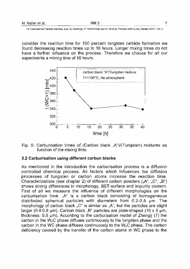
consider the reaction time for 100 percent tungsten carbide formation wefound decreasing reaction times up to 16 hours. Longer mixing times do nothave a further influence on the process. Therefore we choose for all ourexperiments a mixing time of 16 hours.
440
'E400
,360
'340
320
300
carbon black "A'VTungsten mixture
T=1100°C, He atmosphere
0 10 15 20 25
time [h]
30 35 40
Fig. 5: Carburisation times of (Carbon black ,,A")/(Tungsten) mixtures asfunction of the mixing time.
3.2 Carburisation using different carbon blacks
As mentioned in the introduction the carburisation process is a diffusioncontrolled chemical process. All factors which influences the diffusionprocesses of tungsten or carbon atoms increase the reaction time.Characterizations (see chapter 2) of different carbon powders (,,A", ,,C", ,,B")shows strong differences in morphology, BET-surface and impurity content.First of all we measure the influence of different morphologies on thecarburisation time. ,,A" is a carbon black consisting of homogeneousdistributed spherical particles with diameters from 0.2-0.5 urn. Themorphology of carbon black ,,C" is similar as ,,A", but the particles are slightlarger (0.4-0.8 urn). Carbon black ,,B" particles are plate-shaped (10x5 urn,thickness: 0.5 urn). According to the carburisation model of Zhengij (7) thecarbon in the W2C phase diffuses continuously to the tungsten phase and thecarbon in the WC phase diffuses continuously to the W2C phase. The carbondeficiency caused by the transfer of the carbon atoms in WC phase to the
HM3 H. Natter et al.15* International Plansee Seminar, Eds. G. Kneringer, P. Rodhammer and H. Wildner, Plansee Holding AG, Reutte (2001), Vol. 2
inner layer is compensated continuously by the carbon atoms supplied fromthe outside.
CD
o
800
600
400
200
0
-
-"' ;
-
*
1•• • ~ . . . •
^ H "C"
1 1 "A"
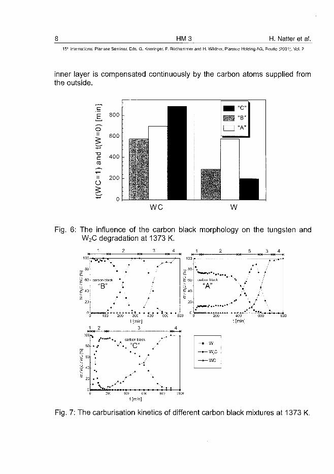
•we w
Fig. 6: The influence of the carbon black morphology on the tungsten andW2C degradation at 1373 K.
3 4
100 200 300 400 500 600
t [min]3 4
Fig. 7: The carburisation kinetics of different carbon black mixtures at 1373 K.
H. Natter et al. HM315" International Plansee Seminar, Eds. G. Kneringer, P. Rodhammer and H. Wildner, Plansee Holding AG, Reutte (2001), Vol. 2
Range 1 and 4 are single phase regions (1: W, 2: W2C). In 2 (W and W2C)and 3 (W2C and WC) two phases can be found. ,,A" shows an additionalrange with 3 phases (region 5). The small dimension of the spherical particlesshould expect a faster reaction compared to the large ,,B"-plates. Fig. 6, 7summarizes the results of the reaction rates at 1373 K. The tungsten/carbonblack mixture with ,,B" powder shows the longest reaction times for thecomplete carburisation whereas the mixes with carbon black ,,A" and ,,C"shows clearly shorter reaction times.
3.4 The influence of impurities on the carburisation process
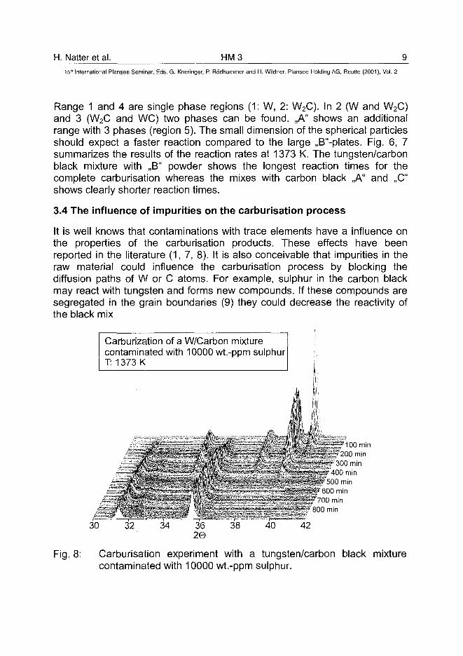
It is well knows that contaminations with trace elements have a influence onthe properties of the carburisation products. These effects have beenreported in the literature (1, 7, 8). It is also conceivable that impurities in theraw material could influence the carburisation process by blocking thediffusion paths of W or C atoms. For example, sulphur in the carbon blackmay react with tungsten and forms new compounds. If these compounds aresegregated in the grain boundaries (9) they could decrease the reactivity ofthe black mix
Carburization of a W/Carbon mixturecontaminated with 10000 wt.-ppm sulphurT: 1373 K
600 min700 min
800 min
30 32 34 3620
38 40 42
Fig. 8: Carburisation experiment with a tungsten/carbon black mixturecontaminated with 10000 wt.-ppm sulphur.
10 HM3 H. Natter et al.15* International Plansee Seminar, Eds. G. Kneringer, P. Rodhammer and H. Wildner, Plansee Holding AG, Reutte (2001), Vol. 2
To the best of our knowledge no in-situ data are available in the literatureabout this phenomena. We prepare a tungsten/carbon black mix with highpure raw materials. In one half of this mixture we add 10000 wt.-ppm ofsulphur. After a milling time of 16 hours the high pure mixture and thecontaminated mixture were carburised at 1373 K in He atmosphere. It couldbe demonstrated (Fig. 8 and Tab. 2) that the contaminated sample shows bythe factor of 2 increased reaction times for the tungsten degradation as wellas for the WC formation.
Tab. 2: Reaction times of a high pure and a sulphur contaminated W/Cmixture carburised at 1373 K
c(sulphur) [ppm]
0
10000
t(W=0) [min]
105
230
t(WC=1)[min]
250
520
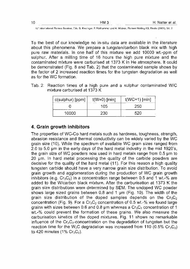
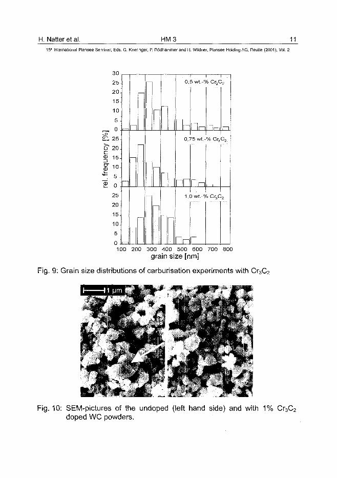
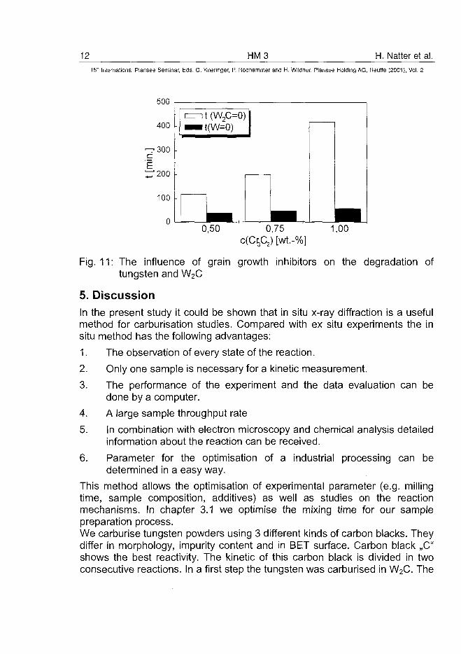
4. Grain growth inhibitorsThe properties of WC-Co hard metals such as hardness, toughness, strength,abrasion resistance and thermal conductivity can be widely varied by the WCgrain size (10). While the spectrum of available WC grain sizes ranged from2.0 to 5.0 urn in the early days of the hard metal industry in the mid 1920's,the grain size of WC powders now used in hard metals range from 0.5 urn to20 urn. In hard metal processing the quality of the carbide powders aredecisive for the quality of the hard metal (11). For this reason a high qualitytungsten carbide should have a very narrow grain size distribution. To avoidgrain growth and agglomeration during the production of WC grain growthinhibitors (e.g. Cr3C2) in a concentration range between 0.5 and 1 wt.-% areadded to the W/carbon black mixture. After the carburisation at 1373 K thegrain size distributions were determined by SEM. The undoped WC powdershows large sized grains between 0.8 and 1 urn (Fig. 10). The width of thegrain size distribution of the doped samples depends on the Cr3C2
concentration (Fig. 9). For a Cr3C2 concentration of 0.5 wt.-% we found largegrains with sizes between 0.6 and 0.8 urn whereas a Cr3C2 concentration of 1wt.-% could prevent the formation of these grains. We also measure thecarburisation kinetics of the doped mixtures. Fig. 11 shows no remarkableinfluence of the Cr3C2-concentration on the degradation of tungsten but thereaction time for the W2C degradation was increased from 110 (0.5% Cr3C2)to 420 minutes (1% Cr3C2).
H. Natter et al. HM3 11
I i I0,5 wt.-% Cr3C2
15lh International Plansee Seminar, Eds. G. Kneringer, P. Rodhammer and H. Wildner, Plansee Holding AG, Reutte (2001), Vol. 2
30
25-
20-
15-
10-
5 -
r—, 0
£ l 25-cr 20.
15-
5 -
0
25
20
15-
10-
5-
0 m
n0,75 wt.-% Cr3C2
n1,0 wt.-% Cr,C,
n100 200 300 400 500 600 700 800
grain size [nm]
Fig. 9: Grain size distributions of carburisation experiments with Cr3C2
Fig. 10: SEM-pictures of the undoped (left hand side) and with 1% Cr3C2
doped WC powders.
12 HM3 H. Natter et al.15" International Plansee Seminar, Eds. G. Kneringer, P. Rodhammer and H. Wildner, Plansee Holding AG, Reutte (2001), Vol. 2
500
400
^-300cE^ 2 0 0
100
i=nt(W£=0)••t(W=0)
0,50 0,75 1,00
Fig. 11: The influence of grain growth inhibitors on the degradation oftungsten and W2C
5. DiscussionIn the present study it could be shown that in situ x-ray diffraction is a usefulmethod for carburisation studies. Compared with ex situ experiments the insitu method has the following advantages:
1. The observation of every state of the reaction.
2. Only one sample is necessary for a kinetic measurement.
3. The performance of the experiment and the data evaluation can bedone by a computer.
4. A large sample throughput rate
5. In combination with electron microscopy and chemical analysis detailedinformation about the reaction can be received.
6. Parameter for the optimisation of a industrial processing can bedetermined in a easy way.
This method allows the optimisation of experimental parameter (e.g. millingtime, sample composition, additives) as well as studies on the reactionmechanisms. In chapter 3.1 we optimise the mixing time for our samplepreparation process.We carburise tungsten powders using 3 different kinds of carbon blacks. Theydiffer in morphology, impurity content and in BET surface. Carbon black ,,C"shows the best reactivity. The kinetic of this carbon black is divided in twoconsecutive reactions. In a first step the tungsten was carburised in W2C. The
H. Natter et al. HM 3 13_15" International Plansee Seminar, Eds. G. Kneringer, P. Rodhammer and H. Wildner, Plansee Holding AG, Reutte (2001), Vol. 2
pure WC phase was formed in a second step. The reaction time from the Wdegradation is similar to WC formation time. For Carbon black ,,B" we observesimilar reaction kinetics. In these experiments the second reaction (W2Cdegradation) is the time dependent step whereas the W degradation needsnearly the same time as the W degradation in the ,,C" experiments. Thismechanism can be explained with the model of Zhengji (2). Carbon black ,,A"has a complete different reaction mechanism. After a slight formation of W2Cthe reaction stagnates for nearly 190 minutes. After 400 minutes a 3 phaseregion can be observed in which the WC content increases whereas the W2Cand the W concentration decreases simultaneously. The decrased reactivityof ,,B" could be explained with the plate shaped morphology of the ,,B"particles. The time for tungsten degradation is similar to the carburisation withthe spherical ,,C" particles but the WC formation of ,,B" mixtures takes 4 timeslonger. This can be explained by the longer diffusion paths of the carbonatoms from the outside to the surface of a W2C particle. Now is the questionwhy the fine grained ,,A" particles do not show the similar behaviour like ,,C"carbon black. A sulphur concentration of 5000 wt.-ppm results from thechemical analysis. As demonstrated in chapter 3.4 the addition of sulphur in amixture of high pure raw material decreases the reactivity of the black mix.This impurity could be the reason for the observed kinetic. In the early statethe degradation of tungsten follows a normal course but the stagnation after30 minutes could be caused from a sulphur compound which segregates inthe grain boundaries and block the solid state diffusion. The grain boundaryare not blocked in a irreversible way. Either the sulphur compounddecomposes at the high temperature or the compound diffuses along thegrain boundary and forms larger agglomerates. Both possibilities have theconsequence that the carbon diffusion was not blocked furthermore and weobserve a continuously increasing WC content.The grain refining effect of Cr3C2 can be explained in a similar way. Thechromium compound cover the grain surfaces with a very thin layer(thickness: only a few atom diameter). The coating allows the diffusion of thesmall carbon atoms but prevents the sintering of the WC grains. The width ofthe grain size distribution is a function of inhibitor content. In the case of a lowCr3C2 concentration we detect a small fraction of large grains. In this case thechromium content is not enough for a homogeneous grain size distribution. ACr3C2 concentration of 1 wt.-% is sufficient to produce nearly uniform WCgrains. A disadvantage of the inhibitor addition is the increase of the reactiontime for the WC formation by obstructing the solid state diffusion of thecarbon atoms from the outside thought the grain surface. The tungsten
U HM3 H. Natter et al.15" International Plansee Seminar, Eds. G. Kneringer, P. Rodhammer and H. Wildner, Plansee Holding AG, Reurte (2001), Vol. 2
degradation is not concerned from this effect because the additive needssome time to distribute homogeneously in the sample by solid state diffusion.The in situ x-ray diffraction is not restricted to solid state reactions. Reactionswith gaseous educts (e.g. H2, CO or CH4) can also be done in the PaarHTK1200 oven.
6. References
(1)T. Zhengji: RM & HM (december 1988), pp. 215(2)T. Zhengji: RM & HM (december 1987), pp. 221-225(3) M. K. Andrews, S. Dushman: J. Phys. Chem. 29 (1925), pp. 462(4)G. S. Kreimer, L. D. Efros, E. A. Voronkova: Zh. Tekhn. Fiz. 22 (1952),
pp. 825, AEC Translation No. 3902(5)L. V. McCarty, R. Donelson, R. F. Hehemann: Metall. Trans. A (1987),
pp. 969(6) M., Pirani, J. Sandor: J. Inst. Metals, 73, (1956), pp.384-95(7) E. Lassner, M. Schreiner, B. Lux: RM & HM, flune 1982), pp. 51(8) E. Lassner, B. Lux: RM & HM, (June 1986), pp. 102(9) E. Lasser: R&HM, (September 1989), pp. 185(10) J. Gurland, P.Bardzil: Journal of Metals 7 (1965), p. 311(11) W. Schedler: Hartmetall fur den Praktiker, VDI-Verlag GmbH, Dusseldorf
1988
Acknowledgements
This work was initiated and performed in the framework of the "Universitatdes Saarlandes" and the "Plansee Tizit AG", which we acknowledge forfinancial support. We thank Dipl.-Chem. H.-J. Engels and Dipl. Ing. F.Mikaelssoon for experimental support.
ATO100436D.F. Carroll et al. HM 4 1
15th International Plansee Seminar, Eds. G. Kneringer, P. Rodhammer and H. Wildner, Plansee Holding AG, Reutte (2001), Vol. 2
Granulated Cobalt Powders For WC/Co Materials
D. F. Carroll* and J. Jarvf
OMG Americas, Research Triangle Park, NC USA"OMG Kokkola Chemicals OY, Kokkola, Finland
Abstract:
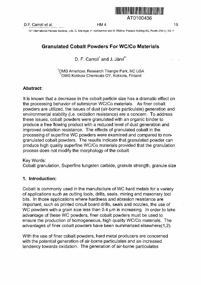
It is known that a decrease in the cobalt particle size has a dramatic effect onthe processing behavior of submicron WC/Co materials. As finer cobaltpowders are utilized, the issues of dust (air-borne particulate) generation andenvironmental stability (i.e. oxidation resistance) are a concern. To addressthese issues, cobalt powders were granulated with an organic binder toproduce a free flowing product with a reduced level of dust generation andimproved oxidation resistance. The effects of granulated cobalt in theprocessing of superfine WC powders were examined and compared to non-granulated cobalt powders. The results indicate that granulated powder canproduce high quality superfine WC/Co materials provided that the granulationprocess does not modify the morphology of the cobalt.
Key Words:Cobalt granulation, Superfine tungsten carbide, granule strength, granule size
1. Introduction:
Cobalt is commonly used in the manufacture of WC hard metals for a varietyof applications such as cutting tools, drills, seals, mining and masonary toolbits. In those applications where hardness and abrasion resistance areimportant, such as printed circuit board drills, seals and nozzles, the use ofWC powders with a grain size less than 0.4 u.m is increasing. In order to takeadvantage of these WC powders, finer cobalt powders must be used toensure the production of homogeneous, high quality WC/Co materials. Theadvantages of finer cobalt powders have been summarized elsewhere(1,2).
With the use of finer cobalt powders, hard metal producers are concernedwith the potential generation of air-borne particulates and an increasedtendency towards oxidation. The generation of air-borne particulates
16 HM4 D.F. Carroll et al.15-" International Plansee Seminar, Eds. G. Kneringer, P. Rodhammer and H. Wildner, Plansee Holding AG, Reutte (2001), Vol. 2
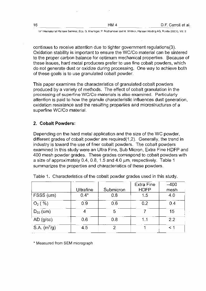
continues to receive attention due to tighter government regulations(3).Oxidation stability is important to ensure the WC/Co material can be sinteredto the proper carbon balance for optimum mechanical properties. Because ofthese issues, hard metal producers prefer to use fine cobalt powders, whichdo not generate dust or oxidize during processing. One way to achieve bothof these goals is to use granulated cobalt powder.
This paper examines the characteristics of granulated cobalt powdersproduced by a variety of methods. The effect of cobalt granulation in theprocessing of superfine WC/Co materials is also examined. Particularlyattention is paid to how the granule characteristic influences dust generation,oxidation resistance and the resulting properties and microstructures of asuperfine WC/Co material.
2. Cobalt Powders:
Depending on the hard metal application and the size of the WC powder,different grades of cobalt powder are required(1,2). Generally, the trend inindustry is toward the use of finer cobalt powders. The cobalt powdersexamined in this study were an Ultra Fine, Sub Micron, Extra Fine HDFP and400 mesh powder grades. These grades correspond to cobalt powders witha size of approximately 0.4, 0.8, 1.5 and 4.0 |im, respectively. Table 1summarizes the properties and characteristics of these powders.
Table 1. Characteristics of the cobalt powder grades used in this study.
FSSS (urn)
O2 ( %)
D50 (urn)
AD (g/cc)
S.A. (m2/g)
Ultrafine0.4*
0.9
4
0.6
4.5
Submicron0.8
0.6
5
0.8
2
Extra FineHDFP
1.5
0.2
7
1.1
1
-400mesh4.0
0.4
15
2.2
< 1
* Measured from SEM micrograph
D.F. Carroll et al. HM 4 17_15'" International Plansee Seminar, Eds. G. Kneringer, P. Rodhammer and H. Wildner, Plansee Holding AG, Reutte (2001), Vol. 2
3. Characteristics of Granulated Cobalt Powder:
Many different methods are commercially available to granulate finepowders(4-6). During granulation, a force acts on the powder to bond ittogether into larger granules. The forces bonding the powder together can beclassified into three categories. The first category is capillary forces. Thistype of force is generated when a liquid is used to granulate a powdertogether. The strength of these granules is generally low. The second typeof force in granulation is adhesive bonding. In this case, a solidified binderphase adheres to the surface of the powder bonding particles together intolarger granules. The binder phase is usually an organic material such asparaffin wax, PVA, etc.. The strength of these granules is dependent uponthe amount and type of binder phase present. Generally, the strength ofadhesively-bonded granules is higher than ones formed by capillary forces.The third type of force for granulation is solid bridging. Granules formed bysolid bridging are usually very strong. This high strength is obtained byinterlocking or deforming the individual particles together into granules.
The common methods for granulation can produce a variety of granule typesdepending upon the processing variables. In general, the methods forgranulation are conventional mixing, spray drying, fluidized bed granulation,high shear mixing, disk or drum granulation, mechanical granulation,extrusion and compaction(4-6).
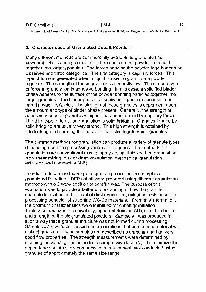
In order to determine the range of granule properties, six samples ofgranulated Extrafine HDFP cobalt were prepared using different granulationmethods with a 2 wt.% addition of paraffin wax. The purpose of thisevaluation was to provide a better understanding of how the granulecharacteristic affected the level of dust generation, oxidation resistance andprocessing behavior of superfine WC/Co materials. From this information,the optimum characteristics were identified for cobalt granulation.Table 2 summarizes the flowability, apparent density (AD), size distributionand strength of the six granulated powders. Sample #1 was produced insuch a way that a granular structure was not formed during processing.Samples #2-6 were processed under conditions that produced a material withdistinct granules. These samples are described as granular and had verygood flow properties. The strength measurements were determined bycrushing individual granules under a compressive load (N). To minimize thedependence on size, this compressive measurement was conducted usinggranules of approximately the same size range.
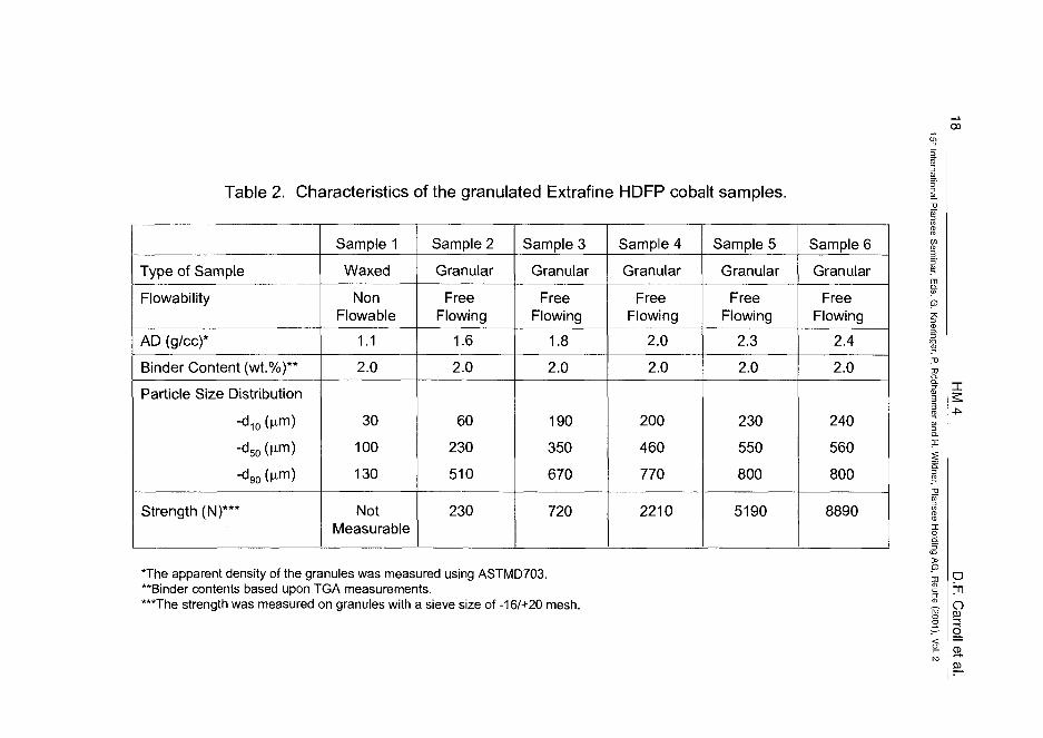
Table 2. Characteristics of the granulated Extrafine HDFP cobalt samples.
00
Type of Sample
Flowability
AD (g/cc)*
Binder Content (wt.%)**
Particle Size Distribution
-d10 (u.m)
-d50 (^m)
-d 9 0 (n™)
Strength (N)***
Sample 1
Waxed
NonFlowable
1.1
2.0
30
100
130
NotMeasurable
Sample 2
Granular
FreeFlowing
1.6
2.0
60
230
510
230
Sample 3
Granular
FreeFlowing
1.8
2.0
190
350
670
720
Sample 4
Granular
FreeFlowing
2.0
2.0
200
460
770
2210
Sample 5
Granular
FreeFlowing
2.3
2.0
230
550
800
5190
Sample 6
Granular
FreeFlowing
2.4
2.0
240
560
800
8890
The apparent density of the granules was measured using ASTMD703."Binder contents based upon TGA measurements.***The strength was measured on granules with a sieve size of-16/+20 mesh.
P3J
oSB
CD
D.F. Carroll et a l . H M 415" International Plansee Seminar, Eds. G. Kneringer, P. Rodhammer and H. Wildner, Plansee Holding AG, Reutte (2001), Vol. 2
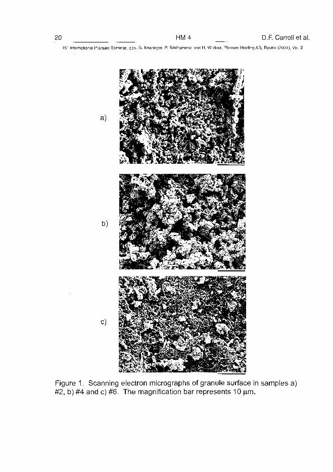
The granulated samples had a range of apparent densities (1.1 to 2.4 g/cc),average granule sizes (d50 of 100 to 560 microns), and strengths (-200 toover 8800 N). Since each sample contained the same organic binderaddition, the variation in granule strength must be related in someway to thedensity of the cobalt granules. To support this finding, a series of scanningelectron micrographs (Figure 1) were taken of a low (sample #2), medium(sample #4) and high (sample #6) strength granule. These micrographsclearly show an increase in granule density with strength. For samples #2and #4, the increase in granule density is the result of an improved packingefficiency among the cobalt grains. In both of these samples, the morphologyof the starting cobalt powder is still present. For sample #6, the highergranule density was obtained by the deformation of individual cobalt grains.The deformation and physical interlocking of the cobalt grains results in avery high strength granule. This type of granule is undesirable since themorphology of the starting cobalt powder no longer exists.
4. Dust Generation of Cobalt Extrafine Powders Before and AfterGranulation:
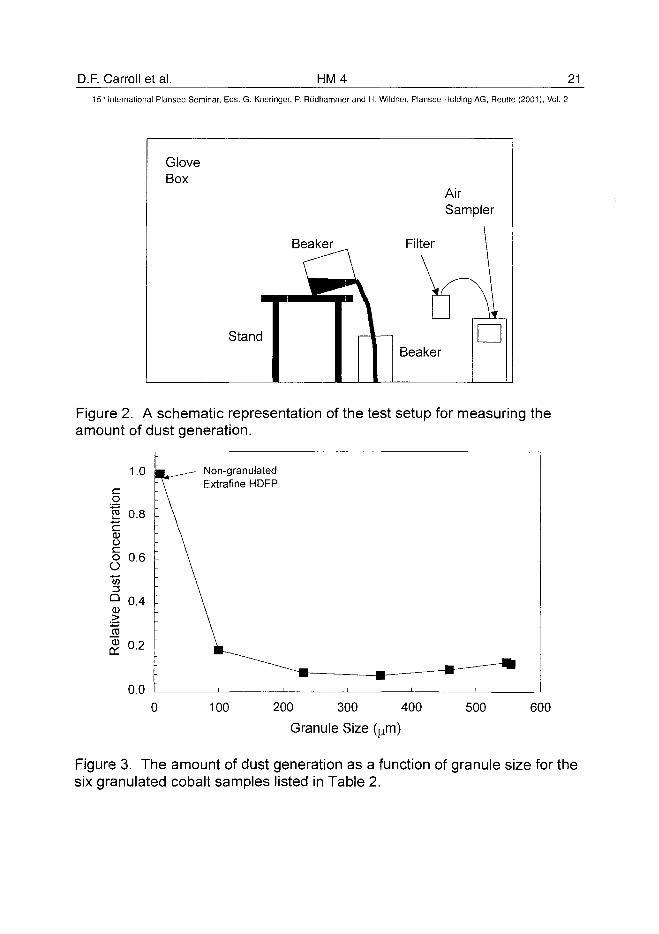
The relative amount of dust generated by non-granulated and granulatedcobalt powders was characterized by an in-house laboratory test. Figure 2 isa schematic representation of the test method used. During testing, a cobaltpowder is poured from one beaker to another, several times, generating adust cloud inside the glove box.a The air within the glove box is pumpedthrough a filter cartridge that can trap air-borne particulates.b After testing,the filter cartridge is analyzed to determine the concentration of cobalt. Bycomparing the measured concentrations, the tendency for a powder togenerate dust or air-borne particulates during handling can be obtained.
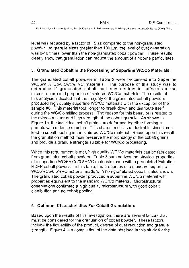
The levels of dust generation associated with the six samples listed in Table 2are summarized in Figure 3 as a function of average granule size. In thisfigure, the results are normalized by the dust level for the non-granulatedextrafine HDFP powder. For an average granule size of 100 |im, the dust
a The cobalt powder was poured once every ten minutes for a total of six times.b The air sampler was a device commonly used in the Industrial Hygiene area. In thiscase, the air sampler was made by GILAIR. The air was sampled at 2L/min over a twohour period.
20 HM4 D.F. Carroll et al.15' International Plansee Seminar, Eds. G. Kneringer, P. Rodhammer and H. Wildner, Plansee Holding AG, Reutte (2001), Vol. 2
a)
b)
c)
Figure 1. Scanning electron micrographs of granule surface in samples a)#2, b) #4 and c) #6. The magnification bar represents 10 urn.
D.F. Carroll et al. HM4 2115lh International Plansee Seminar, Eds. G. Kneringer, P. Rodhammer and H. Wildner, Plansee Holding AG, Reutte (2001), Vol. 2
GloveBox
m
Stand
AirSampler
Beaker Filter \
^ Y\\Beaker
•
Figure 2. A schematic representation of the test setup for measuring theamount of dust generation.
o
rat
c0ooO"513Q0
m0
on
1.0
0.8
0.6
0.4
0.2
0.0
•L__—— Non-granulated- \ ^ EExtrafine HDFP: \: \_- \
: \\\
: \\\\
- • — - •• — •
100 200 300
Granule Size
400 500 600
Figure 3. The amount of dust generation as a function of granule size for thesix granulated cobalt samples listed in Table 2.
22 HM4 D.F. Carroll et al.15" International Plansee Seminar, Eds. G. Kneringer, P. Rodhammer and H. Wildner, Plansee Holding AG, Reutte (2001), Vol. 2
level was reduced by a factor of ~5 as compared to the non-granulatedpowder. At granule sizes greater than 100 )im, the level of dust generationwas 8-10 times lower than the non-granulated cobalt powder. These resultsclearly show that granulation can reduce the amount of air-borne particulates.
5. Granulated Cobalt in the Processing of Superfine WC/Co Materials:
The granulated cobalt powders in Table 2 were processed into SuperfineWC/6wt.% Co/0.5wt.% VC materials. The purpose of this study was todetermine if granulated cobalt had any detrimental affects on themicrostructure and properties of sintered WC/Co materials. The results ofthis analysis indicated that the majority of the granulated cobalt powdersproduced high quality superfine WC/Co materials with the exception of thesample #6. This material took longer to break down and distribute itselfduring the WC/Co milling process. The reason for this behavior is related tothe microstructure and high strength of the cobalt granule. As shown inFigure 1c, the individual cobalt grains are deformed together forming agranule with a dense structure. This characteristic is undesirable since it canlead to cobalt pooling in the sintered WC/Co material. Based upon this result,the granulation method must preserve the morphology of the cobalt grainsand provide a granule strength suitable for WC/Co processing.
When this requirement is met, high quality WC/Co materials can be fabricatedfrom granulated cobalt powders. Table 3 summarizes the physical propertiesof a superfine WC/6%Co/0.5%VC materials made with a granulated ExtrafineHDFP cobalt powder. In this table, the properties of a standard superfineWC/6%Co/0.5%VC material made with non-granulated cobalt is also shown.The granulated cobalt powder produced a superfine WC/Co material withproperties equivalent to the standard WC/Co material. Microstructuralobservations confirmed a high quality microstructure with good cobaltdistribution and no cobalt pooling.
6. Optimum Characteristics For Cobalt Granulation:
Based upon the results of this investigation, there are several factors thatmust be considered for the granulation of cobalt powder. These factorsinclude the flowability of the product, degree of dust reduction and granulestrength. Figure 4 is a compilation of the data obtained in this study for the
D.F. Carroll et al. HM4 2315" International Plansee Seminar, Eds. G. Kneringer, P. Rodhammer and H. Wildner, Plansee Holding AG, Reutte (2001), Vol. 2
Table 3. Sintered properties of a Superfine WC/6 wt.%Co/0.5 wt.%VCcomponent made with Extrafine HDFP cobalt powder.
PropertiesMagnetic Saturation
Coercivity (Oe)
Hardness (Ra)
A type porosity level
Non-granulatedExtrafine HDFP
140
607
94.9
A02-04
GranulatedExtrafine HDFP
142
603
94.9
A02-04
1.0
I 0.8ooO 0.613
Q9> 0 .4~mQ)
OH 0.2 -
0.0
Poor Flowability ; Optimum Window of ; Excessiveor Low Granule ! Granule Strength, Dust Control Granule
Strength • and Flowability Strength
12000
10000
01.0 1.2 1.4 1.6 1.8 2.0 2.2 2.4 2.6
Apparent density (g/cc)
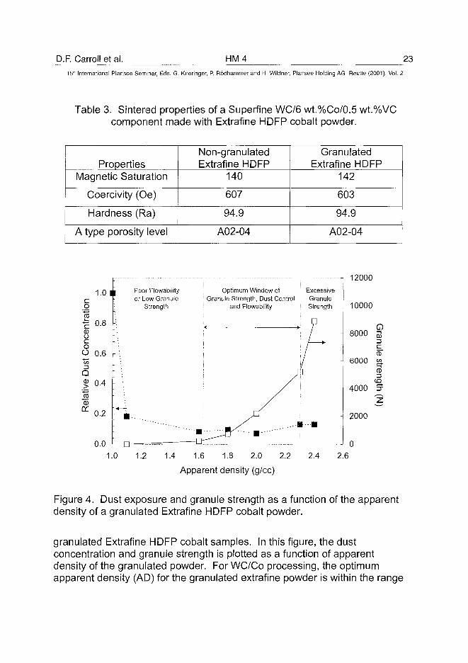
Figure 4. Dust exposure and granule strength as a function of the apparentdensity of a granulated Extrafine HDFP cobalt powder.
granulated Extrafine HDFP cobalt samples. In this figure, the dustconcentration and granule strength is plotted as a function of apparentdensity of the granulated powder. For WC/Co processing, the optimumapparent density (AD) for the granulated extrafine powder is within the range
24 HM4 D.F. Carroll et al.15:" International Plansee Seminar, Eds. G. Kneringer, P. Rodhammer and H. Wildner, Plansee Holding AG, Reutte (2001), Vol. 2
of 1.8 to 2.3 g/cc. This type of granulated powder has an acceptable level offlow, dust reduction and granule strength. For cobalt granules with anapparent density 1.6 g/cc or less, the strength is too low to withstand thestresses associated with shipping and handling of the powder. At anapparent density 2.4 g/cc or greater, the strength of the granule strengthbecomes too high for the WC/Co milling process. This excessive granulestrength leads to cobalt pooling in the sintered WC/Co material. As long asthe apparent density is within the range of ~1.8 to 2.3 g/cc, high qualityWC/Co components can be fabricated with granulated extrafine HDFP cobalt.
7. Oxidation Resistance of Cobalt Before and After Granulation:
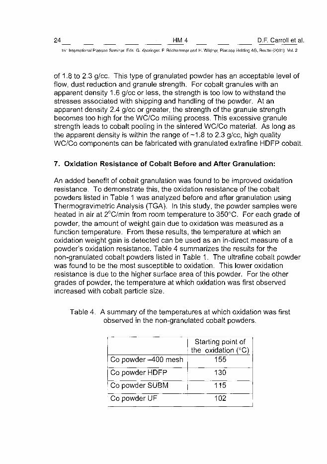
An added benefit of cobalt granulation was found to be improved oxidationresistance. To demonstrate this, the oxidation resistance of the cobaltpowders listed in Table 1 was analyzed before and after granulation usingThermogravimetric Analysis (TGA). In this study, the powder samples wereheated in air at 2°C/min from room temperature to 350°C. For each grade ofpowder, the amount of weight gain due to oxidation was measured as afunction temperature. From these results, the temperature at which anoxidation weight gain is detected can be used as an in-direct measure of apowder's oxidation resistance. Table 4 summarizes the results for thenon-granulated cobalt powders listed in Table 1. The ultrafine cobalt powderwas found to be the most susceptible to oxidation. This lower oxidationresistance is due to the higher surface area of this powder. For the othergrades of powder, the temperature at which oxidation was first observedincreased with cobalt particle size.
Table 4. A summary of the temperatures at which oxidation was firstobserved in the non-granulated cobalt powders.
Co powder -400 mesh
Co powder HDFP
Co powder SUBM
Co powder UF
Starting point ofthe oxidation (°C)
155
130
115
102
D.F. Carroll et al. HM4 2515'" International Plansee Seminar, Eds. G. Kneringer, P. Rodhammer and H. Wildner, Plansee Holding AG, Reutte (2001), Vol. 2
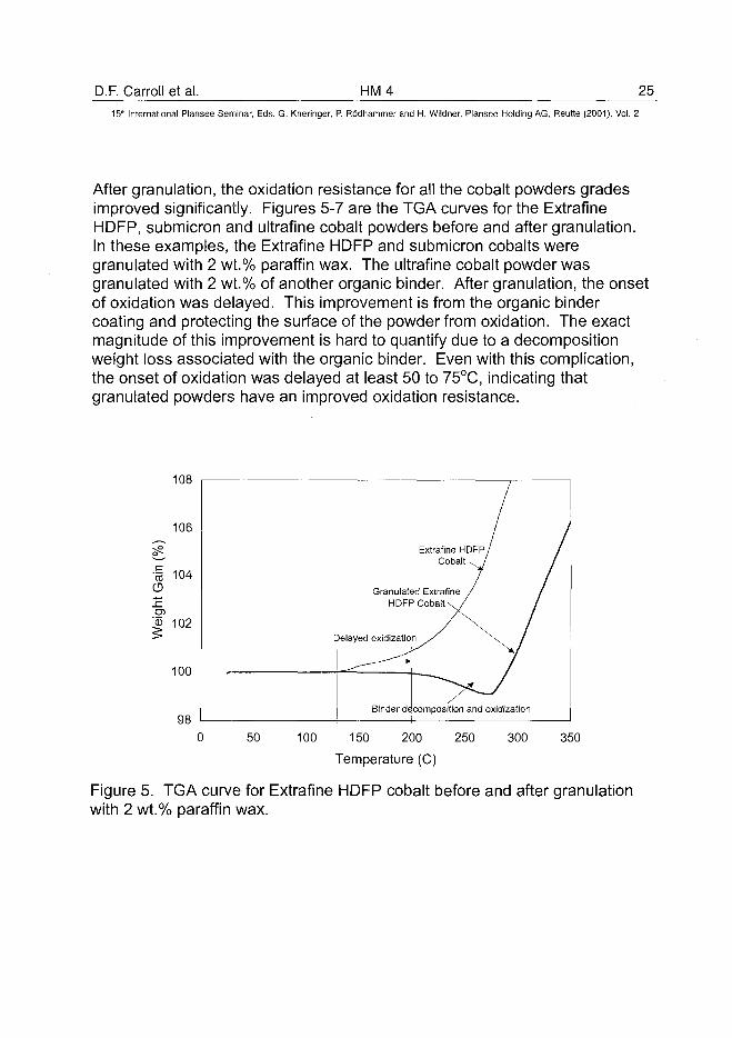
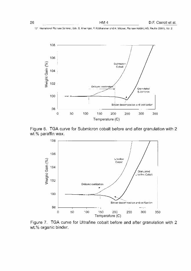
After granulation, the oxidation resistance for all the cobalt powders gradesimproved significantly. Figures 5-7 are the TGA curves for the ExtrafineHDFP, submicron and uitrafine cobalt powders before and after granulation.In these examples, the Extrafine HDFP and submicron cobalts weregranulated with 2 wt.% paraffin wax. The uitrafine cobalt powder wasgranulated with 2 wt.% of another organic binder. After granulation, the onsetof oxidation was delayed. This improvement is from the organic bindercoating and protecting the surface of the powder from oxidation. The exactmagnitude of this improvement is hard to quantify due to a decompositionweight loss associated with the organic binder. Even with this complication,the onset of oxidation was delayed at least 50 to 75°C, indicating thatgranulated powders have an improved oxidation resistance.
108
Binder decomposition and oxidization
0 50 100 150 200 250 300 350
Temperature (C)
Figure 5. TGA curve for Extrafine HDFP cobalt before and after granulationwith 2 wt.% paraffin wax.
26 HM D.F. Carroll et al.
15~ International Plansee Seminar, Eds. G. Kneringer, P. Rodhammer and H. Wildner, Plansee Holding AG, Reutte (2001), Vol. 2
108
106
"I 104O
D)102
100
98
GranulatedSubmicron
Binder decompositon and oxidization
0 50 100 150 200 250 300 350
Temperature (C)
Figure 6. TGA curve for Submicron cobalt before and after granulation with 2wt.% paraffin wax.
108
106
•§ 104O
102
100
98
UltrafiniCobalt
Delayed oxidization
GranulatedUltrafine Cobalt
Binder decomposition and oxidization
0 50 100 150 200 250 300 350Temperature (C)
Figure 7. TGA curve for Ultrafine cobalt before and after granulation with 2wt.% organic binder.
D.F. Carroll et al. HM4 2715!h International Plansee Seminar, Eds. G. Kneringer, P. Rodhammer and H. Wildner, Plansee Holding AG, Reutte (2001), Vol. 2
8. Dust Generation of different Cobalt Powder grades Before and AfterGranulation:
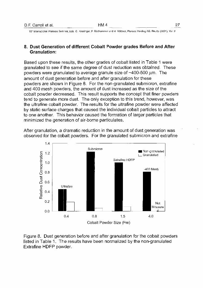
Based upon these results, the other grades of cobalt listed in Table 1 weregranulated to see if the same degree of dust reduction was obtained. Thesepowders were granulated to average granule size of -400-500 jam. Theamount of dust generation before and after granulation for thesepowders are shown in Figure 8. For the non-granulated submicron, extrafineand 400 mesh powders, the amount of dust increased as the size of thecobalt powder decreased. This result supports the concept that finer powderstend to generate more dust. The only exception to this trend, however, wasthe ultrafine cobalt powder. The results for the ultrafine powder were affectedby static surface charges that caused the individual cobalt particles to attractto one another. This behavior caused the formation of larger particles thatminimized the generation of air-borne particulates.
After granulation, a dramatic reduction in the amount of dust generation wasobserved for the cobalt powders. For the granulated submicron and extrafine
1.4
o 1-2
| 1 0
| 0.8Ina 0.6CD
Jj 0.4CD
or0.2
0.0
Submicron
0.4 0.8 1.5
Cobalt Powder Size (hn)
4.0
Figure 8. Dust generation before and after granulation for the cobalt powderslisted in Table 1. The results have been normalized by the non-granulatedExtrafine HDFP powder.
28 HM4 D.F. Carroll et al.15:" International Plansee Seminar, Eds. G. Kneringer, P. Rodhammer and H. Wildner, Plansee Holding AG, Reutte (2001), Vol. 2
cobalt powders, the amount of dust was reduced by a factor of ~10 times,respectively over their non-granulated forms. From these results, the use ofgranulated cobalt powders is one method by which the air-borne particulatelevels can be reduced.
9. Summary:
This study examined the granulation of cobalt powders for WC/Coapplications. The results indicated that granulation reduced the level of dustgeneration of cobalt powders. In a laboratory test, the amount of air-borneparticulates associated with cobalt powder was reduced by a factor of 8-10,respectively by granulation. In terms of WC/Co processing, the granulestrength must be optimized for the milling process. If the granule strength istoo high, excessive cobalt pooling may occur in the sintered WC/Co material.For the granulated Extrafine HDFP cobalt powder, optimum properties wereobtained when the apparent density was between 1.8 and 2.3 g/cc. At anapparent density of 1.6 g/cc or less, the strength of the granules was too lowand flowability became an issue. At an apparent density of 2.4 g/cc orgreater, deformation of the cobalt grains occurred producing excessivegranule strengths. In order to produce an acceptable product, the apparentdensity must be controlled to ensure the morphology of the cobalt grains ismaintained and the granule strength is appropriate for WC/Co processing. Inaddition, the oxidation resistance of granulated cobalt powders, particularlyfor the finer 0.4 and 0.8 |xm grades, was also improved.
10. References:
1. D. F. Carroll and J. E. Jarvi, Adv. Powder Metal I. Part. Mater. (1999),(Vol.3), 10/3-10/14.
2. D. F. Carroll and C. L, Adv. Powder Metal I. Part. Mater. (1997), (Vol. 2),12/61-12/74.
3. Powder Metall., (1999), (Vol. 42), 295.4. C. E. Capes., Particle Size Enlargement, Amsterdam 1980, Elsevier
Scientific Publishing Company. 192.5. W. Pietsch, Size Enlargement by Agglomeration, Chichester 1991, John
Wiley & Sons, 532.6. J. K. Beddow, Particulate Science and Technology, New York 1980,
Chemical Publishing Co. Inc., 725.
AT0100437V.A. Falkovsky et al. HM 5 29^
15'h International Plansee Seminar, Eds. G. Kneringer, P. Rodhammer and H. Wildner, Plansee Holding AG, Reutte (2001), Vol. 2
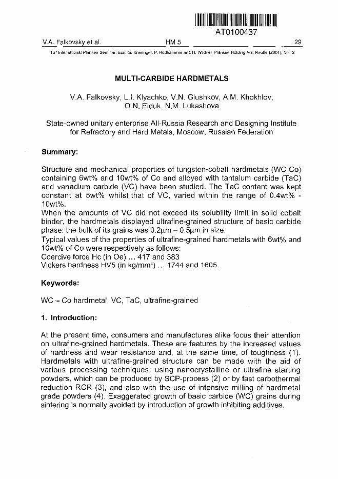
MULTI-CARBIDE HARDMETALS
V.A. Falkovsky, L.I. Klyachko, V.N. Glushkov, A.M. Khokhlov,O.N. Eiduk, N.M. Lukashova
State-owned unitary enterprise All-Russia Research and Designing Institutefor Refractory and Hard Metals, Moscow, Russian Federation
Summary:
Structure and mechanical properties of tungsten-cobalt hardmetals (WC-Co)containing 6wt% and 10wt% of Co and alloyed with tantalum carbide (TaC)and vanadium carbide (VC) have been studied. The TaC content was keptconstant at 5wt% whilst that of VC, varied within the range of 0.4wt% -10wt%.When the amounts of VC did not exceed its solubility limit in solid cobaltbinder, the hardmetals displayed ultrafine-grained structure of basic carbidephase: the bulk of its grains was 0.2(im - 0.5j m in size.Typical values of the properties of ultrafine-grained hardmetals with 6wt% and10wt% of Co were respectively as follows:Coercive force He (in Oe)... 417 and 383Vickers hardness HV5 (in kg/mm2) ... 1744 and 1605.
Keywords:
WC - Co hardmetal, VC, TaC, ultrafine-grained
1. Introduction:
At the present time, consumers and manufactures alike focus their attentionon ultrafine-grained hardmetals. These are features by the increased valuesof hardness and wear resistance and, at the same time, of toughness (1).Hardmetals with ultrafine-grained structure can be made with the aid ofvarious processing techniques: using nanocrystalline or ultrafine startingpowders, which can be produced by SCP-process (2) or by fast carbothermalreduction RCR (3), and also with the use of intensive milling of hardmetalgrade powders (4). Exaggerated growth of basic carbide (WC) grains duringsintering is normally avoided by introduction of growth inhibiting additives.
30 HM5 V.A. Falkovsky et al.15-" International Plansee Seminar, Eds. G. Kneringer, P. Rddhammer and H. Wiidner, Plansee Holding AG, Reutte (2001), Vol. 2
Vanadium and chromium carbides usually serve no grain growth inhibitorsand are added in amounts less than 1%. In such amounts theybecome completely dissolved in cobalt phase and therefore do not formexcessive carbide phases.The impact of minor amounts of inhibitors on the mechanical properties andoperational performance of hardmetals is indirect and caused by the relatedreduction of carbide-grain sized and the modified composition of binder solidsolution. The properties could be further modified by adding vanadium andchromium carbides in larger amounts which would allow them to formseparate phases in microstructure. Tantalum carbide, which also acts asgrowth inhibitor, can provide an additional effect - the increased toughness ofhardmetals.
2. Experimental:
The hardmetals were made from tungsten carbide powder with a grain size of(10+0,2^171) (FSSS) and 6.12wt% of combined carbon and 0.03wt% ofexcessive carbon. The grains of cobalt powder were 3jj,m - 4jim (FSSS) insize. Tantalum and vanadium carbide powders contained 6.01wt% and16.03wt% of free carbon respectively. Both the powder alloying and thecomponent powders mixing were performed by means of wet ball-milling inethanol for 96 hours with a balls-to-powder ratio of 6:1. The hardmetals weresintered in hydrogen atmosphere in the temperature range of 1360°C -1480°C. A methodical study have been carried out for MeC - 10% Cocompositions where MC consisted of a fixed amount of 5wt% TaC andvarying amounts of VC, from 0.4wt% - 10wt%, and WC, from 84.6wt% -75wt%. Several stages of the study were repeated for hardmetals with 6%Co. Under study was the influence of vanadium carbide on the mechanicalproperties and structure of hardmetals.
3. Physical and mechanical properties of hardmetals:
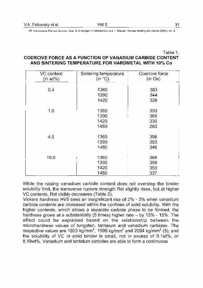
Coercive force He, which is commonly taken as measure of the grain size ofbasic carbide phase, drastically drops with the increase in sinteringtemperature if the vanadium carbide content does not exceed its solubilitylimit in solid binder. This was just the case with the vanadium carbideadditions of less than 1%. With the higher contents, the coercive forcedecreased insignificantly as the sintering temperature was raised (Table 1).
V.A. Falkovsky et al. HM5 3115" International Plansee Seminar, Eds. G. Kneringer, P. Rodhammer and H. Wildner, Plansee Holding AG, Reutte (2001), Vol. 2
Table 1.COERCIVE FORCE AS A FUNCTION OF VANADIUM CARBIDE CONTENT
AND SINTERING TEMPERATURE FOR HARDMETAL WITH 10% Co
VC content(in wt%)
0.4
1.0
4.0
10.0
Sintering temperature(in °C)
136013901420
1360139014201480
136013901480
1360139014201480
Coercive force(in Oe)
383344326
393366330260
398393346
368358353337
While the raising vanadium carbide content does not overstep the bindersolubility limit, the transverse rupture strength Rst slightly rises, but at higherVC contents, Rst visibly decreases (Table 2).Vickers hardness HV5 sees an insignificant rise of 2% - 3% when vanadiumcarbide contents are increased within the confines of solid solubility. With thehigher contents, which allows a separate carbide phase to be formed, thehardness grows at a substantially (5 times) higher rate - by 13% - 15%. Theeffect could be explained based on the relationship between themicrohardness value.s of tungsten, tantalum and vanadium carbides. Therespective values are 1923 kg/mm2, 1599 kg/mm2 and 2094 kg/mm2 (5), andthe solubility of VC in solid binder is small, not in excess of 9.1at%, or8.19wt%. Vanadium and tantalum carbides are able to form a continuous
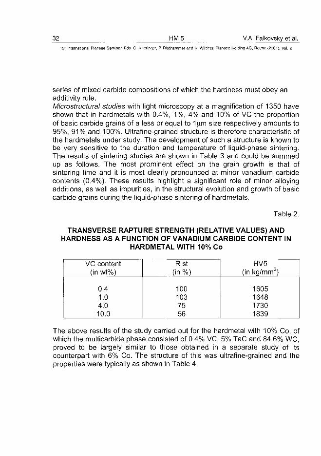
32 HM5 V.A. Falkovsky et al.
15" International Plansee Seminar, Eds. G. Kneringer, P. Rodhammer and H. Wildner, Plansee Holding AG, Reutte (2001), Vol. 2
series of mixed carbide compositions of which the hardness must obey anadditivity rule.Microstructural studies with light microscopy at a magnification of 1350 haveshown that in hardmetals with 0.4%, 1%, 4% and 10% of VC the proportionof basic carbide grains of a less or equal to 1 jj.m size respectively amounts to95%, 91% and 100%. Ultrafine-grained structure is therefore characteristic ofthe hardmetals under study. The development of such a structure is known tobe very sensitive to the duration and temperature of liquid-phase sintering.The results of sintering studies are shown in Table 3 and could be summedup as follows. The most prominent effect on the grain growth is that ofsintering time and it is most clearly pronounced at minor vanadium carbidecontents (0.4%). These results highlight a significant role of minor alloyingadditions, as well as impurities, in the structural evolution and growth of basiccarbide grains during the liquid-phase sintering of hardmetals.
Table 2.
TRANSVERSE RAPTURE STRENGTH (RELATIVE VALUES) ANDHARDNESS AS A FUNCTION OF VANADIUM CARBIDE CONTENT IN
HARDMETAL WITH 10% Co
VC content(in wt%)
0.41.04.010.0
Rst(in %)
1001037556
HV5(in kg/mm2)
1605164817301839
The above results of the study carried out for the hardmetal with 10% Co, ofwhich the multicarbide phase consisted of 0.4% VC, 5% TaC and 84.6% WC,proved to be largely similar to those obtained in a separate study of itscounterpart with 6% Co. The structure of this was ultrafine-grained and theproperties were typically as shown in Table 4.
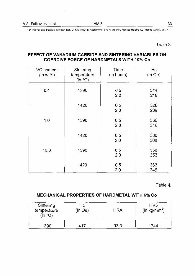
V.A. Falkovsky et al. HM5 3315lh International Plansee Seminar, Eds. G. Kneringer, P. Rodhammer and H. Wildner, Plansee Holding AG, Reutte (2001), Vol. 2
Table 3.
EFFECT OF VANADIUM CARBIDE AND SINTERING VARIABLES ONCOERCIVE FORCE OF HARDMETALS WITH 10% Co
VC content(in wt%)
0.4
1.0
10.0
Sinteringtemperature
(in °C)
1390
1420
1390
1420
1390
1420
Time(in hours)
0.52.0
0.52.0
0.52.0
0.52.0
0.52.0
0.52.0
He(in Oe)
344218
326209
366316
380308
358353
363345
Table 4.
MECHANICAL PROPERTIES OF HARDMETAL WITH 6% Co
Sinteringtemperature
(in °C)
1390
He(in Oe)
417
HRA
93.3
HV5(in kg/mm2)
1744
34 HM5 V.A. Falkovsky et al.15" International Plansee Seminar, Eds. G. Kneringer, P. Rodhammer and H. Wildner, Plansee Holding AG, Reutte (2001), Vol. 2
4. Conclusion:
1. A processing technology has been developed to manufacture ultrafine-grained tungsten-cobalt hardmetals using a certain combination of alloyingadditives that inhibit the growth of basic carbide grains.
2. An optimum content of growth inhibiting additives (MeC*) is defined by thesolid solubility limit of cobalt binder or, in other words, by MeCVCo ratio.
3. The composition and amount of the multi-carbide phase are shown to belargely responsible for the combination of strength, hardness and wearresistance achieved in sintered hardmetals.
5. References:
1. Schubert W. D. et al. In: P r o d 3 Plansee Seminar. Ed. H. Bildstin, R. EckReutte, 1993, v.4, p. 283-305.
2. Pat. USA 5352269. L.E. McCandlish et al, Oct. 4, 1994.3. Conner C.L. In: Proc. 7 Intern. Tungsten Sympos. Sept. 24-27, 1996,
Goslar, Germany. Goslar: Intern. Tungsten Industry Assoc. 1997, v.1, p.171-179.
4. Whitefield D. J., Luyckx S. et al. In: Proc. 14 Inter. Plansee Seminar, Reutt.1997, v.2, HM50.
5. Andrievsky R. A., Spivak I. I. Strength of refractory compounds andmaterials on their base. Hardbook (1989). Metallurgy Publishers, Moscow.367 pp (In Russian).
AT0100438. Azcona et al. HM 6 35^
15!h International Plansee Seminar, Eds. G. Kneringer, P. Rodhammer and H. Wildner, Plansee Holding AG, Reutte (2001), Vol. 2
HOT ISOSTATIC PRESSING OF NANOSIZED WC-Co HARDMETALS
I. Azcona1'2, A. Ordonez1'2, L. Dominguez2, J.M. Sanchez1'2 and F. Castro1'2
1- CEIT - Centro de Estudios e Investigaciones Tecnicas de Guipuzcoa.Paseo Manuel de Lardizabal, 15, 20018 - San Sebastian - Spain.
2- Escuela Superior de Ingenieros de San Sebastian, Universidad de Navarra(UN). Paseo Manuel de Lardizabal, 1, 20018 - San Sebastian - Spain
SUMMARY
A new technique based on Hot Isostatic Pressing (HIP) has been developedto produce dense nanosized WC-Co hardmetals without the addition of graingrowth inhibitors. The glass encapsulation process is the key for the effectiveapplication of isostatic pressure at temperatures well below those usuallyrequired for reaching the closed porosity state in the WC-Co system. Fullydense WC-Co samples with cobalt contents ranging from 10 to 12 wt. % havebeen obtained by this technique at temperatures between 1000°C and1200°C with 150 MF'a of applied isostatic pressure for 30 minutes. The role ofisostatic pressure on the activation of densification mechanisms is discussed.
KEYWORDS: Hardmetals, Tungsten Carbide, Hot Isostatic Pressing,Nanocrystalline Structure.
1. INTRODUCTION
Presently, the use of nanosized WC powders for producing WC-Co materialswith finer microstructures represents one of the most active fields of researchin the hardmetal industry. These so-called superfine grained hardmetals, withgrain WC grain sizes from 0.3-0.4 \im, show not only a significant increase inhardness with respect to the finest commercial WC-Co grades (so far, withWC mean grain sizes from 0.4 to 0.5 \xm), but also higher strength andtoughness (1-6).
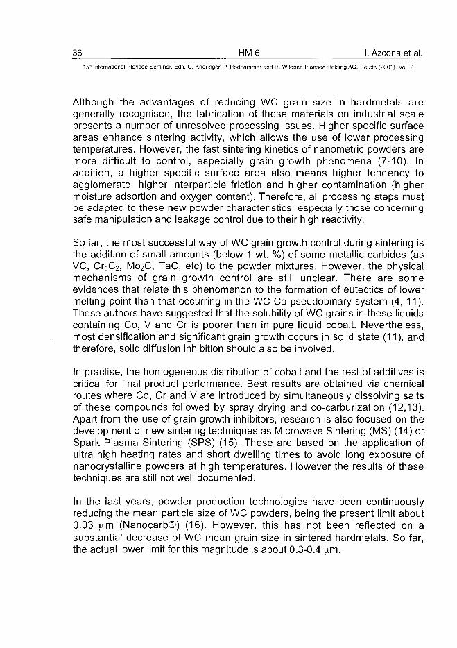
36 HM 6 I. Azcona et al.15" International Plansee Seminar, Eds. G. Kneringer, P. Rodhammer and H. Wildner, Plansee Holding AG, Reutte (2001), Vol. 2
Although the advantages of reducing WC grain size in hardmetals aregenerally recognised, the fabrication of these materials on industrial scalepresents a number of unresolved processing issues. Higher specific surfaceareas enhance sintering activity, which allows the use of lower processingtemperatures. However, the fast sintering kinetics of nanometric powders aremore difficult to control, especially grain growth phenomena (7-10). Inaddition, a higher specific surface area also means higher tendency toagglomerate, higher interparticle friction and higher contamination (highermoisture adsortion and oxygen content). Therefore, all processing steps mustbe adapted to these new powder characteristics, especially those concerningsafe manipulation and leakage control due to their high reactivity.
So far, the most successful way of WC grain growth control during sintering isthe addition of small amounts (below 1 wt. %) of some metallic carbides (asVC, Cr3C2, Mo2C, TaC, etc) to the powder mixtures. However, the physicalmechanisms of grain growth control are still unclear. There are someevidences that relate this phenomenon to the formation of eutectics of lowermelting point than that occurring in the WC-Co pseudobinary system (4, 11).These authors have suggested that the solubility of WC grains in these liquidscontaining Co, V and Cr is poorer than in pure liquid cobalt. Nevertheless,most densification and significant grain growth occurs in solid state (11), andtherefore, solid diffusion inhibition should also be involved.
In practise, the homogeneous distribution of cobalt and the rest of additives iscritical for final product performance. Best results are obtained via chemicalroutes where Co, Cr and V are introduced by simultaneously dissolving saltsof these compounds followed by spray drying and co-carburization (12,13).Apart from the use of grain growth inhibitors, research is also focused on thedevelopment of new sintering techniques as Microwave Sintering (MS) (14) orSpark Plasma Sintering (SPS) (15). These are based on the application ofultra high heating rates and short dwelling times to avoid long exposure ofnanocrystalline powders at high temperatures. However the results of thesetechniques are still not well documented.
In the last years, powder production technologies have been continuouslyreducing the mean particle size of WC powders, being the present limit about0.03 |im (Nanocarb®) (16). However, this has not been reflected on asubstantial decrease of WC mean grain size in sintered hardmetals. So far,the actual lower limit for this magnitude is about 0.3-0.4 ^m.
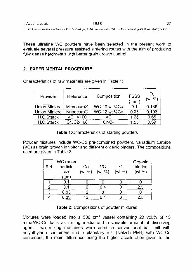
I. Azcona et al. HM6 3715th International Plansee Seminar, Eds. G. Kneringer, P. Rodhammer and H. Wildner, Plansee Holding AG, Reutte (2001), Vol. 2
These ultrafine WC powders have been selected in the present work toevaluate several pressure assisted sintering routes with the aim of producingfully dense hardmetals with better grain growth control.
2. EXPERIMENTAL PROCEDURE
Characteristics of raw materials are given in Table 1:
Provider
Union MiniereUnion Miniere
H.C.StarckH.C.Starck
Reference
Microcarb®Nanocarb®VCHV100Cr3C2-160
Composition
WC-10wt.%CoWC-12wt.%Co
VCCT3C2
FSSSUrn)
0.10.031.251.55
o2(wt.%)
0.1350.1980.650.59
Table 1 :Characteristics of starting powders
Powder mixtures include WC-Co pre-combined powders, vanadium carbide(VC) as grain growth inhibitor and different organic binders. The compositionsused are given in Table 2:
Ref.
1234
WC meanparticle
size(jim)
0.10.1
0.030.03
Co(wt.%)
10101212
VC(wt.%)
00.40
0.4
C(wt.%)
0000
Organicbinder(wt.%)
02.50
2.5
Table 2: Compositions of powder mixtures
Mixtures were loaded into a 500 cm3 vessel containing 20 vol.% of 15mm(|) WC-Co balls as milling media and a variable amount of dissolvingagent. Two mixing machines were used: a conventional ball mill withpolyethylene containers and a planetary mill (Netzch PM4) with WC-Cocontainers, the main difference being the higher acceleration given to the
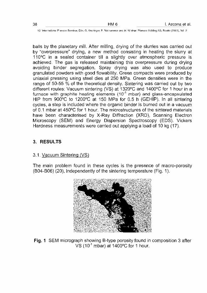
38 HM 6 I. Azcona et al.15" International Plansee Seminar, Eds. G. Kneringer, P. Rodhammer and H. Wildner, Plansee Holding AG, Reutte (2001), Vol. 2
balls by the planetary mill. After milling, drying of the slurries was carried outby "overpressure" drying, a new method consisting in heating the slurry at110°C in a sealed container till a slightly over atmospheric pressure isachieved. The gas is released maintaining this overpressure during dryingavoiding binder segregation. Spray drying was also used to producegranulated powders with good flowability. Green compacts were produced byuniaxial pressing using steel dies at 250 MPa. Green densities were in therange of 50-55 % of the theoretical density. Sintering was carried out by twodifferent routes: Vacuum sintering (VS) at 1320°C and 1400°C for 1 hour in afurnace with graphite heating elements (10'1 mbar) and glass-encapsulatedHIP from 900°C to 1200°C at 150 MPa for 0.5 h (GEHIP). In all sinteringcycles, a step is included where the organic binder is burned out in a vacuumof 0.1 mbar at 450°C for 1 hour. The microstructures of the sintered materialshave been characterised by X-Ray Diffraction (XRD), Scanning ElectronMicroscopy (SEM) and Energy Dispersion Spectroscopy (EDS). VickersHardness measurements were carried out applying a load of 10 kg (17).
3. RESULTS
3.1. Vacuum Sintering (VS)
The main problem found in these cycles is the presence of macro-porosity(B04-B06) (20), independently of the sintering temperature (Fig. 1).
Fig. 1 SEM micrograph showing B-type porosity found in composition 3 afterVS (1Q-1 mbar) at 1400°C for 1 hour.
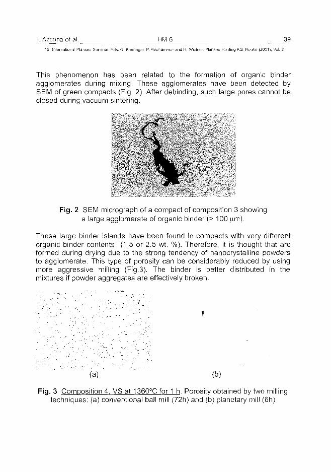
I. Azcona et al. HM 6 39
15' International Plansee Seminar, Eds. G. Kneringer, P. Rodhammer and H. Wildner. Plansee Holding AG. Reutte (2001), Vol. 2
This phenomenon has been related to the formation of organic binderagglomerates during mixing. These agglomerates have been detected bySEM of green compacts (Fig. 2). After debinding, such large pores cannot beclosed during vacuum sintering.
Fig. 2 SEM micrograph of a compact of composition 3 showinga large agglomerate of organic binder (> 100 |um).
These large binder islands have been found in compacts with very differentorganic binder contents (1.5 or 2.5 wt. %). Therefore, it is thought that areformed during drying due to the strong tendency of nanocrystalline powdersto agglomerate. This type of porosity can be considerably reduced by usingmore aggressive milling (Fig.3). The binder is better distributed in themixtures if powder aggregates are effectively broken.
(a) (b)
Fig. 3 Composition 4, VS at 1360°C for 1 h. Porosity obtained by two millingtechniques: (a) conventional ball mill (72h) and (b) planetary mill (6h)
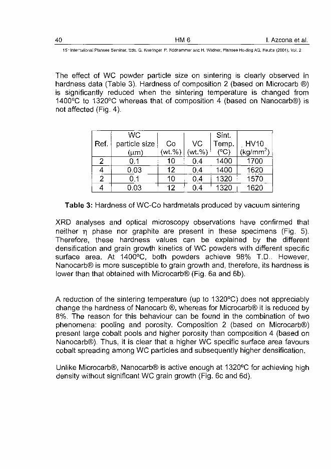
40 HM6 I. Azcona et al." International Plansee Seminar, Eds. G. Kneringer, P. Rodhammer and H. Wildner, Plansee Holding AG, Reutte (2001), Vol. 2
The effect of WC powder particle size on sintering is clearly observed inhardness data (Table 3). Hardness of composition 2 (based on Microcarb ®)is significantly reduced when the sintering temperature is changed from1400°C to 1320°C whereas that of composition 4 (based on Nanocarb®) isnot affected (Fig. 4).
Ref.
2424
WCparticle size
(lorn)0.1
0.030.1
0.03
Co(wt.%)
10121012
VC(wt.%)
0.40.40.40.4
Sint.Temp.
(°C)1400140013201320
HV10(kg/mm2)
1700162015701620
Table 3: Hardness of WC-Co hardmetals produced by vacuum sintering
XRD analyses and optical microscopy observations have confirmed thatneither r\ phase nor graphite are present in these specimens (Fig. 5).Therefore, these hardness values can be explained by the differentdensification and grain growth kinetics of WC powders with different specificsurface area. At 1400°C, both powders achieve 98% T.D.. However,Nanocarb® is more susceptible to grain growth and, therefore, its hardness islower than that obtained with Microcarb® (Fig. 6a and 6b).
A reduction of the sintering temperature (up to 1320°C) does not appreciablychange the hardness of Nanocarb ®, whereas for Microcarb® it is reduced by8%. The reason for this behaviour can be found in the combination of twophenomena: pooling and porosity. Composition 2 (based on Microcarb®)present large cobalt pools and higher porosity than composition 4 (based onNanocarb®). Thus, it is clear that a higher WC specific surface area favourscobalt spreading among WC particles and subsequently higher densification.
Unlike Microcarb®, Nanocarb® is active enough at 1320°C for achieving highdensity without significant WC grain growth (Fig. 6c and 6d).
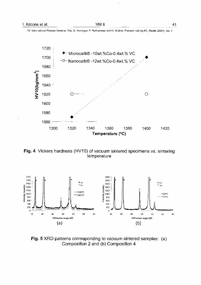
1. Azcona et al. HM6 4115lh International Plansee Seminar, Eds. G. Kneringer, P. Rodhammer and H. Wildner, Plansee Holding AG, Reutte (2001), Vol. 2
Es=
HV
10(k
g/r
1720 i
1700 :
1680 -
1660
1640
1620
1600 -
1580
1560 — -
1300
• -- Microcarb® -10wt.%Co-0.4wt.% V C
-©- Nanocarb® -12wt.%Co-0.4wt.% V C ,•
G-— 7 -'--
1320 1340 1360 1380
Temperature (°C)
--O
1400 1420
Fig. 4 Vickers hardness (HV10) of vacuum sintered specimens vs. sinteringtemperature
—1320°C
—1400°C
40 45 50
Diffraction angle (26)
(a)
1800 -I
_ 1 6 0 0 :
| 1400g 1200
J10001 800 -j j 600 -
400 -
200 - UL40 45 50 55 60
Diffraction angle (28)
(b)
Fig. 5 XRD patterns corresponding to vacuum sintered samples: (a)Composition 2 and (b) Composition 4
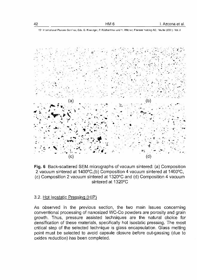
42 HM 6 1. Azcona et al.15" International Plansee Seminar, Eds. G. Kneringer, P. Rodhammer and H. Wildner, Plansee Holding AG, Reutte (2001), Vol. 2
' * • ~:
, * " : '<•. ' • ' » . »
* • ; <
(a)
- V - > . - - " - . • , :,.C"
'v. * . <' .
" , J* ' - -r
(c) (d)
Fig. 6 Back-scattered SEM micrographs of vacuum sintered: (a) Composition2 vacuum sintered at 1400°C,(b) Composition 4 vacuum sintered at 1400°C,(c) Composition 2 vacuum sintered at 1320°C and (d) Composition 4 vacuum
sintered at 1320°C
3.2. Hot Isostatic Pressing (HIP)
As observed in the previous section, the two main issues concerningconventional processing of nanosized WC-Co powders are porosity and graingrowth. Thus, pressure assisted techniques are the natural choice fordensification of these materials, specifically hot isostatic pressing. The mostcritical step of the selected technique is glass encapsulation. Glass meltingpoint must be selected to avoid capsule closure before out-gassing (due tooxides reduction) has been completed.
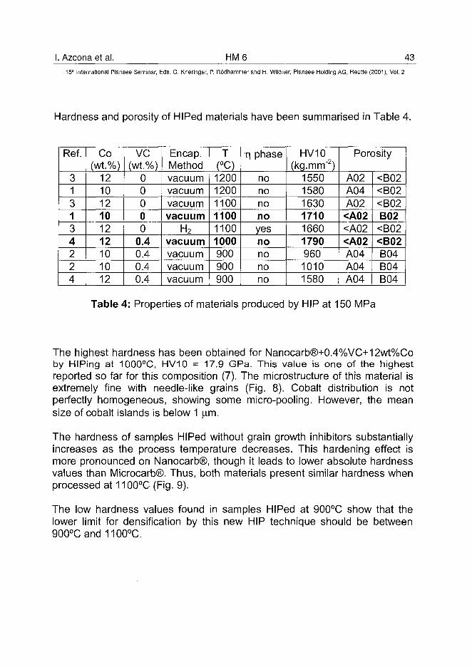
I. Azcona et al. HM6 4315lh International Plansee Seminar, Eds. G. Kneringer, P. Rodhammer and H. Wildner, Plansee Holding AG, Reutte (2001), Vol. 2
Hardness and porosity of HIPed materials have been summarised in Table 4.
Ref.
313134224
Co(wt.%)
121012101212101012
VC(wt.%)
00000
0.40.40.40.4
Encap.Methodvacuumvacuumvacuumvacuum
H2
vacuumvacuumvacuumvacuum
T(°C)120012001100110011001000900900900
T) phase
nonononoyesnononono
HV10(kg. mm"2)
15501580163017101660179096010101580
Porosity
A02A04A02<A02<A02<A02A04A04A04
<B02<B02<B02B02<B02<B02B04B04B04
Table 4: Properties of materials produced by HIP at 150 MPa
The highest hardness has been obtained for Nanocarb®+0.4%VC+12wt%Coby HIPing at 1000°C, HV10 = 17.9 GPa. This value is one of the highestreported so far for this composition (7). The microstructure of this material isextremely fine with needle-like grains (Fig. 8). Cobalt distribution is notperfectly homogeneous, showing some micro-pooling. However, the meansize of cobalt islands is below 1 )im.
The hardness of samples HIPed without grain growth inhibitors substantiallyincreases as the process temperature decreases. This hardening effect ismore pronounced on Nanocarb®, though it leads to lower absolute hardnessvalues than Microcarb®. Thus, both materials present similar hardness whenprocessed at 1100°C (Fig. 9).
The low hardness values found in samples HIPed at 900°C show that thelower limit for densification by this new HIP technique should be between900°Cand1100°C.
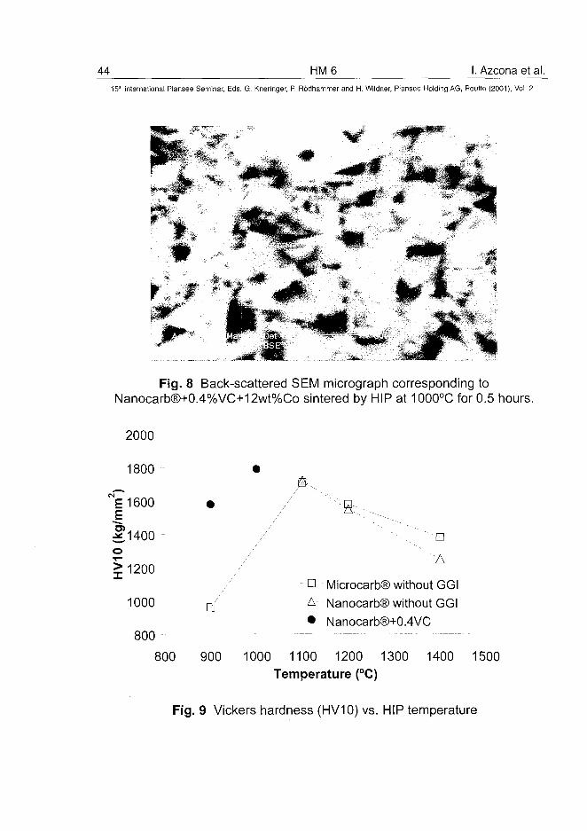
44 HM6 I. Azcona et al.15* International Plansee Seminar, Eds. G. Kneringer, P. Rodhammer and H. Wildner, Plansee Holding AG, Reutte (2001), Vol. 2
Fig. 8 Back-scattered SEM micrograph corresponding toNanocarb®+0.4%VC+12wt%Co sintered by HIP at 1000°C for 0.5 hours.
2000
1800
E 1600S
.21400 -
>1200
1000 •800
800
•" 'A
• Microcarb® without GGIA Nanocarb® without GGI• Nanocarb®+0.4VC
900 1000 1100 1200 1300 1400 1500Temperature (°C)
Fig. 9 Vickers hardness (HV10) vs. HIP temperature
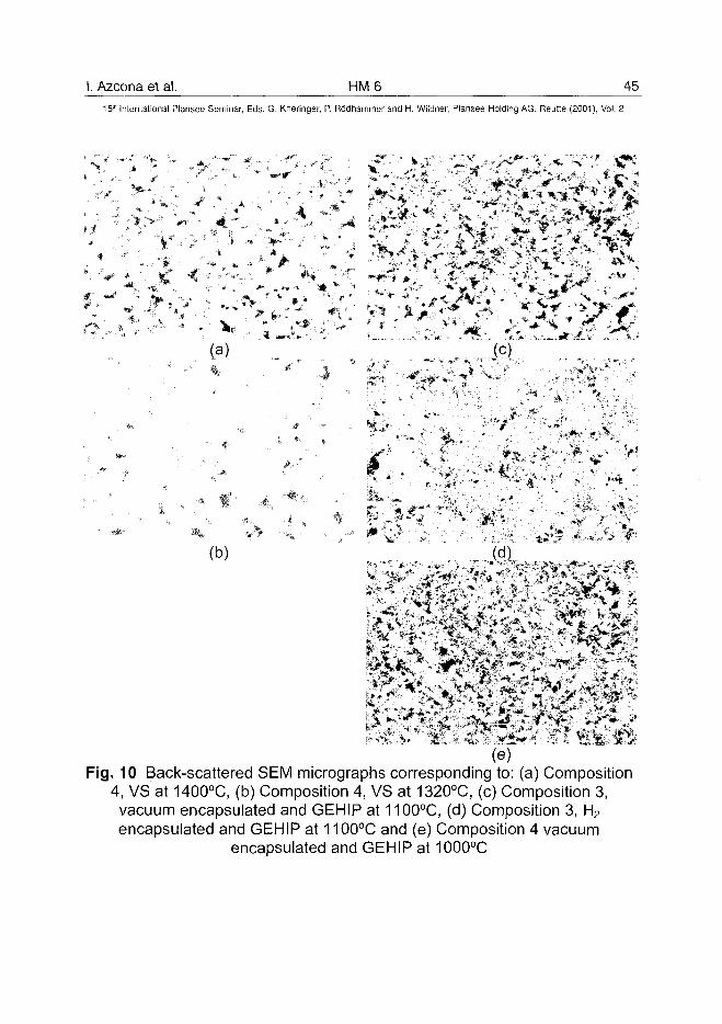
I. Azcona et al. HM 6 45^
15th International Plansee Seminar, Eds. G. Kneringer, P. Rodhammer and H. Wildner, Plansee Holding AG, Reutte (2001), Vol. 2
c -'
<- •
•M
*vr?
_ V> -
-' ' S
, /
if
•
(a)
(e)Fig. 10 Back-scattered SEM micrographs corresponding to: (a) Composition
4, VS at 1400°C, (b) Composition 4, VS at 1320°C, (c) Composition 3,vacuum encapsulated and GEHIP at 1100°C, (d) Composition 3, H2
encapsulated and GEHIP at 1100°C and (e) Composition 4 vacuumencapsulated and GEHIP at 1000°C
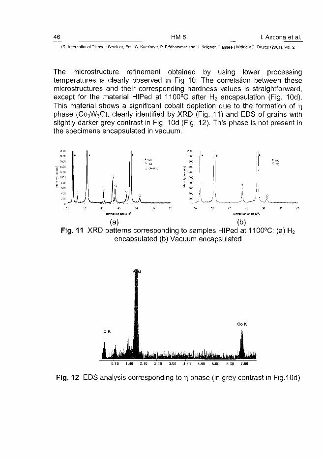
46 HM 6 I. Azcona et al.15:" International Plansee Seminar, Eds. G. Kneringer, P. Rodhammer and H. Wildner, Plansee Holding AG, Reutte (2001), Vol. 2
The microstructure refinement obtained by using lower processingtemperatures is clearly observed in Fig 10. The correlation between thesemicrostructures and their corresponding hardness values is straightforward,except for the material HIPed at 1100°C after H2 encapsulation (Fig. 10d).This material shows a significant cobalt depletion due to the formation of T|phase (C03W3C), clearly identified by XRD (Fig. 11) and EDS of grains withslightly darker grey contrast in Fig. 10d (Fig. 12). This phase is not present inthe specimens encapsulated in vacuum.
2000
1800
16C3
•£• 14C0
| 1200
^ 1CG0
Into
nsl
40D
203
•
iJ
•
0
u.40 45 50 55
Diffraction angle (29)
(a) (b)Fig. 11 XRD patterns corresponding to samples HIPed at 1100°C: (a) H2
encapsulated (b) Vacuum encapsulated
C o K
0.70 1.40 2.10 2.80 3.50 4.20 4.90 5.60 6.30 7.00
Fig. 12 EDS analysis corresponding to r| phase (in grey contrast in Fig.10d)
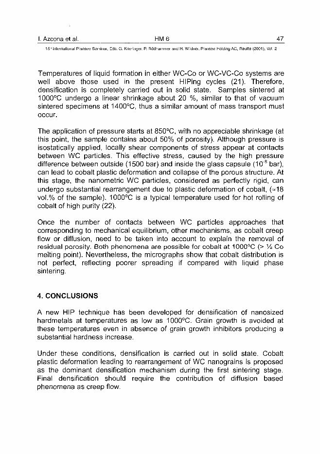
I. Azcona et al. HM 6 47^
15th International Plansee Seminar, Eds. G. Kneringer, P. Rodhammer and H. Wildner, Plansee Holding AG, Reutte (2001), Vol. 2
Temperatures of liquid formation in either WC-Co or WC-VC-Co systems arewell above those used in the present HIPing cycles (21). Therefore,densification is completely carried out in solid state. Samples sintered at1000°C undergo a linear shrinkage about 20 %, similar to that of vacuumsintered specimens at 1400°C, thus a similar amount of mass transport mustoccur.
The application of pressure starts at 850°C, with no appreciable shrinkage (atthis point, the sample contains about 50% of porosity). Although pressure isisostatically applied, locally shear components of stress appear at contactsbetween WC particles. This effective stress, caused by the high pressuredifference between outside (1500 bar) and inside the glass capsule (108 bar),can lead to cobalt plastic deformation and collapse of the porous structure. Atthis stage, the nanometric WC particles, considered as perfectly rigid, canundergo substantial rearrangement due to plastic deformation of cobalt, (-18vol.% of the sample). 1000°C is a typical temperature used for hot rolling ofcobalt of high purity (22).
Once the number of contacts between WC particles approaches thatcorresponding to mechanical equilibrium, other mechanisms, as cobalt creepflow or diffusion, need to be taken into account to explain the removal ofresidual porosity. Both phenomena are possible for cobalt at 1000°C (> Vz Comelting point). Nevertheless, the micrographs show that cobalt distribution isnot perfect, reflecting poorer spreading if compared with liquid phasesintering.
4. CONCLUSIONS
A new HIP technique has been developed for densification of nanosizedhardmetals at temperatures as low as 1000°C. Grain growth is avoided atthese temperatures even in absence of grain growth inhibitors producing asubstantial hardness increase.
Under these conditions, densification is carried out in solid state. Cobaltplastic deformation leading to rearrangement of WC nanograins is proposedas the dominant densification mechanism during the first sintering stage.Final densification should require the contribution of diffusion basedphenomena as creep flow.
48 HM 6 I. Azcona et al.15" International Plansee Seminar, Eds. G. Kneringer, P. Rodhammer and H. Wildner, Plansee Holding AG, Reutte (2001), Vol. 2
Processing of these materials by conventional vacuum sintering present twomain issues: porosity and grain growth. Porosity is related to milling-mixingconditions, whereas grain growth can be controlled by VC additions.
ACKNOWLEDGEMENTS
The authors gratefully acknowledge the financial support of the Consejeria deIndustria of the Basque Government for the realisation of this work.
REFERENCES
1- R. Edwards. "Cutting Tools", The Institute of Materials. The UniversityPress. Cambridge,1993.
2- J. Guriand, Int. Mats. Reviews, Vol.33, No.3, 1988, 151-166.3- K. Dreyer and H. Van den Berg. Metal Powder Report. Vol. 54, No.4,
1999,14-19.4- R.K. Sadangi, L.E. McCandlish, B.H.Kear y P. Seegopaul. Int. J. of Powder
Metallurgy. Vol. 35, No.1, 1999, 27-33.5- A. Parasiris and K.T. Hartwig. Int. J. of Refr. Metals Hard Mater., 18, 2000,
23-31.6- S. Soderberg. "Advances in metal cutting tool materials". Scand. J. of
Metallurgy, 26, 1997,65-70.7- D.F. Carroll. 14th Int. Plansee Seminar'97. Plansee Proc. Vol.2. Cemented
Carbides and Hard Materials. Eds. G. Kneringer, P. Rodhammer and P.Wilhartitz.1997, 168-182.
8- R. Porat, S. Berger y A. Rosen. 14th Int. Plansee Seminar'97. PlanseeProc. Vol.2. Cemented Carbides and Hard Materials. Eds. G. Kneringer, P.Rodhammer and P. Wilhartitz.1997, 183-196.
9- K. Hayashi and N. Matsuoka, 14th Int. Plansee Seminar'97. Plansee Proc.Vol.2. Cemented Carbides and Hard Materials. Eds. G. Kneringer, P.Rodhammer and P. Wilhartitz.1997, 609-621.
10- T. Taniuchi, K. Okada y T. Tanase, 14th Int. Plansee Seminar'97. PlanseeProc. Vol.2. Cemented Carbides and Hard Materials. Eds. G. Kneringer, P.Rodhammer and P. Wilhartitz.1997, 644-657.
11- G. Gille, B. Szesny and G. Leitner, 14th Int. Plansee Seminar'97. PlanseeProc. Vol.2. Cemented Carbides and Hard Materials. Eds. G. Kneringer, P.Rodhammer and P. Wilhartitz.1997, 139-167.
12- K.J.A. Brookes, Metal Powder Report, Vol. 53. No. 7/8, 1998, 24-25.
I. Azcona et al. HM 6 49^
15* International Plansee Seminar, Eds. G. Kneringer, P. Rodhammer and H. Wildner, Plansee Holding AG, Reutte (2001), Vol. 2
13- T.S. Sudarshan, Metal Powder Report, Vol. 53. No. 3, 1998, 26-33.14- K. Rodiger, K. Dreyer, T. Gerdes, D. Kassel and M. Willert-Porada, Proc.
of the 14th 14th Int. Plansee Seminar'97. Plansee Proc. Vol.2. CementedCarbides and Hard Materials. Eds. G. Kneringer, P. Rodhammer and P.Wilhartitz,1997, 197-215.
15- T. Murakami, A. Kitahara, Y. Koga, M. Kawahara, H. Inui and M.Yamaguchi, Materials Science and Engineering , A239-240, (1997) 672-679.
16- L.E. McCandlish, Metal Powder Report, Vol. 51. No. 4, 1996, 16-20.17- International Standard ISO-3878-1983 (E).18- International Standard ISO-3327-1982 (E).19- K. Shetty, I.G. Wright, P.N. Mincer and A.H. Clauer, J. Mat. Sci., 20,1985,
1873-1882.20- International Standard ISO-4505-1978 (E).21- G. Leitner, T. Gestrich and G. Gille, Proc. of the 14th 14th Int. Plansee
Seminar'97. Plansee Proc. Vol.2. Cemented Carbides and Hard Materials.Eds. G. Kneringer, P. Rodhammer and P. Wilhartitz, 1997, 86-99.
22- Cobalt Monograph, Ed. by Centre d'lnformation du Cobalt, Brussels,Belgium, 1960, 112.
AT010043950 HM7 J. Kishino et al.
15" International Plansee Seminar, Eds. G. Kneringer, P. Rodhammer and H. Wildner, Plansee Holding AG, Reutte (2001), Vol. 2
Computational study on grain growth in cemented carbides
J. Kishino* , H. Nomura , S-G. Shin , H. Matsubara and T. Tanase*
*Mitsubishi Materials Corp.1511 Furumagi, Ishige, Yuuki-gun, Ibaraki 300-2795, JAPAN
Japan Fine Ceramics Center4-6-1 Mutuno, Atsuta-ku, Nagoya, Aichi 456-8587, JAPAN
SummaryMicro-grained cemented carbides are widely applied to the tools such as
solid endmills and micro-drills. The knowledge on grain growth of carbides isvery important for manufacturing micro-grained cemented carbides. In thepresent study, continuous and discontinuous grain growth in such cementedcarbides is investigated using the Monte Carlo computer simulationtechnique. The Ostwald ripening process (solution/re-precipitation) and thegrain boundary migration process are assumed in the simulation as graingrowth mechanism. The effects of liquid phase fraction, grain boundaryenergy and an implanted coarse grain are examined. The results of thesesimulations qualitatively agree with experimental ones and suggest thatdistribution of liquid phase and WC/WC grain boundary energy as well ascontamination by coarse grain are important factors controllingdiscontinuous grain growth in cemented carbides.
Keywords:Cemented carbides, simulation, grain growth, WC, grain boundary
1. IntroductionIn the last decade, a lot of attention has been paid to micro-grained
cemented carbides as a material for sharp edged tools such as endmillsand micro-drills. Tungsten carbide grains grow during liquid phase sinteringand the grain size strongly affects the mechanical properties of the alloy.Therefore control of microstructure is very important to produce highlyqualified carbide tools.
The grain growth process in cemented carbides can be characterized bycontinuous and discontinuous ones. Continuous grain growth is recognizedas a uniform growth of the individual grains. Discontinuous grain growth is
J. Kishino et al. HM7 51_15'" International Plansee Seminar, Eds. G. Kneringer, P. Rodhammer and H. Wildner, Plansee Holding AG, Reutte (2001), Vol. 2
known as an undesired formation of isolated coarse WC grains which growfaster and larger than the surrounding grains. In the production of micro-grained cemented carbides, controlling both continuous and discontinuousgrain growth in the microstructure has to be taken into account. Especially,the isolated coarse grains deteriorates the performance of the material. Oneof the effective methods for controlling grain growth is doping grain growthinhibitors, such as VC and Cr3C2 (1-3).
The grain growth in liquid phase sintered materials, which is generallyunderstood as a solution/re-precipitation process called Ostwald ripening,has often been studied from a theoretical point of view (4-9). Most of studiesassume that carbide grains are completely surrounded by a liquid phase.These classical theories of Ostwald ripening are not sufficient to explain thegrain growth mechanism in cemented carbides (10-14), especially in thecase of low binder content which is popular for industrial applications.Because in that case WC grains are not completely surrounded by a binderphase, but contact with neighboring grains. Simulation techniques seemuseful to examine the effects of both solid/liquid and solid/solid interface ongrain growth behavior.
In the present study, the Monte Carlo computer simulation technique isutilized to investigate continuous and discontinuous grain growthmechanisms in cemented carbides. Because grain growth simulation usingthe Monte Carlo method is considered to be useful for understanding thegrain growth behavior in complicated systems (15-17). In addition to thesimulations, experiments on microstructures of WC-Co and WC-VC-Cosystems are performed. Comparing the simulations to the experimentalresults, the grain growth mechanism is discussed with special focus on thepresence of WC/WC grain boundaries.
2. Simulation methodThe grain growth simulation was carried out on the basis of the Potts
model using the Monte Carlo method (18, 19). The temperature term in theBoltzman equation is set at zero. A two dimensional lattice comprised ofsolid (WC) cell and liquid (Co binder phase) cell was used to simulate themicrostructure of cemented carbides. The lattice size was 200 x 200 cells.The number of crystal orientations of solid particles, Q, was fixed at 64.
Two kinds of mass transfer were assumed in the simulation algorithm. If asolid cell is selected in the array, the mass transfer proceeds through grainboundaries in the solid owing to the same way as the Potts model. If a liquidcell is selected, the mass transfer through the liquid phase is designed inthe algorithm as follows.
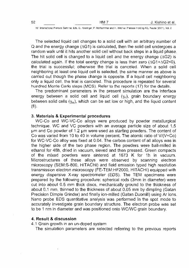
52 HM7 J. Kishino et al.15" International Plansee Seminar, Eds. G. Kneringer, P. Rodhammer and H. Wildner, Plansee Holding AG, Reutte (2001), Vol. 2
The selected liquid cell changes to a solid cell with an arbitrary number ofQ and the energy change (AG1) is calculated, then the solid cell undergoes arandom walk until it hits another solid cell without back steps in a liquid phase.The hit solid cell is changed to a liquid cell and the energy change (AG2) iscalculated again. If the total energy change is less than zero (AG1+AG2<0),the trial is successful; otherwise the trial is canceled. When a solid cellneighboring at least one liquid cell is selected, the same manner as above iscarried out though the phase change is opposite. If a liquid cell neighboringonly a liquid cell, the trial is canceled. This procedure is repeated for severalhundred Monte Carlo steps (MCS). Refer to the reports (17) for the details.
The predominant parameters in the present simulation are the interfaceenergy between a solid cell and liquid cell (yS|), grain boundary energybetween solid cells (ySs), which can be set low or high, and the liquid content(fl).
3. Materials & Experimental proceduresWC-Co and WC-VC-Co alloys were produced by powder metallurgical
technique. WC and VC powders with an average particle size of about 1.5urn and Co powder of 1.2 urn were used as starting powders. The content ofCo was varied from 10 to 40 in volume percent. The atomic ratio of V/(V+Co)for WC-VC-Co alloy was fixed at 0.04. The carbon content of all alloys was inthe higher side of the two phase region. The powders were ball-milled inethanol for48h, dried in vacuum, sieved and then pressed. Green compactsof the mixed powders were sintered at 1673 K for 1h in vacuum.Microstructures of these alloys were observed by scanning electronmicroscopy (SEM:S-800, HITACHI) and field emission typed high resolutiontransmission electron microscopy (FE-TEM:HF2000, HITACHI) equipped withenergy dispersive X-ray spectrometer (EDS). The TEM specimens wereprepared by the following procedure: spherical rods (3mm in diameter) werecut into about 0.5 mm thick discs, mechanically ground to the thickness ofabout 0.1 mm, thinned to the thickness of about 0.05 mm by dimpling (GatanPrecision Dimple Grinder) and finally ion-milled (Gatan Duomill) using Ar ions.Nano probe EDS quantitative analysis was performed in the spot mode toaccurately investigate grain boundary structure. The electron probe was setto be 1 nm in diameter and was positioned onto WC/WC grain boundary.
4. Result & discussion4.1 Grain growth in an un-doped system
The simulation parameters are selected referring to the previous reports
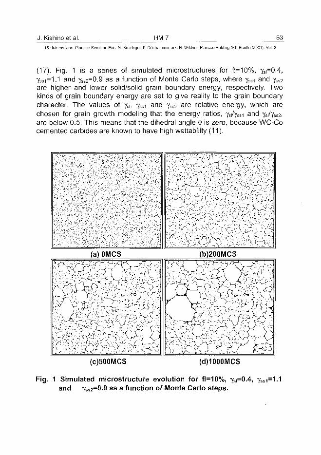
J. Kishino et al. HM7 53
15" International Plansee Seminar, Eds. G. Kneringer, P. Rodhammer and H. Wildner, Plansee Holding AG, Reutte (2001), Vol. 2
(17). Fig. 1 is a series of simulated microstructures for fl=10%, ys\=0A,yss1=1.1 and Yss2=0.9 as a function of Monte Carlo steps, where yss1 and YSS2
are higher and lower solid/solid grain boundary energy, respectively. Twokinds of grain boundary energy are set to give reality to the grain boundarycharacter. The values of ysi, Yssi and ySS2 are relative energy, which arechosen for grain growth modeling that the energy ratios, Ysi/ySsi and yJySS2,are below 0.5. This means that the dihedral angle 6 is zero, because WC-Cocemented carbides are known to have high wettability (11).
> . ' • •
• ; = • >
'•- .
' / * •
:'•:
I;
":?
"'.
•••"'" •
'": : .'
; * . « '
"• ; . v
• / ••"
r.
: • ' "
V '•
. z
v1 »1- £••'
r')-*-J •" -*
V ' ' " . - !=*•
•7:,\;\
• :~K;> ,r/ •_•
• i .'"'4
/;?'-'j*"''--*'
."-..". - -
• F'
;-'••-.[;
: : • " >
"?"".
- •_»
• • • • - , 7^
?:•' '•"
V-'
- . . • / . ^
• • - ^"
' " • I - ' . ' - 1
"• ? • ' • - -
...] ; '
. _ • = ' ' ' • '
. ' * • - . " ' '
' \?~;
- • • _ -
' . . ; ; • .
! .•"• • " : L ,
J •; '_J
- :\-t'
' • ' i".
~?: ' --•; \ - v ' .
v iw •
:; = • = " • . •
> ' . * . • ' •
-;V-
C ' % j :
. • • • ' . - " • 1 1
;~ J
• " • ^
" ^
. v
• / " " " * '
• ' f-*.'.'
\ • > -
~VC- <
• • ' ' " • * - (
• - '
^ •
V >
^ ; 1
^ ^
• ^ '
V ,! — *>
V ,
>/
•v :
T - " • -
• ^ I - . ' "
"v -* . rf -
f:
A-. i-'j; " • • v : •
. / ^ / ^ ' : :
- "- • /
v / " » •
? /
-.-)' 'r' \\\
' " * ' • - ;
. * • ;
i'i
'V -
_,* _
' " -
\ *
. V™*
~?:'.
r <
'/ <
.'^..
k'Vi
\ '
/-v
v7
: ' ' . - •
• • • . ; • ;
y - \.
" ' • . : ; " ' • •
*; • .-*
?- ' L
(a)OMCS (b)200MCS
(c)!500MCS (d)1000MCS
Fig. 1 Simulated microstructure evolution for fl=10%, ySi=0.4, ySsi=1-1and Yss2=0-9 as a function of Monte Carlo steps.
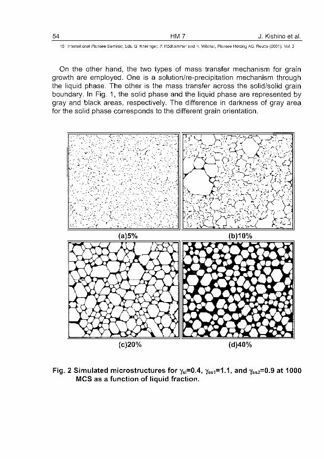
54 HM 7 J. Kishino et al.15" International Plansee Seminar, Eds. G. Kneringer, P. Rodhammer and H. Wildner, Plansee Holding AG, Reutte (2001), Vol. 2
On the other hand, the two types of mass transfer mechanism for graingrowth are employed. One is a solution/re-precipitation mechanism throughthe liquid phase. The other is the mass transfer across the solid/solid grainboundary. In Fig. 1, the solid phase and the liquid phase are represented bygray and black areas, respectively. The difference in darkness of gray areafor the solid phase corresponds to the different grain orientation.
(c)20% (d)40%
Fig. 2 Simulated microstructures for ySi=0.4, ySsi=1.1, and yss2=0.9 at 1000MCS as a function of liquid fraction.
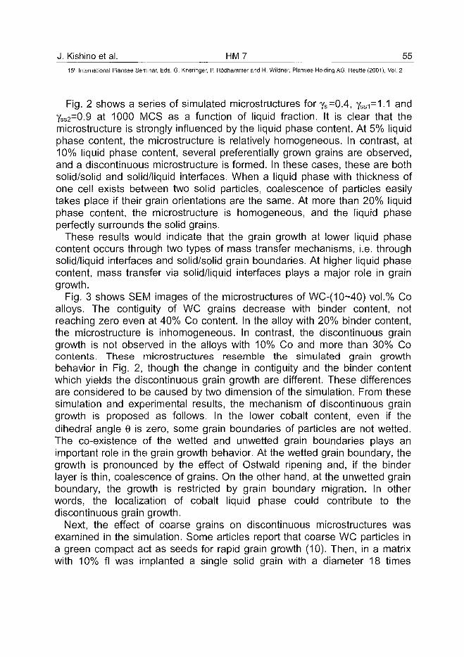
J. Kishino et al. HM 7 55^
15" International Plansee Seminar, Eds. G. Kneringer, P. Rodhammer and H. Wildner, Plansee Holding AG, Reutte (2001), Vol. 2
Fig. 2 shows a series of simulated microstructures for ySi=0.4, yss1=1.1 andySS2=0.9 at 1000 MCS as a function of liquid fraction. It is clear that themicrostructure is strongly influenced by the liquid phase content. At 5% liquidphase content, the microstructure is relatively homogeneous. In contrast, at10% liquid phase content, several preferentially grown grains are observed,and a discontinuous microstructure is formed. In these cases, these are bothsolid/solid and solid/liquid interfaces. When a liquid phase with thickness ofone cell exists between two solid particles, coalescence of particles easilytakes place if their grain orientations are the same. At more than 20% liquidphase content, the microstructure is homogeneous, and the liquid phaseperfectly surrounds the solid grains.
These results would indicate that the grain growth at lower liquid phasecontent occurs through two types of mass transfer mechanisms, i.e. throughsolid/liquid interfaces and solid/solid grain boundaries. At higher liquid phasecontent, mass transfer via solid/liquid interfaces plays a major role in graingrowth.
Fig. 3 shows SEM images of the microstructures of WC-(10~40) vol.% Coalloys. The contiguity of WC grains decrease with binder content, notreaching zero even at 40% Co content. In the alloy with 20% binder content,the microstructure is inhomogeneous. In contrast, the discontinuous graingrowth is not observed in the alloys with 10% Co and more than 30% Cocontents. These microstructures resemble the simulated grain growthbehavior in Fig. 2, though the change in contiguity and the binder contentwhich yields the discontinuous grain growth are different. These differencesare considered to be caused by two dimension of the simulation. From thesesimulation and experimental results, the mechanism of discontinuous graingrowth is proposed as follows. In the lower cobalt content, even if thedihedral angle 9 is zero, some grain boundaries of particles are not wetted.The co-existence of the wetted and unwetted grain boundaries plays animportant role in the grain growth behavior. At the wetted grain boundary, thegrowth is pronounced by the effect of Ostwald ripening and, if the binderlayer is thin, coalescence of grains. On the other hand, at the unwetted grainboundary, the growth is restricted by grain boundary migration. In otherwords, the localization of cobalt liquid phase could contribute to thediscontinuous grain growth.
Next, the effect of coarse grains on discontinuous microstructures wasexamined in the simulation. Some articles report that coarse WC particles ina green compact act as seeds for rapid grain growth (10). Then, in a matrixwith 10% fl was implanted a single solid grain with a diameter 18 times
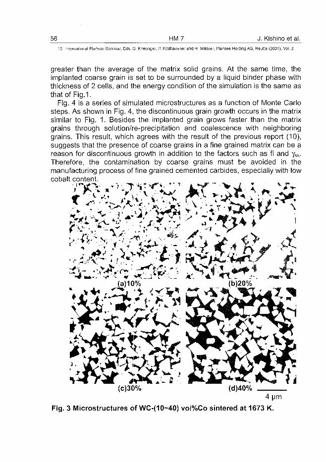
56 HM 7 J. Kishino et al.15:" International Plansee Seminar, Eds. G. Kneringer, P. Rodhammer and H. Wildner, Plansee Holding AG, Reutte (2001), Vol. 2
greater than the average of the matrix solid grains. At the same time, theimplanted coarse grain is set to be surrounded by a liquid binder phase withthickness of 2 cells, and the energy condition of the simulation is the same asthat of Fig.1.
Fig. 4 is a series of simulated microstructures as a function of Monte Carlosteps. As shown in Fig. 4, the discontinuous grain growth occurs in the matrixsimilar to Fig. 1. Besides the implanted grain grows faster than the matrixgrains through solution/re-precipitation and coalescence with neighboringgrains. This result, which agrees with the result of the previous report (10),suggests that the presence of coarse grains in a fine grained matrix can be areason for discontinuous growth in addition to the factors such as fl and yss.Therefore, the contamination by coarse grains must be avoided in themanufacturing process of fine grained cemented carbides, especially with lowcobalt content.
X v 1 • "-v ' J C . v <%
V
'. • . V ?^*^r-.^r ^
4 urn
Fig. 3 Microstructures of WC-(10~40) voI%Co sintered at 1673 K.
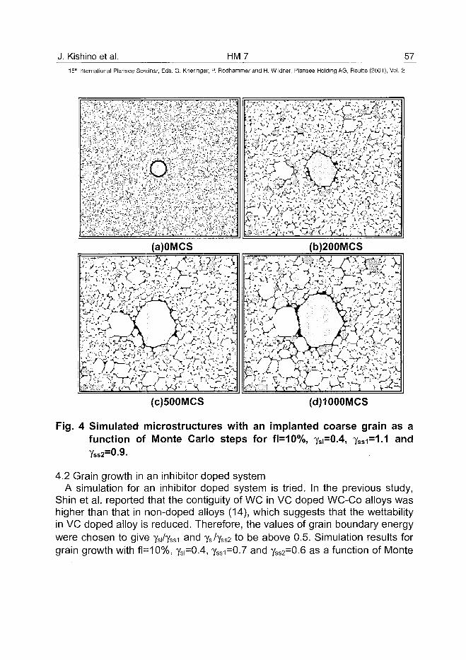
J. Kishino et al. HM7 57
15" International Plansee Seminar, Eds. G. Kneringer, P. Rodhammer and H. Wildner, Plansee Holding AG, Reutte (2001), Vol. 2
1. . J.1'—xrr-z
" ' • • • ; ; : * ' . ' • ' : • ' • * * : • • . * • . " • ' . • • • > : r • - ; • • . • . • . " . . • • : ' • • : • . • • ; • • - ? • • - . ' ! - - -
. • . —1
'?.:-'•>
y\'
'. l_^
s
< ;r-JJ
'-
•"••' V J-
J-'!•-"->-••'-
^ ^
? A
m
(a)OMCS
• • / • > - • ' : • • . • • • : x - ; ' '
••.V u v ^ v•-:. ,.C^"A
(b)200MCS
(c)500MCS (d)1000MCS
Fig. 4 Simulated microstructures with an implanted coarse grain as afunction of Monte Carlo steps for fl=10%, Ysi=0-4, YSSI=1-1 andYss2=0.9.
4.2 Grain growth in an inhibitor doped systemA simulation for an inhibitor doped system is tried. In the previous study,
Shin et al. reported that the contiguity of WC in VC doped WC-Co alloys washigher than that in non-doped alloys (14), which suggests that the wettabilityin VC doped alloy is reduced. Therefore, the values of grain boundary energywere chosen to give YS|/YSSI and yS|/ySs2 to be above 0.5. Simulation results forgrain growth with fl=10%, ySi=0.4, yss1=0.7 and ySS2=0.6 as a function of Monte
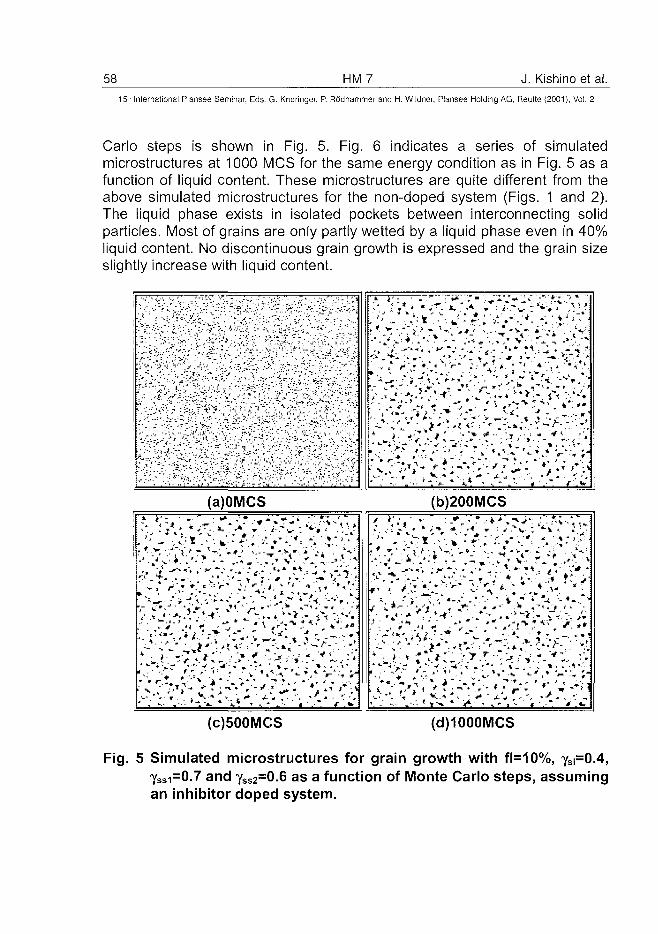
58 HM7 J. Kishino et al.15" International Plansee Seminar, Eds. G. Kneringer, P. Rodhammer and H. Wildner, Piansee Holding A6, Reutte (2001), Vol. 2
Carlo steps is shown in Fig. 5. Fig. 6 indicates a series of simulatedmicrostructures at 1000 MCS for the same energy condition as in Fig. 5 as afunction of liquid content. These microstructures are quite different from theabove simulated microstructures for the non-doped system (Figs. 1 and 2).The liquid phase exists in isolated pockets between interconnecting solidparticles. Most of grains are only partly wetted by a liquid phase even in 40%liquid content. No discontinuous grain growth is expressed and the grain sizeslightly increase with liquid content.
1 . •' -.::_; ;; i~ '• , ._ :
- • ' '- ' ' A '
'- ' • ' • ! ' ;••• '
: ' . . \ •"-;
V r . - . •':•
'-'•':'}J<
y"-;•;/:'^"•'\ •'./-
- T -
' " . _:.
. ^ • * " . . *
- , , ^ • * - .
•>" . * ' - : >
.-I; :".•; ;.r.:
*'" /.".
S'.r. ':'
'•,;£:'
- ' / • • '
.'-•>"::''•
' . - ."*•" -"
•y >', /.^
- - / \ •'•'
•%'.•'•.-
• : ' -
. ; ' /
•'>.
'-.-[
• ; '
v'
V -: ' • - ' -
V.-V
%:
! " • • " •
y -
• ; • ' • ;
" - - ^
=' • >
- ^ • -
; = : - :
• ; ^ • . '
" • ' ; . ' *
' " . " : ' •
-'•' \ • ' .
" ' i . ' • ' • • ' : V
. - • . : " • • . •
' . - ' : - • ~~'~
J,'•'•'•'}
\ . . ..,//;:. .'v'
• • ' • ' • ' ' • ' ; .
\ : \ - % .
*• ;> - '^;
•.iv : '
- • • - - ' ^ .
" •'.'•
• .".-.V.
;/>;;
" . " • T-
•^ • • . j
• " " • • > : . 1
, 1
:- :
- •
r1—'• * ?
• . •
A • .
* • >
—7-^ —* " ^ - J L
" • » ^ ,
, ' , " • * • • * •
" * •«
>•• - •
j . ^ .
, * , * •
' ? ^-»
. ; - '
' » *-
• . *
*
. " r
1 *
r- *
• f-^C
* * ] ' ' '• i ^-• '", i*. * v * }
-•-! " *
•; ^ J )
* * ' • • •
-F
\ '
' * '.V»
•" i \
• ^ . " - *
_ _ _ . —
' ' ^ ^ J*
i- •* ? . J
> > -
; • ' - . ; ;
- • » . ' t
* ; * *
- • - . . • • • * ^
"v" ';'•*•*-• < - *
, . * / _ :
; ,*\<
" i
" •• " . '
r'i.
¥ %
T~
-'-
• > • - - *
4 ' ^ " ^ ^
,*v."t • J
^ . • .
* ' 1 . * '
1 V
'
. • •
- • r
* - • -
. ; •
V-'
/*/' V ,
f *•
* " . :
F " -*i
(a)OMCS
5 >'•'*• *%,'•*•"• ~\: S-' i
* " • " v * •*" * ^ ' r * "
V ' - - : * • * • ' . " ' 1 '
* ' * - * . , T \ * • >• -
* 4 " " ' *
J : **>4 _ «. i! • - * • . J . -
- ' ' * W / H
fc ^ ' ^
•% * A." J
-'* v^w"
• i *
" ' * • '" • » ^
4 ' . - " .
V
* V
^ -
•*
• > ' " , * .
• ^ . * .
1 • - . ,
. ' • }
' . . * •
* : » '
' - * .
••¥ # "
* • ' • •
^ . »
/ . ^ " * * •
\ * » • ' - ' -
• L \ ?-""•"r* ", ^.»
^ L *. ' • * * • "
' • • ' < ' * •
- ]J|** 1 «
"*" s •—
* • > • *
»t -fr
1 *^ ,t * 'V - - T
* ' • - - * - • • - '
c *
V ft
(b)200MCS
' •{•.» : / . ; •/-,•-;:•=
;
1 r
•
. * - + • • " ' • * ' • » » ' l * " 3 "
"*•" • * J " • * " • i'*!**' . * * + i ^
Y ^ ** . ' t * i - t
* * - i •••-
* T-
; > ^
'f - ^
• •»
; »
( # -
* *
• m/ 1
- • _
f\- • ^
- ^
1 _
a
(c)500MCS (d)1000MCS
Fig. 5 Simulated microstructures for grain growth with fl=10%, yS|=0.4,ySsi=0.7 and YsS2
=0.6 as a function of Monte Carlo steps, assumingan inhibitor doped system.
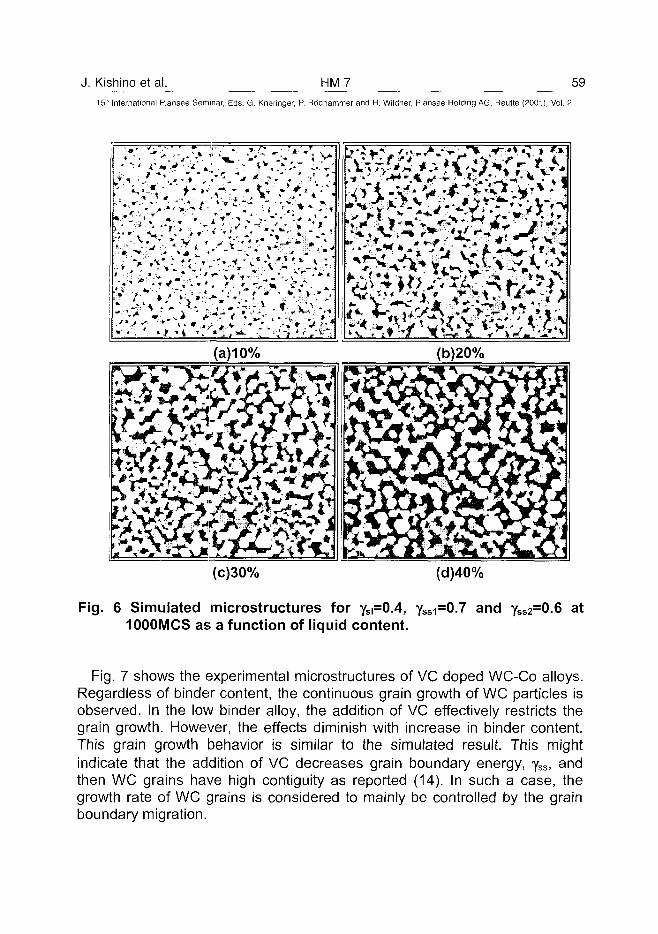
J. Kishino et al. HM7 59
15" International Plansee Seminar, Eds. G. Kneringer, P. Rodhammer and H. Wildner, Plansee Holding AG, Reutte (2001), Vol. 2
m%<Smm(c)30% (d)40%
Fig. 6 Simulated microstructures for ySi=0.4, YSSI=0.7 and YSS2=0.6 at1000MCS as a function of liquid content.
Fig. 7 shows the experimental microstructures of VC doped WC-Co alloys.Regardless of binder content, the continuous grain growth of WC particles isobserved. In the low binder alloy, the addition of VC effectively restricts thegrain growth. However, the effects diminish with increase in binder content.This grain growth behavior is similar to the simulated result. This mightindicate that the addition of VC decreases grain boundary energy, yss, andthen WC grains have high contiguity as reported (14). In such a case, thegrowth rate of WC grains is considered to mainly be controlled by the grainboundary migration.
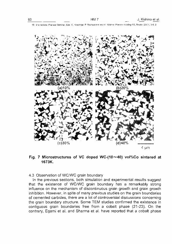
60 HM 7 J. Kishino et al.15'" International Plansee Seminar, Eds. G. Kneringer, P. Rddhammer and H. Wildner, Plansee Holding AG, Reutte (2001), Vol. 2
*& -mm $&x£$.iM
(c)30% (d)40%4 um
Fig. 7 Microstructures of VC doped WC-(10~40) vol%Co sintered at1673K.
4.3 Observation of WC/WC grain boundaryIn the previous sections, both simulation and experimental results suggest
that the existence of WC/WC grain boundary has a remarkably stronginfluence on the mechanism of discontinuous grain growth and grain growthinhibition. However, in spite of many previous studies on the grain boundariesof cemented carbides, there are a lot of controversial discussions concerningthe grain boundary structure. Some TEM studies confirmed the existence incontiguous grain boundaries free from a cobalt phase (21-23). On thecontrary, Egami et al. and Sharma et al. have reported that a cobalt phase
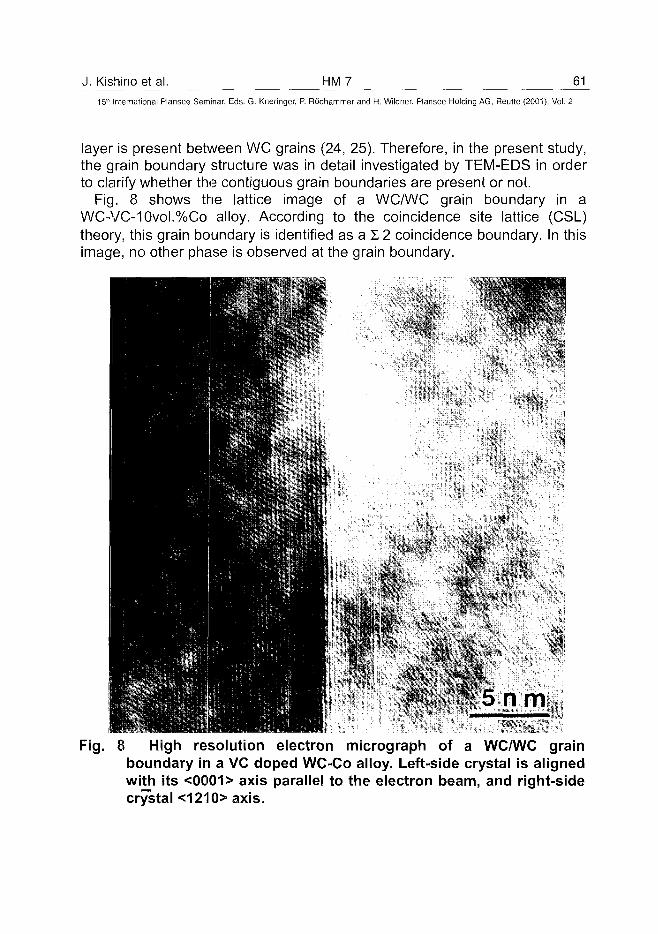
J. Kishino et al. HM7 6115th International Plansee Seminar, Eds. G. Kneringer, P. Rodhammer and H. Wildner, Plansee Holding AG, Reutte (2001), Vol. 2
layer is present between WC grains (24, 25). Therefore, in the present study,the grain boundary structure was in detail investigated by TEM-EDS in orderto clarify whether the contiguous grain boundaries are present or not.
Fig. 8 shows the lattice image of a WC/WC grain boundary in aWC-VC-10vol.%Co alloy. According to the coincidence site lattice (CSL)theory, this grain boundary is identified as a 12 coincidence boundary. In thisimage, no other phase is observed at the grain boundary.
Fig. 8 High resolution electron micrograph of a WC/WC grainboundary in a VC doped WC-Co alloy. Left-side crystal is alignedwith its <0001> axis parallel to the electron beam, and right-sidecrystal <1210> axis.
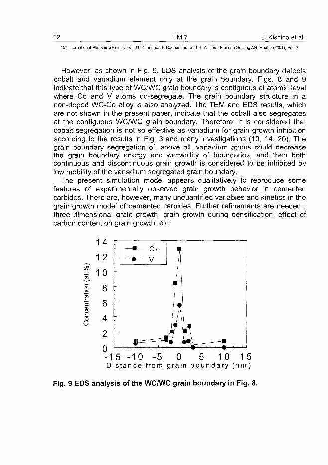
62 HM7 J. Kishino et al.15" International Piansee Seminar, Eds. G. Kneringer, P. Rodhammer and H. Wildner, Plansee Holding AG, Reutte (2001), Vol. 2
However, as shown in Fig. 9, EDS analysis of the grain boundary detectscobalt and vanadium element only at the grain boundary. Figs. 8 and 9indicate that this type of WC/WC grain boundary is contiguous at atomic levelwhere Co and V atoms co-segregate. The grain boundary structure in anon-doped WC-Co alloy is also analyzed. The TEM and EDS results, whichare not shown in the present paper, indicate that the cobalt also segregatesat the contiguous WC/WC grain boundary. Therefore, it is considered thatcobalt segregation is not so effective as vanadium for grain growth inhibitionaccording to the results in Fig. 3 and many investigations (10, 14, 20). Thegrain boundary segregation of, above all, vanadium atoms could decreasethe grain boundary energy and wettability of boundaries, and then bothcontinuous and discontinuous grain growth is considered to be inhibited bylow mobility of the vanadium segregated grain boundary.
The present simulation model appears qualitatively to reproduce somefeatures of experimentally observed grain growth behavior in cementedcarbides. There are, however, many unqualified variables and kinetics in thegrain growth model of cemented carbides. Further refinements are needed :three dimensional grain growth, grain growth during densification, effect ofcarbon content on grain growth, etc.
IoO
- 1 5 - 1 0 - 5 0 5 10 15
D i s t a n c e f r o m g r a i n b o u n d a r y ( n m )
Fig. 9 EDS analysis of the WC/WC grain boundary in Fig. 8.
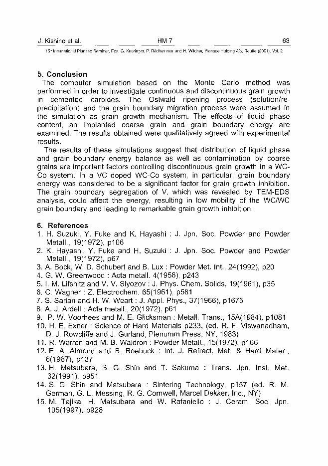
J. Kishino et al. HM 7 63^
15'" Internationa! Plansee Seminar, Eds. G. Kneringer, P. Rodhammer and H. Wildner, Plansee Holding AG, Reutte (2001), Vol. 2
5. ConclusionThe computer simulation based on the Monte Carlo method was
performed in order to investigate continuous and discontinuous grain growthin cemented carbides. The Ostwald ripening process (solution/re-precipitation) and the grain boundary migration process were assumed inthe simulation as grain growth mechanism. The effects of liquid phasecontent, an implanted coarse grain and grain boundary energy areexamined. The results obtained were qualitatively agreed with experimentalresults.
The results of these simulations suggest that distribution of liquid phaseand grain boundary energy balance as well as contamination by coarsegrains are important factors controlling discontinuous grain growth in a WC-Co system. In a VC doped WC-Co system, in particular, grain boundaryenergy was considered to be a significant factor for grain growth inhibition.The grain boundary segregation of V, which was revealed by TEM-EDSanalysis, could affect the energy, resulting in low mobility of the WC/WCgrain boundary and leading to remarkable grain growth inhibition.
6. References1. H. Suzuki, Y. Fuke and K. Hayashi : J. Jpn. Soc. Powder and Powder
Metall., 19(1972), p1062. K. Hayashi, Y. Fuke and H. Suzuki : J. Jpn. Soc. Powder and Powder
Metall., 19(1972), p673. A. Bock, W. D. Schubert and B. Lux : Powder Met. Int., 24(1992), p204. G. W. Greenwood : Acta metall. 4(1956), p2435. I. M. Lifshitz and V. V. Slyozov : J. Phys. Chem. Solids, 19(1961), p356. C. Wagner: Z. Electrochem. 65(1961), p5817. S. Sarian and H. W. Weart: J. Appl. Phys., 37(1966), p16758. A. J. Ardell : Acta metall., 20(1972), p619. P. W. Voorhees and M. E. Glicksman : Metall. Trans., 15A(1984), p108110. H. E. Exner : Science of Hard Materials p233, (ed. R. F. Viswanadham,
D. J. Rowcliffe and J. Gurland, Plenumm Press, NY, 1983)11. R. Warren and M. B. Waldron : Powder Metall., 15(1972), p16612. E. A. Almond and B. Roebuck : Int. J. Refract. Met. & Hard Mater.,
6(1987), p13713. H. Matsubara, S. G. Shin and T. Sakuma : Trans. Jpn. Inst. Met.
32(1991), p95114. S. G. Shin and Matsubara : Sintering Technology, p157 (ed. R. M.
German, G. L. Messing, R. G. Cornwell, Marcel Dekker, Inc., NY)15. M. Tajika, H. Matsubara and W. Rafaniello : J. Ceram. Soc. Jpn.
105(1997), p928
64 HM7 J. Kishino et al.15" Internationa! Plansee Seminar, Eds. G. Kneringer, P. Rodhammer and H. Wildner, Plansee Holding AG, Reutte (2001), Vol. 2
16. Y. Okamoto, N. Hirosaki and H. Matsubara : J. Ceram. Soc. Jpn.107(1999), p109
17. H. Matsubara and R. J. Brook : Ceramic Transactions, vol.71, p403,(ed. K. Koumoto, L. M. Sheppard and H. Matsubara, Am. Ceram. Soc.,Westerville, Ohio, USA)
18. M. P. Anderson, D. J. Srolovitz, G. S. Grest and P. S. Sahni : Actametall., 32(1984), p783
19. G. S. Grest, D. J. Srolovitz and M. P. Anderson : Acta Metall. 33(1985),p509
20. W. D. Schubert, A. Bock and B. Lux : Int. J. Refract. Met. & Hard Mater.,13(1995), p281
21. T. Suzuki, K. Shibuki and Y. Ikuhara : Phil. Mag. Letter, 71(1995), p28922. V. Jayaram and R. Sinclair: J. Amer. Ceram. Soc. 66(1983), p13723. J. Vicens, M. Benjdir, G. Nouet, A. Dubon and J. Y. Laval : J. Mat. Sci.,
29(1994), p98724. A. Egami, M. Ehira and M. Machida : Proc. 13th Int. Plansee Seminar,
Vol3, p639 (ed. H. Bildstein and R. Eck, Plansee AG Reutte 1993)25. N. K. Sharma, I. D. Ward, H. L. Fraser and W. S. Williams : J. Am.
Ceram. Soc., 63(1980), p194
ATO100440P. Warbichler et al. HM 9 65^
15" International Plansee Seminar, Eds. G. Kneringer, P. Rodhammer and H. Wildner, Plansee Holding AG, Reutte (2001), Vol. 2
EFTEM-EELS Characterization of VC and Cr3C2 Doped Cemented Carbides
Peter Warbichler*, Ferdinand Hofer*, Werner Grogger* and Andreas Lackner+
* Zentrum fur Elektronenmikroskopie Graz und
* Forschungsinstitut fur Elektronenmikroskopie, Technische Universitat Graz, Graz, Austria+ Plansee Tizit AG, Reutte, Tyrol, Austria
Summary
Structure-property correlation plays an important role in the design of advancedmaterials which are increasingly based on sub-micrometer and sometimes evennanometer grains. In this respect, analytical electron microscopy (AEM) offers acomprehensive range of characterization techniques which are particularly well suitedfor hard materials: Electron diffraction and high resolution electron microscopy forobtaining crystallographical information and especially new emerging techniquessuch as energy-filtering TEM (EFTEM) and electron energy-loss spectroscopy(EELS) which enable nearly atomic resolution analysis.In this paper we concentrate on EFTEM and HREM investigations of both WCprecursor-powders and sintered WC-Co composites doped with vanadium andchromium carbides in order to control the grain growth during the sintering of theultra fine WC powders. The aim was to locate the distribution of the doping elementsin the powders and in the sintered materials.
Keywords
WC, Cr3C2, VC, energy-filtering transmission electron microscopy, electron energy-loss spectrometry
1. Introduction
Cemented carbides and cermets are materials commonly used in wear parts andcutting tool application. One way of gaining a better understanding of theirbehaviour is to study their complex microstructures and relate them to the fabricationprocess parameters and the mechanical properties. This has been done previouslyusing above all scanning electron microscopy (SEM) with energy-dispersive and/orwave length-dispersive x-ray spectrometry (EDXS or WDXS). Unfortunately, thismethod has its limitations in quantitative microanalysis, as it lacks the resolution
66 HM9 P. Warbichler et al.15" International Plansee Seminar, Eds. G. Kneringer. P. Rddhammer and H. Wildner, Plansee Holding AG, Reutte (2001), Vol. 2
needed for the fine-scale microstructure of these materials. As the hard materialindustry moves towards the fabrication of super- and ultrafine WC/Co grades with anaverage grain size ranging from 0.2 to 0.5 |im and with vanadium carbide orchromium carbides as grain growth inhibitors, their structure-property optimisationneeds high resolution microanalysis, such as atom probe field ion microscopy(APFIM) and analytical transmission electron microscopy (AEM).The atom probe technique is well suited for this type of materials where a fine scalemicrostructure requires a high spatial resolution, e.g. for characterising singleprecipitates or grain boundaries (1). However, due to the needle-shaped specimenwhich are necessary for the atom probe, the investigated volume is limited to somenm3. This is not always enough to get representative information on the chemicalcomposition of a larger specimen volume.Analytical electron microscopy (AEM) is a very efficient and powerful tool forcharacterising all kinds of materials, because it allows to study morphological,crystallographical and chemical information. Especially energy-filtering electronmicroscopy (EFTEM) in combination with electron energy-loss spectrometry (EELS)has many advantages for characterising cemented carbides, hard metals and relatedmaterials, that no other technique can quite match (2,3,4). It combines the advantageof large area view (some 10 |im) with high spatial resolution (down to a few nm).The aim of the present paper is to highlight the possibilities of AEM and todemonstrate how the AEM based techniques can be used to examine the role of VCand &3C2 addition in the grain growth of micro-grained cemented carbides.
2. Analytical Electron Microscopy and its Information Content
In contrast to the traditional AEM investigations which are based on acquiring TEMimages, focusing a small electron probe on the specimen area of interest andrecording energy-dispersive x-ray spectra (EDX), EFTEM makes it possible toacquire images showing the two-dimensional intensity distribution of the electrons,which have lost a certain amount of energy due to inelastic scattering in thespecimen. These electrons form the electron energy-loss spectrum (EELS) of theforward transmitted beam providing information on physical properties and chemicalcomposition of the specimen (5). Some of the advantages of EELS are:
• Qualitative and quantitative analysis of the elements ranging from lithium touranium with high sensitivity especially for the light elements.
• Chemical bonding information such as coordination numbers, oxidation statesand bonding lengths from nanometer regions.
• EELS information is available with resolutions from some [xm to ~1 nm.
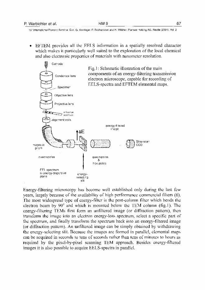
P. Warbichler et al. HM9 6715th International Plansee Seminar, Eds. G. Kneringer, P. Rodhammer and H. Wildner, Plansee Holding AG, Reutte (2001), Vol. 2
• EFTEM provides all the EELS information in a spatially resolved characterwhich makes it particularly well suited to the exploration of the local chemicaland also electronic properties of materials with nanometer resolution.
$P Cathode
XCondensor lens
Specimen
—--H Objective lens
Projective lens
Fig.l: Schematic illustration of the maincompoments of an energy-filtering transmissionelectron microscope, capable for recording ofEELS-spectra and EFTEM elemental maps.
'CttSTi"'—-—- entrance^ ^ ^ aperture
i — j alignment coils
AE
magneticprism
energy-filteredimage
JSlow-scanCCD
quadru poles
EEL-spectrumin energy-dispersiveplane
quadruples&
hexupoles
energy-selecting
slit
Energy-filtering microscopy has become well established only during the last fewyears, largely because of the availability of high performance commercial filters (6).The most widespread type of energy-filter is the post-column filter which bends theelectron beam by 90° and which is mounted below the TEM column (fig.l). Theenergy-filtering TEMs first form an unfiltered image (or diffraction pattern), thentransform the image into an electron energy-loss spectrum, select a specific part ofthe spectrum, and finally transform the spectrum back into an energy-filtered image(or diffraction pattern). An unfiltered image can be simply obtained by withdrawingthe energy-selecting slit. Because the images are formed in parallel, elemental mapscan be acquired in seconds to tens of seconds rather than tens of minutes to hours asrequired by the pixel-by-pixel scanning TEM approach. Besides energy-filteredimages it is also possible to acquire EELS-spectra in parallel.
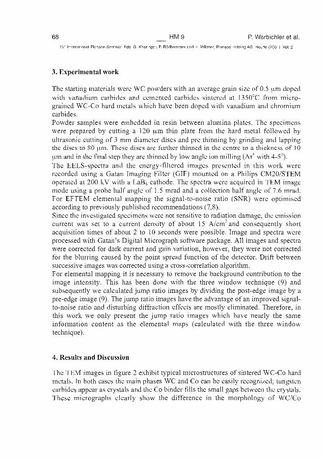
68 HM9 P. Warbichler et al.15'" International Plansee Seminar Eds. G. Kneringer, P. Rddhammer and H. Wildner, Plansee Holding AG, Reutte (2001), Vol. 2
3. Experimental work
The starting materials were WC powders with an average grain size of 0.5 \xm dopedwith vanadium carbides and cemented carbides sintered at 1350°C from micro-grained WC-Co hard metals which have been doped with vanadium and chromiumcarbides.Powder samples were embedded in resin between alumina plates. The specimenswere prepared by cutting a 120 |im thin plate from the hard metal followed byultrasonic cutting of 3 mm diameter discs and pre thinning by grinding and lappingthe discs to 80 um. These discs are further thinned in the centre to a thickness of 10jim and in the final step they are thinned by low angle ion milling (Ar+ with 4-5°).The EELS-spectra and the energy-filtered images presented in this work wererecorded using a Gatan Imaging Filter (GIF) mounted on a Philips CM20/STEMoperated at 200 kV with a LaB6 cathode. The spectra were acquired in TEM imagemode using a probe half angle of 1.5 mrad and a collection half angle of 7.6 mrad.For EFTEM elemental mapping the signal-to-noise ratio (SNR) were optimisedaccording to previously published recommendations (7,8).Since the investigated specimens were not sensitive to radiation damage, the emissioncurrent was set to a current density of about 15 A/cm2 and consequently shortacquisition times of about 2 to 10 seconds were possible. Image and spectra wereprocessed with Gatan's Digital Micrograph software package. All images and spectrawere corrected for dark current and gain variation, however, they were not correctedfor the blurring caused by the point spread function of the detector. Drift betweensuccessive images was corrected using a cross-correlation algorithm.For elemental mapping it is necessary to remove the background contribution to theimage intensity. This has been done with the three window technique (9) andsubsequently we calculated jump ratio images by dividing the post-edge image by apre-edge image (9). The jump ratio images have the advantage of an improved signal-to-noise ratio and disturbing diffraction effects are mostly eliminated. Therefore, inthis work we only present the jump ratio images which have nearly the sameinformation content as the elemental maps (calculated with the three windowtechnique).
4. Results and Discussion
The TEM images in figure 2 exhibit typical microstructures of sintered WC-Co hardmetals. In both cases the main phases WC and Co can be easily recognized; tungstencarbides appear as crystals and the Co binder fills the small gaps between the crystals.These micrographs clearly show the difference in the morphology of WC/Co
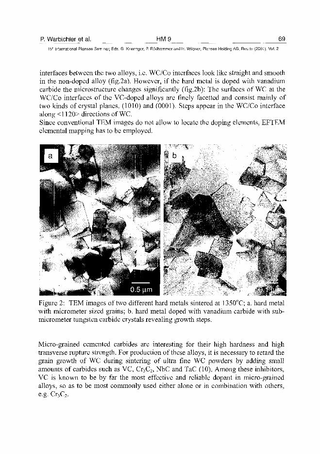
P. Warbichler et al. HM9 6915th International Plansee Seminar, Eds. G. Kneringer, P. Rodhammer and H. Wildner, Plansee Holding AG, Reutte (2001), Vol. 2
interfaces between the two alloys, i.e. WC/Co interfaces look like straight and smoothin the non-doped alloy (fig.2a). However, if the hard metal is doped with vanadiumcarbide the microstructure changes significantly (fig.2b): The surfaces of WC at theWC/Co interfaces of the VC-doped alloys are finely facetted and consist mainly oftwo kinds of crystal planes, (1010) and (0001). Steps appear in the WC/Co interfacealong <1120> directions of WC.Since conventional TEM images do not allow to locate the doping elements, EFTEMelemental mapping has to be employed.
Figure 2: TEM images of two different hard metals sintered at 1350°C; a. hard metalwith micrometer sized grains; b. hard metal doped with vanadium carbide with sub-micrometer tungsten carbide crystals revealing growth steps.
Micro-grained cemented carbides are interesting for their high hardness and hightransverse rupture strength. For production of these alloys, it is necessary to retard thegrain growth of WC during sintering of ultra fine WC powders by adding smallamounts of carbides such as VC, Cr3C2, NbC and TaC (10). Among these inhibitors,VC is known to be by far the most effective and reliable dopant in micro-grainedalloys, so as to be most commonly used either alone or in combination with others,e.g. Cr3C2.
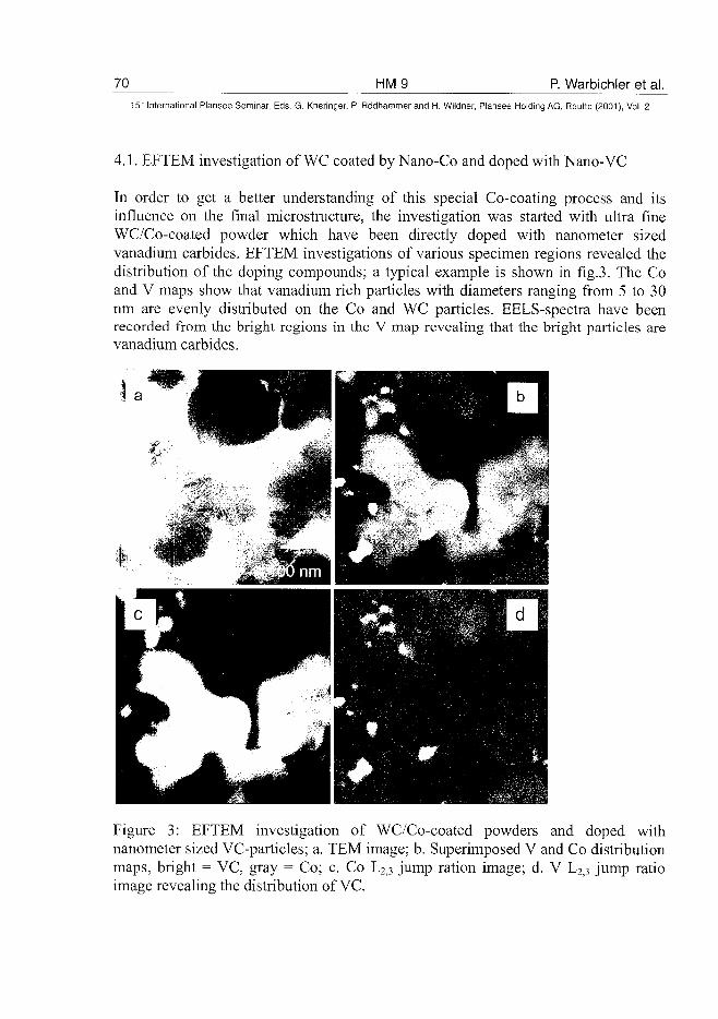
70 HM9 P. Warbichler et al.
15" International Plansee Seminar, Eds. G. Kneringer, P. Rodhammer and H. Wildner, Plansee Holding AG, Reutte (2001), Vol. 2
4.1. EFTEM investigation of WC coated by Nano-Co and doped with Nano-VC
In order to get a better understanding of this special Co-coating process and itsinfluence on the final microstructure, the investigation was started with ultra fineWC/Co-coated powder which have been directly doped with nanometer sizedvanadium carbides. EFTEM investigations of various specimen regions revealed thedistribution of the doping compounds; a typical example is shown in fig.3. The Coand V maps show that vanadium rich particles with diameters ranging from 5 to 30nm are evenly distributed on the Co and WC particles. EELS-spectra have beenrecorded from the bright regions in the V map revealing that the bright particles arevanadium carbides.
Figure 3: EFTEM investigation of WC/Co-coated powders and doped withnanometer sized VC-particles; a. TEM image; b. Superimposed V and Co distributionmaps, bright = VC, gray = Co; c. Co L2j3 jump ration image; d. V L2j3 jump ratioimage revealing the distribution of VC.
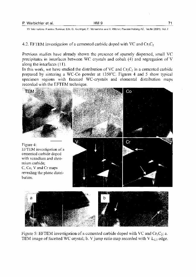
P. Warbichler et al. HM9 7115Lh International Plansee Seminar, Eds. G. Kneringer, P. Rodhammer and H. Wildner, Plansee Holding AG, Reutte (2001), Vol. 2
4.2. EFTEM investigation of a cemented carbide doped with VC and Cr3C2
Previous studies have already shown the presence of sparsely dispersed, small VCprecipitates in interfaces between WC ciystals and cobalt (4) and segregation of Valong the interfaces (11).In this work, we have studied the distribution of VC and Cr3C2 in a cemented carbideprepared by sintering a WC-Co powder at 1350°C. Figures 4 and 5 show typicalspecimen regions with facetted WC-crystals and elemental distribution mapsrecorded with the EFTEM technique.
TEM
Figure 4:EFTEM investigation of acemented carbide dopedwith vanadium and chro-mium carbide;C, Co, V and Cr mapsrevealing the phase distri-bution.
Figure 5: EFTEM investigation of a cemented carbide doped with VC and Cr3C2; a.TEM image of facetted WC crystal; b. V jump ratio map recorded with V L2j3 edge.
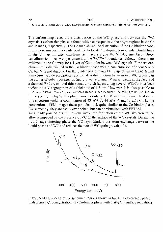
72 HM9 P. Warbichler et al.
15" International Plansee Seminar, Eds. G. Kneringer, P. Rodhammer and H. Wildner, Plansee Holding AG, Reutte (2001), Vol. 2
The carbon map reveals the distribution of the WC phase and between the WCcrystals a carbon rich phase is found which corresponds to the bright regions in the Crand V maps, respectively. The Co map shows the distribution of the Co binder phase.From these images it is easily possible to locate the doping compounds. Bright linesin the V map indicate vanadium rich layers along the WC/Co interface. Thesevanadium rich lines even penetrate into the WC/WC boundaries, although there is noevidence in the Co map for a layer of Co binder between WC crystals. Furthermore,chromium is distributed in the Co binder phase with a concentration of about 5 at%Cr, but V is not dissolved in the binder phase (from EELS-spectrum in fig.6). Smallvanadium carbide precipitates are found in the junction between two WC crystals inthe corner of cobalt pockets. In figure 5 we find small V enrichments at the facets ofa facetted WC crystal and thin vanadium rich layers along several WC/Co interfacesindicating a V segregation of a thickness of 1-3 nm. However, it is also possible tofind larger vanadium carbide particles in the space between the WC grains. As shownin the spectrum (fig.6), this phase consists only of Cr, V and C and quantification ofthis spectrum yields a composition of 43 at% C, 44 at% V and 13 at% Cr. In theconventional TEM images these particles look quite similar to the Co binder phase.Consequently, they are easily overlooked, but can be visualized with EFTEM.As already pointed out in previous work, the formation of the WC skeleton in thealloy is impeded by the presence of VC on the surface of the WC crystals. During theliquid stage sintering phase the VC layer hinders the atom exchange between theliquid phase and WC and reduces the rate of WC grain growth (11).
COL2,3
300 400 500 600 700 800Energy Loss (eV)
Figure 6 EELS spectra of the specimen regions shown in fig. 4; (1) V-carbide phasewith a small Cr concentration; (2) Co-binder phase with 5 at% Cr (surface oxidation)
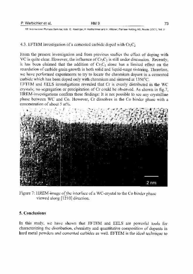
P. Warbichler et al. HM9 7315lh International Plansee Seminar, Eds. G. Kneringer, P. Rodhammer and H. Wildner, Plansee Holding AG, Reutte (2001), Vol. 2
4.3. EFTEM investigation of a cemented carbide doped with Cr3C2
From the present investigation and from previous studies the effect of doping withVC is quite clear. However, the influence of Cr3C2 is still under discussion. Recently,it has been claimed that the addition of Cr3C2 alone has a limited effect on theretardation of carbide grain growth in both solid and liquid-stage sintering. Therefore,we have performed experiments to try to locate the chromium dopant in a cementedcarbide which has been doped only with chromium and sintered at 1350°C.EFTEM and EELS investigations revealed that Cr is evenly distributed in the WCcrystals; no segregation or precipitation of Cr could be observed. As shown in fig.7,HREM-investigations confirm these findings: It is not possible to see any crystallinephase between WC and Co. However, Cr dissolves in the Co binder phase with aconcentration of about 5 at%.
Figure 7: HREM-image ofthe interface of a WC-crystal to the Co binder phaseviewed along [1210] direction.
5. Conclusions
In this study, we have shown that EFTEM and EELS are powerful tools forcharacterizing the distribution, chemistry and quantitative composition of dopants inhard metal powders and cemented carbides as well. EFTEM is the ideal technique to
74 HM9 P. Warbichler et al.15" Internationa] Plansee Seminar, Eds. G. Kneringer, P. Rodhammer and H. Wildner, Plansee Holding AG, Reutte (2001), Vol. 2
map relatively high local concentrations of elements at high spatial resolutiondistributed over large areas of the specimen.From EFTEM and EELS-analysis we have been able to locate the doping compoundssuch as VC and Cr3C2.In case of a VC and Cr3C2 doped cemented carbide we have found the following:• VC layers with an average thickness of a few nanometers have been found along
WC/Co interfaces and even in boundaries between WC crystals.• In the space between the WC crystals we have also found larger vanadium carbide
precipitates.In case of a cemented carbide which has been doped with Cr3C2 alone, we could notreveal Cr enrichments in interfaces and boundaries, but we have found that Cr isevenly distributed both in the WC crystals and in the Co binder phase.
Acknowledgements:The authors thank Margit Brunegger and Albert Brunegger for the preparation ofTEM specimen of the hard metal samples.
References:(1) J. Zackrisson, A. Kvist, H.-O. Andren: Proc. 14th Int. Plansee Seminar, Vol 2,
pp. 127-138 (ed. G.Kneringer et al., Plansee AG, Reutte 1997).(2) F. Hofer, W. Grogger, P. Warbichler, I. Papst: Microchim. Acta 132 (2000),
pp. 273-288.(3) J. Zackrisson, W. Grogger, F. Hofer, H.-O. Andren: Ultramicroscopy 79
(1999),pp.273-281.(4) W. Grogger, F. Hofer, P. Warbichler: Proc. 14th Int. Plansee Seminar, Vol 3,
pp. 304-316 (ed. G.Kneringer et al., Plansee AG, Reutte 1997).(5) R.F. Egerton: ,,Electron Energy-Loss Spectroscopy in the Electron
Microscope", 2nd ed., Plenum Press, New York and London (1996).(6) O.L. Krivanek, AJ. Gubbens, N. Dellby, C.E. Meyer: Microsc. Microanal.
Microstruct. 3 (1992), pp. 187-199.(7) A. Berger, J. Mayer, H. Kohl: Ultramicroscopy 55 (1994), pp. 101-117.(8) G. Kothleitner and F. Hofer: Micron 29 (1998), pp. 349-351(9) F. Hofer, P. Warbichler a. W. Grogger: Ultramicroscopy 59 (1995), pp. 15-31.(10) K. Hayashi, Y. Fuke and H. Suzuki: J. Jpn. Soc. Powder and Powder Metall.
19 (1972), pp. 67-71.(11) A. Jaroenworaluck, T. Yamamoto, Y. Ikuhara, T. Sakuma, K. Okada and T.
Tanase: J. Mater. Res. 13 (1998), pp.2450-52
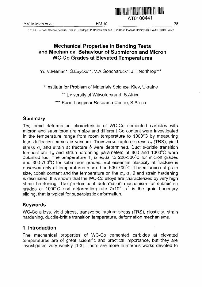
AT0100441Y.V. Milman et al. HM 10 75^
15" International Plansee Seminar, Eds. G. Kneringer, P. Ro'dhammer and H. Wildner, Plansee Holding AG, Reutte (2001), Vol. 2
Mechanical Properties in Bending Testsand Mechanical Behaviour of Submicron and Micron
WC-Co Grades at Elevated Temperatures
Yu.V.Milman*, S.Luyckx**, V.A.Goncharuck*, J.T.Northrop***
* Institute for Problem of Materials Science, Kiev, Ukraine
** University of Witwatersrand, S.Africa
*** Etoart Longyear Research Centre, S.Africa
SummaryThe bend deformation characteristic of WC-Co cemented carbides withmicron and submicron grain size and different Co content were investigatedin the temperature range from room temperature to 1000°C by measuringload deflection curves in vacuum. Transverse rupture stress of (TRS), yieldstress as and strain at fracture 8 were determined. Ductile-brittle transitiontemperature Td and strain-hardening parameters at 800 and 1000°C wereobtained too. The temperature Td is equal to 200-300°C for micron gradesand 300-700°C for submicron grades. But essential plasticity at fracture isobserved only at temperatures more than 600-700°C. The influence of grainsize, cobalt content and the temperature on the cs, af, 8 and strain hardeningis discussed. It is shown that the WC-Co alloys are characterized by very highstrain hardening. The predominant deformation mechanism for submicrongrades at 1000°C and deformation rate 7x10"5 s"1 is the grain boundarysliding, that is typical for superplastic deformation.
KeywordsWC-Co alloys, yield stress, transverse rupture stress (TRS), plasticity, strainhardening, ductile-brittle transition temperature, deformation mechanisms.
1. IntroductionThe mechanical properties of WC-Co cemented carbides at elevatedtemperatures are of great scientific and practical importance, but they areinvestigated very weakly [1-3]. There are more numerous works devoted to
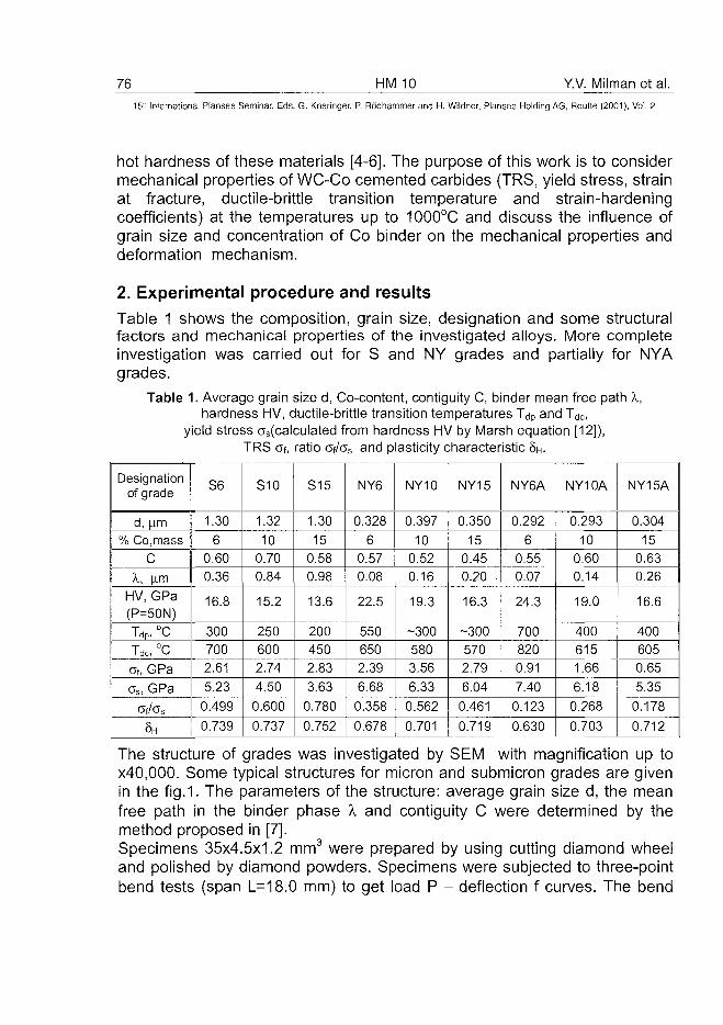
76 HM 10 Y.V. Milman et al.
15:" International Plansee Seminar, Eds. G. Kneringer, P. Rodhammer and H. Wildner, Plansee Holding AG, Reutte (2001), Vol. 2
hot hardness of these materials [4-6]. The purpose of this work is to considermechanical properties of WC-Co cemented carbides (TRS, yield stress, strainat fracture, ductile-brittle transition temperature and strain-hardeningcoefficients) at the temperatures up to 1000°C and discuss the influence ofgrain size and concentration of Co binder on the mechanical properties anddeformation mechanism.
2. Experimental procedure and resultsTable 1 shows the composition, grain size, designation and some structuralfactors and mechanical properties of the investigated alloys. More completeinvestigation was carried out for S and NY grades and partially for NYAgrades.
Table 1. Average grain size d, Co-content, contiguity C, binder mean free path X,hardness HV, ductile-brittle transition temperatures Tdp and Tdc,
yield stress (^(calculated from hardness HV by Marsh equation [12]),TRS Of, ratio af/as and plasticity characteristic 8H.
Designationof grade
I d, |a.m: % Co, mass
C
X, |imHV, GPa(P=50N)Tdp, °C
Tdc, °C
Of, GPa
os, GPa
CTf/Cs
5H
S6
1.30
60.600.36
16.8
3007002.61
5.23
0.499
0.739
S10
1.32
100.700.84
15.2
2506002.74
4.50
0.600
0.737
S15
1.30
150.580.98
13.6
2004502.83
3.63
0.780
0.752
NY6
0.328
60.570.08
22.5
5506502.39
6.68
0.358
0.678
NY10
0.397
100.520.16
19.3
-3005803.56
6.330.562
0.701
NY15
0.35015
0.450.20
16.3
-3005702.79
6.04
0.461
0.719
NY6A
0.292
60.550.07
24.3
7008200.91
7.40
0.123
0.630
NY10A
0.293
100.600.14
19.0
4006151.66
6.18
0.268
0.703
NY15A
0.304
150.630.26
16.6
4006050.65
5.35
0.178
0.712
The structure of grades was investigated by SEM with magnification up tox40,000. Some typical structures for micron and submicron grades are givenin the fig. 1. The parameters of the structure: average grain size d, the meanfree path in the binder phase X and contiguity C were determined by themethod proposed in [7].Specimens 35x4.5x1.2 mm3 were prepared by using cutting diamond wheeland polished by diamond powders. Specimens were subjected to three-pointbend tests (span L=18.0 mm) to get load P - deflection f curves. The bend
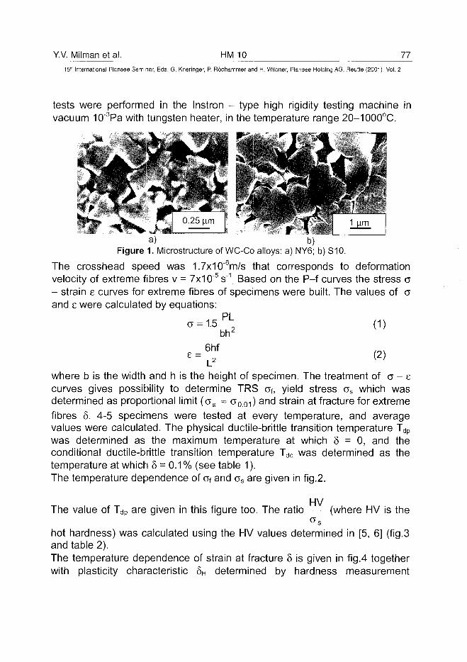
Y.V. Milman et al. HM 10 77
15Ih International Plansee Seminar, Eds. G. Kneringer, P. Rodhammer and H. Wildner, Plansee Holding AG, Reutte (2001), Vol. 2
tests were performed in the Instron - type high rigidity testing machine in1-3vacuum 10 Pa with tungsten heater, in the temperature range 20-1000 C.
a) b)Figure 1. Microstructure of WC-Co alloys: a) NY6; b) S10.
The crosshead speed was 1.7x10"6m/s that corresponds to deformationvelocity of extreme fibres v = 7x10"5 s'\ Based on the P-f curves the stress a- strain e curves for extreme fibres of specimens were built. The values of aand e were calculated by equations:
a = 1.5PL; (1)bh'
8 =6hf
(2)
where b is the width and h is the height of specimen. The treatment of o - ecurves gives possibility to determine TRS cf, yield stress cs which wasdetermined as proportional limit (o s ~ a001) and strain at fracture for extremefibres 5. 4-5 specimens were tested at every temperature, and averagevalues were calculated. The physical ductile-brittle transition temperature Tdp
was determined as the maximum temperature at which 8 = 0, and theconditional ductile-brittle transition temperature Tdc was determined as thetemperature at which 8 = 0.1 % (see table 1).The temperature dependence of af and os are given in fig.2.
HVThe value of Tdp are given in this figure too. The ratio (where HV is the
hot hardness) was calculated using the HV values determined in [5, 6] (fig.3and table 2).The temperature dependence of strain at fracture 8 is given in fig.4 togetherwith plasticity characteristic 8H determined by hardness measurement
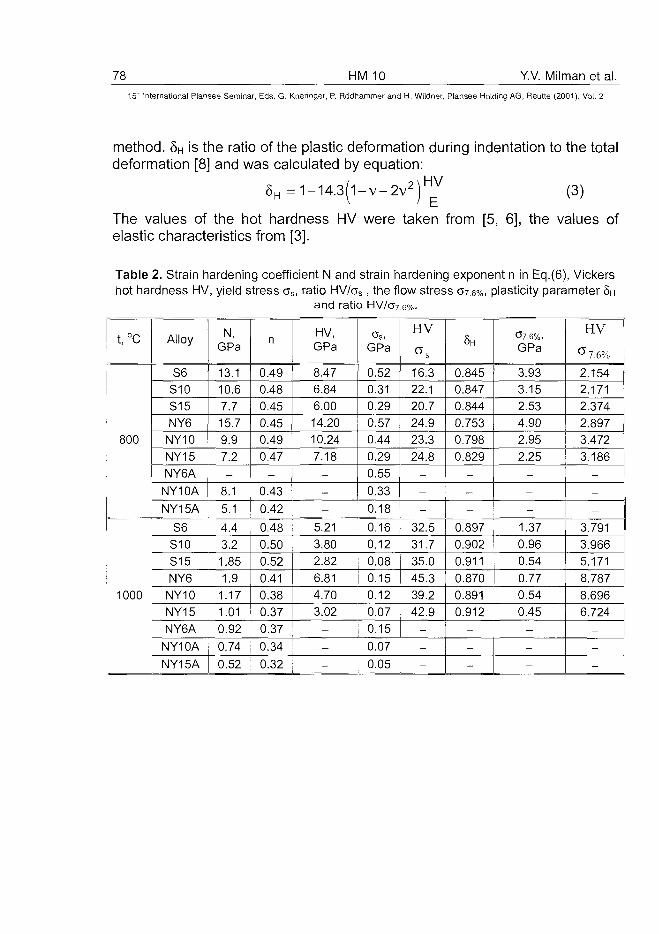
78 HM 10 Y.V. Milman et al.
15'" International Plansee Seminar, Eds. G. Kneringer, P. Rodhammer and H. Wildner, Plansee Holding AG, Reutte (2001), Vol. 2
method. 5H is the ratio of the plastic deformation during indentation to the totaldeformation [8] and was calculated by equation:
8 H = 1 - 1 4 . 3 ( 1 - V - 2 V 2 ) H V (3)
The values of the hot hardness HV were taken from [5, 6], the values ofelastic characteristics from [3].
Table 2. Strain hardening coefficient N and strain hardening exponent n in Eq.(6), Vickershot hardness HV, yield stress os, ratio HV/cs, the flow stress 07.6%, plasticity parameter 5H
and ratio HV/c>7.6%.
t, °c
800
Alloy
S6S10S15NY6
NY10NY15NY6A
NY10A
NY15A
S6S10S15NY6
1000 NY10NY15NY6A
NY10A
NY15A
N,GPa
13.110.67.715.79.97.2-
8.1
5.1
4.43.21.851.9
1.171.010.92
0.74
0.52
n
0.490.480.450.450.490.47
0.43
0.42
0.480.500.520.410.380.370.37
0.34
0.32
HV,GPa
8.476.84
6.0014.2010.24
7.18-
-
-
5.21
3.802.82
6.814.703.02
-
-
-
GPa
0.520.310.290.570.44
0.290.55
0.33
0.18
0.160.120.080.150.120.070.15
0.07
0.05
HV
°s16.322.1
20.724.9
23.324.8
-
-
-
32.531.735.045.339.242.9
-
-
-
SH
0.8450.8470.8440.7530.7980.829
-
-
-
0.897
0.9020.911
0.8700.8910.912
-
-
-
07.6%,GPa
3.933.152.534.902.952.25
-
-
-
1.370.960.540.770.540.45
-
-
-
HV07.6%
2.1542.1712.3742.8973.472
3.186-
-
-
3.791
3.9665.1718.7878.6966.724
-
-
-
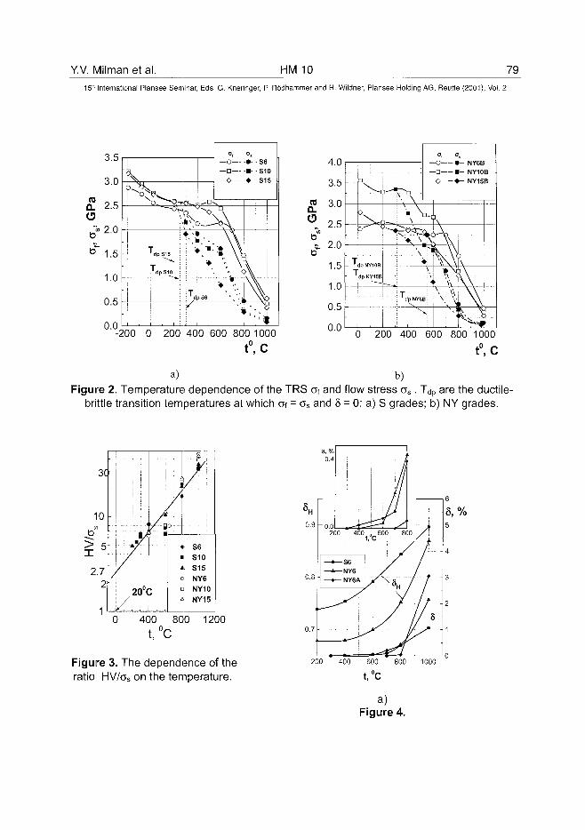
Y.V. Milman et al. HM 10 79
15" International Plansee Seminar, Eds. G. Kneringer, P. Rodhammer and H. Wildner, Plansee Holding AG, Reutte (2001), Vol. 2
-200 0 200 400 600 800 1000t°,c
a)
0 200 400 600 800 1000t°,c
b)Figure 2. Temperature dependence of the TRS Of and flow stress a s . Tdp are the ductile-
brittle transition temperatures at which Oi = as and § = 0: a) S grades; b) NY grades.
3C
10
2.72
7720°(
ur.A
C
r_
I
2
f» S6
i S10
i. S15
a NY6
i NY10
\ NY15
0 400 800 1200
t,°C
Figure 3. The dependence of theratio HV/os on the temperature.
0.9200 400 „ 600 800
t, C
6
5,%5
200 400 600 800 1000
t,°c
a)Figure 4.
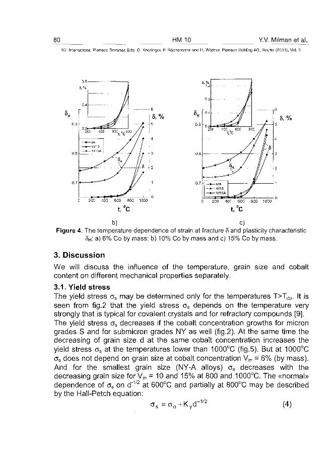
80 HM 10 Y.V. Milman et al.
15" International Plansee Seminar, Eds. G. Kneringer, P. Rodhammer and H. Wildner, Plansee Holding AG, Reutte (2001), Vol. 2
0.7 -
b) c)Figure 4. The temperature dependence of strain at fracture § and plasticity characteristic
8H: a) 6% Co by mass; b) 10% Co by mass and c) 15% Co by mass.
3. DiscussionWe will discuss the influence of the temperature, grain size and cobaltcontent on different mechanical properties separately.
3.1. Yield stressThe yield stress os may be determined only for the temperatures T>Tdp. It isseen from fig.2 that the yield stress as depends on the temperature verystrongly that is typical for covalent crystals and for refractory compounds [9].The yield stress os decreases if the cobalt concentration growths for microngrades S and for submicron grades NY as well (fig.2). At the same time thedecreasing of grain size d at the same cobalt concentration increases theyield stress os at the temperatures lower than 1000°C (fig.5). But at 1000°Cos does not depend on grain size at cobalt concentration Vm = 6% (by mass).And for the smallest grain size (NY-A alloys) cs decreases with thedecreasing grain size for Vm = 10 and 15% at 800 and 1000°C. The «normal»dependence of as on d"1/2 at 600°C and partially at 800°C may be describedby the Hall-Petch equation:
(4)as =ao+Kyd -1/2
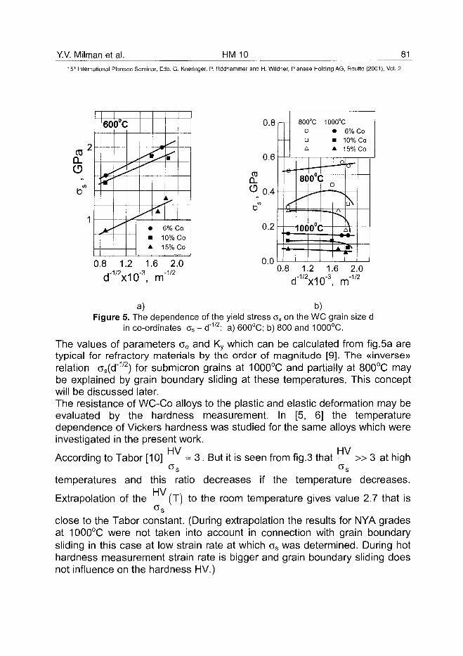
Y.V. Milman et al. HM 10 81
151h International Plansee Seminar, Eds. G. Kneringer, P. Rodhammer and H. Wildner, Plansee Holding AG, Reutte (2001), Vol. 2
COQ_CD
b
2
1
60o"c
i
• 6% C• 10%A 15%
:oJo30
0.8 1.2 1.6 2.0,-1/2 . ~-3 -1/2
d x10 , m
05Q_
0.8
0.6
0.4
0.2
n n
800°C 1000°CO • 6% CoD • 10% CoA A 15% Co
• e -
&
i
-44-8G
<-"
0"(
. 0 .lOOu t
c
—*
-a
V
1* - ;
V
M
4\
0.8 1.2 1.6 2.0.-1/2 .,-.-3 -1/2
d x10 , m
a) b)Figure 5. The dependence of the yield stress os on the WC grain size d
in co-ordinates os - d"1/2: a) 600°C; b) 800 and 1000°C.
The values of parameters o0 and Ky which can be calculated from fig.5a aretypical for refractory materials by the order of magnitude [9]. The «inverse»relation cs(d~1/2) for submicron grains at 1000°C and partially at 800°C maybe explained by grain boundary sliding at these temperatures. This conceptwill be discussed later.The resistance of WC-Co alloys to the plastic and elastic deformation may beevaluated by the hardness measurement. In [5, 6] the temperaturedependence of Vickers hardness was studied for the same alloys which wereinvestigated in the present work.
HV HVAccording to Tabor [10] ~ 3. But it is seen from fig.3 that » 3 at high
temperatures and this ratio decreases if the temperature decreases.HV
Extrapolation of the (T) to the room temperature gives value 2.7 that is
close to the Tabor constant. (During extrapolation the results for NYA gradesat 1000°C were not taken into account in connection with grain boundarysliding in this case at low strain rate at which cs was determined. During hothardness measurement strain rate is bigger and grain boundary sliding doesnot influence on the hardness HV.)
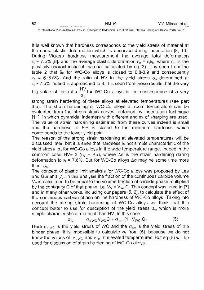
82 HM 10 Y.V. Milman et al.
15" International Plansee Seminar, Eds. G. Kneringer, P. Rodhammer and H. Wildner, Plansee Holding AG, Reutte (2001), Vol. 2
It is well known that hardness corresponds to the yield stress of material atthe same plastic deformation which is observed during indentation [8, 10].During Vickers hardness measurement the average total deformationEt ~ 7.6% [8], and the average plastic deformation ep = et8H, where 8H is theplasticity characteristic of material calculated by eq.(3). It is seen from thetable 2 that 5H for WC-Co alloys is closed to 0.8-0.9 and consequentlyep = 6-5-6.5%. And the ratio of HV to the yield stress as determined atet ~ 7.6% indeed is approached to 3. It is seen from these results that the very
HVbig value of the ratio for WC-Co alloys is the consequence of a very
strong strain hardening of these alloys at elevated temperatures (see part3.5). The strain hardening of WC-Co alloys at room temperature can beevaluated from the stress-strain curves, obtained by indentation technique[11], in which pyramidal indenters with different angles of sharping are used.The value of strain hardening estimated from these curves indeed is smalland the hardness at 8% is closed to the minimum hardness, whichcorresponds to the lower yield point.The reason of the strong strain hardening at elevated temperatures will bediscussed later, but it is seen that hardness is not simple characteristic of theyield stress cs for WC-Co alloys in the wide temperature range. Indeed in thecommon case HV~ 3 (cs + AG), where Ac is the strain hardening duringdeformation to et = 7.6%. But for WC-Co alloys Aa may be some time morethan os.
The concept of plastic limit analysis for WC-Co alloys was proposed by Leeand Gurland [7]. In this analysis the fraction of the continuous carbide volumeVv is calculated to be equal to the volume fraction of carbide phase multipliedby the contiguity C of that phase, i.e. Vv = VWCC. This concept was used in [7]and in many other works, including our papers [5, 6], to calculate the effect ofthe continuous carbide phase on the hardness of WC-Co alloys. Taking intoaccount the strong strain hardening of WC-Co alloys we think that thisconcept better to use for description of the yield stress os, which is moresimple characteristic of material than HV. In this case
os = s s W C V w c C + G s m (1 -V w c C) (5)Here os we is the yield stress of WC and the csm is the yield stress of thebinder phase. It is impossible to calculate os from (5), because we do notknow the values of oswc and osm at elevated temperatures. But eq.(5) will beused for discussion of strain hardening of WC-Co alloys.
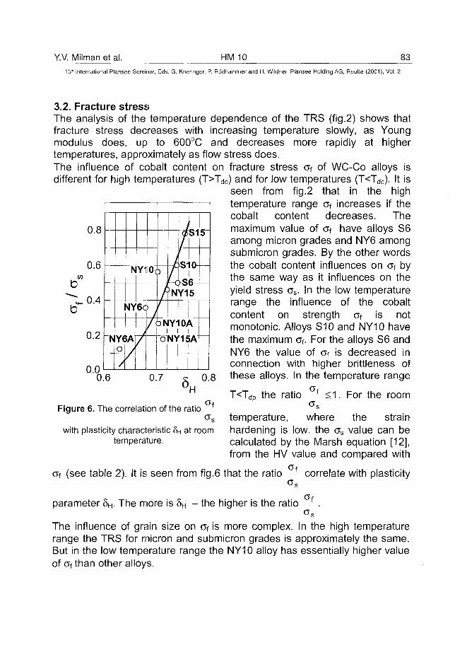
Y.V. Milman et al. HM 10 83
15" International Plansee Seminar, Eds. G. Kneringer, P. Rodhammer and H. Wildner, Plansee Holding AG, Reutte (2001), Vol. 2
0.8
3.2. Fracture stressThe analysis of the temperature dependence of the TRS (fig.2) shows thatfracture stress decreases with increasing temperature slowly, as Youngmodulus does, up to 600°C and decreases more rapidly at highertemperatures, approximately as flow stress does.The influence of cobalt content on fracture stress cf of WC-Co alloys isdifferent for high temperatures (T>Tdc) and for low temperatures (T<Tdc). It is
seen from fig.2 that in the hightemperature range af increases if thecobalt content decreases. Themaximum value of of have alloys S6among micron grades and NY6 amongsubmicron grades. By the other wordsthe cobalt content influences on of bythe same way as it influences on theyield stress as. In the low temperaturerange the influence of the cobaltcontent on strength af is notmonotonic. Alloys S10 and NY10 havethe maximum of. For the alloys S6 andNY6 the value of Cf is decreased inconnection with higher brittleness ofthese alloys. In the temperature range
T<Tdp th ti f
0.6CO
0.4
0.2
0.0
NY1l0(
N Y 6 <?/NY6A
—(° y/ /
f/
A1
o
fJff
, e
>NY1
Y10)
NY1i
S I
i n
6 -5
\
»A
5
0.6 0.7 0.8'H the ratio <1. For the room
Figure 6. The correlation of the ratio f
temperature, where the strainhardening is low, the as value can becalculated by the Marsh equation [12],from the HV value and compared with
af (see table 2). It is seen from fig.6 that the ratio f correlate with plasticity
with plasticity characteristic 8H at roomtemperature.
parameter 5H. The more is 8H - the higher is the ratio f .
The influence of grain size on of is more complex. In the high temperaturerange the TRS for micron and submicron grades is approximately the same.But in the low temperature range the NY10 alloy has essentially higher valueof 0f than other alloys.
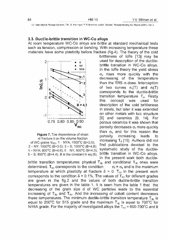
84 HM 10 Y.V. Milman et al.
15" International Plansee Seminar, Eds. G. Kneringer, P. Rodhammer and H. Wildner, Plansee Holding AG, Reutte (2001), Vol. 2
3.3. Ductile-brittle transition in WC-Co alloysAt room temperature WC-Co alloys are brittle at standard mechanical testssuch as tension, compression or bending. With increasing temperature thesematerials have some plasticity before fracture (fig.4). The theory of the cold
brittleness of loffe [13] may beused for description of the ductile-brittle transition in WC-Co alloys.In the loffe theory the yield stressas rises more quickly with thedecreasing of the temperaturethan the TRS afdoes. Interceptionof two curves os(T) and oT(T)corresponds to the ductile-brittletransition temperature Td. Firstlythis concept was used fordescription of the cold brittlenessin steels, but later it was extendedon other metals with bcc structure[9] and ceramics [9, 14]. Forporous ceramics it was shown thatporosity decreases af more quicklythan cs and for this reason theporosity increasing leads toincreasing Td [15]. Authors did notfind publications devoted to thesystematic study of the ductile-
0.75 0.80 0.85 0.90Vwc
Figure 7. The dependence of strainat fracture 5 on the volume fraction
of WC grains VWC- 1 - NYA; 1000°C (B=2.0);2 - NY; 1000°C (B=3.0); 3 - S; 1000°C (B=4.8);4 - NYA; 800°C (B=4.8); 5 - NY; 800°C (B=4.3);6 - S; 800°C (B=4.4). B is the constant in eq.(6). b r i t t | e transition in WC-Co alloys.
In the present work both ductile-brittle transition temperatures: physical Tdp and conditional Tdc ones weredetermined. Tdp corresponds to the condition af = as and is the maximumtemperature at which plasticity at fracture 8 = 0. Tdc in the present workcorresponds to the condition 8 = 0.1%. The values of Tdp for different gradesare given in the fig.2 and the values of both ductile-brittle transitiontemperatures are given in the table 1. It is seen from the table 1 that thedecreasing of the grain size d of WC particles leads to the essentialincreasing of Tdp and Tdc. And the increasing of cobalt content decreasesthese temperatures. The minimum ductile-brittle transition temperature Tdp isequal to 200°C for S15 grade and the maximum Tdp is equal to 700°C forNY6A grade. For the majority of investigated alloys the Tdc = 600-700°C and it
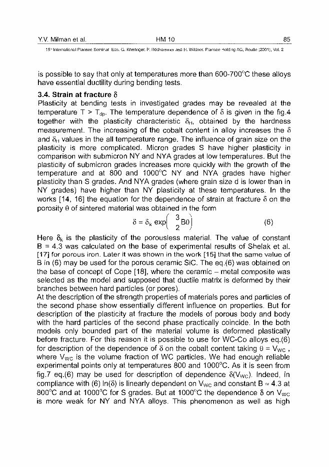
Y.V. Milman et al. HM 10 85^
15" International Plansee Seminar, Eds. G. Kneringer, P. Rodhammer and H. Wildner, Plansee Holding AG, Reutte (2001), Vol. 2
is possible to say that only at temperatures more than 600-700°C these alloyshave essential ductility during bending tests.
3.4. Strain at fracture 8Plasticity at bending tests in investigated grades may be revealed at thetemperature T > Tdp. The temperature dependence of 8 is given in the fig.4together with the plasticity characteristic 8H, obtained by the hardnessmeasurement. The increasing of the cobalt content in alloy increases the 8and 8H values in the all temperature range. The influence of grain size on theplasticity is more complicated. Micron grades S have higher plasticity incomparison with submicron NY and NYA grades at low temperatures. But theplasticity of submicron grades increases more quickly with the growth of thetemperature and at 800 and 1000°C NY and NYA grades have higherplasticity than S grades. And NYA grades (where grain size d is lower than inNY grades) have higher than NY plasticity at these temperatures. In theworks [14, 16] the equation for the dependence of strain at fracture 8 on theporosity 9 of sintered material was obtained in the form
(6)
Here 8k is the plasticity of the porousless material. The value of constantB = 4.3 was calculated on the base of experimental results of Shelak et al.[17] for porous iron. Later it was shown in the work [15] that the same value ofB in (6) may be used for the porous ceramic SiC. The eq.(6) was obtained onthe base of concept of Cope [18], where the ceramic - metal composite wasselected as the model and supposed that ductile matrix is deformed by theirbranches between hard particles (or pores).At the description of the strength properties of materials pores and particles ofthe second phase show essentially different influence on properties. But fordescription of the plasticity at fracture the models of porous body and bodywith the hard particles of the second phase practically coincide. In the bothmodels only bounded part of the material volume is deformed plasticallybefore fracture. For this reason it is possible to use for WC-Co alloys eq.(6)for description of the dependence of 8 on the cobalt content taking 0 = VWc ,where Vw c is the volume fraction of WC particles. We had enough reliableexperimental points only at temperatures 800 and 1000°C. As it is seen fromfig.7 eq.(6) may be used for description of dependence 8(VWc)- Indeed, incompliance with (6) ln(8) is linearly dependent on Vw c and constant B = 4.3 at800°C and at 1000°C for S grades. But at 1000°C the dependence 8 on Vw c
is more weak for NY and NYA alloys. This phenomenon as well as high
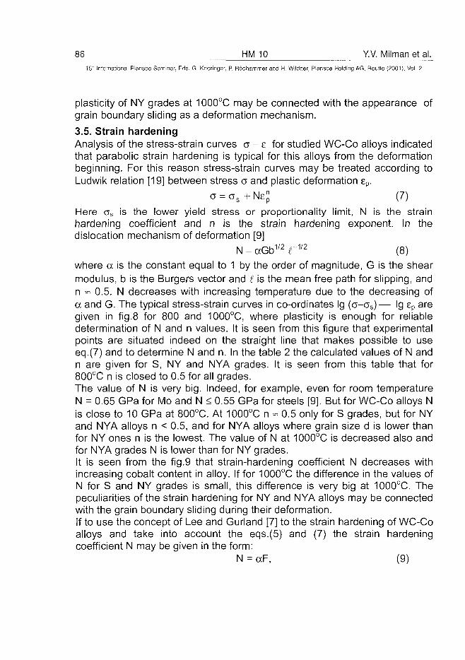
86 HM 10 Y.V. Milman et al.
15' Internationa! Plansee Seminar, Eds. G. Kneringer, P. Rodhammer and H. Wildner, Plansee Holding AG, Reutte (2001), Vol. 2
plasticity of NY grades at 1000°C may be connected with the appearance ofgrain boundary sliding as a deformation mechanism.
3.5. Strain hardeningAnalysis of the stress-strain curves a - e for studied WC-Co alloys indicatedthat parabolic strain hardening is typical for this alloys from the deformationbeginning. For this reason stress-strain curves may be treated according toLudwik relation [19] between stress a and plastic deformation ep.
c = cs+Ne£ (7)Here as is the lower yield stress or proportionality limit, N is the strainhardening coefficient and n is the strain hardening exponent. In thedislocation mechanism of deformation [9]
N = ccGb1/2 CV2 (8)where a is the constant equal to 1 by the order of magnitude, G is the shearmodulus, b is the Burgers vector and I is the mean free path for slipping, andn = 0.5. N decreases with increasing temperature due to the decreasing ofa and G. The typical stress-strain curves in co-ordinates Ig (a-os)— Ig ep aregiven in fig.8 for 800 and 1000°C, where plasticity is enough for reliabledetermination of N and n values. It is seen from this figure that experimentalpoints are situated indeed on the straight line that makes possible to useeq.(7) and to determine N and n. In the table 2 the calculated values of N andn are given for S, NY and NYA grades. It is seen from this table that for800°C n is closed to 0.5 for all grades.The value of N is very big. Indeed, for example, even for room temperatureN = 0.65 GPa for Mo and N < 0.55 GPa for steels [9]. But for WC-Co alloys Nis close to 10 GPa at 800°C. At 1000°C n « 0.5 only for S grades, but for NYand NYA alloys n < 0.5, and for NYA alloys where grain size d is lower thanfor NY ones n is the lowest. The value of N at 1000°C is decreased also andfor NYA grades N is lower than for NY grades.It is seen from the fig.9 that strain-hardening coefficient N decreases withincreasing cobalt content in alloy. If for 1000°C the difference in the values ofN for S and NY grades is small, this difference is very big at 1000°C. Thepeculiarities of the strain hardening for NY and NYA alloys may be connectedwith the grain boundary sliding during their deformation.If to use the concept of Lee and Gurland [7] to the strain hardening of WC-Coalloys and take into account the eqs.(5) and (7) the strain hardeningcoefficient N may be given in the form:
N = aF, (9)
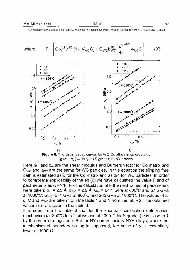
Y.V. Milman et al. HM 10 87
15h International Plansee Seminar, Eds. G. Kneringer, P. Rodhammer and H. Wildner, Plansee Holding AG, Reutte (2001), Vol. 2
where Ou.1/2 i1/2 /.i w n \
Gbm A, ( 1 - V w c C )u.1/2
w c b w c
-1/2(9')
0.05 0.1
a) b)Figure 8. The strain-stress curves for WC-Co alloys in co-ordinates
Ig (a - o s ) — Ig ep: a) S grades; b) NY grades.
Here Gm and bm are the shear modulus and Burgers vector for Co matrix andGwc and bWc are the same for WC particles. In this equation the slipping freepath is estimated as X for the Co matrix and as d/4 for WC particles. In orderto control the applicability of the eq.(9) we have calculated the value F and ofparameter a as a =N/F. For the calculation of F the next values of parameterswere taken: bm = 2.5 A; bwc = 2.9 A; Gm = 64.1 GPa at 800°C and 57.5 GPaat 1000°C; GWc=271 GPa at 800°C and 265 GPa at 1000°C. The values oiX,d, C and Vw c are taken from the table 1 and N from the table 2. The obtainedvalues of a are given in the table 3.It is seen from the table 3 that for the «normal» dislocation deformationmechanism (at 800°C for all alloys and at 1000°C for S grades) a is close to 1by the order of magnitude. But for NY and especially NYA alloys, where themechanism of boundary sliding is supposed, the value of a is essentiallylower at 1000°C.
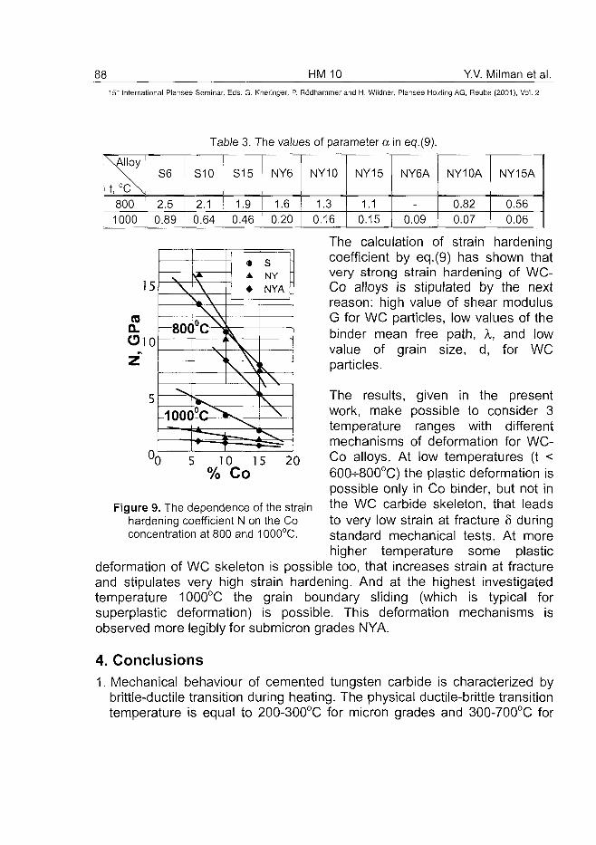
HM 10 Y.V. Milman et al.
15" International Plansee Seminar, Eds. G. Kneringer, P. Rodhammer and H. Wildner, Plansee Holding AG, Reutte (2001), Vol. 2
\Alloy
t, °c\8001000
S6
2.50.89
Table 3. The values of parameter a
S10
2.10.64
S15
1.90.46
NY6
1.60.20
NY10
1.30.16
NY15
1.10.15
in eq.(9).
NY6A
-
0.09
NY10A
0.820.07
NY15A
0.560.06
15
CO
Oio
b
I
\ \\ \
800 C i
-100C
—
V
N\, V\ \\]
s -NY
NYA
kk.
\
\
10 15 20
The calculation of strain hardeningcoefficient by eq.(9) has shown thatvery strong strain hardening of WC-Co alloys is stipulated by the nextreason: high value of shear modulusG for WC particles, low values of thebinder mean free path, X, and lowvalue of grain size, d, for WCparticles.
The results, given in the presentwork, make possible to consider 3temperature ranges with differentmechanisms of deformation for WC-Co alloys. At low temperatures (t <60f>800°C) the plastic deformation ispossible only in Co binder, but not inthe WC carbide skeleton, that leadsto very low strain at fracture 5 duringstandard mechanical tests. At morehigher temperature some plastic
deformation of WC skeleton is possible too, that increases strain at fractureand stipulates very high strain hardening. And at the highest investigatedtemperature 1000°C the grain boundary sliding (which is typical forsuperplastic deformation) is possible. This deformation mechanisms isobserved more legibly for submicron grades NYA.
4. Conclusions1. Mechanical behaviour of cemented tungsten carbide is characterized by
brittle-ductile transition during heating. The physical ductile-brittle transitiontemperature is equal to 200-300°C for micron grades and 300-700°C for
% Co
Figure 9. The dependence of the strainhardening coefficient N on the Coconcentration at 800 and 1000°C.
Y.V. Milman et al. HM 10 89^
15" International Plansee Seminar, Eds. G. Kneringer, P. Rodhammer and H. Wildner, Plansee Holding AG, Reutte (2001), Vol. 2
submicron grades. But essential plasticity at fracture is observed only attemperatures more than 600-700°C.
2. Transverse rupture stress af (TRS) decreases with increasing temperatureslowly, as Young modulus does, up to 600°C and more rapidly at highertemperatures. At the temperatures T > 600°C cf depends on the cobaltcontent by the same way as yield stress as. But at the low temperatureswhere af < as the ratio ov /os decreases with decreasing ductility, whichmay be characterized by plasticity characteristic 8H, determined duringhardness measurement.
3. The yield stress os (which was determined at very low deformation degreeas ao.01) increases rapidly with decreasing the temperature and ductile-brittle transition takes place at the temperature of intersection of cs(T) andCf(T) curves. The ratio HV/as increases rapidly with increasing thetemperature from the value ~ 3 at room temperature to the value 30-40 at1000°C. But the ratio HV/c7.6% ~ 3 in the wide temperature range.
4. The increasing of the cobalt content in WC-Co alloy increases the strain atfracture 5 and plasticity characteristic 8H in the all investigated temperaturerange. The equation for the dependence of 5 on the Co concentration isproposed. Micron grades have higher plasticity than submicron grades attemperatures t < 800°C. But the plasticity of submicron grades increasesmore quickly with the growth of the temperature and at 800 and 1000°C thelower is WC grain size, the more is the 5 value.
5. The WC-Co alloys are characterized by high strain hardening even at 800and 1000°C, that may be explained by the high value of shear modulus Gfor WC phase and low value of the mean free path for dislocation slippingin Co binder and WC particles.
6. The obtained results give possibility to consider for WC cobalt alloys 3temperature ranges with different mechanisms of plastic deformation:
• Low temperature range (t < 600-800°C). Plastic deformation duringmechanical tests is possible only in Co binder phase, that leads to very lowstrain at fracture 5.
• Middle temperature range (from 600-800 to 1000°C). Plastic deformationtakes place not only in binder phase, but in WC skeleton too, that stipulatesvery high strain hardening.
• High temperature range (1000 and partially 800°C - only for submicrongrains). Grain boundary sliding (which is typical for superplasticdeformation) is the predominant deformation mechanism. This mechanismis confirmed by the low value of yield stress as and decreasing of as withdecreasing WC grain size, high value of strain at fracture, low values of
90 HM 10 Y.V. Milman et al.15" International Plansee Seminar, Eds. G. Kneringer, P. Rodhammer and H. Wildner, Plansee Holding AG, Reutte (2001), Vol. 2
strain hardening coefficient and strain hardening exponent. It is possiblethat appearance of grain boundary sliding was possible due to very lowstrain rate during mechanical tests (7x10~5s~1).
AcknowledgementsThe authors are grateful to Dr. S.Chugunova and Mrs. I.Goncharova forexperimental help and useful discussion of results. This work was supportedpartially by the Boart Longyear Research Centre.
References
1. H.Suzuki, K.Hayashi, Y.Taniguchi, H.Mastubara: Trans. Japan Inst. Met. Vol 23, No.2(1982), pp.77-84
2. L.S.Sigl, H.E.Exner: Mater.Sci. and Engineering A108 (1989), pp.121-1293. S.Luyckx, I.T.Northrop, Yu.V.Milman, V.A.Goncharuck: Proc. Powder Metallurgy World
Congress and Exhibition, Vol 4 (Granada, Spain, 1998), pp.27-394. M.Lee: Metallurgical Transitions A, Vol 14A (1983), pp.1625-16295. Yu.V.Milman, S.Chugunova, V.Goncharuck, S.Luyckx, I.T.Northrop: Int.J. of Refractory
Metals and Hard Materials Vol 15(1997), pp.97-1016. Yu.V.Milman, S.Luyckx, I.T.Northrop: Int.J. of Refractory Metals and Hard Materials
Vol 7, No.1-3 (1999), pp.39-447. H.C.Lee, J.Gurland: Materials Science and Engineering Vol 33 (1978), pp.125-1338. Yu.V.Milman, B.A.Galanov, S.Chugunova: Acta Metal, et Mater. Vol 41, No.9 (1993),
pp.2523-25329. I.V.Trefilov, Yu.V.Milman, S.A.Firstov. «Physical Basis of Strength for Refractory
Metals» 315 p. (ed. Kiev, Naukova Dumka, 1975)10. D.Tabor. «The Hardness of Metals» (ed. London, Clarendon Press, 1951)11. Yu.V.Milman, S.I.Chugunova, I.V.Goncharova, S.Luyckx: Science of Sintering Vol
29(3) (1997), pp.155-16112. D.M.Marsh: Proc.Phys Soc.A Vol 279 (1964), p.42013. A.l.loffe. Selected works Vol 1 (ed.S.-Petersburg, Nauka, 1974)14. M.M.Ristic, V.l.Trefilov, Yu.V.Milman, I.V.Gridneva, D.Duzevic. «Structure and
Mechanical Properties of Powder Metallurgy Materials* 254 p. (ed. Belgrad, SerbianAcademy of Science and Art, 1992)
15. Yu.V.Milman, S.I.Chugunova, I.V.Goncharova, T.Chudoba, W.Lojkowski, W.Gooch:Int.Journal of Refractory Metals and Hard Materials Vol 17, No.5 (1999), pp.361-368
16. Yu.V.Milman, R.K.Ivashchenko, N.P.Zakharova: Powder Metallurgy No.3 (1991),pp.93-100
17. A.Salak, V.Miloskovich, E.Dudrova, E.Rudnayova: Powd. Metal. Inter. Vol 6 (1974),p.128
18. L.H.Cope: Metallurgia Vol 72 (1965), p.16519. P.Ludwik: Elemente dertechnologyschen Mechanik (ed. Berlin, Springer, 1909)
AT0100442V. Falkovsky et al. HM 11 91_
15'* International Plansee Seminar, Eds. G. Kneringer, P. Rodhammer and H. Wildner, Plansee Holding AG, Reutte (2001), Vol. 2
NANOCRYSTALLINE WC-Co HARDMETALS PRODUCED BYPLASMOCHEMICAL METHOD
V. Falkovsky, Yu. EBIagoveschenski*, V. Glushkov, L. Klyachko, A. Khokhlov
All-Russia Institute for Refractory and Hard Metals, Moscow, RussiaInstitute of Metallurgy and Materials Science RAS, Moscow, Russia
Summary:
A process has been developed to manufacture nanopowders of tungstencarbide with the use of plasmochemical reduction. The average size ofcarbide grains was adjustable within the range of 0.01 |iim - 0.05 jim. Twoalternative procedures are suggested to produce ultrafine WC - Co gradepowder mixes. Subject to sintering variables, the carbide grains sizes can bekept in the range of 0.1|a,m - 0.2 |im or 0.3|im - 0.4|im. The hardmetals'hardness proved sharply increased and the strength raised for 25% - 30%.
Keywords:
Nanopowders, hardmetals, tungsten, carbide, plasmochemical reductionsynthesis, sintering, nanostructure.
1. Introduction:
Materialisation of high physical and mechanical properties offered bynanocrystalline solids, is a challenge for large circles of specialists engagedin Materials Science, Physics and Chemistry of Solids and advancedtechnologies. As regards hardmetals, potential breakthrough is expected fromthe creation of materials having nanocrystalline structures. These can only bemade if there are techniques to manufacture nanocrystalline starting powdersand to further process them.Studies of plasmochemical synthesis have been carried out for more than 20years. In these, conventional starting powders, tungsten trioxide andammonium paratungstate, as well as less common tungsten halogens andother organic compounds were employed (1 -3).The reduction synthesis was conducted in a high-temperature plasma jet.Combined function of plasmogenic and reduction agent was performed eitherby hydrogen or by air-methane mixture. A high-temperature gas jet was
92 HM 11 V. Falkovsky et al.15' International Plansee Seminar, Eds. G. Kneringer, P. Rodhammer and H. Wildner, Plansee Holding AG, Reutte (2001), Vol. 2
created by an arc plasma generation and in some cases by a high-frequencyplasma generator.The process has been shown to result in complete reduction at a certainexcess (5 or 10-fold) of reducing agent and with power consumption not lowerthan 5 kWhkg"1- - 7kWhkg~1 The product's carbon content was defined by aC/W ratio in the reaction space. The course of pyrolysis of hydrocarbonsdiffers for different hydrocarbons and compositions of plasmogenic agent.The carbon content in the products was selected empirically and adjustedwithin a wide range (3).A phase content of the products is also a junction of power consumption anda ratio of reactants. In the course of reduction synthesis, there could beproduced powders that contain W, W2C, (3-WC(WC1-x), a-W and C. It worthmentioning that, although the higher-content carbide has been obtained withthe higher power consumption, the single-phase monocarbide free ofadmixtures of subcarbides and pure tungsten has never been obtained.Grain sizes of the powders depended on the jet temperature and theconsumption of new materials. A specific surface of the powders was 5m2g"1-25m2g~1 and it significantly rised with the increase of free carbon content.Trial studies of the synthesis of tungsten monocarbide from ultrafine powdersmade by plasmochemical process have shown poorly reproducible results -the products either contain an insufficient amount of carbon and were notsingle-phased, or there was a considerable amount of free carbon in theproducts. After the trails had failed in a number of organisations, the work inthis area was suspended.
2. Experimental:
Plasmochemical synthesis.Plasmochemical studies were carried out on an arc plasma unit equippedwith a 100kW plasma generator. A plasmogenic gas, hydrogen was heated to2700K - 3500K. A hydrocarbon gas, methane or propane-butane eitherentered the reaction space together with the plasmogenic gas or wasintroduced in order to transfer tungsten-bearing ran materials. These wereeither ammonium paratungstate or tungsten trioxide. The powder with a grainsize of (-60)(im was fed by a metering screw conveyer at a rate of 0.5kgh~1-10kg-h"1.The starting powders were blended close to the plasma generator's exitsection in the high-temperature portion of the jet. The processes ofvapourisation, chemical interaction, condensation, particle growth by
V. Falkovsky et al. HMJJ 93^15'" International Plansee Seminar, Eds. G. Kneringer, P. Rodhammer and H. Wildner, Plansee Holding AG, Reutte (2001), Vol. 2
coagulation, and adsorption in a gas jet were complete after times in theorder of 10"1s. Under the selected process conditions, particles of therefractory products grew up on average from less than 0.01 |a,m to (0.05-0.08)(im in size.The products' phase content varied dependent on a degree of reduction ofstarting powders, a ratio of reactants and a temperature. The completenessof reduction is an important factor in attaining the lowest oxygen content inpowders. At relatively low temperatures, the process could result in tungsten-carbon mixes that are stoichiometric with respect to carbon but contain minoramounts of the carbide phase. As the temperature rises, the combinedcarbon content increases to over 5wt%. Predominant becomes W2C -semicarbide phase, although W, cubic WC1-X and cc-WC were also present.Oxygen (nitrogen) contents in powders were measured with a gas-analyserTC436 made by LECO, by a fractional method using a novel software"OxCEP" (4). The technique enables to define in what form oxygen exists inpowders. Thus, in tungsten-carbon powders it can be presented by an oxideor adsorbed on a powder's surface. The results of synthesis of themonocarbide from these powders would differ.Furnace synthesis of monocarbide.Synthesis of the monocarbide from ultrafine tungsten-carbon powders wascarried out in hydrogen. By means of a thermobalance unit equipped with ananalyser of gaseous products, weight loss on heating was measured andfound to be caused by the chemical and physical reactions in which thepowders got involved. In the range of 100°C - 150°C the powders' moisturewas desorbing. At 600°C - 700°C, the chemosorbed oxygen was beingreduced by hydrogen, as well as a certain amount of the oxides. From 750°Cand up to 1000°C, carbothermal reduction of the bulk of oxides occured, withthe reduction temperature being also a function of the size of powder grains.The actual synthesis of the carbide from the phase constituents available inthe powder occupied approximately the same temperature range as thecarbothermal reduction - from 900°C and above, subject to the initial powdergrain size. This appeared to also be the range where the grains startedgrowing by recrystallisation, for raising the synthesis temperature from1000°C to 1050°C made sizes of grains 5 times as large.The synthesis time is defined by the phase content in an ultrafine powder mixand the desired grain size of a product, and it normally was 1.5h - 3h.With the developed technology the product's (tungsten monocarbide's) grainsizes are adjustable within the range of 0.01 \xm - 0.05|j,m and can be made
94 HM 11 V. Falkovsky et al.15" International Plansee Seminar, Eds. G. Kneringer, P. Rodhammer and H. Wildner, Plansee Holding AG, Reutte (2001), Vol. 2
larger (as estimated by the BET specific surface values, from 8m2g"1 to+40m2g"1). The free carbon content is controllable within the accuracy of0.1wt%. The oxygen content amounts to 0.3% - 0.5%, and, according to thefractional analysis data, 80% of these amounts account for absorbed oxygen.Manufacture of tungsten carbide-cobalt grade powder mixes.To make an ultrafine hardmetal grade powder mix, two alternative schemesof cobalt production have been selected. According to the first, an ultrafinecobalt powder is produced by plasmochemical reduction of cobalt oxide inhydrogen followed by size separation. After reduction, cobalt powders werecomposed of spherical particles that displayed a very broad size distribution.During the plasmochemical reduction the powders' specific surface valueswere kept within the range of 1m2g"1 - 5m2g"1, and the bulk of grains werefrom micrometers to tens of micrometers in size. After separation, the amountof submicron grains totalled from 5wt% to over 20wt%, and the specificsurface, from 8m2g"1 to 12m2g~1. Grade powder mixes were made by wetmilling for 8h - 24h in a jar mixer with hardmetal balls.By the second scheme, cobalt entered a tungsten carbide powder viaprecipitation of its salt from solution in an organic solvent followed byreduction in hydrogen. After the salt had dissolved, an ultrafine powder wasadded to the solution and, under active agitation, the solvent was beingevapourated. The dried and comminuted powder was then reduced inhydrogen. This way, WC - Co grade powder mixes were produced with 3wt%- 1-wt% and larger cobalt contents.The grain size of a grade powder mix was estimated by the value of itsspecific surface. In the first scheme, the grade powder mix's specific surfaceis somewhat less (by 2% - 5%) than the initial carbide powder's, whilst in thesecond, after reduction, it is by 5% - 10% larger than that of the carbidepowder.Homogeneity of products was assessed by means of an X-ray microanalyserJEOL-8600 with electron beams of a minimum cross-section.In order to check growth of carbide grains during sintering, tantalum carbidewas admixed, as inhibitor, to grade powders in amounts of 0.5wt% - 1wt%.Sintering of ultrafine WC-Co grade powder mixes has been carried out in twoways. Conventional sintering was conducted at 1350°C and sintering bymeans of hot pressing was studied as follows.Solid-phase sintering at temperatures 1100°C and 1200°C and pressures 33MPa and 50 MPa has been employed. This resulted in specimens with adensity of over 0.95. Carbide grain sizes after sintering amounted to 0.1 jim -0.2,um. Several specimens displayed anomalously high values of
V. Falkovsky et al. HM 11 95^
15'" International Plansee Seminar, Eds. G. Kneringer, P. Rodhammer and H. Wildner, Plansee Holding AG, Reutte (2001), Vol. 2
microhardness (HV), up to 2700kgmm~2. Sintering at 1300°C - 1400°Cbrought about almost pore-free specimens with an average size of carbidegrains in the range of 0.2jim - 0.4|im subject to the sintering time andtemperature, and hardness (HV) of 2100kgmm~2 - 2300kg-mm~2. Thetransverse rupture strength and ultimate tensile stress were respectively 25%and 30% higher than these of conventional hardmetals.
3. Discussion:
The study of plasmochemical synthesis of tungsten carbide from tungstentrioxide, or ammonium paratungstate, and carbon in a high-temperaturehydrogen jet has shown that the process is controllable. A major prerequisiteis the completeness of reduction of tungsten-bearing starting powders. This issecured by selection of an optimum ratio of the reactants (H/O > 10) andappropriate thermal conditions. The phase content can be controlled bymaintaining a certain W/C ratio and a desired temperature profile. In anycare, powder products are mixtures of several phases. The more carbidephases are there in a powder and the less in the tungsten content, easier itfor the low-temperature synthesis to run. This, however, requires large powerconsumption and, accordingly, the higher process temperatures, and,naturally results in the coarser powders.The chance to make a stoichiometric carbide that is almost free fromexcessive carbon is defined by interaction of oxygen impurities present in apowder after the plasmochemical stage. The best option is to make at thisstage a completely reduced power with some 1% of adsorbed oxygen whichwould outgas when the synthesis starts, at the second stage. It is underthese conditions that the single phased powders of tungsten monocarbidewith total carbon content of 6.15% - 6.20% and oxygen content of 0.3% -0.5% were produced.Grain sizes of the synthesised monocarbide powders were, as expected,determined by those of the powders after the plasmochemical stage. With thelowest temperature at the second stage the specific surface of a productalmost inherited its value from a starting powder. In some cases this valuewas around 50m2g"1 which implies that, on average, the particles were of lessthan 0.01 |im in size.The both suggested schemes for cobalt to enter an ultrafine carbide powderare capable of making grade powder mixes that retain high values of specificsurface. It, however, worth mentioning that the grade powder mixes withcobalt entered from a solution displayed the lower compactability.
96 HM 11 V. Falkovsky et al.
15" International Plansee Seminar, Eds. G. Kneringer, P. Rddhammer and H. Wildner, Plansee Holding AG, Reutte (2001), Vol. 2
4. References:
1. Newenschwander E., Schutt K., Scheller W. Finelly dispersed carbidesand process for their production, Pat. US N 3340020, 1967.
2. Borg R.J., Lay D.Y.F., Riby N.K. Cermet powders. Pat. US N 3723359 on27.03.73.
3. Shorin S.N., Alekseev N.V., Blagoveschenski Yu.V. et. at. Abstracts of thereports at 2nd All-Union conference of plasmochemical technology,Moscow, 1977, vol. 1, p. 4 (In Russian).
4. Grigorovich K.V., Krilov A.S., Katsnelson A.M. New Approach to theFractional Gas Analysis Application in Metallurgy and Material ControlUsing Oxide Separation Software Developed, Proceeding of the 6 SETASConference Luxembourg. 1985. P. 527-532.
AT0100443L. Bartha et al. HM 13 97^
15th International Plansee Seminar, Eds. G. Kneringer, P. Rodhammer and H. Wildner, Plansee Holding AG, Reutte (2001), Vol. 2
High Temperature Reactions of WC-Co Nanopowders inVarious Atmospheres
LBartha2, I.Kotsis1, L. Laczko1, P.Harmat21lnst. f. Silicate and Materials Engineering, Univ. Veszprem, Veszprem, Hungary2Res.lnst. for Technical Phys. and Mat. Sciences, Budapest, Hungary
Summary:
The melting of 30 nanometer size WC-6w% and -15w% Co particles,heated in hot chamber microscope under N2 atmosphere, was observedbetween 1130°C and 1280 °C, i.e. under the equilibrium melting point of theWC-Co eutectics, 1320 °C. Such a dependence of the melting temperature ofultrafine particles on the grain size can be explained by Allen's model, or incase of a thin layer by a modified version of the model. At cooling, moltenphases were observed down till 1190 °C, which shows the probability ofchemical reactions occurred at high temperature, and the formation ofcompounds with lower melting points.
Further experiments were carried out by heating the above samples in N2-1v%CO and in N2-3,5v%H2 atmospheres, in the chamber of the microscope.The samples were cooled down rapidly to room temperature, and theproducts were analyzed by X-ray diffractometry and by X-ray microanalysis.Several phases were found, which may help to describe possible solid-liquid-gas phase reactions between the components to be present either in thesamples or in the atmosphere.
Keywords:
WC-Co, nanosize, melting, solid state reactivity
1. Introduction
It was reported earlier [1], that in 30 nm average size WC powdersamples with 6 w% or with 15 w% Co content , heated in hot chambermicroscope in N2 atmosphere of 4N5 purity, the melting appears first alreadyat 1130 °C instead of 1320 °C, which is the melting point of the correspondingeutectics
98 HM 13 L. Bartha et al.15" International Plansee Seminar, Eds. G. Kneringer, P. Rodhammer and H. Wildner, Plansee Holding AG, Reutte (2001), Vol. 2
under equilibrium conditions. In case of technical processing, liquid phasesintering is always carried out above this temperature.
The decrease of melting point of ultrafine particles has been observedearlier [2]. Allen et al. [3] have described the reduction of melting temperaturedue to small particle size, in the function of the particle radius, r, surface freeenergy per unit area, a, change of the free strain energy density, AE, andlatent heat, L. They found the simple relation
- AE]/L1To r
where Tm is the melting temperature of the small sphere with radius r, To isthe melting temperature of the bulk (both in Kelvin), asoiid and anqUid are thesolid and liquid surface free energy values, respectively. In order to illustratesuch an effect, the calculation for a Co sphere with a radius of r = 10 nmgives 50 K as a reduction of melting temperature. A minor transformation ofAllen's equation makes it applicable for thin layers, the probable shape of abinder phase in the hardmetal, where layer thickness is the determiningdimension. The transformation results in the following equation:
Tm
In case of layer thickness of 10 nm, 100 K decrease of meltingtemperature can be expected.
The melting phenomena did not appear, if the heat treatment of thesamples was carried out in N2 atmospheres with 1v% CO or 3,5% H2 content,i.e. under reducing conditions.
2. Experimental and discussion
It follows from the above observations, that the decrease of meltingtemperature of small primary phases in different atmospheres can not beunderstood only on the basis of physical ideas, but it needs also chemicalconsiderations. Therefore, we have studied more detailed the atmosphericinfluence on the phase composition of our samples in the temperature regionbetween 1000-1400 °C.
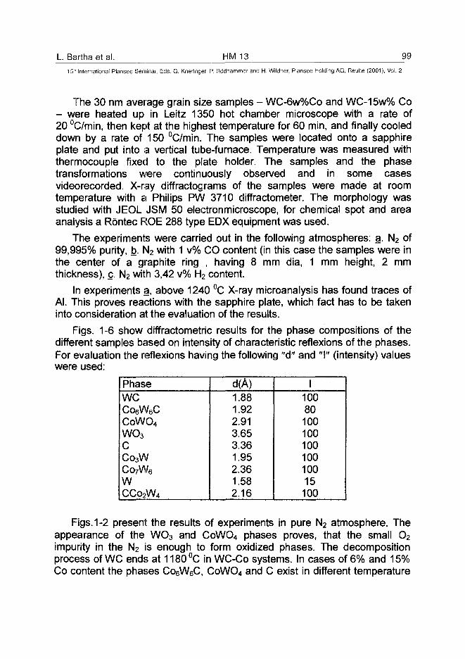
L. Bartha et al. HM 13 99
15!h International Plansee Seminar, Eds. G. Kneringer, P. Rodhammer and H. Wildner, Plansee Holding AG, Reutte (2001), Vol. 2
The 30 nm average grain size samples - WC-6w%Co and WC-15w% Co- were heated up in Leitz 1350 hot chamber microscope with a rate of20 °C/min, then kept at the highest temperature for 60 min, and finally cooleddown by a rate of 150 °C/min. The samples were located onto a sapphireplate and put into a vertical tube-furnace. Temperature was measured withthermocouple fixed to the plate holder. The samples and the phasetransformations were continuously observed and in some casesvideorecorded. X-ray diffractograms of the samples were made at roomtemperature with a Philips PW 3710 diffractometer. The morphology wasstudied with JEOL JSM 50 electronmicroscope, for chemical spot and areaanalysis a Rontec ROE 288 type EDX equipment was used.
The experiments were carried out in the following atmospheres: a. N2 of99,995% purity, b. N2 with 1 v% CO content (in this case the samples were inthe center of a graphite ring , having 8 mm dia, 1 mm height, 2 mmthickness), c. N2 with 3,42 v% H2 content.
In experiments a, above 1240 °C X-ray microanalysis has found traces ofAl. This proves reactions with the sapphire plate, which fact has to be takeninto consideration at the evaluation of the results.
Figs. 1-6 show diffractometric results for the phase compositions of thedifferent samples based on intensity of characteristic reflexions of the phases.For evaluation the reflexions having the following "d" and " I " (intensity) valueswere used:
Phase
weCo6W6CCoWO4
WO3
CC03WCo7W6
WCCo2W4
d(A)
1.881.922.913.653.361.952.361.582.16
I1008010010010010010015
100
Figs. 1-2 present the results of experiments in pure N2 atmosphere. Theappearance of the WO3 and CoWO4 phases proves, that the small O2
impurity in the N2 is enough to form oxidized phases. The decompositionprocess of WC ends at 1180°C in WC-Co systems. In cases of 6% and 15%Co content the phases Co6VV6C, CoWO4 and C exist in different temperature
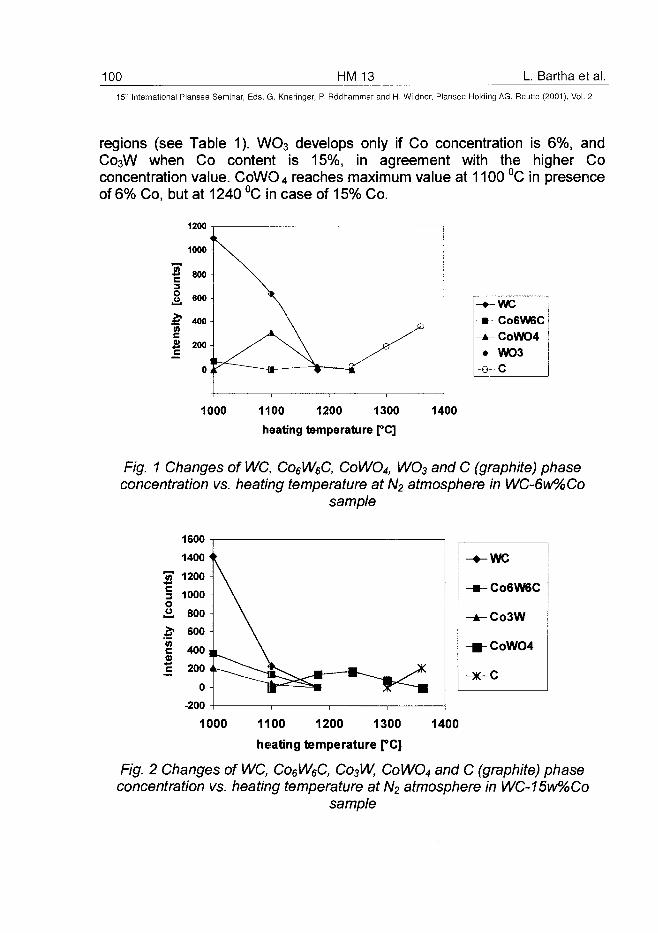
100 HM 13 L. Bartha et al.
15" International Plansee Seminar, Eds. G. Kneringer, P. Rodhammer and H. Wildner, Plansee Holding AG, Reutte (2001), Vol. 2
regions (see Table 1). WO3 develops only if Co concentration is 6%, andCo3W when Co content is 15%, in agreement with the higher Coconcentration value. CoWO4 reaches maximum value at 1100 °C in presenceof 6% Co, but at 1240 °C in case of 15% Co.
weC06W6CCoWO4WO3C
1000 1100 1200 1300
heating temperature [°C]
1400
Fig. 1 Changes of WC, Co6W6C, CoWO4, WO3 and C (graphite) phaseconcentration vs. heating temperature at A/2 atmosphere in WC-6w%Co
sample
J2
[cou
ni
&
Inte
nsi
• guv -
1400 <
1200
1000
800
600
400 ,
200 t
0
-200
\
\
weC06W6C
Co3W
CoWO4
1000 1100 1200 1300
heating temperature [°C]
1400
Fig. 2 Changes of WC, Co6W6C, Co3W, CoWO4 and C (graphite) phaseconcentration vs. heating temperature at A/2 atmosphere in WC-15w%Co
sample
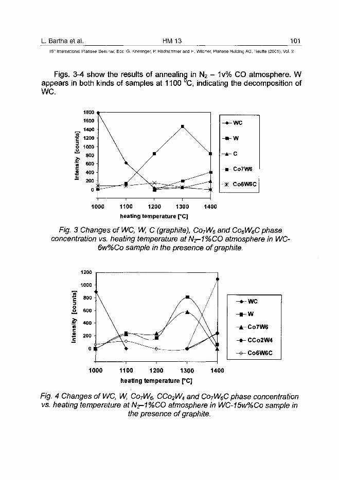
L Bartha et al. HM 13 101
15!" International Plansee Seminar, Eds. G. Kneringer, P. Rodhammer and H. Wildner, Plansee Holding AG, Reutte (2001), Vol. 2
Figs. 3-4 show the results of annealing in N2 - 1v% CO atmosphere. Wappears in both kinds of samples at 1100 C, indicating the decomposition ofWC.
1000 1100 1200 1300
heating temperature [°C]1400
Fig. 3 Changes of WC, W, C (graphite), Co7W6 and Co6W6C phaseconcentration vs. heating temperature atN2-1%CO atmosphere in WC-
6w%Co sample in the presence of graphite.
1200
we
w
CCo2W4
C06W6C
1000 1100 1200 1300
heating temperature [°C]
1400
Fig. 4 Changes of WC, W, Co7W6, CCo2W4 and Co7W6C phase concentrationvs. heating temperature at N2-1%CO atmosphere in WC-15w%Co sample in
the presence of graphite.
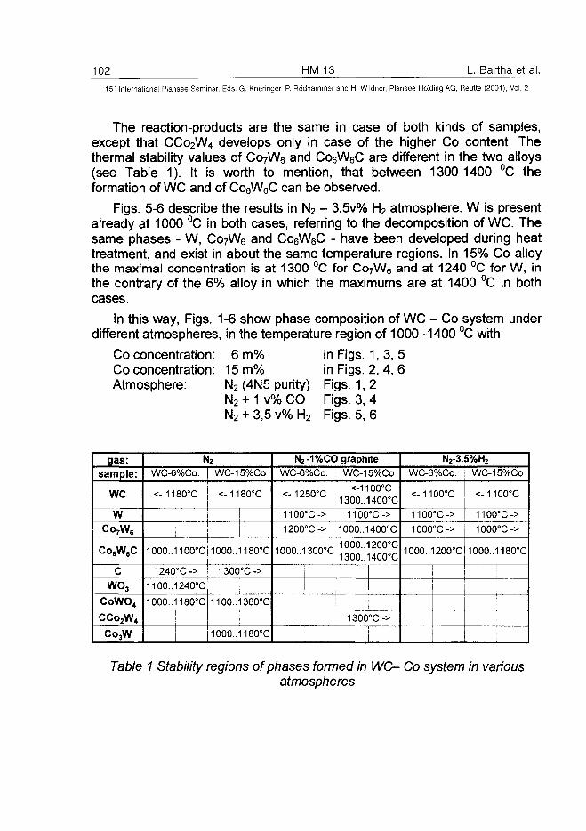
102 HM 13 L. Bartha et al.15" International Plansee Seminar, Eds. G. Kneringer, P. Rodhammer and H. Wildner, Plansee Holding AG, Reutte (2001), Vol. 2
The reaction-products are the same in case of both kinds of samples,except that CCo2W4 develops only in case of the higher Co content. Thethermal stability values of CoyWe and Co6W6C are different in the two alloys(see Table 1). It is worth to mention, that between 1300-1400 °C theformation of WC and of Co6W6C can be observed.
Figs. 5-6 describe the results in N2 - 3,5v% H2 atmosphere. W is presentalready at 1000 °C in both cases, referring to the decomposition of WC. Thesame phases - W, Co7W6 and Co6W6C - have been developed during heattreatment, and exist in about the same temperature regions. In 15% Co alloythe maximal concentration is at 1300 °C for Co7W6 and at 1240 °C for W, inthe contrary of the 6% alloy in which the maximums are at 1400 °C in bothcases.
In this way, Figs. 1-6 show phase composition of WC - Co system underdifferent atmospheres, in the temperature region of 1000 -1400 °C with
Co concentration: 6 m%Co concentration: 15 m%Atmosphere: N2 (4N5 purity)
N2 + 1 v% CO
in Figs. 1, 3, 5in Figs. 2, 4, 6Figs. 1,2Figs. 3, 4
N2 + 3,5 v% H2 Figs. 5, 6
gas:sample:
WC
WCo7W6
Co6W6C
CWO3
CoWO,
CCo2W4
Co3W
N2
WC-6%Co.
<-1180°C
WC-15%Co
<-1180°C
1000..1100°Ci 1000..1180°C
1240°C-> ! 1300°C->
11OO..124O°C ;
1000.. 1180-C 1100..1360°C
1000..1180°C
N2-1%CO graphite
WC-6%Co.
<-1250°C
1100°C->
1200°C->
1000..1300°C
WC-15%Co
<-1100°C1300..1400°C
1100°C->
1000..1400°C
1000..1200°C1300..1400°C
1300°C->
N2-3.5%H2
WC-6%Co.
<-1100°C
1100°C->
1000°C->
1OOO..12OO°C
I
WC-15%Co
<-1100°C
1100°C->
1000°C->
1000..1180°C
Table 1 Stability regions of phases formed in WC- Co system in variousatmospheres
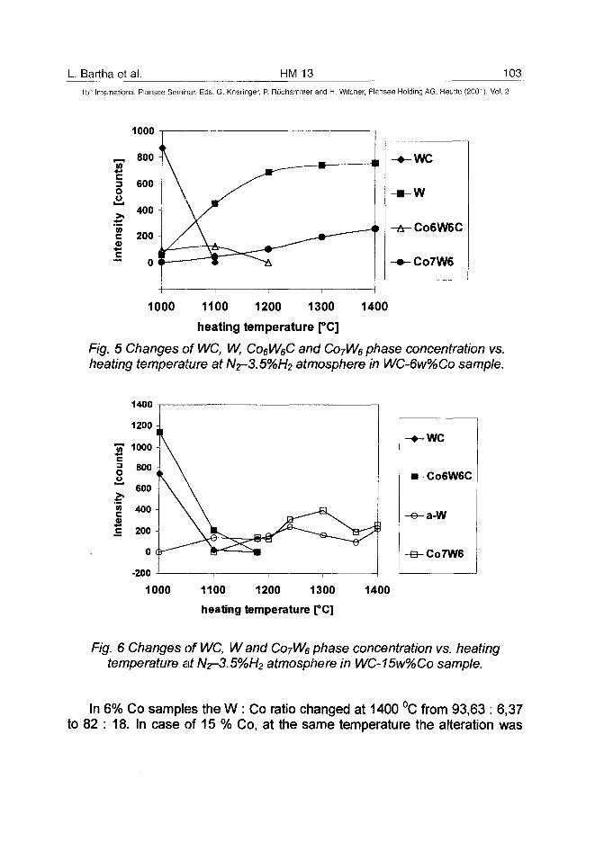
L Bartha et al. HM 13 103
15* International Plansee Seminar, Eds. G. Kneringer, P. Rodhammer and H. Wildner, Plansee Holding AG, Reutte (2001), Vol. 2
1000
1000 1100 1200 1300 1400
heating temperature [°C]
Fig. 5 Changes of WC, W, Co^WeC and COJWQ phase concentration vs.heating temperature at Nz-3.5%H2 atmosphere in WC-6w%Co sample.
-200
-•-we
-m- C06W6C
-e-a-W
-a-Co7W6
1000 1100 1200 1300
heating temperature [°C]
1400
Fig. 6 Changes of WC, Wand Co7W6 phase concentration vs. heatingtemperature at N2-3.5%H2 atmosphere in WC-15w%Co sample.
In 6% Co samples the W : Co ratio changed at 1400 °C from 93,63 : 6,37to 82 : 18. In case of 15 % Co, at the same temperature the alteration was
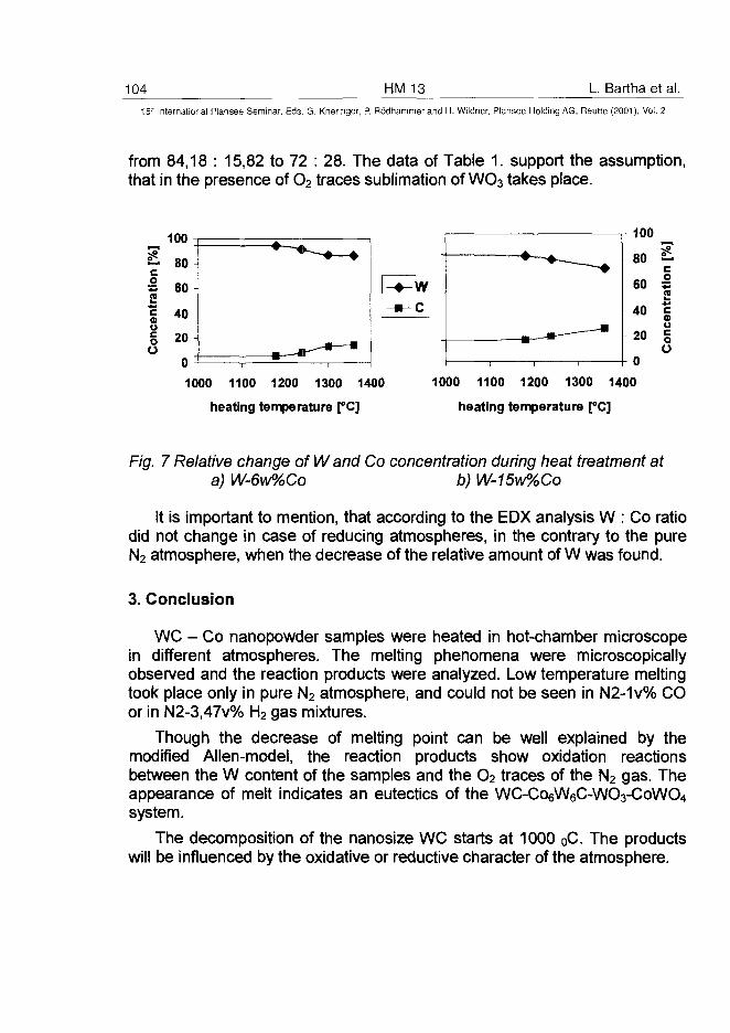
104 HM 13 L. Bartha et al.
15" International Plansee Seminar, Eds. G. Kneringer, P. Rodhammer and H. Wildner, Plansee Holding AG, Reutte (2001), Vol. 2
from 84,18 : 15,82 to 72 : 28. The data of Table 1. support the assumption,that in the presence of O2 traces sublimation of WO3 takes place.
1000 1100 1200 1300 1400
heating temperature [°C]
1000 1100 1200 1300 1400
heating temperature [°C]
Fig. 7 Relative change of Wand Co concentration during heat treatment ata) W-6w%Co b) W-15w%Co
It is important to mention, that according to the EDX analysis W : Co ratiodid not change in case of reducing atmospheres, in the contrary to the pureN2 atmosphere, when the decrease of the relative amount of W was found.
3. Conclusion
WC - Co nanopowder samples were heated in hot-chamber microscopein different atmospheres. The melting phenomena were microscopicallyobserved and the reaction products were analyzed. Low temperature meltingtook place only in pure N2 atmosphere, and could not be seen in N2-1v% COor in N2-3,47v% H2 gas mixtures.
Though the decrease of melting point can be well explained by themodified Allen-model, the reaction products show oxidation reactionsbetween the W content of the samples and the O2 traces of the N2 gas. Theappearance of melt indicates an eutectics of the WC-Co6W6C-WO3-CoWO4system.
The decomposition of the nanosize WC starts at 1000 0C. The productswill be influenced by the oxidative or reductive character of the atmosphere.
L. Bartha et al. HM 13 105^15" International Plansee Seminar, Eds. G. Kneringer, P. Rodhammer and H. Wildner, Plansee Holding AG, Reutte (2001), Vol. 2
References
1. L.Bartha, I.Kotsis, P.Harmat, L.Laczko:Proc. 2nd lnt.Conf.on Powder Metallurgy RoPM 2000Cluj-Napoca, 6-8 07.2000. p. 99-104 (2000)
2. J.F. Pocza, A.Barna, P.B.Barna:J.Vacuum Sci. and Technology 6.(4) p. 472-475 (1968)
3. G.I. Allen, W.W. Gille, W.A.Jesser:Acta Met. 28. P. 1695-1701 (1980)
Acknowledgement
The work was supported by the National Scientific Research Fund (OTKA),contract No.T 32730.
AT0100444106 HM 15 S. Lay et al.
15" International Plansee Seminar, Eds. G. Kneringer, P. Rodhammer and H. Wildner, Plansee Holding AG, Reutte (2001), Vol. 2
HREM characterisation of VC in doped WC-Co Cermets
S. Lay*, S. Hamar-Thibault*, A. Lackner**
*LTPCM, INPG/CNRS/UJF (UMR 5614) 38402 St Martin d'Heres Cedex, France
"PLANSEE TIZIT AG, Reutte, Austria
Summary:
The microstructure of sintered WC-Co composite doped with VC isinvestigated by several techniques (TEM, HREM, EDS, EELS) in order toaccurately locate the VC phase. Small VC precipitates are frequently found atthe junction between two WC grains in the corner of cobalt pockets. Due tothe good match between the WC and VC parameters, the VC grains adopt apreferential orientation with regards to WC:
(111)vc // (0001 )wc with < i i0> v c / / <1210>wc.Moreover steps along the <1120>Wc directions are observed at the interfacebetween cobalt and WC. Small VC precipitates lying on the (0001 )Wc facet ofthe steps are identified. A thin VC layer less than 1 nm thick covering all(0001 )wc surfaces of WC grains is also pointed out. Most WC grainboundaries contain a thin film of VC phase whereas some high coincidencegrain boundaries seem to be free from second phase.
Keywords:
WC, VC, Cr3C2, cermet, grain growth inhibitor, interface, high resolutionelectron microscopy
1. Introduction:
Progress in powder processing allows ultra fine powders to be used. In orderto control the grain growth during sintering of the ultra fine WC powder, someinhibitors are added. VC and Cr3C2 have been shown to be the most effectiveinhibitors. In this work, we have focused our interest on the location ofvanadium after liquid phase sintering. Our aim is to have a better knowledgeof the final microstructure of these materials and to have a better
S. Lay et al. HM 15 10715th International Plansee Seminar, Eds. G. Kneringer, P. Rodhammer and H. Wildner, Plansee Holding AG, Reutte (2001), Vol. 2
understanding of the grain growth inhibition mechanism. Previous studieshave been devoted to this subject. No vanadium is found in the centre ofcobalt pockets or in WC grains (1,2). Taniuchi et al. (2) have shown thepresence of sparsely and homogeneously dispersed (V,W)C precipitatesabout 0.1jim in size in a WC-12wt%Co-0.5%VC alloy and the presence ofsmall (V,W)C precipitates has also been pointed out in interfaces betweenWC grains and cobalt (1). Further investigations show that the concentrationof segregated vanadium is higher on (0001) plane of WC grains than on(1010) planes (3). The addition of vanadium induces the presence of steps atWC/Co interfaces with basal and prismatic WC habit planes for liquid phase-sintered alloys (3) and for solid-state alloys (4). Small precipitates at thecorner of the steps are observed only for liquid phase sintered specimens (4).EDS analyses show that some WC/WC interfaces contain vanadium (2) evenif the grain boundary is shown by HREM to be free from second phase (4). Inwhat follows, we have examined in detail the microstructure and thedistribution of vanadium compounds in the alloys. In particular, we show thatthe VC phase adopt a special orientation relationship with regards to WC. Insome WC/WC interfaces, a layer of VC is observed.
2. Experimental procedure:
Two types of industrial submicron materials have been examined with aconstant VC content (0.5wt%), with 0.3wt%-Cr3C2 (sample C) and withoutchromium (sample A). The Co content is between 6.5 and 9.2wt%.Thin slices prepared by argon ion milling have been observed by highresolution electron microscopy (HREM) using a 4000 EX Jeol microscope.Metallic elements have been analysed by EDS (energy dispersivespectroscopy) performed by using a Philips CM300 microscope. The spotsize was about 25 nm. EELS (electron energy loss spectroscopy) was carriedout on a 3000FX microscope to confirm the presence of carbon in thephases.
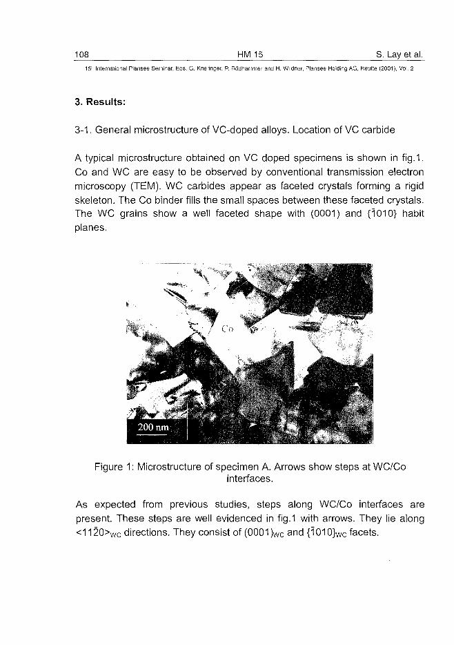
108 HM 15 S. Lay et al.
15" International Plansee Seminar, Eds. G. Kneringer, P. Rodhammer and H. Wildner, Plansee Holding AG, Reutte (2001), Vol. 2
3. Results:
3-1. General microstructure of VC-doped alloys. Location of VC carbide
A typical microstructure obtained on VC doped specimens is shown in fig.1.Co and WC are easy to be observed by conventional transmission electronmicroscopy (TEM). WC carbides appear as faceted crystals forming a rigidskeleton. The Co binder fills the small spaces between these faceted crystals.The WC grains show a well faceted shape with (0001) and {1010} habitplanes.
Figure 1: Microstructure of specimen A. Arrows show steps at WC/Cointerfaces.
As expected from previous studies, steps along WC/Co interfaces arepresent. These steps are well evidenced in fig.1 with arrows. They lie along<1120>wc directions. They consist of (0001 )wc and {1010}wc facets.
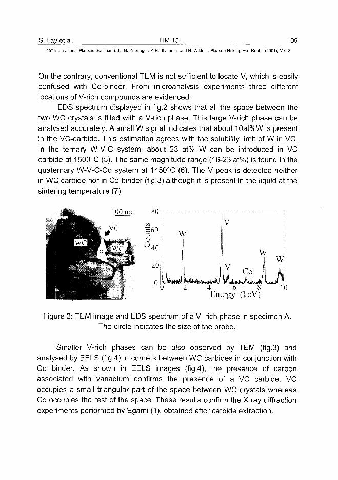
S. Lay et al. HM 15 10915th International Plansee Seminar, Eds. G. Kneringer, P. Rodhammer and H. Wildner, Plansee Holding AG, Reutte (2001), Vol. 2
On the contrary, conventional TEM is not sufficient to locate V, which is easilyconfused with Co-binder. From microanalysis experiments three differentlocations of V-rich compounds are evidenced:
EDS spectrum displayed in fig.2 shows that all the space between thetwo WC crystals is filled with a V-rich phase. This large V-rich phase can beanalysed accurately. A small W signal indicates that about 10at%W is presentin the VC-carbide. This estimation agrees with the solubility limit of W in VC.In the ternary W-V-C system, about 23 at% W can be introduced in VCcarbide at 1500°C (5). The same magnitude range (16-23 at%) is found in thequaternary W-V-C-Co system at 1450°C (6). The V peak is detected neitherin WC carbide nor in Co-binder (fig.3) although it is present in the liquid at thesintering temperature (7).
100 nm 80 r—
w
LL3 2
V
4 6Energy
w
8(keV)
W
i1
Figure 2: TEM image and EDS spectrum of a V-rich phase in specimen A.The circle indicates the size of the probe.
Smaller V-rich phases can be also observed by TEM (fig.3) andanalysed by EELS (fig.4) in corners between WC carbides in conjunction withCo binder. As shown in EELS images (fig.4), the presence of carbonassociated with vanadium confirms the presence of a VC carbide. VCoccupies a small triangular part of the space between WC crystals whereasCo occupies the rest of the space. These results confirm the X ray diffractionexperiments performed by Egami (1), obtained after carbide extraction.
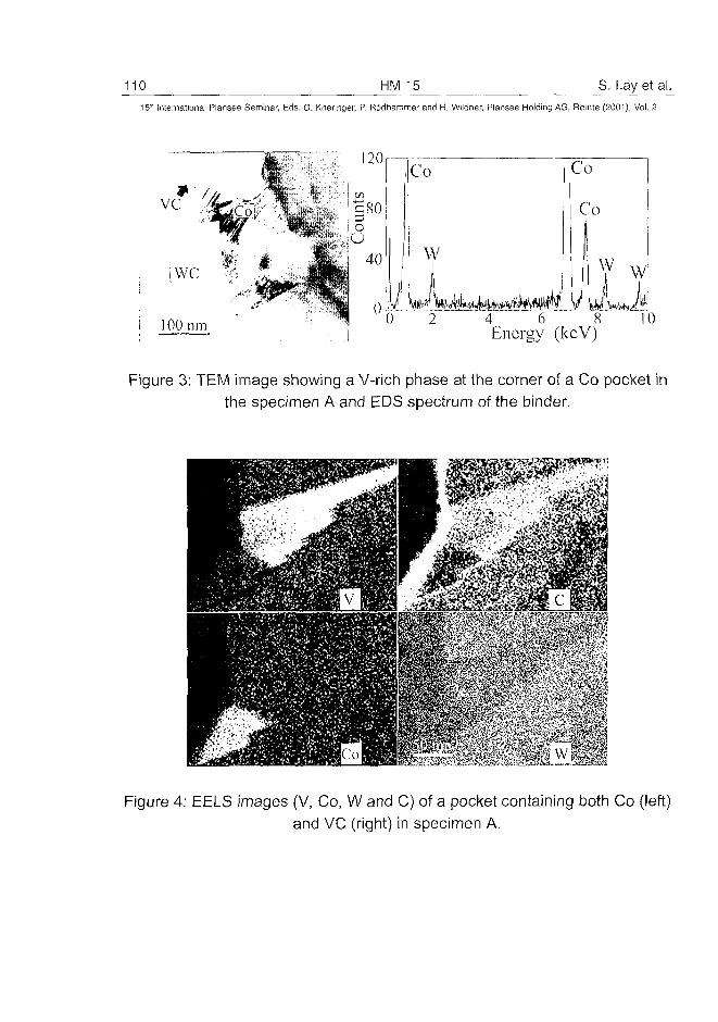
110 HM 15 S. Lay et al.
15:h International Plansee Seminar, Eds. G. Kneringer, P. Rodhammer and H. Wildner, Plansee Holding AG, Reutte (2001), Vol. 2
Co
Co
W W
4 6 8 l'OEnergy (kcV)
Figure 3: TEM image showing a V-rich phase at the comer of a Co pocket inthe specimen A and EDS spectrum of the binder.
Figure 4: EELS images (V, Co, W and C) of a pocket containing both Co (left)and VC (right) in specimen A.
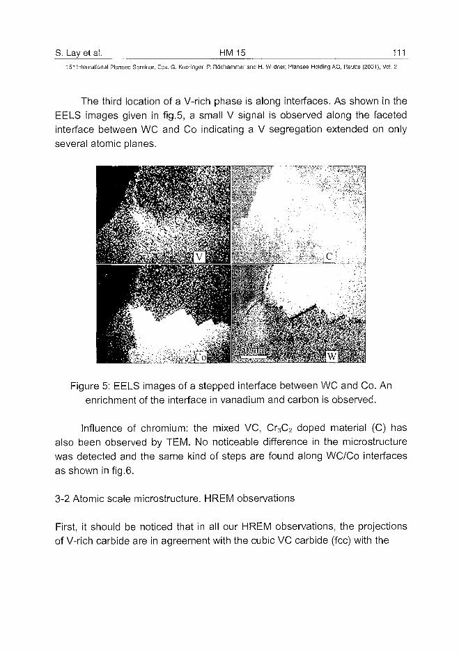
S. Lay et al. HM 15 111
15" International Plansee Seminar, Eds. G. Kneringer, P. Rodhammer and H. Wildner, Plansee Holding AG, Reutte (2001), Vol. 2
The third location of a V-rich phase is along interfaces. As shown in theEELS images given in fig.5, a small V signal is observed along the facetedinterface between WC and Co indicating a V segregation extended on onlyseveral atomic planes.
Figure 5: EELS images of a stepped interface between WC and Co. Anenrichment of the interface in vanadium and carbon is observed.
Influence of chromium: the mixed VC, Cr3C2 doped material (C) hasalso been observed by TEM. No noticeable difference in the microstructurewas detected and the same kind of steps are found along WC/Co interfacesas shown in fig.6.
3-2 Atomic scale microstructure. HREM observations
First, it should be noticed that in all our HREM observations, the projectionsof V-rich carbide are in agreement with the cubic VC carbide (fee) with the
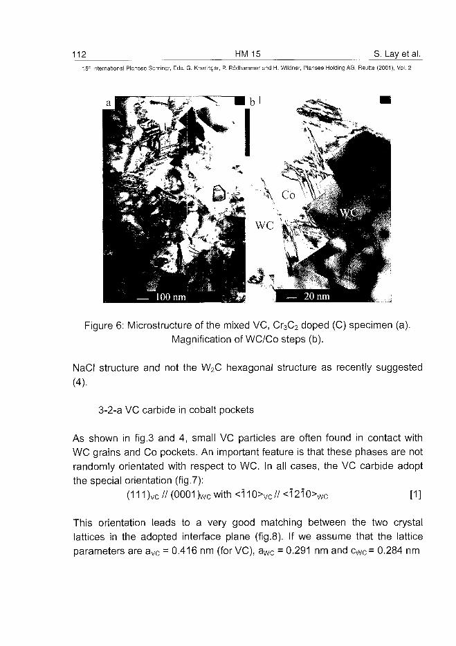
112 HM 15 S. Lay et al.15-" International Plansee Seminar, Eds. G. Kneringer, P. Rodhammer and H. Wildner, Plansee Holding AG, Reutte (2001), Vol. 2
Figure 6: Microstructure of the mixed VC, Cr3C2 doped (C) specimen (a).Magnification of WC/Co steps (b).
NaCI structure and not the W2C hexagonal structure as recently suggested
(4).
3-2-a VC carbide in cobalt pockets
As shown in fig.3 and 4, small VC particles are often found in contact withWC grains and Co pockets. An important feature is that these phases are notrandomly orientated with respect to WC. In all cases, the VC carbide adoptthe special orientation (fig.7):
(111)vc//(0001)wcwith<ii0>vc//<i2i0>Wc [1]
This orientation leads to a very good matching between the two crystallattices in the adopted interface plane (fig.8). If we assume that the latticeparameters are aVc = 0.416 nm (for VC), aWc = 0.291 nm and cWc= 0.284 nm
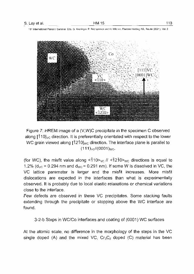
S. Lay et al. HM 15 11315'" International Plansee Seminar, Eds. G. Kneringer, P. Rodhammer and H. Wildner, Plansee Holding AG, Reutte (2001), Vol. 2
Figure 7: HREM image of a (V,W)C precipitate in the specimen C observedalong [110]vc direction. It is preferentially orientated with respect to the lowerWC grain viewed along [12iO]wc direction. The interface plane is parallel to
(111)vc//(0001)wc.
(for WC), the misfit value along <110>Vc // <1210>Wc directions is equal to1.2% (dvc = 0.294 nm and dWc = 0.291 nm). If some W is dissolved in VC, theVC lattice parameter is larger and the misfit increases. More misfitdislocations are expected in the interfaces than what is experimentallyobserved. It is probably due to local elastic relaxations or chemical variationsclose to the interface.Few defects are observed in these VC precipitates. Some stacking faultsextending through the precipitate or stopping above the WC interface arefound.
3-2-b Steps in WC/Co interfaces and coating of (0001) WC surfaces
At the atomic scale, no difference in the morphology of the steps in the VCsingle doped (A) and the mixed VC, Cr3C2 doped (C) material has been
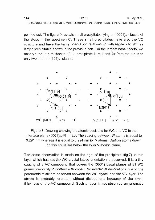
114 HM 15 S. Lay et al.15" International Plansee Seminar, Eds. G. Kneringer, P. Rodhammer and H. Wildner, Plansee Holding AG, Reutte (2001), Vol. 2
pointed out. The figure 9 reveals small precipitates lying on (0001 )wc facets ofthe steps in the specimen C. These small precipitates have also the VCstructure and have the same orientation relationship with regards to WC aslarger precipitates shown in the previous part. On the largest basal facets, weobserve that the thickness of the precipitate is reduced far from the steps toonly two or three (111 )vc planes.
« Q
• &*
1/3 [12l 0]*
0 0
e « - 0
/3[2110]
l/3[1120]
WC [0001] VC [111] 0 V - C
Figure 8: Drawing showing the atomic positions for WC and VC in theinterface plane (0001 )wc//(111 )vc- The spacing between W atoms is equal to0.291 nm whereas it is equal to 0.294 nm for V atoms. Carbon atoms drawn
on this figure are below the W or V atomic plane.
The same observation is made on the right of the precipitate (fig.7), a thinlayer which has not the WC crystal lattice orientation is observed. It is a tinycoating of a VC compound that covers the (0001) basal planes of all WCgrains previously in contact with cobalt. No interfacial dislocations due to theparametric misfit are observed between the WC crystal and the VC layer. Thestress is probably released without dislocations because of the smallthickness of the VC compound. Such a layer is not observed on prismatic
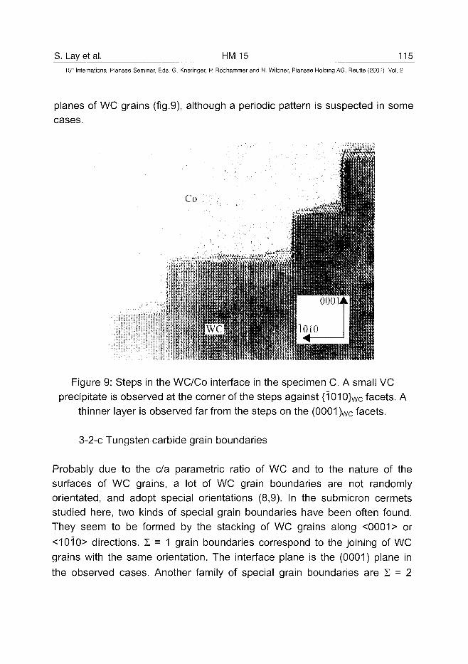
S. Lay et al. HM 15 11515Ih International Plansee Seminar, Eds. G. Kneringer, P. Rddhammer and H. Wildner, Plansee Holding AG, Reutte (2001), Vol. 2
planes of WC grains (fig.9), although a periodic pattern is suspected in somecases.
Figure 9: Steps in the WC/Co interface in the specimen C. A small VCprecipitate is observed at the corner of the steps against {1010}wc facets. A
thinner layer is observed far from the steps on the (0001 )wc facets.
3-2-c Tungsten carbide grain boundaries
Probably due to the c/a parametric ratio of WC and to the nature of thesurfaces of WC grains, a lot of WC grain boundaries are not randomlyorientated, and adopt special orientations (8,9). In the submicron cermetsstudied here, two kinds of special grain boundaries have been often found.They seem to be formed by the stacking of WC grains along <0001> or<1010> directions. Z = 1 grain boundaries correspond to the joining of WCgrains with the same orientation. The interface plane is the (0001) plane inthe observed cases. Another family of special grain boundaries are Z = 2
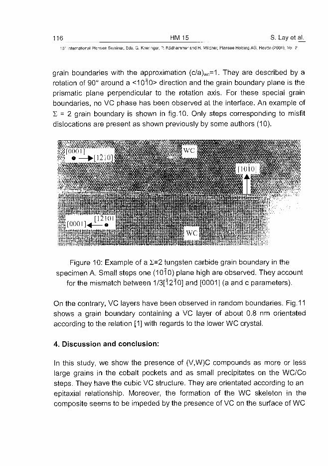
116 HM 15 S. Lay et al.
15" International Plansee Seminar, Eds. G. Kneringer, P. Rodhammer and H. Wildner, Plansee Holding AG, Reutte (2001), Vol. 2
grain boundaries with the approximation (c/a)wc=1. They are described by arotation of 90° around a <1010> direction and the grain boundary plane is theprismatic plane perpendicular to the rotation axis. For these special grainboundaries, no VC phase has been observed at the interface. An example of1 = 2 grain boundary is shown in fig.10. Only steps corresponding to misfitdislocations are present as shown previously by some authors (10).
11 m viivfff'fffffttiffjTffmfxt
Figure 10: Example of a S=2 tungsten carbide grain boundary in thespecimen A. Small steps one (1010) plane high are observed. They account
for the mismatch between 1/3[1210] and [0001] (a and c parameters).
On the contrary, VC layers have been observed in random boundaries. Fig.11shows a grain boundary containing a VC layer of about 0.8 nm orientatedaccording to the relation [1] with regards to the lower WC crystal.
4. Discussion and conclusion:
In this study, we show the presence of (V,W)C compounds as more or lesslarge grains in the cobalt pockets and as small precipitates on the WC/Costeps. They have the cubic VC structure. They are orientated according to anepitaxial relationship. Moreover, the formation of the WC skeleton in thecomposite seems to be impeded by the presence of VC on the surface of WC
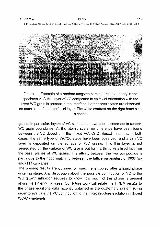
S. Lay et al. HM 15 11715lh International Plansee Seminar, Eds. G. Kneringer, P. Rodhammer and H. Wildner, Plansee Holding AG, Reutte (2001), Vol. 2
Figure 11: Example of a random tungsten carbide grain boundary in thespecimen A. A thin layer of VC compound in epitaxial orientation with the
lower WC grain is present in the interface. Larger precipitates are observedon each side of the interfacial layer. The white contrast on the right hand side
is cobalt.
grains. In particular, layers of VC compound have been pointed out in randomWC grain boundaries. At the atomic scale, no difference have been foundbetween the VC doped and the mixed VC, Cr3C2 doped materials: in bothcases, the same type of WC/Co steps have been observed, and a thin VClayer is deposited on the surface of WC grains. This thin layer is notsegregated on the surface of WC grains but form a thin crystallised layer onthe basal planes of WC grains. The affinity between the two compounds ispartly due to the good matching between the lattice parameters of (0001 )Wcand (111)vc planes.
The present results are obtained on specimens cooled after a liquid phasesintering stage. Any discussion about the possible contribution of VC to theWC growth inhibition requires to know how much of this phase is presentalong the sintering process. Our future work will relate the HREM results tothe phase equilibria data recently obtained in the quaternary system (6) inorder to evaluate the VC contribution to the microstructure evolution in dopedWC-Co materials.
118 HM 15 S. Lay et al.
15" International Plansee Seminar, Eds. G. Kneringer, P. Rodhammer and H. Wildner, Plansee Holding AG, Reutte (2001), Vol. 2
Acknowledgements:
The authors are grateful to C.H. Allibert for fruitful discussion and to J.Thibault for her help with the EELs analyses.
References:
(1) A. Egami, M. Ehira and M. Machida, Proc. 13th Int. Plansee Seminar, Vol.3, pp 639-648 (ed. H. Bilstein et al., Plansee AG, Reutte 1993).(2) T. Taniuchi, K. Okada and T. Tanase, Proc. 14th Int. Plansee Seminar,Vol. 2, pp 644-657 (ed. G. Kneringer et al., Plansee AG, Reutte 1997).(3) A. Jaroenworaluck, T. Yamamoto, Y. Ikuhara, T. Sakuma, T. Taniuchi, K.Okada and T. Tanase, Journal of Materials Research 13 (1998), pp 2450-2452.(4) T. Yamamoto, Y. Ikuhara and T. Sakuma, Science and Technology ofAdvanced Materials 1 (2000), pp 97-104.(5) E. Rudy, F. Benesovsky and E. Rudy, Monatshefte Chem. 93 (1962) pp693-707.(6) E.G. Obbard, L.A. Cornish, S. Luyckx, S. Hamar-Thibault and C.H.Allibert, Inter. Conf. On Science of Hard Mat., ICSHM7, Ixtapa, Mexico, 5-9March 2001.(7) V. Chabretou, O. Lavergne, S. Lay, L. Pontonnier and C.H. Allibert, Proc.Powder Metallurgy World Congress PM 98, Grenada, EPMA eds vol. 4, pp.146-151.(8) S. Hagege, G. Nouet and P. Delavignette, Physica Status Solidi (a) 62(1980), pp. 97-107.(9) J. Vicens, S. Lay, E. Laurent-Pinson and G. Nouet, Surface and Interfacesof ceramic Materials, pp. 115-140 (ed. L.-C. Dufour et al., Kluver AcademicPublishers, 1989).(10) J. Vicens, E. Laurent-Pinson, J.L. Chermant and G. Nouet, Journal dePhysique C5 49 (1988), pp 271-276.
ATO100445S.I. Chaetal. HM 16 VI9_
15" International Plansee Seminar, Eds. G. Kneringer, P. Rodhammer and H. Wildner, Plansee Holding AG, Reutte (2001), Vol. 2
Microstructure and Mechanical Properties of Ultra-fine
WC-IOCo Hardmetais
Seung I. Cha, Soon H. Hong, Gook H. Ha* and Byung K. Kim*
Department of Materials Science and Engineering
Korea Advanced Institute of Science and Technology
373-1 Kusung-dong, Yusung-gu, Taejon 305-701, KOREA
*Korea Institute of Machinery & Materials
66 Sangnam-dong, Changwon, Kyungnam, KOREA
Summary:
The mechanical properties of ultra-fine WC-10wt%Co-X hardmetais wereinvestigated. Ultra-fine precursor powders were prepared by spray drying ofsolution containing AMT and cobalt nitrate. The precursor powders werereduced and carbonized into WC/Co powders by mechano-chemical process.The WC powders were about 100nm in diameter and were mixedhomogeneously with Co binder. The powders were wet ball-milled in n-Hexanewith ball-to-powder ratio of 5:1 for 24hrs and dried for 24hrs. The milledpowders were sintered at 1375°C under a pressure of Imtorr. In order tocompare the microstructures and mechanical properties with ultra-finehardmetais, the commercial WC powders with 0.57-4jxm in diameter weremixed with Co powders, and were followed by sintering at 1375°C under apressure of Imtorr. Varying amount of TaC, Cr3C2 and VC were added intoultra-fine WC-10wt%Co hardmetais as grain growth inhibitors. It was observedthat Co phase was precipitated within faceted WC grains in sintered ultra-finehardmetais. The hardness of WC-10wt%Co hardmetais increased withdecreasing WC grain size following the Hall-Petch type relationship. Thetransverse rupture strengths of WC-10wt%Co hardmetais were dependent onthe solute contents within the Co binder phase.
KEYWORDS:WC-CO, HARDMETALS, ULTRA-FINE, HARDNESS, STRENGTH
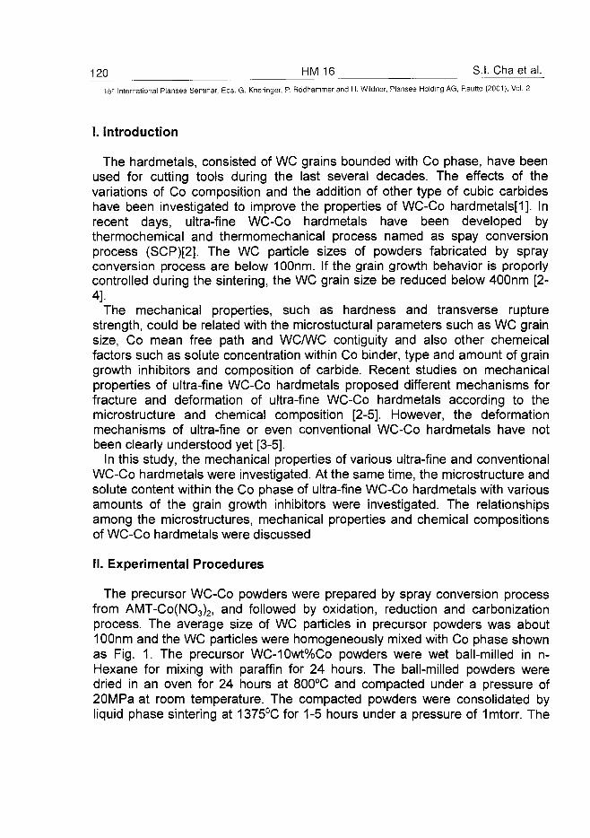
120 HM 16 S.I. Chaetal.
15- International Plansee Seminar, Eds. G. Kneringer, P. Rodhammer and H. Wildner, Plansee Holding AG, Reutte (2001), Vol. 2
I. Introduction
The hardmetals, consisted of WC grains bounded with Co phase, have beenused for cutting tools during the last several decades. The effects of thevariations of Co composition and the addition of other type of cubic carbideshave been investigated to improve the properties of WC-Co hardmetals[1]. Inrecent days, ultra-fine WC-Co hardmetals have been developed bythermochemical and thermomechanical process named as spay conversionprocess (SCP)[2]. The WC particle sizes of powders fabricated by sprayconversion process are below 100nm. If the grain growth behavior is proporlycontrolled during the sintering, the WC grain size be reduced below 400nm [2-4].
The mechanical properties, such as hardness and transverse rupturestrength, could be related with the microstuctural parameters such as WC grainsize, Co mean free path and WC/WC contiguity and also other chemeicalfactors such as solute concentration within Co binder, type and amount of graingrowth inhibitors and composition of carbide. Recent studies on mechanicalproperties of ultra-fine WC-Co hardmetals proposed different mechanisms forfracture and deformation of ultra-fine WC-Co hardmetals according to themicrostructure and chemical composition [2-5]. However, the deformationmechanisms of ultra-fine or even conventional WC-Co hardmetals have notbeen clearly understood yet [3-5].
In this study, the mechanical properties of various ultra-fine and conventionalWC-Co hardmetals were investigated. At the same time, the microstructure andsolute content within the Co phase of ultra-fine WC-Co hardmetals with variousamounts of the grain growth inhibitors were investigated. The relationshipsamong the microstructures, mechanical properties and chemical compositionsof WC-Co hardmetals were discussed
II. Experimental Procedures
The precursor WC-Co powders were prepared by spray conversion processfrom AMT-Co(NO3)2, and followed by oxidation, reduction and carbonizationprocess. The average size of WC particles in precursor powders was about10Onm and the WC particles were homogeneously mixed with Co phase shownas Fig. 1. The precursor WC-10wt%Co powders were wet ball-milled in n-Hexane for mixing with paraffin for 24 hours. The ball-milled powders weredried in an oven for 24 hours at 800°C and compacted under a pressure of20MPa at room temperature. The compacted powders were consolidated byliquid phase sintering at 1375°C for 1-5 hours under a pressure of Imtorr. The
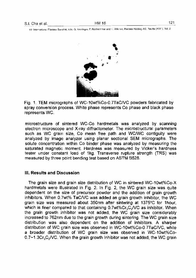
S.I. Cha et al. HM 16 121_15" International Plansee Seminar, Eds. G. Kneringer, P. Rodhammer and H. Wildner, Plansee Holding AG, Reutte (2001), Vol. 2
Fig. 1. TEM micrographs of WC-10wt%Co-0.7TaC/VC powders fabricated byspray conversion process. White phase represents Co phase and black phaserepresents WC.
microstructure of sintered WC-Co hardmetals was analyzed by scanningelectron microscope and X-ray diffractometer. The microstructural parameterssuch as WC grain size, Co mean free path and WC/WC contiguity wereanalyzed by image analyzer using planar sectional SEM micrographs. Thesolute concentration within Co binder phase was analyzed by measuring thesaturated magnetic moment. Hardness was measured by Vicker's hardnesstester under constant load of 1kg. Transverse rupture strength (TRS) wasmeasured by three point bending test based on ASTM B528.
III. Results and Discussion
The grain size and grain size distribution of WC in sintered WC-10wt%Co-Xhardmetals were illustrated in Fig. 2. In Fig. 2, the WC grain size was quitedependent on the size of precursor powder and the addition of grain growthinhibitors. When 0.7wt% TaC/VC was added as grain growth inhibitor, the WCgrain size was measured about 350nm after sintering at 1375°C for 1hour,which is finer compared to that containing 0.7wt%Cr3C2/VC as inhibitor. Whenthe grain growth inhibitor was not added, the WC grain size considerablyincreased to 762nm due to the grain growth during sintering. The WC grain sizedistribution was also dependent on the addition of inhibitors. A sharperdistribution of WC grain size was observed in WC-10wt%Co-0.7TaC/VC, whilea broader distribution of WC grain size was observed in WC-10wt%Co-0.7~1.3Cr3C2/VC. When the grain growth inhibitor was not added, the WC grain
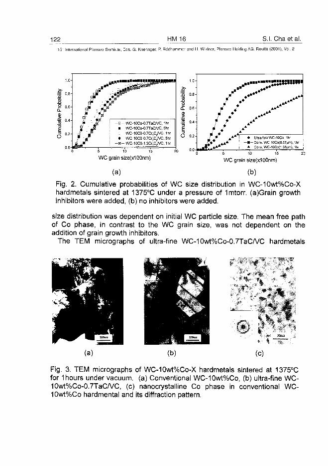
122 HM 16 S.I. Chaetal.15" International Plansee Seminar, Eds. G. Kneringer, P. Rodhammer and H. Wildner, Plansee Holding AG, Reutte (2001), Vol. 2
5 10 15
WC grain size(x1 OOnm)
abilit
y
J5
2
:ive
|
O
1.0-
0.8-
0.6-
0.4-
0.2-
0.0-
, * "
/' / A*A1 •' % AAA ^ B
A
-••"-HHIIXW*
***
Ultra-fine WC-10CO, 1hr- Conv. WC-10Co(0.57|im), 1hr
Conv. WC-10Co(1.33um), 1hr
5 10 15
WC grain size(x100nm)
(a) (b)
Fig. 2. Cunnulative probabilities of WC size distribution in WC-10wt%Co-Xhardmetals sintered at 1375°C under a pressure of Imtorr. (a)Grain growthinhibitors were added, (b) no inhibitors were added.
size distribution was dependent on initial WC particle size. The mean free pathof Co phase, in contrast to the WC grain size, was not dependent on theaddition of grain growth inhibitors.
The TEM micrographs of ultra-fine WC-10wt%Co-0.7TaC/VC hardmetals
(b)
A
•/T* «
(c)
0 p•*..-•.•,« • 50nm
Fig. 3. TEM micrographs of WC-10wt%Co-X hardmetals sintered at 1375°Cfor 1 hours under vacuum, (a) Conventional WC-10wt%Co, (b) ultra-fine WC-10wt%Co-0.7TaC/VC, (c) nanocrystalline Co phase in conventional WC-10wt%Co hardmental and its diffraction pattern.
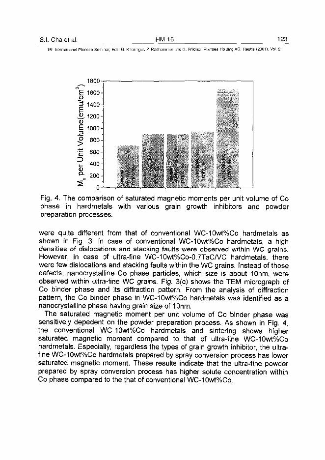
S.I. Chaet al. HM 16 12315" International Plansee Seminar, Eds. G. Kneringer, P. Rodhammer and H. Wildner, Plansee Holding AG, Reutte (2001), Vol. 2
1800
Fig. 4. The comparison of saturated magnetic moments per unit volume of Cophase in hardmetals with various grain growth inhibitors and powderpreparation processes.
were quite different from that of conventional WC-10wt%Co hardmetals asshown in Fig. 3. In case of conventional WC-10wt%Co hardmetals, a highdensities of dislocations and stacking faults were observed within WC grains.However, in case of ultra-fine WC-10wt%Co-0.7TaC/VC hardmetals, therewere few dislocations and stacking faults within the WC grains. Instead of thosedefects, nanocrystalline Co phase particles, which size is about 10nm, wereobserved within ultra-fine WC grains. Fig. 3(c) shows the TEM micrograph ofCo binder phase and its diffraction pattern. From the analysis of diffractionpattern, the Co binder phase in WC-10wt%Co hardmetals was identified as ananocrystalline phase having grain size of 10nm.
The saturated magnetic moment per unit volume of Co binder phase wassensitively depedent on the powder preparation process. As shown in Fig. 4,the conventional WC-10wt%Co hardmetals and sintering shows highersaturated magnetic moment compared to that of ultra-fine WC-10wt%Cohardmetals. Especially, regardless the types of grain growth inhibitor, the ultra-fine WC-10wt%Co hardmetals prepared by spray conversion process has lowersaturated magnetic moment. These results indicate that the ultra-fine powderprepared by spray conversion process has higher solute concentration withinCo phase compared to the that of conventional WC-10wt%Co.
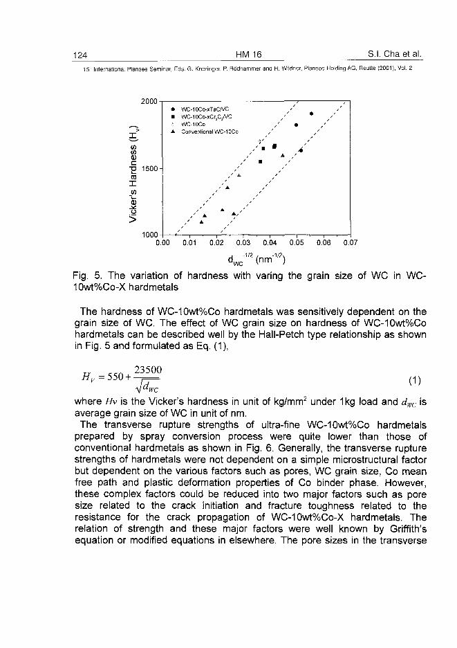
124 HM 16 S.I. Chaetal.15" International Plansee Seminar, Eds. G. Kneringer, P. Rodhammer and H. Wildner, Plansee Holding AG, Reutte (2001), Vol. 2
W
<DC
"S03
X
o>
1500-
1000
• WC-10Co-xTaC/VC• WC-10Co-xCr3CyvC
WC-10COA Conventional WC-10CO
0.00 0.01 0.02 0.03 0.04 0.05 0.06 0.07
"WC V1 1 1 1 I
Fig. 5. The variation of hardness with varing the grain size of WC in WC-10wt%Co-X hardmetals
The hardness of WC-10wt%Co hardmetals was sensitively dependent on thegrain size of WC. The effect of WC grain size on hardness of WC-10wt%Cohardmetals can be described well by the Hall-Petch type relationship as shownin Fig. 5 and formulated as Eq. (1),
Hv =550 +23500
(1)
where Hv is the Vicker's hardness in unit of kg/mm2 under 1 kg load and dwc isaverage grain size of WC in unit of nm.The transverse rupture strengths of ultra-fine WC-10wt%Co hardmetals
prepared by spray conversion process were quite lower than those ofconventional hardmetals as shown in Fig. 6. Generally, the transverse rupturestrengths of hardmetals were not dependent on a simple microstructural factorbut dependent on the various factors such as pores, WC grain size, Co meanfree path and plastic deformation properties of Co binder phase. However,these complex factors could be reduced into two major factors such as poresize related to the crack initiation and fracture toughness related to theresistance for the crack propagation of WC-10wt%Co-X hardmetals. Therelation of strength and these major factors were well known by Griffith'sequation or modified equations in elsewhere. The pore sizes in the transverse
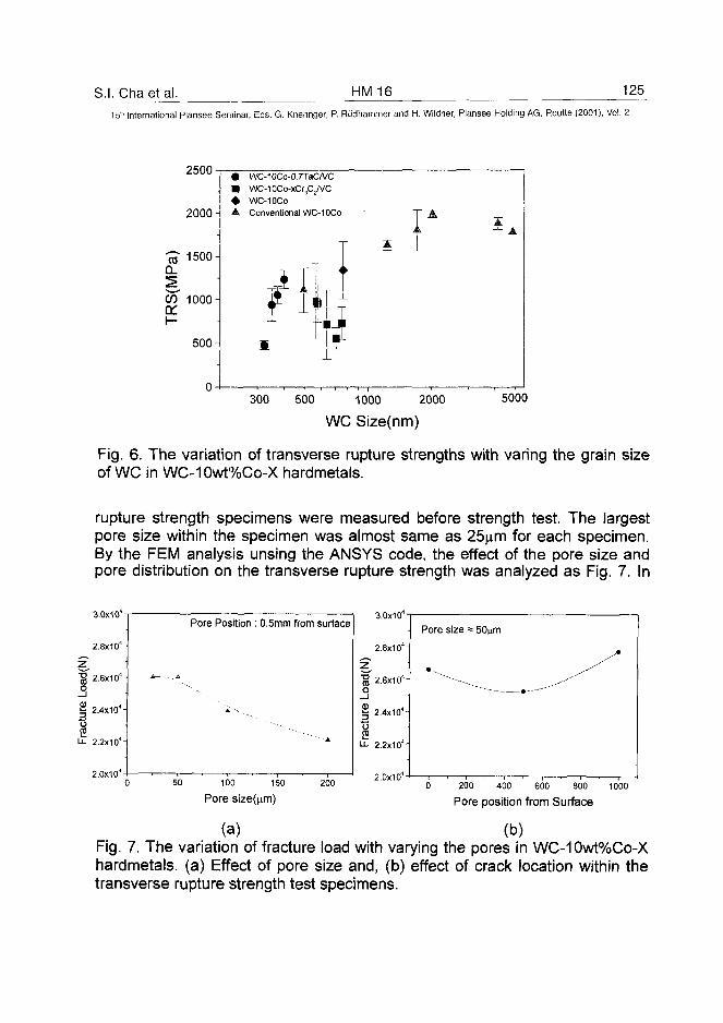
S.I. Chaetal. HM 16 125
15* International Plansee Seminar, Eds. G. Kneringer, P. Rodhammer and H. Wildner, Plansee Holding AG, Reutte (2001), Vol. 2
2500
2000 A
1500Q.
W 1000-1
500 A
• WC-10Co-0.7TaCA/C• WC-IOCo-xCrjCjA/C• WC-10COA Conventional WC-10Co
H
300 500 1000 2000
WC Size(nm)
5000
Fig. 6. The variation of transverse rupture strengths with varing the grain sizeof WC in WC-10wt%Co-X hardmetals.
rupture strength specimens were measured before strength test. The largestpore size within the specimen was almost same as 25^m for each specimen.By the FEM analysis unsing the ANSYS code, the effect of the pore size andpore distribution on the transverse rupture strength was analyzed as Fig. 7. In
3.0x10⁴
2.8x1 ON
"§ 2.6x10⁴ -I
5§ 2.4x10'-\
t5
2.2x10'-\
2.0x10⁴
Pore Position : 0.5mm from surface
50 100 150
Pore size(nm)
200
3.0x10"
2.8x10"-\
13 2.6x10⁴-(o_J
§ 2.4x10⁴-|
U- 2.2x10" A
2.0x10"
Pore size = 50nm
200 400 600 800
Pore position from Surface
1000
(a) (b)Fig. 7. The variation of fracture load with varying the pores in WC-10wt%Co-Xhardmetals. (a) Effect of pore size and, (b) effect of crack location within thetransverse rupture strength test specimens.
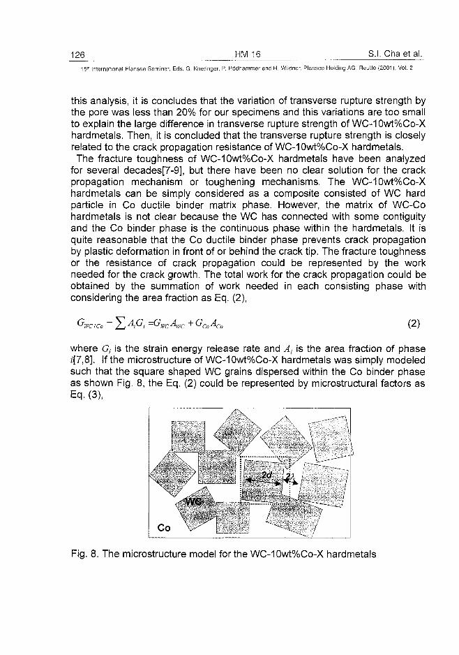
126 HM 16 S.I. Chaetal.
15" International Plansee Seminar, Eds. G. Kneringer, P. Rodhammer and H. Wildner, Plansee Holding AG, Reutte (2001), Vol. 2
this analysis, it is concludes that the variation of transverse rupture strength bythe pore was less than 20% for our specimens and this variations are too smallto explain the large difference in transverse rupture strength of WC-10wt%Co-Xhardmetals. Then, it is concluded that the transverse rupture strength is closelyrelated to the crack propagation resistance of WC-10wt%Co-X hardmetals.The fracture toughness of WC-10wt%Co-X hardmetals have been analyzed
for several decades[7-9], but there have been no clear solution for the crackpropagation mechanism or toughening mechanisms. The WC-10wt%Co-Xhardmetals can be simply considered as a composite consisted of WC hardparticle in Co ductile binder matrix phase. However, the matrix of WC-Cohardmetals is not clear because the WC has connected with some contiguityand the Co binder phase is the continuous phase within the hardmetals. It isquite reasonable that the Co ductile binder phase prevents crack propagationby plastic deformation in front of or behind the crack tip. The fracture toughnessor the resistance of crack propagation could be represented by the workneeded for the crack growth. The total work for the crack propagation could beobtained by the summation of work needed in each consisting phase withconsidering the area fraction as Eq. (2),
'WCICo + GCoACo (2)
where G, is the strain energy release rate and At is the area fraction of phasez'[7,8]. If the microstructure of WC-10wt%Co-X hardmetals was simply modeledsuch that the square shaped WC grains dispersed within the Co binder phaseas shown Fig. 8, the Eq. (2) could be represented by microstructural factors asEq. (3),
Co
Fig. 8. The microstructure model for the WC-10wt%Co-X hardmetals
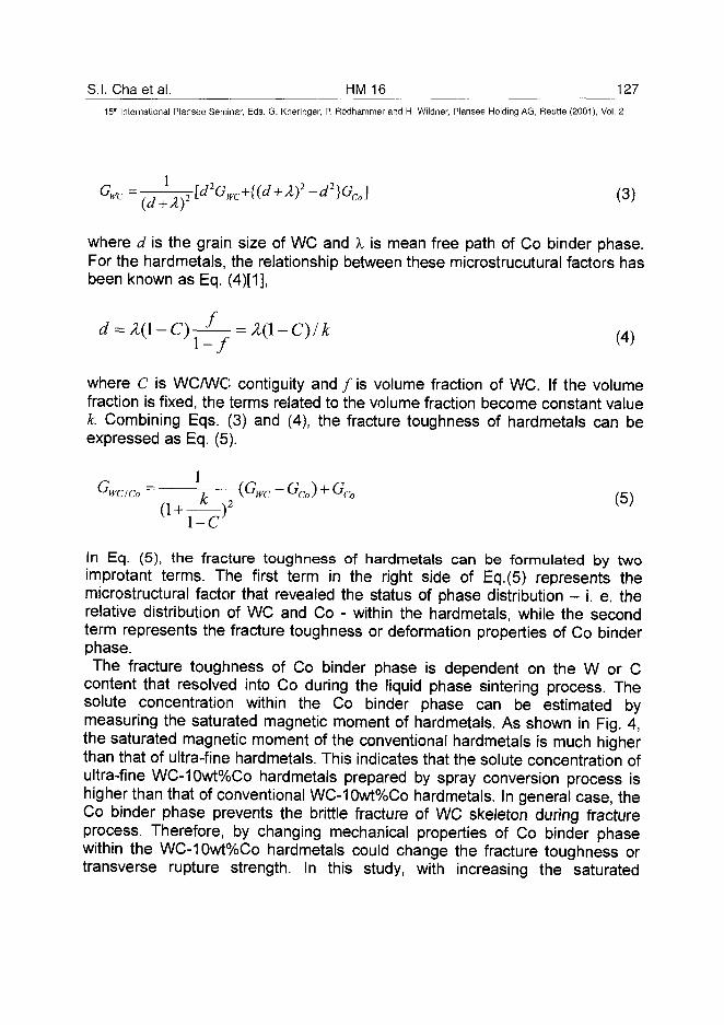
S.I. Chaetal. HM 16 12715" International Plansee Seminar, Eds. G. Kneringer, P. Rodhammer and H. Wildner, Plansee Holding AG, Reutte (2001), Vol. 2
(3)
where d is the grain size of WC and X is mean free path of Co binder phase.For the hardmetals, the relationship between these microstrucutural factors hasbeen known as Eq. (4)[1],
1-/
where C is WC/WC contiguity and / is volume fraction of WC. If the volumefraction is fixed, the terms related to the volume fraction become constant valuek. Combining Eqs. (3) and (4), the fracture toughness of hardmetals can beexpressed as Eq. (5).
GWCICo ~ 7 (GWC ~GCo) + GCo (C\
f (5)(1 +1-C
In Eq. (5), the fracture toughness of hardmetals can be formulated by twoimprotant terms. The first term in the right side of Eq.(5) represents themicrostructural factor that revealed the status of phase distribution - i. e. therelative distribution of WC and Co - within the hardmetals, while the secondterm represents the fracture toughness or deformation properties of Co binderphase.The fracture toughness of Co binder phase is dependent on the W or C
content that resolved into Co during the liquid phase sintering process. Thesolute concentration within the Co binder phase can be estimated bymeasuring the saturated magnetic moment of hardmetals. As shown in Fig. 4,the saturated magnetic moment of the conventional hardmetals is much higherthan that of ultra-fine hardmetals. This indicates that the solute concentration ofultra-fine WC-10wt%Co hardmetals prepared by spray conversion process ishigher than that of conventional WC-10wt%Co hardmetals. In general case, theCo binder phase prevents the brittle fracture of WC skeleton during fractureprocess. Therefore, by changing mechanical properties of Co binder phasewithin the WC-10wt%Co hardmetals could change the fracture toughness ortransverse rupture strength. In this study, with increasing the saturated
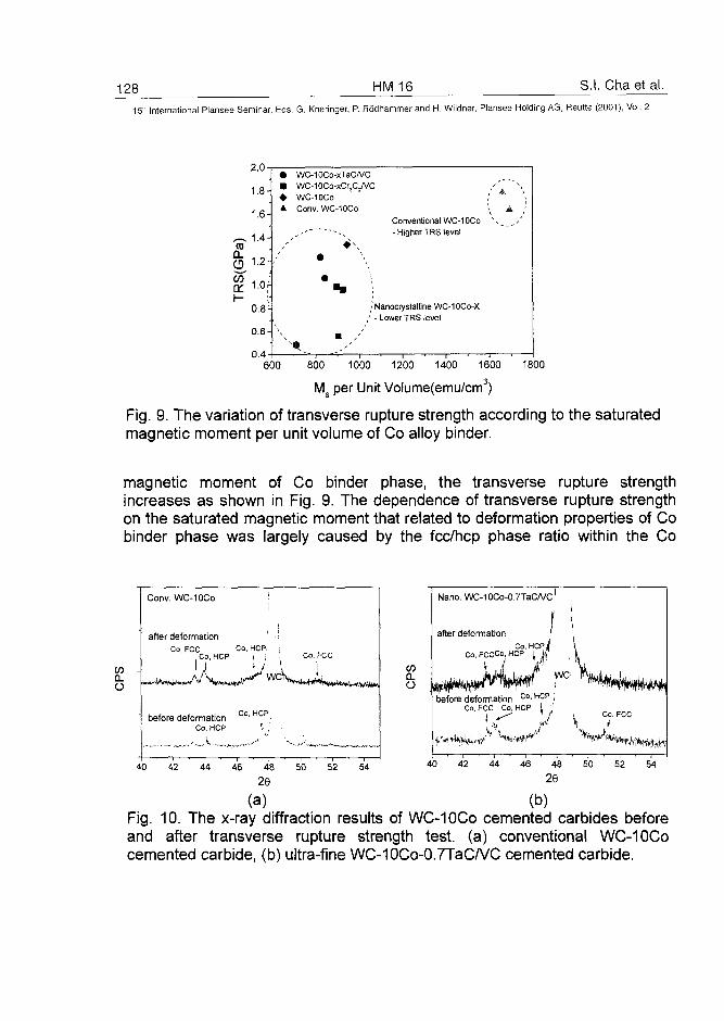
128 HM 16 S.I. Chaet al.
15" International Plansee Seminar, Eds. G. Kneringer, P. Rodhammer and H. Wildner, Plansee Holding AG, Reutte (2001), Vol. 2
a.CDCO
oc
1.8-
1.6-
1.4-
1.2-
1.0|-
0.8^
0.6-
0 .4-
••A
WC-10Co-xTaC/VCWC-1OCo-xCr3C2/VC , ' \ ~ \WC-10COConv. WC-10CO
, ' - -~^
•
1
m /.'' |
i ^ jConventional WC-IOCo \ ^ _/- Higher TRS level
Nanocrystalline WC-10CO-X- Lower TRS level
—i 1 1 1 . 1 .
600 800 1000 1200 1400 1600 1800
Ms per Unit Volume(emu/cm3)
Fig. 9. The variation of transverse rupture strength according to the saturatedmagnetic moment per unit volume of Co alloy binder.
magnetic moment of Co binder phase, the transverse rupture strengthincreases as shown in Fig. 9. The dependence of transverse rupture strengthon the saturated magnetic moment that related to deformation properties of Cobinder phase was largely caused by the fcc/hcp phase ratio within the Co
o
Conv. WC-10Co
after deformation , -ICo, FCC Co, HCP. ;
. Co, HCP i ; .
1 * J
Co, HCP
Co, FCC
before deformationCo. HCP
CO
O
Nano. WC-10Co-0.7TaC/VC
after deformation ICo, HCP.lj
Co, FCCCo.HCP 1 ft'
yve
before deformation c ° ' H p p <Co, FCC Co, HCP \
Co, FCC
40 42 44 46 48 50 52 54
2640 42 44 46 48 50 52 54
29
(a) (b)Fig. 10. The x-ray diffraction results of WC-10Co cemented carbides beforeand after transverse rupture strength test, (a) conventional WC-10Cocemented carbide, (b) ultra-fine WC-10Co-0.7TaC/VC cemented carbide.
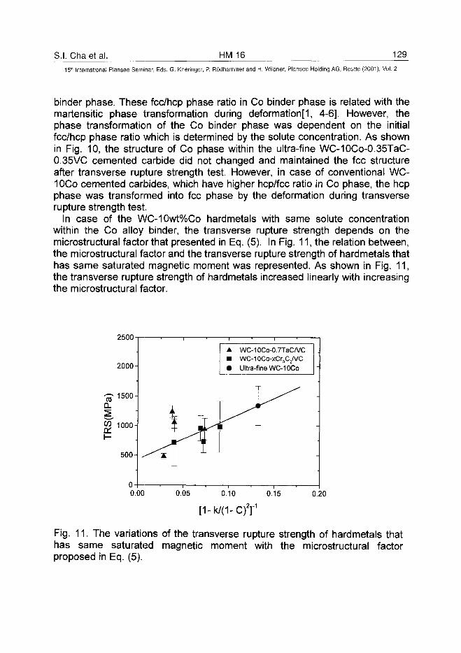
S.I. Cha et al. HM 16 129
15lh International Plansee Seminar, Eds. G. Kneringer, P. Rodhammer and H. Wildner, Plansee Holding AG, Reutte (2001), Vol. 2
binder phase. These fcc/hcp phase ratio in Co binder phase is related with themartensitic phase transformation during deformation[1, 4-6]. However, thephase transformation of the Co binder phase was dependent on the initialfcc/hcp phase ratio which is determined by the solute concentration. As shownin Fig. 10, the structure of Co phase within the ultra-fine WC-10Co-0.35TaC-0.35VC cemented carbide did not changed and maintained the fee structureafter transverse rupture strength test. However, in case of conventional WC-10Co cemented carbides, which have higher hep/fee ratio in Co phase, the hepphase was transformed into fee phase by the deformation during transverserupture strength test.
In case of the WC-10wt%Co hardmetals with same solute concentrationwithin the Co alloy binder, the transverse rupture strength depends on themicrostructural factor that presented in Eq. (5). In Fig. 11, the relation between,the microstructural factor and the transverse rupture strength of hardmetals thathas same saturated magnetic moment was represented. As shown in Fig. 11,the transverse rupture strength of hardmetals increased linearly with increasingthe microstructural factor.
2500
(0
W
2000-
1500-
1000-
500-
WC-10Co-0.7TaC/VCWC-10Co-xCr3C/VCUltra-fine WC-10Co
0.00 0.05 0.10 0.15 0.20
Fig. 11. The variations of the transverse rupture strength of hardmetals thathas same saturated magnetic moment with the microstructural factorproposed in Eq. (5).
130 HM16 S.I. Chaetal.15" International Plansee Seminar, Eds. G. Kneringer, P. Rodhammer and H. Wildner, Plansee Holding AG, Reutte (2001), Vol. 2
IV. Conclusions
1. The ultra-fine WC-10wt%Co powders with average WC size of about 100nmcould be produced by the spray conversion process. The grain size of WC insintered WC-10wt%Co hardmetals could be controlled by 300~700nm withvarying the amount and kind of grain growth inhibitors.
2. Microstructures of WC-10wt%Co-X hardmetals were sensitively dependenton the addition of grain growth inhibitors. The grain growth of WC grain wasmore effectively retarded by the addition of TaC/VC compared to the Cr3C2/VCduring the liquid phase sintering of ultra-fine WC-Co powders prepared byspray conversion process.
3. The hardness of WC-10wt%Co increased hardness with decreasing WC sizefollowing the Hall-Petch type relationship. The transverse rupture strength ofultra-fine WC-10wt%Co fabricated by spray conversion process was lower levelthan conventional WC-10wt%Co. These differences arose from solute contentin Co binder. The transverse rupture strength of WC-10wt%Co-X hardmetalswith the same solute content in Co binder phase varied with the microstructurefactor that consisted of WC/WC contiguity, WC volume fraction and Co meanfree path.
References
[1] J. Gurland, Int. Mater. Rev. 33 (1988), 151.[2] B.K. Kim, G. H. Ha and D. W. Lee, J. of Mater. Process. Technol., 63
(1997), 317.[3] K. Jia, T. E. Fischer and B. Gallois, Nanostructured Materials, 10(5) (1998)
875[4] Seung I. Cha, Soon H. Hong, Gook H. Ha and Byung K. Kim, Scrpta mater,
in press(2001).[5] B. Roebuck and E. A. Almond, Int. Mater. Rev. 33 (1988) 90.[6] H. E. Exner, Int. Mater. Rev. 4 (1979), 149.[7] K. S. Ravichandran, Acta Metall. Mater. 42 (1994) 143.[8] L. S. Sigl and H. F. Fischmeister, Acta Metall. Mater. 36 (1988) 887.[9] M. Kotoul, Acta Mater. 45(1997) 3363.
AT0100446O.B. Zgalat-Lozynskyy et al. HM 17 131
15th International Plansee Seminar, Eds. G. Kneringer, P. Rodhammer and H. Wildner, Plansee Holding AG, Reutte (2001), Vol. 2
High Melting Point Nanocrystaiiine Ceramics
O. B. Zgalat-Lozynskyy, A. V. Ragulya, M. Herrmann*
Institute for Problems of Materials Science, Ukrainian National Academy of Science*Fraunhofer Institute of Ceramics Technology and Sintering, Germany
Summary:
Sintering behavior of nanocrystaiiine titanium nitride powders has been studied under bothlinear and rate-controlled heating regimes in vacuum. The non-linear temperature-timepath of RCS results in more uniform grain structure than linear heating schedule duringsintering. The final grain size around 50 nm and residual porosity less than 2 % is the bestevidence of RCS advantages over linear heating rate regime (600 - 1100 nm grain sizeand ~6 %, respectively). The near fully dense and fine-grained rate-controlled sinteredspecimens demonstrated the highest hardness ~ 26±1.3 GPa and fracture toughness4,2±0.2 MPa-m1/2. The dependence of hardness against heating rate, grain size, porosityand regime of sintering is a result of the present investigation.
Keywords:
titanium nitride, nanocrystaiiine ceramic, hardness, fracture toughness
1. Introduction:
The titanium nitride is widely used as a material suitable for coatings or compositions butnever as a bulk ceramics because of law fracture toughness, bending strength and durability.The recent studies demonstrated an increased interest to bulk nanocrystaiiine ceramics,which possess the materially improved mechanical properties (1-5). Meanwhile, nobody ofauthors (1-4) obtained fully dense ceramics with grain less than 100 nm by sintering, despiteof different sintering techniques used of rate-controlled (RCS), field-assisted (FAST) or plainramp-and-hold sintering. Bulk titanium nitride with grain size 30-60 nm was obtained underhigh-pressure sintering (HPS) by Andrievski and Urbanovich in (5). The main finding in thesestudies was 20-25% increase of hardness compared with that in coarse-grained ceramics.The highest Hv=28 GPa was achieved under HPS (5), but strength of samples was low andfracture toughness was bellow 2 MPa-m1'2 because of imperfectness of grain boundaries (6).The main drawback of sintered nano-TiN was extremely high content of oxygen (5-20%),mainly due to the lack of oxygen control through the entire cycle of manipulation.RCS was explored as a more promising method to obtain near fully dense titanium nitridebulk ceramics with grain size within nanometer scale and perfect grain boundaries. Anumber of studies on RCS of different nano-materials demonstrated good ability tomanufacture near fully dense ceramics and to prevent grain growth during the process (6-8). The concept of rate controlled sintering was first introduced by Palmour III andJohnson, who postulated that a finer-grained microstructure could be developed in a
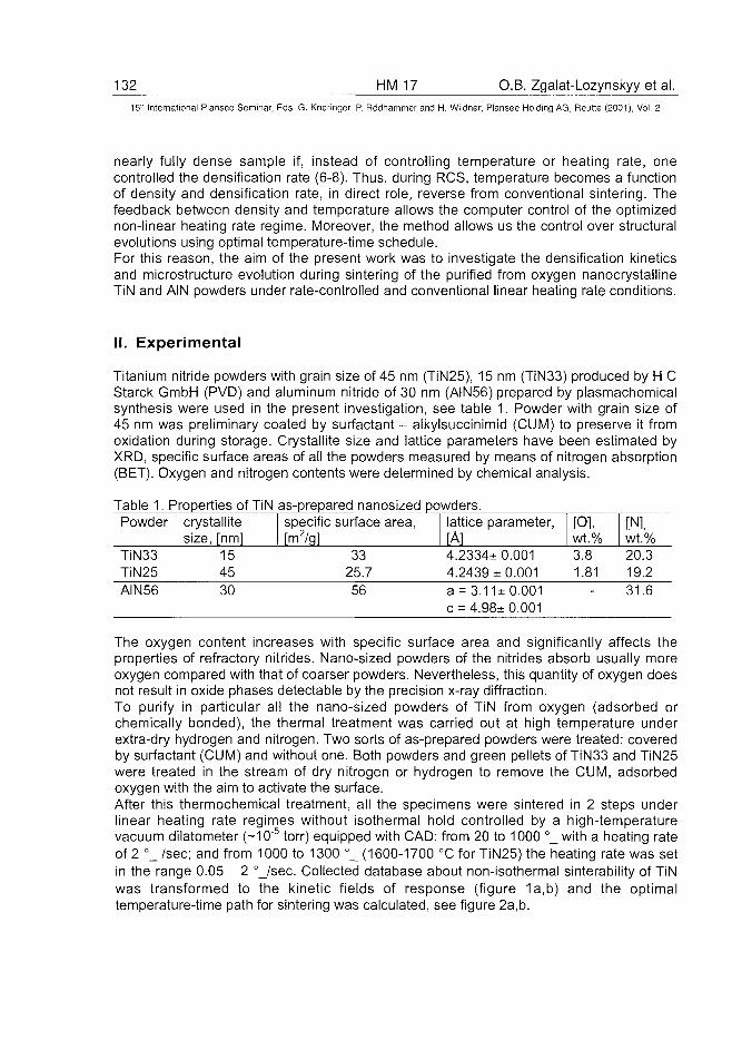
132 HM 17 O.B. Zgalat-Lozynskyy et al.15lr International Plansee Seminar, Eds. G. Kneringer, P. Rodhammer and H. Wildner, Plansee Holding AG, Reutte (2001), Vol. 2
nearly fully dense sample if, instead of controlling temperature or heating rate, onecontrolled the densification rate (6-8). Thus, during RCS, temperature becomes a functionof density and densification rate, in direct role, reverse from conventional sintering. Thefeedback between density and temperature allows the computer control of the optimizednon-linear heating rate regime. Moreover, the method allows us the control over structuralevolutions using optimal temperature-time schedule.For this reason, the aim of the present work was to investigate the densification kineticsand microstructure evolution during sintering of the purified from oxygen nanocrystallineTiN and AIN powders under rate-controlled and conventional linear heating rate conditions.
II. Experimental
Titanium nitride powders with grain size of 45 nm (TiN25), 15 nm (TiN33) produced by H CStarck GmbH (PVD) and aluminum nitride of 30 nm (AIN56) prepared by plasmachemicalsynthesis were used in the present investigation, see table 1. Powder with grain size of45 nm was preliminary coated by surfactant - alkylsuccinimid (CUM) to preserve it fromoxidation during storage. Crystallite size and lattice parameters have been estimated byXRD, specific surface areas of all the powders measured by means of nitrogen absorption(BET). Oxygen and nitrogen contents were determined by chemical analysis.
Table 1. Properties of TiN as-prepared nanosized powders.Powder
TiN33TiN25AIN56
crystallitesize, [nm]
154530
specific surface area,[m2/g]
3325.756
lattice parameter,[A]4.2334± 0.0014.2439 ± 0.001a = 3.11+0.001c = 4.98± 0.001
[O],wt.%3.81.81
[N],wt.%20.319.231.6
The oxygen content increases with specific surface area and significantly affects theproperties of refractory nitrides. Nano-sized powders of the nitrides absorb usually moreoxygen compared with that of coarser powders. Nevertheless, this quantity of oxygen doesnot result in oxide phases detectable by the precision x-ray diffraction.To purify in particular all the nano-sized powders of TiN from oxygen (adsorbed orchemically bonded), the thermal treatment was carried out at high temperature underextra-dry hydrogen and nitrogen. Two sorts of as-prepared powders were treated: coveredby surfactant (CUM) and without one. Both powders and green pellets of TiN33 and TiN25were treated in the stream of dry nitrogen or hydrogen to remove the CUM, adsorbedoxygen with the aim to activate the surface.After this thermochemical treatment, all the specimens were sintered in 2 steps underlinear heating rate regimes without isothermal hold controlled by a high-temperaturevacuum dilatometer (~10"5 torr) equipped with CAD: from 20 to 1000 °_ with a heating rateof 2 °_ /sec; and from 1000 to 1300 °_ (1600-1700 °C for TiN25) the heating rate was setin the range 0.05 - 2 °_/sec. Collected database about non-isothermal sinterability of TiNwas transformed to the kinetic fields of response (figure 1a,b) and the optimaltemperature-time path for sintering was calculated, see figure 2a,b.
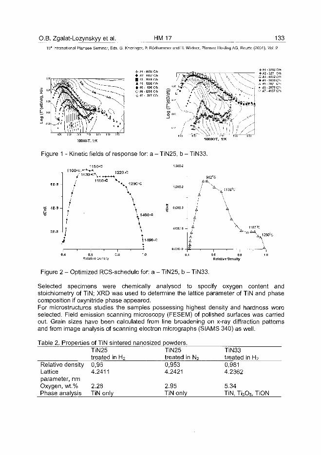
O.B. Zgalat-Lozynskyy et al. HM 17 13315'h International Plansee Seminar, Eds. G. Kneringer, P. Rodhammer and H. Wildner, Plansee Holding AG, Reutte (2001), Vol. 2
10000/T, 1/K
•f #1• *2| *3A #4• »5O *6A *7
.6532 Cyh- 4157 Oh- 2513 Cfll-1260 C/h- 505 C/h- 3265 Oh- 327 Oh
- 3266 C/hO#2-327 C/h• #3 - 6532 C/h• #4 - 5039 C/h
-- A #5 - 207 C/h; * #6 - 2078 C/h
O #7 - 4157 C/h
10000/T, 1/K
Figure 1 - Kinetic fields of response for: a - TiN25, b - TiN33.
1180-C
1220-C
*_ 1290°C
\1136°C
\ 1400-O
H460.C
0.6Relative Density
0.6 0.8Relative Density
Figure 2 - Optimized RCS-schedule for: a - TiN25, b - TiN33.
Selected specimens were chemically analysed to specify oxygen content andstoichiometry of TiN; XRD was used to determine the lattice parameter of TiN and phasecomposition if oxynitride phase appeared.For microstructures studies the samples possessing highest density and hardness wereselected. Field emission scanning microscopy (FESEM) of polished surfaces was carriedout. Grain sizes have been calculated from line broadening on x-ray diffraction patternsand from image analysis of scanning electron micrographs (SIAMS 340) as well.
Table 2. Properties of TiN sintered nanosized powders.
Relative densityLatticeparameter, nmOxygen, wt.%Phase analysis
TiN25treated in H2
0,964.2411
2.28TiN only
TiN25treated in N2
0,9534.2421
2.95TiN only
TiN33treated in H2
0,9814.2362
5.34TiN, Ti3O5, TiON
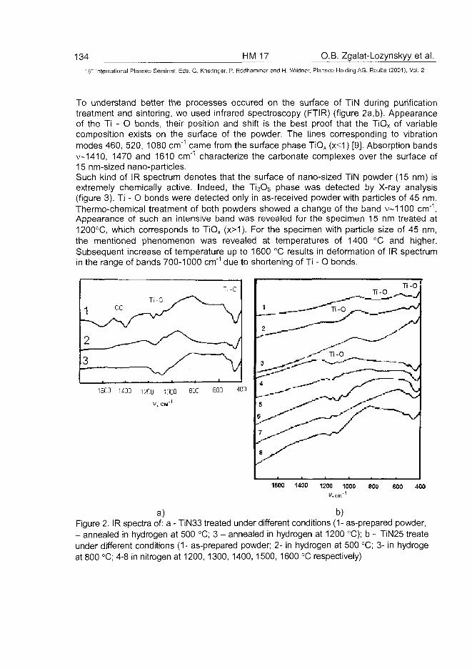
134 HM 17 O.B. Zgalat-Lozynskyy et ai.
International Plansee Seminar, Eds. G. Kneringer, P. Rodhammer and H. Wildner, Plansee Holding AG, Reutte (2001), Vol. 2
To understand better the processes occured on the surface of TiN during purificationtreatment and sintering, we used infrared spectroscopy (FTIR) (figure 2a,b). Appearanceof the Ti - O bonds, their position and shift is the best proof that the TiOx of variablecomposition exists on the surface of the powder. The lines corresponding to vibrationmodes 460, 520, 1080 cm"1 came from the surface phase TiOx (x<1) [9]. Absorption bandsv~1410, 1470 and 1610 cm"1 characterize the carbonate complexes over the surface of15 nm-sized nano-particles.Such kind of IR spectrum denotes that the surface of nano-sized TiN powder (15 nm) isextremely chemically active. Indeed, the Ti3O5 phase was detected by X-ray analysis(figure 3). Ti - O bonds were detected only in as-received powder with particles of 45 nm.Thermo-chemical treatment of both powders showed a change of the band v~1100 cm"1.Appearance of such an intensive band was revealed for the specimen 15 nm treated at1200°C, which corresponds to TiOx (x>1). For the specimen with particle size of 45 nm,the mentioned phenomenon was revealed at temperatures of 1400 °C and higher.Subsequent increase of temperature up to 1600 °C results in deformation of IR spectrumin the range of bands 700-1000 cm"1 due to shortening of Ti - O bonds.
1600 400V, cm'
a) b)Figure 2. IR spectra of: a - TiN33 treated under different conditions (1- as-prepared powder,- annealed in hydrogen at 500 °C; 3 - annealed in hydrogen at 1200 °C); b - TiN25 treateunder different conditions (1- as-prepared powder; 2- in hydrogen at 500 °C; 3- in hydrogeat 800 °C; 4-8 in nitrogen at 1200, 1300, 1400, 1500, 1600 °C respectively)
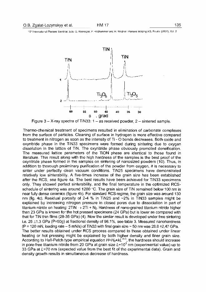
O.B. Zgalat-Lozynskyy et al. HM 17 135
15" International Plansee Seminar, Eds. G. Kneringer, P. Rodhammer and H. Wildner, Plansee Holding AG, Reutte (2001), Vol. 2
TiN
TiN
1 r60 40 35 3055 50 45
e , graaFigure 3 - X-ray spectra of T1N33: 1 - as received powder, 2 - sintered sample.
Thermo-chemical treatment of specimens resulted in elimination of carbonate complexesfrom the surface of particles. Cleaning of surface in hydrogen is more effective comparedto treatment in nitrogen as soon as the intensity of Ti - O bonds decreases. Both oxide andoxynitride phase in the TiN33 specimens were formed during sintering due to oxygendissolution in the lattice of TiN. The oxynitride phase obviously promoted densification.The measured lattice parameters of the TiON phase are identical to those found inliterature. This result along with the high hardness of the samples is the best proof of theoxynitride phase formed in the samples on sintering of nanosized powders (10). Thus, inaddition to thorough preliminary purification of the powder from oxygen, it is necessary tosinter under perfectly clean vacuum conditions. TiN25 specimens have demonstratedrelatively low sinterability. A five-times increase of the grain size has been establishedafter the RCS, see figure 4a. The best results have been achieved for TiN33 specimensonly. They showed perfect sinterability, and the final temperature in the optimized RCS-schedule of sintering was around 1200 °C. The grain size of TiN remained below 100 nm innear fully dense ceramics (figure 4b). For standard RCS-regime, the grain size was around 130nm (fig. 4c). Residual porosity of 2-4 % in TiN25 and -2% in TiN33 samples might beexplained by increasing nitrogen pressure in closed pores due to dissociation in part oftitanium nitride on heating: 2TiN -» 2Ti + N2. Hardness of nano-grained titanium nitride higherthan 23 GPa is known for the hot pressed specimens (24 GPa) but is lower as compared withthat for TiN thin films (28-35 GPa) (4). Now the similar result is developed under free sinteringi.e. 26 ±1.3 GPa (P=50g) at fractional density of 98.1 %, see table 3. Measured nanohardness(P = 120 mN, loading rate - 5 mN/s) of TiN33 with final grain size ~ 50 nm was 28.8 +2,47 GPa.The better results obtained under RCS process compared to those obtained under linearheating or hot pressing might be explained by both higher density and finer grain size.According to Hall-Petch type empirical equation H=HQ+kL'°5, the hardness should increasein pore-free titanium nitride from 20 GPa at grain size /_=103 nm (experimental value) up to33 GPa at L=70 nm (expected value from the best fit of the experimental data). Grain anddensity growth results in simultaneous decrease of hardness.
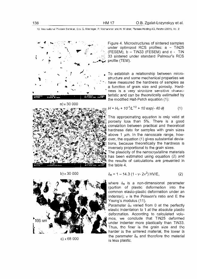
136 HM 17 O.B. Zgalat-Lozynskyy et al.15" International Plansee Seminar, Eds. G. Kneringer, P. Rodhammer and H. Wildner, Plansee Holding AG, Reutte (2001), Vol. 2
Figure 4. Microstructures of sintered samplesunder optimized RCS profiles: a - TiN25(FESEM), b - TiN33 (FESEM) and c - TiN33 sintered under standard Palmour's RCSprofile (TEM).
To establish a relationship between micro-structure and some mechanical properties wehave measured the hardness of samples asa function of grain size and porosity. Hard-ness is a very structure sensitive charac-teristic and can be theoretically estimated bythe modified Hall-Petch equation (1):
= H0+ 10 exp(- 40, (1)
«*»«*:* rJLV^M &«^V^ ( •'^'S.^i^ J
• > ; - »*.* i
This approximating equation is only valid atporosity less than 5%. There is a goodcorrelation between practical and theoreticalhardness data for samples with grain sizesabove 1 |i.m. In the nanoscale range, how-ever, the equation (1) gives substantial devia-tions, because theoretically the hardness isinversely proportional to the grain sizes.The plasticity of the nanocrystalline materialshas been estimated using equation (2) andthe results of calculations are presented inthe table 4.
b)x30 000 8H = 1 -14.3(1 -v-2v2)HV/E, (2)
where §H is a non-dimensional parameter(portion of plastic deformation into thecommon elasto-plastic deformation under anindenter); v is the Poisson's ratio and E theYoung's modulus (11).Parameter §H varied from 0 at the perfectlyelastic indentation to 1 at the absolute plasticdeformation. According to calculated volu-mes, we conclude that TiN25 deformedunder indenter more plastically than TiN33.Thus, the finer is the grain size and theharder is the sintered material, the lower isthe parameter 8H and therefore the materialis less plastic.
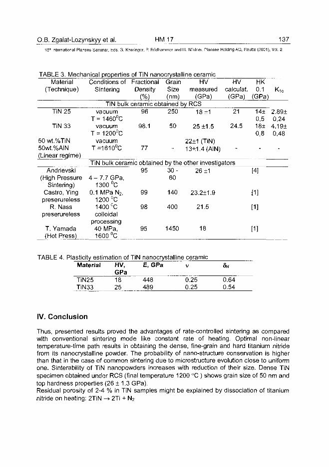
O.B. Zgalat-Lozynskyy et al. HM 17 13715" International Plansee Seminar, Eds. G. Kneringer, P. Rodhammer and H. Wildner, Plansee Holding AG, Reutte (2001), Vol. 2
TABLE 3. Mechanical properties of TiN nanocrystalline ceramicMaterial Conditions of Fractional Grain HV HV HK
(Technique) Sintering Density Size measured calculat. 0.1 K1c
(%) (nm) (GPa) (GPa) (GPa)TiN bulk ceramic obtained by RCS
TiN 25
TiN 33
50 wt.%TiN50wt.%AIN(Linear regime)
Andrievski(High Pressure
Sintering)Castro, Yingpreserureless
R. Nasspreserureless
T. Yamada(Hot Press)
vacuumT = 1460°C
vacuumT = 1200°C
vacuumT=1610°C
TiN bulk ceramic
4-7 .7 GPa,1300°C
0.1 MPa N2,1200°C1400°Ccolloidal
processing40 MPa,1600°C
96
98.1
77
obtained95
99
98
95
250
50
-
by the30-60
140
400
1450
18 ±1
25 ±1.5
22±1 (TiN)13±1.4(AIN)
21
24.5
-
other investigators26+1
23.2±1.9
21.5
18
14±0,518±0,8
-
[4]
[1]
[1]
[1]
2.0
4.0
89±,2419±,48
-
TABLE 4. Plasticity estimation of TiN nanocrystalline ceramicMaterial HV, E, GPa v
GPa5H
TIN25TiN33
1825
448489
0.250.25
0.640.54
IV. Conclusion
Thus, presented results proved the advantages of rate-controlled sintering as comparedwith conventional sintering mode like constant rate of heating. Optimal non-lineartemperature-time path results in obtaining the dense, fine-grain and hard titanium nitridefrom its nanocrystalline powder. The probability of nano-structure conservation is higherthan that in the case of common sintering due to microstructure evolution close to uniformone. Sinterability of TiN nanopowders increases with reduction of their size. Dense TiNspecimen obtained under RCS (final temperature 1200 °C ) shows grain size of 50 nm andtop hardness properties (26 ± 1.3 GPa).Residual porosity of 2-4 % in TiN samples might be explained by dissociation of titaniumnitride on heating: 2TiN -» 2Ti + N2
138 HM 17 O.B. Zgalat-Lozynskyy et al.
15" International Plansee Seminar, Eds. G. Kneringer, P. Rodhammer and H. Wildner, Plansee Holding AG, Reutte (2001), Vol. 2
Acknowledgments
Authors thank NATO Science for Peace Program for support via Project # 973529 and Dr.I. Schulz, IKTS (Dresden, Germany) for HRSEM images and powder supply; Dr. T.V.Tomila, Dr. I.I. Timofeeva and Mr. L.A. Klochkov (aa from IPMS, Ukraine) forexperimental assistance and useful discussion of the results.
References
1 D.T.Castro, J.Y.Ying: Fine, Ultrafine and Nano Powders'98 Conference (1998)2 T.Rabe, R. Wasche: Nanostructured Materials 6 (1995), pp. 357-3603 J.R. Groza, J.D. Curtis, M. Kramer: J. Amer. Ceram. Soc 5 (2000), pp.1281-12834 R.A. Andrievsky, G.V.Kalinnikov, A.F.Potafeev and V.S.Urbanovich (1995).
NanoStructured Materials, 6± 1-4, 3535 V.V. Skorokhod , A.V. Ragulya Proc. 14 th Int. Plansee Seminar, Vol. 3, pp. (ed.
G. Kneringer et al, Plansee AG, Reutte 1997)6 Palmour III H. and Hare T.M. (1985) Proc. of the Sixth World Round Table
conference on sintering, Hercig-Novi, New-York, Plenum Press, 16-237 Palmour III H. (1988) Powder Metal Report, No 9, 572-580.8 Palmour III H. (1989) Proc. of the Seventh World Round Table conference on
sintering, Hercig-Novi, New-York, 337-3429 Ariya S.M. and Golomozina M.V. (1962) [in Russian], Infrared spectra of solid
state titanium and vanadium oxide// Fizika tverdogo tela, V.4 #10, p. 2921-292410 Alyamovsky, Zaynulin Yu. G., Shveykin G.P. (1981) [in Russian], Nauka, Moscow,
58-6211 Milman Yu. V. (1999) [in Russian]: Powder Metallurgy, 7-8, 85-91
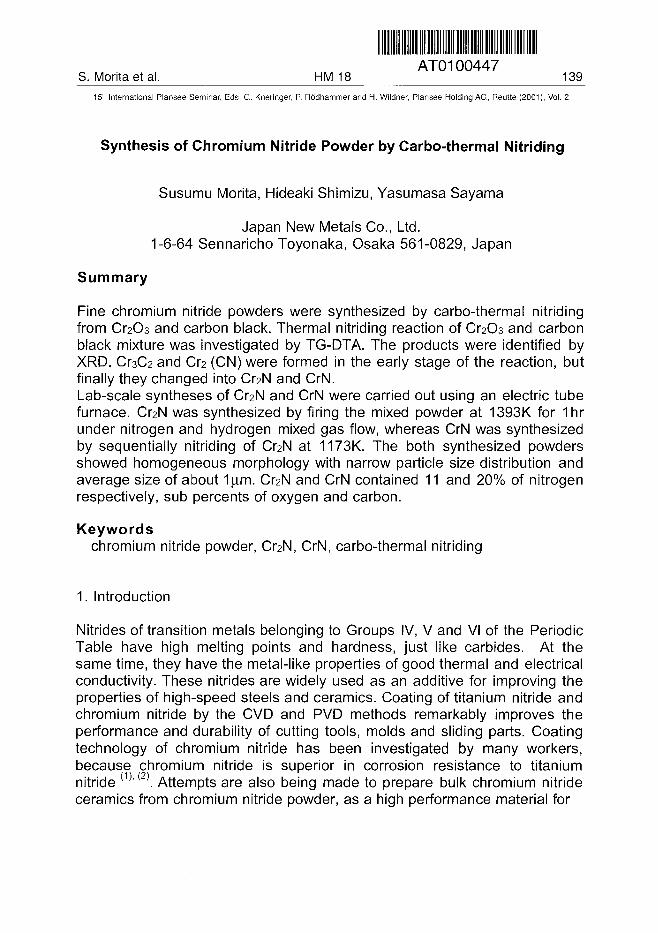
AT0100447S. Morita et al. HM 18 139
15" International Plansee Seminar, Eds. G. Kneringer, P. Rodhammer and H. Wildner, Plansee Holding AG, Reutte (2001), Vol. 2
Synthesis of Chromium Nitride Powder by Carbo-thermal Nitriding
Susumu Morita, Hideaki Shimizu, Yasumasa Sayama
Japan New Metals Co., Ltd.1-6-64 Sennaricho Toyonaka, Osaka 561-0829, Japan
Summary
Fine chromium nitride powders were synthesized by carbo-thermal nitridingfrom Cr2O3 and carbon black. Thermal nitriding reaction of O2O3 and carbonblack mixture was investigated by TG-DTA. The products were identified byXRD. O3C2 and O2 (CN) were formed in the early stage of the reaction, butfinally they changed into CteN and CrN.Lab-scale syntheses of O2N and CrN were carried out using an electric tubefurnace. Cr2N was synthesized by firing the mixed powder at 1393K for 1 hrunder nitrogen and hydrogen mixed gas flow, whereas CrN was synthesizedby sequentially nitriding of Cr2N at 1173K. The both synthesized powdersshowed homogeneous morphology with narrow particle size distribution andaverage size of about 1|a.m. Cr2N and CrN contained 11 and 20% of nitrogenrespectively, sub percents of oxygen and carbon.
Keywordschromium nitride powder, Cr2N, CrN, carbo-thermal nitriding
1. Introduction
Nitrides of transition metals belonging to Groups IV, V and VI of the PeriodicTable have high melting points and hardness, just like carbides. At thesame time, they have the metal-like properties of good thermal and electricalconductivity. These nitrides are widely used as an additive for improving theproperties of high-speed steels and ceramics. Coating of titanium nitride andchromium nitride by the CVD and PVD methods remarkably improves theperformance and durability of cutting tools, molds and sliding parts. Coatingtechnology of chromium nitride has been investigated by many workers,because chromium nitride is superior in corrosion resistance to titaniumnitride (1)'(2). Attempts are also being made to prepare bulk chromium nitrideceramics from chromium nitride powder, as a high performance material for
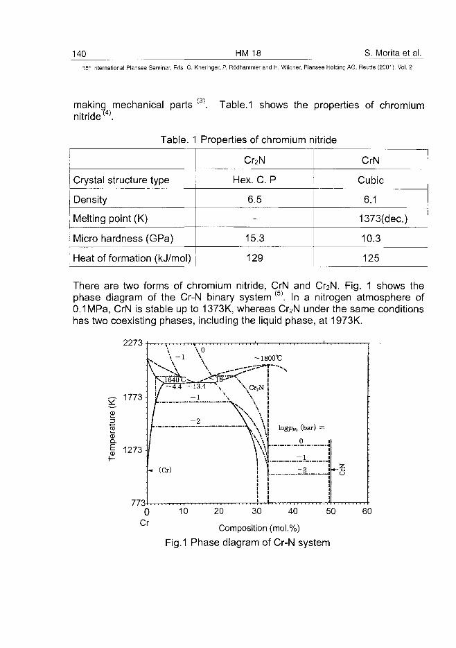
140 HM 18 S. Morita et al.15" International Plansee Seminar, Eds. G. Kneringer, P. Rodhammer and H. Wildner, Plansee Holding AG, Reutte (2001), Vol. 2
making mechanical partsnitride™.
(3) Table.1 shows the properties of chromium
Table. 1 Properties of chromium nitride
Crystal structure type
Density
Melting point (K)
Micro hardness (GPa)
Heat of formation (kJ/mol)
Cr2N
Hex. C. P
6.5
-
15.3
129
CrN
Cubic
6.1
1373(dec.)
10.3
125
There are two forms of chromium nitride, CrN and Cr2N. Fig. 1 shows thephase diagram of the Cr-N binary system (5). In a nitrogen atmosphere of0.1 MPa, CrN is stable up to 1373K, whereas Cr2N under the same conditionshas two coexisting phases, including the liquid phase, at 1973K.
2273
20 30 40
Composition (mol.%)
Fig.1 Phase diagram of Cr-N system
50 60
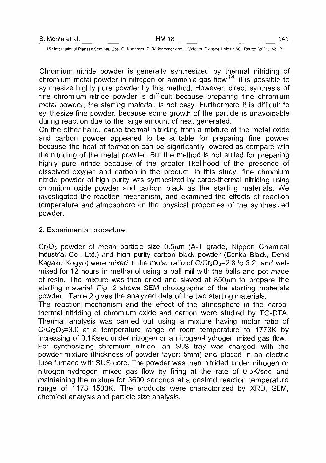
S. Morita et al. HM 18 14115'" International Plansee Seminar, Eds. G. Kneringer, P. Rodhammer and H. Wildner, Plansee Holding AG, Reutte (2001), Vol. 2
Chromium nitride powder is generally synthesized by thermal nitriding ofchromium metal powder in nitrogen or ammonia gas flow(6). It is possible tosynthesize highly pure powder by this method. However, direct synthesis offine chromium nitride powder is difficult because preparing fine chromiummetal powder, the starting material, is not easy. Furthermore it is difficult tosynthesize fine powder, because some growth of the particle is unavoidableduring reaction due to the large amount of heat generated.On the other hand, carbo-thermal nitriding from a mixture of the metal oxideand carbon powder appeared to be suitable for preparing fine powderbecause the heat of formation can be significantly lowered as compare withthe nitriding of the metal powder. But the method is not suited for preparinghighly pure nitride because of the greater likelihood of the presence ofdissolved oxygen and carbon in the product. In this study, fine chromiumnitride powder of high purity was synthesized by carbo-thermal nitriding usingchromium oxide powder and carbon black as the starting materials. Weinvestigated the reaction mechanism, and examined the effects of reactiontemperature and atmosphere on the physical properties of the synthesizedpowder.
2. Experimental procedure
Cr2C>3 powder of mean particle size 0.5,um (A-1 grade, Nippon ChemicalIndustrial Co., Ltd.) and high purity carbon black powder (Denka Black, DenkiKagaku Kogyo) were mixed in the molar ratio of C/Cr2O3=2.8 to 3.2, and wet-mixed for 12 hours in methanol using a ball mill with the balls and pot madeof resin. The mixture was then dried and sieved at 8 5 0 ^ to prepare thestarting material. Fig. 2 shows SEM photographs of the starting materialspowder. Table 2 gives the analyzed data of the two starting materials.The reaction mechanism and the effect of the atmosphere in the carbo-thermal nitriding of chromium oxide and carbon were studied by TG-DTA.Thermal analysis was carried out using a mixture having molar ratio ofC/Cr2O3=3.0 at a temperature range of room temperature to 1773K byincreasing of 0.1K/sec under nitrogen or a nitrogen-hydrogen mixed gas flow.For synthesizing chromium nitride, an SUS tray was charged with thepowder mixture (thickness of powder layer: 5mm) and placed in an electrictube furnace with SUS core. The powder was then nitrided under nitrogen ornitrogen-hydrogen mixed gas flow by firing at the rate of 0.5K/sec andmaintaining the mixture for 3600 seconds at a desired reaction temperaturerange of 1173-1503K. The products were characterized by XRD, SEM,chemical analysis and particle size analysis.
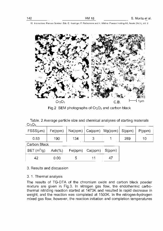
142 HM 18 S. Morita et al.15" International Plansee Seminar, Eds. G. Kneringer, P. Rodhammer and H. Wildner, Plansee Holding AG, Reutte (2001), Vol. 2
"» %,
, V
Cr2O3 C.B.
Fig.2 SEM photographs of O2O3 and carbon black
Table. 2 Average particle size and chemical analyses of starting materialsCr7O3
FSSSOum)
0.53
Fe(ppm)
190
Na(ppm)
134
Ca(ppm)
3
Mg(ppm)
1
S(ppm)
289
P(ppm)
10
Carbon
BET(m
42
Black2/g) Ash(%)
0.00
Fe(ppm)
5
Ca(ppm)
11
S(ppm)
47
3. Results and discussion
3. 1. Thermal analysis
The results of TG-DTA of the chromium oxide and carbon black powdermixture are given in Fig.3. In nitrogen gas flow, the endothermic carbo-thermal nitriding reaction started at 1473K and resulted in rapid decrease inweight, and the reaction was completed at 1503K. In the nitrogen-hydrogenmixed gas flow, however, the reaction initiation and completion temperatures
S. Morita et al. HM 18 143
15* International Plansee Seminar, Eds. G. Kneringer, P. Rodhammer and H. Wildner, Plansee Holding AG, Reutte (2001), Vol. 2
were 1353 and 1393K respectively, showing a shift to the low temperatureside. Final reactants obtained by TG-DTA were CrN and Cr2N in both thereaction systems.
CQ
-801323 1473 15231373 1423
Temperature (K)Fig.3 The results of TG-DTA of carbo-thermal nitriding from
Cr2O3 and carbon black
The intermediate products in lab-scale synthesis at 1353 and 1393K underthe nitrogen-hydrogen mixed gas flow were examined by XRD (Fig. 4). At1353K, apart from the main peak of Cr2 (CN), minor peaks corresponding toO3C2 and O2O3 appeared. At 1393K, only O2N peek was observed. Thisresult suggests that the chromium oxide transformed into the carbide and thecarbonitride at the beginning of reaction and then converted into the nitride.Fig. 5 shows the change in standard free energy of chromium nitrideformation when chromium oxide is the starting material (7). This graphindicates that a reaction temperature of 1450K or higher is needed for thereaction of chromium oxide and carbon in the nitrogen atmosphere. Thisagrees well with the results of TG-DTA. In the reaction of chromium oxidewith a gas mixture of methane and nitrogen, AG had a negative value at thereaction temperature 1200K or higher, suggesting that the reaction started ata relatively low temperature. On the basis of the above results, it is assumedthat when the nitrogen-hydrogen gas mixture is used as the reaction gas, thesurface of the chromium oxide is first reduced by the hydrogen, andgenerates a lower oxide and H2O gas<8). Then hydrocarbon gas, produced by
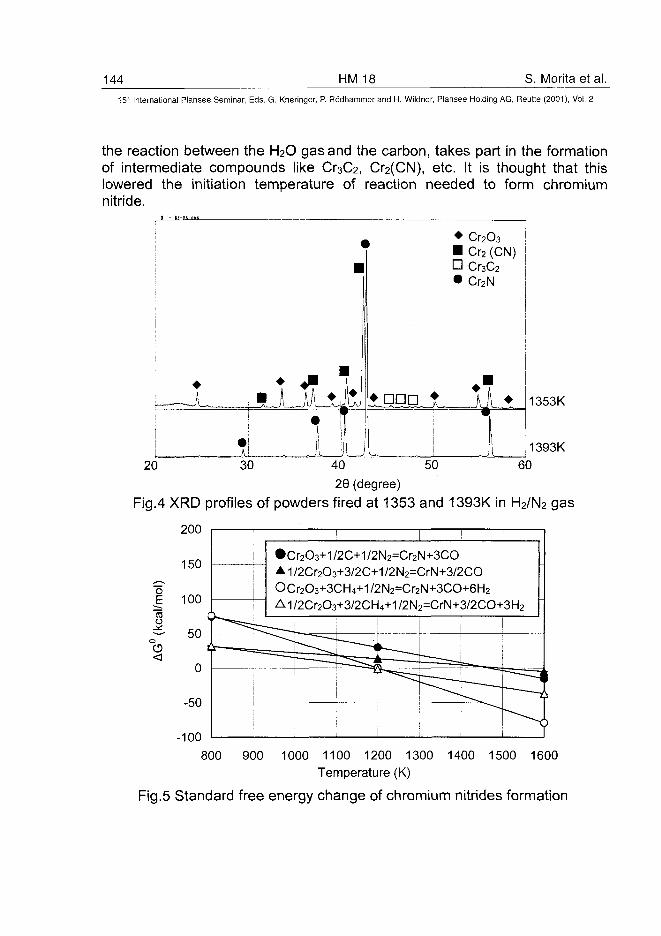
144 HM 18 S. Morita et al.15* International Plansee Seminar, Eds. G. Kneringer, P. Rodhammer and H. Wildner, Plansee Holding AG, Reutte (2001), Vol. 2
the reaction between the H2O gas and the carbon, takes part in the formationof intermediate compounds like Cr3C2, Cr2(CN), etc. It is thought that thislowered the initiation temperature of reaction needed to form chromiumnitride.
1353K
1393K
20 30 6040 50
29 (degree)
Fig.4 XRD profiles of powders fired at 1353 and 1393K in H2/N2 gas
200
150
£ 100too
r——=
!
•Cr2O3+1/2C+1/2N2=Cr2N+3COAi/2Cr2O3+3/2C+1/2N2=CrN+3/2COOCr203+3CH4+1/2N2=Cr2N+3CO+6H2
Ai/2Cr2O3+3/2CH4+1/2N2=CrN+3/2CO+3H2
i
i ^ —
I
*H' • — .
50
-50
-100800 900 1000 1100 1200 1300 1400 1500 1600
Temperature (K)
Fig.5 Standard free energy change of chromium nitrides formation
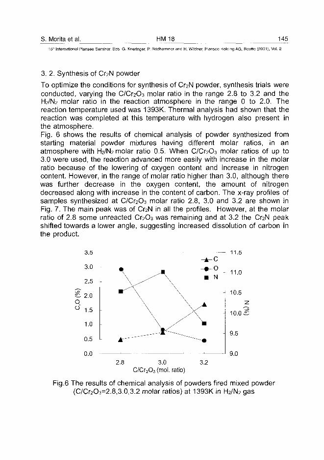
S. Morita et al. HM 18 145
15th International Plansee Seminar, Eds. G. Kneringer, P. Rodhammer and H. Wildner, Plansee Holding AG, Reutte (2001), Vol. 2
3. 2. Synthesis of O2N powder
To optimize the conditions for synthesis of O2N powder, synthesis trials wereconducted, varying the C/O2O3 molar ratio in the range 2.8 to 3.2 and theH2/N2 molar ratio in the reaction atmosphere in the range 0 to 2.0. Thereaction temperature used was 1393K. Thermal analysis had shown that thereaction was completed at this temperature with hydrogen also present inthe atmosphere.Fig. 6 shows the results of chemical analysis of powder synthesized fromstarting material powder mixtures having different molar ratios, in anatmosphere with H2/N2 molar ratio 0.5. When C/O2O3 molar ratios of up to3.0 were used, the reaction advanced more easily with increase in the molarratio because of the lowering of oxygen content and increase in nitrogencontent. However, in the range of molar ratio higher than 3.0, although therewas further decrease in the oxygen content, the amount of nitrogendecreased along with increase in the content of carbon. The x-ray profiles ofsamples synthesized at C/Cr2O3 molar ratio 2.8, 3.0 and 3.2 are shown inFig. 7. The main peak was of O2N in all the profiles. However, at the molarratio of 2.8 some unreacted O2O3 was remaining and at 3.2 the O2N peakshifted towards a lower angle, suggesting increased dissolution of carbon inthe product.
11.5
2.8 3.0C/Cr2O3 (mol. ratio)
3.2
Fig.6 The results of chemical analysis of powders fired mixed powder(C/Cr2O3=2.8,3.0,3.2 molar ratios) at 1393K in H2/N2 gas
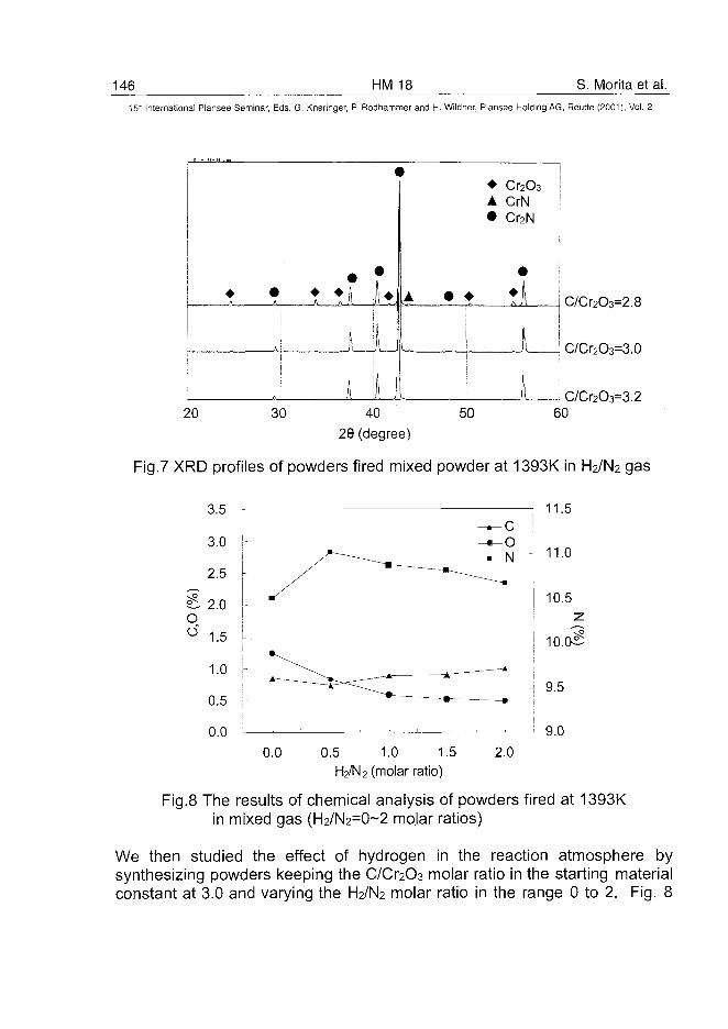
146 HM 18 S. Morita et al.15" International Plansee Seminar, Eds. G. Kneringer, P. Rodhammer and H. Wildner, Plansee Holding AG, Reutte (2001), Vol. 2
C/Cr2O3=2.8
C/Cr2O3=3.0
I C/Cr2O3=3.240
29 (degree)
Fig.7 XRD profiles of powders fired mixed powder at 1393K in H2/N2 gas
11.5
0.0 0.5 1.0 1.5H2/N2 (molar ratio)
2.0
Fig.8 The results of chemical analysis of powders fired at 1393Kin mixed gas (H2/N2=0~2 molar ratios)
We then studied the effect of hydrogen in the reaction atmosphere bysynthesizing powders keeping the C/Cr2C>3 molar ratio in the starting materialconstant at 3.0 and varying the H2/N2 molar ratio in the range 0 to 2. Fig. 8
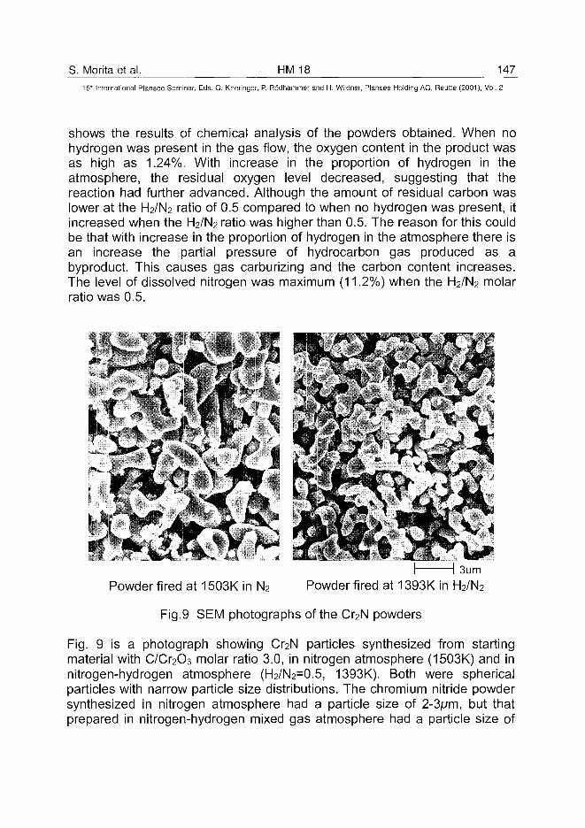
S. Morita et al. HM 18 14715th International Plansee Seminar, Eds. G. Kneringer, P. Rodhammer and H. Wildner, Plansee Holding AG, Reutte (2001), Vol. 2
shows the results of chemical analysis of the powders obtained. When nohydrogen was present in the gas flow, the oxygen content in the product wasas high as 1.24%. With increase in the proportion of hydrogen in theatmosphere, the residual oxygen level decreased, suggesting that thereaction had further advanced. Although the amount of residual carbon waslower at the H2/N2 ratio of 0.5 compared to when no hydrogen was present, itincreased when the H2/N2 ratio was higher than 0.5. The reason for this couldbe that with increase in the proportion of hydrogen in the atmosphere there isan increase the partial pressure of hydrocarbon gas produced as abyproduct. This causes gas carburizing and the carbon content increases.The level of dissolved nitrogen was maximum (11.2%) when the H2/N2 molarratio was 0.5.
Powder fired at 1503K in N2
3umPowder fired at 1393K in H2/N2
Fig.9 SEM photographs of the Cr2N powders
Fig. 9 is a photograph showing Cr2N particles synthesized from startingmaterial with C/Cr2C)3 molar ratio 3.0, in nitrogen atmosphere (1503K) and innitrogen-hydrogen atmosphere (H2/N2=0.5, 1393K). Both were sphericalparticles with narrow particle size distributions. The chromium nitride powdersynthesized in nitrogen atmosphere had a particle size of 2-3jum, but thatprepared in nitrogen-hydrogen mixed gas atmosphere had a particle size of
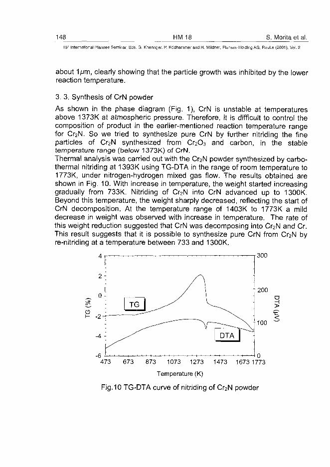
148 HM 18 S. Morita et al.15" International Plansee Seminar, Eds. G. Kneringer, P. Rodhammer and H. Wildner, Plansee Holding AG, Reutte (2001), Vol. 2
about 1/vm, clearly showing that the particle growth was inhibited by the lowerreaction temperature.
3. 3. Synthesis of CrN powder
As shown in the phase diagram (Fig. 1), CrN is unstable at temperaturesabove 1373K at atmospheric pressure. Therefore, it is difficult to control thecomposition of product in the earlier-mentioned reaction temperature rangefor Cr2N. So we tried to synthesize pure CrN by further nitriding the fineparticles of Cr2N synthesized from Cr2O3 and carbon, in the stabletemperature range (below 1373K) of CrN.Thermal analysis was carried out with the Cr2N powder synthesized by carbo-thermal nitriding at 1393K using TG-DTA in the range of room temperature to1773K, under nitrogen-hydrogen mixed gas flow. The results obtained areshown in Fig. 10. With increase in temperature, the weight started increasinggradually from 733K. Nitriding of Cr2N into CrN advanced up to 1300K.Beyond this temperature, the weight sharply decreased, reflecting the start ofCrN decomposition. At the temperature range of 1403K to 1773K a milddecrease in weight was observed with increase in temperature. The rate ofthis weight reduction suggested that CrN was decomposing into Cr2N and Cr.This result suggests that it is possible to synthesize pure CrN from Cr2N byre-nitriding at a temperature between 733 and 1300K.
300
T200
+ 100
473 673 873 1073 1273 1473 1673 1773
Temperature (K)
Fig.10 TG-DTA curve of nitriding of Cr2N powder
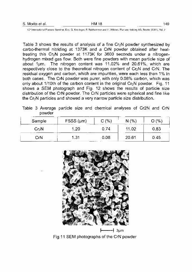
S. Morita et al. HM 18 149
15" International Plansee Seminar, Eds. G. Kneringer, P. Rodhammer and H. Wildner, Plansee Holding AG, Reutte (2001), Vol. 2
Table 3 shows the results of analysis of a fine O2N powder synthesized bycarbo-thermal nitriding at 1373K and a CrN powder obtained after heat-treating this O2N powder at 1173K for 3600 seconds under a nitrogen-hydrogen mixed gas flow. Both were fine powders with mean particle size ofabout 1/vm. The nitrogen content was 11.02% and 20.61%, which arerespectively close to the theoretical nitrogen content of O2N and CrN. Theresidual oxygen and carbon, which are impurities, were each less than 1% inboth cases. The CrN powder was purer, with only 0.08% carbon, which wasonly about 1/10th of the carbon content in the original C^N powder. Fig. 11shows a SEM photograph and Fig. 12 shows the results of particle sizedistribution of the CrN powder. The CrN particles were spherical and fine likethe Cr2N particles and showed a very narrow particle size distribution.
Table 3 Average particle size and chemical analyses of Cr2N and CrNpowder
Sample
Cr2N
CrN
FSSS (urn)
1.20
1.31
C (%)
0.74
0.08
N (%)
11.02
20.61
O (%)
0.83
0.45
Fig. 11 SEM photographs of the CrN powder
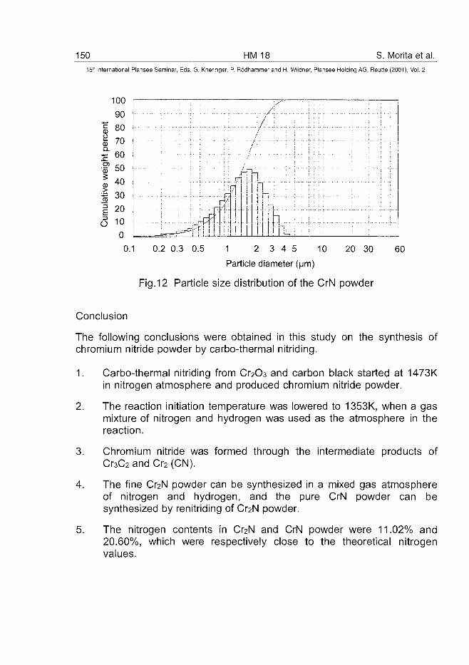
150 HM 18 S. Morita et al.15r International Plansee Seminar, Eds. G. Kneringer, P. Rodhammer and H. Wildner, Plansee Holding AG, Reutte (2001), Vol. 2
100 r -
90 j
| 80 !
£ 70 I5 60 j .f 50
II 401 3 0 !
20j
o LO 10
l i l l
n•f]f
0.1 0.2 0.3 0.5 1 2 3 4 5 10 20 30Particle diameter (|jm)
Fig.12 Particle size distribution of the ON powder
60
Conclusion
The following conclusions were obtained in this study on the synthesis ofchromium nitride powder by carbo-thermal nitriding.
1. Carbo-thermal nitriding from Cr2C>3 and carbon black started at 1473Kin nitrogen atmosphere and produced chromium nitride powder.
2. The reaction initiation temperature was lowered to 1353K, when a gasmixture of nitrogen and hydrogen was used as the atmosphere in thereaction.
3. Chromium nitride was formed through the intermediate products ofCr3C2 and Cr2 (CN).
4. The fine Cr2N powder can be synthesized in a mixed gas atmosphereof nitrogen and hydrogen, and the pure CrN powder can besynthesized by renitriding of Cr2N powder.
5. The nitrogen contents in Cr2N and CrN powder were 11.02% and20.60%, which were respectively close to the theoretical nitrogenvalues.
S. Morita et al. HM 18 15115" International Plansee Seminar, Eds. G. Kneringer, P. Rodhammer and H. Wildner, Plansee Holding AG, Reutte (2001), Vol. 2
References
(1) G.V.Samsonov and I.M.Vinitskii: "Handbook of Refractory Compounds",(IFI/Plenum, New York, 1980), pp.371-386
(2) H.Kuwahara and JXakada: J. Japan Inst. Powder and PowderMetallurgy, 39(1992), pp.318-321
(3) H.Kuwahara, New Ceramics, Vol.11, No.9 (1998), pp.37-44
(4) H.J.Goldschmidt: "Interstitial Alloys", (Butterworths, London, 1967),pp.220
(5) M.Venkatraman and JP.Neuman, "Binary Phase Diagram", (ASMInternational, 1990), pp.1293-1297
(6) P.Schwarzkopf and R.Kieffer: "Refractory Hard Metals", (The MacmillanCompany, New York, 1953), pp.248-250
(7) O.Kubaschewski and C.B.AIcock: "Metallurgical Thermochemistry",(Pergamon Press, Oxford, 1979), pp.378-379
(8) A.H.Sully: "Metallugy of the Rarer Metals No.1, Chromium", (ButterworthScientific Publication, 1954), pp.52-54
ATO100448152 HM21 T. Vasile et al.
15" International Plansee Seminar, Eds. G. Kneringer, P. Rodhammer and H. Wildner, Plansee Holding AG, Reutte (2001), Vol. 2
THE IMPROVEMENT OF THE WC-TiC-Co ALLOY PERFORMANCES,
REALISED BY ADDITION OF (Ta,Nb)C
Toma Vasile, Catalin Sfat, Marius Vasilescu, Gherghina Zafiu
Physical Metallurgy Dept, POLITEHNICA University of Bucharest, Romania
ABSTRACT
Hard alloys from WC-TiC-Co system are known such as alloys with good
wear resistance and high temperature stability in service. (Ta,Nb)C carbide
additions improve bending resistance, providing a remarkable corrosion
resistance at temperatures of 800°C. The researches and the results
presented in this paper lead to conclusion that (Ta,Nb)C additions in WC-
TiC-Co alloys are very important and must be considered.
KEYWORDS
Hard alloys, WC-TiC-Co alloys, hard powder product
INTRODUCTION
Hard alloys from WC-TiC-Co system are very appreciated because their
significant improvement of hardness, good high temperature stability and a
better wear resistance. TaC addition in these alloys improves wear resistance
and generally all physical and mechanical characteristics at high
temperatures, bigger than reference WC-TiC-Co alloys.
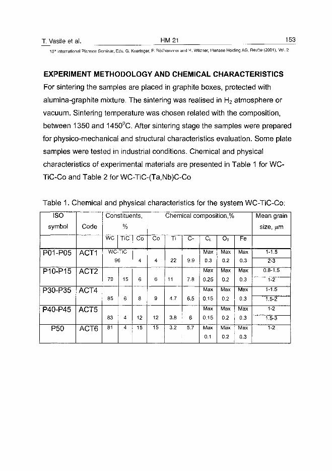
T. Vasile et al. HM21 153
15" International Plansee Seminar, Eds. G. Kneringer, P. Rodhammer and H. Wildner, Plansee Holding AG, Reutte (2001), Vol. 2
EXPERIMENT METHODOLOGY AND CHEMICAL CHARACTERISTICS
For sintering the samples are placed in graphite boxes, protected with
alumina-graphite mixture. The sintering was realised in H2 atmosphere or
vacuum. Sintering temperature was chosen related with the composition,
between 1350 and 1450°C. After sintering stage the samples were prepared
for physico-mechanical and structural characteristics evaluation. Some plate
samples were tested in industrial conditions. Chemical and physical
characteristics of experimental materials are presented in Table 1 for WC-
TiC-Co and Table 2 for WC-TiC-(Ta,Nb)C-Co
Table 1. Chemical and physical characteristics for the system WC-TiC-Co:
ISO
symbol
P01-P05
P10-P15
P30-P35
P40-P45
P50
Code
ACT1
ACT2
ACT4
ACT5
ACT6
Constituents,
%
we TiC
WC-TiC
96
79
85
83
81
15
6
4
4
Co
4
6
8
12
15
Chemical composition,%
Co
4
6
9
12
15
Ti
22
11
4.7
3.8
3.2
CT
9.9
7.8
6.5
6
5.7
CL
Max
0.3
Max
0.25
Max
0.15
Max
0.15
Max
0.1
o2
Max
0.2
Max
0.2
Max
0.2
Max
0.2
Max
0.2
Fe
Max
0.3
Max
0.3
Max
0.3
Max
0.3
Max
0.3
Mean grain
size, |am
1-1.5
2-3
0.8-1.5
1-2
1-1.5
1.5-2
1-2
1.5-3
1-2
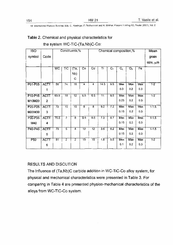
154 HM21 T. Vasile et al.
15- International Plansee Seminar, Eds. G. Kneringer, P. Rodhammer and H. Wildner, Plansee Holding AG, Reutte (2001), Vol. 2
Table 2. Chemical and physical characteristics for
the system WC-TiC-(Ta,Nb)C-Co:
ISO
symbol
P01-P05
P10-P15
M10M20
P20-P25
M20M30
P30-P35
M40
P40-P45
P50
Code
ACTT
1
ACTT
2
ACTT
3
ACTT
4
ACTT
5
ACTT
6
Constituents,%
we
56
63.5
72
75.5
79
81
TiC
24
18
10
7
5
2
(Ta,
Nb)
c16
12
10
8
4
2
Co
4
6.5
8
9.5
12
15
Chemical composition,%
Co
4
6.5
8
9.5
12
15
Ti
14.5
11
9.2
7.3
3.6
1.8
CT
9.5
8.5
7.2
6.7
6.2
5.5
CL
Max
0.3
Max
0.25
Max
0.15
Max
0.15
Max
0.15
Max
0.1
o2
Max
0.2
Max
0.2
Max
0.2
Max
0.2
Max
0.2
Max
0.2
Fe
Max
0.3
Max
0.3
Max
0.3
Max
0.3
Max
0.3
Max
0.3
Mean
grain
size, jam
1-2
1-2
1-1.5
1-1.5
1-1.5
1-2
RESULTS AND DISCUTION
The influence of (Ta,Nb)C carbide addition in WC-TiC-Co alloy system, for
physical and mechanical characteristics were presented in Table 3. For
comparing in Table 4 are presented physico-mechanical characteristics of the
alloys from WC-TiC-Co system.
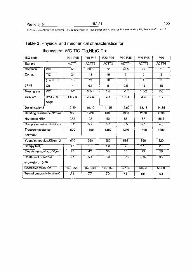
T. Vasile et al. HM21 155
15" International Plansee Seminar, Eds. G. Kneringer, P. Rodhammer and H. Wildner, Plansee Holding AG, Reutte (2001), Vol. 2
Table 3 Physical and mechanical characteristics
the system WC-TiC-(Ta,Nb)C-Co:
for
ISO code
Sample
Chemical
Comp.
(%w)
Mean grain
size, im
weTiC
(Ta,Nb)C
Co
we(W.Ti.Ta,
Nb)C
Density,g/cm3
Bending resistance,N/mm2
Hardness HRA
Compress. resist.,KN/mm2
Traction resistance,
KN/mm2
Young's modulus,KN/mm2
Charpy test, J
Electric resistivity, nfJ/cm
Coefficient of termal
expansion, 10-6K
Coercitive force, Oe
Termal conductivity,W/mK
P01-P05
ACTT1
56
24
16
4
1-2
1.5-2.5-
9.40
950
92.5
6.2
600
650
1.1
73
5.1
140.-220
81
P10-P15
ACTT2
63.5
18
12
6.5
0.8-1
2-2.5
10.10
1200
92
5.9
1150
590
1.6
42
5.4
150-200
77
P20-P25
ACTT3
72
10
10
8
1-2
2-3
11.25
1800
90
5.7
1280
580
1.8
38
5.6
100-150
72
P30-P35
ACTT4
75.5
7
8
9.5
1-1.5
1.5-2
12.60
1930
88
5.5
1350
565
2
35
5.75
95-130
71
P40-P45
ACTT5
79
5
4
12
1.5-2
2-3
13.15
2300
87
5.1
1400
540
2.15
29
5.82
60-90
66
P50
ACTT6
81
2
2
15
2-3
1-2
14.35
2650
86.5
4.5
1480
520
2.5
20
6.2
50-60
63
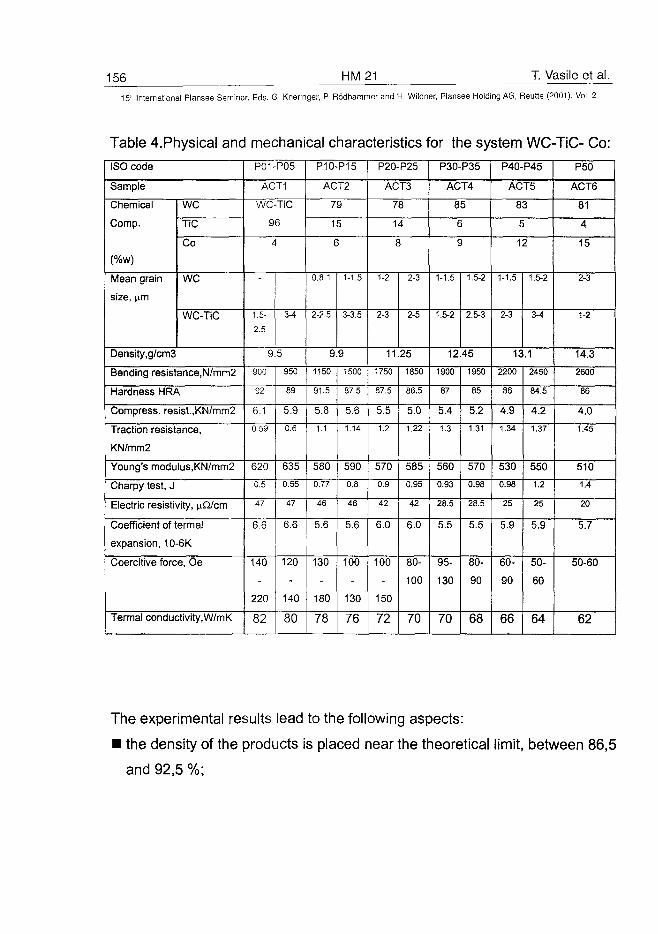
156 HM21 T. Vasile et al.
15" International Plansee Seminar, Eds. G. Kneringer, P. Rodhammer and H. Wildner, Plansee Holding AG, Reutte (2001), Vol. 2
Table 4.Physical anc
ISO code
Sample
Chemical
Comp.
Mean grain
size, urn
weTiC
Co
we
WC-TiC
Density,g/cm3
Bending resistance,N/mm2
Hardness HRA
Compress, resist.,KN/mm2
Traction resistance,
KN/mm2
Young's modulus,KN/mm2
Charpy test, J
Electric resistivity, \iMcm
Coefficient of termal
expansion, 10-6K
Coercitive force, Oe
Termal conductivity,W/mK
mechanical characteristics for the system
P01-P05
ACT1
WC-TiC
96
4
1.5-
2.5
3-4
9.5
900
92
6.1
0.59
620
0.5
47
6.6
140
220
82
950
89
5.9
0.6
635
0.55
47
6.6
120
140
80
P10-P15
ACT2
79
15
6
0.8-1
2-2.5
1-1.5
3-3.5
9.9
1150
91.5
5.8
1.1
580
0.77
46
5.6
130
180
78
1500
87.5
5.6
1.14
590
0.8
46
5.6
100
130
76
P20-P25
ACT3
78
14
8
1-2
2-3
2-3
2-5
11.25
1750
87.5
5.5
1.2
570
0.9
42
6.0
100
150
72
1850
86.5
5.0
1.22
585
0.95
42
6.0
80-
100
70
P30-P35
ACT4
85
6
9
1-1.5
1.5-2
1.5-2
2.5-3
12.45
1900
87
5.4
1.3
560
0.93
28.5
5.5
95-
130
70
1950
85
5.2
1.31
570
0.98
28.5
5.5
80-
90
68
WC-TiC- Co:
P40-P45
ACT5
83
5
12
1-1.5
2-3
1.5-2
3-4
13.12200
86
4.9
1.34
530
0.98
25
5.9
60-
90
66
2450
84.5
4.2
1.37
550
1.2
25
5.9
50-
60
64
P50
ACT6
81
4
15
2-3
1-2
14.3
2600
86
4.0
1.45
510
1.4
20
5.7
50-60
62
The experimental results lead to the following aspects:
• the density of the products is placed near the theoretical limit, between 86,5
and 92,5 %;
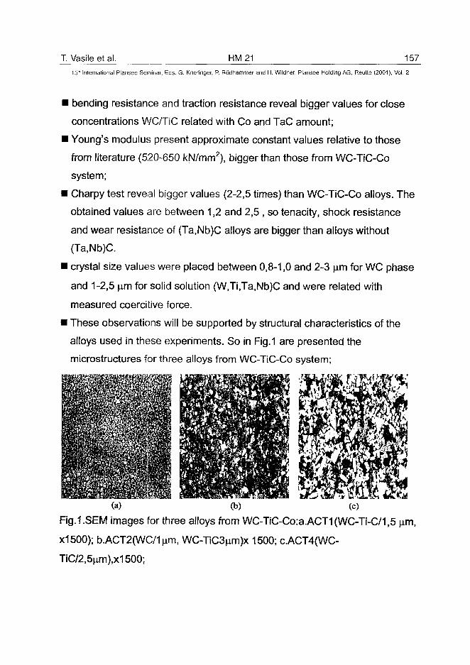
T. Vasile et al. HM21 15715'" International Plansee Seminar, Eds. G. Kneringer, P. Rddhammer and H. Wildner, Plansee Holding AG, Reutte (2001), Vol. 2
I bending resistance and traction resistance reveal bigger values for close
concentrations WC/TiC related with Co and TaC amount;
i Young's modulus present approximate constant values relative to those
from literature (520-650 kN/mm2), bigger than those from WC-TiC-Co
system;
i Charpy test reveal bigger values (2-2,5 times) than WC-TiC-Co alloys. The
obtained values are between 1,2 and 2,5 , so tenacity, shock resistance
and wear resistance of (Ta,Nb)C alloys are bigger than alloys without
(Ta,Nb)C.
i crystal size values were placed between 0,8-1,0 and 2-3 am for WC phase
and 1-2,5 am for solid solution (W,Ti,Ta,Nb)C and were related with
measured coercitive force.
i These observations will be supported by structural characteristics of the
alloys used in these experiments. So in Fig.1 are presented the
microstructures for three alloys from WC-TiC-Co system;
(a) (b) (c)
Fig.1 .SEM images for three alloys from WC-TiC-Co:a.ACT1 (WC-Ti-C/1,5 am,
X1500); b.ACT2(WC/1um, WC-TiC3am)x 1500; c.ACT4(WC-
TiC/2,5am),x1500;
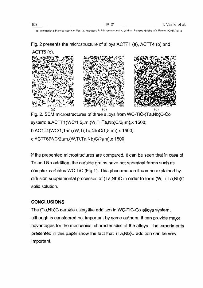
158 HM21 T. Vasile et al.15" International Plansee Seminar, Eds. G. Kneringer, P. Rodhammer and H. Wildner, Plansee Holding AG, Reutte (2001), Vol. 2
Fig. 2 presents the microstructure of alloys:ACTT1 (a), ACTT4 (b) and
ACTT6 (c).
mmm kmm(a) (b) (c)
Fig. 2. SEM microstructures of three alloys from WC-TiC-(Ta,Nb)C-Co
system: a.ACTT1(WC/1,5^m,(W,Ti,Ta,Nb)C/2^m),x 1500;
b.ACTT4(WC/1,1 nm,(W,Ti,Ta,Nb)C/1,5^m),x 1500;
c.ACTT6(WC/2^m,(W,Ti,Ta,Nb)C/2nm),x 1500;
If the presented microstructures are compared, it can be seen that in case of
Ta and Nb addition, the carbide grains have not spherical forms such as
complex carbides WC-TiC (Fig.1). This phenomenon it can be explained by
diffusion supplemental processes of (Ta,Nb)C in order to form (W,Ti,Ta,Nb)C
solid solution.
CONCLUSIONS
The (Ta,Nb)C carbide using like addition in WC-TiC-Co alloys system,
although is considered not important by some authors, it can provide major
advantages for the mechanical characteristics of the alloys. The experiments
presented in this paper show the fact that (Ta,Nb)C addition can be very
important.
T. Vasile et al. HM 21 159
15" International Plansee Seminar, Eds. G. Kneringer, P. Rodhammer and H. Wildner, Plansee Holding AG, Reutte (2001), Vol. 2
Then although lead to hardness improvement, (Ta,Nb)C addition increase
bending resistance. TaC additions improves the corrosion resistance and
wear resistance of the alloys from WC-TiC-Co system. At 800°C corrosion
resistance increase 3 times than the alloys from WC-TiC-Co system.
Likewise, if at normal temperature the influence of TaC addition is not
significant relative to physical and mechanical characteristics, instead at high
temperatures almost all physical and mechanical properties are better.
All these conclusions are supported by industrial tests realised on carbide
alloy bits, made by tested alloys.
REFERENCES
1. Fahrmann M. et al.Hardmetall-PMI 4/1991, pp 211-216
2. Karwata T. et al., 7-th K.M.P.,Krakow,1998,pp 417
3. Nenridich J. et al., Powder Met.lnt., 3/1991, pp181-184
4. BhaumikS.K., Mater.Sci.Technol., 8/1991, pp723-727
ATO100449160 HM22 T. Vasile et al.
15" International Plansee Seminar, Eds. G. Kneringer, P. Rodhammer and H. Wildner, Plansee Holding AG, Reutte (2001), Vol. 2
The Improvement of Classical Alloys by Adding Cr3C2 Carbides
Toma Vasile, Gherghina Zafiu, Marius Vasilescu,
ioana Vasilescu, Catalin Sfat
Physical Metallurgy Dept, POLITEHNICA University of Bucharest, Romania
Abstract
To improve the mechanic characteristics, especially hardness and strength,the literature of specialty recommend the use of Cr3C2 carbides more than0,5%. In this paper the research made emphasis that also at contents ofmaximum 0,5% Cr3C2 can be obtain certain performance for hard alloys fromWC-Co system with Cr3C2 addition.
Keywords
Cr3C2, carbides, addition, W, Co, hardness, strength
Introduction
Through hard alloys from WC-Co class is based on the use of some deficitarymetals like W and Co, today there are many hard alloys without W and evenwithout Co which can replace the WC-Co hard alloys. There are howeversome utilization domains in which WC-Co hard alloys can not be replace,respective those hard alloys which have high elastic modulus, tenacity, wearand impact resistance in dynamic conditions, such as mining and oil drillingon hard rocks and processing of composite materials with ceramic insertions.
The main research objectives have in view the performanceimprovement of hard alloys from WC-Co class through Cr3C2 addition.
The presence of Cr3C2 in WC-Co system make possible the obtaining ofsome sintered products with fine-grained, thanks to the fact that this type ofcarbide lay down at WC grain limit prevent thus their growing during thesintering process. The alloys with low Cr3C2 contents (0,5%) have wearresistance, low porosity, high resistance at chemical agents and oxidizing.
These hard alloys are frequently used in the manufacture of cuttingtools and also for drilling tools, dies, piercers, discs, guards, pistons, balls,abrasive shot and others.
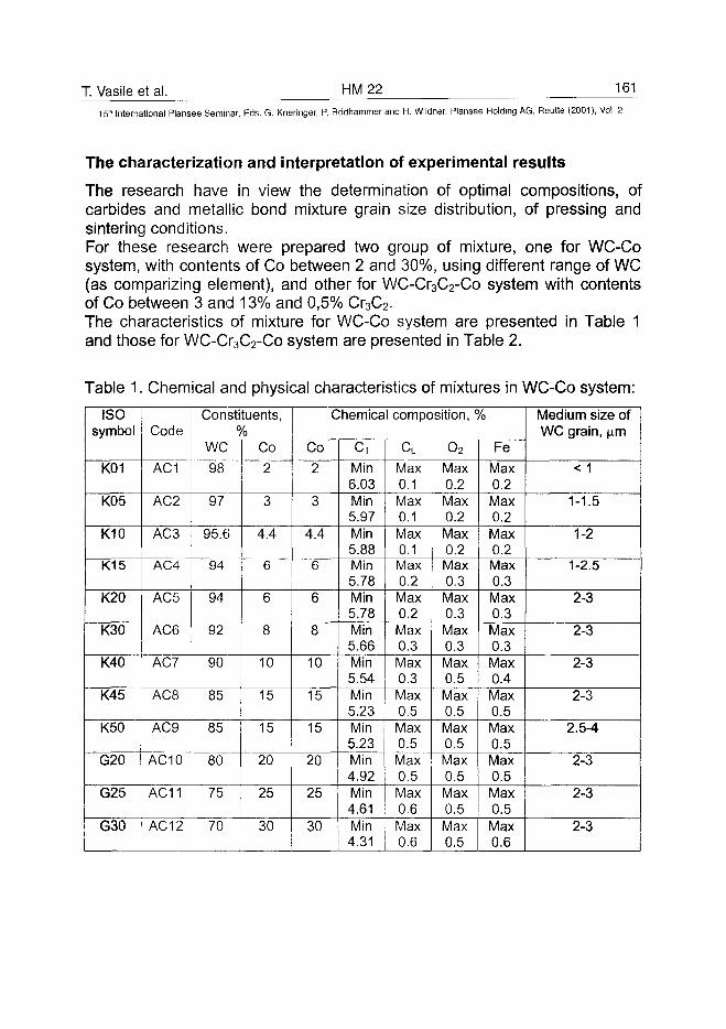
T. Vasile et al. HM22 161
15lh International Plansee Seminar, Eds. G. Kneringer, P. Rodhammer and H. Wildner, Plansee Holding AG, Reutte (2001), Vol. 2
The characterization and interpretation of experimental results
The research have in view the determination of optimal compositions, ofcarbides and metallic bond mixture grain size distribution, of pressing andsintering conditions.For these research were prepared two group of mixture, one for WC-Cosystem, with contents of Co between 2 and 30%, using different range of WC(as comparizing element), and other for WC-Cr3C2-Co system with contentsof Co between 3 and 13% and 0,5% Cr3C2.The characteristics of mixture for WC-Co system are presented in Table 1and those for WC-Cr3C2-Co system are presented in Table 2.
Table 1. Chemical and physical characteristics of mixtures in WC-Co system:
ISOsymbol
K01
K05
K10
K15
K20
K30
K40
K45
K50
G20
G25
G30
Code
AC1
AC2
AC3
AC4
AC5
AC6
AC7
AC8
AC9
Constituents,%
WC
98
97
95.6
94
94
92
90
85
85
AC10 80
AC11 | 75
AC12 70
Co
2
3
4.4
6
6
8
10
15
15
20
25
30
Chemical composition, %
Co
2
3
4.4
6
6
8
10
15
15
20
25
30
CT
Min6.03Min5.97Min5.88Min5.78Min5.78Min5.66Min5.54Min5.23Min5.23Min4.92Min4.61Min4.31
cLMax0.1Max0.1Max0.1Max0.2Max0.2Max0.3Max0.3Max0.5Max0.5Max0.5Max0.6Max0.6
o2Max0.2Max0.2Max0.2Max0.3Max0.3Max0.3Max0.5Max0.5Max0.5Max0.5Max0.5Max0.5
Fe
Max0.2Max0.2Max0.2Max0.3Max0.3Max0.3Max0.4Max0.5Max0.5Max0.5Max0.5Max0.6
Medium size ofWC grain, |im
<1
1-1.5
1-2
1-2.5
2-3
2-3
2-3
2-3
2.5-4
2-3
2-3
2-3
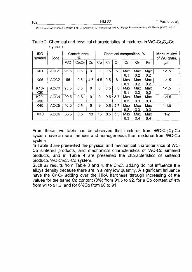
162 HM22 T. Vasile et al.
15:' International Plansee Seminar, Eds. G. Kneringer, P. Rodhammer and H. Wildner, Plansee Holding AG, Reutte (2001), Vol. 2
Table 2. Chemical and physical characteristics of mixtures in WC-Cr3C2-Cosystem:
ISOsymbol
K01
K05
K10-K20K20-K30K40
M10
Code
ACC1
ACC2
ACC3
ACC4
ACC5
ACC6
Constituents,%
we
96.5
95
93.5
90.5
90.5
86.5
Cr3C2
0.5
0.5
0.5
0.5
0.5
0.5
Co
3
4.5
6
9
9
13
Chemical composition, %
Co
3
4.5
6
9
9
13
Cr
0.5
0.5
0.5
0.5
0.5
0.5
CT
6
6
5.8
5.7
5.7
5.5
CL
Max0.1Max0.1Max0.1Max0.2Max0.2Max0.3
O2
Max0.2Max0.2Max0.2Max0.3Max0.3Max0.4
Fe
Max0.2Max0.2Max0.3Max0.3Max0.3Max0.4
Medium sizeof WC grain,
j^m
1-1.5
1-1.5
1-1.5
1-1.5
1-1.5
1-2
From these two table can be observed that mixtures from WC-Cr3C2-Cosystem have a more fineness and homogeneous than mixtures from WC-Cosystem.In Table 3 are presented the physical and mechanical characteristics of WC-Co sintered products, and mechanical characteristics of WC-Co sinteredproducts, and in Table 4 are presented the characteristics of sinteredproducts WC-Cr3C2-Co system.Such as results from Table 3 and 4, the Cr3C2 adding do not influence thealloys density because there are in a very low quantity. A significant influencehave the Cr3C2 adding over the HRA hardness through increasing of thevalues for the same Co content (3%) from 91.5 to 92, for a Co content of 4%from 91 to 91.2, and for 6%Co from 90 to 91.
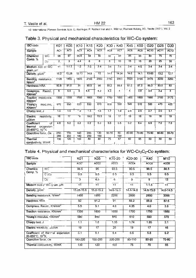
T. Vasile et al. HM22 163
15'" International Plansee Seminar, Eds. G. Kneringer, P. Rodhammer and H. Wildner, Plansee Holding AG, Reutte (2001), Vol. 2
Table 3. Physical and mechanical characteristics for WC-Co system:
ISO code
Sample
ChemicalComp. %
WC
Co
Medium size of WCgrain, nmDensity, g/cmJ
Bending resistance,N/mm2
Hardness HRA
Compress. Resist.,KN/mm2
Traction resistance,KN/mm2
Young's modulus,KN/mm2
Charpy test, J
Electric resistivity,nfi/cmCoefficient ofthermal expansion20-650°C, 10"6KCoercitive force, Oe
Thermalconductivity, W/mK
K01AC1
98
2
<1
15.3
1130
92.8
6
1200
670
1.0
16
4.8
250-280130
K05AC2
97
3
1-1.5
15.28
1450
91.5
5.5
1300
650
1.0
17
5.2
170-200120
K10AC3
95.6
4.4
1-2
15.13
1800
91
5
1500
630
1.0
16
5.2
140-180100
K15AC4
94
6
2-3
14.9
2150
90.5
4.4
1600
630
1.5
19.2
5.2
200-25080
K20AC5
94
6
3-4
15
2600
90
4.3
1580
610
1.6
18.8
5.3
130-16080
K30AC6
92
8
3-4
14.6
2780
89.2
4.3
1700
600
1.7
18
5.5
50-70
75
K40AC7
90
10
3-4
14.54
2900
88.8
4
1800
590
1.9
17
5.8
80-10067
K45AC8
85
15
3-4
14.0
3000
87.5
4
1900
540
2.4
19
6.2
80-90
60
K50AC9
85
15
4-5
14.1
3100
87.3
3.8
1850
510
2.5
18
6.4
70-80
55
G20AC10
80
20
3-4
13.63
3170
85.3
3.4
1950
500
2.7
19
6.8
75-90
53
G25AC11
75
25
3-4
13.2
3200
83.5
3.2
2100
470
2.0
18
7.0
60-80
50
G30AC12
70
30
3-4
12.7
3250
83
3
2175
420
3.1
19
7.5
55-70
50
Table 4. Physical and mechanical characteristics for WC-Cr3C2-Co system:ISO code
Sample
ChemicalComp. %
WC
Cr3C2
Co
Medium size of WC grain, \im
Density, glcm"
Bending resistance, N/mm'
Hardness HRA
Compress. Resist., KN/mm'
Traction resistance, KN/mm'
Young's modulus, KN/mm'
Charpy test, J
Electric resistivity, nQ/cm
Coefficient of thermal expansion20-650°C, 10"6KCoercitive force, Oe
Thermal conductivity, W/mK
K01ACC1
96.5
0.5
3
<1
15.28-15.6
1460
92
5.5
1350
680
1.1
19
5.1
180-220
130
K05ACC2
95
0.5
4.5
<1
15.0-15.2
1900
91.2
5.1
1600
650
1.6
17
5.1
150-200
120
K10-20ACC3
93.5
0.5
6
<1
14.6-15.0
2200
91
4.6
1650
640
1.65
20
5.4
220-260
100
K20-30ACC4
90.5
0.5
9
<1
14.4-14.8
2800
89.2
4.35
1700
610
1.74
19
5.6
90-110
75
K40ACC5
90.5
0.5
9
1-1.5
14.6-15.0
2900
88.8
4.0
1750
590
1.85
17
5.8
80-90
70
M10ACC6
86.5
0.5
13
<1
14.0-14.5
3000
87.5
3.8
1850
570
2.1
18
6.2
70-80
65
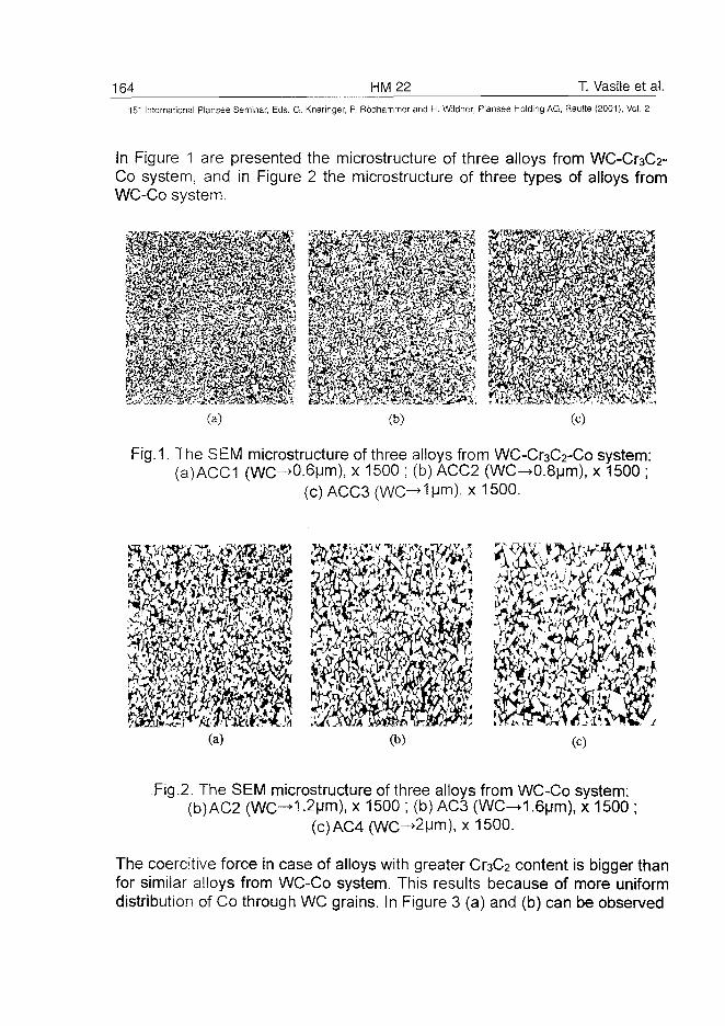
164 HM22 T. Vasile et al.
15" International Plansee Seminar, Eds. G. Kneringer, P. Rodhammer and H. Wildner, Plansee Holding AG, Reutte (2001), Vol. 2
In Figure 1 are presented the microstructure of three alloys from WC-Cr3C2-Co system, and in Figure 2 the microstructure of three types of alloys fromWC-Co system.
mmffim(a) (c)
Fig. l The SEM microstructure of three alloys from WC-Cr3C2-Co system:(a)ACC1 (WC-^0.6um), x 1500 ; (b) ACC2 (WC^0.8um), x 1500 ;
(c)ACC3(WC^1um), x 1500.
(a) (b)
Fig.2. The SEM microstructure of three alloys from WC-Co system-(b)AC2 (WC-+1-2um), x 1500 ; (b) AC3 (WC-»1.6um), x 1500 ;
(c)AC4 (WC^2um), x 1500.
The coercitive force in case of alloys with greater Cr3C2 content is bigger thanfor similar alloys from WC-Co system. This results because of more uniformdistribution of Co through WC grains. In Figure 3 (a) and (b) can be observed
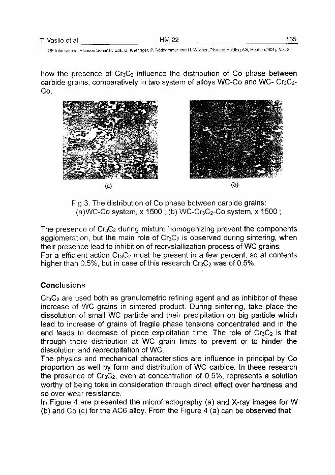
T. Vasile et al. HM22 165
15'" International Plansee Seminar, Eds. G. Kneringer, P. Rodhammer and H. Wildner, Plansee Holding AG, Reutte (2001), Vol. 2
how the presence of O3C2 influence the distribution of Co phase betweencarbide grains, comparatively in two system of alloys WC-Co and WC-Co.
A
Fig.3. The distribution of Co phase between carbide grains:(a)WC-Co system, x 1500 ; (b) WC-Cr3C2-Co system, x 1500 ;
The presence of Cr3C2 during mixture homogenizing prevent the componentsagglomeration, but the main role of Cr3C2 is observed during sintering, whentheir presence lead to inhibition of recrystallization process of WC grains.For a efficient action Cr3C2 must be present in a few percent, so at contentshigher than 0.5%, but in case of this research Cr3C2 was of 0.5%.
Conclusions
are used both as granulometric refining agent and as inhibitor of theseincrease of WC grains in sintered product. During sintering, take place thedissolution of small WC particle and their precipitation on big particle whichlead to increase of grains of fragile phase tensions concentrated and in theend leads to decrease of piece exploitation time. The role of Cr3C2 is thatthrough there distribution at WC grain limits to prevent or to hinder thedissolution and reprecipitation of WC.The physics and mechanical characteristics are influence in principal by Coproportion as well by form and distribution of WC carbide. In these researchthe presence of Cr3C2, even at concentration of 0.5%, represents a solutionworthy of being toke in consideration through direct effect over hardness andso over wear resistance.In Figure 4 are presented the microfractography (a) and X-ray images for W(b) and Co (c) for the AC6 alloy. From the Figure 4 (a), can be observed that
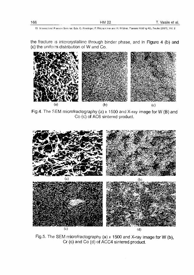
166 HM 22 T. Vasile et al.15" International Plansee Seminar, Eds. G. Kneringer, P. Rodhammer and H. Wiidner, Plansee Holding AG, Reutte (2001), Vol. 2
the fracture is intercrystalline through binder phase, and in Figure 4 (b) and(c) the uniform distribution of W and Co.
Fig.4. The SEM microfractography (a) x 1500 and X-ray image for W (B) andCo (c) of AC6 sintered product.
Fig.5. The SEM microfractography (a) x 1500 and X-ray image for W (b),Cr (c) and Co (d) of ACC4 sintered product.
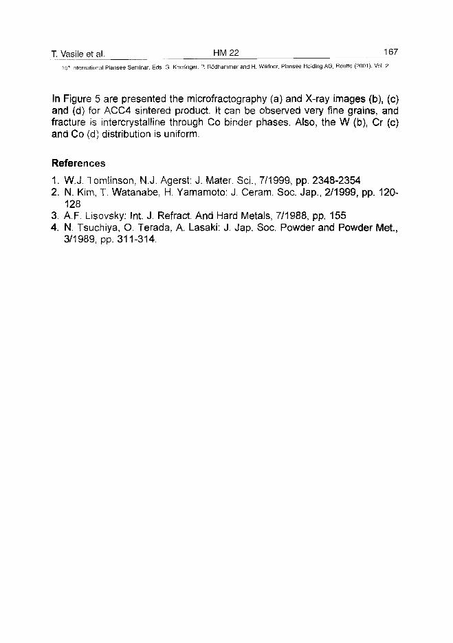
T. Vasile et al. HM 22 16715" International Plansee Seminar, Eds. G. Kneringer, P. Rodhammer and H. Wildner, Plansee Holding AG, Reutte (2001), Vol. 2
In Figure 5 are presented the microfractography (a) and X-ray images (b), (c)and (d) for ACC4 sintered product. It can be observed very fine grains, andfracture is intercrystalline through Co binder phases. Also, the W (b), Cr (c)and Co (d) distribution is uniform.
References
1. WJ . Tomlinson, N.J. Agerst: J. Mater. Sci., 7/1999, pp. 2348-23542. N. Kim, T. Watanabe, H. Yamamoto: J. Ceram. Soc. Jap., 2/1999, pp. 120-
1283. A.F. Lisovsky: Int. J. Refract. And Hard Metals, 7/1988, pp. 1554. N. Tsuchiya, O. Terada, A. Lasaki: J. Jap. Soc. Powder and Powder Met.,
3/1989, pp. 311-314.
AT0100450168 HM23 A.F. Lisovsky et al.
15'" International Plansee Seminar, Eds. G. Kneringer, P. Rodhammer and H. Wildner, Plansee Holding AG, Reutte (2001), Vol. 2
Properties of Cemented Carbides Alloyed by Metal Melt
Treatment
Anatoly F. Lisovsky
Institute for Superhard Materials, 2, Avtozavodskaya, 04074 Kiev, Ukraine
Summary:
The paper presents the results of investigations into the influence of alloyingelements introduced by metal melt treatment (MMT-process) on properties ofWC-Co and WC-Ni cemented carbides. Transition metals of the IV - VIIIgroups (Ti, Zr, Ta, Cr, Re, Ni) and silicon were used as alloying elements. Itis shown that the MMT-process allows cemented carbides to be producedwhose physico-mechanical properties (bending strength, fracture toughness,total deformation, total work of deformation and fatigue fracture toughness)are superior to those of cemented carbides produced following a traditionalpowder metallurgy (PM) process. The main mechanism and peculiarities ofthe influence of alloying elements added by the MMT-process on propertiesof cemented carbides have been first established. The effect of alloyingelements on structure and substructure of phases has been analyzed.
Keywords:
Cemented carbide, properties, metal melt treatment, alloying elements
1. Introduction:
Cemented carbides are, as a rule, alloyed by adding a chemical element tothe initial mixture of powders from which specimens are prepared following atraditional PM technology. It should be noted that addition of an alloyingelement to the mixture can significantly change conditions of the formation ofcemented carbides during sintering. Thus, additions of V, Ta and Cr favor theformation of very fine-grained structure [1].At present a new technology is developed of treatment of as-sintered carbidearticles with a metal melt (MMT-process) [2], which allows both local and bulkalloying of cemented carbide articles. The MMT-process is based on the
A.F. Lisovsky et al. HM 23 169_
15* International Plansee Seminar, Eds. G. Kneringer, P. Rodhammer and H. Wildner, Plansee Holding AG, Reutte (2001), Vol. 2
phenomena of the metal melt imbibition by sintered pore-free compositionmaterials [3]. One of the special features of the MMT-process is thereconstruction of a high-melting skeleton during the metal melt imbibition.This can affect the cemented carbide properties. Our studies have shown thatthe common practice for alloying cemented carbides and the adding ofalloying elements by the MMT-process differ essentially. The data on theinfluence of alloying elements on properties of cemented carbides producedby a traditional technique cannot be applied to cemented carbides preparedby the MMT-process. There is only small quantity of publications concernedwith alloying cemented carbides by the MMT-process [2, 4, 5]. For thisreason, a need has arisen for generalizing the findings [2, 4, 5] and tosupplement them with our new results.
2. Experimental:
Studied were WC-Co and WC-Ni cemented carbides. To alloy the cementedcarbides, metals Ti, Zr, Ta, Cr, Re, Ni and silicon were used. At first we takea look at the procedure used to study WC-Co cemented carbides. The initialspecimens were made using a traditional PM method from WC-6C0cemented carbide. The specimens contained 6.0 mass % Co, 94.0 mass %WC, graphite and the rirphase were not present. The specimens weredipped in cobalt melts alloyed with the above elements (except for Re) in avacuum furnace at 1390 °C. The cobalt melt alloyed with Re was heated to1410 °C. Compositions of the melts used in tests are given in Table 1. Themetal melts were saturated on carbon and tungsten, which was due to theintroduction of excess W and C into the melts. The specimens were held inthe cobalt melt for 20 s. During that time the specimens imbibed the cobaltmelt together with alloying elements. Thereupon the specimens wereremoved from the melt and subjected to homogenizing annealing at the sametemperature for 600 s. During annealing the liquid phase content andcomposition equalized throughout the bulk specimens. Once the cobalt melthad been imbibed, the binder content of the specimens increased from6.0 mass % to 9.5±0.1 mass % (15.5 vol %). Specimens whose bindercontent was not in that range were rejected. Every alloying element and as-received test specimen were given a serial number, a binder elementalcomposition was specified. For comparison, cemented carbide specimens(9.5 mass % Co + 90.5 mass % WC) were prepared following a traditionaltechnology (compaction of the mixture followed by sintering). The specimenswere designated WC-10Co. In WC-Co cemented carbides, the binder was a
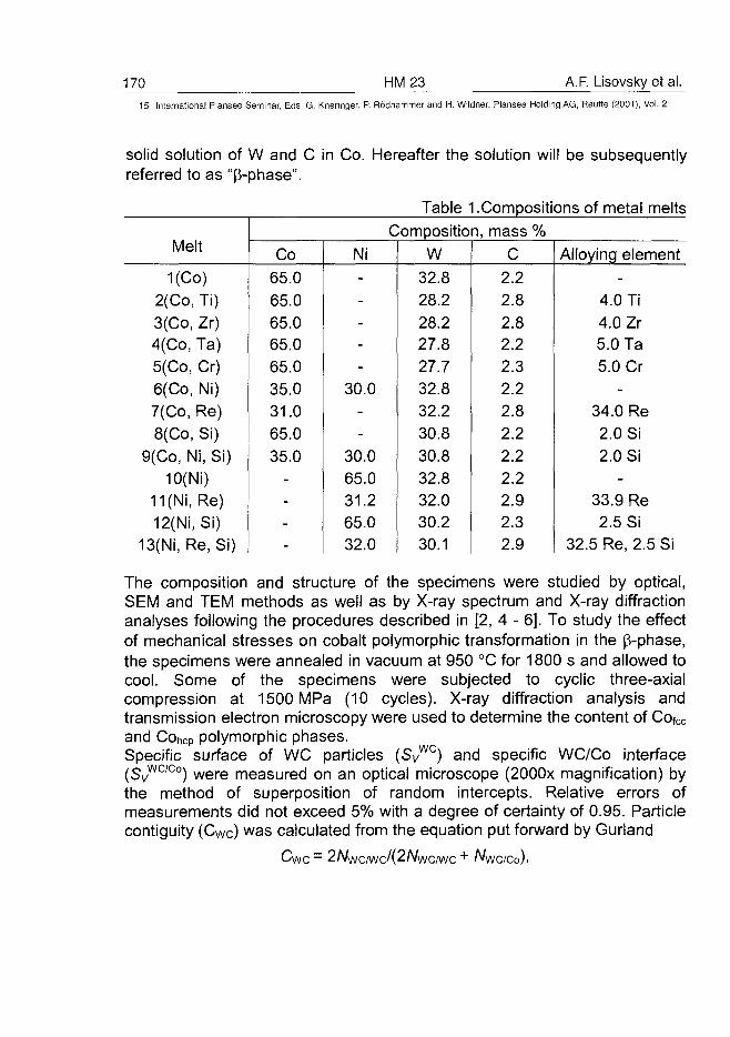
170 HM23 A.F. Lisovsky et al.
15" International Plansee Seminar, Eds. G. Kneringer, P. Rodhammer and H. Wildner, Plansee Holding AG, Reutte (2001), Vol. 2
solid solution of W and C in Co. Hereafter the solution will be subsequentlyreferred to as "6-phase".
Melt
1(Co)2(Co, Ti)3(Co, Zr)4(Co, Ta)5(Co, Cr)6(Co, Ni)7(Co, Re)8(Co, Si)
9(Co, Ni, Si)10(Ni)
11 (Ni, Re)12(Ni, Si)
13(Ni, Re, Si)
Co65.065.065.065.065.035.031.065.035.0
----
Ni-----
30.0--
30.065.031.265.032.0
Table 'Composition
W
32.828.228.227.827.732.832.230.830.832.832.030.230.1
Compositions of metal melts, mass %
C2.22.82.82.22.32.22.82.22.22.22.92.32.9
Alloying element-
4.0 Ti4.0 Zr5.0 Ta5.0 Cr
-34.0 Re2.0 Si2.0 Si
-33.9 Re2.5 Si
32.5 Re, 2.5 Si
The composition and structure of the specimens were studied by optical,SEM and TEM methods as well as by X-ray spectrum and X-ray diffractionanalyses following the procedures described in [2, 4 - 6]. To study the effectof mechanical stresses on cobalt polymorphic transformation in the B-phase,the specimens were annealed in vacuum at 950 °C for 1800 s and allowed tocool. Some of the specimens were subjected to cyclic three-axialcompression at 1500 MPa (10 cycles). X-ray diffraction analysis andtransmission electron microscopy were used to determine the content of Cofcc
and Cohcp polymorphic phases.Specific surface of WC particles (SvWC) and specific WC/Co interface(SyWC/Co) were measured on an optical microscope (2000x magnification) bythe method of superposition of random intercepts. Relative errors ofmeasurements did not exceed 5% with a degree of certainty of 0.95. Particlecontiguity (CWc) was calculated from the equation put forward by Gurland
= 2A/wc/wc/(2A/wc/wc
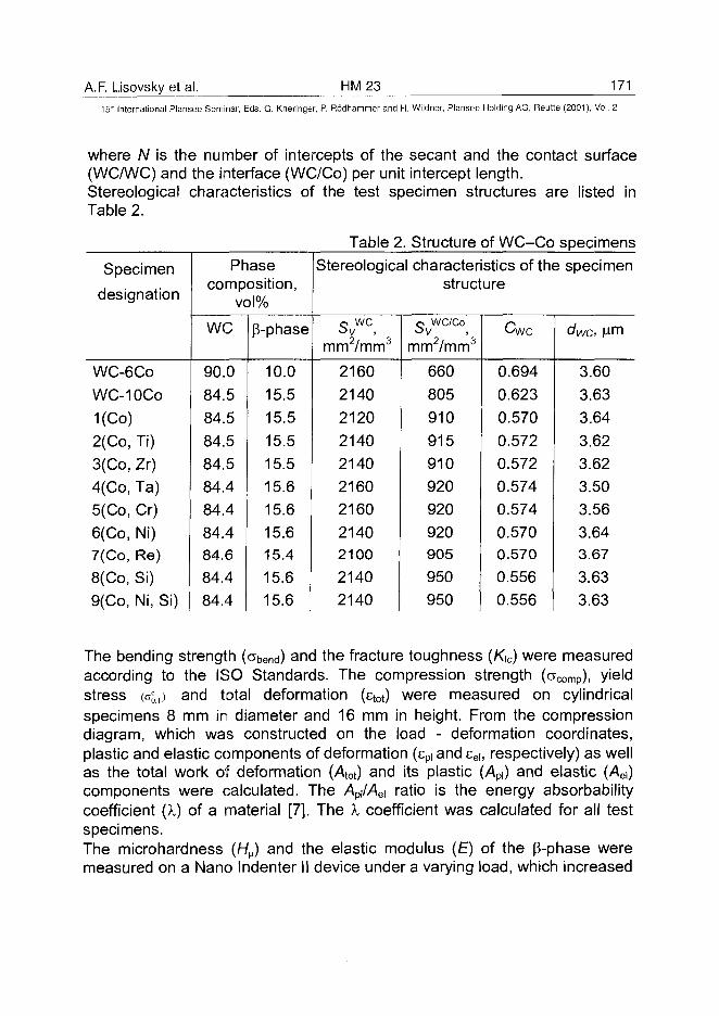
A.F. Lisovsky et al. HM23 171
15" International Plansee Seminar, Eds. G. Kneringer, P. Rodhammer and H. Wildner, Plansee Holding AG, Reutte (2001), Vol. 2
where N is the number of intercepts of the secant and the contact surface(WC/WC) and the interface (WC/Co) per unit intercept length.Stereological characteristics of the test specimen structures are listed inTable 2.
Specimen
designation
WC-6C0
WC-10CO
1(Co)2(Co, Ti)3(Co, Zr)4(Co, Ta)
5(Co, Cr)
6(Co, Ni)7(Co, Re)
8(Co, Si)9(Co, Ni, Si)
Phasecomposition,
vol%
we
90.0
84.584.5
84.584.584.484.484.484.684.484.4
p-phase
10.0
15.5
15.5
15.515.515.615.6
15.615.4
15.615.6
Table 2 . Structure of WC-Co specimensStereological characteristics of the specimen
structure
0 WC
mm2/mm3
2160
21402120
2140214021602160
2140210021402140
O WC/Co
ovmm2/mm3
660805
910
915910920
920
920905
950950
Cwc
0.694
0.623
0.570
0.5720.5720.5740.574
0.5700.570
0.5560.556
dwc, |nm
3.60
3.633.64
3.623.623.503.563.643.67
3.633.63
The bending strength (abend) and the fracture toughness (K\c) were measuredaccording to the ISO Standards. The compression strength (acomp), yieldstress K , ) and total deformation (etot) were measured on cylindricalspecimens 8 mm in diameter and 16 mm in height. From the compressiondiagram, which was constructed on the load - deformation coordinates,plastic and elastic components of deformation (spi and sei, respectively) as wellas the total work of deformation (Aot) and its plastic (>4P|) and elastic (>4ei)components were calculated. The Api/Aei ratio is the energy absorbabilitycoefficient {X) of a material [7]. The i coefficient was calculated for all testspecimens.The microhardness (HH) and the elastic modulus (£) of the p-phase weremeasured on a Nano Indenter II device under a varying load, which increased
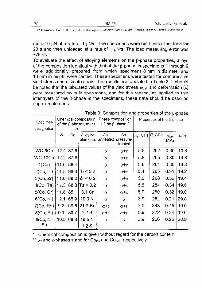
172 HM23 A.F. Lisovsky et al.
15" International Plansee Seminar, Eds. G. Kneringer, P. Rodhammer and H. Wildner, Plansee Holding AG, Reutte (2001), Vol. 2
up to 10 )j.N at a rate of 1 \xN/s. The specimens were held under that load for20 s and then unloaded at a rate of 1 ^N/s. The load measuring error was±75 nN.To evaluate the effect of alloying elements on the p-phase properties, alloysof the composition identical with that of the p-phase in specimens 1 through 9were additionally prepared from which specimens 8 mm in diameter and16 mm in height were casted. These specimens were tested for compressiveyield stress and ultimate strain. The results are tabulated in Table 3. It shouldbe noted that the tabulated values of the yield stress (a§.,) and deformation (s)were measured on bulk specimens, and for this reason, as applied to thininterlayers of the p-phase in the specimens, these data should be used asapproximate ones.
Table 3. Composition and properties of the p-phase
Specimen
designation
WC-6C0
WC-10CO
1(Co)
2(Co, Ti)
3(Co, Zr)
4(Co, Ta)
5(Co, Cr)
6(Co, Ni)
7(Co, Re)
8(Co, Si)
9(Co, Ni,Si)
Chemical compositionof the p-phase*, mass
W
12.4
12.2
11.6
11.5
11.6
11.5
11.8
12.1
9.2
9.1
10.5
Co
87.6
87.8
88.4
88.3
88.2
88.3
85.1
68.9
69.6
89.7
69.8
Alloyingelements
-
-
-
Ti < 0.2
Zr<0.2
Ta < 0.2
3.1 Cr
19.0 Ni
21.2 Re
1.2 Si
18.5 Ni1.2 Si
Phase compositionof the p-phase**
As-annealed
a
a
a
a
a
a
a
a
a+e
a+s
a
As-pressure-treated
a+e
a+e
a+s
a+s
a+s
a+s
a+e
a
a+e
a+s
a
Properties of t
H^, GPa
5.8
5.8
5.8
5.4
5.6
5.5
5.9
3.9
7.9
5.9
3.9
E, GPa
264
265
264
265
268
284
250
262
348
272
260
he p-phase
c
MPa
0.30
0.30
0.30
0.31
0.32
0.34
0.32
0.21
0.45
0.34
0.25
s, %
19.8
19.8
19.8
19.2
19.4
19.6
19.0
29.8
19.0
19.6
28.9
Chemical composition is given without regard for the carbon content,a- and s-phases stand for Cofcc and Concp, respectively.
A.F. Lisovsky et al. HM 23 173^15" International Plansee Seminar, Eds. G. Kneringer, P. Rodhammer and H. Wildner, Plansee Holding AG, Reutte (2001), Vol. 2
The cyclic fracture toughness experiments were performed on SENBcemented carbide specimens measuring 5x5x35 mm [4, 5] in resonancemode in the 280 to 330 Hz range under asymmetric loading cycle (theasymmetry coefficient was 0.5 - 0.8). The load for each lot of specimens wasselected by experiments such that the time of the fatigue crack initiation fromthe notch was the same for all the specimens and was limited by a base of400,000 cycles. The test results were represented as a fatigue failurediagram constructed on the fatigue crack growth rate (\gv) - stress intensityfactor (K|) semilog coordinates. From the diagram, a relative threshold stressintensity factor {Kth) and a relative critical stress intensity factor (Kfc) weredetermined for each lot of specimens. The Kth and Kfc coefficients weremeasured as the stress intensity factor K\ at the fatigue crack growth rate v of10"9m/cycle and 10~6m/cycle, respectively.To study the effect of alloying elements on physico-mechanical properties ofWC-Ni cemented carbides, initial specimens of WC-6Ni cemented carbide(6.1 mass % Ni, 93.9 mass % WC) were prepared following a commonprocedure. After treatment with the 10(Ni) melt, the composition of the abovespecimens was as follows: 9.5+0.1 mass % Ni and 90.5 mass % WC,average WC particle size was 2.3 urn The WC-6Ni specimens werealloyed with Re and Si using 11 (Ni, Re), 12(Ni, Si) and 13(Ni, Re, Si) meltsfollowing the above procedure.
3. Results and discussion:
Our findings have shown that Ti, Zr, Ta, Cr, Ni, Re and Si alloying elementsdid not exert any action on the composition and structure of WC. Theseelements had an impact on the compositions and structures of the p-phaseand interfaces.The WC-10Co specimens prepared by a traditional procedure and the 1(Co)specimens produced from WC-6C0 cemented carbide by the MMT-processwere the same in composition, the (3-phase and WC contents, the size of WCparticles, and differed in values of specific interface sv
wc/Co (see Tables 2 and3). The 1(Co) specimen featured a more developed WC/Co interface whichwas responsible for higher values of bending strength, work of deformation,the coefficient X, and plastic and fatigue characteristics as compared with theWC-10Co specimen (Table 4). The develop WC/Co surface of the 1(Co)specimen formed during the imbibition of the cobalt melt. This process wasaccompanied by a partial fracture of the carbide skeleton [3]. Thus, using the
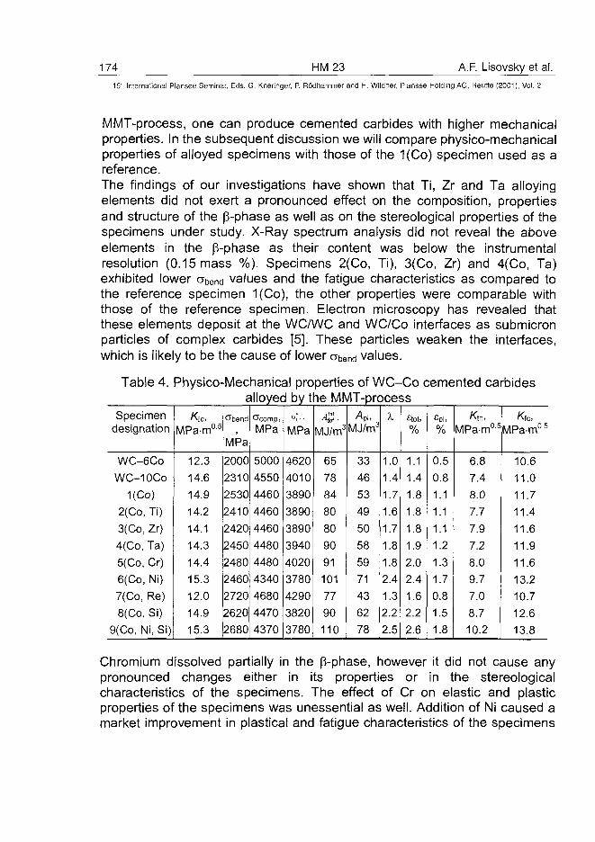
174 HM23 A.F. Lisovsky et al.
15" international Plansee Seminar, Eds. G. Kneringer, P. Rodhammer and H. Wildner, Plansee Holding AG, Reutte (2001), Vol. 2
MMT-process, one can produce cemented carbides with higher mechanicalproperties. In the subsequent discussion we will compare physico-mechanicalproperties of alloyed specimens with those of the 1(Co) specimen used as areference.The findings of our investigations have shown that Ti, Zr and Ta alloyingelements did not exert a pronounced effect on the composition, propertiesand structure of the p-phase as well as on the stereological properties of thespecimens under study. X-Ray spectrum analysis did not reveal the aboveelements in the p-phase as their content was below the instrumentalresolution (0.15 mass %). Specimens 2(Co, Ti), 3(Co, Zr) and 4(Co, Ta)exhibited lower abend values and the fatigue characteristics as compared tothe reference specimen 1(Co), the other properties were comparable withthose of the reference specimen. Electron microscopy has revealed thatthese elements deposit at the WC/WC and WC/Co interfaces as submicronparticles of complex carbides [5]. These particles weaken the interfaces,which is likely to be the cause of lower abend values.
Table 4. Physico-Mechanica! properties of WC-Co cemented carbidesalloyed by the MMT-process
Specimendesignation
WC-6C0
WC-10Co
1(Co)
2(Co, Ti)
3(Co, Zr)
4(Co, Ta)
5(Co, Cr)
6(Co, Ni)
7(Co, Re)
8(Co, Si)
9(Co, Ni, Si)
Kic,MPa-m0-5
12.3
14.6
14.9
14.2
14.1
14.3
14.4
15.3
12.0
14.9
15.3
CTbend
MPa
2000
2310
2530
2410
2420
2450
2480
2460
2720
2620
2680
CTcomp,
MPa
5000
4550
4460
4460
4460
4480
4480
4340
4680
4470
4370
<*;,.MPa
4620
4010
3890
3890
3890
3940
4020
3780
4290
3820
3780
.tot4jef •
MJ/m3
65
78
84
80
80
90
91
101
77
90
110
Apt,
MJ/m3
33
46
53
49
50
58
59
71
43
62
78
X
1.0
1.4
1.7
1.6
1.7
1.8
1.8
2.4
1.3
2.2
2.5
Stot,%
1.1
1.4
1.8
1.8
1.8
1.9
2.0
2.4
1.6
2.2
2.6
£Pl,%
0.50.81.1
1.1
1.1
1.2
1.3
1.7
0.8
1.5
1.8
MPa-m05
6.8
7.4
8.0
7.7
7.9
7.2
8.0
9.7
7.0
8.7
10.2
MPa-m05
10.6
11.0
11.7
11.4
11.6
11.9
11.6
13.2
10.7
12.6
13.8
Chromium dissolved partially in the p-phase, however it did not cause anypronounced changes either in its properties or in the stereologicalcharacteristics of the specimens. The effect of Cr on elastic and plasticproperties of the specimens was unessential as well. Addition of Ni caused amarket improvement in plastical and fatigue characteristics of the specimens
A.F. Lisovsky et al. HM 23 175_
15th International Plansee Seminar, Eds. G. Kneringer, P. Rodhammer and H. Wildner, Plansee Holding AG, Reutte (2001), Vol. 2
(see Table 4), in this case, a slight decrease in CTbend and acomp was observedas compared with the reference 1(Co) specimen. It should be noted thatnickel did not affect stereological characteristics of the specimen structure,but changed the phase composition of the p-phase. Nickel stabilized thecubic modification of cobalt in the p-phase. Cubic modification of Co (COfCC) ismore plastic phase as compared to hexagonal modification of Co (Cohcp), as ithas four planes of easy slippage in the <110> {111} system, while Concp hasonly one plane of easy slippage [8]. This means that in cemented carbides inwhich the p-phase has a cubical crystal lattice, stress relaxation proceedseasily by the p-phase deformation. These processes have been responsiblefor both lower H^ values of 6(Co,Ni) specimens and higher plasticcharacteristics of the p-phase as compared to the 1(Co) specimen. It shouldbe noted that in as-annealed 1(Co), 2(Co, Ti), 3(Co, Zr), 4(Co, Ta), and5(Co, Cr) specimens, cobalt in the p-phase was in its cubic modification(COfCC), however, under the action of stresses induced by volumecompression partial Cofcc—> Concp transformation took place thus reducing theplastic properties of the p-phase (see Table 3). It is clear from these findingsthat in testing the above specimens for strength as well as in hardnesstesting, the Cofcc-> Concp polymorphic transformation occurs in the p-phasetoo, thus affecting the specimen properties [9].Rhenium formed the Co(Re, W, C) solid solution in the p-phase which hadhigh Hp, E and a§, values. From our investigations (see Table 3), the as-annealed specimens showed the presence of Cohcp interlayers in thep-phase. The volume compression of the 7(Re, Co) specimens promotedfurther COfCC-»Concp transformation, as evidenced by an increase in thecharacteristic line intensity in X-ray patterns. Our previous electronmicroscopic observations have also shown that Re facilitates theCOfcc-»Cohcp polymorphic transpormation in the p-phase [10]. Thesechanges in the p-phase were responsible for higher elastic properties (c7comp,oj,) and lower plastic properties (e) in the 7(Co, Re) specimens. Also, lowervalues of K\c, work of deformation and the energy absorbability coefficient Xwere obtained for these specimens. Analysis of both the structure of the7(Co, Re) specimens and the composition and structure of the p-phase doesnot allow the explanation of the ultimate bending strength growth. Anadditional lot of Re-alloyed specimens was prepared using a traditionaltechnology. The binder content of those specimens was 16.1 vol%, the sizeof WC particles was 3.81 (im. The p-phase contained 20.8 mass % Re and9.0 mass % W. The ultimate bending strength of the specimens was
176 HM23 A.F. Lisovsky et al.15" Internationa! Plansee Seminar, Eds. G. Kneringer, P. Rodhammer and H. Wildner, Plansee Holding AG, Reutte (2001), Vol. 2
2200 MPa, i.e. below the values for the WC-10Co and 1(Co) specimens.Thus, an increase of abend up to 2720 MPa for 7(Co, Re) specimen is thephenomenon of the MMT-process and calls for further investigation.Our findings have shown that addition of silicon facilitated formation of moredeveloped SvWC/c° interface in the 8(Co, Si) specimens. Despite the fact thatcompared to the reference 1(Co) specimen, an increase in SyWC/Co was only40 mm2/mm3, which is within the interface measuring error, this result isconsidered to be reliable, as it is reproduced in all Si-alloyed specimens andwas proved by us in [2]. Also, silicon is a surfactant in the Co melt [2], breaksthe carbide skeleton very actively when penetrating into cemented carbides[11] and is adhesion active at the WC/Co interface [2]. Combined action ofthe above factors allowed an increase in ultimate bending strength, work ofdeformation, coefficient X and plastic characteristics of the 8(Co, Si)specimens (see Table 4). Addition of Si decreased the W solubility in the p-phase of the 8(Co, Si) specimens to 9.04 mass %. A decrease of the Wsolubility in the p-phase of WC-Co cemented carbides produced by atraditional procedure reduces physico-mechanical properties of the alloys[12]. In addition, according to our findings presented in this paper and thedata given in [2], silicon, as well as rhenium, contributes to the Cofcc-> ConCppolymorphic transformation thus reducing plastic characteristics of cementedcarbides. In case where Si is added by the MMT-process, the effect of thesenegative factors is compensated for by a number of the above-enumeratedpositive factors peculiar to the MMT-process (an increase in the WC/Cointerface, a partial breakage of the carbide skeleton, etc.).Combined alloying of specimens with nickel and silicon, increases plastic andelastic properties of the 9(Co, Ni, Si) specimens due to the joint action ofthese elements on the specimens' structure and composition. Despite thepresence of Si, cobalt in the p-phase of the 9(Co, Ni, Si) specimens was in itscubic modification. This fact was responsible for higher values of the work ofdeformation, the A. coefficient and plastic characteristics of cemented carbide.Of special interest are values of fatigue fracture toughness of alloyedspecimens (see Table 4). The 1(Co) specimens produced by the MMT-process surpassed the WC-10Co specimens in fatigue behavior. Ti, Zr, Ta,and Cr, alloying elements affected only slightly the specimens' fatiguefracture toughness. Addition of Ni and Si considerable increased the fatiguefracture toughness and particularly in the case of combined alloying (Ni + Si)of the 9(Co, Ni, Si) specimens. Addition of Re reduced the value of thisparameter.
A.F. Lisovsky et al. HM 23 17715" International Plansee Seminar, Eds. G. Kneringer, P. Rodhammer and H. Wildner, Plansee Holding AG, Reutte (2001), Vol. 2
The influence of both the MMT-process and alloying elements on the fatiguefracture toughness is explained from the mechanism of the fatigue cracksinitiation. Under fatigue loading, COfCC transforms into Cohcp in the p-phase [9],the p-phase loses its plastic properties and the ability to relax local stresses.For this reason, microcracks initiate at the WC/Co and WC/WC interfaces,extend along these interfaces and arrest in the P-phase interlayers. Silicon,as a surfactant, can greatly improve the adhesion between the p-phase andWC particles, thus retarding the fatigue microcracks initiation at interfaces.Nickel, which stabilizes the Co cubic modification in the p-phase, preservesits high ability to retard the microcracks development in the p-phase.Combined action of Ni and Si enhances the above effects and allows one toimprove the fatigue characteristics of WC-Co cemented carbides.A high elasticity of the Co(Re, W, C) solid solution, the presence of a greatamount of the Concp in the p-phase contributed to the microcracking of thep-phase thus decreasing the fatigue fracture toughness of the 7(Co, Re)specimens. A special feature of the WC-Co cemented carbides is that thealloying elements under consideration did not affect the WC carbide phase,but changed the composition and the structure of the p-phase and theinterfaces. Analysis of the experimental results (see Tables 2 - 4 ) has shownthat elements which show a great affinity for carbon, e.g., Ti, Zr, and Ta,affected, mainly, the composition and the structure of the WC/Co andWC/WC interfaces. These data are supported by TEM observations [5].Analysis of our findings allows us to predict the same dependence of theWC-Co properties on Hf and Nb. Chromium dissolves partially in the p-phase,affect its structure and properties only slightly, and for this reason its influenceon the WC-Co properties is of no significance. It should be noted that V, Nb,Ta and Cr added into the WC-Co cemented carbide by a traditionaltechnology strongly affect the cemented carbide structure formation duringliquid-phase sintering, which makes it possible to produce very fine-grainedcemented carbides [1]. These elements when added by the MMT-processdoes not affect the size of WC particles because they penetrate into thecemented carbide after termination of liquid-phase sintering.A strong influence of Re and Ni on the WC-Co cemented carbide properties isdue to substantial changes in the p-phase composition, structure andproperties. We believe that Ru, Os and Ir will influence the cemented carbideproperties just in the same manner as Re does. When alloying WC-Cocemented carbides with the above elements, one should take into accountthat Ru and Os contribute to the Cofcc-> Cohcp polymorphic transformation,while Ir stabilizes the Co cubic modification.
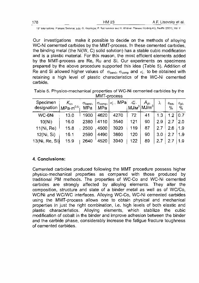
178 HM23 A.F. Lisovsky et al.15:' International Plansee Seminar, Eds. G. Kneringer, P. Rodhammer and H. Wildner, Plansee Holding AG, Reutte (2001), Vol. 2
Our investigations make it possible to decide on the methods of alloyingWC-Ni cemented carbides by the MMT-process. In these cemented carbides,the binding metal (the Ni(W, C) solid solution) has a stable cubic modificationand is a plastic material. For this reason, the most efficient elements addedby the MMT-process are Re, Ru and Si. Our experiments on specimensprepared by the above procedure supported this idea (Table 5). Addition ofRe and Si allowed higher values of abend, crcomp and oj, to be obtained withretaining a high level of plastic characteristics of the WC-Ni cementedcarbide.
Table 5. Physico-mechanical properties of WC-Ni cemented carbides by theMMT-process
Specimendesignation
WC-6Ni
10(Ni)11(Ni, Re)
12(Ni, Si)13(Ni, Re, Si)
Kic,
MPa-m05
13.0
16.015.816.115.9
MPa
1900
23802500
25902640
MPa
4620411045004490
4520
o5.,. MPa
4270
354039203860
3940
MJ/M3
72121
119120122
A*MJ/m3
41
9087
9089
X
1.32.92.73.02.7
Stoti
%
1.22.7
2.62.72.7
£pii
%
0.7
2.01.9
1.91.9
4. Conclusions:
Cemented carbides produced following the MMT procedure possess higherphysico-mechanical properties as compared with those produced bytraditional PM methods. The properties of WC-Co and WC-Ni cementedcarbides are strongly affected by alloying elements. They alter thecomposition, structure and state of a binder metal as well as of WC/Co,WC/Ni and WC/WC interfaces. Alloying WC-Co, WC-Ni cemented carbidesusing the MMT-process allows one to obtain physical and mechanicalproperties in just the right combination, i.e. high levels of both elastic andplastic characteristics. Alloying elements, which stabilize the cubicmodification of cobalt in the binder and improve adhesion between the binderand the carbide phase, considerably increase the fatigue fracture toughnessof cemented carbides.
A.F. Lisovsky et al. HM 23 17915" International Plansee Seminar, Eds. G. Kneringer, P. Rodhammer and H. Wildner, Plansee Holding AG, Reutte (2001), Vol. 2
5. Acknowledgements:
The author wishes to thank the scientific workers of the Institute forSuperhard Materials Tkach V. N. for X-ray spectrum analysis, Loshak M. G.for measuring physico-mechanical properties of specimens, Dub S. N. formeasuring the microhardness and modulus of elasticity, and Kulakovsky V.N. for measuring the fatigue fracture toughness of specimens.
6. References:
1. E. A. Almond and B. Roebuck: Proc. Final Conf. Meeting, Brussels, 9 -11Dec, 1986, London, New York,(1988), pp. 427 - 444
2. A. F. Lisovsky and N. V. Tkachenko: Powder Metallurgy International 23(1991), pp. 157-161
3. A. F. Lisovsky: Powder Metallurgy International 19 (1987), pp. 18 - 214. A. F. Lisovsky, T. E. Gracheva, and V. N. Kulakovsky: Int. Journal of
Refractory Metals and Hard Materials 13 (1995), pp. 379-3835. A. F. Lisovsky and N. V. Tkanechenko: Int. Journal of Refractory Metals
and Hard Materials 15 (1997), pp. 227-2356. A. F. Lisovsky: Proc. of the 1998 Powder Metallurgy World Congress and
Exhibition, Granada, Spain, 18—22 Oct., 1998, vol. 4, pp. 115—118,EPMA, Bellstone, 1998
7. A. A.Lebeden and E. V. Chechin: Problemy Prochnosti 4 (1980), pp. 32-348. L. Manlang, H. Xiaoying, D. Shitian, et al.: Int. Journal of Refractory Metals
and Hard Materials 2 (1983), pp. 129-1329. C. H. Vasel, A. D. Krawitz, E. F. Drake, et al.: Metallurgical Transactions A
16(19&5), pp. 2309-232710. A. F. Lisovsky, N. V. Tkachenko, and V. P. Kebko: Int. Journal of
Refractory Metals and Hard Materials 10 (1991) pp. 33-3611. F. Lisovsky and T. E. Gracheva: Inzhenerno-Fizicheskii Zhurnal 53
(1987), pp. 84-8712. B. Roebuck and E. A. Almond: Int. Mater. Rev. 33, (1988) pp. 90-110
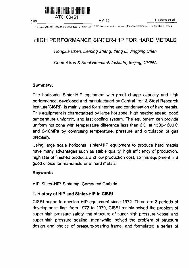
AT0100451180 HM 25 H. Chen et al.
1S' International Plansee Seminar, Eds. G. Kneringer, P. Rodhammer and H. Wildner, Plansee Holding AG, Reutte (2001), Vol. 2
HIGH PERFORMANCE SINTER-HIP FOR HARD METALS
Hongxia Chen, Deming Zhang, Yang Li, Jingping Chen
Central Iron & Steel Research Institute, Beijing, CHINA
Summary:
The horizontal Sinter-HIP equipment with great charge capacity and highperformance, developed and manufactured by Central Iron & Steel ResearchInstitute(CISRI), is mainly used for sintering and condensation of hard metals.This equipment is characterized by large hot zone, high heating speed, goodtemperature uniformity and fast cooling system. The equipment can provideuniform hot zone with temperature difference less than 6°C at 1500-1600°Cand 6-10MPa by controlling temperature, pressure and circulation of gasprecisely.
Using large scale horizontal sinter-HIP equipment to produce hard matalshave many advantages such as stable quality, high efficiency of production,high rate of finished products and low production cost, so this equipment is agood choice for manufacturer of hard metals.
Keywords
HIP, Sinter-HIP, Sintering, Cemented Carbide,
1. History of HIP and Sinter-HIP in CISRI
CISRI began to develop HIP equipment since 1972. There are 3 periods ofdevelopment: first, from 1972 to 1979, CISRI mainly solved the problem ofsuper-high pressure safety, the structure of super-high pressure vessel andsuper-high pressure sealing, meanwhile, solved the problem of structuredesign and choice of pressure-bearing frame, and formulated a series of
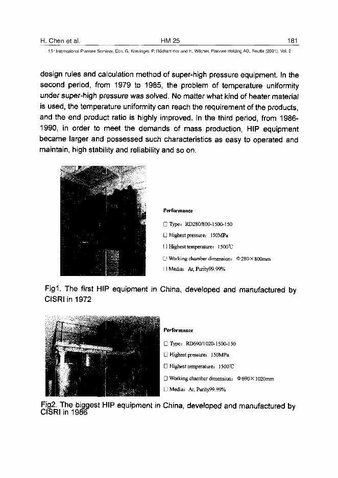
H. Chen et al. HM25 181
15* International Plansee Seminar, Eds. G. Kneringer, P. Rodhammer and H. Wildner, Plansee Holding AG, Reutte (2001), Vol. 2
design rules and calculation method of super-high pressure equipment. In thesecond period, from 1979 to 1985, the problem of temperature uniformityunder super-high pressure was solved. No matter what kind of heater materialis used, the temperature uniformity can reach the requirement of the products,and the end product ratio is highly improved. In the third period, from 1986-1990, in order to meet the demands of mass production, HIP equipmentbecame larger and possessed such characteristics as easy to operated andmaintain, high stability and reliability and so on.
Performance
• Type: RD280/800-1500-150
• Highest pressure: ISOMPa
• Highest temperature: 1500T?
• Working chamber dimension: <t> 280 X 800mm
• Media: Ar, Purity99.99%
F i g l The first HIP equipment in China, developed and manufactured byCISRI in 1972
Performance
D Type: RD690/1020-1500-150
D Highest pressure: 150MPa
D Highest temperature: 1500"C
D Working chamber dimension: O690X 1020mm
D Media: Ar, Purity99.99%
Fig2. The biggest HIP equipment in China, developed and manufactured byCISRI in 1986
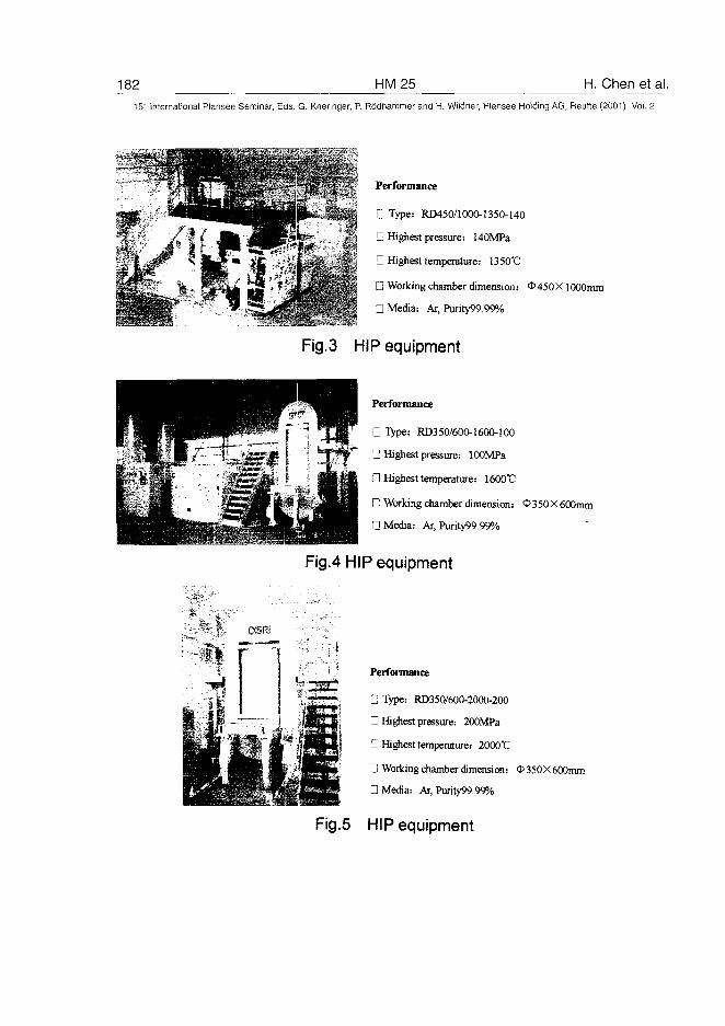
182 HM25 H. Chen et al.15" International Plansee Seminar, Eds. G. Kneringer, P. Rodhammer and H. Wildner, Plansee Holding AG, Reutte (2001), Vol. 2
Performance
• Type: RD450/1000-1350-140
D Highest pressure: 140MPa
D Highest temperature: 1350°C
D Working chamber dimension: O450X 1000mm
D Media: Ar, Purity99.99%
Fig.3 HIP equipment
Performance
D Type: R035O/6OO-16OO-1OO
• Highest pressure: lOOMPa
D Highest temperature: 1600'C
n Working chamber dimension: c£>350X 600mm
D Media: Ar, Purity99.99%
Fig.4 HIP equipment
csn
Performance
D Type: RD350/600-2000-200
D Highest pressure: 200MPa
D Highest temperature: 2000°C
D Working chamber dimension: <S> 350 X 600mm
D Media: Ar, Purity99.99%
Fig.5 HIP equipment
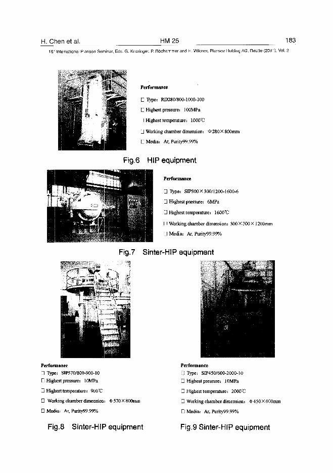
H. Chen et al. HM25 183
15th International Plansee Seminar, Eds. G. Kneringer, P. Rodhammer and H. Wildner, Plansee Holding AG, Reutte (2001), Vol. 2
Performance
D Type: RD280/800-1000-100
D Highest pressure: lOOMPa
D Highest temperature: 1000'C
D Working chamber dimension: <t>28OX 800mm
D Media: Ar, Purity99.99%
Fig.6 HIP equipment
Performance
D Type: SIP300X 300/1200-1600-6
D Highest pressure: 6MPa
D Highest temperature: 1600'C
D Working chamber dimension: 300X 300X 1200mm
D Media: Ar, Purity99.99%
Fig.7 Sinter-HIP equipment
Performance
D Type: SIP570/800-900-10
D Highest pressure: lOMPa
Q Highest temperature: 900X:
• Working chamber dimension: <t>570X800mm
D Media: Ar, Purity99.99%
Performance
D Type: SIP450/600-2000-10
D Highest pressure: 1 OMPa
D Highest temperature: 2000'C
D Working chamber dimension: <t>450X600mm
D Media: Ar, Purity99.99%
Fig.8 Sinter-HIP equipment Fig.9 Sinter-HIP equipment
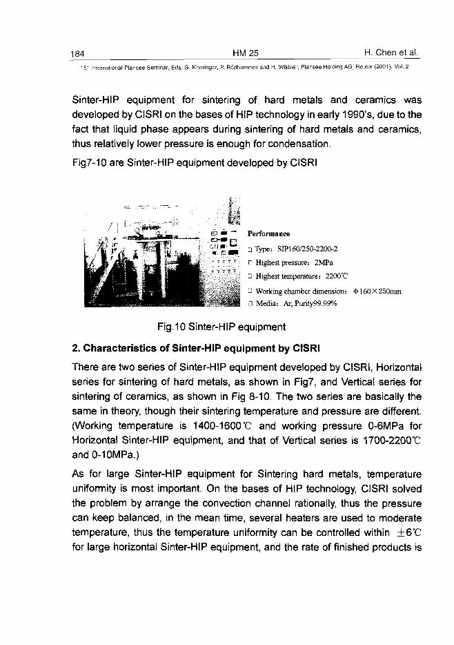
184 HM25 H. Chenetal.
15" International Plansee Seminar, Eds. G. Kneringer, P. Rodhammer and H. Wildner, Plansee Holding AG, Reutte (2001), Vol. 2
Sinter-HIP equipment for sintering of hard metals and ceramics wasdeveloped by CISRI on the bases of HIP technology in early 1990's, due to thefact that liquid phase appears during sintering of hard metals and ceramics,thus relatively lower pressure is enough for condensation.
Fig7-10 are Sinter-HIP equipment developed by CISRI
Performance
DType: SIP160/250-2200-2
D Highest pressure: 2MPa
n Highest temperature: 2200°C
D Working chamber dimension: <1> 160 X 250mm
a Media: Ar, Purity99.99%
Fig.10 Sinter-HIP equipment
2. Characteristics of Sinter-HIP equipment by CISRI
There are two series of Sinter-HIP equipment developed by CISRI, Horizontalseries for sintering of hard metals, as shown in Fig7, and Vertical series forsintering of ceramics, as shown in Fig 8-10. The two series are basically thesame in theory, though their sintering temperature and pressure are different.(Working temperature is 1400-1600 °C and working pressure 0-6MPa forHorizontal Sinter-HIP equipment, and that of Vertical series is 1700-2200°Cand0-10MPa.)
As for large Sinter-HIP equipment for Sintering hard metals, temperatureuniformity is most important. On the bases of HIP technology, CISRI solvedthe problem by arrange the convection channel rationally, thus the pressurecan keep balanced, in the mean time, several heaters are used to moderatetemperature, thus the temperature uniformity can be controlled within ±6°Cfor large horizontal Sinter-HIP equipment, and the rate of finished products is
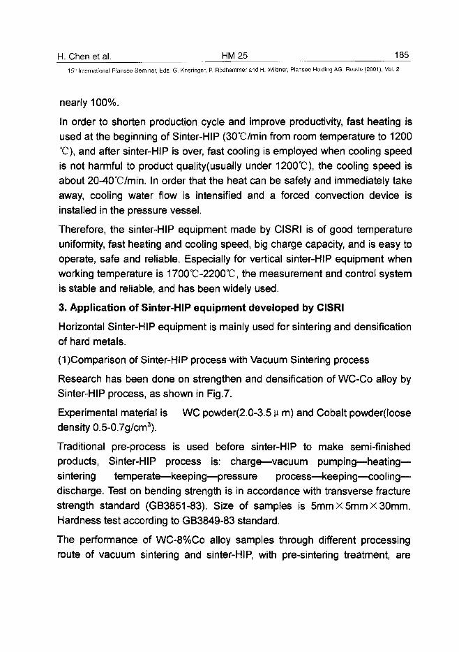
H. Chen et al. HM 25 18515" International Plansee Seminar, Eds. G. Kneringer, P. Rodhammer and H. Wildner, Plansee Holding AG, Reutte (2001), Vol. 2
nearly 100%.
In order to shorten production cycle and improve productivity, fast heating isused at the beginning of Sinter-HIP (30°C/min from room temperature to 1200°C), and after sinter-HIP is over, fast cooling is employed when cooling speedis not harmful to product quality(usually under 1200°C), the cooling speed isabout 20-40°C/min. In order that the heat can be safely and immediately takeaway, cooling water flow is intensified and a forced convection device isinstalled in the pressure vessel.
Therefore, the sinter-HIP equipment made by CISRI is of good temperatureuniformity, fast heating and cooling speed, big charge capacity, and is easy tooperate, safe and reliable. Especially for vertical sinter-HIP equipment whenworking temperature is 1700°C-2200°C, the measurement and control systemis stable and reliable, and has been widely used.
3. Application of Sinter-HIP equipment developed by CISRI
Horizontal Sinter-HIP equipment is mainly used for sintering and densificationof hard metals.
(1)Comparison of Sinter-HIP process with Vacuum Sintering process
Research has been done on strengthen and densification of WC-Co alloy bySinter-HIP process, as shown in Fig.7.
Experimental material is WC powder(2.0-3.5 u m) and Cobalt powder(loosedensity 0.5-0.7g/cm3).
Traditional pre-process is used before sinter-HIP to make semi-finishedproducts, Sinter-HIP process is: charge—vacuum pumping—heating—sintering temperate—keeping—pressure process—keeping—cooling—discharge. Test on bending strength is in accordance with transverse fracturestrength standard (GB3851-83). Size of samples is 5mm x 5mm x 30mm.Hardness test according to GB3849-83 standard.
The performance of WC-8%Co alloy samples through different processingroute of vacuum sintering and sinter-HIP, with pre-sintering treatment, are
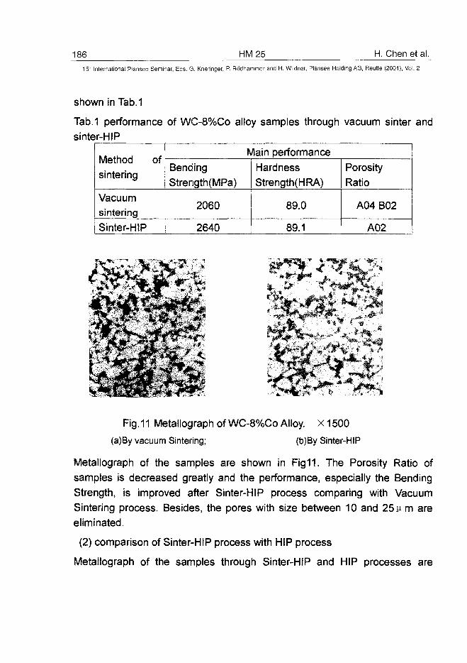
186 HM25 H. Chen et al.15" International Plansee Seminar, Eds. G. Kneringer, P. Rodhammer and H. Wildner, Plansee Holding AG, Reutte (2001), Vol. 2
shown in Tab. 1
Tab.1 performance of WC-8%Co alloy samples through vacuum sinter andsinter-HIP
Method ofsintering
Vacuumsintering
Sinter-HIP
Main performance
Bending
Strength(MPa)
2060
2640
HardnessStrength(HRA)
89.0
89.1
PorosityRatio
A04 B02
A02
I *
Fig. 11 Metallograph of WC-8%Co Alloy. X1500
(a)By vacuum Sintering; (b)By Sinter-HIP
Metallograph of the samples are shown in Fig11. The Porosity Ratio ofsamples is decreased greatly and the performance, especially the BendingStrength, is improved after Sinter-HIP process comparing with VacuumSintering process. Besides, the pores with size between 10 and 25 u m areeliminated.
(2) comparison of Sinter-HIP process with HIP process
Metallograph of the samples through Sinter-HIP and HIP processes are
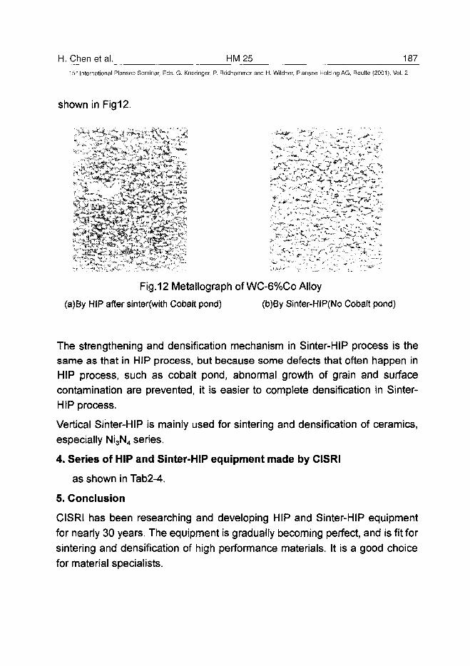
H. Chen et al. HM25 18715" International Plansee Seminar, Eds. G. Kneringer, P. Rodhammer and H. Wildner, Plansee Holding A6, Reutte (2001), Vol. 2
shown in Fig12.
: j *y .t-A i ».
.:-'••„ V * : :
Fig. 12 Metallograph of WC-6%Co Alloy
(a)By HIP after sinter(with Cobalt pond) (b)By Sinter-HIP(No Cobalt pond)
The strengthening and densification mechanism in Sinter-HIP process is thesame as that in HIP process, but because some defects that often happen inHIP process, such as cobalt pond, abnormal growth of grain and surfacecontamination are prevented, it is easier to complete densification in Sinter-HIP process.
Vertical Sinter-HIP is mainly used for sintering and densification of ceramics,
especially Ni3N4 series.
4. Series of HIP and Sinter-HIP equipment made by CISRI
as shown in Tab2-4.
5. Conclusion
CISRI has been researching and developing HIP and Sinter-HIP equipment
for nearly 30 years. The equipment is gradually becoming perfect, and is fit for
sintering and densification of high performance materials. It is a good choice
for material specialists.
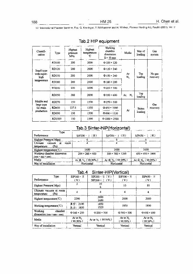
188 HM25 H. Chen et al.
15" International Plansee Seminar, Eds. G. Kneringer, P. Rodhammer and H. Wildner, Plansee Holding AG, Reutte (2001), Vol. 2
Tab.2 HIP equipment
Classifi-cation
Small typewith super-
hightemperature
Middle andlarge typefor mass
production
Type
RD100
RD120
RD150
RD180
RD200
RD350
RD270
RD450
RD690
RD1000
HighestpressureMPa
200
200
200
200
200
200
150
137.5
150
150
Highesttemperature
2000
2000
2000
2000
2000
2000
1500
1350
1500
1500
Workingchamber
dimensionD*Hmm
<P 100 * 120
5> 120x240
<D 150 x 240
0180 x 200
<D200*300
<D350x600
*270x500
<D450xl000
d>690xll20
<D 1000 x 2500
Media
ArN2
Ar, N2
Ar
Way ofloading
Toploading
Toploading
Botonloading
Gassystem
No gasrecovery
Gasrecovery
Tab.3 Sinter-HlP(Horizontal)Type
Performance
Highest Pressure( Mpa)Ultimate vacuum at roomtemperature (Pa)Highest temperature( V)Working chamber dimension
MediaWay of installation
SIP200- I (H)
64
1600
200 x 200 x 600
AriSN:, (99.99%)Horizontal
SIP300- I ( H )
64
1600
300 x 300 x 1200
Ar t, N2 ( 99.99%)Horizontal
SIP450- I (H)
64
1600
450 x 450 x 1800
Ar j£ N2 (99.99%)Horizontal
TypePerformance
Highest Pressure( Mpa)
Ultimate vacuum at roomtemperature (Pa)
Highest temperature( V)
Working temperatureCC)
Working chamberdimension (mm « mm * mm)
Media
Way of installation
Tab.4SIP 160- n
(V)2
4
2200
£ S : 2100ffjj: 1850
<P 160 x 250
ArorN2
(99.99%)
Vertical
Sinter-HIP(Vertical)SIP200- 11 ( V )SIP200- I (V)
106
4
2000160018501520
0200x300
ArorN2 (99.99%)
Vertical
SIP300 - II(V)
10
4
2000
1850
*300x500
ArorN2
(99.99%)
Vertical
SIP450- II(V)
10
4
2000
1850
<P450 x 600
ArorN2
(99.99%)
Vertical
AT0100452V. Bondarenko et al. HM 26 189^
15" International Plansee Seminar, Eds. G. Kneringer, P. Rodhammer and H. Wildner, Plansee Holding AG, Reutte (2001), Vol. 2
Advanced Technologies of Production of Cemented Carbides
and Composite Materials Based on Them
Vladimir Bondarenko, Ella Pavlotskaya, Lyudmila Martynova, Irina Epik
V. Bakul Institute for Superhard Materials of the National Academy
of Sciences of Ukraine, 2, Avtozavodskaya Str., Kiev, Ukraine
Summary:
The paper presents new technological processes of production of W, WC and(Ti, W)C powders, cemented carbides having a controlled carbon content,high-strength nonmagnetic nickel-bonded cemented carbides, cementedcarbide-based composites having a wear-resistant antifriction working layeras well as processes of regeneration of cemented carbide waste. It is shownthat these technological processes permit radical changes in the productionof carbide powders and products of VK, TK, VN and KKhN cementedcarbides. The processes of cemented carbide production becomeecologically acceptable and free of carbon black, the use of cumbersomemixers is excluded, the power expenditure is reduced and the efficiency oflabor increases. It becomes possible to control precisely the carbon contentwithin a two-phase region — carbide-metal. A high wear resistance of parts offriction couples which are lubricated with water, benzine, kerosene, diesel fueland other low-viscosity liquids, is ensured with increased strength and shockresistance.
Keywords:
W, WC, (Ti, W)C, tungsten hard alloys, titanium-tungsten hard alloys,methane-hydrogen medium, composite materials, sintering, phasecomposition, properties.
1. Introduction:
Following Schroter and his patent (1) where the basic principles of thetechnology of production of hard alloys were presented it was shown (2-3)
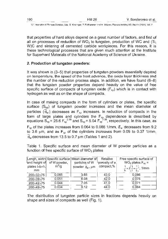
190 HM26 V. Bondarenko et al.15~ International Plansee Seminar, Eds. G. Kneringer, P. Rodhammer and H. Wildner, Plansee Holding AG, Reutte (2001), Vol. 2
that properties of hard alloys depend on a great number of factors, and first ofall on processes of reduction of WO3 to tungsten, production of WC and (Ti,W)C and sintering of cemented carbide workpieces. For this reason, it isthese technological processes that are given much attention at the Institutefor Superhard Materials of the National Academy of Science of Ukraine.
2. Production of tungsten powders:
It was shown in (3-5) that properties of tungsten powders essentially dependon temperature, the speed of the boat advance, the oxide layer thickness andthe number of the reduction process steps. In addition, we have found (6-8)that the tungsten powder properties depend heavily on the value of freespecific surface of compacts of tungsten oxide (Fsp) which is in contact withhydrogen as well as on the shape of compacts.
In case of making compacts in the form of cylinders or plates, the specificsurface (Ssp) of tungsten powder increases and the mean diameter ofparticles (dw) decreases as Fsp increases. In reduction of compacts in theform of large plates and cylinders the FSp dependence is described byequations Ssp= 25.6 Fsp
238 and Ssp= 5.04 Fsp , respectively. In this case, as
Fsp of the plates increases from 0.064 to 0.086 1/mm, d~w decreases from 9.2to 3.6 (im, and as Fsp of the cylinders increases from 0.09 to 0.37 1/mm,dwdecreases from 13.5 to 0.7 jam (Tables 1 and 2).
Table 1. Specific surface and mean diameter of W powder particles as afunction of free specific surface of WO3 plates
Lengh, widthand height ofplates Ixbxh,
mm200x32x75200x39x75200x42x75200x49x75
Specific surfaceof W powder,
m2/g
0.0850.0510.0440.034
Mean diameter ofparticles of W
powder dw, |im
3.656.087.059.12
Relativeporosity of acompact,%
43.042.041.044.0
Free specific surface ofWO3 plates Fsp =
MK)' 1 / m m0.0860.0750.0710.064
The distribution of tungsten particle sizes in fractions depends heavily onshape and sizes of compacts as well (Fig. 1).
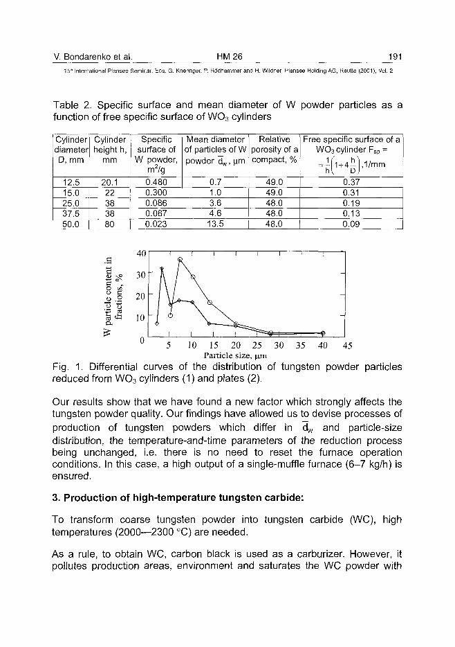
V. Bondarenko et al. HM26 19115'h International Plansee Seminar, Eds. G. Kneringer, P. Rodhammer and H. Wildner, Plansee Holding AG, Reutte (2001), Vol. 2
Table 2. Specific surface and mean diameter of W powder particles as afunction of free specific surface of WO3 cylinders
CylinderdiameterD, mm
12.515.025.037.550.0
Cylinderheight h,
mm
20.122383880
Specificsurface of
W powder,m2/g
0.4800.3000.0860.0670.023
Mean diameterof particles of Wpowder d w , (xm
0.71.03.64.613.5
Relativeporosity of acompact, %
49.049.048.048.048.0
Free specific surface of aWO3 cylinder Fsp =
hi D)'0.370.310.190.130.09
O ofo a« .2
10 30 35 40 4515 20 25Particle size, ^m
Fig. 1. Differential curves of the distribution of tungsten powder particlesreduced from WO3 cylinders (1) and plates (2).
Our results show that we have found a new factor which strongly affects thetungsten powder quality. Our findings have allowed us to devise processes ofproduction of tungsten powders which differ in dw and particle-sizedistribution, the temperature-and-time parameters of the reduction processbeing unchanged, i.e. there is no need to reset the furnace operationconditions. In this case, a high output of a single-muffle furnace (6-7 kg/h) isensured.
3. Production of high-temperature tungsten carbide:
To transform coarse tungsten powder into tungsten carbide (WC), hightemperatures (2000—2300 °C) are needed.
As a rule, to obtain WC, carbon black is used as a carburizer. However, itpollutes production areas, environment and saturates the WC powder with
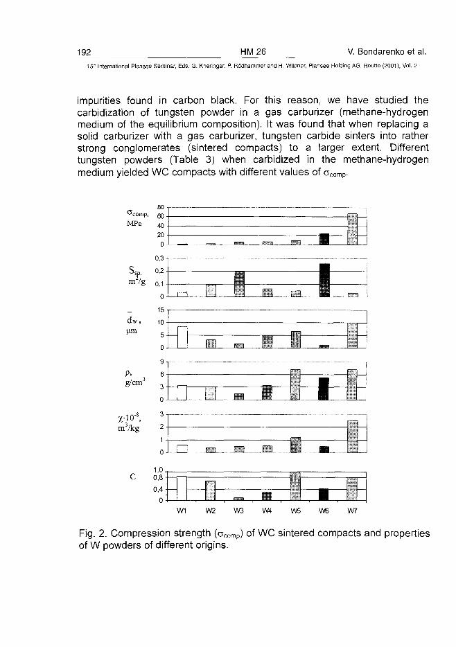
192 HM26 V. Bondarenko et al.International Plansee Seminar, Eds. G. Kneringer, P. Rodhammer and H. Wildner, Plansee Holding AG, Reutte (2001), Vol. 2
impurities found in carbon black. For this reason, we have studied thecarbidization of tungsten powder in a gas carburizer (methane-hydrogenmedium of the equilibrium composition). It was found that when replacing asolid carburizer with a gas carburizer, tungsten carbide sinters into ratherstrong conglomerates (sintered compacts) to a larger extent. Differenttungsten powders (Table 3) when carbidized in the methane-hydrogenmedium yielded WC compacts with different values of acomp-
1,0.0,8
0,4 -(—
0 tdtW1 W2 W3 W4
Fig. 2. Compression strength (aCOmp) of WC sintered compacts and propertiesof W powders of different origins.
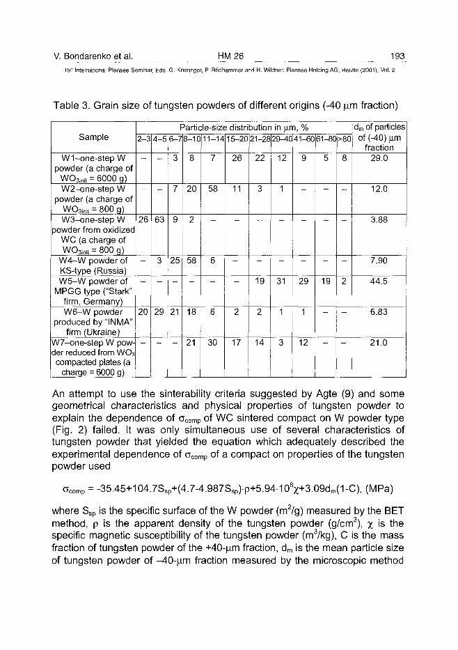
V. Bondarenko et al. HM26 19315" International Plansee Seminar, Eds. G. Kneringer, P. Rodhammer and H. Wildner, Plansee Holding AG, Reutte (2001), Vol. 2
Table 3. Grain size of tungsten powders of different origins (-40 urn fraction)
Sample
W1-one-step Wpowder (a charge of
WOainit = 6000 g)W2-one-step W
powder (a charge ofWO3init = 800 g)W3-one-step W
powder from oxidizedWC (a charge ofWOsinit = 800 g)
W4-W powder ofKS-type (Russia)W5-W powder of
MPGG type ("Stark"firm, Germany)W6-W powder
produced by "INMA"firm (Ukraine)
W7-one-step W pow-der reduced from WO3compacted plates (a
charge = 6000 g)
Particle-size distribution in \im, %2-3
26
—
20
4-5
63
3
29
6-7
3
7
9
25
21
8-10
8
20
2
58
18
21
11-14
7
58
6
6
30
15-20
26
11
—
2
17
21-28
22
3
—
19
2
14
29-40
12
1
—
31
1
3
41-60
9
—
29
1
12
61-80
5
—
19
>80
8
—
2
dm of particlesof (-40) urn
fraction29.0
12.0
3.88
7.90
44.5
6.83
21.0
An attempt to use the sinterability criteria suggested by Agte (9) and somegeometrical characteristics and physical properties of tungsten powder toexplain the dependence of ocomp of WC sintered compact on W powder type(Fig. 2) failed. It was only simultaneous use of several characteristics oftungsten powder that yielded the equation which adequately described theexperimental dependence of 0comp of a compact on properties of the tungstenpowder used
c>comp = -35.45+104.7Ssp+(4.7-4.987Ssp)p+5.94-108%+3.09dm(1-C), (MPa)
where Ssp is the specific surface of the W powder (m2/g) measured by the BETmethod, p is the apparent density of the tungsten powder (g/cm3), % is thespecific magnetic susceptibility of the tungsten powder (m3/kg), C is the massfraction of tungsten powder of the +40-um fraction, dm is the mean particle sizeof tungsten powder of -40-um fraction measured by the microscopic method
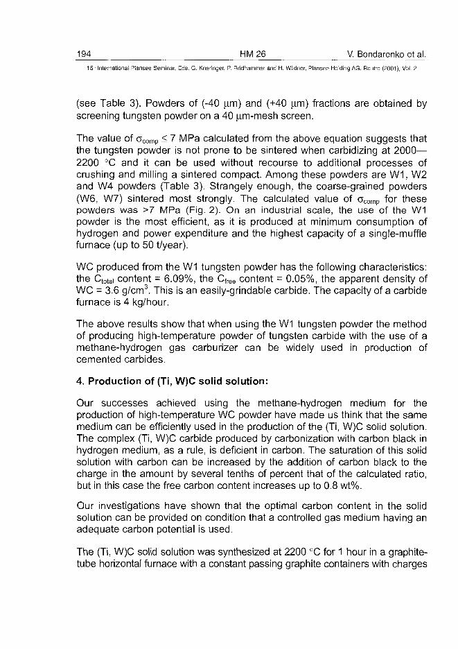
194 HM26 V. Bondarenko et al.15'" International Plansee Seminar, Eds. G. Kneringer, P. Rodhammer and H. Wildner, Plansee Holding AG, Reutte (2001), Vol. 2
(see Table 3). Powders of (-40 |im) and (+40 \irr\) fractions are obtained byscreening tungsten powder on a 40 jim-mesh screen.
The value of 0comp < 7 MPa calculated from the above equation suggests thatthe tungsten powder is not prone to be sintered when carbidizing at 2000—2200 °C and it can be used without recourse to additional processes ofcrushing and milling a sintered compact. Among these powders are W1, W2and W4 powders (Table 3). Strangely enough, the coarse-grained powders(W6, W7) sintered most strongly. The calculated value of acomp for thesepowders was >7 MPa (Fig. 2). On an industrial scale, the use of the W1powder is the most efficient, as it is produced at minimum consumption ofhydrogen and power expenditure and the highest capacity of a single-mufflefurnace (up to 50 t/year).
WC produced from the W1 tungsten powder has the following characteristics:the Ctotai content = 6.09%, the Cfree content = 0.05%, the apparent density ofWC = 3.6 g/cm3. This is an easily-grindable carbide. The capacity of a carbidefurnace is 4 kg/hour.
The above results show that when using the W1 tungsten powder the methodof producing high-temperature powder of tungsten carbide with the use of amethane-hydrogen gas carburizer can be widely used in production ofcemented carbides.
4. Production of (Ti, W)C solid solution:
Our successes achieved using the methane-hydrogen medium for theproduction of high-temperature WC powder have made us think that the samemedium can be efficiently used in the production of the (Ti, W)C solid solution.The complex (Ti, W)C carbide produced by carbonization with carbon black inhydrogen medium, as a rule, is deficient in carbon. The saturation of this solidsolution with carbon can be increased by the addition of carbon black to thecharge in the amount by several tenths of percent that of the calculated ratio,but in this case the free carbon content increases up to 0.8 wt%.
Our investigations have shown that the optimal carbon content in the solidsolution can be provided on condition that a controlled gas medium having anadequate carbon potential is used.
The (Ti, W)C solid solution was synthesized at 2200 °C for 1 hour in a graphite-tube horizontal furnace with a constant passing graphite containers with charges
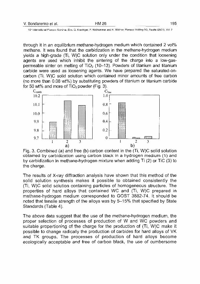
V. Bondarenko et al. HM26 19515'" International Plansee Seminar, Eds. G. Kneringer, P. Rodhammer and H. Wildner, Plansee Holding AG, Reutte (2001), Vol. 2
through it in an equilibrium methane-hydrogen medium which contained 2 vol%methane. It was found that the carbidization in the methane-hydrogen mediumyields a high-grade (Ti, W)C solution only under the condition that looseningagents are used which inhibit the sintering of the charge into a low-gas-permeable sinter on melting of TiO2 (10-13). Powders of titanium and titaniumcarbide were used as loosening agents. We have prepared the saturated-on-carbon (Ti, W)C solid solution which contained minor amounts of free carbon(no more than 0.08 wt%) by substituting powders of titanium or titanium carbidefor 50 wt% and more of TiO2 powder (Fig. 3).
l .U
0.8
0.6
0.4
0.2
0
-
-
-
ijjjjjilj;
ill!i l l111!ijiiillll!
2 3 1 2 3a) b)
Fig. 3. Combined (a) and free (b) carbon content in the (Ti, W)C solid solutionobtained by carbidization using carbon black in a hydrogen medium (1) andby carbidization in methane-hydrogen mixture when adding Ti (2) or TiC (3) tothe charge.
The results of X-ray diffraction analysis have shown that this method of thesolid solution synthesis makes it possible to obtained consistently the(Ti, W)C solid solution containing particles of homogeneous structure. Theproperties of hard alloys that contained WC and (Ti, W)C prepared inmethane-hydrogen medium corresponded to GOST 3882-74. It should benoted that tensile strength of the alloys was by 5-15% that specified by StateStandards (Table 4).
The above data suggest that the use of the methane-hydrogen medium, theproper selection of processes of production of W and WC powders andsuitable propertioning of the charge for the production of (Ti, W)C make itpossible to change radically the production of carbides for hard alloys of VKand TK groups. The processes of production of hard alloys becomeecologically acceptable and free of carbon black, the use of cumbersome
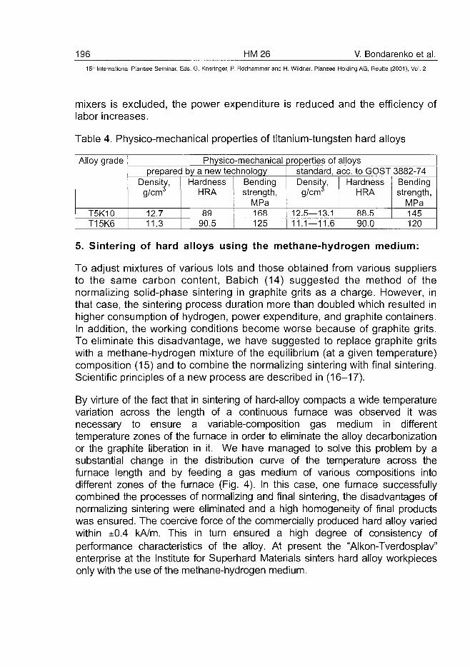
196 HM26 V. Bondarenko et al.15" International Plansee Seminar, Eds. G. Kneringer, P. Rodhammer and H. Wildner, Plansee Holding AG, Reutte (2001), Vol. 2
mixers is excluded, the power expenditure is reduced and the efficiency oflabor increases.
Table 4. Physico-mechanical properties of titanium-tungsten hard alloys
Alloy grade
T5K10T15K6
Physico-mechanical properties of alloysprepared by a new technology
Density,g/cm
12.711.3
HardnessHRA
8990.5
Bendingstrength,
MPa168125
standard, ace. to GOST 3882-74Density,g/cm
12.5—13.111.1—11.6
HardnessHRA
88.590.0
Bendingstrength,
MPa145120
5. Sintering of hard alloys using the methane-hydrogen medium:
To adjust mixtures of various lots and those obtained from various suppliersto the same carbon content, Babich (14) suggested the method of thenormalizing solid-phase sintering in graphite grits as a charge. However, inthat case, the sintering process duration more than doubled which resulted inhigher consumption of hydrogen, power expenditure, and graphite containers.In addition, the working conditions become worse because of graphite grits.To eliminate this disadvantage, we have suggested to replace graphite gritswith a methane-hydrogen mixture of the equilibrium (at a given temperature)composition (15) and to combine the normalizing sintering with final sintering.Scientific principles of a new process are described in (16-17).
By virture of the fact that in sintering of hard-alloy compacts a wide temperaturevariation across the length of a continuous furnace was observed it wasnecessary to ensure a variable-composition gas medium in differenttemperature zones of the furnace in order to eliminate the alloy decarbonizationor the graphite liberation in it. We have managed to solve this problem by asubstantial change in the distribution curve of the temperature across thefurnace length and by feeding a gas medium of various compositions intodifferent zones of the furnace (Fig. 4). In this case, one furnace successfullycombined the processes of normalizing and final sintering, the disadvantages ofnormalizing sintering were eliminated and a high homogeneity of final productswas ensured. The coercive force of the commercially produced hard alloy variedwithin ±0.4 kA/m. This in turn ensured a high degree of consistency ofperformance characteristics of the alloy. At present the "Alkon-Tverdosplav"enterprise at the Institute for Superhard Materials sinters hard alloy workpiecesonly with the use of the methane-hydrogen medium.
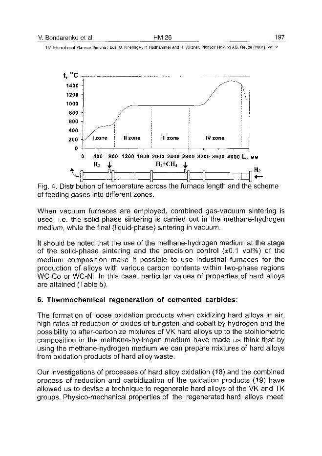
V. Bondarenko et al. HM26 197
15" International Plansee Seminar, Eds. G. Kneringer, P. Rodhammer and H. Wildner, Plansee Holding AG, Reutte (2001), Vol. 2
400 800 1200 1600 2000 2400 2800 3200 3600 4000 L, M M
H2 1 H2+CH4 4,
Fig. 4. Distribution of temperature across the furnace length and the schemeof feeding gases into different zones.
When vacuum furnaces are employed, combined gas-vacuum sintering isused, i.e. the solid-phase sintering is carried out in the methane-hydrogenmedium, while the final (liquid-phase) sintering in vacuum.
It should be noted that the use of the methane-hydrogen medium at the stageof the solid-phase sintering and the precision control (±0.1 vol%) of themedium composition make it possible to use industrial furnaces for theproduction of alloys with various carbon contents within two-phase regionsWC-Co or WC-Ni. In this case, particular values of properties of hard alloysare attained (Table 5).
6. Thermochemical regeneration of cemented carbides:
The formation of loose oxidation products when oxidizing hard alloys in air,high rates of reduction of oxides of tungsten and cobalt by hydrogen and thepossibility to after-carbonize mixtures of VK hard alloys up to the stoihiometriccomposition in the methane-hydrogen medium have made us think that byusing the methane-hydrogen medium we can prepare mixtures of hard alloysfrom oxidation products of hard alloy waste.
Our investigations of processes of hard alloy oxidation (18) and the combinedprocess of reduction and carbidization of the oxidation products (19) haveallowed us to devise a technique to regenerate hard alloys of the VK and TKgroups. Physico-mechanical properties of the regenerated hard alloys meet
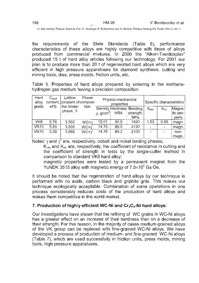
198 HM26 V. Bondarenko et al.
15" International Plansee Seminar, Eds. G. Kneringer, P. Rodhammer and H. Wildner, Plansee Holding AG, Reutte (2001), Vol. 2
the requirements of the State Standards (Table 6), performancecharacteristics of these alloys are highly competitive with those of alloysproduced from commercial mixtures. In 2000 the "Alkon-Tverdosplav"produced 15 t of hard alloy articles following our technology. For 2001 ourplan is to produce more than 20 t of regenerated hard alloys which are veryefficient in high pressure apparatuses for diamond synthesis, cutting andmining tools, dies, press molds, friction units, etc.
Table 5. Properties of hard alloys prepared by sintering in the methane-hydrogen gas medium having a precision composition
Hardalloygrade
VK6VN10VN10
Qotalcontent,
wt%
5.765.555.39
Latticeconstant ofthe binderphase,A
3.5523.5553.565
Phasecomposi-
tion
\NC+y_WC+f_WC+Y1
Physico-mechanicalproperties
Densityp, g/cm3
15.0114.7514.76
HardnessHRA
90.589.089.2
Bendingstrength,
MPa192021202100
Specific characteristics
Kres
1.53--
Kstr
0.95--
Magne-tic pro-perty
magn.magn.non-
magn.
Notes: yand y1 are, respectively, cobalt and nickel binding phases;Kres and Kstr are, respectively, the coefficient of resistance in cutting andthe coefficient of strength in tests by the single-cutter method incomparison to standard VK8 hard alloy;magnetic properties were tested by a permanent magnet from theYuNDK 3515 alloy with magnetic energy of 7.5x10⁶ Gs-Oe.
It should be noted that the regeneration of hard alloys by our technique isperformed with no acids, carbon black and griphite grits. This makes ourtechnique ecologically acceptable. Combination of some operations in oneprocess considerably reduces costs of the production of hard alloys andmakes them competitive in the world market.
7. Production of highly efficient WC-Ni and Cr3C2-Ni hard alloys:
Our investigations have shown that the refining of WC grains in WC-Ni alloyshas a greater effect on an increase of their hardness than on a decrease oftheir strength. For this reason, in the majority of cases medium-grained alloysof the VK group can be replaced with fine-grained WC-Ni alloys. We havedeveloped a process of production of medium- and fine-grained WC-Ni alloys(Table 7), which are used successfully in friction units, press molds, miningtools, high pressure apparatuses.
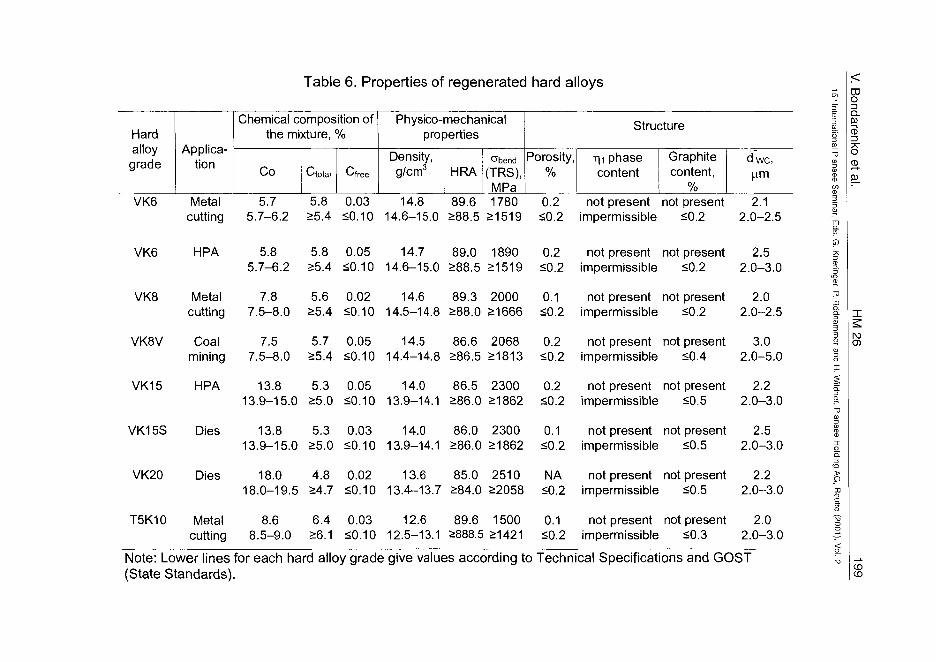
Table 6. Properties of regenerated hard alloys
Hardalloy
gradeApplica-
tion
Chemical composition ofthe mixture, %
Co Ctotal Cfree
Physico-mechanicalproperties
Density,g/cm3 HRA
abend
(TRS),MPa
Structure
Porosity,%
r|i phasecontent
Graphitecontent,
%
d we,p.m
VK6
VK6
VK8
VK8V
VK15
VK15S
VK20
T5K10
Metalcutting
HPA
Metalcutting
Coalmining
HPA
Dies
Dies
Metalcutting
5.75.7-6.2
5.85.7-6.2
7.87.5-8.0
7.57.5-8.0
13.813.9-15.0
13.813.9-15.0
18.018.0-19.5
8.68.5-9.0
5.8>5.4
5.8>5.4
5.6>5.4
5.7>5.4
5.3>5.0
5.3>5.0
4.8>4.7
6.426.1
0.03<0.10
0.0550.10
0.02SO. 10
0.0550.10
0.0550.10
0.0350.10
0.0250.10
0.0350.10
14.814.6-15.0
14.714.6-15.0
14.614.5-14.8
14.514.4-14.8
14.013.9-14.1
14.013.9-14.1
13.613.4-13.7
12.612.5-13.1
89.6>88.5
89.0288.5
89.3288.0
86.6286.5
86.5286.0
86.0286.0
85.0284.0
89.6>888.5
178021519
189021519
200021666
206821813
230021862
230021862
251022058
150021421
0.2 not present not present 2.1<0.2 impermissible <0.2 2.0-2.5
0.2 not present not present 2.550.2 impermissible <0.2 2.0-3.0
0.1 not present not present 2.0<0.2 impermissible <0.2 2.0-2.5
0.2 not present not present 3.0<0.2 impermissible <0.4 2.0-5.0
0.2 not present not present 2.2<0.2 impermissible 50.5 2.0-3.0
0.1 not present not present 2.5<0.2 impermissible <0.5 2.0-3.0
NA not present not present 2.2<0.2 impermissible <0.5 2.0-3.0
0.1 not present not present 2.0<0.2 impermissible <0.3 2.0-3.0
03ooCD
l\3O)
Note: Lower lines for each hard alloy grade give values according to Technical Specifications and GOST(State Standards).
CDCD
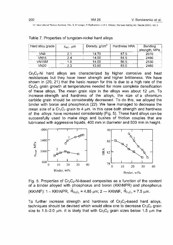
200 HM26 V. Bondarenko et al.15-" International Plansee Seminar, Eds. G. Kneringer, P. Rodhammer and H. Wildner, Plansee Holding AG, Reutte (2001), Vol. 2
Table 7. Properties of tungsten-nickel hard alloys
Hard alloy grade
VN8VN15
VN15MVN20
d W c . P-m
2.12.41.82.3
Density, g/cma
14.7014.0014.0013.60
Hardness HRA
87.584.586.583.0
Bendingstrength, MPa
2070249025302460
Cr3C2-Ni hard alloys are characterized by higher corrosive and heatresistances but they have lower strength and higher brittleness. We haveshown in (20, 21) that the basic reason for this is due to a high rate of theCr3C2 grain growth at temperatures needed for more complete densificationof these alloys. The mean grain size in the alloys was about 12 |im. Toincrease strength and hardness of the alloys, the size of a chromiumcarbide grain should be considerably decreased. To do this, we alloyed thebinder with boron and phosphorus (22). We have managed to decrease themean size of a Cr3C2 grain to 4 jam. In this case both strength and hardnessof the alloys have increased considerably (Fig. 5). These hard alloys can besuccessfully used to make rings and bushes of friction couples that arelubricated with aggressive liquids, 400 mm in diameter and 500 mm in height.
1800
1400-
i 1000
60010 20
Binder, wt%
30 4010 20 30
Binder, wt%
40
Fig. 5. Properties of Cr3C2-Ni-based composites as a function of the contentof a binder alloyed with phosphorus and boron (KKhNPR) and phosphorus
(KKhNF): 1 - KKhNPR, dCr3c2 = 4.85 urn; 2 — KKhNF, dCr3C2 = 7.5
To further increase strength and hardness of Cr3C2-based hard alloys,techniques should be devised which would allow one to decrease Cr3C2 grainsize to 1.5-2.0 ^m. It is likely that with Cr3C2 grain sizes below 1.5 ^m the
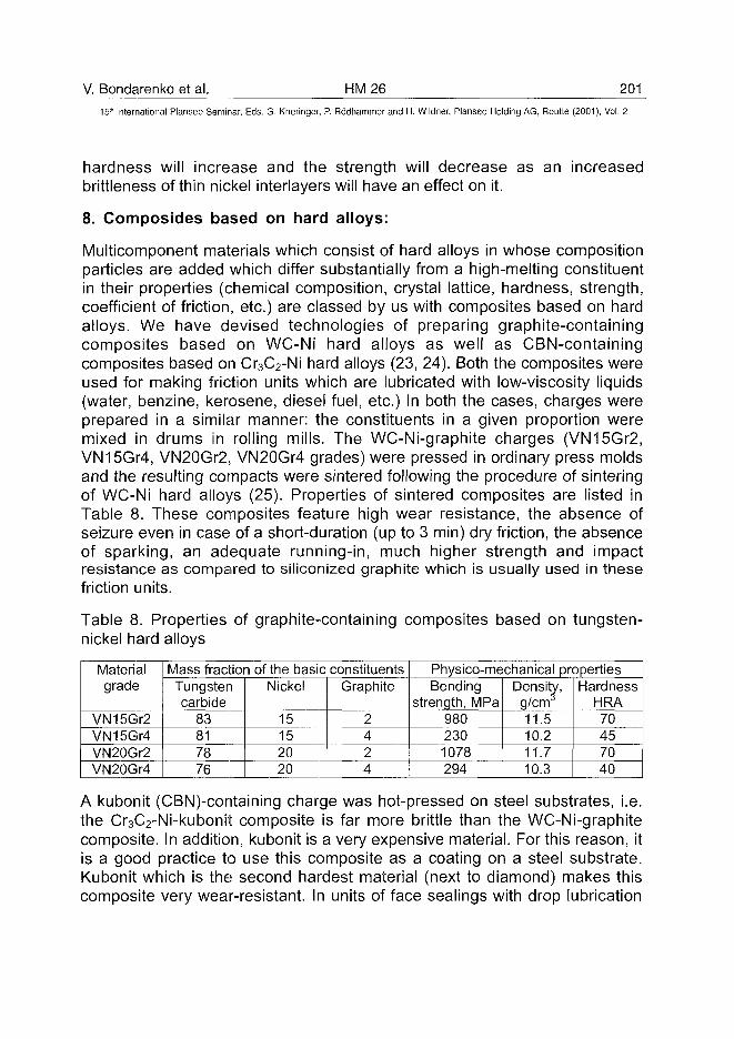
V. Bondarenko et al. HM26 20115" International Plansee Seminar, Eds. G. Kneringer, P. Rodhammer and H. Wildner, Plansee Holding AG, Reutte (2001), Vol. 2
hardness will increase and the strength will decrease as an increasedbrittleness of thin nickel interlayers will have an effect on it.
8. Composides based on hard alloys:
Multicomponent materials which consist of hard alloys in whose compositionparticles are added which differ substantially from a high-melting constituentin their properties (chemical composition, crystal lattice, hardness, strength,coefficient of friction, etc.) are classed by us with composites based on hardalloys. We have devised technologies of preparing graphite-containingcomposites based on WC-Ni hard alloys as well as CBN-containingcomposites based on Cr3C2-Ni hard alloys (23, 24). Both the composites wereused for making friction units which are lubricated with low-viscosity liquids(water, benzine, kerosene, diesel fuel, etc.) In both the cases, charges wereprepared in a similar manner: the constituents in a given proportion weremixed in drums in rolling mills. The WC-Ni-graphite charges (VN15Gr2,VN15Gr4, VN20Gr2, VN20Gr4 grades) were pressed in ordinary press moldsand the resulting compacts were sintered following the procedure of sinteringof WC-Ni hard alloys (25). Properties of sintered composites are listed inTable 8. These composites feature high wear resistance, the absence ofseizure even in case of a short-duration (up to 3 min) dry friction, the absenceof sparking, an adequate running-in, much higher strength and impactresistance as compared to siliconized graphite which is usually used in thesefriction units.
Table 8. Properties of graphite-containing composites based on tungsten-nickel hard alloys
Materialgrade
VN15Gr2VN15Gr4VN20Gr2VN20Gr4
Mass fraction of the basic constituentsTungstencarbide
83817876
Nickel
15152020
Graphite
2424
Physico-mechanical propertiesBending
strength, MPa9802301078294
Density,g/cm11.510.211.710.3
HardnessHRA70457040
A kubonit (CBN)-containing charge was hot-pressed on steel substrates, i.e.the Cr3C2-Ni-kubonit composite is far more brittle than the WC-Ni-graphitecomposite. In addition, kubonit is a very expensive material. For this reason, itis a good practice to use this composite as a coating on a steel substrate.Kubonit which is the second hardest material (next to diamond) makes thiscomposite very wear-resistant. In units of face sealings with drop lubrication
202 HM26 V. Bondarenko et al.15" International Plansee Seminar, Eds. G. Kneringer, P. Rodhammer and H. Wildner, Plansee Holding AG, Reutte (2001), Vol. 2
with industrial water, the serviceability of components of a friction couplemade of this composite is retained during 40,000 hours. Following ourprocedure we can make rings for face sealings up to 350 mm in diameter.
9. Conclusions:
The above presentation of a great number of new technologies shows thatthe use of only some technological approaches (shape and size variation ofWO3 compacts, application of a methane-hydrogen medium of an equilibriumcomposition and the addition of particles of antifriction or superhard materialsto hard alloys) have allowed us to devise a wide range of advancedprocesses of production of hard alloys and composites based on them. It isevident that the potentialities to devise new advanced technologies have notyet been exhausted. We are working now on the development of newtechnologies and have already obtained promising results.
The authors express their gratitude to Dr. Sci. (Phys.-Math.) Golovchan,Cand. Sci. (Eng.) Khalepa, Engs. Moshkun, Sirota and Tsalyuk for theirparticipation in the development of the above technologies as well as toBaranovsky, Sotnikova, Manokhin and Baidenko for the commercialimplementation of the above technologies at "Alkon-Tverdosplav" enterprise.
References
1. K. Schroter: "Gesinterte harte Metallegierung and Verfahren zu ihrerHerstellung", Patent des Deutsches Reich No. 420689, 30 Marz 1923
2. R. Kieffer and F. Benesovsky: "Hartmetalle" (Springer Verlag, Wien, New-York, 1953)
3. V. Tretiakov: "Fundamentals of Materials Science and Production ofSintered Hard Alloys" (Metallurgiya, Moscow, 1976)
4. V. Bondarenko, L. Martynova, A. Baranovsky, et al.: "Method of ProducingTungsten Powder", Patent No. 10917 of Ukraine, Publ. 25 December1996, Bullet, no. 4, p. 31.163
5. L. Martynova: in "Highly Filled Granular Composites" (ISM NAN Ukraine,Kiev, 1991), pp. 14-26
6. V. Bondarenko and L. Martynova: Proc. 2nd Int. Conf. on Treatment ofMaterials with Hydrogen, pp. 127-128 (Donetsk, 1998)
7. V. Bondarenko, L. Martynova, V. Golovchan: "Method of production ofhigh-temperature tungsten powder", Decision on giving a patent ofUkraine ace. to Application 2000042230 of 22 Aug. 2000
V. Bondarenko et al. HM 26 203^
15"1 International Plansee Seminar, Eds. G. Kneringer, P. Ro'dhammer and H. Wildner, Plansee Holding AG, Reutte (2001), Vol. 2
8. V. Bondarenko, L. Martynova, V. Golovchan: in "Materials of Science andTechnology Conf. on Complex of Scientific Measures of the Countries ofthe Former Soviet Union, P. 4, pp. 97-100 (Odessa, Ukraine)
9. K. Agte and I. Watsek: "Tungsten and Molybdenum" (Energiya, Moscow, 1964)10. V. Bondarenko, S. Korablev, I. Epik: Int. Journal of Hydrogen Energy 24
(1999), pp. 845-84811. V. Bondarenko, S. Korablev, I. Epik: Sverkhtverdye Materialy 2 (1999),
pp. 43-4612. V. Bondarenko, S. Korablev, I. Epik: Ogneupory i Tekhnicheskaya
Keramika7(1999), pp. 14-1613. V. Bondarenko, E. Pavlotskaya, I. Epik: Proc. 3rd European Conference
on Advances in Hard Materials Production, Turin, 8-10 October 1999, pp.191-198
14. M. Babich: "Non-uniformity of Hard Alloys with Respect to CarbonContent and the Ways to Eliminate It" (Naukova Dumka, Kiev, 1975)
15. V. Bondarenko and E. Pavlotskaya: "Method of sintering of hard alloys",the USSR Author's Certificate No. 605692, publ. 5 May 1978, Bullet, no. 17
16. V. Bondarenko and E. Pavlotskaya: "Sintering of Tungsten Carbide inPrecisely Controlled Gas Medium" (Naukova Dumka, Kiev, 1995)
17. V. Bondarenko and E. Pavlotskaya: Int. Journal of Hydrogen Energy 22(1997), pp. 205-212
18. V. Bondarenko, L. Martynova, O. Bespalko: Proc. 7th European Conferenceon An Application of Surface and Interface Analysis, Goteborg, 1997, p. 187
19. V. Bondarenko and E. Pavlotskaya: Int. Journal of Hydrogen Energy 24(1999), pp. 853-859
20. V. Bondarenko: in "Highly Filled Granular Composites" (ISM NANUkrainy, Kiev, 1991), pp. 4-14
21. V. Bondarenko: Proc. 1st Polish-Ukrainian Seminar on Advanced CeramicMaterials and Composites, Madralin, 1993, Polish Ceramic Bullet, no. 7
22. A. Khalepa and V. Bondarenko: Proc. Seminar on Composite Materials inMechanical Engineering, pp. 130-132 (Ternopol, Ukraine, Oct. 1989)
23. V. Bondarenko: "Tribotechnical Composites with High-Modular Fillers"(Naukova Dumka, Kiev, 1987)
24. V. Bondarenko, A. Khalepa, V. Malnev, E. Chistyakov: in "Processes ofthe Interaction at the Interphase", Collection of Scientific Papers (ISM,Kiev, 1982), pp. 79-84
25. V. Bondarenko, K. Sirota, A. Baranovsky, et al.: in "Prospects in Increa-sing Service Life and Reliability of Operation of Friction Couples which areLublicated with Machining Media", Collection of Scientific Papers (ISM,Kiev, 1987), pp. 47-53
ATO100453204 HM27 J. Vleugels et al.
15" International Plansee Seminar, Eds. G. Kneringer, P. Rodhammer and H. Wildner, Plansee Holding AG, Reutte (2001), Vol. 2
Hybrid-Microwave Sintering of Hardmetals and Graded Oxide
Composites
J. Vleugels, I. Volders, S. Put, C. Zhao, O. Van der Biest, C. Groffils*, P. J.Luypaert*, G. Barbier**, L. Bourgeois**
Katholieke Universiteit Leuven, Department of Metallurgy and Materials Engineering,
Leuven, Belgium
*Microwave Energy Applications Company, MEAC, Leuven, Belgium
**Cerametal Sari, Mamer, Luxembourg
Summary:
Commercial WC-Co hardmetal grades and functionally graded ZrO2-AI2O3
ceramic composites were fully densified by means of hybrid microwavesintering in a cylindrical 2.45 GHz single-mode microwave furnace using atubular susceptor concept. The hybrid sintering approach allowed immediate,smooth, programmable and reproducible thermal cycling of materials whichdo not couple with microwaves at room temperature. Unequivocal proof ofmicrowave activity on the samples inside the cylindrical SiC susceptor wasobtained from microstructural analysis of fast heated oxide ceramics.Densification of continuously graded ZrO2-AI2O3 materials could be achievedin shorter sintering times when compared to conventional sintering in air,without influencing the material properties. Hybrid microwave annealing ofthese composites in an inert atmosphere allowed to increase the fracturetoughness of the components significantly.The microstructural properties of commercial hardmetal grades obtained byconventional sintering could be fully reproduced by hybrid microwavesintering.
Keywords:hybrid microwave heating, oxide composites, graded materials, WC/Co,AI2O3, ZrO2
J. Vleugels et al. HM 27 205^15'" International Plansee Seminar, Eds. G. Kneringer, P. Rbdhammer and H. Wildner, Plansee Holding AG, Reutte (2001), Vol. 2
1. Introduction:
The use of microwave (MW) energy to sinter ceramics and cermets hasbecome a major research area world-wide over the past ten years.Microwave-only processing, where microwave energy is the only directenergy source, has been offered as an alternative to conventional furnaceswith the principle benefit being that heat energy can be deposited directlywithin the component so that the problems associated with conventional heattransfer can be overcome. There have also been reports that diffusionprocesses may be enhanced in the microwave field so that sintering can beaccomplished at a lower temperature. Although the dielectric properties ofsome ceramic materials appear to be reasonably favourable for microwave-only heating, in practice however, difficulties arise when heating a body tohigh temperature with microwave energy alone. Unlike in conventionalfurnaces, the specimen will be at a higher temperature than the surroundingswhen absorbing microwave energy, resulting in a temperature gradient withinthe components, albeit the reverse of the one associated with conventionalheating. Furthermore, the amount of microwave energy absorbed by thematerial is partly dependent on temperature, so that the centre maypreferentially absorb the microwaves, enhancing the temperature gradient.Due to the absence of an external heat source, microwave heated samplesare in direct contact with the colder surroundings, making them more prone tothermal shocks.One route to tackle these problems is the use of materials that act assusceptors. These materials preferentially absorb microwave energy and re-radiate the heat back to the surface of the component, reducing thetemperature gradient and risk of thermal shocks. This method is also knownas hybrid heating.Most of the research efforts up to now were given to microwave drying, firingand sintering of glasses and ceramics. In the last five years however,increasing attention is given to multi-mode microwave sintering of polyphasematerials containing a strong microwave dissipating phase and an electricallyconducting phase such as cutting tool materials based on AI2O3/TiC (1) andWC/Co hardmetals (2-5). Moreover, the application of multi-mode MWprocessing to prepare ceramic (AI2O3-ZrO2) and metal-ceramic (ZrO2-Ni steeland AI2O3-steel) functionally gradient materials are reported (6). Evensintering of metal powders by means of multi-mode microwave heating isdescribed (7).It may come as a surprise to some that it is possible to sinter metal containingsystems such as WC-Co, since it is known that microwaves are reflected at
206 HM 27 J. Vleugels et al.15" International Plansee Seminar, Eds. G. Kneringer, P. Rddhammer and H. Wildner, Plansee Holding AG, Reutte (2001), Vol. 2
the surface of a conductor. Nevertheless this is perfectly possible as long asthe metallic phase is present in the form of isolated not-connected particles.The microwave field induces then electric currents in the skin of the particleswhich will cause them to heat up. The processes by which microwaves aredissipated in WC-Co have been reported in (8). It has been demonstratedthat multi-mode microwave sintering of WC-Co (6-25 %) cemented carbideshas the potential of reducing the processing time and improving mechanicalproperties (2). Guidelines for upscaled batch microwave sintering ofhardmetals are reported (3).In this paper, the possibility to sinter and/or anneal continuously gradedZrO2/AI2O3 ceramic composites and homogeneous WC/Co hardmetals bymeans of hybrid microwave heating using a tubular SiC susceptor, in asingle-mode microwave cavity is illustrated.
2. Hybrid Microwave Heating:
2.1. The Hybrid Microwave Heating Set-up:
The microwave furnace used in this study is designed and fabricated byMEAC (Microwave Energy Applications Company, Leuven, Belgium). Themicrowave furnace consists of a 2.45 GHz microwave generator with acontinuously adjustable power output from 0-2 kW, a cylindrical single-modetuneable applicator, and a computer control system. Temperature control isperformed by means of a two-color pyrometer, directly focussed on thesample surface. The onset temperature of the pyrometer used is 700°C. Thefurnace can be operated in vacuum, air, nitrogen, argon or gas mixtures. Ablock diagram and photograph of the microwave heating system are given inFig. 1.In literature, SiC and MoSi2 rods or sample holders are commonly used assusceptors in microwave furnaces. Other researchers use a casketingstructure (1), in which the sample is surrounded by coarse-grained fused orsintered granules of oxide powders. SiC rods have been widely used formicrowave heating of oxide ceramics. In most cases, 4 to 6 rods aresymmetrically arranged around the samples.Because of its excellent dielectric loss and oxidation resistance, SiC wasselected as susceptor material. In this work, a tube geometry rather than aset of SiC rods was preferred in order to keep the symmetric cylindricalgeometry of the MW cavity and to avoid additional positioning problems. The
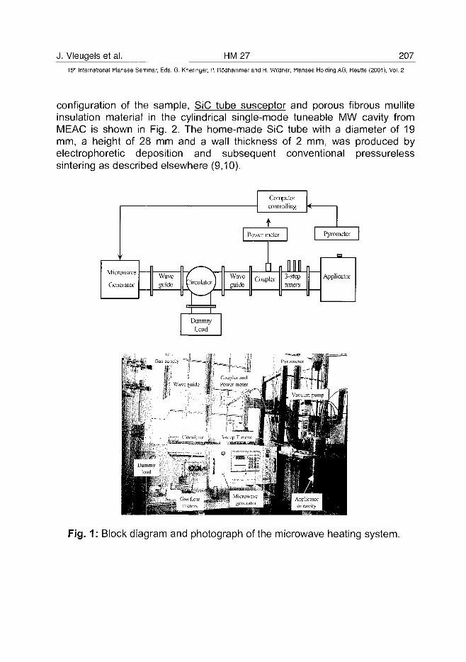
J. Vleugels et al. HM27 20715lh International Plansee Seminar, Eds. G. Kneringer, P. Rodhammer and H. Wildner, Plansee Holding AG, Reutte (2001), Vol. 2
configuration of the sample, SiC tube susceptor and porous fibrous mulliteinsulation material in the cylindrical single-mode tuneable MW cavity fromMEAC is shown in Fig. 2. The home-made SiC tube with a diameter of 19mm, a height of 28 mm and a wail thickness of 2 mm, was produced byelectrophoretic deposition and subsequent conventional pressurelesssintering as described elsewhere (9,10).
Computercontrolling
tPower meter Pyrometer
W a v e Coupler 3"stePguide tuners
Applicator
Coupler andWa\c guide M Pcmcrmetci
Fig. 1: Block diagram and photograph of the microwave heating system.
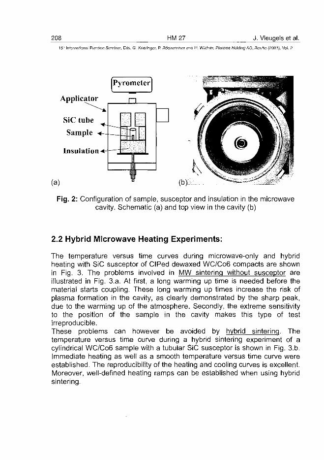
208 HM27 J. Vleugels et al.15" International Plansee Seminar, Eds. G. Kneringer, P. Rodhammer and H. Wildner, Plansee Holding AG, Reutte (2001), Vol. 2
Pyrometer
Applicator
SiC tube
Sample
Insulation
(a)
Fig. 2: Configuration of sample, susceptor and insulation in the microwavecavity. Schematic (a) and top view in the cavity (b)
2.2 Hybrid Microwave Heating Experiments:
The temperature versus time curves during microwave-only and hybridheating with SiC susceptor of CIPed dewaxed WC/C06 compacts are shownin Fig. 3. The problems involved in MW sintering without susceptor areillustrated in Fig. 3.a. At first, a long warming up time is needed before thematerial starts coupling. These long warming up times increase the risk ofplasma formation in the cavity, as clearly demonstrated by the sharp peak,due to the warming up of the atmosphere. Secondly, the extreme sensitivityto the position of the sample in the cavity makes this type of testirreproducible.These problems can however be avoided by hybrid sintering. Thetemperature versus time curve during a hybrid sintering experiment of acylindrical WC/C06 sample with a tubular SiC susceptor is shown in Fig. 3.b.Immediate heating as well as a smooth temperature versus time curve wereestablished. The reproducibility of the heating and cooling curves is excellent.Moreover, well-defined heating ramps can be established when using hybridsintering.
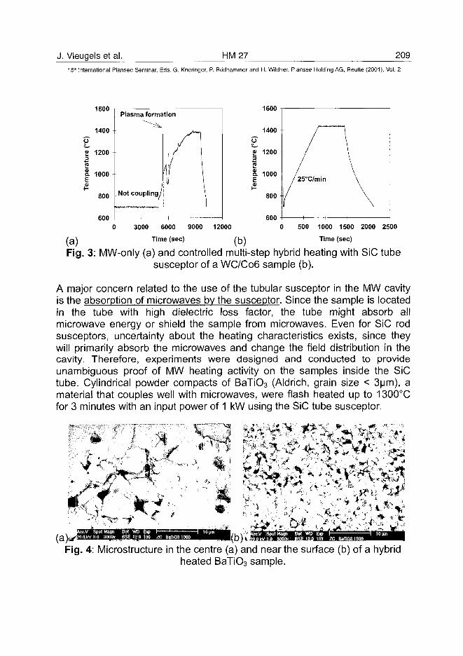
J. Vleugels et al. HM27 20915" International Plansee Seminar, Eds. G. Kneringer, P. Rbdhammer and H. Wildner, Plansee Holding AG, Reutte (2001), Vol. 2
1600
1400
p"1200
S. 1000
I800
600
Plasma formation
Not coupling,
1600
6000 3000 6000 9000 12000 0 500 1000 1500 2000 2500
/g\ Time (sec) lfo\ Time (sec)
Fig. 3: MW-only (a) and controlled multi-step hybrid heating with SiC tubesusceptor of a WC/C06 sample (b).
A major concern related to the use of the tubular susceptor in the MW cavityis the absorption of microwaves by the susceptor. Since the sample is locatedin the tube with high dielectric loss factor, the tube might absorb allmicrowave energy or shield the sample from microwaves. Even for SiC rodsusceptors, uncertainty about the heating characteristics exists, since theywill primarily absorb the microwaves and change the field distribution in thecavity. Therefore, experiments were designed and conducted to provideunambiguous proof of MW heating activity on the samples inside the SiCtube. Cylindrical powder compacts of BaTiO3 (Aldrich, grain size < 3um), amaterial that couples well with microwaves, were flash heated up to 1300°Cfor 3 minutes with an input power of 1 kW using the SiC tube susceptor.
-f(a)
cc,y SpotMagn Det WO Exp |-2O.akV3.O 3000X 8SE 12.9 130 ZC BaTlO31300
WD Bqp IE 13.0 133 ZC
Fig. 4: Microstructure in the centre (a) and near the surface (b) of a hybridheated BaTiO3 sample.
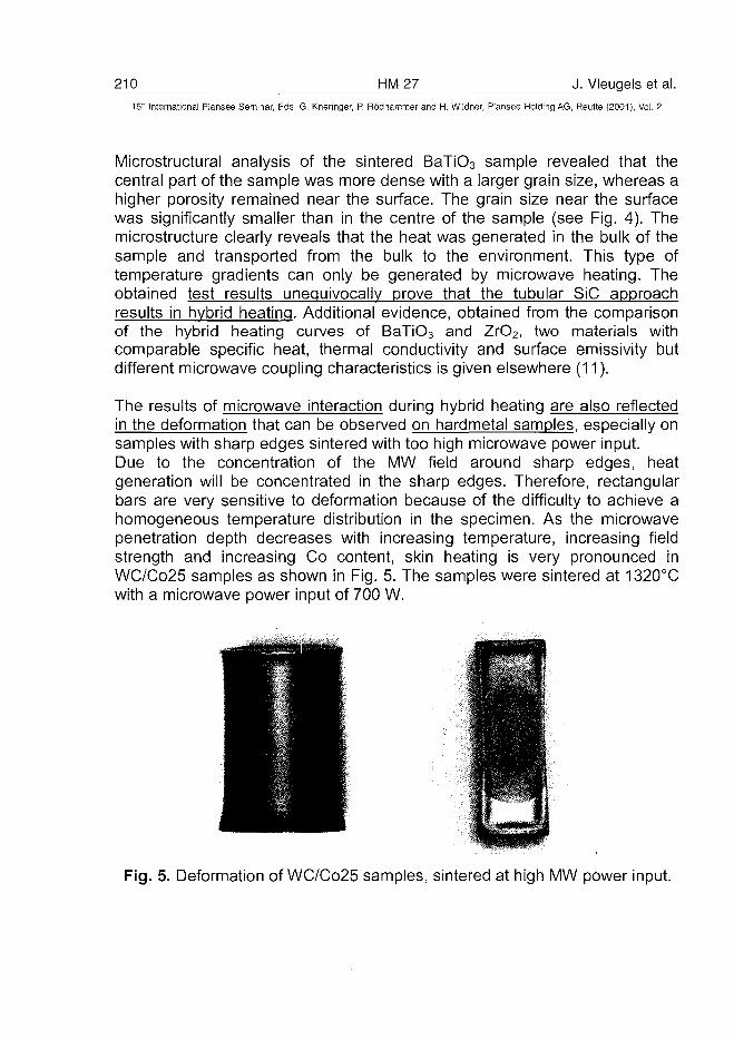
210 HM27 J. Vleugels et al.15" International Plansee Seminar, Eds. G. Kneringer, P. Rodhammer and H. Wildner, Piansee Holding AG, Reutte (2001), Vol. 2
Microstructural analysis of the sintered BaTiO3 sample revealed that thecentral part of the sample was more dense with a larger grain size, whereas ahigher porosity remained near the surface. The grain size near the surfacewas significantly smaller than in the centre of the sample (see Fig. 4). Themicrostructure clearly reveals that the heat was generated in the bulk of thesample and transported from the bulk to the environment. This type oftemperature gradients can only be generated by microwave heating. Theobtained test results unequivocally prove that the tubular SiC approachresults in hybrid heating. Additional evidence, obtained from the comparisonof the hybrid heating curves of BaTiO3 and ZrO2, two materials withcomparable specific heat, thermal conductivity and surface emissivity butdifferent microwave coupling characteristics is given elsewhere (11).
The results of microwave interaction during hybrid heating are also reflectedin the deformation that can be observed on hardmetal samples, especially onsamples with sharp edges sintered with too high microwave power input.Due to the concentration of the MW field around sharp edges, heatgeneration will be concentrated in the sharp edges. Therefore, rectangularbars are very sensitive to deformation because of the difficulty to achieve ahomogeneous temperature distribution in the specimen. As the microwavepenetration depth decreases with increasing temperature, increasing fieldstrength and increasing Co content, skin heating is very pronounced inWC/Co25 samples as shown in Fig. 5. The samples were sintered at 1320°Cwith a microwave power input of 700 W.
Fig. 5. Deformation of WC/Co25 samples, sintered at high MW power input.
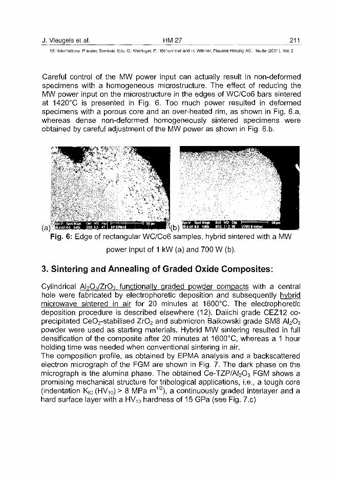
J. Vleugels et al. HM27 21115th International Plansee Seminar, Eds. G. Kneringer, P. Rodhammer and H. Wildner, Plansee Holding AG, Reutte (2001), Vol. 2
Careful control of the MW power input can actually result in non-deformedspecimens with a homogeneous microstructure. The effect of reducing theMW power input on the microstructure in the edges of WC/C06 bars sinteredat 1420°C is presented in Fig. 6. Too much power resulted in deformedspecimens with a porous core and an over-heated rim, as shown in Fig. 6.a,whereas dense non-deformed homogeneously sintered specimens wereobtained by careful adjustment of the MW power as shown in Fig. 6.b.
Fig. 6: Edge of rectangular WC/C06 samples, hybrid sintered with a MW
power input of 1 kW (a) and 700 W (b).
3. Sintering and Annealing of Graded Oxide Composites:
Cylindrical AbCVZrO? functionally graded powder compacts with a centralhole were fabricated by electrophoretic deposition and subsequently hybridmicrowave sintered in air for 20 minutes at 1600°C. The electrophoreticdeposition procedure is described elsewhere (12). Daiichi grade CEZ12 co-precipitated CeO2-stabilised ZrO2 and submicron Baikowski grade SM8 AI2O3
powder were used as starting materials. Hybrid MW sintering resulted in fulldensification of the composite after 20 minutes at 1600°C, whereas a 1 hourholding time was needed when conventional sintering in air.The composition profile, as obtained by EPMA analysis and a backscatteredelectron micrograph of the FGM are shown in Fig. 7. The dark phase on themicrograph is the alumina phase. The obtained Ce-TZP/AI2O3 FGM shows apromising mechanical structure for tribological applications, i.e., a tough core(indentation K|C (HV10) > 8 MPa m1/2), a continuously graded interlayer and ahard surface layer with a HV10 hardness of 15 GPa (see Fig. 7.c)
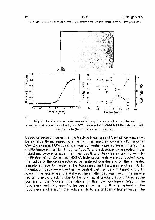
212 HM27 J. Vleugels et al.15* International Plansee Seminar, Eds. G. Kneringer, P. Rodhammer and H. Wildner, Plansee Holding AG, Reutte (2001), Vol. 2
0.0 0.5 2.5 3.0 0.5 1.0 1.5 2.0Radius (mm)
2.51.0 1.5 2.0
Radius (mm)
(b) (c)Fig. 7. Backscattered electron micrograph, composition profile and
mechanical properties of a hybrid MW sintered ZrO2/AI2O3 FGM cylinder withcentral hole (left hand side of graphs).
Based on recent findings that the fracture toughness of Ce-TZP ceramics canbe significantly increased by sintering in an inert atmosphere (13), anotherCe-TZP/alumina FGM cylindrical was conventially pressureless sintered in amuffle furnace in air for 1 hour at 1600°C and subsequently annealed in thehybrid microwave furnace in an inert gas flow of Ar (> 99.99 %) + 5 vol% N2
(> 99.999 %) for 20 min at 1450°C. Indentation tests were conducted alongthe radius of the cross-sectioned air sintered cylinder and on the annealedsample surface to measure the toughness and hardness profiles. 10 kgindentation loads were used in the central part (radius < 2.0 mm) and 5 kgloads in the region near the surface. The smaller load was used in the surfaceregion to avoid cracking due to the long radial cracks that originated at thecorners of the Vickers indentations in this low toughness region. Thetoughness and hardness profiles are shown in Fig. 8. After annealing, thetoughness profile along the radius shifts to a significantly higher value. The
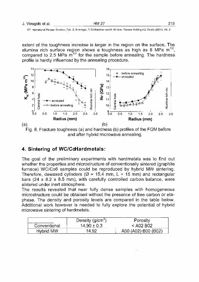
J. Vleugels et al. HM27 213
15'" International Plansee Seminar, Eds. G. Kneringer, P. Rodhammer and H. Wildner, Plansee Holding AG, Reutte (2001), Vol. 2
extent of the toughness increase is larger in the region on the surface. Thealumina rich surface region shows a toughness as high as 8 MPa m1/2
compared to 2.5 MPa m for the sample before annealing. The hardnessprofile is hardly influenced by the annealing procedure.
na.5
14
12
10
8
6
4
2
(a)
O
16 — • — annealed
§ — A —A—before annealing
°oo 0.5 1.0 1.5 2.0
Radius (mm)
16
15
14
CO i o
7 12
X 11
10
— A — before annealing— • — annealed
U
2.5 3.090.0
(b)
0.5 1.0 1.5 2.0 2.5
Radius (mm)3.0
Fig. 8. Fracture toughness (a) and hardness (b) profiles of the FGM beforeand after hybrid microwave annealing.
4. Sintering of WC/CoHardmetals:
The goal of the preliminary experiments with hardmetals was to find outwhether the properties and microstructure of conventionally sintered (graphitefurnace) WC/C06 samples could be reproduced by hybrid MW sintering.Therefore, dewaxed cylinders (0 = 15.4 mm, L = 15 mm) and rectangularbars (24 x 8.2 x 8.5 mm), with carefully controlled carbon balance, weresintered under inert atmosphere.The results revealed that near fully dense samples with homogeneousmicrostructure could be obtained without the presence of free carbon or eta-phase. The density and porosity levels are compared in the table below.Additional work however is needed to fully explore the potential of hybridmicrowave sintering of hardmetals.
ConventionalHybrid MW
Density (g/cm3)14.90 ±0.3
14.92
Porosity< A02 B02
A00 (A02) BOO (B02)
214 HM27 J. Vleugels et al.15r International Plansee Seminar, Eds. G. Kneringer, P. Rodhammer and H. Wildner, Plansee Holding AG, Reutte (2001), Vol. 2
5. Conclusions:
Hybrid microwave heating was established and experimentally proven in a2.45 GHz cylindrical single-mode tuneable MW applicator, using home-madeSiC tube susceptors.The experimental work revealed the possibility to fully density and annealZrO2-AI2O3 FGM materials as well as the densification of homogeneousWC/C06 hardmetals by means of hybrid MW heating.The advantages of the hybrid MW heating concept with a SiC tube over thatof microwave-only heating are:• Immediate heating of poor coupling materials.• Controllable and reproducible thermal cycles.• Strongly reduced or eliminated temperature gradient in the samples.• Re-heating of MW reflecting specimens is possible.• The tube susceptor has a correcting effect on the electromagnetic field,
resulting in a more uniform MW field distribution inside the tube.• SiC tubes can be used under inert atmosphere, vacuum as well as in air.• Heated samples are less susceptible to thermal shocks.
6. Acknowledgement:
This work was supported by the Brite-Euram program of the Commission ofthe European Communities under project contract No. BRPR-CT97-0505.
7. References:
1. A. Goldstein, A. Singurindi: J. Am. Ceram. Soc. 83 [6] (2000), pp. 1530-1532
2. T. Gerdes, M. Willert-Porada: Proc. of the Materials Research SocietySymposium: Microwave Processing of Materials IV, Vol 347, pp. 531-537(ed. M.F. Islander etal, MRS, Pittsburgh, Pennsylvania 1994)
3. T. Gerdes, M. Willert-Porada, K. Rodinger, H. Kolaska: In ..Microwaves:Theory and application in materials processing III" Ceramic TransactionsVol 59, pp. 423-431 (ed. D.E. Clarck et al. American Ceramic Society,Westerville, Ohio 1995)
4. D. Agrawal, J. Cheng, P. Seegopaul, L. Gao: Powder Metallurgy 43 [1](2000), pp. 15-16
J. Vleugels et al. HM 27 215^15'" International Plansee Seminar, Eds. G. Kneringer, P. Rodhammer and H. Wildner, Plansee Holding AG, Reutte (2001), Vol. 2
5. D. Agrawal, J. Cheng, A. Lackner, W. Ferstl: Proc. Euro PM 99, pp. 175-182. (EPMA, 1999)
6. M. Willert-Porada, T. Gerdes, R. Borchert: Proc. 3rd InternationalSymposium on Functional Gradient Materials pp. 15-20 (ed. B. llschner,N. Cherradi, Presses Polytechniques et Universitaires Romandes,Lausanne, Switzerland, 1994)
7. R. Roy, D. Agrawal, J. Cheng, S. Gedevanishvili: Nature 399 (1999), pp.668-670
8. T. Gerdes, M. Willert-Porada, K. Rodiger: Mat. Res. Soc. Symp. Proc. Vol430(1996), pp. 45-50.
9. L. Vandeperre, O. Van Der Biest, F. Bouyer, J. Persello, A. Foissy: J.Eur. Ceram. Soc. 17 (1997) pp. 373-376
10. L. Vandeperre, F. Bouyer, A. Foissy, O. Van Der Biest: Ceramic Bulletin,77(1) (1998), pp. 53-58
11. C. Zhao, J. Vleugels, O. Van Der Biest, C. Groffils, P.J. Luypaert: ActaMaterialia 48 [14] (2000), pp. 3795-3801
12. C. Zhao, J. Vleugels, L. Vandeperre, O. Van Der Biest: British CeramicTransactions 99 [6] (2000).
13. C. Zhao, J. Vleugels, B. Basu, O. Van Der Biest: Scripta Materialia 43(2000), pp. 1015-1020
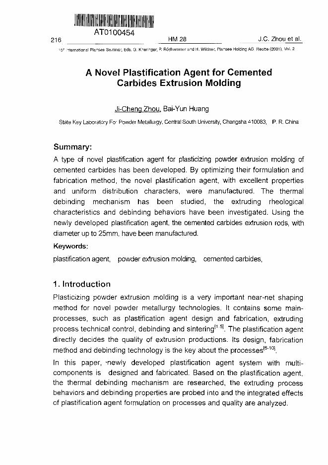
ATO100454216 HM 28 J.C. Zhou et al.
15" International Plansee Seminar, Eds. G. Kneringer, P. Rodhammer and H. Wildner, Plansee Holding AG, Reutte (2001), Vol. 2
A Novel Plastification Agent for CementedCarbides Extrusion Molding
Ji-Cheng Zhou, Bai-Yun Huang
State Key Laboratory For Powder Metallurgy, Central South University, Changsha 410083, P. R. China
Summary:A type of novel plastification agent for plasticizing powder extrusion molding ofcemented carbides has been developed. By optimizing their formulation andfabrication method, the novel plastification agent, with excellent propertiesand uniform distribution characters, were manufactured. The thermaldebinding mechanism has been studied, the extruding rheologicalcharacteristics and debinding behaviors have been investigated. Using thenewly developed plastification agent, the cemented carbides extrusion rods, withdiameter up to 25mm, have been manufactured.
Keywords:
plastification agent, powder extrusion molding, cemented carbides,
1. Introduction
Plasticizing powder extrusion molding is a very important near-net shapingmethod for novel powder metallurgy technologies. It contains some main-processes, such as plastification agent design and fabrication, extrudingprocess technical control, debinding and sintering11"51. The plastification agentdirectly decides the quality of extrusion productions. Its design, fabricationmethod and debinding technology is the key about the processes16"101.
In this paper, -newly developed plastification agent system with multi-components is designed and fabricated. Based on the plastification agent,the thermal debinding mechanism are researched, the extruding processbehaviors and debinding properties are probed into and the integrated effectsof plastification agent formulation on processes and quality are analyzed.
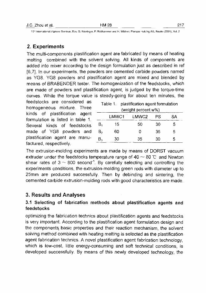
J.C. Zhou et al. HM 28 217^15* International Plansee Seminar, Eds. G. Kneringer, P. Rodhammer and H. Wildner, Plansee Holding AG, Reutte (2001), Vol. 2
2. ExperimentsThe multi-components plastification agent are fabricated by means of heatingmelting combined with the solvent solving. All kinds of components areadded into mixer according to the design formulation just as described in ref[6,7]. In our experiments, the powders are cemented carbide powders namedas YG8. YG8 powders and plastification agent are mixed and blended bymeans of BRABENDER tester. The homogenization of the feedstocks, whichare made of powders and plastification agent, is judged by the torque-timecurves. While the torque value is steady-going for about ten minutes, thefeedstocks are considered as T a b | e 1_ plastifiCation agent formulation
homogeneous m.xture. Three (weight percent w%)kinds of plastification agentformulation is listed in table 1.Several kinds of feedstocksmade of YG8 powders andplastification agent are manu-factured, respectively.
The extrusion-molding experiments are made by means of DORST vacuumextruder under the feedstocks temperature range of 40 ~ 80 °C and Newtonshear rates of 3 ~ 800 second"1. By carefully selecting and controlling theexperiments conditions, the extrusion-molding green rods with diameter up to25mm are produced successfully. Then by debinding and sintering, thecemented carbide extrusion-molding rods with good characteristics are made.
3. Results and Analyses3.1 Selecting of fabrication methods about plastification agents andfeedstocks
optimizing the fabrication technics about plastification agents and feedstocksis very important. According to the plastification agent formulation design andthe components, basic properties and their reaction mechanism, the solventsolving method combined with heating melting is selected as the plastificationagent fabrication technics. A novel plastification agent fabrication technology,which is low-cost, little energy-consuming and soft technical conditions, isdeveloped successfully. By means of this newly developed technology, the
Bi
B2
B3
LMWC1
15
60
30
LMWC2
50
0
35
PS
30
35
30
SA
5
5
5
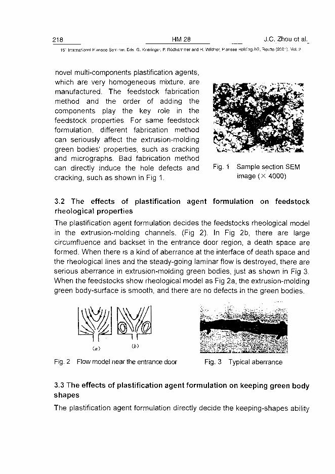
218 HM28 J.C. Zhou et al.15" International Plansee Seminar, Eds. G. Kneringer, P. Rodhammer and H. Wildner, Plansee Holding AG, Reutte (2001), Vol. 2
novel multi-components plastification agents,which are very homogeneous mixture, aremanufactured. The feedstock fabricationmethod and the order of adding thecomponents play the key role in thefeedstock properties For same feedstockformulation, different fabrication methodcan seriously affect the extrusion-moldinggreen bodies' properties, such as crackingand micrographs. Bad fabrication methodcan directly induce the hole defects andcracking, such as shown in Fig 1.
Fig. 1 Sample section SEMimage (X 4000)
3.2 The effects of plastification agent formulation on feedstockrheological properties
The plastification agent formulation decides the feedstocks rheological modelin the extrusion-molding channels. (Fig 2). In Fig 2b, there are largecircumfluence and backset in the entrance door region, a death space areformed. When there is a kind of aberrance at the interface of death space andthe rheological lines and the steady-going laminar flow is destroyed, there areserious aberrance in extrusion-molding green bodies, just as shown in Fig 3.When the feedstocks show rheological model as Fig 2a, the extrusion-moldinggreen body-surface is smooth, and there are no defects in the green bodies.
Fig. 2 Flow model near the entrance door Fig. 3 Typical aberrance
3.3 The effects of plastification agent formulation on keeping green bodyshapes
The plastification agent formulation directly decide the keeping-shapes ability
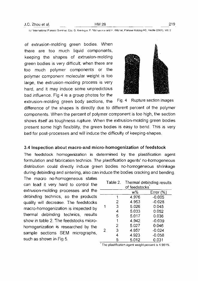
J.C. Zhou et a l . H M 2815" International Plansee Seminar, Eds. G. Kneringer, P. Rodhammer and H. Wildner, Plansee Holding AG, Reutte (2001), Vol. 2
of extrusion-molding green bodies. When
there are too much liquid components,keeping the shapes of extrusion-molding
green bodies is very difficult; when there aretoo much polymer components or thepolymer component molecular weight is toolarge, the extrusion-molding process is very
hard, and it may induce some unpredictousbad influence. Fig 4 is a group photos for theextrusion-molding green body sections, the Fi9- 4 Rupture section images
difference of the shapes is directly due to different percent of the polymercomponents. When the percent of polymer component is too high, the section
shows itself as toughness rupture. When the extrusion-molding green bodiespresent some high flexibility, the green bodies is easy to bend. This is verybad for post-processes and will induce the difficulty of keeping-shapes.
3.4 Inspection about macro-and micro-homogenization of feedstock
The feedstock homogenization is determined by the plastification agentformulation and fabrication technics. The plastification agents1 no-homogeneousdistribution could directly induce green bodies no-homogeneous shrinkageduring debinding and sintering, also can induce the bodies cracking and bending.The macro no-homogeneous statescan lead it very hard to control theextrusion-molding processes and thedebinding technics, so the productsquality will decrease. The feedstocksmacro-homogenization is inspected bythermal debinding technics, resultsshow in table 2. The feedstocks micro-homogenization is researched by thesample sections SEM micrographs,such as shown in Fig 5.
The plastification agent weight percent is 4.981%.
Table 2.
12
1 34512
2 345
Thermal debinding resultsof feedstocks'
w%4.9764.9535.0265.0335.0174.9425.0274.9574.9235.012
Error (%)-0.005-0.0280.0450.0520.036-0.0390.046-0.024-0.0580.031
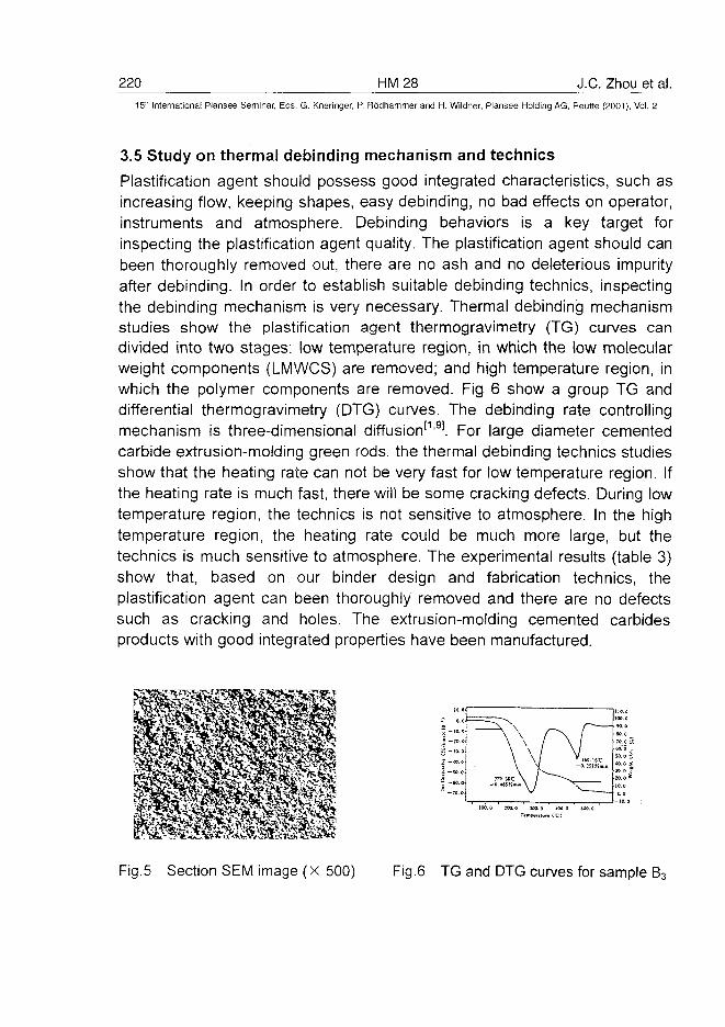
220 HM28 J.C. Zhou et al.15" International Plansee Seminar, Eds. G. Kneringer, P. Rodhammer and H. Wildner, Plansee Holding AG, Reutte (2001), Vol. 2
3.5 Study on thermal debinding mechanism and technics
Plastification agent should possess good integrated characteristics, such asincreasing flow, keeping shapes, easy debinding, no bad effects on operator,instruments and atmosphere. Debinding behaviors is a key target forinspecting the plastification agent quality. The plastification agent should canbeen thoroughly removed out, there are no ash and no deleterious impurityafter debinding. In order to establish suitable debinding technics, inspectingthe debinding mechanism is very necessary. Thermal debinding mechanismstudies show the plastification agent thermogravimetry (TG) curves candivided into two stages: low temperature region, in which the low molecularweight components (LMWCS) are removed; and high temperature region, inwhich the polymer components are removed. Fig 6 show a group TG anddifferential thermogravimetry (DTG) curves. The debinding rate controllingmechanism is three-dimensional diffusion'119]. For large diameter cementedcarbide extrusion-molding green rods, the thermal debinding technics studiesshow that the heating rate can not be very fast for low temperature region. Ifthe heating rate is much fast, there will be some cracking defects. During lowtemperature region, the technics is not sensitive to atmosphere. In the hightemperature region, the heating rate could be much more large, but thetechnics is much sensitive to atmosphere. The experimental results (table 3)show that, based on our binder design and fabrication technics, theplastification agent can been thoroughly removed and there are no defectssuch as cracking and holes. The extrusion-molding cemented carbidesproducts with good integrated properties have been manufactured.
iO.0
o.c
; -<o .o
-SO.O
-70.0
- o . usr.Du.
r\lV
' l« . 16C-o.;siriotin
100.0 M0.0
Fig.5 Section SEM image (x 500) Fig.6 TG and DTG curves for sample B3
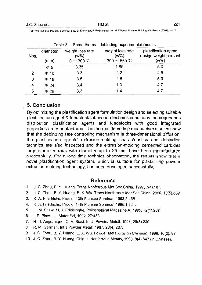
J.C. Zhou et al. HM 28 221
15* International Plansee Seminar, Eds. G. Kneringer, P. Rodhammer and H. Wildner, Plansee Holding AG, Reutte (2001), Vol. 2
Table 3. Some thermal debinding experimental results
Nos.
1
2
3
4
5
diameter
(mm)
<J> 5
O 10
<D 18
* 24
O 25
weight loss rate(w%)
0 ~ 300 °C
3.35
3.3
3.5
3.4
3.3
weight loss rate(w%)
300 ~ 550 °C
1.65
1.21.51.31.4
plastification agentdesign weight percent
(w%)
5.04.55.04.74.7
5. ConclusionBy optimizing the plastification agent formulation design and selecting suitableplastification agent & feedstock fabrication technics conditions, homogeneousdistribution plastification agents and feedstocks with good integratedproperties are manufactured. The thermal debinding mechanism studies showthat the debinding rate controlling mechanism is three-dimensional diffusion,the plastification agents' extrusion-molding characteristics and debindingtechnics are also inspected and the extrusion-molding cemented carbideslarge-diameter rods with diameter up to 25 mm have been manufacturedsuccessfully. For a long time technics observation, the results show that anovel plastification agent system, which is suitable for plasticizing powderextrusion molding technology, has been developed successfully.
Reference1. J. C. Zhou, B. Y. Huang. Trans Nonferrous Met Soc China, 1997, 7(4): 107.
2. J. C. Zhou, B. Y. Huang, E. X. Wu. Trans Nonferrous Met Soc China, 2000, 10(5):639
3. K. A. Friedrichs. Proc of 13th Plansee Seminar, 1993,2:468.
4. K. A. Friedrichs. Proc of 14th Plansee Seminar, 1995,1:321.
5. H. M. Shaw, M. J. Edirisihghe. Philosophical Magazine A, 1995, 72(1):267.
6. I. E. Pinwill. J. Mater Sci, 1992, 27:4381.
7. H. H. Angermgnn, O. V. Biest. Int J. Powder Metall. 1993, 29(3):239.
8. R. M. German. Int J Powder Metall, 1987, 23(4):237.
9. J. C. Zhou, B. Y. Huang, E. X. Wu. Powder Metallurgy (in Chinese), 1998, 16(2): 97.
10. J. C. Zhou, B. Y. Huang. Chin. J. Nonferrous Metals, 1998, 8(4):647 (in Chinese).
ATO100455222 HM29 G. Mori et al.
15" International Plansee Seminar, Eds. G. Kneringer, P. Rodhammer and H. Wildner, Plansee Holding AG, Reutte (2001), Vol. 2
Influencing the Corrosion Resistance of Cemented Carbidesby addition of Cr2C3, TiC and TaC
G. Mori*, H. Zitter*, A. Lackner**, M. Schretter**
*Department for General and Analytical Chemistry, University of Leoben,
A-8700 Leoben, Austria
"Plansee Tizit AG, A-6600 Reutte
Summary
Corrosion resistance of different cemented carbides has been investigated.As parameters different binder content and refractory metal carbide additionswere studied in various media with different pH values. As media 1n sulphuricacid, sodium sulphate and sodium hydroxide solution were used.An increase of pH shifted corrosion potential to more negative values due tolower current densities of cathodic reaction. Additions of refractory metalcarbides such as Cr3C2, TiC and TaC increased corrosion resistance. Theeffect of carbide addition is discussed.
Keywords
cemented carbides, hard metal, Cr3C2, TiC, TaC, corrosion resistance,corrosion, electrochemical behaviour, electrochemistry, potentiodynamicmeasurements, current density potential diagrams
1. Introduction
Several authors have investigated corrosion behaviour of cemented carbidesin the last years. Human, Exner et al. (1,2,3,4) systematically studied severalparameters such as grain size, binder content and binder composition.
G. Mori et al. HM 29 22315" International Plansee Seminar, Eds. G. Kneringer, P. Rodhammer and H. Wildner, Plansee Holding AG, Reutte (2001), Vol. 2
It has been found that grain size of WC had no influence on corrosionresistance (1). When increasing potential in 1n sulphuric acid from freecorrosion potential into the positive direction first only the binder starts tocorrode. Stern (5) already proposed for heterogeneous alloys the linear ruleof mixtures, which has been applied to cemented carbides by Human andExner (1,2) according to equation [1]:
:WC-C0 _ A WC ;WC , . Co ;CO m
I — M A " I T r\A ' L ' J
where iwc 'Co is the current density of WC-Co, AAWC, AA
Co are the cross-sectional area fractions of WC and Co phase respectively and iwc, iCo are thecurrent densities on WC and the binder metal. When keeping all otherparameters constant, an increase of binder content yields to an increase ofmass loss of the tested sample according to equation [1].The composition of binder is of focal importance for corrosion resistance ofcemented carbides. On the one hand the binder dissolves W and Cdepending from sintering conditions. The effect of dissolved WC has recentlybeen investigated (3). Corrosion properties of cemented carbides further canbe improved by changing binder composition (Ni instead of Co) (1,6,7) and byadding refractory metal carbides such as Cr3C2, TiC, TaC, VC and Mo2C tothe material.
The aim of the present paper is to give informations on the effect of Cr3C2,TiC and TaC with respect to corrosion resistance. Measurements were donein three different media varying the pH value since such data are rare inliterature and there is an increasing demand for use of cemented carbides indifferent media.
2. Experimental procedure
By using a conventional three electrode cell current density vs. potentialdiagrams have been measured at room temperature in deaerated solutions.As gas argon with a purity of 99.999 % was used. The reference electrode
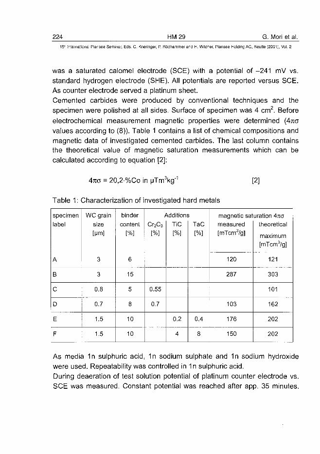
224 HM29 G. Mori et al.15" International Plansee Seminar, Eds. G. Kneringer, P. Rodhammer and H. Wildner, Plansee Holding AG, Reutte (2001), Vol. 2
was a saturated calomel electrode (SCE) with a potential of -241 mV vs.standard hydrogen electrode (SHE). All potentials are reported versus SCE.As counter electrode served a platinum sheet.Cemented carbides were produced by conventional techniques and thespecimen were polished at all sides. Surface of specimen was 4 cm2. Beforeelectrochemical measurement magnetic properties were determined (4KOvalues according to (8)). Table 1 contains a list of chemical compositions andmagnetic data of investigated cemented carbides. The last column containsthe theoretical value of magnetic saturation measurements which can becalculated according to equation [2]:
Awes = 20,2%Co in uTm3kg"
Table 1: Characterization of investigated hard metals
[2]
specimen
label
A
B
C
D
E
F
WC grain
size
[Mm]
3
3
0.8
0.7
1.5
1.5
binder
content
[%]
6
15
5
8
10
10
/
Cr2C3
[%]
0.55
0.7
\ddition:
TiC
[%]
0.2
4
TaC
[%]
0.4
8
magnetic satmeasured[mTcm3/g]
120
287
103
176
150
uration Ana
theoretical
maximum
[mTcm3/g]
121
303
101
162
202
202
As media 1n sulphuric acid, 1n sodium sulphate and 1n sodium hydroxidewere used. Repeatability was controlled in 1n sulphuric acid.During deaeration of test solution potential of platinum counter electrode vs.SCE was measured. Constant potential was reached after app. 35 minutes.
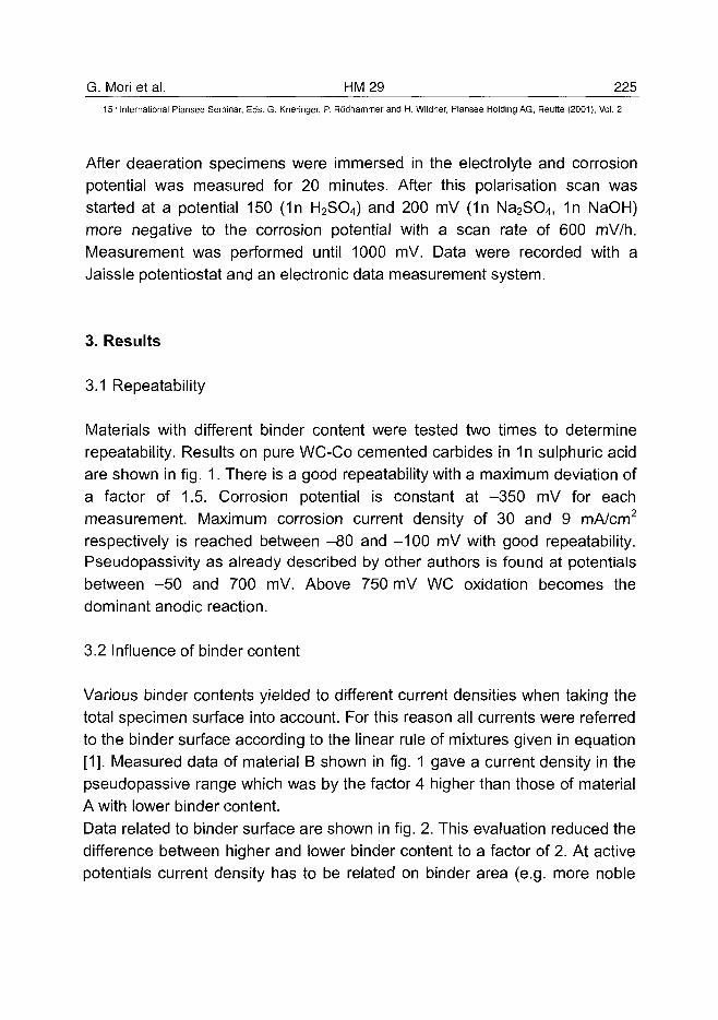
G. Mori et al. HM 29 22515'" International Plansee Seminar, Eds. G. Kneringer, P. Rodhammer and H, Wildner, Plansee Holding AG, Reutte (2001), Vol. 2
After deaeration specimens were immersed in the electrolyte and corrosionpotential was measured for 20 minutes. After this polarisation scan wasstarted at a potential 150 ("In H2SO4) and 200 mV ("In Na2SO4, "In NaOH)more negative to the corrosion potential with a scan rate of 600 mV/h.Measurement was performed until 1000 mV. Data were recorded with aJaissle potentiostat and an electronic data measurement system.
3. Results
3.1 Repeatability
Materials with different binder content were tested two times to determinerepeatability. Results on pure WC-Co cemented carbides in 1n sulphuric acidare shown in fig. 1. There is a good repeatability with a maximum deviation ofa factor of 1.5. Corrosion potential is constant at -350 mV for eachmeasurement. Maximum corrosion current density of 30 and 9 mA/cm2
respectively is reached between -80 and -100 mV with good repeatability.Pseudopassivity as already described by other authors is found at potentialsbetween -50 and 700 mV. Above 750 mV WC oxidation becomes thedominant anodic reaction.
3.2 Influence of binder content
Various binder contents yielded to different current densities when taking thetotal specimen surface into account. For this reason all currents were referredto the binder surface according to the linear rule of mixtures given in equation[1]. Measured data of material B shown in fig. 1 gave a current density in thepseudopassive range which was by the factor 4 higher than those of materialA with lower binder content.
Data related to binder surface are shown in fig. 2. This evaluation reduced thedifference between higher and lower binder content to a factor of 2. At activepotentials current density has to be related on binder area (e.g. more noble
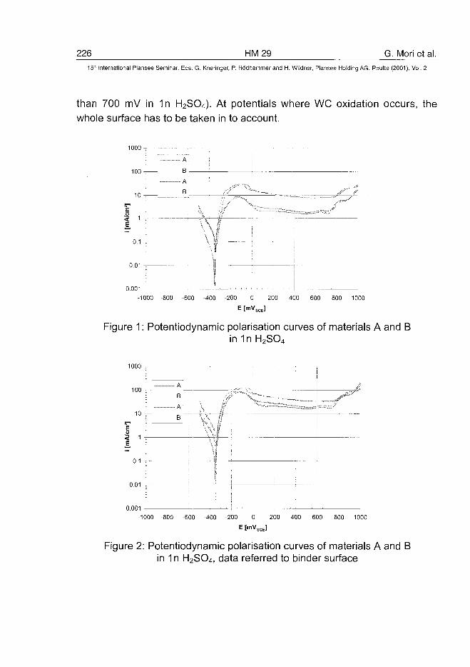
226 HM29 G. Mori et al.15" International Plansee Seminar, Eds. G. Kneringer, P. Rodhammer and H. Wildner, Plansee Holding AG, Reutte (2001), Vol. 2
than 700 mV in 1n H2SO4). At potentials where WC oxidation occurs, thewhole surface has to be taken in to account.
1000 -
B
4\ X
i
ii
0.1
0.01
0.001
-1000 -800 -600 -400 -200 0 200 400 600 800 1000
E [mVSCE]
Figure 1: Potentiodynamic polarisation curves of materials A and Bin 1n H2SO4
1000 T
100 v-
10 —
< 1E
0.1
If
0.01 !-
0.001
-1000 -800 -600 -400 -200 0 200 400 600 800 1000
E [mVSCE]
Figure 2: Potentiodynamic polarisation curves of materials A and Bin 1n H2SO4, data referred to binder surface
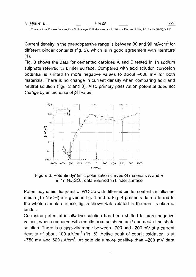
G. Mori et al. HM29 227
15" International Plansee Seminar, Eds. G. Kneringer, P. Rodhammer and H. Wildner, Plansee Holding AG, Reutte (2001), Vol. 2
Current density in the pseudopassive range is between 30 and 90 mA/cm2 fordifferent binder contents (fig. 2), which is in good agreement with literature
(1)-Fig. 3 shows the data for cemented carbides A and B tested in 1n sodiumsulphate referred to binder surface. Compared with acid solution corrosionpotential is shifted to more negative values to about -600 mV for bothmaterials. There is no change in current density when comparing acid andneutral solution (figs. 2 and 3). Also primary passivation potential does notchange by an increase of pH value.
1000 T
0.001-1000 -800 -600 -400 -200 0 200 400 600 800 1000
E [mVSCE]
Figure 3: Potentiodynamic polarisation curves of materials A and Bin 1 n Na2SO4, data referred to binder surface
Potentiodynamic diagrams of WC-Co with different binder contents in alkalinemedia (1n NaOH) are given in fig. 4 and 5. Fig. 4 presents data referred tothe whole sample surface, fig. 5 shows data related to the area fraction ofbinder.Corrosion potential in alkaline solution has been shifted to more negativevalues, when compared with results from sulphuric acid and neutral sulphatesolution. There is a passivity range between -700 and -200 mV at a currentdensity of about 100 \xAlcm2 (fig. 5). Active peak of cobalt oxidation is at-750 mV and 500 ^A/cm2. At potentials more positive than -200 mV data
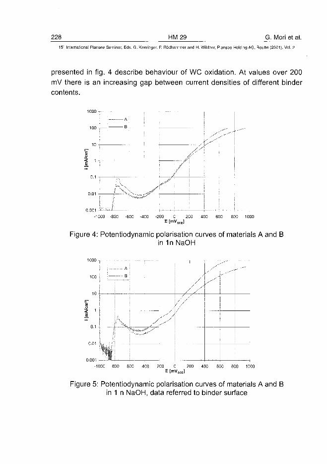
228 HM29 G. Mori et al.15'" International Plansee Seminar, Eds. G. Kneringer, P. Rodhammer and H. Wildner, Plansee Holding AG, Reutte (2001), Vol. 2
presented in fig. 4 describe behaviour of WC oxidation. At values over 200mV there is an increasing gap between current densities of different bindercontents.
1000 -=
100
0.001-1000 -800 -600 -400 -200 0 200 400 600 800 1000
E [mVSCE]
Figure 4: Potentiodynamic polarisation curves of materials A and Bin 1nNaOH
1000-
1 0 0 - : B
10 -4
<E
0.1
„,.-•' /
0.01 -i*
0.001
-1000 -800 -600 -400 -200 0 200 400 600 800 1000E [mVSCE]
Figure 5: Potentiodynamic polarisation curves of materials A and Bin 1 n NaOH, data referred to binder surface
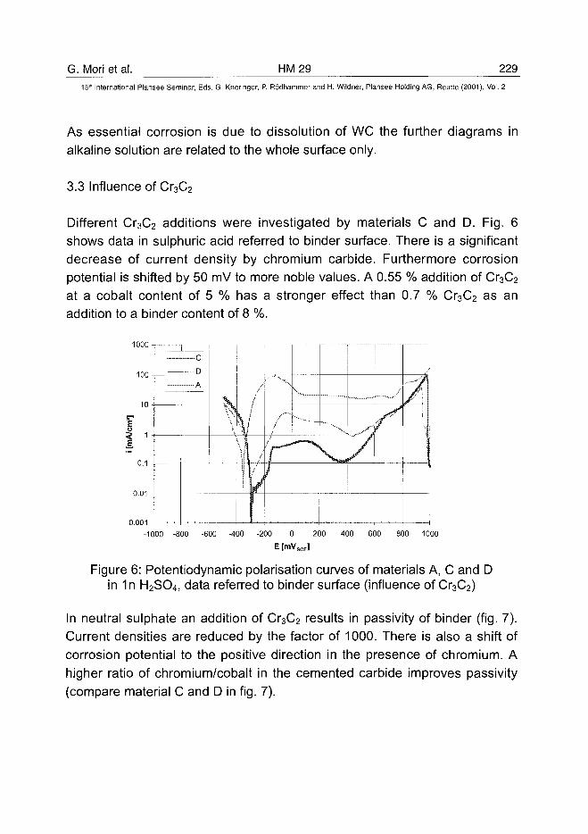
G. Mori et al. HM29 22915lh International Plansee Seminar, Eds. G. Kneringer, P. Rodhammer and H. Wildner, Plansee Holding AG, Reutte (2001), Vol. 2
As essential corrosion is due to dissolution of WC the further diagrams inalkaline solution are related to the whole surface only.
3.3 Influence of Cr3C2
Different Cr3C2 additions were investigated by materials C and D. Fig. 6shows data in sulphuric acid referred to binder surface. There is a significantdecrease of current density by chromium carbide. Furthermore corrosionpotential is shifted by 50 mV to more noble values. A 0.55 % addition of Cr3C2
at a cobalt content of 5 % has a stronger effect than 0.7 % Cr3C2 as anaddition to a binder content of 8 %.
1000!
0.001-1000 -800 -600 -400 -200 200 400 600 800 1000
E [mVSCE]
Figure 6: Potentiodynamic polarisation curves of materials A, C and Din 1n H2SO4, data referred to binder surface (influence of Cr3C2)
In neutral sulphate an addition of Cr3C2 results in passivity of binder (fig. 7).Current densities are reduced by the factor of 1000. There is also a shift ofcorrosion potential to the positive direction in the presence of chromium. Ahigher ratio of chromium/cobalt in the cemented carbide improves passivity(compare material C and D in fig. 7).
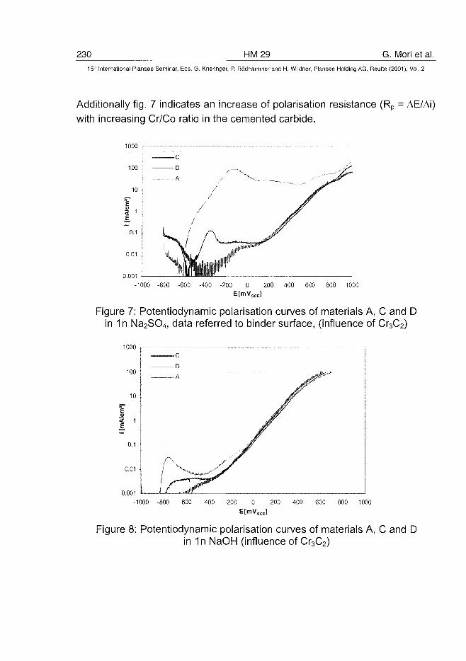
230 HM29 G. Mori et al.15" International Plansee Seminar, Eds. G. Kneringer, P. Rodhammer and H. Wildner, Plansee Holding AG, Reutte (2001), Vol. 2
Additionally fig. 7 indicates an increase of polarisation resistance (Rp = AE/Ai)with increasing Cr/Co ratio in the cemented carbide.
1000 r-
100
0.01
0.001-1000 -800 -600 -400 -200 0 200 400 600 800 1000
E[mVSCE]
Figure 7: Potentiodynamic polarisation curves of materials A, C and Din 1n Na2SO4, data referred to binder surface, (influence of Cr3C2)
1000
100 I
0.001
-1000 -800 -600 -400 -200 0 200 400 600 800 1000E[mVSCE]
Figure 8: Potentiodynamic polarisation curves of materials A, C and Din 1n NaOH (influence of Cr3C2)
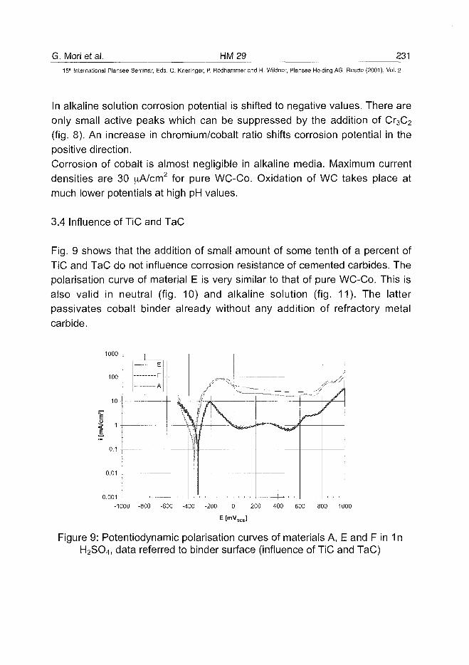
G. Mori et al. HM29 231
15" International Plansee Seminar, Eds. G. Kneringer, P. Rodhammer and H. Wildner, Plansee Holding AG, Reutte (2001), Vol. 2
In alkaline solution corrosion potential is shifted to negative values. There areonly small active peaks which can be suppressed by the addition of Cr3C2
(fig. 8). An increase in chromium/cobalt ratio shifts corrosion potential in thepositive direction.Corrosion of cobalt is almost negligible in alkaline media. Maximum currentdensities are 30 [iNcm2 for pure WC-Co. Oxidation of WC takes place atmuch lower potentials at high pH values.
3.4 Influence of TiC and TaC
Fig. 9 shows that the addition of small amount of some tenth of a percent ofTiC and TaC do not influence corrosion resistance of cemented carbides. Thepolarisation curve of material E is very similar to that of pure WC-Co. This isalso valid in neutral (fig. 10) and alkaline solution (fig. 11). The latterpassivates cobalt binder already without any addition of refractory metalcarbide.
1000 t
100
10 [
J• ' — A
0.1 4
0.01
0.001 —
-1000 -800 -600 -400 -200 0 200 400 600 800 1000
E [mVSCE]
Figure 9: Potentiodynamic polarisation curves of materials A, E and F in 1nH2SO4, data referred to binder surface (influence of TiC and TaC)
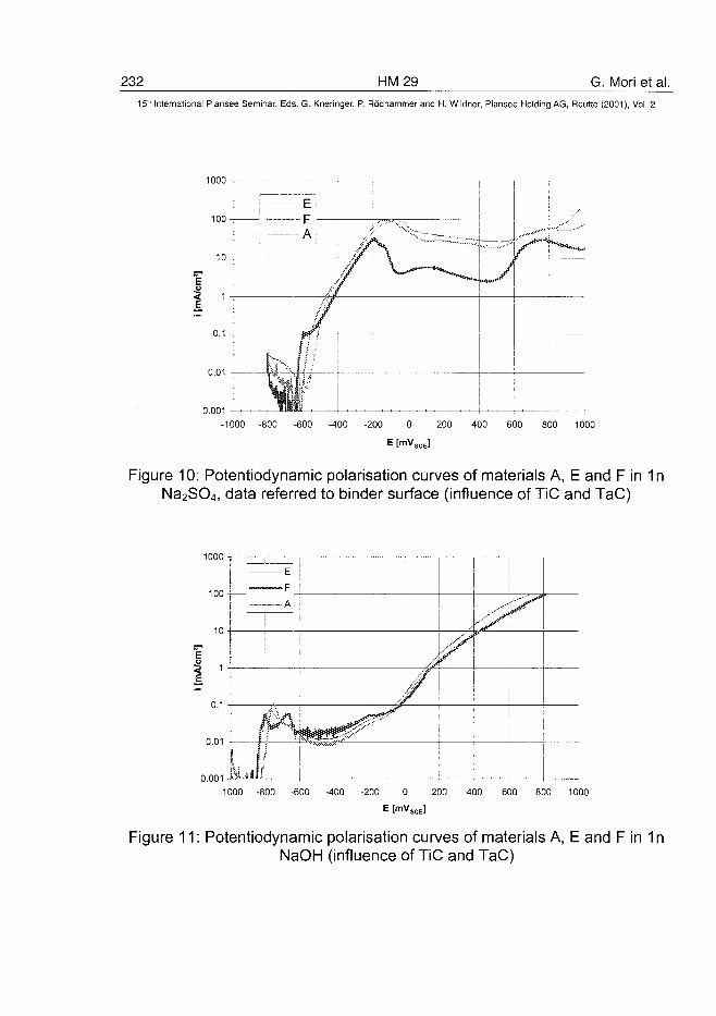
232 HM29 G. Mori et al.15" International Plansee Seminar, Eds. G. Kneringer, P. Rodhammer and H. Wildner, Plansee Holding AG, Reutte (2001), Vol. 2
1000 -=
100
0.1 -5
0.01
0.001-1000 -800 -600 -400 -200 0 200 400 600 800 1000
E [mVSCE]
Figure 10: Potentiodynamic polarisation curves of materials A, E and F in 1nNa2SO4, data referred to binder surface (influence of TiC and TaC)
1000 T
100
0.001 -f
-1000 -800 -600 -400 -200 0 200 400 600 800 1000
E [mVSCE]
Figure 11: Potentiodynamic polarisation curves of materials A, E and F in 1nNaOH (influence of TiC and TaC)
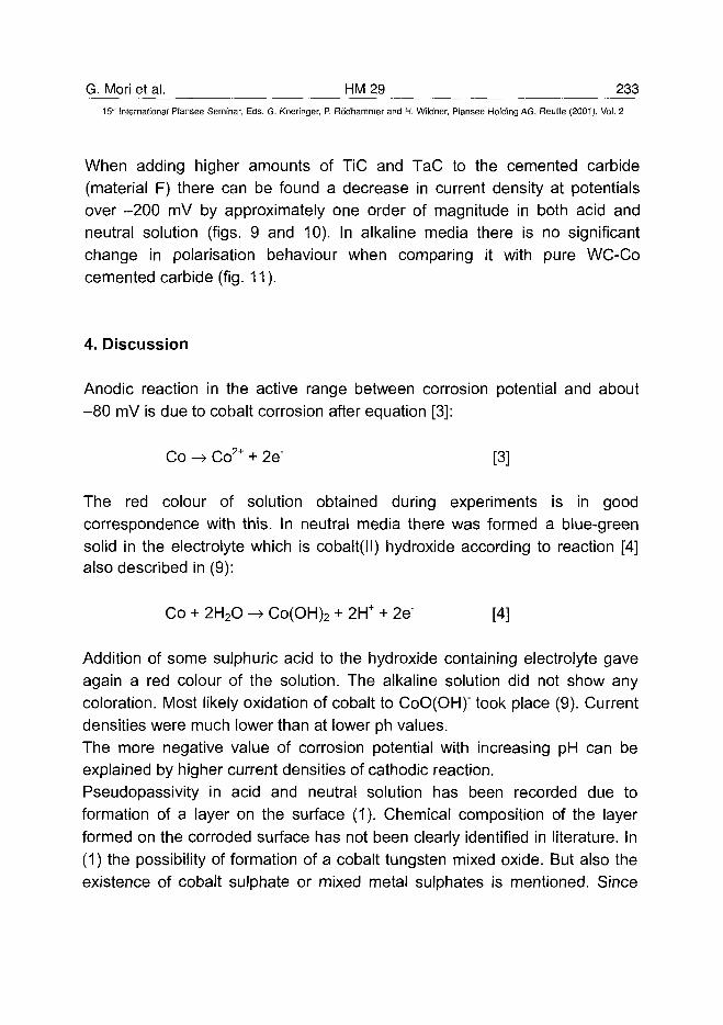
G. Mori et al. HM 29 233^15'" International Plansee Seminar, Eds. G. Kneringer, P. Rodhammer and H. Wildner, Plansee Holding AG, Reutte (2001), Vol. 2
When adding higher amounts of TiC and TaC to the cemented carbide(material F) there can be found a decrease in current density at potentialsover -200 mV by approximately one order of magnitude in both acid andneutral solution (figs. 9 and 10). In alkaline media there is no significantchange in polarisation behaviour when comparing it with pure WC-Cocemented carbide (fig. 11).
4. Discussion
Anodic reaction in the active range between corrosion potential and about-80 mV is due to cobalt corrosion after equation [3]:
Co -> Co2+ + 2e" [3]
The red colour of solution obtained during experiments is in goodcorrespondence with this. In neutral media there was formed a blue-greensolid in the electrolyte which is cobalt(ll) hydroxide according to reaction [4]also described in (9):
Co + 2H2O -» Co(OH)2 + 2H+ + 2e" [4]
Addition of some sulphuric acid to the hydroxide containing electrolyte gaveagain a red colour of the solution. The alkaline solution did not show anycoloration. Most likely oxidation of cobalt to CoO(OH)" took place (9). Currentdensities were much lower than at lower ph values.The more negative value of corrosion potential with increasing pH can beexplained by higher current densities of cathodic reaction.Pseudopassivity in acid and neutral solution has been recorded due toformation of a layer on the surface (1). Chemical composition of the layerformed on the corroded surface has not been clearly identified in literature. In(1) the possibility of formation of a cobalt tungsten mixed oxide. But also theexistence of cobalt sulphate or mixed metal sulphates is mentioned. Since
234 HM29 G. Mori et al.15" International Plansee Seminar, Eds. G. Kneringer, P. Rodhammer and H. Wildner, Plansee Holding AG, Reutte (2001), Vol. 2
our experiments show the same behaviour of pseudopassivity in acid andneutral sulphate solution as well, a sulphate formation can not be excluded.Oxidation of WC already has been identified by other authors as the anodicreaction which becomes significantly important at potentials more positivethan 750 mV in 1n H2SO4 (equation [5]):
WC + 5H2O -> WO3 + CO2 + 10H+ + 10e" [5]
An increase of pH shifts the reaction to more negative potentials. This alsocan be concluded from data in (9).The addition of Cr3C2 reduces significantly current densities several orders ofmagnitude and there occurs true passive behaviour. The reason for this is thedissolution of chromium in the binder during sintering and the formation of apassive film on the surface of the binder. A high fraction of added chromiumis found in the binder after sintering as a solid solution. These results wereobtained by TEM analysis with binders at different chromium concentrationsand also by other authors (10,11). Passivity in the presence of chromium hasbeen obtained in all tested electrolytes (figs. 6, 7 and 8). Corrosion potentialis shifted to more noble values in the presence of chromium, which also canbe explained by passive layer formation of chromium containing cobalt.Alloy C has a lower current density than alloy D even after relation of data tobinder surface. This is most probably due to the higher Cr/Co ratio in thebinder.
Small additions of TiC and TaC have no influence on corrosion resistance.Alloy F has a lower current density in the active and pseudopassive range byabout one order of magnitude. When comparing highly W and C containingalloys with pure cobalt metal there is no sharp decrease in current densitiesthroughout the whole potential range (3). As a consequence the effect ofcurrent decrease is due to TiC and TaC addition. This effect is not fullyunderstood now. TiC and TaC may also be partly dissolved in the binder. Incontradiction to Cr3C2, which is mainly dissolved in the binder TiC and TaCare also significantly precipitated in cemented carbides. They already can be
G. Mori et al. HM 29 235^15'h International Plansee Seminar, Eds. G. Kneringer, P. Rodhammer and H. Wildner, Plansee Holding AG, Reutte (2001), Vol. 2
identified by optical microscopy. Dissolution of TiC and TaC in the binder willbe investigated in future by TEM analysis.
5. Conclusions and outlook
The following results have been obtained in the present work:
- Corrosion of cemented carbide is determined by dissolution of binder inacid and neutral solution at lower potentials. In alkaline solution WC isdissolved at higher potentials.
- Increasing pH value shifts corrosion potential to the more negativdirection. In alkaline media there is a passive behaviour. In acidic andneutral pure WC-Co alloys show pseudopassivity.
- Cr3C2 increases corrosion resistance of binder materials due topassivation of cobalt.
- Substantial amounts of TiC and TaC also improve corrosion resistance.This mechanism is not fully clear now.
Future work will be focused to characterize mechanism of pseudopassivityand the function of further refractory metal carbide additions.
References
(1) A.M. Human and H.E. Exner, International Journal of Refractory Metalsand Hard Materials 15 (1997), 65-71(2) A.M. Human and H.E. Exner, Materials Science and Engineering A209(1996), 180-191(3) A.M. Human, B. Roebuck and H.E. Exner, Materials Science andEngineering A241 (1998), 202-210(4) A.M. Human, Doctoral thesis, Technical University of Darmstadt, 1994(5) M. Stern, Corrosion 14 (1958), 329t-332t(6) E.J. Wentzel and C. Allen, International Journal of Refractory Metals andHard Materials 15 (1997), 81-87
236 HM29 G. Mori et al.15" International Plansee Seminar, Eds. G. Kneringer, P. Rodhammer and H. Wildner, Plansee Holding AG, Reutte (2001), Vol. 2
(7) H. Fordsmand, E. Galli and K.A. Thorsen, Proc. 12th Int. Plansee Seminar,Vol. 2, 429-447 (ed. H. Bildstein et al., Plansee AG, Reutte 1989)(8) J. Freytag, P. Walter and H.E. Exner, Zeitschrift fur Metallkunde 69(1978), 546-549(9) M. Pourbaix, Atlas of electrochemical equilibria in aqueous solutions,NACE, 2nd edition, 1974(10) S. Imisato, S. Sakaguchi and Y. Hayashi, Nippon Tungsten Review 29(1997), 39-46(11) J.S. Bai, Z.K. Feng, H.N. Zhang and S.T. Shen, Powder MetallurgyTechnology 11 (1993), 43-46
AT0100456B. Roebuck et al. HM 30 237
15" International Plansee Seminar, Eds. G. Kneringer, P. Rodhammer and H. Wildner, Plansee Holding AG, Reutte (2001), Vol. 2
A SCANNING DEPTH SENSING HARDNESS TEST
SYSTEM TO CHARACTERISE HARDMETALS
B Roebuck, M Stewart, M G Gee and E G Bennett
NPL Materials Centre
National Physical Laboratory, Teddington, Middlesex TW11 0LW, UK
Summary
Newer grades of hardmetals, including materials with non-standardmicrostructures, with graded compositions and complex coatings need to becharacterised for their spatial variation in mechanical properties, particularlyhardness. A new test machine has been developed for this purpose thatuses depth sensing hardness because the measurement process can beautomated. The system was developed with a high speed facility to maplarge areas quickly and force and displacement are monitored continuouslyduring the complete indentation cycle. The machine operates in the range0.05-20N with a load resolution of 2 mN and a depth sensing resolution of20 nm using a specially designed capacitance displacement sensor.Typically a matrix of 30 x 30 indents using a diamond indenter can beperformed in about 2.5h.
Two case studies were developed to evaluate the test machine capability. Amaterial with an unconventional WC grain size distribution was comparedwith a standard WC/Co grade. The system was used to provide informationon the uniformity of the structure, mapping hardness at an appropriate scale.A coated hardmetal was also tested to evaluate the ability of the hardnesstester to map variations in hardness through the coating into the substrate.
KEYWORDS: Microhardness; Property Maps; Hardmetals; Coatings
238 HM30 B. Roebuck et al.15" International Plansee Seminar, Eds. G. Kneringer, P. Rodhammer and H. Wildner, Plansee Holding AG, Reutte (2001), Vol. 2
1 Introduction
Measurement of the hardness of materials is a quick and simple method ofobtaining mechanical property data from a small sample. The traditionalmethod relies on an optical measurement of the projected area of thehardness indent by a trained operator. This can give rise to a large scatter inresults because it is typically operator dependent. More recently, with theadvance of computer aided measurement electronics and availability ofsensitive displacement measurement transducers, systems are increasinglymeasuring the depth of the indent rather than the area (1,2). The majoradvantage of this method is that dynamic measurements can be performed(i.e. a load vs displacement curve), and also the subjectivity of the operator isremoved. Most of the advances in depth sensing machines have been invery small load systems, nano-hardness, where it would otherwise be difficultto measure the projected area without using electron microscopy (3). Incomparison many macro hardness machines still rely on opticalmeasurements for reasons of cost and compatibility with standards.
The concept behind the NPL scanning indentation mapping microhardnesssystem is to use depth sensing methods on a microhardness scale, coupledwith an X-Y scanning stage, and improved speed of indentation. This meansthat measurements can be made anywhere on the sample, quickly andwithout operator intervention, and the use of microhardness means that thesize of the indents can be of the order of the microstructure of the material.Potential uses for the method are:-
• Determine the hardness of individual phases in a multi-phase system bydoing a statistically significant number of indents.
• Measure the hardness in a homogeneous material to estimate the strainfield.
• Measure the spatial hardness variation in an inhomogeneous material forexample coatings, castings, welds and heat treated materials.
This paper reports two feasibility studies on hardmetal structures to assessthe system performance. Also, a detailed series of tests were performed tocalibrate the system in comparison with conventional microhardness tests.
B, Roebuck et al. HM 30 23915" International Plansee Seminar, Eds. G. Kneringer, P. Rodhammer and H. Wildner, Plansee Holding AG, Reutte (2001), Vol. 2
2 System Design and Operation
The basis for the system is three linear slides that provide the X, Y and Zmovement, (Fig 1). Each slide is driven by a 1 mm pitch screw thread,powered by a servo controlled DC motor. These are controlled by feedbackfrom a linear capacitance displacement transducer, positioned on theopposite side to the motor drive. The load is measured with a conventionalstrain gauged load cell, and the Vickers indenter was taken from aconventional microhardness system.
The motor feedback system uses a rotary encoder with 500 lines perrevolution on the shaft, and each motor is controlled by an independentmicroprocessor. Coupled with the reduction gears this gives a potential stagepositioning resolution of about 0.1 micrometre, but since the drive is based ona 1 mm pitch thread a figure of 0.5-1 micrometre is probably more realistic.Although it is still possible to measure the actual position of any stage usingdisplacement transducers it was considered sufficient simply to use thecounts from the rotary encoder to indicate position.
The loading mechanism uses a piezoelectric actuator. A piezoelectric systemhas the potential to be quick, with a high resolution. However, the maindrawback is a limited range of around 60 pirn. The complete assembly ismounted on a motorised Z stage. The motor is driven to within a fewmicrometres of the surface, and the piezoelectric mechanism is used toperform the indentation. From this position the Z motor is only used toaccommodate any roughness or misalignment of the sample surface.
To operate the system the piezoelectric actuator is expanded by theapplication of a high voltage, and this causes the indenter to move towardsthe sample. The motion of the indenter is measured by the capacitancetransducer and is a measurement relative to a static capacitance plate whichis in turn mechanically connected to the sample surface. When the indentertouches the sample surface a load is registered on the load cell. Loading iscontinued until the desired load is reached. The design of the loadingmechanism is such that although the strain gauge load cell is effectively a softspring, the compression of the load cell does not register on the displacementmeasurement system as the load cell is above the capacitance transducers,(Fig 1). This means that there is no need to correct for the load cell stiffnessin the final load against displacement curves.
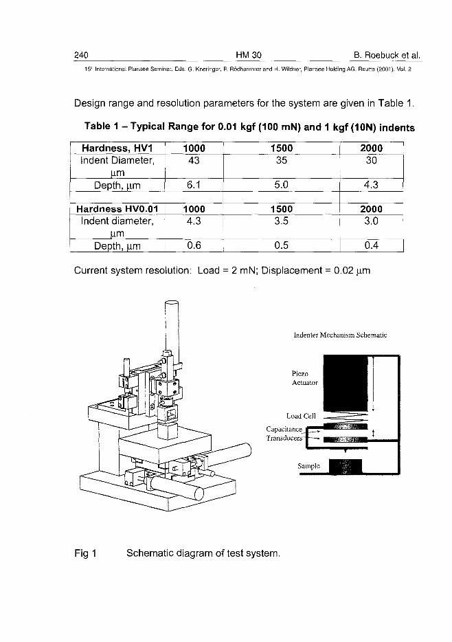
240 HM30 B. Roebuck et al.15th International Plansee Seminar, Eds. G. Kneringer, P. Rodhammer and H. Wildner, Plansee Holding AG, Reutte (2001), Vol. 2
Design range and resolution parameters for the system are given in Table 1.
Table 1 - Typical Range for 0.01 kgf (100 mN) and 1 kgf (10N) indents
Hardness, HV1Indent Diameter,
limDepth, |im
Hardness HV0.01Indent diameter,
|imDepth, |im
100043
6.1
10004.3
0.6
150035
5.0
15003.5
0.5
200030
4.3
20003.0
0.4
Current system resolution: Load = 2 mN; Displacement = 0.02 |a.m
Indenter Mechanism Schematic
CapacitanceTransducers
Fig 1 Schematic diagram of test system.
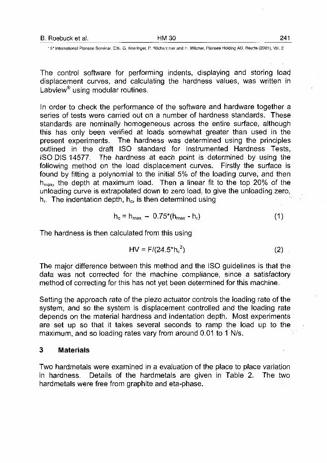
B. Roebuck et al. HM 30 24115th International Plansee Seminar, Eds. G. Kneringer, P. Rodhammer and H. Wildner, Plansee Holding AG, Reutte (2001), Vol. 2
The control software for performing indents, displaying and storing loac)displacement curves, and calculating the hardness values, was written inLabview® using modular routines.
In order to check the performance of the software and hardware together aseries of tests were carried out on a number of hardness standards. Thesestandards are nominally homogeneous across the entire surface, althoughthis has only been verified at loads somewhat greater than used in thepresent experiments. The hardness was determined using the principlesoutlined in the draft ISO standard for Instrumented Hardness Tests,ISO DIS 14577. The hardness at each point is determined by using thefollowing method on the load displacement curves. Firstly the surface isfound by fitting a polynomial to the initial 5% of the loading curve, and thenhmax, the depth at maximum load. Then a linear fit to the top 20% of theunloading curve is extrapolated down to zero load, to give the unloading zero,hr. The indentation depth, hc, is then determined using
hc = h m a x - 0.75*(hmax - hr) (1)
The hardness is then calculated from this using
HV = F/(24.5*hc2) (2)
The major difference between this method and the ISO guidelines is that thedata was not corrected for the machine compliance, since a satisfactorymethod of correcting for this has not yet been determined for this machine.
Setting the approach rate of the piezo actuator controls the loading rate of thesystem, and so the system is displacement controlled and the loading ratedepends on the material hardness and indentation depth. Most experimentsare set up so that it takes several seconds to ramp the load up to themaximum, and so loading rates vary from around 0.01 to 1 N/s.
3 Materials
Two hardmetals were examined in a evaluation of the place to place variationin hardness. Details of the hardmetals are given in Table 2. The twohardmetals were free from graphite and eta-phase.
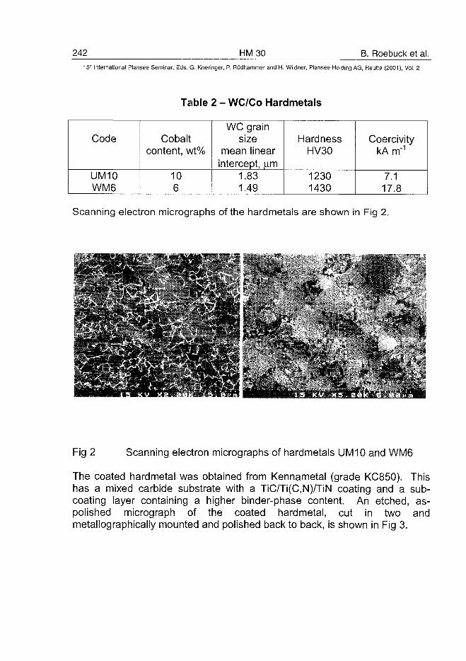
242 HM30 B. Roebuck et al.5W International Plansee Seminar, Eds. G. Kneringer, P. Rddhammer and H. Wildner, Plansee Holding AG, Reutte (2001), Vol. 2
Table 2 - WC/Co Hardmetals
Code
UM10WM6
Cobaltcontent, wt%
106
WC grainsize
mean linearintercept, ujn
1.831.49
HardnessHV30
12301430
CoercivitykAm"1
7.117.8
Scanning electron micrographs of the hardmetals are shown in Fig 2.
<V - , • • " " "IT
V
- *
Fig 2 Scanning electron micrographs of hardmetals UM10 and WM6
The coated hardmetal was obtained from Kennametal (grade KC850). Thishas a mixed carbide substrate with a TiC/Ti(C,N)/TiN coating and a sub-coating layer containing a higher binder-phase content. An etched, as-polished micrograph of the coated hardmetal, cut in two andmetallographically mounted and polished back to back, is shown in Fig 3.
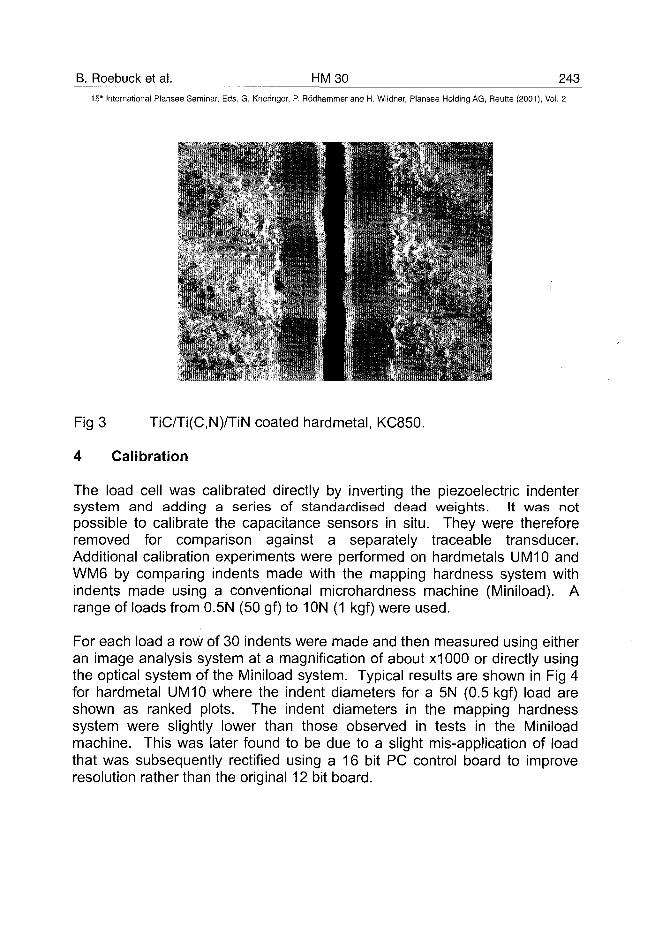
B. Roebuck et al. HM 30 243_
15* International Plansee Seminar, Eds. G. Kneringer, P. Rodhammer and H. Wildner, Plansee Holding AG, Reutte (2001), Vol. 2
"I • "r?".. •'
S
•
Fig 3 TiC/Ti(C,N)/TiN coated hardmetal, KC850.
4 Calibration
The load cell was calibrated directly by inverting the piezoelectric indentersystem and adding a series of standardised dead weights. It was notpossible to calibrate the capacitance sensors in situ. They were thereforeremoved for comparison against a separately traceable transducer.Additional calibration experiments were performed on hardmetals UM10 andWM6 by comparing indents made with the mapping hardness system withindents made using a conventional microhardness machine (Miniload). Arange of loads from 0.5N (50 gf) to 10N (1 kgf) were used.
For each load a row of 30 indents were made and then measured using eitheran image analysis system at a magnification of about x1000 or directly usingthe optical system of the Miniload system. Typical results are shown in Fig 4for hardmetal UM10 where the indent diameters for a 5N (0.5 kgf) load areshown as ranked plots. The indent diameters in the mapping hardnesssystem were slightly lower than those observed in tests in the Miniloadmachine. This was later found to be due to a slight mis-application of loadthat was subsequently rectified using a 16 bit PC control board to improveresolution rather than the original 12 bit board.
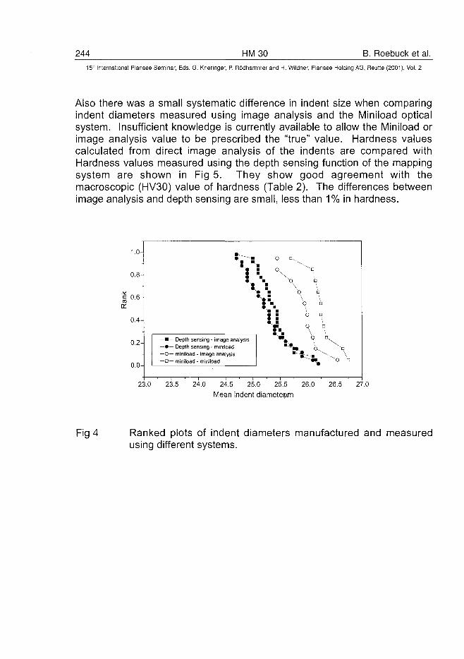
244 HM30 B. Roebuck et al.15~ International Plansee Seminar, Eds. G. Kneringer, P. Rodhammer and H. Wildner, Plansee Holding AG, Reutte (2001), Vol. 2
Also there was a small systematic difference in indent size when comparingindent diameters measured using image analysis and the Miniioad opticalsystem. Insufficient knowledge is currently available to allow the Miniioad orimage analysis value to be prescribed the "true" value. Hardness valuescalculated from direct image analysis of the indents are compared withHardness values measured using the depth sensing function of the mappingsystem are shown in Fig 5. They show good agreement with themacroscopic (HV30) value of hardness (Table 2). The differences betweenimage analysis and depth sensing are small, less than 1% in hardness.
1.0-
0.8-
01
0.4-
0.2-
0.0-
•— Depth sensing - image analysis»— Depth sensing - miniioad
-O— miniioad - image analysis- D — miniioad - miniioad
o
u
23.0 23.5 24.0 24.5 25.0 25.5 26.0
Mean indent diameteiftfn
26.5 27.0
Fig 4 Ranked plots of indent diameters manufactured and measuredusing different systems.
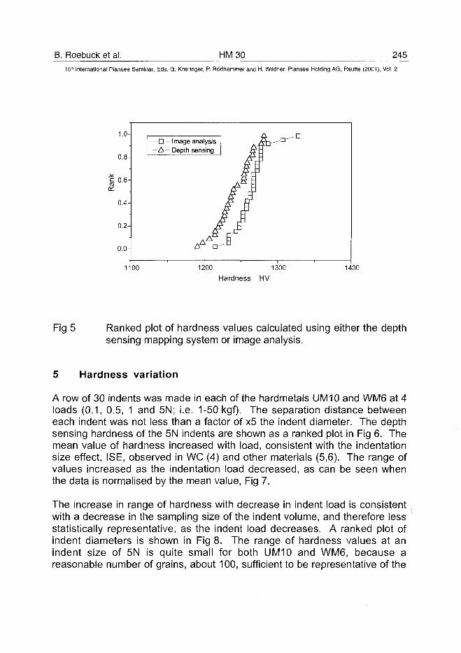
B. Roebuck et al. HM30 24515" International Plansee Seminar, Eds. G. Kneringer, P. Rodhammer and H. Wildner, Plansee Holding AG, Reutte (2001), Vol. 2
1.0-
0.8-
J°.«H0.4-
0.2-
0.0-
— • — Image analysis
—A— Depth sensing
1100 1200 1300
Hardness HV1400
Fig 5 Ranked plot of hardness values calculated using either the depthsensing mapping system or image analysis.
5 Hardness variation
A row of 30 indents was made in each of the hardmetals UM10 and WM6 at 4loads (0.1, 0.5, 1 and 5N; i.e. 1-50 kgf). The separation distance betweeneach indent was not less than a factor of x5 the indent diameter. The depthsensing hardness of the 5N indents are shown as a ranked plot in Fig 6. Themean value of hardness increased with load, consistent with the indentationsize effect, ISE, observed in WC (4) and other materials (5,6). The range ofvalues increased as the indentation load decreased, as can be seen whenthe data is normalised by the mean value, Fig 7.
The increase in range of hardness with decrease in indent load is consistentwith a decrease in the sampling size of the indent volume, and therefore lessstatistically representative, as the indent load decreases. A ranked plot ofindent diameters is shown in Fig 8. The range of hardness values at anindent size of 5N is quite small for both UM10 and WM6, because areasonable number of grains, about 100, sufficient to be representative of the
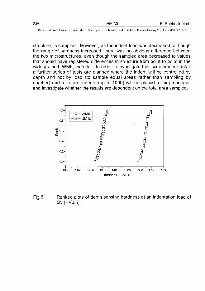
246 HM30 B. Roebuck et al.15" International Plansee Seminar, Eds. G. Kneringer, P. Rodhammer and H. Wildner, Plansee Holding AG, Reutte (2001), Vol. 2
structure, is sampled. However, as the indent load was decreased, althoughthe range of hardness increased, there was no obvious difference betweenthe two microstructures, even though the sampled area decreased to valuesthat should have registered differences in structure from point to point in thewide grained, WM6, material. In order to investigate this issue in more detaila further series of tests are planned where the indent will be controlled bydepth and not by load (to sample equal areas rather than sampling bynumber) and for more indents (up to 1000) will be placed to map changesand investigate whether the results are dependent on the total area sampled.
1000 1100 1200 1300 1400 1500 1600 1700 1800
Hardness HV0.5
Fig 6 Ranked plots of depth sensing hardness at an indentation load of5N (HV0.5).
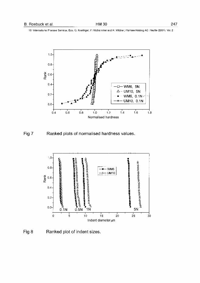
B. Roebuck et al. HM30 247
15th International Plansee Seminar, Eds. G. Kneringer, P. Rodhammer and H. Wildner, Plansee Holding AG, Reutte (2001), Vol. 2
1.0-
0.8-
a:0.6-
0.4-
0.2-
0.0-
-D-WM6, 5N-A-UM10, 5N—•—WM6, 0.1N—*— UM10, 0.1N
0.4 0.6 0.8 1.0 1.2 1.4Normalised hardness
1.6
Fig 7 Ranked plots of normalised hardness values.
1.0-
0.8-
i° -6 H
0.4-
0.2-
0.0-0.1N 0.5N 1N
—•— WM6—A-UM10
10 15 20Indent diameterym
5N
25 30
Fig 8 Ranked plot of indent sizes.
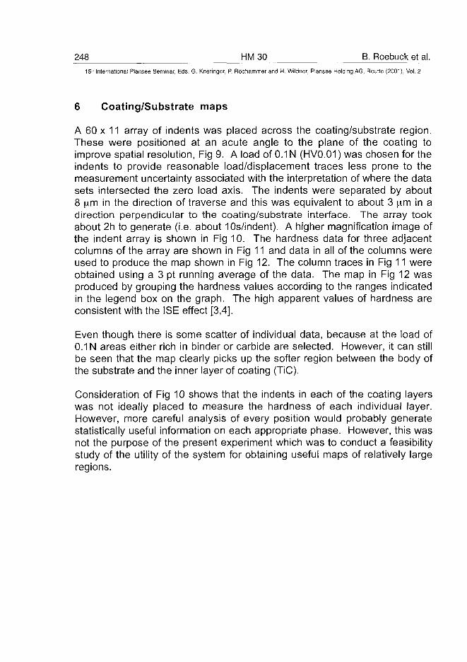
248 HM30 B. Roebuck et al.15'-' International Piansee Seminar, Eds. G. Kneringer, P. Rodhammer and H. Wildner, Plansee Holding AG, Reutte (2001), Vol. 2
6 Coating/Substrate maps
A 60 x 11 array of indents was placed across the coating/substrate region.These were positioned at an acute angle to the plane of the coating toimprove spatial resolution, Fig 9. A load of 0.1 N (HV0.01) was chosen for theindents to provide reasonable load/displacement traces less prone to themeasurement uncertainty associated with the interpretation of where the datasets intersected the zero load axis. The indents were separated by about8 im in the direction of traverse and this was equivalent to about 3 pirn in adirection perpendicular to the coating/substrate interface. The array tookabout 2h to generate (i.e. about 10s/indent). A higher magnification image ofthe indent array is shown in Fig 10. The hardness data for three adjacentcolumns of the array are shown in Fig 11 and data in all of the columns wereused to produce the map shown in Fig 12. The column traces in Fig 11 wereobtained using a 3 pt running average of the data. The map in Fig 12 wasproduced by grouping the hardness values according to the ranges indicatedin the legend box on the graph. The high apparent values of hardness areconsistent with the ISE effect [3,4].
Even though there is some scatter of individual data, because at the load of0.1 N areas either rich in binder or carbide are selected. However, it can stillbe seen that the map clearly picks up the softer region between the body ofthe substrate and the inner layer of coating (TiC).
Consideration of Fig 10 shows that the indents in each of the coating layerswas not ideally placed to measure the hardness of each individual layer.However, more careful analysis of every position would probably generatestatistically useful information on each appropriate phase. However, this wasnot the purpose of the present experiment which was to conduct a feasibilitystudy of the utility of the system for obtaining useful maps of relatively largeregions.
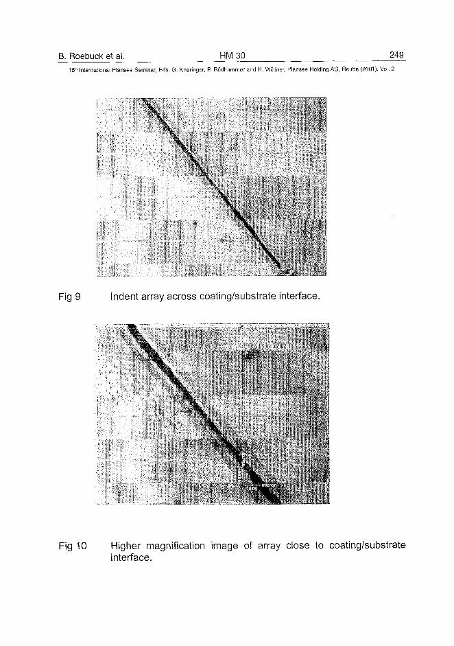
B. Roebuck et al. HM30 24915" International Plansee Seminar, Eds. G. Kneringer, P. Rodhammer and H. Wildner, Plansee Holding AG, Reutte (2001), Vol. 2
Fig 9 Indent array across coating/substrate interface.
\
\
Fig 10 Higher magnification image of array close to coating/substrateinterface.
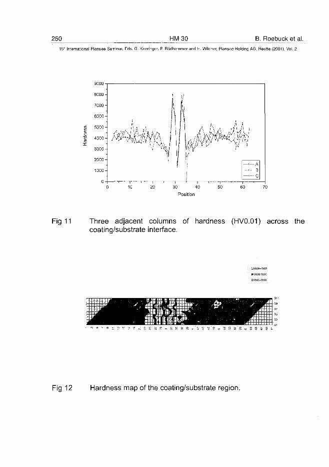
250 HM30 B. Roebuck et al.15" International Plansee Seminar, Eds. G. Kneringer, P. Rddhammer and H. Wildner, Plansee Holding AG, Reutte (2001), Vol. 2
9000
60 70
Fig 11 Three adjacent columns of hardness (HV0.01) across thecoating/substrate interface.
D 5500-7500 !
B 3500-5500
• 1500-3500
Fig 12 Hardness map of the coating/substrate region.
B. Roebuck et al. HM 30 25115* International Plansee Seminar, Eds. G. Kneringer, P. Rodhammer and H. Wildner, Plansee Holding AG, Reutte (2001), Vol. 2
7 Summary
A new depth sensing microhardness mapping system has been developedthat is capable of producing arrays of indents, typically up to 20 x 20 in 1h, atloads of between 0.05-20N. The arrays are placed and analysedautomatically, obviating the need for operator selection of indentationdiameters. The system was calibrated, both statically and by comparisonwith indents made using a conventional microhardness machine.
The system was evaluated in two feasibility experiments:
• to assess point to point variation in WC/Co hardmetals• to assess mapping capability in a coating/substrate system.
Both experiments generated useful data sufficient to validate the utility of thesystem but future work is needed to develop the analytical aspects of datapresentation and to understand why the hardness map of the wide grainedhardmetal did not show any obvious difference to that in the conventionalWC/Co hardmetal.
8 Acknowledgements
The design and construction of the test system was supported by UKDepartment of Trade and Industry Materials Measurements Programmes.Hardmetals for study were provided by members of the Research Group ofthe British Hardmetals Association.
9 References
(1) T J Bell, A Bendeli, J S Field, M V Swain and E G Thwaile, Metrologia,28(1991/2), pp 463-492.
(2) J B Pethica, R Hutchings and W C Oliver, Phil. Mag. A, 48 (4) (1983),pp 593-606.
(3) N J McCormick, M G Gee and D J Hall, Proc. Mat. Res. Soc. Symp.,Vol 308 (1993), Materials Research Society, pp 195-200.
(4) S Luyckx, C M Demanet and S Shrivastava, J Mater. Sci. Letters, 18(1999), pp 705-706.
(5) K Miyahara, N Nagashima, T Ohmura and S Matsuoka, NanostructuredMaterials, 12 (1999), pp 1049-1052.
AT0100457252 HM31 J.M. Missiaen et al.
15" International Plansee Seminar, Eds. G. Kneringer, P. Rodhammer and H. Wildner, Plansee Holding AG, Reutte (2001), Vol. 2
QUANTITATIVE ANALYSIS OF BIMODAL GRAIN SIZE DISTRIBUTIONS
IN WC-CO HARD MATERIALS
J.M. MISSIAEN, A. LACKNER*, L. SCHMID*
Laboratoire de Thermodynamique et de Physico-Chimie Metallurgiques
(UMR 5614, CNRS - INPG/UJF)
Saint-Martin d'Heres, FRANCE
*Plansee Tizit AG, Reutte/Tirol, AUSTRIA
Abstract :
A special method was implemented to quantify the bimodal character of the3D grain size distribution in WC-Co sintered materials. The method deals withSEM images of materials sections. Grains are separated on binary images byan automatic algorithm. The intercept length distributions are measured. Dataare then fitted with a model population of trigonal prisms with constant shape.Two kinds of grain size distributions are considered for the model : aunimodal (lognormal) distribution or a bimodal (bi-lognormal) size distribution.The method is applied to different WC-Co grades, and the bimodal characterof the distribution is discussed.
Keywords
bimodal distribution ; grain size distribution ; polyhedra ; image analysis
Introduction
A precise characterisation of the grain size distribution in WC-Co materials isneeded to better understand grain growth mechanisms, and also to optimisethe mechanical properties. Quantitative analysis of images taken on a sectionof the material is a suitable tool for this. Analysis of the intercept lengthdistribution in the WC phase can be used to analyse the influence of processparameters on the microstructure coarsening (1). However, determination ofthe 3D grain size distribution should be preferred for a detailed analysis ofgrain growth.
J.M. Missiaen et al. HM 31 25315'" International Plansee Seminar, Eds. G. Kneringer, P. Rodhammer and H. Wildner, Plansee Holding AG, Reutte (2001), Vol. 2
A possible method is to use random set models (boolean models) to describethe grains. The model parameters are then fitted by image analysis of thecomplementary set of the grains, i.e. the binder phase. This method does notrequire any segmentation of the grains, which may be a tedious task forsubmicronic particles, especially when the binder fraction is small. Such anapproach was used by Quenech et al. (2), using Poisson 's polyhedrons forthe representation of WC grains. These are polyhedrons with random shapes,and a one-parametric size distribution, i.e the size distribution is fixed for agiven average size. A different model was proposed by one of the presentauthors (3), using trigonal prisms for WC grains, i.e. the equilibrium shape forWC grains in a Co-based liquid (4). However, estimation of a two-parameter(unimodal) size distribution from this method is highly sensitive toexperimental errors, and it could not be used for the characterisation ofbimodal distributions.
The more usual approach starts with a segmentation of the grains on theimage. The distribution of a size parameter is then measured on individual 2Dparticles. Automatic segmentation requires complex image processing (5, 6).The size distribution of 3D-particles can be computed from analytical modelfor simple shapes (7), but requires numerical methods for more complexshapes, like polyhedrons (8, 9, 10). Analysis of the size distribution based ona segmentation of particles was applied to the WC-Co system, to get thedistribution of intercept lengths in the grains (11), or of 2D equivalentdiameters (12) It was also be applied to determine the 3D grain sizedistribution of equivalent spheres (13, 14), cubes (9) or truncated trigonalprisms (8). The present method uses an automatic segmentation algorithmbased on the work of Serra (6). The 3D grain size reconstruction is performedfrom measured intercept length distributions, assuming a trigonal prismaticshape (Fig. 2) for WC grains, with a fixed ratio F=h/L of the height to thebasal triangle side. The method is applied to the analysis of WC-Co sinteredmaterials prepared from mixtures of large and small WC particles. Lognormaland bi-lognormal grain size distributions are used to fit the experimentalintercept length distributions.
Image analysis methods
Image acquisition was performed in SEM for the 3 samples, in thebackscattered mode. 5 to 10 images were acquired in each case,corresponding to several thousands of particles analysed. The WC phasewas thresholded (Fig 1).
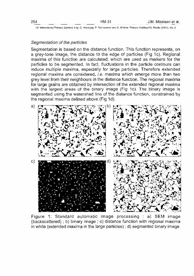
254 HM31 J.M. Missiaen et al.15'' International Plansee Seminar, Eds. G. Kneringer, P. Rodhammer and H. Wildner, Plansee Holding AG, Reutte (2001), Vol. 2
Segmentation of the particles
Segmentation is based on the distance function. This function represents, ona grey-tone image, the distance to the edge of particles (Fig 1c). Regionalmaxima of this function are calculated, which are used as markers for theparticles to be segmented. In fact, fluctuations in the particle contours caninduce multiple maxima, especially for large particles. Therefore extendedregional maxima are considered, i.e. maxima which emerge more than twogrey level from their neighbours in the distance function. The regional maximafor large grains are obtained by intersection of the extended regional maximawith the largest areas of the binary image (Fig 1c). The binary image issegmented using the watershed line of the distance function, constrained bythe regional maxima defined above (Fig 1d).
c)
Figure 1: Standard automatic image processing : a) SEM image(backscattered) ; b) binary image ; c) distance function with regional maximain white (extended maxima in the large particles); d) segmented binary image

J.M. Missiaen et al. HM 31 25515" International Plansee Seminar, Eds. G. Kneringer, P. Rodhammer and H. Wildner, Plansee Holding AG, Reutte (2001), Vol. 2
Measurements
Intercept length distributions were determined by classical openinggranulometry (15). This analysis gives the number of intercept per unit lengthNL {lk) Al which are comprised between lk_i and lk., for any class {lk.-i; lk}.
Reconstruction of the 3D grain size distribution
Assuming a discrete 3D grain size distribution, and a fixed particle shape, thenumbers of intercepts per unit length are related to the numbers of particlesper unit volume Nv(Dj) having size D, (7) :
NL(lk)AI = ZAp(Di)P(Di,lk)Nv(Di) (1)/
where Ap (D,) is the average area of the projection of a particle on a plane,p(Dh lk) is the probability that a particle with size D, gives an intercept oflength between lk.-, et lk.
Expressions for Ap (D,-) and p{Dh lk) can be calculated for a given particleshape. In principle, discrete values Nv(Dj) of the 3D grain size distribution canbe deduced from the intercept length distribution by a simple matrix inversionof eq. (1). This method gives an unique solution and it can be used forspherical shapes for example, but it produces aberrant values of Nv(Dj) forpolyhedral shapes, due to discontinuities in the probability function p(Dh lk). Aregression method was used here to fit eq. (1), with the constraint that allNv(Di) are positive.
h
DFigure 2 : The trigonal prismatic shape used for 3D grain size reconstruction
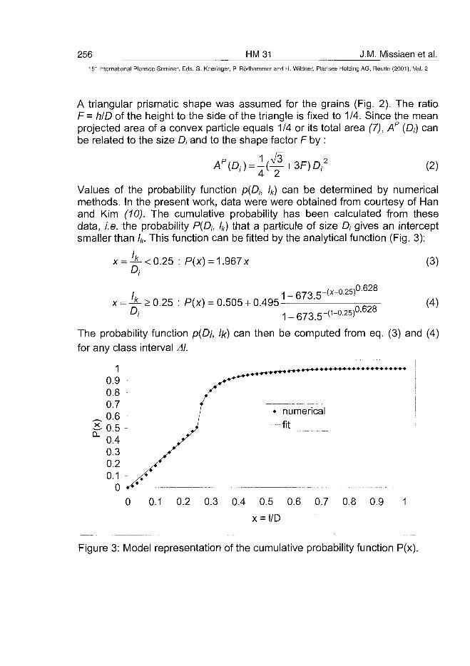
256 HM31 J.M. Missiaen et al.5- International Plansee Seminar, Eds. G. Kneringer, P. Rodhammer and H. Wildner, Plansee Holding AG, Reutte (2001), Vol. 2
A triangular prismatic shape was assumed for the grains (Fig. 2). The ratioF = hID of the height to the side of the triangle is fixed to 1/4. Since the meanprojected area of a convex particle equals 1/4 or its total area (7), Ap (D,) canbe related to the size D, and to the shape factor F by :
(2)
Values of the probability function p{Dh lk) can be determined by numericalmethods. In the present work, data were were obtained from courtesy of Hanand Kim (10). The cumulative probability has been calculated from thesedata, i.e. the probability P{Dh lk) that a particule of size D, gives an interceptsmaller than lk. This function can be fitted by the analytical function (Fig. 3):
: P(x) = 1.967x
,0.628
x = > 0.25 : P(x) = 0.505 + 0.4951-673.5- (x-°25)
11 n oc\0.628
(3)
(4)
The probability function p{Dj, Ik) can then be computed from eq. (3) and (4)for any class interval Al.
0.1 0.2 0.3 0.4 0.5 0.6 0.7 0.8 0.9 1
Figure 3: Model representation of the cumulative probability function P(x).
J.M. Missiaen et al. HM31 25715" International Plansee Seminar, Eds. G. Kneringer, P. Rodhammer and H. Wildner, Plansee Holding AG, Reutte (2001), Vol. 2
In order to analyse the bimodal character of the size distribution, two casesare considered for the grain size distribution: a unimodal grain sizedistribution, of log-normal type (in volume %), and a bimodal grain sizedistribution, constructed by adding two log-normal distributions (in volume %).For the unimodal distribution, parameters to adjust are the mean size and thestandard deviation of the distribution (2 parameters). For the bimodaldistribution, parameters to adjust are the mean sizes and standard deviationsof the two modes (4 parameters) and the proportion of each mode (1parameter). The measured intercept distribution is fitted with the distributioncalculated from the model (eq. (1)), by a chi2 minimisation. The deduced 3Ddistributions are plotted for the equivalent 3D-diameter (i.e. the diameter ofthe sphere of same volume).
Experiments
Three WC-Co compositions were prepared by mixing Co powder with amixture of large grains and small grains WC powders. Compositions of themixtures are reported in Table 1.
Powders were compacted and sintered at 1450°C for 1h.
Composition
ABC
Co
(weight%)
1799
VC<1> or(Ta, Nb)C(2)
(weight%)
0.2<1>2P)2(2)
LargeWC
(weight%)10
17,845
Size
8 um5.5 um5.5 um
SmallWC
(weight%)73
71,244
Size
0.8 pirn1 um
1.5 umTable 1 : The 3 compositions reported in this work
Results
Figure 4 shows microstructures of the sintered specimens. A secondary(Ta, Nb)C carbide phase can be observed in grey on samples B and C, whichhas been eliminated for the analysis of the WC grain size distribution.Measured intercept length distributions, together with the fit and thecorresponding 3D grain size distributions are presented on Fig. 5 to 10.Unimodal and bimodal fits are considered.
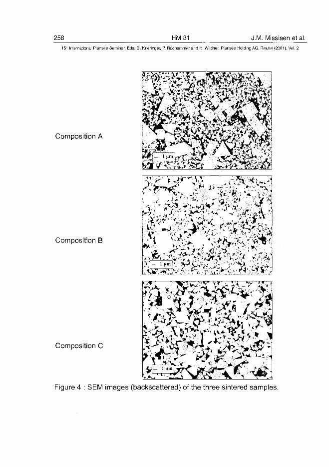
258 HM31 J.M. Missiaen et al.15:' International Plansee Seminar, Eds. G. Kneringer, P. Rodhammer and H. Wildner, Plansee Holding AG, Reutte (2001), Vol. 2
Composition A
Composition B
Composition i
Figure 4 : SEM images (backscattered) of the three
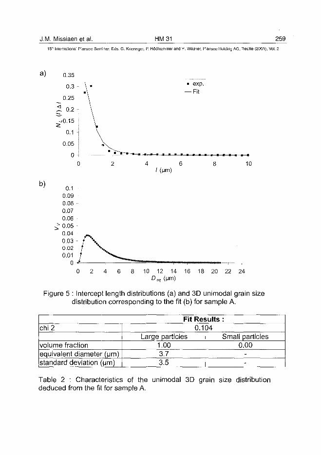
J.M. Missiaen et al. HM31 25915th International Plansee Seminar, Eds. G. Kneringer, P. Rodhammer and H. Wildner, Plansee Holding AG, Reutte (2001), Vol. 2
a)
b) 0.10.090.080.070.060.050.040.03 -0.020.01
0 •*
0
• exp.— Fit
4 6/(Mm)
10
10 12 14 16 18 20 22 24Deq (Mm)
Figure 5 : Intercept length distributions (a) and 3D unimodal grain sizedistribution corresponding to the fit (b) for sample A.
Fit Results :chi 2
volume fractionequivalent diameter (urn)standard deviation (urn)
0.104Large particles
1.003.73.5
Small particles0.00
--
Table 2 : Characteristics of the unimodal 3D grain size distributiondeduced from the fit for sample A.
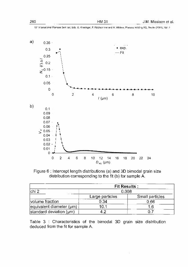
260 HM31 J.M. Missiaen et al.15" International Plansee Seminar, Eds. G. Kneringer, P. Rodhammer and H. Wildner, Plansee Holding AG, Reutte (2001), Vol. 2
a)
b)
• exp.— Fit
4 6/(Mm)
10
0 2 4 6 8 10 12 14 16 18 20 22 24Deq (Mm)
Figure 6 : Intercept length distributions (a) and 3D bimodal grain sizedistribution corresponding to the fit (b) for sample A.
Fit Results :chi 2
volume fractionequivalent diameter (urn)standard deviation (urn)
0.008Large particles
0.3410.14.2
Small particles0.661.60.7
Table 3 : Characteristics of the bimodal 3D grain size distributiondeduced from the fit for sample A.
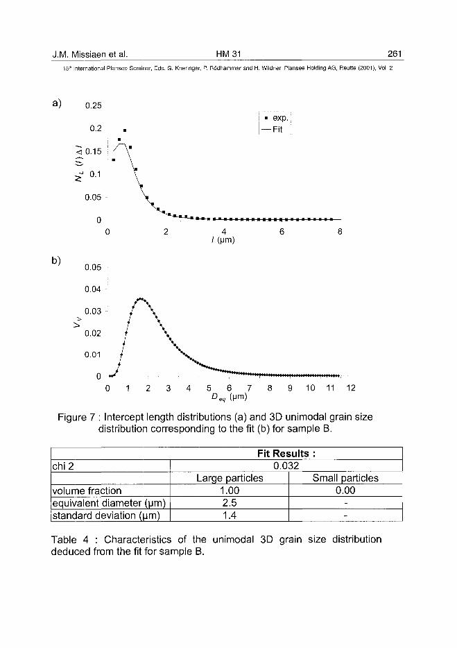
J.M. Missiaen et al. HM31 26115" International Plansee Seminar, Eds. G. Kneringer, P. Rodhammer and H. Wildner, Plansee Holding AG, Reutte (2001), Vol. 2
a) 0.25
0.2
< 0.15
^ 0.1
0.05
0
b)
/(Mm)
0 1 2 3 4 5 6 7Deq (Mm)
exp.-Fit
9 10 11 12
Figure 7 : Intercept length distributions (a) and 3D unimodal grain sizedistribution corresponding to the fit (b) for sample B.
Fit Results :chi 2
volume fractionequivalent diameter (urn)standard deviation (urn)
0.032Large particles
1.002.51.4
Small particles0.00
--
Table 4 : Characteristics of the unimodal 3D grain size distributiondeduced from the fit for sample B.
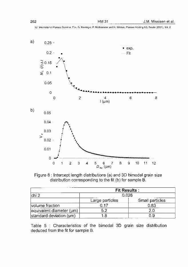
262 HM31 J.M. Missiaen et al.15'k International Plansee Seminar, Eds. G. Kneringer, P. Rodhammer and H. Wildner, Plansee Holding AG, Reutte (2001), Vol. 2
a ) 0.25 -
0.2
2 0.1
0.05 -
b)
0 1 5 6 7Deq (Mm)
exp.
-Fit
10 11 12
Figure 8 : Intercept length distributions (a) and 3D bimodal grain sizedistribution corresponding to the fit (b) for sample B.
Fit Results :chi 2
volume fractionequivalent diameter (urn)standard deviation (urn)
0.026Large particles
0.175.21.8
Small particles0.832.00.9
Table 5 : Characteristics of the bimodal 3D grain size distributiondeduced from the fit for sample B.
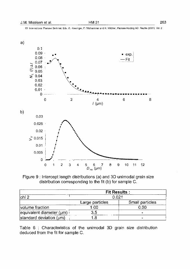
J.M. Missiaen et ai. HM31 26315" International Plansee Seminar, Eds. G. Kneringer, P. Rodhammer and H. Wildner, Plansee Holding AG, Reutte (2001), Vol. 2
a)
exp.-Fit
b)
5 6 7Deq (Mm)
10 11 12
Figure 9 : Intercept length distributions (a) and 3D unimodal grain sizedistribution corresponding to the fit (b) for sample C.
Fit Results :chi 2
volume fractionequivalent diameter (urn)standard deviation (um)
0.021Large particles
1.003.51.8
Small particles0.00
--
Table 6 : Characteristics of the unimodal 3D grain size distributiondeduced from the fit for sample C.
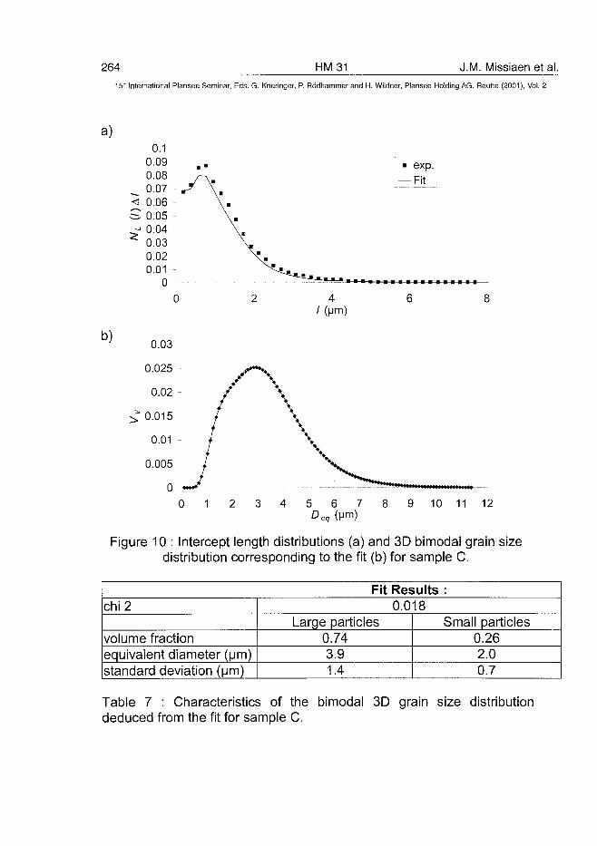
264 HM31 J.M. Missiaen et al.15" International Plansee Seminar, Eds. G. Kneringer, P. Rodhammer and H. Wildner, Plansee Holding AG, Reutte (2001), Vol. 2
a)
b)
• exp.— Fit
4/(Mm)
10 11 12
Figure 10 : Intercept length distributions (a) and 3D bimodal grain sizedistribution corresponding to the fit (b) for sample C.
Fit Results :chi 2
volume fractionequivalent diameter (urn)standard deviation (urn)
0.018Large particles
0.743.91.4
Small particles0.262.00.7
Table 7 : Characteristics of the bimodal 3D grain size distributiondeduced from the fit for sample C.
J.M. Missiaen et al. HM 31 26515'" International Plansee Seminar, Eds. G. Kneringer, P. Rodhammer and H. Wildner, Plansee Holding AG, Reutte (2001), Vol. 2
Discussion
The present work proposes an automatic sequence of image processing,measurements and microstructure modelling to describe the grain sizedistribution in WC-Co materials. Errors in the final result can come either fromimprecisions in image processing and measurements, or from approximationsin the model. As for image processing, grain segmentation can be a majorsource of errors. Individual grain boundaries are frequently mispositionned.Random deviations from the actual position will probably not disturb the grainsize distribution too much, but oversegmentation of large grains andundersegmentation of small grains is sometimes observed. Another source oferrors comes from the assumption of constant grain shape, and from the ideallog-normal representation of the distributions. In fact, the main advantage ofthe present analysis is that it can be easily implemented, and reproduced ondifferent samples. The resulting size distribution must not be considered asabsolute, but as the reproducible result a series of image processing andmeasurements, for a realistic model representation of the microstructure.Samples treated the same way can then be directly compared.
Despite imprecisions in the analysis process, the bimodal character of thegrain size distribution can be evidenced when the difference in the initialmean sizes of the powders is large enough, and is consistent withmicrostructural observations. Therefore the fit is improved sharply forspecimen A, and more slightly for sample B when using a bimodaldistribution. The improvement is not significant for sample C. Initial sizedistributions of the two classes in the initial powder mixture are closer in thatcase, and volume fractions are similar so that the two modes are merging inthe sintered material when the bimodal analysis is performed. The sizedistribution may as well be represented by a broad unimodal distribution inthat case (it must be recalled that 5 parameters instead of 2 are used for thefit of the bimodal distribution). The volume fraction of large grains in the WCphase which is deduced from the model for sample A (34%) is lower than inthe powder mixture (12%). This is explained by grain growth, whichconsumes small particles at the expense of large ones. These volumefractions are similar for sample B (20 % in the powder mixture and 17% in thesintered material). Grain growth is not so strong in that case, due to the largersize and smaller amount of small particles, and possibly to the difference ininhibitors. But the two modes in the grain size distribution deduced from themodel are not so well separated in that case, and error in the volume fraction
266 HM 31 J.M. Missiaen et al.15-" International Plansee Seminar, Eds. G. Kneringer, P. Rodhammer and H. Wildner, Plansee Holding AG, Reutte (2001), Vol. 2
estimation is therefore higher. For sample C, where the two modes aremerging, no conclusion can be drawn from the volume fraction analysis.
Conclusion
Automatic image analysis has been performed to quantify the grain sizedistribution in WC-Co sintered materials prepared from mixtures of large andsmall WC particles. When the difference of the mean sizes of the initialpowder mixture is large enough, the bimodal character of the distribution canbe quantified using a model representation of the grains by a bi-lognormalgrain size distribution of trigonal prisms.
References
1. V. Chabretou, O. Lavergne, J.M. Missiaen, C.H. Allibert: Metals andMaterials 5 (1999), pp. 205-210.2. J.L. Quenech, M. Coster, J.L. Chermant, D. Jeulin: J. Microsc. 168(1992), pp. 3-14.3. J.M. Missiaen, S. Roure: Mater. Sci. Eng. A-Struct. Mater, to bepublished (2001).4. J.T. Strauss, Thesis, Rensselaer Polytechnic Institute (1991).5. G. Gauthier, J.L. Quenec'h, M. Coster, C. J.L.: Acta Stereol. 13 (1994),pp. 209-214.6. J. Serra: Acta Stereol. 14 (1995), pp. 99-111.7. R.T. DeHoff, F.N. Rhines: Quantitative Microscopy (Me Graw Hill, NewYork, 1968).8. J. Wasen, R. Warren: Mater. Sci. Technol. 5 (1989), pp. 222-226.9. J. Ohser, M. Nippe: J. Microsc. 187 (1997), pp. 22-30.10. J.W. Han, D.Y. Kim: Acta Mater. 46 (1998), pp. 2021-2028.11. H.E. Exner, H. Fischmeister: Z. Metallkde 57 (1966), pp. 187-193.12. K. Choi, N.M. Hwang, D.Y. Kim: Powder Metall. Int. 43 (2000), pp. 168-172.13. J.L. Chermant, M. Coster, A. Deschanvres, A. lost: J. Less-CommonMetals 52 (1977), pp. 177-196.14. Y.J. Park, N.M. Hwang, D.Y. Yoon: Metall. Trans. A 27 (1996), pp.2809-2819.15. J. Serra: Image Analysis and Mathematical Morphology. Vol. I(Academic Press, London, 1982).
AT0100458H. Engqvist et al. HM 32 267^
15" International Plansee Seminar, Eds. G. Kneringer, P. Rodhammer and H. Wildner, Plansee Holding AG, Reutte (2001), Vol. 2
SLIDING WEAR OF CEMENTED CARBIDES
H. Engqvist, S. Ederyd, S. Hogmark* and B. Uhrenius
AB Sandvik Hard Materials, Stockholm, Sweden
*Dept. of Materials Science, Uppsala, Sweden
SummaryCemented carbides are known to be very hard and wear resistant and are thereforeoften used in applications involving surface damage and wear. The wear rate ofcemented carbides is often measured in abrasion. In such tests it has been shownthat the wear rate is inversely dependent on the material hardness. The sliding wearis even more of a surface phenomenon than abrasion, making it difficult to predictfriction and wear from bulk properties. This paper concentrates on the sliding wearof cemented carbides and elucidates some wear mechanisms. It is especially shownthat a fragmenting wear mechanism of WC is very important for the description ofwear of cemented carbides.
Keywords: Cemented carbides, binderless carbides, sliding wear, friction
1. IntroductionDue to its unique combination of high hardness and high toughness cementedcarbides are used in applications involving wear, e.g. face seals, knifes, pen balls,cutting tools and drills for circuit boards. In a majority of the applications relativemotion between the cemented carbide and a counter material occurs. This willinevitable lead to wear of the cemented carbide, in some cases the wear rate iscontrolled by abrasion but often the wear rate is controlled by the sliding wearproperties of cemented carbides. Sliding wear occurs when two solid surfaces slideagainst each other. The contact may be lubricated or dry. Sliding wear and abrasivewear are similar in that they both demand relative motion between two surfaces,while in abrasive wear also hard particles are involved as well [1, 2], Sliding wear ismore complicated than abrasion due to the larger number of factors that caninfluence both friction and wear, e.g. temperature, pressure, counter material,formation of surface films, phase transformations and lubrication [2]. The slidingwear is even more of a surface phenomenon than abrasion, making it difficult topredict friction and wear from bulk properties.
When adding a lubricant to the system, many effects have to be considered [2, 3].The lubricant can reduce the pressure on the surface through lubricating films,
268 HM32 H. Engqvist et al.15" International Plansee Seminar, Eds. G. Kneringer, P. Rodhammer and H. Wildner, Plansee Holding AG, Reutte (2001), Vol. 2
which leads to reduced wear and friction. It can also dissolve or remove wear debrisfrom the interface thus affecting the formation of tribofilms [3]. Liquids have alsobeen reported to influence the near surface mechanical properties, which theninfluences the wear property [4]. The possible formation of corrosion films alsoinfluences friction and wear.
In a model test, the many parameters in a real application are often varied one at atime. Model tests are often denoted by their contact geometry [1, 2]. All contactscan be described as being either conformal or non-conformal. Conformal means thattwo surfaces have or adapts to the same form, e.g. a ring on a ring. Non-conformalindicates varying contact geometry, e.g. a spherical ball on a disc. When evaluatingmaterials tribologically, the behaviour in both types of geometries is often tested. Acontact can also be closed or open [2], the latter meaning that one of the surfaces isrenewed continuously, as for instance cutting tools. Closed contacts arecharacterised through both surfaces being part of the same construction and bythese meeting repeatedly, such as for face seals. This paper concentrates on slidingwear in closed contacts and the wear mechanisms and wear phenomena acting insuch contacts.
2. Wear mechanisms of single crystalline WCCemented carbides contain in general above 80 volume percent of micrometer sizedsingle crystals of WC. To understand the wear mechanisms for the material it thusseems natural to study the wear of WC single crystals [5]. Large single crystals(about 5 mm) were grooved by a spherical diamond indenter inside a SEM, whichenabled the formation of wear debris to be studied in situ. The main wearmechanism was shown to be the formation of small fragments, see Fig. 1. Analyseof the small fragments with TEM showed the surface planes, preferred by thefragments, to be identical to the crystals slip planes [5, 6].
2.1. Non-conformal contact (ball-on-disc)
2.1.1. Dry slidingIn tests against silicon nitride balls, cemented carbide discs show a decreasing wearrate with increasing composite hardness. The effect of hardness is not as strong as inabrasion [7]. The wear mechanisms have been found to occur on a scale smaller thanthe individual carbide grains. In sliding contact, the wear debris are not as easilyremoved as in abrasion. The debris can therefore accumulate on the surface and formtribofilms. The properties of the tribofilms are normally different from those of theoriginal material, thus changing the wear behaviour. It has been speculated that smallWC fragments compacted and mixed with Co increase the surface toughness and
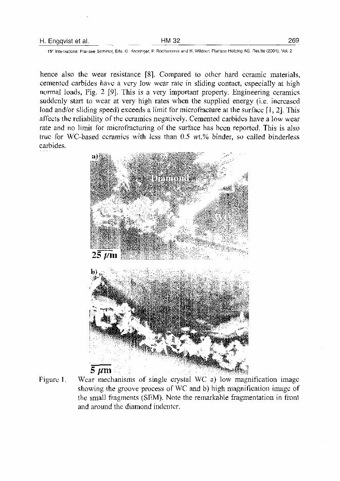
H. Engqvist et al. HM32 269
15'" International Plansee Seminar, Eds. G. Kneringer, P. Rodhammer and H. Wildner, Plansee Holding AG, Reutte (2001), Vol. 2
hence also the wear resistance [8]. Compared to other hard ceramic materials,cemented carbides have a very low wear rate in sliding contact, especially at highnormal loads, Fig. 2 [9]. This is a very important property. Engineering ceramicssuddenly start to wear at very high rates when the supplied energy (i.e. increasedload and/or sliding speed) exceeds a limit for micro fracture at the surface [1,2]. Thisaffects the reliability of the ceramics negatively. Cemented carbides have a low wearrate and no limit for microfracturing of the surface has been reported. This is alsotrue for WC-based ceramics with less than 0.5 wt.% binder, so called binderlesscarbides.
Figure 1. Wear mechanisms of single crystal WC a) low magnification imageshowing the groove process of WC and b) high magnification image ofthe small fragments (SEM). Note the remarkable fragmentation in frontand around the diamond indenter.
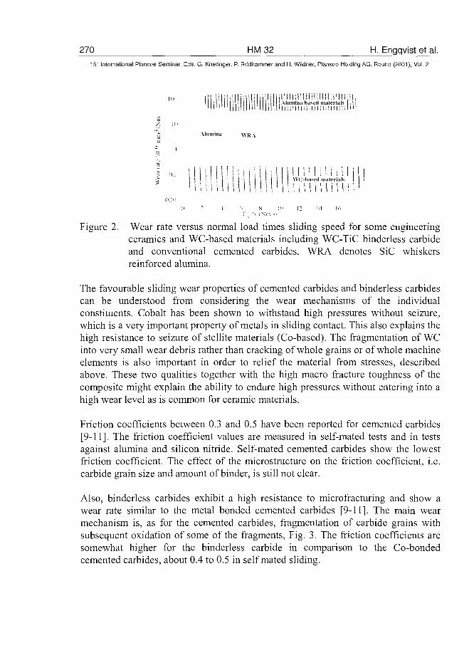
270 HM32 H. Engqvist et al.15tr International Plansee Seminar, Eds. G. Kneringer, P. Rodhammer and H. Wildner, Plansee Holding AG, Reutte (2001), Vol. 2
i Alumina based materials
1111! 111 m 11 m 111
Almnimt \\R \
Ii I
MUM i i i l\\ Obased materials
(i 2 •! fi X :'.< 12 II 16:-', *\ (Nir. si
Figure 2. Wear rate versus normal load times sliding speed for some engineeringceramics and WC-based materials including WC-TiC binderless carbideand conventional cemented carbides. WRA denotes SiC whiskersreinforced alumina.
The favourable sliding wear properties of cemented carbides and binderless carbidescan be understood from considering the wear mechanisms of the individualconstituents. Cobalt has been shown to withstand high pressures without seizure,which is a very important property of metals in sliding contact. This also explains thehigh resistance to seizure of stellite materials (Co-based). The fragmentation of WCinto very small wear debris rather than cracking of whole grains or of whole machineelements is also important in order to relief the material from stresses, describedabove. These two qualities together with the high macro fracture toughness of thecomposite might explain the ability to endure high pressures without entering into ahigh wear level as is common for ceramic materials.
Friction coefficients between 0.3 and 0.5 have been reported for cemented carbides[9-11]. The friction coefficient values are measured in self-mated tests and in testsagainst alumina and silicon nitride. Self-mated cemented carbides show the lowestfriction coefficient. The effect of the microstructure on the friction coefficient, i.e.carbide grain size and amount of binder, is still not clear.
Also, binderless carbides exhibit a high resistance to microfracturing and show awear rate similar to the metal bonded cemented carbides [9-11]. The main wearmechanism is, as for the cemented carbides, fragmentation of carbide grains withsubsequent oxidation of some of the fragments, Fig. 3. The friction coefficients aresomewhat higher for the binderless carbide in comparison to the Co-bondedcemented carbides, about 0.4 to 0.5 in self mated sliding.
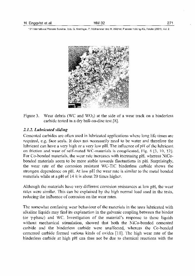
H. Engqvist et al. HM 32 271_
15th International Plansee Seminar, Eds. G. Kneringer, P. Rodhammer and H. Wildner, Plansee Holding AG, Reutte (2001), Vol. 2
Figure 3. Wear debris (WC and WO3) at the side of a wear track on a binderlesscarbide tested in a dry ball-on-disc test [8].
2.1.2. Lubricated slidingCemented carbides are often used in lubricated applications where long life times arerequired, e.g. face seals. It does not necessarily need to be water and therefore thelubricant can have a very high or a very low pH. The influence of pH of the lubricanton friction and wear of self-mated WC-materials is complicated, Fig. 4 [3, 10, 12].For Co-bonded materials, the wear rate increases with increasing pH, whereas NiCo-bonded materials seem to be more stable towards fluctuations in pH. Surprisingly,the wear rate of the corrosion resistant WC-TiC binderless carbide shows thestrongest dependence on pH. At low pH the wear rate is similar to the metal bondedmaterials while at a pH of 14 it is about 20 times higher.
Although the materials have very different corrosion resistances at low pH, the wearrates were similar. This can be explained by the high normal load used in the tests,reducing the influence of corrosion on the wear rates.
The somewhat confusing wear behaviour of the materials in the tests lubricated withalkaline liquids may find its explanation in the galvanic coupling between the binder(or y-phase) and WC. Investigation of the material's response to these liquidswithout mechanical stimulation, showed that both the NiCo-bonded cementedcarbide and the binderless carbide were unaffected, whereas the Co-bondedcemented carbide formed various kinds of oxides [11]. The high wear rate of thebinderless carbide at high pH can thus not be due to chemical reactions with the
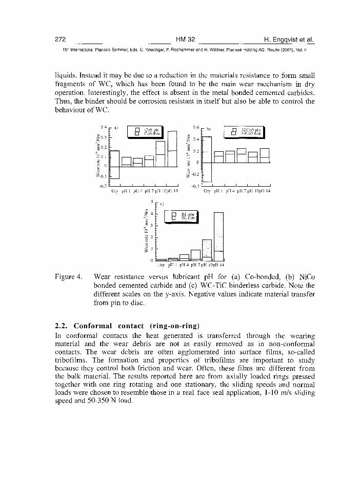
272 HM32 H. Engqvist et al.15" International Plansee Seminar, Eds. G. Kneringer, P. Rodhammer and H. Wildner, Plansee Holding AG, Reutte (2001), Vol. 2
liquids. Instead it may be due to a reduction in the materials resistance to form smallfragments of WC, which has been found to be the main wear mechanism in dryoperation. Interestingly, the effect is absent in the metal bonded cemented carbides.Thus, the binder should be corrosion resistant in itself but also be able to control thebehaviour of WC.
0.4
Jo.3| 0 , 2
32 o
£-0.1
-0.2
- a) B
_ l—1
i i i
Co6 pCo6d
in 1
i
Dry pH 1 pH 4 pH 7 pH 10pH 14
0,6
| 0,4
j 3 0.2
| °> -0.2
-0,4
" b) 8 NiCo9niNiCo9 dis
i
1
Dry pH 1 pH4 pH7pH lOpH 14
2 4
«s 3
o3 2
I '0 i . | 1 = 1 |
BL disci
-ifl i
Dry pH 1 pH4 pH7pH lOpH 14
Figure 4. Wear resistance versus lubricant pH for (a) Co-bonded, (b) NiCobonded cemented carbide and (c) WC-TiC binderless carbide. Note thedifferent scales on the y-axis. Negative values indicate material transferfrom pin to disc.
2.2. Conformal contact (ring-on-ring)In conformal contacts the heat generated is transferred through the wearingmaterial and the wear debris are not as easily removed as in non-conformalcontacts. The wear debris are often agglomerated into surface films, so-calledtribofilms. The formation and properties of tribofilms are important to studybecause they control both friction and wear. Often, these films are different fromthe bulk material. The results reported here are from axially loaded rings pressedtogether with one ring rotating and one stationary, the sliding speeds and normalloads were chosen to resemble those in a real face seal application, 1-10 m/s slidingspeed and 50-350 N load.
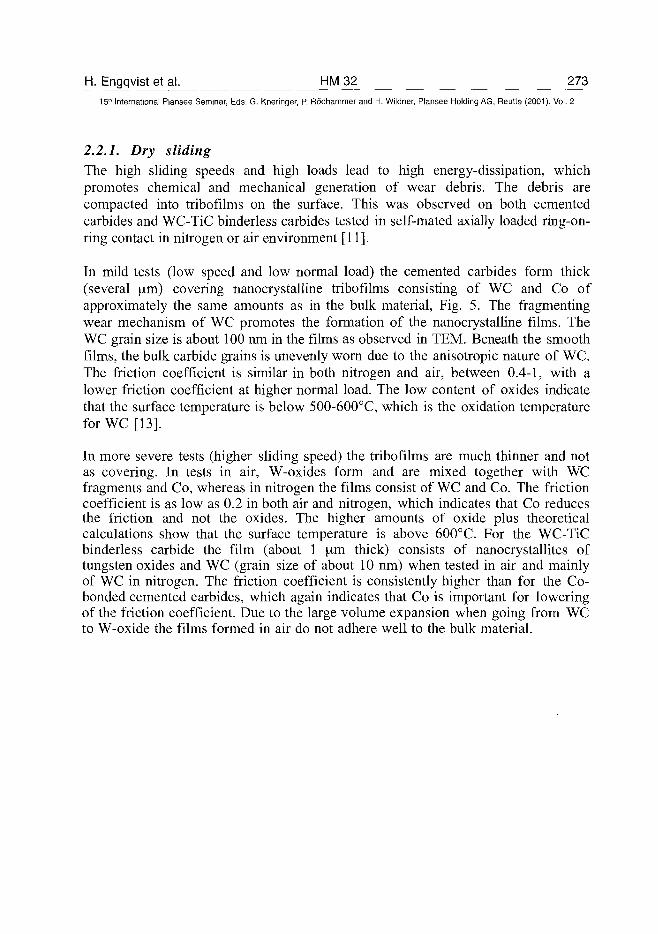
H. Engqvist et al. HM 32 273^15" International Plansee Seminar, Eds. G. Kneringer, P. Rddhammer and H. Wildner, Plansee Holding AG, Reutte (2001), Vol. 2
2.2.1. Dry slidingThe high sliding speeds and high loads lead to high energy-dissipation, whichpromotes chemical and mechanical generation of wear debris. The debris arecompacted into tribofilms on the surface. This was observed on both cementedcarbides and WC-TiC binderless carbides tested in self-mated axially loaded ring-on-ring contact in nitrogen or air environment [11].
In mild tests (low speed and low normal load) the cemented carbides form thick(several im) covering nanocrystalline tribofilms consisting of WC and Co ofapproximately the same amounts as in the bulk material, Fig. 5. The fragmentingwear mechanism of WC promotes the formation of the nanocrystalline films. TheWC grain size is about 100 nm in the films as observed in TEM. Beneath the smoothfilms, the bulk carbide grains is unevenly worn due to the anisotropic nature of WC.The friction coefficient is similar in both nitrogen and air, between 0.4-1, with alower friction coefficient at higher normal load. The low content of oxides indicatethat the surface temperature is below 500-600°C, which is the oxidation temperatureforWC [13].
In more severe tests (higher sliding speed) the tribofilms are much thinner and notas covering. In tests in air, W-oxides form and are mixed together with WCfragments and Co, whereas in nitrogen the films consist of WC and Co. The frictioncoefficient is as low as 0.2 in both air and nitrogen, which indicates that Co reducesthe friction and not the oxides. The higher amounts of oxide plus theoreticalcalculations show that the surface temperature is above 600°C. For the WC-TiCbinderless carbide the film (about 1 [ira thick) consists of nanocrystallites oftungsten oxides and WC (grain size of about 10 nm) when tested in air and mainlyof WC in nitrogen. The friction coefficient is consistently higher than for the Co-bonded cemented carbides, which again indicates that Co is important for loweringof the friction coefficient. Due to the large volume expansion when going from WCto W-oxide the films formed in air do not adhere well to the bulk material.
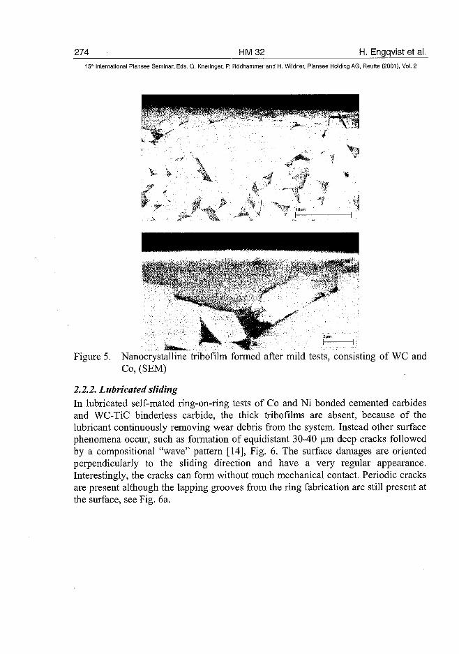
274 HM32 H. Engqvist et al.15* International Plansee Seminar, Eds. G. Kneringer, P. Rodhammer and H. Wildner, Plansee Holding AG, Reutte (2001), Vol. 2
Figure 5. Nanocrystalline tribofilm formed after mild tests, consisting of WC andCo, (SEM)
2.2.2. Lubricated slidingIn lubricated self-mated ring-on-ring tests of Co and Ni bonded cemented carbidesand WC-TiC binderless carbide, the thick tribofilms are absent, because of thelubricant continuously removing wear debris from the system. Instead other surfacephenomena occur, such as formation of equidistant 30-40 urn deep cracks followedby a compositional "wave" pattern [14], Fig. 6. The surface damages are orientedperpendicularly to the sliding direction and have a very regular appearance.Interestingly, the cracks can form without much mechanical contact. Periodic cracksare present although the lapping grooves from the ring fabrication are still present atthe surface, see Fig. 6a.
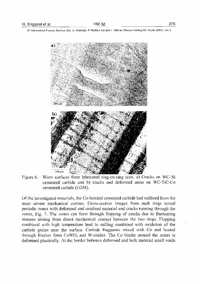
H. Engqvist et al. HM32 27515* International Plansee Seminar, Eds. G. Kneringer, P. Rbdhammer and H. Wildner, Plansee Holding AG, Reutte (2001), Vol. 2
a)
! 100/,
Figure 6. Worn surfaces from lubricated ring-on-ring tests, a) Cracks on WC-Nicemented carbide and b) cracks and deformed areas on WC-TiC-Cocemented carbide (LOM).
Of the investigated materials, the Co-bonded cemented carbide had suffered from themost severe mechanical contact. Cross-section images from such rings revealperiodic zones with deformed and oxidised material and cracks running through thezones, Fig. 7. The zones can form through flopping of cracks due to fluctuatingstresses arising from direct mechanical contact between the two rings. Floppingcombined with high temperature lead to milling combined with oxidation of thecarbide grains near the surface. Carbide fragments mixed with Co and heatedthrough friction form CoWO4 and W-oxides. The Co binder around the zones isdeformed plastically. At the border between deformed and bulk material small voids
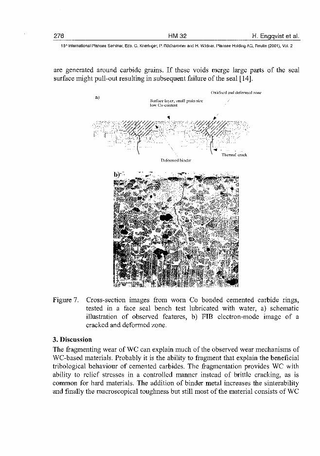
276 HM32 H. Engqvist et al.15" International Plansee Seminar, Eds. G. Kneringer, P. Rodhammer and H. Wildner, Plansee Holding AG, Reutte (2001), Vol. 2
are generated around carbide grains. If these voids merge large parts of the sealsurface might pull-out resulting in subsequent failure of the seal [14].
a)Oxidised and deformed zone
Surface layer, small szrain sizelow Co-content
Thermal crackDeformed hinder
Figure 7. Cross-section images from worn Co bonded cemented carbide rings,tested in a face seal bench test lubricated with water, a) schematicillustration of observed features, b) FIB electron-mode image of acracked and deformed zone.
3. DiscussionThe fragmenting wear of WC can explain much of the observed wear mechanisms ofWC-based materials. Probably it is the ability to fragment that explain the beneficialtribological behaviour of cemented carbides. The fragmentation provides WC withability to relief stresses in a controlled manner instead of brittle cracking, as iscommon for hard materials. The addition of binder metal increases the sinterabilityand finally the macroscopical toughness but still most of the material consists of WC
H. Engqvist et al. HM 32 27715'" International Plansee Seminar, Eds. G. Kneringer, P. Rodhammer and H. Wildner, Plansee Holding AG, Reutte (2001), Vol. 2
and thus it must be WC that controls the steady state wear. Of course when cracksdevelop or when subjected to corrosive liquids also the binder plays a major role.The metal binder also affects the hardness, which controls the indentation depth andindirectly the wear. But most of the removed material is WC and thus WC's wearbehaviour is very important.
In dry sliding, the WC-based materials show a low and stable wear rate but thefriction coefficients are above 0.3. To further improve the material, a reduction ofthe friction coefficient is desirable.
The complex relation of the WC-based materials to the pH of the lubricant needsfurther investigation to be understood. The results for the binderless carbidecompared to the metal bonded cemented carbides clearly show the importance of thebinderphase.
The thick tribofilms formed in the dry ring-on-ring tests can be said to resembleliquid lubricants, i.e. to even out stresses acting on the bulk material. To get an extraprotection of face seals, the seals could be run dry for a short time to form atribofilm (at correct sliding speeds and normal load to avoid too much oxidation)before the lubricant is added to the system. By putting powders of elements, withdesirable properties, directly on the surface before the run, tailored tribofilms can beformed.
As in the lubricated ball-on-disc tests, it becomes more complicated when a lubricantis added to the ring-on-ring contact. Especially the mechanisms behind the crackformation and the compositional wave pattern need further investigations. One wayto prevent both could be to use the pre-maid tribofilms mentioned above to protectthe bulk material.
The effects from specific environments on sliding wear behaviour of WC basedmaterials is not well known. There are still many parameters, the effects of whichare not sufficiently investigated, e.g. temperature, lubricant and counter material.Experiments conducted to investigate this should preferably be performed in somekind of model test where the parameters can be carefully controlled.
4. Conclusions• Tungsten carbide wear through fragmentation into fine wear debris.• The fragmenting wear can explain the wear behaviour also for cemented carbides.• Tungsten carbide-based materials can withstand very high PV-values without
microfracture, much higher than common engineering ceramic materials.
278 HM32 H. Engqvist et al.15*' International Plansee Seminar, Eds. G. Kneringer, P. Rddhammer and H. Wildner, Plansee Holding AG, Reutte (2001), Vol. 2
• Cemented carbides have the ability to form thick covering nanocrystallinetribofilms during wear in dry conformal contact.
• In lubricated contacts WC-based materials can have a high wear rate. This hasprobably to do with the galvanic coupling between WC and the binder. A periodiccrack pattern can also form on the wear surface. The crack pattern can lead tofailure of the material.
5. References1. S. Jacobsson, S. Hogmark, Tribologi - Friktion, smorjning och notning, Liber
UtbildningAB(1996).2. I. M. Hutchings, Tribology - Friction and wear of engineering materials,
Arnold (1992).3. T.E. Fischer, Ann. Rev. Mater. Sci., 18 (1988), 303-323.4. J. T. Czernuszka, T. P. Page, Journal of Materials Science, 22 (1987), 3917-
3923.5. H. Engqvist, S. Ederyd, N. Axen, S. Hogmark, Wear, 230 (1999), 165-174.6. D. N. French, D. A. Thomas, in F. V. Vahldiek, J. Mersol (Eds.), Vol. 1,
Plenum, New York (1968).7. K. Jia, T. E. Fischer, Wear, 203-204 (1997), 310-318.8. E. A. Almond, L. A. Lay, M. G. Gee, Inst. Phys. Conf. Ser. No. 75 (1986)
919-948.9. H. Engqvist, N. Axen, S. Hogmark, Wear, 232 (1999), 157-162.10. H. Engqvist, U. Beste, N. Axen, Proc. Euro PM 99, 327-334.11. H. Engqvist, H. Hogberg, G. A. Botton, N. Axen, S. Ederyd, S. Hogmark,
Wear, 239 (2000) 219-228.12. S. Sasaki, Bulletin of mechanical engineering laboratory Japan, No. 58 (1992).13. S. N. Basu., V. K. Basu, Oxidation behaviour of WC-Co, Materials Science
and Engineering A209 (1996), 206-212.14. H. Engqvist, G. A. Botton, S. Ederyd, M. Pfaneuf, J. Fondelius, N. Axen, Int.
Journal of Refractory Metals and Hard Materials,
AT0100459K. Kitamura et al. HM 34 279^
15m International Plansee Seminar, Eds. G. Kneringer, P. Rddhammer and H. Wildner, Plansee Holding AG, Reutte (2001), Vol. 2
Properties of New WC-Co Base Hardmetal Prepared From CoxWyCz
Complex Carbide Powder Instead of WC+Co Mixed powder
K. Kitamura, M. Kobayashi and K. Hayashi*
Toshiba Tungaloy Co., Ltd., Iwaki-ctty, Fukushima, JAPAN
* Institute of Industrial Science, The University of Tokyo, Meguro-ku, Tokyo, JAPAN
SummaryIn the previous papers, we have already reported that WC-Co base hardmetal
(W+Graphite+Co alloy) prepared from W+Graphite mixed powder instead of
conventional WC powder has a large amount of plate-like triangular prismatic WC
grains with highly unidirectional orientation, and that it shows higher fracture toughness
and transverse-rupture strength than the conventional hardmetal at an identical
hardness.
In this study, we prepared new WC-Co base hardmetal by using Co2W4C and
Co3WgC4 complex carbide powders as the main starting materials. It was confirmed
that WC grains in the hardmetals are also plate-like triangular prismatic, but are not
oriented, i.e., isotropic, differing from W+ Graphite+Co alloy. The fracture toughness,
however, was higher by 10-15% than the conventional alloy at an identical hardness,
although the transverse-rupture strength was nearly the same as that of the
conventional alloy.
Keywordshardmetal, cemented carbide, complex carbide, plate-like, isotropy, WC, CoxWyCz
1. IntroductionWC-Co base hardmetal (hereafter, described as alloy) are widely applied to cutting
tools, PCB (printed circuit board) drills, wear-resistant tools, etc., because of its high
toughness as well as high hardness and fracture strength. The improvements of
these properties have been continuously carried out by changing the composition and
microstructure, and also by applying new process such as HIP, PVD and CVD(1X2).
Recently, we have developed an alloy which has plate-like triangular prismatic WC
grains with highly unidirectional orientation(3X4), as shown in Fig. 1. The new alloy is
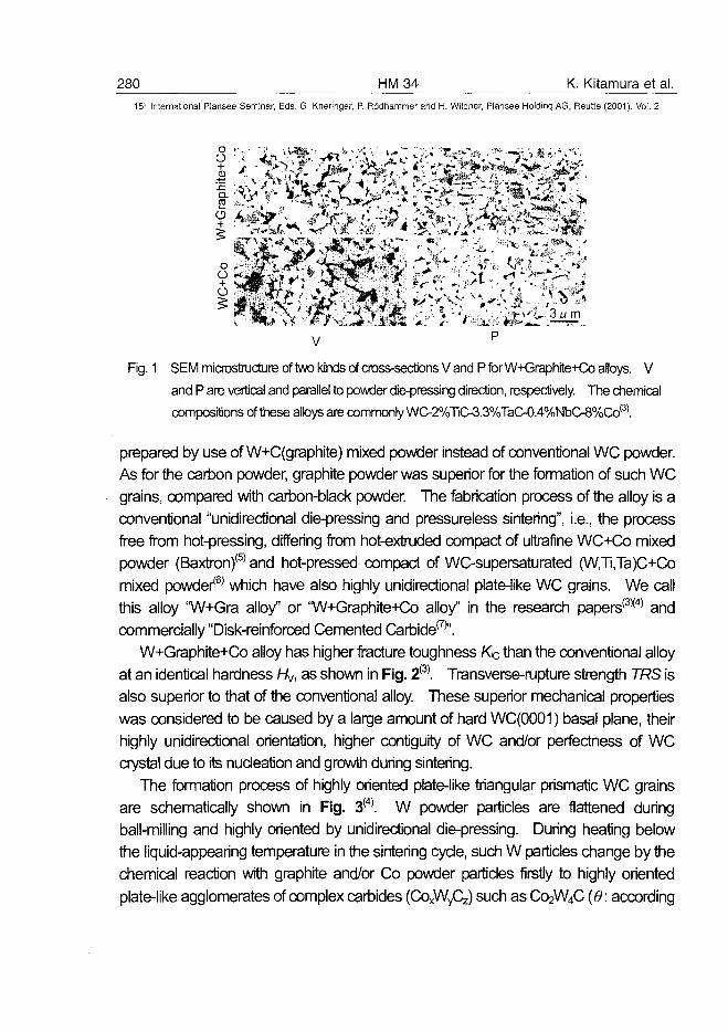
280 HM34 K. Kitamura et al.15;= International Plansee Seminar, Eds. G. Kneringer, P. Rodhammer and H. Wildner, Plansee Holding AG, Reutte (2001), Vol. 2
V
Fig. 1 SEMmicnoslnjc^reof1wokindsof(TOss-secfcnsVandPforW^raphite4€oalloys. V
and P are vertical and parallel to powder die-pressing direction, respectively. The chemical
compositions of these alloys are commonly WC-2%TiO3.3%TaC-0.4%NbC-8%Co(3).
prepared by use of W+C(graphite) mixed powder instead of conventional WC powder.
As for the carbon powder, graphite powder was superior for the formation of such WC
grains, compared with carbon-black powder. The fabrication process of the alloy is a
conventional "unidirectional die-pressing and pressureless sintering", i.e., the process
free from hot-pressing, differing from hot-extruded compact of ultrafine WC+Co mixed
powder (Baxtron)(5) and hot-pressed compact of WC-supersaturated (W,Ti,Ta)C+Co
mixed powder*6' which have also highly unidirectional plate-iike WC grains. We call
this alloy "W+Gra alloy" or "W+Graphite+Co alloy" in the research papers(3X4) and
commercially "Disk-reinforced Cemented Carbide^'.
W+Graphite+Co alloy has higher fracture toughness Kjc than the conventional alloy
at an identical hardness Hy, as shown in Fig. 2(3). Transverse-rupture strength TRS is
also superior to that of the conventional alloy. These superior mechanical properties
was considered to be caused by a large amount of hard WC(0001) basal plane, their
highly unidirectional orientation, higher contiguity of WC and/or perfectness of WC
crystal due to its nucleation and growth during sintering.
The formation process of highly oriented plate-like triangular prismatic WC grains
are schematically shown in Fig. 3(4). W powder particles are flattened during
ball-milling and highly oriented by unidirectional die-pressing. During heating below
the liquid-appearing temperature in the sintering cycle, such W particles change by the
chemical reaction with graphite and/or Co powder particles firstly to highly oriented
plate-like agglomerates of complex carbides (COxWyQ,) such as C02W4C (6: according
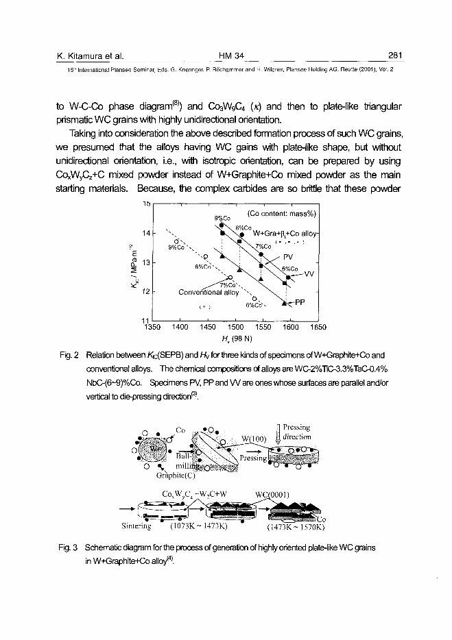
K. Kitamura et al. HM34 281
15lh International Plansee Seminar, Eds. G. Kneringer, P. Rodhammer and H. Wildner, Plansee Holding AG, Reutte (2001), Vol. 2
to W-C-Co phase diagram(8)) and C03W9C4 (x) and then to plate-like triangular
prismatic WC grains with highly unidirectional orientation.
Taking into consideration the above described formation process of such WC grains,
we presumed that the alloys having WC gains with plate-like shape, but without
unidirectional orientation, i.e., with isotropic orientation, can be prepared by using
COxWyCz+C mixed powder instead of W+Graphite+Co mixed powder as the main
starting materials. Because, the complex carbides are so brittle that these powder
1b
14
Erij
12 -
(Co content: mass%)
^ X 8%Co* \ \ # W+Gra+p+Co alloy-
Conventional alloy XC\
, o , 6%Co s- <r-PP
111350 1400 1450 1500 1550 1600 1650
Hv (98 N)
Fig. 2 Relation between Kc{SEPB) and hi/ for three kinds of specimens of W+Graphite+Co and
conventional alloys. The chemical compositions of alloys are WC-2%TiC-3.3%TaC-0.4%
NbC-(6~9)%Co. Specimens PV, PP and W are ones whose surfaces are parallel and/or
vertical to die-pressing direction'3'.
O .Co fl Pressing
100) I direction
O «L millings 0 r : 0 « i £ /Graphite(C)
CoxWyCz +W2C+W WQ0001)
Sintering (1073K-1473K) (1473K-1570K)
Fig. 3 Schematic diagram for the process of generation of highly oriented plate-like WC grains
in W+Graphite+Co alloy*4'.
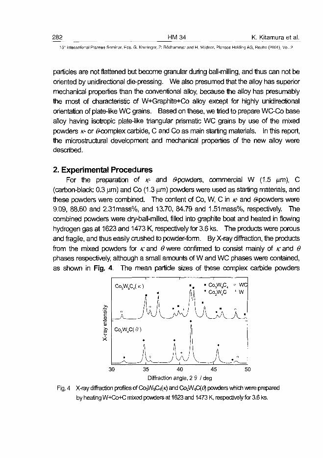
282 HM34 K. Kitamura et al.15" International Plansee Seminar, Eds. G. Kneringer, P. Rodhammer and H. Wildner, Plansee Holding AG, Reutte (2001), Vol. 2
particles are not flattened but become granular during ball-milling, and thus can not be
oriented by unidirectional die-pressing. We also presumed that the alloy has superior
mechanical properties than the conventional alloy, because the alloy has presumably
the most of characteristic of W+Graphite+Co alloy except for highly unidirectional
orientation of plate-like WC grains. Based on these, we tried to prepare WC-Co base
alloy having isotropic plate-like triangular prismatic WC grains by use of the mixed
powders K- or ^complex carbide, C and Co as main starling materials. In this report,
the microstructural development and mechanical properties of the new alloy were
described.
2. Experimental ProceduresFor the preparation of K- and (9-powders, commercial W (1.5 \im), C
(carbon-black: 0.3 jam) and Co (1.3 ^m) powders were used as starting materials, and
these powders were combined. The content of Co, W, C in K- and ^powders were
9.09, 88.60 and 2.31mass%, and 13.70, 84.79 and 1.51mass%, respectively. The
combined powders were dry-ball-milled, filled into graphite boat and heated in flowing
hydrogen gas at 1623 and 1473 K, respectively for 3.6 ks. The products were porous
and fragile, and thus easily crushed to powder-form. By X-ray diffraction, the products
from the mixed powders for K and 6 were confirmed to consist mainly of K and 6
phases respectively, although a small amounts of W and WC phases were contained,
as shown in Fig. 4. The mean particle sizes of these complex carbide powders
>>c3c
«
X-t
Co3W9C4( K )
• f
/ ° I . " /l i f t \ ' A +
A I \J V N^JA y v -'
Co2W4C( 9 )
_ULJw— ^ — - ^ i — - — '
• Co3W9C4
1 j * C°2W4C1 •
\ A • "A
^^ v y v v .
•
° we+ w
o
o
30 5035 40 45
Diffraction angle, 2 9 I deg
Fig. 4 X-ray diffraction profiles of Ck^VVgC^K) and C02W4C(^ powders which were prepared
by heating W+Co+C mixed powders at 1623 and 1473 K, respectively for 3.6 ks.
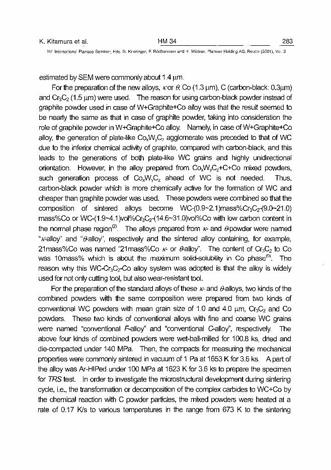
K. Kitamura et al. HM 34 28315'" International Plansee Seminar, Eds. G. Kneringer, P. Rodhammer and H. Wildner, Plansee Holding AG, Reutte (2001), Vol. 2
estimated by SEM were commonly about 1.4 |wn.
For the preparation of the new alloys, icor 0, Co (1.3 |im), C (carbon-black: 0.3(im)
and Cr3C2 (1.5 jam) were used. The reason for using carbon-black powder instead of
graphite powder used in case of W+Graphite+Co alloy was that the result seemed to
be nearly the same as that in case of graphite powder, taking into consideration the
role of graphite powder in W+Graphite+Co alloy. Namely, in case of W+Graphite+Co
alloy, the generation of plate-like CoxWyC2 agglomerate was preceded to that of WC
due to the inferior chemical activity of graphite, compared with carbon-black, and this
leads to the generations of both plate-like WC grains and highly unidirectional
orientation. However, in the alloy prepared from CoxWyCz+C+Co mixed powders,
such generation process of CoxWyCz ahead of WC is not needed. Thus,
carbon-black powder which is more chemically active for the formation of WC and
cheaper than graphite powder was used. These powders were combined so that the
composition of sintered alloys become WC-(0.9~2.1)mass%Cr3C2-(9.0~21.0)
mass%Co or WC-(1.9-4.1)vol%Cr3C2-(14.6-31.0)vol%Co with low carbon content in
the normal phase region(2). The alloys prepared from K- and #-powder were named
"/r-alloy" and "#-alloy", respectively and the sintered alloy containing, for example,
21mass%Co was named "21mass%Co K- or 0-alloy". The content of Cr3C2 to Co
was 10mass% which is about the maximum solid-solubility in Co phase(9). The
reason why this WC-Cr3C2-Co alloy system was adopted is that the alloy is widely
used for not only cutting tool, but also wear-resistant tool.
For the preparation of the standard alloys of these K- and 0-alloys, two kinds of the
combined powders with the same composition were prepared from two kinds of
conventional WC powders with mean grain size of 1.0 and 4.0 pm, Cr3C2 and Co
powders. These two kinds of conventional alloys with fine and coarse WC grains
were named "conventional F-alloy" and "conventional C-alloy", respectively. The
above four kinds of combined powders were wet-ball-milled for 100.8 ks, dried and
die-compacted under 140 MPa. Then, the compacts for measuring the mechanical
properties were commonly sintered in vacuum of 1 Pa at 1653 K for 3.6 ks. A part of
the alloy was Ar-HIPed under 100 MPa at 1623 K for 3.6 ks to prepare the specimen
for TRS test. In order to investigate the microstructural development during sintering
cycle, i.e., the transformation or decomposition of the complex carbides to WC+Co by
the chemical reaction with C powder particles, the mixed powders were heated at a
rate of 0.17 K/s to various temperatures in the range from 673 K to the sintering
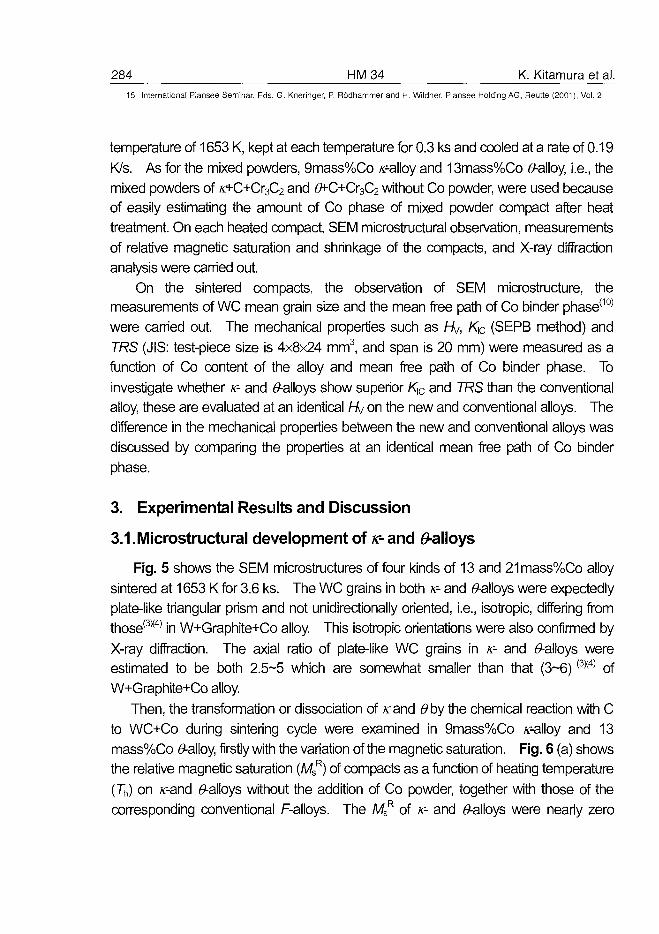
284 HM34 K. Kitamura et al.15' International Plansee Seminar, Eds. G. Kneringer, P. Rodhammer and H. Wildner, Plansee Holding AG, Reutte (2001), Vol. 2
temperature of 1653 K, kept at each temperature for 0.3 ks and cooled at a rate of 0.19
K/s. As for the mixed powders, 9mass%Co s--alloy and 13mass%Co tf-alloy, i.e., the
mixed powders of K+C+Cr3C2 and #^C+Cr3C2 without Co powder, were used because
of easily estimating the amount of Co phase of mixed powder compact after heat
treatment. On each heated compact, SEM microstructural observation, measurements
of relative magnetic saturation and shrinkage of the compacts, and X-ray diffraction
analysis were carried out.
On the sintered compacts, the observation of SEM microstructure, the
measurements of WC mean grain size and the mean free path of Co binder phase(10)
were carried out. The mechanical properties such as hk/, K\C (SEPB method) and
TRS (JIS: test-piece size is 4x8x24 mm3, and span is 20 mm) were measured as a
function of Co content of the alloy and mean free path of Co binder phase. To
investigate whether K- and ^-alloys show superior Klc and TRS than the conventional
alloy, these are evaluated at an identical hkj on the new and conventional alloys. The
difference in the mechanical properties between the new and conventional alloys was
discussed by comparing the properties at an identical mean free path of Co binder
phase.
3. Experimental Results and Discussion
3.1. Microstructural development of K- and ^alloys
Fig. 5 shows the SEM microstructures of four kinds of 13 and 21mass%Co alloy
sintered at 1653 K for 3.6 ks. The WC grains in both K- and t9-a!loys were expectedly
plate-like triangular prism and not unidirectionally oriented, i.e., isotropic, differing from
those(3X4) in W+Graphite+Co alloy. This isotropic orientations were also confirmed by
X-ray diffraction. The axial ratio of plate-like WC grains in K- and ^-alloys were
estimated to be both 2.5-5 which are somewhat smaller than that (3-6)(3X4) of
W+Graphite+Co alloy.
Then, the transformation or dissociation of /rand 6>by the chemical reaction with C
to WC+Co during sintering cycle were examined in 9mass%Co /r-alloy and 13
mass%Co #-alloy, firstly with the variation of the magnetic saturation. Fig. 6 (a) shows
the relative magnetic saturation (MSR) of compacts as a function of heating temperature
(7"h) on x--and ^-alloys without the addition of Co powder, together with those of the
corresponding conventional F-alloys. The MSR of K- and 6>-alloys were nearly zero
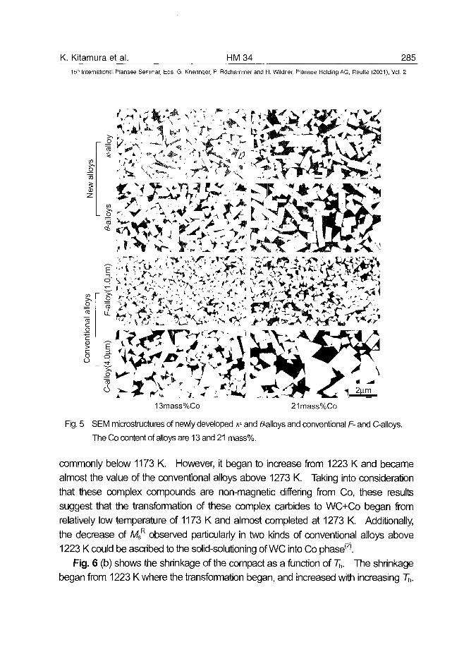
K. Kitamura et al. HM34 285
15* International Plansee Seminar, Eds. G. Kneringer, P. Rodhammer and H. Wildner, Plansee Holding AG, Reutte (2001), Vol. 2
13mass%Co 21mass%Co
Fig. 5 SEM microstnjctures of newly developed r- and 0-alloys and conventional F- and C-alloys.
The Co content of alloys are 13 and 21 mass%.
commonly below 1173 K. However, it began to increase from 1223 K and became
almost the value of the conventional alloys above 1273 K. Taking into consideration
that these complex compounds are non-magnetic differing from Co, these results
suggest that the transformation of these complex carbides to WC+Co began from
relatively low temperature of 1173 K and almost completed at 1273 K. Additionally,
the decrease of MSR observed particularly in two kinds of conventional alloys above
1223 K could be ascribed to the solid-solutioning of WC into Co phase(2>.
Fig. 6 (b) shows the shrinkage of the compact as a function of Th. The shrinkage
began from 1223 K where the transformation began, and increased with increasing Th.
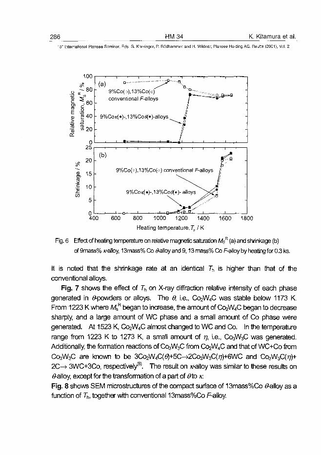
286 HM34 K. Kitamura et al.
15:" International Plansee Seminar, Eds. G. Kneringer, P. Rodhammer and H. Wildner, Plansee Holding AG, Reutte (2001), Vol. 2
100
- 8 0
^ - 6 0
E £CD 5 40
I -20or
025
20
CD
c 10
5
0400
(a) ° ^ \9%Co(o),13%Co(u) °-conventional F-alloys
- 9%Cox(»)-,13%Cofl(«)-alloys
(b)
9%Co(o),13%Co(a) conventional F-alloys
9%COK(»)- ,13%CO0(«)- alloys
600 800 1000 1200 1400 1600 1800
Heating temperature, Th IK
Fig. 6 Effect of heating temperature on relative magnetic saturation MsR (a) and shrinkage (b)
of 9mass% sr-alby, 13mass% Co (9-alloy and 9,13 mass% Co F-alloy by heating for 0.3 ks.
It is noted that the shrinkage rate at an identical 7"h is higher than that of the
conventional alloys.
Fig. 7 shows the effect of 7"h on X-ray diffraction relative intensity of each phase
generated in ^-powders or alloys. The 0, i.e., C02W4C was stable below 1173 K.
From 1223 K where MSR began to increase, the amount of C02W4C began to decrease
sharply, and a large amount of WC phase and a small amount of Co phase were
generated. At 1523 K, C02W4C almost changed to WC and Co. In the temperature
range from 1223 K to 1273 K, a small amount of 77, i.e., C03W3C was generated.
Additionally, the formation reactions of C03W3C from C02W4C and that of WC+Co from
C03W3C are known to be 3C^W4C(65+5C->2Co3W3C(?7)+6WC and Co3W3C(^)+
2C-H> 3WC+3Co, respectively*8'. The result on «--alloy was similar to these results on
<9-alloy, except for the transformation of a part of 9\a K.
Fig. 8 shows SEM microstructures of the compact surface of 13mass%Co 0-alloy as a
function of 7~h, together with conventional 13mass%Co F-alloy.
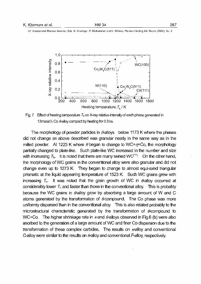
K. Kitamura et al. HM34 287
15lh International Plansee Seminar, Eds. G. Kneringer, P. Rodhammer and H. Wildner, Plansee Holding AG, Reutte (2001), Vol. 2
1.0
0.8B•- 0.6
JS 0.4Sjo1 0.2X
0.0200 400 600 800 1000 1200 1400 1600 1800
Heating temperature, Th I K
Fig. 7 Effect of heating temperature 7"h on X-ray relative intensity of each phase generated in
13mass% Co #alloy compact by heating for 0.3 ks.
The morphology of powder particles in ^-alloys below 1173 K where the phases
did not change as above described was granular nearly in the same way as in the
milled powder. At 1223 K where 6 began to change to W C + T ^ C O , the morphology
partially changed to plate-like. Such plate-like WC increased in the number and size
with increasing 7~h. It is noted that there are many twined WC(11). On the other hand,
the morphology of WC grains in the conventional alloy were also granular and did not
change even up to 1273 K. They began to change to almost equi-axed triangular
prismatic at the liquid appearing temperature of 1523 K. Such WC grains grew with
increasing 7"h. It was noted that the grain growth of WC in #-alloy occurred at
considerably lower Th and faster than those in the conventional alloy. This is probably
because the WC grains in #-alloy grow by absorbing a large amount of W and C
atoms generated by the transformation of ^compound. The Co phase was more
uniformly dispersed than in the conventional alloy. This is also related probably to the
microstructural characteristic generated by the transformation of ^compound to
WC+Co. The higher shrinkage rate in /r-and ^-alloys observed in Fig.6 (b) were also
ascribed to the generation of a large amount of WC and finer Co dispersion due to the
transformation of these complex carbides. The results on ^-alloy and conventional
C-alloy were similar to the results on (9-alloy and conventional F-alloy, respectively.
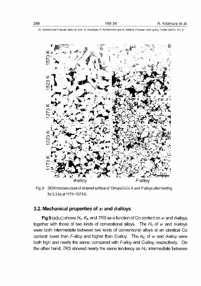
288 HM34 K. Kitamura et al.15'" International Plansee Seminar, Eds. G. Kneringer, P. Rddhammer and H. Wildner, Plansee Holding AG, Reutte (2001), Vol. 2
CO
CM
CO
^-alloy F-alloy
Fig. 8 SEM microstructure of sintered surface of 13mass%Co 9- and F-alloys after heating
for 0.3 ks at 1173-1573 K.
3.2. Mechanical properties of K- and d-alloys
Fig.9 (a,b,c) shows hi/, KiC and TRS as a function of Co content on K- and 6"-alloys,
together with those of two kinds of conventional alloys. The hi/ of K- and 6>-alloys
were both intermediate between two kinds of conventional alloys at an identical Co
content: lower than F-alloy and higher than C-alloy. The Klc of K- and (9-alloy were
both high and nearly the same, compared with F-alloy and C-alloy, respectively. On
the other hand, TRS showed nearly the same tendency as Hj\ intermediate between
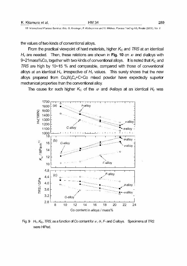
K. Kitamura et al. HM34 289
15m International Plansee Seminar, Eds. G. Kneringer, P. Rodhammer and H. Wildner, Plansee Holding AG, Reutte (2001), Vol. 2
the values of two kinds of conventional alloys.
From the practical viewpoint of hard materials, higher K\C and TRS at an identical
hkj are needed. Then, these relations are shown in Fig. 10 on K- and 6*-alloys with
9-21 mass%Co, together with two kinds of conventional alloys. It is noted that K[C and
TRS are high by 10-15 % and comparable, compared with those of conventional
alloys at an identical Hj, irrespective of Hy values. This surely shows that the new
alloys prepared from CoxWyCz+C+Co mixed powder have expectedly superior
mechanical properties than the conventional alloy.
The cause for such higher K[C of the K- and ^-alloys at an identical Hy was
17001600150014001300120011001000
o._ yd) g
n...
-
i ' i ' I
/
C-alloy
1i • i > i • i •
^alloy
^ ^ ^ ^ ^ P
• •
1 1 ' 1 ' 1
^^Z °D
1 ' 1 '
-
s*-alloy-
i , i .
mHIAI
o
I O
16
14
12
10
i
• ( b )
-
-
-
i i i
C-alloy
^ . . . ^ ^ - ^ ^
o °'\
F-alloy
^ x--alloy .
• - P
-
-
4.
8 10 12 14 16 18 20 22 24
Co content in alloys / mass%
Fig. 9 hi/, K\C, TRS, as a function of Co content for K-, 6-, F- and C-alloys. Specimens of TRS
were HIPed.
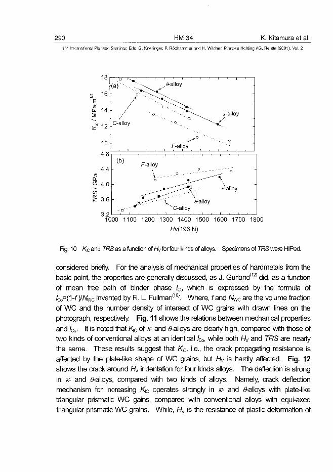
290 HM34 K. Kitamura et al.
15" International Plansee Seminar, Eds. G. Kneringer, P. Rodhammer and H. Wildner, Plansee Holding AG, Reutte (2001), Vol. 2
CO
18
16
14
12
10
4.8'
4.4
4.0
3.6 h
( a ) ' • - • . . .
/
C-alloy
1
" \ . e-alloy
" ' • * " " - ^ ^ ^ \
" ' • • o .
0
F-alloyi . i . i . i
x--alloy
(b)
--•a"'
i
F-alloy
" 0
_....p.
^C-alloy
0
\
e-alloy
o
v-alloy
-
3.21000 1100 1200 1300 1400 1500 1600 1700 1800
Hi/(196N)
Fig. 10 Kicand TRS as a function of hkj for four kinds of alloys. Specimens of TRS were HIPed.
considered briefly. For the analysis of mechanical properties of hardmetals from the
basic point, the properties are generally discussed, as J. Gurland(12) did, as a function
of mean free path of binder phase /Q, which is expressed by the formula of
IcoH^-fyNwc invented by R. L. Fullman(10). Where, fand AW; are the volume fraction
of WC and the number density of intersect of WC grains with drawn lines on the
photograph, respectively. Fig. 11 shows the relations between mechanical properties
and /a,. It is noted that K]C of K- and 0-alloys are clearly high, compared with those of
two kinds of conventional alloys at an identical /Q,, while both Hy and TRS are nearly
the same. These results suggest that KiC, i.e., the crack propagating resistance is
affected by the plate-like shape of WC grains, but Hy is hardly affected. Fig. 12
shows the crack around Hy indentation for four kinds alloys. The deflection is strong
in K- and <9-alloys, compared with two kinds of alloys. Namely, crack deflection
mechanism for increasing K\C operates strongly in K- and ^-alloys with plate-like
triangular prismatic WC gains, compared with conventional alloys with equi-axed
triangular prismatic WC grains. While, Hj is the resistance of plastic deformation of
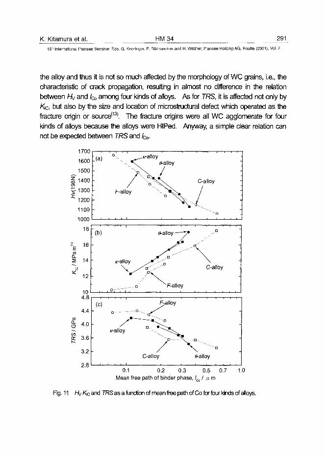
K. Kitamura et al. HM34 291
15" International Plansee Seminar, Eds. G. Kneringer, P. Rodhammer and H. Wildner, Plansee Holding AG, Reutte (2001), Vol. 2
the alloy and thus it is not so much affected by the morphology of WC grains, i.e., the
characteristic of crack propagation, resulting in almost no difference in the relation
between Hy and fa among four kinds of alloys. As for TRS, it is affected not only by
Kjc, but also by the size and location of microstructural defect which operated as the
fracture origin or source(13). The fracture origins were all WC agglomerate for four
kinds of alloys because the alloys were HIPed. Anyway, a simple clear relation can
not be expected between TRS and fa-
1700
1600
CL
s.
1100
1000
18
. 16 -
14 -
12 -
104.8
4.4 -
4.0 -
I 36I—-
3.2
2.8
»
-
(c)
-
-
-
v-alloy
•'
o
r-alloy
6>-alloy—T
j r ^ ••'"' Oy^ .-•'
jr D" .-'"'
o F-alloy
Fpalloy
C-alloy
•
C-alloy
-
p....
^-alloy
0.1 0.2 0.3 0.5 0.7 1.0Mean free path of binder phase, lCo I i±m
Fig. 11 hi/ Kic and TRS as a function of mean free path of Co for four kinds of alloys.
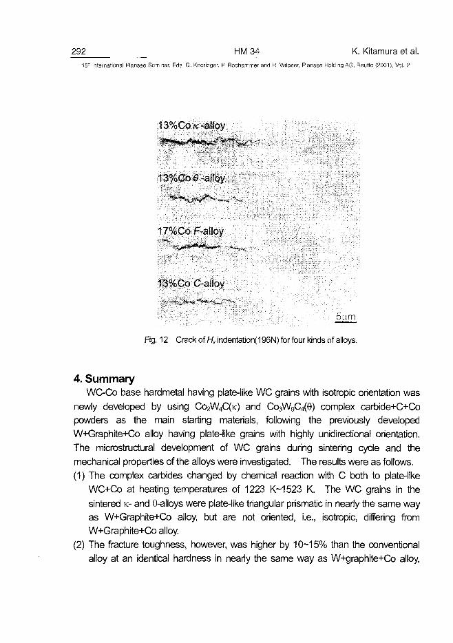
292 HM34 K. Kitamura et al.15" International Plansee Seminar, Eds. G. Kneringer, P. Rodhammer and H. Wildner, Plansee Holding AG, Reutte (2001), Vol. 2
13%Co/c -alloy
13%Co£-alloy
17%CoF-al!oy
13%CoC-alloy
Fig. 12 Crack of Hv indentation(196N) for four kinds of alloys.
4. SummaryWC-Co base hardmetal having plate-like WC grains with isotropic orientation was
newly developed by using CO2W4C(K) and CosWgC^G) complex carbide+C+Co
powders as the main starting materials, following the previously developed
W+Graphite+Co alloy having plate-like grains with highly unidirectional orientation.
The microstructural development of WC grains during sintering cycle and the
mechanical properties of the alloys were investigated. The results were as follows.
(1) The complex carbides changed by chemical reaction with C both to plate-like
WC+Co at heating temperatures of 1223 K-1523 K. The WC grains in the
sintered K- and 0-alloys were plate-like triangular prismatic in nearly the same way
as W+Graphite+Co alloy, but are not oriented, i.e., isotropic, differing from
W+Graphite+Co alloy.
(2) The fracture toughness, however, was higher by 10-15% than the conventional
alloy at an identical hardness in nearly the same way as W+graphite+Co alloy,
K. Kitamura et al. HM 34 29315'" International Plansee Seminar, Eds. G. Kneringer, P. Rodhammer and H. Wildner, Plansee Holding AG, Reutte (2001), Vol. 2
although the transverse-rupture strength was nearly the same as that of the
conventional alloy.
(3) The result was ascribed to the high crack deflection due to plate-like triangular
prismatic WC grains in K- and 0-alloys, compared with conventional alloys having
equi-axed triangular prismatic WC grains.
References(1) S. Schwartzkopf and R. Kieffer: Hartstoffe u. Hartmetalle, Springer-Veriag, NY
(1953).
(2) H. Suzuki et al.: Cemented Carbides and Sintered Hardmaterial-Basics and
Application-, Maruzen Co., Ltd., Tokyo, (1986).
(3) S. Kinoshita, T Saito, M. Kobayashi and K. Hayashi: J. Jpn. Soc. Powder and
Powder Metallur., 47(2000), 526.
(4) S. Kinoshita, T. Saito, M. Kobayashi and K. Hayashi: J. Jpn. Soc. Powder and
Powder Metallur., 48(2001), 51.
(5) US PATENT: 3451791 (1969).
(6) K. Kobori, M. Ueki, T. Saito and H. Suzuki: J. Jpn. Soc. Powder and Powder
Me1allur.,36(1989),379.
(7) T. Saito, Y. Taniguchi, M. Kobayashi and K. Kbori: Advances in Powder Metallurgy
and Particulate Materials -1998, vol.1(1998), 147.
(8) P. Rautala, and J. T. Norton: J. Metals, 4(1952), 1045.
(9) H. Suzuki, K. Tokumoto: J. Jpn. Soc. Powder and Powder Metallur., 31 (1984),715.
(10)R. L. Fullman: J. Metals, 6(1958), 447.
(11 )M. Kobayashi and S. Yamaya: 10* Plansee Seminar, (1981),597.
(12)J. Guriand: Trans. Met. Soc. AIME, 212(1958), 452.
(13)1-1. Suzuki and K. Hayashi: Planseeberichte fur Pulvermet, 23(1975),24.
AT0100460294 HM36 S. Kim et al.
15" International Plansee Seminar, Eds. G. Kneringer, P. Rodhammer and H. Wildner, Plansee Holding AG, Reutte (2001), Vol. 2
Observation of WC Grain Shapes determined by Carbon Content
during Liquid Phase Sintering of WC-Co Alloys
Sona Kim, Seok-Hee Han*, Jong-Ku Park*, Hyoun-Ee Kim
Center for Microstructure Science of Materials, School of Materials Scienceand Engineering, Seoul National University, Seoul, 151-742, Korea
* Ceramic Processing Research Center, Division of Materials, Korea Instituteof Science and Technology, Seoul, 136-791, Korea
Summary
In the composite materials of WC-Co alloys, the faceted WC grains as a hardphase are dispersed in the ductile matrix of cobalt. Properties of WC-Coalloys are affected by microstructural factors such as volume fraction of WCphase, size of WC grains, and carbon content (kinds of constituent phases).Although the properties of WC-Co alloys are inevitably affected by the shapeof WC grains, the shape of WC grains has not been thrown light on theproperties of WC-Co alloys yet, because it has been regarded to have auniform shape regardless of alloy compositions.It is proved that the WC grains have various shapes varying reversibly withcarbon content in the sintered WC-Co compacts. This dependency of grainshape on the carbon content is attributed to asymmetric atomic structure ofWC crystal. The {10i0} prismatic planes are distinguished into two groupswith different surface energy according to their atomic structures. Theprismatic planes of high surface energy tend to disappear in the compactswith high carbon content. In addition, these high energy prismatic planes tendto split into low energy surfaces in the large WC grains.
Keywards:WC-Co hard metals, liquid phase sintering, carbon content, grain shape,grain growth, asymmetry in crystal structure
S. Kim et al. HM 36 29515'" International Plansee Seminar, Eds. G. Kneringer, P. Rodhammer and H. Wildner, Plansee Holding AG, Reutte (2001), Vol. 2
1. Introduction
Cemented tungsten carbide with cobalt binder, so called WC-Co hard metals,has been applied to wear-resistant materials. The WC-Co hard metals areone of most typical composite materials in which faceted WC grains are beingdispersed in the cobalt matrix[13]. They are usually fabricated using liquidphase sintering methods, because of great difference in melting temperaturebetween WC and Co ingredients. During liquid phase sintering, the WCgrains dispersed in the liquid matrix grow through Ostwald ripening and havea faceted grain shape[4]. Until now the WC grains in the WC-Co alloys havebeen generally regarded to have an equilibrium shape of truncated trigonalprism, which means that the shape of WC grains does not vary withsurrounding conditions15"71.Various phase fields in the WC-Co alloys are determined both by cobaltcontent and by carbon content [8]. If the shape of WC crystals in the liquidcobalt matrix depends on the thermodynamic conditions, especially on thecarbon content, it cannot be defined regardless of carbon content even in thethree-phase regions, because each chemical species in the three-phaseregion does not have a fixed chemical potential. Considering high sensitivityof WC-Co alloy to the carbon content, there is enough possibility for WCcrystal shape to be affected by carbon potential in the alloys[8"111.In the present study, an effect of carbon content on the WC grain shapeduring liquid phase sintering has been determined varying the carbon contentin the WC-Co alloys.
2. Experimental
The respective powders used in the present study are as follows: WC(1.24urn, 99.99%) made by TaeguTec(formerly Korea Tungsten Mining Co.),Co(2.4 jj,m, 99.9%) made by Hermann C. Stark, and C(lamp black carbon)supplied by Fisher Scientific Company. Each powder was weighed separatelyaccording to predetermined ratio and mixed mechanically. The powdermixtures were milled for 72 h in the jar lined with pure WC-Co alloy with WC-Co balls in order to avoid chemical contamination during milling. Milledpowders were dried in a vacuum oven and granuled passing through #40mesh.
296 HM36 S. Kim et al.15" International Plansee Seminar, Eds. G. Kneringer, P. Rodhammer and H. Wildner, Plansee Holding AG, Reutte (2001), Vol. 2
Two compositions of WC-30%Co and WC-35%Co were chosen. All thefractions are in weight percentage. In order to determine the effect of carboncontent on WC grain shape, various amount of carbon from 0.1% to 1.5%was added to each WC-Co mixtures. The granuled powders were compactedinto the cylindrical disks with diameter of 10 mm under 25 MPa pressure. Thecompacts were sintered, respectively, at 1450°C or 1500°C in a vacuumfurnace heated resistively by a graphite heater. Several sintered compactsimbedded in the powder pack of carbon black were sintered again either toprevent carbon loss from the compact or to add carbon into the interior of thecompact by diffusion.Microstructures of the sintered compacts were observed along the specimenpreparation method for WC-Co materials. The microstructures of the polishedspecimens were observed by optical microscope and SEM (scanning electronmicroscopy) and analyzed with Image-Pro Plus V4.0. For stereographicobservation of WC grains, the WC grains in the sintered compacts wereextracted by removing the cobalt matrix with boiling 20% hydrochloricsolution. A cobalt residue was removed by dilute hydrogen peroxide solutionand the extracted WC grains were rinsed sequentially with distilled water andacetone. The extracted WC grains were observed by SEM.
3. Results and Discussion
(1) Changes of microstructures and WC grain shape with carbon contentWhen the WC-30%Co compacts with different carbon content were sinteredat 1450°C for 2 h, different microstructures were evoluted with carbon content(Figure 1). Two kinds of WC grains were found in the compacts. A group oflarge grains are homogeneously dispersed in the fine grain matrix. Largegrains in the compact are called hereafter 'large grains', whereas the finematrix grains are called 'matrix agrains'. A shape of large grains seemssimilar to a truncated trigonal prism, a typical shape of WC crystal. The largegrains in the WC-30%Co-0.3%C compact are larger in size than those in theWC-30%Co-0.1%C compact. The large grains in both compacts seem tohave a similar shape. With increase in carbon content up to 0.7%C in theWC-30%Co compacts, the shape of large grains changed from relatively thick
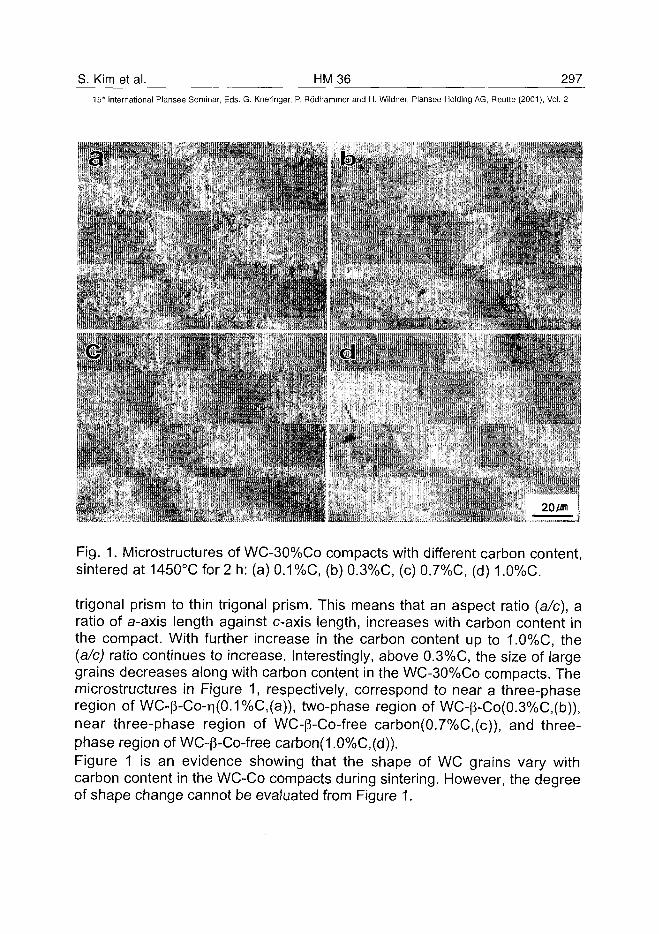
S. Kim et al. HM 36 29715'h International Plansee Seminar, Eds. G. Kneringer, P. Rodhammer and H. Wildner, Plansee Holding AQ, Reutte (2001), Vol. 2
b
• 20m
Fig. 1. Microstructures of WC-30%Co compacts with different carbon content,sintered at 1450°C for 2 h: (a) 0.1%C, (b) 0.3%C, (c) 0.7%C, (d) 1.0%C.
trigonal prism to thin trigonal prism. This means that an aspect ratio (a/c), aratio of a-axis length against c-axis length, increases with carbon content inthe compact. With further increase in the carbon content up to 1.0%C, the(a/c) ratio continues to increase. Interestingly, above 0.3%C, the size of largegrains decreases along with carbon content in the WC-30%Co compacts. Themicrostructures in Figure 1, respectively, correspond to near a three-phaseregion of WC-|3-Co-n(0.1%C,(a)), two-phase region of WC-|3-Co(0.3%C,(b)),near three-phase region of WC-|3-Co-free carbon(0.7%C,(c)), and three-phase region of WC-p-Co-free carbon(1.0%C,(d)).Figure 1 is an evidence showing that the shape of WC grains vary withcarbon content in the WC-Co compacts during sintering. However, the degreeof shape change cannot be evaluated from Figure 1.
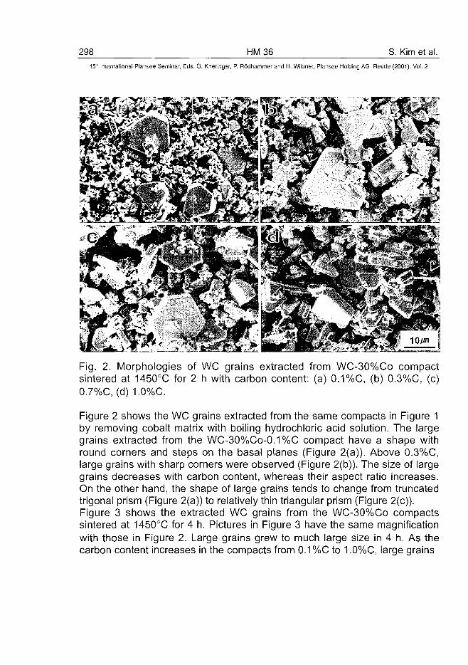
298 HM36 S. Kim et al.15" International Plansee Seminar, Eds. G. Kneringer, P. Rodhammer and H. Wildner, Plansee Holding A6, Reutte (2001), Vol. 2
Fig. 2. Morphologies of WC grains extracted from WC-30%Co compactsintered at 1450°C for 2 h with carbon content: (a) 0.1 %C, (b) 0.3%C, (c)0.7%C, (d) 1.
Figure 2 shows the WC grains extracted from the same compacts in Figure 1by removing cobalt matrix with boiling hydrochloric acid solution. The largegrains extracted from the WC-30%Co-0.1%C compact have a shape withround comers and steps on the basal planes (Figure 2(a)). Above 0.3%C,large grains with sharp corners were observed (Figure 2(b)). The size of largegrains decreases with carbon content, whereas their aspect ratio increases.On the other hand, the shape of large grains tends to change from truncatedtrigonal prism (Figure 2(a)) to relatively thin triangular prism (Figure 2(c)).Figure 3 shows the extracted WC grains from the WC-30%Co compactssintered at 1450°C for 4 h. Pictures in Figure 3 have the same magnificationwith those in Figure 2. Large grains grew to much large size in 4 h. As thecarbon content increases in the compacts from 0.1 %C to 1.0%C, large grains
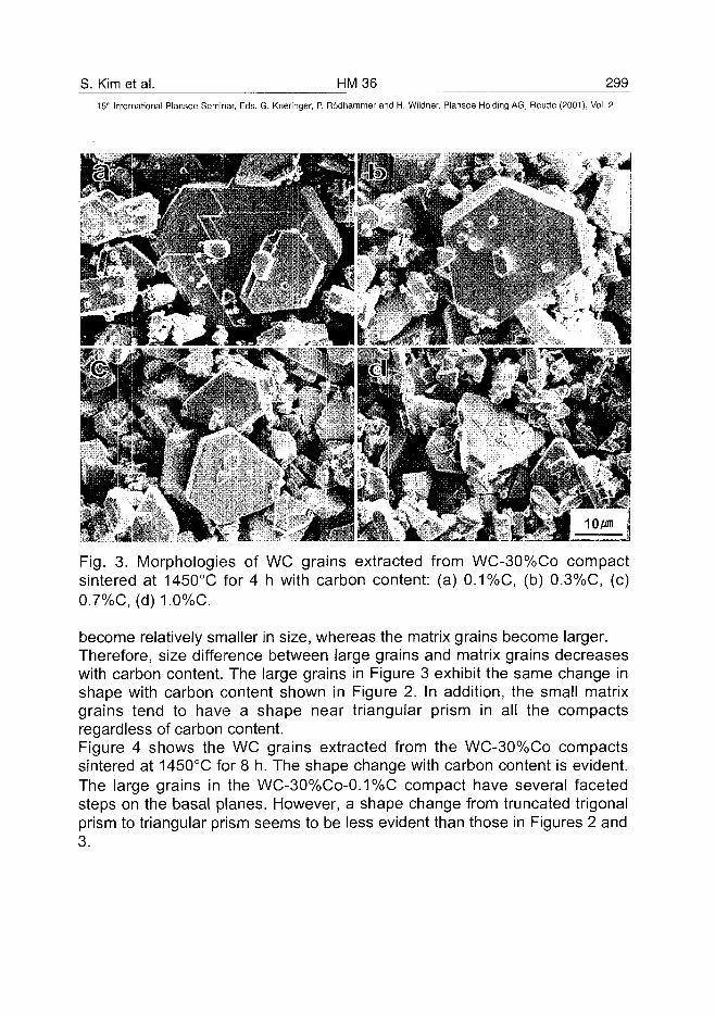
S. Kim et al. HM36 299
15" International Plansee Seminar, Eds. G. Kneringer, P. Rodhammer and H. Wildner, Plansee Holding AG, Reutte (2001), Vol. 2
•J
Fig. 3. Morphologies of WC grains extracted from WC-30%Co compactsintered at 1450°C for 4 h with carbon content: (a) 0.1 %C, (b) 0.3%C, (c)0.7%C,(d)1.0%C.
become relatively smaller in size, whereas the matrix grains become larger.Therefore, size difference between large grains and matrix grains decreaseswith carbon content. The large grains in Figure 3 exhibit the same change inshape with carbon content shown in Figure 2. In addition, the small matrixgrains tend to have a shape near triangular prism in all the compactsregardless of carbon content.Figure 4 shows the WC grains extracted from the WC-30%Co compactssintered at 1450°C for 8 h. The shape change with carbon content is evident.The large grains in the WC-30%Co-0.1%C compact have several facetedsteps on the basal planes. However, a shape change from truncated trigonalprism to triangular prism seems to be less evident than those in Figures 2 and3.
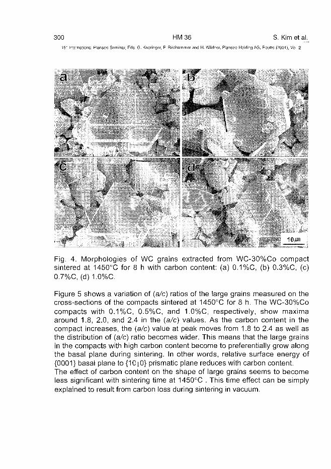
300 HM36 S. Kim et al.15" International Plansee Seminar, Eds. G. Kneringer, P. Rodhammer and H. Wildner, Plansee Holding AG, Reutte (2001), Vol. 2
v
d
Fig. 4. Morphologies of WC grains extracted from WC-30%Co compactsintered at 1450°C for 8 h with carbon content: (a) 0.1%C, (b) 0.3%C, (c)0.7%C, (d) 1.0%C.
Figure 5 shows a variation of (a/c) ratios of the large grains measured on thecross-sections of the compacts sintered at 1450°C for 8 h. The WC-30%Cocompacts with 0.1 %C, 0.5%C, and 1.0%C, respectively, show maximaaround 1.8, 2.0, and 2.4 in the (a/c) values. As the carbon content in thecompact increases, the (a/c) value at peak moves from 1.8 to 2.4 as well asthe distribution of (a/c) ratio becomes wider. This means that the large grainsin the compacts with high carbon content become to preferentially grow alongthe basal plane during sintering. In other words, relative surface energy of{0001} basal plane to {10i0} prismatic plane reduces with carbon content.The effect of carbon content on the shape of large grains seems to becomeless significant with sintering time at 1450°C . This time effect can be simplyexplained to result from carbon loss during sintering in vacuum.
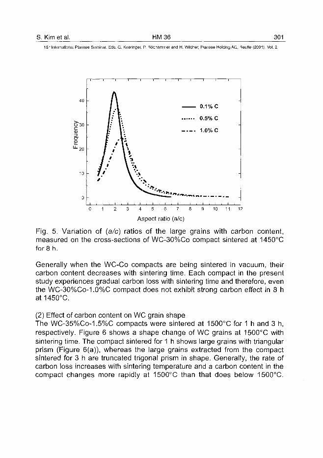
S. Kim et al. HM36 30115lh International Plansee Seminar, Eds. G. Kneringer, P. Rodhammer and H. Wildner, Plansee Holding AG, Reutte (2001), Vol. 2
40
O~30cCD
•^20
10
0
A
IX/: t/• V"v Vt „ L":f ''\\
If \**J.' \ "'•»/ ' \ '"'\
0.1% c
0.5% C-
1.0% c
-
-
I , I I I , I 1 I ,
4 5 6 7
Aspect ratio (a/c)
10 11 12
Fig. 5. Variation of {a/c) ratios of the large grains with carbon content,measured on the cross-sections of WC-30%Co compact sintered at 1450°Cfor 8 h.
Generally when the WC-Co compacts are being sintered in vacuum, theircarbon content decreases with sintering time. Each compact in the presentstudy experiences gradual carbon loss with sintering time and therefore, eventhe WC-30%Co-1.0%C compact does not exhibit strong carbon effect in 8 hat1450°C.
(2) Effect of carbon content on WC grain shapeThe WC-35%Co-1.5%C compacts were sintered at 1500°C for 1 h and 3 h,respectively. Figure 6 shows a shape change of WC grains at 1500°C withsintering time. The compact sintered for 1 h shows large grains with triangularprism (Figure 6(a)), whereas the large grains extracted from the compactsintered for 3 h are truncated trigonal prism in shape. Generally, the rate ofcarbon loss increases with sintering temperature and a carbon content in thecompact changes more rapidly at 1500°C than that does below 1500°C.
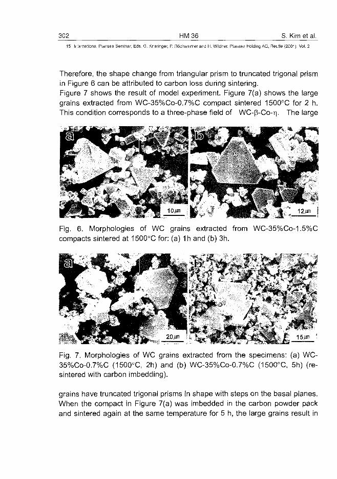
302 HM36 S. Kim et al.15'" International Plansee Seminar, Eds. G. Kneringer, P. Rodhammer and H. Wildner, Plansee Holding AG, Reutte (2001), Vol. 2
Therefore, the shape change from triangular prism to truncated trigonal prismin Figure 6 can be attributed to carbon loss during sintering.Figure 7 shows the result of model experiment. Figure 7(a) shows the largegrains extracted from WC-35%Co-0.7%C compact sintered 1500°C for 2 h.This condition corresponds to a three-phase field of WC-p-Co-r). The large
Fig. 6. Morphologies of WC grains extracted from WC-35%Co-1.5%Ccompacts sintered at 1500°C for: (a) 1h and (b) 3h.
'<••! *> i i
Fig. 7. Morphologies of WC grains extracted from the specimens: (a) WC-35%Co-0.7%C (1500°C, 2h) and (b) WC-35%Co-0.7%C (1500°C, 5h) (re-sintered with carbon imbedding).
grains have truncated trigonal prisms in shape with steps on the basal planes.When the compact in Figure 7(a) was imbedded in the carbon powder packand sintered again at the same temperature for 5 h, the large grains result in
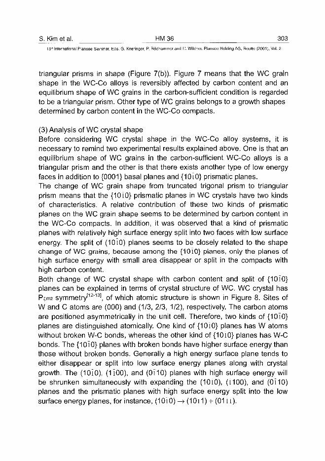
S. Kim et al. HM 36 30315" International Plansee Seminar, Eds. G. Kneringer, P. Rodhammer and H. Wildner, Plansee Holding AG, Reutte (2001), Vol. 2
triangular prisms in shape (Figure 7(b)). Figure 7 means that the WC grainshape in the WC-Co alloys is reversibly affected by carbon content and anequilibrium shape of WC grains in the carbon-sufficient condition is regardedto be a triangular prism. Other type of WC grains belongs to a growth shapesdetermined by carbon content in the WC-Co compacts.
(3) Analysis of WC crystal shapeBefore considering WC crystal shape in the WC-Co alloy systems, it isnecessary to remind two experimental results explained above. One is that anequilibrium shape of WC grains in the carbon-sufficient WC-Co alloys is atriangular prism and the other is that there exists another type of low energyfaces in addition to {0001} basal planes and {1010} prismatic planes.The change of WC grain shape from truncated trigonal prism to triangularprism means that the {1010} prismatic planes in WC crystals have two kindsof characteristics. A relative contribution of these two kinds of prismaticplanes on the WC grain shape seems to be determined by carbon content inthe WC-Co compacts. In addition, it was observed that a kind of prismaticplanes with relatively high surface energy split into two faces with low surfaceenergy. The split of (1010) planes seems to be closely related to the shapechange of WC grains, because among the {1010} planes, only the planes ofhigh surface energy with small area disappear or split in the compacts withhigh carbon content.Both change of WC crystal shape with carbon content and split of {10i0}planes can be explained in terms of crystal structure of WC. WC crystal hasPjm2 symmetry'12"131, of which atomic structure is shown in Figure 8. Sites ofW and C atoms are (000) and (1/3, 2/3, 1/2), respectively. The carbon atomsare positioned asymmetrically in the unit cell. Therefore, two kinds of {1010}planes are distinguished atomically. One kind of {1010} planes has W atomswithout broken W-C bonds, whereas the other kind of {1010} planes has W-Cbonds. The {10i0} planes with broken bonds have higher surface energy thanthose without broken bonds. Generally a high energy surface plane tends toeither disappear or split into low surface energy planes along with crystalgrowth. The (1 OlO), (1100), and (0110) planes with high surface energy willbe shrunken simultaneously with expanding the (10i0), (i100), and (0110)planes and the prismatic planes with high surface energy split into the lowsurface energy planes, for instance, (10i0) -> (1 Oi 1) + (0111).
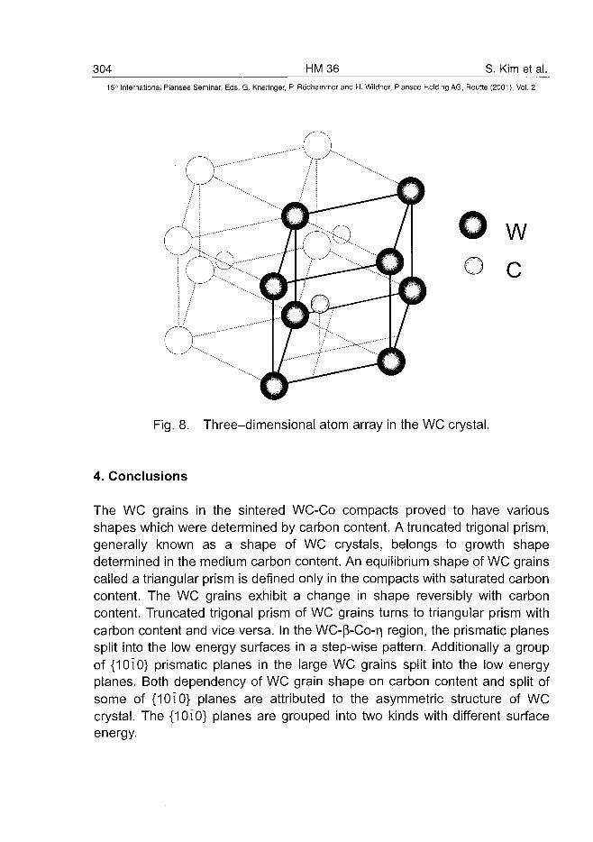
304 HM36 S. Kim et al.5 ' International Plansee Seminar, Eds. G. Kneringer, P. Rodhammer and H. Wildner, Plansee Holding AG, Reutte (2001), Vol. 2
wc
Fig. 8. Three-dimensional atom array in the WC crystal.
4. Conclusions
The WC grains in the sintered WC-Co compacts proved to have variousshapes which were determined by carbon content. A truncated trigonal prism,generally known as a shape of WC crystals, belongs to growth shapedetermined in the medium carbon content. An equilibrium shape of WC grainscalled a triangular prism is defined only in the compacts with saturated carboncontent. The WC grains exhibit a change in shape reversibly with carboncontent. Truncated trigonal prism of WC grains turns to triangular prism withcarbon content and vice versa. In the WC-p-Co-T| region, the prismatic planessplit into the low energy surfaces in a step-wise pattern. Additionally a groupof {10i0} prismatic planes in the large WC grains split into the low energyplanes. Both dependency of WC grain shape on carbon content and split ofsome of {1010} planes are attributed to the asymmetric structure of WCcrystal. The {1010} planes are grouped into two kinds with different surfaceenergy.
S. Kim et al. HM 36 30515" International Plansee Seminar, Eds. G. Kneringer, P. Rodhammer and H. Wildner, Plansee Holding AG, Reutte (2001), Vol. 2
References
1. E. Lardner: Powder Metall. 21 [2] (1978), pp. 65-802. E. Lardner: Powder Metall. 13[26] (1970), pp. 394-4283. Leo J. Prakash: Int. J. Ref. Metals & Hard Mat. 13 (1995), pp. 2574. J. Gurland and P. Bardzil: Trans. AIME. 203 (1955), pp. 311-3155. J. Wasen and R. Warren: Mat. Sci. Tech. 5 (1989), pp. 2226. A.V. Shatov, S.A. Firstov and I.V. Shatova: Mat. Sci. Eng. A242 (1998), pp.7-147. H.S. Ryoo and S.K. Hwang: Scri. Mat. 39[11] (1998), pp. 1577-15838. J. Gurland: Trans. AIME. 200 (1954), pp. 285-2909. J. Gurland: J. Metals Nov. (1954), pp. 1372-133010. H.E. Exner, E. Santa and G. Petzow: Modern Developments in PowderMetallurgy 4 H.H. Hausner (ed.) Plenum Press. New York (1971), pp. 315-32511. P. Rautala and J.T. Norton: J. Metals Oct. (1952), pp. 1045-105012. E. Parthe and V. Sadagopan: Monatshefte fur Chemie. 93 (1962), pp. 26313. M. Hansen: Constitution of Binary Alloys 2nd ed. MacGraw-Hill Book Co.New York (1958), pp. 391
AT0100461306 HM37 R.E. Toth et al.
15" International Plansee Seminar, Eds. G. Kneringer, P. Rodhammer and H. Wildner, Plansee Holding AG, Reutte (2001), Vol. 2
TOUGH-COATED HARD POWDERS FORHARDMETALS OF NOVEL PROPERTIES
Richard E. TothA, I. Smid*, A. Sherman**, P. Ettmayer***, G. Kladler*, G. Korb*
A TCHP Inventor, EnDurAloy Corporation, Savannah, Georgia, USA* Austrian Research Center at Seibersdorf, High Performance Materials
** Powdermet, Inc. Sun Valley, California, USA*** Technical University of Vienna, Austria
ABSTRACT
The properties and performance of conventional materials and compositesare constrained by solubility limits, diffusion coefficients, and compatibility ofphysical and chemical constituent properties in their phase equilibria. To es-cape these limits, ingenious ways of combining strength, toughness, andwear resistance by way of various coatings and laminations have been de-vised. These coated tools are systematically discarded after only about 10%of their wear tolerance has been used.
Tough-Coated Hard Powders (TCHP), patented by EnDurAloy (USA), arehard refractory particles CVD coated with nanolayers of WC and Co. Con-solidation of TCHP creates an engineered homogeneous cellular structurewhose interconnected tough WC-Co "shells" each contain a wear-resistantcore (e.g., TiN). In TCHP's, the coating is throughout the tool, not only on thesurface, combining the strength, heat resistance, and toughness of cementedcarbides with the chemical and abrasion wear resistance of harder materials.As wear progresses, new wear-resistant material continuously replaces theworking surfaces and edges of the tool until its geometry reaches its maxi-mum limits. TCHP tools are then reusable many times.
Specific coating and consolidation processes, characterization of compacts,and test comparisons with conventional materials are discussed.
KEY WORDS
TCHP, Hardmetal, Cermet, Ceramic, Nanocomposite CVD Coated Powder,Refractory Alloy, TiN, AI2O3.
R.E. Toth et al. HM 37 307_
15" International Plansse Seminar, Eds. G. Kneringer, P. Rddhammer and H. Wildner, Plansee Holding AG, Reutte (2001), Vol. 2
A. NEED FOR - and PROGRESS TOWARD - a NEW APPROACH
It appears that few if any "new paradigm" tool materials that combine highfracture toughness and_wear resistance will result using classical metallurgi-cal principles. The physical, chemical, and mechanical properties of materialswill be determined mainly by chemical composition, microstructure, and de-formation- or thermal-treatments. Moreover, the properties of certain materi-als cannot be influenced: a diamond must remain a diamond. To escapethese limits, man has devised ingenious ways of combining toughness andwear resistance, including CVD-PVD (chemical/physical vapor deposition)coatings, ceramic and cermet mixtures, and FGM (lamination).
New tool approaches are needed to form or machine today's challenging ma-terials. EtemAloy™, or Tough-Coated Hard Powders (TCHPs), are novelnanocomposites of one or more types of hard refractory alloy core particlesthat are CVD-encapsulated in a WC coating and an outer cobalt binder coat-ing. The objective is to design and engineer a homogeneous "core-rim" cellu-lar structure of 60-90 volume percent of evenly distributed hard core particlesof the most wear resistant refractory core materials known in a tungsten car-bide (WC) matrix support structure with toughness and strength comparableto WC-Co substrates.
In this way, "thermodynamically incompatible" material combinations havebeen successfully consolidated into tool inserts and tested. We have shownthat WC-Co coatings form a nanoscale cemented carbide matrix betweenevenly distributed wear-resistant particles. This structure is expected to ex-hibit exceptional strength and wear resistance when compared to cementedcarbides, coated carbides, cermets, and ceramics. It is expected this will oc-cur after solid state and liquid phase consolidation and at minimum cost, thenovel material being industrially competitive with conventional materials. It ishoped TCHPs may promise the elusive combination of properties that state-of-the-art tools cannot.
TCHP enables us to nano-engineer building block properties. Nanoencapsu-lating fine particles having one set of desirable properties with grain boundarymodifiers having other properties allows us (a) to combine heretofore uncom-binable material-property combinations, and (b) to unite many desirableproperties prior to sintering. With over 30 candidate core materials, manyEternAloy™ combinations are possible. TCHP allows us to engineer almost
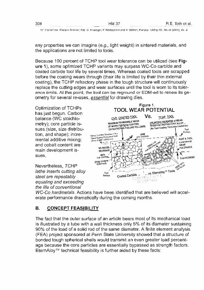
308 HM37 R.E. Toth et al.15:" International Plansee Seminar, Eds. G. Kneringer, P. Rodhammer and H. Wildner, Plansee Holding AG, Reutte (2001), Vol. 2
any properties we can imagine (e.g., light weight) in sintered materials, andthe applications are not limited to tools.
Because 100 percent of TCHP tool wear tolerance can be utilized (see Fig-ure 1), some optimized TCHP variants may surpass WC-Co carbide andcoated carbide tool life by several times. Whereas coated tools are scrappedbefore the coating wears through (their life is limited by their thin externalcoating), the TCHP refractory phase in the tough structure will continuouslyreplace the cutting edges and wear surfaces until the tool is worn to its toler-ance limits. At this point, the tool can be reground or EDM-ed to renew its ge-ometry for several re-uses, essential for drawing dies.
Optimization of TCHPshas just begun. Carbonbalance (WC stoichio-metry); core particle is-sues (size, size distribu-tion, and shape); incre-mental additive mixing;and cobalt content aremain development is-sues.
Figure 1.TOOL WEAR POTENTIAL
V S . TCHLIQOL
Typical tool Wear Ti
Typical Coating TDK
micron ( (WOM-M 0 0 6
CVD COATII
TOUGH CARBIDESUBSTRATE
PART & TOOL
fLANKICRATER
WEAR•TOLERANCE
First REGRIND
Coated Carbide vs,;.EternMoy™ Tools
Nevertheless, TCHPlathe inserts cutting alloysteel are repeatablyequaling and exceedingthe life of conventionalWC-Co hardmetals. Actions have been identified that are believed will accel-erate performance dramatically during the coming months.
B. CONCEPT FEASIBILITY
The fact that the outer surface of an article bears most of its mechanical loadis illustrated by a tube with a wall thickness only 5% of its diameter sustaining90% of the load of a solid rod of the same diameter. A finite element analysis(FEA) project sponsored at Penn State University showed that a structure ofbonded tough spherical shells would transmit an even greater load percent-age because the core particles are essentially bypassed as strength factors.EternAloy™ technical feasibility is further aided by these facts:
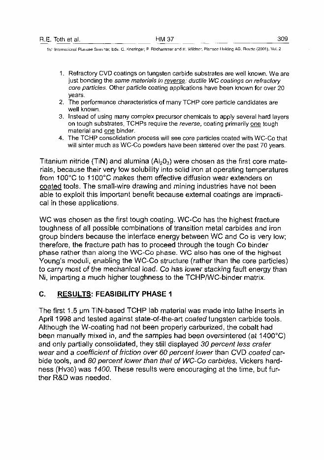
R.E. Toth et al. HM 37 309^15lh International Plansee Seminar, Eds. G. Kneringer, P. RocJhammer and H. Wildner, Plansee Holding AG, Reutte (2001), Vol. 2
1. Refractory CVD coatings on tungsten carbide substrates are well known. We arejust bonding the same materials in reverse: ductile WC coatings on refractorycore particles. Other particle coating applications have been known for over 20years.
2. The performance characteristics of many TCHP core particle candidates arewell known.
3. Instead of using many complex precursor chemicals to apply several hard layerson tough substrates, TCHPs require the reverse, coating primarily one toughmaterial and one binder.
4. The TCHP consolidation process will see core particles coated with WC-Co thatwill sinter much as WC-Co powders have been sintered over the past 70 years.
Titanium nitride (TiN) and alumina (AI203) were chosen as the first core mate-rials, because their very low solubility into solid iron at operating temperaturesfrom 100°C to 1100°C makes them effective diffusion wear extenders oncoated tools. The small-wire drawing and mining industries have not beenable to exploit this important benefit because external coatings are impracti-cal in these applications.
WC was chosen as the first tough coating. WC-Co has the highest fracturetoughness of all possible combinations of transition metal carbides and irongroup binders because the interface energy between WC and Co is very low;therefore, the fracture path has to proceed through the tough Co binderphase rather than along the WC-Co phase. WC also has one of the highestYoung's moduli, enabling the WC-Co structure (rather than the core particles)to carry most of the mechanical load. Co has lower stacking fault energy thanNi, imparting a much higher toughness to the TCHP/WC-binder matrix.
C. RESULTS: FEEASIBILITY PHASE 1
The first 1.5 urn TiN-based TCHP lab material was made into lathe inserts inApril 1998 and tested against state-of-the-art coated tungsten carbide tools.Although the W-coating had not been properly carburized, the cobalt hadbeen manually mixed in, and the samples had been oversintered (at 1400°C)and only partially consolidated, they still displayed 30 percent less craterwear and a coefficient of friction over 60 percent lower than CVD coated car-bide tools, and 80 percent lower than that of WC-Co carbides. Vickers hard-ness (Hv30) was 7400. These results were encouraging at the time, but fur-ther R&D was needed.
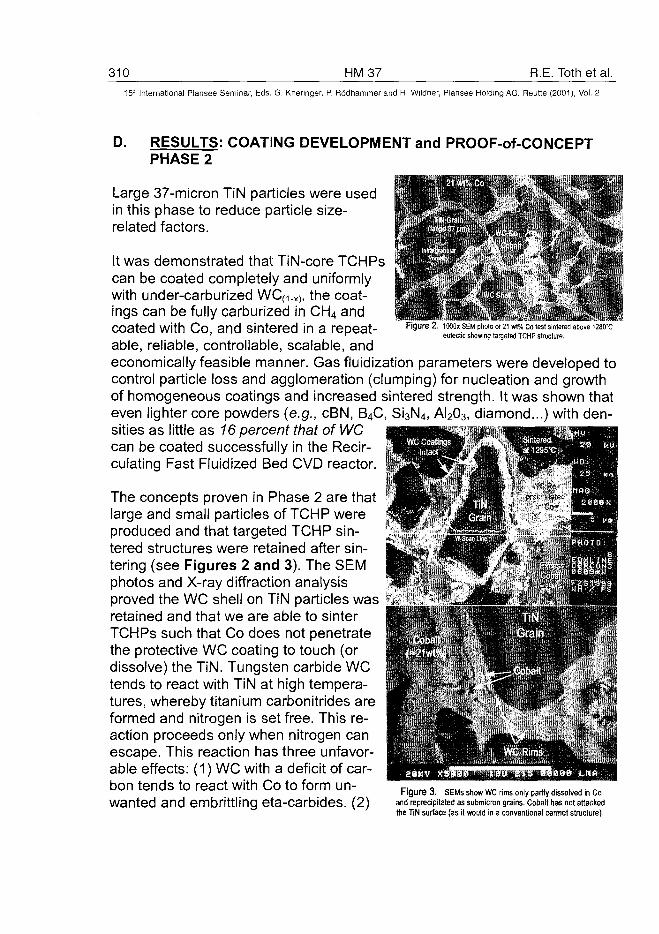
310 HM37 R.E. Toth et al.15-" International Plansee Seminar, Eds. G. Kneringer, P. Rodhammer and H. Wildner, Plansee Holding AG, Reutte (2001), Vol. 2
D. RESULTS: COATING DEVELOPMENT and PROOF-of-CONCEPTPHASE 2
Large 37-micron TiN particles were usedin this phase to reduce particle size-related factors. . - * " .
eulectic showing targeted TCHP structure.
It was demonstrated that TiN-core TCHPscan be coated completely and uniformlywith under-carburized WC(1.X), the coat- J *j?£ings can be fully carburized in CH4 and , f .!•coated with Co, and sintered in a repeat-able, reliable, controllable, scalable, andeconomically feasible manner. Gas fluidization parameters were developed tocontrol particle loss and agglomeration (clumping) for nucleation and growthof homogeneous coatings and increased sintered strength. It was shown thateven lighter core powders (e.g., cBN, B4C, Si3N4, AI203, diamond...) with den-sities as little as 16 percent that of WCcan be coated successfully in the Recir-culating Fast Fluidized Bed CVD reactor.
The concepts proven in Phase 2 are thatlarge and small particles of TCHP wereproduced and that targeted TCHP sin-tered structures were retained after sin-tering (see Figures 2 and 3). The SEMphotos and X-ray diffraction analysisproved the WC shell on TiN particles wasretained and that we are able to sinterTCHPs such that Co does not penetratethe protective WC coating to touch (ordissolve) the TiN. Tungsten carbide WCtends to react with TiN at high tempera-tures, whereby titanium carbonitrides areformed and nitrogen is set free. This re-action proceeds only when nitrogen canescape. This reaction has three unfavor-able effects: (1) WC with a deficit of car-bon tends to react with Co to form un-wanted and embrittling eta-carbides. (2)
Figure 3 . SEMs show WC rims only partly dissolved in Co
and reprecipitated as submicron grains. Cobalt has not attacked
the TIN surface (as it would in a conventional cermet structure).
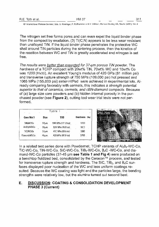
R.E. Toth et al. HM 37 311
15" International Plansee Seminar, Eds. G. Kneringer, P. Rodhammer and H. Wildner, Plansee Holding AG, Reutte (2001), Vol. 2
The nitrogen set free forms pores and can even expel the liquid binder phasefrom the compact by exudation. (3) Ti(C,N) appears to be less wear resistantthan unalloyed TiN. If the liquid binder phase penetrates the protective WCshell around TiN particles during the sintering process, then the kinetics ofthe reaction between WC and TiN is greatly accelerated and nitrogen is setfree.
The results were better than expected for 37-fjm porous TiN powder. Thehardness of a TCHP compact with 20wt% TiN, 70wt% WC and 10wt% Cowas 1200 (Hv30). An excellent Young's modulus of 420 GPa (61 million psi)and transverse rupture strength of 750 MPa (109,000 psi) hot pressed and1065 MPa (155,000 psi) sinter-HIPed were achieved in experimental lots. Al-ready comparing favorably with cermets, this indicates a strength potentialsuperior to that of ceramics, cermets, and cBN-diamond compacts. Becauseof (a) large size core powders and (b) hidden internal porosity in the pur-chased powder (see Figure 2), cutting tool wear trial tests were not per-formed.
Core Mat'l
TiNfWC/Co
Al203/WCfCo
TiC/WC/Co
DiamondlWC/Co
Size
37/vm
35/ym
37//m
45yam
T a b l e 1
TRS
840 MPa (121.8 ksi]
524 MPa (76.0 ksi)
410 MPa (59.5 ksi)
420 MPa (60.9 ksi)
Hardness (Hv)
1200
1800
1680
3200
In a related test series done with Powdermet, TCHP variants of AI203-WC-Co,TiC-WC-Co, TiN-WC-Co, SiC-WC-Co, TiB2-WC-Co, B4C -WC-Co, and dia-mond-WC-Co particles (37-45 urn see Table 1 and Fig 4) were produced ona benchtop fluidized bed, consolidated by the Ceracon™ process, and testedfor transverse rupture strength and hardness. The SiC, TiB2, and B4C sur-faces displayed poor nucleation of the WC and less uniform coatings re-sulted. Because the WC coating was light and the particles large, the bendingstrengths were relatively low, but the alumina turned out second best.
E. DISCUSSION: COATING & CONSOLIDATION DEVELOPMENTPHASE 3 (Current)
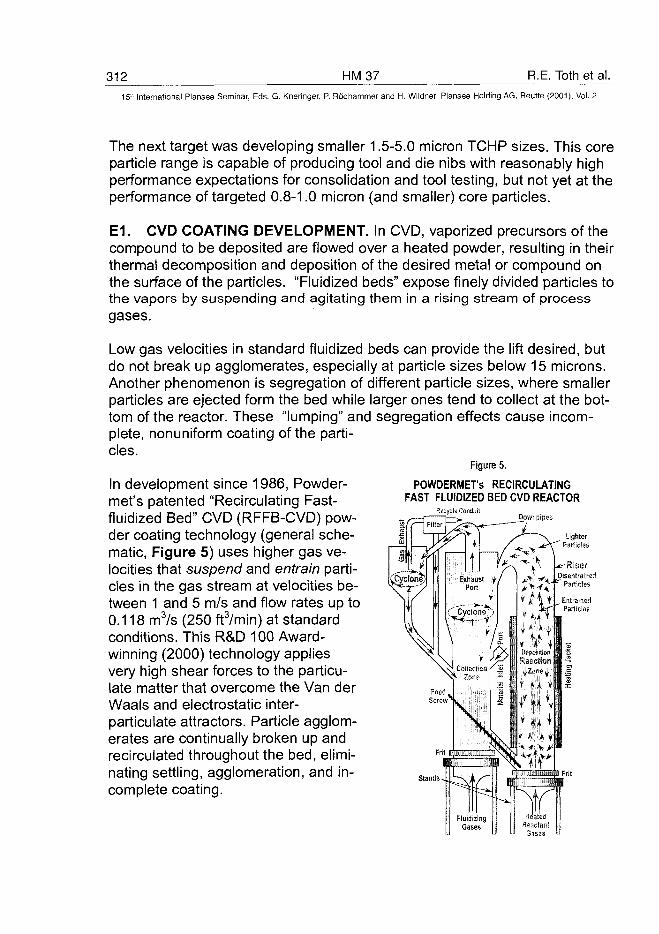
312 HM37 R.E. Toth et al.15" International Plansee Seminar, Eds. G. Kneringer, P. Rodhammer and H. Wildner, Plansee Holding AG, Reurte (2001), Vol. 2
The next target was developing smaller 1.5-5.0 micron TCHP sizes. This coreparticle range is capable of producing tool and die nibs with reasonably highperformance expectations for consolidation and tool testing, but not yet at theperformance of targeted 0.8-1.0 micron (and smaller) core particles.
E1. CVD COATING DEVELOPMENT. In CVD, vaporized precursors of thecompound to be deposited are flowed over a heated powder, resulting in theirthermal decomposition and deposition of the desired metal or compound onthe surface of the particles. "Fluidized beds" expose finely divided particles tothe vapors by suspending and agitating them in a rising stream of processgases.
Low gas velocities in standard fluidized beds can provide the lift desired, butdo not break up agglomerates, especially at particle sizes below 15 microns.Another phenomenon is segregation of different particle sizes, where smallerparticles are ejected form the bed while larger ones tend to collect at the bot-tom of the reactor. These "lumping" and segregation effects cause incom-plete, nonuniform coating of the parti-cles.
In development since 1986, Powder-met's patented "Recirculating Fast-fluidized Bed" CVD (RFFB-CVD) pow-der coating technology (general sche-matic, Figure 5) uses higher gas ve-locities that suspend and entrain parti-cles in the gas stream at velocities be-tween 1 and 5 m/s and flow rates up to0.118 m3/s (250 ftVmin) at standardconditions. This R&D 100 Award-winning (2000) technology appliesvery high shear forces to the particu-late matter that overcome the Van derWaals and electrostatic inter-particulate attractors. Particle agglom-erates are continually broken up andrecirculated throughout the bed, elimi-nating settling, agglomeration, and in-complete coating.
Figure 5.
POWDERMET's RECIRCULATINGFAST FLUIDIZED BED CVD REACTOR
Recycte ConduitDown pipes
Stands -
Gases
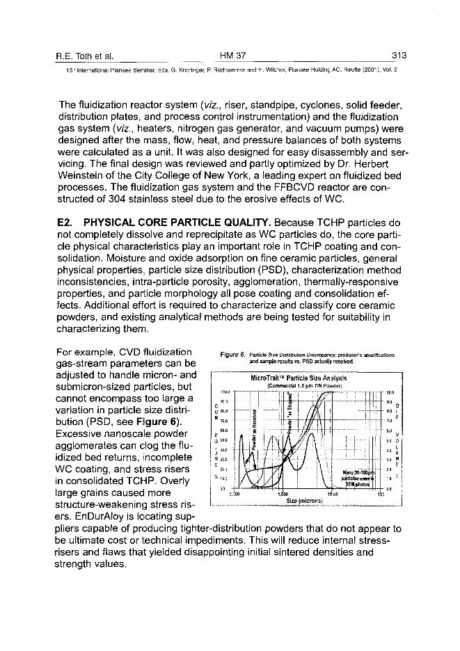
R.E. Toth et al. HM37 31315" International Plansee Seminar, Eds. G. Kneringer, P. Rodhammer and H. Wildner, Plansee Holding AG, Reutte (2001), Vol. 2
The fluidization reactor system {viz., riser, standpipe, cyclones, solid feeder,distribution plates, and process control instrumentation) and the fluidizationgas system {viz., heaters, nitrogen gas generator, and vacuum pumps) weredesigned after the mass, flow, heat, and pressure balances of both systemswere calculated as a unit. It was also designed for easy disassembly and ser-vicing. The final design was reviewed and partly optimized by Dr. HerbertWeinstein of the City College of New York, a leading expert on fluidized bedprocesses. The fluidization gas system and the FFBCVD reactor are con-structed of 304 stainless steel due to the erosive effects of WC.
E2. PHYSICAL CORE PARTICLE QUALITY. Because TCHP particles donot completely dissolve and reprecipitate as WC particles do, the core parti-cle physical characteristics play an important role in TCHP coating and con-solidation. Moisture and oxide adsorption on fine ceramic particles, generalphysical properties, particle size distribution (PSD), characterization methodinconsistencies, intra-particle porosity, agglomeration, thermally-responsiveproperties, and particle morphology all pose coating and consolidation ef-fects. Additional effort is required to characterize and classify core ceramicpowders, and existing analytical methods are being tested for suitability incharacterizing them.
Figure 6. Particle Size Distribution Discrepancy: producer's specificationsand sample results vs. PSD actually received.
MicroTrak™ Particle Size Analysis(Commercial 1.5 |im TiN Powder)
For example, CVD fluidizationgas-stream parameters can beadjusted to handle micron- andsubmicron-sized particles, butcannot encompass too large avariation in particle size distri-bution (PSD, see Figure 6).Excessive nanoscale powderagglomerates can clog the flu-idized bed returns, incompleteWC coating, and stress risersin consolidated TCHP. Overlylarge grains caused morestructure-weakening stress ris-ers. EnDurAloy is locating sup-pliers capable of producing tighter-distribution powders that do not appear tobe ultimate cost or technical impediments. This will reduce internal stress-risers and flaws that yielded disappointing initial sintered densities andstrength values.
Size (microns)
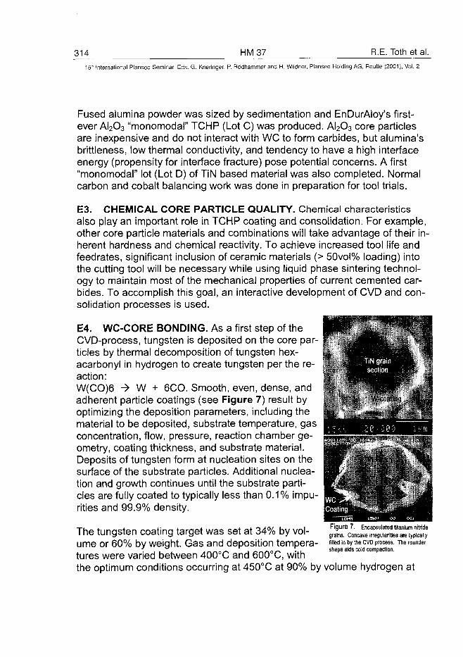
314 HM37 R.E. Toth et al.International Plansee Seminar, Eds. G. Kneringer, P. Rodhammer and H. Wildner, Plansee Holding AG, Reutte (2001), Vol. 2
Fused alumina powder was sized by sedimentation and EnDurAloy's first-ever AI2O3 "monomodal" TCHP (Lot C) was produced. AI2O3 core particlesare inexpensive and do not interact with WC to form carbides, but alumina'sbrittleness, low thermal conductivity, and tendency to have a high interfaceenergy (propensity for interface fracture) pose potential concerns. A first"monomodal" lot (Lot D) of TiN based material was also completed. Normalcarbon and cobalt balancing work was done in preparation for tool trials.
E3. CHEMICAL CORE PARTICLE QUALITY. Chemical characteristicsalso play an important role in TCHP coating and consolidation. For example,other core particle materials and combinations will take advantage of their in-herent hardness and chemical reactivity. To achieve increased tool life andfeedrates, significant inclusion of ceramic materials (> 50vol% loading) intothe cutting tool will be necessary while using liquid phase sintering technol-ogy to maintain most of the mechanical properties of current cemented car-bides. To accomplish this goal, an interactive development of CVD and con-solidation processes is used.
E4. WC-CORE BONDING. As a first step of theCVD-process, tungsten is deposited on the core par-ticles by thermal decomposition of tungsten hex-acarbonyl in hydrogen to create tungsten per the re-action:W(C0)6 -» W + 6CO. Smooth, even, dense, andadherent particle coatings (see Figure 7) result byoptimizing the deposition parameters, including thematerial to be deposited, substrate temperature, gasconcentration, flow, pressure, reaction chamber ge-ometry, coating thickness, and substrate material.Deposits of tungsten form at nucleation sites on thesurface of the substrate particles. Additional nuclea-tion and growth continues until the substrate parti-cles are fully coated to typically less than 0.1% impu-rities and 99.9% density.
The tungsten coating target was set at 34% by vol-ume or 60% by weight. Gas and deposition tempera-tures were varied between 400°C and 600°C, withthe optimum conditions occurring at 450°C at 90% by volume hydrogen at
fiiiedin by the C V D process.
shape aids cold compaction.
R.E. Toth et al. HM 37 315^
15th International Plansee Seminar, Eds. G. Kneringer, P. Rodhammer and H. Wildner, Plansee Holding AG, Reutte (2001), Vol. 2
268 mbar vacuum. Some core particles nucleated the WC(1.X) layer betterthan others. Specifically, the TiN, alumina, diamond, and TiC cores nucle-ated dense uniform coatings at near-theoretical weight gains. The other parti-cles - SiC, TiB2, and B4C - exhibited preferential growth and were less uni-formly coated. Hot pre-treating the particles with hydrogen significantly im-proved the tungsten layer adhesion to diamond; however, this treatment pro-duced only modest improvements for SiC, TiB2, and B4C.
E5. CARBURIZATION PROCESS CONTROL. Control over carburizationof the carbon deficient primary WC^x layer is critical to achieve the desiredTCHP strength and sinterability. After varying methane concentration, hydro-gen/methane ratio, and temperature on carbon diffusion into the tungsten-coated powder, the optimal carburization from tungsten to tungsten carbide iscarried out via methane (concentration 3%; remainder hydrogen) at tempera-tures in excess of 950°C. A twenty-four hour carburization cycle at 1000°Cwith 5vol% methane at zero pressure produces a stoichiometric tungstencarbide layer on titanium nitride particles, as determined by XRD analysis.The formation of elemental carbon via the decomposition of CH4 should beavoided.
While the ability to control carbon was demonstrated, the ability to manuallyadd excess carbon and to control oxygen content and carbon losses duringconsolidation of TCHP materials requires additional investigation. This abilityto tailor carbon contents represents new technology, since it must be accom-plished at relatively low temperatures (i.e., less than 1100°C compared to1600°C for conventional carburization) to prevent coarsening and solubilityreactions from occurring.
We have not yet fully defined and mastered the effects of adsorbed oxygenand other chemical changes occurring during handling and consolidation. Thetype of core powder material, the nature of the core particle size distribution,the presence of adsorbed oxygen or surface oxides, and the presence ofother trace elements can alter the as-sintered TCHP carbon balance andslow the investigative progress.
The role of oxygen in TCHP particulates appears to be particularly trouble-some, because the chemical and mechanical properties of the powder parti-cles appear to depend on where the oxygen content is bound: in the core, atthe interface between core and WC coating, or on the outside of the WC-coating.
316 HM37 R.E. Toth et al.15" International Plansee Seminar, Eds. G. Kneringer, P. Rodhammer and H. Wildner, Plansee Holding AG, Reutte (2001), Vol. 2
In the latter case, some of the carbon may be lost during sintering via COloss. With TiN core powders, outgassing of CO accelerated by the presenceof Co during heating to liquid phase, tends to deplete carbon. N2 outgassingfrom partially-coated TiN cores (if not minimized by N2 overpressure) can alsofree Ti to rob C from WC. This carbon depletion can cause formation ofCo3W3C (eta phase), which consumes free cobalt binder phase and embrit-tles the structure as with conventional WC hardmetals.
Because the tungsten carbide gradient layer grows by diffusion, externalmethods of characterizing coating stoichiometry can be misleading. Modelswill be developed to determine what carburization excess or deficit will antici-pate the chemical evolution during sintering to optimize consolidated TCHPproperties.
These impediments to the TCHP investigative process are more than offsetby the wealth of relevant information and equipment available from decadesof optimizing WC-Co, cermet, and ceramic materials.
E6. FLAWS, POOLING, and OTHER STRESS RISERS. The large indus-trial batch capacity (700-800 kg) of the Recirculating Fast Fluidized Bed CVDcoater (FFB-CVD) requires a minimum TCHP test lot of about 25 kg of a fixedWC-Co composition. This does not allow appropriately small R&D lot itera-tions to be made for each experimental specification. Smaller benchtop CVDreactors will not de-agglomerate small particles. Trial elemental-incrementbatches to attain optimal TCHP carbon and cobalt balance necessitates me-chanically MIXING-in of cobalt, carbon, or tungsten test variant additive pow-ders in partial (500g) lots taken from larger TCHP lots produced with fixed"baseline" constituent levels.
Co- and W-pooling has been a major cause for lower-than-possible TCHPstrength values to date. Because at the present stage of development short-mixing (not milling) cycles must be used (to avoid damaging of the TCHPcoatings), inherently poor distribution of cobalt, tungsten, or carbon powdersadversely affects the sintered structure. Mixed with 5-micron particles, 1.0-1.5micron cobalt particles create Co "pools" observable in the SEM photos. Ithas been shown that more than 48 hours of aggressive ball milling (not mix-ing) are required to eliminate "pooling". Smaller Co powders bring more oxy-gen and agglomeration and are pyrophoric. Pooling will be a problem until thelarge CVD reactor can be operated to deposit nanoscale contiguous coatingsat or close to the empirically found optimum TCHP compositions.
R.E. Toth et al. HM 37 31715" International Plansee Seminar, Eds. G. Kneringer, P. Rodhammer and H. Wildner, Plansee Holding AG, Reutte (2001), Vol. 2
However, using a benchtop fluidized bed CVD reactor improved the me-chanical blending problem by evenly dispersing incremental nanoscale addi-tives without damaging the TCHP, but industrial scale CVD powder coatingwill always be more effective and efficient than plain mixing.
E7. COBALT COATING CONTROL. The cobalt coating was performed us-ing the thermal decomposition of cobalt carbonyl in hydrogen. The cobaltCVD decomposition reaction Co2(CO)8 -> 2Co + 8 CO takes place atdeposition temperatures ranging from 180-220°C, in our case at 200°C at 268mbar. The preparation of the cobalt carbonyl occurs with direct reaction of thesolid carbonate with carbon monoxide gas with hydrogen as a reducing agentas follows: 2 CoCO3 + 8 CO + 2 H2 -» Co2(CO)8 + 2 H2O + 2 CO2, whichtakes place above a pool of acetone solvent. As the reaction proceeds, thecarbonyl sublimes into the gas phase. The carbonyl vapor then dissolves inthe solvent, which also removes the water vapor from the gas phase. Thedissolution of the reaction products in the acetone therefore removes themfrom the gas phase where they would limit the extent of reaction.
E8. TCHP POST-PROCESSING. While reasonably good mechanical prop-erties were achieved with the 1-5 micron materials, TCHP properties have notyet approached the performance predicted by extrapolation. This was attrib-uted to the presence of microstructural defects and flaws in the consolidatedmaterials stemming in part from test additive mixing. Post-processing thecoated powders will also be studied as a way to further reduce these flaws.Sieving the coated powders can eliminate large particles and agglomerates(some agglomerates form at the wall of the CVD reactor when very fine pow-ders are processed) causing flaws in the consolidated product. In addition,physical separation can also control chemical non-homogeneities (i.e., denseand light coated particles) in the final product. Modifying cobalt CVD coatingconditions will also be evaluated for stabilizing the coated powder duringshipping, storage, and handling to prevent pyrophoricity and water/oxygenadsorption as particle size is further decreased.
While the objective is to achieve near-perfect control during TCHP synthesis,the ability to characterize, rework, and modify particles after coating is a prac-tical necessity. Additionally, the need to granulate TCHP in a controlled man-ner for particle flow and repeatable die filling may also become necessary.
318 HM37 R.E. Toth et al.15'-" International Plansee Seminar, Eds. G. Kneringer, P. Rodhammer and H. Wildner, Plansee Holding AG, Reutte (2001), Vol. 2
E9. CONSOLIDATION DEVELOPMENT PROCEDURE. The TCHP sam-ples were mixed with balancing W or C, and/or Co (if required) in acetone for3 hours and pre-compacted at room temperature. They were then hotpressed in a 65 mm cylindrical graphite mold (lined with graphite fabric) witha heating rate of 10 K/min to 1000°C under vacuum, then heated to 1300°Cwith 5 K/min under 50 mbar N2 overpressure and held at 30 MPa maximumuniaxial pressure and temperature for 30 minutes. Cooling rate, atmosphere,and pressure were controlled down to 1000°C.
The following sinter technologies were used: Hot pressing, Ceracon™ forg-ing, electric impulse densification, sintering, and sinter-HIP. Of these, hotpressing and Ceracon™ forging are most suitable at this stage of develop-ment. For production at industrial scale quantities, sintering and sinter-HIPare presently the most economical methods. We will continue to develop hotpressing and the Ceracon™ forging process while developing other TCHPcomposite consolidation methods such as sinter-HIP and PIM/MIM.
E10. TOOL WEAR COMPARISON BASIS. The initial tool wear test com-parisons of TCHP inserts with CVD coated inserts will not be as simple ascomparing "measured wear per unit of time." Coated tools are used until theCVD coating is almost worn through and then thrown away after only about10% of the tool has been used because failure is catastrophic at high speed ifwear proceeds into the carbide substrate. Worn to completion, the wear rateof coated tools would be decidedly two-sloped: slow through the outer coat-ing, much faster in the WC-Co substrate. The ultimate advantage of TCHPsis that they can be left in the machine to operate longer, exploiting the fullmachining tolerance by using the considerable additional volume of wear-resistant material. But first, their strength must be developed and optimized.
Until TCHP chemistry and strength are optimized to compare with those ofWC-Co substrates, comparing tool life of TCHP inserts with coated WC-Coinserts would be heavily biased in favor of coated tools. Why? Since externalCVD coatings are CONTIGUOUS for the first 10% of the wear tolerance, themeasured wear resistance ~ while the coating is in place -- will logically besomewhat better during initial comparisons than with TCHP tools (with ex-posed WC-Co ligaments between the wear-resistant particles). When com-paring TCHP tools with CVD coated tools, the TCHP inserts should last longenough for the coated tool to have its CVD coating worn through and even
R.E. Toth et al. HM 37 31!9_15* International Plansee Seminar, Eds. G. Kneringer, P. Rodhammer and H. Wildner, Plansee Holding AG, Reutte (2001), Vol. 2
into the carbide substrate to demonstrate the wear advantage of TCHP afterlonger use.
Since we are still optimizing chemistry and have only a limited number oftools available, we are making the first TCHP performance test comparisonswith high quality WC-Co inserts. This will make early wear-vs.-time meas-urements equitable and simpler. Since the life multiples of CVD-coated toolsversus WC-Co tools are well known (6-1 OX), the inference and comparison ofTCHP with CVD-coated tools (and even cermets) can also be made. A goodTCHP performance compared with conventional carbide will still have univer-sal appeal, and when the TCHP parameters are optimized, we can have afair TCHP comparison with CVD coated inserts. Later, when more tools areavailable and the TCHPs optimized more, the comparisons will be made withcoated inserts and cermets.
The standard WC-Co insert chosen was a Bohlerit TNMM R131 triangular in-sert. Bohlerstahl V945 alloy steel (CK 45/DIN1.1191; 0.45%C, 0.3% Si, 0.7%Mn) test bars were machined in a lathe with test surface speed set at 200m/min, feed 0.15 mm/rev, depth of cut 2.0 mm. Under these conditions,based on acoustic, chip characteristic, sparking, surface smoothness, anddimensional characteristics, the test was halted after an average life of of 45minutes and a wear of 0.5 mm.
E11. PERFORMANCE RESULTS. The coatings on the 5-um TiN and AI2O3-based TCHP improved substantially in quality and reliability. Powder coating,consolidation, heat-treatment, and test/characterization processes are beinghandled much faster, and we achieved 99.8% density in both liquid-phasehot-pressing consolidation and Ceracon™ forging (see Tables 2 and 3).
Up to 3.8% Co, the alumina TCHP specimens showed a higher bendingstrength; above 5.0% Co TiN based TCHP had a higher strength. In bothTCHP types, starting from 5% Co we found that increasing the cobalt to a to-tal of 10, 14 and 18 wt% tended to progressively decrease strength. In lathetests, low crater wear — but increasingly higher flank wear — were observedwith increasing Co. Flank wear is highly related to low density, carbon bal-ance, and cobalt content - which are a straightforward matter of trial, discov-ery, then control.

320 HM37 R.E. Toth et al.15" International Plansee Seminar, Eds. G. Kneringer, P. Rodhammer and H. Wildner, Plansee Holding AG, Reutte (2001), Vol. 2
We felt these strength trends could beimproved by reducing the Co:WC ratioand by continued improvement in carbonbalance. A new TCHP test series of nineAI2O3 and TiN variants was producedwith cobalt levels of 5.0wt%, 3.8wt%,2.6wt%, and 1.4wt% Co to total. Doingthis was a challenge since the baselineTCHP lots had already been producedwith a 5wt% Co minimum and accord-ingly required adjusting W levels up-wards to get below 5wt% Co and to bal-ance C levels. The non-reactor mixing ofthe experimental composition causedpooling of WC-Co and of WC, with con-sequent reduction of performance. Inspite of this, the results were positive:
WC-Co 3.8wt% » * AI2O3 Phase
Figure 8. Lot c A1203-WC-3.8 wt% Co TCHP
*
E11.1. For the TiN -based TCHP with 3.8 wt% Co, a good Vickers' (Hv30)hardness of 1150 was attained using only hot-press consolidation. Hotisostatic pressing would give higher values. In wear tests, crater wear wasvery low but flank wear was high. At 45.5 min, tool life of state-of-the art-commercial WC-Co was equaled or surpassed.
E11.2. For hot pressed alumina at 3.8%Co, hardness was 1463 (Hv30), and toollife was 35 min. A typical microstructureis seen in Figure 8. In addition, scanningelectron microscope photos of fracturesurfaces show good chemical wetting atthe WC-Co and Alumina interface (seeFigure 9). This assures good materialcontiguity. This is evidenced in the photo,where the gray AI2O3 grain is seen totransition gradually to the white of tung-sten carbide (WC) and the fracture sur-face cleaves the AI2O3 grain rather thanpulling it out of the WC-Co substrate.
- VJ
Figure 9. Alumina TCHP Fracture Surface
(Hot Pressed at 1300'C).
R.E. Toth et al. HM 37 321
15th International Plansee Seminar, Eds. G. Kneringer, P. Rodhammer and H. Wildner, Plansee Holding AG, Reutte (2001), Vol. 2
E11.3. We increased the lathe test surface speed by 30% to increase the testdifficulty (speed 260 m/min, feed 0.15 mm/rev, depth of cut 2.0 mm). Underthese conditions the Bohlerit TNMM R131 "standard" insert life decreasedfrom 44.3 to 42.2 minutes at 0.15 crater wear (chatter, poor finish).
The hot pressed TiN TCHP inserts at 3.8wt% Co nominal (3.3% Co actual)remained at 44.1 minutes, with 0.2 mm crater wear and low flank wear. At2.6wt% Co nominal (2.26% Co actual), tool life slightly increased to 44.3 min-utes.
The hot pressed alumina TCHP insert life with 3.8wt% Co actually decreased-37%. Two explanations are possible: (1) alumina has a difference in thermalexpansion (compared with the WC coating) that is greater than for titaniumnitride, and (2) alumina has a low thermal conductivity, leading to higher tem-peratures and increased wear at the cutting edge.
E11.4. We observed a higher than desired level (1.1-1.5%) of oxygen inthe TiN based TCHP compacts and have observed in the light optical micro-structure gray/brown inclusions (presumably Ti2O3 or Ti3O5). Neither thetungsten carbonyl nor the cobalt carbonyl precursor is believed to be the oxy-gen source, but there is some indication that the coating processes may haveto be adjusted slightly.
E12. RESULTS SUMMARY. These results (see Tables 2 and 3) are espe-cially significant because they were attained using only the first 5.0 \jm pow-der lots of two TCHP variants and we know there are many factors requiringcontinuous optimization, promising significantly increasing TCHP vs. com-mercial tool life multiples during the next year.
F. THERMAL SPRAY TCHP DEVELOPMENT
EnDurAloy's TCHP particulate material (TiN coated with WC and Co) wasused as thermal spray powder in wear tests at Caterpillar with excellent re-sults.
TCHP was thermally sprayed onto flat steel "cylinder wall" wear plates (simu-lating engine cylinder liner wear in a Cameron-Plint test apparatus) and oscil-lation-worn in line contact under 200N of load for 106 cycles (17.7 km of slid-ing distance) against SAE 52100 steel pins, Cr3O2-SiO2, and monolithic Si3N4
pins (simulating piston ring wear) lubricated by 15W40 Exxon HD engine oil.
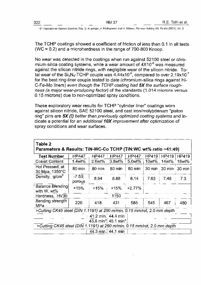
322 HM37 R.E. Toth et al.15:1 International Plansee Seminar, Eds. G. Kneringer, P. Rodhammer and H. Wildner, Plansee Holding AG, Reutte (2001), Vol. 2
The TCHP coatings showed a coefficient of friction of less than 0.1 in all tests(WC = 0.2) and a microhardness in the range of 700-800 Knoop.
No wear was detected in the coatings when run against 52100 steel or chro-mium-silica coating systems, while a wear amount of 4X10"8 was measuredagainst the silicon nitride rings, with negligible wear of the silicon nitride. To-tal wear of the Si3N4-TCHP couple was 4.44x10"8, compared to over 2.19x10'7
for the best ring-liner couple tested to date (chromium-silica rings against Hi-C-Fe-Mo liners) even though the TCHP coating had 5Xthe surface rough-ness (a major wear-producing factor) of the standards (1.014 microns versus0.15 microns) due to non-optimized spray conditions.
These exploratory wear results for TCHP "cylinder liner" coatings wornagainst silicon nitride, SAE 52100 steel, and cast iron/molybdenum "pistonring" pins are 5X (!) better than previously optimized coating systems and in-dicate a potential for an additional 10X improvement after optimization ofspray conditions and wear surfaces.
Table 2Parameters & Results: TiN-WC-Co TCHP (TiN.WC wt% ratio -41:49)
Test NumberCobalt ContentHot Pressed, at30Mpa, 1350°CDensity, g/cm3
Balance Blendingwith W, wt%
HP4471.4wt%
80min
-7.53;porous
HP4472.6wt%
80min
HP4473.8wt%
80 min
8.94 8.88
+ 15% ; +15% +15%
HP4475.0wt%
80 min
8.14
+2.77%
HP41910wt%
30 min
7.63
HP41914wt%
30 min
7.48
HP41918wt%
30 min
7.3
Hardness, HV30 1150Bending strengthMPa
220 418 431 585 545 467 480
>Cutting CK45 steel (DIN 1.1191) at 200 m/min, 0.15 mm/rot, 2.0 mm depth41.2 min.; 44.4 min43.8 min* 45.1 min*|
>Cutting CK45 steel (DIN 1.1191) at 260 m/min, 0.15 mm/rot, 2.0 mm depth44.3 min.i 44.1 min
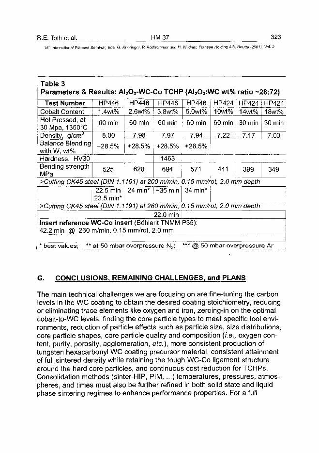
R.E. Toth et al. HM37 323
15'" International Plansee Seminar, Eds. G. Kneringer, P. Rodhammer and H. Wildner, Plansee Holding AG, Reutte (2001), Vol. 2
Table 3Parameters & Results: AI2O3-WC-Co TCHP (AI2O3:WC wt% ratio -28:72)
Test NumberCobalt ContentHot Pressed, at30Mpa, 1350°CDensity, g/cm3
Balance Blendingwith W, wt%
HP4461.4wt%
60 min
8.00
HP4462.6wt%
60 min
7.98
+28.5% | +28.5%
Hardness, HV30Bending strengthMPa
525 628
HP4463.8wt%
60 min
7.97
+28.5%
1463
694
HP4465.0wt%
60 min
7.94
+28.5%
HP42410wt%
60 min
7.22
HP42414wt%
30 min
7.17
HP42418wt%
30 min
7.03
571 441 399 349
>Cutting CK45 steel (DIN 1.1191) at 200 m/min, 0.15 mm/rot, 2.0 mm depth22.5 min23.5 min*
24 min* -35 min 34 min*
>Cutting CK45 steel (DIN 1.1191) at 260 m/min, 0.15 mm/rot, 2.0 mm depth22.0 min
Insert reference WC-Co insert (Bohlerit TNMM P35):42.2 min @ 260 m/min, 0.15 mm/rot, 2.0 mm
* best values; ** at 50 mbar overpressure N2; *** @ 50 mbar overpressure Ar
G. CONCLUSIONS. REMAINING CHALLENGES, and PLANS
The main technical challenges we are focusing on are fine-tuning the carbonlevels in the WC coating to obtain the desired coating stoichiometry, reducingor eliminating trace elements like oxygen and iron, zeroing-in on the optimalcobalt-to-WC levels, finding the core particle types to meet specific tool envi-ronments, reduction of particle effects such as particle size, size distributions,core particle shapes, core particle quality and composition (i.e., oxygen con-tent, purity, porosity, agglomeration, etc.), more consistent production oftungsten hexacarbonyl WC coating precursor material, consistent attainmentof full sintered density while retaining the tough WC-Co ligament structurearound the hard core particles, and continuous cost reduction for TCHPs.Consolidation methods (sinter-HIP, PIM, ...) temperatures, pressures, atmos-pheres, and times must also be further refined in both solid state and liquidphase sintering regimes to enhance performance properties. For a full
324 HM37 R.E. Toth et al.15" International Plansee Seminar, Eds. G. Kneringer, P. Rodhammer and H. Wildner, Plansee Holding AG, Reutte (2001), Vol. 2
evaluation of newly developed TCHPs, a designed experimental matrix willbe defined, employing variations of the (1) composition, (2) particlesize/distribution, (3) consolidation method, (4) cutting parameters, and (5)machined material. In addition, extensive wire drawing field tests are plannedto qualify TCHPs for commercialization.
Because the above challenges are of the kind that will be resolved throughreasonable scientific discovery procedures, significant performance im-provements are expected during the coming months and years.
H. ACKNOWLEDGEMENTS
Heartfelt appreciation and thanks are hereby conveyed to Dr. Randall M. German ofPennState for his continued encouragement and technical assistance from the inception of thisproject; to the co-authors of this paper for their valuable ideas and encouragement; toHenry S. Meeks of Ceracon, Inc. for his consolidation and practical contributions; and toWilliam W. Winspear of Associated Materials, Inc. and the U.S. Department of Energy (In-ventions and Innovation Program) for their financial support; and to the many others whohave provided encouragement, advice, and help in advancing the development of thispromising TCHP (EternAloy™) class of materials.
I. REFERENCES
1. International Patent Application No. PCT/US98/09767, (International Publication No.WO 98/51419), published under the Patent Cooperation Treaty (PCT) and corre-sponding U.S. Patent Application No. 60/046,885, Applicant: Richard Edmund Toth,priority date: 13 May 1997.
2. M. Brad Beardsley and David A. Cusac, Final Report: "Microengineered Wear Coat-ings," Caterpillar, Inc., 5 Jan 2001.
3. A. Bose, A.J. Sherman, A. Biswas, "Microencapsulated Powder Approach for Ad-vanced Materials," International Conference on Powder Metallurgy and ParticulateMaterials, May 31-June 04, 1998 Las Vegas.
4. Daniel F. Carroll and J. Jarvi, "Effect of Cobalt Size on the Processing and Propertiesof Fine-Grained WC-Co Materials," OMG Americas and OMG Kokkola ChemicalsOY.CVD, 1998.
5. Limin Chen, W. Lengauer, and P. Ettmayer; "Metallurgical Reactions and Microstruc-ture Developments During Sintering of Modem Cermets and Cemented Carboni-trides," to be published in Journal of Refractory Metals & Hard Materials.
R.E. Toth et al. HM 37 325^
15" International Plansee Seminar, Eds. G. Kneringer, P. Rodhammer and H. Wildner, Plansee Holding AG, Reutte (2001), Vol. 2
6. Limin Chen, W. Lengauer, and K. Dreyer; "Advances in Modern Nitrogen-containingHardmetals and Cermets," Journal of Refractory Metals & Hard Materials, v. 18 (2000)p. 153-161.
7. A. Doi, T. Nomura, M. Tobioka, and A. Hara; "Thermodynamic Evaluation of Equilib-rium Nitrogen Pressure and WC Separation in Ti-W-C-N- System Carbonitrides," Pro-ceedings of the 11th International Plansee-Seminar, Vol. 1, p. 825-843, (ed. H. Bild-stein, H.M. Ortner, Plansee AG, Reutte 1985)
8. Peter Ettmayer, "Hardmetals and Cermets," Annual Review of Materials Science,1989, v. 19, p. 145-164.
9. Peter Ettmayer, H. Kolaska, W. Lengauer, and K. Dreyer; Ti(C,N) Cermets -Metallurgy and Properties," International Journal of Refractory Metals & Hard Materi-als, v. 13, 1995, p. 343-351.
10. R.J. Fries, J.E. Cummings, C.G. Hoffman, and S.A. Daily; "The Chemical Diffusion ofCarbon in the Group Vlb Metal Carbides," Proceedings of the 6th International Plan-see-Seminar, 1969.
11. Randall M.German, Powder Metallurgy Science, 2nd ed., MPIF, 1994.
12. Andrew J. Sherman, G. Smith, D. Baker, and R. E. Toth; "Cermet Tool and Die Mate-rials from Metal Coated Powders," National Science Foundation Grant Final PhaseOne STTR Report, January, 2001.
13. B.E. Williams, J.J. Stiglich, and R.B. Kaplan, "Improved Composite Powder Fabrica-tion," presented at 15th Annual Conference on Composites and Advanced Ceramics,Cocoa Beach, FL, 13-16 January 1991.
AT0100462326 HM38 H. Moriguchi et al.
15" International Plansee Seminar, Eds. G. Kneringer, P. Rodhammer and H. Wildner, Plansee Holding AG, Reutte (2001), Vol. 2
DIAMOND DISPERSED CEMENTED CARBIDE
PRODUCED WITHOUT USING ULTRAHIGH PRESSURE EQUIPMENT
H. Moriguchi, K. Tsuzuki and A. Ikegaya
Itami Research Laboratories, Sumitomo Electric Industries, Ltd.
1-1-1 Koya-kita, Itami, Hyogo, 664-0016, Japan
SUMMARY
We have developed a composite material of dispersed diamond particles incemented carbide without using ultra high pressure equipment. Thedeveloped diamond dispersed cemented carbide combines the excellentproperties of cemented carbide with diamond and also provides 1.5 timesimproved fracture toughness over that of cemented carbide. They also show10 times higher wear resistance over that of cemented carbide in a wearresistance test against bearing steel, and 5 times greater grindability thandiamond compacts. Because ultra high pressure equipment is not used toproduce the developed material, large compacts over 100 mm in diametercan be manufactured. The developed material showed 10-25 times higherwear resistance in real use as wear-resistant tools such as centerless bladesand work-rests.
KEYWORDS
Diamond particle, graphitization, ultra high pressure equipment, cementedcarbide, fracture toughness, wear resistance, grindability, wear-resistant tools
1. Introduction
Cemented carbide is a composite material made of tungsten carbide (WC)and cobalt (Co). This material was invented by Schorter in 1938, andproduced commercially under the brand name Wie Diamant. Since then this
H. Moriguchi et al. HM 38 327^15" International Plansee Seminar, Eds. G. Kneringer, P. Rodhammer and H. Wildner, Plansee Holding AG, Reutte (2001), Vol. 2
material has been widely used as a material for cutting tools and wear-resistant tools because of its excellent hardness, strength, toughness, andYoung's modulus [1].In recent years, diamond compacts have come into greater use because oftheir extremely high hardness and wear resistance [2]. But diamondcompacts have the disadvantages of being difficult to machine because oftheir high hardness, the inability to be formed into oversized or complexshapes because of the use of ultra high pressure equipment, andconsequential high cost.
Therefore, a material combining the excellent properties of cementedcarbides and diamond compacts, and offering the advantage of inexpensivefabrication without requiring ultra high pressure equipment would be ofconsiderable industrial value. Newly developed diamond dispersed cementedcarbides meet just such needs. This paper describes the properties of newlydeveloped diamond dispersed cemented carbides.
2. Conventional technique and purpose of this study
Because diamond is the hardest material on the earth (9.8 GPa), a sinteredcompact made by dispersing diamond particles in cemented carbide shouldoffer exceptional toughness and wear resistance. Actual fabrication of suchmaterials, however, has encountered the problem of phase transformation ofdiamond, which is thermodynamically stable at high pressures, into graphiteat high-temperature when sintering pressure is inadequate as shown in Fig. 1[3]. Although Hall et al. have reported that diamond can be stable attemperatures below 1400 K, even if thermodynamically unstable at suchtemperatures [4], it is difficult to make diamond dispersed cemented carbideswith dense cemented carbides under such conditions. It is possible butexpensive to make dense diamond dispersed cemented carbides at the hightemperatures and pressures at which diamond is stable due to the requireduse of ultra high pressure equipment.
Thermodynamically, diamond is unstable around 1600 K below 5 GPa. But itis necessary for diamond particles to have sufficient time to transform intographite in view of kinetics. Therefore we attempted to produce diamond
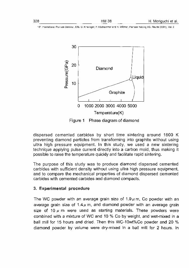
328 HM38 H. Moriguchi et al.15* International Plansee Seminar, Eds. G. Kneringer, P. Rodhammer and H. Wildner, Plansee Holding AG, Reutte (2001), Vol. 2
0 1000 2000 3000 4000 5000
Temperature(K)
Figure 1 Phase diagram of diamond
dispersed cemented carbides by short time sintering around 1600 Kpreventing diamond particles from transforming into graphite without usingultra high pressure equipment. In this study, we used a new sinteringtechnique applying pulse current directly into a carbon mold, thus making itpossible to raise the temperature quickly and facilitate rapid sintering.
The purpose of this study was to produce diamond dispersed cementedcarbides with sufficient density without using ultra high pressure equipment,and to compare the mechanical properties of diamond dispersed cementedcarbides with cemented carbides and diamond compacts.
3. Experimental procedure
The WC powder with an average grain size of 1.9// m, Co powder with anaverage grain size of 1.4// m, and diamond powder with an average grainsize of 10// m were used as starting materials. These powders werecombined with a mixture of WC and 10 % Co by weight, and wet-mixed in aball mill for 15 hours and dried. Then this WC-10wt%Co powder and 20 %diamond powder by volume were dry-mixed in a ball mill for 2 hours. In
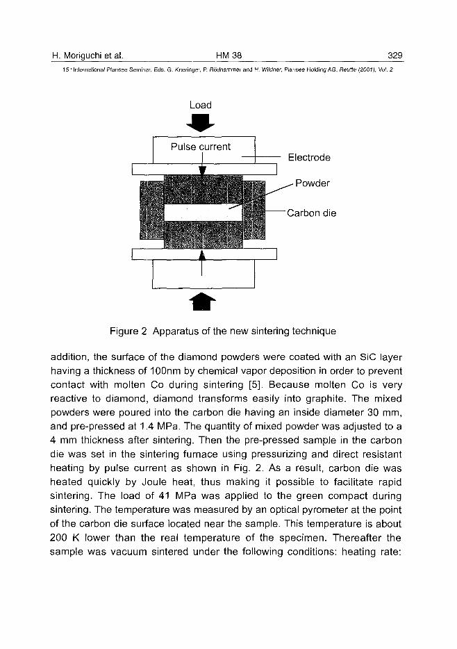
H. Moriguchi et al. HM38 32915" International Plansee Seminar, Eds. G. Kneringer, P. Rodhammer and H. Wildner, Plansee Holding AG, Reurte (2001), Vol. 2
Load
Electrode
Powder
Carbon die
Figure 2 Apparatus of the new sintering technique
addition, the surface of the diamond powders were coated with an SiC layerhaving a thickness of 100nm by chemical vapor deposition in order to preventcontact with molten Co during sintering [5]. Because molten Co is veryreactive to diamond, diamond transforms easily into graphite. The mixedpowders were poured into the carbon die having an inside diameter 30 mm,and pre-pressed at 1.4 MPa. The quantity of mixed powder was adjusted to a4 mm thickness after sintering. Then the pre-pressed sample in the carbondie was set in the sintering furnace using pressurizing and direct resistantheating by pulse current as shown in Fig. 2. As a result, carbon die washeated quickly by Joule heat, thus making it possible to facilitate rapidsintering. The load of 41 MPa was applied to the green compact duringsintering. The temperature was measured by an optical pyrometer at the pointof the carbon die surface located near the sample. This temperature is about200 K lower than the real temperature of the specimen. Thereafter thesample was vacuum sintered under the following conditions: heating rate:
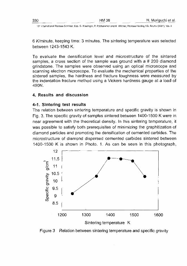
330 HM38 H. Moriguchi et al.15" International Plansee Seminar, Eds. G. Kneringer, P. Rodhammer and H. Wildner, Plansee Holding AG, Reutte (2001), Vol. 2
6 K/minute, keeping time: 3 minutes. The sintering temperature was selectedbetween 1243-1543 K.
To evaluate the densification level and microstructure of the sinteredsamples, a cross section of the sample was ground with a # 200 diamondgrindstone. The samples were observed using an optical microscope andscanning electron microscope. To evaluate the mechanical properties of thesintered samples, the hardness and fracture toughness were measured bythe indentation fracture method using a Vickers hardness gauge at a load of490N.
4. Results and discussion
4-1. Sintering test resultsThe relation between sintering temperature and specific gravity is shown inFig. 3. The specific gravity of samples sintered between 1400-1500 K were innear agreement with the theoretical density. In this sintering temperature, itwas possible to satisfy both prerequisites of minimizing the graphitization ofdiamond particles and promoting the densification of cemented carbides. Themicrostructure of diamond dispersed cemented carbides sintered between1400-1500 K is shown in Photo. 1. As can be seen in this photograph,
12
11.5LUO
/£
ity
<fie
gra
vS
peci
11
10.5
10
9.5
9
8.5
1200 16001300 1400 1500
Sintering temperature K
Figure 3 Relation between sintering temperature and specific gravity
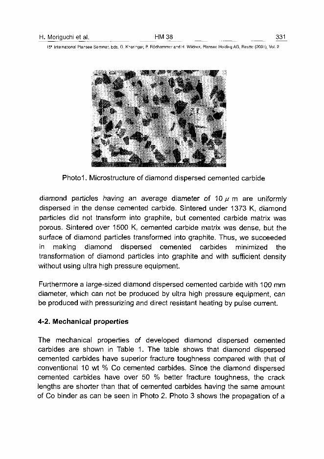
H. Moriguchi et al. HM 38 33115'" International Plansee Seminar, Eds. G. Kneringer, P. Rodhammer and H. Wildner, Plansee Holding AG, Reutte (2001), Vol. 2
Photoi. Microstructure of diamond dispersed cemented carbide
diamond particles having an average diameter of 10 / /m are uniformlydispersed in the dense cemented carbide. Sintered under 1373 K, diamondparticles did not transform into graphite, but cemented carbide matrix wasporous. Sintered over 1500 K, cemented carbide matrix was dense, but thesurface of diamond particles transformed into graphite. Thus, we succeededin making diamond dispersed cemented carbides minimized thetransformation of diamond particles into graphite and with sufficient densitywithout using ultra high pressure equipment.
Furthermore a large-sized diamond dispersed cemented carbide with 100 mmdiameter, which can not be produced by ultra high pressure equipment, canbe produced with pressurizing and direct resistant heating by pulse current.
4-2. Mechanical properties
The mechanical properties of developed diamond dispersed cementedcarbides are shown in Table 1. The table shows that diamond dispersedcemented carbides have superior fracture toughness compared with that ofconventional 10 wt % Co cemented carbides. Since the diamond dispersedcemented carbides have over 50 % better fracture toughness, the cracklengths are shorter than that of cemented carbides having the same amountof Co binder as can be seen in Photo 2. Photo 3 shows the propagation of a
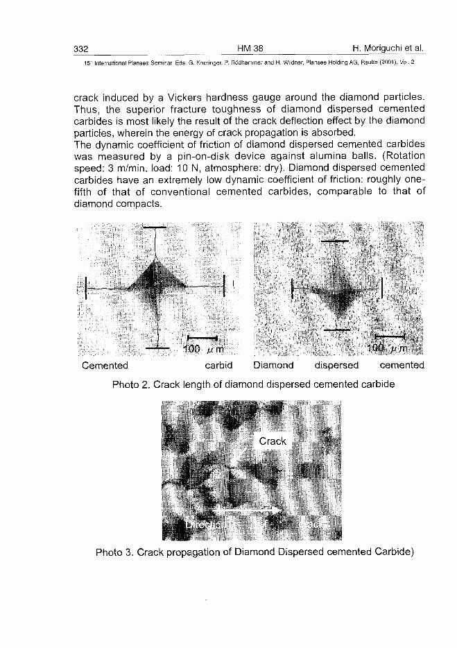
332 HM38 H. Moriguchi et al.
15" International Plansee Seminar, Eds. G. Kneringer, P. Rodhammer and H. Wildner, Plansee Holding AG, Reutte (2001), Vol. 2
crack induced by a Vickers hardness gauge around the diamond particles.Thus, the superior fracture toughness of diamond dispersed cementedcarbides is most likely the result of the crack deflection effect by the diamondparticles, wherein the energy of crack propagation is absorbed.The dynamic coefficient of friction of diamond dispersed cemented carbideswas measured by a pin-on-disk device against alumina balls. (Rotationspeed: 3 m/min, load: 10 N, atmosphere: dry). Diamond dispersed cementedcarbides have an extremely low dynamic coefficient of friction: roughly one-fifth of that of conventional cemented carbides, comparable to that ofdiamond compacts.
—^~ 100 /um -, -,*f ;"•>-'.-, ,;'-
Cemented carbid Diamond dispersed cemented
Photo 2. Crack length of diamond dispersed cemented carbide
* ; • • • • • ; C-ack
. ;
Photo 3. Crack propagation of Diamond Dispersed cemented Carbide)
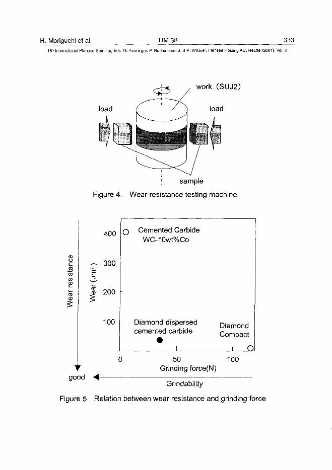
H. Moriguchi et al. HM38 33315lh International Plansee Seminar, Eds. G. Kneringer, P. Rodhammer and H. Wildner, Plansee Holding AG, Reutte (2001), Vol. 2
load
; sample
Figure 4. Wear resistance testing machine
8-2
TOCD
400
300
3 200
100
Cemented CarbideWC-10wt%Co
Diamond dispersed Diamond
Compactcemented carbide
_Q
0 50 100Grinding force(N)
good <Grindability
Figure 5 Relation between wear resistance and grinding force
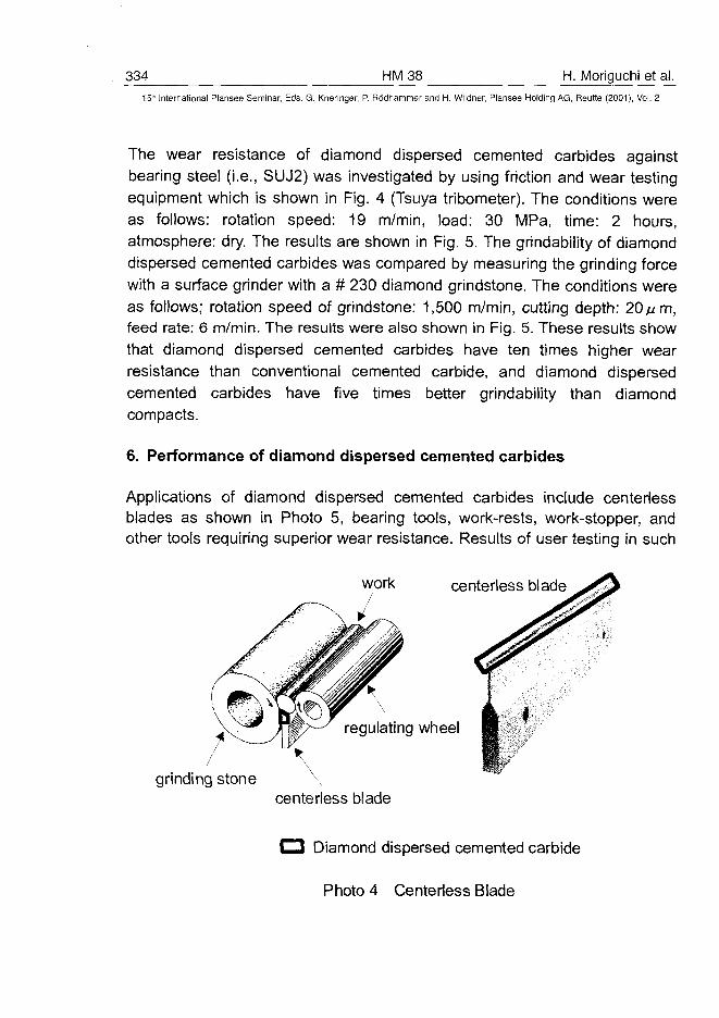
334 HM38 H. Moriguchi et al.15" International Plansee Seminar, Eds. G. Kneringer, P. Rodhammer and H. Wildner, Plansee Holding AG, Reutte (2001), Vol. 2
The wear resistance of diamond dispersed cemented carbides againstbearing steel (i.e., SUJ2) was investigated by using friction and wear testingequipment which is shown in Fig. 4 (Tsuya tribometer). The conditions wereas follows: rotation speed: 19 m/min, load: 30 MPa, time: 2 hours,atmosphere: dry. The results are shown in Fig. 5. The grindability of diamonddispersed cemented carbides was compared by measuring the grinding forcewith a surface grinder with a # 230 diamond grindstone. The conditions wereas follows; rotation speed of grindstone: 1,500 m/min, cutting depth: 20//m,feed rate: 6 m/min. The results were also shown in Fig. 5. These results showthat diamond dispersed cemented carbides have ten times higher wearresistance than conventional cemented carbide, and diamond dispersedcemented carbides have five times better grindability than diamondcompacts.
6. Performance of diamond dispersed cemented carbides
Applications of diamond dispersed cemented carbides include centerlessblades as shown in Photo 5, bearing tools, work-rests, work-stopper, andother tools requiring superior wear resistance. Results of user testing in such
work centerless blade
regulating wheel
centerless blade
Diamond dispersed cemented carbide
Photo 4 Centerless Blade
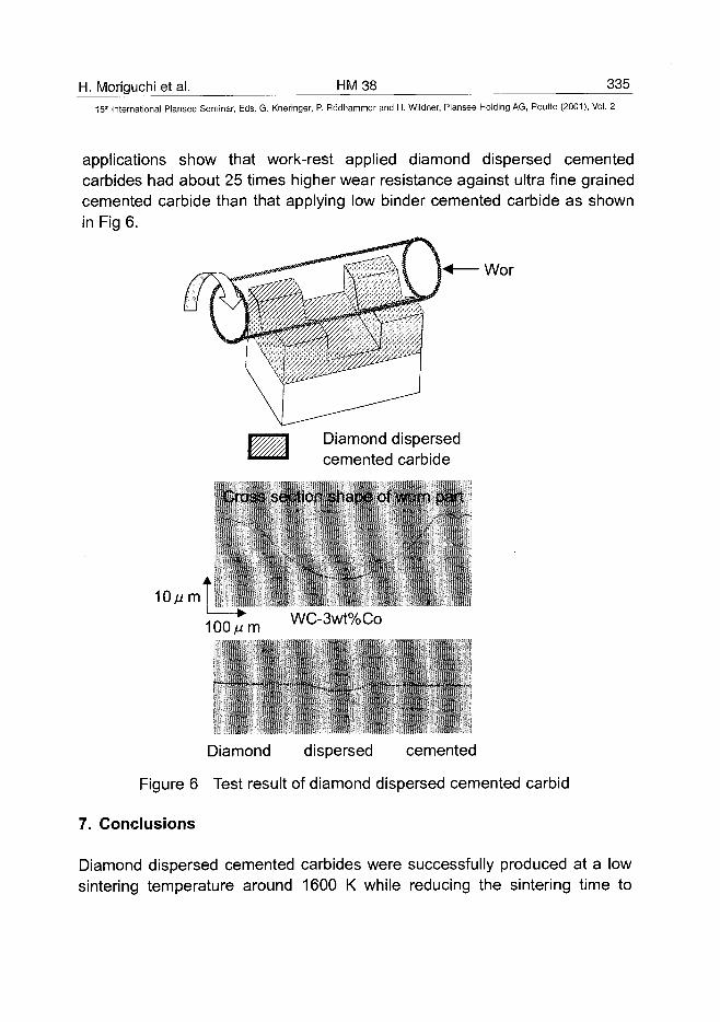
H. Moriguchi et al. HM38 335
15" International Plansee Seminar, Eds. G. Kneringer, P. Rodhammer and H. Wildner, Plansee Holding AG, Reutte (2001), Vol. 2
applications show that work-rest applied diamond dispersed cementedcarbides had about 25 times higher wear resistance against ultra fine grainedcemented carbide than that applying low binder cemented carbide as shownin Fig 6.
Wor
Diamond dispersedcemented carbide
Cross section shape of worn part
•L100//m WC-3wt%Co
Diamond dispersed cemented
Figure 6 Test result of diamond dispersed cemented carbid
7. Conclusions
Diamond dispersed cemented carbides were successfully produced at a lowsintering temperature around 1600 K while reducing the sintering time to
336 HM38 H. Moriguchi et al.15" International Plansee Seminar, Eds. G. Kneringer, P. Rodhammer and H. Wildner, Plansee Holding AG, Reutte (2001), Vol. 2
several minutes as compared to several hours, thereby satisfying bothprerequisites of minimizing the transforming into graphite of diamond particlesand making cemented carbides with sufficient density without using ultra highpressure equipment. Diamond dispersed cemented carbides possess thefollowing superior properties in comparison with conventional cementedcarbides and diamond compacts.
(1) Superior wear resistance:10 times higher than conventional cemented carbide
(2) Superior fracture toughness:1.5 times higher than conventional cemented carbide
(3) Superior grindability: 5 times higher than diamond compact(4) No requirement for ultra high pressure equipment:
Compacts 100 mm or more in diameter can be fabricated and used inapplications unsuited for ordinary diamond compacts.
With such superior properties, diamond dispersed cemented carbides can beused for precision machining, reducing tool costs and shortening down time(e.g., time required for tool changes), thus promoting advancement of themachining industry.
References[1] H. Suzuki: in ,.Cemented carbide and sintered hard material" (Maruzen,Tokyo, 1986), pp. 429-555[2] H. Suzuki: in ,.Cemented carbide and sintered hard material" (Maruzen,Tokyo, 1986), pp. 420-427[3] F. P. Bundy, et al.: Carbon, 34 (1996), pp. 141[4] H. T. Hall: Science (1970), pp. 868-869[5] Y. Miyamoto, et al.: Ceramic Engineering and Science Proceedings,Vol 21, Issue 4, 2000, pp. 185-192 (ed. T. Jessen et al.)
ATO100463A. Scrivani et al. HM 39 337
15" International Plansee Seminar, Eds. G. Kneringer, P. Rõdhammer and H. Wildner, Plansee Holding AG, Relitte (2001), Vol. 2
PERFORMANCES AND RELIABILITY OF WC BASED THERMAL SPRAY
COATINGS
A. Scrivani1'2, M. Rosso3, L. Salvarani4
1. Turbocoating S.p.A., Via Volta 3, 43040 Rubbiano, Parma, Italy2. Università di Parma, Dipartimento di Ingegneria Industriale, Viale delle
Scienze, Parma, Italy3. Politecnico di Torino, Dipartimento di Scienze dei Materiali e
Ingegneria Chimica, Corso Duca degli Abruzzi 24, 10129 Torino, Italy4. Flametal S.p.A., Via G. Di Vittorio 51, 43045, Fornovo Taro, Parma,
Italy
Summary
Thermal spray processes are used for a lot of traditional and innovativeapplications and their importance is becoming higher and higher. WC/CoCrbased thermal spray coatings represent one of the most important class ofcoatings that find application in a wide range of industrial sectors.This paper will address a review of current applications and characteristics ofthis kind of coating.The most important spraying processes, namely HVOF (High VelocityOxygen Fuel) are examined, the characterization of the coatings from thepoint of view of corrosion and wear resistance is considered.
Keywords
Tungsten Carbide, HVOF, Thermal Spray, Corrosion, Wear
1. Introduction
Surface engineering studies the drawing of composite systems constituted bya substrate and a coating, or more generally a surface treatment, in order toobtain functional performances not possible with only substrate materials or
338 HM39 A. Scrivani et al.15" International Plansee Seminar, Eds. G. Kneringer, P. Rodhammer and H. Wildner, Plansee Holding AG, Reutte (2001), Vol. 2
coatings materials (1). Typical is the case of structural materials with goodmechanical strength but bad behaviour in aggressive environments or whensliding or friction are present. In this cases a surface treatment is applied tothe component in order to keep the good mechanical characteristics addinggood anticorrosion or antiwear properties trough the application of hardmaterials like oxides or carbides.An example could be found in petrochemical industry where the used devicesare under conditions of simultaneous mechanical stress and chemicalcorrosion due to the presence of suspended particles in the fluid. Therefore inpipeline engineering it is important to consider the wear and erosion problemsand to guarantee the long life of the equipments (pipes and valves) as well asthe safety.The Ni based alloys are good anticorrosion materials, but they have not goodantiwear characteristics and can not be utilised in the seal parts of the line.From the point of view of the tribological properties the use of hard materialsas thermal sprayed coatings allows to improve drastically the in-servicebehaviour of the component. Quite all these coatings are produced by HVOF(High Velocity Oxygen Fuel) to obtain very hard coating with excellentcohesion and adhesion. This technology also allows to obtain very densecoatings that show good behaviour in aggressive environments. Namelytungsten carbide cobalt-chromium based is standard material for applicationin petrochemical field and finds place in the specification of the maincompanies.Therefore the testing of this coating produced by HVOF is an importantcontribution to the understanding of its capability for petrochemical purpose.This paper addresses the study and characterization of tungsten carbidethermal spray coatings.WC based thermal sprayed coatings have been submitted to severalcorrosion and wear tests in order to determine the performance asanticorrosion (H2S+CO2 test, FeCI3 test according to standard ASTM G48-92and Co release in aqueous environments ), antiwear (pin on disc test) andantiabrasion material (test ASTM G98-75).
2 Metallurgy
The carbides object of this study could be considered as interstitialcompounds: the small carbon atom is located in the octahedral interstitial siteas well as at the centre of a trigonal prism with the close-packed transitionmetal atoms (2).
A. Scrivani et al. HM 39 33915" International Plansee Seminar, Eds. G. Kneringer, P. Rddhammer and H. Wildner, Plansee Holding AG, Reutte (2001), Vol. 2
The crystal structures of the carbides of a transition metal are determined bythe radius ratio:
r = rc/rT
where: C = carbonT = transition metal.
If r < 0.59, the metal atoms form very simple structures with close-packedcubic or hexagonal arrangement with carbon atoms located at interstitial sitesthat are smaller than the carbon atom because otherwise there will beinsufficient bonding resulting in an essentially unstable structure. Namely inthe case of tungsten carbides the most common phases are WC and W2Cboth crystallising in the cubic (NaCI) structure.Tungsten carbide is stable at room temperature as cubic a-WC that melts at2867 °C. The hexagonal W2C-phase melts at a slightly lower temperature of2750 °C. WC loses carbon at appreciable rate above 2200 °C and will form asurface layer of W2C (2).Cemented carbides are composite materials of pure carbides with a bindermetal of low melting point and high ductility. The term refers usually to acarbide of group 4b-6b elements of the periodic table together in a metalmatrix such as cobalt or nickel. Mixtures of these metals, also together withchromium are often utilised. The selection of the binder metal depends to alarge extent on its ability to wet the surface of the carbide particles to ensuresecure coating cohesion. Namely the addition of Cr to WC/Co-cementedcarbide causes important property changes in terms of surface behaviour.The corrosion resistance of cemented carbide coatings is determined by boththe corrosion resistance of the carbide(s) and the binder metals.
3. Coating technologies
Thermal spray technologies find a lot of use in all industrial sectors due to thewide range of materials that can be sprayed by means of these technologiesand the large range of thickness that can be obtained (3).The principle of these technologies is melting the coating materials by meansof heating in gaseous environment and its projecting with high velocity on thesurface that shall be coated. The coating materials is generally in form ofpowder or (less frequently) wire.Thermal spray technologies can be classified according to the energy sourceused to melt the coating material: flame spray and HVOF (High VelocityOxygen Fuel) technologies use the energy deriving from a combustion,electric arc spray technology uses an electric arc to melt the coating materialswhile plasma spray technology uses a plasma generated by an electric arc.
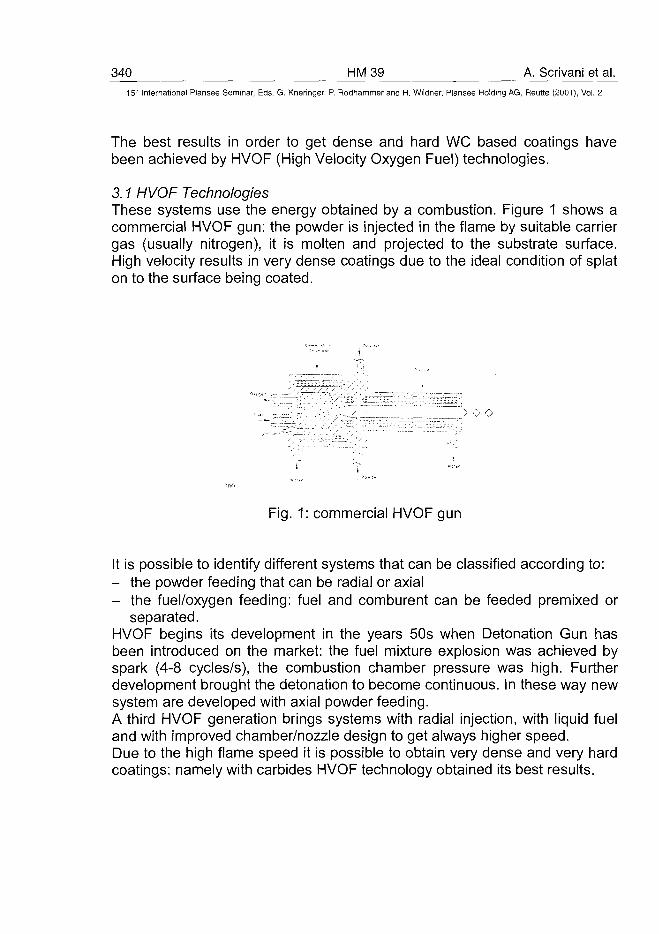
340 HM39 A. Scrivani et al.15'" International Plansee Seminar, Eds. G. Kneringer, P. Rodhammer and H. Wildner, Plansee Holding AG, Reutte (2001), Vol. 2
The best results in order to get dense and hard WC based coatings havebeen achieved by HVOF (High Velocity Oxygen Fuel) technologies.
3.1 HVOF TechnologiesThese systems use the energy obtained by a combustion. Figure 1 shows acommercial HVOF gun: the powder is injected in the flame by suitable carriergas (usually nitrogen), it is molten and projected to the substrate surface.High velocity results in very dense coatings due to the ideal condition of splaton to the surface being coated.
o
Fig. 1: commercial HVOF gun
It is possible to identify different systems that can be classified according to:- the powder feeding that can be radial or axial- the fuel/oxygen feeding: fuel and comburent can be feeded premixed or
separated.HVOF begins its development in the years 50s when Detonation Gun hasbeen introduced on the market: the fuel mixture explosion was achieved byspark (4-8 cycles/s), the combustion chamber pressure was high. Furtherdevelopment brought the detonation to become continuous. In these way newsystem are developed with axial powder feeding.A third HVOF generation brings systems with radial injection, with liquid fueland with improved chamber/nozzle design to get always higher speed.Due to the high flame speed it is possible to obtain very dense and very hardcoatings: namely with carbides HVOF technology obtained its best results.
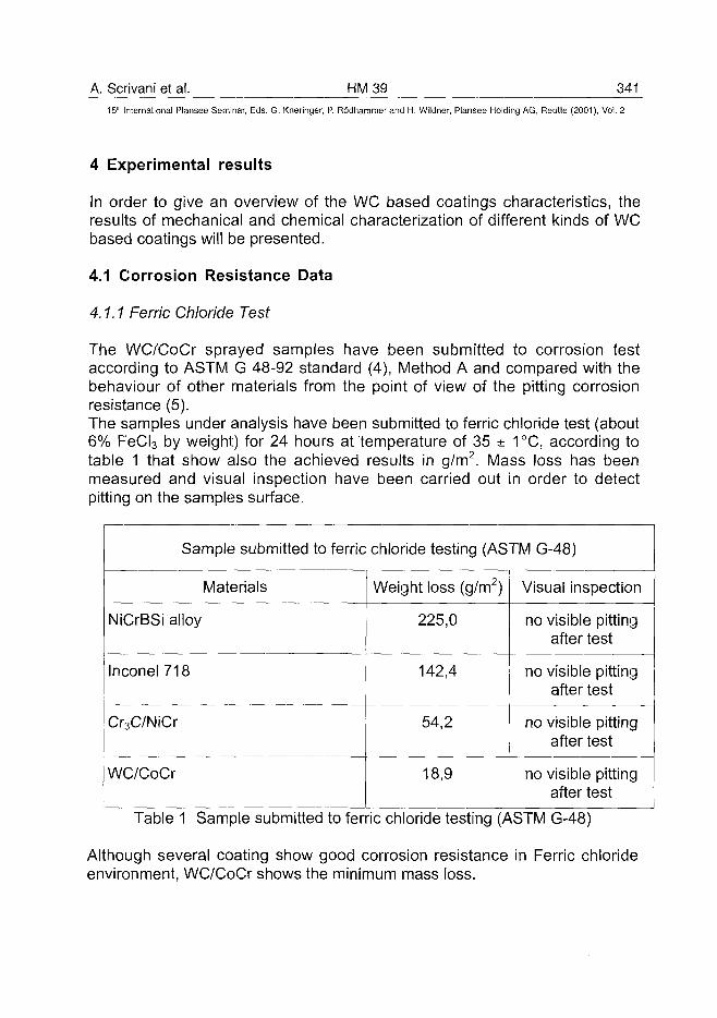
A. Scrivani et al. HM39 34115th International Plansee Seminar, Eds. G. Kneringer, P. Rodhammer and H. Wildner, Plansee Holding AG, Reutte (2001), Vol. 2
4 Experimental results
In order to give an overview of the WC based coatings characteristics, theresults of mechanical and chemical characterization of different kinds of WCbased coatings will be presented.
4.1 Corrosion Resistance Data
4.1.1 Ferric Chloride Test
The WC/CoCr sprayed samples have been submitted to corrosion testaccording to ASTM G 48-92 standard (4), Method A and compared with thebehaviour of other materials from the point of view of the pitting corrosionresistance (5).The samples under analysis have been submitted to ferric chloride test (about6% FeCI3 by weight) for 24 hours at temperature of 35 ± 1°C, according totable 1 that show also the achieved results in g/m2. Mass loss has beenmeasured and visual inspection have been carried out in order to detectpitting on the samples surface.
Sample submitted to ferric chloride testing (ASTM G-48)
Materials
NiCrBSi alloy
Inconel 718
Cr3C/NiCr
WC/CoCr
Weight loss (g/m2)
225,0
142,4
54,2
18,9
Visual inspection
no visible pittingafter test
no visible pittingafter test
no visible pittingafter test
no visible pittingafter test
Table 1 Sample submitted to ferric chloride testing (ASTM G-48)
Although several coating show good corrosion resistance in Ferric chlorideenvironment, WC/CoCr shows the minimum mass loss.
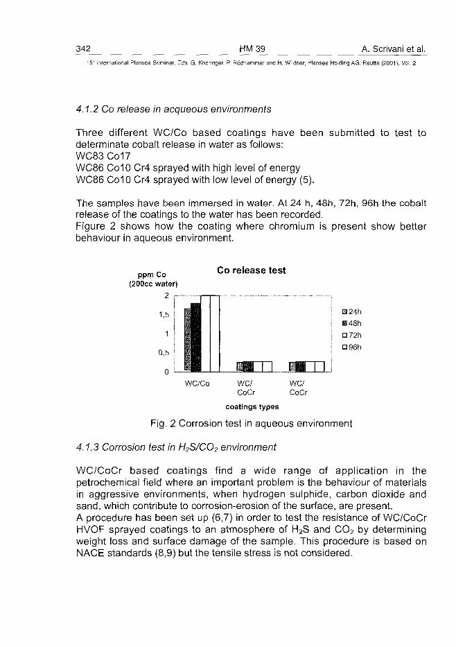
342 HM39 A. Scrivani et al.15" International Plansee Seminar, Eds. G. Kneringer, P. Rodhammer and H. Wildner, Plansee Holding AG, Reutte (2001), Vol. 2
4.1.2 Co release in acqueous environments
Three different WC/Co based coatings have been submitted to test todeterminate cobalt release in water as follows:WC83Co17WC86 Co10 Cr4 sprayed with high level of energyWC86 Co10 Cr4 sprayed with low level of energy (5).
The samples have been immersed in water. At 24 h, 48h, 72h, 96h the cobaltrelease of the coatings to the water has been recorded.Figure 2 shows how the coating where chromium is present show betterbehaviour in aqueous environment.
ppm Co(200cc water)
Co release test
M48hD72hD96h
—~n a m iWC/Co we/
CoCrWC/CoCr
coatings types
Fig. 2 Corrosion test in aqueous environment
4.1.3 Corrosion test in H2S/CO2 environment
WC/CoCr based coatings find a wide range of application in thepetrochemical field where an important problem is the behaviour of materialsin aggressive environments, when hydrogen sulphide, carbon dioxide andsand, which contribute to corrosion-erosion of the surface, are present.A procedure has been set up (6,7) in order to test the resistance of WC/CoCrHVOF sprayed coatings to an atmosphere of H2S and CO2 by determiningweight loss and surface damage of the sample. This procedure is based onNACE standards (8,9) but the tensile stress is not considered.
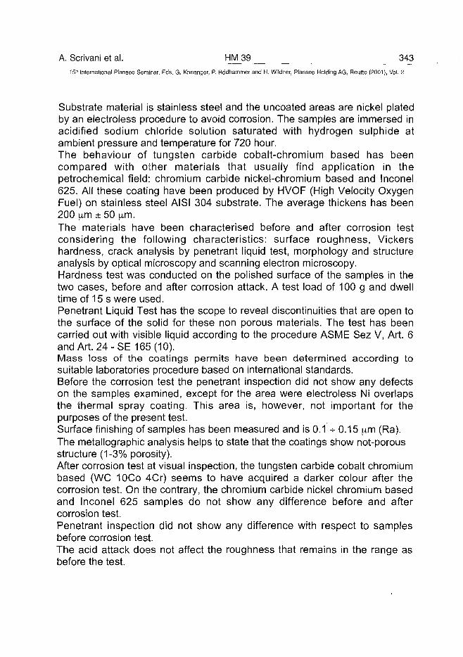
A. Scrivani et al. HM 39 34315'" International Plansee Seminar, Eds. G. Kneringer, P. Rddhammer and H. Wildner, Plansee Holding AG, Reutte (2001), Vol. 2
Substrate material is stainless steel and the uncoated areas are nickel platedby an electroless procedure to avoid corrosion. The samples are immersed inacidified sodium chloride solution saturated with hydrogen sulphide atambient pressure and temperature for 720 hour.The behaviour of tungsten carbide cobalt-chromium based has beencompared with other materials that usually find application in thepetrochemical field: chromium carbide nickel-chromium based and Inconel625. All these coating have been produced by HVOF (High Velocity OxygenFuel) on stainless steel AISI 304 substrate. The average thickens has been200 (xm ± 50 \im.The materials have been characterised before and after corrosion testconsidering the following characteristics: surface roughness, Vickershardness, crack analysis by penetrant liquid test, morphology and structureanalysis by optical microscopy and scanning electron microscopy.Hardness test was conducted on the polished surface of the samples in thetwo cases, before and after corrosion attack. A test load of 100 g and dwelltime of 15 s were used.Penetrant Liquid Test has the scope to reveal discontinuities that are open tothe surface of the solid for these non porous materials. The test has beencarried out with visible liquid according to the procedure ASME Sez V, Art. 6and Art. 24-SE 165 (10).Mass loss of the coatings permits have been determined according tosuitable laboratories procedure based on international standards.Before the corrosion test the penetrant inspection did not show any defectson the samples examined, except for the area were electroless Ni overlapsthe thermal spray coating. This area is, however, not important for thepurposes of the present test.Surface finishing of samples has been measured and is 0.1 * 0.15 ^m (Ra).The metallographic analysis helps to state that the coatings show not-porousstructure (1-3% porosity).After corrosion test at visual inspection, the tungsten carbide cobalt chromiumbased (WC 10Co 4Cr) seems to have acquired a darker colour after thecorrosion test. On the contrary, the chromium carbide nickel chromium basedand Inconel 625 samples do not show any difference before and aftercorrosion test.Penetrant inspection did not show any difference with respect to samplesbefore corrosion test.The acid attack does not affect the roughness that remains in the range asbefore the test.
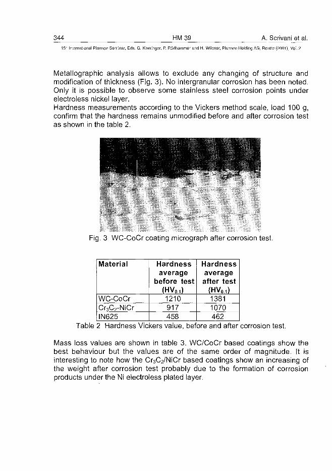
344 HM39 A. Scrivani et al.15:n International Plansee Seminar, Eds. G. Kneringer, P. Rodhammer and H. Wildner, Plansee Holding AG, Reutte (2001), Vol. 2
Metallographic analysis allows to exclude any changing of structure andmodification of thickness (Fig. 3). No intergranular corrosion has been noted.Only it is possible to observe some stainless steel corrosion points underelectroless nickel layer.Hardness measurements according to the Vickers method scale, load 100 g,confirm that the hardness remains unmodified before and after corrosion testas shown in the table 2.
Fig. 3 WC-CoCr coating micrograph after corrosion test.
Material
WC-CoCrCr3C2-NiCrIN625
Hardnessaverage
before test(HV0.i)1210917458
Hardnessaverageafter test
(HV0.i)13811070462
Table 2 Hardness Vickers value, before and after corrosion test.
Mass loss values are shown in table 3. WC/CoCr based coatings show thebest behaviour but the values are of the same order of magnitude. It isinteresting to note how the Cr3C2/NiCr based coatings show an increasing ofthe weight after corrosion test probably due to the formation of corrosionproducts under the Ni electroless plated layer.
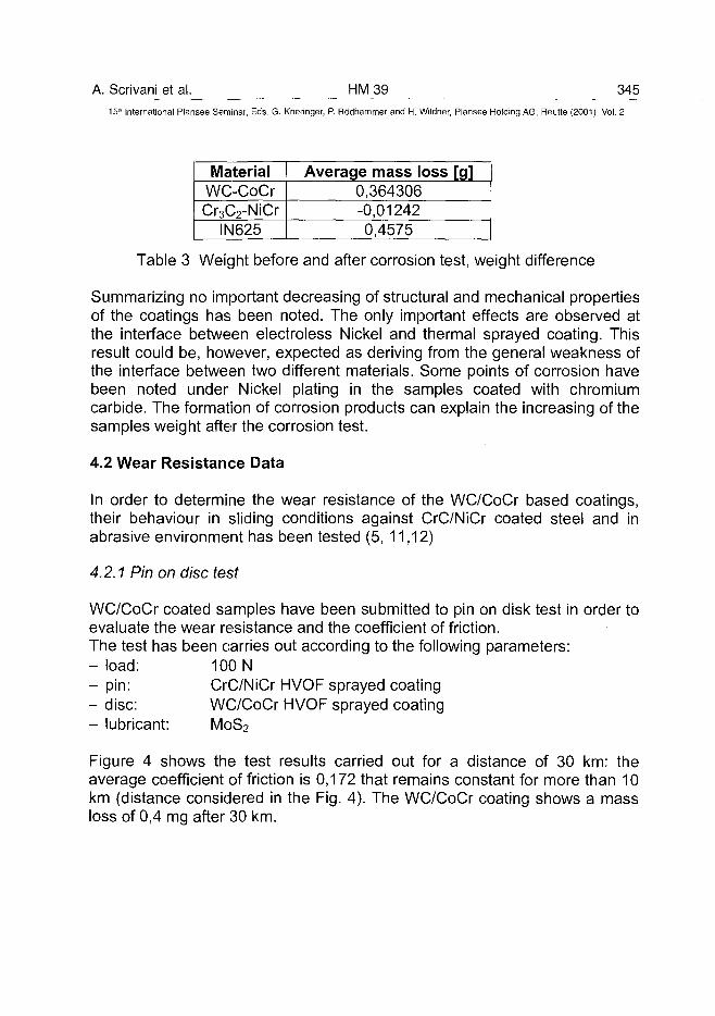
A. Scrivani et al. HM39 34515" International Plansee Seminar, Eds. G. Kneringer, P. Rodhammer and H. Wildner, Plansee Holding AG, Reutte (2001), Vol. 2
MaterialWC-CoCrCr3C2-NiCr
IN625
Average mass loss [g]0,364306-0,012420,4575
Table 3 Weight before and after corrosion test, weight difference
Summarizing no important decreasing of structural and mechanical propertiesof the coatings has been noted. The only important effects are observed atthe interface between electroless Nickel and thermal sprayed coating. Thisresult could be, however, expected as deriving from the general weakness ofthe interface between two different materials. Some points of corrosion havebeen noted under Nickel plating in the samples coated with chromiumcarbide. The formation of corrosion products can explain the increasing of thesamples weight after the corrosion test.
4.2 Wear Resistance Data
In order to determine the wear resistance of the WC/CoCr based coatings,their behaviour in sliding conditions against CrC/NiCr coated steel and inabrasive environment has been tested (5, 11,12)
4.2.1 Pin on disc test
WC/CoCr coated samples have been submitted to pin on disk test in order toevaluate the wear resistance and the coefficient of friction.The test has been carries out according to the following parameters:- load: 100 N- pin: CrC/NiCr HVOF sprayed coating- disc: WC/CoCr HVOF sprayed coating- lubricant: MoS2
Figure 4 shows the test results carried out for a distance of 30 km: theaverage coefficient of friction is 0,172 that remains constant for more than 10km (distance considered in the Fig. 4). The WC/CoCr coating shows a massloss of 0,4 mg after 30 km.
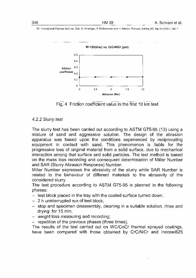
346 HM39 A. Scrivani et al.15'-" International Plansee Seminar, Eds. G. Kneringer, P. Rodhammer and H. Wildner, Plansee Holding AG, Reutte (2001), Vol. 2
W-125(disc) vs. CrC-NiCr (pin)
friction
coefficient
2.5 5 7.5
distance (Km)
Fig. 4 Friction coefficient value in the first 10 km test
4.2.2 Slurry test
The slurry test has been carried out according to ASTM G75-95 (13) using amixture of sand and aggressive solution. The design of the abrasionapparatus was based upon the conditions experienced by reciprocatingequipment in contact with sand. This phenomenon is liable for theprogressive loss of original material from a solid surface, due to mechanicalinteraction among that surface and solid particles. The test method is basedon the mass loss recording and consequent determination of Miller Numberand SAR (Slurry Abrasion Response) Number.Miller Number expresses the abrasivity of the slurry while SAR Number isrelated to the behaviour of different materials to the abrasivity of theconsidered slurry.The test procedure according to ASTM G75-95 is planned in the followingphases:- test block placed in the tray with the coated surface turned down;- 2 h uninterrupted run of test block;- stop and specimen disassembly, cleaning in a suitable solution, rinse and
drying for 15 min;- weight loss measuring and recording;- repetition of the previous phases (three times).The results of the test carried out on WC/CoCr thermal sprayed coatings,have been compared with those obtained by CrC/NiCr and Inconel625
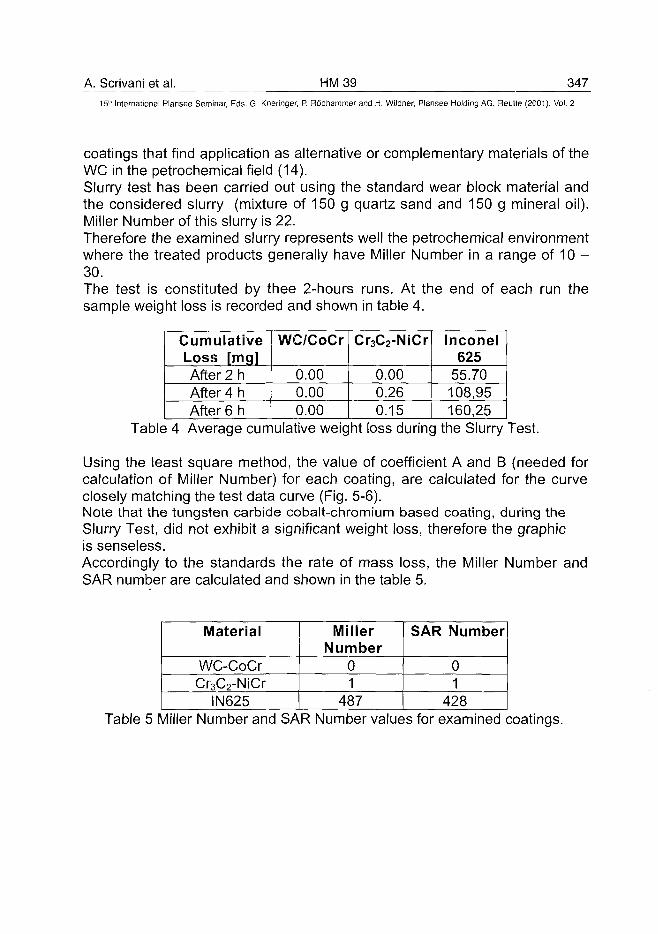
A. Scrivani et al. HM39 34715lh International Plansee Seminar, Eds. G. Kneringer, P. Rodhammer and H. Wildner, Plansee Holding AG, Reutte (2001), Vol. 2
coatings that find application as alternative or complementary materials of theWC in the petrochemical field (14).Slurry test has been carried out using the standard wear block material andthe considered slurry (mixture of 150 g quartz sand and 150 g mineral oil).Miller Number of this slurry is 22.Therefore the examined slurry represents well the petrochemical environmentwhere the treated products generally have Miller Number in a range of 10 -30.The test is constituted by thee 2-hours runs. At the end of each run thesample weight loss is recorded and shown in table 4.
CumulativeLoss [mg]After 2 hAfter 4 hAfter 6 h
WC/CoCr
0.000.000.00
Cr3C2-NiCr
0.000.260.15
Inconel625
55.70108,95160,25
Table 4 Average cumulative weight loss during the Slurry Test.
Using the least square method, the value of coefficient A and B (needed forcalculation of Miller Number) for each coating, are calculated for the curveclosely matching the test data curve (Fig. 5-6).Note that the tungsten carbide cobalt-chromium based coating, during theSlurry Test, did not exhibit a significant weight loss, therefore the graphicis senseless.Accordingly to the standards the rate of mass loss, the Miller Number andSAR number are calculated and shown in the table 5.
Material
WC-CoCrCr3C2-NiCr
IN625
MillerNumber
01
487
SAR Number
01
428Table 5 Miller Number and SAR Number values for examined coatings.
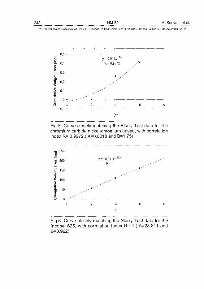
348 HM 39 A, Scrivani et al.15" International Plansee Seminar, Eds. G. Kneringer, P. Rodhammer and H. Wildner, Plansee Holding AG, Reutte (2001), Vol. 2
0,5 -o3 y = 0.018x1J5
— 0,4 - R = 0.9972 A
-1 0 , 3 - /s. * /
I °'2 " /•I 0,1 - _^
I 0^_-^^>O 0 2 4 6
• - 0 , 1 -
Fig.5 Curve closely matching the Slurry Test data for thechromium carbide nickel-chromium based, with correlationindex R= 0.9972.( A=0.0018 and B=1.75)
"SI_EV)
0
£TOJU
11)
ulat
i
E3o
250 -
200
1 5 0 -
100 -
50-
0 2
y = 28,611x0 '9625
R=1
4
[h]
Fig.6 Curve closely matching the Slurry Test data for theInconel 625, with correlation index R= 1.( A=28.611 andB=0.962)
A. Scrivani et al. HM 39 349
15'" International Plansee Seminar, Eds. 6 . Kneringer, P. Rodhammer and H. Wildner, Plansee Holding AG, Reutte (2001), Vol. 2
5 Discussion and conclusion
The WC/CoCr HVOF sprayed coatings submitted to corrosion test accordingto ASTM G 48-92 standard, Method A and compared with the behaviour ofother materials from the point of view of the pitting corrosion resistance, showthe minimum mass loss and therefore the best behaviour in ferric chlorideenvironment.From the point of view of the corrosion in water, the coating where chromiumis present show better behaviour.Corrosion attack due to H2S/CO2 environment does not produce importantdecreasing of structural and mechanical properties of the examined coatings.From the point of view of wear data it is possible to note how the WC/CoCrHVOF sprayed coatings show low friction coefficient when in contact withother metal alloys.The Slurry Test allow us to clear discrimination among the performances ofexamined materials. The cemented carbide coatings under examination,namely the WC/CoCr, have higher erosion resistance than Inconel 625. Thisconfirms a link between mechanical properties and abrasion resistance dueto the microhardness of Inconel 625 smaller than that of cemented carbides.According to the presented characterization WC/CoCr based coatings confirmto be very versatile and useful for a wide range of industrial application.
Acknowledgements
The authors would like to thank Dr. Gabriele Rizzi and Dr. Samantha lanelli.
References
1. D.S Rickerby and A. Matthews A., Advanced surface coatings: a handbookof surface engineering, Blackie & Son Ltd. London, 1991
2. Plasma-Spray Coating. R.H. Heimann, VCH, Weinheim, 19963. A. Scrivani, Thermal spray coatings: introduction and application to the
power generation field, to be published in the Proc. of International Schoolon Advanced Material Science and Technology, "G. Occhialini", Jesi,August 2000
4. ASTM G48-92 Standard Test Method for Pitting and Crevice CorrosionResistance of Stainless Steels and related Alloys by Use of Ferric ChlorideSolution
350 HM 39 A. Scrivani et al.15" International Plansee Seminar, Eds. G. Kneringer, P. Rodhammer and H. Wildner, Plansee Holding AG, Reutte (2001), Vol. 2
5. S. Bertini, A. Scrivani, Tungsten Carbide Cobalt Chromium Based W1125and W225, Flametal Internal Report, September 1998
6. A. Scrivani, C. Aubert, U. Bardi, L. Bertamini, S. Bertini, G. Rizzi, M.Rosso, Resistance of thermal spray coatings in aggressive environments:a comparison of tungsten carbide, chromium carbide and Inconel 625, in:Proceedings of EUROPM 99, Advances in Hard Materials Production,Turin, November 8-10, 1999
7. A. Scrivani, S. Bertini, G. Viola, Corrosion Test: H2S and CO2 media,Flametal Issue, 1997
8. NACE Standard MR-01-75 Sulphide Stress Cracking Resistant MetallicMaterials for Oilfield Equipment
9. NACE Standard TM-01-77 Testing of Metals for Resistance to SulphideStress Cracking at Ambient Temperatures.
10. ASME Sez. V Non-destructive Examination, Art 6 Liquid PenetrantExamination, Art 24 Liquid Penetrant Standard: SE 165
11. G. Medana, Tribologic evaluation of HVOF antiwear self lubricatingcoatings, Degree Thesis Work.
12. N. Antolotti, Flametal new coatings for petrol-chemical industry,Flametal SpA
13. ASTM G75 95 Standard Test Method for Determination of SlurryAbrasivity (Miller Number) and Slurry Abrasion Response of Materials(SAR Number).
14. S. lanelli, Contributo allo studio e alia caratterizzazione di ricoprimentiHVOF per il settore petrolchimico, Degree Thesis Work, April 2000
AT0100464M. Gasik et al. HM 41 351^
15" International Plansee Seminar, Eds. G. Kneringer, P. Rodhammer and H. Wildner, Plansee Holding AG, Reutte (2001), Vol. 2
Sintering of Hardmetals in Different Conditions: ExperimentalResults of 2-D Dilatometry and Computer Simulations
Michael Gasik, Baosheng Zhang, Markku Kaskiala, Jarmo Ylikerala
Helsinki University of Technology, Espoo, Finland
Summary:
Properties of WC-Co functionally gradated materials (FGM) manufacturedby powder metallurgy from nanograin powders are studied. New optical sys-tem (a 2-D dilatometer) has been developed, using a high-resolution CCDcamera and a dedicated software for image processing. Sintering of WC-Cohard metals with different cobalt and grain growth inhibitors content wasperformed for various conditions (substrate, heating rate, temperature) andresulting anisotropy was measured.
Keywords:
Sintering, dilatometer, image processing, anisotropy, hard metals, gradatedmaterials, FGM
1. Introduction:
Powder metallurgy is one of major processing methods for fabrication ofFunctionally Graded (more correct, Gradated) Materials, or FGM (1-3).Pressureless sintering and sinterHIPping (sintering integrated with hotisostatic pressing) are widely used processing techniques to obtain fullydensified cemented carbides, cermets and ceramic matrix composites. Whensintering is performed in the solid state, the diffusion of the components isusually low enough to prevent the degradation of the initial graded structure.If there is a liquid phase during sintering, one has to be aware of the possi-ble destruction of the FGM due to differences in wetting and/or chemical in-teraction of components with each other. On the other hand, this effectcould be used as an advantage of the liquid phase sintering process, as wasshown for FGM hard metals (4). Recent experiments show that it is possible
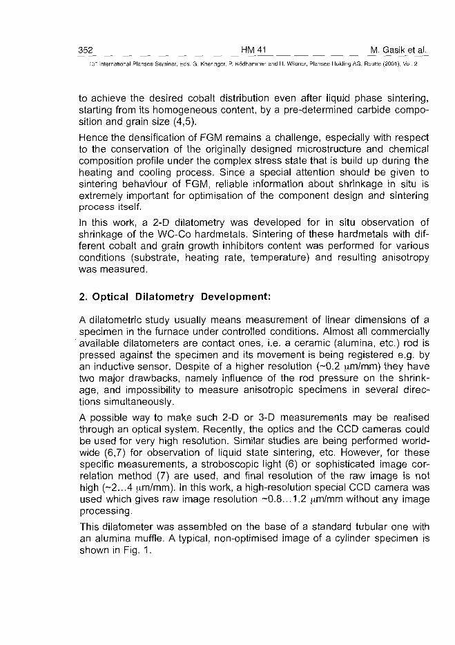
352 HM41 M. Gasik et al.15" International Plansee Seminar, Eds. G. Kneringer, P. Rodhammer and H. Wildner, Plansee Holding AG, Reutte (2001), Vol. 2
to achieve the desired cobalt distribution even after liquid phase sintering,starting from its homogeneous content, by a pre-determined carbide compo-sition and grain size (4,5).
Hence the densification of FGM remains a challenge, especially with respectto the conservation of the originally designed microstructure and chemicalcomposition profile under the complex stress state that is build up during theheating and cooling process. Since a special attention should be given tosintering behaviour of FGM, reliable information about shrinkage in situ isextremely important for optimisation of the component design and sinteringprocess itself.
In this work, a 2-D dilatometry was developed for in situ observation ofshrinkage of the WC-Co hardmetals. Sintering of these hardmetals with dif-ferent cobalt and grain growth inhibitors content was performed for variousconditions (substrate, heating rate, temperature) and resulting anisotropywas measured.
2. Optical Dilatometry Development:
A dilatometric study usually means measurement of linear dimensions of aspecimen in the furnace under controlled conditions. Almost all commerciallyavailable dilatometers are contact ones, i.e. a ceramic (alumina, etc.) rod ispressed against the specimen and its movement is being registered e.g. byan inductive sensor. Despite of a higher resolution (-0.2 ^m/mm) they havetwo major drawbacks, namely influence of the rod pressure on the shrink-age, and impossibility to measure anisotropic specimens in several direc-tions simultaneously.
A possible way to make such 2-D or 3-D measurements may be realisedthrough an optical system. Recently, the optics and the CCD cameras couldbe used for very high resolution. Similar studies are being performed world-wide (6,7) for observation of liquid state sintering, etc. However, for thesespecific measurements, a stroboscopic light (6) or sophisticated image cor-relation method (7) are used, and final resolution of the raw image is nothigh (~2...4 am/mm). In this work, a high-resolution special CCD camera wasused which gives raw image resolution -0.8... 1.2 ,um/mm without any imageprocessing.
This dilatometer was assembled on the base of a standard tubular one withan alumina muffle. A typical, non-optimised image of a cylinder specimen isshown in Fig. 1.
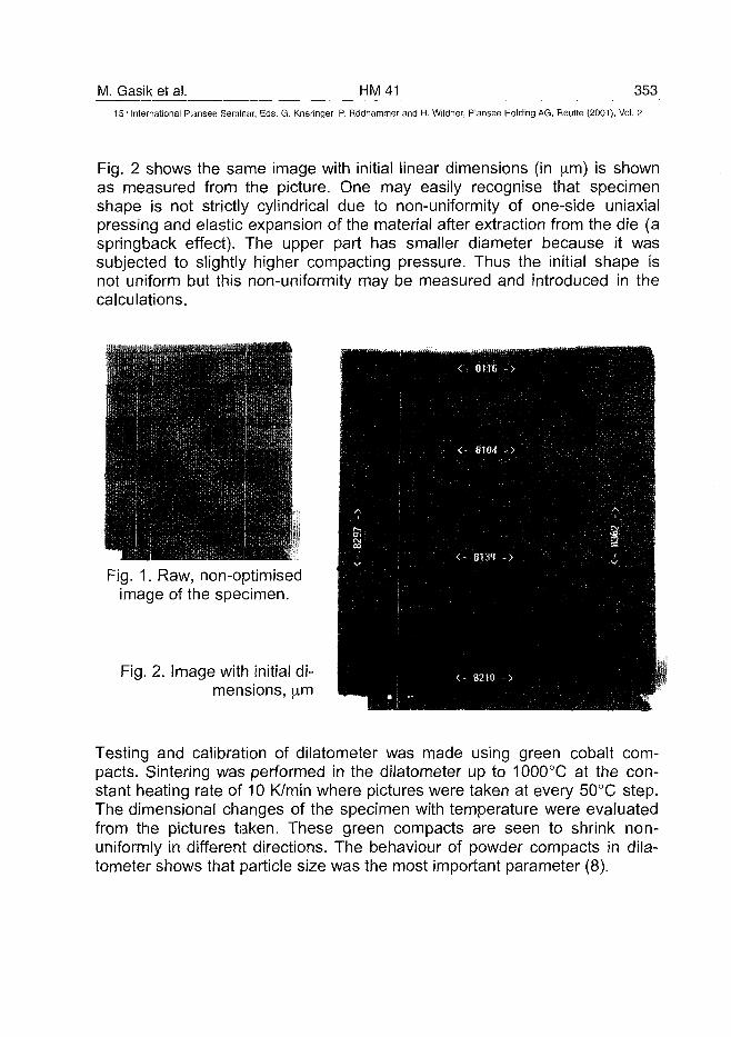
M. Gasik et al. HM41 35315" International Plansee Seminar, Eds. G. Kneringer, P. Rodhammer and H. Wildner, Plansee Holding AG, Reutte (2001), Vol. 2
Fig. 2 shows the same image with initial linear dimensions (in jxm) is shownas measured from the picture. One may easily recognise that specimenshape is not strictly cylindrical due to non-uniformity of one-side uniaxialpressing and elastic expansion of the material after extraction from the die (aspringback effect). The upper part has smaller diameter because it wassubjected to slightly higher compacting pressure. Thus the initial shape isnot uniform but this non-uniformity may be measured and introduced in thecalculations.
Fig. 1. Raw, non-optimisedimage of the specimen.
Fig. 2. Image with initial di-mensions, im
Testing and calibration of dilatometer was made using green cobalt com-pacts. Sintering was performed in the dilatometer up to 1000°C at the con-stant heating rate of 10 K/min where pictures were taken at every 50°C step.The dimensional changes of the specimen with temperature were evaluatedfrom the pictures taken. These green compacts are seen to shrink non-uniformly in different directions. The behaviour of powder compacts in dila-tometer shows that particle size was the most important parameter (8).
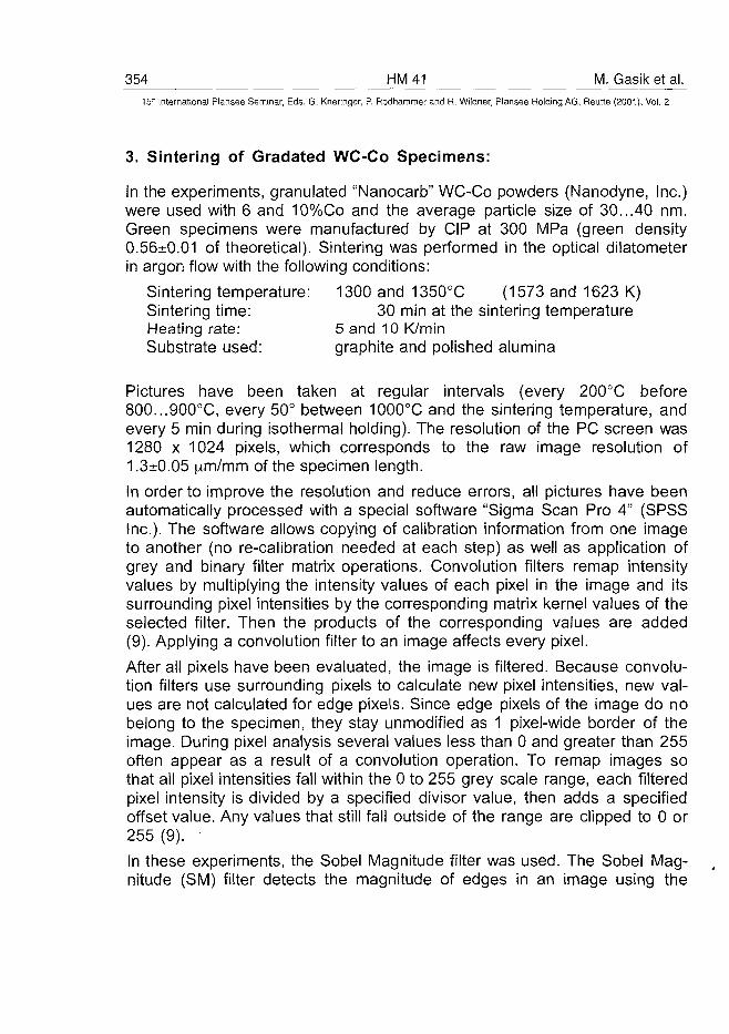
354 HM41 M. Gasik et al.15'" International Plansee Seminar, Eds. G. Kneringer, P. Rodhammer and H. Wildner, Plansee Holding AG, Reutte (2001), Vol. 2
3. Sintering of Gradated WC-Co Specimens:
In the experiments, granulated "Nanocarb" WC-Co powders (Nanodyne, Inc.)were used with 6 and 10%Co and the average particle size of 30...40 nm.Green specimens were manufactured by CIP at 300 MPa (green density0.56±0.01 of theoretical). Sintering was performed in the optical dilatometerin argon flow with the following conditions:
Sintering temperature: 1300 and 1350°C (1573 and 1623 K)Sintering time: 30 min at the sintering temperatureHeating rate: 5 and 10 K/minSubstrate used: graphite and polished alumina
Pictures have been taken at regular intervals (every 200°C before800...900°C, every 50° between 1000°C and the sintering temperature, andevery 5 min during isothermal holding). The resolution of the PC screen was1280 x 1024 pixels, which corresponds to the raw image resolution of1.3±0.05 jim/mm of the specimen length.
In order to improve the resolution and reduce errors, all pictures have beenautomatically processed with a special software "Sigma Scan Pro 4" (SPSSInc.). The software allows copying of calibration information from one imageto another (no re-calibration needed at each step) as well as application ofgrey and binary filter matrix operations. Convolution filters remap intensityvalues by multiplying the intensity values of each pixel in the image and itssurrounding pixel intensities by the corresponding matrix kernel values of theselected filter. Then the products of the corresponding values are added(9). Applying a convolution filter to an image affects every pixel.
After all pixels have been evaluated, the image is filtered. Because convolu-tion filters use surrounding pixels to calculate new pixel intensities, new val-ues are not calculated for edge pixels. Since edge pixels of the image do nobelong to the specimen, they stay unmodified as 1 pixel-wide border of theimage. During pixel analysis several values less than 0 and greater than 255often appear as a result of a convolution operation. To remap images sothat all pixel intensities fall within the 0 to 255 grey scale range, each filteredpixel intensity is divided by a specified divisor value, then adds a specifiedoffset value. Any values that still fall outside of the range are clipped to 0 or255 (9).
In these experiments, the Sobel Magnitude filter was used. The Sobel Mag-nitude (SM) filter detects the magnitude of edges in an image using the
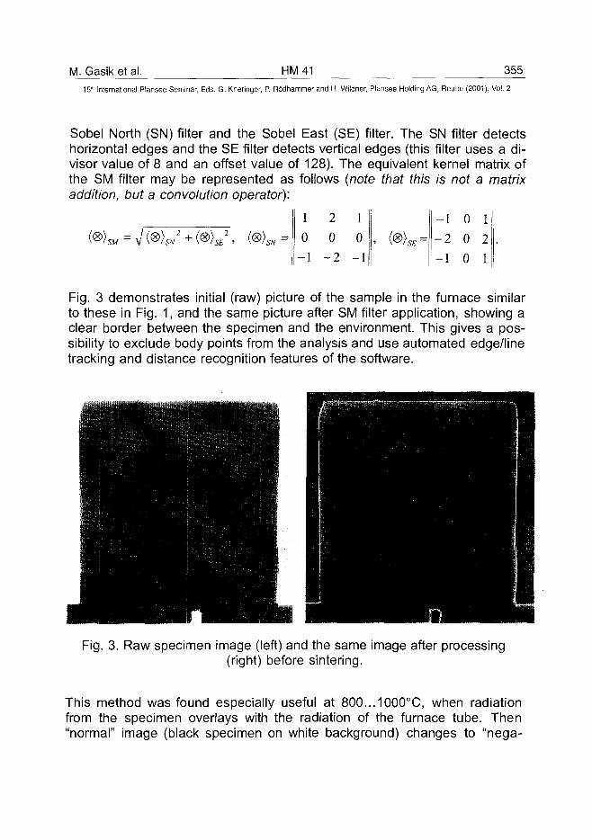
M. Gasik et al. HM41 35515" International Plansee Seminar, Eds. G. Kneringer, P. Rodhammer and H. Wildner, Plansee Holding AG, Reutte (2001), Vol. 2
Sobel North (SN) filter and the Sobel East (SE) filter. The SN filter detectshorizontal edges and the SE filter detects vertical edges (this filter uses a di-visor value of 8 and an offset value of 128). The equivalent kernel matrix ofthe SM filter may be represented as follows (note that this is not a matrixaddition, but a convolution operator):
1
0'SM SN H-2
SE ' 'SN
2
0
• 2
1
0
-1
-1
- 2
-1
0
0
0
1
2
1
Fig. 3 demonstrates initial (raw) picture of the sample in the furnace similarto these in Fig. 1, and the same picture after SM filter application, showing aclear border between the specimen and the environment. This gives a pos-sibility to exclude body points from the analysis and use automated edge/linetracking and distance recognition features of the software.
Fig. 3. Raw specimen image (left) and the same image after processing(right) before sintering.
This method was found especially useful at 800...1000°C, when radiationfrom the specimen overlays with the radiation of the furnace tube. Then"normal" image (black specimen on white background) changes to "nega-
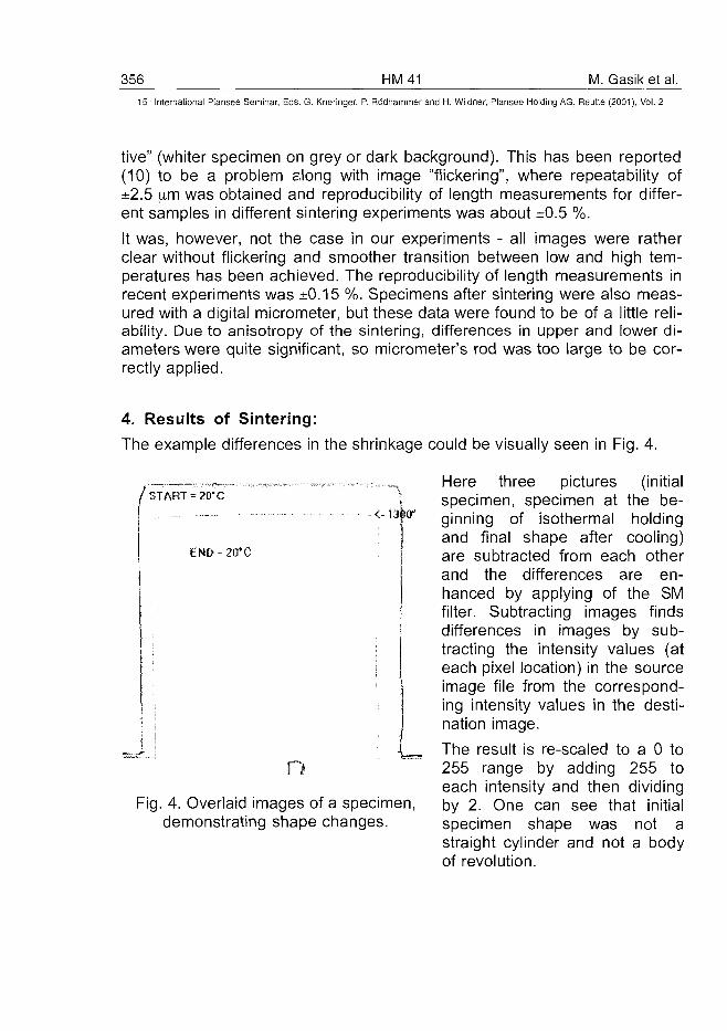
356 HM41 1. Gasik et al.15" International Plansee Seminar, Eds. G. Kneringer, P. Rodhammer and H. Wildner, Plansee Holding AG, Reutte (2001), Vol. 2
tive" (whiter specimen on grey or dark background). This has been reported(10) to be a problem along with image "flickering", where repeatability of±2.5 iim was obtained and reproducibility of length measurements for differ-ent samples in different sintering experiments was about ±0.5 %.
It was, however, not the case in our experiments - all images were ratherclear without flickering and smoother transition between low and high tem-peratures has been achieved. The reproducibility of length measurements inrecent experiments was ±0.15 %. Specimens after sintering were also meas-ured with a digital micrometer, but these data were found to be of a little reli-ability. Due to anisotropy of the sintering, differences in upper and lower di-ameters were quite significant, so micrometer's rod was too large to be cor-rectly applied.
4. Results of Sintering:
The example differences in the shrinkage could be visually seen in Fig. 4.
START = ?0*C
<-i3br
END - 20*C
nFig. 4. Overlaid images of a specimen,
demonstrating shape changes.
Here three pictures (initialspecimen, specimen at the be-ginning of isothermal holdingand final shape after cooling)are subtracted from each otherand the differences are en-hanced by applying of the SMfilter. Subtracting images findsdifferences in images by sub-tracting the intensity values (ateach pixel location) in the sourceimage file from the correspond-ing intensity values in the desti-nation image.
The result is re-scaled to a 0 to255 range by adding 255 toeach intensity and then dividingby 2. One can see that initialspecimen shape was not astraight cylinder and not a bodyof revolution.
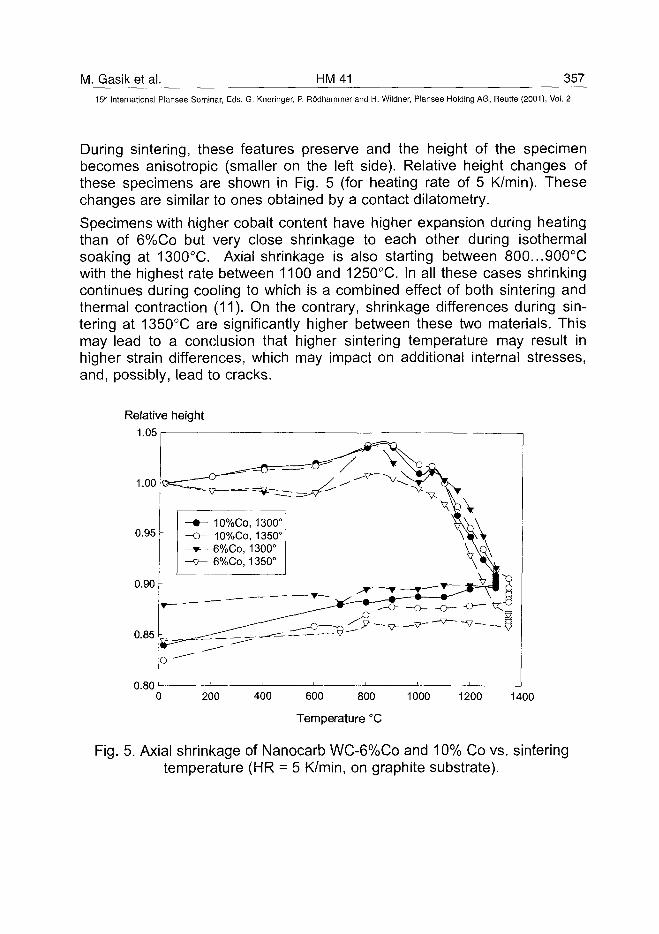
M. Gasik et al. HM41 357
15lh International Plansee Seminar, Eds. G. Kneringer, P. Rodhammer and H. Wildner, Plansee Holding AG, Reutte (2001), Vol. 2
During sintering, these features preserve and the height of the specimenbecomes anisotropic (smaller on the left side). Relative height changes ofthese specimens are shown in Fig. 5 (for heating rate of 5 K/min). Thesechanges are similar to ones obtained by a contact dilatometry.
Specimens with higher cobalt content have higher expansion during heatingthan of 6%Co but very close shrinkage to each other during isothermalsoaking at 1300°C. Axial shrinkage is also starting between 800...900°Cwith the highest rate between 1100 and 1250°C. In all these cases shrinkingcontinues during cooling to which is a combined effect of both sintering andthermal contraction (11). On the contrary, shrinkage differences during sin-tering at 1350°C are significantly higher between these two materials. Thismay lead to a conclusion that higher sintering temperature may result inhigher strain differences, which may impact on additional internal stresses,and, possibly, lead to cracks.
Relative height1.051
1.00
0.95
0.90
0.85
0.80
- 10%Co, 1300°- 10%Co, 1350°• 6%Co, 1300°
- 6%Co, 1350°
200 400 600 800
Temperature °C
1000 1200 1400
Fig. 5. Axial shrinkage of Nanocarb WC-6%Co and 10% Co vs. sinteringtemperature (HR = 5 K/min, on graphite substrate).
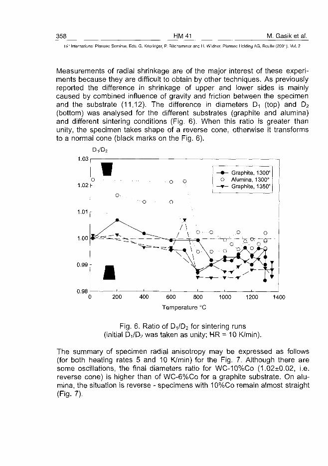
358 HM41 M. Gasik et al.15" International Plansee Seminar, Eds. G. Kneringer, P. Rodhammer and H. Wildner, Plansee Holding AG, Reutte (2001), Vol. 2
Measurements of radial shrinkage are of the major interest of these experi-ments because they are difficult to obtain by other techniques. As previouslyreported the difference in shrinkage of upper and lower sides is mainlycaused by combined influence of gravity and friction between the specimenand the substrate (11,12). The difference in diameters D-i (top) and D2
(bottom) was analysed for the different substrates (graphite and alumina)and different sintering conditions (Fig. 6). When this ratio is greater thanunity, the specimen takes shape of a reverse cone, otherwise it transformsto a normal cone (black marks on the Fig. 6).
1.03
1.02 -
1.01 -
0.98
1o
o
11
o
o o
o
/ \/ \
_—. —•7
\
1
o ••
\ \
v \
o
V C
—r
- • -o
Q-
• • • • o
>
•
- Graphite,Alumina,
- Graphite,
- — 7 eo • " •
oAo
i f *
1300°1300°1350°
oo ®~~
1
(
p11F
11
r
r
r
1.00 # = ^ = . ^ 4 ^ - ^
0.99 -
200 400 600 800
Temperature °C
1000 1200 1400
Fig. 6. Ratio of D^Da for sintering runs(initial DilD2 was taken as unity; HR = 10 K/min).
The summary of specimen radial anisotropy may be expressed as follows(for both heating rates 5 and 10 K/min) for the Fig. 7. Although there aresome oscillations, the final diameters ratio for WC-10%Co (1.02±0.02, i.e.reverse cone) is higher than of WC-6%Co for a graphite substrate. On alu-mina, the situation is reverse - specimens with 10%Co remain almost straight(Fig. 7).
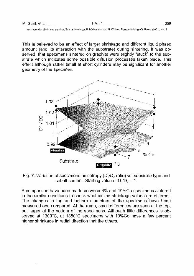
M. Gasik et al. HM41 35915'h International Plansee Seminar, Eds. G. Kneringer, P. Rodhammer and H. Wildner, Plansee Holding AG, Reutte (2001), Vol. 2
This is believed to be an effect of larger shrinkage and different liquid phaseamount (and its interaction with the substrate) during sintering. It was ob-served, that specimens sintered on graphite were slightly "stuck" to the sub-strate which indicates some possible diffusion processes taken place. Thiseffect although rather small at short cylinders may be significant for anothergeometry of the specimen.
Q
%Co
Substrate
Fig. 7. Variation of specimens anisotropy (D-,/D2 ratio) vs. substrate type andcobalt content. Starting value of 0^62 = 1.
A comparison have been made between 6% and 10%Co specimens sinteredin the similar conditions to check whether the shrinkage values are different.The changes in top and bottom diameters of the specimens have beenmeasured and compared. At the ramp, small differences are seen at the top,but larger at the bottom of the specimens. Although little differences is ob-served at 1300°C, at 1350°C specimens with 10%Co have a few percenthigher shrinkage in radial direction that the others.
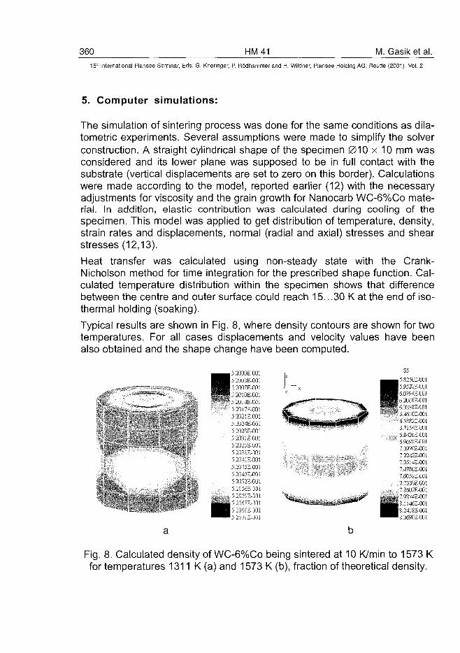
360 HM41 M. Gasik et al.15'" International Plansee Seminar, Eds. G. Kneringer, P. Rodhammer and H. Wildner, Plansee Holding AG, Reutte (2001), Vol. 2
5. Computer simulations:
The simulation of sintering process was done for the same conditions as dila-tometric experiments. Several assumptions were made to simplify the solverconstruction. A straight cylindrical shape of the specimen 010 x 10 mm wasconsidered and its lower plane was supposed to be in full contact with thesubstrate (vertical displacements are set to zero on this border). Calculationswere made according to the model, reported earlier (12) with the necessaryadjustments for viscosity and the grain growth for Nanocarb WC-6%Co mate-rial. In addition, elastic contribution was calculated during cooling of thespecimen. This model was applied to get distribution of temperature, density,strain rates and displacements, normal (radial and axial) stresses and shearstresses (12,13).
Heat transfer was calculated using non-steady state with the Crank-Nicholson method for time integration for the prescribed shape function. Cal-culated temperature distribution within the specimen shows that differencebetween the centre and outer surface could reach 15...30 K at the end of iso-thermal holding (soaking).
Typical results are shown in Fig. 8, where density contours are shown for twotemperatures. For all cases displacements and velocity values have beenalso obtained and the shape change have been computed.
" • • s i . •
5.2000E-001
_ I L . E r il
j I 7E 11
t rEf n„ l a s n i
J17E JI E LH1
I ^ E i i
IT | | | [
i h IJ
J E1 E f i
- -* E ' '•4 E I 1
-iJE 11 1
A J* '! jF II
-i" rJE 1 11- j E ii
1 ii. 11
c 1 1
L' .3
^ ^ _ 5.8250E-001^ ^ • 5 . 9 5 2 2 & 0 0 1
HHB' j ' : ; i ! ;--E K!;•*^ • ^^Sft^j^^ M ^ W b JUuuh-l II.U
K ^ ^ W B u i syE-QOl^^tgk •**' ''• * (i 4610E-001
p ^ p w w ^ M 7i 4E-iinio -:.'4.taE JU1D MJCE-OOl
TOoinE-ooi1 22C'EJini
' . ' 7 3514E-0D1" ' » ' , . 7 47-uE-OOl
' • ' • ' " "! UOJSE-UUI
1 liJflE-OOi"I 2DLI2F-001
^ - ^ » T ) 2 7 4 E - 0 0 1SJS^affiii^*18" «B|M14JE-001
^ ^ • K _4!SEf!Li!^^™8.3690Es00I
Fig. 8. Calculated density of WC-6%Co being sintered at 10 K/min to 1573 Kfor temperatures 1311 K (a) and 1573 K (b), fraction of theoretical density.
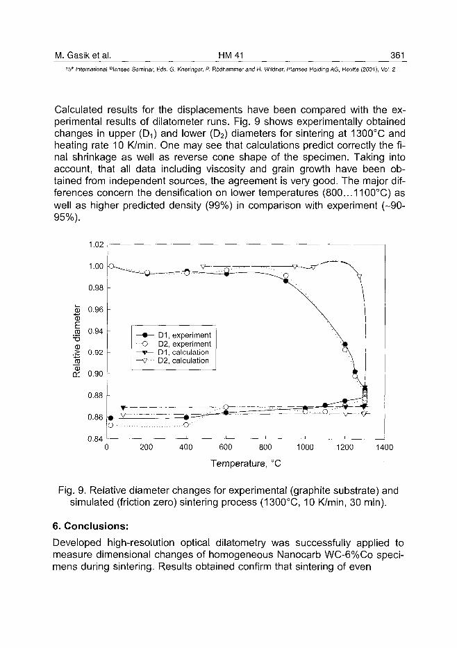
M. Gasik et al. HM41 361
15" International Plansee Seminar, Eds. G. Kneringer, P. Rodhammer and H. Wildner, Plansee Holding AG, Reutte (2001), Vol. 2
Calculated results for the displacements have been compared with the ex-perimental results of dilatometer runs. Fig. 9 shows experimentally obtainedchanges in upper (D-i) and lower (D2) diameters for sintering at 1300°C andheating rate 10 K/min. One may see that calculations predict correctly the fi-nal shrinkage as well as reverse cone shape of the specimen. Taking intoaccount, that all data including viscosity and grain growth have been ob-tained from independent sources, the agreement is very good. The major dif-ferences concern the densification on lower temperatures (800...1100°C) aswell as higher predicted density (99%) in comparison with experiment (-90-95%).
1.02
1.00
0.98
0.96
0.94
0.92
0.90
0.88
0.86
D1, experimentO D2, experiment
D1, calculation—v••• D2, calculation
200 400 600 800 1000
Temperature, °C
1200 1400
Fig. 9. Relative diameter changes for experimental (graphite substrate) andsimulated (friction zero) sintering process (1300°C, 10 K/min, 30 min).
6. Conclusions:
Developed high-resolution optical dilatometry was successfully applied tomeasure dimensional changes of homogeneous Nanocarb WC-6%Co speci-mens during sintering. Results obtained confirm that sintering of even
362 HM41 M. Gasik et al.15" International Plansee Seminar, Eds. G. Kneringer, P. Rodhammer and H. Wildner, Plansee Holding AG, Reutte (2001), Vol. 2
homogeneous specimens is not uniform. Dimensional changes of upper andlower diameters depend on substrate selection and sintering parameters. Us-ing alumina, a "reverse cone" shape with anisotropy of +3...4 % was re-sulted, in comparison with ±0.5...1% on graphite substrate.
The difference in shrinkage kinetics vs. sintering temperature and heatingrate has been observed. The modelling of the sintering process for WC-6%Co was performed and its results are generally in a good agreement withdilatometric experiments. Some differences in densification kinetics in therange of 800...1200°C are caused by viscosity equation, which has to be cor-rected for a better fit. The stress analysis was also performed and the stressdistribution was calculated. This work is part of the project BE97-4176, sup-ported by the European Commission under the contract BRPR-CT97-0505.
REFERENCES:
1. "Functionally Graded Materials: Design, Processing and Applications",Eds. Y. Miyamoto, W.A. Kaysser, B.H. Rabin, A. Kawasaki, and R.G. Ford.Kluwer Academic Publishers, Bosten/Dordrecht/London, 1999, 320 pp.
2. S. Suresh and A. Mortensen, "Fundamentals of Functionally Graded Mate-rials" (IOM Communications Ltd., London, 1998), 166 pp.
3. R. Watanabe, MRS Bull., 20, No.1 (1995), 32-34.
4. A. F. Lisovsky, Intern. J. Heat Mass Transfer 33 (1989), 8, 1599-1603.
5. A. F. Lisovsky, T.E. Gracheva, Refr. Met. & Hard Mater., 11 (1992), 83-87.
6. A. Upadhyaya, A. Lai, K. Sivaraman, R. M. German. Proc. Adv. P/M & Par-tic. Mater. "PM2Tech", Las Vegas, NV, MPIF (1998), 12, 75-84.
7. R. Watanabe, Y. Mizuno, A. Kawasaki, Metals & Materials, 5, No. 2(1999), 163-169.
8. M. Gasik, P. Kervinen, M. Kaskiala, P. Graf. Proc. Intern. Diamond ToolsWorks., Turin, Italy. EPMA, 1999, 107-112.
9. SigmaScan 4.0 User's Manual. SPSS Inc., 1998.
10. F. Raether, G. Leitner. Proc. PM'98 EPMA World Congress, Granada,Spain, 19-24.10.1998.
11. M. M. Gasik and B. Zhang, Proc. of European Conf. on Advances in HardMaterials Production: EURO PM 99, Turin, Italy. EPMA, 1999, 449-454.

M. Gasik et al. HM 41 363^15" International Plansee Seminar, Eds. G. Kneringer, P. Rodhammer and H. Wildner, Plansee Holding AG, Reutte (2001), Vol. 2
12. M. M. Gasik and B. Zhang, Computat. Mater. Sci., 18 93-101 (2000).
13. B. Zhang and M.M. Gasik, Proc. 2000 ABAQUS Users' Conference,Newport, Rhode Island, USA (2000), pp. 823-833.
AT0100465364 HM42 S. Put et al.
15" International Plansee Seminar, Eds. G. Kneringer, P. Rodhammer and H. Wildner, Plansee Holding AG, Reutte (2001), Vol. 2
FUNCTIONALLY GRADED WC-Co HARDMETALS
S. Put, J. Vleugels and O. Varder Biest
Department of Metallurgy and Materials Engineering,
Katholieke Universiteit Leuven,
Kasteelpark Arenberg 44, B-3001 Leuven, Belgium
Summary:
Functionally graded hardmetals with a continuous gradient in cobalt and TiCwere manufactured by electrophoretic deposition (EPD). Most attention wasfocussed on obtaining a fully dense and phase-pure material without loosingthe cobalt gradient during sintering. WC-Co graded plates of 35x35 mm wereprocessed by electrophoretic deposition, cold isostatic pressing and sintering.The resulting graded material showed a continuous variation in composition,microstructure and mechanical properties. The cobalt content in the WC-CoFGM increased from about 6 wt% on the hard side to 17 wt% on the soft side,whereas the Vickers hardness, HV10, was found to decrease continuouslyfrom 19 to 8.5 GPa along the same direction. The WC-Co-TiC FGMcontained a TiC gradient from 0 to 25 wt% and Vickers hardness values from16.3 up to 19.8 GPa along the same direction.
KEYWORDS: Functionally Graded Materials (FGM), Powder Processing,Electrophoretic Deposition (EPD), WC-Co, TiC
S. Put et al. HM_42 365^
15th International Plansee Seminar, Eds. G. Kneringer, P. Rddhammer and H. Wildner, Plansee Holding AG, Reutte (2001), Vol. 2
1. Introduction:
In today's highly demanding environment, more attention is given tocombine irreconcilable properties in the same component during processingand design of materials. A possible concept to meet this demand is that offunctionally graded materials (FGM). The initial idea of functional gradedmaterials was to combine the incompatible properties of heat resistance andstrength with low internal stress, by producing gradual transitions inmicrostructure and/or composition (1). A very wide variety of availableprocesses, such as plasma spraying, centrifugal casting, common powdermetallurgy, PVD, CVD, and colloidal processing have been reported for FGMproduction (2). Amongst these processes, electrophoretic deposition (EPD) isa fairly rapid low cost process, capable of producing continuously and stepgraded materials with complex geometry (3).
Electrophoretic deposition is a two-step process. In a first step, particlessuspended in a liquid are forced to move towards one of the electrodes byapplying an electric field to the suspension (electrophoresis). In a secondstep, the particles collect at one of the electrodes and form a coherent depositon it. Numerous applications of EPD have been developed for the fabricationof ceramics, including the application of coatings (1-3-4), laminated materials(5) and functionally graded ceramic-ceramic materials, as for example in theAI2O3/ZrO2 system (6-7).
In this paper, functionally graded WC-Co hardmetals with a gradient incobalt content and functionally graded WC-Co-TiC composites with a gradientin TiC are processed by means of electrophoretic deposition of the greenmaterials. Subsequent pressureless sintering is performed in order to obtaindense materials.
2. Experimental Procedure:
The WC-Co composite powders that were used are Nanocarb grade WC-6Co (nominally 6wt % Co), Nanocarb grade WC-10Co and Nanocarb gradeWC-12Co. All powder grades were obtained from Union-Miniere (Olen,Belgium) and were ball-milled from an initial agglomerate size of about 50 imdown to about 1 (xm. A WC-25Co was prepared by mixing the Nanocarb WC-
366 HM42 S. Put et al.15" International Plansee Seminar, Eds. G. Kneringer, P. Rodhammer and H. Wildner, Plansee Holding AG, Reutte (2001), Vol. 2
10Co composite powder with pure Co powder (Union-Miniere grade EF with aparticle size of 1.3 jj,m) in a multidirectional mixer (type Turbula) for 48 hoursin n-propanol in a polyethylene bottle. To break the agglomerates in thestarting powder, hardmetal milling balls were added to the container. Aftermixing, the n-propanol was removed by means of a rotating evaporator.Furthermore, a TiC powder (Ceramyg with a particle size of 0.35 ^m) wasused to produce a WC-Co-TiC FGM with a gradient in TiC content.
For the EPD experiments, an in-house developed electrophoreticdeposition set-up, illustrated in figure 1, was used. The polytetrafluorethylene(PTFE) deposition cell contains two parallel flat stainless steel electrodes witha surface area of 9 cm2. The distance between the electrodes is 3.5 cm. Agraphite coating was applied on the surface of the deposition electrode tofacilitate the removal of the deposit and to avoid cracking of the depositduring drying. Due to the hydrolysis of water and the concomitant formation ofgas bubbles at the stainless steel electrodes at voltages above about 3 V,organic solvent based suspensions need to be used for EPD experiments athigher voltages. A starting suspension containing 200 ml acetone with 100 g/lNanocarb WC-6C0 was pumped in a circulation system through thedeposition cell by a peristaltic pump 1. During deposition, the circulatingsuspension moves along the direction indicated by the arrows in figure 1. Inorder to produce a gradient in cobalt content a second acetone suspensionwith 400 g/l WC-25Co powder was added to the circulating suspension bypump 2 at a rate of 1.68 ml/min, allowing to continuously change the cobaltconcentration from 6 up to approximately 17wt % at the end, because someWC-6C0 powder remains in the suspension at the end of the experiment. Forthe WC-Co-TiC FGM, a starting suspension of 400g/l WC-12Co was used. Asecond acetone suspension containing 200 g/l TiC powder was added to thecirculating suspension at the same rate in order to create a gradient in TiC.Since the local composition of the deposit is directly related to theconcentration of the suspension at the moment of deposition, the EPDtechnique allows the processing of functionally graded cemented carbideswith a continuous gradient in composition.
Electrophoretic deposition was performed at a constant DC voltage of 800V in the case of the WC-Co FGM and 500 V for the WC-Co-TiC. After 1minute of deposition of the circulating starting suspension, the secondsuspension was added to create a concentration gradient in the deposit. Thetotal deposition time was 8 and 15 minutes for the WC-Co and WC-Co-TiCFGM respectively. The deposits were removed from the electrode and slowly
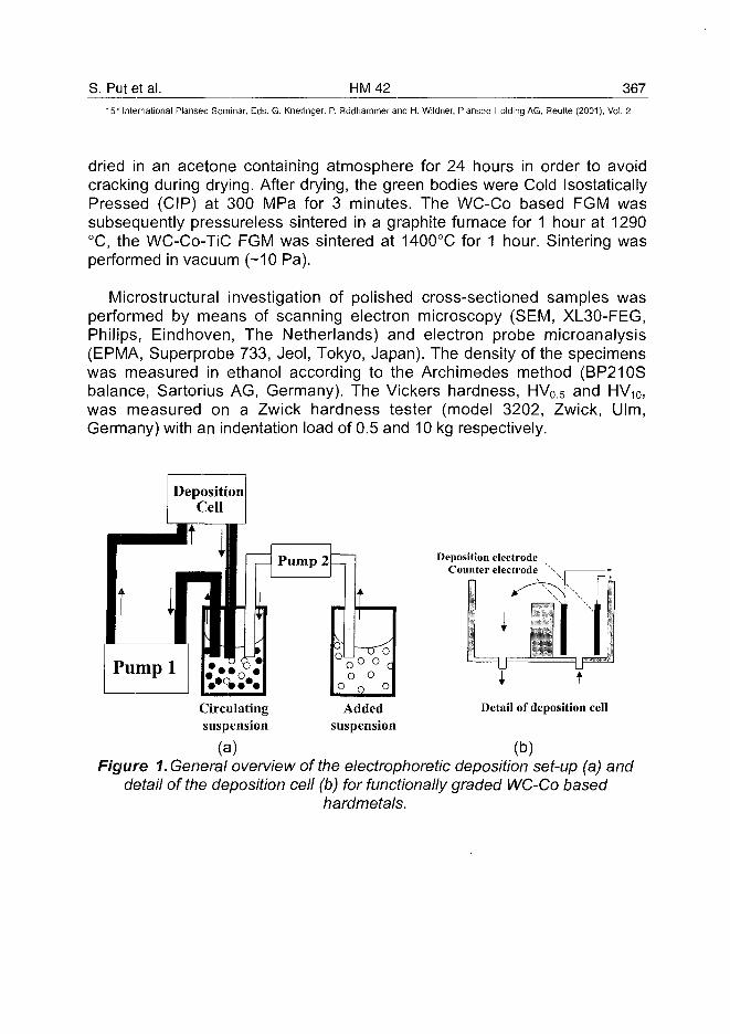
S. Put et al. HM42 367
15'" International Plansee Seminar, Eds. G. Kneringer, P. Rodhammer and H. Wildner, Plansee Holding AG, Reutte (2001), Vol. 2
dried in an acetone containing atmosphere for 24 hours in order to avoidcracking during drying. After drying, the green bodies were Cold IsostaticallyPressed (CIP) at 300 MPa for 3 minutes. The WC-Co based FGM wassubsequently pressureless sintered in a graphite furnace for 1 hour at 1290°C, the WC-Co-TiC FGM was sintered at 1400°C for 1 hour. Sintering wasperformed in vacuum (-10 Pa).
Microstructural investigation of polished cross-sectioned samples wasperformed by means of scanning electron microscopy (SEM, XL30-FEG,Philips, Eindhoven, The Netherlands) and electron probe microanalysis(EPMA, Superprobe 733, Jeol, Tokyo, Japan). The density of the specimenswas measured in ethanol according to the Archimedes method (BP210Sbalance, Sartorius AG, Germany). The Vickers hardness, HV0.5 and HV10,was measured on a Zwick hardness tester (model 3202, Zwick, Ulm,Germany) with an indentation load of 0.5 and 10 kg respectively.
Deposition electrodeCounter electrode
t
Circulating Added Detail of deposition cellsuspension suspension
(a) (b)Figure 1. General overview of the electrophoretic deposition set-up (a) and
detail of the deposition cell (b) for functionally graded WC-Co basedhardmetals.
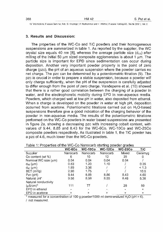
368 HM42 S. Put et al.
15-" International Plansee Seminar, Eds. G. Kneringer, P. Rodhammer and H. Wildner, Plansee Holding AG, Reutte (2001), Vol. 2
3. Results and Discussion:
The properties of the WC-Co and TiC powders and their homogeneoussuspensions are summarized in table 1. As reported by the supplier, the WCcrystal size equals 40 nm [8], whereas the average particle size (d50) aftermilling of the initial 50 |im sized composite agglomerates is about 1 jim. Theparticle size is important for EPD since sedimentation can occur duringdeposition. Another very important powder property is the point of zerocharge (pzc), the pH of an aqueous suspension where the powder carries nonet charge. The pzc can be determined by a potentiometric titration (9). Thepzc is crucial in order to prepare a stable suspension, because a powder willonly charge sufficiently, when the pH of the suspension is carefully adjustedto differ enough from the point of zero charge. Vandeperre et al. (10) showedthat there is a rather good correlation between the charging of a powder inwater, and the electrophoretic mobility during EPD in non-aqueous media.Powders, which charged well at low pH in water, also deposited from ethanol.When a charge is developed on the powder in water at high pH, depositionoccurred from acetone. Potentiometric titrations carried out on H2O-basedsuspensions therefore give a good indication of the charging behavior of thepowder in non-aqueous media. The results of the potentiometric titrationsperformed on the WC-Co powders in water based suspensions are presentedin figure 2a, showing a decreasing pzc with increasing cobalt content, withvalues of 9.44, 8.85 and 8.43 for the WC-6C0, WC-10Co and WC-25Cocomposite powders respectively. As illustrated in table 1, the TiC powder hasa pzc of 4.6, much lower than the WC-Co powders.
Table 1: Properties of the WC-Co Nanocarb starting powder grades
SupplierCo content (wt %)Nominal WC size (|im)d50 (|im)d90 (^m)BET (m2/g)Pzc (pH)Natural pH*Natural conductivity(fiS/cm)*EPD in ethanolEPD in acetone
WC-6C0Nanocarb
60.040.831.892.909.449.56
111-+
WC-IOCoNanocarb
100.041.203.361.758.858.98
77-+
WC-12CONanocarb
120.041.10
//
8.868.55
/-+
WC-25COMixed
250.04
///
8.438.48
28-+
TiCCeramyg
0/
0.35< 1.310.04.605.38
59++
* measured for a concentration of 100 g powder/1000 ml demineralized H2O (pH = 6)./ not measured.
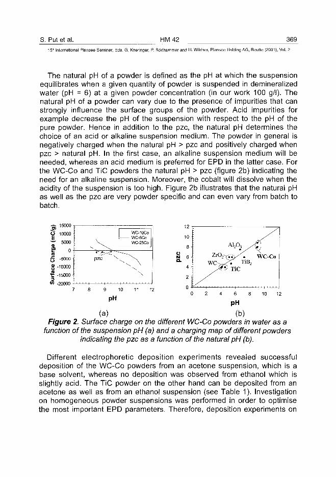
S. Put et al. HM42 369
15" International Plansee Seminar, Eds. G. Kneringer, P. Rodhammer and H. Wildner, Plansee Holding AG, Reutte (2001), Vol. 2
The natural pH of a powder is defined as the pH at which the suspensionequilibrates when a given quantity of powder is suspended in demineralizedwater (pH = 6) at a given powder concentration (in our work 100 g/l). Thenatural pH of a powder can vary due to the presence of impurities that canstrongly influence the surface groups of the powder. Acid impurities forexample decrease the pH of the suspension with respect to the pH of thepure powder. Hence in addition to the pzc, the natural pH determines thechoice of an acid or alkaline suspension medium. The powder in general isnegatively charged when the natural pH > pzc and positively charged whenpzc > natural pH. In the first case, an alkaline suspension medium will beneeded, whereas an acid medium is preferred for EPD in the latter case. Forthe WC-Co and TiC powders the natural pH > pzc (figure 2b) indicating theneed for an alkaline suspension. Moreover, the cobalt will dissolve when theacidity of the suspension is too high. Figure 2b illustrates that the natural pHas well as the pzc are very powder specific and can even vary from batch tobatch.
•g 15000 T
o 10000w 5000
E> ong -5000
g -10000
"C -150003
W -20000
WC-10COWC-6COWC-25CO
: PZC \ ^ ^
: \: \
Figurefunction
7 8 9 10 11 12
pH
(a)2. Surface charge on the different WC-Co powders in water as aof the suspension pH (a) and a charging map of different powders
indicating the pzc as a function of the natural pH (b).
Different electrophoretic deposition experiments revealed successfuldeposition of the WC-Co powders from an acetone suspension, which is abase solvent, whereas no deposition was observed from ethanol which isslightly acid. The TiC powder on the other hand can be deposited from anacetone as well as from an ethanol suspension (see Table 1). Investigationon homogeneous powder suspensions was performed in order to optimisethe most important EPD parameters. Therefore, deposition experiments on
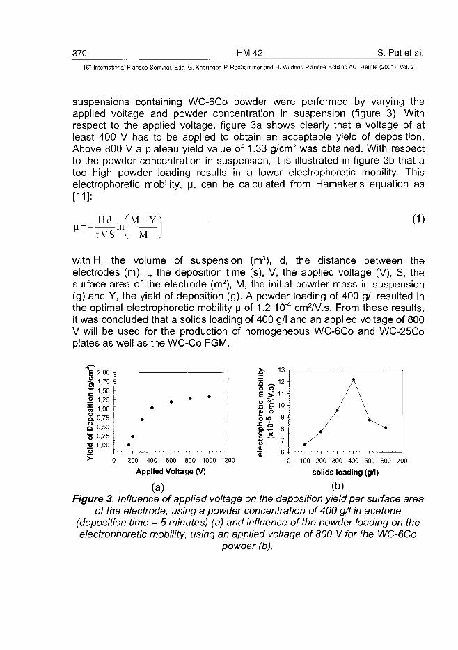
370 HM42 S. Put et al.15" International Plansee Seminar, Eds. G. Kneringer, P. Rodhammer and H. Wildner, Plansee Holding AG, Reutte (2001), Vol. 2
suspensions containing WC-6C0 powder were performed by varying theapplied voltage and powder concentration in suspension (figure 3). Withrespect to the applied voltage, figure 3a shows clearly that a voltage of atleast 400 V has to be applied to obtain an acceptable yield of deposition.Above 800 V a plateau yield value of 1.33 g/cm2 was obtained. With respectto the powder concentration in suspension, it is illustrated in figure 3b that atoo high powder loading results in a lower electrophoretic mobility. Thiselectrophoretic mobility, u, can be calculated from Hamaker's equation as[11]:
H d . ( M - Y-In
MtVS
(D
with H, the volume of suspension (m3), d, the distance between theelectrodes (m), t, the deposition time (s), V, the applied voltage (V), S, thesurface area of the electrode (m2), M, the initial powder mass in suspension(g) and Y, the yield of deposition (g). A powder loading of 400 g/l resulted inthe optimal electrophoretic mobility u of 1.2 10~4 cmW.s. From these results,it was concluded that a solids loading of 400 g/l and an applied voltage of 800V will be used for the production of homogeneous WC-6C0 and WC-25Coplates as well as the WC-Co FGM.
2,00
.2 1,25 Iw 1,00 ta 0,75 Ia °,50 f"S 0,25 •:2 0,001
> 0 200 400 600 800 1000 1200
Applied Voltage (V)
(a)
0 100 200 300 400 500 600 700
solids loading (g/l)
(b)Figure 3. Influence of applied voltage on the deposition yield per surface area
of the electrode, using a powder concentration of 400 g/l in acetone(deposition time = 5 minutes) (a) and influence of the powder loading on theelectrophoretic mobility, using an applied voltage of 800 V for the WC-6C0
powder (b).
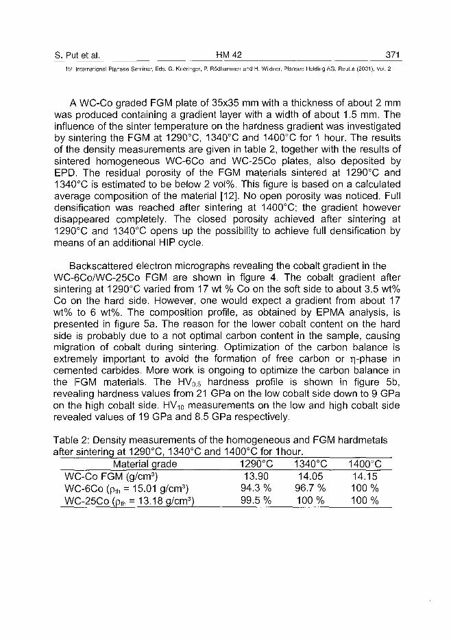
S. Put et al. HM42 37115ih International Plansee Seminar, Eds. G. Kneringer, P. Rodhammer and H. Wildner, Plansee Holding AG, Reutte (2001), Vol. 2
A WC-Co graded FGM plate of 35x35 mm with a thickness of about 2 mmwas produced containing a gradient layer with a width of about 1.5 mm. Theinfluence of the sinter temperature on the hardness gradient was investigatedby sintering the FGM at 1290°C, 1340X and 1400°C for 1 hour. The resultsof the density measurements are given in table 2, together with the results ofsintered homogeneous WC-6C0 and WC-25Co plates, also deposited byEPD. The residual porosity of the FGM materials sintered at 1290X and1340°C is estimated to be below 2 vol%. This figure is based on a calculatedaverage composition of the material [12]. No open porosity was noticed. Fulldensification was reached after sintering at 1400°C; the gradient howeverdisappeared completely. The closed porosity achieved after sintering at1290X and 1340°C opens up the possibility to achieve full densification bymeans of an additional HIP cycle.
Backscattered electron micrographs revealing the cobalt gradient in theWC-6Co/WC-25Co FGM are shown in figure 4. The cobalt gradient aftersintering at 1290°C varied from 17 wt % Co on the soft side to about 3.5 wt%Co on the hard side. However, one would expect a gradient from about 17wt% to 6 wt%. The composition profile, as obtained by EPMA analysis, ispresented in figure 5a. The reason for the lower cobalt content on the hardside is probably due to a not optimal carbon content in the sample, causingmigration of cobalt during sintering. Optimization of the carbon balance isextremely important to avoid the formation of free carbon or r^-phase incemented carbides. More work is ongoing to optimize the carbon balance inthe FGM materials. The HV05 hardness profile is shown in figure 5b,revealing hardness values from 21 GPa on the low cobalt side down to 9 GPaon the high cobalt side. HV10 measurements on the low and high cobalt siderevealed values of 19 GPa and 8.5 GPa respectively.
Table 2: Density measurements of the homogeneous and FGM hardmetalsafter sintering at 1290°C, 1340°C and 1400°C for 1 hour.
Material grade 1290X 1340°C 1400°CWC-Co FGM (g/cm3)WC-6Co(pth = 15.01 g/cm3)WC-25Co (pth = 13.18 g/cm3)
1394.99.
.903%5%
14.0596.7 %100%
14.15100%100%
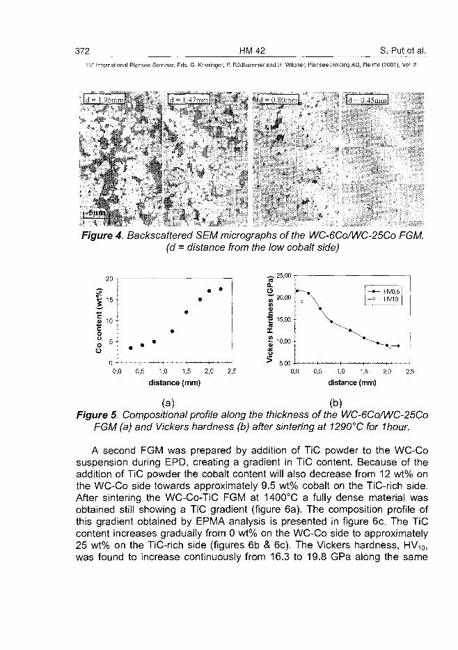
372 HM42 S. Put et al.15" International Plansee Seminar, Eds. G. Kneringer, P. Rodhammer and H. Wildner, Plansee Holding AG, Reutte (2001), Vol. 2
Figure 4. Backscattered SEM micrographs of the WC-6CoAA/C-25Co FGM.(d = distance from the low cobalt side)
20
15
I 1°tOuoo
f[ • ••I
1
: •
\ . • •
+ ' • • - ^ 1 . . • • 4- . . . • 1 • • • • 1 • • • •
no
1 2 a o °0)c"S 15,00aI
Vic
I
3• - - . p » - HV0.5
o \ ] - * - HV10
\
_ ^ _ . — ^ . . . . . . i . . . J— f. . — . • • • • . • • 1—•• . . _ . _ ^ _
0,0 0,5 1,0 1,5 2,0 2,5
distance (mm)0,0 0,5 1,0 1,5 2,0
distance (mm)
2,5
(a) (b)Figure 5. Compositional profile along the thickness of the WC-6CoAVC-25Co
FGM (a) and Vickers hardness (b) after sintering at 1290°C for 1hour.
A second FGM was prepared by addition of TiC powder to the WC-Cosuspension during EPD, creating a gradient in TiC content. Because of theaddition of TiC powder the cobalt content will also decrease from 12 wt% onthe WC-Co side towards approximately 9.5 wt% cobalt on the TiC-rich side.After sintering the WC-Co-TiC FGM at 1400°C a fully dense material wasobtained still showing a TiC gradient (figure 6a). The composition profile ofthis gradient obtained by EPMA analysis is presented in figure 6c. The TiCcontent increases gradually from 0 wt% on the WC-Co side to approximately25 wt% on the TiC-rich side (figures 6b & 6c). The Vickers hardness, HV10,was found to increase continuously from 16.3 to 19.8 GPa along the same
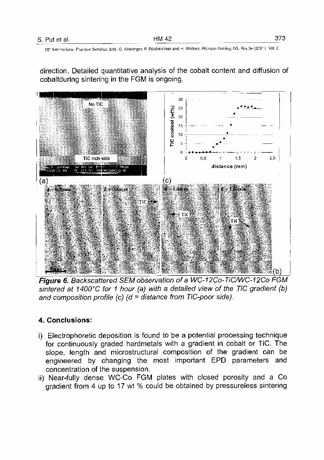
S. Put et al. HM42 37315" International Plansee Seminar, Eds. G. Kneringer, P. Rodhammer and H. Wildner, Plansee Holding AG, Reutte (2001), Vol. 2
direction. Detailed quantitative analysis of the cobalt content and diffusion ofcobaltduring sintering in the FGM is ongoing.
HMI
(a)
•
MMMMINo TiC
TiC rich i
Spo! Mayn Dei WO & p 1—r3 0 45x SE 111 252 FGM
i) Imin
Illl -
IIIIIIIIIIIIHUJIU
idp
1 500 iimWC-CoAVC-Co-dC
d - U.-Smni
1
|
30 i
? 2 5 -
S on
TiC
con
tent
Ol O
Ol
C
0
(c)fl 14inm
•«4 | | (
•
•
•
•
0,5 1 1,5 2
distance (mm)
<1 IS iniu
2,5
(b)Figure 6. Backscattered SEM observation of a WC-12Co-TiC/WC-12Co FGMsintered at 1400°C for 1 hour (a) with a detailed view of the TiC gradient (b)and composition profile (c) (d = distance from TiC-poor side).
4. Conclusions:
i) Electrophoretic deposition is found to be a potential processing techniquefor continuously graded hardmetals with a gradient in cobalt or TiC. Theslope, length and microstructural composition of the gradient can beengineered by changing the most important EPD parameters andconcentration of the suspension.
ii) Near-fully dense WC-Co FGM plates with closed porosity and a Cogradient from 4 up to 17 wt % could be obtained by pressureiess sintering
374 HM42 S. Put et al.15" International Plansee Seminar, Eds. G. Kneringer, P. Rodhammer and H. Wildner, Plansee Holding AG, Reutte (2001), Vol. 2
at 1290°C and 1340°C, with a HV10 hardness gradient decreasing from19.5 on the Co-poor side down to 8.8 GPa on the Co-rich side,
iii) A WC-Co-TiC FGM with TiC gradient could be successfully produced byEPD and sintered to full density, maintaining a TiC gradient from 0 wt% upto 25 wt%. The Vickers hardness, HV10, was found to increase continuouslyfrom 16.3 to 19.8 GPa along the same direction.
5. Acknowledgement:
This work was supported by the Flemish Institute for the Promotion ofScientific and Technological Research in Industry (IWT) and by the Brite-Euram program of the Commission of the European Communities underproject contract No. BRPR-CT97-0505.
6. References:
1. A. Mortensen and S. Suresh, Int. Mat. Rev., 40 [6] (1995), pp. 239-2652. A. Neubrand and J. Rodel, Z. Metallkd. 88 (1997), pp. 358-3713. O. Van Der Biest, L. Vandeperre, Ann. Rev. Mater. Sci. 29 (1999), pp. 3274. I. Zhitomirsky, J. Eur. Ceram. Soc. 18 (1998), pp. 8495. L. Vandeperre, O. Van Der Biest, Key Eng. Mat., 127-131 (1997), pp. 5676. C. Zhao, J. Vleugels, L. Vandeperre, B. Basu and O. Van Der Biest, Mat.
Sci. Forum, (1999), pp. 957. C. Zhao, L. Vandeperre, J. Vleugels, & O. Van Der Biest, Proc. of the Ann.
Am. Cer. Soc Meeting, Indianapolis (1999), pp. 193-2028. L. E. McCandlish, P. Seegopaul and L. Wu, Proc. 14th Int. Plansee
Seminar, Vol. 4, pp. 363-375 (Plansee AG, Reutte 1997).9. I. E. Dzjaloshinsky, E.M. Lifshits and L.P. Pitaevsky, Zhurn. Eksp. Teor.
Fiz. 37(1959), pp.22910. L. Vandeperre, C. Zhao and O. Van Der Biest, 6th Conference of the Eur.
Cer. Soc, (Brighton 1999), to be published in British Ceramic Transactions(In Press).
11. H.C. Hamaker, Trans. Faraday Soc., 36 (1940), pp. 279-28712. S. Put, J. Vleugels and O. Van Der Biest, "Gradient Profile Prediction in
Functionally Graded Materials Processed by Electrophoretic Deposition",Submitted to Acta Materiala.
AT0100466A. Wu et al. HM 47 375
15" International Plansee Seminar, Eds. G. Kneringer, P. Rodhammer and H. Wildner, Plansee Holding AG, Reutte (2001), Vol. 2
Fabrication of ct/p-Sialon Symmetrically Compositional FGM
Wu Anhua, Cao Wenbin, Ge Changchun, Li Jiangtao
Laboratory of Special Ceramic and P/M, University of Science and Technology
Beijing, Beijing, 100083, P. R. China
Summary:
Sialon as one of the important structural ceramics is being paid more andmore attention due to its unique chemistry, crystal structure and microstructurefeatures. a-Sialon has superior hardness, p-Sialon possesses high strengthand toughness, and (a+p)-Sialon is combination of a-Sialon and p-Sialon.This paper presents the crystal structure, fabrication and properties of a-Sialon, p-Sialon and (a+P)-Sialon. On the basis of their properties,Symmetrically Compositional Functionally Graded Material (SCFGM) with theadvantage of both a-Sialon and p-Sialon, has been fabricated, its thermalstress has been calculated with finite element analysis method, and itsmicrostructure has been investigated.
Keywords:
a-Sialon, p-Sialon, (a+P)-Sialon, symmetric composition functionally gradedmaterial (SCFGM)
1. Introduction
There are two well known Sialon phases in the Si3N4-rich corner of the R-Si-Al-O-N phase diagrams (R=rare-earth), called a- and p-Sialon, which areisostructural with a and p-Si3N4, respectively. The p-Sialons have thecomposition Si6.2Alz0zN8_z, with z<4.2, along the tie line from Si3N4 towardsAIN»AI2O3, while the a-Sialon solid solutions, Rm/3Si12_(m+n)AI(m+n)OnN16_n, havetwo-dimensional extensions in the Si3N4- AIN»AI2O3-RN»3AIN plane of thecorresponding Janecke prisms[1-3].a-Sialon ceramics have attracted much attention as structural materials,because they show low linear thermal expansion coefficients(~3.7-4.0x10"6oC)and high hardness(Hv~22GPa), and because they offer the possibility of
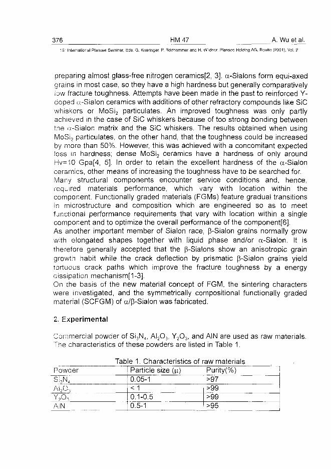
376 HM47 A. Wu et al.15* International Plansee Seminar, Eds. G. Kneringer, P. Rodhammer and H. Wildner, Plansee Holding AG, Reutte (2001), Vol. 2
preparing almost glass-free nitrogen ceramics[2, 3]. a-Sialons form equi-axedgrains in most case, so they have a high hardness but generally comparativelyiow fracture toughness. Attempts have been made in the past to reinforced Y-doped a-Sialon ceramics with additions of other refractory compounds like SiCwhiskers or MoSi2 particulates. An improved toughness was only partlyachieved in the case of SiC whiskers because of too strong bonding betweenthe a-Sialon matrix and the SiC whiskers. The results obtained when usingMoSi2 particulates, on the other hand, that the toughness could be increasedby more than 50%. However, this was achieved with a concomitant expectedloss in hardness; dense MoSi2 ceramics have a hardness of only aroundHv=10 Gpa[4, 5], In order to retain the excellent hardness of the a-Sialonceramics, other means of increasing the toughness have to be searched for.Many structural components encounter service conditions and, hence,required materials performance, which vary with location within thecomponent. Functionally graded materials (FGMs) feature gradual transitionsin microstructure and composition which are engineered so as to meetfunctional performance requirements that vary with location within a singlecomponent and to optimize the overall performance of the component[6].As another important member of Sialon race, (3-Sialon grains normally growwith elongated shapes together with liquid phase and/or a-Sialon. It istherefore generally accepted that the (3-Sialons show an anisotropic graingrowth habit while the crack deflection by prismatic (3-Sialon grains yieldtortuous crack paths which improve the fracture toughness by a energydissipation mechanism[1-3].On the basis of the new material concept of FGM, the sintering characterswere investigated, and the symmetrically compositional functionally gradedmaterial (SCFGM) of a/(3-Sialon was fabricated.
2. Experimental
Commercial powder of Si3N4, AI2O3, Y2O3, and AIN are used as raw materials.The characteristics of these powders are listed in Table 1.
Table 1. Characteristics of raw materialsPowderSi3N4
AI2O3
Y2O3
AIN
Particle size (\x)0.05-1< 10.1-0.50.5-1
Purity(%)>97>99>99>95
A. Wu et al. HM 47 377_
15" International Plansee Seminar, Eds. G. Kneringer, P. Rodhammer and H. Wildner, Plansee Holding AG, Reutte (2001), Vol. 2
The amounts of Si3N4 crystalline phases were semiquantitative estimatedthrough the X-ray spectrum of Si3N4 powder. The weight content of a- Si3N4 is80%, the content of p- Si3N4 is 20%. The powders were prepared according tothe composition of Sialon, the starting material mixtures were milled in water-free propanol for 6 hours in a plastic jar, and then dried in air.For the Sialon ceramics, pellets of dried powder were compacted in BN-coated graphite dies; for a/p-Sialon FGMs, the starting material mixtures werestacked into BN-coated graphite dies according to the designs of gradediayered compositions, and compacted in the die. Then, the green compactswere sintered at a condition of 1780°C, 25MPa and holding for 1 hour in argon.The densities of Sialon ceramics was measured according to Archimedes'method. Scan360 scanning electronic microscopy were used to observe themicrostructures of a/p-Sialon FGMs. Thermal stress distribution within FGMwas calculated by finite element analysis.
3. Results and discussion
3.1 Sintering of Sialon Ceramics
In order to fabricate the FGMs with excellent properties, the gradient ofcomposition must be chemical compatible and physical matched. Sun[7] hasstudied the compatible area among the a-sialon phase, M' phase[Me2Si3.XAIXO3+XN4_X] and p-Sialon phase. She indicated that the a-sialon phase and M'phase are compatible, the compatible area of M' phase and p-Sialon[Si6.:,_AI2OZN8.2] phase is 0<zsS0.8. Slasor[8] has studied the boundary of a-sialonphase and p-Sialon phase. He indicated that the boundary located m=0 andn=0~1.7[Ym/3Si12_(m+n)Alm+nOnN16.n]. In this work, z=0.1, 0.3, 0.5 and 0.7 wereselected for the research on the sintering of p-Sialon ceramics. As to thesintering of a-sialon and a-p-Sialon, the samples were prepared along the joinline of Si3N4-R2O3:9AIN in the Si3N4-AIN«AI2O3-RN»3AIN plane of thecorresponding Janecke prisms, overall compositions with m=0.1, 0.3, 0.5, 0.7,0.9, 1.1, 1.2 and 1.3[Ym/3Si12.(m+n)Alm+nOnNi6.n, n=m/2] in this work. The relativedensity of Sialon ceramics is shown as Fig. 1. Fig.1(a) shows that the relativedensity of p-Sialon ceramics is raised from 68% to 81% as the z valueincreases. But the p-Sialon ceramics can't be densified because of too lowcontent of liquid phase in the sintering process. The relative density of p-Sialon ceramics is improved while 2% Y2O3 was used as additive, reaching92% and 98% respectively when z=0.5 and 0.7. So the p-Sialon ceramics canbe densified as the increase of liquid phase content in sintering process.
378 HM47 A. Wu et al.15" International Plansee Seminar, Eds. G. Kneringer, P. Rodhammer and H. Wildner, Plansee Holding AG, Reutte (2001), Vol. 2
Fig. 1 (b) shows that the relative density of a-Sialon and a-(3-Sialon ceramics israised while the m value increased, the a-Sialon and a-(3-Sialon ceramics aredensified when the m value is higher than 0.5. The relative density is low whenthe m value is lower than 0.5 because the content of liquid-phase in sinteringprocess is too low. It can be concluded that the relative density is related to thecontents of AI2O3, AIN and Y2O3, which increases as the contents of AI2O3, AINand Y2O3 increase.
(a) p -sialon(C—P -sialon, B—Y2O3- 0 -sialon) (b) a-sialon |0a- P -sialon
Fig 1 Relative density of sialon ceramics
3. 2 The phase composition of Sialon Ceramics
Analyses of the crystalline phase of.the prepared samples were based on theirX-ray diffraction records with Cu Kc^ radiation. In the semi-quantitativeestimation of the amounts of crystalline phases, the integrated intensities ofthe following reflection were used: (1) (210) of the a-Sialon, (2) (210) of (3-Sialon. The relative fraction of each phase was then calculated from theexpression
wa=iA+ipwp=ip/ ia+ip
Where Wt, and Wp are the fraction of a-Sialon and p-Sialon phase respectively,I,, and I|S represent for the intensity of the reflection on the (210) of the a-Sialonand p- Sialon respectively.The phase composition of Sialon Ceramics is shown in Table 2. Table 2 showsthat the phase composition of Sialon ceramics with compositions z=0.7 andm=0.1 doesn't fit to the Janecke prisms. It can be concluded that Si3N4 powdernot only doesn't transform into Sialon ceramics, but also can't transform froma-Si3N4 and f3-Si3N4 completely while the content of liquid phase is too low insintering process. When the sample was prepared with composition of z=0.7
A. Wu et al. HM47 379
15'" International Plansee Seminar, Eds. G. Kneringer, P. Rodhammer and H. Wildner, Plansee Holding AG, Reutte (2001), Vol. 2
and 2% Y2O3 additive, the single-phase (3-Sialon ceramics was obtained. Thecontents of a-Sialon phase increase as the m value rises. No matter how toraise the m value, the single-phase a-Sialon ceramics can't be obtained withthis process.
Table 2 Phase composition of sialon ceramics
Composition
a-Si3N4or a-sialon
P-Si3N4 or p-Sialon
Z=0.7wt/%
23
77
Z=0.7(Y2O3)wt/%
0
100
M=0.1wt/%
18
82
M=0.3wt/%
13
87
M=0.5wt/%
22
78
M=0.7wt/%
30
70
M=0.9wt/%
43
57 .
M=1.2wt/%
64
36
3. 3 Fabrication of a/p-Sialon SCFGM
The goal of Fabrication of a/(3-Sialon symmetrically compositional functionallygraded material (SCFGM) is to obtain ceramic wear-resistant material withboth high hardness and toughness. So the composition of surface layershould be Sialon ceramic with high content of a-Sialon phase, the compositionof the central layer is (3-Sialon, the content of a-Sialon phase in the gradedlayers increase from center to surface. The dimension of a/p-Sialon SCFGM is(|)40mm and 6mm thick. The distribution of composition of a/p-Sialon SCFGMfrom surface to center is shown as Table 3.
Table 3 Compositions of a/p-Sialon SCFGM
ThicknessCompositionContents of a phase
1mmM=1.264%
0.5mmM=0.943%
0.5mmM=0.730%
0.5mmM=0.522%
1mmP -Sialon0
The microstructure of a/p-Sialon SCFGM is shown in fig.2. Fig. 2(a) showsthat the sample is densified completely without obvious interface of gradedlayers, and no macro-cracks and flaws were found in the sample. Fig.2(b)shows that the amount of elongated grains gradually increases while theamount of equi-axied grains decrease. The distribution of composition of a/p-Sialon SCFGM is no long stepwise as that the composition in distribution ofgreen compact, which is the result of diffusion in the liquid-phase sinteringprocess. The joint between the elongated grains and the equi-axied grains is
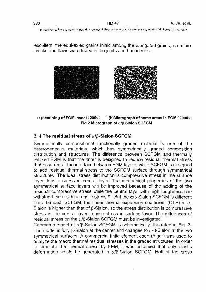
380 HM47 A. Wu et al.15-' International Plansee Seminar, Eds. G. Kneringer, P. Rddhammer and H. Wildner, Plansee Holding AG, Reutte (2001), Vol. 2
excellent, the equi-axied grains inlaid among the elongated grains, no micro-cracks and flaws were found in the joints and boundaries.
(a)Scanning of FGM insect (200x) (b)Micrograph of some areas in FGM (2000x)Fig.2 Micrograph of a/(J Sialon SCFGM
3. 4 The residual stress of a/p-Sialon SCFGM
Symmetrically compositional functionally graded material is one of theheterogeneous materials, which has symmetrically graded compositiondistribution and structures. The difference between SCFGM and thermallyrelaxed FGM is that the latter is designed to reduce residual thermal stressthat occurred at the interface between FGM layers, while SCFGM is designedto add residual therma! stress to the SCFGM surface through symmetricalstructures. The ideal stress distribution is compressive stress in the surfacelayer, tensile stress in central layer. The mechanical properties of the twosymmetrical surface layers will be improved because of the adding of theresidual compressive stress while the central layer with high toughness canwithstand the residual tensile stress[9]. But the a/p-Sialon SCFGM is differentfrom the ideal SCFGM, the linear thermal expansion coefficient (CTE) of a-Sialon is higher than that of p-Sialon, so the stress distribution is compressivestress in the central layer, tensile stress in surface layer. The influences ofresidual stress on the a/p-Sialon SCFGM must be investigated.Geometric model of a/p-Sialon SCFGM is schematically illustrated in Fig. 3.The model is fully p-Sialon at the center and changes to a-p-Sialon at the twosymmetrical surfaces. A commercial finite element code (Algor) was used toanalyze the macro thermal residual stresses in the graded structures. In orderto simulate the thermal stress by FEM, it was assumed that only elasticdeformation would be generated in a/p-Sialon SCFGM. Half of the cross
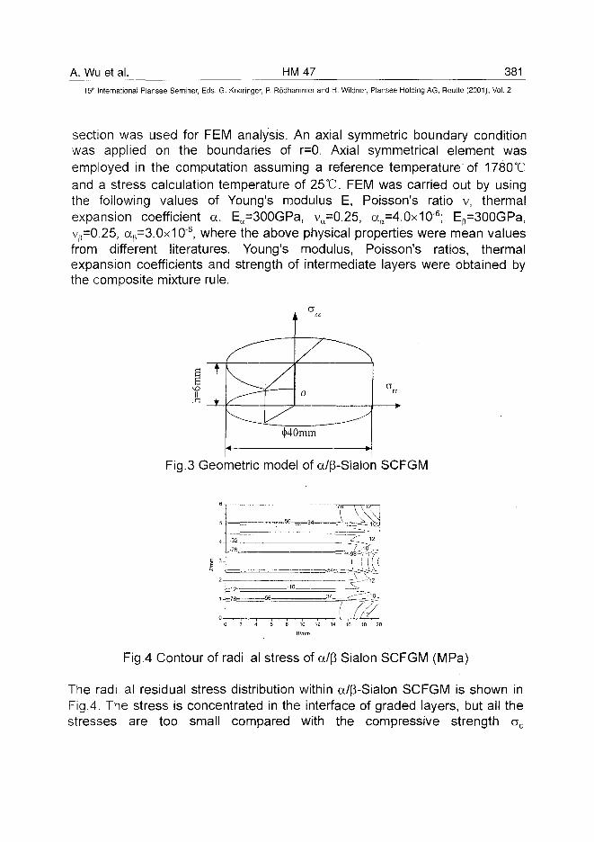
A. Wu et al. HM47 38115'" International Plansee Seminar, Eds. G. Kneringer, P. Rodhammer and H. Wildner, Plansee Holding AG, Reutte (2001), Vol. 2
section was used for FEM analysis. An axial symmetric boundary conditionwas applied on the boundaries of r=0. Axial symmetrical element wasemployed in the computation assuming a reference temperature of 1780°Cand a stress calculation temperature of 25°C. FEM was carried out by usingthe following values of Young's modulus E, Poisson's ratio v, thermalexpansion coefficient a. Ea=300GPa, va=0.25, aa=4.0x10"6; Ep=300GPa,v^O.25, a()=3.Ox1O6, where the above physical properties were mean valuesfrom different literatures. Young's modulus, Poisson's ratios, thermalexpansion coefficients and strength of intermediate layers were obtained bythe composite mixture rule.
Fig.3 Geometric model of a/p-Sialon SCFGM
-32
-76
- 56
-56
-10
14
34
78
\
(
V1255
7
^—
f.
12
ilii—'122
0 2 4 10 12 14 16 18 20
Fig.4 Contour of radi al stress of a/p Sialon SCFGM (MPa)
The radi al residual stress distribution within a/|3-Sialon SCFGM is shown inFig.4. The stress is concentrated in the interface of graded layers, but all thestresses are too small compared with the compressive strength ac
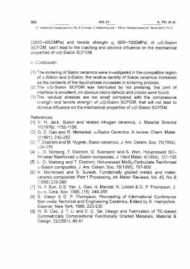
382 HM47 A. Wu et al.15" International Plansee Seminar, Eds. G. Kneringer, P. Rodhammer and H. Wildner, Piansee Holding AG, Reutte (2001), Vol. 2
(3000~4000MPa) and tensile strength at (600-1 OOOMPa) of a/p-SialonSCFGM, can't lead to the cracking and obvious influence on the mechanicalproperties of a/(3-Sialon SCFGM.
4. Conclusion
(1) The sintering of Sialon ceramics were investigated in the compatible regionof a-Sialon and p-Sialon, the relative density of Sialon ceramics increasesas the contents of the liquid-phase increases in sintering process.
(2) The a/p-Sialon SCFGM was fabricated by hot pressing, the joint ofinterface is excellent, no obvious micro-defects and cracks were found.
(3) The residual stresses are too small compared with the compressivestrength and tensile strength of a/p-Sialon SCFGM, that will not lead toobvious influence on the mechanical properties of a/p-Sialon SCFGM.
References[1] K. H. Jack, Sialon and related nitrogen ceramics, J. Material Science
11(1976), 1135-1158,[2] G. Z. Gao and R. Metselaar, a-Sialon Ceramics: A review, Chem. Mater.
3(1991), 242-252[3] T. Ekstrom and M. Nygren, Sialon ceramics, J. Am. Ceram. Soc. 75(1992),
259-276[4] L. O. Norberg, T. Ekstrom, G. Svensson and S. Wen, Hot-pressed SiC-
Whisker Reinforced a-Sialon composites, J. Hard Mater. 4(1993), 121-135[5] L. O. Norberg and T. Ekstrom, Hot-pressed MoSi2-Particulate Reinforced
a-Sialon composites, J. Am. Ceram. Soc. 78(1995), 797-800[6] A. Mortensen and S. Suresh, Functionally graded metals and metal-
ceramic composites: Part 1 Processing, Int. Mater. Reviews, Vol. 40, No. 6(1995)239-265
[7] W. Y Sun, D.S. Yan, L. Gao, H. Mandal, K. Liddell & D. P. Thompson, J.Euro. Cera. Soc. 1995, (15), 349-355
[8] S. Slasor & D. P. Thompson, Proceeding of International ConferenceNon-oxide Technical and Engineering Ceramics, Edited by S. Hampshire,Elsevier, New York, 1986, 223-230
[9] W. B. Cao, J. T. Li and C. C. Ge, Design and Fabrication of TiC-basedSymmetrically Compositional Functionally Graded Materials, Material &Design, 22(2001), 45-51
ATO100467J.T. Li et al. HM 48 383
15lh International Plansee Seminar, Eds. G. Kneringer, P. Rodhammer and H. Wildner, Plansee Holding AG, Reutte (2001), Vol. 2
a-SiAION — new opportunities via new microstructure
J. T. Lf, B. Djuricic", G. Korbb, and C. 0Gea
"Lab. Of Special Ceram. <SJVM, Univ. of Sci. andTech. Beijing, Beijing 100083, Chinab Austrian Research CenteSeibersdcrf, A-2444, Seibersdcrf, Austria
Summary:
Both microstructural graded and homogeneous single-phase a-SiAION isobtained from Si3N4 powder for a broad range of compositions of practicalinterest. Elongated grains of a-SiAION could be developed in the monophasematerial by controlled mechanism of nucleation and growth. Tailoring ofmicrostructure was realized through slow transformation reaction from Si3N4
to a-SiAION at lower temperature than sintering temperature when thecomposition is near the a-SiAION phase boundary. The mechanicalproperties are strongly correlated with the microstructure and are enhancedgreatly in the optimized Sialon composition.
Keywords:
a-SiAION, Self-reinforced microstructure, Graded material
1. Introduction
SiAIONs is a general name for a large family of the so-called ceramic alloysbased on silicon nitride. Profound understanding of basic regularities of theinterrelation between the starting powder's properties, processing parametersand the properties of consolidated materials was achieved [1]. There are twoSiAION phases that are of interest as engineering ceramics, a-SiAION and(3-SiAION, which are solid solutions based on a and |3-Si3N4 structuralmodifications respectively. (3-SiAION is formed by simultaneous equivalentsubstitution of (Al+O) for (Si+N) and has most commonly been described bythe formula Si6.zAlz0zN8.z, where z=0~4.2. The homogeneity region of(3-SiAION extends along the Si3N4-Al2O3-AIN tie line of the phase diagram.The unit cell of |3' contains two Si3N4 units. The a-SiAION has a unit cellcomprising four Si3N4 units and forms a limited two-dimensional phase region
384 HM48 J.T. Li et al.15- International Plansee Seminar, Eds. G. Kneringer, P. Rodhammer and H. Wildner, Plansee Holding AG, Reutte (2001), Vol. 2
in the plane Si3N4-AI2O3:AIN-MeN:3AIN of the phase diagram. Thehomogeneity range composition of a-SiAION can be described by the generalformula MemSii2-(pm+n)Alpm+n0nN-i6-n for a metal ion Mep+. Two substitutionmechanisms may act; the first is similar to that of |3-SiAION with n(Si+N)being replaced by n(AI+O). The second mechanism is further replacement ofpmSi4+ by pmAI3+, the electron balance being retained by incorporation ofmMep+ into the phase structure. It is evident from its chemical compositionthat a-SiAION phase offers possibility of reducing the amount of residualglassy grain-boundary phase by incorporating constituents of sintering aidsinto the crystal structure, which otherwise will be present as substantialamounts of residual glassy phase and deteriorate the high temperatureperformance of the material. Thus, in principle, a-SiAION enables thepreparation of the practically glass-free SiAION composites, which maybecome interesting candidates for high-temperature structural andengineering applications. Moreover, a-SiAION phase normally appears asequiaxed grains in the microstructure of the material, while (3-SiAION phaseforms elongated grains with an aspect ratio of 4 to 10. Commercial product isbased on (3-Sialon, because elongated grains can be obtained in thismaterial, which is toughened by crack deflection and grain pullout. Typicalindentation fracture toughness values of (3-Si3N4 are relatively high for amonolithic ceramic. The possibility of varying the a:(3 phase ratio by slightlychanging the overall composition was shown to open many possibilities toprepare SiAION ceramics with desired properties. This is of the utmostimportance in connection with tailoring the properties for special applications.Chen et al have recently shown that a-SiAION also can obtain such amicrostructure and, hence, the high toughness, which is advantageousbecause a-SiAION is 40% harder than (3-Si3N4.[2,3] Inasmuch as mostapplications of Si3N4 are related to its wear resistance, tough a-SiAION israther attractive and useful. This work provided an excellent possibility foroptimizing phase content and microstructure without further additions ofoxides and nitrides merely by heat treatment at appropriately chosentemperatures. The present work attempts to tailor the microstructure of Y-a-SiAION by using the same idea.
2. Experimental procedure
The compositions investigated lie on the a-SiAION plane represented by theformula Ym/sSi -tm+njAlm+nOnN-ie-n with m=1.2 and n=1.2, m=1.5 and n=1.2, andm=2.0 and n=1.5; these compositions are indentified as C1, C2 and C3
J.T. Li et al. HM 48 385^15'" International Plansee Seminar, Eds. G. Kneringer, P. Rodhammer and H. Wildner, Plansee Holding AG, Reutte (2001), Vol. 2
respectively. Powders of a-Si3N4, (Ube Industry, Japan), AIN (Type F,Tokuyama Soda Co.), Y2O3 (99.9%, Aldrich Chemical Co., Milwaukee, Wl)were used to achieve the desired composition. In the formulation, the residualoxygen content of a-Si3N4 and AIN was considered. Powder mixtures wereattrition-milled in isopropyl alcohol for 24 h with high-purity Si3N4 milling mediain a plastic jar. They subsequently were dried at a temperature of 80°C. Tocontrol nucleation and growth, two-step processing was used: hot pressing at1580°C for 0.5h, followed by holding at 1910°C for 1h. This procedure wasconducted in a nitrogen atmosphere with a graphite furnace, at a heating rateof 20°C/min and a uniaxial pressure of 30 MPa. Full densification wasachieved in all cases.
Phase analysis of the fired specimens was performed via X-ray diffractometry(XRD). The microstructures were observed using scanning electronmicroscopy (SEM) on fracture surface and polished sections after etching inmolten NaOH.
3. Results and Discussion
To obtain elongated grains in (3-Si3N4, either abnormal grain growth orcontrolled nucleation is required. One method to control nucleation in |3-Si3N4
is to use a-Si3N4 as the starting powder. This method is now an industrialpractice that has been perfected by intensive research over the last twentyyears. Some recent research of, in particular, Y-doped a-SiAION, provideseven better possibilities of microstructure tailoring. It was demonstrated thatthe driving force for Y-a-SiAION formation is an important parameter: thelower the driving force, the slower the nucleation rates and the more likely theformation of elongated grains[3]. Furthermore, in cases (e.g., Yb-SiAION)where the driving force is too large, temperature reduction can be used toslow the nucleation rate. Here, we apply this concept of nucleation control toobtain /n-s/Yi/-toughened a-SiAION, using a-Si3N4 as the starting powder.a-Si3N4 to a-SiAION transformation at low temperature is used to tailor thepopulation of in situ nuclei for future growth.
Following the same sintering schedule described in the experimentalprocedure, quite different microstructure were developed in specimens C1and C2 respectively, as are shown in Fig. 1. When the sandwiched sampleassemblage of C2/C1/C2 was hot pressed, the microstructure of the productchanged gradually from equiaxed grains in the surface to self-reinforced
386 HM48 J.T. Li et al.15;" International Plansee Seminar, Eds. G. Kneringer, P. Rodhammer and H. Wildner, Plansee Holding AG, Reutte (2001), Vol. 2
microstructure in the center. Fig. 2 shows the XRD pattern of C1, whichconsists of single phase of a-SiAION. According to Chen et al, when thecomposition is near the a-SiAION phase boundary (in this case, C1 ), thedriving force for the phase transformation of a-Si3N4 to a-SiAION is smallcomparing with that of composition C2, which located in the center of thea-SiAION region. In the Y-a-SiAION system, the nuclei of a-SiAION isbelieved to start to form at temperature over 1600°C. Therefore, the numberof nuclei formed during the first stage holding at 1580°C is less especiallywhen composition C1 is adopted. These nuclei are able to further growth andform elongated large grains during the subsequent sintering. As tocomposition C2, the driving force for the formation of a-SiAION is largeenough that quite a lot of nuclei formed during the first stage sintering, whichwill lead to fine equiaxed grains in the finial product.
The variation of the thickness of each layer of C2/C1/C2 has significanteffects on the sintering behavior of the layered sample. When the thickness ofeach layer is 2mm, fracture occurred along the central line of the C1 aftersintering, indicating the build up of tensional stress due to different shrinkagebehavior between C2 and C1. It is proved that the reaction pathway in hotpressing of Y-Si-AI-O-N consists of three steps: firstly, the formation of ternaryoxide eutectic melt, secondly, the wetting of AIN followed by dissolution of AINand precipitation of [3-SiAION, finally the dissolution of Si3N4 and formation ofa-SiAION. The preferential wetting of AIN lead to localization of the melt toAIN, delocalization occurs at higher temperature when the melt wets Si3N4,which then dissolves and provide more liquid to facilitate the so called secondstage densification [4]. Therefore, higher AIN content could cause delayingeffects on the second stage shrinkage. The AIN content in the startingmixtures of C2 is slightly higher than in C1, the formation of a-SiAION and thesecond stage shrinkage in C2 occurred slower than in C1. Therefore,tensional stress was generated in the middle layer and caused cracking whenthe stress is over the strength of this layer.
It was found in the cracked surface of C1 that nano-size particles co-existwith the self-reinforced microstructure, as shown in Fig. 3, Nano grains alsoexist in rod-like form as evidenced by TEM observation. EDS analysisdemonstrated the nano-particles are rich in Y while the matrix are rich in Si,indicating the effects of transient liquid viscosity on the formation of nuclei.Second stage shrinkage of C2 takes place slower than C1, leading to thecracking of the center layer. On the fractured surface, the evaporation of
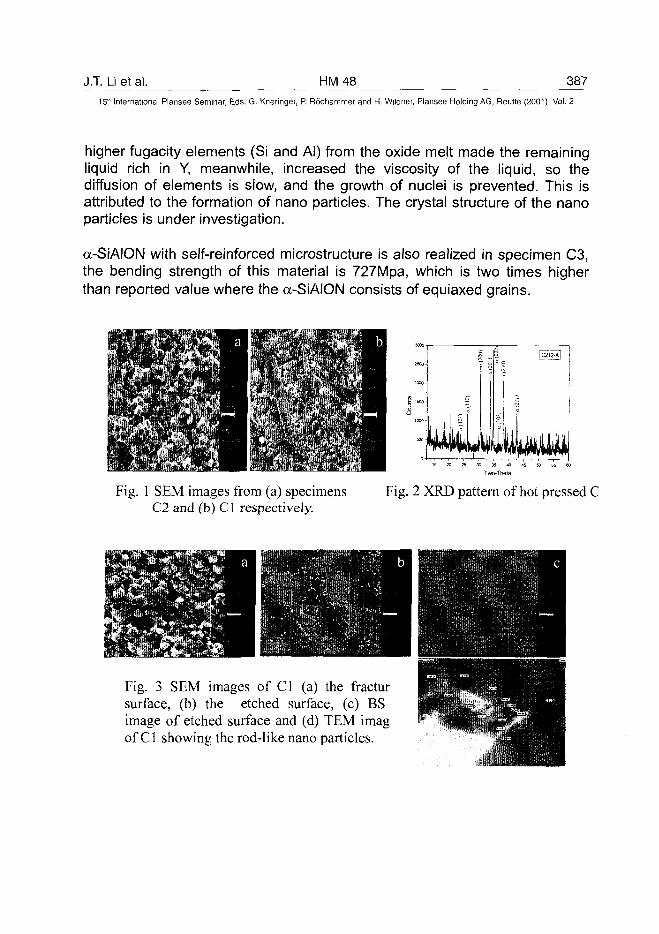
J.T. Li et al. HM48 387
15* International Plansee Seminar, Eds. G. Kneringer, P. Rodhammer and H. Wildner, Plansee Holding AG, Reutte (2001), Vol. 2
higher fugacity elements (Si and Al) from the oxide melt made the remainingliquid rich in Y, meanwhile, increased the viscosity of the liquid, so thediffusion of elements is slow, and the growth of nuclei is prevented. This isattributed to the formation of nano particles. The crystal structure of the nanoparticles is under investigation.
a-SiAION with self-reinforced microstructure is also realized in specimen C3,the bending strength of this material is 727Mpa, which is two times higherthan reported value where the a-SiAION consists of equiaxed grains.
Fig. 1 SEM images from (a) specimensC2 and (b) C1 respectively.
2500
2CC0-
: 1500
1C00-
500
I
2
, 1 | I
I |C212-A|
I
2
s
Fig. 2 XRD pattern of hot pressed C
Fig. 3 SEM images of Cl (a) the fractursurface, (b) the etched surface, (c) BSimage of etched surface and (d) TEM imagof Cl showing the rod-like nano particles.
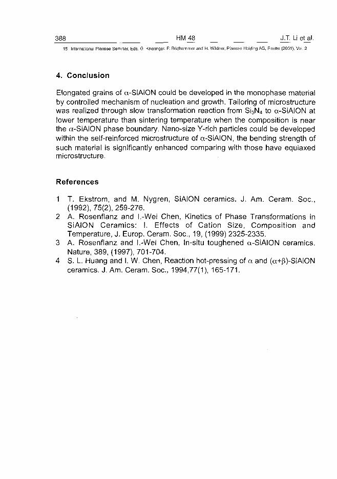
388 HM48 J.T. Li et al.15" International Plansee Seminar, Eds. G. Kneringer, P. Rodhammer and H. Wildner, Plansee Holding AG, Reutte (2001), Vol. 2
4. Conclusion
Elongated grains of a-SiAlON could be developed in the monophase materialby controlled mechanism of nucleation and growth. Tailoring of microstructurewas realized through slow transformation reaction from Si3N4 to a-SiAION atlower temperature than sintering temperature when the composition is nearthe a-SiAION phase boundary. Nano-size Y-rich particles could be developedwithin the self-reinforced microstructure of a-SiAION, the bending strength ofsuch material is significantly enhanced comparing with those have equiaxedmicrostructure.
References
1 T. Ekstrom, and M. Nygren, SiAION ceramics. J. Am. Ceram. Soc,(1992), 75(2), 259-276.
2 A. Rosenflanz and I.-Wei Chen, Kinetics of Phase Transformations inSiAION Ceramics: I. Effects of Cation Size, Composition andTemperature, J. Europ. Ceram. Soc, 19, (1999) 2325-2335.
3 A. Rosenflanz and I.-Wei Chen, In-situ toughened a-SiAION ceramics.Nature, 389, (1997), 701-704.
4 S. L. Huang and I. W. Chen, Reaction hot-pressing of a and (a+(3)-SiAIONceramics. J. Am. Ceram. Soc., 1994,77(1), 165-171.
AT0100468D. Vallauri et al. HM 50 389^
15th International Plansee Seminar, Eds. G. Kneringer, P. Rodhammer and H. Wildner, Plansee Holding AG, Reutte (2001), Vol. 2
Self Propagating High Temperature Synthesis of Mixed Carbide
and Boride Powder Systems for Cutting Tools Manufacturing
D. Vallauri, P.L. De Cola, F. Piscone, I. Amato
Department of Materials Science and Chemical Engineering, Politecnico di Torino, Italy
Summary:
TiC-TiB2 composites have been produced via SHS technique starting fromlow cost raw materials like TiO2, B4C, Mg. The influence of the diluent phase(Mg, TiC) content on combustion temperature has been investigated. The useof magnesium as the reductant phase allowed acid leaching of the undesiredoxide product (MgO), leaving pure hard materials with fine particle sizesuitable to be employed in cutting tools manufacturing through cold pressingand sintering route. The densification has shown to be strongly dependent onthe wetting additions. The influence of the metal binder and wetting additionson the sintering process has been investigated. A characterisation of theobtained materials was performed by the point of view of cutting tools life(hardness, toughness, strength).
Keywords:
Titanium boride, titanium carbide, cermet, cutting tools, SHS, thermite.
1. Introduction:
Self-propagating High temperature Synthesis (SHS) is very attractive forsynthesising refractory and wear resistant compounds to be employed as rawmaterials for cutting tools (1,2). Up to now, the most widely spread method tosynthesise wear-resistant materials is the furnace synthesis technology.Reactions in such heterogeneous system are usually accompanied by theformation of a product layer between the reactants. As the solid statediffusivity is generally low, this layer with its increasing thickness constitutes adiffusion barrier thus reducing the conversion rate. Therefore, hightemperatures and long times are usually necessary for carbide and boridessynthesis with conventional methods. As a result, these processing routes
390 HM50 D. Vallauri et al.15:" International Plansee Seminar, Eds. G. Kneringer, P. Rodhammer and H. Wildner, Plansee Holding AG, Reutte (2001), Vol. 2
are regarded as energy intensive ones and have a very high cost. In SHSprocess (3), a porous compact containing a mixture of reactants is broughtinto contact with an ignition system. This initiates an exothermal reaction,which continues through a self-sustaining combustion wave propagatinglayer-by-layer through the porous mass and into the reaction products. Insolid combustion synthesis, the only heat source required to carry it outconsists of exothermal reactions between the reactants. It is known that thepurity of SHS powders is often higher than for the reactant mixture itself. Infact, due to the high temperature in the reaction zone, many contaminants,which may exist in the starting powders, volatilise. Because of the self-sustenance and simplicity of the needed installation, the process faces withlow energy requirements and is low costly. The objective of this work is theinvestigation of the substitution of conventional cermets used for cutting toolsmanufacturing with more performing and innovative ones based on TiC-TiB2
mixtures as hard phase. These systems are produced with the SHS processstarting by very low cost raw materials like Mg, TiO2 and B4C. SHS allows toobtain sub-micrometric sized and pure powders which can be pressurelessconsolidated through liquid phase sintering to give cermets which are goodcandidates for cutting tools manufacturing (1,2).
2. Experimental methodology:
Combustion synthesis reactions involving a thermite reaction have been usedfor the synthesis of various composite materials. Oxide-carbide and oxide-boride such as AI2O3-TiC and AI2O3-TiB2 have been produced using Al toreduce the other metal (M) oxide as the first step (4,5,6). Similarly,magnesium can be used to produce MgO-containing composites.As an extension of earlier studies in which the SHS synthesis of MgO-TiCand MgO-TiB2 has been investigated (7,8,9), the present work deals with theformation of MgO-TiC-TiB2 mixtures through the self-propagating reactionbetween low cost reactants like Mg, TiO2 and B4C.Commercial reactants of C (Aldrich C.C., 99.5%, <2\im), TiO2 (Riedel-deHaen, 99.8%, <10|im), B4C (H.C. Starck, <10|im), Mg (Aldrich C.C., 99+%,<300jim) and TiC (H.C. Starck, <3|im) were used to synthesise TiC-TiB2-MgO according to the reaction:
3TiO2 + B4C + 1.3 TiC + 8 Mg-^ 2.3TiC + 2TiB2 + 6MgO + 2Mg (g) [1]
TiC has been added in the starting mixture as a diluent to control the reactiontemperature, lowering the adiabatic temperature in order to obtain powder
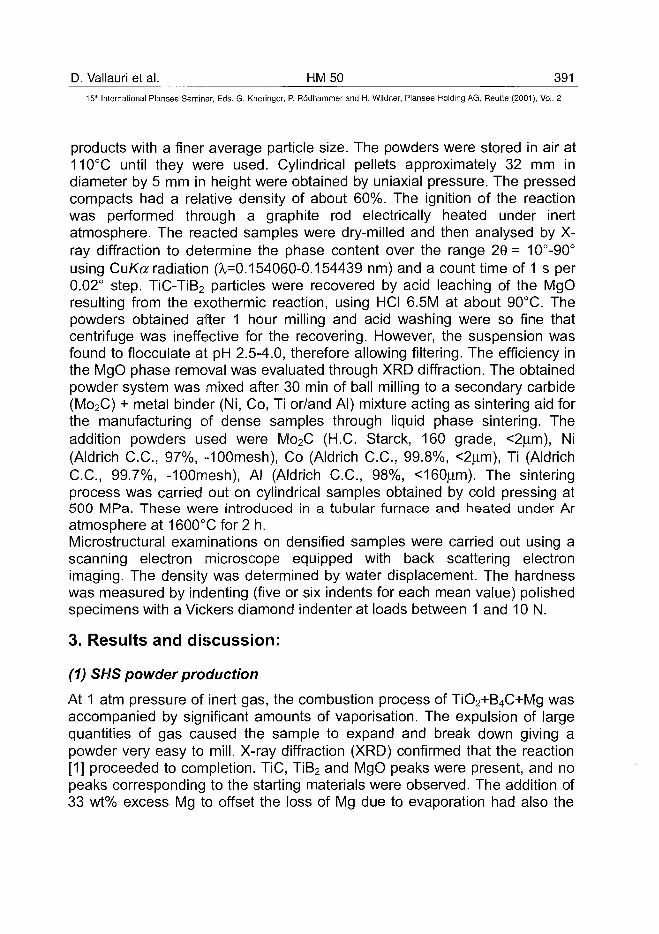
D. Vallauri et al. HM 50 391^
15lh International Plansee Seminar, Eds. G. Kneringer, P. Rodhammer and H. Wildner, Plansee Holding AG, Reutte (2001), Vol. 2
products with a finer average particle size. The powders were stored in air at110°C until they were used. Cylindrical pellets approximately 32 mm indiameter by 5 mm in height were obtained by uniaxial pressure. The pressedcompacts had a relative density of about 60%. The ignition of the reactionwas performed through a graphite rod electrically heated under inertatmosphere. The reacted samples were dry-milled and then analysed by X-ray diffraction to determine the phase content over the range 29= 10°-90°using CuKa radiation (^=0.154060-0.154439 nm) and a count time of 1 s per0.02° step. TiC-TiB2 particles were recovered by acid leaching of the MgOresulting from the exothermic reaction, using HCI 6.5M at about 90°C. Thepowders obtained after 1 hour milling and acid washing were so fine thatcentrifuge was ineffective for the recovering. However, the suspension wasfound to flocculate at pH 2.5-4.0, therefore allowing filtering. The efficiency inthe MgO phase removal was evaluated through XRD diffraction. The obtainedpowder system was mixed after 30 min of ball milling to a secondary carbide(Mo2C) + metal binder (Ni, Co, Ti or/and Al) mixture acting as sintering aid forthe manufacturing of dense samples through liquid phase sintering. Theaddition powders used were Mo2C (H.C. Starck, 160 grade, <2(im), Ni(Aldrich C.C., 97%, -100mesh), Co (Aldrich C.C., 99.8%, <2^m), Ti (AldrichC.C., 99.7%, -100mesh), Al (Aldrich C.C., 98%, <160jxm). The sinteringprocess was carried out on cylindrical samples obtained by cold pressing at500 MPa. These were introduced in a tubular furnace and heated under Aratmosphere at 1600°C for 2 h.
Microstructural examinations on densified samples were carried out using ascanning electron microscope equipped with back scattering electronimaging. The density was determined by water displacement. The hardnesswas measured by indenting (five or six indents for each mean value) polishedspecimens with a Vickers diamond indenter at loads between 1 and 10 N.
3. Results and discussion:
(1) SHS powder production
At 1 atm pressure of inert gas, the combustion process of TiO2+B4C+Mg wasaccompanied by significant amounts of vaporisation. The expulsion of largequantities of gas caused the sample to expand and break down giving apowder very easy to mill. X-ray diffraction (XRD) confirmed that the reaction[1] proceeded to completion. TiC, TiB2 and MgO peaks were present, and nopeaks corresponding to the starting materials were observed. The addition of33 wt% excess Mg to offset the loss of Mg due to evaporation had also the
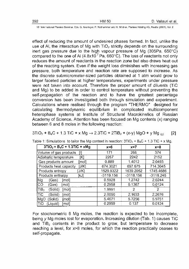
392 HM50 D. Vallauri et al.15" International Plansee Seminar, Eds. G. Kneringer, P. Rodhammer and H. Wildner, Plansee Holding AG, Reutte (2001), Vol. 2
effect of reducing the amount of undesired phases formed. In fact, unlike theuse of Al, the interaction of Mg with TiO2 strictly depends on the surroundinginert gas pressure due to the high vapour pressure of Mg (305Pa, 650°C)compared to the one of Al (4.8x10"7 Pa, 660°C). The loss of reactants not onlyreduces the amount of reactants in the reaction zone but also draws heat outof the reacting system. Even if the weight loss diminishes with increasing gaspressure, both temperature and reaction rate are supposed to increase. Asthe discrete submicrometer-sized particles obtained at 1 atm would grow tolarger faceted particles at higher temperatures, experiments under pressurewere not taken into account. Therefore the proper amount of diluents (TiCand Mg) to be added in order to control temperature without preventing theself-propagation of the reaction and to have the greatest percentageconversion has been investigated both through simulation and experiment.Calculations where realised through the program "THERMO" designed forcalculating thermodynamic equilibrium in complicated multicomponentheterophase systems at Institute of Structural Macrokinetics of RussianAcademy of Science. Attention has been focused on Mg contents (x) rangingbetween 6 and 8 moles in the following reaction:
3TiO2 + B4C + 1.3 TiC 2.3TiC + 2TiB2 + (x-y) MgO + y Mg [2]
Table 1: Simulations to tailor the Mg content in reaction: 3TiO2 + B4C + 1.3 TiC + x Mg.
3TiO2 + B4C + 1.3TiC + xMg
Volume of gas products [I]Adiabatic temperature [K]Gas products amount [mol]Products heat capacity [J/K]Products entropy [J/K]Products enthalpy [kJ]
Mg (Gas) [mol]CO (Gas) [mol]TiB2 (Solid) [mol]TiC (Solid) [mol]MgO (Solid) [mol]TiO (Liquid) [mol]
x=6
17122670.889
674.30211529.9322-3119.156
0.59280.29581.99912.00505.46710.2959
x=7
2662242
1.4012697.675
1639.2052-3118.156
1.27420.1367
2
2.16335.72560.137
x=8
3742152
2.0493714.30451745.4686-3118.245
2.02440.0124
2
2.26765.97510.0124
For stoichiometric 6 Mg moles, the reaction is expected to be incomplete,being y Mg moles lost for evaporation. Increasing dilution (Tab. 1) causes TiCand TiB2 contents in the product to grow, but temperature to decreasereaching a level, for x>8 moles, for which the reaction practically ceases toself-propagate.
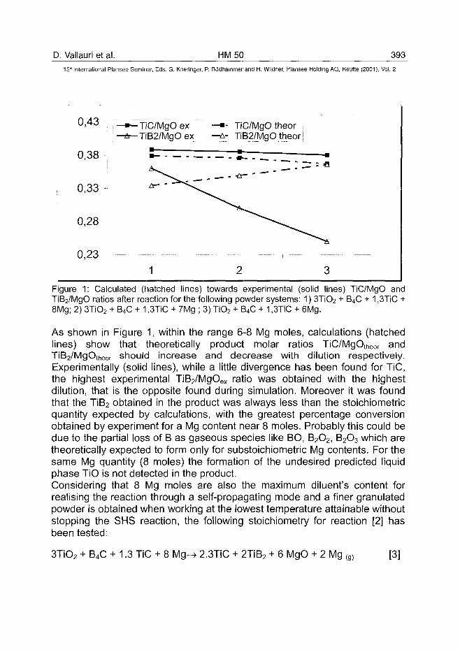
D. Vallauri et al. HM 50 393^
15'" International Plansee Seminar, Eds. G. Kneringer, P. Rodhammer and H. Wildner, Plansee Holding AG, Reutte (2001), Vol. 2
0 , 4 3 •,! ; .
0,33
0,28
0,23
- •— TiC/MgOex- A — TiB2/MgO ex
•—
1
—•- TiC/MgO theor—A- TiB2/MgO theor
, - -ir- "
2
^ *
3
Figure 1: Calculated (hatched lines) towards experimental (solid lines) TiC/MgO andTiB2/MgO ratios after reaction for the following powder systems: 1) 3TiO2 + B4C + 1,3TiC +8Mg; 2) 3TiO2 + B4C + 1,3TiC + 7Mg ; 3) TiO2 + B4C + 1,3TiC + 6Mg.
As shown in Figure 1, within the range 6-8 Mg moles, calculations (hatchedlines) show that theoretically product molar ratios TiC/MgOtheOr andTiB2/MgOtheor should increase and decrease with dilution respectively.Experimentally (solid lines), while a little divergence has been found for TiC,the highest experimental TiB2/MgOex ratio was obtained with the highestdilution, that is the opposite found during simulation. Moreover it was foundthat the TiB2 obtained in the product was always less than the stoichiometricquantity expected by calculations, with the greatest percentage conversionobtained by experiment for a Mg content near 8 moles. Probably this could bedue to the partial loss of B as gaseous species like BO, B2O2, B2O3 which aretheoretically expected to form only for substoichiometric Mg contents. For thesame Mg quantity (8 moles) the formation of the undesired predicted liquidphase TiO is not detected in the product.Considering that 8 Mg moles are also the maximum diluent's content forrealising the reaction through a self-propagating mode and a finer granulatedpowder is obtained when working at the lowest temperature attainable withoutstopping the SHS reaction, the following stoichiometry for reaction [2] hasbeen tested:
3TiO2 + B4C + 1.3 TiC + 8 Mg-^ 2.3TiC + 2TiB2 + 6 MgO + 2 Mg (g) [3]
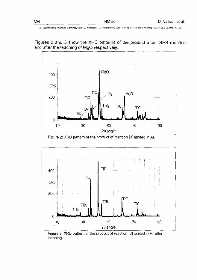
394 HM50 D. Vallauri et al.
15" International Plansee Seminar, Eds. G. Kneringer, P. Rodhammer and H. Wildner, Plansee Holding AG, Reutte (2001), Vol. 2
Figures 2 and 3 show the XRD patterns of the product after SHS reactionand after the leaching of MgO respectively.
400 -
CPS
200 -
o -P*1
10
TiCljTiC I |
TiB2 ' i f 1
30
MgO
/Mg
TiB2 TiC
•L-- I - -*-
50
28 angle
MgO
\\ TiC
t\ kA70 90
Figure 2: XRD pattern of the product of reaction [3] ignited in Ar.
400-
CPS
200-
o -**••<10
- • •
TiBz
TiC
TiBj
, 130
TiC
TiBz
J-y l *A^MIM»I ...rri ft nH
5029 angle
TiC
lTiC !
1170 90
Figure 3: XRD pattern of the product of reaction [3] ignited in Ar afterleaching.
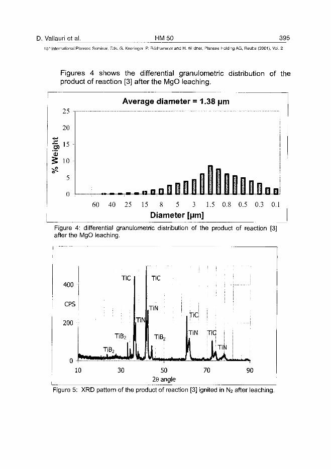
D. Vallauri et al. HM50 39515lh International Plansee Seminar, Eds. G. Kneringer, P. Rodhammer and H. Wildner, Plansee Holding AG, Reutte (2001), Vol. 2
Figures 4 shows the differential granuiometric distribution of theproduct of reaction [3] after the MgO leaching.
Average diameter = 1.3825
20
I 10
5
0 ,., „ H iiilMl 060 40 25 15 8 5 3 1.5 0.8 0.5 0.3 0.1
Diameter [pm]
Figure 4: differential granuiometric distribution of the product of reaction [3]after the MgO leaching.
400 -
CPS
200 -
u *f
10
TiC
TiB2
TiB2 | |• 1 _ * . . I I I !
30
TIN
L
TiC
TiN
TiB2
i. ...50
29 angle
JTiNuI
TiC j
1 TIN ]
70 90
Figure 5: XRD pattern of the product of reaction [3] ignited in N2 after leaching.
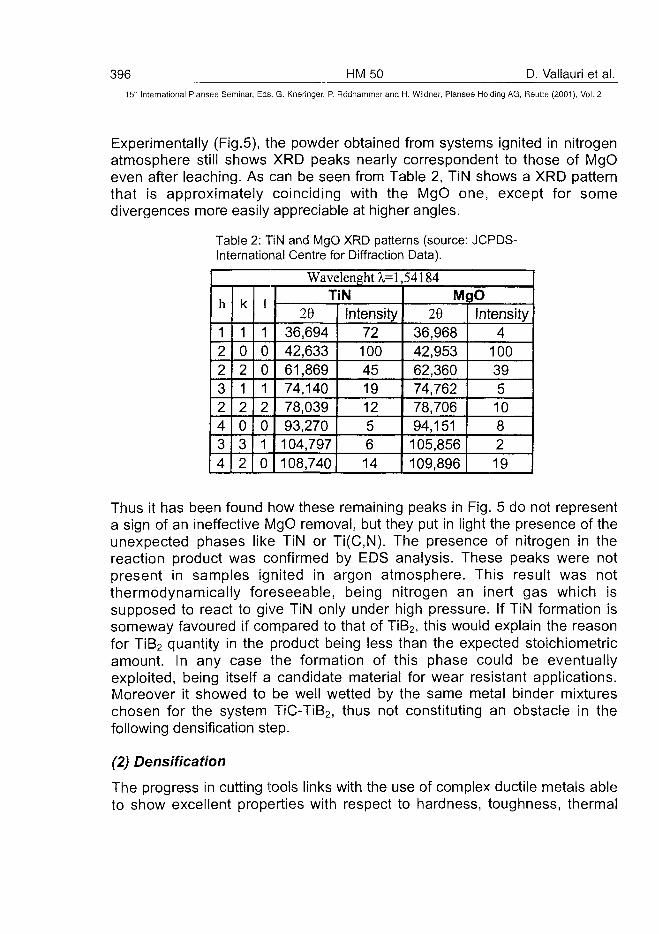
396 HM50 D. Vallauri et al.15' International Plansee Seminar, Eds. G. Kneringer, P. Rodhammer and H. Wildner, Plansee Holding AG, Rsutte (2001), Vol. 2
Experimentally (Fig.5), the powder obtained from systems ignited in nitrogenatmosphere still shows XRD peaks nearly correspondent to those of MgOeven after leaching. As can be seen from Table 2, TiN shows a XRD patternthat is approximately coinciding with the MgO one, except for somedivergences more easily appreciable at higher angles.
Table 2: TiN and MgO XRD patterns (sourceInternational Centre for Diffraction Data).
JCPDS-
WavelenghtA,=l,54184
h
12232434
k
10212032
I
10012010
TiN29
36,69442,63361,86974,14078,03993,270104,797108,740
Intensity721004519125614
MgO20
36,96842,95362,36074,76278,70694,151105,856109,896
Intensity4
100395108219
Thus it has been found how these remaining peaks in Fig. 5 do not representa sign of an ineffective MgO removal, but they put in light the presence of theunexpected phases like TiN or Ti(C,N). The presence of nitrogen in thereaction product was confirmed by EDS analysis. These peaks were notpresent in samples ignited in argon atmosphere. This result was notthermodynamically foreseeable, being nitrogen an inert gas which issupposed to react to give TiN only under high pressure. If TiN formation issomeway favoured if compared to that of TiB2, this would explain the reasonfor TiB2 quantity in the product being less than the expected stoichiometricamount. In any case the formation of this phase could be eventuallyexploited, being itself a candidate material for wear resistant applications.Moreover it showed to be well wetted by the same metal binder mixtureschosen for the system TiC-TiB2, thus not constituting an obstacle in thefollowing densification step.
(2) Densification
The progress in cutting tools links with the use of complex ductile metals ableto show excellent properties with respect to hardness, toughness, thermal
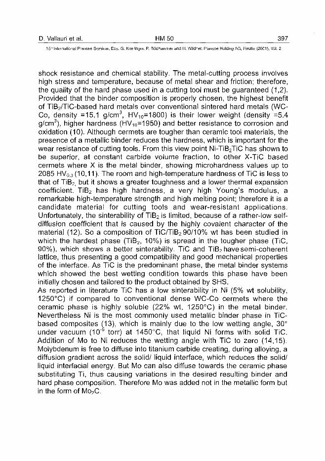
D. Vallauri et al. HM 50 397
15th International Plansee Seminar, Eds. G. Kneringer, P. Rodhammer and H. Wildner, Plansee Holding AG, Reutte (2001), Vol. 2
shock resistance and chemical stability. The metal-cutting process involveshigh stress and temperature, because of metal shear and friction; therefore,the quality of the hard phase used in a cutting tool must be guaranteed (1,2).Provided that the binder composition is properly chosen, the highest benefitof TiB2/TiC-based hard metals over conventional sintered hard metals (WC-Co, density =15.1 g/cm3, HV10=1800) is their lower weight (density =5.4g/cm3), higher hardness (HV10=1950) and better resistance to corrosion andoxidation (10). Although cermets are tougher than ceramic tool materials, thepresence of a metallic binder reduces the hardness, which is important for thewear resistance of cutting tools. From this view point Ni-TiB2TiC has shown tobe superior, at constant carbide volume fraction, to other X-TiC basedcermets where X is the metal binder, showing microhardness values up to2085 HV0.3 (10,11). The room and high-temperature hardness of TiC is less tothat of TiB2, but it shows a greater toughness and a lower thermal expansioncoefficient. TiB2 has high hardness, a very high Young's modulus, aremarkable high-temperature strength and high melting point; therefore it is acandidate material for cutting tools and wear-resistant applications.Unfortunately, the sinterability of TiB2 is limited, because of a rather-low self-diffusion coefficient that is caused by the highly covalent character of thematerial (12). So a composition of TiC/TiB2 90/10% wt has been studied inwhich the hardest phase (TiB2, 10%) is spread in the tougher phase (TiC,90%), which shows a better sinterability. TiC and TiB2 have semi-coherentlattice, thus presenting a good compatibility and good mechanical propertiesof the interface. As TiC is the predominant phase, the metal binder systemswhich showed the best wetting condition towards this phase have beeninitially chosen and tailored to the product obtained by SHS.As reported in literature TiC has a low sinterability in Ni (5% wt solubility,1250°C) if compared to conventional dense WC-Co cermets where theceramic phase is highly soluble (22% wt, 1250°C) in the metal binder.Nevertheless Ni is the most commonly used metallic binder phase in TiC-based composites (13), which is mainly due to the low wetting angle, 30°under vacuum (105 torr) at 1450°C, that liquid Ni forms with solid TiC.Addition of Mo to Ni reduces the wetting angle with TiC to zero (14,15).Molybdenum is free to diffuse into titanium carbide creating, during alloying, adiffusion gradient across the solid/ liquid interface, which reduces the solid/liquid interfacial energy. But Mo can also diffuse towards the ceramic phasesubstituting Ti, thus causing variations in the desired resulting binder andhard phase composition. Therefore Mo was added not in the metallic form butin the form of Mo2C.
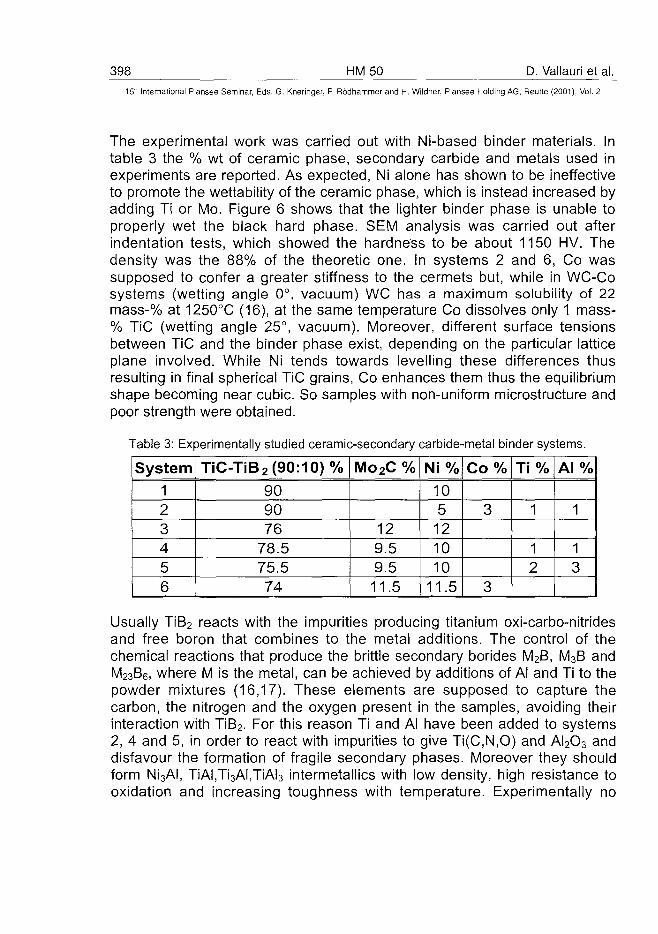
398 HM50 D. Vallauri et al.15" International Plansee Seminar, Eds. G. Kneringer, P. Rodhammer and H. Wildner, Plansee Holding AG, Reutte (2001), Vol. 2
The experimental work was carried out with Ni-based binder materials. Intable 3 the % wt of ceramic phase, secondary carbide and metals used inexperiments are reported. As expected, Ni alone has shown to be ineffectiveto promote the wettability of the ceramic phase, which is instead increased byadding Ti or Mo. Figure 6 shows that the lighter binder phase is unable toproperly wet the black hard phase. SEM analysis was carried out afterindentation tests, which showed the hardness to be about 1150 HV. Thedensity was the 88% of the theoretic one. In systems 2 and 6, Co wassupposed to confer a greater stiffness to the cermets but, while in WC-Cosystems (wetting angle 0°, vacuum) WC has a maximum solubility of 22mass-% at 1250°C (16), at the same temperature Co dissolves only 1 mass-% TiC (wetting angle 25°, vacuum). Moreover, different surface tensionsbetween TiC and the binder phase exist, depending on the particular latticeplane involved. While Ni tends towards levelling these differences thusresulting in final spherical TiC grains, Co enhances them thus the equilibriumshape becoming near cubic. So samples with non-uniform microstructure andpoor strength were obtained.
Table 3: Experimentally studied ceramic-secondary carbide-metal binder systems.
System123456
TiC-TiB2 (90:10)%909076
78.575.574
Mo2C %
129.59.511.5
Ni%105
121010
11.5
Co%
3
3
Ti %
1
12
A l %
1
13
Usually TiB2 reacts with the impurities producing titanium oxi-carbo-nitridesand free boron that combines to the metal additions. The control of thechemical reactions that produce the brittle secondary borides M2B, M3B andM23B6, where M is the metal, can be achieved by additions of Al and Ti to thepowder mixtures (16,17). These elements are supposed to capture thecarbon, the nitrogen and the oxygen present in the samples, avoiding theirinteraction with TiB2. For this reason Ti and Al have been added to systems2, 4 and 5, in order to react with impurities to give Ti(C,N,O) and AI2O3 anddisfavour the formation of fragile secondary phases. Moreover they shouldform Ni3AI, TiAI,Ti3AI,TiAI3 intermetallics with low density, high resistance tooxidation and increasing toughness with temperature. Experimentally no
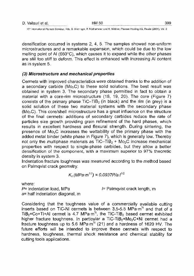
D. Vallauri et al. HM 50 399^
15'" International Plansee Seminar, Eds. G. Kneringer, P. Rodhammer and H. Wildner, Plansee Holding AG, Reutte (2001), Vol. 2
densification occurred in systems 2, 4, 5. The samples showed non-uniformmicrostructures and a remarkable expansion, which could be due to the lowmelting point of Al (660°C), which causes it to expand while the other phasesare still too stiff to deform. This effect is enhanced with increasing Al contentas in system 5.
(3) Microstructure and mechanical properties
Cermets with improved characteristics were obtained thanks to the addition ofa secondary carbide (Mo2C) to these solid solutions. The best result wasobtained in system 3. The secondary phase permitted in fact to obtain amaterial with a core-rim microstructure (18, 19, 20). The core (Figure 7)consists of the primary phase TiC-TiB2 (in black) and the rim (in grey) is asolid solution of these two material systems with the secondary phase(Mo2C). This core/shell microstructure has a great influence on the structureof the final cermets: additions of secondary carbides reduce the rate ofparticles size growth providing grain refinement of the hard phases, whichresults in excellent hardness and flexural strength. During sintering, thepresence of Mo2C increases the wettability of the primary phase with theadded metal binder (white phase in Figure 7), which is generally low. Therebynot only the multiphase materials as TiC-TiB2 + Mo2C increase mechanicalproperties with respect to single-phase carbides, but they allow a betterdensification of the component, with a maximum superior to 97% theoreticdensity in system 3.Indentation fracture toughness was measured according to the method basedon Palmqvist crack geometry:
Kc(MPa-m1/2) = 0.0937P/a-l1/2
where:P= indentation load, MPa /= Palmqvist crack length, ma= half indentation diagonal, m
Considering that the toughness value of a commercially available cuttinginserts based on TiC-Ni cermets is between 3.5-5.5 MPa-m/2 and that of aTiB2+Co+Ti+AI cermet is 4.7 MPa-m/2, the TiC-TiB2 based cermet exhibitedhigher fracture toughness. In particular a TiC-TiB2+Mo2C+Ni cermet had afracture toughness up to 5.6 MPam/2 (21) and a hardness of 1620 HV. Thefuture efforts will be intended to improve these cermets with respect tohardness, toughness, thermal shock resistance and chemical stability forcutting tools applications.
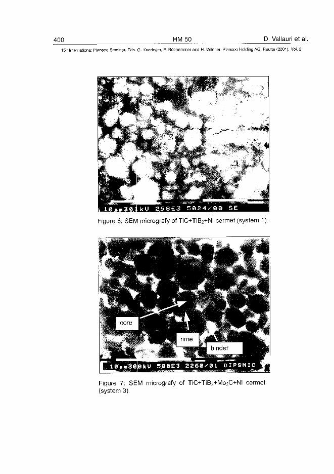
400 HM50 D. Vallauri et al.
15'" International Plansee Seminar, Eds. G. Kneringer, P. Rodhammer and H. Wildner, Plansee Holding AG, Reutte (2001), Vol. 2
Figure 6: SEM micrografy of TiC+TiB2+Ni cermet (system 1).
Figure 7: SEM micrografy of TiC+TiB2+Mo2C+Ni cermet(system 3).
D. Vallauri et al. HM 50 401^
15'" International Plansee Seminar, Eds. G. Kneringer, P. Rodhammer and H. Wildner, Plansee Holding AG, Reutte (2001), Vol. 2
4. Conclusion:
The following conclusions can be drawn by this work :
- The materials for cutting tools employed today are generally WC and TiCbased cemented carbides. If compared to conventional cermets, the highdegree of hardness and chemical stability of TiC/TiB2 makesTiC/TiB2+metal binder based cermets good alternative candidates for wearresistant applications such as cutting.
- The production of these cermets has been carried out through the self-propagating reaction between low cost raw materials like Mg, TiO2 andB4C, resulting in very pure TiC-TiB2 mixtures with a average particle size of1.38 urn.
- The influence of initial parameters (mixture composition, particle size,sample size and density, gas pressure) on combustion temperature,chemical and phase composition, and microstructure mechanismsinvolved in combustion reaction have been investigated both throughsimulation and experiment.
- 3TiO2 + B4C + 1.3 TiC + 8 Mg was found to be the best stoichiometry toyield TiC-TiB2 powder systems with high quality and sub-micrometricdimensions, which has allowed them to be densified through liquidsintering at temperature lower than in usual processes.
- The optimum sintering conditions for the manufacturing of dense cermets(TiC-TiB2+Mo2C+metal binder) have been determined through "trial anderror" route. A secondary carbides (Mo2C) has been added to promote thewetting of the ceramic phase giving the best microstructural andmechanical results in the system [TiC-TiB2(9:1)+12%Mo2C+12%Ni].
5. References:1A.G. King: American Ceramic Society Bulletin (1965), Vol 43 (5), pp. 395-
4012 I . Amato, A. Ferrari, P.L. Rotoloni: Utensil (1992), 11, pp. 51-653Z.A. Munir: American Ceramic Society Bulletin (1988), Vol 67 (2), pp. 342-
349
402 HM50 D. Vallauri et al.15'" Internationa! Plansee Seminar, Eds. G. Kneringer, P. Rodhammer and H. Wildner, Plansee Holding AG, Reutte (2001), Vol. 2
4A. Chrysanthou, D. Cheung, A. Jha: in "Ceramics: Charting the Future" (ed.P. Vincenzini, C. Techna Srl,1997), pp. 1973-80
5B.H. Rabin, G.E. Korth R.L. Williamson: Journal of The American CeramicSociety (1990), Vol 73 (7), pp. 2156-57 I
6T. D. Xia, Z.A. Munir, Y.LTang, W.J. Zhao: Journal of The AmericanCeramic Society (2000), Vol 83 (35), pp. 507-12
7N.J. Welham: Journal of The American Ceramic Society (2000), Vol 83 (5),pp. 1290-92
8 L L Wang, Z.A. Munir, J.B. Holt: Journal of The American Ceramic Society(1995), Vol 78 (3), pp. 756-64
9S. G. Ko, C.W. Won, B.S. Chun: Journals of Materials Science (1995), Vol30, pp. 2835-37
10P. Smith, M.A. Kearns, P. Davies: Metal Powder Report (1995), Vol 50, p.24
1 1 I . Amato: Ceramurgia (1996), N.5, pp. 293-30012M. Einaarsrud, E. Hagen, G. Pettersen, T. Grande: Journal of The American
Ceramic Society (1997), Vol 80(12), pp. 3013-2013P. Lintula, P. Ruuskanen, J. Maunu: in " 4th International Symposiumon
Self-Propagating High-Temperature Synthesis", Toledo , Spain, October 6-10, 1997
14N. Durlu: Journal of The European Ceramic Society (1999), Vol 19, pp.2415-2419
15M. Humenik, N.M. Parikh: Journal of The American Ceramic Society (1956),Vol 39(2), pp. 60-63
16S.K. Bhaumik, G.S. Upadhyaya, M.L. Vaidya: Materials Science andTechnology (1991), Vol 7, pp. 723-727
17R. Gonzalez, M.G. Barandika, D. Ona, J.M. Sanchez, A. Villellas, A. Valea:Materials Science and Engineering A216 (1996), pp. 185-192
18T. Cutard, S. Bolognini, G. Feusier, C. Verdon, T. Viatte, W. Benoit: ECERSV, Key Engineering Materials (1997), Vol 132-136, pp. 747-750
19T. Cutard, S. Bolognini, G. Feusier, W. Benoit: Materials Science andEngineering A209 (1996), pp. 218-227
2 0 l . Amato: Utensil (1993), Luglio, pp. 28-3321D-S. Park, Y-D. Lee: Journal of The American Ceramic Society (1997), Vol
82(11), pp. 3150-54
ATO100469K.I. Takagi et al. HM 52 403^
15"" International Plansee Seminar, Eds. G. Kneringer, P. Rddhammer and H. Wildner, Plansee Holding AG, Reutte (2001), Vol. 2
NOVEL BORIDE BASE CERMETS WITH VERYHIGH STRENGTH
Ken-ichi Takagi, Mari Yonetsu and Yuji Yamasaki
Toyo Kohan Co., Ltd. Kudamatsu, 744-8611 Japan
Summary:
Mo2NiB2 boride base cermets consist of a Mo2NiB2 type complex boride as ahard phase and a Ni base binder. The addition of Cr and V to the cermetschanged the boride structure from orthorhombic to tetragonal and resulted inthe improvement of mechanical properties and microstructural refinement.The tetragonal Mo2NiB2was formed through the orthorhombic Mo2NiB2by thesolid state reaction during sintering and not formed directly from the rawmaterial powders. Ni-4.5B-46.9Mo-12.5V-xMn (wt%) model cermets with fivelevels of Mn content from 0 to 10wt% were prepared to investigate the effectsof Mn on the mechanical properties and microstructure of Mo2NiB2 basecermets. The transverse rupture strength (TRS) of the cermets dependedstrongly on the microstructure, which varied significantly with Mn content.The maximum TRS obtained at 2.5wt%Mn were 3.5Gpa with hardness of87RA.
Keywords:
Boride base cermet, ternary boride, reaction sintering, Mo2NiB2,microstructure, mechanical properties
1. Introduction:
Borides, especially transition metal boride, with exceptional mechanical,chemical, electrical and thermal properties have been explored as promisingcandidates for high-tech applications, especially wear resistant applications,for many years. However, poor sinterability and extreme brittleness resultedfrom high degree of covalent bonding in the borides and strong chemicalreaction between a boride and a metal matrix have limited production of bulk
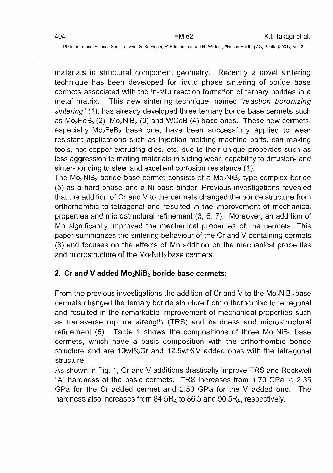
404 HM52 K.I. Takagi et al.15-" International Plansee Seminar, Eds. G. Kneringer, P. Rodhammer and H. Wildner, Plansee Holding AG, Reutte (2001), Vol. 2
materials in structural component geometry. Recently a novel sinteringtechnique has been developed for liquid phase sintering of boride basecermets associated with the in-situ reaction formation of ternary borides in ametal matrix. This new sintering technique, named "reaction boronizingsintering" (1), has already developed three ternary boride base cermets suchas Mo2FeB2(2), Mo2NiB2 (3) and WCoB (4) base ones. These new cermets,especially Mo2FeB2 base one, have been successfully applied to wearresistant applications such as injection molding machine parts, can makingtools, hot copper extruding dies, etc. due to their unique properties such asless aggression to mating materials in sliding wear, capability to diffusion- andsinter-bonding to steel and excellent corrosion resistance (1).The Mo2NiB2 boride base cermet consists of a Mo2NiB2 type complex boride(5) as a hard phase and a Ni base binder. Previous investigations revealedthat the addition of Cr and V to the cermets changed the boride structure fromorthorhombic to tetragonal and resulted in the improvement of mechanicalproperties and microstructural refinement (3, 6, 7). Moreover, an addition ofMn significantly improved the mechanical properties of the cermets. Thispaper summarizes the sintering behaviour of the Cr and V containing cermets(8) and focuses on the effects of Mn addition on the mechanical propertiesand microstructure of the Mo2NiB2base cermets.
2. Cr and V added Mo2NiB2 boride base cermets:
From the previous investigations the addition of Cr and V to the Mo2NiB2basecermets changed the ternary boride structure from orthorhombic to tetragonaland resulted in the remarkable improvement of mechanical properties suchas transverse rupture strength (TRS) and hardness and microstructuralrefinement (6). Table 1 shows the compositions of three Mo2NiB2 basecermets, which have a basic composition with the orthorhombic boridestructure and are 10wt%Cr and 12.5wt%V added ones with the tetragonalstructure.As shown in Fig. 1, Cr and V additions drastically improve TRS and Rockwell"A" hardness of the basic cermets. TRS increases from 1.70 GPa to 2.35GPa for the Cr added cermet and 2.50 GPa for the V added one. Thehardness also increases from 84.5RA to 86.5 and 90.5RA, respectively.
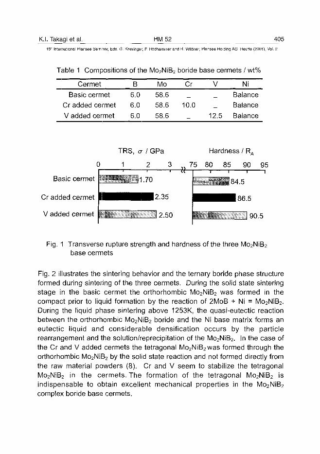
K.I. Takagi et al. HM52 40515" International Plansee Seminar, Eds. G. Kneringer, P. Rodhammer and H. Wildner, Plansee Holding AG, Reutte (2001), Vol. 2
Table 1 Compositions of the Mo2NiB2 boride base cermets / wt%
Cermet
Basic cermetCr added cermet
V added cermet
B
6.06.0
6.0
Mo
58.658.6
58.6
Cr
10.0
—
V
12.5
Ni
BalanceBalance
Balance
0
Basic cermet
Cr added cermet
V added cermet
TRS, a I GPa
1 2 3
Hardness / R
75 80 85
•A
90 95
11.70 84.5
86.5
I 90.5
Fig. 1 Transverse rupture strength and hardness of the three Mo2NiB2
base cermets
Fig. 2 illustrates the sintering behavior and the ternary boride phase structureformed during sintering of the three cermets. During the solid state sinteringstage in the basic cermet the orthorhombic Mo2NiB2 was formed in thecompact prior to liquid formation by the reaction of 2MoB + Ni = Mo2NiB2.During the liquid phase sintering above 1253K, the quasi-eutectic reactionbetween the orthorhombic Mo2NiB2 boride and the Ni base matrix forms aneutectic liquid and considerable densification occurs by the particlerearrangement and the solution/reprecipitation of the Mo2NiB2. In the case ofthe Cr and V added cermets the tetragonal Mo2NiB2was formed through theorthorhombic Mo2NiB2 by the solid state reaction and not formed directly fromthe raw material powders (8). Cr and V seem to stabilize the tetragonalMo2NiB2 in the cermets. The formation of the tetragonal Mo2NiB2 isindispensable to obtain excellent mechanical properties in the Mo2NiB2complex boride base cermets.
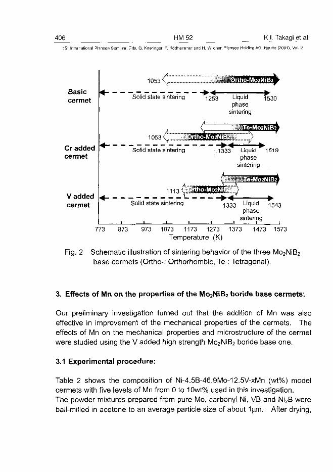
406 HM52 K.I. Takagi et al.
15" International Plansee Seminar, Eds. G. Kneringer, P. Rodhammer and H. Wildner, Plansee Holding AG, Reutte (2001), Vol. 2
Basiccermet
Cr addedcermet
V addedcermet
773
1053\
~* Solid state sintering
1053'-. 3S
Solid state sintering
Solid state sintering
i i i •
^253 Liquid 1530phase
sintering
1333^ Liquid ^1519phase
sintering
"1333 L i c i u i d T543phase
sintering
873 973 1073 1173 1273 1373
Temperature (K)1473 1573
Fig. 2 Schematic illustration of sintering behavior of the three Mo2NiB2
base cermets (Ortho-: Orthorhombic, Te-: Tetragonal).
3. Effects of Mn on the properties of the Mo2NiB2 boride base cermets:
Our preliminary investigation turned out that the addition of Mn was alsoeffective in improvement of the mechanical properties of the cermets. Theeffects of Mn on the mechanical properties and microstructure of the cermetwere studied using the V added high strength Mo2NiB2 boride base one.
3.1 Experimental procedure:
Table 2 shows the composition of Ni-4.5B-46.9Mo-12.5V-xMn (wt%) modelcermets with five levels of Mn from 0 to 10wt% used in this investigation.The powder mixtures prepared from pure Mo, carbonyl Ni, VB and Ni2B wereball-milled in acetone to an average particle size of about 1pm. After drying,
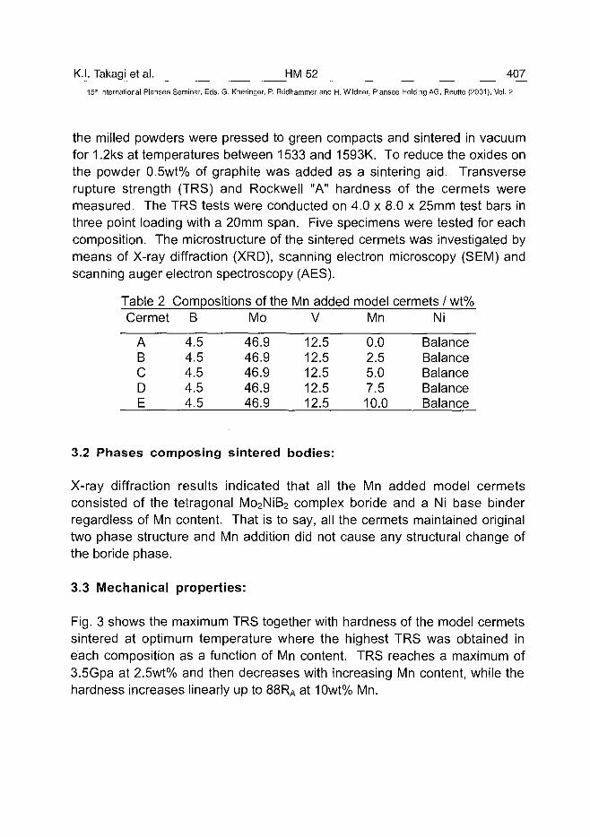
K.I. Takagi et al. HM 52 AV7_15" International Plansee Seminar, Eds. G. Kneringer, P. Rodhammer and H. Wildner, Plansee Holding AG, Reutte (2001), Vol. 2
the milled powders were pressed to green compacts and sintered in vacuumfor 1.2ks at temperatures between 1533 and 1593K. To reduce the oxides onthe powder 0.5wt% of graphite was added as a sintering aid. Transverserupture strength (TRS) and Rockwell "A" hardness of the cermets weremeasured. The TRS tests were conducted on 4.0 x 8.0 x 25mm test bars inthree point loading with a 20mm span. Five specimens were tested for eachcomposition. The microstructure of the sintered cermets was investigated bymeans of X-ray diffraction (XRD), scanning electron microscopy (SEM) andscanning auger electron spectroscopy (AES).
Table 2 Compositions of the Mn added model cermets / wt%Cermet B Mo V Mn Ni
ABCDE
4.54.54.54.54.5
46.946.946.946.946.9
12.512.512.512.512.5
0.02.55.07.510.0
BalanceBalanceBalanceBalanceBalance
3.2 Phases composing sintered bodies:
X-ray diffraction results indicated that all the Mn added model cermetsconsisted of the tetragonal Mo2NiB2 complex boride and a Ni base binderregardless of Mn content. That is to say, all the cermets maintained originaltwo phase structure and Mn addition did not cause any structural change ofthe boride phase.
3.3 Mechanical properties:
Fig. 3 shows the maximum TRS together with hardness of the model cermetssintered at optimum temperature where the highest TRS was obtained ineach composition as a function of Mn content. TRS reaches a maximum of3.5Gpa at 2.5wt% and then decreases with increasing Mn content, while thehardness increases linearly up to 88RA at 10wt% Mn.
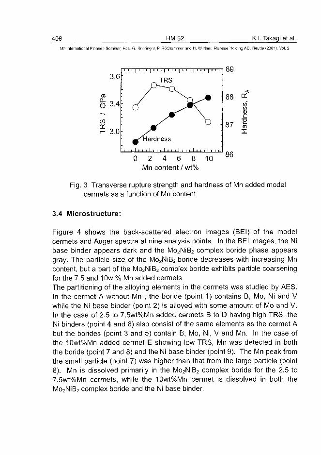
408
15'" International Plansee Seminar
CO
n*'
oCDDCh-
3
3
3
6
4
0
Eds. G.
i i i |
' r
•, , , I
0
HM52<neringer, P. Rodhammer and H. Wildner, Plansee Holding AG
i i i 1 i i 1 | 1 i • 1 i
/) ^
(^Hardness
• , , i i , , i , i , i ,
2 4 6Mn content /
1 1 1 1 1
Y) ^* \
\
• 1 1 1 1
8wt%
• 1 1 1 1
* •
\
D .
i i i , .
89
88
87
10 m
ofto"
cuc
ard
X
K.I. Takagi et al.
Reutte (2001), Vol. 2
Fig. 3 Transverse rupture strength and hardness of Mn added modelcermets as a function of Mn content.
3.4 Microstructure:
Figure 4 shows the back-scattered electron images (BEI) of the modelcermets and Auger spectra at nine analysis points. In the BEI images, the Nibase binder appears dark and the Mo2NiB2 complex boride phase appearsgray. The particle size of the Mo2NiB2 boride decreases with increasing Mncontent, but a part of the Mo2NiB2 complex boride exhibits particle coarseningfor the 7.5 and 10wt% Mn added cermets.The partitioning of the alloying elements in the cermets was studied by AES.In the cermet A without Mn , the boride (point 1) contains B, Mo, Ni and Vwhile the Ni base binder (point 2) is alloyed with some amount of Mo and V.In the case of 2.5 to 7.5wt%Mn added cermets B to D having high TRS, theNi binders (point 4 and 6) also consist of the same elements as the cermet Abut the borides (point 3 and 5) contain B, Mo, Ni, V and Mn. In the case ofthe 10wt%Mn added cermet E showing low TRS, Mn was detected in boththe boride (point 7 and 8) and the Ni base binder (point 9). The Mn peak fromthe small particle (point 7) was higher than that from the large particle (point8). Mn is dissolved primarily in the Mo2NiB2 complex boride for the 2.5 to7.5wt%Mn cermets, while the 10wt%Mn cermet is dissolved in both theMo2NiB2 complex boride and the Ni base binder.
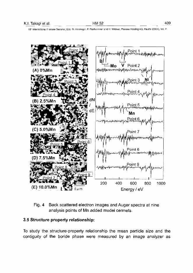
K.I. Takagi et al. HM52 409
15'" International Plansee Seminar, Eds. G. Kneringer, P. Rodhammer and H. Wildner, Plansee Holding AG, Reutte (2001), Vol. 2
1 / i if if if
'=^-Mo V Point
| m vf
u in i . i J Point
i iPoint
n Point
I i i
3 Ni *
R f!
I ff '
if
8
g 1
,1(E) 10.0%Mn
200 400 600 800 1000Energy / eV
Fig. 4 Back scattered electron images and Auger spectra at nineanalysis points of Mn added model cermets.
3.5 Structure property relationship:
To study the structure-property relationship the mean particle size and thecontiguity of the boride phase were measured by an image analyzer as
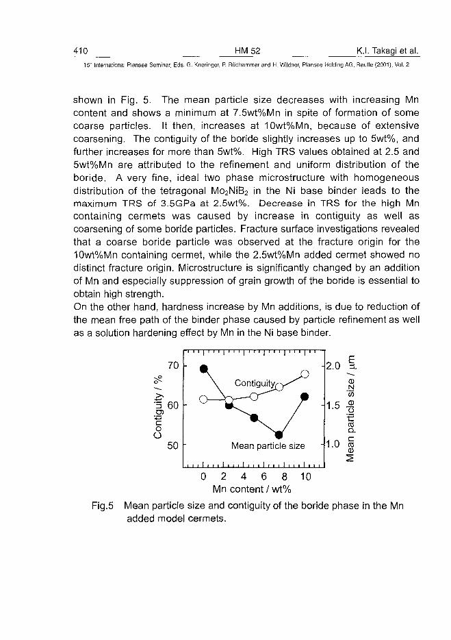
410 HM52 K.I. Takagi et al.
15" International Plansee Seminar, Eds. G. Kneringer, P. Rodhammer and H. Wildner, Plansee Holding AG, Reutte (2001), Vol. 2
shown in Fig. 5. The mean particle size decreases with increasing Mncontent and shows a minimum at 7.5wt%Mn in spite of formation of somecoarse particles. It then, increases at 10wt%Mn, because of extensivecoarsening. The contiguity of the boride slightly increases up to 5wt%, andfurther increases for more than 5wt%. High TRS values obtained at 2.5 and5wt%Mn are attributed to the refinement and uniform distribution of theboride. A very fine, ideal two phase microstructure with homogeneousdistribution of the tetragonal Mo2NiB2 in the Ni base binder leads to themaximum TRS of 3.5GPa at 2.5wt%. Decrease in TRS for the high Mncontaining cermets was caused by increase in contiguity as well ascoarsening of some boride particles. Fracture surface investigations revealedthat a coarse boride particle was observed at the fracture origin for the10wt%Mn containing cermet, while the 2.5wt%Mn added cermet showed nodistinct fracture origin. Microstructure is significantly changed by an additionof Mn and especially suppression of grain growth of the boride is essential toobtain high strength.On the other hand, hardness increase by Mn additions, is due to reduction ofthe mean free path of the binder phase caused by particle refinement as wellas a solution hardening effect by Mn in the Ni base binder.
coO
70
60
50
\ Cont
Mean
, , , ! i , , 1 , , , 1 , ,
rV
particle
i i i i i i
/ •
size
• , , i 1 1 i
-2.0
-1 .5 S>
-1 .0
0NWoo
• •cCDQ.CCDCD
10
Fig.5
0 2 4 6 8Mn content / wt%
Mean particle size and contiguity of the boride phase in the Mnadded model cermets.
K.I. Takagi et al. HM 52 411
15'" International Plansee Seminar, Eds. G. Kneringer, P. Rodhammer and H. Wildner, Plansee Holding AG, Reutte (2001), Vol. 2
4. Conclusions:
In the Cr and V added Mo2NiB2 boride base cermets the tetragonal Mo2NiB2
was formed through the orthorhombic Mo2NiB2by the solid state reactionduring sintering and not formed directly from the raw material powders. Theformation of the tetragonal Mo2NiB2 is indispensable to obtain excellentmechanical properties in the Mo2NiB2 boride base cermets.Mn added V containing Mo2NiB2 complex boride base cermets consist of thetetragonal Mo2NiB2 complex boride alloyed with Mn as the hard phase andthe Ni base binder alloyed with Mo and V. Transverse rupture strengthincreased with increasing Mn content and showed a maximum value of3.5GPa at 2.5wt% and then decreased with increasing Mn content. Hardnessincreased monotonically from 86.4RA to 88.0RA up to the 10wt%Mn. Thehigh TRS at 2.5wt%Mn was attributed to size refinement and homogeneousdistribution of the Mo2NiB2 complex boride.
References:
(1) K. Takagi, M. Komai and S. Matsuo: Proc. of 1994 Powder MetallurgyWorld Congress (PM'94), Vol.1, pp.227-234 (SF2M and EPMA, LesEditions de Physique Les Ulis, France 1994)
(2) K. Takagi, S. Ohira, T. Ide, T. Watanabe and Y. Kondo: Met. PowderRep.,42(1987)pp.483-490
(3) M. Komai, Y. Yamasaki, K. Takagi and T. Watanabe: Properties ofEmerging P/M Materials, Advances in Powder Metallurgy & ParticulateMaterials, Vol. 8, pp.81-88 (ed. J. M. Capus and R. M. German, MetalPowder Industries Federation, Princeton, NJ 1992)
(4)M. Komai, Y. Isobe, S. Ozaki and K. Takagi, Proc. of 1993 PowderMetallurgy World Congress, Part 2, pp.1267-1270 (ed. by Y. Bando and K.Kosuge, Japan Society of Powder and Powder Metallurgy, Kyoto, Japan(1993).
(5)Yu. B. Kuz'ma and M. V. Chepiga: Sov. Powder Metall. Met. Ceram. 10(82)(1969)pp.832-835
(6) K. Takagi, Y. Yamasaki and M. Komai: J. Solid State Chem., 133 (1997)pp. 243-248
(7) K. Takagi, Y. Yamasaki and M. Komai: J. Solid State Chem., 154 (2000)pp.263-268
(8) K. Takagi: Mater. Chem. Phys. 67 (2001) pp.214-219
ATO100470412 HM55 L. Chen et al.
15" International Plansee Seminar, Eds. G. Kneringer, P. Rodhammer and H. Wildner, Plansee Holding AG, Reutte (2001), Vol. 2
Fundamentals of Liquid Phase Sintering for Modern Cermets and Functionally
Graded Cemented Carbonitrides (FGCC)
Limin Chen' *, Walter Lengauer2, Peter Ettmayer2,
Klaus Dreyer3, Hans W. Daub3 and Dieter Kassel3
1 Austrian Research Center, Division of Materials Technology, A-2444, Austria
* Current address: SinterMet, LLC. West Hills Industrial Park, Kittanning, PA 16201, USA.
2 Institute for Chemical Technology of Inorganic Materials
Vienna University of Technology, Getreidemarkt 9/161, A-1060, Austria
3 WIDIA GmbH, Munchener Str. 90, D-45145 Essen, Germany
ABSTRACT
Metallurgical reactions and microstructure developments during sintering of modern cermets andfunctionally graded cemented carbonitrides (FGCC) were investigated by modern thermal andanalytical methods such as mass spectrometer (MS), differential thermal analysis (DTA), differentialscanning calorimeter (DSC), dilatometer (DIL), microscopy and analytical electronic microscopywith energy dispersive spectrometer (EDS). The complex phase reactions and phase equilibria in themulti-component system Ti/Mo/W/Ta/Nb/C,N-Co/Ni were studied. The melting behaviors in thesystems of TiC-WC/MoC-Ni/Co, TiC-TiN-WC-Co and TiCN-TaC-WC-Co have been established.By better understanding of the mechanisms that govern the sintering processing and metallurgicalreactions, new cermets and different types of functionally graded cemented carbonitrides (FGCC)with desired microstructures and properties were developed and fabricated.
Keywords: Functionally graded cemented carbonitrides, Cermets, Cutting tools, Phase diagram,Thermal analysis.
1. INTRODUCTION
The importance of introducing nitrogen in the form of TiN into TiC-Ni/Mo cermets was discoveredby Kieffer et. al. around 1970 [1]. Systematic researches afterwards led to a new generation ofmodem cutting cermets, which is characterized by multi-components with TiC and TiN, oralternatively, TiCN as the basic ingredients. Additions of Mo2C, WC, TaC, NbC and VC add up to20-40 mass% of the total. The binder alloys usually contain Ni and Co on the order of 10-15 mass%but in varying relative amounts. The performance of the modern cutting cermets can match or evenbetter than that of coated cemented carbides. Some excellent reviews on the modern cermets aregiven in the literature [2-5].
L. Chen et al. HM 55 413^15th International Plansee Seminar, Eds. G. Kneringer, P. Rodhammer and H. Wildner, Plansee Holding AG, Reutte (2001), Vol. 2
As for the coated cemented carbides, the surface zone of the "state-of-the-art" substrate oftenfeatures a Co-enriched and cubic-phase free layer (CFL). During interrupted machining, such CFLlayer underneath the ceramic coatings absorbs most of the energy so that the impact resistance of thecoated carbide grades is greatly improved. The CFL surface layer is usually prepared by a post-sintering treatment of nitrogen-containing alloys under (high) vacuum at cooling speeds less than 10K/min. [6-10]. The denitrdation (i.e. decomposition of nitrides or carbonitrides) caused by vacuumtreatment is believed to form the CFL character on the surface of the substrates.
The surface zone can also be modified into a unique structure with a gradation enriched in TiCNcubic phase and depleted in WC and Co/Ni binder. So called FGM (functionally graded material)cemented carbonitrides are sintered in a nitrogen-containing atmosphere. Inserts with as-sinteredsingle or multi- FGM layers have been developed and were reported to perform better than thecoated carbides [11-16]. In addition to the improvement of the cutting performance, very costlycoating process may be eliminated by the new developed FGM technology. Saving potential ispromising since coating process accounts for more than 15% of the total manufacturing costs whilesintering process accounts for only 5% [17].
Nitrogen plays more and more critical role to develop new generation of cutting toll materials.However, with the addition of nitrogen (through carbonitrides, nitrides or nitrogen gas), themetallurgical reactions during sintering become much more complex and the sintering atmospherehas to be more accurately controlled [12-16, 18-19]. The cutting tool industry is still lacking inunderstanding the mechanisms of liquid phase sintering of nitrogen-containing cemented carbides.The present work approaches to carry out a systematic research in order to fill in these gaps.
EXPERIMENTAL PROCEDURES
Differential Thermal Analysis (DTA)DTA was used to measure melting points of experimental alloys with 33 wt % binder metal contentor higher. Highly pure re-crystallized alumina was used as a crucible material and a platinum alloy asa reference standard. The temperature was measured with a Pt/Rh thermocouple and the accuracy ofthe temperature measurement is estimated to be within ± 3°C by calibration against known meltingpoints of high purity Cu and Cu-Ni alloys.
Differential Scanning Calorimeter (DSC) MeasurementsMelting points of industrial alloys were measured by a DSC system (Netzsch DSC 404). This systemmonitors the AT signal representing the difference in temperature between a sample and an inertreference material as a function of temperature. The temperature was calibrated against the meltingpoint of Au and the measurement error was within 1°C.
Dilatometer (DIL) MeasurementsThe shrinkage behaviors of the industrial alloys were monitored by a dilatometer (Netzsch DIL402C, max. temperature 1600°C). The samples were heated under vacuum of 4~6xlO~4 mbar till1300°C. The vacuum pump was then turned off. The gas pressure rose to a few mbar duringsintering.
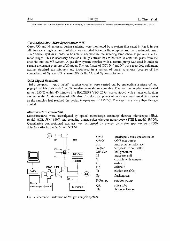
414 HM55 L. Chen et al.15" International Plansee Seminar, Eds. G. Kneringer, P. Rodhammer and H. Wildner, Plansee Holding AG, Reutte (2001), Vol. 2
Gas Analysis by A Mass Spectrometer (MS)Gases CO and N2 released during sintering were monitored by a system illustrated in Fig. 1. In theMF furnace a high-pressure interface was inserted between the recipient and the quadrupole massspectrometer system in order to be able to characterize the sintering atmosphere at pressures in thembar ranges. This is necessary because a He gas stream has to be used to elute the gases from thecrucible into the MS system. A gas flow system together with a second pump was used in order tosustain a constant pressure of 20 mbar. The ion fluxes of CO+, N2T and N+ were recorded, calibratedagainst standard gas mixtures and introduced in a system of linear equations (because of thecoincidence of N2" and CCF at mass 28) for the CO and N2 concentrations.
Solid-Liquid Reactions"Solid compact - liquid metal" reaction couples were carried out by embedding a piece of hot-pressed carbide plate and Co or Ni powders in an alumina crucible. The reaction couples were heatedup to 1550°C within 40 minutes in a BALZERS VSG 02 furnace equipped with a tungsten heatingelement under Ar atmosphere of 300 mbar. The electrical power of the device was turned off as soonas the samples had reached the vertex temperature of 1550°C. The specimens were then furnacecooled.
Microstructure EvaluationMicrostructures were investigated by optical microscope, scanning electron microscope (SEM,model JEOL JSM 6400) and scanning transmission electron microscope (STEM, model H-800).Quantitative compositional analysis was performed by energy dispersive spectroscopy (EDS)detectors attached to SEM and STEM.
QRQMSQMGHPIReglerMF-GenISTBlB2Tr
Sp
R-Pumpe
QRTh
quadrupole mass spectrometerQMS electronicshigh pressure interfacetemperature controllerMF generatorinduction coilcrucible with sampleorifice 1orifice 2elution gas (He)
flushing gas
rotation pump
silica tubethermo-element
Fig.l- Schematic illustration of MS gas analysis system
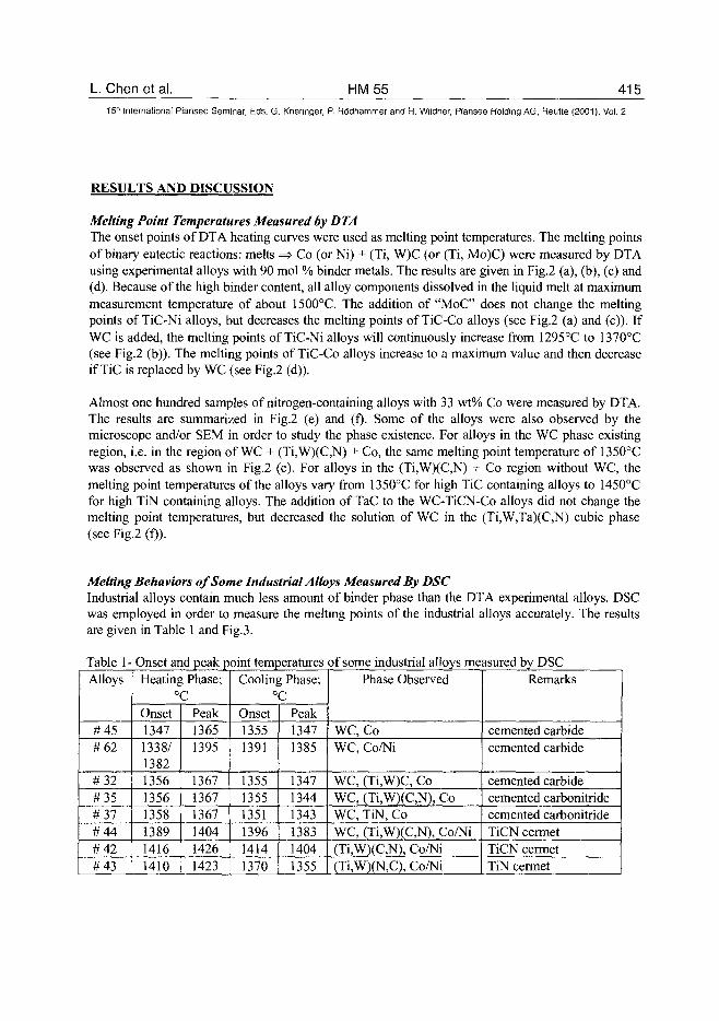
L Chen et al. HM55 415
15" International Plansee Seminar, Eds. G. Kneringer, P. Rodhammer and H. Wildner, Plansee Holding AG, Reutte (2001), Vol. 2
RESULTS AND DISCUSSION
Melting Point Temperatures Measured by DTAThe onset points of DTA heating curves were used as melting point temperatures. The melting pointsof binary eutectic reactions: melts => Co (or Ni) + (Ti, W)C (or (Ti, Mo)C) were measured by DTAusing experimental alloys with 90 mol % binder metals. The results are given in Fig.2 (a), (b), (c) and(d). Because of the high binder content, all alloy components dissolved in the liquid melt at maximummeasurement temperature of about 1500°C. The addition of "MoC" does not change the meltingpoints of TiC-Ni alloys, but decreases the melting points of TiC-Co alloys (see Fig.2 (a) and (c)). IfWC is added, the melting points of TiC-Ni alloys will continuously increase from 1295°C to 1370°C(see Fig.2 (b)). The melting points of TiC-Co alloys increase to a maximum value and then decreaseif TiC is replaced by WC (see Fig.2 (d)).
Almost one hundred samples of nitrogen-containing alloys with 33 wt% Co were measured by DTA.The results are summarized in Fig.2 (e) and (f). Some of the alloys were also observed by themicroscope and/or SEM in order to study the phase existence. For alloys in the WC phase existingregion, i.e. in the region of WC + (Ti,W)(C,N) + Co, the same melting point temperature of 135O°Cwas observed as shown in Fig.2 (e). For alloys in the (Ti,W)(C,N) + Co region without WC, themelting point temperatures of the alloys vary from 1350°C for high TiC containing alloys to 1450°Cfor high TiN containing alloys. The addition of TaC to the WC-TiCN-Co alloys did not change themelting point temperatures, but decreased the solution of WC in the (Ti,W,Ta)(C,N) cubic phase(see Fig.2 (f)).
Melting Behaviors of Some Industrial Alloys Measured By DSCIndustrial alloys contain much less amount of binder phase than the DTA experimental alloys. DSCwas employed in order to measure the melting points of the industrial alloys accurately. The resultsare given in Table 1 and Fig.3.
Table 1- Onset and peak point temperatures of some industrial alloys measured by DSCAlloys
#45#62
#32#35#37#44#42#43
Heating Phase;°C
Onset13471338/1382135613561358138914161410
Peak13651395
136713671367140414261423
Cooling Phase;°C
Onset13551391
135513551351139614141370
Peak13471385
134713441343138314041355
Phase Observed
WC, CoWC, Co/Ni
WC, (Ti,W)C, CoWC, (Ti,W)(C,N), CoWC, TiN, CoWC, (Ti,W)(C,N), Co/Ni(Ti,W)(C,N), Co/Ni(Ti,W)(N,C), Co/Ni
Remarks
cemented carbidecemented carbide
cemented carbidecemented carbonitridecemented carbonitrideTiCN cermetTiCN cermetTiN cermet
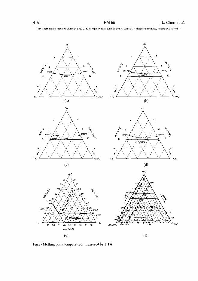
416 HM55 L. Chen et al.15;" International Plansee Seminar, Eds. G. Kneringer, P. Rddhammer and H. Wildner, Plansee Holding AG, Reutte (2001), Vol. 2
V(c)
WC
90 /--A90
/5V
AAAA16 Z V- V V \ 16
/ V \ / V V \
10 20 30 40 50 60 70 80 90
mol%TiN
(e)
(b)
16 L V \L
/ A~A A/ V \ /
A
(f)
v
16
\
TaC
Fig.2- Melting point temperatures measured by DTA.
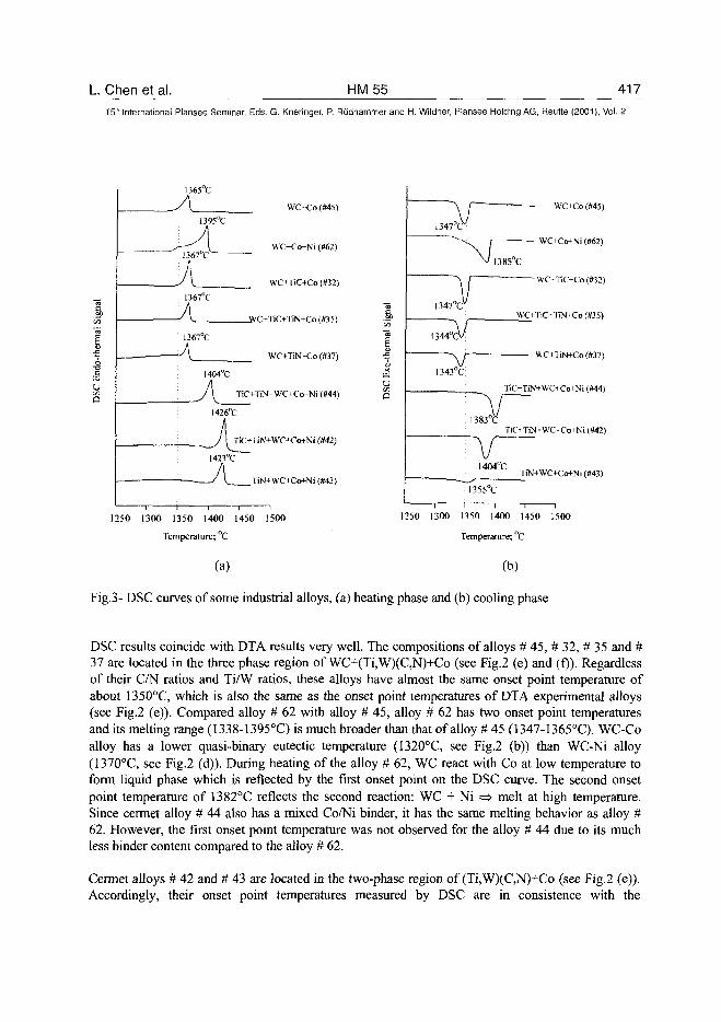
L Chen et al. HM55 41715" International Plansee Seminar, Eds. G. Kneringer, P. Rodhammer and H. Wildner, Plansee Holding A6, Reutte (2001), Vol. 2
1365
Ac
1395°Ch
^1367°
A.: 1367
A
' 1367
A
C L
woc
1404°C
WC-Co (#45)
WC+Co+Ni (#62)
WC+TiC+Co(#32)
TiC+TiN+Co(fl35)
WC<TiN+Co(#37)
J\ TiC+TiN+WC+Co+Ni (#44)
1426°Cij
J\ TiC+TiN
1423°C
A ru
+WT+Co+Ni (#42)
+WC+Co+Ni (#43)
1250 1300 1350 1400 1450 1500
Temperature; °C
— WC+Co(#45)
WC+Co+Ni (#62)
WC-TiC+Co(#32)
W£+TiC-TiN+Co (#35)
WC+TiN+Co(#37)
TiC+TiN+WC+Co+Ni (#44)
TiC+TiN+WOCo+Ni (#42)
TiN+WC+Co+Ni (#43)
1250 1300 1350 1400 1450 1500
Temperature; °C
(a) (b)
Fig.3- DSC curves of some industrial alloys, (a) heating phase and (b) cooling phase
DSC results coincide with DTA results very well. The compositions of alloys # 45, # 32, # 35 and #37 are located in the three phase region of WC+(Ti,W)(C,N)+Co (see Fig.2 (e) and (f)). Regardlessof their C/N ratios and Ti/W ratios, these alloys have almost the same onset point temperature ofabout 1350°C, which is also the same as the onset point temperatures of DTA experimental alloys(see Fig.2 (e)). Compared alloy # 62 with alloy # 45, alloy # 62 has two onset point temperaturesand its melting range (1338-1395°C) is much broader than that of alloy # 45 (1347-1365°C). WC-Coalloy has a lower quasi-binary eutectic temperature (1320°C, see Fig.2 (b)) than WC-Ni alloy(1370°C, see Fig.2 (d)). During heating of the alloy # 62, WC react with Co at low temperature toform liquid phase which is reflected by the first onset point on the DSC curve. The second onsetpoint temperature of 1382°C reflects the second reaction: WC + Ni => melt at high temperature.Since cermet alloy # 44 also has a mixed Co/Ni binder, it has the same melting behavior as alloy #62. However, the first onset point temperature was not observed for the alloy # 44 due to its muchless binder content compared to the alloy # 62.
Cermet alloys # 42 and # 43 are located in the two-phase region of (Ti,W)(C,N)+Co (see Fig.2 (e)).Accordingly, their onset point temperatures measured by DSC are in consistence with the
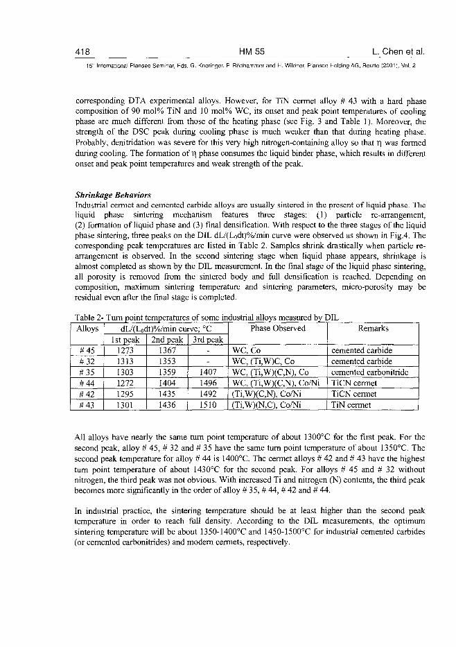
418 HM55 L Chen et al.15* International Plansee Seminar, Eds. G. Kneringer, P. Rodhammer and H. Wildner, Plansee Holding AG, Reutte (2001), Vol. 2
corresponding DTA experimental alloys. However, for TiN cermet alloy # 43 with a hard phasecomposition of 90 mol% TiN and 10 mol% WC, its onset and peak point temperatures of coolingphase are much different from those of the heating phase (see Fig. 3 and Table 1). Moreover, thestrength of the DSC peak during cooling phase is much weaker than that during heating phase.Probably, denitridation was severe for this very high nitrogen-containing alloy so that T) was formedduring cooling. The formation of r\ phase consumes the liquid binder phase, which results in differentonset and peak point temperatures and weak strength of the peak.
Shrinkage BehaviorsIndustrial cermet and cemented carbide alloys are usually sintered in the present of liquid phase. Theliquid phase sintering mechanism features three stages: (1) particle re-arrangement,(2) formation of liquid phase and (3) final densification. With respect to the three stages of the liquidphase sintering, three peaks on the DIL dL/(Lodt)%/min curve were observed as shown in Fig.4. Thecorresponding peak temperatures are listed in Table 2. Samples shrink drastically when particle re-arrangement is observed. In the second sintering stage when liquid phase appears, shrinkage isalmost completed as shown by the DIL measurement. In the final stage of the liquid phase sintering,all porosity is removed from the sintered body and full densification is reached. Depending oncomposition, maximum sintering temperature and sintering parameters, micro-porosity may beresidual even after the final stage is completed.
Table 2-Alloys
#45#32#35#44#42#43
Turn point temperatures of some industrial alloys measured by DILdL/(Lodt)%/min curve; °C
1 st peak127313131303127212951301
2nd peak136713531359140414351436
3rd peak--
1407149614921510
Phase Observed
WC, CoWC, (Ti,W)C, CoWC, (Ti,W)(C,N), CoWC, (Ti,W)(C,N), Co/Ni(Ti,W)(C,N), Co/Ni(Ti,W)(N,C), Co/Ni
Remarks
cemented carbidecemented carbidecemented carbonitrideTiCN cermetTiCN cermetTiN cermet
All alloys have nearly the same turn point temperature of about 1300°C for the first peak. For thesecond peak, alloy # 45, # 32 and # 35 have the same turn point temperature of about 1350°C. Thesecond peak temperature for alloy # 44 is 1400°C. The cermet alloys # 42 and # 43 have the highestturn point temperature of about 1430°C for the second peak. For alloys # 45 and # 32 withoutnitrogen, the third peak was not obvious. With increased Ti and nitrogen (N) contents, the third peakbecomes more significantly in the order of alloy # 35, # 44, # 42 and # 44.
In industrial practice, the sintering temperature should be at least higher than the second peaktemperature in order to reach full density. According to the DIL measurements, the optimumsintering temperature will be about 1350-1400°C and 1450-1500°C for industrial cemented carbides(or cemented carbonitrides) and modern cermets, respectively.
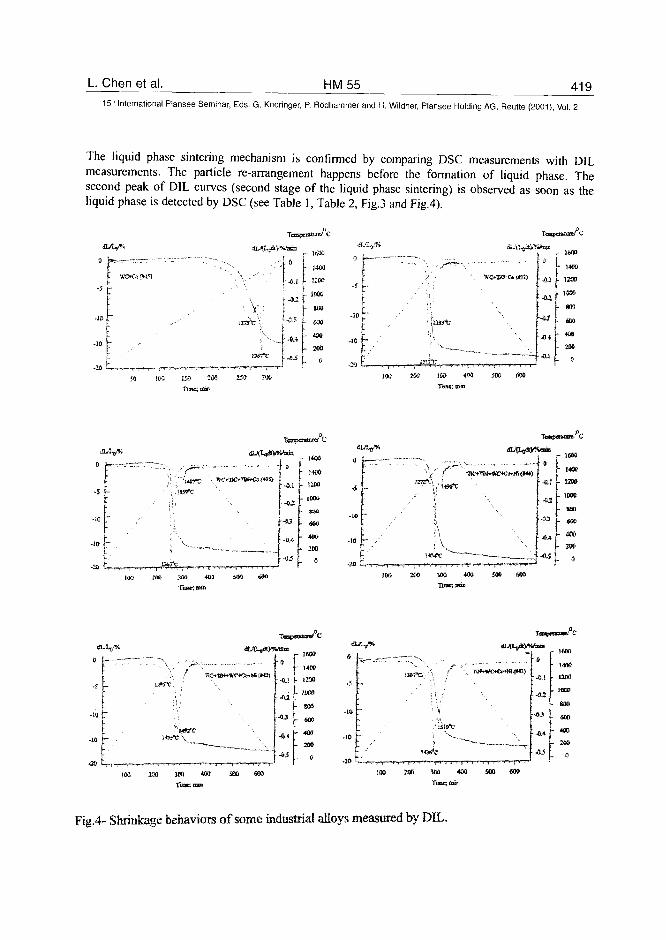
L. Chen et al. HM55 41915" International Plansee Seminar, Eds. G. Kneringer, P. Rodhammer and H. Wildner, Plansee Holding AG, Reutte (2001), Vol. 2
The liquid phase sintering mechanism is confirmed by comparing DSC measurements with DILmeasurements. The particle re-arrangement happens before the formation of liquid phase. Thesecond peak of DIL curves (second stage of the liquid phase sintering) is observed as soon as theliquid phase is detected by DSC (see Table 1, Table 2, Fig.3 and Fig.4).
14,1 J. 12M
IJW
800
SCO
4M
6
!9G 2U 3» # SO© «SX>
ivh 600
OAj*.
JMJ 40) SOS
TIIIIC! rat.
r 1400
• * ! t 120O
- SOS
• " - m
- 200
leoo
I- t«o
SB) MO S» «0 » »
Fig.4- Shrinkage behaviors of some industrial aEoys measured by DIL.
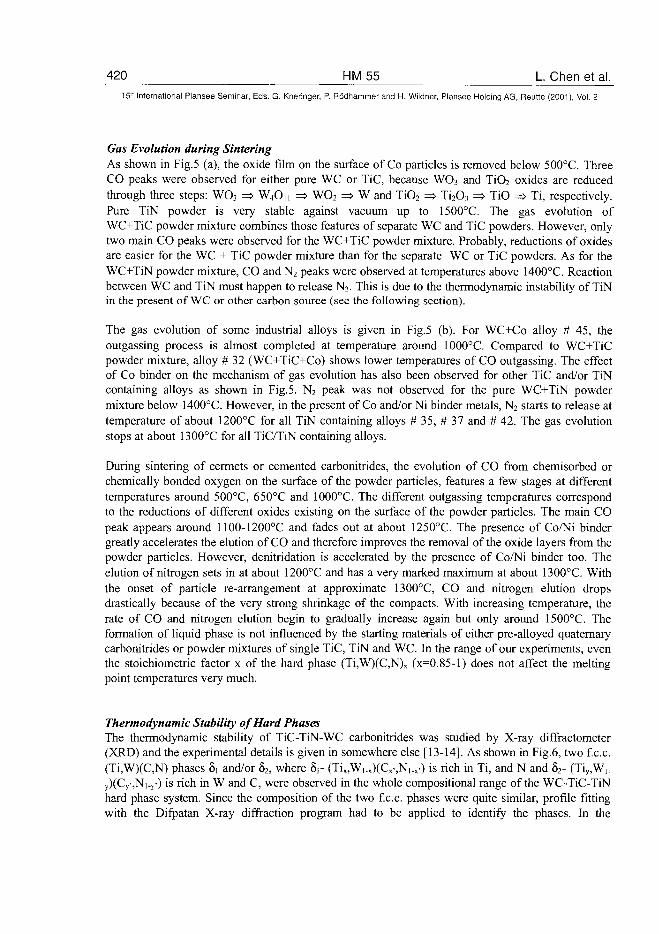
420 HM55 L. Chen et al.15:~ International Plansee Seminar, Eds. G. Kneringer, P. Rodhammer and H. Wildner, Plansee Holding AG, Reutte (2001), Vol. 2
Gas Evolution during SinteringAs shown in Fig.5 (a), the oxide film on the surface of Co particles is removed below 500°C. ThreeCO peaks were observed for either pure WC or TiC, because WO3 and TiO2 oxides are reducedthrough three steps: WO3 => W4On => WO2 => W and TiO2 => Ti2O3 => TiO => Ti, respectively.Pure TiN powder is very stable against vacuum up to 1500°C. The gas evolution ofWC+TiC powder mixture combines those features of separate WC and TiC powders. However, onlytwo main CO peaks were observed for the WC+TiC powder mixture. Probably, reductions of oxidesare easier for the WC + TiC powder mixture than for the separate WC or TiC powders. As for theWC+TiN powder mixture, CO and N2 peaks were observed at temperatures above 1400°C. Reactionbetween WC and TiN must happen to release N2. This is due to the thermodynamic instability of TiNin the present of WC or other carbon source (see the following section).
The gas evolution of some industrial alloys is given in Fig.5 (b). For WC+Co alloy # 45, theoutgassing process is almost completed at temperature around 1000°C. Compared to WC+TiCpowder mixture, alloy # 32 (WC+TiC+Co) shows lower temperatures of CO outgassing. The effectof Co binder on the mechanism of gas evolution has also been observed for other TiC and/or TiNcontaining alloys as shown in Fig.5. N2 peak was not observed for the pure WC+TiN powdermixture below 1400°C. However, in the present of Co and/or Ni binder metals, N2 starts to release attemperature of about 1200°C for all TiN containing alloys # 35, # 37 and # 42. The gas evolutionstops at about 1300°C for all TiC/TiN containing alloys.
During sintering of cermets or cemented carbonitrides, the evolution of CO from chemisorbed orchemically bonded oxygen on the surface of the powder particles, features a few stages at differenttemperatures around 500°C, 650°C and 1000°C. The different outgassing temperatures correspondto the reductions of different oxides existing on the surface of the powder particles. The main COpeak appears around 1100-1200°C and fades out at about 1250°C. The presence of Co/Ni bindergreatly accelerates the elution of CO and therefore improves the removal of the oxide layers from thepowder particles. However, denitridation is accelerated by the presence of Co/Ni binder too. Theelution of nitrogen sets in at about 1200°C and has a very marked maximum at about 1300°C. Withthe onset of particle re-arrangement at approximate 1300°C, CO and nitrogen elution dropsdrastically because of the very strong shrinkage of the compacts. With increasing temperature, therate of CO and nitrogen elution begin to gradually increase again but only around 1500°C. Theformation of liquid phase is not influenced by the starting materials of either pre-alloyed quaternarycarbonitrides or powder mixtures of single TiC, TiN and WC. In the range of our experiments, eventhe stoichiometric factor x of the hard phase (Ti,W)(C,N)x (x=0.85-l) does not affect the meltingpoint temperatures very much.
Thermodynamic Stability of Hard PhasesThe thermodynamic stability of TiC-TiN-WC carbonitrides was studied by X-ray diffractometer(XRD) and the experimental details is given in somewhere else [13-14]. As shown in Fig.6, two f.c.c.(Ti,W)(C,N) phases 8, and/or 82, where 5,- (Tix,Wi.x)(Cx-,N,.x-) is rich in Ti, and N and 82- (Tiy,W,.
y)(Cy-,Ni_y-) is rich in W and C, were observed in the whole compositional range of the WC-TiC-TiNhard phase system. Since the composition of the two f.c.c. phases were quite similar, profile fittingwith the Difpatan X-ray diffraction program had to be applied to identify the phases. In the
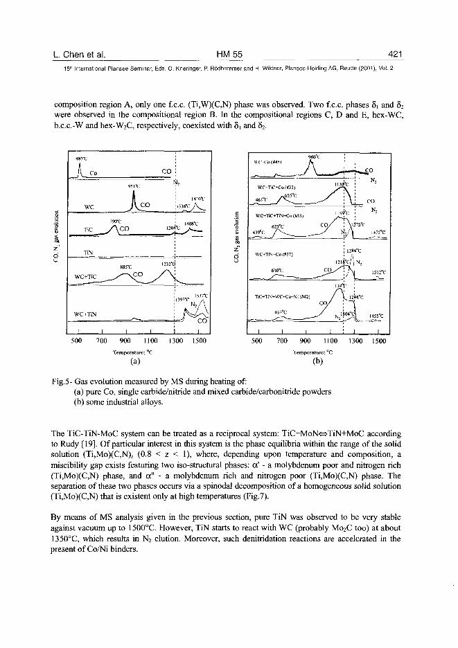
L. Chen et al. HM55 42115lh International Plansee Seminar, Eds. G. Kneringer, P. Rodhammer and H. Wildner, Plansee Holding AG, Reutte (2001), Vol. 2
composition region A, only one f.c.c. (Ti,W)(C,N) phase was observed. Two f.c.c. phases 81 and 82were observed in the compositional region B. In the compositional regions C, D and E, hex-WC,b.c.c.-W and hex-W^C, respectively, coexisted with 81 and 82.
CO
we
V3I ^.
It*._nc_y\co I284"C
TiN
WC+TiN
500 700 900 1100 1300 1500
Temperature; °C
(a)
1
gas
evol
u
2
du
960°(\VOCo<*45> fs
WC+TiC+Co (#32)
463°C / V L
WC+TiC+TtN-tCo («3S)
623"C
,j^ A -
WC+TiN+Co(»37)
630°C
TiC+TiN+WC+CotNi («42)
657°C
1 1 1
C O /
CO
c o //
1
- * -1130
1159
N
121
/
1134°
/ \
N, 1
*—*
\
-c
\ l
128-
X
A:
i—_
75°C
l°C
N,
LkJ294"C
04°ol
i
CO
N;
CO
N,
I4751C
1512°C
I455°C
1
500 700 900 1100 1300 1500
Temperature; °C
(b)
Fig.5- Gas evolution measured by MS during heating of:(a) pure Co, single carbide/nitride and mixed carbide/carbonitride powders(b) some industrial alloys.
The TiC-TiN-MoC system can be treated as a reciprocal system: TiC+MoN<=>TiN+MoC accordingto Rudy [19]. Of particular interest in this system is the phase equilibria within the range of the solidsolution (Ti,Mo)(C,N)z (0.8 < z < 1), where, depending upon temperature and composition, amiscibility gap exists featuring two iso-structural phases: a' - a molybdenum poor and nitrogen rich(Ti,Mo)(C,N) phase, and a" - a molybdenum rich and nitrogen poor (Ti,Mo)(C,N) phase. Theseparation of these two phases occurs via a spinodal decomposition of a homogeneous solid solution(Ti,Mo)(C,N) that is existent only at high temperatures (Fig.7).
By means of MS analysis given in the previous section, pure TiN was observed to be very stableagainst vacuum up to 1500°C. However, TiN starts to react with WC (probably M02C too) at about1350°C, which results in N2 elution. Moreover, such denitridation reactions are accelerated in thepresent of Co/Ni binders.
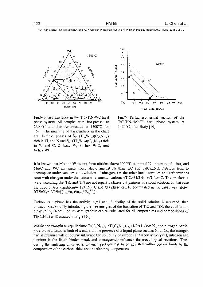
422 HM55 L. Chen et al.15"-" International Plansee Seminar, Eds. G. Kneringer, P. Ro'dhammer and H. Wildner, Plansee Holding AG, Reutte (2001), Vol. 2
1500°C
TiC10 20 30 40 50 60 70 80 90
mol%TiN
TiN
Fig.6- Phase existence in the TiC-TiN-WC hardphase system. All samples were hot-pressed at2300°C and then Ar-annealed at 1500°C for168h. The meaning of the numbers in the chartare: 1- f.c.c. phases of 5i- (Tix,Wi_x)(Cx-,Ni-x-)rich in Ti, and N and 82- (Tiy,Wi_y)(Cy,Ni_y.) richin W and C; 2- b.c.c W; 3- hex W2C; and4- hex WC.
TiN
t0.6
0.5 •
0.4 •
0.3 '
0.2 •
0.1 -
TiC
1450°C
0.1 0.2 0.3 0.4 0.5 0.6 •
y in (Ti»Mo,)(CuN.)
MoC
Fig.7- Partial isothermal section of theTiC-TiN-"MoC" hard phase system at1450°C, after Rudy [19].
It is known that Mo and W do not form nitrides above 1000°C at normal N2 pressure of 1 bar, andMo2C and WC are much more stable against N2 than TiC and Ti(Ci_x,Nx). Nitrides tend todecompose under vacuum via evolution of nitrogen. On the other hand, carbides and carbonitridesreact with nitrogen under formation of elemental carbon: <TiC>+l/2N2—><TiN>+C. The brackets <> are indicating that TiC and TiN are not separate phases but partners in a solid solution. In that casethe three phases equilibrium Ti(C,N), C and gas phase can be formulated in the usual way: AG=-RT*lnKp=-RT*ln[(aTic*ac)/(aTic*-*PN, I / 2 ) ] .
Carbon as a phase has the activity ac=l and if ideality of the solid solution is assumed, thenaTiN/aTic=XTiN/x-fic- By introducing the free energies of the formation of TiC and TiN, the equilibriumpressure PNj in equilibrium with graphite can be calculated for all temperatures and compositions of
Ti(Cx,Ni.x) as illustrated in Fig.8 [20].
Within the two-phase equilibrium: Ti(Cx,N1.x)z—>Ti(Cx,N|.x)z.Az+l/2z(l-x)Az N2, the nitrogen partialpressure is a function both of x and z. In the presence of a liquid phase such as Ni or Co, the nitrogenpartial pressure will of course influence the solubility of carbon (at carbon activity<l), nitrogen andtitanium in the liquid binder metal, and consequently influence the metallurgical reactions. Thus,during the sintering of cermets, nitrogen pressure has to be adjusted within certain limits to thecomposition of the carbonitrides and the sintering temperature.
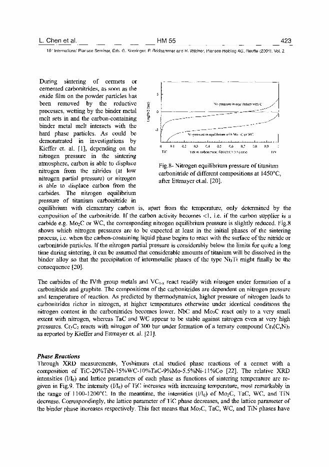
L. Chen et al. HM 55 423
15" International Plansee Seminar, Eds. G. Kneringer, P. Rddhammer and H. Wildner, Plansee Holding AG, Reutte (2001), Vol. 2
5
-5^•^" Ni -pressure i
. . . < " . i . . . . i . . . . i . . . .
N2 -pressure in ec
n equilibrium with Mo
1 . . . . I . . . . ! . . .
uilibrium with C S
——-~"
" ^
iC or WC
. i , , , . i . , . . i . , . .
0.3 0.4 0,5 0,6 0,7
TiN in carbonitride; TiN/(TiOTiN) ratio
0,9 ]
TiN
Fig. 8- Nitrogen equilibrium pressure of titaniumcarbonitride of different compositions at 1450°C,after Ettmayer et.al. [20].
During sintering of cermets orcemented carbonitrides, as soon as theoxide film on the powder particles hasbeen removed by the reductiveprocesses, wetting by the binder metalmelt sets in and the carbon-containingbinder metal melt interacts with thehard phase particles. As could bedemonstrated in investigations byKieffer et. al. [1], depending on thenitrogen pressure in the sinteringatmosphere, carbon is able to displacenitrogen from the nitrides (at lownitrogen partial pressure) or nitrogenis able to displace carbon from thecarbides. The nitrogen equilibriumpressure of titanium carbonitride inequilibrium with elementary carbon is, apart from the temperature, only determined by thecomposition of the carbonitride. If the carbon activity becomes <1, i.e. if the carbon supplier is acarbide e.g. M02C or WC, the corresponding nitrogen equilibrium pressure is slightly reduced. Fig.8shows which nitrogen pressures are to be expected at least in the initial phases of the sinteringprocess, i.e. when the carbon-containing liquid phase begins to react with the surface of the nitride orcarbonitride particles. If the nitrogen partial pressure is considerably below the limits for quite a longtime during sintering, it can be assumed that considerable amounts of titanium will be dissolved in thebinder alloy so that the precipitation of intermetallic phases of the type Ni3Ti might finally be theconsequence [20].
The carbides of the IVth group metals and VC,.X react readily with nitrogen under formation of acarbonitride and graphite. The compositions of the carbonitrides are dependent on nitrogen pressureand temperature of reaction. As predicted by thermodynamics, higher pressure of nitrogen leads tocarbonitrides richer in nitrogen, at higher temperatures otherwise under identical conditions thenitrogen content in the carbonitrides becomes lower. NbC and M02C react only to a very smallextent with nitrogen, whereas TaC and WC appear to be stable against nitrogen even at very highpressures. 0 ^ 2 reacts with nitrogen of 300 bar under formation of a ternary compound Cr3(C,N)2
as reported by Kieffer and Ettmayer et. al. [21].
Phase ReactionsThrough XRD measurements, Yoshimura et.al studied phase reactions of a cermet with acomposition of TiC-20%TiN-15%WC-10%TaC-9%Mo-5.5%Ni-ll%Co [22]. The relative XRDintensities (I/Io) and lattice parameters of each phase as functions of sintering temperature are re-given in Fig.9. The intensity (Wo) of TiC increases with increasing temperature, most remarkably inthe range of 1100-1200°C. In the meantime, the intensities (I/Io) of Mo2C, TaC, WC, and TiNdecrease. Correspondingly, the lattice parameter of TiC phase decreases, and the lattice parameter ofthe binder phase increases respectively. This fact means that M02C, TaC, WC, and TiN phases have
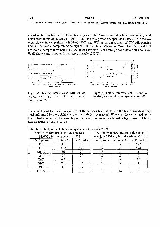
424 HM55 L. Chen et al.15" International Plansee Seminar, Eds. G. Kneringer, P. Rodhammer and H. Wildner, Plansee Holding AG, Reutte (2001), Vol. 2
considerably dissolved in TiC and binder phase. The M02C phase dissolves most rapidly andcompletely disappears already at 1200°C. TaC and WC phases disappear at 1300°C. TiN dissolvesmore slowly in comparison with Mo2C, TaC, and WC. A certain amount of TiN still remainsundissolved even at temperatures as high as 1400°C. The dissolution of M02C, TaC, WC, and TiNobserved at temperatures below 1300°C must have taken place through solid state diffusion, sinceliquid phase starts to appear first at approximately 1300°C.
TiC
— - - "
— — ; _ " • - -
TiN
>w c """•---
700 800 900 1000 1100 1200 1300 1400 15O0
Sintering temperature: "C
Fig.9 (a)- Relative intensities of XRD of Mo,Mo2C, TaC, TiN and TiC vs. sinteringtemperature [22].
900 1000 1100 1200 1300 1400 1500
Sintering temperature; °C
Fig.9 (b)- Lattice parameters of TiC and Nibinder phase vs. sintering temperature [22].
The solubility of the metal components of the carbides (and nitrides) in the binder metals is verymuch influenced by the stoichiometry of the carbides (or nitrides). Whenever the carbon activity islow (sub-stoichiometry), the solubility of the metal component can be rather high. Some solubilitydata are listed in Table 3 [23-24].
Table 3- Solubility of hard phases in liquid and solid metals [23-24]Solubility of hard phases in liquid metals at
1400°C after Ettmayer et. al. [23]Hard phase
TiCTiN
Mo2CWCTaCNbCVC
Cr3C2
in Ni; wt%11
<0.536276.37.014-
in Co; wt%10
<0.539396.38.519-
Solubility of hard phase in solid bindermetals at 1250°C after Edwards et. al. [24]in Ni; wt%
1<0.1
132235-
12
in Co; wt%5
<0.181253-12
in Fe; wt%<0.5<0.1
57
0.51-
8
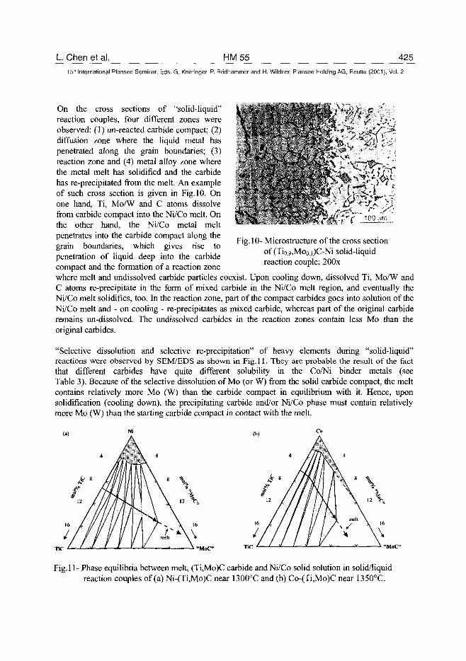
L Chen et al. HM55 425
15'h International Plansee Seminar, Eds. G. Kneringer, P. Rodhammer and H. Wildner, Plansee Holding AG, Reutte (2001), Vol. 2
V
On the cross sections of "solid-liquid"reaction couples, four different zones wereobserved: (1) un-reacted carbide compact; (2)diffusion zone where the liquid metal haspenetrated along the grain boundaries; (3)reaction zone and (4) metal alloy zone wherethe metal melt has solidified and the carbidehas re-precipitated from the melt. An exampleof such cross section is given in Fig. 10. Onone hand, Ti, Mo/W and C atoms dissolvefrom carbide compact into the Ni/Co melt. Onthe other hand, the Ni/Co metal meltpenetrates into the carbide compact along thegrain boundaries, which gives rise topenetration of liquid deep into the carbidecompact and the formation of a reaction zonewhere melt and undissolved carbide particles coexist. Upon cooling down, dissolved Ti, Mo/W andC atoms re-precipitate in the form of mixed carbide in the Ni/Co melt region, and eventually theNi/Co melt solidifies, too. In the reaction zone, part of the compact carbides goes into solution of theNi/Co melt and - on cooling - re-precipitates as mixed carbide, whereas part of the original carbideremains un-dissolved. The undissolved carbides in the reaction zones contain less Mo than theoriginal carbides.
"Selective dissolution and selective re-precipitation" of heavy elements during "solid-liquid"reactions were observed by SEM/EDS as shown in Fig. 11. They are probable the result of the factthat different carbides have quite different solubility in the Co/Ni binder metals (seeTable 3). Because of the selective dissolution of Mo (or W) from the solid carbide compact, the meltcontains relatively more Mo (W) than the carbide compact in equilibrium with it. Hence, uponsolidification (cooling down), the precipitating carbide arid/or Ni/Co phase must contain relativelymore Mo (W) than the starting carbide compact in contact with the melt.
Fig. 10- Microstructure of the cross sectionof (Tio,9,Mo0.i)C-Ni solid-liquidreaction couple; 200x
MoC" TiC
Fig.l 1- Phase equilibria between melt, (Ti,Mo)C carbide and Ni/Co solid solution in solid/liquidreaction couples of (a) Ni-(Ti,Mo)C near 1300°C and (b) Co-(Ti,Mo)C near 1350°C.
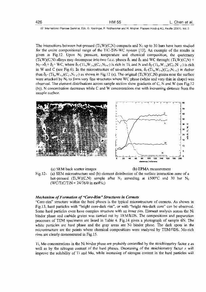
426 HM55 L Chen et al.15" International Plansee Seminar, Eds. G. Kneringer, P. Rodhammer and H. Wildner, Plansee Holding AG, Reutte (2001), Vol. 2
The interactions between hot-pressed (Ti,W)(C,N) compacts and N2 up to 30 bars have been studiedfor the entire compositional range of the TiC-TiN-WC system [13]. An example of the results isgiven in Fig. 12. Upon N2 pressure, temperature and chemical composition, the quaternary(Ti,W)(C,N) alloys may decompose into two f e e . phases 8i and 62 and WC through: (Ti,W)(C,N) +N2->8,+ 82+ WC, where 8i-(Tix,W,.x)(Cx-,N,.x-) is rich in Ti, and N and 52-(Tiy,W1.y)(Cy.,Ni.y) is richin W and C (see Fig.6). In the microstructure of un-attached area, 8i-(Tix,Wi.x)(Cx,Ni.x) is darkerthan 82- (Tiy,Wi-y)(CysNi-y0 as shown in Fig. 12 (a). The original (Ti,W)(C,N) grains near the surfacewere attacked by N2 to form very fine structures where WC phase (white and very thin in shape) wasobserved. The element distributions across sample section show gradients of C, N and W (see Fig. 12(b)). N concentration decreases while C and W concentrations rise with increasing distance from thesample surface.
60
54
48
42
36 "
530 -
I-24 *
18 %
12
80 100 120 140 160 180 200
distance / microns
(a) SEM back scatter images (b) EPMA measurementFig. 12- (a) SEM microstructure and (b) element distribution of the surface interaction zone of a
hot-pressed (Ti,W)(C,N) sample after N2 annealing at 1500°C and 30 bar N2
(WC/TiC/TiN = 24/76/0 in mol%;)
Mechanism of Formation of "Core-Rim " Structures in Cermets"Core-rim" structure within the hard phases is the typical microstructure of cermets. As shown inFig. 13, hard particles with "bright core-dark rim", or with "bright rim-dark core" can be observed.Some hard particles even have complex structure with an inner rim. Element analysis across the Nibinder phase and carbide grains was carried out by TEM/EDS. The compositions and preparationprocesses of TEM specimens are listed in Table 4. Fig.14 gives a photograph of sample 6N. Thewhite particles are hard phase and the gray areas are Ni binder phase. The dark spots in themicrostructure are the points where chemical compositions were analyzed by TEM/EDS. Mo-richrims are clearly demonstrated in Fig. 15.
Ti, Mo concentrations in the Ni binder phase are probably controlled by the stoichiometry factor z aswell as by the nitrogen content of the hard phases. Decreasing of the stoichiometry factor z willimprove the solubility of Ti and Mo, while increasing of nitrogen content in the hard particles will
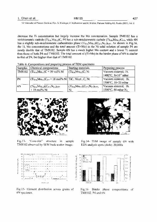
L Chen et al. HM55 427
15" International Plansee Seminar, Eds. G. Kneringer, P. Rodhammer and H. Wildner, Plansee Holding AG, Reutte (2001), Vol. 2
decrease the Ti concentration but largely increase the Mo concentration. Sample TM8102 has astoichiometric carbide (Ti0.8,Moo.2)C, P4 has a sub-stoichiometric carbide (Ti0.8,Moo.2)Co.9, while 6Nhas a slightly sub-stoichiometric carbonitrides phase (Tio.8,Moo.2)(Co.7,No.3)o.97- As shown in Fig. 16,the Ti, Mo concentrations and the total amount (Ti+Mo) in the Ni solid solution of sample P4 arenearly double that of TM8102. Sample 6N has a much higher Mo content and a lower Ti contentthan those of both P4 and TM8102. The total amount of (Ti+Mo) in the binder phase of 6N is similarto that of P4, but higher than that of TM8102.
Table 4- Compositions and preparing process of TEM specimensSamplesTM8102
P4
6N
Chemical compositions(Tio.8,Moo.2)C + 50 vol% Ni
(Tio.8,Mo0.2)Co.9 + 18 mol% Ni
(Tio.8,MOo.2)(Co.7,N0.3)o.97
+ 18mol%Ni
Starting materials(Ti0.8,Moo.2)C; Ni
TiC, Mo2C, C, Ni
(Ti0.8,MOo.2)(Co.7,No.3)o.97,
Ni
Preparing processVacuum sintered; lh.1400°C, 8xl0"2 mbarVacuum sintered; lh.1500°C, 10-20 mbarVacuum sintered; lh.1500°C, 80 mbar N2
Fig. 13- "Core-rim" structure in sampleTM8102 observed by SEM back scatter image.
Fig. 14- TEM image of sample 6N withEDS analysis spots (dark); 20,000x
Fig. 15- Element distribution across grains of Fig. 16- Binder phase compositions of6N specimen. TM8102, P4 and 6N
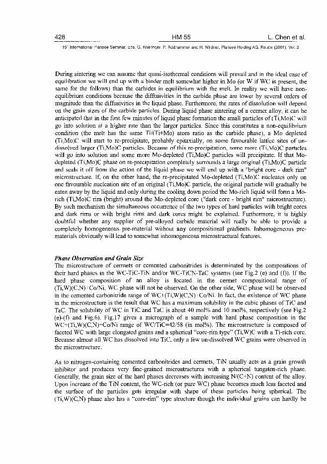
428 HM55 L. Chen et al.15" International Plansee Seminar, Eds. G. Knehnger, P. Rodhammer and H. Wildner, Plansee Holding AG, Reutte (2001), Vol. 2
During sintering we can assume that quasi-isothermal conditions will prevail and in the ideal case ofequilibration we will end up with a binder melt somewhat higher in Mo (or W if WC is present, thesame for the follows) than the carbides in equilibrium with the melt. In reality we will have non-equilibrium conditions because the diffusivities in the carbide phase are lower by several orders ofmagnitude than the diffusivities in the liquid phase. Furthermore, the rates of dissolution will dependon the grain sizes of the carbide particles. During liquid phase sintering of a cermet alloy, it can beanticipated that in the first few minutes of liquid phase formation the small particles of (Ti,Mo)C willgo into solution at a higher rate than the larger particles. Since this constitutes a non-equilibriumcondition (the melt has the same Ti/(Ti+Mo) atom ratio as the carbide phase), a Mo depleted(Ti,Mo)C will start to re-precipitate, probably epitaxially, on some favourable lattice sites of un-dissolved larger (Ti,Mo)C particles. Because of this re-precipitation, some more (Ti,Mo)C particleswill go into solution and some more Mo-depleted (Ti,Mo)C particles will precipitate. If that Mo-depleted (Ti,Mo)C phase on re-precipitation completely surrounds a large original (Ti,Mo)C particleand seals it off from the action of the liquid phase we will end up with a "bright core - dark rim"microstructure. If, on the other hand, the re-precipitated Mo-depleted (Ti,Mo)C nucleates only onone favourable nucleation site of an original (Ti,Mo)C particle, the original particle will gradually beeaten away by the liquid and only during the cooling down period the Mo-rich liquid will form a Mo-rich (Ti,Mo)C rim (bright) around the Mo-depleted core ("dark core - bright rim" microstructure).By such mechanism the simultaneous occurrence of the two types of hard particles with bright coresand dark rims or with bright rims and dark cores might be explained. Furthermore, it is highlydoubtful whether any supplier of pre-alloyed carbide material will really be able to provide acompletely homogeneous pre-material without any compositional gradients. Inhomogeneous pre-materials obviously will lead to somewhat inhomogeneous microstructural features.
Phase Observation and Grain SizeThe microstructure of cermets or cemented carbonitrides is determinated by the compositions oftheir hard phases in the WC-TiC-TiN and/or WC-TiCN-TaC systems (see Fig.2 (e) and (f)). If thehard phase composition of an alloy is located in the cermet compositional range of(Ti,W)(C,N)+Co/Ni, WC phase will not be observed. On the other side, WC phase will be observedin the cemented carbonitride range of WC+(Ti,W)(C,N)+Co/Ni. In fact, the existence of WC phasein the microstructure is the result that WC has a maximum solubility in the cubic phases of TiC andTaC. The solubility of WC in TiC and TaC is about 40 mol% and 10 mol%, respectively (see Fig.2(e)-(f) and Fig.6). Fig. 17 gives a micrograph of a sample with hard phase composition in theWC+(Ti,W)(C,N)+Co/Ni range of WC/TiC=42/58 (in mol%). The microstructure is composed offaceted WC with large elongated grains and a spherical "core-rim type" (Ti,W)C with a Ti-rich core.Because almost all WC has dissolved into TiC, only a few un-dissolved WC grains were observed inthe microstructure.
As to nitrogen-containing cemented carbonitrides and cermets, TiN usually acts as a grain growthinhibitor and produces very fine-grained microstructures with a spherical tungsten-rich phase.Generally, the grain size of the hard phases decreases with increasing N/(C+N) content of the alloy.Upon increase of the TiN content, the WC-rich (or pure WC) phase becomes much less faceted andthe surface of the particles gets irregular with shape of these particles being spherical. The(Ti,W)(C,N) phase also has a "core-rim" type structure though the individual grains can hardly be
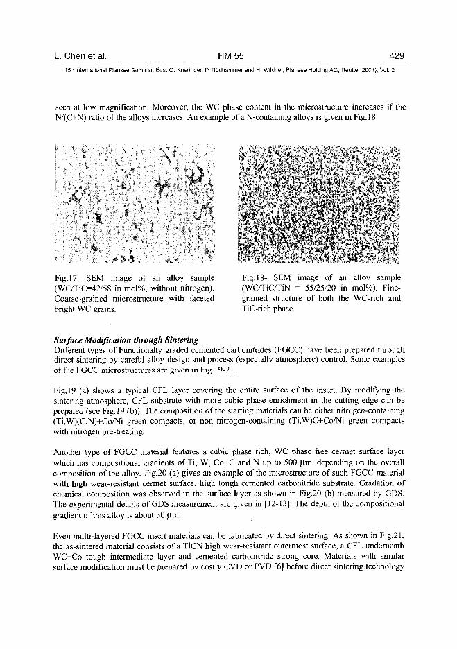
L. Chen et al. HM55 42915" International Plansee Seminar, Eds. G. Kneringer, P. Rodhammer and H. Wildner, Plansee Holding AG, Reutte (2001), Vol. 2
seen at low magnification. Moreover, the WC phase content in the microstructure increases if theN/(C+N) ratio of the alloys increases. An example of a N-containing alloys is given in Fig. 18.
V -
- * * . . ,
* v \
" . - ' < . "
Fig. 17- SEM image of an alloy sample(WC/TiC=42/58 in mol%; without nitrogen).Coarse-grained microstructure with facetedbright WC grains.
Fig. 18- SEM image of an alloy sample(WC/TiC/TiN = 55/25/20 in mol%). Fine-grained structure of both the WC-rich andTiC-rich phase.
Surface Modification through SinteringDifferent types of Functionally graded cemented carbonitrides (FGCC) have been prepared throughdirect sintering by careful alloy design and process (especially atmosphere) control. Some examplesof the FGCC microstructures are given in Fig. 19-21.
Fig. 19 (a) shows a typical CFL layer covering the entire surface of the insert. By modifying thesintering atmosphere, CFL substrate with more cubic phase enrichment in the cutting edge can beprepared (see Fig. 19 (b)). The composition of the starting materials can be either nitrogen-containing(Ti,W)(C,N)+Co/Ni green compacts, or non nitrogen-containing (Ti,W)C+Co/Ni green compactswith nitrogen pre-treating.
Another type of FGCC material features a cubic phase rich, WC phase free cermet surface layerwhich has compositional gradients of Ti, W, Co, C and N up to 500 u.m, depending on the overallcomposition of the alloy. Fig.20 (a) gives an example of the microstructure of such FGCC materialwith high wear-resistant cermet surface, high tough cemented carbonitride substrate. Gradation ofchemical composition was observed in the surface layer as shown in Fig.20 (b) measured by GDS.The experimental details of GDS measurement are given in [12-13]. The depth of the compositionalgradient of this alloy is about 30 |im.
Even multi-layered FGCC insert materials can be fabricated by direct sintering. As shown in Fig.21,the as-sintered material consists of a TiCN high wear-resistant outermost surface, a CFL underneathWC+Co tough intermediate layer and cemented carbonitride strong core. Materials with similarsurface modification must be prepared by costly CVD or PVD [6] before direct sintering technology
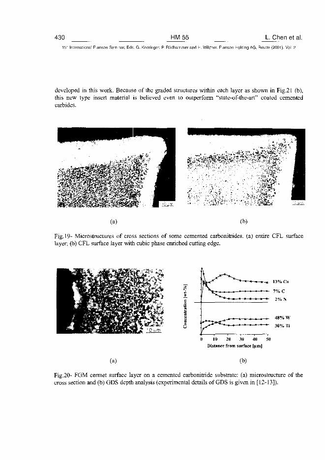
430 HM55 L Chen et al.15- International Plansee Seminar, Eds. G. Kneringer, P. Rodhammer and H. Wildner, Plansee Holding AG, Reutte (2001), Vol. 2
developed in this work. Because of the graded structures within each layer as shown in Fig.21 (b),this new type insert material is believed even to outperform "state-of-the-art" coated cementedcarbides.
(a) (b)
Fig. 19- Microstructures of cross sections of some cemented carbonitrides. (a) entire CFL surfacelayer; (b) CFL surface layer with cubic phase enriched cutting edge.
(a)
48% W
30% Ti
0 10 20 30 40 SO
Distance from surface [fimj
(b)
Fig.20- FGM cermet surface layer on a cemented carbonitride substrate: (a) microstructure of thecross section and (b) GDS depth analysis (experimental details of GDS is given in [12-13]).
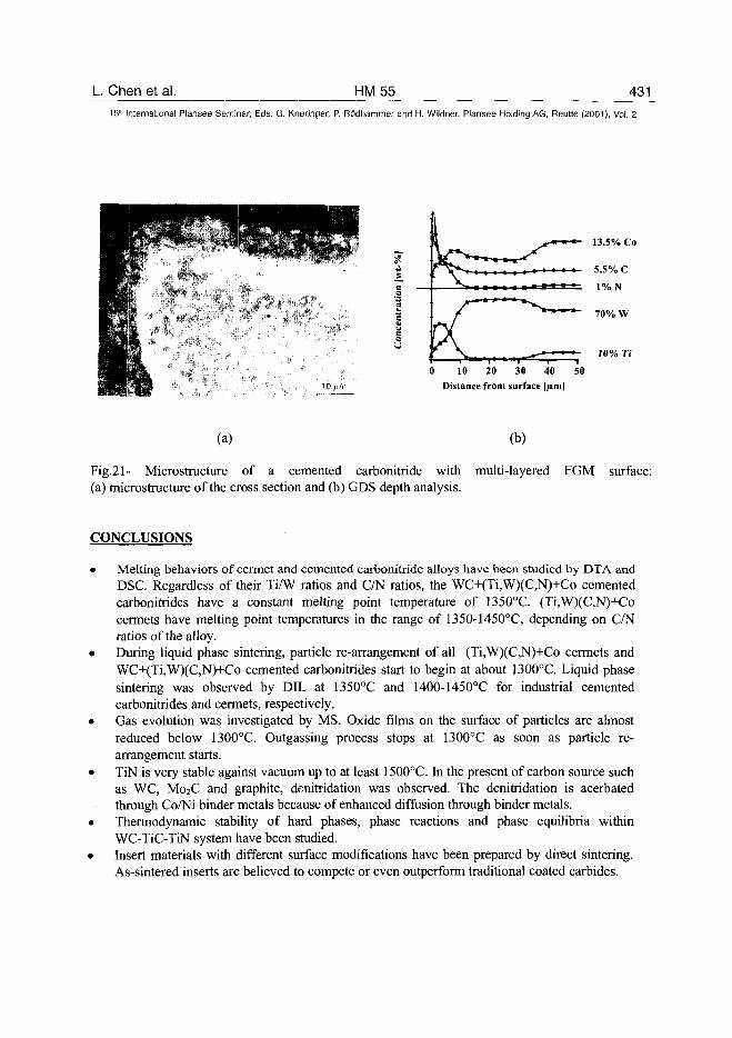
L. Chen et al. HM55 43115" International Plansee Seminar, Eds. G. Kneringer, P. Rodhammer and H. Wildner, Plansee Holding AG, Reutte (2001), Vol. 2
13.5% Co
7 0 % W
10% Ti
0 10 20 30 40 50
Distance from surface [jim|
(a)
Fig.21- Microstructure of a cemented carbonitride with(a) microstructure of the cross section and (b) GDS depth analysis.
(b)
multi-layered FGM surface:
CONCLUSIONS
• Melting behaviors of cermet and cemented carbonitride alloys have been studied by DTA andDSC. Regardless of their Ti/W ratios and C/N ratios, the WC+(Ti,W)(C,N)+Co cementedcarbonitrides have a constant melting point temperature of 135O°C. (Ti,W)(C,N)+Cocermets have melting point temperatures in the range of 1350-1450°C, depending on C/Nratios of the alloy.
• During liquid phase sintering, particle re-arrangement of all (Ti,W)(C,N)+Co cermets andWC+(Ti,W)(C,N)+Co cemented carbonitrides start to begin at about 1300°C. Liquid phasesintering was observed by DIL at 1350°C and 1400-1450°C for industrial cementedcarbonitrides and cermets, respectively.
• Gas evolution was investigated by MS. Oxide films on the surface of particles are almostreduced below 1300°C. Outgassing process stops at 1300°C as soon as particle re-arrangement starts.
• TiN is very stable against vacuum up to at least 1500°C. In the present of carbon source suchas WC, M02C and graphite, denitridation was observed. The denitridation is acerbatedthrough Co/Ni binder metals because of enhanced diffusion through binder metals.
• Thermodynamic stability of hard phases, phase reactions and phase equilibria withinWC-TiC-TiN system have been studied.
• Insert materials with different surface modifications have been prepared by direct sintering.As-sintered inserts are believed to compete or even outperform traditional coated carbides.
432 HM55 L Chen et al.15" International Plansee Seminar, Eds. G. Kneringer, P. Rodhammer and H. Wildner, Plansee Holding AG, Reutte (2001), Vol. 2
ACKNOWLEDGMENTS
The authors would like to acknowledge Widia GmbH, Germany and Austrian Academic ExchangeService (OEAD) for partially financial support of the research. Very valuable discussions andinformation exchange from Dr. van den Berg, Dr. Dreyer, Dipl-Ing. Kassel and Dipl.-Ing. Daub ofWidia GmbH are greatly appreciated. Thanks are also due to Dr. Sejc,Dipl-Ing. Garcia, Mr. Krai of TU-Wien and Ing. Trampert of ARCS Seibersdorf, Austria, for theircontribution to some of the experiments. Dr. Limin Chen would also like to thankhis wife Dr. Hua Ge and Mr. Cippel of SinterMet, LLC. for their assistance during the preparation ofthe manuscript.
REFERENCES
1. R. Kieffer, P. Ettmayer and M. Freudhofmeier: "About Nitrides and Carbonitrides andNitride-Based Cemented Hard Alloys", Modern Development in Powder Metallurgy,Vol. 5, p. 201-214, edited by H. Hausner, 1971.
2. P. Ettmayer and W. Lengauer: "The Story of Cermets", Powder MetallurgyInternational, Vol.21, No.2, p. 37-38, 1989.
3. H. Pastor: "Titanium Carbonitride Based Hard Alloys for Cutting Tools", MaterialsScience and Engineering, A105/106, p. 401-409, 1988
4. P. Ettmayer, H. Kolaska, W. Lengauer and K. Dreyer: "Ti(C,N) Cermets - Metallurgyand Properties", Int. J. Refract. Met. & Hard Meter. Vol.13, p. 343, 1995
5. H. Doi: "Advanced TiC and TiC-TiN based cermets" Proc. Of the 2nd Int. Conf. Scienceof Hard Materials, p. 489-523, 1986.
6. H. van den Berg, U. Konig, V. Sottke, R. Tabersky and H. Westphal: "Die Bedeutungvon modifizierten Randzonen fur die Hartmetallbeschichtung", in "Hartstoffe,Hartstoffschichten, Werkzeuge, Verschleissschutz" of Pulvermetallurgie in Wissenschaftund Praxis Band 13, p. 77-87, edited by R. Ruthardt, Published by Werkstoff-Informationsgesellschaft mbH, 1997.
7. H. Suzuki, K. Hayashi and Y. Taniguchi: "The P-Free Layer near the Surface ofVacuum-Sintered WC-(3-Co Alloys Containing Nitrogen", Transactions of the JapanInstitute of Metals, Vol 22, No. 11, p. 758-764, 1981.
8. W. C. Yohe: "The development of Cubic-Carbide-Free Surface Layers in CementedCarbides without Nitrogen", Proceedings of the 13th International Plansee seminar, Eds.H. Bildstein and R. Eck, metallwerk plansee, Vol.2, p. 151-168, 1993.
9. M. Schwarzkopf, H. E. Exner and H. F. Fischmeister. "Kinetics of CompositionalModification of (W,Ti)C-WC-Co Alloy surfaces", Materials Science and Engineering,A105/106, p. 225-231, 1988.
10. K. Hayashi, H. Suzuki and Y. Doi: "Effect of p-free Layer of Substrate on properties ofCemented Carbide Coated with TiC by CVD Process", Journal of Japan Society ofPowder and Powder Metallurgy, Vol. 32, No. 7, p. 28-31, September, 1985.
11. K. Tsuda, A. Ikegaya, K. Isobe, N. Kitagawa and T. Nomura: "Development ofFunctionally Graded Sintered Hard Materials", Powder Metallurgy, Vol. 39, No.4,p. 296-300, 1996.
_L_Chenet_al. HM 55 43315'" International Plansee Seminar, Eds. G. Kneringer, P. Rodhammer and H. Wildner, Plansee Holding AG, Reutte (2001), Vol. 2
12. L. Chen and W. Lengauer: "Metallurgical Mechanisms and Processing Technologies ofFGM (Ti,W)(C,N)-Co Hardmetals", Internal reports of Austrian Research Center,OEFZS-A—4185, September. 1997
13. L. Chen and W. Lengauer: "Metallurgical Mechanisms and Processing Technologies ofFGM (Ti,W)(C,N)-Co Hardmetals", Internal reports of Austrian Research Center,OEFZS-A-4516,Nov. 1998
14. L. Chen, W. Lengauer and K. Dreyer: "Advances in Modern Nitrogen-ContainingHardmetals and Cermets", Proceeding of the European Conference on Advances in HardMaterials Production sponsored by EHMG & EPMA, Turin, Italy, p. 463-473.November 8-10, 1999.
15. W. Lengauer, L. Chen, J. Garcia, V. Ucakar, K. Dreyer, D. Kassel and H. W. Daub:"Diffusion-Controlled Surface Modification of Functionally-Gradient (Ti,W)C-BasedCemented Carbonitrides", Proceedings of the 1999 International Conference on PowderMetallurgy & Particulate Materials sponsored by the Metal Powder Industries Federationand APMI international, Vol. 3, Part 10, p.85-96, June 20-24, 1999, Vancouver, B.C.Canada,
16. L. Chen, W. Lengauer, H. W. Daub, K. Dreyer and D. Kassel, German PatentDE 198 45 376 Al, January 13, 2000.
17. K. Dreyer, W. Daub, H. Holzhuer, S. Orths, D. Kassel and K. Rodiger: "Trends in derHartmetallfertigung: Legierungen, Verfahren, Produkte", in "Hartstoffe,Hartstoffschichten, Werkzeuge, Verschleissschutz" of Pulvermetallurgie in Wissenschaftund Praxis Band 13, p. 3-27, edited by R. Ruthardt, Published by Werkstoff-Informationsgesellschaft mbH, 1997.
18. P. Ettmayer, H. Kolaska and K. Dreyer: "Effect of the Sintering Atmosphere on theProperties of Cermets", Powder Metallurgy International, Vol.23, No.4, p. 224-229,1991.
19. E. Rudy: "Boundary Phase Stability and Critical Phenomena in Higher Order SolidSolution Systems", Journal of the Less-Common Metals. Vol. 3, p. 343-70, 1973.
20. P. Ettmayer, H. Kolaska and K. Dreyer: " Effect of the Sintering Atmosphere on theProperties of Cermets", pmi Vol. 23, No. 4, p. 224-230, 1991.
21. R. Kieffer and P. Ettmayer: "Grundlagen und Neuentwicklungen auf dem Gebietmetallischer und nichtmetallischer Hartstoffe", Chemie-Ing.-Tech. 42 Jahrg. /Nr. 9/10, p.589-599, 1970.
22. H. Yoshimura, T. Sugizawa, K. Nishigaki and H, Doi: "Reaction Occurring DuringSintering and the Characteristics of TiC-20TiN-15WC-10TaC-9Mo-5.5Ni-llCoCermets", R&HM December 1983, p. 170-174.
23. P. Ettmayer, H. Kolaska, W. Lengauer und K. Dreyer: " Cermetlegierungen-Metallurgieund Eigenschaften", Proceedings of the 13th. International Plansee Seminar '93, HM2,Vol. 4, p. 191-208, May 24-28, 1993, Tirol, Austria.
24. R. Edwards and T. Raine: "The Solid Solubility of Some Stable Carbides in Cobalt,Nickel and Iron at 1250°C", Proc. 1st Int. Plansee Seminar, p. 232, 1952.
AT0100471434 HM58 S.S. Ordanyan et al.
15" International Plansee Seminar, Eds. G. Kneringer, P. Rodhammer and H. Wildner, Plansee Holding AG, Reutte (2001), Vol. 2
PROPERTIES OF HARD ALLOYS ON THE BASIS OF WC-Co
WITH THE ADDITIVES OF NANODSIPERSE TiN
S.S.Ordanyan, I. Zalite*, T.E.Andronova, M.A.VIadimirova, I.B.Pantelejev
St. Petersburg State Institute of Technology, St. Petersburg, Russia
*Riga Technical University, Institute of Inorganic Chemistry, Salaspils, Latvia
Summary:
The addition of nanodisperse titanium nitride (specific surface area of 20 - 30m2/g, medium diameter of grains of 50 - 100 nm) to the starting hard alloyWC-Co in the stage of wet grinding allows to get some advantages:
- the growth of WC grains is retarded by the nanoparticles of TiN, beingas a barrier for the process of secondary crystallisation, and the toughnessof hard alloy is being increased due to the formation of finely dispersedstructure;- the exploitation characteristics of cutting instruments are increased dueto the volume alloying by means of titanium nitride having a decreasedadhesion to the treated metal and decreased coefficient of friction;- the formation of diffusion porosity is being eliminated due to the smallsize of TiN during the unavoidable dissolution of WC in TiN.
Keywords:
Hard alloys, WC-Co, nanodisperse TiN, properties
1. Introduction:
Hard alloys on the basis of WC-Co system are the main material forpreparation of metal cutting tools. It is possible to increase up to 50-100% theefficiency (wear resistance) of cutting hard alloy plates covering them withcoatings from titanium carbide or nitride, also combined multi-layer coatingsare possible, combined with the final layer from AI2O3 because the contactinteraction of metals with refractory compounds (adhesion) decreases in afollowing row: carbide - nitride - oxide [1]. The thickness of coatings
S.S. Ordanyan et al. HM 58 435^15'" International Plansee Seminar, Eds. G. Kneringer, P. Rddhammer and H. Wildner, Plansee Holding A6, Reutte (2001), Vol. 2
prepared by means of the CVD-process (chemical deposition from the gasphase) is of 7-20 |nm [2]. The quality of coatings is a rather sensitive on exactkeeping of technological parameters and gaseous raw materials purity. Inorder to form a dense coating with a base it is necessary to prepare thesurface of cutting plates (polishing, purifying, additional carbonising of thesurface layer).
We have suggested in a stage of wet milling to add in the composition of hardalloy titanium nitride as a component with a less adhesion to the treatedmetal. This titanium nitride is made by plasmachemical synthesis and is ofhigh dispersity (specific surface area of 20-30 m2/g, d50 = 6 0 - 9 0 nm). Fromthe point of view of authors the addition of exactly nanodisperse TiN to thealloy will make possible the following advantages:
- nanodisperse TiN particles (if they are distributed regularly in a volumeof sample) being a original barrier against the processes of the secondrecrystallization, will prevent the growth of WC grains and increase thestrength of hard alloy due to formation of finely dispersed structure;
- volume alloying with TiN possessing less adhesion to the treated metaland decreased friction coefficient will improve exploitationcharacteristics of cutting tool;
- TiN, acting similarly as a coating, is added in a stage of wet milling, soconsiderably simplifies the technological process and decreases theprime cost of cutting tool;
- small size of TiN particles will prevent the formation of diffusion porositywhen WC dissolves unavoidably in TiN.
WC and TiN as a majority of refractory hard solutions in a process of thermaltreating could form the cubic phase of a complex carbonitride, moreover, thisprocess could be accelerated in the presence of a liquid phase (cobalt) whichsignificantly dissolves WC. Considering the unavoidable difference in thehetero-diffusion coefficients of WC and TiN, it is possible to expect formationof internal grain diffusion porosity (the Frenkel effect). The process ofcomplex cubic carbonitride formation (with the common formula W^xTixC^yNy) is not described in scientific literature yet, there are no also the data aboutthe reciprocal solubility of titanium nitride and tungsten carbide. Nevertheless,there is an enough great amount of patent documents where the compositionand preparation methods of instrumental hard alloys on the basis of tungstencarbide with the additives of nitride components (mainly TiN, simple andcomposite carbonitrides). In [3] the dependence of mechanical strength, wearresistance and other properties of alloy WC-TiC-TaC-TiN-Co on the ratio ofTiN/(TaC+TiN) was investigated. Up to 30% titanium carbide was added to
436 HM 58 S.S. Ordanyan et al.15" International Plansee Seminar, Eds. G. Kneringer, P. Rodhammer and H. Wildner, Plansee Holding AG, Reutte (2001), Vol. 2
the mixture WC+TiC, the content of metal binder (cobalt) was 8 - 8,5 wt.%. Itwas ascertained that the increase of TiN content (and the correspondingdecrease of TaC) results in a growth of strength. The reason of thisphenomenon probably is formation of fine phase of complex carbonitridesimultaneously with the formation of tungsten carbide, which was stated byauthors. It was noted that after sintering in vacuum the wear resistanceincreases.
It was stated investigating properties of alloys WC-TiN-Co [4] containing up to15 wt.% of TiN that addition of TiN results in appearance of an increasedamount of cubic phase in comparison with the similar alloys WC-TiC-Co. Thiswould be an indirect approval of the fact that the solubility of WC is higher inTiN than in TiC. Authors point out a peculiarity of microstructure - a verysmall interaction zone around TiN grains, and explain it by the negativenitrogen affinity to tungsten at high temperature. From our point of view thereason of this phenomena is another - if the sintering temperature is of 1400- 1430 °C even the presence of liquid phase could not be the reason ofremarkable velocity of complex titanium - tungsten carbide formation.
Authors [5] have shown that hard alloys Ti(C,N)-WC-Ni possess low strengthif the content of tungsten carbide is low. Probably, in this case the analogycould be observed with the alloys of TK group (WC-TiC-Co) where thetitanium carbide content must be less than 30 wt.% to get enough strength ofalloy.
2. Experimental:
In the following paper the mechanism of composite carbonitrides formation insystem WC-TiN was investigated at first. Tungsten carbide and titaniumnitride (Doneck plant of chemicals, brand "pure", dispersity 10-30 \xm) as wellas titanium nitride prepared by the plasmachemical synthesis (specificsurface area SSA = 20-30 m2/g, d50 = 6 0 - 9 0 nm) were used as a rawmaterials. Components were mixed in alcohol for 60 minutes, mixture wasdried and then the samples pressed. The synthesis of carbonitrides wascarried out in nitrogen for 1 h at 1500, 1700 and 1900 °C isothermally.
Composition of prepared samples was determined by X-ray analysis bymeans of difractometer DRON-3 with the Cu anode and Ni filter (the range ofangles from 10 to 40°).
S.S. Ordanyan et al. HM 58 43715'h International Plansee Seminar, Eds. G. Kneringer, P. Rodhammer and H. Wildner, Plansee Holding AG, Reutte (2001), Vol. 2
It is obvious from X-ray analysis that in system WC-TiN in the case of coarsetitanium nitride the formation of composite cubic carbonitride is going onbeginning with the synthesis temperature 1500 °C. At 1900 °C internal graindiffusion porosity migrates mainly to the grain borders, forming great, mainlyspherical pores. The size of carbonitride grains is from 10 to 30 jam. If the TiNcontent is over 10 wt.% and the synthesis temperature is 1700 °C and more,the vacancies form in a metalloid sub-lattice of titanium nitride as a result ofthermal dissociation of nitrides. These vacancies are partially filled by carbonfrom tungsten carbide, resulting in appearing of W2C in a final product. If TiNis replaced by plasmachemically prepared nitride the appearing of W2C isregistered at the concentration of TiN above 5 wt.% (at synthesis temperature1700 °C). Therefore high dispersity of plasmachemical titanium nitride resultsin intensified decarbonization, the same process is facilitated by increasedamount of oxygen admixtures, which are determined by high SSA.
In the process of liquid-phase sintering tungsten half-carbide W2C reacts withthe fusion of cobalt with the following formation of complex carbides (W,Co)C,resulting in decreased strength and increased brittleness of hard alloy [6].The use of vibratory milling allows to apply more disperse mixtures forsintering, and this intensifies the process of carbonitride synthesis at lowertemperatures. For example, the vibratory milling of raw components in alcoholduring 10 - 15 h allows to obtain carbonitride at 1600 °C with the content of"kiln" titanium nitride up to 15%, for nanodisperse TiN - up to 10%, free ofWC and W2C. The increased time of vibratory milling results in appearing ofhalf-carbide W2C in the reaction products. Most probably, the reason of this isa partial oxidation of WC when its specific surface increases during vibratorymilling.
To ascertain the optimal way of technology of hard alloy WC-TiN-Co twomethods of samples preparation were used in this investigation to findphysico-mechanical properties dependent on structure (phase composition,size of phase components):
- previous synthesis of complex titanium - tungsten carbonitride at themass rate WC : TiN = 9 : 1 (using nanodisperse titanium nitride andvibratory milling for 10 h) at 1500 °C in nitrogen in order to obtain phaseW^xTixC-i-yNy, with its crushing and simultaneous vibratory milling withWC a the addition of 8 wt.% of cobalt (series 1);
- vibratory milling of 92 wt.% of mixture of tungsten carbide andnanodisperse titanium nitride (WC : TiN = 9 : 1 ) and 8 wt.% of cobalt(series 2).
438 HM 58 S.S. Ordanyan et a).
15-" International Plansee Seminar, Eds. G. Kneringer, P. Rodhammer and H. Wildner, Plansee Holding AG, Reutte (2001), Vol. 2
The starting powders of WC, Co, nanodisperse TiN and previouslysynthesized and crushed to the particle size of 0,1 - 0,3 mm complexhomogeneous carbonitride was loaded into vibratory mill filled with hard alloyballs BK6 (WC-6%Co) and alcohol, the ratio material : alcohol : balls was 1 :1 : 8 , and then milled for 60 h. Sample pellets were pressed at the pressureof 100 MPa form vacuum-dried and plasticizated mass. Samples weresintered isothermally for 1 h in vacuum at the temperature range 1400 - 1450
Shrinkage, density (GOST 20018-74), Rockwell hardness (GOST 20017-74),bending strength limit (GOST 20019-74, samples of A-type and non-standardsamples 3 x 3 x 30 mm) and Young modulus were estimated for sinteredsamples. The WC grain size and porosity of samples' ground joints wereestimated by means of automatic analyser "VideoTest-3.0".
Shrinkage of samples for both series in the limit of error was not practicallydependent on sintering temperature: for series 1 it was 23%, for series 2 -21,0-5-21,5%.
The dependence of bend strength limit on sintering temperature is shown inFig. 1. High absolute values of the bend strength were obtained on non-standard samples 3 x 3 x 30 mm. Therefore it was possible to determine theoptimum sintering temperature with a very high number of parallelexperiments but with a small amount of used material. The maximum strengthfor both of series lies in a temperature range of 1425 •*- 1435 °C. It ischaracteristic that the strength of hard alloy prepared without previoussynthesis of carbonitride (series 2) is significantly higher than for alloy ofseries 1.
It was stated by investigations of non-etched structures of ground joints thatthe porosity of hard alloy of series 2 is something higher (series 1 -0,2+0,4%, series 2 - 0,4^0,6%. The structure analysis of etched groundjoints reveals that hard alloy of series 2 has more finely grained structure (thesize of WC grains is 1-K5 [xm, for series 1 it is 2H-6 ^m) with the homogeneousdistribution of metal-binder. The use of previously synthesized carbonitridelevels the difference in particle size of WC and the cubic nitride-containingphase. In the case of utilization of plasmachemical titanium nitride due tosignificantly smaller size of its particles a more effective barrier is created tothe process of secondary recrystallization. It results in a formation of regularand finely dispersed hard alloy structure.
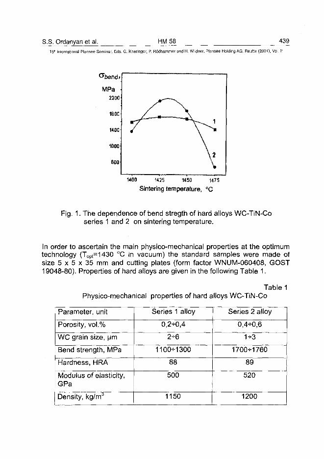
S.S. Ordanyan et al. HM58 43915lh International Plansee Seminar, Eds. G. Kneringer, P. Rodhammer and H. Wildner, Plansee Holding AG, Reutte (2001), Vol. 2
MPa2200
1800
1400
1000•
600'
/
1400 1425
Sintering
\
\ \
1450
temperature,
1
V
\
1475
°c
Fig. 1. The dependence of bend stregth of hard alloys WC-TiN-Coseries 1 and 2 on sintering temperature.
In order to ascertain the main physico-mechanical properties at the optimumtechnology (Topt=1430 °C in vacuum) the standard samples were made ofsize 5 x 5 x 35 mm and cutting plates (form factor WNUM-060408, GOST19048-80). Properties of hard alloys are given in the following Table 1.
Table 1Physico-mechanical properties of hard alloys WC-TiN-Co
Parameter, unit
Porosity, vol.%
WC grain size, urn
Bend strength, MPa
Hardness, HRA
Modulus of elasticity,GPa
Density, kg/m3
Series 1 alloy
0,2-0,4
2-6
1100-1300
88
500
1150
Series 2 alloy
0,4-0,6
1-3
1700-1760
89
520
1200
440 HM58 S.S. Ordanyan et al.15'n International Plansee Seminar, Eds. G. Kneringer, P. Rodhammer and H. Wildner, Plansee Holding AG, Reutte (2001), Vol. 2
The investigation of cutting properties showed that hard alloys of the series 2are better than the standard alloy BK8 (WC-8%Co) and possess the sameproperties as alloy T5K10 (WC-5%TiC-10%Co), but the preparationtechnology is more simple.
References:
1. Kislyi P.S. Cermets. Kiev, Naukova Dumka, 1975, 350 pp. (in Russian)2. Vityaz P.A., Dubrovskaya G.N., Kiriliyuk L.M. Gas-phase deposition of
coatings from titanium nitride. Minsk, Nauka i Technika, 1983, 96 pp. (inRussian)
3. Kobori Keiichi, Ucki Mitsuo, Fukawa Atsushi, Suzuki Hisashi. Someproperties of alloy WC-TiC-TaC-TiN-Co. J. Jap. Soc. Powder and PowderMet., 1987, v 34, No 5, pp. 217-221.
4. Tsuchiya Nobujiro, Terada Osamu, Sasaki Okira, Suzuki Hisashi. Someproperties of alloy WC-TiN-Co. J. Jap. Soc. Powder and Powder Met.,1990, v 37, No 4, pp. 562-565.
5. Sudzuki Keiichi. Properties of cermet Ti(C,N)-WC-Ni. Bull. Jap. Inst.Metals, 1985, April, special volume, p. 168.
6. Tretyakov V.I. Fundamentals of metal science and production technologyof sintered hard alloys. Moscow, Metallurgyia, 1976, 558 pp. (in Russian)
AT0100472H. Holzschuh HM 62 441_
15" International Plansee Seminar, Eds. G. Kneringer, P. Rodhammer and H. Wildner, Plansee Holding AG, Reutte (2001), Vol. 2
Chemical-Vapor Deposition of Wear Resistant Hard Coatings inthe Ti-B-C-N System: Properties and Metal-Cutting Tests
H. Holzschuh
Walter AG, D-72072 Tuebingen, Germany
Summary:
Cubic Ti(BxCyNz) (x+y+z=1) coatings were deposited on cemented carbidesusing chemical-vapor deposition (CVD). The Ti-B-C-N was maintained in thecubic phase by keeping the B content below 5%. The B:C:N ratio,microstructure, hardness and wear resistance of the coatings were controlledby varying the gas precursor flows in the CVD process. Results showed thatTiCN coatings containing B exhibited higher hardness but lower critical loads(Lc) for coating decohesion. Microprobe measurements revealed that Bdiffusion was responsible for inhomogeneous coating compositions and forthe formations of a CoWB phase on the surface of the cemented carbide tool.Milling tests showed the coatings had good abrasion wear resistance. Thedominant wear mechanism in turning tests was cratering.
Keywords:
CVD, wear resistant coatings, Ti(B,C,N), vickers hardness, crystallization,cutting tests
1. Introduction:
Coated tools used for metal cutting must have a combination of abrasionwear resistance and chemical stability at high temperature to meet thedemands of the application. TiCN coatings on cemented carbide tools havean established record of meeting these requirements. The current workexamined the effect of adding B to the TiCN coatings in order to improvewear resistance by increasing coating hardness. This was done using twoCVD processes designated HT for high temperature and MT for moderatetemperature. In the HT process boron doped TiCN coatings were depositedin the range of 1015°C using TiCI4, CH4, N2, H2and BCI3. In the MT process
442 HM62 H. Holzschuh15' International Plansee Seminar, Eds. G. Kneringer, P. Rodhammer and H. Wildner, Plansee Holding AG, Reutte (2001), Vol. 2
coatings are normally deposited between 700° - 900°C using acetonitrile(CH3CN) instead of CH4 and N2 gas. In this study MT coatings refer to allcoatings made with acetonitrile regardless of the actual coating temperature,which in some cases was 1015°C.
2. Experimental:
TiBCN, TiCN, TiC, TiN, TiBN and TiBC coatings were deposited ontostandard cemented carbide tool inserts using a Bernex 325S LPCVD system.Precursors used were TiCI4, CH3CN, CH4, BCI3, N2 and H2 for balance. Thedeposition temperature range was 850° to 1015°C. Precursor flow rates weremonitored by mass flow and liquid flow controllers. Deposition of all coatingsstarted with a TiN base layer that was 0,3 to 0,5 um thick. A top coating layerof TiN approximately 0.5 jam thick was also used to make it easier to observewear patterns in machining. The inserts used as substrates for the millingtests were (P2808 Walter grade H8 and SEHW1204AFN Walter grade H91)and for the turning tests were (CNMA120412 Walter grade TH26).
The deposition rate (um/h) and the statistical distribution of coating thicknesswere evaluated by measuring the coating thickness of 30 inserts evenlysampled from a full load of 5000. Coating thicknesses were measured using aball crater method. Vickers microhardness tests were performed on thecoatings with a Fisherscope H 100VP ultramicrohardness tester. On averageten indentations were performed on each cross-section. For coating adhesionand cohesion the scratch tester used was a SCT3 (GFE Schmalkalden)equipped with an acoustic emission detector. The tests were conducted at aconstant scratching speed (10 mm/min) and loading rate of 100 N/min. Bothoptical microscopy and scanning electron microscopy (SEM) was used toevaluate the surface and fracture morphology of the coatings. X-raydiffractograms (XRD) were recorded using a Siemens D5000 diffractometerusing Cu Ka radiation. The composition of TiCN coatings were determinedfrom lattice parameter measurements from TiN, TiC and T^CxN^x) CVDcoatings. The composition of TiBCN and some TiCN coatings weredetermined by WDX (microprobe analyses on a JEOL Superprobe jx8900 Rinstrument).
Milling and turning tests were conducted without coolant to evaluate thecoating performance in machining applications. Milling tests were conductedon 40CrMnMo7 steel and nodular cast iron under the following conditions( 40CrMnMo7: Vc: 150 m/min, nodular cast: Vc: 180 m/min, f: 0,2mm and ap:
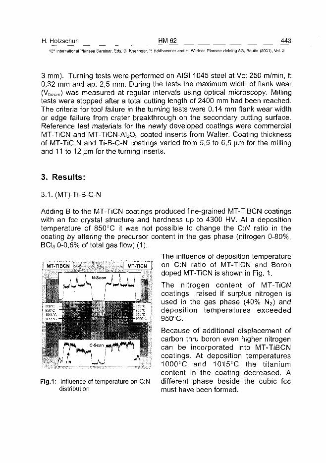
H. Holzschuh HM62 44315" International Plansee Seminar, Eds. G. Kneringer, P. Rodhammer and H. Wildner, Plansee Holding AG, Reutte (2001), Vol. 2
3 mm). Turning tests were performed on AISI 1045 steel at Vc: 250 m/min, f:0,32 mm and ap: 2,5 mm. During the tests the maximum width of flank wear(Vbmax) was measured at regular intervals using optical microscopy. Millingtests were stopped after a total cutting length of 2400 mm had been reached.The criteria for tool failure in the turning tests were 0.14 mm flank wear widthor edge failure from crater breakthrough on the secondary cutting surface.Reference test materials for the newly developed coatings were commercialMT-TiCN and MT-TiCN-AI2O3 coated inserts from Walter. Coating thicknessof MT-TiC,N and Ti-B-C-N coatings varied from 5,5 to 6,5 |im for the millingand 11 to 12 u.m for the turning inserts.
3. Results:
3.1.(MT)-Ti-B-C-N
Adding B to the MT-TiCN coatings produced fine-grained MT-TiBCN coatingswith an fee crystal structure and hardness up to 4300 HV. At a depositiontemperature of 850°C it was not possible to change the C:N ratio in thecoating by altering the precursor content in the gas phase (nitrogen 0-80%,BCI3 0-0,6% of total gas flow) (1).
The influence of deposition temperatureon C:N ratio of MT-TiCN and Borondoped MT-TiCN is shown in Fig. 1.
The nitrogen content of MT-TiCNcoatings raised if surplus nitrogen isused in the gas phase (40% N2) anddeposition temperatures exceeded950°C.
Because of additional displacement ofcarbon thru boron even higher nitrogencan be incorporated into MT-TiBCNcoatings. At deposition temperatures1000°C and 1015°C the titaniumcontent in the coating decreased. Adifferent phase beside the cubic feemust have been formed.
Fig.1: Influence of temperature on C:Ndistribution
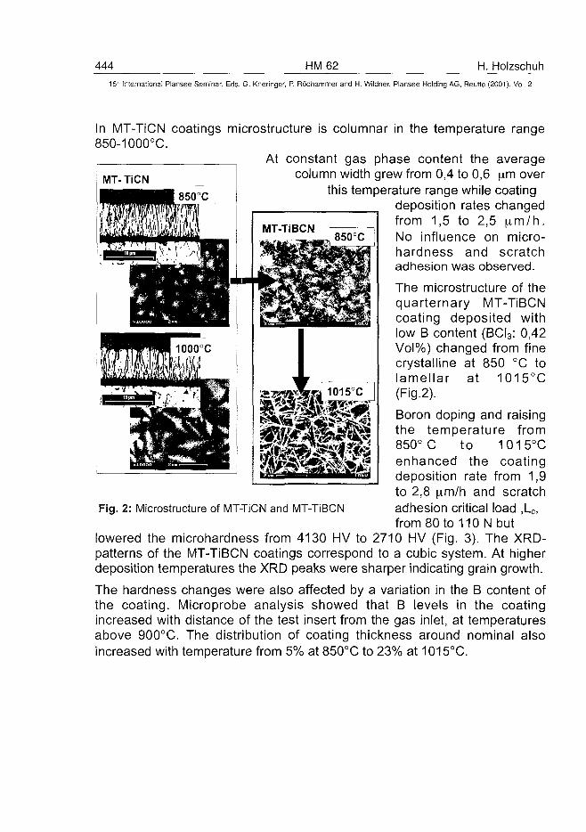
444 HM62 H. Holzschuh15" International Plansee Seminar, Eds. G. Kneringer, P. Rodhammer and H. Wildner, Plansee Holding AG, Reutte (2001), Vol. 2
850°C
In MT-TiCN coatings microstructure is columnar in the temperature range850-1000°C.
At constant gas phase content the averagecolumn width grew from 0,4 to 0,6 ^m over
this temperature range while coatingdeposition rates changedfrom 1,5 to 2,5 ( im/h.No influence on micro-hardness and scratchadhesion was observed.
The microstructure of thequarternary MT-TiBCNcoating deposited withlow B content (BCI3: 0,42Vol%) changed from finecrystalline at 850 °C tolamellar at 1015°C(Fig.2).
Boron doping and raisingthe temperature from850° C to 1015°Cenhanced the coatingdeposition rate from 1,9to 2,8 pim/h and scratchadhesion critical load ,LC,from 80 to 110 N but
lowered the microhardness from 4130 HV to 2710 HV (Fig. 3). The XRD-patterns of the MT-TiBCN coatings correspond to a cubic system. At higherdeposition temperatures the XRD peaks were sharper indicating grain growth.
The hardness changes were also affected by a variation in the B content ofthe coating. Microprobe analysis showed that B levels in the coatingincreased with distance of the test insert from the gas inlet, at temperaturesabove 900°C. The distribution of coating thickness around nominal alsoincreased with temperature from 5% at 850°C to 23% at 1015°C.
Fig. 2: Microstructure of MT-TiCN and MT-TiBCN
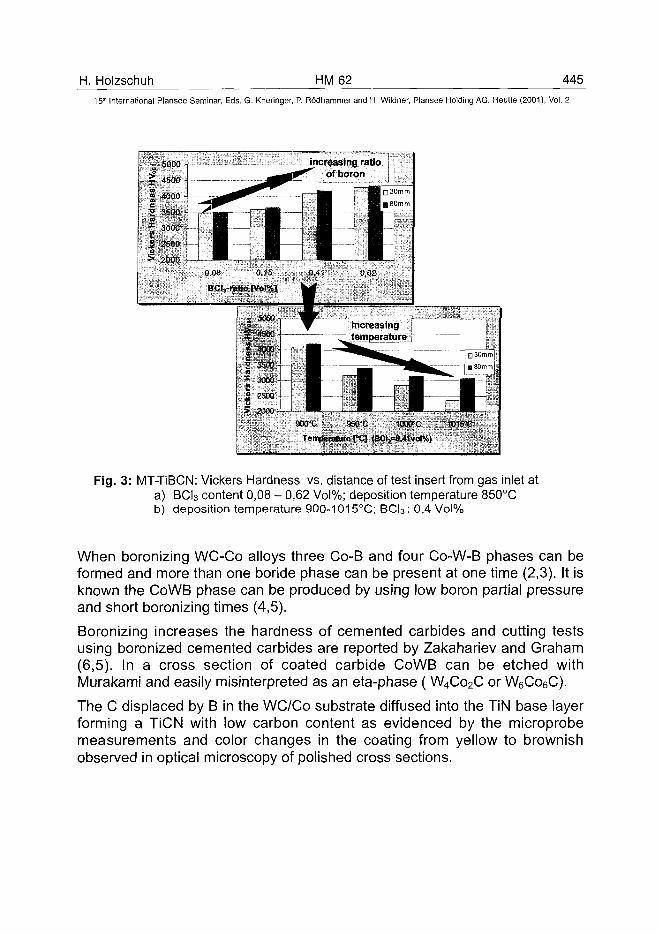
H. Holzschuh HM62 445
15th International Plansee Seminar, Eds. G. Kneringer, P. Rodhammer and H. Wildner, Plansee Holding AG, Reutte (2001), Vol. 2
Fig. 3: MT-TiBCN: Vickers Hardness vs. distance of test insert from gas inlet ata) BCI3 content 0,08 - 0,62 Vol%; deposition temperature 850°Cb) deposition temperature 900-1015°C; BCl3: 0,4 Vol%
When boronizing WC-Co alloys three Co-B and four Co-W-B phases can beformed and more than one boride phase can be present at one time (2,3). It isknown the CoWB phase can be produced by using low boron partial pressureand short boronizing times (4,5).
Boronizing increases the hardness of cemented carbides and cutting testsusing boronized cemented carbides are reported by Zakahariev and Graham(6,5). In a cross section of coated carbide CoWB can be etched withMurakami and easily misinterpreted as an eta-phase (W4Co2C or W6Co6C).
The C displaced by B in the WC/Co substrate diffused into the TiN base layerforming a TiCN with low carbon content as evidenced by the microprobemeasurements and color changes in the coating from yellow to brownishobserved in optical microscopy of polished cross sections.
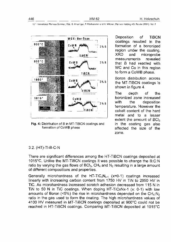
446 HM62 H. Holzschuh15* International Plansee Seminar, Eds. G. Kneringer, P. Rodhammer and H. Wildner, Plansee Holding AG, Reutte (2001), Vol. 2
900 C
1 - :> : •
950 C
,1 1 0 0 0 - ."
! 1 0 1 5 '
WOX: Bor Scan
Co\«B miwvm • 3 % B
\ liBCJilL
CoWB 3%B
, .A... m JNBCJL
'• Wi TiBCN
CoWB
LliBCM
Fig. 4: Distribution of B in MT-TiBCN coatings andformation of CoWB phase
Deposition of TiBCNcoatings resulted in theformation of a boronizedregion under the coating.XRD and microprobemeasurements revealedthat B had reacted withWC and Co in this regionto form a CoWB phase.
Boron distribution acrossthe MT-TiBCN coatings isshown in figure 4.
The depth of theboronized zone increasedwith the depositiontemperature. However thecobalt content of the hardmetal and to a lesserextent the amount of BCI3in the coating gas alsoaffected the size of thezone.
3.2. (HT)-Ti-B-C-N
There are significant differences among the HT-TiBCN coatings deposited at1015°C. Unlike the MT-TiBCN coatings it was possible to change the B:C:Nratio by varying the gas flows of BCI3, CH4 and N2 resulting in a large amountof different compositions and properties.
Generally microhardness of the HT-TiCxNx.-i (x=0-1) coatings increasedlinearly with increasing carbon content from 1750 HV in TiN to 2950 HV inTiC. As microhardness increased scratch adhesion decreased from 115 N inTiN to 50 N in TiC coatings. When doping HT-TiCxNx-1 (x: 0-1) with lowamounts of Boron (<5%) the rise in microhardness depended on the CH4:N2
ratio in the gas used to form the coating. The high microhardness values of4100 HV measured in MT-TiBCN coatings deposited at 900°C could not bereached in HT-TiBCN coatings. Comparing MT-TiBCN deposited at 1015°C
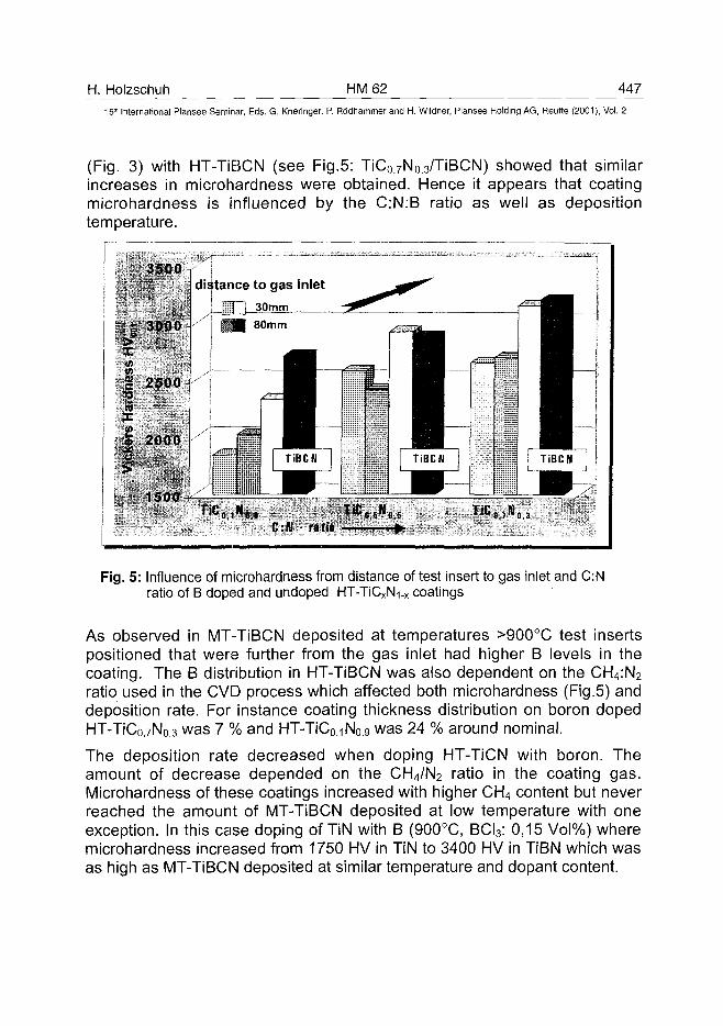
H. Holzschuh HM62 44715'" International Plansee Seminar, Eds. G. Kneringer, P. Rodhammer and H. Wildner, Plansee Holding AG, Reutte (2001), Vol. 2
(Fig. 3) with HT-TiBCN (see Fig.5: TiCo.7No.3/TiBCN) showed that similarincreases in microhardness were obtained. Hence it appears that coatingmicrohardness is influenced by the C:N:B ratio as well as depositiontemperature.
3500 .distance to gas inlet
(3Z i - 3 O m - m
3000 - 1MB 80mm
fll
2500
2000
1500 -
C:K • ratio
Fig. 5: Influence of microhardness from distance of test insert to gas inlet and C:Nratio of B doped and undoped HT-TiCxNi-x coatings
As observed in MT-TiBCN deposited at temperatures >900°C test insertspositioned that were further from the gas inlet had higher B levels in thecoating. The B distribution in HT-TiBCN was also dependent on the CH4:N2
ratio used in the CVD process which affected both microhardness (Fig.5) anddeposition rate. For instance coating thickness distribution on boron dopedHT-TiC0.7N0.3 was 7 % and HT-TiCo.-iNo.g was 24 % around nominal.
The deposition rate decreased when doping HT-TiCN with boron. Theamount of decrease depended on the CH4/N2 ratio in the coating gas.Microhardness of these coatings increased with higher CH4 content but neverreached the amount of MT-TiBCN deposited at low temperature with oneexception. In this case doping of TiN with B (900°C, BCI3: 0,15 Vol%) wheremicrohardness increased from 1750 HV in TiN to 3400 HV in TiBN which wasas high as MT-TiBCN deposited at similar temperature and dopant content.
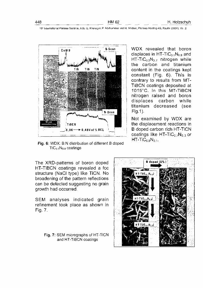
448 HM62 H. Holzschuh15* International Plansee Seminar, Eds. G. Kneringer, P. Rodhammer and H. Wildner, Plansee Holding AG, Reutte (2001), Vol. 2
TiBCN
/'0,06 »-0,48Vol '
Fig. 6: WDX: B:N distribution of different B dopedTiCo.iNo.9 coatings
WDX revealed that borondisplaces in HT-TiC0.iNo.9 andHT-TiCo.3No.7 nitrogen whilethe carbon and titaniumcontent in the coatings keptconstant (Fig. 6). This iscontrary to results from MT-TiBCN coatings deposited at1015°C. In this MT-TiBCNnitrogen raised and borondisplaces carbon whiletitanium decreased (seeFig.1).
Not examined by WDX arethe displacement reactions inB doped carbon rich HT-TiCNcoatings like HT-TiC07N0 3 orHT-TiCo.gNo.1.
The XRD-patterns of boron dopedHT-TiBCN coatings revealed a feestructure (NaCI type) like TiCN. Nobroadening of the pattern reflectionscan be detected suggesting no graingrowth had occurred.
SEM analyses indicated grainrefinement took place as shown inFig. 7.
Fig. 7: SEM micrographs of HT-TiCNand HT-TiBCN coatings
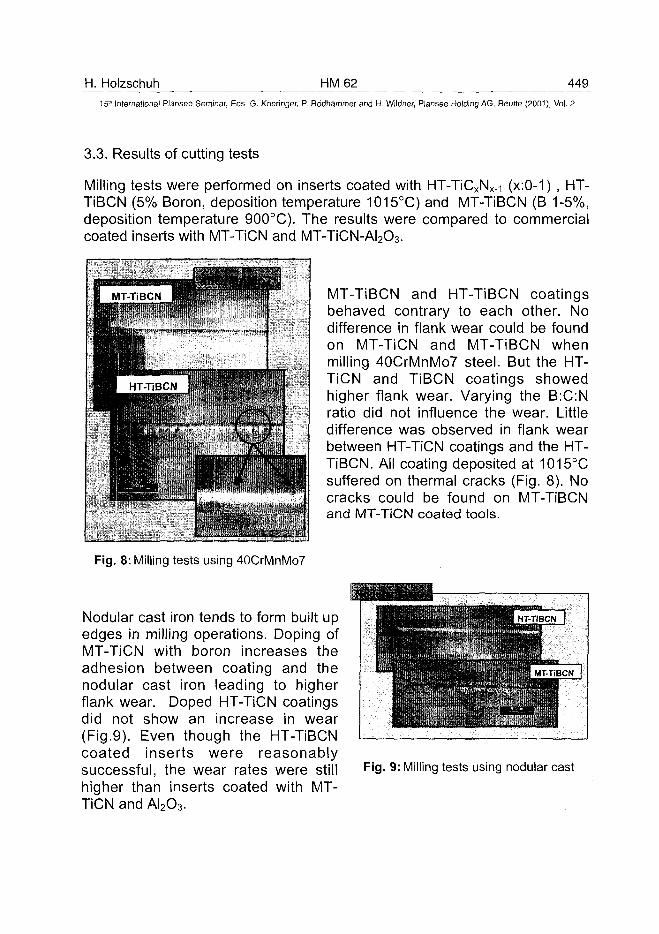
H. Holzschuh HM62 44915th International Plansee Seminar, Eds. G. Kneringer, P. Rodhammer and H. Wildner, Plansee Holding AG, Reutte (2001), Vol. 2
3.3. Results of cutting tests
Milling tests were performed on inserts coated with HT-TiCxNx.-i (x:0-1) , HT-TiBCN (5% Boron, deposition temperature 1015°C) and MT-TiBCN (B 1-5%,deposition temperature 900°C). The results were compared to commercialcoated inserts with MT-TiCN and MT-TiCN-AI2O3.
MT-TiBCN and HT-TiBCN coatingsbehaved contrary to each other. Nodifference in flank wear could be foundon MT-TiCN and MT-TiBCN whenmilling 40CrMnMo7 steel. But the HT-TiCN and TiBCN coatings showedhigher flank wear. Varying the B:C:Nratio did not influence the wear. Littledifference was observed in flank wearbetween HT-TiCN coatings and the HT-TiBCN. Ail coating deposited at 1015°Csuffered on thermal cracks (Fig. 8). Nocracks could be found on MT-TiBCNand MT-TiCN coated tools.
Fig. 8: Milling tests using 40CrMnMo7
Nodular cast iron tends to form built upedges in milling operations. Doping ofMT-TiCN with boron increases theadhesion between coating and thenodular cast iron leading to higherflank wear. Doped HT-TiCN coatingsdid not show an increase in wear(Fig.9). Even though the HT-TiBCNcoated inserts were reasonablysuccessful, the wear rates were stillhigher than inserts coated with MT-TiCN and AI2O3.
mm
1m
• * • ' • . • ' • " •
i '• "
/ • j % | HT-T.SCN I
Fig. 9: Milling tests using nodular cast
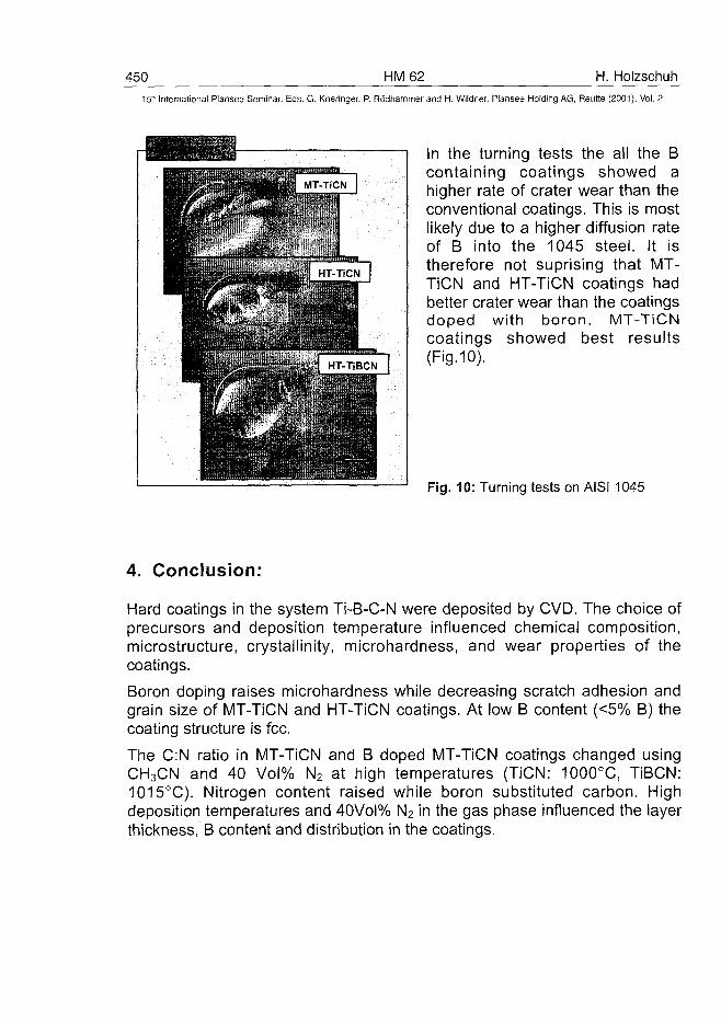
450 HM62 H. HolzschuhInternational Plansee Seminar, Eds. G. Kneringer, P. Rodhammer and H. Wildner, Plansee Holding AG, Reutte (2001), Vol. 2
In the turning tests the all the Bcontaining coatings showed ahigher rate of crater wear than theconventional coatings. This is mostlikely due to a higher diffusion rateof B into the 1045 steel. It istherefore not suprising that MT-TiCN and HT-TiCN coatings hadbetter crater wear than the coatingsdoped with boron. MT-TiCNcoatings showed best results(Fig.10).
Fig. 10: Turning tests on AISI 1045
4. Conclusion:
Hard coatings in the system Ti-B-C-N were deposited by CVD. The choice ofprecursors and deposition temperature influenced chemical composition,microstructure, crystallinity, microhardness, and wear properties of thecoatings.
Boron doping raises microhardness while decreasing scratch adhesion andgrain size of MT-TiCN and HT-TiCN coatings. At low B content (<5% B) thecoating structure is fee.
The C:N ratio in MT-TiCN and B doped MT-TiCN coatings changed usingCH3CN and 40 Vol% N2 at high temperatures (TiCN: 1000°C, TiBCN:1015°C). Nitrogen content raised while boron substituted carbon. Highdeposition temperatures and 40Vol% N2 in the gas phase influenced the layerthickness, B content and distribution in the coatings.
H. Holzschuh HM 62 45115" International Plansee Seminar, Eds. G. Kneringer, P. Rodhammer and H. Wildner, Plansee Holding AG, Reutte (2001), Vol. 2
Diffusion of boron is responsible for inhomogeneity in the boron distribution ofMT-TiBCN (deposition temperature >900°C) and HT-TiBCN coatings and theformations of a CoWB phase on the surface of the cemented carbide.
By adjusting the BCI3:CH4:N2 ratio in the coating gas the B:C:N ratio in HT-TiBCN coatings can be varied.
Boron displaces nitrogen in boron doped HT-TiCxN-|.x (x = 0 - 0.3) coatings.
For milling of steel MT-TiBCN coatings are preferred. On milling of nodularcast HT-TiBCN coatings showed better wear. Neither MT-TiBCN nor HT-TiBCN coatings can be recommended for turning of AISI 1045.
Acknowledgements:
Special thanks go to M. Schaible, J. Stadlbauer (Waiter AG), to the Universityof Tuebingen for E. Nadler (SEM), H. Hoppe (XRD) and M. Westphal (WDX).The author gratefully acknowledge the financial support by theBundesministerium fur Bildung, Wissenschaft, Forschung und Technologie(BMBF; Project-No. 03N5016C).
References:
(1) H. Holzschuh: Journal de Physique IV, EuroCVD 12, (2000), pp. Pr2-49- Pr2-54.
(2) R. Bonetti and H. E. Hinterman: "Chemical Vapor Deposition - SixthInternational Conference", The Electrochemical Society, New York,1977, pp.351.
(3) K. Yamamura, M. Kasai, and H. Harigaya: Powder and PowderMetallurgy (Japan), 16 (1969), pp. 230.
(4 ) Z. Zakhariev, K. Petrov, and M. Christov: Journal of the Less-CommonMetals, 82(1981), pp. 57-62.
(5) D. E. Graham: Carbide and Tool Journal, 18 (1986), pp.35-43.(6) Z. Zakhariev, M. Marinov, R. Zlateva: Surface & Coatings Technology,
31 (1987), pp. 265-271.
ATO100473452 HM 63 A. Borisova et al.
15" International Plansee Seminar, Eds. G. Kneringer, P. Rodhammer and H. Wildner, Plansee Holding AG, Reutte (2001), Vol. 2
VANADIUM CARBIDE COATINGS: DEPOSITION PROCESS AND
PROPERTIES
A.Borisova*, Yu.Borisov*, E.Shavlovsky*, I.Mits*LCastermans**, R.Jongbloed**
*E.O.Paton Electric Welding Institute, Kyiv, Ukraine**Chromin, Maastricht, The Netherlands
Summary
Vanadium carbide coatings on carbon and alloyed steels were producedby the method of diffusion saturation from the borax melt. Thickness ofthe vanadium carbide layer was 5-15 ^m, depending upon the steelgrade and diffusion saturation parameters. Microhardness was 20000-28000 MPa and wear resistance of the coatings under conditions of endface friction without lubrication against a mating body of WC-2Co was15-20 times as high as that of boride coatings. Vanadium carbidecoatings can operate in air at a temperature of up to 400 °C. Theyimprove fatigue strength of carbon steels and decrease the rate ofcorrosion in sea and fresh water and in acid solutions. The use ofvanadium carbide coatings for hardening of various types of tools,including cutting tools, allows their service life to be extended by a factorof 3 to 30.
Key words:
Vanadium carbide, coatings, borax melt, wear resistance, cutting andforming tools
1. Introduction
Formation of carbide coatings on surfaces of carbon-containing steelparts by the no-electrolysis method from the salt melts is a promisingtechnology for thermochemical treatment. Carbide coatings of this typeare characterized by high wear, corrosion and erosion resistance. Thetechnology is environmentally clean. Its basic operations, such asimmersing workpieces into the borax melt containing a carbide-formingelement, holding at preset temperatures and during a preset time,cooling and washing off the remaining borax in hot water, are simple toperform. Advantages of the technology are that the materials andthermal equipment used are inexpensive and readily available, as well as
A. Borisova et al. HM 63 45315" International Plansee Seminar, Eds. G. Kneringer, P. Rodhammer and H. Wildner, Plansee Holding AG, Reutte (2001), Vol. 2
that it is possible to combine oxidation-free heating of workpieces forquenching with the process of formation of carbide coatings andsubsequent heat treatment (quenching) of the coated parts.
The method for production of carbide coatings from the salt melts,termed the TD -process, was developed as far back as 1971 by theToyota Central Research Laboratory (Japan) [1]. Now it is widelyaccepted far beyond Japan (European countries, USA, Australia). TheE.O.Paton Electric Welding Institute has been involved into the work onproduction of carbide coatings from the borax melt since 1985, whilesince 1996 this work has been performed in collaboration with the"Chromin" Company (The Netherlands). This paper gives results of thecollaborative work of the E.O.Paton Electric Welding Institute andChromin on production, investigation and practical application ofvanadium carbide coatings on tool carbon and alloyed steels.
As compared with other metal carbides, vanadium carbide ischaracterized by a combination of high hardness and sufficient ductility.For example, microhardness of vanadium carbide amounts to 29000MPa and elasticity modulus is 280-430 GPa, while the correspondingvalues of titanium carbide are 29000 MPa and 460-600 GPa and thoseof tungsten carbide are 21000 MPa and 510-720 MPa, respectively. Thismakes vanadium carbide a promising material for hardening of machineparts and tools, including cutting tools.
II. Experimental
Investigation of the mechanism of vanadium carbide coating andoptimization of the technology for deposition of the vanadium carbidecoatings were done on carbon steels (carbon content - from 0.2 to 0.8wt. %) in a temperature range of 800-1050 °C and at a holding time of 1-5 h. Structure and phase composition of the coatings were studied bymetallography, microdurometry, X-ray phase analysis and X-raymicroanalysis. The atomic C/V ratio was determined on the basis ofresults of evaluation of the lattice constant of vanadium carbide and dataon its dependence upon the composition in the homogeneity range [2].
Oxidation resistance of vanadium carbide coatings was determined bythe gravimetric method in air (derivatograph Q-1500 D, heating rate - 10°C/min) and corrosion resistance - by the potentiostatic method in sea
454 HM 63 A. Borisova et al.15' International Plansee Seminar, Eds. G. Kneringer, P. Rodhammer and H. Wildner, Plansee Holding AG, Reutte (2001), Vol. 2
and fresh water, in 5 and 10 % solutions of hydrochloric acid, and inalkaline medium of potassium hydroxide.
Tribological properties of the coatings were studied by the followingmethods:1. Abrasive wear was studied by friction of the test and reference
samples on a surface with abrasive particles fixed to it (abrasivepaper) under static loading and at no heating. In addition, thisincluded comparative tests of vanadium carbide coatings with anumber of other coatings.
2. Gas-abrasive wear was studied by simultaneously affecting the testand reference samples by a flow of hard particles formed by acentrifugal accelerator under fixed testing conditions.
3. Wear under conditions of end face friction without lubrication on amating body was studied depending upon the displacement speedand loading.
4. Cavitation wear was studied in a flow of fluid under a pressure at theinlet equal to 20 MPa and a pressure gradient of 0.83.
III. Results and discussion
Sequence of the process of formation of the carbide layer on steel wasestablished on the basis of results of kinetic investigations, structural andphase analysis and thermodynamic calculations.
According to the thermodynamic calculations, interaction of borax withferrovanadium at temperatures of 1000-1500 K is a multi-stage process.Intermediate products of the process are vanadium oxide, boron oxideand sodium hyperoxide. Formation of atomic vanadium is most probableto occur as a result of reaction between vanadium oxide and potassiumhyperoxide. It should be noted that the thermodynamic probability ofsuch as reaction depends but slightly upon the temperature.
Results of our investigations suggest that the process of formation of acarbide layer on the surface of carbon steel consists of the followingstages:1. Adsorption of atomic vanadium on the surface of steel;2. Diffusion of vanadium in the bulk and, at a higher rate, along the grain
boundaries of a steel sample to form solid solution of the Fe-V-Csystem;
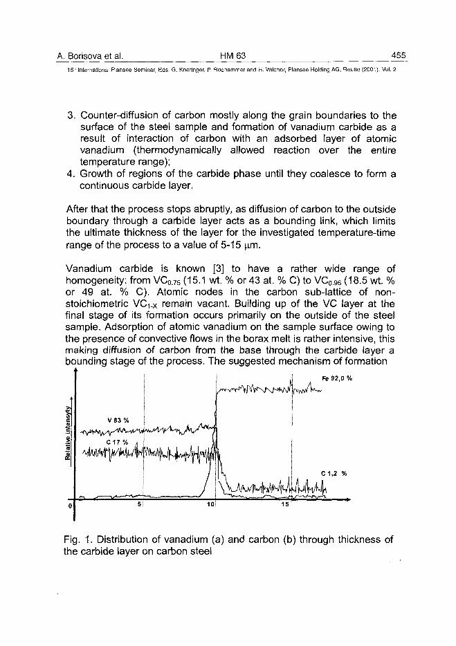
A. Borisova et al. HM63 45515" International Plansee Seminar, Eds. G. Kneringer, P. Rodhammer and H. Wildner, Plansee Holding AG, Reutte (2001), Vol. 2
3. Counter-diffusion of carbon mostly along the grain boundaries to thesurface of the steel sample and formation of vanadium carbide as aresult of interaction of carbon with an adsorbed layer of atomicvanadium (thermodynamically allowed reaction over the entiretemperature range);
4. Growth of regions of the carbide phase until they coalesce to form acontinuous carbide layer.
After that the process stops abruptly, as diffusion of carbon to the outsideboundary through a carbide layer acts as a bounding link, which limitsthe ultimate thickness of the layer for the investigated temperature-timerange of the process to a value of 5-15 ^m.
Vanadium carbide is known [3] to have a rather wide range ofhomogeneity: from VC0.75 (15.1 wt. % or 43 at. % C) to VC0.96 (18.5 wt. %or 49 at. % C). Atomic nodes in the carbon sub-lattice of non-stoichiometric VcYx remain vacant. Building up of the VC layer at thefinal stage of its formation occurs primarily on the outside of the steelsample. Adsorption of atomic vanadium on the sample surface owing tothe presence of convective flows in the borax melt is rather intensive, thismaking diffusion of carbon from the base through the carbide layer abounding stage of the process. The suggested mechanism of formation
Fe 92,0 %
Fig. 1. Distribution of vanadium (a) and carbon (b) through thickness ofthe carbide layer on carbon steel
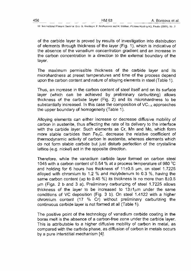
456 HM63 A. Borisova et al.15" International Plansee Seminar, Eds. G. Kneringer, P. Rodhammer and H. Wildner, Plansee Holding AG, Reutte (2001), Vol. 2
of the carbide layer is proved by results of investigation into distributionof elements through thickness of the layer (Fig. 1), which is indicative ofthe absence of the vanadium concentration gradient and an increase inthe carbon concentration in a direction to the external boundary of thelayer.
The maximum permissible thickness of the carbide layer and itsmicrohardness at preset temperatures and time of the process dependupon the carbon content and nature of alloying elements in steel (Table 1).
Thus, an increase in the carbon content of steel itself and on its surfacelayer (which can be achieved by preliminary carburizing) allowsthickness of the carbide layer (Fig. 2) and its microhardness to besubstantially increased. In this case the composition of VC^x approachesthe upper boundary of homogeneity (Table 1).
Alloying elements can either increase or decrease diffusive mobility ofcarbon in austenite, thus affecting the rate of its delivery to the interfacewith the carbide layer. Such elements as Cr, Mn and Mo, which formmore stable carbides than Fe3C, decrease the relative coefficient ofthermodynamic activity of carbon in austenite, whereas elements whichdo not form stable carbide but just disturb perfection of the crystallinelattice (e.g. nickel) act in the opposite direction.
Therefore, while the vanadium carbide layer formed on carbon steel1045 with a carbon content of 0.54 % at a process temperature of 980 °Cand holding for 6 hours has thickness of 11+0.5 \xm, on steel 1.7225alloyed with chromium to 1.2 % and molybdenum to 0.3 %, having thesame carbon content (up to 0.45 %) its thickness is no more than 8±0.5\im (Figs. 2 b and 3 a). Preliminary carburizing of steel 1.7225 allowsthickness of the layer to be increased to 13±1(4.m under the sameconditions of VC deposition (Fig. 3 b). On steel 1.4122 with a higherchromium content (17 % Cr) without preliminary carburizing thecontinuous carbide layer is not formed at all (Table 1).
The positive point of the technology of vanadium carbide coating in theborax melt is the absence of a carbon-free zone under the carbide layer.This is attributable to a higher diffusive mobility of carbon in metal, ascompared with the carbide phase, as diffusion of carbon in metals occursby a pure interstitial mechanism [4].
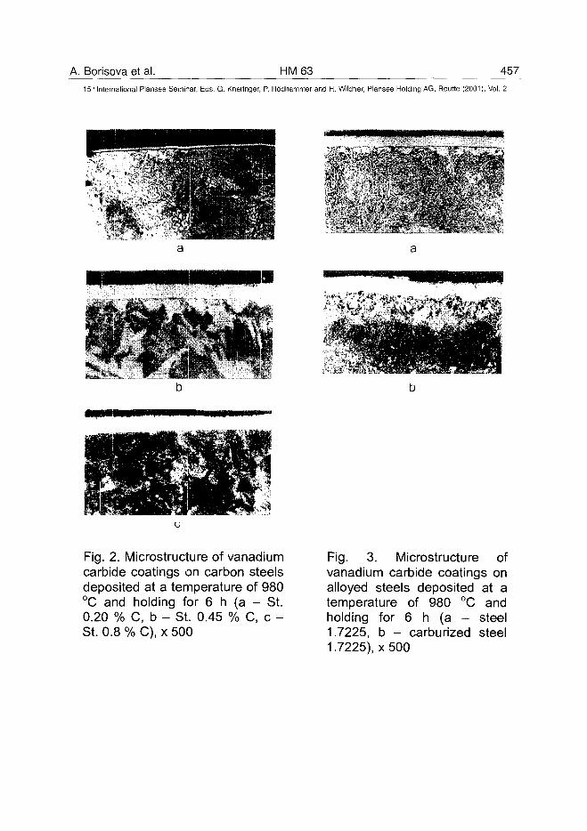
A. Borisova et al. HM63 457
15'" International Plansee Seminar, Eds. G. Kneringer, P. Rodhammer and H. Wildner, Plansee Holding AG, Reutte (2001), Vol. 2
Fig. 2. Microstructure of vanadiumcarbide coatings on carbon steelsdeposited at a temperature of 980°C and holding for 6 h (a - St.0.20 % C, b - St. 0.45 % C, c -St. 0.8 % C), x 500
Fig. 3. Microstructure ofvanadium carbide coatings onalloyed steels deposited at atemperature of 980 °C andholding for 6 h (a - steel1.7225, b - carburized steel1.7225), x 500
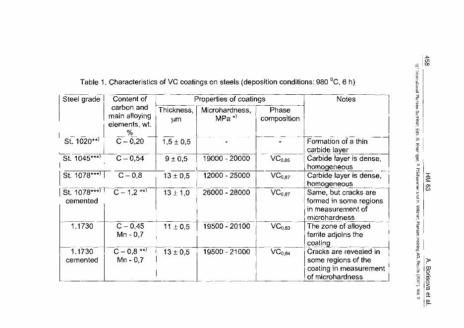
f00
Table 1. Characteristics of VC coatings on steels (deposition conditions: 980 °C, 6 h)
Steel grade
St. 1020**J
St. 1045***'
St. 1078***J
St. 1078***'cemented
1.1730
1.1730cemented
Content ofcarbon and
main alloyingelements, wt.
%C-0,20
C-0,54
C-0,8
C - 1,2 **»
C - 0,45Mn - 0,7
C - 0,8 **>Mn-0,7
Properties of coatingsThickness,
l m
1,5 ±0,5
9 ±0,5
13±0,5
13 ± 1,0
11 ±0,5
13 + 0,5
Microhardness,MPa*>
-
19000-20000
12000-25000
26000 - 28000
19500-20100
19500-21000
Phasecomposition
-
VCo,85
VCo,87
VCo,87
VCo,83
VCQ,84
Notes
Formation of a thincarbide layerCarbide layer is dense,homogeneousCarbide layer is dense,homogeneousSame, but cracks areformed in some regionsin measurement ofmicrohardnessThe zone of alloyedferrite adjoins thecoatingCracks are revealed insome regions of thecoating in measurementof microhardness
"D5T
>
CO
CDO5o
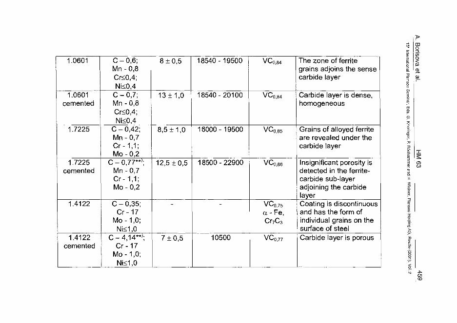
CDO
I1.0601
1.0601cemented
1.7225
1.7225cemented
1.4122
1.4122cemented
C-0,6;Mn-0,8Cr<0,4;Ni<0,4
C-0,7;Mn - 0,8Cr<0,4;Ni<0,4
C-0,42;Mn-0,7Cr-1,1;Mo - 0,2
C - 0,77**';Mn-0,7Cr-1,1;Mo - 0,2
C-0,35;Cr-17
Mo-1,0;Ni<1,0
C-4,14**J;Cr-17
Mo-1,0;Ni<1,0
8 ±0,5
13 ± 1,0
8,5 ±1,0
12,5 ±0,5
7 ±0,5
18540-19500
18540-20100
16000-19500
18500-22900
10500
VCo,84
VCo,84
VCo,85
VCo,86
VC0,75a - Fe,Cr7C3
VC0,77
The zone of ferritegrains adjoins the sensecarbide layer
Carbide layer is dense,homogeneous
Grains of alloyed ferriteare revealed under thecarbide layer
Insignificant porosity isdetected in the ferrite-carbide sub-layeradjoining the carbidelayerCoating is discontinuousand has the form ofindividual grains on thesurface of steelCarbide layer is porous
(D-oor
>
1O lCO
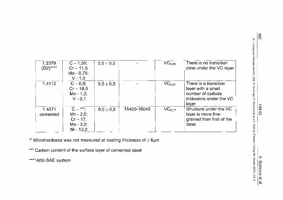
o
1.2379(D2)***>
1.4112
1.4571cemented
C-1,55;Cr-11,5Mo-0,75;
V-1,0C-0,9;Cr-18,0Mo-1,2;
V-0,1
C - **>;Mn-2,0;Cr-17;Mo-2,0;Ni-12,0
5,5 ±0,5
5,5 ±0,5
8,0 ±0,5 15400-16040
vc,85
VCo,77
There is no transitionzone under the VC layer
There is a transitionlayer with a smallnumber of carbideinclusions under the VClayerStructure under the VClayer is more fine-grained than that of thebase
*} Microhardness was not measured at coating thickness of <
**' Carbon content of the surface layer of cemented steel
***>AISI-SAE system
CD03
00gco'
§
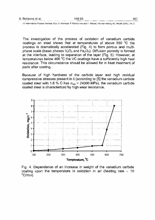
A. Borisova et al. HM63 461
15" International Plansee Seminar, Eds. G. Kneringer, P. Rodhammer and H. Wildner, Plansee Holding AG, Reutte (2001), Vol. 2
The investigation of the process of oxidation of vanadium carbidecoatings on steel shows that at temperatures of above 550 °C theprocess is dramatically accelerated (Fig. 4) to form porous and multi-phase scale (basic phases V2O3 and Fe2O3). Diffusion porosity is formedat the interface, leading to separation of the layer (Fig. 5). However, attemperatures below 400 °C the VC coatings have a sufficiently high heatresistance. This circumstance should be allowed for in heat treatment ofparts after coating.
Because of high hardness of the carbide layer and high residualcompressive stresses present in it (according to [5] the vanadium carbidecoated steel with 1.6 % C has CTres = 24000 MPa), the vanadium carbidecoated steel is characterized by high wear resistance.
IsI 4X i
O2
1• 1
- /
/
/ !
/ !
/ I} !
!i 1
100 200 300 400 500
Temperature, °C
600 700
Fig. 4. Dependence of an increase in weight of the vanadium carbidecoating upon the temperature in oxidation in air (heating rate - 10°C/min)
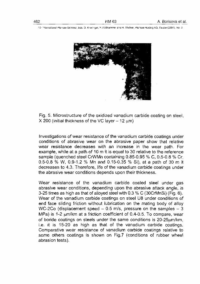
462 HM 63 A. Borisova et al.15" International Plansee Seminar, Eds. G. Kneringer, P. Rodhamrner and H. Wildner, Plansee Holding AG, Reutte (2001), Vol. 2
Fig. 5. Microstructure of the oxidized vanadium carbide coating on steel,X 200 (initial thickness of the VC layer- 12 |u.m)
Investigations of wear resistance of the vanadium carbide coatings underconditions of abrasive wear on the abrasive paper show that relativewear resistance decreases with an increase in the wear path. Forexample, while at a path of 10 m it is equal to 30 relative to the referencesample (quenched steel CrWMn containing 0.85-0.95 % C, 0.5-0.8 % Cr,0.5-0.8 % W, 0.9-1.2 % Mn and 0.15-0.35 % Si), at a path of 30 m itdecreases to 4.3. Therefore, life of the vanadium carbide coatings underthe abrasive wear conditions depends upon their thickness.
Wear resistance of the vanadium carbide coated steel under gasabrasive wear conditions, depending upon the abrasive attack angle, is3-25 times as high as that of alloyed steel with 0.3 % C (30CrMnSi) (Fig. 6).Wear of the vanadium carbide coatings on steel U8 under conditions ofend face sliding friction without lubrication on the mating body of alloyWC-2Co (displacement speed - 0.5 m/s, pressure on the samples - 3MPa) is 1-2 jim/km at a friction coefficient of 0.4-0.5. To compare, wearof boride coatings on steels under the same conditions is 20-25|im/km,i.e. it is 15-20 as high as that of the vanadium carbide coatings.Comparative wear resistance of vanadium carbide coatings relative tosome others coatings is shown on Fig.7 (conditions of rubber wheelabrasion tests).

A. Borisova et al. HM63 46315'h International Plansee Seminar, Eds. G. Kneringer, P. Rodhammer and H. Wildner, Plansee Holding A6, Reutte (2001), Vol. 2
90 60 15
Fig. 6. Linear wear (J) of the vanadium carbide coating at presetabrasive attack angles (~ - wear of the coating; ~ - wear of the referencesample of alloyed steel 30KhGSA, centrifugal accelerator rotation speed- 100 rps, abrasive - SiO2 with particle sizes of up to 1 mm)
Testing the vanadium carbide coatings to cavitation resistance at aworking fluid pressure gradient of 0.83 and a test time of 12 h showed anincrease of 25-30 times in the cavitation resistance of the coated steel,as compared with the uncoated one. As shown by the investigations, ashock wave generated at collapse of the cavitation bubbles leads just todeformation of the carbide grains, causing no cracking or fracture of thecoating. The result obtained is in agreement with the investigations [1],where impact tests using a steel ball caused no cracking and noseparation of the vanadium carbide layer even after 200,000 impacts. Tocompare, the electrolytic chromium layer separates after 50,000 impacts,the depth of the impact trace being identical in both cases.
Owing to the presence of high residual compressive stresses thevanadium carbide coatings increase fatigue fracture resistance of steels.The low-cycle fatigue tests using the electrohydraulic testing machine
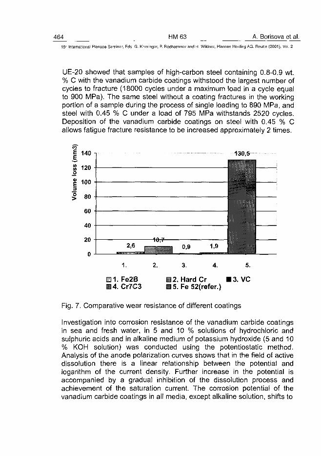
464 HM63 A. Borisova et al.15" International Plansee Seminar, Eds. G. Kneringer, P. Rodhammer and H. Wildner, Plansee Holding AG, Reutte (2001), Vol. 2
UE-20 showed that samples of high-carbon steel containing 0.8-0.9 wt.% C with the vanadium carbide coatings withstood the largest number ofcycles to fracture (18000 cycles under a maximum load in a cycle equalto 900 MPa). The same steel without a coating fractures in the workingportion of a sample during the process of single loading to 890 MPa, andsteel with 0.45 % C under a load of 795 MPa withstands 2520 cycles.Deposition of the vanadium carbide coatings on steel with 0.45 % Callows fatigue fracture resistance to be increased approximately 2 times.
130,5
1.
• 1. Fe2B114. Cr7C3
H 2. Hard CrM 5. Fe 52(refer.)
Fig. 7. Comparative wear resistance of different coatings
Investigation into corrosion resistance of the vanadium carbide coatingsin sea and fresh water, in 5 and 10 % solutions of hydrochloric andsulphuric acids and in alkaline medium of potassium hydroxide (5 and 10% KOH solution) was conducted using the potentiostatic method.Analysis of the anode polarization curves shows that in the field of activedissolution there is a linear relationship between the potential andlogarithm of the current density. Further increase in the potential isaccompanied by a gradual inhibition of the dissolution process andachievement of the saturation current. The corrosion potential of thevanadium carbide coatings in all media, except alkaline solution, shifts to
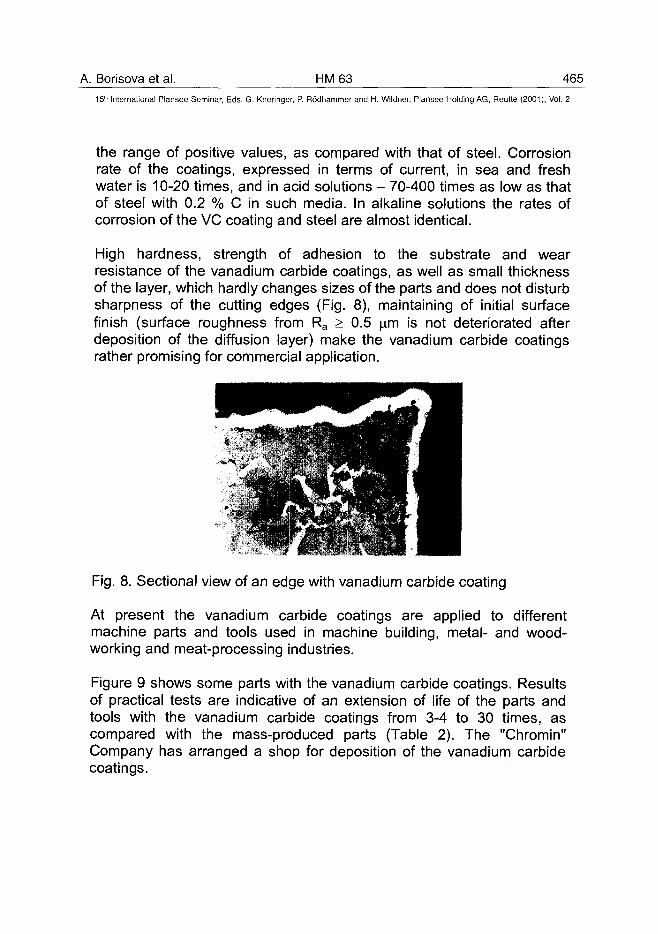
A. Borisova et al. HM 63 46515" International Plansee Seminar, Eds. G. Kneringer, P. Rodhammer and H. Wildner, Plansee Holding AG, Reutte (2001), Vol. 2
the range of positive values, as compared with that of steel. Corrosionrate of the coatings, expressed in terms of current, in sea and freshwater is 10-20 times, and in acid solutions - 70-400 times as low as thatof steel with 0.2 % C in such media. In alkaline solutions the rates ofcorrosion of the VC coating and steel are almost identical.
High hardness, strength of adhesion to the substrate and wearresistance of the vanadium carbide coatings, as well as small thicknessof the layer, which hardly changes sizes of the parts and does not disturbsharpness of the cutting edges (Fig. 8), maintaining of initial surfacefinish (surface roughness from Ra > 0.5 im is not deteriorated afterdeposition of the diffusion layer) make the vanadium carbide coatingsrather promising for commercial application.
Fig. 8. Sectional view of an edge with vanadium carbide coating
At present the vanadium carbide coatings are applied to differentmachine parts and tools used in machine building, metal- and wood-working and meat-processing industries.
Figure 9 shows some parts with the vanadium carbide coatings. Resultsof practical tests are indicative of an extension of life of the parts andtools with the vanadium carbide coatings from 3-4 to 30 times, ascompared with the mass-produced parts (Table 2). The "Chromin"Company has arranged a shop for deposition of the vanadium carbidecoatings.
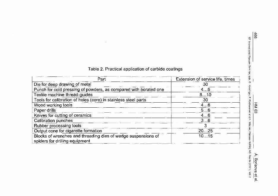
Table 2. Practical application of carbide coatings
en
PartDie for deep drawing of metalPunch for cold pressing of powders, as compared with borated oneTextile machine thread-guidesTools for calibration of holes (core) in stainless steel partsWood working toolsPaper drillsKnives for cutting of ceramicsCalibration punchesRubber processing toolsOutput cone for cigarette formationBlocks of wrenches and threading dies of wedge suspensions ofspiders for drilling equipment
Extension of service life, times30
4...68...10
304...65...64...63...6
320...2510...15
-oa
CO
CDo
o
CD
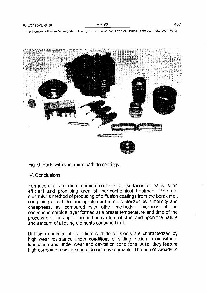
A. Borisova et al. HM63 467
15lh International Plansee Seminar, Eds. G. Kneringer, P. Rodhammer and H. Wildner, Plansee Holding AG, Reutte (2001), Vol. 2
Fig. 9. Parts with vanadium carbide coatings
IV. Conclusions
Formation of vanadium carbide coatings on surfaces of parts is anefficient and promising area of thermochemical treatment. The no-electrolysis method of producing of diffusion coatings from the borax meltcontaining a carbide-forming element is characterized by simplicity andcheapness, as compared with other methods. Thickness of thecontinuous carbide layer formed at a preset temperature and time of theprocess depends upon the carbon content of steel and upon the natureand amount of alloying elements contained in it.
Diffusion coatings of vanadium carbide on steels are characterized byhigh wear resistance under conditions of sliding friction in air withoutlubrication and under wear and cavitation conditions. Also, they featurehigh corrosion resistance in different environments. The use of vanadium
468 HM 63 A. Borisova et al.15- International Plansee Seminar, Eds. G. Kneringer, P. Rodhamnner and H. Wildner, Plansee Holding AG, Reutte (2001), Vol. 2
carbide coatings holds promise for hardening of machine parts operatingunder friction and wear conditions, including impact loading, as well ascutting, drawing, extrusion and press-forming tools.
Results of practical application indicate that life of the parts extends from3 to 30 times.
References
1. Arai Tohry, Das TD-Verfahren. Ein neues Verfahren zur Carbid-Beschichtung, Seine Durchfuhrung und practische Anwendung,Technisches Zentralblatt fur Metallbearbeitung, 1986, Bd. 80, N 3, S.27-32.
2. Samsonov G.V., Upadkhaya Sh., Neshpor V.S. Physical materialsscience of carbides. Kyiv: Naukova Dumka (1974). (Russian)
3. Samsonov G.V., Umansky Ya.S. Hard compounds of refractorymetals. Moscow: Metallurgizdat (1957). (Russian)
4. Andrievsky R., Umansky Ya. Interstitial phases, Moscow: Izd."Nauka" (1977). (Russian)Thermochemical treatment of metals and alloys. Reference Book,Ed. by L.S.Lyakhovich. Moscow: Metallurgiya (1981). (Russian)
ATO100474A.D. Shevchenko et al. HM 69 469^
15" International Plansee Seminar, Eds. G. Kneringer, P. Rddhammer and H. Wildner, Plansee Holding AG, Reutte (2001), Vol. 2
Production of Material With Higher Damping Ability for SuperhardCutting Tools
Anatoliy D. Shevchenko
Institute of Metal Physics Ukrainian AS, 36 Vernadsky pr., Kyiv-03142, Ukraine
Summary
A new material named "avibrite" with higher damping ability Q"1 is createdfrom metallic Ni- and Ti-powder under high pressure using specializedtechnology. Physical and mechanical characteristics of "avibrite " areanalysed in comparison with the alloy of similar composition. The strength of"avibrite" exceeds that of cast alloy of Ti nickelide and Q'1 of the new materialis several orders of magnitude higher at compared with its analogue.Application of vibration-damping elements made of "avibrite" in the cuttingtool and drill bit proved the effective damping of the vibrations due to theimpact load, impact-rotation and permanent loads, which results in aconsiderable increase of wear resistance of cutting tool and diamond drill bit.
Keywords
high pressure, composite material, higher damping ability, cutting tools
1. Introduction
The purpose of given work is to obtain under high pressure conditions usingspecialized technology' the material with thermoelastic martensite, material thatwould provide high level of deformation accumulation Eh, in the martensitetransformation process and, therefore, the increase of Q'1. It may be realized, forexample, if to create necessary quantity of closed pores in the material bulk withthermoelastic martensite. Necessary quantity of closed pores, which wouldrealieze displacement of phase boundaries increasing mobility of boundaries ofmartensite microdomains that would lead to effective relaxation of externalstrains, growth of Eh and amplification of Q'1 in this case it is necessary for"closed" porosity in the material with thermoelastic martensite to be such inmagnitude that Q'1 amplification mechanism would work and simultaneouslystructural material would possess necessary mechanical strength. One may
470 HM69 A.D. Shevchenko et al.15:' International Plansee Seminar, Eds. G. Kneringer, P. Rodhammer and H. Wildner, Plansee Holding AG, Reutte (2001), Vol. 2
expect that mechanism giving rise to the growth of En and Q'1 in the materialwith thermoelastic martensite will also lead to strengthening of the materialitself in the thermoelastic martensite state as a result of manifistation of theplasticity effect at martensite transformation in the field of external strains.
2. Experimental
To create high pressure, solid-phase high pressure chambers ("toroid" and"lens"-types) and a hydraulic press of 2000 tons stress were used. Physical-mechanical characteristics of "avibrite" in comparison with those, studied bythe author, of cast alloy with composition analogous to that of new materialare listed in this work. Complex of "avibrite" physical and mechanicalcharacteristics, and efficiency of cutting and drill tool, equiped by vibration-damping elements made of new material, at permanent, impact and impact-rotation load on the tool has been investigated. The microhardnessmagnitude Hb was measured by the Vickers method at load on indentor 50 g.Compressive strength limit value ac was determined by-compression ofcylindric samples with plane-parallel polished ends between hard-alloyedbearing on the static test machine "P-5". Investigation of damping ability Q'1
was performed over ultrasound damping in the frequency range of 40 •*-1500kHz on the samples of "avibrite" and ones of analogous composition cast alloyusing the resonance method based on measuring of the resonance curve withon the level Amax/V2 (Amax is a resonance maximal amplitude). Structureinvestigations of obtained composite material "avibrite" were performed with X-ray diffractometer "DRON-2" Composition of obtained material was determinedwith the help of X-ray fluorescent spectrometer VRA20 and VRA30 of the "KarlZeiss lenna", Germany and English electron scanning microscope with electronprobe of the "Camscan" firm. The value Eh m the alloy was determined by theformula Eh=c/2r=c/l+ a2/41 (c is thickness of the sample, r is a bending radius, ais the distance between quarts bearings, I is a sag) from investigations of theshape memory effect (SME) by the three-point bending method of rectangularsamples with concentrated load. Investigation of SME according to this methodwas realized by measurement of the temperature dependences of the sag I(T)formed by bending deformation of rectangular "avibrite" plates and ones ofanalogous composition alloy. The composite material microstructure wasinvestigated with "Camscan" and optic microscope "Neophot-2", Germany.
A.D. Shevchenko et al. HM 69 47115" International Plansee Seminar, Eds. G. Kneringer, P. Rodhammer and H. Wildner, Plansee Holding AG, Reutte (2001), Vol. 2
3. Results and discussion
It is determined that at T<323 K obtained composite material "avibrite" ischaracterized by availability of pores placed along the boundaries of microdo-mains having martensite structure. It is known that SME is related to inelasticproperties of materials, it is an effect of phase thermoelastic equilibria andoccurs at martensite transfor-mation. It is also known that the martensitetransformation is accompanied by big shift deformations (effect oftransformation plasticity - decrease of resistance to shift deformation)leading, in its turn, to accumulation of deformation in the martensitetransformation process in the field of external strains, realizing by the way ofdisplacement of interphase boundaries of microdomains with followeddirected orientation of domains under effect of external load; in this case,such displacement realizes relaxation of external strains and therebymotivates damping ability Q'1 characteristic for a given material withthermoelastic martensite. As a rule, good damping materials have Q'1 = 10~3
- 10"4 [1]. It has been turned out that in "avibrite" Eh = 4,5% and it exceeds Eh
for the analogous composition alloy approximately in 17 times, in this casereversible deformation Er = 3,0 % for "avibrite", and SME is characterized byincomplete return of accumulated deformation - remanent deformati on Erem =1,5%. Investigation of Q'1 in "avibrite" and in alloy showed that in the alloy Q'1
= 0,005, and it is impossible to measure ultrasound damping in "avibrite"because offtill absorption of ultrasonic oscillations in it, i. e. "avibrite" ischaracterized by raised Q'1.Investigation of mechanical properties of a given composite material andanalogous composition alloy showed that in "avibrite" ac =2300 MPa andexceed <7c of the alloy in 1,7 times under compression of the samples madeof a new material in response to the external, raising in time load thedisplacement of martensite phase of the latter (at the room temperature"avibrite" is already in the state with thermoelastic martensite) and followingdirect disposition of domains in the field of external strains, at which theprocess of accumulation of deformation proceeds, take place. The result asto ac correlates with the data on microhardness Hb, also resulting in that Hb,in "avibrite" exceeds Hb of analogous composition alloy in 1,8 times. It isdetermined that for Hb=4,8 GPa.Influence of "avibrite" vibration-damping elements on capacity of work of cuttingtool made from polycrystalline super-hard material on the base of the boroncubic nitride from and other superhard materials, developed at the Institute ofSuperhard Materials, Academy of Sciences of Ukraine, under dynamical loads
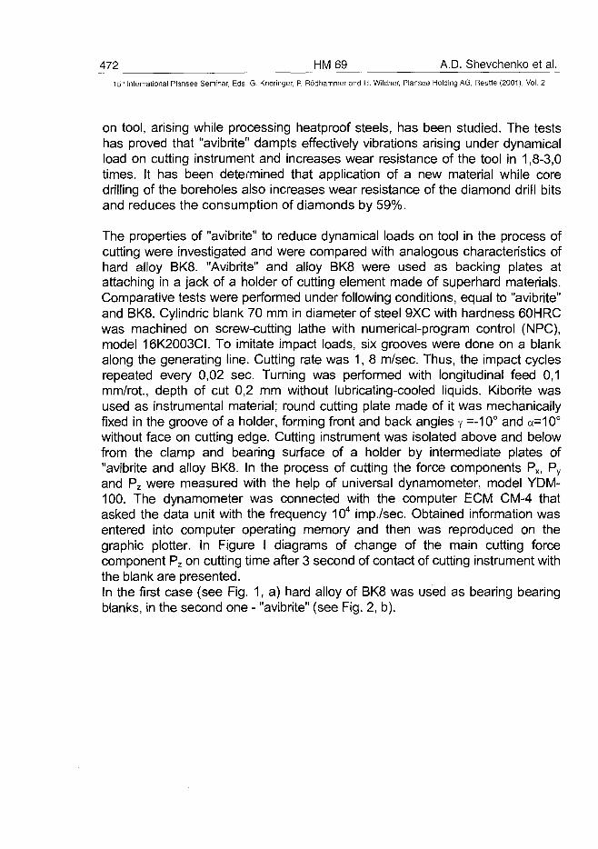
472 HM 69 A.D. Shevchenko et al.15Ln International Plansee Seminar, Eds. G. Kneringer, P. Rodhammer and H. Wildner, Plansee Holding AG, Reutte (2001), Vol. 2
on tool, arising while processing heatproof steels, has been studied. The testshas proved that "avibrite" dampts effectively vibrations arising under dynamicalload on cutting instrument and increases wear resistance of the tool in 1,8-3,0times. It has been determined that application of a new material while coredrilling of the boreholes also increases wear resistance of the diamond drill bitsand reduces the consumption of diamonds by 59%.
The properties of "avibrite" to reduce dynamical loads on tool in the process ofcutting were investigated and were compared with analogous characteristics ofhard alloy BK8. "Avibrite" and alloy BK8 were used as backing plates atattaching in a jack of a holder of cutting element made of superhard materials.Comparative tests were performed under following conditions, equal to "avibrite"and BK8. Cylindric blank 70 mm in diameter of steel 9XC with hardness 60HRCwas machined on screw-cutting lathe with numerical-program control (NPC),model 16K2003CI. To imitate impact loads, six grooves were done on a blankalong the generating line. Cutting rate was 1, 8 m/sec. Thus, the impact cyclesrepeated every 0,02 sec. Turning was performed with longitudinal feed 0,1mm/rot., depth of cut 0,2 mm without lubricating-cooled liquids. Kiborite wasused as instrumental material; round cutting plate made of it was mechanicallyfixed in the groove of a holder, forming front and back angles y =-10° and a=10°without face on cutting edge. Cutting instrument was isolated above and belowfrom the clamp and bearing surface of a holder by intermediate plates of"avibrite and alloy BK8. In the process of cutting the force components Px, Py
and Pz were measured with the help of universal dynamometer, model YDM-100. The dynamometer was connected with the computer ECM CM-4 thatasked the data unit with the frequency 104 imp./sec. Obtained information wasentered into computer operating memory and then was reproduced on thegraphic plotter. In Figure I diagrams of change of the main cutting forcecomponent Pz on cutting time after 3 second of contact of cutting instrument withthe blank are presented.In the first case (see Fig. 1, a) hard alloy of BK8 was used as bearing bearingblanks, in the second one - "avibrite" (see Fig. 2, b).
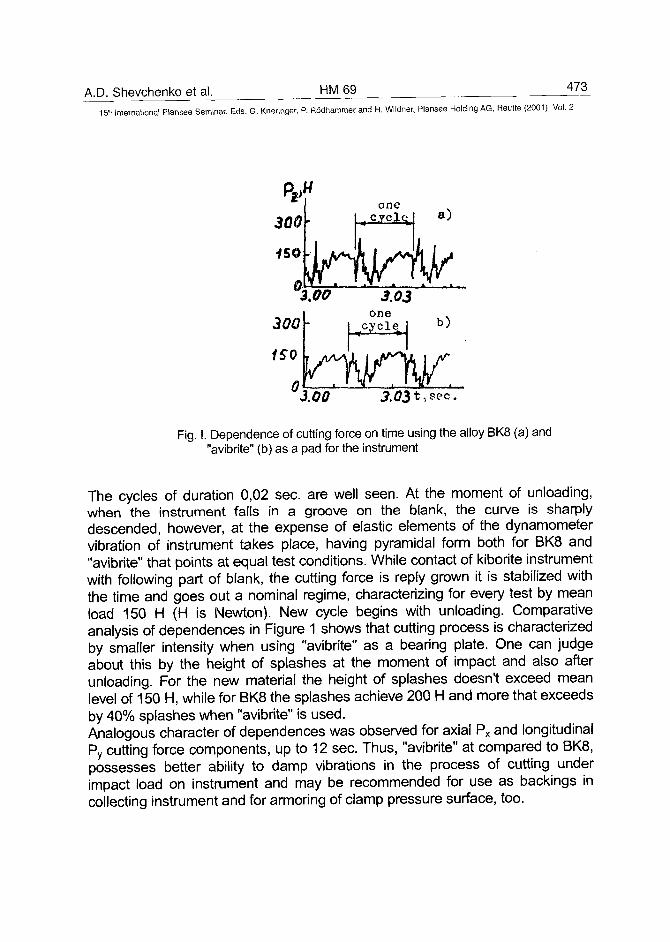
A.D. Shevchenko et al. HM69 473
15- International Plansee Seminar, Eds. G. Kneringer, P. Rodhammer and H. Wildner, Plansee Holding AG, Reutte (2001), Vol. 2
300
450
0
300
1S0
fl
•
\.oo
°3,00
onen c.yclc^
3.03one
Yl
k
y2.03*,
a)
b)
sec.
Fig. I. Dependence of cutting force on time using the alloy BK8 (a) and"avibrite" (b) as a pad for the instrument
The cycles of duration 0,02 sec. are well seen. At the moment of unloading,when the instrument falls in a groove on the blank, the curve is sharplydescended, however, at the expense of elastic elements of the dynamometervibration of instrument takes place, having pyramidal form both for BK8 and"avibrite" that points at equal test conditions. While contact of kiborite instrumentwith following part of blank, the cutting force is reply grown it is stabilized withthe time and goes out a nominal regime, characterizing for every test by meanload 150 H (H is Newton). New cycle begins with unloading. Comparativeanalysis of dependences in Figure 1 shows that cutting process is characterizedby smaller intensity when using "avibrite" as a bearing plate. One can judgeabout this by the height of splashes at the moment of impact and also afterunloading. For the new material the height of splashes doesn't exceed meanlevel of 150 H, while for BK8 the splashes achieve 200 H and more that exceedsby 40% splashes when "avibrite" is used.Analogous character of dependences was observed for axial Px and longitudinalPy cutting force components, up to 12 sec. Thus, "avibrite" at compared to BK8,possesses better ability to damp vibrations in the process of cutting underimpact load on instrument and may be recommended for use as backings incollecting instrument and for armoring of clamp pressure surface, too.
474 HM 69 A.D. Shevchenko et al.
15" International Plansee Seminar, Eds. G. Kneringer, P. Rodhammer and H. Wildner, Plansee Holding AG, Reutte (2001), Vol. 2
4. Conclusions
A new composite material with higher damping ability has been created withthe use of specialized technology. Application of vibration-damping elementsmade of new composite material in the cutting and drilling tools proved theeffective damping of the vibrations arising under permanent loads, impactand impact-rotations ones, resulting in considerable increase of wearresistance of cutting tools and diamond drill bits.
5. Acknowledgment
The author expresses deep gratitude to A.A. Shulzhenko for constant technicalassistance in performins of experiments with the use of high pressuretechniques, and also V.V. Nemoshkalenko - for constant interest in this work.
6. References
[1]. A.D. Shevchenko et al: - Physics and Technique of High Pressure (inRussia "Pizika i Tekhnika Vysokikh Davleni") 27 (1988), pp. 60-69
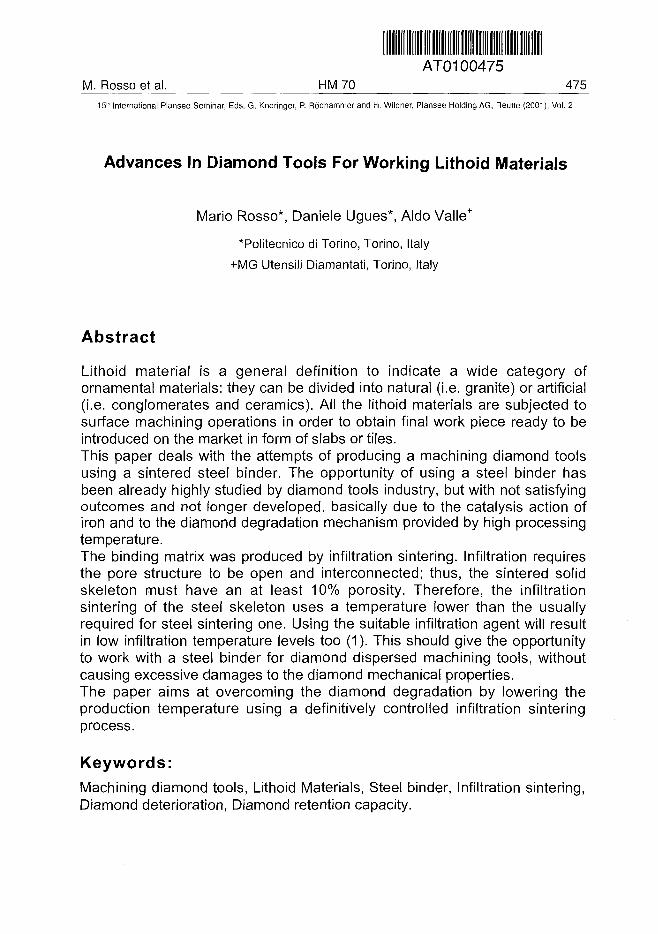
ATO100475. Rosso et al. HM 70 475^
15* International Plansee Seminar, Eds. G. Kneringer, P. Rodhammer and H. Wildner, Plansee Holding AG, Reutte (2001), Vol. 2
Advances In Diamond Tools For Working Lithoid Materials
Mario Rosso*, Daniele Ugues*, Aldo Valle+
*Politecnico di Torino, Torino, Italy
+MG Utensili Diamantati, Torino, Italy
Abstract
Lithoid material is a general definition to indicate a wide category ofornamental materials: they can be divided into natural (i.e. granite) or artificial(i.e. conglomerates and ceramics). All the lithoid materials are subjected tosurface machining operations in order to obtain final work piece ready to beintroduced on the market in form of slabs or tiles.This paper deals with the attempts of producing a machining diamond toolsusing a sintered steel binder. The opportunity of using a steel binder hasbeen already highly studied by diamond tools industry, but with not satisfyingoutcomes and not longer developed, basically due to the catalysis action ofiron and to the diamond degradation mechanism provided by high processingtemperature.The binding matrix was produced by infiltration sintering. Infiltration requiresthe pore structure to be open and interconnected; thus, the sintered solidskeleton must have an at least 10% porosity. Therefore, the infiltrationsintering of the steel skeleton uses a temperature lower than the usuallyrequired for steel sintering one. Using the suitable infiltration agent will resultin low infiltration temperature levels too (1). This should give the opportunityto work with a steel binder for diamond dispersed machining tools, withoutcausing excessive damages to the diamond mechanical properties.The paper aims at overcoming the diamond degradation by lowering theproduction temperature using a definitively controlled infiltration sinteringprocess.
Keywords:
Machining diamond tools, Lithoid Materials, Steel binder, Infiltration sintering,Diamond deterioration, Diamond retention capacity.
476 HM70 M. Rosso et al.15" International Plansee Seminar, Eds. G. Kneringer, P. Rodhammer and H. Wildner, Plansee Holding AG, Reutte (2001), Vol. 2
1. IntroductionSo far, in the production cycle of granite products the machining toolscommonly use magnesite or polyester binders and silicon carbide oraluminium oxide abrasive bits. This type of tools is subject to ageing andreacts with humidity, thus not ensuring long service life and, as aconsequence, providing a low productivity due to the frequent stops ofmachinery process for the machining tools substitution. The machineryoperations using these tools cause a high sludge productions with thefollowing waste disposal problems. As far as the polyester binder basedmachinery tools are concerned, those tools contain the hazardous solventstyrene: the styrene monomers continue to evaporate weeks later thanpolymerisation process has taken place; when the tool is in use thebreakdown and the de-polymerisation also result in styrene giving off.Moreover, the short service life of this type of tools means frequent completeor partial stops of the production lines. Whenever it is possible the toolchange is made without stopping the line, by raising the head bearing the setof tools to be changed, with great risk for operator safety and indeed bybreaking the line productivity. On the other hand, the use of this type ofmachinery tools provides low production costs as the main advantage.However, this indeed provides a not satisfying cost/benefit ratio and theecological-healthy hazards provided by this type of machinery tools alsohighly contrast with the main worldwide policies (2-6).
2. The Building Sector ScenarioThe building related activities make use of 70 per cent of the stone finishedproduct, and during 1998, improvements in this sense were registered only inthe United States, where the financial year closed with a rise of 10.2 per cent,that actually speaking is excellent. On the contrary, within the stone sector'smore significant contexts, and that is the European Union and Asia, the 1998results were not as positive: in the first case, the building related investmentsregistered an overall increase that was limited to 1.5 per cent, whilst in thesecond case significant falls were confirmed, such as those of Indonesia,Thailand and South Korea.Under these conditions, it is obvious that the rise in the world consumptionrates was the lowest of the past five years, remaining steady at three percent, taking the total to around 560 million equivalent square metres,corresponding to thirty million tonnes net, that is a new all time high.
M. Rosso et al. HM 70 47715th International Plansee Seminar, Eds. G. Kneringer, P. Rddhammer and H. Wildner, Plansee Holding AG, Reutte (2001), Vol. 2
The development of the stone sector has led to a no less significant growth inthe technologies sector, and firstly of machinery tools and plants, whoseimprovement, was the main cause for the production and stone consumptionincreases.The fall in the forward propelling movement that the stone sector experiencedin 1998 did not put a stop to its growth trend, that was actually enhanced, bythe contribution of the new financial year. Nevertheless, the rate of growth ofthe nineties has fallen by about one point, to below seven per cent, andtherefore, the hypothesis for future expansion, that as usual has been formed,with the removal statistics from the historic data, has been subject to aprocess of re-dimensioning, that over the short term has been only marginal,but more strongly felt over the long term. The forecast up to the newmillennium highlights a world consumption rate equal to 635 millionequivalent square metres, whilst that up to 2025 predicts it to be of aroundthree billion. In other words despite of the drop in the aforementioned rate,that is equal to 6.75 per cent, the latter forecast represents production andconsumption levels that are basically five times as great with respect to thoseof 1998. Similar considerations apply to trade, the rates of which, in thenineties, have remained over one point greater than those of production. Theresults is that, in the "coeteris paribus" evolution hypothesis, the forecasts tothe year 2000 and to the year 2025 indicate, traffic volumes of 325 and 2140million equivalent square metres. If the current incidence of trade productionis equal to 50 per cent, in just a quarter of a century this would rise to 75 percent, implying a propaedeutic solution of the complex infrastructure andstrategic solutions, that have been previously mentioned.In this continuously increasing development scenario of the stone sectors, itmust be taken into account that even small "technological inventions" arecapable to result in huge productivity gains and production-trade positiveinputs. Thus, the development of innovative low cost machinery toolsespecially increasing productivity, enhancing finished stone product quality,ensuring quality of life good levels, not environmental and not healthimpacting should be the key-points of a definite input for the finished stoneproducts industry.The trend of world production of lithoid materials within the period 1990 -1998 is shown in figure 1 (7).
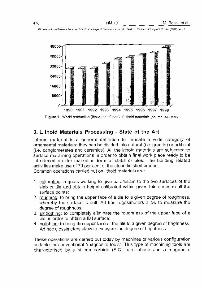
478 HM70 M. Rosso et al.15" International Plansee Seminar, Eds. G. Kneringer, P. Rodhammer and H. Wildner, Plansee Holding AG, Reutte (2001), Vol. 2
1990 1991 1992 1993 1994 1995 1996 1997 1998
Figure 1. World production (thousand of tons) of lithoid materials (source: ACIMM)
3. Lithoid Materials Processing - State of the ArtLithoid material is a general definition to indicate a wide category ofornamental materials: they can be divided into natural (i.e. granite) or artificial(i.e. conglomerates and ceramics). All the lithoid materials are subjected tosurface machining operations in order to obtain final work piece ready to beintroduced on the market in form of slabs or tiles. The building relatedactivities make use of 70 per cent of the stone finished product.Common operations carried out on lithoid materials are:
1. calibrating: a gross working to give parallelism to the two surfaces of theslab or tile and obtain height calibrated within given tolerances in all thesurface points;
2. roughing: to bring the upper face of a tile to a given degree of roughness,whereby the surface is dull. Ad hoc rugosimeters allow to measure thedegree of roughness;
3. smoothing: to completely eliminate the roughness of the upper face of atile, in order to obtain a flat surface;
4. polishing: to bring the upper face of the tile to a given degree of brightness.Ad hoc glossimeters allow to measure the degree of brightness.
These operations are carried out today by machines of various configurationsuitable for conventional "magnesite tools". This type of machining tools arecharacterised by a silicon carbide (SiC) hard phase and a magnesite
M. Rosso et al. HM 70 479^15" International Plansee Seminar, Eds. G. Kneringer, P. Rodhammer and H. Wildner, Plansee Holding AG, Reutte (2001), Vol. 2
(MgCO3) binder one. Theory and experience have proved that continuousswinging of the magnesite tool, normally having the shape of an isoscelestrapezium, allows for a continuous re-sharpening of the tool, whereby thesilicon carbide hold by the magnesite matrix makes the job of treating thesurface to be machined. A different composition of the magnesite binder, aswell as a different granulometry of the silicon carbide, allows the differentwork phases with these conventional magnesite tools, being currentlyemployed in all the machining steps of lithoid materials: calibrating, roughing,smoothing and polishing.However, the work performances of this type of tools are very poor from allpoints of view: work quality (abrasion capacity), work quantity (hours of life),work speed (belt speed). The short service life of this type of tools meansindeed frequent complete or partial stops of the production lines. Whenever itis possible the tool change is made without stopping the line, by raising thehead bearing the set of tools to be changed, with great risk for operator safetyand indeed by breaking the line productivity. The very short life of magnesitetools implies the need of enormous quantity of tools to be fitted and disposedof, at the end of their life, with significant waste to be disposed of.Furthermore, a line using magnesite tools produces 2 types of waste: onaverage 3 kg/h of toxic mud and additionally a great quantity of residual tools.Both mud and residual tools, create significant problems to the environment,and costs of waste disposal.The use of the magnesite tools results in frequent tool change and, as aconsequence, line stops. Further to the fact that the wear of magnesite toolsis very fast, it does not take place simultaneously due to the uneven durationof tools, according to the grits, that is: very short life of calibrating tools (= 2hours), medium of smoothing (~ 7 hours), long of polishing (=15 hours).Thus, the processing lines stop almost continuously. The actual practice is tocarry out the change of tools while operating causing high safety hazards forthe workers (8-9).The advent of new tools must aim at dramatically reducing the quantity ofmud, practically made only of removed material, and also the quantity of toolsin a proportion of say 1 every 15 days instead of 1 every 8,5 hours (that is 1every 360 hours, against one every 8,5 = 42,5 to 1).Even if the low productivity, the ecological and the health problems are highlyfelt by industry and public institutions, satisfying solutions are not so far welldeveloped. In the recent past, diamond tools (that is composite materialsusing metal matrix with diamond dispersion) have successfully replaced themachining magnesite tools only in the first step (calibrating) of machineryprocess. Research into the diamond machinery tools for siliceous product has
480 HM 70 M. Rosso et al.
15 International Plansee Seminar, Eds. G. Kneringer, P. Rodhammer and H. Wildner, Plansee Holding AG, Reutte (2001), Vol. 2
come out of the technical feasibility, to enter that related to the economicopportunities.The slow breaking through the market of diamond tools is basically due to therelated high costs. On the other hand, the increase in productivity provided bythis type of tools would be enormous.As above stated a dramatic issue that is closely tied to the technical problemsand how to solve them regards safety, that in the developed countries hasbeen subjected to the application of standards, such as the MachineryDirective laid down by the European Union: in fact, despite the attention paidto this matter, the rate of accidents and health problems caused by sludgeand powder production in this sector is still rather high. From this point ofview, even if the diamond tools readily eliminate the waste disposal problems,the so far developed technical solutions provides serious health hazards intheir production stage.Beside impregnated tools, inserted tools appeared, consisting of diamondcutters formed from numerous diamond particles firmly embedded in a rigidmatrix of a high wear and impact resistance. The full exploitation of thediamond properties in machining tools is possible only by using a metalmatrix of appropriate mechanical properties and high wear and corrosionresistance. Metal powders like cobalt, iron, tungsten, bronze and others, areused to produce a sintered metal matrix that is extremely tough, durable andwear resistant.The cobalt alloys are indeed the most common binders for diamond tools.The cobalt alloys are very high cost materials and the forming processcommonly used to produce these tools is the hot pressure sintering that is amajor cost increasing cause. Further to the economical aspects the healthissue provides another low interest point. The cobalt can easily get into yourbody by.
• breathing in dusts/mists containing cobalt.• by skin contact with dust or solutions containing cobalt.• by eating, drinking or smoking in cobalt work areas.
The health hazards related to cobalt use are:
1) Effects on the lungs:• 'hard-metal disease';• respiratory sensitisation;• asthma.
2) Effects on the skin:• allergic dermatitis.
M. Rosso et a l . H M 7015" International Plansee Seminar, Eds. G. Kneringer, P. Rddhammer and H. Wildner, Plansee Holding AG, Reutte (2001), Vol. 2
Thus, as far as the lithoid materials machinery tools are concerned, notcomplete satisfying solutions have been given so far to the following crucialproblems concerning:
1. short service life;2. low productivity;3. high sludge production;4. high costs;5. health hazards.
So far the scientific/technical research indeed developed some tools, i.e.cobalt based diamond tools, capable to eliminate the first three bad pointswhereas they couldn't solve the two last ones.
4. Experimental4.1 Materials and Research Activity
The MG Utensili Diamantati has promoted together with the Politecnico diTorino a large research activity dealing with the use of steel as a possiblebinder for diamond tools.The research programme has been split in two main sections:
a) study of the metal binder properties according to the selected sinteringparameters;
b) study of the metal binder-diamond interaction again according to theselected sintering parameters. Both natural (Deb Dust diamond batch)and synthetic diamond grains (De Beers and General Electric diamondbatches) have been used.
This research mainly aims at lowering the usual diamond dispersed steelultimate hardness (too high and thus not ensuring a good diamond retentioncapacity) according to the following parameters:
1) added carbon content (0%wt, 0.5%wt,1%wt);2) few copper powder additions to achieve in the final product a bronze
phase Cu content higher than the infiltration agent one;3) increased pressure to reduce the green porosity; this will result in a
reduced hardness enhancement during the infiltration step;4) reduced infiltration temperature levels using a 75/25 bronze alloy as
infiltration agent.
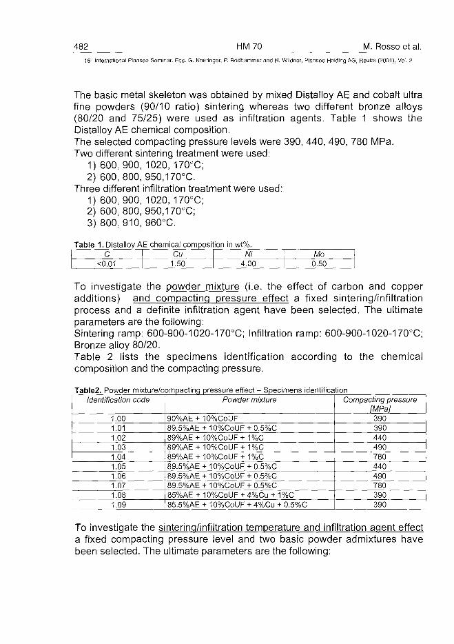
482 HM70 M. Rosso et al.15'-' International Plansee Seminar, Eds. G. Kneringer, P. Rodhammer and H. Wildner, Plansee Holding AG, Reutte (2001), Vol. 2
The basic metal skeleton was obtained by mixed Distalloy AE and cobalt ultrafine powders (90/10 ratio) sintering whereas two different bronze alloys(80/20 and 75/25) were used as infiltration agents. Table 1 shows theDistalloy AE chemical composition.The selected compacting pressure levels were 390, 440, 490, 780 MPa.Two different sintering treatment were used:
1) 600,900, 1020, 170°C;2) 600, 800, 950,170°C.
Three different infiltration treatment were used:1) 600,900, 1020, 170°C;2) 600, 800, 950,170°C;3) 800, 910, 960°C.
Table 1. Distalloy AE chemical compositionc
<0.01Cu
1.50
in wt%.Ni
4.00Mo
0.50
To investigate the powder mixture (i.e. the effect of carbon and copperadditions) and compacting pressure effect a fixed sintering/infiltrationprocess and a definite infiltration agent have been selected. The ultimateparameters are the following:Sintering ramp: 600-900-1020-170°C; Infiltration ramp: 600-900-1020-170°C;Bronze alloy 80/20.Table 2 lists the specimens identification according to the chemicalcomposition and the compacting pressure.
Table2. Powder mixture/compacting pressure effect - Specimens identificationIdentification code
1.001.011.021.031.041.05
Powder mixture
90%AE+ 10%CoUF89.5%AE + 10%CoUF + 0.5%C89%AE + 10%CoUF + 1%C89%AE + 10%CoUF + 1%C89%AE + 10%CoUF + 1%C89.5%AE + 10%CollF + 0.5%C
1.06 89.5%AE + 10%CoUF + 0.5%C1.071.08
89.5%AE + 10%CoUF + 0.5%C85%AE + 10%CoUF + 4%Cu + 1%C
1.09 85.5%AE + 10%CollF + 4%Cu + 0.5%C
Compacting pressure[MPa]390390440490780440490780390390
To investigate the sintering/infiltration temperature and infiltration agent effecta fixed compacting pressure level and two basic powder admixtures havebeen selected. The ultimate parameters are the following:
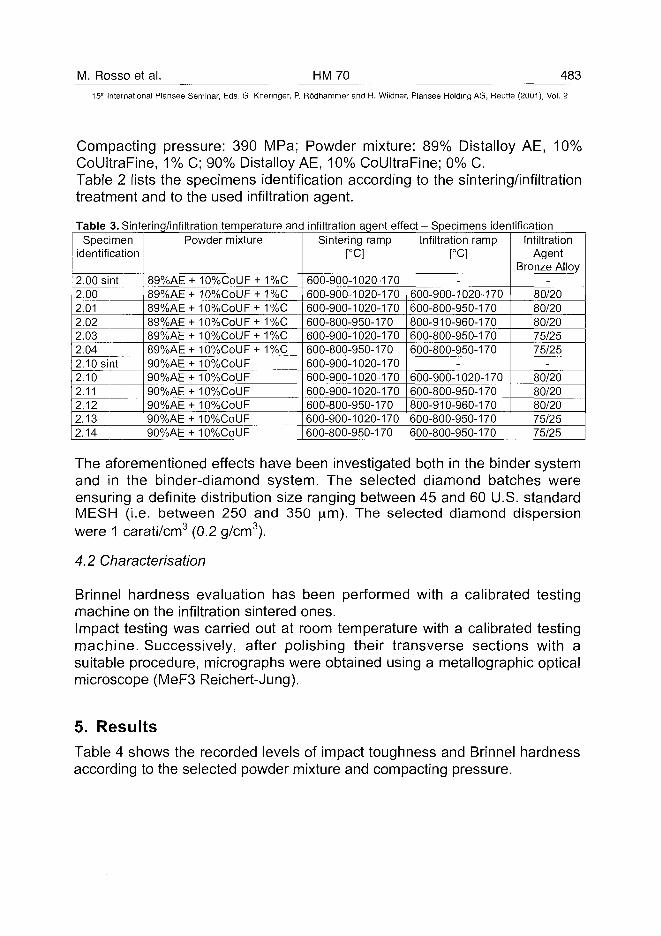
M. Rosso et al. HM70 483
15" International Plansee Seminar, Eds. G. Kneringer, P. Rodhammer and H. Wildner, Plansee Holding AG, Reutte (2001), Vol. 2
Compacting pressure: 390 MPa; Powder mixture: 89% Distalloy AE, 10%CoUltraFine, 1% C; 90% Distalloy AE, 10% CoUltraFine; 0% C.Table 2 lists the specimens identification according to the sintering/infiltrationtreatment and to the used infiltration agent.
Table 3. Sintering/infiltration temperatureSpecimen
identification
2.00 sint2.002.012.022.032.042.10 sint2.102.112.122.132.14
Powder mixture
89%AE -89%AE 89%AE H89%AE H89%AE H89%AE H90%AE H90%AE H90%AE H90%AE H90%AE H90%AE H
H 10%CoUF+ 1%(H0%CoUF+1%CH 10%CoUF+ 1%CH 10%CoUF+ 1%CH 10%CoUF+ 1%CH 10%CoUF+ 1%CM0%CoUFH0%CoUFH0%CoUFH0%CoUFH0%CoUFH0%CoUF
anc
j
-i
j
- \
j
>
infiltration agent effect - Specimens identificationSintering ramp
600-900-1020-170600-900-1020-170600-900-1020-170600-800-950-170600-900-1020-170600-800-950-170600-900-1020-170600-900-1020-170600-900-1020-170600-800-950-170600-900-1020-170600-800-950-170
Infiltration ramp
-600-900-1020-170600-800-950-170800-910-960-170
^00-800-950-170600-800-950-170
-600-900-1020-170600-800-950-170800-910-960-170600-800-950-170600-800-950-170
InfiltrationAgent
Bronze Alloy-
80/2080/2080/2075/2575/25
-
80/2080/2080/2075/2575/25
The aforementioned effects have been investigated both in the binder systemand in the binder-diamond system. The selected diamond batches wereensuring a definite distribution size ranging between 45 and 60 U.S. standardMESH (i.e. between 250 and 350 jam). The selected diamond dispersionwere 1 carati/cm3 (0.2 g/cm3).
4.2 Characterisation
Brinnel hardness evaluation has been performed with a calibrated testingmachine on the infiltration sintered ones.Impact testing was carried out at room temperature with a calibrated testingmachine. Successively, after polishing their transverse sections with asuitable procedure, micrographs were obtained using a metallographic opticalmicroscope (MeF3 Reichert-Jung).
5. Results
Table 4 shows the recorded levels of impact toughness and Brinnel hardnessaccording to the selected powder mixture and compacting pressure.
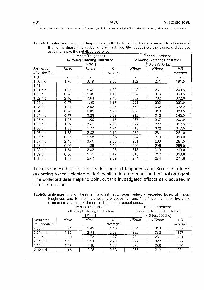
484 HM70 M. Rosso et al.15" International Plansee Seminar, Eds. G. Kneringer, P. Rodhammer and H. Wildner, Plansee Holding AG, Reutte (2001), Vol. 2
Table4. Powder mixture/compacting pressure effectBrinnel hardness (the codes "d" and "n.d."specimens and the not dispersed ones).
- Recorded levels of impact toughness andidentify respectively the diamond dispersed
SpecimenIdentification1.00 d1.00 n.d.1.01 d1.01 n.d.1.02 d1.02 n.d.1.03 d1.03 n.d.1.04 d1.04 n.d.1.05 d1.05 n.d.1.06 d1.06 n.d.1.07 d1.07 n.d1.08 d1.08 n.d.1.09 d1.09 n.d.
Impact Toughnessfollowing Sintering+lnfiltration
[J/cm2]Kmin
-1.75
-
1.150.782.180.971.040.980.771.061.891.031.580.972.180.991.540.861.53
Kmax
-3.19
-1.491.353.641.903.032.093.281.603.431.772.831.583.401.292.331.592.47
Kaverage
-2.36
-1.301.102.731.272.231.262.581.152.431.212.121.252.601.151.861.172.09
Brinnel Hardnessfollowing Sintering+lnfiltration
[j10ball/3000kglHBmin
-182
-238304332332332288342267322313281304281296313313274
HBmax
-201
-261313332332332313342267322322281313288296313313274
HBaverage
-191.5
-249.5308.5332.0332.0332.0300.5342.0267.0322.0317.5281.0313.0284.5296.0313.0313.0274.0
Table 5 shows the recorded levels of impact toughness and Brinnel hardnessaccording to the selected sintering/infiltration treatment and infiltration agent.The collected data helps to point out the investigated effects as discussed inthe next section.
Table5. Sintering/infiltration treatment and infiltration agent effect - Recorded levels of impacttoughness and Brinnel hardness (the codes "d" and "n.d." identify respectively thediamond dispersed specimens and the not dispersed ones).
SpecimenIdentification2.00 d2.00 n.d.2.01 d2.01 n.d.2.02 d2.02 n.d.
Impact Toughnessfollowing Sintering+lnfiltration
[J/cm2]Kmin
0.811.620.991.461.071.45
Kmax
1.492.411.732.911.402.75
Kaverage
1.132.031.272.201.262.33
Brinnel Hardnessfollowing Sintering+lnfiltration
[Ji0baII/3000kg]HBmin
304322281322232255
HBmax
313332281322288313
HBaverage
309327281322260284
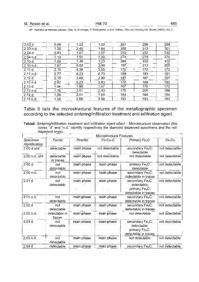
M. Rosso et al. HM70 485
15'h International Plansee Seminar, Eds. G. Kneringer, P. Rodhammer and H. Wildner, Plansee Holding AG, Reutte (2001), Vol. 2
2.03 d2.03 n.d.2.04 d2.04 n.d.2.10 d2.10 n.d.2.11 d2.11 n.d.2.12 d2.12 n.d2.13d2.13 n.d.2.14 d2.14 n.d.
0.891.350.831.101.061.972.192.772.152,921,041.761.091.58
1.222.401.611.511.386.824.399.233.885.231.963.512.012.69
1.021.841.071.301.233.903.056.732.803.831.472.431.602.08
281288232274288197170189167176167170164193
296313232274332213173193167189176205164193
289301232274310205172191167183172188164193
Table 6 lists the microstructural features of the metallographic specimenaccording to the selected sintering/infiltration treatment and infiltration agent.
Table6. Sintering/infiltration treatment and infiltration agent effect - Microstructure observation (thecodes "d" and "n.d." identify respectively the diamond dispersed specimens and the notdispersed ones).
SpecimenIdentification2.00 d sint
2.00 n.d. sint
2.00 d
2.00 n.d.
2.01 d
2.01 n.d.
2.02 d
2.02 n.d.
2.03 d
2.03 n.d.
2.04 d
Microstructural FeaturesFerrite
detectable
detectablein traces
notdetectable
notdetectable
notdetectable
notdetectable
notdetectable
detectable intraces
notdetectable
notdetectabledetectable
Pearlite
main phase
main phase
main phase
main phase
main phase
main phase
main phase
main phase
main phase
main phase
main phase
Fe-Cu-C
not detectable
not detectable
main phase
main phase
main phase
main phase
main phase
main phase
main phase
main phase
main phase
Primary Fe3C
secondary Fe3C:detectable
not detectable
primary Fe3C:detectable
secondary Fe3C:detectable in traces
secondary Fe3C:detectable;
primary Fe3C:detectable in traces
secondary Fe3C:detectable in traces
secondary Fe3C:detectable in traces
not detectable
secondary Fe3C:detectable;
primary Fe3C:detectable in traces
not detectable
secondary Fe3C:
Fe-Cu
not detectable
not detectable
not detectable
not detectable
not detectable
not detectable
not detectable
not detectable
not detectable
not detectable
not detectable
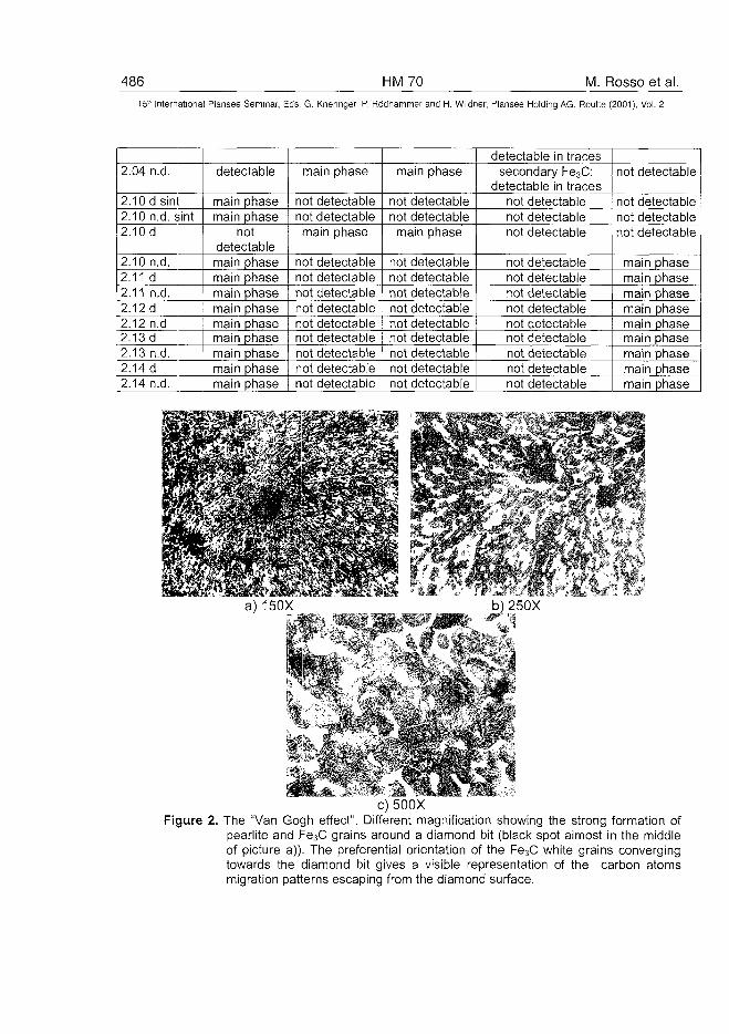
486 HM70 M. Rosso et al.15" Internationa! Plansee Seminar, Eds. G. Kneringer, P. Rodhammer and H. Wildner, Plansee Holding AG, Reutte (2001), Vol. 2
2.04 n.d.
2.10dsint2.10 n.d. sint2.10 d
2.10 n.d.2.11 d2.11 n.d.2.12d2.12 n.d2.13 d2.13 n.d.
detectable
main phasemain phase
notdetectablemain phasemain phasemain phasemain phasemain phasemain phasemain phase
2.14 d main phase2.14 n.d. ] main phase
main phase
not detectablenot detectablemain phase
not detectablenot detectablenot detectablenot detectablenot detectablenot detectablenot detectablenot detectable
main phase
not detectablenot detectablemain phase
not detectablenot detectablenot detectablenot detectablenot detectablenot detectablenot detectablenot detectable
not detectable not detectable
detectable in tracessecondary Fe3C:
detectable in tracesnot detectablenot detectablenot detectable
not detectablenot detectablenot detectablenot detectablenot detectablenot detectablenot detectablenot detectablenot detectable
not detectable
not detectablenot detectablenot detectable
main phasemain phasemain phasemain phasemain phasemain phasemain phasemain phasemain phase
c) 500XFigure 2. The "Van Gogh effect". Different magnification showing the strong formation of
pearlite and Fe3C grains around a diamond bit (black spot almost in the middleof picture a)). The preferential orientation of the Fe3C white grains convergingtowards the diamond bit gives a visible representation of the carbon atomsmigration patterns escaping from the diamond surface.
M. Rosso et al. HM 70 48715'* International Plansee Seminar, Eds. G. Kneringer, P. Rodhammer and H. Wildner, Plansee Holding AG, Reutte (2001), Vol. 2
Figure 2 represents the effect of high interaction between the diamond bitsand the steel matrix in the diamond dispersed 2.10 specimen. The carboncontent in the powder mixture was set to zero; the sintering/infiltrationtreatment was carried out using 1020°C as maximum temperature; theinfiltration agent was the bronze alloy 80/20. It is readily detectable a strongmigration of carbon atoms from the diamond outer surface towards theDistalloy AE binder matrix. This causes a diamond properties fastdeterioration and results in a wide generation of pearlite and Fe3C grains.Since this results in a definite "artistic pattern" around the diamond bits, wedecided to refer the described effect as "Van Gogh effect".
6. DiscussionThe performances of diamond tools are to a great extent determined by theproperties of the matrix and by its capacity to firmly embed the diamondparticles, referred as "diamond retention capacity".We found out a readily detectable deterioration of the either natural orsynthetic diamond during the infiltration sintering treatment. As previouslystated, the phenomenon can be described as a carbon atom migration fromthe outer surface layer of the diamond bits into the Distalloy AE matrix. Thediamonds undergo an actual graphitisation process with serious deteriorationof the mechanical properties and of the bonding with the steel matrix, thuslowering the diamond retention capacity of the diamond tool. The steel matrixshows evidence of pearlite and Fe3C grains formation due to the carbonenrichment (those phases are usually hard to detect in the correspondingspecimens without diamond dispersion). This results in a not controlled steelmatrix hardness enhancement, that is highly undesirable as it lowers againthe matrix diamond retention capacity. The hardness increases from about200 HB to 300 HB with a related dramatic decrease of the impact toughness.The ultimate outcome of the so called Van Gogh effect lies in the fact that thehardness level becomes not dependent on the carbon content in the diamonddispersed specimens. However, following the infiltration sintering treatment,the dispersed specimens never achieved a hardness level as high as the oneof the not diamond dispersed 1% carbon containing specimens.The Van Gogh effect develops at the higher infiltration sintering temperature(1020°C). Since it has not been observed in the sintering step (performedagain at 1020°C), the infiltration agent seems to act as a catalyst of thegraphitisation mechanism.The wide characterisation gives clear clues to the fact that the lower is thecarbon content in the steel matrix and the higher is the diamond deterioration
488 HM70 M. Rosso et al.15" International Plansee Seminar, Eds. G. Kneringer, P. Rodhammer and H. Wildner, Plansee Holding AG, Reutte (2001), Vol. 2
leading to higher hardness increases. This criteria must be restricted only tothe 1020°C infiltration treatment and no attempts have been carried out usingcarbon content higher than 1%wt.Using lower infiltration temperature, that is 950°C, the Van Gogh effect doesnot occur. The hardness of the diamond dispersed specimens and of the notdispersed ones achieves almost the same levels and it obeys again to agraphite content dependent law. Thus, it is advisable to produce diamonddispersed steel machining tools exhibiting carbon content lower than 1%wtusing the low temperature sintering/infiltration treatment (950°C).To use a 75/25 bronze alloy and small Cu addition to the powder mixture canfurther help to lower the infiltration temperature.Furthermore, the research experience also suggests to focus on highcompacting pressure levels obtaining lower sintered porosity and thus a lowerhardness enhancement during the infiltration treatment.
7. ConclusionThis paper aims at providing the basis for giving an actual chance to the useof steel as binder for the machining diamond tools. The opportunity for theactual transfer of the studied theories to an industrial scale-up has beenalready tested by the good cooperation between the scientific soul and theindustrial one developed in the hereby paper.In practice, the complete exploitation of machining diamond tools using steelbinders at an industrial level will provide the high benefit/cost ratio that is theactual reason of the so far lithoid materials sector high distrust in the diamondtools. The research is indeed not over but the light has been turned on!
8. References1. J.E.Elliot, In "Hoeganas - Iron Powder Handbook", Vol. I/E, chapter 30,
Q.I.M. Bound Brook Bearing Ltd, England, pp. 17-26.2. P.L. Cavallotti: "Surfaces Technologies", The Italian Metallurgy Review,
6/983. G: Damiani: "Stone Processing", Marmo Macchine Directory, 93/944. P.Poggiana: "Surface Treatment for Stone Materials. Smoothing and
Polishing", Marmo Macchine Directory, 97/985. P. Primavori: "Surface Treatment of Ornamental Stones", Marmo
Macchine Review No 143, 5/98

/I. Rosso et al. HM 70 489
15'h International Plansee Seminar, Eds. G. Kneringer, P. Rodhammer and H. Wildner, Plansee Holding AG, Reutte (2001), Vol. 2
6. A. Morandini: "Measurement of Brightness Degree of Lithoid Materials",2nd Congress Brasil Italy of Mining engineering, San Paulo Brasil 93
7. Assomarmi: "Report on Italian Lithoid Industry", Marble and IndustryReview -1/97
8. D.N. Wright: "Measurement of Surface Finish", Industrial DiamondReview -1/93
9. De Beers technical service: "Report 4.100.301 On Granite Polishing", 97.
AT0100476490 HM72 S. Liu et al.
15" International Plansee Seminar, Eds. G. Kneringer, P. Rodhammer and H. Wildner, Plansee Holding AG, Reutte (2001), Vol. 2
Chemical Pretreatments At The Surface Of WC-15 wt% CoFor Diamond Coatings
Liu Sha1, Yu Zhiming1, Yi Danqing1, Li Yongxia2
1. Department of Materials Science & Engineering, Central South University,Changsha, Hunan 410083,P. R. Of China
2. Hunan Yin Zhou Nonferrous Metals Hi-Tech. Ltd. Company, Changsha,Hunan 410083,P. R. Of China
Abstract:
Diamond films were deposited on the cemented carbide WC-15%Cosubstrates by a hot-filament chemical vapor deposition reactor. Thesubstrate surfaces were chemically pretreated with the two-step etchingmethod, using first Murakami reagent for 1-3 min., and afterwards an HNO3:HCI=1:1 solution for 10-40 min. . It is indicated that the Co content of thesubstrate surfaces could be reduced from 15% to 0.81-6.04% within theetching depth of 5-10 j^rri, and the surface roughness of the substrates wasincreased up to Ra=1.0 ^m, the substrates hardness was decreased from89.0 HRA to 83.0 HRA after the two-step etching. It is observed that themorphologies of the diamond films on the WC-15%Co substrates emerge invarious shapes. The indentation testing shows that the good adhesionbetween diamond film and the substrate after HF CVD deposition could beobtained.
Keywords:
chemical pretreatments, cemented carbides, diamond coatings
1.Introduction:
Diamond coatings offer the possibility of superior wear resistant, low frictionand chemically protective coatings '1]. At present, the most of the effortswere concentrated on diamond coatings on low cobalt grades of cementedcarbide tools (typically<6%). R. Bichle et al. found the nucleation rate of
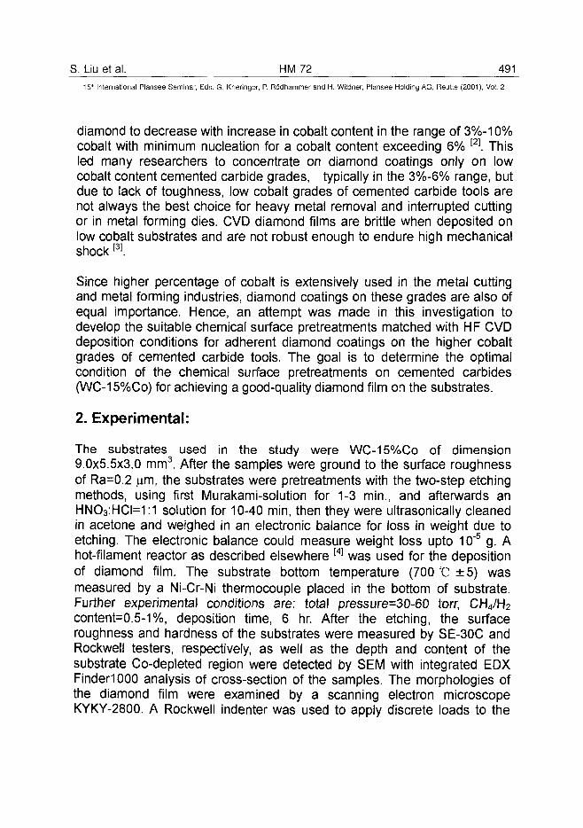
S. Liu et al. HM 72 4EM_15* International Plansee Seminar, Eds. G. Kneringer, P. Rodhammer and H. Wildner, Plansee Holding AG, Reutte (2001), Vol. 2
diamond to decrease with increase in cobalt content in the range of 3%-10%cobalt with minimum nucleation for a cobalt content exceeding 6% [2]. Thisled many researchers to concentrate on diamond coatings only on lowcobalt content cemented carbide grades, typically in the 3%-6% range, butdue to lack of toughness, low cobalt grades of cemented carbide tools arenot always the best choice for heavy metal removal and interrupted cuttingor in metal forming dies. CVD diamond films are brittle when deposited onlow cobalt substrates and are not robust enough to endure high mechanicalshock[3].
Since higher percentage of cobalt is extensively used in the metal cuttingand metal forming industries, diamond coatings on these grades are also ofequal importance. Hence, an attempt was made in this investigation todevelop the suitable chemical surface pretreatments matched with HF CVDdeposition conditions for adherent diamond coatings on the higher cobaltgrades of cemented carbide tools. The goal is to determine the optimalcondition of the chemical surface pretreatments on cemented carbides(WC-15%Co) for achieving a good-quality diamond film on the substrates.
2. Experimental:
The substrates used in the study were WC-15%Co of dimension9.0x5.5x3.0 mm3. After the samples were ground to the surface roughnessof Ra=0.2 jxm, the substrates were pretreatments with the two-step etchingmethods, using first Murakami-solution for 1-3 min., and afterwards anHNO3:HCI=1:1 solution for 10-40 min, then they were ultrasonically cleanedin acetone and weighed in an electronic balance for loss in weight due toetching. The electronic balance could measure weight loss upto 10~5 g. Ahot-filament reactor as described elsewhere [4] was used for the depositionof diamond film. The substrate bottom temperature (700 °C ±5) wasmeasured by a Ni-Cr-Ni thermocouple placed in the bottom of substrate.Further experimental conditions are: total pressure=30-60 torr, CH4/H2content=0.5-1%, deposition time, 6 hr. After the etching, the surfaceroughness and hardness of the substrates were measured by SE-30C andRockwell testers, respectively, as well as the depth and content of thesubstrate Co-depleted region were detected by SEM with integrated EDXFinderiOOO analysis of cross-section of the samples. The morphologies ofthe diamond film were examined by a scanning electron microscopeKYKY-2800. A Rockwell indenter was used to apply discrete loads to the
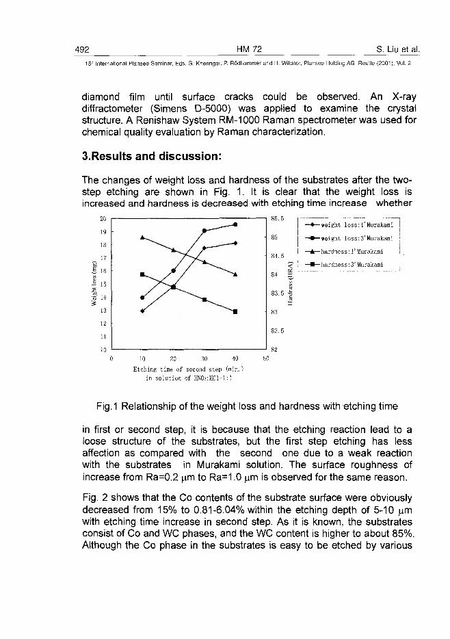
492 HM72 S. Liu et al.15' International Plansee Seminar, Eds. G. Kneringer, P. Rodhammer and H. Wildner, Plansee Holding AG, Reutte (2001), Vol. 2
diamond film until surface cracks could be observed. An X-raydiffractometer (Simens D-5000) was applied to examine the crystalstructure. A Renishaw System RM-1000 Raman spectrometer was used forchemical quality evaluation by Raman characterization.
3.Results and discussion:
The changes of weight loss and hardness of the substrates after the two-step etching are shown in Fig. 1. It is clear that the weight loss isincreased and hardness is decreased with etching time increase whether
-weight loss:1'Murakami
-weight loss:3'Murakami
- hardness:1'Murakami
- hardness:3'Murakami
8210 20 30 40
Etching time of second step (min.)in solution of HNOs:HCl=l:l
50
Fig.1 Relationship of the weight loss and hardness with etching time
in first or second step, it is because that the etching reaction lead to aloose structure of the substrates, but the first step etching has lessaffection as compared with the second one due to a weak reactionwith the substrates in Murakami solution. The surface roughness ofincrease from Ra=0.2 | m to Ra=1.0 ^m is observed for the same reason.
Fig. 2 shows that the Co contents of the substrate surface were obviouslydecreased from 15% to 0.81-6.04% within the etching depth of 5-10 urnwith etching time increase in second step. As it is known, the substratesconsist of Co and WC phases, and the WC content is higher to about 85%Although the Co phase in the substrates is easy to be etched by various
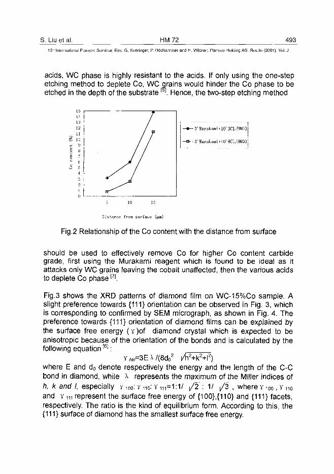
S. Liu et al. HM72 49315" International Plansee Seminar, Eds. G. Kneringer, P. Rodhammer and H. Wildner, Plansee Holding AG, Reutte (2001), Vol. 2
acids, WC phase is highly resistant to the acids. If only using the one-stepetching method to deplete Co, WC grains would hinder the Co phase to beetched in the depth of the substrate []. Hence, the two-step etching method
3' Murakami*10' HC1/HN03
3' Murakami+40' HC1/HN03
Distance from surface
Fig.2 Relationship of the Co content with the distance from surface
should be used to effectively remove Co for higher Co content carbidegrade, first using the Murakami reagent which is found to be ideal as itattacks only WC grains leaving the cobalt unaffected, then the various acidsto deplete Co phase[3].
Fig. 3 shows the XRD patterns of diamond film on WC-15%Co sample. Aslight preference towards {111} orientation can be observed in Fig. 3, whichis corresponding to confirmed by SEM micrograph, as shown in Fig. 4. Thepreference towards {111} orientation of diamond films can be explained bythe surface free energy (y)of diamond crystal which is expected to beanisotropic because of the orientation of the bonds and is calculated by thefollowing equation[6]:
y ftW=3E A /(8d02 /h2+k2+l2)
where E and d0 denote respectively the energy and the length of the C-Cbond in diamond, while A represents the maximum of the Miller indices ofh, k and I, especially y 100: Yn0: Y m=1:1/ /2~: 1/ /3~, where y 100, Y HOand y m represent the surface free energy of {100},{110} and {111} facets,respectively. The ratio is the kind of equilibrium form. According to this, the{111} surface of diamond has the smallest surface free energy.
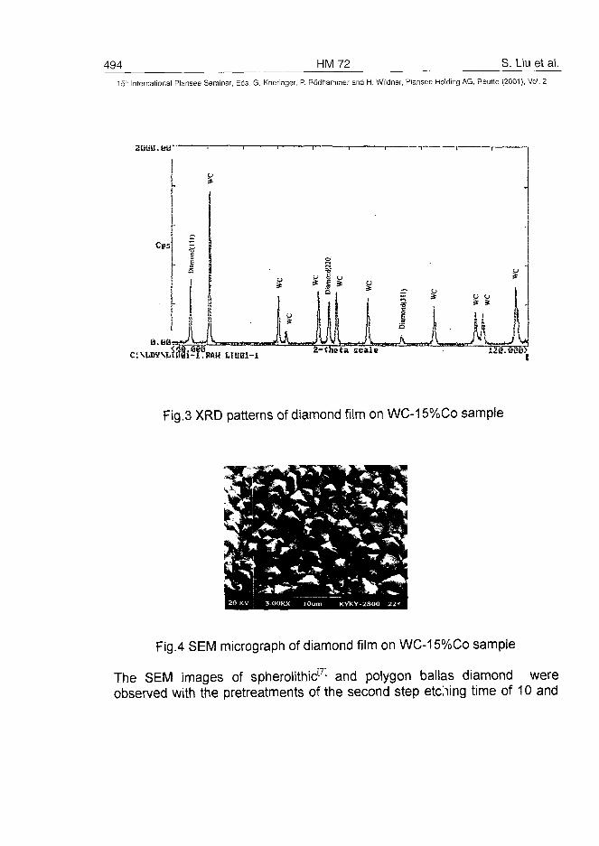
494 HM72 S. Liu et al.
15" International Plansee Seminar, Eds. G. Kneringer, P. Rodhammer and H. Wildner, Plansee Holding AG, Reutte (2001), Vol. 2
2UGU.JJS" - i 1 1 • r -
I i
Fig.3 XRD patterns of diamond film on WC-15%Co sample
Fig.4 SEM micrograph of diamond film on WC-15%Co sample
The SEM images of spherolithicm and polygon ballas diamond wereobserved with the pretreatments of the second step etching time of 10 and
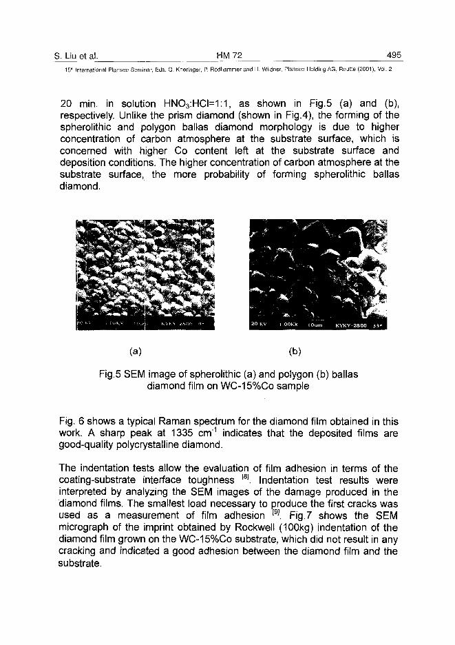
S. Liu et al. HM 72 495^
15" International Plansee Seminar, Eds. G. Kneringer, P. Rodhammer and H. Wildner, Plansee Holding AG, Reutte (2001), Vol. 2
20 min. in solution HNO3:HCI=1:1, as shown in Fig.5 (a) and (b),respectively. Unlike the prism diamond (shown in Fig.4), the forming of thespherolithic and polygon ballas diamond morphology is due to higherconcentration of carbon atmosphere at the substrate surface, which isconcerned with higher Co content left at the substrate surface anddeposition conditions. The higher concentration of carbon atmosphere at thesubstrate surface, the more probability of forming spherolithic ballasdiamond.
(a) (b)
Fig.5 SEM image of spherolithic (a) and polygon (b) ballasdiamond film on WC-15%Co sample
Fig. 6 shows a typical Raman spectrum for the diamond film obtained in thiswork. A sharp peak at 1335 cm"1 indicates that the deposited films aregood-quality polycrystalline diamond.
The indentation tests allow the evaluation of film adhesion in terms of thecoating-substrate interface toughness [8J. Indentation test results wereinterpreted by analyzing the SEM images of the damage produced in thediamond films. The smallest load necessary to produce the first cracks wasused as a measurement of film adhesion f9]. Fig. 7 shows the SEMmicrograph of the imprint obtained by Rockwell (100kg) indentation of thediamond film grown on the WC-15%Co substrate, which did not result in anycracking and indicated a good adhesion between the diamond film and thesubstrate.
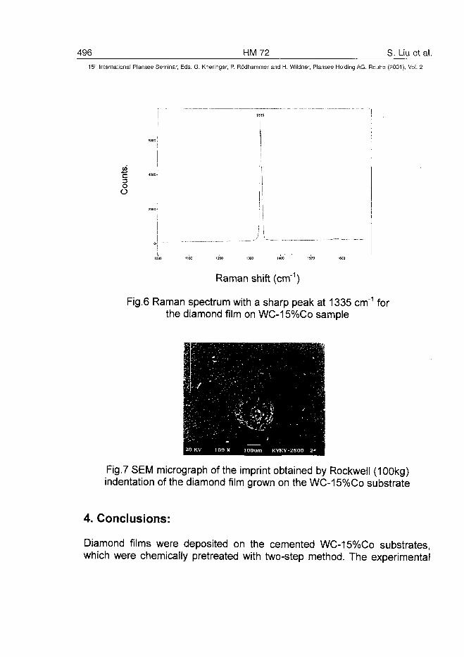
496 HM72 S. Liu et al.5" International Plansee Seminar, Eds. G. Kneringer, P. Rodhammer and H. Wildner, Plansee Holding AG, Reutte (2001), Vol. 2
IO
o
1000 11CO 1200 1300 1400 1500 1600
Raman shift (cm"1)
Fig.6 Raman spectrum with a sharp peak at 1335 cm"1 forthe diamond film on WC-15%Co sample
Fig.7 SEM micrograph of the imprint obtained by Rockwell (100kg)indentation of the diamond film grown on the WC-15%Co substrate
4. Conclusions:
Diamond films were deposited on the cemented WC-15%Co substrates,which were chemically pretreated with two-step method. The experimental
S. Liu et al. HM 72 497_15" International Plansee Seminar, Eds. G. Kneringer, P. Rodhammer and H. Wildner, Plansee Holding AG, Reutte (2001), Vol. 2
results show the following conclusions.(1) After the two-step etching, it is indicated that the Co content of the
substrate surfaces could be reduced from 15% to 0.81-6.04% within theetching depth of 5-10 fim, the surface roughness of the substrates wasincreased up to Ra=1.0 u.m, and the substrates hardness was decreasedfrom 89.0 HRA to 83.0 HRA.
(2) It is observed that the morphologies of the diamond films on theWC-15%Co substrates emerge in various shapes.
(3) The indentation testing shows that the good adhesion between diamondfilm and the WC-15%Co substrate after HF CVD deposition couldobtained.
Acknowledgements
We are grateful to the staff of Hunan Yin Zhou Nonferrous Metals Hi-Tech.Ltd. Company for cemented carbides samples. This work was supported byHunan Science and Technology Commission and State Key Laboratory forPowder Metallurgy of China.
References
1. Nita Dilawar et al, Thin Solid Films 323 (1998), pp.163-1692. R. Bichler et al, Proceedings of the 6th European CVD Conference,
salem, Israel, 1987, pp.413-4223. K. Mallika et al, Wear 224 (1999), pp. 245-2664. Z. Yu et al, Diamond and Related Materials 6 (1997), pp.81-845. Liu Sha et al, Rare Metals Materials and Engineering, in press (in Chinese)6. Z. Yu et al, Surface Science 401 (1998), pp.236-2477. T. Kolber et al, Int. J. Of Refractory Metals & Hard Materials 17 (1999), pp.
445-4528. R. Polini et al, Surface and Coatings Technology 123 (2000), pp.78-839. S. Silva et al, Diamond and Related Materials 8 (1999), pp. 1913-1918
AT0100477498 HM73 K. Zhou et al.
15" International Plansee Seminar, Eds. G. Kneringer, P. Rodhammer and H. Wildner, Plansee Holding AG, Reutte (2001), Vol. 2
The Study on Diamond-Coated Insert by
DC Plasma Jet CVD
Zhou Kesong*, Dai Mingjiang*, Song Jinbing*, Kuang Tongchun+, Liu Zhengyi"1"
*Guangzhou Research Institute of Nonferrous Metals, Guangzhou, PR. China+South China University of Technology, PR. China
Summary
Diamond coating were deposited on cemented carbide inserts by DC plasmajet CVD. The cemented carbide inserts were pretreated by methods includingchemical etching of Co, Ar/H2 plasma etching. The characteristics of diamondfilm, interface structure, adhesion strength and film stress were analysized bydifferent methods such as SEM, XRD, Raman spectrum etc. A comparingexperiment of cutting Al - 22% Si alloy was carried out with diamond-coatedcemented carbide inserts and uncoated cemented carbide inserts. Theresults show that the diamond-coated cemented carbide insert has a greatadvantage for cutting abrasive high content Al - Si alloy.
Keywords
Diamond, coatings, DC plasma jet, cemented carbide, inserts
1. Introduction
Low pressure CVD diamond coating can prolong the lifetime of cementedcarbide cutting tools applied for working on nonferrous materials due to itsexcellent mechanical properties, especially its extreme high hardness, lowfriction coefficient as well as good chemical and wear resistance. Diamond-coated tools are suitable for dry machining without expensive coolants, whichare hazardous to the environment (1). However it's well known that cobalt incemented carbide has a negative effect on the deposition of diamond coating,resulting in low nucleation rates, formation of graphite carbon and poor
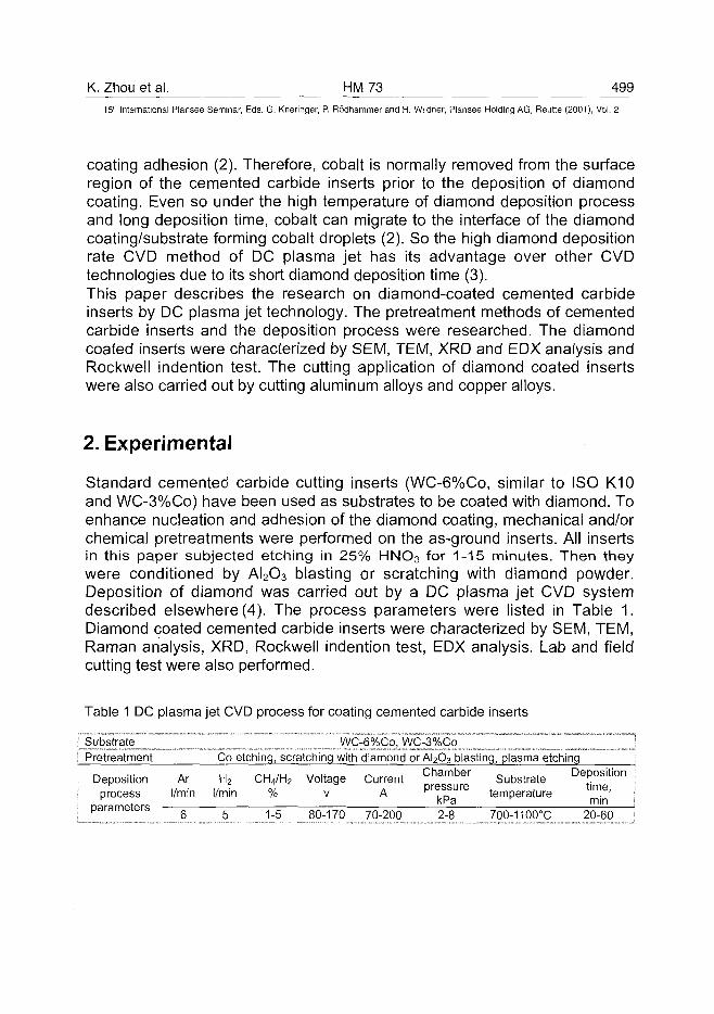
K. Zhou et al. HM 73 49915" International Plansee Seminar, Eds. G. Kneringer, P. Rodhammer and H. Wildner, Plansee Holding AG, Reutte (2001), Vol. 2
coating adhesion (2). Therefore, cobalt is normally removed from the surfaceregion of the cemented carbide inserts prior to the deposition of diamondcoating. Even so under the high temperature of diamond deposition processand long deposition time, cobalt can migrate to the interface of the diamondcoating/substrate forming cobalt droplets (2). So the high diamond depositionrate CVD method of DC plasma jet has its advantage over other CVDtechnologies due to its short diamond deposition time (3).This paper describes the research on diamond-coated cemented carbideinserts by DC plasma jet technology. The pretreatment methods of cementedcarbide inserts and the deposition process were researched. The diamondcoated inserts were characterized by SEM, TEM, XRD and EDX analysis andRockwell indention test. The cutting application of diamond coated insertswere also carried out by cutting aluminum alloys and copper alloys.
2. Experimental
Standard cemented carbide cutting inserts (WC-6%Co, similar to ISO K10and WC-3%Co) have been used as substrates to be coated with diamond. Toenhance nucleation and adhesion of the diamond coating, mechanical and/orchemical pretreatments were performed on the as-ground inserts. All insertsin this paper subjected etching in 25% HNO3 for 1-15 minutes. Then theywere conditioned by AI2O3 blasting or scratching with diamond powder.Deposition of diamond was carried out by a DC plasma jet CVD systemdescribed elsewhere (4). The process parameters were listed in Table 1.Diamond coated cemented carbide inserts were characterized by SEM, TEM,Raman analysis, XRD, Rockwell indention test, EDX analysis. Lab and fieldcutting test were also performed.
Table 1 DC plasma jet CVD process for coating cemented carbide inserts
Pretreatment Co etching, scratching with diamond or AI2O3 blasting, plasma etching
Deposition Ar H2 CH4/H2 Voltage Current C h a m b e r Substrate D e P ° s i t i o n
process l/min l/min % v A pressure t e m p e r a t u r e t i m e -
P a r a m e t e r s 5 5 ^ 5 80-170 70-200 2^8 700-1100°C 20-60
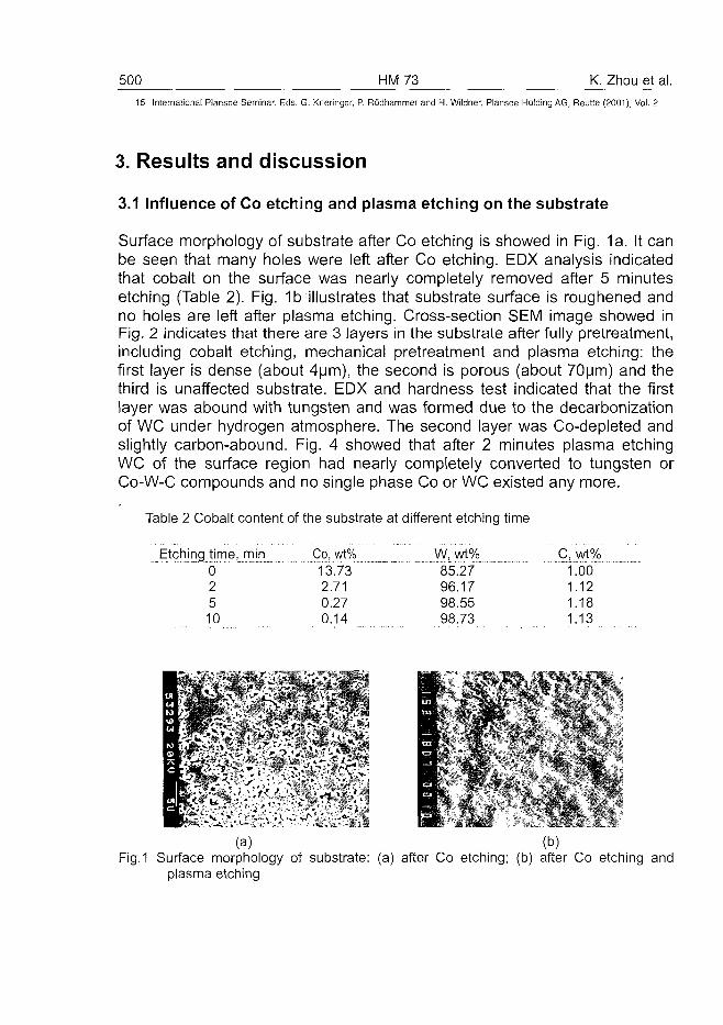
500 HM73 K. Zhou et al.15" International Plansee Seminar, Eds. G. Kneringer, P. Rodhammer and H. Wildner, Plansee Holding AG, Reutte (2001), Vol. 2
3. Results and discussion
3.1 Influence of Co etching and plasma etching on the substrate
Surface morphology of substrate after Co etching is showed in Fig. 1a. It canbe seen that many holes were left after Co etching. EDX analysis indicatedthat cobalt on the surface was nearly completely removed after 5 minutesetching (Table 2). Fig. 1b illustrates that substrate surface is roughened andno holes are left after plasma etching. Cross-section SEM image showed inFig. 2 indicates that there are 3 layers in the substrate after fully pretreatment,including cobalt etching, mechanical pretreatment and plasma etching: thefirst layer is dense (about 4um), the second is porous (about 70um) and thethird is unaffected substrate. EDX and hardness test indicated that the firstlayer was abound with tungsten and was formed due to the decarbonizationof WC under hydrogen atmosphere. The second layer was Co-depleted andslightly carbon-abound. Fig. 4 showed that after 2 minutes plasma etchingWC of the surface region had nearly completely converted to tungsten orCo-W-C compounds and no single phase Co or WC existed any more.
Table 2 Cobalt content of the substrate at different etching time
Etching time, min02510
Co, wt%13.732.710.270.14
W, wt%85.2796.1798.5598.73
C, wt%1.001.121.181.13
(a) (b)Fig.1 Surface morphology of substrate: (a) after Co etching; (b) after Co etching and
plasma etching
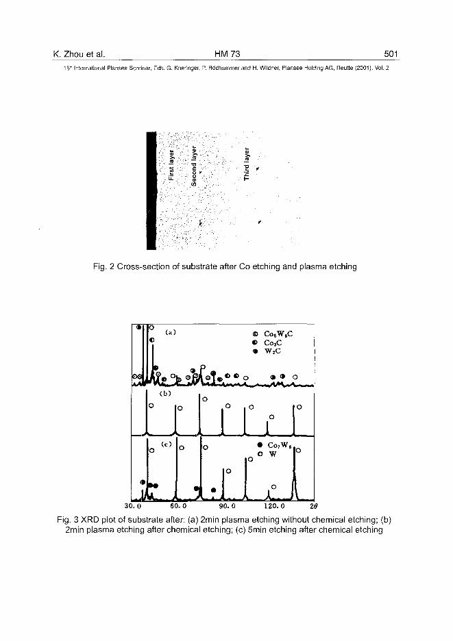
K. Zhou et al. HM73 50115" International Plansee Seminar, Eds. G. Kneringer, P. Rodhammer and H. Wildner, Plansee Holding AG, Reutte (2001), Vol. 2
•aco *u
Fig. 2 Cross-section of substrate after Co etching and plasma etching
•
oe
•
h
c
«
Ic
c
' (a))
(b)
^^^^^
(c)>
»•JL ,
O
O
«
o
l 1o
•rl
© CosW8C€> Co3C• W2C
> • • O
0
0
_J0
30.0 60.0 90.0 120.0
Fig. 3 XRD plot of substrate after: (a) 2min plasma etching without chemical etching; (b)2min plasma etching after chemical etching; (c) 5min etching after chemical etching
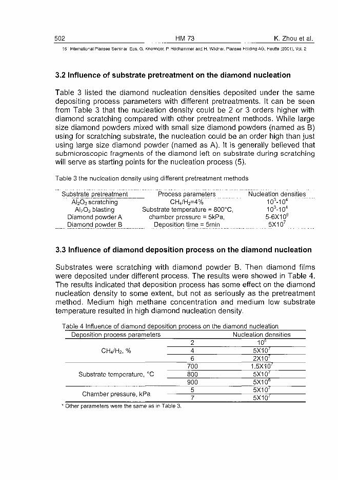
502 HM 73 K. Zhou et al.
15r International Plansee Seminar, Eds. G. Kneringer, P. Rodhammer and H. Wildner, Plansee Holding AG, Reutte (2001), Vol. 2
3.2 Influence of substrate pretreatment on the diamond nucleation
Table 3 listed the diamond nucleation densities deposited under the samedepositing process parameters with different pretreatments. It can be seenfrom Table 3 that the nucleation density could be 2 or 3 orders higher withdiamond scratching compared with other pretreatment methods. While largesize diamond powders mixed with small size diamond powders (named as B)using for scratching substrate, the nucleation could be an order high than justusing large size diamond powder (named as A). It is generally believed thatsubmicroscopic fragments of the diamond left on substrate during scratchingwill serve as starting points for the nucleation process (5).
Table 3 the nucleation density using different pretreatment methods
Substrate pretreatment Process parameters Nucleation densitiesAi2O3 scratching CH4/H2=4% ~ " 103-104
AI2O3 blasting Substrate temperature = 800°C, 103-104
Diamond powder A chamber pressure = 5kPa, 5-6X10⁶
DiamqncI powder B Deposition time = 5min 5X10⁷
3.3 Influence of diamond deposition process on the diamond nucleation
Substrates were scratching with diamond powder B. Then diamond filmswere deposited under different process. The results were showed in Table 4.The results indicated that deposition process has some effect on the diamondnucleation density to some extent, but not as seriously as the pretreatmentmethod. Medium high methane concentration and medium low substratetemperature resulted in high diamond nucleation density.
Table 4 Influence of diamond deposition process on the diamond nucleationDeposition process parameters
CH4/H2, %
Substrate temperature, °C
246
700800900
57
Nucleation densities10b
5X10'2X10'
1.5X10'5X10'5X10b
5X10'5X10'
' Other parameters were the same as in Table 3.
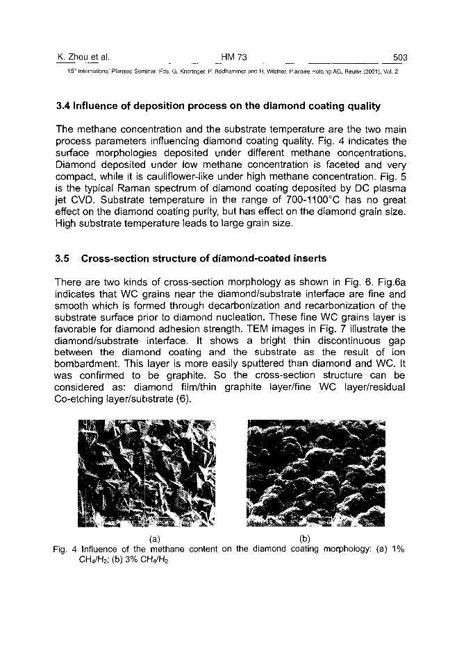
K. Zhou et al. HM73 50315" International Plansee Seminar, Eds. G. Kneringer, P. Rodhammer and H. Wildner, Plansee Holding AG, Reutte (2001), Vol. 2
3.4 Influence of deposition process on the diamond coating quality
The methane concentration and the substrate temperature are the two mainprocess parameters influencing diamond coating quality. Fig. 4 indicates thesurface morphologies deposited under different methane concentrations.Diamond deposited under low methane concentration is faceted and verycompact, while it is cauliflower-like under high methane concentration. Fig. 5is the typical Raman spectrum of diamond coating deposited by DC plasmajet CVD. Substrate temperature in the range of 700-1100°C has no greateffect on the diamond coating purity, but has effect on the diamond grain size.High substrate temperature leads to large grain size.
3.5 Cross-section structure of diamond-coated inserts
There are two kinds of cross-section morphology as shown in Fig. 6. Fig.6aindicates that WC grains near the diamond/substrate interface are fine andsmooth which is formed through decarbonization and recarbonization of thesubstrate surface prior to diamond nucleation. These fine WC grains layer isfavorable for diamond adhesion strength. TEM images in Fig. 7 illustrate thediamond/substrate interface. It shows a bright thin discontinuous gapbetween the diamond coating and the substrate as the result of ionbombardment. This layer is more easily sputtered than diamond and WC. Itwas confirmed to be graphite. So the cross-section structure can beconsidered as: diamond film/thin graphite layer/fine WC layer/residualCo-etching layer/substrate (6).
(a) (b)Fig. 4 Influence of the methane content on the diamond coating morphology: (a) 1%
CH4/H2; (b) 3% CH4/H;,
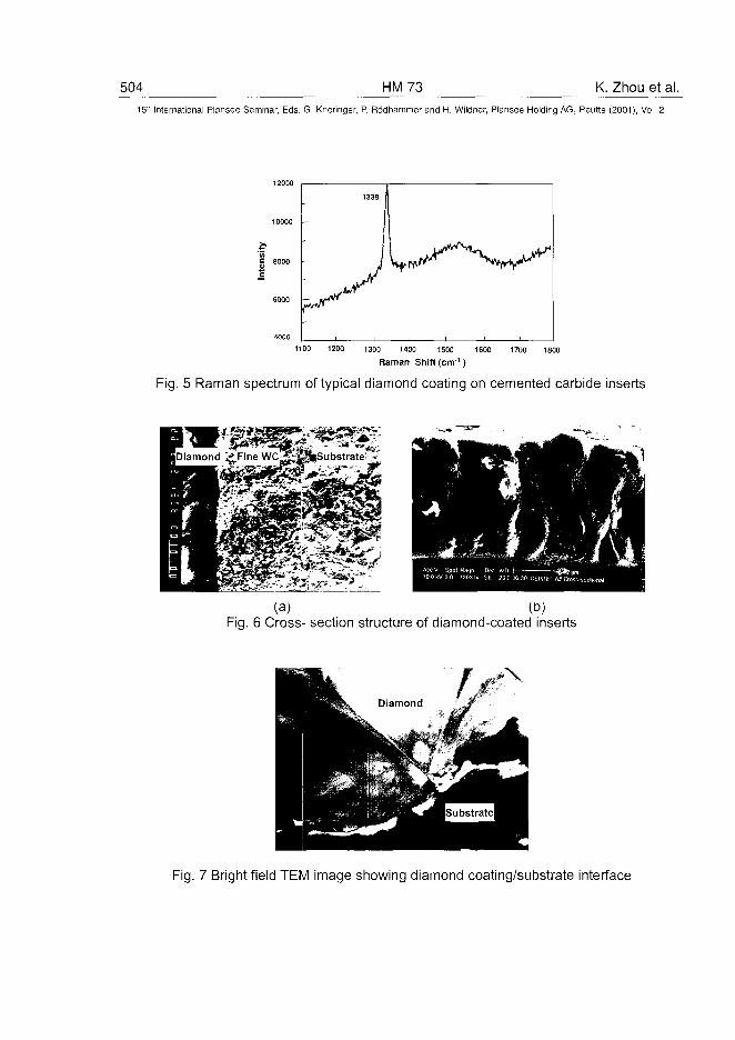
504 HM73 K. Zhou et al.15" International Plansee Seminar, Eds. G. Kneringer, P. Rodhammer and H. Wildner, Plansee Holding AG, Reutte (2001), Vol. 2
1100 1200 1300 1400 1500 1600 1700 1800
Raman Shift (cm'1)
Fig. 5 Raman spectrum of typical diamond coating on cemented carbide inserts
(a) (D)Fig. 6 Cross- section structure of diamond-coated inserts
• V
Fig. 7 Bright field TEM image showing diamond coating/substrate interface
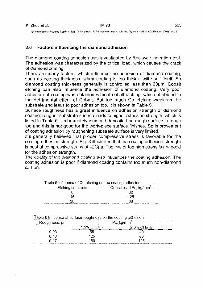
K. Zhou et al. HM 73 505^
15" International Plansee Seminar, Eds. G. Kneringer, P. Rodhammer and H. Wildner, Plansee Holding AG, Reutte (2001), Vol. 2
3.6 Factors influencing the diamond adhesion
The diamond coating adhesion was investigated by Rockwell indention test.The adhesion was characterized by the critical load, which causes the crackof diamond coating.There are many factors, which influence the adhesion of diamond coating,such as coating thickness, when coating is too thick it will spall itself. Sodiamond coating thickness generally is controlled less than 20um. Cobaltetching can also influence the adhesion of diamond coating. Very pooradhesion of coating was obtained without cobalt etching, which attributed tothe detrimental effect of Cobalt. But too much Co etching weakens thesubstrate and leads to poor adhesion too. It is shown in Table 5.Surface roughness has a great influence on adhesion strength of diamondcoating; rougher substrate surface leads to higher adhesion strength, which islisted in Table 6. Unfortunately diamond deposited on rough surface is roughtoo and this is not good for the work-piece surface finishes. So improvementof coating adhesion by roughening substrate surface is very limited.It's generally believed that proper compressive stress is favorable for thecoating adhesion strength. Fig. 8 illustrates that the coating adhesion strengthis best at compressive stress of-2Gpa. Too low or too high stress is not goodfor the adhesion strength.The quality of the diamond coating also influences the coating adhesion. Thecoating adhesion is poor if diamond coating contains too much non-diamondcarbon.
TableJ5 Influence of Co etching_on_the coating^adhesionEtching time, min_ CriticaMoad_Pc^kg/mrrrj_
~ ~0 " ~ " 3015 12530 60
Table (i^hjluencej)f jsujface^ adhesior^Roughness, yrn
1.5%CH4/H2 2.0% CH4/H2
0.03 55 400.10 125 800.17 150 125
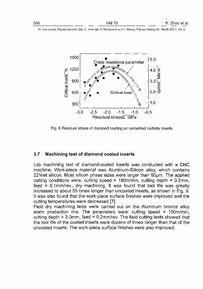
506 HM73 K. Zhou et al.15" International Plansee Seminar, Eds. G. Kneringer, P. Rodhammer and H. Wildner, Plansee Holding AG, Reutte (2001), Vol. 2
1500
1200
300-
Crack resistance parameter
-3.0 -2.5 -2.0 -1.5_ -1.0Residual stress£~GPa
5.0
4.0 'E
3.0 >wx
2.0-e-
1.0
-0.5
Fig. 8 Residual stress of diamond coating on cemented carbide inserts
3.7 Machining test of diamond coated inserts
Lab machining test of diamond-coated inserts was conducted with a CNCmachine. Work-piece material was Aluminum-Silicon alloy, which contains22%wt silicon. Most silicon phase sizes were larger than 60um. The appliedcutting conditions were: cutting speed = 180m/min, cutting depth = 0.2mm,feed = 0.1 mm/rev., dry machining. It was found that tool life was greatlyincreased to about 55 times longer than uncoated inserts, as shown in Fig. 9.It was also found that the work-piece surface finishes were improved and thecutting temperatures were decreased [7].Field dry machining tests were carried out on the Aluminum bronze alloyworm production line. The parameters were: cutting speed = 150m/min,cutting depth = 2-3mm, feed = 0.2mm/rev. The field cutting tests showed thatthe tool life of the coated inserts were dozens of times longer than that of theuncoated inserts. The work-piece surface finishes were also improved.
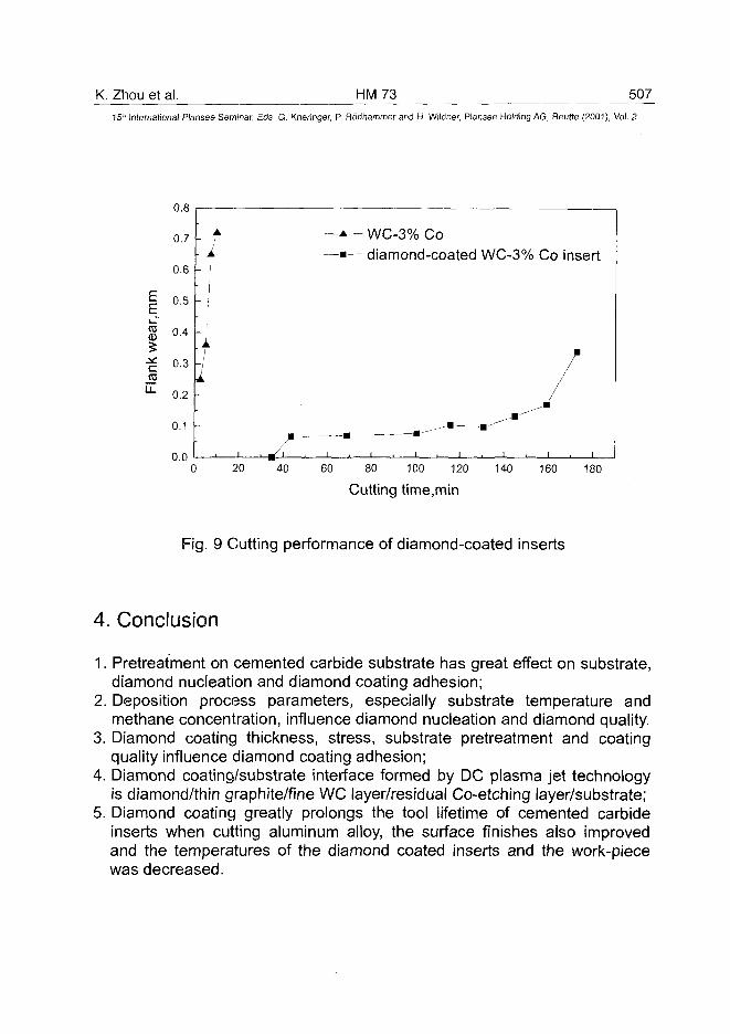
K. Zhou et al. HM73 50715'" International Plansee Seminar, Eds. G. Kneringer, P. Rodhammer and H. Wildner, Plansee Holding AG, Reutte (2001), Vol. 2
EE
ro
0.8
0.7
0.6
0.5
. •
§ 0.4
0.3
0.2
0.1
0.0
1
—A— WC-3% Co—•— diamond-coated WC-3% Co insert
20 40 60 80 100 120
Cutting time.min140 160 180
Fig. 9 Cutting performance of diamond-coated inserts
4. Conclusion
1. Pretreatment on cemented carbide substrate has great effect on substrate,diamond nucleation and diamond coating adhesion;
2. Deposition process parameters, especially substrate temperature andmethane concentration, influence diamond nucleation and diamond quality.
3. Diamond coating thickness, stress, substrate pretreatment and coatingquality influence diamond coating adhesion;
4. Diamond coating/substrate interface formed by DC plasma jet technologyis diamond/thin graphite/fine WC layer/residual Co-etching layer/substrate;
5. Diamond coating greatly prolongs the tool lifetime of cemented carbideinserts when cutting aluminum alloy, the surface finishes also improvedand the temperatures of the diamond coated inserts and the work-piecewas decreased.
508 HM73 K. Zhou et al.15" International Plansee Seminar, Eds. G. Kneringer, P. Rodhammer and H. Wildner, Plansee Holding AG, Reutte (2001), Vol. 2
References
[1] M. Lares, G. Jorgensen: Surface Coating and Technology 96 (1997), pp.198-204
[2] R. Haubner, W. D. Schubert, B. Lux: Int. Journal of Refractory Metals andHard Materials 16 (1998), pp. 177-185
[3] F. Deuerber, J. Peterseim, H. Gruner, Q. Wang, V. Buck: Int. Journal ofRefractory Metals and Hard Materials 16 (1998), pp. 191-199
[4] Zhou Kesong, Dai Mingjiang, Wang Dezheng, Feng Biguang: Proceedingsof the Tenth International Conference on Surface ModificationTechnologies, Vol X, pp. 518-526 (ed. T. S. Sudarshan, The Institute ofMaterials, London)
[5] T. Leyendecker, O. Lemmer, A. Jurgens and S. Esser: Surface andCoating Technology 48 (1999), pp. 253-260
[6] K.S. Zhou, M.J. Dai, T.C. Kuang, D.Z. Wang, Z.H. Liu: SurfaceEngineering 15(1999), pp. 105-108
[7] M.J. Dai, K.S. Zhou, Z. H. Yuan, Q. Ding, Z.Q. Fu: Diamond and RelatedMaterials 9(2000), pp. 1753-1757
AT0100478A. Kopf et al. HMJ4 509
15th International Plansee Seminar, Eds. G. Kneringer, P. Rodhammer and H. Wildner, Plansee Holding AG, Reutte (2001), Vol. 2
MULTILAYER COATINGS CONTAINING DIAMOND AND OTHER HARD
MATERIALS ON HARDMETAL SUBSTRATES
Arno Kopf, Roland Haubner, Benno Lux
Institute for Chemical Technology of Inorganic Materials, TU-Vienna,
Getreidemarkt 9/161, A-1060 Vienna, Austria
Summary:
In order to improve the wear resistance of hardmetal cutting tools, coatings ofhard materials were established. Especially the production of multilayercoatings, which combine useful properties of different materials was a topicof industrial and academic research. The present work examined thepossibilities of combining diamond as basic layer with protective CVD layersof TiC, TiN, Ti(C,N) and AI2O3. All these combinations could be realized andsome showed quite good adherence under strain, which offers possibilitiesfor technical applications.
Keywords: diamond, TiC, TiN, Ti(C,N), corundum
1. Introduction
The concept of applying multilayer coatings to WC-Co hardmetal cutting toolsto prolong tool life is already well known (1,2). Especially coatings with layersequences of TiC / Ti(C,N) / TiN / AI2O3 are commonly used in the machiningindustry (3-5). With the exception of corundum all these materials show asharp decrease of hardness with increasing temperature (6). Additionallythey possess a rather bad thermal conductivity, which causes an extremeheating (up to 1000°C and more) on the cutting edges (7) and therefore aloss of wear resistance as result.Due to their high hardness and excellent thermal conductivity diamondcoatings are used as wear resistant coatings (8,9) and as heat sinks in
510 HM74 A. Kopf et al.15:" International Plansee Seminar, Eds. G. Kneringer, P. Rodhammer and H. Wildner, Plansee Holding AG, Reutte (2001), Vol. 2
electronic devices (10). They show a good mechanical stability up to 1000°C,but at these temperatures they show a rather low resistance against oxygen,which catalyses the transformation into graphite. Another disadvantage ofdiamond is, that it is not suitable for the machining of iron and steel, becausethese materials possess a high carbon solubility. The high workingtemperatures - occurring locally - lead to the diffusion of carbon into theferrous metal and that rapidly destroys the cutting edges.A solution to the above mentioned problems is offered by a multilayerconcept, which combines diamond (for hardness and heat distribution) with aprotective layer of another hard material (TiC, TiN, AI2O3), which is stableagainst oxidation and prevent carbon diffusion (11). This paper describes theproduction of such multilayer-systems by using a CVD process and examinesthe changes in deposition rates, crystal morphology and preferred crystalorientations. Also layer adhesion is qualitatively estimated after performingRockwell tests.
2. Experimental details
2.1 Substrates and its surface pre-treatmentsIndexable hard metal inserts from Teledyne Firth Sterling, La Vergne, TN,USA [grade SPGN 120308, quality H21; 94 wt.% WC, 5.5 wt.% Co and0.5 wt.% (Ta,Nb)C, total surface 4,29 cm2] were used as substrates. Prior topre-treatment they were ultrasonically cleaned in methanol. In order tooptimise growth and adhesion of the diamond layer Co, which detrimentallyinfluences the diamond CVD process (12-17), was removed from thesubstrate surface by etching with Murakami solution (10 g K3[Fe(CN)6] and10 g KOH in 200 ml H2O) for 60 minutes and Caro's acid (5% cone. H2SO4 in35% H2O2) for 30 seconds. No further nucleation enhancement was applied.
2.2 Diamond depositionA hot-filament reactor was used for the deposition of diamond layers (18).Tantalum-wire (0.8 mm diameter) in form of a six times u-shaped loop wasused as a filament. The following deposition conditions were adjusted:filament temperature, 2300±20°C; substrate temperature, 800±15°C;pressure, 30 mbar; total gas flow, 250 cnfVmin; methane concentration,2 vol% and a deposition time of 16 hrs.
A. Kopf et al. HM 74 51j_15" International Plansee Seminar, Eds. G. Kneringer, P. Rodhammer and H. Wildner, Plansee Holding AG, Reutte (2001), Vol. 2
2.3 Deposition of TiC, TiN, Ti(C,N) and AI2O3
These deposition experiments were carried out in a hot-wall thermal CVDreactor (19). The reactor was heated by means of an electric resistancefurnace. Experimental conditions were: Furnace temperature, 1050±20°C;reactor temperature 900±15°C; pressure, 160±20 mbar for TiC, TiN and80±5 mbar for AI2O3; flow rates for TiC, TiN: 333 cm3/min H2, 33 cm3/minTiCI4; gas flow ratio CH4(N2 respectively):TiCI4, 1:1, 2:1, 3:1; flow rates forAI2O3: 400 cm7min H2, 25 cm3/min HCI (8 cm3/min AICI3) gas flow ratioCO2:AICI3, 2:1, 1:1, 1:2 deposition time 1 h (TiC, TiN); 3 h (AI2O3).
2.4 ExaminationsDeposition rates were calculated from the weight difference of the substratebefore and after the deposition experiment. Scanning electron microscopy(SEM) was used to describe the morphology of the deposited layers. Thequality of the diamond layer was examined by micro-Raman spectroscopy(ISA RamanorU 1000; 100 mW 488 nm Ar-ion Laser; back-scatteringgeometry). X-ray-diffraction (Ni filtered Cu Ka radiation A,=1.540562 A) wasused to characterize preferred orientations in TiC and TiN depositions.Adhesion of the coatings was proofed by Rockwell indentation tests andexamination of cracks the surrounding area by SEM. For interfaceinvestigations the ball grinding method (20) was used.
3. Results and Discussion
3.1 Diamond depositionDiamond deposition on hardmetals has already become industrial standard.In order to use diamond as prime layer for a multilayer coating its adhesionhas to be optimised. The negative effects, which the cobalt content of ahardmetal has on diamond deposition, also include the catalysing of sp2-carbon, which leads to the formation of graphite or amorphous carbon,especially during the first period of deposition (15,21). Diamond nucleates onthis thin interlayer, which is of course detrimental to the adhesion of the finitelayer. In order to reduce these negative effects Co has to be removed fromthe surface or stabilized by the formation of stable chemical compounds. Astandard treatment used in industrial production is the two step etching withMurakami solution and Caro's acid. During the first step the substrate surfaceroughness is increased, while the second etching dissolves Co and producesCoSO4 and Co-oxides. Under diamond deposition conditions these
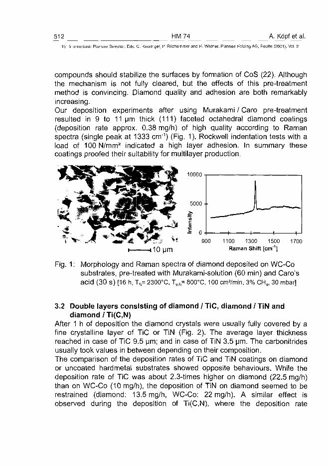
512 HM74 A. Kopf et al.15" International Plansee Seminar, Eds. G. Kneringer, P. Rodhammer and H. Wildner, Plansee Holding AG, Reutte (2001), Vol. 2
compounds should stabilize the surfaces by formation of CoS (22). Althoughthe mechanism is not fully cleared, but the effects of this pre-treatmentmethod is convincing. Diamond quality and adhesion are both remarkablyincreasing.Our deposition experiments after using Murakami / Caro pre-treatmentresulted in 9 to 11 urn thick (111) faceted octahedral diamond coatings(deposition rate approx. 0.38 mg/h) of high quality according to Ramanspectra (single peak at 1333 cm"1) (Fig. 1). Rockwell indentation tests with aload of 100N/mm2 indicated a high layer adhesion. In summary thesecoatings proofed their suitability for multilayer production.
10000
5 0 0 0 • •
(AC
900 1100 1300 1500Raman Shift [cm"1]
1700
Fig. 1; Morphology and Raman spectra of diamond deposited on WC-Cosubstrates, pre-treated with Murakami-solution (60 min) and Caro'sacid (30 s) [16 h, Tf,= 2300°C, Tsub= 800°C, 100 crrfYmin, 3% CH4, 30 mbar]
3.2 Double layers consisting of diamond / TiC, diamond / TiN anddiamond /Ti(C,N)
After 1 h of deposition the diamond crystals were usually fully covered by afine crystalline layer of TiC or TiN (Fig. 2). The average layer thicknessreached in case of TiC 9.5 urn; and in case of TiN 3.5 urn. The carbonitridesusually took values in between depending on their composition.The comparison of the deposition rates of TiC and TiN coatings on diamondor uncoated hardmetal substrates showed opposite behaviours. While thedeposition rate of TiC was about 2.3-times higher on diamond (22.5 mg/h)than on WC-Co (10 mg/h), the deposition of TiN on diamond seemed to berestrained (diamond: 13.5 mg/h, WC-Co: 22 mg/h). A similar effect isobserved during the deposition of Ti(C,N), where the deposition rate
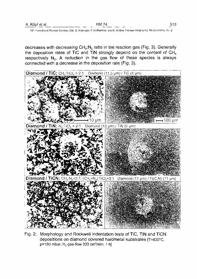
A. Kopf et al. HM74 51315" International Plansee Seminar, Eds. G. Kneringer, P. Rodhammer and H. Wildner, Plansee Holding AG, Reutte (2001), Vol. 2
decreases with decreasing CH4:N2 ratio in the reaction gas (Fig. 3). Generallythe deposition rates of TiC and TiN strongly depend on the content of CH4
respectively N2. A reduction in the gas flow of these species is alwaysconnected with a decrease in the deposition rate (Fig. 3).
[Diamond / TiC; CH4:TiCI4 = 2:1 Diamond (11,5 (jm) / TiC (8
• Diamond / TiN; N2:TiCI4 = 2:1 Diamond (13 pm) / TiN (6 \m\)
Diamond / TiCN; CH4:N2=3:7; (CH4+N2):TiCI4=3:1 Diamond (11 Mm) / Ti(C,N) (11
Fig. 2: Morphology and Rockwell indentation tests of TiC, TiN and TiCNdepositions on diamond covered hardmetal substrates [T=820°C,p=160 mbar, H2 gas-flow 333 cm3/min, 1 h]
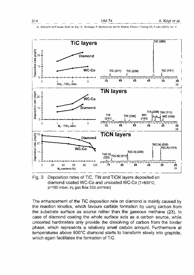
514 HM74 A. Kopf et al.15r International Plansee Seminar, Eds. G. Kneringer, P. Rodhammer and H. Wildner, Plansee Holding AG, Reutte (2001), Vol. 2
E_ 20 ••
S2
| 10 ••
TiC layers TiC (200)
Diamond
TiC(311) TiC (220)
Aw LJLTiC (111)
1 2CH4 : TiCI4 ratio
75 65 55 35 2526
£20--
.2 10--
TiN layersWC-Co
Diamond
TiN(111)
WC (100)
1 2N2 : TiCI4 ratio
-i—<—i—i—i—i—i—i—i—i—I—i—i—i—i—i—i—i—i—i—|—i—i—i—i—i75 65 55 45 35 25
26
DiamondTiCN layers
Ti(C,N) (200)
20 40 60 80 100
N2 content (%)
Tg>Ti(C,N)<311)|
1 1 T
Ti(C,N) (220)
I I—I—I—I—1—I—I—I—I—1—I—I—I—I—I—I—1—I—1—1—I—I—I—I—I75 65 55 45 35 25
26
Fig. 3: Deposition rates of TiC, TiN and TiCN layers deposited ondiamond coated WC-Co and uncoated WC-Co [T=800°C;p=160 mbar, H2 gas flow 333 cm3/min]
The enhancement of the TiC deposition rate on diamond is mainly caused bythe reaction kinetics, which favours carbide formation by using carbon fromthe substrate surface as source rather than the gaseous methane (23). Incase of diamond coating the whole surface acts as a carbon source, whileuncoated hardmetals only provide the dissolving of carbon from the binderphase, which represents a relatively small carbon amount. Furthermore attemperatures above 800°C diamond starts to transform slowly into graphite,which again facilitates the formation of TiC.
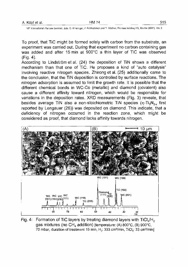
A. Kopf et al. HM74 515
15" International Plansee Seminar, Eds. G. Kneringer, P. Rodhammer and H. Wildner, Plansee Holding AG, Reutte (2001), Vol. 2
To proof, that TiC might be formed solely with carbon from the substrate, anexperiment was carried out. During that experiment no carbon containing gaswas added and after 15min at 900°C a thin layer of TiC was observed(Fig. 4)According to Lindstrom et al. (24) the deposition of TiN shows a differentmechanism than that one of TiC. He proposes a kind of "auto catalysis"involving reactive nitrogen species. Zhirong et al. (25) additionally came tothe conclusion, that the TiN deposition is controlled by surface reactions. Thenitrogen adsorption is assumed to limit the growth rate. It is possible that thedifferent chemical bonds in WC-Co (metallic) and diamond (covalent) alsocause a different affinity toward nitrogen, which would be responsible forvariations in the deposition rates. XRD measurements (Fig. 3) reveale, thatbesides average TiN also a non-stoichiometric TiN species (r|-Ti3N2_x firstreported by Lengauer (26)) was deposited on diamond. This indicate, that adeficiency of nitrogen occurred in the reaction zone, which might beconsidered as proof, that diamond lacks affinity towards nitrogen.
Fig. 4: Formation of TiC layers by treating diamond layers with TiCI4/H2
gas mixtures (no CH4 addition) [temperature: (A) 800°C, (B) 900°C,70 mbar, duration of treatment 15 min, H2: 333 crrvVmin, TiCI4: 33 crrvVmin]
516 HM74 A. Kopf et al.15" International Plansee Seminar, Eds. G. Kneringer, P. Rodhammer and H. Wildner, Plansee Holding AG, Reutte (2001), Vol. 2
The morphology of TiC on diamond did not change significantly with avariation of gas composition. Usually fine crystalline layers were obtained,which turned to coatings of faceted pyramidal crystals after increasing thedeposition time (3 hrs). XRD diagrams revealed, that especially with amethane excess, TiC easily forms textured layers on diamond surfaces.These layers are usually oriented in (200) direction (Fig. 3). TiN crystalsgrown on diamond change their morphology according to the nitrogencontent in relation to the TiCI4. Equal contents or excess of TiCI4 causewhisker growth, while a nitrogen excess results in pyramidal or lens shapedcrystals (Fig. 2). Here no preferred orientations were found according to XRDmeasurements.The Ti(C,N) deposition strongly depend on the reaction gas composition. Ahigher methane content results in fine grained layers, while increasednitrogen contents result in lens shaped crystals. Calculations based on XRDmeasurements revealed, that the composition of the Ti(C,N) layer usuallycontained 10-20% more carbon corresponding to the gas composition. Thisfact shows again that the deposition of TiC on diamond is kineticallyfavoured.Rockwell indentation tests with loads of 68 kg/mm2 proofed, that theadhesion of TiC or TiN onto diamond as well as the adhesion of themultilayer to the substrate were quite good (Fig. 2). Only some minor cracksappeared, which had no further effect on the adherence of the coating. TheTi(C,N) layers showed less adhesion onto diamond than pure TiC or TiNphases. For each of the indentation tests cracks were observed and smallparts of the coating jump off. The Rockwell tests also indicated, that anoptimum for the total layer thickness exists within a range of 15-20 urn. Testson thicker and thinner layers resulted in severe disturbances and thebreaking of layer segments.
3.3 Triple layers with the stacking sequence diamond / TiC / TiNAccording to the success in producing adherent double layers withdiamond / TiC or TiN, experiments were performed to prepare triple layerswith the stacking sequence diamond / TiC / TiN. During this series it was alsoinvestigated how different diamond modifications (namely octahedral andspheroid ballas diamond) as basic layer affect the adhesion of the upperlayers.
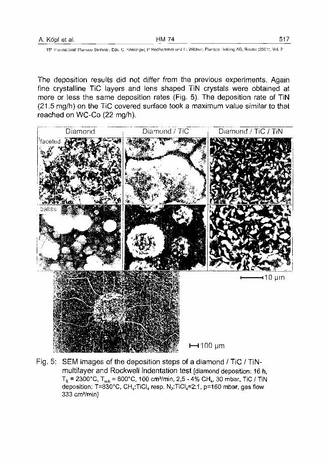
A. Kopf et al. HM74 51715" International Plansee Seminar, Eds. G. Kneringer, P. Rodhammer and H. Wildner, Plansee Holding AG, Reutte (2001), Vol. 2
The deposition results did not differ from the previous experiments. Againfine crystalline TiC layers and lens shaped TiN crystals were obtained atmore or less the same deposition rates (Fig. 5). The deposition rate of TiN(21.5 mg/h) on the TiC covered surface took a maximum value similar to thatreached on WC-Co (22 mg/h).
Diamond / TiC / TiN
Fig. 5: SEM images of the deposition steps of a diamond / TiC / TiN-multilayer and Rockwell indentation test [diamond deposition: 16 h,Tfi, = 2300°C, Tsub = 800°C, 100 cnrrVmin, 2,5 - 4% CH4, 30 mbar, TiC / TiNdeposition: T=830°C, CH4:TiCI4 resp. N2:TiCI4=2:1, p=160 mbar, gas flow333 cm3/min]
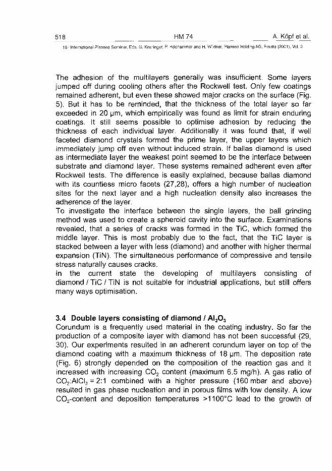
518 HM74 A. Kopfetal.15" International Plansee Seminar, Eds. G. Kneringer, P. Rodhammer and H. Wildner, Plansee Holding AG, Reutte (2001), Vol. 2
The adhesion of the multilayers generally was insufficient. Some layersjumped off during cooling others after the Rockwell test. Only few coatingsremained adherent, but even these showed major cracks on the surface (Fig.5). But it has to be reminded, that the thickness of the total layer so farexceeded in 20 um, which empirically was found as limit for strain enduringcoatings. It still seems possible to optimise adhesion by reducing thethickness of each individual layer. Additionally it was found that, if wellfaceted diamond crystals formed the prime layer, the upper layers whichimmediately jump off even without induced strain. If ballas diamond is usedas intermediate layer the weakest point seemed to be the interface betweensubstrate and diamond layer. These systems remained adherent even afterRockwell tests. The difference is easily explained, because ballas diamondwith its countless micro facets (27,28), offers a high number of nucleationsites for the next layer and a high nucleation density also increases theadherence of the layer.To investigate the interface between the single layers, the ball grindingmethod was used to create a spheroid cavity into the surface. Examinationsrevealed, that a series of cracks was formed in the TiC, which formed themiddle layer. This is most probably due to the fact, that the TiC layer isstacked between a layer with less (diamond) and another with higher thermalexpansion (TiN). The simultaneous performance of compressive and tensilestress naturally causes cracks.In the current state the developing of multilayers consisting ofdiamond / TiC / TiN is not suitable for industrial applications, but still offersmany ways optimisation.
3.4 Double layers consisting of diamond / AI2O3
Corundum is a frequently used material in the coating industry. So far theproduction of a composite layer with diamond has not been successful (29,30). Our experiments resulted in an adherent corundum layer on top of thediamond coating with a maximum thickness of 18 um. The deposition rate(Fig. 6) strongly depended on the composition of the reaction gas and itincreased with increasing CO2 content (maximum 6.5 mg/h). A gas ratio ofCO2:AICI3 = 2:1 combined with a higher pressure (160 mbar and above)resulted in gas phase nucleation and in porous films with low density. A lowCO2-content and deposition temperatures >1100°C lead to the growth of
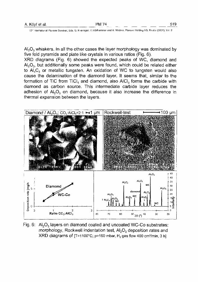
A. Kopf et al. HM74 51915th International Plansee Seminar, Eds. G. Kneringer, P. Rodhammer and H. Wildner, Plansee Holding AG, Reutte (2001), Vol. 2
AI2O3 whiskers. In all the other cases the layer morphology was dominated byfive fold pyramids and plate like crystals in various ratios (Fig. 6).XRD diagrams (Fig. 6) showed the expected peaks of WC, diamond andAI2O3> but additionally some peaks were found, which could be related eitherto AI4C3 or metallic tungsten. An oxidation of WC to tungsten would alsocause the delamination of the diamond layer. It seems that, similar to theformation of TiC from TiCI4 and diamond, also AICI3 forms the carbide withdiamond as carbon source. This intermediate carbide layer reduces theadhesion of AI2O3 on diamond, because it also increase the difference inthermal expansion between the layers.
/ ALCy, CO2:AICI3=2:1 •—«1 urn Rockwell-test « •
LMirnnHi
80 70 60 50 .„. 40 30
Fig. 6: AI2O3 layers on diamond coated and uncoated WC-Co substrates:morphology, Rockwell indentation test, AI2O3 deposition rates andXRD diagrams of [T=1100°C; p=160 mbar, H2 gas flow 400 cm3/min, 3 h]
520 HM 74 A. Kdpf et al.
15-" International Plansee Seminar, Eds. G. Kneringer, P. Rodhammer and H. Wildner, Plansee Holding A6, Reutte (2001), Vol. 2
Rockwell indentation tests (load: 50 kg/mm2) revealed that only very thin(approx. 1 urn) AI2O3 top-layers resulted in stress resistant mutlilayercoatings (Fig. 6). Layers with a thickness above 6 urn easily jump off thediamond underlayer. This fact reveals the question, whether the combinationof diamond and AI2O3 results in technically applicable multilayer coatings ornot. Corundum layers of about 1 urn thickness not seemd to be suitable fordiamond protection.
4. Conclusion
The experiments described in this paper proofed, that it is possible to depositmultilayer coatings containing diamond as basic layer onto WC-Co hardmetalsubstrates and TiC, TiN, TiCN or AI2O3 as protective layer grown by CVDmethods. Under optimal conditions the layers show good adherence amongsteach other and on the substrate. Especially the combinations diamond withTiC or TiN need further investigations to proof their suitability in wearresistant applications. The adhesion of TiCN and AI2O3 on diamond is weakerand offers only little resistance against strain. If the thickness of each layeras well as the total thickness are optimised, then it is possible to obtain welladherent multilayers with stacking sequences of diamond / TiC / AI2O3 bychemical vapour deposition.
AcknowledgmentThe authors gratefully acknowledge financial support of the present work bythe Austrian Science Foundation (FWF) (Project P 12055-CHE) carried outunder the auspices of the trinational "D-A-CH" German, Austrian and Swisscooperation on the "Synthesis of Superhard Materials"Thanks also to Dr. J.J. Oakes (Teledyne Firth Sterling) for delivering thehardmetal substrates free of charge.
A. Köpf et al. HM 74 52115'" International Plansee Seminar, Eds. G. Kneringer, P. Rödhammer and H. Wildner, Plansee Holding AG, Reutte (2001), Vol. 2
References
(1 ) B. Lux and H. Schachner; High Temperatures - High Pressures 10(1978)315
(2) J.N. Lindström, B.F. Johnsson and F.J.O.W. Ohlsson; US Patent3837896(1974)
(3) W. Schintlmeister et al.; Wear, 100 (1984) 153(4) W.A. Bryant; Proc. 7th Euro. Conf. on CVD (1989) C5, 783(5) N. Reiter; Proc. 4th Euro. Conf. on CVD (1983) 568(6) S. Ekemar; Rep.MR 77-201, (1977) Society of manufacturing engines,
Dearborn, Ml(7) P.A. Dearnley and E.M. Trent; Metals Technology 9 (1982) 60-74(8) M. Murakawa and S. Takeuchi, Surf. Coat. Techno/., 49 (1991) 359(9) J. Oakes, X.X. Pan, R. Bichler, R. Haubner and B. Lux; Surface and
Coatings Technology, 47 (1991) 600-607(10) H. Holzer, R. Haubner and B.Lux; Conference Proceedings Vol.52
"EURODIAMOND '96", C.Manfredotti and E.Vittone (Eds.) SIF,Bologna, 1996, pp.71-88
(11) J. Nedelik, W. Kremser and B. Lux, Diamond Films and Technology, 8(1998)37-50
(12) R. Haubner and B.Lux; J. Phys. (Paris), Colloq. C5 (1989) 169(13) R. Haubner, A. Lindlbauer and B. Lux; Diamond Related Materials, 2
(1993) 1505(14) S. Kubelka, R. Haubner, B. Lux, R. Steiner, G. Stingeder & M.
Grasserbauer; Diamond Films and Technology 5 (1995) 105(15) H. Matsubara and J. Kihara in S. Saito, O. Fukunga and M. Yoshikawa
(eds.), Science, Technology of New Diamond, KTK ScientificPublishers, Tokyo, 1990, pp. 89-93
(16) T.H. Huang, C.T. Kuo, C.S. Chang, C.T. Kao and H.Y. Wen, DiamondRelat. Mater., 1 (1992) 594
(17) S. Kubelka, PhD Thesis, Technical University of Vienna, 1994(18) R. Haubner and B.Lux; Diamond and Related Materials 2 (1993) 1277-
1294(19) A. Osada, PhD Thesis, Technical University of Vienna, 1990(20) C. Colombier, B. Lux, A. Riahi, M. Puchhammer and H. Störi, Fresenius
Z. Anal. Chem. 329 (1987) 355-360(21) R. Haubner, W.D. Schubert and B. Lux; Refractory Metals & Hard
Materials 16 (1998) 177-185
522 HM 74 A. Köpf et al.15" International Plansee Seminar, Eds. G. Kneringer, P. Rödhammer and H. Wildner, Plansee Holding AG, Reurte (2001), Vol. 2
(22) R.Haubner, S.Kubelka, B.Lux, M. G riesser, M.Grasserbauer; Journal dePhysique IV, Coll.05, Vol.5, juin 1995, 753-760
(23) C.W. Lee & J.S. Chun; Proc. 8th Int. Conf. on CVD (1981) 563(24) J. Lindström and K. Stjernberg, Proc. 5th Euro Conf. on CVD, (1985)
169(25) T. Zhirong et al., J. Beijing Univ. of Iron and Steel Technol., 10 (1988)
39(26) W. Lengauer, J. Less-Common Met, 725-127(1986)(27) B. Lux, R. Haubner, H. Hölzer and R.C.DeVries; Refractory Metals &
Hard Materials 15 (1997) 263-288(28) S. Bühlmann, E. Blank, R. Haubner and B. Lux; Diamond and Related
Materials 8 (1999) 194-201(29) R. Bichler, J. Peng, R. Haubner and B. Lux; Materials Science and
Engineering A105/106 (1988) 543-547(30) S. Söderberg, A. Gerendas and M. Sjöstrand: Vacuum 41/4-6 (1990)
1317
AT0100479R. Haubner et al. HM 75 523^
15" International Plansee Seminar, Eds. G. Kneringer, P. Rddhammer and H. Wildner, Plansee Holding AG, Reutte (2001), Vol. 2
DEPOSITION OF BALLAS DIAMOND AND NANO-CRYSTALLINE
DIAMOND
Roland Haubner, Benno Lux
Institute for Chemical Technology of Inorganic Materials, TU-Vienna,
Getreidemarkt 9/161, A-1060 Vienna, Austria
Summary
Nano-crystalline materials are of high interest, because mechanical andphysical properties of such materials are different from coarse grainedtypes. In case of diamond the CVD ballas type is a nano-crystalline material.Other names for ballas are also common; e.g. ball-shaped diamond,cauliflower like, nano-crystalline diamond.Ballas is a non-faceted, polycrystalline spherically grown diamond having aradial structure. Several morphological ballas structures have beenobserved by varying the deposition conditions, i.e. ballas having facetedareas, flat ballas, ballas with graphitic inclusions etc.. The nano-crystallinediamond coatings were reported during the last years and grown by addingfullerens to the deposition gas or using Ar / CH4 mixtures with less H2
additions.From the present point of view the ballas morphologies can be described byvarious microstructures. The nano-crystalline diamond is one of thesemicrostructures.
Keywords: diamond, ballas-diamond, nano-crystalline diamond
1. Introduction
Since the beginning of CVD diamond synthesis, faceted diamond layers, butfrequently also half-spherical and polycrystalline diamond (ballas) (1) weredeposited. Ballas deposition is observed under "non-optimal" growingconditions (2). The CVD ballas layers were also called cauliflower like (3),ball-shaped (4) etc. by some authors. Additionally during the last yearsnano-crystalline (5) and ultra-nanocrystalline (6) diamond films weredescribed.
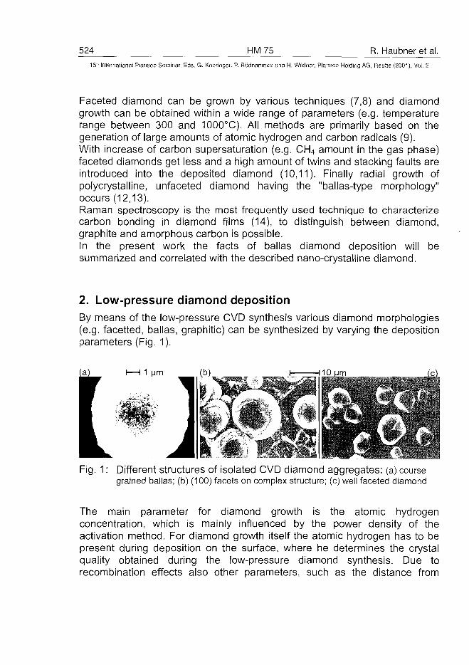
524 HM75 R. Haubner et al.
15" Internationa! Plansee Seminar, Eds. G. Kneringer, P. Rodhammer and H. Wildner, Plansee Holding AG, Reutte (2001), Vol. 2
Faceted diamond can be grown by various techniques (7,8) and diamondgrowth can be obtained within a wide range of parameters (e.g. temperaturerange between 300 and 1000°C). All methods are primarily based on thegeneration of large amounts of atomic hydrogen and carbon radicals (9).With increase of carbon supersaturation (e.g. CH4 amount in the gas phase)faceted diamonds get less and a high amount of twins and stacking faults areintroduced into the deposited diamond (10,11). Finally radial growth ofpolycrystalline, unfaceted diamond having the "ballas-type morphology"occurs (12,13).Raman spectroscopy is the most frequently used technique to characterizecarbon bonding in diamond films (14), to distinguish between diamond,graphite and amorphous carbon is possible.In the present work the facts of ballas diamond deposition will besummarized and correlated with the described nano-crystalline diamond.
2. Low-pressure diamond depositionBy means of the low-pressure CVD synthesis various diamond morphologies(e.g. facetted, ballas, graphitic) can be synthesized by varying the depositionparameters (Fig. 1).
1 urn
Fig. 1: Different structures of isolated CVD diamond aggregates: (a) coursegrained ballas; (b) (100) facets on complex structure; (c) well faceted diamond
The main parameter for diamond growth is the atomic hydrogenconcentration, which is mainly influenced by the power density of theactivation method. For diamond growth itself the atomic hydrogen has to bepresent during deposition on the surface, where he determines the crystalquality obtained during the low-pressure diamond synthesis. Due torecombination effects also other parameters, such as the distance from
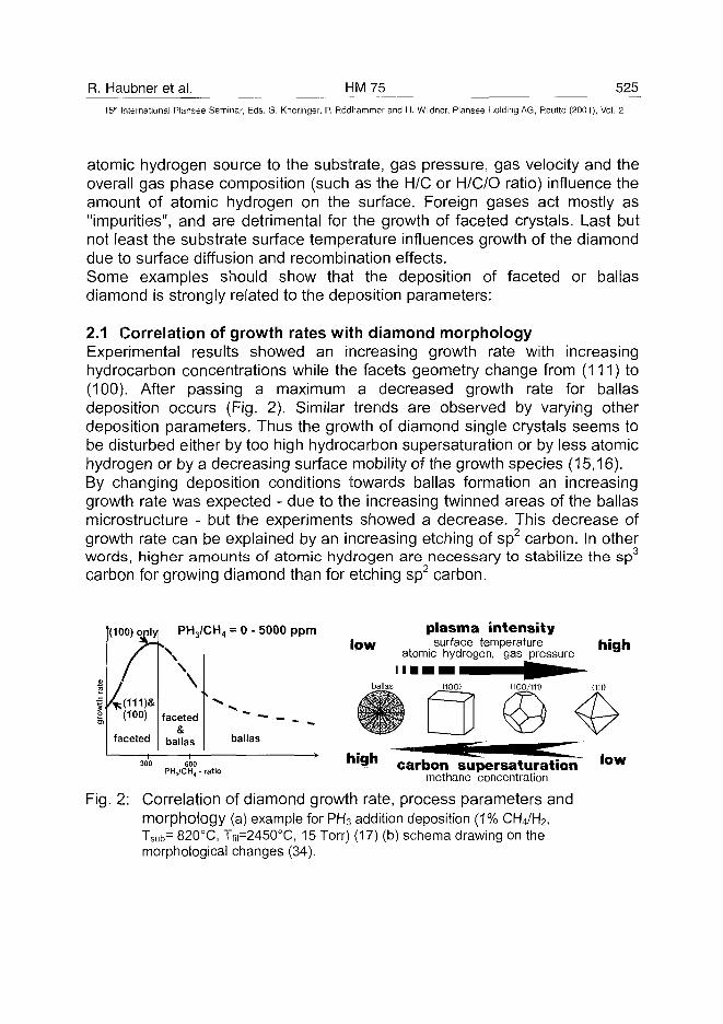
R. Haubner et al. HM75 52515" International Plansee Seminar, Eds. G. Kneringer, P. Rodhammer and H. Wildner, Plansee Holding AG, Reutte (2001), Vol. 2
atomic hydrogen source to the substrate, gas pressure, gas velocity and theoverall gas phase composition (such as the H/C or H/C/O ratio) influence theamount of atomic hydrogen on the surface. Foreign gases act mostly as"impurities", and are detrimental for the growth of faceted crystals. Last butnot least the substrate surface temperature influences growth of the diamonddue to surface diffusion and recombination effects.Some examples should show that the deposition of faceted or ballasdiamond is strongly related to the deposition parameters:
2.1 Correlation of growth rates with diamond morphologyExperimental results showed an increasing growth rate with increasinghydrocarbon concentrations while the facets geometry change from (111) to(100). After passing a maximum a decreased growth rate for ballasdeposition occurs (Fig. 2). Similar trends are observed by varying otherdeposition parameters. Thus the growth of diamond single crystals seems tobe disturbed either by too high hydrocarbon supersaturation or by less atomichydrogen or by a decreasing surface mobility of the growth species (15,16).By changing deposition conditions towards ballas formation an increasinggrowth rate was expected - due to the increasing twinned areas of the ballasmicrostructure - but the experiments showed a decrease. This decrease ofgrowth rate can be explained by an increasing etching of sp2 carbon. In otherwords, higher amounts of atomic hydrogen are necessary to stabilize the sp3
carbon for growing diamond than for etching sp2 carbon.
(100) only
2(100)
faceted
PH3/CH4
\
faceted&
ballas
= 0 - 5000 ppm
balfas
plasma intensityl o w surface temperature
atomic hydrogen, gas pressurehigh
300 600PHa /CH4 - rat io
n ' 9 ncarbon supersaturation
methane concentration
Fig. 2: Correlation of diamond growth rate, process parameters andmorphology (a) example for PH3 addition deposition (1% CH4/H2,Tsub= 820°C, Tfii=2450°C, 15 Torr) (17) (b) schema drawing on themorphological changes (34).
l o w
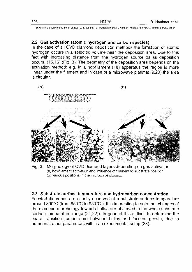
526 HM75 R. Haubner et al.15" International Plansee Seminar, Eds. G. Kneringer, P. Rodhammer and H. Wildner, Plansee Holding AG, Reutte (2001), Vol. 2
2.2 Gas activation (atomic hydrogen and carbon species)In the case of all CVD diamond deposition methods the formation of atomichydrogen occurs in a selected volume near the deposition area. Due to thisfact with increasing distance from the hydrogen source ballas depositionoccurs. (15,16) (Fig. 3). The geometry of the deposition area depends on theactivation method: e.g. in a hot-filament (18) apparatus the region is morelinear under the filament and in case of a microwave plasma(19,20) the areais circular.
(a) (b)
Fig. 3: Morphology of CVD diamond layers depending on gas activation(a) hot-filament activation and influence of filament to substrate position(b) various positions in the microwave plasma.
2.3 Substrate surface temperature and hydrocarbon concentrationFaceted diamonds are usually observed at a substrate surface temperaturearound 800°C (from 650°C to 950°C ). It is interesting to note that changes ofthe diamond morphology towards ballas are observed in the whole substratesurface temperature range (21,22)). In general it is difficult to determine theexact transition temperature between ballas and faceted growth, due tonumerous other parameters within an experimental setup (23).
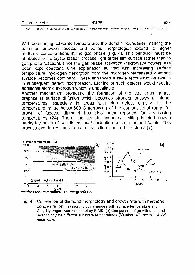
R. Haubner et al. HM75 52715th International Plansee Seminar, Eds. G. Kneringer, P. Rodhammer and H. Wildner, Plansee Holding AG, Reutte (2001), Vol. 2
With decreasing substrate temperature, the domain boundaries marking thetransition between faceted and ballas morphologies extend to highermethane concentrations in the gas phase (Fig. 4). This behavior must beattributed to the crystallization process right at the film surface rather than togas phase reactions since the gas phase activation (microwave power), hasbeen kept constant. One explanation is, that with increasing surfacetemperature, hydrogen desorption from the hydrogen terminated diamondsurface becomes dominant. These enhanced surface reconstruction resultsin subsequent defect incorporation. Etching of such defects would requireadditional atomic hydrogen which is unavailable.Another mechanism promoting the formation of the equilibrium phasegraphite is surface diffusion which becomes stronger anyway at highertemperatures, especially in areas with high defect density. In thetemperature range below 600°C narrowing of the compositional range forgrowth of faceted diamond has also been reported for decreasingtemperatures (24). There, the domain boundary limiting faceted growthmarks the onset of two-dimensional nucleation on the diamond facets. Thisprocess eventually leads to nano-crystalline diamond structures (7).
Surface temperature [°C]1000r
graphitic l-3at%Ha)
950
900
850
800
750
faceted 0.2 - 1.5 at% H
700
0 2 4 6 8
% CH4
-•—faceted -o-ballas-like
Liaii3l»-iike
4 - 7 at% H
10 12
-graphitic
b)870 °C, 5 h
%CH4
Fig. 4: Correlation of diamond morphology and growth rate with methaneconcentration, (a) morphology changes with surface temperature andCH4. Hydrogen was measured by SIMS, (b) Comparison of growth rates andmorphology for different substrate temperatures (60 mbar, 400 seem, 1.4 kWmicrowave)
528 HM 75 R. Haubner et al.
15" International Plansee Seminar, Eds. G. Kneringer, P. Rodhammer and H. Wildner, Plansee Holding AG, Reutte (2001), Vol. 2
2.4 Gas phase compositionThe overall gas phase composition also determines the concentration of thegrowth species (25). The deposition of diamond is possible in a wide rangeof different gas combinations (26), whereby CH4-H2 and CH4- O2 - H2 are thebasic systems. Generally an increasing concentration in CHX compoundsleads to ballas deposition. Literature reported for the transition betweenfaceted crystals and ballas range between 1,5 % CH4 (27) and 11 % CH4
(28). These large differences are caused by all the other parameters, suchas filament temperature, filament substrate distance, gas speed in thereactor etc., which can vary in wide ranges.C6o fulleren was also used as carbon source (29). These experiments werecarried out in Ar atmosphere with varying hydrogen additions (10'2 Torr C6o,90-99 % Ar, rest H2) (30,31). Because under such deposition conditions theratio at. H / C is low, nano-crystalline (ballas) diamond is formed. This effectis not specific for the use of C60 as carbon source because it was shown withexperiments that - at a constant CH4 concentration of 1 % - the H2 / Ar ratiowas varied (32). The experiments with Ar addition showed the transition fromfaceted to ballas growth between 10 and 20 % H2 in the mixtures.Similar to the deposition in H2 carrier gas a decrease in the layer growth ratewas observed at high Ar contents (nano-crystalline deposition) (32)
2.5 Influences of impuritiesImpurities are known to disturb crystal growth, and in low-pressure synthesisof diamond they also influence the diamond crystal morphology in manyother cases. Impurities are usually introduced by additions to the source gasor by substrate evaporation. The addition of foreign gases like N2, PH3 orboron compounds etc. can change the diamond morphology from faceted toballas with increasing concentrations (16). In all cases Raman spectrashowed clearly the formation of the ballas diamond.The occurrence of impurities during the deposition process can also becaused by the evaporation of certain substrate materials (33). This wasobserved by diamond deposition on iron substrates where, due to the highvapor pressure of iron, ballas is formed at methane concentrations lowerthan 0,4 % (34).
2.6 Gas pressure and velocityGas pressure strongly influences the gas activation whereby - at a constantactivation temperature - with increasing gas pressure, a definitely lowerdissociation rate of hydrogen occurs due to changes in the thermodynamic
R. Haubner et al. HM 75 52915" International Plansee Seminar, Eds. G. Kneringer, P. Rodhammer and H. Wildner, Plansee Holding AG, Reutte (2001), Vol. 2
equilibrium (18). Additionally increasing the gas pressure reduces the amountof atomic hydrogen due to higher recombination in the gas phase.At very low pressures the formation of atomic hydrogen is linked with theincreasing gas velocity. This causes a shorter contact time at the hot-filamentor in the plasma zone and therefore a lower concentration of atomichydrogen (18).
3. Characterization and microstructure of diamond coatingsThe morphological changes of diamond coatings with variation of processparameters can easily be seen by scanning electron microscopy (SEM). Toget further information about the layer composition Raman is widely used toidentify the diamond and non-diamond carbon.
3.1 Characterization of various ballas morphologiesThe change between the different morphologies (unfaceted "ballas" -> cubic-> octahedral) (Fig. 5) is characterized by a continuous decrease in theamount of defect rich regions (35).
3.2 Raman characterizationRaman is one of the most important method to characterize the diamondquality. Beside the diamond peak the other non-diamond carbon types canbe identified (e.g. graphite crystalline or microcrystalline and amorphouscarbon) (35). In general two different types of Raman spectra were observedby analyzing the different types of morphology (Fig. 5):
• diamond layers with amorphous contents• ballas layers with graphitic contents
Fig. 6 compares the relevant spectra and gives information about the variouspeaks (35).
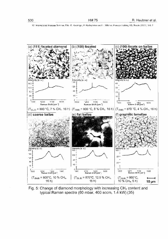
530 HM75 R. Haubner et al.15" International Plansee Seminar, Eds. G. Kneringer, P. Rodhammer and H. Wildner, Plansee Holding AG, Reutte (2001), Vol. 2
(a) (111) faceted diamond
* ate. - ^ ^ - ^ i^afej.
Intensity [a. u.]
1000 1200 1400 1600Raman Shift [cm"1]
(T(SUB) = 800 °C, 7 % CH4, 16 h)
(b) (100) faceted
intensity [a. u.]160 x
1 2 0 "•
1000 1200 1400 1600Raman Shift [cm1]
= 800 °C, 8 % CH4, 16 h)
[c) (100) facets on ballas
1000 1200 1400 1600Raman Shift [cm"']
= 870 °C, 4 % CH4, 16 h)
(d) coarse ballas (e) flat ballas (f) graphitic lamellae
1000 1200 1400 1600Raman Shift [cm4]
(T(SUB) = 800°C, 10%CH 4 ,16 h)
1000 1200 1400 1600Raman Shift [cm1]
(T(suB) = 870°C, 12.5 % CH4,16 h)
1000 1200 1400 1600Raman Shift [cm'1]
(T(SUB) = 950°C, i—10%CH4, 5h) 10 I
Fig. 5: Change of diamond morphology with increasing CH4 content andtypical Raman spectra (60 mbar, 400 seem, 1.4 kW) (35)
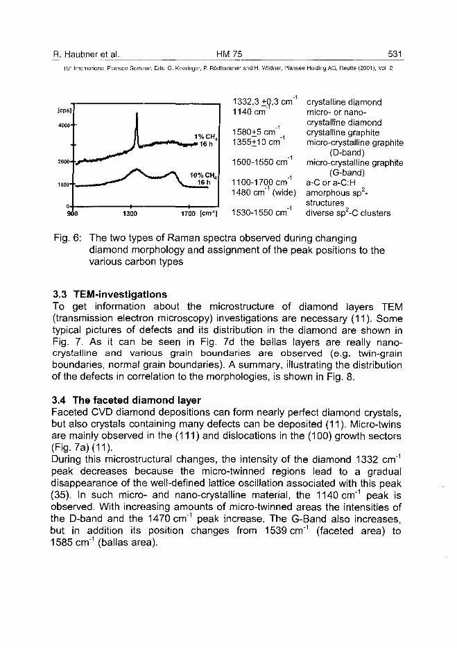
R. Haubner et al. HM75 53115" International Plansee Seminar, Eds. G. Kneringer, P. Rodhammer and H. Wildner, Plansee Holding AG, Reutte (2001), Vol. 2
1300 1700 [cm1]
1332,3+0,3 cm"1
1140 cm"1
1580+5 cm"1
1355+10 cm"1
1500-1550 cm"1
1100-1700 cm"1
1480 cm"1 (wide)
1530-1550 cm"1
crystalline diamondmicro- or nano-crystalline diamondcrystalline graphitemicro-crystalline graphite
(D-band)micro-crystalline graphite
(G-band)a-Cora-C:Hamorphous sp2-structuresdiverse sp2-C clusters
Fig. 6: The two types of Raman spectra observed during changingdiamond morphology and assignment of the peak positions to thevarious carbon types
3.3 TEM-investigationsTo get information about the microstructure of diamond layers TEM(transmission electron microscopy) investigations are necessary (11). Sometypical pictures of defects and its distribution in the diamond are shown inFig. 7. As it can be seen in Fig. 7d the ballas layers are really nano-crystalline and various grain boundaries are observed (e.g. twin-grainboundaries, normal grain boundaries). A summary, illustrating the distributionof the defects in correlation to the morphologies, is shown in Fig. 8.
3.4 The faceted diamond layerFaceted CVD diamond depositions can form nearly perfect diamond crystals,but also crystals containing many defects can be deposited (11). Micro-twinsare mainly observed in the (111) and dislocations in the (100) growth sectors(Fig 7a) (11).During this microstructural changes, the intensity of the diamond 1332 cm"1
peak decreases because the micro-twinned regions lead to a gradualdisappearance of the well-defined lattice oscillation associated with this peak(35). In such micro- and nano-crystalline material, the 1140 cm"1 peak isobserved. With increasing amounts of micro-twinned areas the intensities ofthe D-band and the 1470 cm"1 peak increase. The G-Band also increases,but in addition its position changes from 1539 cm"1 (faceted area) to1585 cm"1 (ballas area).
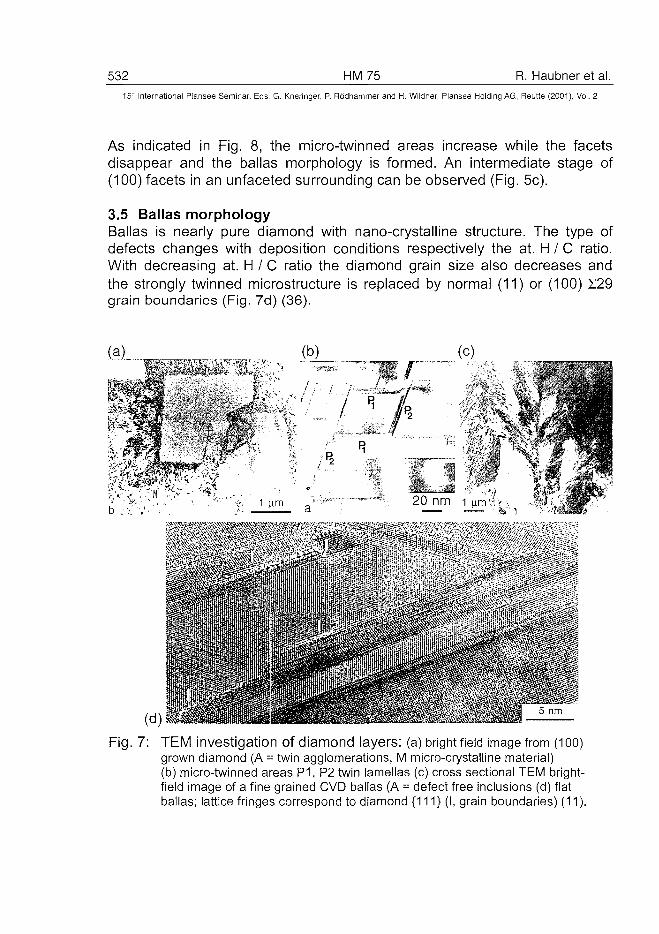
532 HM75 R. Haubner et al.15" International Piansee Seminar, Eds. G. Kneringer, P. Rodhammer and H. Wildner, Plansee Holding AG, Reutte (2001), Vol. 2
As indicated in Fig. 8, the micro-twinned areas increase while the facetsdisappear and the ballas morphology is formed. An intermediate stage of(100) facets in an unfaceted surrounding can be observed (Fig. 5c).
3.5 Ballas morphologyBallas is nearly pure diamond with nano-crystalline structure. The type ofdefects changes with deposition conditions respectively the at. H / C ratio.With decreasing at. H / C ratio the diamond grain size also decreases andthe strongly twinned microstructure is replaced by normal (11) or (100) E29grain boundaries (Fig. 7d) (36).
Fig. 7: TEM investigation of diamond layers: (a) bright field image from (1OO)grown diamond (A = twin agglomerations, M micro-crystalline material)(b) micro-twinned areas P1, P2 twin lamellas (c) cross sectional TEM bright-field image of a fine grained CVD ballas (A = defect free inclusions (d) flatballas; lattice fringes correspond to diamond {111} (I, grain boundaries) (11).
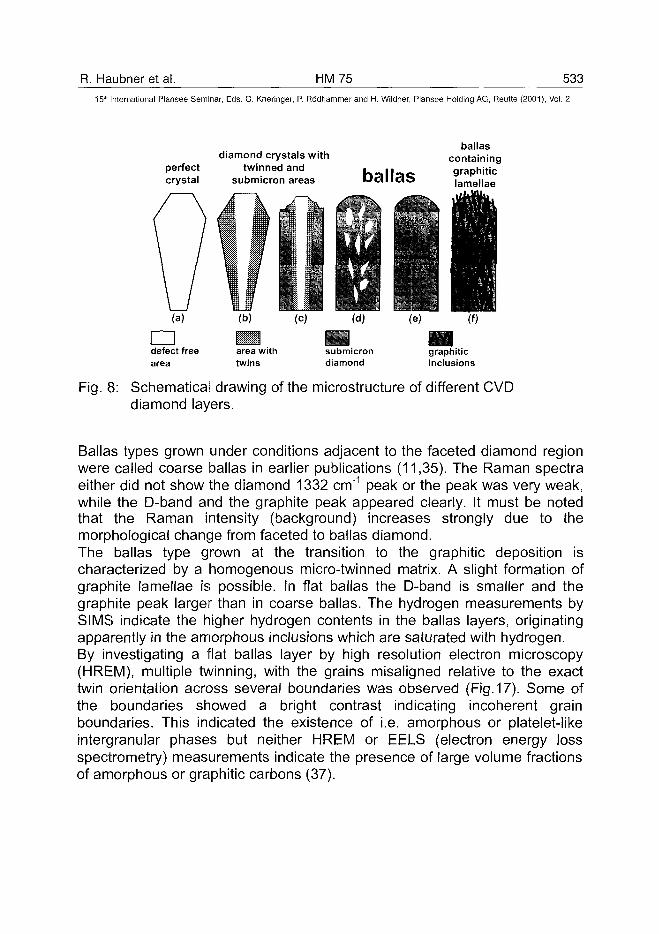
R. Haubner et al. HM75 533
15" International Plansee Seminar, Eds. G. Kneringer, P. Rodhammer and H. Wildner, Plansee Holding AG, Reutte (2001), Vol. 2
diamond crystals withperfect twinned andcrystal submicron areas ballas
ballascontaininggraphiticlamellae
(a)
•defect freearea
(b)
imarea withtwins
(C) (d)
submicrondiamond
(e) (f
mgraphiticinclusions
Fig. 8: Schematical drawing of the microstructure of different CVDdiamond layers.
Ballas types grown under conditions adjacent to the faceted diamond regionwere called coarse ballas in earlier publications (11,35). The Raman spectraeither did not show the diamond 1332 cm"1 peak or the peak was very weak,while the D-band and the graphite peak appeared clearly. It must be notedthat the Raman intensity (background) increases strongly due to themorphological change from faceted to ballas diamond.The ballas type grown at the transition to the graphitic deposition ischaracterized by a homogenous micro-twinned matrix. A slight formation ofgraphite lamellae is possible. In flat ballas the D-band is smaller and thegraphite peak larger than in coarse ballas. The hydrogen measurements bySIMS indicate the higher hydrogen contents in the ballas layers, originatingapparently in the amorphous inclusions which are saturated with hydrogen.By investigating a flat ballas layer by high resolution electron microscopy(HREM), multiple twinning, with the grains misaligned relative to the exacttwin orientation across several boundaries was observed (Fig. 17). Some ofthe boundaries showed a bright contrast indicating incoherent grainboundaries. This indicated the existence of i.e. amorphous or platelet-likeintergranular phases but neither HREM or EELS (electron energy lossspectrometry) measurements indicate the presence of large volume fractionsof amorphous or graphitic carbons (37).
534 HM75 R. Haubner et al.15'1 International Plansee Seminar, Eds. G. Kneringer, P. Rodhammer and H. Wildner, Plansee Holding AG, Reutte (2001), Vol. 2
The described nano-crystalline diamond deposits show nearly the sameRaman peaks than ballas deposits and also the TEM images look verysimilar (5,6,11,30,32,35).
3.6 Graphitic morphologyTransition from ballas-like morphologies to layers containing graphiticinclusions is initialized by implementation of fine lamella. These lamellaappear to be of graphitic nature since Raman spectra show a sharp graphitepeak at about 1585 cm"1 when lamellae are present. With increasing CH4
concentration, these lamella grow until the structure becomes exclusivelylamellar.
4. Summary and ConclusionsIt could be shown that ballas diamond, nano-crystalline diamond andultranano-crystalline diamond are very similar materials. In detail themicrostructures shown by TEM for the nano- and ultranano-crystallinediamond can also be observed in ballas diamond. Because the descriptionof ballas diamond includes all diamond layers without facets (from thefaceted region to graphitic deposits) also the nano- and ultranano-crystallinecoatings are a subgroup of ballas.The formation of ballas is observed with increasing carbon supersaturation(CH4 content) in the gas phase respectively with decreasing at. H / C ratio.These conditions can be reached by variation of the carbon source, e.g.with fullerens or by reduction of the at. H concentration in case of Aradditions. By variation of the other diamond deposition parameters alsoballas can be deposited (e.g. plasma intensity, surface temperature,impurities).In order to use the high potential of the unique ballas structure in industrialapplications further investigations should be performed on the low-pressureballas synthesis. Applying polycrystalline ballas diamond as material forhigh-duty, thin coating surfaces on suitable substrates with even complexpre-shaped geometries should be quite easy. To develop the necessarycoating adhesion to optimize the ballas layer strength, its fracture toughnessand wear behavior versus a variety of materials seems a worthwhile newendeavor.Furthermore, the ballas type containing fine graphite particles could be ofinterest for the flat panel production.
R. Haubner et al. HM 75 535
15th International Plansee Seminar, Eds. G. Kneringer, P. Rodhammer and H. Wildner, Plansee Holding AG, Reutte (2001), Vol. 2
ACKNOWLEDGMENTThe authors gratefully acknowledge financial support of the present work bythe Austrian Science Foundation (FWF) (Project P12055-CHE). Thisresearch project was carried out under the auspices of the trinational"D-A-CH" German, Austrian and Swiss cooperation on the "Synthesis ofSuperhard Materials".
References
(1) R. Bichler, R. Haubner, B. Lux: High Temperature-High Pressure, Vol.21(1989)576-593
(2) "Properties and Growth of Diamond", Editor G.Davies, emis DatareviewsSeries No.9, 1994 INSPEC, London
(3) P.N. Barnes, R.L.C. Wu: Appl.Phys.Lett. 62 (1) (1993) 37-39(4) P.K. Bachmann, D.U. Wiechert, Diamond and Diamond-Like Films and
Coatings, Edited by R.E.Clausing et al., Plenum Press, New York 1991,pp.677-713
(5) D.M. Gruen: in "Properties, growth and application of diamond" pp. 299-302,Ed. M.H.Nazare and A.J.Neves, (2001) INSPEC, London
(6) D.M. Gruen: in "Properties, growth and application of diamond" pp. 303-306,Ed. M.H.Nazare and A.J.Neves, (2001) INSPEC, London
(7) P.K. Bachmann, W. van Enckevort, Diamond and Related Materials, 1,(1992)1021-1034
(8) K.E. Spear: J.Am.Ceram.Soc, 72 (2), (1989) 171-191(9) A. Lindlbauer, R. Haubner, B. Lux: Refractory Metals & Hard Materials 11,
(1992)247-258(10) J. Michler, J. Stiegler, Y. von Kaenel, P. Moeckli, W. Dorsch, D. Stenkamp,
E. Blank: J. Crystal Growth 172 (1997) 404-415(11) M. Joksch, P. Wurzinger, P. Pongratz, R. Haubner, B. Lux: Diamond and
Related Materials, 3 (1994) 681-687(12) B. Lux, R. Haubner, H. Holzer, R.C. DeVries, Refractory Metals & Hard
Materials 15 (1997) 263-288(13) R. Bichler, Diploma Thesis, Vienna University of Technology (1985)(14) R.J. Nemanich, L. Bergman, Y.M. LeGrice, R.E.S chroder, Proc. 2nd Int.Conf.
New Science and Technology, Sept 23-27, 1990, Washington, DC, Eds.R.Messier, J.T.GIass, J.E.Butler, R.Roy, MRS, pp.741-752
(15) R. Litos, R. Haubner, B. Lux, High Temp.-High Press. 22 (1990), 99-118(16) S. Bohr, Doctoral Thesis, Technical University Vienna (1995)(17) R. Haubner, B. Lux: in "Properties, growth and application of diamond" pp.
281-289, Ed. M.H.Nazare and A.J.Neves, (2.001) INSPEC, London
536 HM75 R. Haubner et a!.15~ International Plansee Seminar, Eds. G. Kneringer, P. Rodhammer and H. Wildner, Plansee Holding AG, Reutte (2001), Vol. 2
(18) R. Brunsteiner, R. Haubner, B. Lux, Diamond and Related Materials 2 (1993),1263-1270
(19) R. Haubner, B. Lux, Ref. Metals & Hard Mater. 12 (1987), 210-215(20) R. Haubner, A. Lindlbauer, B. Lux, Ref. Metals & Hard Mater. 14 (1996), 119-
125(21) R. Brunsteiner, R. Haubner, B. Lux, Refractory Metals & Hard Materials 14
(1996)127-135(22) K. Bando, K. Kamo, T. Ando, Y. Sato, MRS Proc.2nd Int.Conf, New Diamond
Science and Technology, Editors: R. Messier et al. (1991) pp.467-472(23) L. Vandenbulcke, P. Bou, R. Herbin, V. Cholet, C. Beny, 7th EURO-CVD,
Perpignan France, 19-23. June 1989, C5-177(24) J. Stiegler, T. Lang, M. Nygard-Ferguson, Y. von Kaenel, E. Blank, Diamond
and Related Materials 5 (1996) 226-230(25) R. Beckmann, B. Sobisch, W. Kulisch, Diamond and Related Materials 4
(1995), 256-260(26) P.K. Bachmann, D. Leers, H. Lydtin, Diamond and Related Materials 1
(1991)1-12(27) K. Kobashi, K. Nishimura, Y. Kawate, T. Horiuchi: Physical Review B, 38 (6),
1988,4067-4084(28) J. Bruckner, T. Mantyla: Diamond and Related Materials 2 (1993), 373-377(29) D.M. Gruen, S. Liu, A.R. Krauss, J. Luo, X. Pan: Appl. Phys. Lett. 64 (1994)
1502(30) L.C. Qin, D. Zhou, A.R. Krauss, D.M. Gruen: Nanostruct. Mater., 10 (1998)
649-660(31) H.G. Busmann, U. Brauneck, H.-E. David: Carbon 36 (1998) 529(32) D. Zhou, D.M. Gruen, L.C. Quin, T.G. McCauley, A.R. Krauss: J. Appl. Phys.
Lett. 84(1998)1981-1989(33) R. Haubner, B. Lux: Diamond Films and Technology, Vol.3, No.4 (1994) 209-
217(34) A. Lindlbauer, R. Haubner, B. Lux: Diamond Films and Technology, Vol.2,
No.2& 3 (1992) 81-98(35) S. Biihlmann, E. Blank, R. Haubner, B. Lux: Diamond and Related Materials
8(1999)194-201(36) D.M. Gruen: in "Properties, growth and application of diamond" pp. 307-312,
Ed. M.H.Nazare and A.J.Neves, (2001) INSPEC, London Gruen(37) M. Joksch, P. Wurzinger, P. Pongratz, R. Haubner, B. Lux: Diamond and
Related Materials 3 (1994), 681-687
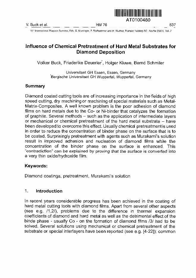
AT0100480V. Buck et al. HM 76 537
15lh International Plansee Seminar, Eds. G. Kneringer, P. Rodhammer and H. Wildner, Plansee Holding AG, Reutte (2001), Vol. 2
Influence of Chemical Pretreatment of Hard Metal Substrates forDiamond Deposition
Volker Buck, Friederike Deuerler*, Holger Kluwe, Bernd Schmiler
Universitaet GH Essen, Essen, Germany*Bergische Universitaet GH Wuppertal, Wuppertal, Germany
Summary
Diamond coated cutting tools are of increasing importance in the fields of highspeed cutting, dry machining or machining of special materials such as Metal-Matrix-Composites. A well known problem is the poor adhesion of diamondfilms on hard metals due to the Co- or Ni-binder that catalyzes the formationof graphite. Several methods - such as the application of intermediate layersor mechanical or chemical pretreatment of the hard metal substrate - havebeen developed to overcome this effect. Usually chemical pretreatmentis usedin order to reduce the concentration of binder phase on the surface that is tobe coated. Surprisingly pretreatment with agents such as Murakami's solutionresult in improved adhesion and nucleation of diamond films while theconcentration of the binder phase on the surface is enhanced. This"contradiction" can be explained by proving that the surface is converted intoa very thin oxide/hydroxide film.
Keywords:
Diamond coatings, pretreatment, Murakami's solution
1. Introduction
In recent years considerable progress has been achieved in the coating ofhard metal cutting tools with diamond films. Apart from several other aspects(see e.g. /1,2/), problems due to the difference in thermal expansioncoefficients of diamond and hard metal as well as the detrimental effect of thebinde phase - usually Co - on the formation of diamond films /3/ had to besolved. Several solutions using mechanical or chemical pretreatment of thesubstrate or special interlayers have been reported (see e.g. [4-22]); common
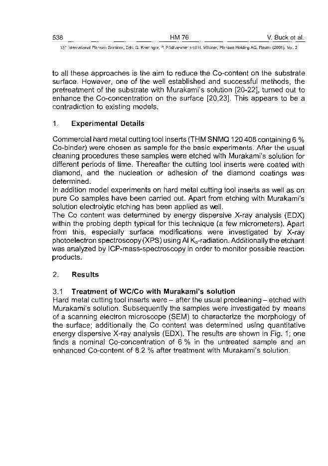
538 HM76 V. Buck et al.15" International Plansee Seminar, Eds. G. Kneringer, P. Rodhammer and H. Wildner, Plansee Holding AG, Reutte (2001), Vol. 2
to all these approaches is the aim to reduce the Co-content on the substratesurface. However, one of the well established and successful methods, thepretreatment of the substrate with Murakami's solution [20-22], turned out toenhance the Co-concentration on the surface [20,23]. This appears to be acontradiction to existing models.
1. Experimental Details
Commercial hard metal cutting tool inserts (THM SNMQ 120 408 containing 6 %Co-binder) were chosen as sample for the basic experiments. After the usualcleaning procedures these samples were etched with Murakami's solution fordifferent periods of time. Thereafter the cutting tool inserts were coated withdiamond, and the nucleation or adhesion of the diamond coatings wasdetermined.In addition model experiments on hard metal cutting tool inserts as well as onpure Co samples have been carried out. Apart from etching with Murakami'ssolution electrolytic etching has been applied as well.The Co content was determined by energy dispersive X-ray analysis (EDX)within the probing depth typical for this technique (a few micrometers). Apartfrom this, especially surface modifications were investigated by X-rayphotoelectron spectroscopy (XPS) using Al Ka-radiation. Additionally the etchantwas analyzed by ICP-mass-spectroscopy in order to monitor possible reactionproducts.
2. Results
3.1 Treatment of WC/Co with Murakami's solutionHard metal cutting tool inserts were - after the usual precleaning - etched withMurakami's solution. Subsequently the samples were investigated by meansof a scanning electron microscope (SEM) to characterize the morphology ofthe surface; additionally the Co content was determined using quantitativeenergy dispersive X-ray analysis (EDX). The results are shown in Fig. 1; onefinds a nominal Co-concentration of 6 % in the untreated sample and anenhanced Co-content of 8.2 % after treatment with Murakami's solution.
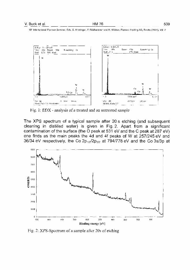
V. Buck et al. HM76 53915* International Plansee Seminar, Eds. G. Kneringer, P. Rodhammer and H. Wildner, Plansee Holding AG, Reutte (2001), Vol. 2
X-Ray: 0 -Live: 100sReal: 122s
W
FS- SKMem : Probe
20keVPreset: 100s18% dead
2.1 / Unbchandelt
Remaining:
C« Co
5.880 keV
0s
W
f\eh 304- 209 cts
wA,
11.0 s-
X-RaLiveRea
>
Jk< .1
y: 0-20 keV100s Pres
21 s
N
F S - 8KMEM1: Probe 2.7
el: 100s17% Dead
Remaining: 0s
W
Co I W
4 Co A /u6.000 keV
ch310»
11.1>
190 cts
Fig. 1: EDX - analysis of a treated and an untreated sample
The XPS spectrum of a typical sample after 20 s etching (and subsequentcleaning in distilled water) is given in Fig. 2. Apart from a significantcontamination of the surface (the O peak at 531 eV and the C peak at 287 eV)one finds as the main peaks the 4d and 4f peaks of W at 257/245 eV and36/34 eV respectively, the Co 2p1/2/2p3/2 at 794/778 eV and the Co 3s/3p at
Binding energy [eV]
Fig. 2: XPS-Spectrum of a sample after 20s of etching
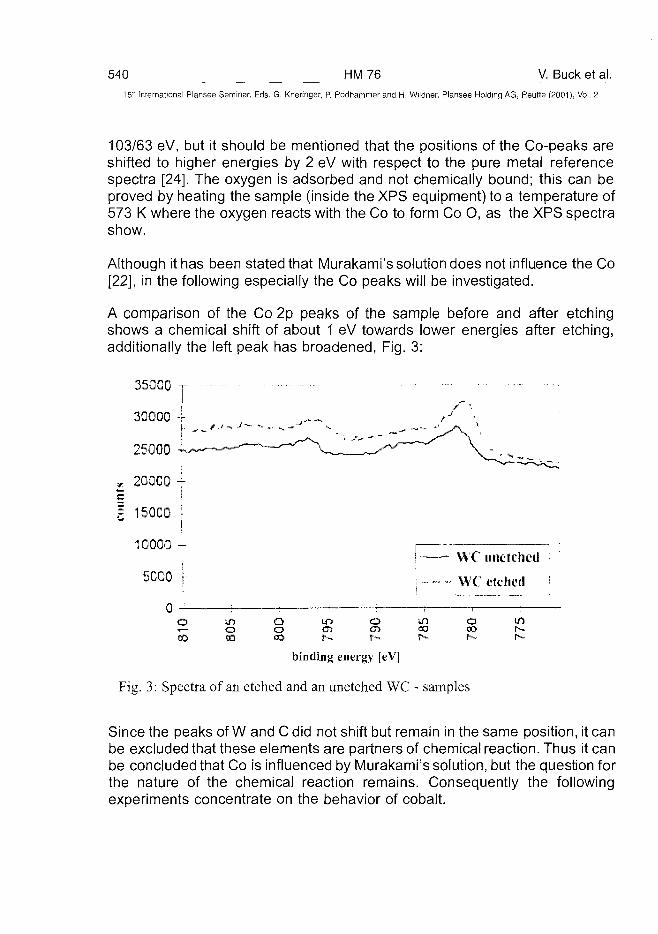
540 HM76 V. Buck et al.15" International Plansee Seminar, Eds. G. Kneringer, P. Rodhammer and H. Wildner, Plansee Holding AG, Reutte (2001), Vol. 2
103/63 eV, but it should be mentioned that the positions of the Co-peaks areshifted to higher energies by 2 eV with respect to the pure metal referencespectra [24]. The oxygen is adsorbed and not chemically bound; this can beproved by heating the sample (inside the XPS equipment) to a temperature of573 K where the oxygen reacts with the Co to form Co O, as the XPS spectrashow.
Although it has been stated that Murakami's solution does not influence the Co[22], in the following especially the Co peaks will be investigated.
A comparison of the Co 2p peaks of the sample before and after etchingshows a chemical shift of about 1 eV towards lower energies after etching,additionally the left peak has broadened, Fig. 3:
35000
30O0Q -r-
25000
* 20QC0 -j-
| 15QC0 \
10000 -
5OG0 |-
0 -
WC unetched
WC etched !
o5
oso
QoO
t p o00
un
binding energy [eV]
Fig. 3: Spectra of an etched and an unetched WC - samples
Since the peaks of W and C did not shift but remain in the same position, it canbe excluded that these elements are partners of chemical reaction. Thus it canbe concluded that Co is influenced by Murakami's solution, but the question forthe nature of the chemical reaction remains. Consequently the followingexperiments concentrate on the behavior of cobalt.
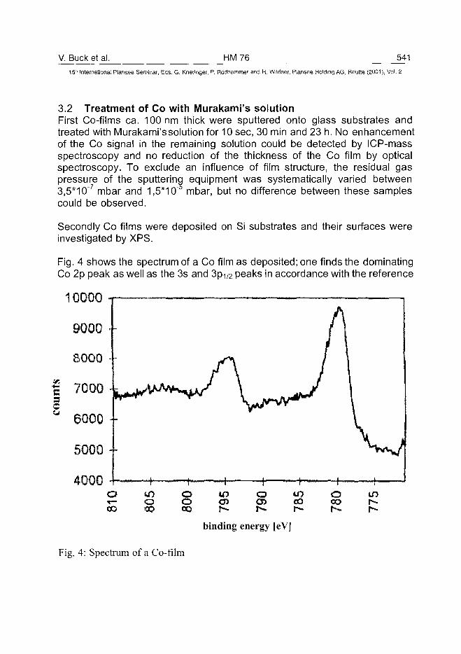
V. Buck et al. HM76 541151K International Plansee Seminar, Eds. G. Kneringer, P. Rodhammer and H. Wildner, Plansee Holding AG, Reutte (2001), Vol. 2
3.2 Treatment of Co with Murakami's solutionFirst Co-films ca. 100 nm thick were sputtered onto glass substrates andtreated with Murakami's solution for 10 sec, 30 min and 23 h. No enhancementof the Co signal in the remaining solution could be detected by ICP-massspectroscopy and no reduction of the thickness of the Co film by opticalspectroscopy. To exclude an influence of film structure, the residual gaspressure of the sputtering equipment was systematically varied between3,5*10"7 mbar and 1,5*10 mbar, but no difference between these samplescould be observed.
Secondly Co films were deposited on Si substrates and their surfaces wereinvestigated by XPS.
Fig. 4 shows the spectrum of a Co film as deposited; one finds the dominatingCo 2p peak as well as the 3s and 3pi /2 peaks in accordance with the reference
10000
9000
8000 -
c7000 -c
6000 - -
5000 -
4000ooo
If)
o•DOooCD
m o toCOr-
oCOh -
i nr-
binding energy [eV]
Fig. 4: Spectrum of a Co-film
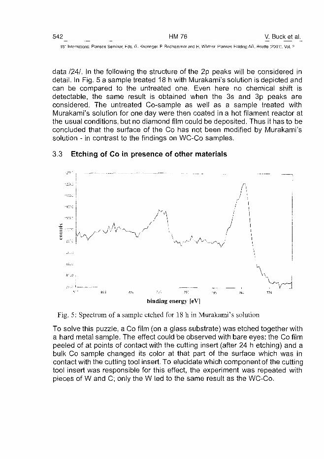
542 HM76 V. Buck et al.15~ International Plansee Seminar, Eds. G. Kneringer, P. Rodhammer and H. Wildner, Plansee Holding AG, Reutte (2001), Vol. 2
data I2AI. In the following the structure of the 2p peaks will be considered indetail. In Fig. 5 a sample treated 18 h with Murakami's solution is depicted andcan be compared to the untreated one. Even here no chemical shift isdetectable, the same result is obtained when the 3s and 3p peaks areconsidered. The untreated Co-sample as well as a sample treated withMurakami's solution for one day were then coated in a hot filament reactor atthe usual conditions, but no diamond film could be deposited. Thus it has to beconcluded that the surface of the Co has not been modified by Murakami'ssolution - in contrast to the findings on WC-Co samples.
3.3 Etching of Co in presence of other materials
: i
V *~ '—.f-\. '
binding energy [eV]
Fig. 5: Spectrum of a sample etched for 18 h in Murakami's solution
To solve this puzzle, a Co film (on a glass substrate) was etched together witha hard metal sample. The effect could be observed with bare eyes: the Co filmpeeled of at points of contact with the cutting insert (after 24 h etching) and abulk Co sample changed its color at that part of the surface which was incontact with the cutting tool insert. To elucidate which component of the cuttingtool insert was responsible for this effect, the experiment was repeated withpieces of W and C; only the W led to the same result as the WC-Co.
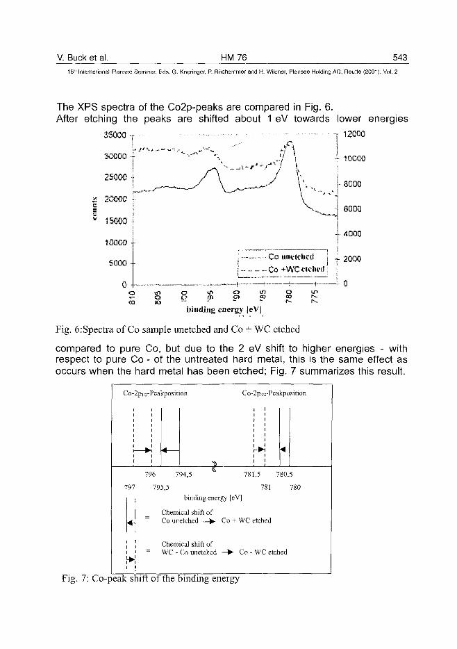
V. Buck et al. HM76 54315" International Plansee Seminar, Eds. G. Kneringer, P. Rodhammer and H. Wildner, Plansee Holding AG, Reutte (2001), Vol. 2
The XPS spectra of the Co2p-peaks are compared in Fig. 6.After etching the peaks are shifted about 1 eV towards lower energies
T 12000
AOGGO
35000
6000
Z 20000c
unvk'hrd: C0+WCclch«lj
o at pi o»
binding energy [eV]
Fig. 6:Spectra of Co sample unetched and Co + WC etched
compared to pure Co, but due to the 2 eV shift to higher energies - withrespect to pure Co - of the untreated hard metal, this is the same effect asoccurs when the hard metal has been etched; Fig. 7 summarizes this result.
Co-2pi/2-Peakposition Co-2p3/2-Peakposition
796 794,5 781,5 780,5
797 795,5 781 780binding energy [eV]
Chemical shift ofCo unetched Co + WC etched
Chemical shift ofWC - Co unetched Co - WC etched
Fig. 7: Co-peak shift of the binding energy
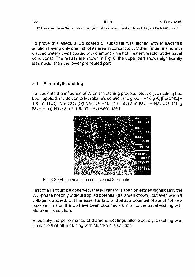
544 HM76 V. Buck et al.15" International Plansee Seminar, Eds. G. Kneringer, P. Rodhammer and H. Wildner, Plansee Holding AG, Reutte (2001), Vol. 2
To prove this effect, a Co coated Si substrate was etched with Murakami'ssolution having only one half of its area in contact to WC then (after rinsing withdistilled water) it was coated with diamond (in a hot filament reactor at the usualconditions). The results are shown in Fig. 8: the upper part shows significantlyless nuclei than the lower pretreated part.
3.4 Electrolytic etching
To elucidate the influence of W on the etching process, electrolytic etching hasbeen applied; in addition to Murakami's solution (10 g KOH + 10 g K3 [Fe(CN)6] +100 ml H2O), Na2 CO3 (5g Na2CO3 +100 ml H2O) and KOH + Na2 CO3 (10 gKOH + 6 g Na2 CO3 + 100 ml H2O) were used.
Fig. 8 SEM Image of a diamond coated Si sample
First of all it could be observed, that Murakami's solution etches significantly theWC-phase not only without applied potential (as is well known), but even when avoltage is applied. But the essential fact is, that at a potential of about 1.45 eVpassive films on the Co have been obtained - similar to the usual etching withMurakami's solution.
Especially the performance of diamond coatings after electrolytic etching wassimilar to that after etching with Murakami's solution.
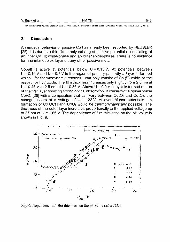
V. Buck et al. HM76 545
15" International Plansee Seminar, Eds. G. Kneringer, P. Rodhammer and H. Wildner, Plansee Holding AG, Reutte (2001), Vol. 2
3. Discussion
An unusual behavior of passive Co has already been reported by HEUSLER[25]. It is due to a thin film - only existing at positive potentials - consisting ofan inner Co (II) oxide-phase and an outer spinel-phase. There is no evidencefor a similar duplex layer on any other passive metal.
Cobalt is active at potentials below U = 0.15 V. At potentials betweenU = 0.15 V and U = 0.7 V in the region of primary passivity a layer is formedwhich - for thermodynamic reasons - can only consist of Co (II) oxide or therespective hydroxide. The film thickness increases only slightly from 2.0 nm atU = 0.45 V to 2.5 nm at U = 0.86 V. Above U := 0.9 V a layer is formed on topof the first layer showing strong optical absorption. It consists of a spinel phaseCo2O4 [26] with a composition that can vary between Co3O4 and Co2O3; thechange occurs at a voltage of U = 1.22 V. At even higher potentials theformation of Co OOH and CoO2 would be thermodynamically possible. Thethickness of the outer layer increases proportionally to the applied voltage upto 37 nm at U = 1.65 V. The dependence of film thickness on the pH-value isshown in Fig. 9.
Ec
W
30
20
JO
0
"" Outer ictf.tr
•0
0
0
•
i
n
pH i
a
>
se
• - c r
D
.1?
42
ta
1.2 1,6 .20 2 i
Mis
Fig. 9: Dependence of film thickness on the ph-value (after 1251)
546 HM76 V. Buck et al.15'-" International Plansee Seminar, Eds. G. Kneringer, P. Rodhammer and H. Wildner, Plansee Holding AG, Reutte (2001), Vol. 2
Electrolytes containing complexing ligands with metal-ions produce asignificantly more negative potential (for example, Cu in cyanid-solutionsproduces a negative potential to the hydrogen-electrode instead of producingthe usual positive value because a complex-ion [Cu(CN)2] is formed).Murakami's solution contains a complexing ligand, too, namely the Fe(lll)(CN)6. A simple measurement of the potential of a Co-W-element and a Co-Murakami-W-element shows a difference greater than 0.7 V, this is sufficientfor an anodic oxydation of Co. Thus it has to be concluded that Co is coveredby a protective layer after treatment with Murakami's solution.
4. Acknowledgements
Thanks are due to WIDIA GmbH for support of this work.
References
1. R. Haubner: Int. J. Refract. Metals & Hard Materials 16 (1998)167
2. R. Haubner, B. Lux in Hartstoffe, Hartstoffschichten, Werkzeuge,VerschleiRschutz, Pulvermetallurgie in Wissenschaft und Praxis, Ed.: R.Ruthardt, Werkstoff-lnformationsgesellschaft, Frankfurt, 1977,p. 8 9 - 116 (in German)
3. S. Kubelka, R. Haubner, B. Lux, R. Steiner, G. Stingeder, M.Grasserbauer: Diamond Films and Technology 5 (1995) 105 - 120
4. M. Nesladek, C. Asinan, J. Spinnewyn, R. Lebout, R. Lorent, M. D.Olieslaeger: Diamond Relat. Mater. 3 (1994) 912-916
5. J. Spinnewyn, M. Nesladek, C. Asinari: Diamond Relat. Mater. 2 (1993)361 - 364
6. H. Schachner, B. Lux, K. G. Stjernberg, A. G. Thellin, H. Tippmann: EP0166708 A2 (1986)
7. M. Tsubokawa, N. Hayashi: EP 0413834 A1 (1991)
8. K. Shibuki, K. Sasaki, M. Yagi, T. Suzuki, and Y. Ikuhara, Surface &Coatings Technol. 68/69 (1994) 369 - 373
V. Buck et al. HM 76 547^15" International Plansee Seminar, Eds. G. Kneringer, P. Rödhammer and H. Wildner, Plansee Holding AG, Reutte (2001), Vol. 2
9. M. Murakawa S. Takeuchi, H. Miyazawa, and Y. Hirose, Surface &Coatings Technol. 36 (1988) 303 - 310
10. Y. Saito, K. Sato, S. Matuda, and H. Koinuma, J. Mater. Sci. 26 (1991)2937 - 2940
11. T.-Y. Yen, C. T. Kuo, and S. E. Hsu, Mater. Res. Soc. Symp. Proc. 168(1990) 207-212
12. T. H. Huang, C. T. Kuo, and T. S. Lin, Surface & Coatings Technol. 56(1993) 105-108
13. K. J. Grannen, F. Xiong, and R. P. H. Chang, Surface & CoatingsTechnol. 57 (1993) 155-162
14. H. Itoh, T. Nakamura, H. Iwahara, and H. Sakamoto, J. Mater. Sci. 29(1994) 1404 - 1410
15. T. lsozaki,Y. Aito, A. Masuda, K. Fukumoto, M. Chosa, T. Ito, E. J. Oies,A. Inspector, and C. E. Bauer, Diamond Relat. Mater 2 (1993) 1156 -1159
16. E. R. Kupp, W. R. Drawl, and K. E. Spear, Surface & Coatings Technol.68/69 (1994)378-383
17. M. Kawarada, K. Kurihara, and K. Sasaki, Diamond Relat. Mater. 2(1993)1083- 1089
18. S. Takatsu, K. Saijo, M. Yagi, K. Shibuki, and J. Echigoya, Mater. Sci.Eng. A 140 (1991)747-752
19. Y. Saijo, T. Isozaki, A. Fukumoto, M. Chosa, T. Ito, E. Bauer, A.Inspector, and E. J. Oies, Diamond Relat. Mater 2 (1993) 1391
20. F. Deuerler, M. Pies, H. van den Berg, R. Tabersky, V. Buck: phys. stat.sol. (a) 154 (1996)403-422
21. R. Haubner, S. Kubelka, B. Lux, M. Griesser, M. Grasserbauer: J.Physique C5 (1995) 753 - 760
548 HM76 V. Buck et al.15" International Plansee Seminar, Eds. G. Kneringer, P. Rodhammer and H. Wildner, Plansee Holding AG, Reutte (2001), Vol. 2
22. M. G. Peters, R. H. Cummings: EP 0519587 A: (1992)
23. V. Buck, F. Deuerler: Diamond Relat. Mater. 7 (1998)1544 - 1552
24. C. D. Wagner, W. M. Riggs, L. E. Davis, J. F. Moulder: Handbook of X-ray photoelectron spectroscopy, Perkin Elmer Corporation, Eden Prairie,Minnesota
25. K.E. Heusler: Passivity and Breakdown of Passivity of Nickel, Cobalt, andChromium in (Eds.):R. P. Frankenthal, J. Kruger: Passivity of Metals, The ElectrochemicalSociety 1978, 771-801
26. P. Petzow: MetallographischesAtzen, Gebr. Borntrager, 1976, p. 8 ff (inGerman)
ATO100481K.H. Dittrich et al. HM 77 549^
15" International Plansee Seminar, Eds. G. Krieringer, P. Rödhammer and H. Wildner, Plansee Holding AG, Reutte (2001), Vol. 2
Herstellung und Charakterisierung von Trockenschmierstoffschichten
für Werkzeuge auf der Basis von Kohlenstoff
Karl-Heinz Dittrich*, Daniel Oelsner*+
*Roth & Rau Oberflächentechnik GmbH, Wüstenbrand, Saxony, Germany
*+Hochschule für Technik und Wirtschaft Mittweida, Mittweida, Saxony, Germany
Summary:
The present development is a layer compound of the category dry lubricantfilms, how they are in development for coating of tools and machine partsworldwide. The basic composition of the compound structure is thecombination of the classical hard coatings titanium nitride (TiN) and titaniumcarbonitride (TiCN) as multilayer. These coatings are generated by means ofPVD (physical vapour deposition) from high rate coating sources to theprinciple of electrical arc vaporization and magnetron sputtering. The on itfollowing dry lubricant coating is based of amorphous, diamond like carbon(DLC) deposited by means of PE-CVD (plasma enhanced - chemical vapourdeposition) in an ECR (electron cyclotron resonance) plasma in the samerecipient. During the operating procedure the amorphous carbon takes thepart of lubricant action, the basic multilayer TiN and TiCN guarantee the well-known great useful life of the tool. The lubricant action of the carbon layer isnot only at the beginning of the use or operating procedure. The carbon layercompounds with the wear protecting film of TiN and TiCN during the actionand prolong the lifetime again more explicitly.
Keywords:
Dry lubricant films, tools, machine parts, TiN, TiCN, DLC, PVD, PE-CVD,ECR, wear protecting film
1. Einleitung
Ausgehend von der weltweiten Zielstellung der verarbeitenden Industriegeeignete Trockenschmierstoffschichten (TSS) für Werkzeuge und Bauteile

550 HM 77 K.H. Dittrich et al.
15" International Plansee Seminar, Eds. G. Kneringer, P. Rödhammer and H. Wildner, Plansee Holding AG, Reutte (2001), Vol. 2
zu erzeugen, wurden auch in der Firma Roth & Rau OberflächentechnikGmbH Schichten auf der Basis von Kohlenstoff (DLC) entwickelt. Dergenerelle Schichtaufbau ist eine klassische Standard-Hartstoffschicht ( TiN,TiCN, TiAIN oder TiAICN) auf die ein Top-coat, bestehend aus amorphemKohlenstoff (DLC) als Trockenschmierstoffschicht TSS-C aufgelegt ist.
Eine Vielzahl von Versuchschargen mit Probekörpern und einsetzbarenWerkzeugen wurde durchgeführt. Folgende Vorgehensweisen wurden dabeigewählt:
1. Entwicklung von DLC -Schichten nach dem PECVD -Verfahren alsTSSC (polymer like, graphite like and diamond like carbon)
2. Dotierung der DLC - Schichten mit Silizium, Titan oder Stickstoff zurVerbesserung der Eigenschaften
3. Verbinden der Prozesse PVD (klassische Hartstoffschichten) undPE-CVD (TSS-C) in einer Beschichtungsanlage
2. Aufbau der Standardschichten (Verschleißschutz)
Die folgende Darstellung zeigt die „multilayer structure" der klassischenStandardschichten TiCN und TiAICN, wie sie derzeit auf dem Markt sind undauch durch die Roth & Rau Oberflächentechnik GmbH angeboten werden.
Abbildung 1:TiCN:
TiCN
TiN
TiCN
TiN
TiCN
TiN
TiCN
TiN
ca. 10min
ca. 5min
ca. 5min
ca. 5min
ca. 10min
ca. 10min
ca. 10min
ca. 30min
ca. 500 nm
ca. 250 nm
ca. 250 nm
ca. 250nm
ca. 500nm
ca. 500 nm
ca. 500 nm
ca. 1|jm
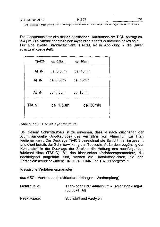
K.H. Dittrich et al. HM 77 551
15" International Plansee Seminar, Eds. G. Kneringer, P. Rodhammer and H. Wildner, Plansee Holding AG, Reutte (2001), Vol. 2
Die Gesamtschichtdicke dieser klassischen Hartstoffschicht TiCN betragt ca.3-4 (jm. Die Anzahl der einzelnen layer kann ebenfalls unterschiedlich sein.Fur eine zweite Standardschicht, TiAICN, ist in Abbildung 2 die Jayerstructure" dargestellt.
TiAICN
AITiN
AITiN
AITiN
TiAIN
ca.
ca.
ca.
ca.
ca
0,5um
0,5um
0,5um
0,5um
. 1,5|jm
ca.
ca.
ca.
ca.
10min
15min
15min
15min
ca. 30min
Abbildung 2: TiAICN layer structure
Bei diesem Schichtaufbau ist zu erkennen, dass je nach Zuschalten derAluminiumquelle (Arc-Kathode) das Verhaltnis von Aluminium zu Titanvariieren kann. Die Decklage TiAICN bezeichnet die Schicht hier insgesamtund dient bereits der Schmierwirkung des Topcoats. Au&erdem begunstig derKohlenstoff in der Decklage der Struktur die Haftung des nachfolgendenlubricant films (TSS-C). Mit den klassischen Verfahrensparametern, dienachfolgend aufgefuhrt sind, werden die Hartstoffschichten, die denVerschleifcschutz bewirken: TiN, TiCN, TiAIN und TiAICN hergestellt.
Klassische Verfahrensparameter
des ARC - Verfahrens (elektrische Lichtbogen - Verdampfung)
Metallquelle:
Reaktivgase:
Titan- oder Titan-Aluminium - Legierungs-Target(50:50=Ti:AI)
Stickstoff und Azetylen
552 yMZ 7 K.H. Dittrich et al.15" International Plansee Seminar, Eds. G. Kneringer, P. Ró'dhammer and H. Wildner, Plansee Holding AG, Reutte (2001), Vol. 2
Prozessdruck: ca. 0,1 - 0,3 Pa
DC-BIAS: ca. 50-100V
Bogenstrom: ca. 100 A (Rechteckverdampfer 635x152 mm)
Expositionsrate: ca. 3 um/h
Prozesstemperatur: ca. bis 400 °C
Schichtdicken: ca. 3 - 4
3. Trockenschmierstoffschicht auf Kohlenstoffbasis: TSS-C
Überlegungen zur Verbesserung der Haftung der C-Schichten führten zu denElementen Titan (1), Aluminium (2), Silizium (3) und Stickstoff (4). Es wurdeausgetestet, welches Element geeignet die Haftung und die Eigenschaftender Trockenschmierstoffschicht C beeinflusst, die als Topcoat den Schmier-bzw. Kühlmittelersatz bringt und auf die klassische Hartstoffschichtaufgebracht werden soll. Das eingesetzte Standardverfahren der Firma Roth& Rau Oberflächentechnik GmbH zur Erzeugung derartiger DLC - Schichtenist das PE-CVD - Verfahren. Mittels energiereicher Plasmen, generiert ausECR (electron - cyclotron - resonance) - Plasmaquellen (5), werden dieProzeßgase zur Reaktion gebracht. Zum Einbau von Titan und damit derweiteren Optimierung der Eigenschaften der DLC - Schicht ist eineSputterquelle mit Titantarget ins Anlagenkonzept eingebaut worden. DieseQuelle arbeitet im gleichen Druckfenster wie die ECR-Quellen. Die Parameterfür den PE-CVD Prozess sind im Folgendem aufgeführt:
I.lonenreiniqunqsprozeß: Argonplasma (ECR)20-30 sccm ArDC-BIASbis1,5kV
2.Überganqsphase: Argonplasma (ECR)Titansputtern (Magnetron)oder HMDSO
3.Abscheidephase: Argon: 20 sccmStickstoff: 60 sccmAcetylen: 5-25 sccmHMDSO
K.H. Dittrich et al. HM 77 55315lh International Plansee Seminar, Eds. G. Kneringer, P. Rödhammer and H. Wildner, Plansee Holding AG, Reutte (2001), Vol. 2
3.1. Si-C:H
Bereits 1979 wurden von Dimigen und Hübsch (DE2926080)Kohlenstoffschichten als Mittel zur Trockenschmierung entwickelt, dieSilizium - und Siliziumdioxidschichten als die Haftung erhöhende Schichtenvon ca. 50 nm Dicke mit einschlössen. In weiteren Patentschriften, so z.B.von Hartmann et. al. (DE 19544 489), Enke (DE 3838905) und auch von Araiund Oguri (EP 0435312) wurden die verschiedenen Möglichkeiten derVerbesserung der Haftung von Kohlenstoffschichten mittels Einbringen vonSiliziumverbindungen beschrieben. Bei all diesen Rezepturen wurden diehervorragenden Ergebnisse der Trockenreibung der Kohlenstoffschichtenherausgestellt. Das heißt, gemittelt über verschiedene Reibpaarungen, sindReibkoeffizienten von < 0,1 „state of the art" bei Kohlenstoffschichten.Ausgehend von den Überlegungen in den hier genannten Schriften, warenunsere Arbeiten angelegt. Es wurden Versuche zum Einbau von Silizium, vorallem als Haftvermittler und zur Erzeugung definierter „Sollbruchstellen" derSchicht, die Schmierschicht freigeben, geplant und durchgeführt. Für dieVersuche war eine ECR - Plasmaquelle das Hauptinstrument derBeschichtungsanlage. Die zur Verfügung stehende Plasmaquelle RR 250arbeitet stabil in einem Bereich von etwa 1x10"3 bis ca. 5x10"2 mbar mit einerMikrowellenleistung von 500 W. Die Mikrowellenfrequenz beträgt 2,45 GHz.Diese Parameter und die Mikrowellenleistung im Beschichtungsprozesswurden über alle Versuche konstant gehalten.Für das erste Plasma im Substratvorreinigungsschritt wurde Argon als Gas,bis 500 W Mikrowellenleistung und in der Regel DC - BIAS eingesetzt. Nachdem Vorreinigen erfolgte der Übergang vom Argonplasma insReaktionsplasma.Von ausschlaggebender Bedeutung für die Prozessführung im eigentlichenAbscheideprozeß ist weiterhin die BIAS - Spannung. Generell kann man dieAussage treffen, dass eine höhere BIAS- Spannung auch eine höhere Härteder Schicht zur Folge hat. Der Lieferant für den Kohlenstoff imPlasmaprozess war Ethin mit der Gasqualität 2.6. Neben dem Siliziumeinbauin die Schicht, wozu Hexamethyldisiloxan (HMDSO) diente, welches über denDampfdruck beim Erwärmen in den Rezipienten eingelassen wurde, ist alsweitere Möglichkeit der Haftungsverbesserung an Metalleinbau inKombination mit Stickstoff gedacht worden.
3.2. a-C:N(H)
Für die Erzeugung stickstoffdotierter DLC - Schichten wurde ins ECR -Plasma molekularer Stickstoff (5.0) eingegeben. Um die Haftung desTopcoats DLC auf der klassischen Hartstoffschicht realisieren zu können,
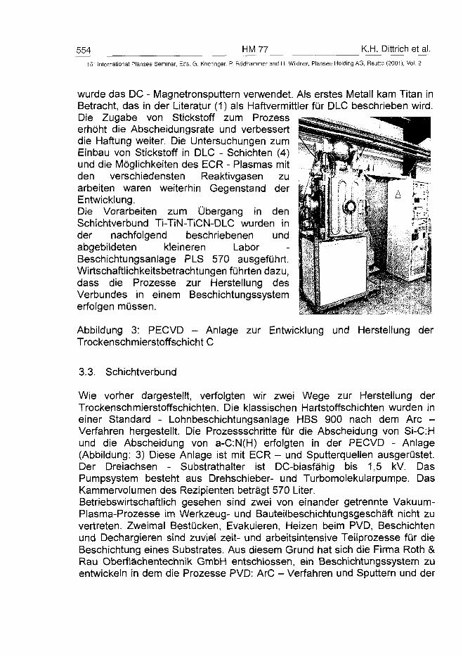
554 HM 77 K.H. Dittrich et al.15" International Plansee Seminar, Eds. G. Kneringer, P. Rödhammer and H. Wildner, Plansee Holding AG, Reutte (2001), Vol. 2
wurde das DC - Magnetronsputtern verwendet. Als erstes Metall kam Titan inBetracht, das in der Literatur (1) als Haftvermittler für DLC beschrieben wird.Die Zugabe von Stickstoff zum Prozesserhöht die Abscheidungsrate und verbessertdie Haftung weiter. Die Untersuchungen zumEinbau von Stickstoff in DLC - Schichten (4)und die Möglichkeiten des ECR - Plasmas mitden verschiedensten Reaktivgasen zuarbeiten waren weiterhin Gegenstand derEntwicklung.Die Vorarbeiten zum Übergang in denSchichtverbund Ti-TiN-TiCN-DLC wurden inder nachfolgend beschriebenen undabgebildeten kleineren LaborBeschichtungsanlage PLS 570 ausgeführt.Wirtschaftlichkeitsbetrachtungen führten dazu,dass die Prozesse zur Herstellung desVerbundes in einem Beschichtungssystemerfolgen müssen.
Abbildung 3: PECVD - Anlage zur Entwicklung und Herstellung derTrockenschmierstoffschicht C
3.3. Schichtverbund
Wie vorher dargestellt, verfolgten wir zwei Wege zur Herstellung derTrockenschmierstoffschichten. Die klassischen Hartstoffschichten wurden ineiner Standard - Lohnbeschichtungsanlage HBS 900 nach dem Are -Verfahren hergestellt. Die Prozessschritte für die Abscheidung von Si-C:Hund die Abscheidung von a-C:N(H) erfolgten in der PECVD - Anlage(Abbildung: 3) Diese Anlage ist mit ECR - und Sputterquellen ausgerüstet.Der Dreiachsen - Substrathalter ist DC-biasfähig bis 1,5 kV. DasPumpsystem besteht aus Drehschieber- und Turbomolekularpumpe. DasKammervolumen des Rezipienten beträgt 570 Liter.Betriebswirtschaftlich gesehen sind zwei von einander getrennte Vakuum-Plasma-Prozesse im Werkzeug- und Bauteilbeschichtungsgeschäft nicht zuvertreten. Zweimal Bestücken, Evakuieren, Heizen beim PVD, Beschichtenund Dechargieren sind zuviel zeit- und arbeitsintensive Teilprozesse für dieBeschickung eines Substrates. Aus diesem Grund hat sich die Firma Roth &Rau Oberflächentechnik GmbH entschlossen, ein Beschichtungssystem zuentwickeln in dem die Prozesse PVD: ArC - Verfahren und Sputtern und der
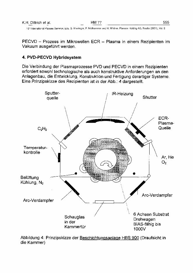
K.H. Dittrich et al. HM 77 555
15" International Plansee Seminar, Eds. G. Kneringer, P. Rödhammer and H. Wildner, Plansee Holding AG, Reutte (2001), Vol. 2
PECVD - Prozess im Mikrowellen ECR - Plasma in einem Rezipienten imVakuum ausgeführt werden.
4. PVD-PECVD Hybridsystem
Die Verbindung der Plasmaprozesse PVD und PECVD in einem Rezipientenerfordert sowohl technologische als auch konstruktive Anforderungen an denAnlagenbau, die Entwicklung, Konstruktion und Fertigung derartiger Systeme.Eine Prinzipskizze des Rezipienten ist in der Abb.: 4 dargestellt.
Sputter-quelle
IR-Heizung
Temperatur-kontrolle
BelüftungKühlung, N2
Are-Verdampfer
Shutter
ECR-Plasma-Quelle
Ar, HeO2
Schauglasin derKammertür
Are-Verdampfer
6 Achsen SubstratDrehwagenBIAS-fähig bis1000V
Abbildung 4: Prinzipskizze der Beschichtungsanlage HBS 900 (Draufsicht indie Kammer)
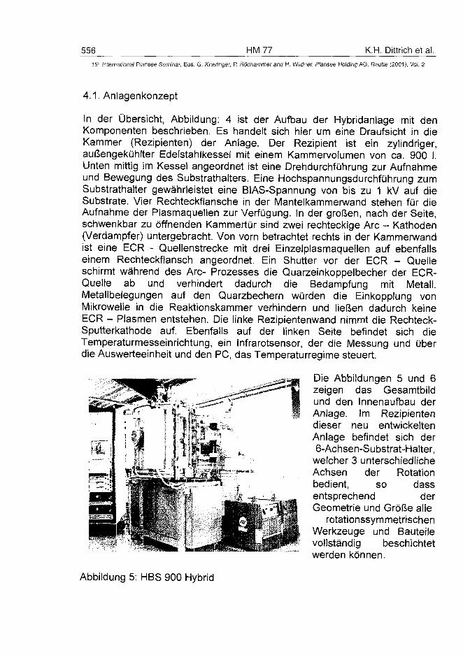
556 HM 77 K.H. Dittrich et al.15" International Plansee Seminar, Eds. G. Kneringer, P. Rôdhammer and H. Wildner, Plansee Holding AG, Reutte (2001), Vol. 2
4.1. Anlagenkonzept
In der Übersicht, Abbildung: 4 ist der Aufbau der Hybridanlage mit denKomponenten beschrieben. Es handelt sich hier um eine Draufsicht in dieKammer (Rezipienten) der Anlage. Der Rezipient ist ein zylindriger,außengekühlter Edelstahlkessel mit einem Kammervolumen von ca. 900 I.Unten mittig im Kessel angeordnet ist eine Drehdurchführung zur Aufnahmeund Bewegung des Substrathalters. Eine Hochspannungsdurchführung zumSubstrathalter gewährleistet eine BIAS-Spannung von bis zu 1 kV auf dieSubstrate. Vier Rechteckflansche in der Mantelkammerwand stehen für dieAufnahme der Plasmaquellen zur Verfügung. In der großen, nach der Seite,schwenkbar zu öffnenden Kammertür sind zwei rechteckige Are - Kathoden(Verdampfer) untergebracht. Von vorn betrachtet rechts in der Kammerwandist eine ECR - Quellenstrecke mit drei Einzelplasmaquellen auf ebenfallseinem Rechteckflansch angeordnet. Ein Shutter vor der ECR - Quelleschirmt während des Are- Prozesses die Quarzeinkoppelbecher der ECR-Quelle ab und verhindert dadurch die Bedampfung mit Metall.Metallbelegungen auf den Quarzbechern würden die Einkopplung vonMikrowelle in die Reaktionskammer verhindern und ließen dadurch keineECR - Plasmen entstehen. Die linke Rezipientenwand nimmt die Rechteck-Sputterkathode auf. Ebenfalls auf der linken Seite befindet sich dieTemperaturmesseinrichtung, ein Infrarotsensor, der die Messung und überdie Auswerteeinheit und den PC, das Temperaturregime steuert.
Die Abbildungen 5 und 6zeigen das Gesamtbildund den Innenaufbau derAnlage. Im Rezipientendieser neu entwickeltenAnlage befindet sich der6-Achsen-Substrat-Halter,
welcher 3 unterschiedlicheAchsen der Rotationbedient, so dassentsprechend derGeometrie und Größe alle
rotationssymmetrischenWerkzeuge und Bauteilevollständig beschichtetwerden können.
Abbildung 5: HBS 900 Hybrid
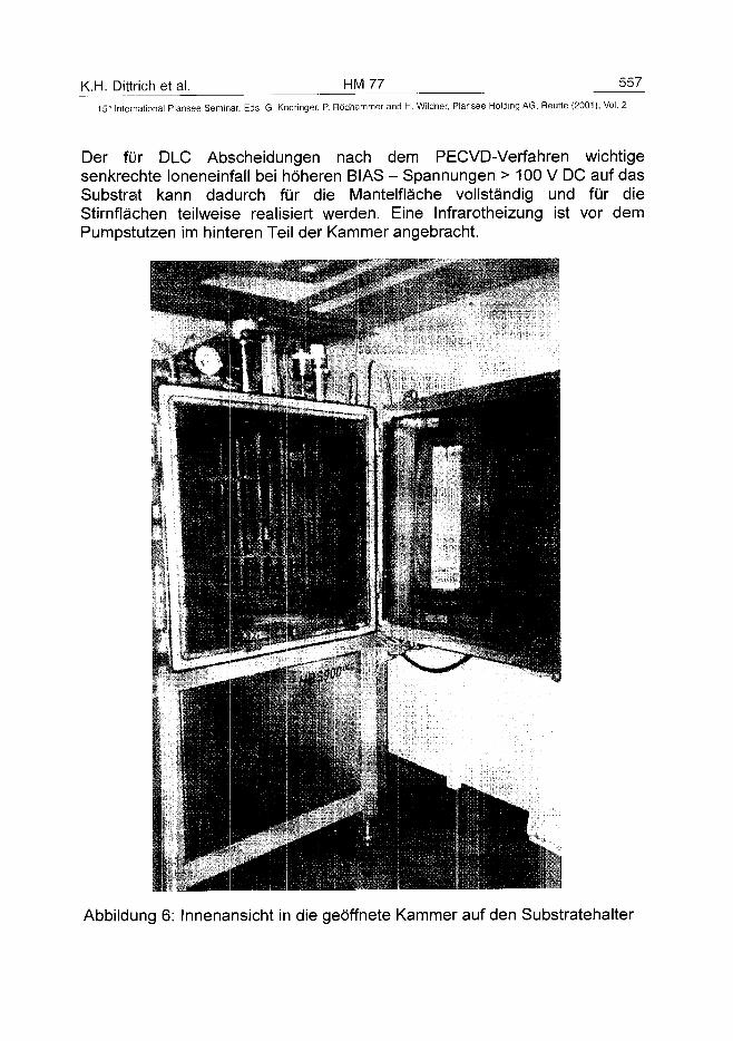
K.H. Dittrich et al. HM 77 557
15th International Plansee Seminar, Eds. G. Kneringer, P. Rödhammer and H. Wildner, Plansee Holding AG, Reutte (2001), Vol. 2
Der für DLC Abscheidungen nach dem PECVD-Verfahren wichtigesenkrechte loneneinfall bei höheren BIAS - Spannungen > 100 V DC auf dasSubstrat kann dadurch für die Mantelfläche vollständig und für dieStirnflächen teilweise realisiert werden. Eine Infrarotheizung ist vor demPumpstutzen im hinteren Teil der Kammer angebracht.
Abbildung 6: Innenansicht in die geöffnete Kammer auf den Substratehalter
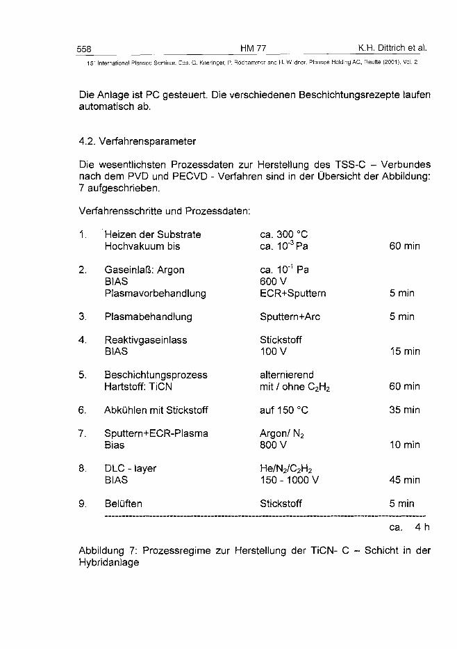
558 HM 77 K.H. Dittrich et al.
15~ Internationa! Plansee Seminar, Eds. G. Kneringer, P. Rôdhammer and H. Wildner, Plansee Holding AG, Reutte (2001), Vol. 2
Die Anlage ist PC gesteuert. Die verschiedenen Beschichtungsrezepte laufenautomatisch ab.
4.2. Verfahrensparameter
Die wesentlichsten Prozessdaten zur Herstellung des TSS-C - Verbundesnach dem PVD und PECVD - Verfahren sind in der Übersicht der Abbildung:7 aufgeschrieben.
Verfahrensschritte und Prozessdaten:
1.
2.
3.
4.
5.
6.
7.
8.
9.
Heizen der SubstrateHochvakuum bis
Gaseinlaß: ArgonBIASPlasmavorbehandlung
Plasmabehandlung
ReaktivgaseinlassBIAS
BeschichtungsprozessHartstoff: TiCN
Abkühlen mit Stickstoff
Sputtern+ECR-PlasmaBias
DLC - layerBIAS
Belüften
ca. 300 °Cca. 10"3Pa
ca. 10"1 Pa600 VECR+Sputtern
Sputtern+Arc
Stickstoff100 V
alternierendmit / ohne C2H2
auf 150°C
Argon/ N2
800 V
He/N2/C2H2150-1000 V
Stickstoff
60 min
5 min
5 min
15 min
60 min
35 min
10 min
45 min
5 min
ca. 4 h
Abbildung 7: Prozessregime zur Herstellung der TiCN- C - Schicht in derHybridanlage
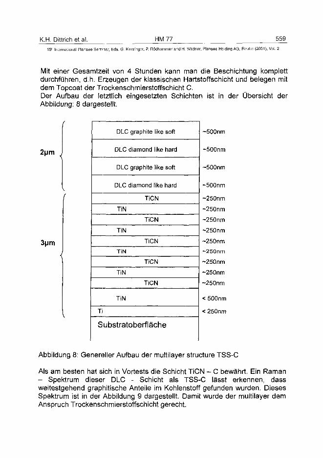
K.H. Dittrich et al. HM 77 559
15" International Plansee Seminar, Eds. G. Kneringer, P. Rödhammer and H. Wildner, Plansee Holding AG, Reutte (2001), Vol. 2
Mit einer Gesamtzeit von 4 Stunden kann man die Besenichtung komplettdurchführen, d.h. Erzeugen der klassischen Hartstoffschicht und belegen mitdem Topcoat der Trockenschmierstoffschicht C.Der Aufbau der letztlich eingesetzten Schichten ist in der Übersicht derAbbildung: 8 dargestellt.
2um
3|jm
DLC
DLC
DLC
DLC
TiN
TiN
TiN
TiN
TiN
Ti
graphite like
diamond like
graphite like
diamond like
TiCN
TiCN
TiCN
TiCN
TiCN
soft
hard
soft
hard
Substratoberfläche
~500nm
~500nm
~500nm
~500nm
~250nm
~250nm
~250nm
~250nm
~250nm
~250nm
-250nm
~250nm
~250nm
< 500nm
< 250nm
Abbildung 8: Genereller Aufbau der multilayer structure TSS-C
Als am besten hat sich in Vortests die Schicht TiCN - C bewährt. Ein Raman- Spektrum dieser DLC - Schicht als TSS-C lässt erkennen, dassweitestgehend graphitische Anteile im Kohlenstoff gefunden wurden. DiesesSpektrum ist in der Abbildung 9 dargestellt. Damit wurde der multilayer demAnspruch Trockenschmierstoffschicht gerecht.
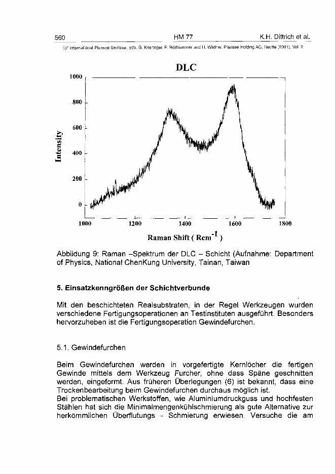
560 HM 77 K.H. Dittrich et al.
15" International Plansee Seminar, Eds. G. Kneringer, P. Rödhammer and H. Wildner, Plansee Holding AG, Reutte (2001), Vol. 2
1000
1000
DLC
1200 1400 1600 1800
Raman Shift ( Rem"1 )
Abbildung 9: Raman -Spektrum der DLC - Schicht (Aufnahme: Departmentof Physics, National ChenKung University, Tainan, Taiwan
5. Einsatzkenngrößen der Schichtverbunde
Mit den beschichteten Realsubstraten, in der Regel Werkzeugen wurdenverschiedene Fertigungsoperationen an Testinstituten ausgeführt. Besondershervorzuheben ist die Fertigungsoperation Gewindefurchen.
5.1. Gewindefurchen
Beim Gewindefurchen werden in vorgefertigte Kernlöcher die fertigenGewinde mittels dem Werkzeug Furcher, ohne dass Späne geschnittenwerden, eingeformt. Aus früheren Überlegungen (6) ist bekannt, dass eineTrockenbearbeitung beim Gewindefurchen durchaus möglich ist.Bei problematischen Werkstoffen, wie Aluminiumdruckguss und hochfestenStählen hat sich die Minimaimengenkühlschmierung als gute Alternative zurherkömmlichen Überflutungs - Schmierung erwiesen. Versuche die am
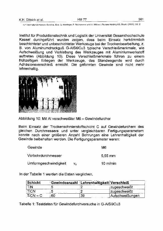
K.H. Dittrich et al. HM 77 561
15'" International Plansee Seminar, Eds. G. Kneringer, P. Rödhammer and H. Wildner, Plansee Holding AG, Reutte (2001), Vol. 2
Institut für Produktionstechnik und Logistik der Universität GesamthochschuleKassel durchgeführt wurden zeigen, dass beim Einsatz herkömmlichbeschichteter und un beschichteter Werkzeuge bei der Trockenbearbeitung, z.B. von Aluminumdruckguß G-AISi9Cu3 typische Verschleißmerkmale, wieAufschweißung und Verklebung des Werkzeuges mit Aluminiumwerkstoffauftreten (Abbildung 10). Diese Verschleißmerkmale führen zu einemfrühzeitigen Erliegen der Werkzeuge, das Standwegende wird durchAdhäsionsverschleiß erreicht. Die geformten Gewinde sind nicht mehrlehrenhaltig.
Abbildung 10: Mit AI verschweißter M6 - Gewindefurcher
Beim Einsatz der Trockenschmierstoffschicht C auf Gewindefurchern desgleichen Durchmessers und unter vergleichbaren Fertigungsparameternkonnte nach einer größeren Anzahl Bohrungen eine Lehrenhaltigkeit derGewinde beibehalten werden. Die Fertigungsparameter waren:
Gewinde
Vorbohrdurchmesser
Umformgeschwindigkeit
M6
5,55 mm
10 m/min
In der Tabelle 1 werden die Daten verglichen.
SchichtTiNTiCNTiCN - C
Gewindeanzahl5560
Lehrenhaltigkeit2239
VerschleißzugeschweißtzugeschweißtAufschweißungen
Tabelle 1 : Testdaten für Gewindefurchversuche in G-AISi9Cu3
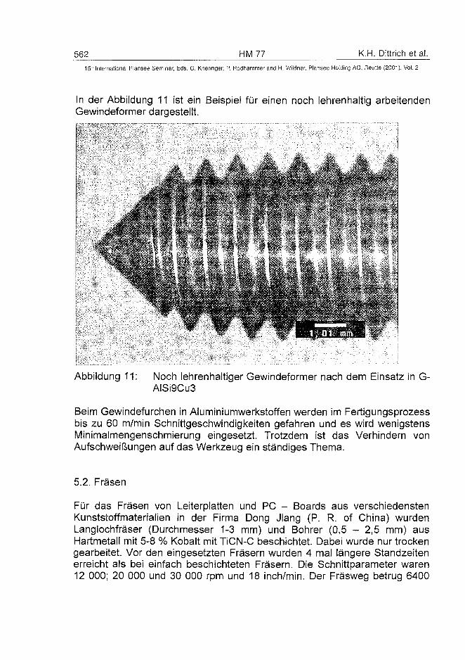
562 HM 77 K,H. Dittrich étal.15:" International Plansee Seminar, Eds. G. Kneringer, P. Rödhammer and H. Wildner, Plansee Holding AG, Reutte (2001), Vol. 2
In der Abbildung 11 ist ein Beispiel für einen noch lehrenhaltig arbeitendenGewindeformer dargestellt.
Abbildung 11: Noch lehrenhaltiger Gewindeformer nach dem Einsatz in G-AISi9Cu3
Beim Gewindefurchen in Aluminiumwerkstoffen werden im Fertigungsprozessbis zu 60 m/min Schnittgeschwindigkeiten gefahren und es wird wenigstensMinimalmengenschmierung eingesetzt. Trotzdem ist das Verhindern vonAufschweißungen auf das Werkzeug ein ständiges Thema.
5.2. Fräsen
Für das Fräsen von Leiterplatten und PC - Boards aus verschiedenstenKunststoffmaterialien in der Firma Dong Jiang (P. R. of China) wurdenLanglochfräser (Durchmesser 1-3 mm) und Bohrer (0,5 - 2,5 mm) ausHartmetall mit 5-8 % Kobalt mit TiCN-C beschichtet. Dabei wurde nur trockengearbeitet. Vor den eingesetzten Fräsern wurden 4 mal längere Standzeitenerreicht als bei einfach beschichteten Fräsern. Die Schnittparameter waren12 000; 20 000 und 30 000 rpm und 18 inch/min. Der Fräsweg betrug 6400
K.H. Dittrich et al. HM 77 56315lh International Plansee Seminar, Eds. G. Kneringer, P. Bödhammer and H. Wildner, Plansee Holding AG, Reutte (2001), Vol. 2
Inch, ca. 162 m. Der Unterschied bei den Bohrungen lag zwischen 7000Bohrungen bei TiCN-C beschichteten und ca. 5000 Bohrungen vorher.
Danksagung
Unser Dank gilt den Kollegen im Forschungsprojekt TSS-C, gefördert durchdas BMBF der BRD, hier insbesondere den Mitarbeitern des IPL derUniversität Kassel. Weiterhin waren wichtige Hilfen die Arbeiten, die in derFirma Diamond - Si Tech Co. Ltd. an der National ChenKung UniversityBusiness Incubation Center in Tainan R.O.C, ausgeführt wurden. DiesenKollegen sei ebenfalls Dank gesagt. Und ein weiterer Dank gilt denMitarbeitern der Firma Roth & Rau Oberflächentechnik GmbH, sowie HerrnProf. Dr. Erler, von der HTW Mittweida für die Betreuung der Arbeiten.
References:
(1) K. Bewilogua, C.V. Cooper, C. Specht, J. Schröder, R. Wittorf, M.Grischke : Surface and Coating Technology 132 (2000), pp. 275-283
(2) J. Koskinen, et. al. : Diamond and Related materials, 3 (1993), pp.52-55
(3) T. Arai and K. Oguri : European Patent Application, EP 0435 312 A1(4) S.I. Novikov, et. al. : 10th European Conference on Diamond,
Diamond-Like Material, Carbon Nanotubes, Nitrides & SiliconCarbide, 13.-17.9.1999, Prag
(5) D. Roth, B. Rau, S. Roth, J. Mai, K.-H. Dittrich : Surface andCoatings Technology 74-75 (1995), pp. 637-641
(6) U. Pécher, W. Scherm : Verschleißfeste PVD-/CVD-Trockenschmierstoffschichten für die umweltschonende undinnovative Fertigung, Schwerpunkt Gewindefurchen, UniversitätGesamthochschule Kassel, Institut für Produktionstechnik undLogistik, Kassel 2000
ATO100482564 HM 78 S.N. Yedave et a!.
15" International Plansee Seminar, Eds. G. Kneringer, P. Rodhammer and H. Wildner, Plansee Holding AG, Reutte (2001), Vol. 2
A Novel Combinatorial Approach for the Realization of
Advanced cBN Composite Coating
Sharad N. Yedave, A.P. Malshe1, N. Sundaram, W.D. Brown, and W.C.
Russell2
Materials and Manufacturing Research Laboratories (MRL),Department of Mechanical Engineering, University of Arkansas,
Fayetteville, AR 72701, USA.1 (Contact Information - Tel: (501) 575-6561 /Email: [email protected])
Valenite, Inc., Troy, Ml 48084, USA.
Summary:
The paper reports a novel coating process for the synthesis of hard materialcomposite coatings. It consists of electrostatic spray coating (ESC) of powderparticles (of micron-nanometer size) followed by chemical vapor infiltration(CVI) of a suitable binder phase. This novel approach enables fabrication ofunique compositions such as cubic boron nitride (cBN) and titanium nitride(TiN) in a coating form. Recently, we have demonstrated the success of thistechnology by first coating a uniform over-layer (in excess of ~ 10 fim) of cBNparticles on carbide cutting tool inserts using ESC, followed by infiltration ofparticulate cBN matrix with TiN from its vapor phase using CVI to synthesizecBN-TiN a composite coating. The composite has shown excellent cBN-to-TiN and composite coating-to-carbide substrate adhesion. One of the mainemphases of the paper is to discuss optimization and scale up of the ESCtechnology to achieve the desired microstructure and tailor the thicknessacross the cutting tool for better performance. Further, the cutting tools havebeen successfully tested for advanced machining applications.
Keywords:
Cubic boron nitride, composite coating, cBN-TiN, ESC, CVI, particulatecoating
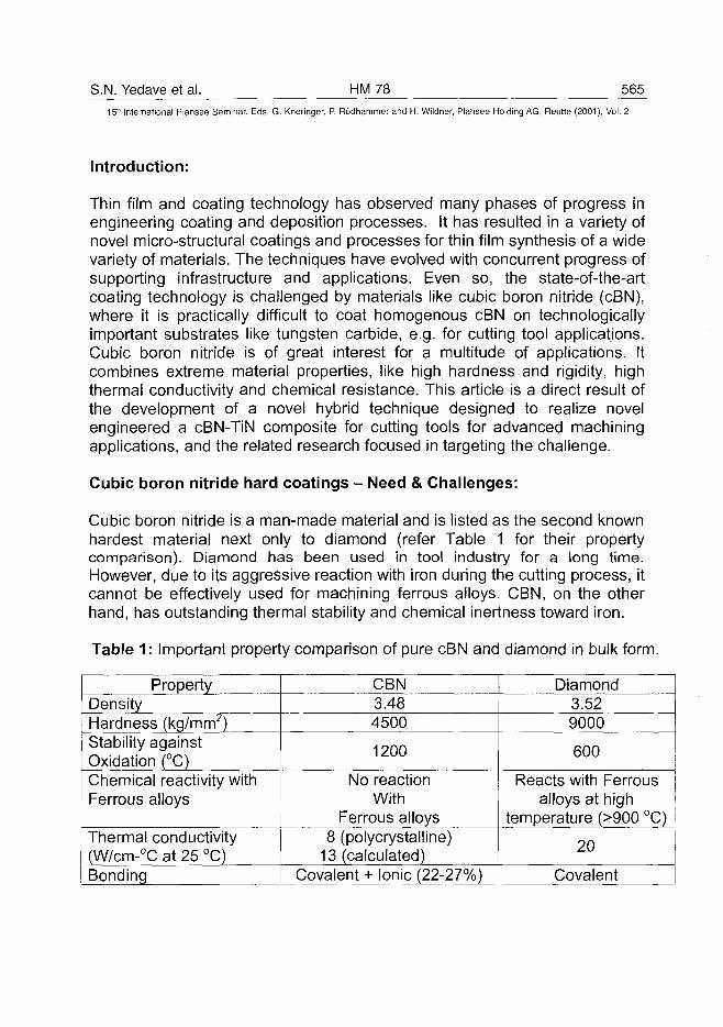
S.N. Yedave et al. HM78 565
15'" International Plansee Seminar, Eds. G. Kneringer, P. Rodhammer and H. Wildner, Plansee Holding AG, Reutte (2001), Vol. 2
Introduction:
Thin film and coating technology has observed many phases of progress inengineering coating and deposition processes. It has resulted in a variety ofnovel micro-structural coatings and processes for thin film synthesis of a widevariety of materials. The techniques have evolved with concurrent progress ofsupporting infrastructure and applications. Even so, the state-of-the-artcoating technology is challenged by materials like cubic boron nitride (cBN),where it is practically difficult to coat homogenous cBN on technologicallyimportant substrates like tungsten carbide, e.g. for cutting tool applications.Cubic boron nitride is of great interest for a multitude of applications. Itcombines extreme material properties, like high hardness and rigidity, highthermal conductivity and chemical resistance. This article is a direct result ofthe development of a novel hybrid technique designed to realize novelengineered a cBN-TiN composite for cutting tools for advanced machiningapplications, and the related research focused in targeting the challenge.
Cubic boron nitride hard coatings - Need & Challenges:
Cubic boron nitride is a man-made material and is listed as the second knownhardest material next only to diamond (refer Table 1 for their propertycomparison). Diamond has been used in tool industry for a long time.However, due to its aggressive reaction with iron during the cutting process, itcannot be effectively used for machining ferrous alloys. CBN, on the otherhand, has outstanding thermal stability and chemical inertness toward iron.
Table 1: Important property comparison of pure cBN and diamond in bulk form.
PropertyDensityHardness (kg/mm2)Stability againstOxidation (°C)Chemical reactivity withFerrous alloys
Thermal conductivity(W/cm-°C at 25 °C)Bonding
CBN3.484500
1200
No reactionWith
Ferrous alloys8 (polycrystalline)
13 (calculated)Covalent + Ionic (22-27%)
Diamond3.529000
600
Reacts with Ferrousalloys at high
temperature (>900 °C)
20
Covalent
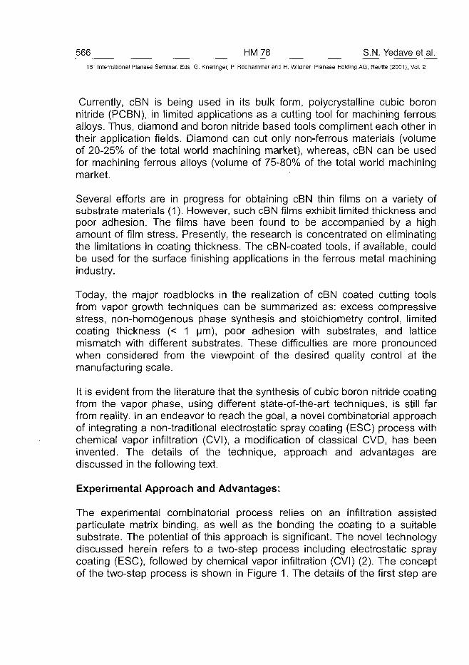
566 HM78 S.N. Yedave et al.15" International Plansee Seminar, Eds. G. Kneringer, P. Rodhammer and H. Wildner, Plansee Holding AG, Reutte (2001), Vol. 2
Currently, cBN is being used in its bulk form, polycrystalline cubic boronnitride (PCBN), in limited applications as a cutting tool for machining ferrousalloys. Thus, diamond and boron nitride based tools compliment each other intheir application fields. Diamond can cut only non-ferrous materials (volumeof 20-25% of the total world machining market), whereas, cBN can be usedfor machining ferrous alloys (volume of 75-80% of the total world machiningmarket.
Several efforts are in progress for obtaining cBN thin films on a variety ofsubstrate materials (1). However, such cBN films exhibit limited thickness andpoor adhesion. The films have been found to be accompanied by a highamount of film stress. Presently, the research is concentrated on eliminatingthe limitations in coating thickness. The cBN-coated tools, if available, couldbe used for the surface finishing applications in the ferrous metal machiningindustry.
Today, the major roadblocks in the realization of cBN coated cutting toolsfrom vapor growth techniques can be summarized as: excess compressivestress, non-homogenous phase synthesis and stoichiometry control, limitedcoating thickness (< 1 um), poor adhesion with substrates, and latticemismatch with different substrates. These difficulties are more pronouncedwhen considered from the viewpoint of the desired quality control at themanufacturing scale.
It is evident from the literature that the synthesis of cubic boron nitride coatingfrom the vapor phase, using different state-of-the-art techniques, is still farfrom reality. In an endeavor to reach the goal, a novel combinatorial approachof integrating a non-traditional electrostatic spray coating (ESC) process withchemical vapor infiltration (CVI), a modification of classical CVD, has beeninvented. The details of the technique, approach and advantages arediscussed in the following text.
Experimental Approach and Advantages:
The experimental combinatorial process relies on an infiltration assistedparticulate matrix binding, as well as the bonding the coating to a suitablesubstrate. The potential of this approach is significant. The novel technologydiscussed herein refers to a two-step process including electrostatic spraycoating (ESC), followed by chemical vapor infiltration (CVI) (2). The conceptof the two-step process is shown in Figure 1. The details of the first step are
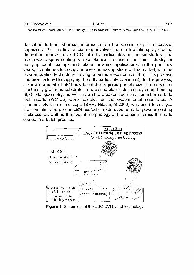
S.N. Yedave et al. HM78 56715'" International Plansee Seminar, Eds. G. Kneringer, P. Rodhammer and H. Wildner, Plansee Holding AG, Reutte (2001), Vol. 2
described further, whereas, information on the second step is discussedseparately (3). The first crucial step involves the electrostatic spray coating(hereafter referred to as ESC) of cBN particulates on the substrates. Theelectrostatic spray coating is a well-known process in the paint industry forapplying paint coatings and related finishing applications. In the past fewyears, it continues to occupy an ever-increasing share of this market, with thepowder coating technology proving to be more economical (4,5). This processhas been tailored for applying the cBN particulate coating (2). In this process,a known amount of cBN powder of the required particle size is sprayed onelectrically grounded substrates in a closed electrostatic spray setup housing(6,7). Flat geometry, as well as a chip breaker geometry, tungsten carbidetool inserts (WC-Co) were selected as the experimental substrates. Ascanning electron microscope (SEM, Hitachi, S-2300) was used to analyzethe non-infiltrated porous cBN coated carbide substrates for powder coatingthickness, as well as the spatial morphology of the coating across the partscoated in a batch process.
I
cBNEScV(ElectrostaticSpray Coating)
Flow ChartESC-CVI Hybrid Coating Process
for cBN Composite Coating
EJ Cubic boron nitride- cBN - particles
• Titanium nitride- TiN -binder phase
Figure 1: Schematic of the ESC-CVI hybrid technology.
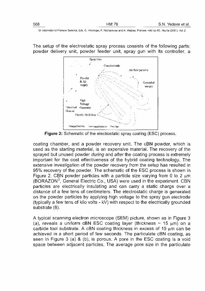
568 HM78 S.N. Yedave et al.15" International Plansee Seminar, Eds. G. Kneringer, P. Rodhammer and H. Wildner, Plansee Holding AG, Reutte (2001), Vol. 2
The setup of the electrostatic spray process consists of the following parts;powder delivery unit, powder feeder unit, spray gun with its controller, a
Spray Gun
y Gun electrode
/ — — - -
P o w d e r J;:- '~-'-. - - ,
& A i r . ' ' . ' > ' ' > - . ~~-•",""•-. '~---
supply ' ', ', \ \ " --s --.
\ \ • - , • • .
High ' • \ / \ / - . ,Voltage J \ '
Electrical Generator ' / ^ ' \ \ ••Ground /( '\ \ \
Electric field lines -C^ ~~~~" "\ *\.
Charged Particles Uncharged Particles Free loos
Air flow patterns
i Grounded
^•.v / sample
Figure 2: Schematic of the electrostatic spray coating (ESC) process.
coating chamber, and a powder recovery unit. The cBN powder, which isused as the starting material, is an expensive material. The recovery of thesprayed but unused powder during and after the coating process is extremelyimportant for the cost effectiveness of the hybrid coating technology. Theextensive investigation of the powder recovery from the setup has resulted in95% recovery of the powder. The schematic of the ESC process is shown inFigure 2. CBN powder particles with a particle size varying from 0 to 2 jim(BORAZON®, General Electric Co., USA) were used in the experiment. CBNparticles are electrically insulating and can carry a static charge over adistance of a few tens of centimeters. The electrostatic charge is generatedon the powder particles by applying high voltage to the spray gun electrode(typically a few tens of kilo volts - kV) with respect to the electrically groundedsubstrate (8).
A typical scanning electron microscope (SEM) picture, shown as in Figure 3(a), reveals a uniform cBN ESC coating layer (thickness ~ 15 iim) on acarbide tool substrate. A cBN coating thickness in excess of 10 |im can beachieved in a short period of few seconds. The particulate cBN coating, asseen in Figure 3 (a) & (b), is porous. A pore in the ESC coating is a voidspace between adjacent particles. The average pore size in the particulate
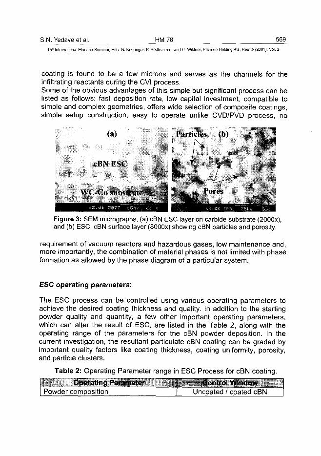
S.N. Yedave et al. HM 78 56915" International Plansee Seminar, Eds. G. Kneringer, P. Rodhammer and H. Wildner, Plansee Holding AG, Reutte (2001), Vol. 2
coating is found to be a few microns and serves as the channels for theinfiltrating reactants during the CVI process.Some of the obvious advantages of this simple but significant process can belisted as follows: fast deposition rate, low capital investment, compatible tosimple and complex geometries, offers wide selection of composite coatings,simple setup construction, easy to operate unlike CVD/PVD process, no
(a)
cBNESC
Particle
Figure 3: SEM micrographs, (a) cBN ESC layer on carbide substrate (2000x),and (b) ESC, cBN surface layer (8000x) showing cBN particles and porosity.
requirement of vacuum reactors and hazardous gases, low maintenance and,more importantly, the combination of material phases is not limited with phaseformation as allowed by the phase diagram of a particular system.
ESC operating parameters:
The ESC process can be controlled using various operating parameters toachieve the desired coating thickness and quality. In addition to the startingpowder quality and quantity, a few other important operating parameters,which can alter the result of ESC, are listed in the Table 2, along with theoperating range of the parameters for the cBN powder deposition. In thecurrent investigation, the resultant particulate cBN coating can be graded byimportant quality factors like coating thickness, coating uniformity, porosity,and particle clusters.
Table 2: Operating Parameter range in ESC Process for cBN coating.
Operating ParameterPowder composition
Control WindowUncoated / coated cBN
570 HM78 S.N. Yedave et al.15-n International Plansee Seminar, Eds. G. Kneringer, P. Rodhammer and H. Wildner, Plansee Holding AG, Reutte (2001), Vol. 2
Powder sizePowder feed rateHigh voltage at the electrode (V)Substrate to gun electrode distance (D)Substrate sizeTime of depositionAir pressure (P)
0-12,111X1< 0.1 g /min.
- 40 to - 90 kV3.5" - 8"
Limited to the size of spray unit< 5 minutes20 - 40 psi
ESC process optimization and ESC cBN coating evaluation:
The electrostatic spray coating process has been successfully employed toobtain cBN powder coatings on tungsten carbide (cobalt binder) tool inserts.The powder coating was studied with respect to the important qualities of aparticulate coating like adhesion, coating thickness, uniformity, porosity andparticle clusters. The cBN particulates are held to the substrates with anelectrostatic force. This force of attraction between the substrate and cBNparticulate layer - generally defined as the adhesion - is strong enough tokeep the over-layer intact until transferred to the CVI reactor and weakenough to be wiped off by improper handling. After processing the sampleswith the second step, i.e., CVI, the resultant composite cBN-TiN coating hasexcellent adhesion.
ESC operating parameters discussed earlier have an influential role on theprocess output. A number of experiments were carried out to optimize theESC operating parameters, which are considered to be the process input, toevaluate the relation between the operating parameters and to obtain desiredESC coating specifications. The process output, in the present case, isdefined as the coating quality and coating characteristics like edge-to-edge,part-to-part and batch-to-batch uniformity, coating thickness, porosity,distribution of particle clusters, etc. A statistical methodology, well known asthe Taguchi method, was employed to find the optimum conditions whichreliably produce the desired coating quality as required for efficient CVIinfiltration for consistent performance in machining (9). The Taguchi approachof parametric design allowed us to converge on the best combination ofprocess parameters using an orthogonal array table (OAT). The optimizationexperiments were designed and conducted as per the selected OAT. Thedata generated from such selected experiments was analyzed by the analysisof variance (ANOVA) technique using statistical software MINITAB (6).
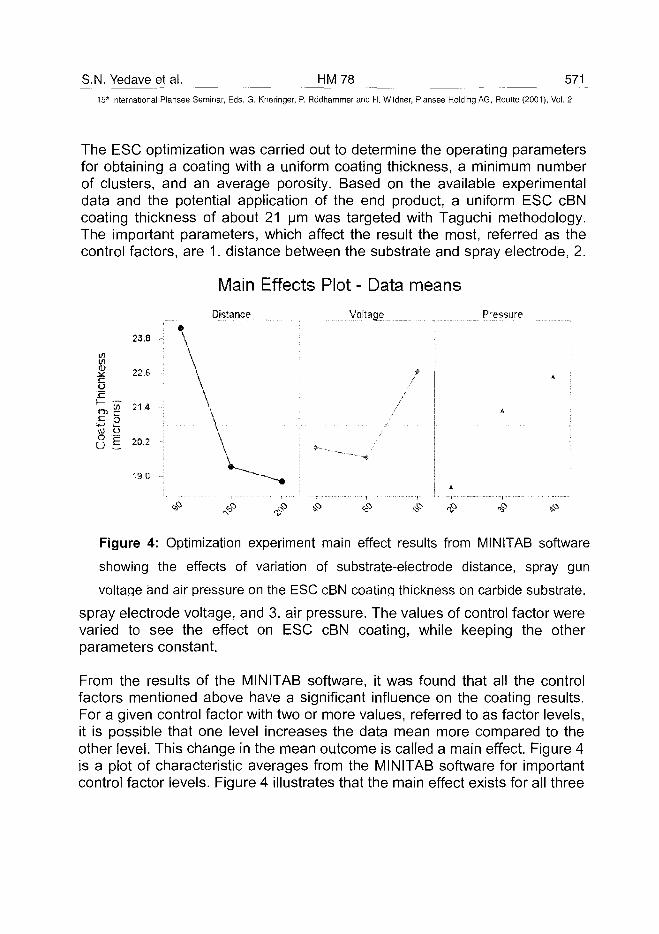
S.N. Yedave et al. HM78 57115* International Plansee Seminar, Eds. G. Kneringer, P. Rodhammer and H. Wildner, Plansee Holding AG, Reutte (2001), Vol. 2
The ESC optimization was carried out to determine the operating parametersfor obtaining a coating with a uniform coating thickness, a minimum numberof clusters, and an average porosity. Based on the available experimentaldata and the potential application of the end product, a uniform ESC cBNcoating thickness of about 21 urn was targeted with Taguchi methodology.The important parameters, which affect the result the most, referred as thecontrol factors, are 1. distance between the substrate and spray electrode, 2.
Main Effects Plot - Data means
Distance Voltage Pressure
3£co
If•s s(0 OO
23.8 -
22.6
21.4
20.2 H
19.0
,f5
Figure 4: Optimization experiment main effect results from MINITAB software
showing the effects of variation of substrate-electrode distance, spray gun
voltage and air pressure on the ESC cBN coating thickness on carbide substrate.
spray electrode voltage, and 3. air pressure. The values of control factor werevaried to see the effect on ESC cBN coating, while keeping the otherparameters constant.
From the results of the MINITAB software, it was found that all the controlfactors mentioned above have a significant influence on the coating results.For a given control factor with two or more values, referred to as factor levels,it is possible that one level increases the data mean more compared to theother level. This change in the mean outcome is called a main effect. Figure 4is a plot of characteristic averages from the MINITAB software for importantcontrol factor levels. Figure 4 illustrates that the main effect exists for all three
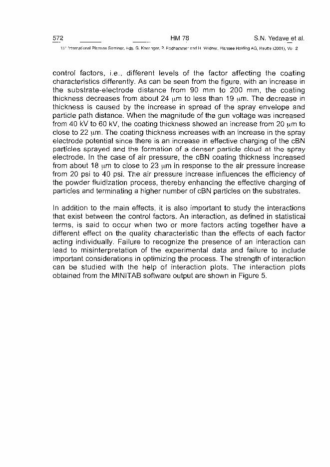
572 HM78 S.N. Yedave et al.15:" International Plansee Seminar, Eds. G. Kneringer, P. Rodhammer and H. Wildner, Plansee Holding AG, Reutte (2001), Vol. 2
control factors, i.e., different levels of the factor affecting the coatingcharacteristics differently. As can be seen from the figure, with an increase inthe substrate-electrode distance from 90 mm to 200 mm, the coatingthickness decreases from about 24 \im to less than 19 [im. The decrease inthickness is caused by the increase in spread of the spray envelope andparticle path distance. When the magnitude of the gun voltage was increasedfrom 40 kV to 60 kV, the coating thickness showed an increase from 20 \im toclose to 22 ^im. The coating thickness increases with an increase in the sprayelectrode potential since there is an increase in effective charging of the cBNparticles sprayed and the formation of a denser particle cloud at the sprayelectrode. In the case of air pressure, the cBN coating thickness increasedfrom about 18 [im to close to 23 |im in response to the air pressure increasefrom 20 psi to 40 psi. The air pressure increase influences the efficiency ofthe powder fluidization process, thereby enhancing the effective charging ofparticles and terminating a higher number of cBN particles on the substrates.
In addition to the main effects, it is also important to study the interactionsthat exist between the control factors. An interaction, as defined in statisticalterms, is said to occur when two or more factors acting together have adifferent effect on the quality characteristic than the effects of each factoracting individually. Failure to recognize the presence of an interaction canlead to misinterpretation of the experimental data and failure to includeimportant considerations in optimizing the process. The strength of interactioncan be studied with the help of interaction plots. The interaction plotsobtained from the MINITAB software output are shown in Figure 5.
S.N. Yedave et al. HM78 573
15lh International Plansee Seminar, Eds. G. Kneringer, P. Rodhammer and H. Wildner, Plansee Holding AG, Reutte (2001), Vol. 2
Interaction Plot - Data Means
Distance
«200
• 150
« 90•
. V\A_v- •
\ -a.
~ — •
Voltage
• 60
.50
• 40
y*
m ':-*-'' •
Pressure
• 40
m 30
• 20
•26
•21
-26
21
•-1626
21
Figure 5: Optimization experiment interaction effect results from MINITAB softwareshowing inter-parameter variation of control factors on the ESC cBN coatingthickness on carbide substrate.
Some of the inferences drawn from Figure 5 are as follows. The interactionbetween the substrate-spray electrode distance and charging voltage issignificant, whereas, it is insignificant between the distance and air pressure.The main effects for the distance and air pressure play a major role on theprocess output, even with insignificant interaction between them. At a givenpressure, an increase in the substrate-electrode distance results in adecrease in the coating thickness. Similar is the case when the pressure isvaried for a given substrate-electrode distance. The coating thicknessincreases with an increase in pressure and, depending on the distance, thereis a variation in the coating thickness. Hence, considering the main effect ofpressure on the coating thickness, the optimum pressure was set to 30 psi toobtain a targeted coating thickness of 21 urn.
It is evident from the interaction between the voltage and distance that, for atargeted cBN coating thickness of 21 urn, gun voltage of 60 kV is anoptimum, irrespective of the substrate-electrode distance. There is nosignificant change in the coating thickness when the distance is increasedfrom 150 mm to 200 mm. In addition, it can be inferred that the substrate-electrode distance has to be maintained at 150 mm. If the interaction betweenthe spray gun voltage and air pressure is considered from Figure 5, it can beseen that the spray gun voltage has to be set at 60 kV for a desired coatingthickness of 21 urn with an air pressure of 30 psi.
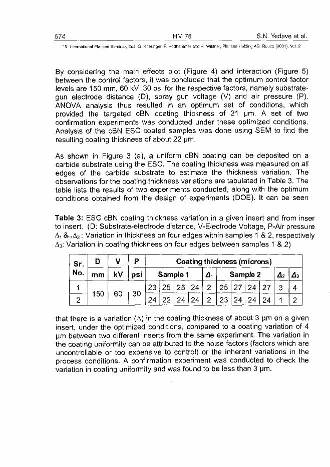
574 HM78 S.N. Yedave et al.15" International Plansee Seminar, Eds. G. Kneringer, P. Rddhammer and H. Wildner, Plansee Holding AG, Reutte (2001), Vol. 2
By considering the main effects plot (Figure 4) and interaction (Figure 5)between the control factors, it was concluded that the optimum control factorlevels are 150 mm, 60 kV, 30 psi for the respective factors, namely substrate-gun electrode distance (D), spray gun voltage (V) and air pressure (P).ANOVA analysis thus resulted in an optimum set of conditions, whichprovided the targeted cBN coating thickness of 21 urn. A set of twoconfirmation experiments was conducted under these optimized conditions.Analysis of the cBN ESC coated samples was done using SEM to find theresulting coating thickness of about 22 urn.
As shown in Figure 3 (a), a uniform cBN coating can be deposited on acarbide substrate using the ESC. The coating thickness was measured on alledges of the carbide substrate to estimate the thickness variation. Theobservations for the coating thickness variations are tabulated in Table 3. Thetable lists the results of two experiments conducted, along with the optimumconditions obtained from the design of experiments (DOE). It can be seen
Table 3: ESC cBN coating thickness variation in a given insert and from inserto insert. (D: Substrate-electrode distance, V-Electrode Voltage, P-Air pressureAi &...A2: Variation in thickness on four edges within samples 1 & 2, respectivelyA3: Variation in coating thickness on four edges between samples 1 & 2)
Sr.No.
1
2
D
mm
150
V
kV
60
P
psi
30
Coating thickness (microns)
Sample 1
23
24
25
22
25
24
24
24
2
2
Sample 2
25
23
27
24
24
24
27
24
A2
3
1
A3
4
2
that there is a variation (A) in the coating thickness of about 3 pm on a giveninsert, under the optimized conditions, compared to a coating variation of 4urn between two different inserts from the same experiment. The variation inthe coating uniformity can be attributed to the noise factors (factors which areuncontrollable or too expensive to control) or the inherent variations in theprocess conditions. A confirmation experiment was conducted to check thevariation in coating uniformity and was found to be less than 3 urn.
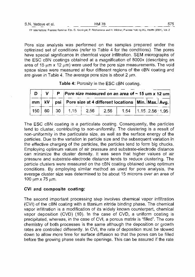
S.N. Yedave et al. HM78 575
15™ International Plansee Seminar, Eds. G. Kneringer, P. Rodhammer and H. Wildner, Plansee Holding AG, Reutte (2001), Vol. 2
Pore size analysis was performed on the samples prepared under theoptimized set of conditions (refer to Table 4 for the conditions). The poreshave special significance in chemical vapor infiltration. SEM micrographs ofthe ESC cBN coatings obtained at a magnification of 8000x (describing anarea of 15 ^m x 12 ^m) were used for the pore size measurements. The voidspace sizes were measured at four different regions of the cBN coating andare given in Table 4. The average pore size is about 2 \im.
Table 4: Porosity in the ESC cBN coating.
D
mm
150
V
kV
60
P
psi
30
Pore size measured on an area of ~ 15 urn x 12 urn
Pore size at 4 different locations
1.15 2.56I
2.56 1.54
Min.
1.15
Max.
2.56
Avg.
1.95
The ESC cBN coating is a particulate coating. Consequently, the particlestend to cluster, contributing to non-uniformity. The clustering is a result ofnon-uniformity in the particulate size, as well as the surface energy of theparticles. Due to the variation in particle size and the subsequent variation inthe effective charging of the particles, the particles tend to form big chucks.Employing optimum values of air pressure and substrate-electrode distancecan minimize the cluster density. It was seen that higher values of airpressure and substrate-electrode distance tends to reduce clustering. Theparticle clusters were measured on the cBN coating obtained using optimumconditions. By employing similar method as used for pore analysis, theaverage cluster size was determined to be about 15 microns over an area of100 fxm x 75 urn.
CVI and composite coating:
The second important processing step involves chemical vapor infiltration(CVI) of the cBN coating with a titanium nitride binding phase. The chemicalvapor infiltration is a modification of its widely known counterpart, chemicalvapor deposition (CVD) (10). In the case of CVD, a uniform coating isprecipitated, whereas, in the case of CVI, a porous matrix is "filled". The corechemistry of both processes is the same although the deposition or growthrates are controlled differently. In CVI, the rate of deposition must be sloweddown to allow more time for surface diffusion so that the pores can be filledbefore the growing phase seals the openings. This can be assured if the rate
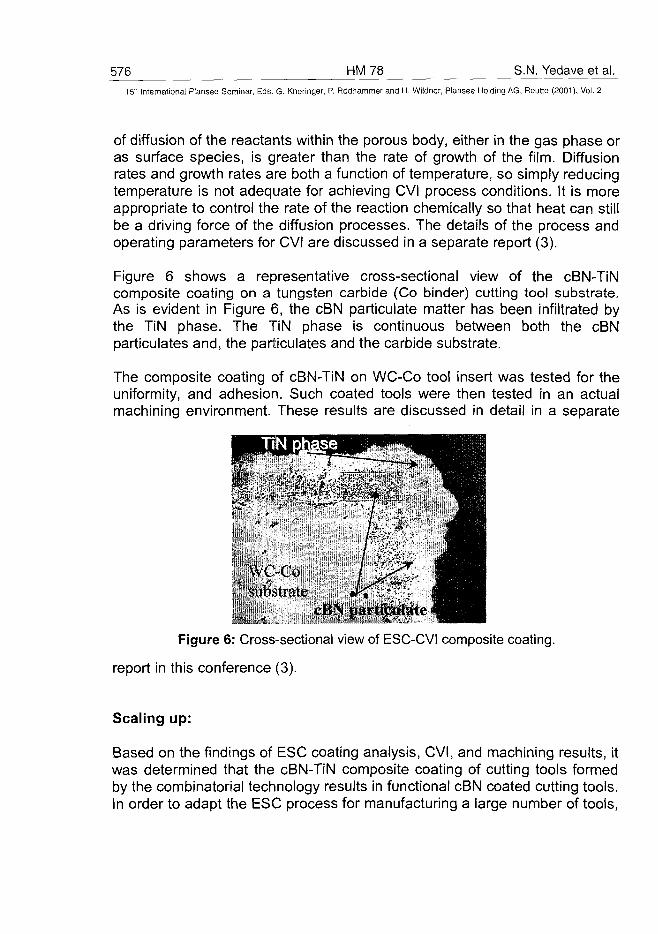
576 HM 78 S.N. Yedave et al.15" International Plansee Seminar, Eds. G. Kneringer, P. Rodhammer and H. Wildner, Plansee Holding AG, Reutte (2001), Vol. 2
of diffusion of the reactants within the porous body, either in the gas phase oras surface species, is greater than the rate of growth of the film. Diffusionrates and growth rates are both a function of temperature, so simply reducingtemperature is not adequate for achieving CVI process conditions. It is moreappropriate to control the rate of the reaction chemically so that heat can stillbe a driving force of the diffusion processes. The details of the process andoperating parameters for CVI are discussed in a separate report (3).
Figure 6 shows a representative cross-sectional view of the cBN-TiNcomposite coating on a tungsten carbide (Co binder) cutting tool substrate.As is evident in Figure 6, the cBN particulate matter has been infiltrated bythe TiN phase. The TiN phase is continuous between both the cBNparticulates and, the particulates and the carbide substrate.
The composite coating of cBN-TiN on WC-Co tool insert was tested for theuniformity, and adhesion. Such coated tools were then tested in an actualmachining environment. These results are discussed in detail in a separate
WC-Co' subbirate
cBN particulate -
Figure 6: Cross-sectional view of ESC-CVI composite coating,
report in this conference (3).
Scaling up:
Based on the findings of ESC coating analysis, CVI, and machining results, itwas determined that the cBN-TiN composite coating of cutting tools formedby the combinatorial technology results in functional cBN coated cutting tools.In order to adapt the ESC process for manufacturing a large number of tools,
S.N. Yedave et al. HM 78 577
15" International Plansee Seminar, Eds. G. Kneringer, P. Rodhammer and H. Wildner, Plansee Holding AG, Reutte (2001), Vol. 2
a scaled up prototype system is being developed at the MRL, University ofArkansas.
In summary, the ultimate success of the above discussed fundamentalresearch and technological development was not only instrumental in thedevelopment of the cBN composite coated tool products, but will also allowthe development of numerous versatile coating and products for applicationssuch as wear parts, electronics, etc. The technology development isunderway for other technologically important coatings.
Conclusion:
A novel combinatorial approach has been reported as an alternative for thesynthesis of cubic boron nitride (cBN) in coating form. It comprised ofelectrostatic spray coating (ESC) of cBN powder particles followed bychemical vapor infiltration (CVI) of a TiN binder phase to synthesize a cBN-TiN composite. The composite shows excellent cBN-to-TiN and compositecoating-to-carbide substrate adhesion. The electrostatic spray coating (ESC)process was optimized using a statistical methodology developed by Taguchi.A design of experiments method provided an optimized set of operatingparameters, namely substrate-electrode distance, spray gun voltage, and airpressure. The ESC cBN coating was examined with respect to coatinguniformity, porosity and particle clusters. Using the ESC optimization results,a scaled up system, which will handle a larger number of samples in amanufacturing unit, is being developed at the MRL, University of Arkansas,USA.
Acknowledgments:
The authors would like acknowledge the financial support for this GOALIproject from the Division of Design, Manufacturing, and Industrial Innovations(DMII), National Science Foundation (Grant # DMI-9713660) for the researchperformed at MRL. The acknowledgments are also due to Dr. John Schultz,Arkansas Analytical Laboratory (AAL), University of Arkansas, for thetechnical support and analytical facilities and, to Dr. D.G. Bhat for technicaldiscussions during his tenure at Valenite, Inc.
578 HM 78 S.N. Yedave et al.
15" International Plansee Seminar, Eds. G. Kneringer, P. Rödhammer and H. Wildner, Plansee Holding AG, Reutte (2001), Vol. 2
References:
(1) P.B. Mirkarimi, K.F. McCarty, G.F. Cardinale, D.L. Mediin, D.K. Ottesen,H.A.Johnsen: J.Vac. Sei. Technol. A Vol. 14, No. 1, (1996), pg. 251.
(2) Ajay Malshe, D.G. Bhat, Sharad Yedave, W.D. Brown, W.C. Russell:US and Foreign Patents pending (2000).
(3) W.C. Russell, A.P. Malshe, S.N. Yedave, W.D. Brown: Proc. 15th Int.Plansee Seminar (2001).
(4) J.F. Hughes: in "Electrostatic Powder Coating" (John Wiley & Sons Inc.,1984).
(5) Public information on spray equipment is available at the web site ofNordson Corp., USA, one of the companies engaged in the productionof spray equipment for the finishing industry; http://www.nordson.com.
(6) Sundaram Narayanaswami: "Design, Development and ParametricOptimization of Electrostatic Coating Process of Micron and Sub-micronParticles: cBN, A Case Study" (University of Arkansas, Fayetteville, MSThesis, 2000).
(7) J. Chang, A. J. Kelly, J.M. Crowley (Eds.): "Handbook of ElectrostaticProcesses", Eds., (Marcel Dekker, Inc., 1995).
(8) Drew Lapps: "Powder coating electrostatics: corona and tribo charging",in Powder Coating Magazine (Sept. 1990).
(9) Glen Peace Stuart: in "Taguchi Methods : a hands-on approach",(Addison-Wisely, Reading, Mass., 1993).
(10) J.K.G. Panitz, D.R. Tallant, C.R. Hills, D.J. Staley: J. Vac. Sci. Technol.Vol. A12, No. 4, (1994), pp. 1480-1486.
ATO100483R. Weissenbacher et al. HM 79 579
15" International Plansee Seminar, Eds. G. Kneringer, P. Rodhammer and H. Wildner, Plansee Holding AG, Reutte (2001), Vol. 2
Deposition of BCN Layers from B-C-N-H Single Source Precursors
Ronald Weissenbacher, Roland Haubner
Vienna University of Technology, Vienna, Austria
Institute for Chemical Technology of Inorganic Materials
Summary:
This work deals with the deposition of BxCyNz phases by decomposition of aB, C, N containing single source precursor called Tris(dimethylamino)boranein a hot-filament CVD apparatus. In contrast to the deposition of diamondlayers the deposition of cubic-BN or cubic-BxCyNz phases with low pressureCVD-methods was not successfully until now.To avoid the problems of filament failure and deposition of Ta into theproduced layers, the Ta-filaments were pre-treated by carburization ornitridation.BCN layers were deposited on Si and on WC-Co substrates in a hydrogenatmosphere similar to diamond deposition. Layers deposited on Si showedhigher growth-rates than layers deposited on WC-Co at the same depositionconditions. An increase of the filament temperature led to an increasinggrowth rate. This increase of growth rate was caused by higher BCNdecomposition but also by additional Ta incorporation. At filamenttemperatures higher than 2200°C Ta evaporated much easier from thefilament. An increase of the precursor flow rate as well led to an increase inthe deposition rate on both types of the investigated substrates.Layers produced at a precursor flow rate of 1,7*10'5 mol/min showed someweak peaks in Raman and IR spectra, but none of the phases that exist in theternary BCN system could be clearly identified. The morphology of the layerswas investigated by SEM.
Keywords: CVD, Coatings, BCN, BN
580 HM 79 R. Weissenbacher et al.15" Internationa] Plansee Seminar, Eds. G. Kneringer, P. Rodhammer and H. Wildner, Plansee Holding AG, Reutte (2001), Vol. 2
1. IntroductionBoron, nitrogen and carbon are relatively small atoms, this fact results inshort bondage lengths and high bonding energies (1). This is the reason forhigh hardness of the phases that exist in the ternary BCN-system, likediamond and cubic boron nitride called superhard phases, or boron carbideas a hard material (2). Cubic BxCyNz phases, which are expected to have highhardness, can be seen as an intermediate link between diamond and c-BN.The deposition of diamond at low pressure has become an industrial process(3), but no low pressure process is known for the deposition of high qualityc-BN crystals in |im size. Nano-crystalline c-BN can be grown by PVDmethods (4) or ion-assisted CVD (5) at low pressure. Cubic BxCyNz phasesare formed by shock wave synthesis (6) or by static high pressure and hightemperature techniques (7). The lattice constant of c-(BN)xC1.x phasesdetermined by x-ray diffraction is in between those of diamond and c-BN(6,7), therefore these phases can be considered as solid solutions of carbonandBN.Studies on the phase stability of c-BN and h-BN showed that at standardconditions c-BN is the stable phase and h-BN the metastable one (8,9).However the exact transition temperature between c-BN and h-BN (10) aswell as exact thermodynamic data are still lacking.In this work the decomposition of Tris(dimethylamino)borane, which is a BCN-containing single source precursor, and deposition of BCN layers in a hot-filament CVD apparatus were investigated. The deposition experiments weredone in hydrogen atmosphere similar to the one used for the deposition ofdiamond layers. The use of a single source precursor was preferred becausethe B:C:N ratio is fixed.
2. Experimental Setup and Characterization of the Samples2.1. The ApparatusThe deposition of BCN-layers by decomposition of the single sourceprecursor B(N(CH3)2)3 was carried out in a hot-filament CVD apparatus. Thereaction chamber was a quartz tube with Viton sealed stainless flanges. As ahot filament a coiled Ta wire (6 mm inner diameter, 4 cm heated length) wasused for the activation of the gas phase (11). For the heating of the filamentand to keep the filament temperature constant a power constanter was used.The filament wire was fixed between two Mo electrodes and held in place witha hook in the middle, which guaranteed a constant distance between filament
R. Weissenbacher et al. HM 79 581
15th International Plansee Seminar, Eds. G. Kneringer, P. Rodhammer and H. Wildner, Plansee Holding AG, Reutte (2001), Vol. 2
and substrate above the entire substrate area. Filament temperature wasmeasured by a two-colour pyrometer (IRCON Mirage OR1500).
2.2. Substrates and ChemicalsAs substrate materials Si-wavers and WC-Co hardmetal inserts (K20 SPGNWC 6% Co) were used. Hydrogen (quality 5.0) was used as reaction gas andargon (quality 5.0) as carrier gas for the precursor. The precursor flow, whichwas empirically quantified, was adjusted by the flow rate of the carrier gas.As B-C-N containing single source precursor, Tris(dimethylamino)borane wasused. A single source precursor was used because of the fixed B:C:N ratio.Literature data for the vapour pressure of Tris(dimethylamino)borane werecontradictory (12,13) and therefore the precursor flow rate was empiricallyinvestigated for different Ar flows - from 0 to 50 seem - at a evaporationpressure of 15mbar and a temperature of 20°C. Precursor flow ratesbetween 1,01*10"5 and 1,50*10"4 mol/min Tris(dimethylamino)borane wereused for the deposition experiments.
2.3. Analytical InvestigationsThe layer deposition rate was measured by gravimetric analysis before andafter the deposition ([mg cm"2h"1]). The morphology of the layers wasinvestigated by scanning electron microscopy (SEM JEOL 6400). X-raydiffraction (CuKa radiation) was carried out to determine the phasecomposition of the layers. Infrared spectroscopy (Biorad FTS 175 with amicroscope) was used to characterize the BN deposits.
2.4. Filament Pre-treatmentsUsing a Ta filament for the deposition of BCN layers two main problemsoccurred. Primarily at temperatures higher than 2000°C the reaction of theB-C-N containing precursor Tris(dimethylamino)borane with the Ta wire led tothe formation of a liquid phase as consequence of the eutectic reaction at2055°C in the Ta-B system (14). Secondly the BCN-layers werecontaminated with Ta, which evaporated from the filament surface. Thereforefilament pre-treatments were carried out to increase their lifetimes and toavoid or at least reduce the Ta contamination into the produced layers.As an alternative to the pre-carburization (15,16) of the filament pre-nitridationwas investigated. In a nitrogen atmosphere (12mbar, N2-flow 50 seem) theTa-filament was heated up to a temperature of 2000°C and heating powerwas kept constant. Within five minutes an abrupt temperature drop of 500°C(from 2000°C to 1500°C) could be observed (Fig. 1), which started at the
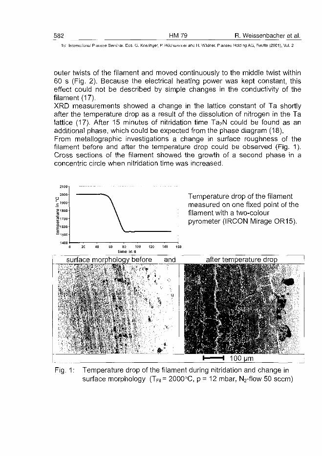
582 HM79 R. Weissenbacher et al.15" International Plansee Seminar, Eds. G. Kneringer, P. Rodhammer and H. Wildner, Plansee Holding AG, Reutte (2001), Vol. 2
outer twists of the filament and moved continuously to the middle twist within60 s (Fig. 2). Because the electrical heating power was kept constant, thiseffect could not be described by simple changes in the conductivity of thefilament (17).XRD measurements showed a change in the lattice constant of Ta shortlyafter the temperature drop as a result of the dissolution of nitrogen in the Talattice (17). After 15 minutes of nitridation time Ta2N could be found as anadditional phase, which could be expected from the phase diagram (18).From metallographic investigations a change in surface roughness of thefilament before and after the temperature drop could be observed (Fig. 1).Cross sections of the filament showed the growth of a second phase in aconcentric circle when nitridation time was increased.
2000O°=1900
£1800
|=1700CD
|"1600
Temperature drop of the filamentmeasured on one fixed point of thefilament with a two-colourpyrometer (IRCON Mirage OR15).
20 40 60 80 100 120 140 160
time in s
r surface morphology before and after temperature drop
Fig. 1: Temperature drop of the filament during nitridation and change insurface morphology (TFii.= 2000°C, p = 12 mbar, N2-flow 50 seem)
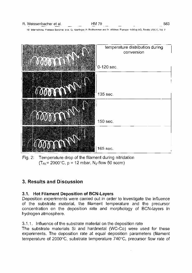
R. Weissenbacher et al. HM79 58315th International Plansee Seminar, Eds. G. Kneringer, P. Rodhammer and H. Wildner, Plansee Holding AG, Reutte (2001), Vol. 2
temperature distribution duringconversion
Fig. 2: Temperature drop of the filament during nitridation(TFii= 2000°C, p = 12 mbar, N2-flow 50 seem)
3. Results and Discussion
3.1. Hot Filament Deposition of BCN-LayersDeposition experiments were carried out in order to investigate the influenceof the substrate material, the filament temperature and the precursorconcentration on the deposition rate and morphology of BCN-layers inhydrogen atmosphere.
3.1.1. Influence of the substrate material on the deposition rateThe substrate materials Si and hardmetal (WC-Co) were used for theseexperiments. The deposition rate at equal deposition parameters (filamenttemperature of 2000°C, substrate temperature 740°C, precursor flow rate of
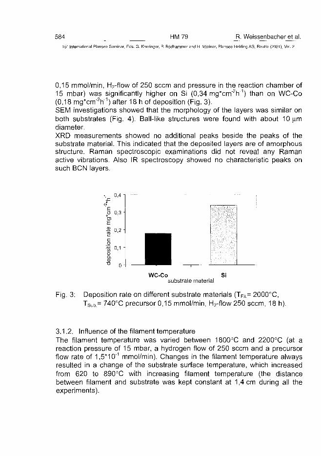
584 HM79 R. Weissenbacher et al.15" International Plansee Seminar, Eds. G. Kneringer, P. Rodhammer and H. Wildner, Plansee Holding AG, Reutte (2001), Vol. 2
0,15 mmol/min, H2-flow of 250 seem and pressure in the reaction chamber of15 mbar) was significantly higher on Si (0,34 mg*cm"2h~1) than on WC-Co(0,18 mg*cm"V) after 18 h of deposition (Fig. 3).SEM investigations showed that the morphology of the layers was similar onboth substrates (Fig. 4). Ball-like structures were found with about 10|imdiameter.XRD measurements showed no additional peaks beside the peaks of thesubstrate material. This indicated that the deposited layers are of amorphousstructure. Raman spectroscopic examinations did not reveal any Ramanactive vibrations. Also IR spectroscopy showed no characteristic peaks onsuch BCN layers.
WC-Cosubstrate material
Si
Fig. 3: Deposition rate on different substrate materials (TFi|.= 2000°C,Tsub.= 740°C precursor 0,15 mmol/min, H2-flow 250 seem, 18 h).
3.1.2. Influence of the filament temperatureThe filament temperature was varied between 1800°C and 2200°C (at areaction pressure of 15 mbar, a hydrogen flow of 250 seem and a precursorflow rate of 1,5*10'1 mmol/min). Changes in the filament temperature alwaysresulted in a change of the substrate surface temperature, which increasedfrom 620 to 890°C with increasing filament temperature (the distancebetween filament and substrate was kept constant at 1,4 cm during all theexperiments).
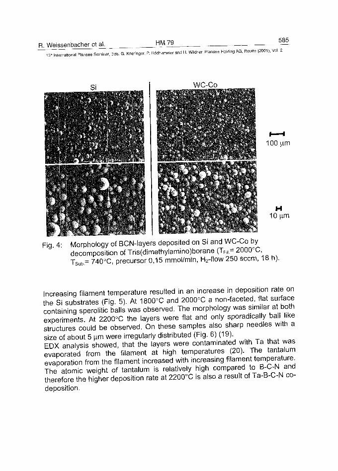
R. Weissenbacher et al. HM79 585
5- international Plansee Seminar, Eds. G. Kneringer, P. Rodhammer and H. Wildner, Plansee Holding AG, Reutte (2001), Voi. 2
WC-Co
100|im
H10|im
Fig. 4: Morphology of BCN-layers deposited on Si and WC-Co bydecomposition of Tris(dimethylamino)borane (TFi| = 2000°C,TSub= 740°C, precursor 0,15 mmol/min, H2-flow 250 seem, 18 h).
Increasing filament temperature resulted in an increase in deposition rate onthe Si substrates (Fig. 5). At 1800°C and 2000°C a non-faceted, flat surfacecontaining sperolitic balls was observed. The morphology was similar at bothexperiments At 2200°C the layers were flat and only sporadically ball likestructures could be observed. On these samples also sharp needles with asize of about 5 |im were irregularly distributed (Fig. 6) (19).EDX analysis showed, that the layers were contaminated with Ta ha wasevaporated from the filament at high temperatures (20). The tantalumevaporation from the filament increased with increasing filament temperature^The atomic weight of tantalum is relatively high compared to B-C-Nandtherefore the higher deposition rate at 2200X is also a result of Ta-B-C-N co-deposition.
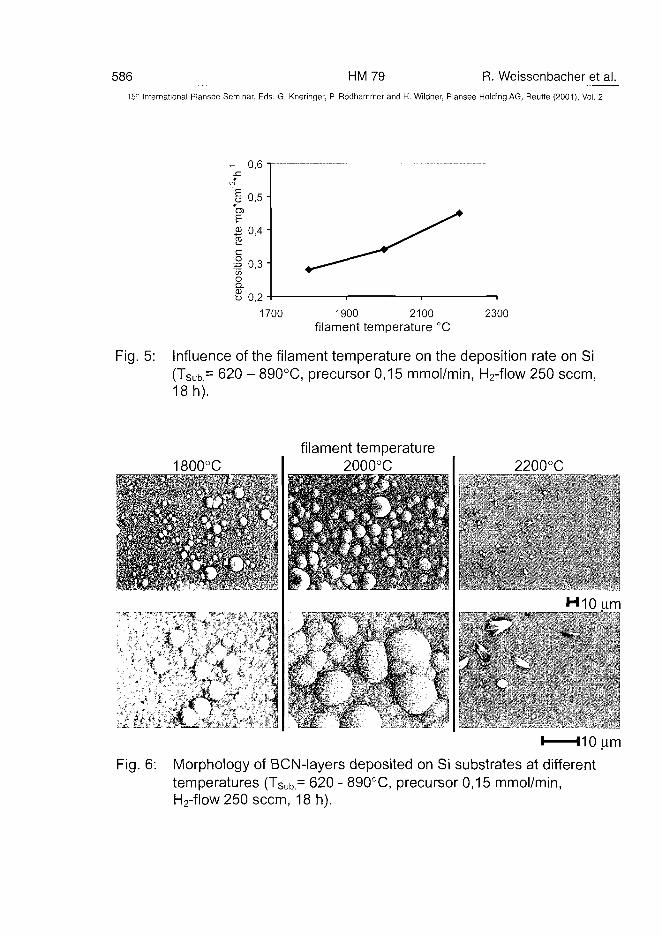
586 HM79 R. Weissenbacher et al.
15" International Piansee Seminar, Eds. G. Kneringer, P. Rodhammer and H. Wildner, Plansee Holding AG, Reutte (2001), Vol. 2
0,6 T -
I 0,5 -enE£ 0,4 •CD
I 0,3 i</>oa.-§0,2
1700 1900 2100filament temperature °C
2300
Fig. 5: Influence of the filament temperature on the deposition rate on Si(TSub= 620 - 890°C, precursor 0,15 mmol/min, H2-flow 250 seem,18 h).
1800°C
• * • *
•••<:•
• • ' . . - • . *X
• - ' • • %
filament temperature2000°C 2200°C
HiOum
I 110 urn
Fig. 6: Morphology of BCN-layers deposited on Si substrates at differenttemperatures (Tsub.= 620 - 890°C, precursor 0,15 mmol/min,H2-flow 250 seem, 18 h).
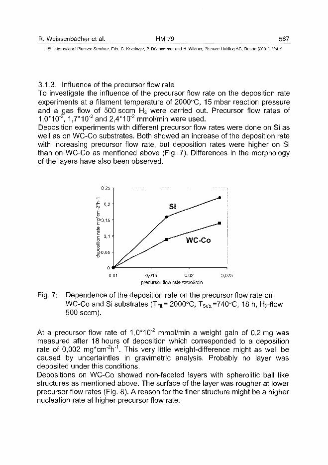
R. Weissenbacher et al. HM79 58715" International Plansee Seminar, Eds. G. Kneringer, P. Rodhammer and H. Wildner, Plansee Holding AG, Reutte (2001), Vol. 2
3.1.3. Influence of the precursor flow rateTo investigate the influence of the precursor flow rate on the deposition rateexperiments at a filament temperature of 2000°C, 15 mbar reaction pressureand a gas flow of 500 seem H2 were carried out. Precursor flow rates of1,0*10~2, 1,7*10"2 and 2,4*10"2 mmol/min were used.Deposition experiments with different precursor flow rates were done on Si aswell as on WC-Co substrates. Both showed an increase of the deposition ratewith increasing precursor flow rate, but deposition rates were higher on Sithan on WC-Co as mentioned above (Fig. 7). Differences in the morphologyof the layers have also been observed.
0,25 1
0,01 0,015 0,02
precursor flow rate mmol/min
0,025
Fig. 7: Dependence of the deposition rate on the precursor flow rate onWC-Co and Si substrates (TRi.= 2000°C, TSub=740°C, 18 h, H2-flow500 seem).
At a precursor flow rate of 1,0*10"2 mmol/min a weight gain of 0,2 mg wasmeasured after 18 hours of deposition which corresponded to a depositionrate of 0,002 mg*crrr2h"1. This very little weight-difference might as well becaused by uncertainties in gravimetric analysis. Probably no layer wasdeposited under this conditions.Depositions on WC-Co showed non-faceted layers with spherolitic ball likestructures as mentioned above. The surface of the layer was rougher at lowerprecursor flow rates (Fig. 8). A reason for the finer structure might be a highernucleation rate at higher precursor flow rate.
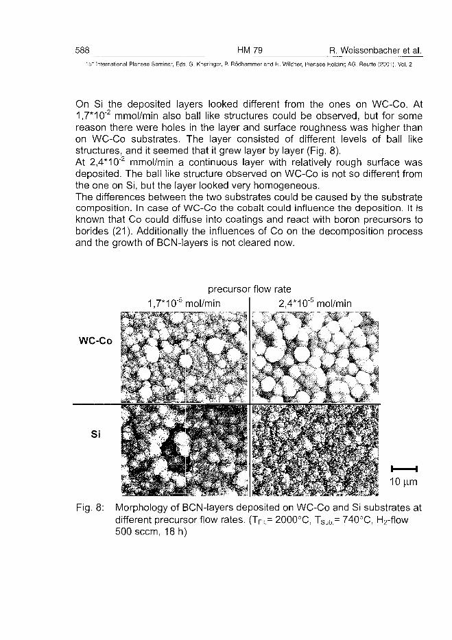
588 HM79 R. Weissenbacher et al.15" International Plansee Seminar, Eds. G. Kneringer, P. Rodhammer and H. Wildner, Plansee Holding AG, Reutte (2001), Vol. 2
On Si the deposited layers looked different from the ones on WC-Co. At1,7*10"2 mmol/min also ball like structures could be observed, but for somereason there were holes in the layer and surface roughness was higher thanon WC-Co substrates. The layer consisted of different levels of ball likestructures, and it seemed that it grew layer by layer (Fig. 8).At 2,4*10"2 mmol/min a continuous layer with relatively rough surface wasdeposited. The ball like structure observed on WC-Co is not so different fromthe one on Si, but the layer looked very homogeneous.The differences between the two substrates could be caused by the substratecomposition. In case of WC-Co the cobalt could influence the deposition. It isknown that Co could diffuse into coatings and react with boron precursors toborides (21). Additionally the influences of Co on the decomposition processand the growth of BCN-layers is not cleared now.
precursor flow rate
1,7*10"5mol/min
WC-Co
2,4*10"5mol/min- - • < - , - - , , ; ^
m& 1o'am
Fig. 8: Morphology of BCN-layers deposited on WC-Co and Si substrates atdifferent precursor flow rates. (TFi| = 2000°C, TSub= 740°C, H2-flow500 seem, 18 h)
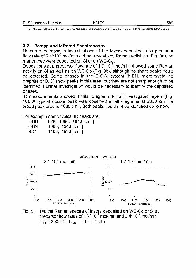
R. Weissenbacher et al. HM79 5895" International Plansee Seminar, Eds. G. Kneringer, P. Rodhammer and H. Wildner, Plansee Holding AG, Reutte (2001), Vol. 2
3.2. Raman and Infrared SpectroscopyRaman spectroscopic investigations of the layers deposited at a precursorflow rate of 2,4*10"5 mol/min did not reveal any Raman activities (Fig. 9a), nomatter they were deposited on Si or on WC-Co.Depositions at a precursor flow rate of 1,7*10"5 mol/min showed some Ramanactivity on Si as well as on WC-Co (Fig. 9b), although no sharp peaks couldbe detected. Some phases in the B-C-N system (h-BN, micro-crystallinegraphite or B4C) show peaks in this area, but they are not sharp enough to beidentified. Further investigation would be necessary to identify the depositedphases.IR measurements showed similar diagrams for all investigated layers (Fig.10). A typical double peak was observed in all diagrams at 2358 cm"1, abroad peak around 1600 cm"1. Both peaks could not be identified up to now.
For example some typical IR peaks are:h-BN 828, 1380, 1610 [cm"1]c-BN 1065, 1340 [cm"1]B4C 1100, 1590 [cm"']
8000 -
6000-
4000-
2000 -
0
800
precursor flow rate2,4*10 mol/min 1,7*10"& mol/min
8000 -
6000 -
4000 -
2000 -
0
1000 1200 1400 1600 1800RAMAN-Shift [cm"1]
800 1000 1200 1400 1600 1800
RAMAN-Shift [cm1]
Fig. 9: Typical Raman spectra of layers deposited on WC-Co or Si atprecursor flow rates of 1,7*10"5 mol/min and 2,4*10"5 mol/min(TF||= 2000°C, TSub= 740X, 18 h)
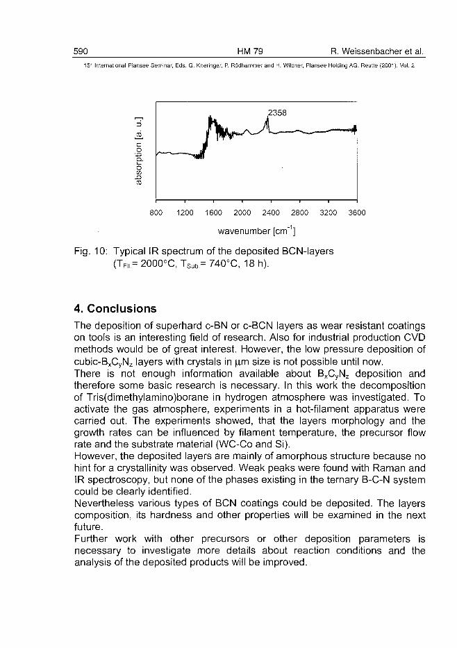
590 HM79 R. Weissenbacher et al.15~ International Plansee Seminar, Eds. G. Kneringer, P. Rodhammer and H. Wildner, Plansee Holding AG, Reutte (2001), Vol. 2
o"5.oC/3
800 1200 1600 2000 2400 2800 3200 3600
wavenumber [cm" ]
Fig. 10: Typical IR spectrum of the deposited BCN-layers(TFi,= 2000°C, TSub= 740°C, 18 h).
4. ConclusionsThe deposition of superhard c-BN or c-BCN layers as wear resistant coatingson tools is an interesting field of research. Also for industrial production CVDmethods would be of great interest. However, the low pressure deposition ofcubic-BxCyNz layers with crystals in jim size is not possible until now.There is not enough information available about BxCyNz deposition andtherefore some basic research is necessary. In this work the decompositionof Tris(dimethylamino)borane in hydrogen atmosphere was investigated. Toactivate the gas atmosphere, experiments in a hot-filament apparatus werecarried out. The experiments showed, that the layers morphology and thegrowth rates can be influenced by filament temperature, the precursor flowrate and the substrate material (WC-Co and Si).However, the deposited layers are mainly of amorphous structure because nohint for a crystallinity was observed. Weak peaks were found with Raman andIR spectroscopy, but none of the phases existing in the ternary B-C-N systemcould be clearly identified.Nevertheless various types of BCN coatings could be deposited. The layerscomposition, its hardness and other properties will be examined in the nextfuture.Further work with other precursors or other deposition parameters isnecessary to investigate more details about reaction conditions and theanalysis of the deposited products will be improved.
R. Weissenbacher et al. HM 79 591
15'" International Plansee Seminar, Eds. G. Kneringer, P. Rodhammer and H. Wildner, Plansee Holding AG, Reutte (2001), Vol. 2
5. AcknowledgementsThis work was supported by NEDO (New Energy and Industrial TechnologyDevelopment Organization) and JFCC (Japan Fine Ceramic Center) as a partof the FCT (Frontier Carbon Technology) project promoted by AIST, MITI;Japan.
References
(1) H. Ehrhardt: Surf. Coat. Technol. 74/75 (1995) 29-35(2) A. Bartl, R. Haubner, B. Lux: Refractory Metals & Hard Materials 14
(1996) 145-157(3) "Low Pressure Synthetic Diamond", B. Dischler and C. Wild, Springer
Verlag, Berlin, 1998(4) T. Yoshida: Diamond and Related Materials 5 (1996) 501-507(5) M. Kuhr, S. Reinke and W. Kulisch: Surf. Coat. Technol. 74-75 (1995)
806-812(6) Y. Kakudate, M. Yoshida, S. Usabe, H. Yokoi, S. Fujiwara, M.
Kawaguchi, K. Sako and T. Sawai: Trans. Mat. Res. Soc. Jpn. 14B(1993) 1447-1450
(7) A. R. Badzian: Mat. Res. Bull. 16 (1981) 1385-1391(8) V. L. Solozhenko and V. Ya. Leonidov: Russian J. of Physical
Chemistry 62(11) (1988), 1646-1647(9) H. Sachdev, R. Haubner and B. Lux: Diamond and Related Materials 6
(1997)286-292.(10) G. Will, G. Nover, J. von der Gonna: Proc. of AIRAPT-16 Meeting
(Kyoto, Japan aug. 22.-30., 1997)(11) R. Brunsteiner: Ph. D. Dissertation, University of Technology Vienna
(1993)(12) Gmelins Handbuch der Anorganischen Chemie, B, Borverbindungen 4
(Bd 22), Springer Verlag, 1975, S. 5-44(13) W. Kalss: Ph. D. Dissertation, University of Technologie, Vienna (1998)(14) T. B. Massalsky et al, "Binary alloy phase diagrams", ASM International,
1990, Vol. 1(15) R. Haubner, B. Lux: Diamond and Related Materials 2 (1993) 1277-
1294(16) S. Okoli, R. Haubner, B. Lux: Surface and Coatings Technology, 47
(1991)585-599
592 HM 79 R. Weissenbacher et al.15" International Plansee Seminar, Eds. G. Kneringer, P. Rödhammer and H. Wildner, Plansee Holding AG, Reutte (2001 ), Vol. 2
(17) R. Weissenbacher, R. Haubner, K. Aigner and B. Lux: Diamond andRelated Materials (submitted)
(18) H. Wiesenberger, W. Lengauer, P.Ettmayer: Acta Mater, Vol 46/2,(1998)651-666
(19) W. Kalss, R. Haubner, B. Lux: Refractory Metals & Hard Materials16(3), (1998)233-241
(20) K. Aigner, X. Tang, R. Haubner, B. Lux New: Diamond Front. CarbonTechnol. (2000), 10(4), 181-189.
(21) W. Kalss, S. Bohr, R. Haubner, B. Lux, M. Griesser, H. Spicka,M. Grasserbauer, P. Wurzinger: Refractory Metals & Hard Materials 14(1996)137-144
AT0100484W. Fleischer et al. HM 80 593^
15" International Plansee Seminar, Eds. G. Kneringer, P. Rodhammer and H. Wildner, Plansee Holding AG, Reutte (2001), Vol. 2
Hard Machining Under Dry Conditions With HardPVD Coatings On Cemented Carbide Endmills
W. Fleischer1', N. Baranski1), G.J. van der Kolk2),
Y.Stockmann2', H. Kunen3), S. Hoppe4)
1) Bodycote Coating Centrum BV, Venlo, The Netherlands
2) Hauzer Techno Coating Europe BV, Venlo, TheNetherlands
3) Jabro Tools BV, Lottum, The Netherlands
4) WZL, Aachen, Germany
Summary:
Machining of hardened steel needs cutting tools for extreme conditions. Notonly the cemented carbide toolmaterial, but also the hard or ultra hard coatingdetermines the tool life and cutting performance on the workpiece. For millingoperation in hardened material 1.2379 with a hardness between 60 and 62HRc, endmills coated with different TiAIN layers in single or multilayer designand also top coatings with low friction performance are used. Cutting testswith investigations of the wear on the cutting edge and in situ infraredtemperature measurements by video camera showed large differences in toolperformance. According to these results the limitations of cutting time orcutting length is, in some cases, not only caused by the wear on the tool, butalso by the surface temperature of the work piece material.
Keywords:
PVD coatings, TiAIN, Endmills, Dry cutting, W-C:H, Hard / Soft-coatings.
594 HM80 W. Fleischer et al.15:" International Plansee Seminar, Eds. G. Kneringer, P. Rodhammer and H. Wildner, Plansee Holding AG, Reutte (2001), Vol. 2
Introduction:
Advanced metal cutting technologies, sich as High Speed Machining (HSM)in hardened materials under dry cutting conditions call for tools with highperformance under extreme conditions. Such technologies are finding theirway more and more into the modern metal working industry: as described byKlocke et al (1) and Tonshoffet al (2).Also the environmental advantage of dry cutting and the cost reduction arevery important criteria to use this technology: as described by Fleischer et al(3).Coated tools for milling operations are already used in production. The aim ofthis work was, by variation of the coating, to increase the lifetime of theendmills. Therefore an already tested cemented carbide material with goodcutting edge stability for this application was used with only the coating asvariation parameter. Systematic cutting tests were carried out on 1.2379 steelwith a hardness of 60 ... 62 HRc. The cutting quality on the workpiecematerial and wear of the tool are compared. To find out the heat generationand distribution in the tool, an infrared video camera was used to examine thechips, the tool and the workpiece in situ.
2. Advantages of high Speed Machining of hardened steel:
High speed machining of hardened steel not only increases the productivityand reduces the manufacturing cost, but also has other advantages such as• in one fixture roughing and finishing operation of the workpiece reduces
the amount of production steps,more heat dissipation by the chip, less heat absorption by the workpiece,higher accuracy, due to one fixture of the workpiece,less machining centres required in the production process,dry chips,less polishing operations are necessary,no post cutting heat treatment which improves product accuracy.
To use this technology for large size workpieces, e.g. large size dies, it isrequired to increase the possible cutting length for one tool. One endmill forfinishing operations in large size workpieces must have a lifetime equal ormore than the operation time needed to produce one workpiece. To be ableto meet the ever increasing size and accuracy requirements of suchworkpieces, the increase of cutting time is extremely important.
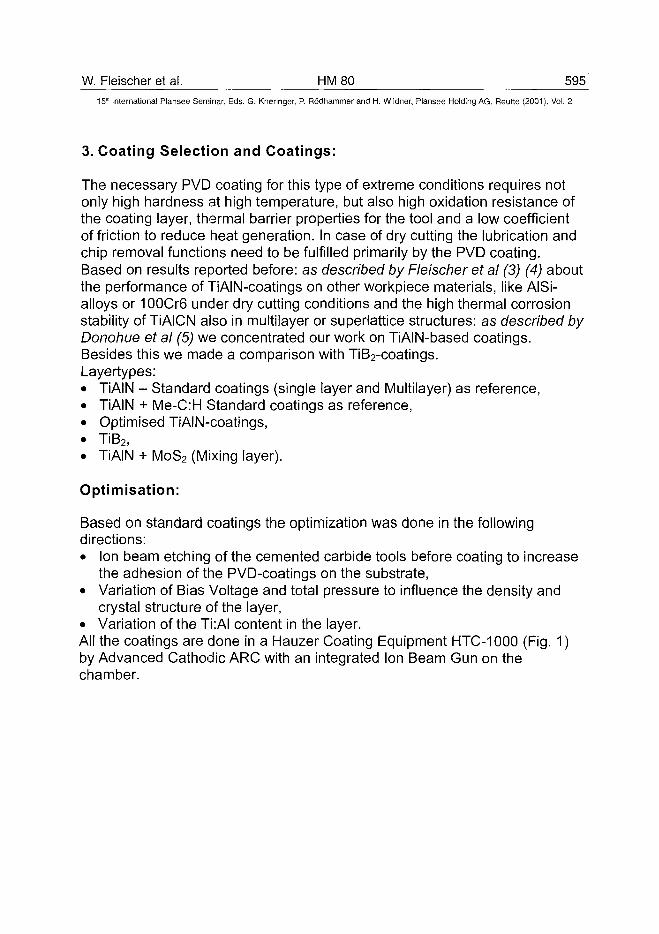
W. Fleischer et al. HM 80 595^15'" International Plansee Seminar, Eds. G. Kneringer, P. Rodhammer and H. Wildner, Plansee Holding AG, Reutte (2001), Vol. 2
3. Coating Selection and Coatings:
The necessary PVD coating for this type of extreme conditions requires notonly high hardness at high temperature, but also high oxidation resistance ofthe coating layer, thermal barrier properties for the tool and a low coefficientof friction to reduce heat generation. In case of dry cutting the lubrication andchip removal functions need to be fulfilled primarily by the PVD coating.Based on results reported before: as described by Fleischer et al (3) (4) aboutthe performance of TiAIN-coatings on other workpiece materials, like AlSi-alloys or 100Cr6 under dry cutting conditions and the high thermal corrosionstability of TiAICN also in multilayer or superlattice structures: as described byDonohue et al (5) we concentrated our work on TiAIN-based coatings.Besides this we made a comparison with TiB2-coatings.Layertypes:• TiAIN - Standard coatings (single layer and Multilayer) as reference,• TiAIN + Me-C:H Standard coatings as reference,• Optimised TiAIN-coatings,• TiB2,• TiAIN + MoS2 (Mixing layer).
Optimisation:
Based on standard coatings the optimization was done in the followingdirections:• Ion beam etching of the cemented carbide tools before coating to increase
the adhesion of the PVD-coatings on the substrate,• Variation of Bias Voltage and total pressure to influence the density and
crystal structure of the layer,• Variation of the Ti:AI content in the layer.All the coatings are done in a Hauzer Coating Equipment HTC-1000 (Fig. 1)by Advanced Cathodic ARC with an integrated Ion Beam Gun on thechamber.
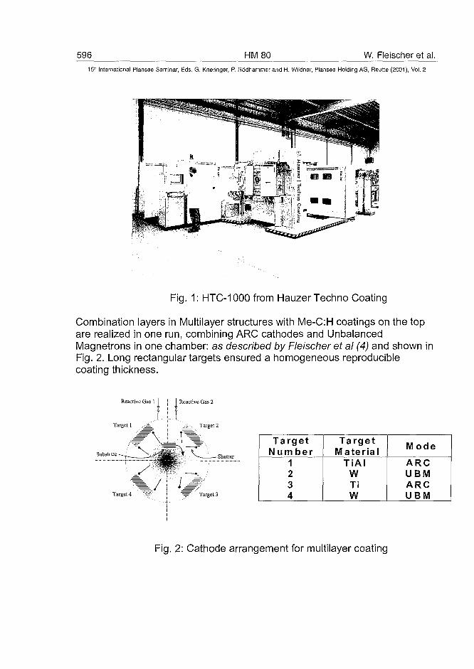
596 HM80 W. Fleischer et al.15" International Plansee Seminar, Eds. G. Kneringer, P. Rodhammer and H. Wildner, Plansee Holding AG, Reutte (2001), Vol. 2
Fig. 1: HTC-1000 from Hauzer Techno Coating
Combination layers in Multilayer structures with Me-C:H coatings on the topare realized in one run, combining ARC cathodes and UnbalancedMagnetrons in one chamber: as described by Fleischer et al (4) and shown inFig. 2. Long rectangular targets ensured a homogeneous reproduciblecoating thickness.
Reactive Gas 1 j Reactive Gas 2
Target 4
TargetN um ber
1234
TargetMaterial
TiAlWTiW
M ode
ARCUBMARCUBM
Fig. 2: Cathode arrangement for multilayer coating
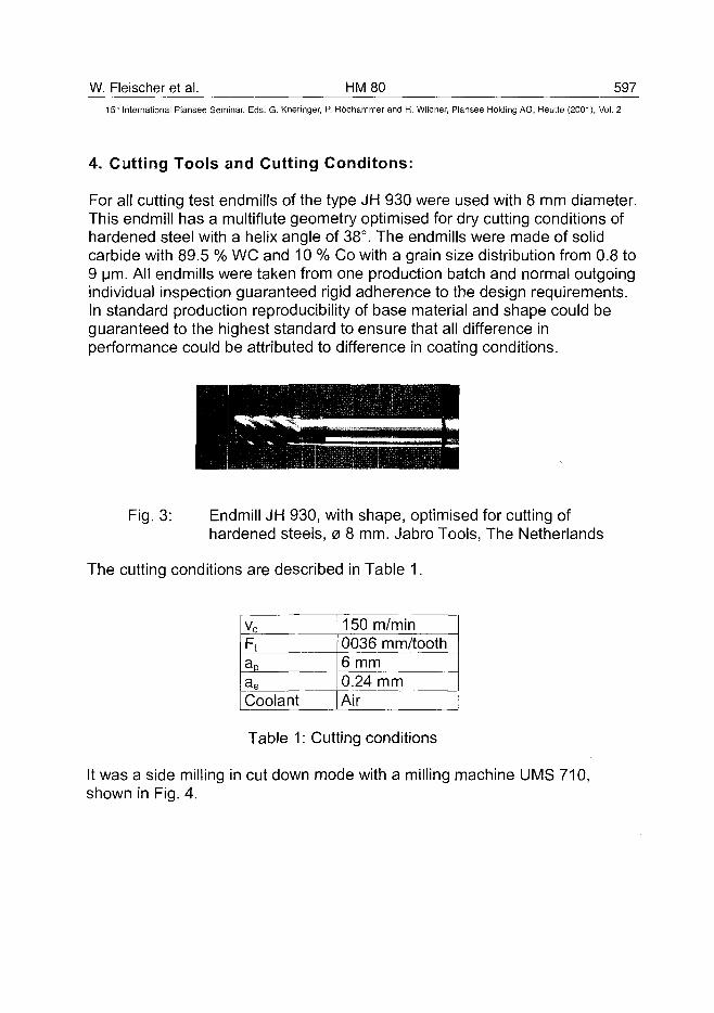
W. Fleischer et al. HM80 59715" International Plansee Seminar, Eds. G. Kneringer, P. Rodhammer and H. Wildner, Plansee Holding AG, Reutte (2001), Vol. 2
4. Cutting Tools and Cutting Conditons:
For all cutting test endmills of the type JH 930 were used with 8 mm diameter.This endmill has a multiflute geometry optimised for dry cutting conditions ofhardened steel with a helix angle of 38°. The endmills were made of solidcarbide with 89.5 % WC and 10 % Co with a grain size distribution from 0.8 to9 urn. All endmills were taken from one production batch and normal outgoingindividual inspection guaranteed rigid adherence to the design requirements.In standard production reproducibility of base material and shape could beguaranteed to the highest standard to ensure that all difference inperformance could be attributed to difference in coating conditions.
Endmill JH 930, with shape, optimised for cutting ofhardened steels, 0 8 mm. Jabro Tools, The Netherlands
Fig. 3:
The cutting conditions are described in Table 1.
Vc
Ft
ac
aeCoolant
150 m/min0036 mm/tooth6 mm0.24 mmAir
Table 1: Cutting conditions
It was a side milling in cut down mode with a milling machine UMS 710,shown in Fig. 4.
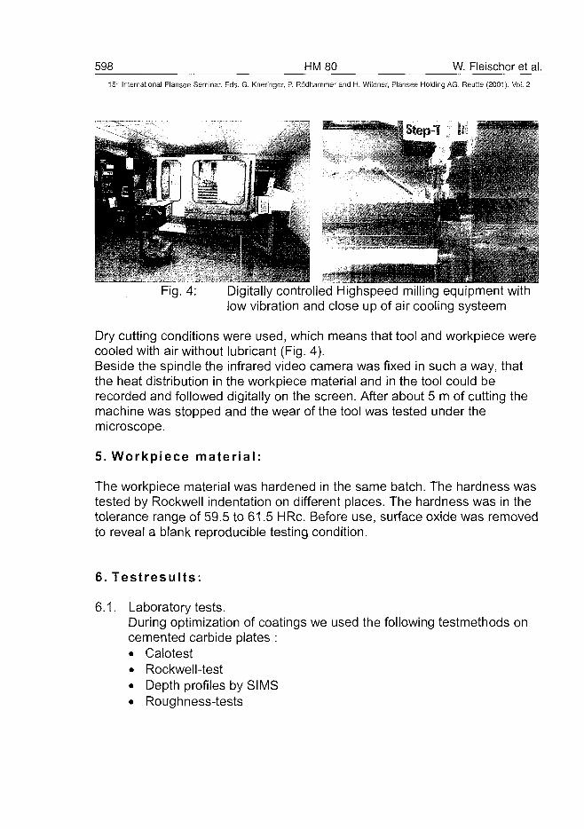
598 HM80 W. Fleischer et al.15" International Plansee Seminar, Eds. G. Kneringer, P. Rodhammer and H. Wildner, Plansee Holding AG, Reutte (2001), Vol. 2
Fig. 4: Digitally controlled Highspeed milling equipment withlow vibration and close up of air cooling systeem
Dry cutting conditions were used, which means that tool and workpiece werecooled with air without lubricant (Fig. 4).Beside the spindle the infrared video camera was fixed in such a way, thatthe heat distribution in the workpiece material and in the tool could berecorded and followed digitally on the screen. After about 5 m of cutting themachine was stopped and the wear of the tool was tested under themicroscope.
5. Workpiece material:
The workpiece material was hardened in the same batch. The hardness wastested by Rockwell indentation on different places. The hardness was in thetolerance range of 59.5 to 61.5 HRc. Before use, surface oxide was removedto reveal a blank reproducible testing condition.
6. Testresults:
6.1. Laboratory tests.During optimization of coatings we used the following testmethods oncemented carbide plates :• Calotest• Rockwell-test• Depth profiles by SIMS• Roughness-tests
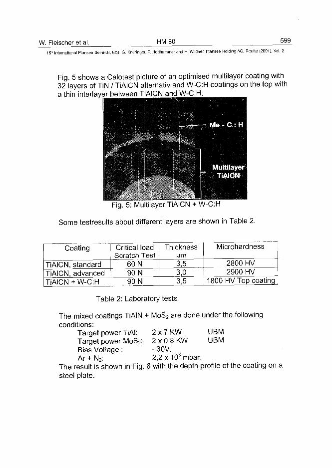
W. Fleischer et al. HM80 599
15'" International Plansee Seminar, Eds. G. Kneringer, P. Rodhammer and H. Wildner, Plansee Holding AG, Reutte (2001), Vol. 2
Fig. 5 shows a Calotest picture of an optimised multilayer coating with32 layers of TiN / TiAICN alternativ and W-C:H coatings on the top witha thin interlayer between TiAICN and W-C:H.
Fig. 5: Multilayer TiAICN + W-C:H
Some testresults about different layers are shown in Table 2.
Coating
TiAICN, standardTiAICN, advancedTiAICN + W-C:H
Critical loadScratch Test
60 N90 N90 N
Thickness|jm
3,53,03,5
Microhardness
2800 HV2900 HV
1800 HV Top coating
Table 2: Laboratory tests
The mixed coatings TiAIN + MoS2 are done under the followingconditions:
Target power TiAl: 2 x 7 KW UBMTarget power MoS2: 2 x 0,8 KW UBMBias Voltage : - 30V.Ar + N2: 2,2x10³mbar.
The result is shown in Fig. 6 with the depth profile of the coating on asteel plate.
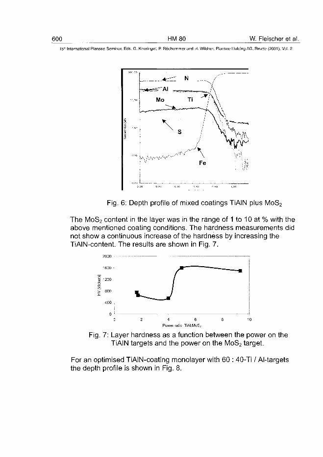
600 HM80 W. Fleischer et al.15" International Plansee Seminar, Eds. G. Kneringer, P. Rodhammer and H. Wildner, Plansee Holding AG, Reutte (2001), Vol. 2
Fig. 6: Depth profile of mixed coatings TiAIN plus MoS2
The MoS2 content in the layer was in the range of 1 to 10 at % with theabove mentioned coating conditions. The hardness measurements didnot show a continuous increase of the hardness by increasing theTiAIN-content. The results are shown in Fig. 7.
2000
> 800 -
400
Power ratio TiAI:MoS?
Fig. 7: Layer hardness as a function between the power on theTiAIN targets and the power on the MoS2 target.
For an optimised TiAiN-coating monolayer with 60 : 40-Ti / Al-targetsthe depth profile is shown in Fig. 8.
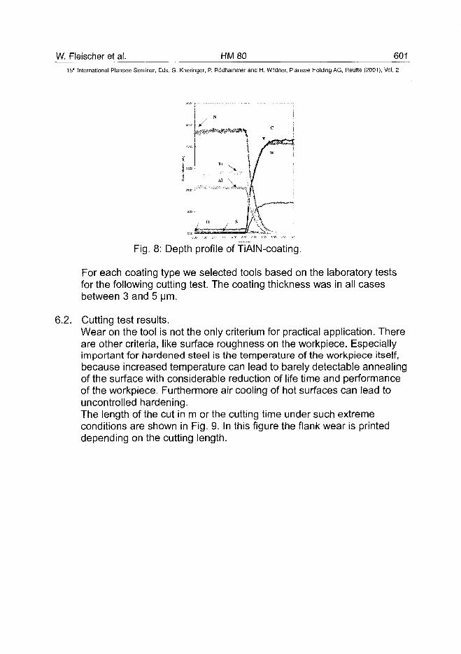
W. Fleischer et al. HM80 60115" International Plansee Seminar, Eds. G. Kneringer, P. Rodhammer and H. Wildner, Plansee Holding AG, Reutte (2001), Vol. 2
Fig. 8: Depth profile of TiAIN-coating.
For each coating type we selected tools based on the laboratory testsfor the following cutting test. The coating thickness was in all casesbetween 3 and 5 urn.
6.2. Cutting test results.Wear on the tool is not the only criterium for practical application. Thereare other criteria, like surface roughness on the workpiece. Especiallyimportant for hardened steel is the temperature of the workpiece itself,because increased temperature can lead to barely detectable annealingof the surface with considerable reduction of life time and performanceof the workpiece. Furthermore air cooling of hot surfaces can lead touncontrolled hardening.The length of the cut in m or the cutting time under such extremeconditions are shown in Fig. 9. In this figure the flank wear is printeddepending on the cutting length.
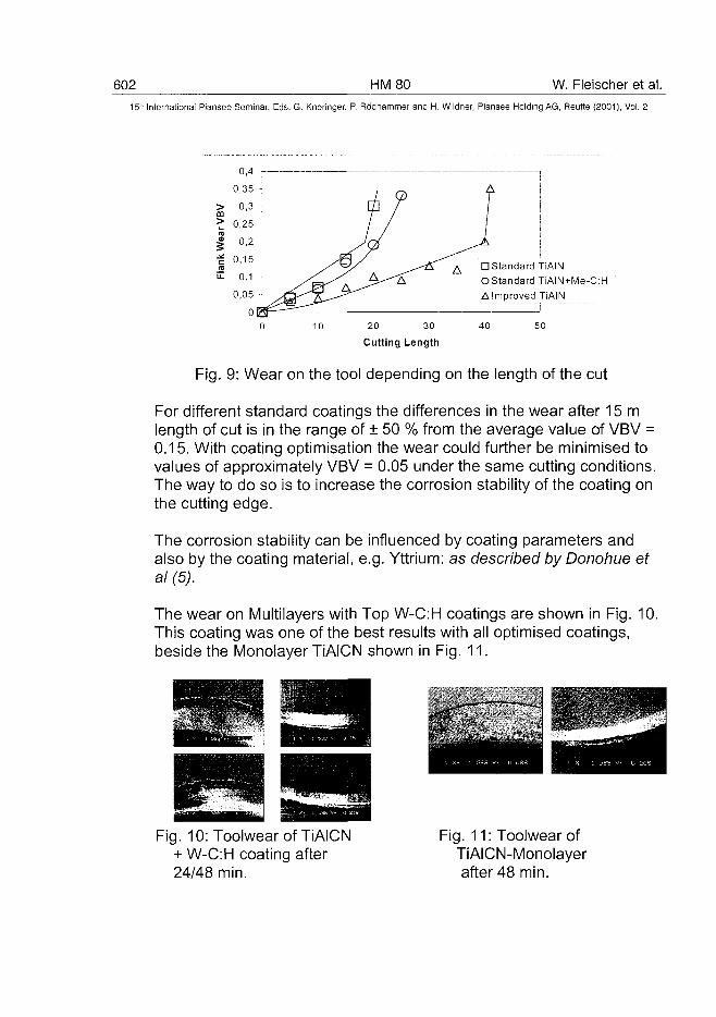
602 HM80 W. Fleischer et al.15" International Plansee Seminar, Eds. G. Kneringer, P. Rddhammer and H. Wildner, Plansee Holding AG, Reutte (2001), Vol. 2
I
0,4
0,35
0,3
0,25
0,2
0,15
0,1
0,05
0 [£c3
10
/ C
TV
20
Cutting
-)
^ ^ A
30
Length
D Standard TiAINOStandardTiAIN+Me-C:HA Improved TiAIN
40 50
Fig. 9: Wear on the tool depending on the length of the cut
For different standard coatings the differences in the wear after 15 mlength of cut is in the range of ± 50 % from the average value of VBV =0.15. With coating optimisation the wear could further be minimised tovalues of approximately VBV = 0.05 under the same cutting conditions.The way to do so is to increase the corrosion stability of the coating onthe cutting edge.
The corrosion stability can be influenced by coating parameters andalso by the coating material, e.g. Yttrium: as described by Donohue et
The wear on Multilayers with Top W-C:H coatings are shown in Fig. 10.This coating was one of the best results with all optimised coatings,beside the Monolayer TiAICN shown in Fig. 11.
Fig. 10: Toolwear of TiAICN+ W-C:H coating after24/48 min.
Fig. 11: Toolwear ofTiAICN-Monolayerafter 48 min.
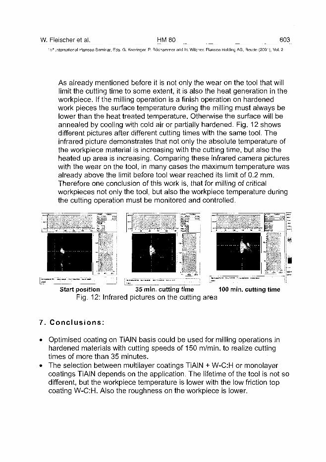
W. Fleischer et al. HM80 60315th International Plansee Seminar, Eds. G. Kneringer, P. Rodhammer and H. Wildner, Plansee Holding AG, Reutte (2001), Vol. 2
As already mentioned before it is not only the wear on the tool that willlimit the cutting time to some extent, it is also the heat generation in theworkpiece. If the milling operation is a finish operation on hardenedwork pieces the surface temperature during the milling must always belower than the heat treated temperature. Otherwise the surface will beannealed by cooling with cold air or partially hardened. Fig. 12 showsdifferent pictures after different cutting times with the same tool. Theinfrared picture demonstrates that not only the absolute temperature ofthe workpiece material is increasing with the cutting time, but also theheated up area is increasing. Comparing these infrared camera pictureswith the wear on the tool, in many cases the maximum temperature wasalready above the limit before tool wear reached its limit of 0.2 mm.Therefore one conclusion of this work is, that for milling of criticalworkpieces not only the tool, but also the workpiece temperature duringthe cutting operation must be monitored and controlled.
Start position 35 min. cutting time 100 min. cutting timeFig. 12: Infrared pictures on the cutting area
7. Conclusions:
• Optimised coating on TiAIN basis could be used for milling operations inhardened materials with cutting speeds of 150 m/min. to realize cuttingtimes of more than 35 minutes.
• The selection between multilayer coatings TiAIN + W-C:H or monolayercoatings TiAIN depends on the application. The lifetime of the tool is not sodifferent, but the workpiece temperature is lower with the low friction topcoating W-C:H. Also the roughness on the workpiece is lower.
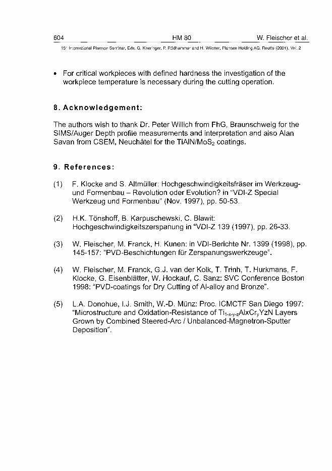
604 HM80 W. Fleischer et al.15:" International Plansee Seminar, Eds. G. Kneringer, P. Rodhammer and H. Wildner, Plansee Holding AG, Reutte (2001), Vol. 2
• For critical workpieces with defined hardness the investigation of theworkpiece temperature is necessary during the cutting operation.
8. Acknowledgement:
The authors wish to thank Dr. Peter Willich from FhG, Braunschweig for theSIMS/Auger Depth profile measurements and interpretation and also AlanSavan from CSEM, Neuchatel for the TiAIN/MoS2 coatings.
9. References:
(1) F. Klocke and S. Altmuller: Hochgeschwindigkeitsfraser im Werkzeug-und Formenbau - Revolution oder Evolution? in "VDI-Z SpecialWerkzeug und Formenbau" (Nov. 1997), pp. 50-53.
(2) H.K. Tonshoff, B. Karpuschewski, C. Blawit:Hochgeschwindigkeitszerspanung in "VDI-Z 139 (1997), pp. 26-33.
(3) W. Fleischer, M. Franck, H. Kunen: in VDI-Berichte Nr. 1399 (1998), pp.145-157: "PVD-Beschichtungen fur Zerspanungswerkzeuge".
(4) W. Fleischer, M. Franck, G.J. van der Kolk, T. Trinh, T. Hurkmans, F.Klocke, G. Eisenblatter, W. Hockauf, C. Sanz: SVC Conference Boston1998: "PVD-coatings for Dry Cutting of Al-alloy and Bronze".
(5) L.A. Donohue, I.J. Smith, W.-D. Munz: Proc. ICMCTF San Diego 1997:"Microstructure and Oxidation-Resistance of Ti x-y.zAlxCryYzN LayersGrown by Combined Steered-Arc / Unbalanced-Magnetron-SputterDeposition".
AT0100485V. Richter HM 82 605_
15* International Plansee Seminar, Eds. G. Kneringer, P. Rödhammer and H. Wildner, Plansee Holding AG, Reutte (2001), Vol. 2
Verschleißmechanismen bei der Bearbeitung vom Grauguß
Volkmar Richter
Fraunhofer-Institut Keramische Technologien und Sinterwerkstoffe, Dresden
Summary
In the paper several aspects of the wear mechanisms of coated hardmetals,ceramics and super-hard materials (CBN) in machining cast iron are dis-cussed, with particular attention being given to high-speed machining of dif-ferent cast iron grades. The influence of machining parameters, microstruc-ture, composition and mechanical and chemical properties of the cutting tooland the work-piece material on wear are considered.
KeywordsTurning of cast iron, CBN, ceramics, wear, cutting forces, cutting temperature
1. EinleitungLamellarer Grauguss findet breite Anwendung im Maschinen- und Fahrzeug-bau. Neben günstigen Herstellungskosten zeichnet ihn eine gute Bearbeit-barkeit aus. So lassen sich mit Werkzeugen aus Siliziumnitridkeramik oderkubischem Bornitrid beim Drehen in der Praxis Schnittgeschwindigkeiten bisüber 1000 m/min realisieren. Höhere Anforderungen an die Festigkeit oderder Wunsch nach einer Senkung des Gewichts der Bauteile zwingen aberzunehmend zur höheren Legierung des lamellaren Graugusses oder zumEinsatz von vermikularem oder globularem Grauguss. Damit sinken üblicher-weise die Standzeiten der Werkzeuge deutlich ab, was zu Effektivitätsein-bußen in der Fertigung führt. Es erscheint deshalb interessant, den Ver-schleißmechanismen der Werkzeuge bei der Bearbeitung verschiedenerGraugussarten tiefer auf den Grund zu gehen, um Hinweise zur Verbesse-rung der Werkzeuge oder zur Modifizierung der Zusammensetzung desGraugusses zu gewinnen.
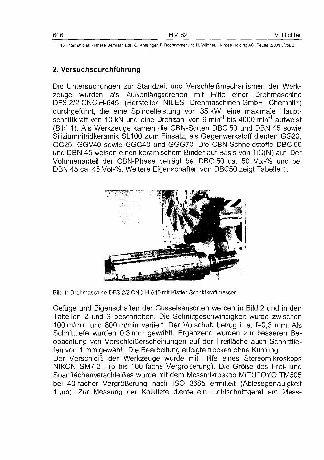
606 HM 82 V. Richter
15" International Plansee Seminar, Eds. G. Kneringer, P. Rödhammer and H. Wildner, Plansee Holding AG, Reutte (2001), Vol. 2
2. Versuchsdurchführung
Die Untersuchungen zur Standzeit und Verschleißmechanismen der Werk-zeuge wurden als Außenlängsdrehen mit Hilfe einer DrehmaschineDFS 2/2 CNC H-645 (Hersteller NILES Drehmaschinen GmbH Chemnitz)durchgeführt, die eine Spindelleistung von 35 kW, eine maximale Haupt-schnittkraft von 10 kN und eine Drehzahl von 6 min'1 bis 4000 min'1 aufweist(Bild 1). Als Werkzeuge kamen die CBN-Sorten DBC 50 und DBN 45 sowieSiliziumnitridkeramik SL100 zum Einsatz, als Gegenwerkstoff dienten GG20,GG25, GGV40 sowie GGG40 und GGG70. Die CBN-Schneidstoffe DBC 50und DBN 45 weisen einen keramischem Binder auf Basis von TiC(N) auf. DerVolumenanteil der CBN-Phase beträgt bei DBC 50 ca. 50 Vol-% und beiDBN 45 ca. 45 Vol-%. Weitere Eigenschaften von DBC50 zeigt Tabelle 1.
Bild 1: Drehmaschine DFS 2/2 CNC H-645 mit Kistler-Schnittkraftmesser
Gefüge und Eigenschaften der Gusseisensorten werden in Bild 2 und in denTabellen 2 und 3 beschrieben. Die Schnittgeschwindigkeit wurde zwischen100 m/min und 800 m/min variiert. Der Vorschub betrug i. a. f=0,3 mm. AlsSchnitttiefe wurden 0,3 mm gewählt. Ergänzend wurden zur besseren Be-obachtung von Verschleißerscheinungen auf der Freifläche auch Schnitttie-fen von 1 mm gewählt. Die Bearbeitung erfolgte trocken ohne Kühlung.Der Verschleiß der Werkzeuge wurde mit Hilfe eines StereomikroskopsNIKON SM7-2T (5 bis 100-fache Vergrößerung). Die Größe des Frei- undSpanflächenverschleißes wurde mit dem Messmikroskop MITUTOYO TM505bei 40-facher Vergrößerung nach ISO 3685 ermittelt (Ablesegenauigkeit1 um). Zur Messung der Kolktiefe diente ein Lichtschnittgerät am Mess-
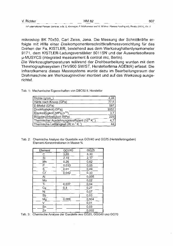
V. Richter HM 82 60715" International Plansee Seminar, Eds. G. Kneringer, P. Ródhammer and H. Wildner, Plansee Holding AG, Relitte (2001), Vol. 2
mikroskop BK 70x50, Carl Zeiss, Jena. Die Messung der Schnittkräfte er-folgte mit Hilfe einer Dreikomponentenschnittkraftmessvorrichtung für dasDrehen der Fa. KISTLER, bestehend aus dem Werkzeughalterdynamometer9171, dem KISTLER-Ladungsverstärker 5011SN und der Auswertesoftwareu-MUSYCS (integrated measurement & control ime, Berlin).Die Werkzeugtemperaturen während der Drehbearbeitung wurden mit demThermographiesystem (THV900 SW/ST, Herstellerfirma AGEMA) erfasst. DieInfrarotkamera dieses Messsystems wurde dazu im Bearbeitungsraum derDrehmaschine am Werkzeugrevolver montiert und auf das Werkzeug ausge-richtet.
Tab. 1: Mechanische Eigenschaften von DBC50 It. Hersteller
Dichte (g/cm )Härte nach Knoop (GPa)E-Modul (GPa)Druckfestigkeit (GPa)Bruchzähigkeit (MPa m1'2)Biegebruchfestigkeit (MPa)Thermischer Ausdehnungskoeffizient (10"b K"1)Thermische Leitfähigkeit (W m"1 K"1)
4,2827,5587
35523,7
2254,744
Tab. 2: Chemische Analyse der Gussteile aus GGV40 und GG25 (Herstellerangaben)Element-Konzentrationen in Masse-%
ElementCSiMnPSCrAIMoTiCuNiSbMgVSnZn
GGV403,652,190,260,0330,010,042
0,0370,4
0,009
GG253,402,170,620,050,090,330,0050,020,040,270,070,030,0040,010,030,002
Tab. 3: Chemische Analyse der Gussteile aus GG20, GGG40 und GG70
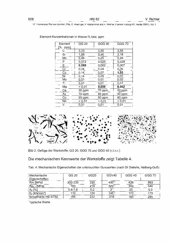
608 HM 82 V. Richter
• International Plansee Seminar, Eds. G. Kneringer, P. Rôdhammer and H. Wildner, Plansee Holding AG, Reutte (2001), Vol. 2
Element-Konzentrationen in Masse-% bzw. ppm
Element[%, ppml
CSiMnPSCrCuNiMoTiMgCeAsCoNbV
GG20
3,231,680,490,0720,0800,040,140,140,010,01< 0,0130 ppm70 ppm90 ppm<0,010,01
GGG40
3,552,460,250,0250,0020,040,070,050,010,010,05970 ppm80 ppm60 ppm<0,010,01
GGG70
3,552,180,290,0280,0070,051,030,070,020,010,05250 ppm50 ppm80 ppm< 0,010,01
imm
Bild 2: Gefüge der Werkstoffe: GG 20, GGG 70 und GGG 40 (v.l.n.r.)
Die mechanischen Kennwerte der Werkstoffe zeigt Tabelle 4.
Tab. 4: Mechanische Eigenschaften der untersuchten Gusssorten (nach DI Dieterle, Halberg-Guß)
MechanischeEigenschaftenRm [MPa]Rp02fMPalA5 [%1Eo [kN/mm2]Brinellhärte HB 5/750
GG20
200-230185
0,8-1,6110185
GG25
2252190,2130237
GGV40
450"»320"'
3"'145*'218
GGG 40
42830025173160
GGG 70
8935405,0175285
"' typische Werte
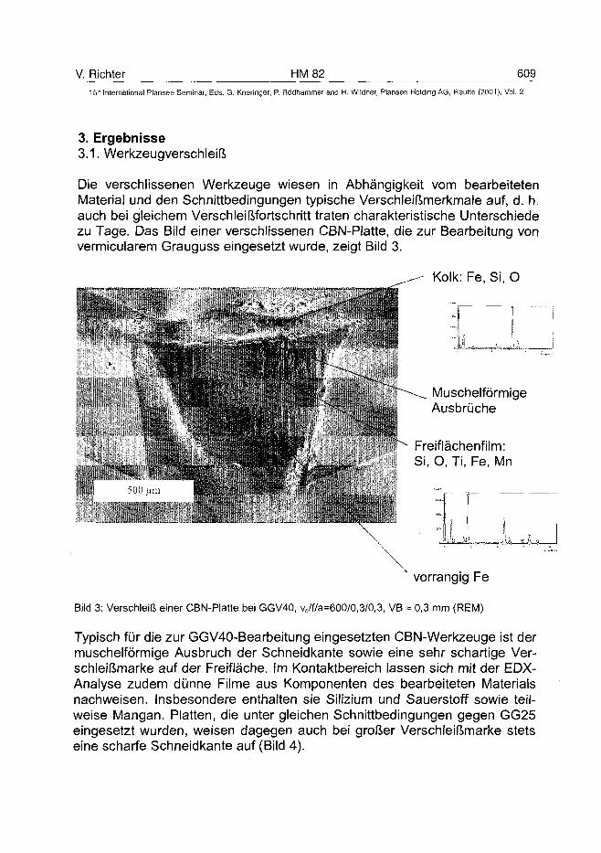
V. Richter HM 82 60915'" International Plansee Seminar, Eds. G. Kneringer, P. Rödhammer and H. Wildner, Plansee Holding AG, Reutte (2001), Vol. 2
3. Ergebnisse3.1. Werkzeugverschleiß
Die verschlissenen Werkzeuge wiesen in Abhängigkeit vom bearbeitetenMaterial und den Schnittbedingungen typische Verschleißmerkmale auf, d. h.auch bei gleichem Verschleißfortschritt traten charakteristische Unterschiedezu Tage. Das Bild einer verschlissenen CBN-Platte, die zur Bearbeitung vonvermicularem Grauguss eingesetzt wurde, zeigt Bild 3.
^ - - Kolk: Fe, Si, O
Müll
Ir!
\
MuschelförmigeAusbrüche
Freiflächenfilm:Si, O, Ti, Fe, Mn
v
v vorrangig Fe
Bild 3: Verschleiß einer CBN-Platte bei GGV40, vc/f/a=600/0,3/0,3, VB = 0,3 mm (REM)
Typisch für die zur GGV40-Bearbeitung eingesetzten CBN-Werkzeuge ist dermuschelförmige Ausbruch der Schneidkante sowie eine sehr schartige Ver-schleißmarke auf der Freifläche. Im Kontaktbereich lassen sich mit der EDX-Analyse zudem dünne Filme aus Komponenten des bearbeiteten Materialsnachweisen. Insbesondere enthalten sie Silizium und Sauerstoff sowie teil-weise Mangan. Platten, die unter gleichen Schnittbedingungen gegen GG25eingesetzt wurden, weisen dagegen auch bei großer Verschleißmarke stetseine scharfe Schneidkante auf (Bild 4).
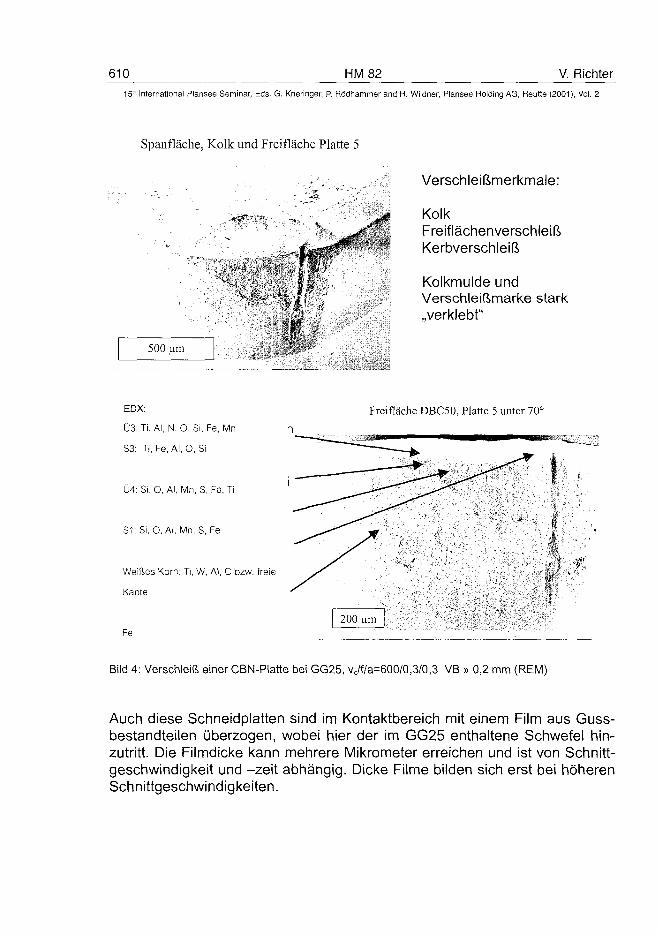
610 HM 82 V. Richter15" International Plansee Seminar, Eds. G. Kneringer, P. Rôdhammer and H. Wildner, Plansee Holding AG, Reutte (2001), Vol. 2
Spanfläche, Kolk und Freifläche Platte 5
500 um
Verschleißmerkmale:
KolkFreiflächenverschleißKerbverschleiß
Kolkmulde undVerschleißmarke stark„verklebt"
EDX:
Ü3: Ti, AI, N, O, Si, Fe, Mn
S3: Ti, Fe, Al, O, Si
Ü4: Si. O, Al, Mn, S, Fe, Ti
S1: Si, O, Al, Mn, S, Fé
Weißes Korn: Ti, W, Al, C bzw. freie
Kante
Fe
Freifläche DBC50, Platte 5 unter 70°
Bild 4: Verschleiß einer CBN-Platte bei GG25, vc/f/a=600/0,3/0,3 VB » 0,2 mm (REM)
Auch diese Schneidplatten sind im Kontaktbereich mit einem Film aus Guss-bestandteilen überzogen, wobei hier der im GG25 enthaltene Schwefel hin-zutritt. Die Filmdicke kann mehrere Mikrometer erreichen und ist von Schnitt-geschwindigkeit und -zeit abhängig. Dicke Filme bilden sich erst bei höherenSchnittgeschwindigkeiten.
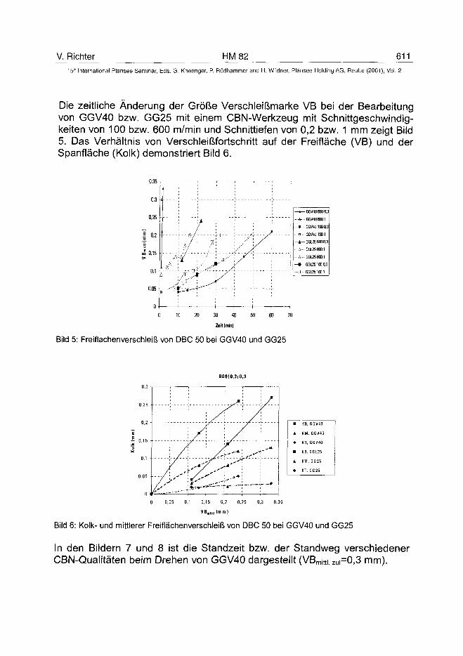
V. Richter HM 82 61115lh International Plansee Seminar, Eds. G. Kneringer, P. Rödhammer and H. Wildner, Plansee Holding AG, Reutte (2001), Vol. 2
Die zeitliche Änderung der Größe Verschleißmarke VB bei der Bearbeitungvon GGV40 bzw. GG25 mit einem CBN-Werkzeug mit Schnittgeschwindig-keiten von 100 bzw. 600 m/min und Schnittiefen von 0,2 bzw. 1 mm zeigt Bild5. Das Verhältnis von Verschleißfortschritt auf der Freifläche (VB) und derSpanfläche (Kolk) demonstriert Bild 6.
- 4 -
- - Ä - -
- » -
. . .& . .
GGV4O6O0O.3
GGV406001
GGV4O1000.3
GGV401G01
—tr- GG1256O00.3
- • • A
• • • A - -
- 1 —
• • • [ } • •
GGL256001
G5L2S6001
GG1251000,3
GG1251001
Bild 5: Freiflachenverschleiß von DBC 50 bei GGV40 und GG25
600/0,3/0.3
• KB,
A KM
• KT.
GGV40
GGV40
GGV40
m KB, GGL25
A KM
• KT,
GG25
G G 25
Bild 6: Kolk- und mittlerer Freiflächenverschleiß von DBC 50 bei GGV40 und GG25
In den Bildern 7 und 8 ist die Standzeit bzw. der Standweg verschiedenerCBN-Qualitäten beim Drehen von GGV40 dargestellt (VBmitti, zui=0,3 mm).
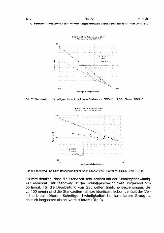
612 HM 82 V. Richter15" International Plansee Seminar, Eds. G. Kneringer, P. Ro'dhammer and H. Wildner, Plansee Holding AG, Reutte (2001), Vol. 2
Standzeil von CBN bei der Bearbeitung von GGV40f=0,3 mmAJ, ap=0,3 mm, VBzul=0,3 mm
100 7 r-
•x.
• DBC50
o- DBN45
X. \ \
Schnittgeschwindigkeit (m/min)
Bild 7: Standzeit und Schnittgeschwindigkeit beim Drehen von GGV40 mit DBC50 und DBN45
Standweg von CBN beim Drehen von GGV40f=0,3 mm/U. ap=0,3 mm. VBzul=0,3 mm
•-DBC50c— DBN45
100100
Schnittgeschwindigkeit (m/min)
Bild 8: Standweg und Schnittgeschwindigkeit beim Drehen von GGV40 mit DBC50 und DBN45
Es wird deutlich, dass die Standzeit sehr schnell mit der Schnittgeschwindig-keit abnimmt. Der Standweg ist der Schnittgeschwindigkeit umgekehrt pro-portional. Für die Bearbeitung von G25 gelten ähnliche Beziehungen. Beivc=100 m/min sind die Standzeiten nahezu identisch, jedoch verläuft der Ver-schleiß bei höheren Schnittgeschwindigkeiten bei lamellarem Graugussdeutlich langsamer als bei vermicularem (Bild 9).
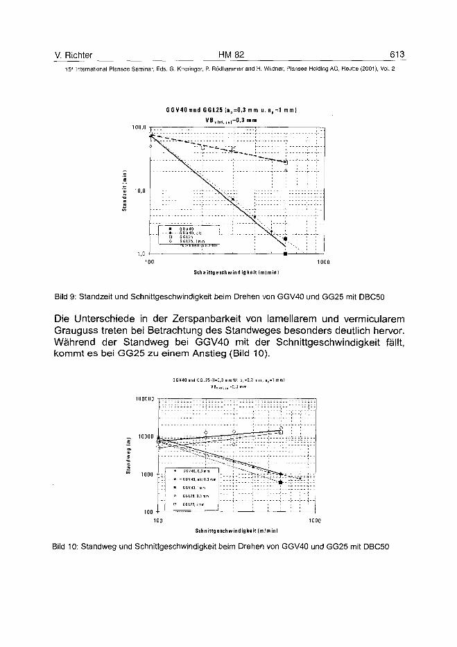
V. Richter HM 82 613
15" International Plansee Seminar, Eds. G. Kneringer, P. Rödhammer and H. Wildner, Plansee Holding AG, Reutte (2001), Vol. 2
00,0
0,0 H
1 n •
G G V 4 0 u n d G G L 2 5 ( a p = 0 , 3 m m u . a
VB m i l l | , , „ i=0 .3 m m
p=1 mm
^ S ^ -T-"?- - ^ ^ u
..N^ £^-4^ [....
:::::::::: :::::?5fc:::t::::: \ , ;
, : N^! • GGV4Û
- - - * - - - G G V 4 Û , a l tD G G L 2 5
| 0 GGL25 , I m m
N ' " " e l " " " 4 " '
' (3 ;
fe ^
•—100 1000
Schnittgeschwindigkeit (mlmini
Bild 9: Standzeit und Schnittgeschwindigkeit beim Drehen von GGV40 und GG25 mit DBC50
Die Unterschiede in der Zerspanbarkeit von lamellarem und vermicularemGrauguss treten bei Betrachtung des Standweges besonders deutlich hervor.Während der Standweg bei GGV40 mit der Schnittgeschwindigkeit fällt,kommt es bei GG25 zu einem Anstieg (Bild 10).
GGV40 und GGL25 l f -0 ,3 mm/U: a , - 0 .3 mm, a „ - l mm}
VBm„n,,„1-0,3 mm
_ 10000 ie
• GGV40, 0,3
• GGV40, alt: 0,3 mm
« GGV40. Imm
O G G 125, 0,3 m m
O SG125. Imm
100 1000
Schnittgeschwindigkeit (m/min)
Bild 10: Standweg und Schnittgeschwindigkeit beim Drehen von GGV40 und GG25 mit DBC50
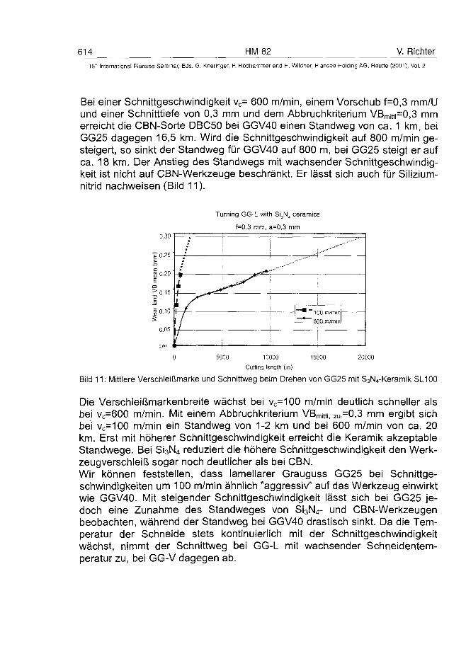
614 HM 82 V. Richter
15'n International Piansee Seminar, Eds. G. Kneringer, P. Rödhammer and H. Wildner, Plansee Holding AG, Reutte (2001), Vol. 2
Bei einer Schnittgeschwindigkeit vc= 600 m/min, einem Vorschub f=0,3 mm/Uund einer Schnitttiefe von 0,3 mm und dem Abbruchkriterium VBmitti=0,3 mmerreicht die CBN-Sorte DBC50 bei GGV40 einen Standweg von ca. 1 km, beiGG25 dagegen 16,5 km. Wird die Schnittgeschwindigkeit auf 800 m/min ge-steigert, so sinkt der Standweg für GGV40 auf 800 m, bei GG25 steigt er aufca. 18 km. Der Anstieg des Standwegs mit wachsender Schnittgeschwindig-keit ist nicht auf CBN-Werkzeuge beschränkt. Er lässt sich auch für Silizium-nitrid nachweisen (Bild 11).
Turning GG-L with Si3N4 ceramics
f=0,3 mm, a=0,3 mm
0,30
-£0.25JE
§0.20Em>0.15C
i 0,10
0,05
;a
i *\
100 m/min
11 , ,
0 5000 10000 15000 20000
Cutting length (m)
Bild 11: Mittlere Verschleißmarke und Schnittweg beim Drehen von GG25 mit S3N4-Keramik SL100
Die Verschleißmarkenbreite wächst bei vc=100 m/min deutlich schneller alsbei vc=600 m/min. Mit einem Abbruchkriterium VBmjtti, ZU|=0,3 mm ergibt sichbei vc=100 m/min ein Standweg von 1-2 km und bei 600 m/min von ca. 20km. Erst mit höherer Schnittgeschwindigkeit erreicht die Keramik akzeptableStandwege. Bei S13N4 reduziert die höhere Schnittgeschwindigkeit den Werk-zeugverschleiß sogar noch deutlicher als bei CBN.Wir können feststellen, dass lamellarer Grauguss GG25 bei Schnittge-schwindigkeiten um 100 m/min ähnlich "aggressiv" auf das Werkzeug einwirktwie GGV40. Mit steigender Schnittgeschwindigkeit lässt sich bei GG25 je-doch eine Zunahme des Standweges von Si3N4- und CBN-Werkzeugenbeobachten, während der Standweg bei GGV40 drastisch sinkt. Da die Tem-peratur der Schneide stets kontinuierlich mit der Schnittgeschwindigkeitwächst, nimmt der Schnittweg bei GG-L mit wachsender Schneidentem-peratur zu, bei GG-V dagegen ab.
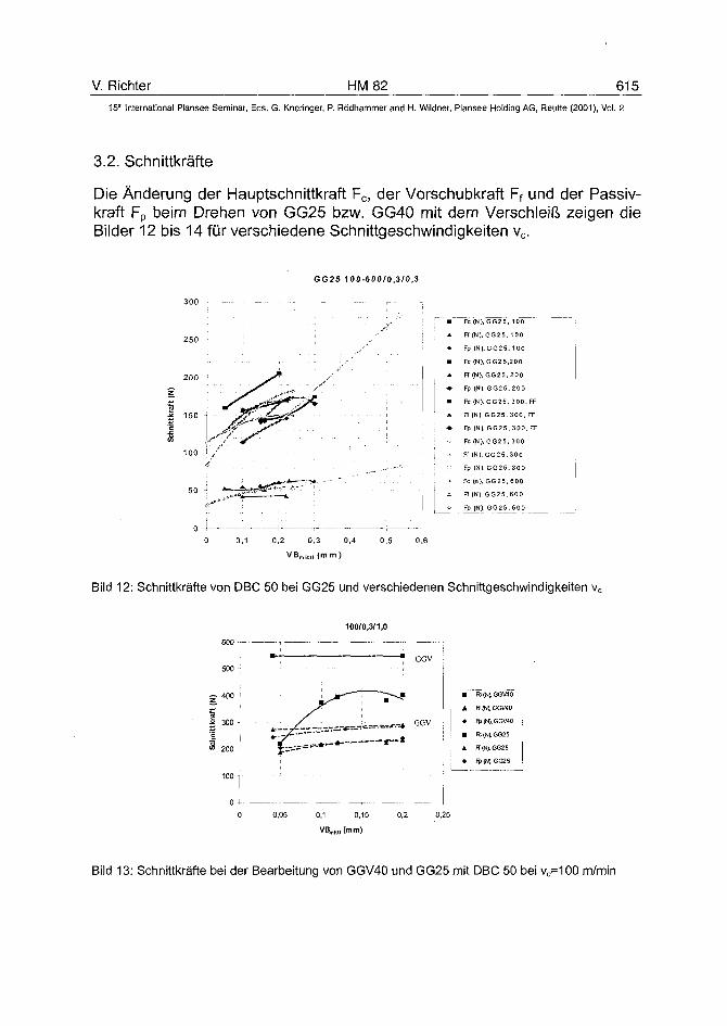
V. Richter HM 82 61515" International Plansee Seminar, Eds. G. Kneringer, P. Rödhammer and H. Wildner, Plansee Holding AG, Reutte (2001), Vol. 2
3.2. Schnittkräfte
Die Änderung der Hauptschnittkraft Fc, der Vorschubkraft Ff und der Passiv-kraft Fp beim Drehen von GG25 bzw. GG40 mit dem Verschleiß zeigen dieBilder 12 bis 14 für verschiedene Schnittgeschwindigkeiten vc.
GG25 100-600/0,3/0,3
250 -
Fc(N). GG25,
Ff (N), GG25.
Fp (N). G G 25
Fc(N), GG2 5
Ff (N), GG25,
Fp (N), GG2 5
FC (N), G G 25
Ff (N). GG25.
Fp (N ). G G 2 5
Fc (N). GG25,
Ff (NJ.GG25.
Fp (N). GG25
Fc (n). GG25.
Ff (N). GG25.
Fp (N), GG2 5
100
100
. 100
200
200
, 200
300. FF
300. FF
. 300, FF
, 300
300
, 300
600
600
, 600
0 0,1 0,2 0,3 0,4 0,5 0,6
VBmit||(mtn)
Bild 12: Schnittkräfte von DBC 50 bei GG25 und verschiedenen Schnittgeschwindigkeiten vc
600
500 -
g 400
tkra
tt
* 200 -
100 -
0
100/0,3/1,0
• ; • GGV
! • j r " — • ~~"--41' •
* ' zf-'- — * ---—-'•--• GGV
-
0,05 0,1 0.15 0,2 0,25
• Fc (N), GGV40
• Fp (NJ. GGV40
• Fc(N),GG25
A Fî (N), GG25
•• Fp (N). GG25
Bild 13: Schnittkräfte bei der Bearbeitung von GGV40 und GG25 mit DBC 50 bei vc=100 m/min
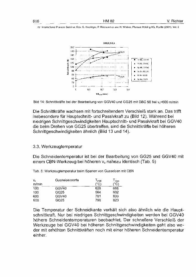
616 HM 82 V. Richter
15s Internationa] Plansee Seminar, Eds. G. Kneringer, P. Rôdhammer and H. Wildner, Plansee Holding AG, Reutte (2001), Vol. 2
600)0,310,3
Bild 14: Schnittkräfte bei der Bearbeitung von GGV40 und GG25 mit DBC 50 bei vc=600 m/min
Die Schnittkräfte wachsen mit fortschreitendem Verschleiß stark an. Das trifftinsbesondere für Hauptschnitt- und Passivkraft zu (Bild 12). Während beiniedrigen Schnittgeschwindigkeiten Hauptschnitt- und Passivkraft bei GGV40die beim Drehen von GG25 übertreffen, sind die Schnittkräfte bei höherenSchnittgeschwindigkeiten ähnlich (Bild 13 und 14).
3.3. Werkzeugtemperatur
Die Schneidentemperatur ist bei der Bearbeitung von GG25 und GGV40 miteinem CBN-Werkzeug bei höheren vc nahezu identisch (Tab. 5)
Tab. 5: Werkzeugtemperatur beim Spanen von Gusseisen mit CBN
Vc
m/min100100600600
Gusseisensorte
GGV40GG25GGV40GG25
Tmrttl
(-C)628564781790
' max
CO668602833823
Die Temperatur der Schneidkante verhält sich also ähnlich wie die Haupt-schnittkraft. Nur bei niedrigen Schnittgeschwindigkeiten werden bei GGV40höhere Schneidentemperaturen beobachtet. Der schnellere Verschleiß derWerkzeuge bei GGV40 bei höheren Schnittgeschwindigkeiten geht also we-der mit erhöhten Schnittkräften noch mit einer höheren Schneidentemperatureinher.
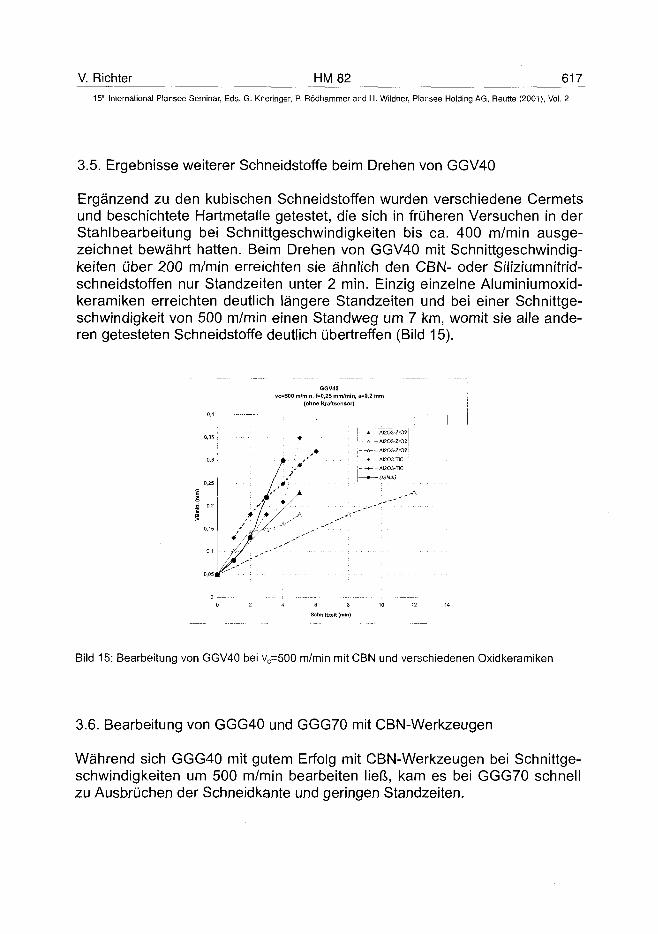
V. Richter HM 82 61715'" International Plansee Seminar, Eds. G. Kneringer, P. Rödhammer and H. Wildner, Plansee Holding AG, Reutte (2001), Vol. 2
3.5. Ergebnisse weiterer Schneidstoffe beim Drehen von GGV40
Ergänzend zu den kubischen Schneidstoffen wurden verschiedene Cermetsund beschichtete Hartmetalle getestet, die sich in früheren Versuchen in derStahlbearbeitung bei Schnittgeschwindigkeiten bis ca. 400 m/min ausge-zeichnet bewährt hatten. Beim Drehen von GGV40 mit Schnittgeschwindig-keiten über 200 m/min erreichten sie ähnlich den CBN- oder Siliziumnitrid-schneidstoffen nur Standzeiten unter 2 min. Einzig einzelne Aluminiumoxid-keramiken erreichten deutlich längere Standzeiten und bei einer Schnittge-schwindigkeit von 500 m/min einen Standweg um 7 km, womit sie alle ande-ren getesteten Schneidstoffe deutlich übertreffen (Bild 15).
vc=500 m/min,(ohi
•
f /I s
6GV40f=0,25 mm/min,
ne Kraftsensor)a=0,2 mm
* AI203-ZO2
\ A ~AI2O3-ZrO2
,--A--AI2O3-ZrO2
* AI2O3-TÏC
j--«--AI2O3-TiC
i • — D8AM5
Bild 15: Bearbeitung von GGV40 bei vc=500 m/min mit CBN und verschiedenen Oxidkeramiken
3.6. Bearbeitung von GGG40 und GGG70 mit CBN-Werkzeugen
Während sich GGG40 mit gutem Erfolg mit CBN-Werkzeugen bei Schnittge-schwindigkeiten um 500 m/min bearbeiten ließ, kam es bei GGG70 schnellzu Ausbrüchen der Schneidkante und geringen Standzeiten.
618 HM 82 V. Richter15" International Plansee Seminar, Eds. G. Kneringer, P. Rödhammer and H. Wildner, Plänsee Holding AG, Reutte (2001), Vol. 2
4. Diskussion
Beim Drehen von GG25 und GGV40 mit CBN mit Schnittgeschwindigkeitenvc=100 ... 800 m/min und VBmitti, zul=0,2 mm wird die Standzeit durch den Frei-flächenverschleiß bestimmt. Bei vc=100 m/min ergibt sich bei GGV40 einehöhere Standzeit als bei GG25, bei höherer Schnittgeschwindigkeit ist sie beiGGV40 jedoch deutlich geringer als bei GG25.Schnittkräfte und Werkzeugtemperatur auf der Spanfläche sind für GG25 undGGV40 bei gleichen Schnittbedingungen nahezu identisch. Die Geometrieder verschlissenen WSP (Ausbildung von Kolk, Freiflächenverschleiß) istähnlich. Unterschiede bestehen in der Zeit, bis sich ein bestimmter Ver-schleißzustand einstellt und der Struktur der verschlissenen Werkzeug-flächen.Beim Drehen von GG25 mit vc=100 m/min ist die Freifläche stark zerklüftet,bei GGV40 relativ glatt. Es bilden sich keine Belegungen auf den Kontakt-flächen des Werkzeugs. Bei vc=600 m/min kommt es bei GGV40 zu Mikro-ausbrüchen der Schneidkante und zur Ausbildung einer zerklüfteten Freiflä-che, während diese bei GG25 glatt erscheint. In beiden Fällen bilden sich aufden Schneidplatten Schichten aus Werkstückbestandteilen (Fe, Si, Mn, Ti,Mg, S) und Sauerstoff, deren Zusammensetzung lokal und zeitlich stark vari-iert. Die Schichten sind beim Drehen mit höheren Schnittgeschwindigkeiten(> 200 m/min) bei GG25 dicker und kompakter und enthalten Schwefel. BeiGGG40 konnten gute Werkzeugstandzeiten auch bei hohen Schnittge-schwindigkeiten erzielt werden, obwohl der Schwefelgehalt ähnlich wie beiGGV40 sehr niedrig ist.Schwarze Keramik (AI2O3-TiC) ist in Standzeit und Verschleißbild dem CBN-TiC-Schneidstoff sehr ähnlich. „Reine" Aluminiumoxidkeramik erreicht beiGGV und vc um 500 m/min höhere Standzeiten als CBN; die Schneidkantezeigt kein „Chipping". Auch bei den beiden Keramiken kommt es zu einerstarken Belagbildung auf den Kontaktflächen.
5. Schlussfolgerungen
Die unterschiedliche Verschleißrate von CBN bei der Bearbeitung von GGund GGV ist ein Effekt der Hochgeschwindigkeitsbearbeitung. Der Unter-schied kann jedoch nicht durch unterschiedliche Schnittkräfte oder unter-schiedliche Schneidentemperaturen erklärt werden. Es wurden keine Anzei-chen dafür gefunden, dass die Verschleißrate primär durch chemische Reak-tionen (mit der Ferritphase etc.) oder durch die Phasenumwandlung von CBN
V. Richter HM 82 619^
15'° International Plansee Seminar, Eds. G. Kneringer, P. Rödhammer and H. Wildner, Plansee Holding AG, Reutte (2001), Vol. 2
bestimmt wird. GGG40 mit einer überwiegend ferritischen Matrix konnte so-gar ausgesprochen gut mit CBN bearbeitet werden.Mit steigender Schnittgeschwindigkeit nehmen beim Drehen von GGV mitCBN Ausbrüche der Schneidkante sowie Riefen und Mikrobrüche im Ver-schleißmarkenbereich zu, was eine mechanische Überlastung andeutet. Beider Bearbeitung von GGG70 ist diese Überlastung eindeutig. Die mechani-sche Zerstörung der Schneidkante könnte durch auftreffende harte Teilchenals Abrasion oder Schockeinwirkung bzw. als Folge einer zyklischen Be-lastung entstehen.Die bei GG mit der Schnittgeschwindigkeit rückläufige Zerklüftung der Freiflä-che deutet auf eine Veränderung der Eigenschaften der abrasiven Bestand-teile und/oder ihrer Einbindung in der Matrix sowie einer schützenden Wir-kung der Schicht hin. Für Schwefel ist ein positiver Einfluss auf Werk-zeugstandzeit beim Spanen von Stahl und Grauguss bekannt, wobei für dieWirkung des Schwefels in der Literatur verschiedene Mechanismen diskutiertwerden (Bildung von Schutzfilmen, Veränderung der Einbindung harter Pha-sen, Verbesserung des Spanbruchs). Man darf annehmen, dass die sichausbildenden Schichten den Verschleiß bremsen, trennen sie doch dieWerkzeugoberfläche von abrasiven Bestandteilen der bearbeiteten Werk-stoffe. Ob sie aber für den prinzipiellen Standzeitunterschied in der Hoch-geschwindigkeitsbearbeitung von GG25 und GGV40 verantwortlich sind,bleibt offen.
Für die GGV-Bearbeitung mit Schnittgeschwindigkeiten um 500 m/min brin-gen AI2O3-Keramiken deutliche Standzeitverbesserungen gegenüber CBN (3bis 7-fach, trocken), erreichen aber nicht die Standzeiten der GG-Bearbei-tung.
Danksagung
Die Arbeiten zur Untersuchung der Werkzeugverschleißmechanismen bei derBearbeitung von vermicularem Grauguss wurden unterstützt durch:Adam Opel AG, AUDI AG, BMW AG, DeBeers Industriediamanten Deutsch-land GmbH, DaimlerChrysler AG, Scania CV AB, Eisenwerk Brühl GmbH,Halberg Guß GmbH und Sintercast GmbH.Die Schneidentemperatur ermittelte Herr Dr. G. Kirchhoff vom FhG-lnstitut fürWerkstoff- und Strahltechnik in Dresden. Herrn Prof. Dr. Brenner und HerrnDr. Luft vom IWS gilt Dank für die stetige Förderung der Arbeiten. Herrn Dipl.-Ing. Dieterle danke ich für die Untersuchung der GGG-Gusswerkstoffe.
AT0100486620 HM83 T. Mertens et al.
15"' International Plansee Seminar, Eds. G. Kneringer, P. Rodhammer and H. Wildner, Plansee Holding AG, Reutte (2001), Vol. 2
In - situ temperature measurement to determine the
machining behaviour of different tool coatings
Thomas Mertens, Gerrit Engering, Michael Lahres, Ulrich Pecher*,Stefan Damm*, Joachim Dorr**, Andreas Huhsam***
DaimlerChrysler AG, Ulm (Germany)
* Institute of Production Engineering and Logistics (IPL), Kassel (Germany)
** Institute of Production Engineering and Machine Tools (PtW), Darmstadt(Germany)
*** Institute of Machine Tools and Production Science (wbk), Karlsruhe (Germany)
BMBF - ProjectNMT-1A732070-03N5013B6
Summary:A research project for the development of dry lubricant coatings for the cuttingtools of different machining operations demanded the generation of certainexperimental techniques to attain knowledge about the coatings behaviour.The solution developed compares the coatings by observing their tempera-ture behaviour during the machining process. A method of in-situ temperaturemeasurement during turning formed the basis of this solution. The method ofmeasurement was further modified for other operations. In addition to thethermographic recording during dry turning, solutions for dry threading, drydrilling and dry milling were also developed. The experimental set-ups weregenerated were generated in collaboration with several project partners. Foreach machining operation investigated, a specific device was developed,which made the in-situ temperature measurement possible using the highresolution thermographic camera.The results were such, that it became possible to attain knowledge about thecoating's in-process temperature behaviour for each of the processes investi-gated. Furthermore the individual coatings are compared among themselvesand with uncoated tools. The combination of the temperature and wearmeasurement yields the possibility for optimisation and further developmentof suitable self-lubricant coated tools for dry machining applications.
T. Mertens et al. HM 83 621
15th International Plansee Seminar, Eds. G. Kneringer, P. Rodhammer and H. Wildner, Plansee Holding AG, Reutte (2001), Vol. 2
Keywords:
Dry lubricant coatings, turning, threading, drilling, milling, dry machining, toolwear, thermographic measurement, in-situ temperature measurement
1. Introduction:Cutting tools, which are used for metal machining operations, are highlystrained by various tribological stresses caused by mechanical and tribo-chemical factors. The thermal load of the tool is interrelated with the afore-mentioned factors. With increasing temperature, tool life decreases. The goalof this work was, to decrease cutting tool wear and increase tool life. Both inthe past and nowadays, there have been many investigations seeking to im-prove tool life. Studies have been undertaken to optimise the cutting sub-strate, the tool cutting geometry and the tool coating.
During the last decade dry machining has achieved increasing importance inseries production due to the associated cost reduction and compliance withstricter environmental legislation. In this regard, a BMBF - Project was initi-ated in 1998 that sought to develop dry lubricant coatings for machining tools.During this project, there was a requirement to develop some devices capableof ,,in - situ temperature measurement". These devices utilise a high resolutionthermographic camera during the different machining operations, thus makingit possible to accumulate knowledge about the temperatures generated duringthe process and to compare the characteristics of different coatings with oneanother. All described temperature measurements were carried out with theThermovision 900 system produced by Agema. The maximum recording fre-quency obtainable in the image recording mode is 30 Hz and up to 2500 Hz inthe line scanning mode. Temperatures measured between -30°C and+2000°C are accurate to within 1°C. The following chapters describe in detail,the experimental set-ups for the different machining operations and examplesof results achieved.
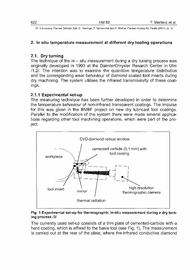
622 HM83 T. Mertens et al.15" International Plansee Seminar, Eds. G. Kneringer, P. Rodhammer and H. Wildner, Plansee Holding AG, Reutte (2001), Vol. 2
2. In situ temperature measurement at different dry tooling operations
2.1. Dry turningThe technique of the in - situ measurement during a dry turning process wasoriginally developed in 1993 at the DaimlerChrysler Resarch Center in Ulm/1,2/. The intention was to examine the quantitive temperature distributionand the corresponding wear behaviour of diamond coated tool inserts duringdry machining. The system utilises the infrared transmissivity of these coat-ings.
2.1.1 Experimental set-upThe measuring technique has been further developed in order to determinethe temperature behaviour of non-infrared transparent coatings. The impulsefor this was given in the BMBF project on new dry lubricant tool coatings.Parallel to the modification of the system there were made several applica-tions regarding other tool machining operations, which were part of the pro-ject.
CVD-diamond optical window
cemented carbide (0,1 mm) withtool coating
workpiece
tool insert ) / high resolutionm i r r o r / thermographic camera
thermal radiation
Fig. 1:Experimental set-up for thermographic in-situ measurement during a dry turn-ing process /3/
The currently used set-up consists of a thin plate of cemented-carbide with ahard coating, which is affixed to the basis-tool (see Fig. 1). The measurementis carried out at the rear of the plate, where the infrared conductive diamond
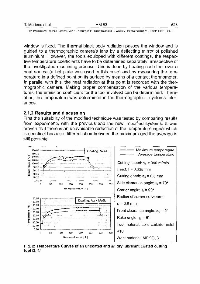
T. Mertens et al. HM83 623
15" International Plansee Seminar, Eds. G. Kneringer, P. Rodhammer and H. Wildner, Plansee Holding AG, Reutte (2001), Vol. 2
window is fixed. The thermal black body radiation passes the window and isguided to a thermographic camera's lens by a deflecting mirror of polishedaluminium. However, the tools equipped with different coatings, the respec-tive temperature coefficients have to be determined separately, irrespective ofthe investigated machining process. This is done by heating each tool over aheat source (a hot plate was used in this case) and by measuring the tem-perature in a defined point on its surface by means of a contact thermometer.In parallel with this, the heat radiation at that point is recorded with the ther-mographic camera. Making proper compensation of the various tempera-tures, the emission coefficient for the tool involved can be determined. There-after, the temperature was determined in the thermographic - systems toler-ances.
2.1.2 Results and discussionFirst the suitability of the modified technique was tested by comparing resultsfrom experiments with the previous and the new, modified systems. It wasproven that there is an unavoidable reduction of the temperature signal whichis uncritical because differentiation between the maximum and the average isstill possible.
180,00160,00
0 140,00— 120,00§ 100,002 80,00S. 60,00
1 40,0020,000,00
180,00160,00
y 140,00i - 120,00| 100,001 80,00S. 60,00I 40,00
20,000,00
^^-^ks^Coating; None
50 100 150 200 250
Measured value [ 1 ]
300 350
50 100 150 200 250
Measured Value [ 1 ]
300 350
Maximum temperatureAverage temperature
Cutting speed: vc = 350 m/min
Feed: f = 0,335 mm
Cutting depth: ap = 0,5 mm
Side clearance angle: Kr = 70°
Comer angle: sr = 90°
Radius of corner curvature:
re = 0,8 mm
Front clearance angle: <xo = 5°
Rake angle: y0 = 6°
Tool material: solid carbide metal
K10
Work material: AISi9Cu3
Fig. 2: Temperature Curves of an uncoated and an dry lubricant coated cuttingtool 13, 4/
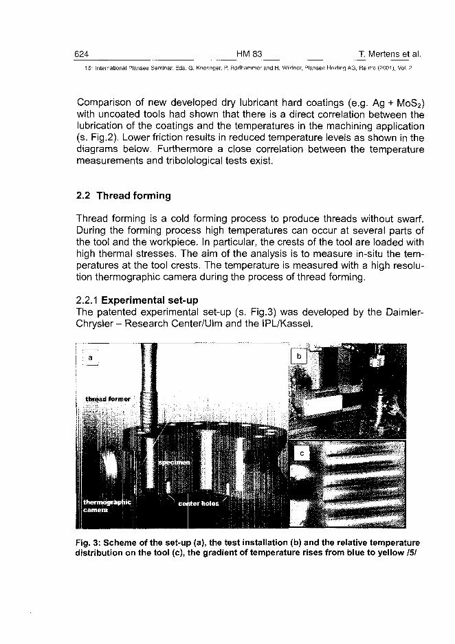
624 HM83 T. Mertens et al.15-' International Plansee Seminar, Eds. G. Kneringer, P. Rodhammer and H. Wildner, Plansee Holding AG, Reutte (2001), Vol. 2
Comparison of new developed dry lubricant hard coatings (e.g. Ag + MoS2)with uncoated tools had shown that there is a direct correlation between thelubrication of the coatings and the temperatures in the machining application(s. Fig.2). Lower friction results in reduced temperature levels as shown in thediagrams below. Furthermore a close correlation between the temperaturemeasurements and tribolological tests exist.
2.2 Thread forming
Thread forming is a cold forming process to produce threads without swarf.During the forming process high temperatures can occur at several parts ofthe tool and the workpiece. In particular, the crests of the tool are loaded withhigh thermal stresses. The aim of the analysis is to measure in-situ the tem-peratures at the tool crests. The temperature is measured with a high resolu-tion thermographic camera during the process of thread forming.
2.2.1 Experimental set-upThe patented experimental set-up (s. Fig.3) was developed by the Daimler-Chrysler- Research Center/Ulm and the IPL/Kassel.
Fig. 3: Scheme of the set-up (a), the test installation (b) and the relative temperaturedistribution on the tool (c), the gradient of temperature rises from blue to yellow 151
T. Mertens et al. HM 83 62515" International Plansee Seminar, Eds. G. Kneringer, P. Rodhammer and H. Wildner, Plansee Holding AG, Reutte (2001), Vol. 2
The test piece is a round blank with a trapezoidal formed groove. The grooveis necessary to avoid disturbance of the optical path during measurementwith the thermographic camera. To prevent reflections at the surface of thetarget, the device is provided with a special thermographic lacquer, so thatonly black body thermal radiation will be recorded. The thermographic cam-era is placed in front of the groove in such a way, that the bottom of thegroove is in-focus.
During the drilling process of the core hole, that will be used for the blind holethread later on, an observation window is cut out of the bottom of the groove.The size of the observation window is slightly smaller than the detection areaof the thermographic camera. The temperature of the drilling tool can now bemeasured by detection of the radiation through an observation window.The observation window allows measurement on the flanks of the thread-former during the forming process. The determination of the tool emissivitycoefficient at different temperatures makes possible the on-line analysis ofabsolute process temperatures.
2.2.2 Results and discussionThe first part of the analysis has been done with M10 threads which are madein Ck45 material. The temperatures of the thread former were measured dur-ing the process using different tool coatings and machining parameters, e.g.pre-drill diameter and forming speed. The thread depth was set to 2xD. Thethreads were made with a tapping attachment and without any lubricant.The thermographic camera image shows the temperature distribution of thethread former. The thermally loaded parts of the tool can be clearly seen. Thetemperature of the crests (yellow and white parts of Fig. 3) are much higherthan the temperatures in the bottom of the thread (dark blue).During the second part of the analysis different dry lubricant coatings weretested using M6 threads, Ck35 material, a thread depth of 0,5xD, a formingspeed of 30 m/min and a pre-drill diameter of 5,55 mm. A reduction of thecrest temperature can be noticed using new dry lubricant coatings. Threadforming with a usual TiN-coating leads to temperatures of about 120°C at thecrests of the tool. Using new dry lubricant coating, temperatures of only 90°Ccould be measured. It has been shown, that a reduction of the thermalstresses using special coatings is possible. The result can be a reduction ofthe wear and an increase in the tool life.
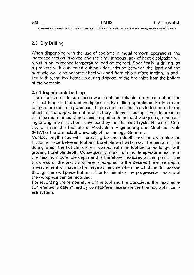
626 HM83 T. Mertens et al.15" International Plansee Seminar, Eds. G. Kneringer, P. Rodhammer and H. Wildner, Plansee Holding AG, Reutte (2001), Vol. 2
2.3 Dry Drilling
When dispensing with the use of coolants in metal removal operations, theincreased friction involved and the simultaneous lack of heat dissipation willresult in an increased temperature load on the tool. Specifically in drilling, asa process with concealed cutting edge, friction between the land and theborehole wall also become effective apart from chip surface friction. In addi-tion to this, the tool heats up during disposal of the hot chips from the bottomof the borehole.
2.3.1 Experimental set-upThe objective of these studies was to obtain reliable information about thethermal load on tool and workpiece in dry drilling operations. Furthermore,temperature recording was used to provide conclusions as to friction-reducingeffects of the application of new tool dry lubricant coatings. For determiningthe maximum temperatures occurring on both tool and workpiece, a measur-ing arrangement has been developed by the DaimlerChrysler Research Cen-tre, Ulm and the Institute of Production Engineering and Machine Tools(PTW) of the Darmstadt University of Technology, Germany.Contact length rises with increasing borehole depth, and therewith also thefriction surface between tool and borehole wall will grow. The period of timeduring which the hot chips are in contact with the tool becomes longer withgrowing borehole depth. Consequently, maximum tool temperature occurs atthe maximum borehole depth and is therefore measured at that point. If thethickness of the test workpiece is adapted to the desired borehole depth,measurement will have to be made at the time when the bit of the drill passesthrough the workpiece bottom. Prior to this also, the progressive heat-up ofthe workpiece can be recorded.For recording the temperature of the tool and the workpiece, the heat radia-tion emitted is determined by contact-free means via the thermographic cam-era system.
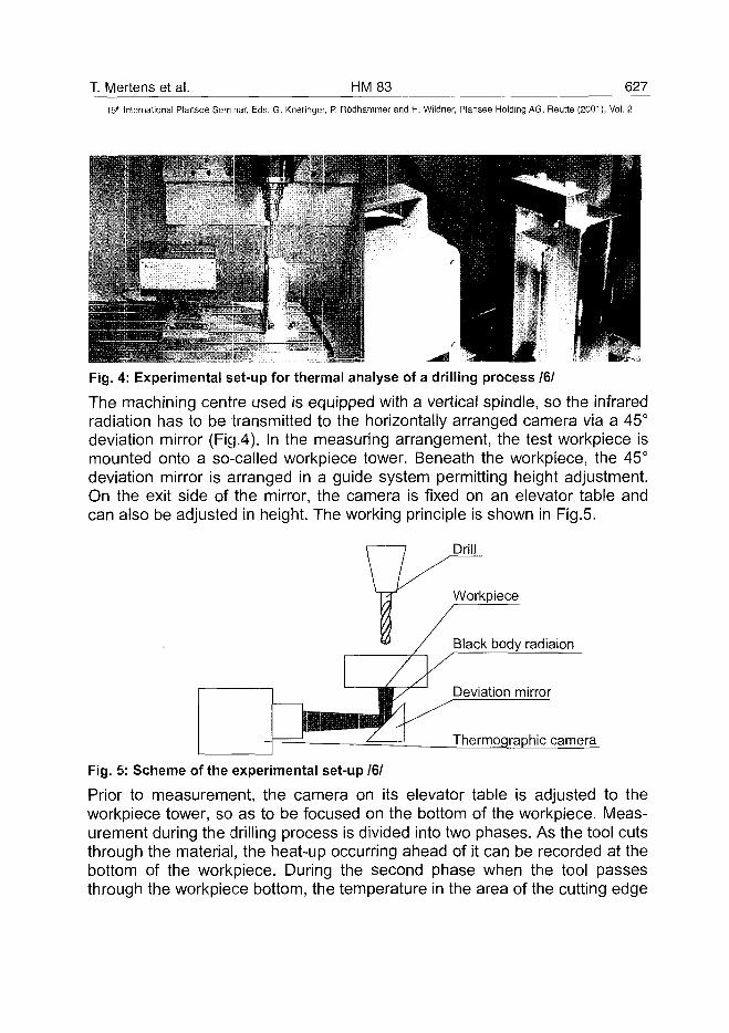
T. Mertens et al. HM 83 62715" International Plansee Seminar, Eds. G. Kneringer, P. Rodhammer and H. Wildner, Plansee Holding AG, Reutte (2001), Vol. 2
Fig. 4: Experimental set-up for thermal analyse of a drilling process 161
The machining centre used is equipped with a vertical spindle, so the infraredradiation has to be transmitted to the horizontally arranged camera via a 45°deviation mirror (Fig.4). In the measuring arrangement, the test workpiece ismounted onto a so-called workpiece tower. Beneath the workpiece, the 45°deviation mirror is arranged in a guide system permitting height adjustment.On the exit side of the mirror, the camera is fixed on an elevator table andcan also be adjusted in height. The working principle is shown in Fig.5.
Drill
Workpiece
Black body radiaion
Deviation mirror
Thermographic camera
Fig. 5: Scheme of the experimental set-up /6/
Prior to measurement, the camera on its elevator table is adjusted to theworkpiece tower, so as to be focused on the bottom of the workpiece. Meas-urement during the drilling process is divided into two phases. As the tool cutsthrough the material, the heat-up occurring ahead of it can be recorded at thebottom of the workpiece. During the second phase when the tool passesthrough the workpiece bottom, the temperature in the area of the cutting edge
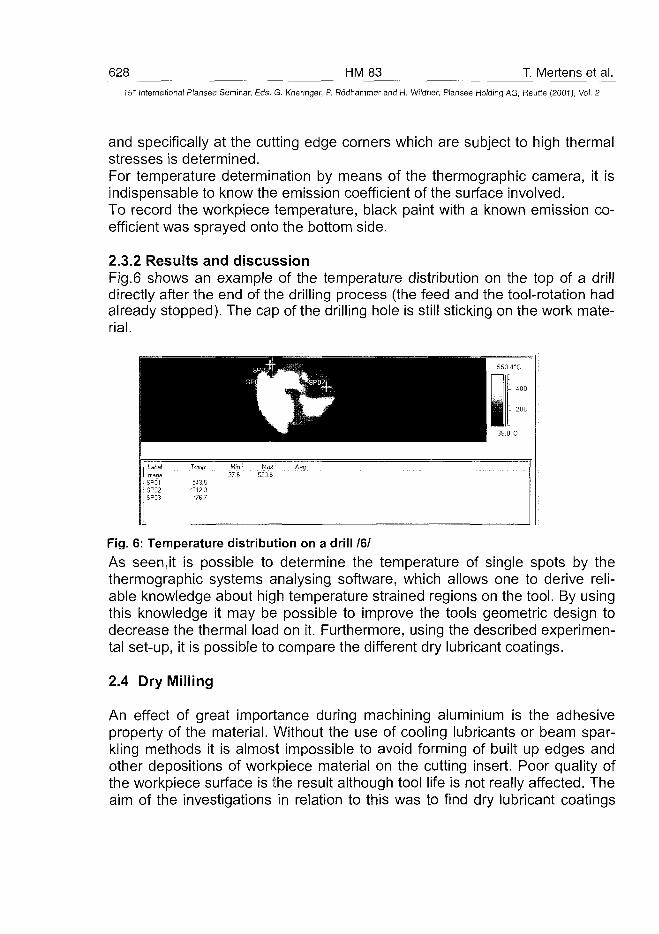
628 HM83 T. Mertens et al.15 r International Plansee Seminar, Eds. G. Kneringer, P. Rodhammer and H. Wildner, Plansee Holding AG, Reutte (2001), Vol. 2
and specifically at the cutting edge corners which are subject to high thermalstresses is determined.For temperature determination by means of the thermographic camera, it isindispensable to know the emission coefficient of the surface involved.To record the workpiece temperature, black paint with a known emission co-efficient was sprayed onto the bottom side.
2.3.2 Results and discussionFig.6 shows an example of the temperature distribution on the top of a drilldirectly after the end of the drilling process (the feed and the tool-rotation hadalready stopped). The cap of the drilling hole is still sticking on the work mate-rial.
Label
Image
SPOTSP02SP03
Temp.
543.5•212.3
"76.7
Min37.6
Max550.6
Avg
Fig. 6: Temperature distribution on a drill 161As seen,it is possible to determine the temperature of single spots by thethermographic systems analysing software, which allows one to derive reli-able knowledge about high temperature strained regions on the tool. By usingthis knowledge it may be possible to improve the tools geometric design todecrease the thermal load on it. Furthermore, using the described experimen-tal set-up, it is possible to compare the different dry lubricant coatings.
2.4 Dry Milling
An effect of great importance during machining aluminium is the adhesiveproperty of the material. Without the use of cooling lubricants or beam spar-kling methods it is almost impossible to avoid forming of built up edges andother depositions of workpiece material on the cutting insert. Poor quality ofthe workpiece surface is the result although tool life is not really affected. Theaim of the investigations in relation to this was to find dry lubricant coatings
T. Mertens et al. HM 83 629^
15" International Plansee Seminar, Eds. G. Kneringer, P. Rodhammer and H. Wildner, Plansee Holding AG, Reutte (2001), Vol. 2
which are appropriate for protecting the milling tools substrate against ma-chining heat and abrasion. Also it is intended to find coatings that are able todiminish adhesion of aluminium on the cutting material, so that dry milling ispossible without loss of workpiece quality and decreasing tool life. One key tofind a suitable coating system is to know the exact process temperature at theworking spot. Because of estimation and experience the conclusion is possi-ble, that milling of aluminium generates rather low temperatures at the work-ing spot because the tool can be touched, for example, by hand immediatelyafter dry machining without causing burns. For the milling of AISi9Cu3, astandard set of machining parameters was used.
2.4.1 Experimental set-upOn account of the high feed rates used for milling of aluminium it is difficult tomeasure temperatures exactly. The main problem was to find a measuringtechnique that is fast enough to detect the cutting inserts temperature on themoving milling head. The solution was to use the already described thermo-graphic system with its high sampling rates moving parallel to the millinghead. The applied test set-up is shown in Figure 7(a). The camera is placedon the outside of the test workpiece, opposite the working spot and the millinghead. The objective lens is focused on a groove on the outside of the work-piece. The groove is necessary to minimize side effects from other infraredradiation sources outside the workpiece, which can influence the accuracy ofthe measurement. The angle between the direction of the milling path and theouter plane of the workpiece is chosen in such a way, that the thickness ofthe dividing wall between camera objective and milling inserts continuouslydecreases during machining. Approaching the end of the milling path imme-diatly before the wall is cut away the thickness of the workpiece-wall is thinenough, that the temperature of the working spot is nearly equal to the wallstemperature. This temperature is detected and recorded by the thermo-graphic system.
Figure 7 (b) shows a radiation-picture taken by the camera in full-scan mode.The white area shows the hottest part of the working spot. In order to get reli-able temperature data the camera was used in line-scan-mode since thesampling rates are 2,5 kHz. The results indicate that temperatures do not ex-ceed 70°C at milling of AISi9Cu3 by applying the parameter-set given inFig. 9.
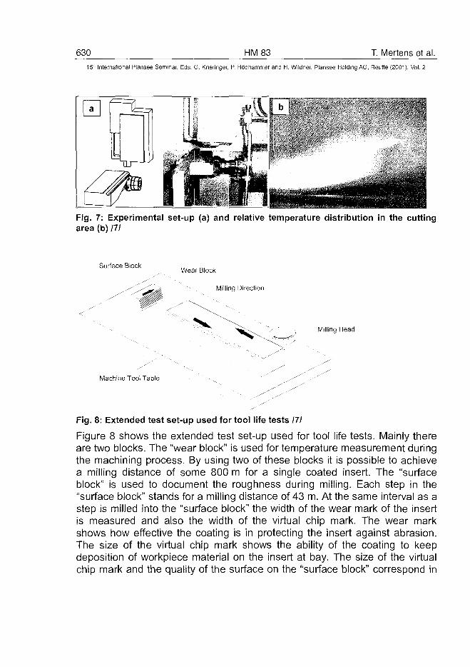
630 HM83 T. Mertens et al.15* International Plansee Seminar, Eds. G. Kneringer, P. Rodhammer and H. Wildner, Plansee Holding AG, Reutte (2001), Vol. 2
Fig. 7: Experimental set-up (a) and relative temperature distribution in the cuttingarea (b) 111
Surface BlockWear Block
Milling Direction
Milling Head
Machine Tool Table
Fig. 8: Extended test set-up used for tool life tests 171
Figure 8 shows the extended test set-up used for tool life tests. Mainly thereare two blocks. The "wear block" is used for temperature measurement duringthe machining process. By using two of these blocks it is possible to achievea milling distance of some 800 m for a single coated insert. The "surfaceblock" is used to document the roughness during milling. Each step in the"surface block" stands for a milling distance of 43 m. At the same interval as astep is milled into the "surface block" the width of the wear mark of the insertis measured and also the width of the virtual chip mark. The wear markshows how effective the coating is in protecting the insert against abrasion.The size of the virtual chip mark shows the ability of the coating to keepdeposition of workpiece material on the insert at bay. The size of the virtualchip mark and the quality of the surface on the "surface block" correspond in
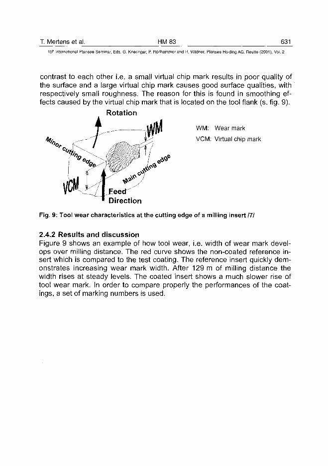
T. Mertens et al. HM 83 631
15lh International Plansee Seminar, Eds. G. Kneringer, P. Rodhammer and H. Wildner, Plansee Holding AG, Reutte (2001), Vol. 2
contrast to each other i.e. a small virtual chip mark results in poor quality ofthe surface and a large virtual chip mark causes good surface qualities, withrespectively small roughness. The reason for this is found in smoothing ef-fects caused by the virtual chip mark that is located on the tool flank (s. fig. 9).
Rotation. . J
WM: Wear mark
VCM: Virtual chip mark
Direction
Fig. 9: Tool wear characteristics at the cutting edge of a milling insert 111
2.4.2 Results and discussionFigure 9 shows an example of how tool wear, i.e. width of wear mark devel-ops over milling distance. The red curve shows the non-coated reference in-sert which is compared to the test coating. The reference insert quickly dem-onstrates increasing wear mark width. After 129 m of milling distance thewidth rises at steady levels. The coated insert shows a much slower rise oftool wear mark. In order to compare properly the performances of the coat-ings, a set of marking numbers is used.
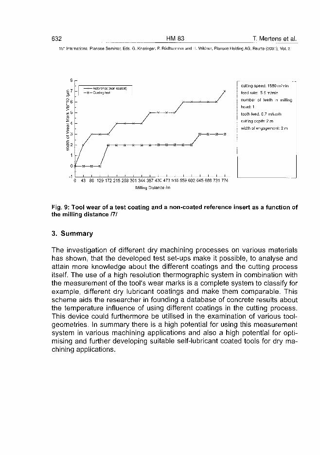
632 HM83 T. Mertens et al.15' International Plansee Seminar, Eds. G. Kneringer, P. Rodhammer and H. Wildner, Plansee Holding AG, Reutte (2001), Vol. 2
cutting speed: 1580 m/min
feed rate: 5.6 m/min
number of teeth in milling
head: 1
tooth feed: 0.7 m/tooth
cutting depth: 2 m
width of engagement: 2 m
0 43 86 129 172 215 258 301344 387 430 473 516 559 602 645 688 731774
Milling Distance /m
Fig. 9: Tool wear of a test coating and a non-coated reference insert as a function ofthe milling distance 171
3. Summary
The investigation of different dry machining processes on various materialshas shown, that the developed test set-ups make it possible, to analyse andattain more knowledge about the different coatings and the cutting processitself. The use of a high resolution thermographic system in combination withthe measurement of the tool's wear marks is a complete system to classify forexample, different dry lubricant coatings and make them comparable. Thisscheme aids the researcher in founding a database of concrete results aboutthe temperature influence of using different coatings in the cutting process.This device could furthermore be utilised in the examination of various tool-geometries. In summary there is a high potential for using this measurementsystem in various machining applications and also a high potential for opti-mising and further developing suitable self-lubricant coated tools for dry ma-chining applications.
T. Mertens et al. HM 83 63315" International Plansee Seminar, Eds. G. Kneringer, P. Rôdhammer and H. Wildner, Plansee Holding AG, Reutte (2001), Vol. 2
4. Acknowledgement
This investigations are funded by the German BMBF - projectNo. NMT- 1A732070-03N5013B6
5. Literature
IM German Patent No. DE 42 33 035 C1, Patentholder: DaimlerChrysler,Inventor: Peter Müller-Hummel
121 Müller - Hummel, Peter; Entwicklung einer Inprozeßtemperaturmeßvor-richtung zur Optimierung der laserunterstützten Zerspanung; For-schungsberichte des IFSW: Laser in der Materialbearbeitung; B.G.Teubner; Stuttgart, Leipzig 1999
13/ Engering, Gerrit (DaimlerChrysler Research Center/Ulm, Germany);presentation of experimental results on the BMBF project meeting atBraunschweig Nov., 28/29. 2000
141 Annual BMBF reports (1998 - 2001 ) on projectNMT - 1A732003N5013B6 (released by the Ministry of Education andResearch)
/5/ Pescher, Ulrich (IPL/Kassel, Germany); presentation of experimentalresults on the BMBF proect meeting at Braunschweig Nov., 28/29. 2000
161 Doerr, Joachim (PtW/Darmstadt, Germany); presentation of experi-mental results on the BMBF project meeting at Braunschweig Nov.,28/29. 2000
111 Huehsam; Andreas (wbk/Kassel, Germany); presentation of experi-mental results on the BMBF project meeting at Braunschweig; Nov.28/29. 2000
AT0100487634 HM85 A. Upadhyaya et al.
15"" International Plansee Seminar, Eds. G. Kneringer, P. Rodhammer and H. Wildner, Plansee Holding AG, Reutte (2001), Vol. 2
IMPROVEMENT IN PROCESSING OF METAL-CUTTING INSERTSTHROUGH SINTERING TIME REDUCTION AND ALLOY DESIGN
Anish Upadhyaya*, Devanathan Sarathy", Gerd Wagner"
Materials & Metallurgical Engineering DepartmentIndian Institute of Technology, Kanpur 208016, INDIA
** WIDIA (India) Ltd., 8/9th Mile Tumkur Road, Bangalore 560073, INDIA
SUMMARY:
This study describes the strategies to reduce the sintering time forhardmetals. It has been shown that the cycle time for consolidating metalcutting grade inserts can be reduced by as much as 70% by employing a fastdewaxing-rapid sintering approach. This study also describes the alloy designapproach to enhance microstructural homogeneity and toughness in fine-grained cemented carbides for metal cutting applications. In fine-grainedhardmetals, combined addition of VC and Cr3C2 in optimal proportion asgrain-growth inhibitors enhances both the hardness as well as indentationfracture toughness. In addition, the synergistic action of these grain-growthinhibitors also results in a more homogeneous microstructure. Consequently,the variation in the mechanical properties of these fine-grained hardmetals issignificantly reduced.
KEYWORDS:Dewaxing, fracture toughness, hardmetals, homogeneity, sintering
1. INTRODUCTION
improved Processing Through Fast SinteringCemented carbides are one of the most important group of sintered tool
materials, owing to their high hardness and outstanding wear resistance [1,2].In earlier days, most of the hardmetal processing was done in reducingatmosphere [3]. However, the control of carbon in hardmetals sintered inhydrogen environment was very difficult, which resulted in inconsistency inproperties and dimensional control [4]. Later on, with advances in furnacemanufacturing technology, most hardmetal sintering was performed invacuum [5]. A typical vacuum furnace in industries is able to sinter up to 200kg of inserts in a single charge. In general, the sintering cycle adopted for
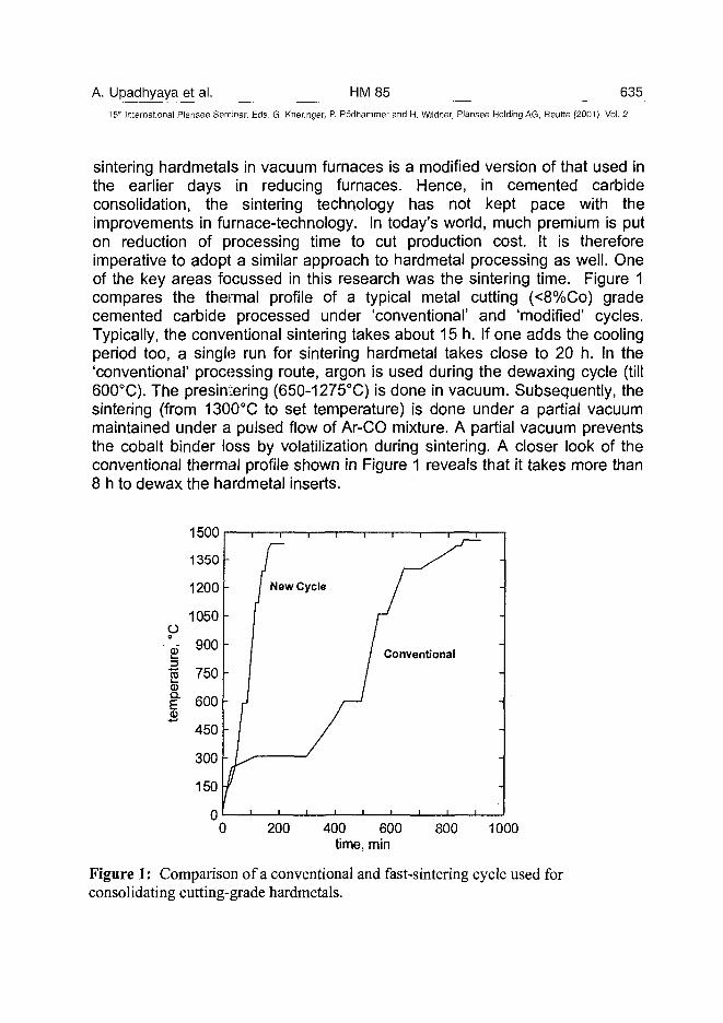
A. Upadhyaya et al. HM85 63515" International Plansee Seminar, Eds. G- Kneringer, P. Rodhammer and H. Wildner, Plansee Holding AG, Reutte (2001), Vol. 2
sintering hardmetals in vacuum furnaces is a modified version of that used inthe earlier days in reducing furnaces. Hence, in cemented carbideconsolidation, the sintering technology has not kept pace with theimprovements in furnace-technology. In today's world, much premium is puton reduction of processing time to cut production cost. It is thereforeimperative to adopt a similar approach to hardmetal processing as well. Oneof the key areas focussed in this research was the sintering time. Figure 1compares the thermal profile of a typical metal cutting (<8%Co) gradecemented carbide processed under 'conventional' and 'modified' cycles.Typically, the conventional sintering takes about 15 h. If one adds the coolingperiod too, a single run for sintering hardmetal takes close to 20 h. In the'conventional' processing route, argon is used during the dewaxing cycle (till600°C). The presintering (650-1275°C) is done in vacuum. Subsequently, thesintering (from 1300°C to set temperature) is done under a partial vacuummaintained under a pulsed flow of Ar-CO mixture. A partial vacuum preventsthe cobalt binder loss by volatilization during sintering. A closer look of theconventional thermal profile shown in Figure 1 reveals that it takes more than8 h to dewax the hardmetal inserts.
200 400 600time, min
800 1000
Figure 1: Comparison of a conventional and fast-sintering cycle used forconsolidating cutting-grade hardmetals.
636 HM85 A. Upadhyaya et al.15" International Plansee Seminar, Eds. G. Kneringer, P. Rodhammer and H. Wildner, Plansee Holding AG, Reutte (2001), Vol. 2
To enhance the flowability into the compaction-die, the hardmetal powderconstituents are agglomerated by spray drying. To facilitate spray drying,about 1.7-2.6% wax is added to the hardmetal powder mixture. Compared tohardmetal processing, most powder injection molded (PIM) parts containmuch higher levels (-40 vol.%) of the same organics [6]. However, theseinjection molded parts are debound in similar timeframe. Dewaxing (ordebinding) is a function of the size and shape of the components. For metal-cutting applications, typically cemented carbide inserts are less than 2 cm3 involume. Hence, it is hypothesized that using the same dewaxing strategies asused in PIM, the dewaxing time of cemented carbides can be significantlyreduced. Consequently, as shown in Figure 1, a new thermal cycle wasproposed for sintering metal-cutting grade hardmetals. Clearly, the totalsintering time is now reduced to about 4 h, which is a about 70% reductionover the conventional cycle.
It is therefore the objective of this research to demonstrate the viability ofsuch a drastic reduction in the sintering time on the microstructurai andperformance integrity hardmetals.
Improved Processing Through Alloy DesignIn fine-grained hardmetals containing sub-micron sized WC grains, use of
cubic carbides, such as VC, Cr3C2, NbC, and TaC as grain-growth inhibitorsis quite common [7,8]. These carbides either form solid solution with the WCor dissolve preferentially into the binder phase, thereby, inhibiting graingrowth through solution-reprecipitation [9]. Most of these alloying additionsincrease the hardness, but adversely affect the toughness of the cementedcarbides. Another concern in the fabrication of fine-grained hardmetals ismicrostructurai homogeneity. The amount of the grain-growth inhibitor in mostsub-micron grain hardmetals is maintained below 1 wt.%. Thus, a uniformdistribution of these additives during processing remains a major challenge.Any non-uniformity in their distribution leads to isolated patches of coarse WCgrains and agglomerated cobalt binder called binder-lakes in themicrostructure. These features are undesirable, as they are the sites ofpremature failure of hardmetals during metal cutting applications throughedge-chipping and cratering.
Amongst the various grain-growth inhibitors, VC is considered to be themost effective [10,11]. In typical metal-cutting grades containing less than 6%cobalt, a higher level of VC (>0.6%) results in drastic reduction in thetoughness. In addition, VC addition is also detrimental to the oxidationresistance at elevated temperatures.
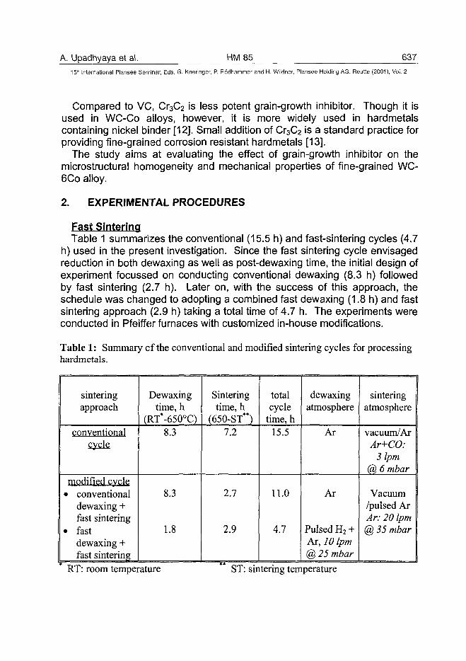
A. Upadhyaya et al. HM85 63715'" International Plansee Seminar, Eds. G. Kneringer, P. Rodhammer and H. Wildner, Plansee Holding AG, Reutte (2001), Vol. 2
Compared to VC, Cr3C2 is less potent grain-growth inhibitor. Though it isused in WC-Co alloys, however, it is more widely used in hardmetalscontaining nickel binder [12]. Small addition of Cr3C2 is a standard practice forproviding fine-grained corrosion resistant hardmetals [13].
The study aims at evaluating the effect of grain-growth inhibitor on themicrostructural homogeneity and mechanical properties of fine-grained WC-6Co alloy.
2. EXPERIMENTAL PROCEDURES
Fast SinteringTable 1 summarizes the conventional (15.5 h) and fast-sintering cycles (4.7
h) used in the present investigation. Since the fast sintering cycle envisagedreduction in both dewaxing as well as post-dewaxing time, the initial design ofexperiment focussed on conducting conventional dewaxing (8.3 h) followedby fast sintering (2.7 h). Later on, with the success of this approach, theschedule was changed to adopting a combined fast dewaxing (1.8 h) and fastsintering approach (2.9 h) taking a total time of 4.7 h. The experiments wereconducted in Pfeiffer furnaces with customized in-house modifications.
Table 1: Summary of the conventional and modified sintering cycles for processinghardmetals.
sinteringapproach
conventionalcycle
modified cvcle• conventional
dewaxing +fast sintering
• fastdewaxing +fast sintering
Dewaxingtime, h
(RT*-650°C)8.3
8.3
1.8
Sinteringtime, h
(650-ST**)7.2
2.7
2.9
totalcycle
time, h15.5
11.0
4.7
dewaxingatmosphere
Ar
Ar
Pulsed H2 +Ar, 10 Ipm@ 25 mbar
sinteringatmosphere
vacuum/ArAr+CO:
3 Ipm@ 6 mbar
Vacuum/pulsed ArAr: 20 Ipm@ 35 mbar
RT: room temperature ST: sintering temperature
638 HM 85 A. Upadhyaya et al.
15:" International Plansee Seminar, Eds. G. Kneringer, P. Rodhammer and H. Wildner, Plansee Holding AG, Reutte (2001), Vol. 2
One of the major concerns during the fast heating is preventing thethermal-lag. To avoid that, holds were provided at specific temperatures tominimize the thermal inertia. Temperature was monitored at six locationswithin the furnace throughout the cycle.
Table 1 also presents the details of the sintering atmosphere, gas-flow,and pressure conditions. Two metal-cutting grades, WC-10TiC-12TaC-1.5NbC-10Co and WC-4.5TiC-3.5TaC-2.2NbC-11.5Co were used for the fastsintering experiments. Experiments were conducted on two insert geometriesSPAN1504EDR and TPKN2204PDR designated according to the ISOStandard [14]. For the fast sintering, repeated experiments were performedwith 95 kg and 130 kg charge corresponding to 65% and 90% of the totalfurnace loading capacity, respectively.
To test for the homogeneity of the properties, the sampling was donefrom the top, middle, and bottom regions from each of the three zones: front,middle and back of the furnace. Hence, in all 27 samples from each sinteringcharge were characterized for porosity, microstructure {coarse WC (amax) andCo-binder distribution (p-lake)}, magnetic properties {coercivity (Hc) andPermeability (47io)}, and hardness. The detailed procedure have beendescribed elsewhere [15].
Alloy DesignThe effect of grain-growth inhibitor addition was studied on WC-6C0 alloys
prepared using a nominal WC grain size of 0.9 urn. Table 2 summarizesvarious compositions of WC-6C0 alloys prepared for this study with VC andCr3C2 additions. In our experiments, VC was doped into WC by adding itduring the carburization-stage of tungsten, while Cr3C2 was added directlyduring the milling stage. In the fine-grained cemented carbides having VCand Cr3C2, the substoichiometric carbon-level was produced by adding acalculated amount of sub-micron tungsten during milling of the carbidepowders and cobalt. The WC-6Co-VC-Cr3C2 alloys were sintered in vacuumat 1520°C for 1h using Pfeiffer furnace. The sintering condition was optimizedto avoid macro-level pores and to restrict the microporosity (< 25 urn) at A02,BOO, and COO levels [16].
The sintered samples were metallographically evaluated and the magneticproperties, namely permeability (4na) and coercivity (Hc) were measured. Thefracture toughness of the hardmetals was measured by the Palmqvistindentation technique. The detailed experimental procedures are providedelsewhere [17].
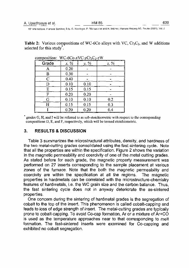
A. Upadhyaya et al. HM85 63915" International Plansee Seminar, Eds. G. Kneringer, P. Rodhammer and H. Wildner, Plansee Holding AG, Reutte (2001), Vol. 2
Table 2: Various compositions of WC-6C0 alloys with VC, Cr3C2, and W additionsselected for this study*.
composition: WC-6Co-xVC-yCr3C2-zWGrade
ABCDEFGHI
x, %0.200.300.400.100.150.200.100.150.20
y,%---
0.100.150.200.100.150.20
z,%------
0.20.30.4
grades G, H, and I will be referred to as sub-stoichiometric with respect to the correspondingcompositions D, E, and F, respectively, which will be termed stoichiometric.
3. RESULTS & DISCUSSION
Table 3 summarizes the microstructural attributes, density, and hardness ofthe two metal-cutting grades consolidated using the fast sintering cycle. Notethat all the properties are within the specification. Figure 2 shows the variationin the magnetic permeability and coercivity of one of the metal cutting grades.As stated before for each grade, the magnetic property measurement wasperformed on 27 inserts corresponding to the sample placement at variouszones of the furnace. Note that the both the magnetic permeability andcoercivity are within the specification at all the regions. The magneticproperties in hardmetals can be correlated with the microstructure-chemistryfeatures of hardmetals, i.e. the WC grain size and the carbon balance. Thus,the fast sintering cycle does not in anyway deteriorate the as-sinteredproperties.
One concern during the sintering of hardmetal grades is the segregation ofcobalt to the top of the insert. This phenomenon is called cobalt-capping andleads to loss of edge strength of insert. The metal-cutting grades are typicallyprone to cobalt-capping. To avoid Co-cap formation, Ar or a mixture of Ar+COis used as the temperature approaches near to that corresponding to meltformation. The fast-sintered inserts were examined for Co-capping andexhibited no cobalt segregation.
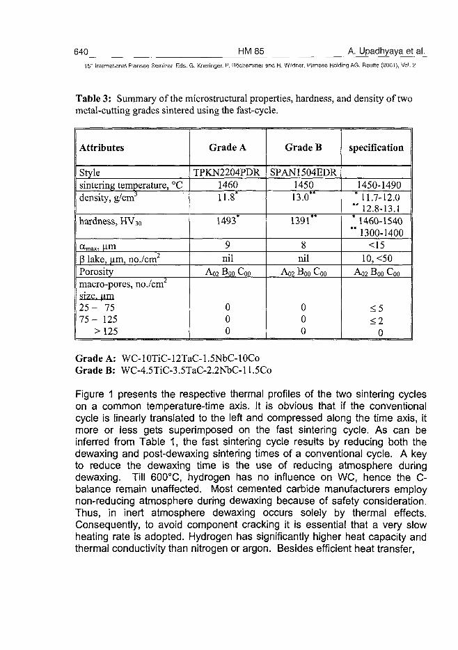
640 HM85 A. Upadhyaya et al.15" International Plansee Seminar, Eds. G. Kneringer, P. Rodhammer and H. Wildner, Plansee Holding A6, Reutte (2001), Vol. 2
Table 3: Summary of the microstructural properties, hardness, and density of twometal-cutting grades sintered using the fast-cycle.
Attributes
Stylesintering temperature, °Cdensity, g/cm
hardness, HV30
cWx, umP lake, \im, no./cm2
Porositymacro-pores, no./cm2
size, um2 5 - 757 5 - 125
> 125
Grade A
TPKN2204PDR146011.8*
1493*
9nil
A02 Boo Coo
000
Grade B
SPAN1504EDR145013.0"
1391"
8nil
A02 Boo Coo
000
specification
1450-1490* 11.7-12.0" 12.8-13.1* 1460-1540** 1300-1400
<1510, <50
A02 Boo Coo
<5<2
0
Grade A: WC-10TiC-12TaC-1.5NbC-10CoGrade B: WC-4.5TiC-3.5TaC-2.2NbC-ll.5Co
Figure 1 presents the respective thermal profiles of the two sintering cycleson a common temperature-time axis. It is obvious that if the conventionalcycle is linearly translated to the left and compressed along the time axis, itmore or less gets superimposed on the fast sintering cycle. As can beinferred from Table 1, the fast sintering cycle results by reducing both thedewaxing and post-dewaxing sintering times of a conventional cycle. A keyto reduce the dewaxing time is the use of reducing atmosphere duringdewaxing. Till 600°C, hydrogen has no influence on WC, hence the re-balance remain unaffected. Most cemented carbide manufacturers employnon-reducing atmosphere during dewaxing because of safety consideration.Thus, in inert atmosphere dewaxing occurs solely by thermal effects.Consequently, to avoid component cracking it is essential that a very slowheating rate is adopted. Hydrogen has significantly higher heat capacity andthermal conductivity than nitrogen or argon. Besides efficient heat transfer,
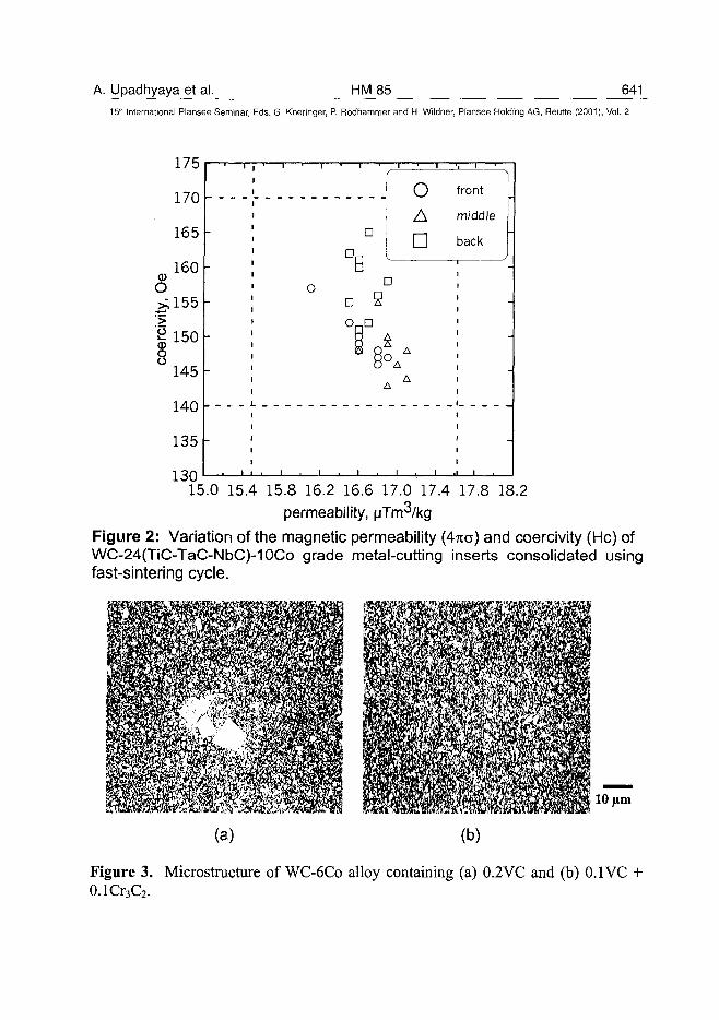
A. Upadhyaya et al. HM85 64115" International Plansee Seminar, Eds. G. Kneringer, P. Rodhammer and H. Wildner, Plansee Holding AG, Reutte (2001), Vol. 2
175
170
165
160<D
o
^155
1 1508
145
140
135
130
•JB
oA•
front
middle
back
D
D SCUD
3O.
i . i . i , i
15.0 15.4 15.8 16.2 16.6 17.0 17.4 17.8 18.2permeability, yTm /kg
Figure 2: Variation of the magnetic permeability (4na) and coercivity (He) ofWC-24(TiC-TaC-NbC)-10Co grade metal-cutting inserts consolidated usingfast-sintering cycle.
10 urn
(a) (b)
Figure 3. Microstructure of WC-6C0 alloy containing (a) 0.2VC and (b) 0.1 VC +0.1Cr3C2.
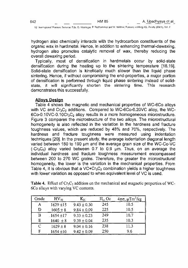
642 HM 85 A. Upadhyaya et al.15" International Plansee Seminar, Eds. G. Kneringer, P. Rodhammer and H. Wildner, Plansee Holding AG, Reutte (2001), Vol. 2
hydrogen also chemically interacts with the hydrocarbon constituents of theorganic wax in hardmetal. Hence, in addition to enhancing thermal-dewaxing,hydrogen also promotes catalytic removal of wax, thereby reducing theoverall dewaxing period.
Typically, most of densification in hardmetals occur by solid-statedensification during the heating up to the sintering temperature [18,19].Solid-state densification is kinetically much slower than the liquid phasesintering. Hence, if without compromising the end-properties, a major portionof densification is performed through liquid phase sintering instead of solid-state, it will significantly shorten the sintering time. This researchdemonstrates this successfully.
Alloys DesignTable 4 shows the magnetic and mechanical properties of WC-6C0 alloys
with VC and Cr3C2 additions. Compared to WC-6Co-0.20VC alloy, the WC-6Co-0.10VC-0.10Cr3C2 alloy results in a more homogeneous microstructure.Figure 3 compares the microstructure of the two alloys. The microstructuralhomogeneity is also reflected in the variation in the hardness and fracturetoughness values, which are reduced by 48% and 70%, respectively. Thehardness and fracture toughness were measured using indentationtechniques [20]. In the present study, the average indentation diagonal lengthvaried between 180 to 190 urn and the average grain size of the WC-Co-VC(-Cr3C2) alloy varied between 0.7 to 0.9 urn. Thus, on an average theindividual hardness and fracture toughness measurement encompassedbetween 200 to 270 WC grains. Therefore, the greater the microstructuralhomogeneity, the lower is the variation in the mechanical properties. FromTable 4, it is obvious that a VC+Cr3C2 combination yields a higher toughnesswith lower variation as opposed to when equivalent level of VC is used.
Table 4. Effect of Cr3C2 addition on the mechanical and magnetic properties of WC-6C0 alloys with varying VC contents.
GradeADBECF
HV30
16291151605 ± 816541171640 ± 81629181654110
Kic
9.43 10.309.8410.099.33 10.239.39 10.049.0410.169.42 10.09
Hc, Oe 1245225249235238250
\nc, nTm3/kg10.510.510.710.311.39.6
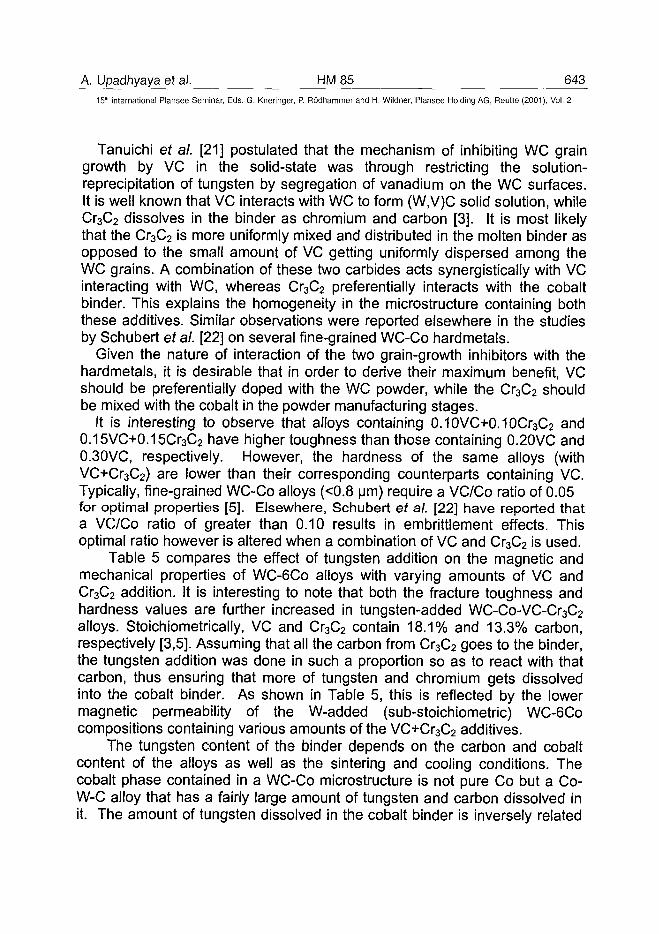
A. Upadhyaya et al. HM 85 643^15" International Plansee Seminar, Eds. G. Kneringer, P. Rodhammer and H. Wildner, Plansee Holding AG, Reutte (2001), Vol. 2
Tanuichi et al. [21] postulated that the mechanism of inhibiting WC graingrowth by VC in the solid-state was through restricting the solution-reprecipitation of tungsten by segregation of vanadium on the WC surfaces.It is well known that VC interacts with WC to form (W,V)C solid solution, whileCr3C2 dissolves in the binder as chromium and carbon [3]. It is most likelythat the Cr3C2 is more uniformly mixed and distributed in the molten binder asopposed to the small amount of VC getting uniformly dispersed among theWC grains. A combination of these two carbides acts synergistically with VCinteracting with WC, whereas Cr3C2 preferentially interacts with the cobaltbinder. This explains the homogeneity in the microstructure containing boththese additives. Similar observations were reported elsewhere in the studiesby Schubert et al. [22] on several fine-grained WC-Co hardmetals.
Given the nature of interaction of the two grain-growth inhibitors with thehardmetals, it is desirable that in order to derive their maximum benefit, VCshould be preferentially doped with the WC powder, while the Cr3C2 shouldbe mixed with the cobalt in the powder manufacturing stages.
It is interesting to observe that alloys containing 0.10VC+0.10Cr3C2 and0.15VC+0.15Cr3C2 have higher toughness than those containing 0.20VC and0.30VC, respectively. However, the hardness of the same alloys (withVC+Cr3C2) are lower than their corresponding counterparts containing VC.Typically, fine-grained WC-Co alloys (<0.8 Mm) require a VC/Co ratio of 0.05for optimal properties [5]. Elsewhere, Schubert et al. [22] have reported thata VC/Co ratio of greater than 0.10 results in embrittlement effects. Thisoptimal ratio however is altered when a combination of VC and Cr3C2 is used.
Table 5 compares the effect of tungsten addition on the magnetic andmechanical properties of WC-6C0 alloys with varying amounts of VC andCr3C2 addition. It is interesting to note that both the fracture toughness andhardness values are further increased in tungsten-added WC-Co-VC-Cr3C2
alloys. Stoichiometrically, VC and Cr3C2 contain 18.1% and 13.3% carbon,respectively [3,5]. Assuming that all the carbon from Cr3C2 goes to the binder,the tungsten addition was done in such a proportion so as to react with thatcarbon, thus ensuring that more of tungsten and chromium gets dissolvedinto the cobalt binder. As shown in Table 5, this is reflected by the lowermagnetic permeability of the W-added (sub-stoichiometric) WC-6C0compositions containing various amounts of the VC+Cr3C2 additives.
The tungsten content of the binder depends on the carbon and cobaltcontent of the alloys as well as the sintering and cooling conditions. Thecobalt phase contained in a WC-Co microstructure is not pure Co but a Co-W-C alloy that has a fairly large amount of tungsten and carbon dissolved init. The amount of tungsten dissolved in the cobalt binder is inversely related
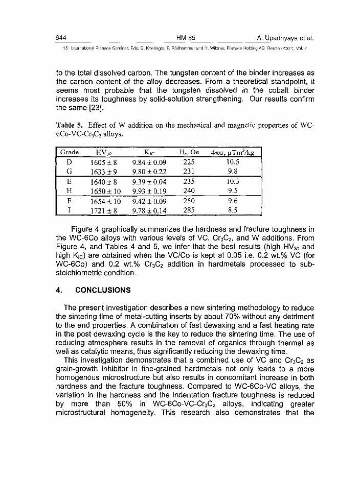
644 HM 85 A. Upadhyaya et al.
15" International Plansee Seminar, Eds. G. Kneringer, P. Rodhammer and H. Wildner, Plansee Holding AG, Reutte (2001), Vol. 2
to the total dissolved carbon. The tungsten content of the binder increases asthe carbon content of the alloy decreases. From a theoretical standpoint, itseems most probable that the tungsten dissolved in the cobalt binderincreases its toughness by solid-solution strengthening. Our results confirmthe same [23].
Table 5. Effect of W addition on the mechanical and magnetic properties of WC-6Co-VC-Cr3C2 alloys.
GradeDGEHFI
HV 3 0
1605 + 81633 ±9
1640 ± 81650 ±101654 ±101721 ± 8
Kic
9.84 ± 0.099.80 + 0.229.39 ± 0.049.93 ±0.199.42 ± 0.099.78 ±0.14
Hc, Oe t
225231235240250285
\n<3, jaTm3/kg
10.59.8
10.39.59.68.5
Figure 4 graphically summarizes the hardness and fracture toughness inthe WC-6C0 alloys with various levels of VC, Cr3C2, and W additions. FromFigure 4, and Tables 4 and 5, we infer that the best results (high HV30 andhigh Kic) are obtained when the VC/Co is kept at 0.05 i.e. 0.2 wt.% VC (forWC-6C0) and 0.2 wt.% Cr3C2 addition in hardmetals processed to sub-stoichiometric condition.
4. CONCLUSIONS
The present investigation describes a new sintering methodology to reducethe sintering time of metal-cutting inserts by about 70% without any detrimentto the end properties. A combination of fast dewaxing and a fast heating ratein the post dewaxing cycle is the key to reduce the sintering time. The use ofreducing atmosphere results in the removal of organics through thermal aswell as catalytic means, thus significantly reducing the dewaxing time.
This investigation demonstrates that a combined use of VC and Cr3C2 asgrain-growth inhibitor in fine-grained hardmetals not only leads to a morehomogenous microstructure but also results in concomitant increase in bothhardness and the fracture toughness. Compared to WC-6C0-VC alloys, thevariation in the hardness and the indentation fracture toughness is reducedby more than 50% in WC-6Co-VC-Cr3C2 alloys, indicating greatermicrostructural homogeneity. This research also demonstrates that the
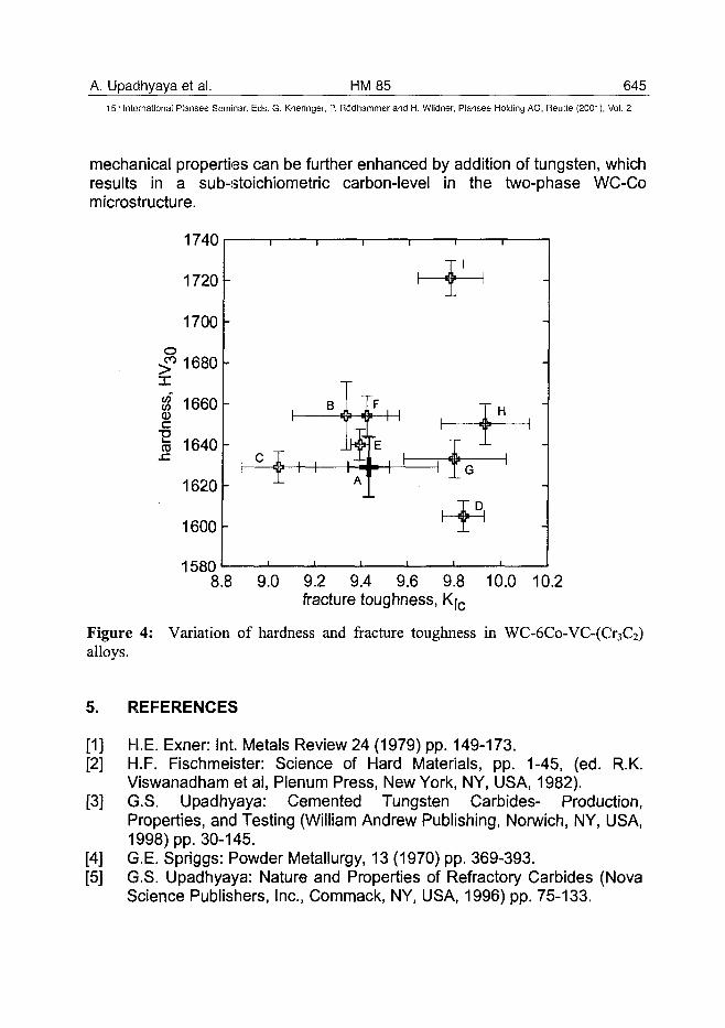
A. Upadhyaya et al. HM85 64515lhl International Plansee Seminar, Eds. G. Kneringer, P. Rodhammer and H. Wildner, Plansee Holding AG, Reutte (2001), Vol. 2
mechanical properties can be further enhanced by addition of tungsten, whichresults in a sub-stoichiometric carbon-level in the two-phase WC-Comicrostructure.
15808.8 9.0 9.2 9.4 9.6 9.8 10.0 10.2
fracture toughness, K|c
Figure 4: Variation of hardness and fracture toughness in WC-6Co-VC-(Cr3C2)alloys.
5. REFERENCES
[1] H.E. Exner: Int. Metals Review 24 (1979) pp. 149-173.[2] H.F. Fischmeister: Science of Hard Materials, pp. 1-45, (ed. R.K.
Viswanadham et al, Plenum Press, New York, NY, USA, 1982).[3] G.S. Upadhyaya: Cemented Tungsten Carbides- Production,
Properties, and Testing (William Andrew Publishing, Norwich, NY, USA,1998) pp. 30-145.
[4] G.E. Spriggs: Powder Metallurgy, 13 (1970) pp. 369-393.[5] G.S. Upadhyaya: Nature and Properties of Refractory Carbides (Nova
Science Publishers, Inc., Commack, NY, USA, 1996) pp. 75-133.
646 HM 85 A. Upadhyaya et al.15" International Plansee Seminar, Eds. G. Kneringer, P. Rodhammer and H. Wildner, Plansee Holding AG, Reutte (2001), Vol. 2
[6] R.M. German: Powder Injection Molding (Metal Powder IndustriesFederation, Princeton, NJ, USA, 1990).
[7] E.A. Almond and B. Roebuck: Metal Powder Report 42 (1987) pp. 512-515.
[8] G.E. Spriggs: Int. J. Refractory Metals Hard Material 13 (1995) pp. 241-255.
[9] G.S. Upadhyaya: Sintered Metallic and Ceramic Materials, (John Wiley,Chichester, UK, 2000), pp. 25-75.
[10] S. Luyckx, C. Osborne, L.A. Cornish, and D.J. Whitefield: PowderMetallurgy 39 (1996) pp. 210-212.
[11] D.J. Whitefield, S. Luyckx, M.J. Witcomb, and L.A. Cornish: Proc. 14th
Int. Plansee Seminar, Vol. 2, pp. 477-484 (ed. G. Kneringer et al,Plansee AG, Reutte, Austria, 1997).
[12] G.S. Upadhyaya and D. Banerjee: Proc. 14th Inter. Plansee Seminar,Vol. 2, pp. 463-476 (ibid. 1997).
[13] D. Banerjee, A. Upadhyaya, and G.S. Upadhyaya: Advances in PowderMetallurgy and Particulate Materials, Vol. 1 pp. 3.99-3.116 (MetalPowder Industries Federation, Princeton, NJ, USA, 1996).
[14] R. Edwards: Cutting Tools (The Institute of Materials, London, UK,1993).
[15] A. Upadhyaya, D. Sarathy, and G. Wagner: Material and Design 22(2001) (in Press).
[16] S. Amberg and H. Doxner: Powder Metallurgy 20 (1977) pp. 1-10.[17] A. Upadhyaya, D. Sarathy, and G. Wagner: Material and Design 22
(2001) (in Press).[18] S. Haglund and J. Agren: Science Sintering 32 (2000) pp. 21-24.[19] A.G.P. DaSilva, W.D. Schubert, and B. Lux: Proceedings 1998 Powder
Metallurgy World Congress & Exhibition, Vol. 4, pp. 99-104 (EPMA,Shrewsbury, UK, 1998).
[20] A. Upadhyaya and G. Wagner: Proc. Powder Metallurgy WorldCongress 2000 (Japan Powder Metallurgy Association, Tokyo, Japan,2000) (in Press).
[21] T. Tanuichi, K. Okada, and T. Tanase: Proc. 14th Int. Plansee Seminar,Vol. 2 pp. 644-657 (ed. G. Kneringer et al, Plansee AG, Reutte, Austria,1997).
[22] W.D. Schubert, H. Neumeister, G. Kinger, and B. Lux: Int. J. RefractoryMaterials and Hard Metals 16 (1998) pp. 133-142.
[23] A. Upadhyaya: Metal Powder Report 55 (2000) pp. 36-39.
ATO100488G.K. Schwenke IJMJ3*? 647
15th International Plansee Seminar, Eds. G. Kneringer, P. Rodhammerand H. Wildner, Plansee Holding AG, Reutte (2001), Vol. 2
THERMODYNAMICS OF THE HYDROGEN-CARBON-OXYGEN-
TUNGSTEN SYSTEM, AS APPLIED TO THE MANUFACTURE OF
TUNGSTEN AND TUNGSTEN CARBIDE
G. Kris Schwenke
OSRAM SYLVANIA Chemical & Metallurgical Products, Towanda, PA, USA
Summary:
The thermodynamics of the quaternary hydrogen-carbon-oxygen-tungstensystem and its binary and ternary sub-systems are reviewed. Publishedthermodynamic data are evaluated, and expressions for free energies offormation are chosen. These expressions are integrated with an equilibrium-calculating algorithm, producing a powerful tool for understanding andimproving the manufacture of tungsten and tungsten carbide. Threeexamples are presented: reduction/carburization of tungstic oxide withhydrogen, carbon, and methane.
Keywords:
Carbide, Equilibrium, HCOW, Model, Reduction, Thermodynamics, Tungsten
1. IntroductionThe manufacture of tungsten requires an understanding of thethermodynamics of systems containing it. To quote Don Parsons (1),
"In order to study... the reduction reactions for the various tungstenoxides with hydrogen, it was first necessary to determine what thestable oxide compositions were. ... Next, it was necessary to studythe thermodynamic quantities, especially the free-energy change,and the equilibrium constant for each of the reduction reactions.This was to show if any thermodynamic limitations were involved inthe reduction reactions."
Similarly, the manufacture of tungsten carbide depends on thethermodynamics of systems containing its constituent elements.
648 HM86 G.K. Schwenke15'-1 International Plansee Seminar, Eds. G. Kneringer, P. Rodhammer and H. Wildner, Plansee Holding AG, Reutte (2001), Vol. 2
Capable reduction and carburization processes have been designed withknowledge of the binary O-W and C-W systems. Carbothermal reduction ismore challenging. It requires understanding the ternary C-O-W system.However, no comprehensive summary of the quaternary H-C-O-W systemhas been published. By considering tungsten and oxygen together with bothhydrogen and carbon, we gain the ability to compare independent reducingand carburizing tendencies and to calculate equilibrium compositions whenalternate reductants/carburizers, such as methane, are used.
The interplay between four components and the existence of multiple oxidesand carbides represent complexities not easily handled by commercialsoftware. After some disappointing results, the present work was undertaken.The goal was to develop a thermodynamic model of this quaternary system(and/or any of its sub-systems) and then demonstrate its utility in processresearch & development.
To do so, published thermodynamic data for tungsten-containing sub-systemswill first be reviewed and evaluated. This is followed by a brief introduction tothe predominance area diagram and the Boudouard equilibrium. Then threeexamples will be presented and discussed: reactions of tungstic oxide withhydrogen, carbon, and methane.
2. Carbon-Tungsten SystemSeveral tungsten carbides have been reported in the literature, but only two -WC and W2C - are important industrially. Gupta (2), Knacke (3), and Worrell(4) all report thermodynamic data for this system. They draw on experimentsinvolving equilibration with carbon-containing systems ranging from H2-CH4 orCO-CO2 gases to Fe-C rods. Their free energies can be converted intophase diagrams, plotting stable phases as functions of temperature andcomposition, for a fixed pressure. Qualitatively, all three resulting diagramsare similar: W2C is stable at high temperatures, but it should decompose intoW and WC below a certain point.
Worrell's numbers result in a temperature of 1327°C. Gupta's give 1339°C,though they claim 1302°C in their paper. Massalski (5) reports a value of1250°C. Knacke's numbers are clearly unacceptable for two reasons: theygive 446°C as the W2C minimum, and they predict that WC will decomposeinto W2C and C above 1370°C. As Worrell's free energy formulations mostclosely approximate Massalski's phase diagram, they are adopted here.
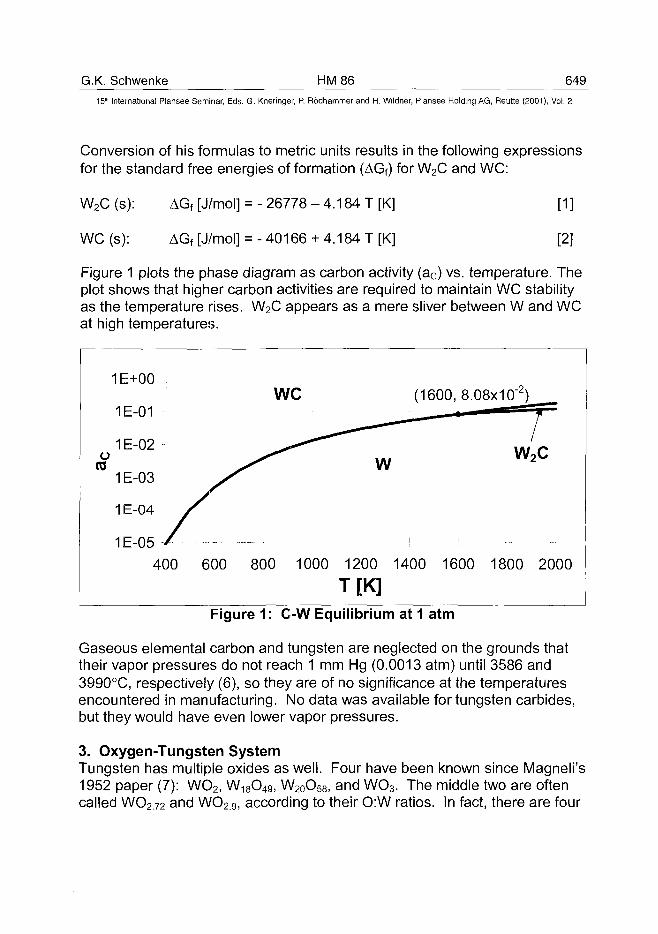
G.K. Schwenke HM 86 64915" International Plansee Seminar, Eds. G. Kneringer, P. Rodhammer and H. Wildner, Plansee Holding AG, Reutte (2001), Vol. 2
Conversion of his formulas to metric units results in the following expressionsfor the standard free energies of formation (AGf) for W2C and WC:
W2C (s): AGf [J/mol] = - 26778 - 4.184 T [K] [1 ]
WC (s): AGf [J/mol] =-40166+ 4.184 T[K] [2]
Figure 1 plots the phase diagram as carbon activity (ac) vs. temperature. Theplot shows that higher carbon activities are required to maintain WC stabilityas the temperature rises. W2C appears as a mere sliver between W and WCat high temperatures.
ore
1E+00
1E-01
1 E-02
1E-03
1E-04 >
1E-05 /
400
WC
600 800 1000
w
1200
T[K]
(1600, 8.08x10"2)
- - =/
W 2
-! !
1400 1600 1800
c
• - -
2000
Figure 1: C-W Equilibrium at 1 atm
Gaseous elemental carbon and tungsten are neglected on the grounds thattheir vapor pressures do not reach 1 mm Hg (0.0013 atm) until 3586 and3990°C, respectively (6), so they are of no significance at the temperaturesencountered in manufacturing. No data was available for tungsten carbides,but they would have even lower vapor pressures.
3. Oxygen-Tungsten SystemTungsten has multiple oxides as well. Four have been known since Magneli's1952 paper (7): WO2, W18O49, W20O58, and WO3. The middle two are oftencalled WO272 and WO29, according to their O:W ratios. In fact, there are four
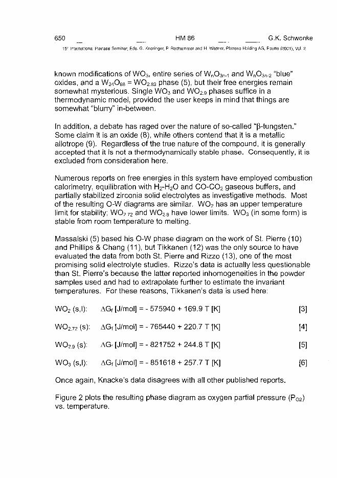
650 HM86 G.K. Schwenke15" International Plansee Seminar, Eds. G. Kneringer, P. Rodhammer and H. Wildner, Plansee Holding AG, Reutte (2001), Vol. 2
known modifications of WO3, entire series of WnO3n-i and WnO3n_2 "blue"oxides, and a W24O68 = WO283 phase (5), but their free energies remainsomewhat mysterious. Single WO3 and WO2.9 phases suffice in athermodynamic model, provided the user keeps in mind that things aresomewhat "blurry" in-between.
In addition, a debate has raged over the nature of so-called "(3-tungsten."Some claim it is an oxide (8), while others contend that it is a metallicallotrope (9). Regardless of the true nature of the compound, it is generallyaccepted that it is not a thermodynamically stable phase. Consequently, it isexcluded from consideration here.
Numerous reports on free energies in this system have employed combustioncalorimetry, equilibration with H2-H2O and CO-CO2 gaseous buffers, andpartially stabilized zirconia solid electrolytes as investigative methods. Mostof the resulting O-W diagrams are similar. WO2 has an upper temperaturelimit for stability; WO272 and WO2.g have lower limits. WO3 (in some form) isstable from room temperature to melting.
Massalski (5) based his O-W phase diagram on the work of St. Pierre (10)and Phillips & Chang (11), but Tikkanen (12) was the only source to haveevaluated the data from both St. Pierre and Rizzo (13), one of the mostpromising solid electrolyte studies. Rizzo's data is actually less questionablethan St. Pierre's because the latter reported inhomogeneities in the powdersamples used and had to extrapolate further to estimate the invarianttemperatures. For these reasons, Tikkanen's data is used here:
WO2 (s,l): AGf [J/mol] = - 575940 + 169.9 T [K] [3]
WO2.72 (s): AGf [J/mol] = - 765440 + 220.7 T [K] [4]
WO29 (s): AGf [J/mol] = - 821752 + 244.8 T [K] [5]
WO3 (s,l): AGf [J/mol] = - 851618 + 257.7 T [K] [6]
Once again, Knacke's data disagrees with all other published reports.
Figure 2 plots the resulting phase diagram as oxygen partial pressure (P02)vs. temperature.
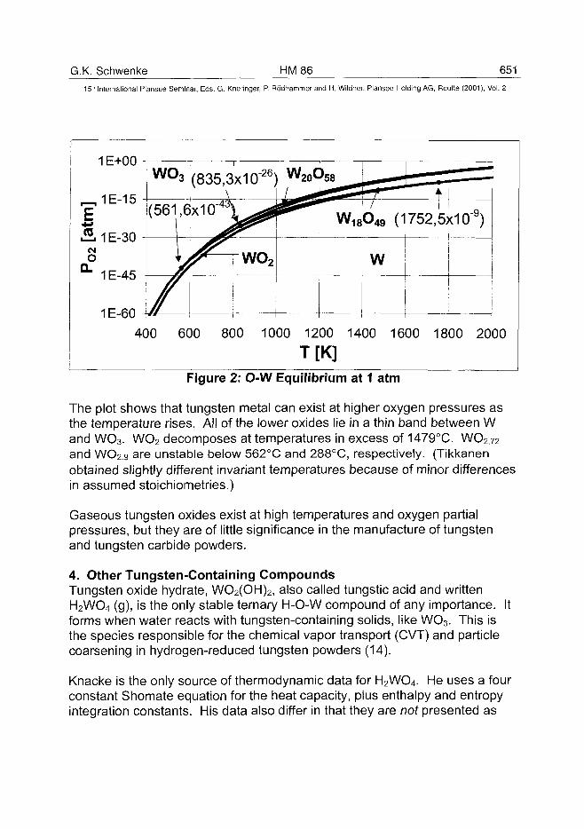
G.K. Schwenke HM86 65115lh International Plansee Seminar, Eds. G. Kneringer, P. Rodhammer and H. Wildner, Plansee Holding AG, Reutte (2001), Vol. 2
1E+00
.2.1E-30CM
o°" 1E-45
1E-60
wo3
(561,6
(835 ,3x1 cr26;X -
•
—w o 2
w2 0o5 8
w1 8o4 9
w
— —'
(1752
—>•»
,5x10" 9 )
400 600 800 1000 1200 1400 1600 1800 2000
T[K]Figure 2: O-W Equilibrium at 1 atm
The plot shows that tungsten metal can exist at higher oxygen pressures asthe temperature rises. All of the lower oxides lie in a thin band between Wand WO3. WO2 decomposes at temperatures in excess of 1479°C. WO2.72and WO2.9 are unstable below 562°C and 288°C, respectively. (Tikkanenobtained slightly different invariant temperatures because of minor differencesin assumed stoichiometries.)
Gaseous tungsten oxides exist at high temperatures and oxygen partialpressures, but they are of little significance in the manufacture of tungstenand tungsten carbide powders.
4. Other Tungsten-Containing CompoundsTungsten oxide hydrate, WO2(OH)2, also called tungstic acid and writtenH2WO4 (g), is the only stable ternary H-O-W compound of any importance. Itforms when water reacts with tungsten-containing solids, like WO3. This isthe species responsible for the chemical vapor transport (CVT) and particlecoarsening in hydrogen-reduced tungsten powders (14).
Knacke is the only source of thermodynamic data for H2WO4. He uses a fourconstant Shomate equation for the heat capacity, plus enthalpy and entropyintegration constants. His data also differ in that they are not presented as
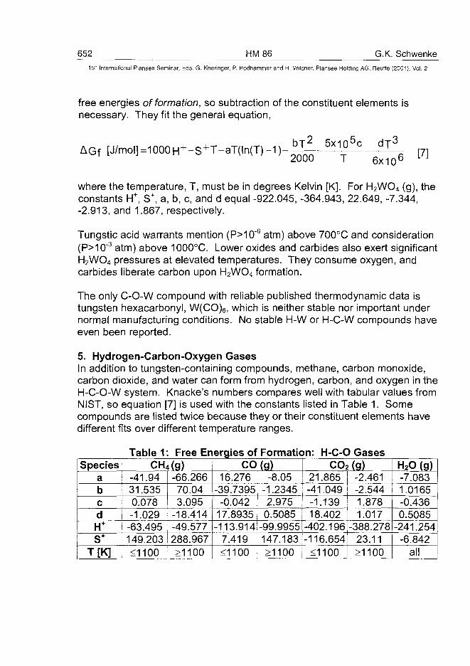
652 HM86 G.K. Schwenke15" International Plansee Seminar, Eds. G. Kneringer, P. Rodhammer and H. Wildner, Plansee Holding AG, Reutte (2001), Vol. 2
free energies of formation, so subtraction of the constituent elements isnecessary. They fit the general equation,
AG f2000 T 6x10b
where the temperature, T, must be in degrees Kelvin [K]. For H2WO4 (g), theconstants H+, S+, a, b, c, and d equal -922.045, -364.943, 22.649, -7.344,-2.913, and 1.867, respectively.
Tungstic acid warrants mention (P>10~6 atm) above 700°C and consideration(P>10~3 atm) above 1000°C. Lower oxides and carbides also exert significantH2WO4 pressures at elevated temperatures. They consume oxygen, andcarbides liberate carbon upon H2WO4 formation.
The only C-O-W compound with reliable published thermodynamic data istungsten hexacarbonyl, W(C0)6, which is neither stable nor important undernormal manufacturing conditions. No stable H-W or H-C-W compounds haveeven been reported.
5. Hydrogen-Carbon-Oxygen GasesIn addition to tungsten-containing compounds, methane, carbon monoxide,carbon dioxide, and water can form from hydrogen, carbon, and oxygen in theH-C-O-W system. Knacke's numbers compares well with tabular values fromNIST, so equation [7] is used with the constants listed in Table 1. Somecompounds are listed twice because they or their constituent elements havedifferent fits over different temperature ranges.
SpeciesabcdH+
S+
T[K]
Table 1 Free Energies ofCH4(g)
-41.9431.5350.078-1.029
-63.495149.203<1100
-66.26670.043.095
-18.414-49.577288.967>1100
Formation: H-C-0 GasesCO(g)
16.276-39.7395
-0.04217.8935-113.914
7.419<1100
-8.05-1.23452.9750.5085
-99.9955147.183£1100
CO2 (g)^21.865-41.049-1.13918.402
-402.196-116.654
<1100
-2.461-2.5441.8781.017
-388.27823.11>1100
_H2PJgJ_-7.0831.0165-0.4360.5085
-241.254-6.842
all
G.K. Schwenke HM 86 65315" International Plansee Seminar, Eds. G. Kneringer, P. Rodhammer and H. Wildner, Plansee Holding AG, Reutte (2001), Vol. 2
6. Predominance Area DiagramsBase & Sale (15) present a "Kellogg (predominance area) diagram" for thecarbon-oxygen-tungsten system with log (ac) on the ordinate axis andlog (P02) on the abscissa. The diagram shows which tungsten-containingphases are stable as a function of carbon activity and oxygen partialpressure. Switching the axes results in plots like Figure 7. The systempressure (1 atm) is the physical limit on P02, though it is far from the graphmaximum. Graphite stability at ac=1 represents the upper limit on carbonactivity. Oxide-oxide equilibria involve only P02, so they appear as horizontallines. Carbide-carbide equilibria involve only ac, so they appear as verticallines. Oxide-carbide equilibria involve both, so their lines are sloped,according to the stoichiometries of the compounds involved.
The basis for this diagram is the Gibbs Phase Rule, which states that thedegrees of freedom, F, available in specifying a system, is related to thenumber of components, C, and phases, P, therein:
F=C-P+2 [8]
For a three component system, like C-O-W, a single phase can exist over arange of both variables. Co-existence of two phases restricts the system toone of the lines, and co-existence of three fixes it at an intersection.
7. Boudouard EquilibriumCarbon and oxygen may react to form carbon monoxide and/or carbondioxide gases. Their combinations exert both an effective oxygen partialpressure and an effective carbon activity:
2 CO (g) + O2 (g) = 2 CO2 (g) [9]
2 CO (g) = C (s) + CO2 (g) [10]
This link between ac and P02 is known as the Boudouard equilibrium. It, too,can be plotted on a log-log plot, such as in Figure 3. Three curves are plotted,spanning total pressures that vary by four orders of magnitude. They arequalitatively similar, downward-sloping lines with knees yielding steeperslopes at the bottom right. Dashed guide lines are also included, indicatingthe limiting cases of pure CO2 (slope of -1 in the upper left at high P02 & lowac) and pure CO (slope o f -2 in the lower right at low P02 & high ac).
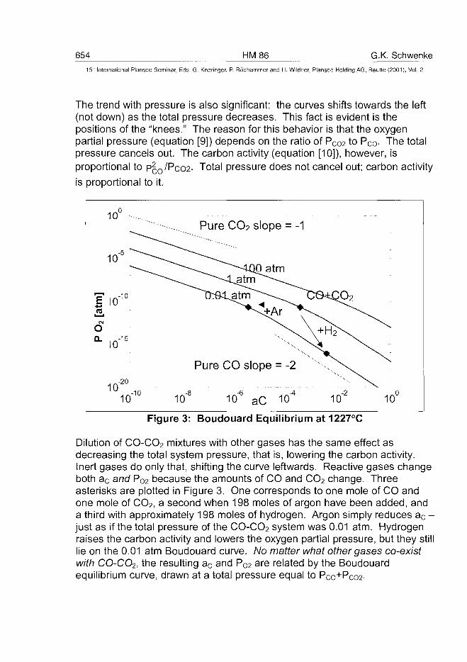
654 HM86 G.K. Schwenke15" International Plansee Seminar, Eds. G. Kneringer, P. Rodhammer and H. Wildner, Plansee Holding AG, Reutte (2001), Vol. 2
The trend with pressure is also significant: the curves shifts towards the left(not down) as the total pressure decreases. This fact is evident is thepositions of the "knees." The reason for this behavior is that the oxygenpartial pressure (equation [9]) depends on the ratio of PCo2 to Pc<> The totalpressure cancels out. The carbon activity (equation [10]), however, isproportional to p£o/Pco2- Total pressure does not cancel out; carbon activityis proportional to it.
r—i
CM
OQ.
1 0 ° •-.
ID"10
io-15
1 O i °o - 1 0
Pure CO2 slope = -1
Pure CO slope = -2 ^ ^ ^
10-8 10-6 aC 10"4 10-2 10°
Figure 3: Boudouard Equilibrium at 1227°C
Dilution of CO-CO2 mixtures with other gases has the same effect asdecreasing the total system pressure, that is, lowering the carbon activity.Inert gases do only that, shifting the curve leftwards. Reactive gases changeboth ac and P02 because the amounts of CO and CO2 change. Threeasterisks are plotted in Figure 3. One corresponds to one mole of CO andone mole of CO2, a second when 198 moles of argon have been added, anda third with approximately 198 moles of hydrogen. Argon simply reduces ac -just as if the total pressure of the CO-CO2 system was 0.01 atm. Hydrogenraises the carbon activity and lowers the oxygen partial pressure, but they stilllie on the 0.01 atm Boudouard curve. No matter what other gases co-existwith CO-CO2, the resulting ac and PO2 are related by the Boudouardequilibrium curve, drawn at a total pressure equal to Pco+Pco2-
G.K. Schwenke HM 86 655^15" International Plansee Seminar, Eds. G. Kneringer, P. Rodhammer and H. Wildner, Plansee Holding AG, Reutte (2001), Vol. 2
Boudouard equilibrium curves may be superimposed on predominance areadiagrams. These reactions are more temperature sensitive than thoseinvolving tungsten-containing solids, so as the temperature rises, theBoudouard curve appears to sink leftwards and lower.
8. Model DetailsBefore presenting sample equilibrium calculations, it is necessary to mentiona few modeling details. Some compromise is necessary in balancing modelbreadth and simplicity. Some tungsten carbides and oxides havetemperature limits discussed in the preceding sections. In addition, somegaseous species may be neglected at certain temperatures. H2WO4 hasbeen discussed above. In addition, CO is unimportant below approximately327°C. CH4 can be neglected above 1427°C. Between these temperaturelimits, a four component (H-C-O-W) system containing thirteen or fourteenpossible species (WO3, WO29, WO272, WO2, W, W2C, WC, C, H2, H2O, CO,CO2, CH4, and perhaps H2WO4) may be specified by nine or ten independentreactions.
Reactions are chosen in a manner which most easily permits definition ofstability regions on predominance area diagrams. Most involve two adjacentphases and oxygen or carbon directly. Four reactions are possible amongthe oxides, and two between the carbides, leaving four more involving gasesand solid carbon.
To carry out the calculation, a program was developed using Matlab™. Itconsists of separate H-C-O, solid C-O-W, and gaseous W modules.Tungsten-containing phases are assumed, the necessary carbon and/oroxygen are subtracted from the system, and equilibrium is computed in theremaining H-C-0 system. If the carbon activity and oxygen pressure so-determined fall within the stability region of the phase(s) assumed, a solutionhas been found. If not, iteration continues with a new guess. Condensedphases are assumed to have unit activities, and gases are assumed ideal.
9. ResultsThree sample cases are presented below: reduction/carburization of WO3
with 3 H2, 3 C, and CH4. Table 2 lists tabular results for temperatures inintervals of 100°C. Figures 4-6 display similar results graphically.
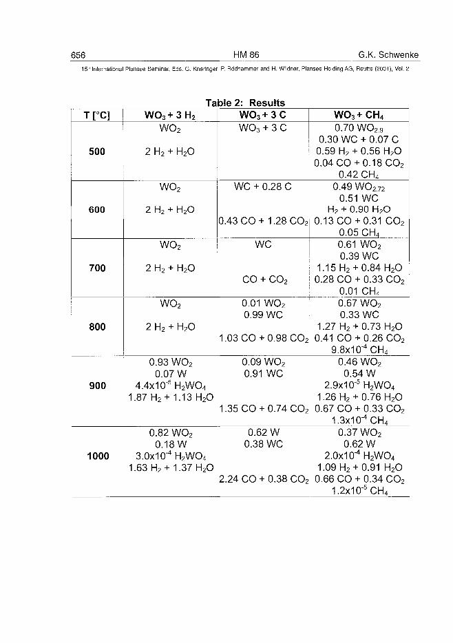
656 HM86 G.K. Schwenke15" International Plansee Seminar, Eds. G. Kneringer, P. Rodhammer and H. Wildner, Plansee Holding AG, Reutte (2001), Vol. 2
Table 2: ResultsT[°C]
500
600
700
800
900
1000
WO3 + 3 H2
WO2
2 H2 + H2O
WO2
2 H2 + H2O
WO2
2 H2 + H2O
WO2
2 H2 + H2O
0.93 WO2
0.07 W4.4x10"5H2WO4
1.87 H2 + 1.13 H2O
0.82 WO2
0.18W3.0x10-4H2WO4
1.63 H2 + 1.37 H2O
WO3 + 3 CWO3 + 3 C
WC + 0.28 C
0.43 CO + 1.28 CO2
WC
CO + CO2
0.01 WO2
0.99 WC
1.03 CO + 0.98 CO2
0.09 WO2
0.91 WC
1.35 CO + 0.74 CO2
0.62 W0.38 WC
2.24 CO + 0.38 CO2
WO3 + CH4
0.70 WO2 90.30 WC + 0.07 C0.59 H2 + 0.56 H2O0.04 CO + 0.18 CO2
0.42 CH4
0.49WO2720.51 WC
H2 + 0.90 H2O0.13 C O + 0.31 CO2
0.05 CH4
0.61 WO2
0.39 WC1.15 H2 + 0.84 H2O
0.28 CO + 0.33 CO2
0.01 CH4
0.67 WO2
0.33 WC1.27 H2 +0.73 H2O
0.41 CO + 0.26 CO2
9.8x10"4CH4
0.46 WO2
0.54 W2.9x10"5H2WO4
1.26 H2 +0.76 H2O0.67 CO + 0.33 CO2
1.3x10"4CH4
0.37 WO2
0.62 W2.0x10"4H2WO4
1.09 H2 +0.91 H2O0.66 CO + 0.34 CO2
1.2x10"5CH4
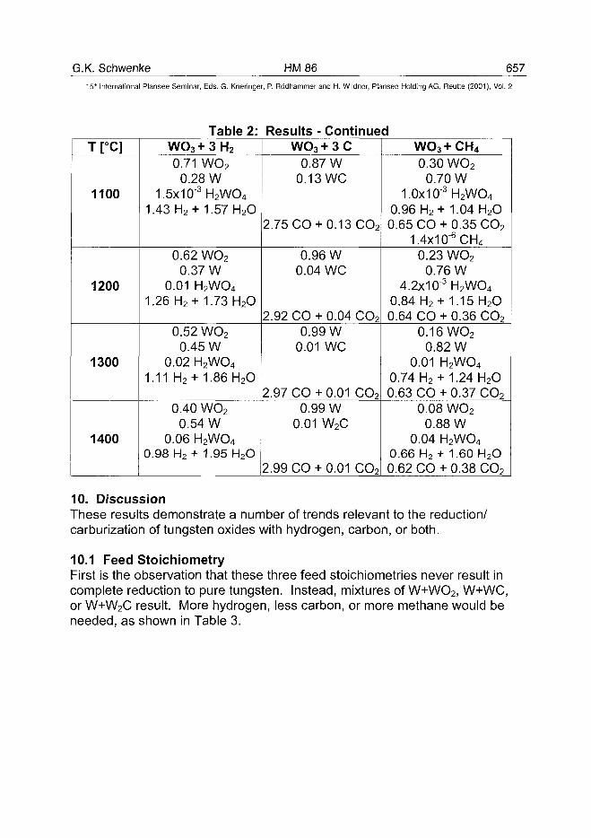
G.K. Schwenke HM86 65715th International Plansee Seminar, Eds. G. Kneringer, P. Rodhammer and H. Wildner, Plansee Holding AG, Reutte (2001), Vol. 2
T[°C]
1100
1200
1300
1400
Table 2:WO3 + 3 H2
0.71 WO2
0.28 W1.5x10"3H2WO4
1.43 H2 + 1.57 H2O
0.62 WO2
0.37 W0.01 H2WO4
1.26H2 + 1.73 H2O
0.52 WO2
0.45 W0.02 H2WO4
1.11 H2 + 1.86 H2O
0.40 WO2
0.54 W0.06 H2WO4
0.98 H2 + 1.95 H2O
Results - ContinuedWO 3 +3C
0.87 W0.13 WC
2.75 CO + 0.13 CO2
0.96 W0.04 WC
2.92 CO + 0.04 CO2
0.99 W0.01 WC
2.97 CO + 0.01 CO2
0.99 W0.01 W2C
2.99 CO + 0.01 CO2
WO3+CH40.30 WO2
0.70 W1.0x10"3H2WO4
0.96 H2+ 1.04 H2O0.65 CO + 0.35 CO2
1.4x10"6CH4
0.23 WO2
0.76 W4.2x10"3H2WO4
0.84 H2 + 1.15 H2O0.64 CO + 0.36 CO2
0.16 WO2
0.82 W0.01 H2WO4
0.74 H2 + 1.24 H2O0.63 CO + 0.37 CO2
0.08 WO2
0.88 W0.04 H2WO4
0.66 H2 + 1.60 H2O0.62 CO + 0.38 CO2
10. DiscussionThese results demonstrate a number of trends relevant to the reduction/carburization of tungsten oxides with hydrogen, carbon, or both.
10.1 Feed StoichiometryFirst is the observation that these three feed stoichiometries never result incomplete reduction to pure tungsten. Instead, mixtures of W+W02, W+WC,or W+W2C result. More hydrogen, less carbon, or more methane would beneeded, as shown in Table 3.
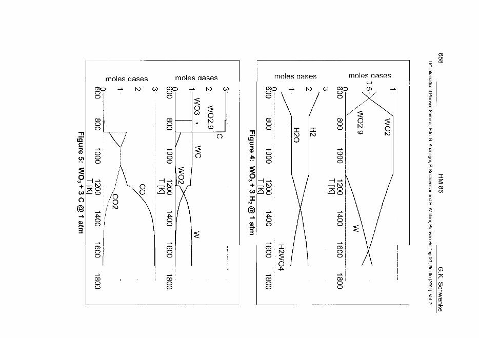
in"jure 5
• "
Ou
CO
o@
fil
3
moles aases moles aases
CDo -»• N> CO CDO -»• l\3 COO i i • O
o
oo
o
1
100
o
- " . 1 V o/o \
nooo
100
o
/
" 8
£ / \ ! -Jo \o 1CDoo
:OAA
w dCO
o
o i
A/ \/ \o
CDoo
CO i CO
o oo o
CO
aioo
goo
COoo
ooo
38
moles aases
-»• N> co
O
ooo
38
16001800
/
o /
oo
16001800
00
p7s
CD
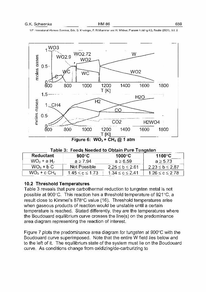
G.K. Schwenke HM86 659
15'h International Plansee Seminar, Eds. G. Kneringer, P. Rodhammer and H. Wildner, Plansee Holding AG, Reutte (2001), Vol. 2
C/3CD03CD
aC/3CUoE
C/3CD03CD
aCD
o
0
1
0
.W03I L~-|
.5
0""
we
600
. 5 —
1 CH4
.5 ^>
600
3,2.9V
we/\800
/<
800
WO2.72• WO2_-
nIj
r~~~~~—
1000
— - - ^
1000
—A
1200T[K]
J
1200T[K1
1400
XCO
CO2
1400
\N ^~-—'. •
WO2
1600 1800
l_ip-jX^QJ.—
H2WO4
1600 1800
Figure 6: WO3 + CH4 @ 1 atm
Table 3: Feeds Needed to Obtain Pure TungstenReductantWO3
wo3W03H
+ a H2
+ bC-cCH 4
900°Ca > 7.94
Not Possible1.45 < c < 1.73
21
1000a > 6
.25 <b
.34 <c
°C.59<2<2
.61
.412.1
1100°Ca > 5.73
23 < b < 226 < c < 2
.87
.78
10.2 Threshold TemperaturesTable 3 reveals that pure carbothermal reduction to tungsten metal is notpossible at 900°C. This reaction has a threshold temperature of 921 °C, aresult close to Kimmel's 878°C value (16). Threshold temperatures arisewhen gaseous products of reaction would be unstable until a certaintemperature is reached. Stated differently, they are the temperatures wherethe Boudouard equilibrium curve crosses the line(s) on the predominancearea diagram representing the reaction of interest.
Figure 7 plots the predominance area diagram for tungsten at 900°C with theBoudouard curve superimposed. Note that the entire W field lies below andto the left of it. The equilibrium state of the system must lie on the Boudouardcurve. As conditions change from oxidizing/de-carburizing to
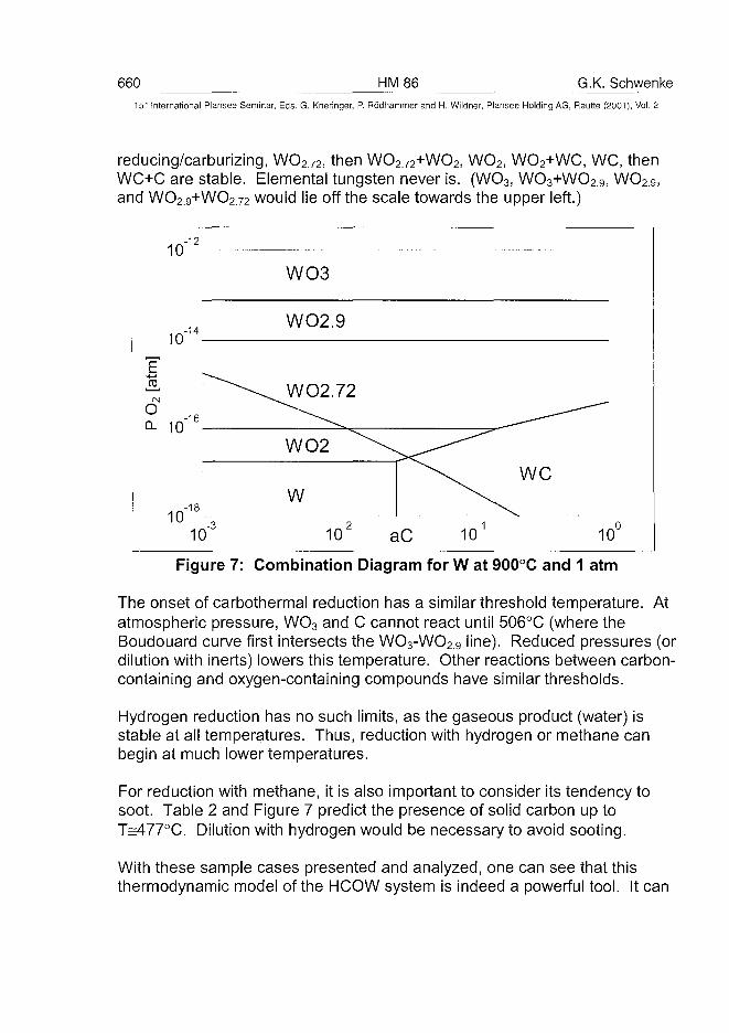
660 HM86 G.K. Schwenke15" International Plansee Seminar, Eds. G. Kneringer, P. Rodhammer and H. Wildner, Plansee Holding AG, Reutte (2001), Vol. 2
reducing/carburizing, WO2.72, then WO272+WO2, WO2, WO2+WC, WC, thenWC+C are stable. Elemental tungsten never is. (WO3, WO3+WO2.9j WO29,and WO2.9+WO2.72 would lie off the scale towards the upper left.)
10-12
WO3
10-14
WO2.9
10 aC 1010
Figure 7: Combination Diagram for W at 900°C and 1 atm
The onset of carbothermal reduction has a similar threshold temperature. Atatmospheric pressure, WO3 and C cannot react until 506°C (where theBoudouard curve first intersects the WO3-WO29 line). Reduced pressures (ordilution with inerts) lowers this temperature. Other reactions between carbon-containing and oxygen-containing compounds have similar thresholds.
Hydrogen reduction has no such limits, as the gaseous product (water) isstable at all temperatures. Thus, reduction with hydrogen or methane canbegin at much lower temperatures.
For reduction with methane, it is also important to consider its tendency tosoot. Table 2 and Figure 7 predict the presence of solid carbon up toT^477°C. Dilution with hydrogen would be necessary to avoid sooting.
With these sample cases presented and analyzed, one can see that thisthermodynamic model of the HCOW system is indeed a powerful tool. It can
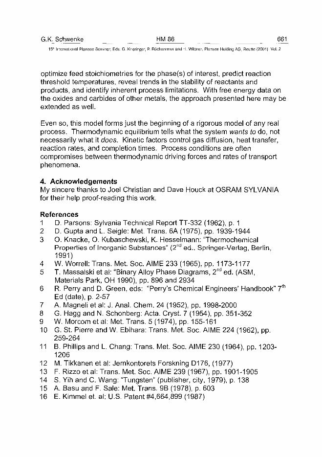
G.K. Schwenke HM 86 661_
15'" International Plansee Seminar, Eds. G. Kneringer, P. Rodhammer and H. Wildner, Plansee Holding AG, Reutte (2001), Vol. 2
optimize feed stoichiometries for the phase(s) of interest, predict reactionthreshold temperatures, reveal trends in the stability of reactants andproducts, and identify inherent process limitations. With free energy data onthe oxides and carbides of other metals, the approach presented here may beextended as well.
Even so, this model forms just the beginning of a rigorous model of any realprocess. Thermodynamic equilibrium tells what the system wants to do, notnecessarily what it does. Kinetic factors control gas diffusion, heat transfer,reaction rates, and completion times. Process conditions are oftencompromises between thermodynamic driving forces and rates of transportphenomena.
4. AcknowledgementsMy sincere thanks to Joel Christian and Dave Houck at OSRAM SYLVANIAfor their help proof-reading this work.
References1 D. Parsons: Sylvania Technical Report TT-332 (1962), p. 12 D. Gupta and L. Seigle: Met. Trans. 6A (1975), pp. 1939-19443 O. Knacke, O. Kubaschewski, K. Hesselmann: "Thermochemical
Properties of Inorganic Substances" (2nd ed., Springer-Verlag, Berlin,1991)
4 W. Worrell: Trans. Met. Soc. AIME 233 (1965), pp. 1173-11775 T. Massalski et al: "Binary Alloy Phase Diagrams, 2nd ed. (ASM,
Materials Park, OH 1990), pp. 896 and 29346 R. Perry and D. Green, eds: "Perry's Chemical Engineers' Handbook" 7th
Ed (date), p. 2-577 A. Magneli et al: J. Anal. Chem. 24 (1952), pp. 1998-20008 G. Hagg and N. Schonberg: Acta. Cryst. 7 (1954), pp. 351-3529 W. Morcom et al: Met. Trans. 5 (1974), pp. 155-16110 G. St. Pierre and W. Ebihara: Trans. Met. Soc. AIME 224 (1962), pp.
259-26411 B. Phillips and L. Chang: Trans. Met. Soc. AIME 230 (1964), pp. 1203-
120612 M. Tikkanen et al: Jernkontorets Forskning D176, (1977)13 F. Rizzo et al: Trans. Met. Soc. AIME 239 (1967), pp. 1901-190514 S. Yin and C. Wang: "Tungsten" (publisher, city, 1979), p. 13815 A. Basu and F. Sale: Met. Trans. 9B (1978), p. 60316 E. Kimmel et. al: U.S. Patent #4,664,899 (1987)
ATO100489662 HM87 G. Andersson et al.
15' International Plansee Seminar, Eds. G. Kneringer, P. Rodhammer and H. Wildner, Plansee Holding AG, Reutte (2001), Vol. 2
THE SOLUBILITY OF CUBIC CARBIDE FORMERS
IN LIQUID COBALT
Gunilla Andersson, Bo Jansson
AB Sandvik Coromant, SE-126 80 Stockholm, Sweden
Summary
Accurate phase diagram and thermodynamic information are essential for theunderstanding and modelling of microstructure evolution. An importantexample is the growth of a binder phase enriched and cubic carbonitride freefunctional gradient in cemented carbides. The growth mechanism of such agradient is controlled by diffusion in the liquid binder and the kinetics dependson gradients in chemical potentials, diffusivities and the solubility in the liquidbinder phase. Available experimental data on the solubility of cubic carbideformers, e.g. Nb, Ta, Ti, and Zr, in the liquid binder phase of cementedcarbides is insufficient for accurate predictions of microstructure evolution.
Therefore, an experimental technique based on heat treatment of acompound of a straight WC-Co grade and a grade further containing a cubiccarbide phase has been developed. The carbide forming metal will diffuseinto the liquid binder of the straight grade without forming any cubic carbide.A state close to the equilibrium can be reached by long time holding. Thus,after cooling the solubility in the liquid binder can be determined by standardmethods. Making sure that graphite or M6C carbide is present in thecompound during the heat treatment controls the carbon content.
The experimental method can also be used to study the kinetics ofdiffusion and surface tension driven viscous flow of the liquid by interruptingthe process before an equilibrium state is reached and analysing gradients inthe WC-Co part of the compound.
Keywords: solubility, Ta, Nb, Ti, liquid Co, cemented carbide, sintering
1. Introduction
Cemented carbides are produced by liquid phase sintering and consist ofgrains of hard hexagonal WC embedded in a more ductile binder phase,usually based on Co. Often other hard phase grains are also present in theform of carbides and nitrides with a cubic structure. The metal composition of
G. Andersson et al. HM 87 66315lh International Plansee Seminar, Eds. G. Kneringer, P. Rodhammer and H. Wildner, Plansee Holding AG, Reutte (2001), Vol. 2
the cubic phase may vary over a wide range but is often a mixture of W, Ti,Ta, and Nb. The size of the hard grains span from less then one to severalmicrometers. The content of binder phase is rather low, typically less than 20vol-%.
A recognised tool in alloy and process development is phase equilibriacalculations based on modelling of the thermodynamic properties of thephases that may form in the system, the so called CALPHAD method (1,2).Accurate thermodynamic information is crucial for understanding andprediction of microstructual evolution during sintering and growth of functionalgradients. For example, the formation of a tough surface zone duringsintering has successfully been simulated as multi-component diffusioncoupled with thermodynamic calculations (3).
Within the Swedish material consortium CAMPADA a thermodynamicdatabase for cemented carbides has been developed (4). Despite theindustrial importance of cemented carbides the phase diagrams and thethermodynamic properties are not too well established. Improvements of thisdatabase require many additional pieces of experimental information. Thepurpose of the present work is to generate new accurate experimentalinformation on the solubility of cubic carbide forming elements in the liquidbinder. The standard method to study the solubility in a liquid is rapid coolingcombined with determination of the compositions in regions where the liquidhas transformed to a mixture of solid phases. This type of methods is notapplicable to cemented carbides since unrealistic high cooling rates areneeded to prevent that carbide-forming elements will precipitate on alreadyexisting carbide grains.
The carbon content of cemented carbides must be carefully controlled.If it is too high free graphite will form. A too low carbon content will result inthe formation of M6C carbide with a composition close to Co3W3C. Bothgraphite and M6C carbide are unwanted since they cause brittleness of thecemented carbide. Alloys with small amounts of M6C carbide or graphiteprovide a mean of studying the limits of the distribution of carbon at well-defined carbon activities.
An experimental technique based on heat treatment of a layeredcompound of a straight WC-Co grade and a grade also containing cubiccarbide has been developed in the present work. During sintering the cubiccarbide phase dissolves and the cubic carbide forming metals will diffuse intothe WC-Co part. However, there is no driving force for nucleation of cubicphase and therefore the diffusion will stop when the equilibrium content isreached. Long time heat treatment will result in equilibrium content of carbideforming metals in the binder of the originally straight WC-Co alloy. However,
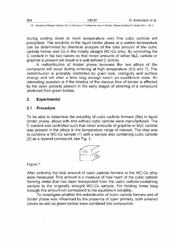
664 HM 87 G. Andersson et al.15" International Plansee Seminar, Eds. G. Kneringer, P. Rodhammer and H. Wildner, Plansee Holding AG, Reutte (2001), Vol. 2
during cooling down to room temperature very fine cubic carbide willprecipitate. The solubility in the liquid binder phase at a certain temperaturecan be determined by chemical analysis of the total amount of the cubiccarbide former and Co in the initially straight WC-Co alloy. By controlling theC content in the two halves so that minor amounts of either M6C carbide orgraphite is present will result in a well-defined C activity.
A redistribution of binder phase between the two alloys of thecompound will occur during sintering at high temperature (5,6 and 7). Theredistribution is probably controlled by grain size, contiguity and surfaceenergy and will after a time long enough reach an equilibrium state. Aninteresting question is if the kinetics of the viscous flow of binder is affectedby the open porosity present in the early stages of sintering of a compoundproduced from green bodies.
2. Experimental
2.1 Procedure
To be able to determine the solubility of cubic carbide formers (Me) in liquidbinder phase, alloys with and without cubic carbide were manufactured. TheC content was controlled such that minor amounts of graphite or M6C carbidewas present in the alloys in the temperature range of interest. The idea wasto combine a WC-Co sample (1) with a sample also containing cubic carbide(2) as a layered compound, see Fig. 1.
(1)(2J
Figure 1.
After sintering the total amount of cubic carbide formers in the WC-Co alloywere measured. This amount is a measure of how much of the cubic carbideforming metal that has been transported from the cubic carbide-containingsample to the originally straight WC-Co sample. For holding times longenough this amount will correspond to the equilibrium solubility.
To investigate whether the redistribution of cubic carbide formers and ofbinder phase was influenced by the presence of open porosity, both sinteredpieces as well as green bodies were combined into compounds.
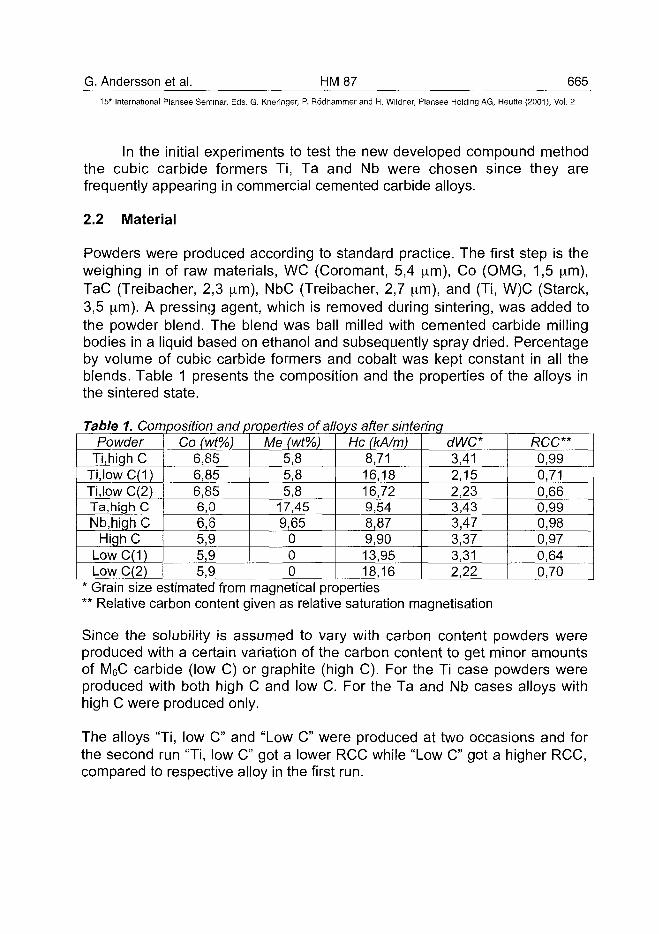
G. Andersson et al. HM87 66515* International Plansee Seminar, Eds. G. Kneringer, P. Rodhammer and H. Wildner, Plansee Holding AG, Reutte (2001), Vol. 2
In the initial experiments to test the new developed compound methodthe cubic carbide formers Ti, Ta and Nb were chosen since they arefrequently appearing in commercial cemented carbide alloys.
2.2 Material
Powders were produced according to standard practice. The first step is theweighing in of raw materials, WC (Coromant, 5,4 ^m), Co (OMG, 1,5 \im),TaC (Treibacher, 2,3 |xm), NbC (Treibacher, 2,7 pirn), and (Ti, W)C (Starck,3,5 \im). A pressing agent, which is removed during sintering, was added tothe powder blend. The blend was ball milled with cemented carbide millingbodies in a liquid based on ethanol and subsequently spray dried. Percentageby volume of cubic carbide formers and cobalt was kept constant in all theblends. Table 1 presents the composition and the properties of the alloys inthe sintered state.
Table 1. Composition and properties of alloys after sinteringPowder
Ti.high CTi,lowC(1)Ti.low C(2)Ta.high CNb.hiqh C
HighCLowC(1)Low C(2)
Co (wt%)6,856,856,856,06,65,95,95,9
Me (wt%)5,85,85,8
17,459,65
000
He (kA/m)8,7116,1816,729,548,879,9013,9518,16
dWC*3,412,152,233,433,473,373,312,22
RCC**0,990,710,660,990,980,970,640,70
* Grain size estimated from magnetical properties** Relative carbon content given as relative saturation magnetisation
Since the solubility is assumed to vary with carbon content powders wereproduced with a certain variation of the carbon content to get minor amountsof M6C carbide (low C) or graphite (high C). For the Ti case powders wereproduced with both high C and low C. For the Ta and Nb cases alloys withhigh C were produced only.
The alloys "Ti, low C" and "Low C" were produced at two occasions and forthe second run "Ti, low C" got a lower RCC while "Low C" got a higher RCC,compared to respective alloy in the first run.
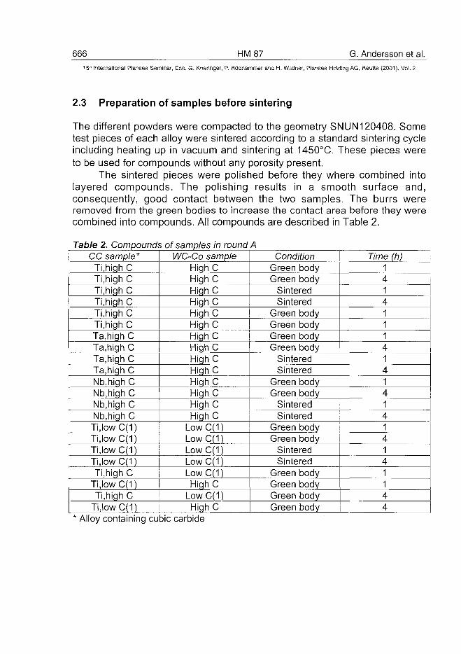
666 HM87 G. Andersson et al.15-': International Plansee Seminar, Eds. G. Kneringer, P. Rodhammer and H. Wildner, Plansee Holding AG, Reutte (2001), Vol. 2
2.3 Preparation of samples before sintering
The different powders were compacted to the geometry SNUN120408. Sometest pieces of each alloy were sintered according to a standard sintering cycleincluding heating up in vacuum and sintering at 1450°C. These pieces wereto be used for compounds without any porosity present.
The sintered pieces were polished before they where combined intolayered compounds. The polishing results in a smooth surface and,consequently, good contact between the two samples. The burrs wereremoved from the green bodies to increase the contact area before they werecombined into compounds. All compounds are described in Table 2.
Table 2. Compounds of samples in round ACC sample*
Ti,high CTi.high CTi.high CTi.high CTi.high CTi.high CTa.high CTa.high CTa.high CTa.high CNb,high CNb.high CNb.high CNb.high CTi,lowC(1)Ti,lowC(1)Ti,lowC(1)Ti,lowC(1)Ti.high C
Ti,lowC(1)Ti.high C
Ti,lowC(1)
WC-Co sampleHighCHighCHighCHighCHighCHighCHighCHighCHighCHighCHighCHighCHighCHighC
LowC(1)LowC(1)LowC(1)LowC(1)LowC(1)HighC
LowC(1)HighC
ConditionGreen bodyGreen body
SinteredSintered
Green bodyGreen bodyGreen bodyGreen body
SinteredSintered
Green bodyGreen body
SinteredSintered
Green bodyGreen body
SinteredSintered
Green bodyGreen bodyGreen bodyGreen body
Time (h)1414111414141414141144
* Alloy containing cubic carbide
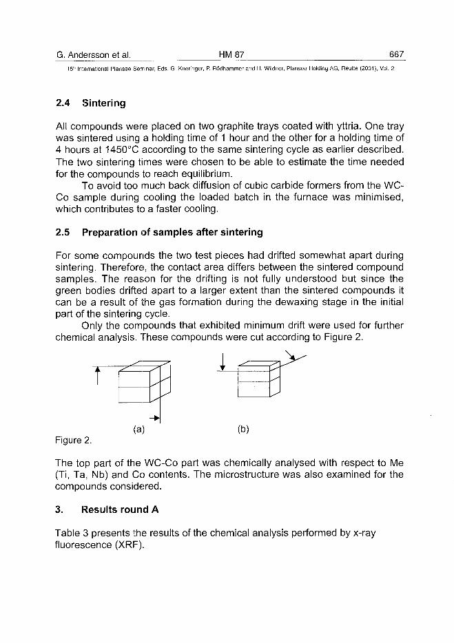
G. Andersson et al. HM87 66715lh International Plansee Seminar, Eds. G. Kneringer, P. Rodhammer and H. Wildner, Plansee Holding AG, Reutte (2001), Vol. 2
2.4 Sintering
Alt compounds were placed on two graphite trays coated with yttria. One traywas sintered using a holding time of 1 hour and the other for a holding time of4 hours at 1450°C according to the same sintering cycle as earlier described.The two sintering times were chosen to be able to estimate the time neededfor the compounds to reach equilibrium.
To avoid too much back diffusion of cubic carbide formers from the WC-Co sample during cooling the loaded batch in the furnace was minimised,which contributes to a faster cooling.
2.5 Preparation of samples after sintering
For some compounds the two test pieces had drifted somewhat apart duringsintering. Therefore, the contact area differs between the sintered compoundsamples. The reason for the drifting is not fully understood but since thegreen bodies drifted apart to a larger extent than the sintered compounds itcan be a result of the gas formation during the dewaxing stage in the initialpart of the sintering cycle.
Only the compounds that exhibited minimum drift were used for furtherchemical analysis. These compounds were cut according to Figure 2.
T
Figure 2.(a) (b)
The top part of the WC-Co part was chemically analysed with respect to Me(Ti, Ta, Nb) and Co contents. The microstructure was also examined for thecompounds considered.
3. Results round A
Table 3 presents the results of the chemical analysis performed by x-rayfluorescence (XRF).
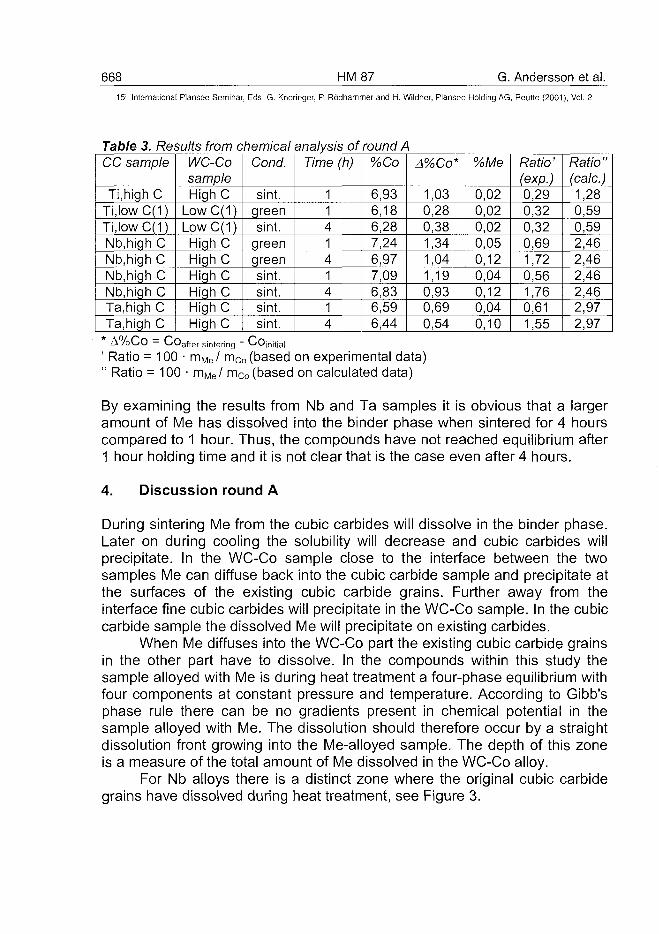
668 HM87 G. Andersson et al.151" International Plansee Seminar, Eds. G. Knernger, P. Rodhammer and H. Wildner, Plansee Holding AG, Reutte (2001), Vol. 2
Table 3. Results from chemical analysis of round ACC sample
Ti.high CTi,lowC(1)Ti,lowC(1)Nb,high CNb,high CNb,high CNb.high CTa.high CTa.high C
WC-CosampleHighC
LowC(1)LowC(1)High CHighCHighCHighCHighCHighC
Cond.
sint.greensint.
greengreensint.sint.sint.sint.
Time (h)
114141414
%Co
6,936,186,287,246,977,096,836,596,44
A%Co*
1,030,280,381,341,041,190,930,690,54
%Me
0,020,020,020,050,120,040,120,040,10
Ratio'(exp.)0,290,320,320,691,720,561,760,611,55
Ratio"(calc.)1,280,590,592,462,462,462,462,972,97
A%Co = Co'after sintering - Coini,itial
Ratio = 100 • mMe / mCo (based' Ratio = 100 • mMe/ mCo (based
on experimental data)on calculated data)
By examining the results from Nb and Ta samples it is obvious that a largeramount of Me has dissolved into the binder phase when sintered for 4 hourscompared to 1 hour. Thus, the compounds have not reached equilibrium after1 hour holding time and it is not clear that is the case even after 4 hours.
4. Discussion round A
During sintering Me from the cubic carbides will dissolve in the binder phase.Later on during cooling the solubility will decrease and cubic carbides willprecipitate. In the WC-Co sample close to the interface between the twosamples Me can diffuse back into the cubic carbide sample and precipitate atthe surfaces of the existing cubic carbide grains. Further away from theinterface fine cubic carbides will precipitate in the WC-Co sample. In the cubiccarbide sample the dissolved Me will precipitate on existing carbides.
When Me diffuses into the WC-Co part the existing cubic carbide grainsin the other part have to dissolve. In the compounds within this study thesample alloyed with Me is during heat treatment a four-phase equilibrium withfour components at constant pressure and temperature. According to Gibb'sphase rule there can be no gradients present in chemical potential in thesample alloyed with Me. The dissolution should therefore occur by a straightdissolution front growing into the Me-alloyed sample. The depth of this zoneis a measure of the total amount of Me dissolved in the WC-Co alloy.
For Nb alloys there is a distinct zone where the original cubic carbidegrains have dissolved during heat treatment, see Figure 3.
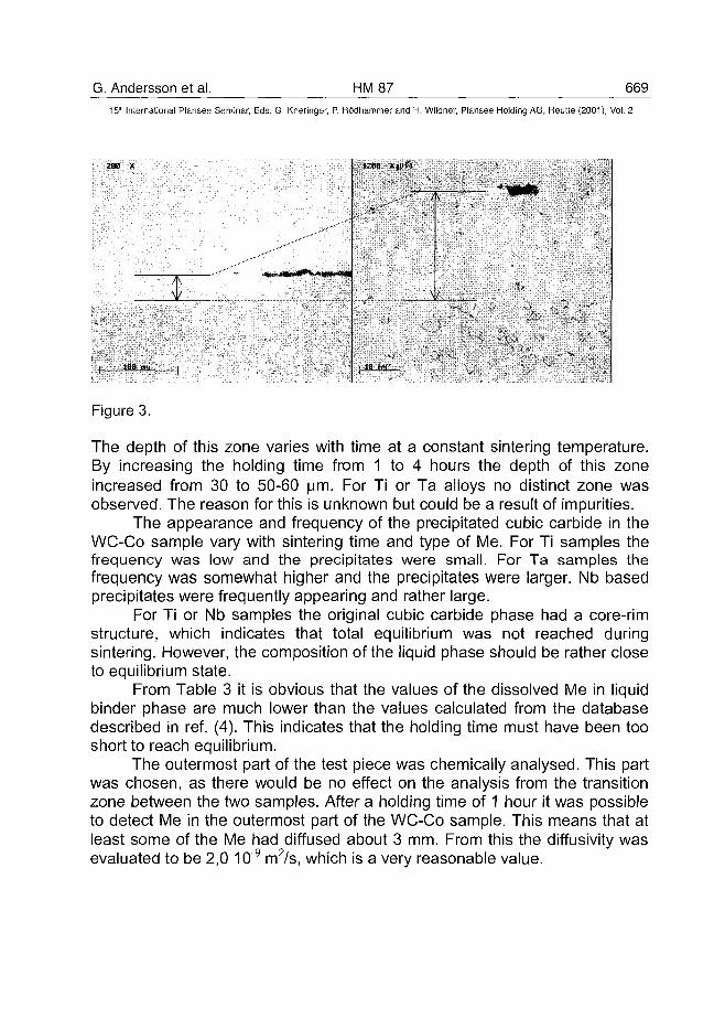
G. Andersson et al. HM87 66915'" International Plansee Seminar, Eds. G. Kneringer, P. Rodhammer and H. Wildner, Plansee Holding AG, Reutte (2001), Vol. 2
A
1ZBB XjOii . '
A
V
Figure 3.
The depth of this zone varies with time at a constant sintering temperature.By increasing the holding time from 1 to 4 hours the depth of this zoneincreased from 30 to 50-60 |a.m. For Ti or Ta alloys no distinct zone wasobserved. The reason for this is unknown but could be a result of impurities.
The appearance and frequency of the precipitated cubic carbide in theWC-Co sample vary with sintering time and type of Me. For Ti samples thefrequency was low and the precipitates were small. For Ta samples thefrequency was somewhat higher and the precipitates were larger. Nb basedprecipitates were frequently appearing and rather large.
For Ti or Nb samples the original cubic carbide phase had a core-rimstructure, which indicates that total equilibrium was not reached duringsintering. However, the composition of the liquid phase should be rather closeto equilibrium state.
From Table 3 it is obvious that the values of the dissolved Me in liquidbinder phase are much lower than the values calculated from the databasedescribed in ref. (4). This indicates that the holding time must have been tooshort to reach equilibrium.
The outermost part of the test piece was chemically analysed. This partwas chosen, as there would be no effect on the analysis from the transitionzone between the two samples. After a holding time of 1 hour it was possibleto detect Me in the outermost part of the WC-Co sample. This means that atleast some of the Me had diffused about 3 mm. From this the diffusivity wasevaluated to be 2,0 10"9 m2/s, which is a very reasonable value.
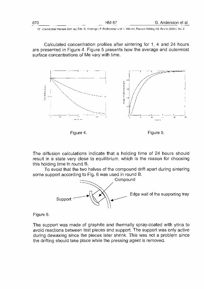
670 HM87 G. Andersson et al.International Plansee Seminar, Eds. G. Kneringer, P. Rodhammer and H. Wildner, Plansee Holding AG, Reutte (2001), Vol. 2
Calculated concentration profiles after sintering for 1, 4 and 24 hoursare presented in Figure 4. Figure 5 presents how the average and outermostsurface concentrations of Me vary with time.
2(1 25
Figure 4. Figure 5.
The diffusion calculations indicate that a holding time of 24 hours shouldresult in a state very close to equilibrium, which is the reason for choosingthis holding time in round B.
To avoid that the two halves of the compound drift apart during sinteringsome support according to Fig. 6 was used in round B.
Compound
SupportEdge wall of the supporting tray
Figure 6.
The support was made of graphite and thermally spray-coated with yttria toavoid reactions between test pieces and support. The support was only activeduring dewaxing since the pieces later shrink. This was not a problem sincethe drifting should take place while the pressing agent is removed.
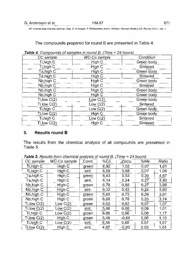
G. Andersson et al. HM 87 67115'" International Plansee Seminar, Eds. G. Kneringer, P. Rödhammer and H. Wildner, Plansee Holding AG, Reutte (2001), Vol. 2
The compounds prepared for round B are presented in Table 4.
Table 4. CompoundsCC sampleTi,high CTi,high CTa.high CTa,high CNb.high CNb.highCNb,highCNb.high CTi,low C(2)Ti.low C(2)Ti,high C
Ti,low C(2)Ti,high C
Ti,lowC(2)
of samples in round B. (TimeWC-Co sample
High CHigh CHigh CHigh CHigh CHigh CHigh CHigh C
Low C(2)Low C(2)Low C(2)High C
Low C(2)High C
= 24 hours)Condition
Green bodySintered
Green bodySintered
Green bodySintered
Green bodyGreen bodyGreen body
SinteredGreen bodyGreen body
• SinteredSintered
5. Results round B
The results from the chemical analysis of all compounds are presented inTable 5.
Table 5. Results from chemical analysis of round B. (CC sampleTi,high CTi,high CTa,high CTa.high CNb.high CNb.high CNb,high CNb.high CTi,low C(2)Ti.low C(2)Ti.high C
Ti,low C(2)Ti,high C
Ti.low C(2)
WC-Co sampleHigh CHigh CHigh CHigh CHigh CHigh CHigh CHigh C
Low C(2)Low C(2)Low C(2)
High CLow C(2)High C
Cond.greensint.
greensint.
greensint.
greengreengreensint.
greengreensint.sint.
%Co6,926,586,436,146,786,326,656,686,525,966,865,466,564,97
'Time = 24A%Co1,020,680,530,240,880,420,750,780,620,060,96-0,440,66-0,93
hours)%Me0,070,070,300,270,270,240,260,250,070,060,080,060,070,05
Ratio1,011,064,674,403,983,803,913,741,071,011,171,101,071,01
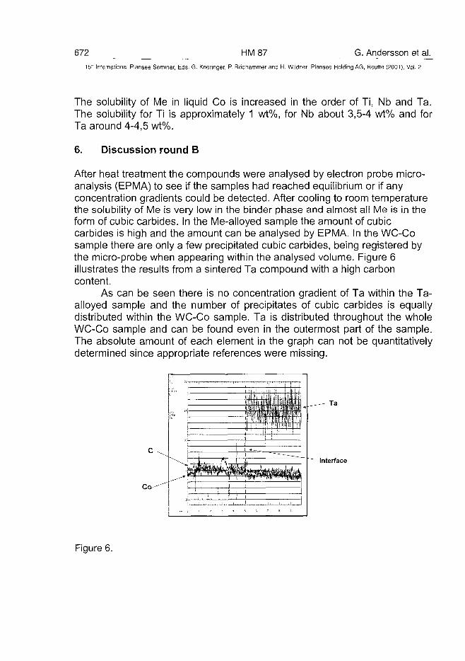
672 HM87 G. Andersson et al.15" International Plansee Seminar, Eds. G. Kneringer, P. Rddhammer and H. Wildner, Plansee Holding AG, Reutte (2001), Vol. 2
The solubility of Me in liquid Co is increased in the order of Ti, Nb and Ta.The solubility for Ti is approximately 1 wt%, for Nb about 3,5-4 wt% and forTa around 4-4,5 wt%.
6. Discussion round B
After heat treatment the compounds were analysed by electron probe micro-analysis (EPMA) to see if the samples had reached equilibrium or if anyconcentration gradients could be detected. After cooling to room temperaturethe solubility of Me is very low in the binder phase and almost all Me is in theform of cubic carbides. In the Me-alloyed sample the amount of cubiccarbides is high and the amount can be analysed by EPMA. In the WC-Cosample there are only a few precipitated cubic carbides, being registered bythe micro-probe when appearing within the analysed volume. Figure 6illustrates the results from a sintered Ta compound with a high carboncontent.
As can be seen there is no concentration gradient of Ta within the Ta-alloyed sample and the number of precipitates of cubic carbides is equallydistributed within the WC-Co sample. Ta is distributed throughout the wholeWC-Co sample and can be found even in the outermost part of the sample.The absolute amount of each element in the graph can not be quantitativelydetermined since appropriate references were missing.
Interface
Figure 6.
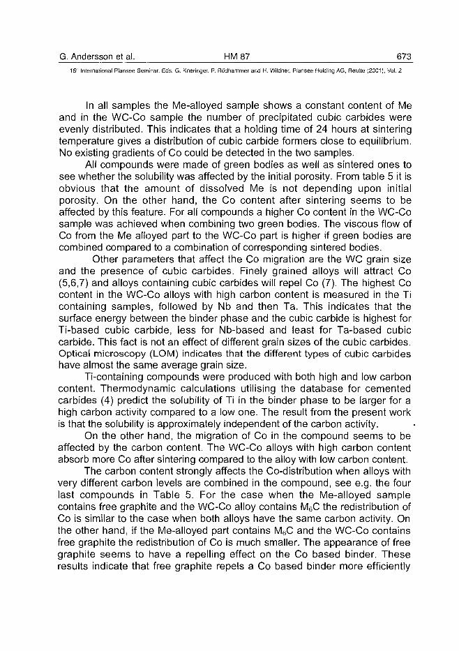
G. Andersson et al. HM 87 67315'" International Plansee Seminar, Eds. G. Kneringer, P. Rodhammer and H. Wildner, Plansee Holding AG, Reutte (2001), Vol. 2
In all samples the Me-alloyed sample shows a constant content of Meand in the WC-Co sample the number of precipitated cubic carbides wereevenly distributed. This indicates that a holding time of 24 hours at sinteringtemperature gives a distribution of cubic carbide formers close to equilibrium.No existing gradients of Co could be detected in the two samples.
All compounds were made of green bodies as well as sintered ones tosee whether the solubility was affected by the initial porosity. From table 5 it isobvious that the amount of dissolved Me is not depending upon initialporosity. On the other hand, the Co content after sintering seems to beaffected by this feature. For all compounds a higher Co content in the WC-Cosample was achieved when combining two green bodies. The viscous flow ofCo from the Me alloyed part to the WC-Co part is higher if green bodies arecombined compared to a combination of corresponding sintered bodies.
Other parameters that affect the Co migration are the WC grain sizeand the presence of cubic carbides. Finely grained alloys will attract Co(5,6,7) and alloys containing cubic carbides will repel Co (7). The highest Cocontent in the WC-Co alloys with high carbon content is measured in the Ticontaining samples, followed by Nb and then Ta. This indicates that thesurface energy between the binder phase and the cubic carbide is highest forTi-based cubic carbide, less for Nb-based and least for Ta-based cubiccarbide. This fact is not an effect of different grain sizes of the cubic carbides.Optical microscopy (LOM) indicates that the different types of cubic carbideshave almost the same average grain size.
Ti-containing compounds were produced with both high and low carboncontent. Thermodynamic calculations utilising the database for cementedcarbides (4) predict the solubility of Ti in the binder phase to be larger for ahigh carbon activity compared to a low one. The result from the present workis that the solubility is approximately independent of the carbon activity.
On the other hand, the migration of Co in the compound seems to beaffected by the carbon content. The WC-Co alloys with high carbon contentabsorb more Co after sintering compared to the alloy with low carbon content.
The carbon content strongly affects the Co-distribution when alloys withvery different carbon levels are combined in the compound, see e.g. the fourlast compounds in Table 5. For the case when the Me-alloyed samplecontains free graphite and the WC-Co alloy contains M6C the redistribution ofCo is similar to the case when both alloys have the same carbon activity. Onthe other hand, if the Me-alloyed part contains M6C and the WC-Co containsfree graphite the redistribution of Co is much smaller. The appearance of freegraphite seems to have a repelling effect on the Co based binder. Theseresults indicate that free graphite repels a Co based binder more efficiently
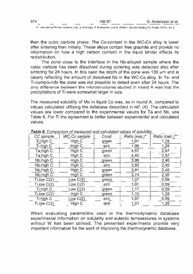
674 HM87 G. Andersson et al.15" International Plansee Seminar, Eds. G. Kneringer, P. Rodhammer and H. Wildner, Plansee Holding AG, Reutte (2001), Vol. 2
than the cubic carbide phase. The Co-content in the WC-Co alloy is lowerafter sintering than initially. These alloys contain free graphite and provide noinformation on how a high carbon content in the liquid binder effects itsredistribution.
The zone close to the interface in the Nb-alloyed sample where thecubic carbide has been dissolved during sintering was detected also aftersintering for 24 hours. In this case the depth of the zone was 130 \im and isclearly reflecting the amount of dissolved Nb in the WC-Co alloy. In Ta- andTi-compounds the zone was not possible to detect even after 24 hours. Theonly difference between the microstructures studied in round A was that theprecipitations of Ti were somewhat larger in size.
The measured solubility of Me in liquid Co was, as in round A, compared tovalues calculated utilising the database described in ref. (4). The calculatedvalues are lower compared to the experimental values for Ta and Nb, seeTable 6. For Ti the agreement is better between experimental and calculatedvalues.
Table 6. Comparison of measured and calculatedCC sampleTi,high CTi.high CTa.high CTa.high CNb.high CNb,high CNb,high CNb.high CTi.low C(2)Ti.low C(2)Ti.high C
Ti.low C(2)Ti,high C
Ti.low C(2)
WC-Co sampleHighCHighCHigh CHighCHighCHigh CHighC
Cond.greensint.
greensint.
greensint.
greenHigh C ! green
Low C(2) greenLow C(2) sint.Low C(2) greenHigh C green
Low C(2) sint.High C sint.
values of solubilitjRatio (exp.)*
1,011,064,674,403,983,803,913,741,071,011,171,101,071,01
/Ratio (calc.)**
1,281,282,972,972,462,462,462,460,590,590,591,280,591,28
When evaluating parameters used in the thermodynamic databaseexperimental information on solubility and eutectic temperatures in systemswithout W has been utilised. The presented experiments provide veryimportant information for the work of improving the thermodynamic database.
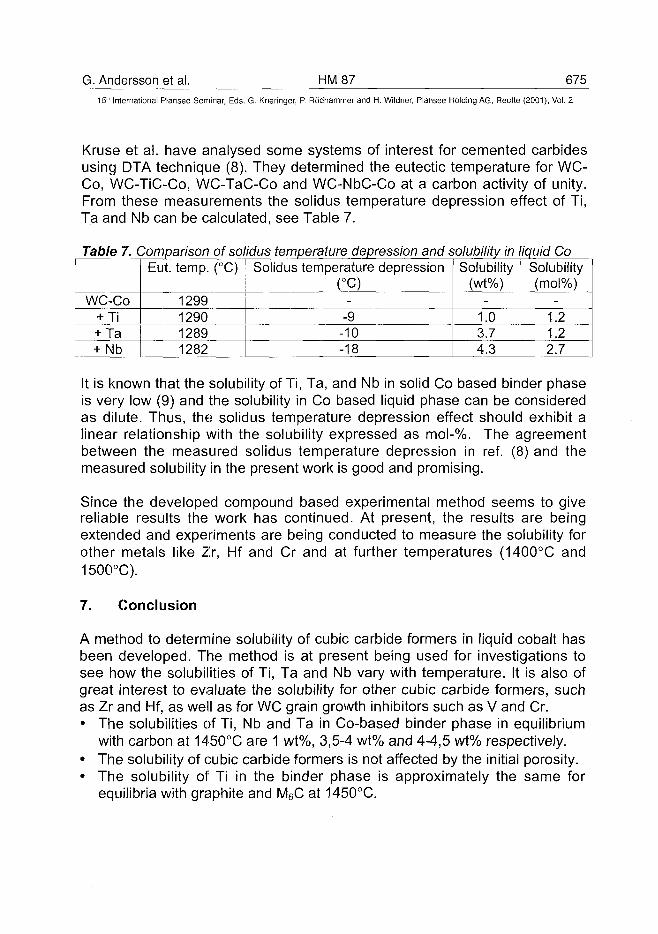
G. Andersson et al. HM87 67515th International Plansee Seminar, Eds. G. Kneringer, P. Rodhammer and H. Wildner, Plansee Holding AG, Reutte (2001), Vol. 2
Kruse et al. have analysed some systems of interest for cemented carbidesusing DTA technique (8). They determined the eutectic temperature for WC-Co, WC-TiC-Co, WC-TaC-Co and WC-NbC-Co at a carbon activity of unity.From these measurements the solidus temperature depression effect of Ti,Ta and Nb can be calculated, see Table 7.
Table 7. Comparison of solidus temperature depression and solubility in liquid Co
WC-Co+ Ti+ Ta+ Nb
Eut. temp. (°C)
1299129012891282
Solidus temperature depression(°C)
--9-10-18
Solubility(wt%)
-1.03.74.3
Solubility(mol%)
-1.21.22.7
It is known that the solubility of Ti, Ta, and Nb in solid Co based binder phaseis very low (9) and the solubility in Co based liquid phase can be consideredas dilute. Thus, the solidus temperature depression effect should exhibit alinear relationship with the solubility expressed as mol-%. The agreementbetween the measured solidus temperature depression in ref. (8) and themeasured solubility in the present work is good and promising.
Since the developed compound based experimental method seems to givereliable results the work has continued. At present, the results are beingextended and experiments are being conducted to measure the solubility forother metals like Zr, Hf and Cr and at further temperatures (1400°C and1500°C).
7. Conclusion
A method to determine solubility of cubic carbide formers in liquid cobalt hasbeen developed. The method is at present being used for investigations tosee how the solubilities of Ti, Ta and Nb vary with temperature. It is also ofgreat interest to evaluate the solubility for other cubic carbide formers, suchas Zr and Hf, as well as for WC grain growth inhibitors such as V and Cr.• The solubilities of Ti, Nb and Ta in Co-based binder phase in equilibrium
with carbon at 1450°C are 1 wt%, 3,5-4 wt% and 4-4,5 wt% respectively.• The solubility of cubic carbide formers is not affected by the initial porosity.• The solubility of Ti in the binder phase is approximately the same for
equilibria with graphite and M6C at 1450°C.
676 HM87 G. Andersson et al.15" International Plansee Seminar, Eds. G. Kneringer, P. Rodhammer and H. Wildner, Plansee Holding AG, Reutte (2001), Vol. 2
The solubility of Ta and Nb is higher than what the thermodynamic databasepredicts. For Ti the agreement is good. The presented experiments give veryimportant information for the work of improving the thermodynamic database.• Redistribution of Co is larger if the samples are combined in pairs with
initial porosity.• The level of redistribution of the binder phase indicates that the surface
energy between liquid Co based binder phase and solid phase isincreasing in the following order of solid phase: WC, Ta-based cubiccarbide, Nb-based cubic carbide, Ti-based cubic carbide and graphite.
Acknowledgements
Dr P. Gustafson and Dr L. Akesson for valuable ideas and discussions andAB Sandvik Coromant for permission to publish these results are gratefullyacknowledged.
References
(1) L. Kaufman and H. Bernstein: Computer Calculation of PhaseDiagrams - with special reference to refractory metals, AcademicPress, Inc., New York, 1970, 4, 334 P
(2) N. Saunders and A.P. Miodownik: Calphad Calculation of PhaseDiagrams. A Comprehensive Guide, Pergamon Materials Series,Pergamon Materials Series, vol. 1 (ed. R.W. Cahn, 1998)
(3) M. Ekroth, R. Frykholm, M. Lindholm, H-O. Andren and J. Agren:Acta Mater. (USA), vol. 48, no.9, (2000), pp. 2177-2185
(4) M. Ekroth, K. Frisk, B. Jansson and L.F.S Dumitrescu: Met. Mat.Trans. B (USA), vol. 31B, no. 4, (2000), pp. 615-619B
(5) R. Cooper, T.H. Owen and C.T. Peters: Metallwerk Plansee (1985)HM23, pp. 959-972
(6) C. Colin, L. Durant, N. Favrot, J. Besson, G. Barbier and F.Delannay: Int. J. Refract. Metals & Hard Materials, vol. 12, no. 3,(1993-4), pp. 145-150
(7) V. Richter: Proc. 3rd Int. Symp. Struct. Funct. Gradient Mat., (1995),pp. 587-592
(8) O. Kruse, B. Jansson and K. Frisk: submitted to J. of Phase Equil.(9) H. Jonsson: Scand. J. Met., 4 (1975), pp. 220-224
AT0100490D. Agrawal et al. HM 90 677
15lh International Plansee Seminar, Eds. G. Kneringer, P. Rddhammer and H. Wildner, Plansee Holding AG, Reutte (2001), Vol. 2
Microstructural Examination by TEM of WC/Co Composites Prepared byConventional and Microwave Processes
Dinesh Agrawal1, A. J. Papworth2, J. Cheng1, H. Jain2 and D.B. Williams2
1 Materials Research Lab, The Pennsylvania State UniversityUniversity Park, PA 16802 USA
2Lehigh University, Department of Materials Science and Engineering,Betheleham, PA 18015 USA
Summary:
Recently, significant developments and advances have taken place in thefield of microwave processing of ceramics, composites and metals.Microwave sintering technology of WC/Co based hard metal parts has beennow developed for commercial products. Microwave processed WC/Co partsreportedly have exhibited superior performance over standard parts.Additionally, the microwave process requires only one tenth of the total cycletime employed in a conventional process. Laboratory corrosion and impactresistance tests have proved that microwave processed WC/Co parts areseveral times more resistant than the conventional parts of the samecomposition. The Scanning Transmission Electron Microscopic (STEM)examination conducted on conventionally and microwave sintered WC/Cosamples exhibited remarkable difference in the chemistry of cobalt binderphase. It is understood that the superior mechanical properties of microwavesintered part are due to the pure cobalt phase present at the grain boundaryof WC grains, while the conventionally sintered part showed there wassubstantial interalloying of Co with tungsten.
Keywords:
Microwave sintering, composite, WC/Co, microstructure, TEM
1. Introduction
Tungsten Carbide - Cobalt (WC/Co) based hard metal composites orcemented carbides due to their unique combination of hardness, toughness
678 HM90 D. Agrawal et al.15* International Plansee Seminar, Eds. G. Kneringer, P. Rodhammer and H. Wildner, Plansee Holding AG, Reutte (2001), Vol. 2
and strength, are universally used as cutting and polishing tools, and indrilling operations underground. The production of WC/Co componentsinvolves the mixing of WC powders with cobalt binder, and then compactingthe mass into a pre-sintered green body followed by the sintering.Conventional methods for sintering of WC/Co green bodies involve hightemperature and lengthy sintering cycles, consequently undesirable graingrowth occurs in the presence of liquid Co phase. This has adverse effect onthe mechanical properties of the tool. Microwave sintering process offers analternative method of sintering and providing finer microstructures with outusing grain growth inhibitors. The technology has now been developed forcemented carbides with remarkably superior properties and overall improvedperformance.
Abrasion resistance, hardness, and toughness are essential materialproperties for cutting tools, machining metals, tools for mining of minerals;drills for oil, gas and geothermal energy; and in countless other mechanicalapplications such as bearings and seals. Additionally, high corrosion anderosion resistances are important in many applications. Tradeoffs inproperties such as fracture toughness and abrasion or erosion resistance canbe designed into the parts by varying component materials such as cobaltcontent or carbide grain size. In many applications, an improvement in morethan one property simultaneously is required for better performance.
Microwave heating is fundamentally different from conventional heating whichinvolves radiant/resistance heating followed by transfer of thermal energy viaconduction to the inside of the body under process. In case of microwaveprocess it is the absorption of the microwave energy followed by volumetricheating involving a conversion of electromagnetic energy into thermal energy,which makes it instantaneous and a rapid process. Microwave absorption andheating is a function of material properties. The degree of microwaveabsorption and consequently heating changes dramatically with the rise intemperature. There are major potential and real advantages using microwaveenergy for material processing over conventional heating. Some of theseadvantages include: time and energy saving, very rapid heating rates(>400°C/min), considerably reduced processing time and temperature, finemicrostructures and hence improved mechanical properties, better productperformance, and selective heating.Conventional methods for sintering WC with Co as a binder phase involvehigh temperature (up to 1500°C) and lengthy sintering cycles (up to 20 hours)in order to achieve a high degree of sintering [1]. Such conditions
D. Agrawal et al. HM 90 67915'" International Plansee Seminar, Eds. G. Kneringer, P. Rodhammer and H. Wildner, Plansee Holding AG, Reutte (2001), Vol. 2
unfortunately favor undesirable WC grain growth in the presence of Co liquidphase. Consequently, the mechanical strength and hardness of the tools arediminished. It is generally recognized that finer microstructures providesuperior mechanical properties and longer life of the product. Often, additivessuch as titanium carbide (TiC), vanadium carbide (VC) and tantalum carbide(TaC) are used to prevent grain growth of WC grains. Unfortunately, besidesadding to the material cost, such additives adversely affect the mechanicalproperties of the product as well. Since microwave heating requires very littletime to obtain full densification, the abnormal grain growth and cobalt 'laking'are avoided. In 1991, J. P. Cheng in a Ph.D. thesis [2] first showed thatWC/Co composites could be sintered in a microwave field. Gerdes andWiliert-Porada [3,4] also reported the microwave sintering of WC objects withimproved mechanical properties. In another independent work [5], Cheng etal. using a newly designed microwave apparatus were able to fully sinter WCcommercial green bodies containing 12% and 6% Co. They observed thatmicrowave processed WC/Co bodies exhibited better mechanical propertiesthan the conventional parts, finer and more uniform microstructure, andnearly full density without using any pressure or adding any grain-growthinhibitors when sintered at 1250°-1320°C for only 10-30 minutes [6,7,8].
The mechanism of microwave and material interaction is not very wellunderstood. How does microwave heating improve the mechanical propertiesof cemented carbide part, has not been explained yet? In this study, acomparative investigation of microwave and conventionally sintered WC/Cosamples has been undertaken. Erosion, corrosion and abrasion resistancetests on both types of samples were conducted. A detailed TEM examinationhas been carried out toidentify the differences between the microstructures ofthe conventional and microwave sintered samples.
2. Experimental
Commercial parts of WC/Co (6 to 25 wt % Co, Dennis Tool Co. Houston,Texas, USA) parts of various sizes (0.5 to 3 inch) and shapes were sinteredin a microwave system operated at 2.45 GHz, 6 kW, and under ambientpressure conditions, and hydrogen atmosphere. The sintering conditionsvaried depending upon the amount of cobalt in the part. Typical sinteringtemperatures were in the range of 1350 - 1425°C and sintering time variedfrom 5 to 20 minutes at temperature. The total cycle time was around 1.5hours including dewaxing.
680 HM 90 D. Agrawal et al.15" International Plansee Seminar, Eds. G. Kneringer, P. Rodhammer and H. Wildner, Plansee Holding AG, Reutte (2001), Vol. 2
The erosion resistance test was performed using dry blasting medium ofaluminum oxide powder. Two samples of each type were tested. Theabrasion resistance test was performed using SiC dry grinding wheel. Volumeof wheel removed was compared to the volume of carbide removed in eachcase. The corrosion resistance test was performed by the submersion of thecarbide samples in15% HNO3 solution for 48 hours and determining theweight change after the test.
Specimens for TEM study were made by manual polishing of both themicrowave and conventionally sintered WC/Co composites from 3 mm discsto ~ 40 jim. The discs were then ion-beam thinned at an angle of 4°, using aGatan precision ion polishing system. The microstructural and microchemicalanalyses were carried out using a VG HB603 FEGSTEM with a probe size of1.4 nm (FWTM) and a beam current of 0.5 nA. The STEM uses a windowlessSi(Li) EDS X-ray detector with a large detector solid angle of 0.3 sr. X-rayacquisition was carried out on an Oxford (Link) exl system, where elementalwindows of 7 channels wide were defined over the Ka lines of C, O, Ti, Fe, Coand the Ma line of W (the W La overlaps with Si). Two normalizingbackgrounds were defined from 3.3 - 3.8 keV and 12.0 -14.0 keVrespectively. X-ray maps had an acquisition time of 100 ms/pixel with a128x128 pixels resolution. Digital line-scans were 64 nm in length with a totalof 64 spectra/scan. Each spectrum in the line scan had an acquisition time of4 s, and was normalized with respect to the background to remove the effectsof thickness. Each spectrum in the line-scan had an acquisition time of 4seconds, and was normalized with respect to the background to remove theeffects of thickness. Fully quantified line-scans were obtained by takingtwenty spectra, each equally spaced apart in a line crossing the PAGB. Thepeak intensities were then deconvoluted from each other by the simplexroutine in the DTSA program. The elemental compositions were thendetermined using the Cliff Lorimer equation and calculated k factors.
3. Results and Discussion
The microstructural examination of microwave sintered WC/Co samples, ingeneral, exhibited smaller average grain size than the conventionally sinteredsample. A typical microstructure of two kinds of sintered samples is illustratedin Figure 1.
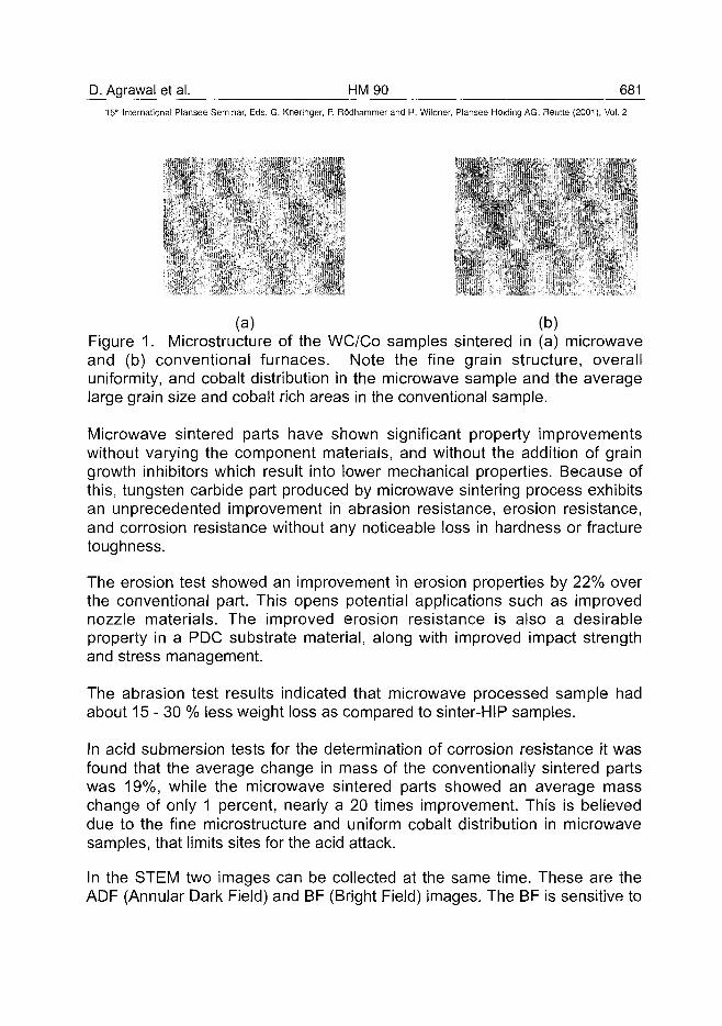
D. Agrawal et al. HM 90 68115" International Plansee Seminar, Eds. G. Kneringer, P. Rodhammer and H. Wildner, Plansee Holding AG, Reutte (2001), Vol. 2
(a) (b)Figure 1. Microstructure of the WC/Co samples sintered in (a) microwaveand (b) conventional furnaces. Note the fine grain structure, overalluniformity, and cobalt distribution in the microwave sample and the averagelarge grain size and cobalt rich areas in the conventional sample.
Microwave sintered parts have shown significant property improvementswithout varying the component materials, and without the addition of graingrowth inhibitors which result into lower mechanical properties. Because ofthis, tungsten carbide part produced by microwave sintering process exhibitsan unprecedented improvement in abrasion resistance, erosion resistance,and corrosion resistance without any noticeable loss in hardness or fracturetoughness.
The erosion test showed an improvement in erosion properties by 22% overthe conventional part. This opens potential applications such as improvednozzle materials. The improved erosion resistance is also a desirableproperty in a PDC substrate material, along with improved impact strengthand stress management.
The abrasion test results indicated that microwave processed sample hadabout 15-30 % less weight loss as compared to sinter-HIP samples.
In acid submersion tests for the determination of corrosion resistance it wasfound that the average change in mass of the conventionally sintered partswas 19%, while the microwave sintered parts showed an average masschange of only 1 percent, nearly a 20 times improvement. This is believeddue to the fine microstructure and uniform cobalt distribution in microwavesamples, that limits sites for the acid attack.
In the STEM two images can be collected at the same time. These are theADF (Annular Dark Field) and BF (Bright Field) images. The BF is sensitive to
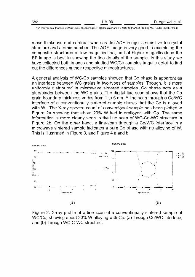
682 HM 90 D. Agrawal et al.15" International Plansee Seminar, Eds. G. Kneringer, P. Rodhammer and H. Wildner, Plansee Holding AG, Reutte (2001), Vol. 2
mass thickness and contrast whereas the ADF image is sensitive to crystalstructure and atomic number. The ADF image is very good in examining thecomposite structures at low magnification, and at higher magnifications theBF image is best in showing the fine details of the sample. In this study wehave collected both images and studied WC/Co samples in quite detail to findout the differences in their respective microstructures.
A general analysis of WC/Co samples showed that Co phase is apparent asan interface between WC grains in two types of samples. Though, it is moreuniformly distributed in microwave sintered samples. Co phase acts as aglue/binder between the WC grains. The digital line scan shows that the Cograin boundary thickness varies from 1 to 5 nm. A line-scan through a Co/WCinterface of a conventionally sintered sample shows that the Co is alloyedwith W. The X-ray spectra count of conventional sample has been plotted inFigure 2a showing that about 20% W had interalloyed with Co. The sameinformation is more clearly seen in the line scan of WC-Co-WC structure inFigure 2b. On the other hand, a line-scan through a Co/WC interface in amicrowave sintered sample indicates a pure Co phase with no alloying of W.This is illustrated in Figure 3, and Figure 4 a and b.
= 50 -
C40 -
30 -
20 *—1 2 3 4
Spectrum No.
* w
—» - - Co
Wt%
CSCWC Data
100 T —,-- ^
30 -
30 -
40 -
20 -
04
' = = \ r
\ r - "
A
/8 12
Spectrum No
(a) (b)
Figure 2. X-ray profile of a line scan of a conventionally sintered sample ofWC/Co, showing about 20% W alloying with Co: (a) through Co/WC interface,and (b) through WC-C-WC structure.
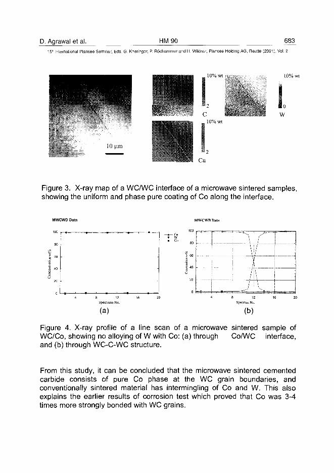
D. Agrawal et al. HM90 683
15" International Plansee Seminar, Eds. G. Kneringer, P. Rodhammer and H. Wildner, Plansee Holding AG, Reutte (2001), Vol. 2
10% wt
2
10% wt
10% wt
• 0w
10|xm
Figure 3. X-ray map of a WCA/VC interface of a microwave sintered samples,showing the uniform and phase pure coating of Co along the interface.
MWCWD Data M W C W B Data
80
5 60
| 4 O
20
0 r
\ '• '•
: \ : /
I 1: jli / j \
i / i \
\ j \ \^ \16 20
Spectrum No.
(b)
Figure 4. X-ray profile of a line scan of a microwave sintered sample ofWC/Co, showing no alloying of W with Co: (a) through Co/WC interface,and (b) through WC-C-WC structure.
From this study, it can be concluded that the microwave sintered cementedcarbide consists of pure Co phase at the WC grain boundaries, andconventionally sintered material has intermingling of Co and W. This alsoexplains the earlier results of corrosion test which proved that Co was 3-4times more strongly bonded with WC grains.
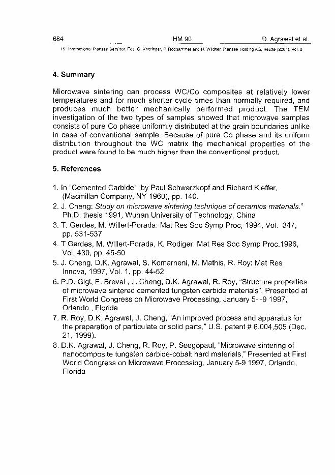
684 HM90 D. Agrawal et al.15" International Plansee Seminar, Eds. G. Kneringer, P. Rodhammer and H. Wildner, Plansee Holding AG, Reutte (2001), Vol. 2
4. Summary
Microwave sintering can process WC/Co composites at relatively lowertemperatures and for much shorter cycle times than normally required, andproduces much better mechanically performed product. The TEMinvestigation of the two types of samples showed that microwave samplesconsists of pure Co phase uniformly distributed at the grain boundaries unlikein case of conventional sample. Because of pure Co phase and its uniformdistribution throughout the WC matrix the mechanical properties of theproduct were found to be much higher than the conventional product.
5. References
1. In "Cemented Carbide" by Paul Schwarzkopf and Richard Kieffer,(Macmillan Company, NY 1960), pp. 140.
2. J. Cheng: Study on microwave sintering technique of ceramics materials."Ph.D. thesis 1991, Wuhan University of Technology, China
3. T. Gerdes, M. Willert-Porada: Mat Res Soc Symp Proc, 1994, Vol. 347,pp. 531-537
4. T Gerdes, M. Willert-Porada, K. Rodiger: Mat Res Soc Symp Proc.1996,Vol. 430, pp. 45-50
5. J. Cheng, D.K. Agrawal, S. Komarneni, M. Mathis, R. Roy: Mat ResInnova, 1997, Vol. 1, pp. 44-52
6. P.D. Gigl, E. Breval , J. Cheng, D.K. Agrawal, R. Roy, "Structure propertiesof microwave sintered cemented tungsten carbide materials", Presented atFirst World Congress on Microwave Processing, January 5- -9 1997,Orlando , Florida
7. R. Roy, D.K. Agrawal, J. Cheng, "An improved process and apparatus forthe preparation of particulate or solid parts," U.S. patent # 6,004,505 (Dec.21, 1999).
8. D.K. Agrawal, J. Cheng, R. Roy, P. Seegopaul, "Microwave sintering ofnanocomposite tungsten carbide-cobalt hard materials," Presented at FirstWorld Congress on Microwave Processing, January 5-9 1997, Orlando,Florida
AT0100491U. Beste et al. HM 92 685
15" International Plansee Seminar, Eds. G. Kneringer, P. Rodhammer and H. Wildner, Plansee Holding AG, Reutte (2001), Vol. 2
PRESSURE CYCLING INDUCED MODIFICATION
OF A CEMENTED CARBIDE
Ulrik Beste, Hakan Engqvist, Staffan Jacobson
Tribomaterials Group at The Angstrom Laboratory, Uppsala University
Box 534, SE-751 21 Uppsala, Sweden
Summary
The wear of cemented carbide rock drill buttons is due to a complex mixtureof mechanisms. One important of such mechanism is the surface fatigue thatoccurs due to the percussive conditions of rock drilling. To isolate the effectsof this mechanism, a mechanical pressure cycling test has been performedon a cemented carbide with 11 % Co and 2 \xm WC grain size. The test wasended after 60000 pressure cycles. No signs of fatigue crack nucleationwere found. The changes in hardness, fracture toughness, erosionresistance, magnetical coercivity and thermal shock resistance weremeasured. The microstructure of the sample was investigated with x-raydiffraction, plus scanning and transmission electron microscopy.
The fracture toughness decreased 14 % due to the pressure cycling whilethe hardness did not change. In addition, the thermal shock resistance andthe erosion resistance decreased. The magnetical coercivity increased 90 %indicating significant phase transformations or high defect density in the Cobinder phase. The TEM revealed no deformation of the WC phase, butimportant alterations of the Co phase. The Co phase was transformed fromfee into a new unidentified phase, characterized by atomic inter planardistance present in fee and hep plus an unfamiliar distance of 2.35 A. Thisphase is suggested to be due to a more complex stacking sequence of theclose-packed planes than in hep or fee.
Keywords
Cemented carbide, cobalt, mechanical fatigue, phase transformation,fracture toughness, erosion resistance, load cycling
686 HM 92 U. Beste et al.15" International Plansee Seminar, Eds. G. Kneringer, P. Rodhammer and H. Wildner, Plansee Holding AG, Reutte (2001), Vol. 2
Introduction
WC/Co cemented carbides (or hard metals) are commonly used when theconditions demand the combination of high hardness and high toughness(1). The mixture of hard WC grains and the ductile binder phase of cobaltresults in a material well suited for applications like rock drilling, wear partsor hot rolling of steel. Still, the material possesses some importantlimitations. In products where it is exposed to repeated loadings, the limitedfatigue resistance sets the boundaries. One such fatigue relatedphenomenon is the formation of reptile skin, which is a surface pattern ofplateaus and valleys. This pattern may lead to formation of catastrophiccracks, if not inhibited by a re-shaping involving removal of the patternedsurface layer (2). The name reptile skin is of course derived from the visualsimilarity with the back of a reptile. The forming mechanism of the reptileskin is not clear, but is known to be related to surface fatigue processes. Thesurface fatigue can be divided into two types: mechanical (e. g. frompercussive operations) or thermal (e. g. repeatedly cooled hot roll surfaces)(3). In this paper, the mechanical fatigue process is investigated with respectto the microstructual changes induced by repeated strains and thecorresponding changes of the mechanical bulk properties.
Below 418 °C, hep (epsilon phase) is normally the stable phase of Co.However, when producing cemented carbides, the high temperature feephase (beta phase) is stabilized in sintering due to the presence of solvedtungsten and carbon. The deformation induced microstructural changes inWC-Co have been investigated by e.g. Rettenmayr and Exner (4). TheirTEM investigations indicated that when plastically deformed, the Co binderphase accumulates stacking faults up to the limit of complete transformationfrom fee to hep. It was also established that the low stacking fault energy ofCo leads to a high deformability, and that the WC phase is hard, brittle andshows low specific crack resistance.
Due to fewer slip systems (three instead of twelve), hep-Co is consideredmore brittle than fcc-Co. The slip systems description in hep-Co is complexcompared with fcc-Co, but as a rule, a large number of slip systems areconsidered to result in a low brittleness of the material (5), (6).
Also Manlang (7) has studied the Co fec-hep phase transformation in acemented carbide with 12 wt% Co. Manlang observed crack initiation
U. Beste et al. HM 92 68715'" International Plansee Seminar, Eds. G. Kneringer, P. Rodhammer and H. Wildner, Plansee Holding AG, Reutte (2001), Vol. 2
already if less then 10% of Co is transformed into hep, and also that thetransformation from fcc-Co to hep-Co occurs at only 1% strain. He statedthat Co, and its different phases, plays an important role in the mechanicalproperties of the cemented carbide.Kindermann (8) investigated surface fatigue cracks in WC-Co induced bycyclic loads at different temperatures. At 25° C he observed a distinct binderphase transformation from fcc-Co to hep-Co in the vicinity of crack tips.Consistent with Rettenmayr, Kindermann mentioned a stacking faultmechanism achieved by appropriately gliding Shockley partials to describethe phase transformation. At higher temperatures, the phase transformationhad less influence on the cracking mechanism due to the reduction ofstacking faults. The crack tips were rather embrittled by oxidation of Co. Ahigher stacking fault energy (e.g. by alloying with Ni) leads to lessembrittlement at room temperature.
Another way to eliminate the fee to hep transformation of the Co binder is toreduce the WC grain size to the nano meter level, and hence get at bettersolubility of W in Co and stabilize the high temperature phase fcc-Co (9).
Vasel et al. have examined the binder deformation in a cemented carbide(17 wt% Co) exposed to a fatigue test involving 500 000 cycles to 2.1 GPa(10). They found that 45 vol% of the binder phase was transformed from feeto hep, without formation of cracks. When the binder was alloyed with 30-wt% Ni, only 12 vol% was transformed and dislocation motion and twinningbecame the predominant deformation mechanisms.
Obrtlik stated that a plastic strain hardening of WC-Co is obtained in theearly stages of the fatigue test, already after 5 cycles of 1000. His push-pulltest (+/- 1 GPa) was performed on a cemented carbide with 9-wt% Co and1.3 urn large WC grains. The direct influence from internal defects on thefatigue life was also concluded (11).
The magnetical coercivity force He is commonly used to measure the meanfree path of the binder in WC-Co. It is a measure of the force necessary toreduce the magnetic induction to zero and is thus only influenced by theferromagnetic Co (12). The He value is also a measure of the density ofdislocations, free atoms, solved atoms, packing order and grain boundariesin the binder phase (13). No correlation between He and phasetransformation in Co has been well established.
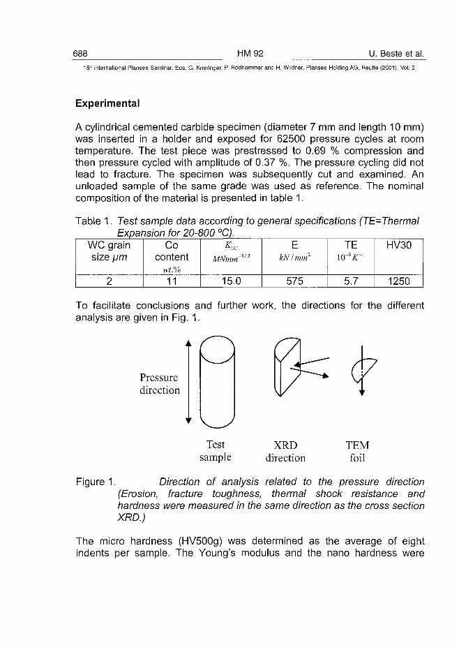
688 HM92 U. Beste et al.5" International Plansee Seminar, Eds. G. Kneringer, P. Rodhammer and H. Wildner, Plansee Holding AG, Reutte (2001), Vol. 2
Experimental
A cylindrical cemented carbide specimen (diameter 7 mm and length 10 mm)was inserted in a holder and exposed for 62500 pressure cycles at roomtemperature. The test piece was prestressed to 0.69 % compression andthen pressure cycled with amplitude of 0.37 %. The pressure cycling did notlead to fracture. The specimen was subsequently cut and examined. Anunloaded sample of the same grade was used as reference. The nominalcomposition of the material is presented in table 1.
Table 1. Test sample data according to general specifications (TE=ThermalExpansion for 20-800 °C).
WC grainsize \jm
2
Cocontent
wt.%11
MNmm~3'2
15.0
EkNImm2
575
TE
5.7
HV30
1250
To facilitate conclusions and further work, the directions for the differentanalysis are given in Fig. 1.
Pressuredirection
Testsample
XRDdirection
TEMfoil
Figure 1. Direction of analysis related to the pressure direction(Erosion, fracture toughness, thermal shock resistance andhardness were measured in the same direction as the cross sectionXRD.)
The micro hardness (HV500g) was determined as the average of eightindents per sample. The Young's modulus and the nano hardness were
U. Beste et al. HM 92 689^15* International Plansee Seminar, Eds. G. Kneringer, P. Rbdhammer and H. Wildner, Plansee Holding AG, Reutte (2001), Vol. 2
measured in a Nanoindenter. In the Nanoindenter, 25 indents were made totwo fixed depths, 0.5 urn and 2 urn. The fracture toughness was determinedusing the Palmqvist method (14) where the crack lengths from eight 50 kgdents were measured in the scanning electron microscope (SEM). Themicrostructures were also investigated in the SEM.A thermal shock test comparing the original and the pressure cycled samplewas also performed. Following the Palmqvist fracture toughness indentation,the samples were heated to a series of increasing temperatures, eachfollowed by cooling in water. The temperatures were 340, 380, 420, 460,500, 540, 580, 620 and 660 °C. For temperatures above 480 °C, thematerials were highly oxidized, and therefore lightly polished to facilitatemeasurements. However, at temperatures above 660 °C, it was impossibleto remove the thick oxide layer without ruining the surfaces including thecracks formed. The total crack length originating from the four indent cornerswas measured in a light optical microscope. This length is very sensitive tothe temperature (1) and constitutes a measure of the thermal shockresistance.
Further, an erosion resistance test was performed in an centrifugal erosiontester. Both a pressure cycled and an as-sintered samples were eroded by500 urn Aip^ -particles at 70.3 m/s velocity and 90° impact angle. The testwas performed at room temperature and was long enough to representsteady state conditions.
The pressure cycled sample was also examined in the transmission electronmicroscope (TEM) after grinding, polishing and ion thinning. The normalvector of the examined TEM foil was directed perpendicularly to the pressuredirection, as shown in Fig. 1. Phase composition and microstructure wasexamined by X-ray diffraction and magnetical coercivity measurements. Themagnetical coercivity was measured according to the European standard EN23 326. It should be noticed that the coercivity normally is measured on as-produced material, and is considered a measure of the Co mean free path.This correlation is not confirmed for materials that have been subjected tocyclic high stress loading, as will be further discussed.
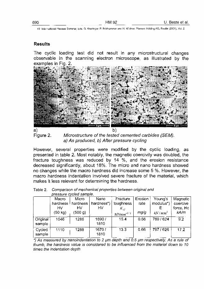
690 HM92 U. Beste et al.15* International Plansee Seminar, Eds. G. Kneringer, P. Rodhammer and H. Wildner, Plansee Holding AG, Reutte (2001), Vol. 2
Results
The cyclic loading test did not result in any microstructural changesobservable in the scanning electron microscope, as illustrated by theexamples in Fig. 2.fc'jn*" • . . • • • - 1 * • " \ • . ' - i : • « * * . ' •
~-*.jL+'\J-
*
a) b)Figure 2. Microstructure of the tested cemented carbides (SEM).
a) As produced, b) After pressure cycling
However, several properties were modified by the cyclic loading, aspresented in table 2. Most notably, the magnetic coercivity was doubled, thefracture toughness was reduced by 14 %, and the erosion resistancedecreased significantly, about 18%. The micro and nano hardness showedno changes while the macro hardness did increase some 5 %. However, themacro hardness indentation involved severe fracture of the material, whichmakes it less relevant for determining the hardness.
Table 2. Comparison of mechanical properties between original andpressure cycled sample.
OriginalsampleCycledsample
Macrohardness
HV(50 kg)
1046
1110
Microhardness
HV(500 g)
1286
1288
Nanohardness*)
HV
1690/1810
1670/1810
Fracturetoughness
MNmm-il2
15.4
13.3
Erosionrate
mg/g
0.56
0.66
Young'smodulus*)
EkN/mm2
760 / 624
797 / 626
Magneticcoerciveforce, He
kA/m
9.2
17.2
*) As measured by nanoindentation to 2 pm depth and 0.5 pm respectively. As a rule ofthumb, the hardness value is considered to be influenced from the material down to 10times the indentation depth
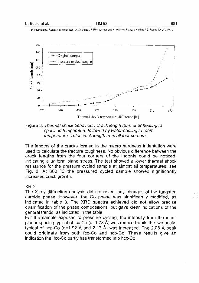
U. Beste et al. HM92 69115'" International Plansee Seminar, Eds. G. Kneringer, P. Rodhammer and H. Wildner, Plansee Holding AG, Reutte (2001), Vol. 2
140 -
120 -
^ 100 -
u
"o 60 -su40 -
20 -
0 -
—•— Original sample
—»- Pressure cycled sample
//
r " ' ^ ^ ^
\- """" I 4 — *320 370 420 470 520 570
Thermal shock temperature difference [K]
620 670
Figure 3. Thermal shock behaviour. Crack length (/jm) after heating tospecified temperature followed by water-cooling to roomtemperature. Total crack length from all four corners.
The lengths of the cracks formed in the macro hardness indentation wereused to calculate the fracture toughness. No obvious difference between thecrack lengths from the four corners of the indents could be noticed,indicating a uniform plane stress. The test showed a lower thermal shockresistance for the pressure cycled sample at almost all temperatures, seeFig. 3. At 660 °C the pressured cycled sample showed significantlyincreased-crack growth.
XRDThe X-ray diffraction analysis did not reveal any changes of the tungstencarbide phase. However, the Co phase was significantly modified, asindicated in table 3. The XRD spectra achieved did not allow precisequantification of the phase compositions, but gave clear indications of thegeneral trends, as indicated in the table.For the sample exposed to pressure cycling, the intensity from the inter-planar spacing typical of fcc-Co (d=1.78 A) was reduced while the two peakstypical of hep-Co (d=1.92 A and 2.17 A) was increased. The 2.06 A peakcould originate from both fcc-Co and hep-Co. These results give anindication that fcc-Co partly has transformed into hep-Co.
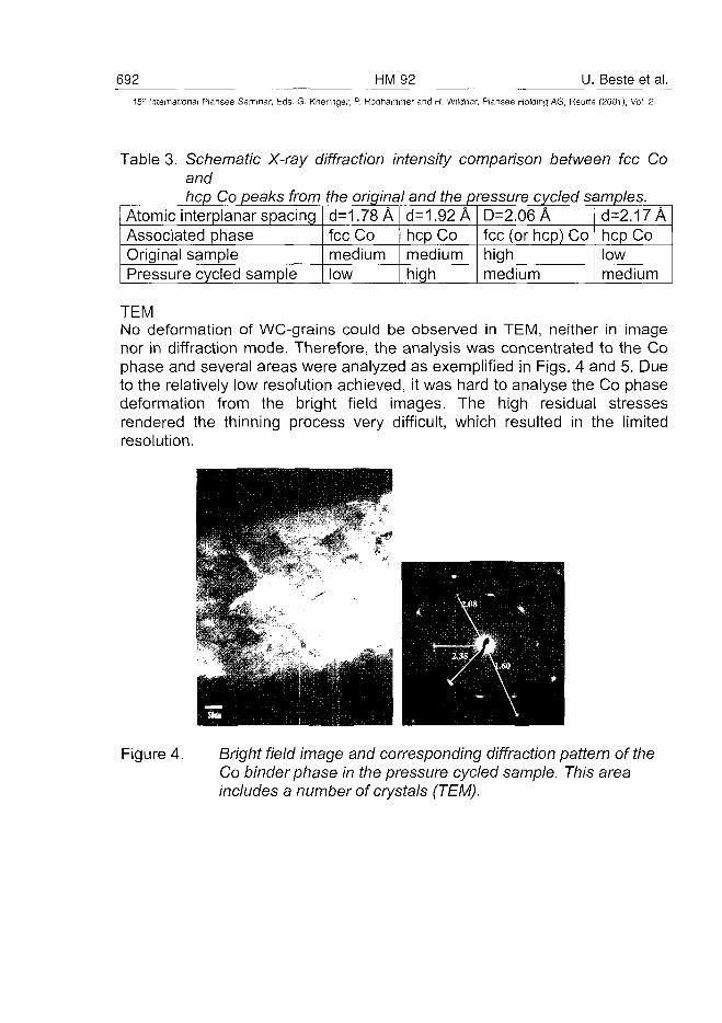
692 HM92 U. Beste et al.15" International Plansee Seminar, Eds. G. Kneringer, P. Rodhammer and H. Wildner, Plansee Holding AG, Reutte (2001), Vol. 2
Table 3. Schematic X-ray diffraction intensity comparison between fee Coandhep Co peaks from the original and the pressure cycled samples.
Atomic interplanar spacingAssociated phaseOriginal samplePressure cycled sample
d=1.78Afee Comediumlow
d=1.92Ahep Co _,mediumhigh
D=2.06Afee (or hep) Cohighmedium
d=2.17Ahep Colowmedium
TEMNo deformation of WC-grains could be observed in TEM, neither in imagenor in diffraction mode. Therefore, the analysis was concentrated to the Cophase and several areas were analyzed as exemplified in Figs. 4 and 5. Dueto the relatively low resolution achieved, it was hard to analyse the Co phasedeformation from the bright field images. The high residual stressesrendered the thinning process very difficult, which resulted in the limitedresolution.
Figure 4. Bright field image and corresponding diffraction pattern of theCo binder phase in the pressure cycled sample. This areaincludes a number of crystals (TEM).
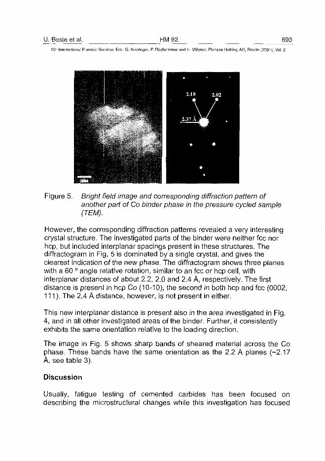
U. Beste et al. HM 92 693^15" International Plansee Seminar, Eds. G. Kneringer, P. Rodhammer and H. Wildner, Plansee Holding AG, Reutte (2001), Vol. 2
Figure 5. Bright field image and corresponding diffraction pattern ofanother part of Co binder phase in the pressure cycled sample(TEM).
However, the corresponding diffraction patterns revealed a very interestingcrystal structure. The investigated parts of the binder were neither fee norhep, but included interplanar spacings present in these structures. Thediffractogram in Fig. 5 is dominated by a single crystal, and gives theclearest indication of the new phase. The diffractogram shows three planeswith a 60 ° angle relative rotation, similar to an fee or hep cell, withinterplanar distances of about 2.2, 2.0 and 2.4 A, respectively. The firstdistance is present in hep Co (10-10), the second in both hep and fee (0002,111). The 2.4 A distance, however, is not present in either.
This new interplanar distance is present also in the area investigated in Fig.4, and in all other investigated areas of the binder. Further, it consistentlyexhibits the same orientation relative to the loading direction.
The image in Fig. 5 shows sharp bands of sheared material across the Cophase. These bands have the same orientation as the 2.2 A planes (-2.17A, see table 3).
Discussion
Usually, fatigue testing of cemented carbides has been focused ondescribing the microstructurai changes while this investigation has focused
694 HM92 U. Beste et al.15:' International Plansee Seminar, Eds. G. Kneringer, P. Rodhammer and H. Wildner, Plansee Holding AG, Reutte (2001), Vol. 2
on property modifications induced by the cyclic loading. These modificationswill be discussed below.
Fracture toughnessAn embrittlement of the cyclic loaded material was manifested by thefracture toughness decrease of about 14 %. The accuracy of this figurecould perhaps be questioned. However, the Palmqvist formula applied is notvery sensitive to small variations of the crack lengths measure, since thetotal crack length appears as an square root in the denominator, and thecrack lengths could be accurately measured in SEM. Since the fracturetoughness was used for direct comparison between of two materials, thechoice of Palmqvist method is not crucial.
Erosion resistanceThe embrittlement of the binder was also manifested by the reduced erosionresistance. The erosion parameters were chosen to yield a good measure ofthe binder properties, involving particles too soft to plastically deform the WCgrains and large enough (500um) to deform relatively large volumes of thecemented carbide in each hit. The exposure to repeated hits from largeparticles, leads to a removal mechanism dominated by fatigue and fractureof the binder phase. No difference in erosion mechanism could be observedin the SEM.
Thermal shock resistanceThe loaded sample showed reduced thermal shock resistance at almost alltemperatures. At 660 °C temperature, the difference is substantial. Thisdegradation either may be due to an increased defect density in the binder,or to better properties of the original fcc-Co, than the phase transformed Co,in the cycled sample.
HardnessThe hardness was found not to change due to the pressure cycling. Thiscould be understood from the microstructures in Fig. 1; the WC-grain sizeand the mean free path both are constant. In this case, current hardnessmodels (1), (15), predict a constant hardness, unless the hardness of thebinder is modified. The hardness of the binder has not been measured inthis investigation.
U. Beste et al. HM 92 695_
15'" International Plansee Seminar, Eds. G. Kneringer, P. Rodhammer and H. Wildner, Plansee Holding AG, Reutte (2001), Vol. 2
Co phase alterationsThe phase of the binder in the cycled specimen has not been identified.From the X-ray diffraction, it was obvious that the initially pure fcc-Co, afterpressure cycling also exhibited planar distances typical of hep-Co. Inelectron diffraction, the binder displays planar distances typical of both feeand hep Co plus a distance not present in either of these phases.
This is a new phase that probably represents some transition form betweenfee and hep, which is stable under the specific conditions of this test. Thephase is probably formed by a more complex stacking sequence of the closepacked atomic planes than the ABAB sequence of hep or the ABCABCsequence of fee. During the TEM sample preparation, very high residualstresses were observed. These stresses may be an important factor in thetransformation process.
Manlang (7) reported overlapping diffraction patterns from fcc-Co and hep-Co, but no interplanar spacing values were mentioned.
The 2.35 A distance was not present in the XRD-spectra. Since the XRDspectroscopy was made on a plane with perpendicular normal direction asthe TEM sample plane (see Figure 1), this could be indicative of a preferredorientation of the crystal lattice relative to the loading direction. In XRD, theintensity from several crystals (i.e. several millimeters) in the loadingdirection is collected, while TEM only yield diffraction from a single or a fewcrystals. The TEM sample showed the same crystal orientation in all Cograins investigated.
Magnetical coercive force, HeThe pressure cycling resulted in a doubling of the magnetic coercive force.However, it is not clear if it is due only to the increasing density of defects orif the phase transformation from fee to hep is contributing.
Conclusions
This investigation illuminates the important role of the binder in thedegradation of cemented carbides. It is interesting to notice thatmodifications of the binder phase can change the tribological behaviour,without modifying the hardness. In applications involving repeated loading,transformations of the binder phase and its properties have been shownlikely to occur and being important for the mechanical properties. However,
696 HM92 U. Beste et al.15" International Plansee Seminar, Eds. G. Kneringer, P. Rodhammer and H. Wildner, Plansee Holding AG, Reutte (2001), Vol. 2
more investigations of the new phase are required. It would for example, beinteresting to know if it is formed in an early stage of the pressure cyclingand then become stable, or if it is a transition form that will change with thenumber of loadings.
To summarise, the cyclic compressive loading (62500 cycles from 0.32 % to1.1 % compression) of the 11%Co-cemented carbide resulted in thefollowing changes of the material structure:
• Insignificant deformation or phase transformation of the WC grains.• Deformation and phase transformation of the Co binder.• Transformation of a new, unidentified Co binder phase characterised
by an undocumented planar distance of 2.35A.• Distinctly increased magnetic coercivity force, due to increased defect
density or phase transformations of the binder.
These changes resulted in the following modifications of the mechanicalproperties:
• Reduced fracture toughness.• Reduced erosion resistance.• Reduced thermal shock resistance.• Insignificant modification of the hardness.• Insignificant modification of Young's modulus.
AcknowledgementsThe financial support, the providing of test materials and the pressurecycling experiments from Sandvik AB are gratefully acknowledged. Theauthors are grateful to Mr. Stefan Ederyd at Sandvik Hard Materials and Dr.Fredric Ericson for valuable discussions.
References
1) H. E. Exner: Physical and chemical nature of cemented carbides,International Metals Review 4 (1979), pp. 149-173
2) U. Beste, T. Hartzell, H. Engqvist and N. Axen: Surface damage oncemented carbide rock drill buttons, Proc. NordTrib 2000, vol. 1,pp. 196-205, Porvoo 2000,
3) J. Larsen-Basse: Wear of hard-metals in rock drilling: a survey ofthe literature, Powder Metallurgy 16 (1973), pp. 1-32
U. Beste et al. HM 92 697_
15'h International Plansee Seminar, Eds. G. Kneringer, P. Rodhammer and H. Wildner, Plansee Holding AG, Reutte (2001), Vol. 2
4) M. Rettenmayr, H. E. Exner and W. Mader: Electron microscopy of binderphase deformation in WC-Co alloys, Materials Science and Technology 4(1988), pp. 984-990
5) R. W. Hertzberg: Deformation and fracture mehcanics of engineeringmaterials, (John Wiley & Sons Inc. 1996), pp. 786
6) A. R. West: Basic solid state chemistry, (John Wiley & Sons Ltd 1996),pp.415
7) L. Manlang, H. Xiaoying, D. Shitian, S. Daqin, C. Yumei and Y. Zhenmei:Diffraction-Contrast Study of Microstructure and Deformation Process ofWC-Co Cemented Carbide, Refractory and Hard Materials, (Sept 1983),pp. 129-132
8) P. Kindermann, P. Schlund, H.-G. Sockel and M. Hern High-temperaturefatigue of cemented carbides under cyclic loads, International journal ofRefractory Metals & Hard Materials 17 (1999), pp. 55-68
9) K. Jia, T. E. Fischer and B. Gallois: Microstructure, hardness andtoughness of nanostructured and conventional WC-Co composites,Nanostructured materials (1998), pp. 875-891
10) C. H. Vasel, A. D. Krawitz, E. F. Drake and E. A. Kenik: Binderdeformation in WC-(Co, Ni) cemented carbide composites, Metallurgical
Transactions 16A (1985), pp. 2309-231711) K. Obrtlik, J. Polak and M. Hajek: Low-cycle fatigue of WC-Co sintered
carbide, Metallic materials 31 (1993), pp. 10-1512) D. Jiles: Introduction to Magnetism and Magnetic Materials, (Chapman &
Hall, London, 1991) pp. 44013) J. Freytag, P. Walter and H. E. Exner: Carakterisierung der Binderphase
von WC-Co Hartmetalien Giber magnetische Eigenschaften, Zeitschriftfur Metallkunde 69 (1978), pp. 546-549
14) B. Roebuck, E. Bennett, L. Lay and R. Morell: Palmqvist Toughness forHard and Brittle Materials, 1998, pp. 36
15) H. Engqvist: Microstructual Aspects on Wear of Cemented Carbides,PhD. Thesis, Uppsala University, 2000
AT0100492698 HM93 F. Klocke et al.
15" International Plansee Seminar, Eds. G. Kneringer, P. Rodhammer and H. Wildner, Plansee Holding AG, Reutte (2001), Vol. 2
Laser-assisted turning of components made ofsilicon-nitride ceramics
Prof. Dr.-lng- Fritz Klocke*, Dipl.-lng. Sascha Bausch*
*Fraunhofer-lnstitute of Production Technology IPT, Aachen, Germany
Summary:
The manufacture of high-precision parts made of silicon-nitride ceramic, suchas roller bearing rings or valves, currently involves finishing in the form of timeand cost intensive grinding operations. This has resulted in demands for thedevelopment of more efficient machining techniques and for the subsequentprovision of these within a manufacturing environment. A prototype of aprecision lathe with an integrated high power diode laser for laser-assistedturning has been developed at the Fraunhofer IPT in close co-operation withindustrial partners. When the workpiece is heated continuously by the laser,the resultant localised material softening enables the ceramic to be machinedusing a defined cutting edge. The application of this technique allowscomplex silicon nitride ceramic parts with surface qualities of up toRa = 0.3 urn to be produced considerably more flexibly than before, with norequirement for cooling lubricant.
Keywords:
Laser-assisted turning, ceramics, silicon-nitride Si3N4
Introduction:
Innovative products frequently call for the use of innovative materials. Thematerial plays a key role within the manufacturing chain - from materialmanufacture through the manufacture of semi-finished parts and finishedparts, to their use within engineering systems. The importance of advancedceramics is increasingly steadily due both to their specific characteristics andto the very exacting demands being imposed on engineering products. Thereis a demand for innovative ceramic components in many areas of industry.Because of their higher wear resistance and lower weight, silicon nitridevalves, for example, are increasingly replacing steel valves in the engineconstruction sector. In sealing and bearing applications too, ceramic roller
F. Klocke et al. HM 93 69915" International Plansee Seminar, Eds. G. Kneringer, P. Rodhammer and H. Wildner, Plansee Holding AG, Reutte (2001), Vol. 2
bearings are already being manufactured and are enhancing slide andemergency running properties in high frequency spindles, for example. In thefield of process engineering, valve seats and cones are being manufacturedfrom ceramic materials. Consequently, they can cope with exposure toaggressive media. Silicon nitride ceramic has come to occupy a position ofparticular importance, by virtue of its characteristics which are superior tothose of oxide ceramics in many respects (high strength in relation to theirweight, high levels of hardness and wear resistance, good thermal fatigueresistance and high temperature strength).
The successful use of new advanced ceramics depends largely on the abilityto implement ceramic-oriented designs on application-oriented functionalparts. The widespread use of ceramic functional parts is hampered, however,by the comparatively high manufacturing costs which arise on one hand fromthe sintering operations conducted in the course of the manufacture of thematerial and on the other hand, to a much larger extent, from the finish-machining (hard machining) operation. The reduction in volume which takesplace in the sintering operation and any distortion which may occur, result indimensional and form inaccuracies which stand in the way of any attempt toachieve »Near-Net-Shaping« during sintering. The properties of thesubsurface zone which forms during sintering (sinter skin) are different fromthose of the base material and must therefore be removed in a finishingoperation. The manufacture of parts with complex geometries and the highlevels of surface quality required, in a green or white machining operationconducted on formed and strengthened unmachined parts prior to sintering, isalso possible only in certain cases. Semi-finished goods must therefore befinish-machined in their sintered (hard) state in order to ensure that thefunctional surfaces required in engineering applications, are achieved.
To date, the industrially applicable manufacturing techniques suitable forfinish-machining ceramic materials in their sintered state, have been limited tomanufacturing operations which are conducted using a geometricallyundefined cutting edge, such as grinding, honing and lapping. The materialremoval rates achieved in these operations, are comparatively low. The abilityto meet demands for ever higher machining capacities in conjunction withincreasingly high levels of machining accuracy is therefore severely limited inrelation to hard machining operations conducted on advanced ceramics.Alongside material removal, surface quality and the subsurface properties ofhard-machined ceramics are important factors in operations involving hard-machined ceramics. Because of the process characteristics of these
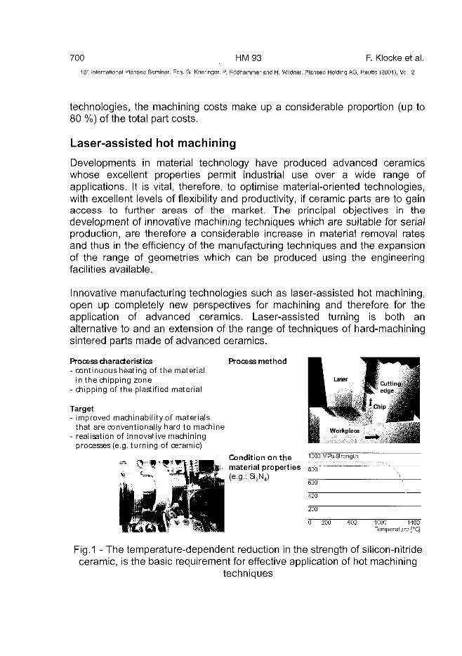
700 HM93 F. Klocke et al.15;" Internationa! Plansee Seminar, Eds. G. Kneringer, P. Rodhammer and H. Wildner, Plansee Holding AG, Reutte (2001), Vol. 2
technologies, the machining costs make up a considerable proportion (up to80 %) of the total part costs.
Laser-assisted hot machining
Developments in material technology have produced advanced ceramicswhose excellent properties permit industrial use over a wide range ofapplications. It is vital, therefore, to optimise material-oriented technologies,with excellent levels of flexibility and productivity, if ceramic parts are to gainaccess to further areas of the market. The principal objectives in thedevelopment of innovative machining techniques which are suitable for serialproduction, are therefore a considerable increase in material removal ratesand thus in the efficiency of the manufacturing techniques and the expansionof the range of geometries which can be produced using the engineeringfacilities available.
Innovative manufacturing technologies such as laser-assisted hot machining,open up completely new perspectives for machining and therefore for theapplication of advanced ceramics. Laser-assisted turning is both analternative to and an extension of the range of techniques of hard-machiningsintered parts made of advanced ceramics.
Process characteristics Process method- continuous heating of the material
in the chipping zone- chipping of the plastified material
Target- improved machinability of materials
that are conventionally hard to machine- realisation of innovative machining
processes (e.g. turning of ceramic)
Condition on the !000.M^?r.ensth_.material properties goo(e.g.: S3N4)
600
400
1000 1400Temperature [°q
Fig.1 - The temperature-dependent reduction in the strength of silicon-nitrideceramic, is the basic requirement for effective application of hot machining
techniques
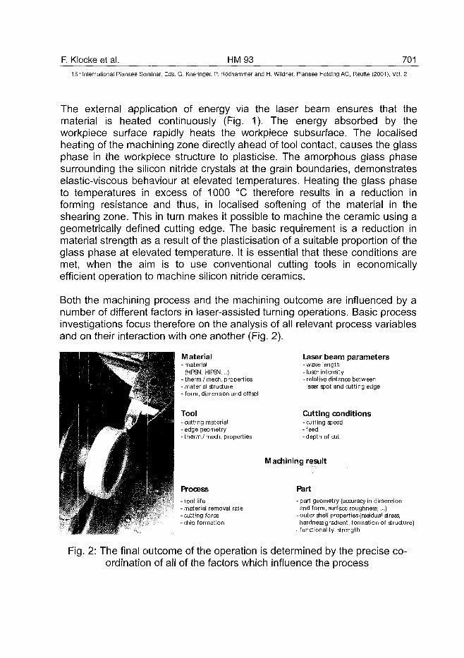
F. Klocke et al. HM93 70115" International Plansee Seminar, Eds. G. Kneringer, P. Rodhammer and H. Wildner, Plansee Holding AG, Reutte (2001), Vol. 2
The external application of energy via the laser beam ensures that thematerial is heated continuously (Fig. 1). The energy absorbed by theworkpiece surface rapidly heats the workpiece subsurface. The localisedheating of the machining zone directly ahead of tool contact, causes the glassphase in the workpiece structure to plasticise. The amorphous glass phasesurrounding the silicon nitride crystals at the grain boundaries, demonstrateselastic-viscous behaviour at elevated temperatures. Heating the glass phaseto temperatures in excess of 1000 °C therefore results in a reduction informing resistance and thus, in localised softening of the material in theshearing zone. This in turn makes it possible to machine the ceramic using ageometrically defined cutting edge. The basic requirement is a reduction inmaterial strength as a result of the plasticisation of a suitable proportion of theglass phase at elevated temperature. It is essential that these conditions aremet, when the aim is to use conventional cutting tools in economicallyefficient operation to machine silicon nitride ceramics.
Both the machining process and the machining outcome are influenced by anumber of different factors in laser-assisted turning operations. Basic processinvestigations focus therefore on the analysis of all relevant process variablesand on their interaction with one another (Fig. 2).
M aterial- material
(HPSN, HIPgvl,..)- therm./ mech. properties- material structure- form, dimension and offset
Tool-cutting material-edge geometry- therm./ mech. properties
Laser beam parameters-wavelength- laser intensity- relative distance betweenlaser spot and cutting edge
Cutting conditions-cutting speed-feed-depth of cut
Process
-tool life- material removal rate- cutting force- chip formation
Machining result
Part
- part geometry (accuracy in dimensionand form, surface roughness,...)
- outer shell propertiesfreadual stress,hardnessgradient, formation of structure)
- functionality, strength
Fig. 2: The final outcome of the operation is determined by the precise co-ordination of all of the factors which influence the process
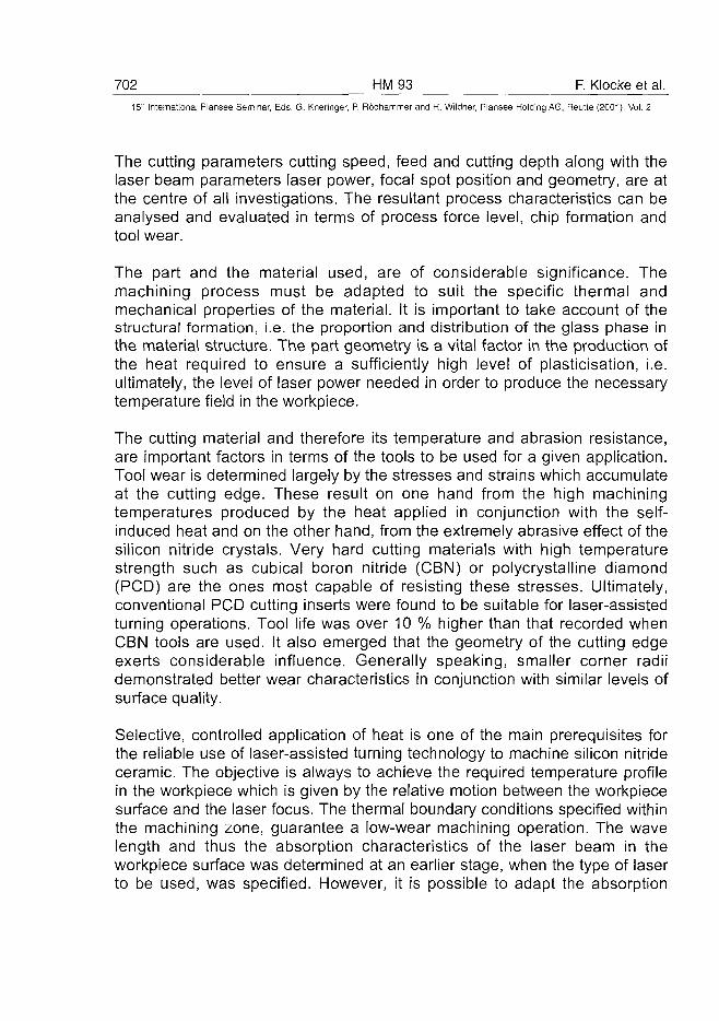
702 HM93 F. Klocke et al.15" International Plansee Seminar, Eds. G. Kneringer, P. Rodhammer and H. Wildner, Plansee Holding AG, Reutte (2001), Vol. 2
The cutting parameters cutting speed, feed and cutting depth along with thelaser beam parameters laser power, focal spot position and geometry, are atthe centre of all investigations. The resultant process characteristics can beanalysed and evaluated in terms of process force level, chip formation andtool wear.
The part and the material used, are of considerable significance. Themachining process must be adapted to suit the specific thermal andmechanical properties of the material. It is important to take account of thestructural formation, i.e. the proportion and distribution of the glass phase inthe material structure. The part geometry is a vital factor in the production ofthe heat required to ensure a sufficiently high level of plasticisation, i.e.ultimately, the level of laser power needed in order to produce the necessarytemperature field in the workpiece.
The cutting material and therefore its temperature and abrasion resistance,are important factors in terms of the tools to be used for a given application.Tool wear is determined largely by the stresses and strains which accumulateat the cutting edge. These result on one hand from the high machiningtemperatures produced by the heat applied in conjunction with the self-induced heat and on the other hand, from the extremely abrasive effect of thesilicon nitride crystals. Very hard cutting materials with high temperaturestrength such as cubical boron nitride (CBN) or polycrystalline diamond(PCD) are the ones most capable of resisting these stresses. Ultimately,conventional PCD cutting inserts were found to be suitable for laser-assistedturning operations. Tool life was over 10 % higher than that recorded whenCBN tools are used. It also emerged that the geometry of the cutting edgeexerts considerable influence. Generally speaking, smaller corner radiidemonstrated better wear characteristics in conjunction with similar levels ofsurface quality.
Selective, controlled application of heat is one of the main prerequisites forthe reliable use of laser-assisted turning technology to machine silicon nitrideceramic. The objective is always to achieve the required temperature profilein the workpiece which is given by the relative motion between the workpiecesurface and the laser focus. The thermal boundary conditions specified withinthe machining zone, guarantee a low-wear machining operation. The wavelength and thus the absorption characteristics of the laser beam in theworkpiece surface was determined at an earlier stage, when the type of laserto be used, was specified. However, it is possible to adapt the absorption
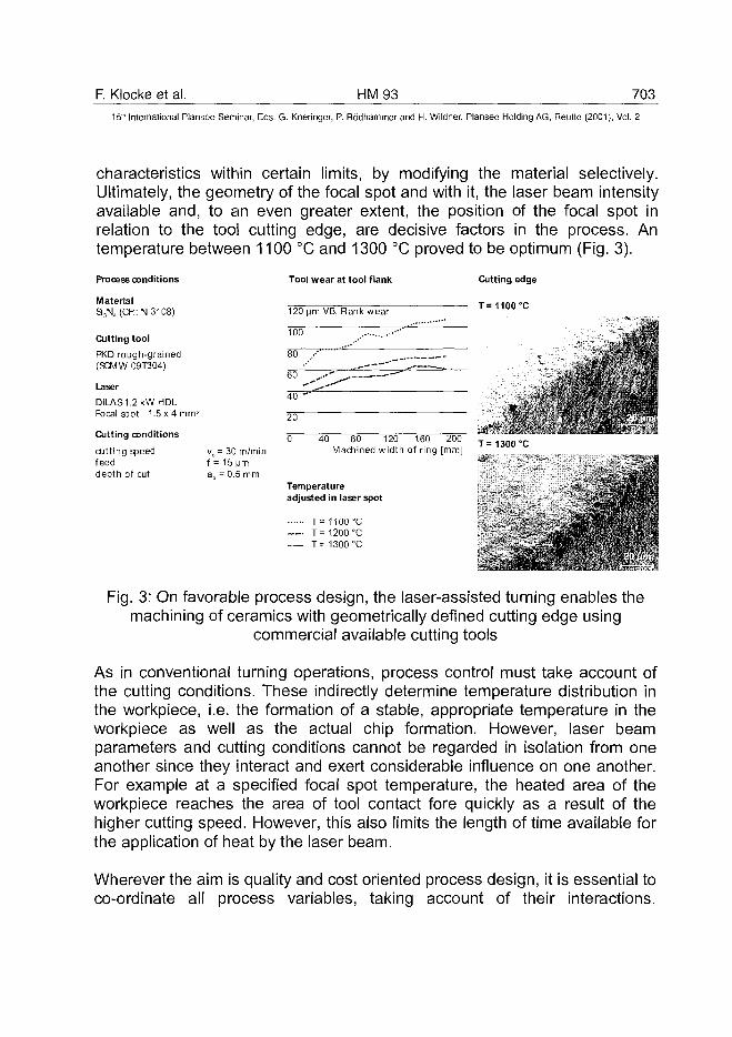
F. Klocke et al. HM93 70315'" International Plansee Seminar, Eds. G. Kneringer, P. Rodhammer and H. Wildner, Plansee Holding AG, Reutte (2001), Vol. 2
characteristics within certain limits, by modifying the material selectively.Ultimately, the geometry of the focal spot and with it, the laser beam intensityavailable and, to an even greater extent, the position of the focal spot inrelation to the tool cutting edge, are decisive factors in the process. Antemperature between 1100 °C and 1300 °C proved to be optimum (Fig. 3).
Cutting edge
T=1100°C
Process conditions
MaterialS3N4 (CFI: N 3108)
Cutting tool
PKD rough-grained(9CMW 09T304)
Laser
DILAS1.2kW HDLFocal spot 1.5x4 mm2
Cutting conditions
cutting speed vc = 30m/minfeed f = 15 Mmdepth of cut ap = 0.5mm
Tool wear at tool flank
120 Mm VB, Rank wear
100
80 /
60 .<£> ""40 ~"
20
0 40 80 120 160 200Machined width of ring [mm]
Temperatureadjusted in laser spot
T= 1100 °C— T= 1200 °C
T= 1300 °C
' •:§.
*.
. # • • $ • •
T=1300°C
Fig. 3: On favorable process design, the laser-assisted turning enables themachining of ceramics with geometrically defined cutting edge using
commercial available cutting tools
As in conventional turning operations, process control must take account ofthe cutting conditions. These indirectly determine temperature distribution inthe workpiece, i.e. the formation of a stable, appropriate temperature in theworkpiece as well as the actual chip formation. However, laser beamparameters and cutting conditions cannot be regarded in isolation from oneanother since they interact and exert considerable influence on one another.For example at a specified focal spot temperature, the heated area of theworkpiece reaches the area of tool contact fore quickly as a result of thehigher cutting speed. However, this also limits the length of time available forthe application of heat by the laser beam.
Wherever the aim is quality and cost oriented process design, it is essential toco-ordinate all process variables, taking account of their interactions.
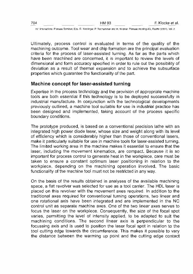
704 HM93 F. Klocke et al.15" International Plansee Seminar, Eds. G. Kneringer, P. Rodhammer and H. Wildner, Plansee Holding AG, Reutte (2001), Vol. 2
Ultimately, process control is evaluated in terms of the quality of themachining outcome. Tool wear and chip formation are the principal evaluationcriteria for the process of laser-assisted turning. As far as the parts whichhave been machined are concerned, it is important to review the levels ofdimensional and form accuracy specified in order to rule out the possibility ofdeviation as a result of thermal expansion and to achieve the subsurfaceproperties which guarantee the functionality of the part.
Machine concept for laser-assisted turning
Expertise in the process technology and the provision of appropriate machinetools are both essential if this technology is to be deployed successfully inindustrial manufacture. In conjunction with the technological developmentspreviously outlined, a machine tool suitable for use in industrial practice hasbeen designed and implemented, taking account of the process specificboundary conditions.
The prototype produced, is based on a conventional precision lathe with anintegrated high power diode laser, whose size and weight along with its levelof efficiency which is considerably higher than those of conventional lasers,make it particularly suitable for use in machine tools for laser-assisted turning.The limited working area in the machine makes it essential to ensure that thelaser, including the movement kinematics, are compact. Because it is soimportant for process control to generate heat in the workpiece, care must betaken to ensure a constant optimum laser positioning in relation to theworkpiece, depending on the machining operation involved. The basicfunctionality of the machine tool must not be restricted in any way.
On the basis of the results obtained in analyses of the available machiningspace, a flat revolver was selected for use as a tool carrier. The HDL laser isplaced on this revolver with the movement axes required. In addition to thetraditional axes required for conventional turning operations, two linear andone rotational axis have been integrated and are implemented in the NCcontrol unit as separate machine axes. One of the two linear axes serves tofocus the laser on the workpiece. Consequently, the size of the focal spotvaries, permitting the level of intensity applied, to be adapted to suit themachining conditions. The second linear axis is perpendicular to thefocussing axis and is used to position the laser focal spot in relation to thetool cutting edge towards the circumference. This makes it possible to varythe distance between the warming up point and the cutting edge contact
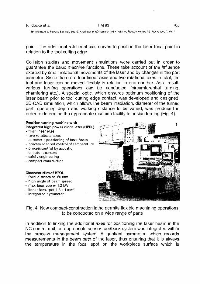
F. Klocke et al. HM93 70515th International Plansee Seminar, Eds. G. Kneringer, P. Rodhammer and H. Wildner, Plansee Holding AG, Reutte (2001), Vol. 2
point. The additional rotational axis serves to position the laser focal point inrelation to the tool cutting edge.
Collision studies and movement simulations were carried out in order toguarantee the basic machine functions. These take account of the influenceexerted by small rotational movements of the laser and by changes in the partdiameter. Since there are four linear axes and two rotational axes in total, thetool and laser can be moved flexibly in relation to one another. As a result,various turning operations can be conducted (circumferential turning,chamfering etc.). A special optic, which ensures optimum positioning of thelaser beam prior to tool cutting edge contact, was developed and designed.3D-CAD simulation, which allows the beam irradiation, diameter of the turnedpart, operating depth and working distance to be varied, was produced inorder to determine the appropriate machine facility for inside turning (Fig. 4).
IPrecision turning machine withintegrated high power diode laser (HPDL)- four linear axes- two rotational axes- automatic positioning of laser focus- process adapted control of temperature- process control by acoustic
emissionssensors- safety engineering- compact construction
Characteristics of HPDL- focal distance ca. 80 mm- high angle of beam spread- max. laser power 1.2 kW- linear focal spot 1.5 x 4 mm2
- integrated pyrometer
Fig. 4: New compact-construction lathe permits flexible machining operationsto be conducted on a wide range of parts
In addition to linking the additional axes for positioning the laser beam in theNC control unit, an appropriate sensor feedback system was integrated withinthe process management system. A quotient pyrometer, which recordsmeasurements in the beam path of the laser, thus ensuring that it is alwaysthe temperature in the focal spot on the workpiece surface which is
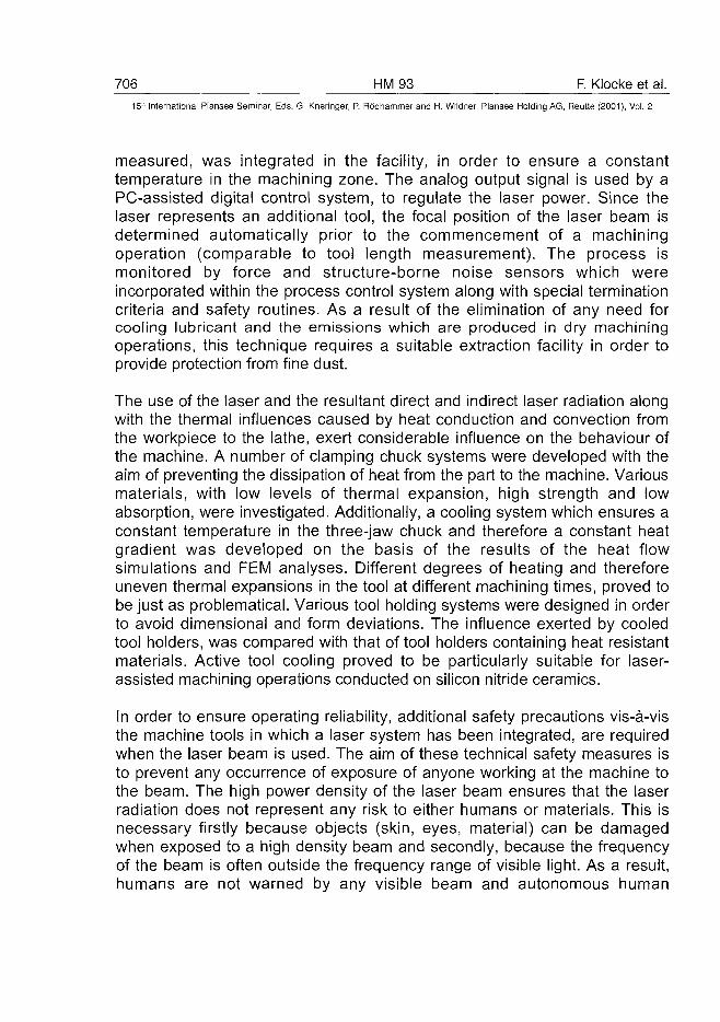
706 HM 93 F. Klocke et al.15" International Plansee Seminar, Eds. G. Kneringer, P. Rodhammer and H. Wildner, Plansee Holding AG, Reutte (2001), Vol. 2
measured, was integrated in the facility, in order to ensure a constanttemperature in the machining zone. The analog output signal is used by aPC-assisted digital control system, to regulate the laser power. Since thelaser represents an additional tool, the focal position of the laser beam isdetermined automatically prior to the commencement of a machiningoperation (comparable to tool length measurement). The process ismonitored by force and structure-borne noise sensors which wereincorporated within the process control system along with special terminationcriteria and safety routines. As a result of the elimination of any need forcooling lubricant and the emissions which are produced in dry machiningoperations, this technique requires a suitable extraction facility in order toprovide protection from fine dust.
The use of the laser and the resultant direct and indirect laser radiation alongwith the thermal influences caused by heat conduction and convection fromthe workpiece to the lathe, exert considerable influence on the behaviour ofthe machine. A number of clamping chuck systems were developed with theaim of preventing the dissipation of heat from the part to the machine. Variousmaterials, with low levels of thermal expansion, high strength and lowabsorption, were investigated. Additionally, a cooling system which ensures aconstant temperature in the three-jaw chuck and therefore a constant heatgradient was developed on the basis of the results of the heat flowsimulations and FEM analyses. Different degrees of heating and thereforeuneven thermal expansions in the tool at different machining times, proved tobe just as problematical. Various tool holding systems were designed in orderto avoid dimensional and form deviations. The influence exerted by cooledtool holders, was compared with that of tool holders containing heat resistantmaterials. Active tool cooling proved to be particularly suitable for laser-assisted machining operations conducted on silicon nitride ceramics.
In order to ensure operating reliability, additional safety precautions vis-a-visthe machine tools in which a laser system has been integrated, are requiredwhen the laser beam is used. The aim of these technical safety measures isto prevent any occurrence of exposure of anyone working at the machine tothe beam. The high power density of the laser beam ensures that the laserradiation does not represent any risk to either humans or materials. This isnecessary firstly because objects (skin, eyes, material) can be damagedwhen exposed to a high density beam and secondly, because the frequencyof the beam is often outside the frequency range of visible light. As a result,humans are not warned by any visible beam and autonomous human
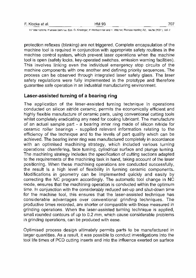
F. Klocke et al. HM 93 707^15'" International Plansee Seminar, Eds. G. Kneringer, P. Rodhammer and H. Wildner, Plansee Holding AG, Reutte (2001), Vol. 2
protection reflexes (blinking) are not triggered. Complete encapsulation of themachine tool is required in conjunction with appropriate safety routines in themachine control system, which prevent laser operations when the machinetool is open (safety locks, key-operated switches, emission warning facilities).This involves linking even the individual emergency stop circuits of themachine components with one another and defining priority sequences. Theprocess can be observed through integrated laser safety glass. The lasersafety regulations were fully implemented in the prototype and thereforeguarantee safe operation in an industrial manufacturing environment.
Laser-assisted turning of a bearing ring
The application of the laser-assisted turning technique in operationsconducted on silicon nitride ceramic, permits the economically efficient andhighly flexible manufacture of ceramic parts, using conventional cutting toolswhilst completely eradicating any need for cooling lubricant. The manufactureof an actual sample part - a bearing inner ring made of silicon nitride forceramic roller bearings - supplied relevant information relating to theefficiency of the technique and to the levels of part quality which can beachieved. The bearing inner ring was manufactured completely in accordancewith an optimised machining strategy, which included various turningoperations: chamfering, face turning, cylindrical surface and plunge turning.The machining strategy includes the specification of cutting sections adaptedto the requirements of the machining task in hand, taking account of the laserpositioning. When these machining operations are conducted successfully,the result is a high level of flexibility in forming ceramic components.Modifications in geometry can be implemented quickly and easily bycorrecting the NC program accordingly. The automatic tool change in NCmode, ensures that the machining operation is conducted within the optimumtime. In conjunction with the considerably reduced set-up and shut-down timefor the machine tool, this ensures that the laser-assisted technique hasconsiderable advantages over conventional grinding techniques. Theproductive times recorded, are shorter or comparable with those measured ingrinding operations. When the laser-assisted turning technique is applied,small rounded contours of up to 0.2 mm, which cause considerable problemsin grinding operations, can be produced with ease.
Optimised process design ultimately permits parts to be manufactured inlarger quantities. As a result, it was possible to conduct investigations into thetool life times of PCD cutting inserts and into the influence exerted on surface
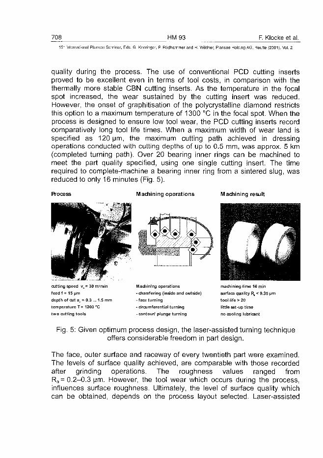
708 HM93 F. Klocke et al.15r International Plansee Seminar, Eds. G. Kneringer, P. Rodhammer and H. Wildner, Plansee Holding AG, Reutte (2001), Vol. 2
quality during the process. The use of conventional PCD cutting insertsproved to be excellent even in terms of tool costs, in comparison with thethermally more stable CBN cutting inserts. As the temperature in the focalspot increased, the wear sustained by the cutting insert was reduced.However, the onset of graphitisation of the polycrystalline diamond restrictsthis option to a maximum temperature of 1300 °C in the focal spot. When theprocess is designed to ensure low tool wear, the PCD cutting inserts recordcomparatively long tool life times. When a maximum width of wear land isspecified as 120 urn, the maximum cutting path achieved in dressingoperations conducted with cutting depths of up to 0.5 mm, was approx. 5 km(completed turning path). Over 20 bearing inner rings can be machined tomeet the part quality specified, using one single cutting insert. The timerequired to complete-machine a bearing inner ring from a sintered slug, wasreduced to only 16 minutes (Fig. 5).
Process Machining operations Machining result
cutting speed vc = 30m/min
feed f = 15 pm
depth of cut ap = 0.3 ... 1.5 mm
temperature T= 1200 °C
two cutting tools
Machining operations
- chamfering (inside and outside)
-face turning
- circumferential turning
-contour/ plunge turning
machining time 16 min
surface quality R, < 0.35 urn
tool life > 20
little set-up time
no cooling lubricant
Fig. 5: Given optimum process design, the laser-assisted turning techniqueoffers considerable freedom in part design.
The face, outer surface and raceway of every twentieth part were examined.The levels of surface quality achieved, are comparable with those recordedafter grinding operations. The roughness values ranged fromRa= 0.2-0.3 um. However, the tool wear which occurs during the process,influences surface roughness. Ultimately, the level of surface quality whichcan be obtained, depends on the process layout selected. Laser-assisted
F. Klocke et al. HM 93 709_
15" International Plansee Seminar, Eds. G. Kneringer, P. Rodhammer and H. Wildner, Plansee Holding AG, Reutte (2001), Vol. 2
machining has a clear advantage over grinding in terms of edge quality.Examinations conducted on the edge transitions between areas machined indifferent turning operations, did not reveal and edge spading. This alsoapplies to machining operations conducted on ceramic parts, using toolswhich already show signs of considerable wear. With regard to the levels ofpart quality which can be achieved, the levels of dimensional and formaccuracy achieved following integration of the cooling devices previouslydescribed, were satisfactory (Tolerance Grades IT 9 and IT 7), despite thehigh process temperatures of up to 1300 °C in the machining zone.
Conclusion
In terms of economic factors such as the machining time and cost, laser-assisted turning is a promising alternative to the traditional grinding operation.Investigations conducted against the background of a concrete machiningtask, show that in some cases, higher rates of material removal and largerareas of material removal can be achieved in conjunction with lower toolcosts. It is likely that further potential for savings will arise when thetechnological options are exploited by replacing individual process steps.Additionally, the cost of preparing for a machining operation is lower in termsof the NC programming and the adjustment work required. Accordingly,companies will be able to respond more rapidly to customer requirements andwill provide greater flexibility with regard to part design. This has beenconfirmed by an extensive analysis of the manufacture of demo-parts. Furtherincreases in efficiency in the production planning department are likely toarise in future, as a result of the deployment of computer systems to supportNC programming. Adequate consideration must also be given to theecological factors. The complete elimination of any need for cooling lubricantin laser-assisted turning operations, provides a substantial competitiveadvantage. No cost at all is incurred in relation to procurement, preparationand the disposal of cooling lubricant.
The integration concept selected and the resultant possible machiningoperations, will enable manufacturing companies to extend the range ofgeometries and forms for ceramic parts, by applying the laser-assistedturning technique. Economically efficient manufacture of geometricalelements, whose manufacture in conventional grinding operations waspreviously obstructed by technological limitations, will likewise ultimatelyresult in expansion of the range of applications for ceramic components andwill open up new markets for ceramic. It is worth bearing in mind that there
710 HM93 F. Klocke et al.15" International Plansee Seminar, Eds. G. Kneringer, P. Rodhammer and H. Wildner, Plansee Holding AG, Reutte (2001), Vol. 2
will, in the future, be the option of machining other advanced ceramics (SiC,AI2O3, ZrO2) in laser-assisted turning operations and therefore new potentialfor the use of ceramics.
Acknowledgements
Financial support of this work by the German Federal Ministry for Educationand Research (BMBF) under 02PV72077 is gratefully acknowledged.
References
A. Zaboklicki: "Laserunterstutztes Drehen dichtgesinterter Siliziumnitrid-Keramik, Berichte aus der Produktionstechnik" Bd. 16, 98 (Shaker VerlagGmbH, 1998)
F. Klocke and T. Bergs: Werkstoffwoche '98, Vol. V, pp. 131
F. Klocke and T. Bergs: Maschinenmarkt 105 (1999) 16, pp. 68-74
M. Week and S. Kasperowski: Schweizer Maschinenmarkt SMM 13 (1998),pp. 36-38
T. Bergs and S. Kasperowski: Tools, Informationen der AachenerProduktionstechniker4 (1998), pp. 6-7
AT0100493J. L Collins HM94 711
15lh International Plansee Seminar, Eds. G. Kneringer, P. Rodhammer and H. Wildner, Plansee Holding AG, Reutte (2001), Vol. 2
High Speed Dry Machining of MMCs With Diamond Tools
J. L CollinsDe Beers Industrial Diamonds (UK) Ltd, Charters,
Ascot, Berkshire, SL5 9PX, UK
Summary
The increasing use of Metal Matrix Composites (MMCs) has raised new issuesin their machining. Industrial demands for higher speed and dry machining ofMMCs with improved component production to closer tolerances have driventhe development of new tool materials. In particular, the wear characteristics ofsynthetic diamond tooling satisfy many of the requirements imposed in cuttingthese highly abrasive workpieces. The use of diamond tool materials, such asPolycrystalline Diamond (PCD), has resulted in tool life improvements which,allied with environmiental considerations, show great potential for the develop-ment of dry cutting. This paper explores the wear characteristics of PCD,which is highly suited to the dry machining of particulate silicon carbide MMCs.Also, two further diamond tool materials are evaluated - Chemical VapourDeposition (CVD) thick layer diamond and synthetic single crystal diamond.Their suitability for the efficient machining of high volume fraction MMC materi-als is shown and their potential impact on the subsequent acceptance andintegration of MMCs into engineering components is discussed.
Keywords
Diamond; Metal Matrix Composites; MMC; PCD; Chemical Vapour Deposition;CVD; Synthetic Single Crystal Diamond;
1. MMC Machining in a New Millennium
For several years, metal matrix composites (MMCs) have been widely avail-able in a variety of forms, engineered for specialist industrial use. In particular,because of their excellent abrasion resistance and ease of manufacture,silicon carbide particle reinforced and short fibre reinforced aluminium alloysare increasingly desired by industry to replace existing components in a mass-production environment (1). In 1999, the world-wide sales of MMCs was$102.7 million, representing approximately 2.5 million kilogrammes of metal
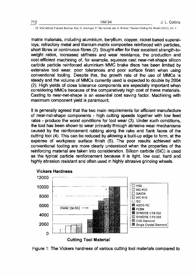
712 HM94 J. L. Collins15* International Plansee Seminar, Eds. G. Kneringer, P. Rodhammer and H. Wildner, Plansee Holding AG, Reutte (2001), Vol. 2
matrix materials, including aluminium, beryllium, copper, nickel-based superal-loys, refractory metal and titanium-matrix composites reinforced with particles,short fibres or continuous fibres (2). Sought-after for their excellent strength-to-weight ratios, increased stiffness and wear resistance, the production andcost-efficient machining of, for example, squeeze cast near-net-shape siliconcarbide particle reinforced aluminium MMC brake discs has been limited byextensive tool wear, poor tolerances and poor surface finish when usingconventional tooling. Despite this, the growth rate of the use of MMCs issteady and the volume of MMCs currently used is expected to double by 2004(2). High yields of close tolerance components are especially important whenconsidering MMCs because of the comparatively high cost of these materials.Casting to near-net-shape is an essential cost saving factor. Machining withmaximum component yield is paramount.
It is generally agreed that the two main requirements for efficient manufactureof near-net-shape components - high cutting speeds together with low feedrates - produce the worst conditions for tool wear (3). Under such conditions,the tool has been shown to wear primarily through abrasive wear mechanismscaused by the reinforcement rubbing along the rake and flank faces of thecutting tool (4). This can be reduced by allowing a built-up edge to form, at theexpense of workpiece surface finish (5). The poor results achieved withconventional tooling are more clearly understood when the properties of thereinforcing material are taken into consideration. Silicon carbide (SiC) is usedas the typical particle reinforcement because it is light, low cost, hard andhighly abrasion resistant and often used in highly abrasive grinding wheels.
Vickers Hardness12000
'"-ft| Harder than SiC| »- fep*
T—
10000
8000
6000
4000
2000
0
Cutting Tool Material
Figure 1: The Vickers hardness of various cutting tool materials compared to
• HSS• WC-K20• SiAION• WC-K10• SiCM AI2O3-TiCH PCBNM SYNDITE CTB 002• SYNDITE CTH 025• CVD Diamond0 Single Crystal Diamond
J. L. Collins HM 94 T\3_15" International Plansee Seminar, Eds. G. Kneringer, P. Rddhammer and H. Wildner, Plansee Holding AG, Reutte (2001), Vol. 2
Figure 1 shows the relative Vickers hardness of various cutting tool materialscompared to that of SiC. Only ultrahard materials and novel coated tools willbe resilient against the abrasive SiC particle reinforcement, their comparativelyhigh thermal conductivity also reducing tool wear caused by temperaturegeneration during machining. However, economic constraints often limit thetool material used to those less durable materials, where tool life is short butsurface finish is adequate, thus limiting the mass-production of high tolerancecomponents. Machining using coolant to improve surface finish and tool lifehas been shown to be moderately effective, but it has been noted that this, infact, can reduce the tendency for built-up edge formation, thereby improvingworkpiece surface finish. However, the abrasive slurry which is formed fromthe MMC reinforcement can accelerates tool wear (6). The difficulties encoun-tered in industrial applications have led to grinding with superabrasive materi-als being used as the main operation employed to achieve the desiredcomponent surface finish and dimensional tolerances. The use of SiC particu-late reinforced aluminium alloy MMC has, until relatively recently, beenpredominantly in specialist applications rather than in mass production.
Over the past decade the machining of MMCs to the stringent requirements ofindustry by techniques other than grinding has been made possible throughresearch using ultrahard materials such as PCD. In particular, dry machining isincreasingly used to reduce costs and fulfil environmental obligations set bycurrent legislation (7). As MMC technology and usage have evolved, so toohas the development of improved ultrahard and wear-resistant grades of PCDfor dry machining with enhanced tool performance, improved workpiecesurface integrity, better machining tolerances and the potential for reducedmachining costs (8). The more recent development of novel ultrahard materi-als - such as CVD diamond - offers an exciting alternative to currently usedtool materials, their excellent abrasion resistance and high thermal stabilityallowing increased cutting speeds during dry machining.
This paper examines the performance of two grades of PCD (SYNDITE CTB002 and SYNDITE CTH 025), two grades of thick layer CVD diamond(CVDITE CDM and CVDITE CDE), and synthetic single crystal diamond(MONODITE) in single point turning a typical SiC particulate reinforced alumin-ium alloy MMC over a range of cutting speeds in terms of surface finish,monitoring wear progression and cutting forces to estimate overall tool life.
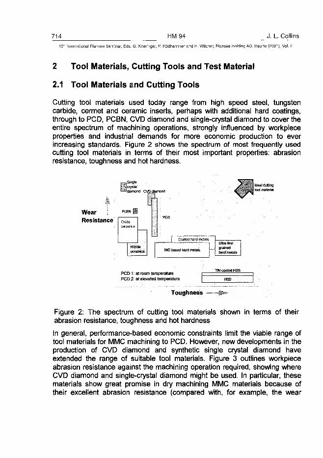
714 HM94 J. L. Collins15* International Plansee Seminar, Eds. G. Kneringer, P. Rodhammer and H. Wildner, Plansee Holding AG, Reutte (2001), Vol. 2
2 Tool Materials, Cutting Tools and Test Material
2.1 Tool Materials and Cutting Tools
Cutting tool materials used today range from high speed steel, tungstencarbide, cermet and ceramic inserts, perhaps with additional hard coatings,through to PCD, PCBN, CVD diamond and single-crystal diamond to cover theentire spectrum of machining operations, strongly influenced by workpieceproperties and industrial demands for more economic production to everincreasing standards. Figure 2 shows the spectrum of most frequently usedcutting tool materials in terms of their most important properties: abrasionresistance, toughness and hot hardness.
_ Singlejjjcrystal^ d i a m o n d CVD diamond
ItWear \ ^NIResistance
Nitrideceramics
PCD
Coated hard metals
WC based hard metals
Ultra fmeg railedhafd metals
PCD 1: at room temperaturePCD 2: at elevated temperature
TiN coated HSS
HSS
Toughness
Figure 2: The spectrum of cutting tool materials shown in terms of theirabrasion resistance, toughness and hot hardness
In general, performance-based economic constraints limit the viable range oftool materials for MMC machining to PCD. However, new developments in theproduction of CVD diamond and synthetic single crystal diamond haveextended the range of suitable tool materials. Figure 3 outlines workpieceabrasion resistance against the machining operation required, showing whereCVD diamond and single-crystal diamond might be used. In particular, thesematerials show great promise in dry machining MMC materials because oftheir excellent abrasion resistance (compared with, for example, the wear
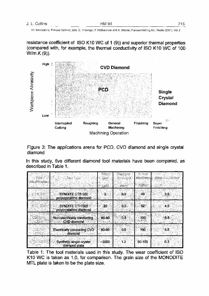
J. L. Collins HM94 71515:h International Plansee Seminar, Eds. G. Kneringer, P. Rodhammer and H. Wildner, Plansee Holding AG, Reurte (2001), Vol. 2
resistance coefficient of ISO K10 WC of 1 (9)) and superior thermal properties(compared with, for example, the thermal conductivity of ISO K10 WC of 100W/m.K(9)).
J5<
CD
High A,
Low
InterruptedCutting
CVD Diamond
PCD SingleCrystalDiamond
Roughing General Finishing SuperMachining Finishing
Machining Operation
Figure 3: The applications arena for PCD, CVD diamond and single crystaldiamond
In this study, five different diamond tool materials have been compared, asdescribed in Table 1.
<
• • ) • • • " ' , ' • • .
SYNDITE CTB 002polycrystalline diamond
SYNDITE CTH 025polycrystalline diamond
Non-electrically conducting' CVD diamond
Electrically conducting CVDdiamond
Synthetic single crystaldiamond plate
2
25
60-80
60-80
-3500
"•;• ; • ; . . . - M I
0.5
0.5
0.5
0.5
1.2
48
52
100
100
50-100
3.9
4.5
5.5
5.5
6.3
Table 1: The tool materials used in this study. The wear coefficient of ISOK10 WC is taken as 1.0, for comparison. The grain size of the MONODITEMTL plate is taken to be the plate size.
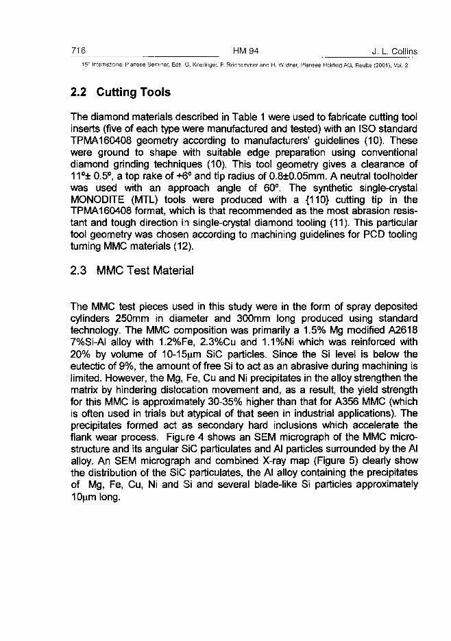
716 HM94 J. L. Collins1511 International Plansee Seminar, Eds. G. Kneringer, P. Rodhammer and H. Wildner, Plansee Holding AG, Reutte (2001), Vol. 2
2.2 Cutting Tools
The diamond materials described in Table 1 were used to fabricate cutting toolinserts (five of each type were manufactured and tested) with an ISO standardTPMA160408 geometry according to manufacturers' guidelines (10). Thesewere ground to shape with suitable edge preparation using conventionaldiamond grinding techniques (10). This tool geometry gives a clearance of11°± 0.5°, a top rake of +6° and tip radius of 0.8±0.05mm. A neutral toolholderwas used with an approach angle of 60°. The synthetic single-crystalMONODITE (MTL) tools were produced with a {110} cutting tip in theTPMA160408 format, which is that recommended as the most abrasion resis-tant and tough direction in single-crystal diamond tooling (11). This particulartool geometry was chosen according to machining guidelines for PCD toolingturning MMC materials (12).
2.3 MMC Test Material
The MMC test pieces used in this study were in the form of spray depositedcylinders 250mm in diameter and 300mm long produced using standardtechnology. The MMC composition was primarily a 1.5% Mg modified A26187%Si-AI alloy with 1.2%Fe, 2.3%Cu and 1.1 %Ni which was reinforced with20% by volume of 10-15p.m SiC particles. Since the Si level is below theeutectic of 9%, the amount of free Si to act as an abrasive during machining islimited. However, the Mg, Fe, Cu and Ni precipitates in the alloy strengthen thematrix by hindering dislocation movement and, as a result, the yield strengthfor this MMC is approximately 30-35% higher than that for A356 MMC (whichis often used in trials but atypical of that seen in industrial applications). Theprecipitates formed act as secondary hard inclusions which accelerate theflank wear process. Figure 4 shows an SEM micrograph of the MMC micro-structure and its angular SiC particulates and Al particles surrounded by the Alalloy. An SEM micrograph and combined X-ray map (Figure 5) clearly showthe distribution of the SiC particulates, the Al alloy containing the precipitatesof Mg, Fe, Cu, Ni and Si and several blade-like Si particles approximately10(am long.
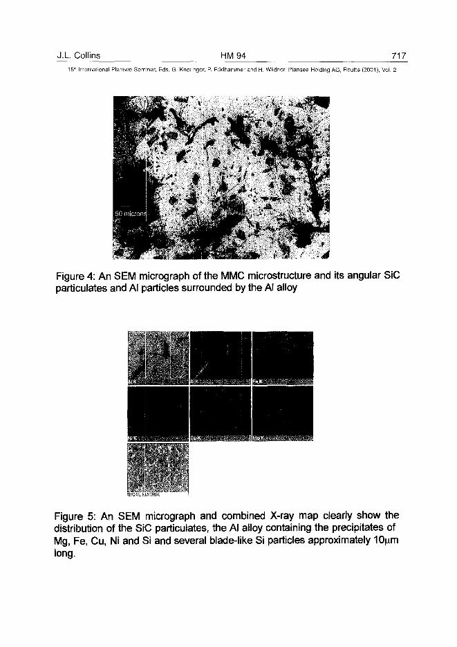
J.L. Collins HM94 71715"1 International Plansee Seminar, Eds. G. Kneringer, P. Rodhammer and H. Wildner, Plansee Holding AG, Reutte (2001), Vol. 2
Figure 4: An SEM micrograph of the MMC microstructure and its angular SiCparticulates and Al particles surrounded by the Al alloy
Figure 5: An SEM micrograph and combined X-ray map clearly show thedistribution of the SiC particulates, the Al alloy containing the precipitates ofMg, Fe, Cu, Ni and Si and several blade-like Si particles approximately 10nmlong.
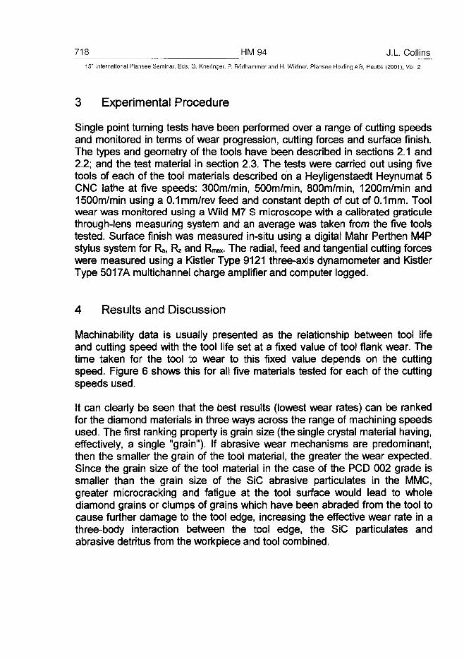
718 HM94 J.L Collins15" International Plansee Seminar, Eds. G. Kneringer, P. Rodhammer and H. Wildner, Plansee Holding AG, Reutte (2001), Vol. 2
3 Experimental Procedure
Single point turning tests have been performed over a range of cutting speedsand monitored in terms of wear progression, cutting forces and surface finish.The types and geometry of the tools have been described in sections 2.1 and2.2; and the test material in section 2.3. The tests were carried out using fivetools of each of the tool materials described on a Heyligenstaedt Heynumat 5CNC lathe at five speeds: 300m/min, 500m/min, 800m/min, 1200m/min and1500m/min using a 0.1 mm/rev feed and constant depth of cut of 0.1mm. Toolwear was monitored using a Wild M7 S microscope with a calibrated graticulethrough-lens measuring system and an average was taken from the five toolstested. Surface finish was measured in-situ using a digital Mahr Perthen M4Pstylus system for Ra, Rz and Rmax. The radial, feed and tangential cutting forceswere measured using a Kistler Type 9121 three-axis dynamometer and KistlerType 5017A multichannel charge amplifier and computer logged.
4 Results and Discussion
Machinability data is usually presented as the relationship between tool lifeand cutting speed with the tool life set at a fixed value of tool flank wear. Thetime taken for the tool to wear to this fixed value depends on the cuttingspeed. Figure 6 shows this for all five materials tested for each of the cuttingspeeds used.
It can clearly be seen that the best results (lowest wear rates) can be rankedfor the diamond materials in three ways across the range of machining speedsused. The first ranking property is grain size (the single crystal material having,effectively, a single "grain"). If abrasive wear mechanisms are predominant,then the smaller the grain of the tool material, the greater the wear expected.Since the grain size of the tool material in the case of the PCD 002 grade issmaller than the grain size of the SiC abrasive particulates in the MMC,greater microcracking and fatigue at the tool surface would lead to wholediamond grains or clumps of grains which have been abraded from the tool tocause further damage to the tool edge, increasing the effective wear rate in athree-body interaction between the tool edge, the SiC particulates andabrasive detritus from the workpiece and tool combined.
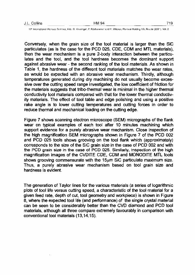
J.L Collins HM94 71915" International Plansee Seminar, Eds. G. Kneringer, P. Rodhammer and H. Wildner, Plansee Holding AG, Reutte (2001), Vol. 2
Conversely, when the grain size of the tool material is larger than the SiCparticulates (as is the case for the PCD 025, CDE, CDM and MTL materials),then the wear mechanism is a pure 2-body interaction between the particu-lates and the tool, and the tool hardness becomes the dominant supportagainst abrasive wear - the second ranking of the tool materials. As shown inTable 1, the hardness of the different tool materials matches the wear rates,as would be expected with an abrasive wear mechanism. Thirdly, althoughtemperatures generated during dry machining do not usually become exces-sive over the cutting speed range investigated, the low coefficient of friction forthe materials suggests that tribo-thermal wear is minimal in the higher thermalconductivity tool materials compared with that for the lower thermal conductiv-ity materials. The effect of tool table and edge polishing and using a positiverake angle is to lower cutting temperatures and cutting forces in order toreduce thermal and mechanical loading on the cutting edge.
Figure 7 shows scanning electron microscope (SEM) micrographs of the flankwear on typical examples of each tool after 10 minutes machining whichsupport evidence for a purely abrasive wear mechanism. Close inspection ofthe high magnification SEM micrographs shown in Figure 7 of the PCD 002and PCD 025 tools shows grooving on the tool flank which (approximately)corresponds to the size of the SiC grain size in the case of PCD 002 and withthe PCD grain size in the case of PCD 025. Similarly, inspection of the highmagnification images of the CVDITE CDE, CDM and MONODITE MTL toolsshows grooving commensurate with the 15|im SiC particulate maximum size.Thus, a purely abrasive wear mechanism based on tool grain size andhardness is evident.
The generation of Taylor lines for the various materials (a series of logarithmicplots of tool life versus cutting speed, a characteristic of the tool material for agiven feed rate, depth of cut, tool geometry and workpiece) is shown in Figure8, where the expected tool life (and performance) of the single crystal materialcan be seen to be considerably better than the CVD diamond and PCD toolmaterials, although all three compare extremely favourably in comparison withconventional tool materials (13,14,15).
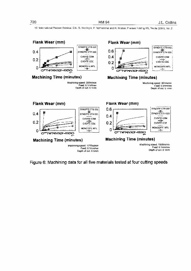
720 HM 94 J.L. Collins5'-'' International Plansee Seminar, Eds. G. Kneringer, P. Rödhammer and H. Wildner, Plansee Holding AG, Reutte (2001), Vol. 2
Flank Wear (mm)SYNODE CTB 002
-•-SYNDITE CTH 025
CVDrTE CDM
-a-CVDITECDE
MONODfTE MTLMachining Time (minutes)Machining speed: 300m/min
Feed: 0.1mm/revDepth of cut: 0.1mm
Flank Wear (mm)SYNDITE CTB 002
- » -SYNDrTE CTH 025
CVDITE CDM-a- j
CVDITE CDE
MONODFTE MTL
Machining Time (minutes)Machining speed: 800m/min
Feed: 0.1 mm/revDepth of cut: O.imm
SYNDFTE CTB 002
SYNDITE CTH 025
CVDITE CDM
-B-CVDITE CDE
MONODITE MTL
Machining Time (minutes)Macnining speed: 1200m/min
Feed: 0.1mm/revDepth of cut: 0.1mm
Flank Wear (mm)SYNDITE CTB 002
-B-SYNDITE CTH 025
CVDrTE CDM
-e-CVDrTE CDE
MONODITE MTL
Machining Time (minutes)Machining speed: 1500m/min
Feed: 0.1mm/revDepth of cut: 0.1mm
Figure 6: Machining data for all five materials tested at four cutting speeds
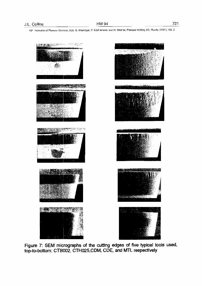
J.L. Collins HM94 721
15" International Plansee Seminar, Eds. G. Kneringer, P. Rodhammer and H. Wildner, Plansee Holding AG, Reutte (2001), Vol. 2
Figure 7: SEM micrographs of the cutting edges of five typical tools used,top-to-bottom: CTB002, CTH025.CDM, CDE, and MTL respectively
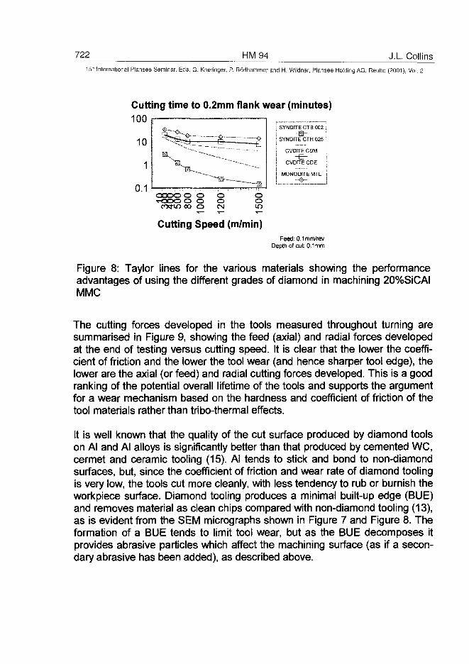
722 HM 94 J.L Collins15:' International Plansee Seminar, Eds. G. Kneringer, P. Rödhammer and H. Wildner, Plansee Holding AG, Reutte (2001), Vol. 2
Cutting time to 0.2mm flank wear (minutes)
HsYNDITE CTB 002
| SYNDUE CTH 025
CVDITE CDM
-B-CVDITE CDE
MONODrTE MTL
Cutting Speed (m/min)Feed: 0.1mm/rev
Depth of cut: 0.1mm
Figure 8: Taylor lines for the various materials showing the performanceadvantages of using the different grades of diamond in machining 20%SiCAIMMC
The cutting forces developed in the tools measured throughout turning aresummarised in Figure 9, showing the feed (axial) and radial forces developedat the end of testing versus cutting speed. It is clear that the lower the coeffi-cient of friction and the lower the tool wear (and hence sharper tool edge), thelower are the axial (or feed) and radial cutting forces developed. This is a goodranking of the potential overall lifetime of the tools and supports the argumentfor a wear mechanism based on the hardness and coefficient of friction of thetool materials rather than tribo-thermal effects.
It is well known that the quality of the cut surface produced by diamond toolson Al and Al alloys is significantly better than that produced by cemented WC,cermet and ceramic tooling (15). Al tends to stick and bond to non-diamondsurfaces, but, since the coefficient of friction and wear rate of diamond toolingis very low, the tools cut more cleanly, with less tendency to rub or burnish theworkpiece surface. Diamond tooling produces a minimal built-up edge (BUE)and removes material as clean chips compared with non-diamond tooling (13),as is evident from the SEM micrographs shown in Figure 7 and Figure 8. Theformation of a BUE tends to limit tool wear, but as the BUE decomposes itprovides abrasive particles which affect the machining surface (as if a secon-dary abrasive has been added), as described above.
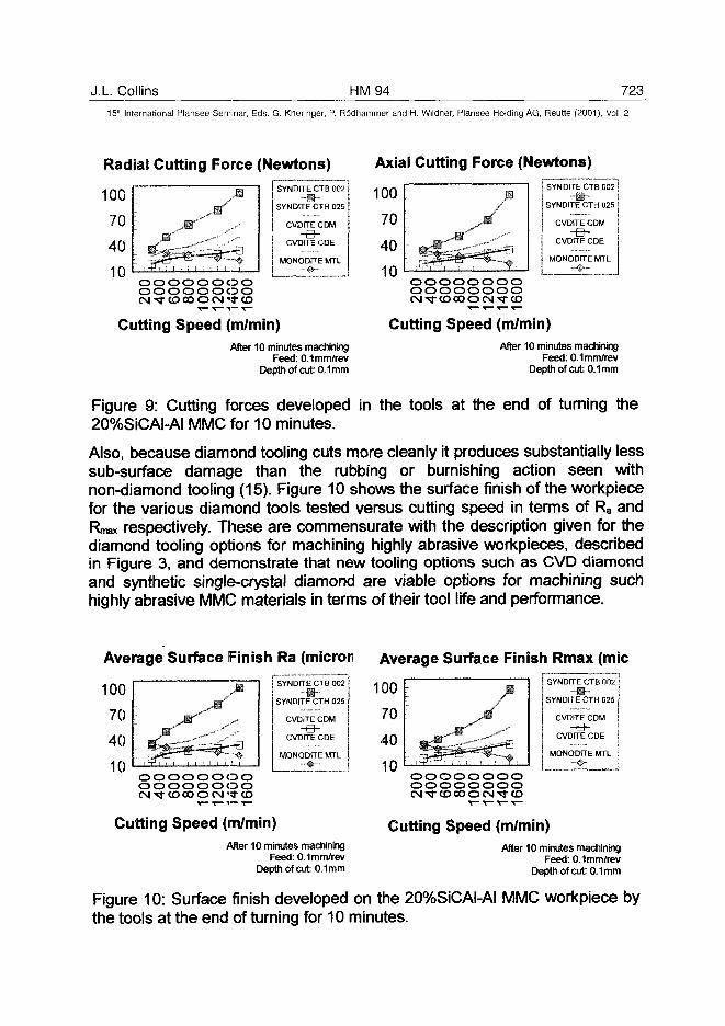
J.L. Collins HM 94 72315" International Plansee Seminar, Eds. G. Kneringer, P. Rödhammer and H. Wildner, Plansee Holding AG, Relitte (2001), Vol. 2
Radial Cutting Force (Newtons) Axial Cutting Force (Newtons)
oooooooooooooooo
SYNDITE CTB 002-H-
SYNDtTE CTH 025
CVDITE CDM
-B-CVDrTE CDE
MONODITE MTL OOOOOOOO
oooooooo
Cutting Speed (m/min) Cutting Speed (m/min)After 10 minutes machining
Feed: 0.1 mm/revDepth of cut: 0.1mm
After 10 minutes machiningFeed: 0.1 mm/rev
Depth of cut: 0.1mm
Figure 9: Cutting forces developed in the tools at the end of turning the20%SiCAI-AI MMC for 10 minutes.
Also, because diamond tooling cuts more cleanly it produces substantially lesssub-surface damage than the rubbing or burnishing action seen withnon-diamond tooling (15). Figure 10 shows the surface finish of the workpiecefor the various diamond tools tested versus cutting speed in terms of Ra andRmax respectively. These are commensurate with the description given for thediamond tooling options for machining highly abrasive workpieces, describedin Figure 3, and demonstrate that new tooling options such as CVD diamondand synthetic single-crystal diamond are viable options for machining suchhighly abrasive MMC materials in terms of their tool life and performance.
Average Surface Finish Ra (micron Average Surface Finish Rmax (mie
oooooooooooooooo
SYNDITE CTB 002-fl~SYNDÎTECTH025
CVDFTE CDM
-e-CVDITE CDE
MONODrre MTL
100
70
40
10
Cutting Speed (im/min)After 10 minutes machining
Feed: 0.1 mm/revDepth of cut: 0.1mm
oooooooooooooooo
SYNDtTE CTB 002
SVNDITE CTH 025
CVDITE CDM
-B-CVDITE CDE
MONODFTE MTL
Cutting Speed (m/min)After 10 minutes machining
Feed: 0.1 mm/revDepth of cut: 0.1mm
Figure 10: Surface finish developed on the 20%SiCAI-AI MMC workpiece bythe tools at the end of turning for 10 minutes.
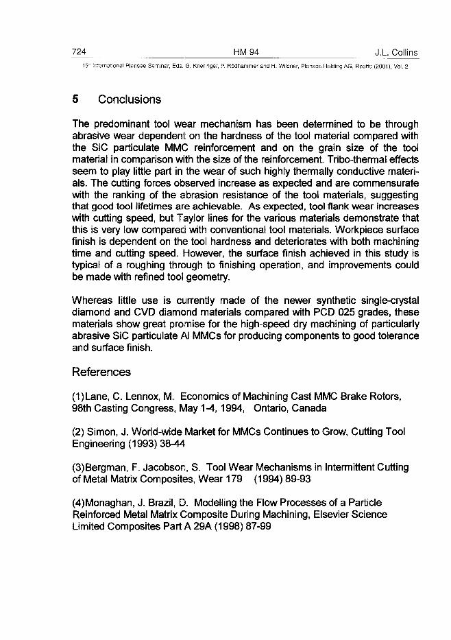
724 HM94 J.L Collins15" International Plansee Seminar, Eds. G. Kneringer, P. Rodhammer and H. Wildner, Plansee Holding AG, Reutte (2001), Vol. 2
5 Conclusions
The predominant tool wear mechanism has been determined to be throughabrasive wear dependent on the hardness of the tool material compared withthe SiC participate MMC reinforcement and on the grain size of the toolmaterial in comparison with the size of the reinforcement. Tribo-thermal effectsseem to play little part in the wear of such highly thermally conductive materi-als. The cutting forces observed increase as expected and are commensuratewith the ranking of the abrasion resistance of the tool materials, suggestingthat good tool lifetimes are achievable. As expected, tool flank wear increaseswith cutting speed, but Taylor lines for the various materials demonstrate thatthis is very low compared with conventional tool materials. Workpiece surfacefinish is dependent on the tool hardness and deteriorates with both machiningtime and cutting speed. However, the surface finish achieved in this study istypical of a roughing through to finishing operation, and improvements couldbe made with refined tool geometry.
Whereas little use is currently made of the newer synthetic single-crystaldiamond and CVD diamond materials compared with PCD 025 grades, thesematerials show great promise for the high-speed dry machining of particularlyabrasive SiC particulate Al MMCs for producing components to good toleranceand surface finish.
References
(1)Lane, C. Lennox, M. Economics of Machining Cast MMC Brake Rotors,98th Casting Congress, May 1-4, 1994, Ontario, Canada
(2) Simon, J. World-wide Market for MMCs Continues to Grow, Cutting ToolEngineering (1993) 38-44
(3) Bergman, F. Jacobson, S. Tool Wear Mechanisms in Intermittent Cuttingof Metal Matrix Composites, Wear 179 (1994) 89-93
(4)Monaghan, J. Brazil, D. Modelling the Flow Processes of a ParticleReinforced Metal Matrix Composite During Machining, Elsevier ScienceLimited Composites Part A 29A (1998) 87-99
J.L Collins HM94 725^15lh International Plansee Seminar, Eds. G. Kneringer, P. Rodhammer and H. Wildner, Plansee Holding AG, Reutte (2001), Vol. 2
(5)Jesus Filho, E.S. Rossi, J.L. Surface Finishing and Damage in Metal MatrixComposite Machining, Materials Science Forum Vols. 299-300 (1999) 416-423
(6)Hung, N.P. Venkatesh, V.C. Loh, N.L. Cutting Tools for Metal MatrixComposites, Key Engineering Materials Vols. 138-140 (1998) 289-325
(7) Eastman, M. Lane, C. Machining MMC's, Cutting Tool Engineering (1993)38-44
(8)Cook, M.W. Machining MMC Engineering Components with PolycrystallineDiamond and Diamond Grinding, Materials Science and Technology Vol 14(1998)892-895
(9)Santhananam, AT., Tierney, P., Hunt, J.L., Cemented Carbides. ASMMetals Handbook, 2 (1990 )950-977
(10) Clark, I.E. A Guide to Machining Metal Matrix Composites with SYNDITEPCD, Industrial Diamond Review, 3 (1994) 135-138
(11) Sen, P.K. De Beers Monodite - A Performance Evaluation, IndustrialDiamond Review, 1 (1994) 13-20
(12) Cook, M.W. Diamond Machining of MMC Engineering Components,Industrial Diamond Review, 1 (1998) 15-18
(13) Hung, N.P. Ng, K.J. Low, K.W. Teng, C.W., Review on ConventionalMachining of Metal Matrix Composites, PD-Vol. 75, Engineering SystemsDesign and Analysis Vol 3 (1996) 75 - 81
14)EJarnes, S. Pashby, I.R. Machining of Aluminium Based Metal MatrixComposites, Applied Composite Materials 2: (1995) 31-42
(15) Weinert, K. and Biermann, D. Turning of Fiber and Particle ReinforcedAluminium, Machining of Advanced Materials 20-22 July 1993 Maryland US
SYNDITE, CVDITE and MONODITE are Trade Marks of the De BeersIndustrial Diamonds group of companies.
AT0100494726 HM98 M. Kathrein et al.
15'"1 International Plansee Seminar, Eds. G. Kneringer, P. Rodhammer and H. Wildner, Plansee Holding AG, Reutte (2001), Vol. 2
Wear Protection in Cutting Tool Applications by PACVD
(Ti,AI)N and AI2O3 Coatings
M. Kathrein*, M. Heiss*, R. Rofner*, U. Schleinkofer*,
W. Schintlmeister*, J. Schatte*, C. Mitterer0
* PLANSEE TIZITAG, Reutte, Austria
° Department of Physical Metallurgy and Materials Testing, University of Leoben, Austria
AbstractVarious (Ti,AI)N-, AI2O3-, and (Ti,AI)N/AI2O3 multilayer coatings weredeposited onto cemented carbide cutting tool inserts by a plasma assistedchemical vapour deposition (PACVD) technique. AI2O3 coatings weredeposited using the gaseous mixture AICI3, Ar, H2, and O2. (Ti,AI)Nintermediate layers were deposited in the same device using the processmentioned and the gases AICI3, Ar, H2, TiCI4 and N2. The unique properties of(Ti,AI)N/AI2O3 multilayer coatings result in superior wear protection for cuttinginserts applied in severe multifunction cutting processes. The influence ofdifferent deposition temperatures on structure and properties of the coatingslike crystallographic phases, chemical composition, mechanical andtechnological properties is shown.
PACVD (Ti,AI)N/AI2O3 coated cutting inserts with fine grained crystalline CC/K-AI2O3 offer performance advantages which are superior with respect tocoatings deposited by chemical vapour deposition (CVD) due to the lowdeposition temperature applied.
Keywords:PACVD, (Ti,AI)!\l, AI2O3, Multilayer, Cemented Carbide , Wear
M. Kathrein et al. HM 98 7Z7_
15" International Plansee Seminar, Eds. G. Kneringer, P. Rodhammer and H. Wildner, Plansee Holding AG, Reutte (2001), Vol. 2
1. IntroductionChanges in economical and technological developments in the cutting marketshow an impact on the requirements in the design of coated cementedcarbide cutting tools. Wear resistance was mostly considered as the maincriteria for cutting operations during the last 20 years. Modern automaticmachining process facilities created additionally a demand in processstability. The appropriate fatigue properties of cemented carbide substratematerials and cermets attract a considerably higher amount of attention forhighly reliable machining.
It is well known that the mechanical properties of powder metallurgicalsubstrates may suffer from the high process temperatures of a common CVDprocess [1,2,3]. The superior performance of PVD TiN, TiCN, and (Ti,AI)Nbased coated tools in interrupted cutting applications, such as milling,grooving, threading, and drilling led to a considerable development ofcommercial PVD coatings. Nevertheless, the wear resistance of CVDcrystalline 0C-AI2O3 or K-AI2O3 is still superior in many cutting applications.
Plasma Assisted Chemical Vapour Deposition (PACVD) allows both to obtainthe excellent properties of CVD coatings and the advantages of the low PVDsubstrate temperature. This creater a new approach to meet the requiredwear behaviour of modern cutting tools, such as multifunctional cutting tools(e.g., for drilling and turning).
Additional advantages of the PACVD process are:
• the possibility to deposit crystalline AI2O3
• the possibility to deposit (Ti,AI)N
• the deposition of AI2O3 directly onto cemented carbide, cermets, andsteel substrates without using bonding layers
• substrate rotation is not required to obtain homogeneous coatingthickness
• only low amounts of process gas are required
• relatively high pressure of 100...500 Pa are used
• the process is highly economical
In this study, cutting of steel with the multifunctional tool Tizit EcoCut® waschosen to demonstrate these special advantages.
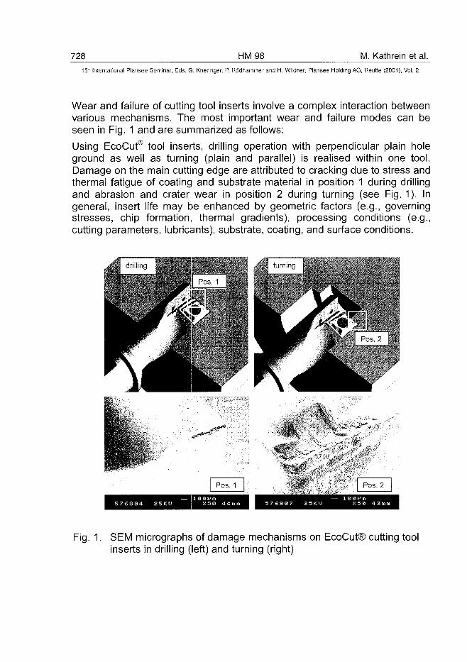
728 HM98 M. Kathrein et al.15" International Plansee Seminar, Eds. G. Kneringer, P. Rodhammer and H. Wildner, Plansee Holding AG, Reutte (2001), Vol. 2
Wear and failure of cutting tool inserts involve a complex interaction betweenvarious mechanisms. The most important wear and failure modes can beseen in Fig. 1 and are summarized as follows:
Using EcoCut® tool inserts, drilling operation with perpendicular plain holeground as well as turning (plain and parallel) is realised within one tool.Damage on the main cutting edge are attributed to cracking due to stress andthermal fatigue of coating and substrate material in position 1 during drillingand abrasion and crater wear in position 2 during turning (see Fig. 1). Ingeneral, insert life may be enhanced by geometric factors (e.g., governingstresses, chip formation, thermal gradients), processing conditions (e.g.,cutting parameters, lubricants), substrate, coating, and surface conditions.
Fig. 1. SEM micrographs of damage mechanisms on EcoCut® cutting toolinserts in drilling (left) and turning (right)
M. Kathrein et al. HM 98 72915" International Plansee Seminar, Eds. G. Kneringer, P. Rodhammer and H. Wildner, Plansee Holding AG, Reutte (2001), Vol. 2
It is the aim of this paper to present and discuss the results obtained with newPACVD (Ti,AI)N/AI2O3 multilayer coatings on cutting tool inserts. For thisinvestigation, two goals are focused: (i) the performance of PACVD coatingsin cutting and (ii) the interpretation of analytical methods related to the wearmechanisms observed.
2. Experimental Details2.1. Coating Deposition
Deposition experiments were carried out using a PACVD system, whichconsists of an inductively heated vertical reactor with parallel plate-typeelectrodes (diameter, 500 mm), powered by a unipolar pulsed dc powersupply for deposition of (Ti,AI)N and a bipolar pulsed dc power supply(MAGTRON) for deposition of AI2O3 [4]. The electrodes are connected to thepulse power supply and isolated from each other and the reactor wall. Theplasma was generated using a DC pulse power supply (unipolar, bipolar) withfrequencies up to 33.3 kHz. The reactor size was 400 mm in diameter and600 mm in height.
The gas inlet system consists of a tube with a perforated gas ring distributorpositioned between the plate electrodes. As process gases, H2, Ar, O2, N2,TiCI4 and AICI3 (formed by reaction between HCI and Al chips) were used.The total gas flow, the total pressure and the pulse frequency duringdeposition were kept constant. In addition to further process parameters, thesubstrate temperature was varied as shown in Table 1. (Ti,AI)N and AI2O3
single layered coatings as well as (Ti,AI)N/AI2O3 multilayered coatings weredeposited in the same reactor. Multilayered coatings were produced in thesame run.
Table 1. Deposition process parameters for (Ti,AI)N and Al2O3
deposition parameter
total pressure [Pa]
substrate temperature [CC]
total gas flow [l/h]
discharge voltage [V]
power supply
(Ti,AI)N
200
500... 600
500
440
unipolar
AI2O3
200
500 ... 700
500
280
bipolar
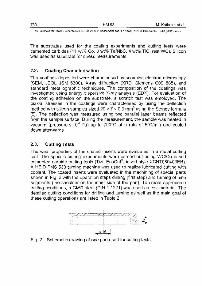
730 HM98 M. Kathrein et al.15- International Plansee Seminar, Eds. G. Kneringer, P. Rodhammer and H. Wildner, Plansee Holding AG, Reutte (2001), Vol. 2
The substrates used for the coating experiments and cutting tests werecemented carbides (11 wt% Co, 8 wt% Ta/NbC, 4 wt% TiC, rest WC). Siliconwas used as substrate for stress measurements.
2.2. Coating Characterisation
The coatings deposited were characterised by scanning electron microscopy(SEM, JEOL JSM 6300), X-ray diffraction (XRD, Siemens C09 585), andstandard metallographic techniques. The composition of the coatings wasinvestigated using energy dispersive X-ray analysis (EDX). For evaluation ofthe coating adhesion on the substrate, a scratch test was employed. Thebiaxial stresses in the coatings were characterised by using the deflectionmethod with silicon samples sized 20 x 7 x 0.3 mm3 using the Stoney formula[5]. The deflection was measured using two parallel laser beams reflectedfrom the sample surface. During the measurement, the sample was heated invacuum (pressures 10~2Pa) up to 700°C at a rate of 5°C/min and cooleddown afterwards.
2.3. Cutting Tests
The wear properties of the coated inserts were evaluated in a metal cuttingtest. The specific cutting experiments were carried out using WC/Co basedcemented carbide cutting tools (Tizit EcoCut®, insert style XCNT080403EN).A HEID FMS 530 turning machine was used to realize lubricated cutting withcoolant. The coated inserts were evaluated in the machining of special partsshown in Fig. 2 with the operation steps drilling (first step) and turning of ninesegments (the shoulder on the inner side of the part). To create appropriatecutting conditions, a Ck60 steel (DIN 1.1221) was used as test material. Thedetailed cutting conditions for drilling and turning as well as the main goal ofthese cutting operations are listed in Table 2.
Fig. 2. Schematic drawing of one part used for cutting tests
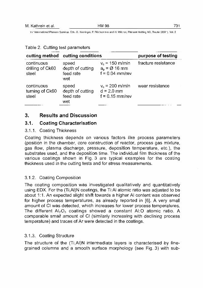
M. Kathrein et al. HM98 73115" International Plansee Seminar, Eds. G. Kneringer, P. Rodhammer and H. Wildner, Plansee Holding AG, Reutte (2001), Vol. 2
Table 2. Cutting test parameters
cutting method
continuousdrilling of Ck60steel
continuousturning of Ck60steel
cutting conditions
speeddepth of cuttingfeed ratewet
speeddepth of cuttingfeed ratewet
vc = 150 m/minap = 0 16 mmf = 0.04 mm/rev
vc = 200 m/mind = 2.0 mmf = 0.15 mm/rev
purpose of testing
fracture resistance
wear resistance
3. Results and Discussion3.1. Coating Characterisation3.1.1. Coating Thickness
Coating thickness depends on various factors like process parameters(position in the chamber, core construction of reactor, process gas mixture,gas flow, plasma discharge, pressure, deposition temperature, etc.), thesubstrates used, and the deposition time. The individual film thickness of thevarious coatings shown in Fig. 3 are typical examples for the coatingthickness used in the cutting tests and for stress measurements.
3.1.2. Coating Composition
The coating composition was investigated qualitatively and quantitativelyusing EDX. For the (Ti,AI)N coatings, the Ti:AI atomic ratio was adjusted to beabout 1:1. An expected slight shift towards a higher Al content was observedfor higher process temperatures, as already reported in [6]. A very smallamount of Cl was detected, which increases for lower process temperatures.The different AI2O3 coatings showed a constant AI:O atomic ratio. Acomparable small amount of Cl (similarly increasing with declining processtemperature) and traces of Ar were detected in the coatings.
3.1.3. Coating Structure
The structure of the (Ti,AI)N intermediate layers is characterised by fine-grained columns and a smooth surface morphology (see Fig. 3) with sub-
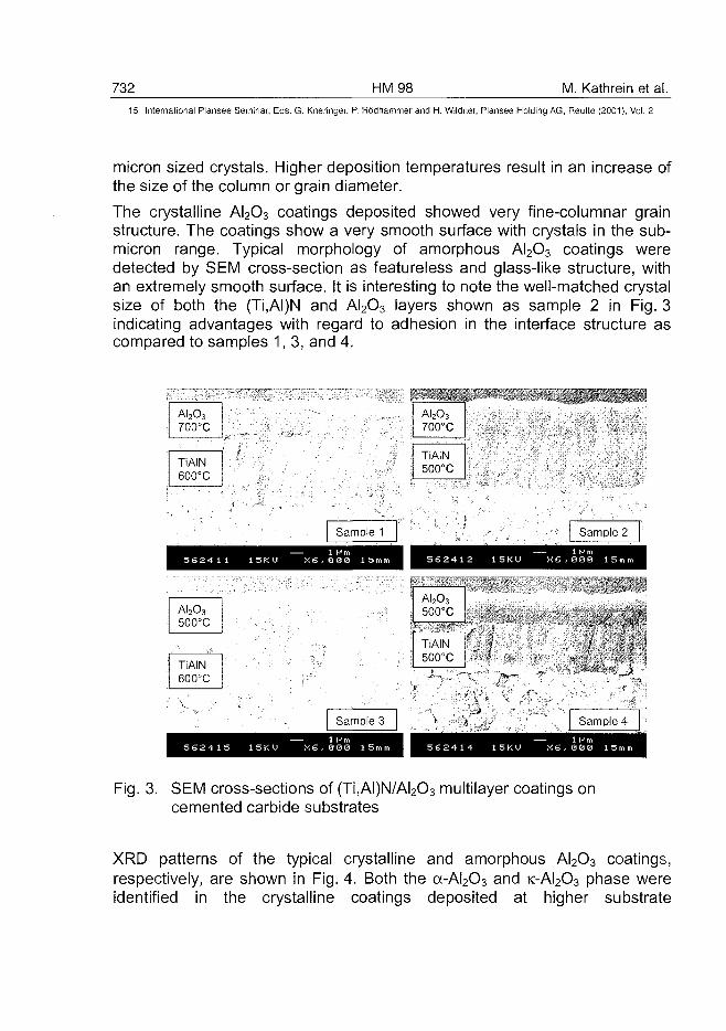
732 HM98 M. Kathrein et al.15:~ International Plansee Seminar, Eds. G. Kneringer, P. Rodhammer and H. Wildner, Plansee Holding AG, Reutte (2001), Vol. 2
micron sized crystals. Higher deposition temperatures result in an increase ofthe size of the column or grain diameter.
The crystalline AI2O3 coatings deposited showed very fine-columnar grainstructure. The coatings show a very smooth surface with crystals in the sub-micron range. Typical morphology of amorphous AI2O3 coatings weredetected by SEM cross-section as featureless and glass-like structure, withan extremely smooth surface. It is interesting to note the well-matched crystalsize of both the (Ti,AI)N and AI2O3 layers shown as sample 2 in Fig. 3indicating advantages with regard to adhesion in the interface structure ascompared to samples 1, 3, and 4.
Al2O3700°C
TiAIN600°C
AI2O700°
3C
TiAIN500°C
AI2O3
500°C
TiAIN600°C
Sample 1 Sample 2
1 6 2 4 1 2 1 5 K U X6 ,000 1!
AI2O3
500°C
TiAIN500°C
V'^:>sm
:MM\Sample 4
Fig. 3. SEM cross-sections of (Ti,AI)N/AI2O3 multilayer coatings oncemented carbide substrates
XRD patterns of the typical crystalline and amorphous AI2O3 coatings,respectively, are shown in Fig. 4. Both the a-AI2O3 and K-AI2O3 phase wereidentified in the crystalline coatings deposited at higher substrate
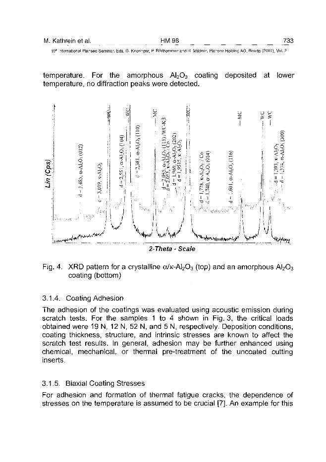
M. Kathrein et al. HM98 733
15" International Plansee Seminar, Eds. G. Kneringer, P. Rodhammer and H. Wildner, Plansee Holding AG, Reutte (2001), Vol. 2
temperature. For the amorphous AI2O3 coating deposited at lowertemperature, no diffraction peaks were detected.
nq<oo
11
V
CO.
r-< O
1 C:-$<
£^"°S
11 11
So
a ^
,969
,1 9
51— IIII T3
•a !\
6S
\J\/2-Theta - Scale
Fig. 4. XRD pattern for a crystalline a/K-AI2O3 (top) and an amorphous AI2O3
coating (bottom)
3.1.4. Coating Adhesion
The adhesion of the coatings was evaluated using acoustic emission duringscratch tests. For the samples 1 to 4 shown in Fig. 3, the critical loadsobtained were 19 N, 12 N, 52 N, and 5 N, respectively. Deposition conditions,coating thickness, structure, and intrinsic stresses are known to affect thescratch test results. In general, adhesion may be further enhanced usingchemical, mechanical, or thermal pre-treatment of the uncoated cuttinginserts.
3.1.5. Biaxial Coating Stresses
For adhesion and formation of thermal fatigue cracks, the dependence ofstresses on the temperature is assumed to be crucial [7]. An example for this
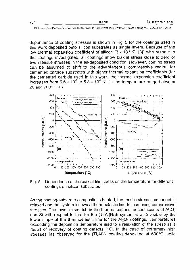
734 HM98 M. Kathrein et al.15'h International Plansee Seminar, Eds. Q. Kneringer, P. Rodhammer and H. Wildner, Plansee Holding AG, Reutte (2001), Vol. 2
dependence of coating stresses is shown in Fig. 5 for the coatings used inthis work deposited onto silicon substrates as single layers. Because of thelow thermal expansion coefficient of silicon (3 x 10"6 K"1 [8]) with respect tothe coatings investigated, all coatings show biaxial stress close to zero oreven tensile stresses in the as-deposited condition. However, coating stresscan be assumed to shift to the advantageous compressive region forcemented carbide substrates with higher thermal expansion coefficients (forthe cemented carbide used in this work, the thermal expansion coefficientincreases from 5.6 x 10"6 to 5.8 x 10~6 K"1 in the temperature range between20 and 700°C [9]).
COQ.
CO
CDXCDla
800
600
400
200
0
-200
-400
-600
-800
-1000 -
-1200 -
-1400
I ' I ' Itension I
: "*s, L-V -V
• \ x• ••
Vheating ^
(a)
compressioni , i , i
i , i i i i
—o— (Ti,AI)N, 500'C
- ••- - (Ti,AI)N, 60CTC
°'°tj y cooling -
••
•>
CDD.
tn
%m
- "SxCD
800
600
400
200
0
-200
-400
-600
-800 -
-1000 -
-1200 -
0 100 200 300 400 500 600 700
temperature [°C]
-1400
rTtension
• •»•&
heating
(b)AI,O,, 500"C
• AI,O,, 700X
compression. ' • ' • i
0 100 200 300 400 500 600 700
temperature [°C]
Fig. 5. Dependence of the biaxial film stress on the temperature for differentcoatings on silicon substrates
As the coating-substrate composite is heated, the tensile stress component isrelaxed and the system follows a thermoelastic line to increasing compressivestresses. The lower mismatch in the thermal expansion coefficients of AI2O3
and Si with respect to that for the (Ti,AI)N/Si system is also visible by thelower slope of the thermoelastic line for the AI2O3 coatings. Temperaturesexceeding the deposition temperature lead to a relaxation of the stress as aresult of recovery of coating defects [10]. In the case of extremely highstresses (as observed for the (Ti,AI)N coating deposited at 600°C, solid
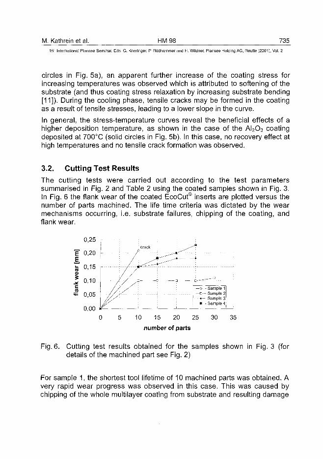
M. Kathrein et al. HM98 73515" International Plansee Seminar, Eds. G. Kneringer, P. Rodhammer and H. Wildner, Plansee Holding AG, Reutte (2001), Vol. 2
circles in Fig. 5a), an apparent further increase of the coating stress forincreasing temperatures was observed which is attributed to softening of thesubstrate (and thus coating stress relaxation by increasing substrate bending[11]). During the cooling phase, tensile cracks may be formed in the coatingas a result of tensile stresses, leading to a lower slope in the curve.
In general, the stress-temperature curves reveal the beneficial effects of ahigher deposition temperature, as shown in the case of the AI2O3 coatingdeposited at 700°C (solid circles in Fig. 5b). In this case, no recovery effect athigh temperatures and no tensile crack formation was observed.
3.2. Cutting Test Results
The cutting tests were carried out according to the test parameterssummarised in Fig. 2 and Table 2 using the coated samples shown in Fig. 3.In Fig. 6 the flank wear of the coated EcoCut® inserts are plotted versus thenumber of parts machined. The life time criteria was dictated by the wearmechanisms occurring, i.e. substrate failures, chipping of the coating, andflank wear.
0,25 r
0,00 *-0
Sample 1— D — Sample 2—•— Sample 3—•— Sample 4
10 15 20 25
number of parts
30 35
Fig. 6. Cutting test results obtained for the samples shown in Fig. 3 (fordetails of the machined part see Fig. 2)
For sample 1, the shortest tool lifetime of 10 machined parts was obtained. Avery rapid wear progress was observed in this case. This was caused bychipping of the whole multilayer coating from substrate and resulting damage
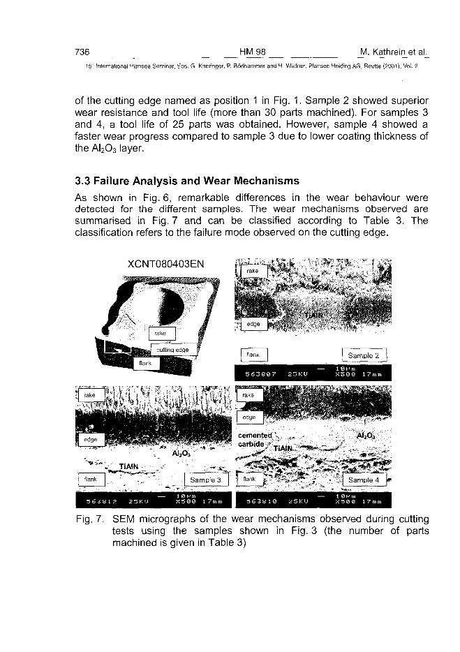
736 HM98 M. Kathrein et al.15" International Plansee Seminar, Eds. G. Kneringer, P. Rodhammer and H. Wildner, Plansee Holding AG, Reutte (2001), Vol. 2
of the cutting edge named as position 1 in Fig. 1. Sample 2 showed superiorwear resistance and tool life (more than 30 parts machined). For samples 3and 4, a tool life of 25 parts was obtained. However, sample 4 showed afaster wear progress compared to sample 3 due to lower coating thickness ofthe AI2O3 layer.
3.3 Failure Analysis and Wear MechanismsAs shown in Fig. 6, remarkable differences in the wear behaviour weredetected for the different samples. The wear mechanisms observed aresummarised in Fig. 7 and can be classified according to Table 3. Theclassification refers to the failure mode observed on the cutting edge.
XCNT080403EN
Fig. 7. SEM micrographs of the wear mechanisms observed during cuttingtests using the samples shown in Fig. 3 (the number of partsmachined is given in Table 3)
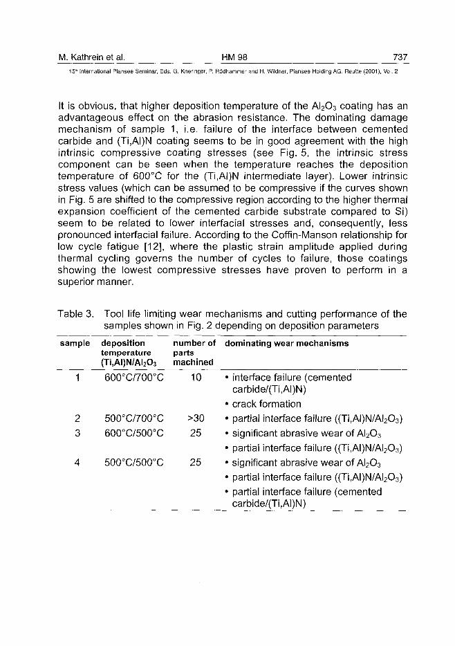
M. Kathrein et al. HM98 737
15" International Plansee Seminar, Eds. G. Kneringer, P. Rodhammer and H. Wildner, Plansee Holding AG, Reutte (2001), Vol. 2
It is obvious, that higher deposition temperature of the AI2O3 coating has anadvantageous effect on the abrasion resistance. The dominating damagemechanism of sample 1, i.e. failure of the interface between cementedcarbide and (Ti,AI)N coating seems to be in good agreement with the highintrinsic compressive coating stresses (see Fig. 5, the intrinsic stresscomponent can be seen when the temperature reaches the depositiontemperature of 600°C for the (Ti,AI)N intermediate layer). Lower intrinsicstress values (which can be assumed to be compressive if the curves shownin Fig. 5 are shifted to the compressive region according to the higher thermalexpansion coefficient of the cemented carbide substrate compared to Si)seem to be related to lower interfacial stresses and, consequently, lesspronounced interfacial failure. According to the Coffin-Manson relationship forlow cycle fatigue [12], where the plastic strain amplitude applied duringthermal cycling governs the number of cycles to failure, those coatingsshowing the lowest compressive stresses have proven to perform in asuperior manner.
Table 3. Tool life limiting wear mechanisms and cutting performance of thesamples shown in Fig. 2 depending on deposition parameters
sample depositiontemperature(Ti,AI)N/AI2O3
number ofpartsmachined
dominating wear mechanisms
600°C/700°C 10 • interface failure (cementedcarbide/(Ti,AI)N)
• crack formation• partial interface failure ((Ti,AI)N/AI2O3)• significant abrasive wear of AI2O3
• partial interface failure ((Ti,AI)N/AI2O3)500°C/500°C 25 • significant abrasive wear of AI2O3
• partial interface failure ((Ti,AI)N/AI2O3)• partial interface failure (cemented
carbide/(Ti,AI)N)
2 500°C/700°C >303 600°C/500°C 25
4
738 HM98 M. Kathrein et al.15" International Plansee Seminar, Eds. G. Kneringer, P. Rodhammer and H. Wildner, Plansee Holding AG, Reutte (2001), Vol. 2
4. Conclusions
Hard coatings based on (Ti,AI)N/AI2O3 deposited by PACVD have proven toincrease the lifetime of cemented carbide cutting tools. Using the PACVDtechnique, a direct deposition of hard coatings like TiN, Ti(C,N), (Ti,AI)N,(Ti,AI)(C,N) and AI2O3 onto cemented carbide, cermet, and steel substrates ispossible. 700°C crystalline AI2O3 coatings could be deposited which showexcellent wear resistance. Coatings deposited at 500°C were amorphous.(Ti,AI)N coatings deposited in the same run serve as highly suitableintermediate layer.
In applications with severe cutting conditions, the lifetime of cementedcarbide inserts depends besides a variety of different mechanisms on thetoughness of the substrate material and the coating properties as well.Cracking of substrates and coatings has been considered to be caused byhigher stresses induced by higher deposition temperatures. The tool lifelimiting wear mechanisms of crack formation in the substrate material,abrasion and chipping due to adhesion problems are determining the toolperformance.
Although the properties of (Ti,AI)N/AI2O3 multilayers are not known sufficientlywell until now, biaxial stress measurements of the individual single layersseems to be an appropriate additional method to characterize and improvethe required coating properties.
6. References
[1] W. Konig, R. Fritsch, Proc. 13th Int. Plansee Seminar, Reutte, 1993,Vol.3, 1-15.
[2] W. Schedler, Hartmetall fur den Praktiker, VDI-Verlag, Dusseldorf,1988,207.
[3] K. G. Stjernberg, Metal Science, May 1980, 189-192.
[4] F. Holler, S. Feistritzer, W. Schintlmeister, C. Mitterer, in G. Kneringer,P. Rodhammer, P. Wilhartitz, eds., Proc. 14th International PlanseeSeminar, Reutte (A), 1997, Vol. 2, 274-285.
[5] G.G: Stoney, Proc. Royal Society London Ser. A 82 (1909) 172.
1. Kathrein et al. HM 98 73915'" International Plansee Seminar, Eds. G. Kneringer, P. Rodhammer and H. Wildner, Plansee Holding AG, Reutte (2001), Vol. 2
[6] S. Anderbouhr, V. Ghetta, E. Blanquet, C. Chabrol, F. Schuster, C.Bernard, R. Madar, Surface and Coatings Technology 115 (1999) 103-110.
[7] W. D. Nix, Metall. Trans. A: 20 (1989) 299.
[8] R. C. Weast (Ed.), Handbook of Chemistry and Physics, 55th ed., CRCPress, Cleaveland, OH, 1974, D152.
[9] K. Brookes, Handbook of Hardmetals and Hard Materials, 6th ed.,International Carbide Data, 1996, pD164.
[10] P.H. Mayrhofer, C. Mitterer, Surface and Coatings Technology, 133-134(2000)131-137.
[11] C. Mitterer, F. Holler, C. Lugmair, R. Nobauer, R. Kuilmer, C. Teichert,Surface and Coatings Technology, in press.
[12] S. Suresh, Fatigue of Materials, Cambridge University Press,Cambridge, 1991.
AT0100495740 HM99 V.N. Glushkov et al.
15" International Plansee Seminar, Eds. G. Kneringer, P. Rodhammer and H. Wildner, Plansee Holding AG, Reutte (2001), Vol. 2
MULTILAYERED AND COMPOSITE PVD-CVD COATINGS IN CEMENTEDCARBIDES MANUFACTURE
Vladimir N. Glushkov*, Alexander I. Anikeev*, Viacheslav N. Anikin*, AnatolyS. Vereshchaka+
*Unitary State-Owned Enterprise (GUP) VNIITS, Moscow,Russian Federation
+State Technological University "STANKIN", Moscow,Russian Federation
Summary
Carbide cutting tools with wear-resistant coatings deposited by CVD processare widely employed in mechanical engineering to ensure a substantiallylonger service life of tool systems. However, the relatively high temperatureand long time of the process make the substrate decarburise and, as a result,the bend strength and performance characteristics of a tool decrease. Thepresent study suggests the problem of deteriorated strength of CVD-coatedcarbide tools be solved by the development of a technology that combinesarc-PVD and CVD processes to deposit multilayered coatings of titanium andaluminium compounds.
Key words
Supermultilayered coating, combined arc-PVD/CVD technology, tool life
1. Introduction
The recent years saw substantial progress in the improvement of surfaceproperties of tool materials and efficiency and reliability of a wide range ofhigh-speed steel carbide and ceramic cutting tools by various methods ofdeposition of wear-resistant coatings. With perfected equipment andprocesses to synthesise the coatings it becomes possible to lay downconcepts on the impact of modified surface on a set of properties that defineoperational performance of cutting tools. Rated among this are hardness,heat resistance, adhesion to a workpiece material, corrosion and oxidationresistance at elevated temperatures, resistance to mechanical and thermalcycling. Service life of cutting tools with wear-resistant coatings depends on
V.N. Glushkov et al. HM 99 741^15" International Plansee Seminar, Eds. G. Kneringer, P. Rodhammer and H. Wildner, Plansee Holding AG, Reutte (2001), Vol. 2
coating's composition, thickness and number of layers as well as on asynthesis technology.Present-day technologies are capable of depositing multilayered coatingscomposed by single, dual and triple compounds of groups IV, V and VI of theperiodic system (carbides, nitrides, borides, oxides and their mixtures. Eachlayer can be made as thin as several nanometres, which allows, in theory, tomake it almost defect-free. This way "ideal" properties of a material, inparticular, "theoretical strength" could be realised, and multilayered coatingshould result in the utmost of efficiency and reliability of cutting tools. Thismakes the tools with coats of this kind instrumental in solving a number ofproblems for a gamut of cutting operations: improving production rate,precision and quality of machining; reducing the consumption of costly toolmaterials; implementing environmentally safe cutting with no resort to cuttingfluid.
2. A survey of trends in the development of processes to coat carbidetools.
At the present time, chemical (CVD) and physical (PVD) synthesis of coatingsare prevalent world-wide in tool-making practice.CVD processes make use of heterogeneous thermochemical reactions thatlead to adsorption and chemosorption with the ensuing coat-comprisingcompounds being formed in the vapour-gas environment and on the tool'sworking faces alike /1,2/. The starting materials are gaseous halogens ofmetals, MeG of which the interaction with other compounds of gas mixtures(H2, N2, CH3, Ar) accounts for the synthesis of a coating.Properties, structure and quality of a coatings depend on CVD processingvariables, among which most important are a time and a temperature ofdeposition, composition and reactants' content in a vapour-gas medium, aswell as a pressure and a flow rate of this. Subject to these variables arestructure, phase composition, presence of defects in a coatings, itsadherence to a substrate and, therefore, its basic properties. The adhesionstrength also strongly depends on the crystallochemical similitude of acoating being deposited and a substrate. As a result, on working faces of atool a coating is formed that posesses high strength and homogeneity; strongadhesion to substrate; uniform thickness, even on faces of complex shape.However, CVD processes do not often comply with the environmental safetystandards, run at high temperatures (800 °C - 1500 °C) and take long times.The latter results in a brittle rj-phase, W3Co3C on coating-substrate and grain-
742 HM99 V.N. Glushkov et al.15r International Plansee Seminar, Eds. G. Kneringer, P. Rodhammer and H. Wildner, Plansee Holding AG, Reutte (2001), Vol. 2
binder interfaces in carbide, which makes the material's strength decrease for20% - 30% (1,2) and, in the case of WC-Co substrates, is due to reactions:(x - 2)Me + xWC + yCo -> (x - 2)MeC + W3Co3C.Besides, characteristic of CVD processes is strong dependence of a coating'squality on a substrate's substructure, because nucleation of condensationsites and growth of coatings display pronounced epitaxy /1,7,8/. In particular,when coatings of TiC-type are being formed on carbide substrates (e.g. WC-Co), condensation nuclei of a coating only arise on cobalt grains becausethese display a maximum of crystallographic fit. As a consequence, after thecoat coalescence completed, straight above carbide grains pores could beformed which proved to be quality-deteriorating defects in coated carbide/7,8/. Therefore in manufacture of these considerable attention is being paidto the grain structure of carbide, which, in particular, is manifested by theemployment of fine and ultrafine structures to make pores less likely. In orderto check ebrittlement due to r|-phase on coat-substrate interfaces, the surfaceof a substrate is being saturated with carbon prior to coating. Still, there is noadequate solution to the problem of deteriorated strength of carbide insertsafter CVD-coating.PVD processes are essentially generation of matter in an evacuated chamberwith reactant gases (N2, O2, CH4, etc.) admitted into it. Particular PVD-technologies differs in the way of matter generation, the extent of ionisation ofa vapour-gas stream, the design and operational parameters of installations.Most common in tool-making practice are low-voltage vacuum-arcevaporation systems known as Ion Bond (CIB) systems.In CIB-processes, matter is generated by the cathode spot of a vacuum-arc ofhigh-current low-voltage discharge within the confines of a stream ofvaporised cathode material. The enter of reactant gases (N2, O2, CH4, etc.)into vacuum space are thus assisted by ion bombardment and triggersplasmochemical reactions of the type: Me+ + N+^MexNy (in the case ofnitrides), which result in coating of working faces of a tool. Arc-evaporation,plasmochemical reactions, ion bombardment and coating processes operatein a vacuum chamber of which the metal case acts as anode.Characteristic of CIB processes is high reactivity of vaporised media thatcomprise a highly ionised low-temperature plasma beam (the ionisationdegree can be as high as 90% - 95%). A substrate and a deposit undergointensive bombardment with ions of vaporised metal, which, leads to thesurface layers of substrate being partially sputtered and the temperature in acoating zone raised. As a result, atomic mobility on a substrate's surface isintensified, a deposited condensate is further activated, and strong adhesivebonds are formed between a coat and a substrate.
V.N. Glushkov et al. HM 99 743^
15" International Plansee Seminar, Eds. G. Kneringer, P. Rodhammer and H. Wildner, Plansee Holding AG, Reutte (2001), Vol. 2
For CIB processes, of extreme importance are ion-jet density and ion energyduring bombardment of a substrate and subsequent coating. The kineticenergy of an ion colliding with a substrate's surface, Wj, is determined by theatomic structure of a substrate, the accelerating voltage U|B applied tothis, and the ion charge ratio, eZ, Wj = W|0 + eZU|B, where W|0 - energyof ions leaving an evaporator. Subject to exposure time, the energy of ionsdetermines the temperature on a tool's working faces which is ofimportance for proper thermal activation of a substrate's surface beforecoating and for the plasmochemical reaction to end in thermodinamicallystable, stoichiometric refractory compounds /1,12/.CIB processes display high production rate, tens of times that of CVDprocesses which is achieved by the highly ionised beam being accelerated bysetting a negative (relative to a chamber's case) potential on a substrate, orby the stream density and homogeneity being enhanced with plasma-opticalmagnetic systems. One more advantage is that IB processes areenvironmentally safe.However, CIB processes have limitations of their own largely due to a micro-droplet constituent of a vapour-ion beam which is most pronounced for metalswith relatively low atomic weight and density (Ti, Al, Cr, a.o.). Micro-dropletsconstitute a coating's structural defect that is most hazardous when locatedon a substrate-coating interface or on a coating's surface and therebydeteriorate operational performance of a tool /1,11,12/. Besides, inconventional CIB schemes the processes of thermal activation and cleaningof a tool prior to coating are not separated which, on one hand, may lead to atool's cutting edges being eroded and on the other, results in severelydowngraded surface finish of a coating caused by micro-arcs.Summarily, both CVD and PVD processes still need further development andperfection. And alternative could also be sought in the development of novelprocesses that should be incorporating the advantages of both.
3. Development of coated carbide tools with improved performance.
Two ways of perfecting carbides with wear-resistant coatings have been tried.One was selection of optimum composition and "architecture" of a coating aswell as process variables of a deposition technology that incorporate bothchemical and physical methods, whilst the other addressed a carbides ofwhich the structure and properties should comply with the optimumcoating conditions and thus result in enhanced cutting performance of acarbide-coating composite.
744 HM99 V.N. Glushkov et al.15" International Plansee Seminar, Eds. G. Kneringer, P. Rodhammer and H. Wildner, Plansee Holding AG, Reutte (2001), Vol. 2
To make less likely deterioration of a carbides's strength during coating,caused by decarburising, it has been suggested that a barrier layer shouldfirst be deposited with an arc-PVD process and only then the main wear-resistant coatings applied by means of specifically designed CVD-processes.Such a strategy resulted in a coating that consists of a thin underlayer ofcomplex composition and a wear-resistant upper layer. The barrier wasintended to arrest interdiffusion between a substrate and a coating, andthereby ensuring decarburising, r|-phase formation and embrittlement of asubstrate. Besides, the CIB (arc-PVD) processes, employed to deposit anunderlayer, also provided for a coating/substrate transitional zone withsubstantially fewer defects. The upper coating was aimed at the utmost ofwear resistance.To make less likely surface defects inherent to CVD coatings, anothersequence of operations have been employed. After deposition of CVD layers,these were first treated with a 1.5 keV metal (e.g. Ti+) plasma beam (ionbombardment) to eliminate stress concentrators (relief peaks, defective layersof a hardmetal and the like), and the CIB-coated.A further problem to be solved was selection of a coating's structure and"architecture". Properties were reviewed for several refractory compoundsthat qualify as wear-resistant coatings on cutting tools, on thermodynamicgrounds. A concept was posited of a coating as "technological intermediary"between a tool and a machining materials of which the role is tosimultaneously improve the wear resistance of the contact areas and lowerthe wear-inducing thermomechanical stresses in a tool IM. Proceeding fromthe above, a single-layer coating does not seem to comply with therequirements of wear resistance and, therefore, the efforts were largelyconcentrated on the development of many-layered coatings with variedcompositions and properties, to reach the utmost of operational performanceof hardmetal tools, especially those intended for severe and intermittentmachining.The study has been conducted in two stages. At the first, to verify the aboveconcepts, at issue was improving the wear resistance of conventional gradeswith various combinations of multi-purpose layers in a multilayered coating,which were synthesised by a combination of arc-PVD and CVD processes. Atthe second stage hardmetal substrates were specifically designed to fit bestfor coating, and the "architecture" of a coating comprised many-layeredandmulti-layered structures of compounds TiC - TiCN-TiN and TiC-AI2O3 withthin (0.15 (im - 0.2 urn) interlayers of TiN and TiC (CVD processes) and onthe base Ti-AI-N compounds (arc-PVD processes). To synthesise multi-
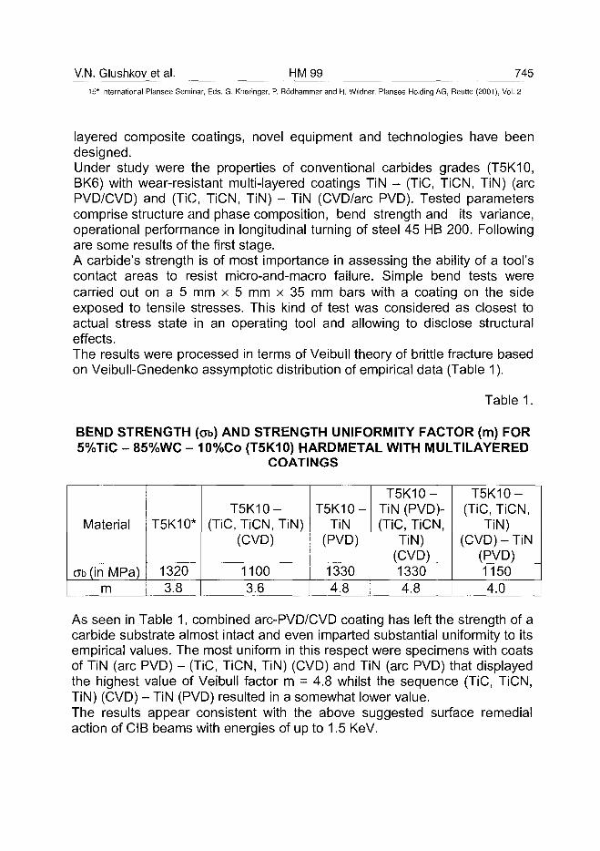
V.N. Glushkov et al. HM99 74515" International Plansee Seminar, Eds. G. Kneringer, P. Rodhammer and H. Wildner, Plansee Holding AG, Reutte (2001), Vol. 2
layered composite coatings, novel equipment and technologies have beendesigned.Under study were the properties of conventional carbides grades (T5K10,BK6) with wear-resistant multi-layered coatings TiN - (TiC, TiCN, TiN) (arcPVD/CVD) and (TiC, TiCN, TiN) - TiN (CVD/arc PVD). Tested parameterscomprise structure and phase composition, bend strength and its variance,operational performance in longitudinal turning of steel 45 HB 200. Followingare some results of the first stage.A carbide's strength is of most importance in assessing the ability of a tool'scontact areas to resist micro-and-macro failure. Simple bend tests werecarried out on a 5 mm x 5 mm x 35 mm bars with a coating on the sideexposed to tensile stresses. This kind of test was considered as closest toactual stress state in an operating tool and allowing to disclose structuraleffects.The results were processed in terms of Veibull theory of brittle fracture basedon Veibull-Gnedenko assymptotic distribution of empirical data (Table 1).
Table 1.
BEND STRENGTH (cb) AND STRENGTH UNIFORMITY FACTOR (m) FOR5%TiC - 85%WC - 10%Co (T5K10) HARDMETAL WITH MULTILAYERED
COATINGS
Material
Gb(in MPa)m
T5K10*
13203.8
T5K10-(TiC, TiCN, TiN)
(CVD)
11003.6
T5K10-TiN
(PVD)
13304.8
T5K10-TiN (PVD)-(TiC, TiCN,
TiN)(CVD)13304.8
T5K10-(TiC, TiCN,
TiN)(CVD) - TiN
(PVD)11504.0
As seen in Table 1, combined arc-PVD/CVD coating has left the strength of acarbide substrate almost intact and even imparted substantial uniformity to itsempirical values. The most uniform in this respect were specimens with coatsof TiN (arc PVD) - (TiC, TiCN, TiN) (CVD) and TiN (arc PVD) that displayedthe highest value of Veibull factor m = 4.8 whilst the sequence (TiC, TiCN,TiN) (CVD) - TiN (PVD) resulted in a somewhat lower value.The results appear consistent with the above suggested surface remedialaction of CIB beams with energies of up to 1.5 KeV.
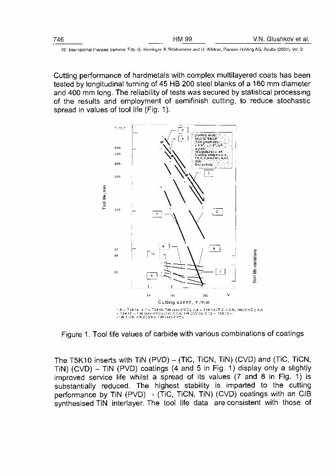
746 HM99 V.N. Glushkov et al.15" International Plansee Seminar, Eds. G. Kneringer, P. Rodhammer and H. Wildner, Plansee Holding AG, Reutte (2001), Vol. 2
Cutting performance of hardmetals with complex multilayered coats has beentested by longitudinal turning of 45 HB 200 steel blanks of a 160 mm diameterand 400 mm long. The reliability of tests was secured by statistical processingof the results and employment of semifinish cutting, to reduce stochasticspread in values of tool life (Fig. 1).
200 —
, - , " 5 . .W:orfcplece:C 4-5: -Cutting parameters:f 1 0,3 mm/rey; aD
a2.
50
40
CD H
60 100 200 V
Cutting speed, m/m in
1,6 - T5K10; 2.7 - T5K10-TIN (arc-PVD); 3,8 - T5K1 0-(TiC,TiCN,TiN)(C VD ); 4,9- T5K10 - TiN (arc-PVD)-(TiC,TiCN,TiN)(CVD); 5,10 - T5K10 -(TiN,TiCN,TiN)(CVD)- TiN (arc-PVD)
Figure 1. Tool life values of carbide with various combinations of coatings
The T5K10 inserts with TiN (PVD) - (TiC, TiCN, TiN) (CVD) and (TiC, TiCN,TiN) (CVD) - TiN (PVD) coatings (4 and 5 in Fig. 1) display only a slightlyimproved service life whilst a spread of its values (7 and 8 in Fig. 1) issubstantially reduced. The highest stability is imparted to the cuttingperformance by TiN (PVD) - (TiC, TiCN, TiN) (CVD) coatings with an CIBsynthesised TiN interlayer. The tool life data are consistent with those of
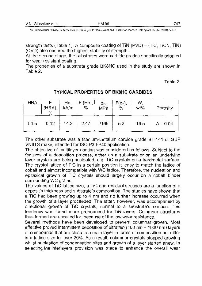
V.N. Glushkov et al. HM99 747
15" International Plansee Seminar, Eds. G. Kneringer, P. Rodhammer and H. Wildner, Plansee Holding AG, Reutte (2001), Vol. 2
strength tests (Table 1). A composite coating of TiN (PVD) - (TiC, TiCN, TiN)(CVD) also ensured the highest stability of strength.At the second stage, the substrates were carbide grades specifically adaptedfor wear resistant coating.The properties of a substrate grade BK8HC used in the study are shown inTable 2.
Table 2.
TYPICAL PROPERTIES OF BK8HC CARBIDES
HRA
90.5
F(HRA),
%
0.12
He,kA/m
14.2
F (He),%
2.47
Ob,MPa
2165
F(0b),%
5.2
w,wt%
16.5
Porosity
A -0 .04
The other substrate was a titanium-tantalum carbide grade BT-141 of GUPVNIITS make, intended for ISO P30-P40 application.The objective of multilayer coating was considered as follows. Subject to thefeatures of a deposition process, either on a substrate or on an underlyinglayer crystals are being nucleated, e.g. TiC crystals on a hardmetal surface.The crystal lattice of TiC in a certain position is easy to match the lattice ofcobalt and almost incompatible with WC lattice. Therefore, the nucleation andepitaxical growth of TiC crystals should largely occur on a cobalt bindersurrounding WC grains.The values of TiC lattice size, a TiC and residual stresses are a function of adeposit's thickness and substrate's composition. The studies have shown thata TiC had been growing up to 4 nm and no further increase occurred whenthe growth of a layer proceeded. The latter, however, was accompanied bydirectional growth of TiC crystals, normal to a substrate's surface. Thistendency was found more pronounced for TiN layers. Columnar structuresthus formed are uncalled for, because of the low wear resistance.Several methods have been developed to prevent columnar growth. Mosteffective proved intermittent deposition of ultrathin (100 nm - 1000 nm) layersof compounds that are close to a main layer in terms of composition but differin a lattice size for over 20%. As a result, columnar crystals stopped growingwhilst nucleation of condensation sites and growth of a layer started anew. Inselecting the interlayers, provision was made to enhance the overall wear
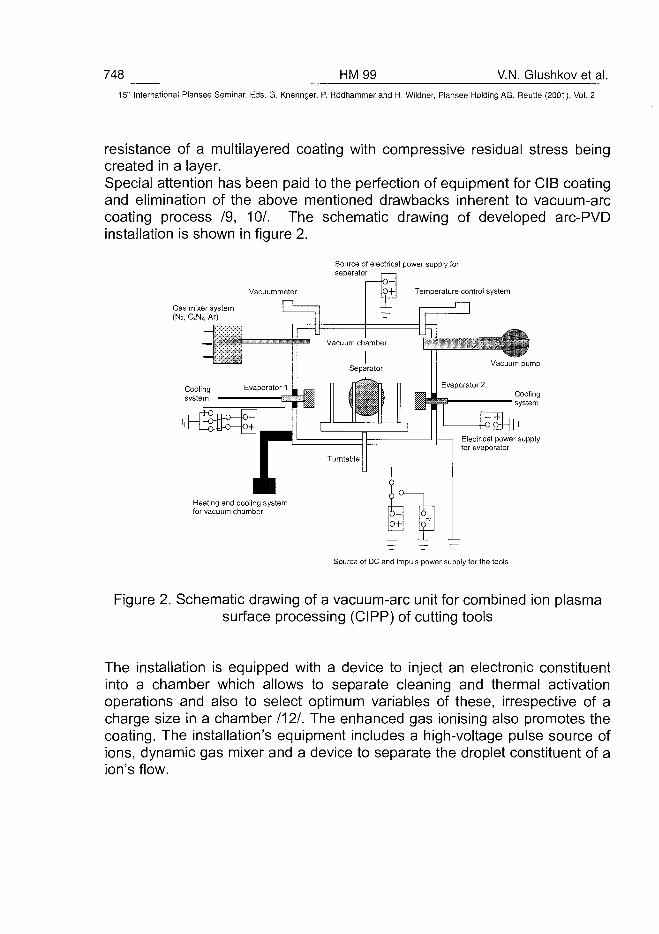
748 HM99 V.N. Glushkov et al.15" International Plansee Seminar, Eds. G. Kneringer, P. Rodhammer and H. Wildner, Plansee Holding AG, Reutte (2001), Vol. 2
resistance of a multilayered coating with compressive residual stress beingcreated in a layer.Special attention has been paid to the perfection of equipment for CIB coatingand elimination of the above mentioned drawbacks inherent to vacuum-arccoating process /9, 10/. The schematic drawing of developed arc-PVDinstallation is shown in figure 2.
Source of electrical power supply forseparator
Vacuummeter p-H Temperature controi system
Gas mixer system(N2, CxNx, Ar)
Heating and cooling systemfor vacuum chamber
Source of DC and impuls power supply for the tools
Figure 2. Schematic drawing of a vacuum-arc unit for combined ion plasmasurface processing (CIPP) of cutting tools
The installation is equipped with a device to inject an electronic constituentinto a chamber which allows to separate cleaning and thermal activationoperations and also to select optimum variables of these, irrespective of acharge size in a chamber /12/. The enhanced gas ionising also promotes thecoating. The installation's equipment includes a high-voltage pulse source ofions, dynamic gas mixer and a device to separate the droplet constituent of aion's flow.
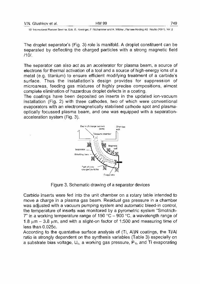
V.N. Glushkov et al. HM99 74915" International Plansee Seminar, Eds. G. Kneringer, P. Rodhammer and H. Wildner, Plansee Holding AG, Reutte (2001), Vol. 2
The droplet separator's (Fig. 3) role is manifold. A droplet constituent can beseparated by deflecting the charged particles with a strong magnetic field
no/.The separator can also act as an accelerator for plasma beam, a source ofelectrons for thermal activation of a tool and a source of high-energy ions of ametal (e.g. titanium) to ensure efficient modifying treatment of a carbide'ssurface. Thus the installation's design provides for suppression ofmicroareas, feeding gas mixtures of highly precise compositions, almostcomplete elimination of hazardous droplet defects in a coating.The coatings have been deposited on inserts in the updated ion-vacuuminstallation (Fig. 2) with three cathodes, two of which were conventionalevaporators with an electromagnetically stabilised cathode spot and plasma-optically focussed plasma beam, and one was equipped with a separation-acceleration system (Fig. 3).
Beam of charge carriers Chamber(ions) w a N
Separator
Shielding bars
Path of non-charged particles
Evaporator
Figure 3. Schematic drawing of a separator devices
Carbide inserts were fed into the unit chamber on a rotary table intended tomove a charge in a plasma gas beam. Residual gas pressure in a chamberwas adjusted with a vacuum pumping system and automatic bleed-in control,the temperature of inserts was monitored by a pyrometric system "Smotrich-7" in a working temperature range of 150 °C - 900 °C, a wavelength range of1.8 |im - 3.8 urn, and with a slight-on factor of 1:500 and measuring time ofless than 0.025c.According to the quantative surface analysis of (Ti, AI)N coatings, the Ti/AIratio is strongly dependent on the synthesis variables (Table 3) especially ona substrate bias voltage, Uc, a working gas pressure, PN, and Ti evaporating
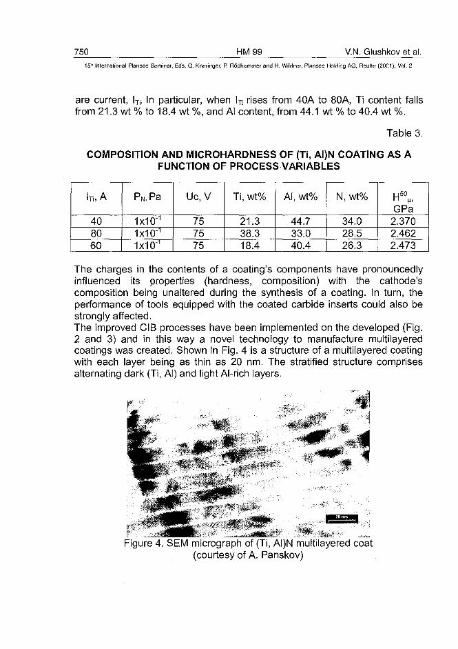
750 HM99 V.N. Glushkov et al.15" International Plansee Seminar, Eds. G. Kneringer, P. Rodhammer and H. Wildner, Plansee Holding AG, Reutte (2001), Vol. 2
are current, lTj. In particular, when lTi rises from 40A to 80A, Ti content fallsfrom 21.3 wt % to 18.4 wt %, and Al content, from 44.1 wt % to 40.4 wt %.
Table 3.
COMPOSITION AND MICROHARDNESS OF (Ti, AI)N COATING AS AFUNCTION OF PROCESS VARIABLES
h, A
408060
PN,Pa
1x10"1
1x10"1
1x10"1
Uc, V
757575
Ti, wt%
21.338.318.4
Al, wt%
44.733.040.4
N, wt%
34.028.526.3
GPa2.3702.4622.473
The charges in the contents of a coating's components have pronouncedlyinfluenced its properties (hardness, composition) with the cathode'scomposition being unaltered during the synthesis of a coating. In turn, theperformance of tools equipped with the coated carbide inserts could also bestrongly affected.The improved CIB processes have been implemented on the developed (Fig.2 and 3) and in this way a novel technology to manufacture multilayeredcoatings was created. Shown in Fig. 4 is a structure of a multilayered coatingwith each layer being as thin as 20 nm. The stratified structure comprisesalternating dark (Ti, Al) and light Al-rich layers.
Figure 4. SEM micrograph of (Ti, AI)N multilayered coat(courtesy of A. Panskov)
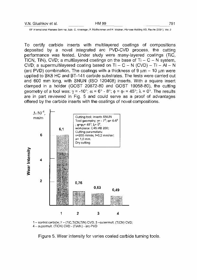
V.N. Glushkov et al. HM99 75115th International Plansee Seminar, Eds. G. Kneringer, P. Rodhammer and H. Wildner, Plansee Holding AG, Reutte (2001), Vol. 2
To certify carbide inserts with multilayered coatings of compositionsdeposited by a novel integrated arc PVD-CVD process, the cuttingperformance was tested. Under study were many-layered coatings (TiC,TiCN, TiN), CVD; a multilayered coatings on the base of Ti - C - N system,CVD; a supermultilayered coating based on Ti - C - N (CVD) - Ti - Al - N(arc PVD) combination. The coatings with a thickness of 9 |im - 10 jim wereuppiied to BK8 HC and BT-141 carbide substrates. The tests were carried outand 600 mm long, with SNUN (ISO 120408) inserts. With a square insertclamped in a holder (GOST 20872-80 and GOST 19058-80), the cuttinggeometry of a tool was: y = -10°; a = 6° - 8°; ty = (j)i = 45°; X = 0°. The resultsare in part reviewed in Fig. 5 and could serve as a proof of advantagesoffered by the carbide inserts with the coatings of novel compositions.
JxlO"4,mm/m
6 —
c
(0
2 _
—
6,1
•
—
Cutting tool: inserts SNUNTool geometry; 7= - 7°; OF 6-8°; cp=<pi= 45°; X= 0°.workpiece: C45 HB 200;Cutting parameters:v-200 m/min; f-0,2 mm/rev;a= 1,0 mm.Dry cutting
0,760.63
| " • "
0,49
1 - control carbide; 2 - (TiCJiCN.TiN) CVD; 3 -supermult. (TiCN) CVD;4 - supermult. (TiCN) CVD - (TiAIN) - arc-PVD
Figure 5. Wear intensity for varies coated carbide turning tools.
752 HM99 V.N. Glushkov et al.15-' International Plansee Seminar, Eds. G. Kneringer, P. Rodhammer and H. Wildner, Plansee Holding AG, Reutte (2001), Vol. 2
4. Conclusion:
Novel compositions have been elaborated for multilayered coatingssynthesised by a combination of CVD and arc PVD deposition processes.The tools equipped with carbide inserts having the supermultilayered coatingsnot only displayed improved cutting performance but also were highly reliableand, therefore, can be recommended for application in high speed automatedoperations, severe cutting conditions, interrupted cutting and, in a number ofconditions, for cutting of hardmachining materials.
5. References:
1. Vereshchaka A.S. Service life of cutting tools with wear-resistant coatings(1993). Moscow. "Mashinostroyeniye" Publishers. 336 pp (in Russian).
2. Samsonov G.V., Epik A.A. Refractory coatings (1973). "Metallurgiya"Publishers. 400 pp. (in Russian).
3. Habig K.H.: Chemical vapor deposition and physical vapor depositioncoating: Properties, tribological behavior, and application. J. Vac. Sci.Technol. A4/(6), Nov/Dec 1986. 2832-2842.
4. Stok H.L., Mayr P.: Hartstoffbeschichtund mit dem Plasma-CVD-Verfahren. HTM 41 (1986) 3. 145-151.
5. Yaws C.L.; Wakefield G.F.: Scale - up Process for Erosion ResistantTitanium - Carbonitride Coating. Proc. 4lnt. Conf. CVD (1973) S. 577.
6. Baneffi R.; Wahl H.: Industrialisation of titanium - carbonitride Coating.Proc. 4. Europ. Conf. (1983) S. 510.
7. Platonov G.L., Anikin V.N., Anikeev A.I. et al. Study of growth of wear-resistant titanium carbide layers on carbides. Powder Metallurgy, 1980, Ns8, p. 48-52 (in Russian).
8. Anikin V.N., Anikeev A.I., Zolotareva M.N. et al. Technological features ofdeposition of titanium-carbide coats on carbides. Advanced processes intool-making industry (1979), p. 263-266 (in Russian).
9. Sableb L.P. et al. Apparatus for evaporation coatings. US Patent3/793.179(1971).
V.N. Glushkov et al. HM 99 753^
15* International Plansee Seminar, Eds. G. Kneringer, P. Rodhammer and H. Wildner, Plansee Holding AG, Reutte (2001), Vol. 2
lO.Dodonov A.I., Salaev V. A. Operational performance of ultrafine-grainedcoats. ITO, 2000, N° 1, p. 38-39 (in Russian).
11.Moll, E. Bergmann. Hard coatings by plasma-assisted PVD technologies:industrial practice." Surface and Coatings Technology, no. 37: 483-509.
12. Lierat F., Vereshchaka A. S. Entwicklungsstand und-trends der Hartstoffbeschichtung.Tagungsband Magdeburger ProduktionstechischesKolloquiumMPK'99. Die Wissensintensive Production, 1999. ISBN 3-00-004 180-x.( in German).
AT0100496754 HM 100 W.C. Russell et al.
15" International Plansee Seminar, Eds. G. Kneringer, P. Rodhammer and H. Wildner, Plansee Holding AG, Reutte (2001), Vol. 2
Novel Composite cBN-TiN Coating Deposition Method:Structure and Performance In Metal Cutting
W.C. Russell, A.P. Malshe*, S.N. Yedave*, W.D. Brown*
Valenite Inc., Troy, Michigan, USA*MRL-MEEG, University of Arkansas, Fayetteville. Arkansas, USA
Summary:
Cubic boron nitride coatings are under development for a variety ofapplications but stabilization of the pure cBN form and adhesion of filmsdeposited by PVD and ion-based methods has been difficult. An alternativemethod for depositing a composite cBN-TiN film has been developed for wearrelated applications. The coating is deposited in a two-stage process utilizingESC (electrostatic spray coating) and CVI (chemical vapor infiltration). Fullydense films of cBN particles evenly dispersed in a continuous TiN matrix havebeen developed. Testing in metal cutting has shown an increase in tool life(turning - 4340 steel) of three to seven times, depending on machiningparameters, in comparison with CVD deposited TiN films.
Keywords:
Cubic boron nitride, cBN, titanium nitride, TiN, electrostatic spray coating,ESC, chemical vapor infiltration, CVI, composite coating
1. Introduction:Diamond is the hardest known material and likewise the hardest materialused in the cutting tool industry. However, since carbon is soluble in iron,diamond does not hold up well in applications on ferrous materials wheresignificant cutting temperatures are generated. Cubic boron nitride (cBN),known as the second hardest material, has good thermal stability andchemical inertness with respect to ferrous materials. Currently, cBN is beingused in it's bulk form as tool insert bodies or as brazed segments incombination with tool bodies, usually WC-Co. A number of technical groupsaround the world are also working on developing a cBN coating much in theway that diamond coatings have been developed for cutting tools in recentyears.12 Such coatings on cemented carbide substrates would provide the
W.C. Russell et al. HM 100 755^
15" International Plansee Seminar, Eds. G. Kneringer, P. Rb'dhammer and H. Wildner, Plansee Holding AG, Reutte (2001), Vol. 2
hardness and chemical resistance of cBN in combination with the toughnessof a cemented carbide body.
Cubic boron nitride cutting tools are currently manufactured usingconventional high pressure/high temperature forming technology. Theresulting polycrystalline cBN (PCBN) compacts, due to their structural rigidityand limitations of the forming methods, cannot be manufactured in complexgeometries such as chip-breaking cutting tools, rotary tools and other shapes.Cubic boron nitride coating technology would allow the incorporation of suchcomplex shapes provided the coating technique is flexible enough. Suchcoated tools would be a significant product for surface finishing applications inthe ferrous metal machining industry and would complement the PCBNcompact tools used for coarse machining.
Most groups working on cBN film deposition employ either high energyplasma or ion bombardment to create stabilization of the cubic phase relativeto the hexagonal or amorphous phases that are more thermodynamicallystable but do not have the hardness of cBN.3 These methods, althoughresulting in the formation of very thin films (< 1 ^im), of cBN have so far notdemonstrated the capability to form cBN independent of the other phases.4
Invariably, amorphous and/or hexagonal phase cBN forms first on thesubstrate before the cBN phase can be stabilized.5'6 Another problem is thehigh intrinsic compressive stress associated with the cBN film when formedby these methods.7'8'9 These stresses can overwhelm the adhesive bondsbetween the coating and the substrate leading to delamination and severelylimits the functional thickness of these films.
Today the major roadblock to the realization of cBN coated cutting tools is theinability of conventional vapor deposition techniques to coat the cBN phaseand at useful thicknesses. The challenges in the growth process are:
1) excess compressive stress2) homogeneous phase synthesis3) uniform stoichiometry control4) thick coatings (> 1 ^m)5) adhesion with substrate6) phase stabilization on different substrates
These issues are magnified when considering manufacturing on an industrialscale.
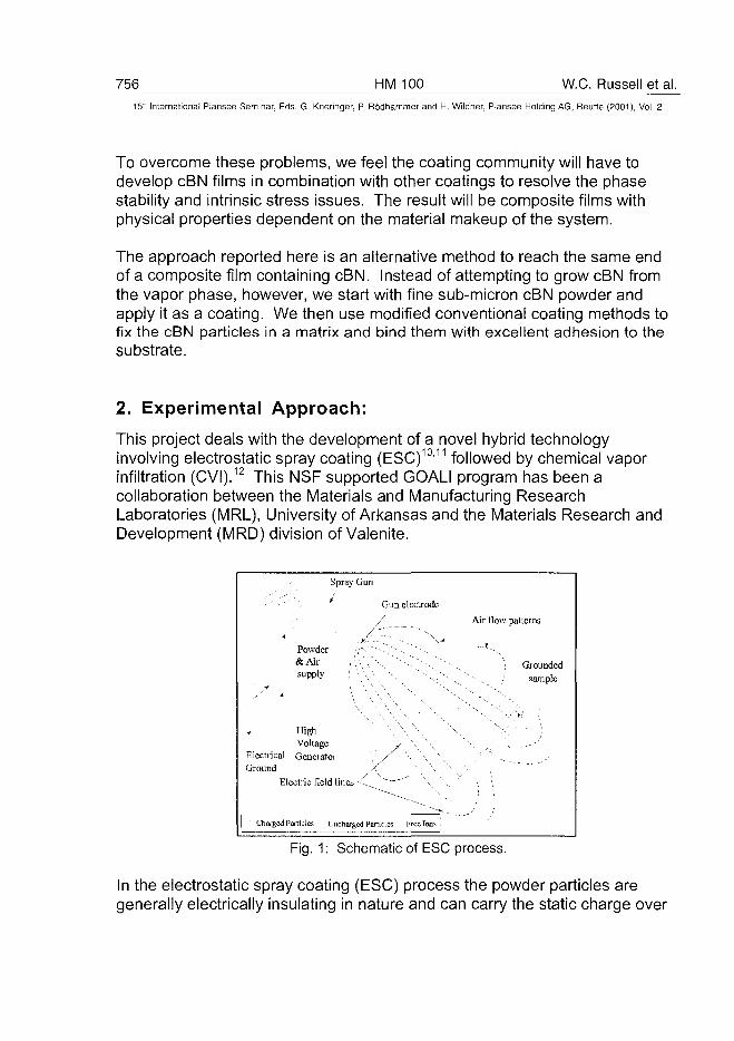
756 HM 100 W.C. Russell et al.
15" International Plansee Seminar, Eds. G. Kneringer, P. Rodhammer and H. Wildner, Plansee Holding AG, Reutte (2001), Vol. 2
To overcome these problems, we feel the coating community will have todevelop cBN films in combination with other coatings to resolve the phasestability and intrinsic stress issues. The result will be composite films withphysical properties dependent on the material makeup of the system.
The approach reported here is an alternative method to reach the same endof a composite film containing cBN. Instead of attempting to grow cBN fromthe vapor phase, however, we start with fine sub-micron cBN powder andapply it as a coating. We then use modified conventional coating methods tofix the cBN particles in a matrix and bind them with excellent adhesion to thesubstrate.
2. Experimental Approach:
This project deals with the development of a novel hybrid technologyinvolving electrostatic spray coating (ESC)10'11 followed by chemical vaporinfiltration (CVI).12 This NSF supported GOALI program has been acollaboration between the Materials and Manufacturing ResearchLaboratories (MRL), University of Arkansas and the Materials Research andDevelopment (MRD) division of Valenite.
Spray Gun
Gun electrode
/^ -.
Powder / • » " • - , " / - . . --._
& A i r i , • , ' - ' • , ' • ' - > • . "
supply ; \ \ \ '•-.
f High \ \
Voltage y \ ^
Electrica] Generator \ / "•, '-,. '"Ground /\ \ "\
Air flow patterns
•-,. : Grounded
" s- , ~ ., / sample
Electric field lines -C^ ^ ~ " \ ' v, \ \
Charged Particles Uncharged Particles Frcclons
Fig. 1: Schematic of ESC process.
In the electrostatic spray coating (ESC) process the powder particles aregenerally electrically insulating in nature and can carry the static charge over
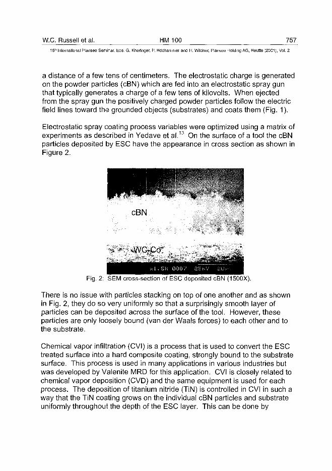
W.C. Russell et al. HM 100 757
15" International Plansee Seminar, Eds. G. Kneringer, P. Rodhammer and H. Wildner, Plansee Holding AG, Reutte (2001), Vol. 2
a distance of a few tens of centimeters. The electrostatic charge is generatedon the powder particles (cBN) which are fed into an electrostatic spray gunthat typically generates a charge of a few tens of kilovolts. When ejectedfrom the spray gun the positively charged powder particles follow the electricfield lines toward the grounded objects (substrates) and coats them (Fig. 1).
Electrostatic spray coating process variables were optimized using a matrix ofexperiments as described in Yedave et al.13 On the surface of a tool the cBNparticles deposited by ESC have the appearance in cross section as shown inFigure 2.
cBN
Fig. 2: SEM cross-section of ESC deposited cBN (1500X).
There is no issue with particles stacking on top of one another and as shownin Fig. 2, they do so very uniformly so that a surprisingly smooth layer ofparticles can be deposited across the surface of the tool. However, theseparticles are only loosely bound (van der Waals forces) to each other and tothe substrate.
Chemical vapor infiltration (CVI) is a process that is used to convert the ESCtreated surface into a hard composite coating, strongly bound to the substratesurface. This process is used in many applications in various industries butwas developed by Valenite MRD for this application. CVI is closely related tochemical vapor deposition (CVD) and the same equipment is used for eachprocess. The deposition of titanium nitride (TiN) is controlled in CVI in such away that the TiN coating grows on the individual cBN particles and substrateuniformly throughout the depth of the ESC layer. This can be done by
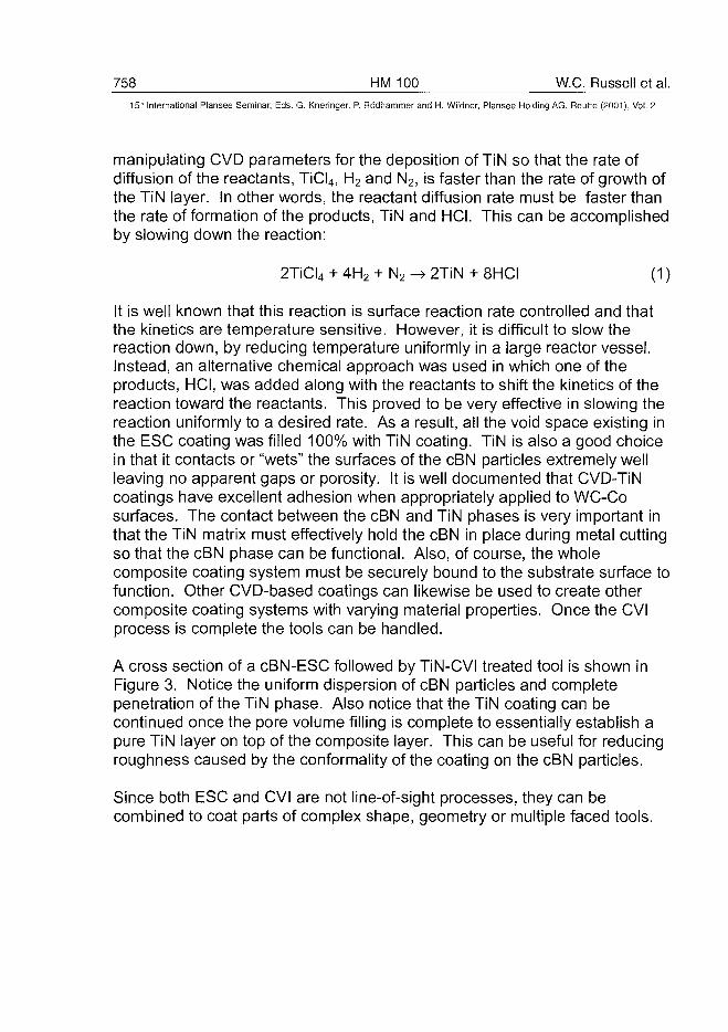
758 HM 100 W.C. Russell et al.
15;" International Plansee Seminar, Eds. G. Kneringer, P. Rodhammer and H. Wildner, Plansee Holding AG, Reutte (2001), Vol. 2
manipulating CVD parameters for the deposition of TiN so that the rate ofdiffusion of the reactants, TiCI4, H2 and N2, is faster than the rate of growth ofthe TiN layer. In other words, the reactant diffusion rate must be faster thanthe rate of formation of the products, TiN and HCI. This can be accomplishedby slowing down the reaction:
2TiCI4 + 4H2 + N2 -» 2TiN + 8HCI (1)
It is well known that this reaction is surface reaction rate controlled and thatthe kinetics are temperature sensitive. However, it is difficult to slow thereaction down, by reducing temperature uniformly in a large reactor vessel.Instead, an alternative chemical approach was used in which one of theproducts, HCI, was added along with the reactants to shift the kinetics of thereaction toward the reactants. This proved to be very effective in slowing thereaction uniformly to a desired rate. As a result, all the void space existing inthe ESC coating was filled 100% with TiN coating. TiN is also a good choicein that it contacts or "wets" the surfaces of the cBN particles extremely wellleaving no apparent gaps or porosity. It is well documented that CVD-TiNcoatings have excellent adhesion when appropriately applied to WC-Cosurfaces. The contact between the cBN and TiN phases is very important inthat the TiN matrix must effectively hold the cBN in place during metal cuttingso that the cBN phase can be functional. Also, of course, the wholecomposite coating system must be securely bound to the substrate surface tofunction. Other CVD-based coatings can likewise be used to create othercomposite coating systems with varying material properties. Once the CVIprocess is complete the tools can be handled.
A cross section of a cBN-ESC followed by TiN-CVI treated tool is shown inFigure 3. Notice the uniform dispersion of cBN particles and completepenetration of the TiN phase. Also notice that the TiN coating can becontinued once the pore volume filling is complete to essentially establish apure TiN layer on top of the composite layer. This can be useful for reducingroughness caused by the conformality of the coating on the cBN particles.
Since both ESC and CVI are not line-of-sight processes, they can becombined to coat parts of complex shape, geometry or multiple faced tools.
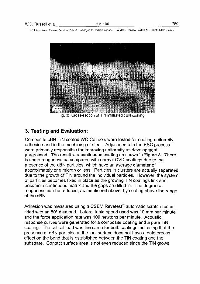
W.C. Russell et al. HM 100 75915" International Plansee Seminar, Eds. G. Kneringer, P. Rodhammer and H. Wildner, Plansee Holding AG, Reutte (2001), Vol. 2
• • A l * ^ * * * ^ * ^
• » .
Fig. 3: Cross-section of TiN infiltrated cBN coating.
3. Testing and EEvaluation:
Composite cBN-TiN coated WC-Co tools were tested for coating uniformity,adhesion and in the machining of steel. Adjustments to the ESC processwere primarily responsible for improving uniformity as developmentprogressed. The result is a continuous coating as shown in Figure 3. Thereis some roughness as compared with normal CVD coatings due to thepresence of the cBN particles, which have an average diameter ofapproximately one micron or less. Particles in clusters are actually separateddue to the growth of TiN around the individual particles. However, the systemof particles becomes fixed in place as the growing TiN coatings link andbecome a continuous matrix and the gaps are filled in. The degree ofroughness can be reduced, as mentioned above, by coating above the rangeofthecBN.
Adhesion was measured using a CSEM Revetest® automatic scratch testerfitted with an 80° diamond. Lateral table speed used was 10 mm per minuteand the force application rate was 100 newtons per minute. Acousticresponse curves were generated for a composite coating and a pure TiNcoating. The critical load was the same for both coatings indicating that thepresence of cBN particles at the tool surface does not have a deletereouseffect on the bond that is established between the TiN coating and thesubstrate. Contact surface area is not even reduced since the TiN grows
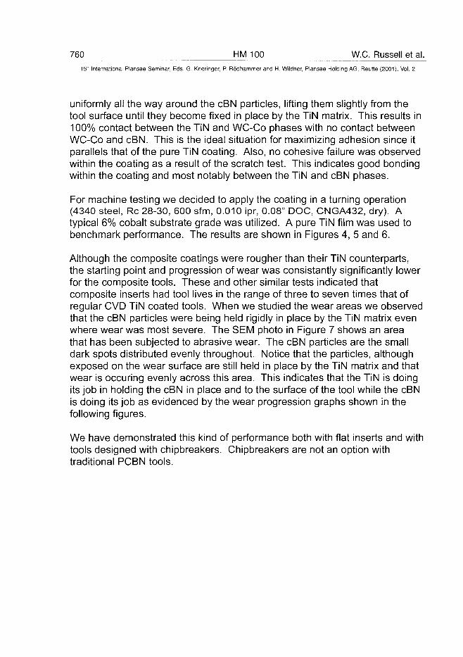
760 HM 100 W.C. Russell et al.
15- International Plansee Seminar, Eds. G. Kneringer, P. Rodhammer and H. Wildner, Plansee Holding AG, Reutte (2001), Vol. 2
uniformly all the way around the cBN particles, lifting them slightly from thetool surface until they become fixed in place by the TiN matrix. This results in100% contact between the TiN and WC-Co phases with no contact betweenWC-Co and cBN. This is the ideal situation for maximizing adhesion since itparallels that of the pure TiN coating. Also, no cohesive failure was observedwithin the coating as a result of the scratch test. This indicates good bondingwithin the coating and most notably between the TiN and cBN phases.
For machine testing we decided to apply the coating in a turning operation(4340 steel, Re 28-30, 600 sfm, 0.010 ipr, 0.08" DOC, CNGA432, dry). Atypical 6% cobalt substrate grade was utilized. A pure TiN film was used tobenchmark performance. The results are shown in Figures 4, 5 and 6.
Although the composite coatings were rougher than their TiN counterparts,the starting point and progression of wear was consistantly significantly lowerfor the composite tools. These and other similar tests indicated thatcomposite inserts had tool lives in the range of three to seven times that ofregular CVD TiN coated tools. When we studied the wear areas we observedthat the cBN particles were being held rigidly in place by the TiN matrix evenwhere wear was most severe. The SEM photo in Figure 7 shows an areathat has been subjected to abrasive wear. The cBN particles are the smalldark spots distributed evenly throughout. Notice that the particles, althoughexposed on the wear surface are still held in place by the TiN matrix and thatwear is occuring evenly across this area. This indicates that the TiN is doingits job in holding the cBN in place and to the surface of the tool while the cBNis doing its job as evidenced by the wear progression graphs shown in thefollowing figures.
We have demonstrated this kind of performance both with flat inserts and withtools designed with chipbreakers. Chipbreakers are not an option withtraditional PCBN tools.
W.C. Russell et al. HM 100 761
15lh International Plansee Seminar, Eds. G. Kneringer, P. Rodhammer and H. Wildner, Plansee Holding AG, Reurte (2001), Vol. 2
5 10Cutting Time (minutes)
Fig. 4: Flank wear, Turning 4340 Steel, Re 28-30 (600 sfm, 0.010 ipr, 0.08 in. DOC,CNGA432, dry machining)
TiN + cBN (trial 1)
-« -T iN + cBN(trial2)
-*--TiN (trial 1)
-x - TiN (trial 2)
5 10
Cutting Time (minutes)
Fig. 5: Flank wear, Turning 4340 Steel, Re 28-30 (600 sfm, 0.010 ipr, 0.08 in. DOC,CNGA432, dry machining)
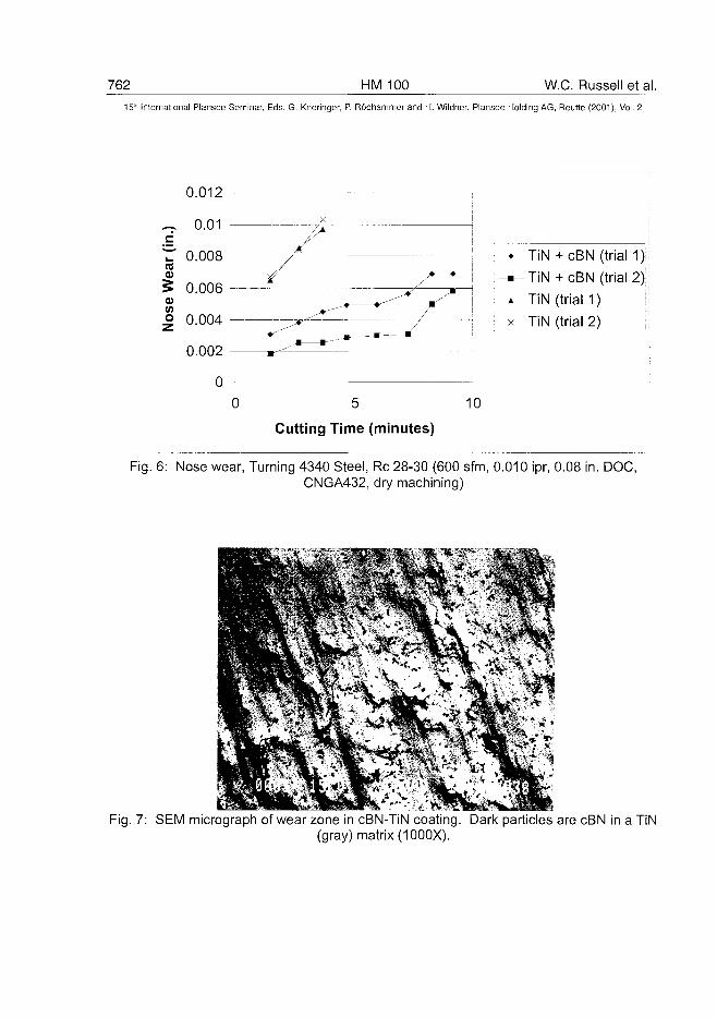
762 HM 100 W.C. Russell et al.
15" International Plansee Seminar, Eds. G. Kneringer, P. Rodhammer and H. Wildner, Plansee Holding AG, Reutte (2001), Vol. 2
0.012
^ 0.01dt " 0.008re5 0.006v
| 0.004 -^^*L
0.002 r-^*^
0
—
•
cBN (trial 1);
TiN + cBN (trial 2) ;
TiN (trial 1) !
TiN (trial 2) '•',
0 10
Cutting Time (minutes)
Fig. 6: Nose wear, Turning 4340 Steel, Re 28-30 (600 sfm, 0.010 ipr, 0.08 in. DOC,CNGA432, dry machining)
Fig. 7: SEM micrograph of wear zone in cBN-TiN coating. Dark particles are cBN in a TiN(gray) matrix (1000X).
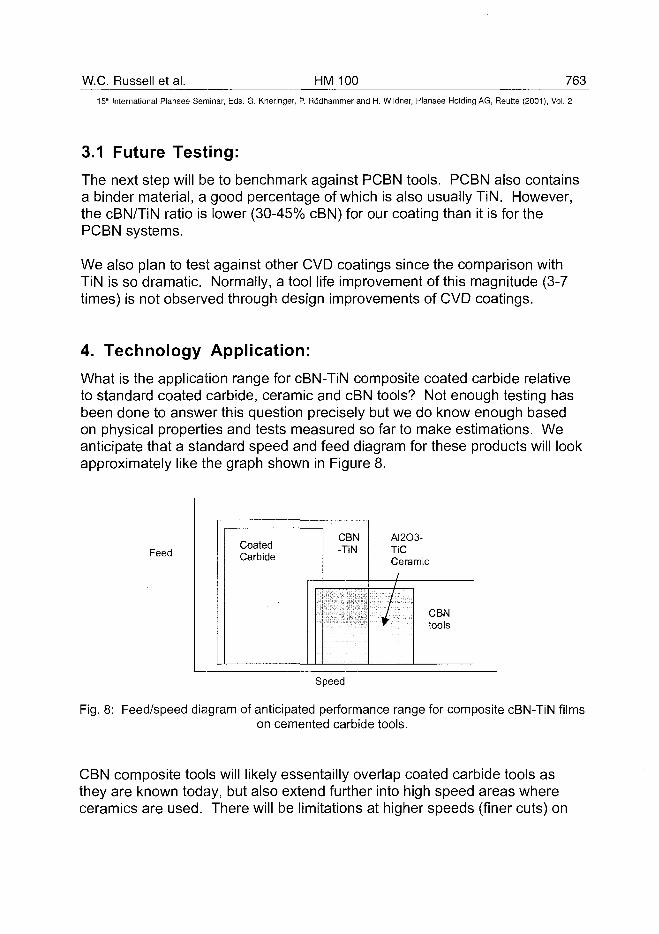
W.C. Russell et al. HM 100 76315'" International Plansee Seminar, Eds. G. Kneringer, P. Rodhammer and H. Wildner, Plansee Holding A6, Reutte (2001), Vol. 2
3.1 Future Testing:The next step will be to benchmark against PCBN tools. PCBN also containsa binder material, a good percentage of which is also usually TiN. However,the cBN/TiN ratio is lower (30-45% cBN) for our coating than it is for thePCBN systems.
We also plan to test against other CVD coatings since the comparison withTiN is so dramatic. Normally, a tool life improvement of this magnitude (3-7times) is not observed through design improvements of CVD coatings.
4. Technology Application:What is the application range for cBN-TiN composite coated carbide relativeto standard coated carbide, ceramic and cBN tools? Not enough testing hasbeen done to answer this question precisely but we do know enough basedon physical properties and tests measured so far to make estimations. Weanticipate that a standard speed and feed diagram for these products will lookapproximately like the graph shown in Figure 8.
FeedCoatedCarbide
CBN-TiN
AI2O3-TiCCeramic//
/CBNtools
Speed
Fig. 8: Feed/speed diagram of anticipated performance range for composite cBN-TiN filmson cemented carbide tools.
CBN composite tools will likely essentailly overlap coated carbide tools asthey are known today, but also extend further into high speed areas whereceramics are used. There will be limitations at higher speeds (finer cuts) on
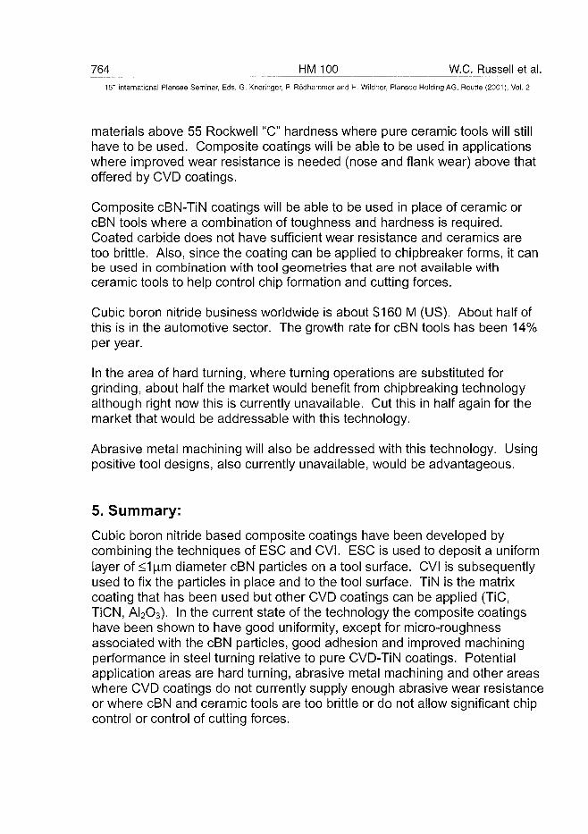
764 HM 100 W.C. Russell et al.
15" International Plansee Seminar, Eds. G. Kneringer, P. Rodhammer and H. Wildner, Plansee Holding AG, Reutte (2001), Vol. 2
materials above 55 Rockwell "C" hardness where pure ceramic tools will stillhave to be used. Composite coatings will be able to be used in applicationswhere improved wear resistance is needed (nose and flank wear) above thatoffered by CVD coatings.
Composite cBN-TiN coatings will be able to be used in place of ceramic orcBN tools where a combination of toughness and hardness is required.Coated carbide does not have sufficient wear resistance and ceramics aretoo brittle. Also, since the coating can be applied to chipbreaker forms, it canbe used in combination with tool geometries that are not available withceramic tools to help control chip formation and cutting forces.
Cubic boron nitride business worldwide is about $160 M (US). About half ofthis is in the automotive sector. The growth rate for cBN tools has been 14%per year.
In the area of hard turning, where turning operations are substituted forgrinding, about half the market would benefit from chipbreaking technologyalthough right now this is currently unavailable. Cut this in half again for themarket that would be addressable with this technology.
Abrasive metal machining will also be addressed with this technology. Usingpositive tool designs, also currently unavailable, would be advantageous.
5. Summary:
Cubic boron nitride based composite coatings have been developed bycombining the techniques of ESC and CVI. ESC is used to deposit a uniformlayer of <1u.m diameter cBN particles on a tool surface. CVI is subsequentlyused to fix the particles in place and to the tool surface. TiN is the matrixcoating that has been used but other CVD coatings can be applied (TiC,TiCN, AI2O3). In the current state of the technology the composite coatingshave been shown to have good uniformity, except for micro-roughnessassociated with the cBN particles, good adhesion and improved machiningperformance in steel turning relative to pure CVD-TiN coatings. Potentialapplication areas are hard turning, abrasive metal machining and other areaswhere CVD coatings do not currently supply enough abrasive wear resistanceor where cBN and ceramic tools are too brittle or do not allow significant chipcontrol or control of cutting forces.
W.C. Russell et al. HM 100 76515'" International Plansee Seminar, Eds. G. Kneringer, P. Rodhammer and H. Wildner, Plansee Holding AG, Reutte (2001), Vol. 2
Acknowledgements:
The authors would like to acknowledge the financial support from Division ofDesign, Manufacture and Industrial Innovations (DMII), National ScienceFoundation (GOALI grant #DMI-9713660), USA. We would also like to thankS. Onyskin (Valenite) for experimental and analytical support, K. Katbi(Valenite) and D. Johnson (Valenite) for application analysis.
References:1. J. Robertson, Diamond and Related Materials 5 (1996) 519-524.2. T. Yoshida, Diamond Films and Technology, Vol. 7, No. 2 (1997) 87-
104.3. P.B. Mirkarimi et al., J. Mater. Res., Vol. 9, No. 11, Nov. 1994, 2925-
2938.4. P.B. Mirkarimi et al., J. Appl. Phys., Vol. 82, No. 4, 15 August 1997,
1617-1625.5. K.S. Park et al., J. Vac. Sci. Technol. A 15(3), May/Jun 1997, 1041-
1047.6. M.F. Plass et. al., Thin Solid Films, 305 (1997) 172-184.7. Y. Setsuhara et al., Nucl. Instr. And Meth. In Phys. Res. B 127/128
(1997)851-856.8. W. Sproul, Surface and Coatings Technology, 81 (1996) 1-7.9. H. Wituschek et al., Surface and Coatings Technology 74-75 (1995)
729-733.10. "Electrostatic Powder Coating", J.F. Hughes, (Publ. - John Wiley &
Sons, Inc.) 1984.11. "Handbook of Electrostatic Processes", Eds. J. Chang, J. Kelly and J.M.
Crowley (Publ. Marcel Dekker, Inc.) 1995.12. T.M. Besmann, "Processing Science for Chemical Vapor Infiltration",
High Temperature Materials Laboratory Industry/Government Briefing(Oak Ridge National Laboratory, Oak Ridge, TN, 1990).
13. S.N. Yedave et al., to be published, Proceedings of the 15th
International Plansee Seminar (2001).
AT0100497766 HM 103 E. Lugscheider et al.
15:r International Plansee Seminar, Eds. G. Kneringer, P. Rödhammer and H. Wildner, Plansee Holding AG, Reutte (2001), Vol. 2
Weiterentwicklung umweltverträglicher Tribosysteme in der Zerspanungmittels PVD-Technologie
Erich Lugscheider*, Thomas Hornig*, Stefan Kienitz*Fritz Klocke+, Tilo Krieg+
*Lehr- und Forschungsgebiet Werkstoffwissenschaften, RWTH-Aachen+Laboratorium für Werkzeugmaschinen, Lehrstuhl für Technologie der
Fertigungsverfahren, RWTH-Aachen
Summary
PVD coatings offer a wide variety of applications. The focal point of this workis the development of an advanced type of PVD-hardcoating which allowsmachining with environmentally compatible lubricants. Representativeexamples for the investigations are the tribological systems "turning ofquenched and tempered steel 42CrMo4 V" and "austenitic stainless steelXôCrNiiS-IO". Ti-Hf-Cr-N and TiAIN/AI2O3 were deposited by AIP- andH.I.S.™ - process respectively. These coating systems showed best resultsconcerning oxidation wear and abrasive wear in former investigations. Thiswas necessary because main cutting-edge life criterias are oxidation wearand abrasive wear at the minor cutting edge. Consequently, a high oxidationstability and a high hardness at high temperatures are required.
KeywordsTiHf, Hafnium, TiHfCrN, TiAIN, AI2O3, Tribooxidation, Drehen
1 Problemstellung
Eine gesteigerte Umweltverträglichkeit der Fertigungsprozesse läßt sichdurch verschiedene Strategien erreichen. Alternativen bestehen in derTrockenbearbeitung, im Einsatz der Minimalmengenkühlschmierung oder,wenn beides aus technologischen oder ökonomischen Gründen nicht möglichist, in der Verwendung nichtwassermischbarer, biologisch schnell abbaubarerKühlschmierstoffe (NWBA-KSS). Anhand des modellhaft ausgewähltenVerfahrens Drehen von zwei repräsentativen Stahlwerkstoffen (X5CrNi 18-10und 42CrMo4V) wurde das Einsatzverhalten eines NWBA-KSS untersucht,
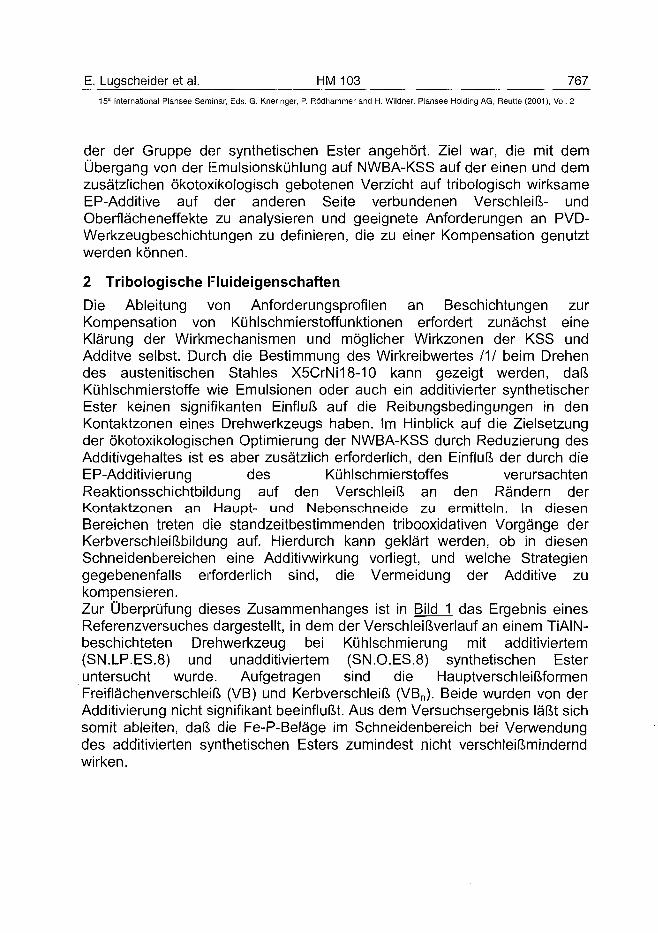
E. Lugscheider et al. HM 103 76715" International Plansee Seminar, Eds. G. Knerìnger, P. Rödhammer and H. Wildner, Plansee Holding AG, Reutte (2001), Vol. 2
der der Gruppe der synthetischen Ester angehört. Ziel war, die mit demÜbergang von der Emulsionskühlung auf NWBA-KSS auf der einen und demzusätzlichen ökotoxikologisch gebotenen Verzicht auf tribologisch wirksameEP-Additive auf der anderen Seite verbundenen Verschleiß- undOberflächeneffekte zu analysieren und geeignete Anforderungen an PVD-Werkzeugbeschichtungen zu definieren, die zu einer Kompensation genutztwerden können.
2 Tribologische Fluideigenschaften
Die Ableitung von Anforderungsprofilen an Beschichtungen zurKompensation von Kühlschmierstoffunktionen erfordert zunächst eineKlärung der Wirkmechanismen und möglicher Wirkzonen der KSS undAdditve selbst. Durch die Bestimmung des Wirkreibwertes IM beim Drehendes austenitischen Stahles X5CrNi18-10 kann gezeigt werden, daßKühlschmierstoffe wie Emulsionen oder auch ein additivierter synthetischerEster keinen signifikanten Einfluß auf die Reibungsbedingungen in denKontaktzonen eines Drehwerkzeugs haben. Im Hinblick auf die Zielsetzungder ökotoxikologischen Optimierung der NWBA-KSS durch Reduzierung desAdditivgehaltes ist es aber zusätzlich erforderlich, den Einfluß der durch dieEP-Additivierung des Kühlschmierstoffes verursachtenReaktionsschichtbildung auf den Verschleiß an den Rändern derKontaktzonen an Haupt- und Nebenschneide zu ermitteln. In diesenBereichen treten die standzeitbestimmenden tribooxidativen Vorgänge derKerbverschleißbildung auf. Hierdurch kann geklärt werden, ob in diesenSchneidenbereichen eine Additivwirkung vorliegt, und welche Strategiengegebenenfalls erforderlich sind, die Vermeidung der Additive zukompensieren.Zur Überprüfung dieses Zusammenhanges ist in Bild 1 das Ergebnis einesReferenzversuches dargestellt, in dem der Verschleißverlauf an einem TiAIN-beschichteten Drehwerkzeug bei Kühlschmierung mit additiviertem(SN.LP.ES.8) und unadditiviertem (SN.O.ES.8) synthetischen Esteruntersucht wurde. Aufgetragen sind die HauptverschleißformenFreiflächenverschleiß (VB) und Kerbverschleiß (VBn). Beide wurden von derAdditivierung nicht signifikant beeinflußt. Aus dem Versuchsergebnis läßt sichsomit ableiten, daß die Fe-P-Beläge im Schneidenbereich bei Verwendungdes additivierten synthetischen Esters zumindest nicht verschleißminderndwirken.
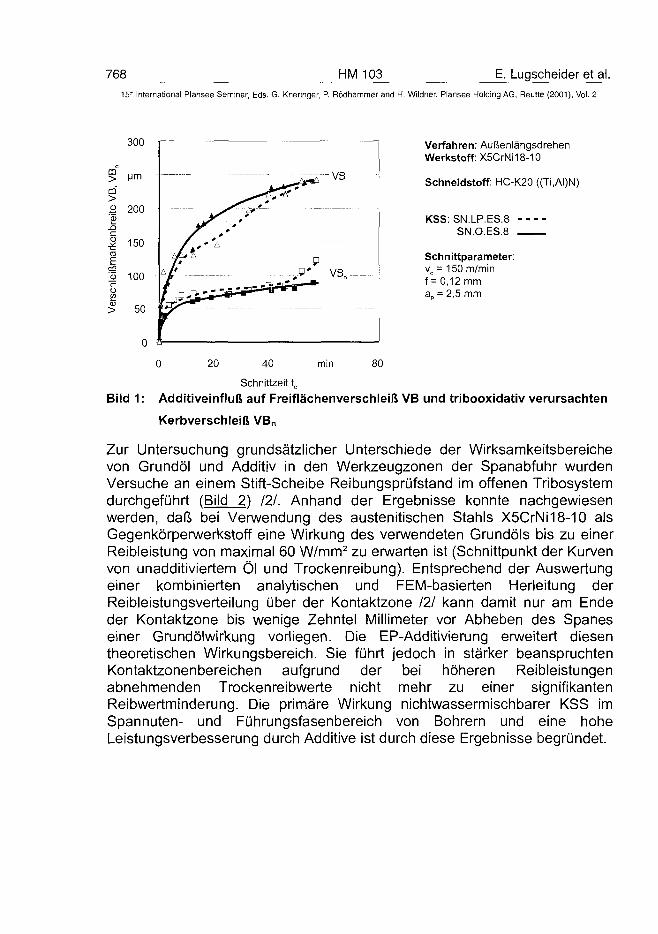
768 HM 103 E. Lugscheider et al.15' International Plansee Seminar, Eds. G. Kneringer, P. Rödhammer and H. Wildner, Plansee Holding AG, Relitte (2001), Vol. 2
300 Verfahren: AußenlängsdrehenWerkstoff: X5CrNi18-10
Schneidstoff: HC-K20 ((Ti,AI)N)
KSS: SN.LP.ES.8SN.O.ES.8
Schnittparameter:vc= 150 m/minf = 0,12 mma„ = 2,5 mm
0 20 40 80
Schnittzeit t0Bild 1 : Additiveinfluß auf Freiflächenverschleiß VB und tribooxidativ verursachten
Kerbverschleiß VB„
Zur Untersuchung grundsätzlicher Unterschiede der Wirksamkeitsbereichevon Grundöl und Additiv in den Werkzeugzonen der Spanabfuhr wurdenVersuche an einem Stift-Scheibe Reibungsprüfstand im offenen Tribosystemdurchgeführt (Bild 2) 121. Anhand der Ergebnisse konnte nachgewiesenwerden, daß bei Verwendung des austenitischen Stahls X5CrNi18-10 alsGegenkörperwerkstoff eine Wirkung des verwendeten Grundöls bis zu einerReibleistung von maximal 60 W/mm2 zu erwarten ist (Schnittpunkt der Kurvenvon unadditiviertem Öl und Trockenreibung). Entsprechend der Auswertungeiner kombinierten analytischen und FEM-basierten Herleitung derReibleistungsverteilung über der Kontaktzone 121 kann damit nur am Endeder Kontaktzone bis wenige Zehntel Millimeter vor Abheben des Spaneseiner Grundölwirkung vorliegen. Die EP-Additivierung erweitert diesentheoretischen Wirkungsbereich. Sie führt jedoch in stärker beanspruchtenKontaktzonenbereichen aufgrund der bei höheren Reibleistungenabnehmenden Trockenreibwerte nicht mehr zu einer signifikantenReibwertminderung. Die primäre Wirkung nichtwassermischbarer KSS imSpannuten- und Führungsfasenbereich von Bohrern und eine hoheLeistungsverbesserung durch Additive ist durch diese Ergebnisse begründet.
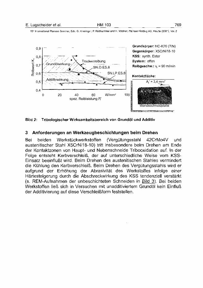
E. Lugscheider et al. HM 103 76915" International Plansee Seminar, Eds. G. Kneringer, P. Rödhammer and H. Wildner, Plansee Holding AG, Reutte (2001), Vol. 2
0,9
0,8
o 0,7
£0 ,6
0,5
0,4
-Grundölwirkung^r-Trockenreibung
Additivwirkung
SN.O.ES.8
SN.LP.ES.8
Grundkörper: HC-K20 (TiN)
Gegenkörper: X5CrNi18-10
KSS: synth. Ester
System: offen
Reibgeschw.: vr = 90 m/min
Kontaktfläche:
20 40 60 W/mm2
spez. Reibleistung P,'100
A,' = 3,4 mm2
endeschneidplatte
Bild 2: Tribologischer Wirksamkeitsbereich von Grundöl und Additiv
3 Anforderungen an Werkzeugbeschichtungen beim Drehen
Bei beiden Werkstückwerkstoffen (Vergütungsstahl 42CrMo4V undaustenitischer Stahl X5CrNi18-10) tritt insbesondere beim Drehen am Endeder Kontaktzonen von Haupt- und Nebenschneide Tribooxidation auf. In derFolge entsteht Kerbverschleiß, der auf unterschiedliche Weise vom KSS-Einsatz beeinflußt wird. Beim Drehen des austenitischen Stahles vermindertdie Kühlung den Kerbverschleiß. Beim Drehen des Vergütungsstahls wird eraufgrund der Erhöhung der Abrasivität des Werkstoffes infolge einerHärtesteigerung durch die Abschreckwirkung des KSS tendenziell verstärkt(s. REM-Aufnahmen der unbeschichteten Schneiden in Bild 3). Bei beidenWerkstoffen ließ sich in Versuchen mit unadditiviertem Grundöl kein Einflußder Additivierung auf diese Verschleißform feststellen.
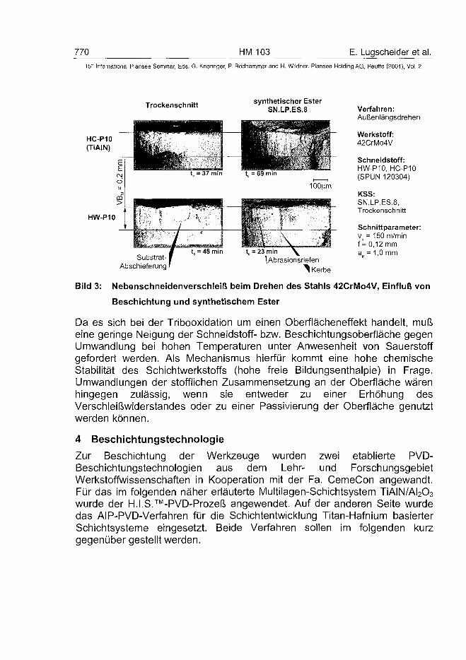
770 HM 103 E. Lugscheider et al.15* International Plansee Seminar, Eds. G. Kneringer, P. Rödhammer and H. Wildner, Plansee Holding AG, Reutte (2001), Vol. 2
Trockenschnitt synthetischer EsterSN.LP.ES.8
HC-P10(TiAIN)
HW-P10
Substrat-Abschieferung
tc = 23 min \
lAbrasionsriefen^ Kerbe
Verfahren:Außenlängsdrehen
Werkstoff:42CrMo4V
Schneidstoff:HW-P10, HC-P10(SPUN 120304)
KSS:SN.LP.ES.8,Trockenschnitt
Schnittparameter:vc= 150 m/minf = 0,12 mma = 1,0 mm
Bild 3: Nebenschneidenverschleiß beim Drehen des Stahls 42CrMo4V, Einfluß von
Beschichtung und synthetischem Ester
Da es sich bei der Tribooxidation um einen Oberflächeneffekt handelt, mußeine geringe Neigung der Schneidstoff- bzw. Beschichtungsoberfläche gegenUmwandlung bei hohen Temperaturen unter Anwesenheit von Sauerstoffgefordert werden. Als Mechanismus hierfür kommt eine hohe chemischeStabilität des Schichtwerkstoffs (hohe freie Bildungsenthalpie) in Frage.Umwandlungen der stofflichen Zusammensetzung an der Oberfläche wärenhingegen zulässig, wenn sie entweder zu einer Erhöhung desVerschleißwiderstandes oder zu einer Passivierung der Oberfläche genutztwerden können.
4 Beschichtungstechnologie
Zur Beschichtung der Werkzeuge wurden zwei etablierte PVD-Beschichtungstechnologien aus dem Lehr- und ForschungsgebietWerkstoffwissenschaften in Kooperation mit der Fa. CemeCon angewandt.Für das im folgenden näher erläuterte Multilagen-Schichtsystem TiAIN/AI2O3
wurde der H.I.S.™-PVD-Prozeß angewendet. Auf der anderen Seite wurdedas AIP-PVD-Verfahren für die Schichtentwicklung Titan-Hafnium basierterSchichtsysteme eingesetzt. Beide Verfahren sollen im folgenden kurzgegenüber gestellt werden.
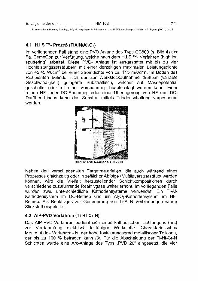
E. Lugscheider et al. HM 103 77115'h International Plansee Seminar, Eds. G. Kneringer, P. Rödhammer and H. Wildner, Plansee Holding AG, Reutte (2001), Vol. 2
4.1 H.I.S.™- Prozeß (TiAIN/AI2O3)
Im vorliegenden Fall stand eine PVD-Anlage des Typs CC800 (s. Bild 4) derFa. CemeCon zur Verfügung, welche nach dem H.I.S.™-Verfahren (high ionsputtering) arbeitet. Diese PVD- Anlage ist ausgestattet mit bis zu vierHochleistungszerstäubern mit einer derzeitigen maximalen Leistungsdichtevon 45,45 W/cm2 bei einer Stromdichte von ca. 115 mA/cm2. Im Boden desRezipienten befindet sich der zur Werkstückaufnahme drehbar (variableGeschwindigkeit) gelagerte Substrattisch, welcher auf Massepotentialgeschaltet oder mit einer Vorspannung beaufschlagt werden kann: Einerreinen HF- oder DC-Spannung oder einer Überlagerung von HF und DC.Darüber hinaus kann das Substrat mittels Triodenschaltung vorgespanntwerden.
Bild 4: PVD-Anlage CC-800
Neben den verschiedensten Targetmaterialien, die auch während einesProzesses gleichzeitig oder in zeitlicher Abfolge (Multilayer) zerstäubt werdenkönnen, wird die Vielfalt herzustellender Schichtkompositionen durchverschiedene zuzuführende Reaktivgase weiter erhöht. Im vorliegenden Fallewurden zwei unterschiedliche Kathodensysteme verwendet: Ein Ti-Al-Kathodensystem im DC-Betrieb und ein AI2O3-Kathodensytsem im HF-Betrieb. Als Reaktivgas zur Generierung von Ti-Al-N Verbindungen wurdeStickstoff eingeleitet.
4.2 AIP-PVD-Verfahren (Ti-Hf-Cr-N)
Das AIP-PVD-Verfahren bedient sich eines kathodischen Lichtbogens (arc)zur Verdampfung elektrisch leitfähiger Werkstoffe. CharakteristischesMerkmal des Verfahrens ist der hohe lonisierungsgrad metallischer Teilchen,der bis zu 100 % betragen kann 131. Für die Abscheidung der Ti-Hf-Cr-NSchichten wurde eine Are-Anlage des Typs „PVD 20" eingesetzt, die vier
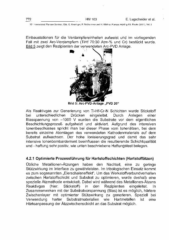
772 HM 103 E. Lugscheider et al.15'~ International Plansee Seminar, Eds. G. Kneringer, P. Rödhammer and H. Wildner, Plansee Holding AG, Reutte (2001 ), Vol. 2
Einbaustationen für die Verdampfereinheiten aufweist und im vorliegendenFall mit zwei Are-Verdampfern (TiHf 70:30 Atm-% und Cr) bestückt wurde.Bild 5 zeigt den Rezipienten der verwendeten Arc-PVD Anlage.
Bild 5: Arc-PVD-Anlage „PVD 20"
Als Reaktivgas zur Generierung von Ti-Hf-Cr-N Schichten wurde Stickstoffbei unterschiedlichen Drücken eingeleitet. Durch Anlegen einerBiasspannung von -1000 V wurden die Substrate vor dem eigentlichenBeschichtungsprozeß aufgeheizt und aktiviert. Aufgrund des intensivenlonenbeschusses spricht man bei dieser Phase vom lonenätzen, bei dembereits einzelne Atomlagen des verwendeten Kathodenmaterials auf demSubstrat aufwachsen. Der hohe lonisierungsgrad und damit das sehrintensive lonenbombardement beeinflussen die resultierende Schichtqualitiätund - haftung sehr positiv, wie unten beschriebene Haftungstest belegen.
4.2.1 Optimierte Prozessführung für Hartstoffschichten (Hartstoffätzen)
Übliche Metallionen-Ätzungen haben den Nachteil, eine zu geringeStützwirkung im interface zu gewährleisten. Im tribologischen Einsatz kommtes zum sogenannten „Eierschaleneffekt". Um das Werkstoffverbundverhaltenzwischen Hartstoffschicht und Substrat zu optimieren, wurde deshalb einespezielle Ätzmethode entwickelt. Dabei wird während des Metallionen-ÄtzensReaktivgas (hier: Stickstoff) in den Rezipienten eingeleitet. InZusammenwirken mit der Substratvorspannung (Bias) ist es möglich, härtereZwischenlayer mit optimierter Stützwirkung zu generieren. Speziell beiVerwendung harter Substratmaterialien wie Hartmetallen ist eineHärteanpassung der Ätzzwischenschicht an das Substrat möglich.
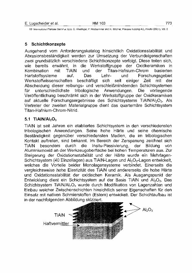
E. Lugscheider et al. HM 103 77315'h International Plansee Seminar, Eds. G. Kneringer, P. Rödhammer and H. Wildner, Plansee Holding AG, Reutte (2001), Vol. 2
5 Schichtkonzepte
Ausgehend vom Anforderungskatalog hinsichtlich Oxidationsstabilität undAbrasionsbeständigkeit werden zur Umsetzung der Verbundeigenschaftenzwei grundsätzlich verschiedene Schichtkonzepte verfolgt. Diese teilen sich,wie bereits erwähnt, in die Werkstoff g ruppe der Oxidkeramiken inKombination mit TiAIN und der Titan-Hafnium-Chrom basiertenHartstoffsysteme auf. Das Lehr- und ForschungsgebietWerkstoffwissenschaften beschäftigt sich seit einiger Zeit mit derAbscheidung dieser reibungs- und verschleißmindernden Schichtsystemenfür unterschiedlichste tribologische Anwendungen. Die vorliegendeVeröffentlichung beschränkt sich in der Werkstoffgruppe der Oxidkeramikenauf aktuelle Forschungsergebnisse des Schichtsystems TiAIN/AI2O3. AlsVertreter der zweiten Materialgruppe dient das quarternäre SchichtsystemTitan-Hafnium-Chrom-Nitrid.
5.1 TiAIN/AI2O3
TiAIN ist seit Jahren ein etabliertes Schichtsystem in den verschiedenstentribologischen Anwendungen. Seine hohe Härte und seine chemischeBeständigkeit gegenüber verschiedensten Medien, die im tribologischenKontakt auftreten, sind bekannt. Im Bereich der Zerspanung zeichnet sichTiAIN besonders durch die Insitu-Passivierung, der Bildung vonAluminiumoxid an der Werkzeugoberfläche bei hohen Temperaturen aus. ZurSteigerung der Oxidationsstabilität und der Härte wurde ein Mehrlagen-Schichtsystem (40 Einzellagen) aus TiAIN-Lagen und AI2O3-Lagen entwickelt,welches die Vorteile beider Monolagensysteme verbindet. Einerseits dievergleichsweise hohe Elastizität des TiAIN und andererseits die hohe Härteund Oxidationsstabilität der oxidischen Keramik. Als Ausgangspunkt derEntwicklung dient ein Schichtsystem auf der Basis TiAIN und AI2O3. DasSchichtsystem TiAIN/AI2O3 wurde durch Modifikation von Lagenzahlen undEinbau weicher Zwischenschichten hinsichtlich seiner Eigenschaften für denEinsatz mit nativen Schmierstoffen (Estern) entwickelt. Der Schichtaufbau istin der nachfolgenden Abbildung skizziert.
^ ™ ™ _ ™ _ _ _ _ - A ' 2 ° 3
TiAINH aftve rmittler
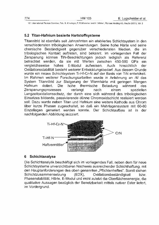
774 HM 103 E. Lugscheider et al.15" International Plansee Seminar, Eds. G. Kneringer, P. Rödhammer and H. Wildner, Plansee Holding AG, Reutte (2001), Vol. 2
5.2 Titan-Hafnium basierte Hartstoffsysteme
Titannitrid ist ebenfalls seit Jahrzehnten ein etabliertes Schichtsystem in denverschiedensten tribologischen Anwendungen. Seine hohe Härte und seinechemische Beständigkeit gegenüber verschiedensten Medien, die imtribologischen Kontakt auftreten, sind bekannt. Im vorliegenden Fall derZerspanung können TiN-Beschichtungen jedoch lediglich als Referenzbetrachtet werden, da sie mit Werten zwischen 450-590 GPa einvergleichsweise hohes E-Modul aufweisen. Auch hinsichtlich derOxidationsstabilität besteht weiterer Entwicklungsbedarf. Aus diesem Grundewurde ein neues Schichtsystem Ti-Hf-Cr-N auf der Basis von TiN entwickelt.Im Rahmen weiterer Forschungsarbeiten wurde in Anlehnung an 141 dasSystem Titannitrid zur Steigerung der Warmhärte mit geringen MengenHafnium dotiert. Die hohe thermische Belastung während desZerspanungsprozesses verlangt nach einem speziellenLangzeitoxidationsschutz, der durch eine sich während des tribologischenEinsatzes bildende, passivierende dünne Chromoxidschicht realisiert werdensoll. Dazu wurde neben Titan und Hafnium eine weitere Kathode aus Chromüber kurze Phasen zugeschaltet, so daß ein Mehrlagensystem mit 60-80Einzellagen generiert werden konnte. Der Schichtaufbau ist in dernachfolgenden Abbildung skizziert.
CrNTi-Hf-N"
Haftvermittler I
6 Schichtanalyse
Die Schichtanalytik beschäftigt sich im vorliegenden Fall, neben dem für neueSchichtsysteme unverzichtbaren Nachweis ausreichender Schichthaftung, mitden Hauptanforderungen des oben genannten „Pflichtenheftes". Somit stehenSchichtzusammensetzung (EDX), Oxidationsbeständigkeit bzw.Phasenstabilität, Härte, E-Modul und nicht zuletzt die Oberflächenenergie, diequalitative Aussagen bezüglich der Benetzbarkeit mittels nativer Ester liefert,im Vordergrund.
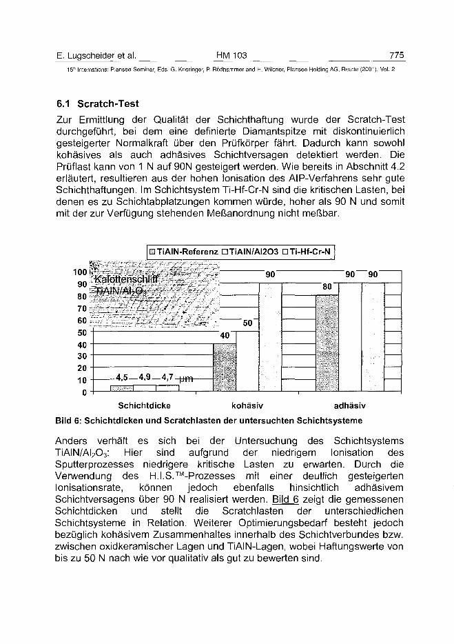
E. Lugscheider et al. HM 103 775
15lh International Plansee Seminar, Eds. G. Kneringer, P. Rödhammer and H. Wildner, Plansee Holding AG, Reutte (2001), Vol. 2
6.1 Scratch-Test
Zur Ermittlung der Qualität der Schichthaftung wurde der Scratch-Testdurchgeführt, bei dem eine definierte Diamantspitze mit diskontinuierlichgesteigerter Normalkraft über den Prüfkörper fährt. Dadurch kann sowohlkohäsives als auch adhäsives Schichtversagen detektiert werden. DiePrüflast kann von 1 N auf 90N gesteigert werden. Wie bereits in Abschnitt 4.2erläutert, resultieren aus der hohen Ionisation des AIP-Verfahrens sehr guteSchichthaftungen. Im Schichtsystem Ti-Hf-Cr-N sind die kritischen Lasten, beidenen es zu Schichtabplatzungen kommen würde, hoher als 90 N und somitmit der zur Verfügung stehenden Meßanordnung nicht meßbar.
UTiAIN-Referenz DTÌAIN/AI2O3 D Ti-Hf-Cr-N
100 |
70;6050403020100
"90" "90 90"
"50"
"40
-4,5—4,9_4,7._ i m T
80'
Schichtdicke kohäsiv adhäsiv
Bild 6: Schichtdicken und Scratchlasten der untersuchten Schichtsysteme
Anders verhält es sich bei der Untersuchung des SchichtsystemsTiAIN/AI2O3: Hier sind aufgrund der niedrigem Ionisation desSputterprozesses niedrigere kritische Lasten zu erwarten. Durch dieVerwendung des H.I.S.™-Prozesses mit einer deutlich gesteigertenlonisationsrate, können jedoch ebenfalls hinsichtlich adhäsivemSchichtversagens über 90 N realisiert werden. Bild 6 zeigt die gemessenenSchichtdicken und stellt die Scratchlasten der unterschiedlichenSchichtsysteme in Relation. Weiterer Optimierungsbedarf besteht jedochbezüglich kohäsivem Zusammenhaltes innerhalb des Schichtverbundes bzw.zwischen oxidkeramischer Lagen und TiAIN-Lagen, wobei Haftungswerte vonbis zu 50 N nach wie vor qualitativ als gut zu bewerten sind.
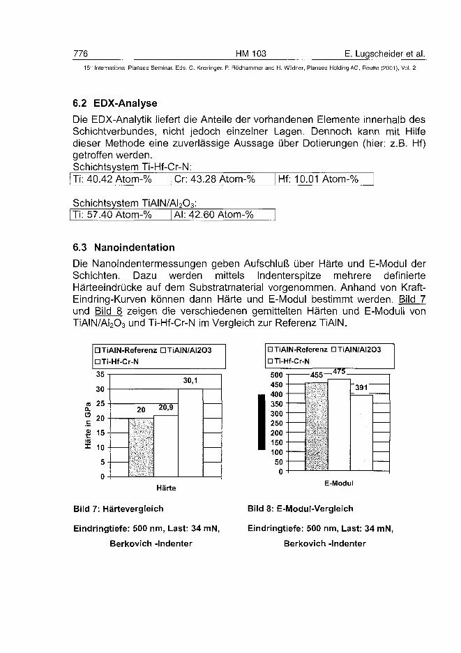
776 HM 103 E. Lugscheider et al.15" International Plansee Seminar, Eds. G. Kneringer, P. Rödhammer and H. Wildner, Plansee Holding AG, Reutte (2001), Vol. 2
6.2 EDX-Analyse
Die EDX-Analytik liefert die Anteile der vorhandenen Elemente innerhalb desSchichtverbundes, nicht jedoch einzelner Lagen. Dennoch kann mit Hilfedieser Methode eine zuverlässige Aussage über Dotierungen (hier: z.B. Hf)getroffen werden.Schichtsystem Ti-Hf-Cr-N:Ti: 40.42 Atom-% Cr: 43.28 Atom-% Hf: 10.01 Atom-%
Schichtsystem TiAIN/AI2O3:Ti: 57.40 Atom-% | AI: 42.60 Atom-%
6.3 Nanoindentation
Die Nanoindentermessungen geben Aufschluß über Härte und E-Modul derSchichten. Dazu werden mittels Indenterspitze mehrere definierteHärteeindrücke auf dem Substratmaterial vorgenommen. Anhand von Kraft-Eindring-Kurven können dann Härte und E-Modul bestimmt werden. Bild 7und Bild 8 zeigen die verschiedenen gemittelten Härten und E-Moduli vonTiAIN/AI2O3 und Ti-Hf-Cr-N im Vergleich zur Referenz TiAIN.
DTiAIN-Referenz OTÌAIN/AI2O3
D Ti-Hf-Cr-N
35
30
25
20
15
10
5
0
Härte
30,1
20 2 0 > 9
Bild 7: Härtevergleich
Eindringtiefe: 500 nm, Last: 34 mN,
Berkovich -Indenter
HTiAlN-Referenz DTÌAIN/AI2O3
D Ti-Hf-Cr-N
50045040035030025020015010050
0
4 7 54 3 3
391
E-Modul
Bild 8: E-Modul-Vergleich
Eindringtiefe: 500 nm, Last: 34 mN,
Berkovich -Indenter
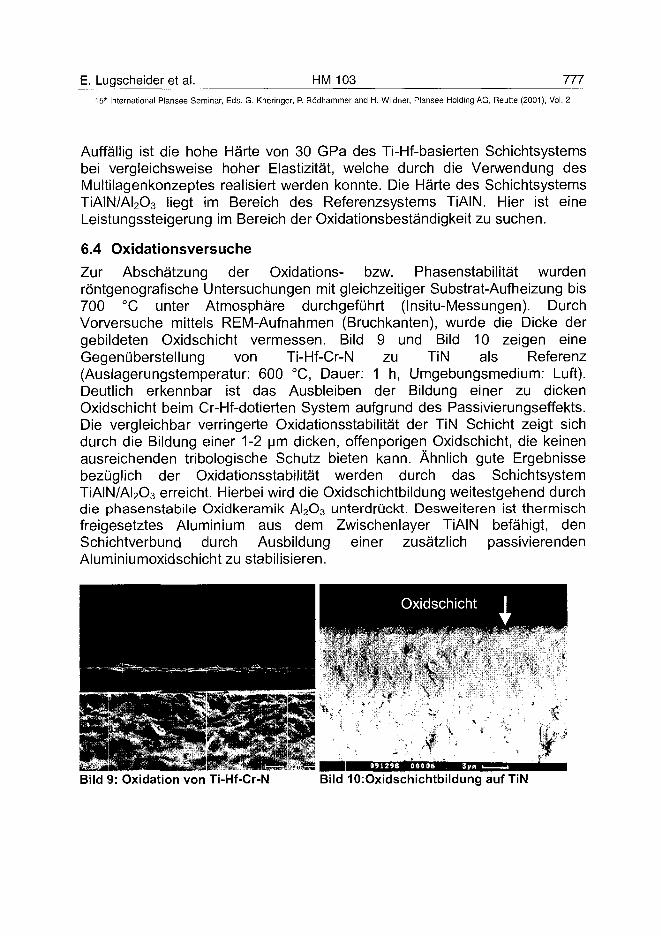
E. Lugscheider et al. HM 103 777
15'" International Plansee Seminar, Eds. G. Kneringer, P. Rödhammer and H. Wildner, Plansee Holding AG, Reutte (2001), Vol. 2
Auffällig ist die hohe Härte von 30 GPa des Ti-Hf-basierten Schichtsystemsbei vergleichsweise hoher Elastizität, welche durch die Verwendung desMultilagenkonzeptes realisiert werden konnte. Die Härte des SchichtsystemsTÏAIN/AI2O3 liegt im Bereich des Referenzsystems TiAIN. Hier ist eineLeistungssteigerung im Bereich der Oxidationsbeständigkeit zu suchen.
6.4 Oxidationsversuche
Zur Abschätzung der Oxidations- bzw. Phasenstabilität wurdenröntgenografische Untersuchungen mit gleichzeitiger Substrat-Aufheizung bis700 °C unter Atmosphäre durchgeführt (Insitu-Messungen). DurchVorversuche mittels REM-Aufnahmen (Bruchkanten), wurde die Dicke dergebildeten Oxidschicht vermessen. Bild 9 und Bild 10 zeigen eineGegenüberstellung von Ti-Hf-Cr-N zu TiN als Referenz(Auslagerungstemperatur: 600 °C, Dauer: 1 h, Umgebungsmedium: Luft).Deutlich erkennbar ist das Ausbleiben der Bildung einer zu dickenOxidschicht beim Cr-Hf-dotierten System aufgrund des Passivierungseffekts.Die vergleichbar verringerte Oxidationsstabilität der TiN Schicht zeigt sichdurch die Bildung einer 1-2 um dicken, offenporigen Oxidschicht, die keinenausreichenden tribologische Schutz bieten kann. Ähnlich gute Ergebnissebezüglich der Oxidationsstabilität werden durch das SchichtsystemTÏAIN/AI2O3 erreicht. Hierbei wird die Oxidschichtbildung weitestgehend durchdie phasenstabile Oxidkeramik AI2O3 unterdrückt. Desweiteren ist thermischfreigesetztes Aluminium aus dem Zwischenlayer TiAIN befähigt, denSchichtverbund durch Ausbildung einer zusätzlich passivierendenAluminiumoxidschicht zu stabilisieren.
Oxidschicht
Bild 9: Oxidation von Ti-Hf-Cr-N Bild lOiOxidschichtbildung auf TiN
778 HM 103 E. Lugscheider et al.15" International Plansee Seminar, Eds. G. Kneringer, P. Rödhammer and H. Wildner, Plansee Holding AG, Reutte (2001), Vol. 2
7 Realisierung erforderlicher Schichteigenschaften
7.1 Tribooxidationswiderstand
Die Ergebnisse eines Prüfkonzeptes aus Universalhärte- undAbrasionswiderstandsmessung an geglühten und beschichteten Proben zurIdentifizierung tribooxidationsstabiler Schichtsysteme 151 haben gezeigt, daßes möglich ist, eine Steigerung der Oxidationsstabilität durch Modifikation vonMonolagenbeschichtungen zu erreichen, ohne mechanische Eigenschaftenwie die Härte oder den Abrasionswiderstand gegenüber anderenkonventionellen Hartstoffsystemen zu verschlechtern. Hierfür haben sichErgänzungen konventioneller Ti-basierter Systeme mit Hf und Cr als überausgeeignet erwiesen /6/.Bild 11 zeigt für beide Schichtsysteme (TiAIN/AI2O3 und Ti-Hf-Cr-N) denVergleich der Verschleißmeßgrößen VBNn und VBNmax nach Standzeitendebzw. einer Schnittzeit von tc = 57 min beim Drehen des austenitischen StahlsX5CrNi18-10. Zu diesen Zeitpunkten wiesen sowohl die mit Ti-Hf-Cr-Nbeschichteten als auch die mit der TiAIN/A^Os-Multilagenbeschichtungversehenen Wendeschneidplatten keinen Kerbverschleiß auf. Beideuntersuchten Konzepte des Schichtaufbaus sind somit geeignet, die primäreZielsetzung zu erfüllen, den tribooxidativ verursachten Kerbverschleiß zuvermindern. Der maximale Freiflächenverschleiß VBNmax stieg beiVerwendung der Ti-Hf-Cr-N Schicht jedoch ab einer Schnittzeit vontc = 25 min progressiv. Dieses Ergebnis ist jedoch typisch für neu entwickelteprototypische Schichtsysteme. Dennoch kann aufgrund des hohenTribooxidationswiderstandes ein hohes Weiterentwicklungspotential beidiesem Schichtsystem für zukünftige Anwendung der Drehbearbeitung vonaustenitischem Stahl mit NWBA-KSS vorausgesagt werden.
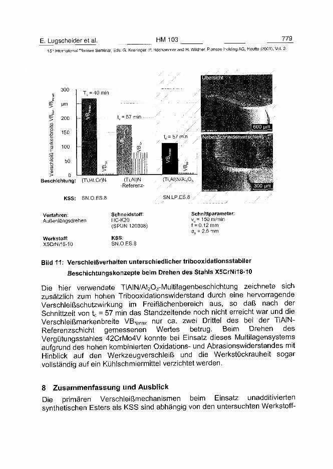
E. Lugscheider et al. HM 103 779
15" Internataìional Plansee Seminar, Eds. G. Kneringer, P. Rödhammer and H. Wildner, Plansee Holding AG, Reutte (2001), Vol. 2
>
af
Ic2
2
300
200
150
100
50
T , = 40 min
t = 57 min
co>
CD
Beschichtung: (Ti,Hf,Cr)N
KSS: SN.O.ES.8
(Ti,AI)N-Referenz-
Verfahren:Außenlängsdrehen
Werkstoff:X5CrNi18-10
Schneidstoff:HC-K20(SPUN 120308)
KSS:SN.O.ES.8
SN.LP.ES.8
Schnittparameter:vc = 150 m/minf = 0,12 mma„ = 2,5 mm
Bild 11: Verschleißverhalten unterschiedlicher tribooxidationsstabiler
Beschichtungskonzepte beim Drehen des Stahls X5CrNi18-10
Die hier verwendete TiAIN/A^Os-Multilagenbeschichtung zeichnete sichzusätzlich zum hohen Tribooxidationswiderstand durch eine hervorragendeVerschleißschutzwirkung im Freiflächenbereich aus, so daß nach derSchnittzeit von tc = 57 min das Standzeitende noch nicht erreicht war und dieVerschleißmarkenbreite VBNmax nur ca. zwei Drittel des bei der TiAIN-Referenzschicht gemessenen Wertes betrug. Beim Drehen desVergütungsstahles 42CrMo4V konnte bei Einsatz dieses Multilagensystemsaufgrund des hohen kombinierten Oxidations- und Abrasionswiderstandes mitHinblick auf den Werkzeugverschleiß und die Werkstückrauheit sogarvollständig auf ein Kühlschmiermittel verzichtet werden.
8 Zusammenfassung und AusblickDie primären Verschleißmechanismen beim Einsatz unadditiviertensynthetischen Esters als KSS sind abhängig von den untersuchten Werkstoff-
780 HM 103 E. Lugscheider et al.15- International Plansee Seminar, Eds. G. Kneringer, P. Rödhammer and H. Wildner, Plansee Holding AG, Relitte (2001), Vol. 2
Verfahrenskombinationen Abrasion, Tribooxidation und thermisch aktivierteAnhaftung von Werkstückwerkstoff am Schneidstoff. Diese treten inunterschiedlichen tribologischen Subsystemen der Zerspanwerkzeuge auf,die mit zunehmendem Abstand von der Schneide wechseln. Sie sind je nachKombination von Werkstoff und Verfahren unterschiedlich gewichtet. Indiesem Zusammenhang sind die in den Untersuchungen ermitteltenZuordnungen von KSS-Wirkungsmechanismen und von gefordertenSchichteigenschaften auf einzelne Verschleißmechanismen beschrieben. Mitzunehmendem Abstand von der Schneide können sich die Anforderungen andie Beschickungen von hohem Abrasionswiderstand überOxidationsbeständigkeit hin zu schwerweichem Verhalten und guterBenetzbarkeit für KSS wandeln. Aber auch über den Schichtquerschnitt istaufgrund der Untersuchungsergebnisse ein gegenläufigesSchichtanforderungsprofil vorhanden. Im schneidennahen Bereich wird imInterface Schicht-Substrat eine gute Haftung gefordert, was eine hoheZähigkeit und Polarität voraussetzt. Im Interface Schicht-Span hingegen wirdeine hohe Härte und eine schlechte Haftung zum Span gefordert, was einergeringeren Zähigkeit und einer geringen Polarität entspricht.Beschichtungskonzepte, die erfolgreich den aus ökotoxikologischer Sichtanzustrebende Einsatz von unadditivierten NWBA-KSS ohne größereLeistungseinbußen der Zerspanprozesse ermöglichen, sind demnach auf diespezifischen Werkstoff-Verfahrenskombination zuzuschneiden und müsseninsbesondere ein in verschiedenen Werkzeugzonen variablesEigenschaftsprofil aufweisen. Die Untersuchungen haben am Beispiel zweierNeuentwicklungen TiAIN/AI2O3 und Ti-Hf-Cr-N gezeigt, daß dies teils schonheute durch die systematische Übertragung von Erkenntnissen auf dieAuswahl von PVD-Schichten realisiert werden kann, die zum Teil noch aufbekannten Ansätzen der Werkzeugbeschichtung beruhen.
9 Danksagung
Die in diesem Beitrag dargestellten Arbeiten wurden im Rahmen desSonderforschungsbereiches 442 „Umweltverträgliche Tribosysteme" derDeutschen Forschungsgemeinschaft gefördert.
E. Lugscheider et al. HM 103 78115" International Plansee Seminar, Eds. G. Kneringer, P. Rôdhammer and H. Wildner, Plansee Holding AG, Reutte (2001), Vol. 2
Literatur
IM KLOCKE, F.; KÖNIG, W.: Fertigungsverfahren Band 1: Drehen, Fräsen, Bohren. SpringerVerlag, 6. Aufl., 1997
121 KRIEG, T.: Eigenschaftsprofile von PVD-Werkzeugbeschichtungen für den Einsatz vonumweltverträglichem Kühlschmierstoff beim Drehen und Bohren von Stahlwerkstoffen.Dr.-Ing. Diss. RWTH-Aachen, 2000
/3/ HAEFER: Oberflächen- und Dünnschichtentechnologie (TeiH), Springer-Verlag Berlin(1987)
/4/ MÜNZ, W. -D.: Prozeedings of the first French and German Conference on High SpeedMachining, Metz, France, 1997
/5/ KLOCKE, F.; KRIEG T.; LUGSCHEIDER, E.; HELLMANN, S.: Methodische Schichtentwick-lung für das Drehen von Austenit mit umweltverträglichem Kühlschmierstoff, GFTTribologie-Fachtagung, 27.-29.9.99, Göttingen
/6/ KLOCKE, F.; KRIEG, T.: Umweltverträglich Zerspanen; wt Werkstatttechnik 89 (1999) 10
ATO100498782 HM 1 G. Gilleetal.
15" International Plansee Seminar, Eds. G. Kneringer, P. Rodhammer and H. Wildner, Plansee Holding AG, Reutte (2001), Vol. 2
SUBMICRON and ULTRAFINE GRAINED HARDMETALS for
MICRODRILLS and METAL CUTTING INSERTS
G. Gille1), B. Szesny1), K. Dreyer2', H. van den Berg2', J. Schmidt3',
T. Gestrich4', G. Leitner4'1)H. C. STARCK GmbH & Co. KG, Goslar, Germany
2)WIDIA VALENITE GmbH, Essen, Germany3) HPTec GmbH, Ravensburg, Germany
4)FRAUNHOFER INSTITUTE IKTS, Dresden, Germany
Summary
Although round tools as carbide drills and mills are dominating by far theapplication of submicron and ultrafine hardmetals the consumption for PCBmicrodrills had the strongest growth rate over the last decade. This paperdeals with the latest developments of ultrafine hardmetals and theirapplication for PCB microdrills and metal cutting inserts. Based on optimizedprocessing and properties such as hardness, hot hardness, toughness,strength and wear resistance a new generation of microdrills is presented. Inparticular the failure probability of the microdrills could be considerablyreduced and the number of drilling strokes was nearly doubled.Combining improved pressing behaviour with proper doping and optimizedprocessing new applications of submicron and ultrafine hardmetals could beobtained by using complex shaped metal cutting inserts. Apart from theseapplication examples the paper gives some insight into fundamentalinvestigations on sintering and properties of ultrafine hardmetals and showsin particular the influence of milling, doping and sintering on the properties ofultrafine hardmetals.The paper also presents a new ultrafine WC grade showing a 0.1 urn WCintercept of a sintered WC - 10 wt % Co structure and a hardness of HV30 =2050 for a 1 wt % mixed VC/Cr3C2 doping.
Keywords:
Submicron and ultrafine grained hardmetals, processing and sinteringbehaviour, application of submicron hardmetals, PCB microdrills, metalcutting inserts.
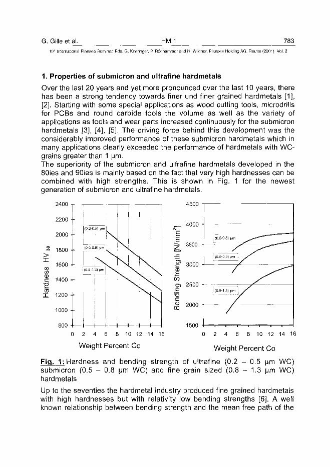
G. Gille et al. HM 1 78315'" International Plansee Seminar, Eds. G. Kneringer, P. Rodhammer and H. Wildner, Plansee Holding AG, Reutte (2001), Vol. 2
1. Properties of submicron and ultrafine hardmetals
Over the last 20 years and yet more pronounced over the last 10 years, therehas been a strong tendency towards finer und finer grained hardmetals [1],[2]. Starting with some special applications as wood cutting tools, microdrillsfor PCBs and round carbide tools the volume as well as the variety ofapplications as tools and wear parts increased continuously for the submicronhardmetals [3], [4], [5]. The driving force behind this development was theconsiderably improved performance of these submicron hardmetals which inmany applications clearly exceeded the performance of hardmetals with WC-grains greater than 1 urn.The superiority of the submicron and ulfrafine hardmetals developed in the80ies and 90ies is mainly based on the fact that very high hardnesses can becombined with high strengths. This is shown in Fig. 1 for the newestgeneration of submicron and ultrafine hardmetals.
4500
oCO
X
ci—mX
ituu •
2200 •
2000 -
1800 •
1600 •
1400 -
1200 -
1000 -
800 -
(0.2-0.5) |jm
(0.5-0.8) (im
(0.8-1.3) Mm
i 1
N
i—i—i—i— 15000 2 4 6 8 10 12 14 16
Weight Percent Co
0 2 4 6 8 10 12 14 16
Weight Percent Co
Fig. 1: Hardness and bending strength of ultrafine (0.2 - 0.5 urn WC)submicron (0.5 - 0.8 urn WC) and fine grain sized (0.8 - 1.3 urn WC)hardmetals
Up to the seventies the hardmetal industry produced fine grained hardmetalswith high hardnesses but with relativity low bending strengths [6]. A wellknown relationship between bending strength and the mean free path of the
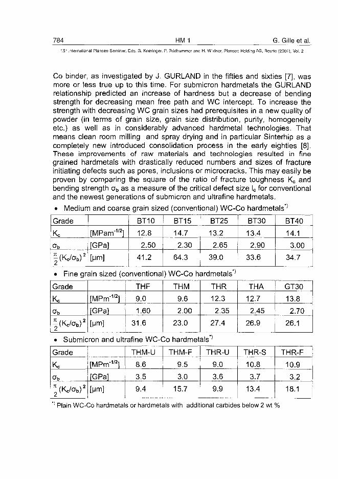
784 HM 1 G. Gille et al.
5" International Plansee Seminar, Eds. G. Kneringer, P. Rodhammer and H. Wildner, Plansee Holding AG, Reutte (2001), Vol. 2
Co binder, as investigated by J. GURLAND in the fifties and sixties [7], wasmore or less true up to this time. For submicron hardmetals the GURLANDrelationship predicted an increase of hardness but a decrease of bendingstrength for decreasing mean free path and WC intercept. To increase thestrength with decreasing WC grain sizes had prerequisites in a new quality ofpowder (in terms of grain size, grain size distribution, purity, homogeneityetc.) as well as in considerably advanced hardmetal technologies. Thatmeans clean room milling and spray drying and in particular Sinterhip as acompletely new introduced consolidation process in the early eighties [8],These improvements of raw materials and technologies resulted in finegrained hardmetals with drastically reduced numbers and sizes of fractureinitiating defects such as pores, inclusions or microcracks. This may easily beproven by comparing the square of the ratio of fracture toughness Kc andbending strength ab as a measure of the critical defect size lc for conventionaland the newest generations of submicron and ultrafine hardmetals.
• Medium and coarse grain sized (conventional) WC-Co hardmetals*'
Grade
Kc
ob
| (Kc /a b ) 2
[MPam"1'2]
[GPa]
[urn]
BT10
12.8
2.50
41.2
BT15
14.7
2.30
64.3
BT25
13.2
2.65
39.0
BT30
13.4
2.90
33.6
BT40
14.1
3.00
34.7
• Fine grain sized (conventional) WC-Co hardmetals*'
Grade
Kc
ab
| (Kc /a b ) 2
[MPrrT1'2]
[GPa]
[urn]
THF
9.0
1.60
31.6
THM
9.6
2.00
23.0
THR
12.3
2.35
27.4
THA
12.7
2.45
26.9
GT30
13.8
2.70
26.1
• Submicron and ultrafine WC-Co hardmetals*'
Grade
Kc
| (Kc /a b ) 2
[MPrrr1'2]
[GPa]
[urn]
THM-U
8.6
3.5
9.4
THM-F
9.5
3.0
15.7
THR-U
9.0
3.6
9.9
THR-S
10.8
3.7
13.4
THR-F
10.9
3.2
18.1
1 Plain WC-Co hardmetals or hardmetals with additional carbides below 2 wt %
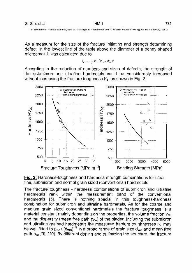
G. Gille et al. HM 1 785
15" International Plansee Seminar, Eds. G. Kneringer, P. Rodhammer and H. Wildner, Plansee Holding AG, Reutte (2001), Vol. 2
As a measure for the size of the fracture initiating and strength determiningdefect, in the lowest line of the table above the diameter of a penny shapedmicrocrack lc was calculated due to
lc = 1 * (KJab)2
According to the reduction of numbers and sizes of defects, the strength ofthe submicron and ultrafine hardmetals could be considerably increasedwithout increasing the fracture toughness Kc, as shown in Fig. 2.
2250
2000OCO
^ 1750IS)
% 1500cECD 1250
1000
750
500
O Submicron and UltrafineHardmetals
- Conventional Hardmetals
V -\o\o
—' --|v = -••
• ; - — r—• i
2b00
2250
2000
X 1750IS)IS)
0 1500
Jj5 1250
1000
750
5nn
O Submicron and UltrafineHardmetals
- Conventional Hardmetals
\
__ \
o. i . . . _
oo ;
n °
" \ I '
] \ J
i • - ;
0 5 10 15 20 25 30 35
1/2nFracture Toughness [MPa m ]
1000 2000 3000 4000 5000
Bending Strength [MPa]
Fig. 2: Hardness-toughness and hardness-strength combinations for ultra-fine, submicron and normal grain sized (conventional) hardmetals
The fracture toughness - hardness combinations of submicron and ultrafinehardmetals rank within the measurement band of the conventionalhardmetals [5]. There is nothing special in this toughness-hardnesscombination for submicron and ultrafine hardmetals. As for the coarse andmedium grain sized conventional hardmetals the fracture toughness is amaterial constant mainly depending on the properties, the volume fraction vCo
and the dispersity (mean free path pCo) of the binder. Including the submicronand ultrafine grained hardmetals the measured fracture toughnesses Kc maybe well fitted to pCo/ (dwc)1'2 in a broad range of grain size d w c and mean freepath pco [9], [10]. By different doping and optimizing the structure, the fracture

786 HM 1 G. Gille et al.15" International Plansee Seminar, Eds. G. Kneringer, P. Rodhammer and H. Wildner, Plansee Holding AG, Reutte {2001), Vol. 2
toughness of submicron and ultrafine hardmetals may be improved within avery limited range [5], [11]. But there may be some possibilities to improvealso the fracture toughness much more as it seems to be realistic up to now,by specially shaped WC micrograins, by special doping or alloying the binder[17].As for conventional hardmetals the hardness declines with increasingtemperature. But up to 800 - 900 °C the submicron and ultrafine hardmetalsshow superior hot hardnesses, see Fig. 3.
2500 100
0 200 400 600 800 1000
Temperature [°C]
200 400 600 800
Temperature [°C]1000
Fig. 3: Hardness and thermal conductivity versus temperature for ultrafine,submicron and fine grain sized hardmetals
This superiority in hot hardness up to 800 - 900 °C provides betterperformance not only in cutting wood, plastics and non ferrous metals butalso in cutting operations with higher thermal loading as drilling, milling andturning of cast iron and steels [4], [12] and [13]. The hot hardness may becontrolled and improved within a limited range by the doping carbides andtheir contents, see section 3.1. of this paper and [5].The diagramm at the right side of Fig. 3 shows the relative strong decrease ofthe thermal conductivity with decreasing WC grain size. This lower thermalconductivity has a positive influence on the thermal loading of the tool,because the arising heat is transfered in a bigger ratio to the workpiece. An
G. Gille et al. HM 1 787
15" International Plansee Seminar, Eds. G. Kneringer, P. Rodhammer and H. Wildner, Plansee Holding AG, Reutte (2001), Vol. 2
effect very similar to that of AI2O3/2rO2 coatings on cutting inserts. On theother hand a lower thermal conductivity A decreases the thermal shockresistance, which is proportional to
aEwhere v is the POISSON ratio, E is the YOUNG-modulus, ob is the bendingstrength and a is the coefficient of thermal expansion. Calculations showhowever the decrease of A is completely compensated by the higher bendingstrength of submicron and ultrafine hardmetals and there are nodisadvantages for these hardmetals concerning thermal shock resistance.
2. Processing of submicron and ultrafine powder and hardmetalmixtures
To obtain advanced submicron or ultrafine hardmetals with minimal porosity,defects and discontinuous grain growth the processing of the raw materialmixtures requires appropiate milling and sintering conditions as well as properformulations of grain growth inhibitor additives. Sinterhip as an essentialprogress in consolidation technique can help a lot to minimize the residualporosity, but without optimizied milling, granulation and pressing, thisadvanced technique is not sufficient to provide high performance ultrafinehardmetals. Any contamination or inhomogeneity from the raw material orproduced by milling or pressing can not completely be removed by sinterhipand can be a fracture initiating or wear accelerating defect. To obtain the highlevel of the state of the art, high efforts have been made in the past but only asmall part of this work has been published [2], [14], [15]. In particular thepapers of SCHUBERT et al. [2] and CARROLL [14] give good overviews ofthe problems connected with the processing of submicron powders andmixtures. This paper is restricted to two issues selected from the high numberof problems addressed in [2], [14] and elsewhere.
• Pressing behaviour of submicron and ultrafine hardmetal mixtures• Aspects of doping and sintering
2.1. Pressing behaviour
Some years ago nearly all tools and wear parts made from submicronhardmetals were extruded materials or were machined as greenware orfinished in the sintered state to provide the final geometry and surface quality.One reason to restrict submicron hardmetals to this type of tools and partswas determined by the application as drills, mills, wood cutting tools or otherround carbide tools and construction parts. A second reason for thisrestriction arose from the difficulties in pressing parts with complicated
788 HMJ G. Gille et al.15* International Plansee Seminar, Eds. G. Kneringer, P. Rodhammer and H. Wildner, Plansee Holding AG, Reutte (2001), Vol. 2
geometries and shapes. The finer the powder and their mixtures, the higherthe necessary pressing forces and the greater the problems withinhomogeneities and intrinsic stresses in pressed parts. In particular thesedifficulties prevented the mass production of submicron sintered inserts asthe working horse of the cutting tool industry. To reduce the pressing forcesand to improve the pressing behaviour of fine grained mixtures is therefore ofconsiderable interest for the hardmetal insert producing industry. In Fig. 4 acomparison is made between conventional 0.6 and 0.8 urn WC powder (WCDS 60 and WC DS 80) and WC powder with the same grain size butimproved pressing behaviour (WC DS 60 S and WC DS 80 S). The effect isshown for the WC powder itself as well as for 24 h ball milled, ungranulatedWC - 6 wt % Co mixtures. The improved pressing behaviour means either ahigher green density may be obtained by the same pressure or the pressuremay be reduced for a given green density. Using the improved WC DS Sgrades it is possible to press and sinter sucessfully inserts complicated inshape and low in tolerances. And based on that progress new applicationareas for submicron and ultrafine grained cutting tools could be opened up,see section 3.
2.2. Aspects of Sintering
Some of the typical features of sintering of submicron and ultrafinehardmetals were discussed recently in different papers as [2], [15], [16], [17],[18] and [19].
- The driving force for sintering and densification of WC-Co hardmetals ingeneral is a reduction of interface energy stored in the WC/gas, Co/gas,WC/Co, WC/WC and Co/Co interfaces. The finer the WC and Co grainsize the higher the internal interface areas and the stored interface energyas the driving force for sintering. Therefore densification and sintering ofhardmetals is intensified considerably, and the onset of shrinkage isshifted to lower temperatures if the WC and Co grain sizes are decreasedto that of submicron (0.5 - 0.8 urn) and ultrafine WC powder (0.2 - 0.5 urn)[16], [17] and [18], see Fig. 5.
- Although WC-Co hardmetals are typically liquid phase sintering systems,for normal grain sized hardmetals between 65 and 80 % of the totalshrinkage is realized already before melting of the eutectic binder. Forultrafine hardmetals the solid state sintering is yet more pronounced andcan contribute up to 90 % of total shrinkage.This first stage of densificationor solid state sintering is driven by the conversion of WC/gas and Co/gas
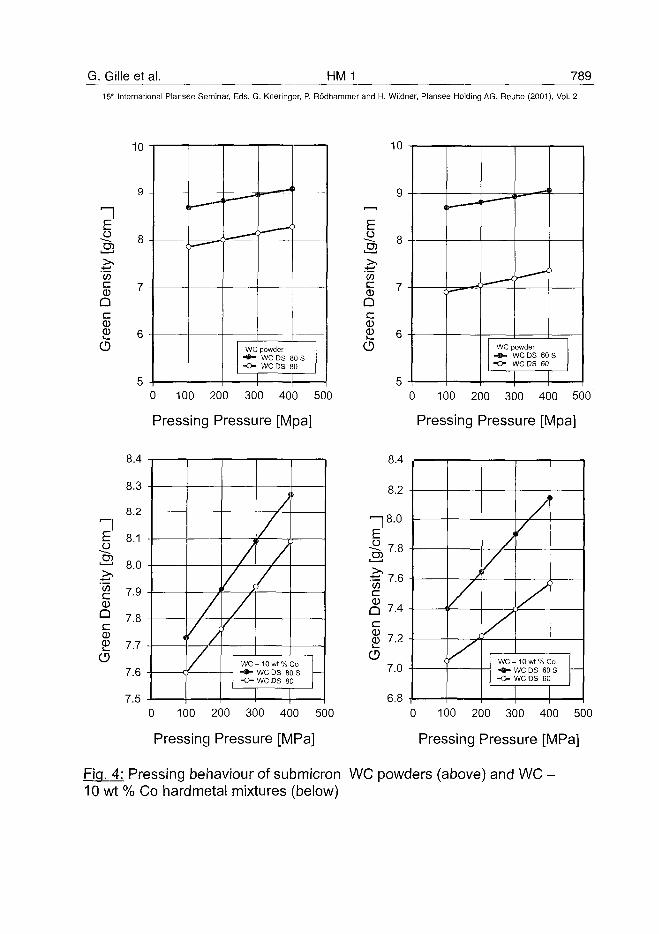
G. Gille et al. HM 1 789
15* International Plansee Seminar, Eds. G. Kneringer, P. Rodhammer and H. Wildner, Plansee Holding AG, Reutte (2001), Vol. 2
10
n
&wc0
Q
0
CD
0Qc0
CD
,——' ——-A
, <j
WC powder- * - WC DS 80 S• O WC DS 80
10
0 100 200 300 400 500
Pressing Pressure [Mpa]
8.4
8.3
8.2
8.1
8.0
7.9
7.8
7.7
7.6
7.5
)
/
/
/
v\/
/
Vv
WC-10wt%Co• • • WC DS 80 S- O WC DS SO
0 100 200 300 400 500
Pressing Pressure [MPa]
o
0Qc0
CD
\
c
. J
, '
i
WC powder- • • WC DS 60 S- O WC DS 60
0 100 200 300 400 500
Pressing Pressure [Mpa]
%• * - '
" tr\
Den
j"e
en
CD
8.4
8.2
8.0
7.8
7.6
7.4
7.2
7.0
6.8
(
J
/y
/
yWC-10wt%Co- * - WC DS 60 S- O WC DS 60
0 100 200 300 400 500
Pressing Pressure [MPa]
Fig. 4: Pressing behaviour of submicron WC powders (above) and WC -10 wt % Co hardmetal mixtures (below)
790 HM 1 G. Gilleetal.15'" International Plansee Seminar, Eds. G. Kneringer, P. Rodhammer and H. Wildner, Plansee Holding AG, Reutte (2001), Vol. 2
interfaces into WC/Co interfaces with around one fifth of interface energy.The lower the grain size and the higher the internal interface areas, thehigher the solid state sintering intensity, as can be obtained from the rightpart of Fig. 5 (ARRHENIUS plot of T_(shrinkage rate) versus inversetemperature 1/T).
- Besides the very low grain sizes of the submicron and ultrafine hardmetalsthe always necessary doping with grain growth inhibitors has a stronginfluence on the sintering and densification [16], [18]. As shown in Figs. 6and 7 the composition and content of grain growth inhibitors as VC, Cr3C2,TaC etc. shifts the onset of shrinkage to higher temperatures, decreasesthe shrinkage rate (at least within the solid state sintering range) andreduces the melting point of the eutectic binder.
- The solid state sintering is subdivided into two stages, see Figs. 5, 7 and8. The first stage at lower temperatures strongly depends on theprocessing before sintering and depends only slightly on grain size. Thesecond stage with a higher slope rate of the straight ARRHENIUS fit lineonly weakly depends on processing but is correlated to the grain size, seeFigs. 5, 7 and 8. Some of the most important factors bearing influence onthe first stage of solid state densification are:
• Milling conditions: Ball or attritor mill, mill media, milling time etc.• Pressing additives: Content and composition of organic binder
(paraffine, PEG etc.)• Granulation and pressing conditions (hardness of granules, pressure
etc.)• Atmosphere, heating rate and holding times during debinding, out-
gassing and sintering.
All these effects are more pronounced if the grain sizes of WC and WC-Co mixtures are decreased to submicron and ultrafine grain sizes.
- Coming to ultrafine hardmetals the elementary mechanism behind thesolid state sintering seems to be yet more complicated and the process issubdivided into more than two stages, see Figs. 7 and 23 in section 4.With increasing temperature T the shrinkage rate versus 1/T shows againthe upward tendency with increasing T, but the curve may beapproximated by one or two straight lines only very roughly.
In cases of submicron and ultrafine hardmetals in particular the solid statesintering, the discontinuous as well as the continuous grain growth and theresidual porosity are of interest.
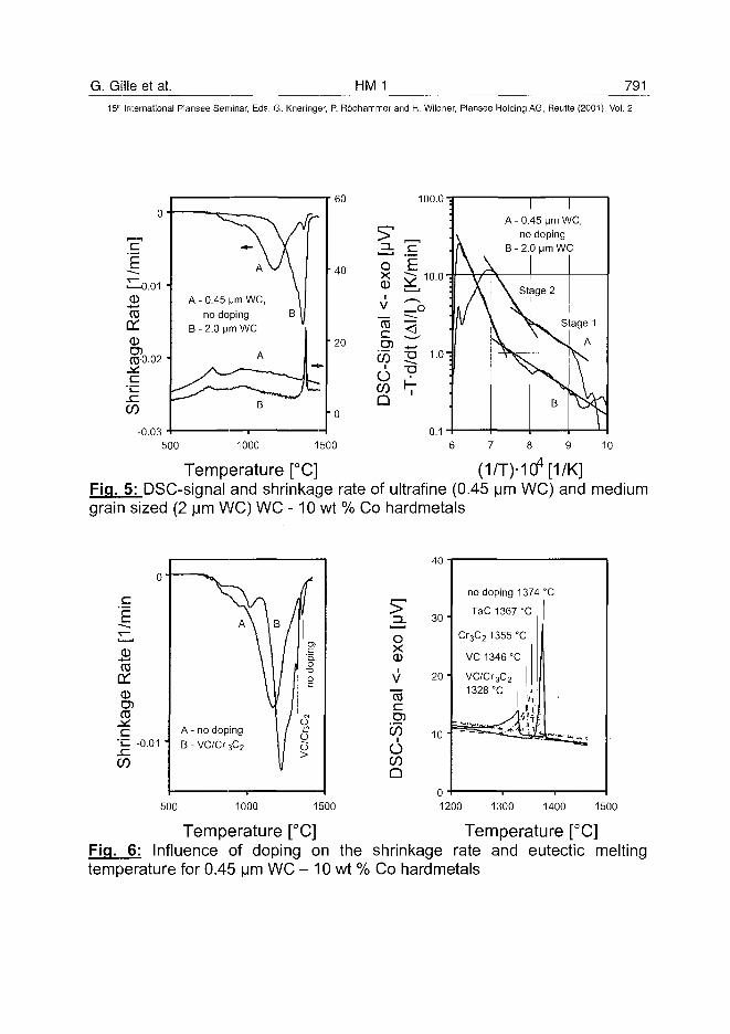
G. Gille et al. HM 1 79115th International Plansee Seminar, Eds. G. Kneringer, P. Rodhammer and H. Wildner, Plansee Holding AG, Reutte (2001), Vol. 2
<D-t—•
CO
a:CD0*0.02
xCO
-0.03
A - 0.45 Mm WC,no doping
B - 2.0 urn WC
60
40
20
100.0
1500
A-0.45 Mm WC,no doping
B - 2.0 urn WC
500 1000
Temperature [°C] (1/T)-1 cf [1/K]Fig. 5: DSC-siqnal and shrinkage rate of ultrafine (0.45 [jm WC) and mediumgrain sized (2 urn WC) WC -10 wt % Co hardmetais
o-
1/m
in
'—i
SCO
oroCOc
• ^ -0.01 •<~CO
A \
\
A - no dopingB-VC/Cr3C2
/
\B //
\\\\w\vM
iCO
pin
o"Ooc
I / °/ A)/O/
V
500 1000 1500
Temperature [°C]
oX0
CO
c
CO
6COQ
40 •
30-
20 •
10 "
no doping
TaC1367
Cr3C21355
1374°C
°C
c
VC1346°C
VC/Cr3C2
1328 °C • i iTl I
1200 1300 1400 1500
Temperature [°C]Fig. 6: Influence of doping on the shrinkage rate and eutectic meltingtemperature for 0.45 urn WC - 10 wt % Co hardmetais
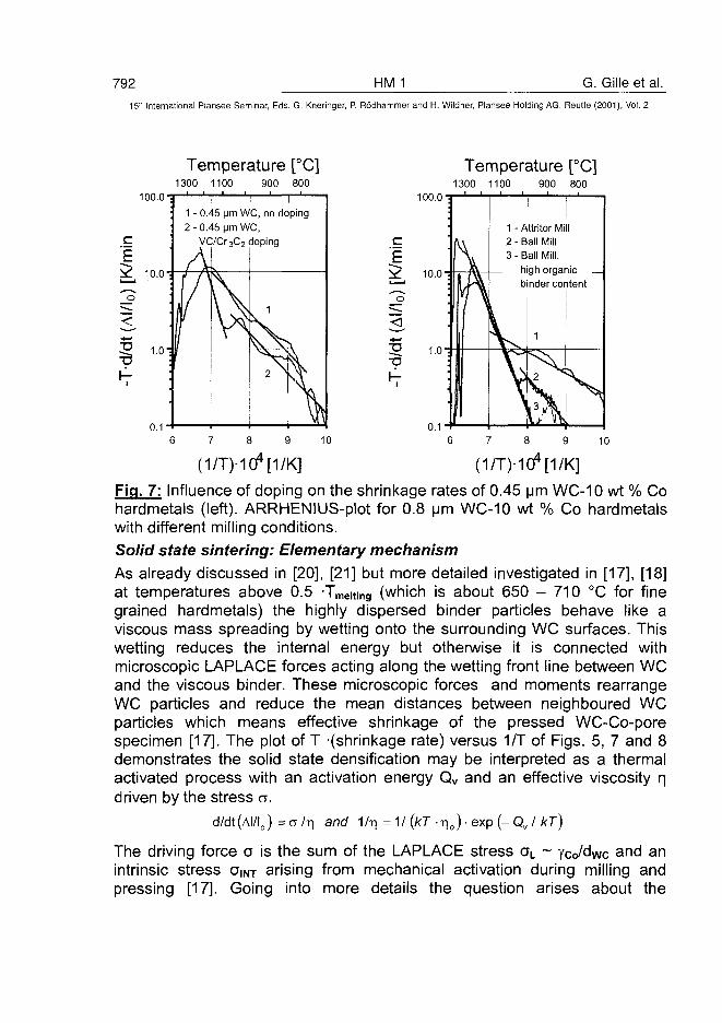
792 HM 1 G. Gille et al.
15" International Plansee Seminar, Eds. G. Kneringer, P. Rodhammer and H. Wildner, Plansee Holding AG, Reutte (2001), Vol. 2
Temperature [°C]1300 1100 900 800
Temperature [°C]1300 1100 900 800
100.0 "3
c
"Eio.oi
T I I
1 - 0.45 pm W C , no doping
2 - 0.45 m W C ,
VC/Cr3C2 doping
100.0-5
1 - Attritor Mill
2 - Ball Mill
3-Ball Mill,
high organic
binder content
Fig. 7: Influence of doping on the shrinkage rates of 0.45 urn WC-10 wt % Cohardmetals (left). ARRHENIUS-plot for 0.8 urn WC-10 wt % Co hardmetalswith different milling conditions.
Solid state sintering: Elementary mechanismAs already discussed in [20], [21] but more detailed investigated in [17], [18]at temperatures above 0.5 Toting (which is about 650 - 710 °C for finegrained hardmetals) the highly dispersed binder particles behave like aviscous mass spreading by wetting onto the surrounding WC surfaces. Thiswetting reduces the internal energy but otherwise it is connected withmicroscopic LAPLACE forces acting along the wetting front line between WCand the viscous binder. These microscopic forces and moments rearrangeWC particles and reduce the mean distances between neighboured WCparticles which means effective shrinkage of the pressed WC-Co-porespecimen [17]. The plot of T -(shrinkage rate) versus 1/T of Figs. 5, 7 and 8demonstrates the solid state densification may be interpreted as a thermalactivated process with an activation energy Qv and an effective viscosity rjdriven by the stress a.
d/dt (Al/Io) = a /T) and 1 lr\ = 1 / (kT • r\0) • exp (- Qv I kT)
The driving force a is the sum of the LAPLACE stress aL ~ ycJdwc and anintrinsic stress aiNT arising from mechanical activation during milling andpressing [17]. Going into more details the question arises about the
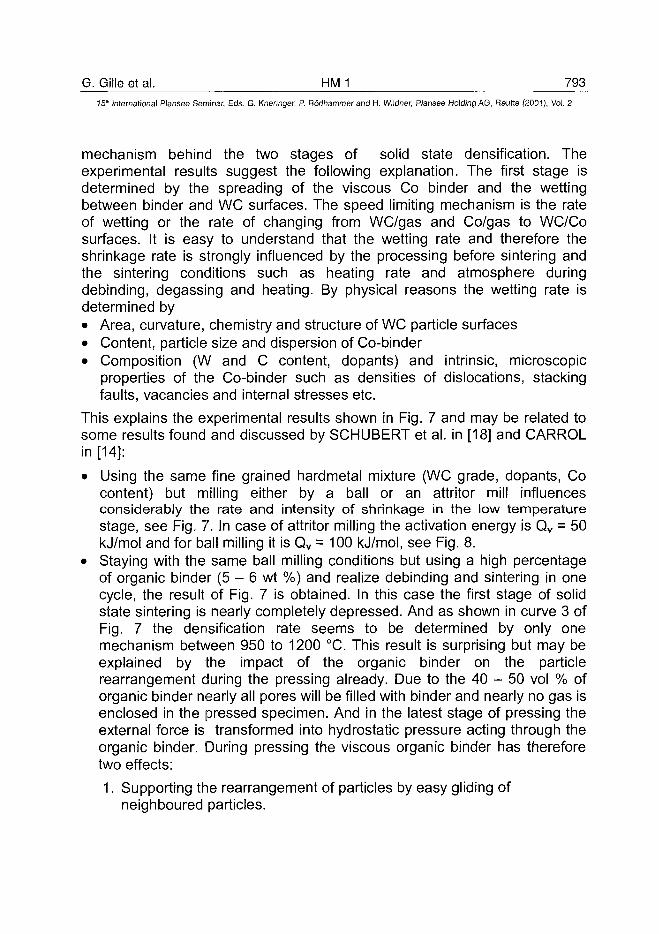
G. Gille et al. HMJ 793^15* International Plansee Seminar, Eds. G. Kneringer, P. Rodhammer and H. Wildner, Plansee Holding AG, Reutte (2001), Vol. 2
mechanism behind the two stages of solid state densification. Theexperimental results suggest the following explanation. The first stage isdetermined by the spreading of the viscous Co binder and the wettingbetween binder and WC surfaces. The speed limiting mechanism is the rateof wetting or the rate of changing from WC/gas and Co/gas to WC/Cosurfaces. It is easy to understand that the wetting rate and therefore theshrinkage rate is strongly influenced by the processing before sintering andthe sintering conditions such as heating rate and atmosphere duringdebinding, degassing and heating. By physical reasons the wetting rate isdetermined by• Area, curvature, chemistry and structure of WC particle surfaces• Content, particle size and dispersion of Co-binder• Composition (W and C content, dopants) and intrinsic, microscopic
properties of the Co-binder such as densities of dislocations, stackingfaults, vacancies and internal stresses etc.
This explains the experimental results shown in Fig. 7 and may be related tosome results found and discussed by SCHUBERT et al. in [18] and CARROLin [14]:
• Using the same fine grained hardmetal mixture (WC grade, dopants, Cocontent) but milling either by a ball or an attritor mill influencesconsiderably the rate and intensity of shrinkage in the low temperaturestage, see Fig. 7. In case of attritor milling the activation energy is Qv = 50kj/mol and for ball milling it is Qv = 100 kJ/mol, see Fig. 8.
• Staying with the same ball milling conditions but using a high percentageof organic binder (5 - 6 wt %) and realize debinding and sintering in onecycle, the result of Fig. 7 is obtained. In this case the first stage of solidstate sintering is nearly completely depressed. And as shown in curve 3 ofFig. 7 the densification rate seems to be determined by only onemechanism between 950 to 1200 °C. This result is surprising but may beexplained by the impact of the organic binder on the particlerearrangement during the pressing already. Due to the 40 - 50 vol % oforganic binder nearly all pores will be filled with binder and nearly no gas isenclosed in the pressed specimen. And in the latest stage of pressing theexternal force is transformed into hydrostatic pressure acting through theorganic binder. During pressing the viscous organic binder has thereforetwo effects:
1. Supporting the rearrangement of particles by easy gliding ofneighboured particles.
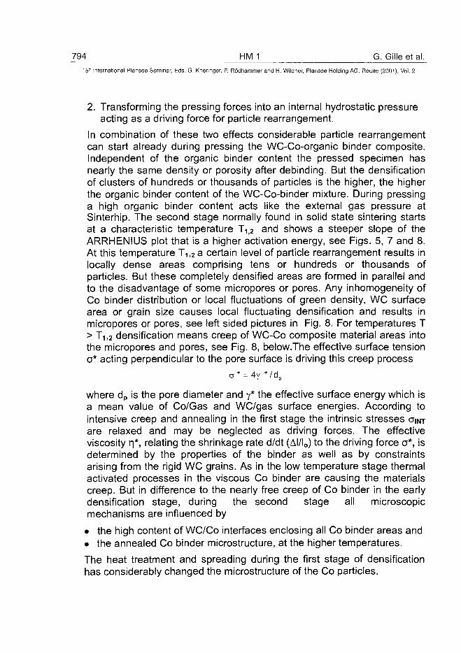
794 HMJ G. Gille et al.15" International Piansee Seminar, Eds. G. Kneringer, P. Rodhammer and H. Wildner, Plansee Holding AG, Reutte (2001), Vol. 2
2. Transforming the pressing forces into an internal hydrostatic pressureacting as a driving force for particle rearrangement.
In combination of these two effects considerable particle rearrangementcan start already during pressing the WC-Co-organic binder composite.Independent of the organic binder content the pressed specimen hasnearly the same density or porosity after debinding. But the densificationof clusters of hundreds or thousands of particles is the higher, the higherthe organic binder content of the WC-Co-binder mixture. During pressinga high organic binder content acts like the external gas pressure atSinterhip. The second stage normally found in solid state sintering startsat a characteristic temperature T ^ and shows a steeper slope of theARRHENIUS plot that is a higher activation energy, see Figs. 5, 7 and 8.At this temperature T1j2a certain level of particle rearrangement results inlocally dense areas comprising tens or hundreds or thousands ofparticles. But these completely densified areas are formed in parallel andto the disadvantage of some micropores or pores. Any inhomogeneity ofCo binder distribution or local fluctuations of green density, WC surfacearea or grain size causes local fluctuating densification and results inmicropores or pores, see left sided pictures in Fig. 8. For temperatures T> T1l2 densification means creep of WC-Co composite material areas intothe micropores and pores, see Fig. 8, below.The effective surface tensiona* acting perpendicular to the pore surface is driving this creep process
a* = 4y */dpdp
where dp is the pore diameter and y* the effective surface energy which isa mean value of Co/Gas and WC/gas surface energies. According tointensive creep and annealing in the first stage the intrinsic stresses amare relaxed and may be neglected as driving forces. The effectiveviscosity r f . relating the shrinkage rate d/dt (Al/Io) to the driving force a*, isdetermined by the properties of the binder as well as by constraintsarising from the rigid WC grains. As in the low temperature stage thermalactivated processes in the viscous Co binder are causing the materialscreep. But in difference to the nearly free creep of Co binder in the earlydensification stage, during the second stage all microscopicmechanisms are influenced by
• the high content of WC/Co interfaces enclosing all Co binder areas and• the annealed Co binder microstructure, at the higher temperatures.
The heat treatment and spreading during the first stage of densificationhas considerably changed the microstructure of the Co particles.
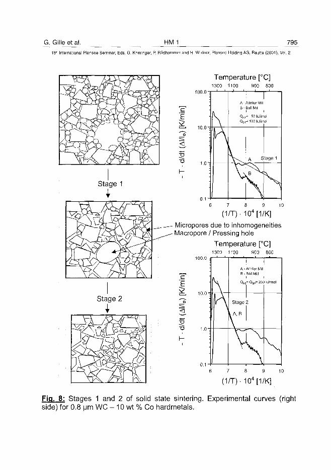
G. Gilleetal. HM 1 79515" International Plansee Seminar, Eds. G. Kneringer, P. Rodhammer and H. Wildner, Plansee Holding AG, Reutte (2001), Vol. 2
Temperature [°C]1300 1100 900 800
100.0 i
10.0
33
104[1/K]
Micropores due to inhomogeneitiesMacropore / Pressing hole
Temperature [°C]1300 1100 900 800
100.0 ^
10.0
o
0.1 "f
- 104[1/K]
Fig. 8: Stages 1 and 2 of solid state sintering. Experimental curves (rightside) for 0.8 urn WC - 10 wt % Co hardmetals.
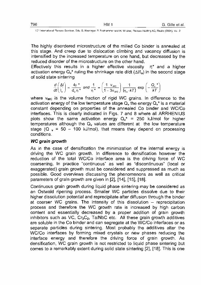
796 HMJ G. Gille et al.15" International Plansee Seminar, Eds. G. Kneringer, P. Rodhammer and H. Wildner, Plansee Holding AG, Reutte (2001), Vol. 2
The highly disordered microstructure of the milled Co binder is annealed atthis stage. And creep due to dislocation climbing and vacancy diffusion isintensified by the increased temperature on one hand, but decreased by thereduced disorder of the microstructure on the other hand.Effectively this results in a higher effective viscosity n* and a higheractivation energy Qv* ruling the shrinkage rate d/dt (Al/Io) in the second stageof solid state sintering
e H U ~ d p r l -M " " T 1 - - L i + 3v w c J fo o . *T )~ l H kT
where vWc is the volume fraction of rigid WC grains. In difference to theactivation energy of the low temperature stage Qv the energy Qv* is a materialconstant depending on properties of the annealed Co binder and WC/Cointerfaces. This is clearly indicated in Figs. 7 and 8 where all ARRHENIUSplots show the same activation energy Qv* = 250 kJ/mol for highertemperatures although the Qv values are different at the low temperaturestage (Q v = 50 - 100 kJ/mol), that means they depend on processingconditions.
WC grain growth
As in the case of densification the minimization of the internal energy isdriving the WC grain growth. In difference to densification however thereduction of the total WC/Co interface area is the driving force of WCcoarsening. In practice "continuous" as well as "discontinuous" (local orexaggerated) grain growth must be considered and suppressed as much aspossible. Good overviews discussing the phenomenons as well as criticalparameters of grain growth are given in [2], [14], [15], [18].
Continuous grain growth during liquid phase sintering may be considered asan Ostwald ripening process. Smaller WC particles dissolve due to theirhigher dissolution potential and reprecipitate after diffusion through the binderat coarser WC grains. The intensity of this dissolution - reprecipitationprocess and therefore the WC growth rate is increased by high carboncontent and essentially decreased by a proper addition of grain growthinhibitors such as VC, Cr3C2, Ta/NbC etc. All these grain growth additivesare soluble in the Co binder and can segregate at the WC/Co interfaces or asseparate particles during sintering. Most probably the additives alter theWC/Co interfaces by forming mixed crystals or new phases reducing theinterface energy and therefore the driving force of grain growth. Asdensification, WC grain growth is not restricted to liquid phase sintering butcomes to a remarkably extent during solid state sintering [2], [18]. This is one
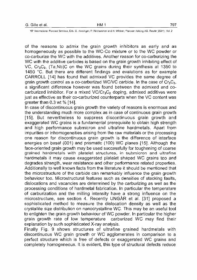
G. Gilleetal. HMJ 797^15th International Plansee Seminar, Eds. G. Kneringer, P. Rddnammer and H. Wildner, Plansee Holding AG, Reutte (2001), Vol. 2
of the reasons to admix the grain growth inhibitors as early and ashomogeneously as possible to the WC-Co mixture or to the WC powder orco-carburize the WC with the additives. Another reason for co-carburizing theWC with the additive carbides is based on the grain growth inhibiting effect ofVC, Cr3C2, (Ta,Nb)C on the WC grains during their synthesis at 1350 to1450 °C. But there are different findings and evalutions as for exampleCARROLL [14] has found that admixed VC provides the same degree ofgrain growth control as a co-carburized WCA/C carbide. In the case of Cr3C2,a significant difference however was found between the admixed and co-carburized inhibitor. For a mixed VC/Cr3C2 doping, admixed additives werejust as effective as their co-carburized counterparts when the VC content wasgreater than 0.3 wt% [14].In case of discontinuous grain growth the variety of reasons is enormous andthe understanding much more complex as in case of continuous grain growth[15]. But nevertheless to suppress discontinuous grain growth andexaggerated WC grains is a fundamental prerequisite to obtain high strengthand high performance submicron and ultrafine hardmetals. Apart fromimpurities or inhomogeneities arising from the raw materials or the processingone reason for discontinuous grain growth is the difference of interfaceenergies on basal (001) and prismatic (100) WC planes [15]. Although theface-oriented grain growth may be used successfully for toughening of coarsegrained hardmetals with platelet structures, in submicron and ultrafinehardmetals it may cause exaggerated platelet shaped WC grains too anddegrades strength, wear resistance and other performance related properties.Additionally to well known facts from the literature it should be mentioned thatthe microstructure of the carbide can remarkably influence the grain growthbehaviour too. Microstructural features such as densities of stacking faults,dislocations and vacancies are determined by the carburizing as well as theprocessing conditions of hardmetal fabrication. In particular the temperatureof carburization and the milling intensity have a strong influence on themicrostructure, see section 4. Recently UNGAR et al. [31] proposed asophisticated method to measure the dislocation density as well as thecrystallite size distribution on nanocrystalline WC. This may be an useful toolto enlighten the grain growth behaviour of WC powder. In particular the highergrain growth rate of low temperature carburized WC may find theirexplanation by such sophisticated X-ray analysis.Finally Fig. 9 shows structures of ultrafine grained hardmetals withdiscontinuous WC grain growth or WC agglomerates in comparison to aperfect structure which is free of defects or exaggerated WC grains andcompletely homogeneous. It is evident, this type of structural defects reduce
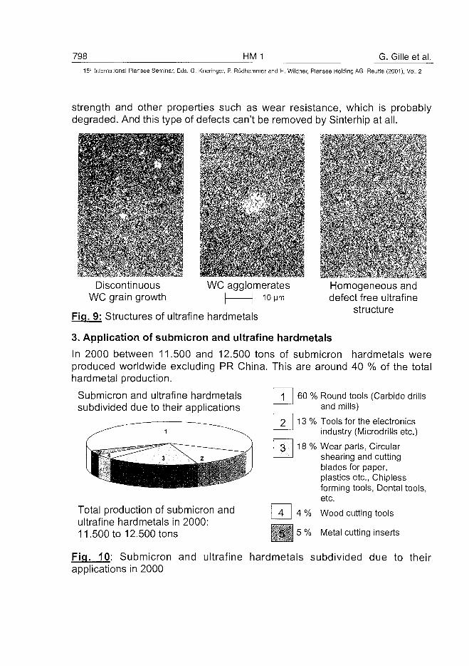
798 HM 1 G. Gilleetal.
15" International Plansee Seminar, Eds. G. Kneringer, P. Rodhammer and H. Wildner, Plansee Holding AG, Reutte (2001), Vol. 2
strength and other properties such as wear resistance, which is probablydegraded. And this type of defects can't be removed by Sinterhip at all.
DiscontinuousWC grain growth
WC agglomeratesI 1 10 pm
Fig. 9: Structures of uitrafine hardmetals
Homogeneous anddefect free uitrafine
structure
3. Application of submicron and uitrafine hardmetals
In 2000 between 11.500 and 12.500 tons of submicron hardmetals wereproduced worldwide excluding PR China. This are around 40 % of the totalhardmetal production.
Submicron and uitrafine hardmetalssubdivided due to their applications
1 60 % Round tools (Carbide drillsand mills)
Total production of submicron anduitrafine hardmetals in 2000:11.500 to 12.500 tons
13 % Tools for the electronicsindustry (Microdrills etc.)
18 % Wear parts, Circularshearing and cuttingblades for paper,plastics etc., Chiplessforming tools, Dental tools,etc.
4 % Wood cutting tools
r^'7, 5 o/o |\/|eta| cutting inserts
Fig. 10: Submicron and uitrafine hardmetals subdivided due to theirapplications in 2000
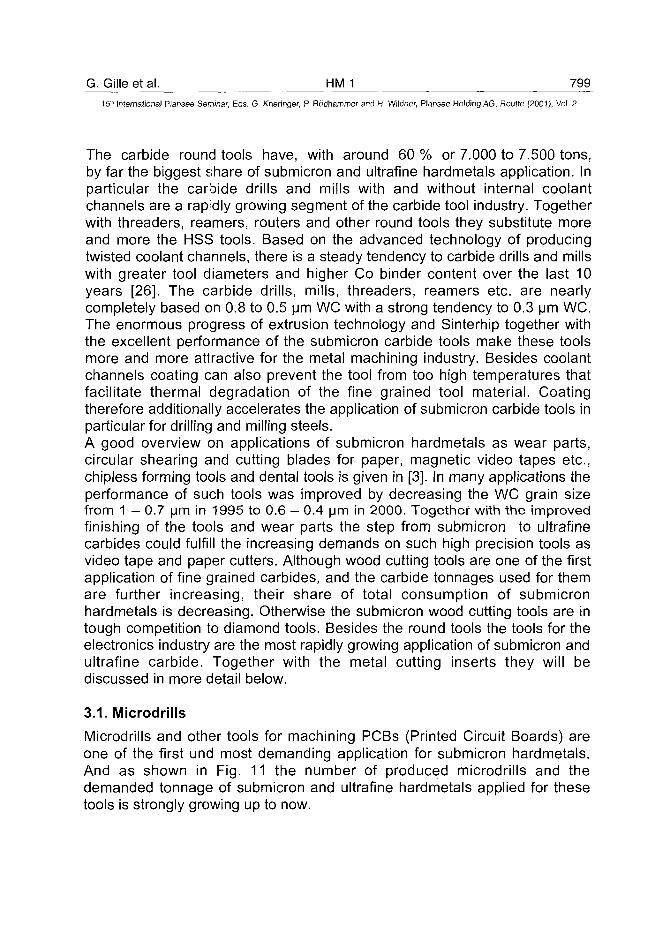
G. Gilleetal. HM_1 799
15"1 International Plansee Seminar, Eds. G. Kneringer, P. Rodhammer and H. Wildner, Plansee Holding AG, Reutte (2001), Vol. 2
The carbide round tools have, with around 60 % or 7.000 to 7.500 tons,by far the biggest share of submicron and ultrafine hardmetals application. Inparticular the carbide drills and mills with and without internal coolantchannels are a rapidly growing segment of the carbide tool industry. Togetherwith threaders, reamers, routers and other round tools they substitute moreand more the HSS tools. Based on the advanced technology of producingtwisted coolant channels, there is a steady tendency to carbide drills and millswith greater tool diameters and higher Co binder content over the last 10years [26]. The carbide drills, mills, threaders, reamers etc. are nearlycompletely based on 0.8 to 0.5 urn WC with a strong tendency to 0.3 urn WC.The enormous progress of extrusion technology and Sinterhip together withthe excellent performance of the submicron carbide tools make these toolsmore and more attractive for the metal machining industry. Besides coolantchannels coating can also prevent the tool from too high temperatures thatfacilitate thermal degradation of the fine grained tool material. Coatingtherefore additionally accelerates the application of submicron carbide tools inparticular for drilling and milling steels.
A good overview on applications of submicron hardmetals as wear parts,circular shearing and cutting blades for paper, magnetic video tapes etc.,chipless forming tools and dental tools is given in [3]. In many applications theperformance of such tools was improved by decreasing the WC grain sizefrom 1 — 0.7 |jm in 1995 to 0.6 — 0.4 pm in 2000. Together with the improvedfinishing of the tools and wear parts the step from submicron to ultrafinecarbides could fulfill the increasing demands on such high precision tools asvideo tape and paper cutters. Although wood cutting tools are one of the firstapplication of fine grained carbides, and the carbide tonnages used for themare further increasing, their share of total consumption of submicronhardmetals is decreasing. Otherwise the submicron wood cutting tools are intough competition to diamond tools. Besides the round tools the tools for theelectronics industry are the most rapidly growing application of submicron andultrafine carbide. Together with the metal cutting inserts they will bediscussed in more detail below.
3.1. Microdrills
Microdrills and other tools for machining PCBs (Printed Circuit Boards) areone of the first und most demanding application for submicron hardmetals.And as shown in Fig. 11 the number of produced microdrills and thedemanded tonnage of submicron and ultrafine hardmetals applied for thesetools is strongly growing up to now.
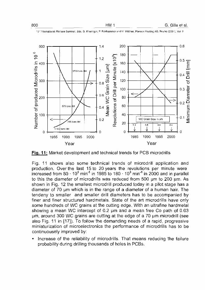
800 HM 1 G. Gille et al.
15" International Plansee Seminar, Eds. G. Kneringer, P. Rodhammer and H. Wildner, Plansee Holding AG, Reutte (2001), Vol. 2
500
toO
.£ 400
T3Oo 300
T3CDO
-D200E
"5CD 1 0 0
.Q
E
\\
^-< 14(
\
\
570 tons 1
/
tons HM
1700 tons!
\ 1M /
ons HM
-
/ ^
/ '
1.4
- 1 . 2
200
„— 180o
r-. 21 160E a)
1 3 15 ,40N ^W "Z 120
0.8 c ©'ro = 100
a 6S I 800 4 c | 60
CD oCD £^ ^ 40
0.2 5
£ 20
0 0
\ Ac.
WC Grain Size in Mm
0.8
\
0.6
0.6
E
0.3 £CD
- • 0 . 2
CD
Eb
E+ 0.1 '.£
1985 1990 1995 2000
Year
1985 1990 1995 2000
Year
Fig. 11: Market development and technical trends for PCB microdrills
Fig. 11 shows also some technical trends of microdrill application andproduction. Over the last 15 to 20 years the revolutions per minute wereincreased from 80 • 103 min'1 in 1985 to 180 • 103 min"1 in 2000 and in parallelto this the diameter of microdrills was reduced from 500 urn to 200 urn. Asshown in Fig. 12 the smallest microdrill produced today in a pilot stage has adiameter of 70 urn which is in the range of a diameter of a human hair. Thetendeny to smaller and smaller drill diameters has to be accompanied byfiner and finer structured hardmetals. State of the art microdrills have onlysome hundreds of WC grains at the cutting edge. With an ultrafine hardmetalshowing a mean WC intercept of 0.2 urn and a mean free Co path of 0.03urn, around 300 WC grains are cutting at the edge of a 70 urn microdrill (seealso Fig. 11 in [17]). To follow the demanding needs of a rapid, progressiveminiaturization of microelectronics the performance of microdrills has to becontinuousely improved by:
• Increase of the reliability of microdrills. That means reducing the failureprobability during drilling thousands of holes in PCBs.
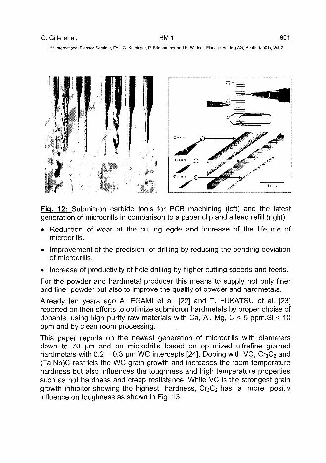
G. Gille et al. HM 1 80115'" International Plansee Seminar, Eds. G. Kneringer, P. Rodhammer and H. Wildner, Plansee Holding AG, Reutte (2001), Vol. 2
Fig. 12: Submicron carbide tools for PCB machining (left) and the latestgeneration of microdrills in comparison to a paper clip and a lead refill (right)
• Reduction of wear at the cutting egde and increase of the lifetime ofmicrodrills.
• Improvement of the precision of drilling by reducing the bending deviationof microdrills.
• Increase of productivity of hole drilling by higher cutting speeds and feeds.
For the powder and hardmetal producer this means to supply not only finerand finer powder but also to improve the quality of powder and hardmetals.
Already ten years ago A. EGAMI et al. [22] and T. FUKATSU et al. [23]reported on their efforts to optimize submicron hardmetals by proper choise ofdopants, using high purity raw materials with Ca, Al, Mg, C < 5 ppm.Si < 10ppm and by clean room processing.
This paper reports on the newest generation of microdrills with diametersdown to 70 urn and on microdrills based on optimized ulfrafine grainedhardmetals with 0.2 - 0.3 urn WC intercepts [24]. Doping with VC, Cr3C2 and(Ta,Nb)C restricts the WC grain growth and increases the room temperaturehardness but also influences the toughness and high temperature propertiessuch as hot hardness and creep restistance. While VC is the strongest graingrowth inhibitor showing the highest hardness, Cr3C2 has a more positivinfluence on toughness as shown in Fig. 13.
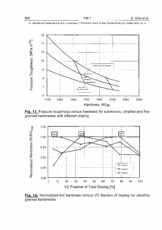
802 HM 1 G. Gille et al.
15" International Plansee Seminar, Eds. G. Kneringer, P. Rodhammer and H. Wildner, Plansee Holding AG, Reutte (2001), Vol. 2
CDQ.
coCOCD
c
CD
OCO
19
17
15
13
11
Fig. 13:grained
1100 1300 1500 1700 1900 2100 2300 2500
Hardness HV30
_Fracture toughness versus hardness for submicron, ultrafine and finehardmetals with different doping
E>X
«CDc
•o
XT3<DN
"TOE
Fig. 14grained
1.05
1.00
0.95
0.90
0.85
0.800 10 20 30 40 50 60 70 80 90 100
VC Fraction of Total Doping [%]
Normalized hot hardness versus VC fraction of doping for ultrafinehardmetals
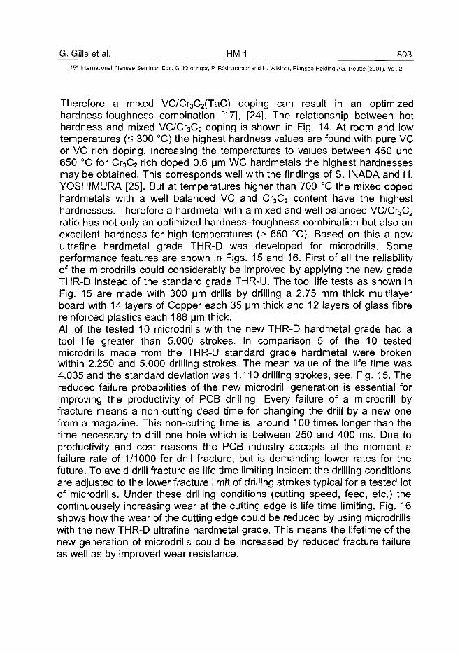
G. Gille et al. HM 1 803
15" International Plansee Seminar, Eds. G. Kneringer, P. Rddhammer and H. Wildner, Plansee Holding AG, Reutte (2001), Vol. 2
Therefore a mixed VC/Cr3C2(TaC) doping can result in an optimizedhardness-toughness combination [17], [24]. The relationship between hothardness and mixed VC/Cr3C2 doping is shown in Fig. 14. At room and lowtemperatures (^ 300 °C) the highest hardness values are found with pure VCor VC rich doping. Increasing the temperatures to values between 450 und650 °C for Cr3C2 rich doped 0.6 urn WC hardmetals the highest hardnessesmay be obtained. This corresponds well with the findings of S. INADA and H.YOSHIMURA [25]. But at temperatures higher than 700 °C the mixed dopedhardmetals with a well balanced VC and Cr3C2 content have the highesthardnesses. Therefore a hardmetal with a mixed and well balanced VC/Cr3C2
ratio has not only an optimized hardness-toughness combination but also anexcellent hardness for high temperatures (> 650 °C). Based on this a newultrafine hardmetal grade THR-D was developed for microdrills. Someperformance features are shown in Figs. 15 and 16. First of all the reliabilityof the microdrills could considerably be improved by applying the new gradeTHR-D instead of the standard grade THR-U. The tool life tests as shown inFig. 15 are made with 300 urn drills by drilling a 2.75 mm thick multilayerboard with 14 layers of Copper each 35 urn thick and 12 layers of glass fibrereinforced plastics each 188 urn thick.All of the tested 10 microdrills with the new THR-D hardmetal grade had atool life greater than 5.000 strokes. In comparison 5 of the 10 testedmicrodrills made from the THR-U standard grade hardmetal were brokenwithin 2.250 and 5.000 drilling strokes. The mean value of the life time was4.035 and the standard deviation was 1.110 drilling strokes, see. Fig. 15. Thereduced failure probabilities of the new microdrill generation is essential forimproving the productivity of PCB drilling. Every failure of a microdrill byfracture means a non-cutting dead time for changing the drill by a new onefrom a magazine. This non-cutting time is around 100 times longer than thetime necessary to drill one hole which is between 250 and 400 ms. Due toproductivity and cost reasons the PCB industry accepts at the moment afailure rate of 1/1000 for drill fracture, but is demanding lower rates for thefuture. To avoid drill fracture as life time limiting incident the drilling conditionsare adjusted to the lower fracture limit of drilling strokes typical for a tested lotof microdrills. Under these drilling conditions (cutting speed, feed, etc.) thecontinuousely increasing wear at the cutting edge is life time limiting. Fig. 16shows how the wear of the cutting edge could be reduced by using microdrillswith the new THR-D ultrafine hardmetal grade. This means the lifetime of thenew generation of microdrills could be increased by reduced fracture failureas well as by improved wear resistance.
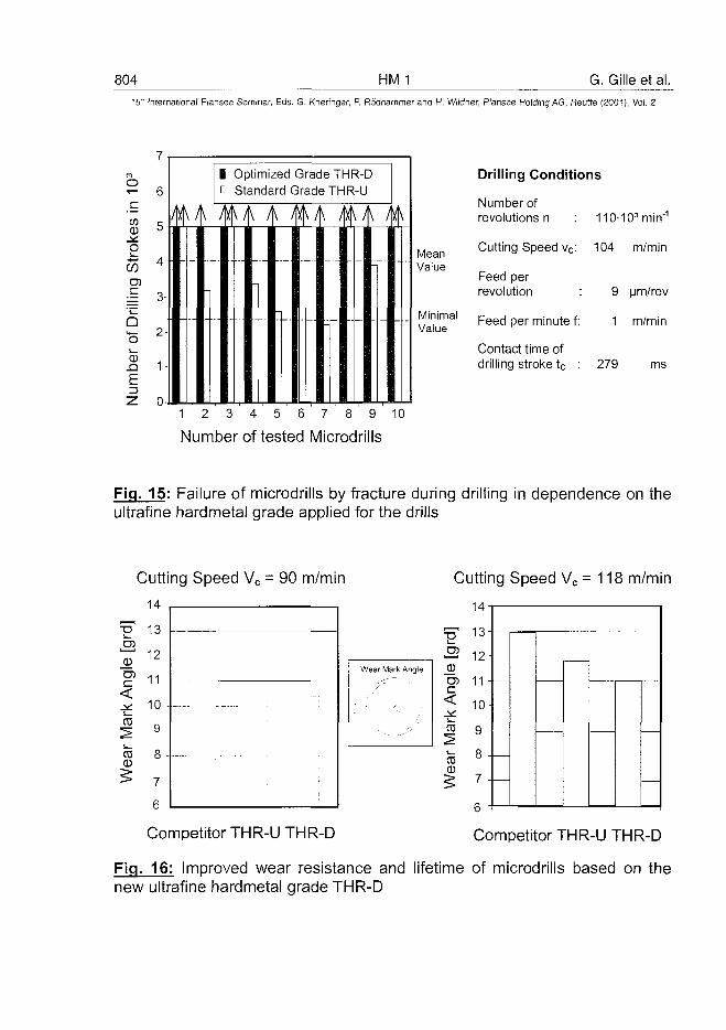
804 HM 1 G. Gille et al.
15" International Plansee Seminar, Eds. G. Kneringer, P. Rodhammer and H. Wildner, Plansee Holding AG, Reutte (2001), Vol. 2
6-
0
o-i—<
COen
Qo0
. Q
5
4
3-
2'
1-
- - - - • •
1 Optimized Grade THR-D• Standard Grade THR-U
-,
- i
V I
-1
\ /
MeanValue
MinimalValue
Drilling Conditions
Number ofrevolutions n :
Cutting Speed vc:
Feed perrevolution :
Feed per minute f:
Contact time ofdrilling stroke tc :
110-
104
9
1
279
103min"1
m/min
urn/rev
m/min
ms
1 2 3 4 5 6 7 8 9 10
Number of tested Microdrills
Fig. 15: Failure of microdrills by fracture during drilling in dependence on theuitrafine hardmetai grade applied for the drills
Cutting Speed Vc = 90 m/min Cutting Speed Vc = 118 m/min
Fig.
Competitor THR-U THR-D Competitor THR-U THR-D
16: Improved wear resistance and lifetime of microdrills based on thenew uitrafine hardmetai grade THR-D
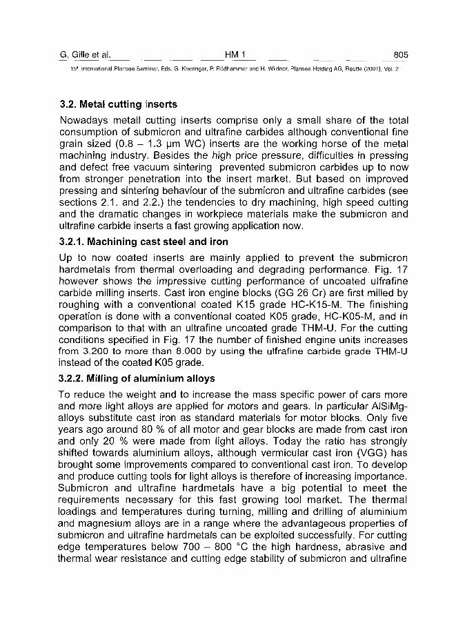
G. Gille et al. HM 1 80515'" International Plansee Seminar, Eds. G. Kneringer, P. Rodhammer and H. Wildner, Plansee Holding AG, Reutte (2001), Vol. 2
3.2. Metal cutting inserts
Nowadays metall cutting inserts comprise only a small share of the totalconsumption of submicron and ultrafine carbides although conventional finegrain sized (0.8 - 1.3 urn WC) inserts are the working horse of the metalmachining industry. Besides the high price pressure, difficulties in pressingand defect free vacuum sintering prevented submicron carbides up to nowfrom stronger penetration into the insert market. But based on improvedpressing and sintering behaviour of the submicron and ultrafine carbides (seesections 2.1. and 2.2.) the tendencies to dry machining, high speed cuttingand the dramatic changes in workpiece materials make the submicron andultrafine carbide inserts a fast growing application now.
3.2.1. Machining cast steel and iron
Up to now coated inserts are mainly applied to prevent the submicronhardmetals from thermal overloading and degrading performance. Fig. 17however shows the impressive cutting performance of uncoated ulfrafinecarbide milling inserts. Cast iron engine blocks (GG 26 Cr) are first milled byroughing with a conventional coated K15 grade HC-K15-M. The finishingoperation is done with a conventional coated K05 grade, HC-K05-M, and incomparison to that with an ultrafine uncoated grade THM-U. For the cuttingconditions specified in Fig. 17 the number of finished engine units increasesfrom 3.200 to more than 8.000 by using the ulfrafine carbide grade THM-Uinstead of the coated K05 grade.
3.2.2. Milling of aluminium alloys
To reduce the weight and to increase the mass specific power of cars moreand more light alloys are applied for motors and gears. In particular AISiMg-alloys substitute cast iron as standard materials for motor blocks. Only fiveyears ago around 80 % of all motor and gear blocks are made from cast ironand only 20 % were made from light alloys. Today the ratio has stronglyshifted towards aluminium alloys, although vermicular cast iron (VGG) hasbrought some improvements compared to conventional cast iron. To developand produce cutting tools for light alloys is therefore of increasing importance.Submicron and ultrafine hardmetals have a big potential to meet therequirements necessary for this fast growing tool market. The thermalloadings and temperatures during turning, milling and drilling of aluminiumand magnesium alloys are in a range where the advantageous properties ofsubmicron and ultrafine hardmetals can be exploited successfully. For cuttingedge temperatures below 700 - 800 °C the high hardness, abrasive andthermal wear resistance and cutting edge stability of submicron and ultrafine
806 HM 1 G. Gille et al.
15" International Plansee Seminar, Eds. G. Kneringer, P. Rodhammer and H. Wildner, Plansee Holding AG, Reutte (2001), Vol. 2
hardmetals result in higher lifetimes and allow higher cutting speeds andfeeds compared to conventional hardmetals. Also the surface quality(roughness) may be improved by using ulfrafine hardmetals with sharp andspecially designed cutting edges. To demonstrate the excellent performanceof ultrafine hardmetals Figs. 18 and 19 show results of milling operations ongearbox and valve cases of AlSiCu and AISiMg alloys.
Workpiece: GG 26 CrEngine Units
Tool:
8000
Roughing:
Finishing:
Cuttingconditions:
Hexacut M 750 (for roughing andfinishing)finishing excess length = 0.04 mm• 39 Inserts HNGF 090520-MM•Grade: HC-K15-M• 13 Inserts HNGF 090512-MF• Grade: 1. Coated HC-K05-M
2. Ultrafine THM-U
vc = 125.3 m/min= 0.361 mm/t= 0.50 mm
Coated GradeHC-K05-M
Ultrafine HMTHM-U
Fig. 17: Tool life advantages for ultrafine, uncoated milling inserts THM-U.Comparison is made with coated HC-K05-M insert in milling GG 26 Cr engineblocks (oil sump side)
In Fig. 18 a two step milling operation - roughing with conventional K10 gradeand finishing with a PCD insert - is compared with a one step roughing/finishing operation using an ultrafine carbide grade THM-U for bothoperations. Using THM-U inserts the number of machined GK-AISi18Cu3gearbox cases can be increased from 400 to 1200 per tool and the cuttingtime per workpiece can be reduced from 4 to 2.7 min. In Fig. 19 the lifetimeand productivity improvement for machining AISi10Mg(Cu) valve cases areshown if ultrafine carbide grade THM-U inserts are used instead of submicrongrade THM-F milling inserts.
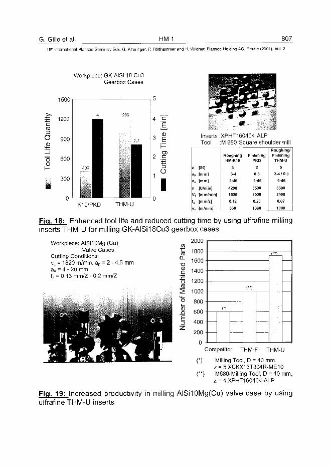
G. Gilleetal. HM 1 807
15'" International Plansee Seminar, Eds. G. Kneringer, P. Rodhammer and H. Wildner, Plansee Holding AG, Reutte (2001), Vol. 2
Workpiece: GK-AISi 18 Cu3Gearbox Cases
1500
•£ 1200cCO
.03900
•o 600o
300
4
1400 ^ H
i •by ^^B
1200
2,7
II
4 g
3
2 .E-4—>
O
IK10/PKD THM-U
z
a p
ae
n
vf
fz
Inserts :Tool :
[St]
[mm]
[mm]
[U/min]
[mm/min]
[mm/z]
[m/min]
XPHT160404 ALPM 680 Square shoulder mill
RoughingHM-K10
3
3-4
9-46
4200
1500
0.12
830
FinishingPKD
2
0.3
M 6
5500
2500
0.23
1088
Roughing/Finishing
THM-U
5
3-4/0.3
9-46
5500
2000
0.07
1088
Fig. 18: Enhanced tool life and reduced cutting time by using ulfrafine millinginserts THM-U for milling GK-AISi18Cu3 gearbox cases
2000
1800
1600
1400
1200
1000
800
600
400
Workpiece: AISHOMg (Cu)Valve Cases
Cutting Conditions:vc = 1820 m/min, ap = 2 - 4.5 mmae = 4 - 20 mmfz = 0.13 mm/Z-0.2 mm/Z
wCO
CL-o0
oCD
o
CD
E
200
0Competitor THM-F THM-U
(*) Milling Tool, D = 40 mm,z = 5 XCKX13T304R-ME10
(**) M680-Milling Tool, D = 40 mm,z = 4XPHT160404-ALP
Fig. 19: Increased productivity in milling AISHOMg(Cu) valve case by usingulfrafine THM-U inserts
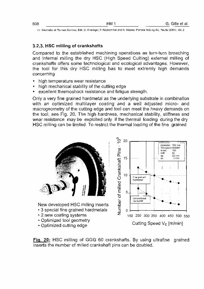
808 HM 1 G. Gille et al.15" International Plansee Seminar, Eds. G. Kneringer, P. Rodhammer and H. Wildner, Plansee Holding AG, Reutte (2001), Vol. 2
3.2.3. HSC milling of crankshafts
Compared to the established machining operations as turn-turn broachingand internal milling the dry HSC (High Speed Cutting) external milling ofcrankshafts offers some technological and ecological advantages. However,the tool for this dry HSC milling has to meet extremly high demandsconcerning
• high temperature wear resistance• high mechanical stability of the cutting edge• excellent thermoshock resistance and fatigue strength.
Only a very fine grained hardmetal as the underlying substrate in combinationwith an optimized multilayer coating and a well adjusted micro- andmacrogeometry of the cutting edge and tool can meet the heavy demands onthe tool, see Fig. 20. The high hardness, mechanical stability, stiffness andwear resistance maybe exploited only if the thermal loading during the dryHSC milling can be limited. To restrict the thermal loading of the fine grained
New developed HSC milling inserts• 3 special fine grained hardmetals• 2 new coating systems• Optimized tool geometry• Optimized cutting edge
mO
W
CD
2oQ
(D
E
1b -
1 0 •
5
0
i 1,
Fine grainedhardmetal
i
Conventionalhardmetal
DiameterWorkpiecInsert:zeff:ap:ae:
* ,
i "*
700 mm9:GGG60
1804522 mm
3 mm
* i 1
* • *
150 250 300 350 400 450 500 550
Cutting Speed Vc [m/min]
Fig. 20: HSC milling of GGG 60 crankshafts. By using ultrafine grainedinserts the number of milled crankshaft pins can be doubled.
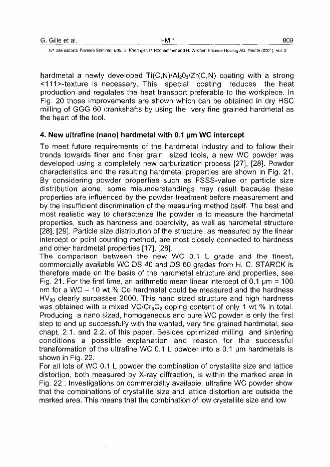
G. Gille et al. HMJ 809^15" International Plansee Seminar, Eds. G. Kneringer, P. Rodhammer and H. Wildner, Plansee Holding A6, Reutte (2001), Vol. 2
hardmetal a newly developed Ti(C,N)/AI203/Zr(C,N) coating with a strong<111>-texture is necessary. This special coating reduces the heatproduction and regulates the heat transport preferable to the workpiece. InFig. 20 those improvements are shown which can be obtained in dry HSCmilling of GGG 60 crankshafts by using the very fine grained hardmetal asthe heart of the tool.
4. New ultrafine (nano) hardmetal with 0.1 [im WC intercept
To meet future requirements of the hardmetal industry and to follow theirtrends towards finer and finer grain sized tools, a new WC powder wasdeveloped using a completely new carburization process [27], [28]. Powdercharacteristics and the resulting hardmetal properties are shown in Fig. 21.By considering powder properties such as FSSS-value or particle sizedistribution alone, some misunderstandings may result because theseproperties are influenced by the powder treatment before measurement andby the insufficient discrimination of the measuring method itself. The best andmost realistic way to characterize the powder is to measure the hardmetalproperties, such as hardness and coercivity, as well as hardmetal structure[28], [29]. Particle size distribution of the structure, as measured by the linearintercept or point counting method, are most closely connected to hardnessand other hardmetal properties [17], [28].The comparison between the new WC 0.1 L grade and the finest,commercially available WC DS 40 and DS 60 grades from H. C. STARCK istherefore made on the basis of the hardmetal structure and properties, seeFig. 21. For the first time, an arithmetic mean linear intercept of 0.1 urn = 100nm for a WC - 10 wt % Co hardmetal could be measured and the hardnessHV30 clearly surpasses 2000. This nano sized structure and high hardnesswas obtained with a mixed VC/Cr3C2 doping content of only 1 wt % in total.Producing a nano sized, homogeneous and pure WC powder is only the firststep to end up successfully with the wanted, very fine grained hardmetal, seechapt. 2.1. and 2.2. of this paper. Besides optimized milling and sinteringconditions a possible explanation and reason for the successfultransformation of the ultrafine WC 0.1 L powder into a 0.1 u m hardmetals isshown in Fig. 22.For all lots of WC 0.1 L powder the combination of crystallite size and latticedistortion, both measured by X-ray diffraction, is within the marked area inFig. 22 . Investigations on commercially available, ultrafine WC powder showthat the combinations of crystallite size and lattice distortion are outside themarked area. This means that the combination of low crystallite size and low
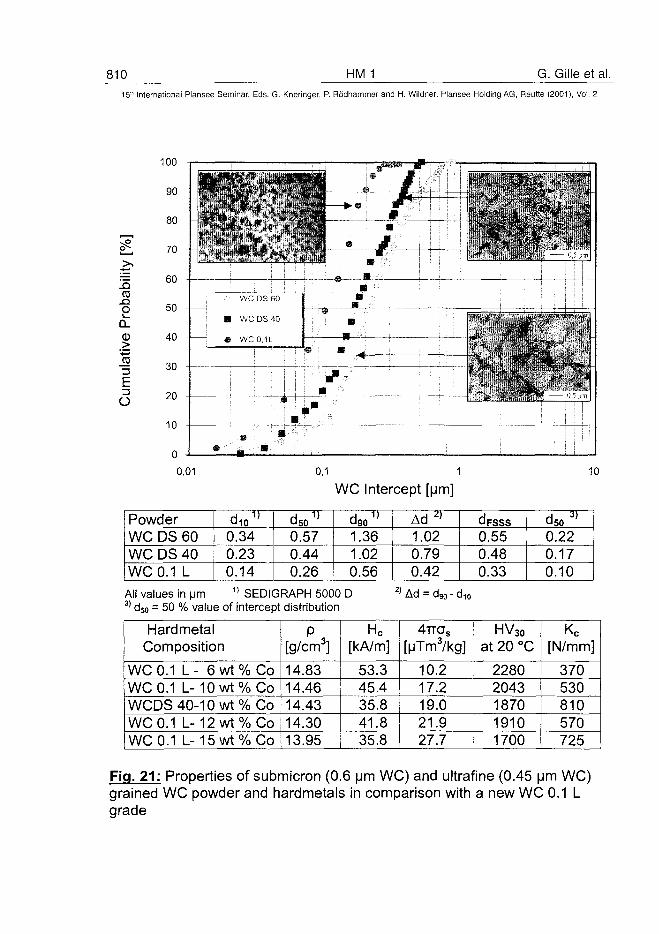
810 HM 1 G. Gille et al.5" International Plansee Seminar, Eds. G. Kneringer, P. Rödhammer and H. Wildner, Plansee Holding AG, Reutte (2001), Vol. 2
.O
o
Eü
100
90
80
70
60
50 -
40
30
20
10
WC DS 60
• WCDS40
® WC0,1L
•i . , M
! '. ' •
„ -;-•'0,01 0,1 1
WC Intercept [um]10
PowderWC DSWC DSWC 0.1
6040L
d0.0.0.
io1 )
342314
d000
50 1 )
.57
.44
.26
d110
9 0 1 )
.36
.02
.56
Ad 2 )
1.020.790.42
d000
FSSS
.55
.48
.33
d000
so 3 )
.22
.17
.10All values in |jm 1) SEDIGRAPH 5000 D3) d50 = 50 % value of intercept distribution
1 Ad = d90 - d
HardmetalComposition
WC 0.1 L- 6wt%CoWC 0.1 L-10wt%CoWCDS 40-10 wt% CoWC 0.1 L-12wt%CoWC 0.1 L-15wt%Co
P ,[g/cm3]14.8314.4614.4314.3013.95
Hc[kA/m]
53.345.435.841.835.8
4TTOS
[MTm3/kg]
10.217.219.021.927.7
HV30
at 20 °C
22802043187019101700
Kc[N/mm]
370530810570725
Fig. 21: Properties of submicron (0.6 pm WC) and ultrafine (0.45 um WC)grained WC powder and hardmetals in comparison with a new WC 0.1 Lgrade
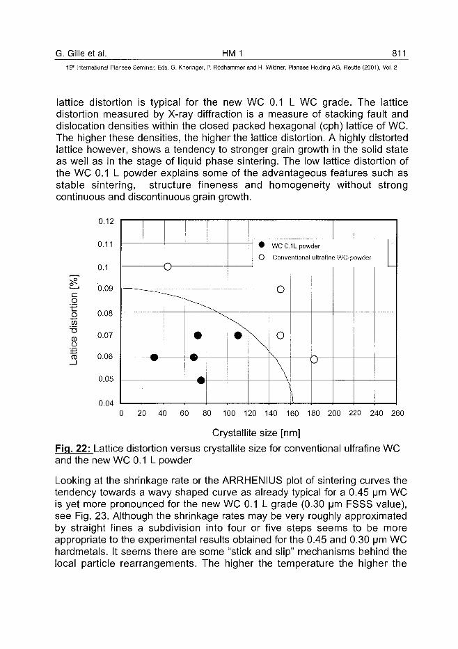
G. Gilleetal. HM 1 81115'" International Plansee Seminar, Eds. G. Kneringer, P. Rodhammer and H. Wildner, Plansee Holding AG, Reutte (2001), Vol. 2
lattice distortion is typical for the new WC 0.1 L WC grade. The latticedistortion measured by X-ray diffraction is a measure of stacking fault anddislocation densities within the closed packed hexagonal (cph) lattice of WC.The higher these densities, the higher the lattice distortion. A highly distortedlattice however, shows a tendency to stronger grain growth in the solid stateas well as in the stage of liquid phase sintering. The low lattice distortion ofthe WC 0.1 L powder explains some of the advantageous features such asstable sintering, structure fineness and homogeneity without strongcontinuous and discontinuous grain growth.
0.12
0.11
0.1
0.09co•
aCDO
ifciTO
— —
-—-^
* -
w
V w
W
• WC0.1L powder
O Conventional ultrafine WC-powder
W
\ \ I
\
\
P
0.08
0.07
0.06
0.05
0.040 20 40 60 80 100 120 140 160 180 200 220 240 260
Crystallite size [nm]
Fig. 22: Lattice distortion versus crystallite size for conventional ulfrafine WCand the new WC 0.1 L powder
Looking at the shrinkage rate or the ARRHENIUS plot of sintering curves thetendency towards a wavy shaped curve as already typical for a 0.45 urn WCis yet more pronounced for the new WC 0.1 L grade (0.30 um FSSS value),see Fig. 23. Although the shrinkage rates may be very roughly approximatedby straight lines a subdivision into four or five steps seems to be moreappropriate to the experimental results obtained for the 0.45 and 0.30 um WChardmetals. It seems there are some "stick and slip" mechanisms behind thelocal particle rearrangements. The higher the temperature the higher the
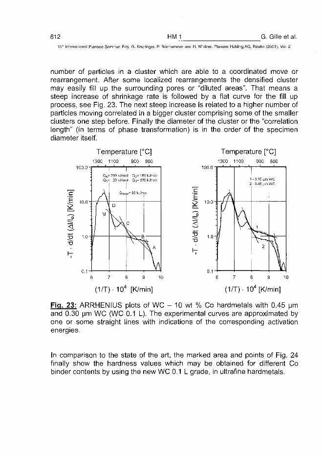
812 HM 1 G. Gille et al.15" International Plansee Seminar, Eds. G. Kneringer, P. Rodhammer and H. Wildner, Plansee Holding AG, Reutte (2001), Vol. 2
number of particles in a cluster which are able to a coordinated move orrearrangement. After some localized rearrangements the densified clustermay easily fill up the surrounding pores or "diluted areas". That means asteep increase of shrinkage rate is followed by a flat curve for the fill upprocess, see Fig. 23. The next steep increase is related to a higher number ofparticles moving correlated in a bigger cluster comprising some of the smallerclusters one step before. Finally the diameter of the cluster or the "correlationlength" (in terms of phase transformation) is in the order of the specimendiameter itself.
Temperature [°C]1300 1100 900 800
Temperature [°C]1300 1100 900 800
100.0
QA= 290 kJ/mol Qc= 185 kj/mol= 20 kJ/mol QD= 330 kj/mol
100.0
0.1
(1/T)- 104 [K/min] (1/T)- 104 [K/min]
Fig. 23: ARRHENIUS plots of WC - 10 wt % Co hardmetals with 0.45 urnand 0.30 urn WC (WC 0.1 L). The experimental curves are approximated byone or some straight lines with indications of the corresponding activationenergies.
In comparison to the state of the art, the marked area and points of Fig. 24finally show the hardness values which may be obtained for different Cobinder contents by using the new WC 0.1 L grade, in ultrafine hardmetals.
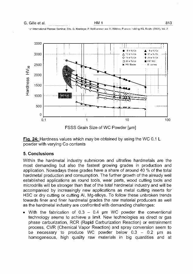
G. Gille et al. HM 1 81315th International Plansee Seminar, Eds. G. Kneringer, P. Rodhammer and H. Wildner, Plansee Holding AG, Reutte (2001), Vol. 2
IwwCDcCOI
3500
3000
2500
2000
1500
1000
1 10
FSSS Grain Size of WC Powder [urn]
100
Fig. 24: Hardness values which may be obtained by using the WC 0.1 Lpowder with varying Co contents
5. Conclusions
Within the hardmetal industry submicron and ultrafine hardmetals are themost demanding but also the fastest growing grades in production andapplication. Nowadays these grades have a share of around 40 % of the totalhardmetal production and consumption. The further growth of the already wellestablished applications as round tools, wear parts, wood cutting tools andmicrodrills will be stronger than that of the total hardmetal industry and will beaccompanied by increasingly new applications as metal cutting inserts forHSC or dry cutting or cutting Al, Mg-alloys. To follow these unbroken trendstowards finer and finer hardmetal grades the raw material producers as wellas the hardmetal industry are confronted with demanding challenges:
• With the fabrication of 0.3 - 0.4 urn WC powder the conventionaltechnology seems to achieve a limit. New technologies as direct or gasphase carburization, RCR (Rapid Carburization Reaction) or entrainmentprocess, CVR (Chemical Vapor Reaction) and spray conversion seem tobe necessary to produce WC powder below 0.3 - 0.2 urn ashomogeneous, high quality raw materials in big quantities and at
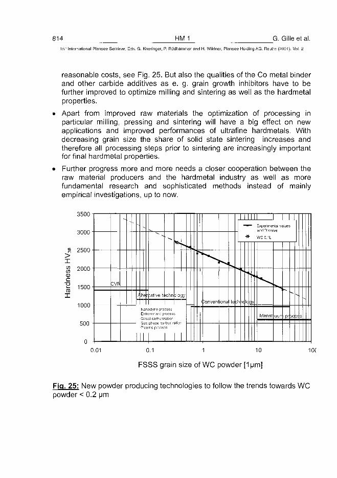
814 HM 1 G. Gille et al.15L" International Plansee Seminar, Eds. G. Kneringer, P. Rodhammer and H. Wildner, Plansee Holding AG, Reutte (2001), Vol. 2
reasonable costs, see Fig. 25. But also the qualities of the Co metal binderand other carbide additives as e. g. grain growth inhibitors have to befurther improved to optimize milling and sintering as well as the hardmetalproperties.
Apart from improved raw materials the optimization of processing inparticular milling, pressing and sintering will have a big effect on newapplications and improved performances of ultrafine hardmetals. Withdecreasing grain size the share of solid state sintering increases andtherefore all processing steps prior to sintering are increasingly importantfor final hardmetal properties.
Further progress more and more needs a closer cooperation between theraw material producers and the hardmetal industry as well as morefundamental research and sophisticated methods instead of mainlyempirical investigations, up to now.
3500
3000
2500>XcowCD
c
Har
d
2000
1500
1000-
500
0.01
CVF
-
/ 11
NE
n
e
an r
p as
I
lative tt ichnDlO jy
Ddyne processginment processt carburization
Tia proce
N
ionven ona te
~P I I I^mmm Experimental values
and fit curve
* WC0.1L
%
ch
k
Ic y
Menst 'uun pr ac S
0.1 1 10
FSSS grain size of WC powder [1 urn]
Fig. 25: New powder producing technologies to follow the trends towards WCpowder < 0.2 urn
G. Gille et al. HM 1 81515"1 International Plansee Seminar, Eds. G. Kneringer, P. Rodhammer and H. Wildner, Plansee Holding AG, Reutte (2001), Vol. 2
Literature
[ I ] L. J. Prakash, Metal Powder Report, 12, (1989), 835-838
[ 2] W. D. Schubert, A. Bock and B Lux, Int. J. of Refractories and HardMaterials, 13 (1995), 281-296
[ 3] L. J. Prakash, Int. J. of Refractories and Hard Materials, 13 (1995),257-264
[ 4] H. W. Daub, K. Dreyer, A. Happe, H. Holzhauer and D. Kassel,Pulvermetallurgie in Wissenschaft und Praxis, Bd. 11, Hrsg. H. Kolaska,Oberursel 1995, 285-306
[ 5] G. Gille, G. Schwier and B. Szesny, Pulvermetallurgie in Wissenschaftund Praxis, Bd. 14, Hrsg. H. Kolaska, Oberursel 1998, 194-227
[ 6] E. Lardner and S. Iggstrom, Proc. of 10th Int. Plansee Seminar, Reutte,Vol. 1, 549-579, Ed. H. Ortner, Innsbruck 1981,
[ 7] J. Gurland, Trans. Amer. Inst. Min. Met. Engng., 200 (1954), 285-298
[ 8] G. Hofmann and R. Hack, Proc. of 11th Int. Plansee Seminar, Reutte,Vol. 2, HM 32, 527-538, Innsbruck 1984, Eds. H. Bildstein and H. Ortner
[ 9] J.-L. Chermant and F. Osterstock, J. Mat. Sci. 11 (1976), 1939-1951
[10] W. Pompe, H. A. Bahr, G. Gille, W. Kreher, B. Schultrich and H. J.Weiss, Current Topics in Material Science, Volume 12 chapt. 4, ed. H.Kaldis, ElsevierSci. Publ. 1985
[ I I ] W. D. Schubert, H. Neumeister, G. Kinger and B. Lux, Int. J. ofRefractories and Hard Materials, 16 (1998), 133-142
[12] D. Kammermeier, K. Gbrting, W. Heinrich and M. Wolf,Pulvermetallurgie in Wissenschaft und Praxis, Bd. 16, Hrsg. H. Kolaska,Oberursel 2000, 113-136
[13] K. Dreyer, W. Daub, H. Holzhauer, S. Orths, D. Kassel and K. Rodiger,Pulvermetallurgie in Wissenschaft und Praxis, Bd. 13, Hrsg. H. Kolaska,Oberursel 1997, 3-27
[14] D. F. Carroll, Int. J. of Refractories and Hard Materials, 17 (1999),123-133
[15] W. D. Schubert, 2000 Int. Conference on Tungsten, Hard Metals andRefractory Alloys, Annapolis/USA, Sept. 2000
[16] G. Gille, G. Leitner and B. Roebuck, Proc. of European Conf. onAdvances in Hard Materials Production, Stockholm, May 1996, 195-210
816 HM 1 G. Gille et al.15~ International Plansee Seminar, Eds. G. Kneringer, P. Rodhammer and H. Wildner, Plansee Holding AG, Reutte (2001), Vol. 2
[17] G. Gille, B. Szesny and G. Leitner, Proc. of 14th Int. Plansee Seminar,Reutte, Vol. 2, 139-167, Eds. G. Kneringer, F. Rodhammer andP. Wilhartiz, Innsbruck 1997
[18] W. D. Schubert, A. Bock and B. Lux, Adv. in Powder Met. andParticulare Mat., Vol. 3 (1999), 10-23, Eds. Ch. L. Rose and M. H.Thibodeau, Princeton 1999
[19] C. H. Alibert, Proc. of European Conference on Advances in HardMaterials Production, Turin, Nov. 1999, 167-174
[20] B. Meredith and D. R. Milner, Powder Metallurgy 19 (1976), 38-45
[21] W. Schatt, Sintervorgange: Grundlagen, VDI Verlag, Dusseldorf 1992
[22] A. Egami, T. Kusaka, M. Machida and K. Kobyashi, Metal PowderReport, 12 (1989), 822-826
[23] T. Fukatsu, K. Kobori and M. Uebi, Int. J. Refractory Metals and HardMaterials 10(1991), 57-60
[24] G. Gille, B. Szesny, B. Mende, K. Dreyer and H. van den Berg,Pulvermetallurgie in Wissenschaft und Praxis Bd. 16, Hrsg. H. Kolaska,Oberursel 2000, 85-112
[25] S. Inada and H. Yoshimura, Proc. of 13th Int. Plansee Seminar, Reutte,Vol. 2, HM 8, 67-79, Eds. H. Bildstein and R. Eck, Innsbruck 1993
[26] K. Friedrichs, Eine neue Technologie zur Herstellung vonHartmetallstaben mit gedrallten Kuhlkanalen, Prospekt K. FRIEDRICHSAG, Kulmbach 1996
[27] WO 00/29 325: Verfahren zur Herstellung von Wolframcarbiden durchGasphasencarburierung
[28] G. Gille, J. Bredthauer, B. Gries, B. Mende and W. Heinrich, Proc. ofEuropean Conf. on Advances in Hard Materials Production, Turin Nov.1999,27-46
[29] C. Connor, D. Carroll and G. Cochran et al., Proc. 7th Int. TungstenSymposium, Goslar, Sept. 1996, 171-180, Eds. ITIA, 1997
[30] M. Kobayashi and K. Kobori, 8th Int. Tungsten Symposium,Fukuoka/Japan, Oct. 1999
[31] T. Ungar, A. Borbely, G. R. Goren-Muginstein, S. Berger and A. R.Rosen, Nanostructured Materials, Vol. 1/1 (1999), 103-113
ATO100499K. Dreyer et al. HM 40 817
15" International Plansee Seminar, Eds. G. Kneringer, P. Rodhammer and H. Wildner, Plansee Holding AG, Reutte (2001), Vol. 2
Functionally Graded Hardmetals and Cermets: Preparation,
Performance and Production Scale Up
K. Dreyer1, D. Kassel1, H.-W. Daub1, H. van den Berg1,
W. Lengauer2, J. Garcia2, V. Ucakar2
1 Widia GmbH, Munchener StrafAe 125, D-45145 Essen, Germany2 Institute for Chemical Technology of Inorganic Materials, Vienna University of Technology,
Getreidemarkt 9/161, A-1060 Vienna, Austria
Summary:
Sintering experiments were carried out to establish graded microstructures inhardmetals and cermets. The formation of these microstructural features wasinvestigated as a function of nitrogen pressure, sintering temperature,sintering period and sintering profile. The nitrogen pressure influences theformation of carbonitride layers at the surface. Decreasing sinteringtemperature yields similar results as increasing nitrogen pressure. Uponprolonged sintering time a small growth of the outer carbonitride layer canonly be obtained if a substantial WC grain growth is accepted. Variation of thesintering profile after dense sintering does not principally change the type ofthe graded microstructure.The laboratory experiments were scaled up in an industrial sinter/HIP furnaceand showing good correspondence with each other. First turning cutting testswith different alloys show excellent performance in comparison to ungradedmaterials.
Keywords:functionally graded hardmetals, sintering, HIPing, cutting test
1. Introduction:
Coated hardmetal tools show a topographic distribution of their properties: thesurface withstands the mechanical/chemical interaction with the workpiece,air and lubricants at high temperatures and the core exhibits high toughnessin order to resist mechanical load. The increasing needs of performance led
818 HM40 K. Dreyer et al.15" International Plansee Seminar, Eds. G. Kneringer, P. Rodhammer and H. Wildner, Plansee Holding AG, Reutte (2001), Vol. 2
to the application of complicated multilayer coatings with the aim of anoptimum combination of different hard phases compatible with substrateadherence and resistance to wear. One of the ideas behind the preparation ofmultilayer coatings is to approach the properties of the tough core stepwise.However, even multilayers show a discontinuous change of properties at theinterfaces of the various layers. Such a discontinuous change can only beavoided if graded microstructures can be established in which the chemicalcomposition or phase content changes gradually from one side to the other.Since the different parts of such a structure have a different function thesematerials are called functionally graded.Functionally graded cermets with a hard outer surface (Ti(C,N)-enriched) anda tough inner core have been described only recently (1,2) and were claimedto have superior properties. In our own efforts to prepare functionally gradedhardmetals and cermets (3-6) we have found a variety of different near-surface microstructures which were classified into four main types and threesub-types. The four principal types show the following features:
Type 1: a graded structure in which a globular (Ti,W)(C,N)-governed micro-structure changes smoothly into a hardmetal-type bulk structure(angular WC grains) or a bulk microstructure with a mixture ofangular WC together with globular (Ti,W)(C,N). The bulk structure issmoothly attained. Such a type can also be obtained if cermets areannealed below the liquidus temperature (7)
Type 2: a microstructure that contains a more or less well-differentiated WC-Co surface zone with a following graded microstructure. This type isrelated to the well-known cubic-carbide-free (or most confusing"(3-free" or "y-free") layer hardmetals (7-11) but has a carbonitrideenriched zone below the WC-Co layer fading smoothly into the bulkstructure governed by a hardmetal-type microstructure
Type 3: a microstructure with a Ti(C,N) top layer followed by a WC-Co layer,and then a graded structure with a carbonitride-enriched zonesmoothly attaining a hardmetal type microstructure - this is a type 2structure with a carbonitride surface layer
Type 4: a Ti(C,N) top layer that forms onto a gradient structure governed bycarbonitrides - representing a type 1 functional gradient cermet plusa carbonitride surface layer (1)
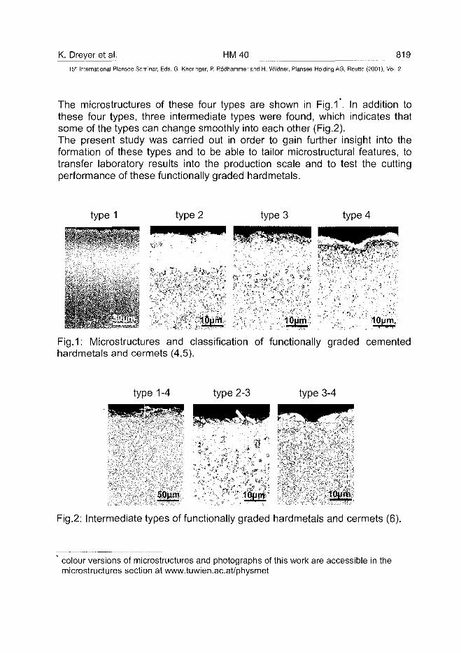
K. Dreyer et al. HM40 819
15* International Plansee Seminar, Eds. G. Kneringer, P. Rodhammer and H. Wildner, Plansee Holding AG, Reutte (2001), Vol. 2
The microstructures of these four types are shown in Fig.1*. In addition tothese four types, three intermediate types were found, which indicates thatsome of the types can change smoothly into each other (Fig.2).The present study was carried out in order to gain further insight into theformation of these types and to be able to tailor microstructural features, totransfer laboratory results into the production scale and to test the cuttingperformance of these functionally graded hardmetals.
type 1 type 2 type 3 type 4
''. lOurft 10um10um
Fig.1: Microstructures and classification of functionally graded cementedhardmetals and cermets (4,5).
type 1-4 type 2-3 type 3-4
50um
Fig.2: Intermediate types of functionally graded hardmetals and cermets (6).
colour versions of microstructures and photographs of this work are accessible in themicrostructures section at www.tuwien.ac.at/physmet
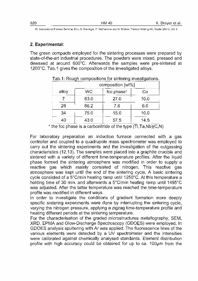
820 HM40 K. Dreyer et al.15" International Plansee Seminar, Eds. G. Kneringer, P. Rodhammer and H. Wildner, Plansee Holding AG, Reutte (2001), Vol. 2
2. Experimental:
The green compacts employed for the sintering processes were prepared bystate-of-the-art industrial procedures. The powders were mixed, pressed anddewaxed at around 600°C. Afterwards the samples were pre-sintered at1200°C. Tab.1 gives the composition of the investigated alloys.
Tab.1: Rough compositions for sintering investigations.
alloy
7
28
34
40
we63.0
86.2
75.0
43.0
composition [wt%]
fee phase*
27.0
7.8
15.0
57.5
Co
10.0
6.0
10.0
14.5* the fee phase is a carbonitride of the type (Ti,Ta,Nb)(C,N)
For laboratory preparation an induction furnace connected with a gascontroller and coupled to a quadrupole mass spectrometer was employed tocarry out the sintering experiments and the investigation of the outgassingcharacteristics (12,13). The samples were placed into a graphite crucible andsintered with a variety of different time-temperature profiles. After the liquidphase formed the sintering atmosphere was modified in order to supply areactive gas which mainly consisted of nitrogen. This reactive gasatmosphere was kept until the end of the sintering cycle. A basic sinteringcycle consisted of a 5°C/min heating ramp until 1250°C. At this temperature aholding time of 30 min. and afterwards a 5°C/min heating ramp until 1495°Cwas adjusted. After the latter temperature was reached the time-temperatureprofile was modified in different ways.In order to investigate the conditions of gradient formation more deeplyspecific sintering experiments were done by interrupting the sintering cycle,varying the nitrogen pressure, applying a zigzag time-temperature profile andheating different periods at the sintering temperature.For the characterisation of the graded microstructures metallography, SEM,XRD, EPMA and Glow-Discharge Spectroscopy (GDOES) were employed. InGDOES analysis sputtering with Ar was applied. The fluorescence lines of thevarious elements were detected by a UV spectrometer and the intensitieswere calibrated against chemically analysed standards. Element distributionprofile with high accuracy could be obtained for up to ca. 100um from the
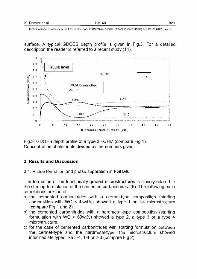
K. Dreyer et al. HM40 82115"1 International Plansee Seminar, Eds. G. Kneringer, P. Rodhammer and H. Wildner, Plansee Holding AG, Reutte (2001), Vol. 2
surface. A typical GDOES depth profile is given in Fig.3. For a detaileddescription the reader is referred to a recent study (14).
1
0.9
0.8
is 0.7
i 0.6co
I °-5
§ ° - 4
c3 0-3
0.2
0.1
0
Ti(C,N) layer
W/100
WC-Co enrichedzone
\ / v CO/5° C/!°
f" \ ^ Ti/100 ^ . - - ^ N/10
bulk
10 15 20 25 30 35
Distance from surface [urn]
40 4 5 50
Fig.3: GDOES depth profile of a type 3 FGHM (compare Fig.1).Concentration of elements divided by the numbers given.
3. Results and Discussion
3.1. Phase formation and phase separation in FGHMs
The formation of the functionally graded microstructures is closely related tothe starting formulation of the cemented carbonitrides. (6). The following maincorrelations are found:a) the cemented carbonitrides with a cermet-type composition (starting
composition with WC < 43wt%) showed a type 1 or 1-4 microstructure(compare Fig.1 and 2).
b) the cemented carbonitrides with a hardmetal-type composition (startingformulation with WC > 69wt%) showed a type 2, a type 3 or a type 4microstructure.
c) for the case of cemented carbonitrides with starting formulation betweenthe cermet-type and the hardmetal-type, the microstructure showedintermediate types like 3-4, 1-4 or 2-3 (compare Fig.2).
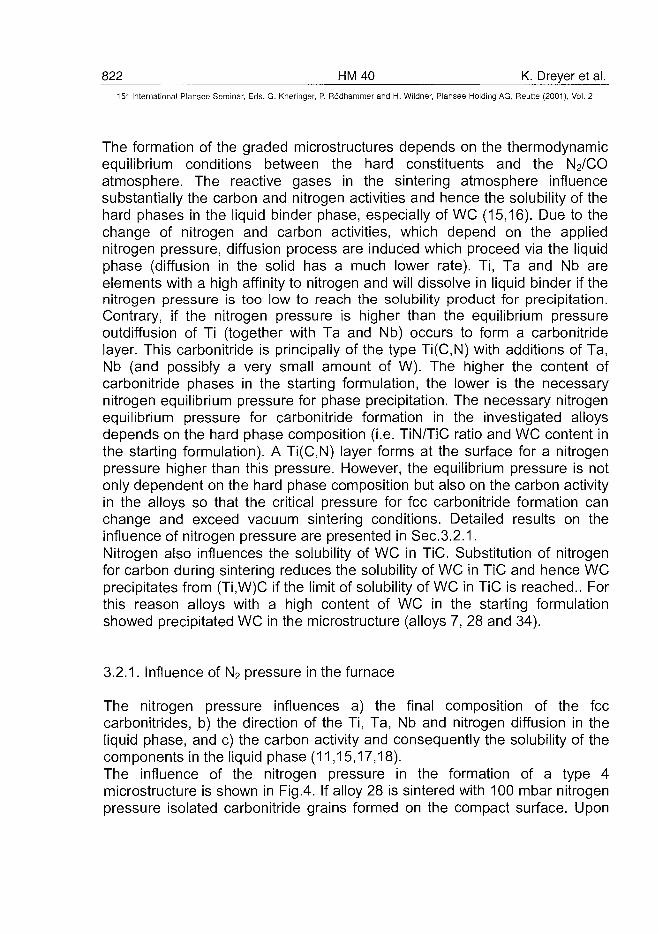
822 HM40 K. Dreyer et al.15" International Plansee Seminar, Eds. G. Kneringer, P. Rodhammer and H. Wildner, Plansee Holding AG, Reutte (2001), Vol. 2
The formation of the graded microstructures depends on the thermodynamicequilibrium conditions between the hard constituents and the N2/COatmosphere. The reactive gases in the sintering atmosphere influencesubstantially the carbon and nitrogen activities and hence the solubility of thehard phases in the liquid binder phase, especially of WC (15,16). Due to thechange of nitrogen and carbon activities, which depend on the appliednitrogen pressure, diffusion process are induced which proceed via the liquidphase (diffusion in the solid has a much lower rate). Ti, Ta and Nb areelements with a high affinity to nitrogen and will dissolve in liquid binder if thenitrogen pressure is too low to reach the solubility product for precipitation.Contrary, if the nitrogen pressure is higher than the equilibrium pressureoutdiffusion of Ti (together with Ta and Nb) occurs to form a carbonitridelayer. This carbonitride is principally of the type Ti(C,N) with additions of Ta,Nb (and possibly a very small amount of W). The higher the content ofcarbonitride phases in the starting formulation, the lower is the necessarynitrogen equilibrium pressure for phase precipitation. The necessary nitrogenequilibrium pressure for carbonitride formation in the investigated alloysdepends on the hard phase composition (i.e. TiN/TiC ratio and WC content inthe starting formulation). A Ti(C,N) layer forms at the surface for a nitrogenpressure higher than this pressure. However, the equilibrium pressure is notonly dependent on the hard phase composition but also on the carbon activityin the alloys so that the critical pressure for fee carbonitride formation canchange and exceed vacuum sintering conditions. Detailed results on theinfluence of nitrogen pressure are presented in Sec.3.2.1.Nitrogen also influences the solubility of WC in TiC. Substitution of nitrogenfor carbon during sintering reduces the solubility of WC in TiC and hence WCprecipitates from (Ti,W)C if the limit of solubility of WC in TiC is reached.. Forthis reason alloys with a high content of WC in the starting formulationshowed precipitated WC in the microstructure (alloys 7, 28 and 34).
3.2.1. Influence of N2 pressure in the furnace
The nitrogen pressure influences a) the final composition of the feecarbonitrides, b) the direction of the Ti, Ta, Nb and nitrogen diffusion in theliquid phase, and c) the carbon activity and consequently the solubility of thecomponents in the liquid phase (11,15,17,18).The influence of the nitrogen pressure in the formation of a type 4microstructure is shown in Fig.4. If alloy 28 is sintered with 100 mbar nitrogenpressure isolated carbonitride grains formed on the compact surface. Upon
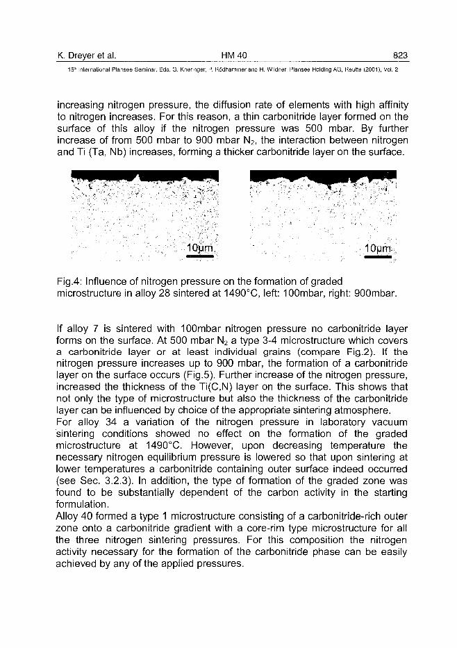
K. Dreyer et al. HM 40 823^15lh International Plansee Seminar, Eds. G. Kneringer, P. Rodhammer and H. Wildner, Plansee Holding AG, Reutte (2001), Vol. 2
increasing nitrogen pressure, the diffusion rate of elements with high affinityto nitrogen increases. For this reason, a thin carbonitride layer formed on thesurface of this alloy if the nitrogen pressure was 500 mbar. By furtherincrease of from 500 mbar to 900 mbar N2, the interaction between nitrogenand Ti (Ta, Nb) increases, forming a thicker carbonitride layer on the surface.
10um 10um
Fig.4: Influence of nitrogen pressure on the formation of gradedmicrostructure in alloy 28 sintered at 1490°C, left: 100mbar, right: 900mbar.
If alloy 7 is sintered with lOOmbar nitrogen pressure no carbonitride layerforms on the surface. At 500 mbar N2 a type 3-4 microstructure which coversa carbonitride layer or at least individual grains (compare Fig.2). If thenitrogen pressure increases up to 900 mbar, the formation of a carbonitridelayer on the surface occurs (Fig.5). Further increase of the nitrogen pressure,increased the thickness of the Ti(C,N) layer on the surface. This shows thatnot only the type of microstructure but also the thickness of the carbonitridelayer can be influenced by choice of the appropriate sintering atmosphere.For alloy 34 a variation of the nitrogen pressure in laboratory vacuumsintering conditions showed no effect on the formation of the gradedmicrostructure at 1490°C. However, upon decreasing temperature thenecessary nitrogen equilibrium pressure is lowered so that upon sintering atlower temperatures a carbonitride containing outer surface indeed occurred(see Sec. 3.2.3). In addition, the type of formation of the graded zone wasfound to be substantially dependent of the carbon activity in the startingformulation.Alloy 40 formed a type 1 microstructure consisting of a carbonitride-rich outerzone onto a carbonitride gradient with a core-rim type microstructure for allthe three nitrogen sintering pressures. For this composition the nitrogenactivity necessary for the formation of the carbonitride phase can be easilyachieved by any of the applied pressures.
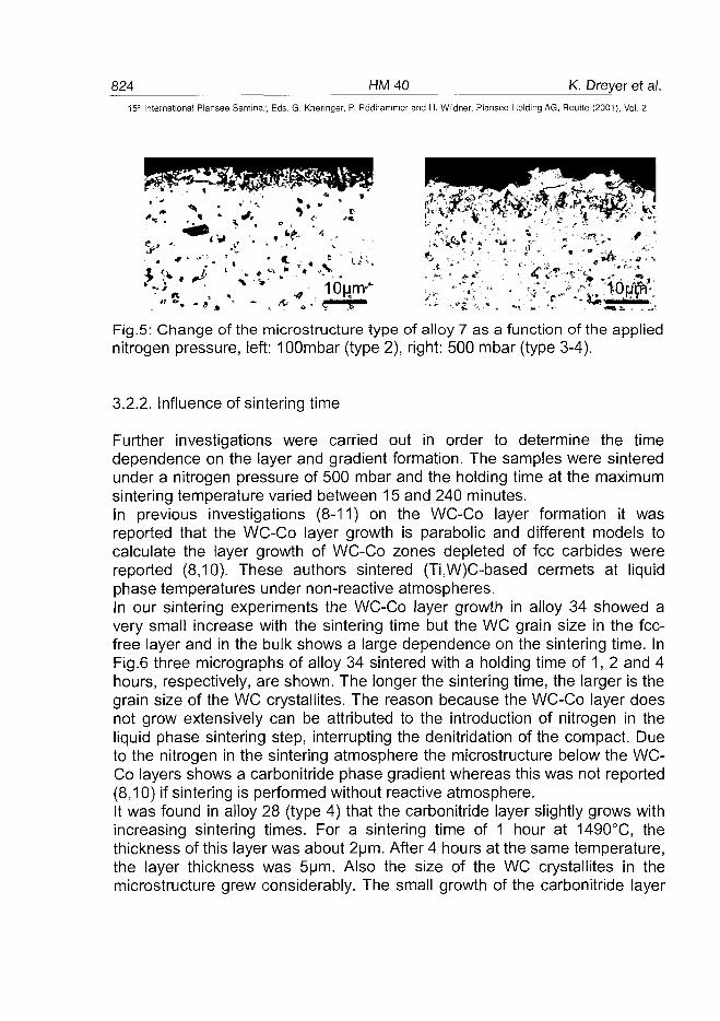
824 HM40 K. Dreyer et al.15" International Plansee Seminar, Eds. G. Kneringer, P. Rodhammer and H. Wildner, Plansee Holding AG, Reutte (2001), Vol. 2
Fig.5: Change of the microstructure type of alloy 7 as a function of the appliednitrogen pressure, left: 100mbar (type 2), right: 500 mbar (type 3-4).
3.2.2. Influence of sintering time
Further investigations were carried out in order to determine the timedependence on the layer and gradient formation. The samples were sinteredunder a nitrogen pressure of 500 mbar and the holding time at the maximumsintering temperature varied between 15 and 240 minutes.In previous investigations (8-11) on the WC-Co layer formation it wasreported that the WC-Co layer growth is parabolic and different models tocalculate the layer growth of WC-Co zones depleted of fee carbides werereported (8,10). These authors sintered (Ti.W)C-based cermets at liquidphase temperatures under non-reactive atmospheres.In our sintering experiments the WC-Co layer growth in alloy 34 showed avery small increase with the sintering time but the WC grain size in the fee-free layer and in the bulk shows a large dependence on the sintering time. InFig.6 three micrographs of alloy 34 sintered with a holding time of 1, 2 and 4hours, respectively, are shown. The longer the sintering time, the larger is thegrain size of the WC crystallites. The reason because the WC-Co layer doesnot grow extensively can be attributed to the introduction of nitrogen in theliquid phase sintering step, interrupting the denitridation of the compact. Dueto the nitrogen in the sintering atmosphere the microstructure below the WC-Co layers shows a carbonitride phase gradient whereas this was not reported(8,10) if sintering is performed without reactive atmosphere.It was found in alloy 28 (type 4) that the carbonitride layer slightly grows withincreasing sintering times. For a sintering time of 1 hour at 1490°C, thethickness of this layer was about 2um. After 4 hours at the same temperature,the layer thickness was 5um. Also the size of the WC crystallites in themicrostructure grew considerably. The small growth of the carbonitride layer
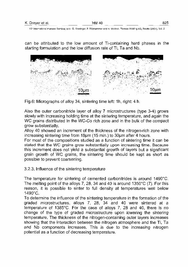
K. Dreyer et al. HM 40 82515'" International Plansee Seminar, Eds. G. Kneringer, P. Rodhammer and H. Wildner, Plansee Holding AG, Reutte (2001), Vol. 2
can be attributed to the low amount of Ti-containing hard phases in thestarting formulation and the low diffusion rate of Ti, Ta and Nb.
10um 10um
Fig.6: Micrographs of alloy 34, sintering time left: 1h, right: 4 h.
Also the outer carbonitride layer of alloy 7 microstructures (type 3-4) growsslowly with increasing holding time at the sintering temperature, and again theWC grains distributed in the WC-Co rich zone and in the bulk of the compactgrow substantially.Alloy 40 showed an increment of the thickness of the nitrogen-rich zone withincreasing sintering time from 18um (15 min.) to 30um after 4 hours.For most of the compositions studied as a function of sintering time it can bestated that the WC grains grow substantially upon increasing time. Becausethis increment does not yield a substantial growth of layers but a significantgrain growth of WC grains, the sintering time should be kept as short aspossible to prevent coarsening.
3.2.3. Influence of the sintering temperature
The temperature for sintering of cemented carbonitrides is around 1490°C.The melting point of the alloys 7, 28, 34 and 40 is around 1350°C (7). For thisreason, it is possible to sinter to full density at temperatures well below1490°C.To determine the influence of the sintering temperature in the formation of thegraded microstructures, alloys 7, 28, 34 and 40 were sintered at atemperature of 1385°C. For the case of alloys 7, 28 and 40, there is nochange of the type of graded microstructure upon lowering the sinteringtemperature. The thickness of the nitrogen-containing outer layers increasesshowing that the interaction between the nitrogen atmosphere and the Ti, Taand Nb components increases. This is due to the increasing nitrogenpotential as a function of decreasing temperature.
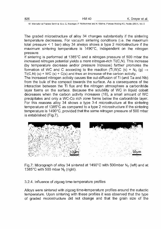
826 HM40 K. Dreyer et al.15:" International Plansee Seminar, Eds. G. Kneringer, P. Rodhammer and H. Wildner, Plansee Holding AG, Reutte (2001), Vol. 2
The graded microstructure of alloy 34 changes substantially if the sinteringtemperature decreases. For vacuum sintering conditions (i.e. the maximumtotal pressure < 1 bar) alloy 34 always shows a type 2 microstructure if themaximum sintering temperature is 1490°C, independent on the nitrogenpressure.If sintering is performed at 1385°C and a nitrogen pressure of 500 mbar theincreased nitrogen potential yields a more nitrogen-rich Ti(C,N). This increase(by temperature decrease and/or pressure increase) further promotes theformation of WC and C according to the reaction (Ti,W)C (s) + N2 (g) ->Ti(C,N) (s) + WC (s) + C(s) and thus an increase of the carbon activity.The increased nitrogen activity causes the out-diffusion of Ti (and Ta and Nb)from the bulk of the compact towards the surface. As a consequence of theinteraction between the Ti flux and the nitrogen atmosphere a carbonitridelayer forms on the surface. Because the solubility of WC in liquid cobaltdecreases when the carbon activity increases (16), a small amount of WCprecipitates and only a WC-Co rich zone forms below the carbonitride layer.For this reasons alloy 34 shows a type 3-4 microstructure at the sinteringtemperature of 1385°C as compared to a type 2 microstructure if the sinteringtemperature is 1490°C, provided that the same nitrogen pressure of 500 mbaris established (Fig.7).
v\ /I*',
10um
Fig.7: Micrograph of alloy 34 sintered at 1490°C with 500mbar N2 (left) and at1385°C with 500 mbar N2 (right).
3.2.4. Influence of zigzag time-temperature profiles
Alloys were sintered with zigzag time-temperature profiles around the eutectictemperature. Upon sintering with these profiles it was observed that the typeof graded microstructure did not change and that the grain size of the
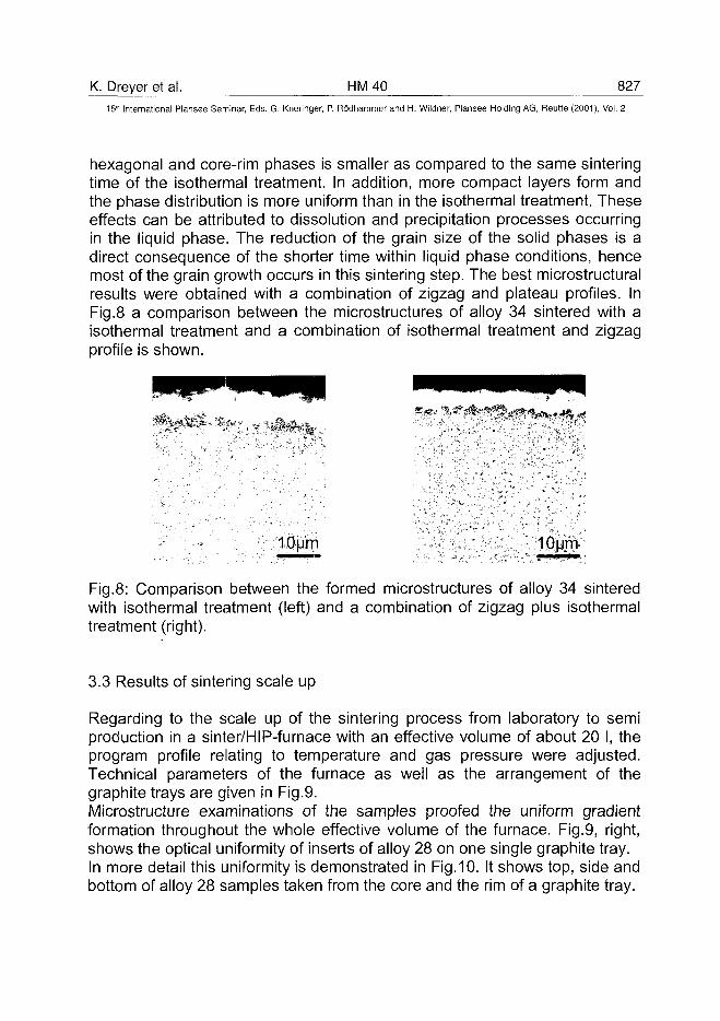
K. Dreyer et al. HM 40 827^
15'" International Plansee Seminar, Eds. G. Kneringer, P. Rodhammer and H. Wildner, Plansee Holding AG, Reutte (2001), Vol. 2
hexagonal and core-rim phases is smaller as compared to the same sinteringtime of the isothermal treatment. In addition, more compact layers form andthe phase distribution is more uniform than in the isothermal treatment. Theseeffects can be attributed to dissolution and precipitation processes occurringin the liquid phase. The reduction of the grain size of the solid phases is adirect consequence of the shorter time within liquid phase conditions, hencemost of the grain growth occurs in this sintering step. The best microstructuralresults were obtained with a combination of zigzag and plateau profiles. InFig.8 a comparison between the microstructures of alloy 34 sintered with aisothermal treatment and a combination of isothermal treatment and zigzagprofile is shown.
10um . • " ' 10jjm-
Fig.8: Comparison between the formed microstructures of alloy 34 sinteredwith isothermal treatment (left) and a combination of zigzag plus isothermaltreatment (right).
3.3 Results of sintering scale up
Regarding to the scale up of the sintering process from laboratory to semiproduction in a sinter/HIP-furnace with an effective volume of about 20 I, theprogram profile relating to temperature and gas pressure were adjusted.Technical parameters of the furnace as well as the arrangement of thegraphite trays are given in Fig.9.Microstructure examinations of the samples proofed the uniform gradientformation throughout the whole effective volume of the furnace. Fig.9, right,shows the optical uniformity of inserts of alloy 28 on one single graphite tray.In more detail this uniformity is demonstrated in Fig. 10. It shows top, side andbottom of alloy 28 samples taken from the core and the rim of a graphite tray.
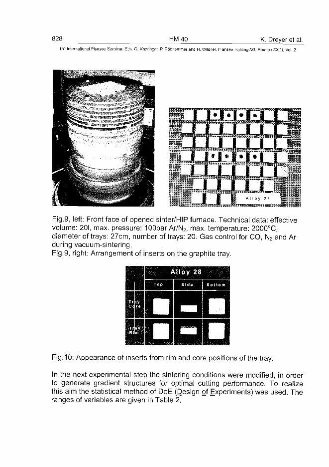
828 HM 40 K. Dreyer et al.
15" International Plansee Seminar, Eds. G. Kneringer, P. Rödhammer and H. Wildner, Plansee Holding AG, Reutte (2001), Voi. 2
um 1 1 1
Fig.9, left: Front face of opened sinter/HIP furnace. Technical data: effectivevolume: 20I, max. pressure: 100bar Ar/N2, max. temperature: 2000°C,diameter of trays: 27cm, number of trays: 20. Gas control for CO, N2 and Arduring vacuum-sintering.Fig.9, right: Arrangement of inserts on the graphite tray.
Alloy 28
•ODFig. 10: Appearance of inserts from rim and core positions of the tray.
In the next experimental step the sintering conditions were modified, in orderto generate gradient structures for optimal cutting performance. To realizethis aim the statistical method of DoE (Design of Experiments) was used. Theranges of variables are given in Table 2.
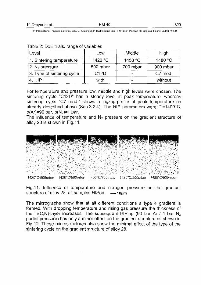
K. Dreyer et al. HM40 82915* International Plansee Seminar, Eds. G. Kneringer, P. Rodhammer and H. Wildner, Plansee Holding AG, Reutte (2001), Vol. 2
Table 2: DoE trials, range of variables
Level
1. Sintering temperature
2. N2 pressure
3. Type of sintering cycle
4. HIP
Low
1420 °C
500 mbar
C12D
with
Middle
1450 °C
700 mbar-
-
High
1480 °C
900 mbar
C7 mod.
without
For temperature and pressure low, middle and high levels were chosen. Thesintering cycle "C12D" has a steady level at peak temperature, whereassintering cycle "C7 mod." shows a zigzag-profile at peak temperature asalready described above (Sec.3.2.4). The HIP parameters were: T=1400°C,p(Ar)=90 bar, p(N2)=1 bar.The influence of temperature and N2 pressure on the gradient structure ofalloy 28 is shown in Fig.11.
1420°C/900mbar 1420°C/500mbar 1450°C/700mbar 1480°C/900mbar 1480°C/500mbar
Fig.11: Influence of temperature and nitrogen pressure on the gradientstructure of alloy 28, all samples HIPed. —i0| jm
The micrographs show that at all different conditions a type 4 gradient isformed. With dropping temperature and rising gas pressure the thickness ofthe Ti(C,N)-layer increases. The subsequent HIPing (90 bar Ar / 1 bar N2
partial pressure) has only a minor effect on the gradient structure as shown inFig.12. These microstructures also show the minimal effect of the type of thesintering cycle on the gradient structure of alloy 28.
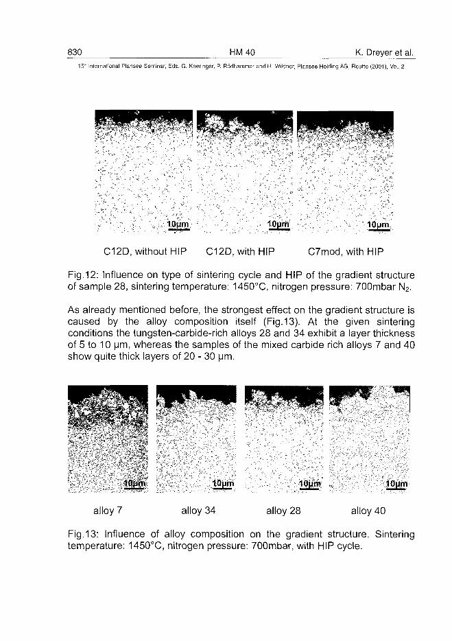
830 HM40 K. Dreyer et al.15'" International Plansee Seminar, Eds. G. Kneringer, P. Rodhammer and H. Wildner, Plansee Holding AG, Reutte (2001), Vol. 2
lOym 10um
C12D, without HIP C12D, with HIP C7mod, with HIP
Fig.12: Influence on type of sintering cycle and HIP of the gradient structureof sample 28, sintering temperature: 1450°C, nitrogen pressure: 700mbar N2.
As already mentioned before, the strongest effect on the gradient structure iscaused by the alloy composition itself (Fig. 13). At the given sinteringconditions the tungsten-carbide-rich alloys 28 and 34 exhibit a layer thicknessof 5 to 10 urn, whereas the samples of the mixed carbide rich alloys 7 and 40show quite thick layers of 20 - 30
alloy 7
\0\\tn
alloy 34 alloy 28
10um
alloy 40
Fig. 13: Influence of alloy composition on the gradient structure. Sinteringtemperature: 1450°C, nitrogen pressure: 700mbar, with HIP cycle.
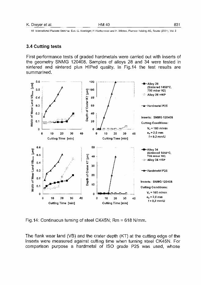
K. Dreyer et al. HM40 83115" International Plansee Seminar, Eds. G. Kneringer, P. Rodhammer and H. Wildner, Plansee Holding AG, Reutte (2001), Vol. 2
3.4 Cutting tests
First performance tests of graded hardmetals were carried out with inserts ofthe geometry SNMG 120408. Samples of alloys 28 and 34 were tested insintered and sintered plus HIPed quality. In Fig.14 the test results aresummarised.
* 0-51
> 0.4•DC
™ 0.3ra
5 0.2"oI 0.1
120
10 20 30
Cutting Time [min]
40 10 20 30
Cutting Time [min]
-Alloy 28(Sintered 1450°C,700 mbar N2)Alloy 28 +HIP
- * ^ Hardmetal P25
Inserts: SNMG 120408
Cutting Conditions:
Vc = 180 m/minap = 2,0 mmf = 0,2 mm/U
its
I
0.6
0.5
0.4
0.3
0.2
10 20 30
Cutting Time [min]
50
40
Io•S 20
Q.
Q 10
40 0 10 20 30
Cutting Time [min]
40
-Alloy 34(Sintered 1450°C,700 mbar N2)Alloy 34+HIP
- * - Hardmetal P25
Inserts: SNMG 120408
Cutting Conditions:
Vc = 160 m/min
ap = 2,0 mmf = 0,2 mm/U
Fig.14: Continuous turning of steel CK45N; Rm = 618 N/mm.
The flank wear land (VB) and the crater depth (KT) at the cutting edge of theinserts were measured against cutting time when turning steel CK45N. Forcomparison purpose a hardmetal of ISO grade P25 was used, whose
832 HM40 K. Dreyer et al.15" International Plansee Seminar, Eds. G. Kneringer, P. Rodhammer and H. Wildner, Plansee Holding AG, Reutte (2001), Vol. 2
composition is roughly comparable to alloy 34. As it is quite obvious, thegraded structure enables an extremely high wear protection. Especially thecrater wear is still negligible even after a cutting time of 30 minutes, whereasthe service life of the P25 ISO grade insert is over by means of crater wearalready after a cutting time of 20 minutes.
4. References:
(1) K.Tsuda, A.lkegaya, T.Nomura, K.lsobe, N.Kitagawa, M.Chudou,H.Arimoto: Sumitomo Techn. Rev. 41, (1996), 47.
(2) G.Weinl, U.Rolander, P.Lindahl: PCT WO 98/51831, (1998).(3) L.Chen, W.Lengauer, H.Daub, K.Dreyer, D.Kassel: DE 198 45 376A1,
(2000).(4) W.Lengauer, J.Garcia, V.Ucakar, L.Chen, K.Dreyer, D.Kassel, H.-
W.Daub: Proc.PM2tec, Vancouver, Vol.3, part 10, (1999), 85.(5) W.Lengauer, J.Garcia, K.Dreyer, I.Smid, D.Kassel, H.-W.Daub, G.Korb
and L.Chen: Proc. EURO PM'99, Turin, (1999), 475.(6) W.Lengauer, J.Garcia, V.Ucakar, K.Dreyer, D.Kassel, H.-W.Daub: Proc.
FGM 2000, Estes Park, CO, in press.(7) P.Lindahl, P.Gustafson, U.Rolander, L.Stals, H.-O.Andren: Int. J. Refr.
Met. & Hard Mater. 17,(1999), 411.(8) H.Suzuki, K.Hayashi, Y.Taniguchi: J. Inst. of Metals, 22, No.11, (1981),
758.(9) W.Yohe: Proc. 13th Plansee Seminar, Vol. 2, (1993), 151.(10) M.Schwarzkopf, H.Exner, H.Fischmeister: Mat. Sci. Eng. 105/106,
(1988), 225.(11) P.Gustafson, A.Ostlund: Proc. 13th Plansee Seminar, Vol. 2, (1993), 537.(12) J.Garcia, W.Lengauer, I.Smid, K.Dreyer, D.Kassel, H-W.Daub: Proc.
PM2tec 2000, CD-ROM edition (2000).(13) J.Garcia and W.Lengauer: this conference, paper no.268(14) J.Garcia, S.Trampert, W.Lengauer, V.Ucakar, M.Bohn, I.Smid, K.Dreyer:
Mikrochim. Acta 133 (1-4), (2000), 223.(15) A.Doi, T.Nomura, M.Tokioba, K.Takahashi, A.Hara: P r o d 1 th Plansee
Seminar, HM8, (1985), 825.(16) L.Akesson: PhD Thesis, Institutionen for metallografi Kungliga Tekniska
Hogskolan, Stockholm, (1982).(17) S.Jonsson: PhD Thesis, Royal Institute of Technology, Stockholm,
(1993).(18) S.Jonsson: Z.Metallkd. 87, (1996), 784.
AT0100500V. Ucakar et al. HM 43 833
15* International Plansee Seminar, Eds. G. Kneringer, P. Rodhammer and H. Wildner, Plansee Holding AG, Reutte (2001), Vol. 2
NEAR-SURFACE MICROSTRUCTURAL MODIFICATION OF
(Ti,W)(C,N)-BASEB COMPACTS WITH NITROGEN
Vera Ucakar*, Christoph Krai*, Klaus Dreyer+, Walter Lengauer*
institute for Chemical Technology of Inorganic Materials, Vienna University of
Technology, Getreidemarkt 9/161, A-1060 VIENNA, Austria, www.tuwien.ac.at/physmet+WIDIA GmbH, Munchener Str. 90, D-45145 ESSEN, Germany
Summary:
For developing of functional-gradient hardmetals the interaction of nitrogenwith (Ti,W)(C,N)-based compacts was investigated. Hot-pressed (Ti,W)(C,N)compacts as well as sintered compacts of (Ti,W)(C,N)+Co were subjected tosintering and heat treatment at 1200-1500°C and up to 30 bar N2.In (Ti,W)(C,N) compacts four microstructure types were obtained uponreaction with nitrogen. A uniform single-phase (Ti,W)(C,N) forms in sampleswith a low WC and high TiN content. If medium WC and high TiN/TiC ratio ispresent a core-rim type structure forms during Ar annealing which remainsthe same when nitrogen in-diffusion occurs. The third type of microstructureshows sub-micron lamellae of nitrogen-rich fee phase and WC. This structureforms at increased WC and/or TiC content. If the WC content is increasedagain a WC layer forms at the outermost surface. Compressive stressesintroduced by phase formation/decomposition were obtained for the nitrogenin-diffusion.Sintered (Ti,W)(C,N)+Co compacts were heat treated above and below theeutectic temperature. Above the eutectic temperature compact Ti(C,N) top-layers independent on sample composition were observed. Below theeutectic temperature the microstructure formation is mainly influenced by thesample composition. A Ti(C,N) top-layer forms in materials with a highTi(C,N) content. Contrary, interaction zones without a layer were obtained incompacts with high WC/Ti(C,N) ratio. Some of these surface modifiedcompacts show surfaces and particle sizes favourable for a cutting tool.
834 HM43 V. Ucakar et al.15* International Plansee Seminar, Eds. G. Kneringer, P. Rodhammer and H. Wildner, Plansee Holding AG, Reutte (2001), Vol. 2
Keywords: hardmetals, reactive sintering, interaction zone, diffusion,functionally graded materials;
1.Introduction:
The concept of functionally graded materials (FGM) has been put forward inthe past years [1,2]. One of the fields of application of this concept is relatedto hardmetals and cermets used as cutting tools in which special propertiessuch as the ratio of hard phase vs. binder metal, hardness, stress, grainsize,... change gradually along certain pre-determined directions. It is wellestablished that any approach towards fabricating a graded hardmetal(cermet) has to rely on knowledge about relevant properties and phasereactions of the components and their relation with the process parameters[3-6]. The formation of the graded zone is controlled by diffusion of thevarious elements in the liquid binder and by the thermodynamic properties ofthe system [7-9].Several papers concerning the formation of layers and gradients in(Ti,W)(C,N)-based cermets using a diffusion-controlled process have beenpublished [1,10-12]. Lengauer et al. [12,13] describe a principle classificationscheme consisting of four types of the near-surface microstructures formedby sintering in reactive atmosphere, mainly containing N2.Substantial work has been done in the development of functional gradienthardmetals but they are mainly dealing with gas pressures < 1bar. The aim ofthis work is to investigate the influence of higher-than-ambient gas pressuresfor temperatures near the eutectic temperature on the formation of layers andgradients at the surface and in near-surface areas of (Ti,W)(C,N)-basedcompacts. Prior to these studies the reaction of (Ti,W)(C,N) with nitrogen wasinvestigated in order to study the phase reactions and diffusion in the hardphase system.
2.Experimental:
Hot-pressed (Ti,W)(C,N) compacts as well as dense-sintered (Ti,W)(C,N)+Cocompacts, with small amounts of (Ta,Nb)C, were used. Hot-pressed sampleswere made of TiC, TiN, and WC powders which were planetary ball-milled for30min. in cyclohexane, dried and hot-pressed at >2300°C under 55MPa in Aratmosphere. Afterwards the samples were annealed in Ar atmosphere for168 hours at 1500°C. Dumas-GC analysis was done to chemically analyse
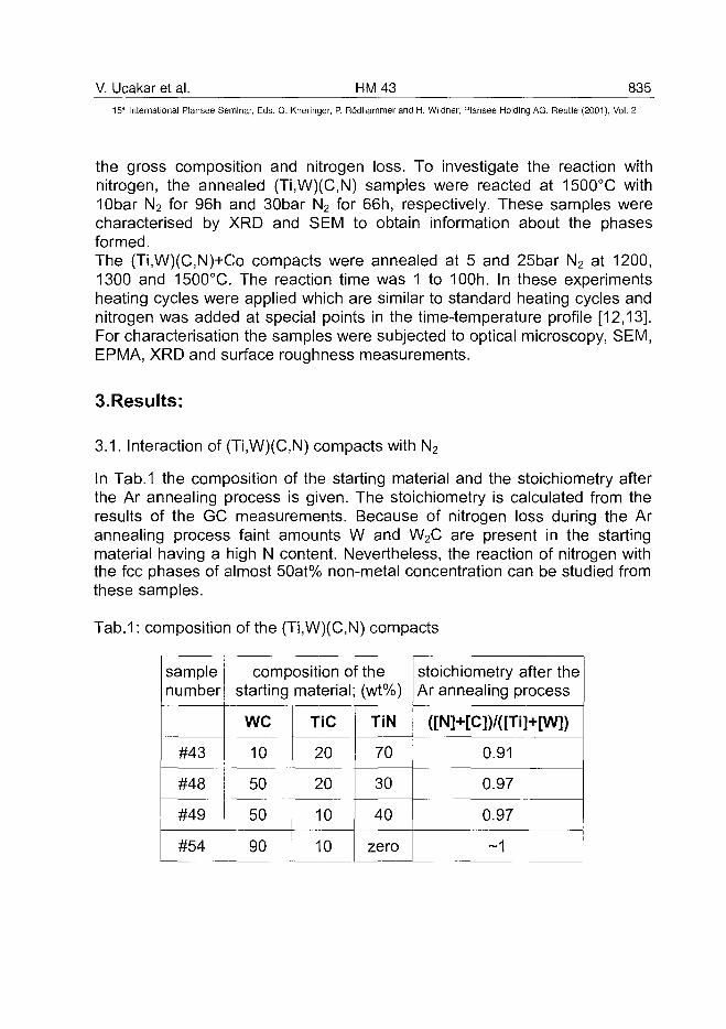
V. Ucakar et al. HM43 835
15"' International Plansee Seminar, Eds. G. Kneringer, P. Rodhammer and H. Wildner, Plansee Holding AG, Reutte (2001), Vol. 2
the gross composition and nitrogen loss. To investigate the reaction withnitrogen, the annealed (Ti,W)(C,N) samples were reacted at 1500°C with10bar N2 for 96h and 30bar N2 for 66h, respectively. These samples werecharacterised by XRD and SEM to obtain information about the phasesformed.The (Ti,W)(C,N)+Co compacts were annealed at 5 and 25bar N2 at 1200,1300 and 1500°C. The reaction time was 1 to 100h. In these experimentsheating cycles were applied which are similar to standard heating cycles andnitrogen was added at special points in the time-temperature profile [12,13].For characterisation the samples were subjected to optical microscopy, SEM,EPMA, XRD and surface roughness measurements.
3.Results:
3.1. Interaction of (Ti,W)(C,N) compacts with N2
In Tab.1 the composition of the starting material and the stoichiometry afterthe Ar annealing process is given. The stoichiometry is calculated from theresults of the GC measurements. Because of nitrogen loss during the Arannealing process faint amounts W and W2C are present in the startingmaterial having a high N content. Nevertheless, the reaction of nitrogen withthe fee phases of almost 50at% non-metal concentration can be studied fromthese samples.
Tab.1: composition of the (Ti,W)(C,N) compacts
samplenumber
#43
#48
#49
#54
composition of thestarting material; (wt%)
we
10
50
50
90
TiC
20
20
10
10
TiN
70
30
40
zero
stoichiometry after theAr annealing process
([N]+[C])/([Ti]+[W])
0.91
0.97
0.97
~1
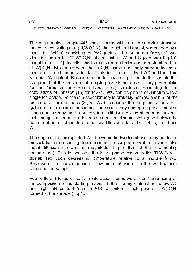
836 HM43 V. Ucakar et al.15:" International Plansee Seminar, Eds. G. Kneringer, P. Rddhammer and H. Wildner, Plansee Holding AG, Reutte (2001), Vol. 2
The Ar annealed sample #43 shows grains with a triple core-rim structure,the cores consisting of a (Ti,W)(C,N) phase rich in Ti and N, surrounded by ainner rim (white) consisting of WC grains. The outer rim (greyish) wasidentified as an fee (Ti,W)(C,N) phase, rich in W and C (compare Fig.1a).Lindahl et al. [14] describe the formation of a similar core-rim structure in a(Ti,W)(C,N)+Ni sample were the Ti(C,N) cores are partly surrounded by ainner rim formed during solid state sintering from dissolved WC and thereforewith high W content. Because no binder phase is present in the sample thisis a proof that the presence of a liquid phase is not a necessary prerequisitefor the formation of core-rim type (triple) structures. According to thecalculations of Jonsson [15] for 1427X WC can only be in equilibrium with asingle fee phase. As the sub-stoichiometry is probably not responsible for thepresence of three phases (81, 52, WC) - because the fee phases can attainquite a sub-stoichiometric composition before they undergo a phase reaction- the samples may not be entirely in equilibrium. As the nitrogen diffusion isfast enough to promote attainment of an equilibrium state (see below) thenon-equilibrium state is due to the low diffusion rate of the metals, i.e. Ti andW.
The origin of the precipitated WC between the two fee phases may be due toprecipitation upon cooling down from hot pressing temperatures (where alsometal diffusion is orders of magnitudes higher than at the re-annealingtemperature). This is because the 81+82 phase region in the Ti-W-C-N isdestabilised upon decreasing temperature relative to a mixture S+WC.Because of the above-mentioned low metal diffusion rate the two 8 phasesremain in the sample.
Four different types of surface interaction zones were found depending onthe composition of the starting material. If the starting material has a low WCand high TiN content (sample #43) a uniform single-phase (Ti,W)(C,N)formed at the surface (Fig. 1b).
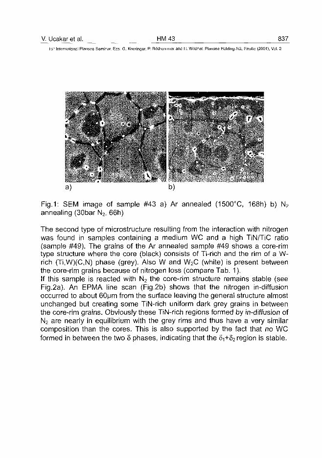
V. Ucakar et al. HM43 83715lh International Plansee Seminar, Eds. G. Kneringer, P. Rodhammer and H. Wildner, Plansee Holding AG, Reutte (2001), Vol. 2
a) b)
Fig.1: SEM image of sample #43 a) Ar annealed (1500°C, 168h) b) N2
annealing (30bar N2, 66h)
The second type of microstructure resulting from the interaction with nitrogenwas found in samples containing a medium WC and a high TiN/TiC ratio(sample #49). The grains of the Ar annealed sample #49 shows a core-rimtype structure where the core (black) consists of Ti-rich and the rim of a W-rich (Ti,W)(C,N) phase (grey). Also W and W2C (white) is present betweenthe core-rim grains because of nitrogen loss (compare Tab. 1).If this sample is reacted with N2 the core-rim structure remains stable (seeFig.2a). An EPMA line scan (Fig.2b) shows that the nitrogen in-diffusionoccurred to about 60um from the surface leaving the general structure almostunchanged but creating some TiN-rich uniform dark grey grains in betweenthe core-rim grains. Obviously these TiN-rich regions formed by in-diffusion ofN2 are nearly in equilibrium with the grey rims and thus have a very similarcomposition than the cores. This is also supported by the fact that no WCformed in between the two 8 phases, indicating that the 5i+82 region is stable.
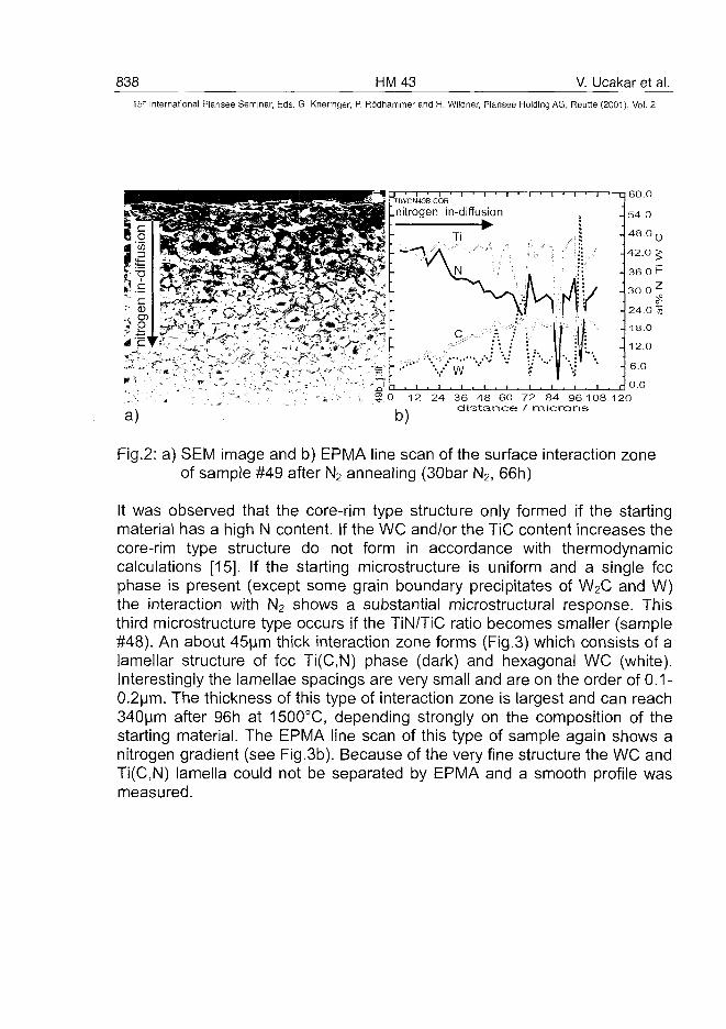
838 HM43 V. Ucakar et al.15~ International Plansee Seminar, Eds. G. Kneringer, P. Rodhammer and H. Wildner, Plansee Holding AG, Reutte (2001), Vol. 2
- - - A
TIWCN49B.COR
.nitrogen in-diffusion•
60.0
54.0
48.0 0
42.0 ^
36.0 P
30.0^
24.0 n
18.0
12.0
6.0
0 .0
12 24 36 48 60 72 84 96 108 120distance / microns
Fig.2: a) SEM image and b) EPMA line scan of the surface interaction zoneof sample #49 after N2 annealing (30bar N2, 66h)
It was observed that the core-rim type structure only formed if the startingmaterial has a high N content. If the WC and/or the TiC content increases thecore-rim type structure do not form in accordance with thermodynamiccalculations [15]. If the starting microstructure is uniform and a single feephase is present (except some grain boundary precipitates of W2C and W)the interaction with N2 shows a substantial microstructural response. Thisthird microstructure type occurs if the TiN/TiC ratio becomes smaller (sample#48). An about 45um thick interaction zone forms (Fig.3) which consists of alamellar structure of fee Ti(C,N) phase (dark) and hexagonal WC (white).Interestingly the lamellae spacings are very small and are on the order of 0.1-0.2um. The thickness of this type of interaction zone is largest and can reach340um after 96h at 1500°C, depending strongly on the composition of thestarting material. The EPMA line scan of this type of sample again shows anitrogen gradient (see Fig.3b). Because of the very fine structure the WC andTi(C,N) lamella could not be separated by EPMA and a smooth profile wasmeasured.
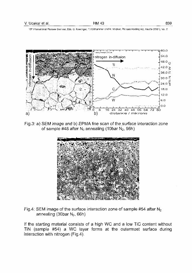
V. Ucakar et al. HM43 839
15'" International Plansee Seminar, Eds. G. Kneringer, P. Rodhammer and H. Wildner, Plansee Holding AG, Reutte (2001), Vol. 2
60.0
8 16 24 32 40 48 56 64 72 80distance / microns
Fig.3: a) SEM image and b) EPMA line scan of the.surface interaction zoneof sample #48 after N2 annealing (10bar N2, 96h)
- <• V • • * ^
Fig.4: SEM image of the surface interaction zone of sample #54 after N2
annealing (30bar N2, 66h)
If the starting material consists of a high WC and a low TiC content withoutTiN (sample #54) a WC layer forms at the outermost surface duringinteraction with nitrogen (Fig.4).
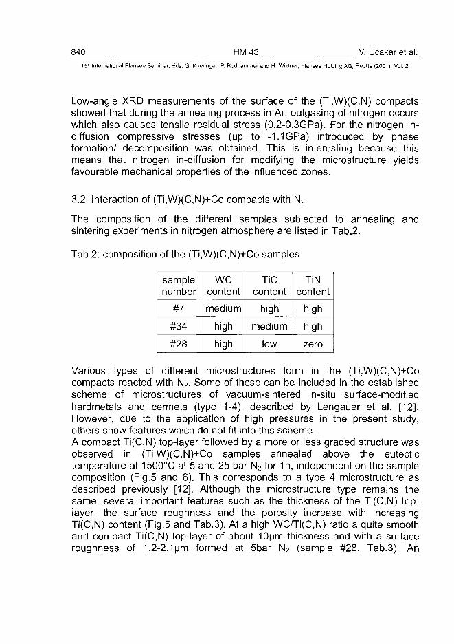
840 HM43 V. Ucakar et al.15" International Plansee Seminar, Eds. G. Kneringer, P. Rodhammer and H. Wildner, Plansee Holding AG, Reutte (2001), Vol. 2
Low-angle XRD measurements of the surface of the (Ti,W)(C,N) compactsshowed that during the annealing process in Ar, outgasing of nitrogen occurswhich also causes tensile residual stress (0.2-0.3GPa). For the nitrogen in-diffusion compressive stresses (up to -1.1 GPa) introduced by phaseformation/ decomposition was obtained. This is interesting because thismeans that nitrogen in-diffusion for modifying the microstructure yieldsfavourable mechanical properties of the influenced zones.
3.2. Interaction of (Ti,W)(C,N)+Co compacts with N2
The composition of the different samples subjected to annealing andsintering experiments in nitrogen atmosphere are listed in Tab.2.
Tab.2: composition of the (Ti,W)(C,N)+Co samples
samplenumber
#7
#34
#28
wecontent
medium
high
high
TiCcontent
high
medium
low
TiNcontent
high
high
zero
Various types of different microstructures form in the (Ti,W)(C,N)+Cocompacts reacted with N2. Some of these can be included in the establishedscheme of microstructures of vacuum-sintered in-situ surface-modifiedhardmetals and cermets (type 1-4), described by Lengauer et al. [12].However, due to the application of high pressures in the present study,others show features which do not fit into this scheme.A compact Ti(C,N) top-layer followed by a more or less graded structure wasobserved in (Ti,W)(C,N)+Co samples annealed above the eutectictemperature at 1500°C at 5 and 25 bar N2 for 1h, independent on the samplecomposition (Fig.5 and 6). This corresponds to a type 4 microstructure asdescribed previously [12]. Although the microstructure type remains thesame, several important features such as the thickness of the Ti(C,N) top-layer, the surface roughness and the porosity increase with increasingTi(C,N) content (Fig.5 and Tab.3). At a high WC/Ti(C,N) ratio a quite smoothand compact Ti(C,N) top-layer of about 10um thickness and with a surfaceroughness of 1.2-2.1 urn formed at 5bar N2 (sample #28, Tab.3). An
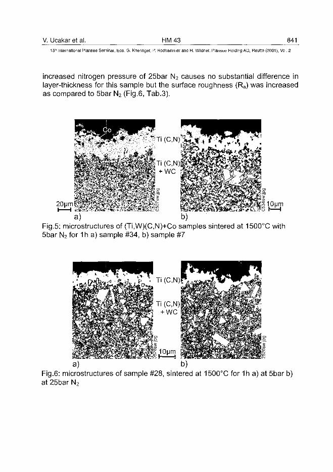
V. Ucakar et al. HM43 84115" International Plansee Seminar, Eds. G. Kneringer, P. Rodhammer and H. Wildner, Plansee Holding AG, Reutte (2001), Vol. 2
increased nitrogen pressure of 25bar N2 causes no substantial difference inlayer-thickness for this sample but the surface roughness (Ra) was increasedas compared to 5bar N2 (Fig.6, Tab.3).
10|jm
a) b)Fig.5: microstructures of (Ti,W)(C,N)+Co samples sintered at 1500°C with5bar N2 for 1 h a) sample #34, b) sample #7
a) b)Fig.6: microstructures of sample #28, sintered at 1500°C for 1h a) at 5bar b)at 25bar N2
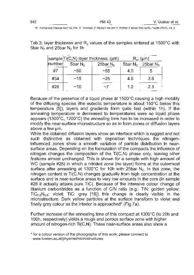
842 HM43 V. Ucakar et al.15-' International Plansee Seminar, Eds. G. Kneringer, P. Rodhammer and H. Wildner, Plansee Holding AG, Reutte (2001), Vol. 2
Tab.3: layer thickness and Ra values of the samples sintered at 1500°C with5bar N2 and 25bar N2 for 1 h
samplenumber
#7
#34
#28
Ti(C,N) layer thickness; (urn)5bar N2
-50
-15
-10
25bar N2
-55
-25
-7
Ra;5bar N2
4.5
4.6
1.2
(Mm)25bar N2
5
3.6
2.1
Because of the presence of a liquid phase at 1500°C causing a high mobilityof the diffusing species (the eutectic temperature is about 150°C below thistemperature [5]), layers and gradients form quite fast (within 1h). If theannealing temperature is decreased to temperatures were no liquid phaseappears (1300°C, 1200°C) the annealing time has to be increased in order tomodify the near-surface microstructure so as to form zones or diffusion layersabove a few urn.While the obtained diffusion layers show an interface which is rugged and notsuch distinctive as obtained with deposition techniques the nitrogen-influenced zones show a smooth variation of particle distribution in near-surface areas. Depending on the formulation of the compacts the influence ofnitrogen changes the composition of the Ti(C,N) phase only, leaving otherfeatures almost unchanged. This is shown for a sample with high amount ofWC (sample #28) in which a nitrided zone (no layer) forms at the outermostsurface after annealing at 1300°C for 10h with 25bar N2. In this zone, thenitrogen content in Ti(C,N) changes gradually from high concentration at thesurface and in near-surface areas to very low amounts in the core (in sample#28 it actually attains pure TiC). Because of the intensive colour change oftitanium carbonitrides as a function of C/N ratio (e.g.: TiN: golden yellow;TiC0.2N0.8: violet; TiC: grey [16]) this change is clearly visible in themicrostructure. Dark yellow particles at the surface transform to violet andfinally grey colour as the interior is approached* (Fig.7a).
Further increase of the annealing time of this compact at 1300°C (to 20h and100h, respectively) yields a rough and porous surface zone with higheramount of nitrogen-rich Ti(C,N). These near-surface areas also show a
* for a colour version of the photographs of this work, please connect towww.tuwien.ac.at/physmet/microstructures
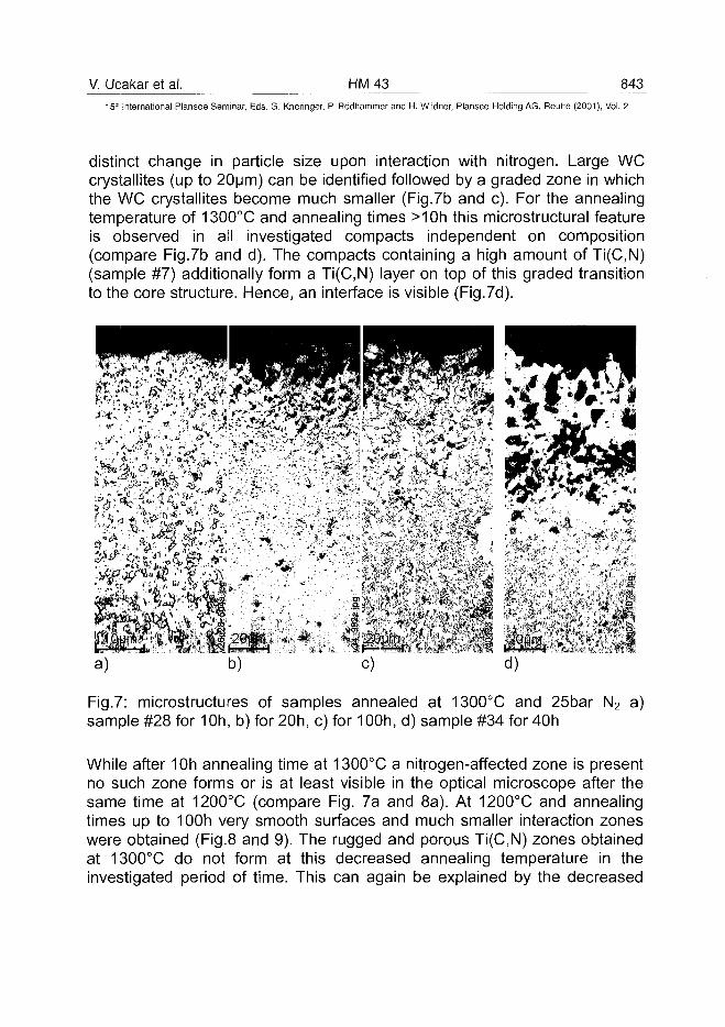
V. Ucakar et al. HM43 84315lh International Plansee Seminar, Eds. G. Kneringer, P. Rodhammer and H. Wildner, Plansee Holding AG, Reutte (2001), Vol. 2
distinct change in particle size upon interaction with nitrogen. Large WCcrystallites (up to 20um) can be identified followed by a graded zone in whichthe WC crystallites become much smaller (Fig.7b and c). For the annealingtemperature of 1300°C and annealing times >10h this microstructural featureis observed in all investigated compacts independent on composition(compare Fig.7b and d). The compacts containing a high amount of Ti(C,N)(sample #7) additionally form a Ti(C,N) layer on top of this graded transitionto the core structure. Hence, an interface is visible (Fig.7d).
b) c) d)
Fig.7: microstructures of samples annealed at 1300°C and 25bar N2 a)sample #28 for 10h, b) for 20h, c) for 10Oh, d) sample #34 for 40h
While after 10h annealing time at 1300°C a nitrogen-affected zone is presentno such zone forms or is at least visible in the optical microscope after thesame time at 1200°C (compare Fig. 7a and 8a). At 1200°C and annealingtimes up to 100h very smooth surfaces and much smaller interaction zoneswere obtained (Fig.8 and 9). The rugged and porous Ti(C,N) zones obtainedat 1300°C do not form at this decreased annealing temperature in theinvestigated period of time. This can again be explained by the decreased
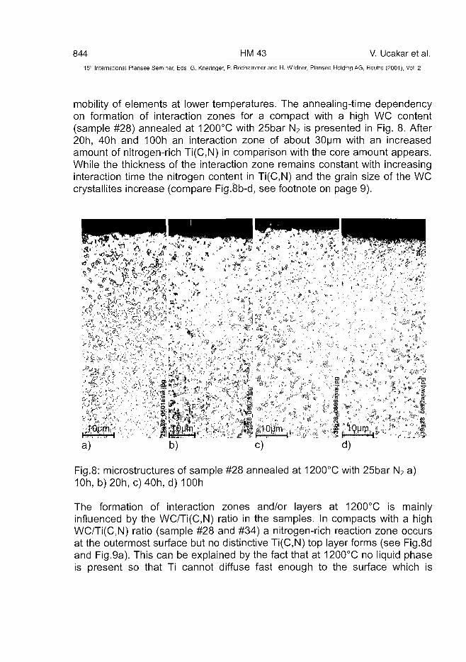
844 HM43 V. Ucakar et al.Sn International Plansee Seminar, Eds. G. Kneringer, P. Rodhammer and H. Wildner, Plansee Holding AG, Reutte (2001), Vol. 2
mobility of elements at lower temperatures. The annealing-time dependencyon formation of interaction zones for a compact with a high WC content(sample #28) annealed at 1200°C with 25bar N2 is presented in Fig. 8. After20h, 40h and 100h an interaction zone of about 30um with an increasedamount of nitrogen-rich Ti(C,N) in comparison with the core amount appears.While the thickness of the interaction zone remains constant with increasinginteraction time the nitrogen content in Ti(C,N) and the grain size of the WCcrystallites increase (compare Fig.8b-d, see footnote on page 9).
Fig.8: microstructures of sample #28 annealed at 1200°C with 25bar N2 a)10h, b)20h, c)40h, d) 100h
The formation of interaction zones and/or layers at 1200°C is mainlyinfluenced by the WC/Ti(C,N) ratio in the samples. In compacts with a highWC/Ti(C,N) ratio (sample #28 and #34) a nitrogen-rich reaction zone occursat the outermost surface but no distinctive Ti(C,N) top layer forms (see Fig.8dand Fig.9a). This can be explained by the fact that at 1200°C no liquid phaseis present so that Ti cannot diffuse fast enough to the surface which is
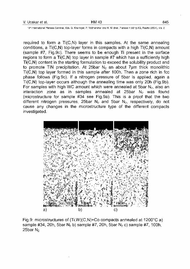
V. Ucakar et al. HM43 84515th International Plansee Seminar, Eds. G. Kneringer, P. Rodhammer and H. Wildner, Plansee Holding AG, Reutte (2001), Vol. 2
required to form a Ti(C,N) layer in this samples. At the same annealingconditions, a Ti(C,N) top-layer forms in compacts with a high Ti(C,N) amount(sample #7, Fig.9c). There seems to be enough Ti present in the surfaceregions to form a Ti(C,N) top layer in sample #7 which has a sufficiently highTi(C,N) content in the starting formulation to exceed the solubility product andto promote TiN precipitation. At 25bar N2 an about 7um thick monolithicTi(C,N) top layer formed in this sample after 100h. Then a zone rich in feephase follows (Fig.9c). If a nitrogen pressure of 5bar is applied, again aTi(C,N) top-layer occurs although the annealing time was only 20h (Fig.9b).For samples with high WC amount which were annealed at 5bar N2, also aninteraction zone as in samples annealed at 25bar N2 was found(microstructure for sample #34 see Fig.9a). This is a proof that the twodifferent nitrogen pressures, 25bar N2 and 5bar N2, respectively, do notcause any changes in the microstructure type of the different compactsinvestigated.
b) c)
Fig.9: microstructures of (Ti,W)(C,N)+Co compacts annealed at 1200°C a)sample #34, 20h, 5bar N2 b) sample #7, 20h, 5bar N2 c) sample #7, 100h,25bar N2
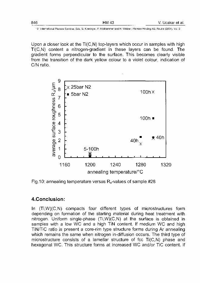
846 HM43 V. Ucakar et al.15" International Plansee Seminar, Eds. G. Kneringer, P. Rodhammer and H. Wildner, Plansee Holding AG, Reutte (2001), Vol. 2
Upon a closer look at the Ti(C,N) top-layers which occur in samples with highTi(C,N) content a nitrogen-gradient in these layers can be found. Thegradient forms perpendicular to the surface. This becomes clearly visiblefrom the transition of the dark yellow colour to a violet colour, indication ofC/N ratio.
E9
orco 7CO
JeO5 _
8 4
CD
CO
03
jj> 103 0
"X 25bar N2
i 5bar N2 100hX
100h
40h* 4 0 h
X5-1 OOh
1160 1200 1240 1280
annealing temperature/°C
Fig.10: annealing temperature versus Revalues of sample #28
1320
4.Conclusion:
In (Ti,W)(C,N) compacts four different types of microstructures formdepending on formation of the starting material during heat treatment withnitrogen. Uniform single-phase (Ti,W)(C,N) at the surface is obtained insamples with a low WC and a high TiN content. If medium WC and highTiN/TiC ratio is present a core-rim type structure forms during Ar annealingwhich remains the same when nitrogen in-diffusion occurs. The third type ofmicrostructure consists of a lamellar structure of fee Ti(C,N) phase andhexagonal WC. This structure forms at increased WC and/or TiC content. If
V. Ucakar et al. HM 43 847_
15'* International Plansee Seminar, Eds. G. Kneringer, P. Rodhammer and H. Wildner, Plansee Holding AG, Reutte (2001), Vol. 2
the WC content is increased again a WC layer forms at the outermostsurface.(Ti,W)(C,N)+Co compacts modified with high-pressure nitrogen either form acompact Ti(C,N) top-layer and/or an interaction zone. Above the eutectictemperature compact Ti(C,N) top-layers independent on sample compositionwere observed. Below the eutectic temperature the microstructure formationis mainly influenced by the sample composition. A Ti(C,N) top layer forms in(Ti,W)(C,N)+Co compacts with a high Ti(C,N) content. Contrary, interactionzones without a layer were obtained in compacts with high WC/Ti(C,N) ratio.These interaction zones show a smooth variation of particle distribution innear surface areas. The two different nitrogen pressure applied, 25bar N2
and 5bar N2, respectively cause no substantial difference in themicrostructure type for all investigated temperatures.It was observed that the surface roughness increases with increasingannealing temperature and/or annealing time or nitrogen pressure. The Ra
values of one (Ti,W)(C,N)+Co compact (sample #28) are presented in Fig 10.The surface roughness plays an important role in the cutting performance ofindexable inserts. Some of the structures formed below the eutectictemperature show surface roughness lower than 0.5um and therefore as lowas the roughness of deposited layers. Although some nitrogen-reactedcompacts show features, such as rugged and porous influence zones and bigWC crystallites, which make them not suitable for use in metal cuttingoperations,Some microstructural features were observed which are very interesting forthe development of new gradient types formed by diffusional in-situ surfacemodification. They show surfaces and particle sizes favourable for a cuttingtool. The low temperatures of solid-state modification of these compactsallow not only the formation of zones with changing particle composition butalso the formation of graded interlocked layers (e.g. TiN-Ti(C,N)-TiC).
5. References:
[1] K. Tsuda, A. Ikegaya, K. Isobe, N. Kitagawa, T. Nomura: PowderMetallurgy 39 (4) (1996), pp. 296-300
[2] A. Neubrand, J. Rbdel: Z. Metal Ik. 88 (5) (1997), pp. 358-371
[3] P. Ettmayer, H. Kolaska, W. Lengauer, K. Dreyer: Int. J. Ref. Met. &Hard Mater. 13 (1995), pp. 343-351
848 HM 43 V. Ucakar et al.
15" International Plansee Seminar, Eds. G. Kneringer, P. Rödhammer and H. Wildner, Plansee Holding AG, Reutte (2001), Vol. 2
[4] C. Colin, L. Durant, N. Favrot, J. Besson, G. Barbier, F. Delannay: Int.J. Ref. Met. & Hard Mater. 12 (1993-1994), pp. 145-151
[5] L. Chen, W. Lengauer and K. Dreyer: Proc. Euro PM 99 (1999), pp.463-473
[6] J. Garcia, W. Lengauer, I. Smid, K. Dreyer, D. Kassel, H.-W. Daub:Proc. PM2tec. 30.5.-3.6. 2000, New York, USA, CD edition
[7] M. Schwarzkopf, E. Exner, H. F. Fischmeister, W. Schintlmeister:Mater. Sci. Eng. A105/106 (1988), pp. 225-231
[8] P. Gustafson, A. Östlund: Proc. 13th Int. Plansee Seminar 2 (1993), pp.537-552
[9] M. Ekroth, R. Frykholm, M. Lindholm, H.-O. Andren, J. Ågren: ActaMater. 48 (2000), pp2177-2185
[10] J. Zackrisson, U. Rolander, B. Janson, H.-O. Andren: Acta Mater 48(2000), pp. 4281-4291
[11] H.-O. Andren: Mater. Chem. and Phys. 67 (2001), pp. 209-213
[12] W. Lengauer, J. Garcia, V. Ucakar, L. Chen, K. Dreyer, D. Kassel, H.-W. Daub: Proc.PM2tec, Vancouver, Vol.3, part 10, (1999), pp. 85-96
[13] W. Lengauer, J. Garcia, K. Dreyer, I. Smid, D. Kassel, H.-W. Daub, G.Korb and L. Chen: Proc. Euro PM'99, Turin, (1999), pp. 475-482
[14] P. Lindahl, P. Gustafson, U. Rolander, L. Stals, H.-O. Andrén: Int. J. ofRef. Metals & Mater. 17 (1999), pp. 411-421
[15] S.Jonsson: PhD Thesis, Stockholm, Sweden: Royal Institute ofTechnology, (1993)
[16] W. Lengauer: in "Handbook of Ceramic Hard Materials Vol.1" (WILEY-VCH Verlag, Weinheim, 2000), pp.202-252
ATO100501V. Richter et al. HM 53 849^
15" International Plansee Seminar, Eds. G. Kneringer, P. Rödhammer and H. Wildner, Plansee Holding AG, Reutte (2001), Vol. 2
Gradient Structures in Hardmetals
V. Richter, M. von Ruthendorf
Fraunhofer Institut IKTS, Winterbergstraße 28, D - 01277 Dresden, Germany
Zusammenfassung
Gradientenhartmetalle ermöglichen Kombinationen von Eigenschaften wieHärte und Bruchzähigkeit, die mit homogenen Werkstoffen nicht erreichtwerden können. Die Ausbildung von Gradienten in Hartmetallen korreliert mitder Migration von Bindemetall, die von Unterschieden in der Zusammenset-zung des Preßgranulates sowie von der Hartstoffteilchengröße und derenVerteilung abhängig ist. Um die Gradientenbildung zu untersuchen, wurdenHartmetallproben aus unterschiedlich feinkörnigen WC-Pulvern mit variablenZusatzmengen von Cobalt und Ruß hergestellt. Neben Standard-Biegebruchstäben wurden Zweischichtverbunde durch Aufeinanderpressenvon Granulaten mit unterschiedlichem Co-Gehalt und unterschiedlicherKorngröße hergestellt. Die Verdichtung der Preß- und Sinterproben wurdebestimmt und die magnetischen und mechanischen Eigenschaften der Sin-terkörper gemessen. An dichten Verbundproben erfolgte die Aufnahme derKonzentrationsprofile von Co, C und W parallel zur Preßrichtung über die ge-samte Probenlänge (>10 mm) mittels ESMA. In gleicher Richtung wurdenHärte und Bruchzähigkeit ortsabhängig gemessen. Bei gegebener Hartme-tallzusammensetzung ist die sich ausbildende Gradientenstruktur abhängigvon den Hartstoffteilchengrößen, den Nichtmetallgehalten (Kohlenstoff, Sau-erstoff) und auch von Verunreinigungselementen im ppm-Bereich (Beeinflus-sung der Benetzungs- und Löslichkeitsverhältnisse). Die Ergebnisse zeigen,daß Unterschiede im Co- und C-Gehalt zur Co-Migration in Richtung desniedrigeren Gehaltes führt. Bei Unterschieden in der Hartstoffkorngrößewandert das Bindemetall grundsätzlich in Richtung der feinkörnigeren Hart-stoffmatrix. Es war möglich, Co-Gradienten in den WC-Co-Verbunden bis zu10 mm Dicke reproduzierbar einzustellen. Dabei wurden Härteunterschiedebis 500 Vickers-Einheiten (HV10) gemessen.
850 HM53 V. Richter et al.15* International Plansee Seminar, Eds. G. Kneringer, P. Rodhammer and H. Wildner, Plansee Holding AG, Reutte (2001), Vol. 2
Summary
Functionally graded materials enable combinations of properties like hard-ness and toughness that can not be achieved with homogeneous materials.The formation of gradients in tungsten carbides correlates with the migrationof binder which is caused by differences in the composition of the greenbody, gas-phase treatment during sintering or the mean particle size and par-ticle-size distribution of the hard phase. In order to examine the gradient for-mation fracture bars were made of differently fine-grained WC powders andvariable additions of Co and carbon black. Beside homogeneous samplestwo-layer samples were manufactured by step-wise pressing of powders withdifferent composition and/or grain size. The densification behaviour of thegreen bodies and the magnetic and mechanical properties of the sinteredcompacts were measured. On two-layer samples with full density the concen-tration profiles of Co, C and W was determined parallel to the pressing direc-tion over the entire sample height (< 10 mm) by ESMA. Additionally, hard-ness and fracture toughness were measured along this line. Differences incobalt contents are rapidly homogenised in liquid-phase sintering. But largeCo gradients can be generated by differences in particle sizes of the hardphase, the non-metal content (carbon, oxygen) and impurities in the ppmrange (influence of the wetting and solubility conditions). After sintering thebinder content of the finer grained layer is generally higher than in thecoarser layer independent of the starting composition. In two-layer samplesCo gradients up to 10 mm in thickness and hardness differences to 500 units(HV10) could be produced.
Keywords: WC-Co hardmetal, functionally graded materials, layer samplesmigration of Co, effect of grain size and carbon content
V. Richter et al. HM 53 851
15" International Plansee Seminar, Eds. G. Kneringer, P. Rödhammer and H. Wildner, Plansee Holding AG, Reutte (2001), Vol. 2
1. Einführung
Wie aus dem Schrifttum hervorgeht, ist die Ausbildung von Gradientenstruk-turen in Hartmetallen vielfach untersucht worden. Das Ziel ist, für die jeweili-ge Anwendung günstige Oberflächenbereiche mit bestimmten Eigenschaftenherzustellen, ungleichmäßig ausgebildete rauhe Oberflächen zu vermeidenoder eine anwendungsgerechte Eigenschaftsgradierung über das gesamteBauteil zu erzeugen. Dabei wurde die Ausbildung zäher Randzonen auf WC-TiC-TiN-Co und WC-(W,Ti)(N,C)-Co während des Vakuumsinterns, die mitCo angereichert und frei von kubischen Carbiden sind, umfassend theore-tisch untersucht (1,2) und bereits in die Praxis eingeführt. Die Dicke derRandzone, mit der die Zähigkeit steigt, ist praktisch auf etwa 50 um begrenzt.Inzwischen ist es möglich, die bei der Oberflächengradierung innerhalb dessinternden Materials ablaufenden Diffusionsvorgänge durch definiertes Ein-führen von Gasen während des Sintems zu steuern (3),(4). Binderreiche O-berflächenschichten lassen sich auf WC-Co durch entkohlendes Ausheizenund Sintern auch ohne Anwesenheit von Stickstoff herstellen (4). Wesentlichaugedehntere Gradienten wurden in WC-Co-Hartmetallen durch Infiltrierenvorgesinterter Proben mit flüssigem Bindemetall (5,6) oder durch Sintern vonSchichtverbundteilen mit variablem Co-Gehalt (7,8,10) erzeugt. Beim Infiltrie-ren und Sintern von Schichtverbunden wurde von einigen Autoren ein sehrgroßer Einfluß unterschiedlicher Hartstoffteilchengrößen beobachtet (5,8,9).Die Migration des flüssigen Bindemetalls kann zu Porosität und Verzug(7,10) der Sinterteile führen. Mit den im vorliegenden Beitrag dargestelltenArbeiten sollte untersucht werden, ob eine reproduzierbare Einstellung vonCo-Gradienten mit so großer Ausdehnung möglich ist, daß auch die Eigen-schaften in Hartmetallteilen gradiert werden können, ohne die Hartmetallqua-lität einzuschränken.
2. Experimentelles
Tabelle 1 enthält die Eigenschaften der eingesetzten Pulver im oberen Teilund die Verunreinigungsgehalte der WC-Pulver (Massenspektroskopie) imunteren Teil. Die BET-Werte sind mittels Stickstoffadsorption (ASAP 2000),die Nichtmetallgehalte mittels LECO-Geräten und die Teilchengrößenvertei-lung mittels Laserbeugung im MASTER SIZER (Malvern) gemessen worden.Die Teilchengrößenverteilung der WC-Pulver enthält Bild 1.
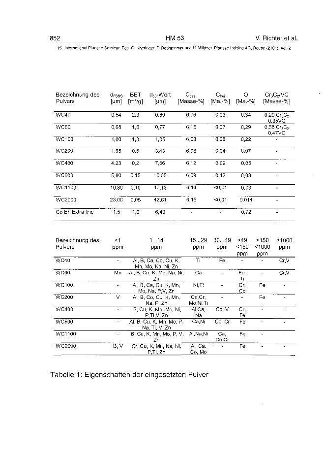
852 HM53 V. Richter et al.5'" International Plansee Seminar, Eds. G. Kneringer, P. Rodhammer and H. Wildner, Plansee Holding AG, Reutte (2001), Vol. 2
Bezeichnung des dFsss BET d5o-Wert Cfrei o Cr3C2A/CPulvers [Mm] [m2/g] [Mm] [Masse-%] [Ma.-%] [Ma.-%] [Masse-%]
WC40
WC60
WC100
WC200
WC400
WC600
WC1100
WC2000
Co EF Extra fine
0,54
0,68
1,00
1,95
4,23
5,80
10,80
23,00
1,5
2,3
1,6
1,3
0,5
0,2
0,15
0,10
0,05
1,0
0,69
0,77
1,05
3,43
7,66
10,05
17,13
42,61
6,40
6,06
6,15
6,08
6,08
6,12
6,09
6,14
6,15
-
0,03
0,07
0,08
0,04
0,09
0,12
<0,01
<0,01
-
0,34
0,29
0,22
0,07
0,05
0,03
0,03
0,014
0,72
0,29 Cr3C2
0.35VC0,58 Cr3C2
0.47VC-
-
-
-
-
-
-
Bezeichnung des <1 1 ...14Pulvers ppm ppm
15...29 30...49 >49 >150 >1000ppm ppm <150 <1000 ppm
ppm ppmWC40
WC60
WC100
WC200
WC400
WC600
WC1100
WC2000
Al, B, Ca, Co, Cu, K,Mn, Mo, Na, Ni, Zn
Mn Al, B, Cu, K, Mo, Na, Ni,Zn
Al, B, Ca, Cu, K, Mn,Mo, Na, P,V, Zn
V Al, B, Co, Cu, K, Mn,Na, P, Zn
B, Cu, K, Mn, Mo, Ni,P,Ti,V, Zn
Al, B, Cu, K, Mn, Mo, P,Na, Ti, V, Zn
B, Cu, K, Mn, Mo, P, V,Zn
B, V Cr, Cu, K, Mn, Na, Ni,P,Ti, Zn
Ti
Ca
Ni.Ti
Ca.Cr,Mo,Ni,TiAl.Ca,
NaCa.Ni
AI.Na.Ni
Al, Ca,Co, Mo
Fe
-
-
-
Co, V
Co, Cr
Ca,Co.Cr
-
-
Fe,TiCr,Co-
Cr,FeFe
Fe
Fe
-
-
Fe
Fe
-
-
-
-
Cr,V
Cr,V
-
-
-
-
-
-
Tabelle 1: Eigenschaften der eingesetzten Pulver
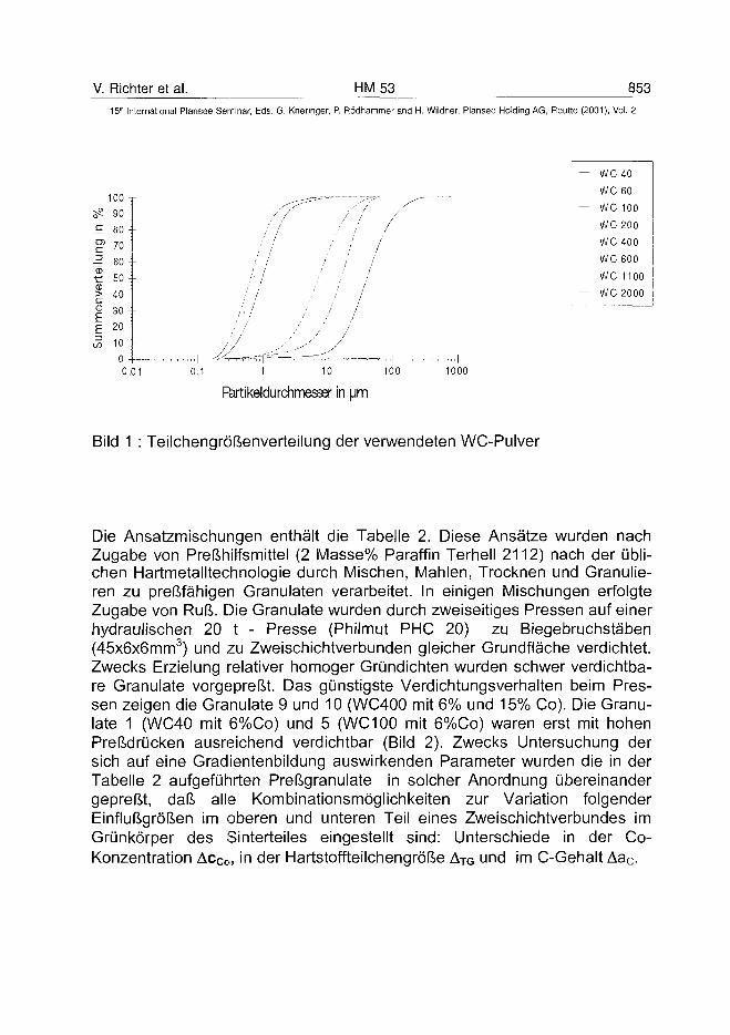
V. Richter et al. HM 53 853
15* International Plansee Seminar, Eds. G. Kneringer, P. Rödhammer and H. Wildner, Plansee Holding AG, Relitte (2001), Vol. 2
100 j
5? 90 --
.E 80 -~
70 J-O)
-= 60 --
r 50 --
> 40 --
£ 30 --£ 20 J-
œ 10 H
0 4- -0.01 0.1 10 100 1000
Fàrtikeldurchmesœr in |jm
Bild 1 : Teilchengrößenverteilung der verwendeten WC-Pulver
— wcWC
— wcWC
----- wcWC
— wc— wc
40
60
100
200
400
600
1100
2000
Die Ansatzmischungen enthält die Tabelle 2. Diese Ansätze wurden nachZugabe von Preßhilfsmittel (2 Masse% Paraffin Terhell 2112) nach der übli-chen Hartmetalltechnologie durch Mischen, Mahlen, Trocknen und Granulie-ren zu preßfähigen Granulaten verarbeitet. In einigen Mischungen erfolgteZugabe von Ruß. Die Granulate wurden durch zweiseitiges Pressen auf einerhydraulischen 20 t - Presse (Philmut PHC 20) zu Biegebruchstäben(45x6x6mm3) und zu Zweischichtverbunden gleicher Grundfläche verdichtet.Zwecks Erzielung relativer homoger Gründichten wurden schwer verdichtba-re Granulate vorgepreßt. Das günstigste Verdichtungsverhalten beim Pres-sen zeigen die Granulate 9 und 10 (WC400 mit 6% und 15% Co). Die Granu-late 1 (WC40 mit 6%Co) und 5 (WC100 mit 6%Co) waren erst mit hohenPreßdrücken ausreichend verdichtbar (Bild 2). Zwecks Untersuchung dersich auf eine Gradientenbildung auswirkenden Parameter wurden die in derTabelle 2 aufgeführten Preßgranulate in solcher Anordnung übereinandergepreßt, daß alle Kombinationsmöglichkeiten zur Variation folgenderEinflußgrößen im oberen und unteren Teil eines Zweischichtverbundes imGrünkörper des Sinterteiles eingestellt sind: Unterschiede in der Co-Konzentration AcCo, in der Hartstoffteilchengröße ATG und im C-Gehalt Aac.
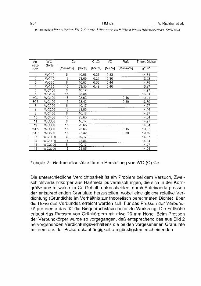
854 HM 53 V. Richter et al.15" International Plansee Seminar, Eds. G. Kneringer, P. Rödhammer and H. Wildner, Plansee Holding AG, Reutte (2001), Vol. 2
An-satz-Bez.
123456
6C26C3
789101112
12C212C3
13141516
WC-Sorte .
WC40WC40WC60WC60WC100WC100WC100WC100WC200WC200WC400WC400WC600WC600WC600WC600WC1100WC1100WC2000WC2000
Co
[Masse%]
61561561515156156156151515615615
[Vol%]
10,0823,6610,0323,5610,1723,8523,6323,4210,1723,8510,1723,8510,1723,8523,6323,4210,1723,8510,1723,85
Cr3C2
[Ma.%]
0,270,250,550,49
VC
[Ma.%]
0,330,300,440,40
Ruß
[Masse%]
0,150,30
0,150,30
Theor. Dichte
g/cm0
14,8413,9314,7613,8714,9714,0413,9113,7914,9714,0414,9714,0414,9714,0413,9113,7914,9714,0414,9714,04
Tabelle 2 : Hartmetallansätze für die Herstellung von WC-(C)-Co
Die unterschiedliche Verdichtbarkeit ist ein Problem bei dem Versuch, Zwei-schichtverbundkörper aus Hartmetallpulvermischungen, die sich in der Korn-größe und teilweise im Co-Gehalt unterscheiden, durch Aufeinanderpressender entsprechenden Granulate herzustellen, wobei eine gleiche relative Ver-dichtung (Gründichte im Verhältnis zur theoretisch berechneten Dichte) überdie Höhe des Verbundes erreicht werden soll. Für das Pressen der Verbund-körper diente das für die Biegebruchstäbe benutzte Werkzeug. Die Füllhöheerlaubt das Pressen von Grünkörpern mit etwa 20 mm Höhe. Beim Pressender Verbundkörper wurde so vorgegangen, daß entsprechend des aus Bild 2hervorgehenden Verdichtungsverhaltens die beiden vorgesehenen Granulatemit dem aus der Preßdruckabhängigkeit am günstigsten erscheinenden
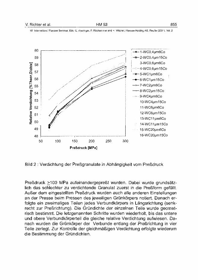
V. Richter et al. HM 53 85515" International Plansee Seminar, Eds. G. Kneringer, P. Rödhammer and H. Wildner, Plansee Holding AG, Reutte (2001), Vol. 2
50
-^1-WC0,4|jm6Co
-a^2-WC0,4|jm15Co
3-WC0,6|jm6Co
;••-- 4-WC0,6|jm15Co
-*-5-WC1|jm6Co
-•-e-WClijnniSCo
-+-7-WC2|jm6Co
— 8-WC2|jm15Co
9-WC4|jm6Co
10-WC4(jm15Co
n-wceijmeco^-WCeijmiöCo
13-WC11|jnn6Co
: 14-WC11|jm15Co
15-WC20|jm6Co
16-WC20|jm15Co
100 150 200
Preßdruck [MPa]
250
Bild 2 : Verdichtung der Preßgranulate in Abhängigkeit vom Preßdruck
Preßdruck >100 MPa aufeinandergepreßt wurden. Dabei wurde grundsätz-lich das schlechter zu verdichtende Granulat zuerst in die Preßform gefüllt.Außer dem eingestellten Preßdruck wurden auch alle anderen Einstellungenan der Presse beim Pressen des jeweiligen Grünkörpers notiert. Danach er-folgte ein zweimaliges Teilen jedes Verbundkörpers in Längsrichtung (senk-recht zur Preßrichtung). Die Gründichte der einzelnen Teile wurde geomet-risch bestimmt. Die letzgenannten Schritte wurden wiederholt, bis das untereund obere Verbundkörperteil die gleiche relative Verdichtung aufwiesen. Da-nach wurden die Grünkörper der Verbünde entlang der Preßrichtung in vierTeile zerlegt. Zur Kontrolle der gleichmäßigen Verdichtung erfolgte wiederumdie Bestimmung der Gründichten.
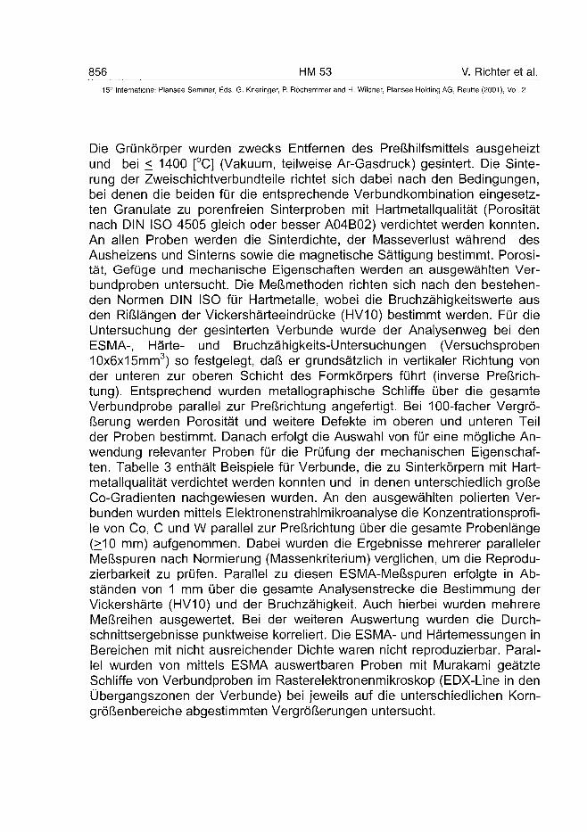
856 HM 53 V. Richter et al.
15" International Plansee Seminar, Eds. G. Kneringer, P. Rödhammer and H. Wildner, Plansee Holding AG, Reutte (2001), Vol. 2
Die Grünkörper wurden zwecks Entfernen des Preßhilfsmittels ausgeheiztund bei < 1400 [°C] (Vakuum, teilweise Ar-Gasdruck) gesintert. Die Sinte-rung der Zweischichtverbundteile richtet sich dabei nach den Bedingungen,bei denen die beiden für die entsprechende Verbundkombination eingesetz-ten Granulate zu porenfreien Sinterproben mit Hartmetallqualität (Porositätnach DIN ISO 4505 gleich oder besser A04B02) verdichtet werden konnten.An allen Proben werden die Sinterdichte, der Masseverlust während desAusheizens und Sinterns sowie die magnetische Sättigung bestimmt. Porosi-tät, Gefüge und mechanische Eigenschaften werden an ausgewählten Ver-bundproben untersucht. Die Meßmethoden richten sich nach den bestehen-den Normen DIN ISO für Hartmetalle, wobei die Bruchzähigkeitswerte ausden Rißlängen der Vickershärteeindrücke (HV10) bestimmt werden. Für dieUntersuchung der gesinterten Verbünde wurde der Analysenweg bei denESMA-, Härte- und Bruchzähigkeits-Untersuchungen (Versuchsproben10x6x15mm3) so festgelegt, daß er grundsätzlich in vertikaler Richtung vonder unteren zur oberen Schicht des Formkörpers führt (inverse Preßrich-tung). Entsprechend wurden metallographische Schliffe über die gesamteVerbundprobe parallel zur Preßrichtung angefertigt. Bei 100-facher Vergrö-ßerung werden Porosität und weitere Defekte im oberen und unteren Teilder Proben bestimmt. Danach erfolgt die Auswahl von für eine mögliche An-wendung relevanter Proben für die Prüfung der mechanischen Eigenschaf-ten. Tabelle 3 enthält Beispiele für Verbünde, die zu Sinterkörpern mit Hart-metallqualität verdichtet werden konnten und in denen unterschiedlich großeCo-Gradienten nachgewiesen wurden. An den ausgewählten polierten Ver-bunden wurden mittels Elektronenstrahlmikroanalyse die Konzentrationsprofi-le von Co, C und W parallel zur Preßrichtung über die gesamte Probenlänge(>10 mm) aufgenommen. Dabei wurden die Ergebnisse mehrerer parallelerMeßspuren nach Normierung (Massenkriterium) verglichen, um die Reprodu-zierbarkeit zu prüfen. Parallel zu diesen ESMA-Meßspuren erfolgte in Ab-ständen von 1 mm über die gesamte Analysenstrecke die Bestimmung derVickershärte (HV10) und der Bruchzähigkeit. Auch hierbei wurden mehrereMeßreihen ausgewertet. Bei der weiteren Auswertung wurden die Durch-schnittsergebnisse punktweise korreliert. Die ESMA- und Härtemessungen inBereichen mit nicht ausreichender Dichte waren nicht reproduzierbar. Paral-lel wurden von mittels ESMA auswertbaren Proben mit Murakami geätzteSchliffe von Verbundproben im Rasterelektronenmikroskop (EDX-Line in denÜbergangszonen der Verbünde) bei jeweils auf die unterschiedlichen Korn-größenbereiche abgestimmten Vergrößerungen untersucht.
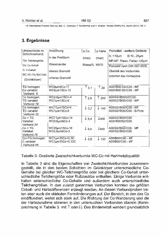
V. Richter et al. HM 53 857
15" International Plansee Seminar, Eds. G. Kneringer, P. Rödhammer and H. Wildner, Plansee Holding AG, Reutte (2001), Vol. 2
3. Ergebnisse
Unterschiede imSchichtverbund:
TG: Teilchengröße
Co: Co-Gehalt
C: C-Gehalt
MC:TiC-/Ta,NbC-Geh.
(Grünkörper)
TG homogenCo variabelVerbund 6Co homogenTG variabelVerbund 18Co homogenTG variabelVerbund 22Co + TGVariabelVerbund 24Co + TGVariabelVerbund 25Co+TG homogenC variabelVerbund 44
Anordnung
in der Preßform
übereinander
oberes Granulat
unteres Granulat
WC6um6Co-11WC6um15Co-12
WC0,6um15Co-4WC1um15Co-6
WC11um15Co14WC1um15Co-6
WCHum-loCo-MWC0,6um6Co-3
WC20|jm15Co-16WC0,6um6Co-3
WC1um15Co+0,3CWC1um15Co+0,15C
A Co
(max)
Masse%
T 3,1
T 2,6
i 3,7
i 6,4
•i 6,6
i 3,8
A Härte
(max)
HV10
t 20
Î250
4- 140
Ì400
Ì500
i 130
Porosität - weitere Defekte
A: <10um B:10...25um
MP,MF: Poren, Fehler >25um
Porosität nach DIN ISO 4505:
Oberteil des Verbundes
Unterteil des Verbundes
A00//B00-02//C00 - MFA00//B00-02//C00 - MF
A00/02//B00/02//C00A00/02//B00//C00 - MP
A00/02//B00//C00 - MFA00/02//B00//C00 - B-Pore
A00/02//B00//C00A02//B00/02//C00
A00/02//B02//C00 - MFA00/02//B00//C00
AOO/BOO/COO - MFAOO/BOO/COO - MF
Tabelle 3: Gradierte Zweischichtverbunde WC-Co mit Hartmetallqualität
In Tabelle 3 sind die Eigenschaften von Zweischichtverbunden zusammen-gestellt, die in den beiden Schichten im Grünkörper unterschiedliche Co-Gehalte bei gleicher WC-Teilchengröße oder bei gleichem Co-Gehalt unter-schiedliche Teilchengröße oder Rußzusätze enthalten. Einige Verbünde ent-halten unterschiedliche Co-Gehalte und außerdem auch unterschiedlicheTeilchengrößen. In den zuletzt genannten Verbunden konnten die größtenCobalt- und Härtedifferenzen erzeugt werden. An diesen Verbundproben tre-ten aber auch die stärksten Formänderungen auf. Der Bereich, in den das Coeindiffundiert, weitet sich stark auf. Die Richtung der Co-Wanderung und dieder Härtezunahme stimmen in den untersuchten Verbunden überein (Kenn-zeichnung in Tabelle 3 mit T odei\l). Das Bindemetall wandert grundsätzlich
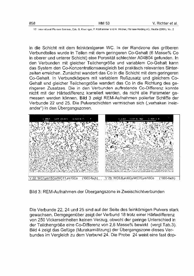
858 HM 53 V. Richter et al.
15" International Plansee Seminar, Eds. G. Kneringer, P. Rödhammer and H. Wildner, Plansee Holding AG, Reutte (2001), Vol. 2
in die Schicht mit dem feinkörnigeren WC. In der Randzone des gröberenVerbundteiles wurde in Teilen mit dem geringeren Co-Gehalt (6 Masse% Coin oberer und unterer Schicht) eine Porosität schlechter A04B04 gefunden. Inden Verbunden mit gleicher Teilchengröße und variablem Co-Gehalt kanndas System den Co-Konzentrationsausgleich bei praktisch relevanten Sinter-zeiten erreichen. Zunächst wandert das Co in die Schicht mit dem geringerenCo-Gehalt. In Verbundkörpern mit variablem Rußzusatz und gleichem Co-Gehalt und gleicher Teilchengröße wandert das Co in die Richtung des ge-ringeren Zusatzes. Die in den Verbunden auftretende Co-Differenz konntenicht mit der Härtedifferenz korreliert werden, da nicht alle Parameter ge-messen werden können. Bild 3 zeigt REM-Aufnahmen polierter Schliffe derVerbünde 22 und 25. Die Pulverschichten vermischen sich („verhaken inein-ander") in den Übergangszonen.
V22:WC1|jm15Co/WC1iMm15Co (1000-fach) V 25: WC0,6Mm6Co/WC20Mm15Co (1000-fach)
Bild 3: REM-Aufnahmen der Übergangszone in Zweischichtverbunden
Die Verbünde 22, 24 und 25 sind auf der Seite des feinkörnigen Pulvers starkgewachsen. Demgegenüber zeigt der Verbund 18 trotz einer Härtedifferenzvon 250 Vickerseinheiten keinen Verzug, obwohl der geringe Unterschied inder Teilchengröße eine Co-Differenz von 2,6 Masse% bewirkt (vergi.Tab.3).Bild 4 zeigt das Gefüge (Murakamiätzung) der Übergangszone dieses Ver-bundes im Vergleich zu dem Verbund 24. Die Probe 24 weist eine fast dop-
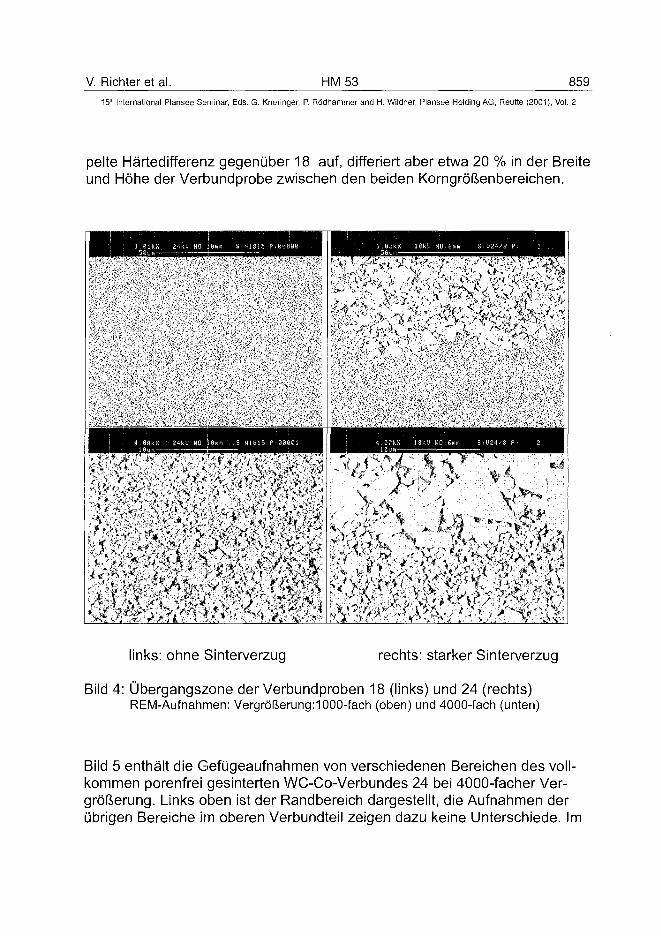
V. Richter et al. HM 53 85915th International Plansee Seminar, Ecls. G. Kneringer, P. RÖdhammer and H. Wildner, Plansee Holding AG, Reutte (2001), Vol. 2
pelte Härtedifferenz gegenüber 18 auf, differiert aber etwa 20 % in der Breiteund Höhe der Verbundprobe zwischen den beiden Korngrößenbereichen.
links: ohne Sinterverzug rechts: starker Sinterverzug
Bild 4: Übergangszone der Verbundproben 18 (links) und 24 (rechts)REM-Aufnahmen: Vergrößerung:!000-fach (oben) und 4000-fach (unten)
Bild 5 enthält die Gefügeaufnahmen von verschiedenen Bereichen des voll-kommen porenfrei gesinterten WC-Co-Verbundes 24 bei 4000-facher Ver-größerung. Links oben ist der Randbereich dargestellt, die Aufnahmen derübrigen Bereiche im oberen Verbundteil zeigen dazu keine Unterschiede. Im
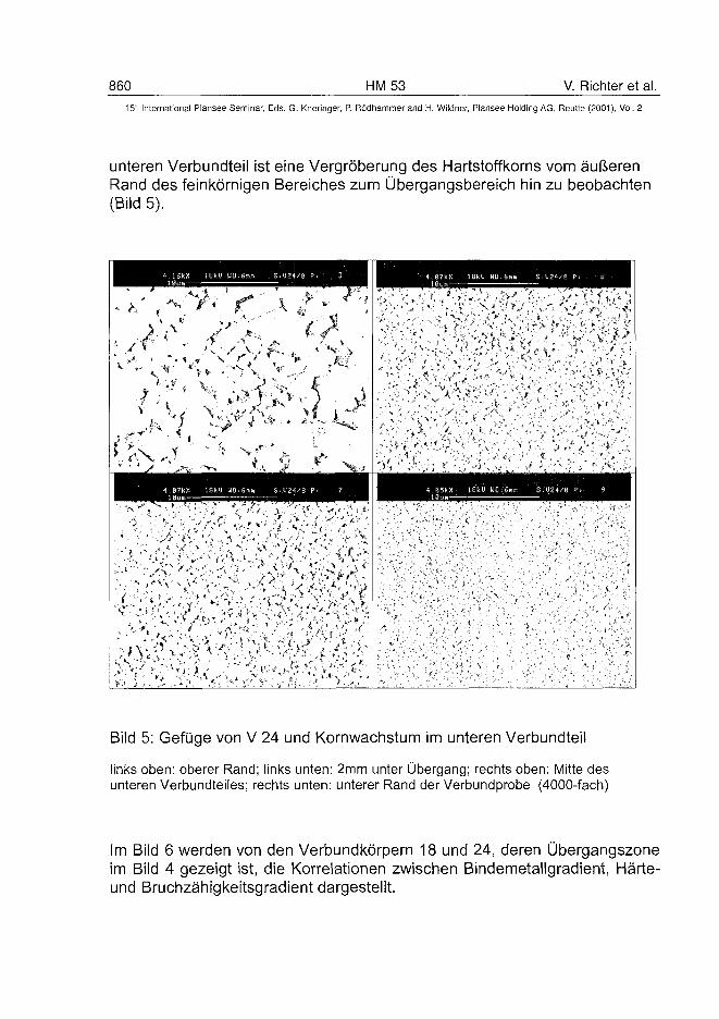
860 HM53 V. Richter et al.15" International Plansee Seminar, Eds. G. Kneringer, P. Rodhammer and H. Wildner, Plansee Holding AG, Reutte (2001), Vol. 2
unteren Verbundteil ist eine Vergroberung des Hartstoffkorns vom aufterenRand des feinkornigen Bereiches zum Ubergangsbereich hin zu beobachten(Bild 5).
Bild 5: Gefuge von V 24 und Kornwachstum im unteren Verbundteil
links oben: oberer Rand; links unten: 2mm unter Ubergang; rechts oben: Mitte desunteren Verbundteiles; rechts unten: unterer Rand der Verbundprobe (4000-fach)
Im Bild 6 werden von den Verbundkorpern 18 und 24, deren Ubergangszoneim Bild 4 gezeigt ist, die Korrelationen zwischen Bindemetallgradient, Harte-und Bruchzahigkeitsgradient dargestellt.
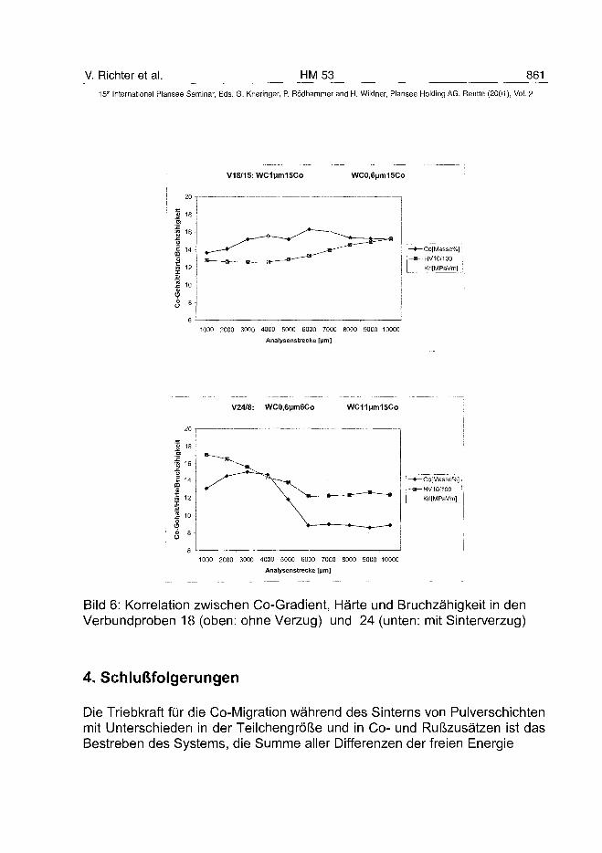
V. Richter et al. HM 53 86115" International Plansee Seminar, Eds. G. Kneringer, P. Rödhammer and H. Wildner, Plansee Holding AG, Reutte (2001), Vol. 2
V18/15: WC1)jm15Co WC0,6(jm15Co
20
| 18
| 1 e
Ü
! "
S 12 -
1 10a>
<?
8 «
L
-Co[Masse%]
-HV10/100
Kfl[MPaVm)
1000 2000 3000 4000 5000 6000 7000 8000 9000 10000
Analysenstrecke [Mm]
V24/8: WC0,6|jm6Co WC1iMm15Co
20
» 18
™ 16
-Co[Masse%]
- HV1G/100
Krl[MPaVm]
1000 2000 3000 4000 5000 6000 7000 8000 9000 10000
Analysenstrecke [|jm]
Bild 6: Korrelation zwischen Co-Gradient, Härte und Bruchzähigkeit in denVerbundproben 18 (oben: ohne Verzug) und 24 (unten: mit Sinterverzug)
4. Schlußfolgerungen
Die Triebkraft für die Co-Migration während des Sintems von Pulverschichtenmit Unterschieden in der Teilchengröße und in Co- und Rußzusätzen ist dasBestreben des Systems, die Summe aller Differenzen der freien Energie
862 HM 53 V. Richter et al.15" International Plansee Seminar, Eds. G. Kneringer, P. Rödhammer and H. Wildner, Plansee Holding AG, Reutte (2001), Vol. 2
(5G = ÔH), zu minimieren und Konzentrationsunterschiede auszugleichen.Die freiwerdene Energie korreliert mit der Oberflächen- bzw. Grenzflächen-spannung der festen Phase (Pulverteilchengröße), der flüssigen Phase (Co-Gehalt) und der Grenzflächen (Benetzung, Löslichkeit, Kohlung).
DanksagungDie Arbeiten erfolgten im Rahmen des von der DFG geförderten Projektes„Gradientenbildung bei Hartmetallen im Sinterprozeß". Wir danken für dieUnterstützung im Schwerpunktprogramm „Gradientenwerkstoffe" (322733).
Literatur
(1) H. Suzuki et al: Transact.Jap.lnst.Metals Vol.22, 11 (1981), pp. 758-764.
(2) M. Schwarzkopf, H.E. Exner, H.F. Fischmeister, W. Schintlmeister: Material Sei.And Engin. A 105/106 (1988), pp. 225-231.
(3) L. Chen, W. Lengauer, K. Dreyer: Proc. Euro PM99, Turin 1999, pp.463-473.
(4) C. Chatfield: Scand. J. Metallurgy 16 (1987), pp. 9-15.
(5) A. F. Lisovsky, N. V. Tkachenko, T. E. Gracheva: Proc. Int. Conf. Materials by Pow-der Technology, PTM'93, Dresden 1993, pp. 919-922 (ed. F. Aldinger).
(6) M. M. Gasik: Proc. 3th Int. Sympos. on Structural and Functional Gradient Materials,FGM'94, pp. 575-578 (ed. B. Ilschnerand N. Cherradi, Lausanne 1995).
(7) C. Colin, L. Durant, N. Favrot, J. Besson, G. Barbier, F. Delannay: Proc. 13th Int.Plansee Seminar, Reutte 1993, Vol. 2, HM 55, pp. 522-536.
(8) V. Richter: Proc. 3th Int. Sympos. on Structural and Functional Gradient Materials,FGM'94, Lausanne (Schweiz), 10.-12.10.1994. P. Nicolae, P. Nita: Proc. 14th Int.Plansee Seminar, Reutte 1997, Vol. 4, HM 54, pp. 332-341.
(9) P. Nicolae, P. Nita: Proc. 14th Int. Plansee Seminar, Reutte 1997, Vol. 4,HM54, pp. 332-341.
(10) V. Richter, Th. Jüngling, M. Joensson: 11. Hagener Symposium „Pulver- technolo-gische Wege in die Zukunft" in: Pulvermetallurgie in Wissenschaft und Praxis, 11(1995), pp. 81-100 (ed. H. Kolaska).
AT0100502J. Garcia et al. HM 59 863
15" International Plansee Seminar, Eds. G. Kneringer, P. Rodhammer and H. Wildner, Plansee Holding AG, Reutte (2001), Vol. 2
Quantitative Mass Spectrometry of Decarburisation and
Denitridation of Cemented Carbonitrides During Sintering1
Jose Garcia and Walter Lengauer
Institute for Chemical Technology of Inorganic Materials, Vienna University of Technology,
Getreidemarkt 9/161, A-1060 Vienna, Austria.
Summary:
Quantitative quadrupole mass spectrometry of (Ti,W)C-based cementedcarbonitrides was carried out in order to monitor the evolution of the gasspecies as a function of time and temperature during vacuum sintering. Solidstandards and gas mixtures as well as precise flow control were employed forcalibration. Upon integration of the outgassing rates the carbon and nitrogenevolutions and mass losses during sintering of raw hardmetal powdermixtures (WC, TiC, ...) and cemented carbonitrides could be quantified.Outgassing occurs in the range of temperatures 490-1480°C. Nitrogenoutgassing of (Ti,W)(C,N) was greater than that of Ti(C,N) due to thepresence of W which increases the nitrogen activity in the solid causing ahigher nitrogen equilibrium pressure. TiN showed a CO (0.2wt%) and N2
(0.5wt%) weight loss only in the presence of the binder phase. For powdermixtures, it was observed that the amount of CO, CO2 and N2 liberated duringvacuum sintering increased with the addition of cobalt in comparison with thesame powders without binder phase. Nitrogen containing cermet alloysshowed a greater loss of carbon than (Ti,W)C-based hardmetals.
Keywords:Quadrupole mass spectrometry, quantification, sintering, outgassing,hardmetals.
1. Introduction:
Mass spectrometry has been employed for studying the outgassingcharacteristics (vapour species) of many components in vacuum systems (1).1 Part of this work was presented at the PM2tec2000 (New York) in cooperation with theAustrian Research Centers Seibersdorf and Widia GmbH, Germany.
^64 HM 59 J. Garcia et al.15" International Plansee Seminar, Eds. G. Kneringer, P. Rodhammer and H. Wildner, Plansee Holding AG, Reutte (2001), Vol. 2
It provides a continuous and valuable information about the gas compositionin the vacuum environment as a function of temperature and time.Many studies on the reaction products (mainly H2O, CO2, CO, N2 andhydrocarbons) liberated during sintering of hardmetais and (Ti,W)C-basedcemented carbonitrides can be found in the literature (2-11) but no detailedwork on quantification of carbon and nitrogen mass losses due todecarburisation and denitridation of cemented carbonitrides during sinteringhas been reported. In the field of hardmetais, most of the work is related tothe study of WC-Co based hardmetais with different grain sizes (between0.4um and 30um) and doped with little amounts of VC, Cr3C2, SiO2 or MgO(2-6). Mass spectrometry investigations are often combined with dilatometrymeasurements, differential thermal analysis and differential scanningcalorimetry, in order to understand some basic processes of the complexmechanisms of the sintering of hardmetais (2-4,6-9). A detailed chronologicalsummary of outgassing investigations of hard metals by mass spectrometrycan be found in (12).In this work a first approach to measure the amount of the species (CO2, CO,N2) liberated during vacuum sintering of cemented carbonitrides was carriedout in order to quantify the loss of carbon and nitrogen. This is of value forsintering of conventional hardmetais and cermets to achieve figures for theappropriate starting formulation (e.g. doping).
2. Experimental:
2.1. Principal set up and experiments
A Balzers QMS 421 quadrupole mass spectrometer for the mass range 1-200amu was employed to carry out the experiments (Fig.1). A high-pressureinterface (HPI) connects the vacuum sintering furnace with the high-vacuumrecipient of the QMS (PQMS< 1.10"5 bar). Helium was used as carrier gas andthe total pressure of the vacuum furnace was kept at 20 mbar during thewhole sintering experiment. The ionisation energy was 100 eV. As a constantflow rate through orifice 01 and a constant pumping rate at orifice 02 wereestablished throughout all experiments a quantified calibration could beperformed. The masses were measured sequentially and each measurementcycle took 35 s. Conditions of measurements are shown in Tab.1.The calibration of the mass spectrometer was carried out for the main speciesliberated during sintering, i.e.: 1 4 N\ 28N2
+, 28CO+ and 44CO2+. The mass
difference of the ions 28N2+ and 28CO+ is very small (Am=0.01123 amu) which
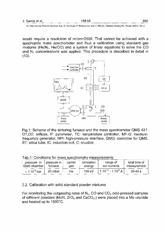
J. Garcia et al. HM59 865
15th International Plansee Seminar, Eds. G. Kneringer, P. Rodhammer and H. Wildner, Plansee Holding AG, Reutte (2001), Vol. 2
would require a resolution of m/Am=2500. That cannot be achieved with aquadrupole mass spectrometer and thus a calibration using standard gasmixtures (He/N2, He/CO) and a system of linear equations to solve the COand N2 concentrations was applied. This procedure is described in detail in(13).
Fig.1: Scheme of the sintering furnace and the mass spectrometer QMS 421.01,02: orifices, P: pyrometer, TC: temperature controller, MF-G: medium-frequency generator, HPI: high-pressure interface, QMG: controller for QMS,ST: silica tube, IC: induction coil, C: crucible.
Tab.1: Conditions for mass spectrometry measurementspressure in
QMS chamber
<1.irj5bar
pressure infurnace
20 mbar
carriergas
He
ionisationenergy
100eV
range ofion currents
1.irj12-1.1CT8A
total time ofmeasurement
35-40 s
2.2. Calibration with solid standard powder mixtures
For monitoring the outgassing rates of N2, CO and CO2 cold-pressed samplesof different powders (MoN, ZrO2 and CaCO3,) were placed into a Mo crucibleand heated up to 1500°C.
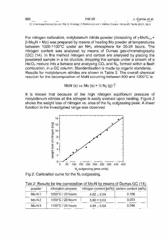
866 HM59 J. Garcia et al.15:" International Plansee Seminar, Eds. G. Kneringer, P. Rodhammer and H. Wildner, Plansee Holding AG, Reutte (2001), Vol. 2
For nitrogen calibration, molybdenum nitride powder (consisting of y-MoN1.x +P-Mo2N + Mo) was prepared by means of heating Mo powder at temperaturesbetween 1000-1100°C under an NH3 atmosphere for 20-24 hours. Thenitrogen content was analysed by means of Dumas gas-chromatography(GC) (14). In this method nitrogen and carbon are analysed by placing thepowdered sample in a tin crucible, dropping the sample under a stream of aHe/O2 mixture into a furnace and analysing CO2 and N2, formed within a flashcombustion, in a GC column. Standardisation is made by organic standards.Results for molybdenum nitrides are shown in Table 2. The overall chemicalreaction for the decomposition of MoN occurring between 800 and 1200°C is:
MoN (s) « Mo (s) + 1/2 N2 (g) T
It is known that because of the high nitrogen equilibrium pressure ofmolybdenum nitrides all the nitrogen is easily evolved upon heating. Figure 2shows the weight loss of nitrogen vs. area of the N2 outgassing peak. A linearfunction in the investigated range was observed.
o0 50 100 150 200 250 300 350 400 450
N2 outgassing [area units]
Fig.2: Calibration curve for the N2 outgassing.
Tab.2: Results for the composition of Mo-N by meanspowder
Mo-N 1
Mo-N 2
Mo-N 3
nitridation process
1000°C/ 20 hours
1000°C/ 20 hours
1100°C/24 hours
nitrogen content [wt%]
4.82 ± 0.04
5.60 ±0.03
4.94 ±0.04
of Dumas GC (14).carbon content [wt%]
0.106
0.003
0.046
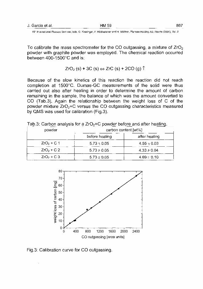
J. Garcia et al. HM 59 867
15" International Plansee Seminar, Eds. G. Kneringer, P. Rfidhammer and H. Wildner, Plansee Holding AG, Reutte (2001), Vol. 2
To calibrate the mass spectrometer for the CO outgassing, a mixture of ZrO2
powder with graphite powder was employed. The chemical reaction occurredbetween 400-1500°C and is:
ZrO2 (s) + 3C (s) <=> ZrC (s) + 2CO (g) t
Because of the slow kinetics of this reaction the reaction did not reachcompletion at 1500°C. Dumas-GC measurements of the solid were thuscarried out also after heating in order to determine the amount of carbonremaining in the sample, the balance of which was the amount converted toCO (Tab.3). Again the relationship between the weight loss of C of thepowder mixture ZrO2+C versus the CO outgassing characteristics measuredby QMS was used for calibration (Fig.3).
Tab.3: Carbon analysis for a ZrO2+C powder before and after heating.powder
ZrO2 + C 1
ZrO2 + C 2
ZrO2 + C 3
carbon content [wt%]
before heating
5.73 + 0.05
5.73 + 0.05
5.73 + 0.05
after heating
4.55 ±0.03
4.33 ± 0.04
4.69 + 0.10
400 800 1200 1600 2000 2400
CO outgassing [area units]
Fig.3: Calibration curve for CO outgassing.
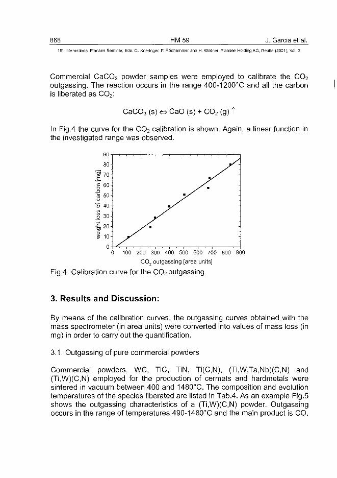
868 HM59 J. Garcia et al.15* International Plansee Seminar, Eds. G. Kneringer, P. Rodhammer and H. Wildner, Plansee Holding AG, Reutte (2001), Vol. 2
Commercial CaCO3 powder samples were employed to calibrate the CO2
outgassing. The reaction occurs in the range 400-1200°C and all the carbonis liberated as CO2:
CaCO3 (s) <=> CaO (s) + CO2 (g) T
In Fig.4 the curve for the CO2 calibration is shown. Again, a linear function inthe investigated range was observed.
100 200 300 400 500 600 700 800 900
CO2 outgassing [area units]
Fig.4: Calibration curve for the CO2 outgassing.
3. Results and Discussion:
By means of the calibration curves, the outgassing curves obtained with themass spectrometer (in area units) were converted into values of mass loss (inmg) in order to carry out the quantification.
3.1. Outgassing of pure commercial powders
Commercial powders, WC, TiC, TiN, Ti(C,N), (Ti,W,Ta,Nb)(C,N) and(Ti,W)(C,N) employed for the production of cermets and hardmetals weresintered in vacuum between 400 and 1480°C. The composition and evolutiontemperatures of the species liberated are listed in Tab.4. As an example Fig.5shows the outgassing characteristics of a (Ti,W)(C,N) powder. Outgassingoccurs in the range of temperatures 490-1480°C and the main product is CO.
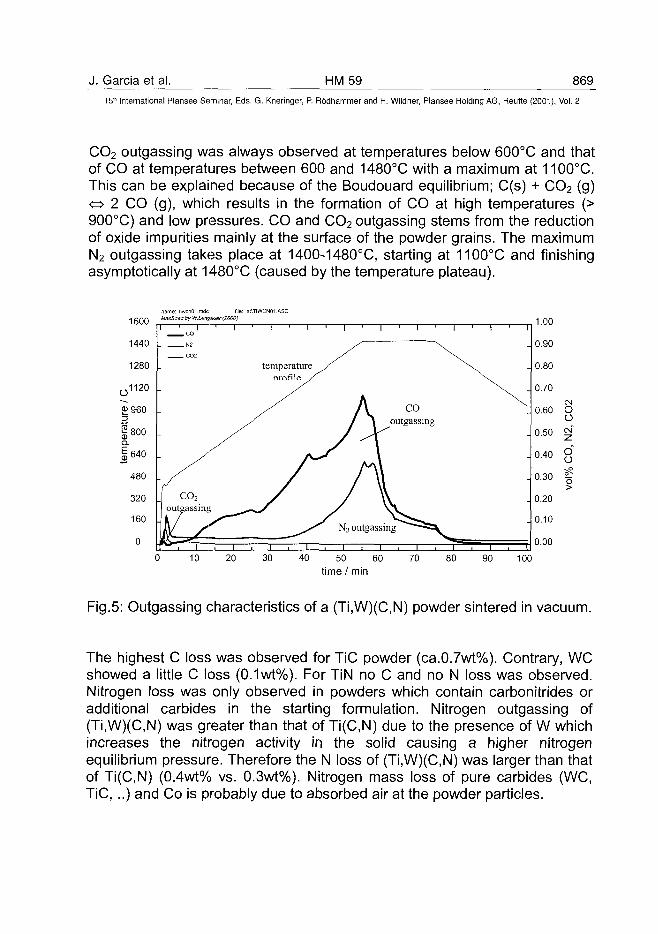
J. Garcia et al. HM59 86915* International Plansee Seminar, Eds. G. Kneringer, P. Rodhammer and H. Wildner, Plansee Holding AG, Reutte (2001), Vol. 2
CO2 outgassing was always observed at temperatures below 600°C and thatof CO at temperatures between 600 and 1480°C with a maximum at 1100°C.This can be explained because of the Boudouard equilibrium; C(s) + CO2 (g)<=> 2 CO (g), which results in the formation of CO at high temperatures (>900°C) and low pressures. CO and CO2 outgassing stems from the reductionof oxide impurities mainly at the surface of the powder grains. The maximumN2 outgassing takes place at 1400-1480°C, starting at 1100°C and finishingasymptotically at 1480°C (caused by the temperature plateau).
cnOLmdc file: a:\TIWCN01.ASCasSpec by W.Lercgauer (2000)
0 10 20 30 40 50 60 70 80
Fig.5: Outgassing characteristics of a (Ti,W)(C,N) powder sintered in vacuum.
The highest C loss was observed for TiC powder (ca.0.7wt%). Contrary, WCshowed a little C loss (0.1wt%). For TiN no C and no N loss was observed.Nitrogen loss was only observed in powders which contain carbonitrides oradditional carbides in the starting formulation. Nitrogen outgassing of(Ti,W)(C,N) was greater than that of Ti(C,N) due to the presence of W whichincreases the nitrogen activity in the solid causing a higher nitrogenequilibrium pressure. Therefore the N loss of (Ti,W)(C,N) was larger than thatof Ti(C,N) (0.4wt% vs. 0.3wt%). Nitrogen mass loss of pure carbides (WC,TiC, ..) and Co is probably due to absorbed air at the powder particles.
870 HM59 J. Garcia et al.15" International Plansee Seminar, Eds. G. Kneringer, P. Rodhammer and H. Wildner, Plansee Holding AG, Reutte (2001), Vol. 2
3.2. Powders mixed with cobaltThe temperatures at which the gas evolutions occur remained unchangedwith the addition of Co. It was observed that the amount of CO, CO2 and N2
liberated during vacuum sintering increased with the addition of cobalt incomparison with the same powders without binder phase (compare Tab.5 vs.Tab.6).
Tab.4: Range of temperatures for outgassing of CO, CO2 and N2
powder
weTiC
TiN
Ti(C,N)
(Ti,W)(C,N)
(Ti,W,Ta,Nb)C
Co
initial composition[Wt%]
we100
-
-
-
50
33
-
TiC
-
100
-
50
28
33
-
TiN
-
-
100
50
22
-
-
TaC
-
-
-
-
-
30
-
NbC
-
-
-
-
-
3.3
-
Co
-
-
-
-
-
-
100
range of temperatures of evolutions
raCO
830-1400
600-1400
-
600-1480
600-1480
600-1480
450-550
CO2
<600
<600
-
<600
<600
<600
<600
N2
-
-
-
1100-1485
1100-1485
1100-1485
-
Tab.5: C and N mass loss in % for industrial powders without binder metal
powder
weTiC
TiN
Ti(C,N)
(Ti,W)(C,N)
(Ti,W,Ta,Nb)C
Co
we100
-
-
-
50
33
-
initial
TiC
-
100
-
50
28
33
-
composition
TiN
-
-
100
50
22
-
-
TaC
-
-
-
-
-
30
-
[wt%]
NbC
-
-
-
-
-
3.3
-
Co
-
-
-
-
-
-
100
mass loss [%]O ( # )
C
0.1
0.7
0.05
0.8
0.5
0.3
0.22
N
0.05
0.06
0.05
0.3
0.4
0.2
0.05n values in % of the total sample weight(#> standard deviation estimated to be in the range of ± 12%
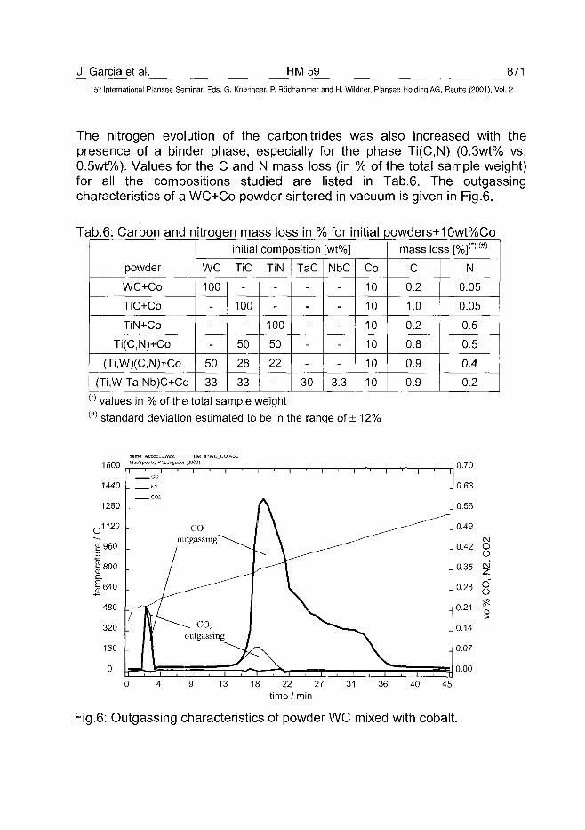
J. Garcia et al. HM59 87115" International Plansee Seminar, Eds. G. Kneringer, P. Rodhammer and H. Wildner, Plansee Holding AG, Reutte (2001), Vol. 2
The nitrogen evolution of the carbonitrides was also increased with thepresence of a binder phase, especially for the phase Ti(C,N) (0.3wt% vs.0.5wt%). Values for the C and N mass loss (in % of the total sample weight)for all the compositions studied are listed in Tab.6. The outgassingcharacteristics of a WC+Co powder sintered in vacuum is given in Fig.6.
Tab.6: Carbon and nitrogen mass loss in % for initial powders+10wt%Co
powder
WC+Co
TiC+Co
TiN+Co
Ti(C,N)+Co
(Ti,W)(C,N)+Co
(Ti,W,Ta,Nb)C+Co
initial composition [wt%]
WC
100
-
-
-
50
33
TiC
-
100
-
50
28
33
TiN
-
-
100
50
22
-
TaC
-
-
-
-
-
30
NbC
-
-
-
-
-
3.3
Co
10
10
10
10
10
10
mass loss [%]O(#)
C
0.2
1.0
0.2
0.8
0.9
0.9
N
0.05
0.05
0.5
0.5
0.4
0.2(*' values in % of the total sample weight(#) standard deviation estimated to be in the range of ± 12%
1600name: wccobOO mdc file: a:\WC_CO.ASCMasSpec by W.Lengauer (2000)
1 ' I
13 18 22 27time / min
31 36 40
0.70
0.00
45
Fig.6: Outgassing characteristics of powder WC mixed with cobalt.
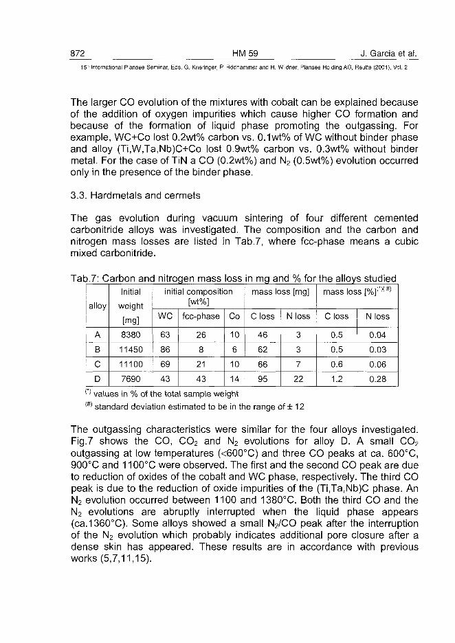
872 HM59 J. Garcia et al.1 5 r IInternational Plansee Seminar, Eds. G. Kneringer, P. Rodhammer and H. Wildner, Plansee Holding AG, Reutte (2001), Vol. 2
The larger CO evolution of the mixtures with cobalt can be explained becauseof the addition of oxygen impurities which cause higher CO formation andbecause of the formation of liquid phase promoting the outgassing. Forexample, WC+Co lost 0.2wt% carbon vs. 0.1 wt% of WC without binder phaseand alloy (Ti,W,Ta,Nb)C+Co lost 0.9wt% carbon vs. 0.3wt% without bindermetal. For the case of TiN a CO (0.2wt%) and N2 (0.5wt%) evolution occurredonly in the presence of the binder phase.
3.3. Hardmetals and cermets
The gas evolution during vacuum sintering of four different cementedcarbonitride alloys was investigated. The composition and the carbon andnitrogen mass losses are listed in Tab.7, where fcc-phase means a cubicmixed carbonitride.
Tab.7: Carbon and nitrogen mass loss in mg and % for the alloys studied
alloy
A
B
C
D
Initial
weight
[mg]
8380
11450
11100
7690
initial composition[wt%]
WC
63
86
69
43
fcc-phase
26
8
21
43
Co
10
6
10
14
mass loss [mg]
C loss
46
62
66
95
N loss
3
3
7
22
mass loss [%]n (# )
C loss
0.5
0.5
0.6
1.2
N loss
0.04
0.03
0.06
0.28(>) values in % of the total sample weight(#) standard deviation estimated to be in the range of ± 12
The outgassing characteristics were similar for the four alloys investigated.Fig.7 shows the CO, CO2 and N2 evolutions for alloy D. A small CO2
outgassing at low temperatures (<600°C) and three CO peaks at ca. 600°C,900°C and 1100°C were observed. The first and the second CO peak are dueto reduction of oxides of the cobalt and WC phase, respectively. The third COpeak is due to the reduction of oxide impurities of the (Ti,Ta,Nb)C phase. AnN2 evolution occurred between 1100 and 1380X. Both the third CO and theN2 evolutions are abruptly interrupted when the liquid phase appears(ca.1360°C). Some alloys showed a small N2/CO peak after the interruptionof the N2 evolution which probably indicates additional pore closure after adense skin has appeared. These results are in accordance with previousworks (5,7,11,15).
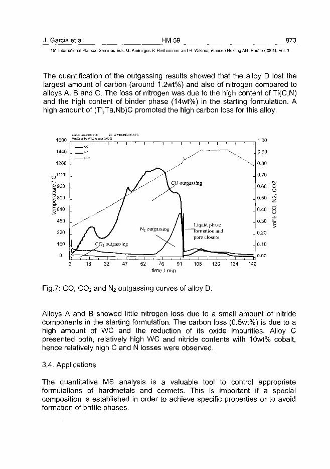
J. Garcia et al. HM59 87315" International Plansee Seminar, Eds. G. Kneringer, P. Rodhammer and H. Wildner, Plansee Holding AG, Beutte (2001), Vol. 2
The quantification of the outgassing results showed that the alloy D lost thelargest amount of carbon (around 1.2wt%) and also of nitrogen compared toalloys A, B and C. The loss of nitrogen was due to the high content of Ti(C,N)and the high content of binder phase (14wt%) in the starting formulation. Ahigh amount of (Ti,Ta,Nb)C promoted the high carbon loss for this alloy.
name: probe40cmdc fie: a:\PROBE40C.ASCMasSpec by W.Lengauer (2000)
Liquid phaseormation and
pore closure
CM
OO
OO
o>
62 76 91time / min
Fig.7: CO, CO2 and N2 outgassing curves of alloy D.
Alloys A and B showed little nitrogen loss due to a small amount of nitridecomponents in the starting formulation. The carbon loss (0.5wt%) is due to ahigh amount of WC and the reduction of its oxide impurities. Alloy Cpresented both, relatively high WC and nitride contents with 10wt% cobalt,hence relatively high C and N losses were observed.
3.4. Applications
The quantitative MS analysis is a valuable tool to control appropriateformulations of hardmetals and cermets. This is important if a specialcomposition is established in order to achieve specific properties or to avoidformation of brittle phases.
874 HM59 J. Garcia et al.15" International Plansee Seminar, Eds. G. Kneringer, P. Rodhammer and H. Wildner, Plansee Holding AG, Reutte (2001), Vol. 2
Outgassing quantification showed that the loss of carbon is substantial foralloy D. This alloy exhibited some brittle phases in the microstructure aftersintering (see Fig.8). It could be concluded that the lack of carbon producedfor reduction of impurities allowed the formation of (W,Co)6C-type ri-phases.Thus, if such an alloy is doped with carbon in such a way so as tocompensate the carbon loss, ri-phase formation can be avoided.
r^^v^-. - •' . . .
Fig.8: rj-phase formation in alloy D due to loss of carbon during sintering.
4. Conclusion:
In this work, a first approach was done in order to quantify the gas evolutionsof cemented carbonitrides during sintering. For the starting powders anincrease of the outgassing products with the presence of a binder phase wasobserved. Special attention should be paid to the changes in carbon andnitrogen contents relative to the starting formulation upon vacuum sinteringfor a better control of the microstructure.Nitrogen containing cermet alloys showed a greater loss of carbon than(Ti,W)C-based hardmetals. A careful control of carbon content by dopingseems to be necessary in such alloys to avoid r)-phase formation.
J. Garcia et al. HM 59 87515'" International Plansee Seminar, Eds. G. Kneringer, P. Rodhammer and H. Wildner, Plansee Holding AG, Reutte (2001), Vol. 2
5. Acknowledgments:
The authors would like to thank Professor Peter Ettmayer for criticaldiscussions and the Austrian Exchange Service (OAD) for financial support ofJose Garcia within the North-South dialog program.
6. References:
(1) R.F.Bunshah: American Vacuum Society, Boston, 98, (1966), 98.(2) G.Leitner, T.Gestrich: 14th Plansee Proceedings, Eds. G.Kneringer,
P.Rodhammer, P.Wilhartitz, Plansee AG, Reutte, 2, (1997) 86.(3) G.Gille, B.Szesny, G.Leitner: 14th Plansee Proceedings, Eds.
G.Kneringer, P.Rodhammer, P.Wilhartitz, Plansee AG, Reutte, 2,(1997), 139.
(4) G.Leitner, W.Heinrich, K.Gbrting: Adv. in Pow. Metall. & Part. Mat.,1,(1997), 4/259.
(5) D.Schuler, O.Jung, B.Frisch, W.Thiele: Pulvermet. in Wiss. und Praxis,3, (1987), 113.
(6) O.Pacher, W.Schintlmeister, F.Weirather: Planseeberichte furPulvermetallurgie, Plansee AG, Reutte, Austria, 26, (1978), 244.
(7) P.Ettmayer, H.Kolaska, W.Lengauer, K.Dreyer: Int. J. Refr. Met. HardMater., 13, (1995), 343.
(8) P.Ettmayer: PMI vol. 23, 4, (1991), 224.(9) P.Ettmayer, H.Kolaska, K.Dreyer: Pulvermet. in Wiss. und Praxis, 6,
(1990), 239.(10) P.Ettmayer: Annu. Rev. Mat. Sci., 19, (1989), 145.(11) A.Maurer: J. Hard. Mat., 3, (1992), 235.(12) T.Gestrich, R.Cherchiara: Proc. Int. Conf. In Powd. Metall. & Part.
Mater., 10, (1999), 111.(13) H.Eppler: Hochvakuum Fachbericht, BK800 006, Fa. Balzers,
Liechtenstein, (1991).(14) R.Taubler, S.Binder, M.Groschner, W.Lengauer, P.Ettmayer:
Mikrochim. Acta 107, (1992), 337.(15) W.Lengauer, J.Garcia, K.Dreyer, I.Smid, D.Kassel, H.-W.Daub, G.Korb
and L.Chen: Proc. EURO PM'99, Turin, (1999), 475.


