Embed Size (px)
Citation preview
1
Process Intensification for Post-combustion CO2 capture 1
with Chemical Absorption: A critical review 2 Meihong Wanga,*, Atuman S. Joela, Colin Ramshawa, Dag Eimerb, Nuhu M. Musaa 3 aProcess/Energy Systems Engineering Group, School of Engineering, University of Hull, HU6 7RX, 4 UK 5 bTelemark Technological Research and Development Centre (Tel-Tek), Norway 6 *Corresponding author. Tel: +44 01482 466688; Fax: +44 01482 466664; Email address: [email protected] 7
Abstract 8
The concentration of CO2 in the atmosphere is increasing rapidly. CO2 emissions 9 may have an impact on global climate change. Effective CO2 emission abatement 10 strategies such as carbon capture and storage (CCS) are required to combat this 11 trend. Compared with pre-combustion carbon capture and oxy-fuel carbon capture 12 approaches, post-combustion CO2 capture (PCC) using solvent process is one of the 13 most mature carbon capture technologies. There are two main barriers for the PCC 14 process using solvent to be commercially deployed: (a) high capital cost; (b) high 15 thermal efficiency penalty due to solvent regeneration. Applying Process 16 intensification (PI) technology into PCC with solvent process has the potential to 17 significantly reduce capital costs compared with conventional technology using 18 packed columns. This paper intends to evaluate different PI technologies for their 19 suitability in PCC process. The study shows that rotating packed bed (RPB) 20 absorber/stripper has attracted much interest due to its high mass transfer capability. 21 Currently experimental studies on CO2 capture using RPB are based on standalone 22 absorber or stripper. Therefore a schematic process flow diagram of intensified PCC 23 process is proposed so as to motivate other researches for possible optimal design, 24 operation and control. To intensify heat transfer in reboiler, spinning disc technology 25 is recommended. To replace cross heat exchanger in conventional PCC (with 26 packed column) process, printed circuit heat exchanger will be preferred. Solvent 27 selection for conventional PCC process has been studied extensively. However, it 28 needs more studies for solvent selection in intensified PCC process. The authors 29 also predicted research challenges in intensified PCC process and potential new 30 breakthrough from different aspects. 31
Keywords: Post-combustion CO2 capture, Chemical Absorption, Rotating Packed 32 Bed (RPB), Process Intensification (PI), Solvents, Intensified Heat Exchanger 33
1. Introduction 34
1.1 CO2 Emissions and Climate Change 35
Global energy demand is expected to continue to rise due to the increasing world 36 population, in addition to economic development of nations such as Brazil, Russia 37
2
India and China. Dependence on renewable energy alone such as solar, wind and 38 tidal power to meet the projected demand is not feasible due to their intermittent 39 nature. Therefore, fossil fuel remains the very attractive options in meeting future 40 energy demands. But power generation using fossil fuel is estimated to be the 41 largest source of worldwide carbon emissions [1]. 42
Combustion of fossil fuels (e.g. petroleum, coal and natural gas) accounts for the 43 majority of CO2 emissions. Globally most fossil-fuelled electricity production is from 44 coal (63%), followed by natural gas (29%) and oil (9%) [2]. For instance about 85.5% 45 of its coal (produced and imported) is used for electricity generation in the UK in 46 2011[3]. Albo et al. [4] stated that among the greenhouse gases, CO2 contributes to 47 more than 60% of global warming. Statistics from World Metrological Organisation 48 (WMO) showed that the amount of CO2 in the atmosphere reached 393.1 ppm in 49 2012. The WMO report also showed that the amount of CO2 in the atmosphere has 50 increased on average by 2 ppm per year for the past 10 years, this increased 51 atmospheric concentration of CO2 affects the radiative balance of the Earth [5]. 52
1.2 CCS Technologies 53
Intergovernmental panel on climate change (IPCC) [6] has set ambitious goal to 54 reduce CO2 emission by 50% in 2050 as compared to the level of 1990 so as to 55 overcome the foreseen environmental challenges. In order to achieve the required 56 emission reductions in the most cost-effective manner, carbon capture and storage 57 (CCS) will need to contribute around one-fifth of total reductions in emissions by 58 2050 [7]. 59
CCS consists of three basic stages: (a) separation of CO2; (b) CO2 transportation 60 and (c) CO2 storage. There are three major approaches for CCS: post-combustion 61 capture, pre-combustion capture and oxy-fuel process [8]. 62
1.3 Different technical options in the context of PCC 63
PCC technologies are at various stages of development. Abanades et al. [9] 64 reviewed the technological readiness level for different CO2 capture technologies in 65 the context of PCC including chemical looping, calcium looping, PCC using solvent, 66 PCC using adsorbent and PCC using membrane. The most matured process is PCC 67 using solvent [9,10]. 68
However, the PCC using solvent process has several drawbacks including: (1) low 69 CO2 loading capacity; (2) high equipment corrosion rate; (3) amine degradation by 70 SO2, NO2, and O2 in the flue gases which induces a high solvent makeup rate; (4) 71 high energy consumption during solvent regeneration; (5) large equipment size [11-72 14] (in whole PCC process, absorber and stripper account for 55% and 17% of the 73 total capital cost respectively [15]). This process is introduced in more detail in 74 Section 1.4. and Table 1 gives its performance indicators and status for chemical 75 absorption compared to adsorption and membrane technologies. 76
77
3
Table 1 Status of post-combustion CO2 capture development [15-23] 78
Absorbent Adsorbent Membrane Commercial usage in chemical process industries
High Moderate Low/Niche
Operational confidence High High, but complex Low to moderate Primary source of energy penalty
Solvent Regeneration (thermal)
Solid sorbent Regeneration (thermal/vacuum)
Compression on feed and/or vacuum on permeate
Regeneration energy (MJ/kg-CO2)
2.2 – 6 0.5 – 3.12 0.5 – 6
Efficiency penalty (%) 8.2 – 14 5.4 – 9.0 6.4 – 8.5 Development trends New solvent,
thermal integration New sorbent, process configuration
New membrane, process configuration
79
Chemically modified adsorbents have proved to be applicable for PCC process 80 because of large CO2 adsorption capacity, high adsorption and desorption rates, 81 high tolerance to moisture, and high selectivity towards CO2 over other gases [24]. In 82 terms of regeneration energy, Zhao et al. [25] reported that solid sorbent does not 83 have any obvious advantage over the matured MEA process in terms of energy 84 consumption in the first design (i.e. two reactor used, one for adsorption and the 85 other for regeneration). But the novel (second) design (i.e. using three reactors, one 86 for adsorption, one for regeneration and another one for formation of 87 K2CO3.1.5H2O), the regeneration energy can be reduced by utilizing the waste heat 88 from the process, however this design is difficult to control because the reactors 89 operate at different pressures. A lot of researchers have focused on new adsorbent 90 development, process optimization, and equipment innovation [26-50]. 91
Abanades et al. [9] shows that membrane process for PCC is at almost the same 92 level of technological readiness as adsorption. Therefore, more study in this area is 93 needed in order to get detailed technical performance at large scale condition. Many 94 researchers have developed new membranes that offer better performance in term 95 of selectivity. The recent key projects developing membranes and modules for CO2 96 capture include Membrane Technology and Research (MTR) in the USA, 97 NanoGLOWA in Germany, the carbon capture project (CCP) and the CO2CRC in 98 Australia [9]. Membranes process for PCC is beneficial because of relatively small 99 footprint, no phase change, simple mechanical system, steady-state operating 100 conditions (usually), easy scale-up and flexibility [51-53]. The major challenge for 101 membranes comes from the potential fouling of the membrane surfaces from 102 particulate matter, uncertainty about the performance and cost of large-scale efficient 103 vacuum pumps and compressors required for PCC, and the ability to integrate the 104 process into a power plant. Technological outlook of membrane system is reported in 105 Abanades et al. [9] and highlighted that for the technology to be competitive with 106 other PCC technology, the membrane needs to be of high CO2 permeance (around 107 1000 gas permeance units (GPU)) to be economical. 108
4
The technological readiness (maturity) level of PCC based on chemical absorption 109 and the first commercial deployment of PCC using solvents plant in 2014 motivate 110 the authors to write this paper and highlight the process design option that will 111 improve the chemical absorption PCC process using the RPB technology. 112
1.4 Current status of PCC using solvent and its commercial deployment 113
114
115
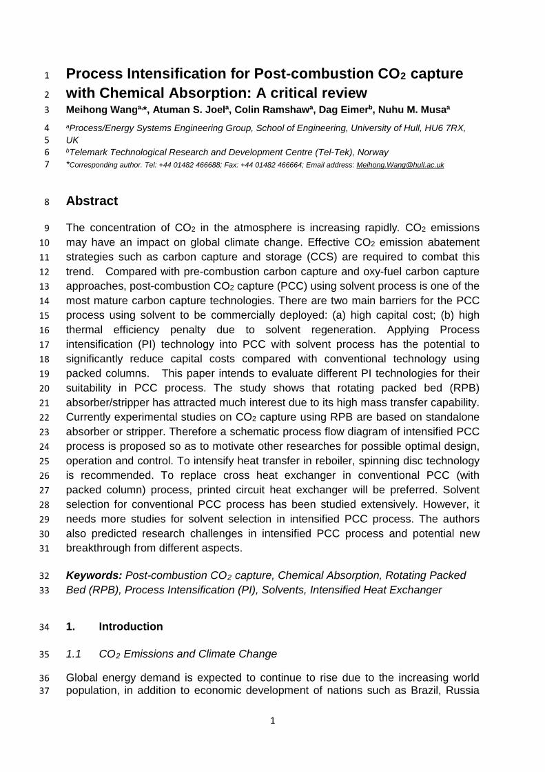
Figure 1 Simplified process flow diagram of chemical absorption process for post 116 combustion carbon capture [54] 117
Figure 1 shows a simplified PCC process. Flue gas from CO2 sources such as 118 power plant is contacted counter-currently with lean solvent solution in the absorber. 119 Solvent chemically absorbs CO2 in the flue gas. This leaves a treated gas stream of 120 lower CO2 content. The solvent solution (now rich solvent) is regenerated in the 121 stripper. CO2 from the top of the stripper is compressed and transported while the 122 lean (regenerated) solvent solution is returned to the absorber column passing 123 through a cross exchanger to recover heat with rich solvent from the absorber. 124
Studies on PCC with chemical absorption process were reported mainly for fossil 125 fuel-fired power plants. Dugas [55] carried out pilot plant experimental studies of 126 PCC in the context of fossil fuel-fired power plants. Mangalapally et al. [56-59] 127 reported pilot plant studies of PCC for gas fired power plant. Lawal et al. [11,60-62], 128 Biliyok et al. [63], Kvamsdal et al. [54,64-66], MacDowell and Shah [67-69], 129 MacDowell et al. [70], Lucquiaud et al. [71,72], Errey et al. [73], Agbonghae et al. 130 [14,74] carried out steady state and dynamic modelling of CO2 absorption for PCC 131 using solvents for fossil-fuel fired power plants. Asendrych et al. [75], Sebastia-Saez 132 et al. [76], Raynal et al. [77], Raynal and Royon-Lebeaud [78] studied PCC for fossil 133 fuel fired power plant using CFD. 134
5
There is also good progress in commercial deployment of PCC using solvent 135 technology. SaskPower's Boundary Dam Integrated Carbon Capture and Storage 136 (ICCS) Demonstration Project (that comes online on 2nd October, 2014) captures 137 over one million metric tons of CO2 per year, reflecting a 90% CO2 capture rate for 138 the 139 MWe coal-fired unit. This is the first commercial CCS plant in the world[79], 139
The demonstration plant of Southern Company's 25 MWe Plant Barry CCS project in 140 Alabama, USA using Mitsubishi Heavy Industries (MHI) technology has been 141 operational since Jun. 2011 and it reached full-scale capture of 500 tonnes a day in 142 September 2012 [80]. 143
Petra Nova/NRG 240 MWe W.A. Parish project using the MHI technology is the 144 largest commercial PCC using solvent project in the world. It is located in southwest 145 of Houston, Texas, USA. It is installed on an existing coal-fired power plant and is 146 expected to be operational in 2016 [81]. The plant is expected to capture 1.6 million 147 tons of CO2 annually for use in enhanced production at mature oil fields in the Gulf 148 Coast region [81] 149
However, there are two main barriers for the PCC using solvent process to be 150 commercially deployed: (a) huge capital cost; (b) high thermal efficiency penalty due 151 to solvent regeneration. Therefore it is necessary to improve the technologies that 152 can reduce various costs in PCC. 153
1.5 Motivation for using PI in PCC with solvents process 154
It was reported that a 500 MWe supercritical coal fired power plant operating at 46% 155 efficiency (LHV basis) releases over 8,000 tonnes of CO2 per day [82]. PCC using 156 solvents based on the conventional technology (i.e. using packed columns) requires 157 very large packed columns. Dynamic modelling and simulation study of a 500MWe 158 sub-critical coal-fired power plant by Lawal et al. [11] showed that two absorbers of 159 17m in packing height and 9m in diameter will be needed to separate CO2 from the 160 flue gas. These huge packed columns translate into high capital costs. A significant 161 amount of steam from power plants has to be used for solvent regeneration. This 162 translates into high thermal efficiency penalty. It is reported that 3.2 to 4.5 MJ energy 163 is required to capture per kg of CO2 using MEA solvent [11,54,68,83,84]. Technical 164 approaches such as heat integration, inter-cooling among others can reduce the 165 operating cost slightly. However, they limit the plant flexibility and will make operation 166 and control more difficult [54]. On the other hand, PI has potentials of significant 167 capital cost reduction [85-89], and also to improve process dynamics. 168
1.6 Introduction to PI and Evaluation of different PI technologies for PCC 169
According to Reay [86], process intensification (PI) can be defined as: “Any 170 engineering development that leads to a substantially smaller, cleaner, safer and 171 more energy efficient technology.” There are general approaches to PI with the aim 172 to improve process performance [86]: (a) Reducing equipment size using an 173 intensified field (e.g. centrifugal, electrical, microwave); (b) Simplifying processes by 174

6
integrating multiple process tasks in a single item of equipment; (c) Reducing 175 equipment size by reducing its scale of structure. 176
PI technologies differ in functions and areas of application. Some will be very good at 177 intensifying mass transfer, whilst others are good at intensifying heat transfer. Some 178 typical PI studies are presented in Table 2 to evaluate the most preferred option for 179 CO2 capture application. 180
7
Table 2 Summary of Different PI Technologies 181
PI Equipment Description Mechanism for Intensification Area of application at present
Suitability to CO2 capture
Limitation
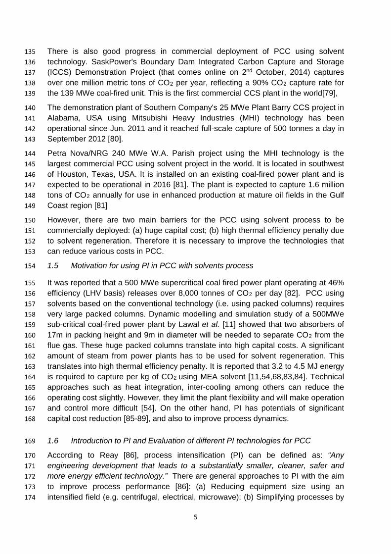
Static mixer A static mixer or motionless mixer is a device inserted into a housing or pipeline with the objective of manipulating fluid streams. Different designs are available, typically consisting of plates or baffles positioned in precise angles in order to direct flow, increase turbulence and achieve mixing and reactions [90].
Static mixer functions to divide, recombine, accelerate / decelerate, spread, swirl or form layers of fluid streams as they pass through the mixer. mixture components are brought into intimate contact thereby enhancing reaction processes [90]
Mostly this equipment is used for liquid system. e.g. Waste water treatment process (Formose treatment) [91]
Because of its high mass transfer capability, this can be used for CO2 capture by combining the flue gas stream and the solvent stream. At the exit, a flash drum can be used to separate the treated gas and the rich solvent.
The challenge would be the high volume of flue gas to be treated (For example, 500 MWe coal-fired power plant releases 8,000 tonnes/day of pure CO2).
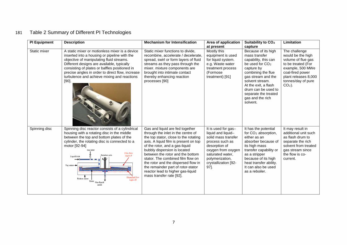
Spinning disc Spinning disc reactor consists of a cylindrical housing with a rotating disc in the middle between the top and bottom plates of the cylinder, the rotating disc is connected to a motor [92-94]
Gas and liquid are fed together through the inlet in the centre of the top stator, close to the rotating axis. A liquid film is present on top of the rotor, and a gas-liquid bubbly dispersion is located between the rotor and the bottom stator. The combined film flow on the rotor and the dispersed flow in the remainder part of rotor-stator reactor lead to higher gas-liquid mass transfer rate [92].
It is used for gas–liquid and liquid–solid mass transfer process such as desorption of oxygen from oxygen saturated water, polymerization, crystallization [92-97].
It has the potential for CO2 absorption, either as an absorber because of its high mass transfer capability or as a stripper because of its high heat transfer ability. It can also be used as a reboiler.
It may result in additional unit such as flash drum to separate the rich solvent from treated gas stream since the flow is co-current.
8
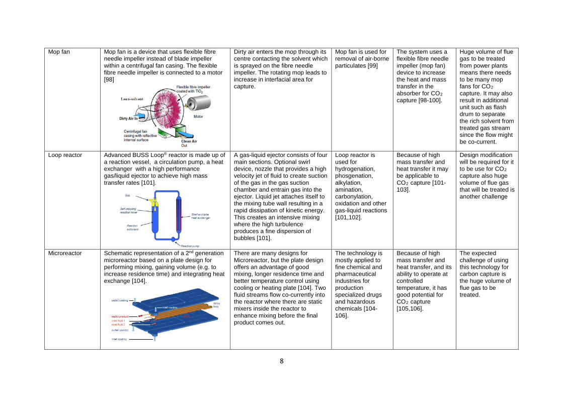
Mop fan Mop fan is a device that uses flexible fibre needle impeller instead of blade impeller within a centrifugal fan casing. The flexible fibre needle impeller is connected to a motor [98]
Dirty air enters the mop through its centre contacting the solvent which is sprayed on the fibre needle impeller. The rotating mop leads to increase in interfacial area for capture.
Mop fan is used for removal of air-borne particulates [99]
The system uses a flexible fibre needle impeller (mop fan) device to increase the heat and mass transfer in the absorber for CO2 capture [98-100].
Huge volume of flue gas to be treated from power plants means there needs to be many mop fans for CO2 capture. It may also result in additional unit such as flash drum to separate the rich solvent from treated gas stream since the flow might be co-current.
Loop reactor Advanced BUSS Loop® reactor is made up of a reaction vessel, a circulation pump, a heat exchanger with a high performance gas/liquid ejector to achieve high mass transfer rates [101].
A gas-liquid ejector consists of four main sections. Optional swirl device, nozzle that provides a high velocity jet of fluid to create suction of the gas in the gas suction chamber and entrain gas into the ejector. Liquid jet attaches itself to the mixing tube wall resulting in a rapid dissipation of kinetic energy. This creates an intensive mixing where the high turbulence produces a fine dispersion of bubbles [101].
Loop reactor is used for hydrogenation, phosgenation, alkylation, amination, carbonylation, oxidation and other gas-liquid reactions [101,102].
Because of high mass transfer and heat transfer it may be applicable to CO2 capture [101-103].
Design modification will be required for it to be use for CO2 capture also huge volume of flue gas that will be treated is another challenge
Microreactor Schematic representation of a 2nd generation microreactor based on a plate design for performing mixing, gaining volume (e.g. to increase residence time) and integrating heat exchange [104].
There are many designs for Microreactor, but the plate design offers an advantage of good mixing, longer residence time and better temperature control using cooling or heating plate [104]. Two fluid streams flow co-currently into the reactor where there are static mixers inside the reactor to enhance mixing before the final product comes out.
The technology is mostly applied to fine chemical and pharmaceutical industries for production specialized drugs and hazardous chemicals [104-106].
Because of high mass transfer and heat transfer, and its ability to operate at controlled temperature, it has good potential for CO2 capture [105,106].
The expected challenge of using this technology for carbon capture is the huge volume of flue gas to be treated.
9
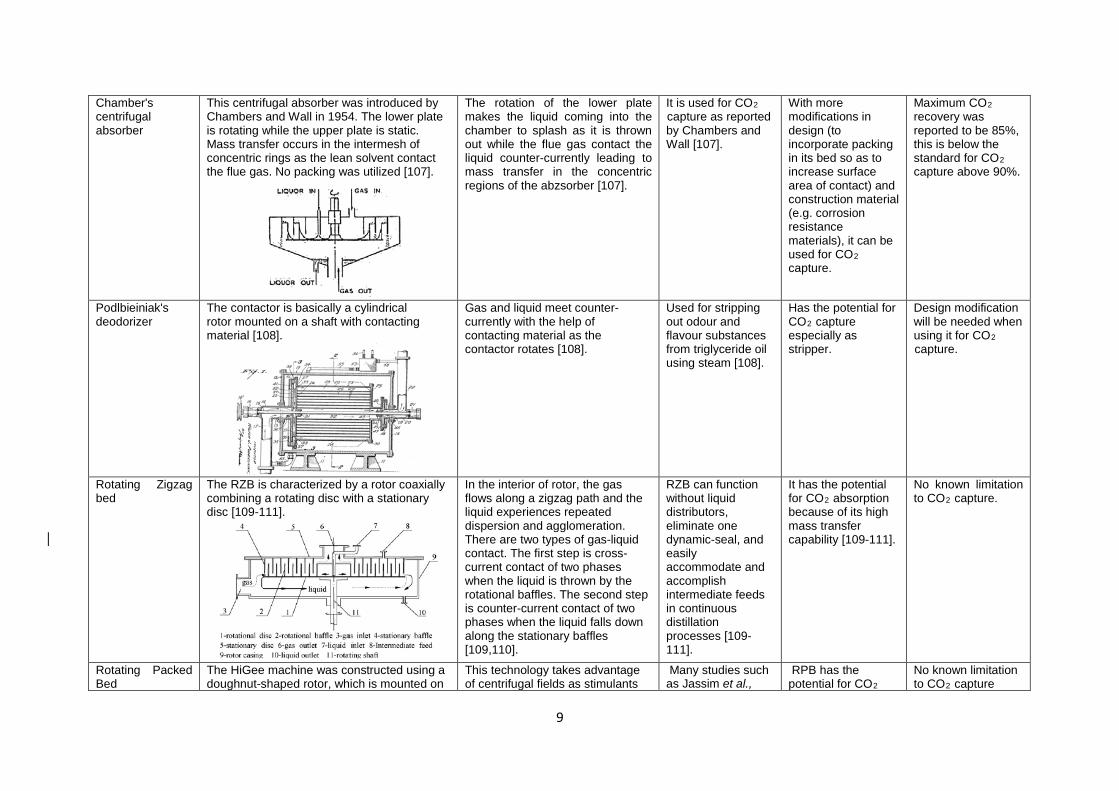
Chamber's centrifugal absorber
This centrifugal absorber was introduced by Chambers and Wall in 1954. The lower plate is rotating while the upper plate is static. Mass transfer occurs in the intermesh of concentric rings as the lean solvent contact the flue gas. No packing was utilized [107].
The rotation of the lower plate makes the liquid coming into the chamber to splash as it is thrown out while the flue gas contact the liquid counter-currently leading to mass transfer in the concentric regions of the abzsorber [107].
It is used for CO2 capture as reported by Chambers and Wall [107].
With more modifications in design (to incorporate packing in its bed so as to increase surface area of contact) and construction material (e.g. corrosion resistance materials), it can be used for CO2 capture.
Maximum CO2 recovery was reported to be 85%, this is below the standard for CO2 capture above 90%.
Podlbieiniak's deodorizer
The contactor is basically a cylindrical rotor mounted on a shaft with contacting material [108].
Gas and liquid meet counter-currently with the help of contacting material as the contactor rotates [108].
Used for stripping out odour and flavour substances from triglyceride oil using steam [108].
Has the potential for CO2 capture especially as stripper.
Design modification will be needed when using it for CO2 capture.
Rotating Zigzag bed
The RZB is characterized by a rotor coaxially combining a rotating disc with a stationary disc [109-111].
In the interior of rotor, the gas flows along a zigzag path and the liquid experiences repeated dispersion and agglomeration. There are two types of gas-liquid contact. The first step is cross-current contact of two phases when the liquid is thrown by the rotational baffles. The second step is counter-current contact of two phases when the liquid falls down along the stationary baffles [109,110].
RZB can function without liquid distributors, eliminate one dynamic-seal, and easily accommodate and accomplish intermediate feeds in continuous distillation processes [109-111].
It has the potential for CO2 absorption because of its high mass transfer capability [109-111].
No known limitation to CO2 capture.
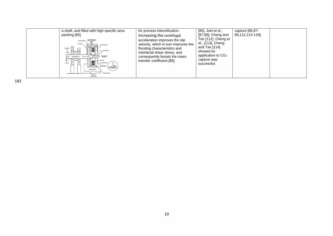
Rotating Packed Bed
The HiGee machine was constructed using a doughnut-shaped rotor, which is mounted on
This technology takes advantage of centrifugal fields as stimulants
Many studies such as Jassim et al.,
RPB has the potential for CO2
No known limitation to CO2 capture
10
182
a shaft, and filled with high specific area packing [85]
for process intensification. Increasing the centrifugal acceleration improves the slip velocity, which in turn improves the flooding characteristics and interfacial shear stress, and consequently boosts the mass transfer coefficient [85].
[85], Joel et al., [87,89], Cheng and Tan [112], Cheng et al., [113], Cheng and Tan [114] showed its application to CO2 capture was successful.
capture [85,87-89,112,114-118].
11
183
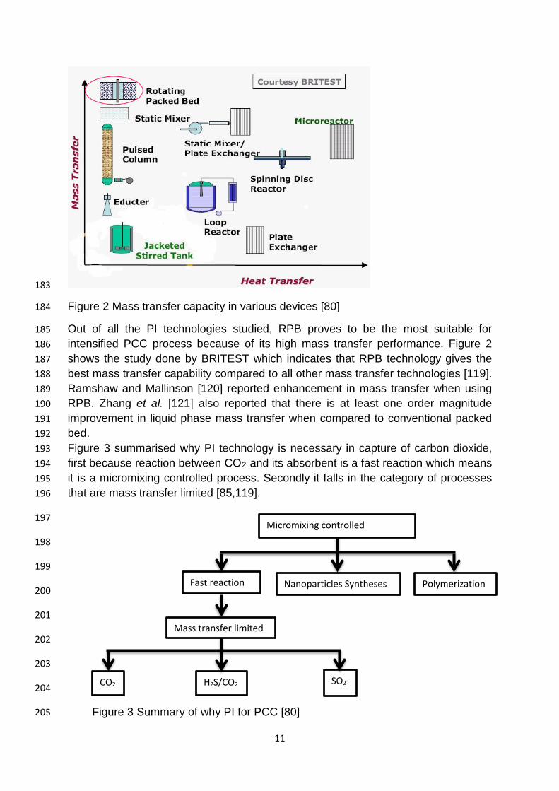
Figure 2 Mass transfer capacity in various devices [80] 184
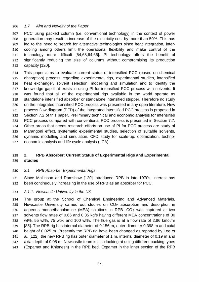
Out of all the PI technologies studied, RPB proves to be the most suitable for 185 intensified PCC process because of its high mass transfer performance. Figure 2 186 shows the study done by BRITEST which indicates that RPB technology gives the 187 best mass transfer capability compared to all other mass transfer technologies [119]. 188 Ramshaw and Mallinson [120] reported enhancement in mass transfer when using 189 RPB. Zhang et al. [121] also reported that there is at least one order magnitude 190 improvement in liquid phase mass transfer when compared to conventional packed 191 bed. 192 Figure 3 summarised why PI technology is necessary in capture of carbon dioxide, 193 first because reaction between CO2 and its absorbent is a fast reaction which means 194 it is a micromixing controlled process. Secondly it falls in the category of processes 195 that are mass transfer limited [85,119]. 196
197
198
199
200
201
202
203
204
205
Micromixing controlled
Nanoparticles Syntheses Fast reaction Polymerization
Mass transfer limited
CO2 H2S/CO2 SO2
Figure 3 Summary of why PI for PCC [80]
12
1.7 Aim and Novelty of the Paper 206
PCC using packed column (i.e. conventional technology) in the context of power 207 generation may result in increase of the electricity cost by more than 50%. This has 208 led to the need to search for alternative technologies since heat integration, inter-209 cooling among others limit the operational flexibility and make control of the 210 technology more difficult [54,63,64,66]. PI technology offers the benefit of 211 significantly reducing the size of columns without compromising its production 212 capacity [120]. 213
This paper aims to evaluate current status of intensified PCC (based on chemical 214 absorption) process regarding experimental rigs, experimental studies, intensified 215 heat exchanger, solvent selection, modelling and simulation and to identify the 216 knowledge gap that exists in using PI for intensified PCC process with solvents. It 217 was found that all of the experimental rigs available in the world operate as 218 standalone intensified absorber or standalone intensified stripper. Therefore no study 219 on the integrated intensified PCC process was presented in any open literature. New 220 process flow diagram (PFD) of the integrated intensified PCC process is proposed in 221 Section 7.2 of this paper. Preliminary technical and economic analysis for intensified 222 PCC process compared with conventional PCC process is presented in Section 7.7. 223 Other areas that needs research efforts on use of PI for PCC process are study of 224 Marangoni effect, systematic experimental studies, selection of suitable solvents, 225 dynamic modelling and simulation, CFD study for scale-up, optimization, techno-226 economic analysis and life cycle analysis (LCA). 227
2. RPB Absorber: Current Status of Experimental Rigs and Experimental 228 studies 229
2.1 RPB Absorber Experimental Rigs 230
Since Mallinson and Ramshaw [120] introduced RPB in late 1970s, interest has 231 been continuously increasing in the use of RPB as an absorber for PCC. 232
2.1.1. Newcastle University in the UK 233
The group at the School of Chemical Engineering and Advanced Materials, 234 Newcastle University carried out studies on CO2 absorption and desorption in 235 aqueous monoethanolamine (MEA) solutions in RPB. CO2 was captured at two 236 solvents flow rates of 0.66 and 0.35 kg/s having different MEA concentrations of 30 237 wt%, 55 wt%, 75 wt% and 100 wt%. The flue gas is at a flow rate of 2.86 kmol/hr 238 [85]. The RPB rig has internal diameter of 0.156 m, outer diameter 0.398 m and axial 239 height of 0.025 m. Presently the RPB rig have been changed as reported by Lee et 240 al. [122], the new RPB rig has outer diameter of 1 m, internal diameter of 0.19 m and 241 axial depth of 0.05 m. Newcastle team is also looking at using different packing types 242 (Expamet and Knitmesh) in the RPB bed. Expamet in the inner section of the RPB 243
13
packing while Knitmesh at the outer section of the packing to reduce or avoid the 244 problem known as the end effect. 245
2.1.2. BUCT in China 246
Counter-current flow RPB was reported by Yi et al. [123] using Benfield solution 247 (amine-promoted hot potassium carbonate solution). The experimental rig has the 248 following specifications: inner and outer radius of the packing 0.040 m and 0.100 m 249 respectively, and axial depth of 0.031 m. Zhang et al. [121] reported RPB absorber 250 using ionic liquid with the following rig specifications: inner diameter of 0.020 m, 251 outer diameter 0.060 m and axial packing depth of 0.020m. Luo et al. [124] proposed 252 correlation for gas-Liquid effective interfacial area in a RPB using NaOH solvent to 253 absorbed CO2. Luo et al. [124,125] reported the following rig specifications: inner 254 and outer radii of the rotor were 0.078 m and 0.153 m respectively, and the axial 255 height of the rotor was 0.050 m. The static casing had an inner radius of 0.248 m 256 and an axial height of 0.098 m. Zhang et al. [121] found that liquid side volumetric 257 mass transfer coefficient for RPB has been improved to around 3.9 X 10⁻² s-1 258 compared with 1.9 X10⁻³ s-1 for the conventional packed column under the same 259 operating conditions. 260
2.1.3. Taiwan (National Tsing Hua University, Chang Gung University and Chung 261 Yuan University) 262
The group in National Tsing Hua University in Taiwan studied CO2 capture using 263 counter-current flow arrangement. Yu et al. [126] studied CO2 capture by 264 alkanolamine solutions containing diethylenetriamine (DETA) and piperazine (PZ) in 265 an RPB. Cheng and Tan [114] studied removal of CO2 from indoor air by 266 alkanolamine in RPB, the experimental rig used is the same as for Tan and Chen 267 [127] and Yu et al. [126]. The diameter of the static casing of the RPB was 0.228 m, 268 the inner and outer diameters of the packing in the RPB were 0.076 and 0.16 m 269 respectively, and the height was 0.02 m. The total volume of the packing in the RPB 270 was of 0.0003114 m3. Stainless wire mesh with a specific surface area of 803 m2/m3 271 and a void fraction of 0.96 was packed in the bed acting as packing. In all these 272 studies, there is significant improvement in overall mass transfer and height of 273 transfer unit (HTU) demonstrating the performance superiority of an RPB compared 274 to conventional packed bed. Overall mass transfer coefficient (KGa) and HTU 275 corresponding to the most appropriate operating conditions in RPB were found to be 276 higher than 5.8 s-1 and lower than 1.0 cm [114]. However HTU is around 40 cm for 277 conventional PCC process. 278
The group in Chang Gung University in Taiwan studied RPB absorber using cross-279 flow RPB for CO2 capture which is believed to have relatively small gas flow 280 resistance and unaffected by centrifugal force. Another benefit of cross-flow is higher 281 gas velocity due to no critical gas velocity limitation. Lin et al. [128] and Lin and Chen 282 [129] found that cross-flow RPB absorber is effective for CO2 absorption process. In 283 their study, the following rig specifications were used: inner radius of 0.024 m, an 284
14
outer radius of 0.044 m, and an axial length of 0.12 m, specific surface area of 285 855m2/m3 and a voidage of 0.95. 286
2.1.4. India 287
India Institute of Technology (IIT) Kanpur reported the use of RPB as absorber in 288 CO2 absorption process using split packing. The two packing discs can rotate co-289 currently or counter-currently. Their work shows that counter-current rotation of the 290 packing disc gives better performance. The technology improves slip velocity to as 291 high as 30 m/s [130]. It was also reported in their study that this type of RPB shows 292 good performance in gas phase control processes by enhancing volumetric mass 293 transfer coefficient on the gas side to about 35 – 280 times compared to those of 294 packed columns, the liquid side volumetric mass transfer coefficient enhances in the 295 range of 25 – 250 times compared to the packed column [130]. Agarwal et al. [131] 296 stated that continuous single block packing causes a significant reduction only in the 297 liquid side mass-transfer resistance with little or no reduction in the gas side 298 resistance. Rajan et al. [130] studied RPB absorber in NaOH solution and found that 299 the split packing gives the highest volumetric liquid side mass transfer coefficient as 300 compared to conventional packed column. 301
2.2 Experimental Studies on Intensified Absorber 302
Significant progress has been witnessed in the area of intensified absorber, from the 303 early work published by Chamber’s Wall in early 1950’s to what we have at present. 304 Newcastle research team in the UK as reported by Jassim et al. [85] was able to 305 establish that RPB has the potential to dramatically reduce the size and cost of 306 carbon capture units for power plants. Lee et al. [122] reported that there are some 307 uncertainties which need to be tackled such as (a) Power consumption; (b) Pressure 308 drop; (c) Viscous liquid distribution in a RPB, this leads to the modification of the 309 experimental rig used by Jassim et al. [85] with the aim of addressing these 310 challenges. 311
Research Groups in China and Taiwan also made significant progress towards the 312 commercialization of this technology. The early report of the technology based on 313 counter-current flow has now turned to look at the other flow geometries such as co-314 current and cross-flow arrangement to take the advantage of lower gas phase 315 pressure drop and eliminating the need for air blower. 316
The research Group In India studies split packing RPB which has been suggested to 317 increase the gas-phase mass transfer coefficient as against continuous packing RPB 318 which is said to have the same gas phase mass transfer coefficient as conventional 319 packed column [132]. 320
15
3 RPB stripper: Current status of experimental rigs and experimental 321 studies 322
3.1 RPB stripper experimental rigs 323
Study on intensified stripper experimental rig for intensified PCC process was 324 published by just two research groups: Newcastle University in the UK and National 325 Tsing Hua University in Taiwan. With both groups, reboiler is the same as that of 326 conventional packed column (i.e. big in size). 327
3.1.1. Newcastle University, UK 328
Jassim et al. [85] reported RPB stripper for desorption runs for 30 wt%, 54 wt% and 329 60 wt% MEA solution having flow rate range from 0.2 kg/s to 0.6 kg/s. The rich MEA 330 solution is preheated to the temperature range between 57 oC and 70 oC and at 331 atmospheric pressure before being sent into the intensified stripper. The RPB 332 stripper has internal diameter of 0.156 m, outer diameter 0.398 m and axial height of 333 0.025 m. The packed bed material was stainless steel expamet with very high 334 specific surface area (2132 m2/m3) and a moderate voidage (0.76). Comparison 335 between RPB stripper and conventional stripper operating at the same performance 336 was done by Jassim et al. [85] which shows that the intensified stripper height is 337 reduced by a factor of 8.4 and its diameter is reduced by a factor of 11.3. 338
3.1.2. Taiwan 339
With conventional packed columns, energy consumption in capturing CO2 from a 340 conventional coal-fired power plant ranges from 3.24 to 4.2 GJ/tonne CO2 [20]. 341 Kothandaraman et al. [133] noted that the majority (approximately 62%) of the 342 energy consumed during the CO2 capture process was required for the regeneration 343 of solvent. Moreover, the consumption of steam is the most important component of 344 the operating costs of alkanolamine absorption as reported in Chapel and Mariz 345 [134]; Tobiesen and Svendsen [135]. 346
In order to regenerate CO2-rich solvent solution at a temperature higher than 100 oC 347 and a pressure higher than atmospheric pressure, Cheng et al. [88] introduced a 348 back pressure regulator, this is the major difference between Jassim et al. [85] setup 349 and Cheng et al. [88] setup. Because of the back pressure regulator, the 350 regeneration could be operated at various temperatures over a fixed pressure, and 351 vice versa. Cheng et al. [88] rig specifications are as following: the diameter of the 352 static casing of the RPB was 0.228 m, the inner and outer diameters of the packing 353 in the RPB were 0.076 and 0.16 m respectively, and the packing height in the RPB 354 was 0.02 m. The total volume of the packing in the RPB was 0.000311 m3. For the 355 RPB packing, a stainless wire mesh with a specific surface area of 803 m2/m3 and a 356 void fraction of 0.96 was packed into the bed. 357
The use of an RPB apparatus instead of a packed bed not only dramatically reduces 358 the required stripper volume but also consumes less regeneration energy [88]. 359 360
16
3.2 Experimental studies on Intensified Regenerator 361
Intensified regenerator for CO2 capture was reported by Jassim et al. [85] and 362 Cheng et al. [88]. In both studies, they found that RPB regenerator can significantly 363 reduce the size of column as compared to conventional stripper, but the reboiler size 364 is still as big as before since it has not been intensified. Cheng et al. [88] improved 365 from Jassim et al. [85] by introducing a back pressure controller, this will help in 366 operating the regenerator at higher pressure and temperature. 367
4 Intensified Heat Exchanger 368
In conventional PCC process, there is a cross heat exchanger. This is huge in 369 volume. In addition to this, the piping surrounding the cross heat exchanger has 370 high footprint. Therefore, the cross heat exchanger has to be intensified. 371
4.1 Technologies available to choose 372
4.1.1 Printed Circuit Heat Exchanger (PCHE) 373
The PCHE was invented in 1980 in Australia and applied to refrigerators in 1985 by 374 Heatric (UK) [136]. The PCHE is a high-integrity plate type compact heat exchanger 375 in which fluid flow channels are produced by chemical etching on flat metal plates. 376 Etched plates are stacked to produce single block by diffusion bonding [136-139]. 377
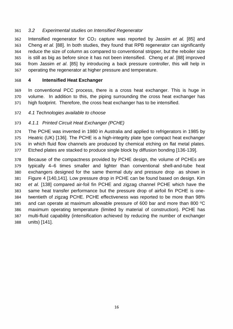
Because of the compactness provided by PCHE design, the volume of PCHEs are 378 typically 4–6 times smaller and lighter than conventional shell-and-tube heat 379 exchangers designed for the same thermal duty and pressure drop as shown in 380 Figure 4 [140,141]. Low pressure drop in PCHE can be found based on design. Kim 381 et al. [138] compared air-foil fin PCHE and zigzag channel PCHE which have the 382 same heat transfer performance but the pressure drop of airfoil fin PCHE is one-383 twentieth of zigzag PCHE. PCHE effectiveness was reported to be more than 98% 384 and can operate at maximum allowable pressure of 600 bar and more than 800 oC 385 maximum operating temperature (limited by material of construction). PCHE has 386 multi-fluid capability (intensification achieved by reducing the number of exchanger 387 units) [141]. 388
17
389 Figure 4 Printed Circuit Heat Exchanger (Courtesy of Heatric Ltd): the big one at the 390 back is shell-and-tube heat exchanger; while the small one in front is PCHE. 391
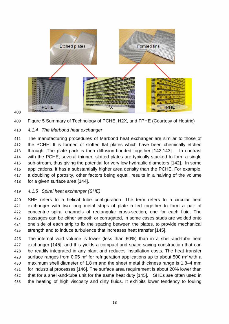
4.1.2 Formed Plate Heat Exchanger (FPHE) 392
The FPHE uses the same concept as various fin plate heat exchangers, but adds the 393 advantage of replacing the brazing process with the diffusion-bonding process. This 394 is shown in Figure 5. Heatric Ltd reported that FPHE has bigger channels size (about 395 3mm x 3mm) than the PCHE, this leads to lower pressure drop than PCHE [141]. 396 FPHE has effectiveness of more than 98%. Maximum allowable pressure for FPHE 397 is 200 bar and can operate at higher temperature of up to 800 oC, it has multi-fluid 398 capability (Intensification by reducing number exchanger units)[141]. 399
4.1.3 Hybrid Heat Exchanger (H²X) 400
H²X technology developed by Heatric Ltd combines the etched plates and the 401 formed fins to form what is known as Hybrid Heat Exchanger [141]. The heat 402 exchanger takes some of the advantages offered by PCHE and FPHE. H²X has 403 bigger hydraulic diameter than PCHE because of the presence of FPHE and can 404 also withstand higher pressure than FPHE because of the advantage offered by the 405 presence of PCHE. Typical hydraulic diameter of PCHE is in the range of 0.1 mm to 406 3 mm while that of FPHE is in the range of 1.2 mm to 3.3 mm [141]. 407
18
408
Figure 5 Summary of Technology of PCHE, H2X, and FPHE (Courtesy of Heatric) 409
4.1.4 The Marbond heat exchanger 410
The manufacturing procedures of Marbond heat exchanger are similar to those of 411 the PCHE. It is formed of slotted flat plates which have been chemically etched 412 through. The plate pack is then diffusion-bonded together [142,143]. In contrast 413 with the PCHE, several thinner, slotted plates are typically stacked to form a single 414 sub-stream, thus giving the potential for very low hydraulic diameters [142]. In some 415 applications, it has a substantially higher area density than the PCHE. For example, 416 a doubling of porosity, other factors being equal, results in a halving of the volume 417 for a given surface area [144]. 418
4.1.5 Spiral heat exchanger (SHE) 419
SHE refers to a helical tube configuration. The term refers to a circular heat 420 exchanger with two long metal strips of plate rolled together to form a pair of 421 concentric spiral channels of rectangular cross-section, one for each fluid. The 422 passages can be either smooth or corrugated, in some cases studs are welded onto 423 one side of each strip to fix the spacing between the plates, to provide mechanical 424 strength and to induce turbulence that increases heat transfer [145]. 425
The internal void volume is lower (less than 60%) than in a shell-and-tube heat 426 exchanger [145], and this yields a compact and space-saving construction that can 427 be readily integrated in any plant and reduces installation costs. The heat transfer 428 surface ranges from 0.05 m2 for refrigeration applications up to about 500 m2 with a 429 maximum shell diameter of 1.8 m and the sheet metal thickness range is 1.8–4 mm 430 for industrial processes [146]. The surface area requirement is about 20% lower than 431 that for a shell-and-tube unit for the same heat duty [145]. SHEs are often used in 432 the heating of high viscosity and dirty fluids. It exhibits lower tendency to fouling 433
19
[147]. When a SHE requires cleaning, all heat transfer surfaces are readily 434 accessible by simply removing the heads. 435
4.2 Recommendation for intensified Heat Exchanger for PCC application 436
To make a decision on best intensified heat exchanger to be used for PCC 437 application, many factors need to be considered. Some of them are listed as follows 438 [140]: (a) Operating Pressure limits; (b) Thermal performance (also known as the 439 effectiveness of the heat exchanger); (c) Expected working temperature range; (d) 440 Product mix to be used in the exchanger (liquid-to-liquid or gas-to-gas); (e) Pressure 441 drop desired across the expected heat exchanger; (f) The expected fluid flow 442 capacities over both sides of the heat exchanger; (g) Method of cleaning employed, 443 maintenance and repair issues associated with heat exchanger; (h) Materials 444 required for construction; (i) Ease of expansion of exchanger when it becomes 445 necessary; (j) The cost of the heat exchanger . 446
Compromise would therefore have to be made in most cases when selecting a heat 447 exchanger. For instance, cost of the exchanger is a paramount factor, but it should 448 not be the determining factor. If just for a cheaper heat exchanger, certain desired 449 performance demands of the heat exchanger would have to be forfeited. 450
The authors believe that the PCHE and the Marbond heat exchanger look promising 451 for use in intensified PCC process because of its many benefits such as high 452 efficiency (>98%), Compactness to improve safety and economics, weight saving, 453 low pressure drop, high temperature and retrofit options [141-143]. PCHE has been 454 reported to have additional advantage of being multi-fluid, meaning it can be used for 455 preheating of rich-MEA stream and also as a condenser for CO2 – stream. 456
5. Solvents used for intensified PCC process 457
There are extensive studies in solvent selection from both academia and industry 458 trying to identify alternative solvents for conventional PCC process. There are very 459 few studies on PI using different solvents [85,87,89,121,123-126,128,129,148-150]. 460
5.1 Factors to consider 461
Factors to consider when conducting solvent screening for conventional PCC 462 process and intensified PCC process is similar to some extent but the major 463 difference comes from residence time of solvent in different technologies. In 464 intensified PCC process, the residence time is relatively short (less than 10% of the 465 conventional PCC process). Therefore the factors to consider are: (1) CO2 466 absorption reaction kinetics, (2) CO2 absorption capacity, (3) heat of absorption, (4) 467 solvent toxicity, (5) solvent volatility, (6) solvent corrosivity, (7) solvent degradation, 468 (8) solvent foaming, (9) solvent viscosity, (10) solvent surface tension and (11) cost. 469
(1) CO2 reaction kinetics: This determines the rate at which CO2 will be captured. 470 Fast reaction kinetics is essential for intensified PCC process since the residence 471 time is very short. 472
20
(2) CO2 absorption capacity: This is related to the solvent flow rate required and 473 the sensible heat requirement. Higher CO2 absorption capacity would require lower 474 solvent flow rate and subsequent less regeneration energy demand. 475
(3) Heat of absorption: This would be an important factor affecting reboiler heat 476 duty. Lower heat of absorption will require less regeneration energy input to reverse 477 the chemical reaction and release absorbed CO2. 478
(4) Solvent stability, operational issues and environmental impact: These are the 479 other factors to be evaluated when selecting solvents. Solvent degradation (which 480 may be controlled by having high stability against oxygen and thermal stress) and 481 corrosion will cause an increase in operation and maintenance (O&M) costs by 482 making up solvent and reducing the lifetime of the equipment. Higher solvent 483 viscosity would increase the pump work in circulating the solvent between the 484 absorber and regenerator. Cost and availability of potential solvents in commercial 485 scale could contribute to limitations of the process feasibility. Environmental impacts 486 such as solvent toxicity and volatility deserve serious attention when judging the 487 potential of a solvent since causing secondary pollution while capturing CO2 is not a 488 scenario the public would be willing to take. 489
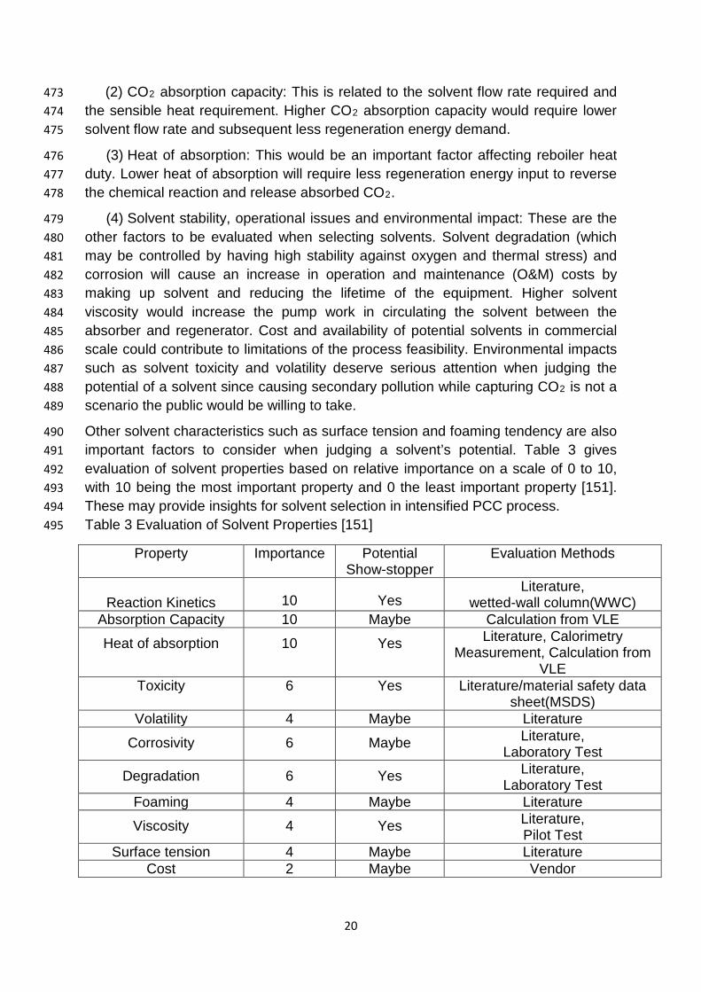
Other solvent characteristics such as surface tension and foaming tendency are also 490 important factors to consider when judging a solvent’s potential. Table 3 gives 491 evaluation of solvent properties based on relative importance on a scale of 0 to 10, 492 with 10 being the most important property and 0 the least important property [151]. 493 These may provide insights for solvent selection in intensified PCC process. 494 Table 3 Evaluation of Solvent Properties [151] 495
Property Importance Potential Show-stopper
Evaluation Methods
Reaction Kinetics 10 Yes
Literature, wetted-wall column(WWC)
Absorption Capacity 10 Maybe Calculation from VLE
Heat of absorption 10 Yes Literature, Calorimetry Measurement, Calculation from
VLE Toxicity 6 Yes Literature/material safety data
sheet(MSDS) Volatility 4 Maybe Literature
Corrosivity 6 Maybe Literature, Laboratory Test
Degradation 6 Yes Literature, Laboratory Test
Foaming 4 Maybe Literature
Viscosity 4 Yes Literature, Pilot Test
Surface tension 4 Maybe Literature Cost 2 Maybe Vendor

21
5.2 Solvents Used 496
Different solvents were used for intensified PCC process by different research 497 groups. Some researchers use one solvent while others mix solvents so as to benefit 498 from properties each solvent offers. 499
5.2.1. Alkanolamine 500
The use of MEA for CO2 capture in RPB was reported in Jassim et al. [85]. MEA has 501 high reactivity but is rapidly replaced by more efficient solvents because of its 502 corrosive nature, toxicity and high heat of reaction with CO2. Diethanolamine (DEA) 503 is much slower to react with CO2. It is not good for intensified PCC process itself. 504 Methyldiethanolamine (MDEA) has become an important alkanolamine because of 505 its low energy requirement, high capacity and high stability but has the disadvantage 506 of low rate of reaction with CO2. Lin et al., [128] presents study on the evaluation of 507 various alkanolamine solutions for CO2 removal in cross-flow RPB. The reaction rate 508 of these solvents with CO2 followed the order of Piperazine (PZ) > MEA > 2-amino-509 2-methyl-1-propanol (AMP). 510
Yu et al. [126] reported study on CO2 capture by alkanolamine solutions containing 511 diethylenetriamine (DETA) and PZ in RPB. They found that the CO2 capture 512 efficiency of DETA in terms of overall mass transfer coefficient 𝐾𝐾𝐺𝐺𝑎𝑎 and HTU was 513 superior to that of MEA in RPB. This is because DETA possesses higher CO2 514 absorption capacity and reaction rate with CO2 than MEA. Higher boiling point and 515 lower vapour pressure of DETA will lead to lower energy requirement and less loss 516 of solvent in stripper compared with MEA, suggesting DETA as a promising solvent 517 to substitute MEA for CO2 capture. The mixed solution DETA + PZ exhibited higher 518 CO2 capture efficiency than DETA indicating PZ was a great promoter for capturing 519 CO2. This was because the promoter PZ possesses higher reaction rate with CO2 520 than DETA [126]. 521
5.2.2 NaOH 522
Munjal et al. [152] reported the use of NaOH for absorption of CO2. Their study 523 shows that the gas-liquid mass transfer could be improved. Lin et al. [153] compared 524 the overall volumetric mass-transfer coefficient (𝐾𝐾𝐺𝐺𝑎𝑎) of RPB for different solvents 525 (i.e. NaOH, MEA and AMP) and found that 𝐾𝐾𝐺𝐺𝑎𝑎 values for the CO2-MEA system 526 were approximately 2-5 times higher than those for the CO2-AMP system also 𝐾𝐾𝐺𝐺𝑎𝑎 527 values for MEA were at least 20% higher than those for NaOH at the same operating 528 conditions. Therefore rate of reaction for CO2 capture in RPB follows the order MEA 529 > NaOH > AMP [154]. But AMP has higher absorption capacity than MEA. Lin and 530 Chen [81], Luo et al. [125] studied chemisorption’s of CO2 using NaOH in RPB. They 531 found that NaOH has the potential for use as solvent in RPB, but one of the major 532 challenges is the formation of stable salt which make solvent regeneration difficult. 533
22
5.2.3 Ionic liquid (1-n-butyl-3-methyllimidazolium hexafluorophosphate) 534
The use of ionic liquids for CO2 capture is gaining interest due to their unique 535 characteristics (i.e., wide liquid ranges, thermal stabilities, negligible vapour 536 pressures up to their thermal decomposition points, tunable physicochemical 537 characters, and high CO2 solubility) [121,155]. However, ionic liquids are commonly 538 high or superhigh viscosity liquids with poor fluidities. A significant limitation for large-539 scale application of a continuous CO2 capture process for conventional packed 540 columns by ionic liquid is the great resistance of mass transfer and low gas – liquid 541 mass transfer rate due to the high viscosity. As reported in Chen et al. [118], the 542 dependence of 𝑘𝑘𝐿𝐿𝑎𝑎 on liquid viscosity in RPB is less than that of packed column. 543
5.2.4 Potassium Carbonate (K2CO3) 544
The use of K2CO3 is receiving great attention because of its high CO2 absorption 545 capacity. Firstly, K2CO3 is a more efficient solvent for CO2 than either MEA or DEA 546 [156]. This means that for a given amount of solvent, K2CO3 can absorb more than 547 the other two solvents. In addition, the cost of this solvent is lower because less is 548 needed and K2CO3 is cheaper than other traditional solvents [156]. Secondly, this 549 eliminates the need for cross heat exchanger because the stripper runs at lower 550 temperature than the absorber [156]. Thirdly, K2CO3 increases the safety in CO2 551 removal by not only absorbing CO2 but also small amounts of hydrogen. Hydrogen 552 possesses a safety threat. Flashing off hydrogen can cause fires or explosions if 553 proper precautions are not taken. Lastly K2CO3 is not volatile, which means minimal 554 losses of the solvent with the exit gas occur. Since K2CO3 is not prone to the 555 degradation reactions associated with MEA, there is no loss of solvent associated 556 with degradation [133]. However one of the major drawbacks of using K2CO3 in RPB 557 is its low rate of reaction. This necessitated the need for promoter so as to increase 558 its rate of reaction. Kothandaraman et al. [133] reported regeneration energy (without 559 energy recuperation) of 3.2 MJ/kg for K2CO3 when treating flue gas (12 vol% CO2). 560
5.2.5 Benfield solution (Amine-promoted hot K2CO3 solution) 561
Amine-promoted hot K2CO3 solution, which is called Benfield solution, is used in 562 Benfield process [157]. The amine promoter could significantly enhance the reaction 563 rate while the carbonate–bicarbonate buffer offers advantages of large capacity for 564 CO2 capture and ease of regeneration [123,157]. Pilot plant studies by Field et al. 565 [158] shows that hot-carbonate system is particularly effective for removing CO2, 566 especially when present at high partial pressure. Steam consumption is one-third to 567 one-haft that of ethanolamine. Therefore, Benfield Process is known as an economic 568 and efficient way of removing large quantities of CO2 from flue gases and can be 569 effectively used in RPB [123]. 570
5.2.6 Piperazine (PZ) 571
PZ is a diamine solvent whereby one amine group is involved in a fast reaction with 572 CO2 to form the carbamate while the other amine absorbs the released proton [159]. 573
23
PZ reacts rapidly with CO2 and thus has attracted interest for usage in CO2 capture, 574 particularly as a reaction rate promoter for CO2 absorption in carbonate and tertiary 575 amine solutions [148,159-162]. Chemical reactions which describe the absorption of 576 CO2 in PZ solutions are more complex than MEA [159,160]. 577
Reaction rate between CO2 and aqueous PZ solution is high [148,160-162]. 578 However, the absorption has to take place at high temperatures because its solubility 579 in water is limited [161]. Freeman et al. [160] suggested the use of concentrated PZ 580 solution for CO2 capture because of its effective resistant to oxygen degradation and 581 thermal degradation. Despite its high reactivity with CO2, it has some challenges 582 such as limited solubility in water and more volatile than MEA. 583
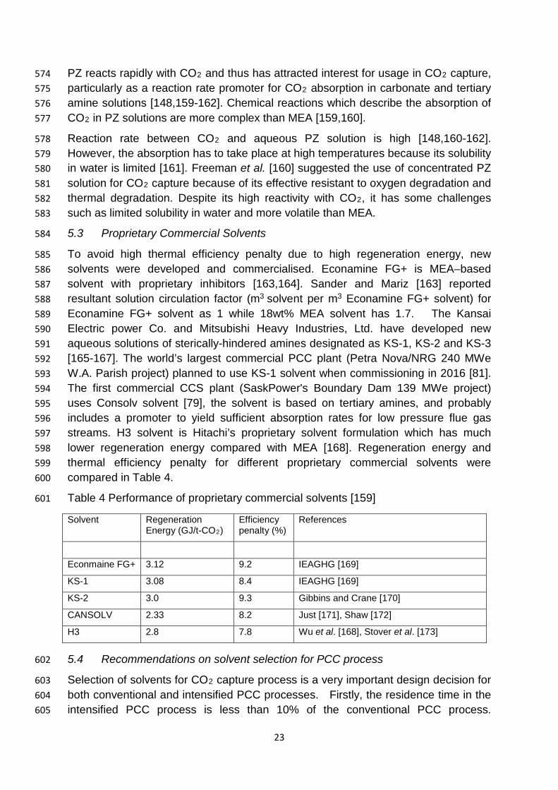
5.3 Proprietary Commercial Solvents 584
To avoid high thermal efficiency penalty due to high regeneration energy, new 585 solvents were developed and commercialised. Econamine FG+ is MEA–based 586 solvent with proprietary inhibitors [163,164]. Sander and Mariz [163] reported 587 resultant solution circulation factor (m3 solvent per m3 Econamine FG+ solvent) for 588 Econamine FG+ solvent as 1 while 18wt% MEA solvent has 1.7. The Kansai 589 Electric power Co. and Mitsubishi Heavy Industries, Ltd. have developed new 590 aqueous solutions of sterically-hindered amines designated as KS-1, KS-2 and KS-3 591 [165-167]. The world’s largest commercial PCC plant (Petra Nova/NRG 240 MWe 592 W.A. Parish project) planned to use KS-1 solvent when commissioning in 2016 [81]. 593 The first commercial CCS plant (SaskPower's Boundary Dam 139 MWe project) 594 uses Consolv solvent [79], the solvent is based on tertiary amines, and probably 595 includes a promoter to yield sufficient absorption rates for low pressure flue gas 596 streams. H3 solvent is Hitachi’s proprietary solvent formulation which has much 597 lower regeneration energy compared with MEA [168]. Regeneration energy and 598 thermal efficiency penalty for different proprietary commercial solvents were 599 compared in Table 4. 600
Table 4 Performance of proprietary commercial solvents [159] 601
Solvent Regeneration Energy (GJ/t-CO2)
Efficiency penalty (%)
References
Econmaine FG+ 3.12 9.2 IEAGHG [169]
KS-1 3.08 8.4 IEAGHG [169]
KS-2 3.0 9.3 Gibbins and Crane [170]
CANSOLV 2.33 8.2 Just [171], Shaw [172]
H3 2.8 7.8 Wu et al. [168], Stover et al. [173]
5.4 Recommendations on solvent selection for PCC process 602
Selection of solvents for CO2 capture process is a very important design decision for 603 both conventional and intensified PCC processes. Firstly, the residence time in the 604 intensified PCC process is less than 10% of the conventional PCC process. 605
24
Therefore solvent for intensified PCC process should have fast kinetics to capture 606 CO2. That is why most studies on RPB absorber uses primary or secondary 607 alkanolamines due to their fast kinetics. Concentration of the solvent in RPB is 608 usually high in order to have high reaction rate. High concentration solvent generally 609 has high viscosity, which prevents its use in conventional PCC process. However, 610 this is not a problem in RPB case. Secondly to achieve high CO2 absorption 611 capacity and reaction kinetics fast, mixing solvents such as amine-promoted K2CO3 612 will play a significant role. Thirdly the regeneration energy of solvents should be low 613 in addition to fast kinetics and high absorption capacity. Oexmann et al. [174] 614 reported mixing MDEA and PZ gives lower regeneration energy of 2.52 GJ/t-CO2. 615 Lastly when an intensified PCC plant is to be built in non-compliant area, volatility of 616 the solvent will have a big impact on whether or not the project will be permitted. 617
6. Modelling/Simulation for CO2 Capture Process using RPB 618
Modelling and simulation can be used to circumvent the difficulties with the 619 experimental approach, and complement the experimental studies. 620
6.1 Correlations for Mass/Heat Transfer 621
Significant progress has been noticed in the development of correlations for 622 mass/heat transfer in RPB. Tung and Mah [132] developed correlations for liquid 623 phase mass transfer coefficient based on the penetration theory. In developing Tung 624 and Mah [132] correlation, the effect coriolis acceleration and packing material 625 geometry were neglected. Chen et al. [175] developed correlation that takes into 626 consideration of those terms that were neglected by Tung and Mah [132]. Chen [176] 627 reported mass transfer correlation for gas-phase mass transfer coefficients which 628 has predicted experimental data reasonably well. The challenge of predicting 629 accurately the interfacial area in RPB is another issue of concern. Onda et al. [177] 630 correlation for gas-liquid interfacial area for conventional packed column was 631 modified by replacing the gravity term with centrifugal gravity term, but this does not 632 take into account different types of packing factors such as wire diameter and the 633 wire mesh opening. Luo et al. [124] developed gas-liquid interfacial area correlation 634 for wire mesh packing which takes into account the effect of wire diameter and wire 635 mesh opening. Burns et al. [178] correlation predicts the liquid hold-up for a high 636 voidage structured packing in an RPB. 637
6.2 Modelling/Simulation of Intensified Absorber 638
Few open literature discussed modelling and simulation of intensified absorber. The 639 group in Taiwan modelled the RPB as a series of continues stirred tank with 640 contactors. Cheng and Tan [114] reported that five CSTRs with a contactor can 641 achieve the set target for a given case through simulation study. The research group 642 at University of Hull, UK reported modelling and simulation of RPB absorber using 643 Aspen Plus® and visual FORTRAN [87,89]. Their key findings include: (a) the 644
25
packing volume can be reduced 52 times and the absorber size can be reduced 12 645 times; (b) there is no temperature bulge observed so far inside the packing [87,89]. 646
6.3 Modelling/Simulation of Intensified Stripper 647
Experimental studies of intensified regenerator were only reported in Jassim et al. 648 [85] and Cheng et al. [88]. No modelling and simulation of intensified stripper was 649 reported in open literature. 650
6.4 Modelling and Simulation of the whole plant 651
Open literature on modelling and simulation of whole intensified PCC process was 652 not available as at the time of this review. 653
7. Prospective of applying PI Technology into PCC using solvents 654
With the high potential to reduce capital and operating costs for carbon capture, the 655 UK Engineering and Physical Sciences Research Council (EPSRC) recently 656 awarded a consortium project worth £1.27 million to the universities of Hull, 657 Newcastle, Sheffield and Imperial College London to apply PI technology into PCC 658 with solvents process. 659
7.1 Fundamental study regarding Marangoni effect and enhanced mass transfer 660
Interfacial turbulence (i.e. Marangoni effect) which is caused by surface tension 661 gradient have been analysed by Semkov and Kolev [179], Kolev and Semkov [180], 662 Sternling and Scriven [181] and Buzek et al. [182]. The main reason for the 663 phenomenon of instability can be the local disturbances of temperature and /or 664 concentration near the interface [182]. Marangoni effect can significantly enhance 665 mass transfer rate by a factor of two or more, but it can easily be damped by a 666 surface active agent. Therefore, amine solutions used for absorption should not be 667 contaminated by even traces of surfactants [182]. A future task is to use simple 668 experiments to observe whether interfacial turbulence exists in RPB absorber. 669
26
7.2 Proposed schematic PFD for whole intensified PCC process 670
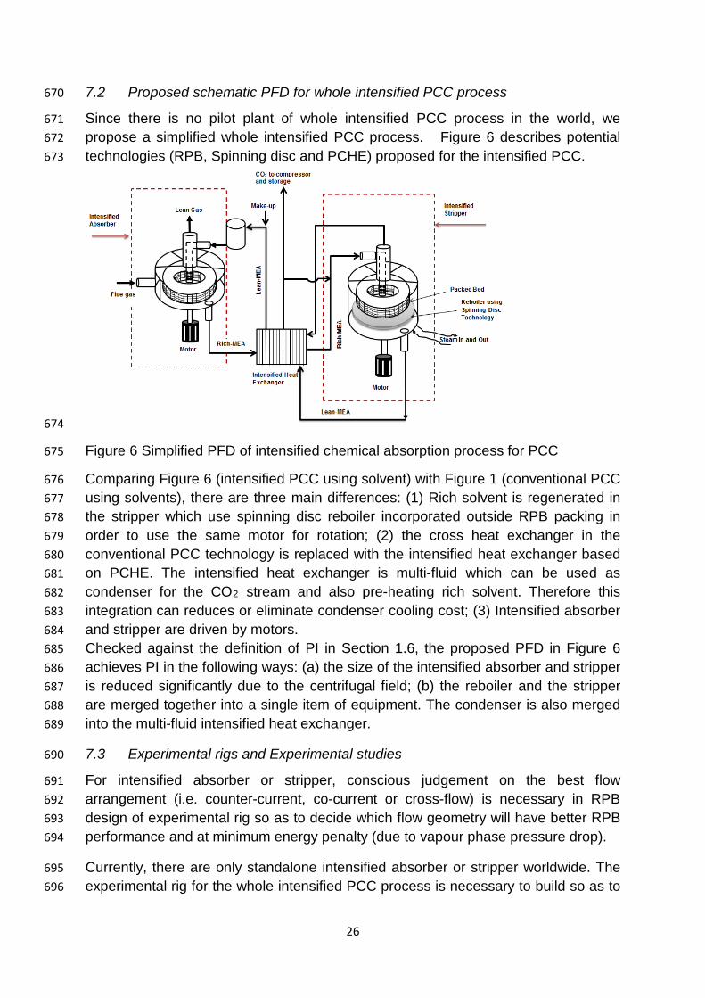
Since there is no pilot plant of whole intensified PCC process in the world, we 671 propose a simplified whole intensified PCC process. Figure 6 describes potential 672 technologies (RPB, Spinning disc and PCHE) proposed for the intensified PCC. 673
674
Figure 6 Simplified PFD of intensified chemical absorption process for PCC 675
Comparing Figure 6 (intensified PCC using solvent) with Figure 1 (conventional PCC 676 using solvents), there are three main differences: (1) Rich solvent is regenerated in 677 the stripper which use spinning disc reboiler incorporated outside RPB packing in 678 order to use the same motor for rotation; (2) the cross heat exchanger in the 679 conventional PCC technology is replaced with the intensified heat exchanger based 680 on PCHE. The intensified heat exchanger is multi-fluid which can be used as 681 condenser for the CO2 stream and also pre-heating rich solvent. Therefore this 682 integration can reduces or eliminate condenser cooling cost; (3) Intensified absorber 683 and stripper are driven by motors. 684 Checked against the definition of PI in Section 1.6, the proposed PFD in Figure 6 685 achieves PI in the following ways: (a) the size of the intensified absorber and stripper 686 is reduced significantly due to the centrifugal field; (b) the reboiler and the stripper 687 are merged together into a single item of equipment. The condenser is also merged 688 into the multi-fluid intensified heat exchanger. 689
7.3 Experimental rigs and Experimental studies 690
For intensified absorber or stripper, conscious judgement on the best flow 691 arrangement (i.e. counter-current, co-current or cross-flow) is necessary in RPB 692 design of experimental rig so as to decide which flow geometry will have better RPB 693 performance and at minimum energy penalty (due to vapour phase pressure drop). 694
Currently, there are only standalone intensified absorber or stripper worldwide. The 695 experimental rig for the whole intensified PCC process is necessary to build so as to 696
27
understand the dynamic behaviour of the whole capture process and to provide 697 foundation for studies in optimal design, operation and control. 698
Mass transfer performance of the intensified absorber has been fully determined by 699 experimental studies and modelling & simulation. More studies are needed to 700 understand the actual surface area in the RPB which over the years not been fully 701 determined. Dynamic flow behaviour in RPB is another aspect that needs to be 702 studied. 703
7.4 Selection of Solvents 704
Studies in conventional packed column showed that solvent with high viscosity 705 affects its performance. Zhang et al. [121] reported that the impact of high viscosity 706 on CO2 capture process is not so severe for intensified CO2 capture process. 707 Therefore study on ionic liquid solvent which has high absorption capacity and 708 selectivity can be a good driver in improving the performance of intensified PCC 709 process. Again studies on mixed solvents in intensified PCC process should be 710 emphasized in order to bring in balance during absorption and desorption so as to 711 have high capture performance in the absorber and less amount of regeneration 712 energy to be consumed in the stripper. 713
7.5 Modelling and simulation of intensified CO2 capture process 714
Thermodynamic and transport property data is central to any modelling and 715 simulation of intensified CO2 capture process and these properties were readily 716 available for up to 30 wt% aqueous MEA solution. However higher MEA 717 concentration is required for RPB absorber or stripper due to low residence time. 718 There is very limited data for CO2 with high concentration MEA in literature. 719
Solubility (i.e. VLE) data for MEA concentration up to 60 wt% and for temperature 720 range of 40 to 120 oC were reported in Aronu et al. [183]. Mason and Dodge [184] 721 reported solubility for MEA concentration up to 75 wt%. More solubility data at 722 80wt% or even 100 wt% MEA concentrations is needed for intensified PCC process. 723 Therefore there is a need for more solubility studies for higher solvent 724 concentrations. This can be done by experiment or using molecular simulation 725 software to interpolate or extrapolate. 726
Other areas that require experimental or molecular simulation study are reaction 727 equilibrium constants and kinetic parameters determination for higher solvent 728 concentration with CO2. 729
Most studies through modelling and simulation focused on intensified absorber with 730 few researches on intensified stripper for PCC. Studies on steady state simulation of 731 intensified absorber were reported in Joel et al. [87,89] with main aim on process 732 analysis for design and operation. However, these studies could not check the 733 dynamic behaviour of the absorber or the whole intensified PCC process. Therefore 734 future study on dynamic modelling is necessary in order to meet such challenges. It 735
28
is believed that if a dynamic model is developed and validated, sensitivity analysis 736 will be done for optimal design, operation and control. 737
7.6 Scale-up 738
Commercial-scale capture on operating power plants has yet to be undertaken, 739 leading to uncertainty regarding scale-up and integration of existing technologies 740 [185]. Harzog [186] reported that the challenge for CCS commercial deployment is 741 to integrate and scale up these components (absorber, heat exchanger and the 742 regenerator). Shi et al. [187] and Yang et al. [188] use computational fluid dynamic 743 (CFD) to study fluid flow in RPB. But more studies are required for scale-up of RPB 744 columns. To be able to carry out the scale-up study of an intensified PCC process, it 745 is recommended to couple process modelling software with CFD software so as to 746 accurately predict the hydraulic behaviour and the mass transfer behaviour of the 747 RPB. 748
7.7 Evaluation of Technical, Economical and Environmental Performance 749
So far, no detailed and systematic studies were reported on the technical, 750 economical and environmental impact on the use of intensified PCC process 751 compared with conventional PCC process. 752
There are some operational benefits when using RPB in intensified PCC process. 753 The first is its ability to be operated at higher gas and/or liquid flow rates owing to the 754 low tendency of flooding compared to the conventional packed bed [128]. The 755 second benefit of using RPB is its better self-cleaning, avoidance of plugging in the 756 system, and being unaffected by a moderate disturbance in its orientation [189]. 757
Joel et al. [87] carried out comparative study between conventional absorber and 758 intensified absorber, and found the size reduction factor of about 12 times. Jassim et 759 al. [85] reported stripper height reduction factor of 8.4 and stripper diameter 760 reduction factor of 11.3 as compared to conventional packed column. Cheng et al. 761 [88] reported a reduction factor for RPB stripper of at least 10 times as compared to 762 conventional stripper. Li et al. [190] reported that for PCHE performing the same duty 763 as shell-and-Tube heat exchanger has size reduction factor of 4-6 times. From the 764 analysis above, the size of main components in intensified PCC process can be 765 significantly reduced. 766
Because of much less gas–liquid contact time that occurs in RPB absorber than in a 767 conventional packed bed columns, the selection of solvent with a fast reaction rate 768 with CO2 is crucial [85,87,89,112,113,120,127,191]. This necessitates the use of 769 higher concentration solvent (such as 55 wt% or 75 wt% MEA reported in 770 [85,87,89]), but this comes with another challenge of corrosion as reported by 771 Barham, et al. [192]. This corrosion problem can be managed by the use of (a) more 772 expensive construction material such as stainless steel rather than the commonly 773 used carbon steel; (b) coating with high performance polymer on the surface of 774 stainless steel. 775
29
In addition to steam consumption for solvent regeneration, electricity will be 776 consumed to drive the intensified absorber and stripper in the intensified PCC 777 process. This means parasitic energy consumption added to carbon capture in 778 intensified PCC process. Cheng et al. [88] reported that regeneration energy of RPB 779 stripper is smaller than that of conventional packed column (excluding the energy for 780 rotating the RPB stripper). This is caused by decrease in the amount of vapour lean 781 MEA required from reboiler to RPB due to improved heat transfer zone inside RPB 782 thereby decreasing its reboiler duty. Only Agarwal et al. [131] studied electricity 783 consumption to drive the motors in RPB absorber using DEA solvent for carbon 784 capture. Generally the higher the rotating speed, the higher the electricity 785 consumption by the motor. The study in Agarwal et al. [131] indicates that electricity 786 consumption is quite low at 900 rpm while the number increased significantly at 1500 787 rpm. More experimental studies are required to quantify the contribution of electricity 788 used by motors to overall energy consumption in intensified PCC process. 789
The authors have performed preliminary technical and economic analysis for 790 intensified PCC process compared with conventional PCC process. The initial 791 prediction is that the capital cost of the whole intensified PCC process can reduce to 792 1/6 (i.e. 16.7%) compared with the same capacity conventional PCC process. The 793 reasons behind this prediction are: (a) the average size reduction is around 12 times; 794 (b) Due to corrosion, stainless steel has to be used instead of carbon steel. Unit 795 material price will roughly double. The initial prediction on energy consumption in 796 capturing unit mass of CO2 will be similar between the two processes. The reasons 797 behind this prediction are: (a) the steam consumption (or the regeneration energy) in 798 intensified PCC process will be lower due to higher concentration of solvent used; (b) 799 electricity consumed to drive the intensified absorber and stripper in the intensified 800 PCC process is highly related to rotating speed. The second item can only be 801 determined by specific design conditions. 802
In summary, it is necessary to quantify overall costs (capital & operating costs) used 803 for capturing unit mass of CO2 in intensified and conventional PCC processes based 804 on detailed and accurate process models. Detailed life cycle analysis (LCA) for 805 intensified PCC process should be performed in order to compare with conventional 806 PCC process. 807
8. Conclusions 808
The paper presents a critical evaluation of current research status in intensified PCC 809 regarding experimental rigs (including intensified absorber and stripper, intensified 810 heat exchanger), experimental studies worldwide, solvent selection, modelling and 811 simulation. It was found: (a) there is no experimental rig for whole intensified PCC 812 process apart from standalone intensified absorber or stripper. There have been no 813 efforts to intensify the reboiler and the cross heat exchanger so far. (b) There is no 814 systematic study on solvent selection for intensified PCC process. (c) There are 815
30
some papers on steady state modelling and simulation of intensified absorber. No 816 modelling and simulation of intensified stripper was reported in open literature. 817 Future research efforts and potential breakthrough on different aspects of intensified 818 PCC process have been discussed. These include: (a) A schematic PFD for 819 intensified PCC process has been proposed. (b) It is important to use simple 820 experiments to observe whether interfacial turbulence (i.e. Marangoni effect) exists 821 in RPB absorber. (c) It is vital to develop dynamic models for the whole intensified 822 PCC process for future work in process control. (d) It is necessary to combine CFD 823 study and process modelling for scale-up study. (e) A preliminary technical and 824 economic analysis for the intensified PCC process has been carried out in 825 comparison with conventional PCC process. More detailed and systematic technical, 826 economic and environmental performance analysis should be performed. 827
Acknowledgement 828
The authors would like to acknowledge financial support from EPSRC Research 829 Challenges in Carbon Capture for CCS (Ref: EP/M001458), UK Research Councils’ 830 Energy Programme (Ref: NE/H013865/2) and EU FP7 (Ref: PIRSES-GA-2013-831 612230). 832
References 833
[1] Freund P. Making deep reductions in CO2 emissions from coal-fired power plant 834 using capture and storage of CO2. Proc Inst Mech Eng A: J Power Energy 835 2003;217:1-7. 836
[2] Taylor Peter, Lavagne d’orTigue Olivier, Trudeau N, Francoeur M. Energy 837 efficiency indicators for public electricity production from fossil fuels. 2008. 838
[3] Department of Energy and Climate Change (DECC). Solid Fuels and Derived 839 Gases Statistics: Data Sources and Methodologies. 2012;Available 840 at: http://webarchive.nationalarchives.gov.uk/20121217150421/http://decc.gov.uk/en/841 content/cms/statistics/energy_stats/source/electricity/electricity.aspx; (accessed 842 May,2013). 843
[4] Albo J, Luis P, Irabien A. Carbon dioxide capture from flue gases using a cross-844 flow membrane contactor and the ionic liquid 1-ethyl-3-methylimidazolium 845 ethylsulfate. Ind Eng Chem Res 2010;49:11045-51. 846
[5] World Meteorological Organization (WMO). Press Release No. 991<br />. 26 847 May 2014;http://www.wmo.int/pages/mediacentre/press_releases/pr_991_en.html 848 (accessed June, 2014). 849
[6] Intergovernmental Panel on Climate Change (IPCC). Contribution of Working 850 Group III to the Fourth Assessment Report of the Intergovernmental Panel on 851 Climate Change. Cambridge, United Kingdom/New York, United States: Cambridge 852 University Press, 2007. 853
31
[7] International Energy Agency. Carbon Capture and Storage Model Regulatory 854 Framework. IEA 2010;Available 855 at: http://www.iea.org/publications/freepublications/publication/model_framework.pdf, 856 (accessed May 2013). 857
[8] Metz B, Davidson O, De Coninck H, Loos M, Meyer L. IPCC, 2005: IPCC special 858 report on carbon dioxide capture and storage. Prepared by Working Group III of the 859 Intergovernmental Panel on Climate Change. Cambridge, United Kingdom and New 860 York, NY, USA, 442 pp 2005. 861
[9] Abanades JC, Arias B, Lyngfelt A, Mattisson T, Wiley DE, Li H et al. Emerging 862 CO2 capture systems. International Journal of Greenhouse Gas 863 Control http://dx.doi.org/10.1016/j.ijggc.2015.04.018 2015:1750-5836. 864
[10] Folger P. Carbon capture: a technology assessment. 865 2013. http://oai.dtic.mil/oai/oai?verb=getRecord&metadataPrefix=html&identifier=AD866 A590346 (accessed January, 2015). 867
[11] Lawal A, Wang M, Stephenson P, Obi O. Demonstrating full-scale post-868 combustion CO2 capture for coal-fired power plants through dynamic modelling and 869 simulation. Fuel 2012;101:115-28. 870
[12] Resnik KP, Yeh JT, Pennline HW. Aqua ammonia process for simultaneous 871 removal of CO2, SO2 and NOx. Int J Environ Technol Manage 2004;4:89-104. 872
[13] Haszeldine RS. Carbon capture and storage: how green can black be? Science 873 2009;325:1647-52. 874
[14] Agbonghae EO, Hughes KJ, Ingham DB, Ma L, Pourkashanian M. Optimal 875 Process Design of Commercial-Scale Amine-Based CO2 Capture Plants. Ind Eng 876 Chem Res 2014;53:14815-29. 877
[15] Abu-Zahra MRM, Niederer JPM, Feron PHM, Versteeg GF. CO2 capture from 878 power plants: Part II. A parametric study of the economical performance based on 879 mono-ethanolamine. International Journal of Greenhouse Gas Control 2007;1:135-880 42. 881
[16] GLOBAL CCS INSTITUTE. CO2 Capture Technologies: Post Combustion 882 Capture (PCC). January, 2012 Available at: http://hub globalccsinstitute 883 com/sites/default/files/publications/29721/co2-capture-technologies-pcc 884 pdf;(accessed June, 2015). 885
[17] Bounaceur R, Lape N, Roizard D, Vallieres C, Favre E. Membrane processes 886 for post-combustion carbon dioxide capture: a parametric study. Energy 887 2006;31:2556-70. 888
[18] Favre E. Carbon dioxide recovery from post-combustion processes: Can gas 889 permeation membranes compete with absorption? J Membr Sci 2007;294:50-9. 890
32
[19] Goto K, Yogo K, Higashii T. A review of efficiency penalty in a coal-fired power 891 plant with post-combustion CO2 capture. Appl Energy 2013;111:710-20. 892
[20] International Energy Agency (IEA). Prospects for CO2 Capture and Storage. 893 OECD/IEA, Paris, France. 2004;Available at: http://ccs-894 info.org/onewebmedia/iea_oecd_ccs_prospects.pdf (accessed June, 2014). 895
[21] Zhao L, Menzer R, Riensche E, Blum L, Stolten D. Concepts and investment 896 cost analyses of multi-stage membrane systems used in post-combustion processes. 897 Energy Procedia 2009;1:269-78. 898
[22] Zhao L, Riensche E, Blum L, Stolten D. Multi-stage gas separation membrane 899 processes used in post-combustion capture: Energetic and economic analyses. J 900 Membr Sci 2010;359:160-72. 901
[23] Zhao M, Minett AI, Harris AT. A review of techno-economic models for the 902 retrofitting of conventional pulverised-coal power plants for post-combustion capture 903 (PCC) of CO 2. Energy & Environmental Science 2013;6:25-40. 904
[24] Yu C, Huang C, Tan C. A review of CO2 capture by absorption and adsorption. 905 Aerosol and Air Quality Research 2012;12:745-69. 906
[25] Zhao W, Sprachmann G, Li Z, Cai N, Zhang X. Effect of K2CO3·1.5H2O on the 907 regeneration energy consumption of potassium-based sorbents for CO2 capture. 908 Appl Energy 2013;112:381-7. 909
[26] Clausse M, Merel J, Meunier F. Numerical parametric study on CO2 capture by 910 indirect thermal swing adsorption. International Journal of Greenhouse Gas Control 911 2011;5:1206-13. 912
[27] Kapica-Kozar J, Kusiak-Nejman E, Wanag A, Kowalczyk Ł, Wrobel RJ, Mozia S 913 et al. Alkali-treated titanium dioxide as adsorbent for CO2 capture from air. 914 Microporous and Mesoporous Materials 2015;202:241-9. 915
[28] Li K, Jiang J, Yan F, Tian S, Chen X. The influence of polyethyleneimine type 916 and molecular weight on the CO2 capture performance of PEI-nano silica 917 adsorbents. Appl Energy 2014;136:750-5. 918
[29] Maring BJ, Webley PA. A new simplified pressure/vacuum swing adsorption 919 model for rapid adsorbent screening for CO2 capture applications. International 920 Journal of Greenhouse Gas Control 2013;15:16-31. 921
[30] Parshetti GK, Chowdhury S, Balasubramanian R. Biomass derived low-cost 922 microporous adsorbents for efficient CO2 capture. Fuel 2015;148:246-54. 923
[31] Plaza MG, Pevida C, Arias B, Fermoso J, Rubiera F, Pis JJ. A comparison of 924 two methods for producing CO2 capture adsorbents. Energy Procedia 2009;1:1107-925 13. 926
33
[32] Wei L, Jing Y, Gao Z, Wang Y. Development of a pentaethylenehexamine-927 modified solid support adsorbent for CO2 capture from model flue gas. Chin J Chem 928 Eng 2015;23:366-71. 929
[33] Xu C, Hedin N. Microporous adsorbents for CO2 capture – a case for 930 microporous polymers? Materials Today 2014;17:397-403. 931
[34] Zhang W, Liu H, Sun C, Drage TC, Snape CE. Capturing CO2 from ambient air 932 using a polyethyleneimine–silica adsorbent in fluidized beds. Chemical Engineering 933 Science 2014;116:306-16. 934
[35] Zhang W, Liu H, Sun C, Drage TC, Snape CE. Performance of 935 polyethyleneimine–silica adsorbent for post-combustion CO2 capture in a bubbling 936 fluidized bed. Chem Eng J 2014;251:293-303. 937
[36] Dasgupta S, Nanoti A, Gupta P, Jena D, Goswami AN, Garg MO. Carbon Di-938 Oxide Removal with Mesoporous Adsorbents in a Single Column Pressure Swing 939 Adsorber. Sep Sci Technol 2009;44:3973-83. 940
[37] Dasgupta S, Biswas N, Gode NG, Divekar S, Nanoti A, Goswami AN. CO2 941 recovery from mixtures with nitrogen in a vacuum swing adsorber using metal 942 organic framework adsorbent: A comparative study. International Journal of 943 Greenhouse Gas Control 2012;7:225-9. 944
[38] Krishna R, van Baten JM. A comparison of the CO2 capture characteristics of 945 zeolites and metal–organic frameworks. Separation and Purification Technology 946 2012;87:120-6. 947
[39] Gil MV, Martínez M, García S, Rubiera F, Pis JJ, Pevida C. Response surface 948 methodology as an efficient tool for optimizing carbon adsorbents for CO2 capture. 949 Fuel Process Technol 2013;106:55-61. 950
[40] González AS, Plaza MG, Pis JJ, Rubiera F, Pevida C. Post-combustion CO2 951 capture adsorbents from spent coffee grounds. Energy Procedia 2013;37:134-41. 952
[41] González AS, Plaza MG, Rubiera F, Pevida C. Sustainable biomass-based 953 carbon adsorbents for post-combustion CO2 capture. Chem Eng J 2013;230:456-65. 954
[42] Han SJ, Bang Y, Lee H, Lee K, Song IK, Seo JG. Synthesis of a dual-templated 955 MgO–Al2O3 adsorbent using block copolymer and ionic liquid for CO2 capture. 956 Chem Eng J 2015;270:411-7. 957
[43] Hlaing NN, Sreekantan S, Othman R, Hinode H, Kurniawan W, Thant AA et al. A 958 novel (Zr–Ce) incorporated Ca(OH)2 nanostructure as a durable adsorbent for CO2 959 capture. Mater Lett 2014;133:204-7. 960
[44] Huang Y, Chiueh P, Shih C, Lo S, Sun L, Zhong Y et al. Microwave pyrolysis of 961 rice straw to produce biochar as an adsorbent for CO2 capture. Energy 2015;84:75-962 82. 963
34
[45] Samanta A, Zhao A, Shimizu GK, Sarkar P, Gupta R. Post-combustion CO2 964 capture using solid sorbents: a review. Ind Eng Chem Res 2011;51:1438-63. 965
[46] Drage TC, Snape CE, Stevens LA, Wood J, Wang J, Cooper AI et al. Materials 966 challenges for the development of solid sorbents for post-combustion carbon 967 capture. Journal of Materials Chemistry 2012;22:2815-23. 968
[47] Durán-Guevara MB, Ortiz-Landeros J, Pfeiffer H, Espitia-Cabrera MI, Contreras-969 García ME. Potassium-based sorbents using mesostructured γ-alumina supports for 970 low temperature CO2 capture. Ceram Int 2015;41:3036-44. 971
[48] Cheung O, Bacsik Z, Liu Q, Mace A, Hedin N. Adsorption kinetics for CO2 on 972 highly selective zeolites NaKA and nano-NaKA. Appl Energy 2013;112:1326-36. 973
[49] Hedin N, Andersson L, Bergström L, Yan J. Adsorbents for the post-combustion 974 capture of CO2 using rapid temperature swing or vacuum swing adsorption. Appl 975 Energy 2013;104:418-33. 976
[50] Shakerian F, Kim K, Szulejko JE, Park J. A comparative review between amines 977 and ammonia as sorptive media for post-combustion CO2 capture. Appl Energy 978 2015;148:10-22. 979
[51] Bernardo P, Drioli E, Golemme G. Membrane gas separation: a review/state of 980 the art. Ind Eng Chem Res 2009;48:4638-63. 981
[52] Brunetti A, Scura F, Barbieri G, Drioli E. Membrane technologies for CO2 982 separation. J Membr Sci 2010;359:115-25. 983
[53] Car A, Stropnik C, Yave W, Peinemann K. PEG modified poly (amide-b-ethylene 984 oxide) membranes for CO2 separation. J Membr Sci 2008;307:88-95. 985
[54] Kvamsdal H, Jakobsen J, Hoff K. Dynamic modeling and simulation of a CO2 986 absorber column for post-combustion CO2 capture. Chemical Engineering and 987 Processing: Process Intensification 2009;48:135-44. 988
[55] Dugas RE. Pilot plant study of carbon dioxide capture by aqueous 989 monoethanolamine. MSE Thesis, University of Texas at Austin 2006. 990
[56] Mangalapally HP, Hasse H. Pilot plant study of two new solvents for post 991 combustion carbon dioxide capture by reactive absorption and comparison to 992 monoethanolamine. Chemical Engineering Science 2011;66:5512-22. 993
[57] Mangalapally HP, Hasse H. Pilot plant experiments for post combustion carbon 994 dioxide capture by reactive absorption with novel solvents. Energy Procedia 995 2011;4:1-8. 996
[58] Mangalapally HP, Notz R, Hoch S, Asprion N, Sieder G, Garcia H et al. Pilot 997 plant experimental studies of post combustion CO2 capture by reactive absorption 998 with MEA and new solvents. Energy Procedia 2009;1:963-70. 999
35
[59] Mangalapally HP, Notz R, Asprion N, Sieder G, Garcia H, Hasse H. Pilot plant 1000 study of four new solvents for post combustion carbon dioxide capture by reactive 1001 absorption and comparison to MEA. International Journal of Greenhouse Gas 1002 Control 2012;8:205-16. 1003
[60] Lawal A, Wang M, Stephenson P, Yeung H. Dynamic Modeling and Simulation 1004 of CO2 Chemical Absorption Process for Coal-Fired Power Plants. Computer Aided 1005 Chemical Engineering 2009;27:1725-30. 1006
[61] Lawal A, Wang M, Stephenson P, Yeung H. Dynamic modelling of CO2 1007 absorption for post combustion capture in coal-fired power plants. Fuel 1008 2009;88:2455-62. 1009
[62] Lawal A, Wang M, Stephenson P, Koumpouras G, Yeung H. Dynamic modelling 1010 and analysis of post-combustion CO2 chemical absorption process for coal-fired 1011 power plants. Fuel 2010;89:2791-801. 1012
[63] Biliyok C, Lawal A, Wang M, Seibert F. Dynamic modelling, validation and 1013 analysis of post-combustion chemical absorption CO2 capture plant. International 1014 Journal of Greenhouse Gas Control 2012;9:428-45. 1015
[64] Kvamsdal HM, Rochelle GT. Effects of the temperature bulge in CO2 absorption 1016 from flue gas by aqueous monoethanolamine. Ind Eng Chem Res 2008;47:867-75. 1017
[65] Kvamsdal HM, Hetland J, Haugen G, Svendsen HF, Major F, Kårstad V et al. 1018 Maintaining a neutral water balance in a 450MWe NGCC-CCS power system with 1019 post-combustion carbon dioxide capture aimed at offshore operation. International 1020 Journal of Greenhouse Gas Control 2010;4:613-22. 1021
[66] Kvamsdal HM, Haugen G, Svendsen HF. Flue-gas cooling in post-combustion 1022 capture plants. Chem Eng Res Design 2011;89:1544-52. 1023
[67] MacDowell N, Shah N. Optimisation of Post-combustion CO2 Capture for 1024 Flexible Operation. Energy Procedia 2014;63:1525-35. 1025
[68] Mac Dowell N, Shah N. Dynamic modelling and analysis of a coal-fired power 1026 plant integrated with a novel split-flow configuration post-combustion CO2 capture 1027 process. International Journal of Greenhouse Gas Control 2014;27:103-19. 1028
[69] Mac Dowell N, Shah N. The multi-period operation of an amine-based CO2 1029 capture process integrated with a supercritical coal-fired power station. Computers 1030 and Chemical Engineering 2014. 1031
[70] Mac Dowell N, Samsatli N, Shah N. Dynamic modelling and analysis of an 1032 amine-based post-combustion CO2 capture absorption column. International Journal 1033 of Greenhouse Gas Control 2013;12:247-58. 1034
[71] Lucquiaud M, Gibbins J. On the integration of CO2 capture with coal-fired power 1035 plants: A methodology to assess and optimise solvent-based post-combustion 1036 capture systems. Chem Eng Res Design 2011;89:1553-71. 1037
36
[72] Lucquiaud M, Fernandez ES, Chalmers H, Dowell NM, Gibbins J. Enhanced 1038 Operating Flexibility and Optimised Off-design Operation of Coal Plants with Post-1039 combustion Capture. Energy Procedia 2014;63:7494-507. 1040
[73] Errey O, Chalmers H, Lucquiaud M, Gibbins J. Valuing Responsive Operation of 1041 Post-combustion CCS Power Plants in Low Carbon Electricity Markets. Energy 1042 Procedia 2014;63:7471-84. 1043
[74] Agbonghae EO, Hughes KJ, Ingham DB, Ma L, Pourkashanian M. A Semi-1044 Empirical Model for Estimating the Heat Capacity of Aqueous Solutions of 1045 Alkanolamines for CO2 Capture. Ind Eng Chem Res 2014. 1046
[75] Asendrych D, Niegodajew P, Drobniak S. CFD modelling of CO2 capture in a 1047 packed bed by chemical absorption. Chemical and Process Engineering 1048 2013;34:269-82. 1049
[76] Sebastia-Saez D, Gu S, Ranganathan P, Papadikis K. 3D modeling of 1050 hydrodynamics and physical mass transfer characteristics of liquid film flows in 1051 structured packing elements. International Journal of Greenhouse Gas Control 1052 2013;19:492-502. 1053
[77] Raynal L, Ben Rayana F, Royon-Lebeaud A. Use of CFD for CO2 absorbers 1054 optimum design : from local scale to large industrial scale. Energy Procedia 1055 2009;1:917-24. 1056
[78] Raynal L, Royon-Lebeaud A. A multi-scale approach for CFD calculations of 1057 gas–liquid flow within large size column equipped with structured packing. Chemical 1058 Engineering Science 2007;62:7196-204. 1059
[79] Stéphenne K. Start-up of world's first commercial post-combustion coal fired ccs 1060 project: Contribution of shell cansolv to saskpower boundary dam iccs project. 1061 Energy Procedia 2014;63:6106-10. 1062
[80] ZEROCO2.NO. Plant Barry CCS demo. ;Available 1063 at: http://www.zeroco2.no/projects/southern-company-ccs-demonstration (accessed 1064 November, 2014). 1065
[81] NRG Energy. WA Parish CO2 capture project. 2014;Available 1066 at: https://www.nrg.com/documents/business/pla-2014-petranova-waparish-1067 factsheet.pdf (accessed December, 2014). 1068
[82] BERR. Advanced power plant using high efficiency boiler/turbine. Report 1069 BPB010. BERR, Department for Business Enterprise and Regulatory Reform. 1070 2006;Available at: www.berr.gov.uk/files/file30703.pdf (accessed April 2012). 1071
[83] Agbonghae EO, Best T, Finney KN, Palma CF, Hughes KJ, Pourkashanian M. 1072 Experimental and Process Modelling Study of Integration of a Micro-turbine with an 1073 Amine Plant. Energy Procedia 2014;63:1064-73. 1074
37
[84] Henderson C. Towards zero emission coal-fired power plant. IEA Clean Coal 1075 Centre Reports 2005, http://www.iea-coal.org.uk/documents/81379/5947/Towards-1076 zero-emission-coal-fired-power-plant%C2%A0 (accessed February, 2015). 1077
[85] Jassim MS, Rochelle G, Eimer D, Ramshaw C. Carbon dioxide absorption and 1078 desorption in aqueous monoethanolamine solutions in a rotating packed bed. Ind 1079 Eng Chem Res 2007;46:2823-33. 1080
[86] Reay D. The role of process intensification in cutting greenhouse gas emissions. 1081 Appl Therm Eng 2008;28:2011-9. 1082
[87] Joel AS, Wang M, Ramshaw C, Oko E. Process analysis of intensified absorber 1083 for post-combustion CO2 capture through modelling and simulation. International 1084 Journal of Greenhouse Gas Control 2014;21:91-100. 1085
[88] Cheng H, Lai C, Tan C. Thermal regeneration of alkanolamine solutions in a 1086 rotating packed bed. International Journal of Greenhouse Gas Control 2013;16:206-1087 16. 1088
[89] Joel AS, Wang M, Ramshaw C. Modelling and simulation of intensified absorber 1089 for post-combustion CO2 capture using different mass transfer correlations. Appl 1090 Therm Eng 2015;74:47-53. 1091
[90] Charles Ross and Son Company. Charles Ross and Son Company. ;Available 1092 at: http://www.staticmixers.com/staticmixer_designs.pdf (accessed June, 2014). 1093
[91] Johns GA. Toxicity reduction for industrial effluent containing formaldehyde. 1094 MSc Thesis Cranfield University, UK 2006. 1095
[92] Meeuwse M, Van Der Schaaf J, Schouten JC. Mass Transfer in a rotor-stator 1096 spinning disk reactor with cofeeding of gas and liquid. Industrial and Engineering 1097 Chemistry Research 2010;49:1605-10. 1098
[93] Meeuwse M, Van der Schaaf J, Kuster B, Schouten J. Gas–liquid mass transfer 1099 in a rotor–stator spinning disc reactor. Chemical Engineering Science 2010;65:466-1100 71. 1101
[94] Meeuwse M, Lempers S, van der Schaaf J, Schouten JC. Liquid− Solid Mass 1102 Transfer and Reaction in a Rotor− Stator Spinning Disc Reactor. Ind Eng Chem Res 1103 2010;49:10751-7. 1104
[95] Dobie CG, MarijaVicevic, Boodhoo KVK. An evaluation of the effectiveness of 1105 continuous thin film processing in a spinning disc reactor for bulk free-radical photo-1106 copolymerisation. Chemical Engineering and Processing: Process Intensification 1107 2013;71:97-106. 1108
[96] Boodhoo KVK, Jachuck RJ. Process intensification: Spinning disk reactor for 1109 styrene polymerization. Appl Therm Eng 2000;20:1127-46. 1110
38
[97] Brechtelsbauer C, Lewis N, Oxley P, Ricard F, Ramshaw C. Evaluation of a 1111 spinning disc reactor for continuous processing. Organic Process Research and 1112 Development 2001;5:65-8. 1113
[98] Riffat S, Zhao X. Preliminary study of the performance and operating 1114 characteristics of a mop-fan air cleaning system for buildings. Build Environ 1115 2007;42:3241-52. 1116
[99] Shehata H, Riffat S, Shao L. Mop fan for removal of air-borne pollutants. 1117 1995;2:45-59. 1118
[100] Riffat S, Shehata H, Srivastava N. The desiccant air-conditioning system. Int J 1119 Ambient Energy 2004;25:163-8. 1120
[101] BUSS ChemTech AG. Advanced BUSS Loop® Reactor Technology. 1121 2009;Available at: http://www.buss-1122 ct.com/up/files/PDFs_RT/Brochure_RT_Advanced_Loop_Reactor_operating_principl1123 e.pdf (accessed December, 2014). 1124
[102] Machado RM, Heier KR, Broekhuis RR. Developments in hydrogenation 1125 technology for fine-chemical and pharmaceutical applications. Current Opinion in 1126 Drug Discovery and Development 2001;4:745-55. 1127
[103] Cramers PHMR, Beenackers AACM. Influence of the ejector configuration, 1128 scale and the gas density on the mass transfer characteristics of gas-liquid ejectors. 1129 Chem Eng J 2001;82:131-41. 1130
[104] Roberge DM, Gottsponer M, Eyholzer M, Kockmann N. Industrial design, 1131 scale-up, and use of microreactors. Chimica Oggi 2009;27:8-11. 1132
[105] Roberge DM, Zimmermann B, Rainone F, Gottsponer M, Eyholzer M, 1133 Kockmann N. Microreactor technology and continuous processes in the fine 1134 chemical and pharmaceutical industry: Is the revolution underway? Organic Process 1135 Research and Development 2008;12:905-10. 1136
[106] Ehrfeld Mikrotechnik BTS. High Performance reactors for pharmaceutical and 1137 fine chemical production. 2011;Available at: http://www.pharma-1138 food.de/media/file/5474 (accessed December, 2014). 1139
[107] Chambers H, Wall M. Some factors affecting the design of centrifugal gas 1140 absorbers. Trans.Inst.Chem.Eng 1954;32:S96-S107. 1141
[108] Podbielniak WJ. Continuous Centrifugal Vapor-Liquid Contactor. 1966;US 1142 Patent 3,233,880. 1143
[109] Wang G, Xu Z, Yu Y, Ji J. Performance of a rotating zigzag bed—A new 1144 HIGEE. Chemical Engineering and Processing: Process Intensification 1145 2008;47:2131-9. 1146
39
[110] Wang G, Xu Z, Ji J. Progress on Higee distillation—Introduction to a new 1147 device and its industrial applications. Chem Eng Res Design 2011;89:1434-42. 1148
[111] Wang GQ, Xu OG, Xu ZC, Ji JB. New HIGEE-rotating zigzag bed and its mass 1149 transfer performance. Industrial and Engineering Chemistry Research 2008;47:8840-1150 6. 1151
[112] Cheng H, Tan C. Reduction of CO2 concentration in a zinc/air battery by 1152 absorption in a rotating packed bed. J Power Sources 2006;162:1431-6. 1153
[113] Cheng H, Shen J, Tan C. CO2 capture from hot stove gas in steel making 1154 process. International Journal of Greenhouse Gas Control 2010;4:525-31. 1155
[114] Cheng H, Tan C. Removal of CO2 from indoor air by alkanolamine in a rotating 1156 packed bed. Separation and Purification Technology 2011;82:156-66. 1157
[115] Cheng H, Tan C. Carbon dioxide capture by blended alkanolamines in rotating 1158 packed bed. Energy Procedia 2009;1:925-32. 1159
[116] Chen Y, Hsu Y, Lin C, Tai CY, Liu H. Volatile organic compounds absorption in 1160 a cross-flow rotating packed bed. Environ Sci Technol 2008;42:2631-6. 1161
[117] Chen Y, Lin F, Lin C, Tai CY, Liu H. Packing characteristics for mass transfer 1162 in a rotating packed bed. Ind Eng Chem Res 2006;45:6846-53. 1163
[118] Chen Y, Lin C, Liu H. Mass transfer in a rotating packed bed with viscous 1164 Newtonian and non-Newtonian fluids. Ind Eng Chem Res 2005;44:1043-51. 1165
[119] Chen JF. The recent developments in the HiGee technology. Presentation at 1166 GPE-EPIC,14-17June 2009. 2009;Available at http://inpact.inp-toulouse.fr/GPE-1167 EPIC2009/images/presentation_chen.pdf (accessed February, 2014). 1168
[120] Mallinson RH, Ramshaw C. Mass transfer process. 1981;US Patent 4,283,255. 1169
[121] Zhang L, Wang J, Xiang Y, Zeng X, Chen J. Absorption of carbon dioxide with 1170 ionic liquid in a rotating packed bed contactor: Mass transfer study. Ind Eng Chem 1171 Res 2011;50:6957-64. 1172
[122] Lee, J., Reay, D., Ramshaw C.,. Post-combustion carbon capture research at 1173 Newcastle University, Presentation to PIN, 2nd May, 2012. 2012;Available 1174 at: www.pinetwork.org (accessed June 2013). 1175
[123] Yi F, Zou H, Chu G, Shao L, Chen J. Modeling and experimental studies on 1176 absorption of CO2 by Benfield solution in rotating packed bed. Chem Eng J 1177 2009;145:377-84. 1178
[124] Luo Y, Chu G, Zou H, Zhao Z, Dudukovic MP, Chen J. Gas–liquid effective 1179 interfacial area in a rotating packed bed. Ind Eng Chem Res 2012;51:16320-5. 1180
40
[125] Luo Y, Chu G, Zou H, Xiang Y, Shao L, Chen J. Characteristics of a two-stage 1181 counter-current rotating packed bed for continuous distillation. Chemical Engineering 1182 and Processing: Process Intensification 2012;52:55-62. 1183
[126] Yu C, Cheng H, Tan C. CO2 capture by alkanolamine solutions containing 1184 diethylenetriamine and piperazine in a rotating packed bed. International Journal of 1185 Greenhouse Gas Control 2012;9:136-47. 1186
[127] Tan C-, Chen J-. Absorption of carbon dioxide with piperazine and its mixtures 1187 in a rotating packed bed. Separation and Purification Technology 2006;49:174-80. 1188
[128] Lin C, Lin Y, Tan C. Evaluation of alkanolamine solutions for carbon dioxide 1189 removal in cross-flow rotating packed beds. J Hazard Mater 2010;175:344-51. 1190
[129] Lin C-, Chen Y-. Performance of a cross-flow rotating packed bed in removing 1191 carbon dioxide from gaseous streams by chemical absorption. International Journal 1192 of Greenhouse Gas Control 2011;5:668-75. 1193
[130] Rajan S, Kumar M, Ansari MJ, Rao D, Kaistha N. Limiting gas liquid flows and 1194 mass transfer in a novel rotating packed bed (HiGee). Ind Eng Chem Res 1195 2010;50:986-97. 1196
[131] Agarwal L, Pavani V, Rao D, Kaistha N. Process intensification in HiGee 1197 absorption and distillation: design procedure and applications. Ind Eng Chem Res 1198 2010;49:10046-58. 1199
[132] Tung H, Mah RS. Modeling liquid mass transfer in higee separation process. 1200 Chem Eng Commun 1985;39:147-53. 1201
[133] Kothandaraman A, Nord L, Bolland O, Herzog HJ, McRae GJ. Comparison of 1202 solvents for post-combustion capture of CO2 by chemical absorption. Energy 1203 Procedia 2009;1:1373-80. 1204
[134] Chapel DG, Mariz CL, Ernest J. Recovery of CO2 from flue gases: commercial 1205 trends. 1999:4-6. 1206
[135] Tobiesen FA, Svendsen HF. Study of a modified amine-based regeneration 1207 unit. Ind Eng Chem Res 2006;45:2489-96. 1208
[136] Nikitin K, Kato Y, Ngo L. Printed circuit heat exchanger thermal–hydraulic 1209 performance in supercritical CO2 experimental loop. Int J Refrig 2006;29:807-14. 1210
[137] Tsuzuki N, Kato Y, Ishiduka T. High performance printed circuit heat 1211 exchanger. Appl Therm Eng 2007;27:1702-7. 1212
[138] Kim DE, Kim MH, Cha JE, Kim SO. Numerical investigation on thermal–1213 hydraulic performance of new printed circuit heat exchanger model. Nucl Eng Des 1214 2008;238:3269-76. 1215
41
[139] Li X, Kininmont D, Le Pierres R, Dewson SJ. Alloy 617 for the high temperature 1216 diffusion-bonded compact heat exchangers. Proceedings of ICAPP08, Anaheim, CA, 1217 Paper 2008. 1218
[140] Li Q, Flamant G, Yuan X, Neveu P, Luo L. Compact heat exchangers: A review 1219 and future applications for a new generation of high temperature solar receivers. 1220 Renewable and Sustainable Energy Reviews 2011;15:4855-75. 1221
[141] Pierres R. L.,. Diffusion Bonded Compact Heat Exchangers - Compact 1222 Reactors Presentation to PIN, 23rd May, 2013. 2013;Available at: www.pinetwork.org 1223 (accessed November, 2013). 1224
[142] Hesselgreaves JE. Compact heat exchangers: selection, design and operation. 1225 : Gulf Professional Publishing, 2001. 1226
[143] Phillips, C. H.,Symonds, K. T. Development of a novel integrated chemical 1227 reactor–heat exchanger. 2007;Available 1228 at: http://lorien.ncl.ac.uk/ming/pdfs/bhrpaper1.pdf (accessed August, 2013). 1229
[144] Reay D. Learning from experiences with compact heat exchangers. : CADDET 1230 Series 25, Centre for the Analysis and Dissemination of Demonstrated Energy 1231 Technologies. Sittard, The Netherlands, 1999. 1232
[145] Shah RK, Sekulic DP. Fundamentals of heat exchanger design. : John Wiley & 1233 Sons, 2003. 1234
[146] Thonon B, Breuil E. Compact heat exchanger technologies for the HTRs 1235 recuperator application. 2001;Available 1236 at: http://www.iaea.org/inis/collection/NCLCollectionStore/_Public/32/047/32047838.1237 pdf (accessed on May, 2014). 1238
[147] Picon-Nunez M, Canizalez-Davalos L, Martinez-Rodriguez G, Polley G. 1239 Shortcut design approach for spiral heat exchangers. Food Bioprod Process 1240 2007;85:322-7. 1241
[148] Yu C-, Wu T-, Tan C-. CO2 capture by piperazine mixed with non-aqueous 1242 solvent diethylene glycol in a rotating packed bed. International Journal of 1243 Greenhouse Gas Control 2013;19:503-9. 1244
[149] Luo X, Hartono A, Hussain S, Svendsen FH. Mass transfer and kinetics of 1245 carbon dioxide absorption into loaded aqueous monoethanolamine solutions. 1246 Chemical Engineering Science 2015;123:57-69. 1247
[150] Lin C, Chen B. Carbon dioxide absorption into NaOH solution in a cross-flow 1248 rotating packed bed. Journal of Industrial and Engineering Chemistry-Seoul- 1249 2007;13:1083. 1250
[151] Ji, L., Bonnin-Nartker, P., Klidas, M. G., Zang, R. Solvent Selection for 1251 Commercial Deployment of B&W PGG’s RSAT TM CO2 Scrubbing Process. The 35th 1252
42
International Technical Conference on Coal Utilization & Fuel Systems, US A, June 1253 6-10 2010. 1254
[152] Munjal S, Duduković MP, Ramachandran P. Mass-transfer in rotating packed 1255 beds—II. Experimental results and comparison with theory and gravity flow. 1256 Chemical Engineering Science 1989;44:2257-68. 1257
[153] Lin C-, Liu W-, Tan C-. Removal of carbon dioxide by absorption in a rotating 1258 packed bed. Industrial and Engineering Chemistry Research 2003;42:2381-6. 1259
[154] Lin C, Chen B. Carbon dioxide absorption in a cross-flow rotating packed bed. 1260 Chem Eng Res Design 2011;89:1722-9. 1261
[155] Wappel D, Gronald G, Kalb R, Draxler J. Ionic liquids for post-combustion CO2 1262 absorption. International Journal of Greenhouse Gas Control 2010;4:486-94. 1263
[156] Undewood, J., Dawson, G., Barney, C.,. Design of a CO2 absorption system in 1264 an Ammonia plant. 1997;Available 1265 at: http://www.owlnet.rice.edu/~ceng403/co2abs.html (accessed April, 2014). 1266
[157] Benson H, Field J, Jimeson R. CO2 absorption: employing hot potassium 1267 carbonate solutions. Chem.Eng.Prog.;(United States) 1954;50. 1268
[158] Field JH, Benson H, Johnson G, Tosh J, Forney A. Pilot-plant studies of the 1269 hot-carbonate process for removing carbon dioxide and hydrogen sulfide.[Removal 1270 of CO2 and H2S from gas mixtures necessary in synthesizing liquid fuels from coal]. 1271 US Bur.Mines, Bull. 1962;597. 1272
[159] Bishnoi S, Rochelle GT. Absorption of carbon dioxide into aqueous piperazine: 1273 reaction kinetics, mass transfer and solubility. Chemical Engineering Science 1274 2000;55:5531-43. 1275
[160] Freeman SA, Dugas R, Van Wagener DH, Nguyen T, Rochelle GT. Carbon 1276 dioxide capture with concentrated, aqueous piperazine. International Journal of 1277 Greenhouse Gas Control 2010;4:119-24. 1278
[161] Yu C-, Tan C-. Mixed alkanolamines with low regeneration energy for CO2 1279 capture in a rotating packed bed. Energy Procedia 2013;37:455-60. 1280
[162] Dugas R, Rochelle G. Absorption and desorption rates of carbon dioxide with 1281 monoethanolamine and piperazine. Energy Procedia 2009;1:1163-9. 1282
[163] Sander MT, Mariz CL. The Fluor Daniel® econamine FG process: Past 1283 experience and present day focus. Energy Conversion and Management 1284 1992;33:341-8. 1285
[164] Reddy S. Econamine FG Plus SM Technology for Post-Combustion CO2 1286 Capture. 11 th Meeting of the International Post-Combustion CO2 Capture Network 1287 2008. 1288
43
[165] Mimura T, Shimojo S, Suda T, Iijima M, Mitsuoka S. Research and 1289 development on energy saving technology for flue gas carbon dioxide recovery and 1290 steam system in power plant. Energy Conversion and Management 1995;36:397-1291 400. 1292
[166] Mimura T, Simayoshi H, Suda T, Iijima M, Mituoka S. Development of energy 1293 saving technology for flue gas carbon dioxide recovery in power plant by chemical 1294 absorption method and steam system. Energy Conversion and Management 1295 1997;38:S57-62. 1296
[167] Kishimoto S, Hirata T, Iijima M, Ohishi T, Higaki K, Mitchell R. Current status of 1297 MHI's CO2 recovery technology and optimization of CO2 recovery plant with a PC 1298 fired power plant. Energy Procedia 2009;1:1091-8. 1299
[168] Wu S, Bergins C, Kikkawa H, Kobayashi H, Kawasaki T. Technology options 1300 for clean coal power generation with CO2 capture. 2010. 1301
[169] IEA-GHG. Improvements in power generation with post-combustion capture of 1302 CO2. IEA Greenhouse Gas R&D Programme, Cheltenham, UK 2004. 1303
[170] Gibbins J, Crane R. Scope for reductions in the cost of CO2 capture using flue 1304 gas scrubbing with amine solvents. Proc Inst Mech Eng A: J Power Energy 1305 2004;218:231-9. 1306
[171] Just P, Mirfendereski Y, Geuzebroek F. Cansolv technologies: the value of 1307 integration. IEAGHG (International Energy Agency Greenhouse Gas) R&D Program 1308 (Eds ), International Network for CO2 Capture: Report on 12th Workshop, Report 1309 2009. 1310
[172] Shaw D. Cansolv CO2 capture: The value of integration. Energy Procedia 1311 2009;1:237-46. 1312
[173] Stöver B, Bergins C, Klebes J. Optimized post combustion carbon capturing on 1313 coal fired power plants. Energy Procedia 2011;4:1637-43. 1314
[174] Oexmann J, Hasenbein C, Kather A. Semi-empirical model for the direct 1315 simulation of power plant with integrated post-combustion CO2 capture processes by 1316 wet chemical absorption. Energy Procedia 2011;4:1276-85. 1317
[175] Chen Y, Lin C, Liu H. Mass transfer in a rotating packed bed with various radii 1318 of the bed. Ind Eng Chem Res 2005;44:7868-75. 1319
[176] Chen Y. Correlations of mass transfer coefficients in a rotating packed bed. Ind 1320 Eng Chem Res 2011;50:1778-85. 1321
[177] Onda K, Sada E, Takeuchi H. Gas absorption with chemical reaction in packed 1322 columns. J Chem Eng Japan 1968;1:62-6. 1323
44
[178] Burns J, Jamil J, Ramshaw C. Process intensification: operating characteristics 1324 of rotating packed beds—determination of liquid hold-up for a high-voidage 1325 structured packing. Chemical Engineering Science 2000;55:2401-15. 1326
[179] Semkov K, Kolev N. On the evaluation of the interfacial turbulence (the 1327 Marangoni effect) in gas (vapour)—liquid mass transfer: Part I. A method for 1328 estimating the interfacial turbulence effect. Chemical Engineering and Processing: 1329 Process Intensification 1991;29:77-82. 1330
[180] Kolev N, Semkov K. On the evaluation of the interfacial turbulence (the 1331 Marangoni Effect) in gas (vapour)—liquid mass transfer: Part II. Modelling of packed 1332 columns accounting for axial mixing and Marangoni effects. Chemical Engineering 1333 and Processing: Process Intensification 1991;29:83-91. 1334
[181] Sternling C, Scriven L. Interfacial turbulence: hydrodynamic instability and the 1335 Marangoni effect. AIChE J 1959;5:514-23. 1336
[182] Buzek J, Podkański J, Warmuziński K. The enhancement of the rate of 1337 absorption of CO2 in amine solutions due to the Marangoni effect. Energy conversion 1338 and management 1997;38:S69-74. 1339
[183] Aronu UE, Gondal S, Hessen ET, Haug-Warberg T, Hartono A, Hoff KA et al. 1340 Solubility of CO2 in 15, 30, 45 and 60 mass% MEA from 40 to 120 C and model 1341 representation using the extended UNIQUAC framework. Chemical Engineering 1342 Science 2011;66:6393-406. 1343
[184] Mason JW, Dodge BF. Equilibrium absorption of carbon dioxide by solutions of 1344 the ethanolamines. Trans.Am.Inst.Chem.Eng 1936;32:27-48. 1345
[185] Herzog H, Eide J. Rethinking CCS–Moving Forward in Times of Uncertainty. 1346 Mining Report 2013;149:318-23. 1347
[186] Herzog HJ. Scaling up carbon dioxide capture and storage: From megatons to 1348 gigatons. Energy Econ 2011;33:597-604. 1349
[187] Shi X, Xiang Y, Wen L, Chen J. CFD analysis of liquid phase flow in a rotating 1350 packed bed reactor. Chem Eng J 2013;228:1040-9. 1351
[188] Yang W, Wang Y, Chen J, Fei W. Computational fluid dynamic simulation of 1352 fluid flow in a rotating packed bed. Chem Eng J 2010;156:582-7. 1353
[189] Wang GQ, Xu ZC, Yu YL, Ji JB. Performance of a rotating zigzag bed-A new 1354 HIGEE. Chemical Engineering and Processing: Process Intensification 1355 2008;47:2131-9. 1356
[190] Xiuqing L, Le Pierres R, Dewson SJ. Heat exchangers for the next generation 1357 of nuclear reactors. Proceedings of the 2006 international congress on advances in 1358 nuclear power plants-ICAPP'06 2006. 1359

45
[191] Chen Y, Liu H, Lin C, Liu W. Micromixing in a rotating packed bed. J Chem 1360 Eng Japan 2004;37:1122-8. 1361
[192] Barham H, Brahim S, Rozita Y, Mohamed K. Carbon steel corrosion behaviour 1362 in aqueous carbonated solution of MEA/bmim DCA. International Journal of 1363 Electrochemical Science 2011;6:181-98. 1364
1365


