Embed Size (px)
Citation preview

Product manualFeather duster

© C
opyr
ight
201
3-20
15 A
BB
. All
rig
hts
rese
rved
.
Product manual
Feather Duster
Document ID: 3HAW050027150
Revision: B

© C
opyr
ight
201
3-20
15 A
BB
. All
rig
hts
rese
rved
.
The information in this manual is subject to change without notice and should not be construed as a commitment by ABB. ABB assumes no responsibility for any errors that may appear in this manual.
Except as may be expressly stated anywhere in this manual, nothing herein shall be construed as any kind of guarantee or warranty by ABB for losses, damages to persons or property, fitness for a specific purpose or the like.
In no event shall ABB be liable for incidental or consequential damages arising from use of this manual and products described herein.
This manual and parts thereof must not be reproduced or copied without ABB’s written permission.
Additional copies of this manual may be obtained from ABB.
© Copyright 2013-2015 ABB All rights reserved.
ABB Engineering (Shanghai) Ltd.N°4528, Kangxin Highway,
Pudong New District,Shanghai 201319, P.R.CHINA
Table of Contents
© C
opyr
ight
201
3-20
15 A
BB
. All
rig
hts
rese
rved
.
0.0.1 Overview of this manual. . . . . . . . . . . . . . . . . . . . . . . . . . . . . . . . . . . . . . . . . . . . . . . . . . . . . . . . . 50.0.2 Product documentation, M2004. . . . . . . . . . . . . . . . . . . . . . . . . . . . . . . . . . . . . . . . . . . . . . . . . . . 70.0.3 How to read the product manual . . . . . . . . . . . . . . . . . . . . . . . . . . . . . . . . . . . . . . . . . . . . . . . . . . 9
1 Safety 11
1.1 Introduction . . . . . . . . . . . . . . . . . . . . . . . . . . . . . . . . . . . . . . . . . . . . . . . . . . . . . . . . . . . . . . . . . . . . . . . 11
1.2 General safety information. . . . . . . . . . . . . . . . . . . . . . . . . . . . . . . . . . . . . . . . . . . . . . . . . . . . . . . . . . . 121.2.1 Safety in the robot system . . . . . . . . . . . . . . . . . . . . . . . . . . . . . . . . . . . . . . . . . . . . . . . . . . . . . . . 12
1.3 Safety risks related to the robot . . . . . . . . . . . . . . . . . . . . . . . . . . . . . . . . . . . . . . . . . . . . . . . . . . . . . . 131.3.1 Safety risks during installation and service work on robot . . . . . . . . . . . . . . . . . . . . . . . . . . . . . . 131.3.2 Safety risks related to tools/workpieces . . . . . . . . . . . . . . . . . . . . . . . . . . . . . . . . . . . . . . . . . . . . . 151.3.3 Safety risks related to pneumatic/hydraulic systems . . . . . . . . . . . . . . . . . . . . . . . . . . . . . . . . . . . 161.3.4 Safety risks during operational disturbances . . . . . . . . . . . . . . . . . . . . . . . . . . . . . . . . . . . . . . . . . 171.3.5 Risks associated with live electric parts . . . . . . . . . . . . . . . . . . . . . . . . . . . . . . . . . . . . . . . . . . . . . 18
1.4 Safety actions related to the robot . . . . . . . . . . . . . . . . . . . . . . . . . . . . . . . . . . . . . . . . . . . . . . . . . . . . 191.4.1 Safety fence dimensions . . . . . . . . . . . . . . . . . . . . . . . . . . . . . . . . . . . . . . . . . . . . . . . . . . . . . . . . . 191.4.2 Fire extinguishing. . . . . . . . . . . . . . . . . . . . . . . . . . . . . . . . . . . . . . . . . . . . . . . . . . . . . . . . . . . . . . 201.4.3 Emergency release of the robots/manipulators axes . . . . . . . . . . . . . . . . . . . . . . . . . . . . . . . . . . . 211.4.4 Brake testing. . . . . . . . . . . . . . . . . . . . . . . . . . . . . . . . . . . . . . . . . . . . . . . . . . . . . . . . . . . . . . . . . . 221.4.5 Risk of disabling function "Reduced speed 250 mm/s" . . . . . . . . . . . . . . . . . . . . . . . . . . . . . . . . . 231.4.6 Safe use of the Teach Pendant Unit . . . . . . . . . . . . . . . . . . . . . . . . . . . . . . . . . . . . . . . . . . . . . . . . 241.4.7 Work inside the manipulator's working range . . . . . . . . . . . . . . . . . . . . . . . . . . . . . . . . . . . . . . . . 251.4.8 Translate the information on safety and information labels . . . . . . . . . . . . . . . . . . . . . . . . . . . . . . 26
1.5 Safety stops. . . . . . . . . . . . . . . . . . . . . . . . . . . . . . . . . . . . . . . . . . . . . . . . . . . . . . . . . . . . . . . . . . . . . . . 271.5.1 What is an emergency stop? . . . . . . . . . . . . . . . . . . . . . . . . . . . . . . . . . . . . . . . . . . . . . . . . . . . . . . 27
1.6 Safety related instructions . . . . . . . . . . . . . . . . . . . . . . . . . . . . . . . . . . . . . . . . . . . . . . . . . . . . . . . . . . . 291.6.1 Safety signals in the manual . . . . . . . . . . . . . . . . . . . . . . . . . . . . . . . . . . . . . . . . . . . . . . . . . . . . . . 29
2 System description 31
2.1 System overview. . . . . . . . . . . . . . . . . . . . . . . . . . . . . . . . . . . . . . . . . . . . . . . . . . . . . . . . . . . . . . . . . . . 312.1.1 System basics . . . . . . . . . . . . . . . . . . . . . . . . . . . . . . . . . . . . . . . . . . . . . . . . . . . . . . . . . . . . . . . . . 312.1.2 Components overview . . . . . . . . . . . . . . . . . . . . . . . . . . . . . . . . . . . . . . . . . . . . . . . . . . . . . . . . . . 332.1.3 Process diagram . . . . . . . . . . . . . . . . . . . . . . . . . . . . . . . . . . . . . . . . . . . . . . . . . . . . . . . . . . . . . . . 35
2.2 Feather roller. . . . . . . . . . . . . . . . . . . . . . . . . . . . . . . . . . . . . . . . . . . . . . . . . . . . . . . . . . . . . . . . . . . . . . . 362.3 Ionization . . . . . . . . . . . . . . . . . . . . . . . . . . . . . . . . . . . . . . . . . . . . . . . . . . . . . . . . . . . . . . . . . . . . . . . . . 372.4 Exhaust system . . . . . . . . . . . . . . . . . . . . . . . . . . . . . . . . . . . . . . . . . . . . . . . . . . . . . . . . . . . . . . . . . . . . . 382.5 Compressed air system . . . . . . . . . . . . . . . . . . . . . . . . . . . . . . . . . . . . . . . . . . . . . . . . . . . . . . . . . . . . . . . 39
3 Technical Specification 40
3.1 Feather Duster and robot specifications . . . . . . . . . . . . . . . . . . . . . . . . . . . . . . . . . . . . . . . . . . . . . . . . . . 403.2 Feather Duster dimensions . . . . . . . . . . . . . . . . . . . . . . . . . . . . . . . . . . . . . . . . . . . . . . . . . . . . . . . . . . . . 41
4 Installation and commissioning 43
4.1 Introduction . . . . . . . . . . . . . . . . . . . . . . . . . . . . . . . . . . . . . . . . . . . . . . . . . . . . . . . . . . . . . . . . . . . . . . . 43
4.2 Mechanical installation. . . . . . . . . . . . . . . . . . . . . . . . . . . . . . . . . . . . . . . . . . . . . . . . . . . . . . . . . . . . . . 444.2.1 Introduction . . . . . . . . . . . . . . . . . . . . . . . . . . . . . . . . . . . . . . . . . . . . . . . . . . . . . . . . . . . . . . . . . . 444.2.2 Carbon fiber covers . . . . . . . . . . . . . . . . . . . . . . . . . . . . . . . . . . . . . . . . . . . . . . . . . . . . . . . . . . . . 454.2.3 Instructions for the installation of the steel structure frame . . . . . . . . . . . . . . . . . . . . . . . . . . . . . . 464.2.4 Instructions for the connection of flexible hoses and cables . . . . . . . . . . . . . . . . . . . . . . . . . . . . . 49
4.3 Electrical installation . . . . . . . . . . . . . . . . . . . . . . . . . . . . . . . . . . . . . . . . . . . . . . . . . . . . . . . . . . . . . . . . 54
4.4 System start-up . . . . . . . . . . . . . . . . . . . . . . . . . . . . . . . . . . . . . . . . . . . . . . . . . . . . . . . . . . . . . . . . . . . . 584.4.1 Introduction . . . . . . . . . . . . . . . . . . . . . . . . . . . . . . . . . . . . . . . . . . . . . . . . . . . . . . . . . . . . . . . . . . 584.4.2 Start up of the Feather Duster motor . . . . . . . . . . . . . . . . . . . . . . . . . . . . . . . . . . . . . . . . . . . . . . . 59
33HAW050027150 Revision: B
© C
opyr
ight
201
3-20
15 A
BB
. All
rig
hts
rese
rved
.
Table of Contents
5 Maintenance 63
5.1 Introduction . . . . . . . . . . . . . . . . . . . . . . . . . . . . . . . . . . . . . . . . . . . . . . . . . . . . . . . . . . . . . . . . . . . . . . . 635.2 Expected components lifetime . . . . . . . . . . . . . . . . . . . . . . . . . . . . . . . . . . . . . . . . . . . . . . . . . . . . . . . . . 645.3 Maintenance planning . . . . . . . . . . . . . . . . . . . . . . . . . . . . . . . . . . . . . . . . . . . . . . . . . . . . . . . . . . . . . . . 65
5.4 Maintenance activities . . . . . . . . . . . . . . . . . . . . . . . . . . . . . . . . . . . . . . . . . . . . . . . . . . . . . . . . . . . . . . 665.4.1 Weekly cleaning and inspection. . . . . . . . . . . . . . . . . . . . . . . . . . . . . . . . . . . . . . . . . . . . . . . . . . . 665.4.2 Feather roller care and replacement . . . . . . . . . . . . . . . . . . . . . . . . . . . . . . . . . . . . . . . . . . . . . . . . 675.4.3 Belt replacement. . . . . . . . . . . . . . . . . . . . . . . . . . . . . . . . . . . . . . . . . . . . . . . . . . . . . . . . . . . . . . . 715.4.4 Motor replacement . . . . . . . . . . . . . . . . . . . . . . . . . . . . . . . . . . . . . . . . . . . . . . . . . . . . . . . . . . . . . 72
6 Reference information 75
6.1 Introduction . . . . . . . . . . . . . . . . . . . . . . . . . . . . . . . . . . . . . . . . . . . . . . . . . . . . . . . . . . . . . . . . . . . . . . . 756.2 Unit conversion . . . . . . . . . . . . . . . . . . . . . . . . . . . . . . . . . . . . . . . . . . . . . . . . . . . . . . . . . . . . . . . . . . . . 766.3 Bolt, screws, tightening torques . . . . . . . . . . . . . . . . . . . . . . . . . . . . . . . . . . . . . . . . . . . . . . . . . . . . . . . . 776.4 Standard toolkit . . . . . . . . . . . . . . . . . . . . . . . . . . . . . . . . . . . . . . . . . . . . . . . . . . . . . . . . . . . . . . . . . . . . 786.5 Special tools . . . . . . . . . . . . . . . . . . . . . . . . . . . . . . . . . . . . . . . . . . . . . . . . . . . . . . . . . . . . . . . . . . . . . . . 79
7 Spare parts 81
7.1 Introduction . . . . . . . . . . . . . . . . . . . . . . . . . . . . . . . . . . . . . . . . . . . . . . . . . . . . . . . . . . . . . . . . . . . . . . . 817.2 Mechanical spare parts . . . . . . . . . . . . . . . . . . . . . . . . . . . . . . . . . . . . . . . . . . . . . . . . . . . . . . . . . . . . . . . 827.3 Electrical spare parts . . . . . . . . . . . . . . . . . . . . . . . . . . . . . . . . . . . . . . . . . . . . . . . . . . . . . . . . . . . . . . . . 85
8 Appendix 87
8.1 Assembly drawings . . . . . . . . . . . . . . . . . . . . . . . . . . . . . . . . . . . . . . . . . . . . . . . . . . . . . . . . . . . . . . . . . 878.2 Wiring diagrams. . . . . . . . . . . . . . . . . . . . . . . . . . . . . . . . . . . . . . . . . . . . . . . . . . . . . . . . . . . . . . . . . . . . 88
3HAW050027150 Revision: B 4
©
Cop
yrig
ht 2
013-
2015
AB
B. A
ll r
ight
s re
serv
ed.
0.0.1. Overview of this manual
About this manual
This manual contains instructions for:
• the characteristics of the Feather Duster
• mechanical and electrical installation instructions for the Feather Duster
• maintenance instructions for the Feather Duster
• spare parts
Usage
This manual should be used when working during:
• installation, from lifting the Feather Duster to its work site and securing it to the
foundation, to making it ready for operation
• maintenance work
• repair work.
Who should read this manual?
This manual is intended for:
• installation personnel
• maintenance personnel
• repair personnel.
Prerequisites
A maintenance /repair/ installation craftsman working with an ABB Feather Duster must:
• be trained by ABB and have the required knowledge of mechanical and electrical
installation/repair/maintenance work.
Organization of chapters
The manual is organized in the following chapters:
Chapter Content
Safety Safety information that must be read through before performing any installation or service work on the Feather Duster. Contains general safety aspects as well as more specific information about how to avoid personal injuries and damage to the product.
Description and technical details
Specifications and characteristics of the Feather Duster.
Installation Information for installing the Feather Duster and connection to the control system.
Unpacking, acceptance and handling
Information relative to the steps following the reception of the Feather Duster, until its installation.
Maintenance Step-by-step procedures that describe how to perform maintenance of the Feather Duster. Based on a maintenance schedule that may be used in the work of planning periodical maintenance.
Spare parts List of the spare parts available for the Feather Duster.
53HAW050027150 Revision: B
© C
opyr
ight
201
3-20
15 A
BB
. All
rig
hts
rese
rved
.
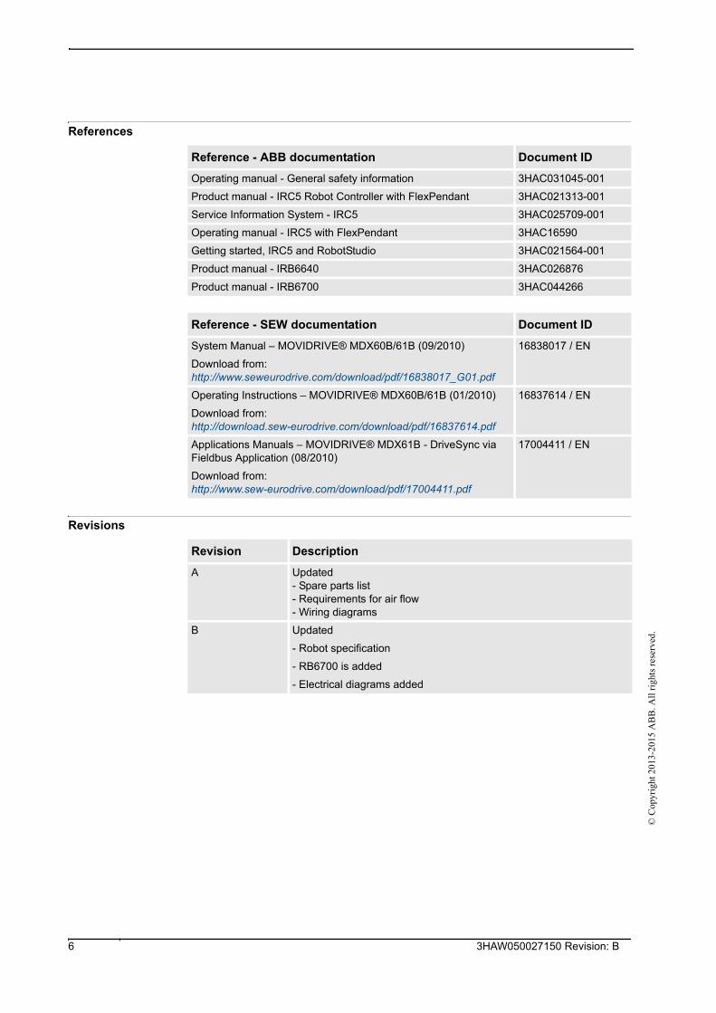
References
Revisions
Reference - ABB documentation Document ID
Operating manual - General safety information 3HAC031045-001
Product manual - IRC5 Robot Controller with FlexPendant 3HAC021313-001
Service Information System - IRC5 3HAC025709-001
Operating manual - IRC5 with FlexPendant 3HAC16590
Getting started, IRC5 and RobotStudio 3HAC021564-001
Product manual - IRB6640 3HAC026876
Product manual - IRB6700 3HAC044266
Reference - SEW documentation Document ID
System Manual – MOVIDRIVE® MDX60B/61B (09/2010)
Download from:http://www.seweurodrive.com/download/pdf/16838017_G01.pdf
16838017 / EN
Operating Instructions – MOVIDRIVE® MDX60B/61B (01/2010)
Download from:http://download.sew-eurodrive.com/download/pdf/16837614.pdf
16837614 / EN
Applications Manuals – MOVIDRIVE® MDX61B - DriveSync via Fieldbus Application (08/2010)
Download from:http://www.sew-eurodrive.com/download/pdf/17004411.pdf
17004411 / EN
Revision Description
A Updated- Spare parts list- Requirements for air flow- Wiring diagrams
B Updated
- Robot specification
- RB6700 is added
- Electrical diagrams added
3HAW050027150 Revision: B 6
©
Cop
yrig
ht 2
013-
2015
AB
B. A
ll r
ight
s re
serv
ed.
0.0.2. Product documentation, M2004
Categories for manipulator documentation
The manipulator documentation is divided into a number of categories. This listing is based
on the type of information in the documents, regardless of whether the products are standard
or optional.
All documents listed can be ordered from ABB on a DVD. The documents listed are valid for
M2004 manipulator systems.
Product manuals
All hardware, manipulators and controllers will be delivered with a Product manual that
contains:
• Safety information.
• Installation and commissioning (descriptions of mechanical installation, electrical
connections).
• Maintenance (descriptions of all required preventive maintenance procedures
including intervals).
• Repair (descriptions of all recommended repair procedures including spare parts).
• Additional procedures, if any (calibration, decommissioning).
• Reference information (article numbers for documentation referred to in Product
manual, procedures, lists of tools, safety standards).
• Parts list.
• Foldouts or exploded views.
• Circuit diagrams (or references to circuit diagrams).
Technical reference manuals
The technical reference manuals describe the manipulator software in general and contain
relevant reference information.
• RAPID Overview: An overview of the RAPID programming language.
• RAPID Instructions, Functions and Data types: Description and syntax for all
RAPID instructions, functions, and data types.
• RAPID Kernel: A formal description of the RAPID programming language.
• System parameters: Description of system parameters and configuration workflows.
Application manuals
Specific applications (for example software or hardware options) are described in
Application manuals. An application manual can describe one or several applications.
An application manual generally contains information about:
• The purpose of the application (what it does and when it is useful).
• What is included (for example cables, I/O boards, RAPID instructions, system
parameters, CD with PC software).
• How to use the application.
• Examples of how to use the application.
73HAW050027150 Revision: B
© C
opyr
ight
201
3-20
15 A
BB
. All
rig
hts
rese
rved
.
Operating manuals
The operating manuals describe hands-on handling of the products. The manuals are aimed
at those having first-hand operational contact with the product, that is production cell
operators, programmers, and trouble shooters.
The group of manuals includes:
• Emergency safety information
• General safety information
• Getting started, IRC5 and RobotStudio
• IRC5 with FlexPendant
• RobotStudio
• Introduction to RAPID
• Trouble shooting, for the controller and manipulator.
3HAW050027150 Revision: B 8
©
Cop
yrig
ht 2
013-
2015
AB
B. A
ll r
ight
s re
serv
ed.
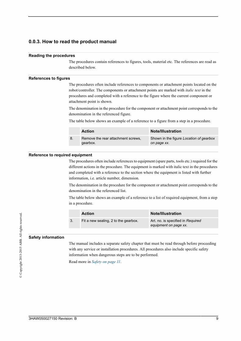
0.0.3. How to read the product manual
Reading the procedures
The procedures contain references to figures, tools, material etc. The references are read as
described below.
References to figures
The procedures often include references to components or attachment points located on the
robot/controller. The components or attachment points are marked with italic text in the
procedures and completed with a reference to the figure where the current component or
attachment point is shown.
The denomination in the procedure for the component or attachment point corresponds to the
denomination in the referenced figure.
The table below shows an example of a reference to a figure from a step in a procedure.
Reference to required equipment
The procedures often include references to equipment (spare parts, tools etc.) required for the
different actions in the procedure. The equipment is marked with italic text in the procedures
and completed with a reference to the section where the equipment is listed with further
information, i.e. article number, dimension.
The denomination in the procedure for the component or attachment point corresponds to the
denomination in the referenced list.
The table below shows an example of a reference to a list of required equipment, from a step
in a procedure.
Safety information
The manual includes a separate safety chapter that must be read through before proceeding
with any service or installation procedures. All procedures also include specific safety
information when dangerous steps are to be performed.
Read more in Safety on page 11.
Action Note/Illustration
8. Remove the rear attachment screws, gearbox.
Shown in the figure Location of gearbox on page xx.
Action Note/Illustration
3. Fit a new sealing, 2 to the gearbox. Art. no. is specified in Required equipment on page xx.
93HAW050027150 Revision: B

© C
opyr
ight
201
3-20
15 A
BB
. All
rig
hts
rese
rved
.
3HAW050027150 Revision: B 10
1 Safety
1.1. Introduction©
Cop
yrig
ht 2
013-
2015
AB
B. A
ll r
ight
s re
serv
ed.
1 Safety
1.1. Introduction
Overview
The safety information in this manual is divided in two categories:
• general safety aspects, important to attend to before performing any service work on
the robot. These are applicable for all service work and are found in General safety
information on page 12.
• specific safety information, pointed out in the procedure at the moment of the danger.
How to avoid and eliminate the danger is either detailed directly in the procedure, or
further detailed in separate instructions, found in Safety related instructions on page
29.
113HAW050027150 Revision: B
1 Safety
1.2.1. Safety in the robot system
© C
opyr
ight
201
3-20
15 A
BB
. All
rig
hts
rese
rved
.
1.2 General safety information
1.2.1. Safety in the robot system
Validity and responsibility
The information does not cover how to design, install and operate a complete system, nor
does it cover all peripheral equipment, which can influence the safety of the total system. To
protect personnel, the complete system must be designed and installed in accordance with the
safety requirements set forth in the standards and regulations of the country where the robot
is installed.
The users of ABB industrial robots are responsible for ensuring that the applicable safety laws
and regulations in the country concerned are observed and that the safety devices necessary
to protect people working with the robot system are designed and installed correctly.
Personnel working with robots must be familiar with the operation and handling of the
industrial robot, described in the applicable documents, e.g. User's Guide and Product
Manual.
Connection of external safety devices
Apart from the built-in safety functions, the robot is also supplied with an interface for the
connection of external safety devices. Via this interface, an external safety function can
interact with other machines and peripheral equipment. This means that control signals can
act on safety signals received from the peripheral equipment as well as from the robot.
Limitation of liability
Any information given in this manual regarding safety, must not be construed as a warranty
by ABB that the industrial robot will not cause injury or damage even if all safety instructions
are complied with.
Related information
Type of information Detailed in document Section
Installation of safety devices Product manual for the robot Installation and commissioning
Changing robot modes Operators manual (RobotWare 5.0)
Operating modes
Restricting the working space Product manual for the robot Installation and commissioning
3HAW050027150 Revision: B 12
1 Safety
1.3.1. Safety risks during installation and service work on robot©
Cop
yrig
ht 2
013-
2015
AB
B. A
ll r
ight
s re
serv
ed.
1.3 Safety risks related to the robot
1.3.1. Safety risks during installation and service work on robot
Overview
This section includes information of general safety risks to be considered when performing
installation and service work on the robot.
General risks during installation and service
• The instructions in the Product Manual - Installation and Commissioning must always
be followed.
• Emergency stop buttons must be positioned in easily accessible places so that the robot
can be stopped quickly.
• Those in charge of operations must make sure that safety instructions are available for
the installation in question.
• Those who install the robot must have the appropriate training for the robot system in
question and in any safety matters associated with it.
Nation/region specific regulations
To prevent injuries and damage during the installation of the robot system, the regulations
applicable in the country concerned and the instructions of ABB Robotics must be complied
with.
Non-voltage related risks
• Safety zones, which have to be crossed before admittance, must be set up in front of
the robot's working space. Light beams or sensitive mats are suitable devices.
• Turntables or the like should be used to keep the operator out of the robot's working
space.
• The axes are affected by the force of gravity when the brakes are released. In addition
to the risk of being hit by moving robot parts, you run the risk of being crushed by the
parallel arm.
• Energy, stored in the robot for the purpose of counterbalancing certain axes, may be
released if the robot, or parts thereof, are dismantled.
• When dismantling/assembling mechanical units, watch out for falling objects.
• Be aware of stored heat energy in the controller.
• Never use the robot as a ladder, i.e. do not climb on the robot motors or other part
during service work. There is a serious risk of slipping because of the high temperature
of the motors or oil spills that can occur on the robot.
To be observed by the supplier of the complete system
• The supplier of the complete system must ensure that all circuits used in the safety
function are interlocked in accordance with the applicable standards for that function.
• The supplier of the complete system must ensure that all circuits used in the
emergency stop function are interlocked in a safe manner, in accordance with the
applicable standards for the emergency stop function.
133HAW050027150 Revision: B
1 Safety
1.3.1. Safety risks during installation and service work on robot
© C
opyr
ight
201
3-20
15 A
BB
. All
rig
hts
rese
rved
.
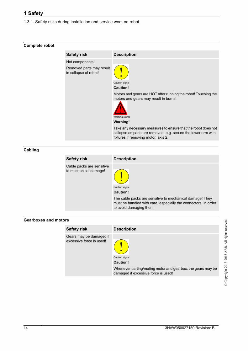
Complete robot
Cabling
Gearboxes and motors
Safety risk Description
Hot components!
Removed parts may result in collapse of robot!
Caution signal
Caution!
Motors and gears are HOT after running the robot! Touching the motors and gears may result in burns!
Warning signal
Warning!
Take any necessary measures to ensure that the robot does not collapse as parts are removed, e.g. secure the lower arm with fixtures if removing motor, axis 2.
Safety risk Description
Cable packs are sensitive to mechanical damage!
Caution signal
Caution!
The cable packs are sensitive to mechanical damage! They must be handled with care, especially the connectors, in order to avoid damaging them!
Safety risk Description
Gears may be damaged if excessive force is used!
Caution signal
Caution!
Whenever parting/mating motor and gearbox, the gears may be damaged if excessive force is used!
3HAW050027150 Revision: B 14
1 Safety
1.3.2. Safety risks related to tools/workpieces©
Cop
yrig
ht 2
013-
2015
AB
B. A
ll r
ight
s re
serv
ed.
1.3.2. Safety risks related to tools/workpieces
Safe handling
It must be possible to safely turn off tools, such as milling cutters, etc. Make sure that guards
remain closed until the cutters stop rotating.
It should be possible to release parts by manual operation (valves).
Safe design
Grippers/end effectors must be designed so that they retain workpieces in the event of a power
failure or a disturbance of the controller.
CAUTION!
Ensure that a gripper is prevented from dropping a workpiece, if such is used.
153HAW050027150 Revision: B
1 Safety
1.3.3. Safety risks related to pneumatic/hydraulic systems
© C
opyr
ight
201
3-20
15 A
BB
. All
rig
hts
rese
rved
.
1.3.3. Safety risks related to pneumatic/hydraulic systems
General
Special safety regulations apply to pneumatic and hydraulic systems.
Residual energy
• Residual energy may be present in these systems. After shutdown, particular care must
be taken.
• The pressure in pneumatic and hydraulic systems must be released before starting to
repair them.
Safe design
• Gravity may cause any parts or objects held by these systems to drop.
• Dump valves should be used in case of emergency.
• Shot bolts should be used to prevent tools, etc., from falling due to gravity.
3HAW050027150 Revision: B 16
1 Safety
1.3.4. Safety risks during operational disturbances©
Cop
yrig
ht 2
013-
2015
AB
B. A
ll r
ight
s re
serv
ed.
1.3.4. Safety risks during operational disturbances
General
• The industrial robot is a flexible tool which can be used in many different industrial
applications.
• All work must be carried out professionally and in accordance with the applicable
safety regulations.
• Care must be taken at all times.
Qualified personnel
• Corrective maintenance must only be carried out by qualified personnel who are
familiar with the entire installation as well as the special risks associated with its
different parts.
Extraordinary risks
If the working process is interrupted, extra care must be taken due to risks other than those
associated with regular operation. Such an interruption may have to be rectified manually.
173HAW050027150 Revision: B
1 Safety
1.3.5. Risks associated with live electric parts
© C
opyr
ight
201
3-20
15 A
BB
. All
rig
hts
rese
rved
.
1.3.5. Risks associated with live electric parts
Voltage related risks, general
• Although troubleshooting may, on occasion, have to be carried out while the power
supply is turned on, the robot must be turned off (by setting the mains switch to OFF)
when repairing faults, disconnecting electric leads and disconnecting or connecting
units.
• The mains supply to the robot must be connected in such a way that it can be turned
off outside the robot's working space.
Voltage related risks, controller IRC5
A danger of high voltage is associated with the following parts:
• Be aware of stored electrical energy (DC link, Ultra Cap unit) in the controller.
• Units inside the controller, e.g. I/O modules, can be supplied with power from an
external source.
• The mains supply/mains switch
• The transformers
• The power unit
• The control power supply (230 VAC)
• The rectifier unit (400-480 VAC and 700 VDC. Note: Capacitors!)
• The drive unit (700 VDC)
• The drive system power supply (230 VAC)
• The service outlets (115/230 VAC)
• The customer power supply (230 VAC)
• The power supply unit for tools, or special power supply units for the machining
process.
• The external voltage connected to the control cabinet remains live even when the robot
is disconnected from the mains.
• Additional connections.
Voltage related risks, robot
A danger of high voltage is associated with the robot in:
• The power supply for the motors (up to 800 VDC).
• The user connections for tools or other parts of the installation (max. 230 VAC, see
chapter Installation and commissioning in the Product manual).
Voltage related risks, tools, material handling devices, etc.
Tools, material handling devices, etc., may be live even if the robot system is in the OFF
position. Power supply cables which are in motion during the working process may be
damaged.
3HAW050027150 Revision: B 18
1 Safety
1.4.1. Safety fence dimensions©
Cop
yrig
ht 2
013-
2015
AB
B. A
ll r
ight
s re
serv
ed.
1.4 Safety actions related to the robot
1.4.1. Safety fence dimensions
General
Install a safety cell around the robot to ensure safe robot installation and operation.
Dimensioning
Dimension the fence or enclosure to enable it to withstand the force created if the load being
handled by the robot is dropped or released at maximum speed. Determine the maximum
speed from the maximum velocities of the robot axes and from the position at which the robot
is working in the work cell (see Product Specification - Description, Robot Motion).
Also consider the maximum possible impact caused by a breaking or malfunctioning rotating
tool or other device fitted to the manipulator.
193HAW050027150 Revision: B
1 Safety
1.4.2. Fire extinguishing
© C
opyr
ight
201
3-20
15 A
BB
. All
rig
hts
rese
rved
.
1.4.2. Fire extinguishing
NOTE!
Use a CARBON DIOXIDE (CO2) extinguisher in the event of a fire in the robot (manipulator
or controller)!
3HAW050027150 Revision: B 20
1 Safety
1.4.3. Emergency release of the robots/manipulators axes©
Cop
yrig
ht 2
013-
2015
AB
B. A
ll r
ight
s re
serv
ed.
1.4.3. Emergency release of the robots/manipulators axes
Description
In an emergency situation, any of the robot's/manipulators axes may be released manually by
pushing the brake release buttons on the robot.
How to release the brakes is detailed in the robot product manual.
• The robot arm may be moved manually on smaller robot models, but larger models
may require using an overhead crane or similar.
Increased injury
Before releasing the brakes, make sure that the weight of the arms does not increase the
pressure on the trapped person, further increasing any injury!
213HAW050027150 Revision: B
1 Safety
1.4.4. Brake testing
© C
opyr
ight
201
3-20
15 A
BB
. All
rig
hts
rese
rved
.
1.4.4. Brake testing
When to test
During operation the holding brakes of each axis motor wear normally. A test may be per-
formed to determine whether the brake can still perform its function.
How to test
The function of each axis' motor holding brakes may be checked as detailed below:
1. Run each manipulator axis to a position where the combined weight of the
manipulator arm and any load is maximized (max. static load).
2. Switch the motor to the MOTORS OFF position with the Operating mode selector on
the controller.
3. Check that the axis maintains its position.
If the manipulator does not change position as the motors are switched off, then the brake
function is adequate.
3HAW050027150 Revision: B 22

1 Safety
1.4.5. Risk of disabling function "Reduced speed 250 mm/s"©
Cop
yrig
ht 2
013-
2015
AB
B. A
ll r
ight
s re
serv
ed.
1.4.5. Risk of disabling function "Reduced speed 250 mm/s"
NOTE!
Do not change Transm. gear ratio or other kinematic parameters from the Teach Pendant Unit
or a PC. This will affect the safety function Reduced speed 250 mm/s.
233HAW050027150 Revision: B
1 Safety
1.4.6. Safe use of the Teach Pendant Unit
© C
opyr
ight
201
3-20
15 A
BB
. All
rig
hts
rese
rved
.
1.4.6. Safe use of the Teach Pendant Unit
NOTE!
The enabling device is a push button located on the side of the Teach Pendant Unit (TPU)
which, when pressed halfway in, takes the system to MOTORS ON. When the enabling
device is released or pushed all the way in, the robot is taken to the MOTORS OFF state. To
ensure safe use of the Teach Pendant Unit, the following must be implemented:
• The enabling device must never be rendered inoperative in any way.
• During programming and testing, the enabling device must be released as soon as
there is no need for the robot to move.
• The programmer must always bring the Teach Pendant Unit with him/her, when
entering the robot's working space. This is to prevent anyone else taking control of the
robot without the programmer knowing.
3HAW050027150 Revision: B 24
1 Safety
1.4.7. Work inside the manipulator's working range©
Cop
yrig
ht 2
013-
2015
AB
B. A
ll r
ight
s re
serv
ed.
1.4.7. Work inside the manipulator's working range
WARNING!
If work must be carried out within the robot's work envelope, the following points must be
observed:
• The operating mode selector on the controller must be in the manual mode position to
render the enabling device operative and to block operation from a computer link or
remote control panel.
• The robot's speed is limited to max. 250 mm/s when the operating mode selector is in
position < 250 mm/s. This should be the normal position when entering the working
space. The position 100% "full speed" may only be used by trained personnel who are
aware of the risks that this entails.
• Pay attention to the rotating axes of the manipulator! Keep a distance to the axes in
order not to get entangled with hair or clothing. Also be aware of any danger that may
be caused by rotating tools or other devices mounted on the manipulator or inside the
cell.
253HAW050027150 Revision: B
1 Safety
1.4.8. Translate the information on safety and information labels
© C
opyr
ight
201
3-20
15 A
BB
. All
rig
hts
rese
rved
.
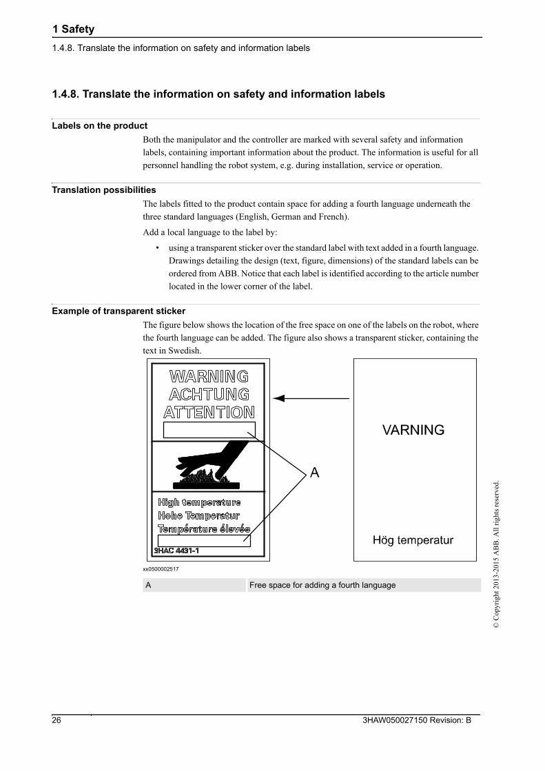
1.4.8. Translate the information on safety and information labels
Labels on the product
Both the manipulator and the controller are marked with several safety and information
labels, containing important information about the product. The information is useful for all
personnel handling the robot system, e.g. during installation, service or operation.
Translation possibilities
The labels fitted to the product contain space for adding a fourth language underneath the
three standard languages (English, German and French).
Add a local language to the label by:
• using a transparent sticker over the standard label with text added in a fourth language.
Drawings detailing the design (text, figure, dimensions) of the standard labels can be
ordered from ABB. Notice that each label is identified according to the article number
located in the lower corner of the label.
Example of transparent sticker
The figure below shows the location of the free space on one of the labels on the robot, where
the fourth language can be added. The figure also shows a transparent sticker, containing the
text in Swedish.
xx0500002517
A Free space for adding a fourth language
3HAW050027150 Revision: B 26
1 Safety
1.5.1. What is an emergency stop?©
Cop
yrig
ht 2
013-
2015
AB
B. A
ll r
ight
s re
serv
ed.
1.5 Safety stops
1.5.1. What is an emergency stop?
Definition of emergency stop
An emergency stop is a state that overrides any other manipulator control, disconnects drivepower from the manipulator motors, stops all moving parts, and disconnects power from any
potentially dangerous functions controlled by the manipulator system.
An emergency stop state means that all power is disconnected from the manipulator except
for the manual brake release circuits. You must perform a recovery procedure, i.e, resetting
the emergency stop button and pressing the Motors On button, in order to return to normal
operation.
The manipulator system can be configured so that the emergency stop results in either:
• An uncontrolled stop, immediately stopping the manipulator actions by disconnecting
power from the motors.
• A controlled stop, stopping the manipulator actions with power available to the motors
so that the manipulator path can be maintained. When completed, power is
disconnected.
The default setting is uncontrolled stop. However, controlled stops are preferred since they
minimize extra, unnecessary wear on the manipulator and the actions needed to return the
manipulator system back to production. Please consult your plant or cell documentation to
see how your manipulator system is configured.
NOTE!
The emergency stop function may only be used for the purpose and under the conditions for
which it is intended.
NOTE!
The emergency stop function is intended for immediately stopping equipment in the event of
an emergency.
NOTE!
Emergency stop should not be used for normal program stops as this causes extra,
unnecessary wear on the manipulator.
Classification of stops
The safety standards that regulates automation and manipulator equipment defines categories
in which each type of stop applies:
If the stop is... then it is classified as...
uncontrolled category 0 (zero)
controlled category 1
273HAW050027150 Revision: B

1 Safety
1.5.1. What is an emergency stop?
© C
opyr
ight
201
3-20
15 A
BB
. All
rig
hts
rese
rved
.
Emergency stop devices
In a manipulator system there are several emergency stop devices that can be operated in
order to achieve an emergency stop. There are emergency stop buttons available on the Flex-
Pendant and on the controller cabinet (on the Control Module on a Dual Cabinet
Controller).There can also be other types of emergency stops on your manipulator, consult
your plant or cell documentation to see how your manipulator system is configured.
3HAW050027150 Revision: B 28
1 Safety
1.6.1. Safety signals in the manual©
Cop
yrig
ht 2
013-
2015
AB
B. A
ll r
ight
s re
serv
ed.
1.6 Safety related instructions
1.6.1. Safety signals in the manual
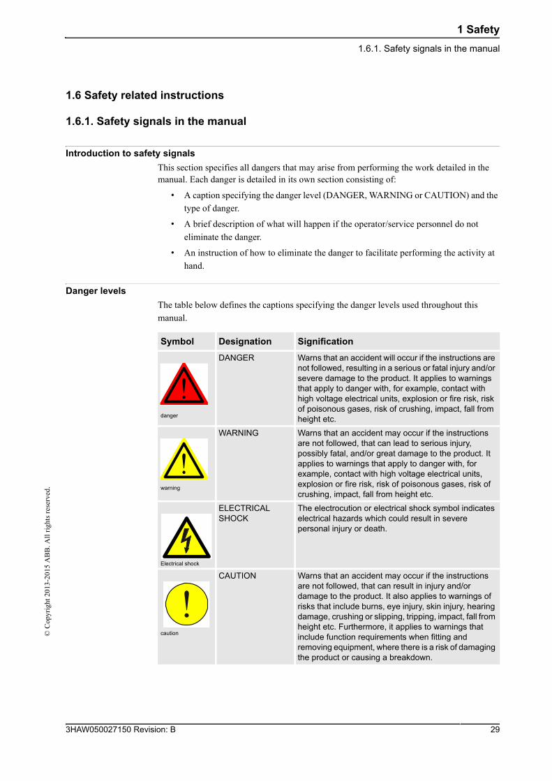
Introduction to safety signals
This section specifies all dangers that may arise from performing the work detailed in themanual. Each danger is detailed in its own section consisting of:
• A caption specifying the danger level (DANGER, WARNING or CAUTION) and the
type of danger.
• A brief description of what will happen if the operator/service personnel do not
eliminate the danger.
• An instruction of how to eliminate the danger to facilitate performing the activity at
hand.
Danger levels
The table below defines the captions specifying the danger levels used throughout this
manual.
Symbol Designation Signification
danger
DANGER Warns that an accident will occur if the instructions are not followed, resulting in a serious or fatal injury and/or severe damage to the product. It applies to warnings that apply to danger with, for example, contact with high voltage electrical units, explosion or fire risk, risk of poisonous gases, risk of crushing, impact, fall from height etc.
warning
WARNING Warns that an accident may occur if the instructions are not followed, that can lead to serious injury, possibly fatal, and/or great damage to the product. It applies to warnings that apply to danger with, for example, contact with high voltage electrical units, explosion or fire risk, risk of poisonous gases, risk of crushing, impact, fall from height etc.
Electrical shock
ELECTRICAL SHOCK
The electrocution or electrical shock symbol indicates electrical hazards which could result in severe personal injury or death.
caution
CAUTION Warns that an accident may occur if the instructions are not followed, that can result in injury and/or damage to the product. It also applies to warnings of risks that include burns, eye injury, skin injury, hearing damage, crushing or slipping, tripping, impact, fall from height etc. Furthermore, it applies to warnings that include function requirements when fitting and removing equipment, where there is a risk of damaging the product or causing a breakdown.
293HAW050027150 Revision: B
1 Safety
1.6.1. Safety signals in the manual
© C
opyr
ight
201
3-20
15 A
BB
. All
rig
hts
rese
rved
.
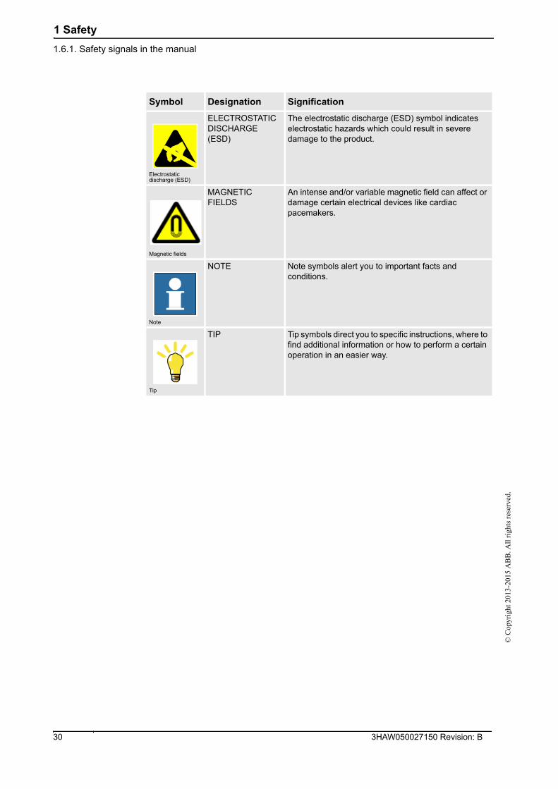
Electrostatic discharge (ESD)
ELECTROSTATIC DISCHARGE (ESD)
The electrostatic discharge (ESD) symbol indicates electrostatic hazards which could result in severe damage to the product.
Magnetic fields
MAGNETIC FIELDS
An intense and/or variable magnetic field can affect or damage certain electrical devices like cardiac pacemakers.
Note
NOTE Note symbols alert you to important facts and conditions.
Tip
TIP Tip symbols direct you to specific instructions, where to find additional information or how to perform a certain operation in an easier way.
Symbol Designation Signification
3HAW050027150 Revision: B 30
2 System description
2.1.1. System basics©
Cop
yrig
ht 2
013-
2015
AB
B. A
ll r
ight
s re
serv
ed.
2 System description
2.1 System overview
2.1.1. System basics
General
The Feather Duster Robot system is a pre-paint finishing equipment mounted on a 6 axis
manipulator. It is used to remove dust and dirt particles from car bodies and from surfaces to
be painted.
This system utilizes brushes manufactured from ostrich feathers to remove contaminants,
which are then vacuumed from the brushes with an exhaust fan. It replaces the tack-off
machine with more flexibility and high efficiency.
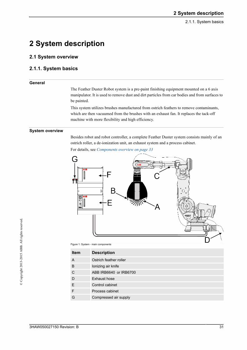
System overview
Besides robot and robot controller, a complete Feather Duster system consists mainly of an
ostrich roller, a de-ionization unit, an exhaust system and a process cabinet.
For details, see Components overview on page 33
Figure 1: System - main components
Item Description
A Ostrich feather roller
B Ionizing air knife
C ABB IRB6640 or IRB6700
D Exhaust hose
E Control cabinet
F Process cabinet
G Compressed air supply
313HAW050027150 Revision: B
2 System description
2.1.1. System basics
© C
opyr
ight
201
3-20
15 A
BB
. All
rig
hts
rese
rved
.
Function
The Feather Duster Robot system is designed to remove contaminants from surfaces to be
painted. The surface is cleaned by the rotating ostrich feather brushes. The brushes come
across the body shell with a depth of immersion of approximately 30~40 mm. Through this
movement, the contaminants are absorbed by the feather brushes and then vacuumed from the
brushes with an exhaust fan.
Two AC Ionization bars are mounted on the Feather Duster to deliver an ionized air stream,
both to remove any static charge from the feather brushes just prior to the exhaust slot and to
neutralize the body surface after cleaning. Removable outer carbon fiber covers allow easy
access to the inner mechanical and electrical components, which are based on a modular
design principle.
Benefits
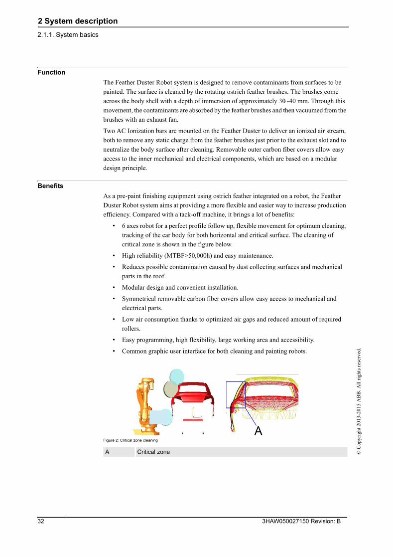
As a pre-paint finishing equipment using ostrich feather integrated on a robot, the Feather
Duster Robot system aims at providing a more flexible and easier way to increase production
efficiency. Compared with a tack-off machine, it brings a lot of benefits:
• 6 axes robot for a perfect profile follow up, flexible movement for optimum cleaning,
tracking of the car body for both horizontal and critical surface. The cleaning of
critical zone is shown in the figure below.
• High reliability (MTBF>50,000h) and easy maintenance.
• Reduces possible contamination caused by dust collecting surfaces and mechanical
parts in the roof.
• Modular design and convenient installation.
• Symmetrical removable carbon fiber covers allow easy access to mechanical and
electrical parts.
• Low air consumption thanks to optimized air gaps and reduced amount of required
rollers.
• Easy programming, high flexibility, large working area and accessibility.
• Common graphic user interface for both cleaning and painting robots.
Figure 2: Critical zone cleaning
A Critical zone
3HAW050027150 Revision: B 32
2 System description
2.1.2. Components overview©
Cop
yrig
ht 2
013-
2015
AB
B. A
ll r
ight
s re
serv
ed.
2.1.2. Components overview
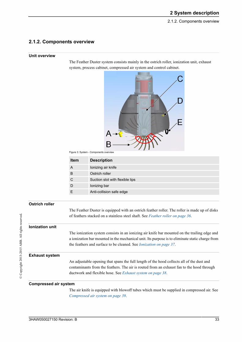
Unit overview
The Feather Duster system consists mainly in the ostrich roller, ionization unit, exhaust
system, process cabinet, compressed air system and control cabinet.
Figure 3: System - Components overview
Ostrich roller
The Feather Duster is equipped with an ostrich feather roller. The roller is made up of disks
of feathers stacked on a stainless steel shaft. See Feather roller on page 36.
Ionization unit
The ionization system consists in an ionizing air knife bar mounted on the trailing edge and
a ionization bar mounted in the mechanical unit. Its purpose is to eliminate static charge from
the feathers and surface to be cleaned. See Ionization on page 37.
Exhaust system
An adjustable opening that spans the full length of the hood collects all of the dust and
contaminants from the feathers. The air is routed from an exhaust fan to the hood through
ductwork and flexible hose. See Exhaust system on page 38.
Compressed air system
The air knife is equipped with blowoff tubes which must be supplied in compressed air. See
Compressed air system on page 39.
Item Description
A Ionizing air knife
B Ostrich roller
C Suction slot with flexible lips
D Ionizing bar
E Anti-collision safe edge
333HAW050027150 Revision: B

2 System description
2.1.2. Components overview
© C
opyr
ight
201
3-20
15 A
BB
. All
rig
hts
rese
rved
.
Process cabinet
The process cabinet is used to control the roller, the ionization bars and the compressed air
valve. It is also an interface to automats (e.g. PLC cabinet), providing the signal from the
main sensors (e.g. anti-collision switch).
Control cabinet
The control cabinet is a standard ABB IRC5 controller, used to control robot motion.
For more information, see Product Manual, Control Cabinet IRC5.
3HAW050027150 Revision: B 34
2 System description
2.1.3. Process diagram©
Cop
yrig
ht 2
013-
2015
AB
B. A
ll r
ight
s re
serv
ed.
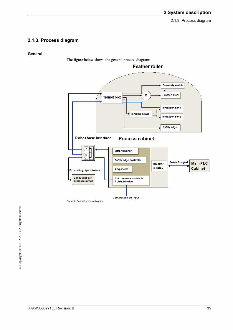
2.1.3. Process diagram
General
The figure below shows the general process diagram:
Figure 4: General process diagram
353HAW050027150 Revision: B
2 System description
2.2. Feather roller
© C
opyr
ight
201
3-20
15 A
BB
. All
rig
hts
rese
rved
.
2.2. Feather roller
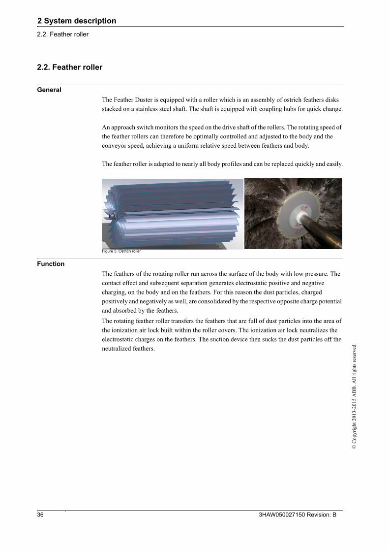
General
The Feather Duster is equipped with a roller which is an assembly of ostrich feathers disks
stacked on a stainless steel shaft. The shaft is equipped with coupling hubs for quick change.
An approach switch monitors the speed on the drive shaft of the rollers. The rotating speed of
the feather rollers can therefore be optimally controlled and adjusted to the body and the
conveyor speed, achieving a uniform relative speed between feathers and body.
The feather roller is adapted to nearly all body profiles and can be replaced quickly and easily.
Figure 5: Ostrich roller
Function
The feathers of the rotating roller run across the surface of the body with low pressure. The
contact effect and subsequent separation generates electrostatic positive and negative
charging, on the body and on the feathers. For this reason the dust particles, charged
positively and negatively as well, are consolidated by the respective opposite charge potential
and absorbed by the feathers.
The rotating feather roller transfers the feathers that are full of dust particles into the area of
the ionization air lock built within the roller covers. The ionization air lock neutralizes the
electrostatic charges on the feathers. The suction device then sucks the dust particles off the
neutralized feathers.
3HAW050027150 Revision: B 36
2 System description
2.3. Ionization©
Cop
yrig
ht 2
013-
2015
AB
B. A
ll r
ight
s re
serv
ed.
2.3. Ionization
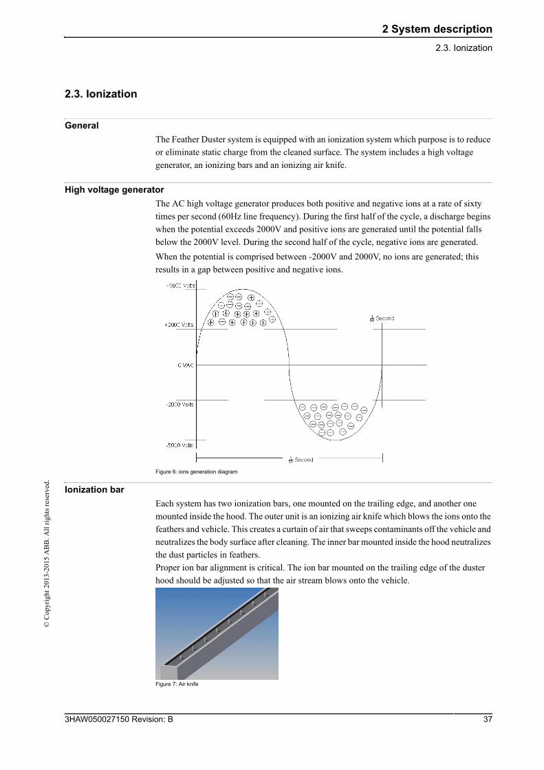
General
The Feather Duster system is equipped with an ionization system which purpose is to reduce
or eliminate static charge from the cleaned surface. The system includes a high voltage
generator, an ionizing bars and an ionizing air knife.
High voltage generator
The AC high voltage generator produces both positive and negative ions at a rate of sixty
times per second (60Hz line frequency). During the first half of the cycle, a discharge begins
when the potential exceeds 2000V and positive ions are generated until the potential falls
below the 2000V level. During the second half of the cycle, negative ions are generated.
When the potential is comprised between -2000V and 2000V, no ions are generated; this
results in a gap between positive and negative ions.
Figure 6: ions generation diagram
Ionization bar
Each system has two ionization bars, one mounted on the trailing edge, and another one
mounted inside the hood. The outer unit is an ionizing air knife which blows the ions onto the
feathers and vehicle. This creates a curtain of air that sweeps contaminants off the vehicle and
neutralizes the body surface after cleaning. The inner bar mounted inside the hood neutralizes
the dust particles in feathers.
Proper ion bar alignment is critical. The ion bar mounted on the trailing edge of the duster
hood should be adjusted so that the air stream blows onto the vehicle.
Figure 7: Air knife
373HAW050027150 Revision: B
2 System description
2.4. Exhaust system
© C
opyr
ight
201
3-20
15 A
BB
. All
rig
hts
rese
rved
.
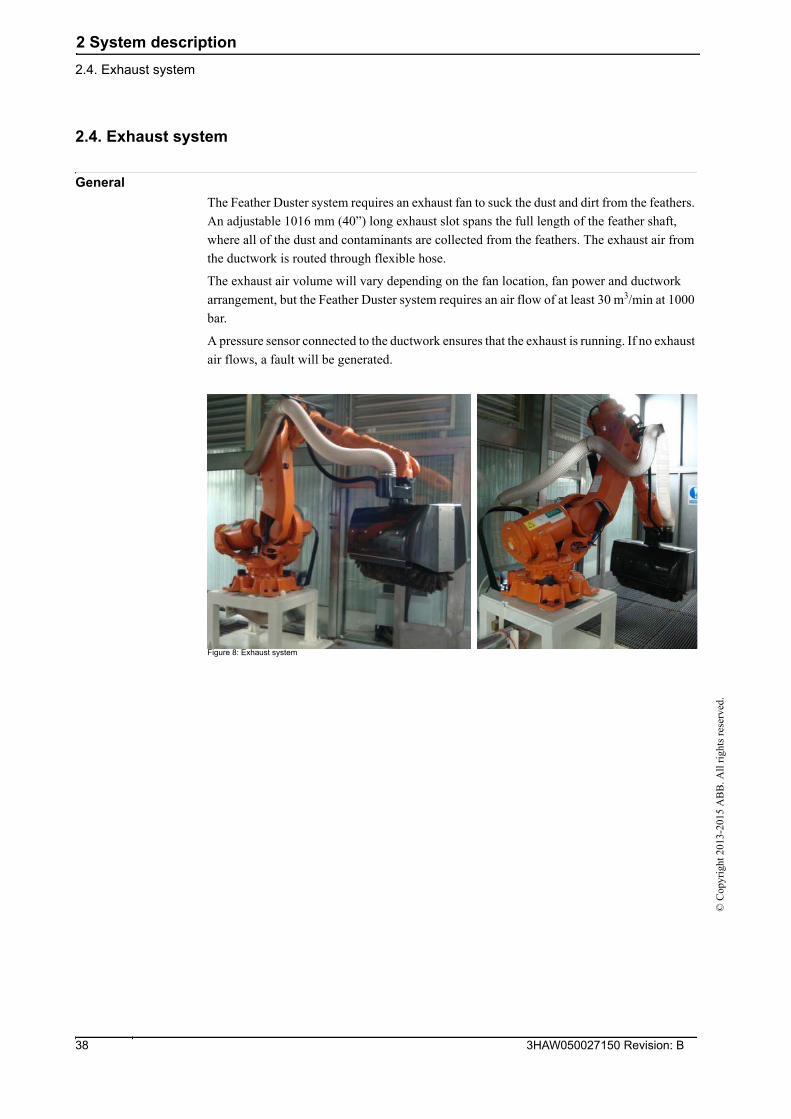
2.4. Exhaust system
General
The Feather Duster system requires an exhaust fan to suck the dust and dirt from the feathers.
An adjustable 1016 mm (40”) long exhaust slot spans the full length of the feather shaft,
where all of the dust and contaminants are collected from the feathers. The exhaust air from
the ductwork is routed through flexible hose.
The exhaust air volume will vary depending on the fan location, fan power and ductwork
arrangement, but the Feather Duster system requires an air flow of at least 30 m3/min at 1000
bar.
A pressure sensor connected to the ductwork ensures that the exhaust is running. If no exhaust
air flows, a fault will be generated.
Figure 8: Exhaust system
3HAW050027150 Revision: B 38
2 System description
2.5. Compressed air system©
Cop
yrig
ht 2
013-
2015
AB
B. A
ll r
ight
s re
serv
ed.
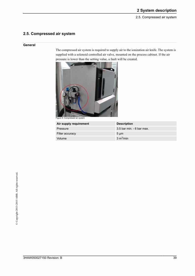
2.5. Compressed air system
General
The compressed air system is required to supply air to the ionization air knife. The system is
supplied with a solenoid controlled air valve, mounted on the process cabinet. If the air
pressure is lower than the setting value, a fault will be created.
Figure 9: Compressed air system
Air supply requirement Description
Pressure 3.5 bar min. - 6 bar max.
Filter accuracy 5 µm
Volume 3 m3/min
393HAW050027150 Revision: B
3 Technical Specification
3.1. Feather Duster and robot specifications
© C
opyr
ight
201
3-20
15 A
BB
. All
rig
hts
rese
rved
.
3 Technical Specification
3.1. Feather Duster and robot specifications
Feather Duster specifications
Robot specifications
Feather Duster is designed to be integrated with ABB IRB6640-185 or IRB6700-175.
No particular option is required for the robot. See 3HAC028284-001, IRB6640 Product
specification or 3HAC044265, IRB6700 Product specification.
For compatibility with other robot variants, please contact ABB.
Weight 140 kg
Cover Length 1200 mm
Cover Width 620 mm
Cover Depth 680 mm
Roller Widths 1000 mm
Motor Power 0.37 kw
Motoreducer Reduction Ration 23.15
Roller Speed 10-90 rpm variable (motor: 230 - 2085 rpm)
Exhaust Air Flow 30 m3/min at 1000Pa dynamic, per roller
Compressed Air Supply 1.5 m3/min at 3.5 bar, per robot
Downdraft Air Velocity 0.3m/s (±0.05)
Humidity and Temperature Humidity: 60-70%; Temperature: 20-25°C
Conveyor System Deviation ≤ 25mm
axis range of movement Max axis speed
1st axis +170 to -170 100/s
2nd axis +85 to -85 90/s
3rd axis +70 to -70 90/s
4th axis +180 to -180 190/s
5th axis +90 to -90 140/s
6th axis +180 to -180 190/s
3HAW050027150 Revision: B 40
3 Technical Specification
3.2. Feather Duster dimensions©
Cop
yrig
ht 2
013-
2015
AB
B. A
ll r
ight
s re
serv
ed.
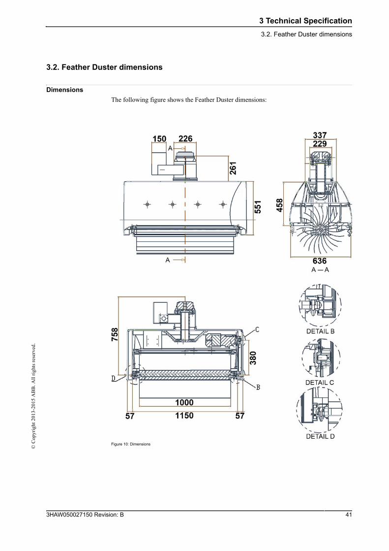
3.2. Feather Duster dimensions
Dimensions
The following figure shows the Feather Duster dimensions:
Figure 10: Dimensions
413HAW050027150 Revision: B
3 Technical Specification
3.2. Feather Duster dimensions
© C
opyr
ight
201
3-20
15 A
BB
. All
rig
hts
rese
rved
.
3HAW050027150 Revision: B 42
4 Installation and commissioning
4.1. Introduction©
Cop
yrig
ht 2
013-
2015
AB
B. A
ll r
ight
s re
serv
ed.
4 Installation and commissioning
4.1. Introduction
Safety information
Before any service work is commenced, it is important that all safety information is observed!
Read Safety on page 11 before performing any service work.
Required equipment
Bolts and screws and tightening torques
Specified in Bolt, screws, tightening torques on page 77.
Equipment Note
Standard toolkit Specified in Standard toolkit on page 78.
Other tools and procedures may be required. See references to these procedures in the step-by-step instructions below.
Specified in Special tools on page 79.
433HAW050027150 Revision: B
4 Installation and commissioning
4.2.1. Introduction
© C
opyr
ight
201
3-20
15 A
BB
. All
rig
hts
rese
rved
.
4.2 Mechanical installation
4.2.1. Introduction
Safety information
Before any service work is commenced, it is extremely important that all safety information
is observed! There are general safety aspects that must be read through, as well as more
specific safety information that describe danger and safety risks when performing the
procedures. Read Safety on page 11 before performing any service work.
General
The Feather Duster mechanical installation consists mainly in the installation of the steel
structure frame and the mounting of the exhaust air and compressed air supply hoses.
Refer to Assembly drawings on page 87 for details.
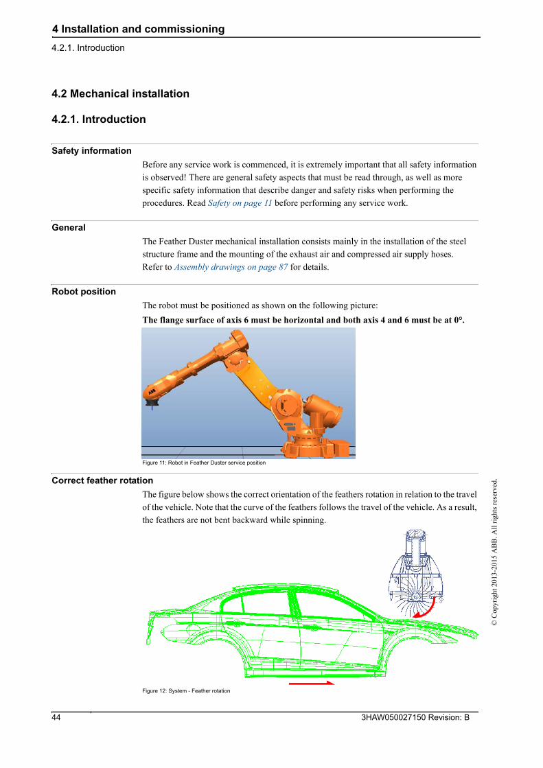
Robot position
The robot must be positioned as shown on the following picture:
The flange surface of axis 6 must be horizontal and both axis 4 and 6 must be at 0°.
Figure 11: Robot in Feather Duster service position
Correct feather rotation
The figure below shows the correct orientation of the feathers rotation in relation to the travel
of the vehicle. Note that the curve of the feathers follows the travel of the vehicle. As a result,
the feathers are not bent backward while spinning.
Figure 12: System - Feather rotation
3HAW050027150 Revision: B 44
4 Installation and commissioning
4.2.2. Carbon fiber covers©
Cop
yrig
ht 2
013-
2015
AB
B. A
ll r
ight
s re
serv
ed.
4.2.2. Carbon fiber covers
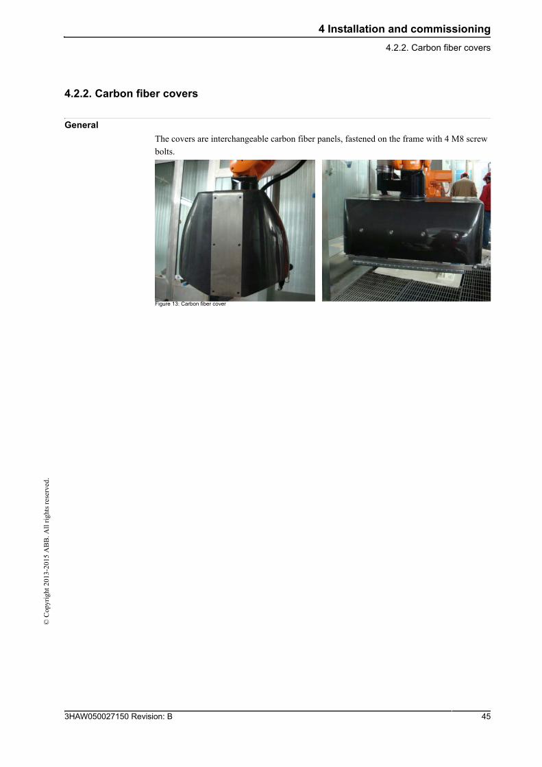
General
The covers are interchangeable carbon fiber panels, fastened on the frame with 4 M8 screw
bolts.
Figure 13: Carbon fiber cover
453HAW050027150 Revision: B
4 Installation and commissioning
4.2.3. Instructions for the installation of the steel structure frame
© C
opyr
ight
201
3-20
15 A
BB
. All
rig
hts
rese
rved
.
4.2.3. Instructions for the installation of the steel structure frame
Procedure
Steps Action Info/IIIustration
1. Ensure that the robot’s axis 4 and 6 are set at 0°.
2. Remove the original 6th axis calibration label.
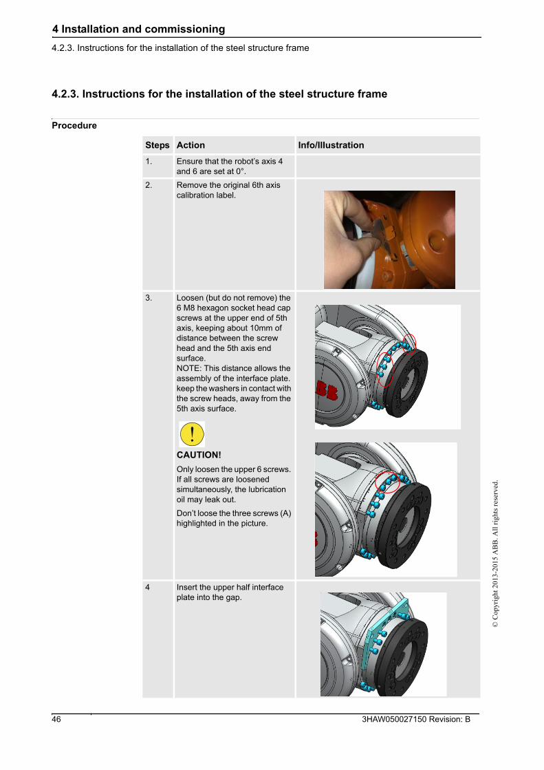
3. Loosen (but do not remove) the 6 M8 hexagon socket head cap screws at the upper end of 5th axis, keeping about 10mm of distance between the screw head and the 5th axis end surface.NOTE: This distance allows the assembly of the interface plate.keep the washers in contact with the screw heads, away from the 5th axis surface.
CAUTION!
Only loosen the upper 6 screws. If all screws are loosened simultaneously, the lubrication oil may leak out.
Don’t loose the three screws (A) highlighted in the picture.
4 Insert the upper half interface plate into the gap.
3HAW050027150 Revision: B 46
4 Installation and commissioning
4.2.3. Instructions for the installation of the steel structure frame©
Cop
yrig
ht 2
013-
2015
AB
B. A
ll r
ight
s re
serv
ed.
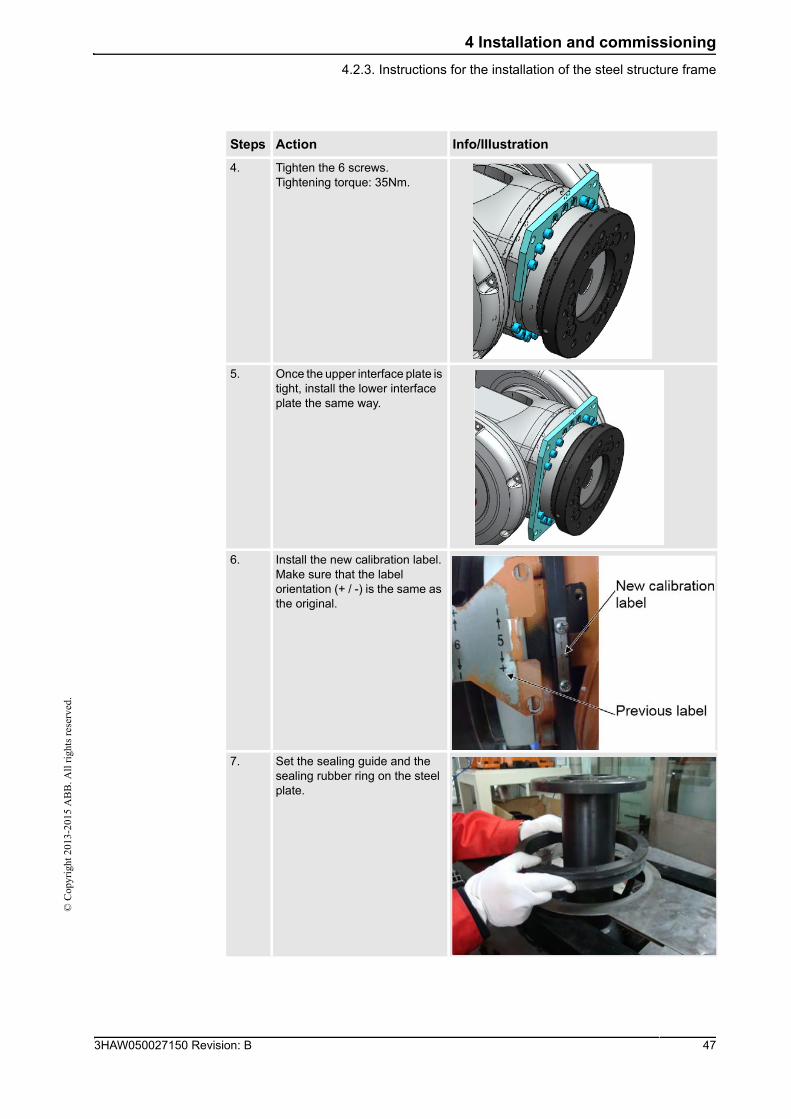
4. Tighten the 6 screws.Tightening torque: 35Nm.
5. Once the upper interface plate is tight, install the lower interface plate the same way.
6. Install the new calibration label.Make sure that the label orientation (+ / -) is the same as the original.
7. Set the sealing guide and the sealing rubber ring on the steel plate.
Steps Action Info/IIIustration
473HAW050027150 Revision: B
4 Installation and commissioning
4.2.3. Instructions for the installation of the steel structure frame
© C
opyr
ight
201
3-20
15 A
BB
. All
rig
hts
rese
rved
.
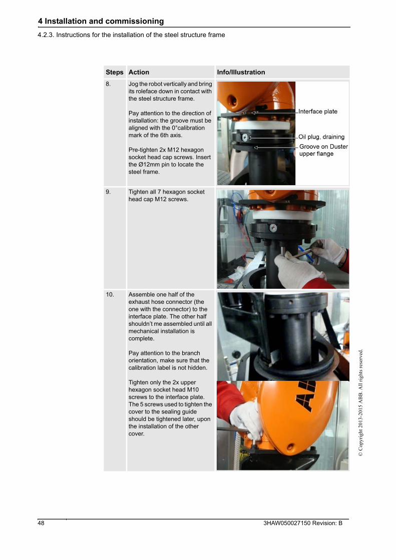
8. Jog the robot vertically and bring its roleface down in contact with the steel structure frame.
Pay attention to the direction of installation: the groove must be aligned with the 0°calibration mark of the 6th axis.
Pre-tighten 2x M12 hexagon socket head cap screws. Insert the Ø12mm pin to locate the steel frame.
9. Tighten all 7 hexagon socket head cap M12 screws.
10. Assemble one half of the exhaust hose connector (the one with the connector) to the interface plate. The other half shouldn’t me assembled until all mechanical installation is complete.
Pay attention to the branch orientation, make sure that the calibration label is not hidden.
Tighten only the 2x upper hexagon socket head M10 screws to the interface plate. The 5 screws used to tighten the cover to the sealing guide should be tightened later, upon the installation of the other cover.
Steps Action Info/IIIustration
3HAW050027150 Revision: B 48
4 Installation and commissioning
4.2.4. Instructions for the connection of flexible hoses and cables©
Cop
yrig
ht 2
013-
2015
AB
B. A
ll r
ight
s re
serv
ed.
4.2.4. Instructions for the connection of flexible hoses and cables
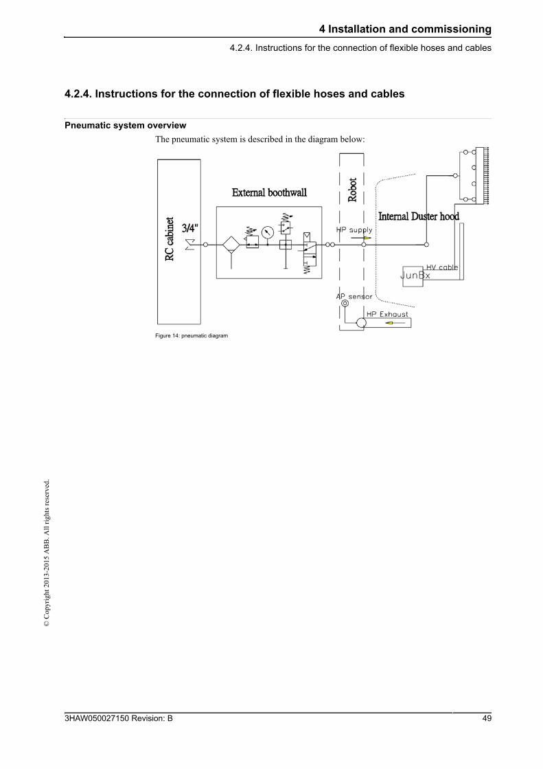
Pneumatic system overview
The pneumatic system is described in the diagram below:
Figure 14: pneumatic diagram
493HAW050027150 Revision: B
4 Installation and commissioning
4.2.4. Instructions for the connection of flexible hoses and cables
© C
opyr
ight
201
3-20
15 A
BB
. All
rig
hts
rese
rved
.
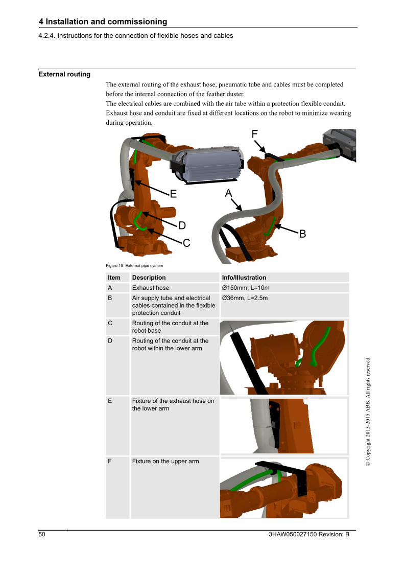
External routing
The external routing of the exhaust hose, pneumatic tube and cables must be completed
before the internal connection of the feather duster.
The electrical cables are combined with the air tube within a protection flexible conduit.
Exhaust hose and conduit are fixed at different locations on the robot to minimize wearing
during operation.
Figure 15: External pipe system
Item Description Info/Illustration
A Exhaust hose Ø150mm, L=10m
B Air supply tube and electrical cables contained in the flexible protection conduit
Ø36mm, L=2.5m
C Routing of the conduit at the robot base
D Routing of the conduit at the robot within the lower arm
E Fixture of the exhaust hose on the lower arm
F Fixture on the upper arm
3HAW050027150 Revision: B 50
4 Installation and commissioning
4.2.4. Instructions for the connection of flexible hoses and cables©
Cop
yrig
ht 2
013-
2015
AB
B. A
ll r
ight
s re
serv
ed.
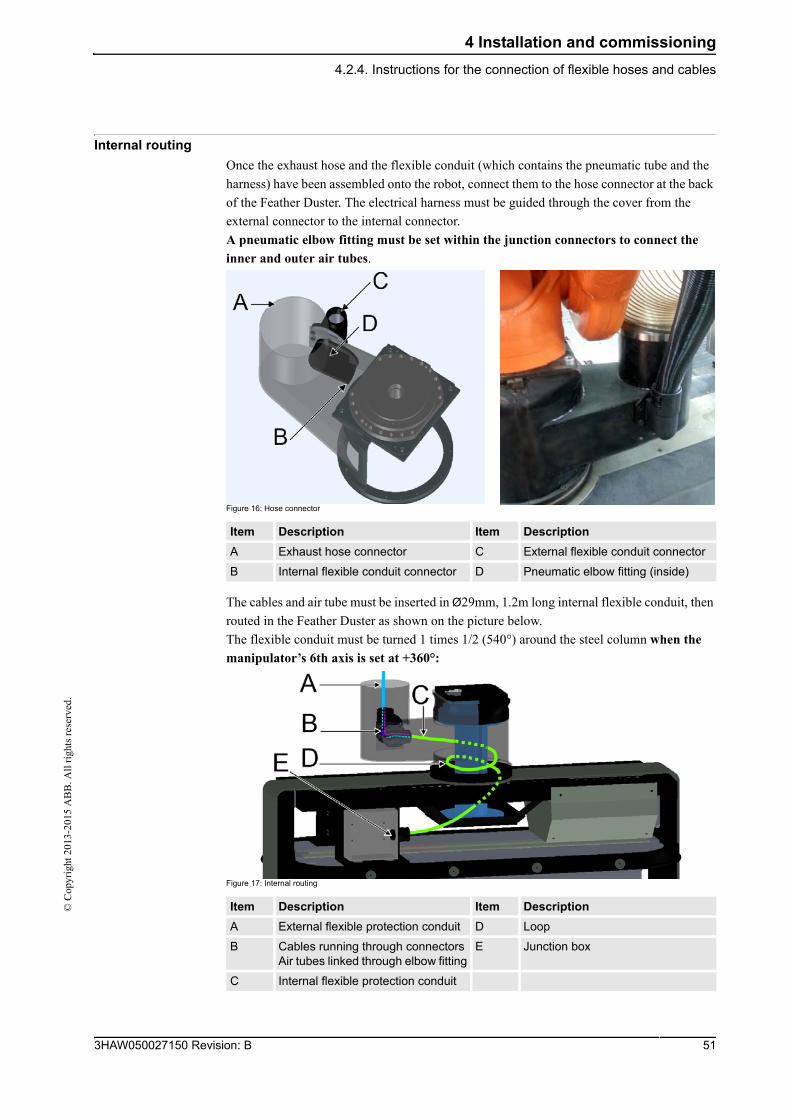
Internal routing
Once the exhaust hose and the flexible conduit (which contains the pneumatic tube and the
harness) have been assembled onto the robot, connect them to the hose connector at the back
of the Feather Duster. The electrical harness must be guided through the cover from the
external connector to the internal connector.
A pneumatic elbow fitting must be set within the junction connectors to connect the
inner and outer air tubes.
Figure 16: Hose connector
The cables and air tube must be inserted in Ø29mm, 1.2m long internal flexible conduit, then
routed in the Feather Duster as shown on the picture below.
The flexible conduit must be turned 1 times 1/2 (540°) around the steel column when the
manipulator’s 6th axis is set at +360°:
Figure 17: Internal routing
Item Description Item Description
A Exhaust hose connector C External flexible conduit connector
B Internal flexible conduit connector D Pneumatic elbow fitting (inside)
Item Description Item Description
A External flexible protection conduit D Loop
B Cables running through connectorsAir tubes linked through elbow fitting
E Junction box
C Internal flexible protection conduit
513HAW050027150 Revision: B
4 Installation and commissioning
4.2.4. Instructions for the connection of flexible hoses and cables
© C
opyr
ight
201
3-20
15 A
BB
. All
rig
hts
rese
rved
.
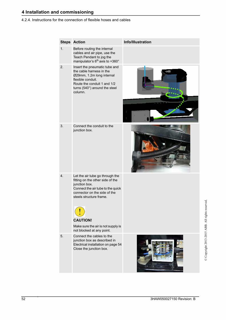
Steps Action Info/IIIustration
1. Before routing the internal cables and air pipe, use the Teach Pendant to jog the manipulator’s 6th axis to +360°
2. Insert the pneumatic tube and the cable harness in the Ø29mm, 1.2m long internal flexible conduit.Route the conduit 1 and 1/2 turns (540°) around the steel column.
3. Connect the conduit to the junction box.
4. Let the air tube go through the fitting on the other side of the junction box.Connect the air tube to the quick connector on the side of the steels structure frame.
CAUTION!
Make sure the air is not supply is not blocked at any point.
5. Connect the cables to the junction box as described in Electrical installation on page 54Close the junction box.
3HAW050027150 Revision: B 52
4 Installation and commissioning
4.2.4. Instructions for the connection of flexible hoses and cables©
Cop
yrig
ht 2
013-
2015
AB
B. A
ll r
ight
s re
serv
ed.
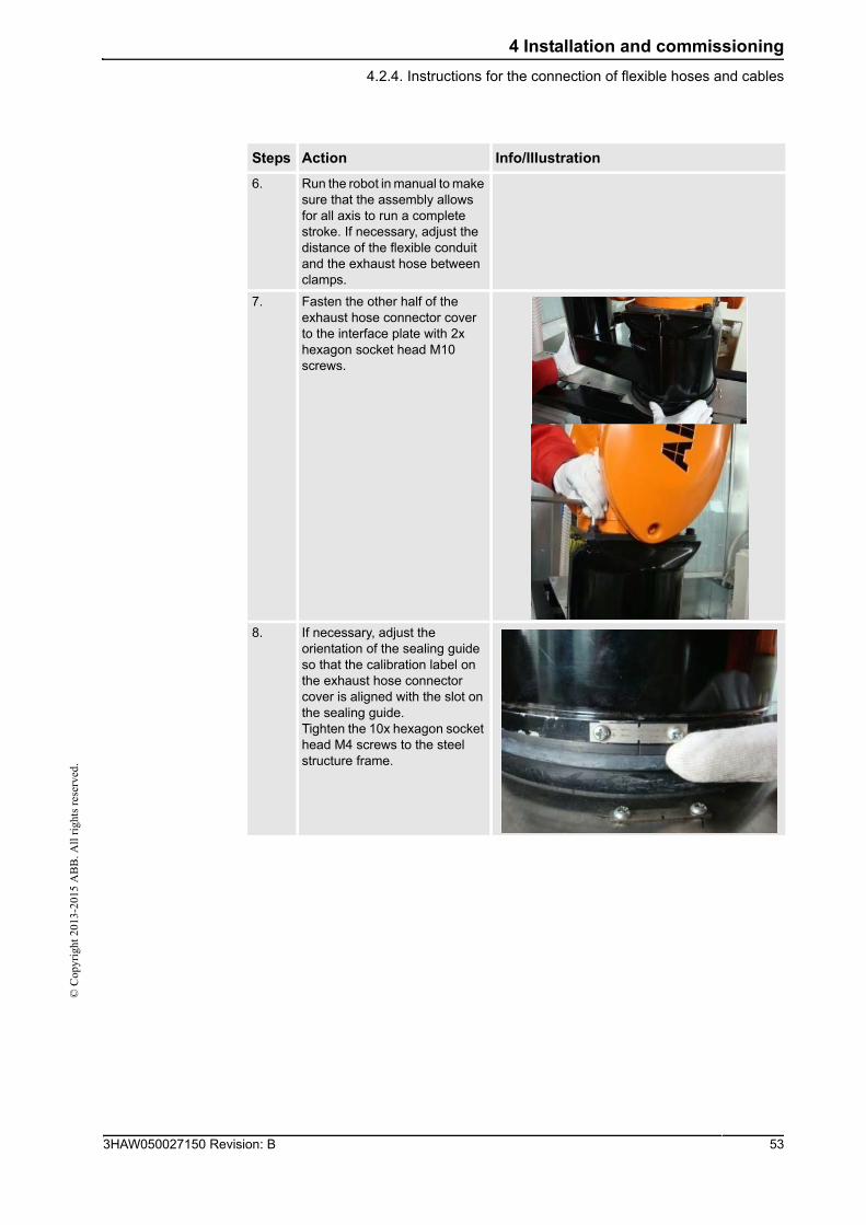
6. Run the robot in manual to make sure that the assembly allows for all axis to run a complete stroke. If necessary, adjust the distance of the flexible conduit and the exhaust hose between clamps.
7. Fasten the other half of the exhaust hose connector cover to the interface plate with 2x hexagon socket head M10 screws.
8. If necessary, adjust the orientation of the sealing guide so that the calibration label on the exhaust hose connector cover is aligned with the slot on the sealing guide.Tighten the 10x hexagon socket head M4 screws to the steel structure frame.
Steps Action Info/IIIustration
533HAW050027150 Revision: B
4 Installation and commissioning
4.3. Electrical installation
© C
opyr
ight
201
3-20
15 A
BB
. All
rig
hts
rese
rved
.
4.3. Electrical installation
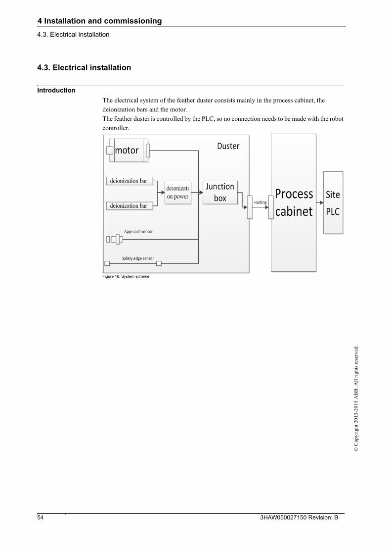
Introduction
The electrical system of the feather duster consists mainly in the process cabinet, the
deionization bars and the motor.
The feather duster is controlled by the PLC, so no connection needs to be made with the robot
controller.
Figure 18: System scheme
3HAW050027150 Revision: B 54
4 Installation and commissioning
4.3. Electrical installation©
Cop
yrig
ht 2
013-
2015
AB
B. A
ll r
ight
s re
serv
ed.
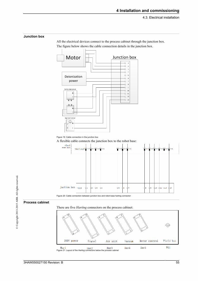
Junction box
All the electrical devices connect to the process cabinet through the junction box.
The figure below shows the cable connection details in the junction box.
Figure 19: Cable connection in the junction box
A flexible cable connects the junction box to the robot base:
Figure 20: Cable connection between junction box and robot base harting connector
Process cabinet
There are five Harting connectors on the process cabinet:
Figure 21: Layout of the Harting connectors below the process cabinet
553HAW050027150 Revision: B
4 Installation and commissioning
4.3. Electrical installation
© C
opyr
ight
201
3-20
15 A
BB
. All
rig
hts
rese
rved
.
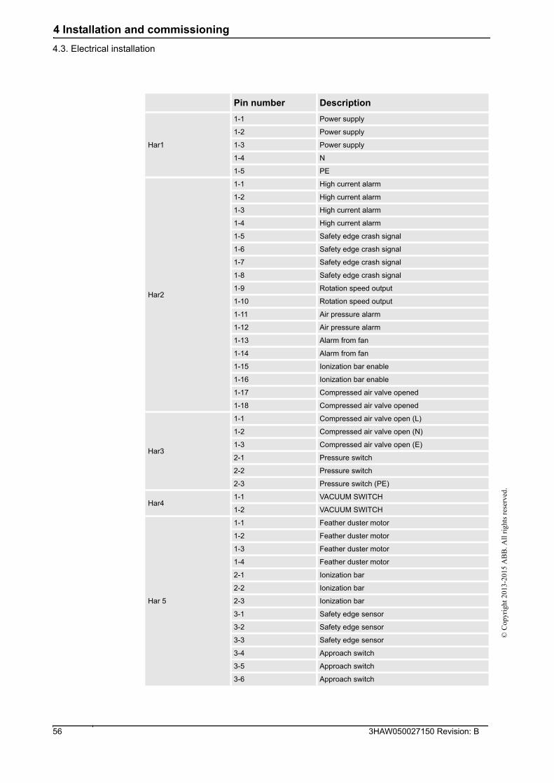
Pin number Description
Har1
1-1 Power supply
1-2 Power supply
1-3 Power supply
1-4 N
1-5 PE
Har2
1-1 High current alarm
1-2 High current alarm
1-3 High current alarm
1-4 High current alarm
1-5 Safety edge crash signal
1-6 Safety edge crash signal
1-7 Safety edge crash signal
1-8 Safety edge crash signal
1-9 Rotation speed output
1-10 Rotation speed output
1-11 Air pressure alarm
1-12 Air pressure alarm
1-13 Alarm from fan
1-14 Alarm from fan
1-15 Ionization bar enable
1-16 Ionization bar enable
1-17 Compressed air valve opened
1-18 Compressed air valve opened
Har3
1-1 Compressed air valve open (L)
1-2 Compressed air valve open (N)
1-3 Compressed air valve open (E)
2-1 Pressure switch
2-2 Pressure switch
2-3 Pressure switch (PE)
Har41-1 VACUUM SWITCH
1-2 VACUUM SWITCH
Har 5
1-1 Feather duster motor
1-2 Feather duster motor
1-3 Feather duster motor
1-4 Feather duster motor
2-1 Ionization bar
2-2 Ionization bar
2-3 Ionization bar
3-1 Safety edge sensor
3-2 Safety edge sensor
3-3 Safety edge sensor
3-4 Approach switch
3-5 Approach switch
3-6 Approach switch
3HAW050027150 Revision: B 56
4 Installation and commissioning
4.3. Electrical installation©
Cop
yrig
ht 2
013-
2015
AB
B. A
ll r
ight
s re
serv
ed.
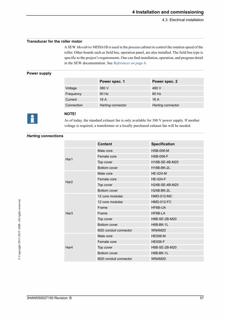
Transducer for the roller motor
A SEW Movidrive MDX61B is used in the process cabinet to control the rotation speed of the
roller. Other boards such as field bus, operation panel, are also installed. The field bus type is
specific to the project’s requirements. One can find installation, operation, and program detail
in the SEW documentation. See References on page 6.
Power supply
NOTE!
As of today, the standard exhaust fan is only available for 380 V power supply. If another
voltage is required, a transformer or a locally purchased exhaust fan will be needed.
Harting connections
Power spec. 1 Power spec. 2
Voltage 380 V 480 V
Frequency 50 Hz 60 Hz
Current 16 A 16 A
Connection Harting connector Harting connector
Content Specification
Har1
Male core HSB-006-M
Female core HSB-006-F
Top cover H16B-SE-4B-M25
Bottom cover H16B-BK-2L
Har2
Male core HE-024-M
Female core HE-024-F
Top cover H24B-SE-4B-M25
Bottom cover H24B-BK-2L
Har3
12 core modules HMD-012-MC
12 core modules HMD-012-FC
Frame HF6B-UA
Frame HF6B-LA
Top cover H6B-SE-2B-M20
Bottom cover H6B-BK-1L
M20 conduit connector WNAM20
Har4
Male core HE006-M
Female core HE006-F
Top cover H6B-SE-2B-M20
Bottom cover H6B-BK-1L
M20 conduit connector WNAM20
573HAW050027150 Revision: B
4 Installation and commissioning
4.4.1. Introduction
© C
opyr
ight
201
3-20
15 A
BB
. All
rig
hts
rese
rved
.
4.4 System start-up
4.4.1. Introduction
Introduction
This chapter contains the instructions for setting up the Feather Duster system once the
physical installation has been completed, and the robot and robot controller have been started
up.
To start the robot system up, refer to the controller and robot documentation. See References
on page 6.
Safety information
Follow the procedure below when performing the first test run after a service activity (repair,
installation or maintenance):
Set the robot TCP
The Tool Center Point must be set as shown below:
Steps Action
1. Remove all service tools and foreign objects from the robot and its working area!
2. Install all safety equipment properly!
3. Make sure all personnel are standing at a safe distance from the robot, i.e. out of its reach behind safety fences, etc.!
4. Pay special attention to the function of the part previously serviced!
Steps Action
1. Use the FTP software to connect the robot.
2. Download \HOME\robdata\robdata.sys. Before any modification, back the current file up.
3. Use the shopfloor editor or UE editor to open the file robdata.sys.
4. Add one line as below to define the TCP for the feather duster:
PERS tooldata Tool_Cleaner:=[TRUE,[[0,0,900],[1,0,0,0]],[125.1,[7.1,3.8,319.5],[1,0,0,0],26.302,12.415,18.623]]; Save the file.
5. Download the modified file to the controller, replace the previous one.
6. Warm start the robot.
3HAW050027150 Revision: B 58
4 Installation and commissioning
4.4.2. Start up of the Feather Duster motor©
Cop
yrig
ht 2
013-
2015
AB
B. A
ll r
ight
s re
serv
ed.
4.4.2. Start up of the Feather Duster motor
Introduction
The content of this chapter is an adapted extract from the SEW Operating Instructions
16837614-Movidrive MDX61B (See References on page 6).
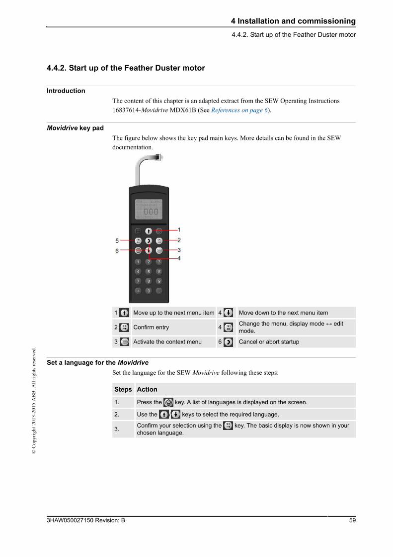
Movidrive key pad
The figure below shows the key pad main keys. More details can be found in the SEW
documentation.
Set a language for the MovidriveSet the language for the SEW Movidrive following these steps:
1 Move up to the next menu item 4 Move down to the next menu item
2 Confirm entry 4 Change the menu, display mode ↔ edit mode.
3 Activate the context menu 6 Cancel or abort startup
Steps Action
1. Press the key. A list of languages is displayed on the screen.
2. Use the / keys to select the required language.
3.Confirm your selection using the key. The basic display is now shown in your chosen language.
593HAW050027150 Revision: B
4 Installation and commissioning
4.4.2. Start up of the Feather Duster motor
© C
opyr
ight
201
3-20
15 A
BB
. All
rig
hts
rese
rved
.
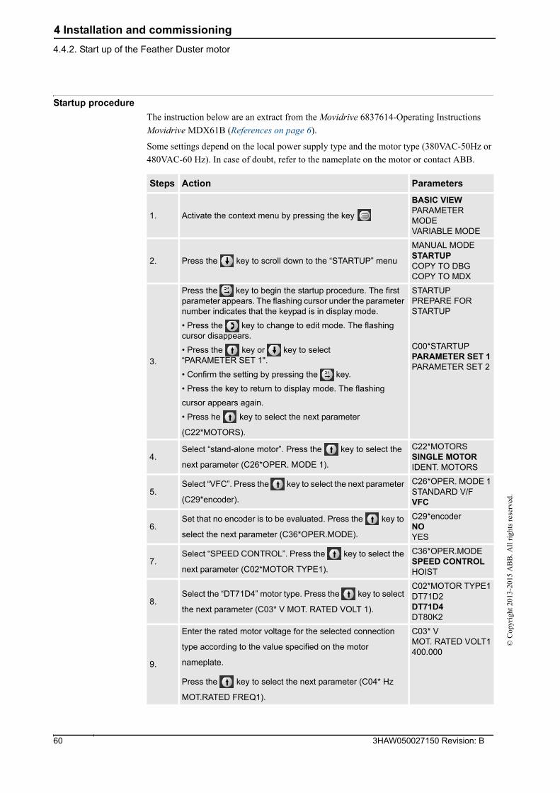
Startup procedure
The instruction below are an extract from the Movidrive 6837614-Operating Instructions
Movidrive MDX61B (References on page 6).
Some settings depend on the local power supply type and the motor type (380VAC-50Hz or
480VAC-60 Hz). In case of doubt, refer to the nameplate on the motor or contact ABB.
Steps Action Parameters
1. Activate the context menu by pressing the key
BASIC VIEWPARAMETER MODEVARIABLE MODE
2. Press the key to scroll down to the “STARTUP” menu
MANUAL MODESTARTUPCOPY TO DBGCOPY TO MDX
3.
Press the key to begin the startup procedure. The first parameter appears. The flashing cursor under the parameter number indicates that the keypad is in display mode.
• Press the key to change to edit mode. The flashing cursor disappears.
• Press the key or key to select “PARAMETER SET 1".
• Confirm the setting by pressing the key.
• Press the key to return to display mode. The flashing
cursor appears again.
• Press he key to select the next parameter
(C22*MOTORS).
STARTUPPREPARE FOR STARTUP
C00*STARTUPPARAMETER SET 1PARAMETER SET 2
4.Select “stand-alone motor”. Press the key to select the
next parameter (C26*OPER. MODE 1).
C22*MOTORSSINGLE MOTORIDENT. MOTORS
5.Select “VFC”. Press the key to select the next parameter
(C29*encoder).
C26*OPER. MODE 1STANDARD V/FVFC
6.Set that no encoder is to be evaluated. Press the key to
select the next parameter (C36*OPER.MODE).
C29*encoderNOYES
7.Select “SPEED CONTROL”. Press the key to select the
next parameter (C02*MOTOR TYPE1).
C36*OPER.MODESPEED CONTROLHOIST
8.Select the “DT71D4” motor type. Press the key to select
the next parameter (C03* V MOT. RATED VOLT 1).
C02*MOTOR TYPE1DT71D2DT71D4DT80K2
9.
Enter the rated motor voltage for the selected connection
type according to the value specified on the motor
nameplate.
Press the key to select the next parameter (C04* Hz
MOT.RATED FREQ1).
C03* VMOT. RATED VOLT1400.000
3HAW050027150 Revision: B 60
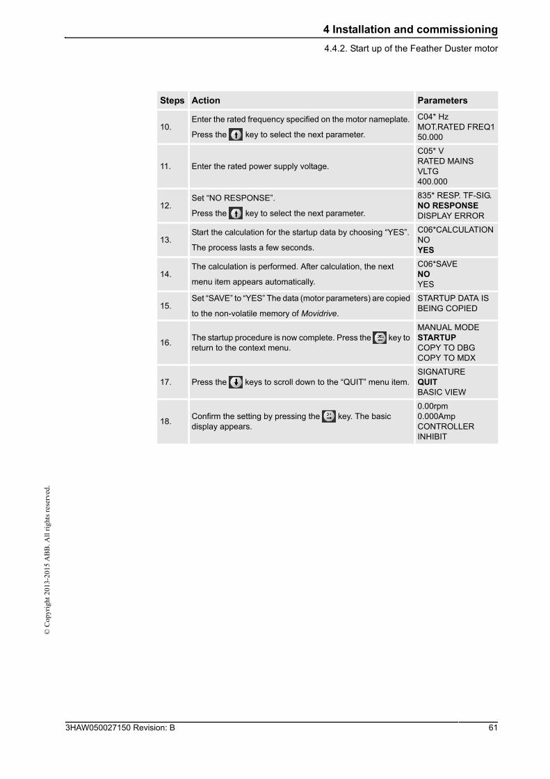
4 Installation and commissioning
4.4.2. Start up of the Feather Duster motor©
Cop
yrig
ht 2
013-
2015
AB
B. A
ll r
ight
s re
serv
ed.
10.Enter the rated frequency specified on the motor nameplate.
Press the key to select the next parameter.
C04* Hz MOT.RATED FREQ150.000
11. Enter the rated power supply voltage.
C05* VRATED MAINS VLTG400.000
12.Set “NO RESPONSE”.
Press the key to select the next parameter.
835* RESP. TF-SIG.NO RESPONSEDISPLAY ERROR
13.Start the calculation for the startup data by choosing “YES”.
The process lasts a few seconds.
C06*CALCULATIONNOYES
14.The calculation is performed. After calculation, the next
menu item appears automatically.
C06*SAVENOYES
15.Set “SAVE” to “YES” The data (motor parameters) are copied
to the non-volatile memory of Movidrive.
STARTUP DATA IS BEING COPIED
16.The startup procedure is now complete. Press the key to return to the context menu.
MANUAL MODESTARTUPCOPY TO DBGCOPY TO MDX
17. Press the keys to scroll down to the “QUIT” menu item.SIGNATUREQUITBASIC VIEW
18.Confirm the setting by pressing the key. The basic display appears.
0.00rpm0.000AmpCONTROLLER INHIBIT
Steps Action Parameters
613HAW050027150 Revision: B
4 Installation and commissioning
4.4.2. Start up of the Feather Duster motor
© C
opyr
ight
201
3-20
15 A
BB
. All
rig
hts
rese
rved
.
3HAW050027150 Revision: B 62
5 Maintenance
5.1. Introduction©
Cop
yrig
ht 2
013-
2015
AB
B. A
ll r
ight
s re
serv
ed.
5 Maintenance
5.1. Introduction
General
This chapter details all maintenance activities recommended for the Feather Duster.
It is based on the maintenance schedule, located in the beginning of the chapter. The schedule
contains information about required maintenance activities including intervals and refers to
procedures for the activities. Each procedure contains all information required to perform the
activity, e.g., required tools and materials. The procedures are gathered in different sections,
divided according to the maintenance activity.
Safety information
Before any service work is commenced, it is extremely important that all safety information
is observed! There are general safety aspects that must be read through, as well as more
specific safety information that describe danger and safety risks when performing the
procedures. Read Safety on page 11 before performing any service work.
Precautions
The precautions below should be observed before proceeding with the maintenance of the
Feather Duster:
CAUTION!
• Before any intervention on the mechanical and electrical components, all power
supplies to the Feather Duster as well as to other machines within the danger zone
must be turned off.
• If required, the main switch should be locked.
• Make sure that the pneumatic system is not pressurized.
• Use only original ABB spare parts. The use of unauthorized parts or others than
original parts will void the warranty.
Required equipment
Bolts and screws and tightening torques
Specified in Bolt, screws, tightening torques on page 77.
Equipment Note
Standard toolkit Specified in Standard toolkit on page 78.
Other tools and procedures may be required. See references to these procedures in the step-by-step instructions below.
Specified in Special tools on page 79.
633HAW050027150 Revision: B
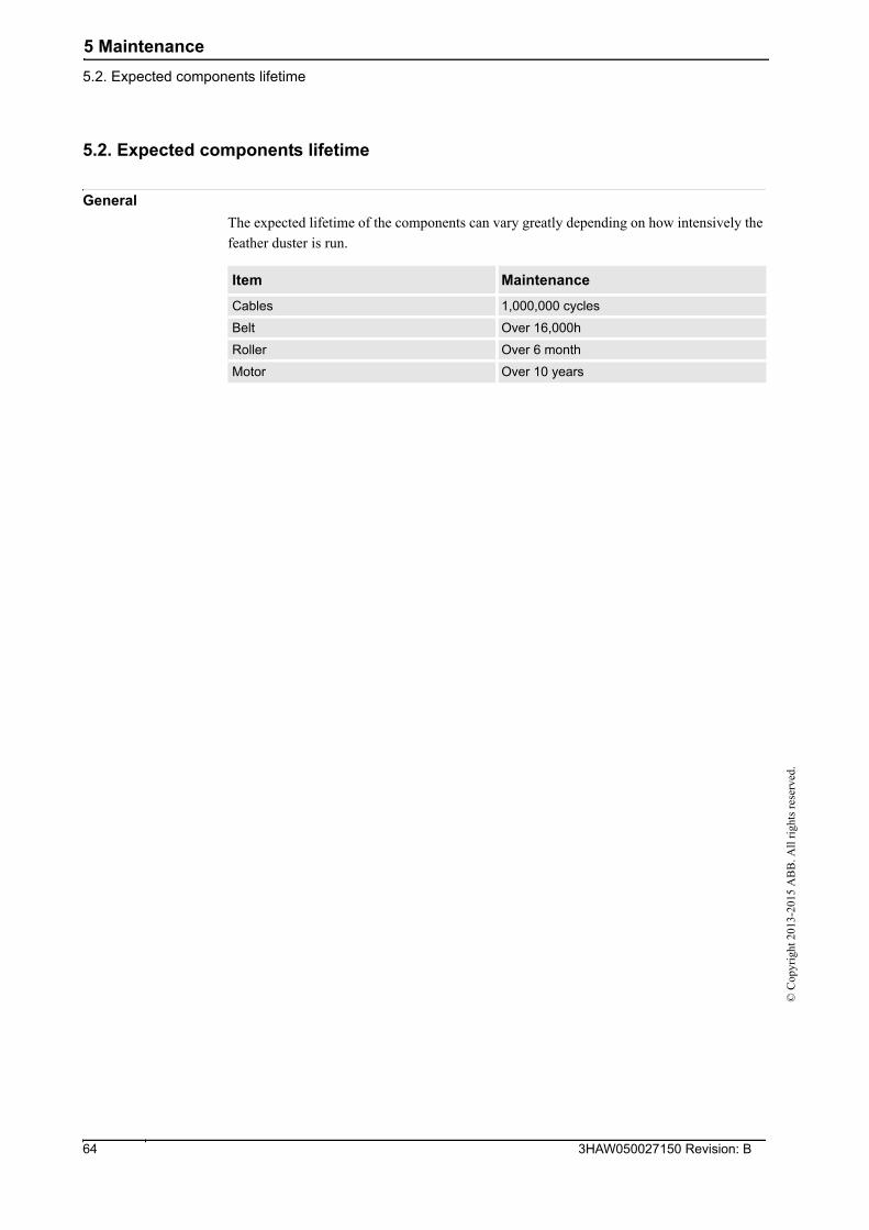
5 Maintenance
5.2. Expected components lifetime
© C
opyr
ight
201
3-20
15 A
BB
. All
rig
hts
rese
rved
.
5.2. Expected components lifetime
General
The expected lifetime of the components can vary greatly depending on how intensively the
feather duster is run.
Item Maintenance
Cables 1,000,000 cycles
Belt Over 16,000h
Roller Over 6 month
Motor Over 10 years
3HAW050027150 Revision: B 64
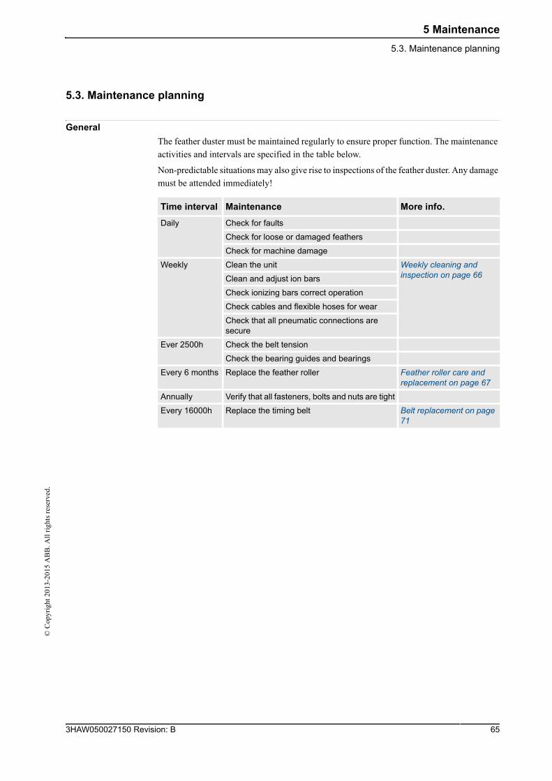
5 Maintenance
5.3. Maintenance planning©
Cop
yrig
ht 2
013-
2015
AB
B. A
ll r
ight
s re
serv
ed.
5.3. Maintenance planning
General
The feather duster must be maintained regularly to ensure proper function. The maintenance
activities and intervals are specified in the table below.
Non-predictable situations may also give rise to inspections of the feather duster. Any damage
must be attended immediately!
Time interval Maintenance More info.
Daily Check for faults
Check for loose or damaged feathers
Check for machine damage
Weekly Clean the unit Weekly cleaning and inspection on page 66Clean and adjust ion bars
Check ionizing bars correct operation
Check cables and flexible hoses for wear
Check that all pneumatic connections are secure
Ever 2500h Check the belt tension
Check the bearing guides and bearings
Every 6 months Replace the feather roller Feather roller care and replacement on page 67
Annually Verify that all fasteners, bolts and nuts are tight
Every 16000h Replace the timing belt Belt replacement on page 71
653HAW050027150 Revision: B
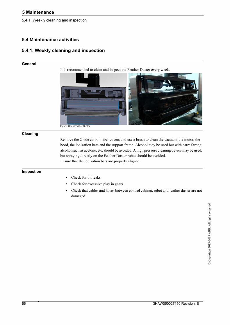
5 Maintenance
5.4.1. Weekly cleaning and inspection
© C
opyr
ight
201
3-20
15 A
BB
. All
rig
hts
rese
rved
.
5.4 Maintenance activities
5.4.1. Weekly cleaning and inspection
General
It is recommended to clean and inspect the Feather Duster every week.
Figure: Open Feather Duster
Cleaning
Remove the 2 side carbon fiber covers and use a brush to clean the vacuum, the motor, the
hood, the ionization bars and the support frame. Alcohol may be used but with care: Strong
alcohol such as acetone, etc. should be avoided. A high pressure cleaning device may be used,
but spraying directly on the Feather Duster robot should be avoided.
Ensure that the ionization bars are properly aligned.
Inspection
• Check for oil leaks.
• Check for excessive play in gears.
• Check that cables and hoses between control cabinet, robot and feather duster are not
damaged.
3HAW050027150 Revision: B 66
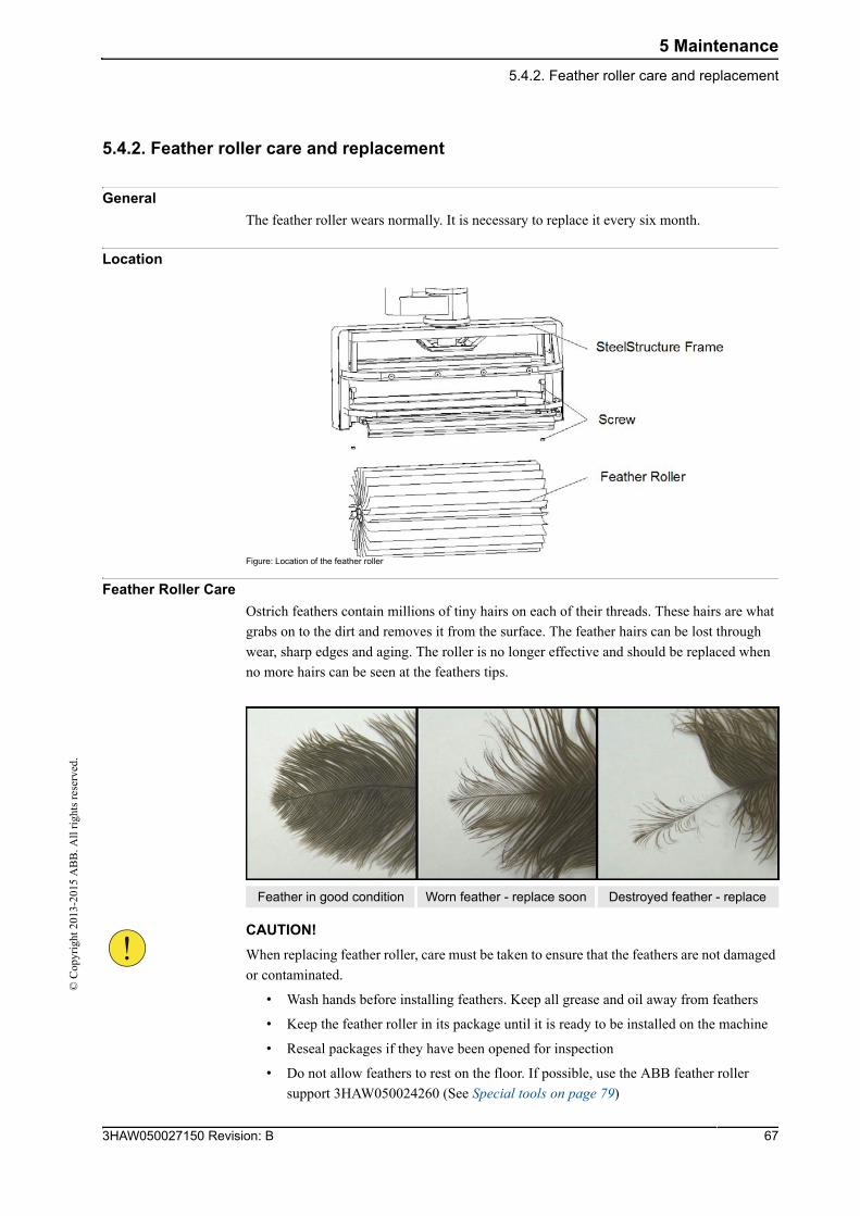
5 Maintenance
5.4.2. Feather roller care and replacement©
Cop
yrig
ht 2
013-
2015
AB
B. A
ll r
ight
s re
serv
ed.
5.4.2. Feather roller care and replacement
General
The feather roller wears normally. It is necessary to replace it every six month.
Location
Figure: Location of the feather roller
Feather Roller Care
Ostrich feathers contain millions of tiny hairs on each of their threads. These hairs are what
grabs on to the dirt and removes it from the surface. The feather hairs can be lost through
wear, sharp edges and aging. The roller is no longer effective and should be replaced when
no more hairs can be seen at the feathers tips.
CAUTION!
When replacing feather roller, care must be taken to ensure that the feathers are not damaged
or contaminated.
• Wash hands before installing feathers. Keep all grease and oil away from feathers
• Keep the feather roller in its package until it is ready to be installed on the machine
• Reseal packages if they have been opened for inspection
• Do not allow feathers to rest on the floor. If possible, use the ABB feather roller
support 3HAW050024260 (See Special tools on page 79)
Feather in good condition Worn feather - replace soon Destroyed feather - replace
673HAW050027150 Revision: B
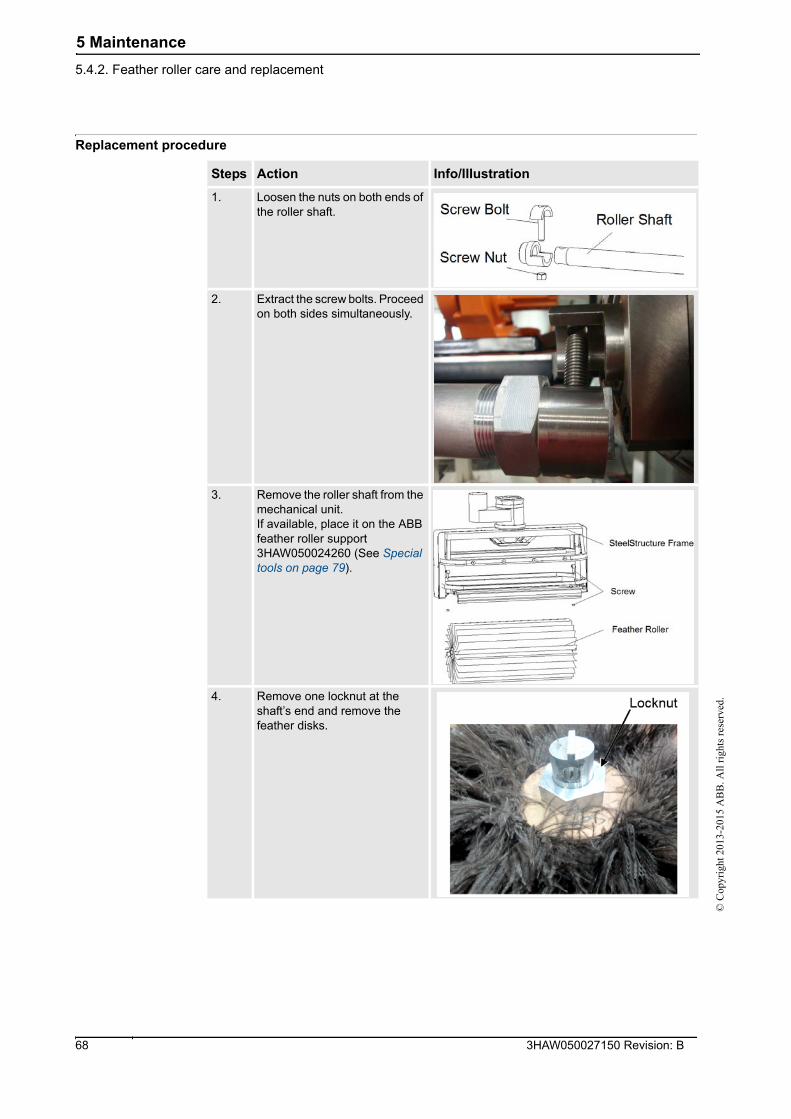
5 Maintenance
5.4.2. Feather roller care and replacement
© C
opyr
ight
201
3-20
15 A
BB
. All
rig
hts
rese
rved
.
Replacement procedure
Steps Action Info/IIIustration
1. Loosen the nuts on both ends of the roller shaft.
2. Extract the screw bolts. Proceed on both sides simultaneously.
3. Remove the roller shaft from the mechanical unit.If available, place it on the ABB feather roller support 3HAW050024260 (See Special tools on page 79).
4. Remove one locknut at the shaft’s end and remove the feather disks.
3HAW050027150 Revision: B 68
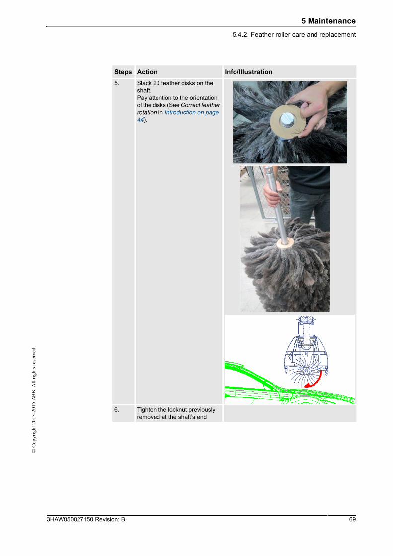
5 Maintenance
5.4.2. Feather roller care and replacement©
Cop
yrig
ht 2
013-
2015
AB
B. A
ll r
ight
s re
serv
ed.
5. Stack 20 feather disks on the shaft. Pay attention to the orientation of the disks (See Correct feather rotation in Introduction on page 44).
6. Tighten the locknut previously removed at the shaft’s end
Steps Action Info/IIIustration
693HAW050027150 Revision: B
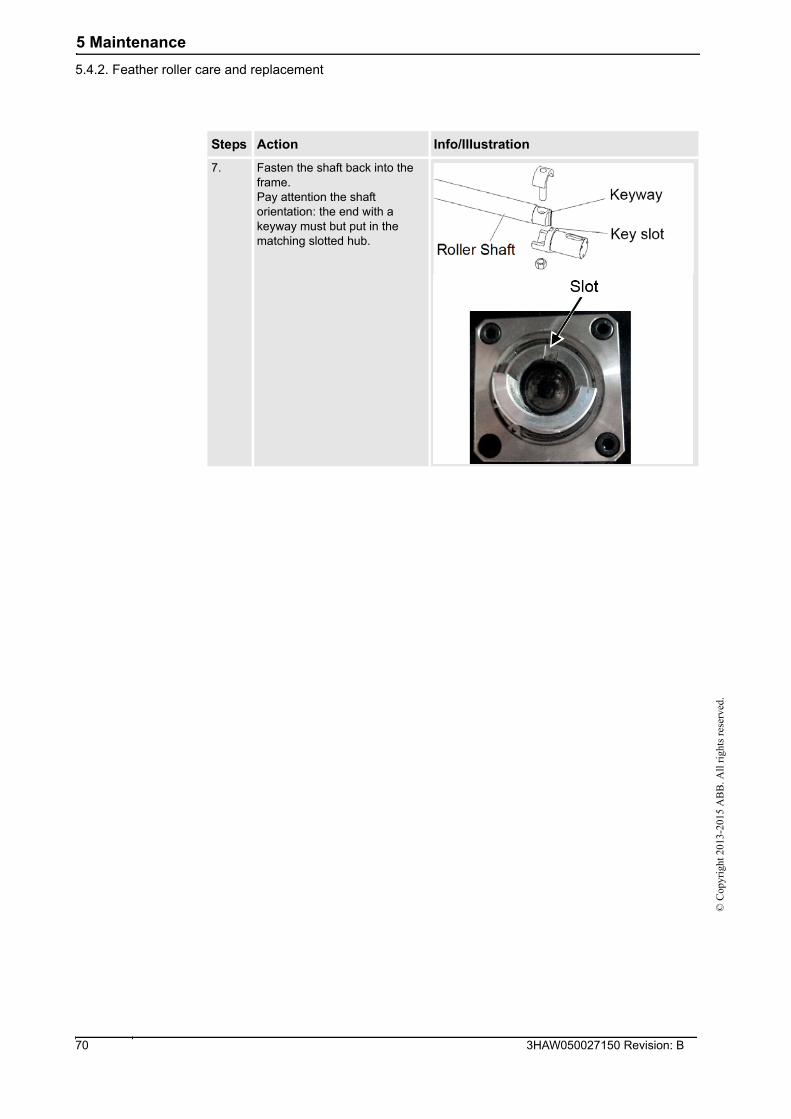
5 Maintenance
5.4.2. Feather roller care and replacement
© C
opyr
ight
201
3-20
15 A
BB
. All
rig
hts
rese
rved
.
7. Fasten the shaft back into the frame.Pay attention the shaft orientation: the end with a keyway must but put in the matching slotted hub.
Steps Action Info/IIIustration
3HAW050027150 Revision: B 70
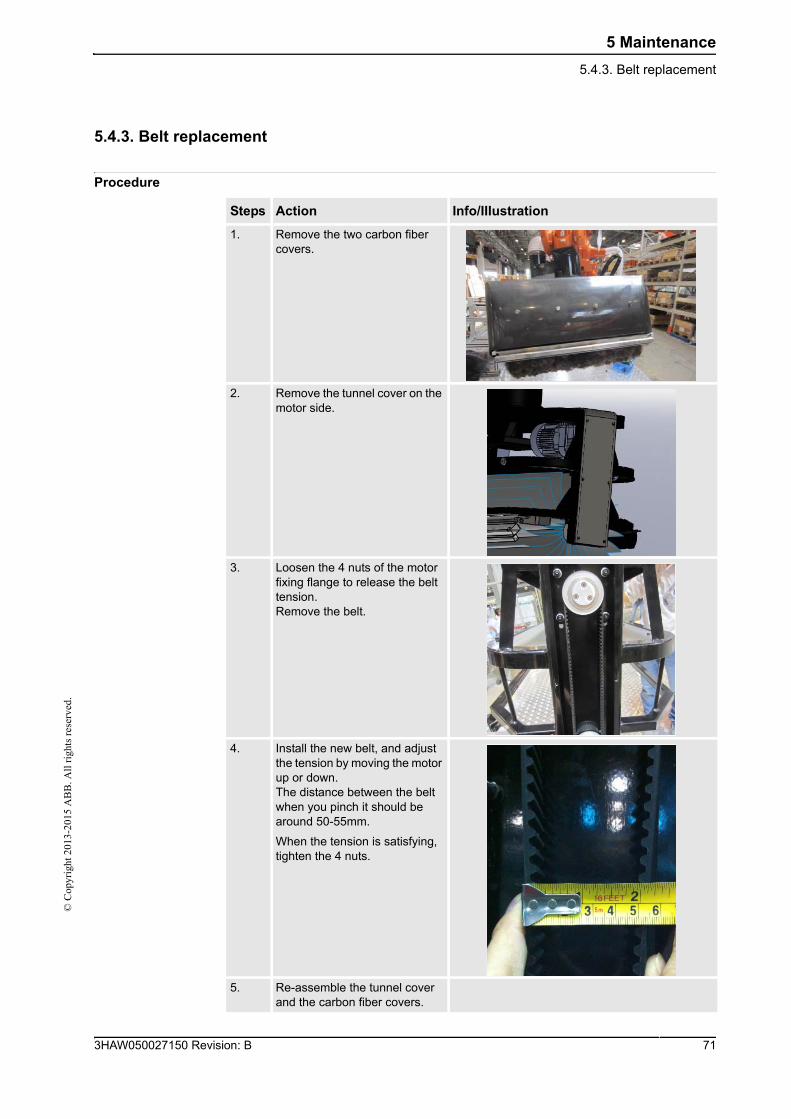
5 Maintenance
5.4.3. Belt replacement©
Cop
yrig
ht 2
013-
2015
AB
B. A
ll r
ight
s re
serv
ed.
5.4.3. Belt replacement
Procedure
Steps Action Info/IIIustration
1. Remove the two carbon fiber covers.
2. Remove the tunnel cover on the motor side.
3. Loosen the 4 nuts of the motor fixing flange to release the belt tension.Remove the belt.
4. Install the new belt, and adjust the tension by moving the motor up or down.The distance between the belt when you pinch it should be around 50-55mm.
When the tension is satisfying, tighten the 4 nuts.
5. Re-assemble the tunnel cover and the carbon fiber covers.
713HAW050027150 Revision: B
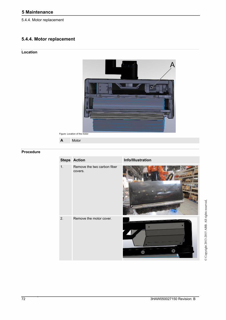
5 Maintenance
5.4.4. Motor replacement
© C
opyr
ight
201
3-20
15 A
BB
. All
rig
hts
rese
rved
.
5.4.4. Motor replacement
Location
Figure: Location of the motor
Procedure
A Motor
Steps Action Info/IIIustration
1. Remove the two carbon fiber covers.
2. Remove the motor cover.
3HAW050027150 Revision: B 72
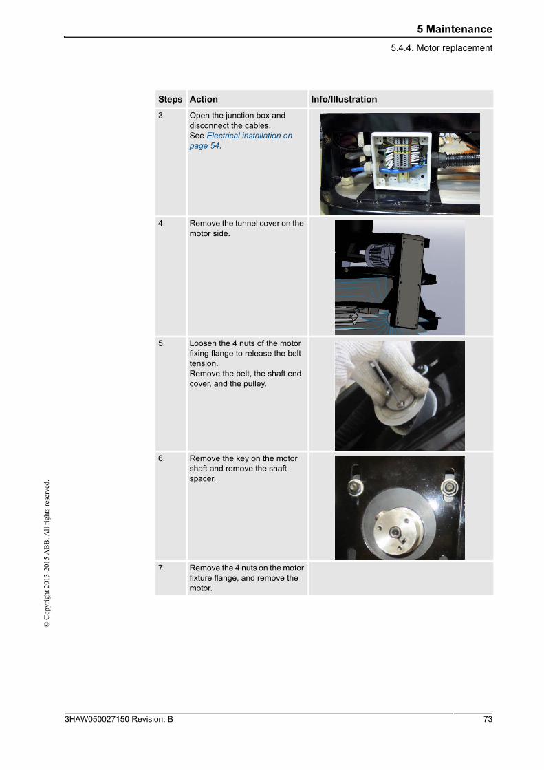
5 Maintenance
5.4.4. Motor replacement©
Cop
yrig
ht 2
013-
2015
AB
B. A
ll r
ight
s re
serv
ed.
3. Open the junction box and disconnect the cables.See Electrical installation on page 54.
4. Remove the tunnel cover on the motor side.
5. Loosen the 4 nuts of the motor fixing flange to release the belt tension.Remove the belt, the shaft end cover, and the pulley.
6. Remove the key on the motor shaft and remove the shaft spacer.
7. Remove the 4 nuts on the motor fixture flange, and remove the motor.
Steps Action Info/IIIustration
733HAW050027150 Revision: B
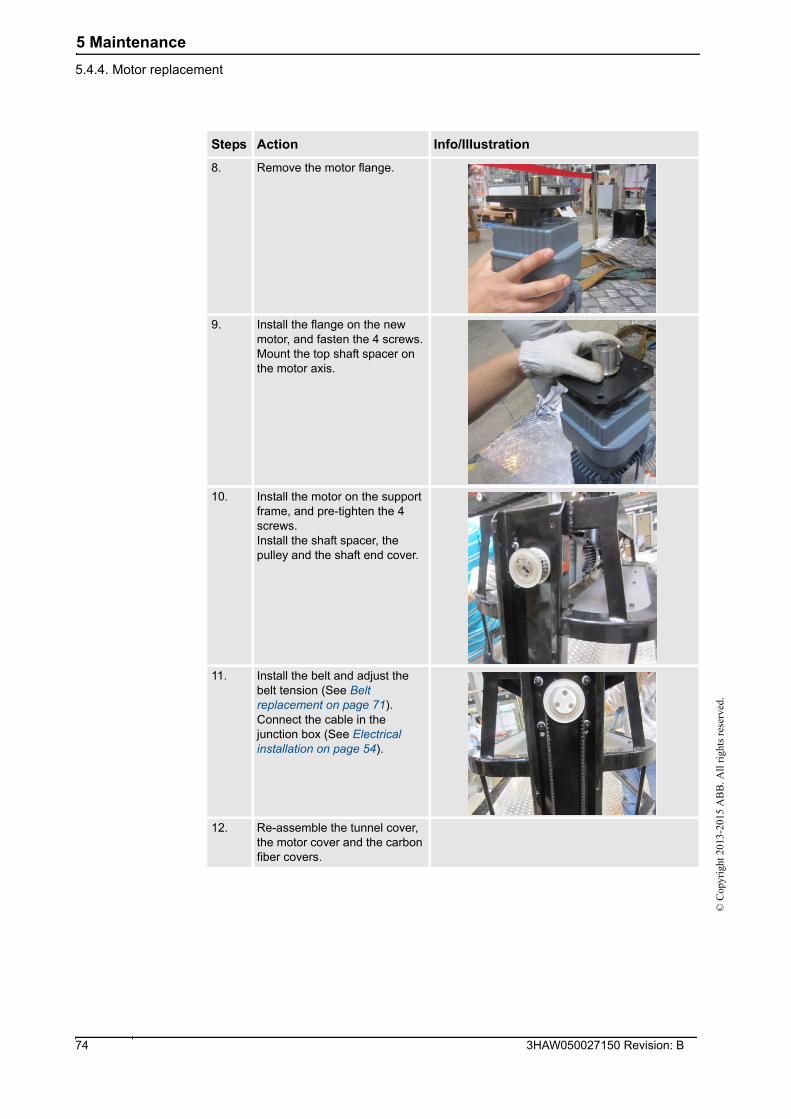
5 Maintenance
5.4.4. Motor replacement
© C
opyr
ight
201
3-20
15 A
BB
. All
rig
hts
rese
rved
.
8. Remove the motor flange.
9. Install the flange on the new motor, and fasten the 4 screws.Mount the top shaft spacer on the motor axis.
10. Install the motor on the support frame, and pre-tighten the 4 screws.Install the shaft spacer, the pulley and the shaft end cover.
11. Install the belt and adjust the belt tension (See Belt replacement on page 71).Connect the cable in the junction box (See Electrical installation on page 54).
12. Re-assemble the tunnel cover, the motor cover and the carbon fiber covers.
Steps Action Info/IIIustration
3HAW050027150 Revision: B 74
6 Reference information
6.1. Introduction©
Cop
yrig
ht 2
013-
2015
AB
B. A
ll r
ight
s re
serv
ed.
6 Reference information
6.1. Introduction
General
This chapter includes general information, complementing the more specific information in
the different procedures in the manual.
753HAW050027150 Revision: B
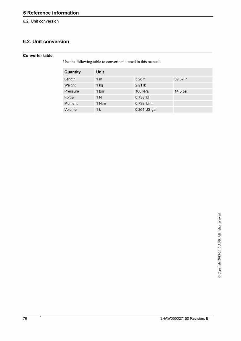
6 Reference information
6.2. Unit conversion
© C
opyr
ight
201
3-20
15 A
BB
. All
rig
hts
rese
rved
.
6.2. Unit conversion
Converter table
Use the following table to convert units used in this manual.
Quantity Unit
Length 1 m 3.28 ft 39.37 in
Weight 1 kg 2.21 lb
Pressure 1 bar 100 kPa 14.5 psi
Force 1 N 0.738 lbf
Moment 1 N.m 0.738 lbf-tn
Volume 1 L 0.264 US gal
3HAW050027150 Revision: B 76
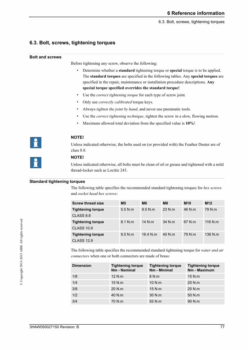
6 Reference information
6.3. Bolt, screws, tightening torques©
Cop
yrig
ht 2
013-
2015
AB
B. A
ll r
ight
s re
serv
ed.
6.3. Bolt, screws, tightening torques
Bolt and screws
Before tightening any screw, observe the following:
• Determine whether a standard tightening torque or special torque is to be applied.
The standard torques are specified in the following tables. Any special torques are
specified in the repair, maintenance or installation procedure descriptions. Any
special torque specified overrides the standard torque!
• Use the correct tightening torque for each type of screw joint.
• Only use correctly calibrated torque keys.
• Always tighten the joint by hand, and never use pneumatic tools.
• Use the correct tightening technique, tighten the screw in a slow, flowing motion.
• Maximum allowed total deviation from the specified value is 10%!
NOTE!
Unless indicated otherwise, the bolts used on (or provided with) the Feather Duster are of
class 8.8.
NOTE!
Unless indicated otherwise, all bolts must be clean of oil or grease and tightened with a mild
thread-locker such as Loctite 243.
Standard tightening torques
The following table specifies the recommended standard tightening torques for hex screws
and socket head hex screws:
The following table specifies the recommended standard tightening torque for water and air
connectors when one or both connectors are made of brass:
Screw thread size M5 M6 M8 M10 M12
Tightening torque
CLASS 8.8
5.5 N.m 9.5 N.m 23 N.m 46 N.m 79 N.m
Tightening torque
CLASS 10.9
8.1 N.m 14 N.m 34 N.m 67 N.m 116 N.m
Tightening torque
CLASS 12.9
9.5 N.m 16.4 N.m 40 N.m 79 N.m 136 N.m
Dimension Tightening torque Nm - Nominal
Tightening torque Nm - Minimal
Tightening torque Nm - Maximum
1/8 12 N.m 8 N.m 15 N.m
1/4 15 N.m 10 N.m 20 N.m
3/8 20 N.m 15 N.m 25 N.m
1/2 40 N.m 30 N.m 50 N.m
3/4 70 N.m 55 N.m 90 N.m
773HAW050027150 Revision: B
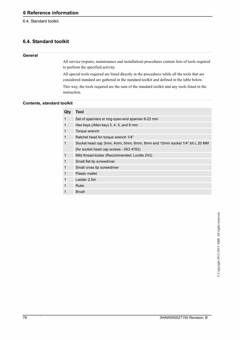
6 Reference information
6.4. Standard toolkit
© C
opyr
ight
201
3-20
15 A
BB
. All
rig
hts
rese
rved
.
6.4. Standard toolkit
General
All service (repairs, maintenance and installation) procedures contain lists of tools required
to perform the specified activity.
All special tools required are listed directly in the procedures while all the tools that are
considered standard are gathered in the standard toolkit and defined in the table below.
This way, the tools required are the sum of the standard toolkit and any tools listed in the
instruction.
Contents, standard toolkit
Qty Tool
1 Set of spanners or ring-open-end spanner 8-22 mm
1 Hex keys (Allen key) 3, 4, 5, and 6 mm
1 Torque wrench
1 Ratchet head for torque wrench 1/4”
1 Socket head cap 3mm, 4mm, 5mm, 6mm, 8mm and 10mm socket 1/4” bit L 20 MM
(for socket head cap screws - ISO 4762)
1 Mild thread-locker (Recommended: Loctite 243)
1 Small flat tip screwdriver
1 Small cross tip screwdriver
1 Plastic mallet
1 Ladder 2.5m
1 Ruler
1 Brush
3HAW050027150 Revision: B 78
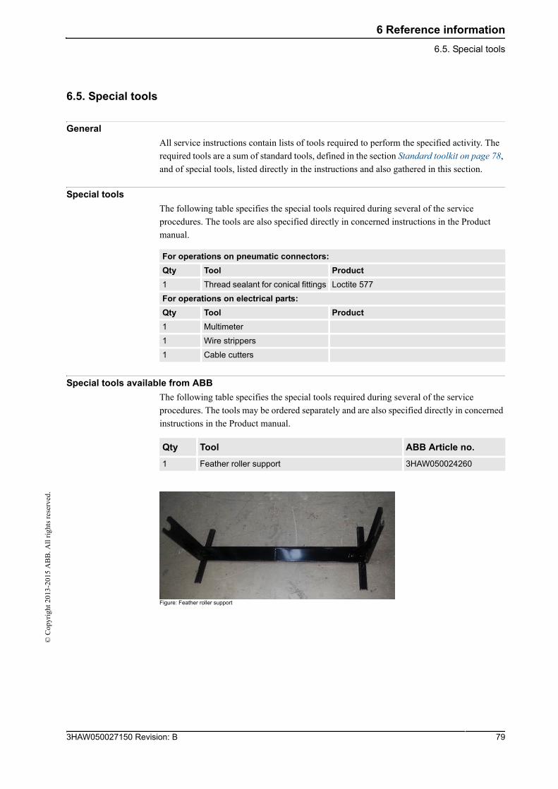
6 Reference information
6.5. Special tools©
Cop
yrig
ht 2
013-
2015
AB
B. A
ll r
ight
s re
serv
ed.
6.5. Special tools
General
All service instructions contain lists of tools required to perform the specified activity. The
required tools are a sum of standard tools, defined in the section Standard toolkit on page 78,
and of special tools, listed directly in the instructions and also gathered in this section.
Special tools
The following table specifies the special tools required during several of the service
procedures. The tools are also specified directly in concerned instructions in the Product
manual.
Special tools available from ABB
The following table specifies the special tools required during several of the service
procedures. The tools may be ordered separately and are also specified directly in concerned
instructions in the Product manual.
Figure: Feather roller support
For operations on pneumatic connectors:
Qty Tool Product
1 Thread sealant for conical fittings Loctite 577
For operations on electrical parts:
Qty Tool Product
1 Multimeter
1 Wire strippers
1 Cable cutters
Qty Tool ABB Article no.
1 Feather roller support 3HAW050024260
793HAW050027150 Revision: B
6 Reference information
6.5. Special tools
© C
opyr
ight
201
3-20
15 A
BB
. All
rig
hts
rese
rved
.
3HAW050027150 Revision: B 80
7 Spare parts
7.1. Introduction©
Cop
yrig
ht 2
013-
2015
AB
B. A
ll r
ight
s re
serv
ed.
7 Spare parts
7.1. Introduction
General
This chapter specifies all spare parts and replacement articles of the Feather Duster. It is
divided in 2 sections:
• Mechanical spare parts
• Electrical parts and cables
Some parts are available in several types, depending on the Feather Duster configuration. If
you do not know what type of material is required for your Feather Duster, contact ABB.
813HAW050027150 Revision: B
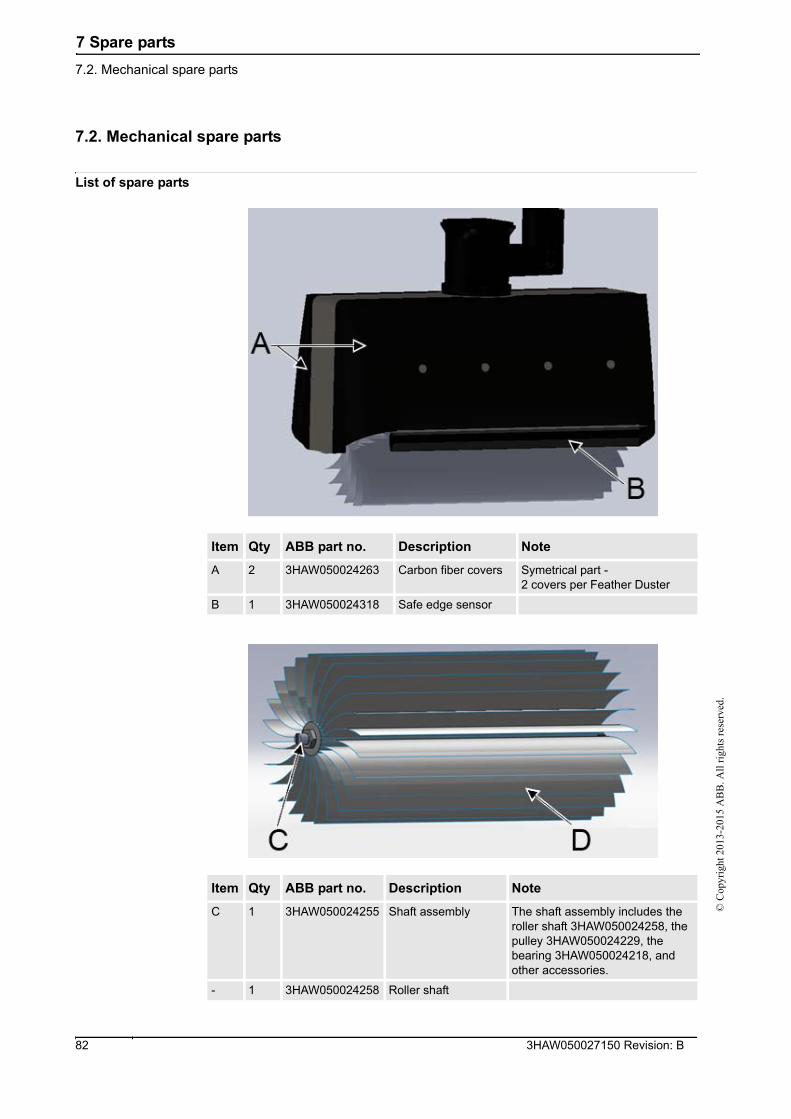
7 Spare parts
7.2. Mechanical spare parts
© C
opyr
ight
201
3-20
15 A
BB
. All
rig
hts
rese
rved
.
7.2. Mechanical spare parts
List of spare parts
Item Qty ABB part no. Description Note
A 2 3HAW050024263 Carbon fiber covers Symetrical part -2 covers per Feather Duster
B 1 3HAW050024318 Safe edge sensor
Item Qty ABB part no. Description Note
C 1 3HAW050024255 Shaft assembly The shaft assembly includes the roller shaft 3HAW050024258, the pulley 3HAW050024229, the bearing 3HAW050024218, and other accessories.
- 1 3HAW050024258 Roller shaft
3HAW050027150 Revision: B 82
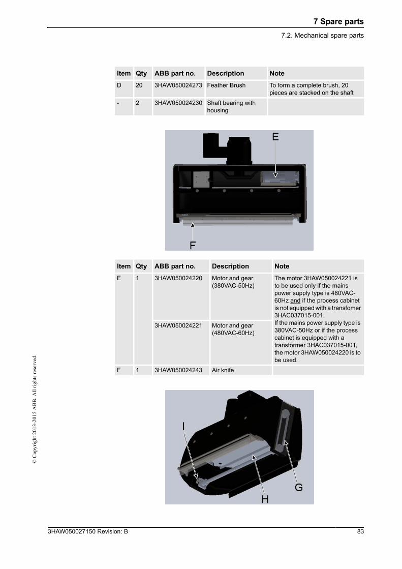
7 Spare parts
7.2. Mechanical spare parts©
Cop
yrig
ht 2
013-
2015
AB
B. A
ll r
ight
s re
serv
ed.
D 20 3HAW050024273 Feather Brush To form a complete brush, 20 pieces are stacked on the shaft
- 2 3HAW050024230 Shaft bearing with housing
Item Qty ABB part no. Description Note
E 1 3HAW050024220 Motor and gear (380VAC-50Hz)
The motor 3HAW050024221 is to be used only if the mains power supply type is 480VAC-60Hz and if the process cabinet is not equipped with a transfomer 3HAC037015-001.If the mains power supply type is 380VAC-50Hz or if the process cabinet is equipped with a transformer 3HAC037015-001, the motor 3HAW050024220 is to be used.
3HAW050024221 Motor and gear (480VAC-60Hz)
F 1 3HAW050024243 Air knife
Item Qty ABB part no. Description Note
833HAW050027150 Revision: B
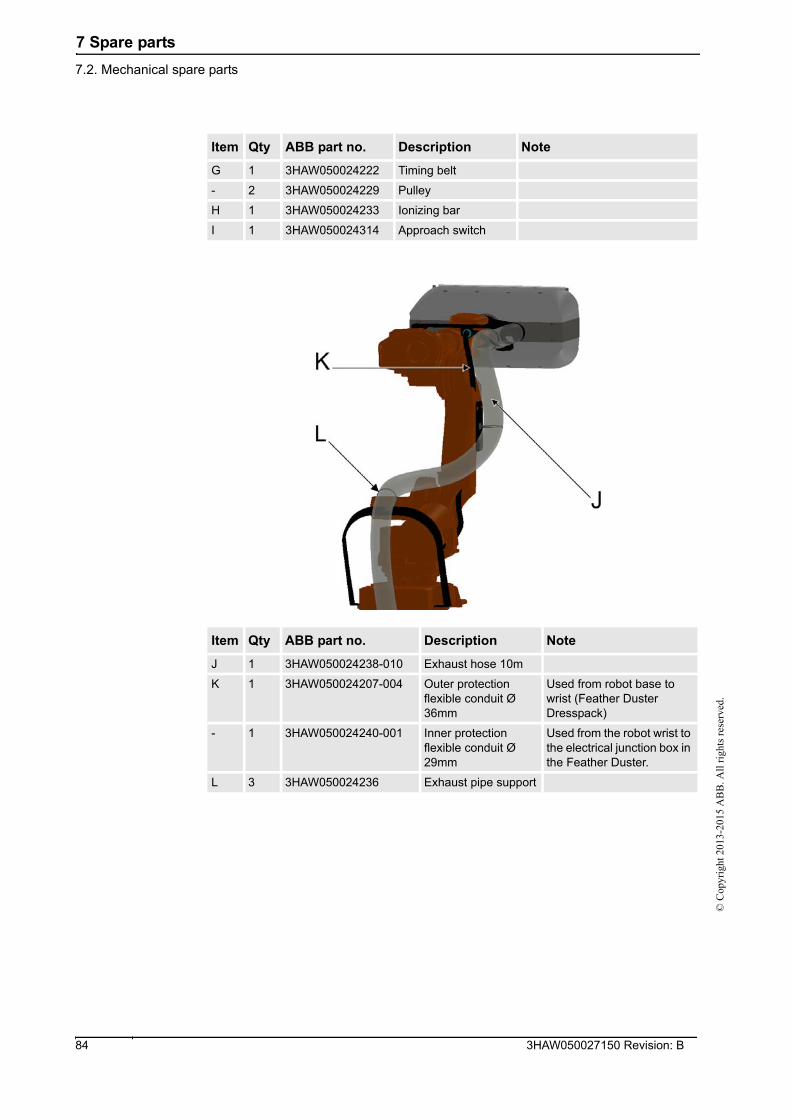
7 Spare parts
7.2. Mechanical spare parts
© C
opyr
ight
201
3-20
15 A
BB
. All
rig
hts
rese
rved
.
Item Qty ABB part no. Description Note
G 1 3HAW050024222 Timing belt
- 2 3HAW050024229 Pulley
H 1 3HAW050024233 Ionizing bar
I 1 3HAW050024314 Approach switch
Item Qty ABB part no. Description Note
J 1 3HAW050024238-010 Exhaust hose 10m
K 1 3HAW050024207-004 Outer protection flexible conduit Ø 36mm
Used from robot base to wrist (Feather Duster Dresspack)
- 1 3HAW050024240-001 Inner protection flexible conduit Ø 29mm
Used from the robot wrist to the electrical junction box in the Feather Duster.
L 3 3HAW050024236 Exhaust pipe support
3HAW050027150 Revision: B 84
7 Spare parts
7.3. Electrical spare parts©
Cop
yrig
ht 2
013-
2015
AB
B. A
ll r
ight
s re
serv
ed.
7.3. Electrical spare parts
List of spare parts
Item Quantity ABB part reference no. Note
- 1 3HAW050024312 Safety edge sensor relay
- 1 3HAW050024313 General relay
- 1 3HAW050024317 Safe edge controller
- 1 3HAW050024325 Brake resistor
- 1 3HAW050024294-010 Control cable (from process cabinet to robot base) - 10m
- 1 3HAW050024294-015 Control cable (from process cabinet to robot base) - 15m
- 1 3HAW050024279 Flexible control harness (from robot base to junction box)
853HAW050027150 Revision: B

© C
opyr
ight
201
3-20
15 A
BB
. All
rig
hts
rese
rved
.
8 Appendix
8.1. Assembly drawings©
Cop
yrig
ht 2
013-
2015
AB
B. A
ll r
ight
s re
serv
ed.
8 Appendix
8.1. Assembly drawings
List
This section contains following drawings:
• Exhaust manifold assembly
• Shaft assembly
• Tack off
• IRB 6640 Feather duster dresspack - left
• IRB 6640 Feather duster dresspack - right
• IRB 6700 Feather duster dresspack - left
873HAW050027150 Revision: B
8 Appendix
8.2. Wiring diagrams
© C
opyr
ight
201
3-20
15 A
BB
. All
rig
hts
rese
rved
.
8.2. Wiring diagrams
List
• 3HAW050024286: EMU process cabinet
• 3HAW050024294: Ground control cable
• 3HAW050024279: Flexible control harness
3HAW050027150 Revision: B 88
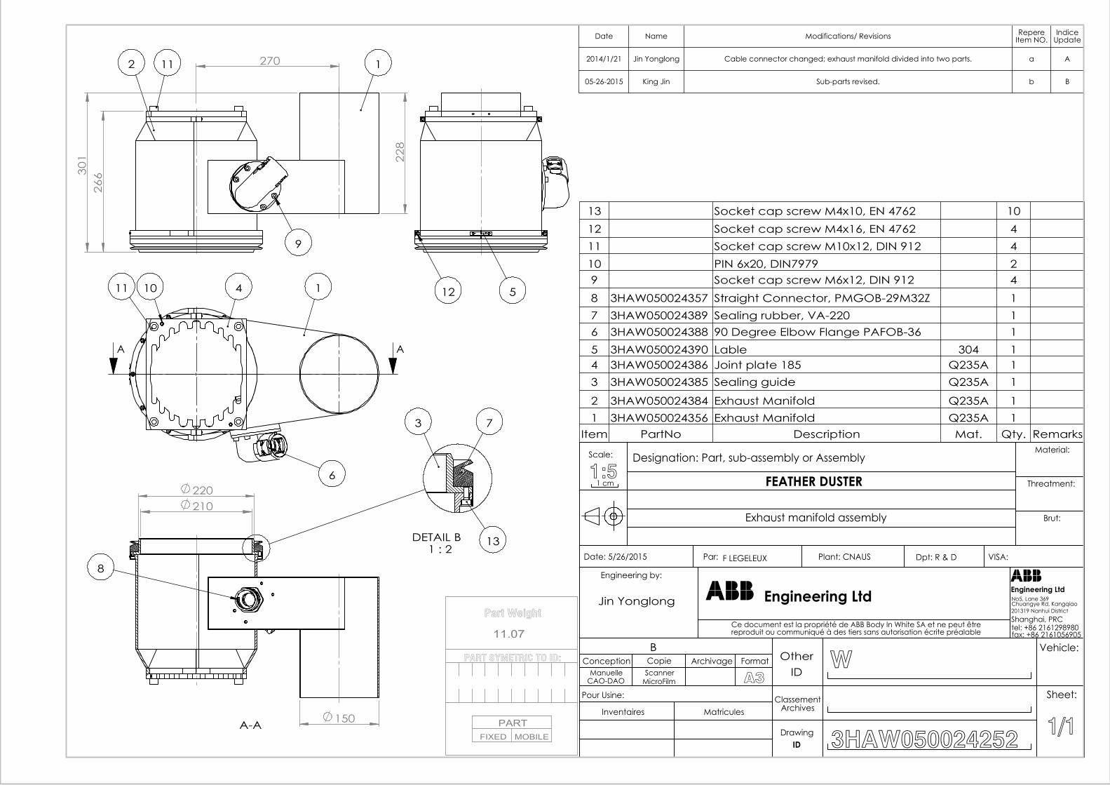
Part Weight
PART SYMETRIC TO ID:
PARTFIXED MOBILE
11.07
228
270
266
301
2 111
9
A A
14
6
1011 512
150
210 220
A-A
8
DETAIL B 1 : 2
3 7
13
Date Name Modifications/ Revisions RepereItem NO.
IndiceUpdate
2014/1/21 Jin Yonglong Cable connector changed; exhaust manifold divided into two parts. a A
05-26-2015 King Jin Sub-parts revised. b B
13 Socket cap screw M4x10, EN 4762 1012 Socket cap screw M4x16, EN 4762 411 Socket cap screw M10x12, DIN 912 410 PIN 6x20, DIN7979 29 Socket cap screw M6x12, DIN 912 48 3HAW050024357 Straight Connector, PMGOB-29M32Z 17 3HAW050024389 Sealing rubber, VA-220 16 3HAW050024388 90 Degree Elbow Flange PAFOB-36 15 3HAW050024390 Lable 304 14 3HAW050024386 Joint plate 185 Q235A 13 3HAW050024385 Sealing guide Q235A 1
2 3HAW050024384 Exhaust Manifold Q235A 11 3HAW050024356 Exhaust Manifold Q235A 1
Item PartNo Description Mat. Qty. Remarks
Exhaust manifold assembly
F LEGELEUX
1 cm1:5Scale: Designation: Part, sub-assembly or Assembly
Brut:
Threatment:
Material:
VISA:Dpt: R & DPlant: CNAUSPar: Date: 5/26/2015
fax: +86 2161056905tel: +86 2161298980Shanghai, PRC201319 Nanhui District
No5, Lane 369
Engineering LtdEngineering Ltd
Ce document est la propriété de ABB Body In White SA et ne peut êtrereproduit ou communiqué à des tiers sans autorisation écrite préalable
Engineering by:
1/1
Sheet:
Vehicle:
3HAW050024252IDDrawing
ClassementArchives
IDOther
MatriculesInventaires
Pour Usine:
A3MicroFilmScanner
CAO-DAOManuelle
FormatArchivageCopieConceptionB
W
Chuangye Rd, KangqiaoJin Yonglong
FEATHER DUSTER
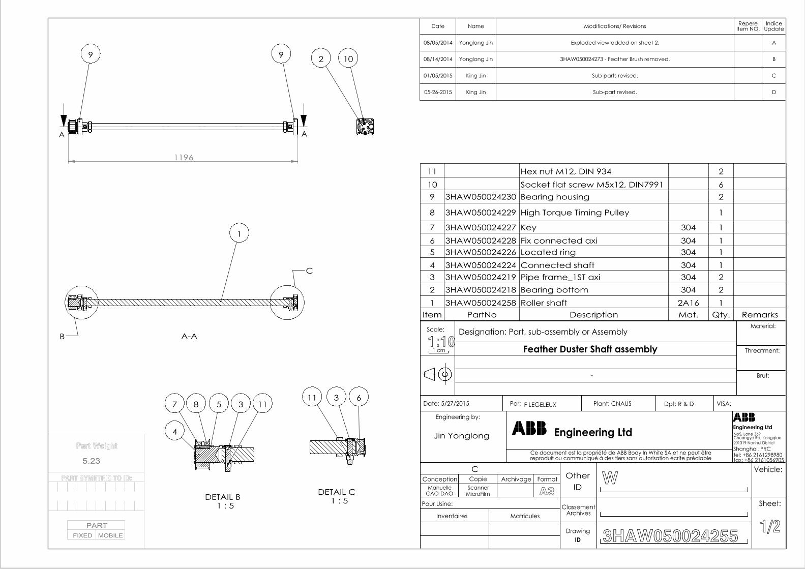
1196
A A
99 2 10
B
C
A-A
1
DETAIL B 1 : 5
3
4
87 5 11
DETAIL C 1 : 5
3 611
11 Hex nut M12, DIN 934 210 Socket flat screw M5x12, DIN7991 69 3HAW050024230 Bearing housing 2
8 3HAW050024229 High Torque Timing Pulley 1
7 3HAW050024227 Key 304 16 3HAW050024228 Fix connected axi 304 15 3HAW050024226 Located ring 304 14 3HAW050024224 Connected shaft 304 13 3HAW050024219 Pipe frame_1ST axi 304 22 3HAW050024218 Bearing bottom 304 21 3HAW050024258 Roller shaft 2A16 1
Item PartNo Description Mat. Qty. Remarks
Date Name Modifications/ Revisions RepereItem NO.
IndiceUpdate
08/05/2014 Yonglong Jin Exploded view added on sheet 2. A
08/14/2014 Yonglong Jin 3HAW050024273 - Feather Brush removed. B
01/05/2015 King Jin Sub-parts revised. C
05-26-2015 King Jin Sub-part revised. D
Part Weight
5.23
PART SYMETRIC TO ID:
PARTFIXED MOBILE
-
F LEGELEUX
1 cm1:10Scale: Designation: Part, sub-assembly or Assembly
Brut:
Threatment:
Material:
VISA:Dpt: R & DPlant: CNAUSPar: Date: 5/27/2015
fax: +86 2161056905tel: +86 2161298980Shanghai, PRC201319 Nanhui District
No5, Lane 369
Engineering LtdEngineering Ltd
Ce document est la propriété de ABB Body In White SA et ne peut êtrereproduit ou communiqué à des tiers sans autorisation écrite préalable
Engineering by:
1/2
Sheet:
Vehicle:
3HAW050024255IDDrawing
ClassementArchives
IDOther
MatriculesInventaires
Pour Usine:
A3MicroFilmScanner
CAO-DAOManuelle
FormatArchivageCopieConceptionC
W
Chuangye Rd, KangqiaoJin Yonglong
Feather Duster Shaft assembly
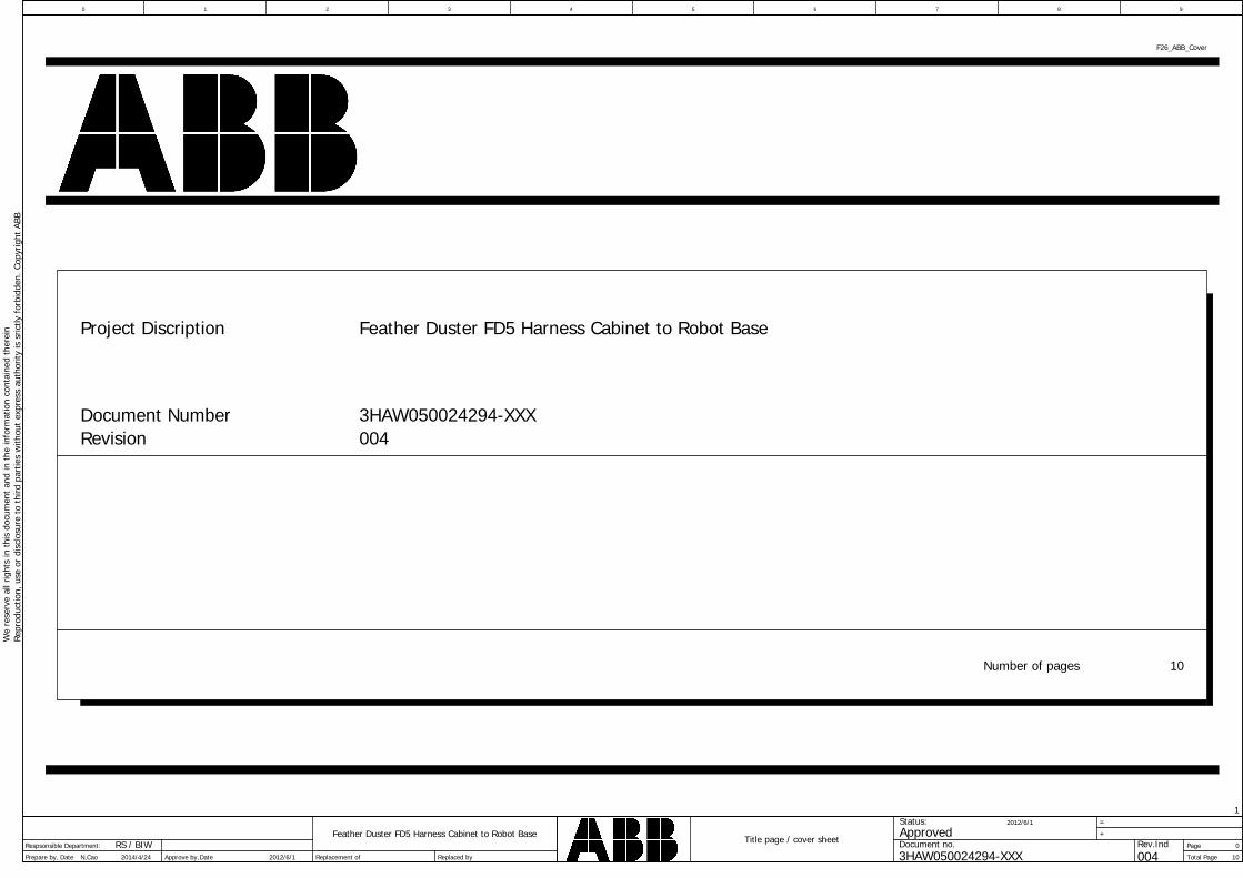
Page
Total Page
Feather Duster FD5 Harness Cabinet to Robot Base +
Date Replaced by
Title page / cover sheet
1
Prepare by,
0 76
Replacement of
8 93
10
1
4
0
2
=
Approve by,
5W
ere
serv
eal
lrig
hts
inth
isdo
cum
ent
and
inth
ein
form
atio
nco
ntai
ned
ther
ein
Repr
oduc
tion,
use
ordi
sclo
sure
toth
irdpa
rtie
sw
ithou
tex
pres
sau
thor
ityis
sric
tlyfo
rbid
den.
Copy
right
ABB
3HAW050024294-XXX
ApprovedStatus:
Document no. Rev.IndDate 2012/6/1N,Cao 2014/4/24 004
2012/6/1
Respsonsible Department: RS / BIW
F26_ABB_Cover
Document Number
Number of pages
Feather Duster FD5 Harness Cabinet to Robot Base
10
Project Discription
3HAW050024294-XXXRevision 004
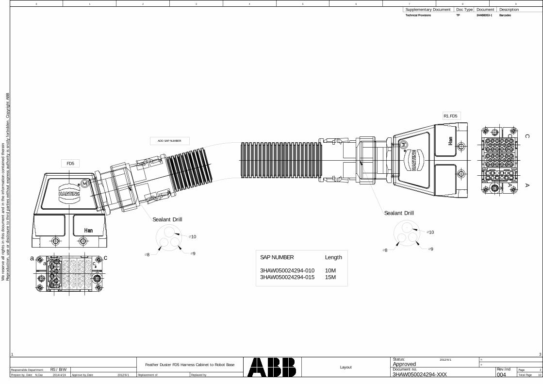
Page
Total Page
Feather Duster FD5 Harness Cabinet to Robot Base
1
+
Date Replaced by
Layout
1
Prepare by,
0 76
Replacement of
8 93
10
3
4
2
2
=
Approve by,
5W
ere
serv
eal
lrig
hts
inth
isdo
cum
ent
and
inth
ein
form
atio
nco
ntai
ned
ther
ein
Repr
oduc
tion,
use
ordi
sclo
sure
toth
irdpa
rtie
sw
ithou
tex
pres
sau
thor
ityis
sric
tlyfo
rbid
den.
Copy
right
ABB
3HAW050024294-XXX
ApprovedStatus:
Document no. Rev.IndDate 2012/6/1N,Cao 2014/4/24 004
2012/6/1
Respsonsible Department: RS / BIW
Technical Provisions TP 3HAB8053-1 BarcodesTechnical Provisions
Supplementary Document Doc Type Document DescriptionTP 3HAB8053-1 Barcodes
R1.FD5
SAP NUMBER Length
3HAW050024294-010 10M3HAW050024294-015 15M
CA
a c
12345
8910
FD5
a c1
2
3
4
5
6
7
8
9
10
11
12
13
14
15
16
17
1
2
3
4
5
6
7
8
9
10
11
12
13
14
15
16
17
7
21
8
93
10 4
511
12 6
172
1213
83
91415
410
161711
56
172
1213
83
91415
410
161711
56
CA
ADD SAP NUMBER
10
98
Sealant Drill
10
98
Sealant Drill
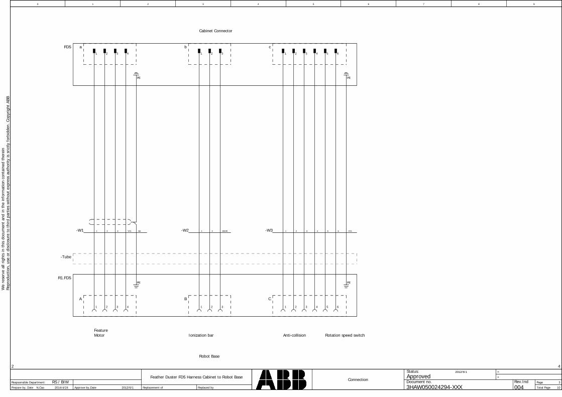
Page
Total Page
Feather Duster FD5 Harness Cabinet to Robot Base
2
+
Date Replaced by
Connection
1
Prepare by,
0 76
Replacement of
8 93
10
4
4
3
2
=
Approve by,
5W
ere
serv
eal
lrig
hts
inth
isdo
cum
ent
and
inth
ein
form
atio
nco
ntai
ned
ther
ein
Repr
oduc
tion,
use
ordi
sclo
sure
toth
irdpa
rtie
sw
ithou
tex
pres
sau
thor
ityis
sric
tlyfo
rbid
den.
Copy
right
ABB
3HAW050024294-XXX
ApprovedStatus:
Document no. Rev.IndDate 2012/6/1N,Cao 2014/4/24 004
2012/6/1
Respsonsible Department: RS / BIW
Cabinet Connector
Robot Base
FeatureMotor Ionization bar Anti-collision Rotation speed switch
FD5
R1.FD5PE
-W1 SH1 Y/G2 3 -W3 3 61 4 52
1 2 3 4 1 2 3 1 2 3 4 5 6
1 2 3 4 1 2 3 1 2 3 4 5 6
PE
-W2 1 2 GNYE
PE
PE
Y/G
A B C
a b c
-Tube

Page
Total Page
Feather Duster FD5 Harness Cabinet to Robot Base
3
+
Date Replaced by
Cable diagram =+-W1
1
Prepare by,
0 76
Replacement of
8 93
10
5
4
4
2
=
Approve by,
5W
ere
serv
eal
lrig
hts
inth
isdo
cum
ent
and
inth
ein
form
atio
nco
ntai
ned
ther
ein
Repr
oduc
tion,
use
ordi
sclo
sure
toth
irdpa
rtie
sw
ithou
tex
pres
sau
thor
ityis
sric
tlyfo
rbid
den.
Copy
right
ABB
3HAW050024294-XXX
ApprovedStatus:
Document no. Rev.IndDate 2012/6/1N,Cao 2014/4/24 004
2012/6/1
Respsonsible Department: RS / BIW
F09_002_ABBCable diagram
Page / columnTarget designation from conductor Target designation to Connectionpoint
cable type
no. of conductorsfunction text
function text
cross-section Length
Page / columnfunction text
Cable name
Connectionpoint
=+-W1
1.54G
Igus:CF140.15.04.UL
1 11-FD5-a -R1.FD5-A /3.1/3.1
2 22-FD5-a -R1.FD5-A /3.1/3.1
3 33-FD5-a -R1.FD5-A /3.1/3.1
PE PESH-FD5 -R1.FD5 /3.2/3.2
4 4Y/G-FD5-a -R1.FD5-A /3.2/3.2

Page
Total Page
Feather Duster FD5 Harness Cabinet to Robot Base
4
+
Date Replaced by
Cable diagram =+-W2
1
Prepare by,
0 76
Replacement of
8 93
10
6
4
5
2
=
Approve by,
5W
ere
serv
eal
lrig
hts
inth
isdo
cum
ent
and
inth
ein
form
atio
nco
ntai
ned
ther
ein
Repr
oduc
tion,
use
ordi
sclo
sure
toth
irdpa
rtie
sw
ithou
tex
pres
sau
thor
ityis
sric
tlyfo
rbid
den.
Copy
right
ABB
3HAW050024294-XXX
ApprovedStatus:
Document no. Rev.IndDate 2012/6/1N,Cao 2014/4/24 004
2012/6/1
Respsonsible Department: RS / BIW
F09_002_ABBCable diagram
Page / columnTarget designation from conductor Target designation to Connectionpoint
cable type
no. of conductorsfunction text
function text
cross-section Length
Page / columnfunction text
Cable name
Connectionpoint
=+-W2
1.54G
Igus:CF130.15.04.UL
1 11-FD5-b -R1.FD5-B /3.3/3.3
2 22-FD5-b -R1.FD5-B /3.3/3.3
3 3GNYE-FD5-b -R1.FD5-B /3.3/3.3
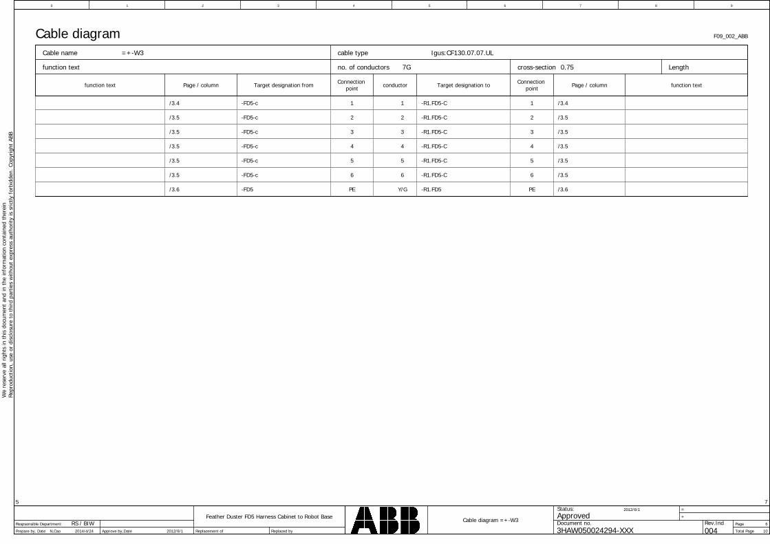
Page
Total Page
Feather Duster FD5 Harness Cabinet to Robot Base
5
+
Date Replaced by
Cable diagram =+-W3
1
Prepare by,
0 76
Replacement of
8 93
10
7
4
6
2
=
Approve by,
5W
ere
serv
eal
lrig
hts
inth
isdo
cum
ent
and
inth
ein
form
atio
nco
ntai
ned
ther
ein
Repr
oduc
tion,
use
ordi
sclo
sure
toth
irdpa
rtie
sw
ithou
tex
pres
sau
thor
ityis
sric
tlyfo
rbid
den.
Copy
right
ABB
3HAW050024294-XXX
ApprovedStatus:
Document no. Rev.IndDate 2012/6/1N,Cao 2014/4/24 004
2012/6/1
Respsonsible Department: RS / BIW
F09_002_ABBCable diagram
Page / columnTarget designation from conductor Target designation to Connectionpoint
cable type
no. of conductorsfunction text
function text
cross-section Length
Page / columnfunction text
Cable name
Connectionpoint
=+-W3
0.757G
Igus:CF130.07.07.UL
1 11-FD5-c -R1.FD5-C /3.4/3.4
2 22-FD5-c -R1.FD5-C /3.5/3.5
3 33-FD5-c -R1.FD5-C /3.5/3.5
4 44-FD5-c -R1.FD5-C /3.5/3.5
5 55-FD5-c -R1.FD5-C /3.5/3.5
6 66-FD5-c -R1.FD5-C /3.5/3.5
PE PEY/G-FD5 -R1.FD5 /3.6/3.6

Page
Total Page
Feather Duster FD5 Harness Robot Base to Arm +
Date Replaced by
Title page / cover sheet
Prepare by,
0
Replacement of 14
1
0
=
Approve by,
We
rese
rve
allr
ight
sin
this
docu
men
tan
din
the
info
rmat
ion
cont
aine
dth
erei
nRe
prod
uctio
n,us
eor
disc
losu
reto
third
part
ies
with
out
expr
ess
auth
ority
issr
ictly
forb
idde
n.Co
pyrig
htAB
B
3HAW050024279
ApprovedStatus:
Document no. Rev.IndDateN,Cao 2014/6/16 006
Respsonsible Department: RS / BIW
1 2 3 4 5 6 7 8 9
F26_ABB_Cover
Document Number
Number of pages
Feather Duster FD5 Harness Robot Base to Arm
14
Project Discription
3HAW050024279Revision 006
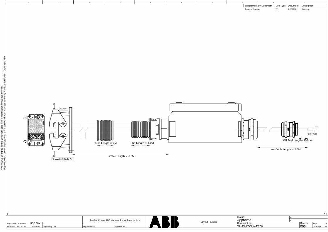
Page
Total Page
Feather Duster FD5 Harness Robot Base to Arm
1
+
Date Replaced by
Layout Harness
Prepare by,
0
Replacement of 14
2.b
2.a
=
Approve by,
We
rese
rve
allr
ight
sin
this
docu
men
tan
din
the
info
rmat
ion
cont
aine
dth
erei
nRe
prod
uctio
n,us
eor
disc
losu
reto
third
part
ies
with
out
expr
ess
auth
ority
issr
ictly
forb
idde
n.Co
pyrig
htAB
B
3HAW050024279
ApprovedStatus:
Document no. Rev.IndDateN,Cao 2014/6/16 006
Respsonsible Department: RS / BIW
1 2 3 4 5 6 7 8 9
Technical Provisions
Supplementary Document Doc Type Document DescriptionTP 3HAB8053-1 Barcodes
ac
1
2 3 4 5 6
7
8 9 10 1112
13 14 15 16 17
1
2 3 4 5 6
7
8 9 10 1112
13 14 15 16 17
7
218 9
310
4 511
126
R1.FD5
Tube Length = 4M
Cable Length = 6.8M
ac
Tube Length = 1.2M
W4 Cable Length = 1.8M
W4 Peel Length=100mm
4x Fork
3HAW050024279
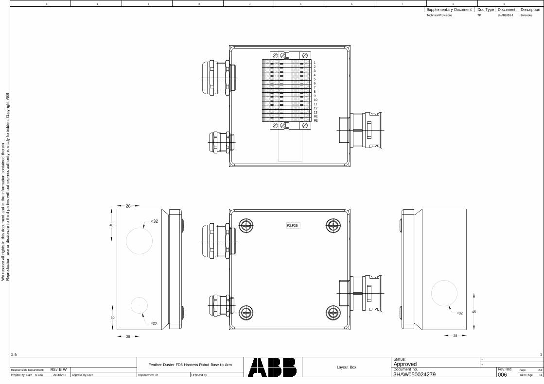
Page
Total Page
Feather Duster FD5 Harness Robot Base to Arm
2.a
+
Date Replaced by
Layout Box
Prepare by,
0
Replacement of 14
3
2.b
=
Approve by,
We
rese
rve
allr
ight
sin
this
docu
men
tan
din
the
info
rmat
ion
cont
aine
dth
erei
nRe
prod
uctio
n,us
eor
disc
losu
reto
third
part
ies
with
out
expr
ess
auth
ority
issr
ictly
forb
idde
n.Co
pyrig
htAB
B
3HAW050024279
ApprovedStatus:
Document no. Rev.IndDateN,Cao 2014/6/16 006
Respsonsible Department: RS / BIW
1 2 3 4 5 6 7 8 9
Technical Provisions
Supplementary Document Doc Type Document DescriptionTP 3HAB8053-1 Barcodes
28
3240
28
30
20
28
4532
R2.FD5
PEPE
12345678910111213
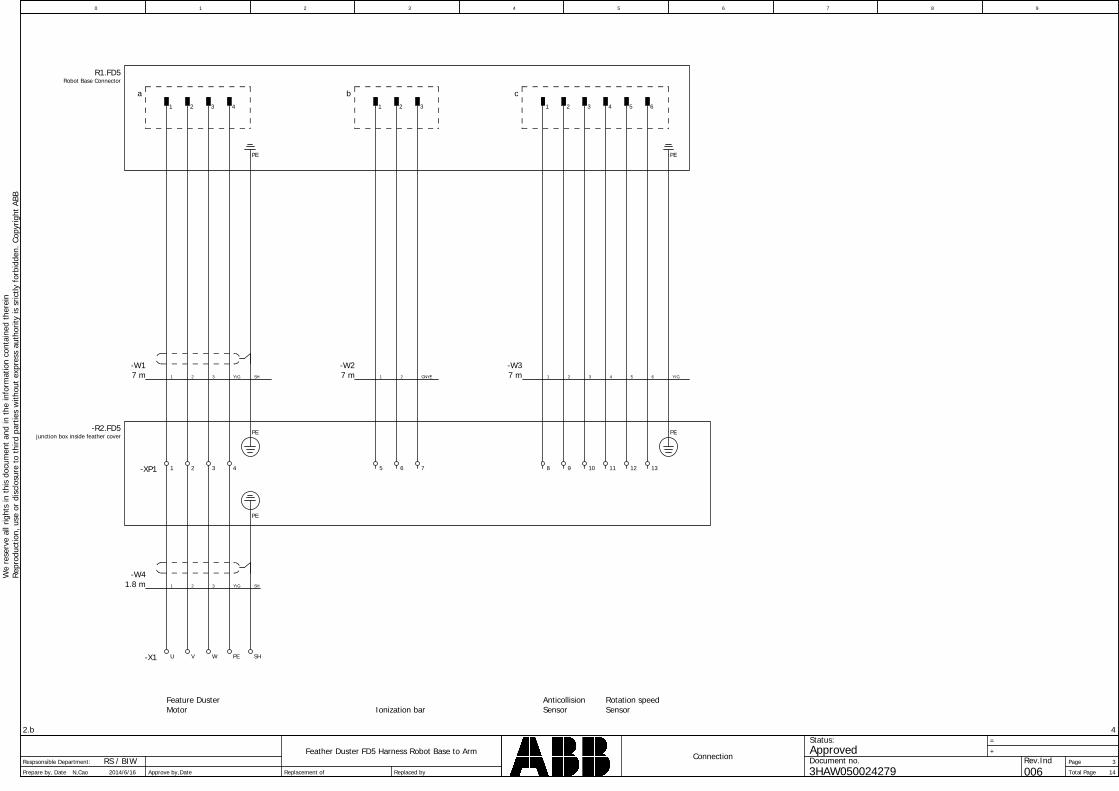
Page
Total Page
Feather Duster FD5 Harness Robot Base to Arm
2.b
+
Date Replaced by
Connection
Prepare by,
0
Replacement of 14
4
3
=
Approve by,
We
rese
rve
allr
ight
sin
this
docu
men
tan
din
the
info
rmat
ion
cont
aine
dth
erei
nRe
prod
uctio
n,us
eor
disc
losu
reto
third
part
ies
with
out
expr
ess
auth
ority
issr
ictly
forb
idde
n.Co
pyrig
htAB
B
3HAW050024279
ApprovedStatus:
Document no. Rev.IndDateN,Cao 2014/6/16 006
Respsonsible Department: RS / BIW
1 2 3 4 5 6 7 8 9
Feature DusterMotor Ionization bar
Rotation speedSensor
AnticollisionSensor
-R2.FD5junction box inside feather cover
R1.FD5Robot Base Connector
1 2 3 4
a1 2 3
b1 2 3 4 5 6
c
PE PE
7 m-W1
SH1 Y\G2 3 7 m-W3
3 61 4 527 m-W2
1 2 GNYE Y/G
-XP1 1 2 3 4 5 6 7 8 9 10 11 12 13
-X1 U V W PE SH
1.8 m-W4
1 Y\G2 3 SH
PE PE
PE

Page
Total Page
Feather Duster FD5 Harness Robot Base to Arm
3
+
Date Replaced by
Cable diagram =+-W1
Prepare by,
0
Replacement of 14
5
4
=
Approve by,
We
rese
rve
allr
ight
sin
this
docu
men
tan
din
the
info
rmat
ion
cont
aine
dth
erei
nRe
prod
uctio
n,us
eor
disc
losu
reto
third
part
ies
with
out
expr
ess
auth
ority
issr
ictly
forb
idde
n.Co
pyrig
htAB
B
3HAW050024279
ApprovedStatus:
Document no. Rev.IndDateN,Cao 2014/6/16 006
Respsonsible Department: RS / BIW
1 2 3 4 5 6 7 8 9
F09_002_ABBCable diagram
Page / columnTarget designation from conductor Target designation to Connectionpoint
cable type
no. of conductorsfunction text
function text
cross-section Length
Page / columnfunction text
Cable name
Connectionpoint
=+-W1
1.5 74G
Igus:CF140.15.04.UL
1 11-R1.FD5-a -R2.FD5-XP1 /3.1/3.1
2 22-R1.FD5-a -R2.FD5-XP1 /3.1/3.1
3 33-R1.FD5-a -R2.FD5-XP1 /3.1/3.1
PE SHSH /3.2/3.2 -R1.FD5
SH PESH -R2.FD5 /3.2/3.2
PE PESH-R1.FD5 -R2.FD5 /3.2/3.2
4 4Y\G-R1.FD5-a -R2.FD5-XP1 /3.1/3.1
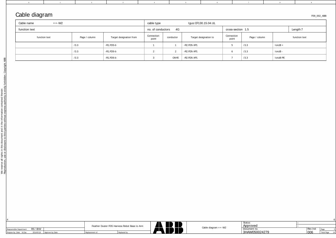
Page
Total Page
Feather Duster FD5 Harness Robot Base to Arm
4
+
Date Replaced by
Cable diagram =+-W2
Prepare by,
0
Replacement of 14
6
5
=
Approve by,
We
rese
rve
allr
ight
sin
this
docu
men
tan
din
the
info
rmat
ion
cont
aine
dth
erei
nRe
prod
uctio
n,us
eor
disc
losu
reto
third
part
ies
with
out
expr
ess
auth
ority
issr
ictly
forb
idde
n.Co
pyrig
htAB
B
3HAW050024279
ApprovedStatus:
Document no. Rev.IndDateN,Cao 2014/6/16 006
Respsonsible Department: RS / BIW
1 2 3 4 5 6 7 8 9
F09_002_ABBCable diagram
Page / columnTarget designation from conductor Target designation to Connectionpoint
cable type
no. of conductorsfunction text
function text
cross-section Length
Page / columnfunction text
Cable name
Connectionpoint
=+-W2
1.5 74G
Igus:CF130.15.04.UL
1 51-R1.FD5-b -R2.FD5-XP1 /3.3/3.3 IonzB +
2 62-R1.FD5-b -R2.FD5-XP1 /3.3/3.3 IonzB -
3 7GNYE-R1.FD5-b -R2.FD5-XP1 /3.3/3.3 IonzB PE
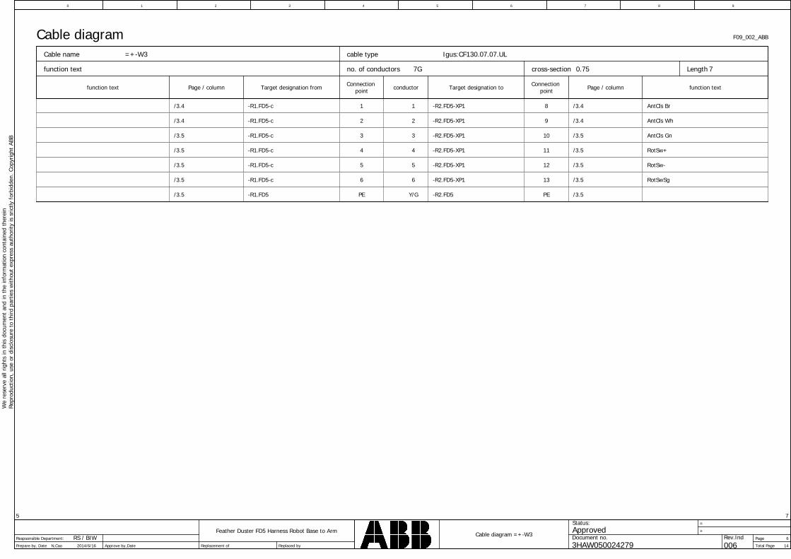
Page
Total Page
Feather Duster FD5 Harness Robot Base to Arm
5
+
Date Replaced by
Cable diagram =+-W3
Prepare by,
0
Replacement of 14
7
6
=
Approve by,
We
rese
rve
allr
ight
sin
this
docu
men
tan
din
the
info
rmat
ion
cont
aine
dth
erei
nRe
prod
uctio
n,us
eor
disc
losu
reto
third
part
ies
with
out
expr
ess
auth
ority
issr
ictly
forb
idde
n.Co
pyrig
htAB
B
3HAW050024279
ApprovedStatus:
Document no. Rev.IndDateN,Cao 2014/6/16 006
Respsonsible Department: RS / BIW
1 2 3 4 5 6 7 8 9
F09_002_ABBCable diagram
Page / columnTarget designation from conductor Target designation to Connectionpoint
cable type
no. of conductorsfunction text
function text
cross-section Length
Page / columnfunction text
Cable name
Connectionpoint
=+-W3
0.75 77G
Igus:CF130.07.07.UL
1 81-R1.FD5-c -R2.FD5-XP1 /3.4/3.4 AntCls Br
2 92-R1.FD5-c -R2.FD5-XP1 /3.4/3.4 AntCls Wh
3 103-R1.FD5-c -R2.FD5-XP1 /3.5/3.5 AntCls Gn
4 114-R1.FD5-c -R2.FD5-XP1 /3.5/3.5 RotSw+
5 125-R1.FD5-c -R2.FD5-XP1 /3.5/3.5 RotSw-
6 136-R1.FD5-c -R2.FD5-XP1 /3.5/3.5 RotSwSg
PE PEY/G-R1.FD5 -R2.FD5 /3.5/3.5
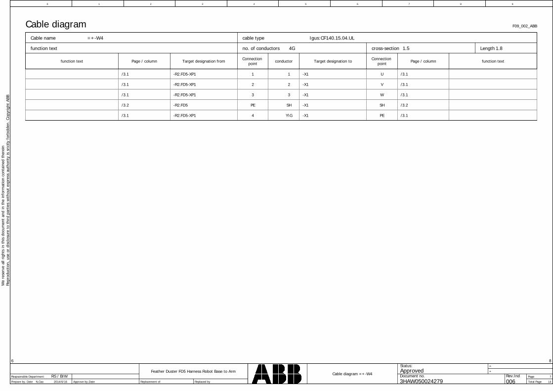
Page
Total Page
Feather Duster FD5 Harness Robot Base to Arm
6
+
Date Replaced by
Cable diagram =+-W4
Prepare by,
0
Replacement of 14
8
7
=
Approve by,
We
rese
rve
allr
ight
sin
this
docu
men
tan
din
the
info
rmat
ion
cont
aine
dth
erei
nRe
prod
uctio
n,us
eor
disc
losu
reto
third
part
ies
with
out
expr
ess
auth
ority
issr
ictly
forb
idde
n.Co
pyrig
htAB
B
3HAW050024279
ApprovedStatus:
Document no. Rev.IndDateN,Cao 2014/6/16 006
Respsonsible Department: RS / BIW
1 2 3 4 5 6 7 8 9
F09_002_ABBCable diagram
Page / columnTarget designation from conductor Target designation to Connectionpoint
cable type
no. of conductorsfunction text
function text
cross-section Length
Page / columnfunction text
Cable name
Connectionpoint
=+-W4
1.5 1.84G
Igus:CF140.15.04.UL
1 U1-R2.FD5-XP1 -X1 /3.1/3.1
2 V2-R2.FD5-XP1 -X1 /3.1/3.1
3 W3-R2.FD5-XP1 -X1 /3.1/3.1
PE SHSH-R2.FD5 -X1 /3.2/3.2
4 PEY\G-R2.FD5-XP1 -X1 /3.1/3.1
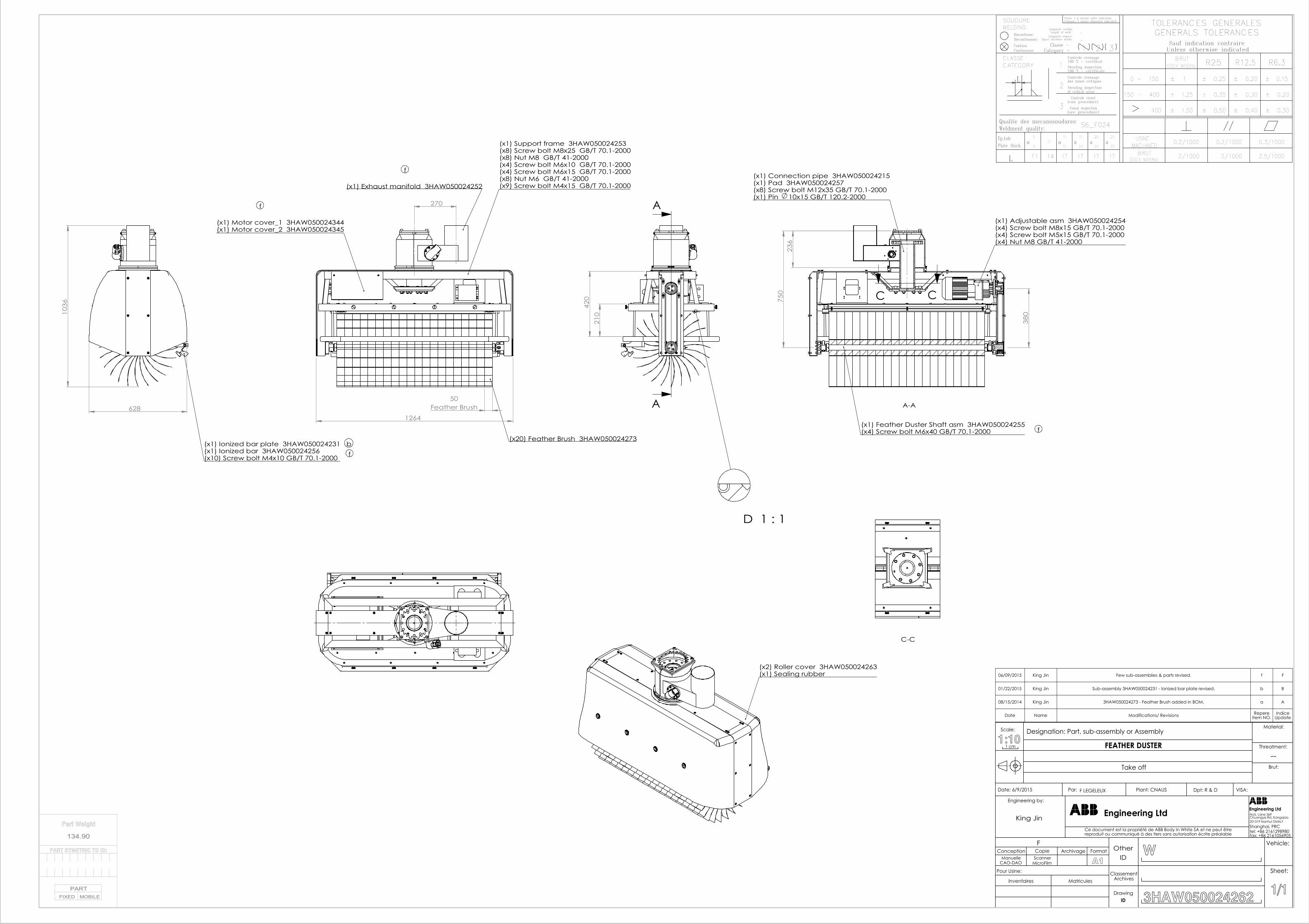
R6.3R12.5R25BRUT
GENERALS TOLERANCESTOLERANCES GENERALES
Unless otherwise indicatedSauf indication contraire
.
2.
1 3
Lenght of weld:
Category =Classe =
Longueur espace:
WELDINGSOUDURE
Discontinue:
CLASSE
ContinuContinuous
Discontinuous:
Classe 3 si aucune autre indicationCategory 3 unless otherwise indicated
Space beetwen welds:
Longueur cordon:
Controle ressuage100 % + certificat
± 0.15
± 0.30
± 0.20
± 0.20
± 0.40
± 0.30
0.3/1000
2.5/1000
± 1
400
± 1.25
± 1.50
0.2/1000
2/1000
0.2/1000
2/1000
± 0.25
± 0.35
± 0.50
25
30a
20
25a
15
20a
17 17 17
S6_F024
2
3
L
a10
1510
14 17
a5
9
Ep.tolePlate thick.
L 11
Weldment quality:Qualite des mecanosoudures:
100 % + certificate
Sweating inspectionof critical areas
Visual inspection(see procedure)
Controle ressuagedes zones critiques
Controle visuel(voir procedure)
STOCK MATERIAL
0 - 150
150 - 400
BRUTMACHINEDUSINE
Sweating inspectionCATEGORY 1 STOCK MATERIAL
270
1264
50Feather Brush
(x1) Exhaust manifold 3HAW050024252
(x20) Feather Brush 3HAW050024273
(x1) Support frame 3HAW050024253(x8) Screw bolt M8x25 GB/T 70.1-2000(x8) Nut M8 GB/T 41-2000(x4) Screw bolt M6x10 GB/T 70.1-2000(x4) Screw bolt M6x15 GB/T 70.1-2000(x8) Nut M6 GB/T 41-2000(x9) Screw bolt M4x15 GB/T 70.1-2000
(x1) Motor cover_1 3HAW050024344(x1) Motor cover_2 3HAW050024345
210
420
A
A
236
380
750
C C
A-A
(x1) Connection pipe 3HAW050024215(x1) Pad 3HAW050024257(x8) Screw bolt M12x35 GB/T 70.1-2000(x1) Pin 10x15 GB/T 120.2-2000
(x1) Adjustable asm 3HAW050024254(x4) Screw bolt M8x15 GB/T 70.1-2000(x4) Screw bolt M5x15 GB/T 70.1-2000(x4) Nut M8 GB/T 41-2000
(x1) Feather Duster Shaft asm 3HAW050024255(x4) Screw bolt M6x40 GB/T 70.1-2000
103
6
628
(x1) Ionized bar plate 3HAW050024231(x1) Ionized bar 3HAW050024256(x10) Screw bolt M4x10 GB/T 70.1-2000
(x2) Roller cover 3HAW050024263(x1) Sealing rubber
C-C
D 1 : 1
b
f
f
f
f
06/09/2015 King Jin Few sub-assemblies & parts revised. f F
01/22/2015 King Jin Sub-assembly 3HAW050024231 - Ionized bar plate revised. b B
08/15/2014 King Jin 3HAW050024273 - Feather Brush added in BOM. a A
Date Name Modifications/ Revisions RepereItem NO.
IndiceUpdate
FEATHER DUSTER
F LEGELEUX
1 cm1:10
Scale: Designation: Part, sub-assembly or Assembly
Brut:
Threatment:
Material:
VISA:Dpt: R & DPlant: CNAUSPar: Date: 6/9/2015
fax: +86 2161056905tel: +86 2161298980Shanghai, PRC201319 Nanhui District
No5, Lane 369
Engineering LtdEngineering Ltd
Ce document est la propriété de ABB Body In White SA et ne peut êtrereproduit ou communiqué à des tiers sans autorisation écrite préalable
Engineering by:
1/1
Sheet:
Vehicle:
3HAW050024262IDDrawing
ClassementArchives
IDOther
MatriculesInventaires
Pour Usine:
A1MicroFilmScanner
CAO-DAOManuelle
FormatArchivageCopieConceptionF
W
--Take off
Chuangye Rd, Kangqiao
Part Weight
134.90
PART SYMETRIC TO ID:
PARTFIXED MOBILE
King Jin
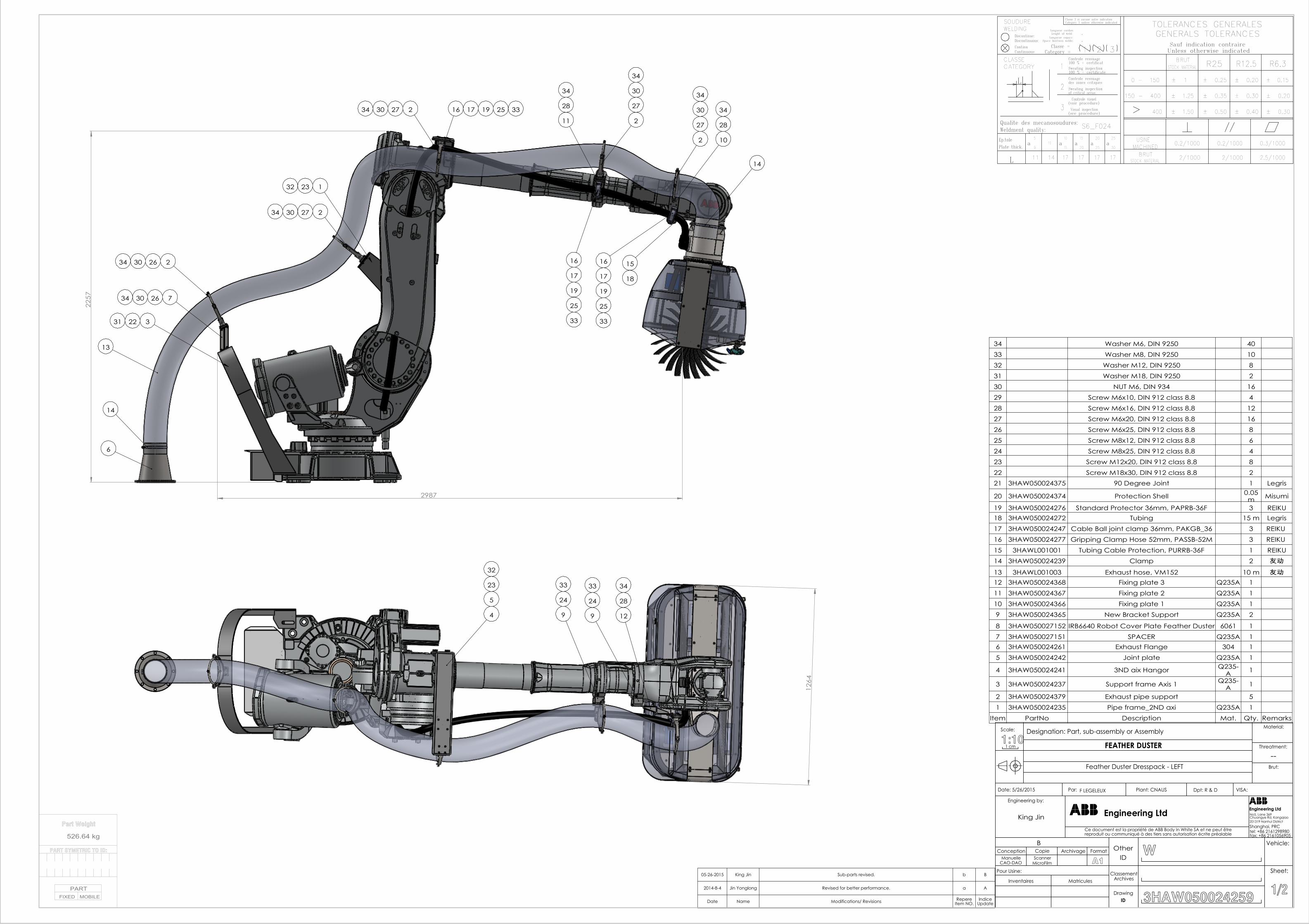
R6.3R12.5R25BRUT
GENERALS TOLERANCESTOLERANCES GENERALES
Unless otherwise indicatedSauf indication contraire
.
2.
1 3
Lenght of weld:
Category =Classe =
Longueur espace:
WELDINGSOUDURE
Discontinue:
CLASSE
ContinuContinuous
Discontinuous:
Classe 3 si aucune autre indicationCategory 3 unless otherwise indicated
Space beetwen welds:
Longueur cordon:
Controle ressuage100 % + certificat
± 0.15
± 0.30
± 0.20
± 0.20
± 0.40
± 0.30
0.3/1000
2.5/1000
± 1
400
± 1.25
± 1.50
0.2/1000
2/1000
0.2/1000
2/1000
± 0.25
± 0.35
± 0.50
25
30a
20
25a
15
20a
17 17 17
S6_F024
2
3
L
a10
1510
14 17
a5
9
Ep.tolePlate thick.
L 11
Weldment quality:Qualite des mecanosoudures:
100 % + certificate
Sweating inspectionof critical areas
Visual inspection(see procedure)
Controle ressuagedes zones critiques
Controle visuel(voir procedure)
STOCK MATERIAL
0 - 150
150 - 400
BRUTMACHINEDUSINE
Sweating inspectionCATEGORY 1 STOCK MATERIAL
2987
225
7
6
14
13
2
7
3
1
2
2
2
2
16 16
14
10
11
15
17 17
19 19
16 17 19
263034
263034
273034
2332
2231
273034 25 33
25
33
25
33
27
30
34
27
30
34
28
3428
34
18
126
4
9 9 124
5
23
32
28
34
24
33
24
33
34 Washer M6, DIN 9250 4033 Washer M8, DIN 9250 1032 Washer M12, DIN 9250 831 Washer M18, DIN 9250 230 NUT M6, DIN 934 1629 Screw M6x10, DIN 912 class 8.8 428 Screw M6x16, DIN 912 class 8.8 1227 Screw M6x20, DIN 912 class 8.8 1626 Screw M6x25, DIN 912 class 8.8 825 Screw M8x12, DIN 912 class 8.8 624 Screw M8x25, DIN 912 class 8.8 423 Screw M12x20, DIN 912 class 8.8 822 Screw M18x30, DIN 912 class 8.8 221 3HAW050024375 90 Degree Joint 1 Legris
20 3HAW050024374 Protection Shell 0.05m Misumi
19 3HAW050024276 Standard Protector 36mm, PAPRB-36F 3 REIKU18 3HAW050024272 Tubing 15 m Legris17 3HAW050024247 Cable Ball joint clamp 36mm, PAKGB_36 3 REIKU 16 3HAW050024277 Gripping Clamp Hose 52mm, PASSB-52M 3 REIKU 15 3HAWL001001 Tubing Cable Protection, PURRB-36F 1 REIKU14 3HAW050024239 Clamp 2 友动
13 3HAWL001003 Exhaust hose, VM152 10 m 友动12 3HAW050024368 Fixing plate 3 Q235A 111 3HAW050024367 Fixing plate 2 Q235A 110 3HAW050024366 Fixing plate 1 Q235A 19 3HAW050024365 New Bracket Support Q235A 2
8 3HAW050027152 IRB6640 Robot Cover Plate Feather Duster 6061 17 3HAW050027151 SPACER Q235A 16 3HAW050024261 Exhaust Flange 304 15 3HAW050024242 Joint plate Q235A 1
4 3HAW050024241 3ND aix Hangor Q235-A 1
3 3HAW050024237 Support frame Axis 1 Q235-A 1
2 3HAW050024379 Exhaust pipe support 51 3HAW050024235 Pipe frame_2ND axi Q235A 1
Item PartNo Description Mat. Qty. Remarks
05-26-2015 King Jin Sub-parts revised. b B
2014-8-4 Jin Yonglong Revised for better performance. a A
Date Name Modifications/ Revisions RepereItem NO.
IndiceUpdate
Feather Duster Dresspack - LEFT
FEATHER DUSTER
F LEGELEUX
1 cm1:10Scale: Designation: Part, sub-assembly or Assembly
Brut:
Threatment:
Material:
VISA:Dpt: R & DPlant: CNAUSPar: Date: 5/26/2015
fax: +86 2161056905tel: +86 2161298980Shanghai, PRC201319 Nanhui District
No5, Lane 369
Engineering LtdEngineering Ltd
Ce document est la propriété de ABB Body In White SA et ne peut êtrereproduit ou communiqué à des tiers sans autorisation écrite préalable
Engineering by:
1/2
Sheet:
Vehicle:
3HAW050024259IDDrawing
ClassementArchives
IDOther
MatriculesInventaires
Pour Usine:
A1MicroFilmScanner
CAO-DAOManuelle
FormatArchivageCopieConceptionB
W
--
Chuangye Rd, Kangqiao
Part Weight
526.64 kg
PART SYMETRIC TO ID:
PARTFIXED MOBILE
King Jin
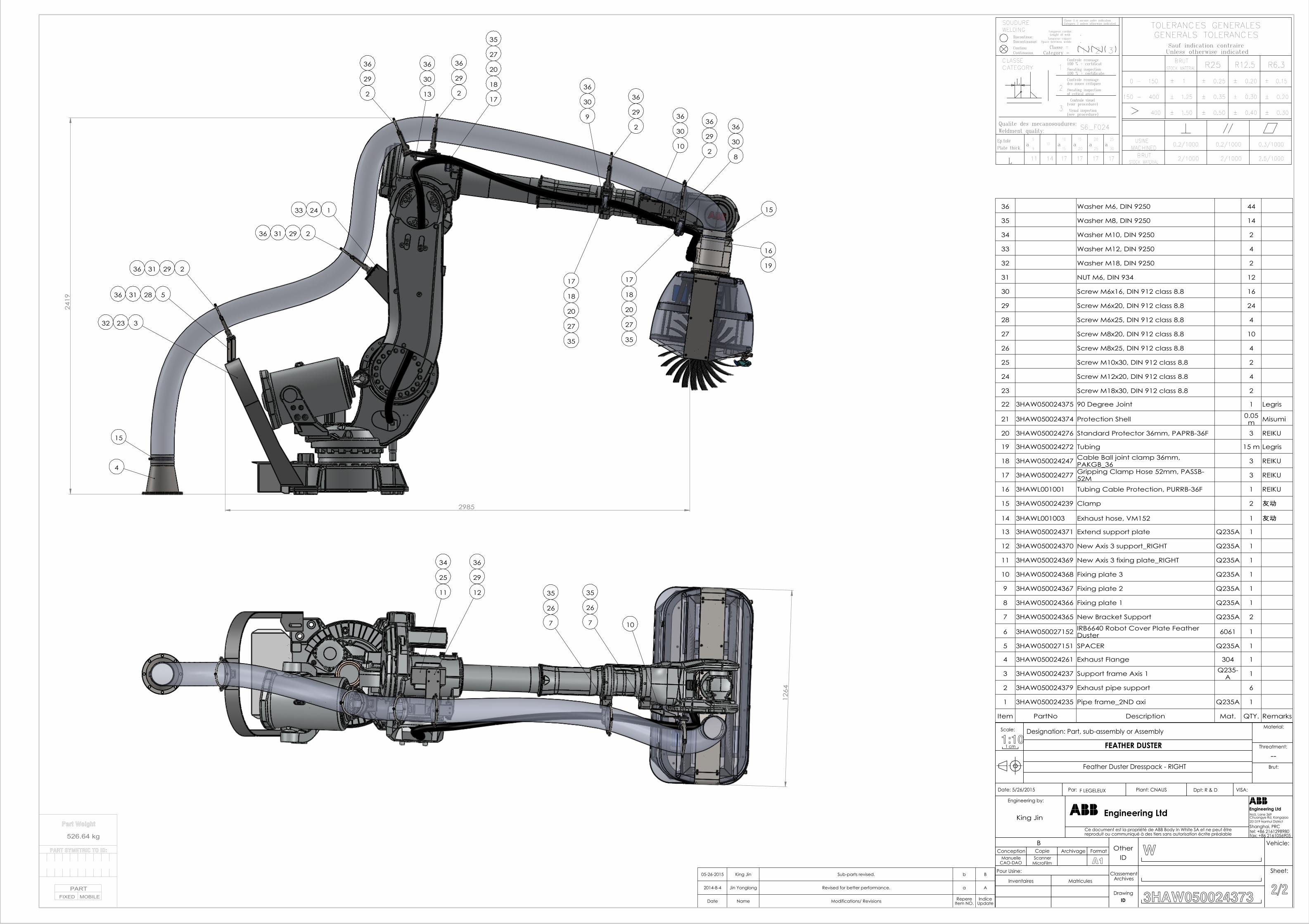
R6.3R12.5R25BRUT
GENERALS TOLERANCESTOLERANCES GENERALES
Unless otherwise indicatedSauf indication contraire
.
2.
1 3
Lenght of weld:
Category =Classe =
Longueur espace:
WELDINGSOUDURE
Discontinue:
CLASSE
ContinuContinuous
Discontinuous:
Classe 3 si aucune autre indicationCategory 3 unless otherwise indicated
Space beetwen welds:
Longueur cordon:
Controle ressuage100 % + certificat
± 0.15
± 0.30
± 0.20
± 0.20
± 0.40
± 0.30
0.3/1000
2.5/1000
± 1
400
± 1.25
± 1.50
0.2/1000
2/1000
0.2/1000
2/1000
± 0.25
± 0.35
± 0.50
25
30a
20
25a
15
20a
17 17 17
S6_F024
2
3
L
a10
1510
14 17
a5
9
Ep.tolePlate thick.
L 11
Weldment quality:Qualite des mecanosoudures:
100 % + certificate
Sweating inspectionof critical areas
Visual inspection(see procedure)
Controle ressuagedes zones critiques
Controle visuel(voir procedure)
STOCK MATERIAL
0 - 150
150 - 400
BRUTMACHINEDUSINE
Sweating inspectionCATEGORY 1 STOCK MATERIAL
2985
241
9
15
4
14
3
5
2
1
2
2 217
16
2
2
15
108
1717
9
1818
18
20
20 20
13
2332
2433
283136
293136
293136
30
36
29
36
29
3627
35
29
3630
36
27
35
27
35
30
36
30
3629
36
19
126
4
77 10
11 12
25
34
29
36
26
35
26
35
36 Washer M6, DIN 9250 44
35 Washer M8, DIN 9250 14
34 Washer M10, DIN 9250 2
33 Washer M12, DIN 9250 4
32 Washer M18, DIN 9250 2
31 NUT M6, DIN 934 12
30 Screw M6x16, DIN 912 class 8.8 16
29 Screw M6x20, DIN 912 class 8.8 24
28 Screw M6x25, DIN 912 class 8.8 4
27 Screw M8x20, DIN 912 class 8.8 10
26 Screw M8x25, DIN 912 class 8.8 4
25 Screw M10x30, DIN 912 class 8.8 2
24 Screw M12x20, DIN 912 class 8.8 4
23 Screw M18x30, DIN 912 class 8.8 2
22 3HAW050024375 90 Degree Joint 1 Legris
21 3HAW050024374 Protection Shell 0.05m Misumi
20 3HAW050024276 Standard Protector 36mm, PAPRB-36F 3 REIKU
19 3HAW050024272 Tubing 15 m Legris
18 3HAW050024247 Cable Ball joint clamp 36mm, PAKGB_36 3 REIKU
17 3HAW050024277 Gripping Clamp Hose 52mm, PASSB-52M 3 REIKU
16 3HAWL001001 Tubing Cable Protection, PURRB-36F 1 REIKU
15 3HAW050024239 Clamp 2 友动
14 3HAWL001003 Exhaust hose, VM152 1 友动
13 3HAW050024371 Extend support plate Q235A 1
12 3HAW050024370 New Axis 3 support_RIGHT Q235A 1
11 3HAW050024369 New Axis 3 fixing plate_RIGHT Q235A 1
10 3HAW050024368 Fixing plate 3 Q235A 1
9 3HAW050024367 Fixing plate 2 Q235A 1
8 3HAW050024366 Fixing plate 1 Q235A 1
7 3HAW050024365 New Bracket Support Q235A 2
6 3HAW050027152 IRB6640 Robot Cover Plate Feather Duster 6061 1
5 3HAW050027151 SPACER Q235A 1
4 3HAW050024261 Exhaust Flange 304 1
3 3HAW050024237 Support frame Axis 1 Q235-A 1
2 3HAW050024379 Exhaust pipe support 6
1 3HAW050024235 Pipe frame_2ND axi Q235A 1
Item PartNo Description Mat. QTY. Remarks
05-26-2015 King Jin Sub-parts revised. b B
2014-8-4 Jin Yonglong Revised for better performance. a A
Date Name Modifications/ Revisions RepereItem NO.
IndiceUpdate
Feather Duster Dresspack - RIGHT
FEATHER DUSTER
F LEGELEUX
1 cm1:10Scale: Designation: Part, sub-assembly or Assembly
Brut:
Threatment:
Material:
VISA:Dpt: R & DPlant: CNAUSPar: Date: 5/26/2015
fax: +86 2161056905tel: +86 2161298980Shanghai, PRC201319 Nanhui District
No5, Lane 369
Engineering LtdEngineering Ltd
Ce document est la propriété de ABB Body In White SA et ne peut êtrereproduit ou communiqué à des tiers sans autorisation écrite préalable
Engineering by:
2/2
Sheet:
Vehicle:
3HAW050024373IDDrawing
ClassementArchives
IDOther
MatriculesInventaires
Pour Usine:
A1MicroFilmScanner
CAO-DAOManuelle
FormatArchivageCopieConceptionB
W
--
Chuangye Rd, Kangqiao
Part Weight
526.64 kg
PART SYMETRIC TO ID:
PARTFIXED MOBILE
King Jin


3HA
W05
0027
150
Rev
B, e
n
Contact us
ABB Engineering (Shanghai) Ltd.N°4528, Kangxin Highway, Pudong New District,Shanghai 201319 P.R.CHINATelephone +86 (0) 21 6105 6666
www.abb.com


