Embed Size (px)
Citation preview
chemical engineering research and design 8 7 ( 2 0 0 9 ) 1206–1216
Contents lists available at ScienceDirect
Chemical Engineering Research and Design
journa l homepage: www.e lsev ier .com/ locate /cherd
Production of bioethanol and other bio-based materialsfrom sugarcane bagasse: Integration to conventionalbioethanol production process
Marina O.S. Diasa,∗, Adriano V. Ensinasa,b, Silvia A. Nebrac, Rubens Maciel Filhoa,Carlos E.V. Rossell a, Maria Regina Wolf Maciela
a School of Chemical Engineering, University of Campinas, Brazilb CECS, Federal University of ABC, Brazilc Interdisciplinary Centre for Energy Planning, University of Campinas, Brazil
a b s t r a c t
Ethanol may be produced using sugarcane bagasse as raw material through the Organosolv process with dilute acid
hydrolysis, thus increasing ethanol production with the same cultivated sugarcane area. In this work simulations
of bioethanol production from sugarcane juice and bagasse are carried out using software UniSim Design. A typical
large scale production plant is considered: 1000 m3/day of ethanol is produced using sugarcane juice as raw material.
A three-step hydrolysis process (pre-hydrolysis of hemicellulose, Organosolv delignification and cellulose hydrolysis)
of surplus sugarcane bagasse is considered. Pinch analysis is used to determine the minimum hot utility obtained
with thermal integration of the plant, in order to find out the maximum availability of bagasse that can be used in
the hydrolysis process, taking into consideration the use of 50% of generated sugarcane trash as fuel for electricity
and steam production. Two different cases were analyzed for the product purification step: conventional and double-
effect distillation systems. It was found that the double-effect distillation system allows 90% of generated bagasse
to be used as raw material in the hydrolysis plant, which accounts for an increase of 26% in bioethanol production,
considering exclusively the fermentation of hexoses obtained from the cellulosic fraction.
© 2009 The Institution of Chemical Engineers. Published by Elsevier B.V. All rights reserved.
Keywords: Bioethanol; Sugarcane; Distillation; Acid hydrolysis; Simulation
One of the world’s largest ethanol producers, Brazil
1. Introduction
Increase on world’s energy demand and the progressive deple-tion of oil reserves motivate the search for alternative energyresources, especially for those derived from renewable mate-rials such as biomass (Saxena et al., 2009). Global concernabout climate change and the consequent need to dimin-ish greenhouse gases emissions have encouraged the use ofbioethanol as a gasoline replacement or additive (Balat et al.,2008). Bioethanol may also be used as raw material for the pro-duction of different chemicals, thus driving a full renewablechemical industry.
Bioethanol is produced from the fermentation of sugarsobtained from biomass. Bioethanol feedstock can contain
∗ Corresponding author at: School of Chemical Engineering, UniversityBrazil. Tel.: +55 19 3521 3958.
E-mail addresses: [email protected], [email protected] (MReceived 5 October 2008; Received in revised form 8 May 2009; Accept
0263-8762/$ – see front matter © 2009 The Institution of Chemical Engidoi:10.1016/j.cherd.2009.06.020
either sucrose (e.g. sugarcane, sugar beet) or starch (e.g. corn,wheat) or be a lignocellulosic material (e.g. sugarcane bagasse,wood and straw). Corn and sugarcane are the feedstock used inthe US and in Brazil, respectively, which are the largest ethanolproducers in the world. Sugarcane is so far the most efficientraw material for bioethanol production: the consumption offossil energy during sugarcane processing is much smallerthan that of corn (Macedo et al., 2008). Furthermore, optimiza-tion of bioethanol production process from sugarcane is stillpossible, and significant reduction of energy consumption canbe achieved.
of Campinas, UNICAMP, P.O. Box 6066, 13083-970, Campinas-SP,
.O.S. Dias).ed 30 June 2009
has been using sugarcane as raw material for large scalebioethanol production for more than 30 years (Goldemberg,
neers. Published by Elsevier B.V. All rights reserved.
design 8 7 ( 2 0 0 9 ) 1206–1216 1207
2obntossda
cwnaat2
loxtc(orb2sIsoc
fobcwfofp
cutoap
2
Sf(tcS
mp
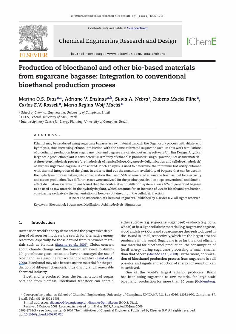
Fig. 1 – Boiling point of the binary mixture sucrose–water,according to experimental data (Hugot, 1972) and estimated
and tops, which constitute the so-called “sugarcane trash”, areseparated from the stalks and left on the fields, increasing soil
Table 1 – Components used on the simulation.
Database components Hypothetic components
Water CelluloseEthanol HemicelluloseDextrose LigninSucrose DirtCarbon dioxide Calcium phosphateGlycerol Potassium saltSuccinic acid MineralsAcetic acid Aconitic acidIso-amyl alcohol LimeSulphuric acid Phosphoric acidFurfural YeastEthylene glycol HMF
chemical engineering research and
007). Typically, in the sugarcane processing, large amountsf sugarcane bagasse are produced (approximately 240 kg ofagasse with 50% humidity per ton of sugarcane), which areowadays burnt in boilers for steam and electricity genera-ion. Better technologies for cogeneration and optimizationf bioethanol production process allow it to have a bagasseurplus (Ensinas et al., 2007), which may be used as a fuelource for electricity generation or as raw material for pro-ucing bioethanol and other biobased products (Buddadee etl., 2008).
Bioethanol from lignocellulosic materials, such as sugar-ane bagasse, has been studied for the past few decadesith great interest, but its production in industrial scale hasot yet become viable (Balat et al., 2008). Studies taking intoccount process integration, increase of fermentation yieldsnd integration of unit operations are still needed in ordero make hydrolysis a competitive technology (Zaldivar et al.,001; Cardona and Sánchez, 2007).
Lignocellulosic materials are mainly comprised of cellu-ose, which is a glucose polymer, hemicellulose, a mixturef polysaccharides composed mainly by glucose, mannose,ylose and arabinose, and lignin (Saxena et al., 2009). In ordero be used as raw material for bioethanol production, sugar-ane bagasse must be processed to yield fermentable sugarsMosier et al., 2005). A pre-treatment process is required inrder to separate lignin and hemicellulose from the cellulose,educe cellulose crystallinity and increase the porosity of theagasse, thus improving cellulose hydrolysis (Kuo and Lee,009). One possible way to achieve that is through the Organo-olv process with dilute acid hydrolysis (Rossell et al., 2005).n this process, pre-hydrolysis of the hemicellulose, Organo-olv delignification and cellulose hydrolysis may be carriedut on three separate steps, thus leading to different streamsontaining pentoses, lignin and hexoses.
In order to increase the amount of bagasse availableor bioethanol production through the hydrolysis process,ptimization of energy consumption of the conventionalioethanol production process from sugarcane juice must bearried out. The Pinch Point Method (Linnhoff et al., 1982)as used to analyze the process streams that are available
or thermal integration, consequently providing a reductionn system consumption. A similar approach was consideredor the optimization of energy consumption of the bioethanolroduction process from corn (Franceschin et al., 2008).
In this work, simulations of bioethanol production pro-ess from sugarcane and sugarcane bagasse were carried outsing software UniSim Design. Pinch Technology was usedo optimize energy consumption and determine the amountf sugarcane bagasse available for hydrolysis, taking intoccount the production of steam and electrical energy to sup-ly the factory.
. Simulation development
imulations were carried out using software UniSim Designrom Honeywell. Except for the dehydration step, NRTLNom-Random Two Liquid) was the model used throughouthe simulation for the calculation of the activity coeffi-ient on the liquid phase, and EOS SRK (equation of stateoave–Redlich–Kwong) for the vapor model.
In order to determine the most suitable thermodynamicodel to represent the process, calculations for the boiling
oint of water–sucrose binary mixtures were carried out, since
using NRTL, EOS Peng-Robinson and UNIQUAC.
sucrose is the most abundant carbohydrate present in sug-arcane juice (Mantelatto, 2005). It was verified that the NRTLmodel provides the best estimations for the boiling tempera-ture of sucrose solutions, when compared either to UNIQUACor equation of state Peng-Robinson, as shown in Fig. 1.
The extractive distillation process with monoethylenegly-col (MEG) was used for ethanol dehydration (Meirelles et al.,1992), and for this step the model UNIQUAC was used to calcu-late activity coefficient on the liquid phase, and EOS SRK wasused as the vapor model.
The most relevant components usually present in theindustrial units were considered, as given in Table 1; it wasnecessary to create some hypothetical components for thosethat are not in the process simulator database.
Prior to the simulation, a mass balance of the conven-tional bioethanol process was made based on data obtainedin an industrial plant located in São Paulo state, during the2006–2007 harvest season, as well as from the literature.
2.1. Ethanol production process from sugarcane
The first step of the ethanol production process takes place inthe fields, where sugarcane is harvested. The sugarcane plantis composed by roots, stalk, tops and leaves. The stalks containmost of the sugars, thus being the fraction of interest in indus-trial processing. Upon mechanical harvest, most of the leaves
Ammonia PentoseHydrogen
1208 chemical engineering research and design 8 7 ( 2 0 0 9 ) 1206–1216
Table 2 – Composition of the sugarcane received in thefactory.
Component Content (wt.%)
Sucrose 13.30Cellulose 4.77Hemicellulose 4.53Lignin 2.62Reducing sugars 0.62Minerals 0.20Impurities 1.79
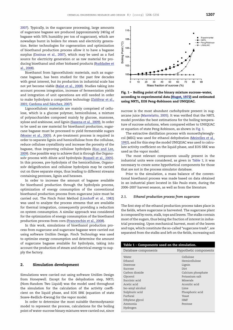
Fig. 2 – Block flow diagram of the conventional bioethanol
Water 71.57Dirt 0.60
protection and inhibiting the growth of weed and other plantspecies.
Sugarcane received in the factory, comprised mainly by itsstalks, contains water, fibre, sugars, impurities and dirt (sand,simulated as silica). The composition considered in this workis based on typical data obtained in the industry and is givenin Table 2.
All reducing sugars were simulated as dextrose; fibre (12%of the sugarcane) is comprised by cellulose, hemicellulose andlignin (Wooley and Putsche, 1996); impurities were simulatedas aconitic acid and potassium salt, since those account for themajority of the impurities (Mantelatto, 2005); minerals weresimulated as K2O and dirt as SiO2. Dirt is dragged along withthe sugarcane during harvest; the other components are partof sugarcane structure.
In this work an autonomous distillery, that is, a factory inwhich sucrose is entirely used as raw material for ethanol pro-duction, is considered for the production of 1000 m3 per dayof anhydrous ethanol, using sugarcane juice as raw material.An input of 493 t of sugarcane per hour is necessary. This iscompatible with large scale units operating nowadays.
Ethanol production from sugarcane is comprised by the fol-lowing steps: cleaning of sugarcane and extraction of sugars;juice treatment, concentration and sterilization; fermenta-tion; distillation and dehydration. A detailed description of thesimulation of each of these steps is presented, and a block flowdiagram is depicted in Fig. 2.
2.1.1. Cleaning of sugarcane, extraction of sugars andjuice treatmentIn order to remove part (70%) of the dirt dragged along withthe sugarcane from the fields, a dry–cleaning system is used.Sugar extraction is carried out using mills, in which water at arate of 28% of sugarcane flow is used to enhance sugar recov-ery, in a process termed imbibition (Chen and Chou, 1993).Sugars recovery in the mills is considered equal to 96%. In themills, sugarcane juice and bagasse are obtained. Sugarcanejuice, which contains the sugars, is fed to the juice treatmentoperations, while sugarcane bagasse (50% humidity) is burntin boilers for generation of steam and electrical energy. In thiswork bagasse surplus from the cogeneration system is used asraw material for bioethanol production through the hydrolysisprocess.
Sugarcane juice contains impurities, such as minerals,salts, acids, dirt and fibre, besides water and sugars. In orderto be efficiently used as a raw material for ethanol produc-tion through fermentation, those impurities must be removed;thus, the juice is submitted to physical and chemical treat-
ments.Screens and hydrocyclones are used in the physical treat-ment, where the majority of fibre and dirt particles are
production process from sugarcane.
removed (Chen and Chou, 1993). In a subsequent chemicaltreatment, phosphoric acid is added to sugarcane juice, toincrease juice phosphates content and enhance impuritiesremoval during settlement, followed by the first heating oper-ation in which juice temperature increases from 30 to 70 ◦C.
Pre-heated juice receives lime and is mixed with a recy-cle stream containing the filtrate obtained at the cake filter,being then heated up again to 105 ◦C. Hot juice is then flashedto remove air bubbles, and a flocculant polymer is added tothe de-aired juice, which is fed to the settler. In the settlerimpurities are removed from the juice and two streams areobtained: mud, which contains the impurities, and clarifiedjuice. One of the main impurities removed in the mud is cal-cium phosphate, which is a precipitate formed in a reactionbetween lime and phosphoric acid; during settlement it dragsmany other impurities contained in the juice, thus enhancingclarified juice purity (Mantelatto, 2005).
Besides impurities, the mud obtained in the settler con-tains sugars, thus a filter is used to enhance sugars recovery.In this filter water and fine particles of bagasse are added toincrease filtration efficiency. The filtrate is then recycled to theprocess and mixed with the limed juice prior to the secondheating operation, while the filter cake is used as fertilizer inthe fields (Chen and Chou, 1993).
2.1.2. Juice concentration and sterilizationClarified juice contains around 15 wt.% diluted solids, so itmust be concentrated before fermentation in order to achievean adequate ethanol content that allows reduction of energyconsumption during product purification steps. Concentra-tion is carried out in a five-stage multiple effect evaporator
(MEE) up to 65 wt.% sucrose (Chen and Chou, 1993). Sucroseconcentration in the juice fed to the fermentation reactor is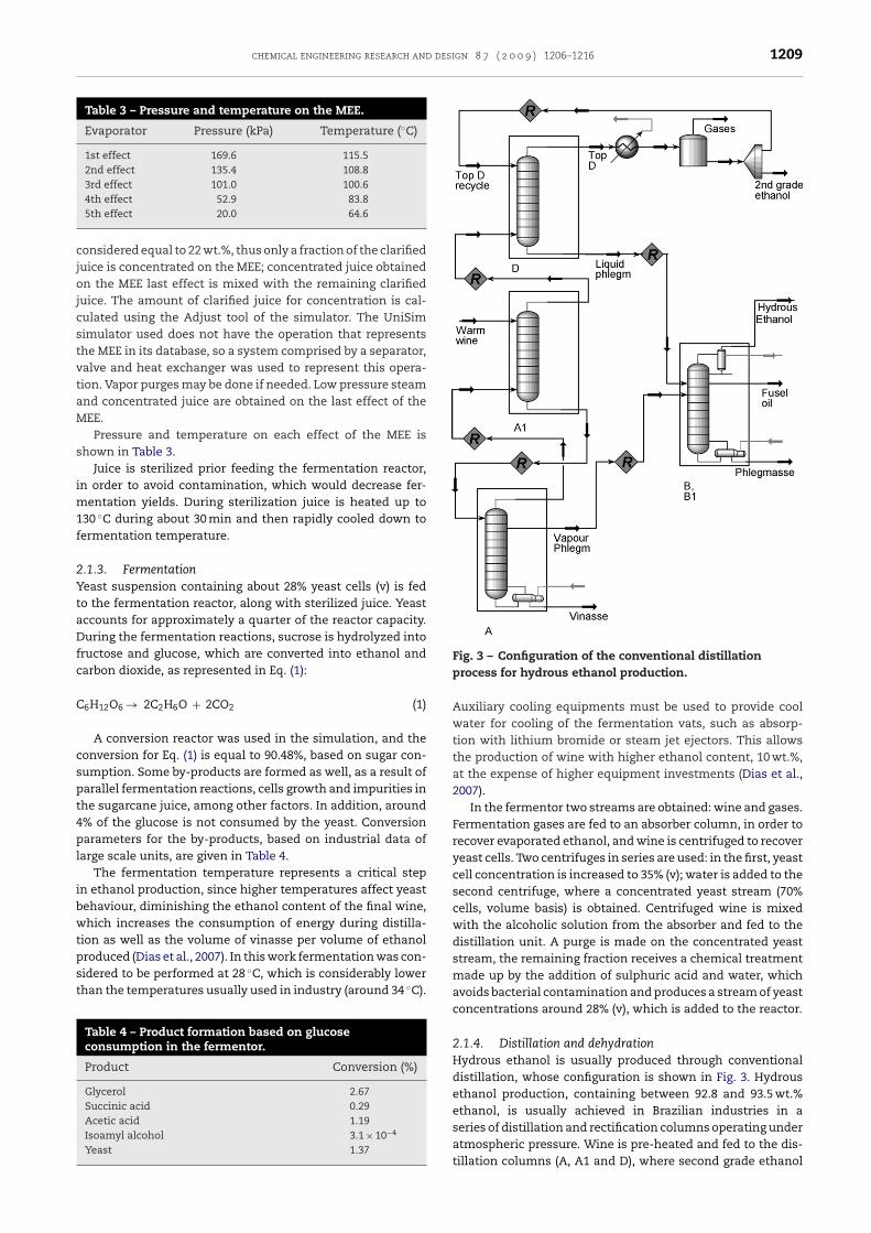
chemical engineering research and design 8 7 ( 2 0 0 9 ) 1206–1216 1209
Table 3 – Pressure and temperature on the MEE.
Evaporator Pressure (kPa) Temperature (◦C)
1st effect 169.6 115.52nd effect 135.4 108.83rd effect 101.0 100.64th effect 52.9 83.8
cjojcstvtaM
s
im1f
2YtaDfc
C
cspt4pl
ibwtpst
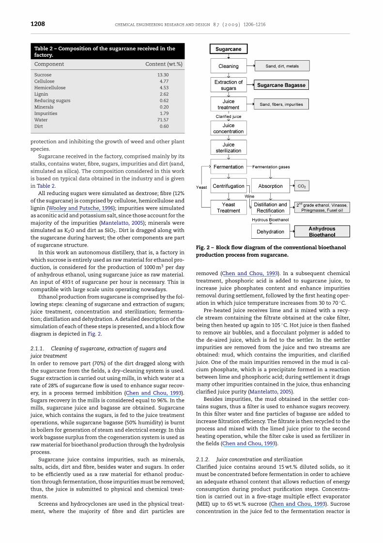
Fig. 3 – Configuration of the conventional distillation
5th effect 20.0 64.6
onsidered equal to 22 wt.%, thus only a fraction of the clarifieduice is concentrated on the MEE; concentrated juice obtainedn the MEE last effect is mixed with the remaining clarified
uice. The amount of clarified juice for concentration is cal-ulated using the Adjust tool of the simulator. The UniSimimulator used does not have the operation that representshe MEE in its database, so a system comprised by a separator,alve and heat exchanger was used to represent this opera-ion. Vapor purges may be done if needed. Low pressure steamnd concentrated juice are obtained on the last effect of theEE.
Pressure and temperature on each effect of the MEE ishown in Table 3.
Juice is sterilized prior feeding the fermentation reactor,n order to avoid contamination, which would decrease fer-
entation yields. During sterilization juice is heated up to30 ◦C during about 30 min and then rapidly cooled down toermentation temperature.
.1.3. Fermentationeast suspension containing about 28% yeast cells (v) is fedo the fermentation reactor, along with sterilized juice. Yeastccounts for approximately a quarter of the reactor capacity.uring the fermentation reactions, sucrose is hydrolyzed into
ructose and glucose, which are converted into ethanol andarbon dioxide, as represented in Eq. (1):
6H12O6 → 2C2H6O + 2CO2 (1)
A conversion reactor was used in the simulation, and theonversion for Eq. (1) is equal to 90.48%, based on sugar con-umption. Some by-products are formed as well, as a result ofarallel fermentation reactions, cells growth and impurities inhe sugarcane juice, among other factors. In addition, around% of the glucose is not consumed by the yeast. Conversionarameters for the by-products, based on industrial data of
arge scale units, are given in Table 4.The fermentation temperature represents a critical step
n ethanol production, since higher temperatures affect yeastehaviour, diminishing the ethanol content of the final wine,hich increases the consumption of energy during distilla-
ion as well as the volume of vinasse per volume of ethanol
roduced (Dias et al., 2007). In this work fermentation was con-idered to be performed at 28 ◦C, which is considerably lowerhan the temperatures usually used in industry (around 34 ◦C).Table 4 – Product formation based on glucoseconsumption in the fermentor.
Product Conversion (%)
Glycerol 2.67Succinic acid 0.29Acetic acid 1.19Isoamyl alcohol 3.1 × 10⁻⁴
Yeast 1.37
process for hydrous ethanol production.
Auxiliary cooling equipments must be used to provide coolwater for cooling of the fermentation vats, such as absorp-tion with lithium bromide or steam jet ejectors. This allowsthe production of wine with higher ethanol content, 10 wt.%,at the expense of higher equipment investments (Dias et al.,2007).
In the fermentor two streams are obtained: wine and gases.Fermentation gases are fed to an absorber column, in order torecover evaporated ethanol, and wine is centrifuged to recoveryeast cells. Two centrifuges in series are used: in the first, yeastcell concentration is increased to 35% (v); water is added to thesecond centrifuge, where a concentrated yeast stream (70%cells, volume basis) is obtained. Centrifuged wine is mixedwith the alcoholic solution from the absorber and fed to thedistillation unit. A purge is made on the concentrated yeaststream, the remaining fraction receives a chemical treatmentmade up by the addition of sulphuric acid and water, whichavoids bacterial contamination and produces a stream of yeastconcentrations around 28% (v), which is added to the reactor.
2.1.4. Distillation and dehydrationHydrous ethanol is usually produced through conventionaldistillation, whose configuration is shown in Fig. 3. Hydrousethanol production, containing between 92.8 and 93.5 wt.%ethanol, is usually achieved in Brazilian industries in a
series of distillation and rectification columns operating underatmospheric pressure. Wine is pre-heated and fed to the dis-tillation columns (A, A1 and D), where second grade ethanol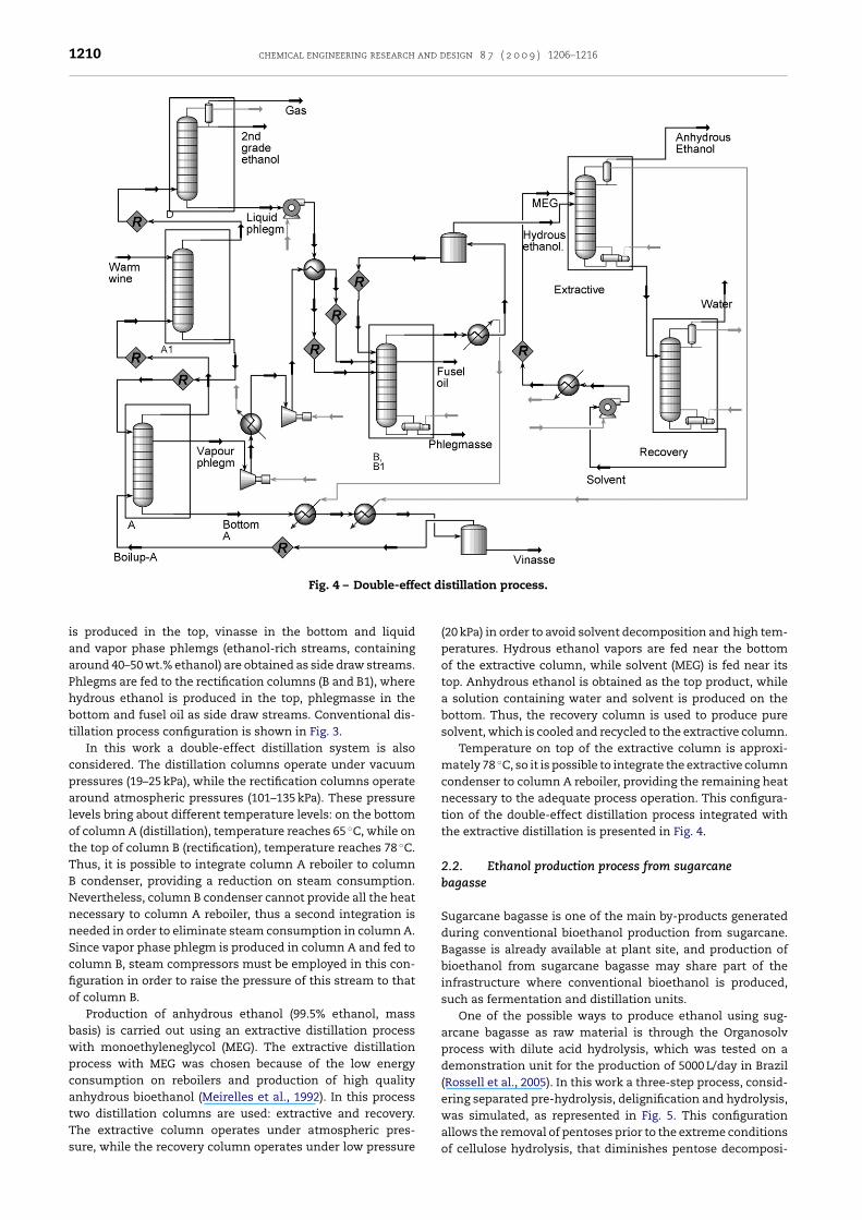
1210 chemical engineering research and design 8 7 ( 2 0 0 9 ) 1206–1216
ct d
Fig. 4 – Double-effeis produced in the top, vinasse in the bottom and liquidand vapor phase phlemgs (ethanol-rich streams, containingaround 40–50 wt.% ethanol) are obtained as side draw streams.Phlegms are fed to the rectification columns (B and B1), wherehydrous ethanol is produced in the top, phlegmasse in thebottom and fusel oil as side draw streams. Conventional dis-tillation process configuration is shown in Fig. 3.
In this work a double-effect distillation system is alsoconsidered. The distillation columns operate under vacuumpressures (19–25 kPa), while the rectification columns operatearound atmospheric pressures (101–135 kPa). These pressurelevels bring about different temperature levels: on the bottomof column A (distillation), temperature reaches 65 ◦C, while onthe top of column B (rectification), temperature reaches 78 ◦C.Thus, it is possible to integrate column A reboiler to columnB condenser, providing a reduction on steam consumption.Nevertheless, column B condenser cannot provide all the heatnecessary to column A reboiler, thus a second integration isneeded in order to eliminate steam consumption in column A.Since vapor phase phlegm is produced in column A and fed tocolumn B, steam compressors must be employed in this con-figuration in order to raise the pressure of this stream to thatof column B.
Production of anhydrous ethanol (99.5% ethanol, massbasis) is carried out using an extractive distillation processwith monoethyleneglycol (MEG). The extractive distillationprocess with MEG was chosen because of the low energyconsumption on reboilers and production of high qualityanhydrous bioethanol (Meirelles et al., 1992). In this process
two distillation columns are used: extractive and recovery.The extractive column operates under atmospheric pres-sure, while the recovery column operates under low pressureistillation process.
(20 kPa) in order to avoid solvent decomposition and high tem-peratures. Hydrous ethanol vapors are fed near the bottomof the extractive column, while solvent (MEG) is fed near itstop. Anhydrous ethanol is obtained as the top product, whilea solution containing water and solvent is produced on thebottom. Thus, the recovery column is used to produce puresolvent, which is cooled and recycled to the extractive column.
Temperature on top of the extractive column is approxi-mately 78 ◦C, so it is possible to integrate the extractive columncondenser to column A reboiler, providing the remaining heatnecessary to the adequate process operation. This configura-tion of the double-effect distillation process integrated withthe extractive distillation is presented in Fig. 4.
2.2. Ethanol production process from sugarcanebagasse
Sugarcane bagasse is one of the main by-products generatedduring conventional bioethanol production from sugarcane.Bagasse is already available at plant site, and production ofbioethanol from sugarcane bagasse may share part of theinfrastructure where conventional bioethanol is produced,such as fermentation and distillation units.
One of the possible ways to produce ethanol using sug-arcane bagasse as raw material is through the Organosolvprocess with dilute acid hydrolysis, which was tested on ademonstration unit for the production of 5000 L/day in Brazil(Rossell et al., 2005). In this work a three-step process, consid-ering separated pre-hydrolysis, delignification and hydrolysis,
was simulated, as represented in Fig. 5. This configurationallows the removal of pentoses prior to the extreme conditionsof cellulose hydrolysis, that diminishes pentose decomposi-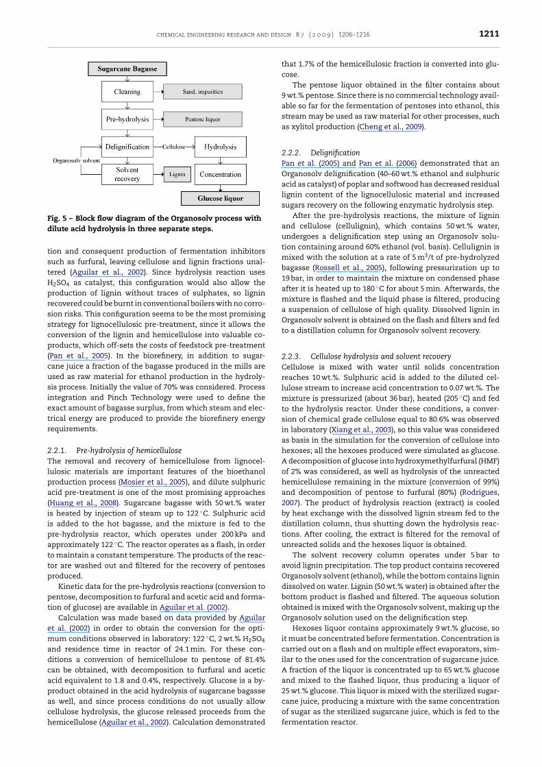
chemical engineering research and desi
Fig. 5 – Block flow diagram of the Organosolv process withd
tstHprsscp(cusietr
2Tlpa(iipattp
pt
emadcapach
ilute acid hydrolysis in three separate steps.
ion and consequent production of fermentation inhibitorsuch as furfural, leaving cellulose and lignin fractions unal-ered (Aguilar et al., 2002). Since hydrolysis reaction uses
2SO4 as catalyst, this configuration would also allow theroduction of lignin without traces of sulphates, so ligninecovered could be burnt in conventional boilers with no corro-ion risks. This configuration seems to be the most promisingtrategy for lignocellulosic pre-treatment, since it allows theonversion of the lignin and hemicellulose into valuable co-roducts, which off-sets the costs of feedstock pre-treatment
Pan et al., 2005). In the biorefinery, in addition to sugar-ane juice a fraction of the bagasse produced in the mills aresed as raw material for ethanol production in the hydroly-is process. Initially the value of 70% was considered. Processntegration and Pinch Technology were used to define thexact amount of bagasse surplus, from which steam and elec-rical energy are produced to provide the biorefinery energyequirements.
.2.1. Pre-hydrolysis of hemicellulosehe removal and recovery of hemicellulose from lignocel-
ulosic materials are important features of the bioethanolroduction process (Mosier et al., 2005), and dilute sulphuriccid pre-treatment is one of the most promising approachesHuang et al., 2008). Sugarcane bagasse with 50 wt.% waters heated by injection of steam up to 122 ◦C. Sulphuric acids added to the hot bagasse, and the mixture is fed to there-hydrolysis reactor, which operates under 200 kPa andpproximately 122 ◦C. The reactor operates as a flash, in ordero maintain a constant temperature. The products of the reac-or are washed out and filtered for the recovery of pentosesroduced.
Kinetic data for the pre-hydrolysis reactions (conversion toentose, decomposition to furfural and acetic acid and forma-ion of glucose) are available in Aguilar et al. (2002).
Calculation was made based on data provided by Aguilart al. (2002) in order to obtain the conversion for the opti-um conditions observed in laboratory: 122 ◦C, 2 wt.% H2SO4
nd residence time in reactor of 24.1 min. For these con-itions a conversion of hemicellulose to pentose of 81.4%an be obtained, with decomposition to furfural and aceticcid equivalent to 1.8 and 0.4%, respectively. Glucose is a by-roduct obtained in the acid hydrolysis of sugarcane bagasse
s well, and since process conditions do not usually allowellulose hydrolysis, the glucose released proceeds from theemicellulose (Aguilar et al., 2002). Calculation demonstratedgn 8 7 ( 2 0 0 9 ) 1206–1216 1211
that 1.7% of the hemicellulosic fraction is converted into glu-cose.
The pentose liquor obtained in the filter contains about9 wt.% pentose. Since there is no commercial technology avail-able so far for the fermentation of pentoses into ethanol, thisstream may be used as raw material for other processes, suchas xylitol production (Cheng et al., 2009).
2.2.2. DelignificationPan et al. (2005) and Pan et al. (2006) demonstrated that anOrganosolv delignification (40–60 wt.% ethanol and sulphuricacid as catalyst) of poplar and softwood has decreased residuallignin content of the lignocellulosic material and increasedsugars recovery on the following enzymatic hydrolysis step.
After the pre-hydrolysis reactions, the mixture of ligninand cellulose (cellulignin), which contains 50 wt.% water,undergoes a delignification step using an Organosolv solu-tion containing around 60% ethanol (vol. basis). Cellulignin ismixed with the solution at a rate of 5 m3/t of pre-hydrolyzedbagasse (Rossell et al., 2005), following pressurization up to19 bar, in order to maintain the mixture on condensed phaseafter it is heated up to 180 ◦C for about 5 min. Afterwards, themixture is flashed and the liquid phase is filtered, producinga suspension of cellulose of high quality. Dissolved lignin inOrganosolv solvent is obtained on the flash and filters and fedto a distillation column for Organosolv solvent recovery.
2.2.3. Cellulose hydrolysis and solvent recoveryCellulose is mixed with water until solids concentrationreaches 10 wt.%. Sulphuric acid is added to the diluted cel-lulose stream to increase acid concentration to 0.07 wt.%. Themixture is pressurized (about 36 bar), heated (205 ◦C) and fedto the hydrolysis reactor. Under these conditions, a conver-sion of chemical grade cellulose equal to 80.6% was observedin laboratory (Xiang et al., 2003), so this value was consideredas basis in the simulation for the conversion of cellulose intohexoses; all the hexoses produced were simulated as glucose.A decomposition of glucose into hydroxymethylfurfural (HMF)of 2% was considered, as well as hydrolysis of the unreactedhemicellulose remaining in the mixture (conversion of 99%)and decomposition of pentose to furfural (80%) (Rodrigues,2007). The product of hydrolysis reaction (extract) is cooledby heat exchange with the dissolved lignin stream fed to thedistillation column, thus shutting down the hydrolysis reac-tions. After cooling, the extract is filtered for the removal ofunreacted solids and the hexoses liquor is obtained.
The solvent recovery column operates under 5 bar toavoid lignin precipitation. The top product contains recoveredOrganosolv solvent (ethanol), while the bottom contains lignindissolved on water. Lignin (50 wt.% water) is obtained after thebottom product is flashed and filtered. The aqueous solutionobtained is mixed with the Organosolv solvent, making up theOrganosolv solution used on the delignification step.
Hexoses liquor contains approximately 9 wt.% glucose, soit must be concentrated before fermentation. Concentration iscarried out on a flash and on multiple effect evaporators, sim-ilar to the ones used for the concentration of sugarcane juice.A fraction of the liquor is concentrated up to 65 wt.% glucoseand mixed to the flashed liquor, thus producing a liquor of25 wt.% glucose. This liquor is mixed with the sterilized sugar-
cane juice, producing a mixture with the same concentrationof sugar as the sterilized sugarcane juice, which is fed to thefermentation reactor.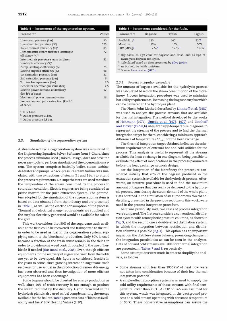
1212 chemical engineering research and design 8 7 ( 2 0 0 9 ) 1206–1216
Table 5 – Parameters of the cogeneration system.
Parameter Values
Live steam pressure (bar) 90Live steam temperature (◦C) 520Boiler thermal efficiency (%)a 85High pressure steam turbines isentropicefficiency (%)b
72
Intermediate pressure steam turbinesisentropic efficiency (%)c
81
Pump isentropic efficiency (%) 75Electric engines efficiency (%) 981st extraction pressure (bar) 212nd extraction pressure (bar) 6Turbine back-pressure (bar) 2.5Deaerator operation pressure (bar) 2.5Electric power demand of distillery(kW h/t of cane)
12
Mechanical power demand—canepreparation and juice extraction (kW h/tof cane)
16
a LHV base.b Outlet pressure 21 bar.c Outlet pressure 2.5 bar.
Table 6 – Parameters considered for the fuels.
Parameters Bagasse Trash Lignin
Availabilitya 120 140 220b
Moisture 50% 15% 50%LHV (MJ/kg)c 7.52d 12.96d 12.36b
a Dry basis, as kg/t cane for bagasse and trash, and as kg/t ofhydrolyzed bagasse for lignin.
b Calculated based on data presented by Silva (1995).c As burned, i.e., with moisture.d
2.3. Simulation of the cogeneration system
A steam-based cycle cogeneration system was simulated inthe Engineering Equation Solver Software from F-Chart, sincethe process simulator used (UniSim Design) does not have thenecessary tools to perform simulation of the cogeneration sys-tem. The system comprises basically boiler, steam turbine,deaerator and pumps. A back-pressure steam turbine was sim-ulated with two extractions of steam (21 and 6 bar) to attendthe process requirements. De-superheaters are used to reducethe temperature of the steam consumed by the process tosaturation condition. Electric engines are being considered asprime movers for the juice extraction system. The parame-ters adopted for the simulation of the cogeneration system isbased on data obtained from the industry and are presentedin Table 5, as well as the electric consumption of the process.Thermal and electrical energy requirements are supplied andthe surplus electricity generated would be available for sale tothe grid.
This work considers that 50% of the sugarcane trash avail-able at the field could be recovered and transported to the millin order to be used as fuel in the cogeneration system, sup-plying steam to the bioethanol production. Only 50% is usedbecause a fraction of the trash must remain in the fields inorder to provide some weed control, coupled to the use of her-bicide if needed (Hassuani et al., 2005). Even though efficientequipments for the recovery of sugarcane trash from the fieldsare yet to be developed, this figure is considered feasible inthe years to come, since growing interest on sugarcane trashrecovery for use as fuel in the production of renewable energyhas been observed and thus investigation of more efficientequipments has been encouraged.
Some bagasse should be diverted for energy production aswell, since 50% of trash recovery is not enough to producethe steam required by the distillery. Lignin recovered in the
hydrolysis plant is also used as fuel complementing the energyavailable for the boilers. Table 6 presents data of biomass avail-ability and fuels’ Low Heating Values (LHV).Source: Larson et al. (2001).
2.3.1. Process integration procedureThe amount of bagasse available for the hydrolysis processwas calculated based on the steam consumption of the biore-finery. Process integration procedure was used to minimizehot utility requirements, increasing the bagasse surplus whichcan be delivered to the hydrolysis plant.
The Pinch Point Method described by Linnhoff et al. (1982)was used to analyze the process streams that are availablefor thermal integration. The method developed by the worksof Hohmann (1971), Umeda et al. (1978, 1979) and Linnhoffand Flower (1978a,b) uses enthalpy-temperature diagrams torepresent the streams of the process and to find the thermalintegration target for them, considering a minimum approachdifference of temperature (�tmin) for the heat exchange.
The thermal integration target obtained indicates the min-imum requirements of external hot and cold utilities for theprocess. This analysis is useful to represent all the streamsavailable for heat exchange in one diagram, being possible toevaluate the effect of modifications in the process parametersbefore the heat exchange network design.
For the integration of the biorefinery the procedure con-sidered initially that 70% of the bagasse produced in theextraction system is available for the hydrolysis process. After-wards, an iterative procedure is used to find the maximumamount of bagasse that can really be delivered to the hydroly-sis process, considering the steam demand of the whole plant.Data obtained in the simulation of an autonomous bioethanoldistillery, presented in the previous sections of this work, wereused in the process integration procedure.
As it was previously said, two cases of process integrationwere compared. The first one considers a conventional distilla-tion system with atmospheric pressure columns, as shown inFig. 3, and the second one a double-effect distillation system,in which the integration between rectification and distilla-tion columns is possible (Fig. 4). This option has an importantimpact on the distillery steam balance, promoting changes inthe integration possibilities as can be seen in the analyses.Data of hot and cold streams available for thermal integrationare presented in Tables 7 and 8, respectively.
Some assumptions were made in order to simplify the anal-ysis, as follows:
• Some streams with less than 1000 kW of heat flow werenot taken into consideration because of their low thermalintegration potential.
• A single-effect absorption system was used to supply thecold utility requirements of those streams with final tem-perature lower than 28 ◦C. A COP of 0.65 was assumed forthis system, which was integrated in the background pro-
cess as a cold stream operating with constant temperatureof 90 ◦C. These conservative assumptions can assure the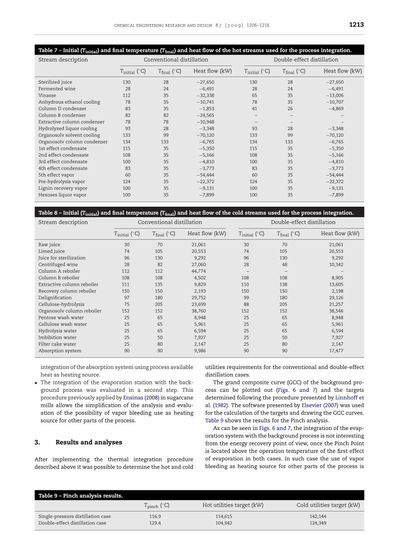
chemical engineering research and design 8 7 ( 2 0 0 9 ) 1206–1216 1213
Table 7 – Initial (Tinitial) and final temperature (Tfinal) and heat flow of the hot streams used for the process integration.
Stream description Conventional distillation Double-effect distillation
Tinitial (◦C) Tfinal (◦C) Heat flow (kW) Tinitial (◦C) Tfinal (◦C) Heat flow (kW)
Sterilized juice 130 28 −27,650 130 28 −27,650Fermented wine 28 24 −6,491 28 24 −6,491Vinasse 112 35 −32,338 65 35 −13,006Anhydrous ethanol cooling 78 35 −10,741 78 35 −10,707Column D condenser 83 35 −1,853 41 26 −4,869Column B condenser 82 82 −24,565 – – –Extractive column condenser 78 78 −10,948 – – –Hydrolyzed liquor cooling 93 28 −3,348 93 28 −3,348Organosolv solvent cooling 133 99 −70,120 133 99 −70,120Organosolv column condenser 134 133 −6,765 134 133 −6,7651st effect condensate 115 35 −5,350 115 35 −5,3502nd effect condensate 108 35 −5,166 108 35 −5,1663rd effect condensate 100 35 −4,810 100 35 −4,8104th effect condensate 83 35 −3,773 83 35 −3,7735th effect vapor 60 35 −54,444 60 35 −54,444Pre-hydrolysis vapor 124 35 −22,372 124 35 −22,372Lignin recovery vapor 100 35 −9,131 100 35 −9,131Hexoses liquor vapor 100 35 −7,899 100 35 −7,899
Table 8 – Initial (Tinitial) and final temperature (Tfinal) and heat flow of the cold streams used for the process integration.
Stream description Conventional distillation Double-effect distillation
Tinitial (◦C) Tfinal (◦C) Heat flow (kW) Tinitial (◦C) Tfinal (◦C) Heat flow (kW)
Raw juice 30 70 21,061 30 70 21,061Limed juice 74 105 20,553 74 105 20,553Juice for sterilization 96 130 9,292 96 130 9,292Centrifuged wine 28 82 27,060 28 48 10,342Column A reboiler 112 112 44,774 – – –Column B reboiler 108 108 4,502 108 108 8,905Extractive column reboiler 111 135 9,829 110 138 13,605Recovery column reboiler 150 150 2,193 150 150 2,198Delignification 97 180 29,752 99 180 29,126Cellulose-hydrolysis 75 205 23,699 88 205 21,257Organosolv column reboiler 152 152 38,760 152 152 38,546Pentose wash water 25 65 8,948 25 65 8,948Cellulose wash water 25 65 5,961 25 65 5,961Hydrolysis water 25 65 6,594 25 65 6,594Imbibition water 25 50 7,927 25 50 7,927Filter cake water 25 80 2,147 25 80 2,147
9,986
•
3
Ad
Absorption system 90 90
integration of the absorption system using process availableheat as heating source.The integration of the evaporation station with the back-ground process was evaluated in a second step. Thisprocedure previously applied by Ensinas (2008) in sugarcanemills allows the simplification of the analysis and evalu-ation of the possibility of vapor bleeding use as heatingsource for other parts of the process.
. Results and analyses
fter implementing the thermal integration procedureescribed above it was possible to determine the hot and cold
Table 9 – Pinch analysis results.
Tpinch (◦C) H
Single-pressure distillation case 116.9Double-effect distillation case 129.4
90 90 17,477
utilities requirements for the conventional and double-effectdistillation cases.
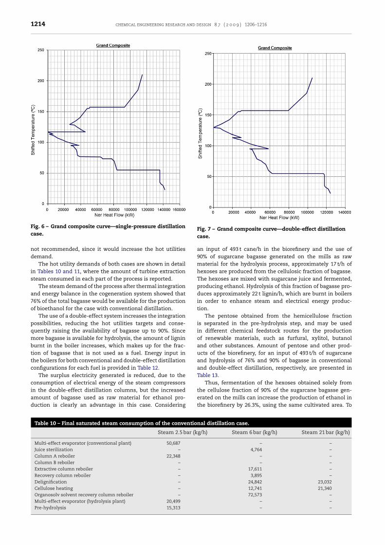
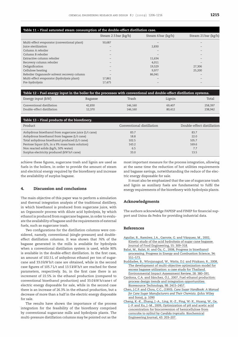
The grand composite curve (GCC) of the background pro-cess can be plotted out (Figs. 6 and 7) and the targetsdetermined following the procedure presented by Linnhoff etal. (1982). The software presented by Elsevier (2007) was usedfor the calculation of the targets and drawing the GCC curves.Table 9 shows the results for the Pinch analysis.
As can be seen in Figs. 6 and 7, the integration of the evap-oration system with the background process is not interestingfrom the energy recovery point of view, once the Pinch Point
is located above the operation temperature of the first effectof evaporation in both cases. In such case the use of vaporbleeding as heating source for other parts of the process isot utilities target (kW) Cold utilities target (kW)
114,615 142,144104,942 124,349
1214 chemical engineering research and design 8 7 ( 2 0 0 9 ) 1206–1216
Fig. 6 – Grand composite curve—single-pressure distillation
the cellulose fraction of 90% of the sugarcane bagasse gen-
case.
not recommended, since it would increase the hot utilitiesdemand.
The hot utility demands of both cases are shown in detailin Tables 10 and 11, where the amount of turbine extractionsteam consumed in each part of the process is reported.
The steam demand of the process after thermal integrationand energy balance in the cogeneration system showed that76% of the total bagasse would be available for the productionof bioethanol for the case with conventional distillation.
The use of a double-effect system increases the integrationpossibilities, reducing the hot utilities targets and conse-quently raising the availability of bagasse up to 90%. Sincemore bagasse is available for hydrolysis, the amount of ligninburnt in the boiler increases, which makes up for the frac-tion of bagasse that is not used as a fuel. Energy input inthe boilers for both conventional and double-effect distillationconfigurations for each fuel is provided in Table 12.
The surplus electricity generated is reduced, due to theconsumption of electrical energy of the steam compressorsin the double-effect distillation columns, but the increased
amount of bagasse used as raw material for ethanol pro-duction is clearly an advantage in this case. ConsideringTable 10 – Final saturated steam consumption of the conventio
Steam 2.5 bar (k
Multi-effect evaporator (conventional plant) 50,687Juice sterilization –Column A reboiler 22,348Column B reboiler –Extractive column reboiler –Recovery column reboiler –Delignification –Cellulose heating –Organosolv solvent recovery column reboiler –Multi-effect evaporator (hydrolysis plant) 20,499Pre-hydrolysis 15,313
Fig. 7 – Grand composite curve—double-effect distillationcase.
an input of 493 t cane/h in the biorefinery and the use of90% of sugarcane bagasse generated on the mills as rawmaterial for the hydrolysis process, approximately 17 t/h ofhexoses are produced from the cellulosic fraction of bagasse.The hexoses are mixed with sugarcane juice and fermented,producing ethanol. Hydrolysis of this fraction of bagasse pro-duces approximately 22 t lignin/h, which are burnt in boilersin order to enhance steam and electrical energy produc-tion.
The pentose obtained from the hemicellulose fractionis separated in the pre-hydrolysis step, and may be usedin different chemical feedstock routes for the productionof renewable materials, such as furfural, xylitol, butanoland other substances. Amount of pentose and other prod-ucts of the biorefinery, for an input of 493 t/h of sugarcaneand hydrolysis of 76% and 90% of bagasse in conventionaland double-effect distillation, respectively, are presented inTable 13.
Thus, fermentation of the hexoses obtained solely from
erated on the mills can increase the production of ethanol inthe biorefinery by 26.3%, using the same cultivated area. To
nal distillation case.
g/h) Steam 6 bar (kg/h) Steam 21 bar (kg/h)
– –4,764 –
– –– –
17,611 –3,895 –
24,842 23,03212,741 21,34072,573 –
– –– –
chemical engineering research and design 8 7 ( 2 0 0 9 ) 1206–1216 1215
Table 11 – Final saturated steam consumption of the double-effect distillation case.
Steam 2.5 bar (kg/h) Steam 6 bar (kg/h) Steam 21 bar (kg/h)
Multi-effect evaporator (conventional plant) 50,687 – –Juice sterilization – 2,830 –Column A reboiler – – –Column B reboiler – – –Extractive column reboiler – 11,634 –Recovery column reboiler – 4,011 –Delignification – 19,529 27,306Cellulose heating – 9,977 25,200Reboiler Organosolv solvent recovery column – 86,041 –Multi-effect evaporator (hydrolysis plant) 17,861 – –Pre-hydrolysis 17,475 – –
Table 12 – Fuel energy input in the boiler for the processes with conventional and double-effect distillation systems.
Energy input (kW) Bagasse Trash Lignin Total
Conventional distillation 42,830 146,160 69,407 258,397Double-effect distillation 12,370 146,160 80,412 238,942
Table 13 – Final products of the biorefinery.
Product Conventional distillation Double-effect distillation
Anhydrous bioethanol from sugarcane juice (L/t cane) 83.7 83.7Anhydrous bioethanol from bagasse (L/t cane) 18.8 22.0Total anhydrous bioethanol produced (L/t cane) 102.5 105.7Pentose liquor (t/h, in a 9% mass basis solution) 143.2 169.6Non reacted solids (kg/h, 50% water) 6.5 7.7
afat
4
Taiaeaf
sebwiaccpicetdf
ibm
Surplus electricity produced (kW h/t cane)
chieve these figures, sugarcane trash and lignin are used asuels in the boilers, in order to provide the amount of steamnd electrical energy required by the biorefinery and increasehe availability of surplus bagasse.
. Discussion and conclusions
he main objective of this paper was to perform a simulationnd thermal integration analysis of the traditional distillery,n which bioethanol is produced from sugarcane juice, withn Organosolv process with dilute acid hydrolysis, by whichthanol is produced from sugarcane bagasse, in order to evalu-te the availability of bagasse and the requirements of externaluels, such as sugarcane trash.
Two configurations for the distillation columns were con-idered, namely, conventional (single-pressure) and double-ffect distillation columns. It was shown that 76% of theagasse generated in the mills is available for hydrolysishen a conventional distillation system is used, while 90%
s available in the double-effect distillation. In the first case,n amount of 102.5 L of anhydrous ethanol per ton of sugar-ane and 33.0 kW h/t cane are obtained, while in the secondase figures of 105.7 L/t and 13.5 kW h/t are reached for thesearameters, respectively. So, in the first case there is an
ncrement of 22.5% in the ethanol production (compared toonventional bioethanol production) and 33.0 kW h/cane t oflectric energy disposable for sale, while in the second casehere is an increase of 26.3% in the ethanol production, but aecrease of more than a half in the electric energy disposableor sale.
The results have shown the importance of the process
ntegration for the feasibility of the biorefinery comprisedy conventional sugarcane mills and hydrolysis plants. Theulti-pressure distillation columns may be pointed out as the33.0 13.5
most important measure for the process integration, allowingat the same time the reduction of hot utilities requirementsand bagasse savings, notwithstanding the reduce of the elec-tric energy disposable for sale.
It must also be emphasized that the use of sugarcane trashand lignin as auxiliary fuels are fundamental to fulfil theenergy requirements of the biorefinery with hydrolysis plants.
Acknowledgments
The authors acknowledge FAPESP and FINEP for financial sup-port and Usina da Pedra for providing industrial data.
References
Aguilar, R., Ramírez, J.A., Garrote, G. and Vázquez, M., 2002,Kinetic study of the acid hydrolysis of sugar cane bagasse.Journal of Food Engineering, 55: 309–318.
Balat, M., Balat, H. and Öz, C., 2008, Progress in bioethanolprocessing. Progress in Energy and Combustion Science, 34:551–573.
Buddadee, B., Wirojanagud, W., Watts, D.J. and Pitakaso, R., 2008,The development of multi-objective optimization model forexcess bagasse utilization: a case study for Thailand.Environmental Impact Assessment Review, 28: 380–391.
Cardona, C.A. and Sánchez, Ó.J., 2007, Fuel ethanol production:process design trends and integration opportunities.Bioresource Technology, 98: 2415–2457.
Chen, J.C.P. and Chou, C.C., (1993). Cane Sugar Handbook: A Manualfor Cane Sugar Manufacturers and Their Chemists. (John Wileyand Sons), p. 1090
Cheng, K.-K., Zhang, J.-A., Ling, H.-Z., Ping, W.-X., Huang, W., Ge,J.-P. and Xu, J.-M., 2009, Optimization of pH and acetic acid
concentration for bioconversion of hemicellulose fromcorncobs to xylitol by Candida tropicalis. BiochemicalEngineering Journal, 43: 203–207.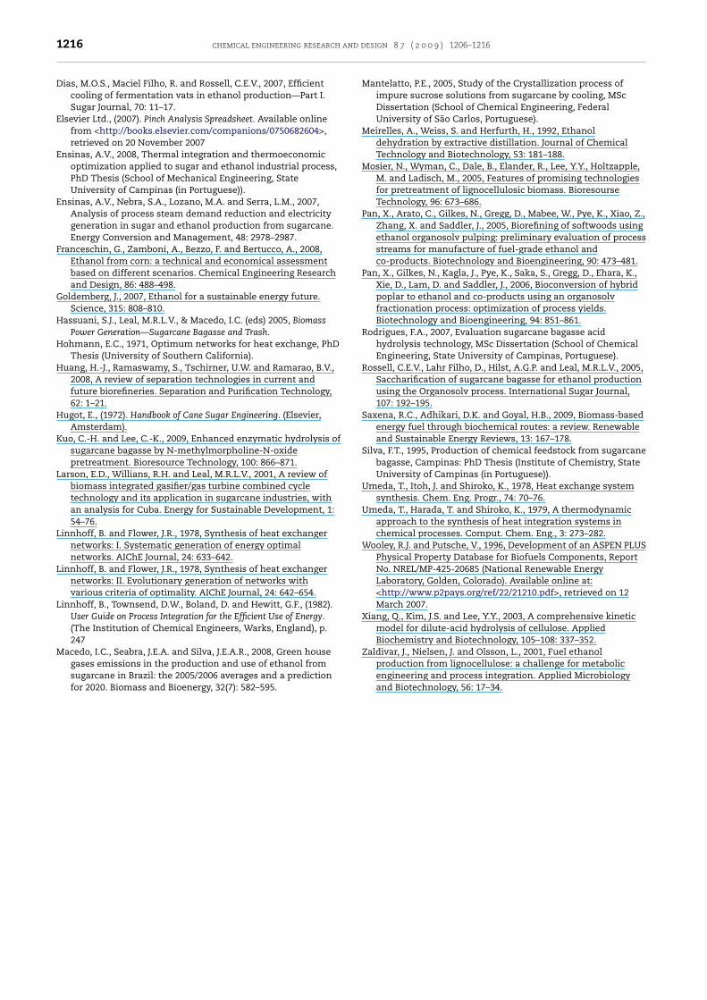
and d
1216 chemical engineering researchDias, M.O.S., Maciel Filho, R. and Rossell, C.E.V., 2007, Efficientcooling of fermentation vats in ethanol production—Part I.Sugar Journal, 70: 11–17.
Elsevier Ltd., (2007). Pinch Analysis Spreadsheet. Available onlinefrom <http://books.elsevier.com/companions/0750682604>,retrieved on 20 November 2007
Ensinas, A.V., 2008, Thermal integration and thermoeconomicoptimization applied to sugar and ethanol industrial process,PhD Thesis (School of Mechanical Engineering, StateUniversity of Campinas (in Portuguese)).
Ensinas, A.V., Nebra, S.A., Lozano, M.A. and Serra, L.M., 2007,Analysis of process steam demand reduction and electricitygeneration in sugar and ethanol production from sugarcane.Energy Conversion and Management, 48: 2978–2987.
Franceschin, G., Zamboni, A., Bezzo, F. and Bertucco, A., 2008,Ethanol from corn: a technical and economical assessmentbased on different scenarios. Chemical Engineering Researchand Design, 86: 488–498.
Goldemberg, J., 2007, Ethanol for a sustainable energy future.Science, 315: 808–810.
Hassuani, S.J., Leal, M.R.L.V., & Macedo, I.C. (eds) 2005, BiomassPower Generation—Sugarcane Bagasse and Trash.
Hohmann, E.C., 1971, Optimum networks for heat exchange, PhDThesis (University of Southern California).
Huang, H.-J., Ramaswamy, S., Tschirner, U.W. and Ramarao, B.V.,2008, A review of separation technologies in current andfuture biorefineries. Separation and Purification Technology,62: 1–21.
Hugot, E., (1972). Handbook of Cane Sugar Engineering. (Elsevier,Amsterdam).
Kuo, C.-H. and Lee, C.-K., 2009, Enhanced enzymatic hydrolysis ofsugarcane bagasse by N-methylmorpholine-N-oxidepretreatment. Bioresource Technology, 100: 866–871.
Larson, E.D., Willians, R.H. and Leal, M.R.L.V., 2001, A review ofbiomass integrated gasifier/gas turbine combined cycletechnology and its application in sugarcane industries, withan analysis for Cuba. Energy for Sustainable Development, 1:54–76.
Linnhoff, B. and Flower, J.R., 1978, Synthesis of heat exchangernetworks: I. Systematic generation of energy optimalnetworks. AIChE Journal, 24: 633–642.
Linnhoff, B. and Flower, J.R., 1978, Synthesis of heat exchangernetworks: II. Evolutionary generation of networks withvarious criteria of optimality. AIChE Journal, 24: 642–654.
Linnhoff, B., Townsend, D.W., Boland, D. and Hewitt, G.F., (1982).User Guide on Process Integration for the Efficient Use of Energy.(The Institution of Chemical Engineers, Warks, England), p.247
Macedo, I.C., Seabra, J.E.A. and Silva, J.E.A.R., 2008, Green house
gases emissions in the production and use of ethanol fromsugarcane in Brazil: the 2005/2006 averages and a predictionfor 2020. Biomass and Bioenergy, 32(7): 582–595.esign 8 7 ( 2 0 0 9 ) 1206–1216
Mantelatto, P.E., 2005, Study of the Crystallization process ofimpure sucrose solutions from sugarcane by cooling, MScDissertation (School of Chemical Engineering, FederalUniversity of São Carlos, Portuguese).
Meirelles, A., Weiss, S. and Herfurth, H., 1992, Ethanoldehydration by extractive distillation. Journal of ChemicalTechnology and Biotechnology, 53: 181–188.
Mosier, N., Wyman, C., Dale, B., Elander, R., Lee, Y.Y., Holtzapple,M. and Ladisch, M., 2005, Features of promising technologiesfor pretreatment of lignocellulosic biomass. BioresourseTechnology, 96: 673–686.
Pan, X., Arato, C., Gilkes, N., Gregg, D., Mabee, W., Pye, K., Xiao, Z.,Zhang, X. and Saddler, J., 2005, Biorefining of softwoods usingethanol organosolv pulping: preliminary evaluation of processstreams for manufacture of fuel-grade ethanol andco-products. Biotechnology and Bioengineering, 90: 473–481.
Pan, X., Gilkes, N., Kagla, J., Pye, K., Saka, S., Gregg, D., Ehara, K.,Xie, D., Lam, D. and Saddler, J., 2006, Bioconversion of hybridpoplar to ethanol and co-products using an organosolvfractionation process: optimization of process yields.Biotechnology and Bioengineering, 94: 851–861.
Rodrigues, F.A., 2007, Evaluation sugarcane bagasse acidhydrolysis technology, MSc Dissertation (School of ChemicalEngineering, State University of Campinas, Portuguese).
Rossell, C.E.V., Lahr Filho, D., Hilst, A.G.P. and Leal, M.R.L.V., 2005,Saccharification of sugarcane bagasse for ethanol productionusing the Organosolv process. International Sugar Journal,107: 192–195.
Saxena, R.C., Adhikari, D.K. and Goyal, H.B., 2009, Biomass-basedenergy fuel through biochemical routes: a review. Renewableand Sustainable Energy Reviews, 13: 167–178.
Silva, F.T., 1995, Production of chemical feedstock from sugarcanebagasse, Campinas: PhD Thesis (Institute of Chemistry, StateUniversity of Campinas (in Portuguese)).
Umeda, T., Itoh, J. and Shiroko, K., 1978, Heat exchange systemsynthesis. Chem. Eng. Progr., 74: 70–76.
Umeda, T., Harada, T. and Shiroko, K., 1979, A thermodynamicapproach to the synthesis of heat integration systems inchemical processes. Comput. Chem. Eng., 3: 273–282.
Wooley, R.J. and Putsche, V., 1996, Development of an ASPEN PLUSPhysical Property Database for Biofuels Components, ReportNo. NREL/MP-425-20685 (National Renewable EnergyLaboratory, Golden, Colorado). Available online at:<http://www.p2pays.org/ref/22/21210.pdf>, retrieved on 12March 2007.
Xiang, Q., Kim, J.S. and Lee, Y.Y., 2003, A comprehensive kineticmodel for dilute-acid hydrolysis of cellulose. AppliedBiochemistry and Biotechnology, 105–108: 337–352.
Zaldivar, J., Nielsen, J. and Olsson, L., 2001, Fuel ethanol
production from lignocellulose: a challenge for metabolicengineering and process integration. Applied Microbiologyand Biotechnology, 56: 17–34.


