Embed Size (px)
Citation preview
Siemens IK PI · 2009
2/4 Industrial Ethernet
2/25 PROFINET
2/29 Passive network components
2/98 Industrial Ethernet Switches
2/183 Industrial security
2/192 CPUs for SIMATIC S7-300
2/232 CPUs for SIMATIC S7-400
2/253 SIMATIC PC-based Control/Embedded Automation
2/260 System interfacing for SIMATIC and SINUMERIK
2/261 System interfacing for SIMATIC S7
2/299 System interfacing for PG/PC
2/339 SIMATIC HMI connection options
2/349 Accessories
2/355 ET 200S distributed I/Os
2/360 ET 200pro distributed I/O
2/368 ET 200M distributed I/Os
2/370 Motion Control System SIMOTION
2/382 SINUMERIK CNC Automation Systems
2/385 SINAMICS S120 Drive system
2/389 SINAMICS G120 Drive system
2/403 SINAMICS G120D Distributed Frequence Inverter
2/411 PROFINET Technology components
2/417 Operator control and monitoring devices
2/421 RFID Systems
2/427 Image Processing System
2/447 Engineering/Network management/Diagnostics
PROFINET/Industrial Ethernet
© Siemens AG 2008
Siemens IK PI · 2009
2/4 Industrial Ethernet2/4 Introduction2/7 Data communication2/8 Communications overview2/10 Configuration examples2/12 Topologies2/24 Network selection criteria
2/25 PROFINET2/25 Introduction
2/29 Passive network components2/29 Overview of
passive network components2/32 Overview of Twisted Pair2/33 Industrial Ethernet FastConnect2/35 IE FC RJ45 Plug 2 x 22/39 IE FC RF45 Plug 4 x 22/41 IE Push Pull Plug PRO2/44 IE Connecting Cable
M12-180/M12-180/IE FC M12 Plug PRO2/46 IE FC TP Cable 2 x 22/53 IE FC TP Cable 4 x 22/56 IE Hybrid Cable2/58 Power cables2/61 IE TP Cord2/66 IE FC Outlet RJ452/71 IE FC RJ45 Modular Outlet2/78 Industrial Twisted Pair –
Cables/connectors2/82 Overview of fiber-optic cables2/83 Glass fiber optic cables2/92 POF and PCF fiber-optic cables2/96 POF/PCF FOC termination kit
2/98 Industrial Ethernet Switches2/98 Overview2/104 Compact Switch Module CSM 3772/107 SCALANCE X005 unmanaged2/110 SCALANCE X-100 unmanaged2/118 SCALANCE X-200 managed2/129 SCALANCE X-200IRT managed2/139 SIPLUS SCALANCE X-200IRT
managed2/140 SCALANCE X-300 managed 2/151 SIPLUS SCALANCE X-300
managed 2/152 SCALANCE X-400 2/164 Industrial Ethernet OSM/ESM2/171 Industrial Ethernet SIPLUS OSM/ESM2/172 SCALANCE X-100 unmanaged
media converter2/182 SIPLUS SCALANCE X-100 unmanaged
media converter
2/183 Industrial security2/183 Overview2/184 SCALANCE S2/190 SOFTNET Security Client
2/192 CPUs for SIMATIC S7-3002/192 CPU 315-2 PN/DP2/198 SIPLUS CPU 315-2 PN/DP
(extended temperature range)2/199 CPU 317-2 PN/DP2/205 SIPLUS CPU 317-2 PN/DP
(extended temperature range)2/206 CPU 319-3 PN/DP2/212 CPU 315F-2 PN/DP2/218 SIPLUS CPU 315F-2 PN/DP
(extended temperature range)2/219 CPU 317F-2 PN/DP2/225 SIPLUS CPU 317F-2 PN/DP
(extended temperature range)2/226 CPU 319F-3 PN/DP
2/232 CPUs for SIMATIC S7-4002/232 CPU 414-3 PN/DP2/239 CPU 416-3 PN/DP2/246 SIPLUS CPU 416-3 PN/DP2/247 CPU 416F-3 PN/DP
2/253 SIMATIC PC-based Control/Embedded Automation
2/253 SIMATIC Microbox 427B-RTX2/256 SIMATIC WinAC Software PLC
2/260 System interfacing for SIMATIC and SINUMERIK
2/260 Introduction
System interfacing for SIMATIC S72/261 CP 243-12/264 CP 243-1 IT2/268 CP 343-1 Lean2/273 CP 343-12/278 CP 343-1 Advanced2/286 CP 443-12/291 CP 443-1 Advanced
PROFINET/Industrial Ethernet
Overview of contents
© Siemens AG 2008
Siemens IK PI · 2009
2/299 System interfacing for PG/PC2/299 Introduction2/300 Performance data2/301 Connection capabilities to
SIMATIC PCs2/302 CP 16042/306 CP 16162/310 CP 1613 A22/314 CP 16232/318 S7-REDCONNECT2/320 SOFTNET for Industrial Ethernet2/323 SOFTNET PN IO2/325 OPC server for Industrial Ethernet2/328 PN CBA OPC server2/331 SNMP OPC server2/333 SOFTNET PN IO Linux2/335 SOFTNET-S7/Linux2/337 SOFTBUS für Linux
2/339 SIMATIC HMI connection options
2/339 Overview2/340 SIMATIC S72/342 SIMATIC WinCC flexible RT2/344 SIMATIC WinCC
2/349 Accessories2/349 C-PLUGSec. 3 Power Supply PS791-1PRO2/351 SICLOCK time synchronization
2/355 ET 200S distributed I/Os2/355 IM 151-3PN interface modules2/357 SIPLUS IM 151-3PN interface module
(extended temperature range)
Interface modules with integrated CPU2/358 IM 151-8 PN/DP CPU interface module2/359 IM 151-8F PN/DP CPU interface module
2/360 ET 200pro distributed I/O2/360 IM 154-4 PN interface modules2/363 IM 154-8 PN/DP CPU interface modules
2/368 ET 200M distributed I/Os2/368 IM 153-4 PN
2/370 Motion Control System SIMOTION2/370 The SIMOTION system2/371 The hardware platforms2/372 SIMOTION P350-32/374 SIMOTION D4102/377 SIMOTION D425/D435/D4452/380 CBE30 Communication Board2/381 MCI-PN Communication Board
2/382 SINUMERIKCNC Automation Systems
2/382 SINUMERIK & SINAMICS2/383 SINUMERIK 840D sl –
NCU 720.2 PN/NCU 730.2 PN
2/385 SINAMICS S120 Drive system2/385 SINAMICS S120 built-in devices2/387 CBE20 Communication Board2/388 CU310 PN Control Unit
2/389 SINAMICS G120 Drive system2/389 SINAMICS G120 chassis units2/397 CU240S PN and CU240S PN-F
Control Units
2/403 SINAMICS G120D Distributed Frequency Inverters
2/403 SINAMICS G120D distributed frequency inverter
2/407 CU240D PN and CU240D PN-FControl Units
2/411 PROFINET Technology components
2/411 ERTEC enhanced real-time Ethernet controller
2/414 Development Kits for ERTEC2/416 Development packages
2/417 Operator control and monitoring devices
2/417 SIMATIC Mobile Panels2/419 SIMATIC Panels2/420 SIMATIC Multi Panels (MP)
2/421 RFID Systems2/421 SIMATIC RF180C2/424 SIMATIC RF170C
2/427 Image Processing System2/427 SIMATIC VS1202/431 SIMATIC VS130-22/436 SIMATIC VS720
2/447 Engineering/Network management/Diagnostics
Sec. 3 SINEMA ESec. 4 STEP 72/447 SIMATIC iMap2/449 BANYnet bus analysis and diagnostics
© Siemens AG 2008
PROFINET/Industrial EthernetIndustrial Ethernet
Introduction
2/4 Siemens IK PI · 2009
2
■ Overview• Area and cell network according to the international standards
IEEE 802.3 (Ethernet) and IEEE 802.11 a/b/g/h (wireless LAN) designed for the industrial environment right down to the field level
• Connection of automation components (controllers and field devices) to each other and to PCs and workstations as well as components for wireless communication
• PROFINET, the Industrial Ethernet standard for automation, is based on Industrial Ethernet and supports the connection of devices from field level up to management level
• Comprehensive open network solutions can be implemented
• High transmission performance up to 1 gigabit/s• Industrial Ethernet is the industry standard, well-proven world-
wide with international acceptance• Wireless expansion by means of Industrial Wireless LAN
(IWLAN) as per IEEE 802.11• Integration of conventional IT functionalities such as Web
server and e-mail in the automation sector• A safety solution specially designed for industrial automation
with the industrial security concept covering all aspects of SCALANCE S
Industrial Ethernet in the communications landscape
© Siemens AG 2008
PROFINET/Industrial EthernetIndustrial Ethernet
Introduction
2/5Siemens IK PI · 2009
2
■ Overview (continued)
EthernetThe LAN standard from the office sector.
Ethernet currently has a market share of over 90% with a rising trend, thus placing it in the pole position in the LAN landscape worldwide. This means that Ethernet has supplanted other LAN standards such as Token Ring or FDDI. The specification of this baseband LAN was developed in the 1970s and standardized in the international IEEE 802.3 standard. Ethernet has continued to experience rapid development and established itself in all speed ranges and application areas.
Milestones include:• Virtually unlimited communication capabilities with scalable
performance due to - switching technology, full duplex, redundancy- continuously rising data rates (10/100 Mbit/s, 1/10 Gbit/s)
• High availability of the network, because: - existing networks can be expanded without any adverse
effects- network structures with any form of meshing compensate for
the failure of individual network components (e.g. by means of the Rapid Spanning Tree Protocol)
• Compatible protocol expansions, e.g. support of virtual sub-networks and prioritized data traffic through the use of VLANs
• Structured cabling concept - Standardized connection technology- Simplest connection technology due to use of preassembled
twisted pair cables- Glass fiber-optic cables for long distances, areas subject to
RFI and inter-building cabling
Ethernet forms the basis for overlaid network protocols such as TCP/IP. TCP/IP is responsible for the transport of data between LANs and represents the basis for IT services (e.g. Internet). In addition, this enables different LAN technologies to be easily integrated, e.g. Ethernet with Wireless LAN.
Ethernet components for the office sector are offered by a large number of vendors, but do not always meets the specific re-quirements of the industrial sector.
For planning, operation and maintenance of Ethernet networks, sufficiently qualified personnel are available worldwide.
Industrial EthernetThe industry-standard version of Ethernet.
It was not only its performance when exchanging large volumes of data that made Ethernet ideal for use in the industrial environ-ment – high availability, reliability, real-time capability, robust connection technology and ease of operation without special IT knowledge have also made this standard suitable for industrial use.
By means of corresponding additions for tough Industrial use, Siemens has shown that Ethernet can also be used successfully in these applications. This approach has been consistently and successfully applied not only for Industrial Ethernet and PROFINET, but also for Industrial WLAN.
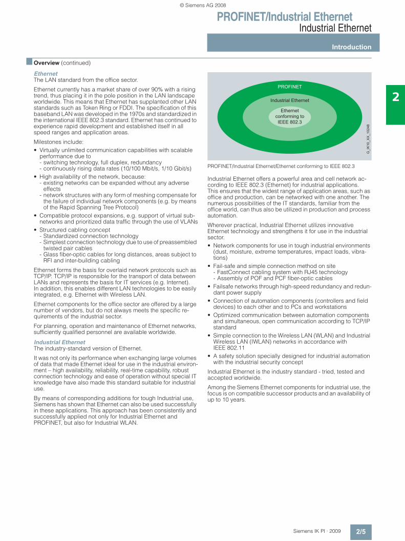
PROFINET/Industrial Ethernet/Ethernet conforming to IEEE 802.3
Industrial Ethernet offers a powerful area and cell network ac-cording to IEEE 802.3 (Ethernet) for industrial applications. This ensures that the widest range of application areas, such as office and production, can be networked with one another. The numerous possibilities of the IT standards, familiar from the office world, can thus also be utilized in production and process automation.
Wherever practical, Industrial Ethernet utilizes innovative Ethernet technology and strengthens it for use in the industrial sector.• Network components for use in tough industrial environments
(dust, moisture, extreme temperatures, impact loads, vibra-tions)
• Fail-safe and simple connection method on site - FastConnect cabling system with RJ45 technology - Assembly of POF and PCF fiber-optic cables
• Failsafe networks through high-speed redundancy and redun-dant power supply
• Connection of automation components (controllers and field devices) to each other and to PCs and workstations
• Optimized communication between automation components and simultaneous, open communication according to TCP/IP standard
• Simple connection to the Wireless LAN (WLAN) and Industrial Wireless LAN (IWLAN) networks in accordance with IEEE 802.11
• A safety solution specially designed for industrial automation with the industrial security concept
Industrial Ethernet is the industry standard - tried, tested and accepted worldwide.
Among the Siemens Ethernet components for industrial use, the focus is on compatible successor products and an availability of up to 10 years.
Ethernetconforming toIEEE 802.3
G_I
K10
_XX
_102
48
Industrial Ethernet
PROFINET
© Siemens AG 2008

PROFINET/Industrial EthernetIndustrial Ethernet
Introduction
2/6 Siemens IK PI · 2009
2
■ Overview (continued)
PROFINETThe open Industrial Ethernet standard for automation
PROFINET is the open, cross-vendor Industrial Ethernet stan-dard (IEC 61158/61784) for automation.
Based on Industrial Ethernet, PROFINET enables direct commu-nication between field devices (IO Devices) and controllers (IO Controllers), up to and including the solution of isochronous drive controls for motion control applications.
As PROFINET is based on Standard Ethernet according to IEEE 802.3, every device from field level to management level can be connected.
In this way, PROFINET enables system-wide communication, supports plant-wide engineering and applies IT standards, such as Webserver or FTP, right down to field level. Tried and tested fieldbus systems, such as PROFIBUS or AS-Interface, can be easily integrated without any modification to the existing devices.
■ More information
Note: In many SIMATIC NET components with management function, extensive parameterization and diagnostics functions are pro-vided over open protocols and interfaces (e.g. Web server, network management).
These open interfaces provide access to those components, which can also be used for illicit activities.
When using the above-mentioned functions and these open interfaces and protocols (such as SNMP, HTTP and Telnet), suitable security measures must be implemented that block un-authorized access to the components or the network especially from the WAN/Internet.
For this reason, automation networks can be isolated from the remaining corporate network using appropriate routers (e.g. the well-proven firewall systems).
These network transitions can be implemented using SCALANCE S products.
For further information, see the section "Industrial Security".
It is important to note the boundary conditions for use of the specified SIMATIC Net products (Order Nos. 6GK..., 6XV1) which you can view in the Internet:
Additional in formation can be found in the Internet under:http://www.siemens.com/simatic-net/ik-info
© Siemens AG 2008
PROFINET/Industrial EthernetIndustrial Ethernet
Data communication
2/7Siemens IK PI · 2009
2
■ Overview
Standard communication This comprises standardized protocols for data communication .
ISO, TCP/IP, UDP transport protocols
ISO, TCP/IP and UDP are available as transport protocols.
PROFINET
Based on Industrial Ethernet, PROFINET enables direct commu-nication of field devices (IO Devices) with controllers (IO Control-lers) as well the solution of isochronous drive controls for motion control applications.
PROFINET also supports distributed automation with the help of component engineering (Component Based Automation).
Media Redundancy Protocol (MRP) Procedure specified in the IEC 61158 Type 10 standard for in-creasing the network availability in a ring topology.
Information technology (IT) IT integrates SIMATIC into the information technology via Industrial Ethernet. These communication media and paths are also available to SIMATIC as a result of the TCP/IP protocol. Depending on the product and stage of expansion, communica-tions processors support technologies from the IT environment such as:• E-mail;
Via the integral e-mail client, network components, communi-cations processors and routers can send emails to provide in-formation about plant states, e.g. plant standstill or imminent overload, or to automatically request a service call.
• Freely definable HTML pages; Communications processors can perform web diagnostics with the aid of static HTML pages and a user-specific display is supported with the aid of freely definable HTML pages.
• FTP; the File Transfer Protocol (FTP) permits simple, universal cou-pling, e.g. the PLC can be connected to different computers or embedded systems
IP routing (IP-R) The connection for the SIMATIC S7 to Industrial Ethernet (CP 343-1 Advanced and CP 443-1 Advanced), with two separate interfaces (integrated network separation) and SCALANCE S and SCALANCE X414-3E, supports the forward-ing of IP messages between Gigabit and PROFINET interfaces.
OPC (Openness, Productivity & Collaboration)
OPC is a standardized, open and manufacturer-independent interface and allows OPC-capable Windows applications to interface to S7 communication (SEND/ RECEIVE). Internet communication can be implemented over the OPC XML DA interface.
PG/OP communication
Integral communication functions that are used by the SIMATIC automation systems to perform data communication with HMI devices (e.g. TP/OP) and SIMATIC PGs (STEP 7, STEP 5). PG/OP communication is supported by MPI, PROFIBUS and Industrial Ethernet.
S7 communication
S7 communication is the integral communications function (SFB) that has been optimized within the SIMATIC S7/C7. It enables PCs and workstations to be connected. The maximum volume of user data per task is 64 KB. S7 communication offers simple, powerful communication services and provides a network inde-pendent software interface for all networks.
Open communication
The open communication (SEND/RECEIVE) allows the SIMATIC S7 controller to communicate with other SIMATIC S7 and SIMATIC S5 controllers (S5-compatible communication), PCs and third-party systems. In addition, for the simple connec-tion of HMI stations, FETCH and WRITE are offered.
System connections For many data terminals, communications processors (CPs) are available that already have the communications functions imple-mented as firmware and which therefore relieve the data terminal of communication tasks (e.g. flow control, blocking, etc.).
Time synchronization By means of SIMATIC procedures or NTP (Network Time Protocol), plant-wide time synchronization is achieved.
© Siemens AG 2008
PROFINET/Industrial EthernetIndustrial Ethernet
Communications overview
2/8 Siemens IK PI · 2009
2
■ Overview
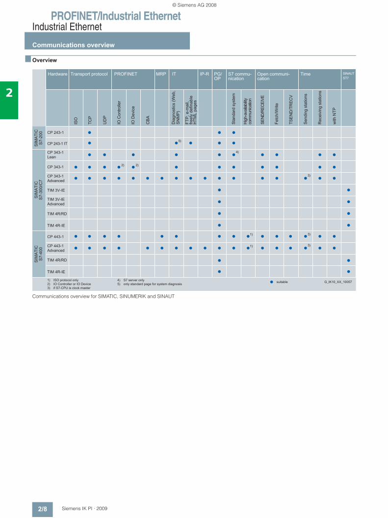
Communications overview for SIMATIC, SINUMERIK and SINAUT
1) ISO protocol only2) IO Controller or IO Device3) if S7-CPU is clock master
4) S7 server only5) only standard page for system diagnosis
© Siemens AG 2008
PROFINET/Industrial EthernetIndustrial Ethernet
Communications overview
2/9Siemens IK PI · 2009
2
■ Overview (continued)
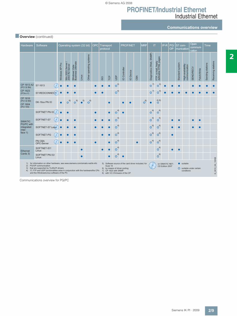
Communications overview for PG/PC
1) for information on other hardware, see www.siemens.com/simatic-net/ik-info2) PG/OP communication3) that are supported by TLI/DLPI drivers4) IT, FTP and UDP functionalities arise in conjunction with the hardware/the CPs and the Windows/Linux software of the PC
5) Software source of the card driver included; for Suse 10
6) by means of driver porting7) CP 1623 with SNMP8) with V2.3 firmware of the CP G
_IK
10_X
X_1
0058
© Siemens AG 2008
PROFINET/Industrial EthernetIndustrial Ethernet
Configuration examples
2/10 Siemens IK PI · 2009
2
■ Overview
Open communication via Industrial Ethernet
PG/OP communication for the transparent access to configuration and diagnostics data of the connected Industrial Ethernet stations
G_I
K10
_XX
_100
11
© Siemens AG 2008
PROFINET/Industrial EthernetIndustrial Ethernet
Configuration examples
2/11Siemens IK PI · 2009
2
■ Overview (continued)
Construction of a small local PROFINET network with integrated switch in the CP 443-1 Advanced
© Siemens AG 2008
PROFINET/Industrial EthernetIndustrial Ethernet
Topologies
2/12 Siemens IK PI · 2009
2
■ Overview
Network performance and network technologies for Industrial Ethernet When combined, the current Industrial Ethernet technologies can boost performance on the network by a factor of 50 and more in comparison with the original 10 Mbit/s technology. These technologies are:• Fast Ethernet with 100 Mbit/s:
Messages are transported much faster than Ethernet (10 Mbit/s) and therefore only occupy the bus for an extremely short time. For Fast Ethernet, a 4-wire FastConnect cabling system (Cat5e) is available with cable, plug and outlet.
• Gigabit Ethernet with 1 Gbit/s: Gigabit Ethernet is faster than Fast Ethernet by a factor of 10, the bus is occupied for only one tenth of the time. For Gigabit Ethernet, an 8-wire FastConnect cabling system (Cat6) is available with cable, plug and outlet.
• Full Duplex prevents collisions: The data throughput increases enormously because the usual message repetitions are avoided. Data can be sent and received simultaneously between two stations. The data throughput for a full duplex connection therefore rises to 200 Mbit/s with Fast Ethernet and to 2 Gbit/s with Gigabit Ethernet. With full duplex, a greater length of the network is possible. This means, for example, that when glass fiber-optic cables are used, distances of up to 70 km can be achieved.
• Switching supports parallel communication: When a network is subdivided into several segments using a switch, or individual stations are connected direct to a switch, this results in load separation. Data communication is possible in each individual segment independently of the other seg-ments. In the overall network, several messages can therefore be en-route simultaneously. The increase in performance is therefore due to the sending of several messages simulta-neously.
• Autocrossover automatically crosses the send and receive cables on Twisted Pair interfaces.
• Autosensing describes the characteristic of network nodes (data terminals and network components) that automatically detect the transmission rate of a signal (10 Mbit/s, 100 Mbit/s or 1 Gbit/s) and support autonegotiation.
• Autonegotiation is a configuration protocol on Fast Ethernet. Before initiating the actual data transmission, network devices automatically negotiate a transmission mode which is sup-ported by any device (1000 Mbit/s,100 Mbit/s or 10 Mbit/s, full duplex or half duplex)
Gross data throughput of the networks
© Siemens AG 2008
PROFINET/Industrial EthernetIndustrial Ethernet
Topologies
2/13Siemens IK PI · 2009
2
■ Overview (continued)
Ethernet Switching
The Industrial Ethernet switch has the following functionality:• Depending on the number of available interfaces, switches
are able to simultaneously interconnect several pairs of sub-networks or stations temporarily and dynamically, with each connection possessing the full data throughput.
• By filtering the data traffic on the basis of the Ethernet (MAC) address of the data terminal, the local data traffic remains lo-cal; only data to users of another subnetwork is forwarded by the switch.
• More data terminals can be connected than in a classic Ether-net network.
• Error propagation is limited to the subnetwork concerned.
The switching technology offers definite advantages:• Subnetworks and network segments can be created.• The data throughput is increased and with it the network per-
formance as a result of structuring the data communication.• Easy rules for network configuration.• Network topologies with 50 switches and an overall extension
of up to 150 km can be implemented without the need to take signal propagation times into account.
• Unlimited extension of the network by connecting individual collision domains/subnetworks.
• Easy, reaction-free extension of existing networks.Full duplex
Full duplex (FDX) is an operating mode in the network that, in contrast to half duplex, allows stations to send and receive data simultaneously. When FDX is used, collision detection is auto-matically deactivated in the participating stations.
For FDX, transmission media with separate send and receive channels must be used, e.g. FOC and TP, and the participating components must be able to store data packages. With an FDX connection collisions do not occur, so components that support FDX can send and receive simultaneously at the nominal trans-mission rate. The data throughput therefore increases to twice the nominal transmission rate of the network, to 20 Mbit/s with the classic Ethernet and 200 Mbit/s with Fast Ethernet. With Gigabit Ethernet, up to 2000 Mbit/s are achieved.
A further advantage of FDX is the increase in the network exten-sion.
By deactivating the collision principle, the distance between two components can be increased by the size of a collision domain or more. With full duplex, the maximum distance can extend as far as the performance limit of the send and receive compo-nents. This is especially the case in connection with fiber-optic cables. When glass fiber-optic cables are used, distances of up to 70 km can be achieved.
Increased performance through switching, full duplex
Autosensing/Autonegotiation
Autosensing describes the characteristic of network nodes (data terminals and network components) that automatically de-tect the transmission rate of a signal (10 Mbit/s, 100 Mbit/s or 1000 Mbit/s) and support autonegotiation.
Autonegotiation is the configuration protocol for Twisted Pair. It enables the participating nodes to negotiate and agree the transmission rate before the first data packages are transferred:• 10 Mbit/s,100 Mbit/s or 1000 Mbit/s• Full duplex or half duplex
Autonegotiation can also be deactivated if a specific transmis-sion rate has to be set.
The advantage with Autosensing lies in the problem-free inter-operability of all Ethernet components. Classical Ethernet components that do not support Autosensing work problem-free with Fast Ethernet and new Gigabit Ethernet components that do support Autosensing.
Autocrossover The Autocrossover function automatically crosses the send and receive cables on Twisted Pair interfaces. This means that crossed connecting lines (e.g. TP XP Cords) are no longer required.
• All nodes in the network share the network performance/data rate.
• All data packets pass through all segments.
• Only one message in the network at a time.
Switched LAN Shared LAN
Data trafficData traffic
Segment DSegment C
Segment BSegment A
Segment DSegment C
Segment BSegment A
G_I
K10
_XX
_100
02
• Each individual segment features the full performance/data rate
• Simultaneous data traffic in several segments, several message frames at the same time
• Filtering: Local data traffic remains local; only selected data packets exceed segment boundaries
© Siemens AG 2008
PROFINET/Industrial EthernetIndustrial Ethernet
Topologies
2/14 Siemens IK PI · 2009
2
■ Overview (continued)
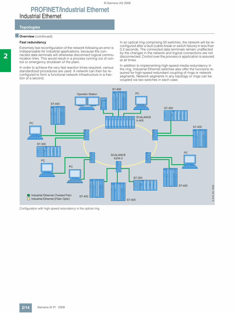
Fast redundancyExtremely fast reconfiguration of the network following an error is indispensable for industrial applications, because the con-nected data terminals will otherwise disconnect logical commu-nication links. This would result in a process running out of con-trol or emergency shutdown of the plant.
In order to achieve the very fast reaction times required, various standardized procedures are used. A network can then be re-configured to form a functional network infrastructure in a frac-tion of a second.
In an optical ring comprising 50 switches, the network will be re-configured after a fault (cable break or switch failure) in less than 0.2 seconds. The connected data terminals remain unaffected by the changes in the network and logical connections are not disconnected. Control over the process or application is assured at all times.
In addition to implementing high-speed media redundancy in the ring, Industrial Ethernet switches also offer the functions re-quired for high-speed redundant coupling of rings or network segments. Network segments in any topology or rings can be coupled via two switches in each case.
Configuration with high-speed redundancy in the optical ring
© Siemens AG 2008
PROFINET/Industrial EthernetIndustrial Ethernet
Topologies
2/15Siemens IK PI · 2009
2
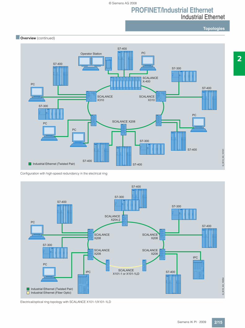
■ Overview (continued)
Configuration with high-speed redundancy in the electrical ring
Electrical/optical ring topology with SCALANCE X101-1/X101-1LD
© Siemens AG 2008
PROFINET/Industrial EthernetIndustrial Ethernet
Topologies
2/16 Siemens IK PI · 2009
2
■ Overview (continued)
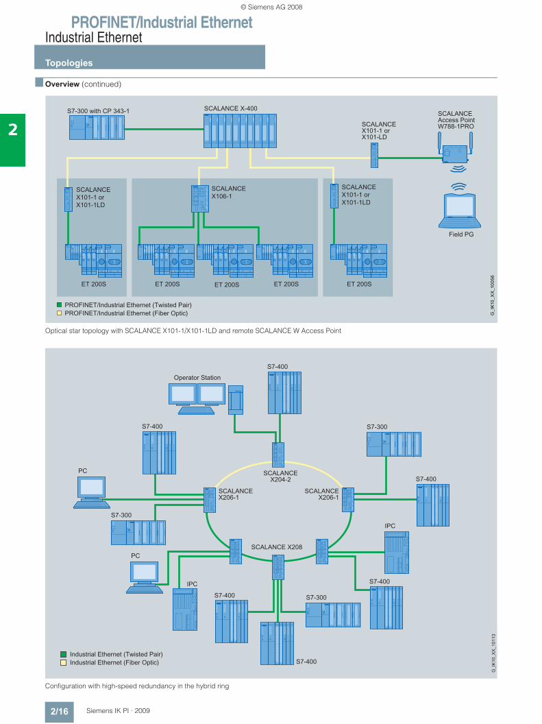
Optical star topology with SCALANCE X101-1/X101-1LD and remote SCALANCE W Access Point
Configuration with high-speed redundancy in the hybrid ring
© Siemens AG 2008
PROFINET/Industrial EthernetIndustrial Ethernet
Topologies
2/17Siemens IK PI · 2009
2
■ Overview (continued)
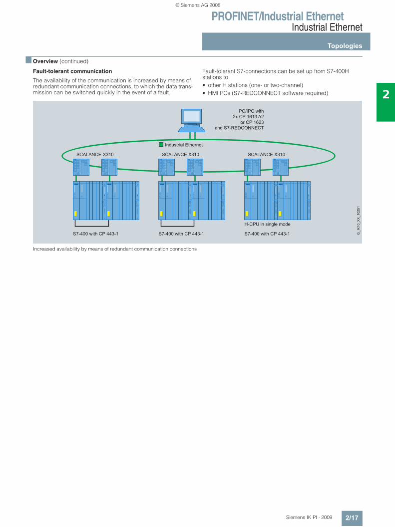
Fault-tolerant communication
The availability of the communication is increased by means of redundant communication connections, to which the data trans-mission can be switched quickly in the event of a fault.
Fault-tolerant S7-connections can be set up from S7-400H stations to• other H stations (one- or two-channel)• HMI PCs (S7-REDCONNECT software required)
Increased availability by means of redundant communication connections
PC/IPC with2x CP 1613 A2
or CP 1623and S7-REDCONNECT
H-CPU in single mode
SCALANCE X310 SCALANCE X310 SCALANCE X310
Industrial Ethernet
G_I
K10
_XX
_102
51
© Siemens AG 2008
PROFINET/Industrial EthernetIndustrial Ethernet
Topologies
2/18 Siemens IK PI · 2009
2
■ Overview (continued)
Redundancy with the Spanning Tree algorithm
The Spanning Tree algorithm is described in the IEEE 802.1d standard; it organizes any number of meshed Ethernet struc-tures comprising bridges and switches.
To prevent data packages circulating in the network, in the case of closed meshes different connections are switched to standby so that an open tree structure results from the meshed structure.
The bridges/switches communicate for this purpose using the Spanning Tree protocol. This protocol is extremely complex be-cause it has to handle any type of network structure.
The organization of network structures with the Spanning Tree protocol can take from 30 to 60 seconds. During this period, pro-ductive communication for reliable visualization or process con-trol in the network is not possible.
In the time-optimized variant "Rapid Reconfiguration Spanning Tree“ according to IEEE 802.1w, the time is shortened to be-tween 1 and 3 seconds for up to 10 series-connected switches. For connecting to office networks, some SIMATIC NET switches support the Rapid Spanning Tree Protocol.
Switched network
Switched industrial networks can be configured electrically or optically with a linear, star or ring structure, or a combination.
They are constructed with SCALANCE X switches or with OSM and ESM. Fiber-optic conductors or Twisted Pair cables are used as the transmission media between the switches.
Data terminals or network segments are connected over twisted-pair cables or polymer optical fiber (POF) . Switched networks can be of any size. The signal propagation times must be taken into account at distances over 150 km.
Optical cabling with POF/PCF or glass fiber optic cable
Fiber-optic cables are always recommended as an alternative to copper cables in environments subject to strong electromag-netic interference (EMI), if reliable equipotential bonding cannot be guaranteed, if the system is in the open air, or if no adverse effects caused by EMI are wanted.
Glass fiber optic cables are used to establish optical network topologies covering long distances, while for shorter distances, plastic fiber optic cable made of light-conducting plastics like polymer optical fiber (POF), or plastic covered glass fibers such as polymer cladded fiber (PCF), are used. Simple fiber-optic ca-bling for machine-level use is implemented with the new SC RJ connection system for polymer optical fiber and PCF. The SC RJ connectors can be assembled especially quickly and simply on-site. The plastic fiber optic cables designed for this purpose can be used universally or specifically in festoon cable systems.
For optical PROFINET networking, products with POF or PCF connection are used, e.g. the Industrial Ethernet Switch SCALANCE X200-4P IRT, ET 200S distributed I/O or the SCALANCE X101-1POF media converter.
Mixed network with SCALANCE X202-2P IRT and SCALANCE X101-1POF media converter
© Siemens AG 2008
PROFINET/Industrial EthernetIndustrial Ethernet
Topologies
2/19Siemens IK PI · 2009
2
■ Overview (continued)
Gigabit at the control level Whereas in the field level, short response times and small data message frames are in the forefront, the need for high data throughput is constantly increasing in the control level. The rea-son for this is the rapidly growing number of nodes and data-in-tensive systems such as HMI, SCADA, VISION systems, web ap-plications or multimedia applications.
In addition to the Gigabit-capable network infrastructure, there are also Gigabit-capable system connections for PCs or SI-MATIC S7-300/400. The CP 1623 communications processor for PCI Express supports a high-performance connection of the HMI/SCADA systems and simultaneously increases the reliabil-ity of the network by means of an optional external power supply.
The CP 343-1 Advanced and CP 443-1 Advanced communica-tions processors for SIMATIC S7-300/400 implement integral network separation between the control level and field level and provide: • Separate network connections on a module for the connection
of two independent IP-subnetworks, e.g. control level is IP subnetwork 1 (Gigabit Ethernet) and the field level is IP sub-network 2 (Fast Ethernet)
• Cross-network utilization of IT services through IP routing, such as access to web servers
• Access protection via a configurable IP access list• Short response times for the lower-level field device connec-
tion with PROFINET
Network separation between field level and enterprise level including Gigabit communication at the control level
Network separation between field level and enterprise levelNetworks often have to be separated physically from one an-other, but nevertheless have to communicate with one another. Reasons for network separation are deliberate load decoupling or different responsibilities within an enterprise (e.g. office and production network).
When using the CP 343-1 Advanced communications proces-sors and CP 443-1 Advanced S7 controllers this requirement presents no problem. With the introduction of interfaces for sep-arate IP subnetworks in Gigabit Ethernet and Fast Ethernet on one module, the cross-network use of IT services is possible by means of static IP routing. The access protection to the controller and the cross-network data traffic in this case is regulated by a configurable IP Access List.
WinCCServerwith CP 1623
SIMATIC S7-400withCP 443-1 Advanced
SIMATIC S7-300withCP 343-1 Advanced
Drives
IPC with Gigabit interfaceand CP 1616
IPcamera
S7-300 withCP 343-1 Lean
1000 Mbit/s
100 Mbit/s
1000 Mbit/s1000 Mbit/s
1000 Mbit/s
SCALANCEX308-2
SCALANCEX408-2
SCALANCEX408-2
SCALANCEX408-2
SCALANCEX308-2
ET 200proET 200SET 200S
1000 Mbit/s
Ethernet
PROFINET
G_I
K10
_XX
_102
26
Field Level
Control Level
Enterprise Level
Industrial Ethernet
1000 Mbit/s
© Siemens AG 2008
PROFINET/Industrial EthernetIndustrial Ethernet
Topologies
2/20 Siemens IK PI · 2009
2
■ Overview (continued)
SIMATIC PCS 7 process control system with Gigabit In the control room, two SCALANCE X-400 switches are used on the terminal bus. If a high number of nodes are connected to the plant bus, SCALANCE X414-3E switches, for example, can be used with extender modules. These are connected together to create an electrical ring with a transfer rate of 1 Gbit/s.
Several operator panels are provided and divided between the two switches so that the system can still be operated in the event of a failure. The terminal and plant buses are connected using redundant servers, e.g. with SCALANCE X408-2 also via high-performance Gigabit lines.
Use of the SCALANCE X switches in a process control system, e.g. PCS 7
© Siemens AG 2008
PROFINET/Industrial EthernetIndustrial Ethernet
Topologies
2/21Siemens IK PI · 2009
2
■ Overview (continued)
Fail-safe wireless communication with PROFIsafe
For several years, safety engineering has been integrating into standard automation on the basis of SIMATIC S7 controllers, PROFIBUS and PROFIsafe.
This range has been expanded by PROFINET-enabled compo-nents, thus providing a complete product range with failsafe controllers, failsafe I/O and a corresponding engineering envi-ronment.
PROFIsafe prevents errors such as address corruption, loss, de-lay, etc., when transmitting messages through continuous num-bering of the PROFIsafe data, time monitoring, and authenticity monitoring using passwords or optimized cyclic redundancy check (CRC).
Failsafe communication is also supported via industrial wireless LAN.
Fail-safe wireless communication with PROFIsafe
© Siemens AG 2008
PROFINET/Industrial EthernetIndustrial Ethernet
Topologies
2/22 Siemens IK PI · 2009
2
■ Overview (continued)
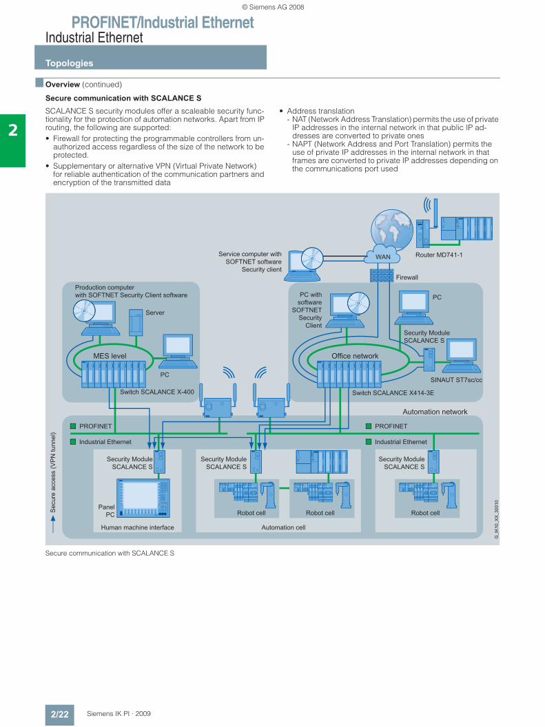
Secure communication with SCALANCE S
SCALANCE S security modules offer a scaleable security func-tionality for the protection of automation networks. Apart from IP routing, the following are supported:• Firewall for protecting the programmable controllers from un-
authorized access regardless of the size of the network to be protected.
• Supplementary or alternative VPN (Virtual Private Network) for reliable authentication of the communication partners and encryption of the transmitted data
• Address translation - NAT (Network Address Translation) permits the use of private
IP addresses in the internal network in that public IP ad-dresses are converted to private ones
- NAPT (Network Address and Port Translation) permits the use of private IP addresses in the internal network in that frames are converted to private IP addresses depending on the communications port used
Secure communication with SCALANCE S
© Siemens AG 2008
PROFINET/Industrial EthernetIndustrial Ethernet
Topologies
2/23Siemens IK PI · 2009
2
■ Overview (continued)
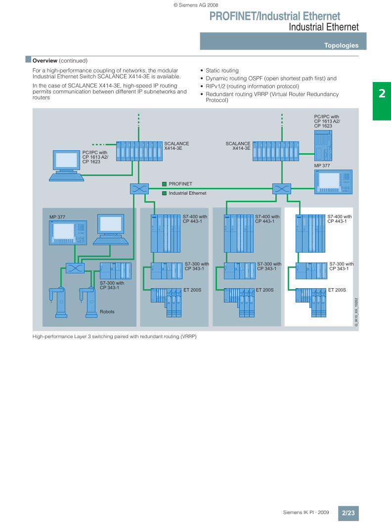
For a high-performance coupling of networks, the modular Industrial Ethernet Switch SCALANCE X414-3E is available.
In the case of SCALANCE X414-3E, high-speed IP routing permits communication between different IP subnetworks and routers
• Static routing• Dynamic routing OSPF (open shortest path first) and• RIPv1/2 (routing information protocol)• Redundant routing VRRP (Virtual Router Redundancy
Protocol)
High-performance Layer 3 switching paired with redundant routing (VRRP)
PC/IPC with CP 1613 A2/CP 1623
PC/IPC with CP 1613 A2/CP 1623
S7-300 with CP 343-1
S7-400 with CP 443-1
S7-300 with CP 343-1
S7-400 with CP 443-1
S7-300 with CP 343-1
S7-400 with CP 443-1
S7-300 with CP 343-1
Robots
G_I
K10
_XX
_102
52
MP 377
MP 377
SCALANCEX414-3E
SCALANCEX414-3E
ET 200S ET 200S ET 200S
© Siemens AG 2008
PROFINET/Industrial EthernetIndustrial Ethernet
Network selection criteria
2/24 Siemens IK PI · 2009
2
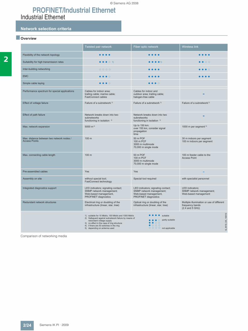
■ Overview
Comparison of networking media
1) suitable for 10 Mbit/s, 100 Mbit/s and 1000 Mbit/s2) Safeguard against subnetwork failure by means of
redundant voltage supply3) no effect in the case of ring structure4) if there are 50 switches in the ring5) depending on antenna used
n n n n
n n n -
n n - -
n - - -
- - - -
n n n n
n n n -n n n -
n n n nn n n nn n n -
n n n n
n n n n
n n n n n n n n
n n n -
n n - -n n n -
- - - -
© Siemens AG 2008
PROFINET/Industrial EthernetPROFINET
Introduction
2/25Siemens IK PI · 2009
2
■ Overview
PROFINET – the open Industrial Ethernet standardfor automation
PROFINET is the innovative and open Industrial Ethernet standard (IEC 61158/61784) for industrial automation. With PROFINET, devices can be linked up from the field level through to the management level. PROFINET enables system-wide communication, supports plant-wide engineering and uses the IT standards right down to the field level. Fieldbus systems such as PROFIBUS can be easily integrated without any changes to existing devices.
PROFINET takes account of the following aspects:
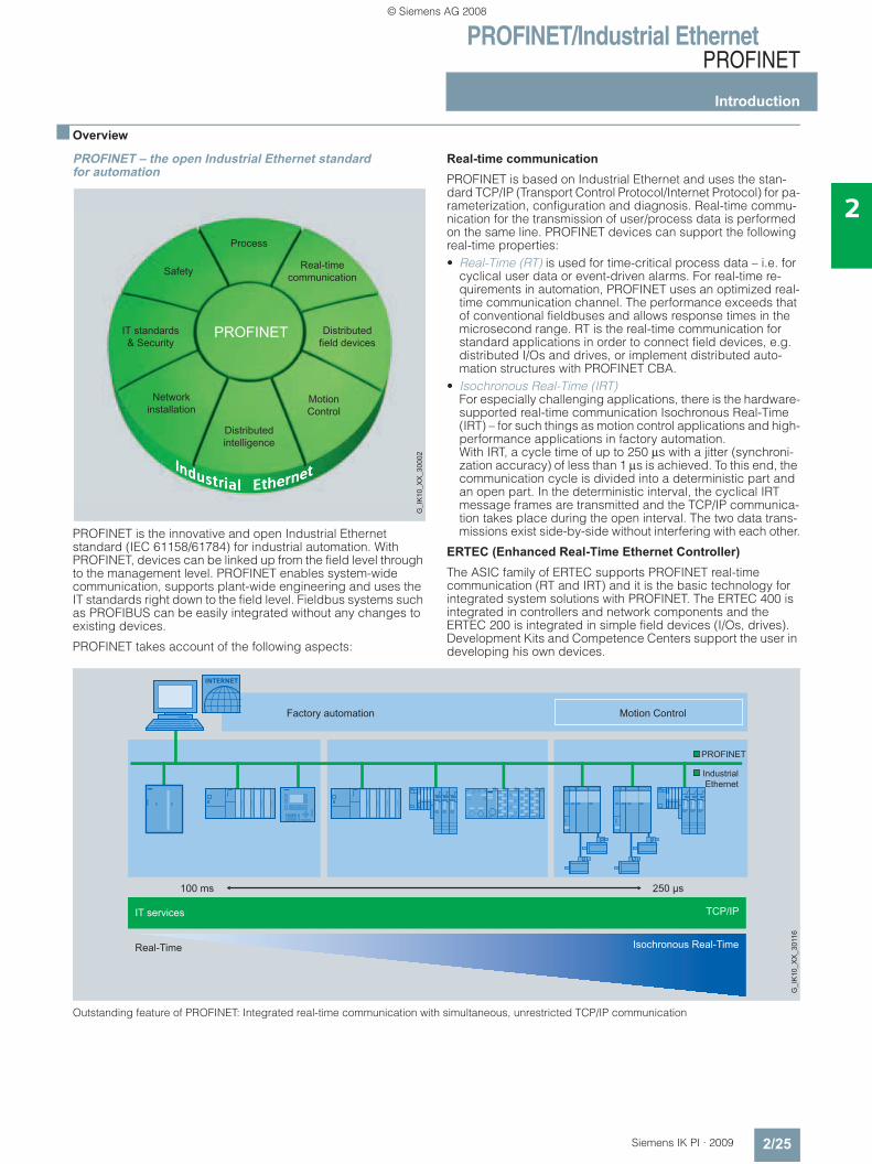
Real-time communication
PROFINET is based on Industrial Ethernet and uses the stan-dard TCP/IP (Transport Control Protocol/Internet Protocol) for pa-rameterization, configuration and diagnosis. Real-time commu-nication for the transmission of user/process data is performed on the same line. PROFINET devices can support the following real-time properties:• Real-Time (RT) is used for time-critical process data – i.e. for
cyclical user data or event-driven alarms. For real-time re-quirements in automation, PROFINET uses an optimized real-time communication channel. The performance exceeds that of conventional fieldbuses and allows response times in the microsecond range. RT is the real-time communication for standard applications in order to connect field devices, e.g. distributed I/Os and drives, or implement distributed auto-mation structures with PROFINET CBA.
• Isochronous Real-Time (IRT) For especially challenging applications, there is the hardware-supported real-time communication Isochronous Real-Time (IRT) – for such things as motion control applications and high-performance applications in factory automation. With IRT, a cycle time of up to 250 μs with a jitter (synchroni-zation accuracy) of less than 1 μs is achieved. To this end, the communication cycle is divided into a deterministic part and an open part. In the deterministic interval, the cyclical IRT message frames are transmitted and the TCP/IP communica-tion takes place during the open interval. The two data trans-missions exist side-by-side without interfering with each other.
ERTEC (Enhanced Real-Time Ethernet Controller) The ASIC family of ERTEC supports PROFINET real-time communication (RT and IRT) and it is the basic technology for integrated system solutions with PROFINET. The ERTEC 400 is integrated in controllers and network components and the ERTEC 200 is integrated in simple field devices (I/Os, drives). Development Kits and Competence Centers support the user in developing his own devices.
Outstanding feature of PROFINET: Integrated real-time communication with simultaneous, unrestricted TCP/IP communication
IT services
Factory automation Motion Control
100 ms 250 μs
Isochronous Real-Time
IndustrialEthernet
PROFINET
Real-Time
TCP/IP
G_I
K10
_XX
_301
16
© Siemens AG 2008
PROFINET/Industrial EthernetPROFINET
Introduction
2/26 Siemens IK PI · 2009
2
■ Overview (continued)
(PROFINET IO) distributed field devices
PROFINET IO enables distributed field devices (IO devices such as signal modules) to be connected directly to Industrial Ethernet. During configuration with STEP 7, these field devices are assigned to a central controller (IO Controller). Existing modules or devices can continue to be used with PROFINET-compatible interfaces or links, which safeguards existing invest-ments by PROFIBUS or AS-Interface users. A configuration with standard and failsafe modules in one station is also possible.
An IO Supervisor serves HMI and diagnostics purposes – as on PROFIBUS – using hierarchical diagnostics dialogs (overview and detailed diagnostics). The user data is transferred by means of TCP/IP or IT standards. The simple engineering for PROFINET, field-proven with PROFIBUS, was adopted here. From the view-point of programming with STEP 7 there is no difference between PROFIBUS and PROFINET when accessing an IO device. Users can thus very easily configure field devices on Industrial Ethernet on the basis of the know-how acquired with PROFIBUS.
By retaining the device model of PROFIBUS, the same diagnos-tics information is available on PROFINET. As well as device diagnostics, module-specific and channel-specific data can also be read out from the devices, enabling simple and fast location of faults.
Alongside the star, tree and ring topologies, PROFINET also supports the line topology shaped by established fieldbuses. By integrating switch functionality into the devices, for example as with the S7-300 with CP 343-1 Lean, CP 343-1, or the SIMATIC ET 200S, ET 200M or ET 200pro distributed field de-vices, line topologies that are oriented around the machine or plant structure can be formed. This results in savings in cabling overhead and cuts down on components such as external switches.
In addition to the products with degree of protection IP20, a complete portfolio is available for IP65, such as the ET 200pro field device or the SCALANCE X208PRO switch.
The Fast Start-Up function allows rapid start-up of PROFINET IO Devices that are connected to SIMATIC controllers within less than a second. This allows tool changes, e.g. for robotics appli-cations, to be accelerated.
Fieldbus integration
PROFINET permits easy integration of existing fieldbus systems. This requires the use of a proxy, which is a master of the PROFIBUS or AS-Interface system on the one hand and a station in the Industrial Ethernet on the other hand and which supports PROFINET communication. This protects the investments of plant operators, mechanical and plant engineers, and device manufacturers.
PROFINET with distributed field devices
Motion control On the basis of PROFINET and using Isochronous Real-Time (IRT), it is possible to implement very fast, isochronous drive controls for high-performance motion control applications. The standardized drive profile PROFIdrive allows multi-vendor communication between motion controllers and drives indepen-dently of the bus system – Industrial Ethernet or PROFIBUS.
Isochronous real-time communication and standard IT commu-nication can be implemented simultaneously on the same line without affecting each other.
© Siemens AG 2008
PROFINET/Industrial EthernetPROFINET
Introduction
2/27Siemens IK PI · 2009
2
■ Overview (continued)
Increased availability through media redundancy (MRP) with ring topologies
Distributed intelligence and machine-to-machine communi-cation (PROFINET CBA)
PROFIBUS and PROFINET International have defined a stan-dard for implementing modular plant structures: PROFINET CBA (Component Based Automation).
Positive experiences have already been made with modulariza-tion for machine and plant construction: Frequently-required parts are ready-made and can be rapidly combined into an individual unit when an order is placed. With PROFINET CBA, modularization can be extended to the automation engineering of the plant with the help of software components. The commu-nication takes place via the real-time channel.
Software components are understood to be encapsulated, reus-able software functions. These can be individual technological functions such as closed-loop controllers, or user programs for entire machines. Like blocks, they can be flexibly combined and easily re-used – regardless of their internal programming. Communication between the software components is carried out exclusively via the component interfaces. On the outside, only those variables are accessible on these interfaces which are required for interaction with other components.
Software components are created with STEP 7 or other vendor-specific tools. SIMATIC iMap is used for plant-wide configuring of the overall plant using graphical interconnection of the com-ponents. The degree of modularization does not determine the number of programmable controllers required. Allocation to one central automation device or several distributed automation devices allows optimal utilization of the automation hardware.
WinCCServerwith CP 1623
SIMATIC S7-400with
CP 443-1 Advanced
PC/IPC withCP 1616/CP 1604
IPcamera
SCALANCEX208
SCALANCEX204IRT
SIMATIC S7-300with CP 343-1 Advanced
1000 Mbit/s
1000 Mbit/s
SCALANCEX308-2
SCALANCEX408-2
ET 200pro ET 200MET 200proET 200S ET 200S
100 Mbit/s
1000 Mbit/s
PROFINET
G_I
K10
_XX
_102
53
Field Level
Control Level
Industrial Ethernet
© Siemens AG 2008
PROFINET/Industrial EthernetPROFINET
Introduction
2/28 Siemens IK PI · 2009
2
■ Overview (continued)
PROFINET CBA for distributed automation
Network installation
PROFINET enables the network to be installed without any specialist knowledge. The open standard based on Industrial Ethernet meets all the requirements relevant to the industrial sector. PROFINET allows the simple setup of the usual network topologies such as star, tree, line and ring, for increased avail-ability, using industry-standard cabling.
The "PROFINET Cabling and Interconnection Technology Guide-line" supports manufacturers and users during network installa-tion. Depending on the application, symmetrical copper cables, fiber optic-cables that are not susceptible to electromagnetic interference or wireless communication are used. Devices from different manufacturers are easily connected via standardized and rugged plug-in connectors (up to IP65).
For assigning addresses and network diagnostics, PROFINET uses the IT standards DCP (Discovery Configuration Protocol) and SNMP (Simple Network Management Protocol).
PROFINET offers new functions and applications for wireless communication with Industrial Wireless LAN. This enables tech-nologies subject to wear, such as contact wires, to be replaced and permits driverless transport systems or personalized oper-ating or maintenance devices to be used. Industrial WLAN is standard-based but also offers additional functions that permit the high-performance connection of field devices to controllers:• Bandwidth reservation;
reserves the bandwidth between an access point and a defined client. This ensures high, reliable performance for this client, regardless of the number of clients operated at the access point.
• Cyclic data traffic and high-speed roaming (iPCF); Various functions that are combined under the term "iPCF" per-mit cyclic data traffic in real time for several wirelessly linked PROFINET IO devices at the same time. In addition, this en-ables mobile stations to be transferred quickly from one radio field to another (roaming) so that the PROFINET IO communi-cation is not interrupted.
These expansions to the standard enable high-performance wireless applications with PROFINET and SCALANCE W right down to the field level.
IT standards & security
In the context of Web integration, the data of PROFINET compo-nents is presented in HTML or XML format. Independently of the tool used, information from the automation level can be ac-cessed from any station using a commercially available Internet browser. This considerably simplifies commissioning and diag-nostics.
The advantages of this openness are however offset by the risks that arise, such as unauthorized access.
For this reason, PROFINET defines a graduated security con-cept – the "cell protection concept" – that can be used without a great deal of specialist knowledge and that largely rules out any operating errors, unauthorized access or manipulation without impeding the production operation. The SCALANCE S product range is available with software or hardware modules for the pro-tection of automation cells. These protect the cells by means of firewalls (SCALANCE S602), which restrict the flow of data traf-fic, for example, so that only S7 communication is allowed through. In addition, the access to the cells that are formed can also be secured by a VPN tunnel (SCALANCE S612, SOFTNET Security Client) that allows secure access from the Internet as well.
Safety
The PROFIsafe safety profile, which has been tried and tested with PROFIBUS and which permits the transmission of standard and safety-related data on a single bus cable, can also be used with PROFINET. Standard switches, proxies and links can also be used for fail-safe communication. In addition, fail-safe com-munication is possible via Industrial Wireless LAN (WLAN).
PROFINET thus permits the implementation of standard and fail-safe applications with integrated configuration throughout the network – not only when designing new plants, but also when upgrading existing ones.
Process
PROFINET is the standard for all applications in automation. By means of the PROFIBUS integration, it also includes the pro-cess industry – including hazardous areas.
© Siemens AG 2008
PROFINET/Industrial EthernetPassive network components
Overview of passive network components
2/29Siemens IK PI · 2009
2
■ Overview
k k k
k
k
k
k
k
k
k
k
k
k
k
k
k
k k
k k
k k
k k
k k
k
k
k
k
k
k
k
k
k k k
FC RJ45 outlet with 2x2 cable (additional 10 m patch cable can be connected in total)
FC RJ45 outlet with 4x2 cable (AWG 22) (additional 10 m patch cable can be connected in total)
Patch cable
IE FC RJ45 Plug 4x2 with
Type of fiber
Patch cable
1) at 100 Mbit/s 2) at 1000 Mbit/s
INDOOR FO Cable
FO Standard Cable
Flexible FO Trailing Cable
© Siemens AG 2008
PROFINET/Industrial EthernetPassive network components
Overview of passive network components
2/30 Siemens IK PI · 2009
2
■ Overview (continued)
© Siemens AG 2008
PROFINET/Industrial EthernetPassive network components
Overview of passive network components
2/31Siemens IK PI · 2009
2
■ Overview (continued)
© Siemens AG 2008
PROFINET/Industrial EthernetPassive network components
Overview of Twisted Pair
2/32 Siemens IK PI · 2009
2
■ Overview
Structured cabling • Structured cabling to ISO IEC 118011/EN 50173 describes the
non-application-specific, tree-like cabling of building com-plexes for IT purposes. A site is subdivided into the following areas: - Primary area (connecting the buildings of a site)- Secondary area (connecting the floors of a building)- Tertiary area (IT connection of data terminals on a floor)
The structured cabling that can be achieved with the Industrial Ethernet FastConnect System corresponds to the structure of the tertiary cabling in accordance with EN 50173 for Ethernet.
FastConnect Twisted Pair (FC) • For structured cabling in the production hall, the FastConnect
Twisted Pair cabling system is ideal. With the fast installation system for Industrial Ethernet, structured cabling from the office environment not only becomes industry compatible for installation in the production hall;
• FastConnect cables can also be assembled extremely quickly and easily on site. The RJ45 cabling technique, an existing standard, is also available in an industry-standard version that supports structured cabling (patch cables, patch field, instal-lation cables, connection socket, connecting cable).
• With the IE FC RJ45 plug and FastConnect cables as an alternative to structured cabling, up to 100 m cable length can be achieved for a point-to-point link (requires less patch technology).
ITP (Sub-D connection method) • For direct connection between stations and network compo-
nents, the ITP Standard Cable is offered preassembled with Sub-D plugs as a rugged connection system. This allows cable lengths of up to 100 m to be achieved without the need for patches.
■ Benefits• Extensive product range for flexible cabling in industry• Faster connection of data terminals thanks to safe stripping of
the outer sheath and braided shield in one step• Easy connection method (insulation-piercing contacts) for
4-core (Cat5) and 8-core (Cat6) Industrial Ethernet FC Twisted Pair installation cables
• Easy assembly for all cable types with the preadjusted FC stripping tool
• Reliable shield contacting and strain relief
■ Application
1) All TP Cord types with a Sub-D interface2) IE TP Cord RJ45/RJ45 and IE TP Cord XP
UL approvals
UL listing (safety standard) for network cables is especially necessary for the American and Canadian markets. The require-ments for the appropriate approvals depend on where the cable is routed within the building. This applies to all cables which have to be routed from a machine to a remote control cabinet and are positioned on cable racks secured on the building. Cables with UL approval have "GP" (General Purpose) added to their name.
■ Design
The FastConnect system comprises:• Industrial Ethernet FastConnect cables specially designed
for fast connection (UL and CAT5e certified) as FC TP Standard, FC TP Flexible, FC TP Trailing, TP Torsion and FC TP Marine Cable.
• Easy stripping with the FastConnect Stripping Tool; the outer sheath and the braided shield are stripped accu-rately in one step
• The prepared cable is connected in the FastConnect products using the insulation displacement method.
■ Integration
Structured cabling to EN 50173
10/100 Mbit/s 10/100/1000 Mbit/sIE FC TP Cable 2x2 n –IE FC TP Cable 4x2 – n
IE FC RJ45 Plug 2x2 n –IE FC Plug 4x2 – n
IE FC Outlet RJ45 n –IE FC RJ45 Modular Outlet – n
IE TP Cord n1) n
2)
© Siemens AG 2008
PROFINET/Industrial EthernetPassive network components
Industrial Ethernet FastConnect
2/33Siemens IK PI · 2009
2
■ Overview
• With the FastConnect (FC) system for Industrial Ethernet, structured cabling from the office environment becomes industry-compatible for installation in the production hall.
• Time-saving, error-free installation on-site• RJ45 cabling technology is used as the permanent standard• The ideal solution for installation of RJ45 connectors in the
field area with 4-core (2 x 2) Industrial Ethernet FC cables• The ideal solution for installation of IE FC RJ45 Modular Outlet
on 8-core (4 x 2) Industrial Ethernet FC cables• Reliable shield attachment and strain relief are integrated• Mistakes are prevented thanks to color coding and the trans-
parent contact cover• Integrated system of FC plug-in connectors and an extensive
FC cable spectrum with appropriate UL approvals
■ Benefits
• Comprehensive product range for flexible wiring in industry in accordance with the innovative Industrial Ethernet standard PROFINET (PROFINET Cabling and Interconnection Technol-ogy Guideline 1))
• Faster connection of data terminals thanks to safe stripping of the outer sheath and braided shield in one step
• Easy connection technique (insulation displacement con-tacts) for 4-core (Cat5) and 8-core (Cat6) Industrial Ethernet FC Twisted Pair installation cables
• Easy assembly of both cable types with the preadjusted FC stripping tool
• Reliable shield contact and strain relief thanks to bolt-on cover• Excellent EMC shielding and deflection (metal housing) • Mistakes are prevented thanks to color coding and the trans-
parent contact cover• RJ45 cabling technology is used as the permanent standard
1) Available as a download under www.profinet.com
© Siemens AG 2008
PROFINET/Industrial EthernetPassive network components
Industrial Ethernet FastConnect
2/34 Siemens IK PI · 2009
2
■ Application
Industrial Ethernet FastConnect is a fast connection technique for easy assembly of 4-core and 8-core Industrial Ethernet FC cables.
After stripping the IE FC cable, it can be directly mounted either in the IE FC RJ45 Plug (4-core), the IE FC Outlet RJ45 (4-core) or the IE RJ45 Modular Outlet (8-core).
■ Design
The complete system:• Industrial Ethernet FC installation cables designed for fast
assembly; 4-core (2x2) Cat5e; - IE FC TP Standard Cable GP- IE FC TP Flexible Cable GP- IE FC TP Trailing Cable GP- IE FC TP Trailing Cable- IE TP Torsion Cable- IE FC TP Marine Cable- IE FC TP FRNC Cable GP- IE FC TP Food Cable- IE FC TP Festoon Cable GP
• 8-core (4 x 2) Cat6 certified, with appropriate UL approval: - IE FC TP Standard Cable GP (AWG 22/AWG 24)- IE FC TP Flexible Cable (AWG 24)
• User-friendly stripping technique with FC Stripping Tool• FC RJ45 Plug immune to interference (10/100 Mbits/s). The
rugged metal casing makes it an ideal solution for installing RJ45 plug-in connectors to 4-core IE FC cables at the field level.
• The prepared cable is connected in the Industrial Ethernet FC Outlet RJ45 (10/100 Mbits/s; 4-core) or IE FC RJ45 Modular Outlet (10/100/1000 Mbits/s; 8-core) using insulation displacement
■ Function
The FastConnect stripping technique supports fast and easy connection of the Industrial Ethernet FC cables• IE FC RJ45 Plug (10/100/1000 Mbit/s)• IE FC Outlet RJ45 (10/100 Mbit/s)• IE FC RJ45 Modular Outlet (10/100/1000 Mbit/s)
The data terminals and network components are connected using outlets via TP Cords.
The Industrial Ethernet FastConnect cables are specially designed for use of the Industrial Ethernet FastConnect Stripping Tool, with which the outer insulation and the braided shield can be stripped accurately in one step. The prepared cable is then connected using insulation displacement.
Approvals
UL listing (safety standard) for network cables is especially necessary for the American and Canadian markets. The require-ments for the appropriate approvals depend on where the cable is routed within the building. This applies to all cables which have to be routed from a machine to a remote control cabinet and are positioned on cable racks secured on the building. OFN/OFNG cable for routing in bundles (general purpose cable).
The various connectors and cables from the FastConnect ca-bling system can also be used in hazardous areas (EX-Zone 2). No special approval is necessary.
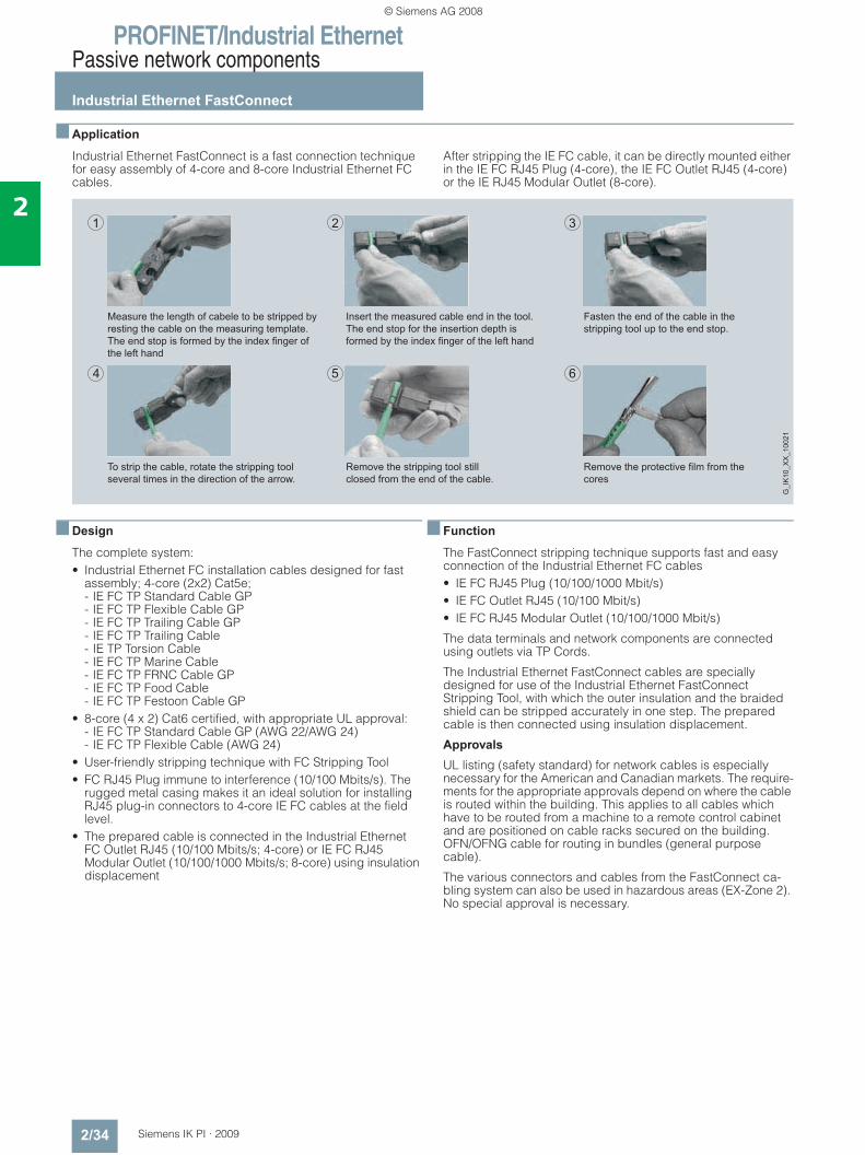
Fasten the end of the cable in the stripping tool up to the end stop.
Insert the measured cable end in the tool.The end stop for the insertion depth is formed by the index finger of the left hand
Measure the length of cabele to be stripped by resting the cable on the measuring template. The end stop is formed by the index finger of the left hand
Remove the protective film from the cores
Remove the stripping tool still closed from the end of the cable.
To strip the cable, rotate the stripping tool several times in the direction of the arrow.
G_I
K10
_XX
_100
21
© Siemens AG 2008
PROFINET/Industrial EthernetPassive network components
IE FC RJ45 Plug 2 x 2
2/35Siemens IK PI · 2009
2
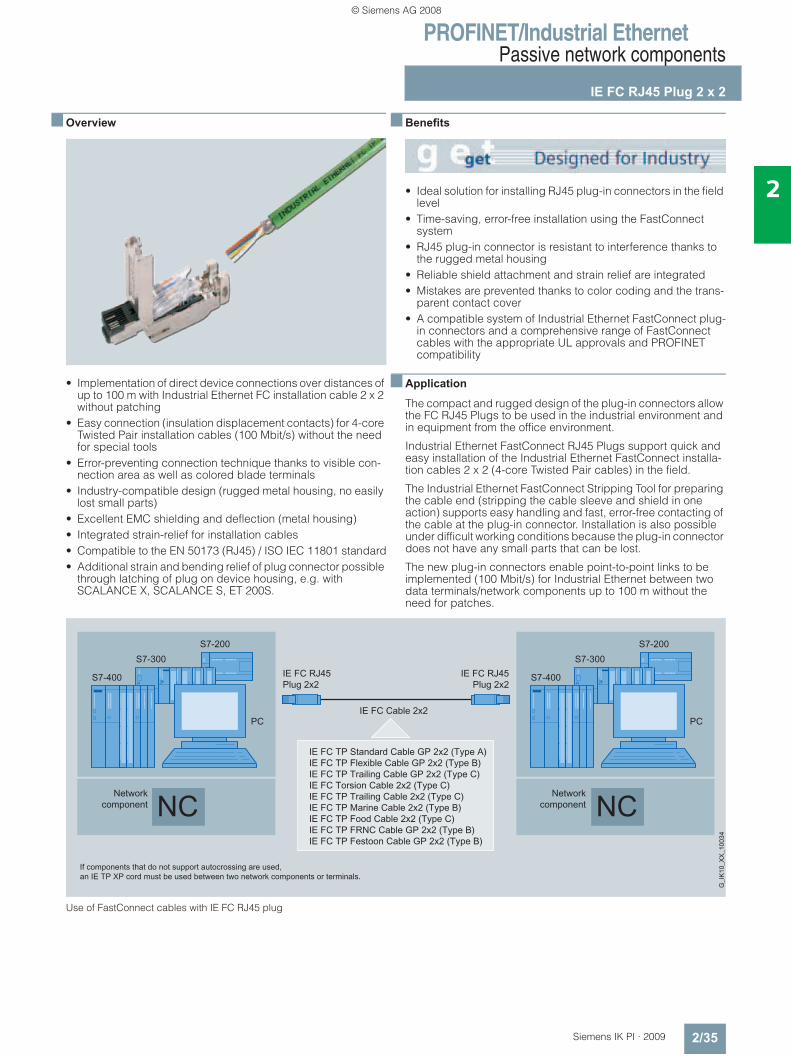
■ Overview
• Implementation of direct device connections over distances of up to 100 m with Industrial Ethernet FC installation cable 2 x 2 without patching
• Easy connection (insulation displacement contacts) for 4-core Twisted Pair installation cables (100 Mbit/s) without the need for special tools
• Error-preventing connection technique thanks to visible con-nection area as well as colored blade terminals
• Industry-compatible design (rugged metal housing, no easily lost small parts)
• Excellent EMC shielding and deflection (metal housing)• Integrated strain-relief for installation cables• Compatible to the EN 50173 (RJ45) / ISO IEC 11801 standard• Additional strain and bending relief of plug connector possible
through latching of plug on device housing, e.g. with SCALANCE X, SCALANCE S, ET 200S.
■ Benefits
• Ideal solution for installing RJ45 plug-in connectors in the field level
• Time-saving, error-free installation using the FastConnect system
• RJ45 plug-in connector is resistant to interference thanks to the rugged metal housing
• Reliable shield attachment and strain relief are integrated• Mistakes are prevented thanks to color coding and the trans-
parent contact cover• A compatible system of Industrial Ethernet FastConnect plug-
in connectors and a comprehensive range of FastConnect cables with the appropriate UL approvals and PROFINET compatibility
■ Application
The compact and rugged design of the plug-in connectors allow the FC RJ45 Plugs to be used in the industrial environment and in equipment from the office environment.
Industrial Ethernet FastConnect RJ45 Plugs support quick and easy installation of the Industrial Ethernet FastConnect installa-tion cables 2 x 2 (4-core Twisted Pair cables) in the field.
The Industrial Ethernet FastConnect Stripping Tool for preparing the cable end (stripping the cable sleeve and shield in one action) supports easy handling and fast, error-free contacting of the cable at the plug-in connector. Installation is also possible under difficult working conditions because the plug-in connector does not have any small parts that can be lost.
The new plug-in connectors enable point-to-point links to be implemented (100 Mbit/s) for Industrial Ethernet between two data terminals/network components up to 100 m without the need for patches.
Use of FastConnect cables with IE FC RJ45 plug
© Siemens AG 2008
PROFINET/Industrial EthernetPassive network components
IE FC RJ45 Plug 2 x 2
2/36 Siemens IK PI · 2009
2
■ Design
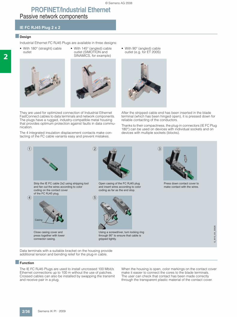
Industrial Ethernet FC RJ45 Plugs are available in three designs:
They are used for optimized connection of Industrial Ethernet FastConnect cables to data terminals and network components. The plugs have a rugged, industry-compatible metal housing that provides optimum protection against faults in data commu-nication.
The 4 integrated insulation displacement contacts make con-tacting of the FC cable variants easy and prevent mistakes.
After the stripped cable end has been inserted in the blade terminal (which has been hinged open), it is pressed down for reliable contacting of the conductors.
Thanks to their compactness, the plug-in connectors (IE FC Plug 180°) can be used on devices with individual sockets and on devices with multiple sockets (blocks).
Data terminals with a suitable bracket on the housing provide additional tension and bending relief for the plug-in cable.
■ Function
The IE FC RJ45 Plugs are used to install uncrossed 100 Mbit/s Ethernet connections up to 100 m without the use of patches. Crossed cables can also be installed by swapping the transmit and receive pair in a plug.
When the housing is open, color markings on the contact cover make it easier to connect the cores to the blade terminals. The user can check that contact has been made correctly through the transparent plastic material of the contact cover.
• With 180° (straight) cable outlet
• With 145° (angled) cable outlet (SIMOTION and SINAMICS, for example)
• With 90° (angled) cable outlet (e.g. for ET 200S)
Press down contact cover tomake contact with the wires.
Using a screwdriver, turn locking ringthrough 90° to ensure that cable isgripped tightly.
Close casing cover andpress together with lowerconnector casing.
Open casing of the FC RJ45 plugand insert wires according to colorcoding as far as the end stop.
Strip the IE FC cable 2x2 using stripping tooland fan out the wires according to color coding on the contact coverof the FC RJ45 plug.
Casing
G_I
K10
_XX
_300
26
© Siemens AG 2008
PROFINET/Industrial EthernetPassive network components
IE FC RJ45 Plug 2 x 2
2/37Siemens IK PI · 2009
2
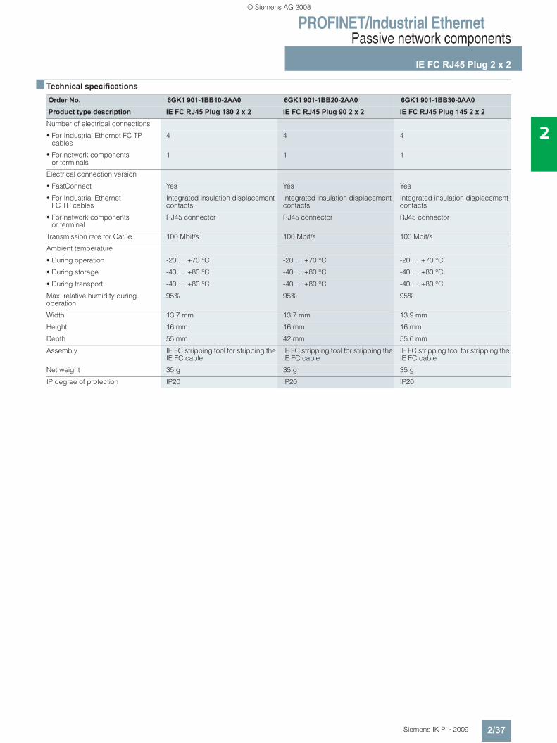
■ Technical specifications
Order No. 6GK1 901-1BB10-2AA0 6GK1 901-1BB20-2AA0 6GK1 901-1BB30-0AA0Product type description IE FC RJ45 Plug 180 2 x 2 IE FC RJ45 Plug 90 2 x 2 IE FC RJ45 Plug 145 2 x 2
Number of electrical connections
• For Industrial Ethernet FC TP cables
4 4 4
• For network components or terminals
1 1 1
Electrical connection version
• FastConnect Yes Yes Yes
• For Industrial Ethernet FC TP cables
Integrated insulation displacement contacts
Integrated insulation displacement contacts
Integrated insulation displacement contacts
• For network components or terminal
RJ45 connector RJ45 connector RJ45 connector
Transmission rate for Cat5e 100 Mbit/s 100 Mbit/s 100 Mbit/s
Ambient temperature
• During operation -20 … +70 °C -20 … +70 °C -20 … +70 °C
• During storage -40 … +80 °C -40 … +80 °C -40 … +80 °C
• During transport -40 … +80 °C -40 … +80 °C -40 … +80 °C
Max. relative humidity during operation
95% 95% 95%
Width 13.7 mm 13.7 mm 13.9 mm
Height 16 mm 16 mm 16 mm
Depth 55 mm 42 mm 55.6 mm
Assembly IE FC stripping tool for stripping the IE FC cable
IE FC stripping tool for stripping the IE FC cable
IE FC stripping tool for stripping the IE FC cable
Net weight 35 g 35 g 35 g
IP degree of protection IP20 IP20 IP20
© Siemens AG 2008
PROFINET/Industrial EthernetPassive network components
IE FC RJ45 Plug 2 x 2
2/38 Siemens IK PI · 2009
2
■ Ordering data Order No. Order No.
IE FC RJ45 plugsRJ45 plug connector for Industrial Ethernet with a rugged metal housing and integrated insulation displacement contacts for connecting Industrial Ethernet FC installation cables
IE FC RJ45 Plug 180180° cable outlet; for network components and CPs/CPUs with Industrial Ethernet interface
• 1 pack = 1 item 6GK1 901-1BB10-2AA0• 1 pack = 10 items 6GK1 901-1BB10-2AB0• 1 pack = 50 items 6GK1 901-1BB10-2AE0IE FC RJ45 Plug 9090° cable outlet; e.g. for ET 200S
• 1 pack = 1 item 6GK1 901-1BB20-2AA0• 1 pack = 10 units 6GK1 901-1BB20-2AB0• 1 pack = 50 units 6GK1 901-1BB20-2AE0IE FC RJ45 Plug 145145° cable outlet; e.g. for SIMOTION and SINAMICS
• 1 pack = 1 item 6GK1 901-1BB30-0AA0• 1 pack = 10 units 6GK1 901-1BB30-0AB0• 1 pack = 50 units 6GK1 901-1BB30-0AE0IE FC stripping tool 6GK1 901-1GA00Preadjusted stripping toolfor fast stripping of Industrial Ethernet FC cables
IE FC TP Standard Cable GP 2 x 2 (Type A)4-core, shielded TP installation cable for connection to IE FC Outlet RJ45/ IE FC RJ45 Plug; PROFINET-compatible; with UL approval;
Sold by the meter
max. quantity 1,000 m; minimum order 20 m
6XV1 840-2AH10
Preferred length
• 1000 m 6XV1 840-2AU10
IE FC TP Flexible Cable GP 2 x 2 (Type B)
6XV1 870-2B
4-core, shielded TP installation cable for connection to IE FC Outlet RJ45/ IE FC RJ45 Plug for occasional movement; PROFINET-compatible;with UL approval; sold by the meter; max. quantity 1000 m, minimum order 20 m
IE FC TP Trailing Cable GP 2 x 2 (Type C)
6XV1 870-2D
4-core, shielded TP installation cable for connection to IE FC Outlet RJ45/ IE FC RJ45 Plug for use in trailing cables; PROFINET-compatible;with UL approval; sold by the meter; max. quantity 1000 m, minimum order 20 m
IE FC TP Trailing Cable 2 x 2 (Type C)
6XV1 840-3AH10
4-core, shielded TP installation cable for connection to IE FC Outlet RJ45/ IE FC RJ45 Plug 180/90 for use in trailing cables; PROFINET-compatible; without UL approval; sold by the meter; max. quantity 1000 m, minimum order 20 m
IE TP Torsion Cable GP 2 x 2 (Type C)
6XV1 870-2F
4-core, shielded TP installation cable for connection to IE FC Outlet RJ45/ IE FC RJ45 Plug for use with robots; PROFINET-compatible; with UL approval; sold by the meter; max. quantity 1000 m, minimum order 20 m
IE FC TP Marine Cable 2 x 2 (Type B)
6XV1 840-4AH10
4-core, shielded TP installation cable for connection to IE FC Outlet RJ45/ IE FC RJ45 Plug 180/90; marine approval; max. quantity 1000 m,minimum order 20 m
IE FC TP FRNC Cable GP 2 x 2 (Type B)
6XV1 871-2F
4-core, shielded, halogen-free TP installation cable for connection to IE FC Outlet RJ45/ IE FC RJ45 Plug for occasional movement; PROFINET-compatible; with UL approval; sold by the meter; max. length 1000 m, minimum order 20 m
IE FC TP Festoon Cable GP 2 x 2 (Type B)
6XV1 871-2S
4-core, shielded TP installation cable for connection to IE FC Outlet RJ45/IE FC RJ45 Plug 180/90 for use in festoon applica-tions; PROFINET-compatible; with UL approval; sold by the meter; max. length 1000 m, minimum order 20 m
IE FC TP Food Cable GP 2 x 2 (Type C)
6XV1 871-2L
4-core, shielded TP installation cable for connection to IE FC Outlet RJ45/ IE FC RJ45 Plug 180/90 for the food and bever-ages industry; PROFINET-compliant; sold by the meter; max. length 1000 m, minimum order 20 m
IE FC Blade Cassettes (5 mm) 6GK1 901-1GB01Replacement blade cassette for the Industrial Ethernet stripping tool; for use with IE FC RJ45 Plugs and Modular Outlet,5 items
© Siemens AG 2008
PROFINET/Industrial EthernetPassive network components
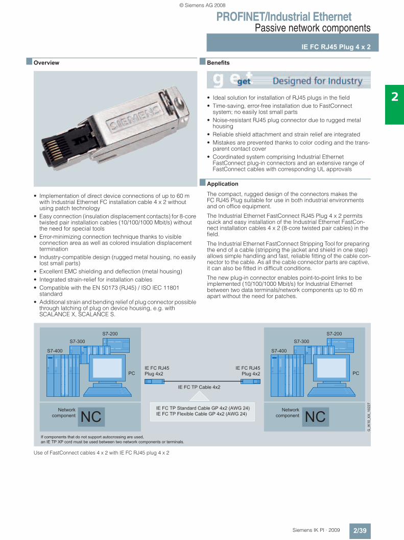
IE FC RJ45 Plug 4 x 2
2/39Siemens IK PI · 2009
2
■ Overview
• Implementation of direct device connections of up to 60 m with Industrial Ethernet FC installation cable 4 x 2 without using patch technology
• Easy connection (insulation displacement contacts) for 8-core twisted pair installation cables (10/100/1000 Mbit/s) without the need for special tools
• Error-minimizing connection technique thanks to visible connection area as well as colored insulation displacement termination
• Industry-compatible design (rugged metal housing, no easily lost small parts)
• Excellent EMC shielding and deflection (metal housing)• Integrated strain-relief for installation cables• Compatible with the EN 50173 (RJ45) / ISO IEC 11801
standard• Additional strain and bending relief of plug connector possible
through latching of plug on device housing, e.g. with SCALANCE X, SCALANCE S.
■ Benefits
• Ideal solution for installation of RJ45 plugs in the field• Time-saving, error-free installation due to FastConnect
system; no easily lost small parts• Noise-resistant RJ45 plug connector due to rugged metal
housing• Reliable shield attachment and strain relief are integrated• Mistakes are prevented thanks to color coding and the trans-
parent contact cover• Coordinated system comprising Industrial Ethernet
FastConnect plug-in connectors and an extensive range of FastConnect cables with corresponding UL approvals
■ Application
The compact, rugged design of the connectors makes the FC RJ45 Plug suitable for use in both industrial environments and on office equipment.
The Industrial Ethernet FastConnect RJ45 Plug 4 x 2 permits quick and easy installation of the Industrial Ethernet FastCon-nect installation cables 4 x 2 (8-core twisted pair cables) in the field.
The Industrial Ethernet FastConnect Stripping Tool for preparing the end of a cable (stripping the jacket and shield in one step) allows simple handling and fast, reliable fitting of the cable con-nector to the cable. As all the cable connector parts are captive, it can also be fitted in difficult conditions.
The new plug-in connector enables point-to-point links to be implemented (10/100/1000 Mbit/s) for Industrial Ethernet between two data terminals/network components up to 60 m apart without the need for patches.
Use of FastConnect cables 4 x 2 with IE FC RJ45 plug 4 x 2
© Siemens AG 2008
PROFINET/Industrial EthernetPassive network components
IE FC RJ45 Plug 4 x 2
2/40 Siemens IK PI · 2009
2
■ Design
The Industrial Ethernet FC RJ45 Plug 4 x 2 is available with a 180° (straight) cable outlet.
It is the ideal method of connecting an Industrial Ethernet Fast-Connect cable to data terminals and network components. The plug has a rugged, industry-compatible metal housing that pro-vides optimum protection against faults in data communication.
The eight integrated insulation displacement contacts make contacting of the FC cable variants 4 x 2 and 2 x 2 easy and pre-vent mistakes. After the stripped cable end has been inserted in the insulation displacement terminals, the conductors make contact when the casing is closed.
Owing to their compact size, the plug connectors can be used both on devices with individual jacks and on devices with multi-ple jacks (blocks).
Data terminals with a suitable bracket on the housing provide additional tension and bending relief for the plug-in cable.
■ Function
The IE FC RJ45 Plug 4 x 2 is used to install uncrossed 10/100/1000 Mbit/s Ethernet connections up to 60 m without the use of patches. Crossed cables can also be installed by swap-ping the transmit and receive pair in a plug.
With the casing open, colored markers on the contact element make it simple to connect the cores to the insulation displace-ment contacts. The transparent synthetic material of the contact element allows users to check the contacts themselves.
■ Technical specifications
■ Ordering data Order No.
Order No. 6GK1 901-1BB11-2AA0Product type description IE FC RJ45 Plug 4 x 2
Number of electrical connections
• for Industrial Ethernet FC TP cables
8
• for network components or terminals
1
Electrical connection version
• FastConnect Yes
• for Industrial Ethernet FC TP cables
integrated insulation displace-ment contacts
• for network components or terminals
RJ45 connector
Transmission rate for Cat6 10/100/1000 Mbit/s
Ambient temperature
• during operating phase -20 … +70 °C
• during storage -40 … +80 °C
• during transport -40 … +80 °C
Max. relative humidity during operating phase
95 %
Width 13.7 mm
Height 16 mm
Depth 55 mm
Assembly IE FC stripping tool for stripping the IE FC cable
Net weight 35 g
Degree of protection IP20
IE FC RJ45 Plug 4 x 2RJ45 plug connector for Industrial Ethernet (10/100/1000 Mbit/s) with a rugged metal housing and integrated insulation displace-ment contacts for connecting Industrial Ethernet FC installation cables; 180° cable outlet; for network components and CPs/CPUs with Industrial Ethernet interface
• 1 pack = 1 unit 6GK1 901-1BB11-2AA0• 1 pack = 10 units 6GK1 901-1BB11-2AB0• 1 pack = 50 units 6GK1 901-1BB11-2AE0IE FC stripping tool 6GK1 901-1GA00Pre-adjusted stripping toolfor fast stripping of Industrial Ethernet FC cables
IE FC TP Standard Cable GP 4 x 2 8-core, shielded TP installation cable for universal applications; with UL approval; sold by the meter; max. length 1000 m, minimum order 20 m
• AWG 22, for connection to IE FC RJ45 Modular Outlet
6XV1 870-2E
• AWG 24, for connection to IE FC RJ45 Plug 4 x 2
6XV1 878-2A
IE FC TP Flexible Cable GP 4 x 2 8-core, shielded TP installation cable for occasional movement; with UL approval; sold by the meter; max. quantity 1000 m, minimum order 20 m
• AWG 24, for connection to IE FC RJ45 Plug 4 x 2
6XV1 878-2B
IE FC blade cassettes (5 mm) 6GK1 901-1GB01Replacement blade cassette for the Industrial Ethernet strip-ping tool; for use with IE FC RJ45 Plugs and Modular Outlet, 5 units
© Siemens AG 2008
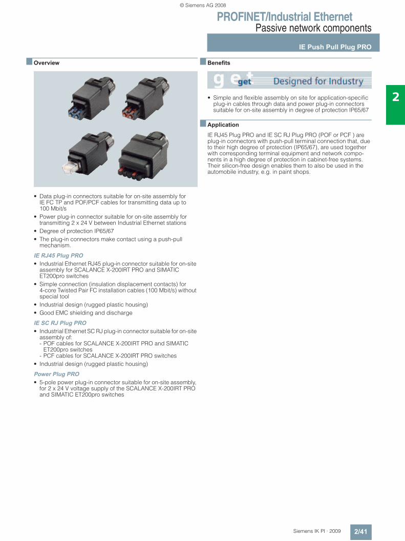
PROFINET/Industrial EthernetPassive network components
IE Push Pull Plug PRO
2/41Siemens IK PI · 2009
2
■ Overview
• Data plug-in connectors suitable for on-site assembly for IE FC TP and POF/PCF cables for transmitting data up to 100 Mbit/s
• Power plug-in connector suitable for on-site assembly for transmitting 2 x 24 V between Industrial Ethernet stations
• Degree of protection IP65/67 • The plug-in connectors make contact using a push-pull
mechanism.
IE RJ45 Plug PRO• Industrial Ethernet RJ45 plug-in connector suitable for on-site
assembly for SCALANCE X-200IRT PRO and SIMATIC ET200pro switches
• Simple connection (insulation displacement contacts) for 4-core Twisted Pair FC installation cables (100 Mbit/s) without special tool
• Industrial design (rugged plastic housing) • Good EMC shielding and discharge
IE SC RJ Plug PRO• Industrial Ethernet SC RJ plug-in connector suitable for on-site
assembly of: - POF cables for SCALANCE X-200IRT PRO and SIMATIC
ET200pro switches- PCF cables for SCALANCE X-200IRT PRO switches
• Industrial design (rugged plastic housing)
Power Plug PRO• 5-pole power plug-in connector suitable for on-site assembly,
for 2 x 24 V voltage supply of the SCALANCE X-200IRT PRO and SIMATIC ET200pro switches
■ Benefits
• Simple and flexible assembly on site for application-specific plug-in cables through data and power plug-in connectors suitable for on-site assembly in degree of protection IP65/67
■ Application
IE RJ45 Plug PRO and IE SC RJ Plug PRO (POF or PCF ) are plug-in connectors with push-pull terminal connection that, due to their high degree of protection (IP65/67), are used together with corresponding terminal equipment and network compo-nents in a high degree of protection in cabinet-free systems. Their silicon-free design enables them to also be used in the automobile industry, e.g. in paint shops.
© Siemens AG 2008
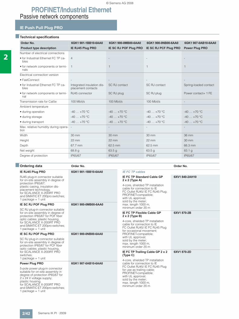
PROFINET/Industrial EthernetPassive network components
IE Push Pull Plug PRO
2/42 Siemens IK PI · 2009
2
■ Technical specifications
■ Ordering data Order No. Order No.
Order No. 6GK1 901-1BB10-6AA0 6GK1 900-0MB00-6AA0 6GK1 900-0NB00-6AA0 6GK1 907-0AB10-6AA0Product type description IE RJ45 Plug PRO IE SC RJ POF Plug PRO IE SC RJ PCF Plug PRO Power Plug PRO
Number of electrical connections
• for Industrial Ethernet FC TP ca-bles
4 - - -
• for network components or termi-nals
1 1 1 1
Electrical connection version
• FastConnect - - - -
• for Industrial Ethernet FC TP ca-bles
Integrated insulation dis-placement contacts
SC RJ contact SC RJ contact Spring-loaded contact
• for network components or termi-nal
RJ45 connector SC RJ plug SC RJ plug Power contact+ 1 FE
Transmission rate for Cat5e 100 Mbit/s 100 Mbit/s 100 Mbit/s -
Ambient temperature
• during operation -40 … +70 °C -40 … +70 °C -40 … +70 °C -40 … +70 °C
• during storage -40 … +70 °C -40 … +70 °C -40 … +70 °C -40 … +70 °C
• during transport -40 … +70 °C -40 … +70 °C -40 … +70 °C -40 … +70 °C
Max. relative humidity during opera-tion
- - - -
Width 30 mm 30 mm 30 mm 36 mm
Height 22 mm 22 mm 22 mm 30 mm
Depth 67.7 mm 62.5 mm 62.5 mm 66.3 mm
Net weight 68.8 g 63.5 g 63.5 g 83.1 g
Degree of protection IP65/67 IP65/67 IP65/67 IP65/67
IE RJ45 Plug PRO 6GK1 901-1BB10-6AA0RJ45 plug-in connector suitable for on-site assembly in degree of protection IP65/67; plastic casing, insulation dis-placement technology, for SCALANCE X-200IRT PRO and SIMATIC ET 200pro switches; 1 package = 1 unit
IE SC RJ POF Plug PRO 6GK1 900-0MB00-6AA0SC RJ plug-in connector suitable for on-site assembly in degree of protection IP65/67 for POF fiber optic cables; plastic housing, for SCALANCE X-200IRT PRO and SIMATIC ET 200pro switches; 1 package = 1 unit
IE SC RJ POF Plug PRO 6GK1 900-0NB00-6AA0SC RJ plug-in connector suitable for on-site assembly in degree of protection IP65/67 for PCF fiber optic cables; plastic housing, for SCALANCE X-200IRT PRO switches; 1 package = 1 unit
Power Plug PRO 6GK1 907-0AB10-6AA05-pole power plug-in connector suitable for on-site assembly in degree of protection IP65/67 for 2 x 24 V voltage supply; plastic housing, for SCALANCE X-200IRT PRO and SIMATIC ET 200pro switches; 1 package = 1 unit
IE FC TP cablesIE FC TP Standard Cable GP 2 x 2 (Type A)
6XV1 840-2AH10
4-core, shielded TP installation cable for connection to IE FC Outlet RJ45/ IE FC RJ45 Plug; PROFINET-compatible; with UL approval; sold by the meter; max. length 1000 m, minimum order 20 m
IE FC TP Flexible Cable GP 2 x 2 (Type B)
6XV1 870-2B
4-core, shielded TP installation cable for connection to IE FC Outlet RJ45/ IE FC RJ45 Plug for occasional movement; PROFINET-compatible; with UL approval; sold by the meter; max. length 1000 m, minimum order 20 m
IE FC TP Trailing Cable GP 2 x 2 (Type C)
6XV1 870-2D
4-core, shielded TP installation cable for connection to IE FC Outlet RJ45/ IE FC RJ45 Plug for use as trailing cable; PROFINET-compatible; with UL approval; sold by the meter; max. length 1000 m, minimum order 20 m
© Siemens AG 2008
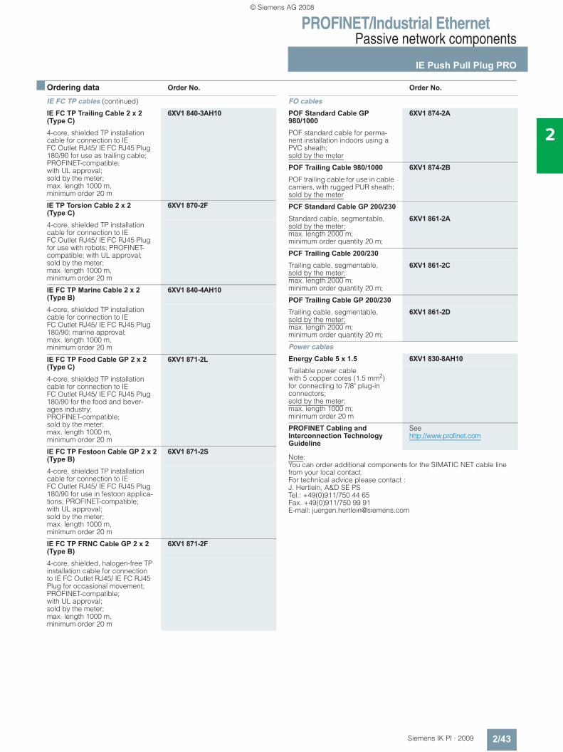
PROFINET/Industrial EthernetPassive network components
IE Push Pull Plug PRO
2/43Siemens IK PI · 2009
2
■ Ordering data Order No. Order No.
Note:You can order additional components for the SIMATIC NET cable line from your local contact.For technical advice please contact :J. Hertlein, A&D SE PSTel.: +49(0)911/750 44 65Fax. +49(0)911/750 99 91E-mail: [email protected]
IE FC TP cables (continued)
IE FC TP Trailing Cable 2 x 2 (Type C)
6XV1 840-3AH10
4-core, shielded TP installation cable for connection to IE FC Outlet RJ45/ IE FC RJ45 Plug 180/90 for use as trailing cable; PROFINET-compatible; with UL approval; sold by the meter; max. length 1000 m, minimum order 20 m
IE TP Torsion Cable 2 x 2 (Type C)
6XV1 870-2F
4-core, shielded TP installation cable for connection to IE FC Outlet RJ45/ IE FC RJ45 Plug for use with robots; PROFINET-compatible; with UL approval; sold by the meter; max. length 1000 m, minimum order 20 m
IE FC TP Marine Cable 2 x 2 (Type B)
6XV1 840-4AH10
4-core, shielded TP installation cable for connection to IE FC Outlet RJ45/ IE FC RJ45 Plug 180/90; marine approval; max. length 1000 m, minimum order 20 m
IE FC TP Food Cable GP 2 x 2 (Type C)
6XV1 871-2L
4-core, shielded TP installation cable for connection to IE FC Outlet RJ45/ IE FC RJ45 Plug 180/90 for the food and bever-ages industry; PROFINET-compatible; sold by the meter; max. length 1000 m, minimum order 20 m
IE FC TP Festoon Cable GP 2 x 2 (Type B)
6XV1 871-2S
4-core, shielded TP installation cable for connection to IE FC Outlet RJ45/ IE FC RJ45 Plug 180/90 for use in festoon applica-tions; PROFINET-compatible; with UL approval; sold by the meter; max. length 1000 m, minimum order 20 m
IE FC TP FRNC Cable GP 2 x 2 (Type B)
6XV1 871-2F
4-core, shielded, halogen-free TP installation cable for connection to IE FC Outlet RJ45/ IE FC RJ45 Plug for occasional movement; PROFINET-compatible; with UL approval; sold by the meter; max. length 1000 m, minimum order 20 m
FO cablesPOF Standard Cable GP 980/1000
6XV1 874-2A
POF standard cable for perma-nent installation indoors using a PVC sheath; sold by the meter
POF Trailing Cable 980/1000 6XV1 874-2BPOF trailing cable for use in cable carriers, with rugged PUR sheath; sold by the meter
PCF Standard Cable GP 200/230Standard cable, segmentable,sold by the meter;max. length 2000 m; minimum order quantity 20 m;
6XV1 861-2A
PCF Trailing Cable 200/230Trailing cable, segmentable,sold by the meter;max. length 2000 m; minimum order quantity 20 m;
6XV1 861-2C
POF Trailing Cable GP 200/230Trailing cable, segmentable,sold by the meter;max. length 2000 m; minimum order quantity 20 m;
6XV1 861-2D
Power cablesEnergy Cable 5 x 1.5 6XV1 830-8AH10Trailable power cable with 5 copper cores (1.5 mm2) for connecting to 7/8" plug-in connectors; sold by the meter; max. length 1000 m; minimum order 20 m
PROFINET Cabling and Interconnection Technology Guideline
See http://www.profinet.com
© Siemens AG 2008
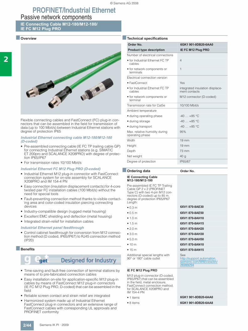
PROFINET/Industrial EthernetPassive network componentsIE Connecting Cable M12-180/M12-180/IE FC M12 Plug PRO
2/44 Siemens IK PI · 2009
2
■ Overview
Flexible connecting cables and FastConnect (FC) plug-in con-nectors that can be assembled in the field for transmission of data (up to 100 Mbit/s) between Industrial Ethernet stations with degree of protection IP65
Industrial Ethernet connecting cable M12-180/M12-180(D-coded)• Pre-assembled connecting cable (IE FC TP trailing cable GP)
for connecting Industrial Ethernet stations (e.g. SIMATIC ET 200pro and SCALANCE X208PRO) with degree of protec-tion IP65/IP67
• For transmission rates 10/100 Mbit/s
Industrial Ethernet FC M12 Plug PRO (D-coded)• Industrial Ethernet M12 plug-in connector with FastConnect
connection system for on-site assembly for SCALANCE X208PRO and IM 154-4 PN
• Easy connection (insulation displacement contacts) for 4-core twisted pair FC installation cables (100 Mbit/s) without the need for special tools
• Fault-preventing connection method thanks to visible contact-ing area and color-coded insulation piercing connecting devices
• Industry-compatible design (rugged metal housing)• Excellent EMC shielding and deflection (metal housing)• Integrated strain-relief for installation cables
Industrial Ethernet panel feedthrough• Control cabinet feedthrough for conversion from M12 connec-
tion method (D coded, IP65/IP67) to RJ45 connection method (IP20)
■ Benefits
• Time-saving and fault-free connection of terminal stations by means of to pre-fabricated connection cables
• Easy installation on-site for application-specific M12 plug-in cables by means of FastConnect M12 plug-in connectors (IE FC M12 Plug PRO, D-coded) that can be assembled in the field
• Reliable screen contact and strain relief are integrated• Harmonized system made up of Industrial Ethernet
FastConnect plug-in connectors and an extensive range of FastConnect cables with corresponding UL approvals and PROFINET conformity
■ Technical specifications
■ Ordering data Order No.
Order No. 6GK1 901-0DB20-6AA0Product type description IE FC M12 Plug PRO
Number of electrical connections
• for Industrial Ethernet FC TP cables
4
• for network components or terminals
1
Electrical connection version
• FastConnect Yes
• for Industrial Ethernet FC TP cables
integrated insulation displace-ment contacts
• for network components or terminal
M12 connector (D-coded)
Transmission rate for Cat5e 10/100 Mbit/s
Ambient temperature
• during operating phase -40 … +85 °C
• during storage -40 … +85 °C
• during transport -40 … +85 °C
Max. relative humidity during operating phase
95%
Width 19 mm
Height 19 mm
Depth 73 mm
Net weight 40 g
Degree of protection IP65/67
IE Connecting Cable M12-180/M12-180Pre-assembled IE FC TP Trailing Cable GP 2 x 2 (PROFINET Type C) with two 4-pin M12 con-nectors (D-coded) up to 85 m, degree of protection IP65/IP67 Length:
• 0.3 m 6XV1 870-8AE30
• 0.5 m 6XV1 870-8AE50• 1.0 m 6XV1 870-8AH10• 1.5 m 6XV1 870-8AH15• 2.0 m 6XV1 870-8AH20• 3.0 m 6XV1 870-8AH30• 5.0 m 6XV1 870-8AH50• 10 m 6XV1 870-8AN10• 15 m 6XV1 870-8AN15Additional special lengths with 90° or 180° cable outlet
See http://support.automation.siemens.com/WW/view/en/26999294
IE FC M12 Plug PROM12 plug-in connector (D-coded, IP65/IP67) that can be assembled in the field, metal enclosure, FastConnect connection method, for SCALANCE X208PRO and IM 154-4 PN
• 1 items 6GK1 901-0DB20-6AA0
• 8 items 6GK1 901-0DB20-6AA8
© Siemens AG 2008
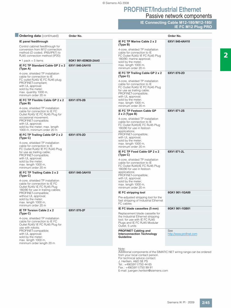
PROFINET/Industrial EthernetPassive network components
IE Connecting Cable M12-180/M12-180/IE FC M12 Plug PRO
2/45Siemens IK PI · 2009
2
■ Ordering data (continued) Order No. Order No.
Note:Additional components of the SIMATIC NET wiring range can be ordered from your local contact person.For technical advice contact:J. Hertlein, A&D SE PSTel.: +49(0)911/750 44 65Fax.: +49(0)911/750 99 91E-mail: [email protected]
IE panel feedthroughControl cabinet feedthrough for conversion from M12 connection method (D coded, IP65/IP67) to RJ45 connection method (IP20)
• 1 pack = 5 items 6GK1 901-0DM20-2AA5IE FC TP Standard Cable GP 2 x 2 (Type A)
6XV1 840-2AH10
4-core, shielded TP installation cable for connection to IE FC outlet RJ45/ IE FC RJ45 plug; PROFINET-compliant; with UL approval; sold by the meter; max. quantity 1000 m, minimum order 20 m
IE FC TP Flexible Cable GP 2 x 2 (Type B)
6XV1 870-2B
4-core, shielded TP installation cable for connection to IE FC Outlet RJ45/ IE FC RJ45 Plug for occasional movement; PROFINET-compatible; with UL approval; sold by the meter; max. length 1000 m, minimum order 20 m
IE FC TP Trailing Cable GP 2 x 2 (Type C)
6XV1 870-2D
4-core, shielded TP installation cable for connection to IE FC Outlet RJ45/ IE FC RJ45 Plug for use as trailing cable; PROFINET-compatible;with UL approval; sold by the meter; max. length 1000 m, minimum order 20 m
IE FC TP Trailing Cable 2 x 2 (Type C)
6XV1 840-3AH10
4-core, shielded TP installation cable for connection to IE FC Outlet RJ45/ IE FC RJ45 Plug 180/90 for use in trailing cables; PROFINET-compatible; without UL approval; sold by the meter; max. length 1000 m, minimum order 20 m
IE TP Torsion Cable 2 x 2 (Type C)
6XV1 870-2F
4-core, shielded TP installation cable for connection to IE FC Outlet RJ45/ IE FC RJ45 Plug for use with robots; PROFINET-compatible; with UL approval; sold by the meter; max. length 1000 m, minimum order length 20 m
IE FC TP Marine Cable 2 x 2 (Type B)
6XV1 840-4AH10
4-core, shielded TP installation cable for connection to IE FC Outlet RJ45/ IE FC RJ45 Plug 180/90; marine approval; sold by the meter, max. length 1000 m, minimum order 20 m
IE FC TP Trailing Cable GP 2 x 2 (Type C)
6XV1 870-2D
4-core, shielded TP installation cable for connection to IE FC Outlet RJ45/ IE FC RJ45 Plug for use as trailing cable; PROFINET-compatible; with UL approval; sold by the meter; max. length 1000 m, minimum order 20 m
IE FC TP Festoon Cable GP 2 x 2 (Type B)
6XV1 871-2S
4-core, shielded TP installation cable for connection to IE FC Outlet RJ45/IE FC RJ45 Plug 180/90 for use in festoon applications; PROFINET-compatible; with UL approval; sold by the meter; max. length 1000 m, minimum order 20 m
IE FC TP Food Cable GP 2 x 2 (Type C)
6XV1 871-2L
4-core, shielded TP installation cable for connection to IE FC Outlet RJ45/IE FC RJ45 Plug 180/90 for use in festoon applications; PROFINET-compatible; with UL approval; sold by the meter; max. length 1000 m, minimum order 20 m
IE FC stripping tool 6GK1 901-1GA00Pre-adjusted stripping tool for the fast stripping of Industrial Ethernet FC cables
IE FC blade cassettes (5 mm) 6GK1 901-1GB01Replacement blade cassette for the Industrial Ethernet stripping tool; for use with IE FC RJ45 Plugs and IE FC RJ45 Modular Outlet, 5 units
PROFINET Cabling and Interconnection Technology Guideline
See http://www.profinet.com
© Siemens AG 2008
PROFINET/Industrial EthernetPassive network components
IE FC TP Cable 2 x 2
2/46 Siemens IK PI · 2009
2
■ Overview
• For structured cabling in the factory hall; specially designed for fast assembly
• Easy stripping with the FastConnect Stripping Tool; the outer sheath and the braided shield are stripped accurately in one step
• Connection to FastConnect products using insulation dis-placement
• Exceeds Category 5 (Cat5e) of the international cabling standards ISO/IEC 11801 and EN 50173
• PROFINET-compatible• UL approval• Different variants for different applications
- IE FC TP Standard Cable GP- IE FC TP Flexible Cable GP- IE FC TP FRNC Cable GP- IE FC TP Trailing Cable GP- IE FC TP Trailing Cable- IE FC TP Festoon Cable- IE FC TP Festoon Cable GP- IE TP Torsion Cable- IE FC TP Food Cable- IE FC TP Marine Cable
• High interference immunity thanks to double shielding• Easy length measurement thanks to printed meter markings
■ Benefits
• Time-saving due to simple and quick assembly with FastConnect cables 2 x 2 to Industrial Ethernet FC outlet RJ45 (10/100 Mbit/s) or Industrial Ethernet FC RJ45 plug 180/90.
• Time-saving due to simple and quick assembly with FastConnect cables 2 x 2 to Industrial Ethernet FC RJ45 plugs.
• Versatile application due to special bus cables• Noise immune network due to double-shielded cables and
integrated grounding concept.• Silicone-free and therefore suitable for use in the automotive
industry (for example in paint shops)
■ Application
For the construction of Industrial Ethernet networks (4-core), different cable types are offered to suit the different types of application.
In general, the listed Industrial Ethernet FC cables IE FC Cable 2 x 2 must be used.
Note:You will find other specifications of the network topology in the manual for TP and fiber optic networks.
UL approvalsDifferent cable versions are offered with appropriate UL approv-als for laying in cable bundles and cable racks according to the specifications of NEC (National Electrical Code) Article 800/725. These are identified as GP (General Purpose).
■ Design
The FastConnect (FC) Industrial Ethernet cables IE FC Cable 2 x 2 are designed with radial symmetry and therefore allow the use of the FC Stripping Tool The IE FC Outlet RJ45 and the IE FC RJ45 Plug can therefore be attached quickly and easily.• The double shield makes it especially suitable for routing
through industrial areas with strong electro-magnetic fields• Easy connection to the insulation displacement contacts of the
FC RJ45 plug without the need for special tools• System-wide grounding concept can be implemented through
the outer shield of the bus cable as well as through the grounding concept of the IE FC Outlet RJ45 and the IE FC RJ45 Plugs
• Printed meter marks
���������
�����������
� �������������
�� ��� ���
�� ����� ���
��������
����������� �� �
�����
�����
����
����
© Siemens AG 2008
PROFINET/Industrial EthernetPassive network components
IE FC TP Cable 2 x 2
2/47Siemens IK PI · 2009
2
■ Design (continued)
Cable types • IE FC TP Standard Cable GP 2 x 2:
Standard bus cable with rigid cores specially designed for fast installation; four rigid cores connected in a four-branch star
• IE FC TP Flexible Cable GP 2 x 2: Flexible bus cable for the special application of occasional motion control; four stranded cores connected in a four branch star
• IE FC TP FRNC Cable GP 2 x 2: Flexible, halogen-free cable for use in buildings (FRNC= Flame Retardant Non Corrosive); four conductors (flexible leads) stranded into star-quad for occasional movement
• IE FC TP Trailing Cable GP / IE FC TP Trailing Cable 2 x 2: Highly flexible bus cable for the special application of con-stant motion control in a cable carrier, e.g. for continuously moving machine parts; four stranded cores connected in a four branch star
• IE FC Festoon Cable GP 2 x 2: Flexible cable for special use in constant movement in a cable trail/festoon arrangement, e.g. on crane systems; four cores (stranded) in twisted quads
• IE TP Torsion Cable 2 x 2: Highly flexible bus cable for the special application of contin-uous motion control, e.g. for use with robots; stranded cores
• IE FC TP Food Cable 2 x 2: Flexible cable for special use in the food and beverages in-dustry; four cores (stranded) in twisted quads
• IE FC TP Marine Cable 2 x 2: Bus cable for marine applications; four cores (stranded) connected in a four branch star, halogen-free, certified for marine applications
Product overview IE FC TP Cable 2 x 2 (PROFINET-compatible according to "PROFINET Cabling and Interconnection Technology Guideline1))
1) Available as a download under http://www.profinet.com
PROFINET Type A PROFINET Type B PROFINET Type CAWG 22/1 rigid laying
AWG 22/7 flexible cable for occasional movement
AWG 22 highly flexible cablefor continuous motion, e.g. cable carrier or robots
IE FC TP Standard Cable GP 2 x 2 (Type A) 6XV1 840-2AH10
● – –
IE FC TP Flexible Cable GP 2 x 2 (Type B)6XV1 870-2B
– ● –
IE FC TP FRNC Cable GP 2 x 2 (Type B)6XV1 871-2F)
– ● –
IE FC TP Trailing Cable GP 2 x 2 (Type C)6XV1 870-2D
– ● ●
IE FC TP Trailing Cable 2 x 2 (Type C)6XV1 840-3AH10
– – ●
IE FC TP Festoon Cable GP 2 x 2 (Type B)6XV1871-2S
– ● –
IE TP Torsion Cable 2 x 2 (Type C)6XV1 870-2F
– – ●
IE FC TP Food Cable 2 x 2 (Type C)6XV1871-2L
– – ●
IE FC TP Marine Cable 2 x 2 (Type B)6XV1 840-4AH10
– ● –
© Siemens AG 2008
PROFINET/Industrial EthernetPassive network components
IE FC TP Cable 2 x 2
2/48 Siemens IK PI · 2009
2
■ Technical specifications
Order No. 6XV1 840-2AH10 6XV1 870-2B 6XV1 870-2DProduct type description IE FC Standard Cable GP 2 x 2
(Type A) IE FC Flexible Cable GP 2 x 2 (Type A)
IE FC Trailing Cable GP 2 x 2 (Type C)
Suitability for use All-purpose Occasional movement In cable carriers
Cable name 2YY (ST) CY 2x2x0.64/1.5-100 GN 2YY (ST) CY 2x2x0.75/1.5-100 LI GN
2YY (ST) CY 2x2x0,75/1.5-100 LI GN
Standard for structured cabling Cat5e Cat5e Cat5e
Electrical data
Attenuation measurement per length
• at 10 MHz 5.2 dB/100 m 6.0 dB/100 m 6.3 dB/100 m
• at 100 MHz 19.5 dB/100 m 21.0 dB/100 m 21.3 dB/100 m
Characteristic impedance at 1 MHz ... 100 MHz
100 Ω 100 Ω 100 Ω
• Relative symmetrical tolerance of characteristic impedance at 1 MHz ... 100 MHz
± 15% ± 15% ± 15%
Near-end crosstalk attenuation per length at 1 MHz ... 100 MHz
50.0 dB/100 m 50.0 dB/100 m 50.0 dB/100 m
Surface transfer impedance at 10 MHz
10 mOhm/m 20 mOhm/m 20 mOhm/m
Loop resistance per length 115 Ohm/km 120 Ohm/km 120 Ohm/km
Coefficient of insulation resistance 500 MOhm *km 500 MOhm *km 500 MOhm *km
Mechanical data
Outer diameter
• of the inner conductor 0,64 mm 0,75 mm 0,75 mm
• AWG cross-section AWG 22 AWG 22 AWG 22
• of the wire insulation 1.5 mm 1.5 mm 1.5 mm
• of the inner sheath of the cable 3.9 mm 3.9 mm 3.9 mm
• of the cable sheath 6.5 mm 6.5 mm 6.5 mm
• Symmetrical tolerance of the outer diameter of the cable sheath
0.2 mm 0.2 mm 0.2 mm
Ambient temperature
• during operation -40 … +70 °C -25 … +70 °C -10 … +70 °C
• during transport -40 … +70 °C -25 … +70 °C -25 … +75 °C
• during storage -40 … +70 °C -25 … +70 °C -25 … +75 °C
• during installation -20 … +60 °C -10 … +60 °C -10 … +60 °C
Bending radius
• for one-off bending 19.5 mm 32.5 mm 32.5 mm
• for repeated bending 49 mm 52 mm 49 mm
Number of bending cycles - - 3000000
Tensile load, max. 150 N 150 N 150 N
Weight per length 67 kg/km 68 kg/km 68 kg/km
Fire behavior Flame retardant to UL 1685 (CSA FT 4)
Flame retardant to UL 1685 (CSA FT 4)
Flame retardant to UL 1685 (CSA FT 4)
Chemical resistance to mineral oil conditional resistance conditional resistance conditional resistance
Radiological resistance to UV radiation
resistant resistant resistant
Product property
• halogen-free No No No
• Silicone-free Yes Yes Yes
FastConnect electrical connection version
Yes Yes Yes
UL listing at 300 V rating Yes/CM/SMG/PLTC/Sun Res Yes/CM/CMG/PLTC/Sun Res Yes/CMG/PLTC/Sun Res
UL style at 600 V rating Yes No Yes
Marine classification association - - -
© Siemens AG 2008
PROFINET/Industrial EthernetPassive network components
IE FC TP Cable 2 x 2
2/49Siemens IK PI · 2009
2
■ Technical specifications (continued)
Order No. 6XV1 870-2F 6XV1 840-3AH10 6XV1 840-4AH10Product type description IE TP Torsion Cable 2 x 2 (Type C) IE FC Trailing Cable 2 x 2 (Type C) IE FC Marine Cable 2 x 2 (Type B)
Suitability for use Use with robots In cable carriers Marine and offshore use
Cable name 02YS C11Y 1 x 4 x 0.75/1.5-100LI GN VZN FRNC
2YH (ST) C11Y 2 x 2 x 0.75/1.5-100 LI GN VZN FRNC
L-9YH (ST) CH 2 x 2 x 0.34/1.5-100 GN VZN FRNC
Standard for structured cabling Cat5e Cat5e Cat5e
Electrical data Attenuation measurement per length• at 10 MHz 8.1 dB/100 m 6.0 dB/100 m 6.0 dB/100 m• at 100 MHz 41.0 dB/100 m 22.0 dB/100 m 22.0 dB/100 m
Characteristic impedance at 1 MHz ... 100 MHz
100 Ω 100 Ω 100 Ω
• Relative symmetrical tolerance of characteristic impedance at 1 MHz ... 100 MHz
± 15% ± 15% ± 15%
Near-end crosstalk attenuation per length at 1 MHz ... 100 MHz
50.0 dB/100 m 50.0 dB/100 m 50.0 dB/100 m
Surface transfer impedance at 10 MHz
100 mOhm/m 10 mOhm/m 10 mOhm/m
Loop resistance per length 120 Ohm/km 120 Ohm/km 120 Ohm/km
Coefficient of insulation resistance 500 MOhm *km 500 MOhm *km 500 MOhm *km
Mechanical data Outer diameter• of the inner conductor 0.76 mm 0.75 mm 0.75 mm• of the wire insulation 1.5 mm 1.5 mm 1.5 mm• of the inner sheath of the cable 4.6 mm 3.9 mm 3.9 mm• of the cable sheath 6.5 mm 6.5 mm 6.5 mm• symmetrical tolerance
of the outer diameter of the cable sheath
0.2 mm 0.2 mm 0.2 mm
Material• of the wire insulation PE PE PP• of the inner sheath of the cable - FRNC FRNC• of the cable sheath PUR PUR FRNC
Ambient temperature• during operation -40 … +80 °C -40 … +70 °C -25 … +70 °C• during transport -40 … +80 °C -40 … +70 °C -40 … +70 °C• during storage -40 … +80 °C -40 … +70 °C -40 … +70 °C• during installation -20 … +60 °C -20 … +60 °C 0 … 50 °C
Bending radius• for one-off bending 32.5 mm 19.5 mm 39 mm• for repeated bending 65 mm 49 mm 97.5 mm
Number of bending cycles 5,000,000 (torsional movement on 1 m cable ± 180°)
4000000 -
Tensile load, max. 130 N 150 N 150 N
Weight per length 54 kg/km 63 kg/km 68 kg/km
Fire behavior Flame retardant to IEC 60332-1 Flame retardant to IEC 60332-1 Flame retardant to IEC 60332-3-22 Category A/F
Chemical resistance to mineral oil resistant resistant conditional resistance
Radiological resistance to UV radiation
resistant resistant resistant
Product property• halogen-free Yes Yes Yes• Silicone-free Yes Yes Yes
FastConnect electrical connection version
No Yes Yes
UL listing at 300 V rating UL Style 21161 Yes / CMX No
UL style at 600 V rating No No Yes/CM/CMG/PLTC/Sun Res
Marine classification association - - American Bureau of Shipping, Lloyds Register of Shipping, Det Norske Veritas, Germanischer Lloyd, Bureau Veritas
© Siemens AG 2008
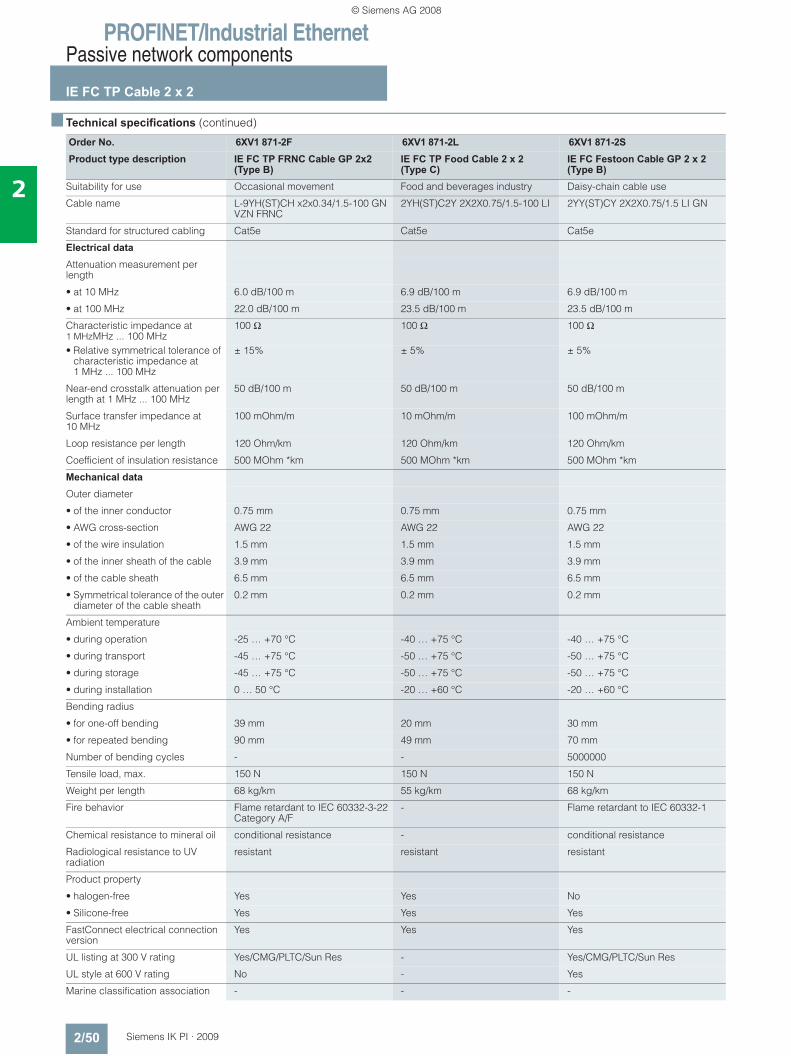
PROFINET/Industrial EthernetPassive network components
IE FC TP Cable 2 x 2
2/50 Siemens IK PI · 2009
2
■ Technical specifications (continued)
Order No. 6XV1 871-2F 6XV1 871-2L 6XV1 871-2SProduct type description IE FC TP FRNC Cable GP 2x2
(Type B) IE FC TP Food Cable 2 x 2 (Type C)
IE FC Festoon Cable GP 2 x 2 (Type B)
Suitability for use Occasional movement Food and beverages industry Daisy-chain cable use
Cable name L-9YH(ST)CH x2x0.34/1.5-100 GN VZN FRNC
2YH(ST)C2Y 2X2X0.75/1.5-100 LI 2YY(ST)CY 2X2X0.75/1.5 LI GN
Standard for structured cabling Cat5e Cat5e Cat5e
Electrical data
Attenuation measurement per length
• at 10 MHz 6.0 dB/100 m 6.9 dB/100 m 6.9 dB/100 m
• at 100 MHz 22.0 dB/100 m 23.5 dB/100 m 23.5 dB/100 m
Characteristic impedance at 1 MHzMHz ... 100 MHz
100 Ω 100 Ω 100 Ω
• Relative symmetrical tolerance of characteristic impedance at 1 MHz ... 100 MHz
± 15% ± 5% ± 5%
Near-end crosstalk attenuation per length at 1 MHz ... 100 MHz
50 dB/100 m 50 dB/100 m 50 dB/100 m
Surface transfer impedance at 10 MHz
100 mOhm/m 10 mOhm/m 100 mOhm/m
Loop resistance per length 120 Ohm/km 120 Ohm/km 120 Ohm/km
Coefficient of insulation resistance 500 MOhm *km 500 MOhm *km 500 MOhm *km
Mechanical data
Outer diameter
• of the inner conductor 0.75 mm 0.75 mm 0.75 mm
• AWG cross-section AWG 22 AWG 22 AWG 22
• of the wire insulation 1.5 mm 1.5 mm 1.5 mm
• of the inner sheath of the cable 3.9 mm 3.9 mm 3.9 mm
• of the cable sheath 6.5 mm 6.5 mm 6.5 mm
• Symmetrical tolerance of the outer diameter of the cable sheath
0.2 mm 0.2 mm 0.2 mm
Ambient temperature
• during operation -25 … +70 °C -40 … +75 °C -40 … +75 °C
• during transport -45 … +75 °C -50 … +75 °C -50 … +75 °C
• during storage -45 … +75 °C -50 … +75 °C -50 … +75 °C
• during installation 0 … 50 °C -20 … +60 °C -20 … +60 °C
Bending radius
• for one-off bending 39 mm 20 mm 30 mm
• for repeated bending 90 mm 49 mm 70 mm
Number of bending cycles - - 5000000
Tensile load, max. 150 N 150 N 150 N
Weight per length 68 kg/km 55 kg/km 68 kg/km
Fire behavior Flame retardant to IEC 60332-3-22 Category A/F
- Flame retardant to IEC 60332-1
Chemical resistance to mineral oil conditional resistance - conditional resistance
Radiological resistance to UV radiation
resistant resistant resistant
Product property
• halogen-free Yes Yes No
• Silicone-free Yes Yes Yes
FastConnect electrical connection version
Yes Yes Yes
UL listing at 300 V rating Yes/CMG/PLTC/Sun Res - Yes/CMG/PLTC/Sun Res
UL style at 600 V rating No - Yes
Marine classification association - - -
© Siemens AG 2008
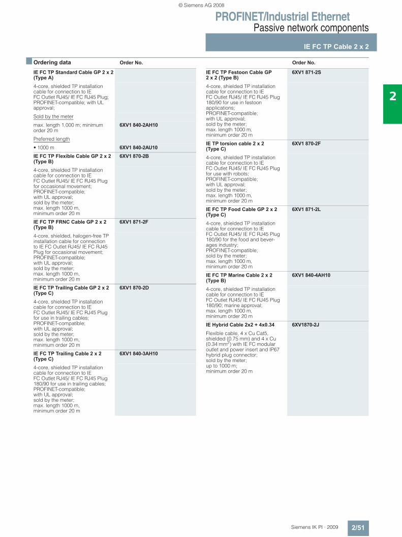
PROFINET/Industrial EthernetPassive network components
IE FC TP Cable 2 x 2
2/51Siemens IK PI · 2009
2
■ Ordering data Order No. Order No.
IE FC TP Standard Cable GP 2 x 2 (Type A)4-core, shielded TP installation cable for connection to IE FC Outlet RJ45/ IE FC RJ45 Plug; PROFINET-compatible; with UL approval;
Sold by the meter
max. length 1,000 m; minimum order 20 m
6XV1 840-2AH10
Preferred length
• 1000 m 6XV1 840-2AU10IE FC TP Flexible Cable GP 2 x 2 (Type B)
6XV1 870-2B
4-core, shielded TP installation cable for connection to IE FC Outlet RJ45/ IE FC RJ45 Plug for occasional movement; PROFINET-compatible; with UL approval; sold by the meter; max. length 1000 m, minimum order 20 m
IE FC TP FRNC Cable GP 2 x 2 (Type B)
6XV1 871-2F
4-core, shielded, halogen-free TP installation cable for connection to IE FC Outlet RJ45/ IE FC RJ45 Plug for occasional movement; PROFINET-compatible; with UL approval; sold by the meter; max. length 1000 m, minimum order 20 m
IE FC TP Trailing Cable GP 2 x 2 (Type C)
6XV1 870-2D
4-core, shielded TP installation cable for connection to IE FC Outlet RJ45/ IE FC RJ45 Plug for use in trailing cables; PROFINET-compatible; with UL approval; sold by the meter; max. length 1000 m, minimum order 20 m
IE FC TP Trailing Cable 2 x 2 (Type C)
6XV1 840-3AH10
4-core, shielded TP installation cable for connection to IE FC Outlet RJ45/ IE FC RJ45 Plug 180/90 for use in trailing cables; PROFINET-compatible;with UL approval; sold by the meter; max. length 1000 m, minimum order 20 m
IE FC TP Festoon Cable GP 2 x 2 (Type B)
6XV1 871-2S
4-core, shielded TP installation cable for connection to IE FC Outlet RJ45/ IE FC RJ45 Plug 180/90 for use in festoon applications; PROFINET-compatible; with UL approval; sold by the meter; max. length 1000 m, minimum order 20 m
IE TP torsion cable 2 x 2 (Type C)
6XV1 870-2F
4-core, shielded TP installation cable for connection to IE FC Outlet RJ45/ IE FC RJ45 Plug for use with robots; PROFINET-compatible; with UL approval; sold by the meter; max. length 1000 m, minimum order 20 m
IE FC TP Food Cable GP 2 x 2 (Type C)
6XV1 871-2L
4-core, shielded TP installation cable for connection to IE FC Outlet RJ45/ IE FC RJ45 Plug 180/90 for the food and bever-ages industry; PROFINET-compatible; sold by the meter; max. length 1000 m, minimum order 20 m
IE FC TP Marine Cable 2 x 2 (Type B)
6XV1 840-4AH10
4-core, shielded TP installation cable for connection to IE FC Outlet RJ45/ IE FC RJ45 Plug 180/90; marine approval; max. length 1000 m, minimum order 20 m
IE Hybrid Cable 2x2 + 4x0.34 6XV1870-2JFlexible cable, 4 x Cu Cat5, shielded (0.75 mm) and 4 x Cu (0.34 mm2) with IE FC modular outlet and power insert and IP67 hybrid plug connector; sold by the meter; up to 1000 m; minimum order 20 m
© Siemens AG 2008
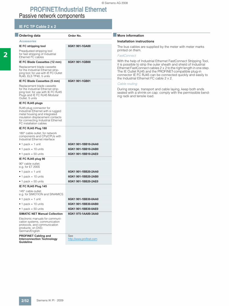
PROFINET/Industrial EthernetPassive network components
IE FC TP Cable 2 x 2
2/52 Siemens IK PI · 2009
2
■ Ordering data Order No. ■ More information
Installation instructions
The bus cables are supplied by the meter with meter marks printed on them.
FastConnect
With the help of Industrial Ethernet FastConnect Stripping Tool, it is possible to strip the outer sheath and shield of Industrial Ethernet FastConnect cables 2 x 2 to the right length in one step. The IE Outlet RJ45 and the PROFINET-compatible plug-in connector IE FC RJ45 can be connected quickly and easily to the Industrial Ethernet FC cable 2 x 2.
Cable routing
During storage, transport and cable laying, keep both ends sealed with a shrink-on cap; comply with the permissible bend-ing radii and tensile load.
AccessoriesIE FC stripping tool 6GK1 901-1GA00Preadjusted stripping tool for fast stripping of Industrial Ethernet FC cables
IE FC Blade Cassettes (12 mm) 6GK1 901-1GB00Replacement blade cassettefor the Industrial Ethernet strip-ping tool; for use with IE FC Outlet RJ45, ELS TP40, 5 units
IE FC Blade Cassettes (5 mm) 6GK1 901-1GB01Replacement blade cassette for the Industrial Ethernet strip-ping tool; for use with IE FC RJ45 Plugs and IE FC RJ45 Modular Outlet, 5 units
IE FC RJ45 plugsRJ45 plug connector for Industrial Ethernet with a rugged metal housing and integrated insulation displacement contacts for connecting Industrial Ethernet FC installation cables
IE FC RJ45 Plug 180180° cable outlet; for network components and CPs/CPUs with Industrial Ethernet interface
• 1 pack = 1 unit 6GK1 901-1BB10-2AA0• 1 pack = 10 units 6GK1 901-1BB10-2AB0• 1 pack = 50 units 6GK1 901-1BB10-2AE0IE FC RJ45 plug 9090° cable outlet; e.g. for ET 200S
• 1 pack = 1 unit 6GK1 901-1BB20-2AA0• 1 pack = 10 units 6GK1 901-1BB20-2AB0• 1 pack = 50 units 6GK1 901-1BB20-2AE0IE FC RJ45 Plug 145145° cable outlet; e.g. for SIMOTION and SINAMICS
• 1 pack = 1 unit 6GK1 901-1BB30-0AA0• 1 pack = 10 units 6GK1 901-1BB30-0AB0• 1 pack = 50 units 6GK1 901-1BB30-0AE0SIMATIC NET Manual Collection 6GK1 975-1AA00-3AA0Electronic manuals for communi-cation systems, communication protocols, and communication products; on DVD; German/English
PROFINET Cabling and Interconnection Technology Guideline
See http://www.profinet.com
© Siemens AG 2008
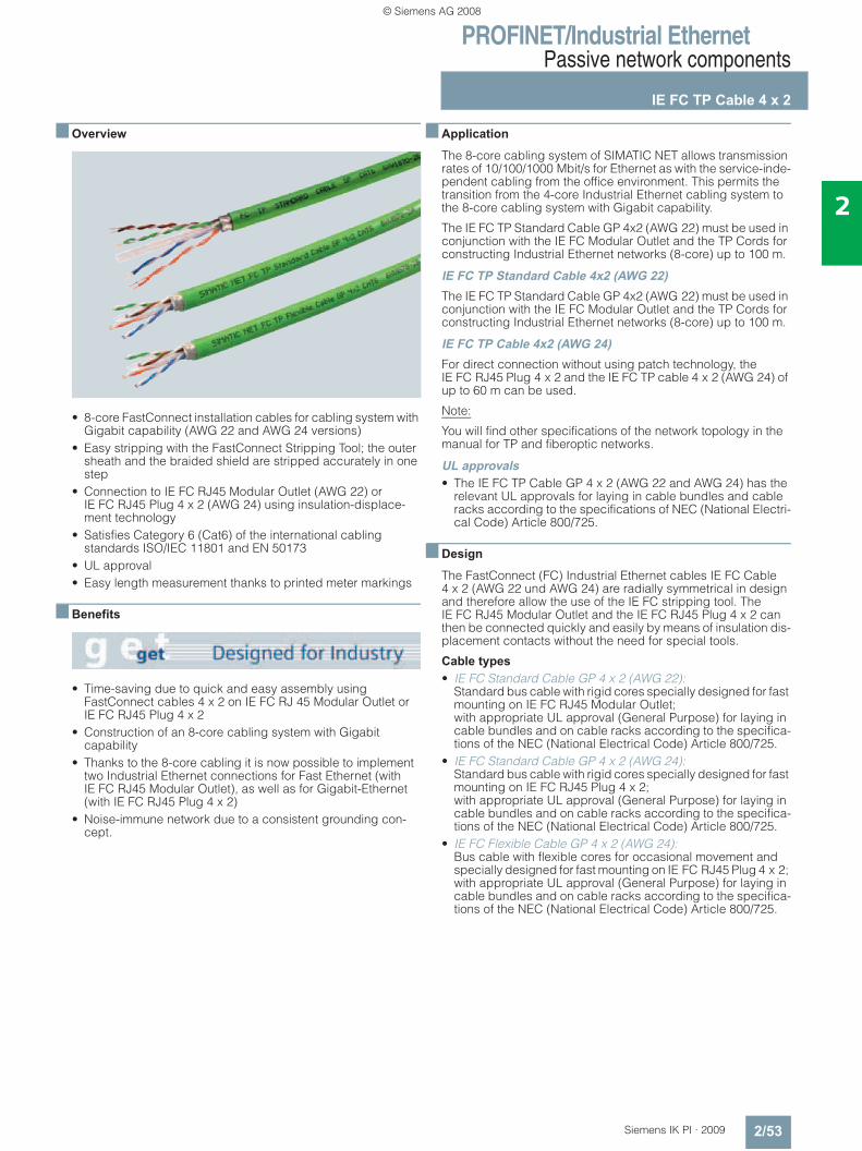
PROFINET/Industrial EthernetPassive network components
IE FC TP Cable 4 x 2
2/53Siemens IK PI · 2009
2
■ Overview
• 8-core FastConnect installation cables for cabling system with Gigabit capability (AWG 22 and AWG 24 versions)
• Easy stripping with the FastConnect Stripping Tool; the outer sheath and the braided shield are stripped accurately in one step
• Connection to IE FC RJ45 Modular Outlet (AWG 22) or IE FC RJ45 Plug 4 x 2 (AWG 24) using insulation-displace-ment technology
• Satisfies Category 6 (Cat6) of the international cabling standards ISO/IEC 11801 and EN 50173
• UL approval• Easy length measurement thanks to printed meter markings
■ Benefits
• Time-saving due to quick and easy assembly using FastConnect cables 4 x 2 on IE FC RJ 45 Modular Outlet or IE FC RJ45 Plug 4 x 2
• Construction of an 8-core cabling system with Gigabit capability
• Thanks to the 8-core cabling it is now possible to implement two Industrial Ethernet connections for Fast Ethernet (with IE FC RJ45 Modular Outlet), as well as for Gigabit-Ethernet (with IE FC RJ45 Plug 4 x 2)
• Noise-immune network due to a consistent grounding con-cept.
■ Application
The 8-core cabling system of SIMATIC NET allows transmission rates of 10/100/1000 Mbit/s for Ethernet as with the service-inde-pendent cabling from the office environment. This permits the transition from the 4-core Industrial Ethernet cabling system to the 8-core cabling system with Gigabit capability.
The IE FC TP Standard Cable GP 4x2 (AWG 22) must be used in conjunction with the IE FC Modular Outlet and the TP Cords for constructing Industrial Ethernet networks (8-core) up to 100 m.
IE FC TP Standard Cable 4x2 (AWG 22)The IE FC TP Standard Cable GP 4x2 (AWG 22) must be used in conjunction with the IE FC Modular Outlet and the TP Cords for constructing Industrial Ethernet networks (8-core) up to 100 m.
IE FC TP Cable 4x2 (AWG 24)For direct connection without using patch technology, the IE FC RJ45 Plug 4 x 2 and the IE FC TP cable 4 x 2 (AWG 24) of up to 60 m can be used.
Note:
You will find other specifications of the network topology in the manual for TP and fiberoptic networks.
UL approvals• The IE FC TP Cable GP 4 x 2 (AWG 22 and AWG 24) has the
relevant UL approvals for laying in cable bundles and cable racks according to the specifications of NEC (National Electri-cal Code) Article 800/725.
■ Design
The FastConnect (FC) Industrial Ethernet cables IE FC Cable 4 x 2 (AWG 22 und AWG 24) are radially symmetrical in design and therefore allow the use of the IE FC stripping tool. The IE FC RJ45 Modular Outlet and the IE FC RJ45 Plug 4 x 2 can then be connected quickly and easily by means of insulation dis-placement contacts without the need for special tools.
Cable types • IE FC Standard Cable GP 4 x 2 (AWG 22):
Standard bus cable with rigid cores specially designed for fast mounting on IE FC RJ45 Modular Outlet; with appropriate UL approval (General Purpose) for laying in cable bundles and on cable racks according to the specifica-tions of the NEC (National Electrical Code) Article 800/725.
• IE FC Standard Cable GP 4 x 2 (AWG 24): Standard bus cable with rigid cores specially designed for fast mounting on IE FC RJ45 Plug 4 x 2; with appropriate UL approval (General Purpose) for laying in cable bundles and on cable racks according to the specifica-tions of the NEC (National Electrical Code) Article 800/725.
• IE FC Flexible Cable GP 4 x 2 (AWG 24): Bus cable with flexible cores for occasional movement and specially designed for fast mounting on IE FC RJ45 Plug 4 x 2; with appropriate UL approval (General Purpose) for laying in cable bundles and on cable racks according to the specifica-tions of the NEC (National Electrical Code) Article 800/725.
© Siemens AG 2008
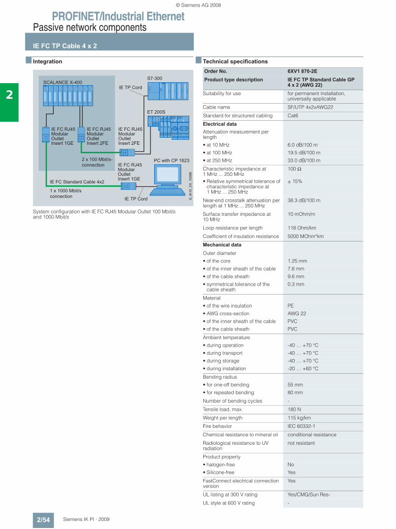
PROFINET/Industrial EthernetPassive network components
IE FC TP Cable 4 x 2
2/54 Siemens IK PI · 2009
2
■ Integration
System configuration with IE FC RJ45 Modular Outlet 100 Mbit/s and 1000 Mbit/s
■ Technical specifications
Order No. 6XV1 870-2EProduct type description IE FC TP Standard Cable GP
4 x 2 (AWG 22) Suitability for use for permanent installation,
universally applicable
Cable name SF/UTP 4x2xAWG22
Standard for structured cabling Cat6
Electrical data
Attenuation measurement per length
• at 10 MHz 6.0 dB/100 m
• at 100 MHz 19.5 dB/100 m
• at 250 MHz 33.0 dB/100 m
Characteristic impedance at 1 MHz ... 250 MHz
100 Ω
• Relative symmetrical tolerance of characteristic impedance at 1 MHz ... 250 MHz
± 15%
Near-end crosstalk attenuation per length at 1 MHz ... 250 MHz
38.3 dB/100 m
Surface transfer impedance at 10 MHz
10 mOhm/m
Loop resistance per length 118 Ohm/km
Coefficient of insulation resistance 5000 MOhm*km
Mechanical data
Outer diameter
• of the core 1.25 mm
• of the inner sheath of the cable 7.6 mm
• of the cable sheath 9.6 mm
• symmetrical tolerance of the cable sheath
0.3 mm
Material
• of the wire insulation PE
• AWG cross-section AWG 22
• of the inner sheath of the cable PVC
• of the cable sheath PVC
Ambient temperature
• during operation -40 … +70 °C
• during transport -40 … +70 °C
• during storage -40 … +70 °C
• during installation -20 … +60 °C
Bending radius
• for one-off bending 55 mm
• for repeated bending 80 mm
Number of bending cycles -
Tensile load, max. 180 N
Weight per length 115 kg/km
Fire behavior IEC 60332-1
Chemical resistance to mineral oil conditional resistance
Radiological resistance to UV radiation
not resistant
Product property
• halogen-free No
• Silicone-free Yes
FastConnect electrical connection version
Yes
UL listing at 300 V rating Yes/CMG/Sun Res-
UL style at 600 V rating -
© Siemens AG 2008
PROFINET/Industrial EthernetPassive network components
IE FC TP Cable 4 x 2
2/55Siemens IK PI · 2009
2
■ Ordering data Order No. Order No.
■ More information
Installation instructions
The bus cable is supplied by the meter with meter marks printed on it.
FastConnect
With the help of Industrial Ethernet FastConnect Stripping Tool, it is possible to strip the outer sheath and shield of the Industrial Ethernet FastConnect cable 4 x 2 to the right length in one step. This allows the IE FC RJ45 Modular Outlet to be attached quickly and easily to the Industrial Ethernet FC cable 4 x 2.
Cable routing
During storage, transport and cable laying, keep both ends sealed with a shrink-on cap; comply with the permissible bend-ing radii and tensile load.
IE FC TP Standard Cable GP 4 x 2 8-core, shielded TP installation cable for universal applications; with UL approval; sold by the meter; max. length 1000 m, minimum order 20 m• AWG 22,
for connection to IE FC RJ45 Modular Outlet
6XV1 870-2E
• AWG 24, for connection to IE FC RJ45 Plug 4 x 2
6XV1 878-2A
IE FC TP Flexible Cable GP 4 x 2 8-core, shielded TP installation cable for occasional movement; with UL approval; sold by the meter; max. length 1000 m, minimum order 20 m• AWG 24,
for connection to IE FC RJ45 Plug 4 x 2
6XV1 878-2B
IE FC stripping tool 6GK1 901-1GA00Preadjusted stripping toolfor fast stripping of Industrial Ethernet FC cables 4 x 2
IE FC Blade Cassettes (5 mm) 6GK1 901-1GB01Replacement blade cassette for the Industrial Ethernet stripping tool, for use with IE FC RJ45 Plugs and IE FC RJ45 Modular Outlet, 5 units
IE FC RJ45 Modular OutletFastConnect RJ45 Outlet for Industrial Ethernet with interface for a replaceable insert;
• without replaceable insert 6GK1 901-1BE00-0AA0• With 2FE insert; ;
replaceable insert for 2 x 100 Mbit/s interfaces
6GK1 901-1BE00-0AA1
• With 1GE insert; replaceable insert for 1 x 1000 Mbit/s interfaces
6GK1 901-1BE00-0AA2
• With power insert; replaceable insertfor 1 x 24 V DC and 1 x 100 Mbit/s interface
6GK1 901-1BE00-0AA3
IE FC RJ45 Modular Outlet Insert 2FE
6GK1 901-1BK00-0AA1
Replaceable insert for FC Modular Outlet Base; 2 x RJ45 for 2 x 100 Mbit/s inter-faces; 1 pack = 4 items
IE FC RJ45 Modular Outlet Insert 1GE
6GK1 901-1BK00-0AA2
Replaceable insert for FC Modular Outlet Base; 1 x RJ45 for 1 x 1000 Mbit/s inter-face; 1 pack = 4 items
IE FC RJ45 Plug 4 x 2RJ45 plug connector for Industrial Ethernet with a rugged metal housing and integrated insulation displacement contacts for con-necting Industrial Ethernet FC installation cables 4 x 2;180° cable outlet; for network components and CPs/CPUs with Industrial Ethernet interface
• 1 pack = 1 unit 6GK1 901-1BB11-2AA0• 1 pack = 10 units 6GK1 901-1BB11-2AB0• 1 pack = 50 units 6GK1 901-1BB11-2AE0IE Manual Collection 6GK1 975-1AA00-3AA0Electronic manuals for communication systems, communication protocols, and communication products; on DVD; German/English
© Siemens AG 2008
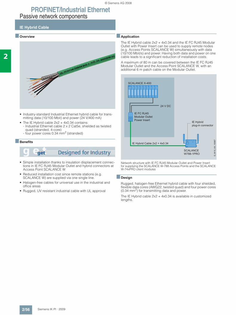
PROFINET/Industrial EthernetPassive network components
IE Hybrid Cable
2/56 Siemens IK PI · 2009
2
■ Overview
• Industry-standard Industrial Ethernet hybrid cable for trans-mitting data (10/100 Mbit) and power (24 V/400 mA)
• The IE Hybrid cable 2x2 + 4x0.34 contains: - Industrial Ethernet cable 2 x 2 Cat5e, shielded as twisted
quad (stranded, 4-core)- four power cores 0.34 mm2 (stranded)
■ Benefits
• Simple installation thanks to insulation displacement connec-tions in IE FC RJ45 Modular Outlet and hybrid connectors at Access Point SCALANCE W
• Reduced installation cost since remote stations (e.g. SCALANCE W) are supplied via one single line.
• Halogen-free cables for universal use in the industrial and office areas
• Rugged, UV resistant industrial cable with UL approval
■ Application
The IE Hybrid cable 2x2 + 4x0.34 and the IE FC RJ45 Modular Outlet with Power Insert can be used to supply remote nodes (e.g. Access Points SCALANCE W) simultaneously with data (10/100 Mbit/s) and power. Having both data and power on one cable leads to a significant reduction of installation costs.
A maximum of 80 m can be covered between the IE FC RJ45 Modular Outlet and the Access Point SCALANCE W, with an additional 6 m patch cable on the Modular Outlet.
Network structure with IE FC RJ45 Modular Outlet and Power Insert for supplying the SCALANCE W-788 Access Points and the SCALANCE W-74xPRO client modules
■ Design
Rugged, halogen-free Ethernet hybrid cable with four shielded, flexible data cores (AWG22, twisted quad) and four power cores (0.34 mm2) for transmitting data and power.
The IE Hybrid cable 2x2 + 4x0.34 is available in customized lengths.
© Siemens AG 2008
PROFINET/Industrial EthernetPassive network components
IE Hybrid Cable
2/57Siemens IK PI · 2009
2
■ Technical specifications
■ Ordering data Order No.
Order No. 6XV1 870-2JProduct type description IE Hybrid Cable 2x2 + 4x0.34
Cable name 2YH (ST) C 2x2x0.75/1.5LI LIH H 2x2x0.34/1.6GN FRNC
Quality class for network cables Cat5e (data cores); AWG 22 (power cores)
Electrical data
Attenuation per length at 10 MHz 7.5 dB/100 m
Attenuation per length at 100 MHz 26 dB/100 m
Characteristic impedance at 1 MHz ... 100 MHz
100 Ω
• Relative symmetrical tolerance of characteristic impedance at 1 MHz ... 100 MHz
± 15%
Near-end crosstalk attenuation per length at 1 MHz ... 100 MHz
35.3 dB/100 m
Surface transfer impedance at 10 MHz
10 mOhm/m
Loop resistance per length 120 Ohm/km
Coefficient of insulation resistance 500 MOhm *km
Mechanical data
Outer diameter
• of the wire insulation 0.76 mm
• of the AWG22 core 0.76 mm
• of the cable sheath 8.5 mm
Material
• of the cable sheath FRNC
• of the inner sheath of the cable FRNC
• of the wire insulation PE
Color
• of the wire insulation of the power wire
black/brown
• of the cable sheath green
Ambient temperature
• during operation -25 … +70 °C
• during storage -25 … +70 °C
• during transport -25 … +70 °C
• during installation -25 … +50 °C
Bending radius
• for one-off bending 43 mm
• for repeated bending 85 mm
Tensile load, max. 260 N
Weight per length 105 kg/km
Chemical resistance to mineral oil Conditionally resistant
Product property
• halogen-free Yes
• Silicone-free Yes
FastConnect electrical connection version
No
Fire behavior according to IEC 60332-3-24 Category C
UL listing at 300 V rating Yes
UL style at 600 V rating Yes: CMG, PLTC
IE Hybrid Cable 2x2 + 4x0,34 6XV1 870-2JFlexible cable, 4 x Cu Cat 5E, shielded (AWG22) and 4 x Cu (0.34 mm2) with IE FC RJ45 modular outlet and power insert and IP67 hybrid plug connector; sold by the meter
Additional components IE TP Cord RJ45/RJ45TP cable 4 x 2 with 2 RJ45 plugs
• 0.5 m 6XV1 870-3QE50• 1 m 6XV1 870-3QH10• 2 m 6XV1 870-3QH20• 6 m 6XV1 870-3QH60• 10 m 6XV1 870-3QN10IE TP XP Cord RJ45/RJ45Twisted TP cable 4 x 2 with 2 RJ45 plugs
• 0.5 m 6XV1 870-3RE50• 1 m 6XV1 870-3RH10• 2 m 6XV1 870-3RH20• 6 m 6XV1 870-3RH60• 10 m 6XV1 870-3RN10IE FC RJ45 Modular Outlet FastConnect RJ45 Outlet for Industrial Ethernet with interface for a replaceable insert;
• With 2FE insert;replaceable insert for 2 x 100 Mbit/s interfaces
6GK1 901-1BE00-0AA1
• With 1GE insert; replaceable insert for 1 x 1000 Mbit/s interfaces
6GK1 901-1BE00-0AA2
• With power insert; replaceable insert for 1 x 24 V DC and 1 x 100 Mbit/s interface
6GK1 901-1BE00-0AA3
IP67 hybrid connector 09 45 125 1300.00Connector for connecting SCALANCE W-700 to Industrial Ethernet and Power over Ethernet (PoE), with assembly instruc-tions, 1 item
Order directly from: HARTING Deutschland GmbH & Co. KG PO Box 24-51 D -32381 Minden Tel. +49 571-8896-0 Fax. +49 571-8896-354 Email: [email protected] Internet: http://www.HARTING.com
SIMATIC NET Manual Collection 6GK1 975-1AA00-3AA0Electronic manuals for communication systems, communication protocols, and communication products; on DVD; German/English
© Siemens AG 2008
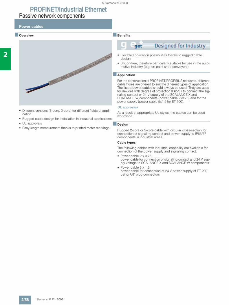
PROFINET/Industrial EthernetPassive network components
Power cables
2/58 Siemens IK PI · 2009
2
■ Overview
• Different versions (5-core, 2-core) for different fields of appli-cation
• Rugged cable design for installation in industrial applications• UL approvals• Easy length measurement thanks to printed meter markings
■ Benefits
• Flexible application possibilities thanks to rugged cable design
• Silicon-free, therefore particularly suitable for use in the auto-motive industry (e.g. on paint shop conveyors)
■ Application
For the construction of PROFINET/PROFIBUS networks, different cable types are offered to suit the different types of application. The listed power cables should always be used. They are used for devices with degree of protection IP65/67 to connect the sig-naling contact or 24-V supply of the SCALANCE X and SCALANCE W components (power cable 2x0.75) and for the power supply (power cable 5x1.5 for ET 200).
UL approvalsAs a result of appropriate UL styles, the cables can be used worldwide.
■ Design
Rugged 2-core or 5-core cable with circular cross-section for connection of signaling contact and power supply to IP65/67 components in industrial areas.
Cable types
The following cables with industrial capability are available for connection of the power supply and signaling contact:• Power cable 2 x 0.75;
power cable for connection of signaling contact and 24 V sup-ply voltage to SCALANCE X and SCALANCE W components
• Power cable 5 x 1.5; power cable for connection of 24 V power supply of ET 200 using 7/8" plug connectors
© Siemens AG 2008
PROFINET/Industrial EthernetPassive network components
Power cables
2/59Siemens IK PI · 2009
2
■ Technical specifications
Order No. 6XV1 812-8A 6XV1 830-8AH10Product type description Energy Cable Energy Cable
Suitability for use Connection of signaling contact and 24-V power supply to SCALANCE X and SCALANCE W
Power supply of ET 200 modules with 7/8" power port
Cable name L-YY-2x1x0.75 GR L-Y11Y-JZ 5x1x1.5 GR
Power wires
Operating voltage (rms value) 600 V 600 V
Conductor cross-section of power wire
0.75 mm² 1.5 mm²
Continuous current of the power wires
6 A 16 A
General mechanical data
Jacket
• Outer diameter 7.4 mm 10.5 mm
• Symmetrical tolerance of the outer diameter
0.3 mm 0.3 mm
- Material PVC PUR- Color gray gray
Ambient temperature
• during operation -20 … +80 °C -40 … +80 °C
• during transport -20 … +80 °C -40 … +80 °C
• during storage -20 … +80 °C -40 … +80 °C
• during installation -20 … +80 °C -40 … +80 °C
Bending radius
• for one-off bending 19 mm 26 mm
• for repeated bending 44 mm 63 mm
Number of bending cycles - -
Tensile load, max. 100 N 500 N
Weight per length 70 kg/km 149 kg/km
Fire behavior Flame retardant to IEC 60332-1 Flame retardant to IEC 60332-1
Chemical resistance
• to mineral oil conditional resistance resistant
• to grease conditional resistance resistant
Radiological resistance to UV radiation
resistant resistant
Product property
• halogen-free No No
• silicone-free Yes Yes
FastConnect electrical connection version
No No
UL listing at 300 V rating Yes/CL3 No
UL style at 600 V rating Yes Yes
© Siemens AG 2008
PROFINET/Industrial EthernetPassive network components
Power cables
2/60 Siemens IK PI · 2009
2
■ Ordering data Order No.
■ More information
Cable routing: During storage, transportation and cable laying, keep both ends sealed with a shrink-on cap.
Comply with the permissible bending radii and tensile load!
Note: Additional components of the SIMATIC NET wiring range can be ordered from your local contact person.For technical advice contact:J. Hertlein, A&D SE PSTel.: +49(0)911/750 44 65Fax.: +49(0)911/750 99 91Email: [email protected]
Power cable 2 x 0.75 6XV1 812-8APower cable with trailing capabil-ity with 2 copper cores (0.75 mm2) for connecting to M12 plug-in connector; sold by the meter; max. 1000 m, minimum order quantity 20 m
Power cable 5 x 1.5 6XV1 830-8AH10Power cable with trailing capabil-ity with 5 copper cores (1.5 mm2) for connecting to 7/8" plug-in con-nector; sold by the meter;max. 1000 m; minimum order quantity 20 m
Additional components 7/8" plug-in connectorPlug with axial cable outlet for field assembly for ET 200, 5-core, plastic enclosure, 1 pack = 5 items
• Male pins 6GK1 905-0FA00• Socket insert 6GK1 905-0FB007/8" Power T-Tap PRO 6GK1 905-0FC00Power T-piece for ET 200 with two 7/8" socket inserts and one 7/8" pin insert 1 pack = 5 items
Signaling Contact M12 Cable Connector PRO
6GK1908-0DC10-6AA3
Socket for connection of SCALANCE X208PRO for signal-ing contact; 5-pole, B-coded, with assembly instructions; 3 items
Power M12 Cable Connector PRO
6GK1 907-0DC10-6AA3
Socket for connection of SCALANCE W-700 for 24 V DC supply voltage; 4-pole, A-coded, with assembly instructions, 3 items
Power M12 Plug PRO 6GK1 907-0DB10-6AA3Plug for connection to PS791-1PRO power supply for 24 V DC supply voltage; 4-pole, A-coded, with assembly instructions, 3 items
SIMATIC NET Manual Collection 6GK1 975-1AA00-3AA0Electronic manuals for communication systems, communication protocols,and communication products; on DVD, German/English
© Siemens AG 2008

PROFINET/Industrial EthernetPassive network components
IE TP Cord
2/61Siemens IK PI · 2009
2
■ Overview
• Patch cable, available as preassembled cables (max. length 10 m)
• With 2 x 2 cores for 10/100 Mbit/s and 4 x 2 cores for 10/100/1000 Mbit/s Ethernet
• Small cable diameter • Category Cat5e (2 x 2) and Cat6 (4 x 2) of the international
cabling standards ISO/IEC 11801 and EN 50173
■ Benefits
• Easy connection of data terminals with an RJ45 connection to the Industrial Ethernet FC cabling system with interference immunity (10/100/1000 Mbit/s)
• Fast, error-free start-up thanks to preassembled, factory-tested patch cables
• Easy cable installation thanks to small cable diameter• Silicon-free, therefore suitable for use in the automotive
industry (e.g. on paint shop conveyors)• Color-coded RJ45 plug to distinguish between twisted and
untwisted cables - Twisted: RJ45 plug red on both sides- Not twisted: RJ45 plug green on both sides
© Siemens AG 2008
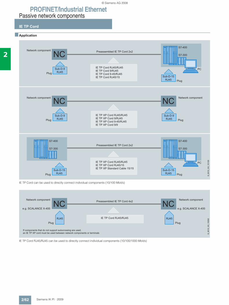
PROFINET/Industrial EthernetPassive network components
IE TP Cord
2/62 Siemens IK PI · 2009
2
■ Application
IE TP Cord can be used to directly connect individual components (10/100 Mbit/s)
IE TP Cord RJ45/RJ45 can be used to directly connect individual components (10/100/1000 Mbit/s)
© Siemens AG 2008
PROFINET/Industrial EthernetPassive network components
IE TP Cord
2/63Siemens IK PI · 2009
2
■ Design• 2 x 2 cores for 10/100 Mbit/s transmission rate;
4 x 2 cores for 10/100/1000 Mbit/s transmission rate• Two cores with two dummy elements twisted into a pair.• Each pair is encased in plastic film and shielded with a
plastic-clad aluminum foil• Outer woven shield around all pairs comprising tinned copper
wires• Plastic sheath (PVC)
IE TP Cord is available as TP Cord 4 x 2, pre-assembled cables in the following versions:• IE TP Cord RJ45/RJ45
with 2 x RJ45 plugs• IE TP XP Cord RJ45/RJ45
with 2 x RJ45 plugs, send and receive cables are twisted.
IE TP Cord is available as TP Cord 2 x 2, pre-assembled cables in the following versions:• IE TP Cord 9/RJ45
with one 9-pole Sub-D connector and one RJ45 connector • IE TP XP Cord 9/RJ45
with one RJ45 connector and one 9-pole Sub-D connector, send and receive cable are twisted
• IE TP Cord 9-45/RJ45 with one RJ45 connector and one 9-pole Sub-D connector, 45° cable outlet
• IE TP XP Cord 9-45/RJ45 with one RJ45 connector and one 9-pole Sub-D connector, 45° cable outlet; send and receive cable are twisted
• IE TP XP Cord 9/9 with two 9-pole Sub-D connectors, send and receive cable are twisted.
• IE TP Cord RJ45/15 with one RJ45 connector and one 15-pole Sub-D connector; this is used to directly connect data terminals with ITP inter-faces to network components with an RJ45 interface.
• IE TP XP Cord RJ45/15 with one RJ45 connector and one 15-pole Sub-D connector, twisted send and receive cable; used for direct connection of a data terminal with 15-pole Sub-D connector to a data terminal with RJ45 plug.
• IE TP Converter Cord 15/RJ45 with a 15-pole Sub-D socket with slide locking and an RJ45 plug. A retaining clip clamps it in place. IE TP Converter Cord 15/RJ45 2 x 2 is used to connect data terminals with an RJ45 interface to the ITP cabling system, e.g. over the ITP Standard 9/15 cable.
■ Function
The flexibility of the cable ensures easy installation, for example in a control cabinet, or to connect equipment in a control room. The maximum length of an IE TP Cord is 10 m.
Adapter cables are used to connect devices with an ITP inter-face to devices with an RJ45 interface.
IE TP Converter Cord 15/RJ45 is used to convert an ITP interface of a data terminal to the RJ45 interface.
■ More information
Additional components of the SIMATIC NET wiring range can be ordered from your local contact person.For technical advice contact:J. Hertlein, A&D SE PSTel.: +49(0)911/750 44 65Fax: +49(0)911/750 99 91E-mail: [email protected]
© Siemens AG 2008
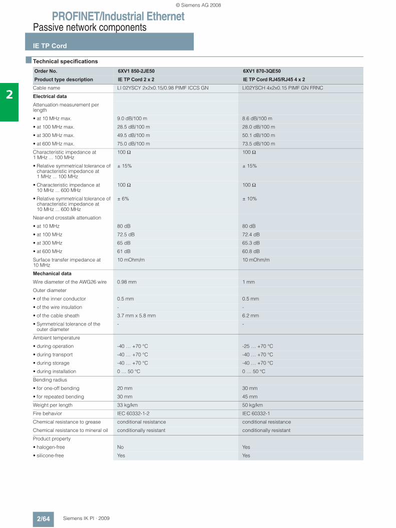
PROFINET/Industrial EthernetPassive network components
IE TP Cord
2/64 Siemens IK PI · 2009
2
■ Technical specifications
Order No. 6XV1 850-2JE50 6XV1 870-3QE50Product type description IE TP Cord 2 x 2 IE TP Cord RJ45/RJ45 4 x 2
Cable name LI 02YSCY 2x2x0.15/0.98 PIMF ICCS GN LI02YSCH 4x2x0.15 PIMF GN FRNC
Electrical data
Attenuation measurement per length
• at 10 MHz max. 9.0 dB/100 m 8.6 dB/100 m
• at 100 MHz max. 28.5 dB/100 m 28.0 dB/100 m
• at 300 MHz max. 49.5 dB/100 m 50.1 dB/100 m
• at 600 MHz max. 75.0 dB/100 m 73.5 dB/100 m
Characteristic impedance at 1 MHz ... 100 MHz
100 Ω 100 Ω
• Relative symmetrical tolerance of characteristic impedance at 1 MHz ... 100 MHz
± 15% ± 15%
• Characteristic impedance at 10 MHz ... 600 MHz
100 Ω 100 Ω
• Relative symmetrical tolerance of characteristic impedance at 10 MHz ... 600 MHz
± 6% ± 10%
Near-end crosstalk attenuation
• at 10 MHz 80 dB 80 dB
• at 100 MHz 72.5 dB 72.4 dB
• at 300 MHz 65 dB 65.3 dB
• at 600 MHz 61 dB 60.8 dB
Surface transfer impedance at 10 MHz
10 mOhm/m 10 mOhm/m
Mechanical data
Wire diameter of the AWG26 wire 0.98 mm 1 mm
Outer diameter
• of the inner conductor 0.5 mm 0.5 mm
• of the wire insulation - -
• of the cable sheath 3.7 mm x 5.8 mm 6.2 mm
• Symmetrical tolerance of the outer diameter
- -
Ambient temperature
• during operation -40 … +70 °C -25 … +70 °C
• during transport -40 … +70 °C -40 … +70 °C
• during storage -40 … +70 °C -40 … +70 °C
• during installation 0 … 50 °C 0 … 50 °C
Bending radius
• for one-off bending 20 mm 30 mm
• for repeated bending 30 mm 45 mm
Weight per length 33 kg/km 50 kg/km
Fire behavior IEC 60332-1-2 IEC 60332-1
Chemical resistance to grease conditional resistance conditional resistance
Chemical resistance to mineral oil conditionally resistant conditionally resistant
Product property
• halogen-free No Yes
• silicone-free Yes Yes
© Siemens AG 2008
PROFINET/Industrial EthernetPassive network components
IE TP Cord
2/65Siemens IK PI · 2009
2
■ Ordering data Order No. Order No.
IE TP Cord RJ45/RJ45TP cable 4 x 2 with 2 RJ45 plugs
• 0.5 m 6XV1 870-3QE50• 1 m 6XV1 870-3QH10• 2 m 6XV1 870-3QH20• 6 m 6XV1 870-3QH60• 10 m 6XV1 870-3QN10IE TP XP Cord RJ45/RJ45Twisted TP cable 4 x 2 with 2 RJ45 plugs
• 0.5 m 6XV1 870-3RE50• 1 m 6XV1 870-3RH10• 2 m 6XV1 870-3RH20• 6 m 6XV1 870-3RH60• 10 m 6XV1 870-3RN10IE TP Cord 9/RJ45TP cable 2 x 2 with one 9-pole Sub-D connector and one RJ45 connector
• 0.5 m 6XV1 850-2JE50• 1 m 6XV1 850-2JH10• 2 m 6XV1 850-2JH20• 6 m 6XV1 850-2JH60• 10 m 6XV1 850-2JN10IE TP XP Cord 9/RJ45Twisted TP cable 2 x 2 with one 9-pole Sub-D connector and one RJ45 connector
• 0.5 m 6XV1 850-2ME50• 1 m 6XV1 850-2MH10• 2 m 6XV1 850-2MH20• 6 m 6XV1 850-2MH60• 10 m 6XV1 850-2MN10IE TP Cord 9-45/RJ45TP cable 2 x 2 with one RJ45 connector and one Sub-D connector with 45° cable outlet (not for OSM/ESM)
• 1 m 6XV1 850-2NH10IE TP XP Cord 9-45/RJ45Twisted TP cable 2 x 2 with one RJ45 connector and one Sub-D connector with 45° cable outlet (not for OSM/ESM)
• 1 m 6XV1 850-2PH10IE TP XP Cord 9/9Twisted TP cable 2 x 2 for direct connection of two Industrial Ethernet components with an ITP interface with two 9-pole Sub-D connectors
• 1 m 6XV1 850-2RH10
IE TP Cord RJ45/15TP cable 2 x 2 with one 15-pole Sub-D connec-tor and one RJ45 connector
• 0.5 m 6XV1 850-2LE50• 1 m 6XV1 850-2LH10• 2 m 6XV1 850-2LH20• 6 m 6XV1 850-2LH60• 10 m 6XV1 850-2LN10IE TP XP Cord RJ45/15Crossed TP cable 2 x 2 with one 15-pole Sub-D connec-tor and one RJ45 connector
• 0.5 m 6XV1 850-2SE50• 1 m 6XV1 850-2SH10• 2 m 6XV1 850-2SH20• 6 m 6XV1 850-2SH60• 10 m 6XV1 850-2SN10IE TP Converter Cord 15/RJ45TP connecting cable 2 x 2 for connecting data terminals with RJ45 interfaces to the ITP cabling system; with a 15-pole Sub-D socket with slide locking and an RJ45 connector.
• 0.5 m 6XV1 850-2EE50• 1 m 6XV1 850-2EH20IE FC Outlet RJ45 6GK1 901-1FC00 0AA0For connection Industrial Ethernet FC cables and TP Cords; graded prices from 10 and 50 units
IE FC RJ45 Modular Outlet FastConnect RJ45 Outlet for Industrial Ethernet with interface for a replaceable insert;
• With 2FE insert ;replaceable insert for 2 x 100 Mbit/s interfaces
6GK1 901-1BE00-0AA1
• With 1GE insert; replaceable insert for 1 x 1000 Mbit/s interfaces
6GK1 901-1BE00-0AA2
• With power insert; replaceable insert for 1 x 24 V DC and 1 x 100 Mbit/s interface
6GK1 901-1BE00-0AA3
SIMATIC NET Manual Collection 6GK1 975-1AA00-3AA0Electronic manuals for communication systems, communication protocols,and communication products; on DVD; German/English
© Siemens AG 2008
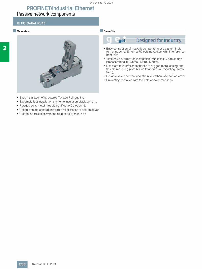
PROFINET/Industrial EthernetPassive network components
IE FC Outlet RJ45
2/66 Siemens IK PI · 2009
2
■ Overview
• Easy installation of structured Twisted Pair cabling.• Extremely fast installation thanks to insulation displacement.• Rugged solid metal module certified to Category 5.• Reliable shield contact and strain relief thanks to bolt-on cover• Preventing mistakes with the help of color markings
■ Benefits
• Easy connection of network components or data terminals to the Industrial Ethernet FC cabling system with interference immunity.
• Time-saving, error-free installation thanks to FC cables and preassembled TP Cords (10/100 Mbit/s).
• Resistant to interference thanks to rugged metal casing and flexible mounting possibilities (standard rail mounting, screw fixing)
• Reliable shield contact and strain relief thanks to bolt-on cover• Preventing mistakes with the help of color markings
© Siemens AG 2008
PROFINET/Industrial EthernetPassive network components
IE FC Outlet RJ45
2/67Siemens IK PI · 2009
2
■ Application
The IE FC Outlet RJ45 is used as a transition from the rugged Industrial Ethernet FC cables used in the industrial environment to prefabricated TP Cord cables (10/100 Mbit/s) using an RJ45 socket.
By connecting several IE FC Outlet RJ45 devices in series, a patch field can be constructed with the required connection density (e.g. 16 outlets over 19“ width).
IE TP Cord can be used for patch technology with IE FC Outlet RJ45 (10/100 Mbit/s)
© Siemens AG 2008
PROFINET/Industrial EthernetPassive network components
IE FC Outlet RJ45
2/68 Siemens IK PI · 2009
2
■ Design
The IE FC Outlet RJ45 has a rugged metal housing and satisfies Category 5 of the international cable standard ISO/IEC 11801 and EN 50173. It is suitable both for mounting on rails and wall mounting by means of four through holes.
The Outlet RJ45 can also be mounted behind a metal plate with a cutout (e.g. in a control cabinet).
The Outlet RJ45 has the following connections• 4 insulation-piercing contacts for connecting the Industrial
Ethernet FC cable 2 x 2 (contacts are color coded)• RJ45 socket with dust protection cap for connecting different
TP Cord cables (10/100 Mbit/s).
■ Function
The Industrial Ethernet FC Outlet RJ45 is directly connected to the Industrial Ethernet FC cable 2 x 2.
Prefabricated RJ45 patch cables (10/100 Mbit/s) are available for the connection between the IE Outlet RJ45 and a network component or data terminal.
System configuration with IE FC Outlet RJ45
© Siemens AG 2008
PROFINET/Industrial EthernetPassive network components
IE FC Outlet RJ45
2/69Siemens IK PI · 2009
2
■ Integration
Configuration example with TP and FO cabling technology
© Siemens AG 2008
PROFINET/Industrial EthernetPassive network components
IE FC Outlet RJ45
2/70 Siemens IK PI · 2009
2
■ Technical specifications
■ Ordering data Order No.
■ Ordering data (continued) Order No.
Order No. 6GK1 901-1FC00-0AA0Product type description IE FC RJ45 outlet
Design CAT 5
Number of electrical connections for Industrial Ethernet FC TP cables 2x2
4
Electrical connection version
• for Industrial Ethernet FC TP cables
Insulation displacement terminals for all IE FC cables 2 x 2
• for network components or terminal
RJ45 socket
Ambient temperature
• during operation -25 … +70 °C
• during storage -40 … +70 °C
• during transport -40 … +70 °C
Width 31,7 mm
Height 107 mm
Depth 30 mm
Net weight 300 g
Type of fixing Standard rail or wall mounting
Degree of protection IP20
Certificate of suitability UL approval Yes
Standard for structured cabling according to ISO/IEC 11801
Yes
IE FC Outlet RJ45 6GK1 901-1FC00 0AA0For connection of Industrial Ethernet FC cables and TP Cords; graded prices from 10 and 50 units on
IE TP Cord 9/RJ45TP cable 2 x 2 with one 9-pole Sub-D connector and one RJ45 connector
• 0.5 m 6XV1 850-2JE50• 1 m 6XV1 850-2JH10• 2 m 6XV1 850-2JH20• 6 m 6XV1 850-2JH60• 10 m 6XV1 850-2JN10IE TP XP Cord 9/RJ45Twisted TP cable 2 x 2 with one 9-pole Sub-D connector and one RJ45 connector
• 0.5 m 6XV1 850-2ME50• 1 m 6XV1 850-2MH10• 2 m 6XV1 850-2MH20• 6 m 6XV1 850-2MH60• 10 m 6XV1 850-2MN10
IE TP Cord 9-45/RJ45TP cable 2 x 2 with one RJ45 connector and one Sub-D connector with 45° cable outlet (not for OSM/ESM)
• 1 m 6XV1 850-2NH10IE TP XP Cord 9-45/RJ45Twisted TP cable with one RJ45 connector and one Sub-D connector with 45° cable outlet (not for OSM/ESM)
• 1 m 6XV1 850-2PH10IE TP XP Cord 9/9Twisted TP cable 2 x 2 for direct connection of two Industrial Ethernet components with an ITP interface with two 9-pole Sub-D connectors
• 1 m 6XV1 850-2RH10IE TP Cord RJ45/15TP cable 2 x 2 with one 15-pole Sub-D connector and one RJ45 connector
• 0.5 m 6XV1 850-2LE50• 1 m 6XV1 850-2LH10• 2 m 6XV1 850-2LH20• 6 m 6XV1 850-2LH60• 10 m 6XV1 850-2LN10IE TP XP Cord RJ45/15Twisted TP cable 2 x 2 with one 15-pole Sub-D connector and one RJ45 connector
• 0.5 m 6XV1 850-2SE50• 1 m 6XV1 850-2SH10• 2 m 6XV1 850-2SH20• 6 m 6XV1 850-2SH60• 10 m 6XV1 850-2SN10IE TP Converter Cord 15/RJ45TP connecting cable 2 x 2 for connecting data terminals with RJ45 interfaces to the ITP cabling system; with a 15-pole Sub-D socket with slide locking and an RJ45 connector.
• 0.5 m 6XV1 850-2EE50• 1 m 6XV1 850-2EH20SIMATIC NET Manual Collection 6GK1 975-1AA00-3AA0Electronic manuals for communication systems, communication protocols,and communication products;on DVD; German/English
© Siemens AG 2008
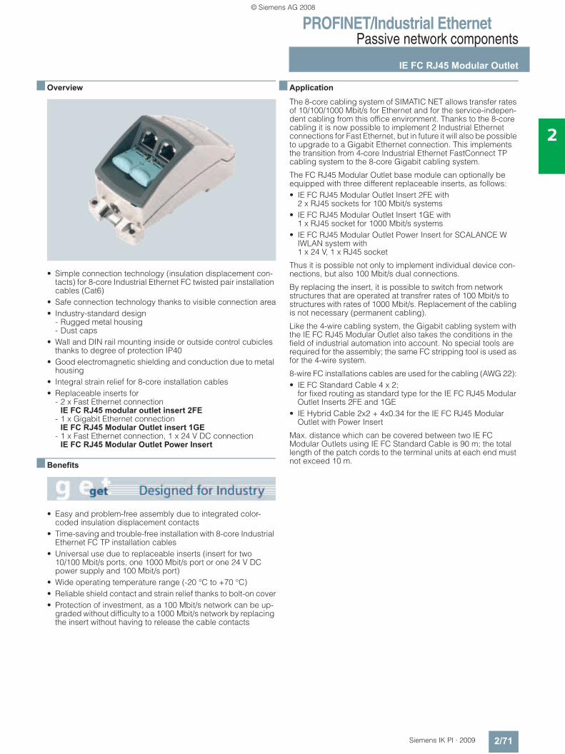
PROFINET/Industrial EthernetPassive network components
IE FC RJ45 Modular Outlet
2/71Siemens IK PI · 2009
2
■ Overview
• Simple connection technology (insulation displacement con-tacts) for 8-core Industrial Ethernet FC twisted pair installation cables (Cat6)
• Safe connection technology thanks to visible connection area• Industry-standard design
- Rugged metal housing- Dust caps
• Wall and DIN rail mounting inside or outside control cubicles thanks to degree of protection IP40
• Good electromagnetic shielding and conduction due to metal housing
• Integral strain relief for 8-core installation cables• Replaceable inserts for
- 2 x Fast Ethernet connection IE FC RJ45 modular outlet insert 2FE
- 1 x Gigabit Ethernet connection IE FC RJ45 Modular Outlet insert 1GE
- 1 x Fast Ethernet connection, 1 x 24 V DC connection IE FC RJ45 Modular Outlet Power Insert
■ Benefits
• Easy and problem-free assembly due to integrated color-coded insulation displacement contacts
• Time-saving and trouble-free installation with 8-core Industrial Ethernet FC TP installation cables
• Universal use due to replaceable inserts (insert for two 10/100 Mbit/s ports, one 1000 Mbit/s port or one 24 V DC power supply and 100 Mbit/s port)
• Wide operating temperature range (-20 °C to +70 °C)• Reliable shield contact and strain relief thanks to bolt-on cover• Protection of investment, as a 100 Mbit/s network can be up-
graded without difficulty to a 1000 Mbit/s network by replacing the insert without having to release the cable contacts
■ Application
The 8-core cabling system of SIMATIC NET allows transfer rates of 10/100/1000 Mbit/s for Ethernet and for the service-indepen-dent cabling from this office environment. Thanks to the 8-core cabling it is now possible to implement 2 Industrial Ethernet connections for Fast Ethernet, but in future it will also be possible to upgrade to a Gigabit Ethernet connection. This implements the transition from 4-core Industrial Ethernet FastConnect TP cabling system to the 8-core Gigabit cabling system.
The FC RJ45 Modular Outlet base module can optionally be equipped with three different replaceable inserts, as follows:• IE FC RJ45 Modular Outlet Insert 2FE with
2 x RJ45 sockets for 100 Mbit/s systems• IE FC RJ45 Modular Outlet Insert 1GE with
1 x RJ45 socket for 1000 Mbit/s systems• IE FC RJ45 Modular Outlet Power Insert for SCALANCE W
IWLAN system with 1 x 24 V, 1 x RJ45 socket
Thus it is possible not only to implement individual device con-nections, but also 100 Mbit/s dual connections.
By replacing the insert, it is possible to switch from network structures that are operated at transfrer rates of 100 Mbit/s to structures with rates of 1000 Mbit/s. Replacement of the cabling is not necessary (permanent cabling).
Like the 4-wire cabling system, the Gigabit cabling system with the IE FC RJ45 Modular Outlet also takes the conditions in the field of industrial automation into account. No special tools are required for the assembly; the same FC stripping tool is used as for the 4-wire system.
8-wire FC installations cables are used for the cabling (AWG 22): • IE FC Standard Cable 4 x 2;
for fixed routing as standard type for the IE FC RJ45 Modular Outlet Inserts 2FE and 1GE
• IE Hybrid Cable 2x2 + 4x0.34 for the IE FC RJ45 Modular Outlet with Power Insert
Max. distance which can be covered between two IE FC Modular Outlets using IE FC Standard Cable is 90 m; the total length of the patch cords to the terminal units at each end must not exceed 10 m.
© Siemens AG 2008
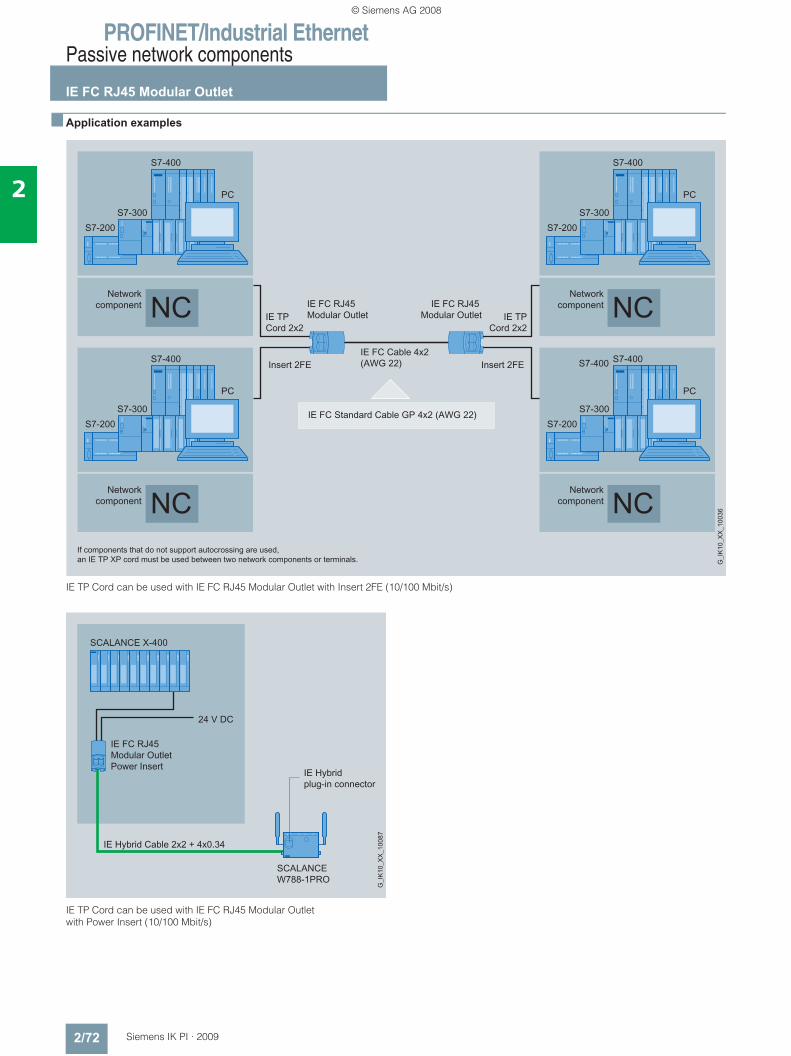
PROFINET/Industrial EthernetPassive network components
IE FC RJ45 Modular Outlet
2/72 Siemens IK PI · 2009
2
■ Application examples
IE TP Cord can be used with IE FC RJ45 Modular Outlet with Insert 2FE (10/100 Mbit/s)
IE TP Cord can be used with IE FC RJ45 Modular Outlet with Power Insert (10/100 Mbit/s)
© Siemens AG 2008
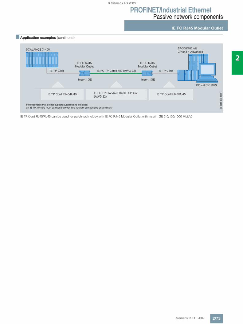
PROFINET/Industrial EthernetPassive network components
IE FC RJ45 Modular Outlet
2/73Siemens IK PI · 2009
2
■ Application examples (continued)
IE TP Cord RJ45/RJ45 can be used for patch technology with IE FC RJ45 Modular Outlet with Insert 1GE (10/100/1000 Mbit/s)
© Siemens AG 2008
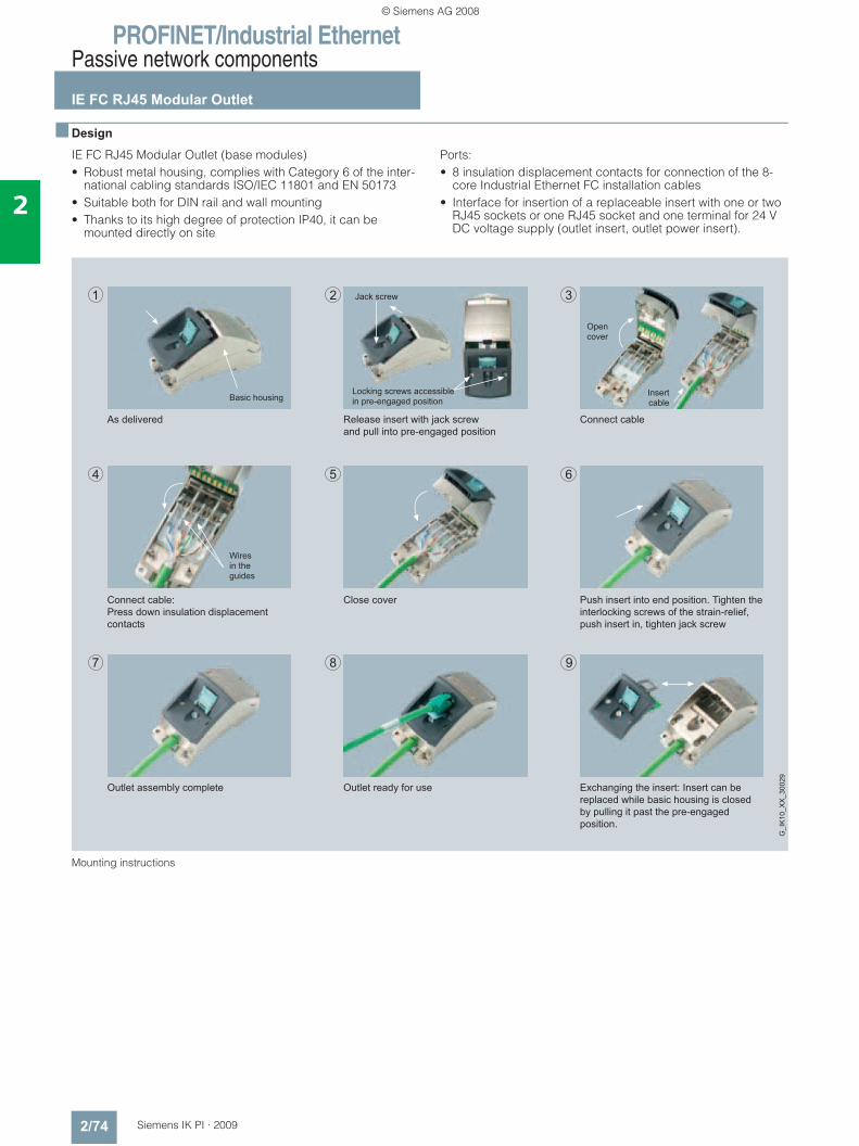
PROFINET/Industrial EthernetPassive network components
IE FC RJ45 Modular Outlet
2/74 Siemens IK PI · 2009
2
■ Design
IE FC RJ45 Modular Outlet (base modules)• Robust metal housing, complies with Category 6 of the inter-
national cabling standards ISO/IEC 11801 and EN 50173• Suitable both for DIN rail and wall mounting• Thanks to its high degree of protection IP40, it can be
mounted directly on site
Ports:• 8 insulation displacement contacts for connection of the 8-
core Industrial Ethernet FC installation cables• Interface for insertion of a replaceable insert with one or two
RJ45 sockets or one RJ45 socket and one terminal for 24 V DC voltage supply (outlet insert, outlet power insert).
Mounting instructions
Outlet assembly complete Outlet ready for use Exchanging the insert: Insert can bereplaced while basic housing is closedby pulling it past the pre-engagedposition.
Connect cable:Press down insulation displacement contacts
Close cover Push insert into end position. Tighten the interlocking screws of the strain-relief, push insert in, tighten jack screw
As delivered Release insert with jack screwand pull into pre-engaged position
Connect cable
Wiresin theguides
Basic housing
Opencover
Insertcable
Jack screw
Locking screws accessiblein pre-engaged position
G_I
K10
_XX
_300
29
© Siemens AG 2008
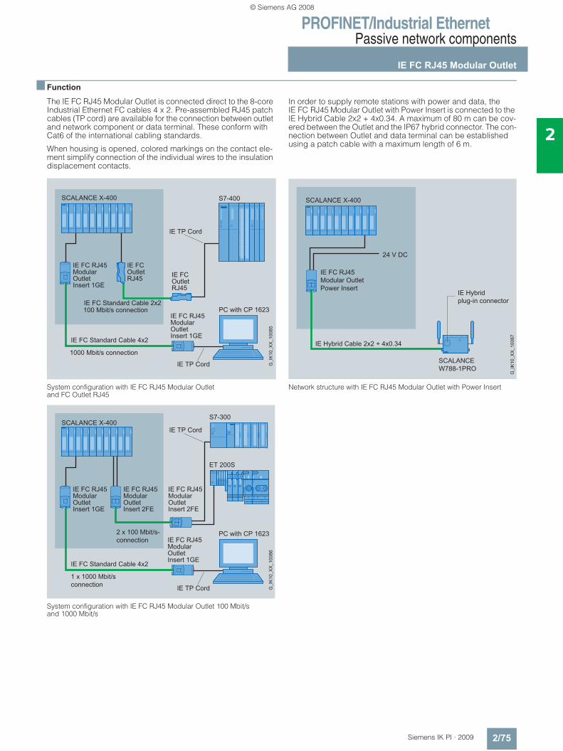
PROFINET/Industrial EthernetPassive network components
IE FC RJ45 Modular Outlet
2/75Siemens IK PI · 2009
2
■ Function
The IE FC RJ45 Modular Outlet is connected direct to the 8-core Industrial Ethernet FC cables 4 x 2. Pre-assembled RJ45 patch cables (TP cord) are available for the connection between outlet and network component or data terminal. These conform with Cat6 of the international cabling standards.
When housing is opened, colored markings on the contact ele-ment simplify connection of the individual wires to the insulation displacement contacts.
In order to supply remote stations with power and data, the IE FC RJ45 Modular Outlet with Power Insert is connected to the IE Hybrid Cable 2x2 + 4x0.34. A maximum of 80 m can be cov-ered between the Outlet and the IP67 hybrid connector. The con-nection between Outlet and data terminal can be established using a patch cable with a maximum length of 6 m.
System configuration with IE FC RJ45 Modular Outlet and FC Outlet RJ45
System configuration with IE FC RJ45 Modular Outlet 100 Mbit/s and 1000 Mbit/s
Network structure with IE FC RJ45 Modular Outlet with Power Insert
© Siemens AG 2008
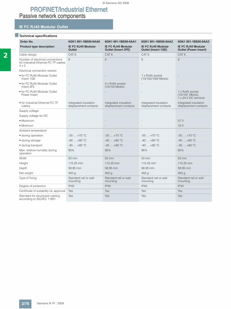
PROFINET/Industrial EthernetPassive network components
IE FC RJ45 Modular Outlet
2/76 Siemens IK PI · 2009
2
■ Technical specifications
Order No. 6GK1 901-1BE00-0AA0 6GK1 901-1BE00-0AA1 6GK1 901-1BE00-0AA2 6GK1 901-1BE00-0AA3Product type description IE FC RJ45 Modular
OutletIE FC RJ45 Modular Outlet (Insert 2FE)
IE FC RJ45 Modular Outlet (Insert 1GE)
IE FC RJ45 Modular Outlet (Power Insert)
Cable design CAT 6 CAT 6 CAT 6 CAT 6
Number of electrical connections for Industrial Ethernet FC TP cables 4 x 2
8 8 8 8
Electrical connection version
• for FC RJ45 Modular OutletInsert 1GE
- - 1 x RJ45 socket (10/100/1000 Mbit/s)
-
• for FC RJ45 Modular OutletInsert 2FE
- 2 x RJ45 socket (10/100 Mbit/s)
- -
• for FC RJ45 Modular Outlet Power Insert
- - - 1 x RJ45 socket (10/100 Mbit/s), 1 x 24 V DC terminal
• for Industrial Ethernet FC TP cables
integrated insulationdisplacement contacts
integrated insulationdisplacement contacts
integrated insulationdisplacement contacts
integrated insulationdisplacement contacts
Supply voltage
Supply voltage for DC
• Maximum - - - 57 V
• Minimum - - - 19 V
Ambient temperature
• during operation -20 … +70 °C -20 … +70 °C -20 … +70 °C -20 … +70 °C
• during storage -40 … +80 °C -40 … +80 °C -40 … +80 °C -40 … +80 °C
• during transport -40 … +80 °C -40 … +80 °C -40 … +80 °C -40 … +80 °C
Max. relative humidity during operation
95% 95% 95% 95%
Width 50 mm 50 mm 50 mm 50 mm
Height 115.25 mm 115.25 mm 115.25 mm 115.25 mm
Depth 58.95 mm 58.95 mm 58.95 mm 58.95 mm
Net weight 450 g 450 g 450 g 450 g
Type of fixing Standard rail or wall mounting
Standard rail or wall mounting
Standard rail or wall mounting
Standard rail or wall mounting
Degree of protection IP40 IP40 IP40 IP40
Certificate of suitability UL approval Yes Yes Yes Yes
Standard for structured cabling according to ISO/IEC 11801
Yes Yes Yes Yes
© Siemens AG 2008
PROFINET/Industrial EthernetPassive network components
IE FC RJ45 Modular Outlet
2/77Siemens IK PI · 2009
2
■ Ordering data Order No. Order No.
IE FC RJ45 Modular Outlet FastConnect RJ45 Outlet for Industrial Ethernet with interface for a replaceable insert;
• without replaceable insert 6GK1 901-1BE00-0AA0• with 2FE insert;
replaceable insert for 2 x 100 Mbit/s interfaces
6GK1 901-1BE00-0AA1
• with 1GE insert; replaceable insertfor 1 x 1000 Mbit/s interfaces
6GK1 901-1BE00-0AA2
• with power insert; replaceable insert for 1 x 24 V DC and 1 x 100 Mbit/s interface
6GK1 901-1BE00-0AA3
IE FC RJ45 Modular Outlet Insert 2FE
6GK1 901-1BK00-0AA1
Replaceable insert for FC Modular Outlet Base; 2 x RJ45 for 2 x 100 Mbit/s interfaces; 1 pack = 4 items
IE FC RJ45 Modular Outlet Insert 1GE
6GK1 901-1BK00-0AA2
Replaceable insert for FC Modular Outlet Base; 1 x RJ45 for 1 x 1000 Mbit/s interface; 1 pack = 4 items
IE FC TP Standard Cable 4 x 2 6XV1 870-2E8-core FastConnect cable (Cat6) for permanent wiring; sold by the meter
IE Hybrid Cable 2x2 + 4x0.34 6XV1870-2JFlexible cable, 4 x Cu Cat5, shielded (0.75 mm) and 4 x Cu (0.34 mm2) with IE FC modular outlet and power insert and IP67 hybrid plug connector; sold by the meter; up to 1000 m; minimum order 20 m
Energy Cable 6XV1812-8A2-wire power cable; stranded wire, 2 x 0.75 mm2, can be trailed, sold by the meter; up to 1000 m, minimum order 20 m
IE TP Cord see TP Cord
8-core patch cable for connection between FC Modular Outlet base modules and data terminal; available in different lengths
IE FC stripping tool 6GK1 901-1GA00Preadjusted stripping toolfor fast stripping of Industrial Ethernet FC cables
© Siemens AG 2008
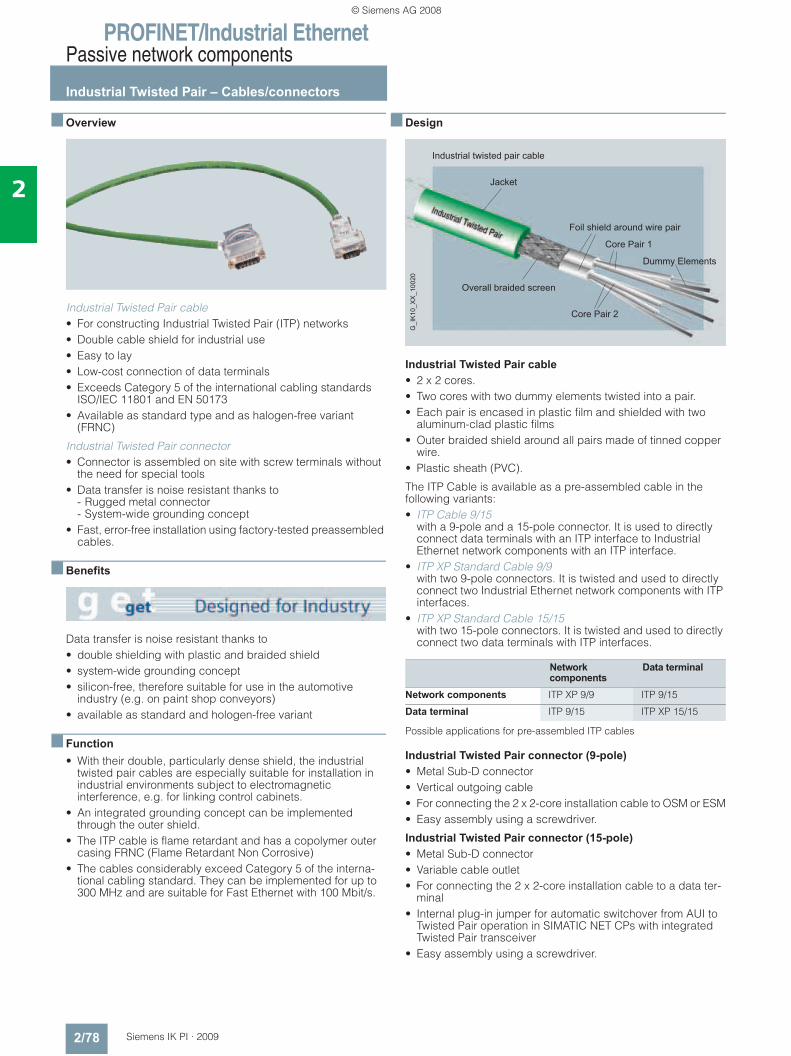
PROFINET/Industrial EthernetPassive network components
Industrial Twisted Pair – Cables/connectors
2/78 Siemens IK PI · 2009
2
■ Overview
Industrial Twisted Pair cable• For constructing Industrial Twisted Pair (ITP) networks• Double cable shield for industrial use• Easy to lay• Low-cost connection of data terminals• Exceeds Category 5 of the international cabling standards
ISO/IEC 11801 and EN 50173• Available as standard type and as halogen-free variant
(FRNC)
Industrial Twisted Pair connector • Connector is assembled on site with screw terminals without
the need for special tools• Data transfer is noise resistant thanks to
- Rugged metal connector- System-wide grounding concept
• Fast, error-free installation using factory-tested preassembled cables.
■ Benefits
Data transfer is noise resistant thanks to• double shielding with plastic and braided shield• system-wide grounding concept• silicon-free, therefore suitable for use in the automotive
industry (e.g. on paint shop conveyors)• available as standard and hologen-free variant
■ Function• With their double, particularly dense shield, the industrial
twisted pair cables are especially suitable for installation in industrial environments subject to electromagnetic interference, e.g. for linking control cabinets.
• An integrated grounding concept can be implemented through the outer shield.
• The ITP cable is flame retardant and has a copolymer outer casing FRNC (Flame Retardant Non Corrosive)
• The cables considerably exceed Category 5 of the interna-tional cabling standard. They can be implemented for up to 300 MHz and are suitable for Fast Ethernet with 100 Mbit/s.
■ Design
Industrial Twisted Pair cable • 2 x 2 cores.• Two cores with two dummy elements twisted into a pair.• Each pair is encased in plastic film and shielded with two
aluminum-clad plastic films• Outer braided shield around all pairs made of tinned copper
wire.• Plastic sheath (PVC).
The ITP Cable is available as a pre-assembled cable in the following variants:• ITP Cable 9/15
with a 9-pole and a 15-pole connector. It is used to directly connect data terminals with an ITP interface to Industrial Ethernet network components with an ITP interface.
• ITP XP Standard Cable 9/9 with two 9-pole connectors. It is twisted and used to directly connect two Industrial Ethernet network components with ITP interfaces.
• ITP XP Standard Cable 15/15 with two 15-pole connectors. It is twisted and used to directly connect two data terminals with ITP interfaces.
Possible applications for pre-assembled ITP cables
Industrial Twisted Pair connector (9-pole) • Metal Sub-D connector• Vertical outgoing cable• For connecting the 2 x 2-core installation cable to OSM or ESM• Easy assembly using a screwdriver.
Industrial Twisted Pair connector (15-pole) • Metal Sub-D connector• Variable cable outlet• For connecting the 2 x 2-core installation cable to a data ter-
minal• Internal plug-in jumper for automatic switchover from AUI to
Twisted Pair operation in SIMATIC NET CPs with integrated Twisted Pair transceiver
• Easy assembly using a screwdriver.
Network components
Data terminal
Network components ITP XP 9/9 ITP 9/15
Data terminal ITP 9/15 ITP XP 15/15
Jacket
Foil shield around wire pair
Overall braided screen
Core Pair 1
Core Pair 2
Dummy Elements
Industrial twisted pair cable
G_I
K10
_XX
_100
20
© Siemens AG 2008
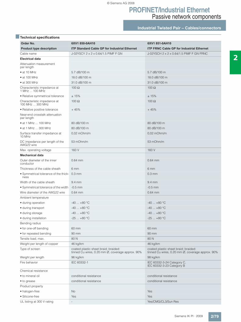
PROFINET/Industrial EthernetPassive network components
Industrial Twisted Pair – Cables/connectors
2/79Siemens IK PI · 2009
2
■ Technical specifications
Order No. 6XV1 850-0AH10 6XV1 851-0AH10Product type description ITP Standard Cable GP for Industrial Ethernet ITP FRNC Cable GP for Industrial Ethernet
Cable name J-02YSCY 2 x 2 x 0.64/1.5 PIMF F GN J-02YSCH 2 x 2 x 0.64/1.5 PIMF F GN FRNC
Electrical data
Attenuation measurement per length
• at 10 MHz 5.7 dB/100 m 5.7 dB/100 m
• at 100 MHz 18.0 dB/100 m 18.0 dB/100 m
• at 300 MHz 31.0 dB/100 m 31.0 dB/100 m
Characteristic impedance at 1 MHz ... 100 MHz
100 Ω 100 Ω
• Relative symmetrical tolerance ± 15% ± 15%
Characteristic impedance at 100 MHz ... 300 MHz
100 Ω 100 Ω
• Relative positive tolerance + 45% + 45%
Near-end crosstalk attenuation per length
• at 1 MHz ... 100 MHz 80 dB/100 m 80 dB/100 m
• at 1 MHz ... 300 MHz 80 dB/100 m 80 dB/100 m
Surface transfer impedance at 10 MHz
0,02 mOhm/m 0,02 mOhm/m
DC impedance per length of the AWG22 wire
53 mOhm/m 53 mOhm/m
Max. operating voltage 160 V 160 V
Mechanical data
Outer diameter of the inner conductor
0.64 mm 0.64 mm
Thickness of the cable sheath 6 mm 6 mm
• Symmetrical tolerance of the thick-ness
0.3 mm 0.3 mm
Width of the cable sheath 9.4 mm 9.4 mm
• Symmetrical tolerance of the width -0.5 mm -0.5 mm
Wire diameter of the AWG22 wire 0.64 mm 0.64 mm
Ambient temperature
• during operation -40 ... +80 °C -40 ... +80 °C
• during transport -40 ... +80 °C -40 ... +80 °C
• during storage -40 ... +80 °C -40 ... +80 °C
• during installation -25 ... +80 °C -25 ... +80 °C
Bending radius
• for one-off bending 60 mm 60 mm
• for repeated bending 90 mm 90 mm
Tensile load, max. 80 N 80 N
Weight per length of copper 46 kg/km 46 kg/km
Type of screen coated plastic sheet braid; braided: tinned Cu wires, 0.20 mm Ø, coverage approx. 90%
coated plastic sheet braid; braided: tinned Cu wires, 0.20 mm Ø, coverage approx. 90%
Weight per length 96 kg/km 98 kg/km
Fire behavior IEC 60332-1 IEC 60332-3-24 Category C, IEC 60332-3-23 Category B
Chemical resistance
• to mineral oil conditional resistance conditional resistance
• to grease conditional resistance conditional resistance
Product property
• halogen-free No Yes
• Silicone-free Yes Yes
UL listing at 300 V rating - Yes/CMG/CL3/Sun Res
© Siemens AG 2008
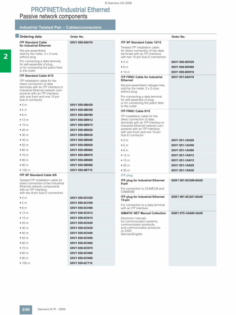
PROFINET/Industrial EthernetPassive network components
Industrial Twisted Pair – Cables/connectors
2/80 Siemens IK PI · 2009
2
■ Ordering data Order No. Order No.
ITP Standard Cable for Industrial Ethernet
6XV1 850-0AH10
Not pre-assembled, sold by the meter, 2 x 2-core, without plugFor connecting a data terminal, for self-assembly of plug,or for connecting the patch field to the outlet
ITP Standard Cable 9/15ITP installation cable for the direct connection of data terminals with an ITP interface to Industrial Ethernet network com-ponents with an ITP interface; with one 9-pin and one 15-pin Sub-D connector
• 2 m 6XV1 850-0BH20• 5 m 6XV1 850-0BH50• 8 m 6XV1 850-0BH80• 12 m 6XV1 850-0BN12• 15 m 6XV1 850-0BN15• 20 m 6XV1 850-0BN20• 30 m 6XV1 850-0BN30• 40 m 6XV1 850-0BN40• 50 m 6XV1 850-0BN50• 60 m 6XV1 850-0BN60• 70 m 6XV1 850-0BN70• 80 m 6XV1 850-0BN80• 90 m 6XV1 850-0BN88• 100 m 6XV1 850-0BT10ITP XP Standard Cable 9/9Twisted ITP installation cable for direct connection of two Industrial Ethernet network components with an ITP interface; with two 9-pin Sub-D connectors
• 2 m 6XV1 850-0CH20• 5 m 6XV1 850-0CH50• 8 m 6XV1 850-0CH80• 12 m 6XV1 850-0CN12• 15 m 6XV1 850-0CN15• 20 m 6XV1 850-0CN20• 30 m 6XV1 850-0CN30• 40 m 6XV1 850-0CN40• 50 m 6XV1 850-0CN50• 60 m 6XV1 850-0CN60• 70 m 6XV1 850-0CN70• 80 m 6XV1 850-0CN80• 90 m 6XV1 850-0CN88• 100 m 6XV1 850-0CT10
ITP XP Standard Cable 15/15Twisted ITP installation cable for direct connection of two data terminals with an ITP interface; with two 15-pin Sub-D connectors
• 2 m 6XV1 850-0DH20• 6 m 6XV1 850-0DH60• 10 m 6XV1 850-0DN10ITP FRNC Cable for Industrial Ethernet
6XV1 851-0AH10
Not pre-assembled, halogen-free, sold by the meter, 2 x 2-core, without plug
For connecting a data terminal, for self-assembly of plug, or for connecting the patch field to the outlet
ITP FRNC Cable 9/15ITP installation cable for the direct connection of data terminals with an ITP interface to Industrial Ethernet network com-ponents with an ITP interface; with one 9-pin and one 15-pin Sub-D connector
• 2 m 6XV1 851-1AH20• 5 m 6XV1 851-1AH50• 8 m 6XV1 851-1AH80• 12 m 6XV1 851-1AN12• 15 m 6XV1 851-1AN15• 20 m 6XV1 851-1AN20• 30 m 6XV1 851-1AN30ITP plugITP plug for Industrial Ethernet 9-pin
6GK1 901-0CA00-0AA0
For connection to OLM/ELM and OSM/ESM
ITP plug for Industrial Ethernet 15-pin
6GK1 901-0CA01-0AA0
For connection to a data terminal with an ITP interface
SIMATIC NET Manual Collection 6GK1 975-1AA00-3AA0Electronic manuals for communication systems, communication protocols, and communication products; on DVD; German/English
© Siemens AG 2008

PROFINET/Industrial EthernetPassive network components
Industrial Twisted Pair – Cables/connectors
2/81Siemens IK PI · 2009
2
■ More information
Installation instructions
The installation cable is either supplied by the meter or with preassembled connectors. It can be used to connect a single data terminal or two active network components (OSM/ESM).
On the network component side, 9-pole metal Sub-D connectors are used, and on the device side, 15-pole connectors are used. The 15-pole connectors contain a special plug-in jumper which can be used by modules with integrated twisted pair transceiver to switch from AUI to twisted pair operation.
Preassembled cables are used to connect data terminals directly to an active network component or for cascading active network components.
The ITP cables can also be ordered by the meter for on site assembly. 9-pole and 15-pole ITP connectors for assembly with-out special tools are available for this purpose.
The maximum cable length of a laid ITP Standard Cable is 100 m if connected directly.
ITP cables are intended only for use inside buildings.
Note:Additional components of the SIMATIC NET wiring range can be ordered from your local contact person.For technical advice contact:J. Hertlein, A&D SE PSTel.: +49(0)911/750 44 65Fax.: +49(0)911/750 99 91Email: [email protected]
Additional installation instructions can be found in the manual for TP and fiber-optic-networks.
© Siemens AG 2008
PROFINET/Industrial EthernetPassive network components
Overview of fiber-optic cables
2/82 Siemens IK PI · 2009
2
■ Overview
• Optical signal transmission• No radiation along the cable• Unaffected by external noise fields• No grounding problems• Electrical isolation• Low weight• Easy routing
■ Application
The fiber optic (FO) cable is used for transmitting signals with the help of waves in the optical frequency range. The light beam is guided by means of total reflection at the transition from the core to the fiber material where there is a lower refractive index than at the core.
The fiber optic cable is provided with a protective coating.
■ Design
Fiber-optic cables with glass fibers , PCF fibers (Polymer Clad-ded Fiber) and POF fibers(Polymer Optical Fiber) are offered for Industrial Ethernet:• Glass fiber-optic cable;
duplex cable for fiber-optic networks indoors and outdoors• POF fiber-optic cable;
Duplex cable for POF networks in the indoor area• PCF fiber-optic cable;
duplex cable for PCF networks indoors and outdoors
Approvals
UL listing (safety standard) for network cables is especially necessary for the American and Canadian markets. The require-ments for the appropriate approvals depend on where the cable is routed within the building. This applies to all cables which have to be routed from a machine to a remote control cabinet and are positioned on cable racks secured on the building. OFN/OFNG cable for routing in bundles (general purpose cable)
Sheath material ApplicationPVC Standard use in indoor and
outdoor areas of industrial appli-cations
PUR Highly mobile applications (trailing cables) for high mechani-cal or chemical stress in harsh industrial environments
PE Routing of cables in moist areas indoors and outdoors, and for direct burying in earth
FRNC Standard applications with high fire protection requirements
© Siemens AG 2008
PROFINET/Industrial EthernetPassive network components
Glass fiber optic cables
2/83Siemens IK PI · 2009
2
■ Overview
• Used for the optical Industrial Ethernet and PROFIBUS net-works
• Rugged design for industrial applications indoors and out-doors
• Halogen-free design for installation inside buildings• Trailing cable for the special application of forced motion con-
trol• High immunity to noise thanks to insensitivity to electro-mag-
netic fields• Available preassembled• Extensive approvals (UL)
■ Benefits
• Easy routing with - Pre-assembled cables- No grounding problems- Very light fiber-optic cable
• Tap-proof due to lack of radiation from the cable
• Silicon-free; therefore suitable for use in the automotive industry (e.g. on paint shop conveyors)
■ Application
Fiber-optic indoor cableHalogen-free fiber-optic cable, non-crush, flame-retardant, for installation inside buildings (e.g. in production halls and in build-ing automation). Supplied in fixed lengths, pre-assembled with four BFOC connectors.
Standard FOC/FRNC cableFiber-optic cables for the following application areas indoors and outdoors• For routing above ground• For installation inside buildings.
Sold by the meter and in fixed lengths, pre-assembled with four BFOC connectors or four SC connectors.
Fiber-optic trailing cableFiber-optic cables for the special application of forced motion control, such as in continuously moving machine parts (in trailing cables) indoors and outdoors. Two cable variants are available for this application:• FO Trailing Cable;
Cable for high mechanical stress, PUR outer sheath, no UL approval
• FO Trailing Cable GP (general purpose); Cable for low mechanical stress, PVC outer sheath, with UL approval
Sold by the meter and in fixed lengths, pre-assembled with four BFOC connectors or four SC connectors.
Fiber-optic outdoor cableWaterproof cable (lengthwise and sideways) for use outdoors with non-metallic protection against rodents for laying into the ground.
Sold by the meter and in fixed lengths, pre-assembled with four BFOC connectors or four SC connectors.
Note:Special tools and specially trained personnel are required for pre-assembling glass fiber-optic cables
© Siemens AG 2008
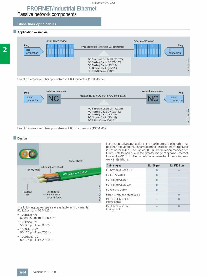
PROFINET/Industrial EthernetPassive network components
Glass fiber optic cables
2/84 Siemens IK PI · 2009
2
■ Application examples
Use of pre-assembled fiber-optic cables with SC connectors (1000 Mbit/s)
Use of pre-assembled fiber-optic cables with BFOC connectors (100 Mbit/s)
■ Design
The following cable types are available in two variants, 50/125 μm and 62.5/125 μm:• 100Base FX;
62.5/125 μm fiber, 3,000 m• 100Base FX;
50/125 μm fiber, 3,000 m• 1000Base SX;
50/125 μm fiber, 750 m• 1000Base LX;
50/125 μm fiber, 2,000 m
In the respective applications, the maximum cable lengths must be taken into account. Passive connection of different fiber types is not permissible. The use of 50 μm fiber is recommended for future installations due to the greater range of gigabit Ethernet. Use of the 62.5 μm fiber is only recommended for existing net-work installations.
Opticalfiber
Strain reliefby means ofAramid fibers
Outer sheath
Individual core sheathHollow core
G_I
K10
_XX
_100
30
Cable types 50/125 µm 62,5/125 µmFO Standard Cable GP ● –
FO FRNC Cable ● –
FO Trailing Cable ● –
FO Trailing Cable GP ● –
FO Ground Cable ● –
FIBER OPTIC standard cable – ●
INDOOR Fiber Optic indoor cable
– ●
Flexible Fiber Optictrailing cable
– ●
© Siemens AG 2008
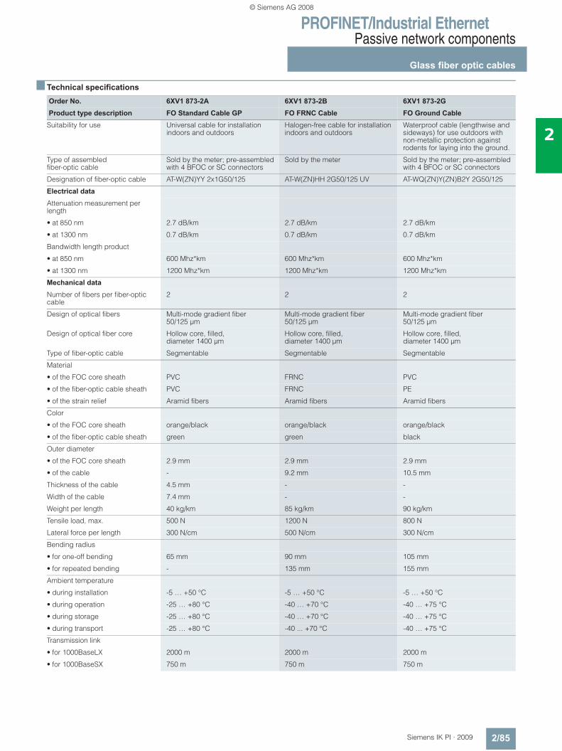
PROFINET/Industrial EthernetPassive network components
Glass fiber optic cables
2/85Siemens IK PI · 2009
2
■ Technical specifications
Order No. 6XV1 873-2A 6XV1 873-2B 6XV1 873-2GProduct type description FO Standard Cable GP FO FRNC Cable FO Ground Cable
Suitability for use Universal cable for installation indoors and outdoors
Halogen-free cable for installation indoors and outdoors
Waterproof cable (lengthwise and sideways) for use outdoors with non-metallic protection against rodents for laying into the ground.
Type of assembled fiber-optic cable
Sold by the meter; pre-assembled with 4 BFOC or SC connectors
Sold by the meter Sold by the meter; pre-assembled with 4 BFOC or SC connectors
Designation of fiber-optic cable AT-W(ZN)YY 2x1G50/125 AT-W(ZN)HH 2G50/125 UV AT-WQ(ZN)Y(ZN)B2Y 2G50/125
Electrical data
Attenuation measurement per length
• at 850 nm 2.7 dB/km 2.7 dB/km 2.7 dB/km
• at 1300 nm 0.7 dB/km 0.7 dB/km 0.7 dB/km
Bandwidth length product
• at 850 nm 600 Mhz*km 600 Mhz*km 600 Mhz*km
• at 1300 nm 1200 Mhz*km 1200 Mhz*km 1200 Mhz*km
Mechanical data
Number of fibers per fiber-optic cable
2 2 2
Design of optical fibers Multi-mode gradient fiber 50/125 μm
Multi-mode gradient fiber 50/125 μm
Multi-mode gradient fiber 50/125 μm
Design of optical fiber core Hollow core, filled, diameter 1400 μm
Hollow core, filled, diameter 1400 μm
Hollow core, filled, diameter 1400 μm
Type of fiber-optic cable Segmentable Segmentable Segmentable
Material
• of the FOC core sheath PVC FRNC PVC
• of the fiber-optic cable sheath PVC FRNC PE
• of the strain relief Aramid fibers Aramid fibers Aramid fibers
Color
• of the FOC core sheath orange/black orange/black orange/black
• of the fiber-optic cable sheath green green black
Outer diameter
• of the FOC core sheath 2.9 mm 2.9 mm 2.9 mm
• of the cable - 9.2 mm 10.5 mm
Thickness of the cable 4.5 mm - -
Width of the cable 7.4 mm - -
Weight per length 40 kg/km 85 kg/km 90 kg/km
Tensile load, max. 500 N 1200 N 800 N
Lateral force per length 300 N/cm 500 N/cm 300 N/cm
Bending radius
• for one-off bending 65 mm 90 mm 105 mm
• for repeated bending - 135 mm 155 mm
Ambient temperature
• during installation -5 … +50 °C -5 … +50 °C -5 … +50 °C
• during operation -25 … +80 °C -40 … +70 °C -40 … +75 °C
• during storage -25 … +80 °C -40 … +70 °C -40 … +75 °C
• during transport -25 … +80 °C -40 ... +70 °C -40 … +75 °C
Transmission link
• for 1000BaseLX 2000 m 2000 m 2000 m
• for 1000BaseSX 750 m 750 m 750 m
© Siemens AG 2008
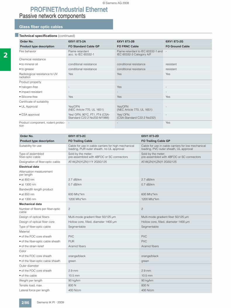
PROFINET/Industrial EthernetPassive network components
Glass fiber optic cables
2/86 Siemens IK PI · 2009
2
■ Technical specifications (continued)
Order No. 6XV1 873-2A 6XV1 873-2B 6XV1 873-2GProduct type description FO Standard Cable GP FO FRNC Cable FO Ground Cable
Fire behavior Flame retardant acc. to IEC 60332-1
Flame retardant to IEC 60332-1 and IEC 60332-3 Category A/F
-
Chemical resistance
• to mineral oil conditional resistance conditional resistance resistant
• to grease conditional resistance conditional resistance resistant
Radiological resistance to UV radiation
Yes Yes Yes
Product property
• halogen-free - Yes -
• impact-resistant - - -
• Silicone-free Yes Yes Yes
Certificate of suitability
• UL Approval Yes/OFN(NEC Article 770, UL 1651)
Yes/OFN(NEC Article 770, UL 1651)
-
• CSA approval Yes/ OFN, 90°C, FT1, FT4 (CSA-Standard C22.2 No232-M1988)
Yes/ OFN,(CSA-Standard C22.2 No232)
-
Product component, rodent protec-tion
- - Yes
Order No. 6XV1 873-2C 6XV1 873-2DProduct type description FO Trailing Cable FO Trailing Cable GP
Suitability for use Cable for use in cable carriers for high mechanical loading, PUR outer sheath, no UL approval
Cable for use in cable carriers for low mechanical loading, PVC outer sheath, UL approval
Type of assembledfiber-optic cable
Sold by the meter; pre-assembled with 4BFOC or SC connectors
Sold by the meter; pre-assembled with 4BFOC or SC connectors
Designation of fiber-optic cable AT-W(ZN)Y(ZN)11Y 2G50/125 AT-W(ZN)Y(ZN)Y 2G50/125
Electrical data
Attenuation measurement per length
• at 850 nm 2.7 dB/km 2.7 dB/km
• at 1300 nm 0.7 dB/km 0.7 dB/km
Bandwidth length product
• at 850 nm 600 Mhz*km 600 Mhz*km
• at 1300 nm 1200 Mhz*km 1200 Mhz*km
Mechanical data
Number of fibers per fiber-optic cable
2 2
Design of optical fibers Multi-mode gradient fiber 50/125 μm Multi-mode gradient fiber 50/125 μm
Design of optical fiber core Hollow core, filled, diameter 1400 μm Hollow core, filled, diameter 1400 μm
Type of fiber-optic cable Segmentable Segmentable
Material
• of the FOC core sheath PVC PVC
• of the fiber-optic cable sheath PUR PVC
• of the strain relief Aramid fibers Aramid fibers
Color
• of the FOC core sheath orange/black orange/black
• of the fiber-optic cable sheath green green
Outer diameter
• of the FOC core sheath 2.9 mm 2.9 mm
• of the cable 10.5 mm 10.5 mm
Weight per length 90 kg/km 90 kg/km
Tensile load, max. 800 N 800 N
Lateral force per length 400 N/cm 400 N/cm
© Siemens AG 2008
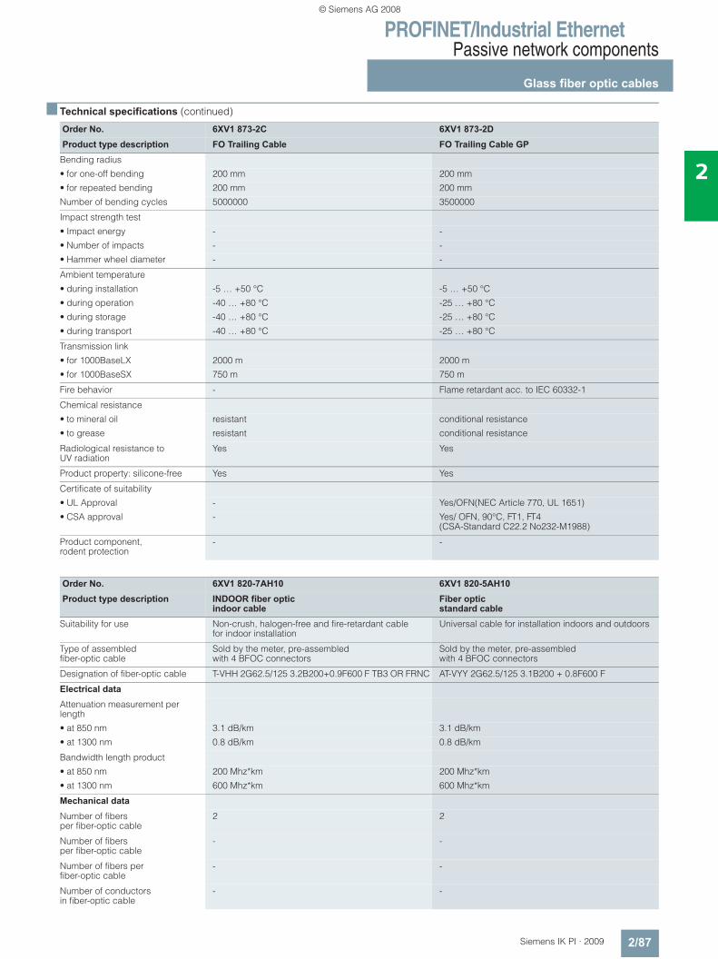
PROFINET/Industrial EthernetPassive network components
Glass fiber optic cables
2/87Siemens IK PI · 2009
2
■ Technical specifications (continued)
Order No. 6XV1 873-2C 6XV1 873-2DProduct type description FO Trailing Cable FO Trailing Cable GP
Bending radius
• for one-off bending 200 mm 200 mm
• for repeated bending 200 mm 200 mm
Number of bending cycles 5000000 3500000
Impact strength test
• Impact energy - -
• Number of impacts - -
• Hammer wheel diameter - -
Ambient temperature
• during installation -5 … +50 °C -5 … +50 °C
• during operation -40 … +80 °C -25 … +80 °C
• during storage -40 … +80 °C -25 … +80 °C
• during transport -40 … +80 °C -25 … +80 °C
Transmission link
• for 1000BaseLX 2000 m 2000 m
• for 1000BaseSX 750 m 750 m
Fire behavior - Flame retardant acc. to IEC 60332-1
Chemical resistance
• to mineral oil resistant conditional resistance
• to grease resistant conditional resistance
Radiological resistance to UV radiation
Yes Yes
Product property: silicone-free Yes Yes
Certificate of suitability
• UL Approval - Yes/OFN(NEC Article 770, UL 1651)
• CSA approval - Yes/ OFN, 90°C, FT1, FT4 (CSA-Standard C22.2 No232-M1988)
Product component, rodent protection
- -
Order No. 6XV1 820-7AH10 6XV1 820-5AH10Product type description INDOOR fiber optic
indoor cable Fiber optic standard cable
Suitability for use Non-crush, halogen-free and fire-retardant cablefor indoor installation
Universal cable for installation indoors and outdoors
Type of assembled fiber-optic cable
Sold by the meter, pre-assembled with 4 BFOC connectors
Sold by the meter, pre-assembled with 4 BFOC connectors
Designation of fiber-optic cable T-VHH 2G62.5/125 3.2B200+0.9F600 F TB3 OR FRNC AT-VYY 2G62.5/125 3.1B200 + 0.8F600 F
Electrical data
Attenuation measurement per length
• at 850 nm 3.1 dB/km 3.1 dB/km
• at 1300 nm 0.8 dB/km 0.8 dB/km
Bandwidth length product
• at 850 nm 200 Mhz*km 200 Mhz*km
• at 1300 nm 600 Mhz*km 600 Mhz*km
Mechanical data
Number of fibers per fiber-optic cable
2 2
Number of fibersper fiber-optic cable
- -
Number of fibers per fiber-optic cable
- -
Number of conductors in fiber-optic cable
- -
© Siemens AG 2008
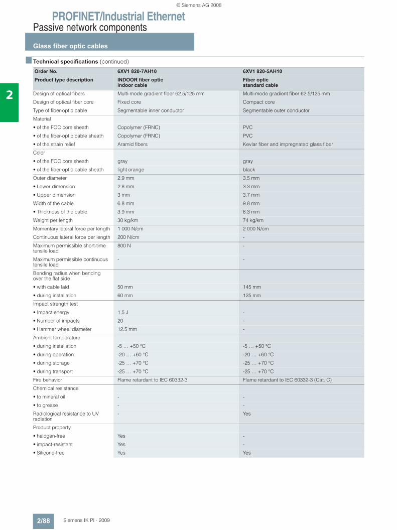
PROFINET/Industrial EthernetPassive network components
Glass fiber optic cables
2/88 Siemens IK PI · 2009
2
■ Technical specifications (continued)
Order No. 6XV1 820-7AH10 6XV1 820-5AH10Product type description INDOOR fiber optic
indoor cable Fiber optic standard cable
Design of optical fibers Multi-mode gradient fiber 62.5/125 mm Multi-mode gradient fiber 62.5/125 mm
Design of optical fiber core Fixed core Compact core
Type of fiber-optic cable Segmentable inner conductor Segmentable outer conductor
Material
• of the FOC core sheath Copolymer (FRNC) PVC
• of the fiber-optic cable sheath Copolymer (FRNC) PVC
• of the strain relief Aramid fibers Kevlar fiber and impregnated glass fiber
Color
• of the FOC core sheath gray gray
• of the fiber-optic cable sheath light orange black
Outer diameter 2.9 mm 3.5 mm
• Lower dimension 2.8 mm 3.3 mm
• Upper dimension 3 mm 3.7 mm
Width of the cable 6.8 mm 9.8 mm
• Thickness of the cable 3.9 mm 6.3 mm
Weight per length 30 kg/km 74 kg/km
Momentary lateral force per length 1 000 N/cm 2 000 N/cm
Continuous lateral force per length 200 N/cm -
Maximum permissible short-time tensile load
800 N -
Maximum permissible continuous tensile load
- -
Bending radius when bending over the flat side
• with cable laid 50 mm 145 mm
• during installation 60 mm 125 mm
Impact strength test
• Impact energy 1,5 J -
• Number of impacts 20 -
• Hammer wheel diameter 12.5 mm -
Ambient temperature
• during installation -5 … +50 °C -5 … +50 °C
• during operation -20 … +60 °C -20 … +60 °C
• during storage -25 … +70 °C -25 … +70 °C
• during transport -25 … +70 °C -25 … +70 °C
Fire behavior Flame retardant to IEC 60332-3 Flame retardant to IEC 60332-3 (Cat. C)
Chemical resistance
• to mineral oil - -
• to grease - -
Radiological resistance to UV radiation
- Yes
Product property
• halogen-free Yes -
• impact-resistant Yes -
• Silicone-free Yes Yes
© Siemens AG 2008
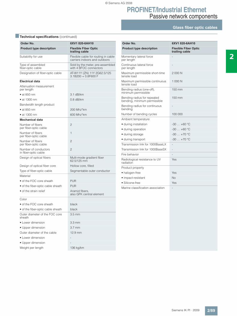
PROFINET/Industrial EthernetPassive network components
Glass fiber optic cables
2/89Siemens IK PI · 2009
2
■ Technical specifications (continued)
Order No. 6XV1 820-6AH10Product type description Flexible Fiber Optic
trailing cable Suitability for use Flexible cable for routing in cable
carriers indoors and outdoors
Type of assembled fiber-optic cable
Sold by the meter, pre-assembled with 4 BFOC connectors
Designation of fiber-optic cable AT-W11Y (ZN) 11Y 2G62.5/125 3.1B200 + 0.8F600 F
Electrical data
Attenuation measurement per length
• at 850 nm 3.1 dB/km
• at 1300 nm 0.8 dB/km
Bandwidth length product
• at 850 nm 200 Mhz*km
• at 1300 nm 600 Mhz*km
Mechanical data
Number of fibers per fiber-optic cable
2
Number of fibers per fiber-optic cable
1
Number of fibers per fiber-optic cable
2
Number of conductors in fiber-optic cable
2
Design of optical fibers Multi-mode gradient fiber 62.5/125 mm
Design of optical fiber core Hollow core, filled
Type of fiber-optic cable Segmentable outer conductor
Material
• of the FOC core sheath PUR
• of the fiber-optic cable sheath PUR
• of the strain relief Aramid fibers, also GFK central element
Color
• of the FOC core sheath black
• of the fiber-optic cable sheath black
Outer diameter of the FOC core sheath
3.5 mm
• Lower dimension 3.3 mm
• Upper dimension 3.7 mm
Outer diameter of the cable 12.9 mm
• Lower dimension -
• Upper dimension -
Weight per length 136 kg/km
Order No. 6XV1 820-6AH10Product type description Flexible Fiber Optic
trailing cable Momentary lateral force per length
-
Continuous lateral force per length
-
Maximum permissible short-time tensile load
2 000 N
Maximum permissible continuous tensile load
1 000 N
Bending radius (one-off), minimum permissible
150 mm
Bending radius for repeated bending, minimum permissible
150 mm
Bending radius for continuous bending
-
Number of bending cycles 100 000
Ambient temperature
• during installation -30 … +60 °C
• during operation -30 … +60 °C
• during storage -30 … +70 °C
• during transport -30 … +70 °C
Transmission link for 1000BaseLX -
Transmission link for 1000BaseSX -
Fire behavior -
Radiological resistance to UV radiation
Yes
Product property
• halogen-free Yes
• impact-resistant No
• Silicone-free Yes
Marine classification association -
© Siemens AG 2008
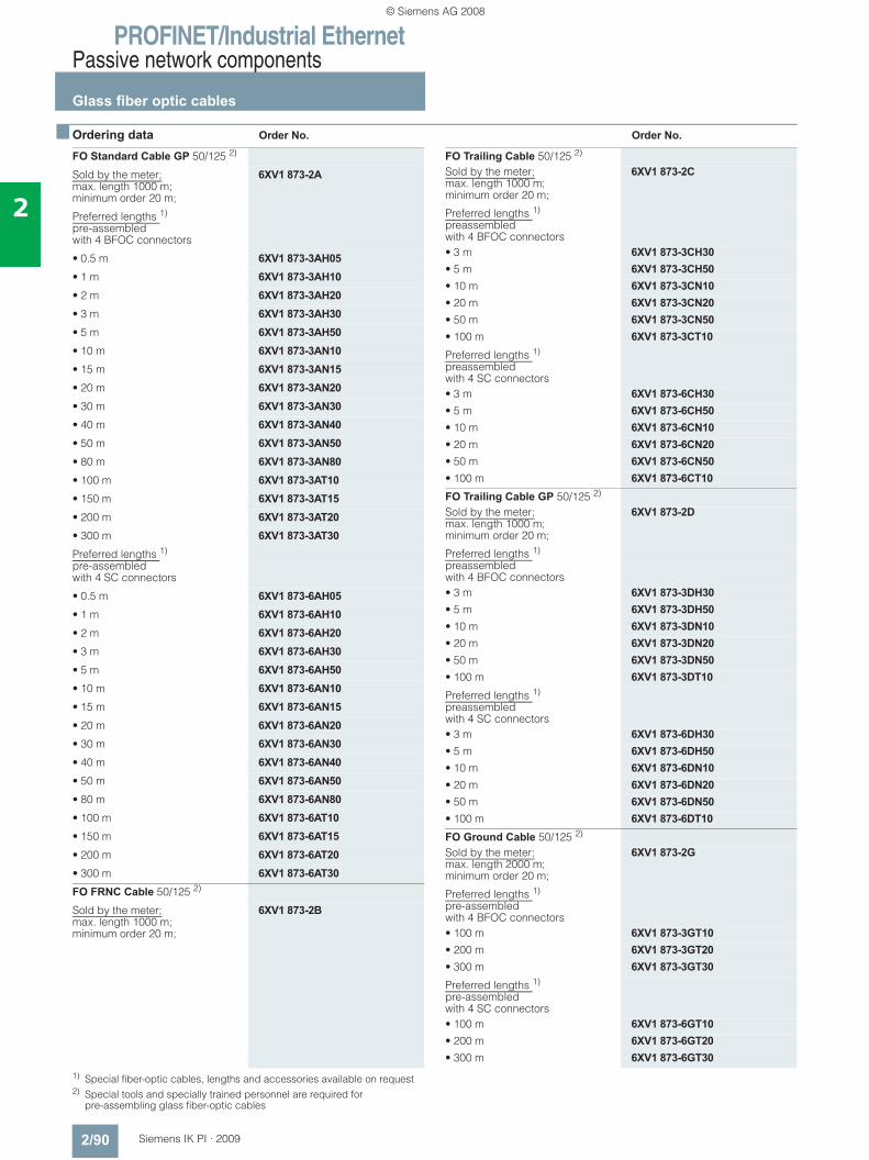
PROFINET/Industrial EthernetPassive network components
Glass fiber optic cables
2/90 Siemens IK PI · 2009
2
■ Ordering data Order No. Order No.
1) Special fiber-optic cables, lengths and accessories available on request2) Special tools and specially trained personnel are required for
pre-assembling glass fiber-optic cables
FO Standard Cable GP 50/125 2)
Sold by the meter; max. length 1000 m; minimum order 20 m;
6XV1 873-2A
Preferred lengths 1)
pre-assembled with 4 BFOC connectors
• 0.5 m 6XV1 873-3AH05• 1 m 6XV1 873-3AH10• 2 m 6XV1 873-3AH20• 3 m 6XV1 873-3AH30• 5 m 6XV1 873-3AH50• 10 m 6XV1 873-3AN10• 15 m 6XV1 873-3AN15• 20 m 6XV1 873-3AN20• 30 m 6XV1 873-3AN30• 40 m 6XV1 873-3AN40• 50 m 6XV1 873-3AN50• 80 m 6XV1 873-3AN80• 100 m 6XV1 873-3AT10• 150 m 6XV1 873-3AT15• 200 m 6XV1 873-3AT20• 300 m 6XV1 873-3AT30Preferred lengths 1)
pre-assembled with 4 SC connectors
• 0.5 m 6XV1 873-6AH05• 1 m 6XV1 873-6AH10• 2 m 6XV1 873-6AH20• 3 m 6XV1 873-6AH30• 5 m 6XV1 873-6AH50• 10 m 6XV1 873-6AN10• 15 m 6XV1 873-6AN15• 20 m 6XV1 873-6AN20• 30 m 6XV1 873-6AN30• 40 m 6XV1 873-6AN40• 50 m 6XV1 873-6AN50• 80 m 6XV1 873-6AN80• 100 m 6XV1 873-6AT10• 150 m 6XV1 873-6AT15• 200 m 6XV1 873-6AT20• 300 m 6XV1 873-6AT30FO FRNC Cable 50/125 2)
Sold by the meter; max. length 1000 m; minimum order 20 m;
6XV1 873-2B
FO Trailing Cable 50/125 2)
Sold by the meter; max. length 1000 m; minimum order 20 m;
6XV1 873-2C
Preferred lengths 1)
preassembled with 4 BFOC connectors• 3 m 6XV1 873-3CH30• 5 m 6XV1 873-3CH50• 10 m 6XV1 873-3CN10• 20 m 6XV1 873-3CN20• 50 m 6XV1 873-3CN50• 100 m 6XV1 873-3CT10Preferred lengths 1)
preassembled with 4 SC connectors• 3 m 6XV1 873-6CH30• 5 m 6XV1 873-6CH50• 10 m 6XV1 873-6CN10• 20 m 6XV1 873-6CN20• 50 m 6XV1 873-6CN50• 100 m 6XV1 873-6CT10FO Trailing Cable GP 50/125 2)
Sold by the meter; max. length 1000 m; minimum order 20 m;
6XV1 873-2D
Preferred lengths 1)
preassembled with 4 BFOC connectors• 3 m 6XV1 873-3DH30• 5 m 6XV1 873-3DH50• 10 m 6XV1 873-3DN10• 20 m 6XV1 873-3DN20• 50 m 6XV1 873-3DN50• 100 m 6XV1 873-3DT10Preferred lengths 1)
preassembled with 4 SC connectors• 3 m 6XV1 873-6DH30• 5 m 6XV1 873-6DH50• 10 m 6XV1 873-6DN10• 20 m 6XV1 873-6DN20• 50 m 6XV1 873-6DN50• 100 m 6XV1 873-6DT10FO Ground Cable 50/125 2)
Sold by the meter; max. length 2000 m; minimum order 20 m;
6XV1 873-2G
Preferred lengths 1)
pre-assembled with 4 BFOC connectors• 100 m 6XV1 873-3GT10• 200 m 6XV1 873-3GT20• 300 m 6XV1 873-3GT30Preferred lengths 1)
pre-assembled with 4 SC connectors• 100 m 6XV1 873-6GT10• 200 m 6XV1 873-6GT20• 300 m 6XV1 873-6GT30
© Siemens AG 2008
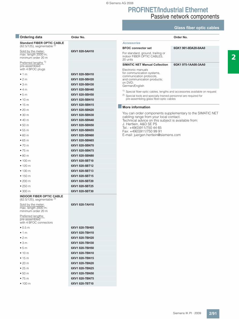
PROFINET/Industrial EthernetPassive network components
Glass fiber optic cables
2/91Siemens IK PI · 2009
2
■ Ordering data Order No. Order No.
1) Special fiber-optic cables, lengths and accessories available on request2) Special tools and specially trained personnel are required for
pre-assembling glass fiber-optic cables
■ More information
You can order components supplementary to the SIMATIC NET cabling range from your local contact.Technical advice on this subject is available from:J. Hertlein, A&D SE PSTel.: +49(0)911/750 44 65Fax: +49(0)911/750 99 91E-mail: [email protected]
Standard FIBER OPTIC CABLE (62.5/125), segmentable 2)
Sold by the meter; max. length 2000 m; minimum order 20 m
6XV1 820-5AH10
Preferred lengths 1)
pre-assembled with 4 BFOC plugs
• 1 m 6XV1 820-5BH10• 2 m 6XV1 820-5BH20• 3 m 6XV1 820-5BH30• 4 m 6XV1 820-5BH40• 5 m 6XV1 820-5BH50• 10 m 6XV1 820-5BN10• 15 m 6XV1 820-5BN15• 20 m 6XV1 820-5BN20• 30 m 6XV1 820-5BN30• 40 m 6XV1 820-5BN40• 50 m 6XV1 820-5BN50• 55 m 6XV1 820-5BN55• 60 m 6XV1 820-5BN60• 65 m 6XV1 820-5BN65• 70 m 6XV1 820-5BN70• 75 m 6XV1 820-5BN75• 80 m 6XV1 820-5BN80• 100 m 6XV1 820-5BT10• 120 m 6XV1 820-5BT12• 130 m 6XV1 820-5BT13• 150 m 6XV1 820-5BT15• 200 m 6XV1 820-5BT20• 250 m 6XV1 820-5BT25• 300 m 6XV1 820-5BT30INDOOR FIBER OPTIC CABLE (62.5/125), segmentable 2)
Sold by the meter; max. length 2000 m; minimum order 20 m
6XV1 820-7AH10
Preferred lengths; pre-assembled with 4 BFOC connectors
• 0.5 m 6XV1 820-7BH05• 1 m 6XV1 820-7BH10• 2 m 6XV1 820-7BH20• 3 m 6XV1 820-7BH30• 5 m 6XV1 820-7BH50• 10 m 6XV1 820-7BN10• 15 m 6XV1 820-7BN15• 20 m 6XV1 820-7BN20• 25 m 6XV1 820-7BN25• 50 m 6XV1 820-7BN50• 75 m 6XV1 820-7BN75• 100 m 6XV1 820-7BT10
AccessoriesBFOC connector set 6GK1 901-0DA20-0AA0For standard, ground, trailing or indoor FIBER OPTIC CABLES, 20 units
SIMATIC NET Manual Collection 6GK1 975-1AA00-3AA0Electronic manuals for communication systems, communication protocols, and communication products; on DVD; German/English
© Siemens AG 2008
PROFINET/Industrial EthernetPassive network components
POF and PCF fiber-optic cables
2/92 Siemens IK PI · 2009
2
■ Overview
• Electrical isolation of PROFINET/Ethernet devices• Protection of the transmission path against electromagnetic
interference• Up to 50 m cable length with plastic fiber optic cables and up
to 100 m with PCF fiber optic cables• Rugged fiber-optic standard cables, designed for industrial
applications• Extensive approvals (UL)
■ Benefits
• Plastic and PCF fiber optic cables can be pre-assembled on site
• Easy connector assembly on site• Time savings on start-up thanks to pre-assembled cables• Protection of the transmission path against electromagnetic
interference• Tap-proof, because the cable does not radiate
■ Application
SIMATIC NET POF and PCF fiber optic cables are used to con-struct optical indoor PROFINET and Industrial Ethernet net-works. Devices with integral optical interface (SC RJ connection system) are, for example, SCALANCE X200-4P IRT, SCALANCE X201-3P IRT, SCALANCE X202-2P IRT, SCALANCE X101-1POF, ET 200S.
POF and PCF fiber optic cables can be assembled easily on site with SC RJ plugs. The maximum cable length between two devices is 50 m for POF and 100 m for PCF fiber-optic cables. PCF cables are also available preassembled with 2 SC RJ plugs.
■ Design
Different types of POF and PCF fiber optic cables are offered:
POF fiber optic cables
Rugged round cables with green outer sheath and Kevlar strain relief elements as well as two plastic fibers with rugged Polyamid inner sheath for applications indoors/outdoors with cable lengths up to 50 m. The cables are suitable for assembly in the field.• POF Standard Cable GP (General Purpose);
for applications indoor/outdoors • POF Trailing Cable;
for trailing cable applications
PCF fiber optic cables Rugged round cables with green outer sheath and Kevlar strain relief elements for applications indoor/outdoors with cable lengths up to 100 m. The cables are suitable for assembly in the field.• PCF Standard Cable GP (General Purpose);
for applications indoor/outdoors with cable lengths up to 100 m.
• PCF fiber-optic trailing cable; for trailing cable applications with cable lengths of up to 100 m. The cable is suitable for assembly in the field. The following cable versions are available: - PCF Trailing Cable;
cable for high mechanical stress, PUR outer sheath, no UL approval
- PCF Trailing Cable GP (general purpose); cable for low mechanical stress, PVC outer sheath, with UL approval
���������
����� ��� � �������������
��� ����� ����� ���� ������
������ �� ����
��
�����
����
�����
���������
��� ����� ���� ����� ���������� ���
����������
���������������
����������� ��� ����� ����� ����������
� �������������
������������������
�����
����
����
�
© Siemens AG 2008
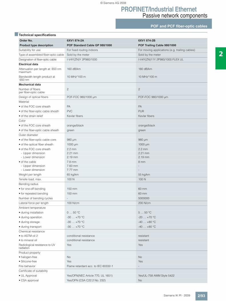
PROFINET/Industrial EthernetPassive network components
POF and PCF fiber-optic cables
2/93Siemens IK PI · 2009
2
■ Technical specifications
Order No. 6XV1 874-2A 6XV1 874-2BProduct type description POF Standard Cable GP 980/1000 POF Trailing Cable 980/1000
Suitability for use For fixed routing indoors For moving applications (e.g. trailing cables)
Type of assembled fiber-optic cable Sold by the meter Sold by the meter
Designation of fiber-optic cable I-V4Y(ZN)Y 2P980/1000 I-V4Y(ZN)11Y 2P980/1000 FLEX UL
Electrical data
Attenuation per length at 650 nm maximum
160 dB/km 180 dB/km
Bandwidth length product at 650 nm
10 MHz*100 m 10 MHz*100 m
Mechanical data
Number of fibers per fiber-optic cable
2 2
Design of optical fibers POF-FOC 980/1000 μm POF-FOC 980/1000 μm
Material
• of the FOC core sheath PA PA
• of the fiber-optic cable sheath PVC PUR
• of the strain relief Kevlar fibers Kevlar fibers
Color
• of the FOC core sheath orange/black orange/black
• of the fiber-optic cable sheath green green
Outer diameter
• of the fiber-optic cable core 980 μm 980 μm
• of the optical fiber sheath 1000 μm 1000 μm
• of the FOC core sheath 2.2 mm 2.2 mm- Upper dimension 2.21 mm 2.21 mm- Lower dimension 2.19 mm 2.19 mm
• of the cable 7.8 mm 8 mm- Upper dimension 7.83 mm -- Lower dimension 7.77 mm -
Weight per length 65 kg/km 55 kg/km
Tensile load, max. 100 N 100 N
Bending radius
• for one-off bending 150 mm 60 mm
• for repeated bending 150 mm 60 mm
Number of bending cycles - 5000000
Lateral force per length 100 N/cm 200 N/cm
Ambient temperature
• during installation 0 … 50 °C 5 … 50 °C
• during operation -30 … +70 °C -20 … +70 °C
• during storage -30 … +70 °C -40 … +80 °C
• during transport -30 … +70 °C -40 … +80 °C
Chemical resistance• to ASTM oil 2 conditional resistance resistant• to mineral oil conditional resistance resistant
Radiological resistance to UV radiation
Yes Yes
Product property• halogen-free No No• Silicone-free Yes Yes
Fire behavior Flame retardant acc. to IEC 60332-1 -
Certificate of suitability
• UL Approval Yes/OFN(NEC Article 770, UL 1651) Yes/UL-758 AWM Style 5422
• CSA approval Yes/OFN (CSA C22.2 No. 232) No
© Siemens AG 2008
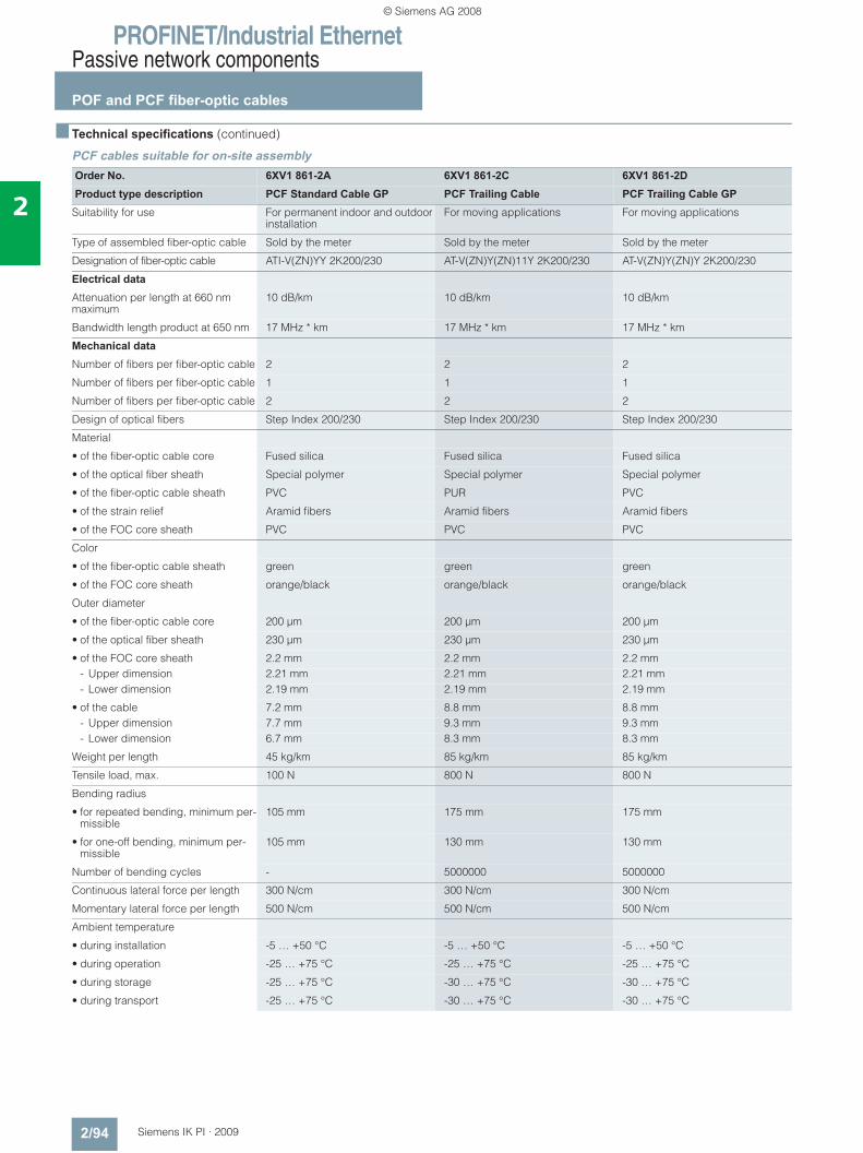
PROFINET/Industrial EthernetPassive network components
POF and PCF fiber-optic cables
2/94 Siemens IK PI · 2009
2
■ Technical specifications (continued)
PCF cables suitable for on-site assembly
Order No. 6XV1 861-2A 6XV1 861-2C 6XV1 861-2DProduct type description PCF Standard Cable GP PCF Trailing Cable PCF Trailing Cable GP
Suitability for use For permanent indoor and outdoor installation
For moving applications For moving applications
Type of assembled fiber-optic cable Sold by the meter Sold by the meter Sold by the meter
Designation of fiber-optic cable ATI-V(ZN)YY 2K200/230 AT-V(ZN)Y(ZN)11Y 2K200/230 AT-V(ZN)Y(ZN)Y 2K200/230
Electrical data
Attenuation per length at 660 nm maximum
10 dB/km 10 dB/km 10 dB/km
Bandwidth length product at 650 nm 17 MHz * km 17 MHz * km 17 MHz * km
Mechanical data
Number of fibers per fiber-optic cable 2 2 2
Number of fibers per fiber-optic cable 1 1 1
Number of fibers per fiber-optic cable 2 2 2
Design of optical fibers Step Index 200/230 Step Index 200/230 Step Index 200/230
Material
• of the fiber-optic cable core Fused silica Fused silica Fused silica
• of the optical fiber sheath Special polymer Special polymer Special polymer
• of the fiber-optic cable sheath PVC PUR PVC
• of the strain relief Aramid fibers Aramid fibers Aramid fibers
• of the FOC core sheath PVC PVC PVC
Color
• of the fiber-optic cable sheath green green green
• of the FOC core sheath orange/black orange/black orange/black
Outer diameter
• of the fiber-optic cable core 200 μm 200 μm 200 μm
• of the optical fiber sheath 230 μm 230 μm 230 μm
• of the FOC core sheath 2.2 mm 2.2 mm 2.2 mm- Upper dimension 2.21 mm 2.21 mm 2.21 mm- Lower dimension 2.19 mm 2.19 mm 2.19 mm
• of the cable 7.2 mm 8.8 mm 8.8 mm- Upper dimension 7.7 mm 9.3 mm 9.3 mm- Lower dimension 6.7 mm 8.3 mm 8.3 mm
Weight per length 45 kg/km 85 kg/km 85 kg/km
Tensile load, max. 100 N 800 N 800 N
Bending radius
• for repeated bending, minimum per-missible
105 mm 175 mm 175 mm
• for one-off bending, minimum per-missible
105 mm 130 mm 130 mm
Number of bending cycles - 5000000 5000000
Continuous lateral force per length 300 N/cm 300 N/cm 300 N/cm
Momentary lateral force per length 500 N/cm 500 N/cm 500 N/cm
Ambient temperature
• during installation -5 … +50 °C -5 … +50 °C -5 … +50 °C
• during operation -25 … +75 °C -25 … +75 °C -25 … +75 °C
• during storage -25 … +75 °C -30 … +75 °C -30 … +75 °C
• during transport -25 … +75 °C -30 … +75 °C -30 … +75 °C
© Siemens AG 2008
PROFINET/Industrial EthernetPassive network components
POF and PCF fiber-optic cables
2/95Siemens IK PI · 2009
2
■ Technical specifications (continued)
■ Ordering data Order No. Order No.
■ More information
You can order components supplementary to the SIMATIC NET cabling range from your local contact. Technical advice on this subject is available from: J. Hertlein A&D SE PSTel.: +49(0)911/750 44 65 Fax: +49(0)911/750 99 91 Email: [email protected]
Order No. 6XV1 861-2A 6XV1 861-2C 6XV1 861-2DProduct type description PCF Standard Cable GP PCF Trailing Cable PCF Trailing Cable GP
Fire behavior Flame retardant to IEC 60332-1 - Flame retardant to IEC 60332-1
Chemical resistance
• to ASTM oil 2 conditional resistance resistant conditional resistance
• to mineral oil conditional resistance resistant conditional resistance
• to water - - -
Radiological resistance to UV radiation
Yes Yes Yes
Product property
• halogen-free - - -
• Silicone-free Yes Yes Yes
Certificate of suitability
• UL Approval Yes/OFN(NEC Article 770, UL 1651)
- Yes/OFN(NEC Article 770, UL 1651)
• CSA approval Yes/ OFN, 90°C, FT1, FT4 (CSA-Standard C22.2 No232-M1988)
- Yes/ OFN, 90°C, FT1, FT4 (CSA-Standard C22.2 No232-M1988)
POF Standard Cable GP 980/1000
6XV1 874-2A
POF standard cable for fixed routing indoors, with PVC sheath; sold by the meter
POF Trailing Cable 980/1000 6XV1 874-2BPOF trailing cable with rugged PUR sheath; sold by the meter
PCF Standard Cable GP 200/230Standard cable, segmentable, sold by the meter;max. quantity 2000 m; minimum order 20 m;
6XV1 861-2A
PCF Trailing Cable 200/230Trailing cable, segmentable, sold by the meter;max. quantity 2000 m; minimum order 20 m;
6XV1 861-2C
PCF Trailing Cable GP 200/230Trailing cable, segmentable,sold by the meter;max. length 2000 m; minimum order quantity 20 m;
6XV1 861-2D
Termination Kit SC RJ POF Plug 6GK1 900-0ML00-0AA0Assembly case for local assembly of SC RJ connectors, comprising a stripping tool, Kevlar scissors, microscope, grinding paper and grinding base
IE SC RJ POF Plug 6GK1 900-0MB00-0AC0Screw connector for local assembly on POF FOC (1 pack = 20 items)
IE SC RJ POF refill set 6GK1 900-0MN00-0AA0Refill set for Termination Kit SC RJ POF Plug consisting of grinding paper and grinding base (set of 5)
Termination Kit SC RJ PCF Plug 6GK1 900-0NL00-0AA0Assembly case for local assembly of SC RJ connectors, comprising a stripping tool, buffer stripping tool, Kevlar scissors, fiber breaking tool, microscope
Industrial Ethernet SC RJ PCF Plug
6GK1 900-0NB00-0AC0
Screw connector for local assem-bly on POF FOC (1 pack = 10 items)
SIMATIC NET Manual Collection 6GK1 975-1AA00-3AA0Electronic manuals for communi-cation systems, communication protocols, and communication products; on DVD; German/English
© Siemens AG 2008
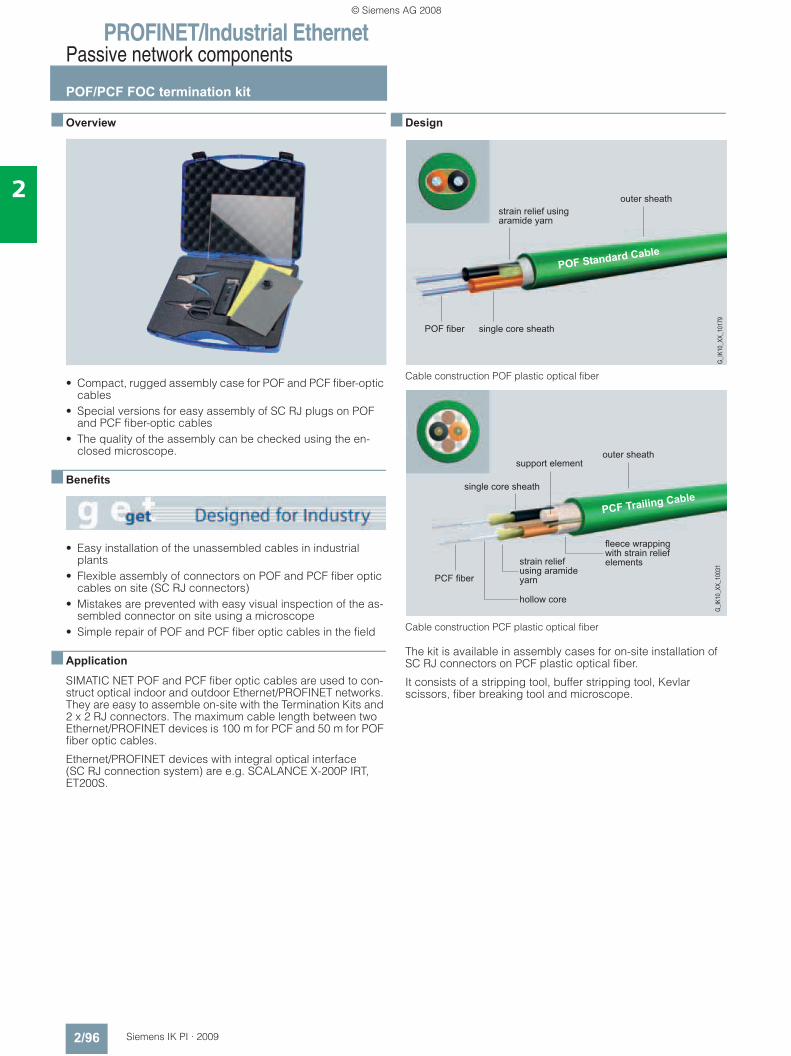
PROFINET/Industrial EthernetPassive network components
POF/PCF FOC termination kit
2/96 Siemens IK PI · 2009
2
■ Overview
• Compact, rugged assembly case for POF and PCF fiber-optic cables
• Special versions for easy assembly of SC RJ plugs on POF and PCF fiber-optic cables
• The quality of the assembly can be checked using the en-closed microscope.
■ Benefits
• Easy installation of the unassembled cables in industrial plants
• Flexible assembly of connectors on POF and PCF fiber optic cables on site (SC RJ connectors)
• Mistakes are prevented with easy visual inspection of the as-sembled connector on site using a microscope
• Simple repair of POF and PCF fiber optic cables in the field
■ Application
SIMATIC NET POF and PCF fiber optic cables are used to con-struct optical indoor and outdoor Ethernet/PROFINET networks. They are easy to assemble on-site with the Termination Kits and 2 x 2 RJ connectors. The maximum cable length between two Ethernet/PROFINET devices is 100 m for PCF and 50 m for POF fiber optic cables.
Ethernet/PROFINET devices with integral optical interface (SC RJ connection system) are e.g. SCALANCE X-200P IRT, ET200S.
■ Design
Cable construction POF plastic optical fiber
Cable construction PCF plastic optical fiber
The kit is available in assembly cases for on-site installation of SC RJ connectors on PCF plastic optical fiber.
It consists of a stripping tool, buffer stripping tool, Kevlar scissors, fiber breaking tool and microscope.
���������
����� ��� � �������������
��� ����� ����� ���� ������
������ �� ����
��
�����
����
�����
���������
��� ����� ���� ����� ���������� ���
����������
���������������
����������� ��� ����� ����� ����������
� �������������
������������������
�����
����
����
�
© Siemens AG 2008
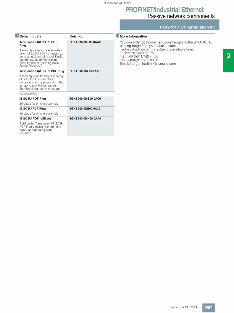
PROFINET/Industrial EthernetPassive network components
POF/PCF FOC termination kit
2/97Siemens IK PI · 2009
2
■ Ordering data Order No.
■ More information
You can order components supplementary to the SIMATIC NET cabling range from your local contact. Technical advice on this subject is available from: J. Hertlein, A&D SE PS Tel.: +49(0)911/750 44 65 Fax: +49(0)911/750 99 91 Email: [email protected]
Termination Kit SC RJ POF Plug
6GK1 900-0ML00-0AA0
Assembly case for on-site instal-lation of SC RJ POF connectors; consisting of stripping tool, Kevlar cutters, SC RJ grinding plate, grinding paper, grinding base and microscope
Termination Kit SC RJ PCF Plug 6GK1 900-0NL00-0AA0Assembly case for local assembly of SC RJ POF connectors, comprising a stripping tool, buffer stripping tool, Kevlar cutters,fiber breaking tool, microscope
AccessoriesIE SC RJ POF Plug 6GK1 900-0MB00-0AC020 plugs for on-site assembly
IE SC RJ PCF Plug 6GK1 900-0NB00-0AC010 plugs for on-site assembly
IE SC RJ POF refill set 6GK1 900-0MN00-0AA0Refill set for Termination Kit SC RJ POF Plug consisting of grinding paper and grinding plate (set of 5)
© Siemens AG 2008
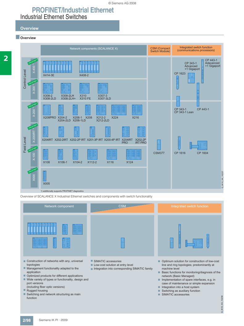
PROFINET/Industrial EthernetIndustrial Ethernet Switches
Overview
2/98 Siemens IK PI · 2009
2
■ Overview
Overview of SCALANCE X Industrial Ethernet switches and components with switch functionality
© Siemens AG 2008
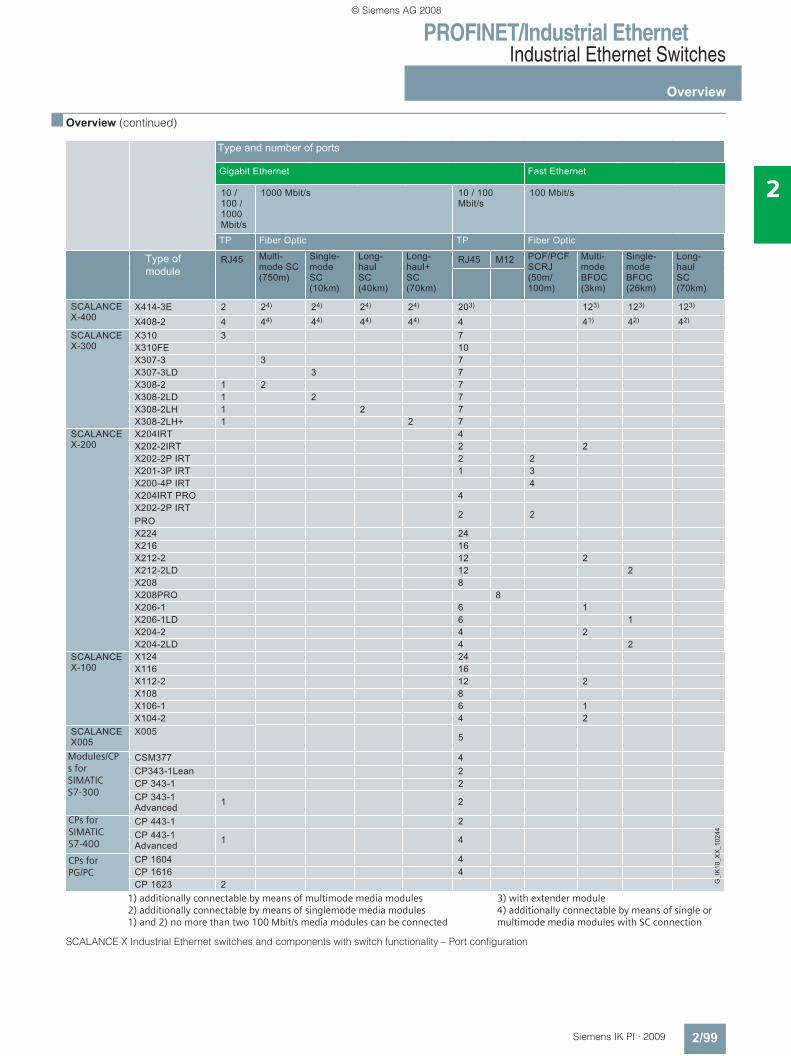
PROFINET/Industrial EthernetIndustrial Ethernet Switches
Overview
2/99Siemens IK PI · 2009
2
■ Overview (continued)
SCALANCE X Industrial Ethernet switches and components with switch functionality – Port configuration
1) additionally connectable by means of multimode media modules 2) additionally connectable by means of singlemode media modules1) and 2) no more than two 100 Mbit/s media modules can be connected
3) with extender module4) additionally connectable by means of single or multimode media modules with SC connection
Modules/CPs for SIMATIC S7-300
CPs for SIMATIC S7-400
CPs for PG/PC
© Siemens AG 2008
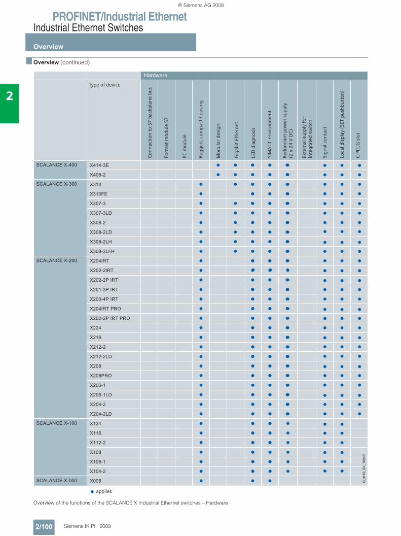
PROFINET/Industrial EthernetIndustrial Ethernet Switches
Overview
2/100 Siemens IK PI · 2009
2
■ Overview (continued)
Overview of the functions of the SCALANCE X Industrial Ethernet switches – Hardware
k k k k kk k k
k k k k kk k k
k k k k kk k k
k k k kk k k
k k k k kk k k
k k k k kk k k
k k k k kk k k
k k k k kk k k
k k k k kk k k
k k k k kk k k
k k k kk k k
k k k kk k k
k k k kk k k
k k k kk k k
k k k kk k k
k k k kk k k
k k k kk k k
k k k kk k k
k k k kk k k
k k k kk k k
k k k kk k k
k k k kk k k
k k k kk k k
k k k kk k k
k k k kk k k
k k k kk k k
k k k kk k k
k k k kk k
k k k kk k
k k k kk k
k k k kk k
k k k kk k
k k k kk k
k k k
k
k k k
k k k
k k k
k k k
k k k
k k k
k k k
k k k
k k k
k k k
k k k
k k k
k k k
k k k
k k k
k k k
k k k
k k k
k k k
k k k
k k k
k k k
k k k
k k k
k k k
k k k
k k k
k k
k k
k k
k k
k k
k k
Con
nec
tion
to
S7 b
ackp
lan
e bu
s
Form
at m
odu
le S
7
PC m
odu
le
Rugg
ed, c
ompa
ct h
ousi
ng
Mod
ula
r de
sign
Gig
abit
Eth
ern
et
LED
dia
gnos
is
SIM
ATIC
env
iron
men
t
Redu
nda
nt
pow
er s
upp
ly
(2 x
24
V D
C)
Exte
rnal
su
pply
for
in
tegr
ated
sw
itch
Sign
al c
onta
ct
Loca
l dis
play
(SE
T pu
shbu
tton
)
C-P
LUG
slo
t
Type of device
applies
© Siemens AG 2008
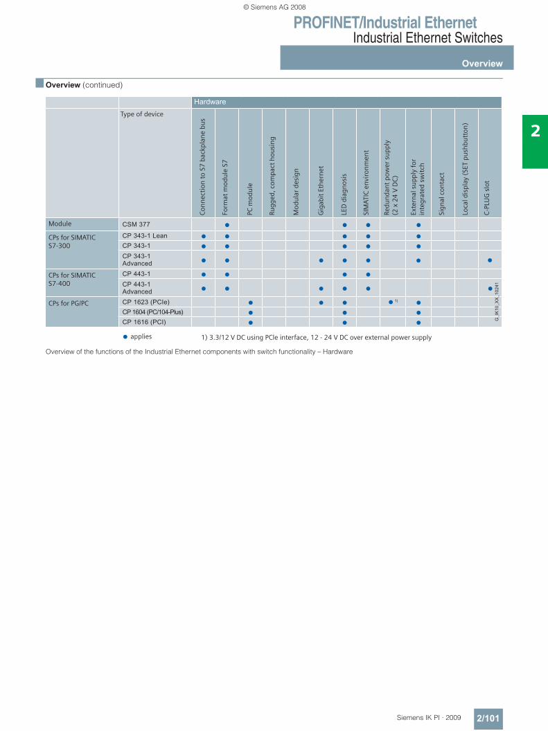
PROFINET/Industrial EthernetIndustrial Ethernet Switches
Overview
2/101Siemens IK PI · 2009
2
■ Overview (continued)
Overview of the functions of the Industrial Ethernet components with switch functionality – Hardware
k k k k
k k k k k
k k k k k
k k k k k
k k k k
k k k k k k
k k k k
k k k
k k k
k
k
k
k
Con
nec
tion
to
S7 b
ackp
lan
e bu
s
Form
at m
odu
le S
7
PC m
odu
le
Rugg
ed, c
ompa
ct h
ousi
ng
Mod
ula
r de
sign
Gig
abit
Eth
ern
et
LED
dia
gnos
is
SIM
ATIC
env
iron
men
t
Redu
nda
nt
pow
er s
upp
ly
(2 x
24
V D
C)
Exte
rnal
su
pply
for
in
tegr
ated
sw
itch
Sign
al c
onta
ct
Loca
l dis
play
(SE
T pu
shbu
tton
)
C-P
LUG
slo
t
Type of device
Module
CPs for SIMATIC S7-300
CPs for SIMATIC S7-400
CPs for PG/PC
applies 1) 3.3/12 V DC using PCle interface, 12 - 24 V DC over external power supply
© Siemens AG 2008
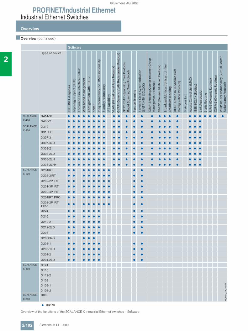
PROFINET/Industrial EthernetIndustrial Ethernet Switches
Overview
2/102 Siemens IK PI · 2009
2
■ Overview (continued)
Overview of the functions of the SCALANCE X Industrial Ethernet switches – Software
k k k k k k k k k k k k k k k k k k k k k k k k k
k k k k k k k k k k k k k k k k k k k k k
k k k k k k k k k k k k k k k k k k k k k
k k k k k k k k k k k k k k k k k k k k k
k k k k k k k k k k k k k k k k k k k k k
k k k k k k k k k k k k k k k k k k k k k
k k k k k k k k k k k k k k k k k k k k k
k k k k k k k k k k k k k k k k k k k k k
k k k k k k k k k k k k k k k k k k k k k
k k k k k k k k k k k k k k k k k k k k k
k k k k k k k k k k
k k k k k k k k k k
k k k k k k k k k k
k k k k k k k k k k
k k k k k k k k k k
k k k k k k k k k k
k k k k k k k k k k
k k k k k k k k
k k k k k k k k
k k k k k k k k
k k k k k k k k
k k k k k k k k
k k k k
k k k k k k k k
k k k k k k k k
k k k k k k k k
k k k k k k k k
k
Type of device
applies
PRO
FIN
ET d
iagn
osis
Topo
logy
su
ppor
t (L
LDP)
Com
man
d Li
ne
Inte
rfac
e / T
eln
et
Web
-bas
ed m
anag
emen
t
Con
figu
rati
on w
ith
STE
P 7
SNM
P
Rin
g re
dun
dan
cy in
cl. R
M f
un
ctio
nal
ity
Stan
dby
redu
nda
ncy
IRT
capa
bilit
y
Pass
ive
liste
nin
g
Forw
ard
Clo
ck S
ynch
ron
izat
ion
(S
NTP
, NTP
, SIC
LOC
K)
Broa
dcas
t/M
ult
icas
t/U
nic
ast
Lim
iter
Broa
dcas
t Bl
ocki
ng
IP A
cces
s Li
st
Acc
ess
Con
trol
Lis
t (M
AC
)
IEEE
80
2.1
x (R
adiu
s)
Lin
k A
ggre
gati
on
Stat
ic R
outi
ng
RIPv
2 (
Dyn
amic
Rou
tin
g)
OSP
Fv2
(D
ynam
ic R
outi
ng)
VRR
P, R
oute
r Re
dun
dan
cy (
Vir
tual
Rou
ter
Redu
nda
ncy
Pro
toco
l)
© Siemens AG 2008
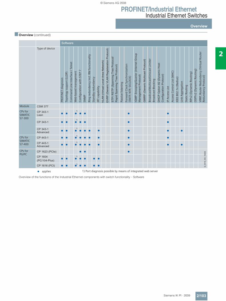
PROFINET/Industrial EthernetIndustrial Ethernet Switches
Overview
2/103Siemens IK PI · 2009
2
■ Overview (continued)
Overview of the functions of the Industrial Ethernet components with switch functionality – Software
k k k k k k k
k k k k k k k
k k k k k k k k
k k k k k k k k
k k k k k k k k
k k k
k k k k k k k
k k k k k k k
k
k
k
k
k
k
Type of device
PRO
FIN
ET d
iagn
osis
Topo
logy
su
ppor
t (L
LDP)
Com
man
d Li
ne
Inte
rfac
e / T
eln
et
Web
-bas
ed m
anag
emen
t
Con
figu
rati
on w
ith
STE
P 7
SNM
P
Rin
g re
dun
dan
cy in
cl. R
M f
un
ctio
nal
ity
Stan
dby
redu
nda
ncy
IRT
capa
bilit
y
Pass
ive
liste
nin
g
Forw
ard
Clo
ck S
ynch
ron
izat
ion
(S
NTP
, NTP
, SIC
LOC
K)
Broa
dcas
t/M
ult
icas
t/U
nic
ast
Lim
iter
Broa
dcas
t Bl
ocki
ng
IP A
cces
s Li
st
Acc
ess
Con
trol
Lis
t (M
AC
)
IEEE
80
2.1
x (R
adiu
s)
Lin
k A
ggre
gati
on
Stat
ic R
outi
ng
RIPv
2 (
Dyn
amic
Rou
tin
g)
OSP
Fv2
(D
ynam
ic R
outi
ng)
VRR
P, R
oute
r Re
dun
dan
cy (
Vir
tual
Rou
ter
Redu
nda
ncy
Pro
toco
l)
Module
CPs for SIMATIC S7-300
CPs for SIMATIC S7-400
CPs for PG/PC
applies 1) Port diagnosis possible by means of integrated web server
© Siemens AG 2008
PROFINET/Industrial EthernetIndustrial Ethernet Switches
Compact Switch Module CSM 377
2/104 Siemens IK PI · 2009
2
■ Overview
• For the connection of a SIMATIC S7-300 with integral PROFINET interface or with an Industrial Ethernet CP or ET 200M to an Industrial Ethernet in an electrical linear, tree or star structure
• As many as three additional nodes can be connected• As an unmanaged switch, the CSM 377 is used for integrating
small machines into existing automation networks or for the standalone operation of the machines
• Simple, space-saving attachment to S7-300 mounting rail due to design as single-width module in S7-300 format
• Economical solution for the implementation of small, local Ethernet networks
• Rugged, industry-standard node connections with PROFINET-compliant RJ45 connectors that latch onto the enclosure to offer additional strain and bending relief
■ Benefits
• Quick and easy connection of a SIMATIC S7-300 or ET 200M to electrical Industrial Ethernets in linear, tree or star structures by means of three additional RJ45 sockets
• Ideal solution for the implementation of small local Ethernets with a SIMATIC S7-300 station
• Secure data communication by means of industry standard device connection with PROFINET-compliant connector IE FC RJ45 Plug 180 and latching of the connector to the enclosure to provide additional strain relief
• Low-maintenance operation thanks to fanless construction• Quick and easy diagnosis by means of LEDs on the device• Use of uncrossed connection cables possible by means of
integrated autocrossover function
■ Application• For the economical construction of small, electrical Industrial
Ethernets with star, tree and linear structures using a SIMATIC S7-300 or ET 200M
■ Design
The compact switch module CSM 377 features all the advantages of the SIMATIC S7-300 design:• Compact construction;
the rugged plastic enclosure features the following on the front panel: - 4 x RJ45 sockets for the connection to Industrial Ethernet
(support collar)- 1 x 2-pin pluggable terminal strip for the connection of the
external 24 VDC power supply- LED indicators for diagnosis and status indication of the
Industrial Ethernet ports • 10/100BaseTX;
automatic detection of the data rate with autosensing and autocrossover function for the connection of IE FC cables by means of IE FC RJ45 Plug 180 up to 100 m
• Simple mounting; the CSM 377 switch module is mounted on the mounting rail of the S7-300. As it has no connection to the backplane bus of the S7-300 or ET 200M, it must either be inserted at the begin-ning (first module to the left of the CPU) or at the end (last module on far right) of the S7-300 station. The connection to the CPU of the S7-300 is either by means of an Industrial Ethernet cable or an Industrial Ethernet twisted pair cord.
• Three further Industrial Ethernet interfaces (TP ports) are avail-able for the connection of additional Ethernet nodes such as HMI panels or ET 200
• The CSM 377 can be operated without a fan and no backup battery is necessary
• The module can be replaced without a programming device
© Siemens AG 2008
PROFINET/Industrial EthernetIndustrial Ethernet Switches
Compact Switch Module CSM 377
2/105Siemens IK PI · 2009
2
■ Function• Connection of a SIMATIC S7-300 to a higher-level electrical
network in a linear, tree or point-to-point structure• Construction of a small local network with one SIMATIC S7-300
and three other Ethernet nodes
Thanks to the switching technology used, the CSM 377 is suitable for use in PROFINET networks, but offers no additional PROFINET functions, i.e. no integration into the PROFINET diagnostics.
Network topology and network configuration
When configuring the network, it is necessary to observe the following boundary conditions:• Length of the TP cable between two nodes:
- max. 100 m with Industrial Ethernet FastConnect cable and IE FC RJ45 Plug 180; of which no more than 10 m by means of patching with TP cord
Connection of SIMATIC S7-300 with CSM 377 to Industrial Ethernet with linear structure
Construction of a local Industrial Ethernet with SIMATIC S7-300 and CSM 377 in a point-to-point structure
Configuration
The Compact Switch Module CSM 377 is an unmanaged switch and requires no configuration.
Diagnostics
The following information is indicated on the device by means of LEDs:• Power• Port status• Data traffic
S7-300 withCP 343-1 Advancedand CSM 377
S7-300withCP 343-1
S7-400with CP 443-1,
Industrial PCwith CP 1613 A2/CP 1623
HMI statione.g. WinCC flexible
S7-300 withCSM 377andCP 343-1
G_I
K10
_XX
_102
24
Industrial Ethernet
PanelPC
ET 200S
© Siemens AG 2008
PROFINET/Industrial EthernetIndustrial Ethernet Switches
Compact Switch Module CSM 377
2/106 Siemens IK PI · 2009
2
■ Technical specifications
■ Ordering data Order No.
Order No. 6GK7 377-1AA00-0AA0Product type description CSM 377
Transfer rate
• Transfer rate 1 10 Mbit/s
• Transfer rate 2 100 Mbit/s
Number of electrical connections
• for signaling contact -
• for network components or terminals
4
• for voltage supply 1
Electrical connection version
• for signaling contact -
• for network components or terminals
RJ45 socket (10/100 Mbit/s; half/full duplex)
• for voltage supply 2-pin terminal block
Version of the C-PLUG swap medium
No
Type of supply voltage DC
Supply voltage 24 V
• Maximum 28,8 V
• Minimum 19,2 V
Current consumed 70 mA
Effective power loss
• at 24 V DC 1.6 W
• Maximum -
Ambient temperature
• during operation 0 °C … + 60 °C
• during storage -40 … +70 °C
• during transport -40 … +70 °C
Maximum relative humidity at 25 °C during operation
95%
Width 40 mm
Height 125 mm
Depth 118 mm
Net weight 200 g
Type of fixing DIN rail, S7-300 mounting rail
Degree of protection IP20
Compact Switch Module CSM 377Unmanaged switch for the con-nection of a SIMATIC S7-300, ET200M and as many as three other nodes to an Industrial Ether-net operating at 10/100 Mbit/s; 4 x RJ45 ports; external 24 V DC power supply, LED diagnostics, S7-300 module incl. electronic equipment manual on CD-ROM
6GK7 377-1AA00-0AA0
AccessoriesIE TP Cord RJ45/RJ45TP cable 4 x 2 with 2 RJ45 connectors
• 0.5 m 6XV1 870-3QE50IE FC TP standard cable GP 2 x 2 (Type A)4-core, shielded TP installation cable for connection to IE FC outlet RJ45/ IE FC RJ45 plug; PROFINET-compliant; with UL approval; sold by the meter; max. quantity 1000 m, minimum order 20 m
6XV1 840-2AH10
IE FC trailing cable 2 x 2 (Type C)
6XV1 840-3AH10
4-core, shielded TP installation cable for connection to IE FC outlet RJ45/ IE FC RJ45 plug 180/90 for tow chain use; PROFINET-compliant; with UL approval; sold by the meter; max. quantity 1000 m, minimum order 20 m
IE FC RJ45 Plug 180RJ45 plug connector for Industrial Ethernet with a rugged metal housing and integrated insulation displacement contacts for con-necting Industrial Ethernet FC installation cables; 180° cable outlet; for network components and CPs/CPUs with Industrial Ethernet interface
• 1 pack = 1 unit 6GK1 901-1BB10-2AA0• 1 pack = 10 units 6GK1 901-1BB10-2AB0• 1 pack = 50 units 6GK1 901-1BB10-2AE0IE FC stripping tool 6GK1 901-1GA00Pre-adjusted stripping tool for the fast stripping of Industrial Ethernet FC cables
IE FC RJ45 outlet 6GK1 901-1FC00 0AA0For connecting Industrial Ethernet FC cables and TP Cords; block pricing for quantities of more than 10 or 50 units
SIMATIC NET Manual Collection 6GK1 975-1AA00-3AA0Electronic manuals for communication systems, communication protocols, and communication products;on DVD; German/English
© Siemens AG 2008
PROFINET/Industrial EthernetIndustrial Ethernet Switches
SCALANCE X005 unmanaged
2/107Siemens IK PI · 2009
2
■ Overview
• The unmanaged Industrial Ethernet Entry Level Switch SCALANCE X005 is optimized for low-cost installation of small Industrial Ethernet networks with 10/100 Mbit/s in a line and star topology
• Five electrical nodes or network connections• Rugged metal housing for space-saving cubicle mounting
on standard rails, S7-300 DIN rail or for wall mounting • Rugged, industry-standard station connections with
PROFINET-compatible RJ45 connectors that offer additional strain relief and bending strain relief thanks to latching on the housing
• Diagnostics on the device by means of LEDs (power, link status, data communication)
■ Benefits
• Ideal solution for configuring Industrial Ethernet line and star topologies
• Space-saving installation in the cabinet thanks to the compact design in S7-300 format
• Secure data communication by means of industry standard device connection with PROFINET-compliant connector IE FC RJ45 Plug 180 and latching of the connector to the en-closure to provide additional strain relief
• Installation is possible without a patch field by means of IE FC RJ45 Plug 180 and IE FC Standard Cable
• Quick and easy diagnosis by means of LEDs on the device• Low-maintenance operation thanks to fanless construction• Use of uncrossed connection cables possible by means of
integrated autocrossover function• Easy network configuration without runtime calculation
■ Application• For low-cost installation of small, electrical Industrial Ethernet
star and line structures with switching functionality, e.g. machine or plant islands
• For installation in the control cabinet
■ Design
The SCALANCE Industrial Ethernet switches with a rugged metal housing (IP30) are optimized for mounting on a standard rail and an S7-300 DIN rail. Direct wall mounting in different positions is also possible. Due to the housing dimensions that correspond to those of the SIMATIC S7-300, the devices are very well suited for integration into an automation solution using S7-300 components.
The SCALANCE X005 switch is equipped with:• Supply voltage (1 x 24 V DC) • A row of LEDs for displaying status information
(power, link status, data communication)• 10/100BaseTX, RJ45 port:
RJ45 port, automatic detection of the data rate (10 or 100 Mbit/s), with Autosensing and Autocrossover function for connecting IE FC cables via IE FC RJ45 Plug 180 over distances up to 100 m
© Siemens AG 2008
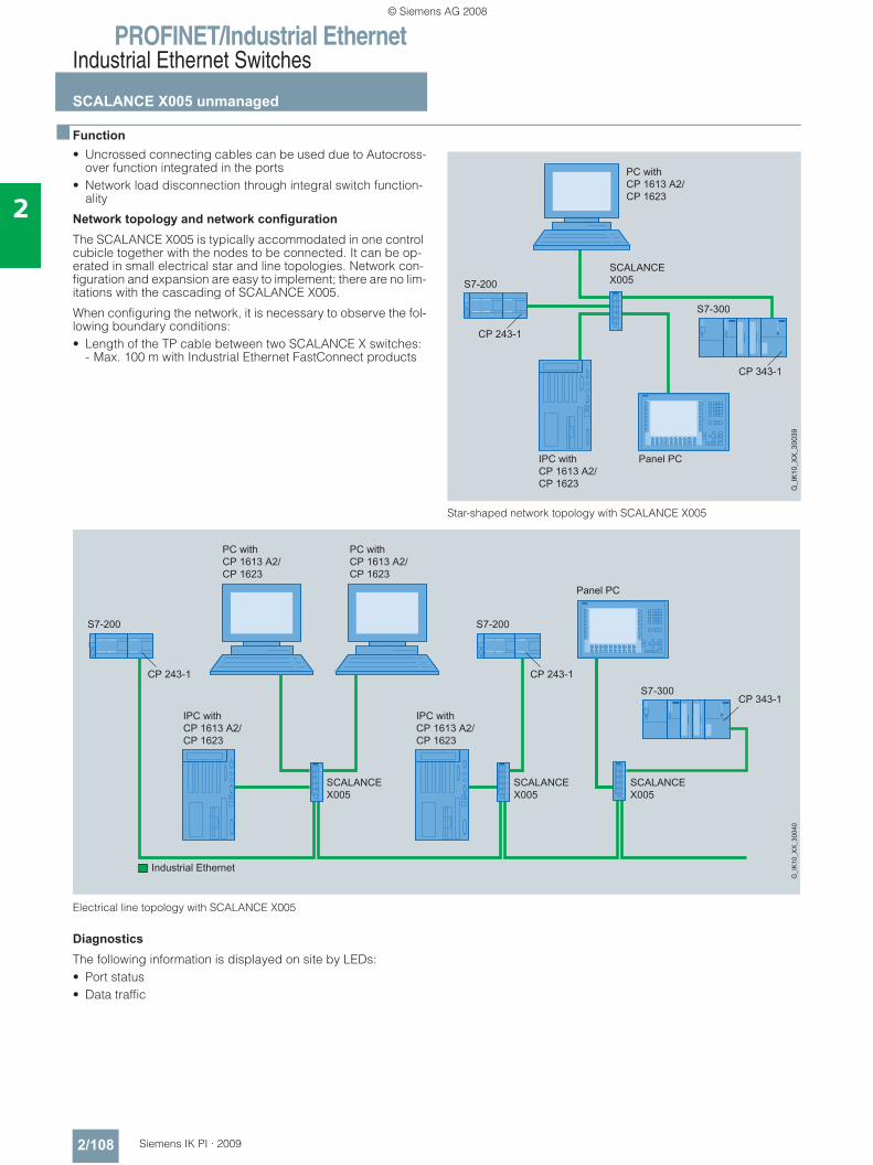
PROFINET/Industrial EthernetIndustrial Ethernet Switches
SCALANCE X005 unmanaged
2/108 Siemens IK PI · 2009
2
■ Function• Uncrossed connecting cables can be used due to Autocross-
over function integrated in the ports • Network load disconnection through integral switch function-
ality
Network topology and network configuration
The SCALANCE X005 is typically accommodated in one control cubicle together with the nodes to be connected. It can be op-erated in small electrical star and line topologies. Network con-figuration and expansion are easy to implement; there are no lim-itations with the cascading of SCALANCE X005.
When configuring the network, it is necessary to observe the fol-lowing boundary conditions:• Length of the TP cable between two SCALANCE X switches:
- Max. 100 m with Industrial Ethernet FastConnect products
Star-shaped network topology with SCALANCE X005
Electrical line topology with SCALANCE X005
Diagnostics
The following information is displayed on site by LEDs:• Port status• Data traffic
© Siemens AG 2008
PROFINET/Industrial EthernetIndustrial Ethernet Switches
SCALANCE X005 unmanaged
2/109Siemens IK PI · 2009
2
■ Technical specifications
■ Ordering data Order No.
Order No. 6GK5 005-0BA00-1AA3Product type description SCALANCE X005
Transfer rate -
• Transfer rate 1 10 Mbit/s
• Transfer rate 2 100 Mbit/s
Number of electrical connections
• for signaling contact -
• for network components or terminals
5
• for voltage supply 1
Electrical connection version
• for network components or terminals
RJ45 socket (10/100 Mbit/s; TP)
• for voltage supply 2-pin terminal block
• for signaling contact -
Number of optical ports for fiber-optic cables
• at 100 Mbit/s -
• at 10 Mbit/s -
Version of optical port for fiber-optic cables
• at 10 Mbit/s -
• at 100 Mbit/s -
Version of the C-PLUG swap medium
No
Type of supply voltage DC
Supply voltage 24 V
• external 24 V
• Maximum 32 V
• Minimum 18 V
Current consumed 80 mA
Effective power loss
• at 24 V DC 2,0 W
Ambient temperature
• during operation 0 … +65 °C
• during storage -40 … +80 °C
• during transport -40 … +80 °C
Maximum relative humidity at 25 °C during operation
95%
Width 40 mm
Height 125 mm
Depth 124 mm
Net weight 550 g
Type of fixing Standard rail, S7-300 rail, wall mounting
Degree of protection IP30
Standard
• for EMI of FM -
• For Ex zone -
• for safety of CSA -
• For emitted interference EN 61000-6-2 (Class A)
• For noise immunity EN 61000-6-4
Order No. 6GK5 005-0BA00-1AA3Product type description SCALANCE X005
Directive
• for C-Tick AS/NZS 2064 (Class A)
• for safety of UL UL 60950, CSA C22.2 Nr. 60950
Certificate of suitability EN 61000-6-2, EN 61000-6-4
• CE label Yes
Marine classification association
• American Bureau ofShipping (ABS),
-
• Bureau Veritas (BV) -
• Det Norske Veritas (DNV) -
• Germanischer Lloyd (GL) -
• Lloyds Register of Shipping (LRS) -
• Nippon Kaiji Kyokai (NK) -
SCALANCE X005 6GK5 005-0BA00-1AA3Industrial Ethernet Switch for 10/100 Mbit/s; with five 10/100 Mbit/s RJ45 ports for configuring small star and line structures
AccessoriesIE FC RJ45 plugsRJ45 plug connector for Industrial Ethernet with a rugged metal housing and integrated insulation displacement contacts for connecting Industrial Ethernet FC installation cables
IE FC RJ45 Plug 180180° cable outlet; for network components and CPs/CPUs with Industrial Ethernet interface
• 1 pack = 1 items 6GK1 901-1BB10-2AA0• 1 pack = 10 items 6GK1 901-1BB10-2AB0• 1 pack = 50 items 6GK1 901-1BB10-2AE0IE FC RJ45 Plug 145145° cable outlet; e.g. for SIMOTION and SINAMICS
• 1 pack = 1 items 6GK1 901-1BB30-0AA0• 1 pack = 10 units 6GK1 901-1BB30-0AB0• 1 pack = 50 units 6GK1 901-1BB30-0AE0
© Siemens AG 2008
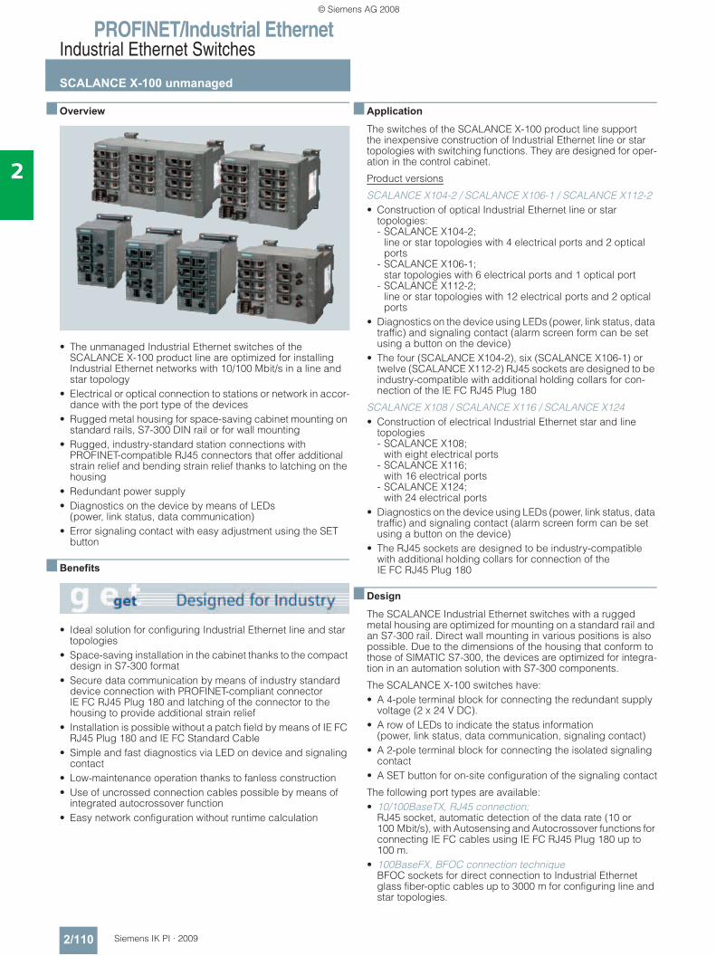
PROFINET/Industrial EthernetIndustrial Ethernet Switches
SCALANCE X-100 unmanaged
2/110 Siemens IK PI · 2009
2
■ Overview
• The unmanaged Industrial Ethernet switches of the SCALANCE X-100 product line are optimized for installing Industrial Ethernet networks with 10/100 Mbit/s in a line and star topology
• Electrical or optical connection to stations or network in accor-dance with the port type of the devices
• Rugged metal housing for space-saving cabinet mounting on standard rails, S7-300 DIN rail or for wall mounting
• Rugged, industry-standard station connections with PROFINET-compatible RJ45 connectors that offer additional strain relief and bending strain relief thanks to latching on the housing
• Redundant power supply• Diagnostics on the device by means of LEDs
(power, link status, data communication)• Error signaling contact with easy adjustment using the SET
button
■ Benefits
• Ideal solution for configuring Industrial Ethernet line and star topologies
• Space-saving installation in the cabinet thanks to the compact design in S7-300 format
• Secure data communication by means of industry standard device connection with PROFINET-compliant connector IE FC RJ45 Plug 180 and latching of the connector to the housing to provide additional strain relief
• Installation is possible without a patch field by means of IE FC RJ45 Plug 180 and IE FC Standard Cable
• Simple and fast diagnostics via LED on device and signaling contact
• Low-maintenance operation thanks to fanless construction• Use of uncrossed connection cables possible by means of
integrated autocrossover function• Easy network configuration without runtime calculation
■ Application
The switches of the SCALANCE X-100 product line support the inexpensive construction of Industrial Ethernet line or star topologies with switching functions. They are designed for oper-ation in the control cabinet.
Product versions
SCALANCE X104-2 / SCALANCE X106-1 / SCALANCE X112-2 • Construction of optical Industrial Ethernet line or star
topologies: - SCALANCE X104-2;
line or star topologies with 4 electrical ports and 2 optical ports
- SCALANCE X106-1; star topologies with 6 electrical ports and 1 optical port
- SCALANCE X112-2; line or star topologies with 12 electrical ports and 2 optical ports
• Diagnostics on the device using LEDs (power, link status, data traffic) and signaling contact (alarm screen form can be set using a button on the device)
• The four (SCALANCE X104-2), six (SCALANCE X106-1) or twelve (SCALANCE X112-2) RJ45 sockets are designed to be industry-compatible with additional holding collars for con-nection of the IE FC RJ45 Plug 180
SCALANCE X108 / SCALANCE X116 / SCALANCE X124 • Construction of electrical Industrial Ethernet star and line
topologies - SCALANCE X108;
with eight electrical ports- SCALANCE X116;
with 16 electrical ports- SCALANCE X124;
with 24 electrical ports• Diagnostics on the device using LEDs (power, link status, data
traffic) and signaling contact (alarm screen form can be set using a button on the device)
• The RJ45 sockets are designed to be industry-compatible with additional holding collars for connection of the IE FC RJ45 Plug 180
■ Design
The SCALANCE Industrial Ethernet switches with a rugged metal housing are optimized for mounting on a standard rail and an S7-300 rail. Direct wall mounting in various positions is also possible. Due to the dimensions of the housing that conform to those of SIMATIC S7-300, the devices are optimized for integra-tion in an automation solution with S7-300 components.
The SCALANCE X-100 switches have:• A 4-pole terminal block for connecting the redundant supply
voltage (2 x 24 V DC).• A row of LEDs to indicate the status information
(power, link status, data communication, signaling contact)• A 2-pole terminal block for connecting the isolated signaling
contact• A SET button for on-site configuration of the signaling contact
The following port types are available:• 10/100BaseTX, RJ45 connection;
RJ45 socket, automatic detection of the data rate (10 or 100 Mbit/s), with Autosensing and Autocrossover functions for connecting IE FC cables using IE FC RJ45 Plug 180 up to 100 m.
• 100BaseFX, BFOC connection technique BFOC sockets for direct connection to Industrial Ethernet glass fiber-optic cables up to 3000 m for configuring line and star topologies.
© Siemens AG 2008

PROFINET/Industrial EthernetIndustrial Ethernet Switches
SCALANCE X-100 unmanaged
2/111Siemens IK PI · 2009
2
■ Function• Construction of electrical and optical Industrial Ethernet line or
star topologies• Use of uncrossed connecting leads is possible due to inte-
grated auto-crossover function of the ports• Isolation of the load due to integrated switch functions• Easy network configuration and network expansion;
no limitation of the expansion of the network when switches of the SCALANCE X-100 product line are cascaded
Network topology and network configuration The SCALANCE X-100 switches are typically installed with the stations to be connected in a control cabinet. They can be mixed electrically and optically in star and line topologies.
When configuring the network, it is necessary to observe the following boundary conditions:• Length of the TP cable between SCALANCE X switches:
- Max. 100 m with Industrial Ethernet FastConnect products• Length of the fiber-optic cables:
- Max. 3000 m with Industrial Ethernet glass fiber-optic cables
Star-shaped network topology with SCALANCE X124
© Siemens AG 2008
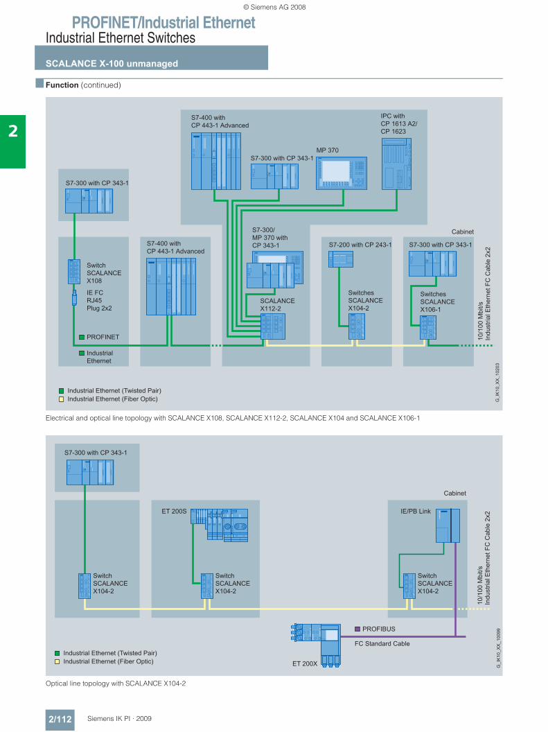
PROFINET/Industrial EthernetIndustrial Ethernet Switches
SCALANCE X-100 unmanaged
2/112 Siemens IK PI · 2009
2
■ Function (continued)
Electrical and optical line topology with SCALANCE X108, SCALANCE X112-2, SCALANCE X104 and SCALANCE X106-1
Optical line topology with SCALANCE X104-2
Industrial Ethernet (Twisted Pair)Industrial Ethernet (Fiber Optic)
PROFINET
IndustrialEthernet
PROFIBUS
Cabinet
S7-300 with CP 343-1
Industrial Ethernet (Twisted Pair)Industrial Ethernet (Fiber Optic)
10/1
00 M
bit/s
Indu
stria
l Eth
erne
t FC
Cab
le 2
x2
FC Standard Cable
IE/PB LinkET 200S
ET 200X G_I
K10
_XX
_100
99
SwitchSCALANCEX104-2
SwitchSCALANCEX104-2
SwitchSCALANCEX104-2
© Siemens AG 2008
PROFINET/Industrial EthernetIndustrial Ethernet Switches
SCALANCE X-100 unmanaged
2/113Siemens IK PI · 2009
2
■ Function (continued)
Optical star topology with SCALANCE X106-1
Diagnostics
The following information is displayed by LEDs on site:• Power• Port status• Data traffic
The Industrial Ethernet switches of the SCALANCE X-100 line can also be monitored over the floating signaling contact.
© Siemens AG 2008
PROFINET/Industrial EthernetIndustrial Ethernet Switches
SCALANCE X-100 unmanaged
2/114 Siemens IK PI · 2009
2
■ Technical specifications
Order No. 6GK5 104-2BB00-2AA3 6GK5 106-1BB00-2AA3 6GK5 108-0BA00-2AA3Product type description SCALANCE X104-2 SCALANCE X106-1 SCALANCE X108
Transfer rate
• Transfer rate 1 10 Mbit/s 10 Mbit/s 10 Mbit/s
• Transfer rate 2 100 Mbit/s 100 Mbit/s 100 Mbit/s
Number of electrical connections
• for signaling contact 1 1 1
• for network components or terminals
4 6 8
• for redundant voltage supply 1 1 1
• for voltage supply 1 1 1
Electrical connection version
• for signaling contact 2-pin terminal block 2-pin terminal block 2-pin terminal block
• for network components or terminals
RJ45 socket (10/100 Mbit/s; TP) RJ45 socket (10/100 Mbit/s; TP) RJ45 socket (10/100 Mbit/s; TP)
• for voltage supply 4-pin terminal block 4-pin terminal block 4-pin terminal block
Number of optical ports for fiber-optic cables
• at 10 Mbit/s - - -
• at 100 Mbit/s 2 1 -
Version of optical port for fiber-optic cables
• at 10 Mbit/s - - -
• at 100 Mbit/s BFOC sockets (100 Mbit/s) BFOC sockets (100 Mbit/s) -
Version of the C-PLUG swap medium
No No No
Type of supply voltage DC DC DC
Supply voltage 24 V 24 V 24 V
• external 24 V 24 V 24 V- Maximum 32 V 32 V 32 V- Minimum 18 V 18 V 18 V
Current consumed 175 mA 150 mA 140 mA
Effective power loss
• at 24 V DC 4.2 W 3.6 W 3.36 W
Ambient temperature
• during operation -10 … +60 °C -10 … +60 °C -20 … +70 °C
• during storage -40 … +80 °C -40 … +80 °C -40 … +80 °C
• during transport -40 … +80 °C -40 … +80 °C -40 … +80 °C
Maximum relative humidityat 25 °C during operation
95% 95% 95%
Width 60 mm 60 mm 60 mm
Height 125 mm 125 mm 125 mm
Depth 124 mm 124 mm 124 mm
Net weight 780 g 780 g 780 g
Type of fixing Standard rail, S7-300 rail, wall mounting
Standard rail, S7-300 rail, wall mounting
Standard rail, S7-300 rail, wall mounting
Degree of protection IP30 IP30 IP30
© Siemens AG 2008
PROFINET/Industrial EthernetIndustrial Ethernet Switches
SCALANCE X-100 unmanaged
2/115Siemens IK PI · 2009
2
■ Technical specifications (continued)
Order No. 6GK5 104-2BB00-2AA3 6GK5 106-1BB00-2AA3 6GK5 108-0BA00-2AA3Product type description SCALANCE X104-2 SCALANCE X106-1 SCALANCE X108
Standard
• for EMI of FM FM 3611 FM 3611 FM 3611
• For Ex zone EN 50012 EN 50012 EN 50012
• for safety of CSA - - -
• For emitted interference EN 61000-6-4 (Class A) EN 61000-6-4 (Class A) EN 61000-6-4 (Class A)
• For noise immunity EN 61000-6-2 EN 61000-6-2 EN 61000-6-2
Directive
• for C-Tick AS/NZS 2064 (Class A) AS/NZS 2064 (Class A) AS/NZS 2064 (Class A)
• for safety of UL UL 60950-1, CSA C22.2 No. 60950-1
UL 60950-1, CSA C22.2 No. 60950-1
UL 60950-1, CSA C22.2 No. 60950-1
Certificate of suitability EN 61000-6-2, EN 61000-6-4 EN 61000-6-2, EN 61000-6-4 EN 61000-6-2, EN 61000-6-4
• CE label Yes Yes Yes
Marine classification association
• American Bureau of Shipping Europe Ltd.(ABS)
Yes Yes Yes
• Bureau Veritas (BV) - - -
• Det Norske Veritas (DNV) Yes Yes Yes
• Germanischer Lloyd (GL) Yes Yes Yes
• Lloyds Register of Shipping (LRS) Yes Yes Yes
• Nippon Kaiji Kyokai (NK) Yes Yes Yes
Order No. 6GK5 112-2BB00-2AA3 6GK5 116-0BA00-2AA3 6GK5 124-0BA00-2AA3Product type description SCALANCE X112-2 SCALANCE X116 SCALANCE X124
Transfer rate
• Transfer rate 1 10 Mbit/s 10 Mbit/s 10 Mbit/s
• Transfer rate 2 100 Mbit/s 100 Mbit/s 100 Mbit/s
Number of electrical connections
• for signaling contact 1 1 1
• for network components or terminals
12 16 24
• for redundant voltage supply 1 1 1
• for voltage supply 1 1 1
Electrical connection version
• for network components or terminals
RJ45 socket (10/100 Mbit/s; TP) RJ45 socket (10/100 Mbit/s; TP) RJ45 socket (10/100 Mbit/s; TP)
• for voltage supply 4-pin terminal block 4-pin terminal block 4-pin terminal block
• for signaling contact 2-pin terminal block 2-pin terminal block 2-pin terminal block
Number of optical ports forfiber-optic cables
• at 10 Mbit/s - - -
• at 100 Mbit/s 2 - -
Version of optical port forfiber-optic cables
• at 10 Mbit/s - - -
• at 100 Mbit/s BFOC sockets (100 Mbit/s) - -
Version of the C-PLUG swap medium
No No No
© Siemens AG 2008
PROFINET/Industrial EthernetIndustrial Ethernet Switches
SCALANCE X-100 unmanaged
2/116 Siemens IK PI · 2009
2
■ Technical specifications (continued)
Order No. 6GK5 112-2BB00-2AA3 6GK5 116-0BA00-2AA3 6GK5 124-0BA00-2AA3Product type description SCALANCE X112-2 SCALANCE X116 SCALANCE X124
Type of supply voltage DC DC DC
Supply voltage 24 V 24 V 24 V
• external 24 V 24 V 24 V- Maximum 32 V 32 V 32 V- Minimum 18 V 18 V 18 V
Current consumed 450 mA 300 mA 450 mA
Effective power loss
• at 24 V DC 10.8 W 7.2 W 10.8 W
Ambient temperature
• during operation -10 … +70 °C -20 … +70 °C -20 … +70 °C
• during storage -40 … +80 °C -40 … +80 °C -40 … +80 °C
• during transport -40 … +80 °C -40 … +80 °C -40 … +80 °C
Maximum relative humidityat 25 °C during operation
95% 95% 95%
Width 120 mm 120 mm 180 mm
Height 125 mm 125 mm 125 mm
Depth 124 mm 124 mm 124 mm
Net weight 1100 g 1100 g 1500 g
Type of fixing Standard rail, S7-300 rail, wall mounting
Standard rail, S7-300 rail, wall mounting
Standard rail, S7-300 rail, wall mounting
Degree of protection IP30 IP30 IP30
Standard - - -
• for EMI of FM FM 3611 FM 3611 FM 3611
• For Ex zone EN 50012 EN 50012 EN 50012
• for safety of CSA - - -
• For emitted interference EN 61000-6-4 (Class A) EN 61000-6-4 (Class A) EN 61000-6-4 (Class A)
• For noise immunity EN 61000-6-2 (Class A) EN 61000-6-2 (Class A) EN 61000-6-2 (Class A)
Directive
• for C-Tick AS/NZS 2064 (Class A) AS/NZS 2064 (Class A) AS/NZS 2064 (Class A)
• for safety of UL UL 60950-1, CSA C22.2 No. 60950-1
UL 60950-1, CSA C22.2 No. 60950-1
UL 60950-1, CSA C22.2 No. 60950-1
Certificate of suitability EN 61000-6-2, EN 61000-6-4 EN 61000-6-2, EN 61000-6-3 EN 61000-6-2, EN 61000-6-3
• CE label Yes Yes Yes
Marine classification association
• American Bureau of Shipping Europe Ltd. (ABS)
- - -
• Bureau Veritas (BV) - - -
• Det Norske Veritas (DNV) - - -
• Germanischer Lloyd (GL) - - -
• Lloyds Register of Shipping (LRS) - - -
• Nippon Kaiji Kyokai (NK) - - -
© Siemens AG 2008
PROFINET/Industrial EthernetIndustrial Ethernet Switches
SCALANCE X-100 unmanaged
2/117Siemens IK PI · 2009
2
■ Ordering data Order No. Order No.
Industrial Ethernet switches SCALANCE X-100Industrial Ethernet switches for 10/100 Mbit/s, incl. operating instructions, Industrial Ethernet network manual and configuration software on CD-ROM
• SCALANCE X104-2 with four 10/100 Mbit/s RJ45 ports and two fiber-optic ports for constructing line topologies
6GK5 104-2BB00-2AA3
• SCALANCE X106-1 with six 10/100 Mbit/s RJ45 ports and one fiber-optic port for constructing star topologies
6GK5106-1BB00-2AA3
• SCALANCE X112-2 with twelve 10/100 Mbit/s RJ45 ports and two fiber-optic ports for constructing star topologies
6GK5 112-2BB00-2AA3
• SCALANCE X108 with eight 10/100 Mbit/s RJ45 ports for constructing star and line topologies
6GK5 108-0BA00-2AA3
• SCALANCE X116 with sixteen 10/100 Mbit/s RJ45 ports for constructing star and line topologies
6GK5 116-0BA00-2AA3
• SCALANCE X124 with twenty-four 10/100 Mbit/s RJ45 ports for constructing star and line topologies
6GK5 124-0BA00-2AA3
AccessoriesIE FC RJ45 Plug 180RJ45 plug connector for Industrial Ethernet with a rugged metal housing and integrated insulation displacement contacts for con-necting Industrial Ethernet FC installation cables; with 180° cable outlet; for network compo-nents and CPs/CPUs with Industrial Ethernet interface
• 1 pack = 1 unit 6GK1 901-1BB10-2AA0• 1 pack = 10 units 6GK1 901-1BB10-2AB0• 1 pack = 50 units 6GK1 901-1BB10-2AE0
© Siemens AG 2008
PROFINET/Industrial EthernetIndustrial Ethernet Switches
SCALANCE X-200 managed
2/118 Siemens IK PI · 2009
2
■ Overview
• The managed Industrial Ethernet switches of the SCALANCE X-200 product line are optimized for installing Industrial Ethernet networks with 10/100 Mbit/s in a line, star and ring topology
• Integrated redundancy manager for constructing Fast Ethernet ring topologies with high-speed media redundancy (excluding SCALANCE X208 PRO)
• Electrical or optical connection to stations or network in accor-dance with the port type of the devices
• High-speed media redundancy through integral redundancy manager for Fast Ethernet (SCALANCE X-300 switches in the ring in combination with SCALANCE X-200 switches or OSM/ESM)
• Rugged metal housing in S7-300 format for mounting on standard rail, S7-300 standard mounting rail or for direct wall mounting in various positions
• Rugged, industry-standard station connections with PROFINET-compatible RJ45 connectors that offer additional strain relief and bending strain relief thanks to latching on the housing
• Redundant power supply• Diagnostics on the device by means of LEDs
(power, link status, data communication)• Error signaling contact with easy adjustment using the SET
button• The devices feature PROFINET diagnostics, SNMP access,
integral web server and automatic e-mail sending function for remote diagnosis and signaling over the network.
■ Benefits
• Ideal solution for configuring Industrial Ethernet line, star and ring topologies
• Reliable data communication thanks to rugged device con-nection using PROFINET-compatible plug-in cables that offer additional strain relief and bending strain relief thanks to latching on the housing.
• High network availability through design of redundant ring structures (Redundancy Manager integrated, except for SCALANCE X208PRO)
• Fast and easy diagnosis with LEDs on the device, through the integral Web server and through signaling contacts
• Integration of the SCALANCE X-200 switches in the existing network management infrastructure through SNMP access point
• Easy integration in the process diagnosis and system diagno-sis with PROFINET
• Configuration and diagnostics integrated into STEP 7 provide significant benefits during the engineering, start-up and oper-ating phases of a plant
• Uncrossed connecting cables can be used due to the inte-grated Autocrossover function
• Low-maintenance operation thanks to fanless construction• Module replacement without the need for a programming
device, using the C-PLUG swap media for backing up the configuration data
• Arrangement possible without control cabinet since devices with high degree of protection IP65
© Siemens AG 2008
PROFINET/Industrial EthernetIndustrial Ethernet Switches
SCALANCE X-200 managed
2/119Siemens IK PI · 2009
2
■ Application
The SCALANCE X-200 Industrial Ethernet switches permit cost-effective configuration of Industrial Ethernet line, star or ring topologies with switching functionality for networks in which high availability or remote diagnostics options are required. The de-vices with degree of protection IP30 have been designed for use in the control cabinet. The SCALANCE X208PRO, is designed to degree of protection IP65 for installation outside the control cabinet.
Product versions • Switches with electrical and optical ports for glass multimode
FOC up to 3 km: - SCALANCE X204-2;
for setting up optical line or ring topologies with 4 electrical ports and 2 optical ports
- SCALANCE X206-1; for setting up star topologies with 6 electrical ports and 1 optical port, line or ring topologies with electrical and optical transmission paths
- SCALANCE X212-2; for constructing optical line or ring topologies with 12 electri-cal ports and 2 optical ports
• Switches with electrical and optical ports for glass single mode FOC up to 26 km: - SCALANCE X204-2LD;
for constructing optical line or ring topologies with 4 electri-cal ports and 2 optical ports
- SCALANCE X206-1LD; for constructing star topologies with 6 electrical ports and 1 optical port, line or ring topologies with electrical and optical transmission paths
- SCALANCE X212-2LD; for constructing optical line or ring topologies with 12 electri-cal ports and 2 optical ports
• Switches with electrical ports for configuring electrical Indus-trial Ethernet line, star or ring topologies: - SCALANCE X208;
with 8 electrical ports for mounting in the control cabinet- SCALANCE X208PRO (degree of protection IP65);
with 8 electrical ports especially for use outside the control cabinet (M12 connection system)
- SCALANCE X216;with 16 electrical ports for mounting in the control cabinet
- SCALANCE X224;with 24 electrical ports for mounting in the control cabinet
Features:• Device diagnostics with LEDs (power, link status, data com-
munication)• Remote diagnosis is possible through signaling contact
(signal mask can be set locally using buttons except with SCALANCE X208PRO), PROFINET, SNMP and web browser
• The RJ45 sockets are industry-standard and feature addi-tional retaining collars (except for SCALANCE X208PRO), for connection to the IE FC RJ45 Plug 180
• The eight PROFINET-compatible M12 sockets of the SCALANCE X208PRO are designed with degree of protection IP65 for connection to the IE M12 Plug PRO or the pre-assem-bled IE M12 connecting cable
• The SCALANCE X208PRO can be mounted on a DIN rail or S7-300 rail or direct on the equipment or machine in a space-saving, horizontal or vertical design; the status information can be read off regardless of the mount-ing position thanks to the angled LED strip.
• Power can also be supplied to the SCALANCE X208PRO from outside the control cabinet from the PS791-1PRO power supply module at 230 V AC.
Diagnostics access over SNMP and Web browser with SCALANCE X208
© Siemens AG 2008
PROFINET/Industrial EthernetIndustrial Ethernet Switches
SCALANCE X-200 managed
2/120 Siemens IK PI · 2009
2
■ Design
The SCALANCE X-200 Industrial Ethernet switches with a rug-ged metal housing are optimized for mounting on a standard rail and an S7-300 rail. Direct wall mounting in various positions is also possible. With the S7-300 housing format, the devices are optimized for integration in an automation solution with S7-300 components.
The switches with degree of protection IP30 feature:• A 4-pole terminal block for connecting the redundant supply
voltage (2 x 24 V DC)• A row of LEDs to indicate the status information (power, link
status, data exchange, power supply, signaling contact)• A 2-pole terminal block for connecting the isolated signaling
contact• A SET button for on-site configuration of the signaling contact
The SCALANCE X208PRO with degree of protection IP65 features:• 2 x M12 interfaces for connecting the redundant supply
voltage (2 x 24 V DC)• A row of LEDs to indicate the status information (power, link
status, data exchange, power supply, signaling contact, redundancy manager function (excluding SCALANCE X208 PRO))
• An M12 interface for connecting the isolated signaling contact
The SCALANCE X-200 switches are available with the following port types:• 10/100BaseTX, RJ45 or M12 connection;
RJ45 or M12 socket, automatic detection of the data rate (10 or 100 Mbit/s), with Autosensing and Autocrossover func-tions for connecting IE FC cables using IE FC RJ45 Plug 180 or IE M12 Plug PRO up to 100 m.
• 100BaseFX, BFOC connection technique; BFOC sockets for direct connection to Industrial Ethernet glass fiber-optic cables up to 3 km (multimode FOC) or up to 26 km (single mode FOC) for configuring line, ring and star topologies.
■ Function• Configuring electrical and optical Industrial Ethernet line, star
and ring topologies• Fast redundancy in the ring with High Speed Redundancy
(HSR); up to 0.3 seconds for reconfiguration of the ring with 50 switches in the ring
• The functioning of the ring is continuously monitored by the integrated redundancy manager (with the exception of SCALANCE X208 PRO). It recognizes failure of a transmission path in the ring or failure of a SCALANCE X-200 and activates the substitute path within 0.3 seconds
• Use in ring topologies (100 Mbit/s) together with SCALANCE X-400, SCALANCE X-300, SCALANCE X-200IRT or OSM
• Uncrossed connecting cables can be used due to Autocross-over function integrated in the ports
• Load disconnection through integral switch functionality• Easy diagnostics using signaling contact, SNMP and Web
browser• Easy copper cable diagnostics with Web browser for localiz-
ing cable breaks• Integration into the diagnostics of a PROFINET IO controller
with expanded diagnostics functions for a consistent diagnos-tics concept, including network infrastructure
• Diagnosis of data traffic by means of a parameterizable mirror port with a standard commercial network analyzer
• Optimized support of PROFINET real-time communication (RT) through prioritizing
• Fast device replacement in the event of a fault by using the op-tional C-PLUG swap medium (not included in scope of supply)
Network topology and network configuration
The Industrial Ethernet SCALANCE X-200 switches with degree of protection IP30 are usually installed in a control cabinet to-gether with the stations to be connected. Electrical and optical versions can be installed together in star, line and ring topolo-gies. The SCALANCE X208PRO is designed for installation outside the control cabinet.
When configuring the network, it is necessary to observe the following boundary conditions:• Length of the TP cable between two SCALANCE X switches:
- Max. 100 m with IE FC cable and IE FC RJ45 Plug 180 or IE FC M12 Plug PRO
- Max. 10 m using patches with TP cord• Length of the optical cables
- Max. 3000 m with Industrial Ethernet glass fiber optic cables (multimode).
- Max. 26000 m with Industrial Ethernet glass fiber optic cables (single mode).
• IP Address: The IP address is assigned by means of the DHCP (Dynamic Host Configuration Protocol). If there is no corresponding server in the network, the IP address can be assigned using the supplied software tool PST (Primary Setup Tool) or STEP 7. The SCALANCE X-200IRT switches and their real-time func-tions are configured with STEP 7.
© Siemens AG 2008
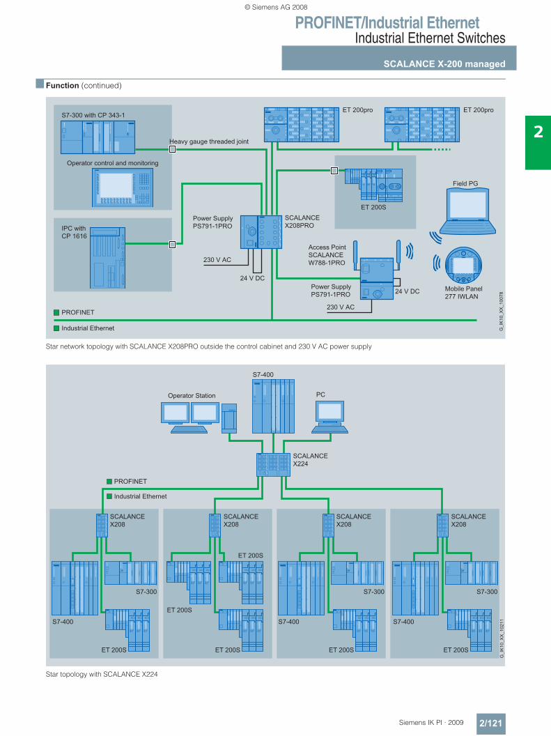
PROFINET/Industrial EthernetIndustrial Ethernet Switches
SCALANCE X-200 managed
2/121Siemens IK PI · 2009
2
■ Function (continued)
Star network topology with SCALANCE X208PRO outside the control cabinet and 230 V AC power supply
Star topology with SCALANCE X224
Operator Station
S7-400
PC
SCALANCEX208
SCALANCEX208
SCALANCEX208
SCALANCEX208
S7-400 S7-400 S7-400
S7-300 S7-300 S7-300
ET 200SET 200S
ET 200S
ET 200SET 200S
PROFINET
Industrial Ethernet
ET 200S
© Siemens AG 2008
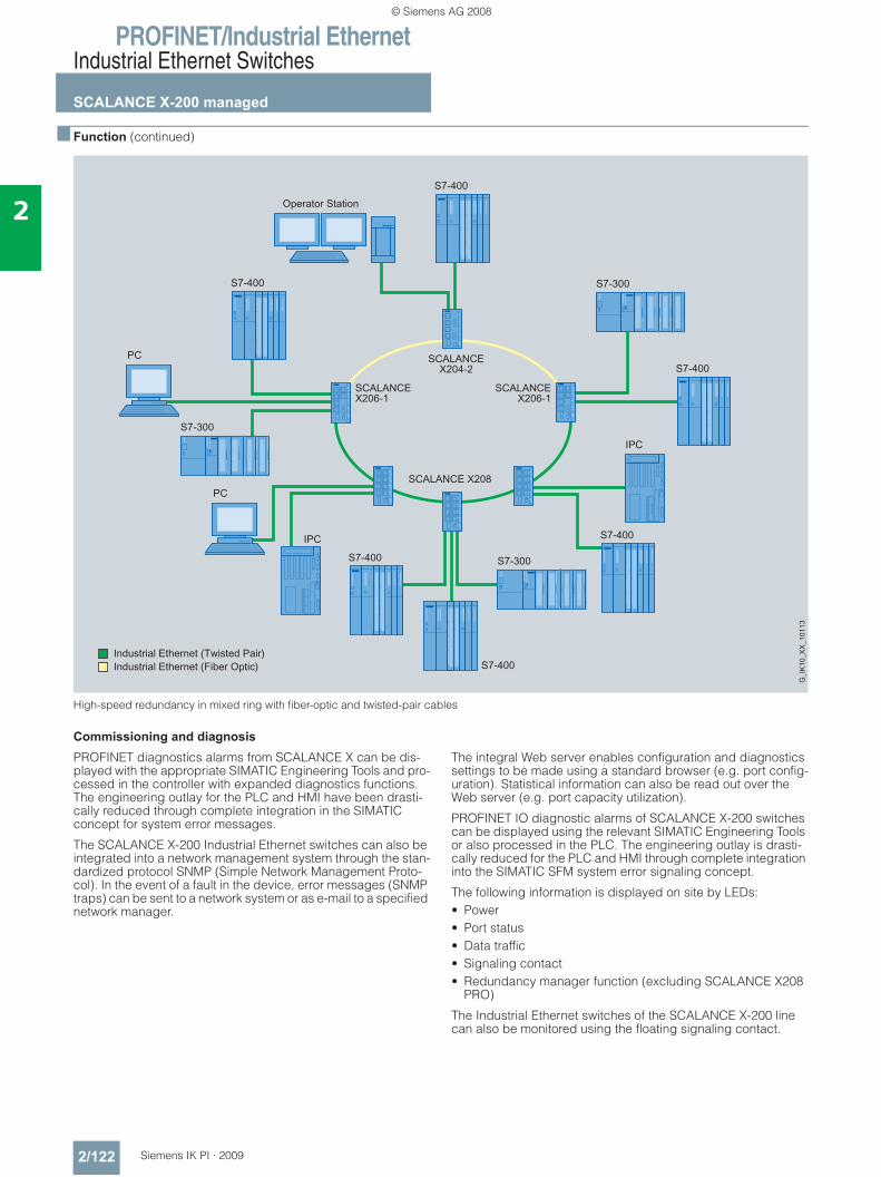
PROFINET/Industrial EthernetIndustrial Ethernet Switches
SCALANCE X-200 managed
2/122 Siemens IK PI · 2009
2
■ Function (continued)
High-speed redundancy in mixed ring with fiber-optic and twisted-pair cables
Commissioning and diagnosis
PROFINET diagnostics alarms from SCALANCE X can be dis-played with the appropriate SIMATIC Engineering Tools and pro-cessed in the controller with expanded diagnostics functions. The engineering outlay for the PLC and HMI have been drasti-cally reduced through complete integration in the SIMATIC concept for system error messages.
The SCALANCE X-200 Industrial Ethernet switches can also be integrated into a network management system through the stan-dardized protocol SNMP (Simple Network Management Proto-col). In the event of a fault in the device, error messages (SNMP traps) can be sent to a network system or as e-mail to a specified network manager.
The integral Web server enables configuration and diagnostics settings to be made using a standard browser (e.g. port config-uration). Statistical information can also be read out over the Web server (e.g. port capacity utilization).
PROFINET IO diagnostic alarms of SCALANCE X-200 switches can be displayed using the relevant SIMATIC Engineering Tools or also processed in the PLC. The engineering outlay is drasti-cally reduced for the PLC and HMI through complete integration into the SIMATIC SFM system error signaling concept.
The following information is displayed on site by LEDs:• Power• Port status• Data traffic• Signaling contact• Redundancy manager function (excluding SCALANCE X208
PRO)
The Industrial Ethernet switches of the SCALANCE X-200 line can also be monitored using the floating signaling contact.
© Siemens AG 2008
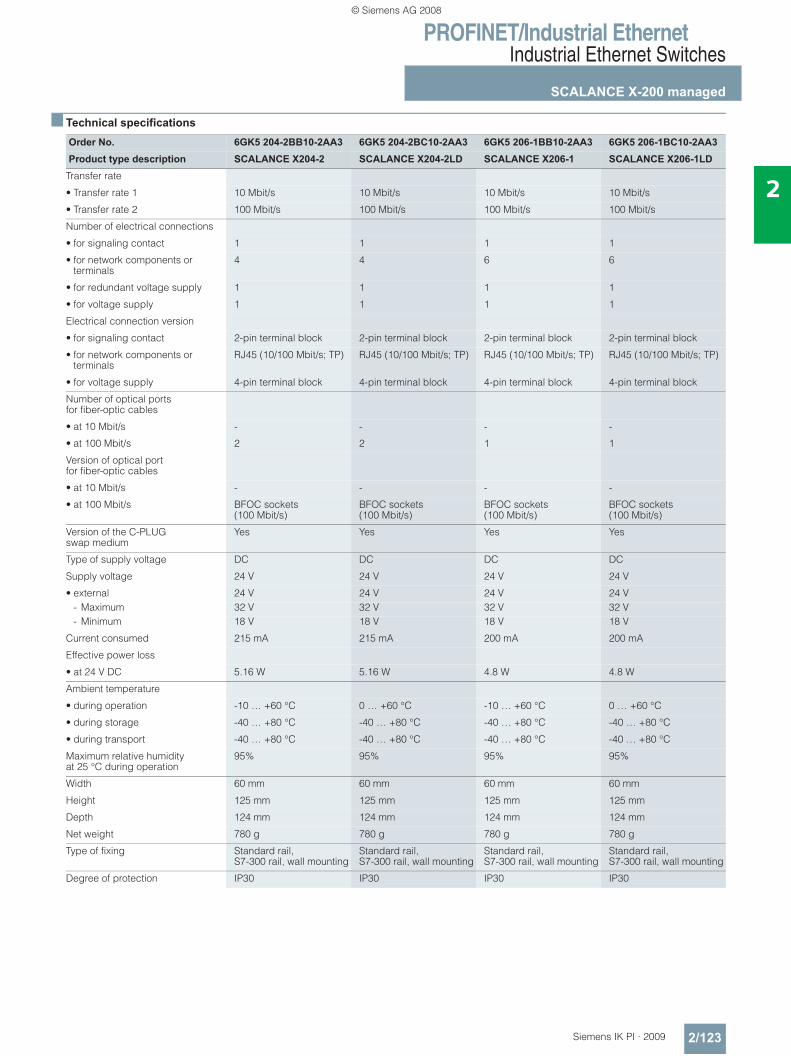
PROFINET/Industrial EthernetIndustrial Ethernet Switches
SCALANCE X-200 managed
2/123Siemens IK PI · 2009
2
■ Technical specifications
Order No. 6GK5 204-2BB10-2AA3 6GK5 204-2BC10-2AA3 6GK5 206-1BB10-2AA3 6GK5 206-1BC10-2AA3Product type description SCALANCE X204-2 SCALANCE X204-2LD SCALANCE X206-1 SCALANCE X206-1LD
Transfer rate
• Transfer rate 1 10 Mbit/s 10 Mbit/s 10 Mbit/s 10 Mbit/s
• Transfer rate 2 100 Mbit/s 100 Mbit/s 100 Mbit/s 100 Mbit/s
Number of electrical connections
• for signaling contact 1 1 1 1
• for network components or terminals
4 4 6 6
• for redundant voltage supply 1 1 1 1
• for voltage supply 1 1 1 1
Electrical connection version
• for signaling contact 2-pin terminal block 2-pin terminal block 2-pin terminal block 2-pin terminal block
• for network components or terminals
RJ45 (10/100 Mbit/s; TP) RJ45 (10/100 Mbit/s; TP) RJ45 (10/100 Mbit/s; TP) RJ45 (10/100 Mbit/s; TP)
• for voltage supply 4-pin terminal block 4-pin terminal block 4-pin terminal block 4-pin terminal block
Number of optical ports for fiber-optic cables
• at 10 Mbit/s - - - -
• at 100 Mbit/s 2 2 1 1
Version of optical port for fiber-optic cables
• at 10 Mbit/s - - - -
• at 100 Mbit/s BFOC sockets (100 Mbit/s)
BFOC sockets (100 Mbit/s)
BFOC sockets (100 Mbit/s)
BFOC sockets (100 Mbit/s)
Version of the C-PLUG swap medium
Yes Yes Yes Yes
Type of supply voltage DC DC DC DC
Supply voltage 24 V 24 V 24 V 24 V
• external 24 V 24 V 24 V 24 V- Maximum 32 V 32 V 32 V 32 V- Minimum 18 V 18 V 18 V 18 V
Current consumed 215 mA 215 mA 200 mA 200 mA
Effective power loss
• at 24 V DC 5.16 W 5.16 W 4.8 W 4.8 W
Ambient temperature
• during operation -10 … +60 °C 0 … +60 °C -10 … +60 °C 0 … +60 °C
• during storage -40 … +80 °C -40 … +80 °C -40 … +80 °C -40 … +80 °C
• during transport -40 … +80 °C -40 … +80 °C -40 … +80 °C -40 … +80 °C
Maximum relative humidity at 25 °C during operation
95% 95% 95% 95%
Width 60 mm 60 mm 60 mm 60 mm
Height 125 mm 125 mm 125 mm 125 mm
Depth 124 mm 124 mm 124 mm 124 mm
Net weight 780 g 780 g 780 g 780 g
Type of fixing Standard rail, S7-300 rail, wall mounting
Standard rail, S7-300 rail, wall mounting
Standard rail, S7-300 rail, wall mounting
Standard rail, S7-300 rail, wall mounting
Degree of protection IP30 IP30 IP30 IP30
© Siemens AG 2008
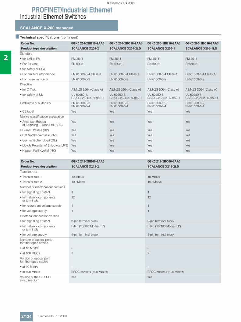
PROFINET/Industrial EthernetIndustrial Ethernet Switches
SCALANCE X-200 managed
2/124 Siemens IK PI · 2009
2
■ Technical specifications (continued)
Order No. 6GK5 204-2BB10-2AA3 6GK5 204-2BC10-2AA3 6GK5 206-1BB10-2AA3 6GK5 206-1BC10-2AA3Product type description SCALANCE X204-2 SCALANCE X204-2LD SCALANCE X206-1 SCALANCE X206-1LD
Standard
• for EMI of FM FM 3611 FM 3611 FM 3611 FM 3611
• For Ex zone EN 50021 EN 50021 EN 50021 EN 50021
• for safety of CSA - - - -
• For emitted interference EN 61000-6-4 Class A EN 61000-6-4 Class A EN 61000-6-4 Class A EN 61000-6-4 Class A
• For noise immunity EN 61000-6-2 EN 61000-6-2 EN 61000-6-2 EN 61000-6-2
Directive
• for C-Tick AS/NZS 2064 (Class A) AS/NZS 2064 (Class A) AS/NZS 2064 (Class A) AS/NZS 2064 (Class A)
• for safety of UL UL 60950-1, CSA C22.2 No. 60950-1
UL 60950-1, CSA C22.2 No. 60950-1
UL 60950-1, CSA C22.2 No. 60950-1
UL 60950-1, CSA C22.2 No. 60950-1
Certificate of suitability EN 61000-6-2, EN 61000-6-4
EN 61000-6-2, EN 61000-6-4
EN 61000-6-2, EN 61000-6-4
EN 61000-6-2, EN 61000-6-4
• CE label Yes Yes Yes Yes
Marine classification association
• American Bureau of Shipping Europe Ltd.(ABS)
Yes Yes Yes Yes
• Bureau Veritas (BV) Yes Yes Yes Yes
• Det Norske Veritas (DNV) Yes Yes Yes Yes
• Germanischer Lloyd (GL) Yes Yes Yes Yes
• Lloyds Register of Shipping (LRS) Yes Yes Yes Yes
• Nippon Kaiji Kyokai (NK) Yes Yes Yes Yes
Order No. 6GK5 212-2BB00-2AA3 6GK5 212-2BC00-2AA3Product type description SCALANCE X212-2 SCALANCE X212-2LD
Transfer rate
• Transfer rate 1 10 Mbit/s 10 Mbit/s
• Transfer rate 2 100 Mbit/s 100 Mbit/s
Number of electrical connections
• for signaling contact 1 1
• for network components or terminals
12 12
• for redundant voltage supply 1 1
• for voltage supply 1 1
Electrical connection version
• for signaling contact 2-pin terminal block 2-pin terminal block
• for network components or terminals
RJ45 (10/100 Mbit/s; TP) RJ45 (10/100 Mbit/s; TP)
• for voltage supply 4-pin terminal block 4-pin terminal block
Number of optical ports for fiber-optic cables
• at 10 Mbit/s - -
• at 100 Mbit/s 2 2
Version of optical port for fiber-optic cables
• at 10 Mbit/s - -
• at 100 Mbit/s BFOC sockets (100 Mbit/s) BFOC sockets (100 Mbit/s)
Version of the C-PLUG swap medium
Yes Yes
© Siemens AG 2008
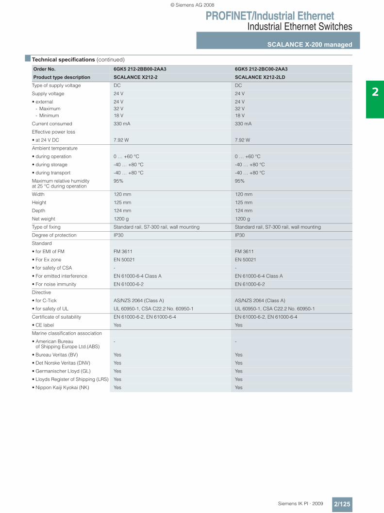
PROFINET/Industrial EthernetIndustrial Ethernet Switches
SCALANCE X-200 managed
2/125Siemens IK PI · 2009
2
■ Technical specifications (continued)
Order No. 6GK5 212-2BB00-2AA3 6GK5 212-2BC00-2AA3Product type description SCALANCE X212-2 SCALANCE X212-2LD
Type of supply voltage DC DC
Supply voltage 24 V 24 V
• external 24 V 24 V- Maximum 32 V 32 V- Minimum 18 V 18 V
Current consumed 330 mA 330 mA
Effective power loss
• at 24 V DC 7.92 W 7.92 W
Ambient temperature
• during operation 0 … +60 °C 0 … +60 °C
• during storage -40 … +80 °C -40 … +80 °C
• during transport -40 … +80 °C -40 … +80 °C
Maximum relative humidity at 25 °C during operation
95% 95%
Width 120 mm 120 mm
Height 125 mm 125 mm
Depth 124 mm 124 mm
Net weight 1200 g 1200 g
Type of fixing Standard rail, S7-300 rail, wall mounting Standard rail, S7-300 rail, wall mounting
Degree of protection IP30 IP30
Standard
• for EMI of FM FM 3611 FM 3611
• For Ex zone EN 50021 EN 50021
• for safety of CSA - -
• For emitted interference EN 61000-6-4 Class A EN 61000-6-4 Class A
• For noise immunity EN 61000-6-2 EN 61000-6-2
Directive
• for C-Tick AS/NZS 2064 (Class A) AS/NZS 2064 (Class A)
• for safety of UL UL 60950-1, CSA C22.2 No. 60950-1 UL 60950-1, CSA C22.2 No. 60950-1
Certificate of suitability EN 61000-6-2, EN 61000-6-4 EN 61000-6-2, EN 61000-6-4
• CE label Yes Yes
Marine classification association
• American Bureau of Shipping Europe Ltd.(ABS)
- -
• Bureau Veritas (BV) Yes Yes
• Det Norske Veritas (DNV) Yes Yes
• Germanischer Lloyd (GL) Yes Yes
• Lloyds Register of Shipping (LRS) Yes Yes
• Nippon Kaiji Kyokai (NK) Yes Yes
© Siemens AG 2008
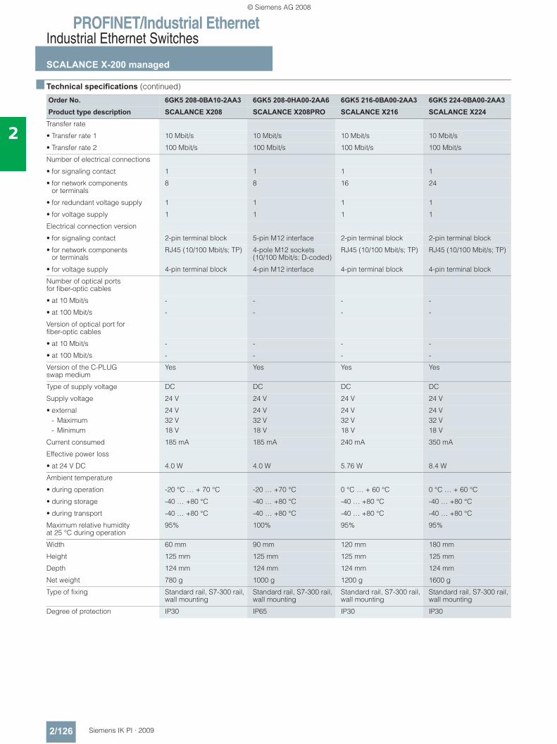
PROFINET/Industrial EthernetIndustrial Ethernet Switches
SCALANCE X-200 managed
2/126 Siemens IK PI · 2009
2
■ Technical specifications (continued)
Order No. 6GK5 208-0BA10-2AA3 6GK5 208-0HA00-2AA6 6GK5 216-0BA00-2AA3 6GK5 224-0BA00-2AA3Product type description SCALANCE X208 SCALANCE X208PRO SCALANCE X216 SCALANCE X224
Transfer rate
• Transfer rate 1 10 Mbit/s 10 Mbit/s 10 Mbit/s 10 Mbit/s
• Transfer rate 2 100 Mbit/s 100 Mbit/s 100 Mbit/s 100 Mbit/s
Number of electrical connections
• for signaling contact 1 1 1 1
• for network components or terminals
8 8 16 24
• for redundant voltage supply 1 1 1 1
• for voltage supply 1 1 1 1
Electrical connection version
• for signaling contact 2-pin terminal block 5-pin M12 interface 2-pin terminal block 2-pin terminal block
• for network components or terminals
RJ45 (10/100 Mbit/s; TP) 4-pole M12 sockets (10/100 Mbit/s; D-coded)
RJ45 (10/100 Mbit/s; TP) RJ45 (10/100 Mbit/s; TP)
• for voltage supply 4-pin terminal block 4-pin M12 interface 4-pin terminal block 4-pin terminal block
Number of optical ports for fiber-optic cables
• at 10 Mbit/s - - - -
• at 100 Mbit/s - - - -
Version of optical port for fiber-optic cables
• at 10 Mbit/s - - - -
• at 100 Mbit/s - - - -
Version of the C-PLUG swap medium
Yes Yes Yes Yes
Type of supply voltage DC DC DC DC
Supply voltage 24 V 24 V 24 V 24 V
• external 24 V 24 V 24 V 24 V- Maximum 32 V 32 V 32 V 32 V- Minimum 18 V 18 V 18 V 18 V
Current consumed 185 mA 185 mA 240 mA 350 mA
Effective power loss
• at 24 V DC 4.0 W 4.0 W 5.76 W 8.4 W
Ambient temperature
• during operation -20 °C … + 70 °C -20 … +70 °C 0 °C … + 60 °C 0 °C … + 60 °C
• during storage -40 … +80 °C -40 … +80 °C -40 … +80 °C -40 … +80 °C
• during transport -40 … +80 °C -40 … +80 °C -40 … +80 °C -40 … +80 °C
Maximum relative humidity at 25 °C during operation
95% 100% 95% 95%
Width 60 mm 90 mm 120 mm 180 mm
Height 125 mm 125 mm 125 mm 125 mm
Depth 124 mm 124 mm 124 mm 124 mm
Net weight 780 g 1000 g 1200 g 1600 g
Type of fixing Standard rail, S7-300 rail, wall mounting
Standard rail, S7-300 rail, wall mounting
Standard rail, S7-300 rail, wall mounting
Standard rail, S7-300 rail, wall mounting
Degree of protection IP30 IP65 IP30 IP30
© Siemens AG 2008
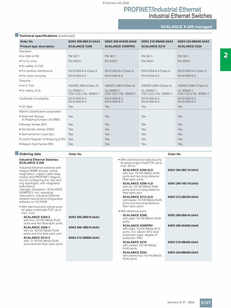
PROFINET/Industrial EthernetIndustrial Ethernet Switches
SCALANCE X-200 managed
2/127Siemens IK PI · 2009
2
■ Technical specifications (continued)
■ Ordering data Order No. Order No.
Order No. 6GK5 208-0BA10-2AA3 6GK5 208-0HA00-2AA6 6GK5 216-0BA00-2AA3 6GK5 224-0BA00-2AA3Product type description SCALANCE X208 SCALANCE X208PRO SCALANCE X216 SCALANCE X224
Standard
• for EMI of FM FM 3611 FM 3611 FM 3611 FM 3611
• For Ex zone EN 50021 EN 50021 EN 50021 EN 50021
• for safety of CSA - - - -
• For emitted interference EN 61000-6-4 Class A EN 61000-6-4 Class A EN 61000-6-4 Class A EN 61000-6-4 Class A
• For noise immunity EN 61000-6-2 EN 61000-6-2 EN 61000-6-2 EN 61000-6-2
Directive
• for C-Tick AS/NZS 2064 (Class A) AS/NZS 2064 (Class A) AS/NZS 2064 (Class A) AS/NZS 2064 (Class A)
• for safety of UL UL 60950-1, CSA C22.2 No. 60950-1
UL 60950-1, CSA C22.2 No. 60950-1
UL 60950-1, CSA C22.2 No. 60950-1
UL 60950-1, CSA C22.2 No. 60950-1
Certificate of suitability EN 61000-6-2, EN 61000-6-4
EN 61000-6-2, EN 61000-6-4
EN 61000-6-2, EN 61000-6-4
EN 61000-6-2, EN 61000-6-4
• CE label Yes Yes Yes Yes
Marine classification association
• American Bureau of Shipping Europe Ltd.(ABS)
Yes Yes Yes Yes
• Bureau Veritas (BV) Yes Yes Yes Yes
• Det Norske Veritas (DNV) Yes Yes Yes Yes
• Germanischer Lloyd (GL) Yes Yes Yes Yes
• Lloyds Register of Shipping (LRS) Yes Yes Yes Yes
• Nippon Kaiji Kyokai (NK) Yes Yes Yes Yes
Industrial Ethernet Switches SCALANCE X-200Industrial Ethernet switches with integral SNMP access, online diagnostics, copper cable diag-nostics and PROFINET diagnos-tics for configuring line, star and ring topologies; with integrated redundancy manager (exception: SCALANCE X208PRO); incl. operating instructions, Industrial Ethernet network manual and configuration software on CD-ROM
• With electrical and optical ports for glass multimode FOC up to max. 3 km- SCALANCE X204-2
with four 10/100 Mbit/s RJ45 ports and two fiber-optic ports
6GK5 204-2BB10-2AA3
- SCALANCE X206-1;with six 10/100 Mbit/s RJ45 ports and one fiber-optic port
6GK5 206-1BB10-2AA3
- SCALANCE X212-2 with 12 10/100 Mbit/s RJ45 ports and two fiber-optic ports
6GK5 212-2BB00-2AA3
• With electrical and optical ports for glass single mode FOC up to max. 26 km- SCALANCE X204-2LD
with four 10/100 Mbit/s RJ45 ports and two long-distance fiber-optic ports
6GK5 204-2BC10-2AA3
- SCALANCE X206-1LD;with six 10/100 Mbit/s RJ45 ports and one long-distance fiber-optic port
6GK5 206-1BC10-2AA3
- SCALANCE X212-2LD with twelve 10/100 Mbit/s RJ45 ports and two long-distance fiber-optic ports
6GK5 212-2BC00-2AA3
• With electrical ports - SCALANCE X208;
with eight 10/100 Mbit/s RJ45 ports
6GK5 208-0BA10-2AA3
- SCALANCE X208PRO with eight 10/100 Mbit/s M12 ports, incl. eleven M12 dust protection caps, degree of protection IP65
6GK5 208-0HA00-2AA6
- SCALANCE X216 with sixteen 10/100 Mbit/s RJ45 ports
6GK5 216-0BA00-2AA3
- SCALANCE X224 with twenty-four 10/100 Mbit/s RJ45 ports
6GK5 224-0BA00-2AA3
© Siemens AG 2008
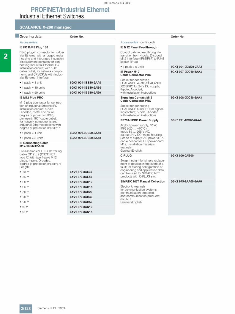
PROFINET/Industrial EthernetIndustrial Ethernet Switches
SCALANCE X-200 managed
2/128 Siemens IK PI · 2009
2
■ Ordering data Order No. Order No.
AccessoriesIE FC RJ45 Plug 180RJ45 plug-in connector for Indus-trial Ethernet with a rugged metal housing and integrated insulation displacement contacts for con-necting Industrial Ethernet FC installation cables; with 180° cable outlet; for network compo-nents and CPs/CPUs with Indus-trial Ethernet interface
• 1 pack = 1 unit 6GK1 901-1BB10-2AA0• 1 pack = 10 units 6GK1 901-1BB10-2AB0• 1 pack = 50 units 6GK1 901-1BB10-2AE0IE M12 Plug PROM12 plug connector for connec-tion of Industrial Ethernet FC installation cables; 4-pole, D-coded, metal enclosure, degree of protection IP65, pin insert; 180° cable outlet; for network components and Industrial Ethernet stations with degree of protection IP65/IP67
• 1 pack = 1 unit 6GK1 901-0DB20-6AA0• 1 pack = 8 units 6GK1 901-0DB20-6AA8IE Connecting Cable M12-180/M12-180Pre-assembled IE FC TP trailing cable GP 2 x 2 (PROFINET type C) with two 4-pole M12 plugs, 4-pole, D-coded, degree of protection IP65/IP67; Length:
• 0.3 m 6XV1 870-8AE30• 0.5 m 6XV1 870-8AE50• 1.0 m 6XV1 870-8AH10• 1.5 m 6XV1 870-8AH15• 2.0 m 6XV1 870-8AH20• 3.0 m 6XV1 870-8AH30• 5.0 m 6XV1 870-8AH50• 10 m 6XV1 870-8AN10• 15 m 6XV1 870-8AN15
Accessories (continued)
IE M12 Panel FeedthroughControl cabinet feedthrough for transition from 4-pole, D-coded M12 interface (IP65IP67) to RJ45 socket (IP20)
• 1 pack = 5 units 6GK1 901-0DM20-2AA5IE Power M12 Cable Connector PRO
6GK1 907-0DC10-6AA3
Socket for connecting SCALANCE W-700/SCALANCE X208PRO for 24 V DC supply; 4-pole, A-coded, with installation instructions
Signaling Contact M12 Cable Connector PRO
6GK1 908-0DC10-6AA3
Socket for connecting SCALANCE X208PRO for signal-ing contact; 5-pole, B-coded, with installation instructions
PS791-1PRO Power Supply 6GK5 791-1PS00-0AA6AC/DC power supply, 10 W, IP65 (-20 … +60°C), Input: 85 … 265 V AC, output: 24 V DC, metal housing, Scope of supply: AC power 3+PE cable connector, DC power cord M12, installation materials, manuals German/English
C-PLUG 6GK1 900-0AB00Swap medium for simple replace-ment of devices in the event of a fault; for storing configuration or engineering and application data; can be used for SIMATIC NET products with C-PLUG slot
SIMATIC NET Manual Collection 6GK1 975-1AA00-3AA0Electronic manuals for communication systems, communication protocols, and communication products;on DVD; German/English
© Siemens AG 2008
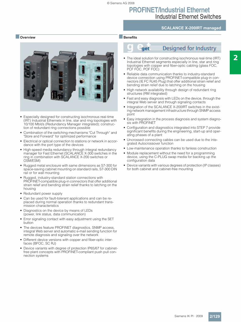
PROFINET/Industrial EthernetIndustrial Ethernet Switches
SCALANCE X-200IRT managed
2/129Siemens IK PI · 2009
2
■ Overview
• Especially designed for constructing isochronous real-time (IRT) Industrial Ethernets in line, star and ring topologies with 10/100 Mbit/s (Redundancy Manager integrated); construc-tion of redundant ring connections possible
• Combination of the switching mechanisms "Cut Through“ and "Store and Forward“ for optimized performance
• Electrical or optical connection to stations or network in accor-dance with the port type of the devices
• High-speed media redundancy through integral redundancy manager for Fast Ethernet (SCALANCE X-300 switches in the ring in combination with SCALANCE X-200 switches or OSM/ESM)
• Rugged metal enclosure with same dimensions as S7-300 for space-saving cabinet mounting on standard rails, S7-300 DIN rail or for wall mounting
• Rugged, industry-standard station connections with PROFINET-compatible plug-in connectors that offer additional strain relief and bending strain relief thanks to latching on the housing
• Redundant power supply • Can be used for fault-tolerant applications and can be re-
placed during normal operation thanks to redundant trans-mission characteristics
• Diagnostics on the device by means of LEDs (power, link status, data communication)
• Error signaling contact with easy adjustment using the SET button
• The devices feature PROFINET diagnostics, SNMP access, integral Web server and automatic e-mail sending function for remote diagnosis and signaling over the network
• Different device versions with copper and fiber-optic inter-faces (BFOC, SC RJ)
• Device variants with degree of protection IP65/67 for cabinet-free plant concepts with PROFINET-compliant push pull con-nection systems
■ Benefits
• The ideal solution for constructing isochronous real-time (IRT) Industrial Ethernet segments especially in line, star and ring topologies with copper and fiber-optic cabling (glass FOC, PCF FOC, POF FOC)
• Reliable data communication thanks to industry-standard device connection using PROFINET-compatible plug-in con-nectors (IE FC RJ45 Plug) that offer additional strain relief and bending strain relief due to latching on the housing
• High network availability through design of redundant ring structures (RM integrated)
• Fast and easy diagnosis with LEDs on the device, through the integral Web server and through signaling contacts
• Integration of the SCALANCE X-200IRT switches in the exist-ing network management infrastructure through SNMP access point
• Easy integration in the process diagnosis and system diagno-sis with PROFINET
• Configuration and diagnostics integrated into STEP 7 provide significant benefits during the engineering, start-up and oper-ating phases of a plant
• Uncrossed connecting cables can be used due to the inte-grated Autocrossover function
• Low-maintenance operation thanks to fanless construction• Module replacement without the need for a programming
device, using the C-PLUG swap media for backing up the configuration data
• Device variants with various degrees of protection (IP classes) for both cabinet and cabinet-free mounting
© Siemens AG 2008
PROFINET/Industrial EthernetIndustrial Ethernet Switches
SCALANCE X-200IRT managed
2/130 Siemens IK PI · 2009
2
■ Application
The SCALANCE X-200IRT Industrial Ethernet switches permit the construction of isochronous real-time (IRT) Industrial Ethernet line and star topologies. Ring structures can also be designed using the integral redundancy manager (RM). Redun-dant ring connections are also possible. Thanks to innovative switching technology, the special requirements of automation with regard to line topology, isochronous mode for motion control applications and unlimited IT openness have been satisfied for the first time within a single technology based on the PROFINET standard.
The switches with degree of protection IP30 have been designed for use in the control cabinet. The switches with degree of protection IP65/67 are designed for cabinet-free mounting (PROFINET-compliant push pull connection technology).
Product versions
SCALANCE X204IRT • For configuring electrical Industrial Ethernet line, star or ring
topologies with 4 electrical ports
SCALANCE X202-2IRT • For configuring electrical or optical Industrial Ethernet line,
star or ring topologies with 2 electrical ports and 2 glass fiber optic ports
SCALANCE X202-2P IRT • For configuring electrical or optical Industrial Ethernet line,
star or ring topologies with 2 electrical ports and 2 plastic fiber optic ports
SCALANCE X201-3P IRT • For configuring electrical or optical Industrial Ethernet line,
star or ring topologies with 1 electrical port and 3 plastic fiber optic ports
SCALANCE X200-4P IRT • For configuring optical Industrial Ethernet line, star or ring
topologies with 4 optical POF FOC ports
SCALANCE X204 IRT PRO • For the construction of electrical Industrial Ethernet linear,
point-to-point or ring structures with four electrical ports with degree of protection IP65/67 and PROFINET-compliant push-pull connection technology
SCALANCE X202-2P IRT PRO • For the construction of electrical or optical Industrial Ethernet
linear, point-to-point or ring structures with two electrical and two optical POF/PCF fiber optic ports with degree of protec-tion IP65/67 and PROFINET-compliant push-pull connection technology
Applicable to all versions: • Integral redundancy manager (RM)• Device diagnostics with LEDs (power, link status, data com-
munication)• Remote diagnosis is possible through signaling contact
(signal mask can be set locally using buttons), PROFINET, SNMP and Web browser
• Automatic e-mail send function• Rugged, industry-standard station connections with
PROFINET-compatible RJ45 connectors that offer additional strain relief and bending strain relief thanks to latching on the housing
The SCALANCE X-200IRT switches, based on PROFINET, satisfy the real-time requirements of the field level up to high-performance motion control applications.
Real-time Ethernet • Interfacing of the PROFINET IO-Devices to the PROFINET IO-
Controller through high-performance, optimized data trans-mission
• Coexistence of isochronous mode for motion control applica-tions and IT openness: Reaction-free transmission of real-time and non-real-time communication on the same line
• Increased availability thanks to redundant transmission with bumpless changeover for real-time data
Additionally through isochronous real-time (IRT) Ethernet • Isochronous real-time communication based on the transmis-
sion procedure of the IEEE 802 by combining the switching mechanisms "Cut Through" and "Store and Forward".
• For drive controls, PROFINET with isochronous real-time is the best performing system worldwide with regard to its isochron-ronous and deterministic response. With a cycle time of 1 ms, for example, axes can be controlled in isochronous mode whereby 50 % of the bandwidth is avail-able solely for IT communication.
■ Design• The SCALANCE X-200IRT switches in a rugged metal housing
with degrees of protection IP30 and IP65/67 are optimized for mounting on a standard rail and an S7-300 rail. Direct wall mounting in various positions is also possible. With the S7-300 housing format, the devices are optimized for integration in an automation solution with S7-300 components. The switches have a 4-pin terminal block for connecting the redundant supply voltage (2 x 24 V DC). The versions with degree of protection IP65/67 have two 5-pin push-pull con-nectors via which the supply voltage is fed and forwarded. In addition, the load voltage circuit is also looped through for the ET200pro devices further along the line. The devices with degree of protection IP65/67 thus have no redundant voltage feed, but permit optimal integration into cabinet-free plant concepts with ET200pro modules. The status information (power, link status, data traffic, voltage supply, message contact) is indicated by means of a row of LEDs.
The SCALANCE X-200IRT modules are available with the following port types:• 10/100BaseTX, RJ45 connection
RJ45 socket, automatic detection of the data rate (10 or 100 Mbit/s), with Autosensing and Autocrossover function for connecting IE FC cables over IE FC RJ45 Plug 180 over dis-tances up to 100 m.
• 10/100BaseTX, push-pull RJ45 connection RJ45 socket, automatic detection of the data rate (10 or 100 Mbit/s), with autosensing and autocrossover function for connecting IE FC cables via IE FC RJ45 Plug PRO over dis-tances up to 100 m
• 100BaseFX, BFOC connection technique BFOC sockets for direct connection to Industrial Ethernet glass fiber-optic cables up to 3000 m for configuring line and star topologies.
• 100BaseFX, SC RJ connections SC RJ sockets for connection to Industrial Ethernet POF (50 m) and PCF FOC (100 m) using SC RJ plug connectors
• 100BaseFX, push-pull SC RJ connections SC RJ sockets for connection to Industrial Ethernet POF (50 m) and PCF FOC (100 m) using SC RJ plug PRO connec-tors
© Siemens AG 2008
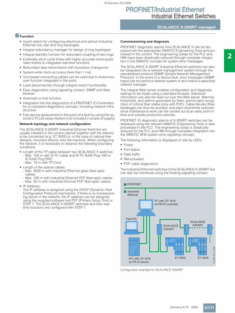
PROFINET/Industrial EthernetIndustrial Ethernet Switches
SCALANCE X-200IRT managed
2/131Siemens IK PI · 2009
2
■ Function• 4-port switch for configuring electrical and optical Industrial
Ethernet line, star and ring topologies• Integral redundancy manager for design of ring topologies• Integral standby function for redundant coupling of two rings• Extremely short cycle times with highly accurate clock-pulse
rates thanks to integrated real-time functions• Redundant data transmission with bumpless changeover• System-wide clock accuracy (less than 1 ms)• Uncrossed connecting cables can be used due to Autocross-
over function integrated in the ports• Load disconnection through integral switch functionality• Easy diagnostics using signaling contact, SNMP and Web
browser• Automatic e-mail function• Integration into the diagnostics of a PROFINET IO-Controllers
for a consistent diagnostics concept, including network infra-structure
• Fast device replacement in the event of a fault by using the op-tional C-PLUG swap medium (not included in scope of supply)
Network topology and network configuration
The SCALANCE X-200IRT Industrial Ethernet Switches are usually installed in the control cabinet together with the stations to be connected (e.g. ET 200S) or, in the case of cabinet-free designs, mounted directly onto the machine. When configuring the network, it is necessary to observe the following boundary conditions:• Length of the TP cable between two SCALANCE X switches:
- Max. 100 m with IE FC cable and IE FC RJ45 Plug 180 or IE RJ45 Plug PRO
- Max. 10 m with TP Cord• Length of the optical cables
- Max. 3000 m with Industrial Ethernet glass fiber-optic cables.
- Max. 100 m with Industrial Ethernet PCF fiber-optic cables.- Max. 50 m with Industrial Ethernet POF fiber-optic cables.
• IP Address: The IP address is assigned using the DHCP (Dynamic Host Configuration Protocol) mechanism. If there is no correspond-ing server in the network, the IP address can be assigned using the supplied software tool PST (Primary Setup Tool) or STEP 7. The SCALANCE X-200IRT switches and their real-time functions are configured with STEP 7.
Commissioning and diagnosis
PROFINET diagnostic alarms from SCALANCE X can be dis-played with the appropriate SIMATIC Engineering Tools and pro-cessed in the control. The engineering outlay for the PLC and HMI have been drastically reduced through complete integra-tion in the SIMATIC concept for system error messages.
The SCALANCE X-200IRT Industrial Ethernet switches can also be integrated into a network management system through the standardized protocol SNMP (Simple Network Management Protocol). In the event of a device fault, error messages (SNMP traps) can be sent to a network system or as e-mail to a specified network manager.
The integral Web server enables configuration and diagnosis settings to be made using a standard browser. Statistical information can also be read out over the Web server. Warning thresholds, and alarms generated by them, permit early recog-nition of critical fiber states (only with POF). Cable failures (fiber breakage) can thus be avoided, and plant downtimes reduced, since maintenance work can be carried out at an early point in time and outside production periods.
PROFINET IO diagnostic alarms of X-200IRT switches can be displayed using the relevant SIMATIC Engineering Tools or also processed in the PLC. The engineering outlay is drastically reduced for the PLC and HMI through complete integration into the SIMATIC SFM system error signaling concept.
The following information is displayed on site by LEDs:• Power• Port status• Data traffic• RM activated• POF cable diagnostics
The Industrial Ethernet switches of the SCALANCE X-200IRT line can also be monitored using the floating signaling contact.
Configuration example for SCALANCE X204IRT
PC with CP 1616as PN IO controller
IPC with CP 1616as PN IO device
PROFINET
IndustrialEthernet
G_I
K10
_XX
_101
00
ET 200S ET 200S
SCALANCEX204IRTSCALANCE
X204IRT
Field PG
© Siemens AG 2008
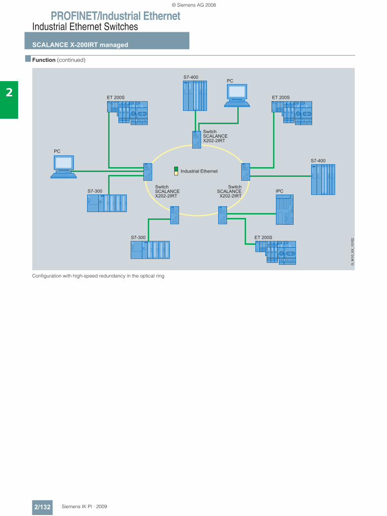
PROFINET/Industrial EthernetIndustrial Ethernet Switches
SCALANCE X-200IRT managed
2/132 Siemens IK PI · 2009
2
■ Function (continued)
Configuration with high-speed redundancy in the optical ring
© Siemens AG 2008
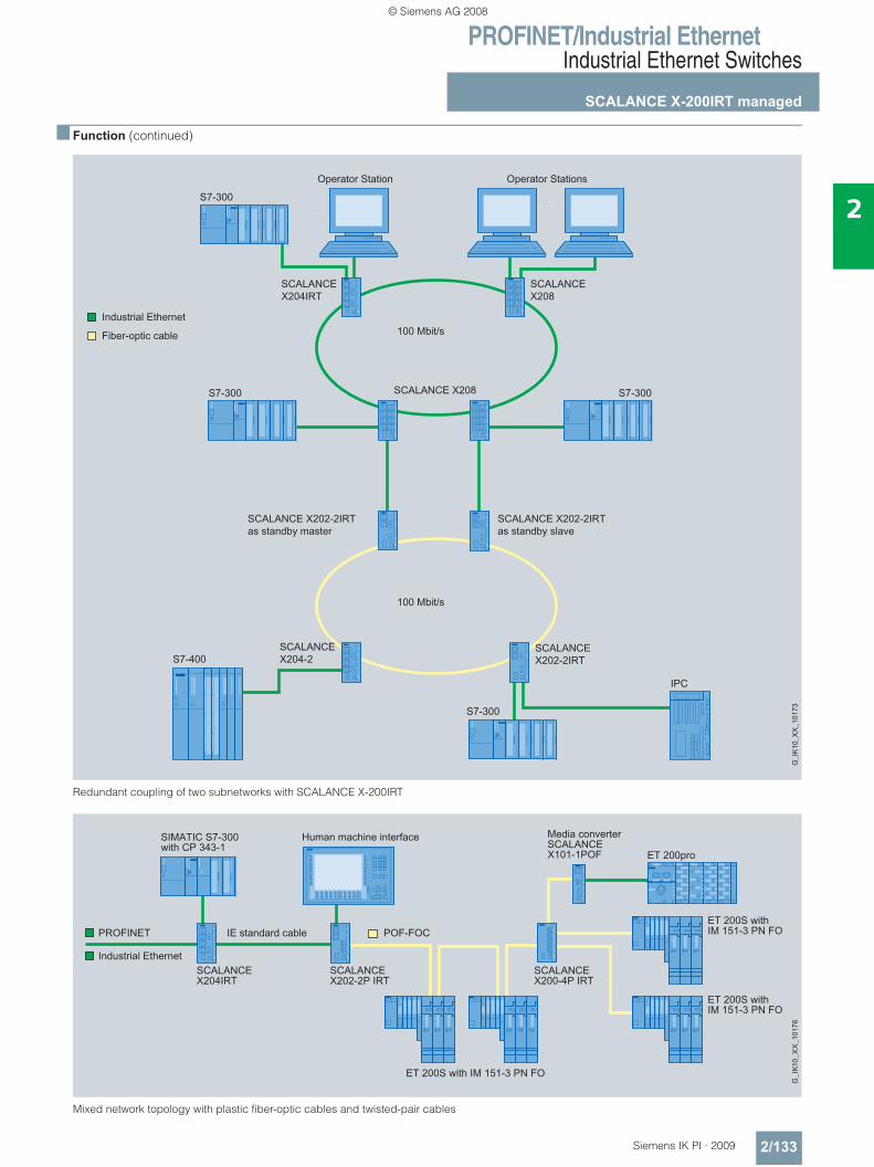
PROFINET/Industrial EthernetIndustrial Ethernet Switches
SCALANCE X-200IRT managed
2/133Siemens IK PI · 2009
2
■ Function (continued)
Redundant coupling of two subnetworks with SCALANCE X-200IRT
Mixed network topology with plastic fiber-optic cables and twisted-pair cables
© Siemens AG 2008
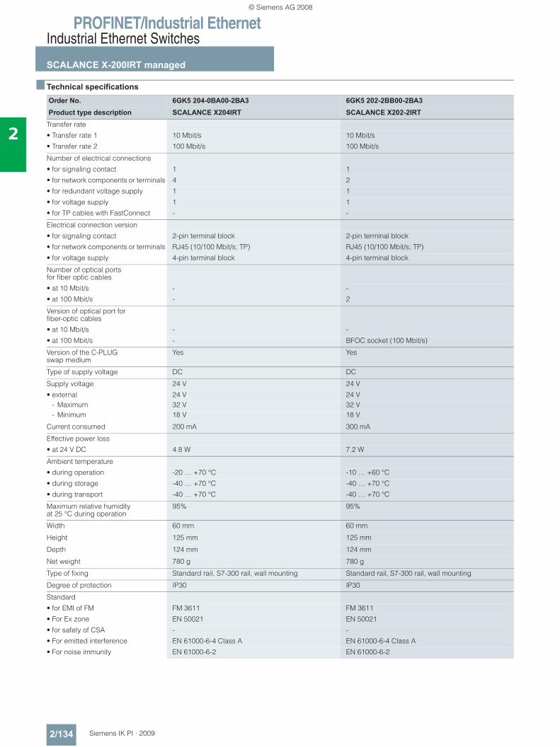
PROFINET/Industrial EthernetIndustrial Ethernet Switches
SCALANCE X-200IRT managed
2/134 Siemens IK PI · 2009
2
■ Technical specifications
Order No. 6GK5 204-0BA00-2BA3 6GK5 202-2BB00-2BA3Product type description SCALANCE X204IRT SCALANCE X202-2IRT
Transfer rate
• Transfer rate 1 10 Mbit/s 10 Mbit/s
• Transfer rate 2 100 Mbit/s 100 Mbit/s
Number of electrical connections
• for signaling contact 1 1
• for network components or terminals 4 2
• for redundant voltage supply 1 1
• for voltage supply 1 1
• for TP cables with FastConnect - -
Electrical connection version
• for signaling contact 2-pin terminal block 2-pin terminal block
• for network components or terminals RJ45 (10/100 Mbit/s; TP) RJ45 (10/100 Mbit/s; TP)
• for voltage supply 4-pin terminal block 4-pin terminal block
Number of optical ports for fiber optic cables
• at 10 Mbit/s - -
• at 100 Mbit/s - 2
Version of optical port for fiber-optic cables
• at 10 Mbit/s - -
• at 100 Mbit/s - BFOC socket (100 Mbit/s)
Version of the C-PLUG swap medium
Yes Yes
Type of supply voltage DC DC
Supply voltage 24 V 24 V
• external 24 V 24 V- Maximum 32 V 32 V- Minimum 18 V 18 V
Current consumed 200 mA 300 mA
Effective power loss
• at 24 V DC 4.8 W 7.2 W
Ambient temperature
• during operation -20 … +70 °C -10 … +60 °C
• during storage -40 … +70 °C -40 … +70 °C
• during transport -40 … +70 °C -40 … +70 °C
Maximum relative humidity at 25 °C during operation
95% 95%
Width 60 mm 60 mm
Height 125 mm 125 mm
Depth 124 mm 124 mm
Net weight 780 g 780 g
Type of fixing Standard rail, S7-300 rail, wall mounting Standard rail, S7-300 rail, wall mounting
Degree of protection IP30 IP30
Standard
• for EMI of FM FM 3611 FM 3611
• For Ex zone EN 50021 EN 50021
• for safety of CSA - -
• For emitted interference EN 61000-6-4 Class A EN 61000-6-4 Class A
• For noise immunity EN 61000-6-2 EN 61000-6-2
© Siemens AG 2008
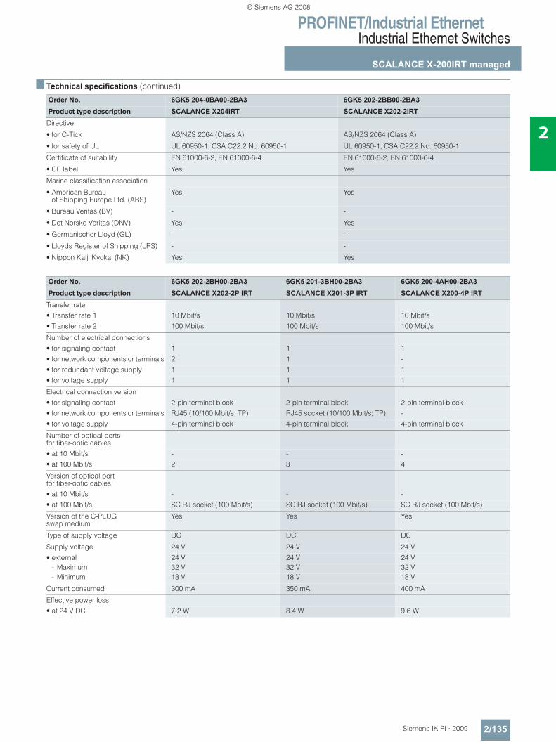
PROFINET/Industrial EthernetIndustrial Ethernet Switches
SCALANCE X-200IRT managed
2/135Siemens IK PI · 2009
2
■ Technical specifications (continued)
Order No. 6GK5 204-0BA00-2BA3 6GK5 202-2BB00-2BA3Product type description SCALANCE X204IRT SCALANCE X202-2IRT
Directive
• for C-Tick AS/NZS 2064 (Class A) AS/NZS 2064 (Class A)
• for safety of UL UL 60950-1, CSA C22.2 No. 60950-1 UL 60950-1, CSA C22.2 No. 60950-1
Certificate of suitability EN 61000-6-2, EN 61000-6-4 EN 61000-6-2, EN 61000-6-4
• CE label Yes Yes
Marine classification association
• American Bureau of Shipping Europe Ltd. (ABS)
Yes Yes
• Bureau Veritas (BV) - -
• Det Norske Veritas (DNV) Yes Yes
• Germanischer Lloyd (GL) - -
• Lloyds Register of Shipping (LRS) - -
• Nippon Kaiji Kyokai (NK) Yes Yes
Order No. 6GK5 202-2BH00-2BA3 6GK5 201-3BH00-2BA3 6GK5 200-4AH00-2BA3Product type description SCALANCE X202-2P IRT SCALANCE X201-3P IRT SCALANCE X200-4P IRT
Transfer rate• Transfer rate 1 10 Mbit/s 10 Mbit/s 10 Mbit/s• Transfer rate 2 100 Mbit/s 100 Mbit/s 100 Mbit/s
Number of electrical connections• for signaling contact 1 1 1• for network components or terminals 2 1 -• for redundant voltage supply 1 1 1• for voltage supply 1 1 1
Electrical connection version• for signaling contact 2-pin terminal block 2-pin terminal block 2-pin terminal block• for network components or terminals RJ45 (10/100 Mbit/s; TP) RJ45 socket (10/100 Mbit/s; TP) -• for voltage supply 4-pin terminal block 4-pin terminal block 4-pin terminal block
Number of optical ports for fiber-optic cables• at 10 Mbit/s - - -• at 100 Mbit/s 2 3 4
Version of optical port for fiber-optic cables• at 10 Mbit/s - - -• at 100 Mbit/s SC RJ socket (100 Mbit/s) SC RJ socket (100 Mbit/s) SC RJ socket (100 Mbit/s)
Version of the C-PLUG swap medium
Yes Yes Yes
Type of supply voltage DC DC DC
Supply voltage 24 V 24 V 24 V• external 24 V 24 V 24 V
- Maximum 32 V 32 V 32 V- Minimum 18 V 18 V 18 V
Current consumed 300 mA 350 mA 400 mA
Effective power loss• at 24 V DC 7.2 W 8.4 W 9.6 W
© Siemens AG 2008
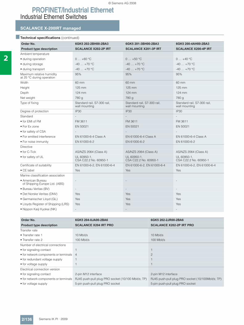
PROFINET/Industrial EthernetIndustrial Ethernet Switches
SCALANCE X-200IRT managed
2/136 Siemens IK PI · 2009
2
■ Technical specifications (continued)
Order No. 6GK5 202-2BH00-2BA3 6GK5 201-3BH00-2BA3 6GK5 200-4AH00-2BA3Product type description SCALANCE X202-2P IRT SCALANCE X201-3P IRT SCALANCE X200-4P IRT
Ambient temperature
• during operation 0 … +60 °C 0 … +50 °C 0 … +40 °C
• during storage -40 … +70 °C -40 … +70 °C -40 … +70 °C
• during transport -40 … +70 °C -40 … +70 °C -40 … +70 °C
Maximum relative humidity at 25 °C during operation
95% 95% 95%
Width 60 mm 60 mm 60 mm
Height 125 mm 125 mm 125 mm
Depth 124 mm 124 mm 124 mm
Net weight 780 g 780 g 780 g
Type of fixing Standard rail, S7-300 rail, wall mounting
Standard rail, S7-300 rail, wall mounting
Standard rail, S7-300 rail, wall mounting
Degree of protection IP30 IP30 IP30
Standard - - -
• for EMI of FM FM 3611 FM 3611 FM 3611
• For Ex zone EN 50021 EN 50021 EN 50021
• for safety of CSA - - -
• For emitted interference EN 61000-6-4 Class A EN 61000-6-4 Class A EN 61000-6-4 Class A
• For noise immunity EN 61000-6-2 EN 61000-6-2 EN 61000-6-2
Directive
• for C-Tick AS/NZS 2064 (Class A) AS/NZS 2064 (Class A) AS/NZS 2064 (Class A)
• for safety of UL UL 60950-1, CSA C22.2 No. 60950-1
UL 60950-1, CSA C22.2 No. 60950-1
UL 60950-1, CSA C22.2 No. 60950-1
Certificate of suitability EN 61000-6-2, EN 61000-6-4 EN 61000-6-2, EN 61000-6-4 EN 61000-6-2, EN 61000-6-4
• CE label Yes Yes Yes
Marine classification association
• American Bureau of Shipping Europe Ltd. (ABS)
- - -
• Bureau Veritas (BV) - - -
• Det Norske Veritas (DNV) Yes Yes Yes
• Germanischer Lloyd (GL) Yes Yes Yes
• Lloyds Register of Shipping (LRS) Yes Yes Yes
• Nippon Kaiji Kyokai (NK) - - -
Order No. 6GK5 204-0JA00-2BA6 6GK5 202-2JR00-2BA6Product type description SCALANCE X204 IRT PRO SCALANCE X202-2P IRT PRO
Transfer rate
• Transfer rate 1 10 Mbit/s 10 Mbit/s
• Transfer rate 2 100 Mbit/s 100 Mbit/s
Number of electrical connections
• for signaling contact 1 1
• for network components or terminals 4 2
• for redundant voltage supply 1 1
• for voltage supply 1 1
Electrical connection version
• for signaling contact 2-pin M12 interface 2-pin M12 interface
• for network components or terminals RJ45 push-pull plug PRO socket (10/100 Mbit/s; TP) RJ45 push-pull plug PRO socket (10/100Mbit/s; TP)
• for voltage supply 5-pin push-pull plug PRO socket 5-pin push-pull plug PRO socket
© Siemens AG 2008
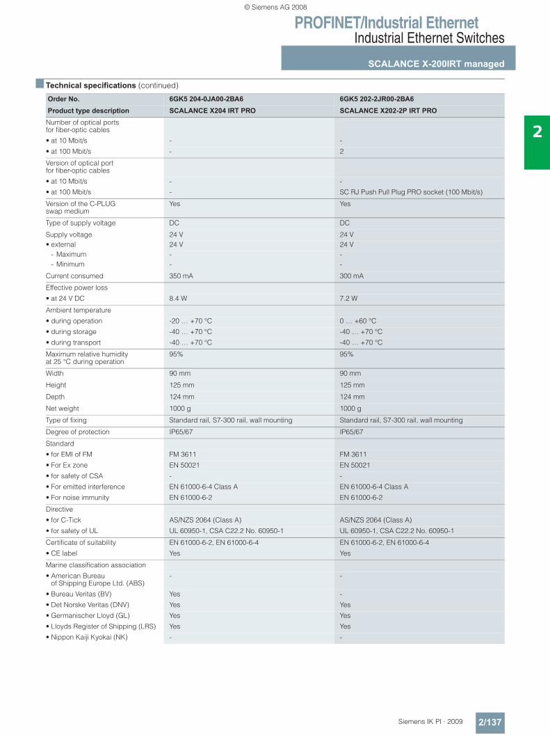
PROFINET/Industrial EthernetIndustrial Ethernet Switches
SCALANCE X-200IRT managed
2/137Siemens IK PI · 2009
2
■ Technical specifications (continued)
Order No. 6GK5 204-0JA00-2BA6 6GK5 202-2JR00-2BA6Product type description SCALANCE X204 IRT PRO SCALANCE X202-2P IRT PRO
Number of optical ports for fiber-optic cables
• at 10 Mbit/s - -
• at 100 Mbit/s - 2
Version of optical portfor fiber-optic cables
• at 10 Mbit/s - -
• at 100 Mbit/s - SC RJ Push Pull Plug PRO socket (100 Mbit/s)
Version of the C-PLUG swap medium
Yes Yes
Type of supply voltage DC DC
Supply voltage 24 V 24 V• external 24 V 24 V
- Maximum - -- Minimum - -
Current consumed 350 mA 300 mA
Effective power loss
• at 24 V DC 8.4 W 7.2 W
Ambient temperature
• during operation -20 … +70 °C 0 … +60 °C
• during storage -40 … +70 °C -40 … +70 °C
• during transport -40 … +70 °C -40 … +70 °C
Maximum relative humidity at 25 °C during operation
95% 95%
Width 90 mm 90 mm
Height 125 mm 125 mm
Depth 124 mm 124 mm
Net weight 1000 g 1000 g
Type of fixing Standard rail, S7-300 rail, wall mounting Standard rail, S7-300 rail, wall mounting
Degree of protection IP65/67 IP65/67
Standard
• for EMI of FM FM 3611 FM 3611
• For Ex zone EN 50021 EN 50021
• for safety of CSA - -
• For emitted interference EN 61000-6-4 Class A EN 61000-6-4 Class A
• For noise immunity EN 61000-6-2 EN 61000-6-2
Directive
• for C-Tick AS/NZS 2064 (Class A) AS/NZS 2064 (Class A)
• for safety of UL UL 60950-1, CSA C22.2 No. 60950-1 UL 60950-1, CSA C22.2 No. 60950-1
Certificate of suitability EN 61000-6-2, EN 61000-6-4 EN 61000-6-2, EN 61000-6-4
• CE label Yes Yes
Marine classification association
• American Bureau of Shipping Europe Ltd. (ABS)
- -
• Bureau Veritas (BV) Yes -
• Det Norske Veritas (DNV) Yes Yes
• Germanischer Lloyd (GL) Yes Yes
• Lloyds Register of Shipping (LRS) Yes Yes
• Nippon Kaiji Kyokai (NK) - -
© Siemens AG 2008
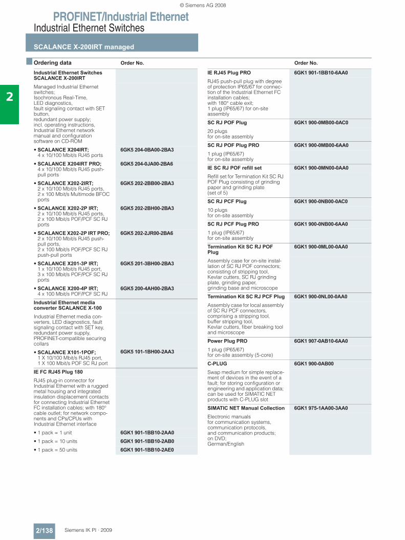
PROFINET/Industrial EthernetIndustrial Ethernet Switches
SCALANCE X-200IRT managed
2/138 Siemens IK PI · 2009
2
■ Ordering data Order No. Order No.
Industrial Ethernet Switches SCALANCE X-200IRTManaged Industrial Ethernet switches; Isochronous Real-Time, LED diagnostics, fault signaling contact with SET button, redundant power supply; incl. operating instructions, Industrial Ethernet network manual and configuration software on CD-ROM
• SCALANCE X204IRT; 4 x 10/100 Mbit/s RJ45 ports
6GK5 204-0BA00-2BA3
• SCALANCE X204IRT PRO; 4 x 10/100 Mbit/s RJ45 push-pull ports
6GK5 204-0JA00-2BA6
• SCALANCE X202-2IRT; 2 x 10/100 Mbit/s RJ45 ports, 2 x 100 Mbit/s Multimode BFOC ports
6GK5 202-2BB00-2BA3
• SCALANCE X202-2P IRT; 2 x 10/100 Mbit/s RJ45 ports, 2 x 100 Mbit/s POF/PCF SC RJ ports
6GK5 202-2BH00-2BA3
• SCALANCE X202-2P IRT PRO; 2 x 10/100 Mbit/s RJ45 push-pull ports, 2 x 100 Mbit/s POF/PCF SC RJ push-pull ports
6GK5 202-2JR00-2BA6
• SCALANCE X201-3P IRT; 1 x 10/100 Mbit/s RJ45 port, 3 x 100 Mbit/s POF/PCF SC RJ ports
6GK5 201-3BH00-2BA3
• SCALANCE X200-4P IRT; 4 x 100 Mbit/s POF/PCF SC RJ
6GK5 200-4AH00-2BA3
Industrial Ethernet media converter SCALANCE X-100 Industrial Ethernet media con-verters, LED diagnostics, fault signaling contact with SET key, redundant power supply, PROFINET-compatible securing collars
• SCALANCE X101-1POF; 1 X 10/100 Mbit/s RJ45 port, 1 X 100 Mbit/s POF SC RJ port
6GK5 101-1BH00-2AA3
IE FC RJ45 Plug 180RJ45 plug-in connector for Industrial Ethernet with a rugged metal housing and integrated insulation displacement contacts for connecting Industrial Ethernet FC installation cables; with 180° cable outlet; for network compo-nents and CPs/CPUs with Industrial Ethernet interface
• 1 pack = 1 unit 6GK1 901-1BB10-2AA0• 1 pack = 10 units 6GK1 901-1BB10-2AB0• 1 pack = 50 units 6GK1 901-1BB10-2AE0
IE RJ45 Plug PRO 6GK1 901-1BB10-6AA0RJ45 push-pull plug with degree of protection IP65/67 for connec-tion of the Industrial Ethernet FC installation cables; with 180° cable exit; 1 plug (IP65/67) for on-site assembly
SC RJ POF Plug 6GK1 900-0MB00-0AC020 plugs for on-site assembly
SC RJ POF Plug PRO 6GK1 900-0MB00-6AA01 plug (IP65/67) for on-site assembly
IE SC RJ POF refill set 6GK1 900-0MN00-0AA0Refill set for Termination Kit SC RJ POF Plug consisting of grinding paper and grinding plate (set of 5)
SC RJ PCF Plug 6GK1 900-0NB00-0AC010 plugs for on-site assembly
SC RJ PCF Plug PRO 6GK1 900-0NB00-6AA01 plug (IP65/67)for on-site assembly
Termination Kit SC RJ POF Plug
6GK1 900-0ML00-0AA0
Assembly case for on-site instal-lation of SC RJ POF connectors; consisting of stripping tool, Kevlar cutters, SC RJ grinding plate, grinding paper, grinding base and microscope
Termination Kit SC RJ PCF Plug 6GK1 900-0NL00-0AA0Assembly case for local assembly of SC RJ PCF connectors, comprising a stripping tool, buffer stripping tool, Kevlar cutters, fiber breaking tool and microscope
Power Plug PRO 6GK1 907-0AB10-6AA01 plug (IP65/67) for on-site assembly (5-core)
C-PLUG 6GK1 900-0AB00Swap medium for simple replace-ment of devices in the event of a fault; for storing configuration or engineering and application data; can be used for SIMATIC NET products with C-PLUG slot
SIMATIC NET Manual Collection 6GK1 975-1AA00-3AA0Electronic manuals for communication systems, communication protocols, and communication products; on DVD; German/English
© Siemens AG 2008
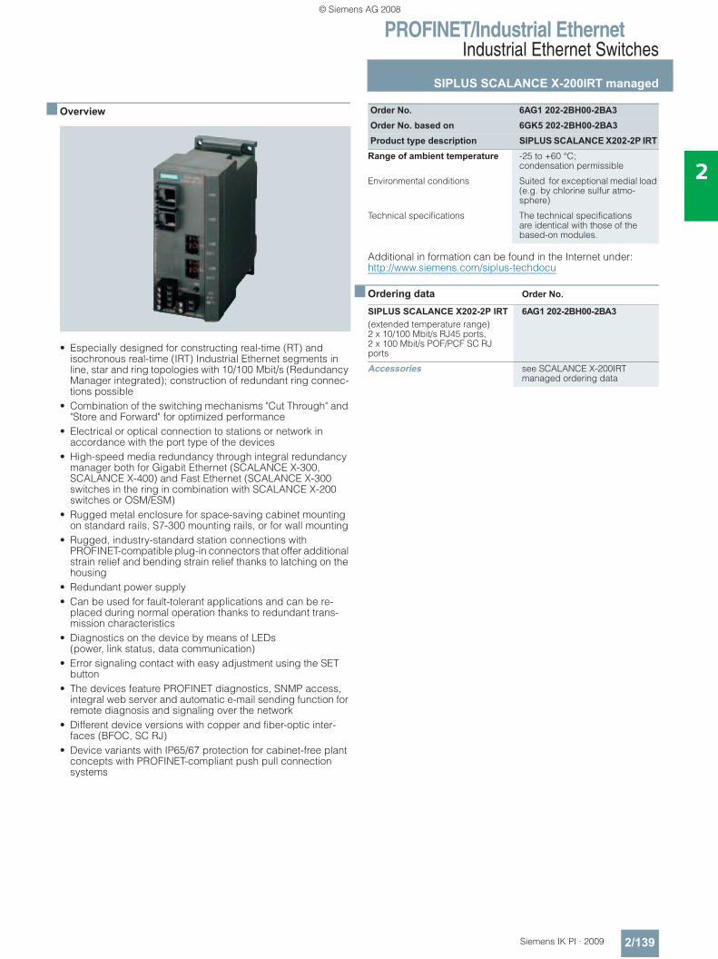
PROFINET/Industrial EthernetIndustrial Ethernet Switches
SIPLUS SCALANCE X-200IRT managed
2/139Siemens IK PI · 2009
2
■ Overview
• Especially designed for constructing real-time (RT) and isochronous real-time (IRT) Industrial Ethernet segments in line, star and ring topologies with 10/100 Mbit/s (Redundancy Manager integrated); construction of redundant ring connec-tions possible
• Combination of the switching mechanisms "Cut Through" and "Store and Forward" for optimized performance
• Electrical or optical connection to stations or network in accordance with the port type of the devices
• High-speed media redundancy through integral redundancy manager both for Gigabit Ethernet (SCALANCE X-300, SCALANCE X-400) and Fast Ethernet (SCALANCE X-300 switches in the ring in combination with SCALANCE X-200 switches or OSM/ESM)
• Rugged metal enclosure for space-saving cabinet mounting on standard rails, S7-300 mounting rails, or for wall mounting
• Rugged, industry-standard station connections with PROFINET-compatible plug-in connectors that offer additional strain relief and bending strain relief thanks to latching on the housing
• Redundant power supply • Can be used for fault-tolerant applications and can be re-
placed during normal operation thanks to redundant trans-mission characteristics
• Diagnostics on the device by means of LEDs (power, link status, data communication)
• Error signaling contact with easy adjustment using the SET button
• The devices feature PROFINET diagnostics, SNMP access, integral web server and automatic e-mail sending function for remote diagnosis and signaling over the network
• Different device versions with copper and fiber-optic inter-faces (BFOC, SC RJ)
• Device variants with IP65/67 protection for cabinet-free plant concepts with PROFINET-compliant push pull connection systems
Additional in formation can be found in the Internet under:http://www.siemens.com/siplus-techdocu
■ Ordering data Order No.
Order No. 6AG1 202-2BH00-2BA3Order No. based on 6GK5 202-2BH00-2BA3Product type description SIPLUS SCALANCE X202-2P IRT
Range of ambient temperature -25 to +60 °C; condensation permissible
Environmental conditions Suited for exceptional medial load (e.g. by chlorine sulfur atmo-sphere)
Technical specifications The technical specifications are identical with those of the based-on modules.
SIPLUS SCALANCE X202-2P IRT 6AG1 202-2BH00-2BA3(extended temperature range)2 x 10/100 Mbit/s RJ45 ports, 2 x 100 Mbit/s POF/PCF SC RJ ports
Accessories see SCALANCE X-200IRT managed ordering data
© Siemens AG 2008
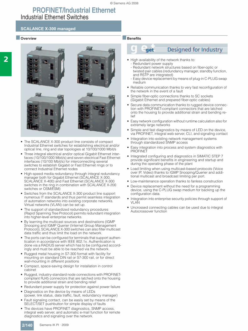
PROFINET/Industrial EthernetIndustrial Ethernet Switches
SCALANCE X-300 managed
2/140 Siemens IK PI · 2009
2
■ Overview
• The SCALANCE X-300 product line consists of compact Industrial Ethernet switches for establishing electrical and/or optical line, ring and star topologies at 10/100/1000 Mbit/s
• Three integral electrical and/or optical Gigabit Ethernet inter-faces (10/100/1000 Mbit/s) and seven electrical Fast Ethernet interfaces (10/100 Mbit/s) for interconnecting several switches to establish Gigabit or Fast Ethernet rings or to connect Industrial Ethernet nodes
• High-speed media redundancy through integral redundancy manager both for Gigabit Ethernet (SCALANCE X-300, SCALANCE X-400) and Fast Ethernet (SCALANCE X-300 switches in the ring in combination with SCALANCE X-200 switches or OSM/ESM)
• Switches from the SCALANCE X-300 product line support numerous IT standards and thus permit seamless integration of automation networks into existing corporate networks. Virtual networks (VLAN) can be set up.
• The support of standardized redundancy procedures (Rapid Spanning Tree Protocol) permits redundant integration into higher-level enterprise networks.
• By learning the multicast sources and destinations (IGMP Snooping and IGMP Querier (Internet Group Management Protocol)), SCALANCE X-300 switches can also filter multicast data traffic and thus limit the load on the network.
• The ports can be configured for terminals that support authen-tication in accordance with IEEE 802.1x. Authentication is done via a RADIUS server which has to be configured accord-ingly and must be able to be reached via the network.
• Rugged metal housing in S7-300 format with facility for mounting on standard DIN rail or S7-300 rail, or for direct wall-mounting in different positions
• Compact, space-saving design for installation in control cabinet
• Rugged, industry-standard node connections with PROFINET-compliant RJ45 connectors that are latched onto the housing to provide additional strain and bending relief
• Redundant power supply for protection against power failure • Diagnostics on the device by means of LEDs
(power, link status, data traffic, fault, redundancy manager) • Fault signaling contact, can be easily set by means of the
SELECT/SET pushbutton for simple display of faults • The devices have PROFINET diagnostics, SNMP access,
integral web server, and automatic e-mail function for remote diagnostics and signaling over the network.
■ Benefits
• High availability of the network thanks to: - Redundant power supply - Redundant network structures based on fiber-optic or
twisted pair cables (redundancy manager, standby function, and RSTP are integrated)
- Easy device replacement by means of plug-in C-PLUG swap medium
• Reliable communication thanks to very fast reconfiguration of the network in the event of a fault
• Simple fiber-optic connections thanks to SC sockets (Gigabit Ethernet and prepared fiber-optic cables)
• Secure data communication thanks to rugged device connec-tion with PROFINET-compliant connectors that are latched onto the housing to provide additional strain and bending re-lief
• Easy network configuration without runtime calculation also for extremely large networks
• Simple and fast diagnostics by means of LED on the device, via PROFINET, integral web server, CLI, and signaling contact
• Integration into existing network management systems through standardized SNMP access
• Easy integration into process and system diagnostics with PROFINET
• Integrated configuring and diagnostics in SIMATIC STEP 7 provide significant benefits in engineering and startup and during the operating phase of the plant
• Load limiting when using multicast-based protocols (Voice over IP, Video) thanks to IGMP Snooping/Querier and addi-tional multicast and broadcast limiting per port.
• Low-maintenance operation thanks to fanless construction• Device replacement without the need for a programming
device, using the C-PLUG swap medium for backing up the configuration data.
• Integration into enterprise security policies through support of VLAN
• Uncrossed connecting cables can be used due to integral Autocrossover function
© Siemens AG 2008
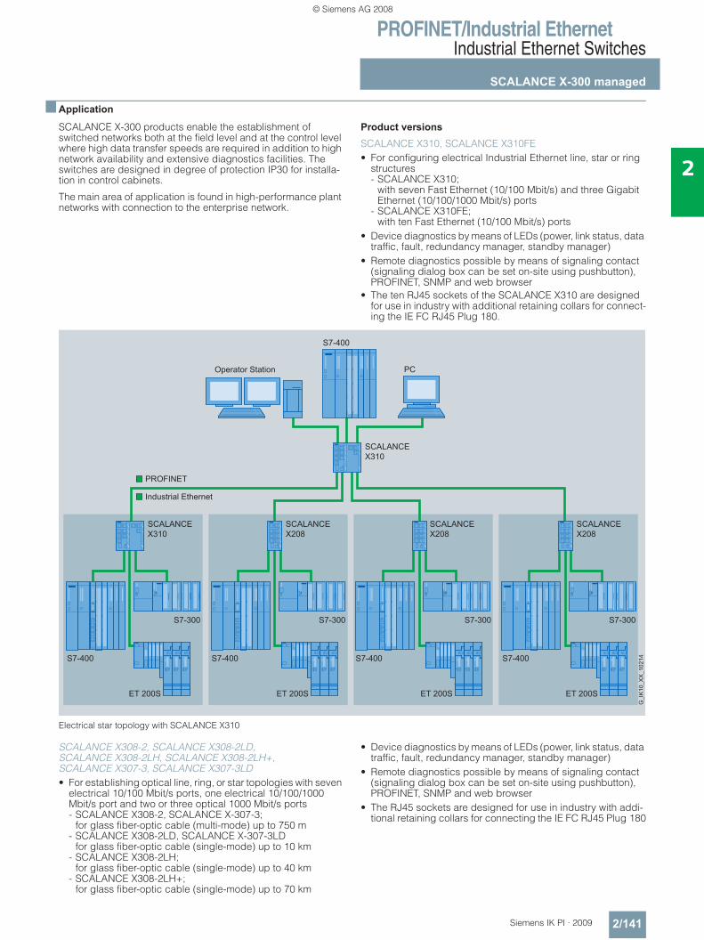
PROFINET/Industrial EthernetIndustrial Ethernet Switches
SCALANCE X-300 managed
2/141Siemens IK PI · 2009
2
■ Application
SCALANCE X-300 products enable the establishment of switched networks both at the field level and at the control level where high data transfer speeds are required in addition to high network availability and extensive diagnostics facilities. The switches are designed in degree of protection IP30 for installa-tion in control cabinets.
The main area of application is found in high-performance plant networks with connection to the enterprise network.
Product versions
SCALANCE X310, SCALANCE X310FE • For configuring electrical Industrial Ethernet line, star or ring
structures - SCALANCE X310;
with seven Fast Ethernet (10/100 Mbit/s) and three Gigabit Ethernet (10/100/1000 Mbit/s) ports
- SCALANCE X310FE; with ten Fast Ethernet (10/100 Mbit/s) ports
• Device diagnostics by means of LEDs (power, link status, data traffic, fault, redundancy manager, standby manager)
• Remote diagnostics possible by means of signaling contact (signaling dialog box can be set on-site using pushbutton), PROFINET, SNMP and web browser
• The ten RJ45 sockets of the SCALANCE X310 are designed for use in industry with additional retaining collars for connect-ing the IE FC RJ45 Plug 180.
Electrical star topology with SCALANCE X310
SCALANCE X308-2, SCALANCE X308-2LD, SCALANCE X308-2LH, SCALANCE X308-2LH+,SCALANCE X307-3, SCALANCE X307-3LD• For establishing optical line, ring, or star topologies with seven
electrical 10/100 Mbit/s ports, one electrical 10/100/1000 Mbit/s port and two or three optical 1000 Mbit/s ports - SCALANCE X308-2, SCALANCE X-307-3;
for glass fiber-optic cable (multi-mode) up to 750 m - SCALANCE X308-2LD, SCALANCE X-307-3LD
for glass fiber-optic cable (single-mode) up to 10 km- SCALANCE X308-2LH;
for glass fiber-optic cable (single-mode) up to 40 km - SCALANCE X308-2LH+;
for glass fiber-optic cable (single-mode) up to 70 km
• Device diagnostics by means of LEDs (power, link status, data traffic, fault, redundancy manager, standby manager)
• Remote diagnostics possible by means of signaling contact (signaling dialog box can be set on-site using pushbutton), PROFINET, SNMP and web browser
• The RJ45 sockets are designed for use in industry with addi-tional retaining collars for connecting the IE FC RJ45 Plug 180
S7-400
PC
SCALANCEX208
SCALANCEX208
PROFINET
Industrial Ethernet
SCALANCEX310
SCALANCEX208
S7-400 S7-400 S7-400 S7-400
S7-300 S7-300 S7-300 S7-300
ET 200SET 200SET 200SET 200S
Operator Station
© Siemens AG 2008
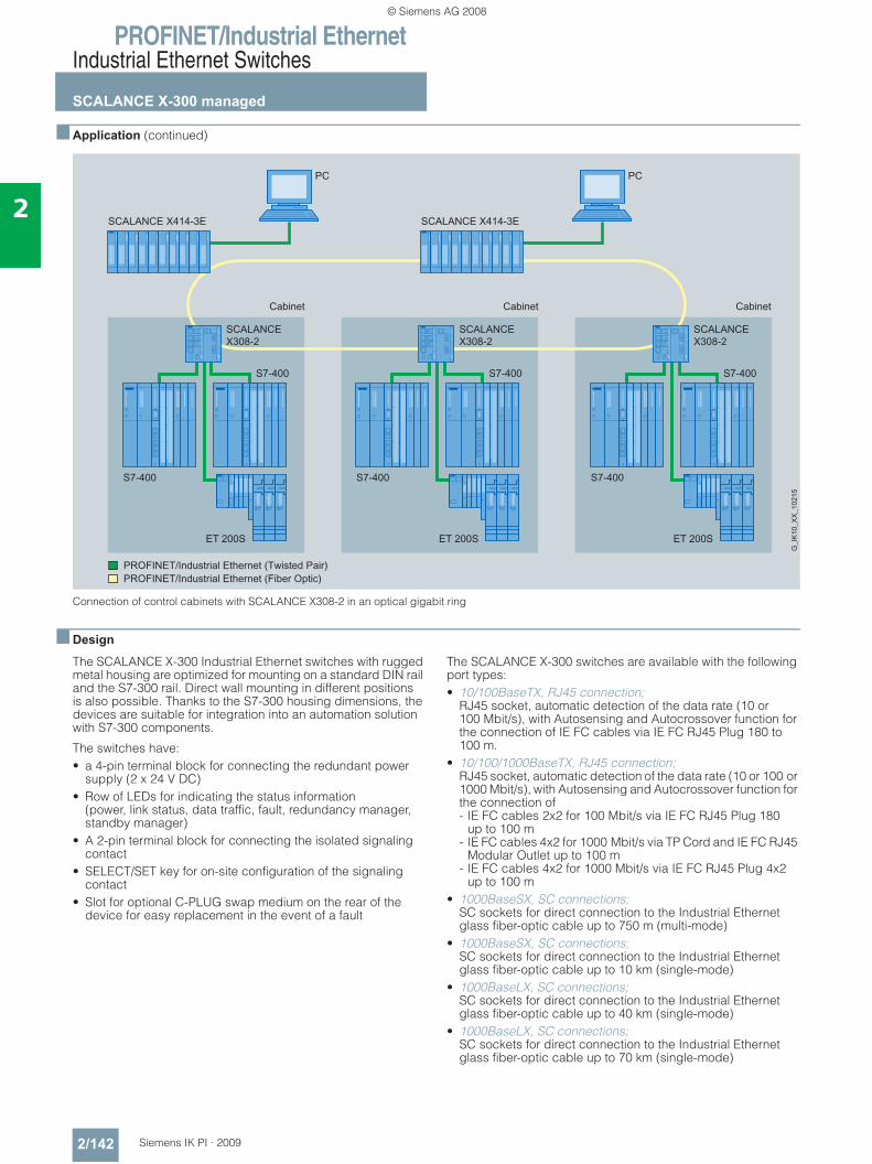
PROFINET/Industrial EthernetIndustrial Ethernet Switches
SCALANCE X-300 managed
2/142 Siemens IK PI · 2009
2
■ Application (continued)
Connection of control cabinets with SCALANCE X308-2 in an optical gigabit ring
■ Design
The SCALANCE X-300 Industrial Ethernet switches with rugged metal housing are optimized for mounting on a standard DIN rail and the S7-300 rail. Direct wall mounting in different positions is also possible. Thanks to the S7-300 housing dimensions, the devices are suitable for integration into an automation solution with S7-300 components.
The switches have:• a 4-pin terminal block for connecting the redundant power
supply (2 x 24 V DC)• Row of LEDs for indicating the status information
(power, link status, data traffic, fault, redundancy manager, standby manager)
• A 2-pin terminal block for connecting the isolated signaling contact
• SELECT/SET key for on-site configuration of the signaling contact
• Slot for optional C-PLUG swap medium on the rear of the device for easy replacement in the event of a fault
The SCALANCE X-300 switches are available with the following port types:• 10/100BaseTX, RJ45 connection;
RJ45 socket, automatic detection of the data rate (10 or 100 Mbit/s), with Autosensing and Autocrossover function for the connection of IE FC cables via IE FC RJ45 Plug 180 to 100 m.
• 10/100/1000BaseTX, RJ45 connection; RJ45 socket, automatic detection of the data rate (10 or 100 or 1000 Mbit/s), with Autosensing and Autocrossover function for the connection of - IE FC cables 2x2 for 100 Mbit/s via IE FC RJ45 Plug 180
up to 100 m- IE FC cables 4x2 for 1000 Mbit/s via TP Cord and IE FC RJ45
Modular Outlet up to 100 m- IE FC cables 4x2 for 1000 Mbit/s via IE FC RJ45 Plug 4x2
up to 100 m• 1000BaseSX, SC connections;
SC sockets for direct connection to the Industrial Ethernet glass fiber-optic cable up to 750 m (multi-mode)
• 1000BaseSX, SC connections; SC sockets for direct connection to the Industrial Ethernet glass fiber-optic cable up to 10 km (single-mode)
• 1000BaseLX, SC connections; SC sockets for direct connection to the Industrial Ethernet glass fiber-optic cable up to 40 km (single-mode)
• 1000BaseLX, SC connections; SC sockets for direct connection to the Industrial Ethernet glass fiber-optic cable up to 70 km (single-mode)
CabinetCabinetCabinet
SCALANCEX308-2
S7-400
S7-400
ET 200S
PC
SCALANCE X414-3E
PC
SCALANCEX308-2
S7-400
S7-400
ET 200S
SCALANCEX308-2
S7-400
S7-400
ET 200S
SCALANCE X414-3E
PROFINET/PROFINET/
© Siemens AG 2008
PROFINET/Industrial EthernetIndustrial Ethernet Switches
SCALANCE X-300 managed
2/143Siemens IK PI · 2009
2
■ Function• Increase of the network performance;
by filtering the data traffic on the basis of the Ethernet (MAC) address of the data terminals, the local data traffic remains local; only data intended for users of another subnetwork are forwarded by the switch.
• Simple network configuration and expansion; the switch saves the data received at the ports and forwards them independently to the destination address. Collision detection (CSMA/CD method) does not restrict the expansion of the network beyond the port.
• Limiting of error spreading to the associated subnetwork; the SCALANCE X-300 switches only pass on data with a valid checksum (CRC).
• Integration of existing subnetworks with 10 Mbit/s into Fast Ethernet networks with 100 Mbit/s; at the twisted-pair ports, the SCALANCE X-300 switch auto-matically recognizes the conductor pairs for transmission and reception (Autocrossover), the data transfer rate of 10 or 100 or 1000 Mbit/s, as well as full-duplex and half-duplex mode (Autonegotiation).
• High-performance connection of SCALANCE X-300 switches with 1 Gbit/s; SCALANCE X-300 switches have three Gigabit Ethernet ports for connecting the switches to each other or with other Giga-bit-Ethernet-enabled components (e.g. SCALANCE X-400)
• Integrated redundancy manager for constructing Fast Ether-net and Gigabit Ethernet ring topologies with high-speed media redundancy. Rings consisting of SCALANCE X-300 and X-400 switches can be operated at 1000 Mbit/s. In rings with SCALANCE X-200 or OSM/ESM it is possible to integrate SCALANCE X-300 switches at 100 Mbit/s.
• High-speed standby redundancy; several network segments such as rings can be connected together redundantly with SCALANCE X-300 over the inte-grated standby function. Two X-300 switches are configured in a ring as a master and slave over two links to the other ring. The redundant connection can be made at 1000 Mbit/s.
• Redundant interfacing to company networks; SCALANCE X-300 switches support the standardized redun-dancy procedures Spanning Tree Protocol (STP) and Rapid Spanning Tree Protocol (RSTP). This enables a subnetwork to be connected redundantly to a higher level corporate network with reduced requirements for the reconfiguration time (in the order of seconds).
• Support of virtual networks (VLAN); for structuring Industrial Ethernet networks with a fast growing number of users, a physically existing network can be divided into several virtual networks.
• Load limiting when multicast protocols (e.g. video transmis-sion) are used; through learning the multicast sources and targets (IGMP Snooping, IGMP Querier), SCALANCE X-300 switches can also filter multicast data traffic and therefore limit the load in the network.
• Configuration of the ports for terminals that support authenti-cation in accordance to IEEE 802.1x. Authentication is done via a RADIUS server which has to be configured accordingly and must be able to be reached via the network.
• Support of the DHCP Option 82 (Dynamic Host Configuration Protocol); this facilitates the IP address assignment of a terminal depending on the connected switch port. The IP address is assigned via a DHCP Server, which has to be configured accordingly and must be able to be reached via the network.
• Support from the Access Control List (ACL); if this function is activated for one port, the switch forwards the message frames received to this port if its source address is present in the address table. All connected nodes can be automatically entered in the ACL.
• Syslog; Syslog according to RFC 3164 is used in the IP network for transmitting short, unencrypted text messages via UDP. To this end, a standard Syslog server is required that has to be configured accordingly and must be able to be reached via the network.
• Time synchronization; diagnostic messages (log table entries, e-mails) are time-stamped. The local time is standardized throughout the net-work by means of synchronization with a SICLOCK or SNTP time transmitter, thereby simplifying the assignment of diag-nostic messages to several devices.
• Fast replacement of devices in event of failure, by means of the C-PLUG switching medium
Network topology and network configuration
The SCALANCE X-300 Industrial Ethernet switches with degree of protection IP30 are typically accommodated in a control cab-inet along with the nodes to be connected. The can be mixed electrically and optically in star, line and ring topologies.
The following network structures and combinations of structures can be implemented:• Fast Ethernet and Gigabit Ethernet rings with fast media
redundancy; to increase network availability, as many as 50 X-200, X-300 or X-400 switches cascaded in line can be connected into a ring with a total length of up to 150 km with multi-mode or up to 3,500 km with single-mode.
• Several rings can be redundantly linked through the standby function
• In addition, SCALANCE X-300 supports redundant connec-tion of the ring structure to the corporate network with a rapid spanning tree.
• Star topology with SCALANCE X-300 switches: The SCALANCE X-300 switch represents a neutral point that can connect up to ten nodes or subnets with each other electrically or optically.
When configuring the network, it is necessary to observe the following boundary conditions:• Maximum line length between two modules for multi-mode
fiber-optic conductors: - 750 m at 1 Gbit/s
• Maximum line length between two modules for single-mode fiber-optic conductors: - 10 - 70 km at 1 Gbit/s
• Maximum cable length of the TP cable between two SCALANCE X switches: - Max. 100 m with IE FC cable 2x2 and IE FC RJ45 Plug 180 - Max. 100 m at 1 Gbit/s with IE FC Standard Cable 4x2 (90 m),
IE FC RJ45 Modular Outlet and patch cable (10 m)- max. 10 m using patches with TP cord
© Siemens AG 2008
PROFINET/Industrial EthernetIndustrial Ethernet Switches
SCALANCE X-300 managed
2/144 Siemens IK PI · 2009
2
■ Function (continued)
Commissioning and diagnosis
Setting options on the device itself:• Redundancy manager RM;
to establish a ring, a SCALANCE X-300 is switched to RM mode. The Gigabit ports (electrical or optical) are preferably used as ring ports.
• Signal mask; the signal mask is set to the current status of the SCALANCE X-300 (setpoint) by pushbutton operation. The signal mask defines which ports and which power supplies are to be monitored. The signal contact only reports an error when a monitored port or a monitored feeder fails (deviation of set-point/actual status).
• IP address; the IP address is assigned via DHCP (Dynamic Host Configu-ration Protocol). If there is no corresponding server in the network, the IP address can be assigned using an enclosed software tool.
Diagnostic options on site:• The following status information is displayed by LEDs on site:
- Port status- Port mode (10/100/1000 Mbit/s, full/half-duplex)- Status of the two power supplies- Signal contact status- Signal mask (setpoint status)- RM mode- Standby mode
• The status of the signal contact is routed externally by means of floating relay contacts. This enables, for example, the mod-ule to be monitored via an input module from a controller.
• Monitoring via the Industrial Ethernet network; the following possibilities are available: - Remote via standard browser (Web-based management):
Selection of SCALANCE X-300 switches via the network from a PC with browser
- Remote via SNMP V1, V2c, V3: Secure integration of SCALANCE X-300 switches via the network into a network management station, e.g. BANYnet
- Remote via PROFINET IO diagnostics: PROFINET IO diagnostics alarms from X-300 switches can be displayed using the relevant SIMATIC engineering tools or they can also be processed in the PLC. The engineering outlay is drastically reduced for the PLC and HMI through complete integration into the SIMATIC SFM system error signaling concept.
Network management The network management provides the following functions:• Password-protected dial-up for "Administrator" (read and write
authorization) and "User" (read only)• Read-out of version and status information• Setting the signal and standby mask and address information• Fixed parameterization of the ports (data rates, half/full du-
plex)• Setting parameters of the VLANs and multicast services• Parameterization of the standby connections for a redundant
ring link• Setting of Rapid Spanning Tree parameters• Parameterization of the web management services• Security
- Ports can be connected or disconnected - Authentication in accordance with IEEE 802.1x- Support from Access Control List (ACL)
• Parameterization of user administration of SNMP V1, V2c, V3• Output of statistics information• Diagnosis of data traffic by means of a parameterizable mirror
port with a standard commercial network analyzer• Loading new firmware updates or configuration data via the
network from one TFTP server or directly via HTTP/HTTPs with an Internet or Web browser.
• Saving the configuration data or log table via the network on a TFTP server
If faults occur in the network, the SCALANCE X-300 switch can independently send error messages (traps) to a network man-agement system or also e-mails to a predefined network admin-istrator.
Remote monitoring (RMON) provides the following functions: The SCALANCE X-300 switch can collect statistics information according to the RMON groups 1 through 4. These include, for example, fault statistics that are kept for each port. This infor-mation can be read out through web-based management in the statistics sub-area.
© Siemens AG 2008
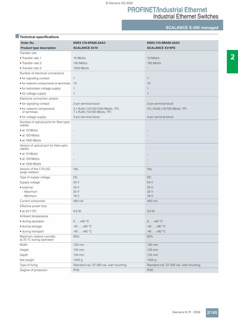
PROFINET/Industrial EthernetIndustrial Ethernet Switches
SCALANCE X-300 managed
2/145Siemens IK PI · 2009
2
■ Technical specifications
Order No. 6GK5 310-0FA00-2AA3 6GK5 310-0BA00-2AA3Product type description SCALANCE X310 SCALANCE X310FE
Transfer rate
• Transfer rate 1 10 Mbit/s 10 Mbit/s
• Transfer rate 2 100 Mbit/s 100 Mbit/s
• Transfer rate 3 1000 Mbit/s -
Number of electrical connections
• for signaling contact 1 1
• for network components or terminals 10 10
• for redundant voltage supply 1 1
• for voltage supply 1 1
Electrical connection version
• for signaling contact 2-pin terminal block 2-pin terminal block
• for network components or terminals
3 x RJ45 (10/100/1000 Mbit/s; TP), 7 x RJ45 (10/100 Mbit/s; TP)
10 x RJ45 (10/100 Mbit/s; TP)
• for voltage supply 4-pin terminal block 4-pin terminal block
Number of optical ports for fiber-optic cables
• at 10 Mbit/s - -
• at 100 Mbit/s - -
• at 1000 Mbit/s - -
Version of optical port for fiber-optic cables
• at 10 Mbit/s - -
• at 100 Mbit/s - -
• at 1000 Mbit/s - -
Version of the C-PLUG swap medium
Yes Yes
Type of supply voltage DC DC
Supply voltage 24 V 24 V
• external 24 V 24 V- Maximum 32 V 32 V- Minimum 18 V 18 V
Current consumed 400 mA 400 mA
Effective power loss
• at 24 V DC 9.6 W 9.6 W
Ambient temperature
• during operation 0 … +60 °C 0 … +60 °C
• during storage -40 … +80 °C -40 … +80 °C
• during transport -40 … +80 °C -40 … +80 °C
Maximum relative humidity at 25 °C during operation
95% 95%
Width 120 mm 120 mm
Height 125 mm 125 mm
Depth 124 mm 124 mm
Net weight 1400 g 1400 g
Type of fixing Standard rail, S7-300 rail, wall mounting Standard rail, S7-300 rail, wall mounting
Degree of protection IP30 IP30
© Siemens AG 2008
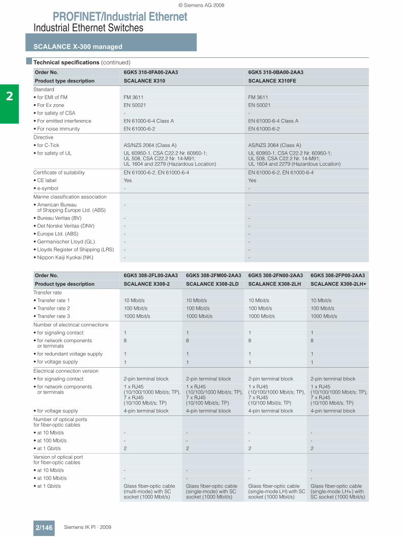
PROFINET/Industrial EthernetIndustrial Ethernet Switches
SCALANCE X-300 managed
2/146 Siemens IK PI · 2009
2
■ Technical specifications (continued)
Order No. 6GK5 310-0FA00-2AA3 6GK5 310-0BA00-2AA3Product type description SCALANCE X310 SCALANCE X310FE
Standard
• for EMI of FM FM 3611 FM 3611
• For Ex zone EN 50021 EN 50021
• for safety of CSA - -
• For emitted interference EN 61000-6-4 Class A EN 61000-6-4 Class A
• For noise immunity EN 61000-6-2 EN 61000-6-2
Directive
• for C-Tick AS/NZS 2064 (Class A) AS/NZS 2064 (Class A)
• for safety of UL UL 60950-1, CSA C22.2 Nr. 60950-1; UL 508, CSA C22.2 Nr. 14-M91; UL 1604 and 2279 (Hazardous Location)
UL 60950-1, CSA C22.2 Nr. 60950-1; UL 508, CSA C22.2 Nr. 14-M91; UL 1604 and 2279 (Hazardous Location)
Certificate of suitability EN 61000-6-2, EN 61000-6-4 EN 61000-6-2, EN 61000-6-4
• CE label Yes Yes
• e-symbol - -
Marine classification association
• American Bureau of Shipping Europe Ltd. (ABS)
- -
• Bureau Veritas (BV) - -
• Det Norske Veritas (DNV) - -
• Europe Ltd. (ABS) - -
• Germanischer Lloyd (GL) - -
• Lloyds Register of Shipping (LRS) - -
• Nippon Kaiji Kyokai (NK) - -
Order No. 6GK5 308-2FL00-2AA3 6GK5 308-2FM00-2AA3 6GK5 308-2FN00-2AA3 6GK5 308-2FP00-2AA3Product type description SCALANCE X308-2 SCALANCE X308-2LD SCALANCE X308-2LH SCALANCE X308-2LH+
Transfer rate
• Transfer rate 1 10 Mbit/s 10 Mbit/s 10 Mbit/s 10 Mbit/s
• Transfer rate 2 100 Mbit/s 100 Mbit/s 100 Mbit/s 100 Mbit/s
• Transfer rate 3 1000 Mbit/s 1000 Mbit/s 1000 Mbit/s 1000 Mbit/s
Number of electrical connections
• for signaling contact 1 1 1 1
• for network components or terminals
8 8 8 8
• for redundant voltage supply 1 1 1 1
• for voltage supply 1 1 1 1
Electrical connection version
• for signaling contact 2-pin terminal block 2-pin terminal block 2-pin terminal block 2-pin terminal block
• for network components or terminals
1 x RJ45 (10/100/1000 Mbit/s; TP), 7 x RJ45 (10/100 Mbit/s; TP)
1 x RJ45 (10/100/1000 Mbit/s; TP), 7 x RJ45 (10/100 Mbit/s; TP)
1 x RJ45 (10/100/1000 Mbit/s; TP), 7 x RJ45 (10/100 Mbit/s; TP)
1 x RJ45 (10/100/1000 Mbit/s; TP), 7 x RJ45 (10/100 Mbit/s; TP)
• for voltage supply 4-pin terminal block 4-pin terminal block 4-pin terminal block 4-pin terminal block
Number of optical ports for fiber-optic cables
• at 10 Mbit/s - - - -
• at 100 Mbit/s - - - -
• at 1 Gbit/s 2 2 2 2
Version of optical portfor fiber-optic cables
• at 10 Mbit/s - - - -
• at 100 Mbit/s - - - -
• at 1 Gbit/s Glass fiber-optic cable (multi-mode) with SC socket (1000 Mbit/s)
Glass fiber-optic cable (single-mode) with SC socket (1000 Mbit/s)
Glass fiber-optic cable (single-mode LH) with SC socket (1000 Mbit/s)
Glass fiber-optic cable (single-mode LH+) with SC socket (1000 Mbit/s)
© Siemens AG 2008
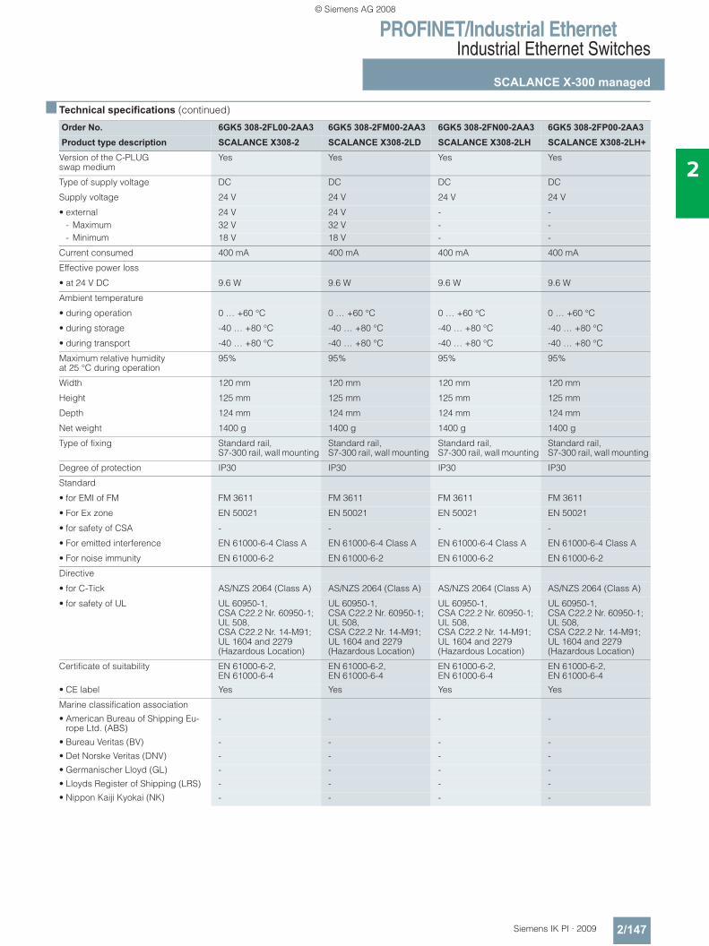
PROFINET/Industrial EthernetIndustrial Ethernet Switches
SCALANCE X-300 managed
2/147Siemens IK PI · 2009
2
■ Technical specifications (continued)
Order No. 6GK5 308-2FL00-2AA3 6GK5 308-2FM00-2AA3 6GK5 308-2FN00-2AA3 6GK5 308-2FP00-2AA3Product type description SCALANCE X308-2 SCALANCE X308-2LD SCALANCE X308-2LH SCALANCE X308-2LH+
Version of the C-PLUG swap medium
Yes Yes Yes Yes
Type of supply voltage DC DC DC DC
Supply voltage 24 V 24 V 24 V 24 V
• external 24 V 24 V - -- Maximum 32 V 32 V - -- Minimum 18 V 18 V - -
Current consumed 400 mA 400 mA 400 mA 400 mA
Effective power loss
• at 24 V DC 9.6 W 9.6 W 9.6 W 9.6 W
Ambient temperature
• during operation 0 … +60 °C 0 … +60 °C 0 … +60 °C 0 … +60 °C
• during storage -40 … +80 °C -40 … +80 °C -40 … +80 °C -40 … +80 °C
• during transport -40 … +80 °C -40 … +80 °C -40 … +80 °C -40 … +80 °C
Maximum relative humidity at 25 °C during operation
95% 95% 95% 95%
Width 120 mm 120 mm 120 mm 120 mm
Height 125 mm 125 mm 125 mm 125 mm
Depth 124 mm 124 mm 124 mm 124 mm
Net weight 1400 g 1400 g 1400 g 1400 g
Type of fixing Standard rail, S7-300 rail, wall mounting
Standard rail, S7-300 rail, wall mounting
Standard rail, S7-300 rail, wall mounting
Standard rail, S7-300 rail, wall mounting
Degree of protection IP30 IP30 IP30 IP30
Standard
• for EMI of FM FM 3611 FM 3611 FM 3611 FM 3611
• For Ex zone EN 50021 EN 50021 EN 50021 EN 50021
• for safety of CSA - - - -
• For emitted interference EN 61000-6-4 Class A EN 61000-6-4 Class A EN 61000-6-4 Class A EN 61000-6-4 Class A
• For noise immunity EN 61000-6-2 EN 61000-6-2 EN 61000-6-2 EN 61000-6-2
Directive
• for C-Tick AS/NZS 2064 (Class A) AS/NZS 2064 (Class A) AS/NZS 2064 (Class A) AS/NZS 2064 (Class A)
• for safety of UL UL 60950-1, CSA C22.2 Nr. 60950-1; UL 508, CSA C22.2 Nr. 14-M91; UL 1604 and 2279 (Hazardous Location)
UL 60950-1, CSA C22.2 Nr. 60950-1; UL 508, CSA C22.2 Nr. 14-M91; UL 1604 and 2279 (Hazardous Location)
UL 60950-1, CSA C22.2 Nr. 60950-1; UL 508, CSA C22.2 Nr. 14-M91; UL 1604 and 2279 (Hazardous Location)
UL 60950-1, CSA C22.2 Nr. 60950-1; UL 508, CSA C22.2 Nr. 14-M91; UL 1604 and 2279 (Hazardous Location)
Certificate of suitability EN 61000-6-2, EN 61000-6-4
EN 61000-6-2, EN 61000-6-4
EN 61000-6-2, EN 61000-6-4
EN 61000-6-2, EN 61000-6-4
• CE label Yes Yes Yes Yes
Marine classification association
• American Bureau of Shipping Eu-rope Ltd. (ABS)
- - - -
• Bureau Veritas (BV) - - - -
• Det Norske Veritas (DNV) - - - -
• Germanischer Lloyd (GL) - - - -
• Lloyds Register of Shipping (LRS) - - - -
• Nippon Kaiji Kyokai (NK) - - - -
© Siemens AG 2008
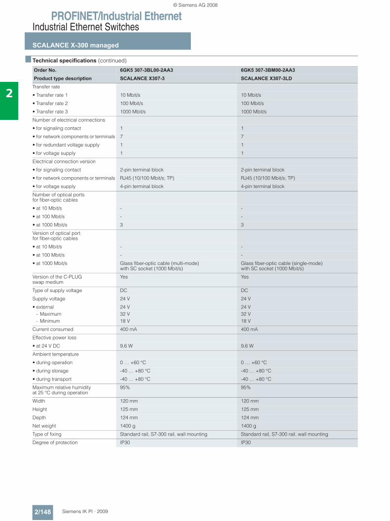
PROFINET/Industrial EthernetIndustrial Ethernet Switches
SCALANCE X-300 managed
2/148 Siemens IK PI · 2009
2
■ Technical specifications (continued)
Order No. 6GK5 307-3BL00-2AA3 6GK5 307-3BM00-2AA3Product type description SCALANCE X307-3 SCALANCE X307-3LD
Transfer rate
• Transfer rate 1 10 Mbit/s 10 Mbit/s
• Transfer rate 2 100 Mbit/s 100 Mbit/s
• Transfer rate 3 1000 Mbit/s 1000 Mbit/s
Number of electrical connections
• for signaling contact 1 1
• for network components or terminals 7 7
• for redundant voltage supply 1 1
• for voltage supply 1 1
Electrical connection version
• for signaling contact 2-pin terminal block 2-pin terminal block
• for network components or terminals RJ45 (10/100 Mbit/s; TP) RJ45 (10/100 Mbit/s; TP)
• for voltage supply 4-pin terminal block 4-pin terminal block
Number of optical ports for fiber-optic cables
• at 10 Mbit/s - -
• at 100 Mbit/s - -
• at 1000 Mbit/s 3 3
Version of optical portfor fiber-optic cables
• at 10 Mbit/s - -
• at 100 Mbit/s - -
• at 1000 Mbit/s Glass fiber-optic cable (multi-mode)with SC socket (1000 Mbit/s)
Glass fiber-optic cable (single-mode) with SC socket (1000 Mbit/s)
Version of the C-PLUG swap medium
Yes Yes
Type of supply voltage DC DC
Supply voltage 24 V 24 V
• external 24 V 24 V- Maximum 32 V 32 V- Minimum 18 V 18 V
Current consumed 400 mA 400 mA
Effective power loss
• at 24 V DC 9,6 W 9,6 W
Ambient temperature
• during operation 0 … +60 °C 0 … +60 °C
• during storage -40 … +80 °C -40 … +80 °C
• during transport -40 … +80 °C -40 … +80 °C
Maximum relative humidity at 25 °C during operation
95% 95%
Width 120 mm 120 mm
Height 125 mm 125 mm
Depth 124 mm 124 mm
Net weight 1400 g 1400 g
Type of fixing Standard rail, S7-300 rail, wall mounting Standard rail, S7-300 rail, wall mounting
Degree of protection IP30 IP30
© Siemens AG 2008
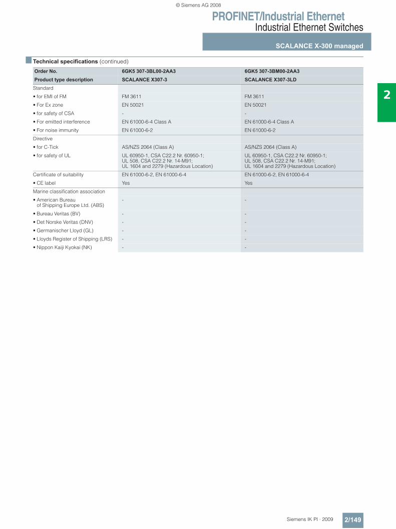
PROFINET/Industrial EthernetIndustrial Ethernet Switches
SCALANCE X-300 managed
2/149Siemens IK PI · 2009
2
■ Technical specifications (continued)
Order No. 6GK5 307-3BL00-2AA3 6GK5 307-3BM00-2AA3Product type description SCALANCE X307-3 SCALANCE X307-3LD
Standard
• for EMI of FM FM 3611 FM 3611
• For Ex zone EN 50021 EN 50021
• for safety of CSA - -
• For emitted interference EN 61000-6-4 Class A EN 61000-6-4 Class A
• For noise immunity EN 61000-6-2 EN 61000-6-2
Directive
• for C-Tick AS/NZS 2064 (Class A) AS/NZS 2064 (Class A)
• for safety of UL UL 60950-1, CSA C22.2 Nr. 60950-1; UL 508, CSA C22.2 Nr. 14-M91; UL 1604 and 2279 (Hazardous Location)
UL 60950-1, CSA C22.2 Nr. 60950-1; UL 508, CSA C22.2 Nr. 14-M91; UL 1604 and 2279 (Hazardous Location)
Certificate of suitability EN 61000-6-2, EN 61000-6-4 EN 61000-6-2, EN 61000-6-4
• CE label Yes Yes
Marine classification association
• American Bureau of Shipping Europe Ltd. (ABS)
- -
• Bureau Veritas (BV) - -
• Det Norske Veritas (DNV) - -
• Germanischer Lloyd (GL) - -
• Lloyds Register of Shipping (LRS) - -
• Nippon Kaiji Kyokai (NK) - -
© Siemens AG 2008
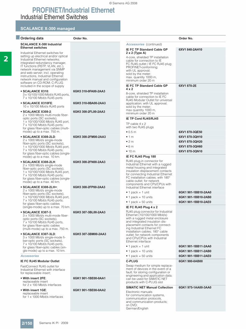
PROFINET/Industrial EthernetIndustrial Ethernet Switches
SCALANCE X-300 managed
2/150 Siemens IK PI · 2009
2
■ Ordering data Order No. Order No.
SCALANCE X-300 Industrial Ethernet switchesIndustrial Ethernet switches for setting up electrical and/or optical Industrial Ethernet networks; integrated redundancy manager, IT functions (RSTP, VLAN, etc.), network management via SNMP and web server; incl. operating instructions, Industrial Ethernet network manual and configuration software on CD-ROM; C-PLUG included in the scope of supply
• SCALANCE X310; 3 x 10/100/1000 Mbit/s RJ45 ports, 7 x 10/100 Mbit/s RJ45 ports
6GK5 310-0FA00-2AA3
• SCALANCE X310FE; 10 x 10/100 Mbit/s RJ45 ports
6GK5 310-0BA00-2AA3
• SCALANCE X308-2; 2 x 1000 Mbit/s multi-mode fiber-optic ports (SC sockets), 1 x 10/100/1000 Mbit/s RJ45 port, 7 x 10/100 Mbit/s RJ45 ports; for glass fiber-optic cables (multi-mode) up to a max. 750 m.
6GK5 308-2FL00-2AA3
• SCALANCE X308-2LD; 2 x 1000 Mbit/s single-mode fiber-optic ports (SC sockets), 1 x 10/100/1000 Mbit/s RJ45 port, 7 x 10/100 Mbit/s RJ45 ports; for glass fiber-optic cables (single-mode) up to a max. 10 km.
6GK5 308-2FM00-2AA3
• SCALANCE X308-2LH; 2 x 1000 Mbit/s single-mode fiber-optic ports (SC sockets), 1 x 10/100/1000 Mbit/s RJ45 port, 7 x 10/100 Mbit/s RJ45 ports; for glass fiber-optic cables (single-mode) up to a max. 40 km.
6GK5 308-2FN00-2AA3
• SCALANCE X308-2LH+; 2 x 1000 Mbit/s single-mode fiber-optic ports (SC sockets), 1 x 10/100/1000 Mbit/s RJ45 port, 7 x 10/100 Mbit/s RJ45 ports; for glass fiber-optic cables (single-mode) up to a max. 70 km.
6GK5 308-2FP00-2AA3
• SCALANCE X307-3; 3 x 1000 Mbit/s multi-mode fiber-optic ports (SC sockets), 7 x 10/100 Mbit/s RJ45 ports, for glass fiber-optic cables (multi-mode) up to a max. 750 m.
6GK5 307-3BL00-2AA3
• SCALANCE X307-3LD; 3 x 1000 Mbit/s single-mode fi-ber-optic ports (SC sockets), 7 x 10/100 Mbit/s RJ45 ports, for glass fiber-optic cables (sin-gle-mode) up to a max. 10 km.
6GK5 307-3BM00-2AA3
AccessoriesIE FC RJ45 Modular Outlet FastConnect RJ45 outlet for Industrial Ethernet with interface for replaceable insert;
• With insert 2FE; replaceable insert for 2 x 100 Mbit/s interfaces
6GK1 901-1BE00-0AA1
• With insert 1GE; replaceable insert for 1 x 1000 Mbit/s interfaces
6GK1 901-1BE00-0AA2
Accessories (continued)
IE FC TP Standard Cable GP 2 x 2 (Type A)
6XV1 840-2AH10
4-core, shielded TP installation cable for connection to IE FC RJ45 outlet / IE FC RJ45 plug; PROFINET-conforming; with UL approval; sold by the meter; max. quantity 1000 m, minimum order 20 m
IE FC TP Standard Cable GP 4 x 2
6XV1 870-2E
8-core, shielded TP installation cable for connection to IE FC RJ45 Modular Outlet for universal application; with UL approval; sold by the meter; max quantity 1000 m, minimum order 20 m
IE TP Cord RJ45/RJ45TP cable 4 x 2 with two RJ45 plugs
• 0.5 m 6XV1 870-3QE50• 1 m 6XV1 870-3QH10• 2 m 6XV1 870-3QH20• 6 m 6XV1 870-3QH60• 10 m 6XV1 870-3QN10IE FC RJ45 Plug 180RJ45 plug-in connector for Industrial Ethernet with a rugged metal housing and integrated insulation displacement contacts for connecting Industrial Ethernet FC installation cables; with 180° cable outlet; for network components and CPs/CPUs with Industrial Ethernet interface
• 1 pack = 1 unit 6GK1 901-1BB10-2AA0• 1 pack = 10 units 6GK1 901-1BB10-2AB0• 1 pack = 50 units 6GK1 901-1BB10-2AE0IE FC RJ45 Plug 4 x 2RJ45 plug connector for Industrial Ethernet (10/100/1000 Mbit/s) with a rugged metal enclosure and integrated insulation dis-placement contacts for connect-ing Industrial Ethernet FC installation cables; 180° cable outlet; for network components and CPs/CPUs with Industrial Ethernet interface
• 1 pack = 1 unit 6GK1 901-1BB11-2AA0• 1 pack = 10 units 6GK1 901-1BB11-2AB0• 1 pack = 50 units 6GK1 901-1BB11-2AE0C-PLUG 6GK1 900-0AB00Swap medium for simple replace-ment of devices in the event of a fault; for storing configuration or engineering and application data; can be used for SIMATIC NET products with C-PLUG slot
SIMATIC NET Manual Collection 6GK1 975-1AA00-3AA0Electronic manuals for communication systems, communication protocols, and communication products; on DVD; German/English
© Siemens AG 2008
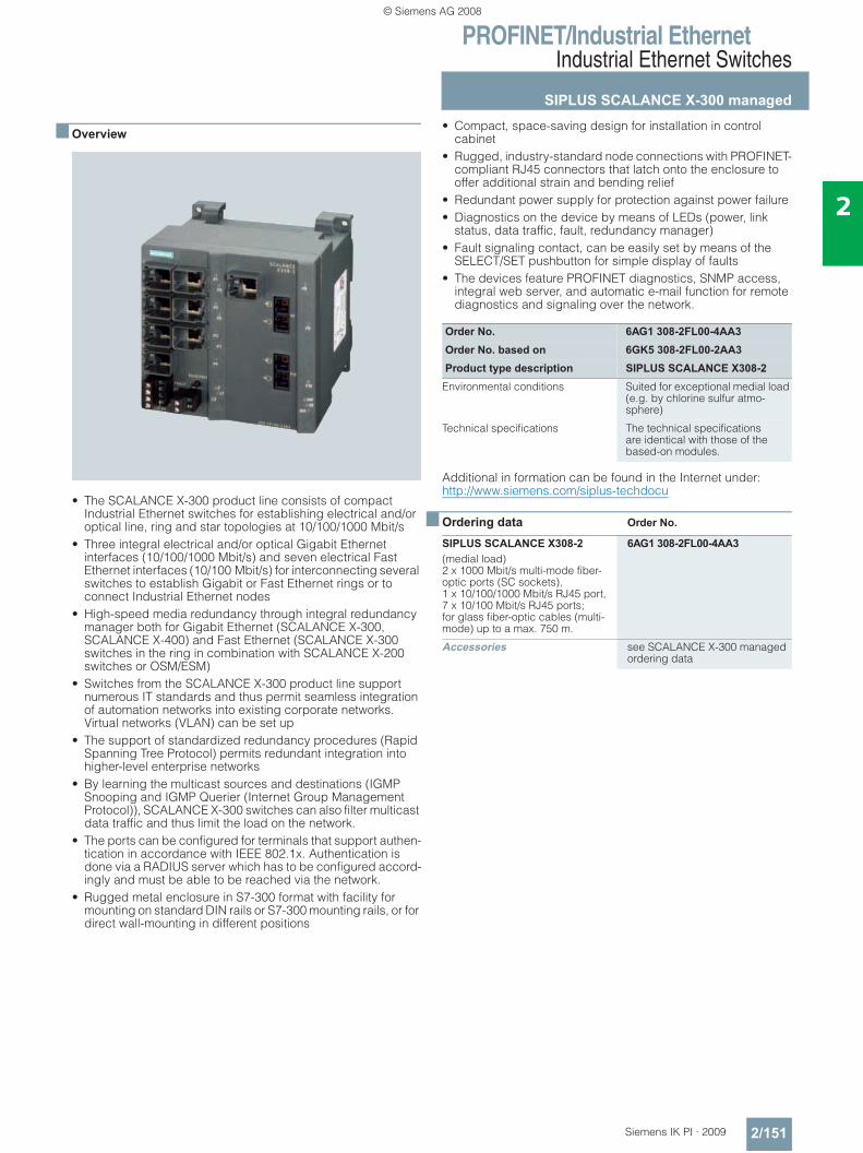
PROFINET/Industrial EthernetIndustrial Ethernet Switches
SIPLUS SCALANCE X-300 managed
2/151Siemens IK PI · 2009
2
■ Overview
• The SCALANCE X-300 product line consists of compact Industrial Ethernet switches for establishing electrical and/or optical line, ring and star topologies at 10/100/1000 Mbit/s
• Three integral electrical and/or optical Gigabit Ethernet interfaces (10/100/1000 Mbit/s) and seven electrical Fast Ethernet interfaces (10/100 Mbit/s) for interconnecting several switches to establish Gigabit or Fast Ethernet rings or to connect Industrial Ethernet nodes
• High-speed media redundancy through integral redundancy manager both for Gigabit Ethernet (SCALANCE X-300, SCALANCE X-400) and Fast Ethernet (SCALANCE X-300 switches in the ring in combination with SCALANCE X-200 switches or OSM/ESM)
• Switches from the SCALANCE X-300 product line support numerous IT standards and thus permit seamless integration of automation networks into existing corporate networks. Virtual networks (VLAN) can be set up
• The support of standardized redundancy procedures (Rapid Spanning Tree Protocol) permits redundant integration into higher-level enterprise networks
• By learning the multicast sources and destinations (IGMP Snooping and IGMP Querier (Internet Group Management Protocol)), SCALANCE X-300 switches can also filter multicast data traffic and thus limit the load on the network.
• The ports can be configured for terminals that support authen-tication in accordance with IEEE 802.1x. Authentication is done via a RADIUS server which has to be configured accord-ingly and must be able to be reached via the network.
• Rugged metal enclosure in S7-300 format with facility for mounting on standard DIN rails or S7-300 mounting rails, or for direct wall-mounting in different positions
• Compact, space-saving design for installation in control cabinet
• Rugged, industry-standard node connections with PROFINET-compliant RJ45 connectors that latch onto the enclosure to offer additional strain and bending relief
• Redundant power supply for protection against power failure • Diagnostics on the device by means of LEDs (power, link
status, data traffic, fault, redundancy manager) • Fault signaling contact, can be easily set by means of the
SELECT/SET pushbutton for simple display of faults • The devices feature PROFINET diagnostics, SNMP access,
integral web server, and automatic e-mail function for remote diagnostics and signaling over the network.
Additional in formation can be found in the Internet under:http://www.siemens.com/siplus-techdocu
■ Ordering data Order No.
Order No. 6AG1 308-2FL00-4AA3Order No. based on 6GK5 308-2FL00-2AA3Product type description SIPLUS SCALANCE X308-2
Environmental conditions Suited for exceptional medial load (e.g. by chlorine sulfur atmo-sphere)
Technical specifications The technical specificationsare identical with those of the based-on modules.
SIPLUS SCALANCE X308-2 6AG1 308-2FL00-4AA3(medial load)2 x 1000 Mbit/s multi-mode fiber-optic ports (SC sockets), 1 x 10/100/1000 Mbit/s RJ45 port, 7 x 10/100 Mbit/s RJ45 ports; for glass fiber-optic cables (multi-mode) up to a max. 750 m.
Accessories see SCALANCE X-300 managedordering data
© Siemens AG 2008
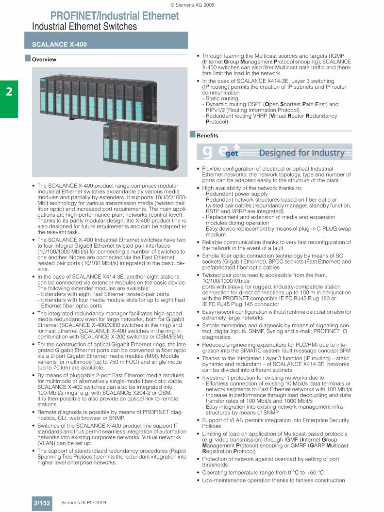
PROFINET/Industrial EthernetIndustrial Ethernet Switches
SCALANCE X-400
2/152 Siemens IK PI · 2009
2
■ Overview
• The SCALANCE X-400 product range comprises modular Industrial Ethernet switches expandable by various media modules and partially by extenders. It supports 10/100/1000-Mbit technology for various transmission media (twisted pair, fiber optic) and increased port requirements. The main appli-cations are high-performance plant networks (control level). Thanks to its partly modular design, the X-400 product line is also designed for future requirements and can be adapted to the relevant task.
• The SCALANCE X-400 Industrial Ethernet switches have two to four integral Gigabit Ethernet twisted pair interfaces (10/100/1000 Mbit/s) for connecting a number of switches to one another. Nodes are connected via the Fast Ethernet twisted pair ports (10/100 Mbit/s) integrated in the basic de-vice.
• In the case of SCALANCE X414-3E, another eight stations can be connected via extender modules on the basic device. The following extender modules are available: - Extenders with eight Fast Ethernet twisted-pair ports - Extenders with four media module slots for up to eight Fast
Ethernet fiber optic ports• The integrated redundancy manager facilitates high-speed
media redundancy even for large networks, both for Gigabit Ethernet (SCALANCE X-400/X300 switches in the ring) and for Fast Ethernet (SCALANCE X-400 switches in the ring in combination with SCALANCE X-200 switches or OSM/ESM).
• For the construction of optical Gigabit Ethernet rings, the inte-grated Gigabit Ethernet ports can be converted to fiber optic via a 2-port Gigabit Ethernet media module (MM). Module variants for multimode (up to 750 m FOC) and single mode (up to 70 km) are available.
• By means of pluggable 2-port Fast Ethernet media modules for multimode or alternatively single-mode fiber-optic cable, SCALANCE X-400 switches can also be integrated into 100-Mbit/s rings, e.g. with SCALANCE X204-2 or OSM.It is then possible to also provide an optical link to remote stations.
• Remote diagnosis is possible by means of PROFINET diag-nostics, CLI, web browser or SNMP.
• Switches of the SCALANCE X-400 product line support IT standards and thus permit seamless integration of automation networks into existing corporate networks. Virtual networks (VLAN) can be set up.
• The support of standardized redundancy procedures (Rapid Spanning Tree Protocol) permits the redundant integration into higher level enterprise networks.
• Through learning the Multicast sources and targets (IGMP (Internet Group Management Protocol snooping), SCALANCE X-400 switches can also filter Multicast data traffic and there-fore limit the load in the network.
• In the case of SCALANCE X414-3E, Layer 3 switching (IP routing) permits the creation of IP subnets and IP router communication - Static routing- Dynamic routing OSPF (Open Shortest Path First) and
RIPv1/2 (Routing Information Protocol)- Redundant routing VRRP (Virtual Router Redundancy
Protocol)
■ Benefits
• Flexible configuration of electrical or optical Industrial Ethernet networks; the network topology, type and number of ports can be adapted easily to the structure of the plant.
• High availability of the network thanks to: - Redundant power supply - Redundant network structures based on fiber-optic or
twisted pair cables (redundancy manager, standby function, RSTP and VRRP are integrated)
- Replacement and extension of media and expansion modules during operation
- Easy device replacement by means of plug-in C-PLUG swap medium
• Reliable communication thanks to very fast reconfiguration of the network in the event of a fault
• Simple fiber optic connection technology by means of SC sockets (Gigabit Ethernet), BFOC sockets (Fast Ethernet) and prefabricated fiber optic cables
• Twisted pair ports readily accessible from the front, 10/100/1000 Mbit/s; ports with sleeve for rugged, industry-compatible station connection for direct connections up to 100 m in conjunction with the PROFINET-compatible IE FC RJ45 Plug 180 or IE FC RJ45 Plug 145 connector
• Easy network configuration without runtime calculation also for extremely large networks
• Simple monitoring and diagnosis by means of signaling con-tact, digital inputs, SNMP, Syslog and e-mail; PROFINET IO diagnostics
• Reduced engineering expenditure for PLC/HMI due to inte-gration into the SIMATIC system fault message concept SFM
• Thanks to the integrated Layer 3 function (IP routing) – static, dynamic and redundant – of SCALANCE X414-3E, networks can be divided into different subnets
• Investment protection for existing networks due to - Effortless connection of existing 10 Mbit/s data terminals or
network segments to Fast Ethernet networks with 100 Mbit/s- Increase in performance through load decoupling and data
transfer rates of 100 Mbit/s and 1000 Mbit/s- Easy integration into existing network management infra-
structures by means of SNMP• Support of VLAN permits integration into Enterprise Security
Policies• Limiting of load on application of Multicast-based protocols
(e.g. video transmission) through IGMP (Internet Group Management Protocol) snooping or GMRP (GARP Multicast Registration Protocol)
• Protection of network against overload by setting of port thresholds
• Operating temperature range from 0 °C to +60 °C• Low-maintenance operation thanks to fanless construction
© Siemens AG 2008
PROFINET/Industrial EthernetIndustrial Ethernet Switches
SCALANCE X-400
2/153Siemens IK PI · 2009
2
■ Application
SCALANCE X-400 products permit the configuration of switched networks at the control level, which not only demands high avail-ability of the network and extensive diagnostic options, but also a high number of ports, high transfer rate and the support of fiber optic and twisted-pair transmission media. SCALANCE X-400 products are designed with degree of protection IP20 for instal-lation in control cabinets.
SCALANCE X408-2• Control stations with a low concentration of devices • Star hub in plant bus for applications with low concentration of
devices • High-speed backbone including high-speed media redun-
dancy for process control systems • In the high-speed backbone for coupling Gigabit network
topologies
SCALANCE X414-3E• Control stations with a high concentration of devices • Star hub in plant bus for applications with high concentration
of devices• High-speed backbone including high-speed media redun-
dancy for process control systems• SCALANCE X414-3E equipped with Layer 3 for IP routing
(static, dynamic, redundant)
■ Design
SCALANCE X408-2/SCALANCE X414-3
Communication connections: • Integral Gigabit Ethernet twisted pair ports
(10/100/1000 Mbit/s, RJ45 sockets) for connecting SCALANCE X-400 switches together: - SCALANCE X408-2:
4 Gigabit Ethernet twisted pair ports- SCALANCE X414-3E:
2 Gigabit Ethernet twisted pair ports• Integral Fast Ethernet twisted pair ports (10/100 Mbit/s,
RJ45 sockets with securing collar) for node connection - SCALANCE X408-2:
4 Fast Ethernet twisted pair ports- SCALANCE X414-3E:
12 Fast Ethernet twisted pair ports• The Gigabit Ethernet ports can be converted to fiber-optic
connections with optical Gigabit Ethernet media modules
Only for SCALANCE X408-2:• Two universal slots either for optical Fast Ethernet or Gigabit
Ethernet media modules with two ports
Only for SCALANCE X414-3E:• Two slots for optical Fast Ethernet media modules with two
ports• One extender interface for expansion by 8 Fast Ethernet ports
(twisted pair or fiber optic, depending on extender version). In this way, a maximum configuration of two Gigabit Ethernet Ports (electrical or optical) and up to 24 Fast Ethernet Ports (of which between 2 and 12 can be optical) is possible. The installation width including extender is max. 19".
Interfaces• Console port (serial interface) for on-site parameterization/
diagnostics, for firmware update; • Slot for C-PLUG swap media for easy device replacement
(included in scope of supply)• Redundant 24 V DC supply; two feeds are available for pro-
tection against voltage failure• One floating message output for simple display of faults
Only for SCALANCE X414-3E:• Additional out-band Ethernet port for on-site parameteriza-
tion/diagnostics• Eight floating inputs for recording digital status information
such as signal contacts of PROFIBUS OLM or door contacts and forwarding via SCALANCE X-400 diagnostic paths (LED indicator, log table, trap or Email)
Extensive operating mode and status information is displayed via LEDs and selection pushbuttons.
SCALANCE X-400 media modules (MM) SCALANCE X-400 switches can be equipped with 2-port media modules. Media modules are available for both multimode and single-mode optical fibers. They can be added or replaced during network operation. The SCALANCE X414-3E basic unit supports two optical Gigabit Ethernet ports and up to four additional optical Fast Ethernet ports.
On two media-module slots, SCALANCE X408-2 supports as many as four optical ports which can optionally be equipped with optical Gigabit Ethernet or Fast Ethernet media modules.
The following media modules are available:• MM491-2;
2 fiber optic ports (BFOC sockets) 100 Mbit/s for distances up to 3 km with multimode fiber-optic conductors
• MM491-2LD; two fiber optic ports (BFOC sockets) 100 Mbit/s for distances up to 26 km with single-mode fiber-optic conductors
• MM491-2LH+; two fiber optic ports (SC sockets) 100 Mbit/s for distances up to 70 km with single-mode fiber-optic conductors
• MM492-2; two fiber optic ports (SC sockets) 1 Gbit/s for distances up to 750 m with multimode fiber-optic conductors (when using SIMATIC NET FO cable 50/125μm)
• MM492-2LD; two fiber optic ports (SC sockets) 1 Gbit/s for distances up to 10 km with single-mode fiber-optic conductors
• MM492-2LH; two fiber optic ports (SC sockets) 1 Gbit/s for distances up to 40 km with single-mode fiber-optic conductors
• MM492-2LH+; two fiber optic ports (SC sockets) 1 Gbit/s for distances up to 70 km with single-mode fiber-optic conductors
Plug-in media modules for Gigabit Ethernet convert the two Gigabit Ethernet twisted pair-ports included in the switch to optical mode. The Gigabit ports can then be used as either twisted-pair or fiber-optic ports. In the case of the SCALANCE X414-3E basic device, optical media modules for Fast Ethernet each generate two additional ports per slot.
© Siemens AG 2008
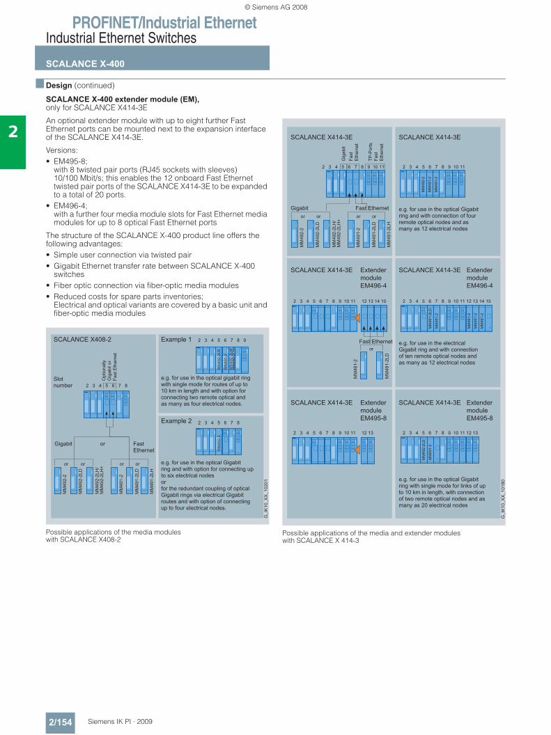
PROFINET/Industrial EthernetIndustrial Ethernet Switches
SCALANCE X-400
2/154 Siemens IK PI · 2009
2
■ Design (continued)
SCALANCE X-400 extender module (EM), only for SCALANCE X414-3E
An optional extender module with up to eight further Fast Ethernet ports can be mounted next to the expansion interface of the SCALANCE X414-3E.
Versions:• EM495-8;
with 8 twisted pair ports (RJ45 sockets with sleeves) 10/100 Mbit/s; this enables the 12 onboard Fast Ethernet twisted pair ports of the SCALANCE X414-3E to be expanded to a total of 20 ports.
• EM496-4; with a further four media module slots for Fast Ethernet media modules for up to 8 optical Fast Ethernet ports
The structure of the SCALANCE X-400 product line offers the following advantages: • Simple user connection via twisted pair• Gigabit Ethernet transfer rate between SCALANCE X-400
switches• Fiber optic connection via fiber-optic media modules• Reduced costs for spare parts inventories;
Electrical and optical variants are covered by a basic unit and fiber-optic media modules
Possible applications of the media modules with SCALANCE X408-2
Possible applications of the media and extender modules with SCALANCE X 414-3
© Siemens AG 2008
PROFINET/Industrial EthernetIndustrial Ethernet Switches
SCALANCE X-400
2/155Siemens IK PI · 2009
2
■ Function• Increasing the network performance;
by filtering the data traffic on the basis of the Ethernet (MAC) address of the data terminals, the local data traffic remains local; only data intended for users of another subnetwork are forwarded by the switch.
• Simple network configuration and expansion; the switch saves the data received at the ports and forwards them independently to the destination address. Collision detection (CSMA/CD method) does not restrict the expansion of the network beyond the port.
• Limiting of error spreading to the associated subnetwork; the SCALANCE X-400 switches only pass on data with a valid checksum (CRC).
• Integration of existing subnetworks with 10 Mbit/s into Fast Ethernet networks with 100 Mbit/s; at the twisted-pair ports, the SCALANCE X-400 switch auto-matically recognizes the conductor pairs for transmission and reception (autocrossover), the data transfer rate of 10 or 100 Mbit/s, as well as full-duplex and half-duplex operation (autonegotiation).
• High-performance connection of SCALANCE X-400 switches with 1 Gbit/s; SCALANCE X-400 switches have two (X414-3E) or four(X408-2) Gigabit Ethernet ports for connecting the switches to each other.
• Integrated redundancy manager for constructing Fast Ethernet and Gigabit Ethernet ring topologies with high-speed media redundancy. Rings consisting of SCALANCE X-300 and X-400 switches can be operated at 1000 Mbit/s. In rings with SCALANCE X-200, X300 or OSM/ESM it is possi-ble to integrate SCALANCE X-400 switches at 100 Mbit/s.
• High-speed standby redundancy; several network segments such as rings can be connected together redundantly with SCALANCE X-400 over the inte-grated standby function. Two X-400 switches are configured in a ring as a master and slave over two links to the other ring. In the case of SCALANCE X408-2 or SCALANCE X-300, a high-performance redundant coupling at 1000 Mbit/s is possible.
• Redundant interfacing to company networks; SCALANCE X-400 switches support the standardized redun-dancy procedures Spanning Tree Protocol (STP) and Rapid Spanning Tree Protocol (RSTP). This enables a subnetwork to be connected redundantly to a higher level corporate network with reduced requirements for the reconfiguration time (in the order of seconds).
• Support of virtual networks (VLAN); for structuring Industrial Ethernet networks with a fast growing number of users, a physically existing network can be divided into several virtual networks.
• Integrated hardware Layer 3 Switching function (IP routing, only SCALANCE X414-3E); IP subnetworks can be created and interconnected, e.g. auto-mation network with office network, enabling a structuring of the networks
• Load limiting with use of Multicast protocols (e.g. video transmission); through learning the Multicast sources and targets (IGMP snooping), SCALANCE X-400 switches can also filter Multi-cast data traffic and therefore limit the load in the network.
• Time synchronization; diagnostics messages (log table entries, e-mails) are time-stamped. The local time is standardized throughout the net-work by means of synchronization with a SICLOCK or SNTP time transmitter, thereby simplifying the assignment of diag-nostic messages to several devices.
• Fast replacement of devices in event of failure, by means of the C-PLUG switching medium
© Siemens AG 2008
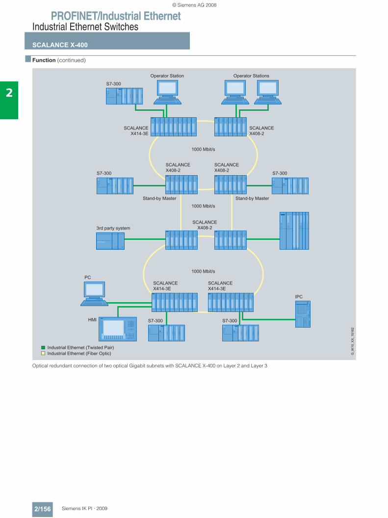
PROFINET/Industrial EthernetIndustrial Ethernet Switches
SCALANCE X-400
2/156 Siemens IK PI · 2009
2
■ Function (continued)
Optical redundant connection of two optical Gigabit subnets with SCALANCE X-400 on Layer 2 and Layer 3
3rd party system
HMI
Operator StationsOperator Station
S7-300
SCALANCEX414-3E
SCALANCEX408-2
SCALANCEX408-2
SCALANCEX408-2
SCALANCEX408-2S7-300 S7-300
Stand-by Master Stand-by Master
1000 Mbit/s
1000 Mbit/s
1000 Mbit/s
SCALANCEX414-3E
SCALANCEX414-3E
S7-300 S7-300
PC
IPC
© Siemens AG 2008
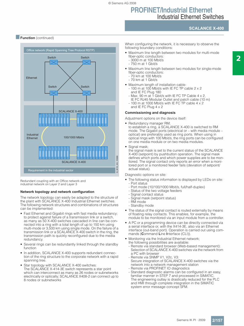
PROFINET/Industrial EthernetIndustrial Ethernet Switches
SCALANCE X-400
2/157Siemens IK PI · 2009
2
■ Function (continued)
l
Redundant coupling with an Office network and industrial network on Layer 2 and Layer 3
Network topology and network configuration
The network topology can easily be adapted to the structure of the plant with SCALANCE X-400 Industrial Ethernet switches. The following network structures and combinations of structures can be implemented:• Fast Ethernet and Gigabit rings with fast media redundancy;
to protect against failure of a transmission link or a switch, as many as 50 X-400 switches cascaded in line can be con-nected into a ring with a total length of up to 150 km using multi-mode or 3,500 km using single mode. On the failure of a transmission link or a SCALANCE X-400 switch in the ring, the transmission path is quickly reconfigured due to the media redundancy.
• Several rings can be redundantly linked through the standby function
• In addition, SCALANCE X-400 supports redundant connec-tion of the ring structure to the corporate network with a rapid spanning tree.
• Star topology with SCALANCE X-400 switches: The SCALANCE X-414-3E switch represents a star point which can interconnect as many as 26 nodes or subnetworks electrically or optically; SCALANCE X408-2 can connect up to 8 nodes or subnetworks
When configuring the network, it is necessary to observe the following boundary conditions:• Maximum line length between two modules for multi-mode
fiber-optic conductors: - 3000 m at 100 Mbit/s- 750 m at 1 Gbit/s
• Maximum line length between two modules for single-mode fiber-optic conductors: - 70 km at 100 Mbit/s- 70 km at 1 Gbit/s
• Maximum length of installation cable: - 100 m at 100 Mbit/s with IE FC TP cable 2 x 2
and IE FC Plug 180- Max. 90 m at 1 Gbit/s with IE FC TP Cable 4 x 2,
IE FC RJ45 Modular Outlet and patch cable (10 m)- 100 m at 1000 Mbit/s with IE FC TP cable 4 x 2
and IE FC Plug 4 x 2
Commissioning and diagnosis
Adjustment options on the device itself:• Redundancy manager RM;
to establish a ring, a SCALANCE X-400 is switched to RM mode. The Gigabit ports (electrical or – with media module – optical) are preferably used as ring ports. When using in optical rings with 100 Mbit/s, the ring ports can be configured on one media module or on two media modules.
• Signal mask; the signal mask is set to the current status of the SCALANCE X-400 (setpoint) by pushbutton operation. The signal mask defines which ports and which power supplies are to be mon-itored. The signal contact only reports an error when a moni-tored port or a monitored feeder fails (deviation of setpoint/actual status).
Diagnostic options on site:• The following status information is displayed by LEDs on site:
- Port status- Port mode (10/100/1000 Mbit/s, full/half-duplex)- Status of the two voltage feeders- Signal contact status- Signal mask (setpoint status)- RM mode- Standby mode
• The status of the signal contact is routed externally by means of floating relay contacts. This enables, for example, the module to be monitored via an input module from a controller.
• A PC or a programming device can be directly connected via a serial interface or, with the X414-3E, also via an Ethernet interface (out-band port). Operation is carried out using com-mands (Command Line Interface (CLI)).
• Monitoring via the Industrial Ethernet network; the following possibilities are available: - Remote via standard browser (Web-based management):
Selection of SCALANCE X-400 switches via the network from a PC with browser
- Remote via SNMP V1, V2c, V3: Secure integration of SCALANCE X-400 switches via the network into a network management station
- Remote via PROFINET IO diagnostics- Standard diagnostic alarms can be configured in an easy,
familiar manner in STEP 7 and processed in SIMATIC. The engineering outlay is drastically reduced for the PLC and HMI through complete integration in the SIMATIC system error message concept SFM.
© Siemens AG 2008
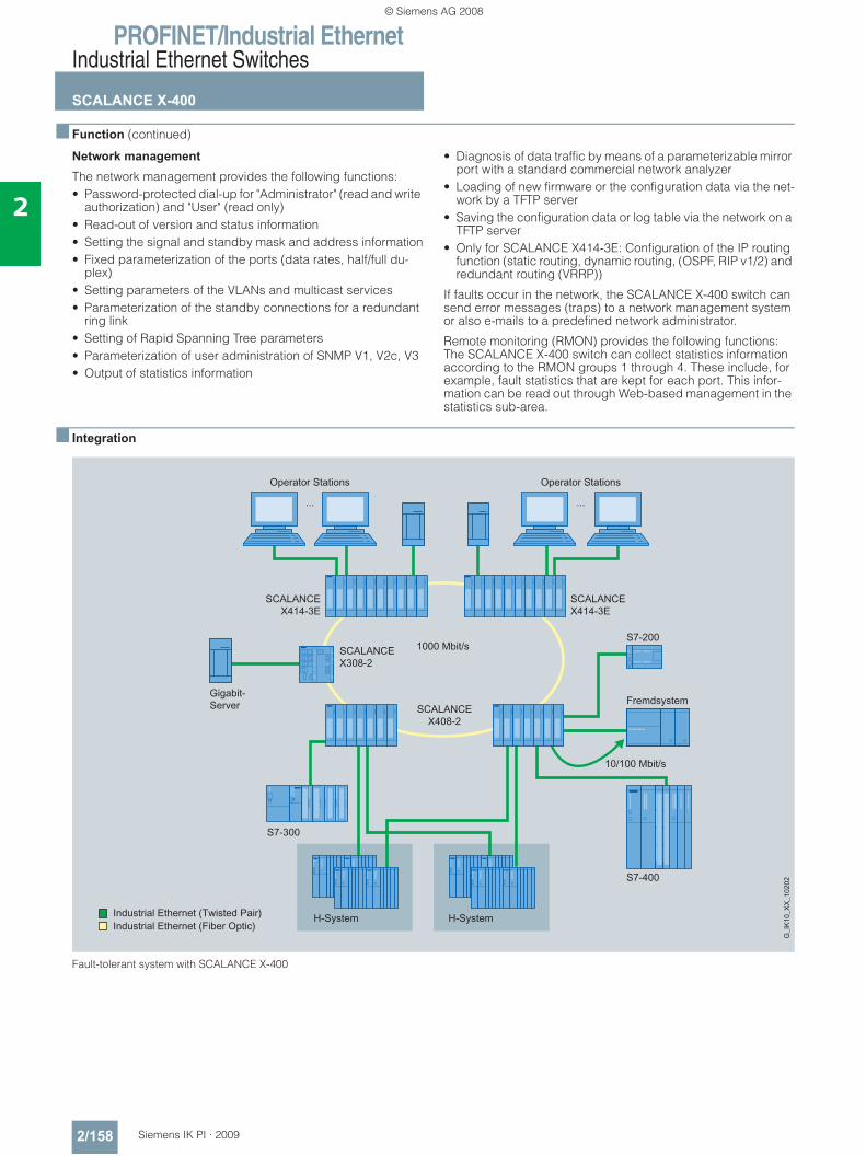
PROFINET/Industrial EthernetIndustrial Ethernet Switches
SCALANCE X-400
2/158 Siemens IK PI · 2009
2
■ Function (continued)
Network management The network management provides the following functions:• Password-protected dial-up for "Administrator" (read and write
authorization) and "User" (read only)• Read-out of version and status information• Setting the signal and standby mask and address information• Fixed parameterization of the ports (data rates, half/full du-
plex)• Setting parameters of the VLANs and multicast services• Parameterization of the standby connections for a redundant
ring link• Setting of Rapid Spanning Tree parameters• Parameterization of user administration of SNMP V1, V2c, V3• Output of statistics information
• Diagnosis of data traffic by means of a parameterizable mirror port with a standard commercial network analyzer
• Loading of new firmware or the configuration data via the net-work by a TFTP server
• Saving the configuration data or log table via the network on a TFTP server
• Only for SCALANCE X414-3E: Configuration of the IP routing function (static routing, dynamic routing, (OSPF, RIP v1/2) and redundant routing (VRRP))
If faults occur in the network, the SCALANCE X-400 switch can send error messages (traps) to a network management system or also e-mails to a predefined network administrator.
Remote monitoring (RMON) provides the following functions: The SCALANCE X-400 switch can collect statistics information according to the RMON groups 1 through 4. These include, for example, fault statistics that are kept for each port. This infor-mation can be read out through Web-based management in the statistics sub-area.
■ Integration
Fault-tolerant system with SCALANCE X-400
......
Operator StationsOperator Stations
SCALANCEX414-3E
SCALANCEX414-3E
FremdsystemSCALANCE
X408-2
1000 Mbit/s
10/100 Mbit/s
S7-200
Gigabit-Server
SCALANCEX308-2
S7-300
H-System H-System
S7-400
© Siemens AG 2008
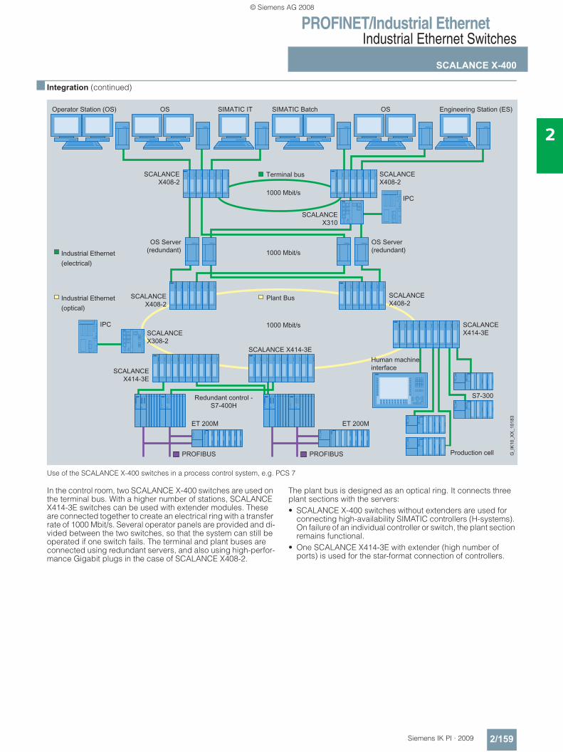
PROFINET/Industrial EthernetIndustrial Ethernet Switches
SCALANCE X-400
2/159Siemens IK PI · 2009
2
■ Integration (continued)
Use of the SCALANCE X-400 switches in a process control system, e.g. PCS 7
In the control room, two SCALANCE X-400 switches are used on the terminal bus. With a higher number of stations, SCALANCE X414-3E switches can be used with extender modules. These are connected together to create an electrical ring with a transfer rate of 1000 Mbit/s. Several operator panels are provided and di-vided between the two switches, so that the system can still be operated if one switch fails. The terminal and plant buses are connected using redundant servers, and also using high-perfor-mance Gigabit plugs in the case of SCALANCE X408-2.
The plant bus is designed as an optical ring. It connects three plant sections with the servers:• SCALANCE X-400 switches without extenders are used for
connecting high-availability SIMATIC controllers (H-systems). On failure of an individual controller or switch, the plant section remains functional.
• One SCALANCE X414-3E with extender (high number of ports) is used for the star-format connection of controllers.
© Siemens AG 2008
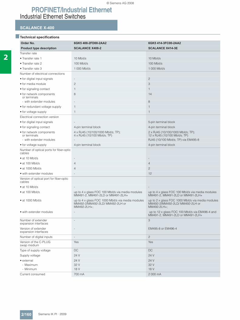
PROFINET/Industrial EthernetIndustrial Ethernet Switches
SCALANCE X-400
2/160 Siemens IK PI · 2009
2
■ Technical specifications
Order No. 6GK5 408-2FD00-2AA2 6GK5 414-3FC00-2AA2 Product type description SCALANCE X408-2 SCALANCE X414-3E
Transfer rate
• Transfer rate 1 10 Mbit/s 10 Mbit/s
• Transfer rate 2 100 Mbit/s 100 Mbit/s
• Transfer rate 3 1 000 Mbit/s 1 000 Mbit/s
Number of electrical connections
• for digital input signals - 2
• for media module 2 3
• for signaling contact 1 1
• for network components or terminals
8 14
- with extender modules - 8
• for redundant voltage supply 1 1
• for voltage supply 1 1
Electrical connection version
• for digital input signals - 5-pin terminal block
• for signaling contact 4-pin terminal block 4-pin terminal block
• for network components or terminals
4 x RJ45 (10/100/1000 Mbit/s; TP); 4 x RJ45 (10/100 Mbit/s; TP)
2 x RJ45 (10/100/1000 Mbit/s; TP); 12 x RJ45 (10/100 Mbit/s; TP)
- with extender modules - RJ45 (10/100 Mbit/s; TP) via EM495-8
• for voltage supply 4-pin terminal block 4-pin terminal block
Number of optical ports for fiber-optic cables
• at 10 Mbit/s - -
• at 100 Mbit/s 4 4
• at 1000 Mbit/s 4 2
• with extender modules - 12
Version of optical port for fiber-optic cables
• at 10 Mbit/s - -
• at 100 Mbit/s up to 4 x glass FOC 100 Mbit/s via media modules MM491-2, MM491-2LD or MM491-2LH+
up to 4 x glass FOC 100 Mbit/s via media modules MM491-2, MM491-2LD or MM491-2LH+
• at 1000 Mbit/s up to 4 x glass FOC 1000 Mbit/s via media modules MM492-2/MM492-2LD/ MM492-2LH or MM492-2LH+;
up to 2 x glass FOC 1000 Mbit/s via media modules MM492-2/MM492-2LD/ MM492-2LH or MM492-2LH+;
• with extender modules - up to 12 x glass FOC 100 Mbit/s via EM496-4 and MM491-2, MM491-2LD or MM491-2LH+
Number of extender expansion interfaces
- 3
Version of extender expansion interfaces
- EM495-8 or EM496-4
Number of digital inputs - 2
Version of the C-PLUG swap medium
Yes Yes
Type of supply voltage DC DC
Supply voltage 24 V 24 V
• external 24 V 24 V- Maximum 32 V 32 V- Minimum 18 V 18 V
Current consumed 700 mA 2 000 mA
© Siemens AG 2008
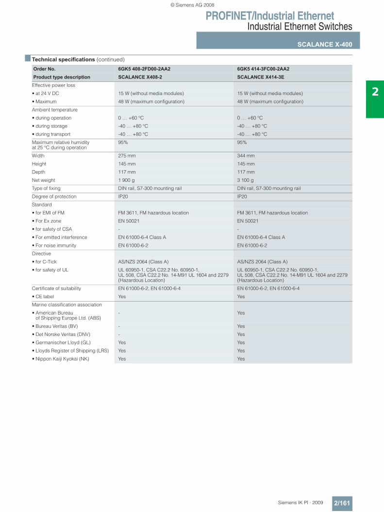
PROFINET/Industrial EthernetIndustrial Ethernet Switches
SCALANCE X-400
2/161Siemens IK PI · 2009
2
■ Technical specifications (continued)
Order No. 6GK5 408-2FD00-2AA2 6GK5 414-3FC00-2AA2 Product type description SCALANCE X408-2 SCALANCE X414-3E
Effective power loss
• at 24 V DC 15 W (without media modules) 15 W (without media modules)
• Maximum 48 W (maximum configuration) 48 W (maximum configuration)
Ambient temperature
• during operation 0 … +60 °C 0 … +60 °C
• during storage -40 … +80 °C -40 … +80 °C
• during transport -40 … +80 °C -40 … +80 °C
Maximum relative humidityat 25 °C during operation
95% 95%
Width 275 mm 344 mm
Height 145 mm 145 mm
Depth 117 mm 117 mm
Net weight 1 900 g 3 100 g
Type of fixing DIN rail, S7-300 mounting rail DIN rail, S7-300 mounting rail
Degree of protection IP20 IP20
Standard
• for EMI of FM FM 3611, FM hazardous location FM 3611, FM hazardous location
• For Ex zone EN 50021 EN 50021
• for safety of CSA - -
• For emitted interference EN 61000-6-4 Class A EN 61000-6-4 Class A
• For noise immunity EN 61000-6-2 EN 61000-6-2
Directive
• for C-Tick AS/NZS 2064 (Class A) AS/NZS 2064 (Class A)
• for safety of UL UL 60950-1, CSA C22.2 No. 60950-1, UL 508, CSA C22.2 No. 14-M91 UL 1604 and 2279 (Hazardous Location)
UL 60950-1, CSA C22.2 No. 60950-1, UL 508, CSA C22.2 No. 14-M91 UL 1604 and 2279 (Hazardous Location)
Certificate of suitability EN 61000-6-2, EN 61000-6-4 EN 61000-6-2, EN 61000-6-4
• CE label Yes Yes
Marine classification association
• American Bureau of Shipping Europe Ltd. (ABS)
- Yes
• Bureau Veritas (BV) - Yes
• Det Norske Veritas (DNV) - Yes
• Germanischer Lloyd (GL) Yes Yes
• Lloyds Register of Shipping (LRS) Yes Yes
• Nippon Kaiji Kyokai (NK) Yes Yes
© Siemens AG 2008
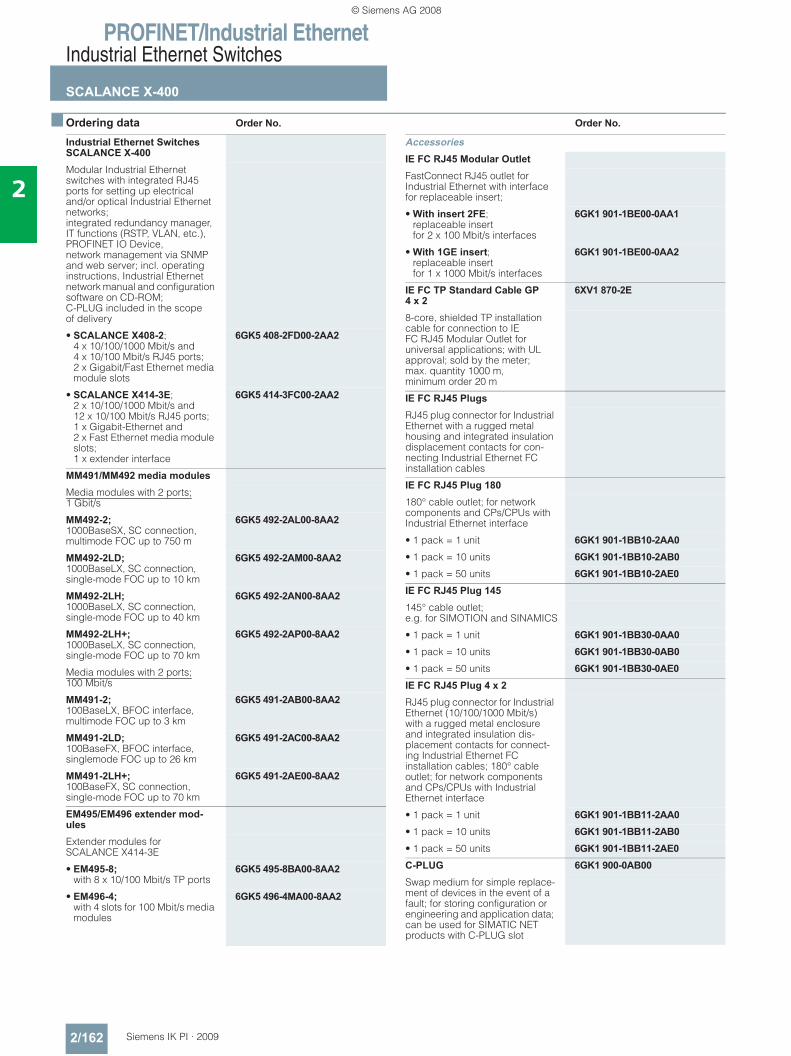
PROFINET/Industrial EthernetIndustrial Ethernet Switches
SCALANCE X-400
2/162 Siemens IK PI · 2009
2
■ Ordering data Order No. Order No.
Industrial Ethernet Switches SCALANCE X-400Modular Industrial Ethernet switches with integrated RJ45 ports for setting up electrical and/or optical Industrial Ethernet networks; integrated redundancy manager, IT functions (RSTP, VLAN, etc.), PROFINET IO Device, network management via SNMP and web server; incl. operating instructions, Industrial Ethernet network manual and configuration software on CD-ROM; C-PLUG included in the scope of delivery
• SCALANCE X408-2; 4 x 10/100/1000 Mbit/s and 4 x 10/100 Mbit/s RJ45 ports; 2 x Gigabit/Fast Ethernet media module slots
6GK5 408-2FD00-2AA2
• SCALANCE X414-3E; 2 x 10/100/1000 Mbit/s and 12 x 10/100 Mbit/s RJ45 ports; 1 x Gigabit-Ethernet and 2 x Fast Ethernet media module slots; 1 x extender interface
6GK5 414-3FC00-2AA2
MM491/MM492 media modulesMedia modules with 2 ports; 1 Gbit/s
MM492-2;1000BaseSX, SC connection, multimode FOC up to 750 m
6GK5 492-2AL00-8AA2
MM492-2LD; 1000BaseLX, SC connection, single-mode FOC up to 10 km
6GK5 492-2AM00-8AA2
MM492-2LH; 1000BaseLX, SC connection, single-mode FOC up to 40 km
6GK5 492-2AN00-8AA2
MM492-2LH+; 1000BaseLX, SC connection, single-mode FOC up to 70 km
6GK5 492-2AP00-8AA2
Media modules with 2 ports; 100 Mbit/s
MM491-2; 100BaseLX, BFOC interface, multimode FOC up to 3 km
6GK5 491-2AB00-8AA2
MM491-2LD; 100BaseFX, BFOC interface, singlemode FOC up to 26 km
6GK5 491-2AC00-8AA2
MM491-2LH+; 100BaseFX, SC connection, single-mode FOC up to 70 km
6GK5 491-2AE00-8AA2
EM495/EM496 extender mod-ulesExtender modules for SCALANCE X414-3E
• EM495-8; with 8 x 10/100 Mbit/s TP ports
6GK5 495-8BA00-8AA2
• EM496-4; with 4 slots for 100 Mbit/s media modules
6GK5 496-4MA00-8AA2
AccessoriesIE FC RJ45 Modular Outlet FastConnect RJ45 outlet for Industrial Ethernet with interface for replaceable insert;
• With insert 2FE; replaceable insertfor 2 x 100 Mbit/s interfaces
6GK1 901-1BE00-0AA1
• With 1GE insert; replaceable insertfor 1 x 1000 Mbit/s interfaces
6GK1 901-1BE00-0AA2
IE FC TP Standard Cable GP4 x 2
6XV1 870-2E
8-core, shielded TP installation cable for connection to IE FC RJ45 Modular Outlet for universal applications; with UL approval; sold by the meter; max. quantity 1000 m, minimum order 20 m
IE FC RJ45 PlugsRJ45 plug connector for Industrial Ethernet with a rugged metal housing and integrated insulation displacement contacts for con-necting Industrial Ethernet FC installation cables
IE FC RJ45 Plug 180180° cable outlet; for network components and CPs/CPUs with Industrial Ethernet interface
• 1 pack = 1 unit 6GK1 901-1BB10-2AA0• 1 pack = 10 units 6GK1 901-1BB10-2AB0• 1 pack = 50 units 6GK1 901-1BB10-2AE0IE FC RJ45 Plug 145145° cable outlet;e.g. for SIMOTION and SINAMICS
• 1 pack = 1 unit 6GK1 901-1BB30-0AA0• 1 pack = 10 units 6GK1 901-1BB30-0AB0• 1 pack = 50 units 6GK1 901-1BB30-0AE0IE FC RJ45 Plug 4 x 2RJ45 plug connector for Industrial Ethernet (10/100/1000 Mbit/s) with a rugged metal enclosure and integrated insulation dis-placement contacts for connect-ing Industrial Ethernet FC installation cables; 180° cable outlet; for network components and CPs/CPUs with Industrial Ethernet interface
• 1 pack = 1 unit 6GK1 901-1BB11-2AA0• 1 pack = 10 units 6GK1 901-1BB11-2AB0• 1 pack = 50 units 6GK1 901-1BB11-2AE0C-PLUG 6GK1 900-0AB00Swap medium for simple replace-ment of devices in the event of a fault; for storing configuration or engineering and application data; can be used for SIMATIC NET products with C-PLUG slot
© Siemens AG 2008
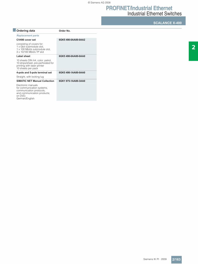
PROFINET/Industrial EthernetIndustrial Ethernet Switches
SCALANCE X-400
2/163Siemens IK PI · 2009
2
■ Ordering data Order No.
Replacement partsCV490 cover set 6GK5 490-0AA00-0AA2consisting of covers for:1 x Gbit submodule slot, 1 x 100 Mbit/s submodule slot, 3 x 10/100 Mbit/s TP slot
Label sheet 6GK5 498-0AA00-0AA010 sheets DIN A4, color: petrol, 10 strips/sheet, pre-perforated for printing with laser printer10 sheets per pack
4-pole and 5-pole terminal set 6GK5 498-1AA00-0AA0Straight, with locking lug
SIMATIC NET Manual Collection 6GK1 975-1AA00-3AA0Electronic manuals for communication systems, communication protocols, and communication products; on DVD; German/English
© Siemens AG 2008
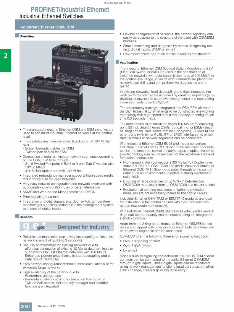
PROFINET/Industrial EthernetIndustrial Ethernet Switches
Industrial Ethernet OSM/ESM
2/164 Siemens IK PI · 2009
2
■ Overview
• The managed Industrial Ethernet OSM and ESM switches are used to construct Industrial Ethernet networks at the control level
• The modules are interconnected (backbone) at 100 Mbit/s over - Glass fiber-optic cables for OSM - Twisted pair cables for ESM
• Connection of data terminals or network segments depending on the OSM/ESM type through - 2 to 8 Twisted Pair ports in RJ45 or 9-pole Sub-D version with
10/100 Mbit/s - 3 or 8 fiber-optic ports with 100 Mbit/s
• Integrated redundancy manager supports high-speed media redundancy also for large networks
• Very easy network configuration and network extension with-out complex configuration rules or parameterization
• SNMP and Web-based Management and RMON• Error signaling by e-mail• Integration of digital signals, e.g. door switch, temperature
monitoring or signaling contacts into the management system by means of digital inputs
■ Benefits
• Reliable communication due to very fast reconfiguration of the network in event of fault (<0.3 seconds)
• Security of investment for existing networks due to - effortless connection of existing 10 Mbit/s data terminals or
subnetworks to Fast Ethernet networks with 100 Mbit/s- Enhanced performance thanks to load decoupling and a
data rate of 100 Mbit/s• Easy network configuration without runtime calculation also for
extremely large networks• High availability of the network due to:
- Redundant voltage feed- Redundant network structures based on fiber-optic or
Twisted Pair cables; redundancy manager and standby function are integrated
• Flexible configuration of networks, the network topology can easily be adapted to the structure of the plant with OSM/ESM modules.
• Simple monitoring and diagnosis by means of signaling con-tact, digital inputs, SNMP or e-mail
• Low-maintenance operation thanks to fanless construction
■ Application
The Industrial Ethernet OSM (Optical Switch Module) and ESM (Electrical Switch Module) are used in the construction of switched networks with data transmission rates of 100 Mbit/s in the control level range, in which strict demands are placed on network availability and comprehensive diagnostics are re-quired.
In existing networks, load decoupling and thus increased net-work performance can be achieved by creating segments (sub-dividing a network into subnetworks/segments) and connecting these segments to an OSM/ESM.
The redundancy manager integrated into OSM/ESM allows re-dundant Industrial Ethernet rings to be constructed in switching technology with high-speed media redundancy (reconfiguration time 0.3 seconds max.).
The data transmission rate in the ring is 100 Mbit/s; for each ring, up to 50 Industrial Ethernet OSMs (optical ring) or ESMs (electri-cal ring) can be used. Apart from the 2 ring ports, OSM/ESM has other ports (with either RJ45, ITP or BFOC interfaces) to which data terminals or network segments can be connected.
With Industrial Ethernet OSM BC08 and media converters Industrial Ethernet OMC TP11, "Fiber to the machine" concepts can be implemented, so that the advantages of optical transmis-sion technology can be utilized both for the backbone area and for station connection:• High-speed station connection (100 Mbit/s Full Duplex) over
Industrial Ethernet OSM BC08 and media converter Industrial Ethernet OMC TP11 (fiber-optic cable through to the control cabinet) in an environment subjected to strong electromag-netic fields
• Bridging of large distances of up to 3 km between two OSM BC08 modules or from an OSM BC08 to a distant station
• Equipotential bonding measures or lightning protection measures are not necessary thanks to fiber-optic cables.
Industrial Ethernet OSM TP22 or ESM TP40 modules are ideal for installation in the control cabinet with 1 or 2 stations con-nected (low equipment density).
With Industrial Ethernet OSM/ESM (devices with 8 ports), several rings can be redundantly interconnected using the integrated standby function.
Apart from the 2 ring ports, Industrial Ethernet OSM/ESM mod-ules are equipped with other ports to which both data terminals and network segments can be connected.
OSM/ESM offer the following three error signaling functions:• Over a signaling contact• Over SNMP (traps)• by e-mail
Signals such as signaling contacts from PROFIBUS OLM or door contacts can be connected to Industrial Ethernet OSM/ESM through digital inputs. These digital inputs can be monitored using network management functions (read out status, e-mail on status change, create trap or log table entry).
© Siemens AG 2008
PROFINET/Industrial EthernetIndustrial Ethernet Switches
Industrial Ethernet OSM/ESM
2/165Siemens IK PI · 2009
2
■ Design
OSM/ESM have a stable metal casing. They are suitable for the following installation types:• Standard rail• Wall mounting• Mounting in 19-inch racks (when 2 modules are used)
All modules have• a 6-pole terminal block for connecting the supply voltage
(redundant 24 V DC infeed) and the floating signaling contact as well as
• one or two 6-pole terminal blocks for connecting four digital inputs in each case
The operating mode and status information are displayed by LEDs and a selection button.
Modules with 8 ports also have a standby interface that is used to synchronize two modules when coupling redundant rings.
Using the serial interface, Industrial Ethernet OSM/ESM can be parameterized, diagnosed or upgraded to the latest firmware status. The firmware can also be upgraded over the network.
Industrial Ethernet OSM/ESM is available with 4 or 8 ports. They are equipped with the following types of ports depending on the variant:• Twisted Pair interface (RJ45); 10/100BaseTX :
RJ45 socket, automatic data rate detection (10 or 100 Mbit/s) as well as automatic cross-over of the send/receive cables for connecting FC cables in the field to IE FC RJ45 Plug 180 of up to 100 m in length or TP Cords (max. length 10 m, in combina-tion with IE FC Outlet RJ45s and IE FC cables up to 100 m)
• Twisted Pair interface (Sub-D); 10/100BaseTX: 9-pole Sub-D socket, automatic data rate detection (10 or 100 Mbit/s) as well as automatic cross-over of the send/re-ceive circuits for connecting ITP cables (max. length 100 m) with Sub-D connectors
• Glass FOC: Multimode (MM);100BaseFX BFOC: 2 BFOC sockets per port, 100 Mbit/s data transmission rate, for connecting multimode fiber-optic cables in environments subjected to strong electro-magnetic fields and for distances of up to 3000 m between two Industrial Ethernet OSMs
• Glass FOC: Singlemode (SM);100BaseFX BFOC: 2 BFOC sockets per port, 100 Mbit/s data transmission rate, for connecting singlemode fiber-optic cables in environments subjected to strong electro-magnetic fields and for distances of up to 26 km between two Industrial Ethernet OSM ITP62-LD modules.
■ Function
Increase in network performance By filtering the data traffic based on the Ethernet (MAC) address of the data terminals, local data traffic remains local, only data intended for nodes in another subnet is forwarded by the OSM or ESM.
Simple network configuration and network expansion The overall extent of the network can be up to 150 km with OSM or up to 5 km with ESM. The OSM/ESM saves the data received at the ports and forwards it independently to the destination address. Collision detection (CSMA/CD method) does not restrict the expansion of the network beyond the switch port.
Limiting error propagation to the subnet concerned The OSM/ESM only forwards valid data.
Integration of existing subnets at 10 Mbit/s into Fast Ethernet networks at 100 Mbit/s The OSM/ESM automatically detects the data rate (10 or 100 Mbit/s) at the twistedpair ports as well full or half duplex mode.
Fast redundancy in the ring (reconfiguration timeof the ring max. 0.3 seconds): The availability of the communication is increased by closing an optical line with OSM or an electrical line with ESM to form a ring. OSM/ESM have an integral redundancy manager which contin-uously monitors the function of the network. It recognizes the failure of a section in the ring or of an OSM/ESM and activates the substitute path within a maximum of 0.3 seconds.
High-speed stand-by redundancy Several redundant rings can be reliably interconnected using the integrated standby function (in the case of OSM/ESM with 8 ports). Two OSMs/ESMs of one ring, linked by means of a standby connection, are connected to the other ring by means of two connecting routes.
Digital Inputs Easy integration of digital signals into the SNMP-based network management.
Autocrossover function at RJ45 ports If necessary, the Industrial Ethernet OSM/ESM TPs automatically cross over the send/receive lines to the connected partner device at RJ45 ports. This means that crossover TP XP cords are not required. A condition of the auto-crossover function is that auto-negotiation is activated.
© Siemens AG 2008
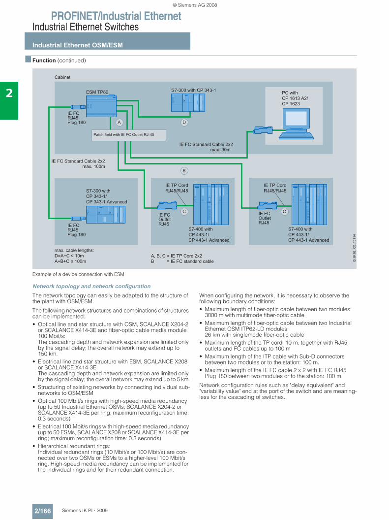
PROFINET/Industrial EthernetIndustrial Ethernet Switches
Industrial Ethernet OSM/ESM
2/166 Siemens IK PI · 2009
2
■ Function (continued)
Example of a device connection with ESM
Network topology and network configurationThe network topology can easily be adapted to the structure of the plant with OSM/ESM.
The following network structures and combinations of structures can be implemented:• Optical line and star structure with OSM, SCALANCE X204-2
or SCALANCE X414-3E and fiber-optic cable media module 100 Mbit/s:The cascading depth and network expansion are limited only by the signal delay; the overall network may extend up to 150 km.
• Electrical line and star structure with ESM, SCALANCE X208 or SCALANCE X414-3E: The cascading depth and network expansion are limited only by the signal delay; the overall network may extend up to 5 km.
• Structuring of existing networks by connecting individual sub-networks to OSM/ESM
• Optical 100 Mbit/s rings with high-speed media redundancy (up to 50 Industrial Ethernet OSMs, SCALANCE X204-2 or SCALANCE X414-3E per ring; maximum reconfiguration time: 0.3 seconds)
• Electrical 100 Mbit/s rings with high-speed media redundancy (up to 50 ESMs, SCALANCE X208 or SCALANCE X414-3E per ring; maximum reconfiguration time: 0.3 seconds)
• Hierarchical redundant rings: Individual redundant rings (10 Mbit/s or 100 Mbit/s) are con-nected over two OSMs or ESMs to a higher-level 100 Mbit/s ring. High-speed media redundancy can be implemented for the individual rings and for their redundant connection.
When configuring the network, it is necessary to observe the following boundary conditions:• Maximum length of fiber-optic cable between two modules:
3000 m with multimode fiber-optic cable• Maximum length of fiber-optic cable between two Industrial
Ethernet OSM ITP62-LD modules: 26 km with singlemode fiber-optic cable
• Maximum length of the TP cord: 10 m; together with RJ45 outlets and FC cables up to 100 m
• Maximum length of the ITP cable with Sub-D connectors between two modules or to the station: 100 m.
• Maximum length of the IE FC cable 2 x 2 with IE FC RJ45 Plug 180 between two modules or to the station: 100 m
Network configuration rules such as "delay equivalent" and "variability value" end at the port of the switch and are meaning-less for the cascading of switches.
© Siemens AG 2008
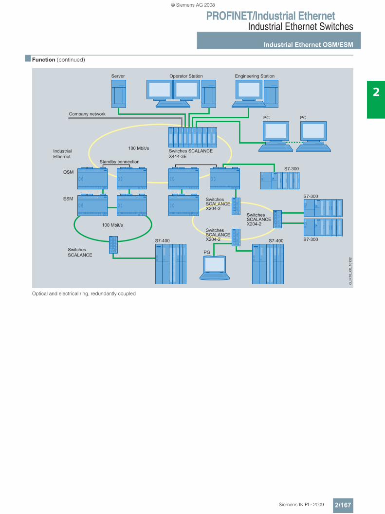
PROFINET/Industrial EthernetIndustrial Ethernet Switches
Industrial Ethernet OSM/ESM
2/167Siemens IK PI · 2009
2
■ Function (continued)
Optical and electrical ring, redundantly coupled
© Siemens AG 2008
PROFINET/Industrial EthernetIndustrial Ethernet Switches
Industrial Ethernet OSM/ESM
2/168 Siemens IK PI · 2009
2
■ Function (continued)
Commissioning and diagnosisOSM/ESM have the following adjustment options on the device itself:• Redundancy manager (RM)• When setting up a ring, one module in the ring is switched
to RM mode by means of a switch.• The non-ring ports of the RM can be used for the connection
of data terminals and networks.• Standby function (for OSM/ESM with 8 ports)• When coupling rings redundantly, one module in the ring
that is connected to the neighboring module by means of a standby connection is switched to the standby mode.
• Signal mask; the signal mask is set to the current (target) status of the module by pushbutton operation. The signal mask defines which ports and which power supplies are to be monitored. The signaling contact only reports an error when a monitored port or a monitored feeder fails (deviation of setpoint/actual status).
OSMs/ESMs have the following diagnostic options:• The following status information is displayed by LEDs on site:
- RM mode- Standby mode (for OSM/ESM with 8 ports)- Signaling contact status- Status of the two power supplies- Port status- Port mode (10/100 Mbit/s, full/half-duplex)- Signal mask (setpoint status)- Status of the digital Inputs
• The status of the signaling contact is routed externally by means of floating relay contacts. This enables the module to be monitored via an input module from a controller.
In addition, Industrial Ethernet OSMs/ESMs can be monitored by means of network management. The following interfaces are offered for this purpose:• Locally on the module;
over the serial interface and PC with terminal emulation per command line (CLI – Command Line Interface)
• Remote via browser (Web-based management): Selection of OSM/ESM via the network from a PC with browser
• Remote via SNMP; Integration of OSM/ESM via the network into a network management station
Network managementNetwork management provides the following functions:• Password-protected dial-up for "Administrator" (read and write
authorization) and "User" (read only)• Read-out of version and status information• Setting the signal and standby mask and address information• Fixed parameterization of the ports and filter tables
(filter tables only in the case of OSMs/ESMs with 8 ports)• Output of statistical information• Diagnosis of data traffic by means of a parameterizable mirror
port with a standard commercial network analyzer• Loading of new firmware or the configuration data via the
network by a TFTP server• Saving the configuration data or log table via the network on a
TFTP server
If problems occur in the network, the OSM/ESM can send error messages (traps) automatically to a network management system or Emails to a network administrator.
The remote monitoring (RMON) in the case of OSM/ESM with 8 ports offers the following functions:The OSM/ESM can collect statistics information according to the RMON groups 1 through 3. These include, for example, fault statistics that are kept for each port.
This information can be read out from the OSM/ESM through Web-based management in the statistics sub-area.
© Siemens AG 2008
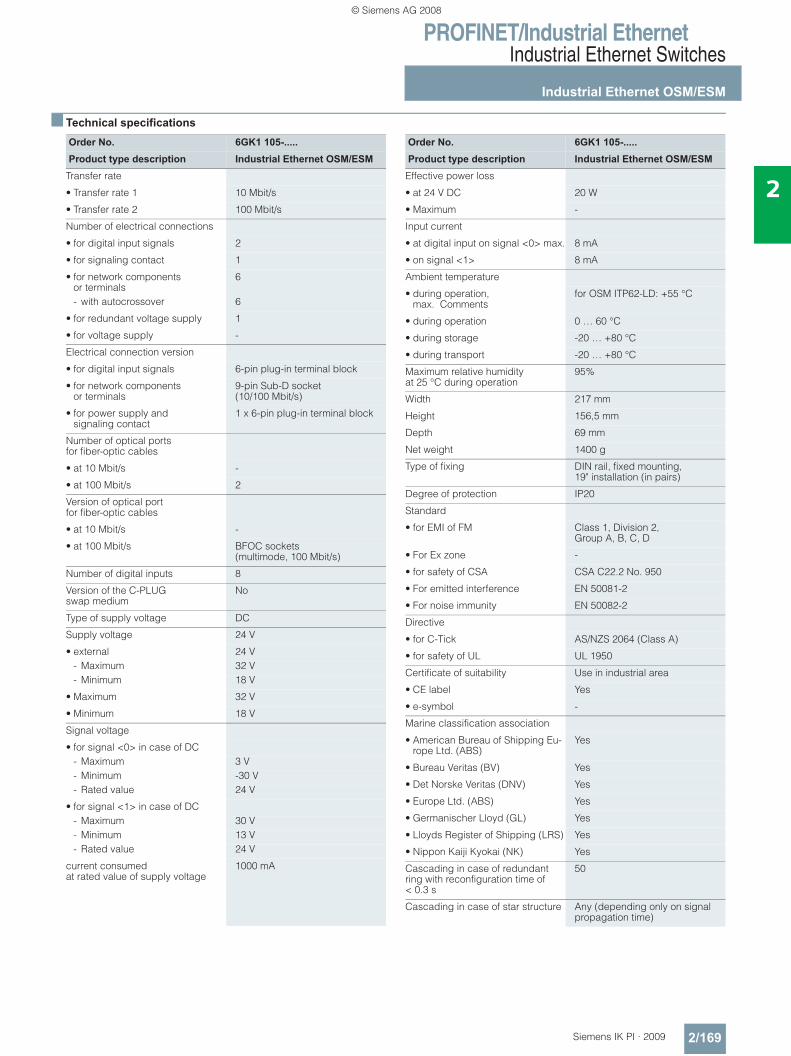
PROFINET/Industrial EthernetIndustrial Ethernet Switches
Industrial Ethernet OSM/ESM
2/169Siemens IK PI · 2009
2
■ Technical specifications
Order No. 6GK1 105-.....Product type description Industrial Ethernet OSM/ESM
Transfer rate
• Transfer rate 1 10 Mbit/s
• Transfer rate 2 100 Mbit/s
Number of electrical connections
• for digital input signals 2
• for signaling contact 1
• for network components or terminals
6
- with autocrossover 6
• for redundant voltage supply 1
• for voltage supply -
Electrical connection version
• for digital input signals 6-pin plug-in terminal block
• for network components or terminals
9-pin Sub-D socket (10/100 Mbit/s)
• for power supply and signaling contact
1 x 6-pin plug-in terminal block
Number of optical ports for fiber-optic cables
• at 10 Mbit/s -
• at 100 Mbit/s 2
Version of optical portfor fiber-optic cables
• at 10 Mbit/s -
• at 100 Mbit/s BFOC sockets (multimode, 100 Mbit/s)
Number of digital inputs 8
Version of the C-PLUG swap medium
No
Type of supply voltage DC
Supply voltage 24 V
• external 24 V- Maximum 32 V- Minimum 18 V
• Maximum 32 V
• Minimum 18 V
Signal voltage
• for signal <0> in case of DC- Maximum 3 V- Minimum -30 V- Rated value 24 V
• for signal <1> in case of DC- Maximum 30 V- Minimum 13 V- Rated value 24 V
current consumed at rated value of supply voltage
1000 mA
Order No. 6GK1 105-.....Product type description Industrial Ethernet OSM/ESM
Effective power loss
• at 24 V DC 20 W
• Maximum -
Input current
• at digital input on signal <0> max. 8 mA
• on signal <1> 8 mA
Ambient temperature
• during operation, max. Comments
for OSM ITP62-LD: +55 °C
• during operation 0 … 60 °C
• during storage -20 … +80 °C
• during transport -20 … +80 °C
Maximum relative humidity at 25 °C during operation
95%
Width 217 mm
Height 156,5 mm
Depth 69 mm
Net weight 1400 g
Type of fixing DIN rail, fixed mounting, 19" installation (in pairs)
Degree of protection IP20
Standard
• for EMI of FM Class 1, Division 2, Group A, B, C, D
• For Ex zone -
• for safety of CSA CSA C22.2 No. 950
• For emitted interference EN 50081-2
• For noise immunity EN 50082-2
Directive
• for C-Tick AS/NZS 2064 (Class A)
• for safety of UL UL 1950
Certificate of suitability Use in industrial area
• CE label Yes
• e-symbol -
Marine classification association
• American Bureau of Shipping Eu-rope Ltd. (ABS)
Yes
• Bureau Veritas (BV) Yes
• Det Norske Veritas (DNV) Yes
• Europe Ltd. (ABS) Yes
• Germanischer Lloyd (GL) Yes
• Lloyds Register of Shipping (LRS) Yes
• Nippon Kaiji Kyokai (NK) Yes
Cascading in case of redundant ring with reconfiguration time of < 0.3 s
50
Cascading in case of star structure Any (depending only on signal propagation time)
© Siemens AG 2008
PROFINET/Industrial EthernetIndustrial Ethernet Switches
Industrial Ethernet OSM/ESM
2/170 Siemens IK PI · 2009
2
■ Ordering data Order No. Order No.
Industrial Ethernet OSM ITP62 6GK1 105-2AA10Optical switch module with 2 fiber-optic ports 100 Mbit/s, 6 ITP ports 10/100 Mbit/s and 8 digital inputs; redundant 24 V DC supply and signaling contact; with network management
Industrial Ethernet OSM TP62 6GK1 105-2AB10Optical switch module with 2 fiber-optic ports 100 Mbit/s, 6 RJ45 ports 10/100 Mbit/s and 8 digital inputs; redundant 24 V DC supply and signaling contact; with network management
Industrial Ethernet OSM ITP62-LD
6GK1 105-2AC10
Optical switch module with 2 fiber-optic ports 100 Mbit/s long distance (single-mode fiber-optic cable up to 26 km), 6 ITP ports 10/100 Mbit/s and 8 digital inputs; redundant 24 V DC supply and signaling contact; with network management
Industrial Ethernet OSM ITP53 6GK1 105-2AD10Optical switch module with 3 fiber-optic ports 100 Mbit/s, 5 ITP ports 10/100 Mbit/s and 8 digital inputs; redundant 24 V DC supply and signaling contact; with network management
Industrial Ethernet OSM TP22 6GK1 105-2AE00Optical switch module with 2 fiber-optic ports 100 Mbit/s, 2 RJ45 ports 10/100 Mbit/s and 4 digital inputs; redundant 24 V DC supply and signaling contact; with network management
Industrial Ethernet OSM BC08 6GK1 105-4AA00Optical switch module with 8 fiber-optic ports 100 Mbit/s and 8 digital inputs; redundant 24 V DC supply and signaling contact; with network management
Industrial Ethernet ESM ITP80 6GK1 105-3AA10Electrical switch module with 8 ITP ports 10/100 Mbit/s and 8 digital inputs; redundant 24 V DC supply and signaling contact; with network management
Industrial Ethernet ESM TP80 6GK1 105-3AB10Electrical switch module with 8 RJ45 ports 10/100 Mbit/s and 8 digital inputs; redundant 24 V DC supply and signaling contact; with network management
Industrial Ethernet ESM TP40 6GK1 105-3AC00Electrical switch module with 4 RJ45 ports 10/100 Mbit/s and 4 digital inputs; redundant 24 V DC supply and signaling contact; with network management
IE FC RJ45 outlet 6GK1 901-1FC00 0AA0For connecting Industrial Ethernet FC cables and TP Cords; block pricing for quantities of more than 10 or 50 units
IE FC RJ45 Plug 180RJ45 cable connector for Indus-trial Ethernet with rugged metal housing and integrated insulation displacement contacts for con-nection of the Industrial Ethernet FC installation cables; with 180° cable outlet; for network components and CPs/CPUs with Industrial Ethernet interface
• 1 pack = 1 unit 6GK1 901-1BB10-2AA0• 1 pack = 10 units 6GK1 901-1BB10-2AB0• 1 pack = 50 units 6GK1 901-1BB10-2AE0ITP XP Standard Cable 9/9ITP installation cable with two 9-pin Sub-D connectors for synchronizing two ESMs via the standby port with redundant coupling of subnets
• 2 m 6XV1 850-0CH20• 5 m 6XV1 850-0CH50• 8 m 6XV1 850-0CH80• 12 m 6XV1 850-0CN12• 15 m 6XV1 850-0CN15• 20 m 6XV1 850-0CN20• 30 m 6XV1 850-0CN30• 40 m 6XV1 850-0CN40
© Siemens AG 2008
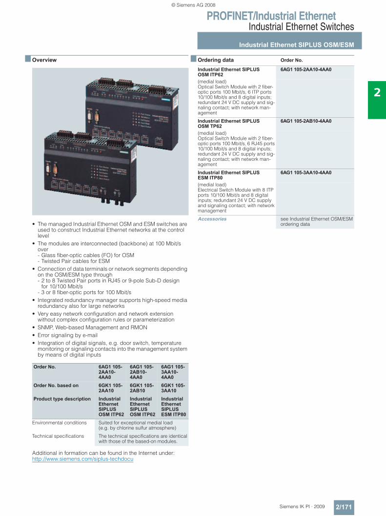
PROFINET/Industrial EthernetIndustrial Ethernet Switches
Industrial Ethernet SIPLUS OSM/ESM
2/171Siemens IK PI · 2009
2
■ Overview
• The managed Industrial Ethernet OSM and ESM switches are used to construct Industrial Ethernet networks at the control level
• The modules are interconnected (backbone) at 100 Mbit/s over - Glass fiber-optic cables (FO) for OSM - Twisted Pair cables for ESM
• Connection of data terminals or network segments depending on the OSM/ESM type through - 2 to 8 Twisted Pair ports in RJ45 or 9-pole Sub-D design
for 10/100 Mbit/s - 3 or 8 fiber-optic ports for 100 Mbit/s
• Integrated redundancy manager supports high-speed media redundancy also for large networks
• Very easy network configuration and network extension without complex configuration rules or parameterization
• SNMP, Web-based Management and RMON• Error signaling by e-mail• Integration of digital signals, e.g. door switch, temperature
monitoring or signaling contacts into the management system by means of digital inputs
Additional in formation can be found in the Internet under:http://www.siemens.com/siplus-techdocu
■ Ordering data Order No.
Order No. 6AG1 105-2AA10-4AA0
6AG1 105-2AB10-4AA0
6AG1 105-3AA10-4AA0
Order No. based on 6GK1 105-2AA10
6GK1 105-2AB10
6GK1 105-3AA10
Product type description IndustrialEthernetSIPLUSOSM ITP62
IndustrialEthernetSIPLUSOSM ITP62
IndustrialEthernetSIPLUSESM ITP80
Environmental conditions Suited for exceptional medial load(e.g. by chlorine sulfur atmosphere)
Technical specifications The technical specifications are identical with those of the based-on modules.
Industrial Ethernet SIPLUS OSM ITP62
6AG1 105-2AA10-4AA0
(medial load)Optical Switch Module with 2 fiber-optic ports 100 Mbit/s, 6 ITP ports 10/100 Mbit/s and 8 digital inputs; redundant 24 V DC supply and sig-naling contact; with network man-agement
Industrial Ethernet SIPLUS OSM TP62
6AG1 105-2AB10-4AA0
(medial load)Optical Switch Module with 2 fiber-optic ports 100 Mbit/s, 6 RJ45 ports 10/100 Mbit/s and 8 digital inputs; redundant 24 V DC supply and sig-naling contact; with network man-agement
Industrial Ethernet SIPLUS ESM ITP80
6AG1 105-3AA10-4AA0
(medial load)Electrical Switch Module with 8 ITP ports 10/100 Mbit/s and 8 digital inputs; redundant 24 V DC supply and signaling contact; with network management
Accessories see Industrial Ethernet OSM/ESM ordering data
© Siemens AG 2008
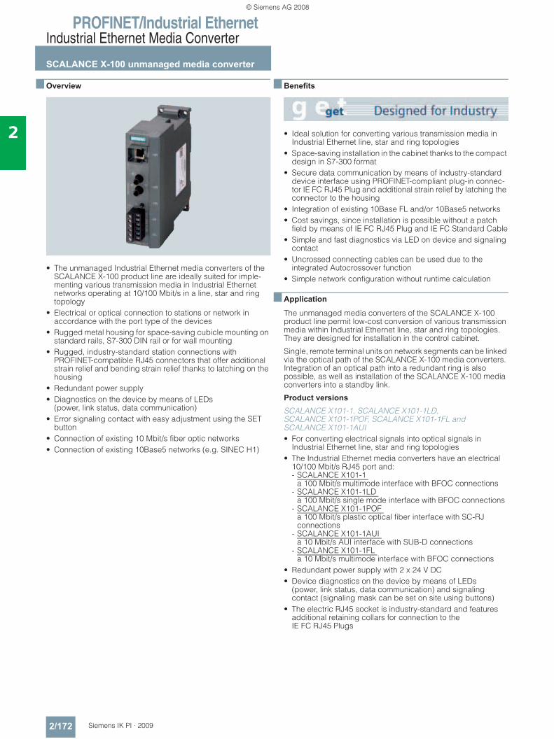
PROFINET/Industrial EthernetIndustrial Ethernet Media Converter
SCALANCE X-100 unmanaged media converter
2/172 Siemens IK PI · 2009
2
■ Overview
• The unmanaged Industrial Ethernet media converters of the SCALANCE X-100 product line are ideally suited for imple-menting various transmission media in Industrial Ethernet networks operating at 10/100 Mbit/s in a line, star and ring topology
• Electrical or optical connection to stations or network in accordance with the port type of the devices
• Rugged metal housing for space-saving cubicle mounting on standard rails, S7-300 DIN rail or for wall mounting
• Rugged, industry-standard station connections with PROFINET-compatible RJ45 connectors that offer additional strain relief and bending strain relief thanks to latching on the housing
• Redundant power supply• Diagnostics on the device by means of LEDs
(power, link status, data communication)• Error signaling contact with easy adjustment using the SET
button• Connection of existing 10 Mbit/s fiber optic networks• Connection of existing 10Base5 networks (e.g. SINEC H1)
■ Benefits
• Ideal solution for converting various transmission media in Industrial Ethernet line, star and ring topologies
• Space-saving installation in the cabinet thanks to the compact design in S7-300 format
• Secure data communication by means of industry-standard device interface using PROFINET-compliant plug-in connec-tor IE FC RJ45 Plug and additional strain relief by latching the connector to the housing
• Integration of existing 10Base FL and/or 10Base5 networks• Cost savings, since installation is possible without a patch
field by means of IE FC RJ45 Plug and IE FC Standard Cable• Simple and fast diagnostics via LED on device and signaling
contact• Uncrossed connecting cables can be used due to the
integrated Autocrossover function• Simple network configuration without runtime calculation
■ Application
The unmanaged media converters of the SCALANCE X-100 product line permit low-cost conversion of various transmission media within Industrial Ethernet line, star and ring topologies. They are designed for installation in the control cabinet.
Single, remote terminal units on network segments can be linked via the optical path of the SCALANCE X-100 media converters. Integration of an optical path into a redundant ring is also possible, as well as installation of the SCALANCE X-100 media converters into a standby link.
Product versions
SCALANCE X101-1, SCALANCE X101-1LD, SCALANCE X101-1POF, SCALANCE X101-1FL and SCALANCE X101-1AUI • For converting electrical signals into optical signals in
Industrial Ethernet line, star and ring topologies• The Industrial Ethernet media converters have an electrical
10/100 Mbit/s RJ45 port and: - SCALANCE X101-1
a 100 Mbit/s multimode interface with BFOC connections - SCALANCE X101-1LD
a 100 Mbit/s single mode interface with BFOC connections - SCALANCE X101-1POF
a 100 Mbit/s plastic optical fiber interface with SC-RJ connections
- SCALANCE X101-1AUI a 10 Mbit/s AUI interface with SUB-D connections
- SCALANCE X101-1FL a 10 Mbit/s multimode interface with BFOC connections
• Redundant power supply with 2 x 24 V DC• Device diagnostics on the device by means of LEDs
(power, link status, data communication) and signaling contact (signaling mask can be set on site using buttons)
• The electric RJ45 socket is industry-standard and features additional retaining collars for connection to the IE FC RJ45 Plugs
© Siemens AG 2008
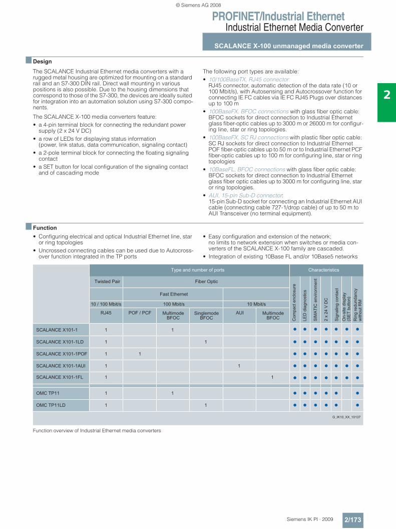
PROFINET/Industrial EthernetIndustrial Ethernet Media Converter
SCALANCE X-100 unmanaged media converter
2/173Siemens IK PI · 2009
2
■ Design
The SCALANCE Industrial Ethernet media converters with a rugged metal housing are optimized for mounting on a standard rail and an S7-300 DIN rail. Direct wall mounting in various positions is also possible. Due to the housing dimensions that correspond to those of the S7-300, the devices are ideally suited for integration into an automation solution using S7-300 compo-nents.
The SCALANCE X-100 media converters feature:• a 4-pin terminal block for connecting the redundant power
supply (2 x 24 V DC)• a row of LEDs for displaying status information
(power, link status, data communication, signaling contact)• a 2-pole terminal block for connecting the floating signaling
contact• a SET button for local configuration of the signaling contact
and of cascading mode
The following port types are available:• 10/100BaseTX, RJ45 connector:
RJ45 connector, automatic detection of the data rate (10 or 100 Mbit/s), with Autosensing and Autocrossover function for connecting IE FC cables via IE FC RJ45 Plugs over distances up to 100 m
• 100BaseFX, BFOC connections with glass fiber optic cable: BFOC sockets for direct connection to Industrial Ethernet glass fiber-optic cables up to 3000 m or 26000 m for configur-ing line, star or ring topologies.
• 100BaseFX, SC RJ connections with plastic fiber optic cable: SC RJ sockets for direct connection to Industrial Ethernet POF fiber-optic cables up to 50 m or to Industrial Ethernet PCF fiber-optic cables up to 100 m for configuring line, star or ring topologies
• 10BaseFL, BFOC connections with glass fiber optic cable: BFOC sockets for direct connection to Industrial Ethernet glass fiber optic cables up to 3000 m for configuring line, star or ring topologies.
• AUI, 15-pin Sub-D connector: 15-pin Sub-D socket for connecting an Industrial Ethernet AUI cable (connecting cable 727-1/drop cable) of up to 50 m to AUI Transceiver (no terminal equipment).
■ Function• Configuring electrical and optical Industrial Ethernet line, star
or ring topologies• Uncrossed connecting cables can be used due to Autocross-
over function integrated in the TP ports
• Easy configuration and extension of the network; no limits to network extension when switches or media con-verters of the SCALANCE X-100 family are cascaded.
• Integration of existing 10Base FL and/or 10Base5 networks
Function overview of Industrial Ethernet media converters
© Siemens AG 2008
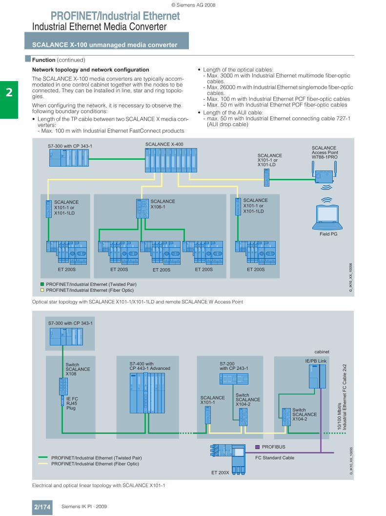
PROFINET/Industrial EthernetIndustrial Ethernet Media Converter
SCALANCE X-100 unmanaged media converter
2/174 Siemens IK PI · 2009
2
■ Function (continued)
Network topology and network configuration
The SCALANCE X-100 media converters are typically accom-modated in one control cabinet together with the nodes to be connected. They can be installed in line, star and ring topolo-gies.
When configuring the network, it is necessary to observe the following boundary conditions:• Length of the TP cable between two SCALANCE X media con-
verters: - Max. 100 m with Industrial Ethernet FastConnect products
• Length of the optical cables: - Max. 3000 m with Industrial Ethernet multimode fiber-optic
cables.- Max. 26000 m with Industrial Ethernet singlemode fiber-optic
cables. - Max. 100 m with Industrial Ethernet PCF fiber-optic cables- Max. 50 m with Industrial Ethernet POF fiber-optic cables
• Length of the AUI cable: - max. 50 m with Industrial Ethernet connecting cable 727-1
(AUI drop cable)
Optical star topology with SCALANCE X101-1/X101-1LD and remote SCALANCE W Access Point
Electrical and optical linear topology with SCALANCE X101-1
PROFINET/PROFINET/
© Siemens AG 2008
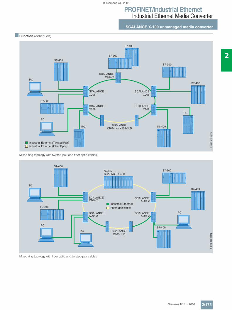
PROFINET/Industrial EthernetIndustrial Ethernet Media Converter
SCALANCE X-100 unmanaged media converter
2/175Siemens IK PI · 2009
2
■ Function (continued)
Mixed ring topology with twisted-pair and fiber optic cables
Mixed ring topology with fiber optic and twisted-pair cables
© Siemens AG 2008
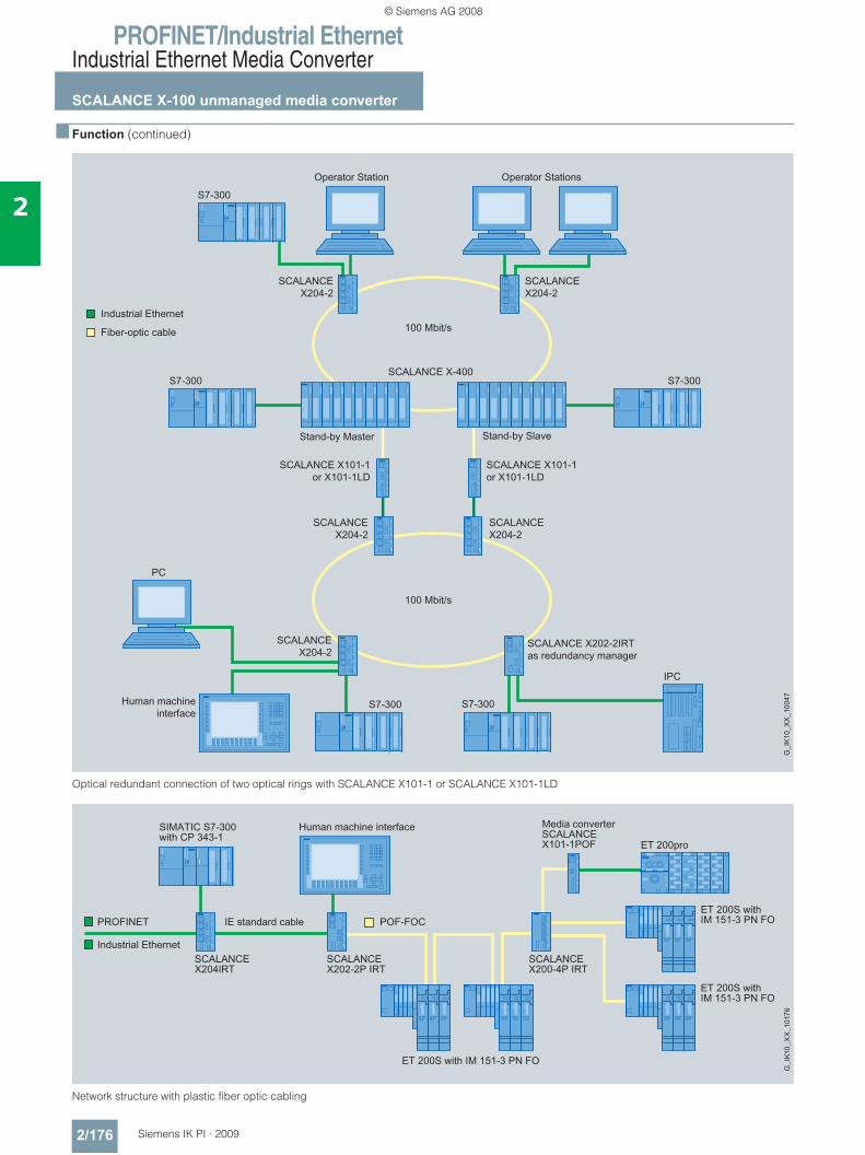
PROFINET/Industrial EthernetIndustrial Ethernet Media Converter
SCALANCE X-100 unmanaged media converter
2/176 Siemens IK PI · 2009
2
■ Function (continued)
Optical redundant connection of two optical rings with SCALANCE X101-1 or SCALANCE X101-1LD
Network structure with plastic fiber optic cabling
G_I
K10
_XX
_100
47
© Siemens AG 2008
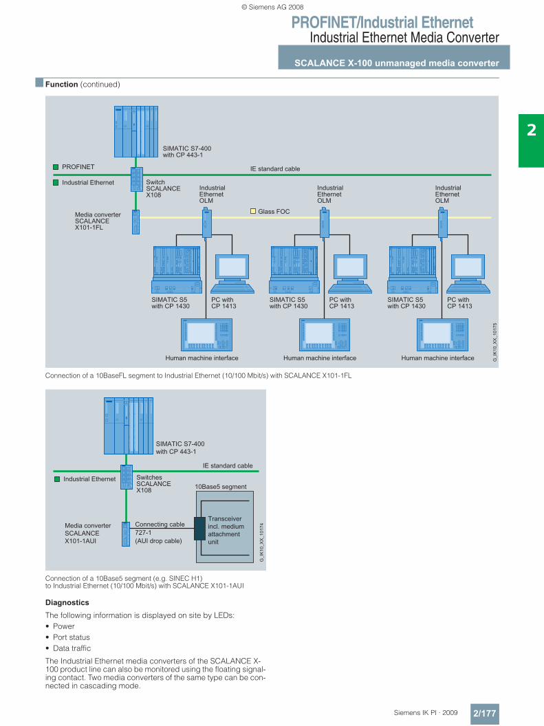
PROFINET/Industrial EthernetIndustrial Ethernet Media Converter
SCALANCE X-100 unmanaged media converter
2/177Siemens IK PI · 2009
2
■ Function (continued)
Connection of a 10BaseFL segment to Industrial Ethernet (10/100 Mbit/s) with SCALANCE X101-1FL
Connection of a 10Base5 segment (e.g. SINEC H1)to Industrial Ethernet (10/100 Mbit/s) with SCALANCE X101-1AUI
Diagnostics
The following information is displayed on site by LEDs:• Power• Port status• Data traffic
The Industrial Ethernet media converters of the SCALANCE X-100 product line can also be monitored using the floating signal-ing contact. Two media converters of the same type can be con-nected in cascading mode.
© Siemens AG 2008
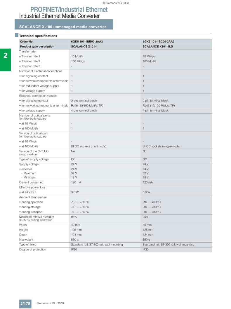
PROFINET/Industrial EthernetIndustrial Ethernet Media Converter
SCALANCE X-100 unmanaged media converter
2/178 Siemens IK PI · 2009
2
■ Technical specifications
Order No. 6GK5 101-1BB00-2AA3 6GK5 101-1BC00-2AA3Product type description SCALANCE X101-1 SCALANCE X101-1LD
Transfer rate
• Transfer rate 1 10 Mbit/s 10 Mbit/s
• Transfer rate 2 100 Mbit/s 100 Mbit/s
• Transfer rate 3 - -
Number of electrical connections
• for signaling contact 1 1
• for network components or terminals 1 1
• for redundant voltage supply 1 1
• for voltage supply 1 1
Electrical connection version
• for signaling contact 2-pin terminal block 2-pin terminal block
• for network components or terminals RJ45 (10/100 Mbit/s; TP) RJ45 (10/100 Mbit/s; TP)
• for voltage supply 4-pin terminal block 4-pin terminal block
Number of optical ports for fiber-optic cables
• at 10 Mbit/s - -
• at 100 Mbit/s 1 1
Version of optical port for fiber-optic cables
• at 10 Mbit/s - -
• at 100 Mbit/s BFOC sockets (multimode) BFOC sockets (single-mode)
Version of the C-PLUG swap medium
No No
Type of supply voltage DC DC
Supply voltage 24 V 24 V
• external 24 V 24 V- Maximum 32 V 32 V- Minimum 18 V 18 V
Current consumed 120 mA 120 mA
Effective power loss
• at 24 V DC 3,0 W 3,0 W
Ambient temperature
• during operation -10 … +60 °C -10 … +60 °C
• during storage -40 … +80 °C -40 … +80 °C
• during transport -40 … +80 °C -40 … +80 °C
Maximum relative humidity at 25 °C during operation
95% 95%
Width 40 mm 40 mm
Height 125 mm 125 mm
Depth 124 mm 124 mm
Net weight 550 g 550 g
Type of fixing Standard rail, S7-300 rail, wall mounting Standard rail, S7-300 rail, wall mounting
Degree of protection IP30 IP30
© Siemens AG 2008
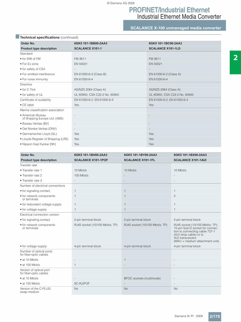
PROFINET/Industrial EthernetIndustrial Ethernet Media Converter
SCALANCE X-100 unmanaged media converter
2/179Siemens IK PI · 2009
2
■ Technical specifications (continued)
Order No. 6GK5 101-1BB00-2AA3 6GK5 101-1BC00-2AA3Product type description SCALANCE X101-1 SCALANCE X101-1LD
Standard
• for EMI of FM FM 3611 FM 3611
• For Ex zone EN 50021 EN 50021
• for safety of CSA - -
• For emitted interference EN 61000-6-3 (Class B) EN 61000-6-2 (Class A)
• For noise immunity EN 61000-6-4 EN 61000-6-4
Directive
• for C-Tick AS/NZS 2064 (Class A) AS/NZS 2064 (Class A)
• for safety of UL UL 60950, CSA C22.2 No. 60950 UL 60950, CSA C22.2 No. 60950
Certificate of suitability EN 61000-6-2, EN 61000-6-4 EN 61000-6-2, EN 61000-6-4
• CE label Yes Yes
Marine classification association
• American Bureau of Shipping Europe Ltd. (ABS)
- -
• Bureau Veritas (BV) - -
• Det Norske Veritas (DNV) - -
• Germanischer Lloyd (GL) Yes Yes
• Lloyds Register of Shipping (LRS) Yes Yes
• Nippon Kaiji Kyokai (NK) Yes Yes
Order No. 6GK5 101-1BH00-2AA3 6GK5 101-1BY00-2AA3 6GK5 101-1BX00-2AA3Product type description SCALANCE X101-1POF SCALANCE X101-1FL SCALANCE X101-1AUI
Transfer rate
• Transfer rate 1 10 Mbit/s 10 Mbit/s 10 Mbit/s
• Transfer rate 2 100 Mbit/s - -
• Transfer rate 3 - - -
Number of electrical connections
• for signaling contact 1 1 1
• for network components or terminals
1 1 2
• for redundant voltage supply 1 1 1
• for voltage supply 1 1 1
Electrical connection version
• for signaling contact 2-pin terminal block 2-pin terminal block 2-pin terminal block
• for network components or terminals
RJ45 socket (10/100 Mbit/s; TP) RJ45 socket (10/100 Mbit/s; TP) RJ45 socket (10/100 Mbit/s; TP); 15-pin Sub-D socket for connec-tion to connecting cable 727-1 (AUI drop cable) or to AUI transceivers (MAU = medium attachment unit)
• for voltage supply 4-pin terminal block 4-pin terminal block 4-pin terminal block
Number of optical portsfor fiber-optic cables
• at 10 Mbit/s - 1 -
• at 100 Mbit/s 1 - -
Version of optical portfor fiber-optic cables
• at 10 Mbit/s - BFOC sockets (multimode) -
• at 100 Mbit/s SC-RJ/POF - -
Version of the C-PLUG swap medium
No No No
© Siemens AG 2008
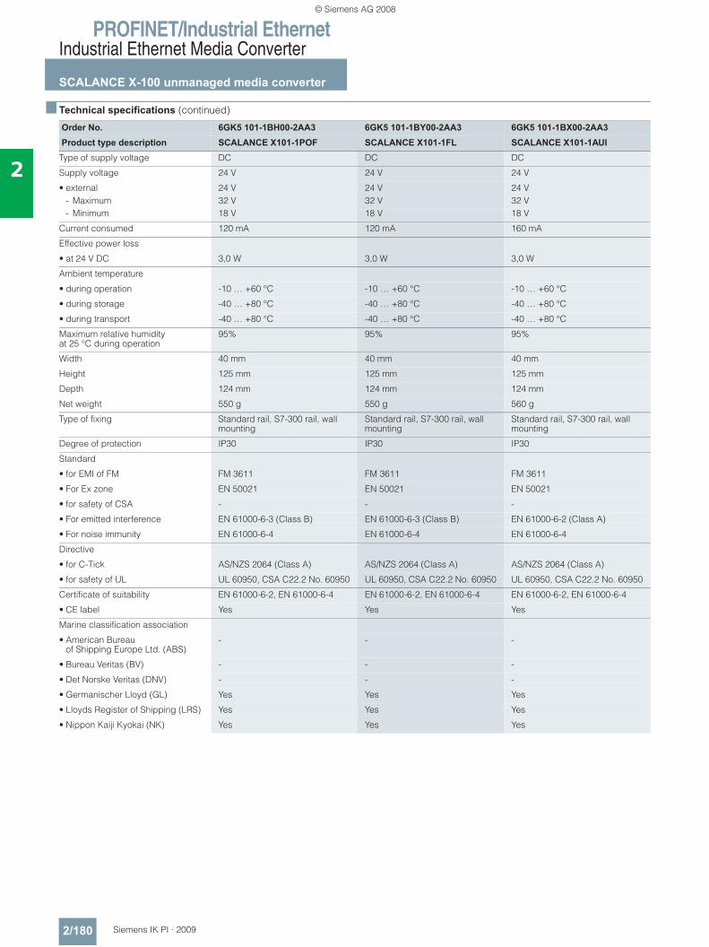
PROFINET/Industrial EthernetIndustrial Ethernet Media Converter
SCALANCE X-100 unmanaged media converter
2/180 Siemens IK PI · 2009
2
■ Technical specifications (continued)
Order No. 6GK5 101-1BH00-2AA3 6GK5 101-1BY00-2AA3 6GK5 101-1BX00-2AA3Product type description SCALANCE X101-1POF SCALANCE X101-1FL SCALANCE X101-1AUI
Type of supply voltage DC DC DC
Supply voltage 24 V 24 V 24 V
• external 24 V 24 V 24 V- Maximum 32 V 32 V 32 V- Minimum 18 V 18 V 18 V
Current consumed 120 mA 120 mA 160 mA
Effective power loss
• at 24 V DC 3,0 W 3,0 W 3,0 W
Ambient temperature
• during operation -10 … +60 °C -10 … +60 °C -10 … +60 °C
• during storage -40 … +80 °C -40 … +80 °C -40 … +80 °C
• during transport -40 … +80 °C -40 … +80 °C -40 … +80 °C
Maximum relative humidity at 25 °C during operation
95% 95% 95%
Width 40 mm 40 mm 40 mm
Height 125 mm 125 mm 125 mm
Depth 124 mm 124 mm 124 mm
Net weight 550 g 550 g 560 g
Type of fixing Standard rail, S7-300 rail, wall mounting
Standard rail, S7-300 rail, wall mounting
Standard rail, S7-300 rail, wall mounting
Degree of protection IP30 IP30 IP30
Standard
• for EMI of FM FM 3611 FM 3611 FM 3611
• For Ex zone EN 50021 EN 50021 EN 50021
• for safety of CSA - - -
• For emitted interference EN 61000-6-3 (Class B) EN 61000-6-3 (Class B) EN 61000-6-2 (Class A)
• For noise immunity EN 61000-6-4 EN 61000-6-4 EN 61000-6-4
Directive
• for C-Tick AS/NZS 2064 (Class A) AS/NZS 2064 (Class A) AS/NZS 2064 (Class A)
• for safety of UL UL 60950, CSA C22.2 No. 60950 UL 60950, CSA C22.2 No. 60950 UL 60950, CSA C22.2 No. 60950
Certificate of suitability EN 61000-6-2, EN 61000-6-4 EN 61000-6-2, EN 61000-6-4 EN 61000-6-2, EN 61000-6-4
• CE label Yes Yes Yes
Marine classification association
• American Bureau of Shipping Europe Ltd. (ABS)
- - -
• Bureau Veritas (BV) - - -
• Det Norske Veritas (DNV) - - -
• Germanischer Lloyd (GL) Yes Yes Yes
• Lloyds Register of Shipping (LRS) Yes Yes Yes
• Nippon Kaiji Kyokai (NK) Yes Yes Yes
© Siemens AG 2008
PROFINET/Industrial EthernetIndustrial Ethernet Media Converter
SCALANCE X-100 unmanaged media converter
2/181Siemens IK PI · 2009
2
■ Ordering data Order No. Order No.
SCALANCE X-100 unmanaged media converterIndustrial Ethernet media converters, LED diagnostics,fault signaling contact with SET key, redundant power supply, PROFINET-compatible retaining collar;incl. Operating Instructions, Industrial Ethernet network manual and configuration software on CD-ROM
• SCALANCE X101-1 1 x 10/100 Mbit/s RJ45 Port 1 x 100 Mbit/s multimode BFOC
6GK5 101-1BB00-2AA3
• SCALANCE X101-1LD 1 x 10/100 Mbit/s RJ45 Port 1 x 100 Mbit/s singlemode BFOC
6GK5 101-1BC00-2AA3
• SCALANCE X101-1POF 1 x 10/100 Mbit/s RJ45 Port 1 x 100 Mbit/s POF SC RJ
6GK5 101-1BH00-2AA3
• SCALANCE X101-1AUI 1 x 10/100 Mbit/s RJ45 Port 1 x 10 Mbit/s AUI segment port
6GK5 101-1BX00-2AA3
• SCALANCE X101-1FL 1 x 10/100 Mbit/s RJ45 Port 1 x 10 Mbit/s multimode BFOC
6GK5 101-1BY00-2AA3
AccessoriesIE FC RJ45 PlugsRJ45 plug connector for Industrial Ethernet with a rugged metal housing and integrated insulation displacement contacts for connecting Industrial Ethernet FC installation cables;
IE FC RJ45 Plug 180180° cable outlet; for network components and CPs/CPUs with Industrial Ethernet interface
• 1 pack = 1 unit 6GK1 901-1BB10-2AA0• 1 pack = 10 units 6GK1 901-1BB10-2AB0• 1 pack = 50 units 6GK1 901-1BB10-2AE0SIMATIC NET Manual Collection 6GK1 975-1AA00-3AA0Electronic manuals for communication systems, communication protocols, and communication products; on DVD; German/English
© Siemens AG 2008
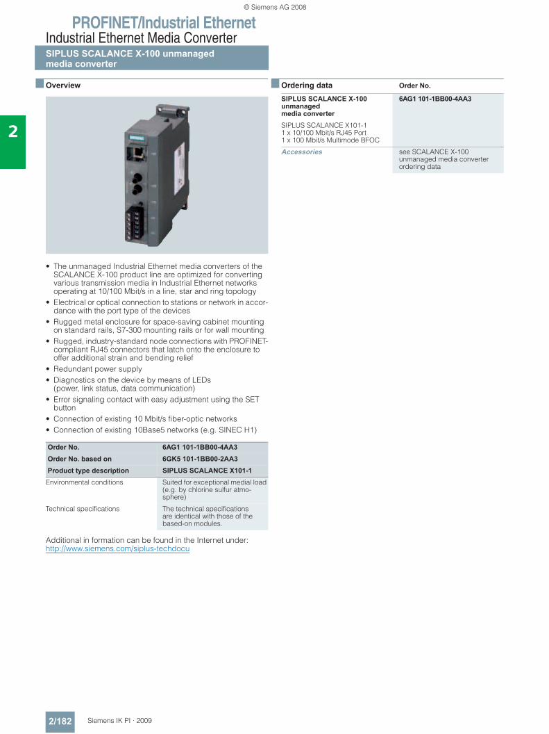
PROFINET/Industrial EthernetIndustrial Ethernet Media ConverterSIPLUS SCALANCE X-100 unmanagedmedia converter
2/182 Siemens IK PI · 2009
2
■ Overview
• The unmanaged Industrial Ethernet media converters of the SCALANCE X-100 product line are optimized for converting various transmission media in Industrial Ethernet networks operating at 10/100 Mbit/s in a line, star and ring topology
• Electrical or optical connection to stations or network in accor-dance with the port type of the devices
• Rugged metal enclosure for space-saving cabinet mounting on standard rails, S7-300 mounting rails or for wall mounting
• Rugged, industry-standard node connections with PROFINET-compliant RJ45 connectors that latch onto the enclosure to offer additional strain and bending relief
• Redundant power supply• Diagnostics on the device by means of LEDs
(power, link status, data communication)• Error signaling contact with easy adjustment using the SET
button• Connection of existing 10 Mbit/s fiber-optic networks• Connection of existing 10Base5 networks (e.g. SINEC H1)
Additional in formation can be found in the Internet under:http://www.siemens.com/siplus-techdocu
■ Ordering data Order No.
Order No. 6AG1 101-1BB00-4AA3Order No. based on 6GK5 101-1BB00-2AA3Product type description SIPLUS SCALANCE X101-1
Environmental conditions Suited for exceptional medial load (e.g. by chlorine sulfur atmo-sphere)
Technical specifications The technical specificationsare identical with those of the based-on modules.
SIPLUS SCALANCE X-100 unmanaged media converter
6AG1 101-1BB00-4AA3
SIPLUS SCALANCE X101-1 1 x 10/100 Mbit/s RJ45 Port 1 x 100 Mbit/s Multimode BFOC
Accessories see SCALANCE X-100unmanaged media converter ordering data
© Siemens AG 2008
PROFINET/Industrial EthernetIndustrial security
Overview
2/183Siemens IK PI · 2009
2
■ Overview
Secure communication with SCALANCE S
Modern automation technology is based on communication and the trend toward increased networking of individual manufactur-ing islands. It is becoming more and more important to integrate all the manufacturing components into a uniform network that merges with the office network and the corporate Intranet. There is also a requirement for remote access for servicing, the increasing use of IT mechanisms such as Web servers and e-mail with programmable controllers as well as the use of wire-less LANs. In this manner, industrial communication interacts more and more with the IT environment and is now subjected to the same dangers that are well-known from the office and IT environment, such as hackers, viruses, worms and Trojans.
The current security concepts are tailored to the office world and require constant administration and specialist knowledge. They are not usually conversant with the special protocol landscape of industrial communication and are not designed to withstand the harsh environmental conditions.
With its security concept, Siemens offers a safety solution spe-cially designed for industrial automation engineering that satis-fies the specific requirements of this application environment.
Advantages of industrial security concept: • Protection from espionage and data manipulation• Protection against overloading of the communication system• Protection against mutual interference • Protection against addressing mistakes• Secure remote access also over the Internet• User-friendly and simple configuration and administration
without specialist knowledge of IT security• No changes or modification of the existing network structure
are necessary• No changes or modification of the existing applications or
network stations are necessary• Rugged, industry-compatible design
SCALANCE S security modules offer a scaleable security functionality:• Firewall for protecting the programmable controllers from
unauthorized access regardless of the size of the network to be protected.
• Supplementary or alternative VPN (Virtual Private Network) for reliable authentication of the communication partners and encryption of the transmitted data
• SOFTNET Security Client for secure access of PCs/notebooks to programmable controllers protected by SCALANCE S (in bridge mode).
© Siemens AG 2008
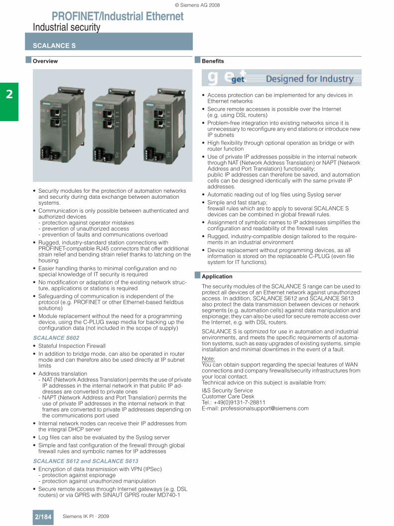
PROFINET/Industrial EthernetIndustrial security
SCALANCE S
2/184 Siemens IK PI · 2009
2
■ Overview
• Security modules for the protection of automation networks and security during data exchange between automation systems.
• Communication is only possible between authenticated and authorized devices - protection against operator mistakes- prevention of unauthorized access- prevention of faults and communications overload
• Rugged, industry-standard station connections with PROFINET-compatible RJ45 connectors that offer additional strain relief and bending strain relief thanks to latching on the housing
• Easier handling thanks to minimal configuration and no special knowledge of IT security is required
• No modification or adaptation of the existing network struc-ture, applications or stations is required
• Safeguarding of communication is independent of the protocol (e.g. PROFINET or other Ethernet-based fieldbus solutions)
• Module replacement without the need for a programming device, using the C-PLUG swap media for backing up the configuration data (not included in the scope of supply)
SCALANCE S602• Stateful Inspection Firewall• In addition to bridge mode, can also be operated in router
mode and can therefore also be used directly at IP subnet limits
• Address translation - NAT (Network Address Translation) permits the use of private
IP addresses in the internal network in that public IP ad-dresses are converted to private ones
- NAPT (Network Address and Port Translation) permits the use of private IP addresses in the internal network in that frames are converted to private IP addresses depending on the communications port used
• Internal network nodes can receive their IP addresses from the integral DHCP server
• Log files can also be evaluated by the Syslog server• Simple and fast configuration of the firewall through global
firewall rules and symbolic names for IP addresses
SCALANCE S612 and SCALANCE S613• Encryption of data transmission with VPN (IPSec)
- protection against espionage- protection against unauthorized manipulation
• Secure remote access through Internet gateways (e.g. DSL routers) or via GPRS with SINAUT GPRS router MD740-1
■ Benefits
• Access protection can be implemented for any devices in Ethernet networks
• Secure remote accesses is possible over the Internet (e.g. using DSL routers)
• Problem-free integration into existing networks since it is unnecessary to reconfigure any end stations or introduce new IP subnets
• High flexibility through optional operation as bridge or with router function
• Use of private IP addresses possible in the internal network through NAT (Network Address Translation) or NAPT (Network Address and Port Translation) functionality; public IP addresses can therefore be saved, and automation cells can be designed identically with the same private IP addresses.
• Automatic reading out of log files using Syslog server• Simple and fast startup;
firewall rules which are to apply to several SCALANCE S devices can be combined in global firewall rules.
• Assignment of symbolic names to IP addresses simplifies the configuration and readability of the firewall rules
• Rugged, industry-compatible design tailored to the require-ments in an industrial environment
• Device replacement without programming devices, as all information is stored on the replaceable C-PLUG (even file system for IT functions).
■ Application
The security modules of the SCALANCE S range can be used to protect all devices of an Ethernet network against unauthorized access. In addition, SCALANCE S612 and SCALANCE S613 also protect the data transmission between devices or network segments (e.g. automation cells) against data manipulation and espionage; they can also be used for secure remote access over the Internet, e.g. with DSL routers.
SCALANCE S is optimized for use in automation and industrial environments, and meets the specific requirements of automa-tion systems, such as easy upgrades of existing systems, simple installation and minimal downtimes in the event of a fault.
Note: You can obtain support regarding the special features of WAN connections and company firewalls/security infrastructures from your local contact. Technical advice on this subject is available from:I&S Security Service Customer Care Desk Tel.: +49(0)9131-7-28811 E-mail: [email protected]
© Siemens AG 2008
PROFINET/Industrial EthernetIndustrial security
SCALANCE S
2/185Siemens IK PI · 2009
2
■ Function
Security functions
VPN (Virtual Private Network) (only for SCALANCE S612 and SCALANCE S613); for reliable authentication (identification) of the network stations, for encrypting the data and checking data integrity.• Authentication;
All incoming data traffic is monitored and checked. As IP addresses can be falsified (IP spoofing), checking the IP address (of the client access) is not sufficient. In addition, Client PCs may have changing IP addresses. For this reason the authentication is performed by means of tried and tested VPN mechanisms.
• Data encryption; Secure encryption is necessary in order to protect data com-munication from espionage and unauthorized manipulation. This means that the data traffic remains incomprehensible to any eavesdropper in the network. The SCALANCE Security Module establishes VPN tunnels to other Security Modules for this purpose.
Firewall; Can be used as an alternative or to supplement VPN with flexible access control. The firewall filters data packets and disables or enables com-munications links in accordance with the filter list (packet filter firewall). Both incoming and outgoing communication can be filtered, IP and MAC addresses, as well as communication protocols (ports). • Logging;
access data are saved by the Security Module in a log file. Detection of how, when and by whom it has been accessed is as important as detecting access attempts, to ensure that appropriate preventative measures can be taken.
Versions: • SCALANCE S602;
uses Stateful Inspection Firewall to protect network segments against unauthorized access
• SCALANCE S612; uses Stateful Inspection Firewall to protect network segments against unauthorized access; protects up to 32 devices using VPN tunnels (up to 64 VPN tunnels simultaneously)
• SCALANCE S613; uses Stateful Inspection Firewall to protect network segments against unauthorized access - Protects up to 64 devices using VPN tunnels,
(up to 128 VPN tunnels simultaneously)- extended temperature range from -20 °C to +70 °C
Configuration
Configuring is simple to carry out even without special IT knowl-edge. Only the Security Modules or SOFTNET Security Clients that have to communicate with each other securely have to be created and configured. All the configuration data can be saved on the optional C-PLUG swap media (not included in scope of supply) so that the Security Module can be replaced quickly in the event of a fault and without the need of a programming device.
© Siemens AG 2008
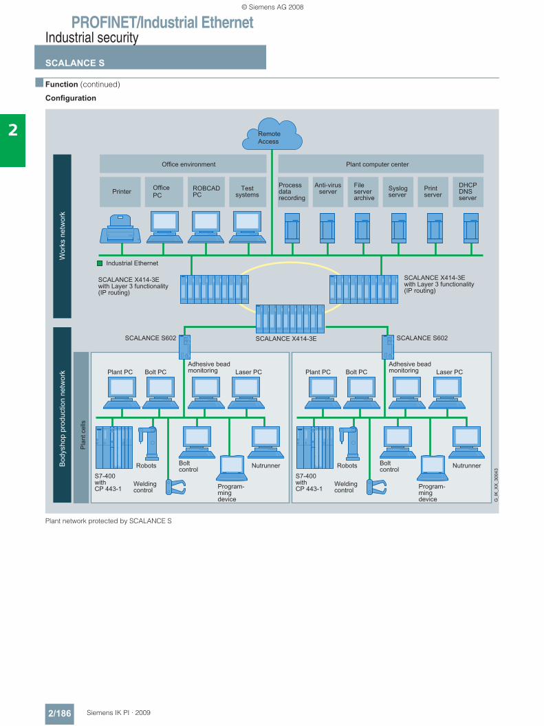
PROFINET/Industrial EthernetIndustrial security
SCALANCE S
2/186 Siemens IK PI · 2009
2
■ Function (continued)
Configuration
Plant network protected by SCALANCE S
© Siemens AG 2008
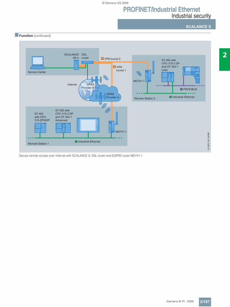
PROFINET/Industrial EthernetIndustrial security
SCALANCE S
2/187Siemens IK PI · 2009
2
■ Function (continued)
Secure remote access over Internet with SCALANCE S, DSL router and EGPRS router MD741-1
© Siemens AG 2008
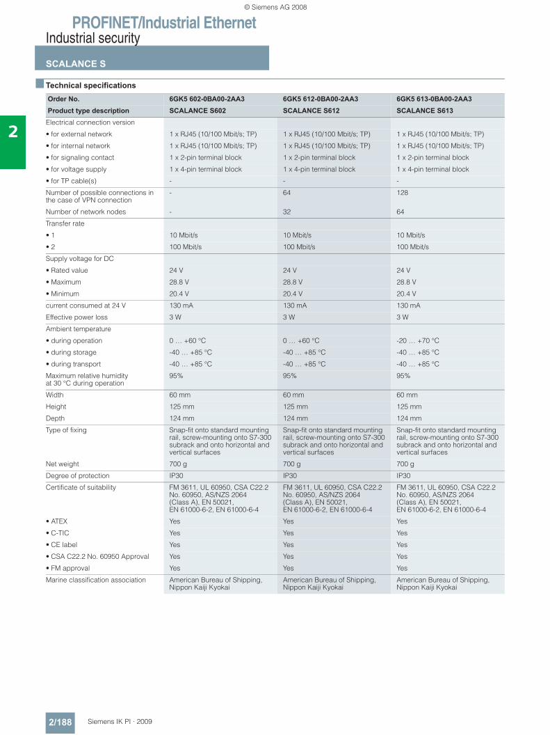
PROFINET/Industrial EthernetIndustrial security
SCALANCE S
2/188 Siemens IK PI · 2009
2
■ Technical specifications
Order No. 6GK5 602-0BA00-2AA3 6GK5 612-0BA00-2AA3 6GK5 613-0BA00-2AA3Product type description SCALANCE S602 SCALANCE S612 SCALANCE S613
Electrical connection version
• for external network 1 x RJ45 (10/100 Mbit/s; TP) 1 x RJ45 (10/100 Mbit/s; TP) 1 x RJ45 (10/100 Mbit/s; TP)
• for internal network 1 x RJ45 (10/100 Mbit/s; TP) 1 x RJ45 (10/100 Mbit/s; TP) 1 x RJ45 (10/100 Mbit/s; TP)
• for signaling contact 1 x 2-pin terminal block 1 x 2-pin terminal block 1 x 2-pin terminal block
• for voltage supply 1 x 4-pin terminal block 1 x 4-pin terminal block 1 x 4-pin terminal block
• for TP cable(s) - - -
Number of possible connections in the case of VPN connection
- 64 128
Number of network nodes - 32 64
Transfer rate
• 1 10 Mbit/s 10 Mbit/s 10 Mbit/s
• 2 100 Mbit/s 100 Mbit/s 100 Mbit/s
Supply voltage for DC
• Rated value 24 V 24 V 24 V
• Maximum 28.8 V 28.8 V 28.8 V
• Minimum 20.4 V 20.4 V 20.4 V
current consumed at 24 V 130 mA 130 mA 130 mA
Effective power loss 3 W 3 W 3 W
Ambient temperature
• during operation 0 … +60 °C 0 … +60 °C -20 … +70 °C
• during storage -40 … +85 °C -40 … +85 °C -40 … +85 °C
• during transport -40 … +85 °C -40 … +85 °C -40 … +85 °C
Maximum relative humidity at 30 °C during operation
95% 95% 95%
Width 60 mm 60 mm 60 mm
Height 125 mm 125 mm 125 mm
Depth 124 mm 124 mm 124 mm
Type of fixing Snap-fit onto standard mounting rail, screw-mounting onto S7-300 subrack and onto horizontal and vertical surfaces
Snap-fit onto standard mounting rail, screw-mounting onto S7-300 subrack and onto horizontal and vertical surfaces
Snap-fit onto standard mounting rail, screw-mounting onto S7-300 subrack and onto horizontal and vertical surfaces
Net weight 700 g 700 g 700 g
Degree of protection IP30 IP30 IP30
Certificate of suitability FM 3611, UL 60950, CSA C22.2 No. 60950, AS/NZS 2064 (Class A), EN 50021, EN 61000-6-2, EN 61000-6-4
FM 3611, UL 60950, CSA C22.2 No. 60950, AS/NZS 2064 (Class A), EN 50021, EN 61000-6-2, EN 61000-6-4
FM 3611, UL 60950, CSA C22.2 No. 60950, AS/NZS 2064 (Class A), EN 50021, EN 61000-6-2, EN 61000-6-4
• ATEX Yes Yes Yes
• C-TIC Yes Yes Yes
• CE label Yes Yes Yes
• CSA C22.2 No. 60950 Approval Yes Yes Yes
• FM approval Yes Yes Yes
Marine classification association American Bureau of Shipping, Nippon Kaiji Kyokai
American Bureau of Shipping, Nippon Kaiji Kyokai
American Bureau of Shipping, Nippon Kaiji Kyokai
© Siemens AG 2008
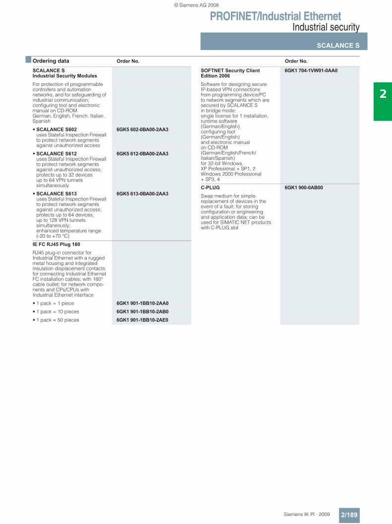
PROFINET/Industrial EthernetIndustrial security
SCALANCE S
2/189Siemens IK PI · 2009
2
■ Ordering data Order No. Order No.
SCALANCE S Industrial Security ModulesFor protection of programmable controllers and automation networks, and for safeguarding of industrial communication; configuring tool and electronic manual on CD-ROMGerman, English, French, Italian, Spanish
• SCALANCE S602 uses Stateful Inspection Firewall to protect network segments against unauthorized access
6GK5 602-0BA00-2AA3
• SCALANCE S612 uses Stateful Inspection Firewall to protect network segments against unauthorized access; protects up to 32 devices up to 64 VPN tunnels simultaneously
6GK5 612-0BA00-2AA3
• SCALANCE S613 uses Stateful Inspection Firewall to protect network segments against unauthorized access; protects up to 64 devices, up to 128 VPN tunnels simultaneously; enhanced temperature range(-20 to +70 °C)
6GK5 613-0BA00-2AA3
IE FC RJ45 Plug 180RJ45 plug-in connector forIndustrial Ethernet with a rugged metal housing and integrated insulation displacement contacts for connecting Industrial Ethernet FC installation cables; with 180° cable outlet; for network compo-nents and CPs/CPUs with Industrial Ethernet interface
• 1 pack = 1 piece 6GK1 901-1BB10-2AA0• 1 pack = 10 pieces 6GK1 901-1BB10-2AB0• 1 pack = 50 pieces 6GK1 901-1BB10-2AE0
SOFTNET Security Client Edition 2006
6GK1 704-1VW01-0AA0
Software for designing secure IP-based VPN connections from programming device/PC to network segments which are secured by SCALANCE S in bridge mode; single license for 1 installation, runtime software (German/English), configuring tool (German/English) and electronic manual on CD-ROM (German/English/French/Italian/Spanish) for 32-bit Windows, XP Professional + SP1, 2 Windows 2000 Professional + SP3, 4
C-PLUG 6GK1 900-0AB00Swap medium for simple replacement of devices in the event of a fault; for storing configuration or engineering and application data; can be used for SIMATIC NET products with C-PLUG slot
© Siemens AG 2008
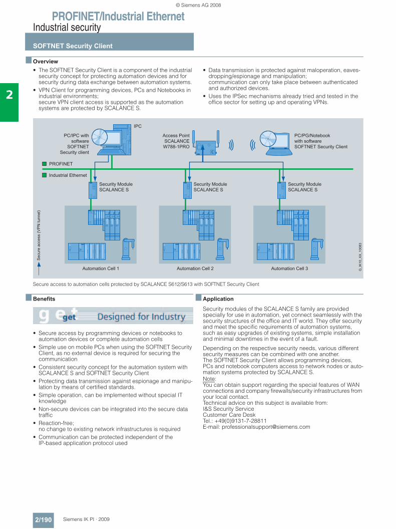
PROFINET/Industrial EthernetIndustrial security
SOFTNET Security Client
2/190 Siemens IK PI · 2009
2
■ Overview• The SOFTNET Security Client is a component of the industrial
security concept for protecting automation devices and for security during data exchange between automation systems.
• VPN Client for programming devices, PCs and Notebooks in industrial environments; secure VPN client access is supported as the automation systems are protected by SCALANCE S.
• Data transmission is protected against maloperation, eaves-dropping/espionage and manipulation; communication can only take place between authenticated and authorized devices.
• Uses the IPSec mechanisms already tried and tested in the office sector for setting up and operating VPNs.
Secure access to automation cells protected by SCALANCE S612/S613 with SOFTNET Security Client
■ Benefits
• Secure access by programming devices or notebooks to automation devices or complete automation cells
• Simple use on mobile PCs when using the SOFTNET Security Client, as no external device is required for securing the communication
• Consistent security concept for the automation system with SCALANCE S and SOFTNET Security Client
• Protecting data transmission against espionage and manipu-lation by means of certified standards.
• Simple operation, can be implemented without special IT knowledge
• Non-secure devices can be integrated into the secure data traffic
• Reaction-free; no change to existing network infrastructures is required
• Communication can be protected independent of theIP-based application protocol used
■ Application
Security modules of the SCALANCE S family are provided specially for use in automation, yet connect seamlessly with the security structures of the office and IT world. They offer security and meet the specific requirements of automation systems, such as easy upgrades of existing systems, simple installation and minimal downtimes in the event of a fault.
Depending on the respective security needs, various different security measures can be combined with one another. The SOFTNET Security Client allows programming devices, PCs and notebook computers access to network nodes or auto-mation systems protected by SCALANCE S.Note: You can obtain support regarding the special features of WAN connections and company firewalls/security infrastructures from your local contact. Technical advice on this subject is available from:I&S Security ServiceCustomer Care DeskTel.: +49(0)9131-7-28811E-mail: [email protected]
© Siemens AG 2008
PROFINET/Industrial EthernetIndustrial security
SOFTNET Security Client
2/191Siemens IK PI · 2009
2
■ Function
Authentication Each incoming item of data traffic is monitored and checked. As IP addresses can be falsified (IP spoofing), checking the IP address (of the client access) is not sufficient. In addition, Client PCs may have changing IP addresses. For this reason the authentication is performed by means of tried and tested VPN mechanisms.
Data encryption To protect the data traffic against espionage and manipulation secure encryption is necessary. This means that the data traffic remains incomprehensible to any eavesdropper in the network. To this end, SOFTNET Security Client sets up VPN tunnels based on IPSec to other SCALANCE S security modules.
Performance data • System requirements:
Windows 2000 Professional (32 bit) + SP3, 4 Windows XP Professional (32 bit) + SP1, 2
ConfiguringUsing the associated configuration tool it is possible to handle setup and administration of security rules even without special IT knowledge. In the simplest case, only the SCALANCE S mod-ules or SOFTNET security clients that are to communicate with one another are set up and configured. As soon as SOFTNET Security Client knows which automation device is to be accessed, a communication can be set up.
■ Ordering data Order No.
SOFTNET Security Client Edition 2006
6GK1 704-1VW01-0AA0
Software for designing secure IP-based VPN connections from programming device/PC to network segments which are secured by SCALANCE S in bridge mode; single license for 1 installation, runtime software (German/English), configuring tool (German/English) and electronic manual on CD-ROM (German/English/French/Italian/Spanish)for 32-bit Windows, XP Professional + SP1, 2 Windows 2000 Professional + SP3, 4
SCALANCE S Industrial Security ModulesFor protection of programmable controllers and automation networks, and for safeguarding of industrial communication; configuring tool and electronic manual on CD-ROMGerman, English, French, Italian, Spanish
SCALANCE S612 6GK5 612-0BA00-2AA3Uses Stateful Inspection Firewall to protect network segments against unauthorized access; protects up to 32 devices, up to 64 VPN tunnels simulta-neously
SCALANCE S613 6GK5 613-0BA00-2AA3Uses Stateful Inspection Firewall to protect network segments against unauthorized access; protects up to 64 devices, up to 128 VPN tunnels simulta-neously expanded temperature range from -20 °C to +70 °C
IE FC RJ45 Plug 180RJ45 plug-in connector for Indus-trial Ethernet with a rugged metal housing and integrated insulation displacement contacts for con-necting Industrial Ethernet FC installation cables; with 180° cable outlet; for network compo-nents and CPs/CPUs with Industrial Ethernet interface
• 1 pack = 1 unit 6GK1 901-1BB10-2AA0• 1 pack = 10 units 6GK1 901-1BB10-2AB0• 1 pack = 50 units 6GK1 901-1BB10-2AE0EGPRS router MD741-1 6NH9 741-1AA00For wireless IP communication from Ethernet-based programma-ble controllers via GSM mobile radio networks; integrated firewall and VPN router (IPsec); quad band GSM; EGPRS Multislot Class 12
AccessoriesANT794-4MR antenna 6NH9 860-1AA00Quad band antenna for MD720-3 and MD741-1, omnidirectional with 5 m cable
© Siemens AG 2008
PROFINET/Industrial EthernetCPUs for SIMATIC S7-300
CPU 315-2 PN/DP
2/192 Siemens IK PI · 2009
2
■ Overview
• The CPU with mid-range program memory and quantity frameworks
• High processing power in binary and floating-point arithmetic• Used as central controller in production lines with central and
distributed I/O• Integral PROFINET interface• Component Based Automation (CBA) on PROFINET• PROFINET proxy for intelligent devices on PROFIBUS DP in
Component Based Automation (CBA)• PROFINET IO Controller for operating distributed I/O on
PROFINET• Combined MPI/PROFIBUS DP master/slave interface• Isochronous mode on PROFIBUS
Micro Memory Card required for operation of CPU.
■ Technical specifications
Order No. 6ES7 315-2EH13-0AB0Product type description CPU 315-2 PN/DP
Product status
associated programming package STEP 7 V5.4 SP2
Supply voltages
Rated value
• 24 V DC Yes
• permissible range, lower limit (DC) 20.4 V
• permissible range, upper limit (DC)
28.8 V
Current consumption
Inrush current, typ. 2.5 A
I²t 1 A²s
Current consumption (in no-load operation), typ.
100 mA
Current consumption (rated value) 650 mA
Power loss, typ. 3.5 W
Memory
Type of storage
• RAM- integrated 256 KByte;
For program and data- erweiterbar No
• Load memory- pluggable (MMC) Yes- pluggable (MMC), max. 8 MByte
Backup
• present Yes
• without battery Yes; Program and data
CPU/blocks
DB
• Number, max. 1 023; Number band: 1 to 1023
• Size, max. 16 KByte
FB
• Number, max. 1 024; Sequence of numbers: 0 to 2047
• Size, max. 16 KByte
Order No. 6ES7 315-2EH13-0AB0Product type description CPU 315-2 PN/DP
FC
• Number, max. 1 024; Sequence of numbers: 0 to 2047
• Size, max. 16 KByte
OB
• Size, max. 16 KByte
Nesting depth
• per priority class 8
• additional within an error OB 4
CPU/processing times
for bit operations, min. 0.1 μs
for word operations, min. 0.2 μs
for fixed point arithmetic, min. 2 μs
for floating point arithmetic, min. 3 μs
Times/countersand their remanence
S7 counter
• Number 256
• of which remanent without battery- adjustable Yes- lower limit 0- upper limit 255
• Remanence- adjustable Yes- lower limit 0- upper limit 255
• Counting range- adjustable Yes- lower limit 0- upper limit 999
IEC counter
• present Yes
• Type SFB
© Siemens AG 2008
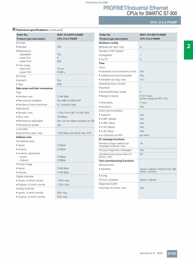
PROFINET/Industrial EthernetCPUs for SIMATIC S7-300
CPU 315-2 PN/DP
2/193Siemens IK PI · 2009
2
■ Technical specifications (continued)
Order No. 6ES7 315-2EH13-0AB0Product type description CPU 315-2 PN/DP
S7 times
• Number 256
• Remanence- adjustable Yes- lower limit 0- upper limit 255
• Time range- lower limit 10 ms- upper limit 9 990 s
IEC timer
• present Yes
• Type SFB
Data areas and their remanence
Flag
• Number, max. 2 048 Byte
• Remanence available Yes; MB 0 to MB 2047
• Number of clock memories 8; 1 memory byte
Data blocks
• Number, max. 1 023; From DB 1 to DB 1023
• Size, max. 16 KByte
• Remanence adjustable Yes; via non-retain property on DB
• Remanence preset yes
Local data
• per priority class, max. 1 024 Byte; per block max. 510
Address area
I/O address area
• Inputs 2 KByte
• Outputs 2 KByte
• of which, distributed- Inputs 2 KByte- Outputs 2 KByte
Process image
• Inputs 2 048 Byte
• Outputs 2 048 Byte
Digital channels
• Inputs, of which central 1 024; max.
• Outputs, of which central 1 024; max.
Analog channels
• Inputs, of which central 256; max.
• Outputs, of which central 256; max.
Order No. 6ES7 315-2EH13-0AB0Product type description CPU 315-2 PN/DP
Hardware config. Modules per rack, max. 8
Number of DP masters
• integrated 1
• via CP 4
Time
Clock
• Hardware clock (real-time clock) Yes
• buffered and synchronizable Yes
• Deviation per day, max. 10 s
Operating hours counter
• Number 1
• Number/Number range 0
• Range of values 2^31 hours(when using the SFC 101)
• Granularity 1 hour
• remanent Yes
Clock synchronization
• supports Yes
• to MPI, Master Yes
• to MPI, Slave Yes
• in AS, Master Yes
• in AS, Slave Yes
• on Ethernet via NTP as client
S7 message functions
Number of login stations for message functions, max.
16
Process diagnostic messages Yes
simultaneously active Alarm-S blocks, max.
40
Test commissioning functions
Status/control
• Variables Inputs, outputs, memory bits, DB, times, counters
Forcing
• Force, variables Inputs, outputs
Diagnostic buffer
• Number of entries, max. 500
© Siemens AG 2008
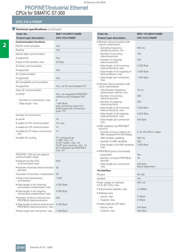
PROFINET/Industrial EthernetCPUs for SIMATIC S7-300
CPU 315-2 PN/DP
2/194 Siemens IK PI · 2009
2
■ Technical specifications (continued)
Order No. 6ES7 315-2EH13-0AB0Product type description CPU 315-2 PN/DP
Communication functions
PG/OP communication Yes
Routing Yes
Global data communication
• supported Yes
• Size of GD packets, max. 22 Byte
S7 basic communication
• supported Yes
S7 communication
• supported Yes
S5-compatible communication
• supported Yes; via CP and loadable FC
Open IE communication
• TCP/IP Yes; via integrated PROFINET interface and loadable FBs
- Number of connections, max. 8- Data length, max. 1 460 Byte;
with connection type 01H; 8192 bytes with connection type 11H
Number of connections
• overall 16
• usable for PG communication 15; max.
• usable for OP communication 15
• usable for S7 basic communica-tion
14
• usable for routing X1 configured as 1) MPI: max. 10; 2) DP master: max. 24; 3) DP slave (active): max. 14; X2 configured as PROFINET: max. 24
PROFINET CBA (at set setpoint communication load)
• Setpoint for the CPU communication load
50%
• Number of remote interconnection partners
32
• Number of functions, master/slave 30
• Total of all master/slave connections
1 000
• Data length of all incoming connections master/slave, max.
4 000 Byte
• Data length of all outgoing connections master/slave, max.
4 000 Byte
• Number of device-internal and PROFIBUS interconnections
500
• Data length of device-internal and PROFIBUS interconnections, max.
4 000 Byte
• Data length per connection, max. 1 400 Byte
Order No. 6ES7 315-2EH13-0AB0Product type description CPU 315-2 PN/DP
• Remote interconnections with acyclic transmission- Sampling frequency:
sampling interval, min.500 ms
- Number of incoming interconnections
100
- Number of outgoing interconnections
100
- Data length of all incoming interconnections, max.
2 000 Byte
- Data length of all outgoing in-terconnections, max.
2 000 Byte
- Data length per connection, max.
1 400 Byte
• Remote interconnections with cyclic transmission- Transmission frequency:
transmission interval, min.10 ms
- Number of incoming interconnections
200
- Number of outgoing interconnections
200
- Data length of all incoming interconnections, max.
2 000 Byte
- Data length of all outgoing interconnections, max.
2 000 Byte
- Data length per connection, max.
450 Byte
• HMI variables via PROFINET (acyclic)- Number of log-in stations for
HMI variables (PN OPC/iMap)3; 2x PN OPC/1x iMap
- HMI variable updating 500 ms- Number of HMI variables 200- Data length of all HMI variables,
max.2 000 Byte
• PROFIBUS proxy functionality- supported Yes- Number of linked PROFIBUS
devices16
- Data length per connection, max.
240 Byte; Slave-dependent
1st interface
Physics RS 485
isolated Yes
Power supply to interface (15 to 30 V DC), max.
200 mA
• Transmission speeds, max. 12 MBit/s
• Address area- Inputs, max. 2 KByte- Outputs, max. 2 KByte
• Useful data per DP slave- Inputs, max. 244 Byte- Outputs, max. 244 Byte
© Siemens AG 2008
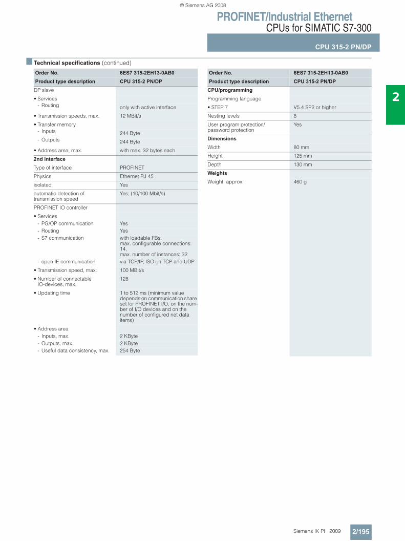
PROFINET/Industrial EthernetCPUs for SIMATIC S7-300
CPU 315-2 PN/DP
2/195Siemens IK PI · 2009
2
■ Technical specifications (continued)
Order No. 6ES7 315-2EH13-0AB0Product type description CPU 315-2 PN/DP
DP slave
• Services- Routing only with active interface
• Transmission speeds, max. 12 MBit/s
• Transfer memory- Inputs 244 Byte- Outputs 244 Byte
• Address area, max. with max. 32 bytes each
2nd interface
Type of interface PROFINET
Physics Ethernet RJ 45
isolated Yes
automatic detection oftransmission speed
Yes; (10/100 Mbit/s)
PROFINET IO controller
• Services- PG/OP communication Yes- Routing Yes- S7 communication with loadable FBs,
max. configurable connections: 14, max. number of instances: 32
- open IE communication via TCP/IP, ISO on TCP and UDP
• Transmission speed, max. 100 MBit/s
• Number of connectable IO-devices, max.
128
• Updating time 1 to 512 ms (minimum value depends on communication share set for PROFINET I/O, on the num-ber of I/O devices and on the number of configured net data items)
• Address area- Inputs, max. 2 KByte- Outputs, max. 2 KByte- Useful data consistency, max. 254 Byte
Order No. 6ES7 315-2EH13-0AB0Product type description CPU 315-2 PN/DP
CPU/programming
Programming language
• STEP 7 V5.4 SP2 or higher
Nesting levels 8
User program protection/password protection
Yes
Dimensions
Width 80 mm
Height 125 mm
Depth 130 mm
Weights
Weight, approx. 460 g
© Siemens AG 2008
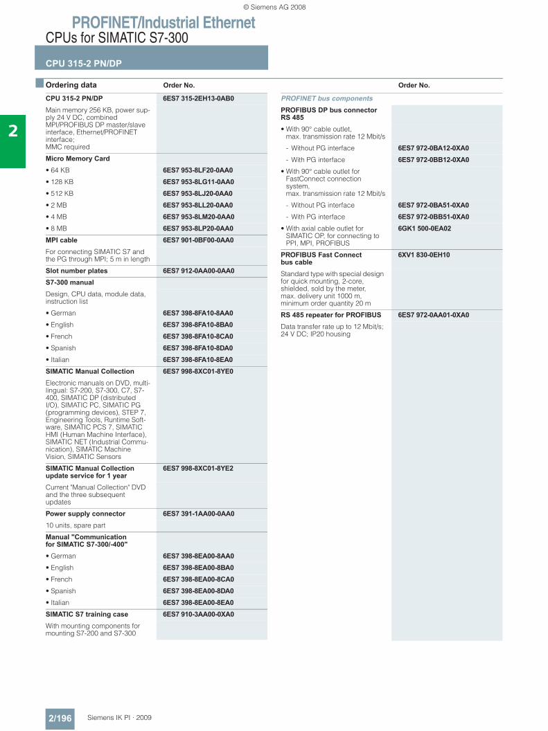
PROFINET/Industrial EthernetCPUs for SIMATIC S7-300
CPU 315-2 PN/DP
2/196 Siemens IK PI · 2009
2
■ Ordering data Order No. Order No.
CPU 315-2 PN/DP 6ES7 315-2EH13-0AB0Main memory 256 KB, power sup-ply 24 V DC, combined MPI/PROFIBUS DP master/slave interface, Ethernet/PROFINET interface; MMC required
Micro Memory Card• 64 KB 6ES7 953-8LF20-0AA0• 128 KB 6ES7 953-8LG11-0AA0• 512 KB 6ES7 953-8LJ20-0AA0• 2 MB 6ES7 953-8LL20-0AA0• 4 MB 6ES7 953-8LM20-0AA0• 8 MB 6ES7 953-8LP20-0AA0MPI cable 6ES7 901-0BF00-0AA0For connecting SIMATIC S7 and the PG through MPI; 5 m in length
Slot number plates 6ES7 912-0AA00-0AA0S7-300 manualDesign, CPU data, module data, instruction list
• German 6ES7 398-8FA10-8AA0• English 6ES7 398-8FA10-8BA0• French 6ES7 398-8FA10-8CA0• Spanish 6ES7 398-8FA10-8DA0• Italian 6ES7 398-8FA10-8EA0SIMATIC Manual Collection 6ES7 998-8XC01-8YE0Electronic manuals on DVD, multi-lingual: S7-200, S7-300, C7, S7-400, SIMATIC DP (distributed I/O), SIMATIC PC, SIMATIC PG (programming devices), STEP 7, Engineering Tools, Runtime Soft-ware, SIMATIC PCS 7, SIMATIC HMI (Human Machine Interface), SIMATIC NET (Industrial Commu-nication), SIMATIC Machine Vision, SIMATIC Sensors
SIMATIC Manual Collection update service for 1 year
6ES7 998-8XC01-8YE2
Current "Manual Collection" DVD and the three subsequent updates
Power supply connector 6ES7 391-1AA00-0AA010 units, spare part
Manual "Communication for SIMATIC S7-300/-400"• German 6ES7 398-8EA00-8AA0• English 6ES7 398-8EA00-8BA0• French 6ES7 398-8EA00-8CA0• Spanish 6ES7 398-8EA00-8DA0• Italian 6ES7 398-8EA00-8EA0SIMATIC S7 training case 6ES7 910-3AA00-0XA0With mounting components for mounting S7-200 and S7-300
PROFINET bus componentsPROFIBUS DP bus connector RS 485• With 90° cable outlet,
max. transmission rate 12 Mbit/s
- Without PG interface 6ES7 972-0BA12-0XA0- With PG interface 6ES7 972-0BB12-0XA0
• With 90° cable outlet for FastConnect connection system, max. transmission rate 12 Mbit/s
- Without PG interface 6ES7 972-0BA51-0XA0- With PG interface 6ES7 972-0BB51-0XA0
• With axial cable outlet for SIMATIC OP, for connecting to PPI, MPI, PROFIBUS
6GK1 500-0EA02
PROFIBUS Fast Connect bus cable
6XV1 830-0EH10
Standard type with special design for quick mounting, 2-core, shielded, sold by the meter, max. delivery unit 1000 m, minimum order quantity 20 m
RS 485 repeater for PROFIBUS 6ES7 972-0AA01-0XA0Data transfer rate up to 12 Mbit/s; 24 V DC; IP20 housing
© Siemens AG 2008

PROFINET/Industrial EthernetCPUs for SIMATIC S7-300
CPU 315-2 PN/DP
2/197Siemens IK PI · 2009
2
■ Ordering data (continued) Order No. Order No.
PROFINET bus componentsIE FC TP Standard Cable GP 2x2 6XV1 840-2AH104-core, shielded TP installation cable for connection to IE FC Outlet RJ45/ IE FC RJ45 Plug; PROFINET-compatible; with UL approval;sold by the meter
FO Standard Cable GP (50/125) 6XV1 873-2AStandard cable, splittable, UL approval, sold by the meter
Industrial Ethernet Switch SCALANCE X208
6GK5 208-0BA10-2AA3
with eight 10/100 Mbit/s RJ45 ports
Compact Switch ModuleCSM 377
6GK7 377-1AA00-0AA0
Unmanaged switch for the connection of a SIMATIC S7-300, ET 200M and as many as three other nodes to an Industrial Ethernet operating at 10/100 Mbit/s; 4 x RJ45 ports; external 24 V DC power supply, LED diagnostics, S7-300 module incl. electronic equipment manual on CD-ROM
IE FC RJ45 plugsRJ45 plug connector for Industrial Ethernet with a rugged metal enclosure and integrated insula-tion displacement contacts for connecting Industrial Ethernet FC installation cables
IE FC RJ45 plug 180180° cable outlet
• 1 unit 6GK1 901-1BB10-2AA0• 10 units 6GK1 901-1BB10-2AB0• 50 units 6GK1 901-1BB10-2AE0
© Siemens AG 2008
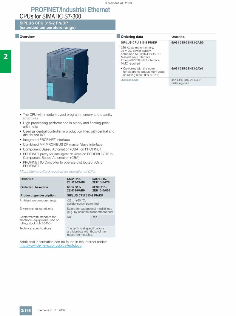
PROFINET/Industrial EthernetCPUs for SIMATIC S7-300SIPLUS CPU 315-2 PN/DP(extended temperature range)
2/198 Siemens IK PI · 2009
2
■ Overview
• The CPU with medium-sized program memory and quantity structures
• High processing performance in binary and floating-point arithmetic
• Used as central controller in production lines with central and distributed I/O
• Integrated PROFINET interface• Combined MPI/PROFIBUS DP master/slave interface• Component Based Automation (CBA) on PROFINET• PROFINET proxy for intelligent devices on PROFIBUS DP in
Component Based Automation (CBA)• PROFINET IO Controller to operate distributed I/Os on
PROFINET
Micro Memory Card required for operation of CPU.
Additional in formation can be found in the Internet under:http://www.siemens.com/siplus-techdocu
■ Ordering data Order No.
Order No. 6AG1 315-2EH13-2AB0
6AG1 315-2EH13-2AY0
Order No. based on 6ES7 315-2EH13-0AB0
6ES7 315-2EH13-0AB0
Product type description SIPLUS CPU 315-2 PN/DPAmbient temperature range -25 ... +60 °C;
condensation permitted
Environmental conditions Suited for exceptional medial load (e.g. by chlorine sulfur atmosphere).
Conforms with standard for electronic equipment used on rolling stock (EN 50155)
No Yes
Technical specifications The technical specifications are identical with those of the based-on modules.
SIPLUS CPU 315-2 PN/DP 6AG1 315-2EH13-2AB0256 Kbyte main memory, 24 V DC power supply, combined MPI/PROFIBUS DP-Master/Slave interfaceEthernet/PROFINET interfaceMMC required
• Conforms with the normfor electronic equuipment used on rolling stock (EN 50155)
6AG1 315-2EH13-2AY0
Accessories see CPU 315-2 PN/DPordering data
© Siemens AG 2008
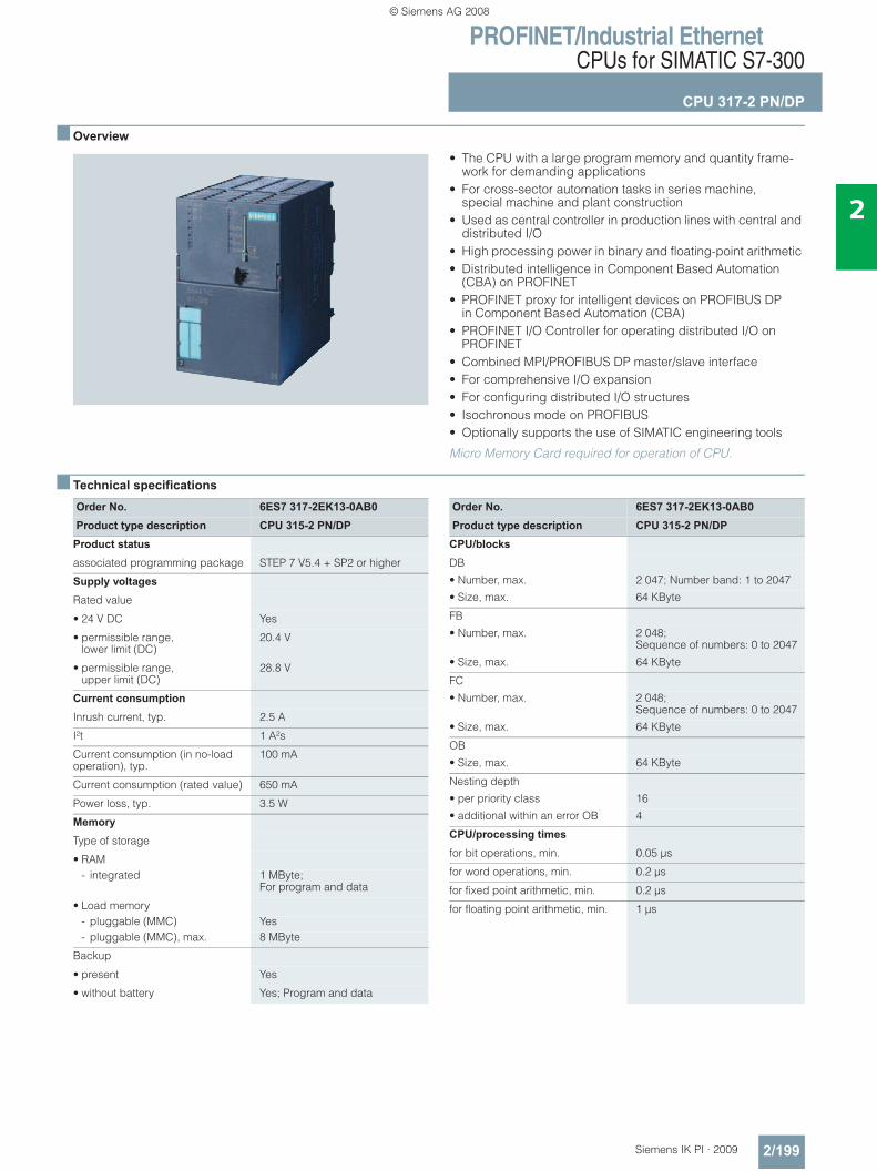
PROFINET/Industrial EthernetCPUs for SIMATIC S7-300
CPU 317-2 PN/DP
2/199Siemens IK PI · 2009
2
■ Overview
• The CPU with a large program memory and quantity frame-work for demanding applications
• For cross-sector automation tasks in series machine, special machine and plant construction
• Used as central controller in production lines with central and distributed I/O
• High processing power in binary and floating-point arithmetic • Distributed intelligence in Component Based Automation
(CBA) on PROFINET• PROFINET proxy for intelligent devices on PROFIBUS DP
in Component Based Automation (CBA)• PROFINET I/O Controller for operating distributed I/O on
PROFINET• Combined MPI/PROFIBUS DP master/slave interface • For comprehensive I/O expansion • For configuring distributed I/O structures • Isochronous mode on PROFIBUS• Optionally supports the use of SIMATIC engineering tools
Micro Memory Card required for operation of CPU.
■ Technical specifications
Order No. 6ES7 317-2EK13-0AB0Product type description CPU 315-2 PN/DP
Product status
associated programming package STEP 7 V5.4 + SP2 or higher
Supply voltages
Rated value
• 24 V DC Yes
• permissible range, lower limit (DC)
20.4 V
• permissible range,upper limit (DC)
28.8 V
Current consumption
Inrush current, typ. 2.5 A
I²t 1 A²s
Current consumption (in no-load operation), typ.
100 mA
Current consumption (rated value) 650 mA
Power loss, typ. 3.5 W
Memory
Type of storage
• RAM- integrated 1 MByte;
For program and data
• Load memory- pluggable (MMC) Yes- pluggable (MMC), max. 8 MByte
Backup
• present Yes
• without battery Yes; Program and data
Order No. 6ES7 317-2EK13-0AB0Product type description CPU 315-2 PN/DP
CPU/blocks
DB
• Number, max. 2 047; Number band: 1 to 2047
• Size, max. 64 KByte
FB
• Number, max. 2 048; Sequence of numbers: 0 to 2047
• Size, max. 64 KByte
FC
• Number, max. 2 048; Sequence of numbers: 0 to 2047
• Size, max. 64 KByte
OB
• Size, max. 64 KByte
Nesting depth
• per priority class 16
• additional within an error OB 4
CPU/processing times
for bit operations, min. 0.05 μs
for word operations, min. 0.2 μs
for fixed point arithmetic, min. 0.2 μs
for floating point arithmetic, min. 1 μs
© Siemens AG 2008
PROFINET/Industrial EthernetCPUs for SIMATIC S7-300
CPU 317-2 PN/DP
2/200 Siemens IK PI · 2009
2
■ Technical specifications (continued)
Order No. 6ES7 317-2EK13-0AB0Product type description CPU 315-2 PN/DP
Times/counters and their remanence
S7 counter
• Number 512
• of which remanent without battery - adjustable Yes- lower limit 0- upper limit 511
• Remanence- adjustable Yes- lower limit 0- upper limit 511
• Counting range- adjustable Yes- lower limit 0- upper limit 999
IEC counter
• present Yes
• Type SFB
S7 times
• Number 512
• Remanence- adjustable Yes- lower limit 0- upper limit 511
• Time range- lower limit 10 ms- upper limit 9 990 s
IEC timer• present Yes• Type SFB
Data areas and their remanence
Flag
• Number, max. 4 096 Byte
• Remanence available Yes; MB 0 to MB 4095
• Number of clock memories 8; 1 memory byte
Data blocks
• Number, max. 2 047; from DB 1 to DB 2047
• Size, max. 64 KByte
• Remanence adjustable Yes; via non-retain property on DB
• Remanence preset yes
Local data
• per priority class, max. 1 024 Byte
Address area
I/O address area
• Inputs 8 KByte
• Outputs 8 KByte
• of which, distributed- Inputs 8 KByte- Outputs 8 KByte
Order No. 6ES7 317-2EK13-0AB0Product type description CPU 315-2 PN/DP
Process image
• Inputs 2 048 Byte
• Outputs 2 048 Byte
• Inputs, adjustable 2 048 Byte
• Outputs, adjustable 2 048 Byte
• Inputs, preset 256 Byte
• Outputs, preset 256 Byte
Digital channels
• Inputs, of which central 1 024
• Outputs, of which central 1 024
Analog channels
• Inputs, of which central 256
• Outputs, of which central 256
Hardware config. Modules per rack, max. 8
Number of DP masters
• integrated 1
• via CP 4
Time
Clock
• Hardware clock (real-time clock) Yes
• buffered and synchronizable Yes
• Deviation per day, max. 10 s
Operating hours counter
• Number 4
• Number/Number range 0 to 3
• Range of values 0 to 2^31 hours (when using SFC 101)
• Granularity 1 hour
• remanent Yes
Clock synchronization
• supports Yes
• to MPI, Master Yes
• to MPI, Slave Yes
• in AS, Master Yes
• in AS, Slave Yes
• on Ethernet via NTP as client
S7 message functions
Number of login stations for message functions, max.
32
Process diagnostic messages Yes
simultaneously active Alarm-S blocks, max.
60
Test commissioning functions
Status/control
• Variables Inputs, outputs, memory bits, DB, times, counters
Forcing
• Force, variables Inputs, outputs
Diagnostic buffer
• Number of entries, max. 500
© Siemens AG 2008
PROFINET/Industrial EthernetCPUs for SIMATIC S7-300
CPU 317-2 PN/DP
2/201Siemens IK PI · 2009
2
■ Technical specifications (continued)
Order No. 6ES7 317-2EK13-0AB0Product type description CPU 315-2 PN/DP
Communication functions
PG/OP communication Yes
Routing Yes
Global data communication
• supported Yes
• Size of GD packets, max. 22 Byte
S7 basic communication
• supported Yes
S7 communication
• supported Yes
S5-compatible communication
• supported Yes; via CP and loadable FC
Open IE communication
• TCP/IP Yes; via integrated PROFINET interface and loadable FBs
- Number of connections, max. 8- Data length, max. 1 460 Byte;
with connection type 01H; 8192 bytes with connection type 11H
• ISO-on-TCP (RFC1006) via integrated PROFINET interface and loadable FBs
• UDP via integrated PROFINET interface and loadable FBs
Number of connections
• overall 32
• usable for PG communication 31
• usable for OP communication 31
• usable for S7 basic communication
30
• usable for routing X1 configured as 1) MPI: max. 10; 2) DP master: max. 24; 3) DP slave (active): max. 14; X2 configured as PROFINET: max. 24
PROFINET CBA (at set setpoint communication load)
• Setpoint for the CPU communication load
50%
• Number of remote interconnection partners
32
• Number of functions, master/slave 30
• Total of all master/slave connections
1 000
• Data length of all incoming connections master/slave, max.
4 000 Byte
• Data length of all outgoing connections master/slave, max.
4 000 Byte
• Number of device-internal and PROFIBUS interconnections
500
• Data length of device-internal and PROFIBUS interconnections, max.
4 000 Byte
• Data length per connection, max. 1 400 Byte
Order No. 6ES7 317-2EK13-0AB0Product type description CPU 315-2 PN/DP
• Remote interconnections with acyclic transmission- Sampling frequency:
sampling interval, min.500 ms
- Number of incoming interconnections
100
- Number of outgoing interconnections
100
- Data length of all incoming interconnections, max.
2 000 Byte
- Data length of all outgoing interconnections, max.
2 000 Byte
- Data length per connection, max.
1 400 Byte
• Remote interconnections with cyclic transmission- Transmission frequency:
transmission interval, min.10 ms
- Number of incoming interconnections
200
- Number of outgoing interconnections
200
- Data length of all incoming interconnections, max.
2 000 Byte
- Data length of all outgoing interconnections, max.
2 000 Byte
- Data length per connection, max.
450 Byte
• HMI variables via PROFINET (acyclic)- Number of log-in stations for
HMI variables (PN OPC/iMap)3; 2x PN OPC/1x iMap
- HMI variable updating 500 ms- Number of HMI variables 200- Data length of all HMI variables,
max.2 000 Byte
• PROFIBUS proxy functionality- supported Yes- Number of linked PROFIBUS
devices16
- Data length per connection, max.
240 Byte; Slave-dependent
1st interface
Physics RS 485
isolated Yes
Power supply to interface(15 to 30 V DC), max.
200 mA
• Transmission speeds, max. 12 MBit/s
DP master
• Services- S7 basic communication I blocks only
• Transmission speeds, max. 12 MBit/s
• Address area- Inputs, max. 8 KByte- Outputs, max. 8 KByte
• Useful data per DP slave- Inputs, max. 244 Byte- Outputs, max. 244 Byte
© Siemens AG 2008
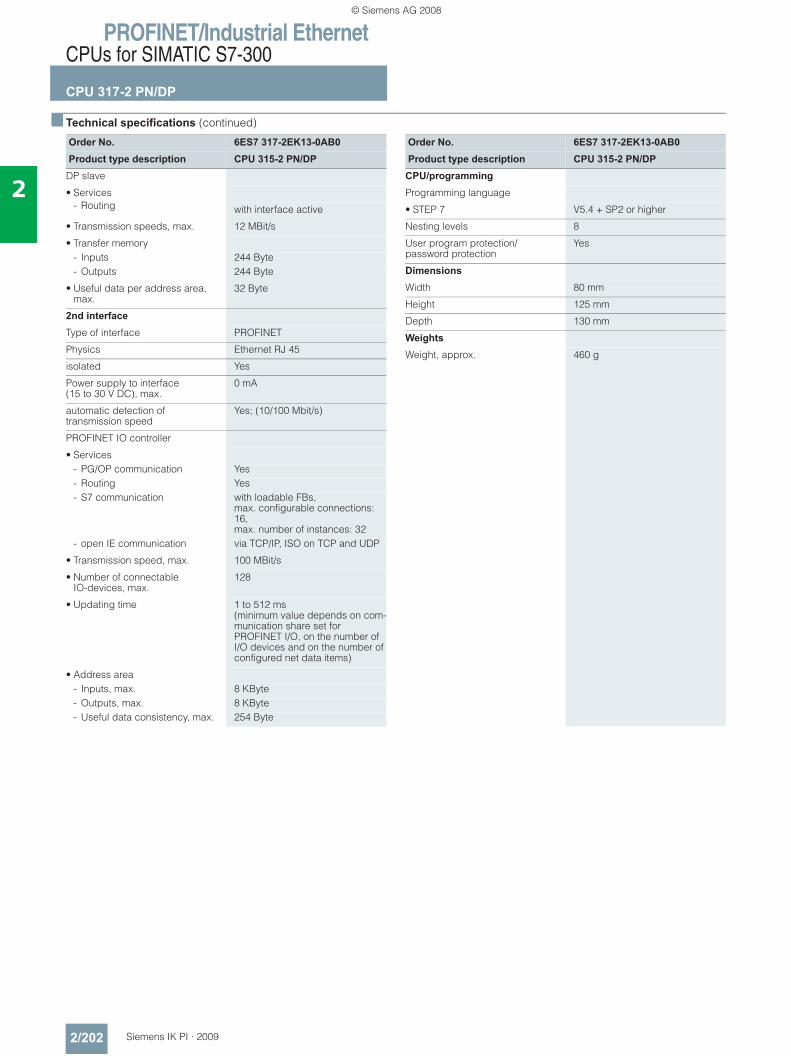
PROFINET/Industrial EthernetCPUs for SIMATIC S7-300
CPU 317-2 PN/DP
2/202 Siemens IK PI · 2009
2
■ Technical specifications (continued)
Order No. 6ES7 317-2EK13-0AB0Product type description CPU 315-2 PN/DP
DP slave
• Services- Routing with interface active
• Transmission speeds, max. 12 MBit/s
• Transfer memory- Inputs 244 Byte- Outputs 244 Byte
• Useful data per address area, max.
32 Byte
2nd interface
Type of interface PROFINET
Physics Ethernet RJ 45
isolated Yes
Power supply to interface(15 to 30 V DC), max.
0 mA
automatic detection of transmission speed
Yes; (10/100 Mbit/s)
PROFINET IO controller
• Services- PG/OP communication Yes- Routing Yes- S7 communication with loadable FBs,
max. configurable connections: 16, max. number of instances: 32
- open IE communication via TCP/IP, ISO on TCP and UDP
• Transmission speed, max. 100 MBit/s
• Number of connectableIO-devices, max.
128
• Updating time 1 to 512 ms (minimum value depends on com-munication share set for PROFINET I/O, on the number of I/O devices and on the number of configured net data items)
• Address area- Inputs, max. 8 KByte- Outputs, max. 8 KByte- Useful data consistency, max. 254 Byte
Order No. 6ES7 317-2EK13-0AB0Product type description CPU 315-2 PN/DP
CPU/programming
Programming language
• STEP 7 V5.4 + SP2 or higher
Nesting levels 8
User program protection/password protection
Yes
Dimensions
Width 80 mm
Height 125 mm
Depth 130 mm
Weights
Weight, approx. 460 g
© Siemens AG 2008
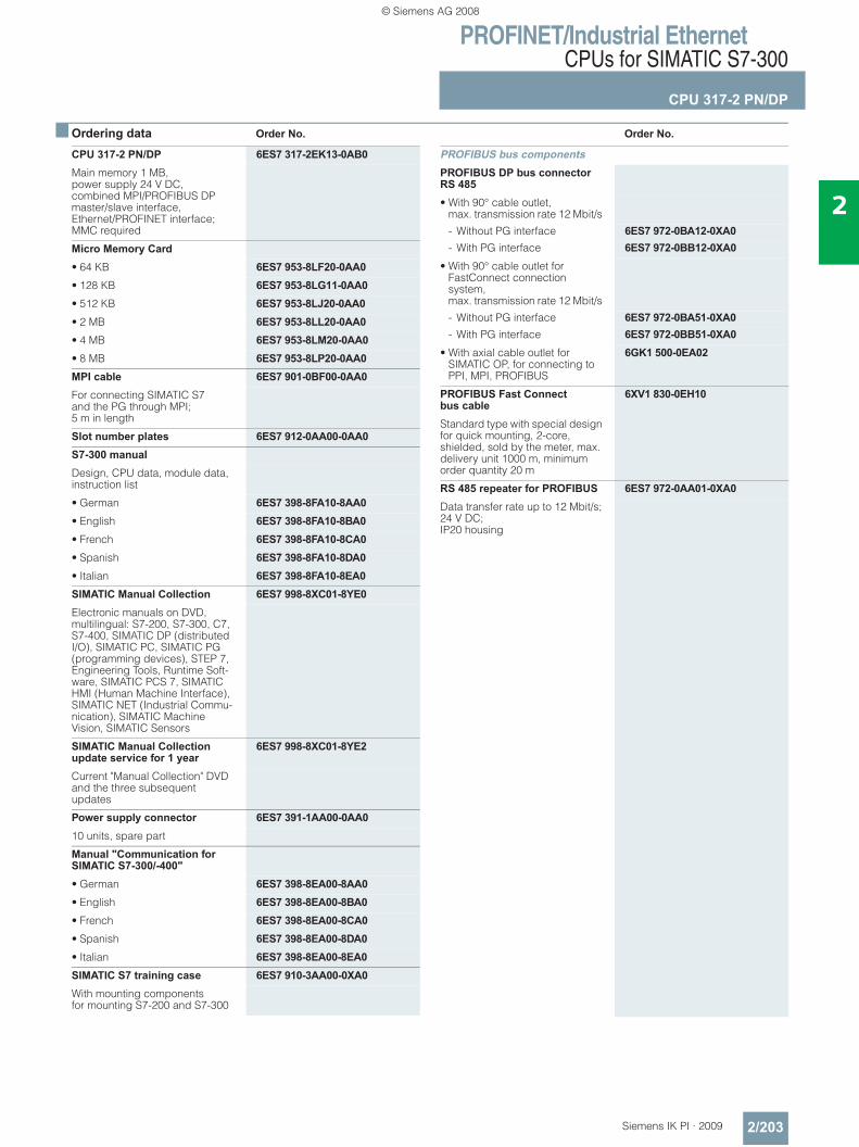
PROFINET/Industrial EthernetCPUs for SIMATIC S7-300
CPU 317-2 PN/DP
2/203Siemens IK PI · 2009
2
■ Ordering data Order No. Order No.
CPU 317-2 PN/DP 6ES7 317-2EK13-0AB0Main memory 1 MB, power supply 24 V DC, combined MPI/PROFIBUS DP master/slave interface, Ethernet/PROFINET interface; MMC required
Micro Memory Card• 64 KB 6ES7 953-8LF20-0AA0• 128 KB 6ES7 953-8LG11-0AA0• 512 KB 6ES7 953-8LJ20-0AA0• 2 MB 6ES7 953-8LL20-0AA0• 4 MB 6ES7 953-8LM20-0AA0• 8 MB 6ES7 953-8LP20-0AA0MPI cable 6ES7 901-0BF00-0AA0For connecting SIMATIC S7 and the PG through MPI; 5 m in length
Slot number plates 6ES7 912-0AA00-0AA0S7-300 manualDesign, CPU data, module data, instruction list
• German 6ES7 398-8FA10-8AA0• English 6ES7 398-8FA10-8BA0• French 6ES7 398-8FA10-8CA0• Spanish 6ES7 398-8FA10-8DA0• Italian 6ES7 398-8FA10-8EA0SIMATIC Manual Collection 6ES7 998-8XC01-8YE0Electronic manuals on DVD, multilingual: S7-200, S7-300, C7, S7-400, SIMATIC DP (distributed I/O), SIMATIC PC, SIMATIC PG (programming devices), STEP 7, Engineering Tools, Runtime Soft-ware, SIMATIC PCS 7, SIMATIC HMI (Human Machine Interface), SIMATIC NET (Industrial Commu-nication), SIMATIC Machine Vision, SIMATIC Sensors
SIMATIC Manual Collection update service for 1 year
6ES7 998-8XC01-8YE2
Current "Manual Collection" DVD and the three subsequent updates
Power supply connector 6ES7 391-1AA00-0AA010 units, spare part
Manual "Communication for SIMATIC S7-300/-400"• German 6ES7 398-8EA00-8AA0• English 6ES7 398-8EA00-8BA0• French 6ES7 398-8EA00-8CA0• Spanish 6ES7 398-8EA00-8DA0• Italian 6ES7 398-8EA00-8EA0SIMATIC S7 training case 6ES7 910-3AA00-0XA0With mounting components for mounting S7-200 and S7-300
PROFIBUS bus components PROFIBUS DP bus connector RS 485• With 90° cable outlet,
max. transmission rate 12 Mbit/s
- Without PG interface 6ES7 972-0BA12-0XA0- With PG interface 6ES7 972-0BB12-0XA0
• With 90° cable outlet for FastConnect connection system, max. transmission rate 12 Mbit/s
- Without PG interface 6ES7 972-0BA51-0XA0- With PG interface 6ES7 972-0BB51-0XA0
• With axial cable outlet for SIMATIC OP, for connecting to PPI, MPI, PROFIBUS
6GK1 500-0EA02
PROFIBUS Fast Connect bus cable
6XV1 830-0EH10
Standard type with special design for quick mounting, 2-core, shielded, sold by the meter, max. delivery unit 1000 m, minimum order quantity 20 m
RS 485 repeater for PROFIBUS 6ES7 972-0AA01-0XA0Data transfer rate up to 12 Mbit/s; 24 V DC; IP20 housing
© Siemens AG 2008
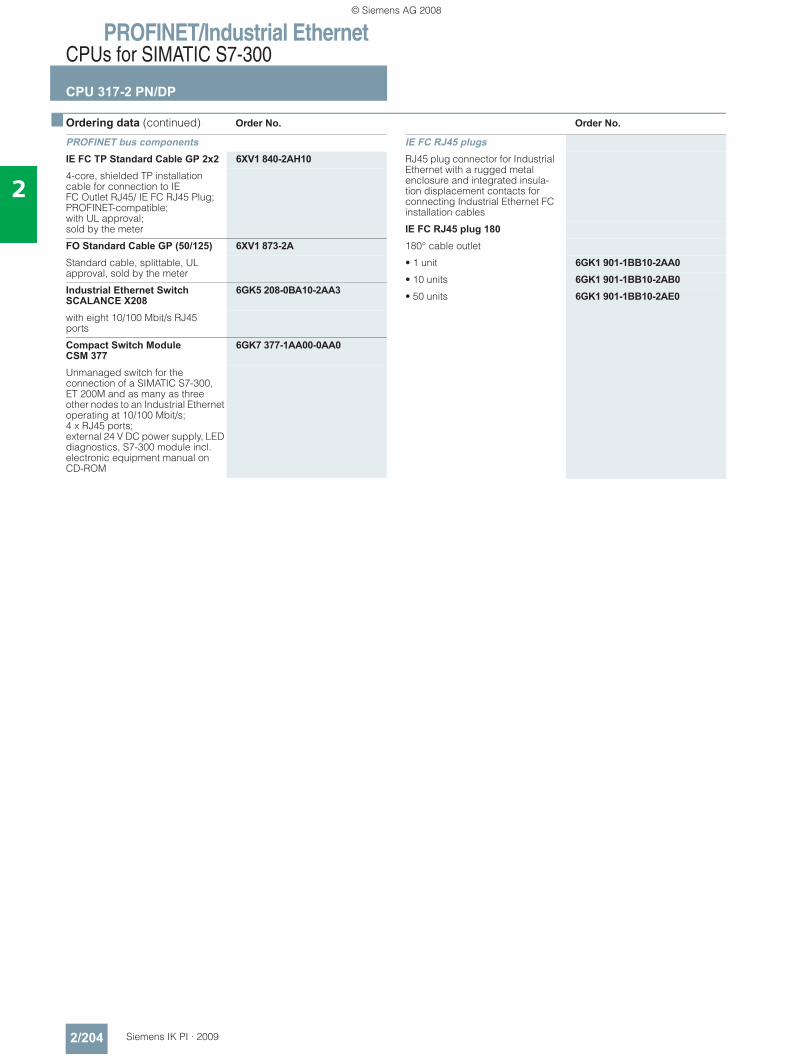
PROFINET/Industrial EthernetCPUs for SIMATIC S7-300
CPU 317-2 PN/DP
2/204 Siemens IK PI · 2009
2
■ Ordering data (continued) Order No. Order No.
PROFINET bus components IE FC TP Standard Cable GP 2x2 6XV1 840-2AH104-core, shielded TP installation cable for connection to IE FC Outlet RJ45/ IE FC RJ45 Plug; PROFINET-compatible; with UL approval;sold by the meter
FO Standard Cable GP (50/125) 6XV1 873-2AStandard cable, splittable, UL approval, sold by the meter
Industrial Ethernet Switch SCALANCE X208
6GK5 208-0BA10-2AA3
with eight 10/100 Mbit/s RJ45 ports
Compact Switch ModuleCSM 377
6GK7 377-1AA00-0AA0
Unmanaged switch for the connection of a SIMATIC S7-300, ET 200M and as many as three other nodes to an Industrial Ethernet operating at 10/100 Mbit/s; 4 x RJ45 ports; external 24 V DC power supply, LED diagnostics, S7-300 module incl. electronic equipment manual on CD-ROM
IE FC RJ45 plugsRJ45 plug connector for Industrial Ethernet with a rugged metal enclosure and integrated insula-tion displacement contacts for connecting Industrial Ethernet FC installation cables
IE FC RJ45 plug 180180° cable outlet
• 1 unit 6GK1 901-1BB10-2AA0• 10 units 6GK1 901-1BB10-2AB0• 50 units 6GK1 901-1BB10-2AE0
© Siemens AG 2008
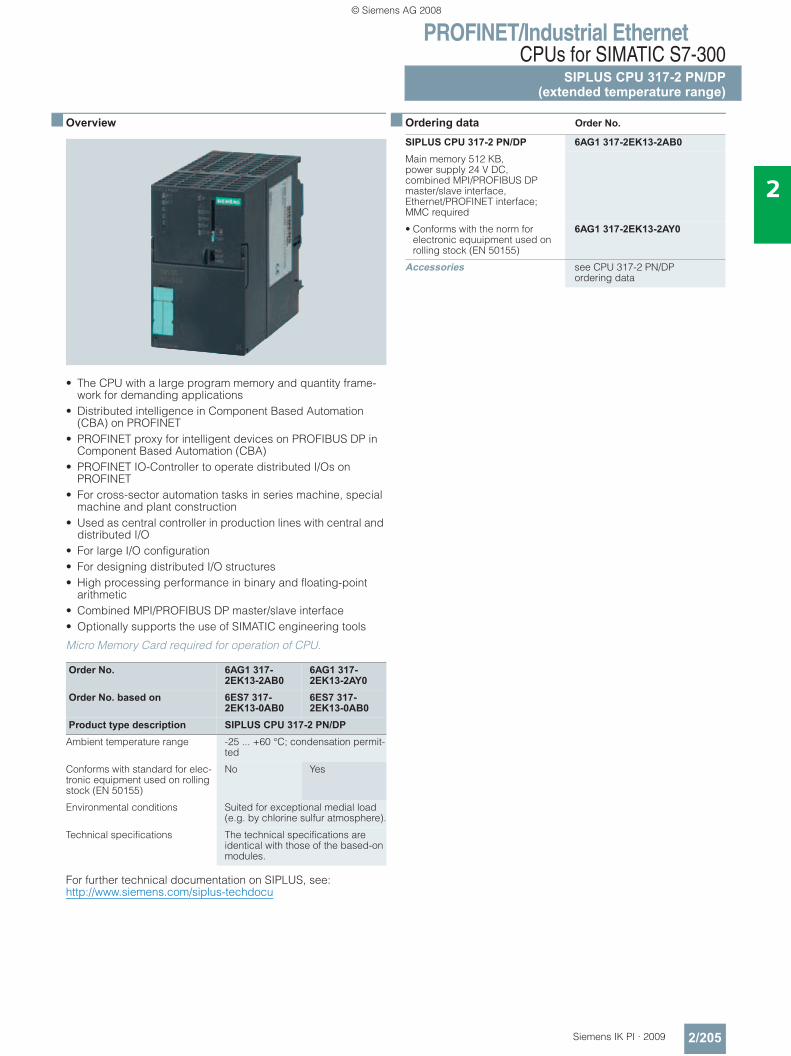
PROFINET/Industrial EthernetCPUs for SIMATIC S7-300
SIPLUS CPU 317-2 PN/DP(extended temperature range)
2/205Siemens IK PI · 2009
2
■ Overview
• The CPU with a large program memory and quantity frame-work for demanding applications
• Distributed intelligence in Component Based Automation (CBA) on PROFINET
• PROFINET proxy for intelligent devices on PROFIBUS DP in Component Based Automation (CBA)
• PROFINET IO-Controller to operate distributed I/Os on PROFINET
• For cross-sector automation tasks in series machine, special machine and plant construction
• Used as central controller in production lines with central and distributed I/O
• For large I/O configuration • For designing distributed I/O structures • High processing performance in binary and floating-point
arithmetic • Combined MPI/PROFIBUS DP master/slave interface • Optionally supports the use of SIMATIC engineering tools
Micro Memory Card required for operation of CPU.
For further technical documentation on SIPLUS, see:http://www.siemens.com/siplus-techdocu
■ Ordering data Order No.
Order No. 6AG1 317-2EK13-2AB0
6AG1 317-2EK13-2AY0
Order No. based on 6ES7 317-2EK13-0AB0
6ES7 317-2EK13-0AB0
Product type description SIPLUS CPU 317-2 PN/DPAmbient temperature range -25 ... +60 °C; condensation permit-
ted
Conforms with standard for elec-tronic equipment used on rolling stock (EN 50155)
No Yes
Environmental conditions Suited for exceptional medial load (e.g. by chlorine sulfur atmosphere).
Technical specifications The technical specifications are identical with those of the based-on modules.
SIPLUS CPU 317-2 PN/DP 6AG1 317-2EK13-2AB0Main memory 512 KB, power supply 24 V DC, combined MPI/PROFIBUS DP master/slave interface, Ethernet/PROFINET interface; MMC required
• Conforms with the norm for electronic equuipment used on rolling stock (EN 50155)
6AG1 317-2EK13-2AY0
Accessories see CPU 317-2 PN/DP ordering data
© Siemens AG 2008
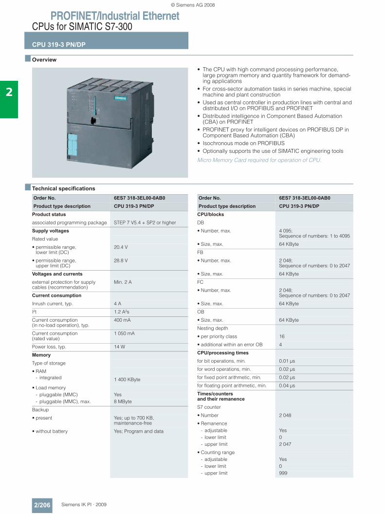
PROFINET/Industrial EthernetCPUs for SIMATIC S7-300
CPU 319-3 PN/DP
2/206 Siemens IK PI · 2009
2
■ Overview
• The CPU with high command processing performance,large program memory and quantity framework for demand-ing applications
• For cross-sector automation tasks in series machine, special machine and plant construction
• Used as central controller in production lines with central and distributed I/O on PROFIBUS and PROFINET
• Distributed intelligence in Component Based Automation (CBA) on PROFINET
• PROFINET proxy for intelligent devices on PROFIBUS DP in Component Based Automation (CBA)
• Isochronous mode on PROFIBUS• Optionally supports the use of SIMATIC engineering tools
Micro Memory Card required for operation of CPU.
■ Technical specifications
Order No. 6ES7 318-3EL00-0AB0Product type description CPU 319-3 PN/DP
Product status
associated programming package STEP 7 V5.4 + SP2 or higher
Supply voltages
Rated value
• permissible range, lower limit (DC)
20.4 V
• permissible range, upper limit (DC)
28.8 V
Voltages and currents
external protection for supply cables (recommendation)
Min. 2 A
Current consumption
Inrush current, typ. 4 A
I²t 1.2 A²s
Current consumption(in no-load operation), typ.
400 mA
Current consumption (rated value)
1 050 mA
Power loss, typ. 14 W
Memory
Type of storage
• RAM- integrated 1 400 KByte
• Load memory- pluggable (MMC) Yes- pluggable (MMC), max. 8 MByte
Backup
• present Yes; up to 700 KB, maintenance-free
• without battery Yes; Program and data
Order No. 6ES7 318-3EL00-0AB0Product type description CPU 319-3 PN/DP
CPU/blocks
DB
• Number, max. 4 095; Sequence of numbers: 1 to 4095
• Size, max. 64 KByte
FB
• Number, max. 2 048; Sequence of numbers: 0 to 2047
• Size, max. 64 KByte
FC
• Number, max. 2 048; Sequence of numbers: 0 to 2047
• Size, max. 64 KByte
OB
• Size, max. 64 KByte
Nesting depth
• per priority class 16
• additional within an error OB 4
CPU/processing times
for bit operations, min. 0.01 μs
for word operations, min. 0.02 μs
for fixed point arithmetic, min. 0.02 μs
for floating point arithmetic, min. 0.04 μs
Times/counters and their remanence
S7 counter
• Number 2 048
• Remanence- adjustable Yes- lower limit 0- upper limit 2 047
• Counting range- adjustable Yes- lower limit 0- upper limit 999
© Siemens AG 2008
PROFINET/Industrial EthernetCPUs for SIMATIC S7-300
CPU 319-3 PN/DP
2/207Siemens IK PI · 2009
2
■ Technical specifications (continued)
Order No. 6ES7 318-3EL00-0AB0Product type description CPU 319-3 PN/DP
IEC counter
• present Yes
• Type SFB
S7 times
• Number 2 048
• Remanence- adjustable Yes- lower limit 0- upper limit 2 047
• Time range- lower limit 10 ms- upper limit 9 990 s
IEC timer
• present Yes
• Type SFB
Data areas and their remanence
Flag
• Number, max. 8 KByte
• Remanence available Yes; MB 0 to MB 8191
• Number of clock memories 8; 1 memory byte
Data blocks
• Number, max. 4 095; Number sequence: 1 to 4095
• Size, max. 64 KByte
• Remanence adjustable Yes; via non-retain property on DB
Local data
• per priority class, max. 1 024 Byte
Address area
I/O address area
• Inputs 8 KByte
• Outputs 8 KByte
• of which, distributed- Inputs 8 KByte- Outputs 8 KByte
Process image
• Inputs, adjustable 2 KByte
• Outputs, adjustable 2 KByte
• Inputs, preset 256 Byte
• Outputs, preset 256 Byte
Subprocess images
• Number of subprocess images, max.
1
Digital channels
• Inputs, of which central 1 024
• Outputs, of which central 1 024
Analog channels
• Inputs, of which central 256
• Outputs, of which central 256
Order No. 6ES7 318-3EL00-0AB0Product type description CPU 319-3 PN/DP
Hardware config. Modules per rack, max. 8
Number of DP masters
• integrated 2
• via CP 4
Time
Clock
• Hardware clock (real-time clock) Yes
• buffered and synchronizable Yes
• Deviation per day, max. 10 s
Operating hours counter
• Number 4
• Number/Number range 0 to 3
• Range of values 0 to 2^31 hours(when using SFC 101)
• Granularity 1 hour
• remanent Yes
Clock synchronization
• supports Yes
• to MPI, Master Yes
• to MPI, Slave Yes
• in AS, Master Yes
• in AS, Slave Yes
• on Ethernet via NTP Yes; as client
S7 message functions
Number of login stations for message functions, max.
32
Process diagnostic messages Yes
simultaneously active Alarm-S blocks, max.
60
Test commissioning functions
Status/control
• Variables Inputs, outputs, memory bits, DB, times, counters
Forcing
• Force, variables Inputs, outputs
Diagnostic buffer
• Number of entries, max. 500
© Siemens AG 2008
PROFINET/Industrial EthernetCPUs for SIMATIC S7-300
CPU 319-3 PN/DP
2/208 Siemens IK PI · 2009
2
■ Technical specifications (continued)
Order No. 6ES7 318-3EL00-0AB0Product type description CPU 319-3 PN/DP
Communication functions
PG/OP communication Yes
Routing Yes
Global data communication
• supported Yes
• Size of GD packets, max. 22 Byte
S7 basic communication
• supported Yes
S7 communication
• supported Yes
S5-compatible communication
• supported Yes; via CP and loadable FC
Open IE communication
• TCP/IP Yes; via integrated PROFINET interface and loadable FBs
- Number of connections, max. 8
- Data length, max. 1 460 Byte; with connection type 01H; 8192 bytes with connection type 11H
• ISO-on-TCP (RFC1006) Yes; via integrated PROFINET interface and loadable FBs
- Number of connections, max. 8
- Data length, max. 8 192 Byte
• UDP Yes; via integrated PROFINET interface and loadable FBs
- Number of connections, max. 8
- Data length, max. 1 472 Byte
Number of connections
• overall 32
• usable for PG communication 31
• usable for OP communication 31
• usable for S7 basic communication
30
PROFINET CBA (at set setpoint communication load)
• PROFIBUS proxy functionality
- Data length per connection, max.
Slave-dependent
Order No. 6ES7 318-3EL00-0AB0Product type description CPU 319-3 PN/DP
1st interface
Physics RS 485
isolated Yes
Power supply to interface (15 to 30 V DC), max.
150 mA
• Transmission speeds, max. 12 MBit/s
DP master
• Services
- S7 basic communication I blocks only
• Transmission speeds, max. 12 MBit/s
• Address area
- Inputs, max. 8 KByte
- Outputs, max. 8 KByte
• Useful data per DP slave
- Inputs, max. 244 Byte
- Outputs, max. 244 Byte
DP slave
• Services
- Routing with interface active
• Transmission speeds, max. 12 MBit/s
• Transfer memory
- Inputs 244 Byte
- Outputs 244 Byte
• Useful data per address area, max.
32 Byte
© Siemens AG 2008
PROFINET/Industrial EthernetCPUs for SIMATIC S7-300
CPU 319-3 PN/DP
2/209Siemens IK PI · 2009
2
■ Technical specifications (continued)
Order No. 6ES7 318-3EL00-0AB0Product type description CPU 319-3 PN/DP
2nd interface
Physics RS 485
isolated Yes
Power supply to interface (15 to 30 V DC), max.
200 mA
DP master
• Services
- S7 basic communication I blocks only
- Isochronous mode OB 61
• Transmission speeds, max. 12 MBit/s
• Address area
- Inputs, max. 8 KByte
- Outputs, max. 8 KByte
• Useful data per DP slave
- Inputs, max. 244 Byte
- Outputs, max. 244 Byte
DP slave
• Services
- Routing with interface active
• Transmission speeds, max. 12 MBit/s
• automatic baud rate search Yes; only with passive interface
• Transfer memory
- Inputs 244 Byte
- Outputs 244 Byte
• Useful data per address area, max.
32 Byte
Order No. 6ES7 318-3EL00-0AB0Product type description CPU 319-3 PN/DP
3rd interface
Type of interfaces PROFINET
Physics Ethernet RJ45
isolated Yes
automatic detection oftransmission speed
Yes
Functionality
• MPI No
• PROFINET IO controller Yes
• PROFINET IO device No
• PROFINET CBA Yes
• Point-to-point coupling No
Open IE communication
• Number of connections, max. 8
PROFINET CBA(at 50 % communication load)
• Acyclic transmission Yes
• cyclic transmission Yes
Nesting levels 8
User program protection/password protection
Yes
Dimensions
Width 120 mm
Height 125 mm
Depth 130 mm
Weights
Weight, approx. 1 250 g
© Siemens AG 2008
PROFINET/Industrial EthernetCPUs for SIMATIC S7-300
CPU 319-3 PN/DP
2/210 Siemens IK PI · 2009
2
■ Ordering data Order No. Order No.
CPU 319-3 PN/DP 6ES7 318-3EL00-0AB0Main memory 1.4 MB, power supply 24 V DC, combined MPI/PROFIBUS DP master/slave interface, PROFIBUS DP master/slave interface, Ethernet/PROFINET interface; MMC required
Micro Memory Card• 64 KB 6ES7 953-8LF20-0AA0• 128 KB 6ES7 953-8LG11-0AA0• 512 KB 6ES7 953-8LJ20-0AA0• 2 MB 6ES7 953-8LL20-0AA0• 4 MB 6ES7 953-8LM20-0AA0• 8 MB 6ES7 953-8LP20-0AA0MPI cable 6ES7 901-0BF00-0AA0For connecting SIMATIC S7 and the PG through MPI; 5 m in length
Slot number plates 6ES7 912-0AA00-0AA0S7-300 manualDesign, CPU data, module data, instruction list
• German 6ES7 398-8FA10-8AA0• English 6ES7 398-8FA10-8BA0• French 6ES7 398-8FA10-8CA0• Spanish 6ES7 398-8FA10-8DA0• Italian 6ES7 398-8FA10-8EA0SIMATIC Manual Collection 6ES7 998-8XC01-8YE0Electronic manuals on DVD, multi-lingual: S7-200, S7-300, C7, S7-400, SIMATIC DP (distributed I/O), SIMATIC PC, SIMATIC PG (programming devices), STEP 7, Engineering Tools, Runtime Soft-ware, SIMATIC PCS 7, SIMATIC HMI (Human Machine Interface), SIMATIC NET (Industrial Commu-nication), SIMATIC Machine Vision, SIMATIC Sensors
SIMATIC Manual Collection update service for 1 year
6ES7 998-8XC01-8YE2
Current "Manual Collection" DVD and the three subsequent updates
Power supply connector 6ES7 391-1AA00-0AA010 units, spare part
Manual "Communication for SIMATIC S7-300/-400"• German 6ES7 398-8EA00-8AA0• English 6ES7 398-8EA00-8BA0• French 6ES7 398-8EA00-8CA0• Spanish 6ES7 398-8EA00-8DA0• Italian 6ES7 398-8EA00-8EA0SIMATIC S7 training case 6ES7 910-3AA00-0XA0With mounting components for mounting S7-200 and S7-300
PROFIBUS bus components PROFIBUS DP bus connector RS 485• With 90° cable outlet,
max. transmission rate 12 Mbit/s
- Without PG interface 6ES7 972-0BA12-0XA0- With PG interface 6ES7 972-0BB12-0XA0
• With 90° cable outlet for FastConnect connection system, max. transmission rate 12 Mbit/s
- Without PG interface 6ES7 972-0BA51-0XA0- With PG interface 6ES7 972-0BB51-0XA0
• With axial cable outlet for SIMATIC OP, for connecting to PPI, MPI, PROFIBUS
6GK1 500-0EA02
PROFIBUS Fast Connect bus cable
6XV1 830-0EH10
Standard type with special design for quick mounting, 2-core, shielded, sold by the meter, max. delivery unit 1000 m, minimum order quantity 20 m
RS 485 repeater for PROFIBUS 6ES7 972-0AA01-0XA0Data transfer rate up to 12 Mbit/s; 24 V DC; IP20 housing
© Siemens AG 2008

PROFINET/Industrial EthernetCPUs for SIMATIC S7-300
CPU 319-3 PN/DP
2/211Siemens IK PI · 2009
2
■ Ordering data (continued) Order No. Order No.
PROFINET bus components IE FC TP Standard Cable GP 2x2
6XV1 840-2AH10
4-core, shielded TP installation cable for connection to IE FC Outlet RJ45/ IE FC RJ45 Plug; PROFINET-compatible; with UL approval;sold by the meter
FO Standard Cable GP (50/125) 6XV1 873-2AStandard cable, splittable, UL approval, sold by the meter
Industrial Ethernet Switch SCALANCE X208
6GK5 208-0BA10-2AA3
with eight 10/100 Mbit/s RJ45 ports
Compact Switch ModuleCSM 377
6GK7 377-1AA00-0AA0
Unmanaged switch for the connection of a SIMATIC S7-300, ET 200M and as many as three other nodes to an Industrial Ethernet operating at 10/100 Mbit/s; 4 x RJ45 ports; external 24 V DC power supply, LED diagnostics, S7-300 module incl. electronic equipment manual on CD-ROM
IE FC RJ45 plugsRJ45 plug connector for Industrial Ethernet with a rugged metal enclosure and integrated insula-tion displacement contacts for connecting Industrial Ethernet FC installation cables
IE FC RJ45 Plug 180180° cable outlet
• 1 unit 6GK1 901-1BB10-2AA0• 10 units 6GK1 901-1BB10-2AB0• 50 units 6GK1 901-1BB10-2AE0
© Siemens AG 2008
PROFINET/Industrial EthernetCPUs for SIMATIC S7-300
CPU 315F-2 PN/DP
2/212 Siemens IK PI · 2009
2
■ Overview
• For design of a fail-safe automation system for plants with increased safety requirements
• Complies with safety requirements up to SIL 3 to IEC 61508 and up to Cat. 4 according to EN 954-1
• Fail-safe I/O modules in distributed stations can be connected through the integrated PROFINET interface (PROFIsafe) and/or through the integrated PROFIBUS DP interface (PROFIsafe);
• Fail-safe I/O modules of the ET 200M range can also be centrally connected
• Central and distributed use of standard modules for non safety-relevant applications
• Component Based Automation (CBA) on PROFINET• PROFINET proxy for intelligent devices on PROFIBUS DP in
Component Based Automation (CBA)
Micro Memory Card required for operation of CPU.
■ Technical specifications
Order No. 6ES7 315-2FH13-0AB0Product type description CPU 315F-2 PN/DP
Product status
associated programming package STEP 7 V5.4 SP2 or higher S7 Distributed Safety V5.4 or higher
Supply voltages
Rated value
• permissible range, lower limit (DC)
20.4 V
• permissible range, upper limit (DC)
28.8 V
Current consumption
Inrush current, typ. 2.5 A
I²t 1 A²s
Current consumption (in no-load operation), typ.
100 mA
Current consumption (rated value) 650 mA
Power loss, typ. 3.5 W
Memory
Type of storage
• RAM- integrated 256 KByte; For program and data
• Load memory- pluggable (MMC) Yes- pluggable (MMC), max. 8 MByte- expandable FEPROM can be plugged in as MMC
Backup
• present Yes
• without battery Yes; Program and data
Order No. 6ES7 315-2FH13-0AB0Product type description CPU 315F-2 PN/DP
CPU/blocks
DB
• Number, max. 1 023; Number band: 1 to 1023
• Size, max. 16 KByte
FB
• Number, max. 1 024; Sequence of numbers: 0 to 2047
• Size, max. 16 KByte
FC
• Number, max. 1 024; Sequence of numbers: 0 to 2047
• Size, max. 16 KByte
OB
• Size, max. 16 KByte
Nesting depth
• per priority class 8
• additional within an error OB 4
CPU/processing times
for bit operations, min. 0.1 μs
for word operations, min. 0.2 μs
for fixed point arithmetic, min. 2 μs
for floating point arithmetic, min. 3 μs
© Siemens AG 2008
PROFINET/Industrial EthernetCPUs for SIMATIC S7-300
CPU 315F-2 PN/DP
2/213Siemens IK PI · 2009
2
■ Technical specifications (continued)
Order No. 6ES7 315-2FH13-0AB0Product type description CPU 315F-2 PN/DP
Times/counters and their rema-nence
S7 counter
• Number 256
• of which remanent without battery- adjustable Yes- lower limit 0- upper limit 255
• Remanence- adjustable Yes- lower limit 0- upper limit 255
• Counting range- adjustable Yes- lower limit 0- upper limit 999
IEC counter
• present Yes
• Type SFB
S7 times
• Number 256
• Remanence- adjustable Yes- lower limit 0- upper limit 255
• Time range- lower limit 10 ms- upper limit 9 990 s
IEC timer
• present Yes
• Type SFB
Data areas and their remanence
Flag
• Number, max. 2 048 Byte
• Remanence available Yes; MB 0 to MB 2047
• Number of clock memories 8; 1 memory byte
Data blocks
• Number, max. 1 023; From DB 1 to DB 1023
• Size, max. 16 KByte
• Remanence adjustable Yes; via non-retain property on DB
• Remanence preset yes
Local data
• per priority class, max. 1 024 Byte; per block max. 510
Order No. 6ES7 315-2FH13-0AB0Product type description CPU 315F-2 PN/DP
Address area
I/O address area
• Inputs 2 KByte
• Outputs 2 KByte
• of which, distributed- Inputs 2 KByte- Outputs 2 KByte
Process image
• Inputs 384 Byte
• Outputs 384 Byte
Digital channels
• Inputs, of which central 1 024; max.
• Outputs, of which central 1 024; max.
Analog channels
• Inputs, of which central 256; max.
• Outputs, of which central 256; max.
Hardware config. Modules per rack, max. 8
Number of DP masters
• integrated 1
• via CP 4
Time
Clock
• Hardware clock (real-time clock) Yes
• buffered and synchronizable Yes
• Deviation per day, max. 10 s
Operating hours counter
• Number 1
• Number/Number range 0
• Range of values 2^31 hours (when using the SFC 101)
• Granularity 1 hour
• remanent Yes
Clock synchronization
• supports Yes
• to MPI, Master Yes
• to MPI, Slave Yes
• in AS, Master Yes
• in AS, Slave Yes
S7 message functions
Number of login stations for message functions, max.
16
Process diagnostic messages Yes
simultaneously active Alarm-S blocks, max.
40
© Siemens AG 2008
PROFINET/Industrial EthernetCPUs for SIMATIC S7-300
CPU 315F-2 PN/DP
2/214 Siemens IK PI · 2009
2
■ Technical specifications (continued)
Order No. 6ES7 315-2FH13-0AB0Product type description CPU 315F-2 PN/DP
Test commissioning functions
Status/control
• Variables Inputs, outputs, memory bits, DB, times, counters
Forcing
• Force, variables Inputs, outputs
Diagnostic buffer
• Number of entries, max. 100
Communication functions
PG/OP communication Yes
Routing Yes
Global data communication
• supported Yes
• Size of GD packets, max. 22 Byte
S7 basic communication
• supported Yes
S7 communication
• supported Yes
S5-compatible communication
• supported Yes; via CP and loadable FC
Open IE communication
• TCP/IP Yes; via integrated PROFINET interface and loadable FBs
- Number of connections, max. 8- Data length, max. 1 460 Byte
Number of connections
• overall 16
• usable for PG communication 15; max.
• usable for OP communication 15
• usable for S7 basic communica-tion
14
• usable for routing X1 as MPI: max. 10; X1 as DP master: max. 24; X1 as DP slave (active): max. 14; X2 as PROFINET: max. 24
PROFINET CBA (at set setpoint communication load)
• Setpoint for the CPU communication load
50%
• Number of remote interconnection partners
32
• Number of functions, master/slave
17
• Total of all master/slave connections
1 000
• Data length of all incoming connections master/slave, max.
4 000 Byte
• Data length of all outgoing con-nections master/slave, max.
4 000 Byte
• Number of device-internal and PROFIBUS interconnections
500
• Data length of device-internal and PROFIBUS interconnections, max.
4 000 Byte
• Data length per connection, max. 1 400 Byte
Order No. 6ES7 315-2FH13-0AB0Product type description CPU 315F-2 PN/DP
• Remote interconnections with acyclic transmission
- Sampling frequency: sampling interval, min.
500 ms
- Number of incoming interconnections
100
- Number of outgoing interconnections
100
- Data length of all incoming interconnections, max.
2 000 Byte
- Data length of all outgoing interconnections, max.
2 000 Byte
- Data length per connection, max.
1 400 Byte
• Remote interconnections with cyclic transmission
- Transmission frequency: transmission interval, min.
10 ms
- Number of incoming interconnections
200
- Number of outgoing interconnections
200
- Data length of all incoming interconnections, max.
2 000 Byte
- Data length of all outgoing interconnections, max.
2 000 Byte
- Data length per connection, max.
450 Byte
• HMI variables via PROFINET (acyclic)
- Number of log-in stations for HMI variables (PN OPC/iMap)
3; 2x PN OPC/1x iMap
- HMI variable updating 500 ms
- Number of HMI variables 200
- Data length of all HMI variables, max.
2 000 Byte
• PROFIBUS proxy functionality
- supported Yes
- Number of linked PROFIBUS devices
16
- Data length per connection, max.
240 Byte; Slave-dependent
PROFINET CBA (at 50 % communication load)
• Data length for arrays and structures (local interconnection), max.
Slave-dependent
• HMI variables via PROFINET (acyclic)- Number of log-in stations for HMI
variables (PN OPC/iMap)2 * PN OPC / 1 * iMap
© Siemens AG 2008
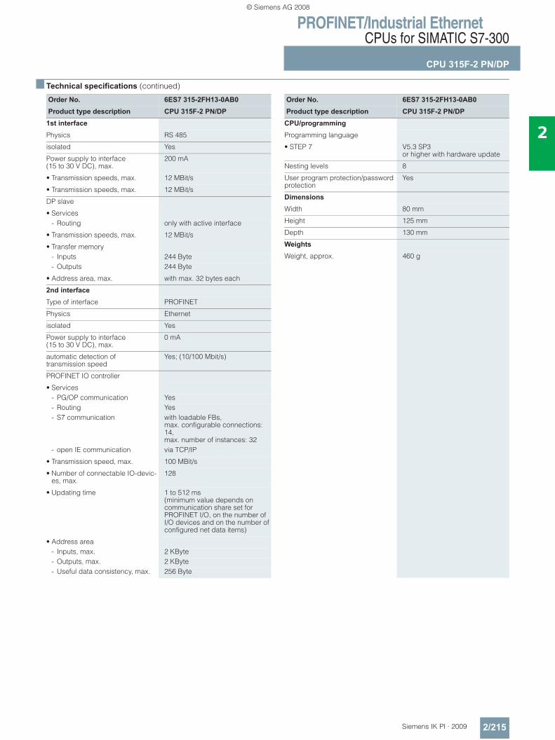
PROFINET/Industrial EthernetCPUs for SIMATIC S7-300
CPU 315F-2 PN/DP
2/215Siemens IK PI · 2009
2
■ Technical specifications (continued)
Order No. 6ES7 315-2FH13-0AB0Product type description CPU 315F-2 PN/DP
1st interface
Physics RS 485
isolated Yes
Power supply to interface (15 to 30 V DC), max.
200 mA
• Transmission speeds, max. 12 MBit/s
• Transmission speeds, max. 12 MBit/s
DP slave
• Services- Routing only with active interface
• Transmission speeds, max. 12 MBit/s
• Transfer memory- Inputs 244 Byte- Outputs 244 Byte
• Address area, max. with max. 32 bytes each
2nd interface
Type of interface PROFINET
Physics Ethernet
isolated Yes
Power supply to interface(15 to 30 V DC), max.
0 mA
automatic detection oftransmission speed
Yes; (10/100 Mbit/s)
PROFINET IO controller
• Services- PG/OP communication Yes- Routing Yes- S7 communication with loadable FBs,
max. configurable connections: 14, max. number of instances: 32
- open IE communication via TCP/IP
• Transmission speed, max. 100 MBit/s
• Number of connectable IO-devic-es, max.
128
• Updating time 1 to 512 ms (minimum value depends on communication share set for PROFINET I/O, on the number of I/O devices and on the number of configured net data items)
• Address area- Inputs, max. 2 KByte- Outputs, max. 2 KByte- Useful data consistency, max. 256 Byte
Order No. 6ES7 315-2FH13-0AB0Product type description CPU 315F-2 PN/DP
CPU/programming
Programming language
• STEP 7 V5.3 SP3or higher with hardware update
Nesting levels 8
User program protection/password protection
Yes
Dimensions
Width 80 mm
Height 125 mm
Depth 130 mm
Weights
Weight, approx. 460 g
© Siemens AG 2008
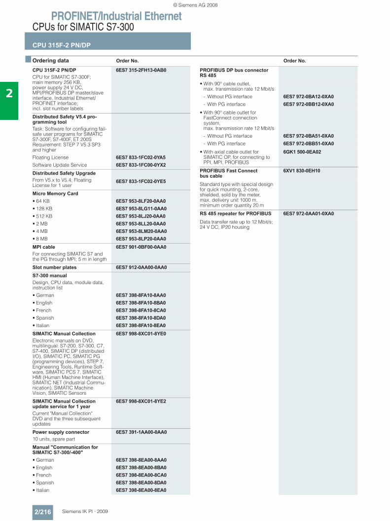
PROFINET/Industrial EthernetCPUs for SIMATIC S7-300
CPU 315F-2 PN/DP
2/216 Siemens IK PI · 2009
2
■ Ordering data Order No. Order No.
CPU 315F-2 PN/DP 6ES7 315-2FH13-0AB0CPU for SIMATIC S7-300F; main memory 256 KB, power supply 24 V DC, MPI/PROFIBUS DP master/slave interface, Industrial Ethernet/PROFINET interface; incl. slot number labels
Distributed Safety V5.4 pro-gramming toolTask: Software for configuring fail-safe user programs for SIMATIC S7-300F, S7-400F, ET 200S Requirement: STEP 7 V5.3 SP3 and higherFloating License 6ES7 833-1FC02-0YA5Software Update Service 6ES7 833-1FC00-0YX2Distributed Safety UpgradeFrom V5.x to V5.4; Floating License for 1 user
6ES7 833-1FC02-0YE5
Micro Memory Card• 64 KB 6ES7 953-8LF20-0AA0• 128 KB 6ES7 953-8LG11-0AA0• 512 KB 6ES7 953-8LJ20-0AA0• 2 MB 6ES7 953-8LL20-0AA0• 4 MB 6ES7 953-8LM20-0AA0• 8 MB 6ES7 953-8LP20-0AA0MPI cable 6ES7 901-0BF00-0AA0For connecting SIMATIC S7 and the PG through MPI; 5 m in length
Slot number plates 6ES7 912-0AA00-0AA0S7-300 manualDesign, CPU data, module data, instruction list• German 6ES7 398-8FA10-8AA0• English 6ES7 398-8FA10-8BA0• French 6ES7 398-8FA10-8CA0• Spanish 6ES7 398-8FA10-8DA0• Italian 6ES7 398-8FA10-8EA0SIMATIC Manual Collection 6ES7 998-8XC01-8YE0Electronic manuals on DVD, multilingual: S7-200, S7-300, C7, S7-400, SIMATIC DP (distributed I/O), SIMATIC PC, SIMATIC PG (programming devices), STEP 7, Engineering Tools, Runtime Soft-ware, SIMATIC PCS 7, SIMATIC HMI (Human Machine Interface), SIMATIC NET (Industrial Commu-nication), SIMATIC Machine Vision, SIMATIC Sensors
SIMATIC Manual Collection update service for 1 year
6ES7 998-8XC01-8YE2
Current "Manual Collection" DVD and the three subsequent updates
Power supply connector 6ES7 391-1AA00-0AA010 units, spare part
Manual "Communication for SIMATIC S7-300/-400"• German 6ES7 398-8EA00-8AA0• English 6ES7 398-8EA00-8BA0• French 6ES7 398-8EA00-8CA0• Spanish 6ES7 398-8EA00-8DA0• Italian 6ES7 398-8EA00-8EA0
PROFIBUS DP bus connector RS 485• With 90° cable outlet,
max. transmission rate 12 Mbit/s
- Without PG interface 6ES7 972-0BA12-0XA0- With PG interface 6ES7 972-0BB12-0XA0
• With 90° cable outlet for FastConnect connection system, max. transmission rate 12 Mbit/s
- Without PG interface 6ES7 972-0BA51-0XA0- With PG interface 6ES7 972-0BB51-0XA0
• With axial cable outlet for SIMATIC OP, for connecting to PPI, MPI, PROFIBUS
6GK1 500-0EA02
PROFIBUS Fast Connect bus cable
6XV1 830-0EH10
Standard type with special design for quick mounting, 2-core, shielded, sold by the meter, max. delivery unit 1000 m, minimum order quantity 20 m
RS 485 repeater for PROFIBUS 6ES7 972-0AA01-0XA0Data transfer rate up to 12 Mbit/s; 24 V DC; IP20 housing
© Siemens AG 2008
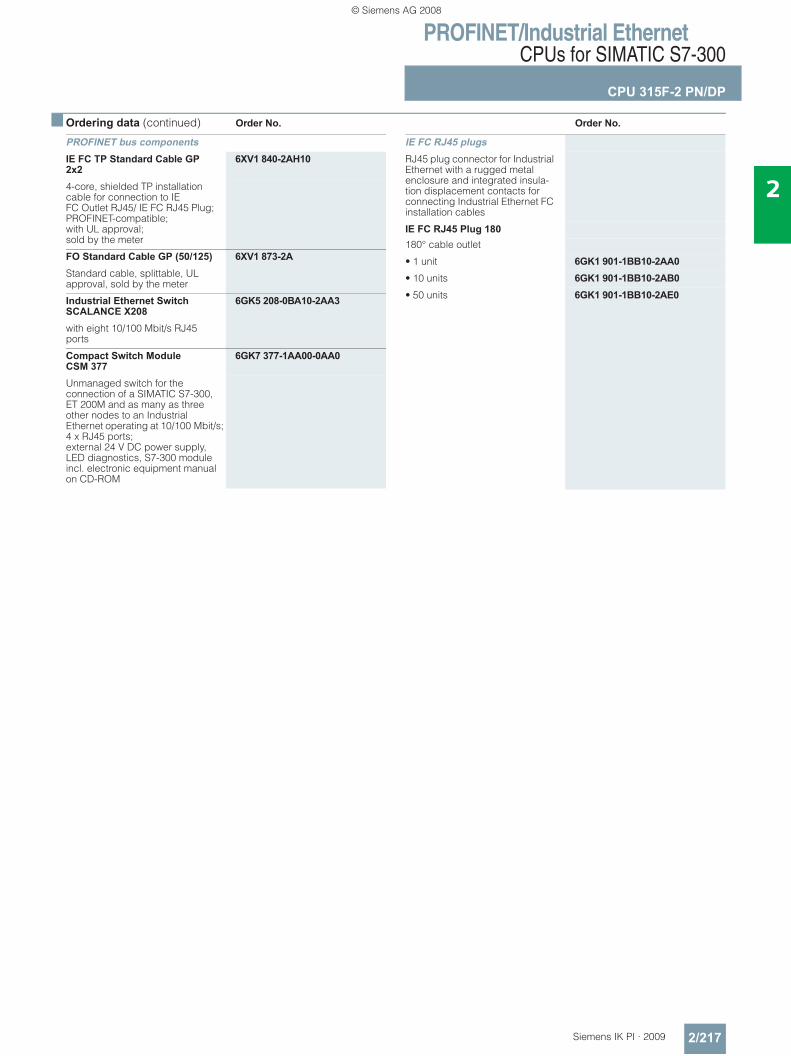
PROFINET/Industrial EthernetCPUs for SIMATIC S7-300
CPU 315F-2 PN/DP
2/217Siemens IK PI · 2009
2
■ Ordering data (continued) Order No. Order No.
PROFINET bus components IE FC TP Standard Cable GP 2x2
6XV1 840-2AH10
4-core, shielded TP installation cable for connection to IE FC Outlet RJ45/ IE FC RJ45 Plug; PROFINET-compatible; with UL approval;sold by the meter
FO Standard Cable GP (50/125) 6XV1 873-2AStandard cable, splittable, UL approval, sold by the meter
Industrial Ethernet Switch SCALANCE X208
6GK5 208-0BA10-2AA3
with eight 10/100 Mbit/s RJ45 ports
Compact Switch ModuleCSM 377
6GK7 377-1AA00-0AA0
Unmanaged switch for the connection of a SIMATIC S7-300, ET 200M and as many as three other nodes to an Industrial Ethernet operating at 10/100 Mbit/s; 4 x RJ45 ports; external 24 V DC power supply, LED diagnostics, S7-300 module incl. electronic equipment manual on CD-ROM
IE FC RJ45 plugsRJ45 plug connector for Industrial Ethernet with a rugged metal enclosure and integrated insula-tion displacement contacts for connecting Industrial Ethernet FC installation cables
IE FC RJ45 Plug 180180° cable outlet
• 1 unit 6GK1 901-1BB10-2AA0• 10 units 6GK1 901-1BB10-2AB0• 50 units 6GK1 901-1BB10-2AE0
© Siemens AG 2008
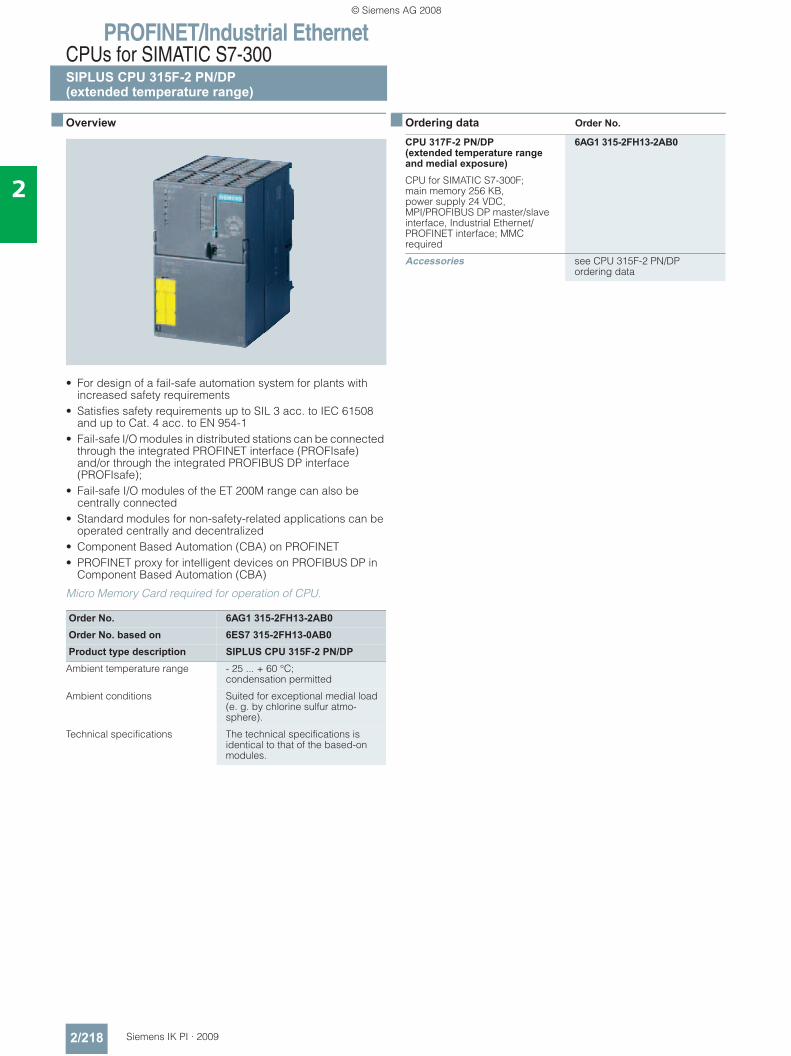
PROFINET/Industrial EthernetCPUs for SIMATIC S7-300SIPLUS CPU 315F-2 PN/DP(extended temperature range)
2/218 Siemens IK PI · 2009
2
■ Overview
• For design of a fail-safe automation system for plants with increased safety requirements
• Satisfies safety requirements up to SIL 3 acc. to IEC 61508 and up to Cat. 4 acc. to EN 954-1
• Fail-safe I/O modules in distributed stations can be connected through the integrated PROFINET interface (PROFIsafe) and/or through the integrated PROFIBUS DP interface (PROFIsafe);
• Fail-safe I/O modules of the ET 200M range can also be centrally connected
• Standard modules for non-safety-related applications can be operated centrally and decentralized
• Component Based Automation (CBA) on PROFINET • PROFINET proxy for intelligent devices on PROFIBUS DP in
Component Based Automation (CBA)
Micro Memory Card required for operation of CPU.
■ Ordering data Order No.
Order No. 6AG1 315-2FH13-2AB0Order No. based on 6ES7 315-2FH13-0AB0Product type description SIPLUS CPU 315F-2 PN/DP
Ambient temperature range - 25 ... + 60 °C; condensation permitted
Ambient conditions Suited for exceptional medial load (e. g. by chlorine sulfur atmo-sphere).
Technical specifications The technical specifications is identical to that of the based-on modules.
CPU 317F-2 PN/DP(extended temperature range and medial exposure)
6AG1 315-2FH13-2AB0
CPU for SIMATIC S7-300F; main memory 256 KB, power supply 24 VDC, MPI/PROFIBUS DP master/slave interface, Industrial Ethernet/PROFINET interface; MMC required
Accessories see CPU 315F-2 PN/DP ordering data
© Siemens AG 2008
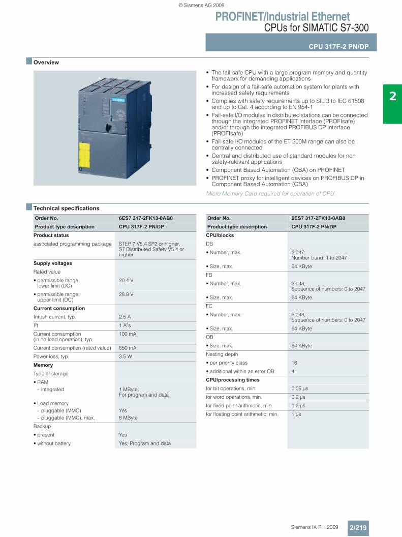
PROFINET/Industrial EthernetCPUs for SIMATIC S7-300
CPU 317F-2 PN/DP
2/219Siemens IK PI · 2009
2
■ Overview
• The fail-safe CPU with a large program memory and quantity framework for demanding applications
• For design of a fail-safe automation system for plants with increased safety requirements
• Complies with safety requirements up to SIL 3 to IEC 61508 and up to Cat. 4 according to EN 954-1
• Fail-safe I/O modules in distributed stations can be connected through the integrated PROFINET interface (PROFIsafe) and/or through the integrated PROFIBUS DP interface (PROFIsafe)
• Fail-safe I/O modules of the ET 200M range can also be centrally connected
• Central and distributed use of standard modules for non safety-relevant applications
• Component Based Automation (CBA) on PROFINET• PROFINET proxy for intelligent devices on PROFIBUS DP in
Component Based Automation (CBA)
Micro Memory Card required for operation of CPU.
■ Technical specifications
Order No. 6ES7 317-2FK13-0AB0Product type description CPU 317F-2 PN/DP
Product status
associated programming package STEP 7 V5.4 SP2 or higher, S7 Distributed Safety V5.4 or higher
Supply voltages
Rated value
• permissible range, lower limit (DC)
20.4 V
• permissible range, upper limit (DC)
28.8 V
Current consumption
Inrush current, typ. 2.5 A
I²t 1 A²s
Current consumption(in no-load operation), typ.
100 mA
Current consumption (rated value) 650 mA
Power loss, typ. 3.5 W
Memory
Type of storage
• RAM- integrated 1 MByte;
For program and data
• Load memory- pluggable (MMC) Yes- pluggable (MMC), max. 8 MByte
Backup
• present Yes
• without battery Yes; Program and data
Order No. 6ES7 317-2FK13-0AB0Product type description CPU 317F-2 PN/DP
CPU/blocks
DB
• Number, max. 2 047; Number band: 1 to 2047
• Size, max. 64 KByte
FB
• Number, max. 2 048; Sequence of numbers: 0 to 2047
• Size, max. 64 KByte
FC
• Number, max. 2 048; Sequence of numbers: 0 to 2047
• Size, max. 64 KByte
OB
• Size, max. 64 KByte
Nesting depth
• per priority class 16
• additional within an error OB 4
CPU/processing times
for bit operations, min. 0.05 μs
for word operations, min. 0.2 μs
for fixed point arithmetic, min. 0.2 μs
for floating point arithmetic, min. 1 μs
© Siemens AG 2008
PROFINET/Industrial EthernetCPUs for SIMATIC S7-300
CPU 317F-2 PN/DP
2/220 Siemens IK PI · 2009
2
■ Technical specifications (continued)
Order No. 6ES7 317-2FK13-0AB0Product type description CPU 317F-2 PN/DP
Times/counters and their rema-nence
S7 counter
• Number 512
• of which remanent without battery- adjustable Yes- lower limit 0- upper limit 511
• Remanence- adjustable Yes- lower limit 0- upper limit 511
• Counting range- adjustable Yes- lower limit 0- upper limit 999
IEC counter
• present Yes
• Type SFB
S7 times
• Number 512
• Remanence- adjustable Yes- lower limit 0- upper limit 511
• Time range- lower limit 10 ms- upper limit 9 990 s
IEC timer
• present Yes
• Type SFB
Data areas and their remanence
Flag
• Number, max. 4 096 Byte
• Remanence available Yes; MB 0 to MB 4095
• Number of clock memories 8; 1 memory byte
Data blocks
• Number, max. 2 047;from DB 1 to DB 2047
• Size, max. 64 KByte
• Remanence adjustable Yes; via non-retain property on DB
• Remanence preset yes
Local data
• per priority class, max. 1 024 Byte
Order No. 6ES7 317-2FK13-0AB0Product type description CPU 317F-2 PN/DP
Address area
I/O address area
• Inputs 8 KByte
• Outputs 8 KByte
• of which, distributed- Inputs 8 KByte- Outputs 8 KByte
Process image
• Inputs 2 048 Byte
• Outputs 2 048 Byte
• Inputs, adjustable 2 048 Byte
• Outputs, adjustable 2 048 Byte
• Inputs, preset 1 024 Byte
• Outputs, preset 1 024 Byte
Digital channels
• Inputs, of which central 1 024
• Outputs, of which central 1 024
Analog channels
• Inputs, of which central 256
• Outputs, of which central 256
Hardware config. Modules per rack, max. 8
Number of DP masters
• integrated 1
• via CP 4
Time
Clock
• Hardware clock (real-time clock) Yes
• buffered and synchronizable Yes
• Deviation per day, max. 10 s
Operating hours counter
• Number 4
• Number/Number range 0 to 3
• Range of values 0 to 2^31 hours(when using SFC 101)
• Granularity 1 hour
• remanent Yes
Clock synchronization
• supports Yes
• to MPI, Master Yes
• to MPI, Slave Yes
• in AS, Master Yes
• in AS, Slave Yes
© Siemens AG 2008
PROFINET/Industrial EthernetCPUs for SIMATIC S7-300
CPU 317F-2 PN/DP
2/221Siemens IK PI · 2009
2
■ Technical specifications (continued)
Order No. 6ES7 317-2FK13-0AB0Product type description CPU 317F-2 PN/DP
S7 message functions
Number of login stationsfor message functions, max.
32
Process diagnostic messages Yes
simultaneously active Alarm-S blocks, max.
60
Test commissioning functions
Status/control
• Variables Inputs, outputs, memory bits, DB, times, counters
Forcing
• Force, variables Inputs, outputs
Diagnostic buffer
• Number of entries, max. 100
Communication functions
PG/OP communication Yes
Routing Yes
Global data communication
• supported Yes
• Size of GD packets, max. 22 Byte
S7 basic communication
• supported Yes
S7 communication
• supported Yes
S5-compatible communication
• supported Yes; via CP and loadable FC
Open IE communication
• TCP/IP Yes; via integrated PROFINET interface and loadable FBs
- Number of connections, max. 8- Data length, max. 1 460 Byte
Number of connections
• overall 32
• usable for PG communication 31
• usable for OP communication 31
• usable for S7 basic communication
30
PROFINET CBA (at set setpoint communication load)
• Setpoint for the CPU communication load
50%
• Number of remote interconnection partners
32
• Number of functions, master/slave
17
• Total of all master/slave connections
1 000
• Data length of all incoming connections master/slave, max.
4 000 Byte
• Data length of all outgoing connections master/slave, max.
4 000 Byte
• Number of device-internal and PROFIBUS interconnections
500
• Data length of device-internal and PROFIBUS interconnections, max.
4 000 Byte
• Data length per connection, max. 1 400 Byte
Order No. 6ES7 317-2FK13-0AB0Product type description CPU 317F-2 PN/DP
• Remote interconnections with acyclic transmission
- Sampling frequency: sampling interval, min.
500 ms
- Number of incoming interconnections
100
- Number of outgoing interconnections
100
- Data length of all incoming interconnections, max.
2 000 Byte
- Data length of all outgoing interconnections, max.
2 000 Byte
- Data length per connection, max.
1 400 Byte
• Remote interconnections with cyclic transmission
- Transmission frequency: transmission interval, min.
10 ms
- Number of incoming interconnections
200
- Number of outgoing interconnections
200
- Data length of all incoming interconnections, max.
2 000 Byte
- Data length of all outgoing interconnections, max.
2 000 Byte
- Data length per connection, max.
450 Byte
• HMI variables via PROFINET (acyclic)
- Number of log-in stations for HMI variables (PN OPC/iMap)
3; 2x PN OPC/1x iMap
- HMI variable updating 500 ms
- Number of HMI variables 200
- Data length of all HMI variables, max.
2 000 Byte
• PROFIBUS proxy functionality
- supported Yes
- Number of linked PROFIBUS devices
16
- Data length per connection, max.
240 Byte; Slave-dependent
PROFINET CBA (at 50 % communication load)
• Data length for arrays and structures (local interconnection), max.
Slave-dependent
• HMI variables via PROFINET (acyclic)
- Number of log-in stations for HMI variables (PN OPC/iMap)
2 * PN OPC / 1 * iMap
© Siemens AG 2008
PROFINET/Industrial EthernetCPUs for SIMATIC S7-300
CPU 317F-2 PN/DP
2/222 Siemens IK PI · 2009
2
■ Technical specifications (continued)
Order No. 6ES7 317-2FK13-0AB0Product type description CPU 317F-2 PN/DP
1st interface
Physics RS 485
isolated Yes
Power supply to interface (15 to 30 V DC), max.
200 mA
• Transmission speeds, max. 12 MBit/s
• Transmission speeds, max. 12 MBit/s
DP slave
• Services- Routing with interface active
• Transmission speeds, max. 12 MBit/s
• Transfer memory- Inputs 244 Byte- Outputs 244 Byte
• Useful data per address area, max.
32 Byte
2nd interface
Type of interface PROFINET
Physics Ethernet
isolated Yes
Power supply to interface (15 to 30 V DC), max.
0 mA
automatic detection of transmission speed
Yes; (10/100 Mbit/s)
Functionality
• PROFINET IO controller Firmware Status V2.3 or higher
PROFINET IO controller
• Services- PG/OP communication Yes- Routing Yes- S7 communication with loadable FBs,
max. configurable connections: 16, max. number of instances: 32
- open IE communication via TCP/IP
• Transmission speed, max. 100 MBit/s
• Number of connectableIO-devices, max.
128
• Updating time 1 to 512 ms(minimum value depends on communication share set for PROFINET I/O, on the number of I/O devices and on the number of configured net data items)
• Address area- Inputs, max. 8 KByte- Outputs, max. 8 KByte- Useful data consistency, max. 256 Byte
Order No. 6ES7 317-2FK13-0AB0Product type description CPU 317F-2 PN/DP
CPU/programming
Programming language
• STEP 7 V5.3 SP3 or higher with hardware update
Nesting levels 8
User program protection/password protection
Yes
Dimensions
Width 80 mm
Height 125 mm
Depth 130 mm
Weights
Weight, approx. 460 g
© Siemens AG 2008
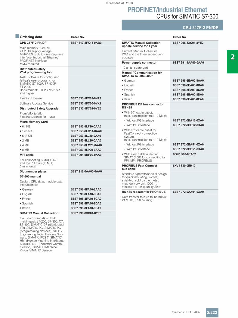
PROFINET/Industrial EthernetCPUs for SIMATIC S7-300
CPU 317F-2 PN/DP
2/223Siemens IK PI · 2009
2
■ Ordering data Order No. Order No.
CPU 317F-2 PN/DP 6ES7 317-2FK13-0AB0Main memory 1024 KB, 24 V DC supply voltage, MPI/PROFIBUS DP master/slave interface, Industrial Ethernet/PROFINET interface; MMC required
Distributed Safety V5.4 programming toolTask: Software for configuring fail-safe user programs for SIMATIC S7-300F, S7-400F, ET 200S Requirement: STEP 7 V5.3 SP3 and higher
Floating License 6ES7 833-1FC02-0YA5Software Update Service 6ES7 833-1FC00-0YX2Distributed Safety Upgrade 6ES7 833-1FC02-0YE5From V5.x to V5.4; Floating License for 1 user
Micro Memory Card• 64 KB 6ES7 953-8LF20-0AA0• 128 KB 6ES7 953-8LG11-0AA0• 512 KB 6ES7 953-8LJ20-0AA0• 2 MB 6ES7 953-8LL20-0AA0• 4 MB 6ES7 953-8LM20-0AA0• 8 MB 6ES7 953-8LP20-0AA0MPI cable 6ES7 901-0BF00-0AA0For connecting SIMATIC S7 and the PG through MPI; 5 m in length
Slot number plates 6ES7 912-0AA00-0AA0S7-300 manualDesign, CPU data, module data, instruction list
• German 6ES7 398-8FA10-8AA0• English 6ES7 398-8FA10-8BA0• French 6ES7 398-8FA10-8CA0• Spanish 6ES7 398-8FA10-8DA0• Italian 6ES7 398-8FA10-8EA0SIMATIC Manual Collection 6ES7 998-8XC01-8YE0Electronic manuals on DVD, multilingual: S7-200, S7-300, C7, S7-400, SIMATIC DP (distributed I/O), SIMATIC PC, SIMATIC PG (programming devices), STEP 7, Engineering Tools, Runtime Soft-ware, SIMATIC PCS 7, SIMATIC HMI (Human Machine Interface), SIMATIC NET (Industrial Commu-nication), SIMATIC Machine Vision, SIMATIC Sensors
SIMATIC Manual Collection update service for 1 year
6ES7 998-8XC01-8YE2
Current "Manual Collection" DVD and the three subsequent updates
Power supply connector 6ES7 391-1AA00-0AA010 units, spare part
Manual "Communication for SIMATIC S7-300/-400"• German 6ES7 398-8EA00-8AA0• English 6ES7 398-8EA00-8BA0• French 6ES7 398-8EA00-8CA0• Spanish 6ES7 398-8EA00-8DA0• Italian 6ES7 398-8EA00-8EA0PROFIBUS DP bus connector RS 485• With 90° cable outlet,
max. transmission rate 12 Mbit/s
- Without PG interface 6ES7 972-0BA12-0XA0- With PG interface 6ES7 972-0BB12-0XA0
• With 90° cable outlet for FastConnect connection system, max. transmission rate 12 Mbit/s
- Without PG interface 6ES7 972-0BA51-0XA0- With PG interface 6ES7 972-0BB51-0XA0
• With axial cable outlet for SIMATIC OP, for connecting to PPI, MPI, PROFIBUS
6GK1 500-0EA02
PROFIBUS Fast Connect bus cable
6XV1 830-0EH10
Standard type with special design for quick mounting, 2-core, shielded, sold by the meter, max. delivery unit 1000 m, minimum order quantity 20 m
RS 485 repeater for PROFIBUS 6ES7 972-0AA01-0XA0Data transfer rate up to 12 Mbit/s; 24 V DC; IP20 housing
© Siemens AG 2008
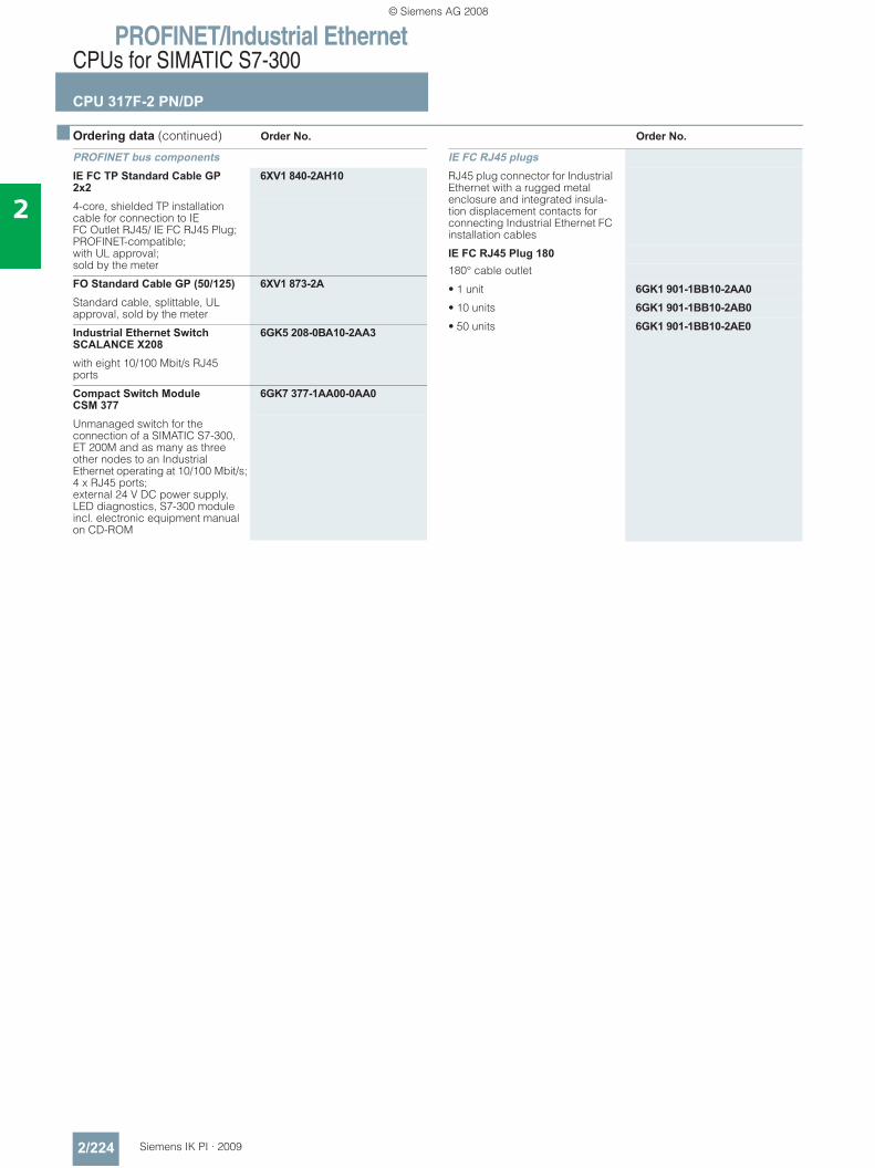
PROFINET/Industrial EthernetCPUs for SIMATIC S7-300
CPU 317F-2 PN/DP
2/224 Siemens IK PI · 2009
2
■ Ordering data (continued) Order No. Order No.
PROFINET bus components IE FC TP Standard Cable GP 2x2
6XV1 840-2AH10
4-core, shielded TP installation cable for connection to IE FC Outlet RJ45/ IE FC RJ45 Plug; PROFINET-compatible; with UL approval;sold by the meter
FO Standard Cable GP (50/125) 6XV1 873-2AStandard cable, splittable, UL approval, sold by the meter
Industrial Ethernet Switch SCALANCE X208
6GK5 208-0BA10-2AA3
with eight 10/100 Mbit/s RJ45 ports
Compact Switch ModuleCSM 377
6GK7 377-1AA00-0AA0
Unmanaged switch for the connection of a SIMATIC S7-300, ET 200M and as many as three other nodes to an Industrial Ethernet operating at 10/100 Mbit/s; 4 x RJ45 ports; external 24 V DC power supply, LED diagnostics, S7-300 module incl. electronic equipment manual on CD-ROM
IE FC RJ45 plugsRJ45 plug connector for Industrial Ethernet with a rugged metal enclosure and integrated insula-tion displacement contacts for connecting Industrial Ethernet FC installation cables
IE FC RJ45 Plug 180180° cable outlet
• 1 unit 6GK1 901-1BB10-2AA0• 10 units 6GK1 901-1BB10-2AB0• 50 units 6GK1 901-1BB10-2AE0
© Siemens AG 2008
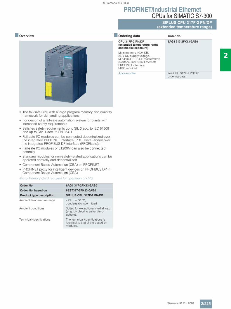
PROFINET/Industrial EthernetCPUs for SIMATIC S7-300
SIPLUS CPU 317F-2 PN/DP(extended temperature range)
2/225Siemens IK PI · 2009
2
■ Overview
• The fail-safe CPU with a large program memory and quantity framework for demanding applications
• For design of a fail-safe automation system for plants with increased safety requirements
• Satisfies safety requirements up to SIL 3 acc. to IEC 61508 and up to Cat. 4 acc. to EN 954-1
• Fail-safe I/O modules can be connected decentralized over the integrated PROFINET interface (PROFIsafe) and/or over the integrated PROFIBUS DP interface (PROFIsafe);
• Fail-safe I/O modules of ET200M can also be connected centrally
• Standard modules for non-safety-related applications can be operated centrally and decentralized
• Component Based Automation (CBA) on PROFINET• PROFINET proxy for intelligent devices on PROFIBUS DP in
Component Based Automation (CBA)
Micro Memory Card required for operation of CPU.
■ Ordering data Order No.
Order No. 6AG1 317-2FK13-2AB0Order No. based on 6ES7317-2FK13-0AB0Product type description SIPLUS CPU 317F-2 PN/DP
Ambient temperature range - 25 ... + 60 °C; condensation permitted
Ambient conditions Suited for exceptional medial load (e. g. by chlorine sulfur atmo-sphere).
Technical specifications The technical specifications is identical to that of the based-on modules.
CPU 317F-2 PN/DP(extended temperature range and medial exposure)
6AG1 317-2FK13-2AB0
Main memory 1024 KB, 24 V DC supply voltage, MPI/PROFIBUS DP master/slave interface, Industrial Ethernet/PROFINET interface; MMC required
Accessories see CPU 317F-2 PN/DP ordering data
© Siemens AG 2008
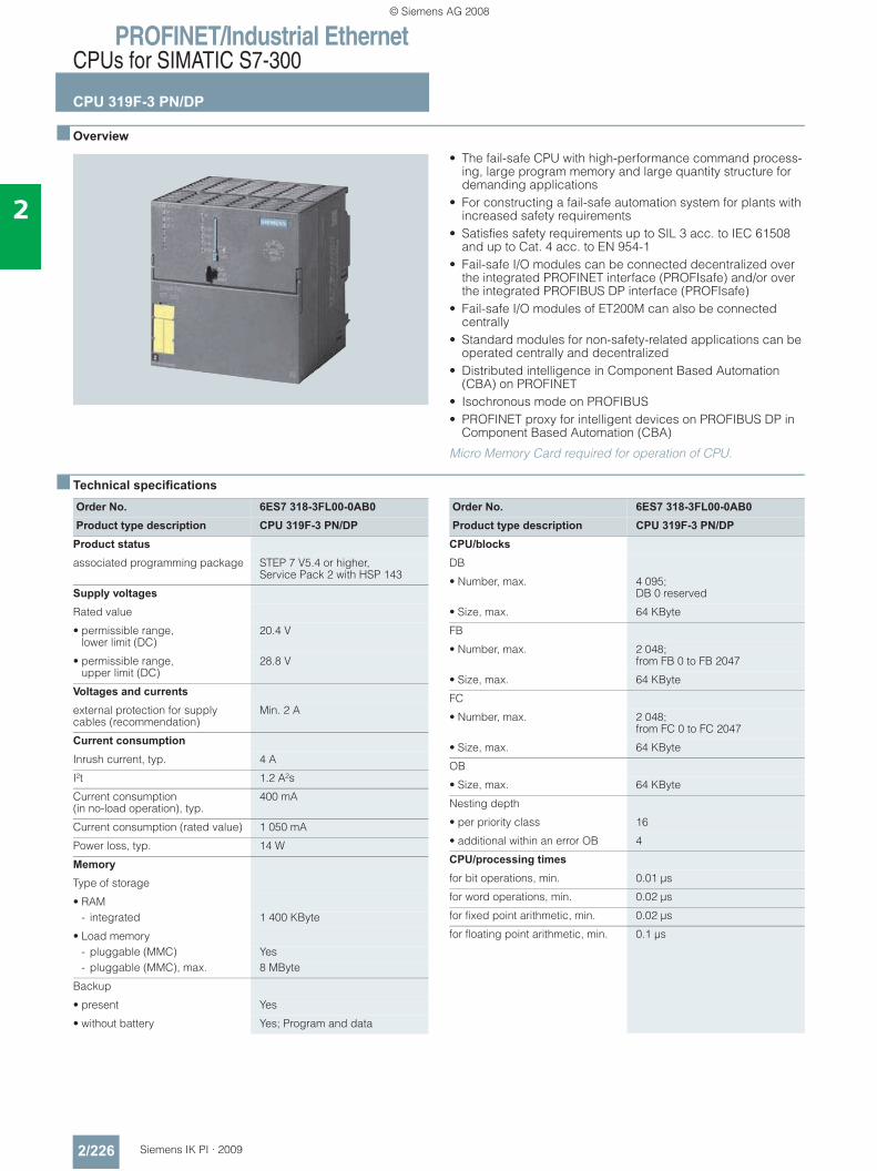
PROFINET/Industrial EthernetCPUs for SIMATIC S7-300
CPU 319F-3 PN/DP
2/226 Siemens IK PI · 2009
2
■ Overview
• The fail-safe CPU with high-performance command process-ing, large program memory and large quantity structure for demanding applications
• For constructing a fail-safe automation system for plants with increased safety requirements
• Satisfies safety requirements up to SIL 3 acc. to IEC 61508 and up to Cat. 4 acc. to EN 954-1
• Fail-safe I/O modules can be connected decentralized over the integrated PROFINET interface (PROFIsafe) and/or over the integrated PROFIBUS DP interface (PROFIsafe)
• Fail-safe I/O modules of ET200M can also be connected centrally
• Standard modules for non-safety-related applications can be operated centrally and decentralized
• Distributed intelligence in Component Based Automation (CBA) on PROFINET
• Isochronous mode on PROFIBUS• PROFINET proxy for intelligent devices on PROFIBUS DP in
Component Based Automation (CBA)
Micro Memory Card required for operation of CPU.
■ Technical specifications
Order No. 6ES7 318-3FL00-0AB0Product type description CPU 319F-3 PN/DP
Product status
associated programming package STEP 7 V5.4 or higher, Service Pack 2 with HSP 143
Supply voltages
Rated value
• permissible range, lower limit (DC)
20.4 V
• permissible range, upper limit (DC)
28.8 V
Voltages and currents
external protection for supply cables (recommendation)
Min. 2 A
Current consumption
Inrush current, typ. 4 A
I²t 1.2 A²s
Current consumption(in no-load operation), typ.
400 mA
Current consumption (rated value) 1 050 mA
Power loss, typ. 14 W
Memory
Type of storage
• RAM- integrated 1 400 KByte
• Load memory- pluggable (MMC) Yes- pluggable (MMC), max. 8 MByte
Backup
• present Yes
• without battery Yes; Program and data
Order No. 6ES7 318-3FL00-0AB0Product type description CPU 319F-3 PN/DP
CPU/blocks
DB
• Number, max. 4 095; DB 0 reserved
• Size, max. 64 KByte
FB
• Number, max. 2 048;from FB 0 to FB 2047
• Size, max. 64 KByte
FC
• Number, max. 2 048;from FC 0 to FC 2047
• Size, max. 64 KByte
OB
• Size, max. 64 KByte
Nesting depth
• per priority class 16
• additional within an error OB 4
CPU/processing times
for bit operations, min. 0.01 μs
for word operations, min. 0.02 μs
for fixed point arithmetic, min. 0.02 μs
for floating point arithmetic, min. 0.1 μs
© Siemens AG 2008
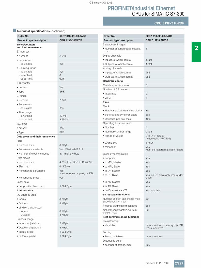
PROFINET/Industrial EthernetCPUs for SIMATIC S7-300
CPU 319F-3 PN/DP
2/227Siemens IK PI · 2009
2
■ Technical specifications (continued)
Order No. 6ES7 318-3FL00-0AB0Product type description CPU 319F-3 PN/DP
Times/counters and their remanence
S7 counter
• Number 2 048
• Remanence- adjustable Yes
• Counting range- adjustable Yes- lower limit 0- upper limit 999
IEC counter
• present Yes
• Type SFB
S7 times
• Number 2 048
• Remanence- adjustable Yes
• Time range- lower limit 10 ms- upper limit 9 990 s
IEC timer
• present Yes
• Type SFB
Data areas and their remanence
Flag
• Number, max. 8 KByte
• Remanence available Yes; MB 0 to MB 8191
• Number of clock memories 8; 1 memory byte
Data blocks
• Number, max. 4 095; from DB 1 to DB 4095
• Size, max. 64 KByte
• Remanence adjustable Yes; via non-retain property on DB
• Remanence preset yes
Local data
• per priority class, max. 1 024 Byte
Address area
I/O address area
• Inputs 8 KByte
• Outputs 8 KByte
• of which, distributed- Inputs 8 KByte- Outputs 8 KByte
Process image
• Inputs, adjustable 2 KByte
• Outputs, adjustable 2 KByte
• Inputs, preset 1 024 Byte
• Outputs, preset 1 024 Byte
Order No. 6ES7 318-3FL00-0AB0Product type description CPU 319F-3 PN/DP
Subprocess images
• Number of subprocess images, max.
1
Digital channels
• Inputs, of which central 1 024
• Outputs, of which central 1 024
Analog channels
• Inputs, of which central 256
• Outputs, of which central 256
Hardware config. Modules per rack, max. 8
Number of DP masters
• integrated 2
• via CP 4
Time
Clock
• Hardware clock (real-time clock) Yes
• buffered and synchronizable Yes
• Deviation per day, max. 10 s
Operating hours counter
• Number 4
• Number/Number range 0 to 3
• Range of values 0 to 2^31 hours (when using SFC 101)
• Granularity 1 hour
• remanent Yes; Must be restarted at each restart
Clock synchronization
• supports Yes
• to MPI, Master Yes
• to MPI, Slave Yes
• to DP, Master Yes
• to DP, Slave Yes; on DP slave only time-of-day slave
• in AS, Master Yes
• in AS, Slave Yes
• on Ethernet via NTP Yes; as client
S7 message functions
Number of login stations for mes-sage functions, max.
32
Process diagnostic messages Yes
simultaneously active Alarm-S blocks, max.
60
Test commissioning functions
Status/control
• Variables Inputs, outputs, memory bits, DB, times, counters
Forcing
• Force, variables Inputs, outputs
Diagnostic buffer
• Number of entries, max. 500
© Siemens AG 2008
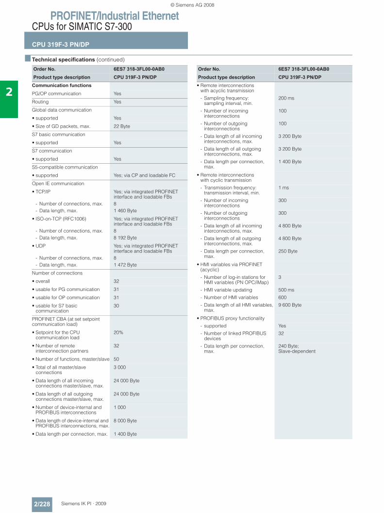
PROFINET/Industrial EthernetCPUs for SIMATIC S7-300
CPU 319F-3 PN/DP
2/228 Siemens IK PI · 2009
2
■ Technical specifications (continued)
Order No. 6ES7 318-3FL00-0AB0Product type description CPU 319F-3 PN/DP
Communication functions
PG/OP communication Yes
Routing Yes
Global data communication
• supported Yes
• Size of GD packets, max. 22 Byte
S7 basic communication
• supported Yes
S7 communication
• supported Yes
S5-compatible communication
• supported Yes; via CP and loadable FC
Open IE communication
• TCP/IP Yes; via integrated PROFINET interface and loadable FBs
- Number of connections, max. 8- Data length, max. 1 460 Byte
• ISO-on-TCP (RFC1006) Yes; via integrated PROFINET interface and loadable FBs
- Number of connections, max. 8- Data length, max. 8 192 Byte
• UDP Yes; via integrated PROFINET interface and loadable FBs
- Number of connections, max. 8- Data length, max. 1 472 Byte
Number of connections
• overall 32
• usable for PG communication 31
• usable for OP communication 31
• usable for S7 basic communication
30
PROFINET CBA (at set setpoint communication load)
• Setpoint for the CPU communication load
20%
• Number of remote interconnection partners
32
• Number of functions, master/slave 50
• Total of all master/slave connections
3 000
• Data length of all incoming connections master/slave, max.
24 000 Byte
• Data length of all outgoing connections master/slave, max.
24 000 Byte
• Number of device-internal and PROFIBUS interconnections
1 000
• Data length of device-internal and PROFIBUS interconnections, max.
8 000 Byte
• Data length per connection, max. 1 400 Byte
Order No. 6ES7 318-3FL00-0AB0Product type description CPU 319F-3 PN/DP
• Remote interconnections with acyclic transmission
- Sampling frequency: sampling interval, min.
200 ms
- Number of incoming interconnections
100
- Number of outgoing interconnections
100
- Data length of all incoming interconnections, max.
3 200 Byte
- Data length of all outgoing interconnections, max.
3 200 Byte
- Data length per connection, max.
1 400 Byte
• Remote interconnections with cyclic transmission
- Transmission frequency: transmission interval, min.
1 ms
- Number of incoming interconnections
300
- Number of outgoing interconnections
300
- Data length of all incoming interconnections, max.
4 800 Byte
- Data length of all outgoing interconnections, max.
4 800 Byte
- Data length per connection, max.
250 Byte
• HMI variables via PROFINET (acyclic)
- Number of log-in stations for HMI variables (PN OPC/iMap)
3
- HMI variable updating 500 ms
- Number of HMI variables 600
- Data length of all HMI variables, max.
9 600 Byte
• PROFIBUS proxy functionality
- supported Yes
- Number of linked PROFIBUS devices
32
- Data length per connection, max.
240 Byte; Slave-dependent
© Siemens AG 2008
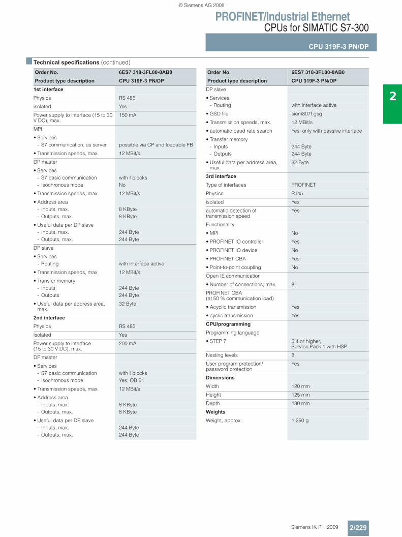
PROFINET/Industrial EthernetCPUs for SIMATIC S7-300
CPU 319F-3 PN/DP
2/229Siemens IK PI · 2009
2
■ Technical specifications (continued)
Order No. 6ES7 318-3FL00-0AB0Product type description CPU 319F-3 PN/DP
1st interface
Physics RS 485
isolated Yes
Power supply to interface (15 to 30 V DC), max.
150 mA
MPI
• Services- S7 communication, as server possible via CP and loadable FB
• Transmission speeds, max. 12 MBit/s
DP master
• Services- S7 basic communication with I blocks- Isochronous mode No
• Transmission speeds, max. 12 MBit/s
• Address area- Inputs, max. 8 KByte- Outputs, max. 8 KByte
• Useful data per DP slave- Inputs, max. 244 Byte- Outputs, max. 244 Byte
DP slave
• Services- Routing with interface active
• Transmission speeds, max. 12 MBit/s
• Transfer memory- Inputs 244 Byte- Outputs 244 Byte
• Useful data per address area, max.
32 Byte
2nd interface
Physics RS 485
isolated Yes
Power supply to interface (15 to 30 V DC), max.
200 mA
DP master
• Services- S7 basic communication with I blocks- Isochronous mode Yes; OB 61
• Transmission speeds, max. 12 MBit/s
• Address area- Inputs, max. 8 KByte- Outputs, max. 8 KByte
• Useful data per DP slave- Inputs, max. 244 Byte- Outputs, max. 244 Byte
Order No. 6ES7 318-3FL00-0AB0Product type description CPU 319F-3 PN/DP
DP slave
• Services- Routing with interface active
• GSD file siem807f.gsg
• Transmission speeds, max. 12 MBit/s
• automatic baud rate search Yes; only with passive interface
• Transfer memory- Inputs 244 Byte- Outputs 244 Byte
• Useful data per address area, max.
32 Byte
3rd interface
Type of interfaces PROFINET
Physics RJ45
isolated Yes
automatic detection oftransmission speed
Yes
Functionality
• MPI No
• PROFINET IO controller Yes
• PROFINET IO device No
• PROFINET CBA Yes
• Point-to-point coupling No
Open IE communication
• Number of connections, max. 8
PROFINET CBA (at 50 % communication load)
• Acyclic transmission Yes
• cyclic transmission Yes
CPU/programming
Programming language
• STEP 7 5.4 or higher, Service Pack 1 with HSP
Nesting levels 8
User program protection/password protection
Yes
Dimensions
Width 120 mm
Height 125 mm
Depth 130 mm
Weights
Weight, approx. 1 250 g
© Siemens AG 2008
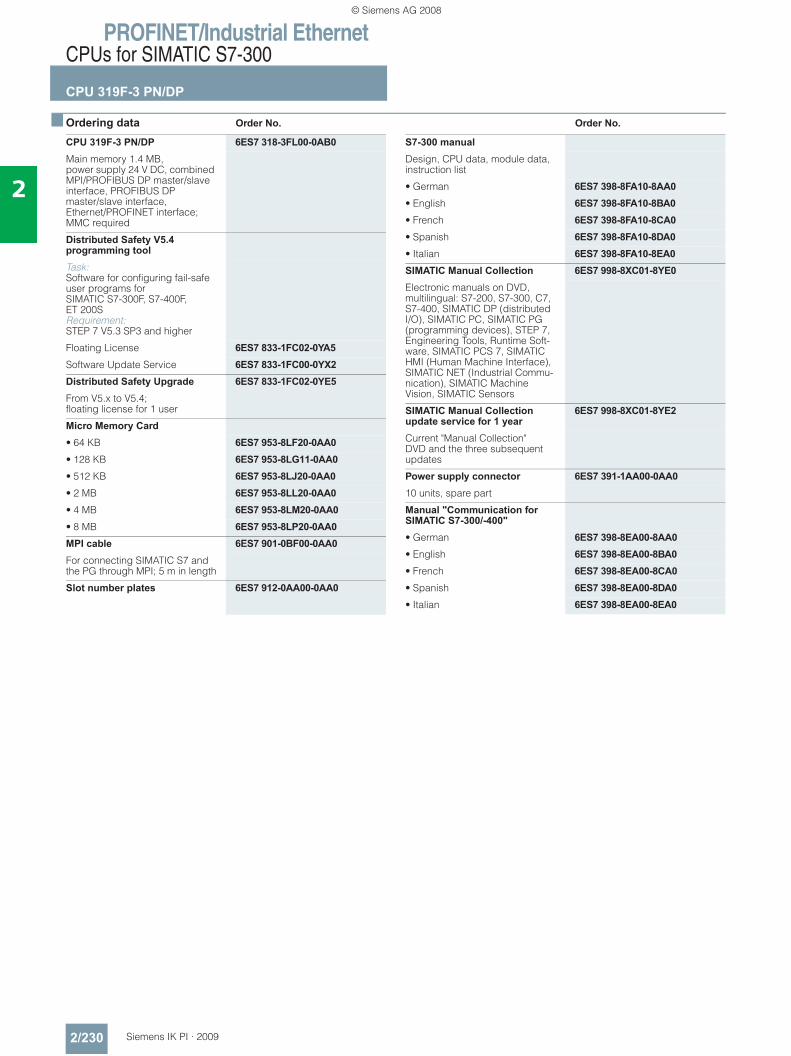
PROFINET/Industrial EthernetCPUs for SIMATIC S7-300
CPU 319F-3 PN/DP
2/230 Siemens IK PI · 2009
2
■ Ordering data Order No. Order No.
CPU 319F-3 PN/DP 6ES7 318-3FL00-0AB0Main memory 1.4 MB, power supply 24 V DC, combined MPI/PROFIBUS DP master/slave interface, PROFIBUS DP master/slave interface, Ethernet/PROFINET interface; MMC required
Distributed Safety V5.4 programming tool Task: Software for configuring fail-safe user programs for SIMATIC S7-300F, S7-400F, ET 200S Requirement:STEP 7 V5.3 SP3 and higher
Floating License 6ES7 833-1FC02-0YA5Software Update Service 6ES7 833-1FC00-0YX2Distributed Safety Upgrade 6ES7 833-1FC02-0YE5From V5.x to V5.4; floating license for 1 user
Micro Memory Card• 64 KB 6ES7 953-8LF20-0AA0• 128 KB 6ES7 953-8LG11-0AA0• 512 KB 6ES7 953-8LJ20-0AA0• 2 MB 6ES7 953-8LL20-0AA0• 4 MB 6ES7 953-8LM20-0AA0• 8 MB 6ES7 953-8LP20-0AA0MPI cable 6ES7 901-0BF00-0AA0For connecting SIMATIC S7 and the PG through MPI; 5 m in length
Slot number plates 6ES7 912-0AA00-0AA0
S7-300 manualDesign, CPU data, module data, instruction list
• German 6ES7 398-8FA10-8AA0• English 6ES7 398-8FA10-8BA0• French 6ES7 398-8FA10-8CA0• Spanish 6ES7 398-8FA10-8DA0• Italian 6ES7 398-8FA10-8EA0SIMATIC Manual Collection 6ES7 998-8XC01-8YE0Electronic manuals on DVD, multilingual: S7-200, S7-300, C7, S7-400, SIMATIC DP (distributed I/O), SIMATIC PC, SIMATIC PG (programming devices), STEP 7, Engineering Tools, Runtime Soft-ware, SIMATIC PCS 7, SIMATIC HMI (Human Machine Interface), SIMATIC NET (Industrial Commu-nication), SIMATIC Machine Vision, SIMATIC Sensors
SIMATIC Manual Collection update service for 1 year
6ES7 998-8XC01-8YE2
Current "Manual Collection" DVD and the three subsequent updates
Power supply connector 6ES7 391-1AA00-0AA010 units, spare part
Manual "Communication for SIMATIC S7-300/-400"• German 6ES7 398-8EA00-8AA0• English 6ES7 398-8EA00-8BA0• French 6ES7 398-8EA00-8CA0• Spanish 6ES7 398-8EA00-8DA0• Italian 6ES7 398-8EA00-8EA0
© Siemens AG 2008
PROFINET/Industrial EthernetCPUs for SIMATIC S7-300
CPU 319F-3 PN/DP
2/231Siemens IK PI · 2009
2
■ Ordering data (continued) Order No. Order No.
PROFIBUS bus components PROFIBUS DP bus connector RS 485• With 90° cable outlet,
max. transmission rate 12 Mbit/s- Without PG interface 6ES7 972-0BA12-0XA0- With PG interface 6ES7 972-0BB12-0XA0
• With 90° cable outlet for FastConnect connection system, max. transmission rate 12 Mbit/s- Without PG interface 6ES7 972-0BA51-0XA0- With PG interface 6ES7 972-0BB51-0XA0
• With axial cable outlet for SIMATIC OP, for connecting to PPI, MPI, PROFIBUS
6GK1 500-0EA02
PROFIBUS Fast Connect bus cable
6XV1 830-0EH10
Standard type with special design for quick mounting, 2-core, shielded, sold by the meter, max. delivery unit 1000 m, minimum order quantity 20 m
RS 485 repeater for PROFIBUS 6ES7 972-0AA01-0XA0Data transfer rate up to 12 Mbit/s; 24 V DC; IP20 housing
PROFINET bus components IE FC TP Standard Cable GP 2x2 6XV1 840-2AH104-core, shielded TP installation cable for connection to IE FC Outlet RJ45/ IE FC RJ45 Plug; PROFINET-compatible; with UL approval;sold by the meter
FO Standard Cable GP (50/125) 6XV1 873-2AStandard cable, splittable, UL approval, sold by the meter
Industrial Ethernet Switch SCALANCE X208
6GK5 208-0BA10-2AA3
with eight 10/100 Mbit/s RJ45 ports
Compact Switch ModuleCSM 377
6GK7 377-1AA00-0AA0
Unmanaged switch for the connection of a SIMATIC S7-300, ET 200M and as many as three other nodes to an Industrial Ethernet operating at 10/100 Mbit/s; 4 x RJ45 ports; external 24 V DC power supply, LED diagnostics, S7-300 module incl. electronic equipment manual on CD-ROM
IE FC RJ45 plugsRJ45 plug connector for Industrial Ethernet with a rugged metal enclosure and integrated insula-tion displacement contacts for connecting Industrial Ethernet FC installation cables
IE FC RJ45 Plug 180180° cable outlet
• 1 unit 6GK1 901-1BB10-2AA0• 10 units 6GK1 901-1BB10-2AB0• 50 units 6GK1 901-1BB10-2AE0
© Siemens AG 2008
PROFINET/Industrial EthernetCPUs for SIMATIC S7-400
CPU 414-3 PN/DP
2/232 Siemens IK PI · 2009
2
■ Overview
• CPUs for high demands in the mid-level performance range• Applicable for plants with additional demands on program-
ming scope and processing speed• Integrated PROFINET functions in CPU 414-3 PN/DP
■ Technical specifications
Order No. 6ES7 414-3EM05-0AB0Product type description CPU 414-3 PN/DP
Product status
Hardware product status 1
Firmware version V5.0
associated programming package STEP7 V5.4 SP1 or higher
Voltages and currents
Feeding of external buffer voltage to CPU
5 to 15 VDC
Current consumption
from backplane bus DC 5 V, max. 1.4 A
from interface DC 5 V, max. 90 mA; At each DP interface
Power loss, typ. 5.5 W
Backup battery
• Buffer current, typ. 125 μA; Valid up to 40°C
• Buffer current, max. 550 μA
Memory
Type of storage
• RAM- integrated (for program) 1.4 MByte- integrated (for data) 1.4 MByte- expandable No
• Load memory- expandable FEPROM Yes- expandable FEPROM, max. 64 MByte- integrated RAM, max. 512 KByte- expandable RAM Yes- expandable RAM, max. 64 MByte
Backup
• present Yes
• with battery Yes; All data
• without battery No
Order No. 6ES7 414-3EM05-0AB0Product type description CPU 414-3 PN/DP
CPU/blocks
DB
• Number, max. 6,000; Number range: 1 to 16,000
• Size, max. 64 KByte
FB
• Number, max. 3,000; Number range: 0 to 7999
• Size, max. 64 KByte
FC
• Number, max. 3,000; Number range: 0 to 7,999
• Size, max. 64 KByte
OB
• Size, max. 64 KByte
Nesting depth
• per priority class 24
• additional within an error OB 1
CPU/processing times
for bit operations, min. 45 ns
for word operations, min. 45 ns
for fixed point arithmetic, min. 45 ns
for floating point arithmetic, min. 135 ns
Times/countersand their remanence
S7 counter
• Number 2,048
• Remanence- adjustable Yes- lower limit 0- upper limit 2,047
• Counting range- lower limit 0- upper limit 999
IEC counter
• present Yes
• Type SFB
© Siemens AG 2008
PROFINET/Industrial EthernetCPUs for SIMATIC S7-400
CPU 414-3 PN/DP
2/233Siemens IK PI · 2009
2
■ Technical specifications (continued)
Order No. 6ES7 414-3EM05-0AB0Product type description CPU 414-3 PN/DP
S7 times
• Number 2,048
• Remanence- adjustable Yes- lower limit 0- upper limit 2,047- preset No times retentive
• Time range- lower limit 10 ms- upper limit 9,990 s
IEC timer
• present Yes
• Type SFB
Data areas and their remanence
remanent data area, total Total working and load memory (with backup battery)
Flag
• Number, max. 8 KByte
• Remanence available Yes
• Number of clock memories 8; (in 1 memory byte)
Address area
I/O address area
• Inputs 8 KByte
• Outputs 8 KByte
• of which, distributed- MPI/DPinterface, inputs 2 KByte- MPI/DP interface, outputs 2 KByte- DP interface, inputs 6 KByte- DP interface, outputs 6 KByte- PN interface, inputs 8 KByte- PN interface, outputs 8 KByte
Process image
• Inputs, adjustable 8 KByte
• Outputs, adjustable 8 KByte
• Inputs, preset 256 Byte
• Outputs, preset 256 Byte
• consistent data, max. 244 Byte
• Access to consistent data in process image
Yes
Subprocess images
• Number of subprocess images, max.
15
Digital channels
• Inputs 65,536
• Outputs 65,536
• Inputs, of which central 65,536
• Outputs, of which central 65,536
Analog channels
• Inputs 4,096
• Outputs 4,096
• Inputs, of which central 4,096
• Outputs, of which central 4,096
Order No. 6ES7 414-3EM05-0AB0Product type description CPU 414-3 PN/DP
Hardware config. connectable OPs 31
Central devices, max. 1
Expansion devices, max. 21
Multicomputing Yes; Max. 4 CPUs (with UR1 or UR2)
IM
• Number of connectable IMs (total), max.
6
• Number of connectable IM 460s, max.
6
• Number of connectable IM 463s, max.
4; IM 463-2
Number of DP masters
• integrated 1
• via IM 467 4
• via CP 10; CP 443-5 Extended
• Mixed mode IM + CP permitted No;IM 467 cannot be used with CP 443-5 Ext.;IM 467 cannot be used with CP 443-1 EX40 in PN IO mode
• via interface module 1; IF 964-DP
• Number of pluggable S5 modules (via adapter capsule in central device), max.
6
Number of IO controllers
• integrated 1
• via CP 4; Via CP 443-1 EX 41 in PN mode; max. 4 in central controller
Number of operable FMs and CPs (recommended)
• FM Limited due to number of slots and number of connections
• CP, point-to-point Limited due to number of slots and number of connections
• PROFIBUS and Ethernet CPs 14
Time
Clock
• Hardware clock (real-time clock) Yes
• buffered and synchronizable Yes
• Resolution 1 ms
Operating hours counter
• Number 8
Clock synchronization
• supports Yes
• to MPI, Master Yes
• to MPI, Slave Yes
• to DP, Master Yes
• to DP, Slave Yes
• in AS, Master Yes
• in AS, Slave Yes
• on Ethernet via NTP Yes; as client
• to IF 964 DP Yes
© Siemens AG 2008
PROFINET/Industrial EthernetCPUs for SIMATIC S7-400
CPU 414-3 PN/DP
2/234 Siemens IK PI · 2009
2
■ Technical specifications (continued)
Order No. 6ES7 414-3EM05-0AB0Product type description CPU 414-3 PN/DP
S7 message functions
Number of login stationsfor message functions, max.
31; Max. 31 with alarm_S and alarm_D (OP’s); max. 8 with alarm_8 and alarm_P (e.g. WinCC)
Symbol-related messages Yes
Number of messages
• overall, max. 512
Block related messages Yes
Alarm 8-blocks Yes
Instrumentation & control messages Yes
Test commissioning functions
Status/control
• Status/control variable Yes
Forcing
• Forcing Yes
Status block Yes
Single step Yes
Number of breakpoints 4
Diagnostic buffer
• present Yes
• Number of entries, max. 3,200
• adjustable Yes
• preset 120
Communication functions
PG/OP communication Yes
Routing Yes
Global data communication
• supported Yes
• Size of GD packets, max. 54 Byte
S7 basic communication
• supported Yes
• Useful data per job, max. 76 Byte
S7 communication
• supported Yes
• Useful data per job, max. 64 KByte
S5-compatible communication
• supported Yes; (via CP max. 10 and FC AG_SEND and FC AG_RECV)
• Useful data per job, max. 8 KByte
Standard communication (FMS)
• supported Yes; Via CP and loadable FB
• Web server Yes
Open IE communication
• TCP/IP Yes- Number of connections, max. 32- Data length, max. 32 KByte
• ISO-on-TCP (RFC1006) Yes- Number of connections, max. 32- Data length, max. 32 KByte; 1452 bytes via CP 443-
1 Adv.
• UDP Yes- Number of connections, max. 32- Data length, max. 1,472 Byte
Order No. 6ES7 414-3EM05-0AB0Product type description CPU 414-3 PN/DP
Number of connections
• overall 32
PROFINET CBA (at set setpoint communication load)
• Number of remote interconnection partners
32
• Number of functions, master/slave 150
• Total of all master/slave connections
4,500
• Data length of all incoming connections master/slave, max.
45,000 Byte
• Data length of all outgoing connections master/slave, max.
45,000 Byte
• Number of device-internal and PROFIBUS interconnections
1,000
• Data length of device-internal and PROFIBUS interconnections, max.
16,000 Byte
• Data length per connection, max. 2,000 Byte
• Remote interconnections with acyclic transmission- Sampling frequency:
sampling interval, min.200 ms; Depending on preset communca-tion load, number of interconnec-tions and data length used
- Number of incoming interconnections
250
- Number of outgoing interconnections
250
- Data length of all incoming interconnections, max.
8,000 Byte
- Data length of all outgoing interconnections, max.
8,000 Byte
- Data length per connection, max.
2,000 Byte
• Remote interconnections with cyclic transmission- Transmission frequency:
transmission interval, min.1 ms; Depending on preset communica-tion load, number of interconnec-tions and data length used
- Number of incoming interconnections
300
- Number of outgoing interconnections
300
- Data length of all incoming interconnections, max.
4,800 Byte
- Data length of all outgoing interconnections, max.
4,800 Byte
- Data length per connection, max.
250 Byte
• HMI variables via PROFINET (acyclic)- Number of log-in stations for
HMI variables (PN OPC/iMap)2x PN OPC/1x iMap
- HMI variable updating 500 ms- Number of HMI variables 1,000- Data length of all HMI variables,
max.32,000 Byte
• PROFIBUS proxy functionality- supported Yes;
32 PROFIBUS slaves max. connectable
- Data length per connection, max.
240 Byte; Slave-dependent
© Siemens AG 2008
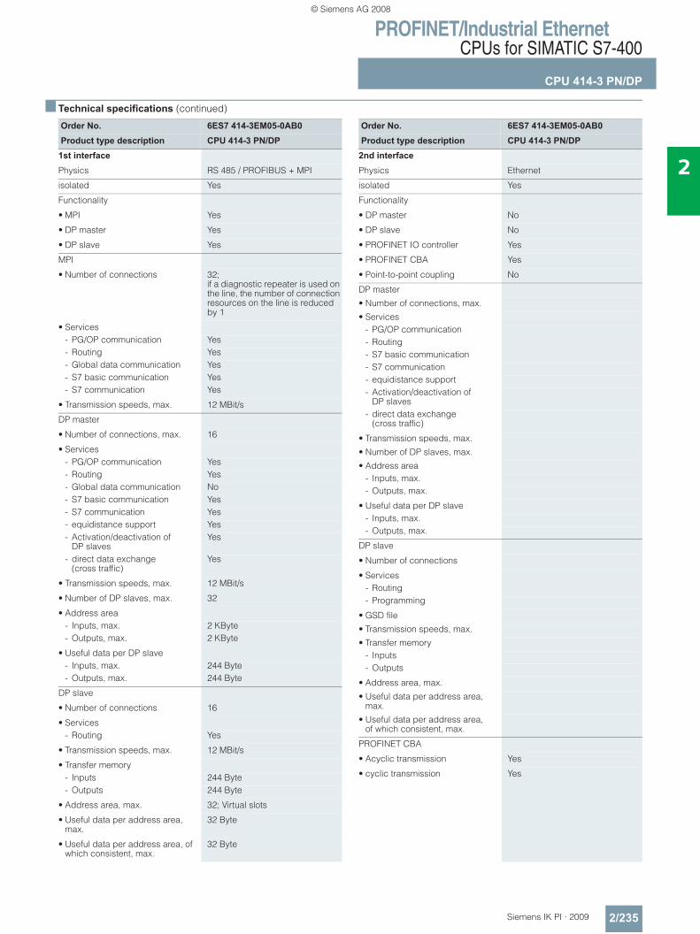
PROFINET/Industrial EthernetCPUs for SIMATIC S7-400
CPU 414-3 PN/DP
2/235Siemens IK PI · 2009
2
■ Technical specifications (continued)
Order No. 6ES7 414-3EM05-0AB0Product type description CPU 414-3 PN/DP
1st interface
Physics RS 485 / PROFIBUS + MPI
isolated Yes
Functionality
• MPI Yes
• DP master Yes
• DP slave Yes
MPI
• Number of connections 32; if a diagnostic repeater is used on the line, the number of connection resources on the line is reduced by 1
• Services- PG/OP communication Yes- Routing Yes- Global data communication Yes- S7 basic communication Yes- S7 communication Yes
• Transmission speeds, max. 12 MBit/s
DP master
• Number of connections, max. 16
• Services- PG/OP communication Yes- Routing Yes- Global data communication No- S7 basic communication Yes- S7 communication Yes- equidistance support Yes- Activation/deactivation of
DP slavesYes
- direct data exchange (cross traffic)
Yes
• Transmission speeds, max. 12 MBit/s
• Number of DP slaves, max. 32
• Address area- Inputs, max. 2 KByte- Outputs, max. 2 KByte
• Useful data per DP slave- Inputs, max. 244 Byte- Outputs, max. 244 Byte
DP slave
• Number of connections 16
• Services- Routing Yes
• Transmission speeds, max. 12 MBit/s
• Transfer memory- Inputs 244 Byte- Outputs 244 Byte
• Address area, max. 32; Virtual slots
• Useful data per address area, max.
32 Byte
• Useful data per address area, of which consistent, max.
32 Byte
Order No. 6ES7 414-3EM05-0AB0Product type description CPU 414-3 PN/DP
2nd interface
Physics Ethernet
isolated Yes
Functionality
• DP master No
• DP slave No
• PROFINET IO controller Yes
• PROFINET CBA Yes
• Point-to-point coupling No
DP master
• Number of connections, max.
• Services- PG/OP communication- Routing- S7 basic communication- S7 communication- equidistance support- Activation/deactivation of
DP slaves- direct data exchange
(cross traffic)
• Transmission speeds, max.
• Number of DP slaves, max.
• Address area- Inputs, max.- Outputs, max.
• Useful data per DP slave- Inputs, max.- Outputs, max.
DP slave
• Number of connections
• Services- Routing- Programming
• GSD file
• Transmission speeds, max.
• Transfer memory- Inputs- Outputs
• Address area, max.
• Useful data per address area, max.
• Useful data per address area, of which consistent, max.
PROFINET CBA
• Acyclic transmission Yes
• cyclic transmission Yes
© Siemens AG 2008
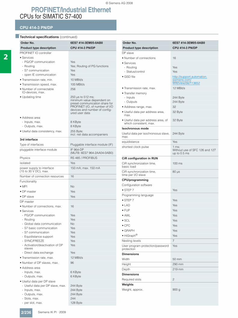
PROFINET/Industrial EthernetCPUs for SIMATIC S7-400
CPU 414-3 PN/DP
2/236 Siemens IK PI · 2009
2
■ Technical specifications (continued)
Order No. 6ES7 414-3EM05-0AB0Product type description CPU 414-3 PN/DP
PROFINET IO controller
• Services- PG/OP communication Yes- Routing Yes; Routing of PG functions- S7 communication Yes- open IE communication Yes
• Transmission rate, min. 10 MBit/s
• Transmission speed, max. 100 MBit/s
• Number of connectable IO-devices, max.
256
• Updating time 250 μs to 512 ms; minimum value dependent on preset communication share for PROFINET I/O, of number of I/O devices and number of config-ured user data
• Address area- Inputs, max. 8 KByte- Outputs, max. 8 KByte
• Useful data consistency, max. 255 Byte; incl. net data accompaniers
3rd interface
Type of interfaces Pluggable interface module (IF)
pluggable interface module IF 964-DP (MLFB: 6ES7 964-2AA04-0AB0)
Physics RS 485 / PROFIBUS
isolated Yes
power supply to interface (15 to 30 V DC), max.
150 mA; max. 150 mA
Number of connection resources 16
Functionality
• MPI No
• DP master Yes
• DP slave Yes
DP master
• Number of connections, max. 16
• Services- PG/OP communication Yes- Routing Yes- Global data communication No- S7 basic communication Yes- S7 communication Yes- Equidistance support Yes- SYNC/FREEZE Yes- Activation/deactivation of DP
slavesYes
- Direct data exchange Yes
• Transmission rate, max. 12 MBit/s
• Number of DP slaves, max. 96
• Address area- Inputs, max. 6 KByte- Outputs, max. 6 KByte
• Useful data per DP slave- Useful data per DP slave, max. 244 Byte- Inputs, max. 244 Byte- Outputs, max. 244 Byte- Slots, max. 244- per slot, max. 128 Byte
Order No. 6ES7 414-3EM05-0AB0Product type description CPU 414-3 PN/DP
DP slave
• Number of connections 16
• Services- Routing Yes- Status/control Yes
• GSD file http://support.automation.siemens.com/WW/view/de/113652
• Transmission rate, max. 12 MBit/s
• Transfer memory- Inputs 244 Byte- Outputs 244 Byte
• Address range, max. 32
• Useful data per address area, max.
32 Byte
• Useful data per address area, of which consistent, max.
32 Byte
Isochronous mode
Useful data per isochronoous slave, max.
244 Byte
equidistance Yes
shortest clock pulse 1 ms; Without use of SFC 126 and 127 up to 0.5 ms
CiR configuration in RUN
CiR synchronization time, basic load
100 ms
CiR synchronization time, time per I/O slave
80 μs
CPU/programming
Configuration software
• STEP 7 Yes
Programming language
• STEP 7 Yes
• LAD Yes
• FUP Yes
• AWL Yes
• SCL Yes
• CFC Yes
• GRAPH Yes
• HiGraph® Yes
Nesting levels 7
User program protection/password protection
Yes
Dimensions
Width 50 mm
Height 290 mm
Depth 219 mm
Dimensions
Required slots 2
Weights
Weight, approx. 900 g
© Siemens AG 2008
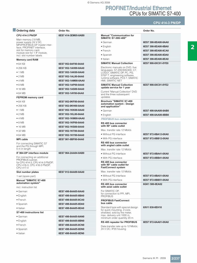
PROFINET/Industrial EthernetCPUs for SIMATIC S7-400
CPU 414-3 PN/DP
2/237Siemens IK PI · 2009
2
■ Ordering data Order No. Order No.
CPU 414-3 PN/DP 6ES7 414-3EM05-0AB0Main memory 2.8 MB, power supply 24 V DC, MPI/PROFIBUS DP master inter-face, PROFINET interface, slot for memory card, module slot for 1 IF module, incl. slot number labels
Memory card RAM• 64 KB 6ES7 952-0AF00-0AA0• 256 KB 6ES7 952-1AH00-0AA0• 1 MB 6ES7 952-1AK00-0AA0• 2 MB 6ES7 952-1AL00-0AA0• 4 MB 6ES7 952-1AM00-0AA0• 8 MB 6ES7 952-1AP00-0AA0• 16 MB 6ES7 952-1AS00-0AA0• 64 MB 6ES7 952-1AY00-0AA0FEPROM memory card• 64 KB 6ES7 952-0KF00-0AA0• 256 KB 6ES7 952-0KH00-0AA0• 1 MB 6ES7 952-1KK00-0AA0• 2 MB 6ES7 952-1KL00-0AA0• 4 MB 6ES7 952-1KM00-0AA0• 8 MB 6ES7 952-1KP00-0AA0• 16 MB 6ES7 952-1KS00-0AA0• 32 MB 6ES7 952-1KT00-0AA0• 64 MB 6ES7 952-1KY00-0AA0MPI cable 6ES7 901-0BF00-0AA0For connecting SIMATIC S7 and the PG through MPI; 5 m in length
IF 964-DP interface module 6ES7 964-2AA04-0AB0For connecting an additional PROFIBUS subnet; for CPU 414-3, CPU 414-3 PN/DP, CPU 416-3, CPU 416-3 PN/DP, CPU 417-4
Slot number plates 6ES7 912-0AA00-0AA01 set (spare part)
Manual "SIMATIC S7-400 automation system"incl. instruction list
• German 6ES7 498-8AA05-8AA0• English 6ES7 498-8AA05-8BA0• French 6ES7 498-8AA05-8CA0• Spanish 6ES7 498-8AA05-8DA0• Italian 6ES7 498-8AA05-8EA0S7-400 instructions list• German 6ES7 498-8AA05-8AN0• English 6ES7 498-8AA05-8BN0• French 6ES7 498-8AA05-8CN0• Spanish 6ES7 498-8AA05-8DN0• Italian 6ES7 498-8AA05-8EN0
Manual "Communication for SIMATIC S7-300/-400"• German 6ES7 398-8EA00-8AA0• English 6ES7 398-8EA00-8BA0• French 6ES7 398-8EA00-8CA0• Spanish 6ES7 398-8EA00-8DA0• Italian 6ES7 398-8EA00-8EA0SIMATIC Manual Collection 6ES7 998-8XC01-8YE0Electronic manuals on DVD, five languages: S7-200/300/400, C7, LOGO!, SIMATIC DP, PC, PG, STEP 7, engineering software, runtime software, PCS 7, SIMATIC HMI, SIMATIC NET
SIMATIC Manual Collection update service for 1 year
6ES7 998-8XC01-8YE2
Current "Manual Collection" DVD and the three subsequent updates
Brochure "SIMATIC S7-400 automation system - Design and application"• German 6ES7 498-8AA00-8AB0• English 6ES7 498-8AA00-8BB0PROFIBUS bus components RS 485 bus connector with 90° cable outletMax. transfer rate 12 Mbit/s
• Without PG interface 6ES7 972-0BA12-0XA0• With PG interface 6ES7 972-0BB12-0XA0RS 485 bus connector with angled cable outletMax. transfer rate 12 Mbit/s
• Without PG interface 6ES7 972-0BA41-0XA0• With PG interface 6ES7 972-0BB41-0XA0RS 485 bus connector with 90° cable outlet for FastConnect systemMax. transfer rate 12 Mbit/s
• Without PG interface 6ES7 972-0BA51-0XA0• With PG interface 6ES7 972-0BB51-0XA0RS 485 bus connector with axial cable outlet
6GK1 500-0EA02
For SIMATIC OP,for connection to PPI, MPI, PROFIBUS
PROFIBUS FastConnect bus cableStandard type with special design for quick mounting, 2-core, shielded, sold by the meter, max. delivery unit 1000 m, minimum order quantity 20 m
6XV1 830-0EH10
RS 485 repeater for PROFIBUS 6ES7 972-0AA01-0XA0Data transfer rate up to 12 Mbit/s; 24 V DC; IP20 housing
© Siemens AG 2008
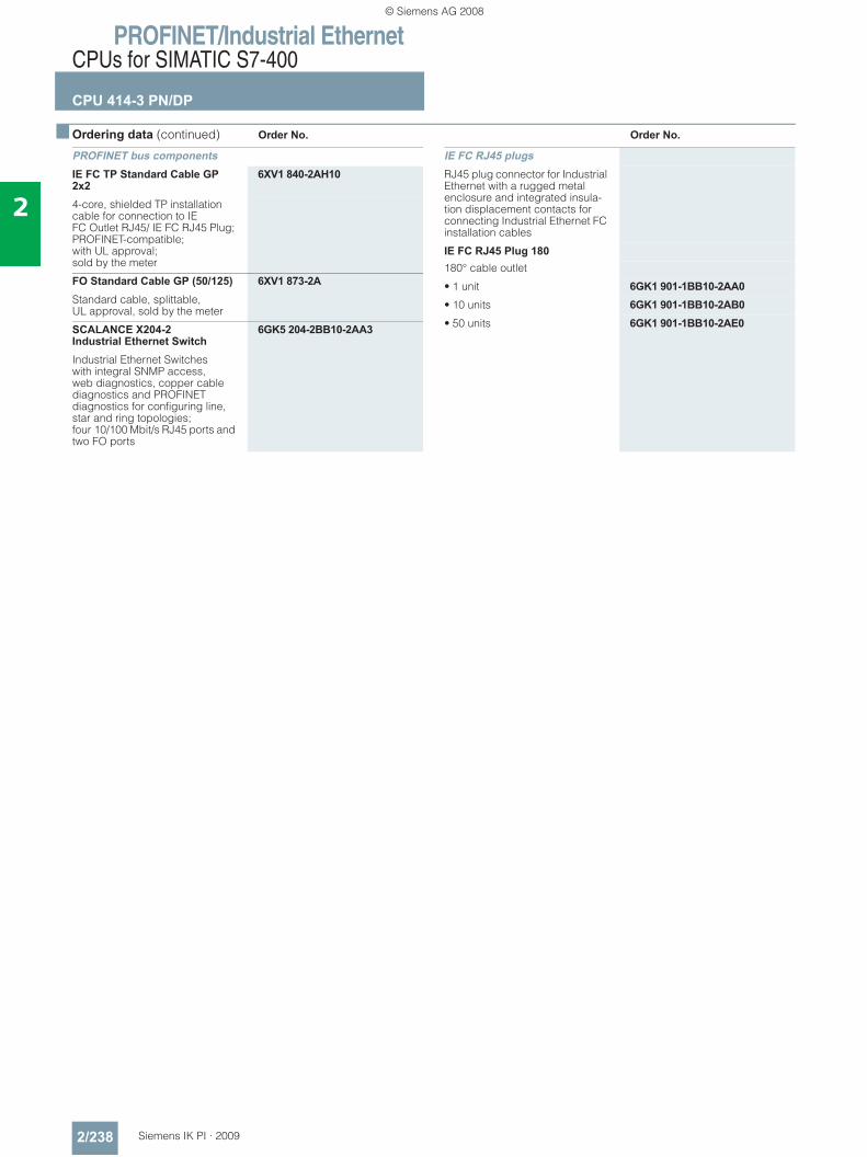
PROFINET/Industrial EthernetCPUs for SIMATIC S7-400
CPU 414-3 PN/DP
2/238 Siemens IK PI · 2009
2
■ Ordering data (continued) Order No. Order No.
PROFINET bus components IE FC TP Standard Cable GP 2x2
6XV1 840-2AH10
4-core, shielded TP installation cable for connection to IE FC Outlet RJ45/ IE FC RJ45 Plug; PROFINET-compatible; with UL approval;sold by the meter
FO Standard Cable GP (50/125) 6XV1 873-2AStandard cable, splittable, UL approval, sold by the meter
SCALANCE X204-2 Industrial Ethernet Switch
6GK5 204-2BB10-2AA3
Industrial Ethernet Switches with integral SNMP access, web diagnostics, copper cable diagnostics and PROFINET diagnostics for configuring line, star and ring topologies; four 10/100 Mbit/s RJ45 ports and two FO ports
IE FC RJ45 plugsRJ45 plug connector for Industrial Ethernet with a rugged metal enclosure and integrated insula-tion displacement contacts for connecting Industrial Ethernet FC installation cables
IE FC RJ45 Plug 180180° cable outlet
• 1 unit 6GK1 901-1BB10-2AA0• 10 units 6GK1 901-1BB10-2AB0• 50 units 6GK1 901-1BB10-2AE0
© Siemens AG 2008
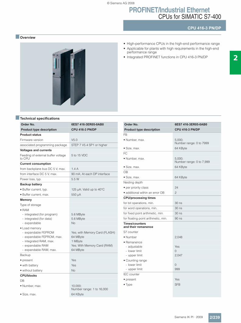
PROFINET/Industrial EthernetCPUs for SIMATIC S7-400
CPU 416-3 PN/DP
2/239Siemens IK PI · 2009
2
■ Overview
• High-performance CPUs in the high-end performance range• Applicable for plants with high requirements in the high-end
performance range• Integrated PROFINET functions in CPU 416-3 PN/DP
■ Technical specifications
Order No. 6ES7 416-3ER05-0AB0Product type description CPU 416-3 PN/DP
Product status
Firmware version V5.0
associated programming package STEP 7 V5.4 SP1 or higher
Voltages and currents
Feeding of external buffer voltage to CPU
5 to 15 VDC
Current consumption
from backplane bus DC 5 V, max. 1.4 A
from interface DC 5 V, max. 90 mA; At each DP interface
Power loss, typ. 5.5 W
Backup battery
• Buffer current, typ. 125 μA; Valid up to 40°C
• Buffer current, max. 550 μA
Memory
Type of storage
• RAM- integrated (for program) 5.6 MByte- integrated (for data) 5.6 MByte- expandable No
• Load memory- expandable FEPROM Yes; with Memory Card (FLASH)- expandable FEPROM, max. 64 MByte- integrated RAM, max. 1 MByte- expandable RAM Yes; With Memory Card (RAM)- expandable RAM, max. 64 MByte
Backup
• present Yes
• with battery Yes
• without battery No
CPU/blocks
DB
• Number, max. 10,000; Number range: 1 to 16,000
• Size, max. 64 KByte
Order No. 6ES7 416-3ER05-0AB0Product type description CPU 416-3 PN/DP
FB
• Number, max. 5,000; Number range: 0 to 7999
• Size, max. 64 KByte
FC
• Number, max. 5,000; Number range: 0 to 7,999
• Size, max. 64 KByte
OB
• Size, max. 64 KByte
Nesting depth
• per priority class 24
• additional within an error OB 2
CPU/processing times
for bit operations, min. 30 ns
for word operations, min. 30 ns
for fixed point arithmetic, min. 30 ns
for floating point arithmetic, min. 90 ns
Times/counters and their remanence
S7 counter
• Number 2,048
• Remanence- adjustable Yes- lower limit 0- upper limit 2,047
• Counting range- lower limit 0- upper limit 999
IEC counter
• present Yes
• Type SFB
© Siemens AG 2008
PROFINET/Industrial EthernetCPUs for SIMATIC S7-400
CPU 416-3 PN/DP
2/240 Siemens IK PI · 2009
2
■ Technical specifications (continued)
Order No. 6ES7 416-3ER05-0AB0Product type description CPU 416-3 PN/DP
S7 times
• Number 2,048
• Remanence- adjustable Yes- lower limit 0- upper limit 2,047- preset No times retentive
• Time range- lower limit 10 ms- upper limit 9,990 s
IEC timer
• present Yes
• Type SFB
Data areas and their remanence
remanent data area, total Total working and load memory (with backup battery)
Flag
• Number, max. 16 KByte; Size of bit memory address area
• Remanence available Yes
• Number of clock memories 8; (in 1 memory byte)
Address area
I/O address area
• Inputs 16 KByte
• Outputs 16 KByte
• of which, distributed- MPI/DPinterface, inputs 2 KByte- MPI/DP interface, outputs 2 KByte- DP interface, inputs 8 KByte- DP interface, outputs 8 KByte- PN interface, inputs 8 KByte- PN interface, outputs 8 KByte
Process image
• Inputs, adjustable 16 KByte
• Outputs, adjustable 16 KByte
• Inputs, preset 512 Byte
• Outputs, preset 512 Byte
• consistent data, max. 244 Byte
• Access to consistent datain process image
Yes
Subprocess images
• Number of subprocess images, max.
15
Digital channels
• Inputs 131,072
• Outputs 131,072
• Inputs, of which central 131,072
• Outputs, of which central 131,072
Analog channels
• Inputs 8,192
• Outputs 8,192
• Inputs, of which central 8,192
• Outputs, of which central 8,192
Order No. 6ES7 416-3ER05-0AB0Product type description CPU 416-3 PN/DP
Hardware config. connectable OPs 63
Central devices, max. 1
Expansion devices, max. 21
Multicomputing Yes; Max. 4 CPUs(with UR1 or UR2)
IM
• Number of connectable IMs (total), max.
6
• Number of connectable IM 460s, max.
6
• Number of connectable IM 463s, max.
4; IM 463-2
Number of DP masters
• integrated 1
• via IM 467 4
• via CP 10; CP 443-5 Extended
• Mixed mode IM + CP permitted No; IM 467 cannot be used with CP 443-5 Ext.; IM 467 cannot be used with CP 443-1 EX40 in PN IO mode
• via interface module 1; IF 964-DP
• Number of pluggable S5 modules (via adapter capsule in central de-vice), max.
6
Number of IO controllers
• integrated 1
• via CP 4; Via CP 443-1 EX 41 in PN mode; max. 4 in central controller
Number of operable FMs and CPs (recommended)
• FM Limited due to number of slots and number of connections
• CP, point-to-point Limited due to number of slots and number of connections
• PROFIBUS and Ethernet CPs 14
Time
Clock
• Hardware clock (real-time clock) Yes
• buffered and synchronizable Yes
• Resolution 1 ms
Operating hours counter
• Number 8
Clock synchronization
• supports Yes
• to MPI, Master Yes
• to MPI, Slave Yes
• to DP, Master Yes
• to DP, Slave Yes
• in AS, Master Yes
• in AS, Slave Yes
• on Ethernet via NTP Yes; as client
• to IF 964 DP Yes
© Siemens AG 2008
PROFINET/Industrial EthernetCPUs for SIMATIC S7-400
CPU 416-3 PN/DP
2/241Siemens IK PI · 2009
2
■ Technical specifications (continued)
Order No. 6ES7 416-3ER05-0AB0Product type description CPU 416-3 PN/DP
S7 message functions
Number of login stations for message functions, max.
63; Max. 63 with alarm_S and alarm_D (OP’s); max. 12 with alarm_8 and alarm_P (e.g. WinCC)
Symbol-related messages Yes
Number of messages
• overall, max. 1,024
Block related messages Yes
Alarm 8-blocks Yes
Instrumentation & control messages Yes
Test commissioning functions
Status/control
• Status/control variable Yes
Forcing
• Forcing Yes
Status block Yes
Single step Yes
Number of breakpoints 4
Diagnostic buffer• present Yes• Number of entries, max. 3,200• adjustable Yes• preset 120
Communication functions
PG/OP communication Yes
Routing Yes
Global data communication
• supported Yes
• Size of GD packets, max. 54 Byte
S7 basic communication
• supported Yes
• Useful data per job, max. 76 Byte
S7 communication
• supported Yes
• Useful data per job, max. 64 KByte
S5-compatible communication
• supported Yes; (via CP max. 10 and FC AG_SEND and FC AG_RECV)
• Useful data per job, max. 8 KByte
Standard communication (FMS)
• supported Yes; Via CP and loadable FB
• Web server Yes; Read-only function
Open IE communication
• TCP/IP Yes- Number of connections, max. 64- Data length, max. 32 KByte
• ISO-on-TCP (RFC1006) Yes- Number of connections, max. 64- Data length, max. 32 KByte;
1452 bytes via CP 443-1 Adv.• UDP Yes
- Number of connections, max. 64- Data length, max. 1,472 Byte
Order No. 6ES7 416-3ER05-0AB0Product type description CPU 416-3 PN/DP
Number of connections
• overall 64
PROFINET CBA (at set setpoint communication load)
• Number of remote interconnection partners
32
• Number of functions, master/slave 150
• Total of all master/slave connections
6,000
• Data length of all incoming connections master/slave, max.
65,000 Byte
• Data length of all outgoing connections master/slave, max.
65,000 Byte
• Number of device-internal and PROFIBUS interconnections
1,000
• Data length of device-internal and PROFIBUS interconnections, max.
16,000 Byte
• Data length per connection, max. 2,000 Byte
• Remote interconnections with acyclic transmission- Sampling frequency:
sampling interval, min.200 ms; Depending on preset communcation load, number of interconnections and data length used
- Number of incoming interconnections
500
- Number of outgoing interconnections
500
- Data length of all incoming interconnections, max.
16,000 Byte
- Data length of all outgoing interconnections, max.
16,000 Byte
- Data length per connection, max.
2,000 Byte
• Remote interconnections with cyclic transmission- Transmission frequency:
transmission interval, min.1 ms; Depending on preset com-munication load, number of inter-connections and data length used
- Number of incoming interconnections
300
- Number of outgoing interconnections
300
- Data length of all incoming interconnections, max.
4,800 Byte
- Data length of all outgoing interconnections, max.
4,800 Byte
- Data length per connection, max.
250 Byte
• HMI variables via PROFINET (acyclic)- Number of log-in stations for
HMI variables (PN OPC/iMap)2x PN OPC/1x iMap
- HMI variable updating 500 ms- Number of HMI variables 1,500- Data length of all HMI variables,
max.48,000 Byte
• PROFIBUS proxy functionality- supported Yes; 32 PROFIBUS slaves max.
connectable- Data length per connection,
max.240 Byte; Slave-dependent
© Siemens AG 2008
PROFINET/Industrial EthernetCPUs for SIMATIC S7-400
CPU 416-3 PN/DP
2/242 Siemens IK PI · 2009
2
■ Technical specifications (continued)
Order No. 6ES7 416-3ER05-0AB0Product type description CPU 416-3 PN/DP
1st interface
Physics RS 485 / PROFIBUS + MPI
isolated Yes
Functionality
• MPI Yes
• DP master Yes
• DP slave Yes
MPI
• Number of connections 44
• Services- PG/OP communication Yes- Routing Yes- Global data communication Yes- S7 basic communication Yes- S7 communication Yes
• Transmission speeds, max. 12 MBit/s
DP master
• Number of connections, max. 32; if a diagnostic repeater is used on the line, the number of connection resources on the line is reduced by 1
• Services- PG/OP communication Yes- Routing Yes- Global data communication No- S7 basic communication Yes- S7 communication Yes- equidistance support Yes- Activation/deactivation of DP
slavesYes
- direct data exchange (cross traf-fic)
Yes
• Transmission speeds, max. 12 MBit/s
• Number of DP slaves, max. 32
• Address area- Inputs, max. 2 KByte- Outputs, max. 2 KByte
• Useful data per DP slave- Inputs, max. 244 Byte- Outputs, max. 244 Byte
DP slave
• Number of connections 32
• Services- Routing Yes; with interface active
• Transmission speeds, max. 12 MBit/s
• Transfer memory- Inputs 244 Byte- Outputs 244 Byte
• Address area, max. 32; Virtual slots
• Useful data per address area, max.
32 Byte
• Useful data per address area, of which consistent, max.
32 Byte
Order No. 6ES7 416-3ER05-0AB0Product type description CPU 416-3 PN/DP
2nd interface
Physics Ethernet
isolated Yes
Functionality
• DP master No
• DP slave No
• PROFINET IO controller Yes
• PROFINET CBA Yes
• Point-to-point coupling No
DP master
• Number of connections, max.
• Services- PG/OP communication- Routing- S7 basic communication- S7 communication- equidistance support- Activation/deactivation of
DP slaves- direct data exchange
(cross traffic)
• Transmission speeds, max.
• Number of DP slaves, max.
• Address area- Inputs, max.- Outputs, max.
• Useful data per DP slave- Inputs, max.- Outputs, max.
DP slave
• Number of connections
• Services- Routing- Programming
• GSD file
• Transmission speeds, max.
• Transfer memory- Inputs- Outputs
• Address area, max.
• Useful data per address area, max.
• Useful data per address area, of which consistent, max.
PROFINET CBA
• Acyclic transmission Yes
• cyclic transmission Yes
© Siemens AG 2008
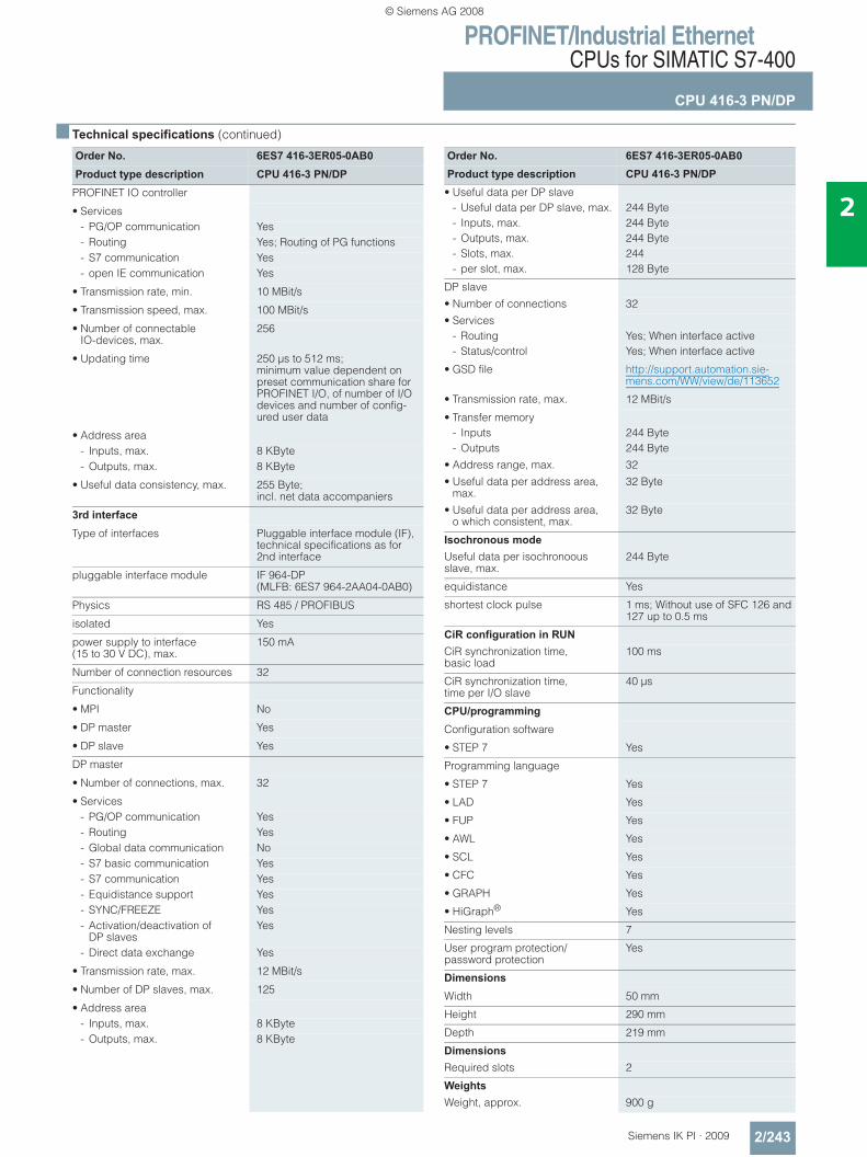
PROFINET/Industrial EthernetCPUs for SIMATIC S7-400
CPU 416-3 PN/DP
2/243Siemens IK PI · 2009
2
■ Technical specifications (continued)
Order No. 6ES7 416-3ER05-0AB0Product type description CPU 416-3 PN/DP
PROFINET IO controller
• Services- PG/OP communication Yes- Routing Yes; Routing of PG functions- S7 communication Yes- open IE communication Yes
• Transmission rate, min. 10 MBit/s
• Transmission speed, max. 100 MBit/s
• Number of connectableIO-devices, max.
256
• Updating time 250 μs to 512 ms; minimum value dependent on preset communication share for PROFINET I/O, of number of I/O devices and number of config-ured user data
• Address area- Inputs, max. 8 KByte- Outputs, max. 8 KByte
• Useful data consistency, max. 255 Byte;incl. net data accompaniers
3rd interface
Type of interfaces Pluggable interface module (IF), technical specifications as for 2nd interface
pluggable interface module IF 964-DP (MLFB: 6ES7 964-2AA04-0AB0)
Physics RS 485 / PROFIBUS
isolated Yes
power supply to interface (15 to 30 V DC), max.
150 mA
Number of connection resources 32
Functionality
• MPI No
• DP master Yes
• DP slave Yes
DP master
• Number of connections, max. 32
• Services- PG/OP communication Yes- Routing Yes- Global data communication No- S7 basic communication Yes- S7 communication Yes- Equidistance support Yes- SYNC/FREEZE Yes- Activation/deactivation of
DP slavesYes
- Direct data exchange Yes
• Transmission rate, max. 12 MBit/s
• Number of DP slaves, max. 125
• Address area- Inputs, max. 8 KByte- Outputs, max. 8 KByte
Order No. 6ES7 416-3ER05-0AB0Product type description CPU 416-3 PN/DP
• Useful data per DP slave- Useful data per DP slave, max. 244 Byte- Inputs, max. 244 Byte- Outputs, max. 244 Byte- Slots, max. 244- per slot, max. 128 Byte
DP slave• Number of connections 32• Services
- Routing Yes; When interface active- Status/control Yes; When interface active
• GSD file http://support.automation.sie-mens.com/WW/view/de/113652
• Transmission rate, max. 12 MBit/s
• Transfer memory- Inputs 244 Byte- Outputs 244 Byte
• Address range, max. 32• Useful data per address area,
max.32 Byte
• Useful data per address area, o which consistent, max.
32 Byte
Isochronous mode Useful data per isochronoous slave, max.
244 Byte
equidistance Yes
shortest clock pulse 1 ms; Without use of SFC 126 and 127 up to 0.5 ms
CiR configuration in RUN CiR synchronization time, basic load
100 ms
CiR synchronization time,time per I/O slave
40 μs
CPU/programming
Configuration software
• STEP 7 Yes
Programming language
• STEP 7 Yes
• LAD Yes
• FUP Yes
• AWL Yes
• SCL Yes
• CFC Yes
• GRAPH Yes
• HiGraph® Yes
Nesting levels 7
User program protection/password protection
Yes
Dimensions
Width 50 mm
Height 290 mm
Depth 219 mm
Dimensions Required slots 2
Weights Weight, approx. 900 g
© Siemens AG 2008
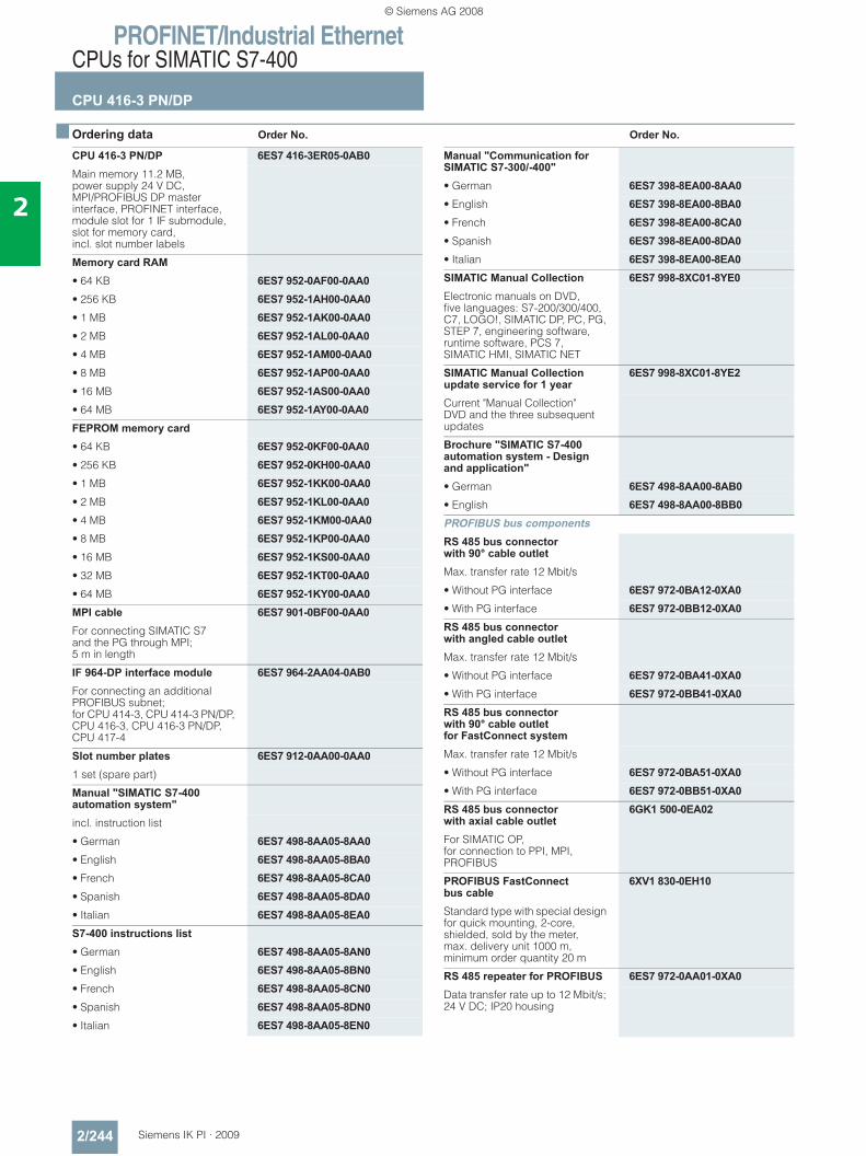
PROFINET/Industrial EthernetCPUs for SIMATIC S7-400
CPU 416-3 PN/DP
2/244 Siemens IK PI · 2009
2
■ Ordering data Order No. Order No.
CPU 416-3 PN/DP 6ES7 416-3ER05-0AB0Main memory 11.2 MB, power supply 24 V DC, MPI/PROFIBUS DP master interface, PROFINET interface, module slot for 1 IF submodule, slot for memory card,incl. slot number labels
Memory card RAM• 64 KB 6ES7 952-0AF00-0AA0• 256 KB 6ES7 952-1AH00-0AA0• 1 MB 6ES7 952-1AK00-0AA0• 2 MB 6ES7 952-1AL00-0AA0• 4 MB 6ES7 952-1AM00-0AA0• 8 MB 6ES7 952-1AP00-0AA0• 16 MB 6ES7 952-1AS00-0AA0• 64 MB 6ES7 952-1AY00-0AA0FEPROM memory card• 64 KB 6ES7 952-0KF00-0AA0• 256 KB 6ES7 952-0KH00-0AA0• 1 MB 6ES7 952-1KK00-0AA0• 2 MB 6ES7 952-1KL00-0AA0• 4 MB 6ES7 952-1KM00-0AA0• 8 MB 6ES7 952-1KP00-0AA0• 16 MB 6ES7 952-1KS00-0AA0• 32 MB 6ES7 952-1KT00-0AA0• 64 MB 6ES7 952-1KY00-0AA0MPI cable 6ES7 901-0BF00-0AA0For connecting SIMATIC S7 and the PG through MPI; 5 m in length
IF 964-DP interface module 6ES7 964-2AA04-0AB0For connecting an additional PROFIBUS subnet; for CPU 414-3, CPU 414-3 PN/DP, CPU 416-3, CPU 416-3 PN/DP, CPU 417-4
Slot number plates 6ES7 912-0AA00-0AA01 set (spare part)
Manual "SIMATIC S7-400 automation system"incl. instruction list
• German 6ES7 498-8AA05-8AA0• English 6ES7 498-8AA05-8BA0• French 6ES7 498-8AA05-8CA0• Spanish 6ES7 498-8AA05-8DA0• Italian 6ES7 498-8AA05-8EA0S7-400 instructions list• German 6ES7 498-8AA05-8AN0• English 6ES7 498-8AA05-8BN0• French 6ES7 498-8AA05-8CN0• Spanish 6ES7 498-8AA05-8DN0• Italian 6ES7 498-8AA05-8EN0
Manual "Communication for SIMATIC S7-300/-400"• German 6ES7 398-8EA00-8AA0• English 6ES7 398-8EA00-8BA0• French 6ES7 398-8EA00-8CA0• Spanish 6ES7 398-8EA00-8DA0• Italian 6ES7 398-8EA00-8EA0SIMATIC Manual Collection 6ES7 998-8XC01-8YE0Electronic manuals on DVD, five languages: S7-200/300/400, C7, LOGO!, SIMATIC DP, PC, PG, STEP 7, engineering software, runtime software, PCS 7, SIMATIC HMI, SIMATIC NET
SIMATIC Manual Collection update service for 1 year
6ES7 998-8XC01-8YE2
Current "Manual Collection" DVD and the three subsequent updates
Brochure "SIMATIC S7-400 automation system - Design and application"• German 6ES7 498-8AA00-8AB0• English 6ES7 498-8AA00-8BB0PROFIBUS bus components RS 485 bus connector with 90° cable outletMax. transfer rate 12 Mbit/s
• Without PG interface 6ES7 972-0BA12-0XA0• With PG interface 6ES7 972-0BB12-0XA0RS 485 bus connector with angled cable outletMax. transfer rate 12 Mbit/s
• Without PG interface 6ES7 972-0BA41-0XA0• With PG interface 6ES7 972-0BB41-0XA0RS 485 bus connector with 90° cable outlet for FastConnect systemMax. transfer rate 12 Mbit/s
• Without PG interface 6ES7 972-0BA51-0XA0• With PG interface 6ES7 972-0BB51-0XA0RS 485 bus connector with axial cable outlet
6GK1 500-0EA02
For SIMATIC OP,for connection to PPI, MPI, PROFIBUS
PROFIBUS FastConnect bus cable
6XV1 830-0EH10
Standard type with special design for quick mounting, 2-core, shielded, sold by the meter, max. delivery unit 1000 m, minimum order quantity 20 m
RS 485 repeater for PROFIBUS 6ES7 972-0AA01-0XA0Data transfer rate up to 12 Mbit/s; 24 V DC; IP20 housing
© Siemens AG 2008
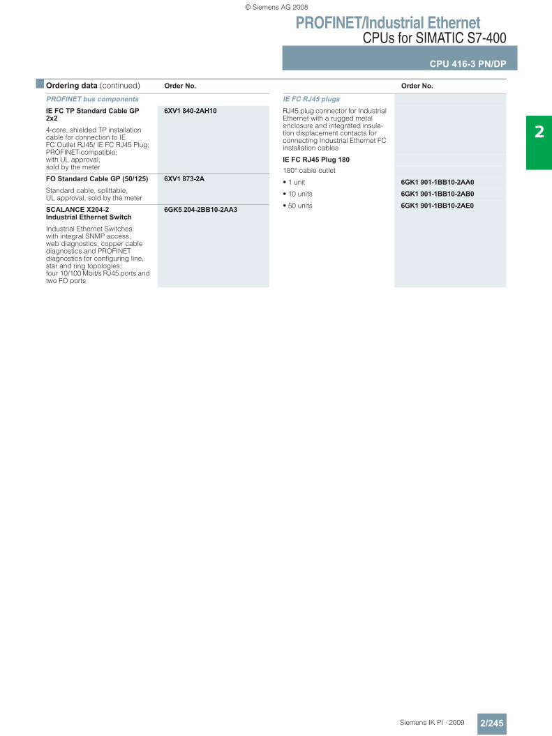
PROFINET/Industrial EthernetCPUs for SIMATIC S7-400
CPU 416-3 PN/DP
2/245Siemens IK PI · 2009
2
■ Ordering data (continued) Order No. Order No.
PROFINET bus components IE FC TP Standard Cable GP 2x2
6XV1 840-2AH10
4-core, shielded TP installation cable for connection to IE FC Outlet RJ45/ IE FC RJ45 Plug; PROFINET-compatible; with UL approval;sold by the meter
FO Standard Cable GP (50/125) 6XV1 873-2AStandard cable, splittable, UL approval, sold by the meter
SCALANCE X204-2 Industrial Ethernet Switch
6GK5 204-2BB10-2AA3
Industrial Ethernet Switches with integral SNMP access, web diagnostics, copper cable diagnostics and PROFINET diagnostics for configuring line, star and ring topologies; four 10/100 Mbit/s RJ45 ports and two FO ports
IE FC RJ45 plugsRJ45 plug connector for Industrial Ethernet with a rugged metal enclosure and integrated insula-tion displacement contacts for connecting Industrial Ethernet FC installation cables
IE FC RJ45 Plug 180180° cable outlet
• 1 unit 6GK1 901-1BB10-2AA0• 10 units 6GK1 901-1BB10-2AB0• 50 units 6GK1 901-1BB10-2AE0
© Siemens AG 2008
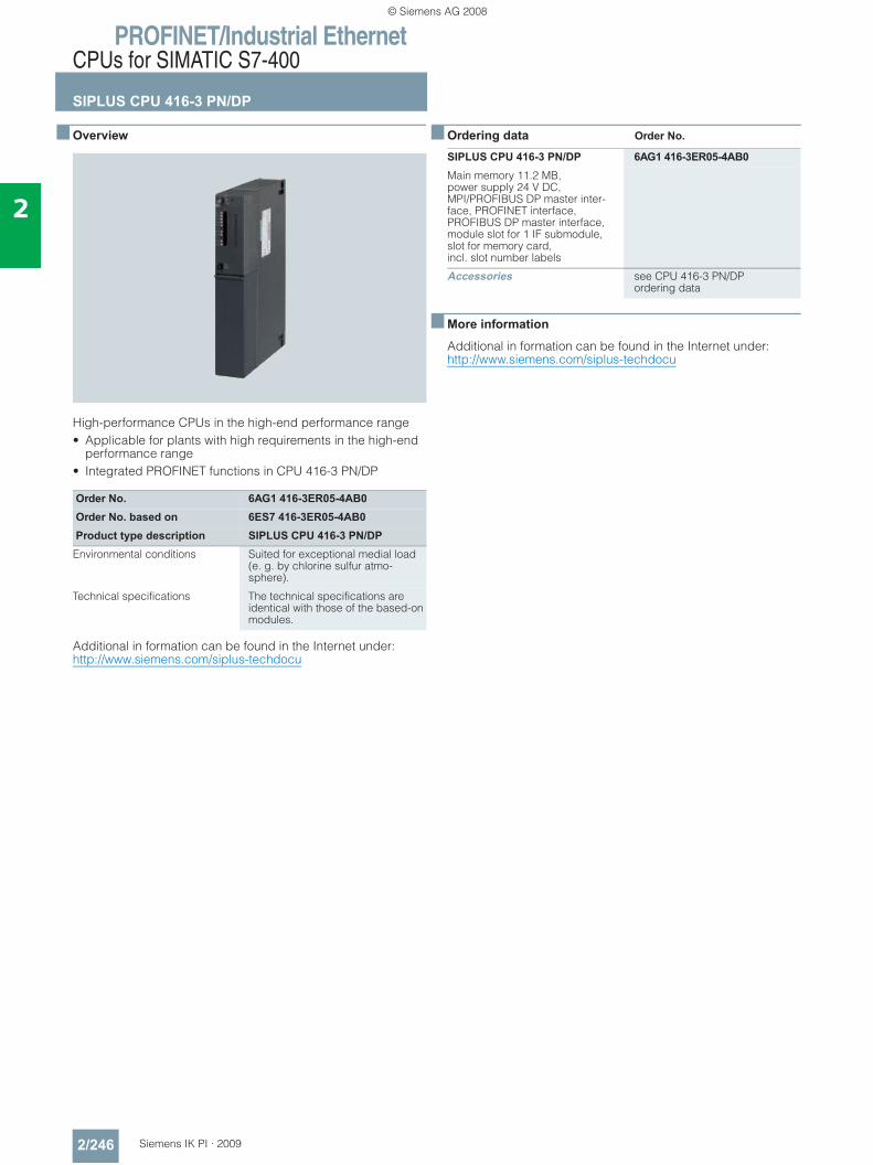
PROFINET/Industrial EthernetCPUs for SIMATIC S7-400
SIPLUS CPU 416-3 PN/DP
2/246 Siemens IK PI · 2009
2
■ Overview
High-performance CPUs in the high-end performance range• Applicable for plants with high requirements in the high-end
performance range• Integrated PROFINET functions in CPU 416-3 PN/DP
Additional in formation can be found in the Internet under:http://www.siemens.com/siplus-techdocu
■ Ordering data Order No.
■ More information
Additional in formation can be found in the Internet under:http://www.siemens.com/siplus-techdocu
Order No. 6AG1 416-3ER05-4AB0Order No. based on 6ES7 416-3ER05-4AB0Product type description SIPLUS CPU 416-3 PN/DP
Environmental conditions Suited for exceptional medial load (e. g. by chlorine sulfur atmo-sphere).
Technical specifications The technical specifications are identical with those of the based-on modules.
SIPLUS CPU 416-3 PN/DP 6AG1 416-3ER05-4AB0Main memory 11.2 MB, power supply 24 V DC, MPI/PROFIBUS DP master inter-face, PROFINET interface, PROFIBUS DP master interface, module slot for 1 IF submodule, slot for memory card,incl. slot number labels
Accessories see CPU 416-3 PN/DPordering data
© Siemens AG 2008
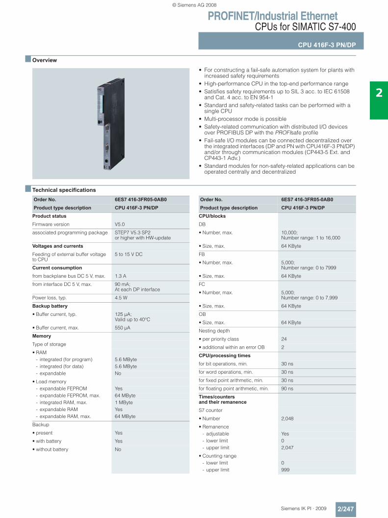
PROFINET/Industrial EthernetCPUs for SIMATIC S7-400
CPU 416F-3 PN/DP
2/247Siemens IK PI · 2009
2
■ Overview
• For constructing a fail-safe automation system for plants with increased safety requirements
• High-performance CPU in the top-end performance range • Satisfies safety requirements up to SIL 3 acc. to IEC 61508
and Cat. 4 acc. to EN 954-1• Standard and safety-related tasks can be performed with a
single CPU• Multi-processor mode is possible• Safety-related communication with distributed I/O devices
over PROFIBUS DP with the PROFIsafe profile• Fail-safe I/O modules can be connected decentralized over
the integrated interfaces (DP and PN with CPU416F-3 PN/DP) and/or through communication modules (CP443-5 Ext. and CP443-1 Adv.)
• Standard modules for non-safety-related applications can be operated centrally and decentralized
■ Technical specifications
Order No. 6ES7 416-3FR05-0AB0Product type description CPU 416F-3 PN/DP
Product status
Firmware version V5.0
associated programming package STEP7 V5.3 SP2 or higher with HW-update
Voltages and currents
Feeding of external buffer voltage to CPU
5 to 15 V DC
Current consumption
from backplane bus DC 5 V, max. 1.3 A
from interface DC 5 V, max. 90 mA; At each DP interface
Power loss, typ. 4.5 W
Backup battery
• Buffer current, typ. 125 μA; Valid up to 40°C
• Buffer current, max. 550 μA
Memory
Type of storage
• RAM- integrated (for program) 5.6 MByte- integrated (for data) 5.6 MByte- expandable No
• Load memory- expandable FEPROM Yes- expandable FEPROM, max. 64 MByte- integrated RAM, max. 1 MByte- expandable RAM Yes- expandable RAM, max. 64 MByte
Backup
• present Yes
• with battery Yes
• without battery No
Order No. 6ES7 416-3FR05-0AB0Product type description CPU 416F-3 PN/DP
CPU/blocks
DB
• Number, max. 10,000; Number range: 1 to 16,000
• Size, max. 64 KByte
FB
• Number, max. 5,000; Number range: 0 to 7999
• Size, max. 64 KByte
FC
• Number, max. 5,000; Number range: 0 to 7,999
• Size, max. 64 KByte
OB
• Size, max. 64 KByte
Nesting depth
• per priority class 24
• additional within an error OB 2
CPU/processing times
for bit operations, min. 30 ns
for word operations, min. 30 ns
for fixed point arithmetic, min. 30 ns
for floating point arithmetic, min. 90 ns
Times/counters and their remanence
S7 counter
• Number 2,048
• Remanence- adjustable Yes- lower limit 0- upper limit 2,047
• Counting range- lower limit 0- upper limit 999
© Siemens AG 2008
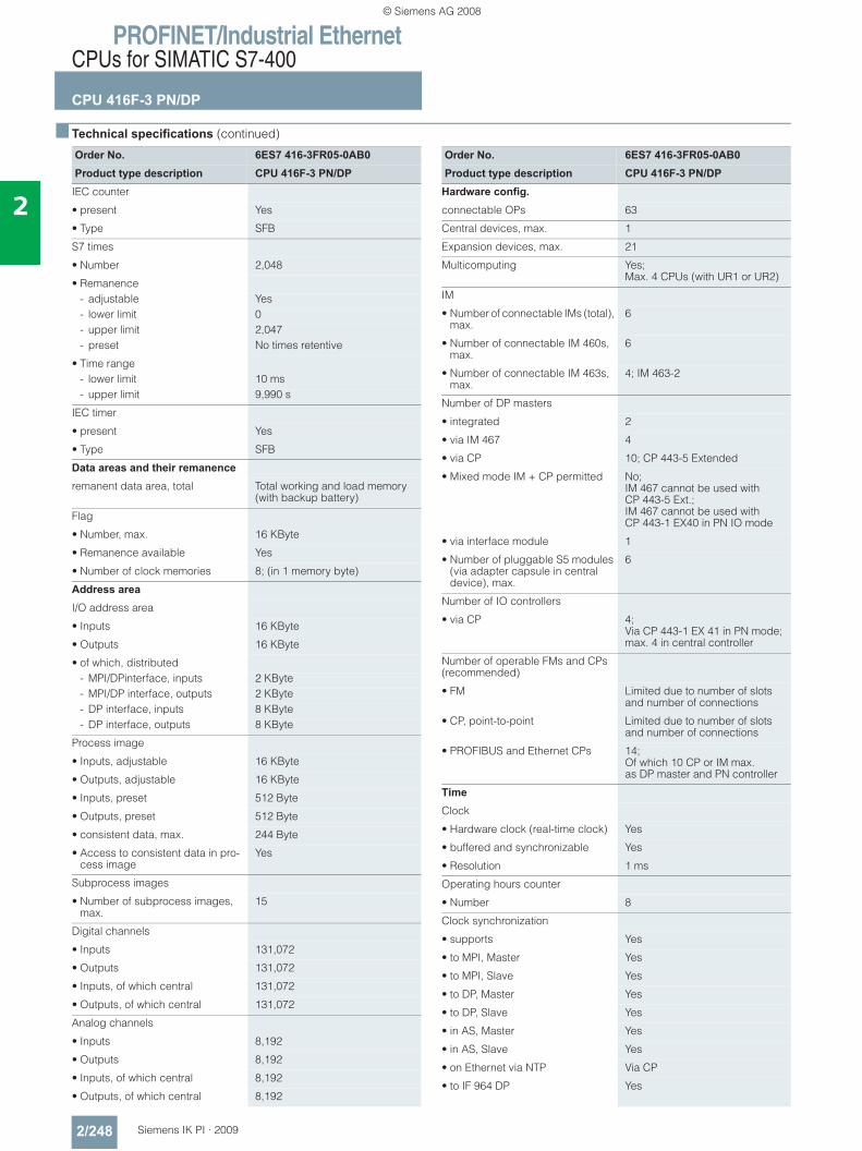
PROFINET/Industrial EthernetCPUs for SIMATIC S7-400
CPU 416F-3 PN/DP
2/248 Siemens IK PI · 2009
2
■ Technical specifications (continued)
Order No. 6ES7 416-3FR05-0AB0Product type description CPU 416F-3 PN/DP
IEC counter
• present Yes
• Type SFB
S7 times
• Number 2,048
• Remanence- adjustable Yes- lower limit 0- upper limit 2,047- preset No times retentive
• Time range- lower limit 10 ms- upper limit 9,990 s
IEC timer
• present Yes
• Type SFB
Data areas and their remanence
remanent data area, total Total working and load memory (with backup battery)
Flag
• Number, max. 16 KByte
• Remanence available Yes
• Number of clock memories 8; (in 1 memory byte)
Address area
I/O address area
• Inputs 16 KByte
• Outputs 16 KByte
• of which, distributed- MPI/DPinterface, inputs 2 KByte- MPI/DP interface, outputs 2 KByte- DP interface, inputs 8 KByte- DP interface, outputs 8 KByte
Process image
• Inputs, adjustable 16 KByte
• Outputs, adjustable 16 KByte
• Inputs, preset 512 Byte
• Outputs, preset 512 Byte
• consistent data, max. 244 Byte
• Access to consistent data in pro-cess image
Yes
Subprocess images
• Number of subprocess images, max.
15
Digital channels
• Inputs 131,072
• Outputs 131,072
• Inputs, of which central 131,072
• Outputs, of which central 131,072
Analog channels
• Inputs 8,192
• Outputs 8,192
• Inputs, of which central 8,192
• Outputs, of which central 8,192
Order No. 6ES7 416-3FR05-0AB0Product type description CPU 416F-3 PN/DP
Hardware config. connectable OPs 63
Central devices, max. 1
Expansion devices, max. 21
Multicomputing Yes; Max. 4 CPUs (with UR1 or UR2)
IM
• Number of connectable IMs (total), max.
6
• Number of connectable IM 460s, max.
6
• Number of connectable IM 463s, max.
4; IM 463-2
Number of DP masters
• integrated 2
• via IM 467 4
• via CP 10; CP 443-5 Extended
• Mixed mode IM + CP permitted No;IM 467 cannot be used with CP 443-5 Ext.; IM 467 cannot be used with CP 443-1 EX40 in PN IO mode
• via interface module 1
• Number of pluggable S5 modules (via adapter capsule in central device), max.
6
Number of IO controllers
• via CP 4; Via CP 443-1 EX 41 in PN mode; max. 4 in central controller
Number of operable FMs and CPs (recommended)
• FM Limited due to number of slots and number of connections
• CP, point-to-point Limited due to number of slots and number of connections
• PROFIBUS and Ethernet CPs 14; Of which 10 CP or IM max. as DP master and PN controller
Time
Clock
• Hardware clock (real-time clock) Yes
• buffered and synchronizable Yes
• Resolution 1 ms
Operating hours counter
• Number 8
Clock synchronization
• supports Yes
• to MPI, Master Yes
• to MPI, Slave Yes
• to DP, Master Yes
• to DP, Slave Yes
• in AS, Master Yes
• in AS, Slave Yes
• on Ethernet via NTP Via CP
• to IF 964 DP Yes
© Siemens AG 2008
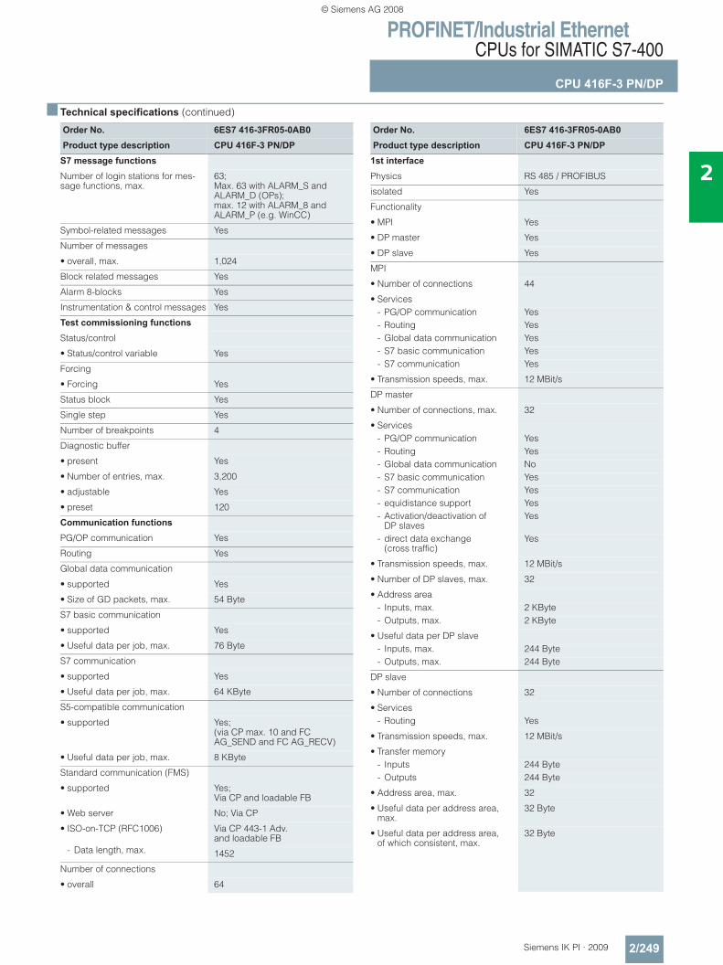
PROFINET/Industrial EthernetCPUs for SIMATIC S7-400
CPU 416F-3 PN/DP
2/249Siemens IK PI · 2009
2
■ Technical specifications (continued)
Order No. 6ES7 416-3FR05-0AB0Product type description CPU 416F-3 PN/DP
S7 message functions
Number of login stations for mes-sage functions, max.
63; Max. 63 with ALARM_S and ALARM_D (OPs); max. 12 with ALARM_8 and ALARM_P (e.g. WinCC)
Symbol-related messages Yes
Number of messages
• overall, max. 1,024
Block related messages Yes
Alarm 8-blocks Yes
Instrumentation & control messages Yes
Test commissioning functions
Status/control
• Status/control variable Yes
Forcing
• Forcing Yes
Status block Yes
Single step Yes
Number of breakpoints 4
Diagnostic buffer
• present Yes
• Number of entries, max. 3,200
• adjustable Yes
• preset 120
Communication functions
PG/OP communication Yes
Routing Yes
Global data communication
• supported Yes
• Size of GD packets, max. 54 Byte
S7 basic communication
• supported Yes
• Useful data per job, max. 76 Byte
S7 communication
• supported Yes
• Useful data per job, max. 64 KByte
S5-compatible communication
• supported Yes; (via CP max. 10 and FC AG_SEND and FC AG_RECV)
• Useful data per job, max. 8 KByte
Standard communication (FMS)
• supported Yes; Via CP and loadable FB
• Web server No; Via CP
• ISO-on-TCP (RFC1006) Via CP 443-1 Adv. and loadable FB
- Data length, max. 1452
Number of connections
• overall 64
Order No. 6ES7 416-3FR05-0AB0Product type description CPU 416F-3 PN/DP
1st interface
Physics RS 485 / PROFIBUS
isolated Yes
Functionality
• MPI Yes
• DP master Yes
• DP slave Yes
MPI
• Number of connections 44
• Services- PG/OP communication Yes- Routing Yes- Global data communication Yes- S7 basic communication Yes- S7 communication Yes
• Transmission speeds, max. 12 MBit/s
DP master
• Number of connections, max. 32
• Services- PG/OP communication Yes- Routing Yes- Global data communication No- S7 basic communication Yes- S7 communication Yes- equidistance support Yes- Activation/deactivation of
DP slavesYes
- direct data exchange (cross traffic)
Yes
• Transmission speeds, max. 12 MBit/s
• Number of DP slaves, max. 32
• Address area- Inputs, max. 2 KByte- Outputs, max. 2 KByte
• Useful data per DP slave- Inputs, max. 244 Byte- Outputs, max. 244 Byte
DP slave
• Number of connections 32
• Services- Routing Yes
• Transmission speeds, max. 12 MBit/s
• Transfer memory- Inputs 244 Byte- Outputs 244 Byte
• Address area, max. 32
• Useful data per address area, max.
32 Byte
• Useful data per address area, of which consistent, max.
32 Byte
© Siemens AG 2008
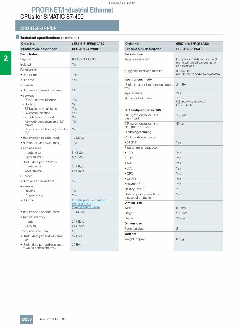
PROFINET/Industrial EthernetCPUs for SIMATIC S7-400
CPU 416F-3 PN/DP
2/250 Siemens IK PI · 2009
2
■ Technical specifications (continued)
Order No. 6ES7 416-3FR05-0AB0Product type description CPU 416F-3 PN/DP
2nd interface
Physics RS 485 / PROFIBUS
isolated Yes
Functionality
• DP master Yes
• DP slave Yes
DP master
• Number of connections, max. 32
• Services- PG/OP communication Yes- Routing Yes- S7 basic communication Yes- S7 communication Yes- equidistance support Yes- Activation/deactivation of DP
slavesYes
- direct data exchange (cross traf-fic)
Yes
• Transmission speeds, max. 12 MBit/s
• Number of DP slaves, max. 125
• Address area- Inputs, max. 8 KByte- Outputs, max. 8 KByte
• Useful data per DP slave- Inputs, max. 244 Byte- Outputs, max. 244 Byte
DP slave
• Number of connections 32
• Services- Routing Yes- Programming Yes
• GSD file http://support.automation.siemens.com/WW/view/de/113652
• Transmission speeds, max. 12 MBit/s
• Transfer memory- Inputs 244 Byte- Outputs 244 Byte
• Address area, max. 32
• Useful data per address area, max.
32 Byte
• Useful data per address area, of which consistent, max.
32 Byte
Order No. 6ES7 416-3FR05-0AB0Product type description CPU 416F-3 PN/DP
3rd interface
Type of interfaces Pluggable interface module (IF), technical specifications as for2nd interface
pluggable interface module IF 964-DP (MLFB: 6ES7 964-2AA04-0AB0)
Isochronous mode
Useful data per isochronoous slave, max.
244 Byte
equidistance Yes
shortest clock pulse 1 ms; 0.5 ms without use of SFC 126, 127
CiR configuration in RUN
CiR synchronization time, basic load
100 ms
CiR synchronization time,time per I/O slave
40 μs
CPU/programming
Configuration software
• STEP 7 Yes
Programming language
• LAD Yes
• FUP Yes
• AWL Yes
• SCL Yes
• CFC Yes
• GRAPH Yes
• HiGraph® Yes
Nesting levels 7
User program protection/password protection
Yes
Dimensions
Width 50 mm
Height 290 mm
Depth 219 mm
Dimensions
Required slots 2
Weights
Weight, approx. 880 g
© Siemens AG 2008
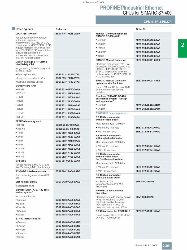
PROFINET/Industrial EthernetCPUs for SIMATIC S7-400
CPU 416F-3 PN/DP
2/251Siemens IK PI · 2009
2
■ Ordering data Order No. Order No.
CPU 416F-3 PN/DP 6ES7 416-3FR05-0AB0For configuring safety-related automation systems;main memory 11.2 MB, 24 V DC power supply, MPI/PROFIBUS DP master interface, PROFINET inter-face, PROFIBUS DP master inter-face, receptacle for 1 IF submodule, slot for memory card, incl. slot number labels
Option package S7 F Distrib-uted Safety V5.4for generating fail-safe programs for the S7-300F
• Floating License 6ES7 833-1FC02-0YA5• Upgrade from V5.x to V5.4 6ES7 833-1FC02-0YE5• Software Update Service 6ES7 833-1FC00-0YX2Memory card RAM• 64 KB 6ES7 952-0AF00-0AA0• 256 KB 6ES7 952-1AH00-0AA0• 1 MB 6ES7 952-1AK00-0AA0• 2 MB 6ES7 952-1AL00-0AA0• 4 MB 6ES7 952-1AM00-0AA0• 8 MB 6ES7 952-1AP00-0AA0• 16 MB 6ES7 952-1AS00-0AA0• 64 MB 6ES7 952-1AY00-0AA0FEPROM memory card• 64 KB 6ES7952-0KF00-0AA0• 256 KB 6ES7952-0KH00-0AA0• 1 MB 6ES7 952-1KK00-0AA0• 2 MB 6ES7 952-1KL00-0AA0• 4 MB 6ES7 952-1KM00-0AA0• 8 MB 6ES7 952-1KP00-0AA0• 16 MB 6ES7 952-1KS00-0AA0• 32 MB 6ES7 952-1KT00-0AA0• 64 MB 6ES7 952-1KY00-0AA0MPI cable 6ES7 901-0BF00-0AA0For connecting SIMATIC S7 and the PG through MPI; 5 m in length
IF 964-DP interface module 6ES7 964-2AA04-0AB0For connecting an additional DP line
Slot number plates 6ES7 912-0AA00-0AA01 set (spare part)
Manual "SIMATIC S7-400 auto-mation system"incl. instruction list
• German 6ES7 498-8AA05-8AA0• English 6ES7 498-8AA05-8BA0• French 6ES7 498-8AA05-8CA0• Spanish 6ES7 498-8AA05-8DA0• Italian 6ES7 498-8AA05-8EA0S7-400 instructions list• German 6ES7 498-8AA05-8AN0• English 6ES7 498-8AA05-8BN0• French 6ES7 498-8AA05-8CN0• Spanish 6ES7 498-8AA05-8DN0• Italian 6ES7 498-8AA05-8EN0
Manual "Communication for SIMATIC S7-300/-400"• German 6ES7 398-8EA00-8AA0• English 6ES7 398-8EA00-8BA0• French 6ES7 398-8EA00-8CA0• Spanish 6ES7 398-8EA00-8DA0• Italian 6ES7 398-8EA00-8EA0SIMATIC Manual Collection 6ES7 998-8XC01-8YE0Electronic manuals on DVD, five languages: S7-200/300/400, C7, LOGO!, SIMATIC DP, PC, PG, STEP 7, engineering software, runtime software, PCS 7, SIMATIC HMI, SIMATIC NET
SIMATIC Manual Collection update service for 1 year
6ES7 998-8XC01-8YE2
Current "Manual Collection" DVD and the three subsequent updates
Brochure "SIMATIC S7-400 automation system - Design and application"• German 6ES7 498-8AA00-8AB0• English 6ES7 498-8AA00-8BB0PROFIBUS bus components RS 485 bus connector with 90° cable outletMax. transfer rate 12 Mbit/s
• Without PG interface 6ES7 972-0BA12-0XA0• With PG interface 6ES7 972-0BB12-0XA0RS 485 bus connector with angled cable outletMax. transfer rate 12 Mbit/s
• Without PG interface 6ES7 972-0BA41-0XA0• With PG interface 6ES7 972-0BB41-0XA0RS 485 bus connector with 90° cable outlet for FastConnect systemMax. transfer rate 12 Mbit/s
• Without PG interface 6ES7 972-0BA51-0XA0• With PG interface 6ES7 972-0BB51-0XA0RS 485 bus connector with axial cable outletFor SIMATIC OP,for connection to PPI, MPI, PROFIBUS
6GK1 500-0EA02
PROFIBUS FastConnect bus cableStandard type with special design for quick mounting, 2-core, shielded, sold by the meter, max. delivery unit 1000 m, minimum order quantity 20 m
6XV1 830-0EH10
RS 485 repeater for PROFIBUS 6ES7 972-0AA01-0XA0Data transfer rate up to 12 Mbit/s; 24 V DC; IP20 housing
© Siemens AG 2008

PROFINET/Industrial EthernetCPUs for SIMATIC S7-400
CPU 416F-3 PN/DP
2/252 Siemens IK PI · 2009
2
■ Ordering data (continued) Order No. Order No.
PROFINET bus components IE FC TP Standard Cable GP 2x2
6XV1 840-2AH10
4-core, shielded TP installation cable for connection to IE FC Outlet RJ45/ IE FC RJ45 Plug; PROFINET-compatible; with UL approval;sold by the meter
FO Standard Cable GP (50/125) 6XV1 873-2AStandard cable, splittable, UL approval, sold by the meter
SCALANCE X204-2 Industrial Ethernet Switch
6GK5 204-2BB10-2AA3
Industrial Ethernet Switches with integral SNMP access, web diagnostics, copper cable diagnostics and PROFINET diagnostics for configuring line, star and ring topologies; four 10/100 Mbit/s RJ45 ports and two FO ports
IE FC RJ45 plugsRJ45 plug connector for Industrial Ethernet with a rugged metal enclosure and integrated insula-tion displacement contacts for connecting Industrial Ethernet FC installation cables
IE FC RJ45 Plug 180180° cable outlet
• 1 unit 6GK1 901-1BB10-2AA0• 10 units 6GK1 901-1BB10-2AB0• 50 units 6GK1 901-1BB10-2AE0
© Siemens AG 2008
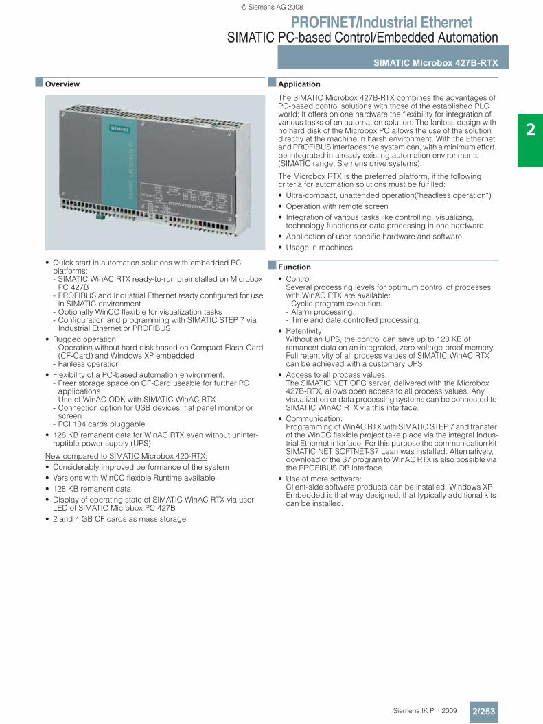
PROFINET/Industrial EthernetSIMATIC PC-based Control/Embedded Automation
SIMATIC Microbox 427B-RTX
2/253Siemens IK PI · 2009
2
■ Overview
• Quick start in automation solutions with embedded PC platforms: - SIMATIC WinAC RTX ready-to-run preinstalled on Microbox
PC 427B- PROFIBUS and Industrial Ethernet ready configured for use
in SIMATIC environment- Optionally WinCC flexible for visualization tasks- Configuration and programming with SIMATIC STEP 7 via
Industrial Ethernet or PROFIBUS• Rugged operation:
- Operation without hard disk based on Compact-Flash-Card (CF-Card) and Windows XP embedded
- Fanless operation• Flexibility of a PC-based automation environment:
- Freer storage space on CF-Card useable for further PC applications
- Use of WinAC ODK with SIMATIC WinAC RTX- Connection option for USB devices, flat panel monitor or
screen- PCI 104 cards pluggable
• 128 KB remanent data for WinAC RTX even without uninter-ruptible power supply (UPS)
New compared to SIMATIC Microbox 420-RTX:• Considerably improved performance of the system• Versions with WinCC flexible Runtime available• 128 KB remanent data• Display of operating state of SIMATIC WinAC RTX via user
LED of SIMATIC Microbox PC 427B• 2 and 4 GB CF cards as mass storage
■ Application
The SIMATIC Microbox 427B-RTX combines the advantages of PC-based control solutions with those of the established PLC world: It offers on one hardware the flexibility for integration of various tasks of an automation solution. The fanless design with no hard disk of the Microbox PC allows the use of the solution directly at the machine in harsh environment. With the Ethernet and PROFIBUS interfaces the system can, with a minimum effort, be integrated in already existing automation environments (SIMATIC range, Siemens drive systems).
The Microbox RTX is the preferred platform, if the following criteria for automation solutions must be fulfilled:• Ultra-compact, unattended operation("headless operation“)• Operation with remote screen• Integration of various tasks like controlling, visualizing,
technology functions or data processing in one hardware• Application of user-specific hardware and software• Usage in machines
■ Function• Control:
Several processing levels for optimum control of processes with WinAC RTX are available: - Cyclic program execution.- Alarm processing.- Time and date controlled processing.
• Retentivity:Without an UPS, the control can save up to 128 KB of remanent data on an integrated, zero-voltage proof memory.Full retentivity of all process values of SIMATIC WinAC RTX can be achieved with a customary UPS
• Access to all process values:The SIMATIC NET OPC server, delivered with the Microbox 427B-RTX, allows open access to all process values. Any visualization or data processing systems can be connected to SIMATIC WinAC RTX via this interface.
• Communication:Programming of WinAC RTX with SIMATIC STEP 7 and transfer of the WinCC flexible project take place via the integral Indus-trial Ethernet interface. For this purpose the communication kit SIMATIC NET SOFTNET-S7 Lean was installed. Alternatively, download of the S7 program to WinAC RTX is also possible via the PROFIBUS DP interface.
• Use of more software:Client-side software products can be installed. Windows XP Embedded is that way designed, that typically additional kits can be installed.
© Siemens AG 2008
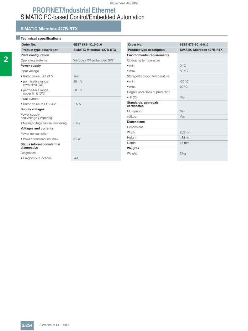
PROFINET/Industrial EthernetSIMATIC PC-based Control/Embedded Automation
SIMATIC Microbox 427B-RTX
2/254 Siemens IK PI · 2009
2
■ Technical specifications
Order No. 6ES7 675-1C..0-0..0Product type description SIMATIC Microbox 427B-RTX
Plant configuration
Operating systems Windows XP embedded SP2
Power supply
Input voltage
• Rated value, DC 24 V Yes
• permissible range,lower limit (DC)
20.4 V
• permissible range, upper limit (DC)
28.8 V
Input current
• Rated value at DC 24 V 2.5 A
Supply voltages
Power supply and voltage jumpering
• Mains/voltage failure jumpering 5 ms
Voltages and currents
Power consumption
• Power consumption, max. 61 W
Status information/alarms/diagnostics
Diagnoses
• Diagnostic functions Yes
Order No. 6ES7 675-1C..0-0..0Product type description SIMATIC Microbox 427B-RTX
Environmental requirements
Operating termperature
• min. 0 °C
• max. 50 °C
Storage/transport temperature
• min. -20 °C
• max. 60 °C
Degree and class of protection
• IP 20 Yes
Standards, approvals, certificates
CE symbol Yes
cULus Yes
Dimensions
Dimensions
Width 262 mm
Height 133 mm
Depth 47 mm
Weights
Weight 2 kg
© Siemens AG 2008
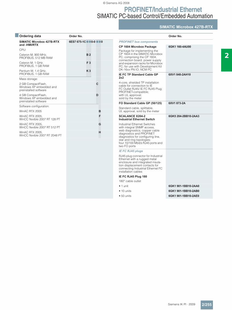
PROFINET/Industrial EthernetSIMATIC PC-based Control/Embedded Automation
SIMATIC Microbox 427B-RTX
2/255Siemens IK PI · 2009
2
■ Ordering data Order No. Order No.
SIMATIC Microbox 427B-RTX and -HMI/RTX
6ES7 675-1C770-0 770
CPU:
Celeron M, 900 MHz, PROFIBUS, 512 MB RAM
B 2
Celeron M, 1 GHz, PROFIBUS, 1 GB RAM
F 3
Pentium M, 1.4 GHz, PROFIBUS, 1 GB RAM
K 3
Mass storage:
2 GB CompactFlash, Windows XP embedded and preinstalled software
C
4 GB CompactFlash,Windows XP embedded and preinstalled software
D
Software configuration:
WinAC RTX 2005 BWinAC RTX 2005, WinCC flexible 2007 RT 128 PT
F
WinAC RTX 2005, WinCC flexible 2007 RT 512 PT
G
WinAC RTX 2005, WinCC flexible 2007 RT 2048 PT
H
PROFINET bus components CP 1604 Microbox Package 6GK1 160-4AU00Package for implementing the CP 1604 in the SIMATIC Microbox PC; comprising the CP 1604, connection board, power supply and expansion racks for Microbox PC; for use with Development Kit DK-16xx PN IO; NCM PC
IE FC TP Standard Cable GP 2x2
6XV1 840-2AH10
4-core, shielded TP installation cable for connection to IE FC Outlet RJ45/ IE FC RJ45 Plug; PROFINET-compatible; with UL approval;sold by the meter
FO Standard Cable GP (50/125) 6XV1 873-2AStandard cable, splittable, UL approval, sold by the meter
SCALANCE X204-2 Industrial Ethernet Switch
6GK5 204-2BB10-2AA3
Industrial Ethernet Switches with integral SNMP access, web diagnostics, copper cable diagnostics and PROFINET diagnostics for configuring line, star and ring topologies; four 10/100 Mbit/s RJ45 ports and two FO ports
IE FC RJ45 plugsRJ45 plug connector for Industrial Ethernet with a rugged metal enclosure and integrated insula-tion displacement contacts for connecting Industrial Ethernet FC installation cables
IE FC RJ45 Plug 180180° cable outlet
• 1 unit 6GK1 901-1BB10-2AA0• 10 units 6GK1 901-1BB10-2AB0• 50 units 6GK1 901-1BB10-2AE0
© Siemens AG 2008
PROFINET/Industrial EthernetSIMATIC PC-based Control/Embedded Automation
SIMATIC WinAC Software PLC
2/256 Siemens IK PI · 2009
2
■ Overview
• SIMATIC WINAC RTX:Optimized for applications that demand a high level of flexibility and integration
• The software solution for tasks that demand hard determinis-tics and high performance
• With real-time expansion for guaranteeing deterministic behavior for the control component
■ Technical specifications
Order No. 6ES7 671-0RC05-0YA0Product type description SIMATIC WinAC Software PLC
Memory
Type of storage
• RAM- integrated PC work memory can be used
(non-paged memory)
• Load memory- integrated RAM, max. PC work memory can be used
(non-paged memory)
CPU/blocks
DB
• Number, max. Limited only by available PC work memory
• Size, max. 64 KByte
FB
• Number, max. Limited only by available PC work memory
• Size, max. 64 KByte
FC
• Number, max. Limited only by available PC work memory
• Size, max. 64 KByte
OB
• Size, max. 64 KByte
Nesting depth
• per priority class 24
• additional within an error OB 24
CPU/processing times
Reference platform Pentium IV, 2.4 GHz
Order No. 6ES7 671-0RC05-0YA0Product type description SIMATIC WinAC Software PLC
Times/counters and their remanence
S7 counter
• Number 2,048
• Remanence- adjustable Yes- lower limit 0- upper limit 2,047- preset 8
• Counting range- adjustable Yes- lower limit 0- upper limit 999
IEC counter
• present Yes
• Type SFB
S7 times
• Number 2,048
• Remanence- lower limit 0- upper limit 2,047- preset 0
• Time range- lower limit 10 ms- upper limit 9,990 s
IEC timer
• present Yes
• Type SFB
Data areas and their remanence
Remanence with UPS all data
© Siemens AG 2008
PROFINET/Industrial EthernetSIMATIC PC-based Control/Embedded Automation
SIMATIC WinAC Software PLC
2/257Siemens IK PI · 2009
2
■ Technical specifications (continued)
Order No. 6ES7 671-0RC05-0YA0Product type description SIMATIC WinAC Software PLC
Flag
• Number, max. 16 KByte
• of which remanent MB 0 to MB 16383
• Remanence preset MB 0 to MB 15
• Number of clock memories 8
Address area
I/O address area
• Inputs 16 KByte
• Outputs 16 KByte
• of which, distributed- DP interface, inputs 16 KByte- DP interface, outputs 16 KByte
Process image
• Inputs, adjustable 8 KByte
• Outputs, adjustable 8 KByte
• Inputs, preset 512 Byte
• Outputs, preset 512 Byte
Subprocess images
• Number of subprocess images, max.
15
Digital channels
• Outputs 128,000
Analog channels
• Inputs 8,000
• Outputs 8,000
Hardware config. Submodules
• Number of submodules, max 4
• of which PROFIBUS, max. 4; CP 5611, CP 5611-A2, integrated PB interface of the SIMATIC PC, CP 5613,CP 5613-A2
Number of operable FMs and CPs (recommended)
• FM FM distributed: FM 350-1 / 350-2, FM 351, FM 352, FM 353, FM 355 / 355-2
• CP, point-to-point CP 340, CP 341 distributed
• CP, LAN Over PC CP
Time
Clock
• Hardware clock (real-time clock) Yes
• buffered and synchronizable Yes
Clock synchronization
• supports Yes
• to PC-CP, Slave Yes
S7 message functions
SCAN procedure No
Process diagnostic messages Yes; Alarm_S
Alarm 8-blocks Yes
Instrumentation & control messages No
Order No. 6ES7 671-0RC05-0YA0Product type description SIMATIC WinAC Software PLC
Test commissioning functions
Status/control
• Status/control variable Yes
Forcing
• Forcing No
Status block Yes
Single step Yes
Diagnostic buffer
• present Yes
• Number of entries, max. 3,200
• preset 120
Communication functions
PG/OP communication Yes
Global data communication
• supported No
S7 basic communication
• supported No
S7 communication
• as server Yes
• as client Yes
Number of connections
• overall 64
• reserved for PG communication 1
• reserved for OP communication 1
1st interface
Type of interface CP 5611, CP 5611-A2, integrated PB interface of the SIMATIC PC
Number of simult. operable CPs, max.
1
Physics RS 485 / PROFIBUS
isolated Yes
Functionality
• MPI No
• DP master Yes
• DP slave No
DP master
• Number of connections, max. 8
• Services- PG/OP communication Yes- Routing Yes- Global data communication No- S7 basic communication No- S7 communication Yes- equidistance support Yes- SYNC/FREEZE Yes- Activation/deactivation of
DP slavesYes
- direct data exchange(cross traffic)
Yes
- DPV0 Yes- DPV1 Yes
© Siemens AG 2008
PROFINET/Industrial EthernetSIMATIC PC-based Control/Embedded Automation
SIMATIC WinAC Software PLC
2/258 Siemens IK PI · 2009
2
■ Technical specifications (continued)
Order No. 6ES7 671-0RC05-0YA0Product type description SIMATIC WinAC Software PLC
• Transmission speeds, max. 12 MBit/s
• Number of DP slaves, max. 64
• Address area- Inputs, max. 16 KByte- Outputs, max. 16 KByte
• Useful data per DP slave- Inputs, max. 244 Byte- Outputs, max. 244 Byte
2nd interface
Type of interface CP 5613, CP 5613-A2
Number of simult. operable CPs, max.
4
Physics RS 485 / PROFIBUS
isolated Yes
Functionality
• MPI No
• DP master Yes
• DP slave No
• PROFINET IO controller No
• PROFINET CBA No
• PROFINET CBA-SRT No
DP master
• Number of connections, max. 50
• Services- PG/OP communication Yes- Routing Yes- Global data communication No- S7 basic communication No- S7 communication Yes- equidistance support Yes- SYNC/FREEZE Yes- Activation/deactivation of
DP slavesYes
- direct data exchange (cross traffic)
Yes
- DPV0 Yes- DPV1 Yes
• Transmission speeds, max. 12 MBit/s
• Number of DP slaves, max. 125
• Address area- Inputs, max. 16 KByte- Outputs, max. 16 KByte
• Useful data per DP slave- Inputs, max. 244 Byte- Outputs, max. 244 Byte
Order No. 6ES7 671-0RC05-0YA0Product type description SIMATIC WinAC Software PLC
Isochronous mode
Isochronouos mode Yes
Number of DP masters with isochro-nous mode
2
Useful data per isochronoous slave, max.
128 Byte
equidistance Yes
shortest clock pulse 2.2 ms; 2.2 ms without partial process image; 2.2 ms with partial process image
CPU/programming
Programming language
• STEP 7 Yes
• LAD Yes
• FUP Yes
• AWL Yes
• SCL Yes
• CFC Yes
• GRAPH Yes
• HiGraph® Yes
Software libraries
• Easy Motion Control Yes
Nesting levels 8
User program protection/password protection
Yes
Open development interfaces
• CCX (Custom Code Extension) Yes; with WinAC ODK V4.1
• SMX (Shared Memory Extension) Yes; with WinAC ODK V4.1- Inputs 4 KByte- Outputs 4 KByte
• CMI (Controller Management In-terface)
Yes; with WinAC ODK V4.1
Hardware requirements
Hardware required PC with color monitor, keyboard, mouse or pointing device for Windows
Resolution (pixels)
Required memory on hard disk, min.
100 MByte
Main memory, min. 256 MByte
Processor Intel Pentium 400 MHz
• Multi-processor system Yes
• Hyperthreading Yes
Operating systems
Operating system
• Windows NT 4.0 No
• Windows 2000 Yes; Professional, SP3 or higher
• Windows XP Yes; Professional, SP1 and SP2
© Siemens AG 2008
PROFINET/Industrial EthernetSIMATIC PC-based Control/Embedded Automation
SIMATIC WinAC Software PLC
2/259Siemens IK PI · 2009
2
■ Ordering data Order No. Order No.
SIMATIC WinAC RTX 2005 6ES7 671-0RC05-0YA0Software-based PC-based control system for applications requiring a strictly deterministic response; CD-ROM with electronic documentation in English, French and German; Single license,for Windows 2000/XP
SIMATIC WinAC RTX 2005 Upgrade
6ES7 671-0RC05-0YE0
For upgrading from Basic/RTX V3.x, V4.0, V4.1 to 2005; single license, for Windows 2000/XP
SIMATIC WinAC NV128 6ES7 671-0AG00-1YA7PC plug-in card with non-volatile memory for the storage of up to 128 Kbyte of retentive data in the event of voltage failure
CP 5611 A2 communications processor
6GK1 561-1AA01
PCI card (32-bit) for connection of a programming device or PC to PROFIBUS
CP 5613 A2 communications processor
6GK1 561-3AA01
PCI card (32-bit; 3.3 V/5 V) for connection to PROFIBUS incl. DP-Base software with NCM PC; DP-RAM interface for DP master, incl. PG and FDL protocol; single license for 1 installation, runtime software, software and electronic manual on CD-ROM, Class A, for 32-bit Windows 2000 Professional/Server, Windows XP Professional,German/English
SIMATIC WinAC RTX 2005 6GK1 161-3AA01Software-based PC-based control system for applications requiring a strictly deterministic response; CD-ROM with electronic documentation in English, French and German; Single license, for Windows 2000/XP
IE FC TP Standard Cable GP 2x2
6XV1 840-2AH10
4-core, shielded TP installation cable for connection to IE FC Outlet RJ45/ IE FC RJ45 Plug; PROFINET-compatible; with UL approval;sold by the meter
FO Standard Cable GP (50/125) 6XV1 873-2AStandard cable, splittable, UL approval, sold by the meter
SCALANCE X204-2 Industrial Ethernet Switch
6GK5 204-2BB10-2AA3
Industrial Ethernet Switches with integral SNMP access, web diagnostics, copper cable diagnostics and PROFINET diagnostics for configuring line, star and ring topologies; four 10/100 Mbit/s RJ45 ports and two FO ports
IE FC RJ45 plugsRJ45 plug connector for Industrial Ethernet with a rugged metal enclosure and integrated insula-tion displacement contacts for connecting Industrial Ethernet FC installation cables
IE FC RJ45 Plug 180180° cable outlet
• 1 unit 6GK1 901-1BB10-2AA0• 10 units 6GK1 901-1BB10-2AB0• 50 units 6GK1 901-1BB10-2AE0
© Siemens AG 2008
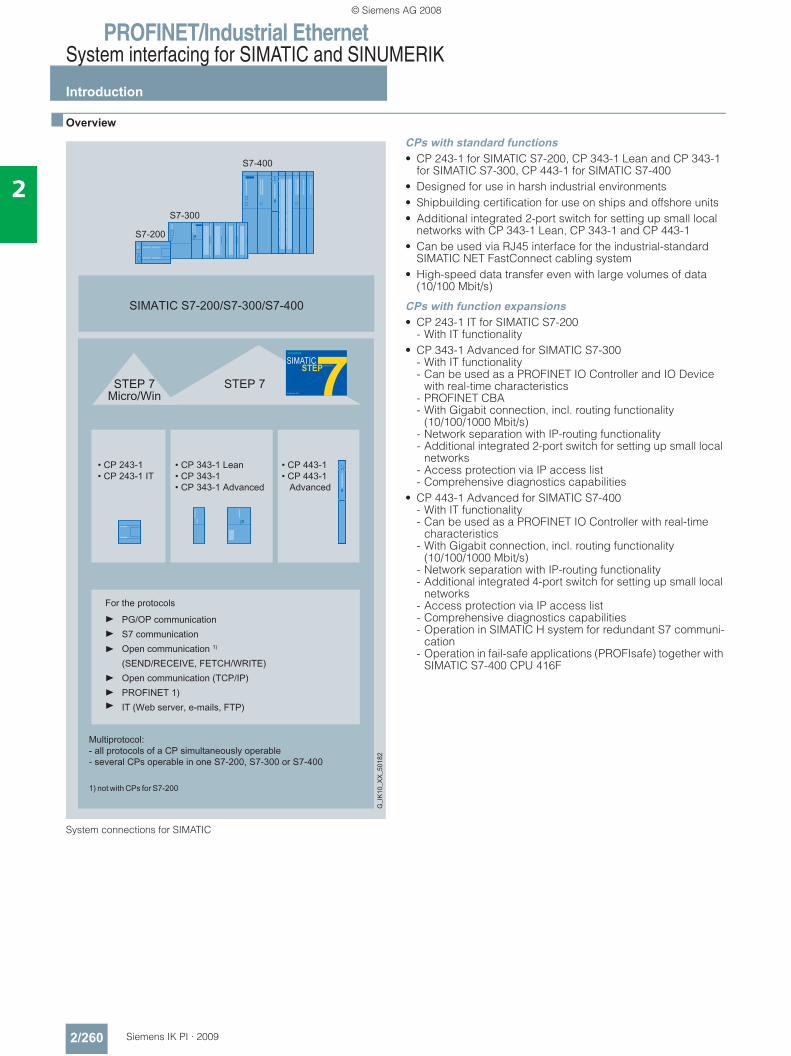
PROFINET/Industrial EthernetSystem interfacing for SIMATIC and SINUMERIK
Introduction
2/260 Siemens IK PI · 2009
2
■ Overview
System connections for SIMATIC
CPs with standard functions• CP 243-1 for SIMATIC S7-200, CP 343-1 Lean and CP 343-1
for SIMATIC S7-300, CP 443-1 for SIMATIC S7-400• Designed for use in harsh industrial environments• Shipbuilding certification for use on ships and offshore units• Additional integrated 2-port switch for setting up small local
networks with CP 343-1 Lean, CP 343-1 and CP 443-1• Can be used via RJ45 interface for the industrial-standard
SIMATIC NET FastConnect cabling system• High-speed data transfer even with large volumes of data
(10/100 Mbit/s)
CPs with function expansions• CP 243-1 IT for SIMATIC S7-200
- With IT functionality• CP 343-1 Advanced for SIMATIC S7-300
- With IT functionality- Can be used as a PROFINET IO Controller and IO Device
with real-time characteristics- PROFINET CBA- With Gigabit connection, incl. routing functionality
(10/100/1000 Mbit/s)- Network separation with IP-routing functionality- Additional integrated 2-port switch for setting up small local
networks- Access protection via IP access list- Comprehensive diagnostics capabilities
• CP 443-1 Advanced for SIMATIC S7-400 - With IT functionality - Can be used as a PROFINET IO Controller with real-time
characteristics - With Gigabit connection, incl. routing functionality
(10/100/1000 Mbit/s)- Network separation with IP-routing functionality- Additional integrated 4-port switch for setting up small local
networks- Access protection via IP access list- Comprehensive diagnostics capabilities- Operation in SIMATIC H system for redundant S7 communi-
cation - Operation in fail-safe applications (PROFIsafe) together with
SIMATIC S7-400 CPU 416F
© Siemens AG 2008
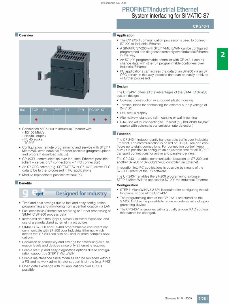
PROFINET/Industrial EthernetSystem interfacing for SIMATIC S7
CP 243-1
2/261Siemens IK PI · 2009
2
■ Overview
• Connection of S7-200 to Industrial Ethernet with - 10/100 Mbit/s- Half/full duplex- RJ 45 socket- TCP/IP
• Configuration, remote programming and service with STEP 7 Micro/WIN over Industrial Ethernet possible (program upload and program download, status)
• CPU/CPU communication over Industrial Ethernet possible (client + server, 8 S7 connections + 1 PG connection)
• An S7 OPC server (e.g. SOFTNET-S7 or S7-1613) allows PLC data to be further processed in PC applications
• Module replacement possible without PG
■ Benefits
• Time and cost savings due to fast and easy configuration, programming and monitoring from a central location via LAN
• Fast access via Ethernet for archiving or further processing of SIMATIC S7-200 process data
• Increased data throughput, almost unlimited expansion and use of a standardized Ethernet infrastructure
• SIMATIC S7-300 and S7-400 programmable controllers can communicate with S7-200 over Industrial Ethernet which means that S7-200 can also be used for more complex appli-cations.
• Reduction of complexity and savings for networking all auto-mation levels and devices since only Ethernet is required
• Simple startup and easy diagnostics options due to configu-ration support by STEP 7 Micro/WIN
• Simple maintenance since modules can be replaced without a PG and network administrator support is simple (e.g. PING)
• Open data exchange with PC applications over OPC is possible
■ Application• The CP 243-1 communication processor is used to connect
S7-200 to Industrial Ethernet.• A SIMATIC S7-200 with STEP 7-Micro/WIN can be configured,
programmed and diagnosed remotely over Industrial Ethernet in this way.
• An S7-200 programmable controller with CP 243-1 can ex-change data with other S7 programmable controllers over Industrial Ethernet.
• PC applications can access the data of an S7-200 via an S7 OPC server. In this way, process data can be easily archived or further processed.
■ Design
The CP 243-1 offers all the advantages of the SIMATIC S7-200 system design:• Compact construction in a rugged plastic housing• Terminal block for connecting the external supply voltage of
24 V DC• LED status display• Alternatively, standard rail mounting or wall mounting• RJ45 socket for connecting to Ethernet (10/100 Mbit/s full/half
duplex with automatic transmission rate detection)
■ Function
The CP 243-1 independently handles data traffic over Industrial Ethernet. The communication is based on TCP/IP. You can con-figure up to eight connections. For connection control (keep alive) it is possible to configure an adjustable time for all TCP/IP transport connections for active and passive partners.
The CP 243-1 enables communication between an S7-200 and another S7-200 or S7-300/S7-400 controller via Ethernet.
Integration into PC applications is possible by means of the S7-OPC server of the PC software.
The CP 243-1 enables the S7-200 programming software STEP 7-Micro/WIN to access the S7-200 via Industrial Ethernet.
Configuration • STEP 7-Micro/WIN V3.2 SP1 is required for configuring the full
functional scope of the CP 243-1.• The programming data of the CP 243-1 are stored on the
S7-200 CPU so it is possible to replace modules without a pro-gramming device
• The CP 243-1 is supplied with a globally unique MAC address that cannot be changed.
© Siemens AG 2008
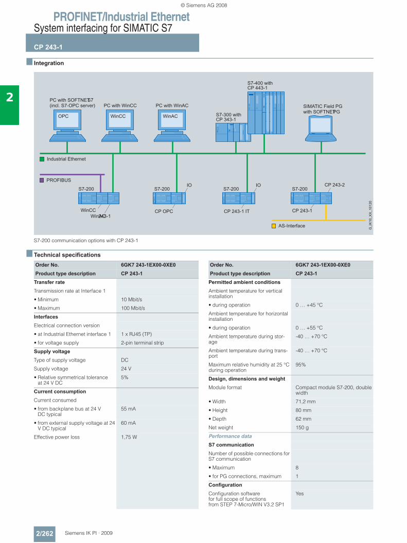
PROFINET/Industrial EthernetSystem interfacing for SIMATIC S7
CP 243-1
2/262 Siemens IK PI · 2009
2
■ Integration
S7-200 communication options with CP 243-1
■ Technical specifications
Order No. 6GK7 243-1EX00-0XE0Product type description CP 243-1
Transfer rate
Transmission rate at Interface 1
• Minimum 10 Mbit/s
• Maximum 100 Mbit/s
Interfaces
Electrical connection version
• at Industrial Ethernet interface 1 1 x RJ45 (TP)
• for voltage supply 2-pin terminal strip
Supply voltage
Type of supply voltage DC
Supply voltage 24 V
• Relative symmetrical tolerance at 24 V DC
5%
Current consumption
Current consumed
• from backplane bus at 24 V DC typical
55 mA
• from external supply voltage at 24 V DC typical
60 mA
Effective power loss 1,75 W
Order No. 6GK7 243-1EX00-0XE0Product type description CP 243-1
Permitted ambient conditions
Ambient temperature for vertical installation
• during operation 0 … +45 °C
Ambient temperature for horizontal installation
• during operation 0 … +55 °C
Ambient temperature during stor-age
-40 … +70 °C
Ambient temperature during trans-port
-40 … +70 °C
Maximum relative humidity at 25 °C during operation
95%
Design, dimensions and weight Module format Compact module S7-200, double
width
• Width 71,2 mm
• Height 80 mm
• Depth 62 mm
Net weight 150 g
Performance data
S7 communication
Number of possible connections for S7 communication
• Maximum 8
• for PG connections, maximum 1
Configuration
Configuration software for full scope of functions from STEP 7-Micro/WIN V3.2 SP1
Yes
© Siemens AG 2008
PROFINET/Industrial EthernetSystem interfacing for SIMATIC S7
CP 243-1
2/263Siemens IK PI · 2009
2
■ Ordering data Order No. Order No.
1) Upgrade for all previous STEP 7-Micro/WIN and STEP 7-Micro/DOS versions
CP 243-1 communications processor
6GK7 243-1EX00-0XE0
for connection of SIMATIC S7-200 to Industrial Ethernet;for S7 communication, PG communication with electronic manual on CD-ROM, German, English, French,Italian, Spanish
SOFTNET Edition 2007 for Industrial EthernetSoftware for S7 and open commu-nication, incl. OPC server, PG/OP communication and NCM PC, runtime software, software and electronic manual on CD-ROM, license key on USB stick, Class A, for 32-bit Windows XP Profes-sional SP1, 2; Windows 2003 Server SP1, R2, SP2; Windows Vista Business/Ultimate; German/English
SOFTNET-S7 Edition 2007 for Industrial Ethernetup to 64 connections
• Single license for 1 installation 6GK1 704-1CW70-3AA0• Software Update Service
for 1 year, with automatic extension; requirement: Current software version
6GK1 704-1CW00-3AL0
• Upgrade from V6.4 to 2007 edition
6GK1 704-1CW00-3AE0
• Upgrade from V6.0, V6.1, V6.2 or V6.3 to 2007 Edition
6GK1 704-1CW00-3AE1
SOFTNET-S7 Lean Edition 2007 for Industrial Ethernetup to 8 connections
• Single license for 1 installation 6GK1 704-1LW70-3AA0• Software Update Service
for 1 year, with automatic extension; requirement: Current software version
6GK1 704-1LW00-3AL0
• Upgrade from V6.4 to 2007 Edition
6GK1 704-1LW00-3AE0
• Upgrade from V6.0, V6.1, V6.2 or V6.3 to 2007 Edition
6GK1 704-1LW00-3AE1
S7-1613 Edition 2007Software for S7 and open commu-nication, incl. PG/OP communi-cation, OPC server and NCM PC; up to 120 connections, runtime software, software and electronic manual on CD-ROM, license key on USB stick, Class A, for 32-bit Windows XP Professional SP1, 2; Windows 2003 Server SP1, R2, SP2, Windows Vista Business/Ultimate; for CP 1613/CP 1613 A2/CP 1623; German/English
• Single license for 1 installation 6GK1 716-1CB70-3AA0• Software Update Service
for 1 year, with automatic extension; requirement: Current software version
6GK1 716-1CB00-3AL0
• Upgrade S7-1613 from V6.4 to 2007 Edition
6GK1 716-1CB00-3AE0
• Upgrade S7-1613 from V6.0, V6.1, V6.2 or V6.3 to S7-1613 Edition 2007
6GK1 716-1CB00-3AE1
STEP 7-Micro/WIN V4 programming softwareTarget system:All CPUs of the SIMATIC S7-200 Prerequisite: Windows 2000/XP on PG or PC Type of delivery: German, English, French, Spanish, Italian, Chinese; with online documentation
• Single license 6ES7 810-2CC03-0YX0• Upgrade Single License1) 6ES7 810-2CC03-0YX3IE FC TP Standard Cable GP 2x2 6XV1 840-2AH104-core, shielded TP installation cable for connection to IE FC Outlet RJ45/ IE FC RJ45 Plug; PROFINET-compatible; with UL approval; sold by the meter
FO Standard Cable GP (50/125) 6XV1 873-2AStandard cable, splittable, UL approval, sold by the meter
SCALANCE X204-2 Industrial Ethernet Switch
6GK5 204-2BB10-2AA3
Industrial Ethernet Switches with integral SNMP access, web diagnostics, copper cable diagnostics and PROFINET diagnostics for configuring line, star and ring topologies; four 10/100 Mbit/s RJ45 ports and two FO ports
IE FC RJ45 plugsRJ45 plug connector for Indus-trial Ethernet with a rugged metal enclosure and integrated insula-tion displacement contacts for connecting Industrial Ethernet FC installation cables
IE FC RJ45 Plug 180180° cable outlet
• 1 unit 6GK1 901-1BB10-2AA0
• 10 units 6GK1 901-1BB10-2AB0
• 50 units 6GK1 901-1BB10-2AE0
© Siemens AG 2008
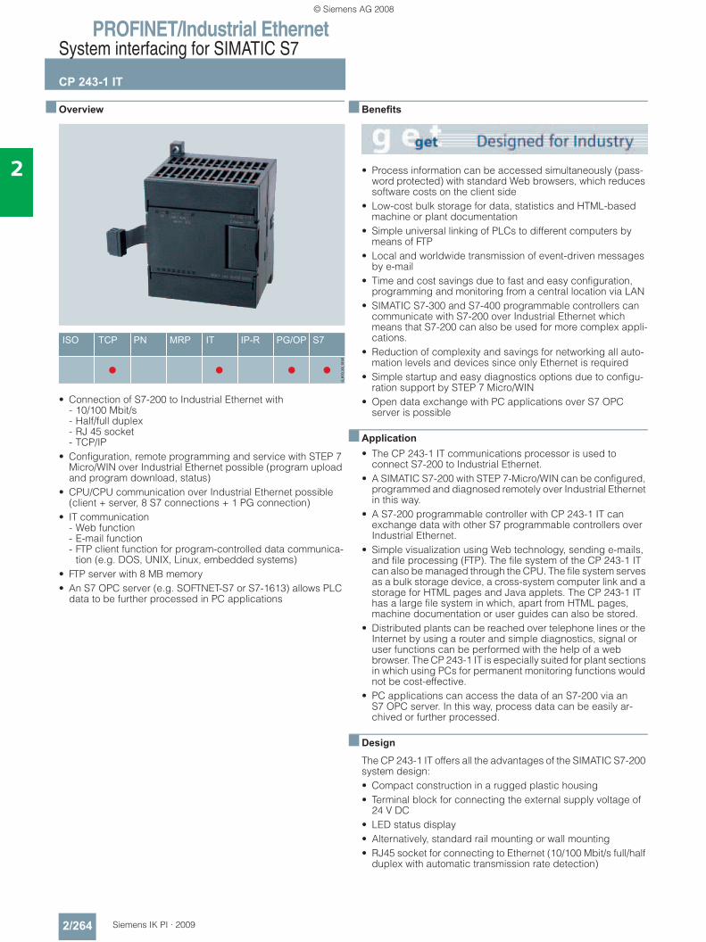
PROFINET/Industrial EthernetSystem interfacing for SIMATIC S7
CP 243-1 IT
2/264 Siemens IK PI · 2009
2
■ Overview
• Connection of S7-200 to Industrial Ethernet with - 10/100 Mbit/s- Half/full duplex- RJ 45 socket- TCP/IP
• Configuration, remote programming and service with STEP 7 Micro/WIN over Industrial Ethernet possible (program upload and program download, status)
• CPU/CPU communication over Industrial Ethernet possible (client + server, 8 S7 connections + 1 PG connection)
• IT communication - Web function - E-mail function - FTP client function for program-controlled data communica-
tion (e.g. DOS, UNIX, Linux, embedded systems)• FTP server with 8 MB memory• An S7 OPC server (e.g. SOFTNET-S7 or S7-1613) allows PLC
data to be further processed in PC applications
■ Benefits
• Process information can be accessed simultaneously (pass-word protected) with standard Web browsers, which reduces software costs on the client side
• Low-cost bulk storage for data, statistics and HTML-based machine or plant documentation
• Simple universal linking of PLCs to different computers by means of FTP
• Local and worldwide transmission of event-driven messages by e-mail
• Time and cost savings due to fast and easy configuration, programming and monitoring from a central location via LAN
• SIMATIC S7-300 and S7-400 programmable controllers can communicate with S7-200 over Industrial Ethernet which means that S7-200 can also be used for more complex appli-cations.
• Reduction of complexity and savings for networking all auto-mation levels and devices since only Ethernet is required
• Simple startup and easy diagnostics options due to configu-ration support by STEP 7 Micro/WIN
• Open data exchange with PC applications over S7 OPC server is possible
■ Application• The CP 243-1 IT communications processor is used to
connect S7-200 to Industrial Ethernet.• A SIMATIC S7-200 with STEP 7-Micro/WIN can be configured,
programmed and diagnosed remotely over Industrial Ethernet in this way.
• A S7-200 programmable controller with CP 243-1 IT can exchange data with other S7 programmable controllers over Industrial Ethernet.
• Simple visualization using Web technology, sending e-mails, and file processing (FTP). The file system of the CP 243-1 IT can also be managed through the CPU. The file system serves as a bulk storage device, a cross-system computer link and a storage for HTML pages and Java applets. The CP 243-1 IT has a large file system in which, apart from HTML pages, machine documentation or user guides can also be stored.
• Distributed plants can be reached over telephone lines or the Internet by using a router and simple diagnostics, signal or user functions can be performed with the help of a web browser. The CP 243-1 IT is especially suited for plant sections in which using PCs for permanent monitoring functions would not be cost-effective.
• PC applications can access the data of an S7-200 via an S7 OPC server. In this way, process data can be easily ar-chived or further processed.
■ Design
The CP 243-1 IT offers all the advantages of the SIMATIC S7-200 system design:• Compact construction in a rugged plastic housing• Terminal block for connecting the external supply voltage of
24 V DC• LED status display• Alternatively, standard rail mounting or wall mounting• RJ45 socket for connecting to Ethernet (10/100 Mbit/s full/half
duplex with automatic transmission rate detection)
© Siemens AG 2008
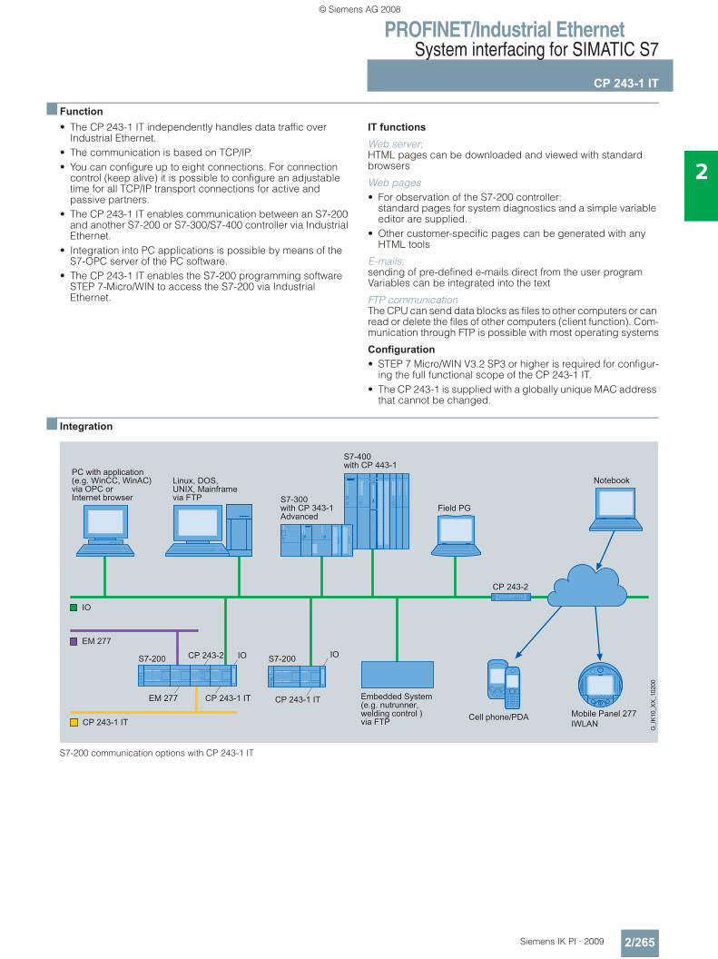
PROFINET/Industrial EthernetSystem interfacing for SIMATIC S7
CP 243-1 IT
2/265Siemens IK PI · 2009
2
■ Function• The CP 243-1 IT independently handles data traffic over
Industrial Ethernet.• The communication is based on TCP/IP.• You can configure up to eight connections. For connection
control (keep alive) it is possible to configure an adjustable time for all TCP/IP transport connections for active and passive partners.
• The CP 243-1 IT enables communication between an S7-200 and another S7-200 or S7-300/S7-400 controller via Industrial Ethernet.
• Integration into PC applications is possible by means of the S7-OPC server of the PC software.
• The CP 243-1 IT enables the S7-200 programming software STEP 7-Micro/WIN to access the S7-200 via Industrial Ethernet.
IT functions
Web server; HTML pages can be downloaded and viewed with standard browsers
Web pages • For observation of the S7-200 controller:
standard pages for system diagnostics and a simple variable editor are supplied.
• Other customer-specific pages can be generated with any HTML tools
E-mails; sending of pre-defined e-mails direct from the user program Variables can be integrated into the text
FTP communication The CPU can send data blocks as files to other computers or can read or delete the files of other computers (client function). Com-munication through FTP is possible with most operating systems
Configuration • STEP 7 Micro/WIN V3.2 SP3 or higher is required for configur-
ing the full functional scope of the CP 243-1 IT.• The CP 243-1 is supplied with a globally unique MAC address
that cannot be changed.
■ Integration
S7-200 communication options with CP 243-1 IT
© Siemens AG 2008
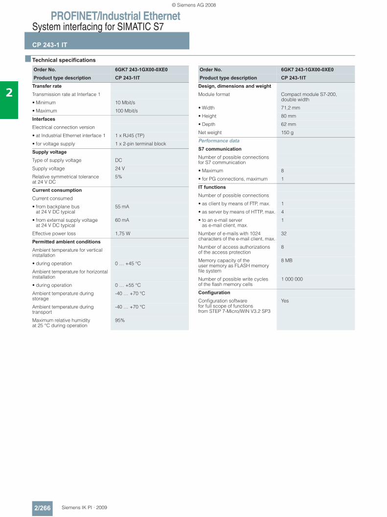
PROFINET/Industrial EthernetSystem interfacing for SIMATIC S7
CP 243-1 IT
2/266 Siemens IK PI · 2009
2
■ Technical specifications
Order No. 6GK7 243-1GX00-0XE0Product type description CP 243-1IT
Transfer rate
Transmission rate at Interface 1
• Minimum 10 Mbit/s
• Maximum 100 Mbit/s
Interfaces
Electrical connection version
• at Industrial Ethernet interface 1 1 x RJ45 (TP)
• for voltage supply 1 x 2-pin terminal block
Supply voltage
Type of supply voltage DC
Supply voltage 24 V
Relative symmetrical tolerance at 24 V DC
5%
Current consumption
Current consumed
• from backplane bus at 24 V DC typical
55 mA
• from external supply voltage at 24 V DC typical
60 mA
Effective power loss 1,75 W
Permitted ambient conditions
Ambient temperature for vertical installation
• during operation 0 … +45 °C
Ambient temperature for horizontal installation
• during operation 0 … +55 °C
Ambient temperature during storage
-40 … +70 °C
Ambient temperature during transport
-40 … +70 °C
Maximum relative humidityat 25 °C during operation
95%
Order No. 6GK7 243-1GX00-0XE0Product type description CP 243-1IT
Design, dimensions and weight Module format Compact module S7-200,
double width
• Width 71,2 mm
• Height 80 mm
• Depth 62 mm
Net weight 150 g
Performance data
S7 communication
Number of possible connectionsfor S7 communication
• Maximum 8
• for PG connections, maximum 1
IT functions
Number of possible connections
• as client by means of FTP, max. 1
• as server by means of HTTP, max. 4
• to an e-mail server as e-mail client, max.
1
Number of e-mails with 1024 characters of the e-mail client, max.
32
Number of access authorizations of the access protection
8
Memory capacity of the user memory as FLASH memoryfile system
8 MB
Number of possible write cycles of the flash memory cells
1 000 000
Configuration
Configuration software for full scope of functions from STEP 7-Micro/WIN V3.2 SP3
Yes
© Siemens AG 2008

PROFINET/Industrial EthernetSystem interfacing for SIMATIC S7
CP 243-1 IT
2/267Siemens IK PI · 2009
2
■ Ordering data Order No. Order No.
1) Upgrade for all previous STEP 7-Micro/WIN and STEP 7-Micro/DOS versions
CP 243-1 IT communications processor
6GK7 243-1GX00-0XE0
for connection of SIMATIC S7-200 to Industrial Ethernet; for S7 com-munication, PG communication, E-mail and WWW server;with electronic manual on CD-ROM German, English, French, Italian, Spanish
SOFTNET Edition 2007 for Industrial EthernetSoftware for S7 and open commu-nication, incl. OPC server, PG/OP communication and NCM PC, runtime software, software and electronic manual on CD-ROM, license key on USB stick, Class A, for 32-bit Windows XP Profes-sional SP1, 2; Windows 2003 Server SP1, R2, SP2; Windows Vista Business/Ultimate; German/English
SOFTNET-S7 Edition 2007 for Industrial Ethernetup to 64 connections
• Single license for 1 installation 6GK1 704-1CW70-3AA0• Software Update Service
for 1 year, with automatic extension; requirement: Current software version
6GK1 704-1CW00-3AL0
• Upgrade from V6.4 to 2007 edition
6GK1 704-1CW00-3AE0
• Upgrade from V6.0, V6.1, V6.2 or V6.3 to 2007 Edition
6GK1 704-1CW00-3AE1
SOFTNET-S7 Lean Edition 2007 for Industrial Ethernetup to 8 connections
• Single license for 1 installation 6GK1 704-1LW70-3AA0• Software Update Service
for 1 year, with automatic extension; requirement: Current software version
6GK1 704-1LW00-3AL0
• Upgrade from V6.4 to 2007 Edition
6GK1 704-1LW00-3AE0
• Upgrade from V6.0, V6.1, V6.2 or V6.3 to 2007 Edition
6GK1 704-1LW00-3AE1
S7-1613 Edition 2007Software for S7 and open commu-nication, incl. PG/OP communi-cation, OPC server and NCM PC; up to 120 connections, runtime software, software and electronic manual on CD-ROM, license key on USB stick, Class A, for 32-bit Windows XP Professional SP1, 2; Windows 2003 Server SP1, R2, SP2, Windows Vista Business/Ultimate; for CP 1613/CP 1613 A2/CP 1623; German/English
• Single license for 1 installation 6GK1 716-1CB70-3AA0• Software Update Service
for 1 year, with automatic extension; requirement: Current software version
6GK1 716-1CB00-3AL0
• Upgrade S7-1613 from V6.4 to 2007 Edition
6GK1 716-1CB00-3AE0
• Upgrade S7-1613 from V6.0, V6.1, V6.2 or V6.3 to S7-1613 Edition 2007
6GK1 716-1CB00-3AE1
STEP 7-Micro/WIN V4 programming softwareTarget system:All CPUs of the SIMATIC S7-200 Prerequisite: Windows 2000/XP on PG or PC Type of delivery: German, English, French, Spanish, Italian, Chinese; with online documentation
• Single license 6ES7 810-2CC03-0YX0• Upgrade Single License1) 6ES7 810-2CC03-0YX3IE FC TP Standard Cable GP 2x2 6XV1 840-2AH104-core, shielded TP installation cable for connection to IE FC Outlet RJ45/ IE FC RJ45 Plug; PROFINET-compatible; with UL approval; sold by the meter
FO Standard Cable GP (50/125) 6XV1 873-2AStandard cable, splittable, UL approval, sold by the meter
SCALANCE X204-2 Industrial Ethernet Switch
6GK5 204-2BB10-2AA3
Industrial Ethernet Switches with integral SNMP access, web diagnostics, copper cable diagnostics and PROFINET diagnostics for configuring line, star and ring topologies; four 10/100 Mbit/s RJ45 ports and two FO ports
IE FC RJ45 plugsRJ45 plug connector for Indus-trial Ethernet with a rugged metal enclosure and integrated insula-tion displacement contacts for connecting Industrial Ethernet FC installation cables
IE FC RJ45 Plug 180180° cable outlet
• 1 unit 6GK1 901-1BB10-2AA0• 10 units 6GK1 901-1BB10-2AB0• 50 units 6GK1 901-1BB10-2AE0
© Siemens AG 2008
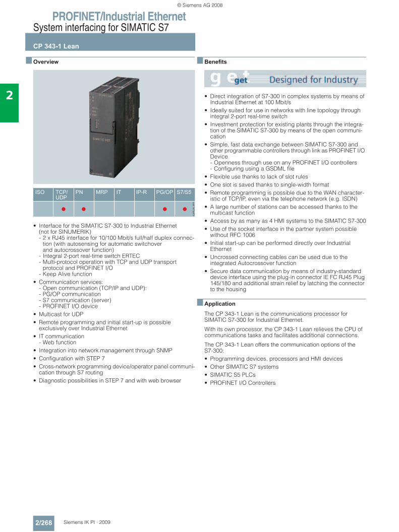
PROFINET/Industrial EthernetSystem interfacing for SIMATIC S7
CP 343-1 Lean
2/268 Siemens IK PI · 2009
2
■ Overview
• Interface for the SIMATIC S7-300 to Industrial Ethernet(not for SINUMERIK) - 2 x RJ45 interface for 10/100 Mbit/s full/half duplex connec-
tion (with autosensing for automatic switchoverand autocrossover function)
- Integral 2-port real-time switch ERTEC- Multi-protocol operation with TCP and UDP transport
protocol and PROFINET I/O- Keep Alive function
• Communication services: - Open communication (TCP/IP and UDP): - PG/OP communication- S7 communication (server)- PROFINET I/O device
• Multicast for UDP• Remote programming and initial start-up is possible
exclusively over Industrial Ethernet• IT communication
- Web function• Integration into network management through SNMP• Configuration with STEP 7 • Cross-network programming device/operator panel communi-
cation through S7 routing• Diagnostic possibilities in STEP 7 and with web browser
■ Benefits
• Direct integration of S7-300 in complex systems by means of Industrial Ethernet at 100 Mbit/s
• Ideally suited for use in networks with line topology through integral 2-port real-time switch
• Investment protection for existing plants through the integra-tion of the SIMATIC S7-300 by means of the open communi-cation
• Simple, fast data exchange between SIMATIC S7-300 and other programmable controllers through link as PROFINET I/O Device - Openness through use on any PROFINET I/O controllers - Configuring using a GSDML file
• Flexible use thanks to lack of slot rules• One slot is saved thanks to single-width format• Remote programming is possible due to the WAN character-
istic of TCP/IP, even via the telephone network (e.g. ISDN)• A large number of stations can be accessed thanks to the
multicast function• Access by as many as 4 HMI systems to the SIMATIC S7-300• Use of the socket interface in the partner system possible
without RFC 1006• Initial start-up can be performed directly over Industrial
Ethernet• Uncrossed connecting cables can be used due to the
integrated Autocrossover function• Secure data communication by means of industry-standard
device interface using the plug-in connector IE FC RJ45 Plug 145/180 and additional strain relief by latching the connector to the housing
■ Application
The CP 343-1 Lean is the communications processor for SIMATIC S7-300 for Industrial Ethernet.
With its own processor, the CP 343-1 Lean relieves the CPU of communications tasks and facilitates additional connections.
The CP 343-1 Lean offers the communication options of the S7-300:• Programming devices, processors and HMI devices• Other SIMATIC S7 systems• SIMATIC S5 PLCs• PROFINET I/O Controllers
© Siemens AG 2008
PROFINET/Industrial EthernetSystem interfacing for SIMATIC S7
CP 343-1 Lean
2/269Siemens IK PI · 2009
2
■ Design
The CP 343-1 Lean offers all the advantages of SIMATIC S7-300 system design:• Compact design;
the rugged plastic casing features on the front: - two RJ45 sockets for connecting to Industrial Ethernet with
automatic detection of data transfer rate by means of autosensing; RJ45 sockets have an industry-compatible design with additional securing collar for connection of IE FC RJ45 Plug 145/180
- diagnostic LEDs for each switch port- 2-pin plug-in terminal block for connecting the external
supply voltage of 24 V DC• Easy installation;
The CP 343-1 Lean is snap-mounted on the S7-300 DIN rail and connected to adjacent modules through the bus connec-tors. There are no slot rules.
• The CP 343-1 Lean can be operated without a fan. A standby battery is not required.
• In combination with IM 360/361, CP 343-1 Lean can also be used in an expansion rack (ER).
• The module can be replaced without the need for a program-ming device
■ Function
The CP 343-1 Lean independently handles data traffic over Industrial Ethernet. The module has its own processor. Layers 1 to 4 comply with international standards.
Multi-protocol operation of the transport protocols TCP/IP and UDP as well as PROFINET I/O is possible.
The CP 343-1 Lean has a preset unique Ethernet address and can be put directly into operation through the network.
The CP 343-1 Lean works in multi-protocol mode for the follow-ing communication services:
PG/OP communication
PG/OP communication allows all S7 stations connected to the network to be remotely programmed.• S7 routing;
Using S7 routing it is possible to use programming device communication across networks.
S7 communication
Is used for connecting the S7-300 (server only) to S7-400, HMI devices and PCs (SOFTNET-S7 or CP 1613 A2 /CP 1623 with S7-1613).
Open communication
On the basis of layer 4, the open communication with SEND/RECEIVE offers a simple and optimized interface for data com-munication. Up to 8 KB of data can be transmitted in one call.
This interface enables• TCP transport connections with or without RFC 1006• UDP
- Multicast for UDP
to be used.
Open IE and S5-compatible communication is used for commu-nication with SIMATIC S5, SIMATIC S7-400/300 and comput-ers/PCs.
The function blocks required are a component part of STEP 7 for Industrial Ethernet and must be integrated into the S7 user program.
Open communication with FETCH/WRITE allows direct access to the CPU data of the SIMATIC S7 (in the same way as in the CP 1430 TCP and the SIMATIC S5). This means existing HMI systems can still be used.
Implementing UDP as the transmission protocol allows utilization of the multicast function to simultaneously send and receive data on configured multicast circuits.
PROFINET I/O device functionality
The CP 343-1 Lean can be operated as a PROFINET I/O device in order to exchange data from the user program of the S7-300 station with a PROFINET I/O controller just like a field device (as input and output data). This high-performance data ex-change using PROFINET I/O communication mechanisms is handled independently by the CP 343-1 Lean.For connection to PC-based systems, for example, the CP 1616 or CP 1604 can be used as PROFINET IO-controller.
Diagnostics
Comprehensive diagnostic options are available via STEP S7 or a web browser, including:• Status of the CP• General diagnostics and statistics functions• Connection diagnostics• LAN controller statistics• Diagnostic buffer• Web diagnostics with easy diagnostic functions
Via SNMP all MIB-2 objects can be read out. This enables the current status of the Ethernet interfaces to be retrieved.
Configuration
STEP 7 V5.4 or higher is required for configuring the full func-tional scope of the CP 343-1 Lean.
The configuration data of the CP is stored on the CPU. This allows the module to be replaced without a programming device.
© Siemens AG 2008
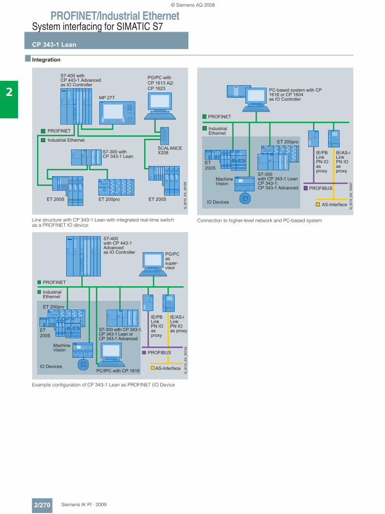
PROFINET/Industrial EthernetSystem interfacing for SIMATIC S7
CP 343-1 Lean
2/270 Siemens IK PI · 2009
2
■ Integration
Line structure with CP 343-1 Lean with integrated real-time switch as a PROFINET IO device
Example configuration of CP 343-1 Lean as PROFINET I/O Device
Connection to higher-level network and PC-based system
© Siemens AG 2008
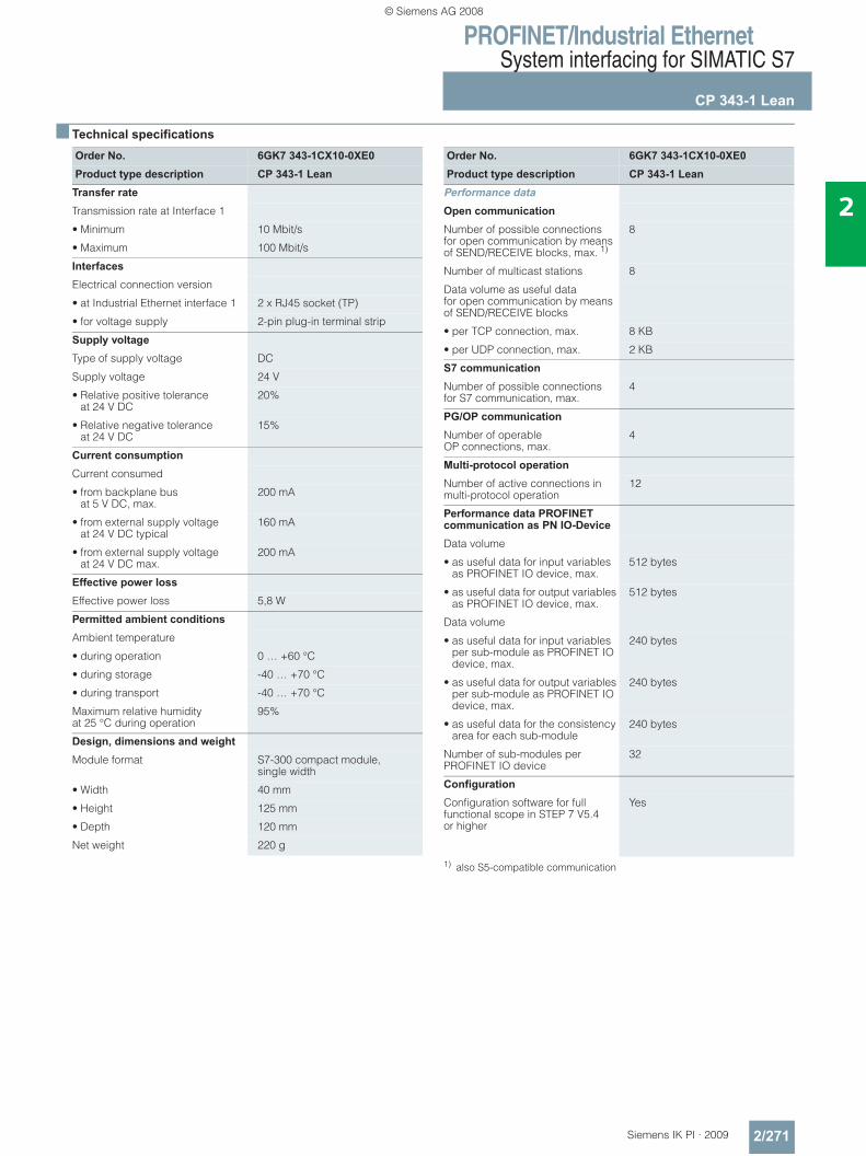
PROFINET/Industrial EthernetSystem interfacing for SIMATIC S7
CP 343-1 Lean
2/271Siemens IK PI · 2009
2
■ Technical specifications
1) also S5-compatible communication
Order No. 6GK7 343-1CX10-0XE0Product type description CP 343-1 Lean
Transfer rate
Transmission rate at Interface 1
• Minimum 10 Mbit/s
• Maximum 100 Mbit/s
Interfaces
Electrical connection version
• at Industrial Ethernet interface 1 2 x RJ45 socket (TP)
• for voltage supply 2-pin plug-in terminal strip
Supply voltage
Type of supply voltage DC
Supply voltage 24 V
• Relative positive tolerance at 24 V DC
20%
• Relative negative tolerance at 24 V DC
15%
Current consumption
Current consumed
• from backplane bus at 5 V DC, max.
200 mA
• from external supply voltage at 24 V DC typical
160 mA
• from external supply voltage at 24 V DC max.
200 mA
Effective power loss
Effective power loss 5,8 W
Permitted ambient conditions
Ambient temperature
• during operation 0 … +60 °C
• during storage -40 … +70 °C
• during transport -40 … +70 °C
Maximum relative humidity at 25 °C during operation
95%
Design, dimensions and weight Module format S7-300 compact module,
single width
• Width 40 mm
• Height 125 mm
• Depth 120 mm
Net weight 220 g
Order No. 6GK7 343-1CX10-0XE0Product type description CP 343-1 Lean
Performance data
Open communication
Number of possible connections for open communication by means of SEND/RECEIVE blocks, max. 1)
8
Number of multicast stations 8
Data volume as useful data for open communication by means of SEND/RECEIVE blocks
• per TCP connection, max. 8 KB
• per UDP connection, max. 2 KB
S7 communication
Number of possible connectionsfor S7 communication, max.
4
PG/OP communication
Number of operable OP connections, max.
4
Multi-protocol operation
Number of active connections in multi-protocol operation
12
Performance data PROFINET communication as PN IO-Device
Data volume
• as useful data for input variables as PROFINET IO device, max.
512 bytes
• as useful data for output variables as PROFINET IO device, max.
512 bytes
Data volume
• as useful data for input variables per sub-module as PROFINET IO device, max.
240 bytes
• as useful data for output variables per sub-module as PROFINET IO device, max.
240 bytes
• as useful data for the consistency area for each sub-module
240 bytes
Number of sub-modules per PROFINET IO device
32
Configuration
Configuration software for full functional scope in STEP 7 V5.4 or higher
Yes
© Siemens AG 2008
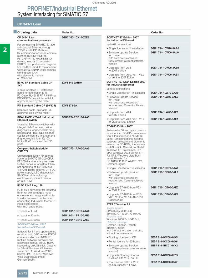
PROFINET/Industrial EthernetSystem interfacing for SIMATIC S7
CP 343-1 Lean
2/272 Siemens IK PI · 2009
2
■ Ordering data Order No. Order No.
CP 343-1 Lean communications processor
6GK7 343-1CX10-0XE0
For connecting SIMATIC S7-300 to Industrial Ethernet through TCP/IP and UDP, Multicast, S7 communication, open commu-nication (SEND/RECEIVE), FETCH/WRITE, PROFINET IO device, integral 2-port switch ERTEC, comprehensive diagnos-tics facilities, module replacement without PG, SNMP, initial commis-sioning over LAN; with electronic manual on CD-ROM
IE FC TP Standard Cable GP 2x2
6XV1 840-2AH10
4-core, shielded TP installation cable for connection to IE FC Outlet RJ45/ IE FC RJ45 Plug; PROFINET-compatible; with UL approval; sold by the meter
FO Standard Cable GP (50/125) 6XV1 873-2AStandard cable, splittable, UL approval, sold by the meter
SCALANCE X204-2 Industrial Ethernet switch
6GK5 204-2BB10-2AA3
Industrial Ethernet switches with integral SNMP access, online diagnostics, copper cable diag-nostics and PROFINET diagnos-tics for configuring line, star and ring topologies; four 10/100 Mbit/s RJ45 ports and two FO ports
Compact Switch Module CSM 377
6GK7 377-1AA00-0AA0
Unmanaged switch for connec-tion of a SIMATIC S7-300-CPU, ET 200M and as many as three further nodes to Industrial Ether-net operating at 10/100 Mbit/s; 4 x RJ45 ports; external 24 V DC power supply, LED diagnostics, S7-300 module including electronic equipment manual on CD-ROM
IE FC RJ45 Plug 180RJ45 plug connector for Industrial Ethernet with a rugged metal enclosure and integrated insula-tion displacement contacts for connecting Industrial Ethernet FC installation cableswith 180° cable outlet;
• 1 pack = 1 unit 6GK1 901-1BB10-2AA0• 1 pack = 10 units 6GK1 901-1BB10-2AB0• 1 pack = 50 units 6GK1 901-1BB10-2AE0SOFTNET Edition 2007 for Industrial EthernetSoftware for S7 and open commu-nication, incl. OPC server, PG/OP communication and NCM PC, runtime software, software and electronic manual on CD-ROM, license key on USB stick, Class A, for 32-bit Windows XP Profes-sional SP1, 2, Windows 2003 Server SP1, R2, SP2, Windows Vista Business/Ultimate; German/English
SOFTNET-S7 Edition 2007 for Industrial Ethernetup to 64 connections
• Single license for 1 installation 6GK1 704-1CW70-3AA0• Software Update Service
for 1 year, with automatic extension; requirement: Current software version
6GK1 704-1CW00-3AL0
• Upgrade from V6.4 to 2007 edition
6GK1 704-1CW00-3AE0
• Upgrade from V6.0, V6.1, V6.2 or V6.3 to 2007 Edition
6GK1 704-1CW00-3AE1
SOFTNET-S7 Lean Edition 2007 for Industrial Ethernetup to 8 connections
• Single License for 1 installation 6GK1 704-1LW70-3AA0• Software Update Service
for 1 year, with automatic extension; requirement: Current software version
6GK1 704-1LW00-3AL0
• Upgrade from V6.4to 2007 edition
6GK1 704-1LW00-3AE0
• Upgrade from V6.0, V6.1, V6.2 or V6.3 to 2007 Edition
6GK1 704-1LW00-3AE1
S7-1613 Edition 2007Software for S7 and open commu-nication, incl. PG/OP communica-tion, OPC server and NCM PC;up to 120 connections, runtime software, software and electronic manual on CD-ROM, license key on USB stick, Class A, for 32-bit Windows XP Professional SP1, SP2; Windows 2003 Server SP1, R2, SP2, Windows Vista Busi-ness/Ultimate; for CP 1613/CP 1613 A2/CP 1623; German/English
• Single License for 1 installation 6GK1 716-1CB70-3AA0• Software Update Service
for 1 year, with automatic extension; requirement: Current software version
6GK1 716-1CB00-3AL0
• Upgrade S7-1613 from V6.4 to 2007 Edition
6GK1 716-1CB00-3AE0
• Upgrade S7-1613 from V6.0, V6.1, V6.2 or V6.3 to S7-1613 Edition 2007
6GK1 716-1CB00-3AE1
STEP 7 Version 5.4Target system: SIMATIC S7-300/-400, SIMATIC C7, SIMATIC WinAC Requirement: Windows 2000 Prof./XP Prof. Delivery package: German, English, French, Spanish, Italian; incl. 3.5" authorization diskette, without documentation
• Floating License on CD 6ES7 810-4CC08-0YA5• Rental license for 50 hours 6ES7 810-4CC08-0YA6• Software Update Service
on CD (requires current software version)
6ES7 810-4BC01-0YX2
• Upgrade Floating License 3.x/4.x/5.x to V5.4; on CD
6ES7 810-4CC08-0YE5
• Trial License STEP 7 V5.4; on CD, runs for 14 days
6ES7 810-4CC08-0YA7
© Siemens AG 2008
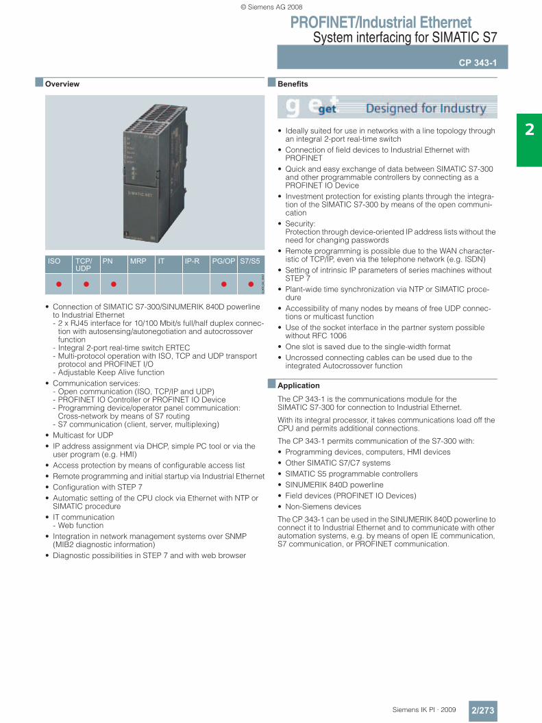
PROFINET/Industrial EthernetSystem interfacing for SIMATIC S7
CP 343-1
2/273Siemens IK PI · 2009
2
■ Overview
• Connection of SIMATIC S7-300/SINUMERIK 840D powerline to Industrial Ethernet - 2 x RJ45 interface for 10/100 Mbit/s full/half duplex connec-
tion with autosensing/autonegotiation and autocrossover function
- Integral 2-port real-time switch ERTEC- Multi-protocol operation with ISO, TCP and UDP transport
protocol and PROFINET I/O- Adjustable Keep Alive function
• Communication services: - Open communication (ISO, TCP/IP and UDP)- PROFINET IO Controller or PROFINET IO Device- Programming device/operator panel communication:
Cross-network by means of S7 routing- S7 communication (client, server, multiplexing)
• Multicast for UDP• IP address assignment via DHCP, simple PC tool or via the
user program (e.g. HMI)• Access protection by means of configurable access list• Remote programming and initial startup via Industrial Ethernet• Configuration with STEP 7• Automatic setting of the CPU clock via Ethernet with NTP or
SIMATIC procedure• IT communication
- Web function• Integration in network management systems over SNMP
(MIB2 diagnostic information)• Diagnostic possibilities in STEP 7 and with web browser
■ Benefits
• Ideally suited for use in networks with a line topology through an integral 2-port real-time switch
• Connection of field devices to Industrial Ethernet with PROFINET
• Quick and easy exchange of data between SIMATIC S7-300 and other programmable controllers by connecting as a PROFINET IO Device
• Investment protection for existing plants through the integra-tion of the SIMATIC S7-300 by means of the open communi-cation
• Security: Protection through device-oriented IP address lists without the need for changing passwords
• Remote programming is possible due to the WAN character-istic of TCP/IP, even via the telephone network (e.g. ISDN)
• Setting of intrinsic IP parameters of series machines without STEP 7
• Plant-wide time synchronization via NTP or SIMATIC proce-dure
• Accessibility of many nodes by means of free UDP connec-tions or multicast function
• Use of the socket interface in the partner system possible without RFC 1006
• One slot is saved due to the single-width format• Uncrossed connecting cables can be used due to the
integrated Autocrossover function
■ Application
The CP 343-1 is the communications module for the SIMATIC S7-300 for connection to Industrial Ethernet.
With its integral processor, it takes communications load off the CPU and permits additional connections.
The CP 343-1 permits communication of the S7-300 with:• Programming devices, computers, HMI devices• Other SIMATIC S7/C7 systems• SIMATIC S5 programmable controllers• SINUMERIK 840D powerline • Field devices (PROFINET IO Devices) • Non-Siemens devices
The CP 343-1 can be used in the SINUMERIK 840D powerline to connect it to Industrial Ethernet and to communicate with other automation systems, e.g. by means of open IE communication, S7 communication, or PROFINET communication.
© Siemens AG 2008
PROFINET/Industrial EthernetSystem interfacing for SIMATIC S7
CP 343-1
2/274 Siemens IK PI · 2009
2
■ Design
The CP 343-1 has all the advantages of the SIMATIC S7-300 de-sign:• Compact design;
on the front, the rugged plastic housing features: - Two RJ45 sockets for connection to Industrial Ethernet with
automatic sensing of the data transmission rate by means of Autosensing/Autonegotiation; the RJ45 sockets are industrially compatible and designed with additional holding collars for connecting to the IE FC RJ45 Plug 145/180
- 2-pole plug-in terminal strip for connection of the 24 V DC ex-ternal supply voltage
- 8 LEDs for indication of the operating and communication status (diagnostics for each switch port)
• Easy installation; the CP 343-1 is mounted on the S7-300 rail and connected through the bus connector with the neighboring modules. No slot rules apply.
• Fan-free operation; A back-up battery is not required.
• Using the IM 360/361, the CP 343-1 can also be operated in the expansion rack (ER)
• Modules can be replaced without the need for a programming device
■ Function
The CP 343-1 independently handles data traffic over Industrial Ethernet. The module has its own processor. Layers 1 to 4 com-ply with international standards.
Multi-protocol operation of the transport protocols ISO, TCP/IP, UDP and PROFINET IO is possible. For connection control (keep alive) it is possible to configure an adjustable time for all TCP transport connections for active and passive partners.
The CPU’s time can be set using NTP or SIMATIC procedures with an accuracy of approx. +/-1 s.
The CP 343-1 has a preset unique Ethernet address and can be put directly into operation over the network.
The CP 343-1 works in multi-protocol mode for the following communication services:
PG/OP communication
PG/OP communication allows all S7 stations connected to the network to be remotely programmed.• S7 routing;
with the aid of S7 routing it is possible to use programming de-vice communication across networks
PROFINET communication • PROFINET IO Controller;
for connecting field devices and PC-based IO devices (e.g. with CP 1616 or CP 1604) over Industrial Ethernet, the CP 343-1 supports the functions of a PROFINET IO Controller
• PROFINET IO Device; the CP 343-1 can be operated as a PROFINET IO Device for exchanging data from the user program of the S7-300 station like a field device (as input and output data) with a PROFINET IO Controller.
Access by means of I/O data from the user program of the S7-300 station is through the PNIO_SEND and PNIO_RECV blocks.
S7 communication
For connecting the S7-300 (server and client) to S7-200/300/400 (server and client), HMI units and PCs (SOFTNET-S7 or CP 1613 A2/CP 1623 with S7-1613).
Open communication
Based on layer 4, this is a simple, optimized interface for data communication. Up to 8 KB of data can be transmitted in one call.
The following connection possibilities can be used with this in-terface: • TCP transport connections
- TCP with RFC 1006 - TCP without RFC 1006
• UDP - Multicast for UDP
• ISO transport connections
Open communication is used for communication with SIMATIC S5, SIMATIC S7-400/300 and computers/PCs.
The function blocks required are a component part of STEP 7 for Industrial Ethernet and must be integrated into the S7 user pro-gram.
Open communication with FETCH/WRITE allows direct access to the CPU data of the SIMATIC S7 (in the same way as in the CP 1430 TCP and the SIMATIC S5). This means existing HMI sys-tems can still be used.
Implementing UDP as the transmission protocol allows utilization of the multicast function to simultaneously send and receive data on configured multicast circuits.
Diagnostics
Comprehensive diagnostic options are available via STEP S7 or a web browser, including:• Operating status of CP• Operating status of PROFINET devices connected to CP• General diagnostics and statistics functions• Connection diagnostics• LAN controller statistics• Diagnostic buffer• Web diagnostics with easy diagnostic functions
Diagnostics possibilities during operation. • Status scanning of connections using function block• SNMP MIB-2 objects;
the current status of the Ethernet interface can then be called, e.g. for network management.
Security
With a configurable IP access list, specific PCs and automation devices can be released for IP-based access to the CP or con-troller.
Configuration
STEP 7 V5.4 or higher is required for configuring the full func-tional scope of the CP 343-1.
The configuration data of the CPs can be saved on the CPU. Modules can be swapped without using a programming device.
The function blocks required for communication and the pro-grammable communications block (S7-Client) are included in the scope of supply of NCM S7 for Industrial Ethernet or can be downloaded from the Internet.
© Siemens AG 2008
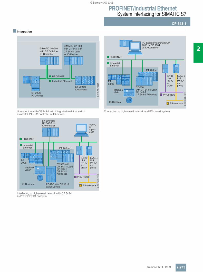
PROFINET/Industrial EthernetSystem interfacing for SIMATIC S7
CP 343-1
2/275Siemens IK PI · 2009
2
■ Integration
Line structure with CP 343-1 with integrated real-time switch as a PROFINET IO controller or IO device
Interfacing to higher-level network with CP 343-1 as PROFINET IO controller
Connection to higher-level network and PC-based system
SIMATIC S7-300with CP 343-1 asIO Controller
SIMATIC S7-300with CP 343-1 orCP 343-1 Leanas IO Device
ET 200proIO Devices
ET 200SIO Devices G
_IK1
0_XX
_102
21
PC/IPC with CP 1616 as IO Device
© Siemens AG 2008
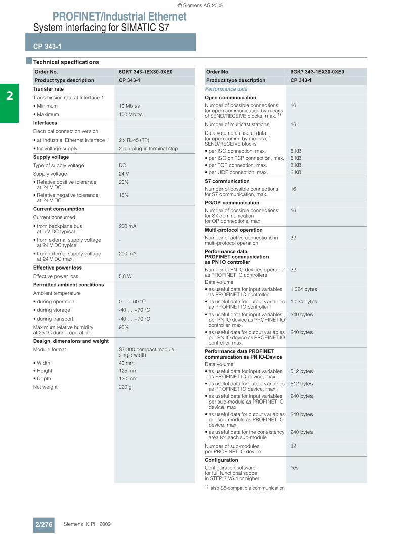
PROFINET/Industrial EthernetSystem interfacing for SIMATIC S7
CP 343-1
2/276 Siemens IK PI · 2009
2
■ Technical specifications
1) also S5-compatible communication
Order No. 6GK7 343-1EX30-0XE0Product type description CP 343-1
Transfer rate
Transmission rate at Interface 1
• Minimum 10 Mbit/s
• Maximum 100 Mbit/s
Interfaces
Electrical connection version
• at Industrial Ethernet interface 1 2 x RJ45 (TP)
• for voltage supply 2-pin plug-in terminal strip
Supply voltage
Type of supply voltage DC
Supply voltage 24 V
• Relative positive tolerance at 24 V DC
20%
• Relative negative tolerance at 24 V DC
15%
Current consumption
Current consumed
• from backplane bus at 5 V DC typical
200 mA
• from external supply voltage at 24 V DC typical
-
• from external supply voltage at 24 V DC max.
200 mA
Effective power loss
Effective power loss 5,8 W
Permitted ambient conditions
Ambient temperature
• during operation 0 … +60 °C
• during storage -40 … +70 °C
• during transport -40 … +70 °C
Maximum relative humidity at 25 °C during operation
95%
Design, dimensions and weight Module format S7-300 compact module,
single width
• Width 40 mm
• Height 125 mm
• Depth 120 mm
Net weight 220 g
Order No. 6GK7 343-1EX30-0XE0Product type description CP 343-1
Performance data
Open communication
Number of possible connections for open communication by means of SEND/RECEIVE blocks, max. 1)
16
Number of multicast stations 16
Data volume as useful datafor open comm. by means of SEND/RECEIVE blocks• per ISO connection, max. 8 KB• per ISO on TCP connection, max. 8 KB• per TCP connection, max. 8 KB• per UDP connection, max. 2 KB
S7 communication
Number of possible connections for S7 communication, max.
16
PG/OP communication
Number of possible connectionsfor S7 communication for OP connections, max.
16
Multi-protocol operation
Number of active connections in multi-protocol operation
32
Performance data, PROFINET communication as PN IO controller Number of PN IO devices operable as PROFINET IO controllers
32
Data volume• as useful data for input variables
as PROFINET IO controller 1 024 bytes
• as useful data for output variables as PROFINET IO controller
1 024 bytes
• as useful data for input variables per PN IO device as PROFINET IO controller, max.
240 bytes
• as useful data for output variables per PN IO device as PROFINET IO controller, max.
240 bytes
Performance data PROFINET communication as PN IO-Device Data volume• as useful data for input variables
as PROFINET IO device, max.512 bytes
• as useful data for output variables as PROFINET IO device, max.
512 bytes
• as useful data for input variables per sub-module as PROFINET IO device, max.
240 bytes
• as useful data for output variables per sub-module as PROFINET IO device, max.
240 bytes
• as useful data for the consistency area for each sub-module
240 bytes
Number of sub-modules per PROFINET IO device
32
Configuration
Configuration software for full functional scope in STEP 7 V5.4 or higher
Yes
© Siemens AG 2008
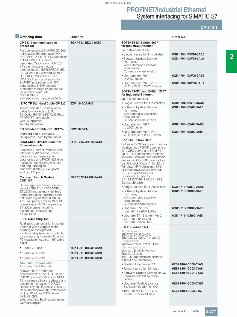
PROFINET/Industrial EthernetSystem interfacing for SIMATIC S7
CP 343-1
2/277Siemens IK PI · 2009
2
■ Ordering data Order No. Order No.
CP 343-1 communications processor
6GK7 343-1EX30-0XE0
For connection of SIMATIC S7-300 to Industrial Ethernet over ISO and TCP/IP; PROFINET IO Controller or PROFINET IO Device,integrated 2-port switch ERTEC;S7 communication, open communication (SEND/RECEIVE), FETCH/WRITE, with and without RFC 1006, multicast, DHCP, CPU clock synchronization via SIMATIC procedure and NTP, diagnostics, SNMP, access protection through IP access list, initialization over LAN 10/100 Mbit/s; with electronic manual on DVD
IE FC TP Standard Cable GP 2x2 6XV1 840-2AH104-core, shielded TP installation cable for connection to IE FC Outlet RJ45/ IE FC RJ45 Plug; PROFINET-compatible; with UL approval; sold by the meter
FO Standard Cable GP (50/125) 6XV1 873-2AStandard cable, splittable, UL approval, sold by the meter
SCALANCE X204-2 Industrial Ethernet switch
6GK5 204-2BB10-2AA3
Industrial Ethernet switches with integral SNMP access, online diagnostics, copper cable diagnostics and PROFINET diag-nostics for configuring line, star and ring topologies;four 10/100 Mbit/s RJ45 ports and two FO ports
Compact Switch Module CSM 377
6GK7 377-1AA00-0AA0
Unmanaged switch for connec-tion of a SIMATIC S7-300-CPU, ET 200M and as many as three further nodes to Industrial Ether-net operating at 10/100 Mbit/s; 4 x RJ45 ports; external 24 V DC power supply, LED diagnostics, S7-300 module including electronic device manual on CD-ROM
IE FC RJ45 Plug 145RJ45 plug connector for Industrial Ethernet with a rugged metal housing and integrated insulation displacement contacts for connecting Industrial Ethernet FC installation cables; 145° cable outlet
• 1 pack = 1 unit 6GK1 901-1BB30-0AA0• 1 pack = 10 units 6GK1 901-1BB30-0AB0• 1 pack = 50 units 6GK1 901-1BB30-0AE0SOFTNET Edition 2007 for Industrial EthernetSoftware for S7 and open communication, incl. OPC server, PG/OP communication and NCM PC, runtime software, software and electronic manual on CD-ROM, license key on USB stick, Class A, for 32 bit Windows XP Professional SP1, 2, Windows 2003 Server SP1, R2, SP2, Windows Vista Business/Ultimate; German/English
SOFTNET-S7 Edition 2007 for Industrial Ethernetup to 64 connections• Single license for 1 installation 6GK1 704-1CW70-3AA0• Software Update Service
for 1 year, with automatic extension; requirement: Current software version
6GK1 704-1CW00-3AL0
• Upgrade from V6.4 to 2007 edition
6GK1 704-1CW00-3AE0
• Upgrade from V6.0, V6.1, V6.2 or V6.3 to 2007 Edition
6GK1 704-1CW00-3AE1
SOFTNET-S7 Lean Edition 2007 for Industrial Ethernetup to 8 connections• Single License for 1 installation 6GK1 704-1LW70-3AA0• Software Update Service
for 1 year, with automatic extension; requirement: Current software version
6GK1 704-1LW00-3AL0
• Upgrade from V6.4 to 2007 edition
6GK1 704-1LW00-3AE0
• Upgrade from V6.0, V6.1, V6.2 or V6.3 to 2007 Edition
6GK1 704-1LW00-3AE1
S7-1613 Edition 2007Software for S7 and open commu-nication, incl. PG/OP communica-tion, OPC server and NCM PC; up to 120 connections, runtime software, software and electronic manual on CD-ROM, license key on USB stick, Class A, for 32-bit Windows XP Professional SP1, SP2; Windows 2003 Server SP1, R2, SP2, Windows Vista Business/Ultimate; for CP 1613/CP 1613 A2/CP 1623; German/English• Single License for 1 installation 6GK1 716-1CB70-3AA0• Software Update Service
for 1 year, with automatic extension; requirement: Current software version
6GK1 716-1CB00-3AL0
• Upgrade S7-1613 from V6.4 to 2007 Edition
6GK1 716-1CB00-3AE0
• Upgrade S7-1613 from V6.0, V6.1, V6.2 or V6.3 to S7-1613 Edition 2007
6GK1 716-1CB00-3AE1
STEP 7 Version 5.4Target system: SIMATIC S7-300/-400, SIMATIC C7, SIMATIC WinAC Requirement: Windows 2000 Prof./XP Prof. Delivery package: German, English, French, Spanish, Italian; incl. 3.5" authorization diskette, without documentation• Floating License on CD 6ES7 810-4CC08-0YA5• Rental license for 50 hours 6ES7 810-4CC08-0YA6• Software Update Service on CD
(requires current software version)
6ES7 810-4BC01-0YX2
• Upgrade Floating License 3.x/4.x/5.x to V5.4; on CD
6ES7 810-4CC08-0YE5
• Trial License STEP 7 V5.4; on CD, runs for 14 days
6ES7 810-4CC08-0YA7
© Siemens AG 2008
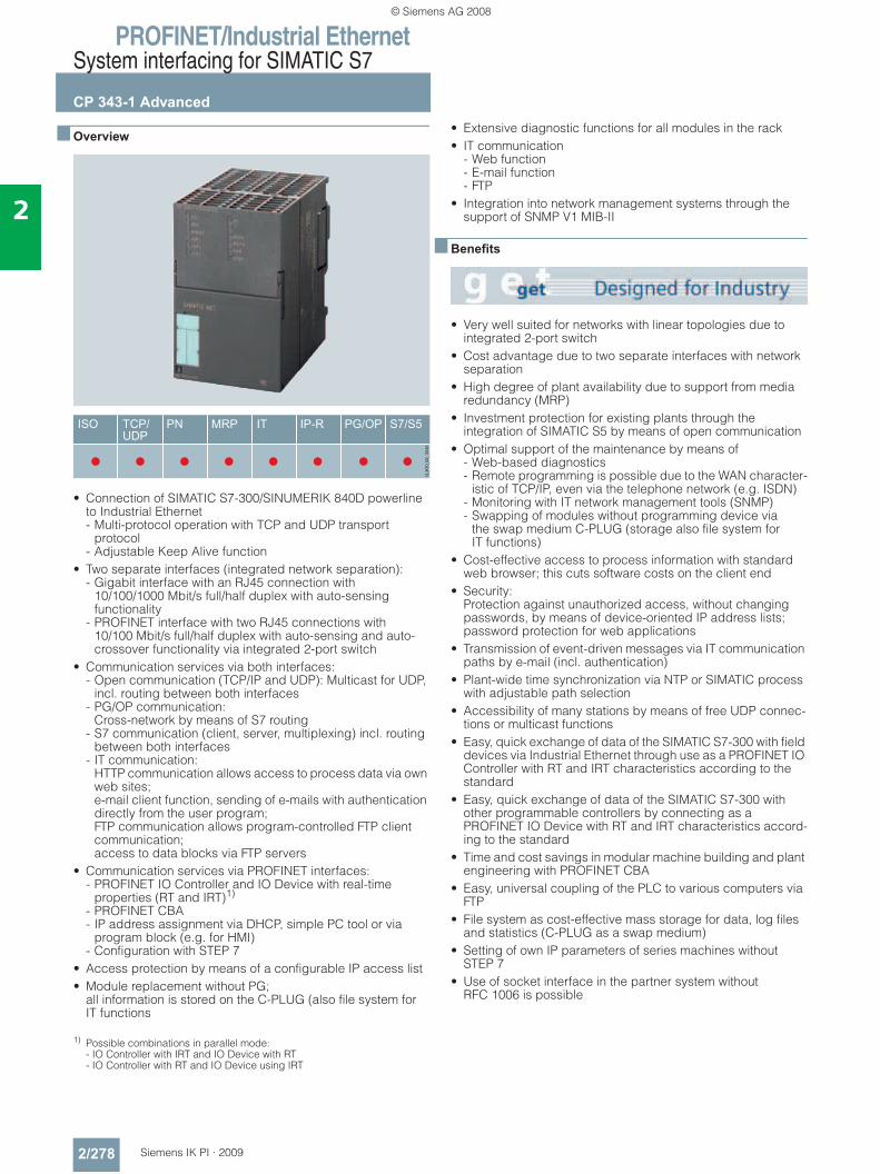
PROFINET/Industrial EthernetSystem interfacing for SIMATIC S7
CP 343-1 Advanced
2/278 Siemens IK PI · 2009
2
■ Overview
• Connection of SIMATIC S7-300/SINUMERIK 840D powerline to Industrial Ethernet - Multi-protocol operation with TCP and UDP transport
protocol- Adjustable Keep Alive function
• Two separate interfaces (integrated network separation): - Gigabit interface with an RJ45 connection with
10/100/1000 Mbit/s full/half duplex with auto-sensing functionality
- PROFINET interface with two RJ45 connections with 10/100 Mbit/s full/half duplex with auto-sensing and auto-crossover functionality via integrated 2-port switch
• Communication services via both interfaces: - Open communication (TCP/IP and UDP): Multicast for UDP,
incl. routing between both interfaces- PG/OP communication:
Cross-network by means of S7 routing- S7 communication (client, server, multiplexing) incl. routing
between both interfaces- IT communication:
HTTP communication allows access to process data via own web sites; e-mail client function, sending of e-mails with authentication directly from the user program; FTP communication allows program-controlled FTP client communication; access to data blocks via FTP servers
• Communication services via PROFINET interfaces: - PROFINET IO Controller and IO Device with real-time
properties (RT and IRT)1)
- PROFINET CBA- IP address assignment via DHCP, simple PC tool or via
program block (e.g. for HMI)- Configuration with STEP 7
• Access protection by means of a configurable IP access list• Module replacement without PG;
all information is stored on the C-PLUG (also file system for IT functions
1) Possible combinations in parallel mode: - IO Controller with IRT and IO Device with RT - IO Controller with RT and IO Device using IRT
• Extensive diagnostic functions for all modules in the rack• IT communication
- Web function- E-mail function- FTP
• Integration into network management systems through the support of SNMP V1 MIB-II
■ Benefits
• Very well suited for networks with linear topologies due to integrated 2-port switch
• Cost advantage due to two separate interfaces with network separation
• High degree of plant availability due to support from media redundancy (MRP)
• Investment protection for existing plants through the integration of SIMATIC S5 by means of open communication
• Optimal support of the maintenance by means of - Web-based diagnostics - Remote programming is possible due to the WAN character-
istic of TCP/IP, even via the telephone network (e.g. ISDN) - Monitoring with IT network management tools (SNMP) - Swapping of modules without programming device via
the swap medium C-PLUG (storage also file system for IT functions)
• Cost-effective access to process information with standard web browser; this cuts software costs on the client end
• Security: Protection against unauthorized access, without changing passwords, by means of device-oriented IP address lists; password protection for web applications
• Transmission of event-driven messages via IT communication paths by e-mail (incl. authentication)
• Plant-wide time synchronization via NTP or SIMATIC process with adjustable path selection
• Accessibility of many stations by means of free UDP connec-tions or multicast functions
• Easy, quick exchange of data of the SIMATIC S7-300 with field devices via Industrial Ethernet through use as a PROFINET IO Controller with RT and IRT characteristics according to the standard
• Easy, quick exchange of data of the SIMATIC S7-300 with other programmable controllers by connecting as a PROFINET IO Device with RT and IRT characteristics accord-ing to the standard
• Time and cost savings in modular machine building and plant engineering with PROFINET CBA
• Easy, universal coupling of the PLC to various computers via FTP
• File system as cost-effective mass storage for data, log files and statistics (C-PLUG as a swap medium)
• Setting of own IP parameters of series machines without STEP 7
• Use of socket interface in the partner system without RFC 1006 is possible
© Siemens AG 2008
PROFINET/Industrial EthernetSystem interfacing for SIMATIC S7
CP 343-1 Advanced
2/279Siemens IK PI · 2009
2
■ Application
The CP 343-1 Advanced is the communications processor for connecting the SIMATIC S7-300 and SINUMERIK 840D power-line to the Industrial Ethernet.
With its own processor, the CP relieves the CPU of communica-tions tasks and provides additional connections.
The CP 343-1 Advanced permits communication of the S7-300 with:• PG/PC• Master computer• HMI devices• SIMATIC S5/S7/C7 systems• PROFINET IO Devices and IO Controller• PROFINET CBA components
PROFINET CBA is used to create reusable technology modules.
■ Design
The CP 343-1 Advanced offers all the advantages of the SIMATIC S7-300 design:• Compact construction;
the rugged plastic enclosure features the following on the front panel: - Three RJ45 jacks for connecting to Industrial Ethernet via
two independent interfaces; automatic data rate detection by means of the auto-sensing and auto-crossover function; the connection is made via the IE FC RJ45 Plug 180 with 180° cable outlet or via a standard patch cable
- 2-pin plug-in terminal strip for connection of the 24 V DC external supply voltage
- Diagnostics LEDs for indicating the operational and commu-nication status
• Easy installation; the CP 343-1 Advanced is installed on the mounting rail of the S7-300 and is connected to adjacent modules via the bus connector. No slot rules apply in this case.
• The CP 343-1 Advanced can be operated without a fan; no backup battery is necessary.
• In combination with IM 360/361, the CP 343-1 Advanced can also be used in an expansion rack (ER).
• The module can be replaced without a programming device• The C-PLUG (configuration plug) is included in the scope of
delivery as replacement medium (operation without C-PLUG is not possible)
■ Function
The CP 343-1 Advanced independently handles data traffic over Industrial Ethernet. The module has its own processor and can be put into service directly using the unique preset Ethernet address (MAC) via the network.
Support of the DHCP (Dynamic Host Configuration Protocol) enables the IP address to be assigned from a central DHCP server.
For connection control (Keep Alive) it is possible to configure an adjustable time for all TCP transport connections for active and passive peers.
The CPU’s time can be set via NTP or SIMATIC procedures with an accuracy of approx. ±1 s.
The CP 343-1 Advanced works in multi-protocol mode for the following communication services:
PG/OP communication
PG/OP communication allows all S7 stations connected to the network to be remotely programmed.• S7 routing;
with the aid of S7 routing it is possible to utilize programming device communication across networks.
S7 communication
For connecting the S7-300 (server and client) to S7-200/300/400 (server and client), HMI units and PCs (SOFTNET-S7 or CP 1613 A2/CP 1623 with S7-1613).
Open communication On the basis of layer 4, open communication with SEND/RECEIVE offers a simple and optimized interface for data com-munication. Up to 8 KB of data can be transmitted in one call.
This interface enables • ISO transport connections• TCP transport connections
- TCP with RFC 1006 - TCP without RFC 1006
• UDP - Multicast for UDP
to be used.
Open communication is used for communication with SIMATIC S5, SIMATIC S7-400/300 and computers/PCs.
The function blocks required are a component part of STEP 7 for Industrial Ethernet and must be integrated into the S7 user program.
Open communication with FETCH/WRITE allows direct access to the CPU data of the SIMATIC S7 (in the same way as in the CP 1430 TCP and the SIMATIC S5). This means existing HMI systems can still be used.
If UDP is used as the transmission protocol, the multicast function can be used to simultaneously send and receive on configured multicast circuits.
PROFINET communication • PROFINET IO Controller;
real-time communication with field devices and PC-based IO Devices (e.g. with CP 1616 or CP 1604) over Industrial Ethernet according to PROFINET standard with RT and IRT real-time properties.
• PROFINET IO Device; the CP 343-1 Advanced can be operated as a PROFINET IO Device for exchanging data from the user program of the S7-300 station like a field device (as input and output data) with a PROFINET IO Controller. This high-performance data exchange using PROFINET I/O communication mechanisms with real-time properties is handled by the CP 343-1 Advanced on its own. Access by means of I/O data from the user program of the S7-300 station is through the PNIO_SEND and PNIO_RECV blocks.
• PROFINET CBA; communication between technological modules (distributed intelligence); the user can choose between cyclic and acyclic communica-tion.
© Siemens AG 2008
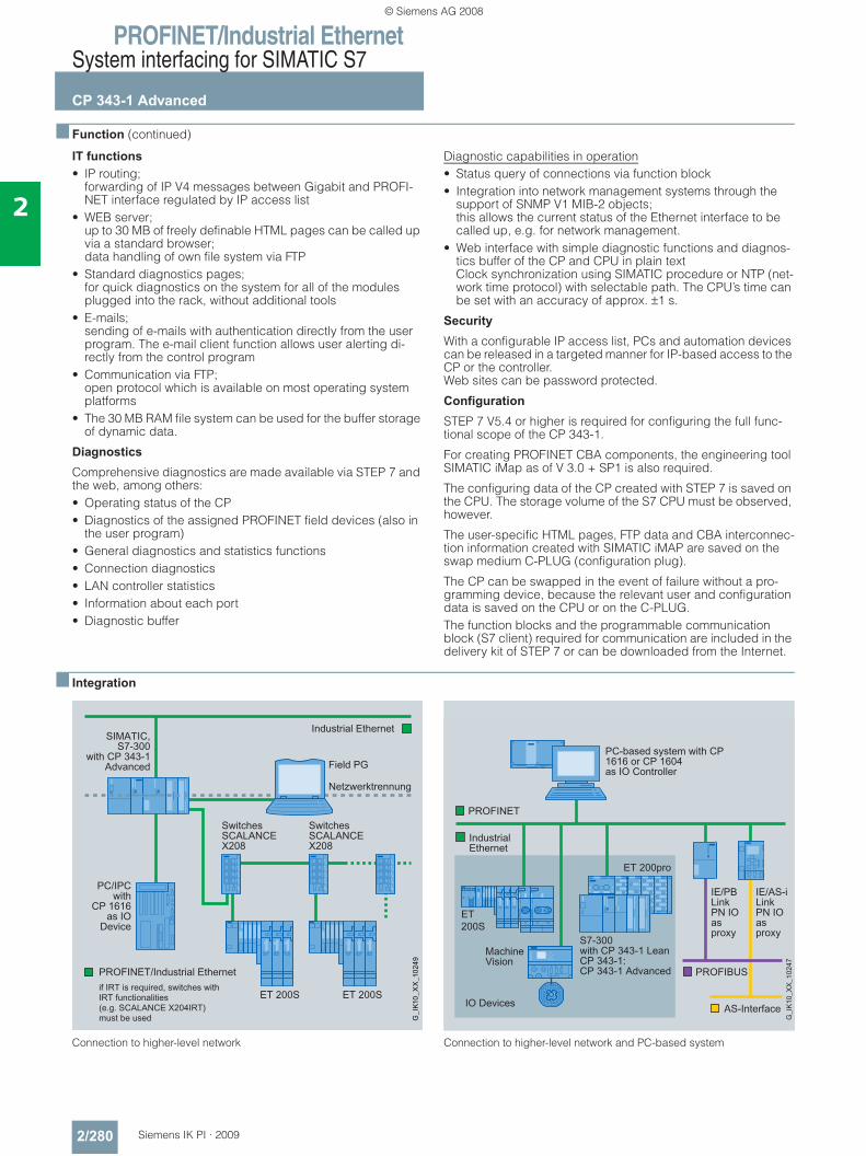
PROFINET/Industrial EthernetSystem interfacing for SIMATIC S7
CP 343-1 Advanced
2/280 Siemens IK PI · 2009
2
■ Function (continued)
IT functions • IP routing;
forwarding of IP V4 messages between Gigabit and PROFI-NET interface regulated by IP access list
• WEB server; up to 30 MB of freely definable HTML pages can be called up via a standard browser; data handling of own file system via FTP
• Standard diagnostics pages; for quick diagnostics on the system for all of the modules plugged into the rack, without additional tools
• E-mails; sending of e-mails with authentication directly from the user program. The e-mail client function allows user alerting di-rectly from the control program
• Communication via FTP; open protocol which is available on most operating system platforms
• The 30 MB RAM file system can be used for the buffer storage of dynamic data.
Diagnostics
Comprehensive diagnostics are made available via STEP 7 and the web, among others:• Operating status of the CP• Diagnostics of the assigned PROFINET field devices (also in
the user program)• General diagnostics and statistics functions• Connection diagnostics• LAN controller statistics• Information about each port• Diagnostic buffer
Diagnostic capabilities in operation • Status query of connections via function block• Integration into network management systems through the
support of SNMP V1 MIB-2 objects; this allows the current status of the Ethernet interface to be called up, e.g. for network management.
• Web interface with simple diagnostic functions and diagnos-tics buffer of the CP and CPU in plain text Clock synchronization using SIMATIC procedure or NTP (net-work time protocol) with selectable path. The CPU’s time can be set with an accuracy of approx. ±1 s.
Security
With a configurable IP access list, PCs and automation devices can be released in a targeted manner for IP-based access to the CP or the controller.Web sites can be password protected.
Configuration
STEP 7 V5.4 or higher is required for configuring the full func-tional scope of the CP 343-1.
For creating PROFINET CBA components, the engineering tool SIMATIC iMap as of V 3.0 + SP1 is also required.
The configuring data of the CP created with STEP 7 is saved on the CPU. The storage volume of the S7 CPU must be observed, however.
The user-specific HTML pages, FTP data and CBA interconnec-tion information created with SIMATIC iMAP are saved on the swap medium C-PLUG (configuration plug).
The CP can be swapped in the event of failure without a pro-gramming device, because the relevant user and configuration data is saved on the CPU or on the C-PLUG.The function blocks and the programmable communication block (S7 client) required for communication are included in the delivery kit of STEP 7 or can be downloaded from the Internet.
■ Integration
Connection to higher-level network Connection to higher-level network and PC-based system
SwitchesSCALANCEX208
SwitchesSCALANCEX208
PC/IPC with
CP 1616 as IO
Device
© Siemens AG 2008
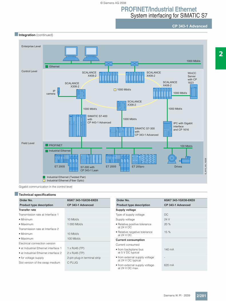
PROFINET/Industrial EthernetSystem interfacing for SIMATIC S7
CP 343-1 Advanced
2/281Siemens IK PI · 2009
2
■ Integration (continued)
Gigabit communication in the control level
■ Technical specifications
WinCC Serverwith CP 1623
SIMATIC S7-400withCP 443-1 Advanced
SIMATIC S7-300withCP 343-1 Advanced
Drives
IPC with Gigabit interfaceand CP 1616
IPcamera
S7-300 withCP 343-1 Lean
1000 Mbit/s
100 Mbit/s
1000 Mbit/s1000 Mbit/s
1000 Mbit/s
SCALANCEX308-2
SCALANCEX408-2
SCALANCEX408-2
SCALANCEX408-2
SCALANCEX308-2
ET 200proET 200SET 200S
1000 Mbit/s
Ethernet
PROFINET
G_I
K10
_XX
_102
26
Field Level
Control Level
Enterprise Level
Industrial Ethernet
1000 Mbit/s
Order No. 6GK7 343-1GX30-0XE0Product type description CP 343-1 Advanced
Transfer rate
Transmission rate at Interface 1
• Minimum 10 Mbit/s
• Maximum 1 000 Mbit/s
Transmission rate at Interface 2
• Minimum 10 Mbit/s
• Maximum 100 Mbit/s
Electrical connection version
• at Industrial Ethernet interface 1 1 x RJ45 (TP)
• at Industrial Ethernet interface 2 2 x RJ45 (TP)
• for voltage supply 2-pin plug-in terminal strip
Slot version of the swap medium C-PLUG
Order No. 6GK7 343-1GX30-0XE0Product type description CP 343-1 Advanced
Supply voltage
Type of supply voltage DC
Supply voltage 24 V
• Relative positive tolerance at 24 V DC
20 %
• Relative negative tolerance at 24 V DC
15 %
Current consumption
Current consumed
• from backplane bus at 5 V DC typical
140 mA
• from external supply voltage at 24 V DC typical
-
• from external supply voltage at 24 V DC max.
620 mA
© Siemens AG 2008
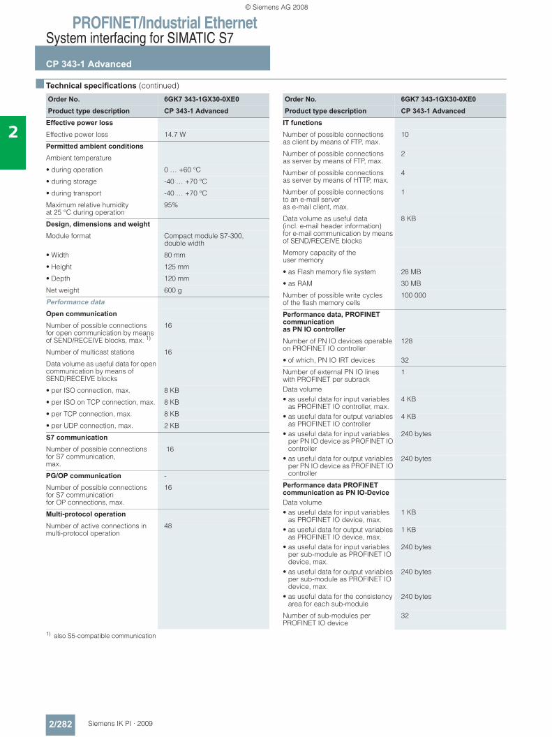
PROFINET/Industrial EthernetSystem interfacing for SIMATIC S7
CP 343-1 Advanced
2/282 Siemens IK PI · 2009
2
■ Technical specifications (continued)
1) also S5-compatible communication
Order No. 6GK7 343-1GX30-0XE0Product type description CP 343-1 Advanced
Effective power loss
Effective power loss 14.7 W
Permitted ambient conditions
Ambient temperature
• during operation 0 … +60 °C
• during storage -40 … +70 °C
• during transport -40 … +70 °C
Maximum relative humidity at 25 °C during operation
95%
Design, dimensions and weight Module format Compact module S7-300,
double width
• Width 80 mm
• Height 125 mm
• Depth 120 mm
Net weight 600 g
Performance data
Open communication
Number of possible connections for open communication by means of SEND/RECEIVE blocks, max. 1)
16
Number of multicast stations 16
Data volume as useful data for open communication by means of SEND/RECEIVE blocks
• per ISO connection, max. 8 KB
• per ISO on TCP connection, max. 8 KB
• per TCP connection, max. 8 KB
• per UDP connection, max. 2 KB
S7 communication
Number of possible connectionsfor S7 communication, max.
16
PG/OP communication -
Number of possible connectionsfor S7 communication for OP connections, max.
16
Multi-protocol operation
Number of active connections in multi-protocol operation
48
Order No. 6GK7 343-1GX30-0XE0Product type description CP 343-1 Advanced
IT functions
Number of possible connections as client by means of FTP, max.
10
Number of possible connections as server by means of FTP, max.
2
Number of possible connections as server by means of HTTP, max.
4
Number of possible connections to an e-mail server as e-mail client, max.
1
Data volume as useful data (incl. e-mail header information) for e-mail communication by means of SEND/RECEIVE blocks
8 KB
Memory capacity of the user memory
• as Flash memory file system 28 MB
• as RAM 30 MB
Number of possible write cycles of the flash memory cells
100 000
Performance data, PROFINET communication as PN IO controller Number of PN IO devices operable on PROFINET IO controller
128
• of which, PN IO IRT devices 32
Number of external PN IO lines with PROFINET per subrack
1
Data volume• as useful data for input variables
as PROFINET IO controller, max.4 KB
• as useful data for output variables as PROFINET IO controller
4 KB
• as useful data for input variables per PN IO device as PROFINET IO controller
240 bytes
• as useful data for output variables per PN IO device as PROFINET IO controller
240 bytes
Performance data PROFINET communication as PN IO-Device Data volume• as useful data for input variables
as PROFINET IO device, max.1 KB
• as useful data for output variables as PROFINET IO device, max.
1 KB
• as useful data for input variables per sub-module as PROFINET IO device, max.
240 bytes
• as useful data for output variables per sub-module as PROFINET IO device, max.
240 bytes
• as useful data for the consistency area for each sub-module
240 bytes
Number of sub-modules per PROFINET IO device
32
© Siemens AG 2008
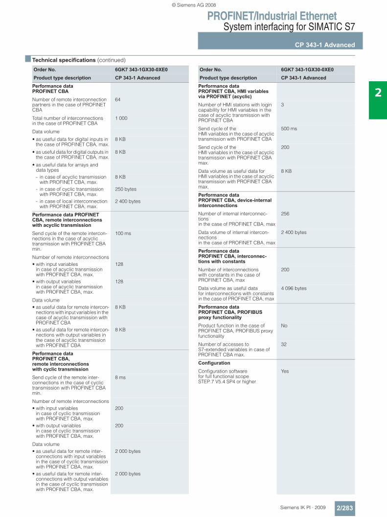
PROFINET/Industrial EthernetSystem interfacing for SIMATIC S7
CP 343-1 Advanced
2/283Siemens IK PI · 2009
2
■ Technical specifications (continued)
Order No. 6GK7 343-1GX30-0XE0Product type description CP 343-1 Advanced
Performance data PROFINET CBA
Number of remote interconnection partners in the case of PROFINET CBA
64
Total number of interconnections in the case of PROFINET CBA
1 000
Data volume
• as useful data for digital inputs in the case of PROFINET CBA, max.
8 KB
• as useful data for digital outputs in the case of PROFINET CBA, max.
8 KB
• as useful data for arrays and data types- in case of acyclic transmission
with PROFINET CBA, max.8 KB
- in case of cyclic transmission with PROFINET CBA, max.
250 bytes
- in case of local interconnection with PROFINET CBA, max.
2 400 bytes
Performance data PROFINET CBA, remote interconnections with acyclic transmission
Send cycle of the remote intercon-nections in the case of acyclic transmission with PROFINET CBA min.
100 ms
Number of remote interconnections• with input variables
in case of acyclic transmission with PROFINET CBA, max.
128
• with output variables in case of acyclic transmission with PROFINET CBA, max.
128
Data volume• as useful data for remote intercon-
nections with input variables in the case of acyclic transmission with PROFINET CBA
8 KB
• as useful data for remote intercon-nections with output variables in the case of acyclic transmission with PROFINET CBA
8 KB
Performance data PROFINET CBA, remote interconnections with cyclic transmission
Send cycle of the remote inter-connections in the case of cyclic transmission with PROFINET CBA min.
8 ms
Number of remote interconnections• with input variables
in case of cyclic transmission with PROFINET CBA, max.
200
• with output variables in case of cyclic transmission with PROFINET CBA, max.
200
Data volume• as useful data for remote inter-
connections with input variables in the case of cyclic transmission with PROFINET CBA, max.
2 000 bytes
• as useful data for remote inter-connections with output variables in the case of cyclic transmission with PROFINET CBA, max.
2 000 bytes
Order No. 6GK7 343-1GX30-0XE0Product type description CP 343-1 Advanced
Performance data PROFINET CBA, HMI variables via PROFINET (acyclic) Number of HMI stations with login capability for HMI variables in the case of acyclic transmission with PROFINET CBA
3
Send cycle of the HMI variables in the case of acyclic transmission with PROFINET CBA
500 ms
Send cycle of the HMI variables in the case of acyclic transmission with PROFINET CBA max.
200
Data volume as useful data for HMI variables in the case of acyclic transmission with PROFINET CBA max.
8 KB
Performance data PROFINET CBA, device-internal interconnections
Number of internal interconnec-tions in the case of PROFINET CBA, max
256
Data volume of internal intercon-nections in the case of PROFINET CBA, max
2 400 bytes
Performance data PROFINET CBA, interconnec-tions with constants
Number of interconnections with constants in the case of PROFINET CBA, max
200
Data volume as useful data for interconnections with constants in the case of PROFINET CBA, max
4 096 bytes
Performance data PROFINET CBA, PROFIBUS proxy functionality
Product function in the case of PROFINET CBA, PROFIBUS proxy functionality
No
Number of accesses to S7-extended variables in case of PROFINET CBA max.
32
Configuration
Configuration software for full functional scope STEP 7 V5.4 SP4 or higher
Yes
© Siemens AG 2008
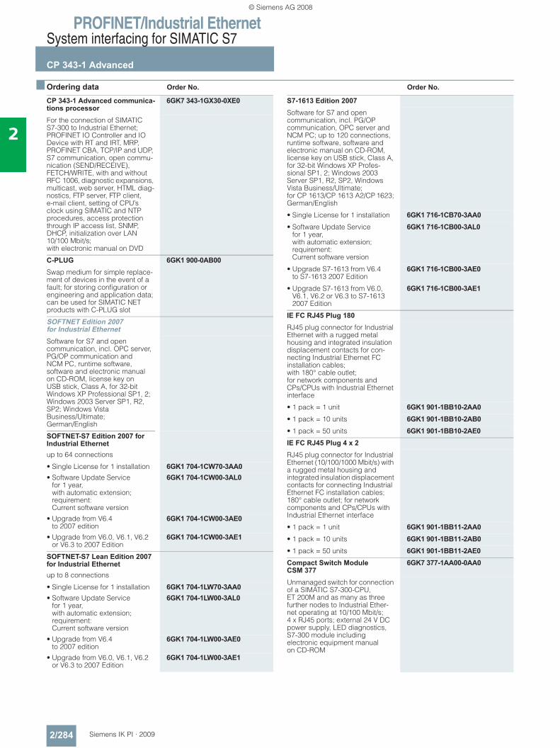
PROFINET/Industrial EthernetSystem interfacing for SIMATIC S7
CP 343-1 Advanced
2/284 Siemens IK PI · 2009
2
■ Ordering data Order No. Order No.
CP 343-1 Advanced communica-tions processor
6GK7 343-1GX30-0XE0
For the connection of SIMATIC S7-300 to Industrial Ethernet; PROFINET IO Controller and IO Device with RT and IRT, MRP, PROFINET CBA, TCP/IP and UDP, S7 communication, open commu-nication (SEND/RECEIVE), FETCH/WRITE, with and without RFC 1006, diagnostic expansions, multicast, web server, HTML diag-nostics, FTP server, FTP client,e-mail client, setting of CPU’s clock using SIMATIC and NTP procedures, access protection through IP access list, SNMP, DHCP, initialization over LAN 10/100 Mbit/s; with electronic manual on DVD
C-PLUG 6GK1 900-0AB00Swap medium for simple replace-ment of devices in the event of a fault; for storing configuration or engineering and application data; can be used for SIMATIC NET products with C-PLUG slot
SOFTNET Edition 2007 for Industrial EthernetSoftware for S7 and open communication, incl. OPC server, PG/OP communication and NCM PC, runtime software, software and electronic manual on CD-ROM, license key on USB stick, Class A, for 32-bit Windows XP Professional SP1, 2; Windows 2003 Server SP1, R2, SP2; Windows Vista Business/Ultimate; German/English
SOFTNET-S7 Edition 2007 for Industrial Ethernetup to 64 connections
• Single License for 1 installation 6GK1 704-1CW70-3AA0• Software Update Service
for 1 year, with automatic extension; requirement: Current software version
6GK1 704-1CW00-3AL0
• Upgrade from V6.4to 2007 edition
6GK1 704-1CW00-3AE0
• Upgrade from V6.0, V6.1, V6.2 or V6.3 to 2007 Edition
6GK1 704-1CW00-3AE1
SOFTNET-S7 Lean Edition 2007 for Industrial Ethernetup to 8 connections
• Single License for 1 installation 6GK1 704-1LW70-3AA0• Software Update Service
for 1 year, with automatic extension; requirement: Current software version
6GK1 704-1LW00-3AL0
• Upgrade from V6.4to 2007 edition
6GK1 704-1LW00-3AE0
• Upgrade from V6.0, V6.1, V6.2or V6.3 to 2007 Edition
6GK1 704-1LW00-3AE1
S7-1613 Edition 2007Software for S7 and open communication, incl. PG/OP communication, OPC server and NCM PC; up to 120 connections, runtime software, software and electronic manual on CD-ROM, license key on USB stick, Class A, for 32-bit Windows XP Profes-sional SP1, 2; Windows 2003 Server SP1, R2, SP2, Windows Vista Business/Ultimate; for CP 1613/CP 1613 A2/CP 1623; German/English
• Single License for 1 installation 6GK1 716-1CB70-3AA0• Software Update Service
for 1 year, with automatic extension; requirement: Current software version
6GK1 716-1CB00-3AL0
• Upgrade S7-1613 from V6.4 to S7-1613 2007 Edition
6GK1 716-1CB00-3AE0
• Upgrade S7-1613 from V6.0, V6.1, V6.2 or V6.3 to S7-1613 2007 Edition
6GK1 716-1CB00-3AE1
IE FC RJ45 Plug 180RJ45 plug connector for Industrial Ethernet with a rugged metal housing and integrated insulation displacement contacts for con-necting Industrial Ethernet FC installation cables; with 180° cable outlet;for network components and CPs/CPUs with Industrial Ethernet interface
• 1 pack = 1 unit 6GK1 901-1BB10-2AA0• 1 pack = 10 units 6GK1 901-1BB10-2AB0• 1 pack = 50 units 6GK1 901-1BB10-2AE0IE FC RJ45 Plug 4 x 2RJ45 plug connector for Industrial Ethernet (10/100/1000 Mbit/s) with a rugged metal housing and integrated insulation displacement contacts for connecting Industrial Ethernet FC installation cables; 180° cable outlet; for network components and CPs/CPUs with Industrial Ethernet interface
• 1 pack = 1 unit 6GK1 901-1BB11-2AA0• 1 pack = 10 units 6GK1 901-1BB11-2AB0• 1 pack = 50 units 6GK1 901-1BB11-2AE0Compact Switch Module CSM 377
6GK7 377-1AA00-0AA0
Unmanaged switch for connection of a SIMATIC S7-300-CPU, ET 200M and as many as three further nodes to Industrial Ether-net operating at 10/100 Mbit/s; 4 x RJ45 ports; external 24 V DC power supply, LED diagnostics, S7-300 module including electronic equipment manual on CD-ROM
© Siemens AG 2008
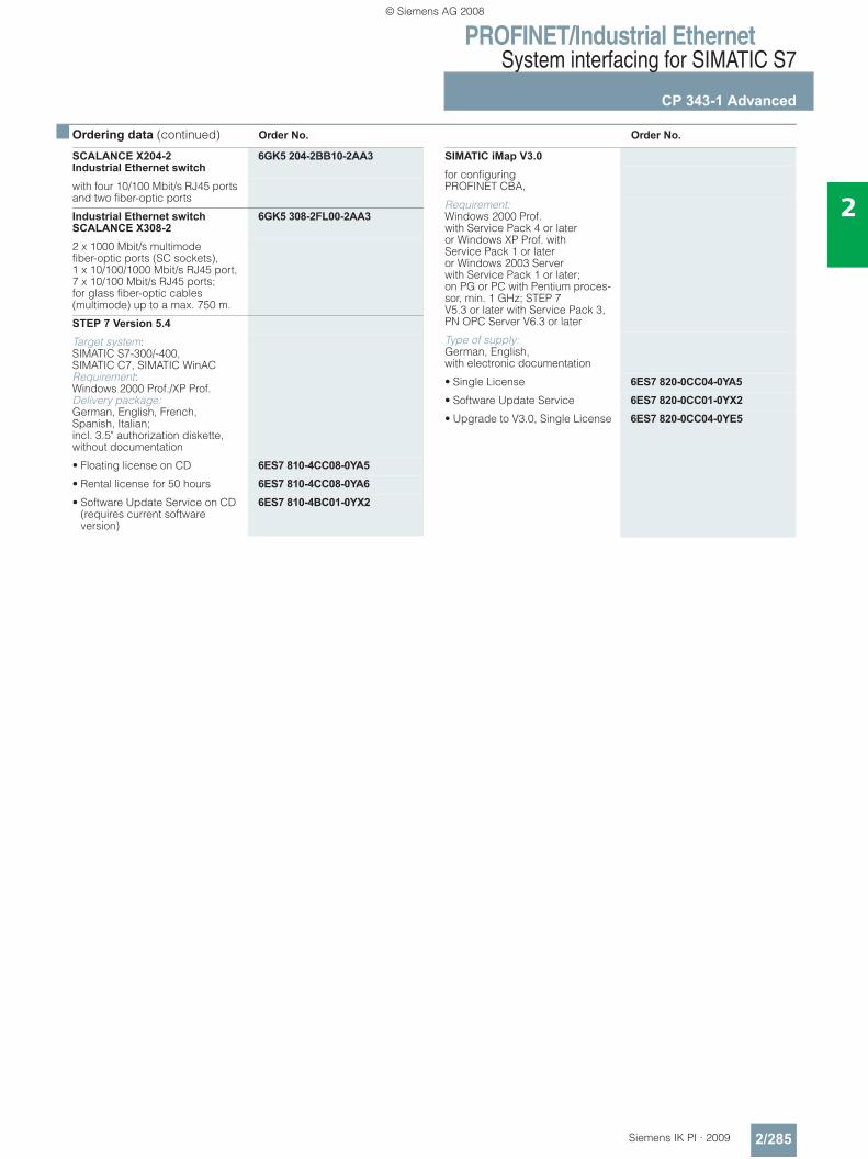
PROFINET/Industrial EthernetSystem interfacing for SIMATIC S7
CP 343-1 Advanced
2/285Siemens IK PI · 2009
2
■ Ordering data (continued) Order No. Order No.
SCALANCE X204-2 Industrial Ethernet switch
6GK5 204-2BB10-2AA3
with four 10/100 Mbit/s RJ45 ports and two fiber-optic ports
Industrial Ethernet switch SCALANCE X308-2
6GK5 308-2FL00-2AA3
2 x 1000 Mbit/s multimode fiber-optic ports (SC sockets), 1 x 10/100/1000 Mbit/s RJ45 port, 7 x 10/100 Mbit/s RJ45 ports; for glass fiber-optic cables(multimode) up to a max. 750 m.
STEP 7 Version 5.4Target system: SIMATIC S7-300/-400, SIMATIC C7, SIMATIC WinAC Requirement: Windows 2000 Prof./XP Prof. Delivery package: German, English, French, Spanish, Italian; incl. 3.5" authorization diskette, without documentation
• Floating license on CD 6ES7 810-4CC08-0YA5• Rental license for 50 hours 6ES7 810-4CC08-0YA6• Software Update Service on CD
(requires current software version)
6ES7 810-4BC01-0YX2
SIMATIC iMap V3.0for configuring PROFINET CBA,
Requirement: Windows 2000 Prof. with Service Pack 4 or later or Windows XP Prof. with Service Pack 1 or later or Windows 2003 Server with Service Pack 1 or later; on PG or PC with Pentium proces-sor, min. 1 GHz; STEP 7 V5.3 or later with Service Pack 3, PN OPC Server V6.3 or later
Type of supply: German, English, with electronic documentation
• Single License 6ES7 820-0CC04-0YA5• Software Update Service 6ES7 820-0CC01-0YX2• Upgrade to V3.0, Single License 6ES7 820-0CC04-0YE5
© Siemens AG 2008
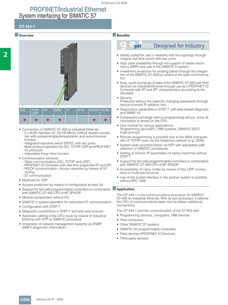
PROFINET/Industrial EthernetSystem interfacing for SIMATIC S7
CP 443-1
2/286 Siemens IK PI · 2009
2
■ Overview
• Connection of SIMATIC S7-400 to Industrial Ethernet - 2 x RJ45 interface for 10/100 Mbit/s full/half duplex connec-
tion with autosensing/autonegotiation and autocrossover function
- Integrated real-time switch ERTEC with two ports- Multi-protocol operation for ISO, TCP/IP, UDP and PROFINET
IO protocols- Adjustable Keep Alive function
• Communication services: - Open communication (ISO, TCP/IP and UDP)- PROFINET IO Controller with real-time properties RT and IRT- PG/OP communication: Across networks by means of S7
routing- S7 communication
• Multicast for UDP• Access protection by means of configurable access list• Support for fail-safe programmable controllers in combination
with SIMATIC S7-400 CPU 416F-3PN/DP• Module replacement without PG• SIMATIC H system operation for redundant S7 communication• Configuration with STEP 7• Diagnostic possibilities in STEP 7 and with web browser• Automatic setting of the CPU clock by means of Industrial
Ethernet with NTP or SIMATIC procedure• Integration of network management systems via SNMP
(MIB II diagnostic information)
■ Benefits
• Ideally suited for use in networks with line topology through integral real-time switch with two ports
• High plant availability through the support of media redun-dancy (MRP) and use in the SIMATIC H system
• Investment protection for existing plants through the integra-tion of the SIMATIC S7-400 by means of the open communica-tion
• Easy, quick exchange of data of the SIMATIC S7-400 with field devices via Industrial Ethernet through use as a PROFINET IO Controller with RT and IRT characteristics according to the standard
• Security: Protection without the need for changing passwords through device-oriented IP address lists
• Diagnostics capabilities in STEP 7, with web-based diagnosis and SNMP V2
• Component exchange without programming device, since all information is stored on the CPU.
• One module for various applications: Programming device/PC, HMI systems, SIMATIC S5/S7 (high-priority)
• Remote programming is possible due to the WAN character-istic of TCP/IP, even via the telephone network (e.g. ISDN)
• System-wide synchronization via NTP with adjustable path selection or SIMATIC procedures
• Setting of intrinsic IP parameters of series machines without STEP 7
• Support for fail-safe programmable controllers in combination with SIMATIC S7-400 CPU 416F-3PN/DP
• Accessibility of many nodes by means of free UDP connec-tions or multicast functions
• Use of the socket interface in the partner system is possible without RFC 1006
■ Application
The CP 443-1 is the communications processor for SIMATIC S7-400 for Industrial Ethernet. With its own processor, it relieves the CPU of communications tasks and facilitates additional connections.
The CP 443-1 permits communication of the S7-400 with:• Programming devices, computers, HMI devices• Host computers• Other SIMATIC S7 systems• SIMATIC S5 programmable controllers• Field devices (PROFINET IO Devices) • Third-party devices
© Siemens AG 2008
PROFINET/Industrial EthernetSystem interfacing for SIMATIC S7
CP 443-1
2/287Siemens IK PI · 2009
2
■ Design
The CP 443-1 features all the advantages of the SIMATIC S7-400 design:• Compact design;
on the front, the rugged plastic housing features: - Two RJ45 sockets for connection to Industrial Ethernet
100 MBit/s with automatic sensing of the data transmission rate by means of Autosensing/Autonegotiation; The RJ45 sockets are industrially compatible and designed with additional sleeves for connecting to the IE FC RJ45 Plug 180 or a standard patch line
- Diagnostic LEDs for indication of the operating and commu-nication status for each switch port
• Easy installation: The CP 443-1 is mounted on the S7-400 rack and connected to other modules of the S7-400 by means of the backplane bus. No slot rules apply.
• The CP 443-1 can be operated without a fan• In combination with the IM 460/461, the CP 443-1 can also be
used in an expansion rack• Module replacement possible without prgramming device
(PG)• General and port-specific LEDs for indicating the operating
and communication status
■ Function
The CP 443-1 independently handles data traffic over Industrial Ethernet. The module has its own powerful processor and can be put into service directly using the unique preset Ethernet address (MAC) via the network.
Support of the DHCP (Dynamic Host Configuration Protocol) enables the IP address to be issued from a central DHCP server.
For connection control (keep alive) it is possible to configure an adjustable time for all TCP transport connections for active and passive partners.
The CPU’s time can be set using NTP with an accuracy of approx. +/-1 s.
The CP 443-1 works in multi-protocol mode for the following communication services:
PG/OP communication
PG/OP communication allows all S7 stations connected to the network to be remotely programmed.• S7 routing
With the aid of S7 routing it is possible to use programming device communication across networks.
PROFINET communication • PROFINET IO Controller;
real-time communication with field devices, including PC-based IO Devices (with CP 1616 or CP 1604) on Industrial Ethernet with PROFINET standard with RT and IRT.
• The prioritized start-up of IO Devices allows quick starting of defined devices.
S7 communication • For connecting to S7-200/300/400 (server and client),
HMI devices and PCs (SOFTNET-S7 or CP 1613 A2/CP 1623 with S7-1613)
Communication takes place through the CP 443-1 without further configuration.• H communication;
For redundant S7 communication, the CP 443-1 can also be used in SIMATIC H systems as of V4.5. In this way, H systems can also be connected redundantly to PC systems (with CP 1613 A2/CP 1623 and S7-REDCONNECT).
• Clock synchronization; Using SIMATIC procedure or NTP (network time protocol) with selectable path.
Open communication
On the basis of layer 4, the open communication with SEND/RECEIVE offers a simple and optimized interface for data com-munication.
Up to 8 KB of data can be transmitted in one call.
This interface enables the following to be used:• ISO transport connections• TCP connections with or without RFC 1006 • UDP (2 KB data length) • UDP Multicast (2 KB data length)
Open communication is used with SIMATIC S5 and comput-ers/PCs. The function calls required are a component part of STEP 7 and must be integrated into the S7 user program.
Open communication with FETCH/WRITE allows direct access to the CPU data in the same way as in the CP 1430. This means existing HMI systems can still be used.
Security
With a freely configurable access list, specific users and programmable controllers can be enabled for accessing the CP or control via TCP/IP.
Diagnostics
Comprehensive diagnostic options are available via STEP S7 or a web browser, including:• General diagnostics and statistics functions • Connection diagnostics • Diagnosis of the assigned PROFINET field devices
(also in the user program) • LAN controller statistics • Information about every port of the switch • Diagnostic buffer • Web diagnostics with easy diagnostic functions• Operating status of CP
Diagnostics possibilities during operation • Status scanning of connections using function block • SNMP MIB-2 objects;
the current status of the Ethernet interface can then be called, e.g. for network management
Configuration
STEP 7 V5.4 or higher is required for configuring the full functional scope of the CP 443-1.
The configuration data of the CP created with STEP 7 is stored on the CPU. Attention must however be paid to the memory volume of the S7-CPU.
Configuration and programming of all SIMATIC S7 controllers connected to the network is possible over the network.
The CP can be replaced in the event of failure without the need for a programming device because the relevant user and config-uration data are saved on the CPU.
© Siemens AG 2008
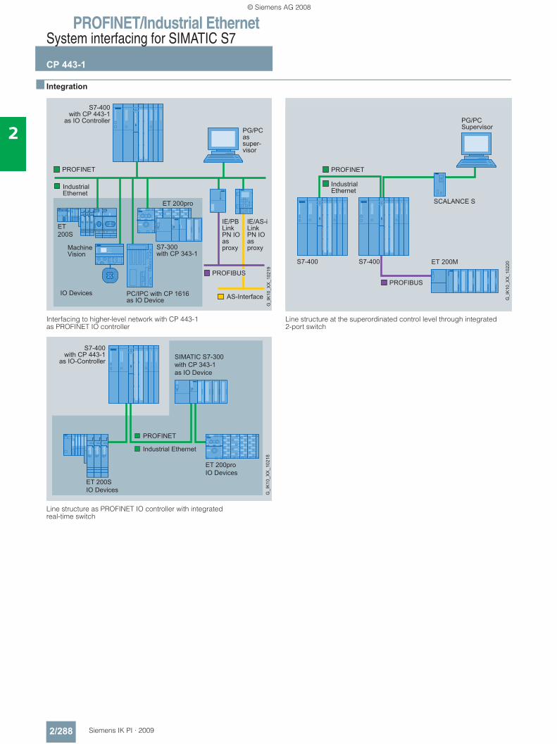
PROFINET/Industrial EthernetSystem interfacing for SIMATIC S7
CP 443-1
2/288 Siemens IK PI · 2009
2
■ Integration
Interfacing to higher-level network with CP 443-1 as PROFINET IO controller
Line structure as PROFINET IO controller with integratedreal-time switch
Line structure at the superordinated control level through integrated 2-port switch
PC/IPC with CP 1616 as IO Device
SIMATIC S7-300with CP 343-1as IO Device
ET 200proIO Devices
ET 200SIO Devices G
_IK
10_X
X_1
0218
© Siemens AG 2008
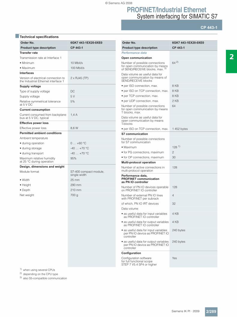
PROFINET/Industrial EthernetSystem interfacing for SIMATIC S7
CP 443-1
2/289Siemens IK PI · 2009
2
■ Technical specifications
1) when using several CPUs2) depending on the CPU type3) also S5-compatible communication
Order No. 6GK7 443-1EX20-0XE0Product type description CP 443-1
Transfer rate
Transmission rate at Interface 1
• Minimum 10 Mbit/s
• Maximum 100 Mbit/s
Interfaces
Version of electrical connection to the Industrial Ethernet interface 1
2 x RJ45 (TP)
Supply voltage
Type of supply voltage DC
Supply voltage 5 V
Relative symmetrical tolerance at 5 V DC
5%
Current consumption
Current consumed from backplane bus at 5 V DC, typical
1,4 A
Effective power loss
Effective power loss 8,6 W
Permitted ambient conditions
Ambient temperature
• during operation 0 … +60 °C
• during storage -40 … +70 °C
• during transport -40 … +70 °C
Maximum relative humidity at 25 °C during operation
95%
Design, dimensions and weight Module format S7-400 compact module,
single width
• Width 25 mm
• Height 290 mm
• Depth 210 mm
Net weight 700 g
Order No. 6GK7 443-1EX20-0XE0Product type description CP 443-1
Performance data
Open communication
Number of possible connections for open communication by means of SEND/RECEIVE blocks, max. 3)
64 2)
Data volume as useful data for open communication by means of SEND/RECEIVE blocks
• per ISO connection, max. 8 KB
• per ISO on TCP connection, max. 8 KB
• per TCP connection, max. 8 KB
• per UDP connection, max. 2 KB
Number of possible connections for open communication by means T blocks, max.
64
Data volume as useful data for open communication by means T-blocks
• per ISO on TCP connection, max. 1 452 bytes
S7 communication
Number of possible connections for S7 communication
• Maximum 128 1)
• for PG connections, maximum 2
• for OP connections, maximum 30
Multi-protocol operation
Number of active connections in multi-protocol operation
128
Performance data, PROFINET communication as PN IO controller Number of PN IO devices operable on PROFINET IO controller
128
Number of external PN IO lines with PROFINET per subrack
4
of which, PN IO IRT devices 32
Data volume
• as useful data for input variables as PROFINET IO controller
4 KB
• as useful data for output variables as PROFINET IO controller
4 KB
• as useful data for input variables per PN IO device as PROFINET IO controller
240 bytes
• as useful data for output variables per PN IO device as PROFINET IO controller
240 bytes
Configuration
Configuration software for full functional scope STEP 7 V5.4 SP4 or higher
Yes
© Siemens AG 2008
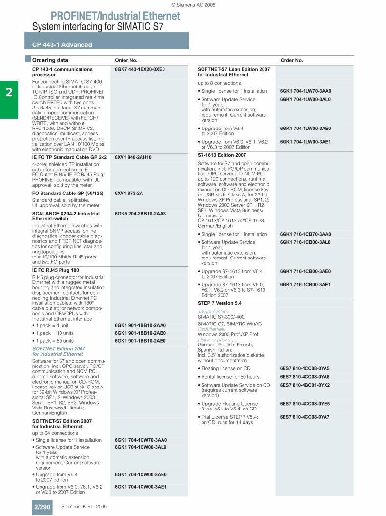
PROFINET/Industrial EthernetSystem interfacing for SIMATIC S7
CP 443-1 Advanced
2/290 Siemens IK PI · 2009
2
■ Ordering data Order No. Order No.
CP 443-1 communications processor
6GK7 443-1EX20-0XE0
For connecting SIMATIC S7-400 to Industrial Ethernet through TCP/IP, ISO and UDP; PROFINET IO Controller, integrated real-time switch ERTEC with two ports; 2 x RJ45 interface; S7 communi-cation, open communication (SEND/RECEIVE) with FETCH/WRITE, with and without RFC 1006, DHCP, SNMP V2, diagnostics, multicast, access protection over IP access list, ini-tialization over LAN 10/100 Mbit/s with electronic manual on DVD
IE FC TP Standard Cable GP 2x2 6XV1 840-2AH104-core, shielded TP installation cable for connection to IE FC Outlet RJ45/ IE FC RJ45 Plug; PROFINET-compatible; with UL approval; sold by the meter
FO Standard Cable GP (50/125) 6XV1 873-2AStandard cable, splittable, UL approval, sold by the meter
SCALANCE X204-2 Industrial Ethernet switch
6GK5 204-2BB10-2AA3
Industrial Ethernet switches with integral SNMP access, online diagnostics, copper cable diag-nostics and PROFINET diagnos-tics for configuring line, star and ring topologies; four 10/100 Mbit/s RJ45 ports and two FO ports
IE FC RJ45 Plug 180RJ45 plug connector for Industrial Ethernet with a rugged metal housing and integrated insulation displacement contacts for con-necting Industrial Ethernet FC installation cables; with 180° cable outlet; for network compo-nents and CPs/CPUs with Industrial Ethernet interface• 1 pack = 1 unit 6GK1 901-1BB10-2AA0• 1 pack = 10 units 6GK1 901-1BB10-2AB0• 1 pack = 50 units 6GK1 901-1BB10-2AE0SOFTNET Edition 2007 for Industrial EthernetSoftware for S7 and open commu-nication, incl. OPC server, PG/OP communication and NCM PC, runtime software, software and electronic manual on CD-ROM, license key on USB stick, Class A, for 32-bit Windows XP Profes-sional SP1, 2, Windows 2003 Server SP1, R2, SP2, Windows Vista Business/Ultimate; German/English
SOFTNET-S7 Edition 2007 for Industrial Ethernetup to 64 connections• Single license for 1 installation 6GK1 704-1CW70-3AA0• Software Update Service
for 1 year, with automatic extension; requirement: Current software version
6GK1 704-1CW00-3AL0
• Upgrade from V6.4to 2007 edition
6GK1 704-1CW00-3AE0
• Upgrade from V6.0, V6.1, V6.2 or V6.3 to 2007 Edition
6GK1 704-1CW00-3AE1
SOFTNET-S7 Lean Edition 2007 for Industrial Ethernetup to 8 connections
• Single license for 1 installation 6GK1 704-1LW70-3AA0• Software Update Service
for 1 year, with automatic extension; requirement: Current software version
6GK1 704-1LW00-3AL0
• Upgrade from V6.4 to 2007 Edition
6GK1 704-1LW00-3AE0
• Upgrade from V6.0, V6.1, V6.2 or V6.3 to 2007 Edition
6GK1 704-1LW00-3AE1
S7-1613 Edition 2007Software for S7 and open commu-nication, incl. PG/OP communica-tion, OPC server and NCM PC; up to 120 connections, runtime software, software and electronic manual on CD-ROM, license key on USB stick, Class A, for 32-bit Windows XP Professional SP1, 2; Windows 2003 Server SP1, R2, SP2, Windows Vista Business/Ultimate; for CP 1613/CP 1613 A2/CP 1623; German/English
• Single license for 1 installation 6GK1 716-1CB70-3AA0• Software Update Service
for 1 year, with automatic extension; requirement: Current software version
6GK1 716-1CB00-3AL0
• Upgrade S7-1613 from V6.4 to 2007 Edition
6GK1 716-1CB00-3AE0
• Upgrade S7-1613 from V6.0, V6.1, V6.2 or V6.3 to S7-1613 Edition 2007
6GK1 716-1CB00-3AE1
STEP 7 Version 5.4Target system: SIMATIC S7-300/-400, SIMATIC C7, SIMATIC WinAC Requirement: Windows 2000 Prof./XP Prof. Delivery package: German, English, French, Spanish, Italian; incl. 3.5" authorization diskette, without documentation
• Floating license on CD 6ES7 810-4CC08-0YA5• Rental license for 50 hours 6ES7 810-4CC08-0YA6• Software Update Service on CD
(requires current software version)
6ES7 810-4BC01-0YX2
• Upgrade Floating License 3.x/4.x/5.x to V5.4; on CD
6ES7 810-4CC08-0YE5
• Trial License STEP 7 V5.4; on CD, runs for 14 days
6ES7 810-4CC08-0YA7
© Siemens AG 2008
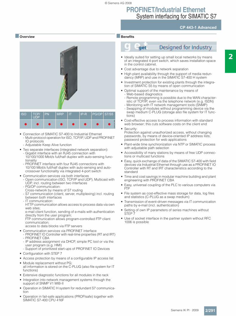
PROFINET/Industrial EthernetSystem interfacing for SIMATIC S7
CP 443-1 Advanced
2/291Siemens IK PI · 2009
2
■ Overview
• Connection of SIMATIC S7-400 to Industrial Ethernet - Multi-protocol operation for ISO, TCP/IP, UDP and PROFINET
IO protocols- Adjustable Keep Alive function
• Two separate interfaces (integrated network separation): - Gigabit interface with an RJ45 connection with
10/100/1000 Mbit/s full/half duplex with auto-sensing func-tionality
- PROFINET interface with four RJ45 connections with 10/100 Mbit/s full/half duplex with auto-sensing and auto-crossover functionality via integrated 4-port switch
• Communication services via both interfaces - Open communication (ISO, TCP/IP and UDP), Multicast with
UDP, incl. routing between two interfaces- PG/OP communication:
Cross-network by means of S7 routing- S7 communication (client, server, multiplexing) incl. routing
between both interfaces- IT communication:
HTTP communication allows access to process data via own web sites; e-mail client function, sending of e-mails with authentication directly from the user program; FTP communication allows program-controlled FTP client communication; access to data blocks via FTP servers
• Communication services via PROFINET interface - PROFINET IO Controller with real-time properties (RT and IRT)- PROFINET CBA- IP address assignment via DHCP, simple PC tool or via the
user program (e.g. HMI)- Support of prioritized start-ups of PROFINET IO Devices
• Configuration with STEP 7• Access protection by means of a configurable IP access list• Module replacement without PG;
all information is stored on the C-PLUG (also file system for IT functions)
• Extensive diagnostic functions for all modules in the rack• Integration into network management systems through the
support of SNMP V1 MIB-II• Operation in SIMATIC H system for redundant S7 communica-
tion• Operation in fail-safe applications (PROFIsafe) together with
SIMATIC S7-400 CPU 416F
■ Benefits
• Ideally suited for setting up small local networks by means of an integrated 4-port switch, which saves installation space in the control cabinet.
• Cost advantage due to network separation• High plant availability through the support of media redun-
dancy (MRP) and use in the SIMATIC S7-400 H system• Investment protection for existing plants through the integra-
tion of SIMATIC S5 by means of open communication• Optimal support of the maintenance by means of
- Web-based diagnostics- Remote programming is possible due to the WAN character-
istic of TCP/IP, even via the telephone network (e.g. ISDN)- Monitoring with IT network management tools (SNMP)- Swapping of modules without programming device via the
swap medium C-PLUG (storage also file system for IT func-tions)
• Cost-effective access to process information with standard web browser; this cuts software costs on the client end
• Security: Protection against unauthorized access, without changing passwords, by means of device-oriented IP address lists; password protection for web applications
• Plant-wide time synchronization via NTP or SIMATIC process with adjustable path selection
• Accessibility of many stations by means of free UDP connec-tions or multicast functions
• Easy, quick exchange of data of the SIMATIC S7-400 with field devices via Industrial Ethernet through use as a PROFINET IO Controller with RT and IRT characteristics according to the standard
• Time and cost savings in modular machine building and plant engineering with PROFINET CBA
• Easy, universal coupling of the PLC to various computers via FTP
• File system as cost-effective mass storage for data, log files and statistics (C-PLUG as a swap medium)
• Transmission of event-driven messages via IT communication paths by e-mail (incl. authentication)
• Setting of own IP parameters of series machines without STEP 7
• Use of socket interface in the partner system without RFC 1006 is possible
© Siemens AG 2008
PROFINET/Industrial EthernetSystem interfacing for SIMATIC S7
CP 443-1 Advanced
2/292 Siemens IK PI · 2009
2
■ Application
The CP 443-1 Advanced is the communications module for connecting SIMATIC S7-400 to the Industrial Ethernet.
With its integral processor, it takes communications load off the CPU and allows additional connections.
The CP 443-1 Advanced provides the capability for the SIMATIC S7-400 to communicate with:• PG/PC• Master computer• HMI devices• SIMATIC S5/S7/C7 systems• PROFINET CBA components• PROFINET IO devices
PROFINET CBA allows the creation of reusable technology mod-ules.
■ Design
The CP 443-1 Advanced offers all the advantages of the SIMATIC S7-400 design: • The front panel of the rugged plastic enclosure includes:
- Five RJ45 jacks for connecting to Industrial Ethernet via two independent interfaces; automatic data rate detection by means of the autosensing and autocrossover functions; the connection is made via the IE FC RJ45 Plug 180 with 180° cable outlet or via a standard patch cable
- Diagnostics LEDs for indicating the operational and commu-nication status
• Easy installation; the CP 443-1 Advanced is installed on the module rack of the S7-400 and is connected to other modules via the backplane bus. No slot rules apply in this case.
• The CP 443-1 Advanced can be operated without a fan.• In combination with IM 460/461, the CP 443-1 Advanced can
also be used in an expansion rack (ER).• The module can be replaced without a programming device• C-PLUG (configuration plug) is included in the scope of
delivery as the replacement medium (cannot be operated without C-PLUG).
• General and port-specific LEDs for indicating the operating and communication status
■ Function
The CP 443-1 Advanced independently handles data traffic over Industrial Ethernet. The module has its own powerful processor and can be put into service directly using the unique preset Ethernet address (MAC) via the network.
Support of the DHCP (Dynamic Host Configuration Protocol) enables the IP address to be assigned from a central DHCP server.
For connection control (Keep Alive) it is possible to configure an adjustable time for the TCP transport connections for active and passive peers.
Multi-protocol operation of the transport protocols ISO, TCP/IP and UDP is possible.
The CP 443-1 Advanced works in multi-protocol mode for the following communication services:
PG/OP communication
PG/OP communication allows all S7 stations connected to the network to be remotely programmed.• S7 routing;
with the aid of S7 routing it is possible to utilize programming device communication across networks.
S7 communication
for connecting the SIMATIC S7-200/300/400 (server and client) to SIMATIC S7-400 (server and client), HMI devices and PCs (SOFTNET-S7 or CP 1613 A2/CP 1623 with S7-1613). Communi-cation takes place through the CP 443-1 Advanced without further configuration.• H communication;
for redundant S7 communication, the CP 443-1 Advanced can also be used in SIMATIC H systems as of CPU V4.5. In this way, H systems can also be connected redundantly to PC systems (with CP 1613 A2/CP 1623 and S7-REDCONNECT).
• Clock synchronization using SIMATIC procedure or NTP (network time protocol) with selectable path. . The CPU’s time can be set with an accuracy of approx. ±1 s.
Open communication
Simple and optimized interface for data communication. Up to 8 KB of data can be transmitted in one call. On the basis of layer 4, open communication with SEND/RECEIVE offers a simple and optimized interface for data communication.
This interface enables• ISO transport connections• TCP connections with or without RFC 1006• UDP (2 KB data length)• UDP Multicast (2 KB data length)
to be used.
Open communication is used for communication with SIMATIC S5, SIMATIC S7-400/300 and computers/PCs. The function blocks required are a component part of STEP S7 and must be integrated into the S7 user program.
Open communication with Fetch/Write allows direct access to the CPU data of the SIMATIC S7 (in the same way as in the CP 1430TCP and SIMATIC S5). This means existing HMI sys-tems can still be used. If UDP is used as the transmission proto-col, the multicast function can be used to simultaneously send and receive in configured multicast circuits.
© Siemens AG 2008
PROFINET/Industrial EthernetSystem interfacing for SIMATIC S7
CP 443-1 Advanced
2/293Siemens IK PI · 2009
2
■ Function (continued)
PROFINET communication
PROFINET IO Controller; real-time communication with field devices, including PC-based IO Devices (with CP 1616 or CP 1604) on Industrial Ethernet with PROFINET standard with RT and IRT.
The prioritized start-up of IO Devices allows defined devices to be quickly started up.
PROFINET CBA; communication between technological modules (distributed intelligence); the user can choose between cyclic and acyclic communica-tion. This communication is suitable for time-critical and non-time-critical applications.
IT functions • IP routing;
forwarding of IP V4 messages between Gigabit and PROFINET interface regulated by IP access list
• WEB server; up to 30 MB of freely definable HTML pages can be called up via a standard browser; data handling of own file system via FTP
• Standard diagnostics pages; for quick diagnostics on the system for all of the modules plugged into the rack, without additional tools
• E-mails; sending of e-mails with authentication directly from the user program. The e-mail client function allows user alerting directly from the control program
• Communication via FTP; open protocol which is available on most operating system platforms
• The 32 MB RAM file system can be used for the buffer storage of dynamic data. In addition, there is a buffered 512 KB area, which is supplied via the central back-up battery
Diagnostics
Comprehensive diagnostics are made available via STEP 7, the web or SNMP, among others:• General diagnostics and statistics functions• Operating status of the CP• Connection diagnostics• Diagnostics of the assigned PROFINET field devices
(also in the user program)• LAN controller statistics• Information about each port• Diagnostic buffer• Web diagnostics with simple diagnostics functions and diag-
nostics buffer of the CP and CPU in plain text
Diagnostic capabilities in operation • Status query of connections via function blocks• Integration into network management systems through the
support of SNMP V1 MIB-II; this allows the current status of the Ethernet interface to be called up.
Security
With a freely configurable access list, PCs and programmable controllers can be released in a targeted manner via TCP/IP for access to the CP or the controller. Web sites can be password protected.
Configuration
STEP 7 V5.4 or higher is required for configuring the full func-tional scope of the CP 443-1.
For creating PROFINET CBA components, the engineering tool SIMATIC iMap as of V 3.0 + SP1 is also required.
The configuring data of the CP created with STEP 7 is saved on the CPU. The storage volume of the S7 CPU must be observed, however.
The user-specific HTML pages, FTP data and interconnection information created with SIMATIC iMAP are saved on the swap medium C-PLUG (configuration plug).
The CP can be swapped in the event of failure without a pro-gramming device, because the relevant user and configuration data is saved on the CPU or on the C-PLUG.
The function blocks required for communication are included in the delivery kit of STEP 7 or can be downloaded from the Internet.
© Siemens AG 2008
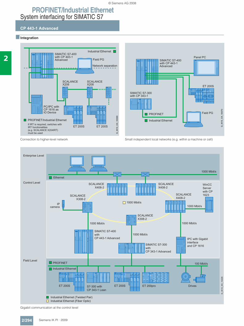
PROFINET/Industrial EthernetSystem interfacing for SIMATIC S7
CP 443-1 Advanced
2/294 Siemens IK PI · 2009
2
■ Integration
Connection to higher-level network Small independent local networks (e.g. within a machine or cell)
Gigabit communication at the control level
PC/IPC withCP 1616 as IO Device
SCALANCEX208
SCALANCEX208
WinCC Serverwith CP 1623
SIMATIC S7-400withCP 443-1 Advanced
SIMATIC S7-300withCP 343-1 Advanced
Drives
IPC with Gigabit interfaceand CP 1616
IPcamera
S7-300 withCP 343-1 Lean
1000 Mbit/s
100 Mbit/s
1000 Mbit/s1000 Mbit/s
1000 Mbit/s
SCALANCEX308-2
SCALANCEX408-2
SCALANCEX408-2
SCALANCEX408-2
SCALANCEX308-2
ET 200proET 200SET 200S
1000 Mbit/s
Ethernet
PROFINET
G_I
K10
_XX
_102
26
Field Level
Control Level
Enterprise Level
Industrial Ethernet
1000 Mbit/s
© Siemens AG 2008
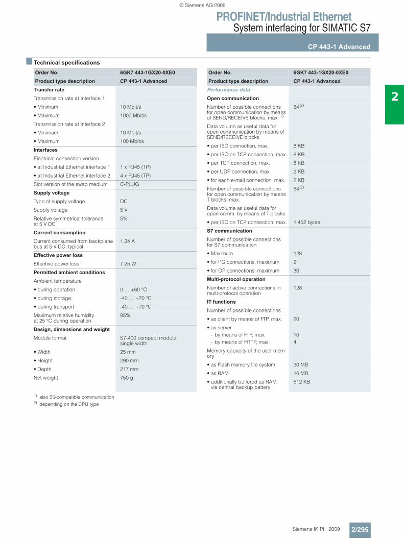
PROFINET/Industrial EthernetSystem interfacing for SIMATIC S7
CP 443-1 Advanced
2/295Siemens IK PI · 2009
2
■ Technical specifications
1) also S5-compatible communication2) depending on the CPU type
Order No. 6GK7 443-1GX20-0XE0Product type description CP 443-1 Advanced
Transfer rate
Transmission rate at Interface 1
• Minimum 10 Mbit/s
• Maximum 1000 Mbit/s
Transmission rate at Interface 2
• Minimum 10 Mbit/s
• Maximum 100 Mbit/s
Interfaces
Electrical connection version
• at Industrial Ethernet interface 1 1 x RJ45 (TP)
• at Industrial Ethernet interface 2 4 x RJ45 (TP)
Slot version of the swap medium C-PLUG
Supply voltage
Type of supply voltage DC
Supply voltage 5 V
Relative symmetrical tolerance at 5 V DC
5%
Current consumption
Current consumed from backplane bus at 5 V DC, typical
1,34 A
Effective power loss
Effective power loss 7.25 W
Permitted ambient conditions
Ambient temperature
• during operation 0 … +60 °C
• during storage -40 … +70 °C
• during transport -40 … +70 °C
Maximum relative humidity at 25 °C during operation
95%
Design, dimensions and weight Module format S7-400 compact module,
single width
• Width 25 mm
• Height 290 mm
• Depth 217 mm
Net weight 750 g
Order No. 6GK7 443-1GX20-0XE0Product type description CP 443-1 Advanced
Performance data
Open communication
Number of possible connections for open communication by means of SEND/RECEIVE blocks, max. 1)
64 2)
Data volume as useful data for open communication by means of SEND/RECEIVE blocks
• per ISO connection, max. 8 KB
• per ISO on TCP connection, max. 8 KB
• per TCP connection, max. 8 KB
• per UDP connection, max. 2 KB
• for each e-mail connection, max. 2 KB
Number of possible connections for open communication by means T blocks, max.
64 2)
Data volume as useful data for open comm. by means of T-blocks
• per ISO on TCP connection, max. 1 452 bytes
S7 communication
Number of possible connections for S7 communication
• Maximum 128
• for PG connections, maximum 2
• for OP connections, maximum 30
Multi-protocol operation
Number of active connections in multi-protocol operation
128
IT functions
Number of possible connections
• as client by means of FTP, max. 20
• as server- by means of FTP, max. 10- by means of HTTP, max. 4
Memory capacity of the user mem-ory
• as Flash memory file system 30 MB
• as RAM 16 MB
• additionally buffered as RAM via central backup battery
512 KB
© Siemens AG 2008
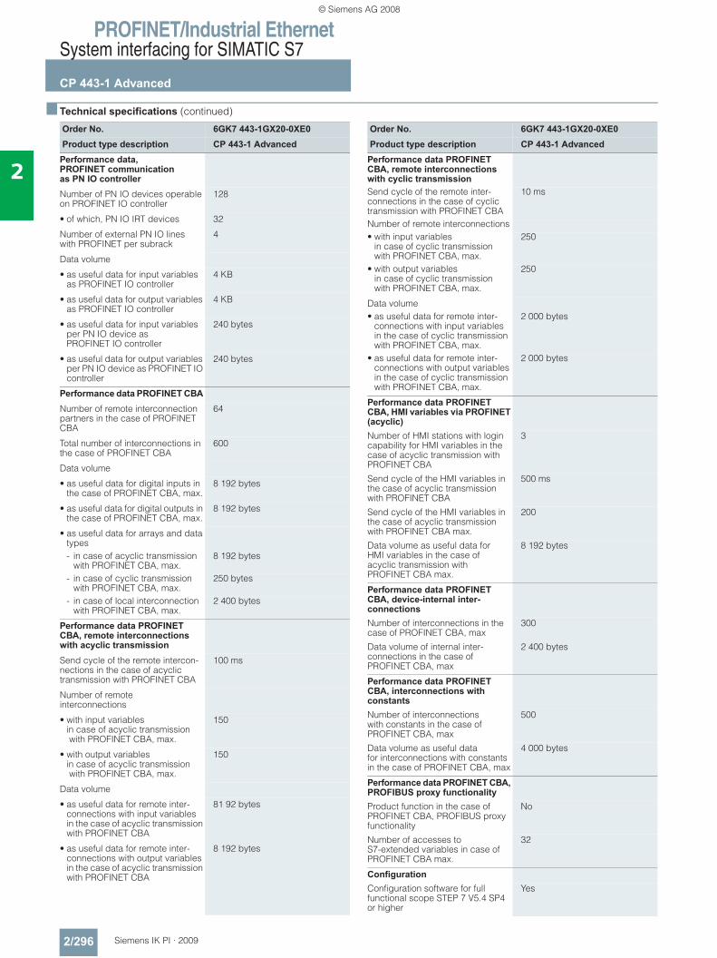
PROFINET/Industrial EthernetSystem interfacing for SIMATIC S7
CP 443-1 Advanced
2/296 Siemens IK PI · 2009
2
■ Technical specifications (continued)
Order No. 6GK7 443-1GX20-0XE0Product type description CP 443-1 Advanced
Performance data, PROFINET communication as PN IO controller Number of PN IO devices operable on PROFINET IO controller
128
• of which, PN IO IRT devices 32
Number of external PN IO lines with PROFINET per subrack
4
Data volume
• as useful data for input variables as PROFINET IO controller
4 KB
• as useful data for output variables as PROFINET IO controller
4 KB
• as useful data for input variables per PN IO device as PROFINET IO controller
240 bytes
• as useful data for output variables per PN IO device as PROFINET IO controller
240 bytes
Performance data PROFINET CBA
Number of remote interconnection partners in the case of PROFINET CBA
64
Total number of interconnections in the case of PROFINET CBA
600
Data volume
• as useful data for digital inputs in the case of PROFINET CBA, max.
8 192 bytes
• as useful data for digital outputs in the case of PROFINET CBA, max.
8 192 bytes
• as useful data for arrays and data types- in case of acyclic transmission
with PROFINET CBA, max.8 192 bytes
- in case of cyclic transmission with PROFINET CBA, max.
250 bytes
- in case of local interconnection with PROFINET CBA, max.
2 400 bytes
Performance data PROFINET CBA, remote interconnections with acyclic transmission
Send cycle of the remote intercon-nections in the case of acyclic transmission with PROFINET CBA
100 ms
Number of remote interconnections
• with input variables in case of acyclic transmission with PROFINET CBA, max.
150
• with output variables in case of acyclic transmission with PROFINET CBA, max.
150
Data volume
• as useful data for remote inter-connections with input variables in the case of acyclic transmission with PROFINET CBA
81 92 bytes
• as useful data for remote inter-connections with output variables in the case of acyclic transmission with PROFINET CBA
8 192 bytes
Order No. 6GK7 443-1GX20-0XE0Product type description CP 443-1 Advanced
Performance data PROFINET CBA, remote interconnections with cyclic transmission Send cycle of the remote inter-connections in the case of cyclic transmission with PROFINET CBA
10 ms
Number of remote interconnections• with input variables
in case of cyclic transmission with PROFINET CBA, max.
250
• with output variables in case of cyclic transmission with PROFINET CBA, max.
250
Data volume• as useful data for remote inter-
connections with input variables in the case of cyclic transmission with PROFINET CBA, max.
2 000 bytes
• as useful data for remote inter-connections with output variables in the case of cyclic transmission with PROFINET CBA, max.
2 000 bytes
Performance data PROFINET CBA, HMI variables via PROFINET (acyclic) Number of HMI stations with login capability for HMI variables in the case of acyclic transmission with PROFINET CBA
3
Send cycle of the HMI variables in the case of acyclic transmission with PROFINET CBA
500 ms
Send cycle of the HMI variables in the case of acyclic transmission with PROFINET CBA max.
200
Data volume as useful data for HMI variables in the case of acyclic transmission with PROFINET CBA max.
8 192 bytes
Performance data PROFINET CBA, device-internal inter-connections
Number of interconnections in the case of PROFINET CBA, max
300
Data volume of internal inter-connections in the case of PROFINET CBA, max
2 400 bytes
Performance data PROFINET CBA, interconnections with constants
Number of interconnections with constants in the case of PROFINET CBA, max
500
Data volume as useful data for interconnections with constants in the case of PROFINET CBA, max
4 000 bytes
Performance data PROFINET CBA,PROFIBUS proxy functionality
Product function in the case of PROFINET CBA, PROFIBUS proxy functionality
No
Number of accesses to S7-extended variables in case of PROFINET CBA max.
32
Configuration
Configuration software for full functional scope STEP 7 V5.4 SP4 or higher
Yes
© Siemens AG 2008
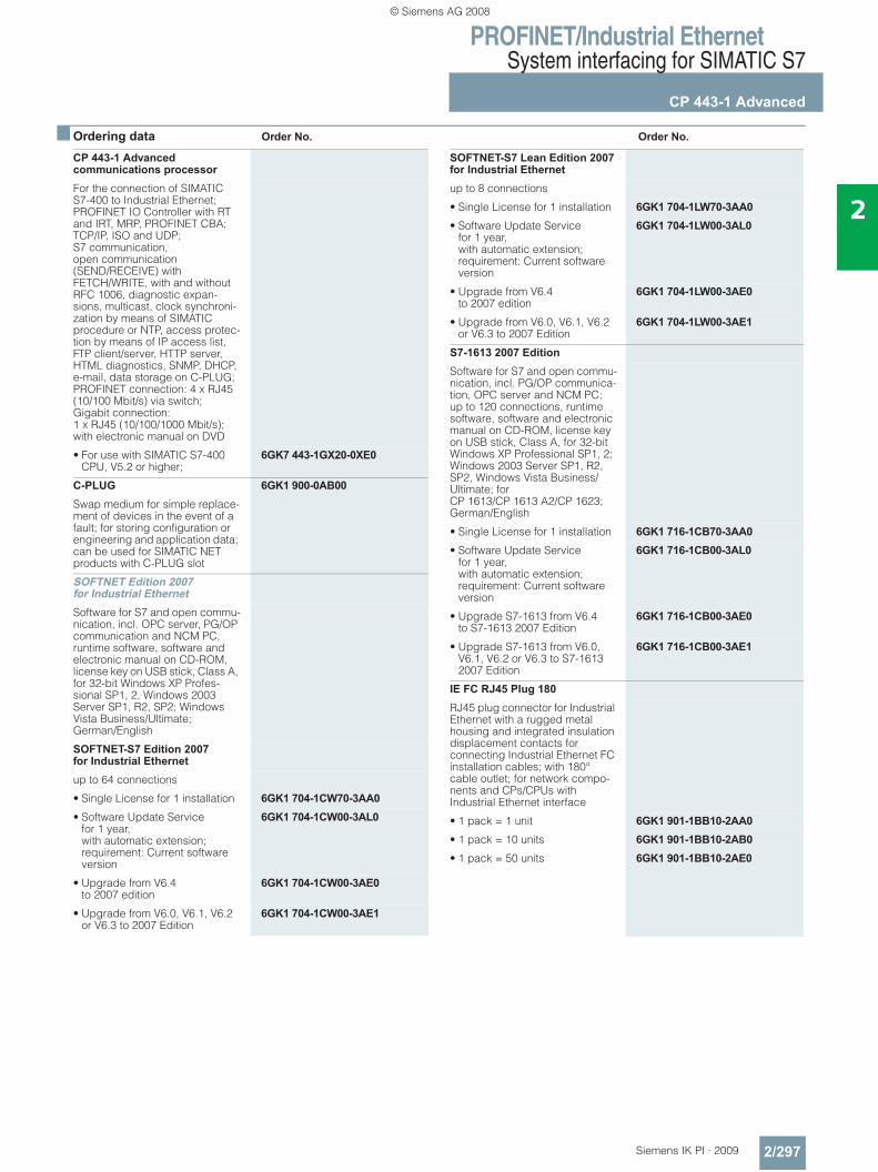
PROFINET/Industrial EthernetSystem interfacing for SIMATIC S7
CP 443-1 Advanced
2/297Siemens IK PI · 2009
2
■ Ordering data Order No. Order No.
CP 443-1 Advanced communications processorFor the connection of SIMATIC S7-400 to Industrial Ethernet; PROFINET IO Controller with RT and IRT, MRP, PROFINET CBA; TCP/IP, ISO and UDP; S7 communication, open communication (SEND/RECEIVE) with FETCH/WRITE, with and without RFC 1006, diagnostic expan-sions, multicast, clock synchroni-zation by means of SIMATIC procedure or NTP, access protec-tion by means of IP access list, FTP client/server, HTTP server, HTML diagnostics, SNMP, DHCP, e-mail, data storage on C-PLUG; PROFINET connection: 4 x RJ45 (10/100 Mbit/s) via switch; Gigabit connection: 1 x RJ45 (10/100/1000 Mbit/s); with electronic manual on DVD
• For use with SIMATIC S7-400 CPU, V5.2 or higher;
6GK7 443-1GX20-0XE0
C-PLUG 6GK1 900-0AB00Swap medium for simple replace-ment of devices in the event of a fault; for storing configuration or engineering and application data; can be used for SIMATIC NET products with C-PLUG slot
SOFTNET Edition 2007 for Industrial EthernetSoftware for S7 and open commu-nication, incl. OPC server, PG/OP communication and NCM PC, runtime software, software and electronic manual on CD-ROM, license key on USB stick, Class A, for 32-bit Windows XP Profes-sional SP1, 2, Windows 2003 Server SP1, R2, SP2; Windows Vista Business/Ultimate; German/English
SOFTNET-S7 Edition 2007 for Industrial Ethernetup to 64 connections
• Single License for 1 installation 6GK1 704-1CW70-3AA0• Software Update Service
for 1 year, with automatic extension; requirement: Current software version
6GK1 704-1CW00-3AL0
• Upgrade from V6.4to 2007 edition
6GK1 704-1CW00-3AE0
• Upgrade from V6.0, V6.1, V6.2 or V6.3 to 2007 Edition
6GK1 704-1CW00-3AE1
SOFTNET-S7 Lean Edition 2007 for Industrial Ethernetup to 8 connections
• Single License for 1 installation 6GK1 704-1LW70-3AA0• Software Update Service
for 1 year, with automatic extension; requirement: Current software version
6GK1 704-1LW00-3AL0
• Upgrade from V6.4 to 2007 edition
6GK1 704-1LW00-3AE0
• Upgrade from V6.0, V6.1, V6.2 or V6.3 to 2007 Edition
6GK1 704-1LW00-3AE1
S7-1613 2007 EditionSoftware for S7 and open commu-nication, incl. PG/OP communica-tion, OPC server and NCM PC; up to 120 connections, runtime software, software and electronic manual on CD-ROM, license key on USB stick, Class A, for 32-bit Windows XP Professional SP1, 2; Windows 2003 Server SP1, R2, SP2, Windows Vista Business/Ultimate; for CP 1613/CP 1613 A2/CP 1623; German/English
• Single License for 1 installation 6GK1 716-1CB70-3AA0• Software Update Service
for 1 year, with automatic extension; requirement: Current software version
6GK1 716-1CB00-3AL0
• Upgrade S7-1613 from V6.4to S7-1613 2007 Edition
6GK1 716-1CB00-3AE0
• Upgrade S7-1613 from V6.0, V6.1, V6.2 or V6.3 to S7-1613 2007 Edition
6GK1 716-1CB00-3AE1
IE FC RJ45 Plug 180RJ45 plug connector for Industrial Ethernet with a rugged metal housing and integrated insulation displacement contacts for connecting Industrial Ethernet FC installation cables; with 180° cable outlet; for network compo-nents and CPs/CPUs with Industrial Ethernet interface
• 1 pack = 1 unit 6GK1 901-1BB10-2AA0• 1 pack = 10 units 6GK1 901-1BB10-2AB0• 1 pack = 50 units 6GK1 901-1BB10-2AE0
© Siemens AG 2008
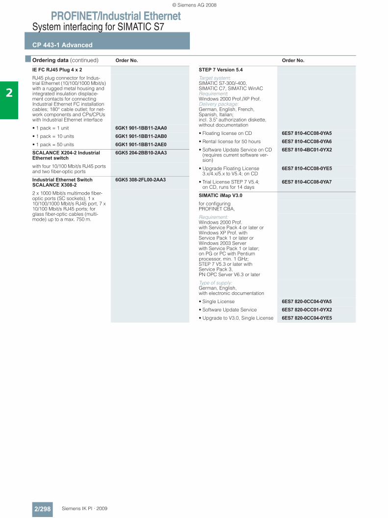
PROFINET/Industrial EthernetSystem interfacing for SIMATIC S7
CP 443-1 Advanced
2/298 Siemens IK PI · 2009
2
■ Ordering data (continued) Order No. Order No.
IE FC RJ45 Plug 4 x 2RJ45 plug connector for Indus-trial Ethernet (10/100/1000 Mbit/s) with a rugged metal housing and integrated insulation displace-ment contacts for connecting Industrial Ethernet FC installation cables; 180° cable outlet; for net-work components and CPs/CPUs with Industrial Ethernet interface
• 1 pack = 1 unit 6GK1 901-1BB11-2AA0• 1 pack = 10 units 6GK1 901-1BB11-2AB0• 1 pack = 50 units 6GK1 901-1BB11-2AE0SCALANCE X204-2 Industrial Ethernet switch
6GK5 204-2BB10-2AA3
with four 10/100 Mbit/s RJ45 ports and two fiber-optic ports
Industrial Ethernet Switch SCALANCE X308-2
6GK5 308-2FL00-2AA3
2 x 1000 Mbit/s multimode fiber-optic ports (SC sockets), 1 x 10/100/1000 Mbit/s RJ45 port, 7 x 10/100 Mbit/s RJ45 ports; for glass fiber-optic cables (multi-mode) up to a max. 750 m.
STEP 7 Version 5.4Target system: SIMATIC S7-300/-400, SIMATIC C7, SIMATIC WinAC Requirement: Windows 2000 Prof./XP Prof. Delivery package: German, English, French, Spanish, Italian;incl. 3.5" authorization diskette, without documentation
• Floating license on CD 6ES7 810-4CC08-0YA5• Rental license for 50 hours 6ES7 810-4CC08-0YA6• Software Update Service on CD
(requires current software ver-sion)
6ES7 810-4BC01-0YX2
• Upgrade Floating License 3.x/4.x/5.x to V5.4; on CD
6ES7 810-4CC08-0YE5
• Trial License STEP 7 V5.4; on CD, runs for 14 days
6ES7 810-4CC08-0YA7
SIMATIC iMap V3.0for configuring PROFINET CBA,
Requirement: Windows 2000 Prof. with Service Pack 4 or later or Windows XP Prof. with Service Pack 1 or later or Windows 2003 Server with Service Pack 1 or later; on PG or PC with Pentium processor, min. 1 GHz; STEP 7 V5.3 or later with Service Pack 3, PN OPC Server V6.3 or later
Type of supply: German, English, with electronic documentation
• Single License 6ES7 820-0CC04-0YA5• Software Update Service 6ES7 820-0CC01-0YX2• Upgrade to V3.0, Single License 6ES7 820-0CC04-0YE5
© Siemens AG 2008
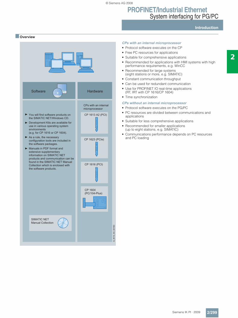
PROFINET/Industrial EthernetSystem interfacing for PG/PC
Introduction
2/299Siemens IK PI · 2009
2
■ Overview
CPs with an internal microprocessor• Protocol software executes on the CP• Free PC resources for applications• Suitable for comprehensive applications• Recommended for applications with HMI systems with high
performance requirements, e.g. WinCC• Recommended for large systems
(eight stations or more, e.g. SIMATIC)• Constant communication throughput• Can be used for redundant communication• Use for PROFINET IO real-time applications
(RT, IRT with CP 1616/CP 1604)• Time synchronization
CPs without an internal microprocessor• Protocol software executes on the PG/PC• PC resources are divided between communications and
applications• Suitable for less comprehensive applications• Recommended for smaller applications
(up to eight stations, e.g. SIMATIC)• Communications performance depends on PC resources
and PC loading
© Siemens AG 2008
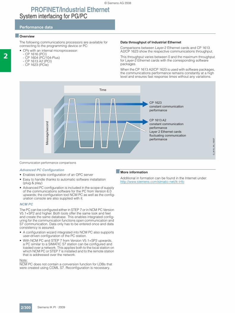
PROFINET/Industrial EthernetSystem interfacing for PG/PC
Performance data
2/300 Siemens IK PI · 2009
2
■ Overview
The following communications processors are available for connecting to the programming device or PC:• CPs with an internal microprocessor:
- CP 1616 (PCI) - CP 1604 (PC/104-Plus)- CP 1613 A2 (PCI)- CP 1623 (PCIe)
Data throughput of Industrial Ethernet Comparisons between Layer-2 Ethernet cards and CP 1613 A2/CP 1623 show the respective communications throughput.
This throughput varies between 0 and the maximum throughput for Layer-2 Ethernet cards with the corresponding software packages.
When the CP 1613 A2/CP 1623 is used with software packages, the communications performance remains constantly at a high level and ensures fast response times without any variations.
Communication performance comparisons
Advanced PC Configuration• Enables simple configuration of an OPC server• Easy to handle thanks to automatic software installation
(plug & play)• Advanced PC configuration is included in the scope of supply
of the communications software for the PC from Version 6.0 upwards; the configuration tool NCM PC as well as the config-uration console are also supplied with it.
NCM PCThe PC can be configured either in STEP 7 or in NCM PC Version V5.1+SP2 and higher. Both tools offer the same look and feel and create the same database. This enables integrated config-uring for the communication functions open communication and S7 communication. Data only has to be entered once and data consistency is assured.• A configuration wizard integrated into NCM PC also supports
user-driven configuration of the PC station.• With NCM PC and STEP 7 from Version V5.1+SP2 upwards,
a PC similar to a SIMATIC S7 station can be configured and loaded over a network. This applies both to the local station on which NCM PC or STEP 7 is installed and to the remote station that is addressed over the network.
Note: NCM PC does not contain a conversion function for LDBs that were created using COML S7. Reconfiguration is necessary.
■ More information
Additional in formation can be found in the Internet under:http://www.siemens.com/simatic-net/ik-info
CP 1613 A2constant communication performance
CP 1623constant communication performance
Layer 2 Ethernet cardsfluctuating communication performance
Mes
sage
/sec
ond
Time
G_I
K10
_XX
_100
37
© Siemens AG 2008
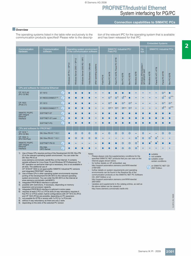
PROFINET/Industrial EthernetSystem interfacing for PG/PC
Connection capabilities to SIMATIC PCs
2/301Siemens IK PI · 2009
2
■ Overview
The operating systems listed in the table refer exclusively to the communication products specified! Please refer to the descrip-
tion of the relevant IPC for the operating system that is available and has been released for that IPC.
© Siemens AG 2008
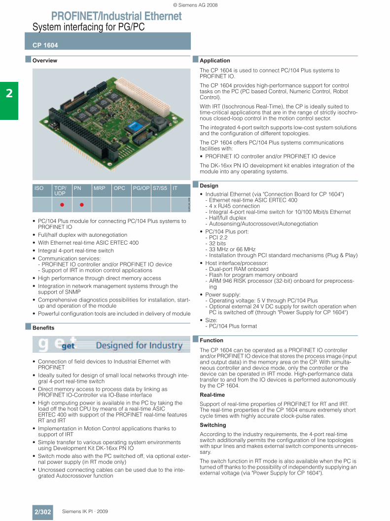
PROFINET/Industrial EthernetSystem interfacing for PG/PC
CP 1604
2/302 Siemens IK PI · 2009
2
■ Overview
• PC/104 Plus module for connecting PC/104 Plus systems to PROFINET IO
• Full/half duplex with autonegotiation • With Ethernet real-time ASIC ERTEC 400• Integral 4-port real-time switch• Communication services:
- PROFINET IO controller and/or PROFINET IO device- Support of IRT in motion control applications
• High performance through direct memory access• Integration in network management systems through the
support of SNMP• Comprehensive diagnostics possibilities for installation, start-
up and operation of the module• Powerful configuration tools are included in delivery of module
■ Benefits
• Connection of field devices to Industrial Ethernet with PROFINET
• Ideally suited for design of small local networks through inte-gral 4-port real-time switch
• Direct memory access to process data by linking as PROFINET IO-Controller via IO-Base interface
• High computing power is available in the PC by taking the load off the host CPU by means of a real-time ASIC ERTEC 400 with support of the PROFINET real-time features RT and IRT
• Implementation in Motion Control applications thanks to support of IRT
• Simple transfer to various operating system environments using Development Kit DK-16xx PN IO
• Switch mode also with the PC switched off, via optional exter-nal power supply (in RT mode only)
• Uncrossed connecting cables can be used due to the inte-grated Autocrossover function
■ Application
The CP 1604 is used to connect PC/104 Plus systems to PROFINET IO.
The CP 1604 provides high-performance support for control tasks on the PC (PC based Control, Numeric Control, Robot Control).
With IRT (Isochronous Real-Time), the CP is ideally suited to time-critical applications that are in the range of strictly isochro-nous closed-loop control in the motion control sector.
The integrated 4-port switch supports low-cost system solutions and the configuration of different topologies.
The CP 1604 offers PC/104 Plus systems communications facilities with:• PROFINET IO controller and/or PROFINET IO device
The DK-16xx PN IO development kit enables integration of the module into any operating systems.
■ Design• Industrial Ethernet (via "Connection Board for CP 1604")
- Ethernet real-time ASIC ERTEC 400- 4 x RJ45 connection- Integral 4-port real-time switch for 10/100 Mbit/s Ethernet - Half/full duplex- Autosensing/Autocrossover/Autonegotiation
• PC/104 Plus port: - PCI 2.2- 32 bits- 33 MHz or 66 MHz- Installation through PCI standard mechanisms (Plug & Play)
• Host interface/processor: - Dual-port RAM onboard- Flash for program memory onboard- ARM 946 RISK processor (32-bit) onboard for preprocess-
ing• Power supply:
- Operating voltage: 5 V through PC/104 Plus- Optional external 24 V DC supply for switch operation when
PC is switched off (through "Power Supply for CP 1604")• Size:
- PC/104 Plus format
■ Function
The CP 1604 can be operated as a PROFINET IO controller and/or PROFINET IO device that stores the process image (input and output data) in the memory area on the CP. With simulta-neous controller and device mode, only the controller or the device can be operated in IRT mode. High-performance data transfer to and from the IO devices is performed autonomously by the CP 1604.
Real-time
Support of real-time properties of PROFINET for RT and IRT. The real-time properties of the CP 1604 ensure extremely short cycle times with highly accurate clock-pulse rates.
Switching
According to the industry requirements, the 4-port real-time switch additionally permits the configuration of line topologies with spur lines and makes external switch components unneces-sary.
The switch function in RT mode is also available when the PC is turned off thanks to the possibility of independently supplying an external voltage (via "Power Supply for CP 1604").
© Siemens AG 2008
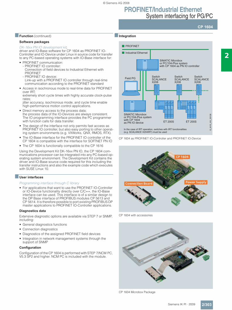
PROFINET/Industrial EthernetSystem interfacing for PG/PC
CP 1604
2/303Siemens IK PI · 2009
2
■ Function (continued)
Software packages
DK-16xx PN IO development kit; driver and IO-Base software for CP 1604 as PROFINET IO-Controller and IO-Device under Linux in source code for transfer to any PC-based operating systems with IO-Base interface for:• PROFINET communication:
- PROFINET IO controller: Connection of field devices to Industrial Ethernet with PROFINET
- PROFINET IO device: Link-up with a PROFINET IO controller through real-time communication according to the PROFINET standard
• Access in isochronous mode to real-time data for PROFINET over IRT; extremely short cycle times with highly accurate clock-pulse rates; jitter accuracy, isochronous mode, and cycle time enable high-performance motion control applications.
• Direct memory access to the process data; the process data of the IO-Devices are always consistent. The IO programming interface provides the PC programmer with function calls for data transfer.
• The design of the interface not only permits fast access as PROFINET IO controller, but also easy porting to other operat-ing system environments (e.g. VXWorks, QNX, RMOS, RTX).
• The IO-Base interface for the PROFINET IO controller of the CP 1604 is compatible with the interface for SOFTNET PN IO
• The CP 1604 is functionally compatible to the CP 1616
Using the Development Kit DK-16xx PN IO, the CP 1604 com-munications processor can be integrated into any PC-based op-erating system environment. The Development Kit contains the driver and IO-Base source code required for this including the transfer instructions and also the example code which executes with SUSE Linux 10.
■ User interfaces
Programming interface through C library • For applications that want to use the PROFINET IO-Controller
or IO-Device functionality directly over C/C++, the IO-Base interface can be used. This interface is of a similar design to the DP Base interface of PROFIBUS modules CP 5613 and CP 5614. It is therefore possible to port existing PROFIBUS DP master applications to PROFINET IO-Controller applications.
Diagnostics data
Extensive diagnostic options are available via STEP 7 or SNMP, including:• General diagnostics functions• Connection diagnostics• Diagnostics of the assigned PROFINET field devices• Integration in network management systems through the
support of SNMP
Configuration
Configuration of the CP 1604 is performed with STEP 7/NCM PC, V5.3 SP2 and higher. NCM PC is included with the module.
■ Integration
CP 1604 as PROFINET IO-Controller and PROFINET IO-Device
CP 1604 with accessories
CP 1604 Microbox Package
SIMATIC Microboxor PC/104-Plus systemwith CP 1604 as PN IO controller
In the case of IRT operation, switches with IRT functionalities(e.g. SCALANCE X204IRT) must be used
SIMATIC Microboxor PC/104-Plus systemwith CP 1604as PN IO device
Industrial Ethernet
PROFINET
G_I
K10
_XX
_301
36
Field PG
ET 200S ET 200S
SwitchSCALANCEX208
SwitchSCALANCEX208
SwitchSCALANCEX208
© Siemens AG 2008
PROFINET/Industrial EthernetSystem interfacing for PG/PC
CP 1604
2/304 Siemens IK PI · 2009
2
■ Technical specifications
Order No. 6GK1 160-4AA00Product type description CP 1604
Transfer rate
Transmission rate for auto-sensing for Industrial Ethernet
• Minimum 10 Mbit/s
• Maximum 100 Mbit/s
Interfaces
Electrical connection version
• the Industrial Ethernet interface 4 x RJ45 TP; via connection board
• of the backplane bus PC/104 Plus compatible, 32 bit, 33 MHz/66 MHz
• for voltage supply Via Power Supply for CP 1604
Supply voltage
Type of supply voltage DC
Supply voltage
• 1 from backplane bus 5 V
• external, max. 24 V
Relative symmetrical tolerance
• at 5 V DC 5%
• at 24 V DC 20%
Current consumption
Current consumed
• 1 from backplane bus if DC, max. 800 mA
• from external supply voltage at 24 V DC max.
300 mA
Power loss
Effective power loss 4 W
• in switch mode- Minimum 3.9 W- Maximum 4.1 W
Permitted ambient conditions
Ambient temperature
• during operation +5 … +55 °C
• during transport -20 … +60 °C
• during storage -20 … +60 °C
Maximum relative humidity at 25 °C during operation
95%
Design, dimensions and weight Module format PC/104 Plus format
• Height 95 mm
• Width 90 mm
• Depth 24 mm
Net weight 110 g
Order No. 6GK1 160-4AA00Product type description CP 1604
Performance data
PROFINET communication as PN IO controller Number of PN IO devices operable on PROFINET IO controller
128
• of which, PN IO IRT devices, max. 16
Data volume• as useful data for input variables
as PROFINET IO controller2 KB
• as useful data for output variables as PROFINET IO controller
2 KB
• as useful data for input variables per PN IO device as PROFINET IO controller
1433 bytes
• as useful data for output variables per PN IO device as PROFINET IO controller
1433 bytes
PROFINET communication as PN IO deviceData volume
• as useful data for input variables as PROFINET IO device
1433 bytes
• as useful data for output variables as PROFINET IO device
1433 bytes
© Siemens AG 2008
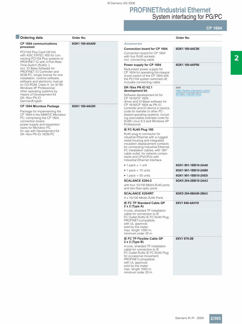
PROFINET/Industrial EthernetSystem interfacing for PG/PC
CP 1604
2/305Siemens IK PI · 2009
2
■ Ordering data Order No. Order No.
CP 1604 communications processor
6GK1 160-4AA00
PCI/104 Plus Card (32 bit) with ASIC ERTEC 400 for con-necting PC/104 Plus systems to PROFINET IO with 4-Port-Real-Time-Switch (RJ45); ); incl. IO Base Software for PROFINET IO Controller and NCM PC; single license for one installation, runtime software, software and electronic manual on CD-ROM, Class A, for 32 Bit Windows XP Professional; other operating systems by means of Development Kit DK-16xx PN IOGerman/English
CP 1604 Microbox Package 6GK1 160-4AU00Package for implementing the CP 1604 in the SIMATIC Microbox PC; comprising the CP 1604, connection board, power supply and expansion racks for Microbox PC;for use with Development Kit DK-16xx PN IO; NCM PC
AccessoriesConnection board for CP 1604 6GK1 160-4AC00Connection board for CP 1604 with four RJ45 socketsincl. connecting cable
Power supply for CP 1604 6GK1 160-4AP00Redundant power supply for CP 1604 for operating the integral 4-port switch of the CP 1604 with the PC/104 system switched off; includes connecting cable
DK-16xx PN IO V2.1 development kit
see http://www.siemens.com/simatic-net/dk16xxSoftware development kit for
CP 1616/CP 1604; driver and IO-Base software for CP 1616/CP 1604 as PN IO controller and IO device in source code for transfer to other PC-based operating systems; includ-ing executable example code for SUSE Linux 9.3 and Windows XP Professional
IE FC RJ45 Plug 180RJ45 plug-in connector for ndustrial Ethernet with a rugged metal housing and integrated insulation displacement contacts for connecting Industrial Ethernet FC installation cables; with 180° cable outlet; for network compo-nents and CPs/CPUs with Industrial Ethernet interface
• 1 pack = 1 unit 6GK1 901-1BB10-2AA0• 1 pack = 10 units 6GK1 901-1BB10-2AB0• 1 pack = 50 units 6GK1 901-1BB10-2AE0SCALANCE X204-2 6GK5 204-2BB10-2AA3with four 10/100 Mbit/s RJ45 ports and two fiber-optic ports
SCALANCE X204IRT 6GK5 204-0BA00-2BA34 x 10/100 Mbit/s RJ45 Ports
IE FC TP Standard Cable GP 2 x 2 (Type A)
6XV1 840-4AH10
4-core, shielded TP installation cable for connection to IE FC Outlet RJ45/ IE FC RJ45 Plug; PROFINET-compatible; with UL approval; sold by the meter; max. length 1000 m, minimum order 20 m
IE FC TP Flexible Cable GP 2 x 2 (Type B)
6XV1 870-2B
4-core, shielded TP installation cable for connection to IE FC Outlet RJ45/ IE FC RJ45 Plug for occasional movement; PROFINET-compatible; with UL approval; sold by the meter; max. length 1000 m, minimum order 20 m
© Siemens AG 2008
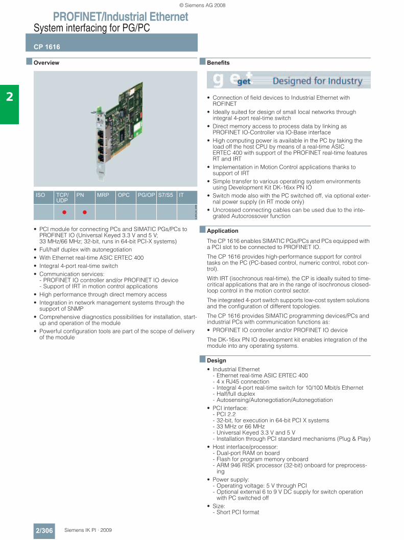
PROFINET/Industrial EthernetSystem interfacing for PG/PC
CP 1616
2/306 Siemens IK PI · 2009
2
■ Overview
• PCI module for connecting PCs and SIMATIC PGs/PCs to PROFINET IO (Universal Keyed 3.3 V and 5 V; 33 MHz/66 MHz; 32-bit, runs in 64-bit PCI-X systems)
• Full/half duplex with autonegotiation • With Ethernet real-time ASIC ERTEC 400• Integral 4-port real-time switch• Communication services:
- PROFINET IO controller and/or PROFINET IO device- Support of IRT in motion control applications
• High performance through direct memory access• Integration in network management systems through the
support of SNMP• Comprehensive diagnostics possibilities for installation, start-
up and operation of the module• Powerful configuration tools are part of the scope of delivery
of the module
■ Benefits
• Connection of field devices to Industrial Ethernet with ROFINET
• Ideally suited for design of small local networks through integral 4-port real-time switch
• Direct memory access to process data by linking as PROFINET IO-Controller via IO-Base interface
• High computing power is available in the PC by taking the load off the host CPU by means of a real-time ASIC ERTEC 400 with support of the PROFINET real-time features RT and IRT
• Implementation in Motion Control applications thanks to support of IRT
• Simple transfer to various operating system environments using Development Kit DK-16xx PN IO
• Switch mode also with the PC switched off, via optional exter-nal power supply (in RT mode only)
• Uncrossed connecting cables can be used due to the inte-grated Autocrossover function
■ Application
The CP 1616 enables SIMATIC PGs/PCs and PCs equipped with a PCI slot to be connected to PROFINET IO.
The CP 1616 provides high-performance support for control tasks on the PC (PC-based control, numeric control, robot con-trol).
With IRT (isochronous real-time), the CP is ideally suited to time-critical applications that are in the range of isochronous closed-loop control in the motion control sector.
The integrated 4-port switch supports low-cost system solutions and the configuration of different topologies.
The CP 1616 provides SIMATIC programming devices/PCs and industrial PCs with communication functions as:• PROFINET IO controller and/or PROFINET IO device
The DK-16xx PN IO development kit enables integration of the module into any operating systems.
■ Design• Industrial Ethernet
- Ethernet real-time ASIC ERTEC 400- 4 x RJ45 connection- Integral 4-port real-time switch for 10/100 Mbit/s Ethernet - Half/full duplex- Autosensing/Autonegotiation/Autonegotiation
• PCI interface: - PCI 2.2- 32-bit, for execution in 64-bit PCI X systems- 33 MHz or 66 MHz- Universal Keyed 3.3 V and 5 V- Installation through PCI standard mechanisms (Plug & Play)
• Host interface/processor: - Dual-port RAM on board- Flash for program memory onboard- ARM 946 RISK processor (32-bit) onboard for preprocess-
ing• Power supply:
- Operating voltage: 5 V through PCI- Optional external 6 to 9 V DC supply for switch operation
with PC switched off• Size:
- Short PCI format
© Siemens AG 2008
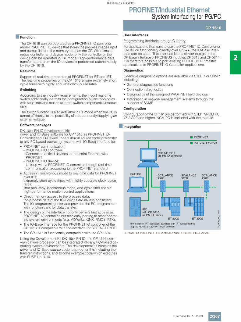
PROFINET/Industrial EthernetSystem interfacing for PG/PC
CP 1616
2/307Siemens IK PI · 2009
2
■ Function
The CP 1616 can be operated as a PROFINET IO controller and/or PROFINET IO device that stores the process image (input and output data) in the memory area on the CP. With simulta-neous controller and device mode, only the controller or the device can be operated in IRT mode. High-performance data transfer to and from the IO devices is performed autonomously by the CP 1616.
Real-time
Support of real-time properties of PROFINET for RT and IRT. The real-time properties of the CP 1616 ensure extremely short cycle times with highly accurate clock-pulse rates.
Switching
According to the industry requirements, the 4-port real-time switch additionally permits the configuration of line topologies with spur lines and makes external switch components unneces-sary.
The switch function is also available in RT mode when the PC is turned off thanks to the possibility of independently supplying an external voltage.
Software packages
DK-16xx PN IO development kit; driver and IO-Base software for CP 1616 as PROFINET IO-Controller and IO-Device under Linux in source code for transfer to any PC-based operating systems with IO-Base interface for:• PROFINET communication:
- PROFINET IO controller: Connection of field devices to Industrial Ethernet with PROFINET
- PROFINET IO device: Link-up with a PROFINET IO controller through real-time communication according to the PROFINET standard
• Access in isochronous mode to real-time data for PROFINET over IRT; extremely short cycle times with highly accurate clock-pulse rates; jitter accuracy, isochronous mode, and cycle time enable high-performance motion control applications.
• Direct memory access to the process data; the process data of the IO-Devices are always consistent. The IO programming interface provides the PC programmer with function calls for data transfer.
• The design of the interface not only permits fast access as PROFINET IO controller, but also easy porting to other operat-ing system environments (e.g. VXWorks, QNX, RMOS, RTX).
• The IO-Base interface for the PROFINET IO controller of the CP 1616 is compatible with the interface for SOFTNET PN IO
• The CP 1616 is functionally compatible with the CP 1604
Using the Development Kit DK-16xx PN IO, the CP 1616 com-munications processor can be integrated into any PC-based op-erating system environments. The development kit contains the driver and IO-Base source code required for this including the transfer instructions, and also the example code which executes with SUSE Linux 10.
User interfaces
Programming interface through C library
For applications that want to use the PROFINET IO-Controller or IO-Device functionality directly over C/C++, the IO-Base inter-face can be used. This interface is of a similar design to the DP Base interface of PROFIBUS modules CP 5613 and CP 5614. It is therefore possible to port existing PROFIBUS DP master applications to PROFINET IO-Controller applications.
Diagnostics
Extensive diagnostic options are available via STEP 7 or SNMP, including:• General diagnostics functions• Connection diagnostics• Diagnostics of the assigned PROFINET field devices• Integration in network management systems through the
support of SNMP
Configuration
Configuration of the CP 1616 is performed with STEP 7/NCM PC, V5.3 SP2 and higher. NCM PC is included with the module.
■ Integration
CP 1616 as PROFINET IO-Controller and PROFINET IO-Device
PCwith CP 1616as PN IO controller
IPCwith CP 1616as PN IO Device
In the case of IRT operation, switches with IRT functionalities(e.g. SCALANCE X204IRT) must be used G
_IK
10_X
X_1
0097
Field PG
ET 200S ET 200S
SCALANCEX208
SCALANCEX208
SCALANCEX208
© Siemens AG 2008
PROFINET/Industrial EthernetSystem interfacing for PG/PC
CP 1616
2/308 Siemens IK PI · 2009
2
■ Technical specifications
Order No. 6GK1 161-6AA00Product type description CP 1616
Transfer rate
Transmission rate for auto-sensing for Industrial Ethernet
• Minimum 10 Mbit/s
• Maximum 100 Mbit/s
Interfaces
Electrical connection version
• the Industrial Ethernet interface 4 x RJ45 (TP)
• of the backplane bus PCI (32 Bit, 3.3 V/5 V; Universal Keyed; 33/66 MHz)
• for voltage supply Low-voltage socket for hollow plug 3.5 mm (-) / 1.3 mm (+)
Supply voltage
Type of supply voltage DC
Supply voltage
• 1 from backplane bus 5 V
• external- Minimum 6 V- Maximum 9 V
Relative symmetrical tolerance at 5 V DC
5%
Current consumption
Current consumed
• 1 from backplane bus if DC, max. 800 mA
• from external supply voltage- at 6 V DC, max. 650 mA- at 9 V DC, max. 450 mA
Power loss
Effective power loss 4 W
• in switch mode- Minimum 3.9 W- Maximum 4.1 W
Order No. 6GK1 161-6AA00Product type description CP 1616
Permitted ambient conditions
Ambient temperature
• during operation +5 … +55 °C
• during transport -20 … +60 °C
• during storage -20 … +60 °C
Maximum relative humidity at 25 °C during operation
95%
Design, dimensions and weight Module format PCI card, short
• Height 167 mm
• Width 107 mm
Net weight 110 g
Performance data
PROFINET communication as PN IO controller Number of PN IO devices operable as PROFINET IO devices
128
• of which, PN IO IRT devices 16
Data volume
• as useful data for input variables as PROFINET IO controller
2 KB
• as useful data for output variables as PROFINET IO controller
2 KB
• as useful data for input variables per PN IO device as PROFINET IO controller
1433 bytes
• as useful data for output variables per PN IO device as PROFINET IO controller
1433 bytes
PROFINET communication as PN IO deviceData volume
• as useful data for input variables as PROFINET IO device
1433 bytes
• as useful data for output variables as PROFINET IO device
1433 bytes
© Siemens AG 2008
PROFINET/Industrial EthernetSystem interfacing for PG/PC
CP 1616
2/309Siemens IK PI · 2009
2
■ Ordering data Order No. Order No.
CP 1616 communications pro-cessor
6GK1 161-6AA00
PCI Card (32 Bit; 3.3/5 V universal keyed) with ASIC ERTEC 400 for connecting PCs to PROFINET IO with 4-Port-Real-Time-Switch (RJ45); incl. IO Base Software for PROFINET IO Controller and NCM PC; single license for one installation, runtime software, software and electronic manual on CD-ROM, Class A, for 32 Bit Windows XP Professional; other operating systems via Development Kit DK-16xx PN IOGerman/English
AccessoriesDK-16xx PN IO V2.1 development kitSoftware development kit for CP 1616/CP 1604; driver and IO-Base software for CP 1616/CP 1604 as PN IO controller and IO device in source code for transfer to other PC-based operating systems; including executable example code for SUSE Linux 10 and Windows XP Professional
see http://www.siemens.com/simatic-net/dk16xx
IE FC RJ45 Plug 180RJ45 plug-in connector for Industrial Ethernet with a rugged metal housing and integrated insulation displacement contacts for connecting Industrial Ethernet FC installation cables; with 180° cable outlet; for network compo-nents and CPs/CPUs with Industrial Ethernet interface
• 1 pack = 1 unit 6GK1 901-1BB10-2AA0• 1 pack = 10 units 6GK1 901-1BB10-2AB0• 1 pack = 50 units 6GK1 901-1BB10-2AE0IE FC TP Standard Cable GP 2 x 2 (Type A)
6XV1 840-4AH10
4-core, shielded TP installation cable for connection to IE FC Outlet RJ45/ IE FC RJ45 Plug; PROFINET-compatible; with UL approval; sold by the meter; max. length 1000 m, minimum order 20 m
IE FC TP Flexible Cable GP 2 x 2 (Type B)
6XV1 870-2B
4-core, shielded TP installation cable for connection to IE FC Outlet RJ45/ IE FC RJ45 Plug for occasional movement; PROFINET-compatible; with UL approval; sold by the meter; max. length 1000 m, minimum order 20 m
© Siemens AG 2008
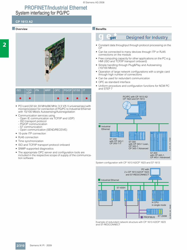
PROFINET/Industrial EthernetSystem interfacing for PG/PC
CP 1613 A2
2/310 Siemens IK PI · 2009
2
■ Overview
• PCI card (32 bit; 33 MHz/66 MHz; 3.3 V/5 V universal key) with microprocessor for connection of PG/PC to Industrial Ethernet with 10/100 Mbit/s Autosensing/Autonegotiation
• Communication services using - Open IE communication via TCP/IP and UDP)- ISO transport protocol - PG/OP communication- S7 communication- Open communication (SEND/RECEIVE)
• 15-pole ITP connection • RJ45 connection• Time synchronization• ISO and TCP/IP transport protocol onboard• SNMP-supported diagnostics• The appropriate OPC server and configuration tools are
included in the respective scope of supply of the communica-tion software
■ Benefits
• Constant data throughput through protocol processing on the CP
• Can be connected to many devices through ITP or RJ45 connections on the module
• Free computing capacity for other applications on the PC e.g. HMI (ISO and TCP/IP transport onboard)
• Simple handling through Plug&Play and Autosensing (10/100 Mbit/s)
• Operation of large network configurations with a single card through high number of connections
• Can be used for redundant communication• OPC as standard interface • Uniform procedure and configuration functions for NCM PC
and STEP 7
System configuration with CP 1613 A2/CP 1623 and S7-1613
Example of redundant network structure with CP 1613 A2/CP 1623 and S7-REDCONNECT
© Siemens AG 2008
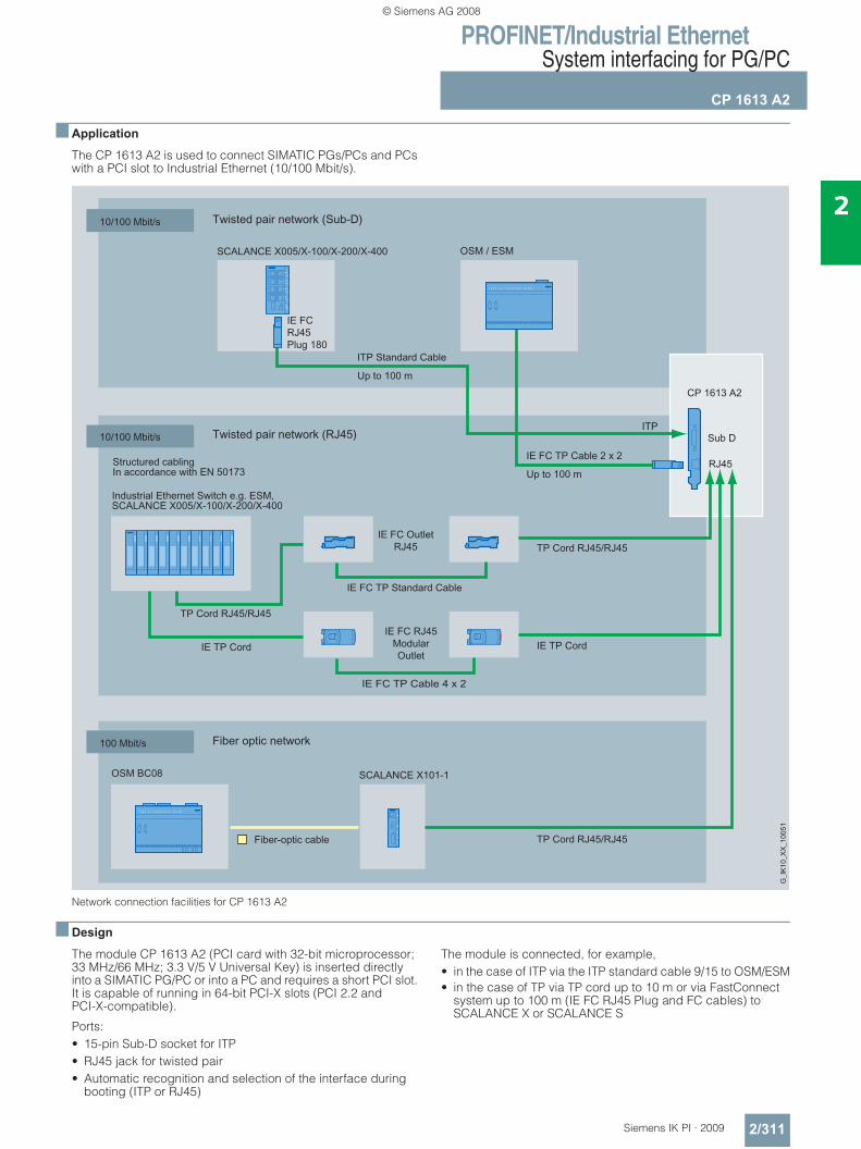
PROFINET/Industrial EthernetSystem interfacing for PG/PC
CP 1613 A2
2/311Siemens IK PI · 2009
2
■ Application
The CP 1613 A2 is used to connect SIMATIC PGs/PCs and PCs with a PCI slot to Industrial Ethernet (10/100 Mbit/s).
Network connection facilities for CP 1613 A2
■ Design
The module CP 1613 A2 (PCI card with 32-bit microprocessor; 33 MHz/66 MHz; 3.3 V/5 V Universal Key) is inserted directly into a SIMATIC PG/PC or into a PC and requires a short PCI slot. It is capable of running in 64-bit PCI-X slots (PCI 2.2 and PCI-X-compatible).
Ports:• 15-pin Sub-D socket for ITP• RJ45 jack for twisted pair• Automatic recognition and selection of the interface during
booting (ITP or RJ45)
The module is connected, for example, • in the case of ITP via the ITP standard cable 9/15 to OSM/ESM• in the case of TP via TP cord up to 10 m or via FastConnect
system up to 100 m (IE FC RJ45 Plug and FC cables) to SCALANCE X or SCALANCE S
© Siemens AG 2008
PROFINET/Industrial EthernetSystem interfacing for PG/PC
CP 1613 A2
2/312 Siemens IK PI · 2009
2
■ Function
User interfaces
OPC interface
As a standard programming interface for the S7 communication and open communication protocols, the OPC server contained in the respective software package can be used to connect the automation technology to OPC-compatible Windows appli-cations (Office, HMI systems, etc.).
Programming interface through C library
The programming interfaces for the S7 communication, PG/OP communication, and open communication protocols for existing applications are implemented as Dynamic Link Library (DLL) interfaces.
You can find the released compilers in the Readme file of the SIMATIC NET CD products at http://www.siemens.com/automation/csi/net.
Software for PG/OP communication
This software supports the programming of SIMATIC S5 and S7 controllers over Industrial Ethernet in combination with STEP 5 / STEP 7 programmable controllers.
It is included in all CP 1613 A2 software packages.
Software for S7 communication (S7-1613 or S7-REDCONNECT)
The S7 interface provides PG/PC applications (e.g. WinCC) and application programs with access to SIMATIC S7 system com-ponents. This provides easy, flexible access to the data of the SIMATIC S7 controller.
S7 communication offers:
Administrative services • Connection management• Mini database• Trace
Data transfer services • Read/write variables• BSEND/BRECEIVE
H-communication
For redundant S7-communication with a fault-tolerant S7-400 H system, the CP 1613/CP1623 can be used in connection with the S7-REDCONNECT software.
Software for open communication (SEND/RECEIVE) This interface is used for communication between • PG/PC and SIMATIC S5• PG/PC and SIMATIC S7• PG/PC and PG/PC
used
Open communication (SEND/RECEIVE) offers the following services:• Management services • Connection establishment services• Data transfer services
The software is included in the S7-1613 product.
Mode of operation
Protocols up to Level 4 (Transport) are processed autonomously on the module.
16 MB of memory is available for this to support a large quanti-tative framework and reliable communication.
Data is exchanged between the module and the host in master mode. This means that the CP 1613 A2 accesses the physical RAM of the host.
A Windows driver is responsible for transferring data between the host system and the CP 1613 A2. The transmission rate to Industrial Ethernet is detected and automatically switched over (autosensing).
The IT functionality is provided in combination with the Windows software of the PC.
Diagnostics data
Via SNMP all MIB-2 objects can be read out. This enables the current status of the Ethernet interfaces to be retrieved.
Configuration • The S7 communication and open communication protocols
are configured in STEP 7 or NCM PC.• The configuration tool NCM PC is included in the CP 1613 A2
software packages.• NCM PC is a component part of Advanced PC Configuration.
© Siemens AG 2008
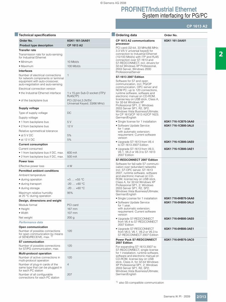
PROFINET/Industrial EthernetSystem interfacing for PG/PC
CP 1613 A2
2/313Siemens IK PI · 2009
2
■ Technical specifications ■ Ordering data Order No.
1) also S5-compatible communication
Order No. 6GK1 161-3AA01Product type description CP 1613 A2
Transfer rate Transmission rate for auto-sensing for Industrial Ethernet• Minimum 10 Mbit/s• Maximum 100 Mbit/s
Interfaces Number of electrical connections for network components or terminal equipment with auto-crossover, auto-negotiation and auto-sensing
1
Electrical connection version• the Industrial Ethernet interface 1 x 15-pin Sub-D socket (ITP)/
RJ45(TP)• of the backplane bus PCI (32-bit,3.3V/5V;
Universal Keyed; 33/66 MHz)
Supply voltage
Type of supply voltage DC
Supply voltage• 1 from backplane bus 5 V• 2 from backplane bus 12 V
Relative symmetrical tolerance• at 5 V DC 5%• at 12 V DC 5%
Current consumption Current consumed• 1 from backplane bus if DC, max. 600 mA• 2 from backplane bus if DC, max. 500 mA
Power loss
Effective power loss 4 W
Permitted ambient conditions Ambient temperature• during operation +5 … +55 °C• during transport -20 … +60 °C• during storage -20 … +60 °C
Maximum relative humidity at 25 °C during operation
95%
Design, dimensions and weight Module format PCI card• Height 167 mm• Width 107 mm
Net weight 200 g
Performance data
Open communication Number of possible connectionsfor open communication by means of SEND/RECEIVE, max. 1)
120
S7 communication Number of possible connectionsfor S7/PG communication, max.
120
Multi-protocol operation Number of active connections in multi-protocol operation
120
Number of plug-in cards of the same type that can be plugged in for each PC station
4
Number of all configurable connections for each PC station
207
CP 1613 A2 communications processor
6GK1 161-3AA01
PCI card (32-bit, 33 MHz/66 MHz; 3.3 V/5 V universal keyed) for connection to Industrial Ethernet (10/100 Mbit/s) with ITP and RJ45 connection over S7-1613 and S7-REDCONNECT, incl. drivers for 32-bit Windows XP Professional, 2003 Server, Windows 2000 Professional/Server
S7-1613 2007 EditionSoftware for S7 and open communication, incl. PG/OP communication, OPC server and NCM PC; up to 120 connections, runtime software, software and electronic manual on CD-ROM, license key on USB stick, Class A, for 32-bit Windows XP Professional SP1, 2; Windows 2003 Server SP1, R2, SP2, Windows Vista Business/Ultimate; for CP 1613/CP 1613 A2/CP 1623; German/English• Single license for 1 installation 6GK1 716-1CB70-3AA0• Software Update Service
for 1 year, with automatic extension; requirement: Current software version
6GK1 716-1CB00-3AL0
• Upgrade S7-1613 from V6.4 to S7-1613 2007 Edition
6GK1 716-1CB00-3AE0
• Upgrade S7-1613 from V6.0, V6.1, V6.2 or V6.3 to S7-1613 2007 Edition
6GK1 716-1CB00-3AE1
S7-REDCONNECT 2007 EditionSoftware for fail-safe S7 communi-cation over redundant networks incl. S7-OPC server, S7-1613 2007, runtime software, software and electronic manual on CD-ROM, license key on USB stick, Class A, for 32-bit Windows XP Professional SP1, 2; Windows 2003 Server SP1, R2, SP2; Windows Vista Business/Ultimate; German/English• Single License for 1 installation 6GK1 716-0HB70-3AA0• Software Update Service
for 1 year, with automatic extension; requirement: Current software version
6GK1 716-0HB00-3AL0
• Upgrade S7-REDCONNECT from V6.4 to S7-REDCONNECT 2007 Edition
6GK1 716-0HB00-3AE0
• Upgrade S7-REDCONNECT from V6.0, V6.1, V6.2 or V6.3 to S7-REDCONNECT 2007 Edition
6GK1 716-0HB00-3AE1
Power Pack S7-REDCONNECT 2007 Edition
6GK1 716-0HB70-3AC0
For expanding S7-1613 2007 to S7-REDCONNECT, single license for 1 installation, runtime software, software and electronic manual on CD-ROM, license key on USB stick, Class A, for 32-bit Windows XP Professional SP1, 2; Windows 2003 Server SP1, R2, SP2; Windows Vista Business/Ultimate; German/English
© Siemens AG 2008
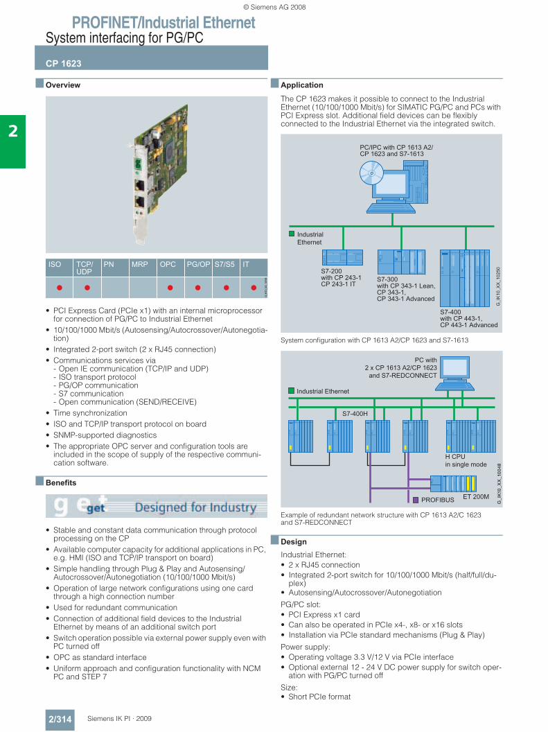
PROFINET/Industrial EthernetSystem interfacing for PG/PC
CP 1623
2/314 Siemens IK PI · 2009
2
■ Overview
• PCI Express Card (PCIe x1) with an internal microprocessor for connection of PG/PC to Industrial Ethernet
• 10/100/1000 Mbit/s (Autosensing/Autocrossover/Autonegotia-tion)
• Integrated 2-port switch (2 x RJ45 connection)• Communications services via
- Open IE communication (TCP/IP and UDP)- ISO transport protocol - PG/OP communication- S7 communication- Open communication (SEND/RECEIVE)
• Time synchronization• ISO and TCP/IP transport protocol on board• SNMP-supported diagnostics• The appropriate OPC server and configuration tools are
included in the scope of supply of the respective communi-cation software.
■ Benefits
• Stable and constant data communication through protocol processing on the CP
• Available computer capacity for additional applications in PC, e.g. HMI (ISO and TCP/IP transport on board)
• Simple handling through Plug & Play and Autosensing/Autocrossover/Autonegotiation (10/100/1000 Mbit/s)
• Operation of large network configurations using one card through a high connection number
• Used for redundant communication• Connection of additional field devices to the Industrial
Ethernet by means of an additional switch port• Switch operation possible via external power supply even with
PC turned off• OPC as standard interface • Uniform approach and configuration functionality with NCM
PC and STEP 7
■ Application
The CP 1623 makes it possible to connect to the Industrial Ethernet (10/100/1000 Mbit/s) for SIMATIC PG/PC and PCs with PCI Express slot. Additional field devices can be flexibly connected to the Industrial Ethernet via the integrated switch.
System configuration with CP 1613 A2/CP 1623 and S7-1613
Example of redundant network structure with CP 1613 A2/C 1623 and S7-REDCONNECT
■ DesignIndustrial Ethernet:• 2 x RJ45 connection• Integrated 2-port switch for 10/100/1000 Mbit/s (half/full/du-
plex)• Autosensing/Autocrossover/Autonegotiation
PG/PC slot:• PCI Express x1 card• Can also be operated in PCIe x4-, x8- or x16 slots• Installation via PCIe standard mechanisms (Plug & Play)
Power supply:• Operating voltage 3.3 V/12 V via PCIe interface• Optional external 12 - 24 V DC power supply for switch oper-
ation with PG/PC turned off
Size:• Short PCIe format
© Siemens AG 2008
PROFINET/Industrial EthernetSystem interfacing for PG/PC
CP 1623
2/315Siemens IK PI · 2009
2
■ Function
User interfaces
OPC interface
As a standard programming interface for the S7 communication and open communication protocols, the OPC server contained in the respective software package can be used to connect the automation technology to OPC-compatible Windows applica-tions (Office, HMI systems, etc.).
Programming interface via C-library
The programming interfaces for the S7 communication, PG/OP communication, and open communication protocols for existing applications are implemented as Dynamic Link Library (DLL) interfaces.
You can find the released compilers in the Readme file of the SIMATIC NET CD products at http://www.siemens.com/automation/csi/net
Software for PG/OP communication
This software makes it possible to program the SIMATIC S5 and S7 controllers via the Industrial Ethernet in conjunction with STEP 5/STEP 7 automation systems.
It is contained in all CP 1623 software packages.
Software for S7 communication (S7-1613 or S7-REDCONNECT)
The S7 interface allows PG/PC applications (e.g. WinCC) and user programs to access the SIMATIC S7 system components. This makes for easy and flexible access to SIMATIC S7 data.
S7 communication offers:
Administrative services • Connection management• Mini database• Trace
Data transfer services • Read/write variables• BSEND/BRECEIVE
H-communication
For redundant S7-communication with a fault-tolerant S7-400 H system, the CP 1613/CP1623 can be used in connection with the S7-REDCONNECT software.
Software for open communication (SEND/RECEIVE) This interface is used for communication between • PG/PC and SIMATIC S5• PG/PC and SIMATIC S7• PG/PC and PG/PC
Open communication (SEND/RECEIVE) offers the following services:• Management services • Dial-up services• Data transfer services
The software is included in the S7-1613 product.
How it works
The protocols up to and including Level 4 (transport) are inde-pendently processed on the module.
The internal memory is available for this purpose and it also provides for a large quantity structure and high communication reliability.
The data exchange between the module and host is done in Master-Mode operation. This means the CP 1623 accesses the physical RAM of the host.
A Windows driver transfers the data between the host system and the CP 1623. The transfer rate to the Industrial Ethernet is detected and automatically switched (Autosensing).
The IT functionality emerges in connection with the PC’s Windows software.
Diagnostics
All MIB-2 objects can be read via SNMP. As a result, the current status of the Ethernet Interface can be called up.
Configuration • The S7 communication and open communication protocols
are configured in STEP 7 or NCM PC.• The configuration tool NCM PC is included in the scope of
supply of the CP 1623 software package.• NCM PC is an integral component of advanced PC configura-
tion.
© Siemens AG 2008
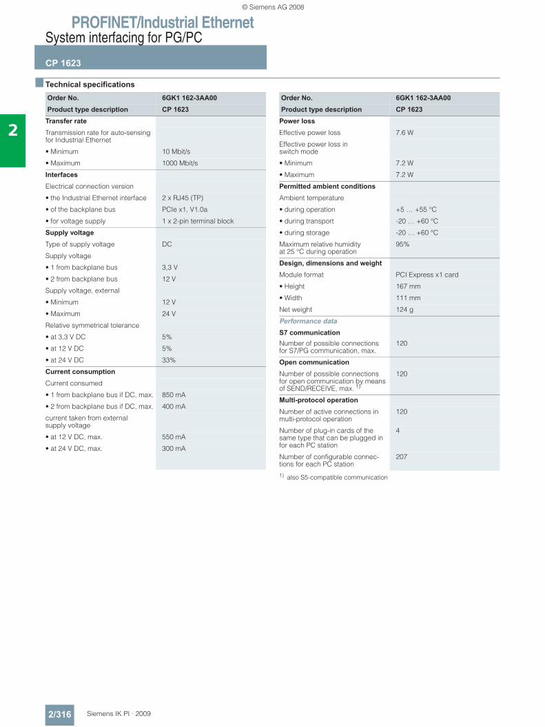
PROFINET/Industrial EthernetSystem interfacing for PG/PC
CP 1623
2/316 Siemens IK PI · 2009
2
■ Technical specifications
1) also S5-compatible communication
Order No. 6GK1 162-3AA00Product type description CP 1623
Transfer rate
Transmission rate for auto-sensing for Industrial Ethernet
• Minimum 10 Mbit/s
• Maximum 1000 Mbit/s
Interfaces
Electrical connection version
• the Industrial Ethernet interface 2 x RJ45 (TP)
• of the backplane bus PCIe x1, V1.0a
• for voltage supply 1 x 2-pin terminal block
Supply voltage
Type of supply voltage DC
Supply voltage
• 1 from backplane bus 3,3 V
• 2 from backplane bus 12 V
Supply voltage, external
• Minimum 12 V
• Maximum 24 V
Relative symmetrical tolerance
• at 3,3 V DC 5%
• at 12 V DC 5%
• at 24 V DC 33%
Current consumption
Current consumed
• 1 from backplane bus if DC, max. 850 mA
• 2 from backplane bus if DC, max. 400 mA
current taken from external supply voltage
• at 12 V DC, max. 550 mA
• at 24 V DC, max. 300 mA
Order No. 6GK1 162-3AA00Product type description CP 1623
Power loss
Effective power loss 7.6 W
Effective power loss in switch mode
• Minimum 7.2 W
• Maximum 7.2 W
Permitted ambient conditions
Ambient temperature
• during operation +5 … +55 °C
• during transport -20 … +60 °C
• during storage -20 … +60 °C
Maximum relative humidity at 25 °C during operation
95%
Design, dimensions and weight Module format PCI Express x1 card
• Height 167 mm
• Width 111 mm
Net weight 124 g
Performance data
S7 communication
Number of possible connections for S7/PG communication, max.
120
Open communication
Number of possible connections for open communication by means of SEND/RECEIVE, max. 1)
120
Multi-protocol operation
Number of active connections in multi-protocol operation
120
Number of plug-in cards of the same type that can be plugged in for each PC station
4
Number of configurable connec-tions for each PC station
207
© Siemens AG 2008
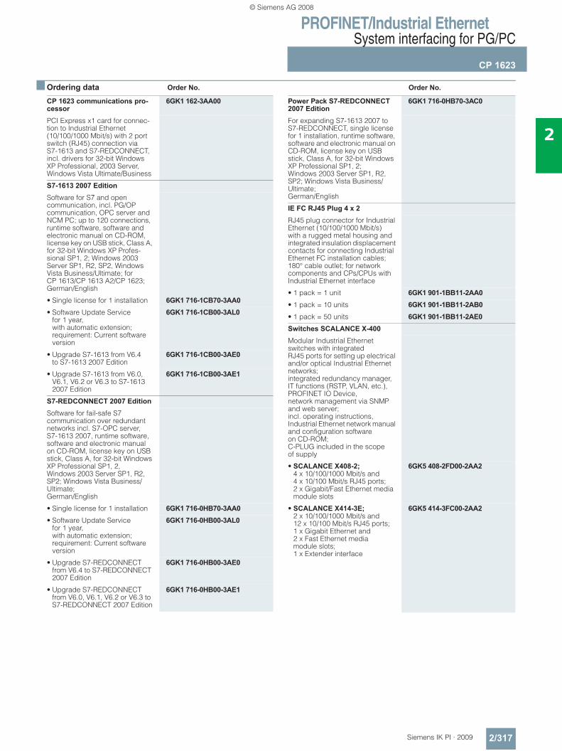
PROFINET/Industrial EthernetSystem interfacing for PG/PC
CP 1623
2/317Siemens IK PI · 2009
2
■ Ordering data Order No. Order No.
CP 1623 communications pro-cessor
6GK1 162-3AA00
PCI Express x1 card for connec-tion to Industrial Ethernet (10/100/1000 Mbit/s) with 2 port switch (RJ45) connection via S7-1613 and S7-REDCONNECT, incl. drivers for 32-bit Windows XP Professional, 2003 Server, Windows Vista Ultimate/Business
S7-1613 2007 EditionSoftware for S7 and open communication, incl. PG/OP communication, OPC server and NCM PC; up to 120 connections, runtime software, software and electronic manual on CD-ROM, license key on USB stick, Class A, for 32-bit Windows XP Profes-sional SP1, 2; Windows 2003 Server SP1, R2, SP2, Windows Vista Business/Ultimate; for CP 1613/CP 1613 A2/CP 1623; German/English
• Single license for 1 installation 6GK1 716-1CB70-3AA0• Software Update Service
for 1 year, with automatic extension; requirement: Current software version
6GK1 716-1CB00-3AL0
• Upgrade S7-1613 from V6.4to S7-1613 2007 Edition
6GK1 716-1CB00-3AE0
• Upgrade S7-1613 from V6.0, V6.1, V6.2 or V6.3 to S7-1613 2007 Edition
6GK1 716-1CB00-3AE1
S7-REDCONNECT 2007 EditionSoftware for fail-safe S7 communication over redundant networks incl. S7-OPC server, S7-1613 2007, runtime software, software and electronic manual on CD-ROM, license key on USB stick, Class A, for 32-bit Windows XP Professional SP1, 2, Windows 2003 Server SP1, R2, SP2; Windows Vista Business/Ultimate; German/English
• Single license for 1 installation 6GK1 716-0HB70-3AA0• Software Update Service
for 1 year, with automatic extension; requirement: Current software version
6GK1 716-0HB00-3AL0
• Upgrade S7-REDCONNECT from V6.4 to S7-REDCONNECT 2007 Edition
6GK1 716-0HB00-3AE0
• Upgrade S7-REDCONNECT from V6.0, V6.1, V6.2 or V6.3 to S7-REDCONNECT 2007 Edition
6GK1 716-0HB00-3AE1
Power Pack S7-REDCONNECT 2007 Edition
6GK1 716-0HB70-3AC0
For expanding S7-1613 2007 to S7-REDCONNECT, single license for 1 installation, runtime software, software and electronic manual on CD-ROM, license key on USB stick, Class A, for 32-bit Windows XP Professional SP1, 2; Windows 2003 Server SP1, R2, SP2; Windows Vista Business/Ultimate; German/English
IE FC RJ45 Plug 4 x 2RJ45 plug connector for Industrial Ethernet (10/100/1000 Mbit/s) with a rugged metal housing and integrated insulation displacement contacts for connecting Industrial Ethernet FC installation cables; 180° cable outlet; for network components and CPs/CPUs with Industrial Ethernet interface
• 1 pack = 1 unit 6GK1 901-1BB11-2AA0• 1 pack = 10 units 6GK1 901-1BB11-2AB0• 1 pack = 50 units 6GK1 901-1BB11-2AE0Switches SCALANCE X-400Modular Industrial Ethernet switches with integrated RJ45 ports for setting up electrical and/or optical Industrial Ethernet networks; integrated redundancy manager, IT functions (RSTP, VLAN, etc.), PROFINET IO Device, network management via SNMP and web server; incl. operating instructions, Industrial Ethernet network manual and configuration software on CD-ROM; C-PLUG included in the scopeof supply
• SCALANCE X408-2;4 x 10/100/1000 Mbit/s and 4 x 10/100 Mbit/s RJ45 ports;2 x Gigabit/Fast Ethernet media module slots
6GK5 408-2FD00-2AA2
• SCALANCE X414-3E;2 x 10/100/1000 Mbit/s and12 x 10/100 Mbit/s RJ45 ports;1 x Gigabit Ethernet and 2 x Fast Ethernet media module slots; 1 x Extender interface
6GK5 414-3FC00-2AA2
© Siemens AG 2008
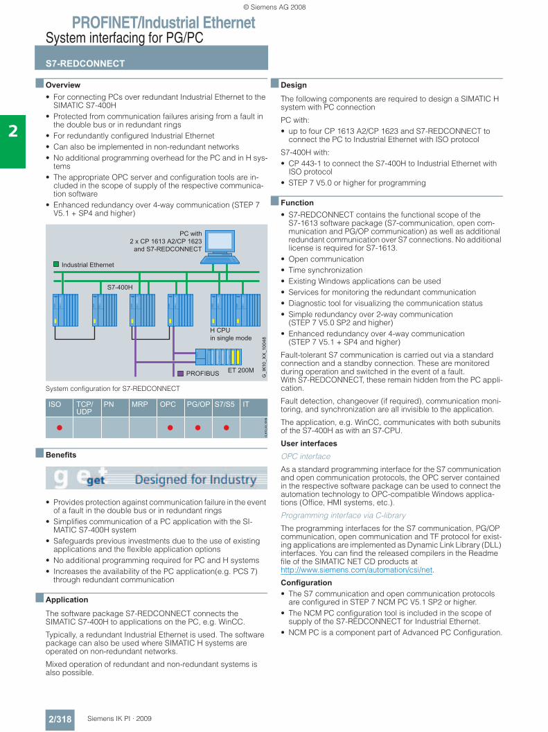
PROFINET/Industrial EthernetSystem interfacing for PG/PC
S7-REDCONNECT
2/318 Siemens IK PI · 2009
2
■ Overview• For connecting PCs over redundant Industrial Ethernet to the
SIMATIC S7-400H• Protected from communication failures arising from a fault in
the double bus or in redundant rings• For redundantly configured Industrial Ethernet • Can also be implemented in non-redundant networks• No additional programming overhead for the PC and in H sys-
tems• The appropriate OPC server and configuration tools are in-
cluded in the scope of supply of the respective communica-tion software
• Enhanced redundancy over 4-way communication (STEP 7 V5.1 + SP4 and higher)
System configuration for S7-REDCONNECT
■ Benefits
• Provides protection against communication failure in the event of a fault in the double bus or in redundant rings
• Simplifies communication of a PC application with the SI-MATIC S7-400H system
• Safeguards previous investments due to the use of existing applications and the flexible application options
• No additional programming required for PC and H systems• Increases the availability of the PC application(e.g. PCS 7)
through redundant communication
■ Application
The software package S7-REDCONNECT connects the SIMATIC S7-400H to applications on the PC, e.g. WinCC.
Typically, a redundant Industrial Ethernet is used. The software package can also be used where SIMATIC H systems are operated on non-redundant networks.
Mixed operation of redundant and non-redundant systems is also possible.
■ Design
The following components are required to design a SIMATIC H system with PC connection
PC with:• up to four CP 1613 A2/CP 1623 and S7-REDCONNECT to
connect the PC to Industrial Ethernet with ISO protocol
S7-400H with:• CP 443-1 to connect the S7-400H to Industrial Ethernet with
ISO protocol• STEP 7 V5.0 or higher for programming
■ Function• S7-REDCONNECT contains the functional scope of the
S7-1613 software package (S7-communication, open com-munication and PG/OP communication) as well as additional redundant communication over S7 connections. No additional license is required for S7-1613.
• Open communication• Time synchronization• Existing Windows applications can be used• Services for monitoring the redundant communication• Diagnostic tool for visualizing the communication status• Simple redundancy over 2-way communication
(STEP 7 V5.0 SP2 and higher)• Enhanced redundancy over 4-way communication
(STEP 7 V5.1 + SP4 and higher)
Fault-tolerant S7 communication is carried out via a standard connection and a standby connection. These are monitored during operation and switched in the event of a fault. With S7-REDCONNECT, these remain hidden from the PC appli-cation.
Fault detection, changeover (if required), communication moni-toring, and synchronization are all invisible to the application.
The application, e.g. WinCC, communicates with both subunits of the S7-400H as with an S7-CPU.
User interfaces
OPC interface
As a standard programming interface for the S7 communication and open communication protocols, the OPC server contained in the respective software package can be used to connect the automation technology to OPC-compatible Windows applica-tions (Office, HMI systems, etc.).
Programming interface via C-library
The programming interfaces for the S7 communication, PG/OP communication, open communication and TF protocol for exist-ing applications are implemented as Dynamic Link Library (DLL) interfaces. You can find the released compilers in the Readme file of the SIMATIC NET CD products at http://www.siemens.com/automation/csi/net.
Configuration • The S7 communication and open communication protocols
are configured in STEP 7 NCM PC V5.1 SP2 or higher.• The NCM PC configuration tool is included in the scope of
supply of the S7-REDCONNECT for Industrial Ethernet.• NCM PC is a component part of Advanced PC Configuration.
© Siemens AG 2008
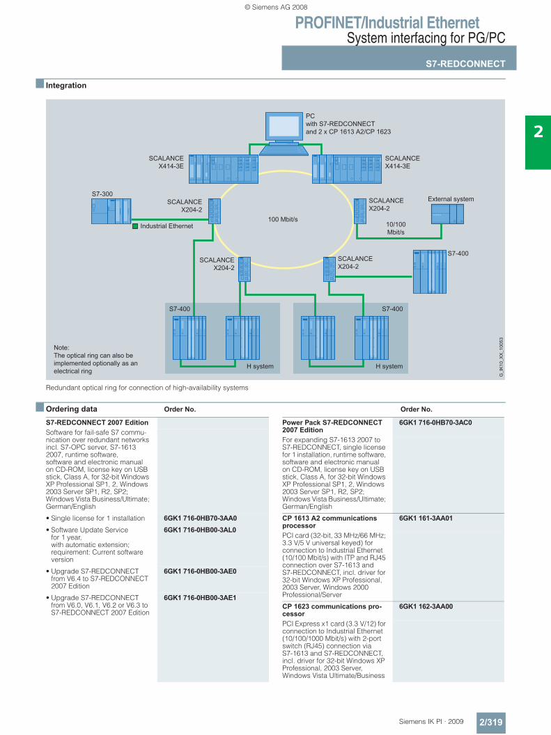
PROFINET/Industrial EthernetSystem interfacing for PG/PC
S7-REDCONNECT
2/319Siemens IK PI · 2009
2
■ Integration
Redundant optical ring for connection of high-availability systems
■ Ordering data Order No. Order No.
100 Mbit/s
S7-REDCONNECT 2007 EditionSoftware for fail-safe S7 commu-nication over redundant networks incl. S7-OPC server, S7-1613 2007, runtime software, software and electronic manual on CD-ROM, license key on USB stick, Class A, for 32-bit Windows XP Professional SP1, 2, Windows 2003 Server SP1, R2, SP2; Windows Vista Business/Ultimate; German/English
• Single license for 1 installation 6GK1 716-0HB70-3AA0• Software Update Service
for 1 year, with automatic extension; requirement: Current software version
6GK1 716-0HB00-3AL0
• Upgrade S7-REDCONNECT from V6.4 to S7-REDCONNECT 2007 Edition
6GK1 716-0HB00-3AE0
• Upgrade S7-REDCONNECT from V6.0, V6.1, V6.2 or V6.3 to S7-REDCONNECT 2007 Edition
6GK1 716-0HB00-3AE1
Power Pack S7-REDCONNECT 2007 Edition
6GK1 716-0HB70-3AC0
For expanding S7-1613 2007 to S7-REDCONNECT, single license for 1 installation, runtime software, software and electronic manual on CD-ROM, license key on USB stick, Class A, for 32-bit Windows XP Professional SP1, 2, Windows 2003 Server SP1, R2, SP2; Windows Vista Business/Ultimate; German/English
CP 1613 A2 communications processor
6GK1 161-3AA01
PCI card (32-bit, 33 MHz/66 MHz; 3.3 V/5 V universal keyed) for connection to Industrial Ethernet (10/100 Mbit/s) with ITP and RJ45 connection over S7-1613 and S7-REDCONNECT, incl. driver for 32-bit Windows XP Professional, 2003 Server, Windows 2000 Professional/Server
CP 1623 communications pro-cessor
6GK1 162-3AA00
PCI Express x1 card (3.3 V/12) for connection to Industrial Ethernet (10/100/1000 Mbit/s) with 2-port switch (RJ45) connection via S7-1613 and S7-REDCONNECT, incl. driver for 32-bit Windows XP Professional, 2003 Server, Windows Vista Ultimate/Business
© Siemens AG 2008
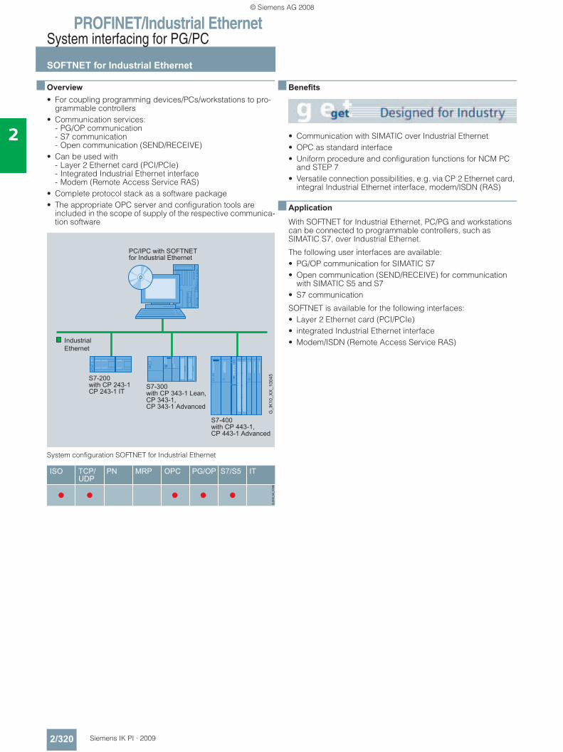
PROFINET/Industrial EthernetSystem interfacing for PG/PC
SOFTNET for Industrial Ethernet
2/320 Siemens IK PI · 2009
2
■ Overview• For coupling programming devices/PCs/workstations to pro-
grammable controllers• Communication services:
- PG/OP communication- S7 communication- Open communication (SEND/RECEIVE)
• Can be used with - Layer 2 Ethernet card (PCI/PCIe)- Integrated Industrial Ethernet interface- Modem (Remote Access Service RAS)
• Complete protocol stack as a software package• The appropriate OPC server and configuration tools are
included in the scope of supply of the respective communica-tion software
System configuration SOFTNET for Industrial Ethernet
■ Benefits
• Communication with SIMATIC over Industrial Ethernet• OPC as standard interface• Uniform procedure and configuration functions for NCM PC
and STEP 7• Versatile connection possibilities, e.g. via CP 2 Ethernet card,
integral Industrial Ethernet interface, modem/ISDN (RAS)
■ Application
With SOFTNET for Industrial Ethernet, PC/PG and workstations can be connected to programmable controllers, such as SIMATIC S7, over Industrial Ethernet.
The following user interfaces are available:• PG/OP communication for SIMATIC S7• Open communication (SEND/RECEIVE) for communication
with SIMATIC S5 and S7• S7 communication
SOFTNET is available for the following interfaces:• Layer 2 Ethernet card (PCI/PCIe)• integrated Industrial Ethernet interface• Modem/ISDN (Remote Access Service RAS)
© Siemens AG 2008
PROFINET/Industrial EthernetSystem interfacing for PG/PC
SOFTNET for Industrial Ethernet
2/321Siemens IK PI · 2009
2
■ Function
With SOFTNET, the complete protocol stack is processed in the PC.
This architecture means that in contrast to the CP 1613 or CP 1623 products, the performance of the SOFTNET packages is dependent on the configuration or loading of the PC used.
The IT functionality is established in connection with the inter-faces and the PC’s Windows software.
User interfaces
OPC interface
As a standard programming interface for the S7 communication and open communication protocols, the OPC server contained in the respective software package can be used to connect the automation technology to OPC-compatible Windows applica-tions (Office, HMI systems, etc.).
Programming interface via C-library
The programming interfaces for the S7 communication, PG/OP communication, and open communication protocols for existing applications are implemented as a Dynamic Link Library (DLL).
You can find the released compilers in the Readme file of the SIMATIC NET CD products at http://www.siemens.com/automation/csi/net.
Software for PG/OP communication
This software makes it possible to program the SIMATIC S5 and S7 controllers via the Industrial Ethernet in conjunction with STEP 5/STEP 7.
Software for S7 communication
SIMATIC S7 system components communicate with each other using S7 communication functions.
The S7 communication can be based optionally on the ISO protocol or the TCP/IP protocol.
S7 communication offers the following services:• Administrative services• S7 connection management services• Variable services• VFD (Virtual Field Device) services• Trace and mini database
Open communication (SEND/RECEIVE)
This interface based on Layer 4 (ISO Transport or TCP/IP with RFC 1006) is used for communication between • PG/PC and SIMATIC S5• PG/PC and SIMATIC S7• PG/PC and PG/PC
Open communication (SEND/RECEIVE) offers the following services:• Management services• Dial-up services• Data transfer services
Configuration • The complete configuration of the S7 communication and
open communication protocols takes place in STEP 7 or SIMATIC NCM PC V5.1 SP2 or higher.
• The NCM PC configuration tool is included in the scope of delivery of the corresponding packages.
System configuration with SOFTNET-S7 Lean for Industrial Ethernet and S7-200
© Siemens AG 2008
PROFINET/Industrial EthernetSystem interfacing for PG/PC
SOFTNET for Industrial Ethernet
2/322 Siemens IK PI · 2009
2
■ Technical specifications
■ Ordering data Order No.
Product type description SOFTNET forIndustrial Ethernet
Performance dataS7 and PG/OP communication (number of operable connections)
• SOFTNET-S7 max. 64
• SOFTNET-S7 Lean max. 8
SOFTNET Edition 2007 for Industrial EthernetSoftware for S7 and open communication, incl. OPC server, PG/OP communication and NCM PC, runtime software, software and electronic manual on CD-ROM, license key on USB stick, Class A, for 32-bit Windows XP Professional SP1, 2, Windows 2003 Server SP1, R2, SP2, Windows Vista Business/Ultimate; German/English
SOFTNET-S7 2007 Editionfor Industrial Ethernetup to 64 connections
• Single license for 1 installation 6GK1 704-1CW70-3AA0• Software Update Service
for 1 year, with automatic extension; requirement: Current software version
6GK1 704-1CW00-3AL0
• Upgrade from V6.4 to 2007 edition
6GK1 704-1CW00-3AE0
• Upgrade from V6.0, V6.1, V6.2 or V6.3 to 2007 Edition
6GK1 704-1CW00-3AE1
SOFTNET-S7 Lean 2007 Edition for Industrial Ethernetup to 8 connections
• Single license for 1 installation 6GK1 704-1LW70-3AA0• Software Update Service
for 1 year, with automatic extension; requirement: Current software version
6GK1 704-1LW00-3AL0
• Upgrade from V6.4 to 2007 Edition
6GK1 704-1LW00-3AE0
• Upgrade from V6.0, V6.1, V6.2 or V6.3 to 2007 Edition
6GK1 704-1LW00-3AE1
SOFTNET-PG Edition 2007for Industrial Ethernet
6GK1 704-1LW00-3AE1
Software for PG/OP-communica-tion; runtime software, software and electronic manual on CD-ROM, license key on USB stick, Class A, for 32-bit Windows XP Professional SP1, 2, Windows 2003 Server SP1, R2, SP2, Win-dows Vista Business/Ultimate; German/English
• Single license for 1 installation 6GK1 704-1PW70-3AA0• Software Update Service
for 1 year, with automatic extension; requirement: Current software version
6GK1 704-1PW00-3AL0
• Upgrade from V6.4to 2007 Edition
6GK1 704-1PW00-3AE0
• Upgrade from V6.0, V6.1, V6.2 or V6.3 to 2007 Edition
6GK1 704-1PW00-3AE1
© Siemens AG 2008
PROFINET/Industrial EthernetSystem interfacing for PG/PC
SOFTNET PN IO
2/323Siemens IK PI · 2009
2
■ Overview
PC with SOFTNET PN IO as PROFINET IO Controller
• Software with PROFINET IO Controller function for coupling PG/PC and IPC with PROFINET IO Devices
• Possible applications: - PC-based control systems - HMI systems - Test applications
• Communication services: - PROFINET IO Controller
• Can be used with - Integrated interfaces of SIMATIC PG/PC- You can find more information about the environment of use
at www.siemens.com/simatic-net/ik-info• Cost-effective solution for the low-end performance range• OPC server for I/O interfacing over PROFINET included in
scope of supply
■ Benefits
• Cost-effective interfacing of field devices to Industrial Ethernet with PROFINET
• Simple porting of the application with OPC as a standard interface
• High-performance IO data access through RT Base interface for linking into C/C++ applications
• Simple changeover from PROFIBUS modules CP 5613 A2/CP 5614 A2 with DP-Base interface to PROFINET through IO-Base interface
• Uniform procedure and configuration functions for NCM PC and STEP 7
PC/IPC withSOFTNET PN IO
z.B. S7-300 withCP 342-5 as Slave
PROFINET Communication
OPC XML DAas Webservice
G_I
K10
_XX
_100
73
InternetIntranet
ET 200S
SIMATIC NETOPC-Scout
COM/DCOM
WinCCOPC-Client
Microsoft OfficeOPC-Client
OPC XMLWebclient
PN IO OPC-Server
SOFTNET PN IO
© Siemens AG 2008
PROFINET/Industrial EthernetSystem interfacing for PG/PC
SOFTNET PN IO
2/324 Siemens IK PI · 2009
2
■ Application
Using SOFTNET PN IO, PCs can be linked with PROFINET field devices including PC-based PN IO devices (e.g. with CP 1616 or CP 1604) via Industrial Ethernet.
SOFTNET PN IO is available for the following interfaces:• Integrated interfaces of SIMATIC PG/PC
■ Function
PROFINET communication • PROFINET IO-Controller
Connection of field devices to Industrial Ethernet with PROFINET
User interfaces • OPC interface
The supplied OPC server can be used as a standard program-ming interface for PROFINET IO-Controller to link automation applications to OPC-capable Windows applications (Office, HMI systems, etc.).
• Programming interface through C library;For applications that want to use the PROFINET IO-Controller functionality directly in C/C++, the IO-Base interface can be used. This interface is of a similar design to the DP Base inter-face of PROFIBUS modules CP 5613 A2 and CP 5614 A2. It is therefore possible to port existing PROFIBUS DP master ap-plications to PN IO-Controller applications.
• You can find the released compilers in the Readme file of the SIMATIC NET CD products at http://www.siemens.com/automation/csi/net.
SOFTNET PN IO and CP 1616 use compatible functions of the IO-Base interface.
Mode of operation
With SOFTNET, the complete protocol stack is processed in the PC. This architecture means that the performance depends on the configuration of the PC used or the loading on the PC.
Configuration • Configuration is performed with STEP 7/NCM PC, V5.3 SP1
and higher
■ Technical specifications
■ Ordering data Order No.
Order No.Product type description SOFTNET PN IO
Performance data • Number of operable IO devices Max. 64
• Number of external IO-lines in one central rack
Max. 1
• Size of IO data areas overall- I/O input area Max. 2 KB- I/O output area Max. 2 KB
• Size of I/O data area per connected I/O device- I/O input range Max. 1433 byte- I/O output range Max. 1433 byte
SOFTNET PN IO, 2007 EditionSoftware for PROFINET IO controller with OPC server and NCM PC; runtime software, software and electronic manual on CD-ROM, license key on USB stick, Class A, for 32-bit Windows XP Professional SP1, 2, Windows 2003 Server SP1, R2, SP2; German/English
• Single license for one installation 6GK1 704-1HW70-3AA0• Software Update Service
for 1 year, with automatic extension; requirement: Current software version
6GK1 704-1HW00-3AL0
• Upgrade SOFTNET-PN IO from V6.4 to SOFTNET-PN IO, 2007 Edition
6GK1 704-1HW00-3AE0
• Upgrade SOFTNET-PN IO from V6.0, V6.1, V6.2 or V6.3 to SOFTNET-PN IO 2007 Edition
6GK1 704-1HW00-3AE1
© Siemens AG 2008
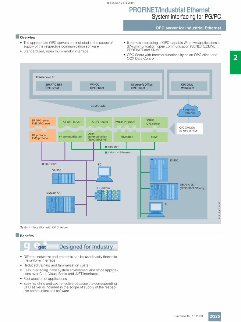
PROFINET/Industrial EthernetSystem interfacing for PG/PC
OPC server for Industrial Ethernet
2/325Siemens IK PI · 2009
2
■ Overview• The appropriate OPC servers are included in the scope of
supply of the respective communication software• Standardized, open multi-vendor interface
• It permits interfacing of OPC-capable Windows applications to S7-communication, open communication (SEND/RECEIVE), PROFINET and SNMP.
• OPC Scout with browser functionality as an OPC client and OCX Data Control
System integration with OPC server
■ Benefits
• Different networks and protocols can be used easily thanks to the uniform interface
• Reduced training and familiarization costs• Easy interfacing in the system environment and office applica-
tions over C++, Visual Basic and .NET interfaces• Fast creation of applications• Easy handling and cost-effective because the corresponding
OPC server is included in the scope of supply of the respec-tive communications software
SIMATIC S5(SEND/RECEIVE only)
DP OPC serverFMS OPC server S7 OPC server S5 OPC server PN IO OPC server
SNMPOPC server
OPC XML-DAas Web service
DP protocolFMS protocol
Opencommunication(SEND/RECEIVE)
S7 communication
G_I
K10
_X
X 1
010
3
PC/Windows PC
PC
S7-400
SIMATIC S5
S7-300
ET 200pro
PC
SNMPPROFINET
COM/DCOM
SIMATIC NETOPC-Scout
WinCCOPC-Client
Microsoft OfficeOPC-Client
OPC XMLWebclient
InternetIntranet
PROFIBUS
Industrial Ethernet
PROFINET
© Siemens AG 2008
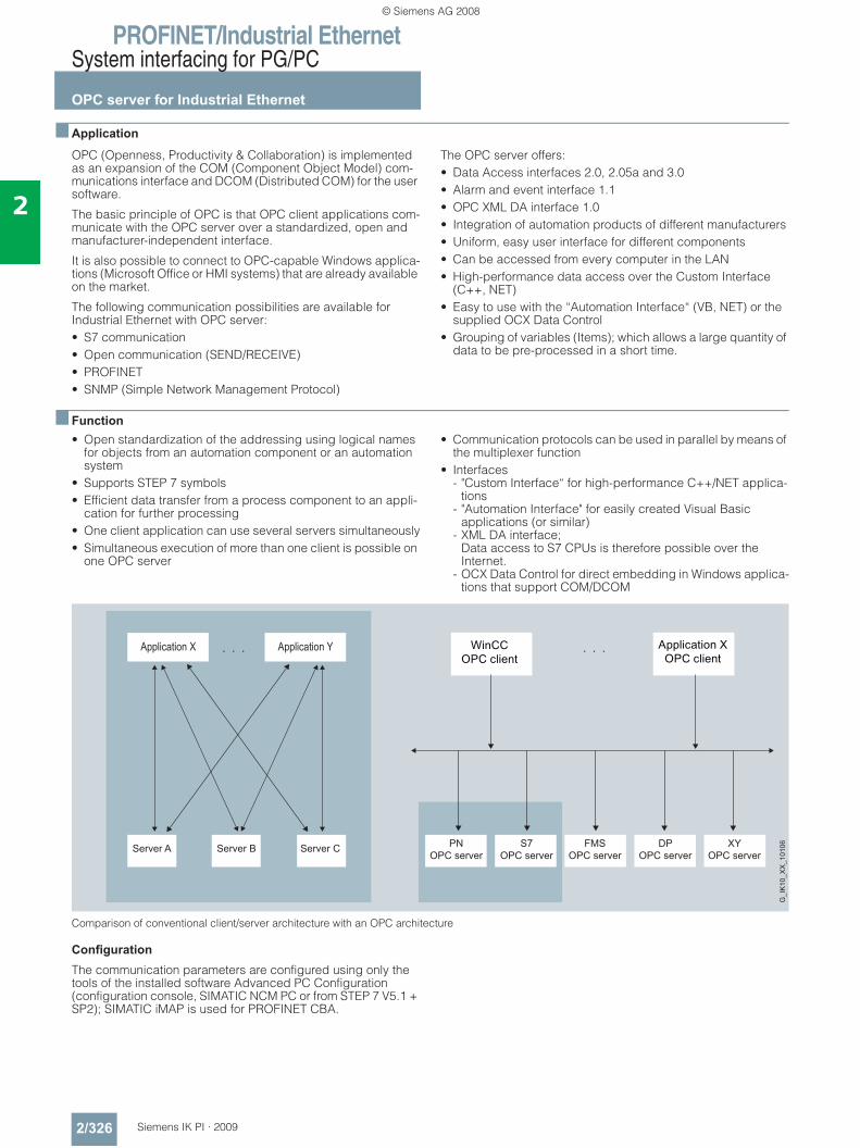
PROFINET/Industrial EthernetSystem interfacing for PG/PC
OPC server for Industrial Ethernet
2/326 Siemens IK PI · 2009
2
■ Application
OPC (Openness, Productivity & Collaboration) is implemented as an expansion of the COM (Component Object Model) com-munications interface and DCOM (Distributed COM) for the user software.
The basic principle of OPC is that OPC client applications com-municate with the OPC server over a standardized, open and manufacturer-independent interface.
It is also possible to connect to OPC-capable Windows applica-tions (Microsoft Office or HMI systems) that are already available on the market.
The following communication possibilities are available for Industrial Ethernet with OPC server:• S7 communication• Open communication (SEND/RECEIVE)• PROFINET• SNMP (Simple Network Management Protocol)
The OPC server offers:• Data Access interfaces 2.0, 2.05a and 3.0• Alarm and event interface 1.1• OPC XML DA interface 1.0• Integration of automation products of different manufacturers• Uniform, easy user interface for different components• Can be accessed from every computer in the LAN• High-performance data access over the Custom Interface
(C++, NET)• Easy to use with the “Automation Interface“ (VB, NET) or the
supplied OCX Data Control• Grouping of variables (Items); which allows a large quantity of
data to be pre-processed in a short time.
■ Function• Open standardization of the addressing using logical names
for objects from an automation component or an automation system
• Supports STEP 7 symbols• Efficient data transfer from a process component to an appli-
cation for further processing• One client application can use several servers simultaneously• Simultaneous execution of more than one client is possible on
one OPC server
• Communication protocols can be used in parallel by means of the multiplexer function
• Interfaces - "Custom Interface“ for high-performance C++/NET applica-
tions- "Automation Interface" for easily created Visual Basic
applications (or similar)- XML DA interface;
Data access to S7 CPUs is therefore possible over the Internet.
- OCX Data Control for direct embedding in Windows applica-tions that support COM/DCOM
Comparison of conventional client/server architecture with an OPC architecture
Configuration
The communication parameters are configured using only the tools of the installed software Advanced PC Configuration (configuration console, SIMATIC NCM PC or from STEP 7 V5.1 + SP2); SIMATIC iMAP is used for PROFINET CBA.
PNOPC server
S7OPC server
FMSOPC server
DPOPC server
XYOPC server
Server A Server CServer B
G_I
K10
_XX
_101
06
© Siemens AG 2008
PROFINET/Industrial EthernetSystem interfacing for PG/PC
OPC server for Industrial Ethernet
2/327Siemens IK PI · 2009
2
■ Technical specifications
1) also S5-compatible communication
■ Ordering data Order No.
Product type description OPC server for Industrial Ethernet
Programming • Synchronous and asynchronous reading and writing of variables
• Monitoring of variables using the OPC server with a signal to the client when a change occurs
• Use of quantity operations;so a large amount of data can be processed in a short time.
Interfaces • Custom Interface (C++, NET)for high OPC performance
• Automation Interface(VB, Excel, Access, Delphi, ...) for ease-of-use
• Graphics with OCX for configuring instead of programming
• OPC XML-Interface for Data Access
Products include OPC servers for:Industrial Ethernet
• S7-1613, SOFTNET-S7for Industrial Ethernet, SOFTNET-S7 Lean
S7-OPC server for S7 communication, XML-DA
S5-OPC server for open communication1) communication, XML-DA
SNMP OPC server for SNMP protocol access; XML-DA
PROFINET
• SOFTNET PN IO PN IO OPC server for PROFINET IO communication; XML-DA
• PN CBA OPC server PN CBA OPC server for access to CBA components; XML-DA
PROFIBUS
• DP-5613, SOFTNET-DP, SOFTNET-DP slave
DP-OPC server for PROFIBUS DP communication; XML-DA
• FMS-5613 FMS-OPC server for PROFIBUS FMS communication; XML-DA
PN CBA OPC Server, 2007 EditionPROFINET OPC server for CBA; runtime software, software and electronic manual on CD-ROM, license key on USB stick, Class A, for 32-bit Windows XP Professional SP1, 2; Windows 2003 Server SP1, R2, SP2; Windows Vista Business/Ultimate; German/English
• Single license for 1 installation 6GK1 706-0HB70-3AA0• Software Update Service
for 1 year, with automatic extension; requirement: Current software version
6GK1 706-0HB00-3AL0
• Upgrade from Edition 2006 to Edition 2007, single license
6GK1 706-0HB00-3AE0
• Upgrade from V6.0to Edition 2007, single license
6GK1 706-0HB00-3AE1
SNMP OPC Server 2007 EditionIncluding MIB compiler; single license for 1 installation of the runtime software, software and electronic manual on CD-ROM; license key on USB stick, Class A, for 32-bit Windows XP Profes-sional SP1, 2; Windows 2003 Server SP1, R2, SP2; Windows Vista Business/Ultimate; German/English
• Basic 2007 Administration of up to 20 IP addresses; Single license for 1 installation
6GK1 706-1NW70-3AA0
- Upgrade from Edition 2006 to Edition 2007, single license
6GK1 706-1NW00-3AE0
- Upgrade from V6.0 toEdition 2007, single license
6GK1 706-1NW00-3AE1
• Extended 2007 Administration of up to 200 IP addresses
6GK1 706-1NX70-3AA0
- Upgrade from Edition 2006 to Edition 2007, single license
6GK1 706-1NX00-3AE0
- Upgrade from V6.0 to Edition 2007, single license
6GK1 706-1NX00-3AE1
• Power Pack 2007; upgrade from SNMP OPC Server Basic to SNMP OPC Server Extended 2007 Edition
6GK1 706-1NW70-3AC0
© Siemens AG 2008
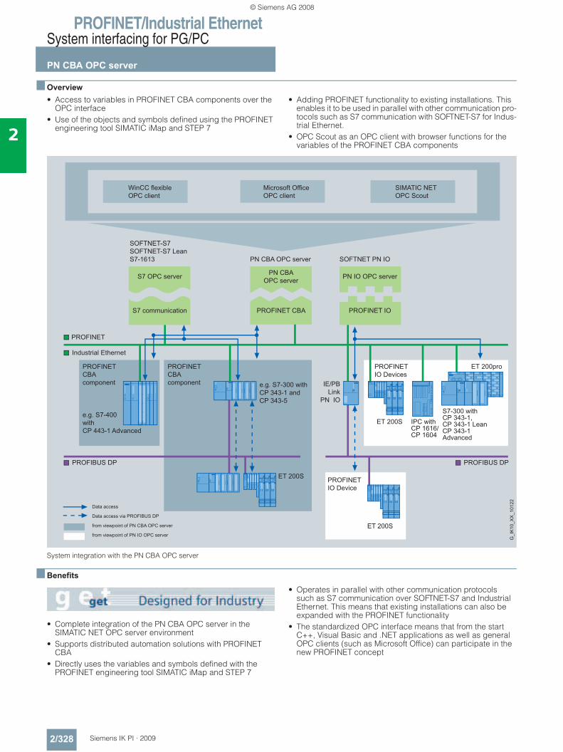
PROFINET/Industrial EthernetSystem interfacing for PG/PC
PN CBA OPC server
2/328 Siemens IK PI · 2009
2
■ Overview• Access to variables in PROFINET CBA components over the
OPC interface• Use of the objects and symbols defined using the PROFINET
engineering tool SIMATIC iMap and STEP 7
• Adding PROFINET functionality to existing installations. This enables it to be used in parallel with other communication pro-tocols such as S7 communication with SOFTNET-S7 for Indus-trial Ethernet.
• OPC Scout as an OPC client with browser functions for the variables of the PROFINET CBA components
System integration with the PN CBA OPC server
■ Benefits
• Complete integration of the PN CBA OPC server in the SIMATIC NET OPC server environment
• Supports distributed automation solutions with PROFINET CBA
• Directly uses the variables and symbols defined with the PROFINET engineering tool SIMATIC iMap and STEP 7
• Operates in parallel with other communication protocols such as S7 communication over SOFTNET-S7 and Industrial Ethernet. This means that existing installations can also be expanded with the PROFINET functionality
• The standardized OPC interface means that from the start C++, Visual Basic and .NET applications as well as general OPC clients (such as Microsoft Office) can participate in the new PROFINET concept
Data access
Data access via PROFIBUS DP
from viewpoint of PN CBA OPC server
from viewpoint of PN IO OPC server
WinCC flexibleOPC client
Microsoft OfficeOPC client
SIMATIC NETOPC Scout
SOFTNET-S7SOFTNET-S7 LeanS7-1613 SOFTNET PN IOPN CBA OPC server
PROFINET IO
PN IO OPC server
PROFINET CBA
PN CBAOPC server
S7 communication
S7 OPC server
PROFINETCBAcomponent
e.g. S7-400withCP 443-1 Advanced
PROFINETCBAcomponent
ET 200S PROFINETIO Device
ET 200S
PROFINETIO Devices
IE/PBLink
PN IO
e.g. S7-300 withCP 343-1 andCP 343-5
G_I
K10
_XX
_101
22
PROFINET
PROFIBUS DP
Industrial Ethernet
PROFIBUS DP
© Siemens AG 2008
PROFINET/Industrial EthernetSystem interfacing for PG/PC
PN CBA OPC server
2/329Siemens IK PI · 2009
2
■ Application• The PN CBA OPC server (PROFINET OPC server) is the
PC application interface for communication over Industrial Ethernet with PROFINET CBA components.
• OPC client applications communicate with the PN CBA OPC server over a standardized, open and manufacturer-indepen-dent interface.
• The PN CBA OPC server offers: - Standardized access for OPC-capable applications and
Windows applications (e.g. Microsoft Office) to variables that are available on the component interface of the PROFINET CBA components.
- High-performance data access over the "Custom Interface" (C++, .NET)
- Easy to use with the "Automation Interface" (VB, .NET) and the OCX Data Control included in the scope of supply.
- Internet communication over OPC XML DA Interface• Based on the PROFINET standard. This standard supports:
- Component technology in automation engineering- Graphical configuration of communication between intelli-
gent devices instead of complex programming- Manufacturer-independent, plant-wide engineering- Vertical integration, i.e. the user can access the interface
variables of a PROFINET component by means of IT standards and an OPC interface over Industrial Ethernet.
■ Function• The PN CBA OPC server communicates with PROFINET CBA
components over Industrial Ethernet by means of DCOM protocol
• Open standardization of the addressing using logical names for objects from an automation component or an automation system
• Operation in parallel with other protocols is possible, such as - S7 communication- Open communication (SEND/RECEIVE)
• Efficient data transfer from a process component to an application for further processing: - Synchronous and asynchronous reading and writing of
variables- Monitoring of variables using the OPC server with a signal to
the client when a change occurs- Use of quantity operations; a large amount of data can be
processed in a short time.• Simultaneous execution of more than one client is possible on
one OPC server• OPC Scout as an OPC client with browser functions for all
interface variables of the PROFINET CBA components
User interfaces • "Custom Interface“ for high-performance C++/.NET applica-
tions• "Automation Interface" for easily created Visual Basic
applications (or similar)• XML DA interface;
Data access to S7 CPUs is therefore possible over the Internet.
• OCX Data Control for direct embedding in Windows applica-tions that support COM/DCOM
Configuration • For configuring the PROFINET communication, a separate
engineering tool SIMATIC iMap is required. This tool is offered as an option package with STEP 7.
• With SIMATIC iMAP, the communication links between PROFINET CBA components are graphically configured. In addition to the interconnection data, the engineering tool also creates the data used to access the interface variables over the PN CBA OPC server from visualization systems or office applications.
© Siemens AG 2008
PROFINET/Industrial EthernetSystem interfacing for PG/PC
PN CBA OPC server
2/330 Siemens IK PI · 2009
2
■ Technical specifications
■ Ordering data Order No.
■ More information
Additional in formation can be found in the Internet under:http://www.siemens.com/cba
Product type description PN CBA OPC serverProgramming • Open and standardized
• Synchronous and asynchronous reading and writing of variables
• Monitoring of variables by the OPC server with an alarm mes-sage to the client in the case of a change
• Use of batch operations, so a large volume of data can be processed in a short time
Interfaces • Custom Interface (C++, .NET)• Automation Interface
(Visual Basic, Excel, Access,...)• OPC Data Control
• OPC XML Interface for Data Access
Protocols • DCOM protocol
Configuration Configuring software for PROFINET SIMATIC iMap
PROFINET communication (CBA)• Number of communication
partnersmax. 228
• Number of connections max. 10,000
PN CBA OPC Server, 2007 EditionPROFINET OPC server for CBA; runtime software, software and electronic manual on CD-ROM, license key on USB stick, Class A, for 32-bit Windows XP Profes-sional SP1, 2, Windows 2003 Server SP1, R2, SP2, Windows Vista Business/Ultimate; German/English
• Single license for 1 installation 6GK1 706-0HB70-3AA0• Software Update Service
for 1 year, with automatic extension; requirement: Current software version
6GK1 706-0HB00-3AL0
• Upgrade of PN CBA OPC Server from V6.4 to PN CBA OPC Server 2007 Edition
6GK1 706-0HB00-3AE0
• Upgrade of PN CBA OPC Server from V6.0, V6.1, V6.2 or V6.3 to PN CBA OPC Server 2007 Edition
6GK1 706-0HB00-3AE1
Software iMap V3.0for configuring PROFINET CBA
Requirement: Windows 2000 Prof. with Service Pack 4 or later or Windows XP Prof. with Service Pack 1 or later or Windows 2003 Server with Service Pack 1 or later; on PG or PC with Pentium processor, min. 1 GHz; STEP 7 V5.3 or later with Service Pack 3, PN OPC Server V6.3 or later
Type of supply: German, English with electronic documentation
• Single license 6ES7 820-0CC04-0YA5• Software Update Service 6ES7 820-0CC01-0YX2• Upgrade to V3.0, single license 6ES7 820-0CC04-0YE5
© Siemens AG 2008
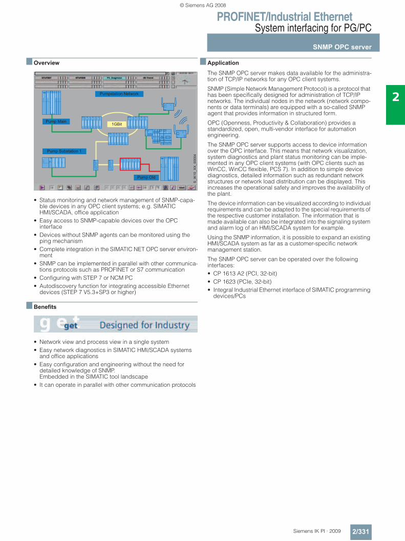
PROFINET/Industrial EthernetSystem interfacing for PG/PC
SNMP OPC server
2/331Siemens IK PI · 2009
2
■ Overview
• Status monitoring and network management of SNMP-capa-ble devices in any OPC client systems; e.g. SIMATIC HMI/SCADA, office application
• Easy access to SNMP-capable devices over the OPC interface
• Devices without SNMP agents can be monitored using the ping mechanism
• Complete integration in the SIMATIC NET OPC server environ-ment
• SNMP can be implemented in parallel with other communica-tions protocols such as PROFINET or S7 communication
• Configuring with STEP 7 or NCM PC• Autodiscovery function for integrating accessible Ethernet
devices (STEP 7 V5.3+SP3 or higher)
■ Benefits
• Network view and process view in a single system• Easy network diagnostics in SIMATIC HMI/SCADA systems
and office applications• Easy configuration and engineering without the need for
detailed knowledge of SNMP. Embedded in the SIMATIC tool landscape
• It can operate in parallel with other communication protocols
■ Application
The SNMP OPC server makes data available for the administra-tion of TCP/IP networks for any OPC client systems.
SNMP (Simple Network Management Protocol) is a protocol that has been specifically designed for administration of TCP/IP networks. The individual nodes in the network (network compo-nents or data terminals) are equipped with a so-called SNMP agent that provides information in structured form.
OPC (Openness, Productivity & Collaboration) provides a standardized, open, multi-vendor interface for automation engineering.
The SNMP OPC server supports access to device information over the OPC interface. This means that network visualization, system diagnostics and plant status monitoring can be imple-mented in any OPC client systems (with OPC clients such as WinCC, WinCC flexible, PCS 7). In addition to simple device diagnostics, detailed information such as redundant network structures or network load distribution can be displayed. This increases the operational safety and improves the availability of the plant.
The device information can be visualized according to individual requirements and can be adapted to the special requirements of the respective customer installation. The information that is made available can also be integrated into the signaling system and alarm log of an HMI/SCADA system for example.
Using the SNMP information, it is possible to expand an existing HMI/SCADA system as far as a customer-specific network management station.
The SNMP OPC server can be operated over the following interfaces:• CP 1613 A2 (PCI, 32-bit)• CP 1623 (PCIe, 32-bit)• Integral Industrial Ethernet interface of SIMATIC programming
devices/PCs
Pumpstation Network
1GBitPump Main
Pump Substation 1
Pump Old
S_I
K10
_XX
_000
04
© Siemens AG 2008
PROFINET/Industrial EthernetSystem interfacing for PG/PC
SNMP OPC server
2/332 Siemens IK PI · 2009
2
■ Function
The SNMP OPC server supports access to SNMP-capable devices in the OPC client systems. For all configured TCP/IP devices that are not SNMP-capable, one OPC variable for sign-of-life monitoring (ICMP-PING) is offered.
Read access and in part write access to the respective device information is possible. Thus the diagnosis of individual devices is possible as well as diagnosis of the complete plant and device characteristics can be actively controlled.
STEP 7/NCM PC contains an MIB compiler (Management Information Base) for integrating SNMP-enabled devices. This allows device profiles to be created on the basis of an MIB file
Devices with SNMP agents:
SIMATIC NET devices that feature special SNMP agents such as switches, WLAN Access Points and Industrial Ethernet PC and S7 communication processors are already included complete with their device profiles.
Thanks to MIB compilers (Management Information Base), other SNMP-enabled devices can be integrated into the OPC config-uration through loading of MIBs in accordance with the SMI V1 and SMI V2 standard from STEP 7 V5.4.
Devices with IP addresses without SNMP agents:
Devices without SNMP agents can be monitored using the ping mechanism. The user can edit and save device-specific infor-mation such as the contact person, site and device description for this purpose.• Any SNMP-capable devices such as printers or PCs can be
depicted using a predefined library. • The devices are integrated into the desktop of a client
application using preconfigured ActiveX Controls.
The predefined device profiles and the associated ActiveX controls allow easy administration of the devices in OPC client applications. Individual expansions can also be implemented.
The SNMP OPC server is integrated in the SIMATIC NET OPC server. The OPC Scout is also included in the functional scope for browsing the displayed SNMP information. The SNMP OPC server can use, for example, PROFINET or S7 communication at the same time as PROFIBUS and Industrial Ethernet communi-cation. This means that existing installations can also be ex-panded with SNMP functionality. The SNMP OPC server also enables several clients to execute simultaneously on one server.
User interfaces • "Custom Interface“ for high-performance C++ applications• "Automation Interface" for easily created Visual Basic applica-
tions (or similar).• OPC Data Control for easy creation of client applications by
configuring ActiveX controls• OPC Alarms & Events (Subset)• Preconfigured ActiveX controls for the device profile used
Configuration
The NCM PC configuration tool is included in the scope of supply of the CP 1613/1623 software packages and SOFTNET for Industrial Ethernet.
■ Ordering data Order No.
SNMP OPC Server 2007 EditionIncluding MIB compiler; single license for 1 installation of the runtime software, software and electronic manual on CD-ROM; license key on USB stick, Class A, for 32-bit Windows XP Professional SP1, 2, Windows 2003 Server SP1, R2, SP2, Windows Vista Business/Ultimate; German/English
• Basic 2007 Administration of up to 20 IP addresses; Single license for 1 installation
6GK1 706-1NW70-3AA0
- Upgrade of SNMP OPC Server Basic from V6.4 to SNMP OPC Server Basic 2007 Edition
6GK1 706-1NW00-3AE0
- Upgrade of SNMP OPC Server Basic from V6.0, V6.1, V6.2 or V6.3 to SNMP OPC Server Basic 2007 Edition
6GK1 706-1NW00-3AE1
• Extended 2007 Administration of up to 200 IP addresses
6GK1 706-1NX70-3AA0
- Upgrade of SNMP OPC Server Extended from V6.4 to SNMP OPC Server Extended 2007 Edition
6GK1 706-1NX00-3AE0
- Upgrade of SNMP OPC Server Extended from V6.0, V6.1, V6.2 or V6.3 to SNMP OPC Server Extended 2007 Edition
6GK1 706-1NX00-3AE1
• Power Pack 2007; upgrade from SNM OPC Server Basic to SNM OPC Server Extended 2007 Edition
6GK1 706-1NW70-3AC0
© Siemens AG 2008
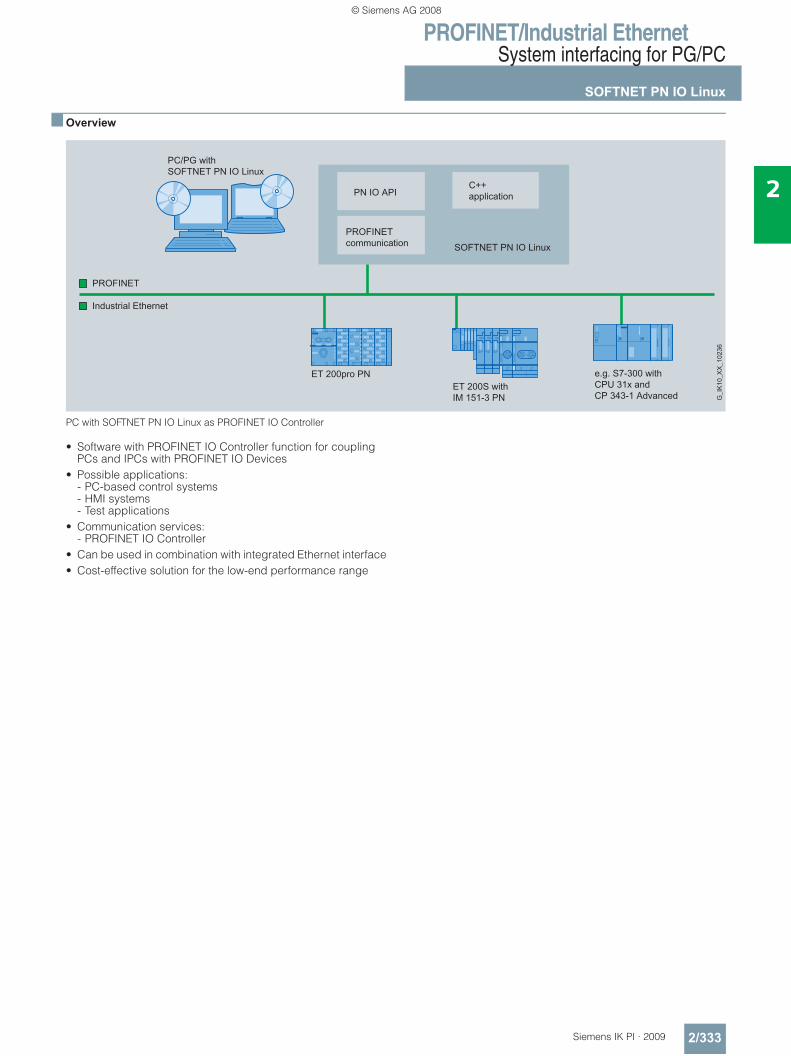
PROFINET/Industrial EthernetSystem interfacing for PG/PC
SOFTNET PN IO Linux
2/333Siemens IK PI · 2009
2
■ Overview
PC with SOFTNET PN IO Linux as PROFINET IO Controller
• Software with PROFINET IO Controller function for coupling PCs and IPCs with PROFINET IO Devices
• Possible applications: - PC-based control systems - HMI systems - Test applications
• Communication services: - PROFINET IO Controller
• Can be used in combination with integrated Ethernet interface• Cost-effective solution for the low-end performance range
© Siemens AG 2008
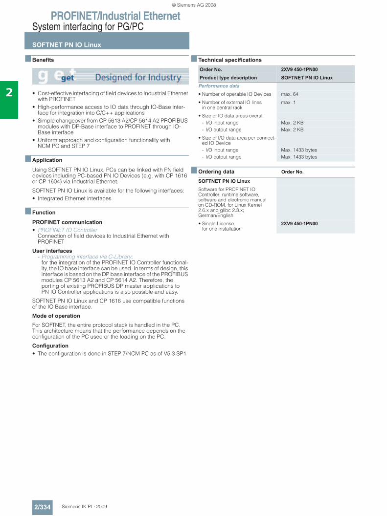
PROFINET/Industrial EthernetSystem interfacing for PG/PC
SOFTNET PN IO Linux
2/334 Siemens IK PI · 2009
2
■ Benefits
• Cost-effective interfacing of field devices to Industrial Ethernet with PROFINET
• High-performance access to IO data through IO-Base inter-face for integration into C/C++ applications
• Simple changeover from CP 5613 A2/CP 5614 A2 PROFIBUS modules with DP-Base interface to PROFINET through IO-Base interface
• Uniform approach and configuration functionality with NCM PC and STEP 7
■ Application
Using SOFTNET PN IO Linux, PCs can be linked with PN field devices including PC-based PN IO Devices (e.g. with CP 1616 or CP 1604) via Industrial Ethernet.
SOFTNET PN IO Linux is available for the following interfaces:• Integrated Ethernet interfaces
■ Function
PROFINET communication • PROFINET IO Controller
Connection of field devices to Industrial Ethernet with PROFINET
User interfaces - Programming interface via C-Library;
for the integration of the PROFINET IO Controller functional-ity, the IO base interface can be used. In terms of design, this interface is based on the DP base interface of the PROFIBUS modules CP 5613 A2 and CP 5614 A2. Therefore, the porting of existing PROFIBUS DP master applications to PN IO Controller applications is also possible and easy.
SOFTNET PN IO Linux and CP 1616 use compatible functions of the IO Base interface.
Mode of operation
For SOFTNET, the entire protocol stack is handled in the PC. This architecture means that the performance depends on the configuration of the PC used or the loading on the PC.
Configuration • The configuration is done in STEP 7/NCM PC as of V5.3 SP1
■ Technical specifications
■ Ordering data Order No.
Order No. 2XV9 450-1PN00Product type description SOFTNET PN IO Linux
Performance data• Number of operable IO Devices max. 64
• Number of external IO lines in one central rack
max. 1
• Size of IO data areas overall- I/O input range Max. 2 KB- I/O output range Max. 2 KB
• Size of I/O data area per connect-ed IO Device- I/O input range Max. 1433 bytes- I/O output range Max. 1433 bytes
SOFTNET PN IO LinuxSoftware for PROFINET IO Controller; runtime software, software and electronic manual on CD-ROM, for Linux Kernel 2.6.x and glibc 2.3.x; German/English
• Single License for one installation
2XV9 450-1PN00
© Siemens AG 2008
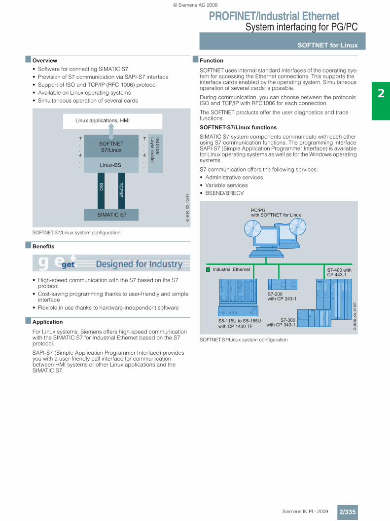
PROFINET/Industrial EthernetSystem interfacing for PG/PC
SOFTNET for Linux
2/335Siemens IK PI · 2009
2
■ Overview• Software for connecting SIMATIC S7• Provision of S7 communication via SAPI-S7 interface• Support of ISO and TCP/IP (RFC 1006) protocol• Available on Linux operating systems• Simultaneous operation of several cards
SOFTNET-S7/Linux system configuration
■ Benefits
• High-speed communication with the S7 based on the S7 protocol
• Cost-saving programming thanks to user-friendly and simple interface
• Flexible in use thanks to hardware-independent software
■ Application
For Linux systems, Siemens offers high-speed communication with the SIMATIC S7 for Industrial Ethernet based on the S7 protocol.
SAPI-S7 (Simple Application Programmer Interface) provides you with a user-friendly call interface for communication between HMI systems or other Linux applications and the SIMATIC S7.
■ Function
SOFTNET uses internal standard interfaces of the operating sys-tem for accessing the Ethernet connections. This supports the interface cards enabled by the operating system. Simultaneous operation of several cards is possible.
During communication, you can choose between the protocols ISO and TCP/IP with RFC1006 for each connection.
The SOFTNET products offer the user diagnostics and trace functions.
SOFTNET-S7/Linux functions
SIMATIC S7 system components communicate with each other using S7 communication functions. The programming interface SAPI-S7 (Simple Application Programmer Interface) is available for Linux operating systems as well as for the Windows operating systems.
S7 communication offers the following services:• Administrative services• Variable services• BSEND/BRECV
SOFTNET-S7/Linux system configuration
© Siemens AG 2008
PROFINET/Industrial EthernetSystem interfacing for PG/PC
SOFTNET for Linux
2/336 Siemens IK PI · 2009
2
■ Ordering data Order No.
■ More information
Support for Linux distributors:Contact for Sales, Service and Training:SIEMENS AGI&S IS E&C IT
ContactYour IT4Industry TeamWerner-von-Siemens-Str. 6091052 ErlangenTel.: +49 (0)9131/7-4 61 11Fax: +49 (0)9131/7-4 47 57E-mail: [email protected]
SOFTNET-S7/Linuxfor Industrial Ethernet
2XV9 4501CG00
Software for S7 communication for SIMATIC S7 including Level 4 interface over ISO or TCP/IP, single license for 1 installation, runtime software, software and electronic manual on CD-ROM, license key by fax, Class A, German/English
Version 2.0
The original distributions of SUSE and RedHat Linux are supported. Please contact your Siemens representative for information about current versions
The original distributions of SUSE and RedHat Linux are supported. Please contact your Siemens representative for information about current versions
Please contact your Siemens contacts for information about the latest versions and their variants (32-bit and 64-bit).
© Siemens AG 2008
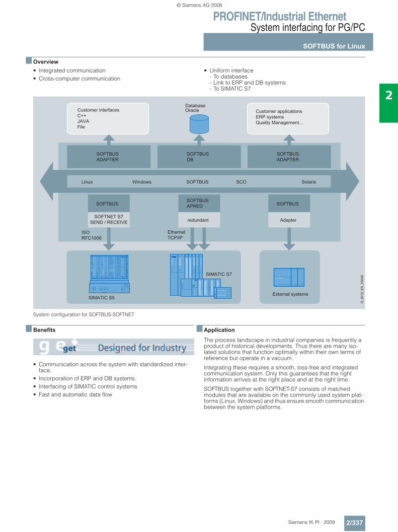
PROFINET/Industrial EthernetSystem interfacing for PG/PC
SOFTBUS for Linux
2/337Siemens IK PI · 2009
2
■ Overview• Integrated communication• Cross-computer communication
• Uniform interface - To databases- Link to ERP and DB systems- To SIMATIC S7
System configuration for SOFTBUS-SOFTNET
■ Benefits
• Communication across the system with standardized inter-face.
• Incorporation of ERP and DB systems.• Interfacing of SIMATIC control systems• Fast and automatic data flow
■ Application
The process landscape in industrial companies is frequently a product of historical developments. Thus there are many iso-lated solutions that function optimally within their own terms of reference but operate in a vacuum.
Integrating these requires a smooth, loss-free and integrated communication system. Only this guarantees that the right information arrives at the right place and at the right time.
SOFTBUS together with SOFTNET-S7 consists of matched modules that are available on the commonly used system plat-forms (Linux, Windows) and thus ensure smooth communication between the system platforms.
© Siemens AG 2008
PROFINET/Industrial EthernetSystem interfacing for PG/PC
SOFTBUS for Linux
2/338 Siemens IK PI · 2009
2
■ Function
SOFTBUS functions
SOFTBUS comprises software modules that can be used on all commonly available computer systems (Windows, Linux).
The modules are compatible and have been adapted to stan-dards such as SIMATIC NET and thus secure vertical integration with short start-up times.
SOFTBUS DB functions
SOFTBUS-DB merges databases and communication and therefore offers possibilities for transaction protection and uni-form data storage.
Interfaces
Thanks to the combination of different modules, all commonly used platforms can be supported and linked together heteroge-neously or homogeneously.
The programming interface of SOFTBUS is identical to the WVS-KOM interface of the SIPAX package.
This means that SIPAX applications can migrate to SOFTBUS without any problems.
■ Ordering data Order No.
■ More information
Support for Linux distributors:
SIEMENS AG I&S IS E&C IT
Contact Your IT4Industry Team Werner-von-Siemens-Str. 60 91052 Erlangen, Germany Tel.: +49 (0)9131/7-4 61 11 Fax: +49 (0)9131/7-4 47 57 E-mail: [email protected]
SOFTBUSVersion 2.3
SOFTBUS Linux• SOFTBUS/Linux redundant
(TCP) (32 bit)2XV9 450-1CG02
• SOFTBUS/Linux redundant (ISO) (32 bit)
2XV9 450-1CG04
• SOFTBUS/Linux (TCP) (32 bit) 2XV9 450-1CG08• SOFTBUS/Linux (ISO) (32 bit) 2XV9 450-1CG10Please contact your Siemens contacts for information about the latest versions and their variants (32-bit and 64-bit).
© Siemens AG 2008
PROFINET/Industrial EthernetSIMATIC HMI connection options
Overview
2/339Siemens IK PI · 2009
2
■ Overview
• System interface possible– System interface not possible
1) SIMATIC WinCC flexible/OPC Server for WinCC flexible Runtime required2) Only with DCOM/XML gateway included in the scope of delivery of WinCC flexible for access to MP277, MP377 and MP 370 OPC XML servers3) WinCC flexible/OPC Server option for SIMATIC Multi Panel required4) WinCC flexible/Sm@rtAccess option required for SIMATIC Panel5) WinCC flexible/Sm@rtAccess option for WinCC flexible Runtime required
Communication standard SIMATIC HMIVersion TP 177B DP/PN
OP 177B DP/PN Mobile Panel 177 PN
TP 277 OP 277 Mobile Panel 277 Mobile Panel 277 IWLAN
MP277 MP370 MP 377
WinCC flexible Runtime
Connection via
OPC Data Access V2.0 + V1.1 (COM)/V1.0 (XML)OPC client (COM/DCOM)
– – – • Industrial Ethernet (s. Catalog IK PI)
OPC server (COM/DCOM)
– – – •1) Industrial Ethernet (s. Catalog IK PI)
OPC XML client (SOAP/XML)
– – – •2) Industrial Ethernet (s. Catalog IK PI)
OPC XML server (SOAP/XML)
– – • 3) – Industrial Ethernet (s. Catalog IK PI)
HTTP communication for variable exchange between SIMATIC HMI systemsHTTP client •4) •4) •4) •5) Industrial Ethernet
(s. Catalog IK PI)
HTTP server •4) •4) •4) •5) Industrial Ethernet (s. Catalog IK PI)
© Siemens AG 2008
PROFINET/Industrial EthernetSIMATIC HMI connection options
SIMATIC S7
2/340 Siemens IK PI · 2009
2
■ Overview
The following types of interface for SIMATIC TP/OP/MP and SIMATIC S7 must be differentiated:• PPI (point-to-point interface):
Connection between SIMATIC TP/OP/MP and SIMATIC S7-200 via PPI. Communication runs on the PPI protocol; a standard FB as with SIMATIC S5 is not required.
• MPI (multi-point interface): Link from SIMATIC TP/OP/MP to SIMATIC S7 via the integrated PPI with S7-200 or MPI with S7-300/-400 or alternatively via the MPI of a separate interface module and the backplane bus to the SIMATIC S7-CPU. Communication runs on the MPI protocol (PG/OP communication); a standard FB as with SIMATIC S5 is not required.
• PROFIBUS interface: Link from SIMATIC TP/OP/MP to SIMATIC S7 via the integrated PROFIBUS interface on the CPU or alternatively via the PROFIBUS interface on a separate interface module and the backplane bus to the SIMATIC S7-CPU. Communication runs on the MPI protocol (PG/OP communication); a standard FB as with SIMATIC S5 is not required.
• PROFINET interface: Link from SIMATIC TP/OP/MP to SIMATIC S7 via the integrated PROFINET interface on the CPU or alternatively via the Indus-trial Ethernet interface on a separate interface module and the backplane bus to the SIMATIC S7-CPU. Communication runs on the MPI protocol (PG/OP communication); a standard FB as with SIMATIC S5 is not required.
The maximum possible number of S7 connections of one CPU is determined by its power (see Catalog ST 70); from the point of view of SIMATIC TP/OP/MP the following restrictions apply: • OP 73micro, TP 177micro:
1 connection• OP 73:
max. 2 connections• OP 77A, TP 177A, OP 77B, TP177B, OP 177B,
Mobile Panel 177: max. 4 connections
• TP 277, OP 277; Mobile Panel 277, MP 277, MP 370, MP 377: max. 6 connections
• PC with WinCC flexible Runtime: max. 8 connections
PPI(not for OP73micro, TP 177micro, OP 73, OP 77A, TP 177A, OP 77B, Mobile Panel 177 PN, Mobile Panel 277 IWLAN )
Basically the PPI is a point-to-point connection between a SIMATIC TP/OP/MP (PPI master) or alternatively a PG (PPI mas-ter) and an S7-200 (PPI slave).
However, a connection between a SIMATIC TP/OP/MP and/or a PG and an S7-200 (sequential logic point-to-point link, i.e. from the point of view of the S7-200 only one connection is active at any one time) is also possible (network topology: PPI only).
MPI/PROFIBUS interface/Industrial Ethernet interface The multipoint-capable communication interfaces of SIMATIC TP/OP/MP and SIMATIC S7 are used. Options are: • Interface between one or a number of TP/OP/MPs
(MPI master) and one or a number of S7-300/400s or WinAC (MPI master)(possible network topology: MPI/PROFIBUS/Industrial Ethernet)
• Interface between one or a number of TP/OP/MPs (MPI master) and one or a number of S7-200s (MPI slave) 1)
(possible network topology: PPI/MPI/PROFIBUS)
Unlike PPI connections, MPI connections are static connections that are set up during booting and then monitored.
A master/slave link has now been added to the original format of a master/master link. This has enabled the integration of the S7-200 (except CPU 212).1)
Generally this type of information exchange between SIMATIC TP/OP/MP and SIMATIC S7 is independent of the network used, PPI, MPI, PROFIBUS or Industrial Ethernet: SIMATIC TP/OP/MPs are S7 clients and SIMATIC S7-CPUs are S7 servers.
1) For constraints with regard to transfer rates for the S7-200, see Catalog ST 70.
© Siemens AG 2008
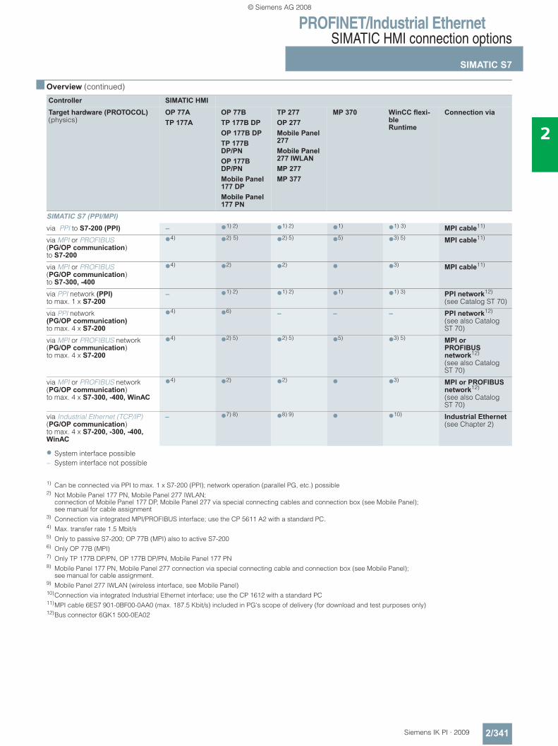
PROFINET/Industrial EthernetSIMATIC HMI connection options
SIMATIC S7
2/341Siemens IK PI · 2009
2
■ Overview (continued)
• System interface possible– System interface not possible
1) Can be connected via PPI to max. 1 x S7-200 (PPI); network operation (parallel PG, etc.) possible2) Not Mobile Panel 177 PN, Mobile Panel 277 IWLAN;
connection of Mobile Panel 177 DP, Mobile Panel 277 via special connecting cables and connection box (see Mobile Panel); see manual for cable assignment
3) Connection via integrated MPI/PROFIBUS interface; use the CP 5611 A2 with a standard PC.4) Max. transfer rate 1.5 Mbit/s 5) Only to passive S7-200; OP 77B (MPI) also to active S7-200 6) Only OP 77B (MPI)7) Only TP 177B DP/PN, OP 177B DP/PN, Mobile Panel 177 PN8) Mobile Panel 177 PN, Mobile Panel 277 connection via special connecting cable and connection box (see Mobile Panel);
see manual for cable assignment.9) Mobile Panel 277 IWLAN (wireless interface, see Mobile Panel) 10)Connection via integrated Industrial Ethernet interface; use the CP 1612 with a standard PC 11)MPI cable 6ES7 901-0BF00-0AA0 (max. 187.5 Kbit/s) included in PG's scope of delivery (for download and test purposes only)12)Bus connector 6GK1 500-0EA02
Controller SIMATIC HMITarget hardware (PROTOCOL) (physics)
OP 77A TP 177A
OP 77B TP 177B DP OP 177B DP TP 177B DP/PNOP 177B DP/PNMobile Panel 177 DP Mobile Panel 177 PN
TP 277OP 277Mobile Panel 277Mobile Panel 277 IWLAN MP 277 MP 377
MP 370 WinCC flexi-ble Runtime
Connection via
SIMATIC S7 (PPI/MPI)via PPI to S7-200 (PPI) – •1) 2) •1) 2) •1) •1) 3) MPI cable11)
via MPI or PROFIBUS (PG/OP communication)to S7-200
•4) •2) 5) •2) 5) •5) •3) 5) MPI cable11)
via MPI or PROFIBUS (PG/OP communication)to S7-300, -400
•4) •2) •2) • •3) MPI cable11)
via PPI network (PPI)to max. 1 x S7-200
– •1) 2) •1) 2) •1) •1) 3) PPI network12) (see Catalog ST 70)
via PPI network (PG/OP communication)to max. 4 x S7-200
•4) •6) – – – PPI network12) (see also Catalog ST 70)
via MPI or PROFIBUS network (PG/OP communication) to max. 4 x S7-200
•4) •2) 5) •2) 5) •5) •3) 5) MPI or PROFIBUS network12) (see also Catalog ST 70)
via MPI or PROFIBUS network (PG/OP communication) to max. 4 x S7-300, -400, WinAC
•4) •2) •2) • •3) MPI or PROFIBUS network12) (see also Catalog ST 70)
via Industrial Ethernet (TCP/IP) (PG/OP communication) to max. 4 x S7-200, -300, -400, WinAC
– •7) 8) •8) 9) • •10) Industrial Ethernet (see Chapter 2)
© Siemens AG 2008
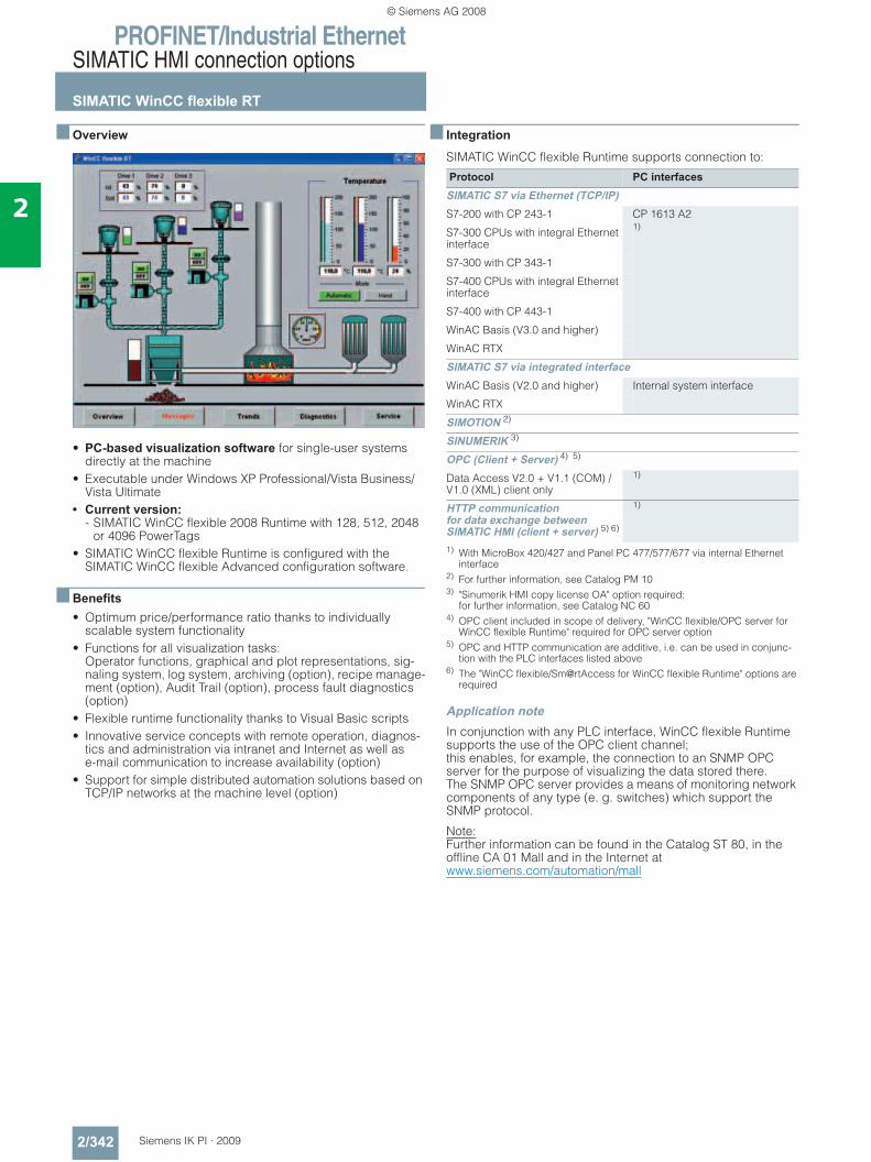
PROFINET/Industrial EthernetSIMATIC HMI connection options
SIMATIC WinCC flexible RT
2/342 Siemens IK PI · 2009
2
■ Overview
• PC-based visualization software for single-user systems directly at the machine
• Executable under Windows XP Professional/Vista Business/Vista Ultimate
• Current version: - SIMATIC WinCC flexible 2008 Runtime with 128, 512, 2048
or 4096 PowerTags• SIMATIC WinCC flexible Runtime is configured with the
SIMATIC WinCC flexible Advanced configuration software.
■ Benefits• Optimum price/performance ratio thanks to individually
scalable system functionality • Functions for all visualization tasks:
Operator functions, graphical and plot representations, sig-naling system, log system, archiving (option), recipe manage-ment (option), Audit Trail (option), process fault diagnostics (option)
• Flexible runtime functionality thanks to Visual Basic scripts• Innovative service concepts with remote operation, diagnos-
tics and administration via intranet and Internet as well as e-mail communication to increase availability (option)
• Support for simple distributed automation solutions based on TCP/IP networks at the machine level (option)
■ Integration
SIMATIC WinCC flexible Runtime supports connection to:
1) With MicroBox 420/427 and Panel PC 477/577/677 via internal Ethernet interface
2) For further information, see Catalog PM 103) "Sinumerik HMI copy license OA" option required;
for further information, see Catalog NC 604) OPC client included in scope of delivery, "WinCC flexible/OPC server for
WinCC flexible Runtime" required for OPC server option5) OPC and HTTP communication are additive, i.e. can be used in conjunc-
tion with the PLC interfaces listed above6) The "WinCC flexible/Sm@rtAccess for WinCC flexible Runtime" options are
required
Application note In conjunction with any PLC interface, WinCC flexible Runtime supports the use of the OPC client channel; this enables, for example, the connection to an SNMP OPC server for the purpose of visualizing the data stored there. The SNMP OPC server provides a means of monitoring network components of any type (e. g. switches) which support the SNMP protocol.
Note: Further information can be found in the Catalog ST 80, in the offline CA 01 Mall and in the Internet atwww.siemens.com/automation/mall
Protocol PC interfacesSIMATIC S7 via Ethernet (TCP/IP)S7-200 with CP 243-1 CP 1613 A2
1)S7-300 CPUs with integral Ethernet interface
S7-300 with CP 343-1
S7-400 CPUs with integral Ethernet interface
S7-400 with CP 443-1
WinAC Basis (V3.0 and higher)
WinAC RTX
SIMATIC S7 via integrated interfaceWinAC Basis (V2.0 and higher) Internal system interface
WinAC RTX
SIMOTION 2)
SINUMERIK 3)
OPC (Client + Server) 4) 5)
Data Access V2.0 + V1.1 (COM) / V1.0 (XML) client only
1)
HTTP communication for data exchange between SIMATIC HMI (client + server) 5) 6)
1)
© Siemens AG 2008
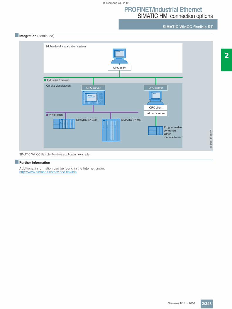
PROFINET/Industrial EthernetSIMATIC HMI connection options
SIMATIC WinCC flexible RT
2/343Siemens IK PI · 2009
2
■ Integration (continued)
SIMATIC WinCC flexible Runtime application example
■ Further information
Additional in formation can be found in the Internet under:http://www.siemens.com/wincc-flexible
G_S
T80_
XX
_000
77
SIMATIC S7-300 SIMATIC S7-400
Industrial Ethernet
PROFIBUS
Higher-level visualization system
On-site visualization
Programmable controllersOthermanufacturers
OPC client
3rd party server
OPC client
OPC serverOPC server
© Siemens AG 2008
PROFINET/Industrial EthernetSIMATIC HMI connection options
SIMATIC WinCC
2/344 Siemens IK PI · 2009
2
■ Overview
• PC-based operator control and monitoring system for visualiz-ing and operating processes, production flows, machines and plants in all sectors – with the simple single-user station through to distributed multi-user systems with redundant servers and cross-location solutions with web clients. WinCC is the information hub for company-wide, vertical integration.
• The basic system configuration (WinCC basic software) in-cludes industry-standard functions for signaling and acknowl-edging events, archiving of messages and measured values, logging of all process and configuration data, user administra-tion and visualization.
• The WinCC basic software forms the core of a wide range of different applications. Based on the open programming inter-faces, a wide range of WinCC options (from Siemens A&D) and WinCC add-ons have been developed (by Siemens-inter-nal and external partners).
• WinCC can be operated with every PC that meets the given HW requirements. The product range of the SIMATIC Panel PC and SIMATIC Rack PC is available in particular for the indus-trial usage of WinCC systems. SIMATIC PCs stand out due to their powerful PC technology, are designed for round-the-clock continuous operation, and can be operated in both harsh industrial environments and office areas.
• Current versions: - SIMATIC WinCC V7.0:
Executable under- Windows VISTA Ultimate, Business and Enterprise- Windows XP Professional- Windows 2003 Server and Windows 2003 Server R2; the Microsoft SQL Server 2005 SP2 is included
- SIMATIC WinCC V6.2 SP2:Executable underWindows XP Professional/ Windows Server 2003 SP2/Windows Server 2003 R2 SP2 and Windows 2000 Professional SP4
■ Integration
Integration in company-wide solutions (IT and business integration)WinCC is strictly based on Microsoft technology, which provides for the greatest possible compatibility and integration ability. Active and .net 1) controls allow for technology and sector-spe-cific expansions. Cross-manufacturer communication is also a simply exercise. The reason: WinCC can be used as OPC client and server, and in addition to the access to current process values, it also supports standards such as OPC HDA (Historical Data Access), OPC Alarm & Events and OPC XML Data Access. Equally important: Visual Basic for Applications (VBA) for user-specific expansions of the WinCC Graphics Designer and Visual Basic Scripting (VBS) as an easy-to-learn, open runtime lan-guage. If desired, professional application developers can also use ANSI-C. And access to the API programming interfaces is really simple with the Open-Development-Kit ODK.
WinCC integrates an efficient, scalable Historian functionality based on the Microsoft SQL Server 2005 in the basic system. Thus the user is given all possibilities: from high-performance archiving of current process data, to long-term archiving with high data compression, through to a central information turnta-ble in form of a company-wide Process Historian. With the help of the option Central Archive Server, this can be set up in the framework of a WinCC solution. Versatile clients and tools for evaluation, the open interfaces, special options (Connectivity Pack, Connectivity Station, IndustrialDataBridge) form the basis for an effective IT and business integration.1) Only supported by WinCC V7.0
Integration in automation solutionsWinCC is an open process visualization system and offers the option of connecting the most diverse control systems.
Released communication software
Only communication software with the listed (or higher) product versions should be used. Corresponding SIMATIC NET up-grades are available for the upgrading of older versions.
Number of connectable controls
For the number of the connectable controls via Industrial Ethernet CP 1613 A2/CP 1623, the following applies for a maximum message frame length of 512 bytes:
Via PROFIBUS, a maximum of 8 controls with CP 5611 A2, CP 5621 and a maximum of 44 controls with CP 5613 A2 can be connected. With approx. 10 or more controls, the usage of Industrial Ethernet is recommended.
Type of connection Number of nodes SIMATIC S5 Ethernet Layer 4 + TCP/IP
up to 60
SIMATIC S5 Ethernet TF up to 60
SIMATIC S7 Protocol Suite up to 64
SIMATIC 505 Ethernet Layer 4 + TCP/IP
up to 60
© Siemens AG 2008
PROFINET/Industrial EthernetSIMATIC HMI connection options
SIMATIC WinCC
2/345Siemens IK PI · 2009
2
■ Integration (continued)
Mixed mode with different controls
With their multi-protocol stack, the communications processors CP 1613 A2 / CP 1623 und CP 5613 A2 allow for the parallel operation of two protocols, e.g. for the mixed operation of differ-ent controls via a bus cable. WinCC supports the operation of two similar Interface Boards only in combination with the chan-nels SIMATIC S5 Ethernet Layer 4 (2 x CP 1613 A2/CP 1623), SIMATIC S7 Protocol Suite (2 x CP 1613 A2/CP 1623, 2 x CP 5613 A2) and PROFIBUS DP (4 x CP 5613 A2; max. 122 slaves per CP 5613 A2). In addition to communication over industrial Ethernet CP 1613 A2/CP 1623 or PROFIBUS CP 5613 A2, one CP 5611 A2/CP 5621 each can be used for communication with SIMATIC S7 via MPI.
Client-server communication
The communication between the clients and the server is achieved using the TCP/IP protocol. The construction of a separate PC-LAN is recommended. For small projects with correspondingly small message frame advent, a SIMATIC NET Industrial Ethernet can be used for both process communication (WinCC/Server ↔ PLC) and for PC-PC communication (WinCC/client ↔ WinCC/server).
Communication redundancy
WinCC itself does not support any redundant LAN interfaces. The software package S7-REDCONNECT is required for the re-dundant connection of PCs via 2 x Industrial Ethernet to SIMATIC S7. This connects the SIMATIC S7 with applications on the PC, e.g. SIMATIC WinCC. A pure communication redundancy can be achieved by setting up optical rings (see Catalog IK PI).
Channel DLL PROFIBUS DP
In accordance with the PROFIBUS standard, DP/slaves are always permanently assigned to a DP master; i.e. a second WinCC station (DP/master) cannot access the same controls (DP/slave). This means that redundant operation of two WinCC stations is not possible with the use of the PROFIBUS DP coupling.
Connection to controls from other manufacturers: For the connection of controls from other manufacturers, OPC (Openness, Productivity & Collaboration) is recommended.
Current notes and information about OPC servers from various suppliers can be found at: http://www.opcfoundation.org/05_man.asp
WinCC supports the standards:• OPC Data Access 1.1• OPC Data Access 2.05a• OPC Data Access 3.0• OPC XML Data Access 1.01
(Connectivity Pack/Connectivity Station)• OPC HDA 1.2 (Connectivity Pack/Connectivity Station)• OPC A&E 1.1 (Connectivity Pack/Connectivity Station)
More information is available in the Internet at:http://www.siemens.com/wincc-connectivity
Coupling overview
1) Application note:The parallel usage of the OPC client channel allows, for example,the connection to an SNMP-OPC server for visualization of the data contained there. The SNMP-OPC server enables monitoring of any network components (e.g. switch) that support the SNMP protocol. Further information can be found in the Catalog IK PI
Protocol DescriptionSIMATIC S7SIMATIC S7 Protocol Suite Channel DLL for S7 functions
via MPI, PROFIBUS or Ethernet Layer 4 + TCP/IP
Cross-manufacturerWindows DDE Channel DLL for DDE communi-
cation, WinCC can acquire data from DDE server applications
OPC client 1) Channel DLL for OPC communi-cation, WinCC can acquire data from OPC server applications
OPC server Server applications for OPC com-munication; WinCC provides pro-cess data for the OPC client
PROFIBUS FMS Channel DLL for PROFIBUS FMS
PROFIBUS DP Channel DLL for PROFIBUS DP
© Siemens AG 2008
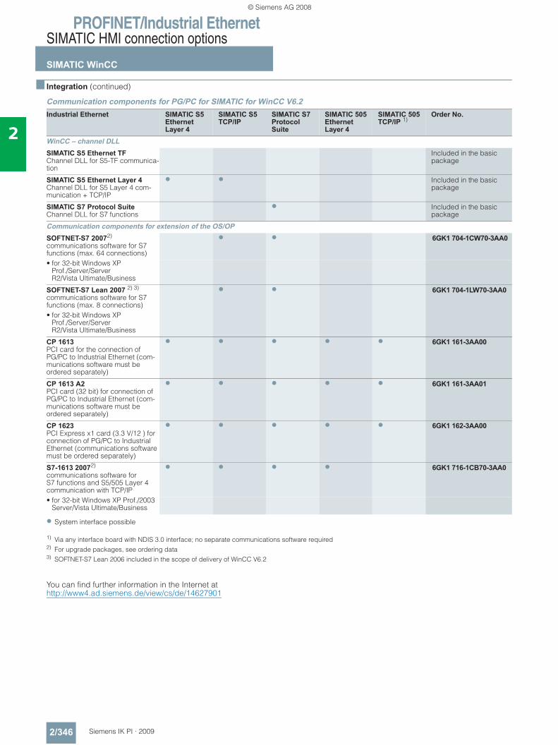
PROFINET/Industrial EthernetSIMATIC HMI connection options
SIMATIC WinCC
2/346 Siemens IK PI · 2009
2
■ Integration (continued)
Communication components for PG/PC for SIMATIC for WinCC V6.2
• System interface possible
1) Via any interface board with NDIS 3.0 interface; no separate communications software required2) For upgrade packages, see ordering data3) SOFTNET-S7 Lean 2006 included in the scope of delivery of WinCC V6.2
You can find further information in the Internet at http://www4.ad.siemens.de/view/cs/de/14627901
Industrial Ethernet SIMATIC S5 EthernetLayer 4
SIMATIC S5 TCP/IP
SIMATIC S7 Protocol Suite
SIMATIC 505 EthernetLayer 4
SIMATIC 505 TCP/IP 1)
Order No.
WinCC – channel DLLSIMATIC S5 Ethernet TF Channel DLL for S5-TF communica-tion
Included in the basic package
SIMATIC S5 Ethernet Layer 4 Channel DLL for S5 Layer 4 com-munication + TCP/IP
• • Included in the basic package
SIMATIC S7 Protocol Suite Channel DLL for S7 functions
• Included in the basic package
Communication components for extension of the OS/OPSOFTNET-S7 20072) communications software for S7 functions (max. 64 connections)
• • 6GK1 704-1CW70-3AA0
• for 32-bit Windows XP Prof./Server/Server R2/Vista Ultimate/Business
SOFTNET-S7 Lean 2007 2) 3) communications software for S7 functions (max. 8 connections)
• • 6GK1 704-1LW70-3AA0
• for 32-bit Windows XP Prof./Server/Server R2/Vista Ultimate/Business
CP 1613 PCI card for the connection of PG/PC to Industrial Ethernet (com-munications software must be ordered separately)
• • • • • 6GK1 161-3AA00
CP 1613 A2 PCI card (32 bit) for connection of PG/PC to Industrial Ethernet (com-munications software must be ordered separately)
• • • • • 6GK1 161-3AA01
CP 1623 PCI Express x1 card (3.3 V/12 ) for connection of PG/PC to Industrial Ethernet (communications software must be ordered separately)
• • • • • 6GK1 162-3AA00
S7-1613 20072) communications software for S7 functions and S5/505 Layer 4 communication with TCP/IP
• • • • 6GK1 716-1CB70-3AA0
• for 32-bit Windows XP Prof./2003 Server/Vista Ultimate/Business
© Siemens AG 2008
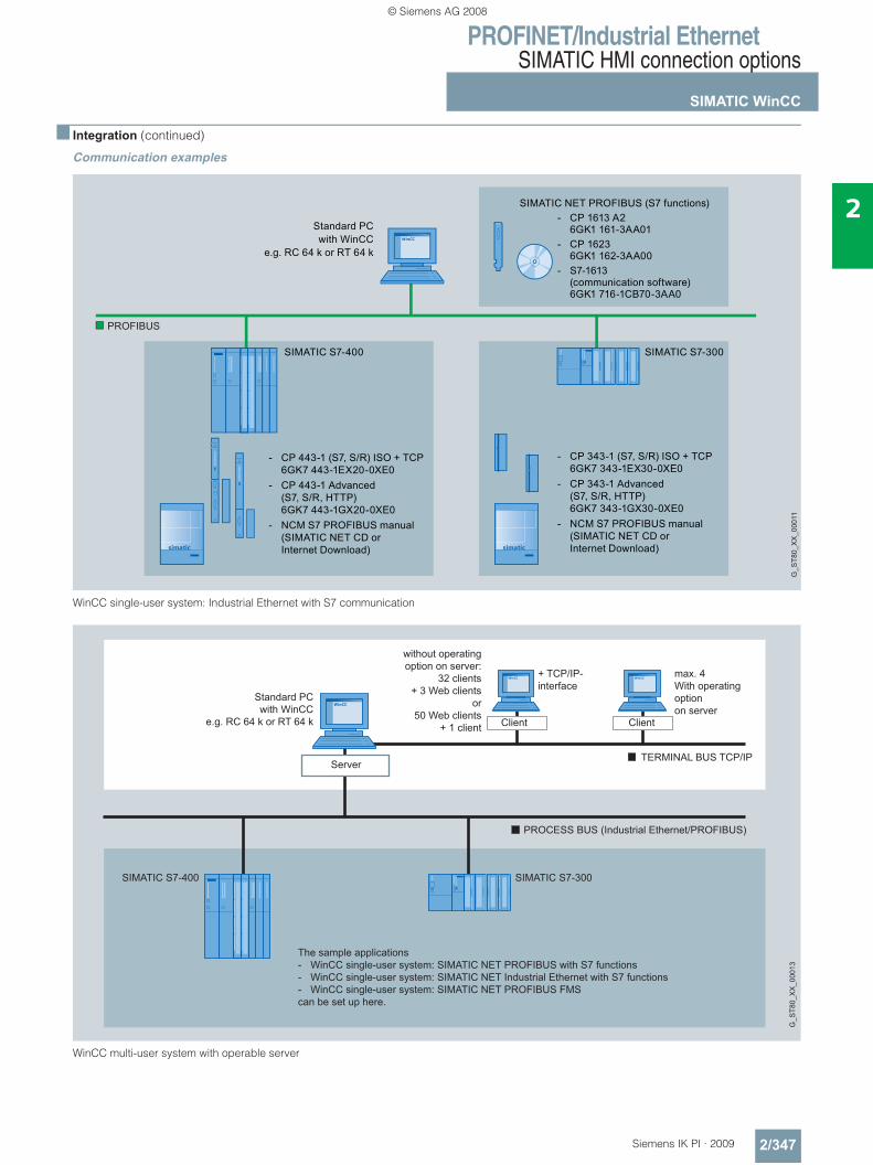
PROFINET/Industrial EthernetSIMATIC HMI connection options
SIMATIC WinCC
2/347Siemens IK PI · 2009
2
■ Integration (continued)
Communication examples
WinCC single-user system: Industrial Ethernet with S7 communication
WinCC multi-user system with operable server
G_S
T80_
XX
_000
11
PROFIBUS
- CP 443-1 (S7, S/R) ISO + TCP 6GK7 443-1EX20-0XE0- CP 443-1 Advanced (S7, S/R, HTTP) 6GK7 443-1GX20-0XE0- NCM S7 PROFIBUS manual (SIMATIC NET CD or Internet Download)
SIMATIC S7-400 SIMATIC S7-300
SIMATIC NET PROFIBUS (S7 functions)
Standard PCwith WinCC
e.g. RC 64 k or RT 64 k
- CP 343-1 (S7, S/R) ISO + TCP 6GK7 343-1EX30-0XE0- CP 343-1 Advanced (S7, S/R, HTTP) 6GK7 343-1GX30-0XE0- NCM S7 PROFIBUS manual (SIMATIC NET CD or Internet Download)
- CP 1613 A2 6GK1 161-3AA01- CP 1623 6GK1 162-3AA00- S7-1613 (communication software) 6GK1 716-1CB70-3AA0
G_S
T80_
XX
_000
13
Client Client
Standard PCwith WinCC
e.g. RC 64 k or RT 64 k
without operatingoption on server:
32 clients+ 3 Web clients
or50 Web clients
+ 1 client
+ TCP/IP-interface
max. 4With operatingoptionon server
TERMINAL BUS TCP/IP
PROCESS BUS (Industrial Ethernet/PROFIBUS)
Server
SIMATIC S7-400 SIMATIC S7-300
The sample applications- WinCC single-user system: SIMATIC NET PROFIBUS with S7 functions- WinCC single-user system: SIMATIC NET Industrial Ethernet with S7 functions- WinCC single-user system: SIMATIC NET PROFIBUS FMScan be set up here.
© Siemens AG 2008
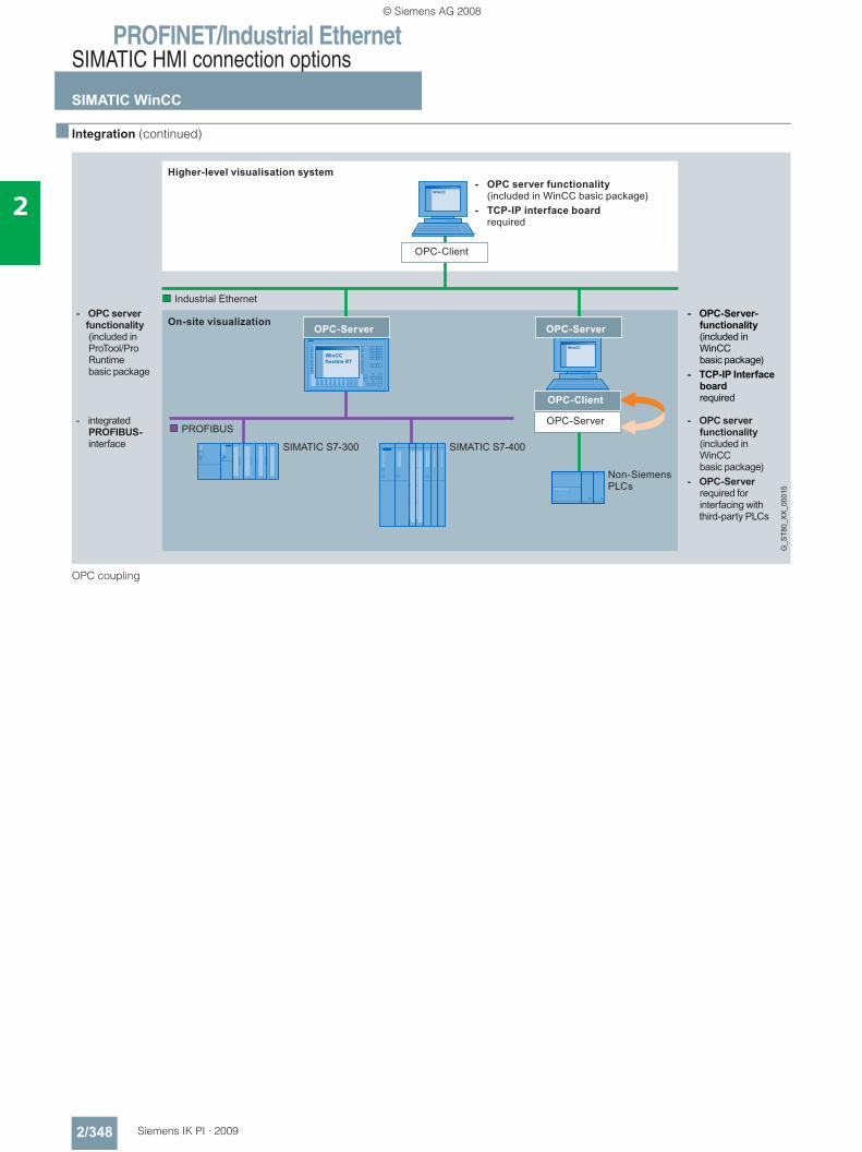
PROFINET/Industrial EthernetSIMATIC HMI connection options
SIMATIC WinCC
2/348 Siemens IK PI · 2009
2
■ Integration (continued)
OPC coupling
Higher-level visualisation system
On-site visualization
- OPC server functionality(included in WinCC basic package)
- TCP-IP interface boardrequired
- OPC-Server- functionality (included in WinCC basic package)- TCP-IP Interface board required
- OPC server functionality (included in WinCC basic package)- OPC-Server required for interfacing with third-party PLCs
- OPC server functionality (included in ProTool/Pro Runtime basic package
- integrated PROFIBUS-
interface
OPC-Client
OPC-Server
Non-Siemens PLCs
OPC-Client
OPC-ServerOPC-Server
G_S
T80_
XX
_000
15
Industrial Ethernet
PROFIBUS
SIMATIC S7-300 SIMATIC S7-400
© Siemens AG 2008
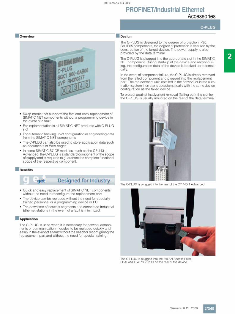
PROFINET/Industrial EthernetAccessories
C-PLUG
2/349Siemens IK PI · 2009
2
■ Overview
• Swap media that supports the fast and easy replacement of SIMATIC NET components without a programming device in the event of a fault
• For implementation in all SIMATIC NET products with C-PLUG slot
• For automatic backing up of configuration or engineering data from the SIMATIC NET components
• The C-PLUG can also be used to store application data such as documents or Web pages
• In some SIMATIC S7 CP modules, such as the CP 443-1 Advanced, the C-PLUG is a standard component of the scope of supply and is required to guarantee the complete functional scope of the respective component.
■ Benefits
• Quick and easy replacement of SIMATIC NET components without the need to reconfigure the replacement part
• The device can be replaced without the need for specially trained personnel or a programming device or PC
• The downtime of network segments and connected Industrial Ethernet stations in the event of a fault is minimized.
■ Application
The C-PLUG is used when it is necessary for network compo-nents or communication modules to be replaced quickly and easily in the event of a fault without the need for reconfiguring the replacement part and without the need for special training.
■ Design
The C-PLUG is designed to the degree of protection IP20. For IP65 components, the degree of protection is ensured by the construction of the target device. The power supply is also provided by the data terminal.
The C-PLUG is plugged into the appropriate slot in the SIMATIC NET component. During start-up of the device and reconfigur-ing, the configuration data of the device is backed up automati-cally.
In the event of component failure, the C-PLUG is simply removed from the failed component and plugged into the replacement part. The replacement unit installed in the network or in the auto-mation system then starts up automatically with the same device configuration as the failed device.
To protect against inadvertent removal (falling out), the slot for the C-PLUG is usually mounted on the rear of the data terminal.
The C-PLUG is plugged into the rear of the CP 443-1 Advanced
The C-PLUG is plugged into the IWLAN Access Point SCALANCE W 788-1PRO on the rear of the device
© Siemens AG 2008
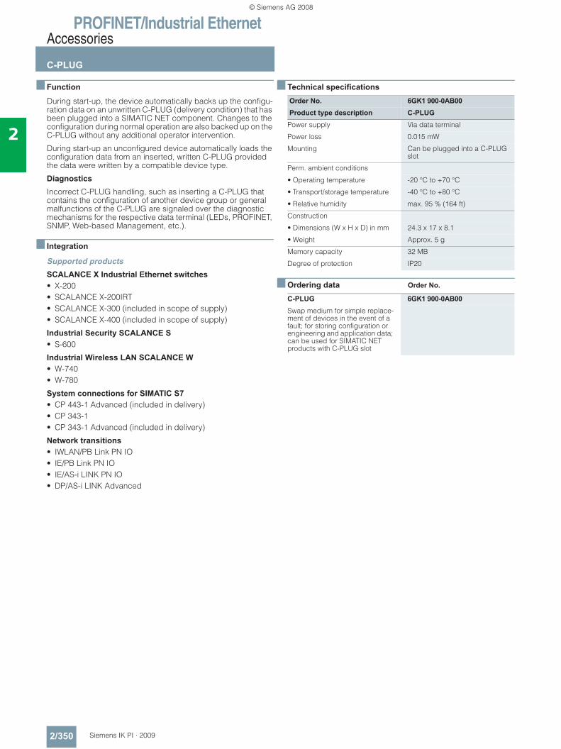
PROFINET/Industrial EthernetAccessories
C-PLUG
2/350 Siemens IK PI · 2009
2
■ Function
During start-up, the device automatically backs up the configu-ration data on an unwritten C-PLUG (delivery condition) that has been plugged into a SIMATIC NET component. Changes to the configuration during normal operation are also backed up on the C-PLUG without any additional operator intervention.
During start-up an unconfigured device automatically loads the configuration data from an inserted, written C-PLUG provided the data were written by a compatible device type.
Diagnostics
Incorrect C-PLUG handling, such as inserting a C-PLUG that contains the configuration of another device group or general malfunctions of the C-PLUG are signaled over the diagnostic mechanisms for the respective data terminal (LEDs, PROFINET, SNMP, Web-based Management, etc.).
■ Integration
Supported productsSCALANCE X Industrial Ethernet switches • X-200• SCALANCE X-200IRT• SCALANCE X-300 (included in scope of supply)• SCALANCE X-400 (included in scope of supply)
Industrial Security SCALANCE S • S-600
Industrial Wireless LAN SCALANCE W • W-740• W-780
System connections for SIMATIC S7 • CP 443-1 Advanced (included in delivery)• CP 343-1• CP 343-1 Advanced (included in delivery)
Network transitions • IWLAN/PB Link PN IO• IE/PB Link PN IO• IE/AS-i LINK PN IO• DP/AS-i LINK Advanced
■ Technical specifications
■ Ordering data Order No.
Order No. 6GK1 900-0AB00Product type description C-PLUG
Power supply Via data terminal
Power loss 0.015 mW
Mounting Can be plugged into a C-PLUG slot
Perm. ambient conditions
• Operating temperature -20 °C to +70 °C
• Transport/storage temperature -40 °C to +80 °C
• Relative humidity max. 95 % (164 ft)
Construction
• Dimensions (W x H x D) in mm 24.3 x 17 x 8.1
• Weight Approx. 5 g
Memory capacity 32 MB
Degree of protection IP20
C-PLUG 6GK1 900-0AB00Swap medium for simple replace-ment of devices in the event of a fault; for storing configuration or engineering and application data; can be used for SIMATIC NET products with C-PLUG slot
© Siemens AG 2008
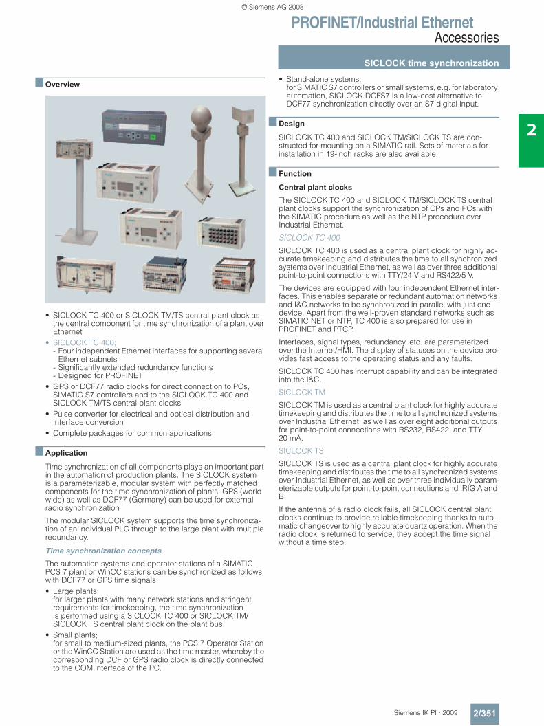
PROFINET/Industrial EthernetAccessories
SICLOCK time synchronization
2/351Siemens IK PI · 2009
2
■ Overview
• SICLOCK TC 400 or SICLOCK TM/TS central plant clock as the central component for time synchronization of a plant over Ethernet
• SICLOCK TC 400; - Four independent Ethernet interfaces for supporting several
Ethernet subnets - Significantly extended redundancy functions- Designed for PROFINET
• GPS or DCF77 radio clocks for direct connection to PCs, SIMATIC S7 controllers and to the SICLOCK TC 400 and SICLOCK TM/TS central plant clocks
• Pulse converter for electrical and optical distribution and interface conversion
• Complete packages for common applications
■ Application
Time synchronization of all components plays an important part in the automation of production plants. The SICLOCK system is a parameterizable, modular system with perfectly matched components for the time synchronization of plants. GPS (world-wide) as well as DCF77 (Germany) can be used for external radio synchronization
The modular SICLOCK system supports the time synchroniza-tion of an individual PLC through to the large plant with multiple redundancy.
Time synchronization concepts The automation systems and operator stations of a SIMATIC PCS 7 plant or WinCC stations can be synchronized as follows with DCF77 or GPS time signals:• Large plants;
for larger plants with many network stations and stringent requirements for timekeeping, the time synchronization is performed using a SICLOCK TC 400 or SICLOCK TM/SICLOCK TS central plant clock on the plant bus.
• Small plants; for small to medium-sized plants, the PCS 7 Operator Station or the WinCC Station are used as the time master, whereby the corresponding DCF or GPS radio clock is directly connected to the COM interface of the PC.
• Stand-alone systems; for SIMATIC S7 controllers or small systems, e.g. for laboratory automation, SICLOCK DCFS7 is a low-cost alternative to DCF77 synchronization directly over an S7 digital input.
■ Design
SICLOCK TC 400 and SICLOCK TM/SICLOCK TS are con-structed for mounting on a SIMATIC rail. Sets of materials for installation in 19-inch racks are also available.
■ Function
Central plant clocks
The SICLOCK TC 400 and SICLOCK TM/SICLOCK TS central plant clocks support the synchronization of CPs and PCs with the SIMATIC procedure as well as the NTP procedure over Industrial Ethernet.
SICLOCK TC 400
SICLOCK TC 400 is used as a central plant clock for highly ac-curate timekeeping and distributes the time to all synchronized systems over Industrial Ethernet, as well as over three additional point-to-point connections with TTY/24 V and RS422/5 V.
The devices are equipped with four independent Ethernet inter-faces. This enables separate or redundant automation networks and I&C networks to be synchronized in parallel with just one device. Apart from the well-proven standard networks such as SIMATIC NET or NTP, TC 400 is also prepared for use in PROFINET and PTCP.
Interfaces, signal types, redundancy, etc. are parameterized over the Internet/HMI. The display of statuses on the device pro-vides fast access to the operating status and any faults.
SICLOCK TC 400 has interrupt capability and can be integrated into the I&C.
SICLOCK TM
SICLOCK TM is used as a central plant clock for highly accurate timekeeping and distributes the time to all synchronized systems over Industrial Ethernet, as well as over eight additional outputs for point-to-point connections with RS232, RS422, and TTY 20 mA.
SICLOCK TS
SICLOCK TS is used as a central plant clock for highly accurate timekeeping and distributes the time to all synchronized systems over Industrial Ethernet, as well as over three individually param-eterizable outputs for point-to-point connections and IRIG A and B.
If the antenna of a radio clock fails, all SICLOCK central plant clocks continue to provide reliable timekeeping thanks to auto-matic changeover to highly accurate quartz operation. When the radio clock is returned to service, they accept the time signal without a time step.
© Siemens AG 2008
PROFINET/Industrial EthernetAccessories
SICLOCK time synchronization
2/352 Siemens IK PI · 2009
2
■ Ordering data Order No. Order No.
SICLOCK TC 400 central plant clockSICLOCK TC 400 preferred packages SICLOCK TC 400 GPS1000 2XV9 450-2AR10SICLOCK TC 400 central plant clock with four Ethernet interfaces + GPS1000 radio clockPackage comprises• SICLOCK TC 400 • SICLOCK GPS1000 system
with antenna frame• Lightning protection for GPS
Complete solution, e.g. for use in PCS 7
SICLOCK TC 400 DCF77 2XV9 450-2AR20SICLOCK TC 400 central plant clock with four Ethernet interfaces + DCFRS radio clock,industrial version; package comprises• SICLOCK TC 400• Active DCF77 antenna with TTY
output (20 mA line current) and antenna frame
• Junction box• 1 m connecting cable mounted,
extendable to 1000 m
SICLOCK TC 400 single device 2XV9 450-2AR01SICLOCK TC 400 central plant clock with four Ethernet interfaces
SICLOCK TM central plant clock SICLOCK TM DCF77SICLOCK TM central plant clock with Ethernet interface + DCFRS radio clock, industrial version; package comprises• SICLOCK TM in stainless steel
housing for rail mounting• Active DCF77 antenna with TTY
output (20 mA line current) and antenna frame
• Junction box• 1 m connecting cable mounted,
extendable to 1000 m- with SICLOCK TM
24 … 110 V DC2XV9 450-1AR26
- with SICLOCK TM 90 … 230 V AC/DC
2XV9 450-1AR27
SICLOCK TM GPSDECSICLOCK TM central plant clock with Ethernet interface + GPS-DEC radio clock, package comprises• SICLOCK TM in stainless steel
housing for rail mounting• GPS antenna with antenna frame• 22 m coax antenna cable
(max. length 70 m,see accessories)
• GPSDEC decoder with power supply
• 5 m RS232 connection cable• Parameterization software for PC
- with SICLOCK TM 24 … 110 V DC
2XV9 450-1AR24
- with SICLOCK TM 90 … 230 V AC/DC
2XV9 450-1AR25
SICLOCK TM central plant clock (continued)
SICLOCK TM GPS1000SICLOCK TM central plant clock with Ethernet interface + GPS1000 radio clock, package comprises
• SICLOCK TM in stainless steel housing for rail mounting
• GPS1000 antenna head with antenna frame
• GPS1000 power supply
• 5 m RS232 connection cable
• Junction box- with SICLOCK TM
24 … 110 V DC2XV9 450-1AR50
- with SICLOCK TM 90 … 230 V AC/DC
2XV9 450-1AR51
SICLOCK TM single deviceSICLOCK TM central plant clock with Ethernet interface, in stainless steel housing for rail mounting• SICLOCK TM
24 … 110 V DC2XV9 450-1AR22
• with SICLOCK TM 90 … 230 V AC/DC
2XV9 450-1AR23
SICLOCK TS central plant clock SICLOCK TS GPS1000SICLOCK TS central plant clock with Ethernet interface and IRIG A and B + GPS1000 radio clock, package comprises
• SICLOCK TS in stainless steel housing for rail mounting
• GPS1000 radio clock with antenna frame
• Junction box- with SICLOCK TS
24 … 110 V DC2XV9 450-1AR54
- with SICLOCK TS 90 … 230 V AC/DC
2XV9 450-1AR55
SICLOCK TS single deviceSICLOCK TS central plant clock with Ethernet interface and IRIG A and B in stainless steel housing for rail mounting
• SICLOCK TS 24 … 110 V DC 2XV9 450-1AR52• SICLOCK TS 90 … 230 V AC/DC 2XV9 450-1AR53
© Siemens AG 2008
PROFINET/Industrial EthernetAccessories
SICLOCK time synchronization
2/353Siemens IK PI · 2009
2
■ Ordering data Order No. Order No.
DCF radio clocks SICLOCK DCFRS, radio clock, industrial version
2XV9 450-1AR21
DCF radio clock for time synchro-nization of individual PCs or servers in industrial environments with high levels of interference; distances of up to 1000 m are possible between the DCF radio clock and the PC, package comprises• Active DCF77 antenna with TTY
output (20 mA line current) and antenna frame
• TTY/RS232 converter• Plug-in power supply• Two junction boxes• 1 m connecting cable mounted,
extendable to 1000 m• DCF77 receiving service for
Windows NT/2000/2003/XP
SICLOCK DCFRS,radio clock for Windows
2XV9 450-1AR14
DCF radio clock for the time synchronization of individual PCs over short distances, package comprises• Active DCF77 antennas with
RS232 interface Mounting bracket
• 20 m connecting cable mounted• DCF77 receiving service
for Windows NT/2000/2003/XP
SICLOCK DCFEMP, receiver with TTY interface
2XV9 450-1AR61
DCF receiver for connection to existing HF cable system in the plant for DCF77 time signals for time synchronization of individual PCs or servers at distances of up to 1000 m, package comprises• Active DCF77 receiver with
mounting bracket and TTY interface
• 1 m connecting cable mounted
SICLOCK DCFS7 2XV9 450-1AR36Low-cost solution for time synchronization of SIMATIC S7-300/400 over DCF77 over one digital input, package comprises• SICLOCK DCFRS, radio clock
with RS232 output, 20 m connecting cable and mounting bracket
• SICLOCK DCFS7 interface• SICLOCK DCFS7 receiving
service (STEP 7 function block for integration in S7 software)
Accessories for SICLOCK DCFS7SICLOCK DCFS7 interface + receiving service
2XV9 450-1AR30
(STEP 7 function block for integration in S7 software)
SICLOCK DCFS7 interface 2XV9 450-1AR35SICLOCK DCFS7 receiving service
2XV9 450-1AR32
(STEP 7 function blockfor integration in S7 software)
GPS radio clocks SICLOCK WINGPS, radio clock for Windows
2XV9 450-1AR13
GPS radio clock for the time synchronization of individual PCs in industrial environments with high levels of interference, package comprises
• GPS antenna with antenna frame
• WINGPS decoder with power supply
• 22 m coax antenna cable (max. length 70 m, see accessories)
• 20 m PC connection cable WINGPS
• DCF77 receiving service for Windows NT/2000/2003/XP
SICLOCK GPSDEC, radio clock for Windows
2XV9 450-1AR00
GPS radio clock for the time synchronization of the SICLOCK TM/TS central plant clocks or programmable logic controllers in industrial environments with high levels of interference, package comprises
• GPS antenna with antenna frame
• GPSDEC decoder with power supply
• 22 m coax antenna cable (max. length 70 m, see accessories)
• 5 m RS232 connecting cable
• Parameterization program
GPS1000 + power supply, radio clock for Windows
2XV9 450-1AR82
GPS radio clock for the time synchronization of PCs, program-mable controllers, as well as the SICLOCK TM and SICLOCK TS central plant clocks in industrial environments with high levels of interference with distances up to 1000 m between the antenna and the device, package comprises
• GPS1000 antenna head with antenna frame
• GPS1000 power supply
• Junction box
• 5 m RS232 connecting cable
• DCF77 receiving service for Windows NT/2000/2003/XP
© Siemens AG 2008
PROFINET/Industrial EthernetAccessories
SICLOCK time synchronization
2/354 Siemens IK PI · 2009
2
■ Ordering data Order No.
■ More information
SIEMENS AG
I&S EDM V ERL Frauenauracher Str. 98 91020 Erlangen, Germany
SICLOCK hotline Phone: +49 (0)9131 7-2 88 66 Fax: +49 (0)9131 18-84456 Email: [email protected]
Additional in formation can be found in the Internet under:
http://www.siemens.com/siclockhttp://www.siemens-edm.de/siclock_zeitsynchronisation.0.html
AccessoriesSet of materials for SICLOCK TM/TS• For desktop housing 2XV9 450-1AR80• for 19“ mounting frame (4 HU) 2XV9 450-1AR81Lightning protection for antenna cable• Lightning protection
for coaxial antenna cable (SICLOCK GPSDEC/WINGPS)
2XV9 450-1AR11
• Lightning protection for TTY connecting cable (SICLOCK GPS1000/DCFRS industrial version)
2XV9 450-1AR83
• Lightning protection for RS232 antenna cable (SICLOCK DCFS7/DCFRS with RS232 interface)
2XV9 450-1AR15
Coaxial antenna cable SICLOCK GPSDEC/WINGPS• 30 m 2XV9 450-1AR12• 70 m 2XV9 450-1AR07SoftwareSICLOCK DCF77 receiving service for Windows
2XV9 450-1AR28
SICLOCK Ethernet receiving service for Windows NT
2XV9 450-1AR44
Pulse converter SICLOCK EOPCElectrical/optical pulse converter for industrial applications with 32 fiber-optic cable outlets for transparent operation and pulse mode• SICLOCK EOPC
24 … 110 V DC2XV9 450-1AR72
• SICLOCK EOPC 90 … 230 V AC/DC
2XV9 450-1AR73
SICLOCK PCONSingle-channel electrical/optical pulse converter for industrial applications• SICLOCK PCON
24 … 230 V AC/DC, with multi-mode fiberglass connection, 820 nm
2XV9 450-1AR63-1SA0
• SICLOCK PCON 24 … 230 V AC/DC, long dis-tance, with multi-mode fiber-glass connection, 1310 nm
2XV9 450-1AR63-1MA0
SICLOCK DCFHF 2XV9 450-1AR64HF modulator for DCF77 signals for industrial applications
Displays SICLOCK DA1000 NETDigital display with Ethernet connection for date and time
• Red display 2XV9 450-1AR68SICLOCK DA1000 Digital display for date and time
• Red display 2XV9 450-1AR65• Green display 2XV9 450-1AR66
© Siemens AG 2008
PROFINET/Industrial EthernetET 200S distributed I/Os
IM 151-3PN interface modules
2/355Siemens IK PI · 2009
2
■ Overview
• Interface module for linking the ET 200S to PROFINET• Handles all data exchange with the PROFINET I/O Controller• 3 versions:
- IM151-3 PN STANDARD- IM151-3 PN HIGH FEATURE and IM 151-3 PN FO:
supports, in contrast to the STANDARD version, the operation of PROFIsafe F modules
- with integrated 2-port switch for line topology• Delivery including connecting module
Note:Micro Memory Card required for operation of the IM 152-3 PN FO.
■ Technical specifications
Order No. 6ES7 151-3AA23-0AB0
6ES7 151-3BA23-0AB0
Product type description Interfacemodule IM 151-3PNSupply voltages
Supply voltage of electronics 1L+
• Rated value (DC) 24 V 24 V
• reverse polarity protection Yes Yes
Voltages and currents
Mains/voltage failure jumpering, min.
20 ms 20 ms
Current consumption
from supply voltage 1L+, max. 250 mA 250 mA
Power loss, typ. 2.5 W 2.5 W
Address area
Adressing volume
• Outputs 256 Byte 256 Byte
• Inputs 256 Byte 256 Byte
Connection point RJ45 Yes Yes
Protocols
PROFINET IO Yes Yes
PROFINET IO
Transmission speed, max. 100 Mbit/s 100 Mbit/s
automatic detection of transmission speed
Yes Yes
Isochronous mode
Isochronouos mode No No
Order No. 6ES7 151-3AA23-0AB0
6ES7 151-3BA23-0AB0
Product type description Interfacemodule IM 151-3PNStatus information/alarms/diagnostics
Alarms
• Alarms Yes Yes
Diagnoses
• Diagnostic functions Yes Yes
Diagnostics indication LED
• Bus error BF (red) Yes Yes
• Collective error SF (red) Yes Yes
• Monitoring 24 V voltage supply ON (green)
Yes Yes
• Connection to network LINK (green)
Yes Yes
• Transmit/receive RX/TX (yellow) Yes Yes
Isolation
between backplane bus and electronics
No No
between Ethernet and electronics Yes Yes
between supply voltage and electronics
No No
General information
Vendor identification (VendorID) 002AH 002AH
Device identifier (DeviceID) 0301 0301H
Dimensions
Width 60 mm 60 mm
Height 119.5 mm 119.5 mm
Depth 75 mm 75 mm
Weights
Weight, approx. 120 g 135 g
© Siemens AG 2008
PROFINET/Industrial EthernetET 200S distributed I/Os
IM 151-3PN interface modules
2/356 Siemens IK PI · 2009
2
■ Ordering data Order No. Order No.
1) For operating the IM 151-3, an MMC is essential
IM 151-3 PN interface module 6ES7 151-3AA23-0AB0for ET 200S; data transmission rates up to 100 Mbit/s; data volume depends on the number of modules inserted, up to 63 modules can be connected, bus connection through RJ45
IM 151-3 PN PROFINET High Feature interface module
6ES7 151-3BA23-0AB0
for ET 200S; data transmission rate up to 100 Mbit/s; max. 63 modules up to 2 m wide can be connected; bus connection via RJ45, incl. terminating module
IM 151-3 FO interface module 6ES7 151-3BB22-0AB0for ET 200S; with 2 PROFINET FO-interfaces and integrated 2-port switch, max. 63 modules up to 2 m wide can be con-nected, incl. terminating module
Accessories
Industrial Ethernet FC RJ45 Plug 90RJ45 plug connector for Industrial Ethernet with a rugged metal housing and integrated insulation displacement contacts for con-necting Industrial Ethernet FC installation cables; with 90° cable outlet
• 1 unit 6GK1 901-1BB20-2AA0• 10 units 6GK1 901-1BB20-2AB0• 50 units 6GK1 901-1BB20-2AE0Industrial Ethernet FastConnect installation cablesFast Connect standard cable 6XV1 840-2AH10Fast Connect trailing cable 6XV1 840-3AH10Fast Connect marine cable 6XV1 840-4AH10Termination KitsSC RJ POF PlugAssembly case for on-site assem-bly of SC RJ plugs consisting of stripping tool, kevlar cutter, microscope, abrasive paper, grinding support
6GK1 900-0ML00-0AA0
IE SC RJ POF PlugScrew-in plug for on-site assem-bly to POF fiber optic cable (1 pack = 20 units)
6GK1 900-0MB00-0AC0
IE SC RJ Refill Set POFRefill set for Termination Kit SC RJ POF Plug, consisting of abrasive paper and grinding plate (set of 5)
6GK1 900-0MN00-0AA0
SC RJ POF PlugAssembly case for on-site assembly of SC RJ plugs consisting of stripping tool, buffer stripping tool, kevlar cutter, fiber breaking tool, microscope
6GK1 900-0NL00-0AA0
Industrial Ethernet SC RJ PCF PlugScrew-in plug for on-site assembly to PCF fiber optic cable (1 pack = 10 units)
6GK1 900-0NB00-0AC0
Industrial Ethernet Fast Connect stripping tool
6GK1 901-1GA00
MMC 64 KB 1) 6ES7 953-8LF20-0AA0for storing the device name
MMC 128 KB 1) 6ES7 953-8LG11-0AA0for storing the device name
MMC 512 KB 1) 6ES7 953-8LJ20-0AA0for storing the device name
MMC 2 MB 1) 6ES7 953-8LL20-0AA0for storing the device name and/or firmware update
MMC 4 MB 1) 6ES7 953-8LM20-0AA0for storing the device name and/or firmware update
MMC 8 MB 1) 6ES7 953-8LP20-0AA0for storing the device name and/or firmware update
ET 200S distributed I/O system manuals
http://www.siemens.com/simatic-docu
are available in the Internet as PDF files:
SIMATIC Manual Collection 6ES7 998-8XC01-8YE0Electronic manuals on DVD, multi-language: S7-200, TD 200, S7-300, M7-300, C7, S7-400, M7-400, STEP 7, Engineering Tools, Runtime Soft-ware, SIMATIC DP (Distributed I/O), SIMATIC HMI (Human Machine Interface), SIMATIC NET (Industrial Communication)
SIMATIC Manual Collection – Update service for 1 year
6ES7 998-8XC01-8YE2
Scope of delivery: Current DVD "S7 Manual Collection" and the three subsequent updates
Label sheets DIN A4 (10 units)Each sheet contains 60 label strips for peripheral modules and 20 label strips for interface modules
• petrol 6ES7 193-4BH00-0AA0
• red 6ES7 193-4BD00-0AA0
• yellow 6ES7 193-4BB00-0AA0
• light beige 6ES7 193-4BA00-0AA0
Terminating module 6ES7 193-4JA00-0AA0as spare part for ET 200S
DIN rail 35 mm • Length: 483 mm for
19'' cabinets6ES5 710-8MA11
• Length: 530 mm for 600 mm cabinets
6ES5 710-8MA21
• Length: 830 mm for 900 mm cabinets
6ES5 710-8MA31
• Length: 2 m 6ES5 710-8MA41Industrial Ethernet Switches Managed Industrial Ethernet Switches; Isochronous real time, LED diagnostics, fault signaling contact with SET button, redun-dant power supply
• SCALANCE X202-2P IRT; 2 x 10/100 Mbit/s RJ45 ports, 2 x 100 Mbit/s POF/PCF SC RJ
6GK5 202-2BH00-2BA3
• SCALANCE X201-3P IRT;1 x 10/100 Mbit/s RJ45 ports, 3 x 100 Mbit/s POF/PCF SC RJ
6GK5 201-3BH00-2BA3
• SCALANCE X200-4P IRT;4 x 100 Mbit/s POF/PCF SC RJ
6GK5 200-4AH00-2BA3
© Siemens AG 2008
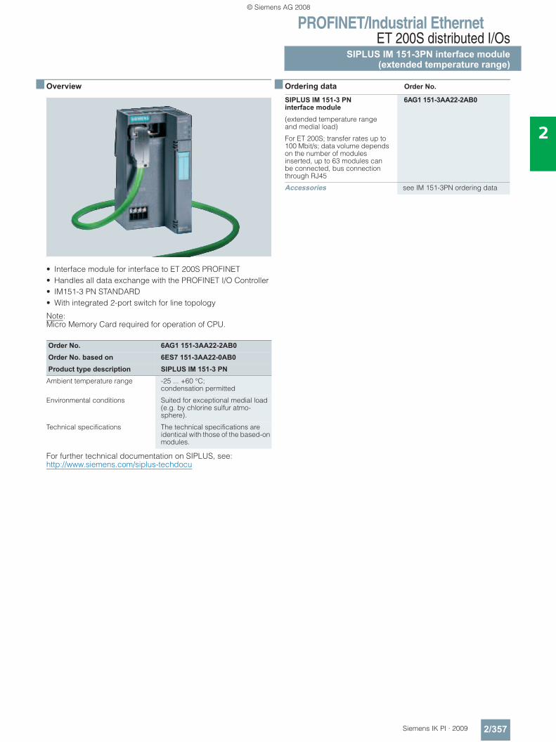
PROFINET/Industrial EthernetET 200S distributed I/Os
SIPLUS IM 151-3PN interface module(extended temperature range)
2/357Siemens IK PI · 2009
2
■ Overview
• Interface module for interface to ET 200S PROFINET• Handles all data exchange with the PROFINET I/O Controller• IM151-3 PN STANDARD• With integrated 2-port switch for line topology
Note: Micro Memory Card required for operation of CPU.
For further technical documentation on SIPLUS, see:http://www.siemens.com/siplus-techdocu
■ Ordering data Order No.
Order No. 6AG1 151-3AA22-2AB0Order No. based on 6ES7 151-3AA22-0AB0Product type description SIPLUS IM 151-3 PN
Ambient temperature range -25 ... +60 °C; condensation permitted
Environmental conditions Suited for exceptional medial load (e.g. by chlorine sulfur atmo-sphere).
Technical specifications The technical specifications are identical with those of the based-on modules.
SIPLUS IM 151-3 PN interface module
6AG1 151-3AA22-2AB0
(extended temperature range and medial load)
For ET 200S; transfer rates up to 100 Mbit/s; data volume depends on the number of modules inserted, up to 63 modules can be connected, bus connection through RJ45
Accessories see IM 151-3PN ordering data
© Siemens AG 2008
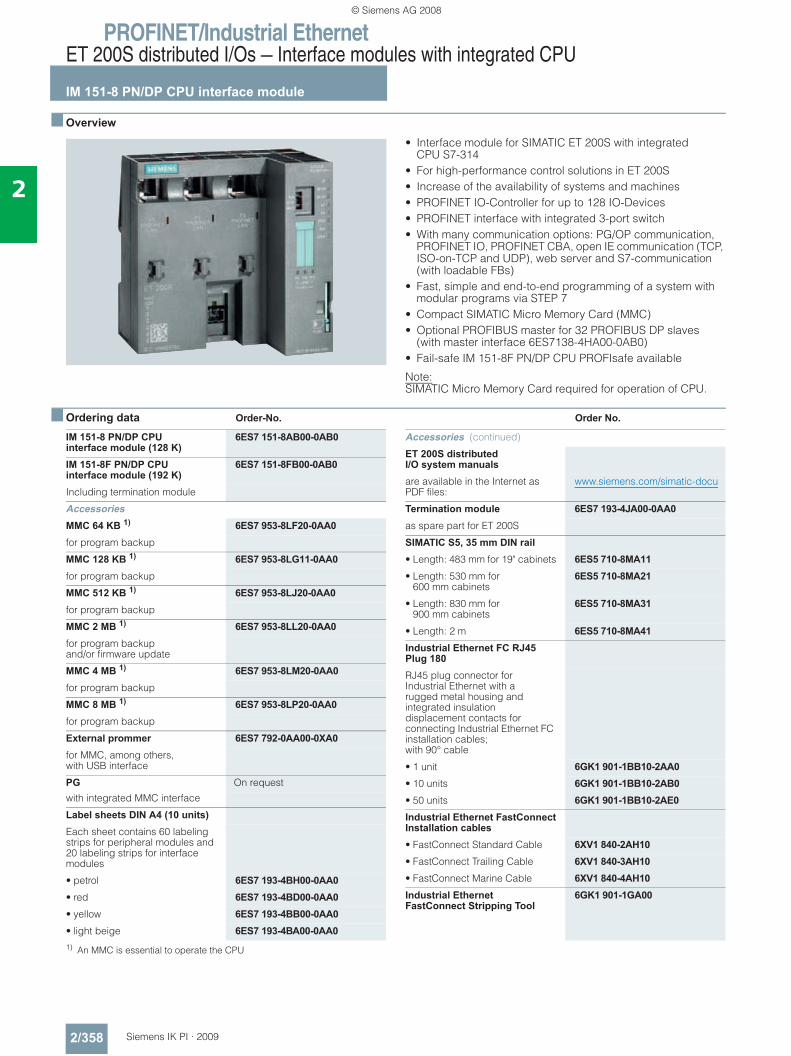
PROFINET/Industrial EthernetET 200S distributed I/Os — Interface modules with integrated CPU
IM 151-8 PN/DP CPU interface module
2/358 Siemens IK PI · 2009
2
■ Overview
• Interface module for SIMATIC ET 200S with integrated CPU S7-314
• For high-performance control solutions in ET 200S • Increase of the availability of systems and machines • PROFINET IO-Controller for up to 128 IO-Devices • PROFINET interface with integrated 3-port switch• With many communication options: PG/OP communication,
PROFINET IO, PROFINET CBA, open IE communication (TCP, ISO-on-TCP and UDP), web server and S7-communication (with loadable FBs)
• Fast, simple and end-to-end programming of a system with modular programs via STEP 7
• Compact SIMATIC Micro Memory Card (MMC)• Optional PROFIBUS master for 32 PROFIBUS DP slaves
(with master interface 6ES7138-4HA00-0AB0)• Fail-safe IM 151-8F PN/DP CPU PROFIsafe available
Note:SIMATIC Micro Memory Card required for operation of CPU.
■ Ordering data Order-No. Order No.
1) An MMC is essential to operate the CPU
IM 151-8 PN/DP CPU interface module (128 K)
6ES7 151-8AB00-0AB0
IM 151-8F PN/DP CPU interface module (192 K)
6ES7 151-8FB00-0AB0
Including termination module
AccessoriesMMC 64 KB 1) 6ES7 953-8LF20-0AA0for program backup
MMC 128 KB 1) 6ES7 953-8LG11-0AA0for program backup
MMC 512 KB 1) 6ES7 953-8LJ20-0AA0for program backup
MMC 2 MB 1) 6ES7 953-8LL20-0AA0for program backup and/or firmware update
MMC 4 MB 1) 6ES7 953-8LM20-0AA0for program backup
MMC 8 MB 1) 6ES7 953-8LP20-0AA0for program backup
External prommer 6ES7 792-0AA00-0XA0for MMC, among others, with USB interface
PG On request
with integrated MMC interface
Label sheets DIN A4 (10 units)Each sheet contains 60 labeling strips for peripheral modules and 20 labeling strips for interface modules
• petrol 6ES7 193-4BH00-0AA0• red 6ES7 193-4BD00-0AA0• yellow 6ES7 193-4BB00-0AA0• light beige 6ES7 193-4BA00-0AA0
Accessories (continued)
ET 200S distributed I/O system manualsare available in the Internet as PDF files:
www.siemens.com/simatic-docu
Termination module 6ES7 193-4JA00-0AA0as spare part for ET 200S
SIMATIC S5, 35 mm DIN rail • Length: 483 mm for 19" cabinets 6ES5 710-8MA11• Length: 530 mm for
600 mm cabinets6ES5 710-8MA21
• Length: 830 mm for 900 mm cabinets
6ES5 710-8MA31
• Length: 2 m 6ES5 710-8MA41Industrial Ethernet FC RJ45 Plug 180RJ45 plug connector for Industrial Ethernet with a rugged metal housing and integrated insulation displacement contacts for connecting Industrial Ethernet FC installation cables; with 90° cable
• 1 unit 6GK1 901-1BB10-2AA0• 10 units 6GK1 901-1BB10-2AB0• 50 units 6GK1 901-1BB10-2AE0Industrial Ethernet FastConnectInstallation cables• FastConnect Standard Cable 6XV1 840-2AH10• FastConnect Trailing Cable 6XV1 840-3AH10• FastConnect Marine Cable 6XV1 840-4AH10Industrial Ethernet FastConnect Stripping Tool
6GK1 901-1GA00
© Siemens AG 2008
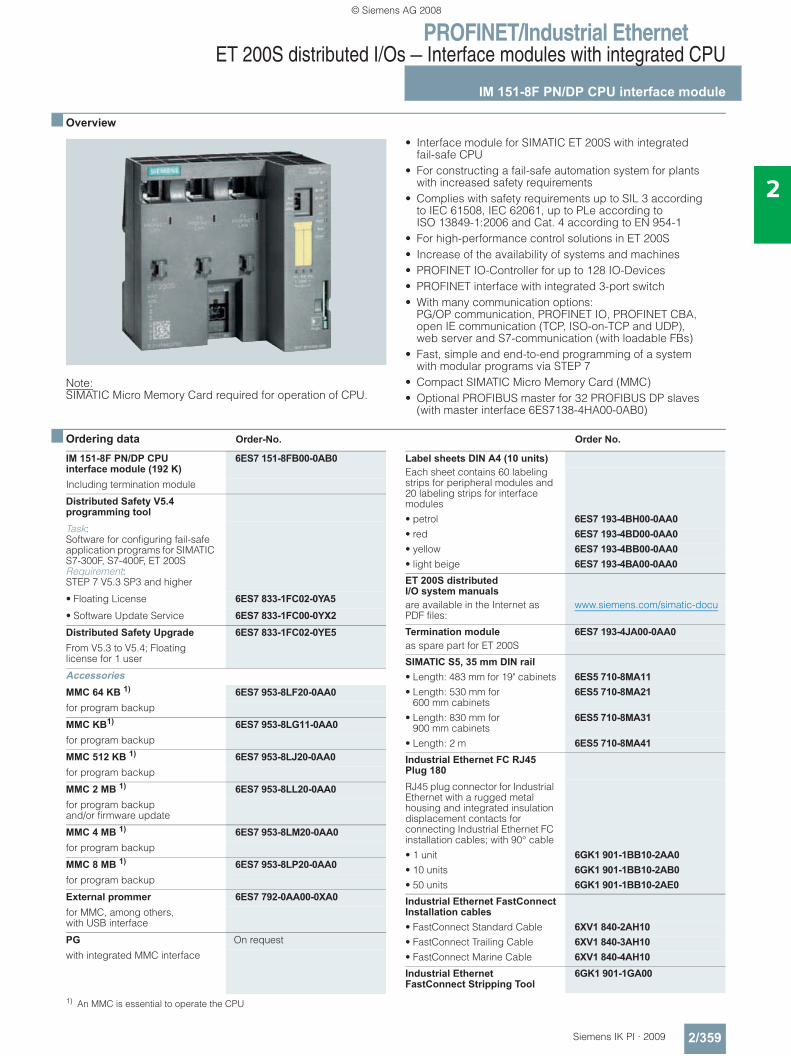
PROFINET/Industrial EthernetET 200S distributed I/Os — Interface modules with integrated CPU
IM 151-8F PN/DP CPU interface module
2/359Siemens IK PI · 2009
2
■ Overview
Note:SIMATIC Micro Memory Card required for operation of CPU.
• Interface module for SIMATIC ET 200S with integrated fail-safe CPU
• For constructing a fail-safe automation system for plants with increased safety requirements
• Complies with safety requirements up to SIL 3 according to IEC 61508, IEC 62061, up to PLe according to ISO 13849-1:2006 and Cat. 4 according to EN 954-1
• For high-performance control solutions in ET 200S • Increase of the availability of systems and machines • PROFINET IO-Controller for up to 128 IO-Devices • PROFINET interface with integrated 3-port switch• With many communication options:
PG/OP communication, PROFINET IO, PROFINET CBA, open IE communication (TCP, ISO-on-TCP and UDP), web server and S7-communication (with loadable FBs)
• Fast, simple and end-to-end programming of a system with modular programs via STEP 7
• Compact SIMATIC Micro Memory Card (MMC)• Optional PROFIBUS master for 32 PROFIBUS DP slaves
(with master interface 6ES7138-4HA00-0AB0)
■ Ordering data Order-No. Order No.
1) An MMC is essential to operate the CPU
IM 151-8F PN/DP CPU interface module (192 K)
6ES7 151-8FB00-0AB0
Including termination module
Distributed Safety V5.4 programming toolTask: Software for configuring fail-safe application programs for SIMATIC S7-300F, S7-400F, ET 200S Requirement: STEP 7 V5.3 SP3 and higher
• Floating License 6ES7 833-1FC02-0YA5• Software Update Service 6ES7 833-1FC00-0YX2Distributed Safety Upgrade 6ES7 833-1FC02-0YE5From V5.3 to V5.4; Floating license for 1 user
AccessoriesMMC 64 KB 1) 6ES7 953-8LF20-0AA0for program backup
MMC KB1) 6ES7 953-8LG11-0AA0for program backup
MMC 512 KB 1) 6ES7 953-8LJ20-0AA0for program backup
MMC 2 MB 1) 6ES7 953-8LL20-0AA0for program backup and/or firmware update
MMC 4 MB 1) 6ES7 953-8LM20-0AA0for program backup
MMC 8 MB 1) 6ES7 953-8LP20-0AA0for program backup
External prommer 6ES7 792-0AA00-0XA0for MMC, among others, with USB interface
PG On request
with integrated MMC interface
Label sheets DIN A4 (10 units)Each sheet contains 60 labeling strips for peripheral modules and 20 labeling strips for interface modules• petrol 6ES7 193-4BH00-0AA0• red 6ES7 193-4BD00-0AA0• yellow 6ES7 193-4BB00-0AA0• light beige 6ES7 193-4BA00-0AA0ET 200S distributed I/O system manualsare available in the Internet as PDF files:
www.siemens.com/simatic-docu
Termination module 6ES7 193-4JA00-0AA0as spare part for ET 200S
SIMATIC S5, 35 mm DIN rail • Length: 483 mm for 19" cabinets 6ES5 710-8MA11• Length: 530 mm for
600 mm cabinets6ES5 710-8MA21
• Length: 830 mm for 900 mm cabinets
6ES5 710-8MA31
• Length: 2 m 6ES5 710-8MA41Industrial Ethernet FC RJ45 Plug 180RJ45 plug connector for Industrial Ethernet with a rugged metal housing and integrated insulation displacement contacts for connecting Industrial Ethernet FC installation cables; with 90° cable• 1 unit 6GK1 901-1BB10-2AA0• 10 units 6GK1 901-1BB10-2AB0• 50 units 6GK1 901-1BB10-2AE0Industrial Ethernet FastConnectInstallation cables• FastConnect Standard Cable 6XV1 840-2AH10• FastConnect Trailing Cable 6XV1 840-3AH10• FastConnect Marine Cable 6XV1 840-4AH10Industrial Ethernet FastConnect Stripping Tool
6GK1 901-1GA00
© Siemens AG 2008
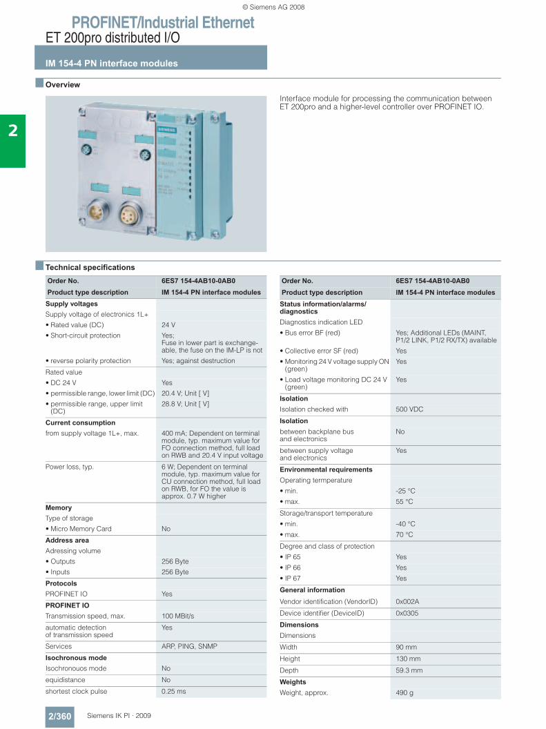
PROFINET/Industrial EthernetET 200pro distributed I/O
IM 154-4 PN interface modules
2/360 Siemens IK PI · 2009
2
■ Overview
Interface module for processing the communication between ET 200pro and a higher-level controller over PROFINET IO.
■ Technical specifications
Order No. 6ES7 154-4AB10-0AB0Product type description IM 154-4 PN interface modules
Supply voltages Supply voltage of electronics 1L+• Rated value (DC) 24 V• Short-circuit protection Yes;
Fuse in lower part is exchange-able, the fuse on the IM-LP is not
• reverse polarity protection Yes; against destruction
Rated value• DC 24 V Yes• permissible range, lower limit (DC) 20.4 V; Unit [ V]• permissible range, upper limit
(DC)28.8 V; Unit [ V]
Current consumption from supply voltage 1L+, max. 400 mA; Dependent on terminal
module, typ. maximum value for FO connection method, full load on RWB and 20.4 V input voltage
Power loss, typ. 6 W; Dependent on terminal module, typ. maximum value for CU connection method, full load on RWB, for FO the value is approx. 0.7 W higher
Memory Type of storage• Micro Memory Card No
Address area Adressing volume• Outputs 256 Byte• Inputs 256 Byte
Protocols PROFINET IO Yes
PROFINET IO Transmission speed, max. 100 MBit/s
automatic detection of transmission speed
Yes
Services ARP, PING, SNMP
Isochronous mode Isochronouos mode No
equidistance No
shortest clock pulse 0.25 ms
Order No. 6ES7 154-4AB10-0AB0Product type description IM 154-4 PN interface modules
Status information/alarms/diagnostics
Diagnostics indication LED
• Bus error BF (red) Yes; Additional LEDs (MAINT, P1/2 LINK, P1/2 RX/TX) available
• Collective error SF (red) Yes
• Monitoring 24 V voltage supply ON (green)
Yes
• Load voltage monitoring DC 24 V (green)
Yes
Isolation
Isolation checked with 500 VDC
Isolation
between backplane bus and electronics
No
between supply voltage and electronics
Yes
Environmental requirements
Operating termperature
• min. -25 °C
• max. 55 °C
Storage/transport temperature
• min. -40 °C
• max. 70 °C
Degree and class of protection
• IP 65 Yes
• IP 66 Yes
• IP 67 Yes
General information
Vendor identification (VendorID) 0x002A
Device identifier (DeviceID) 0x0305
Dimensions
Dimensions
Width 90 mm
Height 130 mm
Depth 59.3 mm
Weights
Weight, approx. 490 g
© Siemens AG 2008
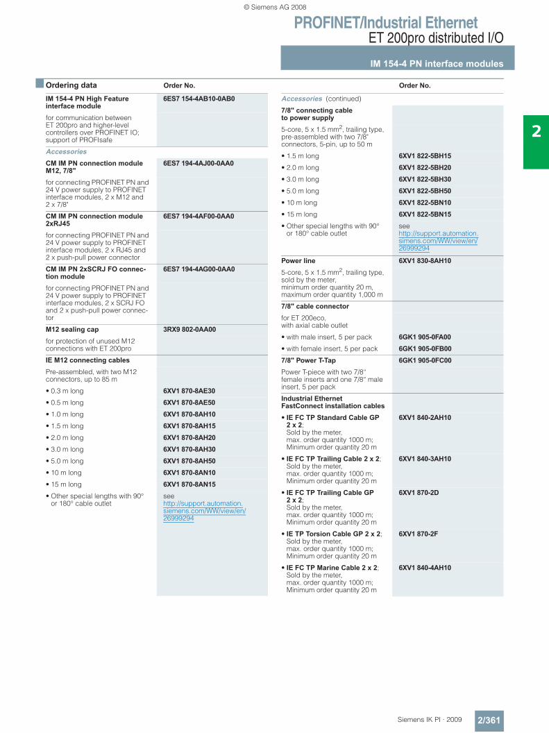
PROFINET/Industrial EthernetET 200pro distributed I/O
IM 154-4 PN interface modules
2/361Siemens IK PI · 2009
2
■ Ordering data Order No. Order No.
IM 154-4 PN High Feature interface module
6ES7 154-4AB10-0AB0
for communication between ET 200pro and higher-level controllers over PROFINET IO; support of PROFIsafe
AccessoriesCM IM PN connection module M12, 7/8"
6ES7 194-4AJ00-0AA0
for connecting PROFINET PN and 24 V power supply to PROFINET interface modules, 2 x M12 and 2 x 7/8"
CM IM PN connection module 2xRJ45
6ES7 194-4AF00-0AA0
for connecting PROFINET PN and 24 V power supply to PROFINET interface modules, 2 x RJ45 and 2 x push-pull power connector
CM IM PN 2xSCRJ FO connec-tion module
6ES7 194-4AG00-0AA0
for connecting PROFINET PN and 24 V power supply to PROFINET interface modules, 2 x SCRJ FO and 2 x push-pull power connec-tor
M12 sealing cap 3RX9 802-0AA00for protection of unused M12 connections with ET 200pro
IE M12 connecting cablesPre-assembled, with two M12 connectors, up to 85 m
• 0.3 m long 6XV1 870-8AE30• 0.5 m long 6XV1 870-8AE50• 1.0 m long 6XV1 870-8AH10• 1.5 m long 6XV1 870-8AH15• 2.0 m long 6XV1 870-8AH20• 3.0 m long 6XV1 870-8AH30• 5.0 m long 6XV1 870-8AH50• 10 m long 6XV1 870-8AN10• 15 m long 6XV1 870-8AN15• Other special lengths with 90°
or 180° cable outletseehttp://support.automation.siemens.com/WW/view/en/26999294
Accessories (continued)
7/8" connecting cable to power supply5-core, 5 x 1.5 mm2, trailing type, pre-assembled with two 7/8" connectors, 5-pin, up to 50 m
• 1.5 m long 6XV1 822-5BH15• 2.0 m long 6XV1 822-5BH20• 3.0 m long 6XV1 822-5BH30• 5.0 m long 6XV1 822-5BH50• 10 m long 6XV1 822-5BN10• 15 m long 6XV1 822-5BN15• Other special lengths with 90°
or 180° cable outletsee http://support.automation.simens.com/WW/view/en/26999294
Power line 6XV1 830-8AH105-core, 5 x 1.5 mm2, trailing type, sold by the meter, minimum order quantity 20 m, maximum order quantity 1,000 m
7/8" cable connectorfor ET 200eco, with axial cable outlet
• with male insert, 5 per pack 6GK1 905-0FA00• with female insert, 5 per pack 6GK1 905-0FB007/8" Power T-Tap 6GK1 905-0FC00Power T-piece with two 7/8“ female inserts and one 7/8“ male insert, 5 per pack
Industrial Ethernet FastConnect installation cables• IE FC TP Standard Cable GP
2 x 2; Sold by the meter, max. order quantity 1000 m; Minimum order quantity 20 m
6XV1 840-2AH10
• IE FC TP Trailing Cable 2 x 2; Sold by the meter, max. order quantity 1000 m; Minimum order quantity 20 m
6XV1 840-3AH10
• IE FC TP Trailing Cable GP 2 x 2; Sold by the meter, max. order quantity 1000 m; Minimum order quantity 20 m
6XV1 870-2D
• IE TP Torsion Cable GP 2 x 2; Sold by the meter, max. order quantity 1000 m; Minimum order quantity 20 m
6XV1 870-2F
• IE FC TP Marine Cable 2 x 2; Sold by the meter, max. order quantity 1000 m; Minimum order quantity 20 m
6XV1 840-4AH10
© Siemens AG 2008
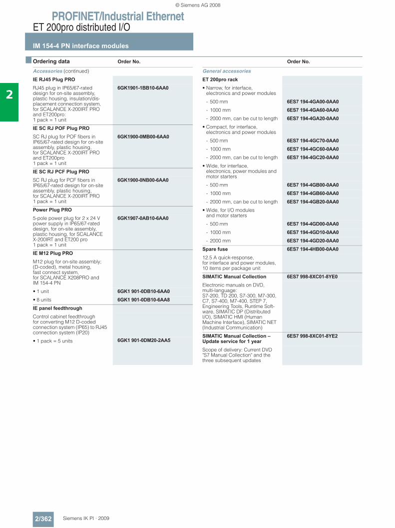
PROFINET/Industrial EthernetET 200pro distributed I/O
IM 154-4 PN interface modules
2/362 Siemens IK PI · 2009
2
■ Ordering data Order No. Order No.
Accessories (continued)
IE RJ45 Plug PRORJ45 plug in IP65/67-rated design for on-site assembly, plastic housing, insulation/dis-placement connection system, for SCALANCE X-200IRT PRO and ET200pro: 1 pack = 1 unit
6GK1901-1BB10-6AA0
IE SC RJ POF Plug PROSC RJ plug for POF fibers in IP65/67-rated design for on-site assembly, plastic housing, for SCALANCE X-200IRT PRO and ET200pro 1 pack = 1 unit
6GK1900-0MB00-6AA0
IE SC RJ PCF Plug PROSC RJ plug for PCF fibers in IP65/67-rated design for on-site assembly, plastic housing,for SCALANCE X-200IRT PRO 1 pack = 1 unit
6GK1900-0NB00-6AA0
Power Plug PRO5-pole power plug for 2 x 24 V power supply in IP65/67-rated design, for on-site assembly, plastic housing, for SCALANCE X-200IRT and ET200 pro 1 pack = 1 unit
6GK1907-0AB10-6AA0
IE M12 Plug PROM12 plug for on-site assembly; (D-coded), metal housing,fast connect system,for SCALANCE X208PRO andIM 154-4 PN
• 1 unit 6GK1 901-0DB10-6AA0• 8 units 6GK1 901-0DB10-6AA8IE panel feedthroughControl cabinet feedthrough for converting M12 D-coded connection system (IP65) to RJ45 connection system (IP20)
• 1 pack = 5 units 6GK1 901-0DM20-2AA5
General accessoriesET 200pro rack• Narrow, for interface,
electronics and power modules
- 500 mm 6ES7 194-4GA00-0AA0- 1000 mm 6ES7 194-4GA60-0AA0- 2000 mm, can be cut to length 6ES7 194-4GA20-0AA0
• Compact, for interface, electronics and power modules
- 500 mm 6ES7 194-4GC70-0AA0- 1000 mm 6ES7 194-4GC60-0AA0- 2000 mm, can be cut to length 6ES7 194-4GC20-0AA0
• Wide, for interface, electronics, power modules and motor starters
- 500 mm 6ES7 194-4GB00-0AA0- 1000 mm 6ES7 194-4GB60-0AA0- 2000 mm, can be cut to length 6ES7 194-4GB20-0AA0
• Wide, for I/O modules and motor starters
- 500 mm 6ES7 194-4GD00-0AA0- 1000 mm 6ES7 194-4GD10-0AA0- 2000 mm 6ES7 194-4GD20-0AA0
Spare fuse 6ES7 194-4HB00-0AA012.5 A quick-response, for interface and power modules, 10 items per package unit
SIMATIC Manual Collection 6ES7 998-8XC01-8YE0Electronic manuals on DVD, multi-language: S7-200, TD 200, S7-300, M7-300, C7, S7-400, M7-400, STEP 7, Engineering Tools, Runtime Soft-ware, SIMATIC DP (Distributed I/O), SIMATIC HMI (Human Machine Interface), SIMATIC NET (Industrial Communication)
SIMATIC Manual Collection – Update service for 1 year
6ES7 998-8XC01-8YE2
Scope of delivery: Current DVD "S7 Manual Collection" and the three subsequent updates
© Siemens AG 2008
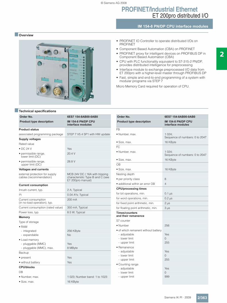
PROFINET/Industrial EthernetET 200pro distributed I/O
IM 154-8 PN/DP CPU interface modules
2/363Siemens IK PI · 2009
2
■ Overview
• PROFINET IO Controller to operate distributed I/Os on PROFINET
• Component Based Automation (CBA) on PROFINET• PROFINET proxy for intelligent devices on PROFIBUS DP in
Component Based Automation (CBA)• CPU with PLC functionality equivalent to S7-315-2 PN/DP,
provides distributed intelligence for preprocessing • Interface module to exchange preprocessed I/O data from
ET 200pro with a higher-level master through PROFIBUS DP• Fast, simple and end-to-end programming of a system with
modular programs via STEP 7
Micro Memory Card required for operation of CPU.
■ Technical specifications
Order No. 6ES7 154-8AB00-0AB0Product type description IM 154-8 PN/DP CPU
interface modulesProduct status
associated programming package STEP 7 V5.4 SP1 with HW update
Supply voltages
Rated value
• DC 24 V Yes
• permissible range,lower limit (DC)
20.4 V
• permissible range,upper limit (DC)
28.8 V
Voltages and currents
external protection for supply cables (recommendation)
MCB 24V DC / 16A with tripping characteristic Type B and C (see ET 200pro manual)
Current consumption
Inrush current, typ. 2 A; Typical
I²t 0.04 A²s; Typical
Current consumption (in no-load operation), typ.
200 mA
Current consumption (rated value) 350 mA; Typical
Power loss, typ. 8.5 W; Typical
Memory
Type of storage
• RAM- integrated 256 KByte- expandable No
• Load memory- pluggable (MMC) Yes- pluggable (MMC), max. 8 MByte
Backup
• present Yes
• without battery Yes
CPU/blocks
DB
• Number, max. 1 023; Number band: 1 to 1023
• Size, max. 16 KByte
Order No. 6ES7 154-8AB00-0AB0Product type description IM 154-8 PN/DP CPU
interface modulesFB
• Number, max. 1 024; Sequence of numbers: 0 to 2047
• Size, max. 16 KByte
FC
• Number, max. 1 024; Sequence of numbers: 0 to 2047
• Size, max. 16 KByte
OB
• Size, max. 16 KByte
Nesting depth
• per priority class 8
• additional within an error OB 4
CPU/processing times
for bit operations, min. 0.1 μs
for word operations, min. 0.2 μs
for fixed point arithmetic, min. 2 μs
for floating point arithmetic, min. 3 μs
Times/counters and their remanence
S7 counter
• Number 256
• of which remanent without battery- adjustable Yes- lower limit 0- upper limit 255
• Remanence- adjustable Yes- lower limit 0- upper limit 255
• Counting range- adjustable Yes- lower limit 0- upper limit 999
© Siemens AG 2008
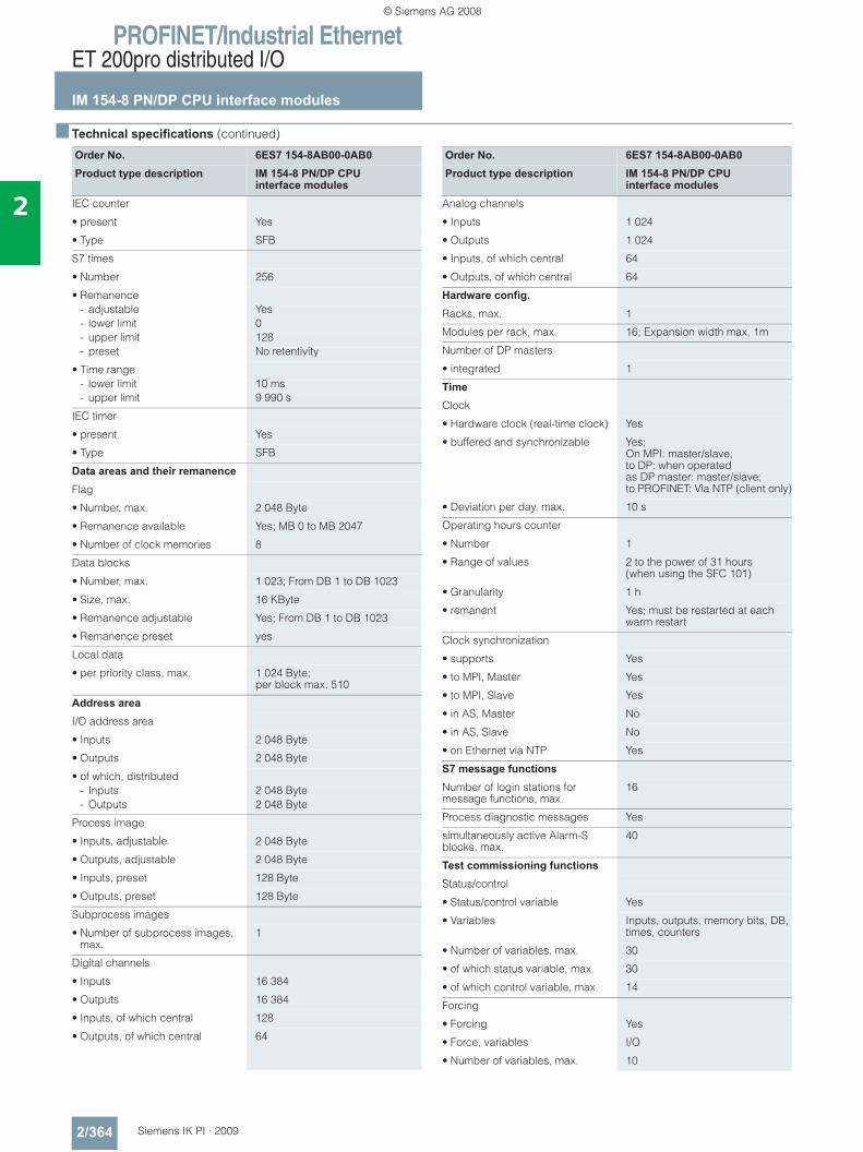
PROFINET/Industrial EthernetET 200pro distributed I/O
IM 154-8 PN/DP CPU interface modules
2/364 Siemens IK PI · 2009
2
■ Technical specifications (continued)
Order No. 6ES7 154-8AB00-0AB0Product type description IM 154-8 PN/DP CPU
interface modulesIEC counter
• present Yes
• Type SFB
S7 times
• Number 256
• Remanence- adjustable Yes- lower limit 0- upper limit 128- preset No retentivity
• Time range- lower limit 10 ms- upper limit 9 990 s
IEC timer
• present Yes
• Type SFB
Data areas and their remanence
Flag
• Number, max. 2 048 Byte
• Remanence available Yes; MB 0 to MB 2047
• Number of clock memories 8
Data blocks
• Number, max. 1 023; From DB 1 to DB 1023
• Size, max. 16 KByte
• Remanence adjustable Yes; From DB 1 to DB 1023
• Remanence preset yes
Local data
• per priority class, max. 1 024 Byte; per block max. 510
Address area
I/O address area
• Inputs 2 048 Byte
• Outputs 2 048 Byte
• of which, distributed- Inputs 2 048 Byte- Outputs 2 048 Byte
Process image
• Inputs, adjustable 2 048 Byte
• Outputs, adjustable 2 048 Byte
• Inputs, preset 128 Byte
• Outputs, preset 128 Byte
Subprocess images
• Number of subprocess images, max.
1
Digital channels
• Inputs 16 384
• Outputs 16 384
• Inputs, of which central 128
• Outputs, of which central 64
Order No. 6ES7 154-8AB00-0AB0Product type description IM 154-8 PN/DP CPU
interface modulesAnalog channels
• Inputs 1 024
• Outputs 1 024
• Inputs, of which central 64
• Outputs, of which central 64
Hardware config. Racks, max. 1
Modules per rack, max. 16; Expansion width max. 1m
Number of DP masters
• integrated 1
Time
Clock
• Hardware clock (real-time clock) Yes
• buffered and synchronizable Yes; On MPI: master/slave;to DP: when operatedas DP master: master/slave;to PROFINET: Via NTP (client only)
• Deviation per day, max. 10 s
Operating hours counter
• Number 1
• Range of values 2 to the power of 31 hours (when using the SFC 101)
• Granularity 1 h
• remanent Yes; must be restarted at each warm restart
Clock synchronization
• supports Yes
• to MPI, Master Yes
• to MPI, Slave Yes
• in AS, Master No
• in AS, Slave No
• on Ethernet via NTP Yes
S7 message functions
Number of login stations for message functions, max.
16
Process diagnostic messages Yes
simultaneously active Alarm-S blocks, max.
40
Test commissioning functions
Status/control
• Status/control variable Yes
• Variables Inputs, outputs, memory bits, DB, times, counters
• Number of variables, max. 30
• of which status variable, max. 30
• of which control variable, max. 14
Forcing
• Forcing Yes
• Force, variables I/O
• Number of variables, max. 10
© Siemens AG 2008
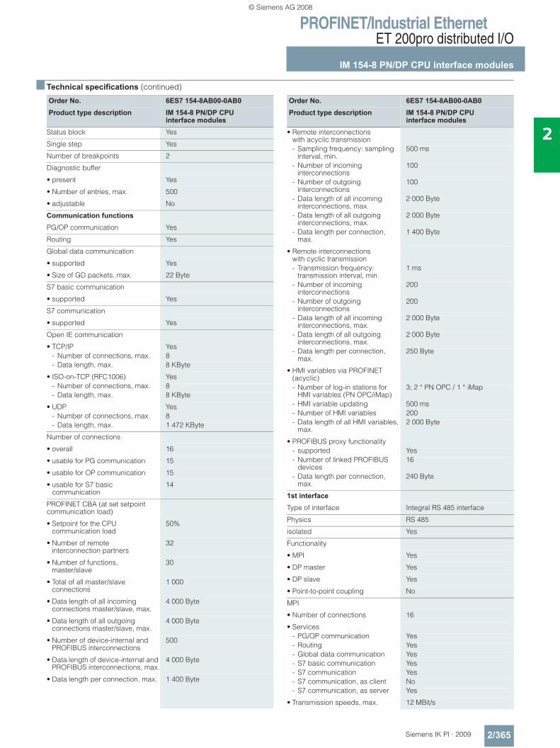
PROFINET/Industrial EthernetET 200pro distributed I/O
IM 154-8 PN/DP CPU interface modules
2/365Siemens IK PI · 2009
2
■ Technical specifications (continued)
Order No. 6ES7 154-8AB00-0AB0Product type description IM 154-8 PN/DP CPU
interface modulesStatus block Yes
Single step Yes
Number of breakpoints 2
Diagnostic buffer
• present Yes
• Number of entries, max. 500
• adjustable No
Communication functions
PG/OP communication Yes
Routing Yes
Global data communication
• supported Yes
• Size of GD packets, max. 22 Byte
S7 basic communication
• supported Yes
S7 communication
• supported Yes
Open IE communication
• TCP/IP Yes- Number of connections, max. 8- Data length, max. 8 KByte
• ISO-on-TCP (RFC1006) Yes- Number of connections, max. 8- Data length, max. 8 KByte
• UDP Yes- Number of connections, max. 8- Data length, max. 1 472 KByte
Number of connections
• overall 16
• usable for PG communication 15
• usable for OP communication 15
• usable for S7 basic communication
14
PROFINET CBA (at set setpoint communication load)
• Setpoint for the CPU communication load
50%
• Number of remote interconnection partners
32
• Number of functions, master/slave
30
• Total of all master/slave connections
1 000
• Data length of all incoming connections master/slave, max.
4 000 Byte
• Data length of all outgoing connections master/slave, max.
4 000 Byte
• Number of device-internal and PROFIBUS interconnections
500
• Data length of device-internal and PROFIBUS interconnections, max.
4 000 Byte
• Data length per connection, max. 1 400 Byte
Order No. 6ES7 154-8AB00-0AB0Product type description IM 154-8 PN/DP CPU
interface modules• Remote interconnections
with acyclic transmission- Sampling frequency: sampling
interval, min.500 ms
- Number of incoming interconnections
100
- Number of outgoing interconnections
100
- Data length of all incoming interconnections, max.
2 000 Byte
- Data length of all outgoing interconnections, max.
2 000 Byte
- Data length per connection, max.
1 400 Byte
• Remote interconnections with cyclic transmission- Transmission frequency:
transmission interval, min.1 ms
- Number of incoming interconnections
200
- Number of outgoing interconnections
200
- Data length of all incoming interconnections, max.
2 000 Byte
- Data length of all outgoing interconnections, max.
2 000 Byte
- Data length per connection, max.
250 Byte
• HMI variables via PROFINET (acyclic)- Number of log-in stations for
HMI variables (PN OPC/iMap)3; 2 * PN OPC / 1 * iMap
- HMI variable updating 500 ms- Number of HMI variables 200- Data length of all HMI variables,
max.2 000 Byte
• PROFIBUS proxy functionality- supported Yes- Number of linked PROFIBUS
devices16
- Data length per connection, max.
240 Byte
1st interface
Type of interface Integral RS 485 interface
Physics RS 485
isolated Yes
Functionality
• MPI Yes
• DP master Yes
• DP slave Yes
• Point-to-point coupling No
MPI
• Number of connections 16
• Services- PG/OP communication Yes- Routing Yes- Global data communication Yes- S7 basic communication Yes- S7 communication Yes- S7 communication, as client No- S7 communication, as server Yes
• Transmission speeds, max. 12 MBit/s
© Siemens AG 2008
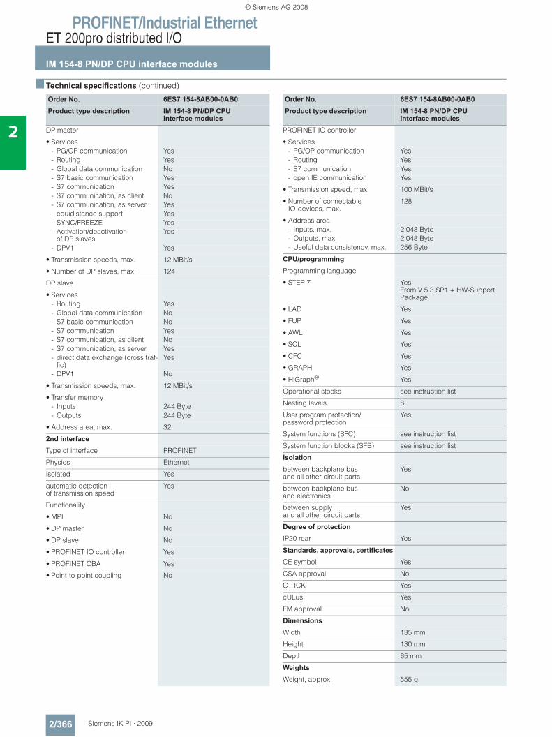
PROFINET/Industrial EthernetET 200pro distributed I/O
IM 154-8 PN/DP CPU interface modules
2/366 Siemens IK PI · 2009
2
■ Technical specifications (continued)
Order No. 6ES7 154-8AB00-0AB0Product type description IM 154-8 PN/DP CPU
interface modulesDP master
• Services- PG/OP communication Yes- Routing Yes- Global data communication No- S7 basic communication Yes- S7 communication Yes- S7 communication, as client No- S7 communication, as server Yes- equidistance support Yes- SYNC/FREEZE Yes- Activation/deactivation
of DP slavesYes
- DPV1 Yes
• Transmission speeds, max. 12 MBit/s
• Number of DP slaves, max. 124
DP slave
• Services- Routing Yes- Global data communication No- S7 basic communication No- S7 communication Yes- S7 communication, as client No- S7 communication, as server Yes- direct data exchange (cross traf-
fic)Yes
- DPV1 No
• Transmission speeds, max. 12 MBit/s
• Transfer memory- Inputs 244 Byte- Outputs 244 Byte
• Address area, max. 32
2nd interface
Type of interface PROFINET
Physics Ethernet
isolated Yes
automatic detection of transmission speed
Yes
Functionality
• MPI No
• DP master No
• DP slave No
• PROFINET IO controller Yes
• PROFINET CBA Yes
• Point-to-point coupling No
Order No. 6ES7 154-8AB00-0AB0Product type description IM 154-8 PN/DP CPU
interface modulesPROFINET IO controller
• Services- PG/OP communication Yes- Routing Yes- S7 communication Yes- open IE communication Yes
• Transmission speed, max. 100 MBit/s
• Number of connectableIO-devices, max.
128
• Address area- Inputs, max. 2 048 Byte- Outputs, max. 2 048 Byte- Useful data consistency, max. 256 Byte
CPU/programming
Programming language
• STEP 7 Yes;From V 5.3 SP1 + HW-Support Package
• LAD Yes
• FUP Yes
• AWL Yes
• SCL Yes
• CFC Yes
• GRAPH Yes
• HiGraph® Yes
Operational stocks see instruction list
Nesting levels 8
User program protection/password protection
Yes
System functions (SFC) see instruction list
System function blocks (SFB) see instruction list
Isolation
between backplane bus and all other circuit parts
Yes
between backplane bus and electronics
No
between supply and all other circuit parts
Yes
Degree of protection
IP20 rear Yes
Standards, approvals, certificates
CE symbol Yes
CSA approval No
C-TICK Yes
cULus Yes
FM approval No
Dimensions
Width 135 mm
Height 130 mm
Depth 65 mm
Weights
Weight, approx. 555 g
© Siemens AG 2008
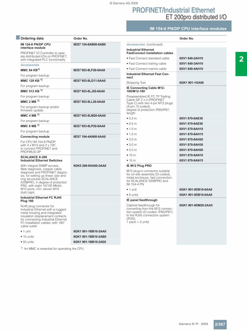
PROFINET/Industrial EthernetET 200pro distributed I/O
IM 154-8 PN/DP CPU interface modules
2/367Siemens IK PI · 2009
2
■ Ordering data Order No. Order No.
1) An MMC is essential for operating the CPU
IM 154-8 PN/DP CPUinterface module
6ES7 154-8AB00-0AB0
PROFINET IO Controller to oper-ate distributed I/Os on PROFINET, with integrated PLC functionality
AccessoriesMMC 64 KB1) 6ES7 953-8LF20-0AA0For program backup
MMC 128 KB 1) 6ES7 953-8LG11-0AA0For program backup
MMC 512 KB 1) 6ES7 953-8LJ20-0AA0For program backup
MMC 2 MB 1) 6ES7 953-8LL20-0AA0For program backup and/or firmware update
MMC 4 MB 1) 6ES7 953-8LM20-0AA0For program backup
MMC 8 MB 1) 6ES7 953-8LP20-0AA0For program backup
Connecting module 6ES7 194-4AN00-0AA0For CPU IM 154-8 PN/DP, with 4 x M12 and 2 x 7/8", to connect PROFINET and PROFIBUS DP
SCALANCE X-200Industrial Ethernet SwitchesWith integral SNMP access, Web diagnosis, copper cable diagnosis and PROFINET diagno-sis, for setting up linear, star and ring structures SCALANCE X208PRO, in degree of protection IP65, with eight 10/100 Mbit/s M12 ports, incl. eleven M12 dust caps
6GK5 208-0HA00-2AA6
Industrial Ethernet FC RJ45 Plug 180RJ45 plug connector for Industrial Ethernet with a rugged metal housing and integrated insulation displacement contacts for connecting Industrial Ethernet FC installation cables; with 180° cable outlet
• 1 unit 6GK1 901-1BB10-2AA0• 10 units 6GK1 901-1BB10-2AB0• 50 units 6GK1 901-1BB10-2AE0
Accessories (continued)
Industrial Ethernet FastConnect installation cables• Fast Connect standard cable 6XV1 840-2AH10• Fast Connect trailing cable 6XV1 840-3AH10• Fast Connect marine cable 6XV1 840-4AH10Industrial Ethernet Fast Con-nectStripping Tool 6GK1 901-1GA00IE Connecting Cable M12-180/M12-180Preassembled IE FC TP Trailing Cable GP 2 x 2 (PROFINET Type C) with two 4-pin M12 plugs (4-pin, D-coded), degree of protection IP65/IP67, length:
• 0.3 m 6XV1 870-8AE30• 0.5 m 6XV1 870-8AE50• 1.0 m 6XV1 870-8AH10• 1.5 m 6XV1 870-8AH15• 2.0 m 6XV1 870-8AH20• 3.0 m 6XV1 870-8AH30• 5.0 m 6XV1 870-8AH50• 10 m 6XV1 870-8AN10• 15 m 6XV1 870-8AN15IE M12 Plug PROM12 plug-in connector suitable for on-site assembly (D-coded), metal enclosure, fast connection, for SCALANCE X208PRO andIM 154-4 PN
• 1 unit 6GK1 901-0DB10-6AA0• 8 units 6GK1 901-0DB10-6AA8IE panel feedthroughCabinet feedthrough for converting from the M12 connec-tion system (D-coded, IP65/IP67) to the RJ45 connection system (IP20), 1 pack = 5 units
6GK1 901-0DM20-2AA5
© Siemens AG 2008
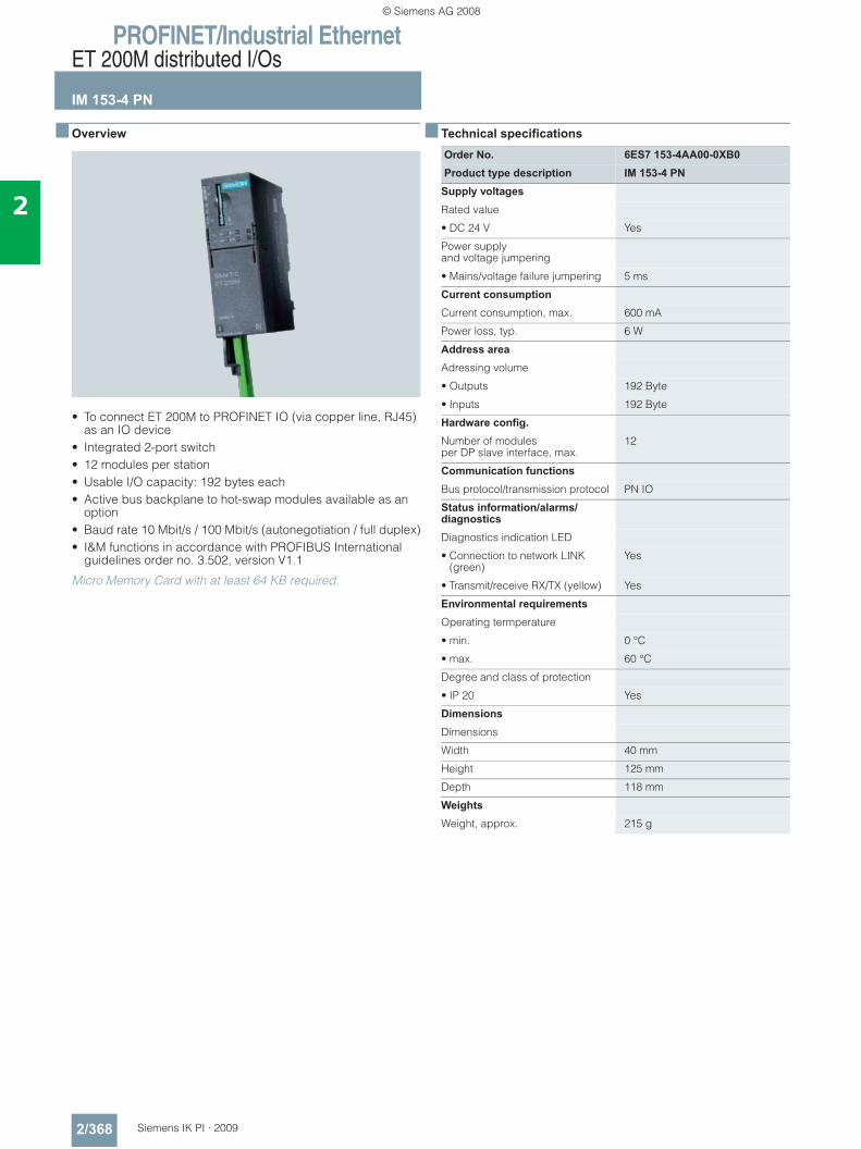
PROFINET/Industrial EthernetET 200M distributed I/Os
IM 153-4 PN
2/368 Siemens IK PI · 2009
2
■ Overview
• To connect ET 200M to PROFINET IO (via copper line, RJ45) as an IO device
• Integrated 2-port switch• 12 modules per station• Usable I/O capacity: 192 bytes each• Active bus backplane to hot-swap modules available as an
option• Baud rate 10 Mbit/s / 100 Mbit/s (autonegotiation / full duplex)• I&M functions in accordance with PROFIBUS International
guidelines order no. 3.502, version V1.1
Micro Memory Card with at least 64 KB required.
■ Technical specifications
Order No. 6ES7 153-4AA00-0XB0Product type description IM 153-4 PN
Supply voltages
Rated value
• DC 24 V Yes
Power supplyand voltage jumpering
• Mains/voltage failure jumpering 5 ms
Current consumption
Current consumption, max. 600 mA
Power loss, typ. 6 W
Address area
Adressing volume
• Outputs 192 Byte
• Inputs 192 Byte
Hardware config. Number of modules per DP slave interface, max.
12
Communication functions
Bus protocol/transmission protocol PN IO
Status information/alarms/diagnostics
Diagnostics indication LED
• Connection to network LINK (green)
Yes
• Transmit/receive RX/TX (yellow) Yes
Environmental requirements
Operating termperature
• min. 0 °C
• max. 60 °C
Degree and class of protection
• IP 20 Yes
Dimensions
Dimensions
Width 40 mm
Height 125 mm
Depth 118 mm
Weights
Weight, approx. 215 g
© Siemens AG 2008
PROFINET/Industrial EthernetET 200M distributed I/Os
IM 153-4 PN
2/369Siemens IK PI · 2009
2
■ Ordering data Order No. Order No.
1) To operate the IM153-4, an MMC is required with at least 64 KB memory. Cards with higher memory capacity may also be used.
IM 153-4 PN interface module 6ES7 153-4AA00-0XB0I/O device to connect an ET 200M to PROFINET
AccessoriesBus modules for ET 200M• To accommodate a power
supply and an IM 153 for the hot-swapping function during RUN, incl. bus module cover
6ES7 195-7HA00-0XA0
• To accommodate two 40-mm wide I/O modules for the hot-swapping function
6ES7 195-7HB00-0XA0
• To accommodate one 80-mm wide I/O module for the hot-swapping function
6ES7 195-7HC00-0XA0
SIMATIC Micro Memory Card64 KB1) 6ES7 953-8LF20-0AA0SIMATIC DP DIN railfor ET200MFor insertion of up to 5 bus modules for
• Length: 483 mm (19“) 6ES7 195-1GA00-0XA0• Length: 530 mm 6ES7 195-1GF30-0XA0SIMATIC S7-300 DIN rail• Length: 160 mm 6ES7 390-1AB60-0AA0• Length: 480 mm (19“) 6ES7 390-1AE80-0AA0• Length: 530 mm 6ES7 390-1AF30-0AA0• Length: 830 mm 6ES7 390-1AJ30-0AA0• Length: 2,000 mm 6ES7 390-1BC00-0AA0S7 Manual Collection 6ES7 998-8XC01-8YE0Electronic manuals on DVD, multi-language: S7-200, TD 200, S7-300, M7-300, C7, S7-400, M7-400, STEP 7, Engineering Tools, Runtime Soft-ware, SIMATIC DP (Distributed I/O), SIMATIC HMI (Human Machine Interface), SIMATIC NET (Industrial Communication)
S7 Manual Collection update service for 1 year
6ES7 998-8XC01-8YE2
Scope of delivery: Current DVD "S7 Manual Collec-tion" and the three subsequent updates
Accessories (continued)
Compact Switch ModuleCSM 377
6GK7 377-1AA00-0AA0
Unmanaged Switch for con-necting a SIMATIC S7-300 CPU and up to three additional nodes to Industrial Ethernet with 10/100 Mbit/s; 4 x RJ45 ports; external 24 V DC power supply, LED diagnostics, S7-300 module incl. electronic manual on CD-ROM
Industrial Ethernet Switch SCALANCE X208
6GK5 208-0BA10-2AA3
managed Switch with integrated SNMP access, Web diagnostics, copper cable diagnostics and PROFINET diagnostics,for configuring line, star and ring topologies; with integrated redundancy manager;with eight 10/100 Mbit/s RJ45 ports
Industrial Ethernet FC RJ45 Plug 180RJ45 plug connector for Industrial Ethernet with a rugged metal housing and integrated insulation displacement contacts for con-necting Industrial Ethernet FC installation cables; with 180° cable outlet
• 1 unit 6GK1 901-1BB10-2AA0• 10 units 6GK1 901-1BB10-2AB0• 50 units 6GK1 901-1BB10-2AE0Industrial Ethernet FastConnect installation cables• Fast Connect standard cable 6XV1 840-2AH10• Fast Connect trailing cable 6XV1 840-3AH10• Fast Connect marine cable 6XV1 840-4AH10Industrial Ethernet FastConnect Stripping Tool
6GK1 901-1GA00
© Siemens AG 2008
PROFINET/Industrial EthernetMotion Control System SIMOTION
The SIMOTION system
2/370 Siemens IK PI · 2009
2
■ Overview
The system approach
SIMOTION is recommended for all machines with Motion Control tasks – from simple to high-performance. The focus is on a simple and flexible solution for the greatest possible range of Motion Control tasks. In order to achieve this in the best way possible, a new system approach has been introduced.
The fusion of Motion Control with two other control functions which are found in most machines: PLC and technology func-tions.
This approach enables motion control and complete machine control within the same system. The same applies to technology functions, such as pressure control of a hydraulic axis. A seam-less switch can be made from position-controlled positioning mode to pressure control.
Combining the three open-loop control functions of Motion Control, PLC and technology functions has the following benefits:• Reduced engineering overhead and increased machine per-
formance• Fast system response – Time-critical interfaces between the
individual components are no longer required• Simple, uniform and transparent programming as well as di-
agnostics of the entire machine
The SIMOTION system is made up of three components:
Engineering systemSCOUT enables Motion Control, PLC and technology functions to be incorporated in one comprehensive, integrated system and provides all the necessary tools: From programming and parameterization through testing and commissioning, to diag-nostics.
Runtime softwareThe runtime system offers an ingenious execution system for cyclic and sequential tasks. The runtime modules make the dif-ferent PLC, Motion Control and technology functions available. By selecting the appropriate modules, the overall functionality of the system can be flexibly adapted to the machine.
Hardware platformsThe hardware platforms are the basis of the SIMOTION Motion Control System. The application created with the engineering system and the associated runtime software modules can be implemented on different hardware platforms.
You can therefore always select the platform that suits your machine best, as a controller, industrial PC or intelligent drive.
SIMOTION(e. g. positioning, syn-chronous operation, etc.)
Technologyfunctions
(e. g. hydraulic control,temperature control, etc.)
G_PM10_EN_00125
Fusion of Motion Control,PLC, and technologyfunctions
PLCfunctionality (IEC 61131-3)
Motion Control Graphical or text-basedprogramming
Engineering systemFor programming,parameterization, ...
Runtime software
Hardware platforms
GearCam
Positioning
Interpolation
PLC
Test anddiagnostics
G_PM10_EN_00126
Controller-basedPC-basedDrive-based
© Siemens AG 2008
PROFINET/Industrial EthernetMotion Control System SIMOTION
The hardware platforms
2/371Siemens IK PI · 2009
2
■ Overview
Automation systems are primarily identified by the following characteristics:• System-specific characteristics, e.g. functionality and
engineering• Hardware-dependent characteristics, e.g. performance,
design and expandability
However, mechanical engineering demands vary greatly, depending on the version of the machine in question.
Every hardware platform has its benefits when used in certain applications. The various platforms can also be combined very easily, which is a particular advantage in modular machines and plants. This is because the individual hardware platforms always contain the same system characteristics, i.e. functionality and engineering are always identical, irrespective of the platform used.
PROFIBUS or PROFINET can be used to create the link to the drives and the I/Os remotely.
PROFIBUS/PROFINET can also be used for communication with HMI devices such as SIMATIC HMI or higher-level controllers such as SIMATIC S7. This means that SIMATIC HMI panels as well as PCs with ProTool/Pro or WinCC flexible can be used as operator systems.
Even 3rd party applications communicate with SIMOTION by means of the OPC interface.
SIMOTION D – Compact and integrated in the drive
In SIMOTION D, the SIMOTION functionality is integrated di-rectly in the closed-loop control module of the SINAMICS S120 drive system. Therefore, the complete system (consisting of the open-loop control and the drive) is extremely compact and pow-erful. Two SIMOTION D versions are available: as a single-axis SIMOTION D410 system and as a multi-axis SIMOTION D4x5 system in different performance variants. This ensures a high degree of scalability and flexibility. The field of application ranges from single axes to high-performance multi-axis ma-chines. SIMOTION D4x5 is supplied with two integrated PROFIBUS interfaces supporting PROFIdrive and two integrated Industrial Ethernet interfaces. An optional Communication Board is used to connect via PROFINET. With SIMOTION D410, a PROFIBUS variant or a PROFINET variant can be selected.
SIMOTION C – Modularity and flexibilitySIMOTION C is a controller based on the SIMATIC S7-300 de-sign. It is supplied with four integrated interfaces for analog or stepper drives and several integrated digital inputs and outputs. SIMOTION C can also be expanded using I/O modules from the SIMATIC S7-300 range. Furthermore, the controller is supplied with two PROFIBUS interfaces supporting PROFIdrive and an Industrial Ethernet interface, thus offering great flexibility in communication.
SIMOTION P – Open for other tasksSIMOTION P350 is a PC-based Motion Control System. The operating system is Windows XP Professional, with a real-time expansion for SIMOTION. Apart from the SIMOTION machine applications, additional PC applications can execute at any time, e.g. the SIMOTION engineering system, an operator con-trol application, process data evaluation, and other standard PC applications. Due to the high processor performance, SIMOTION P350 is optimized for applications with the highest performance requirements (e.g. hydraulic applications with highly dynamic position and pressure control loops).
Several panel variants in various screen sizes are available for operating the industrial PC. These panels can either be operated using a keyboard and mouse, or a touch screen. The drives and I/Os are connected via two PROFIBUS interfaces supporting PROFIdrive or PROFINET with an optional Communication Board.
■ More information
More information regarding technical specifications and ordering data can be found in Catalog PM 21 "SIMOTION, SINAMICS S120 and Motors for Production Machines" and in the interactive catalog under "Automation Systems / SIMOTION Motion Control System"
© Siemens AG 2008
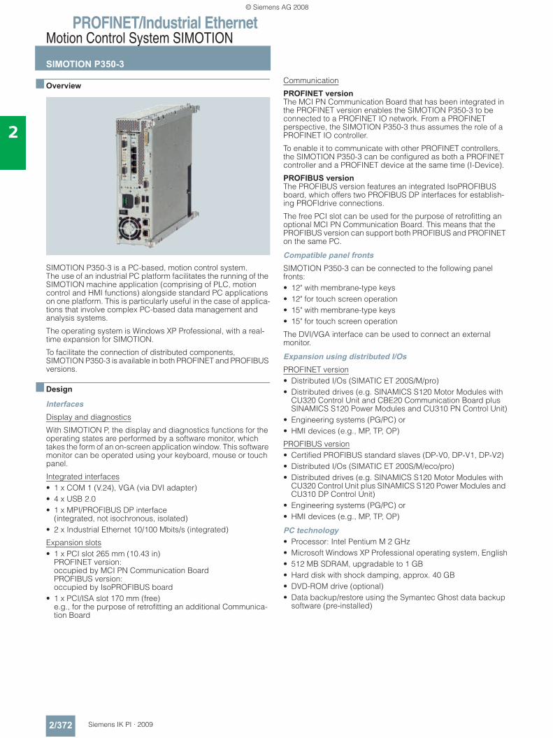
PROFINET/Industrial EthernetMotion Control System SIMOTION
SIMOTION P350-3
2/372 Siemens IK PI · 2009
2
■ Overview
SIMOTION P350-3 is a PC-based, motion control system. The use of an industrial PC platform facilitates the running of the SIMOTION machine application (comprising of PLC, motion control and HMI functions) alongside standard PC applications on one platform. This is particularly useful in the case of applica-tions that involve complex PC-based data management and analysis systems.
The operating system is Windows XP Professional, with a real-time expansion for SIMOTION.
To facilitate the connection of distributed components, SIMOTION P350-3 is available in both PROFINET and PROFIBUS versions.
■ Design
InterfacesDisplay and diagnostics
With SIMOTION P, the display and diagnostics functions for the operating states are performed by a software monitor, which takes the form of an on-screen application window. This software monitor can be operated using your keyboard, mouse or touch panel.
Integrated interfaces• 1 x COM 1 (V.24), VGA (via DVI adapter) • 4 x USB 2.0 • 1 x MPI/PROFIBUS DP interface
(integrated, not isochronous, isolated) • 2 x Industrial Ethernet 10/100 Mbits/s (integrated)
Expansion slots• 1 x PCI slot 265 mm (10.43 in)
PROFINET version: occupied by MCI PN Communication BoardPROFIBUS version: occupied by IsoPROFIBUS board
• 1 x PCI/ISA slot 170 mm (free)e.g., for the purpose of retrofitting an additional Communica-tion Board
Communication
PROFINET version The MCI PN Communication Board that has been integrated in the PROFINET version enables the SIMOTION P350-3 to be connected to a PROFINET IO network. From a PROFINET perspective, the SIMOTION P350-3 thus assumes the role of a PROFINET IO controller.
To enable it to communicate with other PROFINET controllers, the SIMOTION P350-3 can be configured as both a PROFINET controller and a PROFINET device at the same time (I-Device).
PROFIBUS version The PROFIBUS version features an integrated IsoPROFIBUS board, which offers two PROFIBUS DP interfaces for establish-ing PROFIdrive connections.
The free PCI slot can be used for the purpose of retrofitting an optional MCI PN Communication Board. This means that the PROFIBUS version can support both PROFIBUS and PROFINET on the same PC.
Compatible panel frontsSIMOTION P350-3 can be connected to the following panel fronts:• 12" with membrane-type keys • 12" for touch screen operation • 15" with membrane-type keys • 15" for touch screen operation
The DVI/VGA interface can be used to connect an external monitor.
Expansion using distributed I/OsPROFINET version• Distributed I/Os (SIMATIC ET 200S/M/pro)• Distributed drives (e.g. SINAMICS S120 Motor Modules with
CU320 Control Unit and CBE20 Communication Board plus SINAMICS S120 Power Modules and CU310 PN Control Unit)
• Engineering systems (PG/PC) or • HMI devices (e.g., MP, TP, OP)
PROFIBUS version• Certified PROFIBUS standard slaves (DP-V0, DP-V1, DP-V2)• Distributed I/Os (SIMATIC ET 200S/M/eco/pro)• Distributed drives (e.g. SINAMICS S120 Motor Modules with
CU320 Control Unit plus SINAMICS S120 Power Modules and CU310 DP Control Unit)
• Engineering systems (PG/PC) or • HMI devices (e.g., MP, TP, OP)
PC technology• Processor: Intel Pentium M 2 GHz • Microsoft Windows XP Professional operating system, English• 512 MB SDRAM, upgradable to 1 GB • Hard disk with shock damping, approx. 40 GB• DVD-ROM drive (optional) • Data backup/restore using the Symantec Ghost data backup
software (pre-installed)
© Siemens AG 2008
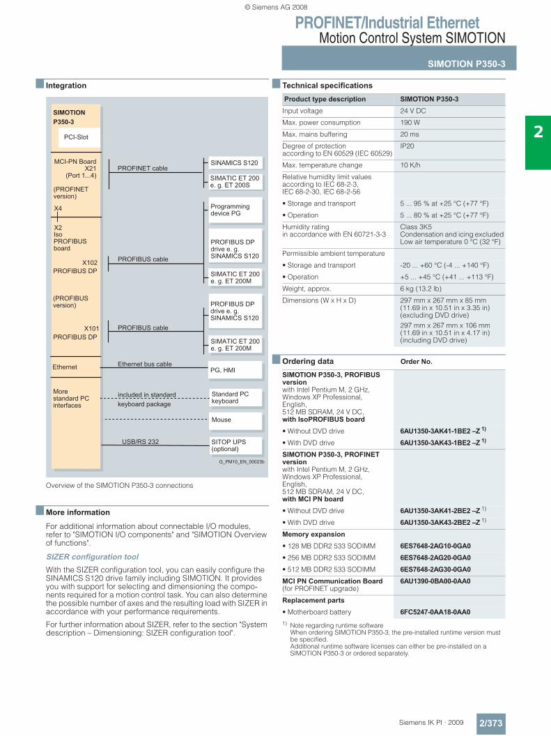
PROFINET/Industrial EthernetMotion Control System SIMOTION
SIMOTION P350-3
2/373Siemens IK PI · 2009
2
■ Integration
Overview of the SIMOTION P350-3 connections
■ More information
For additional information about connectable I/O modules, refer to "SIMOTION I/O components" and "SIMOTION Overview of functions".
SIZER configuration toolWith the SIZER configuration tool, you can easily configure the SINAMICS S120 drive family including SIMOTION. It provides you with support for selecting and dimensioning the compo-nents required for a motion control task. You can also determine the possible number of axes and the resulting load with SIZER in accordance with your performance requirements.
For further information about SIZER, refer to the section "System description – Dimensioning: SIZER configuration tool".
■ Technical specifications
■ Ordering data Order No.
1) Note regarding runtime software When ordering SIMOTION P350-3, the pre-installed runtime version must be specified. Additional runtime software licenses can either be pre-installed on a SIMOTION P350-3 or ordered separately.
SIMOTIONP350-3
X4
X2
X102
X101
Ethernet
PROFIBUS DP
PCI-Slot
SINAMICS S120
USB/RS 232
Morestandard PC interfaces
PROFIBUS DP
included in standardkeyboard package
PROFIBUS cable
PROFIBUS cable
G_PM10_EN_00023b
Mouse
Standard PCkeyboard
Programmingdevice PG
SIMATIC ET 200 e. g. ET 200M
SIMATIC ET 200 e. g. ET 200M
PROFIBUS DP drive e. g.SINAMICS S120
SITOP UPS (optional)
PROFIBUS DPdrive e. g.SINAMICS S120
Ethernet bus cable
IsoPROFIBUSboard
PG, HMI
SIMATIC ET 200e. g. ET 200S
PROFINET cableMCI-PN Board
X21(Port 1...4)
(PROFINETversion)
(PROFIBUSversion)
Product type description SIMOTION P350-3Input voltage 24 V DC
Max. power consumption 190 W
Max. mains buffering 20 ms
Degree of protection according to EN 60529 (IEC 60529)
IP20
Max. temperature change 10 K/h
Relative humidity limit values according to IEC 68-2-3, IEC 68-2-30, IEC 68-2-56
• Storage and transport 5 ... 95 % at +25 °C (+77 °F)
• Operation 5 ... 80 % at +25 °C (+77 °F)
Humidity rating in accordance with EN 60721-3-3
Class 3K5Condensation and icing excluded Low air temperature 0 °C (32 °F)
Permissible ambient temperature
• Storage and transport -20 ... +60 °C (-4 ... +140 °F)
• Operation +5 ... +45 °C (+41 ... +113 °F)
Weight, approx. 6 kg (13.2 lb)
Dimensions (W x H x D) 297 mm x 267 mm x 85 mm (11.69 in x 10.51 in x 3.35 in) (excluding DVD drive)297 mm x 267 mm x 106 mm (11.69 in x 10.51 in x 4.17 in) (including DVD drive)
SIMOTION P350-3, PROFIBUS version with Intel Pentium M, 2 GHz,Windows XP Professional, English, 512 MB SDRAM, 24 V DC, with IsoPROFIBUS board• Without DVD drive 6AU1350-3AK41-1BE2 –Z 1)
• With DVD drive 6AU1350-3AK43-1BE2 –Z 1)
SIMOTION P350-3, PROFINET version with Intel Pentium M, 2 GHz,Windows XP Professional, English, 512 MB SDRAM, 24 V DC, with MCI PN board• Without DVD drive 6AU1350-3AK41-2BE2 –Z 1)
• With DVD drive 6AU1350-3AK43-2BE2 –Z 1)
Memory expansion• 128 MB DDR2 533 SODIMM 6ES7648-2AG10-0GA0• 256 MB DDR2 533 SODIMM 6ES7648-2AG20-0GA0• 512 MB DDR2 533 SODIMM 6ES7648-2AG30-0GA0MCI PN Communication Board (for PROFINET upgrade)
6AU1390-0BA00-0AA0
Replacement parts• Motherboard battery 6FC5247-0AA18-0AA0
© Siemens AG 2008
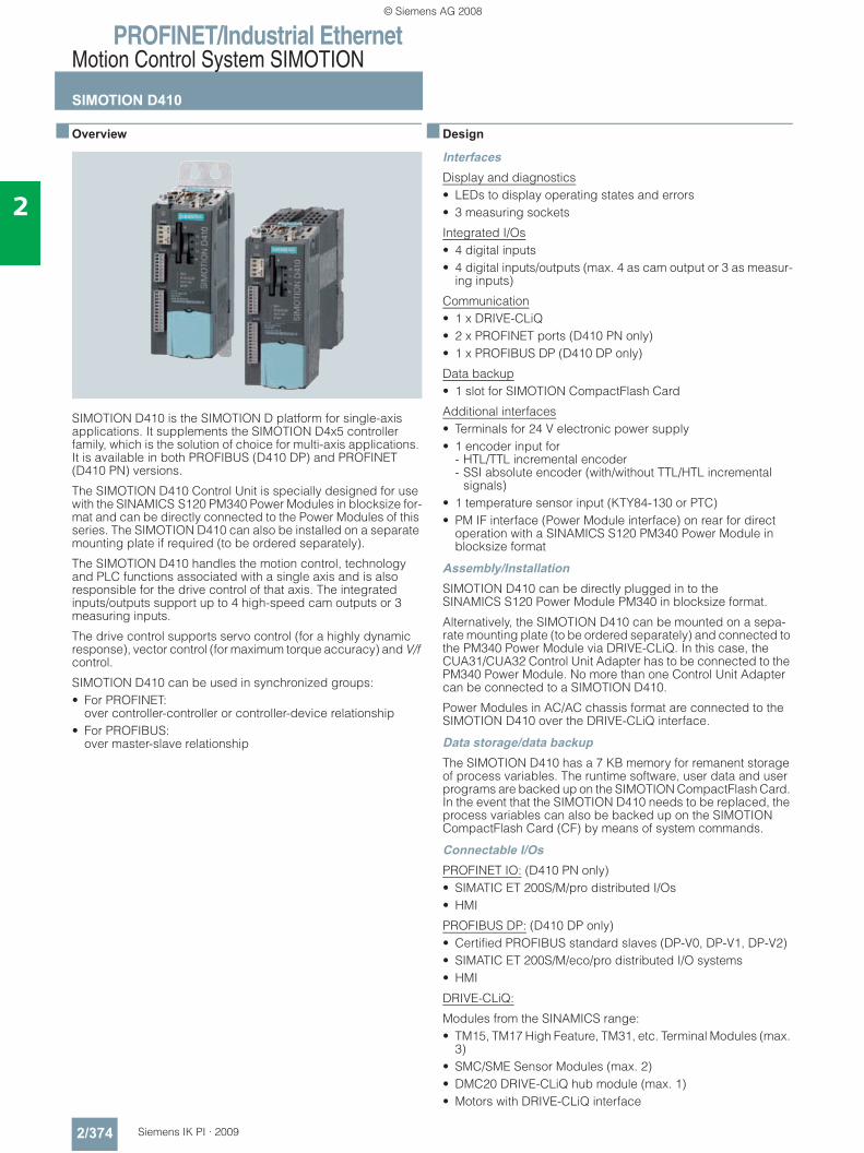
PROFINET/Industrial EthernetMotion Control System SIMOTION
SIMOTION D410
2/374 Siemens IK PI · 2009
2
■ Overview
SIMOTION D410 is the SIMOTION D platform for single-axis applications. It supplements the SIMOTION D4x5 controller family, which is the solution of choice for multi-axis applications. It is available in both PROFIBUS (D410 DP) and PROFINET (D410 PN) versions.
The SIMOTION D410 Control Unit is specially designed for use with the SINAMICS S120 PM340 Power Modules in blocksize for-mat and can be directly connected to the Power Modules of this series. The SIMOTION D410 can also be installed on a separate mounting plate if required (to be ordered separately).
The SIMOTION D410 handles the motion control, technology and PLC functions associated with a single axis and is also responsible for the drive control of that axis. The integrated inputs/outputs support up to 4 high-speed cam outputs or 3 measuring inputs.
The drive control supports servo control (for a highly dynamic response), vector control (for maximum torque accuracy) and V/f control.
SIMOTION D410 can be used in synchronized groups:• For PROFINET:
over controller-controller or controller-device relationship• For PROFIBUS:
over master-slave relationship
■ Design
InterfacesDisplay and diagnostics• LEDs to display operating states and errors • 3 measuring sockets
Integrated I/Os• 4 digital inputs • 4 digital inputs/outputs (max. 4 as cam output or 3 as measur-
ing inputs)
Communication• 1 x DRIVE-CLiQ • 2 x PROFINET ports (D410 PN only)• 1 x PROFIBUS DP (D410 DP only)
Data backup• 1 slot for SIMOTION CompactFlash Card
Additional interfaces• Terminals for 24 V electronic power supply• 1 encoder input for
- HTL/TTL incremental encoder- SSI absolute encoder (with/without TTL/HTL incremental
signals)• 1 temperature sensor input (KTY84-130 or PTC)• PM IF interface (Power Module interface) on rear for direct
operation with a SINAMICS S120 PM340 Power Module in blocksize format
Assembly/InstallationSIMOTION D410 can be directly plugged in to the SINAMICS S120 Power Module PM340 in blocksize format.
Alternatively, the SIMOTION D410 can be mounted on a sepa-rate mounting plate (to be ordered separately) and connected to the PM340 Power Module via DRIVE-CLiQ. In this case, the CUA31/CUA32 Control Unit Adapter has to be connected to the PM340 Power Module. No more than one Control Unit Adapter can be connected to a SIMOTION D410.
Power Modules in AC/AC chassis format are connected to the SIMOTION D410 over the DRIVE-CLiQ interface.
Data storage/data backupThe SIMOTION D410 has a 7 KB memory for remanent storage of process variables. The runtime software, user data and user programs are backed up on the SIMOTION CompactFlash Card. In the event that the SIMOTION D410 needs to be replaced, the process variables can also be backed up on the SIMOTION CompactFlash Card (CF) by means of system commands.
Connectable I/OsPROFINET IO: (D410 PN only)• SIMATIC ET 200S/M/pro distributed I/Os • HMI
PROFIBUS DP: (D410 DP only)• Certified PROFIBUS standard slaves (DP-V0, DP-V1, DP-V2) • SIMATIC ET 200S/M/eco/pro distributed I/O systems • HMI
DRIVE-CLiQ:
Modules from the SINAMICS range: • TM15, TM17 High Feature, TM31, etc. Terminal Modules (max.
3)• SMC/SME Sensor Modules (max. 2)• DMC20 DRIVE-CLiQ hub module (max. 1)• Motors with DRIVE-CLiQ interface
© Siemens AG 2008
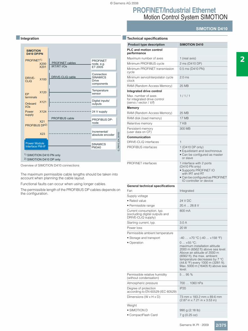
PROFINET/Industrial EthernetMotion Control System SIMOTION
SIMOTION D410
2/375Siemens IK PI · 2009
2
■ Integration
Overview of SIMOTION D410 connections
The maximum permissible cable lengths should be taken into account when planning the cable layout.
Functional faults can occur when using longer cables.
The permissible length of the PROFIBUS DP cables depends on the configuration.
■ Technical specifications
DRIVE-CLiQ
SIMOTIOND410 DP/PN
X120
X121
X124
PROFIBUS DP2)X21
X200X201
X23
Power ModuleInterface PM-IF
Temperaturesensor
Digital inputs/outputs
ConnectionSINAMICS Drivecomponents
24 V supply
Incremental/absolute encoder
PROFIBUS DP-node
G_P
M10
_EN
_001
63
DRIVE-CLiQ cable
1) SIMOTION D410 PN only2) SIMOTION D410 DP only
OnboardI/OsPowersupply
X100
PROFINET1) PROFINETnode, e.g.ET 200S
PROFINET cablesIRT/RT I/Os
SINAMICS PM340
EPterminals
PROFIBUS cable
Product type description SIMOTION D410PLC and motion control performanceMaximum number of axes 1 (real axis)
Minimum PROFIBUS cycle 2 ms (D410 DP)
Minimum PROFINET transmission cycle
0.5 ms (D410 PN)
Minimum servo/interpolator cycle clock
2.0 ms
RAM (Random Access Memory) 25 MB
Integrated drive controlMax. number of axes for integrated drive control (servo / vector / V/f)
1 / 1 / 1
MemoryRAM (Random Access Memory) 25 MB
RAM disk (load memory) 17 MB
Retentive memory 7 KB
Persistent memory (user data on CF)
300 MB
CommunicationDRIVE-CLiQ interfaces 1
PROFIBUS interfaces 1 (D410 DP only)• Equidistant and isochronous• Can be configured as master
or slave
PROFINET interfaces 1 interface with 2 ports (D410 PN only)• Supports PROFINET IO
with IRT and RT• Can be configured as PROFINET
IO controller or device
General technical specificationsFan Integrated
Supply voltage• Rated value 24 V DC• Permissible range 20.4 ... 28.8 V
Current consumption, typ. (excluding digital outputs and DRIVE-CLiQ supply)
800 mA
Starting current, typ. 3.0 A
Power loss 20 W
Permissible ambient temperature• Storage and transport -40 … +70 °C (-40 ... +158 °F)• Operation 0 ... +55 °C;
maximum installation altitude 2000 m (6562 ft) above sea level.Above an altitude of 2000 m (6562 ft), the max. ambient temperature decreases by 7 °C (44.6 °F) every 1000 m (3281 ft).Max. 5000 m (16405 ft) above sea level.
Permissible relative humidity (without condensation)
5 ... 95 %
Atmospheric pressure 700 … 1060 hPa
Degree of protection according to EN 60529 (IEC 60529)
IP20
Dimensions (W x H x D) 73 mm x 183.2 mm x 89.6 mm (2.87 in x 7.21 in x 3.53 in)
Weight• SIMOTION D 990 g (2.18 lb)• CompactFlash Card 7 g (0.25 oz)
© Siemens AG 2008
PROFINET/Industrial EthernetMotion Control System SIMOTION
SIMOTION D410
2/376 Siemens IK PI · 2009
2
■ Technical specifications (continued)
■ Ordering data Order No. Order No.
Product type description SIMOTION D410Digital inputs 4• Input voltage
- Rated value 24 V DC- For "1" signal 15 ... 30 V- For "0" signal -3 ... +5 V
• Galvanic isolation Yes, in groups of 4
• Current consumption typ. at 1-signal level
10 mA at 24 V
• Input delay, typ. (hardware) L -> H: 50 μsH -> L: 100 μs
Digital inputs/outputs (parameterizable)
4(max. 3 as high-speed measuring inputs, max. 4 as high-speed cam outputs)
If used as an input• Input voltage
- Rated value 24 V DC- For "1" signal 15 ... 30 V- For "0" signal -3 ... +5 V
• Isolation No
• Current consumption typ. at 1 signal level
10 mA at 24 V
• Input delay, typ. (hardware)
L -> H: 50 μs (5 μs if used as measuring input)H -> L: 100 μs (50 μs if used as measuring input)
• Measuring input, accuracy 5 μs
If used as an output
• Rated load voltage 24 V DC
• Permissible range 20.4 ... 28.8 V
• Isolation No
• Current load, max. 500 mA per output
• Residual current, max. 2 mA
• Output delay, max. (hardware)
L -> H: 400 μs H -> L: 100 μs
• Cam output, accuracy 200 μs
• Short-circuit protection Yes
Product type description SIMOTION D410Onboard encoder interface
• Encoder interface • TTL or HTL incremental encoders (with adjustable parameters)
• SSI absolute encoders with/without TTL/HTL incremental signals
• Encoder supply 24 V DC/0.35 A or 5 V DC/0.35 A
• Limit frequency, max. 500 kHz
• SSI baud rate 100 ... 250 kBaud
• Resolution absolute position SSI 30 bit
Max. cable length
• For TTL incremental encoder(only bipolar signals permitted)
100 m (328 ft)
• For HTL incremental encoder- For unipolar signals 100 m (328 ft)- For bipolar signals 300 m (984 ft)
• For SSI absolute encoder 100 m (328 ft)
Additional technical specificationsInput for temperature sensing
• Temperature sensor KTY84-130 or PTC
Non-volatile data backup
• Backup time, min. Unlimited(maintenance-free backup)
Approvals cULus (File No. E164110)
SIMOTION D410 DP(SIMOTION V4.1 SP1 or higher)
6AU1410-0AA00-0AA0
SIMOTION D410 PN(SIMOTION V4.1 SP1 or higher)
6AU1410-0AB00-0AA0
Backplane mounting plateFor installing the SIMOTION D410 in a different location if you do not wish to connect it directly to the Power Module.
6AU1400-7AA05-0AA0
SIMOTION CompactFlash Card (CF) 1 GB With SIMOTION Kernel and up-to-date SINAMICS drive software
6AU1400-2PA00-0AA0
Industrial Ethernet Switches SCALANCE X-200IRTManaged Industrial Ethernet switches; Isochronous Real-Time, LED diagnostics, fault signaling contact with SET button, redundant power supply; incl. operating instructions, Industrial Ethernet network manual and configuration soft-ware on CD-ROM• SCALANCE X-204IRT;
4 x 10/100 Mbit/s RJ45 Ports6GK5 204-0BA00-2BA3
© Siemens AG 2008
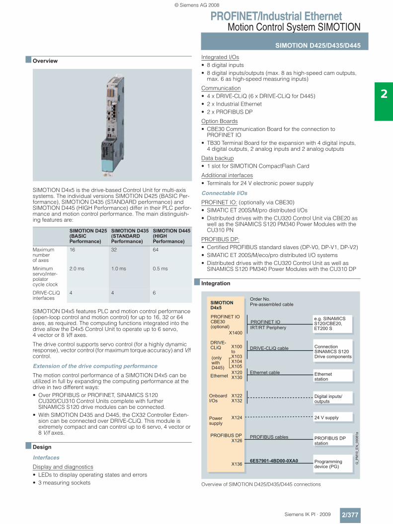
PROFINET/Industrial EthernetMotion Control System SIMOTION
SIMOTION D425/D435/D445
2/377Siemens IK PI · 2009
2
■ Overview
SIMOTION D4x5 is the drive-based Control Unit for multi-axis systems. The individual versions SIMOTION D425 (BASIC Per-formance), SIMOTION D435 (STANDARD performance) and SIMOTION D445 (HIGH Performance) differ in their PLC perfor-mance and motion control performance. The main distinguish-ing features are:
SIMOTION D4x5 features PLC and motion control performance (open-loop control and motion control) for up to 16, 32 or 64 axes, as required. The computing functions integrated into the drive allow the D4x5 Control Unit to operate up to 6 servo, 4 vector or 8 V/f axes.
The drive control supports servo control (for a highly dynamic response), vector control (for maximum torque accuracy) and V/f control.
Extension of the drive computing performanceThe motion control performance of a SIMOTION D4x5 can be utilized in full by expanding the computing performance at the drive in two different ways:• Over PROFIBUS or PROFINET, SINAMICS S120
CU320/CU310 Control Units complete with further SINAMICS S120 drive modules can be connected.
• With SIMOTION D435 and D445, the CX32 Controller Exten-sion can be connected over DRIVE-CLiQ. This module is extremely compact and can control up to 6 servo, 4 vector or 8 V/f axes.
■ Design
InterfacesDisplay and diagnostics• LEDs to display operating states and errors• 3 measuring sockets
Integrated I/Os• 8 digital inputs • 8 digital inputs/outputs (max. 8 as high-speed cam outputs,
max. 6 as high-speed measuring inputs)
Communication• 4 x DRIVE-CLiQ (6 x DRIVE-CLiQ for D445) • 2 x Industrial Ethernet • 2 x PROFIBUS DP
Option Boards• CBE30 Communication Board for the connection to
PROFINET IO • TB30 Terminal Board for the expansion with 4 digital inputs,
4 digital outputs, 2 analog inputs and 2 analog outputs
Data backup• 1 slot for SIMOTION CompactFlash Card
Additional interfaces• Terminals for 24 V electronic power supply
Connectable I/OsPROFINET IO: (optionally via CBE30)• SIMATIC ET 200S/M/pro distributed I/Os• Distributed drives with the CU320 Control Unit via CBE20 as
well as the SINAMICS S120 PM340 Power Modules with the CU310 PN
PROFIBUS DP: • Certified PROFIBUS standard slaves (DP-V0, DP-V1, DP-V2)• SIMATIC ET 200S/M/eco/pro distributed I/O systems• Distributed drives with the CU320 Control Unit as well as
SINAMICS S120 PM340 Power Modules with the CU310 DP
■ Integration
Overview of SIMOTION D425/D435/D445 connections
SIMOTION D425(BASIC Performance)
SIMOTION D435(STANDARD Performance)
SIMOTION D445(HIGHPerformance)
Maximum number of axes
16 32 64
Minimum servo/inter-polator cycle clock
2.0 ms 1.0 ms 0.5 ms
DRIVE-CLiQ interfaces
4 4 6
6ES7901-4BD00-0XA0
DRIVE-CLiQ
SIMOTIOND4x5
EthernetX120X130
X122X132
X124
X136
PROFIBUS DPX126
Ethernet station
Digital inputs/outputs
Connection SINAMICS S120Drive components
24 V supply
Programming device (PG)
PROFIBUS DP station
G_P
M10
_EN
_000
81a
DRIVE-CLiQ cable
Ethernet cable
PROFIBUS cables
OnboardI/Os
Powersupply
Order No.Pre-assembled cable
(onlywithD445)
X100toX103X104X105
PROFINET IOCBE30(optional)
X1400
e.g. SINAMICS S120/CBE20,ET200 S
PROFINET IOIRT/RT Periphery
© Siemens AG 2008
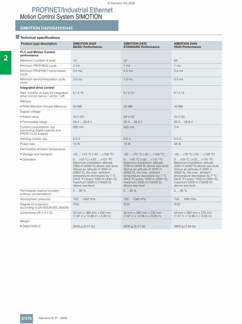
PROFINET/Industrial EthernetMotion Control System SIMOTION
SIMOTION D425/D435/D445
2/378 Siemens IK PI · 2009
2
■ Technical specifications
Product type description SIMOTION D425 BASIC Performance
SIMOTION D435 STANDARD Performance
SIMOTION D445 HIGH Performance
PLC and Motion Control performanceMaximum number of axes 16 32 64
Minimum PROFIBUS cycle 2 ms 1 ms 1 ms
Minimum PROFINET transmission cycle
0.5 ms 0.5 ms 0.5 ms
Minimum servo/interpolator cycle clock
2.0 ms 1.0 ms 0.5 ms
Integrated drive controlMax. number of axes for integrated drive control (servo / vector / V/f)
6 / 4 / 8 6 / 4 / 8 6 / 4 / 8
Memory
• RAM (Random Access Memory) 25 MB 25 MB 50 MB
Supply voltage
• Rated value 24 V DC 24 V DC 24 V DC
• Permissible range 20.4 ... 28.8 V 20.4 ... 28.8 V 20.4 ... 28.8 V
Current consumption, typ. (excluding digital outputs and DRIVE-CLiQ supply)
600 mA 600 mA 2 A
Starting current, typ. 6.0 A 6.0 A 6.0 A
Power loss 15 W 15 W 48 W
Permissible ambient temperature
• Storage and transport -40 ... +70 °C (-40 ... +158 °F) -40 ... +70 °C (-40 ... +158 °F) -40 ... +70 °C (-40 ... +158 °F)
• Operation 0 ... +55 °C (+32 ... +131 °F)Maximum installation altitude 2000 m (6562 ft) above sea level. Above an altitude of 2000 m (6562 ft), the max. ambient temperature decreases by 7 °C (44.6 °F) every 1000 m (3281 ft); maximum 5000 m (16405 ft) above sea level.
0 ... +55 °C (+32 ... +131 °F)Maximum installation altitude 2000 m (6562 ft) above sea level. Above an altitude of 2000 m(6562 ft), the max. ambienttemperature decreases by 7 °C (44.6 °F) every 1000 m (3281 ft); maximum 5000 m (16405 ft) above sea level.
0 ... +55 °C (+32 ... +131 °F)Maximum installation altitude 2000 m (6562 ft) above sea level. Above an altitude of 2000 m (6562 ft), the max. ambient temperature decreases by 7 °C (44.6 °F) every 1000 m (3281 ft); maximum 5000 m (16405 ft) above sea level.
Permissible relative humidity (without condensation)
5 ... 95 % 5 ... 95 % 5 ... 95 %
Atmospheric pressure 700 ... 1060 hPa 700 ... 1060 hPa 700 ... 1060 hPa
Degree of protection according to EN 60529 (IEC 60529)
IP20 IP20 IP20
Dimensions (W x H x D) 50 mm x 380 mm x 230 mm(1.97 in x 14.96 in x 9.06 in)
50 mm x 380 mm x 230 mm(1.97 in x 14.96 in x 9.06 in)
50 mm x 380 mm x 270 mm(1.97 in x 14.96 in x 9.06 in)
Weight
• SIMOTION D 2500 g (5.51 lb) 2500 g (5.51 lb) 3600 g (7.94 lb)
© Siemens AG 2008
PROFINET/Industrial EthernetMotion Control System SIMOTION
SIMOTION D425/D435/D445
2/379Siemens IK PI · 2009
2
■ Ordering data Order No. Order No.
SIMOTION D425 6AU1425-0AA00-0AA0SIMOTION D435 6AU1435-0AA00-0AA1SIMOTION D445 6AU1445-0AA00-0AA0CompactFlash Card (CF) 1 GB with SINAMICS S120 drive software and SIMOTION KernelPre-installed license using Z options 1)
6AU1400-2PA00-0AA0
SIMOTION MultiAxes Bundle D425 consisting of 1 unit each• SIMOTION D425• CompactFlash Card 1 GB
with MultiAxes Package license for D425 platform
6AU1425-0AA00-0CA0
SIMOTION MultiAxes Bundle D435 consisting of 1 unit each• SIMOTION D435• CompactFlash Card 1 GB
with MultiAxes Package license for D435 platform
6AU1435-0AA00-0CA1
SIMOTION MultiAxes Bundle D445 consisting of 1 unit each• SIMOTION D445 • CompactFlash Card 1 GB
with MultiAxes Package license for D445 platform
6AU1445-0AA00-0CA0
Battery and fan module Incl. batteryBattery and fan module for D425/D435 (option). Included in the scope of supply of D445.
6FC5348-0AA01-0AA0
AccessoriesBattery (replacement part) 6FC5247-0AA18-0AA0PROFIBUS RS485 bus connector with angular cable outlet (35°) With screw-type terminals, max. transmission rate 12 Mbit/s
• Without PG interface 6ES7972-0BA41-0XA0• With PG interface 6ES7972-0BB41-0XA0PROFIBUS FastConnect RS485 bus connector with angular cable outlet (35°) With insulation displacement terminals, max. transmission rate 12 Mbit/s
• Without PG interface 6ES7972-0BA60-0XA0• With PG interface 6ES7972-0BB60-0XA0
© Siemens AG 2008
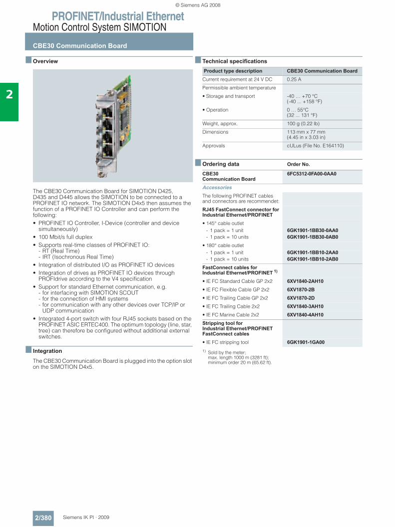
PROFINET/Industrial EthernetMotion Control System SIMOTION
CBE30 Communication Board
2/380 Siemens IK PI · 2009
2
■ Overview
The CBE30 Communication Board for SIMOTION D425, D435 and D445 allows the SIMOTION to be connected to a PROFINET IO network. The SIMOTION D4x5 then assumes the function of a PROFINET IO Controller and can perform the following:• PROFINET IO Controller, I-Device (controller and device
simultaneously)• 100 Mbit/s full duplex• Supports real-time classes of PROFINET IO:
- RT (Real Time)- IRT (Isochronous Real Time)
• Integration of distributed I/O as PROFINET IO devices• Integration of drives as PROFINET IO devices through
PROFIdrive according to the V4 specification• Support for standard Ethernet communication, e.g.
- for interfacing with SIMOTION SCOUT- for the connection of HMI systems- for communication with any other devices over TCP/IP or
UDP communication• Integrated 4-port switch with four RJ45 sockets based on the
PROFINET ASIC ERTEC400. The optimum topology (line, star, tree) can therefore be configured without additional external switches.
■ Integration
The CBE30 Communication Board is plugged into the option slot on the SIMOTION D4x5.
■ Technical specifications
■ Ordering data Order No.
1) Sold by the meter; max. length 1000 m (3281 ft); minimum order 20 m (65.62 ft).
Product type description CBE30 Communication BoardCurrent requirement at 24 V DC 0.25 A
Permissible ambient temperature
• Storage and transport -40 … +70 °C (-40 ... +158 °F)
• Operation 0 … 55°C (32 ... 131 °F)
Weight, approx. 100 g (0.22 lb)
Dimensions 113 mm x 77 mm (4.45 in x 3.03 in)
Approvals cULus (File No. E164110)
CBE30Communication Board
6FC5312-0FA00-0AA0
AccessoriesThe following PROFINET cables and connectors are recommendet:
RJ45 FastConnect connector for Industrial Ethernet/PROFINET• 145° cable outlet
- 1 pack = 1 unit- 1 pack = 10 units
6GK1901-1BB30-0AA06GK1901-1BB30-0AB0
• 180° cable outlet- 1 pack = 1 unit- 1 pack = 10 units
6GK1901-1BB10-2AA06GK1901-1BB10-2AB0
FastConnect cables for Industrial Ethernet/PROFINET 1)
• IE FC Standard Cable GP 2x2 6XV1840-2AH10• IE FC Flexible Cable GP 2x2 6XV1870-2B• IE FC Trailing Cable GP 2x2 6XV1870-2D• IE FC Trailing Cable 2x2 6XV1840-3AH10• IE FC Marine Cable 2x2 6XV1840-4AH10Stripping tool for Industrial Ethernet/PROFINET FastConnect cables• IE FC stripping tool 6GK1901-1GA00
© Siemens AG 2008
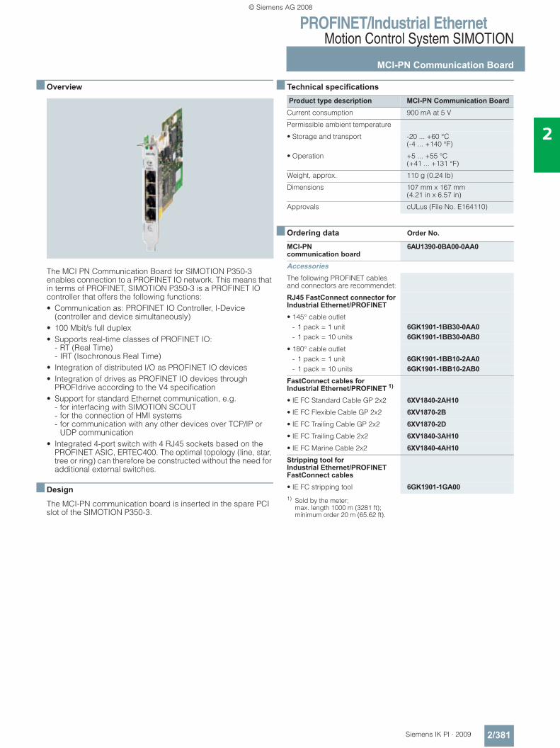
PROFINET/Industrial EthernetMotion Control System SIMOTION
MCI-PN Communication Board
2/381Siemens IK PI · 2009
2
■ Overview
The MCI PN Communication Board for SIMOTION P350-3 enables connection to a PROFINET IO network. This means that in terms of PROFINET, SIMOTION P350-3 is a PROFINET IO controller that offers the following functions:• Communication as: PROFINET IO Controller, I-Device
(controller and device simultaneously)• 100 Mbit/s full duplex• Supports real-time classes of PROFINET IO:
- RT (Real Time)- IRT (Isochronous Real Time)
• Integration of distributed I/O as PROFINET IO devices• Integration of drives as PROFINET IO devices through
PROFIdrive according to the V4 specification• Support for standard Ethernet communication, e.g.
- for interfacing with SIMOTION SCOUT- for the connection of HMI systems- for communication with any other devices over TCP/IP or
UDP communication• Integrated 4-port switch with 4 RJ45 sockets based on the
PROFINET ASIC, ERTEC400. The optimal topology (line, star, tree or ring) can therefore be constructed without the need for additional external switches.
■ Design
The MCI-PN communication board is inserted in the spare PCI slot of the SIMOTION P350-3.
■ Technical specifications
■ Ordering data Order No.
1) Sold by the meter; max. length 1000 m (3281 ft); minimum order 20 m (65.62 ft).
Product type description MCI-PN Communication BoardCurrent consumption 900 mA at 5 V
Permissible ambient temperature
• Storage and transport -20 ... +60 °C (-4 ... +140 °F)
• Operation +5 ... +55 °C(+41 ... +131 °F)
Weight, approx. 110 g (0.24 lb)
Dimensions 107 mm x 167 mm (4.21 in x 6.57 in)
Approvals cULus (File No. E164110)
MCI-PNcommunication board
6AU1390-0BA00-0AA0
AccessoriesThe following PROFINET cables and connectors are recommendet:
RJ45 FastConnect connector for Industrial Ethernet/PROFINET• 145° cable outlet
- 1 pack = 1 unit 6GK1901-1BB30-0AA0- 1 pack = 10 units 6GK1901-1BB30-0AB0
• 180° cable outlet- 1 pack = 1 unit 6GK1901-1BB10-2AA0- 1 pack = 10 units 6GK1901-1BB10-2AB0
FastConnect cables for Industrial Ethernet/PROFINET 1)
• IE FC Standard Cable GP 2x2 6XV1840-2AH10• IE FC Flexible Cable GP 2x2 6XV1870-2B• IE FC Trailing Cable GP 2x2 6XV1870-2D• IE FC Trailing Cable 2x2 6XV1840-3AH10• IE FC Marine Cable 2x2 6XV1840-4AH10Stripping tool for Industrial Ethernet/PROFINET FastConnect cables• IE FC stripping tool 6GK1901-1GA00
© Siemens AG 2008
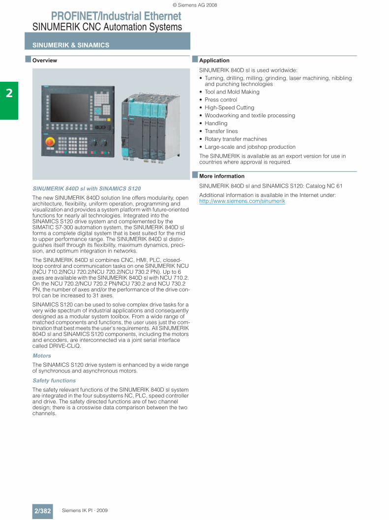
PROFINET/Industrial EthernetSINUMERIK CNC Automation Systems
SINUMERIK & SINAMICS
2/382 Siemens IK PI · 2009
2
■ Overview
SINUMERIK 840D sl with SINAMICS S120The new SINUMERIK 840D solution line offers modularity, open architecture, flexibility, uniform operation, programming and visualization and provides a system platform with future-oriented functions for nearly all technologies. Integrated into the SINAMICS S120 drive system and complemented by the SIMATIC S7-300 automation system, the SINUMERIK 840D sl forms a complete digital system that is best suited for the mid to upper performance range. The SINUMERIK 840D sl distin-guishes itself through its flexibility, maximum dynamics, preci-sion, and optimum integration in networks.
The SINUMERIK 840D sl combines CNC, HMI, PLC, closed-loop control and communication tasks on one SINUMERIK NCU (NCU 710.2/NCU 720.2/NCU 720.2/NCU 730.2 PN). Up to 6 axes are available with the SINUMERIK 840D sl with NCU 710.2. On the NCU 720.2/NCU 720.2 PN/NCU 730.2 and NCU 730.2 PN, the number of axes and/or the performance of the drive con-trol can be increased to 31 axes.
SINAMICS S120 can be used to solve complex drive tasks for a very wide spectrum of industrial applications and consequently designed as a modular system toolbox. From a wide range of matched components and functions, the user uses just the com-bination that best meets the user's requirements. All SINUMERIK 804D sl and SINAMICS S120 components, including the motors and encoders, are interconnected via a joint serial interface called DRIVE-CLiQ.
MotorsThe SINAMICS S120 drive system is enhanced by a wide range of synchronous and asynchronous motors.
Safety functionsThe safety relevant functions of the SINUMERIK 840D sl system are integrated in the four subsystems NC, PLC, speed controller and drive. The safety directed functions are of two channel design; there is a crosswise data comparison between the two channels.
■ Application
SINUMERIK 840D sl is used worldwide:• Turning, drilling, milling, grinding, laser machining, nibbling
and punching technologies• Tool and Mold Making• Press control• High-Speed Cutting• Woodworking and textile processing• Handling• Transfer lines• Rotary transfer machines• Large-scale and jobshop production
The SINUMERIK is available as an export version for use in countries where approval is required.
■ More information
SINUMERIK 840D sl and SINAMICS S120: Catalog NC 61
Additional information is available in the Internet under:http://www.siemens.com/sinumerik
© Siemens AG 2008
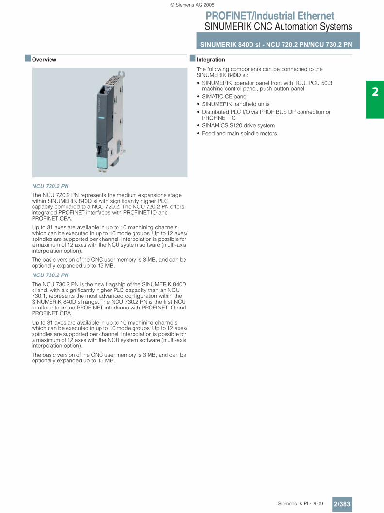
PROFINET/Industrial EthernetSINUMERIK CNC Automation Systems
SINUMERIK 840D sl - NCU 720.2 PN/NCU 730.2 PN
2/383Siemens IK PI · 2009
2
■ Overview
NCU 720.2 PNThe NCU 720.2 PN represents the medium expansions stage within SINUMERIK 840D sl with significantly higher PLC capacity compared to a NCU 720.2. The NCU 720.2 PN offers integrated PROFINET interfaces with PROFINET IO and PROFINET CBA.
Up to 31 axes are available in up to 10 machining channels which can be executed in up to 10 mode groups. Up to 12 axes/spindles are supported per channel. Interpolation is possible for a maximum of 12 axes with the NCU system software (multi-axis interpolation option).
The basic version of the CNC user memory is 3 MB, and can be optionally expanded up to 15 MB.
NCU 730.2 PNThe NCU 730.2 PN is the new flagship of the SINUMERIK 840D sl and, with a significantly higher PLC capacity than an NCU 730.1, represents the most advanced configuration within the SINUMERIK 840D sl range. The NCU 730.2 PN is the first NCU to offer integrated PROFINET interfaces with PROFINET IO and PROFINET CBA.
Up to 31 axes are available in up to 10 machining channels which can be executed in up to 10 mode groups. Up to 12 axes/spindles are supported per channel. Interpolation is possible for a maximum of 12 axes with the NCU system software (multi-axis interpolation option).
The basic version of the CNC user memory is 3 MB, and can be optionally expanded up to 15 MB.
■ Integration
The following components can be connected to the SINUMERIK 840D sl:• SINUMERIK operator panel front with TCU, PCU 50.3,
machine control panel, push button panel • SIMATIC CE panel • SINUMERIK handheld units • Distributed PLC I/O via PROFIBUS DP connection or
PROFINET IO • SINAMICS S120 drive system • Feed and main spindle motors
© Siemens AG 2008
PROFINET/Industrial EthernetSINUMERIK CNC Automation Systems
SINUMERIK 840D sl - NCU 720.2 PN/NCU 730.2 PN
2/384 Siemens IK PI · 2009
2
■ Technical specifications
■ Ordering data Order No.
Order No. 6FC5372-0AA01-0AA1
6FC5373-0AA01-0AA1
Product type description SINUMERIK840D sl; NCU 720.2 PN with PLC 319-3 PN/DP
SINUMERIK840D sl; NCU 730.2 PN with PLC 319-3 PN/DP
RAM 512 Mbyte DDR2-SDRAM; 1 Mbyte SRAM
SIMATIC S7 - integrated PLC 319-3PN/DP
Input voltage 24 V
Degree of protection in accor-dance with DIN EN 60529 (IEC 60529)
IP20
Humidity classification in accor-dance with DIN EN 60721-3-3
Class 3K5 condensation and icing excluded. Low air temperature 0 °C (32 °F).
Relative humidity
• Storage 10 ... 95 %
• Transport 10 ... 95 %
• Operation ≤ 85 % over max. 2 months
Ambient temperature
• Storage -25 ... +55 °C (-13 ... +131 °F)
• Transport -40 ... +70 °C (-40 ... +158 °F)
• Operation 0 ... 55 °C (32 ... 131 °F)
Dimensions
• Width 50 mm (1.97 in)
• Height 418 mm (16.46 in)
• Depth 272 mm (10.71 in)
Weight, approx. 3.8 kg (8.38 lb)
HardwareNCU 720.2 PN with PLC 319-3PN/DP
6FC5372-0AA01-0AA1
NCU 730.2 PN with PLC 319-3PN/DP
6FC5373-0AA01-0AA1
Seal for external heat dissipation (1 pack = 10 units)for NCU 710.2/NCU 720.2/NCU 720.2 PN/ NCU 730.2/NCU 730.2 PN
6FC5348-0AA07-0AA0
CNC user memory Expanded by 2 MB each
6FC5800-0AD00-0YB0
PLC user memory Expanded by 128 KB each
6FC5800-0AD10-0YB0
SoftwareHMI user memory Additional 256 MB on CF card of NCUSoftware option• Single license
without data carrier
6FC5800-0AP12-0YB0
Spare and wear partsSpacersfor NCU 720.2/NCU 720.2 PN/ NCU 730.2/NCU 730.2 PN
6FC5348-0AA06-0AA0
Battery 6FC5247-0AA18-0AA0Dual fan/battery module 6FC5348-0AA02-0AA0Blanking cover for Control Unit CU320/NCU 710.2/NCU 720.2/NCU 720.2 PNNCU 730.2/NCU 730.2 PN
6SL3064-3BB00-0AA0
CompactFlash Card 512 MB Empty
6FC5313-4AG00-0AA2
© Siemens AG 2008
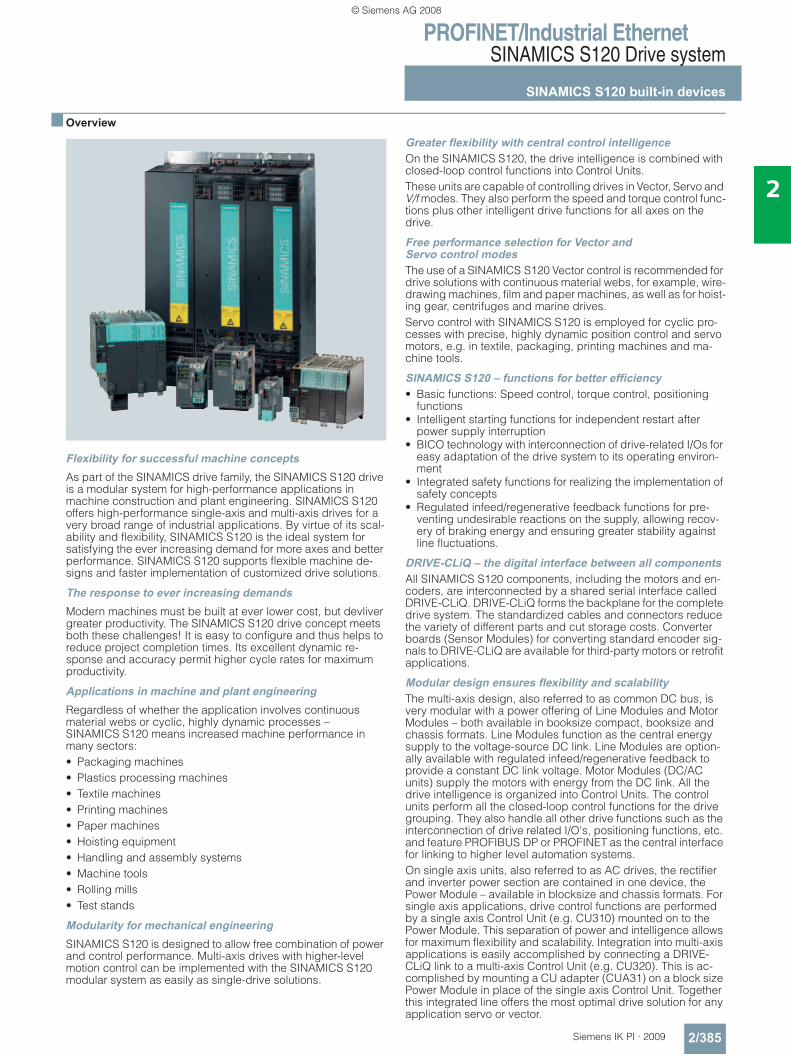
PROFINET/Industrial EthernetSINAMICS S120 Drive system
SINAMICS S120 built-in devices
2/385Siemens IK PI · 2009
2
■ Overview
Flexibility for successful machine conceptsAs part of the SINAMICS drive family, the SINAMICS S120 drive is a modular system for high-performance applications in machine construction and plant engineering. SINAMICS S120 offers high-performance single-axis and multi-axis drives for a very broad range of industrial applications. By virtue of its scal-ability and flexibility, SINAMICS S120 is the ideal system for satisfying the ever increasing demand for more axes and better performance. SINAMICS S120 supports flexible machine de-signs and faster implementation of customized drive solutions.
The response to ever increasing demandsModern machines must be built at ever lower cost, but devliver greater productivity. The SINAMICS S120 drive concept meets both these challenges! It is easy to configure and thus helps to reduce project completion times. Its excellent dynamic re-sponse and accuracy permit higher cycle rates for maximum productivity.
Applications in machine and plant engineeringRegardless of whether the application involves continuous material webs or cyclic, highly dynamic processes – SINAMICS S120 means increased machine performance in many sectors:• Packaging machines• Plastics processing machines• Textile machines• Printing machines• Paper machines• Hoisting equipment• Handling and assembly systems• Machine tools• Rolling mills• Test stands
Modularity for mechanical engineeringSINAMICS S120 is designed to allow free combination of power and control performance. Multi-axis drives with higher-level motion control can be implemented with the SINAMICS S120 modular system as easily as single-drive solutions.
Greater flexibility with central control intelligenceOn the SINAMICS S120, the drive intelligence is combined with closed-loop control functions into Control Units.These units are capable of controlling drives in Vector, Servo and V/f modes. They also perform the speed and torque control func-tions plus other intelligent drive functions for all axes on the drive.
Free performance selection for Vector and Servo control modesThe use of a SINAMICS S120 Vector control is recommended for drive solutions with continuous material webs, for example, wire-drawing machines, film and paper machines, as well as for hoist-ing gear, centrifuges and marine drives.Servo control with SINAMICS S120 is employed for cyclic pro-cesses with precise, highly dynamic position control and servo motors, e.g. in textile, packaging, printing machines and ma-chine tools.
SINAMICS S120 – functions for better efficiency• Basic functions: Speed control, torque control, positioning
functions• Intelligent starting functions for independent restart after
power supply interruption• BICO technology with interconnection of drive-related I/Os for
easy adaptation of the drive system to its operating environ-ment
• Integrated safety functions for realizing the implementation of safety concepts
• Regulated infeed/regenerative feedback functions for pre-venting undesirable reactions on the supply, allowing recov-ery of braking energy and ensuring greater stability against line fluctuations.
DRIVE-CLiQ – the digital interface between all componentsAll SINAMICS S120 components, including the motors and en-coders, are interconnected by a shared serial interface called DRIVE-CLiQ. DRIVE-CLiQ forms the backplane for the complete drive system. The standardized cables and connectors reduce the variety of different parts and cut storage costs. Converter boards (Sensor Modules) for converting standard encoder sig-nals to DRIVE-CLiQ are available for third-party motors or retrofit applications.
Modular design ensures flexibility and scalabilityThe multi-axis design, also referred to as common DC bus, is very modular with a power offering of Line Modules and Motor Modules – both available in booksize compact, booksize and chassis formats. Line Modules function as the central energy supply to the voltage-source DC link. Line Modules are option-ally available with regulated infeed/regenerative feedback to provide a constant DC link voltage. Motor Modules (DC/AC units) supply the motors with energy from the DC link. All the drive intelligence is organized into Control Units. The control units perform all the closed-loop control functions for the drive grouping. They also handle all other drive functions such as the interconnection of drive related I/O's, positioning functions, etc. and feature PROFIBUS DP or PROFINET as the central interface for linking to higher level automation systems.On single axis units, also referred to as AC drives, the rectifier and inverter power section are contained in one device, the Power Module – available in blocksize and chassis formats. For single axis applications, drive control functions are performed by a single axis Control Unit (e.g. CU310) mounted on to the Power Module. This separation of power and intelligence allows for maximum flexibility and scalability. Integration into multi-axis applications is easily accomplished by connecting a DRIVE-CLiQ link to a multi-axis Control Unit (e.g. CU320). This is ac-complished by mounting a CU adapter (CUA31) on a block size Power Module in place of the single axis Control Unit. Together this integrated line offers the most optimal drive solution for any application servo or vector.
© Siemens AG 2008

PROFINET/Industrial EthernetSINAMICS S120 Drive system
SINAMICS S120 built-in devices
2/386 Siemens IK PI · 2009
2
■ Overview (continued)
All formats can be combined as requiredThe different SINAMICS S120 formats can be combined freely thanks to their DRIVE-CLiQ interfaces, e.g. Line Modules in chassis format can be freely combined with Motor Modules in booksize format for multi-axis applications with high total output.
SINAMICS S120 and SIMOTION – the perfect teamModern machines must be capable of handling ever more com-plex Motion Control tasks and perform them with increasing ac-curacy and speed. In regards to this requirement, the SIMOTION Motion Control System and high-performance SINAMICS S120 drive system form a perfect team. The SIMOTION D variant, which is physically integrated in the SINAMICS S120 drive, is the ideal solution for machines with a large number of axes and stringent precision requirements. This distributed automation structure allows the machine to be segmented into various axis groupings, with each grouping controlled by a separate SIMOTION Motion Control System. The SIMOTION systems communicate either via PROFIBUS DP or PROFINET. Another important aspect: The compact machine design thanks to the distributed automation structure and a Control Unit directly in the drive.
Totally Integrated Automation – the unique automation platformWith Totally Integrated Automation (TIA), Siemens is the only single-source provider to offer an integrated spectrum of products and systems for all sectors. Tailored to meet individual customer requirements, sector-specific automation solutions can be implemented efficiently on the basis of TIA. Lower life-cycle costs for plant operation and a significant reduction in the time to market result in a marked improvement in productivity and greater investment security.
Easy – Totally Integrated Automation with SINAMICS S120
Apart from SIMATIC, SIMOTION and SINUMERIK, SINAMICS is also one of the core components of TIA. The STARTER commis-sioning tool is therefore an integral element of the TIA platform. It is thus possible to parameterize, program and commission all components in the automation system using a standardized engineering platform and without any gaps. The system-wide data management functions ensure consistent data and simplify archiving of the entire plant project.
PROFIBUS – the No. 1 fieldbus
PROFIBUS DP, the standard fieldbus of the TIA system, is supported by all SINAMICS S120 variants. It provides a high-performance, system-wide communication network which links all automation components: HMI, controls, drives and I/O devices.
PROFINET – for enhanced performanceand open IT communication
SINAMICS S120 is also available with a PROFINET interface. This Ethernet-based bus enables control data to be exchanged at high speed via PROFINET IO with IRT or RT and makes SINAMICS S120 a suitable choice for integration in top-perfor-mance multi-axis applications.
At the same time, PROFINET also uses standard IT mechanisms (TCP/IP) to transport information, e.g. operating and diagnostic data, to higher-level systems. A SINAMICS S120 with this inter-face can thus easily be integrated into factory IT networks.
■ More information
Further information regarding technical specifications and ordering data can be found in Catalog PM21: SINAMICS S120" as well as in the interactive catalog under "Drives Technology/AC Converters/Low-Voltage Converters".
PROFIBUS
PROFINET
Inverters(Motor Modules)
Digital and analog I/O (Terminal Modules)
DRIVE-CLiQ
Central Control Module (Control Unit)
Infeed (Line Module)
Motors
DRIVE-CLiQ 3 AC
G_D
211_
EN
_000
73
230 V 1 AC 400 V 3 AC
Motors
DRIVE-CLiQ DRIVE-CLiQ
SINAMICS S120 AC Drive with CU310
Control (e. g. SIMATIC or SIMOTION)
PROFIBUS
PROFINET
SINAMICS S120 AC Drive with CU310
230 V 1 AC 400 V 3 AC
G_D
211_
EN
_000
74a
© Siemens AG 2008
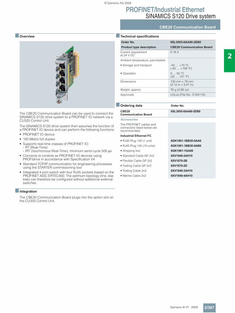
PROFINET/Industrial EthernetSINAMICS S120 Drive system
CBE20 Communication Board
2/387Siemens IK PI · 2009
2
■ Overview
The CBE20 Communication Board can be used to connect the SINAMICS S120 drive system to a PROFINET IO network via a CU320 Control Unit.
The SINAMICS S120 drive system then assumes the function of a PROFINET IO device and can perform the following functions:• PROFINET IO device• 100 Mbit/s full duplex• Supports real-time classes of PROFINET IO:
- RT (Real-Time)- IRT (Isochronous Real-Time), minimum send cycle 500 μs
• Connects to controls as PROFINET IO devices using PROFIdrive in accordance with Specification V4
• Standard TCP/IP communication for engineering processes using the STARTER commissioning tool
• Integrated 4-port switch with four RJ45 sockets based on the PROFINET ASIC ERTEC400. The optimum topology (line, star, tree) can therefore be configured without additional external switches.
■ Integration
The CBE20 Communication Board plugs into the option slot on the CU320 Control Unit.
■ Technical specifications
■ Ordering data Order No.
Order No. 6SL3055-0AA00-2EB0Product type description CBE20 Communication Board
Current requirementat 24 V DC
0.16 A
Ambient temperature, permissible
• Storage and transport -40 … +70 °C (-40 … +158 °F)
• Operation 0 … 55 °C(32 … 131 °F)
Dimensions 130 mm × 78 mm (5.12 in × 3.07 in)
Weight, approx. 76 g (2.68 oz)
Approvals cULus (File No.: E164110)
CBE20Communication Board
6SL3055-0AA00-2EB0
AccessoriesThe PROFINET cables and connectors listed below are recommended:
Industrial Ethernet FC• RJ45 Plug 145 (1 unit) 6GK1901-1BB30-0AA0• RJ45 Plug 145 (10 units) 6GK1901-1BB30-0AB0• Stripping tool 6GK1901-1GA00• Standard Cable GP 2x2 6XV1840-2AH10• Flexible Cable GP 2x2 6XV1870-2B• Trailing Cable GP 2x2 6XV1870-2D• Trailing Cable 2x2 6XV1840-3AH10• Marine Cable 2x2 6XV1840-4AH10
© Siemens AG 2008
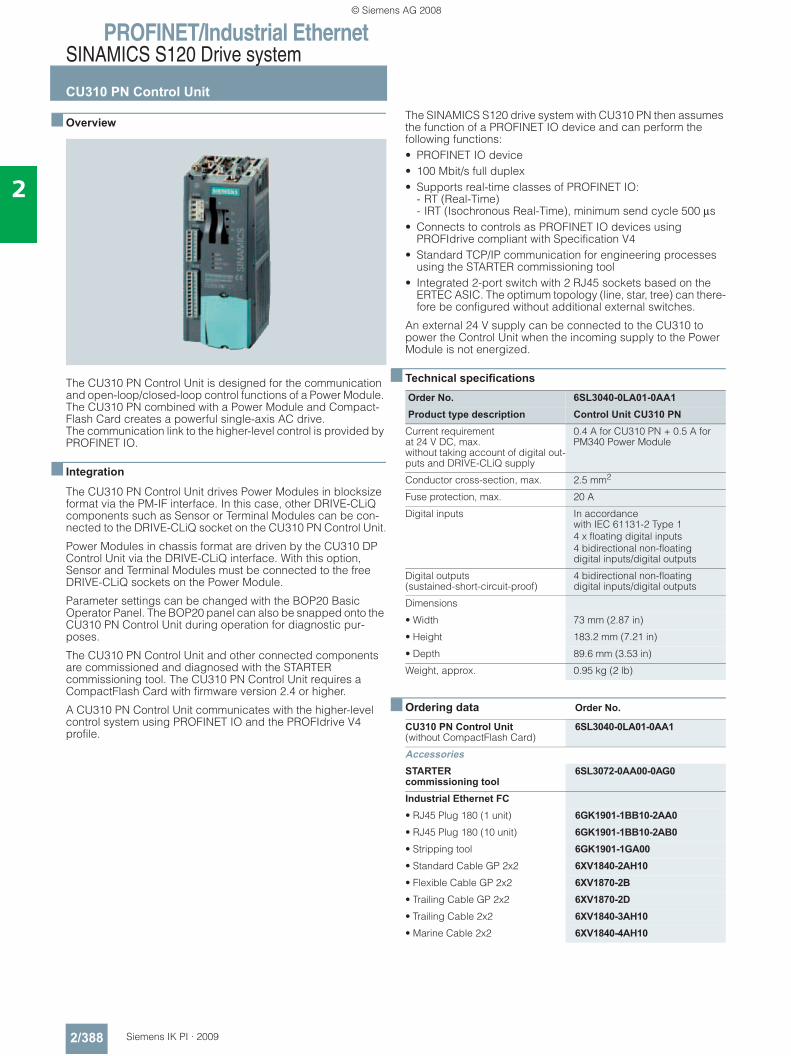
PROFINET/Industrial EthernetSINAMICS S120 Drive system
CU310 PN Control Unit
2/388 Siemens IK PI · 2009
2
■ Overview
The CU310 PN Control Unit is designed for the communication and open-loop/closed-loop control functions of a Power Module. The CU310 PN combined with a Power Module and Compact-Flash Card creates a powerful single-axis AC drive. The communication link to the higher-level control is provided by PROFINET IO.
■ Integration
The CU310 PN Control Unit drives Power Modules in blocksize format via the PM-IF interface. In this case, other DRIVE-CLiQ components such as Sensor or Terminal Modules can be con-nected to the DRIVE-CLiQ socket on the CU310 PN Control Unit.
Power Modules in chassis format are driven by the CU310 DP Control Unit via the DRIVE-CLiQ interface. With this option, Sensor and Terminal Modules must be connected to the free DRIVE-CLiQ sockets on the Power Module.
Parameter settings can be changed with the BOP20 Basic Operator Panel. The BOP20 panel can also be snapped onto the CU310 PN Control Unit during operation for diagnostic pur-poses.
The CU310 PN Control Unit and other connected components are commissioned and diagnosed with the STARTER commissioning tool. The CU310 PN Control Unit requires a CompactFlash Card with firmware version 2.4 or higher.
A CU310 PN Control Unit communicates with the higher-level control system using PROFINET IO and the PROFIdrive V4 profile.
The SINAMICS S120 drive system with CU310 PN then assumes the function of a PROFINET IO device and can perform the following functions:• PROFINET IO device• 100 Mbit/s full duplex• Supports real-time classes of PROFINET IO:
- RT (Real-Time)- IRT (Isochronous Real-Time), minimum send cycle 500 μs
• Connects to controls as PROFINET IO devices using PROFIdrive compliant with Specification V4
• Standard TCP/IP communication for engineering processes using the STARTER commissioning tool
• Integrated 2-port switch with 2 RJ45 sockets based on the ERTEC ASIC. The optimum topology (line, star, tree) can there-fore be configured without additional external switches.
An external 24 V supply can be connected to the CU310 to power the Control Unit when the incoming supply to the Power Module is not energized.
■ Technical specifications
■ Ordering data Order No.
Order No. 6SL3040-0LA01-0AA1Product type description Control Unit CU310 PN
Current requirementat 24 V DC, max.without taking account of digital out-puts and DRIVE-CLiQ supply
0.4 A for CU310 PN + 0.5 A for PM340 Power Module
Conductor cross-section, max. 2.5 mm2
Fuse protection, max. 20 A
Digital inputs In accordancewith IEC 61131-2 Type 14 x floating digital inputs4 bidirectional non-floating digital inputs/digital outputs
Digital outputs(sustained-short-circuit-proof)
4 bidirectional non-floating digital inputs/digital outputs
Dimensions
• Width 73 mm (2.87 in)
• Height 183.2 mm (7.21 in)
• Depth 89.6 mm (3.53 in)
Weight, approx. 0.95 kg (2 lb)
CU310 PN Control Unit(without CompactFlash Card)
6SL3040-0LA01-0AA1
AccessoriesSTARTER commissioning tool
6SL3072-0AA00-0AG0
Industrial Ethernet FC• RJ45 Plug 180 (1 unit) 6GK1901-1BB10-2AA0• RJ45 Plug 180 (10 unit) 6GK1901-1BB10-2AB0• Stripping tool 6GK1901-1GA00• Standard Cable GP 2x2 6XV1840-2AH10• Flexible Cable GP 2x2 6XV1870-2B• Trailing Cable GP 2x2 6XV1870-2D• Trailing Cable 2x2 6XV1840-3AH10• Marine Cable 2x2 6XV1840-4AH10
© Siemens AG 2008
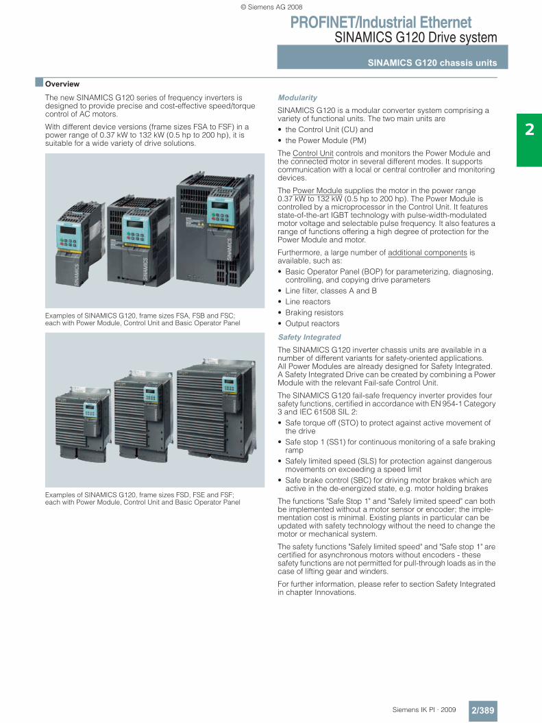
PROFINET/Industrial EthernetSINAMICS G120 Drive system
SINAMICS G120 chassis units
2/389Siemens IK PI · 2009
2
■ Overview
The new SINAMICS G120 series of frequency inverters is designed to provide precise and cost-effective speed/torque control of AC motors.
With different device versions (frame sizes FSA to FSF) in a power range of 0.37 kW to 132 kW (0.5 hp to 200 hp), it is suitable for a wide variety of drive solutions.
Examples of SINAMICS G120, frame sizes FSA, FSB and FSC; each with Power Module, Control Unit and Basic Operator Panel
Examples of SINAMICS G120, frame sizes FSD, FSE and FSF; each with Power Module, Control Unit and Basic Operator Panel
ModularitySINAMICS G120 is a modular converter system comprising a variety of functional units. The two main units are• the Control Unit (CU) and• the Power Module (PM)
The Control Unit controls and monitors the Power Module and the connected motor in several different modes. It supports communication with a local or central controller and monitoring devices.
The Power Module supplies the motor in the power range 0.37 kW to 132 kW (0.5 hp to 200 hp). The Power Module is controlled by a microprocessor in the Control Unit. It features state-of-the-art IGBT technology with pulse-width-modulated motor voltage and selectable pulse frequency. It also features a range of functions offering a high degree of protection for the Power Module and motor.
Furthermore, a large number of additional components is available, such as:• Basic Operator Panel (BOP) for parameterizing, diagnosing,
controlling, and copying drive parameters• Line filter, classes A and B• Line reactors • Braking resistors• Output reactors
Safety IntegratedThe SINAMICS G120 inverter chassis units are available in a number of different variants for safety-oriented applications. All Power Modules are already designed for Safety Integrated. A Safety Integrated Drive can be created by combining a Power Module with the relevant Fail-safe Control Unit.
The SINAMICS G120 fail-safe frequency inverter provides four safety functions, certified in accordance with EN 954-1 Category 3 and IEC 61508 SIL 2:• Safe torque off (STO) to protect against active movement of
the drive• Safe stop 1 (SS1) for continuous monitoring of a safe braking
ramp• Safely limited speed (SLS) for protection against dangerous
movements on exceeding a speed limit• Safe brake control (SBC) for driving motor brakes which are
active in the de-energized state, e.g. motor holding brakes
The functions "Safe Stop 1" and "Safely limited speed" can both be implemented without a motor sensor or encoder; the imple-mentation cost is minimal. Existing plants in particular can be updated with safety technology without the need to change the motor or mechanical system.
The safety functions "Safely limited speed" and "Safe stop 1" are certified for asynchronous motors without encoders - these safety functions are not permitted for pull-through loads as in the case of lifting gear and winders.
For further information, please refer to section Safety Integrated in chapter Innovations.
© Siemens AG 2008
PROFINET/Industrial EthernetSINAMICS G120 Drive system
SINAMICS G120 chassis units
2/390 Siemens IK PI · 2009
2
■ Overview (continued)
Efficient Infeed TechnologyThe advanced Efficient Infeed Technology is employed in PM250 and PM260 Power Modules. This technology allows the energy produced by motors operating in generator mode on standard inverters to be fed back into the supply system. The control cabinet can be designed even more compactly thanks to the omission of extra cooling equipment and components such as braking resistors, brake choppers and line reactors. The time and expense involved in planning and wiring the system are significantly reduced. At the same time, consider-able savings can be achieved in terms of energy consumption and operating costs.
For further information, please refer to section Efficient Infeed Technology in chapter Innovations.
Innovative cooling concept and paint finish of electronic modulesThe new cooling system and the paint finish for the electronic modules significantly increase the service life or useful life of the device. These features are based on the following principles:• Disposal of all heat losses via an external heat sink• Electronic modules not located in air duct• Standardized convection cooling of Control Unit• All cooling air from the fan is directed through the heat sink
STARTER commissioning toolThe STARTER commissioning tool supports the commissioning and maintenance of SINAMICS G120 inverters. The operator guidance combined with comprehensive, user-friendly functions for the relevant drive solution allows you to commission the device quickly and easily.
■ Benefits7 Modularity ensures flexibility for an advanced drive concept
- Module replacement when system is running (hot swapping) - Pluggable terminals - The modules can be easily replaced, which makes the
system extremely service friendly. 7 The safety functions make it easier to integrate drives into
safety-oriented machines or plants 7 Capable of communicating via PROFINET or PROFIBUS with
PROFIdrive Profil 4.0 - Reduced number of interfaces - Plant-wide engineering - Easy to handle
7 The innovative circuit design (bidirectional input rectifier with "pared-down" DC link) allows the kinetic energy of a load to be fed back into the supply system when Power Modules PM250 and PM260 are implemented. This feedback capability pro-vides enormous potential for savings because generated energy no longer has to be converted into heat in a braking resistor
7 Innovative SiC semiconductor technology ensures that when a PM260 Power Module is used, the inverter is more compact than a comparable standard inverter with an optional LC filter for the same output.
7 A new cooling concept and paint finish for the electronic modules increase robustness and service life
7 Simple unit replacement and quick copying of parameters using the optional Basic Operator Panel or the optional MMC memory card
7 Low-noise motor operation resulting from high pulse fre-quency
7 Compact, space-saving construction 7 Software parameters for easy adaptation to 50 Hz or 60 Hz
motors (IEC or NEMA motors) 7 2/3-wire control (static/pulsated signals) for universal control
via digital inputs 7 Engineering and commissioning with uniform engineering
tools such as SIZER, STARTER, and Drive ES: ensure rapid engineering and easy commissioning – STARTER is inte-grated in STEP 7 with Drive ES Basic with all the advantages of central data storage and totally integrated communication
7 Certified worldwide for compliance with CE, UL, cUL, C-tick, Safety Integrated IEC 61508 SIL 2
■ Application
SINAMICS G120 is ideal• as a universal drive in all industrial and commercial applica-
tions • in the automotive, textiles, printing, and chemical industries • for end-to-end applications, e.g. in conveyor systems
© Siemens AG 2008
PROFINET/Industrial EthernetSINAMICS G120 Drive system
SINAMICS G120 chassis units
2/391Siemens IK PI · 2009
2
■ Design
The SINAMICS G120 inverter chassis units are modular fre-quency inverters for standard drives. Each SINAMICS G120 comprises two operative units – the Power Module and Control Unit. Each Control Unit can be combined with each Power Module.
Guide for module selectionThe steps to be taken for the selection of a complete SINAMICS G120 frequency inverter should be as follows:
Control UnitsThe following Control Units and an MMC memory card are avail-able as accessories for SINAMICS G120 inverter chassis units:
CU240 Control Units
The Control Unit performs closed-loop control functions for the inverter. In addition to control functions, the Control Unit can also perform other tasks which can be adapted to the relevant application by parameterization. A number of Control Units are available in different versions:• CU240S PN • CU240S PN-F
MMC memory card (not available for Control Unit CU240E)
The parameter settings for an inverter can be stored on the MMC memory card. When the plant is serviced, it is immediately ready for use again after, for example, replacement of the frequency inverter and transfer of the memory card data. The associated slot is located on top of the Control Unit.
Power ModulesThe following Power Modules are available for SINAMICS G120 inverter chassis units:
PM240 Power Modules
PM240 Power Modules (0.37 kW to 90 kW) feature an integrated brake chopper and are designed for drives without energy re-covery capability. Generator energy produced during braking is converted to heat via externally connected braking resistors.
PM250 Power Modules
PM250 Power Modules (7.5 kW to 132 kW) use an innovative circuit design which allows line-commutated energy recovery to the supply. This innovative circuit permits generator energy to be fed back into the supply system and therefore saves energy.
PM260 Power Modules
PM260 Power Modules (11 kW to 55 kW) also use an innovative circuit design which allows line-commutated energy recovery to the supply. This innovative circuit permits generator energy to be fed back into the supply system and, therefore, saves energy. The PM260 Power Modules also have an integrated sine-wave filter that limits the rate of rise of voltage and the capacitive charge/discharge currents usually associated with converter operation.
Line-side power componentsThe following line-side power components are available for SINAMICS G120 inverter chassis units:
Line filters
The Power Module complies with a higher radio interference class with one additional line filter.
Line reactors (for PM240 Power Modules only)
A line reactor reduces the system perturbations by harmonics. This is valid in particular for low power supplies (system fault level uK > 1 %).
Recommended line components
This is a recommendation for further line-side components, such as fuses and circuit-breakers (line-side components must be dimensioned in accordance with IEC standards). Further infor-mation about the listed fuses and circuit-breakers can be found in Catalogs LV 1 and LV 1 T.
DC link componentsThe following DC-link components are available for SINAMICS G120 inverter chassis units:
Braking resistors (for PM240 Power Modules only)
Excess power in the DC link is dissipated via the braking resistor. The braking resistors are designed for use with PM240 Power Modules. They are equipped with an integrated brake chopper (electronic switch).
Load-side power componentsThe following load-side power components are available for SINAMICS G120 inverter chassis units. This means that during operation with output reactors or LC filters or sine-wave filters, longer, shielded motor cables are possible and the motor ser-vice life can be increased:
Output reactors (for PM240 Power Modules only)
Output reactors reduce the voltage loading on the motor windings. At the same time, the capacitive charge/discharge currents, which place an additional load on the power section when long motor cables are used, are reduced.
Sine-wave filter (available soon, not available forPM260 Power Modules)
Sine-wave filter limits the rate of rise of voltage and the capacitive charge/discharge currents usually associated with converter operation. An output reactor is not required.
1. Selection of the appropriate Control Unit (in dependence of the required style depth of communication, hardware and software)
2. Selection of the appropriate Power Module (in dependence of the necessary performance and technology)
3. Selection of the optional additional components. A large number of components for expanding the system is available (e. g. line-side power components, DC-link components, load-side power compo-nents, and supplementary system components). Please note that not every component is required for every Power Module (example: Braking resistors are not necessary for PM250 and PM260 Power Modules!). You can find the exact indications in the technical data tables of the respective components.
© Siemens AG 2008
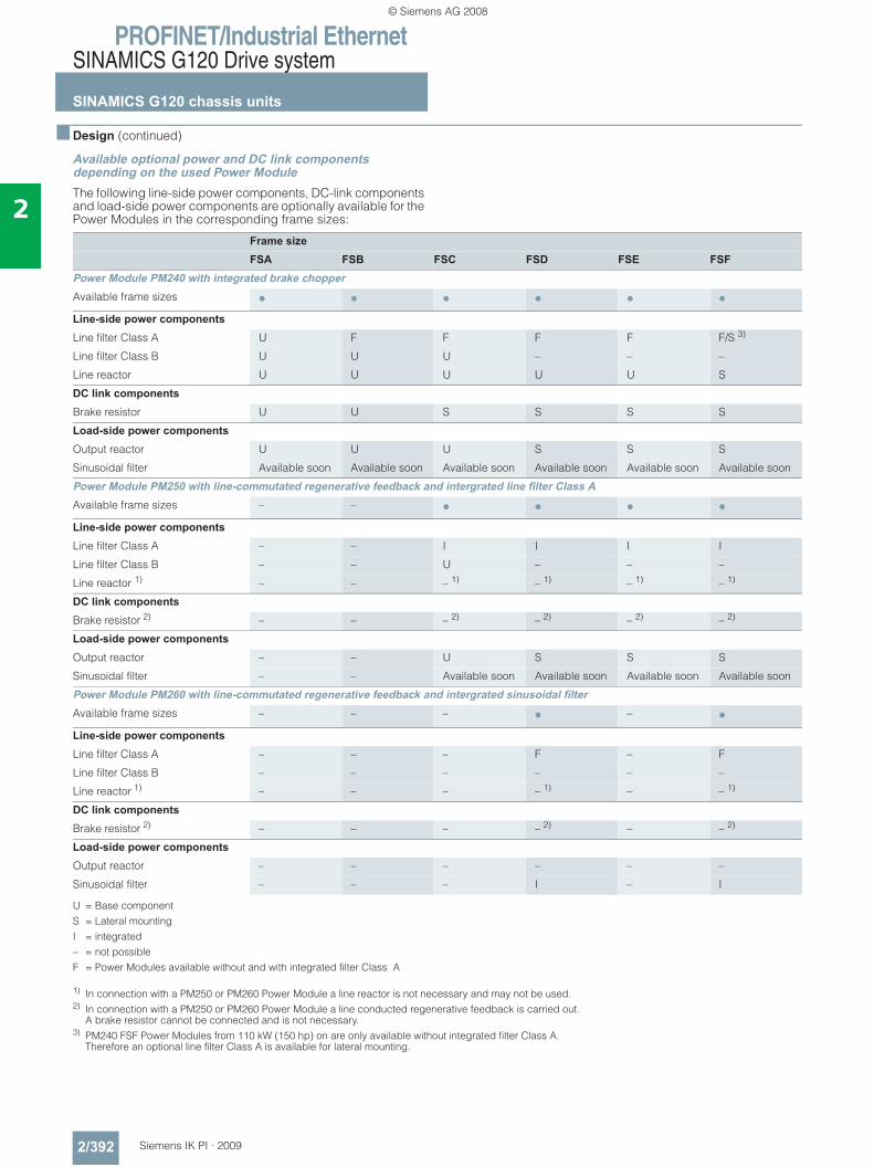
PROFINET/Industrial EthernetSINAMICS G120 Drive system
SINAMICS G120 chassis units
2/392 Siemens IK PI · 2009
2
■ Design (continued)
Available optional power and DC link components depending on the used Power ModuleThe following line-side power components, DC-link components and load-side power components are optionally available for the Power Modules in the corresponding frame sizes:
U = Base componentS = Lateral mounting I = integrated– = not possibleF = Power Modules available without and with integrated filter Class A
1) In connection with a PM250 or PM260 Power Module a line reactor is not necessary and may not be used.2) In connection with a PM250 or PM260 Power Module a line conducted regenerative feedback is carried out.
A brake resistor cannot be connected and is not necessary.3) PM240 FSF Power Modules from 110 kW (150 hp) on are only available without integrated filter Class A.
Therefore an optional line filter Class A is available for lateral mounting.
Frame sizeFSA FSB FSC FSD FSE FSF
Power Module PM240 with integrated brake chopperAvailable frame sizes • • • • • •Line-side power componentsLine filter Class A U F F F F F/S 3)
Line filter Class B U U U – – –
Line reactor U U U U U S
DC link components Brake resistor U U S S S S
Load-side power componentsOutput reactor U U U S S S
Sinusoidal filter Available soon Available soon Available soon Available soon Available soon Available soon
Power Module PM250 with line-commutated regenerative feedback and intergrated line filter Class AAvailable frame sizes – – • • • •Line-side power componentsLine filter Class A – – I I I I
Line filter Class B – – U – – –
Line reactor 1) – – – 1) – 1) – 1) – 1)
DC link components Brake resistor 2) – – – 2) – 2) – 2) – 2)
Load-side power componentsOutput reactor – – U S S S
Sinusoidal filter – – Available soon Available soon Available soon Available soon
Power Module PM260 with line-commutated regenerative feedback and intergrated sinusoidal filterAvailable frame sizes – – – • – •Line-side power componentsLine filter Class A – – – F – F
Line filter Class B – – – – – –
Line reactor 1) – – – – 1) – – 1)
DC link components Brake resistor 2) – – – – 2) – – 2)
Load-side power componentsOutput reactor – – – – – –
Sinusoidal filter – – – I – I
© Siemens AG 2008
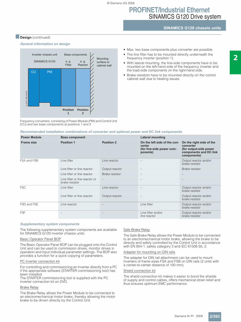
PROFINET/Industrial EthernetSINAMICS G120 Drive system
SINAMICS G120 chassis units
2/393Siemens IK PI · 2009
2
■ Design (continued)
General information on design
Frequency converters, consisting of Power Module (PM) and Control Unit (CU) and two base components at positions 1 and 2
• Max. two base components plus converter are possible.• The line filter has to be mounted directly underneath the
frequency inverter (position 1).• With lateral mounting, the line-side components have to be
mounted on the left-hand side of the frequency inverter and the load-side components on the right-hand side.
• Brake resistors have to be mounted directly on the control cabinet wall due to heating issues.
Recommended installation combinations of converter and optional power and DC link components
Supplementary system componentsThe following supplementary system components are available for SINAMICS G120 inverter chassis units:
Basic Operator Panel BOP
The Basic Operator Panel BOP can be plugged onto the Control Unit and can be used to commission drives, monitor drives in operation and input individual parameter settings. The BOP also provides a function for a quick copying of parameters.
PC inverter connection kit
For controlling and commissioning an inverter directly from a PC if the appropriate software (STARTER commissioning tool) has been installed.The STARTER commissioning tool is supplied with the PC inverter connection kit on DVD.
Brake Relay
The Brake Relay allows the Power Module to be connected to an electromechanical motor brake, thereby allowing the motor brake to be driven directly by the Control Unit.
Safe Brake Relay
The Safe Brake Relay allows the Power Module to be connected to an electromechanical motor brake, allowing the brake to be directly and safely controlled by the Control Unit in accordance with EN 954-1, safety category 3 and IEC 61508 SIL 2.
Adapter for mounting on DIN rails
The adapter for DIN rail attachment can be used to mount inverters of frame sizes FSA and FSB on DIN rails (2 units with a center-to-center distance of 100 mm).
Shield connection kit
The shield connection kit makes it easier to bond the shields of supply and control cables, offers mechanical strain relief and thus ensures optimum EMC performance.
Inverter chassis unit
SINAMICS G120 e. g.Filter
Base components
e. g.Reactor
Mountingsurface or cabinet wall
Position1
Position2
G_D
011_
EN
_001
87
CU PM
Power Module Base component Lateral mountingFrame size Position 1 Position 2 On the left side of the con-
verter (for line-side power com-ponents)
On the right side of the converter(for output-side power components and DC link components)
FSA and FSB Line filter Line reactor – Output reactor and/or brake resistor
Line filter or line reactor Output reactor – Brake resistor
Line filter or line reactor Brake resistor – –
Line filter or line reactor or brake resistor
– – –
FSC Line filter Line reactor – Output reactor and/or brake resistor
Line filter or line reactor Output reactor – Output reactor and/or brake resistor
FSD and FSE Line reactor – Line filter Output reactor and/or brake resistor
FSF – – Line filter and/orline reactor
Output reactor and/or brake resistor
© Siemens AG 2008
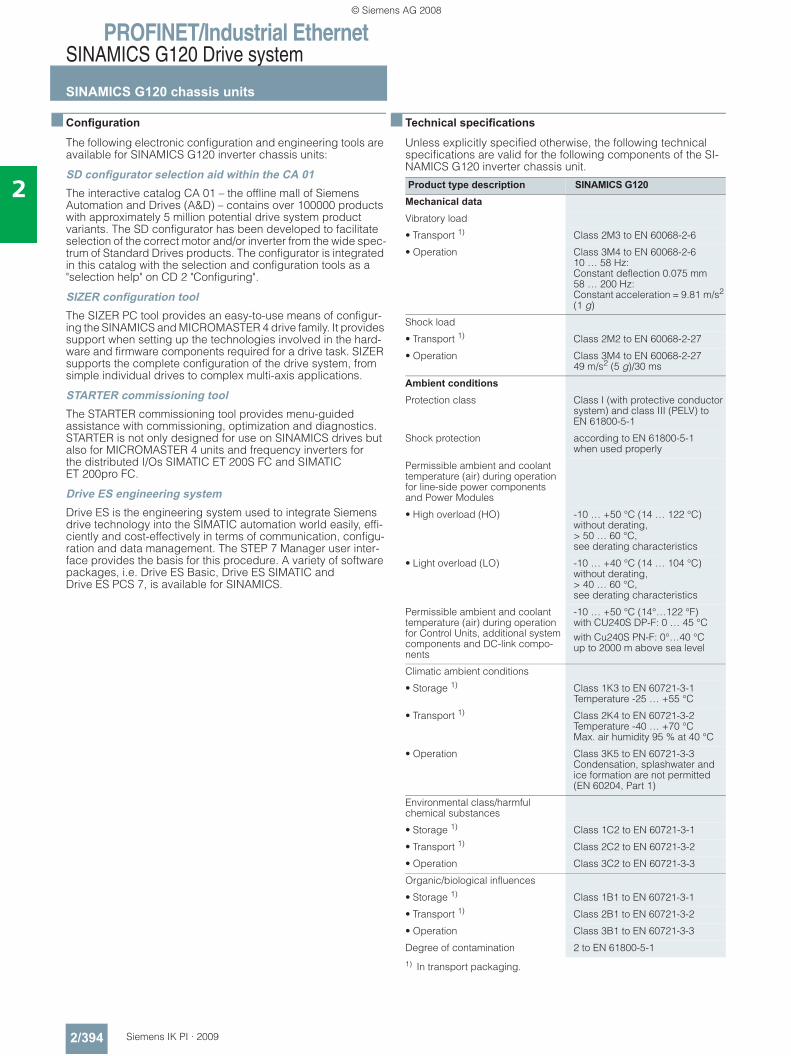
PROFINET/Industrial EthernetSINAMICS G120 Drive system
SINAMICS G120 chassis units
2/394 Siemens IK PI · 2009
2
■ Configuration
The following electronic configuration and engineering tools are available for SINAMICS G120 inverter chassis units:
SD configurator selection aid within the CA 01The interactive catalog CA 01 – the offline mall of Siemens Automation and Drives (A&D) – contains over 100000 products with approximately 5 million potential drive system product variants. The SD configurator has been developed to facilitate selection of the correct motor and/or inverter from the wide spec-trum of Standard Drives products. The configurator is integrated in this catalog with the selection and configuration tools as a "selection help" on CD 2 "Configuring".
SIZER configuration toolThe SIZER PC tool provides an easy-to-use means of configur-ing the SINAMICS and MICROMASTER 4 drive family. It provides support when setting up the technologies involved in the hard-ware and firmware components required for a drive task. SIZER supports the complete configuration of the drive system, from simple individual drives to complex multi-axis applications.
STARTER commissioning toolThe STARTER commissioning tool provides menu-guided assistance with commissioning, optimization and diagnostics. STARTER is not only designed for use on SINAMICS drives but also for MICROMASTER 4 units and frequency inverters for the distributed I/Os SIMATIC ET 200S FC and SIMATIC ET 200pro FC.
Drive ES engineering systemDrive ES is the engineering system used to integrate Siemens drive technology into the SIMATIC automation world easily, effi-ciently and cost-effectively in terms of communication, configu-ration and data management. The STEP 7 Manager user inter-face provides the basis for this procedure. A variety of software packages, i.e. Drive ES Basic, Drive ES SIMATIC and Drive ES PCS 7, is available for SINAMICS.
■ Technical specifications
Unless explicitly specified otherwise, the following technical specifications are valid for the following components of the SI-NAMICS G120 inverter chassis unit.
1) In transport packaging.
Product type description SINAMICS G120Mechanical data Vibratory load
• Transport 1) Class 2M3 to EN 60068-2-6
• Operation Class 3M4 to EN 60068-2-610 … 58 Hz: Constant deflection 0.075 mm58 … 200 Hz: Constant acceleration = 9.81 m/s2 (1 g)
Shock load
• Transport 1) Class 2M2 to EN 60068-2-27
• Operation Class 3M4 to EN 60068-2-2749 m/s2 (5 g)/30 ms
Ambient conditions Protection class Class I (with protective conductor
system) and class III (PELV) to EN 61800-5-1
Shock protection according to EN 61800-5-1when used properly
Permissible ambient and coolant temperature (air) during operation for line-side power components and Power Modules
• High overload (HO) -10 … +50 °C (14 … 122 °C) without derating,> 50 … 60 °C, see derating characteristics
• Light overload (LO) -10 … +40 °C (14 … 104 °C) without derating,> 40 … 60 °C, see derating characteristics
Permissible ambient and coolant temperature (air) during operation for Control Units, additional system components and DC-link compo-nents
-10 … +50 °C (14°…122 °F)with CU240S DP-F: 0 … 45 °Cwith Cu240S PN-F: 0°…40 °Cup to 2000 m above sea level
Climatic ambient conditions
• Storage 1) Class 1K3 to EN 60721-3-1Temperature -25 … +55 °C
• Transport 1) Class 2K4 to EN 60721-3-2Temperature -40 … +70 °CMax. air humidity 95 % at 40 °C
• Operation Class 3K5 to EN 60721-3-3Condensation, splashwater and ice formation are not permitted (EN 60204, Part 1)
Environmental class/harmful chemical substances
• Storage 1) Class 1C2 to EN 60721-3-1
• Transport 1) Class 2C2 to EN 60721-3-2
• Operation Class 3C2 to EN 60721-3-3
Organic/biological influences
• Storage 1) Class 1B1 to EN 60721-3-1
• Transport 1) Class 2B1 to EN 60721-3-2
• Operation Class 3B1 to EN 60721-3-3
Degree of contamination 2 to EN 61800-5-1
© Siemens AG 2008
PROFINET/Industrial EthernetSINAMICS G120 Drive system
SINAMICS G120 chassis units
2/395Siemens IK PI · 2009
2
■ Technical specifications (continued)
2) Unfiltered inverters can be used in industrial environments as long as they are installed in a system that contains line filters on the higher-level infeed side. Then a PDS (Power Drive System) Category C3 can be installed.
3) With shielded motor cable up to 25 m.
Compliance with standardsCE mark
The SINAMICS G120 inverters meet the requirements of the Low-Voltage Directive 73/23/EEC.
Low-voltage directive
The inverters comply with the following standards listed in the EU gazette:• EN 60204
Safety of machinery, electrical equipment of machines• EN 61800-5-1
Electrical power drive systems with variable speed – Part 5-1: Requirements regarding safety – electrical, thermal, and energy requirements
UL listing
Converter devices in UL category NMMS certified to UL and cUL, in compliance with UL508C. UL list numbers E121068 and E192450.
For use in environment with pollution degree 2.
Additional in formation can be found in the Internet under: http://www.ul.com
Machine directive
The devices are suitable for installation in machines. Compli-ance with the machine directive 98/37/EEC requires a separate certificate of conformity. This must be provided by the plant con-structor or the installer of the machine.
EMC directive • EN 61800-3
Variable-speed electric drivesPart 3: EMC product standard including specific test methods
The modified EMC product standard EN 61800-3 for electrical drive systems is valid since 07/01/2005. The transition period for the predecessor standard EN 61800-3/A11 from February 2001 ended on October 1, 2007. The following information applies to the SINAMICS G120 frequency inverters from Siemens AG:• The EMC product standard EN 61800-3 does not apply
directly to a frequency inverter but to a PDS (Power Drive System), which comprises the complete circuitry, motor and cables in addition to the inverter.
• Frequency inverters are normally only supplied to experts for installation in machines or systems. A frequency inverter must, therefore, only be considered as a component which, on its own, is not subject to the EMC product standard EN 61800-3. The inverter’s Instruction Manual, however, specifies the con-ditions regarding compliance with the product standard if the frequency inverter is expanded to a PDS. The EMC directive in the EU is complied with for a PDS by observance of the product standard EN 61800-3. The frequency inverters on their own do not generally require identification according to the EMC directive.
Standards Standards conformance UL, cUL, CE, c-tick
CE mark To Low-Voltage Directive 73/23/EEC and Machinery Direc-tive 98/37/EEC
EMC directive
• Frame sizes FSA to FSF without integrated line filter class A
Category C3 2) to EN 61800-3
• Frame sizes FSB to FSF with integrated line filter class A
Category C2 3) to EN 61800-3 (corresponds to class A to EN 55011 for conducted interference)
• Frame size FSA without integrated line filter and with additional line filter class A
Category C2 3) to EN 61800-3 (corresponds to class A to EN 55011 for conducted interference)
• Frame sizes FSA with additional line filter class A and with additional line filter class B
Category C2 3) to EN 61800-3 (corresponds to class B to EN 55011 for conducted interference)
• Frame sizes FSB and FSC with additional line filter class A and with additional line filter class B
Category C2 3) to EN 61800-3 (corresponds to class B to EN 55011 for conducted interference)
Note: The EMC product standard EN 61800-3 does not apply directly to a frequency inverter but to a PDS (Power Drive System), which comprises the complete circuitry, motor and cables in addition to the inverter. The frequency inverters on their own do not generally require identifica-tion according to the EMC directive.
© Siemens AG 2008
PROFINET/Industrial EthernetSINAMICS G120 Drive system
SINAMICS G120 chassis units
2/396 Siemens IK PI · 2009
2
■ Technical specifications (continued)• In the new EN 61800-3 of July 2005, a distinction is no longer
made between "general availability" and "restricted availabil-ity". Instead, different categories have been defined, C1 to C4, in accordance with the environment of the PDS at the operat-ing site: - Category C1: Drive systems for rated voltages < 1000 V
for use in environment 1- Category C2: Stationary drive systems not connected by
means of a plug connector for rated voltages < 1000 V. When used in environment 1, the system must be installed and commissioned by personnel familiar with EMC require-ments. A warning is required.
- Category C3: Drive systems for rated voltages < 1000 V for exclusive use in the second environment. A warning is required.
- Category C4: Drive systems for rated voltages ≥ 1000 V,for rated currents ≥ 400 A, or for use in complex systems in environment 2. An EMC plan must be created.
• The EMC product standard EN 61800-3 also defines limit values for conducted interference and radiated interference for "environment 2" (= industrial power supply systems that do not supply households). These limit values are below the limit values of filter class A to EN 55011. Unfiltered inverters can be used in industrial environments as long as they are installed in a system that contains line filters on the higher-level infeed side.
• With SINAMICS G120 Power Drive Systems (PDS) that fulfill EMC product standard EN 61800-3 can be set up upon follow-ing the setup instructions.
• A differentiation must be made between the product stan-dards for electrical drive systems (PDS) of the range of stan-dards EN 61800 (of which Part 3 covers EMC topics) and the product standards for the devices/systems/machines, etc. This will probably not result in any changes in the practical use of frequency inverters. Since frequency inverters are always part of a PDS and these are part of a machine, the machine manufacturer must observe various standards depending on their type and environment (e.g. EN 61000-3-2 for line har-monics and EN 55011 for radio interference). The product standard for PDS on its own is, therefore, either insufficient or irrelevant.
• Regarding the compliance of limit values for line harmonics, EMC product standard EN 61800-3 for PDS refers to compli-ance with EN 61000-3-2 and EN 61000-3-12.
• Regardless of the configuration with SINAMICS G120 and its components, the mechanical engineer can also implement other measures to ensure that the machine complies with the EU EMC directive. The EU EMC directive is generally fulfilled when the relevant EMC product standards are observed. If they are not available, the generic standards (e.g. DIN EN 61000-x-x) can be used instead. It is important that the conducted and emitted interferences at the line connection point and outside the machine remain below the relevant limit values. Any suitable technical means can be used to ensure this.
■ More information
Further information on technical specifications and ordering data can be found in Catalog D11.1 "SINAMICS G110/G120 Built-in Devices and SINAMICS 120D Distributed Frequency Converter" as well as iin the interactive catalog under "Drives Technology/AC Converters/Low-Voltage Converters" for "SINAMICS G110/G120 Built-in Devices and SINAMICS 120D Distributed Frequency Converter".
© Siemens AG 2008
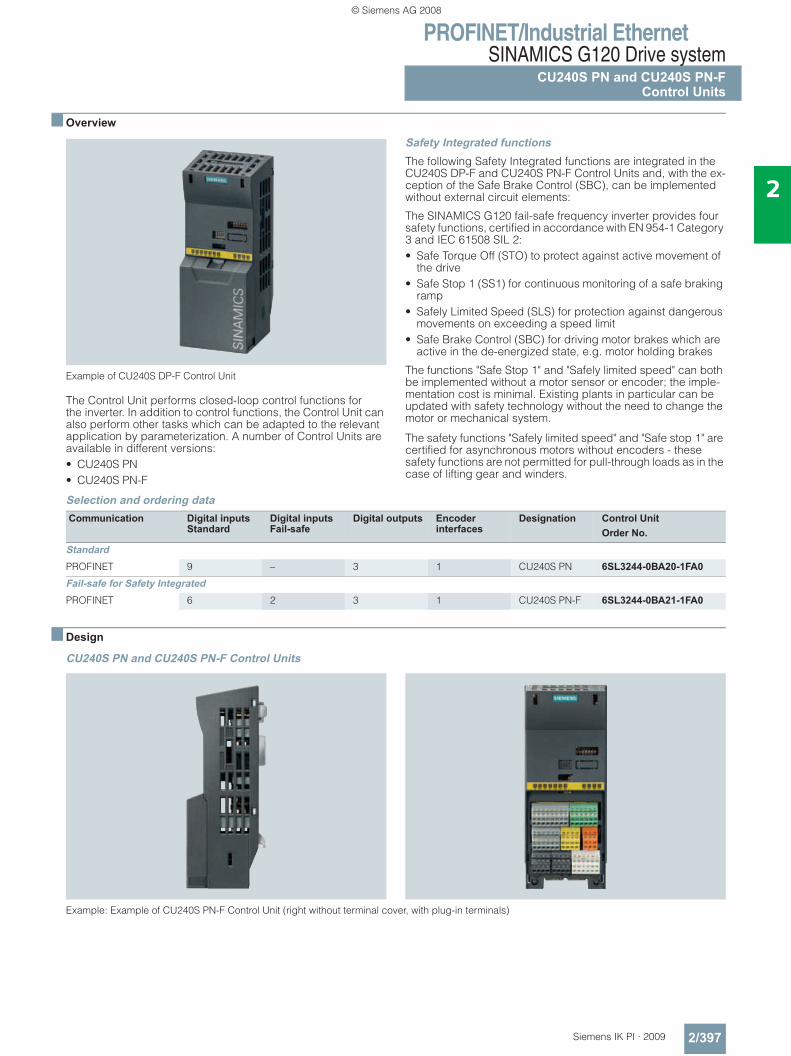
PROFINET/Industrial EthernetSINAMICS G120 Drive system
CU240S PN and CU240S PN-FControl Units
2/397Siemens IK PI · 2009
2
■ Overview
Example of CU240S DP-F Control Unit
The Control Unit performs closed-loop control functions for the inverter. In addition to control functions, the Control Unit can also perform other tasks which can be adapted to the relevant application by parameterization. A number of Control Units are available in different versions:• CU240S PN• CU240S PN-F
Safety Integrated functionsThe following Safety Integrated functions are integrated in the CU240S DP-F and CU240S PN-F Control Units and, with the ex-ception of the Safe Brake Control (SBC), can be implemented without external circuit elements:
The SINAMICS G120 fail-safe frequency inverter provides four safety functions, certified in accordance with EN 954-1 Category 3 and IEC 61508 SIL 2:• Safe Torque Off (STO) to protect against active movement of
the drive• Safe Stop 1 (SS1) for continuous monitoring of a safe braking
ramp• Safely Limited Speed (SLS) for protection against dangerous
movements on exceeding a speed limit• Safe Brake Control (SBC) for driving motor brakes which are
active in the de-energized state, e.g. motor holding brakes
The functions "Safe Stop 1" and "Safely limited speed" can both be implemented without a motor sensor or encoder; the imple-mentation cost is minimal. Existing plants in particular can be updated with safety technology without the need to change the motor or mechanical system.
The safety functions "Safely limited speed" and "Safe stop 1" are certified for asynchronous motors without encoders - these safety functions are not permitted for pull-through loads as in the case of lifting gear and winders.
Selection and ordering data
■ Design
CU240S PN and CU240S PN-F Control Units
Example: Example of CU240S PN-F Control Unit (right without terminal cover, with plug-in terminals)
Communication Digital inputsStandard
Digital inputsFail-safe
Digital outputs Encoderinterfaces
Designation Control UnitOrder No.
StandardPROFINET 9 – 3 1 CU240S PN 6SL3244-0BA20-1FA0Fail-safe for Safety IntegratedPROFINET 6 2 3 1 CU240S PN-F 6SL3244-0BA21-1FA0
© Siemens AG 2008
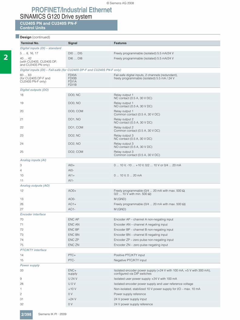
PROFINET/Industrial EthernetSINAMICS G120 Drive systemCU240S PN and CU240S PN-FControl Units
2/398 Siemens IK PI · 2009
2
■ Design (continued)
Terminal No. Signal FeaturesDigital inputs (DI) – standard5 … 8, 16, 17 DI0 … DI5 Freely programmable (isolated) 5.5 mA/24 V
40 … 42(with CU240S, CU240S DP, and CU240S PN only)
DI6 … DI8 Freely programmable (isolated) 5.5 mA/24 V
Digital inputs (DI) – Fail-safe (for CU240S DP-F and CU240S PN-F only)60 … 63(for CU240S DP-F and CU240S PN-F only)
FDI0AFDI0BFDI1AFDI1B
Fail-safe digital inputs, 2 channels (redundant),freely programmable (isolated) 5.5 mA / 24 V
Digital outputs (DO)18 DO0, NC Relay output 1
NC contact (0.5 A, 30 V DC)
19 DO0, NO Relay output 1NO contact (0.5 A, 30 V DC)
20 DO0, COM Relay output 1Common contact (0.5 A, 30 V DC)
21 DO1, NO Relay output 2NO contact (0.5 A, 30 V DC)
22 DO1, COM Relay output 2Common contact (0.5 A, 30 V DC)
23 DO2, NC Relay output 3NC contact (0.5 A, 30 V DC)
24 DO2, NO Relay output 3NO contact (0.5 A, 30 V DC)
25 DO2, COM Relay output 3Common contact (0.5 A, 30 V DC)
Analog inputs (AI)3 AI0+ 0 ... 10 V, -10 ... +10 V, 0/2 ... 10 V or 0/4 ... 20 mA
4 AI0-
10 AI1+ 0 ... 10 V, 0 ... 20 mA
11 AI1-
Analog outputs (AO)12 AO0+ Freely programmable (0/4 ... 20 mA with max. 500 Ω,
0/2 ... 10 V with min. 500 Ω)
13 AO0- M (GND)
26 AO1+ Freely programmable (0/4 ... 20 mA with max. 500 Ω)
27 AO1- M (GND)
Encoder interface70 ENC AP Encoder AP – channel A non-negating input
71 ENC AN Encoder AN – channel A negating input
72 ENC BP Encoder BP – channel B non-negating input
73 ENC BN Encoder BN – channel B negating input
74 ENC ZP Encoder ZP – zero pulse non-negating input
75 ENC ZN Encoder ZN – zero pulse negating input
PTC/KTY interface14 PTC+ Positive PTC/KTY input
15 PTC- Negative PTC/KTY input
Power supply33 ENC+
supplyIsolated encoder power supply (+24 V with 100 mA, +5 V with 300 mA), configured via DIP switches
9 U 24 V Isolated user power supply +24 V with 100 mA
28 U 0 V Isolated encoder power supply and user reference voltage
1 +10 V Non-isolated, stabilized 10 V power supply for I/O – max. 10 mA
2 0 V Power supply reference
31 +24 V 24 V power supply input
32 0 V 24 V power supply reference
© Siemens AG 2008
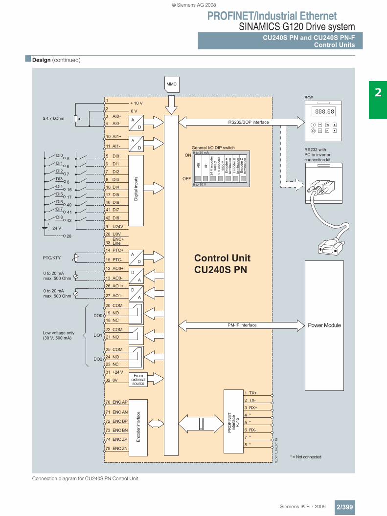
PROFINET/Industrial EthernetSINAMICS G120 Drive system
CU240S PN and CU240S PN-FControl Units
2/399Siemens IK PI · 2009
2
■ Design (continued)
Connection diagram for CU240S PN Control Unit
A
D
A/ D
A/ D
+ 10 V
0 V
ENC+
1
2
3 AI0+
4 AI0-
10 AI1+
11 AI1-
5 DI0
6 DI1
7 DI2
8 DI3
16 DI4
17 DI5
40 DI6
41 DI7
42 DI8
9 U24V
33
14 PTC+
15 PTC-
12 AO0+
13 AO0-
20 COM
18 NC
19 NO
25 COM
23 NC
24 NO
22 COM
21 NO
28 U0V
31 +24 V
32 0V
71 ENC AN
70 ENC AP
1
2 TX-
3 RX+
4 *
5 *
6 RX-
7 *
8 *
72 ENC BP
73 ENC BN
74 ENC ZP
75 ENC ZN
A
D
A
D
A
D
A
D
26 AO1+
27 AO1-
DO1
DO2
DO0
AI0
AI1
Power Module
PTC/KTY
JOG
FN I
P O
BOP
Control UnitCU240S PN
DI0
DI1
DI2
DI3
DI4
DI5
DI6
DI7
DI8
24 V+
-
5
6
7
8
16
17
40
41
42
28
MMC
TX+
General I/O DIP switch
ON
5 V
enc
oder
su
pply
24 V
enc
oder
su
pply
Enc
oder
A
term
inat
ion
Enc
oder
B
term
inat
ion
Enc
oder
Z
term
inat
ion
Enco
der i
nter
face
PRO
FIN
ETin
terfa
ceR
J45
Low voltage only (30 V, 500 mA)
G_D
011_
EN
_001
19
From external source
* = Not connected
Dig
ital i
nput
s
RS232/BOP interface4.7 kOhm
0 to 20 mA max. 500 Ohm
0 to 20 mA max. 500 Ohm
Line
RS232 withPC to inverterconnection kit
PM-IF interface
OFF
0 to 20 mA
0 to 10 V
© Siemens AG 2008
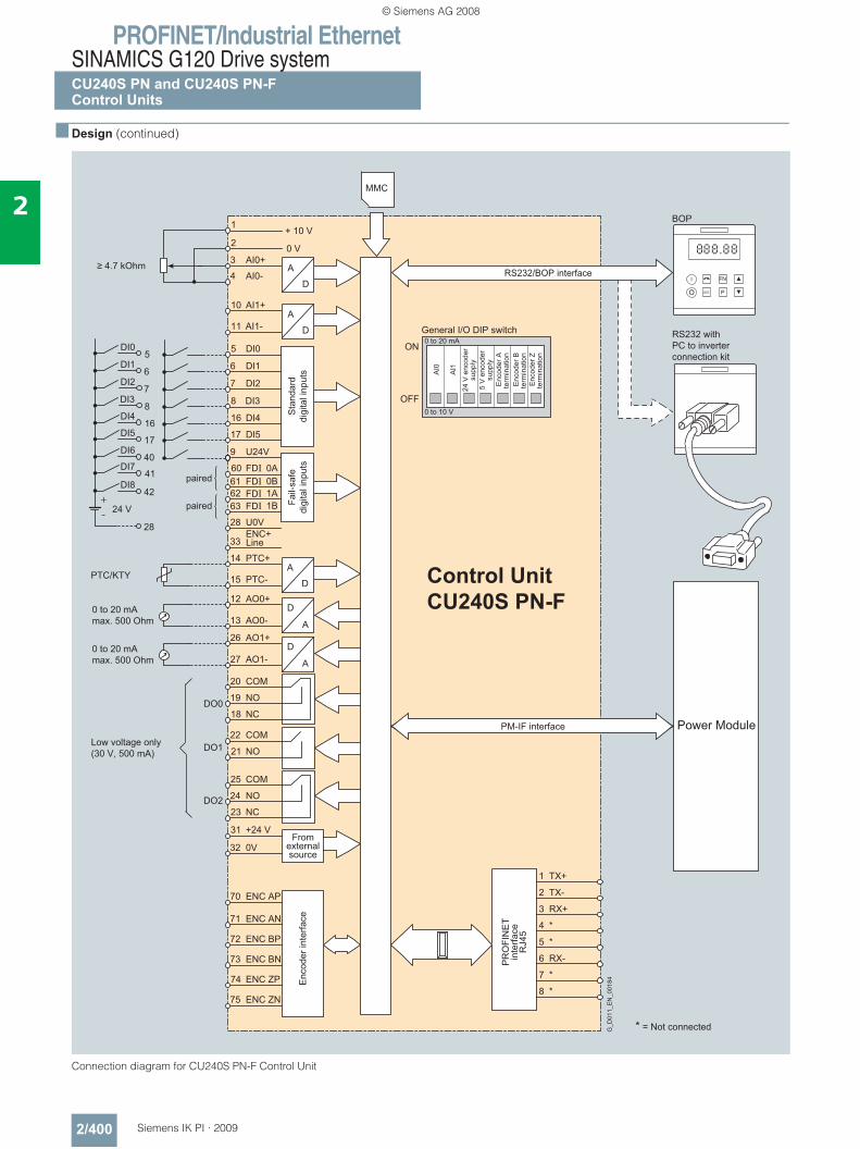
PROFINET/Industrial EthernetSINAMICS G120 Drive systemCU240S PN and CU240S PN-FControl Units
2/400 Siemens IK PI · 2009
2
■ Design (continued)
Connection diagram for CU240S PN-F Control Unit
General I/O DIP switch
ON
5 V
enc
oder
supp
ly
24 V
enc
oder
supp
ly
Enc
oder
Ate
rmin
atio
nE
ncod
er B
term
inat
ion
Enc
oder
Zte
rmin
atio
n
Enc
oder
inte
rface
PR
OFI
NE
Tin
terfa
ceR
J45
Low voltage only(30 V, 500 mA)
G_D
011_
EN
_001
84
Fromexternalsource
* = Not connected
RS232/BOP interface
0 to 20 mAmax. 500 Ohm
0 to 20 mAmax. 500 Ohm
Line
RS232 withPC to inverterconnection kit
PM-IF interface
OFF
0 to 20 mA
0 to 10 V
Fail-
safe
digi
tal i
nput
sS
tand
ard
digi
tal i
nput
s
paired
paired
≥ 4.7 kOhm
A
D
+ 10 V
0 V
ENC+
1
2
3 AI0+
4 AI0-
10 AI1+
11 AI1-
5 DI0
6 DI1
7 DI2
8 DI3
16 DI4
17 DI5
9 U24V
60 0AFDI
63 FDI
33
14 PTC+
15 PTC-
12 AO0+
13 AO0-
20 COM
18 NC
19 NO
25 COM
23 NC
24 NO
22 COM
21 NO
28 U0V
31 +24 V
32 0V
71 ENC AN
70 ENC AP
1
2 TX-
3 RX+
4 *
5 *
6 RX-
7 *
8 *
72 ENC BP
73 ENC BN
74 ENC ZP
75 ENC ZN
A
D
A
D
A
D
A
D26 AO1+
27 AO1-
DO1
DO2
DO0
AI0
AI1
Power Module
PTC/KTY
BOP
Control UnitCU240S PN-F
DI0
DI1
DI2
DI3
DI4
DI5
DI6
DI7
DI8
24 V+
-
5
6
7
8
16
17
40
41
42
28
MMC
TX+
61 FDI 0B62 FDI 1A
1B
© Siemens AG 2008
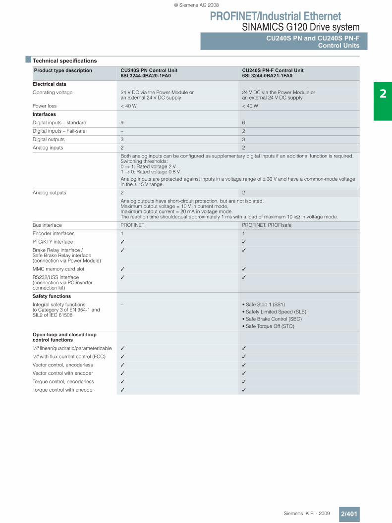
PROFINET/Industrial EthernetSINAMICS G120 Drive system
CU240S PN and CU240S PN-FControl Units
2/401Siemens IK PI · 2009
2
■ Technical specifications
Product type description CU240S PN Control Unit 6SL3244-0BA20-1FA0
CU240S PN-F Control Unit 6SL3244-0BA21-1FA0
Electrical data Operating voltage 24 V DC via the Power Module or
an external 24 V DC supply24 V DC via the Power Module or an external 24 V DC supply
Power loss < 40 W < 40 W
InterfacesDigital inputs – standard 9 6
Digital inputs – Fail-safe – 2
Digital outputs 3 3
Analog inputs 2 2
Both analog inputs can be configured as supplementary digital inputs if an additional function is required.Switching thresholds:0 → 1: Rated voltage 2 V1 → 0: Rated voltage 0.8 VAnalog inputs are protected against inputs in a voltage range of ± 30 V and have a common-mode voltagein the ± 15 V range.
Analog outputs 2 2
Analog outputs have short-circuit protection, but are not isolated. Maximum output voltage = 10 V in current mode,maximum output current = 20 mA in voltage mode.The reaction time shouldequal approximately 1 ms with a load of maximum 10 kΩ in voltage mode.
Bus interface PROFINET PROFINET, PROFIsafe
Encoder interfaces 1 1
PTC/KTY interface ✓ ✓
Brake Relay interface / Safe Brake Relay interface (connection via Power Module)
✓ ✓
MMC memory card slot ✓ ✓
RS232/USS interface (connection via PC-inverter connection kit)
✓ ✓
Safety functions Integral safety functionsto Category 3 of EN 954-1 andSIL2 of IEC 61508
– • Safe Stop 1 (SS1)• Safely Limited Speed (SLS)• Safe Brake Control (SBC)• Safe Torque Off (STO)
Open-loop and closed-loop control functions V/f linear/quadratic/parameterizable ✓ ✓
V/f with flux current control (FCC) ✓ ✓
Vector control, encoderless ✓ ✓
Vector control with encoder ✓ ✓
Torque control, encoderless ✓ ✓
Torque control with encoder ✓ ✓
© Siemens AG 2008
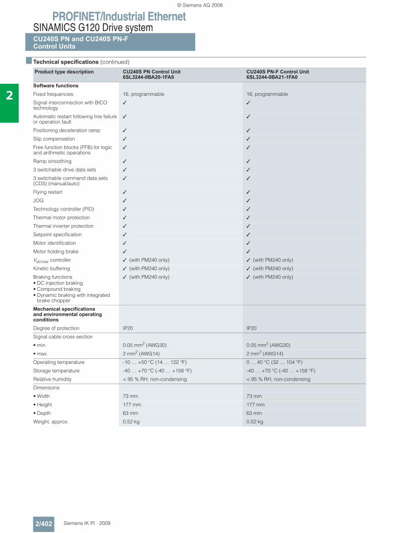
PROFINET/Industrial EthernetSINAMICS G120 Drive systemCU240S PN and CU240S PN-FControl Units
2/402 Siemens IK PI · 2009
2
■ Technical specifications (continued)
Product type description CU240S PN Control Unit 6SL3244-0BA20-1FA0
CU240S PN-F Control Unit 6SL3244-0BA21-1FA0
Software functions Fixed frequencies 16, programmable 16, programmable
Signal interconnection with BICO technology
✓ ✓
Automatic restart following line failure or operation fault
✓ ✓
Positioning deceleration ramp ✓ ✓
Slip compensation ✓ ✓
Free function blocks (FFB) for logic and arithmetic operations
✓ ✓
Ramp smoothing ✓ ✓
3 switchable drive data sets ✓ ✓
3 switchable command data sets (CDS) (manual/auto)
✓ ✓
Flying restart ✓ ✓
JOG ✓ ✓
Technology controller (PID) ✓ ✓
Thermal motor protection ✓ ✓
Thermal inverter protection ✓ ✓
Setpoint specification ✓ ✓
Motor identification ✓ ✓
Motor holding brake ✓ ✓
Vdcmax controller ✓ (with PM240 only) ✓ (with PM240 only)
Kinetic buffering ✓ (with PM240 only) ✓ (with PM240 only)
Braking functions• DC injection braking• Compound braking• Dynamic braking with integrated
brake chopper
✓ (with PM240 only) ✓ (with PM240 only)
Mechanical specifications and environmental operating conditionsDegree of protection IP20 IP20
Signal cable cross-section
• min. 0.05 mm2 (AWG30) 0.05 mm2 (AWG30)
• max. 2 mm2 (AWG14) 2 mm2 (AWG14)
Operating temperature -10 … +50 °C (14 … 122 °F) 0 … 40 °C (32 … 104 °F)
Storage temperature -40 … +70 °C (-40 … +158 °F) -40 … +70 °C (-40 … +158 °F)
Relative humidity < 95 % RH, non-condensing < 95 % RH, non-condensing
Dimensions
• Width 73 mm 73 mm
• Height 177 mm 177 mm
• Depth 63 mm 63 mm
Weight, approx. 0.52 kg 0.52 kg
© Siemens AG 2008
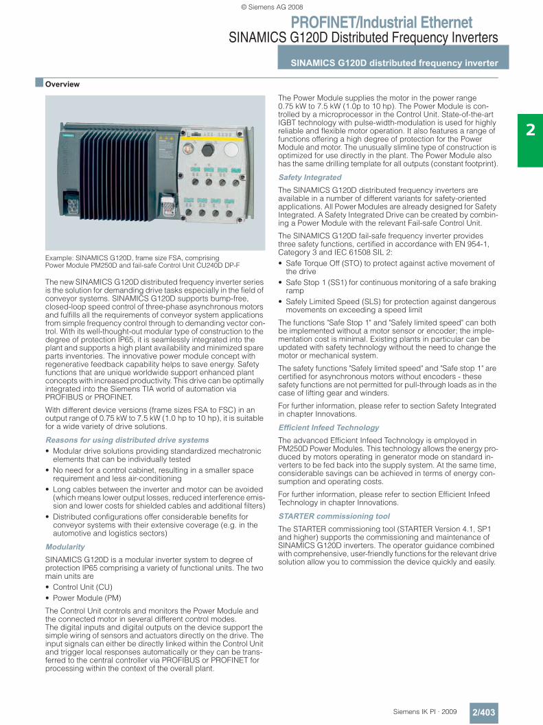
PROFINET/Industrial EthernetSINAMICS G120D Distributed Frequency Inverters
SINAMICS G120D distributed frequency inverter
2/403Siemens IK PI · 2009
2
■ Overview
Example: SINAMICS G120D, frame size FSA, comprising Power Module PM250D and fail-safe Control Unit CU240D DP-F
The new SINAMICS G120D distributed frequency inverter series is the solution for demanding drive tasks especially in the field of conveyor systems. SINAMICS G120D supports bump-free, closed-loop speed control of three-phase asynchronous motors and fulfills all the requirements of conveyor system applications from simple frequency control through to demanding vector con-trol. With its well-thought-out modular type of construction to the degree of protection IP65, it is seamlessly integrated into the plant and supports a high plant availability and minimized spare parts inventories. The innovative power module concept with regenerative feedback capability helps to save energy. Safety functions that are unique worldwide support enhanced plant concepts with increased productivity. This drive can be optimally integrated into the Siemens TIA world of automation via PROFIBUS or PROFINET.
With different device versions (frame sizes FSA to FSC) in an output range of 0.75 kW to 7.5 kW (1.0 hp to 10 hp), it is suitable for a wide variety of drive solutions.
Reasons for using distributed drive systems• Modular drive solutions providing standardized mechatronic
elements that can be individually tested• No need for a control cabinet, resulting in a smaller space
requirement and less air-conditioning• Long cables between the inverter and motor can be avoided
(which means lower output losses, reduced interference emis-sion and lower costs for shielded cables and additional filters)
• Distributed configurations offer considerable benefits for conveyor systems with their extensive coverage (e.g. in the automotive and logistics sectors)
ModularitySINAMICS G120D is a modular inverter system to degree of protection IP65 comprising a variety of functional units. The two main units are• Control Unit (CU)• Power Module (PM)
The Control Unit controls and monitors the Power Module and the connected motor in several different control modes. The digital inputs and digital outputs on the device support the simple wiring of sensors and actuators directly on the drive. The input signals can either be directly linked within the Control Unit and trigger local responses automatically or they can be trans-ferred to the central controller via PROFIBUS or PROFINET for processing within the context of the overall plant.
The Power Module supplies the motor in the power range 0.75 kW to 7.5 kW (1.0p to 10 hp). The Power Module is con-trolled by a microprocessor in the Control Unit. State-of-the-art IGBT technology with pulse-width-modulation is used for highly reliable and flexible motor operation. It also features a range of functions offering a high degree of protection for the Power Module and motor. The unusually slimline type of construction is optimized for use directly in the plant. The Power Module also has the same drilling template for all outputs (constant footprint).
Safety IntegratedThe SINAMICS G120D distributed frequency inverters are available in a number of different variants for safety-oriented applications. All Power Modules are already designed for Safety Integrated. A Safety Integrated Drive can be created by combin-ing a Power Module with the relevant Fail-safe Control Unit.
The SINAMICS G120D fail-safe frequency inverter provides three safety functions, certified in accordance with EN 954-1, Category 3 and IEC 61508 SIL 2:• Safe Torque Off (STO) to protect against active movement of
the drive• Safe Stop 1 (SS1) for continuous monitoring of a safe braking
ramp• Safely Limited Speed (SLS) for protection against dangerous
movements on exceeding a speed limit
The functions "Safe Stop 1" and "Safely limited speed" can both be implemented without a motor sensor or encoder; the imple-mentation cost is minimal. Existing plants in particular can be updated with safety technology without the need to change the motor or mechanical system.
The safety functions "Safely limited speed" and "Safe stop 1" are certified for asynchronous motors without encoders - these safety functions are not permitted for pull-through loads as in the case of lifting gear and winders.
For further information, please refer to section Safety Integrated in chapter Innovations.
Efficient Infeed TechnologyThe advanced Efficient Infeed Technology is employed in PM250D Power Modules. This technology allows the energy pro-duced by motors operating in generator mode on standard in-verters to be fed back into the supply system. At the same time, considerable savings can be achieved in terms of energy con-sumption and operating costs.
For further information, please refer to section Efficient Infeed Technology in chapter Innovations.
STARTER commissioning toolThe STARTER commissioning tool (STARTER Version 4.1, SP1 and higher) supports the commissioning and maintenance of SINAMICS G120D inverters. The operator guidance combined with comprehensive, user-friendly functions for the relevant drive solution allow you to commission the device quickly and easily.
© Siemens AG 2008
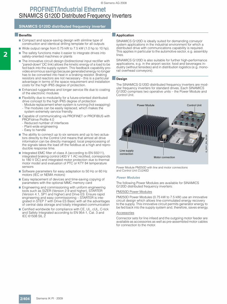
PROFINET/Industrial EthernetSINAMICS G120D Distributed Frequency Inverters
SINAMICS G120D distributed frequency inverter
2/404 Siemens IK PI · 2009
2
■ Benefits7 Compact and space-saving design with slimline type of
construction and identical drilling template for all outputs 7 Wide output range from 0.75 kW to 7.5 kW (1.0 hp to 10 hp). 7 The safety functions make it easier to integrate drives into
safety-oriented machines or plants 7 The innovative circuit design (bidirectional input rectifier with
"pared-down" DC link) allows the kinetic energy of a load to be fed back into the supply system. This feedback capability pro-vides enormous savings because generated energy no longer has to be converted into heat in a braking resistor. Braking resistors and reactors are not necessary - this is a particular advantage in terms of the space requirement and installation costs for the high IP65 degree of protection.
7 Enhanced ruggedness and longer service life due to coating of the electronic modules
7 Flexibility due to modularity for a future-oriented distributed drive concept to the high IP65 degree of protection - Module replacement when system is running (hot swapping) - The modules can be easily replaced, which makes the
system extremely service friendly. 7 Capable of communicating via PROFINET or PROFIBUS with
PROFIdrive Profile 4.0 - Reduced number of interfaces - Plant-wide engineering - Easy to handle
7 The ability to connect up to six sensors and up to two actua-tors directly to the Control Unit means that almost all drive information can be directly managed; local preprocessing of the signals takes the load off the fieldbus at a high and repro-ducible response time.
7 Integrated EMC filter of class A (according to EN 55011), integrated braking control (400 V 1 AC rectified, corresponds to 180 V DC) and integrated motor protection due to thermal motor model and evaluation of PTC or KTY 84 temperature sensors
7 Software parameters for easy adaptation to 50 Hz or 60 Hz motors (IEC or NEMA motors)
7 Easy replacement of devices and time-saving copying of parameters with the optional MMC memory card
7 Engineering and commissioning with uniform engineering tools such as SIZER (Version 2.9 and higher), STARTER (Version 4.1, SP1 and higher) and Drive ES: Ensure rapid engineering and easy commissioning – STARTER is inte-grated in STEP 7 with Drive ES Basic with all the advantages of central data storage and totally integrated communication
7 Certified worldwide for compliance with CE, UL, cUL, C-tick and Safety Integrated according to EN 954-1, Cat. 3 and IEC 61508 SIL 2
■ Application
SINAMICS G120D is ideally suited for demanding conveyor system applications in the industrial environment for which a distributed drive with communications capability is required. This applies in particular to the automotive sector, e.g. assembly lines.
SINAMICS G120D is also suitable for further high-performance applications, e.g. in the airport sector, food and beverages in-dustry (without tensides) and in distribution logistics (e.g. mono-rail overhead conveyors).
■ Design
The SINAMICS G120D distributed frequency inverters are mod-ular frequency inverters for standard drives. Each SINAMICS G120D comprises two operative units – the Power Module and Control Unit.
Power Module PM250D with line and motor connections and Control Unit CU240D
Power ModulesThe following Power Modules are available for SINAMICS G120D distributed frequency inverters:
PM250D Power Modules
PM250D Power Modules (0.75 kW to 7.5 kW) use an innovative circuit design which allows line-commutated energy recovery to the supply. This innovative circuit permits generator energy to be fed back into the supply system and, therefore, saves energy.
Accessories
Connector sets for line infeed and the outgoing motor feeder are available as accessories as well as pre-assembled motor cables for connection to the motor.
Power Module Control Unit
Line supplyconnection
Motor connection
G_D
011_
EN
_001
26
© Siemens AG 2008
PROFINET/Industrial EthernetSINAMICS G120D Distributed Frequency Inverters
SINAMICS G120D distributed frequency inverter
2/405Siemens IK PI · 2009
2
■ Design (continued)
Control UnitsControl UnitsThe following Control Units are available for SINAMICS G120D distributed frequency inverters:
CU240D Control Units
The Control Unit performs closed-loop control functions for the inverter. In addition to control functions, the Control Unit can also perform other tasks which can be adapted to the relevant application by parameterization. A number of Control Units are available in different versions:• CU240D PN• CU240D PN-F
Accessories• MMC memory card
The parameter settings for an inverter can be stored on the MMC memory card. When the plant is serviced, it is immediately ready for use again after, for example, replacement of the frequency inverter and transfer of the memory card data. The associated slot is located on the rear of the Control Unit.• RS232 interface cable for communication with a PC
For controlling and commissioning an inverter directly from a PC if the appropriate software (commissioning tool STARTER Version 4.1, SP1 and higher) has been installed.• Spare parts kit
A spare parts kit is available which comprises small parts such as seals, cover caps, PROFIBUS address windows and screws.• Connecting cable
Flexible connecting cables for data transfer between Industrial Ethernet participants or PROFIBUS participants, as well as for power supply of the Control Unit.
■ Configuration
The following electronic configuration and engineering tools are available for SINAMICS G120D distributed frequency inverters:
SD configurator selection aid within the CA 01The interactive catalog CA 01 – the offline mall of Siemens Automation and Drives (A&D) – contains over 100000 products with approximately 5 million potential drive system product variants. The SD configurator has been developed to facilitate selection of the correct motor and/or inverter from the wide spec-trum of Standard Drives products. The configurator is integrated in this catalog with the selection and configuration tools as a "selection guide" on CD 2 "Configuring".
SIZER configuration toolThe SIZER PC tool provides an easy-to-use means of configur-ing the SINAMICS and MICROMASTER 4 drive family. It provides support when setting up the technologies involved in the hard-ware and firmware components required for a drive task. SIZER supports the complete configuration of the drive system, from simple individual drives to complex multi-axis applications. For SINAMICS G120D as from SIZER Version 2.9.
STARTER commissioning toolThe STARTER commissioning tool provides menu-guided assis-tance with commissioning, optimization and diagnostics. STARTER is not only designed for use on SINAMICS drives but also for MICROMASTER4 units and frequency inverters for the distributed I/O SIMATIC ET 200S FC and SIMATIC ET 200pro FC. For SINAMICS G120D from STARTER Version 4.1, SP1.
Drive ES engineering systemDrive ES is the engineering system used to integrate Siemens drive technology into the SIMATIC automation world easily, efficiently and cost-effectively in terms of communication, configuration and data management. The STEP 7 Manager user interface provides the basis for this procedure. A variety of software packages, i.e. Drive ES Basic, Drive ES SIMATIC and Drive ES PCS 7, is available for SINAMICS.
© Siemens AG 2008
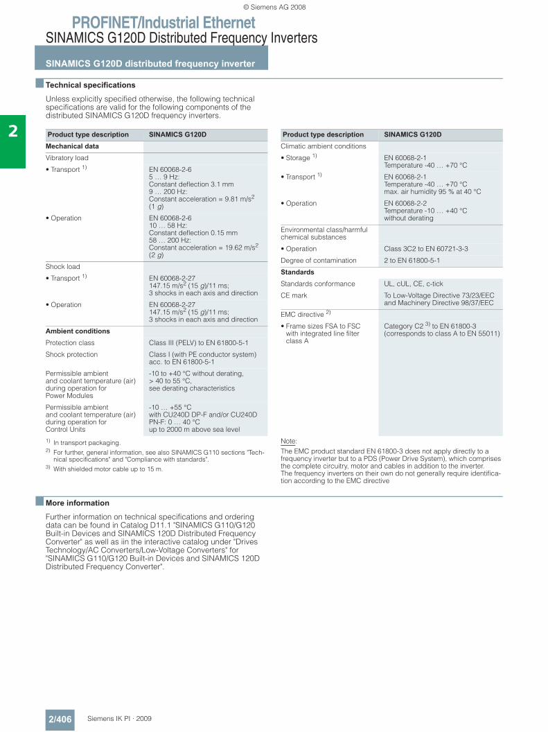
PROFINET/Industrial EthernetSINAMICS G120D Distributed Frequency Inverters
SINAMICS G120D distributed frequency inverter
2/406 Siemens IK PI · 2009
2
■ Technical specifications
Unless explicitly specified otherwise, the following technical specifications are valid for the following components of the distributed SINAMICS G120D frequency inverters.
1) In transport packaging.2) For further, general information, see also SINAMICS G110 sections "Tech-
nical specifications" and "Compliance with standards".3) With shielded motor cable up to 15 m.
■ More information
Further information on technical specifications and ordering data can be found in Catalog D11.1 "SINAMICS G110/G120 Built-in Devices and SINAMICS 120D Distributed Frequency Converter" as well as iin the interactive catalog under "Drives Technology/AC Converters/Low-Voltage Converters" for "SINAMICS G110/G120 Built-in Devices and SINAMICS 120D Distributed Frequency Converter".
Product type description SINAMICS G120DMechanical data Vibratory load
• Transport 1) EN 60068-2-65 … 9 Hz: Constant deflection 3.1 mm9 … 200 Hz: Constant acceleration = 9.81 m/s2 (1 g)
• Operation EN 60068-2-610 … 58 Hz: Constant deflection 0.15 mm58 … 200 Hz: Constant acceleration = 19.62 m/s2 (2 g)
Shock load
• Transport 1) EN 60068-2-27147.15 m/s2 (15 g)/11 ms;3 shocks in each axis and direction
• Operation EN 60068-2-27147.15 m/s2 (15 g)/11 ms;3 shocks in each axis and direction
Ambient conditions Protection class Class III (PELV) to EN 61800-5-1
Shock protection Class I (with PE conductor system) acc. to EN 61800-5-1
Permissible ambient and coolant temperature (air) during operation for Power Modules
-10 to +40 °C without derating,> 40 to 55 °C, see derating characteristics
Permissible ambient and coolant temperature (air) during operation for Control Units
-10 … +55 °Cwith CU240D DP-F and/or CU240D PN-F: 0 … 40 °Cup to 2000 m above sea level
Product type description SINAMICS G120DClimatic ambient conditions
• Storage 1) EN 60068-2-1Temperature -40 … +70 °C
• Transport 1) EN 60068-2-1Temperature -40 … +70 °Cmax. air humidity 95 % at 40 °C
• Operation EN 60068-2-2Temperature -10 … +40 °Cwithout derating
Environmental class/harmful chemical substances
• Operation Class 3C2 to EN 60721-3-3
Degree of contamination 2 to EN 61800-5-1
Standards Standards conformance UL, cUL, CE, c-tick
CE mark To Low-Voltage Directive 73/23/EEC and Machinery Directive 98/37/EEC
EMC directive 2)
• Frame sizes FSA to FSC with integrated line filter class A
Category C2 3) to EN 61800-3 (corresponds to class A to EN 55011)
Note: The EMC product standard EN 61800-3 does not apply directly to a frequency inverter but to a PDS (Power Drive System), which comprises the complete circuitry, motor and cables in addition to the inverter. The frequency inverters on their own do not generally require identifica-tion according to the EMC directive
© Siemens AG 2008
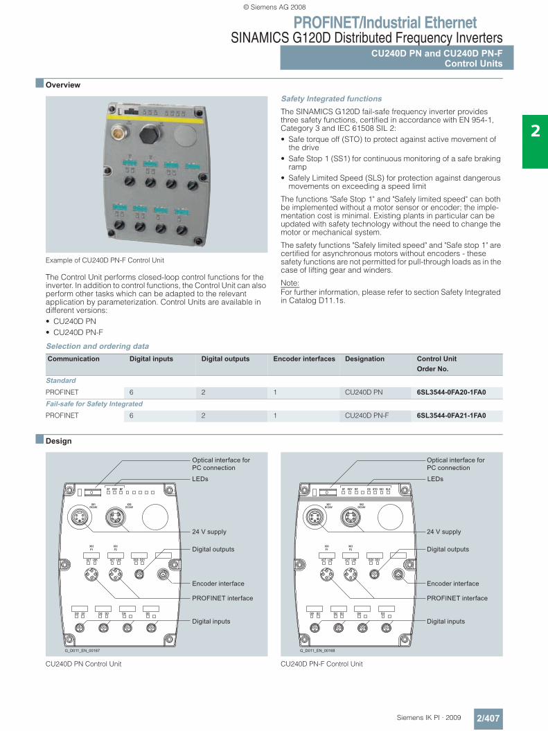
PROFINET/Industrial EthernetSINAMICS G120D Distributed Frequency Inverters
CU240D PN and CU240D PN-FControl Units
2/407Siemens IK PI · 2009
2
■ Overview
Example of CU240D PN-F Control Unit
The Control Unit performs closed-loop control functions for the inverter. In addition to control functions, the Control Unit can also perform other tasks which can be adapted to the relevant application by parameterization. Control Units are available in different versions:• CU240D PN• CU240D PN-F
Safety Integrated functionsThe SINAMICS G120D fail-safe frequency inverter provides three safety functions, certified in accordance with EN 954-1, Category 3 and IEC 61508 SIL 2:• Safe torque off (STO) to protect against active movement of
the drive• Safe Stop 1 (SS1) for continuous monitoring of a safe braking
ramp• Safely Limited Speed (SLS) for protection against dangerous
movements on exceeding a speed limit
The functions "Safe Stop 1" and "Safely limited speed" can both be implemented without a motor sensor or encoder; the imple-mentation cost is minimal. Existing plants in particular can be updated with safety technology without the need to change the motor or mechanical system.
The safety functions "Safely limited speed" and "Safe stop 1" are certified for asynchronous motors without encoders - these safety functions are not permitted for pull-through loads as in the case of lifting gear and winders.
Note:For further information, please refer to section Safety Integrated in Catalog D11.1s.
Selection and ordering data
■ Design
CU240D PN Control Unit CU240D PN-F Control Unit
Communication Digital inputs Digital outputs Encoder interfaces Designation Control UnitOrder No.
StandardPROFINET 6 2 1 CU240D PN 6SL3544-0FA20-1FA0Fail-safe for Safety IntegratedPROFINET 6 2 1 CU240D PN-F 6SL3544-0FA21-1FA0
G_D011_EN_00167
Digital inputs
Encoder interface
LEDs
Digital outputs
Optical interface forPC connection
24 V supply
PROFINET interface
X03P1
SF RDY BF ES STO SS1 SLS
X01DC24V
X02DC24V
ACT LNK ACT LNK DO0 DO1
DI0 DI1 DI2 DI3 DI4 DI5
X03P2
G_D011_EN_00168
Digital inputs
Encoder interface
LEDs
Digital outputs
Optical interface forPC connection
24 V supply
PROFINET interface
© Siemens AG 2008
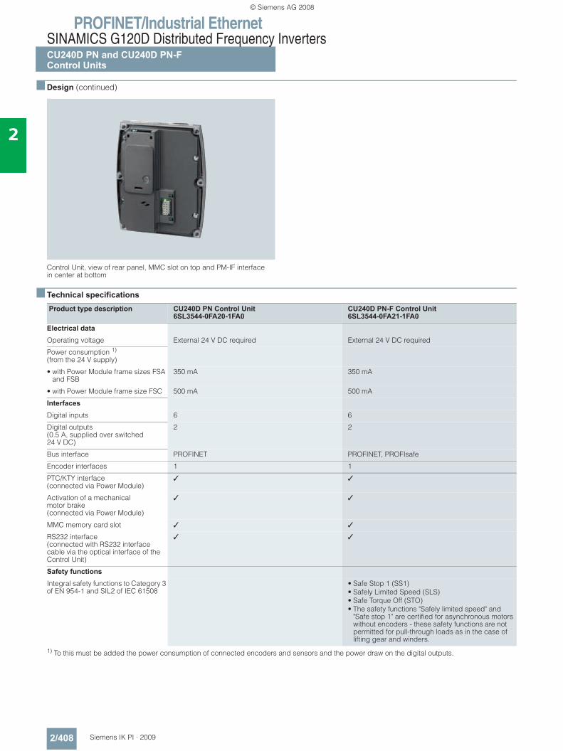
PROFINET/Industrial EthernetSINAMICS G120D Distributed Frequency InvertersCU240D PN and CU240D PN-FControl Units
2/408 Siemens IK PI · 2009
2
■ Design (continued)
Control Unit, view of rear panel, MMC slot on top and PM-IF interfacein center at bottom
■ Technical specifications
1) To this must be added the power consumption of connected encoders and sensors and the power draw on the digital outputs.
Product type description CU240D PN Control Unit 6SL3544-0FA20-1FA0
CU240D PN-F Control Unit 6SL3544-0FA21-1FA0
Electrical data Operating voltage External 24 V DC required External 24 V DC required
Power consumption 1)
(from the 24 V supply)
• with Power Module frame sizes FSA and FSB
350 mA 350 mA
• with Power Module frame size FSC 500 mA 500 mA
InterfacesDigital inputs 6 6
Digital outputs(0.5 A, supplied over switched 24 V DC)
2 2
Bus interface PROFINET PROFINET, PROFIsafe
Encoder interfaces 1 1
PTC/KTY interface(connected via Power Module)
✓ ✓
Activation of a mechanical motor brake(connected via Power Module)
✓ ✓
MMC memory card slot ✓ ✓
RS232 interface(connected with RS232 interface cable via the optical interface of the Control Unit)
✓ ✓
Safety functions Integral safety functions to Category 3 of EN 954-1 and SIL2 of IEC 61508
• Safe Stop 1 (SS1)• Safely Limited Speed (SLS)• Safe Torque Off (STO)• The safety functions "Safely limited speed" and
"Safe stop 1" are certified for asynchronous motors without encoders - these safety functions are not permitted for pull-through loads as in the case of lifting gear and winders.
© Siemens AG 2008
PROFINET/Industrial EthernetSINAMICS G120D Distributed Frequency Inverters
CU240D PN and CU240D PN-FControl Units
2/409Siemens IK PI · 2009
2
■ Technical specifications (continued)
Product type description Control Unit CU240D PN6SL3544-0FA20-1FA0
Control Unit CU240D PN-F6SL3544-0FA21-1FA0
Open-loop and closed-loop control functionsV/f linear/quadratic/parameterizable ✓ ✓
V/f with flux current control (FCC) ✓ ✓
Vector control, encoderless ✓ ✓
Vector control with encoder ✓ ✓
Torque control encoderless ✓ ✓
Torque control with encoder ✓ ✓
Software functions Fixed frequencies 16, programmable 16, programmable
Signal interconnection with BICO technology
✓ ✓
Automatic restart following line failure or fault
✓ ✓
Positioning deceleration ramp ✓ ✓
Slip compensation ✓ ✓
Free function blocks (FFB) for logic and arithmetic operations
✓ ✓
Ramp smoothing ✓ ✓
3 selectable drive data sets ✓ ✓
3 selectable command data sets (CDS) (manual/auto)
✓ ✓
Flying restart ✓ ✓
JOG ✓ ✓
Technology controller (PID) ✓ ✓
Thermal motor protection ✓ ✓
Thermal inverter protection ✓ ✓
Setpoint specification ✓ ✓
Motor identification ✓ ✓
Motor holding brake ✓ ✓
Mechanical specifications and environmental operating conditions Degree of protection IP65 IP65
Operating temperature -10 … +55 °C(14 … 131 °F)
0 … 40 °C(32 … 104 °F)
Storage temperature -40 … +70 °C(-40 … +158 °F)
-40 … +70 °C(-40 … +158 °F)
Relative humidity < 95 % RH, non-condensing < 95 % RH, non-condensing
Dimensions
• Width 150 mm 150 mm
• Height 210 mm 210 mm
• Depth 40 mm 40 mm
Weight, approx. 0.7 kg 0.7 kg
© Siemens AG 2008
PROFINET/Industrial EthernetSINAMICS G120D Distributed Frequency InvertersCU240D PN and CU240D PN-FControl Units
2/410 Siemens IK PI · 2009
2
■ Accessories
MMC memory card
The parameter settings for an inverter can be stored on the MMC memory card. When the plant is serviced, it is immediately ready for use again after, for example, replacement of the frequency inverter and transfer of the memory card data. The associated slot is located on the rear of the Control Unit.
RS232 interface cable for communication with a PCFor controlling and commissioning an inverter directly from a PC over a point-to-point link if the appropriate software (STARTER commissioning tool1), Version 4.1, SP1 and higher) has been installed.
STARTER commissioning toolThe STARTER commissioning tool (STARTER Version 4.1, SP1 and higher) supports the commissioning and maintenance of SINAMICS G120D inverters. The operator guidance combined with comprehensive, user-friendly functions for the relevant drive solution allow you to commission the device quickly and easily.
1) STARTER commissioning tool also available on the Internet athttp://support.automation.siemens.com/WW/view/de/10804985/133100
Spare parts kitA spare parts kit can be ordered which comprises small parts such as replacement seals, cover caps, PROFIBUS address windows and screws.
PROFINET connecting cableFlexible connecting cables and plug-in connectors that can be assembled in the field for transmission of data (up to 100 Mbit/s) between Industrial Ethernet stations with IP65 degree of protection.
Connecting cable/plug-in connector for supplying the Control Unit with power
Further selected accessories are available from Siemens Solution Partners.
Additional in formation can be found in the Internet under:http://www.siemens.com/automation/partnerfinderand select technology "Distributed Field Installation System".
Order No.MMC memory card 6SL3254-0AM00-0AA0
Order No.RS232 interface cable for communication with a PC
3RK1922-2BP00
Order No.STARTER commissioning tool 1)
on DVD6SL3072-0AA00-0AG0
Order No.Spare parts kit for SINAMICS G120D Control Unitscomprising replacement seals, cover caps, PROFIBUS address windows and screws
6SL3500-0SK01-0AA0
Order No.IE connecting cable M12-180/M12-180Pre-assembled IE FC TP trailing cable GP 2 x 2 PROFINET type C) with two 4-pole M12 plugs (4-pole, D-coded), IP65/IP67 degree of protection Length:
• 0.3 m 6XV1870-8AE30• 0.5 m 6XV1870-8AE50• 1.0 m 6XV1870-8AH10• 1.5 m 6XV1870-8AH15• 2.0 m 6XV1870-8AH20• 3.0 m 6XV1870-8AH30• 5.0 m 6XV1870-8AH50• 10 m 6XV1870-8AN10• 15 m 6XV1870-8AN15IE M12 plug PROFor assembly in the field, M12 plug-in connector (D-coded), metal enclosure, fast connection method, for SCALANCE X208PRO and IM 154-4 PN
• 1 unit 6GK1901-0DB10-6AA0• 8 units 6GK1901-0DB10-6AA8
Order No.7/8" plug-in cableFor power supply, pre-assembled with two 5-pole 7/8" male/female connectorsLength:
• 0.3 m 6XV1822-5BE30• 0.5 m 6XV1822-5BE50• 1.0 m 6XV1822-5BH10• 1.5 m 6XV1822-5BH15• 2.0 m 6XV1822-5BH20• 3.0 m 6XV1822-5BH30• 5.0 m 6XV1822-5BH50• 10 m 6XV1822-5BN10• 15 m 6XV1822-5BN157/8" plug-in connector5-pole, B-coded, plastic enclosure, 1 pack = 5 units
• Male insert 6GK1905-0FA00• Socket insert 6GK1905-0FB00
© Siemens AG 2008
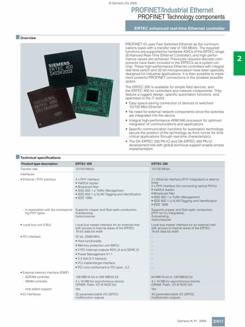
PROFINET/Industrial EthernetPROFINET Technology components
ERTEC enhanced real-time Ethernet controller
2/411Siemens IK PI · 2009
2
■ Overview
PROFINET IO uses Fast Switched Ethernet as the communi-cations basis with a transfer rate of 100 Mbit/s. The required functions are supported by hardware ASICs of the ERTEC range (Enhanced Real-Time Ethernet Controller), and high perfor-mance values are achieved. Previously required discrete com-ponents have been included in the ERTECs as a system-on-chip. These high-performance Ethernet controllers with integral real-time switch and 32-bit microprocessor have been specially designed for industrial applications. It is then possible to imple-ment powerful PROFINET connections in the smallest possible space.
The ERTEC 200 is available for simple field devices, and the ERTEC 400 for controllers and network components. They feature a rugged design, specific automation functions, and openness to the IT world.• Easy space-saving connection of devices to switched
10/100 Mbit Ethernet• No need for external network components since the switches
are integrated into the device • Integral high-performance ARM 946 processor for optimum
integration of communications and applications • Specific communication functions for automation technology
secure the position of the technology as front runner for time-critical applications through real-time characteristics
• The DK-ERTEC 200 PN IO and DK-ERTEC 400 PN IO development kits with global technical support enable simple implementation
■ Technical specifications
Product type description ERTEC 400 ERTEC 200Transfer rate 10/100 Mbit/s 10/100 Mbit/s
Interfaces
• Ethernet / PHY interface 4 x PHY interface• Half/full duplex • Broadcast filter• IEEE 802.1 p Traffic Management • IEEE 802.1 q VLAN Tagging and Identification• IEEE 1588
2 x Ethernet interface (PHY integrated) or alterna-tively2 x PHY interface (for connecting optical PHYs)• Half/full duplex • Broadcast filter• IEEE 802.1 p Traffic Management • IEEE 802.1 q VLAN Tagging and Identification• IEEE 1588
- in association with the correspond-ing PHY types:
Supports copper and fiber-optic conductors; Autosensing; Autocrossover
Supports copper and fiber-optic conductors (PHY for Cu integrated); Autosensing; Autocrossover
• Local bus unit (LBU) Local bus master interface for an external host with access to internal areas of the ERTEC; 16-bit data bit width
Local bus master interface for an external host with access to internal areas of the ERTEC; 16-bit data bit width
• PCI interface 32 bit, 33/66 MHz –• Host functionality –• Memory protection unit (MPU) –• 2 PCI interrupt outputs INTA_N and SERR_N –• Power Management V1.1 –• 3.3 Volt (5 V tolerant) –• PCI master/target interface –• PCI core conformant to PCI spec. 2.2 –
• External memory interface (EMIF) - SDRAM controller 128 MB/16 bit or 256 MB/32 bit 64 MB/16 bit or 128 MB/32 bit- SRAM controller 4 x 16 MB for asynchronous blocks
(SRAM, Flash, I/O 8/16/32 bit)4 x 16 MB for asynchronous blocks(SRAM, Flash, I/O 8/16/32 bit)
- chip select support Yes Yes
• IO interfaces 32 parameterizable I/O (GPIO); multifunction outputs
45 parameterizable I/O (GPIO); multifunction outputs
© Siemens AG 2008
PROFINET/Industrial EthernetPROFINET Technology components
ERTEC enhanced real-time Ethernet controller
2/412 Siemens IK PI · 2009
2
■ Technical specifications (continued)
Product type description ERTEC 400 ERTEC 200Components
• Real-time Ethernet switch Integral 4-port Fast Ethernet/real-time Ethernet switch; 10/100 Mbit Ethernet full-duplex
Integral 2-port Fast Ethernet/real-time Ethernet switch; 10/100 Mbit Ethernet full-duplex
- communications RAM (SRAM on chip for message buffering)
192 KB 64 KB
- intelligent switching and PROFINET IRT prioritizing/timing
Yes Yes
• Integral ARM946 processor 32-bit ARM system 32-bit ARM system- adjustable operating frequency 50/100/150 MHz 50/100/150 MHz- data cache 4 KB 4 KB- instruction cache 8 KB 8 KB- D-TCM 4 KB 4 KB- memory protection unit (MPU) Yes j- trace functionality Debugging capability through embedded ICE (JTAG) Debugging capability through embedded ICE (JTAG)- interrupt controller For 16xIRQ/ 8xFIQ For 16xIRQ/ 8xFIQ
• Processor I/O 2 UART similar to the UART 16C550 standard 1 UART similar to the UART 16C550 standard- SPI master interface Yes Yes- timer 32-bit counting
downwards2 3
- F-Timer 32-bit counting downwards
Yes Yes
- watchdog functions 2 3 - external interrupt inputs Yes Yes
• Internal bus structure 32 bit (multi-layer AHB) with 50 MHz clock frequency; multi-layer architecture with parallel access structure of several multimasters to multislave
32 bit (multi-layer AHB) with 50 MHz clock frequency; multi-layer architecture with parallel access structure of several multimasters to multislave
• SRAM-integrated main memory on AHB- size 8 KB –- program/data memory ARM 946 –- multiport RAM For ARM946, IRT and PCI –
• Clock generation Internal through PLL for ARM 946ES, AHB, APB and IRT
Internal through PLL for ARM 946ES, AHB, APB and IRT
• Boot ROM With Opcode for software download from various sources
With Opcode for software download from various sources
• Debugging functions Boundary scan Boundary scan
Supply voltage
• Core (VDD core) 1.5 V +/- 10 % 1.5 V +/- 10 %
• I/Os (VDD IO) 3.3 V +/- 10 % 3.3 V +/- 10 %
Current consumption
• IDD core typ. 270 mA typ. 535 mA
• IDD IO typ. 150 mA typ. 175 mA
Power loss
• PDD core typ. 0.4 W typ. 0.8 W
• PDD IO typ. 0.5 W typ. 0.57 W
Permissible ambient conditions
• Operating temperature -40 °C … +85 °C -40 °C … +85 °C
• Transport/storage temperature -40 °C … +85 °C -40 °C … +85 °C
• Relative humidity max. 95 % at +25 °C max. 95 % at +25 °C
© Siemens AG 2008
PROFINET/Industrial EthernetPROFINET Technology components
ERTEC enhanced real-time Ethernet controller
2/413Siemens IK PI · 2009
2
■ Technical specifications (continued)
Note:If you have any technical questions, please contact the PROFI Competence Centers
Germany and EuropeSiemens AG ComDeC Postfach 2355 D-90713 Fürth Germany Tel.: +49/911/750 - 2080 Fax: +49/911/750 - 2100 Email: comdec@ siemens.com
AmericaPROFI Interface Center One Internet Plaza Johnson City, TN, 37604 U.S.A. Tel.: (423) - 262 - 2576 Fax: (423) - 262 - 2103 Email: [email protected]
■ Ordering data Order No. Order No.
Product type description ERTEC 400 ERTEC 200Design
• Enclosure Plastic FBGA 304 pin Plastic FBGA 304 pin
• Pinning ball pitch 0.8 mm 0.8 mm
• Soldering notes Versions available for leaded and unleaded processing
Versions available for leaded and unleaded processing
Dimensions (W x H x D) in mm 19 x 1 x 19 19 x 1 x 19
- ERTEC
Supported communications protocols
• General Ethernet protocols Corresponding to the respective software implemen-tation which uses the ERTEC as Ethernet controller
Corresponding to the respective software implemen-tation which uses the ERTEC as Ethernet controller
• PROFINET in combination with a PROFINET software stack
Real-time communication (RT); isochronous real-time communication (IRT)
Real-time communication (RT); isochronous real-time communication (IRT)
ERTEC 400ASIC ERTEC 400 for connection to switched Ethernet 10/100 Mbit/s, Ethernet controller with integrated 4-port switch, ARM 946 RISC and PCI interface (V2.2), data preparation forreal-time and isochrone real-time for PROFINET IO
• Unleaded
- 70 units (individual tray), 6GK1 184-0BB00-0AA1- 350 units (drypack, 5 trays), 6GK1 184-0BB00-0AA2
Development Kit DK-ERTEC 400 PN IO
6GK1 953-0CA00
Development Pack V2.0 for ASIC ERTEC 400 for real-time and isochrone real-time, consisting of: CP 1616, ERTEC 400 Evaluation Board, ASICs ERTEC 400 (10 units), IE FC RJ45 Plug 180 (2 units), IE FC Standard Cable 2 x 2 (5 m), IE FC Stripping Tool, DK-16xx PN IO V 2.0, Wind River Evaluation Software, Documentation and Sample Software
ERTEC 200ASIC ERTEC 200 for connection to switched Ethernet 10/100 Mbit/s, Ethernet controller with integrated 2-port switch, ARM 946 processor and integrated PHYs real-time for PROFINET IO
• Unleaded
- 70 units (individual tray), 6GK1 182-0BB00-0AA1- 350 units (drypack, 5 trays), 6GK1 182-0BB00-0AA2
Development Kit DK-ERTEC 200 PN IO
6GK1 953-0BA00
Development Pack V2.0 for ASIC ERTEC 200 for real-time and isochrone real-time, consisting of: CP 1616, ERTEC 200 Evaluation Board, ASICs ERTEC 200 (10 units), IE FC RJ45 Plug 180 (2 units), IE FC Standard Cable 2 x 2 (5 m), IE FC Stripping Tool, DK-16xx PN IO V 2.0, Wind River Evaluation Software, Documentation and Sample Software
© Siemens AG 2008
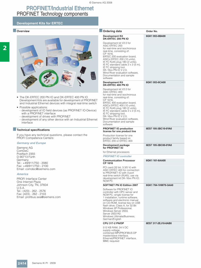
PROFINET/Industrial EthernetPROFINET Technology components
Development Kits for ERTEC
2/414 Siemens IK PI · 2009
2
■ Overview
• The DK-ERTEC 200 PN IO and DK-ERTEC 400 PN IO Development Kits are available for development of PROFINET and Industrial Ethernet devices with integral real-time switch
• Possible applications: - development of IO field devices (as PROFINET IO-Device)
with a PROFINET interface- development of drives with PROFINET - development of any other device with an Industrial Ethernet
interface
■ Technical specifications
If you have any technical questions, please contact the PROFI Competence Centers:
Germany and EuropeSiemens AG ComDeC Postfach 2355 D-90713 Fürth Germany Tel.: +49/911/750 - 2080 Fax: +49/911/750 - 2100 Email: [email protected]
AmericaPROFI Interface Center One Internet Plaza Johnson City, TN, 37604 U.S.A. Tel.: (423) - 262 - 2576 Fax: (423) - 262 - 2103 Email: [email protected]
■ Ordering data Order No.
Development Kit DK-ERTEC 200 PN IO
6GK1 953-0BA00
Development kit V2.0 for ASIC ERTEC 200 for real-time and isochronous real-time, consisting of: CP 1616, ERTEC 200 evaluation board, ASICs ERTEC 200 (10 units), IE FC RJ45 plug 180 (2 units), IE FC standard cable 2 x 2 (5 m), IE FC stripping tool, DK-16xx PN IO V 2.0, Wind River evaluation software, Documentation and sample software
Development Kit DK-ERTEC 400 PN IO
6GK1 953-0CA00
Development kit V2.0 for ASIC ERTEC 400 for real-time and isochronous real-time, consisting of: CP 1616, ERTEC 400 evaluation board, ASICs ERTEC 400 (10 units), IE FC RJ45 plug 180 (2 units), IE FC standard cable 2 x 2 (5 m), IE FC stripping tool, DK-16xx PN IO V 2.0, Wind River evaluation software, Documentation and sample software
PROFINET IO production license for one product line
6ES7 195-3BC10-0YA0
Production license for one product family based on ERTEC 200 or ERTEC 400
Development package for PROFINET IO
6ES7 195-3BC00-0YA0
for Ethernet processors
PROFINET IO controllerCommunication Processor CP 1616
6GK1 161-6AA00
PCI card (32 bit; 3.3/5 V) with ASIC ERTEC 400 for connection to PROFINET IO with 4-port real-time switch (RJ45), use via development kit DK-16xx PN IO; NCM PC
SOFTNET PN IO Edition 2007 6GK1 704-1HW70-3AA0Software for PROFINET IO controller with OPC server and NCM PC; single license for 1 installation, runtime software, software and electronic manual on CD-ROM, license key on USB flash drive, Class A, for 32 Bit Windows XP Professional, Windows Server 2003, Server 2003 R2; Windows Ultimate/Business; German/English
CPU 317-2 PN/DP 6ES7 317-2EJ10-0AB0512 KB RAM, 24 V DC supply voltage, combined MPI/PROFIBUS DP master/slave interface, Ethernet/PROFINET interface, MMC required
© Siemens AG 2008
PROFINET/Industrial EthernetPROFINET Technology components
Development Kits for ERTEC
2/415Siemens IK PI · 2009
2
■ Ordering data Order No. Order No.
■ More information
You can find more detailed information, technical data and manuals for the ERTEC 200, ERTEC 400, DK-ERTEC 200 PN IO and DK-ERTEC 400 PN IO in the Internet.
http://www.siemens.com/ertec-microsite
Additional in formation can be found in the Internet under:
http://www.siemens.com/simatic-net/ik-info
http://www.siemens.com/ertec
http://support.automation.siemens.com/WW/view/de/18977720/133300
The Wind River development environment can be purchased from:
Wind River GmbH Osterfeldstrasse 84 85737 Ismaning, Germany Tel.: +49 89 96 24 45 0 Fax: +49 89 96 24 45 999 [email protected]
Additional in formation can be found in the Internet under:
http://www.windriver.com/alliances/eval-cd/details.html?pgmid=ERTEC
Network componentsIE FC RJ45 Plug 180RJ45 connector for Industrial Ethernet with rugged metal enclosure and integral IDC con-tacts for connecting the Industrial Ethernet FC installation cables; with 180° cable outlet; for network components and CPs/CPUs with Industrial Ethernet interface
• 1 pack = 1 units 6GK1 901-1BB10-2AA0
• 1 pack = 10 units 6GK1 901-1BB10-2AB0
• 1 pack = 50 units 6GK1 901-1BB10-2AE0
IE FC standard cable 2 x 2 (Type B)
6XV1 840-2AH10
4-wire, screened TP installation cable for connection to IE FC outlet RJ45/IE FC RJ45 plug; PROFINET-compliant; with UL-approval; sold by the meter; delivery unit max. 1000 m, minimum order length 20 m
IE FC stripping tool 6GK1 901-1GA00Pre-adjusted stripping tool for fast stripping of insulation from Indus-trial Ethernet FC cables
Industrial Ethernet switches SCALANCE X-200IRTManaged Industrial Ethernet switches; real-time (RT) and isochronous real-time (IRT), LED diagnostics, fault signal contact with SET button, redundant voltage supply• SCALANCE X-204IRT;
4 x 10/100 Mbit/s RJ45 ports6GK5 204-0BA00-2BA3
• SCALANCE X-204IRT PRO; 4 x 10/100 Mbit/s RJ45 push-pull ports
6GK5 204-0JA00-2BA6
• SCALANCE X-202-2IRT; 2 x 10 10/100 Mbit/s RJ45 ports; 2 x 100 Mbit/s multimode BFOC
6GK5 202-2BB00-2BA3
• SCALANCE X-202-2P IRT; 2 x 10/100 Mbit/s RJ45 ports; 2 x 100 Mbit/s POF/PCF SC RJ
6GK5 202-2BH00-2BA3
• SCALANCE X-202-2P IRT PRO; 2 x 10/100 Mbit/s RJ45 push-pull ports; 2 x 100 Mbit/s POF/PCF SC RJ push-pull ports
6GK5 202-2JR00-2BA6
• SCALANCE X-201-3P IRT; 1 x 10/100 Mbit/s RJ45 ports; 3 x 100 Mbit/s POF/PCF SC RJ
6GK5 201-3BH00-2BA3
• SCALANCE X-200-4P IRT; 4 x 100 Mbit/s POF/PCF SC RJ
6GK5 200-4AH00-2BA3
ASIC enhanced real-time Ethernet controllerERTEC 200ASIC ERTEC 200 for connection to switched Ethernet 10/100 Mbit/s, Ethernet controller with integrated 2-port switch, ARM 946 processor and integrated PHYs real-time for PROFINET IO
• Unleaded
- 70 units (individual trays), 6GK1 182-0BB00-0AA1- 350 units (drypack, 5 trays), 6GK1 182-0BB00-0AA2
ERTEC 400ASIC ERTEC 400 for connection to switched Ethernet 10/100 Mbit/s, Ethernet controller with integrated 4-port switch, ARM 946 RISC and PCI (V2.2), data preparation for real-time and isochronous real-time for PROFINET IO
• Unleaded
- 70 units (individual trays), 6GK1 184-0BB00-0AA1- 350 units (drypack, 5 trays), 6GK1 184-0BB00-0AA2
© Siemens AG 2008
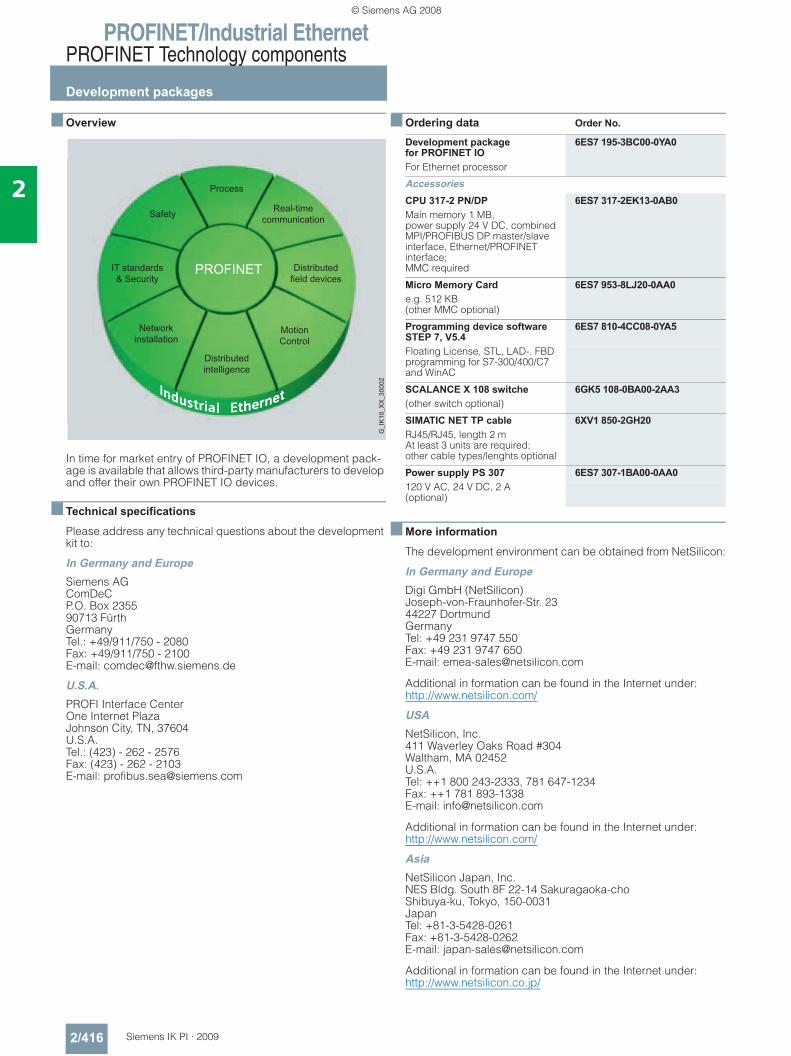
PROFINET/Industrial EthernetPROFINET Technology components
Development packages
2/416 Siemens IK PI · 2009
2
■ Overview
In time for market entry of PROFINET IO, a development pack-age is available that allows third-party manufacturers to develop and offer their own PROFINET IO devices.
■ Technical specifications
Please address any technical questions about the development kit to:
In Germany and EuropeSiemens AGComDeCP.O. Box 235590713 FürthGermanyTel.: +49/911/750 - 2080Fax: +49/911/750 - 2100E-mail: [email protected]
U.S.A.PROFI Interface CenterOne Internet PlazaJohnson City, TN, 37604U.S.A.Tel.: (423) - 262 - 2576Fax: (423) - 262 - 2103E-mail: [email protected]
■ Ordering data Order No.
■ More information
The development environment can be obtained from NetSilicon:
In Germany and EuropeDigi GmbH (NetSilicon)Joseph-von-Fraunhofer-Str. 2344227 DortmundGermanyTel: +49 231 9747 550Fax: +49 231 9747 650E-mail: [email protected]
Additional in formation can be found in the Internet under:http://www.netsilicon.com/
USANetSilicon, Inc.411 Waverley Oaks Road #304Waltham, MA 02452U.S.A.Tel: ++1 800 243-2333, 781 647-1234Fax: ++1 781 893-1338E-mail: [email protected]
Additional in formation can be found in the Internet under:http://www.netsilicon.com/
AsiaNetSilicon Japan, Inc.NES Bldg. South 8F 22-14 Sakuragaoka-choShibuya-ku, Tokyo, 150-0031JapanTel: +81-3-5428-0261Fax: +81-3-5428-0262E-mail: [email protected]
Additional in formation can be found in the Internet under:http://www.netsilicon.co.jp/
Development package for PROFINET IO
6ES7 195-3BC00-0YA0
For Ethernet processor
AccessoriesCPU 317-2 PN/DP 6ES7 317-2EK13-0AB0Main memory 1 MB, power supply 24 V DC, combined MPI/PROFIBUS DP master/slave interface, Ethernet/PROFINET interface; MMC required
Micro Memory Card 6ES7 953-8LJ20-0AA0e.g. 512 KB(other MMC optional)
Programming device software STEP 7, V5.4
6ES7 810-4CC08-0YA5
Floating License, STL, LAD-. FBD programming for S7-300/400/C7 and WinAC
SCALANCE X 108 switche 6GK5 108-0BA00-2AA3(other switch optional)
SIMATIC NET TP cable 6XV1 850-2GH20RJ45/RJ45, length 2 m At least 3 units are required; other cable types/lenghts optional
Power supply PS 307 6ES7 307-1BA00-0AA0120 V AC, 24 V DC, 2 A(optional)
© Siemens AG 2008
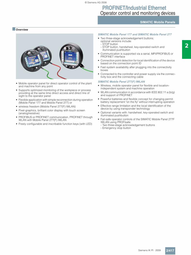
PROFINET/Industrial EthernetOperator control and monitoring devices
SIMATIC Mobile Panels
2/417Siemens IK PI · 2009
2
■ Overview
• Mobile operator panel for direct operator control of the plant and machine from any point
• Supports optimized monitoring of the workpiece or process providing at the same time direct access and direct line of sight to the operator panel
• Flexible application with simple reconnection during operation (Mobile Panel 177 and Mobile Panel 277) or
• wireless freedom (Mobile Panel 277(F) IWLAN) • Pixel-graphics, brilliant color display with touch screen
(analog/resistive) • PROFIBUS or PROFINET communication, PROFINET through
WLAN with Mobile Panel 277(F) IWLAN • Freely configurable and inscribable function keys (with LED)
SIMATIC Mobile Panel 177 and SIMATIC Mobile Panel 277• Two three-stage acknowledgement buttons;
optional versions include: - STOP button - STOP button, handwheel, key-operated switch and
illuminated pushbutton • Communication is supported via a serial, MPI/PROFIBUS or
PROFINET interface • Connection point detection for local identification of the device
based on the connection point ID • Fast system availability after plugging into the connectivity
boxes • Connected to the controller and power supply via the connec-
tivity box and the connecting cable
SIMATIC Mobile Panel 277(F) IWLAN• Wireless, mobile operator panel for flexible and location-
independent system and machine operation • WLAN communication in accordance with IEEE 802.11 a (b/g)
and support of PROFINET • Powerful batteries and flexible concept for changing permit
battery replacement "on the fly" without interrupting operation • Effective range limitation and the local identification of the
device by using transponder technology • Optional variants with: handwheel, key-operated switch and
illuminated pushbutton • Fail-safe operator controls of the SIMATIC Mobile Panel 277F
IWLAN using PROFIsafe: - Two three-stage acknowledgement buttons - Emergency stop button
© Siemens AG 2008
PROFINET/Industrial EthernetOperator control and monitoring devices
SIMATIC Mobile Panels
2/418 Siemens IK PI · 2009
2
■ Order data Order No. Order No.
1) The system components (connecting cables and connection boxes) must be ordered separately.
Note:Documentation (to be ordered separately) and further accessories for Mobile Panels can be found in the ST 80 Catalog, in the electronic catalog CA 01 and in the A&D Mall athttp://www.siemens.com/automation/mall
SIMATIC Mobile Panel 177 PN (PROFINET) • With integrated acknowledgement
button6AV6 645-0BA01-0AX0
• With integrated acknowledgement button and STOP button
6AV6 645-0BB01-0AX0
• With integrated acknowledgement button, STOP button, handwheel, key-operated switch and illuminated pushbutton
6AV6 645-0BC01-0AX0
SIMATIC Mobile Panel 277 8" 1)
• With integrated acknowledgement button
6AV6 645-0CA01-0AX0
• With integrated acknowledgement button and STOP button
6AV6 645-0CB01-0AX0
• With integrated acknowledgement button, STOP button, handwheel, key-operated switch and illuminated pushbutton
6AV6 645-0CC01-0AX0
SIMATIC Mobile Panel 277 10" • With integrated acknowledgement
button and STOP button6AV6 645-0BE02-0AX0
SIMATIC Mobile Panel 277 IWLAN • Communication via WLAN
(PROFINET)6AV6 645-0DD01-0AX0
• Communication via WLAN (PROFINET) with integrated hand-wheel, key-operated switch and two illuminated pushbuttons
6AV6 645-0DE01-0AX0
SIMATIC Mobile Panel 277F IWLAN• Communication via WLAN
(PROFINET) with acknowledgement button and emergency stop button
6AV6 645-0DB01-0AX0
• Communication via WLAN (PROFINET) with acknowledgment button and emergency stop button with integrated handwheel, key-operated switch, and two illuminated pushbuttons
6AV6 645-0DC01-0AX0
Starter packages • Mobile Panel 177 PN Plus 6AV6 651-5DA01-0AA0• Mobile Panel 277 PN 8" 6AV6 651-5FB01-0AA0• Mobile Panel 277 DP 8" 6AV6 651-5EB01-0AA0• Mobile Panel 277 IWLAN 6AV6 651-5GA01-0AA0• Mobile Panel 277F IWLAN 6AV6 651-5HA01-0AA0AccessoriesConnection box PNfor Mobile Panel (PROFINET)• Basic 6AV6 671-5AE01-0AX0• Plus 6AV6 671-5AE11-0AX0PN connecting cable (PROFINET)Standard cables• 2 m 6XV1 440-4BH20• 5 m 6XV1 440-4BH50• 8 m 6XV1 440-4BH80• 10 m 6XV1 440-4BN10• 15 m 6XV1 440-4BN15• 20 m 6XV1 440-4BN20• 25 m 6XV1 440-4BN25
Accessories for Mobile Panel 277 IWLAN/277F IWLANTabletop power supply unit incl. power cable for EU, US, UK, JP (only suitable for operation under laboratory/office conditions)
6AV6 671-5CN00-0AX1
Charging station for safe storage and charging the device incl. lock for securing the device in the charging station. Charging capabilities for up to two extra batteries
6AV6 671-5CE00-0AX0
Extra battery with LED indicator for indicating the charge status
6AV6 671-5CL00-0AX0
Transponder incl. batteries (3x AA)
6AV6 671-5CM00-0AX0
Service packfor Mobile Panel 177/277
6AV6 574-1AA04-4AA0
Service pack for Mobile Panel 277(F) IWLAN con-tains accessories pack for Mobile Panel 277 (labeling strip cover), battery compartment cover (device), backup battery, cover left/right (charging station), power supply connector counterpart (charger), spare key (charging station)
6AV6 671-5CA00-0AX1
Optional package 6AV6 671-5AD00-0AX0Accumulator for Mobile Panels (DP and PN)
Wall holder 6AV6 574-1AF04-4AA0for Mobile Panels
Touch penincl. nylon line for securing it to the Mobile Panel 277 10" • 1 set = 5 units 6AV6 645-7AB14-0AS0
Spare key 6AV6 574-1AG04-4AA0for Mobile Panels(pack of 10)
Protective foil • for Mobile Panel 177
1 pack = 10 units6AV6 574-1AD04-4AA0
• for Mobile Panel 277 8"1 pack = 2 units
6AV6 671-5BC00-0AX0
• for Mobile Panel 277 10"1 pack = 10 units
6AV6 645-7AB15-0AS0
© Siemens AG 2008
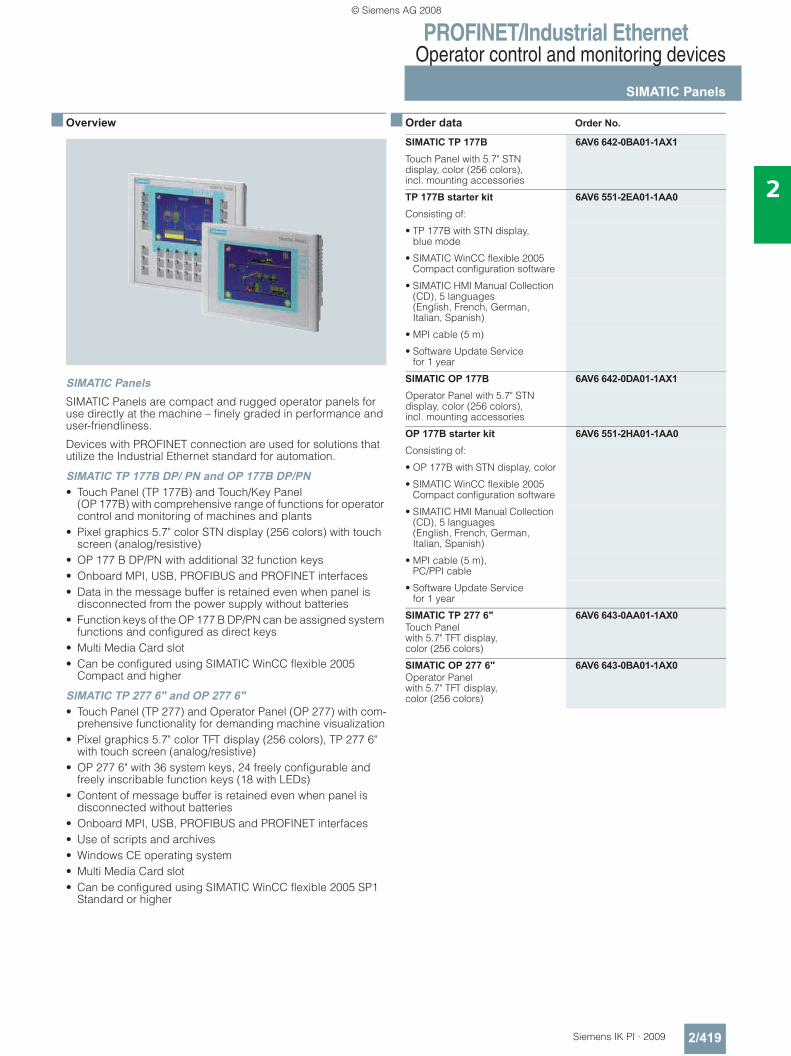
PROFINET/Industrial EthernetOperator control and monitoring devices
SIMATIC Panels
2/419Siemens IK PI · 2009
2
■ Overview
SIMATIC Panels SIMATIC Panels are compact and rugged operator panels for use directly at the machine – finely graded in performance and user-friendliness.
Devices with PROFINET connection are used for solutions that utilize the Industrial Ethernet standard for automation.
SIMATIC TP 177B DP/ PN and OP 177B DP/PN• Touch Panel (TP 177B) and Touch/Key Panel
(OP 177B) with comprehensive range of functions for operator control and monitoring of machines and plants
• Pixel graphics 5.7" color STN display (256 colors) with touch screen (analog/resistive)
• OP 177 B DP/PN with additional 32 function keys • Onboard MPI, USB, PROFIBUS and PROFINET interfaces• Data in the message buffer is retained even when panel is
disconnected from the power supply without batteries• Function keys of the OP 177 B DP/PN can be assigned system
functions and configured as direct keys • Multi Media Card slot• Can be configured using SIMATIC WinCC flexible 2005
Compact and higher
SIMATIC TP 277 6" and OP 277 6"• Touch Panel (TP 277) and Operator Panel (OP 277) with com-
prehensive functionality for demanding machine visualization• Pixel graphics 5.7" color TFT display (256 colors), TP 277 6"
with touch screen (analog/resistive)• OP 277 6" with 36 system keys, 24 freely configurable and
freely inscribable function keys (18 with LEDs)• Content of message buffer is retained even when panel is
disconnected without batteries• Onboard MPI, USB, PROFIBUS and PROFINET interfaces• Use of scripts and archives• Windows CE operating system• Multi Media Card slot• Can be configured using SIMATIC WinCC flexible 2005 SP1
Standard or higher
■ Order data Order No.
SIMATIC TP 177B 6AV6 642-0BA01-1AX1Touch Panel with 5.7" STN display, color (256 colors), incl. mounting accessories
TP 177B starter kit 6AV6 551-2EA01-1AA0Consisting of:
• TP 177B with STN display, blue mode
• SIMATIC WinCC flexible 2005 Compact configuration software
• SIMATIC HMI Manual Collection (CD), 5 languages (English, French, German, Italian, Spanish)
• MPI cable (5 m)
• Software Update Service for 1 year
SIMATIC OP 177B 6AV6 642-0DA01-1AX1Operator Panel with 5.7" STN display, color (256 colors), incl. mounting accessories
OP 177B starter kit 6AV6 551-2HA01-1AA0Consisting of:
• OP 177B with STN display, color
• SIMATIC WinCC flexible 2005 Compact configuration software
• SIMATIC HMI Manual Collection (CD), 5 languages (English, French, German, Italian, Spanish)
• MPI cable (5 m), PC/PPI cable
• Software Update Service for 1 year
SIMATIC TP 277 6"Touch Panel with 5.7" TFT display, color (256 colors)
6AV6 643-0AA01-1AX0
SIMATIC OP 277 6"Operator Panel with 5.7" TFT display, color (256 colors)
6AV6 643-0BA01-1AX0
© Siemens AG 2008
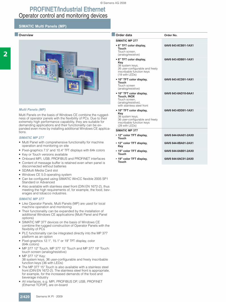
PROFINET/Industrial EthernetOperator control and monitoring devices
SIMATIC Multi Panels (MP)
2/420 Siemens IK PI · 2009
2
■ Overview
Multi Panels (MP) Multi Panels on the basis of Windows CE combine the rugged-ness of operator panels with the flexibility of PCs. Due to their extremely high performance capability, they are suitable for demanding applications and their functionality can be ex-panded even more by installing additional Windows CE applica-tions.
SIMATIC MP 277• Multi Panel with comprehensive functionality for machine
operation and monitoring on site• Pixel-graphics 7.5" and 10.4" TFT displays with 64k colors• Key or Touch versions available• Onboard MPI, USB, PROFIBUS and PROFINET interfaces• Content of message buffer is retained even when panel is
disconnected without batteries• SD/Multi Media Card slot• Windows CE 5.0 operating system• Can be configured using SIMATIC WinCC flexible 2005 SP1
Standard or Advanced• Also available with stainless steel front (DIN EN 1672-2), thus
meeting the high requirements of, for example, the food, bev-erages and tobacco industries.
SIMATIC MP 377• Like Operator Panels, Multi Panels (MP) are used for local
machine operation and monitoring• Their functionality can be expanded by the installation of
additional Windows CE applications (Multi Panel and Panel options)
• SIMATIC MP 377 devices on the basis of Windows CE combine the rugged construction of Operator Panels with the flexibility of PCs
• PLC functionality can be integrated directly into the MP 377 platform as an option
• Pixel-graphics 12.1", 15.1" or 19" TFT display, color (64k colors)
• MP 377 12" Touch, MP 377 15" Touch and MP 377 19" Touch:touch screen (analog/resistive)
• MP 377 12" Key: 38 system keys, 36 user-configurable and freely inscribable function keys (36 with LEDs)
• The MP 377 15" Touch is also available with a stainless steel front (DIN EN 1672-2). The stainless steel front is appropriate, for example, for the increased demands of the food and beverage industry
• All interfaces, e.g. MPI, PROFIBUS DP, USB, PROFINET (Ethernet TCP/IP), are on-board
■ Order data Order No.
SIMATIC MP 277• 8" TFT color display,
TouchTouch screen,(analog/resistive)
6AV6 643-0CB01-1AX1
• 8" TFT color display,Key38 system keys, 26 user-configurable and freely inscribable function keys (18 with LEDs)
6AV6 643-0DB01-1AX1
• 10" TFT color display,TouchTouch screen(analog/resistive)
6AV6 643-0CD01-1AX1
• 10" TFT color display,Touch, INOXTouch screen, (analog/resistive), with stainless steel front
6AV6 643-8AD10-0AA1
• 10" TFT color display,Key38 system keys, 36 user-configurable and freely inscribable function keys (28 with LEDs)
6AV6 643-0DD01-1AX1
SIMATIC MP 377• 12" color TFT display,
Touch6AV6 644-0AA01-2AX0
• 12" color TFT display,Key
6AV6 644-0BA01-2AX1
• 15" color TFT display,Touch
6AV6 644-0AB01-2AX0
• 19" color TFT display,Touch
6AV6 644-0AC01-2AX0
© Siemens AG 2008
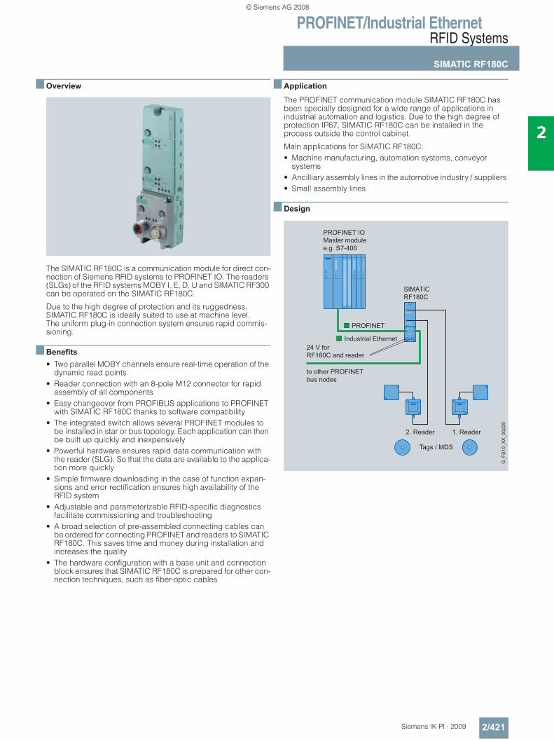
PROFINET/Industrial EthernetRFID Systems
SIMATIC RF180C
2/421Siemens IK PI · 2009
2
■ Overview
The SIMATIC RF180C is a communication module for direct con-nection of Siemens RFID systems to PROFINET IO. The readers (SLGs) of the RFID systems MOBY I, E, D, U and SIMATIC RF300 can be operated on the SIMATIC RF180C.
Due to the high degree of protection and its ruggedness, SIMATIC RF180C is ideally suited to use at machine level. The uniform plug-in connection system ensures rapid commis-sioning.
■ Benefits• Two parallel MOBY channels ensure real-time operation of the
dynamic read points • Reader connection with an 8-pole M12 connector for rapid
assembly of all components • Easy changeover from PROFIBUS applications to PROFINET
with SIMATIC RF180C thanks to software compatibility • The integrated switch allows several PROFINET modules to
be installed in star or bus topology. Each application can then be built up quickly and inexpensively
• Powerful hardware ensures rapid data communication with the reader (SLG). So that the data are available to the applica-tion more quickly
• Simple firmware downloading in the case of function expan-sions and error rectification ensures high availability of the RFID system
• Adjustable and parameterizable RFID-specific diagnostics facilitate commissioning and troubleshooting
• A broad selection of pre-assembled connecting cables can be ordered for connecting PROFINET and readers to SIMATIC RF180C. This saves time and money during installation and increases the quality
• The hardware configuration with a base unit and connection block ensures that SIMATIC RF180C is prepared for other con-nection techniques, such as fiber-optic cables
■ Application
The PROFINET communication module SIMATIC RF180C has been specially designed for a wide range of applications in industrial automation and logistics. Due to the high degree of protection IP67, SIMATIC RF180C can be installed in the process outside the control cabinet.
Main applications for SIMATIC RF180C:• Machine manufacturing, automation systems, conveyor
systems • Ancilliary assembly lines in the automotive industry / suppliers • Small assembly lines
■ Design
PROFINET IOMaster modulee.g. S7-400
24 V forRF180C and reader
to other PROFINETbus nodes
Industrial Ethernet
PROFINET
1. Reader2. Reader
Tags / MDS
G_F
S10
_XX
_002
28
SIMATICRF180C
© Siemens AG 2008
PROFINET/Industrial EthernetRFID Systems
SIMATIC RF180C
2/422 Siemens IK PI · 2009
2
■ Function
The SIMATIC RF180C comprises a basic module and a connec-tion block that must be ordered separately.
The connection block is available in the version M12, 7/8''. PROFINET is connected through an M12 plug, whereas the supply voltage is connected through a 7/8'' plug. There are 2 connections for PROFINET as well as for the power supply. This ensures that SIMATIC RF180C can be connected to addi-tional bus stations without the need for external distribution devices. The removable connection block allows a base module to be replaced without interrupting the supply voltage to other bus stations.
SIMATIC RF180C is integrated in SIMATIC STEP 7 via the GSDML file. SIMATIC RF180C can then be configured via the SW tool HW_Config of SIMATIC Manager or another PROFINET tool.
A pre-assembled reader cable is used to connect one or two readers to the communication module. The standard cable length is 2 m. If other reader cable lengths are required, an ex-tension cable from 2 to 50 m in length can be used. The cable can also be assembled by the customer as required.
The data in the transponder can be accessed in the following manner: Direct addressing via absolute addresses
Error messages and operating states (tag in field, transfer, etc.) are also displayed on LEDs and support commissioning and service.
SIMATIC RF180C has two reader interfaces from which the read-ers are also supplied with voltage. There is a solid-state fuse in SIMATIC RF180C for the reader power supply. The maximum current permitted for the readers per SIMATIC RF180C is 1 A.It is not important here whether the current is drawn by 1 or 2 readers.
The application accesses the tag via FB45. FB45 accesses the tag via absolute addresses. For large volumes of data and com-plex tag operations, the FB45 can process chained commands.
Data is exchanged between SIMATIC RF180C and the applica-tion by means of acyclic data records. This ensures that a large quantity of data can be transferred from/to SIMATIC RF180C without loading the bus cycle. This is advantageous when large volumes of data are being transferred. SIMATIC RF180C can also process chained tag commands in this mode extremely quickly.
■ Technical specifications
Product type description SIMATIC RF180CSupply voltage
• Nominal value 24 V DC
• Permissible range 20 … 30 V DC
Current consumption
• Without reader, typ. 100 mA
• With two readers, max. 1000 mA
Serial reader interface (gross transmission rate)
• MOBY I/E 19200 bit/s
• MOBY U/D, RF300 19200, 57600, 115200 bit/s
Connectors 2 x connector plug M12, 8-pin
Cable length to reader
• Standard length 2 m
• Optional preassembled cables 5 m, 10 m, 20 m, 50 m
Self-assembled cables Reader/SLG-dependent. Up to 1000 m
Supply voltage to reader 24 V
Max. current per reader
• 2 readers connected 0.5 A
• 1 reader connected 1.0 A
Ambient temperature
• Operation -0 ... 60 °C
• Storage -40 ... +70 °C, 20 K/h
Shock load during operation acc. to IEC 61131-2
30 g
Vibratory load during operation acc. to IEC 61131-2
0.75 mm (10 … 58 Hz)10 g (58 … 150 Hz)
Enclosure
• Material Thermoplastic(fiberglass reinforced)
• Color IP Basic 714
• Degree of protection IP67
Dimensions (W x H x D) in mm
• SIMATIC RF180C without connection block
60 x 210 x 30
• SIMATIC RF180C with connection block
60 x 210 x 54
Weight
• Base module only 210 g
• Connection block only 230 g
© Siemens AG 2008
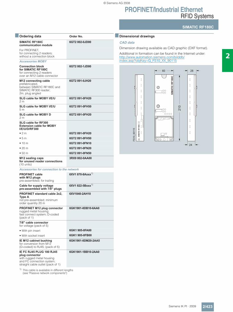
PROFINET/Industrial EthernetRFID Systems
SIMATIC RF180C
2/423Siemens IK PI · 2009
2
■ Ordering data Order No.
1) This cable is available in different lengths (see "Passive network components")
■ Dimensional drawings
CAD dataDimension drawing available as CAD graphic (DXF format).
Additional in formation can be found in the Internet under:http://www.automation.siemens.com/bilddb/index.asp?objKey=G_FS10_XX_90115
SIMATIC RF180C communication module
6GT2 002-0JD00
For PROFINET, for connecting 2 readers; without a connection block
Accessories MOBYConnection block for SIMATIC RF180Cfor connecting 2 readers over an M12 cable connector
6GT2 002-1JD00
M12 connecting cableprefabricated, between SIMATIC RF180C and SIMATIC RF300 reader; 2m, plug angled
6GT2 891-0JH20
SLG cable for MOBY I/E/U2 m
6GT2 091-0FH20
SLG cable for MOBY I/E/U5 m
6GT2 091-0FH50
SLG cable for MOBY D2 m
6GT2 691-0FH20
SLG cable for RF300Extension cable for MOBY I/E/U/D/RF300• 2 m 6GT2 891-0FH20• 5 m 6GT2 891-0FH50• 10 m 6GT2 891-0FN10• 20 m 6GT2 891-0FN20• 50 m 6GT2 891-0FN50M12 sealing caps for unused reader connections (10 units)
3RX9 802-0AA00
Accessories for connection to the networkPROFINET cable with M12 plugspre-assembled; for trailing
6XV1 870-8Axxx1)
Cable for supply voltage pre-assembled with 7/8'' plugs
6XV1 822-5Bxxx1)
PROFINET standard cable 2x2, Type Anot pre-assembled; minimum order quantity 20 m
6XV1840-2AH10
PROFINET M12 plug connectorrugged metal housing; fast connect system; D-coded (pack of 1)
6GK1901-0DB10-6AA0
7/8'' cable connector for voltage (pack of 5)
• With pin insert 6GK1 905-0FA00
• With socket insert 6GK1 905-0FB00
IE M12 cabinet bushingfor conversion from M12 (D-coded) to RJ45; (pack of 5)
6GK1901-0DM20-2AA5
IE FC RJ45 PLUG 180 RJ45 plug connector with rugged metal housing and FC connection system; straight cable outlet (pack of 1)
6GK1901-1BB10-2AA0
SIM
ATIC
RF1
80C
SIM
ATIC
RF1
80C
FS10
_901
15
24
2860
210
© Siemens AG 2008
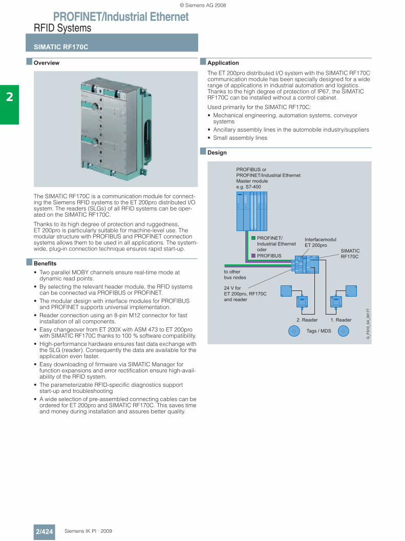
PROFINET/Industrial EthernetRFID Systems
SIMATIC RF170C
2/424 Siemens IK PI · 2009
2
■ Overview
The SIMATIC RF170C is a communication module for connect-ing the Siemens RFID systems to the ET 200pro distributed I/O system. The readers (SLGs) of all RFID systems can be oper-ated on the SIMATIC RF170C.
Thanks to its high degree of protection and ruggedness, ET 200pro is particularly suitable for machine-level use. The modular structure with PROFIBUS and PROFINET connection systems allows them to be used in all applications. The system-wide, plug-in connection technique ensures rapid start-up.
■ Benefits• Two parallel MOBY channels ensure real-time mode at
dynamic read points. • By selecting the relevant header module, the RFID systems
can be connected via PROFIBUS or PROFINET.• The modular design with interface modules for PROFIBUS
and PROFINET supports universal implementation. • Reader connection using an 8-pin M12 connector for fast
installation of all components. • Easy changeover from ET 200X with ASM 473 to ET 200pro
with SIMATIC RF170C thanks to 100 % software compatibility. • High-performance hardware ensures fast data exchange with
the SLG (reader). Consequently the data are available for the application even faster.
• Easy downloading of firmware via SIMATIC Manager for function expansions and error rectification ensure high-avail-ability of the RFID system.
• The parameterizable RFID-specific diagnostics support start-up and troubleshooting
• A wide selection of pre-assembled connecting cables can be ordered for ET 200pro and SIMATIC RF170C. This saves time and money during installation and assures better quality.
■ Application
The ET 200pro distributed I/O system with the SIMATIC RF170C communication module has been specially designed for a wide range of applications in industrial automation and logistics. Thanks to the high degree of protection of IP67, the SIMATIC RF170C can be installed without a control cabinet.
Used primarily for the SIMATIC RF170C:• Mechanical engineering, automation systems, conveyor
systems • Ancillary assembly lines in the automobile industry/suppliers • Small assembly lines
■ Design
PROFIBUS orPROFINET/Industrial EthernetMaster modulee.g. S7-400
to otherbus nodes
24 V forET 200pro, RF170Cand reader
PROFINET/Industrial EthernetoderPROFIBUS
1. Reader2. Reader
Tags / MDS
G_F
S10
_XX
_001
77
SIMATIC RF170C
InterfacemodulET 200pro
© Siemens AG 2008
PROFINET/Industrial EthernetRFID Systems
SIMATIC RF170C
2/425Siemens IK PI · 2009
2
■ Function
The SIMATIC RF170C comprises an electronics module and a connection block that must be ordered separately. The interface module is available in the PROFIBUS or PROFINET variants. For the PROFIBUS connection, you can choose from the con-nection systems of ECOFAST, M12, 7/8", or screwed cable gland. For the PROFINET interface module, M12, 7/8" connec-tion is available.
Integration of SIMATIC RF170C into SIMATIC STEP 7 is achieved by means of an object manager (OM). The GSD file of the ET 200pro system is available for integration into non-Siemens systems. Then the SIMATIC RF170C can be configured by means of the software tool HW_Config of the SIMATIC Manager or another PROFIBUS/PROFINET tool.
One or two readers are connected to the interface module using an off-the-shelf reader cable. The standard length of the cable is 2 m. If other cable lengths to the reader are required, an ex-tension cable measuring between 2 m and 50 m can be used. The cable can also be assembled by the customer as required.
In principle, access to the data in the transponder can take place as follows. • Direct addressing via absolute addresses • Conveniently via the MOBY file handler (MOBY I/U only)
using file names
Error messages and operating states (tag in the field, trans-mission, etc.) are indicated additionally by means of LEDs and simplify commissioning and service.
The SIMATIC RF170C has two reader interfaces from which the readers are also supplied with power. In the SIMATIC RF170C, the power supply for the readers has an electronic fuse. The maximum permissible current per SIMATIC RF170C for the read-ers is 0.8 A. It is of no importance here whether the current is drawn by one or two readers.
The data in the MDS can be directly accessed by means of absolute addresses (FB/FC45, FC55) or more conveniently using the MOBY file handler (FB, FC 56) by means of the file names. When the ET 200pro is operated with a PROFINET inter-face, use of the FB (FB45, FB56) is mandatory.
Communication between the SIMATIC RF170C and the control-ler is acyclic. Consequently, a very large amount of data can be transferred to/from the SIMATIC RF170C without overloading the bus cycle. This has advantages when transferring large volumes of data. In addition, the SIMATIC RF170C can process concatenated tag commands very quickly in this mode.
■ Technical specifications
Product type description SIMATIC RF170CAmbient temperature
• During operation -25 … +55 °C
• During storage -40 … +70 °C 20 K/h
Relative humidity 5 to max. 100 %
Atmospheric pressure from 795 to 1080 hPa
Resistance to shock as for ET 200pro
Vibration as for ET 200pro
Power supply
• Nominal value 24 V DC
• Permissible range 20.4 … 28.8 V DC
Current consumption
• Without reader typ. 130 mA
• With 2 readers Max. 1000 mA
Enclosure
• Degree of protection IP67
• Enclosure material Thermoplastic (fiberglass reinforced)
• Housing color IP Basic 714
Dimensions (W x H x D) in mm
• SIMATIC RF170C without connection block
90 x 130 x 35
• SIMATIC RF170C with connection block
90 x 130 x 60
Weight
• Without connection block Approx. 270 g
• With connection block Approx. 770 g
Serial reader interface (gross transmission rate)
MOBY I/E: 19200 baudMOBY U/D, RF300: 19200, 57600, 115200 baud
Connectors 2 x connector plug M12, 8-pin
Cable length to reader
• Standard length 2 m
• Optional preassembled cables 5 m, 10 m, 20 m, 50 m
• Self-assembled cables According to write/read device. Up to 1000 m
Supply voltage to reader 24 V
Max. current; 2 readers connected
0.4 A per reader
Max. current; 1 readers connected
0.8 A per reader
© Siemens AG 2008
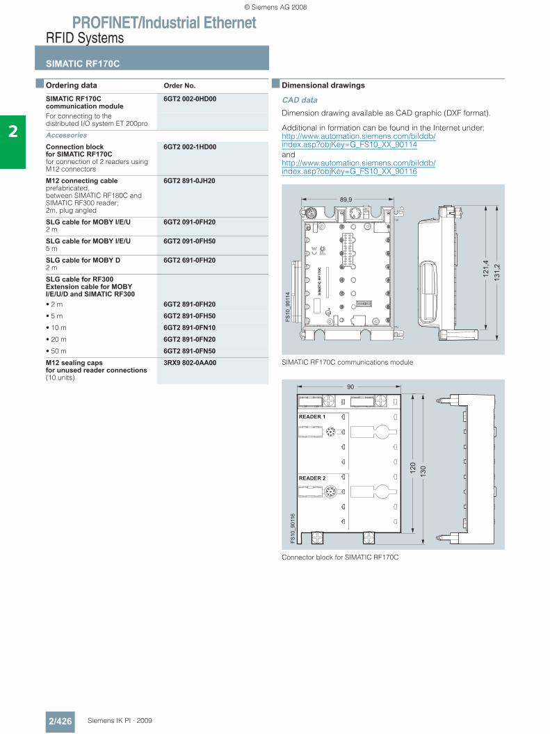
PROFINET/Industrial EthernetRFID Systems
SIMATIC RF170C
2/426 Siemens IK PI · 2009
2
■ Ordering data Order No.
■ Dimensional drawings
CAD dataDimension drawing available as CAD graphic (DXF format).
Additional in formation can be found in the Internet under:http://www.automation.siemens.com/bilddb/index.asp?objKey=G_FS10_XX_90114 andhttp://www.automation.siemens.com/bilddb/index.asp?objKey=G_FS10_XX_90116
SIMATIC RF170C communications module
Connector block for SIMATIC RF170C
SIMATIC RF170C communication module
6GT2 002-0HD00
For connecting to the distributed I/O system ET 200pro
AccessoriesConnection block for SIMATIC RF170Cfor connection of 2 readers using M12 connectors
6GT2 002-1HD00
M12 connecting cableprefabricated, between SIMATIC RF180C and SIMATIC RF300 reader; 2m, plug angled
6GT2 891-0JH20
SLG cable for MOBY I/E/U2 m
6GT2 091-0FH20
SLG cable for MOBY I/E/U5 m
6GT2 091-0FH50
SLG cable for MOBY D2 m
6GT2 691-0FH20
SLG cable for RF300Extension cable for MOBY I/E/U/D and SIMATIC RF300• 2 m 6GT2 891-0FH20• 5 m 6GT2 891-0FH50• 10 m 6GT2 891-0FN10• 20 m 6GT2 891-0FN20• 50 m 6GT2 891-0FN50M12 sealing caps for unused reader connections (10 units)
3RX9 802-0AA00
89,9
121,
413
1,2
SIM
ATIC
RF1
70C
FS10
_901
14
90
FS10
_901
16
120
130
READER 1
READER 2
© Siemens AG 2008
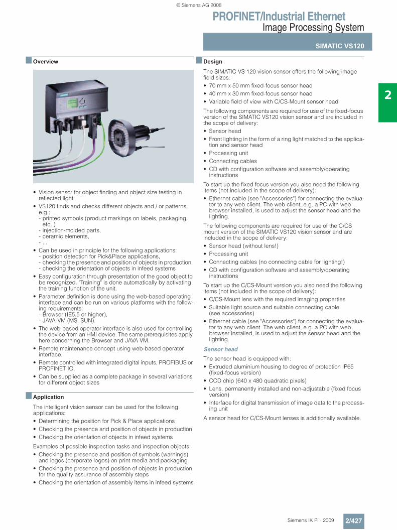
PROFINET/Industrial EthernetImage Processing System
SIMATIC VS120
2/427Siemens IK PI · 2009
2
■ Overview
• Vision sensor for object finding and object size testing in reflected light
• VS120 finds and checks different objects and / or patterns, e.g.: - printed symbols (product markings on labels, packaging,
etc. ) - injection-molded parts, - ceramic elements, - ...
• Can be used in principle for the following applications: - position detection for Pick&Place applications, - checking the presence and position of objects in production, - checking the orientation of objects in infeed systems
• Easy configuration through presentation of the good object to be recognized. "Training" is done automatically by activating the training function of the unit.
• Parameter definition is done using the web-based operating interface and can be run on various platforms with the follow-ing requirements: - Browser (IE5.5 or higher), - JAVA-VM (MS, SUN).
• The web-based operator interface is also used for controlling the device from an HMI device. The same prerequisites apply here concerning the Browser and JAVA VM.
• Remote maintenance concept using web-based operator interface.
• Remote controlled with integrated digital inputs, PROFIBUS or PROFINET IO.
• Can be supplied as a complete package in several variations for different object sizes
■ Application
The intelligent vision sensor can be used for the following applications:• Determining the position for Pick & Place applications• Checking the presence and position of objects in production• Checking the orientation of objects in infeed systems
Examples of possible inspection tasks and inspection objects:• Checking the presence and position of symbols (warnings)
and logos (corporate logos) on print media and packaging• Checking the presence and position of objects in production
for the quality assurance of assembly steps• Checking the orientation of assembly items in infeed systems
■ Design
The SIMATIC VS 120 vision sensor offers the following image field sizes:• 70 mm x 50 mm fixed-focus sensor head • 40 mm x 30 mm fixed-focus sensor head • Variable field of view with C/CS-Mount sensor head
The following components are required for use of the fixed-focus version of the SIMATIC VS120 vision sensor and are included in the scope of delivery:• Sensor head • Front lighting in the form of a ring light matched to the applica-
tion and sensor head • Processing unit • Connecting cables • CD with configuration software and assembly/operating
instructions
To start up the fixed focus version you also need the following items (not included in the scope of delivery):• Ethernet cable (see "Accessories") for connecting the evalua-
tor to any web client. The web client, e.g. a PC with web browser installed, is used to adjust the sensor head and the lighting.
The following components are required for use of the C/CS mount version of the SIMATIC VS120 vision sensor and are included in the scope of delivery:• Sensor head (without lens!) • Processing unit • Connecting cables (no connecting cable for lighting!) • CD with configuration software and assembly/operating
instructions
To start up the C/CS-Mount version you also need the following items (not included in the scope of delivery):• C/CS-Mount lens with the required imaging properties • Suitable light source and suitable connecting cable
(see accessories) • Ethernet cable (see "Accessories") for connecting the evalua-
tor to any web client. The web client, e.g. a PC with web browser installed, is used to adjust the sensor head and the lighting.
Sensor headThe sensor head is equipped with:• Extruded aluminium housing to degree of protection IP65
(fixed-focus version) • CCD chip (640 x 480 quadratic pixels) • Lens, permanently installed and non-adjustable (fixed focus
version) • Interface for digital transmission of image data to the process-
ing unit
A sensor head for C/CS-Mount lenses is additionally available.
© Siemens AG 2008
PROFINET/Industrial EthernetImage Processing System
SIMATIC VS120
2/428 Siemens IK PI · 2009
2
■ Design (continued)
Processing unitThe processing unit has:• Plastic housing, designed for cabinetless construction (IP40)• Connections for
- Supply voltage 24 V DC - Lighting - Sensor head - Digital inputs and outputs - Ethernet interface
(DHCP-Client, DHCP-Server, fixed IP address)- PROFIBUS DP
• 4-line text display for operator prompting • 6 keys for operating the unit • User guidance with web-based operator interface
(HTML, JAVA VM) • Access protection by means of password.
The following communication services are included:• PROFINET IO (slave) • PROFIBUS DP V0 (slave), • TCP/IP native
The analysis is carried out by a powerful digital signal processor.
Front lighting• Designed as ring light pushed onto sensor head • Can be dismounted, and secured with different orientation on
the machine • Housing with degree of protection IP65 • Equipped with red LEDs • Operation in flash mode • Power control for the flash integrated in the light
■ Function• Training the object test parameters using one or more good
objects• Testing an object and/or pattern with the features taken from
the training• Testing can be performed on stationary and moving objects• Checking for a match with the reference provides a good/poor
indication after comparison with set-value criteria • Test results output to three control outputs:
- OK:trained object and/or pattern found based on features; degree of match greater than set value
- N_OK:trained object and/or pattern NOT found based on features; degree of match NOT greater than set value
• Position information output via PROFIBUS DP, PROFINET IO, Ethernet or with converter to RS 232 interface
• Integrated DI/O enables "stand-alone" operation without additional controller.
• Remote control via PROFIBUS DP, PROFINET IO, DI/O or Ethernet
• Remote maintenance via web-based operator interface Intranet or Internet: - monitoring (live image in read mode)- diagnostics (fault image, log information, ...) - system administration (software update, ...) - error analysis for troubleshooting for faulty readings
• Actuation of ring lighting
Mode of operationThe following steps are required for using the SIMATIC VS120:• Mount the vision sensor and lighting. • Manual alignment of the camera, lighting check:
This is handled with the web-server integrated in the unit and the web-based operator interface contained within. The oper-ator interface displays the camera image. In the setup phase, the sensor head can be aligned with reference to the live image in the user interface. The user interface executes on any PC with Microsoft Internet Explorer and JAVA VM installa-tion. If the sensor head adjustment is complete, the vision sensor automatically takes over the following procedures: - optimization of lighting control. - "Training" the image processing parameters by applying a
reference object- the result of the training is stored under one of the 64 data
records• Starting the evaluation operation requires loading a trained
object record and changing into the "RUN" operating mode. The VS120 starts the evaluation after triggering.
• Depending on the trained set values and the actual values of the evaluation, one of the digital control outputs OK (good result) or N_OK (poor result) is set.
The position information is output via the PROFIBUS DP, PROFINET IO or Ethernet interface.
ProgrammingSIMATIC VS120 is not programmed and parameters are not defined as on standard image processing systems. It is trained for its special task, finding and testing a special object. The SIMATIC VS120 is shown a good object and the device is "trained" to this object.
The training procedure can be performed while a conveyor system is running.
Up to 64 different data records can be stored in the device and can be called up at any time by the operator or can also be called up through an external controller.
© Siemens AG 2008
PROFINET/Industrial EthernetImage Processing System
SIMATIC VS120
2/429Siemens IK PI · 2009
2
■ Technical specifications
Product type description Vision Sensor SIMATIC VS120Sensor headImage capture CCD chip ¼",
640 x 480 square pixels;full frame shutter with automatic exposure time
Image data transfer Triggered frame transfer
Available versions • Fixed lens systemfor two different field of view sizes and mounting positions
• One C/CS-mount version without lens.
• Large field of view Size of field of view: 70 mm x 50 mm for object sizes up to approx.: 60 mm x 40 mm Operating distance: 120 mm
• Small field of view Size of field of view: 40 mm x 30 mm for object sizes up to approx.: 34 mm x 24 mm Operating distance: 85 mm
• Variable field of view Lens can be selected by the user; hence freely selectable field of view size and object size Operating distance: dependent on the lens
Enclosure Aluminum profile casing, anodized black
Dimensions (W x H x D) in mm 42 x 42 x 100
Degree of protection IP65 according to DIN EN 60529 / VDE 0470-1
Ambient temperature 0 … 50 °C
Mechanical strength
• Vibrations 1 g (60 … 500 Hz)
• Shock 70 g (6 ms, 3 shocks)
LightingIlluminant LED, wavelength 630 nm (red),
designed as a flash of 20 μs to 10 ms, diffuse
Enclosure Ring lamp with multiple fixing possibilities; plastic with plastic diffusing panel
Dimensions (W x H x D) in mm 102 x 102 x 26.5
Degree of protection IP65 according to DIN EN 60529 / VDE 0470-1
Ambient temperature 0 … 50 °C
Evaluation unitOperator controls 4-line text display and
6 operator buttons
Training Fully-automatic training procedure
Number of types saved 64 different data records, can be selected via control button or digital inputs or PROFIBUS DP or PROFINET IO, network-fail-safe storage
Triggering inspection External (via digital input, PROFIBUS DP or PROFINET IO)
Permitted object rate, max. 20 objects/s
Product type description Vision Sensor SIMATIC VS120Infeed direction of the objects
• For external triggering As required
• Setup software Software for displaying the sensor image when mounting and adjusting the sensor head and lighting. The software is provided directly by the integrated web server and can be executed on every JAVA-capable browser (preferably IE6.0).
Enclosure Plastic, all cables can be plugged in, suitable for installation without cabinet
Dimensions (W x H x D) in mm 170 x 140 x 76
Degree of protection IP40 according to DIN EN 60529 / VDE 0470-1
Ambient temperature 0 … 50 °C
Mechanical strength
• Vibrations 1 g (60 … 500 Hz)
• Shock 70 g (6 ms, 3 shocks)
Interfaces on evaluation unit
• Digital inputs for 24 V DC 8; of which one interrupt-capable trigger input for standard binary sensors, 7 further PLC-capable control inputs
• Digital outputs for 24 V DC 6; of which 3 quality outputs 0.5 A are for the direct activation of pneumatic valves (15-pin Sub-D socket for inputs/outputs)
• Integrated PROFIBUS DP inter-face
DP (9 pin D-sub socket) to control the testing and real-time transmission of test results
• Integrated PROFINET IO interface RJ45 (socket) for operating software, controlling the testing and real-time transmission of test results
• Integrated Ethernet interface RJ45 (socket) for operating software, controlling the testing and real-time transmission of test results
• Lighting control 4-pin circular connector (female) for power supply and for triggering the flash
• Sensor head interface Digital interface (26 pin Sub-D socket) for connecting the VS120 sensor head
Power supply
• Rated value 24 V DC
• Permitted range 20 V … 30 V DC
Current consumption, max. 4 A, of which up to 1.5 A for supplying the pneumatic valves that can be connected
© Siemens AG 2008
PROFINET/Industrial EthernetImage Processing System
SIMATIC VS120
2/430 Siemens IK PI · 2009
2
■ Ordering data Order No.
SIMATIC VS120 vision sensorComplete package for object testing; consisting of sensor head, LED front lighting, process-ing unit and the following cables:
• Cable between processing unit and sensor head,for lengths see below
• Cable between lighting and processing unit (except for vision sensor with variable field of view), for length see below
• Cable for power supply, length 10 m
• Cable for connecting digital I/O devices,length 10 m
Incl. documentation packagefor SIMATIC VS120
• Field of view 70 mm x 50 mm- With cable length 2.5 m 6GF1 120-1AA- With cable length 10 m 6GF1 120-1AA01
• Field of view 40 mm x 30 mm- With cable length 2.5 m 6GF1 120-2AA- With cable length 10 m 6GF1 120-2AA01
• Variable field of view, prepared for IP65 protective housing (note: supplied without light and light cable)- With cable length 2.5 m 6GF1 120-3AB- With cable length 10 m 6GF 1 120-3AB01
© Siemens AG 2008
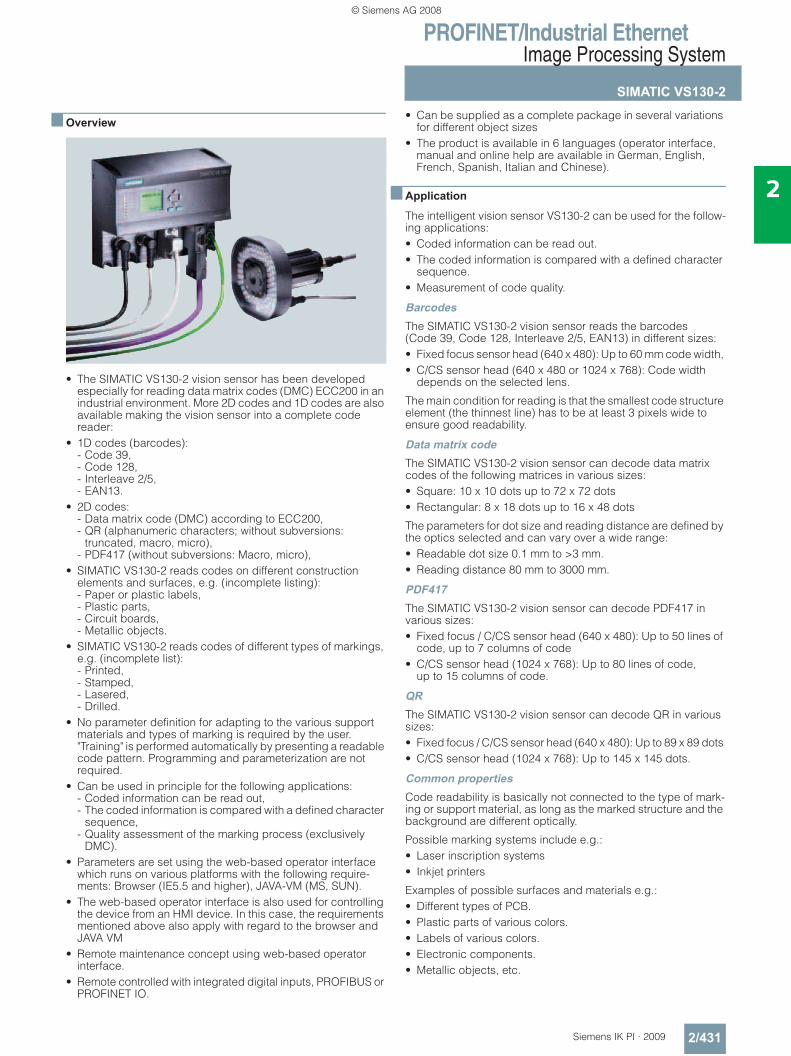
PROFINET/Industrial EthernetImage Processing System
SIMATIC VS130-2
2/431Siemens IK PI · 2009
2
■ Overview
• The SIMATIC VS130-2 vision sensor has been developed especially for reading data matrix codes (DMC) ECC200 in an industrial environment. More 2D codes and 1D codes are also available making the vision sensor into a complete code reader:
• 1D codes (barcodes): - Code 39, - Code 128, - Interleave 2/5, - EAN13.
• 2D codes: - Data matrix code (DMC) according to ECC200, - QR (alphanumeric characters; without subversions:
truncated, macro, micro), - PDF417 (without subversions: Macro, micro),
• SIMATIC VS130-2 reads codes on different construction elements and surfaces, e.g. (incomplete listing): - Paper or plastic labels, - Plastic parts, - Circuit boards, - Metallic objects.
• SIMATIC VS130-2 reads codes of different types of markings, e.g. (incomplete list): - Printed, - Stamped, - Lasered, - Drilled.
• No parameter definition for adapting to the various support materials and types of marking is required by the user. "Training" is performed automatically by presenting a readable code pattern. Programming and parameterization are not required.
• Can be used in principle for the following applications: - Coded information can be read out, - The coded information is compared with a defined character
sequence, - Quality assessment of the marking process (exclusively
DMC). • Parameters are set using the web-based operator interface
which runs on various platforms with the following require-ments: Browser (IE5.5 and higher), JAVA-VM (MS, SUN).
• The web-based operator interface is also used for controlling the device from an HMI device. In this case, the requirements mentioned above also apply with regard to the browser and JAVA VM
• Remote maintenance concept using web-based operator interface.
• Remote controlled with integrated digital inputs, PROFIBUS or PROFINET IO.
• Can be supplied as a complete package in several variations for different object sizes
• The product is available in 6 languages (operator interface, manual and online help are available in German, English, French, Spanish, Italian and Chinese).
■ Application
The intelligent vision sensor VS130-2 can be used for the follow-ing applications:• Coded information can be read out. • The coded information is compared with a defined character
sequence. • Measurement of code quality.
BarcodesThe SIMATIC VS130-2 vision sensor reads the barcodes (Code 39, Code 128, Interleave 2/5, EAN13) in different sizes:• Fixed focus sensor head (640 x 480): Up to 60 mm code width, • C/CS sensor head (640 x 480 or 1024 x 768): Code width
depends on the selected lens.
The main condition for reading is that the smallest code structure element (the thinnest line) has to be at least 3 pixels wide to ensure good readability.
Data matrix codeThe SIMATIC VS130-2 vision sensor can decode data matrix codes of the following matrices in various sizes:• Square: 10 x 10 dots up to 72 x 72 dots • Rectangular: 8 x 18 dots up to 16 x 48 dots
The parameters for dot size and reading distance are defined by the optics selected and can vary over a wide range:• Readable dot size 0.1 mm to >3 mm. • Reading distance 80 mm to 3000 mm.
PDF417The SIMATIC VS130-2 vision sensor can decode PDF417 in various sizes:• Fixed focus / C/CS sensor head (640 x 480): Up to 50 lines of
code, up to 7 columns of code • C/CS sensor head (1024 x 768): Up to 80 lines of code,
up to 15 columns of code.
QRThe SIMATIC VS130-2 vision sensor can decode QR in various sizes:• Fixed focus / C/CS sensor head (640 x 480): Up to 89 x 89 dots • C/CS sensor head (1024 x 768): Up to 145 x 145 dots.
Common propertiesCode readability is basically not connected to the type of mark-ing or support material, as long as the marked structure and the background are different optically.
Possible marking systems include e.g.:• Laser inscription systems • Inkjet printers
Examples of possible surfaces and materials e.g.: • Different types of PCB. • Plastic parts of various colors. • Labels of various colors. • Electronic components. • Metallic objects, etc.
© Siemens AG 2008
PROFINET/Industrial EthernetImage Processing System
SIMATIC VS130-2
2/432 Siemens IK PI · 2009
2
■ Design
The following components are required for use of the SIMATIC VS130-2 vision sensor and are included in the scope of delivery of a fixed-focus complete package (working distance approxi-mately 100 mm):• Fixed-focus sensor head (3 display field sizes available for
selection). • Front lighting in the form of a ring light matched to the applica-
tion and sensor head. • Evaluation unit. • Cables. • CD with mounting/operating instructions
For working distances between 80 mm and 3000 mm, "C/CS-Mount complete packages" are available:• C/CS-Mount sensor head (standard resolution 640 x 480
[pixels], high-resolution 1024 x 768 [pixels]) • Evaluation unit. • Cables. • CD with mounting/operating instructions
The core of this package is a C/CS-Mount sensor head whose imaging behavior is determined with a suitable C/CS-Mount lens. The lens is not included in the package and can be se-lected under "Accessories". The lighting (incl. cables) must be selected in accordance with the working distance and are not included in the "C/CS-Mount complete packages".
The following is additionally required for commissioning (not included in scope of delivery):• Ethernet cable (see "Accessories") for connecting the evalua-
tor to any web client. The web client, e.g. a PC with web browser installed, is used to adjust the sensor head and the lighting.
Sensor headThe sensor head is equipped with:• Extruded aluminium housing with degree of protection IP65 • CCD chip (640 x 480 square pixels, 1024 x 768 square pixels). • Lens, permanently installed (possible field of view sizes:
70 x 50 mm, 40 x 30 mm, 20 x 15 mm for 640 x 480 pixels in each case) or prepared for C/CS-Mount lens (field of view size can be freely selected for 640 x 480 pixels or 1024 x 768 pixels)
• Interface for digital transmission of image data to the evalua-tion unit.
The fixed-focus sensor head offers degree of protection IP65. Even when C/CS-Mount lenses are used, degree of protection IP65 can be achieved by use of the optional protective housing.
Evaluation unitThe evaluation unit has:• Plastic housing designed for cabinet-free mounting (IP40). • Connections for:
- Supply voltage 24 V DC.- Lighting - Sensor head - Digital inputs and outputs - PROFIBUS DP. - Ethernet (DHCP client, DHCP server, fixed IP address).
• Operator prompting on the device (4-line text display, 6 keys). • Operator prompting through web-based user interface
(HTML, JAVA VM). • Access protection by means of password.
The following communication services are included:• PROFINET IO (slave)• PROFIBUS DP V0 (slave),• TCP/IP native.
Frontlighting• Designed as ring light, pushed onto sensor head or lens
housing• Can be dismounted, and secured with different orientation on
the machine• Housing with degree of protection IP65• Equipped with various LEDs for different applications:
- Not focussed, for small reading distances (0.08 m to 0.5 m)- Focussed, for large reading distances (0.5 m to 3 m).- Infrared LED, for daylight-independent operation- Red LED for high light intensity - Operation in flash mode- Power control for the flash integrated in the light
© Siemens AG 2008
PROFINET/Industrial EthernetImage Processing System
SIMATIC VS130-2
2/433Siemens IK PI · 2009
2
■ Function
The following functions are available:• "Training" the vision sensor with reference to a code (DMC)
pattern. • Coded information can be read out. • The coded information is compared with a defined character
sequence. • Measurement of code quality. • Codes on moving or stationary objects can be processed. • Output of the decoding results to three control outputs:
- READ: Code is decoded. - MATCH: Decoded code content exactly matches the refer-
ence. - N_OK: Code cannot be decoded.
• Output of the decoded DMC information via PROFIBUS DP, Ethernet or by means of a converter on the RS232 interface.
• Formatting of the output. • Integrated DI/Os, for example, for "stand-alone" mode without
additional control. • Remote control via PROFIBUS DP, PROFINET IO or DI/O or
Ethernet. • Remote maintenance is possible through web-based Intranet
or Internet user interface: - Monitoring (live image in read mode). - Diagnostics (fault pattern, log information, etc.). - System administration (software update, etc.). - Fault analysis for finding the cause of faulty readings.
• Actuation of ring lighting
Mode of operationWhen using the SIMATIC VS130-2, the following steps are necessary:• Mount the vision sensor and lighting. • Manually align the camera, check the lighting:
The web server integrated into the device complete with web-based user interface is provided for this purpose. The user interface presents the camera image and the decoded result. In the setup phase, the sensor head can be aligned with reference to the live image in the user interface. The user in-terface executes on any PC with Microsoft Internet Explorer and JAVA VM installation. When the sensor head is correctly adjusted, the vision sensor performs the subsequent tasks autonomously: - Optimization of lighting control. - "Training" of the image processing parameters by presenting
a code sample. The image processing parameters for the type of code (carrier material, marking type, dot size, matrix size, etc.) are stored. No further parameter inputs are required.
• Evaluation mode (RUN mode) is started using the training results and a read is started: Feeding of the Data Matrix Code can be carried out manually or via a conveyor unit. The Data Matrix Code must be located within the viewing window at the moment of triggering and is permitted to move at a maximum speed of 5000 mm/s. Any angle of rotation within the viewing window of the sensor head is permitted.
SIMATIC VS130-2 generally has three operating modes that can also be combined: • Operating mode 1 "Code decoding":
The character string is transferred to the controller filtered or unfiltered. Filters can be separators, start position and length of the character string, or company-specific ID numbers.
• Operating mode 2 "Decoded information is compared with a character string": The comparison can refer to the decoded string or to only a certain part. Comparison of parts is possible using the filter functions mentioned above.
• Operating mode 3 "Measurement of code quality": The measurement can be absolute or relative. With the relative method, the reading system is calibrated by presenting a reference sample during the training phase. In this mode, the quality values measured are based on the reference sample. VS130-2 can, however, also use absolute measurement. In this case, the calibration step is omitted and a reference sample is not necessary.
• Depending on the operating mode and the result of the analysis, one of the digital control outputs READ, MATCH or N_OK is set.
• The decoded information is output, over PROFIBUS DP, PROFIBUS IO, Ethernet or a serial interface (converter re-quired) as preferred and on the device display.
ProgrammingSIMATIC VS130-2 is not programmed or parameterized like con-ventional image processing systems. It configures the lighting and trains the algorithms without the need for user settings with reference to a code sample or during the first read.
The training can be performed when the conveyor system is running. Self-parameterization can be started externally using the operator buttons on the device or remotely from the user interface. Self-parameterization is also activated during reading by a failed attempt at reading. Maximum reading reliability is achieved thanks to independence from user inputs and due to automatic self-parameterization.
Up to 15 different parameter records can be stored in the device. These can be called up at any time by the user or by an external controller and can be used for reading code without the need to repeat the training phase.
© Siemens AG 2008
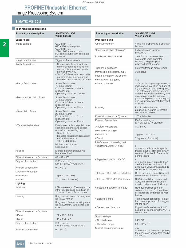
PROFINET/Industrial EthernetImage Processing System
SIMATIC VS130-2
2/434 Siemens IK PI · 2009
2
■ Technical specifications
Product type description SIMATIC VS 130-2 Vision Sensor
Sensor headImage capture CCD chip 1/4",
640 x 480 square pixels; CCD chip 1/3", 1024 x 768 square pixels; Full frame shutter with automatic exposure
Image data transfer Triggered frame transfer
Available versions • Non-adjustable lens for three different image field sizes and reading distances, only avail-able for 640 x 480
• Two C/CS-Mount versions (with-out lens): User-defined image field size and scanning distance
• Large field of view Size of field of view: 70 mm x 50 mm Dot size: 0.60 mm - 3.5 mm (edge length)Operating distance: 120 mm
• Medium-sized field of view Size of field of view: 40 mm x 30 mmDot size: 0.35 mm - 2.0 mm (edge length)Operating distance: 85 mm
• Small field of view Size of field of view: 20 mm x 15 mmDot size: 0.2 mm - 1.0 mm (edge length)Operating distance: 75 mm
• Variable field of view Freely selectable image field size, scanning distance and sensor resolution, depending on: • Selected lens• Selected sensor head resolution
640 x 480 pixels or 1024 x 768 pixels
Minimum requirement: 5 pixels/dot
Housing Extruded aluminum housing, black anodized
Dimensions (W x H x D) in mm 42 x 42 x 100
Degree of protection IP65 according to DIN EN 60529 / VDE 0470-1
Ambient temperature 0 … 50 °C
Mechanical strength
• Vibrations 1 g (60 … 500 Hz)
• Shock 70 g (6 ms, 3 shocks)
LightingIlluminant LED, wavelength 630 nm (red) or
infra-red, designed as a flash of 20 μs to 10 ms, diffuse or clear
Housing Ring lamp of plastic, working area up to 500 mm orRing lamp of metal, working area up to 3000 mm, suitable for lens cover
Dimensions (W x H x D) in mm
• Plastic 102 x 102 x 26.5
• Metal 116 x 116 x 42
Degree of protection IP65 acc. to DIN EN 60529 / VDE 0470-1
Ambient temperature 0 … 50 °C
Product type description SIMATIC VS 130-2 Vision Sensor
Processing unitOperator controls 4-line text display and 6 operator
buttons
"Teach-in" of DMC ("training") Fully-automatic training procedure
Number of objects saved 15 different parameter sets, selectable using operator buttons or digital inputs, powerfail-proof storage
Triggering inspection External (through digital input)
Permissible object rate, max. 20 reads/s
Infeed direction of the objects
• For external triggering Any
• Setup software Software for displaying the sensor image when mounting and adjust-ing the sensor head and lighting. The software makes the integral web server available directly and requires an installed browser (Internet Explorer 5.5 and higher) and installed JAVA-VM (Microsoft or SUN).
Housing Plastic, all cables can be plugged in, suitable for installa-tion without cabinet
Dimensions (W x H x D) in mm 170 x 140 x 76
Degree of protection IP40 according to DIN EN 60529 / VDE 0470-1
Ambient temperature 0 … 50 °C
Mechanical strength
• Vibrations 1 g (60 … 500 Hz)
• Shock 70 g (6 ms, 3 shocks)
Interfaces on processing unit• Digital inputs for 24 V DC 8;
of which one interrupt-capable trigger input for standard binary sensors, 7 further PLC-capable control inputs
• Digital outputs for 24 V DC 6; of which 3 quality outputs 0.5 A are for the direct activation of pneumatic valves (15-pin Sub-D socket for inputs/outputs)
• Integral PROFIBUS DP interface DP (9-pin Sub-D socket) for real-time transfer of the test results
• Integral PROFINET I/O interface RJ45 (socket) for operator soft-ware, real-time transfer of test results and process interfacing
• Integrated Ethernet interface RJ45 (socket) for operator software, transfer (not real-time) of test results and process inter-facing
• Lighting control 4-pin circular connector (female) for power supply and for trigger-ing the flash
• Sensor head interface Digital interface (26-pin Sub-D socket) for connecting the VS110 sensor head
Supply voltage
• Nominal value 24 V DC
• Permitted range 20 … 30 V DC
Current consumption, max. 4 A, of which up to 1.5 A for supplying the pneumatic valves that can be connected
© Siemens AG 2008
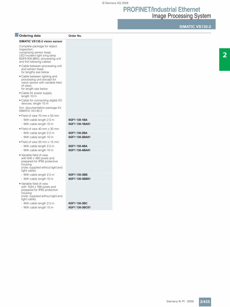
PROFINET/Industrial EthernetImage Processing System
SIMATIC VS130-2
2/435Siemens IK PI · 2009
2
■ Ordering data Order No.
SIMATIC VS130-2 vision sensorComplete package for object inspection;comprising sensor head, LED incident light (ring lamp 6GF9 004-8BA), processing unit and the following cables:• Cable between processing unit
and sensor head, for lengths see below
• Cable between lighting and processing unit (except for vision sensor with variable field of view),for length see below
• Cable for power supply, length 10 m
• Cable for connecting digital I/O devices, length 10 m
Incl. documentation package for SIMATIC VS130-2
• Field of view 70 mm x 50 mm- With cable length 2.5 m 6GF1 130-1BA- With cable length 10 m 6GF1 130-1BA01
• Field of view 40 mm x 30 mm- With cable length 2.5 m 6GF1 130-2BA- With cable length 10 m 6GF1 130-2BA01
• Field of view 20 mm x 15 mm- With cable length 2.5 m 6GF1 130-4BA- With cable length 10 m 6GF1 130-4BA01
• Variable field of view with 640 x 480 pixels and prepared for IP65 protective housing (note: supplied without light and light cable)- With cable length 2.5 m 6GF1 130-3BB- With cable length 10 m 6GF1 130-3BB01
• Variable field of view with 1024 x 768 pixels and prepared for IP65 protective housing (note: supplied without light and light cable)- With cable length 2.5 m 6GF1 130-3BC- With cable length 10 m 6GF1 130-3BC01
© Siemens AG 2008
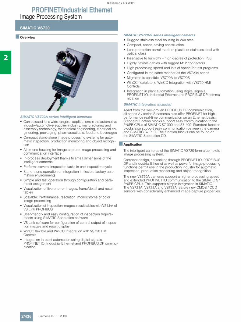
PROFINET/Industrial EthernetImage Processing System
SIMATIC VS720
2/436 Siemens IK PI · 2009
2
■ Overview
SIMATIC VS720A series intelligent cameras:• Can be used for a wide range of applications in the automotive
industry/automotive supplier industry, manufacturing and assembly technology, mechanical engineering, electrical en-gineering, packaging, pharmaceuticals, food and beverages
• Compact stand-alone image processing systems for auto-matic inspection, production monitoring and object recogni-tion
• All-in-one housing for image capture, image processing and communication interface
• In-process deployment thanks to small dimensions of the intelligent cameras
• Performs several inspection tasks in one inspection cycle • Stand-alone operation or integration in flexible factory auto-
mation environments • Simple and fast operation through configuration and para-
meter assignment • Visualization of live or error images, frame/detail and result
tables • Scalable: Performance, resolution, monochrome or color
image processing • Visualization of inspection images, result tables with VS Link of
VS Link PROFIBUS• User-friendly and easy configuration of inspection require-
ments using SIMATIC Spectation software • VS Link software for configuration of central output of inspec-
tion images and result display • WinCC flexible and WinCC Integration with VS720 HMI
Controls • Integration in plant automation using digital signals,
PROFINET IO, Industrial Ethernet and PROFIBUS DP commu-nication
SIMATIC VS720-S series intelligent cameras• Rugged stainless steel housing in V4A steel • Compact, space-saving construction • Lens protection barrel made of plastic or stainless steel with
optical glass • Insensitive to humidity – high degree of protection IP68 • Highly flexible cables with rugged M12 connectors• High processing speed and lots of space for test programs • Configured in the same manner as the VS720A series • Migration is possible: VS720A to VS720S • WinCC flexible and WinCC Integration with VS720 HMI
Controls • Integration in plant automation using digital signals,
PROFINET IO, Industrial Ethernet and PROFIBUS DP commu-nication
SIMATIC integration includedApart from the well-proven PROFIBUS DP communication, all series A / series S cameras also offer PROFINET for high-performance real-time communication on an Ethernet basis. Standard function blocks support easy communication to the PN/PB CPUs of SIMATIC S7-300 and S7-400. Standard function blocks also support easy communication between the camera and SIMATIC S7 PLC. The function blocks can be found on the SIMATIC Spectation CD.
■ Application
The intelligent cameras of the SIMATIC VS720 form a complete image processing system.
Compact design, networking through PROFINET IO, PROFIBUS DP and Industrial Ethernet as well as powerful image processing functions permit use in the production industry for automatic inspection, production monitoring and object recognition.
The new VS720A cameras support a higher processing speed and extended PROFINET IO communication to the SIMATIC S7 PN/PB CPUs. This supports simple integration in SIMATIC. The VS721A, VS722A and VS723A feature new CMOS / CCD sensors with considerably enhanced image capture properties.
© Siemens AG 2008
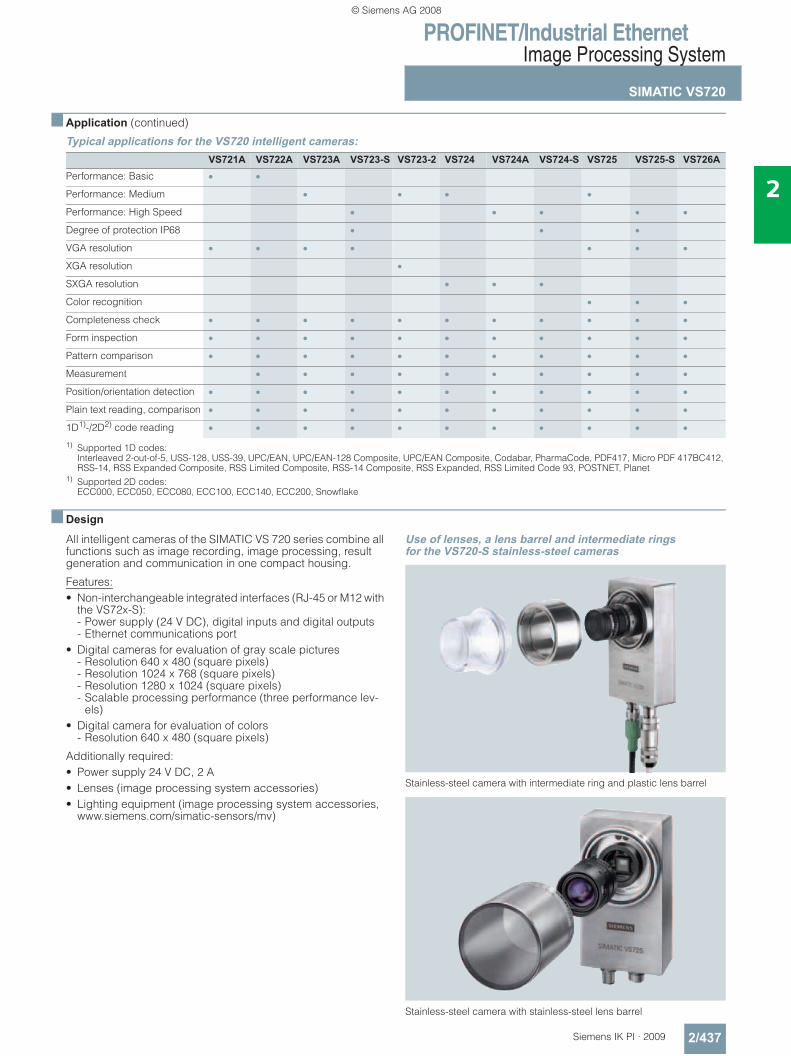
PROFINET/Industrial EthernetImage Processing System
SIMATIC VS720
2/437Siemens IK PI · 2009
2
■ Application (continued)
Typical applications for the VS720 intelligent cameras:
1) Supported 1D codes: Interleaved 2-out-of-5, USS-128, USS-39, UPC/EAN, UPC/EAN-128 Composite, UPC/EAN Composite, Codabar, PharmaCode, PDF417, Micro PDF 417BC412, RSS-14, RSS Expanded Composite, RSS Limited Composite, RSS-14 Composite, RSS Expanded, RSS Limited Code 93, POSTNET, Planet
1) Supported 2D codes: ECC000, ECC050, ECC080, ECC100, ECC140, ECC200, Snowflake
■ Design
All intelligent cameras of the SIMATIC VS 720 series combine all functions such as image recording, image processing, result generation and communication in one compact housing.
Features:• Non-interchangeable integrated interfaces (RJ-45 or M12 with
the VS72x-S): - Power supply (24 V DC), digital inputs and digital outputs- Ethernet communications port
• Digital cameras for evaluation of gray scale pictures - Resolution 640 x 480 (square pixels)- Resolution 1024 x 768 (square pixels)- Resolution 1280 x 1024 (square pixels)- Scalable processing performance (three performance lev-
els)• Digital camera for evaluation of colors
- Resolution 640 x 480 (square pixels)
Additionally required:• Power supply 24 V DC, 2 A• Lenses (image processing system accessories)• Lighting equipment (image processing system accessories,
www.siemens.com/simatic-sensors/mv)
Use of lenses, a lens barrel and intermediate rings for the VS720-S stainless-steel cameras
Stainless-steel camera with intermediate ring and plastic lens barrel
Stainless-steel camera with stainless-steel lens barrel
VS721A VS722A VS723A VS723-S VS723-2 VS724 VS724A VS724-S VS725 VS725-S VS726APerformance: Basic • •Performance: Medium • • • •Performance: High Speed • • • • •Degree of protection IP68 • • •VGA resolution • • • • • • •XGA resolution •SXGA resolution • • •Color recognition • • •Completeness check • • • • • • • • • • •Form inspection • • • • • • • • • • •Pattern comparison • • • • • • • • • • •Measurement • • • • • • • • • •Position/orientation detection • • • • • • • • • • •Plain text reading, comparison • • • • • • • • • • •1D1)-/2D2) code reading • • • • • • • • • • •
© Siemens AG 2008
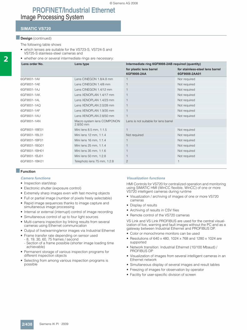
PROFINET/Industrial EthernetImage Processing System
SIMATIC VS720
2/438 Siemens IK PI · 2009
2
■ Design (continued)
The following table shows • which lenses are suitable for the VS723-S, VS724-S and
VS725-S stainless-steel cameras and • whether one or several intermediate rings are necessary:
■ Function
Camera functions • Inspection start/stop • Electronic shutter (exposure control)• Extremely sharp images even with fast moving objects• Full or partial image (number of pixels freely selectable)• Rapid image sequences thanks to image capture and
simultaneous image processing• Internal or external (interrupt) control of image recording• Simultaneous control of up to four light sources• Multi-camera inspection by linking results from several
cameras using Ethernet communication• Output of live/warning/error images via Industrial Ethernet• Frame transfer rate depending on sensor used
- 8, 19, 30, 60, 75 frames / second- Section of a frame possible (shorter image loading time
achievable)• Permanent storage of various inspection programs for
different inspection objects• Selecting from among various inspection programs is
possible
Visualization functions HMI Controls for VS720 for centralized operation and monitoring using SIMATIC HMI (WinCC flexible, WinCC) of one or more VS720 intelligent cameras during runtime • Visualization / archiving of images of one or more VS720
cameras• Display of results• Archiving of results in CSV files• Remote control of the VS720 cameras
VS Link and VS Link PROFIBUS are used for the central visual-ization of live, warning and fault images without the PC and as a gateway between Industrial Ethernet and PROFIBUS DP.• Color or monochrome monitors can be used• Resolutions of 640 x 480, 1024 x 768 and 1280 x 1024 are
supported• Network transition: Industrial Ethernet (10/100 Mbaud) /
PROFIBUS DP• Visualization of images from several intelligent cameras in an
Ethernet network • Simultaneous display of several images and result tables • Freezing of images for observation by operator • Facility for user-specific division of screen
Lens order No. Lens type Intermediate ring 6GF9008-2AB required (quantity)for plastic lens barrel6GF9008-2AA
for stainless-steel lens barrel6GF9008-2AA01
6GF9001-1AV Lens CINEGON 1.8/4.8 mm 1 Nor required
6GF9001-1AE Lens CINEGON 1.4/8 mm 1 Not required
6GF9001-1AJ Lens CINEGON 1.4/12 mm 1 Not required
6GF9001-1AK Lens XENOPLAN 1.4/17 mm 1 Not required
6GF9001-1AL Lens XENOPLAN 1.4/23 mm 1 Not required
6GF9001-1AQ Lens XENOPLAN 2.0/28 mm 1 Not required
6GF9001-1AF Lens XENOPLAN 1.9/35 mm 1 Not required
6GF9001-1AU Lens XENOPLAN 2.8/50 mm 1 Not required
6GF9001-1AN Macro system lens COMPONON 2.8/50 mm
Lens is not suitable for lens barrel
6GF9001-1BE01 Mini lens 8.5 mm, 1:1.5 1 Not required
6GF9001-1BL01 Mini lens 12 mm, 1:1.4 Not required Not required
6GF9001-1BF01 Mini lens 16 mm, 1:1.4 1 Not required
6GF9001-1BG01 Mini lens 25 mm, 1:1.4 1 Not required
6GF9001-1BH01 Mini lens 35 mm, 1:1.6 1 Not required
6GF9001-1BJ01 Mini lens 50 mm, 1:2.8 1 Not required
6GF9001-1BK01 Telephoto lens 75 mm, 1:2.8 2 1
© Siemens AG 2008
PROFINET/Industrial EthernetImage Processing System
SIMATIC VS720
2/439Siemens IK PI · 2009
2
■ Function (continued)
Mode of operation of the intelligent camera• Direct evaluation:
The recorded images are processed by the fast CPU using the selected inspection program.
• High cycle rates:Image exposure is performed while the previously exposed image is being processed in parallel.
• Communication through integral interfaces (configuration, transfer of images, productive data for passing on of result, trigger for image recording)
• Boot capability:When the external voltage is applied, image processing can be activated immediately because the inspection program is memory resident.
• Script programming:For controlling the sequence of the inspection task, per-forming several inspections on the same image, carrying out mathematical calculations with values from image evaluation, communicating with external devices
• Digital I/O signals:Available for controlling the recording of the image as well as for forming the result for controlling the process
Programming: Spectation configuration tool• For online/offline creation of inspection programs for VS720
intelligent cameras;the programs can then be tested and transferred to the intelligent camera - Offline - Test programs can be configured and tested using
the emulator.- Online - Configuring over Ethernet- Several intelligent cameras can be configured from one
programming device/PC• Project management for
- Independent inspection programs of the intelligent camera- Specific system programs of the intelligent camera
• Remote diagnosis is possible over the Internet• Executes on programming device/PC with Windows XP
Surface• Windows-compatible menu prompting• Expanded toolbar for selection of frequently used functions• SoftSensor toolbar for selection of SoftSensors for solving the
test• The result window contains the result table with SoftSensors
and assigned values, as well as the sensor characteristics in the form of graphs or histograms.
• Positioning of SoftSensors by selecting and mouse click• Graphic display of test images and SoftSensors• SoftSensor display can be complete or selective• Status line with x and y coordinates, exposure value and
capacity utilization of the intelligent camera
Inspection and recognition functions• Presence check • Position detection• Pattern comparison• Position and orientation detection• Measurement of radii, clearances and angles• 1D/2D code reading• Plain text reading and comparison (OCR/OCV)• Inspection of color quality• Checking for color falsification;
color differentiation (65000 to 16.7 million colors)• Inspection of color luminosity • Inspection of pattern recognition (color, size, coordinates)
User-triggered new learning and resetting of SoftSensor parameters:• Search for pattern• Search for object• OCR • Code• Color
Communication functions • From one intelligent camera to another • Intelligent camera to automation system
(SIMATIC S7-300/S7-400): - PROFINET IO- Industrial Ethernet - PROFIBUS DP (VS Link PROFIBUS required)
• Intelligent camera to external devices – e.g. robots • Intelligent camera to VS Link or VS Link PROFIBUS • Intelligent camera to PG/PC (engineering) • Intelligent camera to PG/PC (productive data)
VS Link software • For configuration of VS Link and VS Link PROFIBUS function-
alities• Executes on programming device/PC with Windows XP
Configuration facilities• Communication from intelligent camera to VS Link or VS Link
PROFIBUS• Configuration of HMI• Configuration and positioning of image windows and result
tables
© Siemens AG 2008
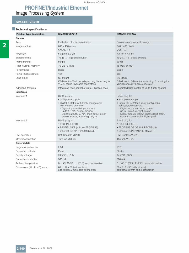
PROFINET/Industrial EthernetImage Processing System
SIMATIC VS720
2/440 Siemens IK PI · 2009
2
■ Technical specifications
Product type description SIMATIC VS721A SIMATIC VS722ACameraType Evaluation of gray scale image Evaluation of gray scale image
Image capture 640 x 480 pixelsCMOS, 1/3“
640 x 480 pixelsCCD, 1/3“
Pixel size 6.0 μm x 6.0 μm 7.4 μm x 7.4 μm
Exposure time 10 μs ... 1 s (global shutter) 10 μs ... 1 s (global shutter)
Frame transfer 60 fps 60 fps
Flash / DRAM memory 16 MB / 64 MB 16 MB / 64 MB
Performance Basic Basic
Partial image capture Yes Yes
Lens mount CS-Mount CS-Mount to C-Mount adapter ring, 5 mm ring for VS720 series (available separately)
CS-MountCS-Mount to C-Mount adapter ring, 5 mm ring for VS720 series (available separately)
Additional features Integrated flash control of up to 4 light sources Integrated flash control of up to 4 light sources
InterfacesInterface 1 RJ-45 plug for
• 24 V power supply • Digital I/O 24 V for 8 freely configurable
non-isolated channels:- Digital inputs with input current
up to 1.5 mA, current-sinking- Digital outputs, 50 mA, short-circuit-proof,
current source, active high signal
RJ-45 plug for• 24 V power supply • Digital I/O 24 V for 8 freely configurable
non-isolated channels:- Digital inputs with input current
up to 1.5 mA, current-sinking- Digital outputs, 50 mA, short-circuit-proof,
current source, active high signal
Interface 2 RJ-45 plug for• PROFINET IO RT• PROFIBUS DP (VS Link PROFIBUS)• Ethernet TCP/IP (10/100 Mbaud)
RJ-45 plug for• PROFINET IO RT• PROFIBUS DP (VS Link PROFIBUS)• Ethernet TCP/IP (10/100 Mbaud)
HMI operation HMI Controls VS720 HMI Controls VS720
Monitor connection Through VS Link Through VS Link
General dataDegree of protection IP51 IP51
Enclosure material Plastic Plastic
Supply voltage 24 VDC ±10 % 24 VDC ±10 %
Current consumption 300 mA 300 mA
Ambient temperature 0 ... 45° C (32 ... 113° F), no condensation 0 ... 45 °C (32 to 113 °F), no condensation
Dimensions (W x H x D) in mm 60 x 112 x 30 (without lens); additional 50 mm cable connection
60 x 112 x 30 (without lens); additional 50 mm cable connection
© Siemens AG 2008
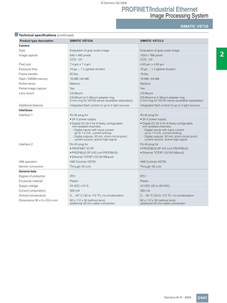
PROFINET/Industrial EthernetImage Processing System
SIMATIC VS720
2/441Siemens IK PI · 2009
2
■ Technical specifications (continued)
Product type description SIMATIC VS723A SIMATIC VS723-2CameraType Evaluation of gray scale image Evaluation of gray scale image
Image capture 640 x 480 pixelsCCD, 1/3“
1024 x 768 pixelsCCD, 1/3“
Pixel size 7.4 μm x 7.4 μm 4.65 μm x 4.65 μm
Exposure time 10 μs ... 1 s (global shutter) 10 μs ... 1 s (global shutter)
Frame transfer 60 fps 19 fps
Flash / DRAM memory 16 MB / 64 MB 16 MB / 64 MB
Performance Medium Medium
Partial image capture Yes Yes
Lens mount CS-Mount CS-Mount to C-Mount adapter ring, 5 mm ring for VS720 series (available separately)
CS-MountCS-Mount to C-Mount adapter ring, 5 mm ring for VS720 series (available separately)
Additional features Integrated flash control of up to 4 light sources Integrated flash control of up to 4 light sources
InterfacesInterface 1 RJ-45 plug for
• 24 V power supply • Digital I/O 24 V for 8 freely configurable
non-isolated channels:- Digital inputs with input current
up to 1.5 mA, current-sinking- Digital outputs, 50 mA, short-circuit-proof,
current source, active high signal
RJ-45 plug for• 24 V power supply • Digital I/O 24 V for 8 freely configurable
non-isolated channels:- Digital inputs with input current
up to 1.5 mA, current-sinking- Digital outputs, 50 mA, short-circuit-proof,
current source, active high signal
Interface 2 RJ-45 plug for• PROFINET IO RT• PROFIBUS DP (VS Link PROFIBUS)• Ethernet TCP/IP (10/100 Mbaud)
RJ-45 plug for• PROFIBUS DP (VS Link PROFIBUS)• Ethernet TCP/IP (10/100 Mbaud)
HMI operation HMI Controls VS720 HMI Controls VS720
Monitor connection Through VS Link Through VS Link
General dataDegree of protection IP51 IP51
Enclosure material Plastic Plastic
Supply voltage 24 VDC ±10 % 24 VDC (20 to 28 VDC)
Current consumption 300 mA 300 mA
Ambient temperature 0 ... 45° C (32 to 113 °F), no condensation 0 ... 45 °C (32 to 113 °F), no condensation
Dimensions (W x H x D) in mm 60 x 112 x 30 (without lens); additional 50 mm cable connection
60 x 112 x 30 (without lens); additional 50 mm cable connection
© Siemens AG 2008
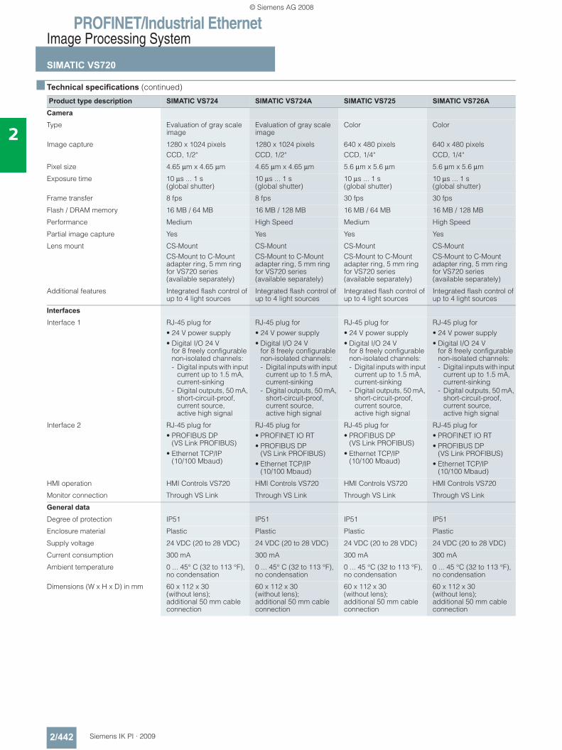
PROFINET/Industrial EthernetImage Processing System
SIMATIC VS720
2/442 Siemens IK PI · 2009
2
■ Technical specifications (continued)
Product type description SIMATIC VS724 SIMATIC VS724A SIMATIC VS725 SIMATIC VS726ACameraType Evaluation of gray scale
imageEvaluation of gray scale image
Color Color
Image capture 1280 x 1024 pixelsCCD, 1/2“
1280 x 1024 pixelsCCD, 1/2“
640 x 480 pixelsCCD, 1/4“
640 x 480 pixelsCCD, 1/4“
Pixel size 4.65 μm x 4.65 μm 4.65 μm x 4.65 μm 5.6 μm x 5.6 μm 5.6 μm x 5.6 μm
Exposure time 10 μs ... 1 s (global shutter)
10 μs ... 1 s (global shutter)
10 μs ... 1 s (global shutter)
10 μs ... 1 s(global shutter)
Frame transfer 8 fps 8 fps 30 fps 30 fps
Flash / DRAM memory 16 MB / 64 MB 16 MB / 128 MB 16 MB / 64 MB 16 MB / 128 MB
Performance Medium High Speed Medium High Speed
Partial image capture Yes Yes Yes Yes
Lens mount CS-Mount CS-Mount to C-Mount adapter ring, 5 mm ring for VS720 series (available separately)
CS-Mount CS-Mount to C-Mount adapter ring, 5 mm ring for VS720 series (available separately)
CS-MountCS-Mount to C-Mount adapter ring, 5 mm ring for VS720 series (available separately)
CS-MountCS-Mount to C-Mount adapter ring, 5 mm ring for VS720 series (available separately)
Additional features Integrated flash control of up to 4 light sources
Integrated flash control of up to 4 light sources
Integrated flash control of up to 4 light sources
Integrated flash control of up to 4 light sources
InterfacesInterface 1 RJ-45 plug for
• 24 V power supply • Digital I/O 24 V
for 8 freely configurable non-isolated channels:- Digital inputs with input
current up to 1.5 mA, current-sinking
- Digital outputs, 50 mA, short-circuit-proof, current source, active high signal
RJ-45 plug for• 24 V power supply • Digital I/O 24 V
for 8 freely configurable non-isolated channels:- Digital inputs with input
current up to 1.5 mA, current-sinking
- Digital outputs, 50 mA, short-circuit-proof, current source, active high signal
RJ-45 plug for• 24 V power supply • Digital I/O 24 V
for 8 freely configurable non-isolated channels:- Digital inputs with input
current up to 1.5 mA, current-sinking
- Digital outputs, 50 mA, short-circuit-proof, current source, active high signal
RJ-45 plug for• 24 V power supply • Digital I/O 24 V
for 8 freely configurable non-isolated channels:- Digital inputs with input
current up to 1.5 mA, current-sinking
- Digital outputs, 50 mA, short-circuit-proof, current source, active high signal
Interface 2 RJ-45 plug for• PROFIBUS DP
(VS Link PROFIBUS)• Ethernet TCP/IP
(10/100 Mbaud)
RJ-45 plug for• PROFINET IO RT• PROFIBUS DP
(VS Link PROFIBUS)• Ethernet TCP/IP
(10/100 Mbaud)
RJ-45 plug for• PROFIBUS DP
(VS Link PROFIBUS)• Ethernet TCP/IP
(10/100 Mbaud)
RJ-45 plug for• PROFINET IO RT• PROFIBUS DP
(VS Link PROFIBUS)• Ethernet TCP/IP
(10/100 Mbaud)
HMI operation HMI Controls VS720 HMI Controls VS720 HMI Controls VS720 HMI Controls VS720
Monitor connection Through VS Link Through VS Link Through VS Link Through VS Link
General dataDegree of protection IP51 IP51 IP51 IP51
Enclosure material Plastic Plastic Plastic Plastic
Supply voltage 24 VDC (20 to 28 VDC) 24 VDC (20 to 28 VDC) 24 VDC (20 to 28 VDC) 24 VDC (20 to 28 VDC)
Current consumption 300 mA 300 mA 300 mA 300 mA
Ambient temperature 0 ... 45° C (32 to 113 °F), no condensation
0 ... 45° C (32 to 113 °F), no condensation
0 ... 45 °C (32 to 113 °F), no condensation
0 ... 45 °C (32 to 113 °F), no condensation
Dimensions (W x H x D) in mm 60 x 112 x 30 (without lens); additional 50 mm cable connection
60 x 112 x 30 (without lens); additional 50 mm cable connection
60 x 112 x 30 (without lens); additional 50 mm cable connection
60 x 112 x 30 (without lens); additional 50 mm cable connection
© Siemens AG 2008
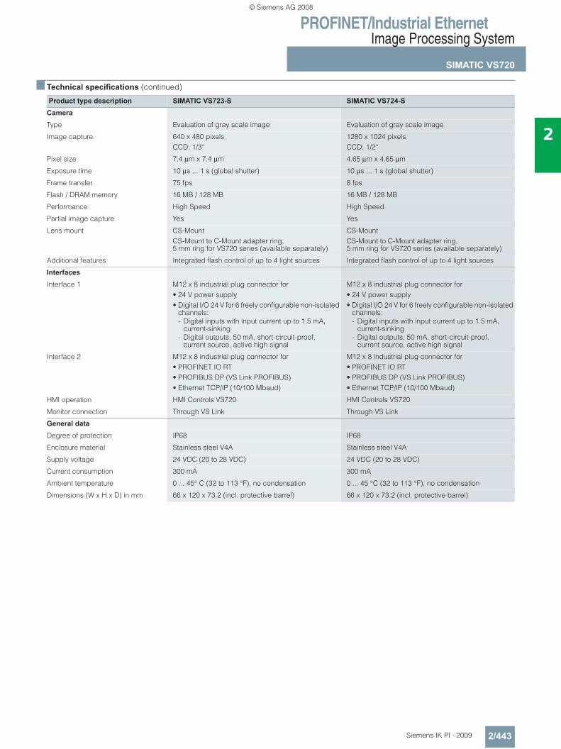
PROFINET/Industrial EthernetImage Processing System
SIMATIC VS720
2/443Siemens IK PI · 2009
2
■ Technical specifications (continued)
Product type description SIMATIC VS723-S SIMATIC VS724-SCameraType Evaluation of gray scale image Evaluation of gray scale image
Image capture 640 x 480 pixelsCCD; 1/3“
1280 x 1024 pixelsCCD; 1/2“
Pixel size 7.4 μm x 7.4 μm 4.65 μm x 4.65 μm
Exposure time 10 μs ... 1 s (global shutter) 10 μs ... 1 s (global shutter)
Frame transfer 75 fps 8 fps
Flash / DRAM memory 16 MB / 128 MB 16 MB / 128 MB
Performance High Speed High Speed
Partial image capture Yes Yes
Lens mount CS-Mount CS-Mount to C-Mount adapter ring, 5 mm ring for VS720 series (available separately)
CS-MountCS-Mount to C-Mount adapter ring, 5 mm ring for VS720 series (available separately)
Additional features Integrated flash control of up to 4 light sources Integrated flash control of up to 4 light sources
InterfacesInterface 1 M12 x 8 industrial plug connector for
• 24 V power supply • Digital I/O 24 V for 6 freely configurable non-isolated
channels:- Digital inputs with input current up to 1.5 mA,
current-sinking- Digital outputs, 50 mA, short-circuit-proof,
current source, active high signal
M12 x 8 industrial plug connector for• 24 V power supply • Digital I/O 24 V for 6 freely configurable non-isolated
channels:- Digital inputs with input current up to 1.5 mA,
current-sinking- Digital outputs, 50 mA, short-circuit-proof,
current source, active high signal
Interface 2 M12 x 8 industrial plug connector for• PROFINET IO RT• PROFIBUS DP (VS Link PROFIBUS)• Ethernet TCP/IP (10/100 Mbaud)
M12 x 8 industrial plug connector for• PROFINET IO RT• PROFIBUS DP (VS Link PROFIBUS)• Ethernet TCP/IP (10/100 Mbaud)
HMI operation HMI Controls VS720 HMI Controls VS720
Monitor connection Through VS Link Through VS Link
General dataDegree of protection IP68 IP68
Enclosure material Stainless steel V4A Stainless steel V4A
Supply voltage 24 VDC (20 to 28 VDC) 24 VDC (20 to 28 VDC)
Current consumption 300 mA 300 mA
Ambient temperature 0 ... 45° C (32 to 113 °F), no condensation 0 ... 45 °C (32 to 113 °F), no condensation
Dimensions (W x H x D) in mm 66 x 120 x 73.2 (incl. protective barrel) 66 x 120 x 73.2 (incl. protective barrel)
© Siemens AG 2008
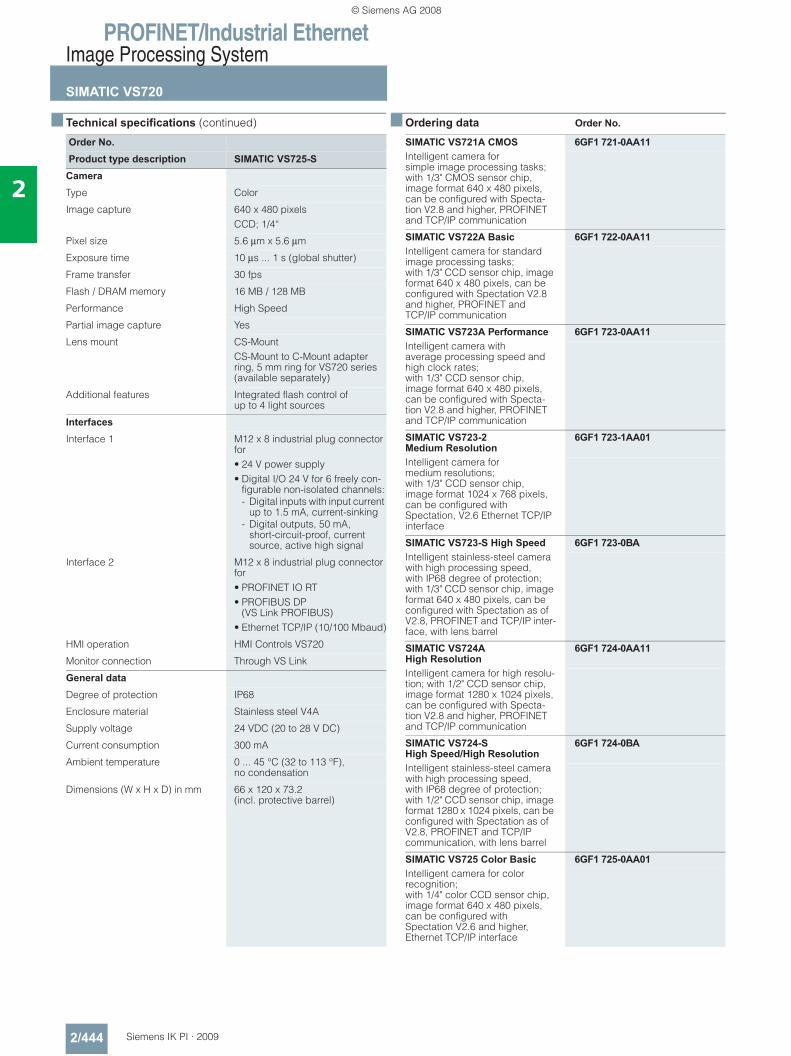
PROFINET/Industrial EthernetImage Processing System
SIMATIC VS720
2/444 Siemens IK PI · 2009
2
■ Technical specifications (continued)
■ Ordering data Order No.
Order No.Product type description SIMATIC VS725-S
CameraType Color
Image capture 640 x 480 pixelsCCD; 1/4“
Pixel size 5.6 μm x 5.6 μm
Exposure time 10 μs ... 1 s (global shutter)
Frame transfer 30 fps
Flash / DRAM memory 16 MB / 128 MB
Performance High Speed
Partial image capture Yes
Lens mount CS-MountCS-Mount to C-Mount adapter ring, 5 mm ring for VS720 series (available separately)
Additional features Integrated flash control of up to 4 light sources
InterfacesInterface 1 M12 x 8 industrial plug connector
for• 24 V power supply • Digital I/O 24 V for 6 freely con-
figurable non-isolated channels:- Digital inputs with input current
up to 1.5 mA, current-sinking- Digital outputs, 50 mA,
short-circuit-proof, current source, active high signal
Interface 2 M12 x 8 industrial plug connector for• PROFINET IO RT• PROFIBUS DP
(VS Link PROFIBUS)• Ethernet TCP/IP (10/100 Mbaud)
HMI operation HMI Controls VS720
Monitor connection Through VS Link
General dataDegree of protection IP68
Enclosure material Stainless steel V4A
Supply voltage 24 VDC (20 to 28 V DC)
Current consumption 300 mA
Ambient temperature 0 ... 45 °C (32 to 113 °F), no condensation
Dimensions (W x H x D) in mm 66 x 120 x 73.2(incl. protective barrel)
SIMATIC VS721A CMOS 6GF1 721-0AA11Intelligent camera for simple image processing tasks; with 1/3" CMOS sensor chip, image format 640 x 480 pixels, can be configured with Specta-tion V2.8 and higher, PROFINET and TCP/IP communication
SIMATIC VS722A Basic 6GF1 722-0AA11Intelligent camera for standard image processing tasks; with 1/3" CCD sensor chip, image format 640 x 480 pixels, can be configured with Spectation V2.8 and higher, PROFINET and TCP/IP communication
SIMATIC VS723A Performance 6GF1 723-0AA11Intelligent camera with average processing speed and high clock rates; with 1/3" CCD sensor chip,image format 640 x 480 pixels, can be configured with Specta-tion V2.8 and higher, PROFINET and TCP/IP communication
SIMATIC VS723-2 Medium Resolution
6GF1 723-1AA01
Intelligent camera for medium resolutions; with 1/3" CCD sensor chip, image format 1024 x 768 pixels, can be configured with Spectation, V2.6 Ethernet TCP/IP interface
SIMATIC VS723-S High Speed 6GF1 723-0BAIntelligent stainless-steel camera with high processing speed, with IP68 degree of protection; with 1/3" CCD sensor chip, image format 640 x 480 pixels, can be configured with Spectation as of V2.8, PROFINET and TCP/IP inter-face, with lens barrel
SIMATIC VS724A High Resolution
6GF1 724-0AA11
Intelligent camera for high resolu-tion; with 1/2" CCD sensor chip, image format 1280 x 1024 pixels, can be configured with Specta-tion V2.8 and higher, PROFINET and TCP/IP communication
SIMATIC VS724-S High Speed/High Resolution
6GF1 724-0BA
Intelligent stainless-steel camera with high processing speed, with IP68 degree of protection; with 1/2" CCD sensor chip, image format 1280 x 1024 pixels, can be configured with Spectation as of V2.8, PROFINET and TCP/IP communication, with lens barrel
SIMATIC VS725 Color Basic 6GF1 725-0AA01Intelligent camera for color recognition; with 1/4" color CCD sensor chip, image format 640 x 480 pixels, can be configured with Spectation V2.6 and higher, Ethernet TCP/IP interface
© Siemens AG 2008
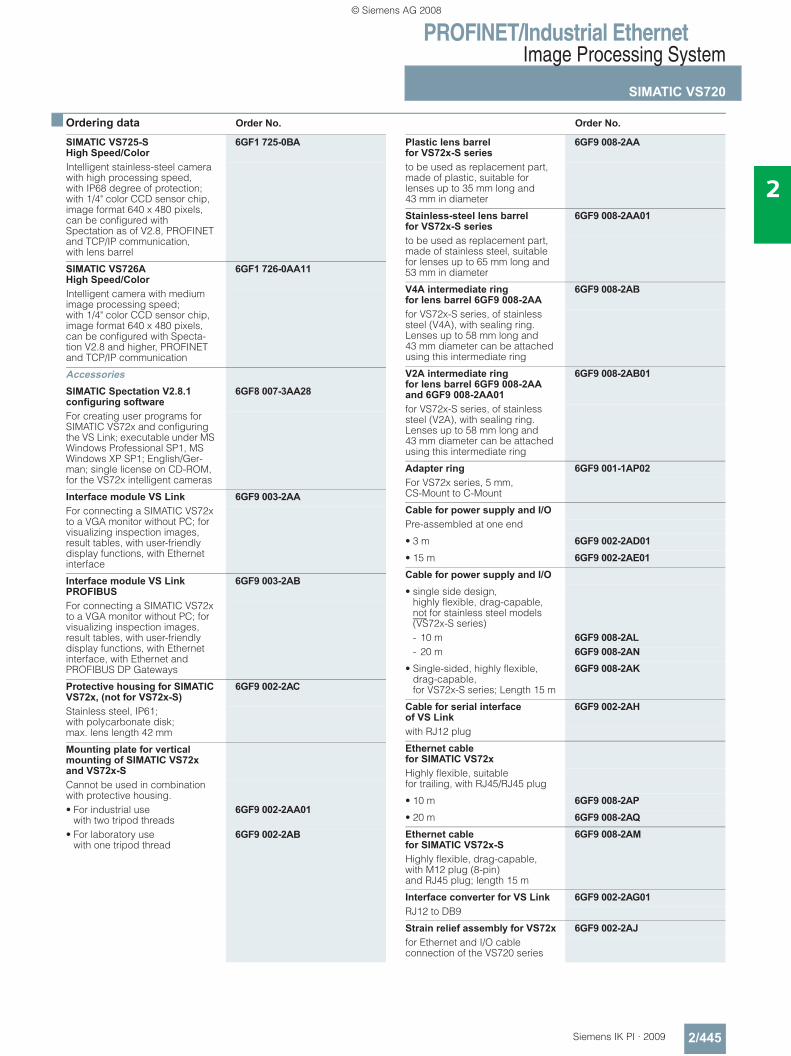
PROFINET/Industrial EthernetImage Processing System
SIMATIC VS720
2/445Siemens IK PI · 2009
2
■ Ordering data Order No. Order No.
SIMATIC VS725-S High Speed/Color
6GF1 725-0BA
Intelligent stainless-steel camera with high processing speed, with IP68 degree of protection; with 1/4" color CCD sensor chip, image format 640 x 480 pixels, can be configured with Spectation as of V2.8, PROFINET and TCP/IP communication, with lens barrel
SIMATIC VS726A High Speed/Color
6GF1 726-0AA11
Intelligent camera with medium image processing speed; with 1/4" color CCD sensor chip, image format 640 x 480 pixels, can be configured with Specta-tion V2.8 and higher, PROFINET and TCP/IP communication
AccessoriesSIMATIC Spectation V2.8.1 configuring software
6GF8 007-3AA28
For creating user programs for SIMATIC VS72x and configuring the VS Link; executable under MS Windows Professional SP1, MS Windows XP SP1; English/Ger-man; single license on CD-ROM, for the VS72x intelligent cameras
Interface module VS Link 6GF9 003-2AAFor connecting a SIMATIC VS72x to a VGA monitor without PC; for visualizing inspection images, result tables, with user-friendly display functions, with Ethernet interface
Interface module VS Link PROFIBUS
6GF9 003-2AB
For connecting a SIMATIC VS72x to a VGA monitor without PC; for visualizing inspection images, result tables, with user-friendly display functions, with Ethernet interface, with Ethernet and PROFIBUS DP Gateways
Protective housing for SIMATIC VS72x, (not for VS72x-S)
6GF9 002-2AC
Stainless steel, IP61; with polycarbonate disk; max. lens length 42 mm
Mounting plate for vertical mounting of SIMATIC VS72x and VS72x-SCannot be used in combination with protective housing. • For industrial use
with two tripod threads6GF9 002-2AA01
• For laboratory use with one tripod thread
6GF9 002-2AB
Plastic lens barrel for VS72x-S series
6GF9 008-2AA
to be used as replacement part, made of plastic, suitable for lenses up to 35 mm long and 43 mm in diameter
Stainless-steel lens barrelfor VS72x-S series
6GF9 008-2AA01
to be used as replacement part, made of stainless steel, suitable for lenses up to 65 mm long and 53 mm in diameter
V4A intermediate ring for lens barrel 6GF9 008-2AA
6GF9 008-2AB
for VS72x-S series, of stainless steel (V4A), with sealing ring. Lenses up to 58 mm long and 43 mm diameter can be attached using this intermediate ring
V2A intermediate ringfor lens barrel 6GF9 008-2AA and 6GF9 008-2AA01
6GF9 008-2AB01
for VS72x-S series, of stainless steel (V2A), with sealing ring. Lenses up to 58 mm long and 43 mm diameter can be attached using this intermediate ring
Adapter ring 6GF9 001-1AP02For VS72x series, 5 mm, CS-Mount to C-Mount
Cable for power supply and I/OPre-assembled at one end
• 3 m 6GF9 002-2AD01• 15 m 6GF9 002-2AE01Cable for power supply and I/O• single side design,
highly flexible, drag-capable, not for stainless steel models (VS72x-S series)- 10 m 6GF9 008-2AL- 20 m 6GF9 008-2AN
• Single-sided, highly flexible, drag-capable, for VS72x-S series; Length 15 m
6GF9 008-2AK
Cable for serial interfaceof VS Link
6GF9 002-2AH
with RJ12 plug
Ethernet cablefor SIMATIC VS72xHighly flexible, suitable for trailing, with RJ45/RJ45 plug
• 10 m 6GF9 008-2AP• 20 m 6GF9 008-2AQEthernet cablefor SIMATIC VS72x-S
6GF9 008-2AM
Highly flexible, drag-capable, with M12 plug (8-pin) and RJ45 plug; length 15 m
Interface converter for VS Link 6GF9 002-2AG01RJ12 to DB9
Strain relief assembly for VS72x 6GF9 002-2AJfor Ethernet and I/O cable connection of the VS720 series
© Siemens AG 2008
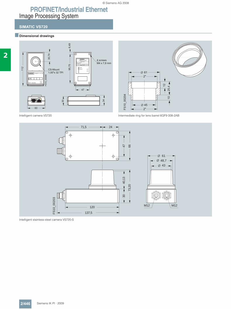
PROFINET/Industrial EthernetImage Processing System
SIMATIC VS720
2/446 Siemens IK PI · 2009
2
■ Dimensional drawings
Intelligent camera VS720
Intermediate ring for lens barrel 6GF9 008-2AB
Intelligent stainless-steel camera VS720-S
47
30,7
4
112
FS10
_000
88
s
95,7
56,
49
60
30 34
SIMATIC VS 722
IP
6GF1 722-0AAX 23 4
CS-Mount1,00"x 32 TPI
s
SIMATIC VS 722Barcode 39
6GF1 722-0AAE-Stand: 03Siemens AD / Automation & Drives
Made in USA
RUMFAULT
RJ45
4 screwsM4 x 7,8 mm
Ø 61
12
2"
1025
,4
Ø 452"FS
10_0
0204
120
137,5
Ø 43
30
FS10
_002
03
Ø 48,7Ø 61
M12 M12
40,1
3
73,2
0
47 6671,5 24
© Siemens AG 2008
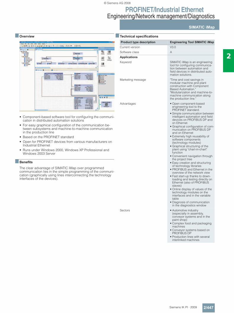
PROFINET/Industrial EthernetEngineering/Network management/Diagnostics
SIMATIC iMap
2/447Siemens IK PI · 2009
2
■ Overview
• Component-based software tool for configuring the communi-cation in distributed automation solutions
• For easy graphical configuration of the communication be-tween subsystems and machine-to-machine communication in the production line
• Based on the PROFINET standard • Open for PROFINET devices from various manufacturers on
Industrial Ethernet• Runs under Windows 2000, Windows XP Professional and
Windows 2003 Server
■ Benefits
The clear advantage of SIMATIC iMap over programmed communication lies in the simple programming of the communi-cation (graphically using lines interconnecting the technology interfaces of the devices).
■ Technical specifications
Product type description Engineering Tool SIMATIC iMapCurrent version V3.0
Software class A
ApplicationsKeyword SIMATIC iMap is an engineering
tool for configuring communica-tion between automation and field devices in distributed auto-mation solutions.
Marketing message "Time and cost savings in modular machine and plant construction with Component Based Automation.""Modularization and machine-to-machine communication along the production line."
Advantages • Open component-based engineering tool to the PROFINET standard.
• Simple communication between intelligent automation and field devices on PROFIBUS DP and on Ethernet.
• Graphical configuration of com-munication on PROFIBUS DP and on Ethernet
• Extremely high reusability of software components (technology modules)
• Graphical structuring of the plant using "chart-in-chart" function
• Convenient navigation through the project tree
• Easy creation and structuring of technology libraries
• PROFIBUS and Ethernet in the overview of the network view
• Fast start-up thanks to down-loading and testing directly on Ethernet (also of PROFIBUS slaves)
• Online display of values of the technology modules on the interfaces and in the variable table
• Diagnosis of communicationin the diagnostics window
Sectors • Automotive industry(especially in assembly, conveyor systems and in the paint shop)
• Complex food and packaging machines
• Conveyor systems based on PROFIBUS DP
• Production lines with several interlinked machines
© Siemens AG 2008
PROFINET/Industrial EthernetEngineering/Network management/Diagnostics
SIMATIC iMap
2/448 Siemens IK PI · 2009
2
■ Technical specifications
■ Ordering data Order No.
Product type description Engineering Tool SIMATIC iMapTarget systems • SIMATIC S7 CPU 31x-2 PN/DP
and SIMATIC S7 CPU 319-3 PN/DP (with integrated PROFINET interface. This can be used as a proxy function for the devices of a complete PROFIBUS segment, one line only)
• SIMATIC WinAC PN(can be used as a proxy function for the devices of a complete PROFIBUS segment, one line only)
• SIMATIC NET IE/PB Link(can be used as a proxy function for the devices of a complete PROFIBUS segment)
• SIMATIC NET CP 343-1 and CP 343-1 Advanced (for connecting SIMATIC S7-300 to Ethernet), CP443-1 Advanced(for connecting SIMATIC S7-400 to Ethernet)
• Distributed I/O stations with separate CPU (all intelligentfield devices on PROFIBUS such asSIMATIC CPU 313C-2DP, CPU 314C-2DP, CPU 315-2DP, CPU 316-2DP, ET 200 IM 151 CPU, ET 200S BM 147 CPU),
• PROFINET CBA OPC Server(for access from PC applications to data in PROFINET devices)
• Devices on Industrial Ethernet based on the PROFINET CBA standard
• SIMATIC OPs (within the components)
• SIMATIC ProTool/Pro, WinCC or any other visualization system with OPC client function
Product type description Engineering Tool SIMATIC iMapSystem requirementsOperating system Windows 2000 Prof.
Service Pack 4 and higher orWindows XP Prof. Service Pack 1 and higher or Windows 2003 Server Service Pack 1 and higher; PC administration rights are required for installation
PG/PC hardware Pentium processor, 1 GHz or higher
Recommended expansion of main memory in PG/PC
RAM: 512 MB or more
Hard disk space required in PG/PC Approx. 200 MB
Software required • STEP 7 V5.3 Service Pack 3 or higher
• PN OPC server V6.3 or higherThe following software must be installed before iMap (included in the iMap package):• MS Internet Explorer V6.0 Ser-
vice Pack 1 and higher• Adobe Acrobat Reader V5.0
Delivery formatLanguages English, German, French, Italian
and Spanish
Single License (SL) Yes
Upgrade License (UL) Yes, from V2.0 to V3.0
Paper manuals Electronically on CD
Authorization/licensesAuthorization Yes
Single License (SL) Yes
Upgrade License (UL) Yes
Software Update Service Yes
Unlock Copy License No
SIMATIC iMap V3.0Target system: CPU 31x-2 PN/DP, CPU 319-3 PN/DP, SIMATIC WinAC PN, SIMATIC NET IE/PB Link, SIMATIC NET CP 343-1,SIMATIC NET CP 343-1 Advanced, SIMATIC NETCP 443-1 Advanced, distributed I/O devices with own CPU, PROFI-NET CBA OPC server, devices on the Industrial Ethernet based on the PROFINET CBA standard, SIMATIC OPs, SIMATIC ProTool/Pro Requirements:Windows 2000 Prof. with Service Pack 4 or later or Windows XP Prof. with Service Pack 1 or later or Windows 2003 Server with Ser-vice Pack 1 or later; on PG or PC with Pentium processor, min. 1 GHz; STEP 7 V5.3 or later with Service Pack 3, PN OPC Server V6.3 or laterDelivery form: German, English, with electronic documentation• Single license 6ES7 820-0CC04-0YA5• Software Update Service (re-
quires current software version)6ES7 820-0CC01-0YX2
• Upgrade to V3.0, single license 6ES7 820-0CC04-0YE5
© Siemens AG 2008
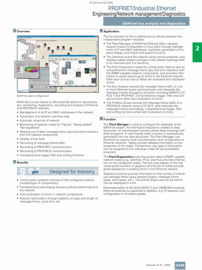
PROFINET/Industrial EthernetEngineering/Network management/Diagnostics
BANYnet bus analysis and diagnostics
2/449Siemens IK PI · 2009
2
■ Overview
BANYnet plant configuration
BANYnet is a tool based on Microsoft Windows for documenta-tion, monitoring, diagnostics, recording and analysis of Ethernet and PROFIBUS networks. • Management of all IP and MAC addresses in the network• Generation of a network overview map• Automatic scanning of network• Monitoring of network nodes for "Failure", "Newly added",
"Not registered"• Reading out of data, message frame types and error statistics
from the network components• Display of bus load• Recording of message frame traffic• Recording of PROFINET communication• Recording of PROFIBUS communication• Comprehensive trigger, filter and sorting functions
■ Benefits
• Continuously updated overview of the configured network (number/type of components)
• Permanent bus load display ensures sufficient performance in the network
• Fast localization of errors in network components• Network optimization through statistics on type and length of
message frame, cycle time, etc.
■ Application
The functionality for this is distributed as follows between five independent program modules:• The Plant Manager of BANYnet Ethernet offers valuable
support toward configuration of your plant through manage-ment of IP and MAC addresses, automatic generation of the plant display, and import and export functions.
• The Observer scans the network using various protocols, and displays safety-related changes in the network topology both in an overview and in a hierarchy.
• The Plant Diagnostics reads the configuration data as well as comprehensive message frame type and error statistics from the SNMP-capable network components, and provides infor-mation to assist searching for errors in the Ethernet network. Data such as bus load or lifelist are evaluated and displayed online.
• The Bus Analysis records the message frame traffic on one or more Ethernet buses synchronously, and interprets the message frames throughout all levels, including SIMATIC S7/PCS 7 and PROFINET. Comprehensive trigger, filter and sort-ing functions allow fast localization of errors.
• The Profibus Scope records the message frame traffic of a PROFIBUS network using a CP 5512, and interprets the message frames accordingly. Comprehensive trigger, filter and sorting functions allow fast localization of errors.
■ Function
The Plant Manager is used to configure the database of the BANYnet project. All information required is created in data structures. An import/export function allows data exchange with other programs. A user-friendly plant overview is automatically generated from the data structures. The Plant Manager can therefore be used for both documentation and configuration of Ethernet networks. Tables provide detailed information on the properties of the nodes. Furthermore, any type of information can be assigned to the individual nodes for documentation purposes.
The Plant Diagnostics scans the system data of SNMP-capable network nodes (e.g. switches, PCs), and thus provides informa-tion on the configured nodes. The bus load display of the indi-vidual ports (numeric or graphic) and the list of nodes provide great assistance in locating errors in the Ethernet network.
Statistics functions provide information on the number of individ-ual message frame types (packet lengths, message frame types, error types, etc.). The events (traps) sent by the switch can be displayed in a list.
Parameterization of the SCALANCE X and OSM/ESM Industrial Ethernet switches is supported in addition, e.g. IP address, port configuration or firmware update.
© Siemens AG 2008
PROFINET/Industrial EthernetEngineering/Network management/Diagnostics
BANYnet bus analysis and diagnostics
2/450 Siemens IK PI · 2009
2
■ Function (continued)
The Bus Analysis allows user-friendly analysis of recorded files (import/export of Netmon or Sniffer files is also possible) over several interfaces simultaneously (e.g. for redundancy analy-ses) by means of the integral BANYmon. Errors can be rapidly located using predefined or user-generated filter and sorting functions. When one of the listed message frames is clicked, the associated detailed information is output. SIMATIC S5/S7/PCS 7-specific message frames are interpreted and displayed accord-ing to their type (e.g. redundant message frames, alarm-8 message frames, etc.).
When using a CP 1616, PROFINET data traffic can be recorded without time losses and with complete message frame inter-pretation.
The Observer permits user-friendly and reliable dynamic monitoring of your network. The actual state is compared with the project created in the Plant Manager, and changes are displayed immediately. In order to locate events such as errors or the penetration of unknown nodes, it is possible to graphically trace the network hierarchy back to the source. In addition, these events are saved in log files for later analysis and documenta-tion.
Furthermore, the scanned data can be imported into the project and updated supplementary to the Plant Manager.
The PROFIBUS Scope permits recording, saving and user-friendly analysis of bus events. It supports all baud rates from 9.6 Kbit/s to 12 Mbit/s, and determines these automatically. The recording can be carried out in a linear buffer or a cyclic buffer of selectable size. Long-term recording is possible in this manner. The start and end of recording can be automated using triggers. The data quantities can be reduced during the record-ing using predefined or user-created filter and sorting functions, and errors can be easily located by means of the subsequent analysis. When a listed message frame is clicked, its detailed information is output. The SIMATIC S7/PCS 7-specific message frames are interpreted and displayed depending on their type (e.g. redundant message frames, alarm-8 message frames, etc.). The following protocols are interpreted: DP, FDL, DPV1, DPV2, FMS and S7.
The BANYnet function for executing several recordings in parallel can be used for the redundancy analysis. BANYnet PROFIBUS is connected to the redundant bus segments for this purpose. Since the recorded message frames are assigned synchronous time stamps, the communication flow information can be easily compared. This allows fast and exact locating of redundancy problems. Note: The computer with the BANYnet PROFIBUS program package requires a CP 5512 (PC card) for the PROFIBUS connection.
■ Ordering data Order No.
■ More information
Support:
SIEMENS AG I&S IS E&C IT OOP 4Contact: Bernhard Kraft Siemensallee 84 D-76187 Karlsruhe Phone: +49 (0) 721 595 4339 Fax: +49 (0) 721 595 5151E-mail: [email protected]
BANYnet bus analysis and diagnostics Program package for PC/PG for Microsoft Windows NT/2000/XP SP2 and electronic documen-tation on CD, dual language (German, English), software protected by USB dongle
• BANYnet Ethernet for Industrial Ethernet networks
9AE4 100-1DB00
• BANYnet PROFIBUS for PROFIBUS networks; (CP 5512 is required)
9AE4 100-1DE00
• BANYnet Ethernet and PROFIBUS for Ethernet and PROFIBUS networks; (CP 5512 is required)
9AE4 100-1DF00
CP 5512 communications processor
6GK1 551-2AA00
PC card (CardBus, 32 bit) for connection of a programming device or notebook to PROFIBUS or MPI, under 32 bit in connection with PROFIBUS SOFTNET software or STEP 7; German/English
7
© Siemens AG 2008


