Embed Size (px)
Citation preview

Project for an Elevator SystemProject Report

Report on an elevator system
1. Introduction An elevator control system– is specified, designed, built, and simulated. Object Oriented Analysis and Design methods, in specific the Unified Modeling Language (UML) are used when designing the system. A lot of corners in the design of this elevator systemare cut in the regular class. The existing UMLdocumentations for the elevator lab of this course arepretty lame compared to real elevators. It is thereforenot so clear whether UML will really represent the designof an elevator well. In this report, a rigorous UMLdocumentation package for the class project is given,based on current system design. From different points of view how UML can be used in areal-time, distributed system, three groups of UMLdiagrams are given, the diagrams in these groups differmostly in their class diagrams, focusing on the viewpointof object architecture, software architecture and systemarchitecture correspondingly. In the following part of this report, overviews of UMLand distributed embedded systems are given in section 2and section 3, correspondingly. In section 4, the designof our elevator control system is presented from a staticstructural point of view, i.e. the Use Case diagram andthe Class diagrams are presented and analyzed. TheSequence diagrams and State Chart diagrams given inSection 5 emphasize on the dynamic aspects of the system.Section 6 is the conclusion.
MECHANICAL HARDWARE -- BASIC ELEVATOR TYPES
Three of the most prevalent types of elevator system structures will be examined and analyzed in the following sections. The
Lahore Garrison University 1 of 36

Report on an elevator system
types will consist of hydraulic elevator systems, as well as geared and gearless ‘roped’ elevator systems. A brief descriptionof each elevator type follows along with system structure diagramsand design analysis.
Hydraulic Elevators
The basic components of hydraulic elevators are shown in figure 3.1. The system includes a piston and cylinder arrangement connected to the hydraulic system. The tank is filled with hydraulic fluid (oil or some other highly viscose fluid) and connected via the valve to the cylinder. When the control system signals the elevator to move up to an upper-level floor the pump (controlled by an electric motor) pushes the hydraulic fluid into the cylinder. At this point the valve is closed and the fluid hasnowhere to go but into the cylinder. As it does so, it forces thepiston to move upwards, consequently pushing the elevator upwards also. As the elevator car approaches the signaled floor a signal is sent to the motor to shut off, thus stopping the flow of liquidand the subsequent movement of the piston and elevator. When it is time for the elevator to move down to a lower level the valve opens and the fluid is allowed to drain (slowly) from the cylinderinto the tank. This relieves the pressure in the cylinder allowing the piston, and consequently the elevator car to accelerate downwards. When the elevator car approaches the correct floor a signal is sent to the valve (controlled by a solenoid switch) to close the valve. When the valve is shut the fluid settles and the piston and elevator car rest where they are at the signaled floor.
Roped Elevators
Whereas hydraulic systems rely on pushing the elevator car up and down, roped elevators pull the elevator cab using ropes or cables.One end of the steel ropes are attached to the elevator car while the other end is attached to a counterbalance. This counterbalanceweighs approximately the same amount as an elevator car that is 40% full. In between the car and the counterbalance the ropes are looped around a sheave, that is, a pulley with grooved ridges thathold the ropes in place. This sheave is connected to a motor that turns the sheave both clockwise and counterclockwise.
Lahore Garrison University 2 of 36

Report on an elevator system
2:- A Brief Introduction to UML The Unified Modeling Language (UML) is the industry-standard language for specifying, visualizing, constructing, and documenting the artifacts of software systems, as well as othernonsoftware systems. UML simplifies the complex process of software design, making a "blueprint" for construction, and is now the standard notation for software architecture. UML provides both the structural views and behavioral views of the system. A set of diagrams with different graphical elementsis the core part as well as the most expressive presentation inUML. The UML includes nine kinds of diagrams, for the sake of grasp the most representative aspects of the design of elevatorsystem, in this paper only following UML diagrams are used and analyzed: Use Case diagram shows a set of use cases and actors (aspecial kind of class) and their relationships. Use casediagrams address the static use case view of a system, thesediagrams are important in organizing and modeling thebehaviors of a system. Class diagram shows a set of classes, interfaces, and collaborations and their relationships. Class diagrams are the most common diagrams used in modeling object-oriented systems. Class diagrams address the static design view of a system. Sequence diagram is an interaction diagram. Interaction diagrams address the dynamic view of a system, besides sequencediagram, the other interaction diagram in UML is the Collaboration diagram. Sequence diagram emphasizes the time ordering of messages between objects in the system, while collaboration diagram emphasizes the structural organization ofthe objects that send and receive messages. Sequence diagrams and collaboration diagrams are isomorphic, and can be transformed from one into the other. Since either of them contributes to the same extend of understanding of our system, while sequence diagrams give more ideas of time, which is essential for real time systems, only the sequence diagrams aregiven in this report.
Lahore Garrison University 3 of 36

Report on an elevator system
State chart diagram shows a state machine, consisting of states, transitions, events and activities. State chart diagrams address the dynamic view of a system. State chart diagrams are especially important in modeling the behavior of an interface, class, or collaboration and emphasize the event-ordered behavior of an object, which is especially useful in modeling reactive systems. The rest four kinds of UML diagrams are: Activity diagram, a special kind of State chart diagram showing the flow from activity to activity within a system; Component diagram, showing the organizations and dependencies among a set of components; and Deployment diagram showing the configuration ofrun-time processing nodes and the components that live on them.Package diagram is UML structure diagram which shows structure of the designed system at the level of packages.
3:-Introduction of the elevator control system:-
Elevators are prevalent throughout many multi-level structures. They control the flow of foot traffic between various floors of buildings, they allow disabled persons to access upper-level floors, and they facilitate the movement of large items (such as furniture and office equipment) between various levels of the building.
Development Process:-In the design, installation, and use of an elevator system much communication goes on between the design engineers, Construction Company, building architects, building owner, and users. The first means of communication is the rules and regulations createdby government with the help of various other public organizations. Building codes, fire regulations, the American Disabilities Act (ADA) are a few examples of these rules to whichthe engineers and architects must submit. As far as the specific rules governing the design of elevators, EN81 and ASME/ANSI A17.1give detailed documentation of what criteria must be met. These documents are the primary means by which the regulating bodies communicate the regulations to the engineers and architects. The engineers that design the elevator must then communicate to the
Lahore Garrison University 4 of 36

Report on an elevator system
architects to ensure them that these standards are met. They alsoconvey the features and functions of the elevator system and helpthem choose the elevator that best fits their needs. The engineers also must convey to the construction company in charge of building the building certain specifications that are criticalto the installation of the elevator in the structure. The architects, if they are in fact involved at this point in the design process, then must communicate with the builders what how the building will be built with the elevator system included in the design. The architects communicate with the owner and vice versa to ensure the building design meets all the needs and expectations of the owner as well as meeting all safety standards. The owner then communicates with the user, via some type of certification posted in a public location, that the elevator is safe to use and ?up to code?.
3.1:-Use Case Diagram and Fully dressed use case:- All systems interact with human or automated actors that usethe system for some purpose, and both human and actors expectthe system to behave in predictable ways. In UML, a use casemodels the behaviors of a system or a part of a system, and isa description of a set of sequences of actions, includingvariants, that a system performs to yield an observable resultof value to an actor.
Lahore Garrison University 5 of 36

Report on an elevator system
A use case diagram models the dynamic design view of systems. Use case diagrams are central to modeling the behavior of a system, a subsystem, or a class. Use case diagram shows a set of use cases and actors and their relationships. The main contents of a use case diagram are:
• Use Cases • Actors • Dependency, generalization, and association relationships
According to the requirements document in our class, the use casediagram of elevator systems is showed in Figure 1:
Figure 3.1: Use Case Diagram of Elevator System
The only actor in elevator system is the elevator user, which is the role that humans play when interacting with the system. The passenger interacts with the Elevator system by making car calls and hall calls. The passenger also makes decision whether to
Lahore Garrison University 6 of 36

Report on an elevator system
enter/leave the car or not by observing the indication of moving direction and car position. Therefore the use case diagram shows that the actor has relationship with four use cases of the system: Process Car Calls, Process Hall calls, Indicate Moving Direction, and Indicate Car Position.
Use Case : move up
Primary Actor(s) : Elevator User Description : The Elevator User uses the Elevator Request System (ERS) to request an elevator.Preconditions : An Elevator User is at a floor and desires to usethe elevator. Flow of Events : The Elevator User arrives at the ERS panel on their floor :
1. User presses “Up” button on ERS panel. 2. The ERS sends a signal to the ELC, detailing which floor the
user is on.3. The request is added to a list of floors to visit.4. The ELC determines which direction to move to service the
next request.5. The doors are closed, if open, and the elevator begins to
move towards the requested floor.6. The ELC checks whether to stop as the elevator approaches a
floor. 7. The elevator stops at requested floors that are along the
route to the original destination floor.8. The ELC opens the elevator door when it comes to a stop.9. The elevator arrives to service the request of the user.
Postconditions : The elevator has arrived in response to a request. Alternative Flow of Events : None. Assumptions : None.
Use Case : move down
Lahore Garrison University 7 of 36

Report on an elevator system
Primary Actor(s) : Elevator User Description : The Elevator User uses the Elevator Request System (ERS) to request an elevator.Preconditions : An Elevator User is at a floor and desires to usethe elevator. Flow of Events : The Elevator User arrives at the ERS panel on their floor :
1. User presses “down” button on ERS panel. 2. The ERS sends a signal to the ELC, detailing which floor the
user is on.3. The request is added to a list of floors to visit.4. The ELC determines which direction to move to service the
next request.5. The doors are closed, if open, and the elevator begins to
move towards the requested floor.6. The ELC checks whether to stop as the elevator approaches a
floor. 7. The elevator stops at requested floors that are along the
route to the original destination floor.8. The ELC opens the elevator door when it comes to a stop.9. The elevator arrives to service the request of the user.
Postconditions : The elevator has arrived in response to a request. Alternative Flow of Events : None. Assumptions : None.
Use Case : Call help
Primary Actor(s) : Elevator User Description : The Elevator User uses the Elevator Request System (ERS) to request an elevator.Preconditions : An Elevator User is at a floor and there is a problem with elevator and desires to use the elevator. Flow of Events : The Elevator User arrives at the ERS panel on their floor :
1. User presses “Help” button on ERS panel. 2. The ERS sends a signal to the ELC, detailing which floor the
user is on.
Lahore Garrison University 8 of 36

Report on an elevator system
3. The request is added to a list of floors to visit.4. The ELC determines which direction to move to service the
next request.5. The ELC checks whether to stop as the elevator approaches a
floor. 6. The elevator stops at requested floors that are along the
route to the original destination floor.7. The ELC opens the elevator door when it comes to a stop.8. The elevator arrives to service the request of the user.
Postconditions : The elevator has arrived in response to a request. Alternative Flow of Events : None. Assumptions : None.
Use Case : Close Door
Primary Actor(s) : Elevator User Description : The Elevator User uses the Elevator Request System (ERS) to request an elevator.Preconditions : An Elevator User is at a floor and desires to usethe elevator. Flow of Events : The Elevator User arrives at the ERS panel on their floor :
1. User presses “close” button on ERS panel. 2. The ERS sends a signal to the ELC, detailing which floor the
user is on.3. The request is added to a list of floors to visit.4. The ELC determines which direction to move to service the
next request.5. The doors are closed, if open, and the elevator begins to
move towards the requested floor.6. The ELC checks whether to stop as the elevator approaches a
floor. 7. The elevator stops at requested floors that are along the
route to the original destination floor.8. The ELC opens the elevator door when it comes to a stop.9. The elevator arrives to service the request of the user.
Lahore Garrison University 9 of 36

Report on an elevator system
Postconditions : The elevator has arrived in response to a request. Alternative Flow of Events : None. Assumptions : None.
Use Case : open door
Primary Actor(s) : Elevator User Description : The Elevator User uses the Elevator Request System (ERS) to request an elevator.Preconditions : An Elevator User is at a floor and desires to usethe elevator. Flow of Events : The Elevator User arrives at the ERS panel on their floor :
1. User presses “open” button on ERS panel. 2. The ERS sends a signal to the ELC, detailing which floor the
user is on.3. The request is added to a list of floors to visit.4. The ELC determines which direction to move to service the
next request.5. The doors are open, if closed.6. The ELC checks whether to stop as the elevator approaches a
floor. 7. The elevator stops at requested floors that are along the
route to the original destination floor.8. The ELC opens the elevator door when it comes to a stop.9. The elevator arrives to service the request of the user.
Postconditions : The elevator has arrived in response to a request. Alternative Flow of Events : None. Assumptions : None.
Use Case : Start Elevator
Primary Actor(s) : System engineer Description : The system engineer uses the Elevator Request System(ERS) to request an elevator.
Lahore Garrison University 10 of 36

Report on an elevator system
Preconditions : An system engineer desires to use the elevator. Flow of Events : The system engineer arrives at the ERS panel:
1. User presses “start” button on ERS panel. 2. The ERS sends a signal to the ELC, detailing which floor the
user is on.3. The request is added to a list of floors to visit.4. The ELC determines which direction to move to service the
next request.5. The doors are closed, if open.6. The ELC checks whether to stop as the elevator approaches a
floor. 7. The elevator stops at requested floors that are along the
route to the original destination floor.8. The ELC opens the elevator door when it comes to a stop.9. The elevator arrives to service the request of the system
engineer.
Postconditions : The elevator has arrived in response to a request. Alternative Flow of Events : None. Assumptions : None.
Use Case : Stop Elevator
Primary Actor(s) : System engineer Description : The system engineer uses the Elevator Request System(ERS) to request an elevator.Preconditions : An system engineer desires to use the elevator. Flow of Events : The system engineer arrives at the ERS panel:
1. User presses “stop” button on ERS panel. 2. The ERS sends a signal to the ELC, detailing which floor the
user is on.3. The request is added to a list of floors to visit.4. The ELC determines which direction to move to service the
next request.
Lahore Garrison University 11 of 36

Report on an elevator system
5. The doors are open, if close.6. The ELC checks whether to stop as the elevator approaches a
floor. 7. The elevator stops at requested floors that are along the
route to the original destination floor.8. The ELC opens the elevator door when it comes to a stop.9. The elevator arrives to service the request of the system
engineer.
Postconditions : The elevator has arrived in response to a request. Alternative Flow of Events : None. Assumptions : None.
Use Case : check clearance
Primary Actor(s) : Barrier Description : The Barrier checkthe Elevator Request System (ERS).Preconditions : Barrier desires to check the elevator. Flow of Events : The Barrier arrives at the ERS.:
1. Barrier “checks” button on ERS panel. 2. The ERS sends a signal to the ELC, detailing which floor the
user is on.3. The request is added to a list of floors to visit.4. The ELC determines which direction to move to service the
next request.5. The doors are closed, if open, and the door open, if closed,
the elevator begins to move towards the requested floor.6. The Barrier checks whether to stop as the elevator approaches
a floor. 7. The elevator stops at requested floors that are along the
route to the original destination floor.8. The ELC opens the elevator door when it comes to a stop.9. The elevator arrives to service the request of the user.
Postconditions : The elevator has arrived in response to a request. Alternative Flow of Events : check clearanceAssumptions : None.
Lahore Garrison University 12 of 36

Report on an elevator system
3.2:- Class Diagram
Class diagram, one of the most commonly used diagrams in object-oriented system, models the static design view for a system. The static view mainly supports the functional requirements of a system – the services the system should provide to the end users. We will see from our practical experience that lots of fun comes out when modeling out system with class diagrams. The discussion on different views of classdiagrams for the system will be put into emphasis later in thispaper. A class diagram shows a set of classes, interfaces, and collaborations and their relationships. Class diagrams involveglobal system description, such as the system architecture, and detail aspects such as the attributes and operations within a class as well. The most common contents of a class diagram are:
• Classes • Interfaces • Collaborations • Dependency, generalization, and association relationships • Notes and constraints
Lahore Garrison University 13 of 36

Report on an elevator system
. Fig3.2:Class Diagram of elevator system
3.3:- Domain diagram:- A domain model is a system of abstractions that describes select aspects of a sphere of knowledge, influence, or activity.The model can then be used to solve problems related to that domain. The domain model is a representation of meaningful real-world concepts pertinent to the domain that need to be modeled in software. The concepts include the data involved inthe business and rules the business uses in relation to that data.A domain model generally uses the vocabulary of the domain so that a representation of the model can be used to communicate with non-technical stakeholders.A domain model is generally implemented as an object model within a layer that uses a lower-level layer for persistence and "publishes" an API to a higher-level layer to gain access to the data and behavior of the model.
Lahore Garrison University 14 of 36

Report on an elevator system
Fig 3.3:-Domain Diagram of Elevator system
3.4:- Sequence Diagram
Sequence diagram is one kind of interaction diagrams, which shows an interaction among a set of objects and their relationships (another kind of interaction diagram is collaboration diagram). The purpose of the Sequence diagram is to document the sequence of messages among objects in a time based view. The scope of a typical sequence diagram includes
Lahore Garrison University 15 of 36

Report on an elevator system
all the message interactions for (part-of) a single use case. There may be multiple sequence diagrams per use case, one per use case scenario. The state diagrams commonly contain:
• Objects • Links • Messages • Respond Time (especially useful in real-time systems)
The vertical “lifelines” represents objects of interest. Messagesare shown flowing between object lifelines. UML supports the notation of respond time in the sequence diagrams, which makes itfeasible to specify the performance requirements for a real time system. Time flows from top to bottom. In following sections, the objects in sequence diagrams are based on the class diagram from the software architecture view. The reason for doing that is we want to neither stay in the object construction view, in which the functions of objects are obscure and inadequate, nor go too further in the system architecture view, where many technical details obstruct a quick understanding of interaction among objects. In some sequence diagrams the passenger appear to be an object ofthe system, since some of the messages are coming out from the passengers.
3.4.1:- Sequence diagram of Elevator System:-
Lahore Garrison University 16 of 36

Report on an elevator system
Fig 3.4.1:-Sequence diagram of Elevator SystemProcess hall calls /car calls There are two scenarios for this use case: when the passenger requests a hall call service by pressing hall call button(s), one scenario is that the elevator is moving the same direction as the passenger's destination, the other is vice versa. The two scenarios can share the same sequence diagram, the only difference is the driving time before the passenger could get on, i.e. the (x sec) in the diagram reflects the travel time ofthe elevator. Hall Call service – the elevator is moving towards the same direction as the passenger’s destination. Hall Call service – the elevator is moving towards the opposite direction as the passenger’s destination.
There are two scenarios for this use case: the passenger entersthe car, presses a car call button. The passenger may either want to go to a upper floor or a lower one, depending on the current moving direction of the elevator, the passenger will either get to the destination floor when the elevator passes byit, or when the elevator turns around. Again, the two scenarioscan share the Car Call service – the elevator is moving towards the same direction as the passenger’s destination. Car Call service – the elevator is moving towards the opposite direction as the passenger’s destination. Move the car – the elevator is commanded to start moving from stop status. The moving direction and desired floor of the carare given by the Dispatcher. Within a safe scope, the car should move from slow speed to a fast speed. is for moving Up, and for moving Down. Stop the car – when the elevator is approaching the desired floor, it should be commanded to slow down its drive speed, and at last stop at the floor. Indicate Elevator position
Lahore Garrison University 17 of 36

Report on an elevator system
There are two scenarios for this use case, which can share one sequence diagram:
Indicating elevator position – whenever the doors of the elevatorare open, the Elevator Position Indicator should be commanded to illuminate to indicate the current car position. Scenario 4.2 Finish indicatingcar position – when the doors are closed, the Elevator Position Indicator should be commanded to indicate the desired floor.
Indicating moving direction (up) – When the doors of the elevator are open and the desired direction of the car is UP, the UP elevator Lantern is illuminated. When the doors are closed, the Elevator Lantern is turned off. Indicating moving direction (down) – When the doors of the elevator are open and the desired direction of the car is DOWN,the DOWN Elevator Lantern is illuminated. When the doors are closed, the Elevator Lantern is turned off.
Open the doors – When the car stops at a floor, the doors should open for a period of time (DesiredDwell), so that the passengers may get in the car. Close the doors – After opening for a specific period of time (Desired period), the doors should close so that the car can move to the next destination.
Door reversals – When the doors are closing but not fully closed, if there are passengers who want to get into the car, the doors should open again for another period of time, then close again.
Trigger emergency brake
If the elevator is commanded to stop but it won’t stop at a desired floor, the emergency brake will be triggered.
If the elevator is commanded to move but it does not move, the emergency brake will be triggered.
Lahore Garrison University 18 of 36

Report on an elevator system
If the doors are commanded to open when the car stops at a floor, but the doors won’t open, the emergency brake will be triggered.
If the doors open when the car is moving, the emergency brake will be triggered.
If the elevator keeps going when the hoist way limit is reached, the emergency brake will be triggered.
3.5:- System Sequence diagram:-
A system sequence diagram is, as the name suggests, a type of sequence diagram in UML. These charts show the details of events that are generated by actors from outside the system.system sequence diagrams are actually a sub-type of sequence diagrams, whose style and notation is dictated by the Unified Modeling Language. This language provides a toolkit for diagram creators to make and read diagrams that are comprehensible regardless of location or industry.Sequence diagrams show the progression of events over a certain amount of time, while system sequence diagrams go a step further and present sequences for specific use cases. Usecases are simply another diagram type which represent a user'sinteraction with the system. For a refresher course on sequence diagrams, you may want to visit this page on “What isa sequence diagram in UML?”. Most elements you see on that page remain in use throughout a system sequence diagram, including:Objects - this box shape with an underlined title represents aclass, or object, in UML. Within a SSD, this shape models the elevator system as a black box (a system with inner workings that are not immediately visible).Actors - shown by stick figures, actors are entities that interact with the system, and yet are external to it.Events - the system events that the actors generate in the sequence. A dashed line, known as a lifeline, represents events in an SSD. Lifelines may begin with a labeled rectangleshape or an actor symbol.Object interactions usually begin at the top of a diagram and end at the bottom. In a sequence diagram, object interaction occurs through messages on the vertical and horizontal
Lahore Garrison University 19 of 36

Report on an elevator system
dimensions and are designated by horizontal arrows and messagenames. The initial sequence diagram message begins at the top and is located on the diagram's left side. Subsequent messagesare added just below previous messages. Sequence diagram messages may be subdivided by type, based on functionality.
A lifeline, which indicates a role, is represented by a named rectangular box with a dashed line descending from the center of the diagram's bottom edge. Lifeline boxes represent participating sequence object instances. Blank instance names represent anonymous instances.
Lahore Garrison University 20 of 36

Report on an elevator system
3.5.1:- System sequence diagram of Elevator System:-
Fig: 3.5.1:- System sequence diagram of Elevator System
Lahore Garrison University 21 of 36

Report on an elevator system
3.6:- State chart Diagram :-
State chart diagram describes a state machine. Now to clarify it state machine can be defined as a machine which defines differentstates of an object and these states are controlled by external or internal events.Activity diagram explained in next, is a special kind of a State chart diagram. As State chart diagram defines states it is used to model lifetime of an object.State chart has been utilized as a visual formalism for the modeling of complex and interactive systems for its illuminating features on describing properties of causality, concurrency, and synchronization. This paper employs the application of state chart to design an elevator control system, whose system behaviorinvolves aggregating complexity of state descriptions, and imposition of underlying control policy. Based on the rules of anelevator, we derive the associated state chart model by looking into the inherent hierarchical structure of the elevator.
Purpose:-State chart diagram is one of the five UML diagrams used to modeldynamic nature of a system. They define different states of an object during its lifetime. And these states are changed by events. So State chart diagrams are useful to model reactive systems. Reactive systems can be defined as a system that responds to external or internal events.State chart diagram describes the flow of control from one state to another state. States are defined as a condition in which an object exists and it changes when some event is triggered. So themost important purpose of State chart diagram is to model life time of an object from creation to termination.State chart diagrams are also used for forward and reverse engineering of a system. But the main purpose is to model reactive system.
Lahore Garrison University 22 of 36

Report on an elevator system
3.6.1 State chart Diagram of Elevator System:-
Lahore Garrison University 23 of 36

Report on an elevator system
Fig 3.6.1:- State chart diagram
of elevator System
Lahore Garrison University 24 of 36

Report on an elevator system
3.7:- Activity Diagram:-
Activity diagram is another important diagram in UML to describe dynamic aspects of the system.Activity diagram is basically a flow chart to represent the flow form one activity to another activity. The activity can be described as an operation of the system.So the control flow is drawn from one operation to another. This flow can be sequential, branched or concurrent. Activity diagramsdeals with all type of flow control by using different elements like fork, join etc.
3.7.1 Purpose:-The basic purposes of activity diagrams are similar to other fourdiagrams. It captures the dynamic behaviour of the system. Other four diagrams are used to show the message flow from one object to another but activity diagram is used to show message flow fromone activity to another.Activity is a particular operation of the system. Activity diagrams are not only used for visualizing dynamic nature of a system but they are also used to construct the executable system by using forward and reverse engineering techniques. The only missing thing in activity diagram is the message part.It does not show any message flow from one activity to another. Activity diagram is some time considered as the flow chart. Although the diagrams looks like a flow chart but it is not. It shows different flow like parallel, branched, concurrent and single.So the purposes can be described as:Draw the activity flow of a system.Describe the sequence from one activity to another.Describe the parallel, branched and concurrent flow of the system.
Activity diagrams are mainly used as a flow chart consists of activities performed by the system. But activity diagram are not exactly a flow chart as they have some additional capabilities. These additional capabilities include branching, parallel flow, swimlane etc.Before drawing an activity diagram we must have a clear understanding about the elements used in activity diagram. The main element of an activity diagram is the activity itself. An
Lahore Garrison University 25 of 36

Report on an elevator system
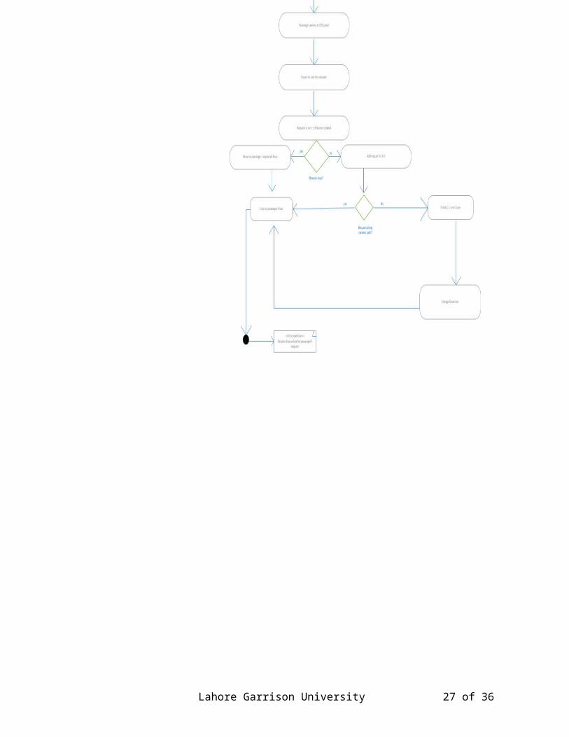
activity is a function performed by the system. After identifyingthe activities we need to understand how they are associated withconstraints and conditions.So before drawing an activity diagram we should identify the following elements: Activities Association Conditions ConstraintsOnce the above mentioned parameters are identified we need to make a mental layout of the entire flow. This mental layout is then transformed into an activity diagram.The following is an activity diagram for Elevator System. In the diagram four activities are identified which are associated with conditions. The activity diagram is made to understand the activies of elevator system.The following diagram is drawn with the three main activities: Elevator System Elevator Control System Passenger
3.7.2:- Activity Diagram of Elevator Sytem:-
Lahore Garrison University 26 of 36
Report on an elevator system
Lahore Garrison University 27 of 36

Report on an elevator system
3.8:- Collaboration Diagram:-
A collaboration diagram, also called a communication diagram or interaction diagram, is an illustration of the relationships and interactions among software objects in the Unified Modeling Language (UML). The concept is more than a decade old although ithas been refined as modeling paradigms have evolved.A collaboration diagram resembles a flowchart that portrays the roles, functionality and behavior of individual objects as well as the overall operation of the system in real time. Objects are shown as rectangles with naming labels inside. These labels are preceded by colons and may be underlined. The relationships between the objects are shown as lines connecting the rectangles.The messages between objects are shown as arrows connecting the relevant rectangles along with labels that define the message sequencing.Collaboration diagrams are best suited to the portrayal of simpleinteractions among relatively small numbers of objects. As the number of objects and messages grows, a collaboration diagram canbecome difficult to read. Several vendors offer software for creating and editing collaboration diagrams.
Like sequence diagrams, collaboration diagrams are also interaction diagrams. Collaboration diagrams convey the same information as sequence diagrams, but focus on object roles instead of the times that messages are sent. In a sequence diagram, object roles are the vertices and messages are the connecting links.
3.8.1:- Collaboration diagram of elevator system
Lahore Garrison University 28 of 36

Report on an elevator system
Fig3.8.1:- Collaboration diagram of elevator system3.9:- Component Diagram:-
In the Unified Modeling Language, a component diagram depicts how components are wired together to form larger components and or software systems. They are used to illustrate the structure ofarbitrarily complex systems.A component is something required to execute a stereotype function. Examples of stereotypes in components include executables, documents, database tables, files, and library files.Components are wired together by using an assembly connector to connect the required interface of one component with the providedinterface of another component. This illustrates the service consumer - service provider relationship between the two components.An assembly connector is a "connector between two components thatdefines that one component provides the services that another component requires. An assembly connector is a connector that is defined from a required interface or port to a provided interfaceor port."[1]
Lahore Garrison University 29 of 36

Report on an elevator system
When using a component diagram to show the internal structure of a component, the provided and required interfaces of the encompassing component can delegate to the corresponding interfaces of the contained components.A delegation connector is a "connector that links the external contract of a component (as specified by its ports) to the internal realization of that behavior by the component’s parts."[1]The example above illustrates what a typical Insurance policy administration system might look like. Each of the components depicted in the above diagram may have other component diagrams illustrating its internal structure.This may have a visual stereotype in the top right of the rectangle of a small rectangle with two even smaller rectangles jutting out on the left.The lollipop, a small circle on a stick represents an implementedor provided interface. The socket symbol is a semicircle on a stick that can fit around the lollipop. This socket is a dependency or needed interface.
3.9.1:- component diagram of elevator system:-
Fig 3.9.1:- component diagram of elevator system
3.10: Deployment diagram
Lahore Garrison University 30 of 36

Report on an elevator system
Deployment diagrams are used to visualize the topology of the physical components of a system where the software components are deployed.So deployment diagrams are used to describe the static deployment view of a system. Deployment diagrams consist of nodes and their relationships.The name Deployment itself describes the purpose of the diagram. Deployment diagrams are used for describing the hardware components where software components are deployed. Component diagrams and deployment diagrams are closely related.Component diagrams are used to describe the components and deployment diagrams shows how they are deployed in hardware.UML is mainly designed to focus on software artifacts of a system. But these two diagrams are special diagrams used to focus on software components and hardware components.So most of the UML diagrams are used to handle logical components but deployment diagrams are made to focus on hardware topology of a system. Deployment diagrams are used bythe system engineers.
The purpose of deployment diagrams can be described as: Visualize hardware topology of a system. Describe the hardware components used to deploy software
components. Describe runtime processing nodes.
Deployment diagram represents the deployment view of a system. It is related to the component diagram. Because the componentsare deployed using the deployment diagrams. A deployment diagram consists of nodes. Nodes are nothing but physical hardwares used to deploy the application.Deployment diagrams are useful for system engineers. An efficient deployment diagram is very important because it controls the following parameters Performance Scalability Maintainability PortabilitySo before drawing a deployment diagram the following artifacts should be identified:
Lahore Garrison University 31 of 36

Report on an elevator system
NodesRelationships among nodesThe following deployment diagram is a sample to give an idea ofthe deployment view of elevator system management. Here we have shown nodes as: Passenger Elevator control system Elevator system
3.10.1:- deployment diagram of elevator system
Fig 3.11.1 :- Deployment diagram of elevator system
3.11:- Package diagram
Lahore Garrison University 32 of 36

Report on an elevator system
Package diagram is UML structure diagram which shows packages and dependencies between the packages.Model diagrams allow to show different views of a system, for example, as multi-layered (aka multi-tiered) application - multi-layered application model.The following nodes and edges are typically drawn in a packagediagram: package, packageable element, dependency, element import, package import, package merge.
Package is a namespace used to group together elements that are semantically related and might change together. It is a general purpose mechanism to organize elements into groups to provide better structure for system model.Owned members of a package should all be packageable elements.If a package is removed from a model, so are all the elements owned by the package. Package by itself is packageable element, so any package could be also a member of other packages.Because package is a namespace, elements of related or the same type should have unique names within the enclosing package. Different types of elements are allowed to have the same name.As a namespace, a package can import either individual membersof other packages or all the members of other packages. Package can also be merged with other packages.A package is rendered as a tabbed folder - a rectangle with a small tab attached to the left side of the top of the rectangle. If the members of the package are not shown inside the package rectangle, then the name of the package should be placed inside.
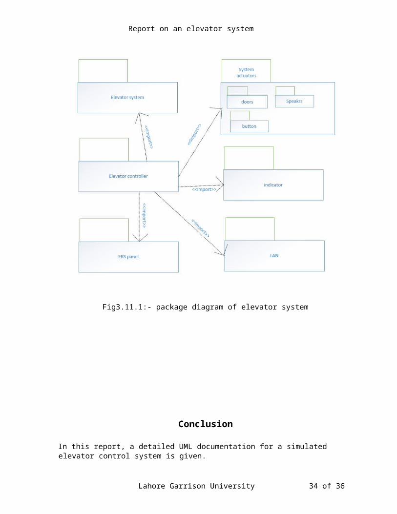
3.11.1:- Package diagram of elevator system:-
Lahore Garrison University 33 of 36
Report on an elevator system
Fig3.11.1:- package diagram of elevator system
Conclusion In this report, a detailed UML documentation for a simulated elevator control system is given.
Lahore Garrison University 34 of 36

Report on an elevator system
UML Diagrams which include: (Use Case, Fully Dressed Use Case, Domain Diagram, Class Diagram, System Sequence Diagram,Sequence Diagram, Collaboration Diagram, State Chart Diagram,Activity Diagram, Component Diagram, Deployment Diagram, Package Diagram. Throughout the process of working on the classproject, how can UML be used in real time systems are paid greatattention to, the successful results of our project can be a good answer for the question.
Lahore Garrison University 35 of 36