Embed Size (px)
Citation preview
U.S. Department of Energy

Propulsion Materials FY 2013 Progress Report
ii
CONTENTS
INTRODUCTION ....................................................................................................................................... 1
Project 18516 – Materials for H1ybrid and Electric Drive Systems ...................................................... 4 Agreement 19201 – Non-Rare Earth Magnetic Materials ............................................................................ 4 Agreement 23278 – Low-Cost Direct-Bonded Aluminum Substrates ....................................................... 11 Agreement 23279 – Improved Organics for Power Electronics and Electric Motors................................. 18 Agreement 23726 – Novel Manufacturing Technologies for High-Power Induction and
Permanent Magnet Electric Motors (General Motors CRADA) ...................................................... 22 Agreement 26461 – Enabling Materials for High-Temperature Power Electronics ................................... 30
Project 18518 – Materials for High-Efficiency Engines ........................................................................ 32 Agreement 8697 – NOx Sensor Development ............................................................................................ 32 Agreement 13329 – Design Optimization of Piezoceramic Multilayer Actuators for Heavy-Duty
Diesel Engine Fuel Injectors ............................................................................................................ 42 Agreement 17058 – Compact Potentiometric NOx Sensor ......................................................................... 52 Agreement 17257 – Materials for Advanced Turbocharger Designs ......................................................... 57 Agreement 18571 – Materials Issues Associated with Exhaust Gas Recirculation Systems ...................... 62 Agreement 23284 – Friction Reduction Through Surface Modification: Integrated Surface
Texturing and Coating ...................................................................................................................... 71 Agreement 23425 – Lightweight Heavy-Duty Engine ............................................................................... 77 Agreement 23725 – Tailored Materials for Improved Internal Combustion Engine Efficiency ................ 82 Agreement 24034 – High-Strength and High-Temperature Materials for Heavy-Duty Engines ............... 94 Agreement 25736 – Computational Design and Development of a New, Lightweight Cast Alloy
for Advanced Cylinder Heads in High-Efficiency, Light-Duty Engines........................................ 103 Agreement 25737 – ICME Guided Development of Advanced Cast Aluminum Alloys for
Automotive Engine Applications ................................................................................................... 110 Agreement 26190 – High-Temperature Materials for High-Efficiency Engines ...................................... 114
Project 18519 – Materials for Exhaust and Energy Recovery ............................................................ 118 Agreement 9130– Development of Materials Analysis Tools for Studying NOx Adsorber
Catalysts (CRADA with Cummins Inc.) ........................................................................................ 118 Agreement 10461 – Durability of Diesel Particulate Filters (CRADA with Cummins, Inc.) .................. 127 Agreement 10635 – Catalysis by First Principles ..................................................................................... 134 Agreement 19214 – Biofuels Impact on Diesel Particulate Filters Durability ......................................... 147 Agreement 26462 – International Characterization Methods ................................................................... 154 Agreement 26463 – Biofuel Impact on Aftertreatment Devices .............................................................. 156
Project 18865 – Application-Specific Materials Simulation, Characterization, and Synthesis ....... 158 Agreement 9105 – Ultra-High Resolution Electron Microscopy for Characterization of Catalyst
Microstructures and Reaction Mechanisms .................................................................................... 158 Agreement 14957 – Modeling of Thermoelectrics ................................................................................... 165 Agreement 15529 – Erosion of Materials by Nanofluids ......................................................................... 171 Agreement 16308 – Thermoelectrics Theory and Structure ..................................................................... 176 Agreement 26391 – Applied ICME for New Propulsion Materials ......................................................... 184 Agreement 26464 – Materials Characterization and Evaluation .............................................................. 188
Propulsion Materials FY 2013 Progress Report
1
INTRODUCTION
Propulsion Materials Research and Development:
Enabling Materials Technologies to Meet
Vehicle Technologies Office Goals The U.S. Department of Energy’s Vehicle Technologies Office (VTO) is pleased to introduce the FY
2013 Annual Progress Report for the Propulsion Materials Research and Development Program.
Together with Department of Energy national laboratories and in partnership with universities and private
industry across the United States, the Propulsion Materials Program continues to invest in research and
development (R&D) that provide enabling materials technologies for fuel-efficient and environmentally
friendly commercial and passenger vehicles.
This introduction summarizes the objectives and progress of the program in fiscal year 2013. The
Propulsion Materials Program actively supports the energy security and reduction of greenhouse
emissions goals of VTO by investigating and identifying the materials properties that are most essential
for continued development of cost-effective, highly efficient, and environmentally friendly
next-generation heavy and light-duty powertrains. The technical approaches available to enhance
propulsion systems focus on improvements in both vehicle efficiency and fuel substitution, both of which
must overcome the performance limitations of the materials currently in use. Propulsion Materials
Program activities include work with national laboratories, industry experts, and VTO powertrain systems
(e.g., Advanced Combustion Engines [ACE], Advanced Power Electronics and Electrical Machines
[APEEM], and fuels) teams to develop strategies that overcome materials limitations in future powertrain
performance. The technical maturity of the portfolio of funded projects ranges from basic science to
subsystem prototype validation.
Propulsion Materials Program activities are structured to serve as an enabling partner and supporter of
the following VTO R&D activities:
Hybrid and vehicle systems
Energy storage
APEEM
ACE
Fuels and lubricants
Projects within a Propulsion Materials Program activity address materials concerns that directly
impact critical technology barriers within each of the above programs, including barriers that impact fuel
efficiency, thermal management, emissions reduction, improved reliability, waste-heat recovery, and
reduced manufacturing costs. The program engages only the barriers that result from material property
limitations and represent fundamental, high-risk materials issues.
Enabling Advanced Technologies
A Propulsion Materials Program activity focuses on key technical deficiencies in materials
performance that limit the expanded capabilities of advanced combustion engines, electric-drive systems,
and fuels and lubricants. It provides materials R&D expertise and advanced materials testing and
development that support the goals of combustion, hybrid, and power electronics development. The
program provides enabling materials support for combustion, hybrid, and power electronics development,
including the following:
Propulsion Materials FY 2013 Progress Report
2
Materials for high-efficiency combustion strategies such as homogenous-charge compression ignition
Materials for 55% thermal efficiency for heavy-duty diesel engines
Materials for waste-heat recovery using mechanical (such as turbo compounding) and solid-state
approaches, with the potential for a 10% increase in fuel efficiency
Materials technologies for effective reduction of tailpipe emissions, including diesel particulate
filters, low-temperature catalyst development, characterization and testing, and exhaust gas
recirculation coolers
Materials technologies for electric and hybrid-electric vehicles, including thermal management of
advanced power electronics materials and reducing dependence on rare earth elements in electric
motors
Materials for alternate-fuels, including engine and exhaust aftertreatment materials compatibility and
corrosion in biofuels
Support for the Materials Genome Initiative through identifying effective computational approaches
and tools to accelerate the development and deployment of new materials with improved properties.
The program supports these core technology areas by providing materials expertise, testing
capabilities, and technical solutions for materials problems. The component development, materials
processing, and characterization that the program provides are enablers of the successful development of
efficient, durable, and emissions-compliant engines.
Program Organization
The Propulsion Materials Program consists of the following four R&D projects, which support VTO
propulsion technologies. Each project consists of several R&D agreements.
1. Materials for Electric and Hybrid Drive Systems
- Develop materials appropriate for automotive power electronics, electric motors, and other
electric and hybrid system applications.
2. Materials for High-Efficiency Engines
- Develop materials for next-generation, high-efficiency engines and address anticipated issues
with engine cylinder block, head, crankshafts, pistons, valves and valve train, fuel injectors,
turbochargers, and exhaust gas recirculation systems.
3. Materials for Control of Exhaust Gases and Energy Recovery Systems
- Develop materials for exhaust aftertreatment and waste heat recovery applications.
4. Materials by Design (Application-Specific Materials Simulation, Characterization, and Synthesis)
- Adopt computational materials design, including an atomic-scale characterization protocol to
develop advanced materials for NOx catalysts, cast engine components, and electric motors and
providing a pathway to transition Basic Energy Science research to practical applications.
Propulsion Materials FY 2013 Progress Report
3
R&D projects are evaluated annually using strategic objectives. Activities are evaluated based on
their relevance to VTO objectives, the supported team’s (i.e., ACE, APEEM, and fuels) assessment of the
work, and the strength of industrial support for the activity. In order to meet future efficiency
improvement targets, new projects and areas of research will be identified by assessments of VTO stretch
objectives and resultant demands for increased material performance.
Edwin Owens
Program Manager, Materials Technology
Vehicle Technologies Office
Energy Efficiency and Renewable Energy
Jerry L. Gibbs
Technology Manager
Vehicle Technologies Office
Energy Efficiency and Renewable Energy
Propulsion Materials FY 2013 Progress Report
4
Project 18516 – Materials for Hybrid and Electric Drive
Systems
Agreement 19201 – Non-Rare Earth Magnetic Materials
M. A. McGuire
Materials Science and Technology Division
Oak Ridge National Laboratory
P.O. Box 2008, MS 6056, Bldg. 4100
Oak Ridge, TN 37831-6068
Phone (865) 574-5496; fax: (865) 576-5023; e-mail: [email protected]
DOE Technology Manager: Jerry L. Gibbs
Phone (202) 586-1182; fax: (202) 586-1600; e-mail: [email protected]
ORNL Technical Advisor: J. Allen Haynes
Phone (865) 576-2894; fax: (865) 574-4913; e-mail: [email protected]
Contractor: Oak Ridge National Laboratory, Oak Ridge, Tennessee
Prime Contract No.: DE-AC05-00OR22725
Objectives
Discover new permanent magnet (PM) materials that do not contain rare earth (RE) elements.
Develop an understanding of the magnetic properties of discovered materials using properties
measurements and first principles calculations to direct work toward improved PM properties.
Approach
Investigate understudied known materials and search for new materials in RE-free chemical systems
that hold promise for the discovery of new high-temperature ferromagnets, with the large magnetic
moments and strong anisotropies required for technologically useful PM materials.
Target materials that contain a high concentration of magnetic 3d elements (e.g., Cr, Mn, Fe, and Co),
along with heavier 4d or 5d transition metals (e.g., Zr, Hf, Nb, Ta, Mo, and W), which have strong
spin-orbit coupling.
Focus on anisotropic crystal structures to allow strong magnetocrystalline anisotropy.
Accomplishments
Published technical report highlighting promising PM properties of melt-spun Hf2Co11B alloys.
Submitted provisional patent application entitled, “Hf-Co-B alloys as permanent magnet materials.”
Demonstrated enhanced stability of the anisotropic (L10) ferromagnetic phase of FePd using high
magnetic fields.
Discovered new ferromagnetic compositions Fe2.85Mo0.15P and Fe2.85W0.15P, which include heavy
transition metals in an iron-rich phosphide.
Future Direction
Funding for this project concluded in fiscal year (FY) 2013.
Propulsion Materials FY 2013 Progress Report
5
Introduction
The strategic importance of RE elements
and the associated potential problems are
receiving increased attention due to their use in
PMs for electric motors. Currently, there are no
alternative PM materials competitive with
Nd2Fe14B that do not contain RE elements. The
development of such materials would allow
progress in lowering the cost of electrical
propulsion systems toward the performance
goals of $12/kW by 2015 and $8/kW by 2020
for the Hybrid and Electric Propulsion
subprogram set forth by the U.S. DRIVE and
Vehicles Technologies Office. The Propulsion
Materials Technology activity has identified a
limited domestic supply of materials required for
advanced vehicle technology, among them RE
elements, as a key barrier to enabling expanded
capabilities of electric drive systems.
An important figure-of-merit for PM
materials is called the maximum energy product
(BHmax). It measures a material’s ability to
maintain its magnetization, or magnetic
induction (B), in the presence of a
demagnetizing field (H). If a large magnetization
can be maintained even for large demagnetizing
fields, then a large BHmax results. Note that
MGOe (mega-Gauss-Oersted) is a unit of energy
density, and 1 MGOe = 7.96 kJ/m3.Typical
values of BHmax at room temperature for the best
RE magnets are 40 to 50 MGOe. Achieving
large values of BHmax requires a large magnetic
moment to persist upon removal of the
magnetizing field (i.e., remanent magnetization
or remanence) and a large field required to
reverse the direction of that moment
(i.e., coercive field or coercivity). A material
with high coercivity (i.e., generally greater than
1,000 Oe) is termed a “hard” ferromagnet. The
Curie temperature is the temperature above
which ferromagnetism vanishes. Typically, the
coercivity drops rapidly upon approaching this
temperature from below. Therefore, good PM
materials must have high Curie temperatures,
typically at least 200°C above the maximum
operation temperature is desired.
The technical barrier that must be overcome
in this research area is related to the role that RE
plays in current state-of-the-art PMs. Realizing
good PM behavior (i.e., large remanence and
high coercivity) requires strong magnetic
anisotropy. This anisotropy gives preference to a
particular orientation of the magnetic moment
and presents an energetic barrier to the
reorientation of the net moment required to
demagnetize the material. There are two sources
of magnetic anisotropy: shape anisotropy (an
extrinsic property) and magnetocrystalline
anisotropy (an intrinsic property). Shape
anisotropy results from the difference in
demagnetization factors along different
directions in non-spherical magnetic particles.
Magnetocrystalline anisotropy arises from the
interactions between the magnetic moments and
the crystal lattice, giving a preferred direction
for the magnetization. Spin-orbit interactions
couple the magnetic moment (spin) to the atomic
orbitals of the magnetic atoms. Strong covalent
bonding can fix the orientation of these atomic
orbitals with respect to the crystal structure. The
combination of these two phenomena (covalent
bonding and spin-orbit coupling) results in a
preferred direction for the alignment of the
magnetic moments, which is manifested as
magnetocrystalline anisotropy. This is expected
to be strongest in materials with anisotropic
(non-cubic) crystallographic structures.
In RE magnets, the strong spin-orbit
coupling and large magnetic moment of the RE
is crucial to providing magnetic anisotropy. The
primary technical barrier to development of
better non-RE PMs is achieving strong
magnetocrystalline anisotropy in the absence of
these constituents. Strong spin-orbit coupling is
not unique to REs. Its strength increases rapidly
with increasing atomic number; therefore, it is
high in all heavy elements. PtCo has strong
magnetocrystalline anisotropy due to the large
spin-orbit coupling of Pt and its interaction with
the 3d Co moments. Despite the high cost of Pt,
this material has seen commercial use in
magnetic recording applications. This example
demonstrates the potential of using heavy
d-block transition metals like Pt to play the role
of the RE.
Some of the most promising chemical
systems for development of new PM materials
are those that include the 3d transition metals Cr,
Mn, Fe, and Co with heavy 4d or 5d metals
Propulsion Materials FY 2013 Progress Report
6
(e.g., Zr, Hf, Nb, Ta, Mo, and W). Analyzing
known compounds containing these elements is
one path toward new hard ferromagnets.
However, the discovery of entirely new
materials is likely to have the largest long-term
impact on technology. This usually requires
examining chemical systems containing at least
three elements, because binary compositional
phase diagrams are generally well characterized.
Indeed, moving beyond binary compounds was
the key to developing Nd2Fe14B-based materials
as replacements for SmCo5 magnets.
The objective of this project is to use the
ideas outlined above to target new and known
materials to identify RE-free chemical systems
that contain PMs with potential for use in
electric motors. Replacing Nd2Fe14B is a serious
and important materials challenge that will
require long-term research efforts and must
include advancements in performance and
understanding of non-RE magnets and, perhaps
most importantly, the discovery and
development of new materials.
Results
Accomplishments from FY 2013 related to
several ferromagnetic material systems are
summarized in the following paragraphs. These
include the hard ferromagnetic Hf-Co-B alloys,
the ferromagnetic phosphide Fe3P, and the
order-disorder alloy FePd. We submitted a
provisional patent application and published a
technical report concerning Hf2Co11B and
applied synchrotron x-ray scattering to probe
local atomic structure of the material. We
discovered and characterized new Fe3P-based
materials, which include heavy transition metals
and display evidence of increased magnetic
anisotropy. Finally, we used neutron diffraction
to study the structure and magnetic order in
FePd, examined the effects of substituting Ni in
place of the expensive Pd, and achieved
enhanced stability of the magnetically
anisotropic tetragonal phase using
thermomagnetic processing techniques.
Hf-Co-B Melt-Spun Alloys
In early FY 2013, we submitted a
provisional patent application related to our
development of promising PM properties in
melt-spun ribbons of composition Hf2Co11B; we
subsequently published some of our findings in
the form of a technical report in the open
scientific literature (McGuire et al. 2012). The
most important finding is that energy products as
high as 6.7 MGOe are obtained from as-spun
ribbons without the need for subsequent thermal
processing. This is as high as most grades of
AlNiCo (the best non-RE PM) and about half
the value obtained in optimized melt-spun
ribbons of Nd2Fe14B.
Recently, we have employed synchrotron
x-ray scattering techniques to study the phase
composition and atomic structure in these
materials. Some results are shown in Figure 1.
This figure shows results from pair distribution
function analysis of x-ray data obtained in
collaboration with Mikhail Feygensen of Oak
Ridge National Laboratory using the Advanced
Photon Source at Argonne National Laboratory.
The figure also shows room temperature
magnetization loops and scanning electron
microscopy (SEM) micrographs of the materials
used for the study.
The pair distribution function technique
probes the local atomic structure of a material.
The reduced pair distribution function G(r)
plotted in Figure 1 is related to the likelihood of
finding pairs of atoms separated by a distance r.
Structures with high periodicity will have large
G(r) persisting to large values of r, while
amorphous materials, for which correlations
between atomic positions are limited to a few
near neighbors, will have small G(r).
Figure 1a shows G(r) for a ribbon melt-spun
with a sufficiently high quench rate to produce
very soft magnetic behavior (i.e., coercivity near
zero). The SEM micrograph shows contrast
modulations; however, the pair distribution
function data show G(r) is small for all values of
r, indicating the material to be amorphous. The
contrast in the SEM image is then attributed to
compositional modulations in the amorphous
phase. Figure 1b shows data for a ribbon
quenched at a rate that produces some small
and/or poorly crystalline precipitates embedded
in the amorphous matrix, as indicated by the
oscillatory behavior of G(r) confined to low
values of r.
Propulsion Materials FY 2013 Progress Report
7
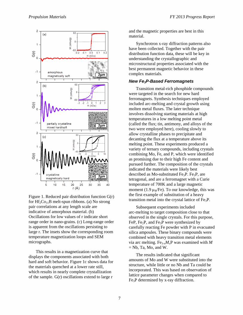
Figure 1. Reduced pair distribution function G(r)
for Hf2Co11B melt-spun ribbons. (a) No strong
pair correlations at any length scale are
indicative of amorphous material. (b)
Oscillations for low values of r indicate short
range order in nano-grains. (c) Long-range order
is apparent from the oscillations persisting to
large r. The insets show the corresponding room
temperature magnetization loops and SEM
micrographs.
This results in a magnetization curve that
displays the components associated with both
hard and soft behavior. Figure 1c shows data for
the materials quenched at a lower rate still,
which results in nearly complete crystallization
of the sample. G(r) oscillations extend to large r
and the magnetic properties are best in this
material.
Synchrotron x-ray diffraction patterns also
have been collected. Together with the pair
distribution function data, these will be key in
understanding the crystallographic and
microstructural properties associated with the
best permanent magnetic behavior in these
complex materials.
New Fe3P-Based Ferromagnets
Transition metal-rich phosphide compounds
were targeted in the search for new hard
ferromagnets. Synthesis techniques employed
included arc-melting and crystal growth using
molten metal fluxes. The later technique
involves dissolving starting materials at high
temperatures in a low melting point metal
(called the flux; tin, antimony, and alloys of the
two were employed here), cooling slowly to
allow crystalline phases to precipitate and
decanting the flux at a temperature above its
melting point. These experiments produced a
variety of ternary compounds, including crystals
combining Mo, Fe, and P, which were identified
as promising due to their high Fe content and
pursued further. The composition of the crystals
indicated the materials were likely best
described as Mo-substituted Fe3P. Fe3P, are
tetragonal, and are a ferromagnet with a Curie
temperature of 700K and a large magnetic
moment (1.9 B/Fe). To our knowledge, this was
the first example of substitution of a heavy
transition metal into the crystal lattice of Fe3P.
Subsequent experiments included
arc-melting to target composition close to that
observed in the single crystals. For this purpose,
FeP, Fe2P, and Fe3P were synthesized by
carefully reacting Fe powder with P in evacuated
silica ampoules. These binary compounds were
combined with heavy transition metal elements
via arc melting. Fe3-xMxP was examined with M
= Nb, Ta, Mo, and W.
The results indicated that significant
amounts of Mo and W were substituted into the
structure, while little or no Nb and Ta could be
incorporated. This was based on observation of
lattice parameter changes when compared to
Fe3P determined by x-ray diffraction.
Propulsion Materials FY 2013 Progress Report
8
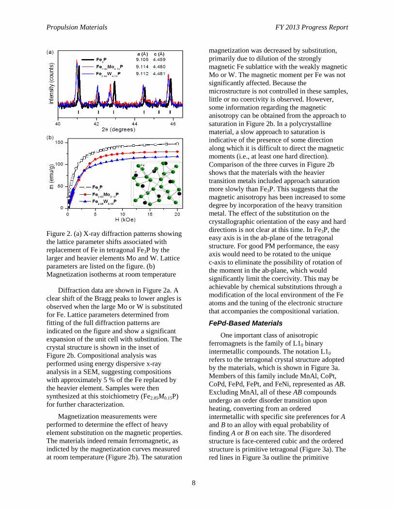
Figure 2. (a) X-ray diffraction patterns showing
the lattice parameter shifts associated with
replacement of Fe in tetragonal Fe3P by the
larger and heavier elements Mo and W. Lattice
parameters are listed on the figure. (b)
Magnetization isotherms at room temperature
Diffraction data are shown in Figure 2a. A
clear shift of the Bragg peaks to lower angles is
observed when the large Mo or W is substituted
for Fe. Lattice parameters determined from
fitting of the full diffraction patterns are
indicated on the figure and show a significant
expansion of the unit cell with substitution. The
crystal structure is shown in the inset of
Figure 2b. Compositional analysis was
performed using energy dispersive x-ray
analysis in a SEM, suggesting compositions
with approximately 5 % of the Fe replaced by
the heavier element. Samples were then
synthesized at this stoichiometry (Fe2.85M0.15P)
for further characterization.
Magnetization measurements were
performed to determine the effect of heavy
element substitution on the magnetic properties.
The materials indeed remain ferromagnetic, as
indicted by the magnetization curves measured
at room temperature (Figure 2b). The saturation
magnetization was decreased by substitution,
primarily due to dilution of the strongly
magnetic Fe sublattice with the weakly magnetic
Mo or W. The magnetic moment per Fe was not
significantly affected. Because the
microstructure is not controlled in these samples,
little or no coercivity is observed. However,
some information regarding the magnetic
anisotropy can be obtained from the approach to
saturation in Figure 2b. In a polycrystalline
material, a slow approach to saturation is
indicative of the presence of some direction
along which it is difficult to direct the magnetic
moments (i.e., at least one hard direction).
Comparison of the three curves in Figure 2b
shows that the materials with the heavier
transition metals included approach saturation
more slowly than Fe3P. This suggests that the
magnetic anisotropy has been increased to some
degree by incorporation of the heavy transition
metal. The effect of the substitution on the
crystallographic orientation of the easy and hard
directions is not clear at this time. In Fe3P, the
easy axis is in the ab-plane of the tetragonal
structure. For good PM performance, the easy
axis would need to be rotated to the unique
c-axis to eliminate the possibility of rotation of
the moment in the ab-plane, which would
significantly limit the coercivity. This may be
achievable by chemical substitutions through a
modification of the local environment of the Fe
atoms and the tuning of the electronic structure
that accompanies the compositional variation.
FePd-Based Materials
One important class of anisotropic
ferromagnets is the family of L10 binary
intermetallic compounds. The notation L10
refers to the tetragonal crystal structure adopted
by the materials, which is shown in Figure 3a.
Members of this family include MnAl, CoPt,
CoPd, FePd, FePt, and FeNi, represented as AB.
Excluding MnAl, all of these AB compounds
undergo an order disorder transition upon
heating, converting from an ordered
intermetallic with specific site preferences for A
and B to an alloy with equal probability of
finding A or B on each site. The disordered
structure is face-centered cubic and the ordered
structure is primitive tetragonal (Figure 3a). The
red lines in Figure 3a outline the primitive
Propulsion Materials FY 2013 Progress Report
9
tetragonal cell. In the tetragonal structure, the
materials show strong magnetic anisotropy.
FeNi is particularly interesting because of
the low cost of the constituents. Unfortunately,
the driving force for atomic ordering is lowest in
this compound and it has proved exceedingly
difficult to prepare in the ordered tetragonal
structure. It occurs naturally in meteorites as the
mineral tetrataenite, which presumably
equilibrates over very long time scales. In this
work, we explored a possible means to
improving the rate at which the conversion takes
place in these materials.
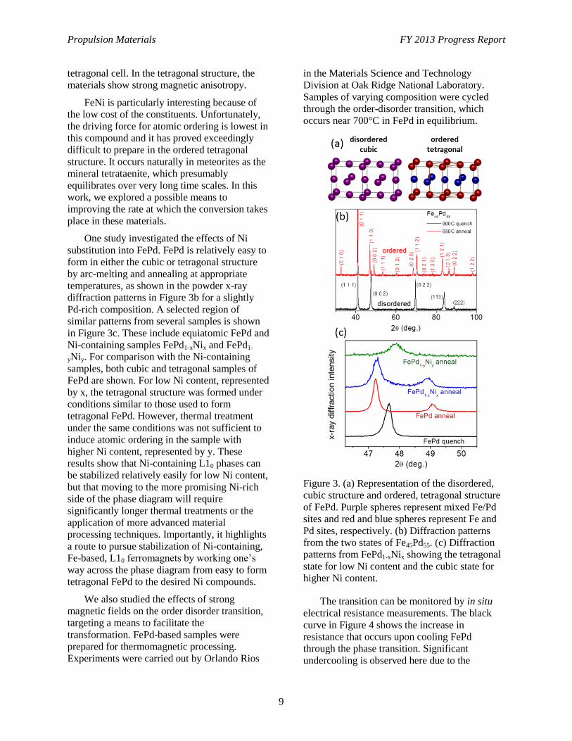
One study investigated the effects of Ni
substitution into FePd. FePd is relatively easy to
form in either the cubic or tetragonal structure
by arc-melting and annealing at appropriate
temperatures, as shown in the powder x-ray
diffraction patterns in Figure 3b for a slightly
Pd-rich composition. A selected region of
similar patterns from several samples is shown
in Figure 3c. These include equiatomic FePd and
Ni-containing samples FePd1-xNix and FePd1-
yNiy. For comparison with the Ni-containing
samples, both cubic and tetragonal samples of
FePd are shown. For low Ni content, represented
by x, the tetragonal structure was formed under
conditions similar to those used to form
tetragonal FePd. However, thermal treatment
under the same conditions was not sufficient to
induce atomic ordering in the sample with
higher Ni content, represented by y. These
results show that Ni-containing L10 phases can
be stabilized relatively easily for low Ni content,
but that moving to the more promising Ni-rich
side of the phase diagram will require
significantly longer thermal treatments or the
application of more advanced material
processing techniques. Importantly, it highlights
a route to pursue stabilization of Ni-containing,
Fe-based, L10 ferromagnets by working one’s
way across the phase diagram from easy to form
tetragonal FePd to the desired Ni compounds.
We also studied the effects of strong
magnetic fields on the order disorder transition,
targeting a means to facilitate the
transformation. FePd-based samples were
prepared for thermomagnetic processing.
Experiments were carried out by Orlando Rios
in the Materials Science and Technology
Division at Oak Ridge National Laboratory.
Samples of varying composition were cycled
through the order-disorder transition, which
occurs near 700°C in FePd in equilibrium.
Figure 3. (a) Representation of the disordered,
cubic structure and ordered, tetragonal structure
of FePd. Purple spheres represent mixed Fe/Pd
sites and red and blue spheres represent Fe and
Pd sites, respectively. (b) Diffraction patterns
from the two states of Fe45Pd55. (c) Diffraction
patterns from FePd1-xNix showing the tetragonal
state for low Ni content and the cubic state for
higher Ni content.
The transition can be monitored by in situ
electrical resistance measurements. The black
curve in Figure 4 shows the increase in
resistance that occurs upon cooling FePd
through the phase transition. Significant
undercooling is observed here due to the
Propulsion Materials FY 2013 Progress Report
10
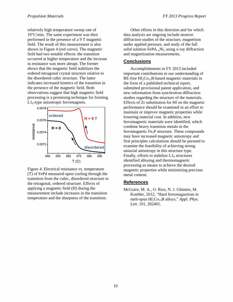
relatively high temperature sweep rate of
10°C/min. The same experiment was then
performed in the presence of a 9 T magnetic
field. The result of this measurement is also
shown in Figure 4 (red curve). The magnetic
field had two notable effects: the transition
occurred at higher temperature and the increase
in resistance was more abrupt. The former
shows that the magnetic field stabilizes the
ordered tetragonal crystal structure relative to
the disordered cubic structure. The latter
indicates increased kinetics of the transition in
the presence of the magnetic field. Both
observations suggest that high magnetic field
processing is a promising technique for forming
L10-type anisotropic ferromagnets.
Figure 4. Electrical resistance vs. temperature
(T) of FePd measured upon cooling through the
transition from the cubic, disordered structure to
the tetragonal, ordered structure. Effects of
applying a magnetic field (H) during the
measurement include increases in the transition
temperature and the sharpness of the transition.
Other efforts in this direction and for which
data analysis are ongoing include neutron
diffraction studies of the structure, magnetism
under applied pressure, and study of the full
solid solution FePd1-xNix using x-ray diffraction
and magnetization measurements.
Conclusions
Accomplishments in FY 2013 included
important contributions to our understanding of
RE-free Hf2Co11B-based magnetic materials in
the form of a published technical report,
submitted provisional patent application, and
new information from synchrotron diffraction
studies regarding the structure of the materials.
Effects of Zr substitution for Hf on the magnetic
performance should be examined in an effort to
maintain or improve magnetic properties while
lowering material cost. In addition, new
ferromagnetic materials were identified, which
combine heavy transition metals in the
ferromagnetic Fe3P structure. These compounds
may have increased magnetic anisotropy and
first principles calculations should be pursued to
examine the feasibility of achieving strong
uniaxial anisotropy in this structure type.
Finally, efforts to stabilize L10 structures
identified alloying and thermomagnetic
processing as means to achieve the desired
magnetic properties while minimizing precious
metal content.
References
McGuire, M. A., O. Rios, N. J. Ghimire, M.
Koehler, 2012, “Hard ferromagnetism in
melt-spun Hf2Co11B alloys,” Appl. Phys.
Lett. 101, 202401.
Propulsion Materials FY 2013 Progress Report
11
Project 18516 – Materials for Hybrid and Electric Drive
Systems
Agreement 23278 – Low-Cost Direct-Bonded Aluminum
Substrates
H.-T. Lin, S. B. Waters, and A. A. Wereszczak
Ceramic Science and Technology Group
Oak Ridge National Laboratory
P.O. Box 2008, MS 6068, Bldg. 4515
Oak Ridge, TN 37831-6068
Phone (865) 576-8857; fax: (865) 574-6098; e-mail: [email protected]
DOE Technology Manager: Jerry L. Gibbs
Phone (202) 586-1182; fax: (202) 586-1600; e-mail: [email protected]
ORNL Technical Advisor: J. Allen Haynes
Phone (865) 576-2894; fax: (865) 574-4913; e-mail: [email protected]
Contractor: Oak Ridge National Laboratory, Oak Ridge, Tennessee
Prime Contract No.: DE-AC05-00OR22725
Objectives
Develop low-cost, high-quality, and thermomechanically robust direct-bonded aluminum (DBA)
substrates.
Develop low-cost DBA substrates that are at least 25% lighter than conventional direct-bonded
copper (DBC) substrates.
Approach
Develop innovative ways to fabricate the ceramic constituent (e.g., low-cast AlN substrate).
Benchmark existing commercially available DBA and DBC substrates.
Develop test method to measure interfacial shear strengths of Al-ceramic interface.
Accomplishments
Completed Al-Si paste, Si powders, and Al-Si-Mg alloy films approaches to fabricate DBA and DBC
substrates.
Demonstrated that a compromise between the low-cost and performance of DBA and DBC substrates
must be struck.
Completed initial development and demonstration of a silicon nitride ceramic substrate with both a
high mechanical and thermal conductivity property.
Funding for this project concluded in fiscal year 2013.
Future Direction
Develop and optimize silicon nitride ceramic substrates with both high mechanical performance and
thermal conductivity property for the next generation of DBC and DBA substrates with GaN and SiC.
Propulsion Materials FY 2013 Progress Report
12
Introduction
Application of low-cost DBA substrates will
enable the reduced cost of the inverter insulated
gate bipolar transistor power modules, while
concomitantly sustaining or improving thermal
management and improving thermomechanical
reliability. Compared to copper and DBC
substrates, aluminum (Al) has a lower elastic
modulus; therefore, it imparts a lower stress on
the ceramic substrate it sandwiches. This
contributes to the improved mechanical
reliability of the entire substrate. Also, the wire
and ribbon used for bonding in power electronic
modules tends to be Al; therefore, the apparent
coefficient of thermal expansion of DBAs is
compatible, unlike DBCs. New sintering
technologies also are more compatible with
DBAs than DBCs. The use of a DBA substrate
will lessen the weight up to 50% compared to
the presently used DBC substrates. This would
contribute to the substantial weight reduction
goals of the inverter and converter in the
Advanced Power Electronics and Electric
Motors (APEEM) Program as well.
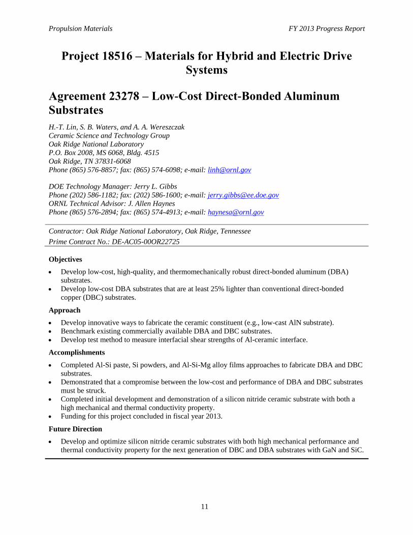
Figure 1. Scann
ing electronic microscopy of
polished cross section of Al/AlN specimen after
bonding process.
On the other hand, reducing cost, improving
volumetric power, extending reliability, and
improving thermal management are all barriers
to the goals of the Vehicle Technology's
APEEM Program. If DBAs could be fabricated
cheaply, then their use would inherently address
those other barriers. DBA substrates presently
are very difficult to fabricate due to the inherent
issues with Al to alumina. DBAs are now only
available from a limited numbers of suppliers
and are expensive. Although Toyota presently
uses DBA substrates in the 2010 Prius, domestic
automotive original equipment manufacturers
would only consider using DBA substrates in
their own inverters if they were cheaper and
more readily available.
The objective of this subtask is to develop
low-cost, high-quality, and thermomechanically
robust DBA substrates, which are comparable to
commercially available units. The ultimate goal
is to facilitate the achievement of the 2015
APEEM goal of $12/kW for an electric traction
system. Also, a secondary goal is to develop a
silicon nitride (Si3N4) ceramic substrate with
both excellent mechanical properties and high
thermal conductivity for next generation DBC
and DBA substrates with GaN and SiC.
Results
Processing of Low Cost Direct-Bonded Aluminum Substrates
Experiments were carried out to bond the Al
metal plate to both Al2O3 and AlN ceramic
substrates using a commercial Al-12Si brazing
paste (designated as DayBraze 729) acquired
from Johnson Manufacturing Company,
Princeton, Iowa. The Al2O3/Al and AlN/Al
specimens with Al-12Si brazing paste were hot
pressed at 640°C and 15 MPa for 30 minutes in
a flowing argon or argon + 4% hydrogen
environment. The purpose of using the argon gas
+ 4% hydrogen was to further reduce the oxygen
content in the hot pressing furnace to inhibit the
oxidation of Al-Si paste and Al plate. Visual
observations after hot pressing both Al2O3/Al
and AlN/Al specimens looked sound. However,
these samples were readily peeled off by hand,
which is indicative of poor bonding. The
detailed scanning electronic microscopy analysis
of the AlN/Al specimen polished cross section
showed the presence of Al-Si brazing paste,
meaning that it was not completely reacted
during the hot-pressing as evident by the
presence of fluorine (F) and potassium (K)
Al
Al N
Al -Si -O Al -Si -K-O -F
Propulsion Materials FY 2013 Progress Report
13
(Figure 1). Also, composition analysis showed
that the interfacial Al-Si reaction layer contained
a high concentration of oxygen. The Al-Si
brazing paste could be oxidized during the
heating process, thus resulting in the formation
of an Al-Si-O compound that prevents sound
bonding between Al and the ceramic substrates.
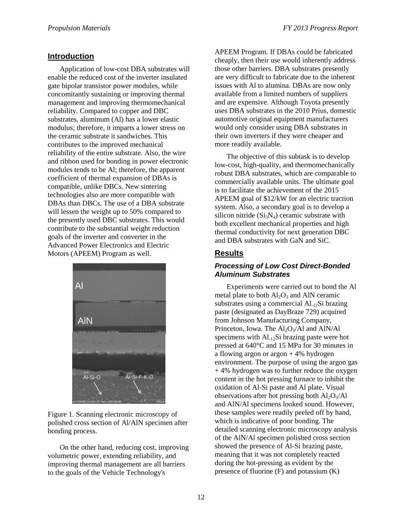
A subsequent detailed chemical element
mapping further confirmed the above stated
results of the partially reacted paste, which is
evident by the presence of fluorine, potassium,
and oxygen (Figure 2).
Figure 2. EDAX element map of polished
cross section of an Al/AlN interface.
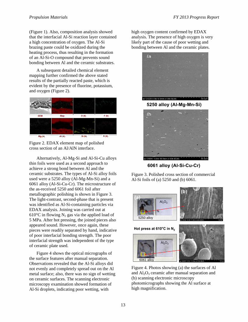
Alternatively, Al-Mg-Si and Al-Si-Cu alloys
thin foils were used as a second approach to
achieve a strong bond between Al and the
ceramic substrates. The types of Al-Si alloy foils
used were a 5250 alloy (Al-Mg-Mn-Si) and a
6061 alloy (Al-Si-Cu-Cr). The microstructure of
the as-received 5250 and 6061 foil after
metallographic polishing is shown in Figure 3.
The light-contrast, second-phase that is present
was identified as Al-Si-containing particles via
EDAX analysis. Joining was carried out at
610°C in flowing N2 gas via the applied load of
5 MPa. After hot pressing, the joined pieces also
appeared sound. However, once again, these
pieces were readily separated by hand, indicative
of poor interfacial bonding strength. The poor
interfacial strength was independent of the type
of ceramic plate used.
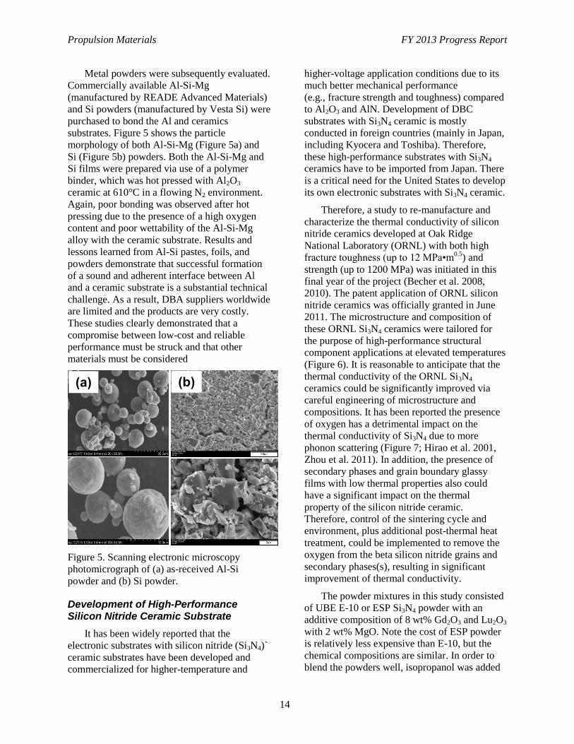
Figure 4 shows the optical micrographs of
the surface features after manual separation.
Observations revealed that the Al-Si alloys did
not evenly and completely spread out on the Al
metal surface; also, there was no sign of wetting
on ceramic surfaces. The scanning electronic
microscopy examination showed formation of
Al-Si droplets, indicating poor wetting, with
high oxygen content confirmed by EDAX
analysis. The presence of high oxygen is very
likely part of the cause of poor wetting and
bonding between Al and the ceramic plates.
Figure 3. Polished cross section of commercial
Al-Si foils of (a) 5250 and (b) 6061.
Figure 4. Photos showing (a) the surfaces of Al
and Al2O3 ceramic after manual separation and
(b) scanning electronic microscopy
photomicrographs showing the Al surface at
high magnification.
5250 alloy (Al-Mg-Mn-Si)
6061 alloy (Al-Si-Cu-Cr)
(a
(b
5250 alloy
6061 alloy
Hot press at 610°C in N2
Al2O3
Al2O3
(a)
(b)
Propulsion Materials FY 2013 Progress Report
14
Metal powders were subsequently evaluated.
Commercially available Al-Si-Mg
(manufactured by READE Advanced Materials)
and Si powders (manufactured by Vesta Si) were
purchased to bond the Al and ceramics
substrates. Figure 5 shows the particle
morphology of both Al-Si-Mg (Figure 5a) and
Si (Figure 5b) powders. Both the Al-Si-Mg and
Si films were prepared via use of a polymer
binder, which was hot pressed with Al2O3
ceramic at 610°C in a flowing N2 environment.
Again, poor bonding was observed after hot
pressing due to the presence of a high oxygen
content and poor wettability of the Al-Si-Mg
alloy with the ceramic substrate. Results and
lessons learned from Al-Si pastes, foils, and
powders demonstrate that successful formation
of a sound and adherent interface between Al
and a ceramic substrate is a substantial technical
challenge. As a result, DBA suppliers worldwide
are limited and the products are very costly.
These studies clearly demonstrated that a
compromise between low-cost and reliable
performance must be struck and that other
materials must be considered
Figure 5. Scanning electronic microscopy
photomicrograph of (a) as-received Al-Si
powder and (b) Si powder.
Development of High-Performance Silicon Nitride Ceramic Substrate
It has been widely reported that the
electronic substrates with silicon nitride (Si3N4)`
ceramic substrates have been developed and
commercialized for higher-temperature and
higher-voltage application conditions due to its
much better mechanical performance
(e.g., fracture strength and toughness) compared
to Al2O3 and AlN. Development of DBC
substrates with Si3N4 ceramic is mostly
conducted in foreign countries (mainly in Japan,
including Kyocera and Toshiba). Therefore,
these high-performance substrates with Si3N4
ceramics have to be imported from Japan. There
is a critical need for the United States to develop
its own electronic substrates with Si3N4 ceramic.
Therefore, a study to re-manufacture and
characterize the thermal conductivity of silicon
nitride ceramics developed at Oak Ridge
National Laboratory (ORNL) with both high
fracture toughness (up to 12 MPa•m0.5
) and
strength (up to 1200 MPa) was initiated in this
final year of the project (Becher et al. 2008,
2010). The patent application of ORNL silicon
nitride ceramics was officially granted in June
2011. The microstructure and composition of
these ORNL Si3N4 ceramics were tailored for
the purpose of high-performance structural
component applications at elevated temperatures
(Figure 6). It is reasonable to anticipate that the
thermal conductivity of the ORNL Si3N4
ceramics could be significantly improved via
careful engineering of microstructure and
compositions. It has been reported the presence
of oxygen has a detrimental impact on the
thermal conductivity of Si3N4 due to more
phonon scattering (Figure 7; Hirao et al. 2001,
Zhou et al. 2011). In addition, the presence of
secondary phases and grain boundary glassy
films with low thermal properties also could
have a significant impact on the thermal
property of the silicon nitride ceramic.
Therefore, control of the sintering cycle and
environment, plus additional post-thermal heat
treatment, could be implemented to remove the
oxygen from the beta silicon nitride grains and
secondary phases(s), resulting in significant
improvement of thermal conductivity.
The powder mixtures in this study consisted
of UBE E-10 or ESP Si3N4 powder with an
additive composition of 8 wt% Gd2O3 and Lu2O3
with 2 wt% MgO. Note the cost of ESP powder
is relatively less expensive than E-10, but the
chemical compositions are similar. In order to
blend the powders well, isopropanol was added
(a) (b)
Propulsion Materials FY 2013 Progress Report
15
to each powder mixture; this slurry was then
attritor-milled for 2 hours using 2-mm silicon
nitride balls. The alcohol–powder slurry was
poured through a 90-mm sieve to separate the
milling media from the powder–alcohol slurry,
which was then captured in a stainless steel tray.
The slurry was then air-dried in a hood for 24
hours; after drying, the powder was gently
ground and poured through a 425-mm sieve to
break up agglomerates. The desired amount of
the powder mixture was then placed into a
graphite die and a pressure of about 20 MPa was
applied via the graphite rams.
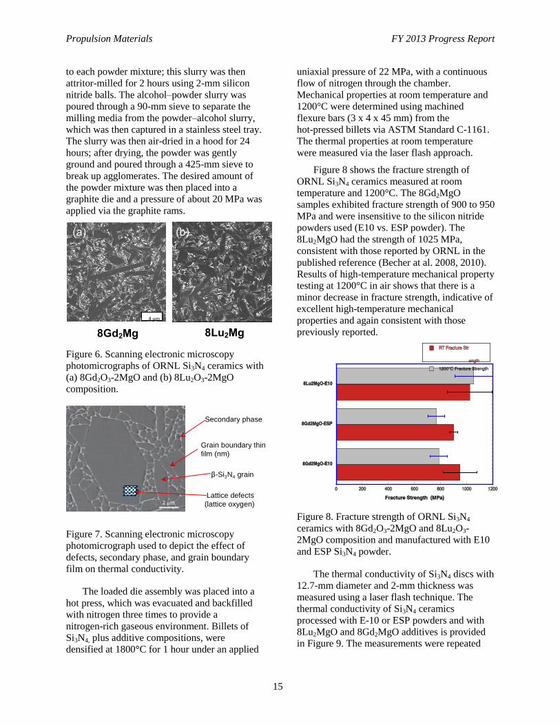
Figure 6. Scanning electronic microscopy
photomicrographs of ORNL Si3N4 ceramics with
(a) 8Gd2O3-2MgO and (b) 8Lu2O3-2MgO
composition.
Figure 7. Scanning electronic microscopy
photomicrograph used to depict the effect of
defects, secondary phase, and grain boundary
film on thermal conductivity.
The loaded die assembly was placed into a
hot press, which was evacuated and backfilled
with nitrogen three times to provide a
nitrogen-rich gaseous environment. Billets of
Si3N4, plus additive compositions, were
densified at 1800°C for 1 hour under an applied
uniaxial pressure of 22 MPa, with a continuous
flow of nitrogen through the chamber.
Mechanical properties at room temperature and
1200°C were determined using machined
flexure bars (3 x 4 x 45 mm) from the
hot-pressed billets via ASTM Standard C-1161.
The thermal properties at room temperature
were measured via the laser flash approach.
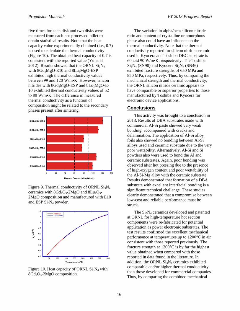
Figure 8 shows the fracture strength of
ORNL Si3N4 ceramics measured at room
temperature and 1200°C. The 8Gd2MgO
samples exhibited fracture strength of 900 to 950
MPa and were insensitive to the silicon nitride
powders used (E10 vs. ESP powder). The
8Lu2MgO had the strength of 1025 MPa,
consistent with those reported by ORNL in the
published reference (Becher at al. 2008, 2010).
Results of high-temperature mechanical property
testing at 1200°C in air shows that there is a
minor decrease in fracture strength, indicative of
excellent high-temperature mechanical
properties and again consistent with those
previously reported.
Figure 8. Fracture strength of ORNL Si3N4
ceramics with 8Gd2O3-2MgO and 8Lu2O3-
2MgO composition and manufactured with E10
and ESP Si3N4 powder.
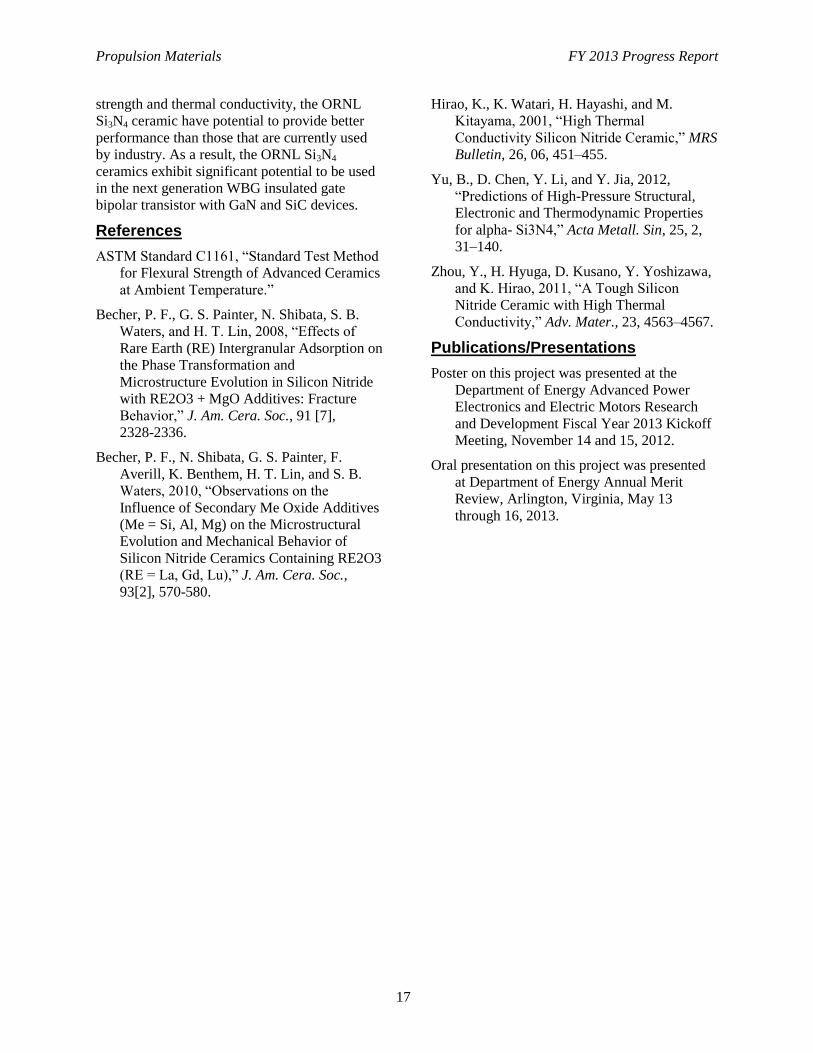
The thermal conductivity of Si3N4 discs with
12.7-mm diameter and 2-mm thickness was
measured using a laser flash technique. The
thermal conductivity of Si3N4 ceramics
processed with E-10 or ESP powders and with
8Lu2MgO and 8Gd2MgO additives is provided
in Figure 9. The measurements were repeated
Se co n d a ry p h a se
G ra i n b o u n d a ry t h i n f i l m (n m)
β -Si 3 N 4 g ra i n
L a t t i ce d e f e ct s (l a t t i ce o xyg e n )
4 µm
8Gd2Mg 8Lu2Mg
(a) (b)
Propulsion Materials FY 2013 Progress Report
16
five times for each disk and two disks were
measured from each hot-processed billet to
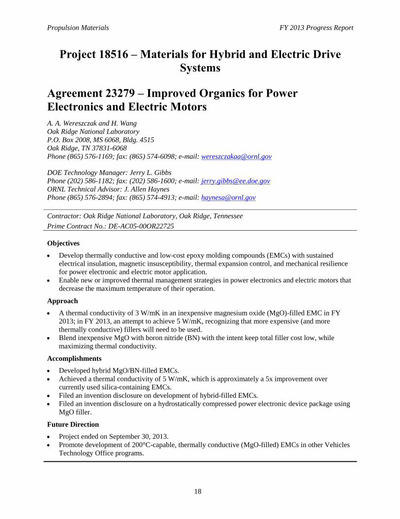
obtain statistical results. Note that the heat
capacity value experimentally obtained (i.e., 0.7)
is used to calculate the thermal conductivity
(Figure 10). The obtained heat capacity of 0.7 is
consistent with the reported value (Yu et al
2012). Results showed that the ORNL Si3N4
with 8Gd2MgO-E10 and 8Lu2MgO-ESP
exhibited high thermal conductivity values
between 99 and 120 W/m•K. However, silicon
nitrides with 8Gd2MgO-ESP and 8Lu2MgO-E-
10 exhibited thermal conductivity values of 52
to 80 W/m•K. The difference in measured
thermal conductivity as a function of
composition might be related to the secondary
phases present after sintering.
Figure 9. Thermal conductivity of ORNL Si3N4
ceramics with 8Gd2O3-2MgO and 8Lu2O3-
2MgO composition and manufactured with E10
and ESP Si3N4 powder.
Figure 10. Heat capacity of ORNL Si3N4 with
8Gd2O3-2MgO composition.
The variation in alpha/beta silicon nitride
ratio and content of crystalline or amorphous
phase also could have an influence on the
thermal conductivity. Note that the thermal
conductivity reported for silicon nitride ceramic
used in Kyocera and Toshiba DBC substrate is
60 and 90 W/m•K, respectively. The Toshiba
Si3N4 (SN90) and Kyocera Si3N4 (SN46)
exhibited fracture strengths of 650 MPa and
850 MPa, respectively. Thus, by comparing the
mechanical strength and thermal conductivity,
the ORNL silicon nitride ceramic appears to
have comparable or superior properties to those
manufactured by Toshiba and Kyocera for
electronic device applications.
Conclusions
This activity was brought to a conclusion in
2013. Results of DBA substrates made with
commercial Al-Si paste showed very weak
bonding, accompanied with cracks and
delamination. The application of Al-Si alloy
foils also showed no bonding between Al-Si
alloys used and ceramic substrate due to the very
poor wettability. Alternatively, Al-Si and Si
powders also were used to bond the Al and
ceramic substrates. Again, poor bonding was
observed after hot pressing due to the presence
of high-oxygen content and poor wettability of
the Al-Si-Mg alloy with the ceramic substrate.
Results demonstrated that formation of a DBA
substrate with excellent interfacial bonding is a
significant technical challenge. These studies
clearly demonstrated that a compromise between
low-cost and reliable performance must be
struck.
The Si3N4 ceramics developed and patented
at ORNL for high-temperature hot section
components were re-fabricated for potential
application as power electronic substrates. The
test results confirmed the excellent mechanical
performance at temperatures up to 1200°C in air
consistent with those reported previously. The
fracture strength at 1200°C is by far the highest
value obtained when compared with those
reported in data found in the literature. In
addition, the ORNL Si3N4 ceramics exhibited
comparable and/or higher thermal conductivity
than those developed for commercial companies.
Thus, by comparing the combined mechanical
Propulsion Materials FY 2013 Progress Report
17
strength and thermal conductivity, the ORNL
Si3N4 ceramic have potential to provide better
performance than those that are currently used
by industry. As a result, the ORNL Si3N4
ceramics exhibit significant potential to be used
in the next generation WBG insulated gate
bipolar transistor with GaN and SiC devices.
References
ASTM Standard C1161, “Standard Test Method
for Flexural Strength of Advanced Ceramics
at Ambient Temperature.”
Becher, P. F., G. S. Painter, N. Shibata, S. B.
Waters, and H. T. Lin, 2008, “Effects of
Rare Earth (RE) Intergranular Adsorption on
the Phase Transformation and
Microstructure Evolution in Silicon Nitride
with RE2O3 + MgO Additives: Fracture
Behavior,” J. Am. Cera. Soc., 91 [7],
2328-2336.
Becher, P. F., N. Shibata, G. S. Painter, F.
Averill, K. Benthem, H. T. Lin, and S. B.
Waters, 2010, “Observations on the
Influence of Secondary Me Oxide Additives
(Me = Si, Al, Mg) on the Microstructural
Evolution and Mechanical Behavior of
Silicon Nitride Ceramics Containing RE2O3
(RE = La, Gd, Lu),” J. Am. Cera. Soc.,
93[2], 570-580.
Hirao, K., K. Watari, H. Hayashi, and M.
Kitayama, 2001, “High Thermal
Conductivity Silicon Nitride Ceramic,” MRS
Bulletin, 26, 06, 451–455.
Yu, B., D. Chen, Y. Li, and Y. Jia, 2012,
“Predictions of High-Pressure Structural,
Electronic and Thermodynamic Properties
for alpha- Si3N4,” Acta Metall. Sin, 25, 2,
31–140.
Zhou, Y., H. Hyuga, D. Kusano, Y. Yoshizawa,
and K. Hirao, 2011, “A Tough Silicon
Nitride Ceramic with High Thermal
Conductivity,” Adv. Mater., 23, 4563–4567.
Publications/Presentations
Poster on this project was presented at the
Department of Energy Advanced Power
Electronics and Electric Motors Research
and Development Fiscal Year 2013 Kickoff
Meeting, November 14 and 15, 2012.
Oral presentation on this project was presented
at Department of Energy Annual Merit
Review, Arlington, Virginia, May 13
through 16, 2013.
Propulsion Materials FY 2013 Progress Report
18
Project 18516 – Materials for Hybrid and Electric Drive
Systems
Agreement 23279 – Improved Organics for Power
Electronics and Electric Motors
A. A. Wereszczak and H. Wang
Oak Ridge National Laboratory
P.O. Box 2008, MS 6068, Bldg. 4515
Oak Ridge, TN 37831-6068
Phone (865) 576-1169; fax: (865) 574-6098; e-mail: [email protected]
DOE Technology Manager: Jerry L. Gibbs
Phone (202) 586-1182; fax: (202) 586-1600; e-mail: [email protected]
ORNL Technical Advisor: J. Allen Haynes
Phone (865) 576-2894; fax: (865) 574-4913; e-mail: [email protected]
Contractor: Oak Ridge National Laboratory, Oak Ridge, Tennessee
Prime Contract No.: DE-AC05-00OR22725
Objectives
Develop thermally conductive and low-cost epoxy molding compounds (EMCs) with sustained
electrical insulation, magnetic insusceptibility, thermal expansion control, and mechanical resilience
for power electronic and electric motor application.
Enable new or improved thermal management strategies in power electronics and electric motors that
decrease the maximum temperature of their operation.
Approach
A thermal conductivity of 3 W/mK in an inexpensive magnesium oxide (MgO)-filled EMC in FY
2013; in FY 2013, an attempt to achieve 5 W/mK, recognizing that more expensive (and more
thermally conductive) fillers will need to be used.
Blend inexpensive MgO with boron nitride (BN) with the intent keep total filler cost low, while
maximizing thermal conductivity.
Accomplishments
Developed hybrid MgO/BN-filled EMCs.
Achieved a thermal conductivity of 5 W/mK, which is approximately a 5x improvement over
currently used silica-containing EMCs.
Filed an invention disclosure on development of hybrid-filled EMCs.
Filed an invention disclosure on a hydrostatically compressed power electronic device package using
MgO filler.
Future Direction
Project ended on September 30, 2013.
Promote development of 200°C-capable, thermally conductive (MgO-filled) EMCs in other Vehicles
Technology Office programs.
Propulsion Materials FY 2013 Progress Report
19
Introduction
The Vehicle Technology Program’s
Advanced Power Electronics and Electric
Motors Program has expressed emphasis on
cost-reducing research targets, challenges, and
areas. These include high-temperature
components, packaging, and reliability for long-
term transformation technologies and thermal
management technologies to reduce volume and
enhance thermal reliability. The technical goals
of this project strike directly at that emphasis.
The goals of this project are to develop,
characterize, and test candidate organic or EMCs
that are thermally conductive and that have the
potential to be low-cost, volume-reducing, and
better-performing alternatives to presently used
compounds for at least the following
applications:
Dielectrics in power electronic devices
Potting compounds used with capacitors
Potting compounds used in motors
Potting compounds for future wireless
charging stations.
For all of these applications, any candidate
EMC must, first and foremost, possess electrical
insulative behavior. However, it needs to be
insusceptible to magnetic fields so that
autogeneous heating does not occur. The EMC
also needs to provide a barrier to moisture
penetration to the constituents it mechanically
protects. Lastly, the thermal expansion response
of the EMC must sufficiently match that of the
constituents it projects.
Our focus last year ( fiscal year 2012) was
on use of MgO-filled EMCs. MgO is an
attractive, low-cost filler. Its use sustains
electrically insulative behavior. Our work
showed that a thermal conductivity of 3 W/mK
can be achieved with a (low-cost) MgO-filled
EMC for a volume content of 56% MgO. This
thermal conductivity is approximately 3 to 4
times higher than the state-of-the-art silica-filled
EMCs.
But thermal analysis of a wide variety of
power electronic and electric motor components
showed that a thermal conductivity of 5 W/mK
of an EMC could offer significantly better
thermal management options. It was recognized
that expensive alternative fillers (with higher
thermal conductivity than MgO) would be
required; however, the satisfaction of it would at
least provide a cost boundary of such a
thermally conductive EMC.
The considerations of aluminum nitride
(AlN) and BN fillers, hybrid blended with MgO
to try to keep cost minimized, occurred in fiscal
year 2013. Processing difficulties with AlN
resulted in our focus being turned to the use of
BN. We were able to achieve a thermal
conductivity of 5 W/mK and an EMC that had a
blend of MgO and BN.
Results
A blend of AlN spheres (FAN-f50,
Tokuyama Americas, Arlington Heights,
Illinois) with MgO powder, used in fiscal year
2012’s work (10C, Ube, Japan), were used.
SolEpoxy (Olean, New York) performed the
processing work. The AlN was not coated with
an organic; therefore, there were difficulties
getting it to bond to the epoxy matrix because of
AlN’s affinity to react with atmospheric
moisture. This poor bonding resulted in poor
thermal transfer to and through the AlN.
The consequence of this was that the EMCs
with AlN in them actually had lower thermal
conductivities than those with just MgO as filler.
It was recognized that to exploit AlN’s high
thermal conductivity, a coating needed to be
applied and likely optimized for these EMCs.
However, because of time and funding
limitations, it was deemed prudent to turn our
attention to BN instead, because it is not
degraded by environmental moisture like AlN.
BN spheres (CarboTherm CTS2M, Saint-
Gobain Advanced Ceramics, Amherst, New
York) were blended with 10C MgO powders,
and then used to fill EMCs. The particle side
distributions are shown in Figure 1.
The EMC composites were fabricated by
SolEpoxy. A range of blended ratios were
examined with the intention to produce a
thermal conductivity of 5 W/mK or greater in an
EMC, but without compromise to processibility.
A thermally conductive EMC that cannot be
Propulsion Materials FY 2013 Progress Report
20
processed into needed shapes for power
electronic or electronic motor components is not
useful; therefore, easy processibility is
important.
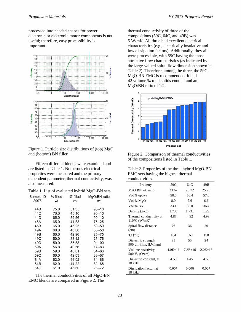
Figure 1. Particle size distributions of (top) MgO
and (bottom) BN filler.
Fifteen different blends were examined and
are listed in Table 1. Numerous electrical
properties were measured and the primary
dependent parameter, thermal conductivity, was
also measured.
Table 1. List of evaluated hybrid MgO-BN sets.
The thermal conductivities of all MgO-BN
EMC blends are compared in Figure 2. The
thermal conductivity of three of the
compositions (59C, 64C, and 49B) was
5 W/mK. All three had excellent electrical
characteristics (e.g., electrically insulative and
low dissipation factors). Additionally, they all
were processible, with 59C having the most
attractive flow characteristics (as indicated by
the large-valued spiral flow dimension shown in
Table 2). Therefore, among the three, the 59C
MgO-BN EMC is recommended. It had
42 volume % total solids content and an
MgO:BN ratio of 1:2.
Figure 2. Comparison of thermal conductivities
of the compositions listed in Table 1.
Table 2. Properties of the three hybrid MgO-BN
EMC sets having the highest thermal
conductivities.
Property 59C 64C 49B
MgO:BN wt. ratio 33:67 28:72 25:75
Vol % epoxy 58.0 56.4 57.0
Vol % MgO 8.9 7.6 6.6
Vol % BN 33.1 36.0 36.4
Density (g/cc) 1.736 1.731 1.29
Thermal conductivity at
110°C (W/mK)
4.87 4.92 4.93
Spiral flow distance
(cm)
76 36 20
Tg (°C) 164 160 158
Dielectric strength,
900 µm film, (kV/mm)
35 55 24
Volume resistivity,
500 V, (Ω•cm)
4.0E+16 7.3E+16 2.0E+16
Dielectric constant, at
10 kHz
4.59 4.45 4.60
Dissipation factor, at
10 kHz
0.007 0.006 0.007
Propulsion Materials FY 2013 Progress Report
21
Although a thermal conductivity of 5 W/mK
was achieved, it needed the relatively expensive
BN for its filler. MgO is inexpensive (about
$3/kg) and can be used to produce 3 W/mK. The
BN spheres were $90/kg (AlN spheres were
$128/kg for comparison); therefore, the cost of
getting that additional 2 W/mK is high.
Conclusions
A thermal conductivity of 5 W/mK was
achieved with a hybrid blend of MgO and BN
used as filler in an EMC. It had a total filler
volume fraction of 42% and a 1:2 weight ratio of
MgO/BN. These hybrid MgO-BN EMCs had
excellent electrical characteristics.
A thermal conductivity of 3 W/mK can be
achieved inexpensively with MgO-filled EMCs.
However, the high cost of materials (i.e., BN)
for increasing that to 5 W/mK results in the
hybrid MgO-BN EMCs being relegated to niche
applications, where thermal performance
characteristics are more important than cost
savings.
Publications
Wereszczak, A. A., 2012, “Hybrid-Filled Epoxy
Molding Compositions,” DOE S-Number
S-124,532, Invention Disclosure Number
201202955, File date October 11, 2012.
Wereszczak, A. A., C. W. Ayers, and M. S.
Chinthavali, 2013, “Hydrostatically
Compressed Power Electronic Device
Package,” DOE S-Number S-124,704,
Invention Disclosure Number 201303116,
File date July 17, 2013.
Wereszczak, A. A., T. G. Morrissey, C. N.
Volante, P. J. Farris, Jr., R. J. Groele, R. H.
Wiles, and H. Wang, 2013, “Thermally
Conductive MgO-Filled Epoxy Molding
Compounds,” IEEE Transactions on
Components, Packaging and Manufacturing
Technology, DOI 10.1109/
TCPMT.2013.2281212.
Propulsion Materials FY 2013 Progress Report
22
Project 18516 – Materials for Hybrid and Electric Drive
Systems
Agreement 23726 – Novel Manufacturing Technologies for
High-Power Induction and Permanent Magnet Electric
Motors (General Motors CRADA)
Glenn J. Grant
Transportation and Industrial Materials
Pacific Northwest National Laboratory
902 Battelle Blvd., K2-03
Richland, Washington 99356
Phone (865) (509) 375-6890; fax: (509) 375-4448; e-mail: [email protected]
Blair E. Carlson
Manager, Lightweight Materials Processing
General Motors Research and Development
30500 Mound Rd
Warren, Michigan 48090
E-mail: [email protected]
DOE Technology Manager: Jerry L. Gibbs
Phone (202) 586-1182; fax: (202) 586-1600; e-mail: [email protected]
Field Technical Manager: Dean Paxton
Phone (509) 375-2620; fax (509) 375-2186; e-mail: [email protected]
Contractor: Pacific Northwest National Laboratory
Prime Contract No.: DE-AC05-76RL01830
Objectives
Develop and deploy high-power induction and permanent magnet rotors and stators that are lighter
weight, have better cooling, and are a lower cost to manufacture through the application of novel
solid-state joining and fabrication technologies.
Apply solid-state processing techniques to improve performance of a low-cost soft magnetic material
used in the rotors of high-power induction motors.
Approach
Develop solid-state joining techniques and manufacturing processes that will increase the efficiency
of electric motors through lightweighting; improvements in electric and magnetic properties; and
improvements in assembly space efficiency, packaging, and cost.
Develop the friction-stir welding (FSW) process parameters and evaluate proper tool materials and
techniques to produce defect-free FSWs in copper (Cu) alloys specified by project partners.
Develop a fundamental understanding of solid-state joints between Cu materials and between
dissimilar Cu/aluminum (Al) materials. This fundamental knowledge is expected to lead to strategies
and techniques that will be used to produce a joining process with low thermal input and low
distortion of adjacent parts and to produce joints with a high degree of structural integrity and with
high thermal and electrical continuity.
Propulsion Materials FY 2013 Progress Report
23
Using fundamental information gained, develop techniques to manufacture Cu and Al rotor and stator
assemblies for high-power induction and permanent magnet motor systems. Joined or processed
components will be evaluated and tested by industry collaborators to demonstrate efficiency benefits
and commercial applications.
Transfer performance data and manufacturing technology to industry through a cooperative research
and development agreement (CRADA) with General Motors (GM), ensuring a clear path to
commercialization.
Accomplishments
Milestone: Completed characterization of the microstructure and mechanical properties of Cu/Cu
joints. Gate is established on the minimum mechanical performance threshold established by the
project team.
First go/no go gate has been achieved with the mechanical testing of a FSW rotor at GM. Test was
completed on a FSW rotor using a 10,000–revolutions-per-minute run-up test.
Milestone: Completed development, fabrication, and testing of an actively cooled welding fixture to
allow for FSW of Cu and Al rotor parts.
Milestone: Demonstration of a robust weld process on Cu/Al dissimilar material welds and
verification that mechanical properties pass the metrics established by the project team are on
schedule.
Future Direction
Propulsion Materials FY 2013 Progress Report
24
Introduction
The purpose of this project is to develop and
deploy high-power induction and permanent
magnet rotors and stators that are lighter weight,
have better cooling, and are a lower cost to
manufacture through the application of novel
solid-state joining and fabrication technologies.
Barriers to achieving these objectives that focus
on the manufacturability of novel rotor designs
have been identified. The project team will
apply friction-stir welding (FSW) to join Cu
subassemblies and Cu/Al joints to eventually
produce prototype lightweight, high-efficiency
rotor assemblies. Fundamental work tasks will
first focus on Cu/Cu FSW and dissimilar Cu/Al
FSW joints. Later tasks will involve full rotor
assembly and testing by GM.
In addition, the project will apply solid-state
processing techniques to improve the
performance of a low-cost soft magnetic
material used in the rotors of high-power
induction motors. GM will provide the motor
design and Pacific Northwest National
Laboratory (PNNL) will employ a novel method
to fabricate the ferrous-based laminates specific
to the GM motor design. The PNNL-developed
method is based on nanoscale powder synthesis
and friction extrusion/consolidation. This new
fabrication process may allow for fewer
energy-intensive processing steps to reach the
microstructure and laminate thicknesses required
for a high-performance soft magnetic material at
a lower manufacturing cost. The project is a
cost-shared CRADA between PNNL and GM.
Background
New manufacturing techniques can cause
step changes in the overall cost of manufactured
assemblies if the new technique can create a
fundamental shift in the way a subsystem is
constructed. For example, an electric motor has
numerous components that are sensitive to high
temperature. Fusion welding, which requires
very high temperature to melt the materials
being joined, cannot be accomplished directly
adjacent to heat-sensitive parts (e.g., sensitive
electronics, wiring, and insulation) or where
coated laminates or substrates are located
nearby. This restriction might require the part to
be assembled through a much more complicated
multistep process. If another joining technology
were available that did not heat the part, then the
multistep assembly could be avoided, saving
cost.
One example of a joining technology that
could satisfy the need for lower adjacent part
temperatures is FSW. Previous work by PNNL
and others has shown that FSW can be made in
Cu alloys that have excellent mechanical,
electrical, and thermomechanical performance.
FSW has a particular advantage in welding Cu
due to the wide range of weld-specific energy
levels that can be applied by the process.
Conventional fusion welding must deliver a high
level of energy to melt the Cu on each side of
the joint line. In many applications, the high part
temperatures during fusion welding can lead to
distortion or overheated adjacent parts. Often,
Cu joining is required in assemblies where
heat-sensitive electronics, wiring, or coated
laminates or substrates are located nearby. FSW
may provide a lower heat input joining
technique in these special applications where
adjacent parts in the assembly can be damaged.
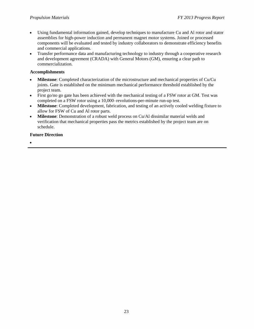
In addition, the next generation of rotor
designs may be Cu/Al hybrids or have Al
components to reduce the rotating mass. It is
anticipated that joints will be needed between
Cu and Al. Solid-state joining techniques such
as FSW are logical to develop for specialized
dissimilar joints like these that cannot be fusion
welded due to the radically different melt
temperatures of the components.
Approach
The project will develop the FSW process
parameters and evaluate proper tool materials
and techniques to produce defect-free FSWs in
Cu alloys specified by project partners. In
addition, the project team will develop statistical
confidence around the manufacturing process
used to fabricate high-power induction motor
rotor assemblies by applying a set of mechanical
test methods and procedures to evaluate process
robustness. The project team also will
investigate the application of FSW to other
joining issues around electric drive systems,
including dissimilar joining between Al/Cu and
Propulsion Materials FY 2013 Progress Report
25
potentially Al/Al joints in specific
configurations.
Finally, to address the overarching goal of
an improved energy efficiency of the induction
motor design, the project team will apply
solid-state processing techniques to fabricate a
low-cost soft magnetic material with unique
properties that has the potential to display high
magnetic flux density (B) and low iron loss (W).
Amorphous iron-based metal and alloys offer
excellent soft magnetic properties. Literature
reports that the material could reduce the core
losses of motors by more than 70% and that the
efficiency of an induction motor with
amorphous iron core could easily reach 80%.
However, the production cost of an amorphous
iron core is high. Specifically, the thickness of
an amorphous iron sheet cannot exceed 25 μm
because of the requirement of ultra-fast
quenching. In this task, we will focus on
developing a cost-effective method to produce
soft iron alloy sheet with magnetic properties
comparable to those of the amorphous iron alloy
and with thickness greater than 100 μm. This
method is based on a modified friction
consolidation and extrusion method, where the
material is subjected to high strain under a
hydrostatic state of stress. This solid-state
process has shown the ability to produce
ultra-fine grain size in bulk solids.
This project will be divided into three
primary task areas. Task 1 will focus on
solid-state joining of Cu materials used in the
rotor assemblies of high-power induction
motors. Task 2 will focus on dissimilar material
joining, primarily Cu to Al, with an emphasis on
components and assembly performance
improvement. Task 3 will develop a unique
solid-state process to create appropriate
microstructures and magnetic performance in
bulk soft magnetic materials that may be able to
improve on the efficiency of stack laminates in
the rotor assembly.
Results
Work completed during fiscal year
(FY) 2013 focused primarily on FSW trials on
Cu bar materials and Cu rotor end caps (Task 1).
The induction motor rotor represents an
excellent example of a multi-material assembly
that may be manufactured more efficiently and
at a lower cost if new manufacturing techniques
could be developed (Figure 1). This project is
investigating using solid-state welding (FSW) to
assemble this component.
Figure 1. Rotor concepts fabricated with FSW.
The primary scope of Task 1 is to develop a
weld process to join the Cu end cap to the
shorting bars that traverse the soft magnetic core
of the rotor. These bars carry current up and
down the rotor between the end caps to produce
the magnetic moment that drives the rotor. The
joint has several important characteristics. It
needs strength because it will be subjected to
high tensional and cantilever loads when the
rotor is moving at high revolutions per minute, it
needs to have optimum electrical conductivity
for high efficiency, and during the joining
operation it cannot get hot enough for the
underlying electric steel laminates to melt their
polymeric insulating coatings. Figure 2 shows a
schematic of a rotor and a photo of a rotor end
cap in place on the shorting bars just prior to
joining.
Maximum electrical continuity is one of the
key factors in rotor efficiency and
lightweighting. The joint must be designed for
the highest electrical cross section at the
minimum weight penalty. The thickness of the
heavy Cu end cap is a key variable to optimize.
It is desired to have the minimum end cap
thickness for weight savings, yet the highest
electrical cross section for current flow. This
requires the joined region to have the largest
possible area between the end cap and the
shorting bar. Figure 3 shows, schematically, the
challenge. The joined area intersecting the end
cap and shorting bar must have maximum width
and appropriate depth. The better the electrical
continuity and current flow in this area, the
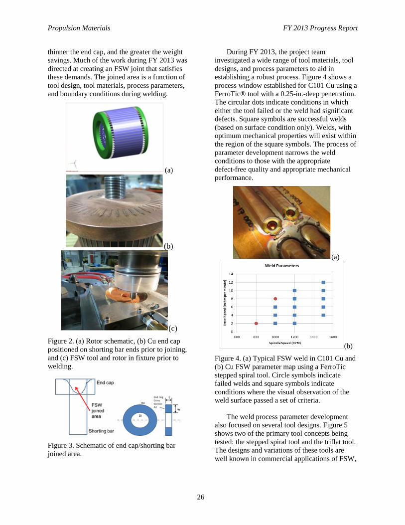
Propulsion Materials FY 2013 Progress Report
26
thinner the end cap, and the greater the weight
savings. Much of the work during FY 2013 was
directed at creating an FSW joint that satisfies
these demands. The joined area is a function of
tool design, tool materials, process parameters,
and boundary conditions during welding.
(a)
(b)
(c)
Figure 2. (a) Rotor schematic, (b) Cu end cap
positioned on shorting bar ends prior to joining,
and (c) FSW tool and rotor in fixture prior to
welding.
Figure 3. Schematic of end cap/shorting bar
joined area.
During FY 2013, the project team
investigated a wide range of tool materials, tool
designs, and process parameters to aid in
establishing a robust process. Figure 4 shows a
process window established for C101 Cu using a
FerroTic® tool with a 0.25-in.-deep penetration.
The circular dots indicate conditions in which
either the tool failed or the weld had significant
defects. Square symbols are successful welds
(based on surface condition only). Welds, with
optimum mechanical properties will exist within
the region of the square symbols. The process of
parameter development narrows the weld
conditions to those with the appropriate
defect-free quality and appropriate mechanical
performance.
(a)
(b)
Figure 4. (a) Typical FSW weld in C101 Cu and
(b) Cu FSW parameter map using a FerroTic
stepped spiral tool. Circle symbols indicate
failed welds and square symbols indicate
conditions where the visual observation of the
weld surface passed a set of criteria.
The weld process parameter development
also focused on several tool designs. Figure 5
shows two of the primary tool concepts being
tested: the stepped spiral tool and the triflat tool.
The designs and variations of these tools are
well known in commercial applications of FSW,
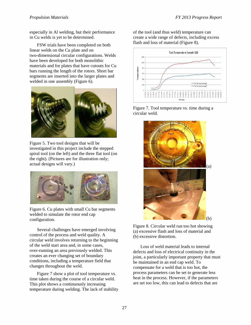
Propulsion Materials FY 2013 Progress Report
27
especially in Al welding, but their performance
in Cu welds is yet to be determined.
FSW trials have been completed on both
linear welds on the Cu plate and on
two-dimensional circular configurations. Welds
have been developed for both monolithic
materials and for plates that have cutouts for Cu
bars running the length of the rotors. Short bar
segments are inserted into the larger plates and
welded in one assembly (Figure 6).
Figure 5. Two tool designs that will be
investigated in this project include the stepped
spiral tool (on the left) and the three flat tool (on
the right). (Pictures are for illustration only;
actual designs will vary.)
Figure 6. Cu plates with small Cu bar segments
welded to simulate the rotor end cap
configuration.
Several challenges have emerged involving
control of the process and weld quality. A
circular weld involves returning to the beginning
of the weld start area and, in some cases,
over-running an area previously welded. This
creates an ever changing set of boundary
conditions, including a temperature field that
changes throughout the weld.
Figure 7 show a plot of tool temperature vs.
time taken during the course of a circular weld.
This plot shows a continuously increasing
temperature during welding. The lack of stability
of the tool (and thus weld) temperature can
create a wide range of defects, including excess
flash and loss of material (Figure 8).
Figure 7. Tool temperature vs. time during a
circular weld.
(a)
(b)
Figure 8. Circular weld run too hot showing
(a) excessive flash and loss of material and
(b) excessive distortion.
Loss of weld material leads to internal
defects and loss of electrical continuity in the
joint, a particularly important property that must
be maintained in an end cap weld. To
compensate for a weld that is too hot, the
process parameters can be set to generate less
heat in the process. However, if the parameters
are set too low, this can lead to defects that are
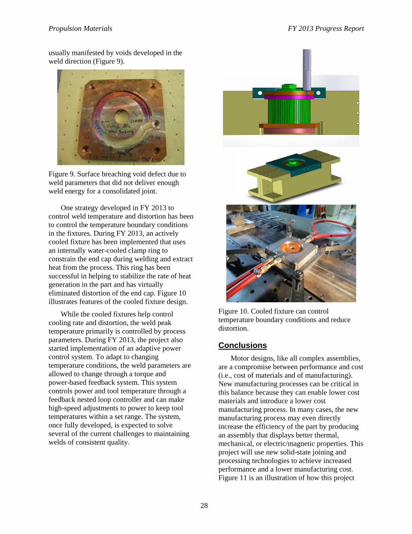
Propulsion Materials FY 2013 Progress Report
28
usually manifested by voids developed in the
weld direction (Figure 9).
Figure 9. Surface breaching void defect due to
weld parameters that did not deliver enough
weld energy for a consolidated joint.
One strategy developed in FY 2013 to
control weld temperature and distortion has been
to control the temperature boundary conditions
in the fixtures. During FY 2013, an actively
cooled fixture has been implemented that uses
an internally water-cooled clamp ring to
constrain the end cap during welding and extract
heat from the process. This ring has been
successful in helping to stabilize the rate of heat
generation in the part and has virtually
eliminated distortion of the end cap. Figure 10
illustrates features of the cooled fixture design.
While the cooled fixtures help control
cooling rate and distortion, the weld peak
temperature primarily is controlled by process
parameters. During FY 2013, the project also
started implementation of an adaptive power
control system. To adapt to changing
temperature conditions, the weld parameters are
allowed to change through a torque and
power-based feedback system. This system
controls power and tool temperature through a
feedback nested loop controller and can make
high-speed adjustments to power to keep tool
temperatures within a set range. The system,
once fully developed, is expected to solve
several of the current challenges to maintaining
welds of consistent quality.
Figure 10. Cooled fixture can control
temperature boundary conditions and reduce
distortion.
Conclusions
Motor designs, like all complex assemblies,
are a compromise between performance and cost
(i.e., cost of materials and of manufacturing).
New manufacturing processes can be critical in
this balance because they can enable lower cost
materials and introduce a lower cost
manufacturing process. In many cases, the new
manufacturing process may even directly
increase the efficiency of the part by producing
an assembly that displays better thermal,
mechanical, or electric/magnetic properties. This
project will use new solid-state joining and
processing technologies to achieve increased
performance and a lower manufacturing cost.
Figure 11 is an illustration of how this project
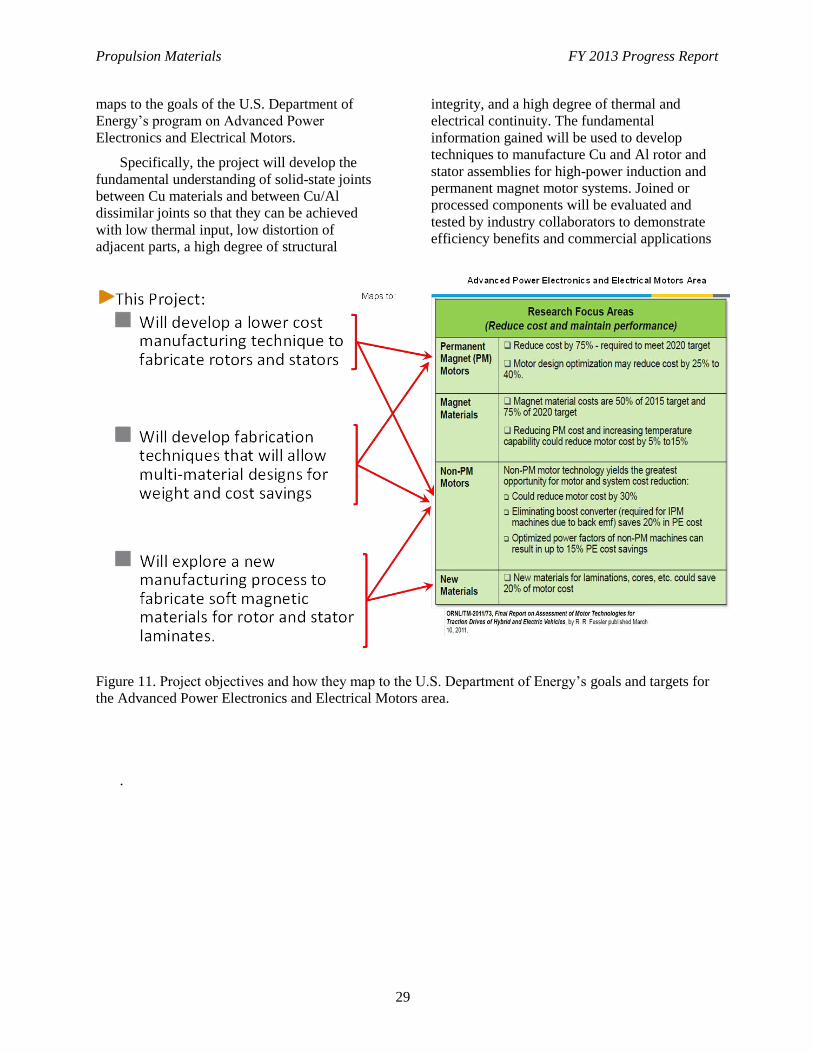
Propulsion Materials FY 2013 Progress Report
29
maps to the goals of the U.S. Department of
Energy’s program on Advanced Power
Electronics and Electrical Motors.
Specifically, the project will develop the
fundamental understanding of solid-state joints
between Cu materials and between Cu/Al
dissimilar joints so that they can be achieved
with low thermal input, low distortion of
adjacent parts, a high degree of structural
integrity, and a high degree of thermal and
electrical continuity. The fundamental
information gained will be used to develop
techniques to manufacture Cu and Al rotor and
stator assemblies for high-power induction and
permanent magnet motor systems. Joined or
processed components will be evaluated and
tested by industry collaborators to demonstrate
efficiency benefits and commercial applications
Figure 11. Project objectives and how they map to the U.S. Department of Energy’s goals and targets for
the Advanced Power Electronics and Electrical Motors area.
.
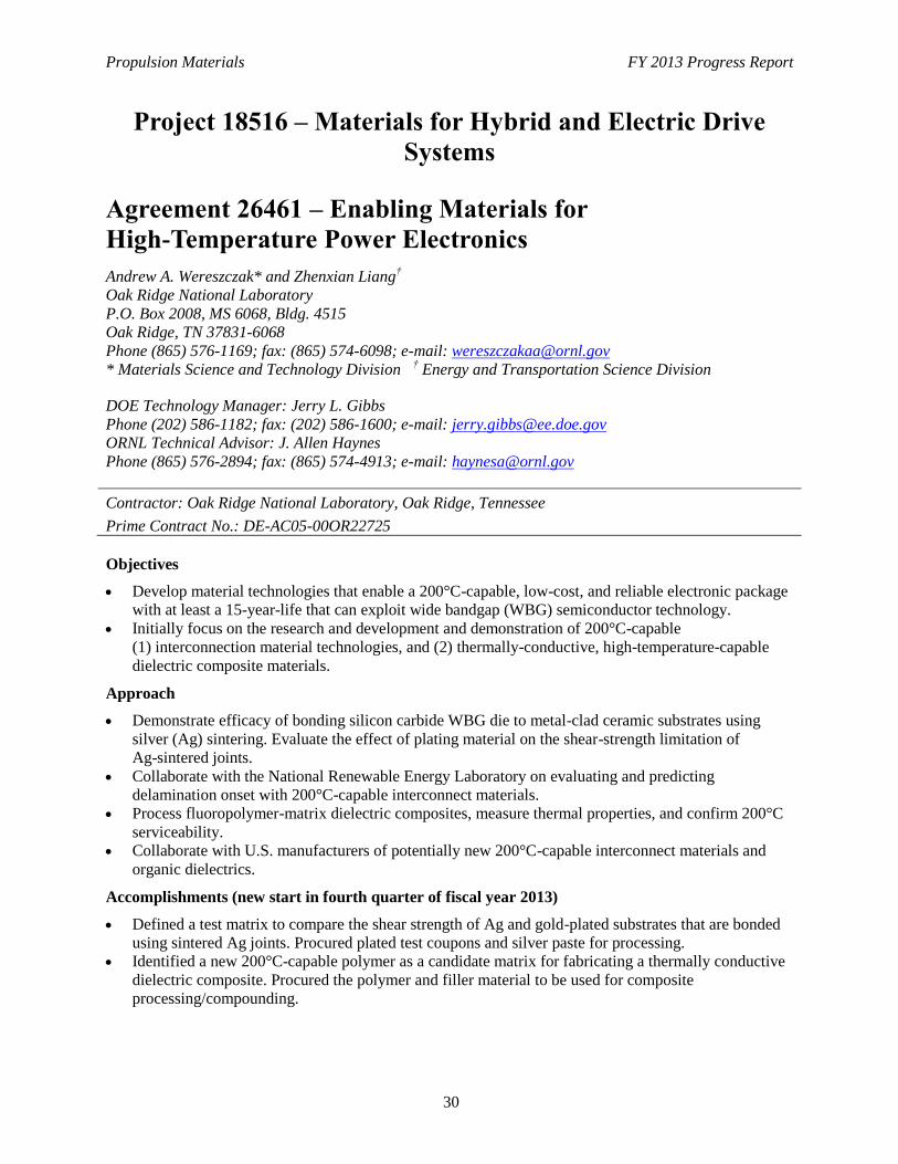
Propulsion Materials FY 2013 Progress Report
30
Project 18516 – Materials for Hybrid and Electric Drive
Systems
Agreement 26461 – Enabling Materials for
High-Temperature Power Electronics
Andrew A. Wereszczak* and Zhenxian Liang†
Oak Ridge National Laboratory
P.O. Box 2008, MS 6068, Bldg. 4515
Oak Ridge, TN 37831-6068
Phone (865) 576-1169; fax: (865) 574-6098; e-mail: [email protected]
* Materials Science and Technology Division † Energy and Transportation Science Division
DOE Technology Manager: Jerry L. Gibbs
Phone (202) 586-1182; fax: (202) 586-1600; e-mail: [email protected]
ORNL Technical Advisor: J. Allen Haynes
Phone (865) 576-2894; fax: (865) 574-4913; e-mail: [email protected]
Contractor: Oak Ridge National Laboratory, Oak Ridge, Tennessee
Prime Contract No.: DE-AC05-00OR22725
Objectives
Develop material technologies that enable a 200°C-capable, low-cost, and reliable electronic package
with at least a 15-year-life that can exploit wide bandgap (WBG) semiconductor technology.
Initially focus on the research and development and demonstration of 200°C-capable
(1) interconnection material technologies, and (2) thermally-conductive, high-temperature-capable
dielectric composite materials.
Approach
Demonstrate efficacy of bonding silicon carbide WBG die to metal-clad ceramic substrates using
silver (Ag) sintering. Evaluate the effect of plating material on the shear-strength limitation of
Ag-sintered joints.
Collaborate with the National Renewable Energy Laboratory on evaluating and predicting
delamination onset with 200°C-capable interconnect materials.
Process fluoropolymer-matrix dielectric composites, measure thermal properties, and confirm 200°C
serviceability.
Collaborate with U.S. manufacturers of potentially new 200°C-capable interconnect materials and
organic dielectrics.
Accomplishments (new start in fourth quarter of fiscal year 2013)
Defined a test matrix to compare the shear strength of Ag and gold-plated substrates that are bonded
using sintered Ag joints. Procured plated test coupons and silver paste for processing.
Identified a new 200°C-capable polymer as a candidate matrix for fabricating a thermally conductive
dielectric composite. Procured the polymer and filler material to be used for composite
processing/compounding.

Propulsion Materials FY 2013 Progress Report
31
Expected Benefits
Increase the temperature tolerance of state-of-the-art electronic packaging by at least 50°C and further
the efforts of the Advanced Power Electronics and Advanced Motors Program to reach the 2020
power electronic targets of $3.30/kW, 14.1 kW/kg, and 13.4 kW/l.
This work will benefit industry and, ultimately, the consumer because it will help hasten sought-after
WBG semiconductor use and exploitation. This project's results also will assist in the cost, size, and
weight reduction of inverters and their sustained operation in harsher conditions.
Propulsion Materials FY 2013 Progress Report
32
Project 18518 – Materials for High-Efficiency Engines
Agreement 8697 – NOx Sensor Development
Leta Y. Woo and Robert S. Glass
Lawrence Livermore National Laboratory
P.O. Box 808, L-103
Livermore, CA 94551-9900
Phone (925) 423-7140; fax: (925) (422-5844); e-mail: [email protected]
DOE Technology Manager: Jerry L. Gibbs
(202) 586-1182; fax: (202) 586-1600; e-mail: [email protected]
Contractor: Lawrence Livermore National Laboratory, Livermore, California
Prime Contract No.: W-7405-Eng-48; LLNL-TR-510234
Objectives
Develop an inexpensive, rapid-response, high-sensitivity, and selective electrochemical
sensor for oxides of nitrogen (NOx) for compression-ignition, direct-injection (CIDI) OBD II
systems.
Explore and characterize novel, effective sensing methodologies based on impedance
measurements and designs and manufacturing methods that are compatible with mass
fabrication.
Transfer the technology to industry for commercialization.
Approach
Use an ionic (O2-
) conducting ceramic as a solid electrolyte and metal or metal-oxide
electrodes.
Correlate NOx concentration with changes in cell impedance.
Evaluate sensing mechanisms and aging effects on long-term performance using
electrochemical techniques.
Collaborate with Ford Research Center and EmiSense Technologies, LLC to optimize sensor
performance and perform dynamometer and on-vehicle testing.
Accomplishments
Successful technology transfer activities as part of a Cooperative Research and Development
Agreement (CRADA) with EmiSense Technologies, LLC, a Salt Lake City, Utah company,
which has licensed the Lawrence Livermore National Laboratory (LLNL) NOx sensor
technology. This has resulted in more advanced sensor designs amenable to mass
manufacturing. The commercialization goal is for 2016 car models.
Completed advanced vehicle dynamometer testing at Ford Motor Company of fiscal year
2013 sensor prototypes using newly developed prototype electronics for data acquisition.
Good performance was obtained in these tests.
Publications/presentations/patents:
Propulsion Materials FY 2013 Progress Report
33
- Du Frane, W. L., L. Y. Woo, R. S. Glass, R. F. Novak, and J. H. Visser, 2013, “Substrate
Effects on Electrochemical NOx Sensor Based on Porous Y2O3-Stabilized ZrO2 (YSZ)
and Sr-doped LaMnO3 (LSM),” ECS Transactions, 45 (14), 3–11.
- Woo, L. Y., R. S. Glass, R. F. Novak, and J. H. Visser, “Zirconia-electrolyte-based
impedancemetric sensors using Sr-doped LaMnO3 (LSM) electrodes for measuring NOx
in combustion exhaust streams,” The 10th Pacific Rim Conference on Ceramic and Glass
Technology, in San Diego, California, June 2–7, 2013.
- New patent application (No. 14055562) entitled, “Electrochemical Sensing Using
Voltage-Current Time Differential,” filed on October 16, 2013.
Future Direction
Working through the CRADA with EmiSense Technologies, LLC and in collaboration with Ford
Motor Company, complete the technology transfer and bring the NOx sensor technology to the
commercialization stage.
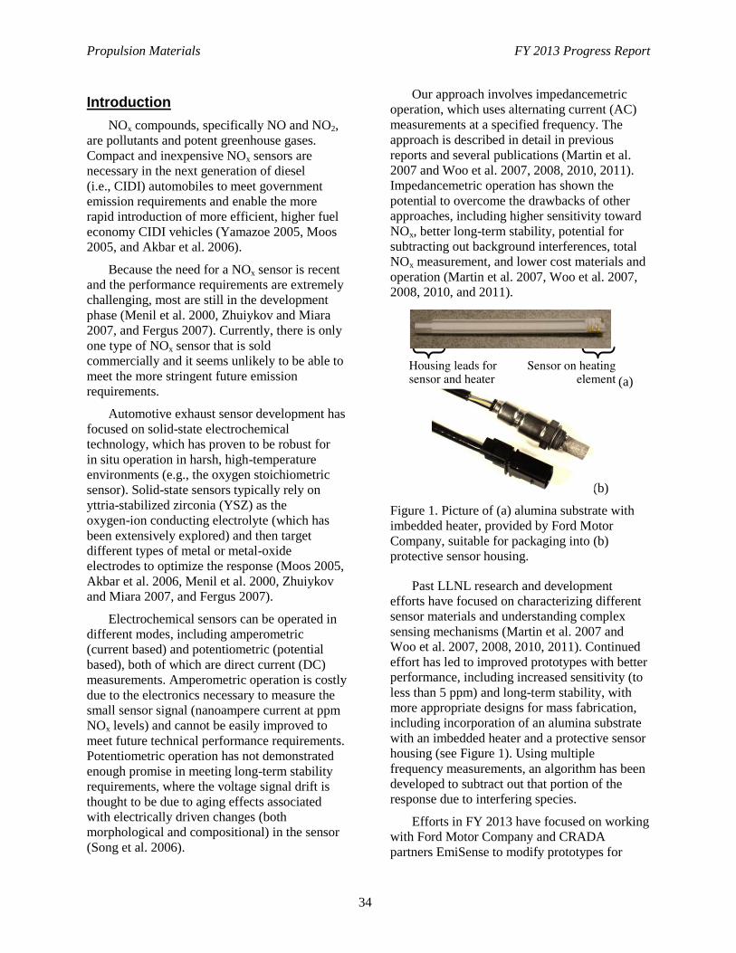
Propulsion Materials FY 2013 Progress Report
34
Introduction
NOx compounds, specifically NO and NO2,
are pollutants and potent greenhouse gases.
Compact and inexpensive NOx sensors are
necessary in the next generation of diesel
(i.e., CIDI) automobiles to meet government
emission requirements and enable the more
rapid introduction of more efficient, higher fuel
economy CIDI vehicles (Yamazoe 2005, Moos
2005, and Akbar et al. 2006).
Because the need for a NOx sensor is recent
and the performance requirements are extremely
challenging, most are still in the development
phase (Menil et al. 2000, Zhuiykov and Miara
2007, and Fergus 2007). Currently, there is only
one type of NOx sensor that is sold
commercially and it seems unlikely to be able to
meet the more stringent future emission
requirements.
Automotive exhaust sensor development has
focused on solid-state electrochemical
technology, which has proven to be robust for
in situ operation in harsh, high-temperature
environments (e.g., the oxygen stoichiometric
sensor). Solid-state sensors typically rely on
yttria-stabilized zirconia (YSZ) as the
oxygen-ion conducting electrolyte (which has
been extensively explored) and then target
different types of metal or metal-oxide
electrodes to optimize the response (Moos 2005,
Akbar et al. 2006, Menil et al. 2000, Zhuiykov
and Miara 2007, and Fergus 2007).
Electrochemical sensors can be operated in
different modes, including amperometric
(current based) and potentiometric (potential
based), both of which are direct current (DC)
measurements. Amperometric operation is costly
due to the electronics necessary to measure the
small sensor signal (nanoampere current at ppm
NOx levels) and cannot be easily improved to
meet future technical performance requirements.
Potentiometric operation has not demonstrated
enough promise in meeting long-term stability
requirements, where the voltage signal drift is
thought to be due to aging effects associated
with electrically driven changes (both
morphological and compositional) in the sensor
(Song et al. 2006).
Our approach involves impedancemetric
operation, which uses alternating current (AC)
measurements at a specified frequency. The
approach is described in detail in previous
reports and several publications (Martin et al.
2007 and Woo et al. 2007, 2008, 2010, 2011).
Impedancemetric operation has shown the
potential to overcome the drawbacks of other
approaches, including higher sensitivity toward
NOx, better long-term stability, potential for
subtracting out background interferences, total
NOx measurement, and lower cost materials and
operation (Martin et al. 2007, Woo et al. 2007,
2008, 2010, and 2011).
(a)
(b)
Figure 1. Picture of (a) alumina substrate with
imbedded heater, provided by Ford Motor
Company, suitable for packaging into (b)
protective sensor housing.
Past LLNL research and development
efforts have focused on characterizing different
sensor materials and understanding complex
sensing mechanisms (Martin et al. 2007 and
Woo et al. 2007, 2008, 2010, 2011). Continued
effort has led to improved prototypes with better
performance, including increased sensitivity (to
less than 5 ppm) and long-term stability, with
more appropriate designs for mass fabrication,
including incorporation of an alumina substrate
with an imbedded heater and a protective sensor
housing (see Figure 1). Using multiple
frequency measurements, an algorithm has been
developed to subtract out that portion of the
response due to interfering species.
Efforts in FY 2013 have focused on working
with Ford Motor Company and CRADA
partners EmiSense to modify prototypes for
Propulsion Materials FY 2013 Progress Report
35
improved performance. Three major
accomplishments this year include (1)
completing evaluation of strontium-doped
lanthanum manganite (LSM) metal oxide
electrodes to enable a material down-select to
focus on Au-based electrodes; (2) development
of new portable electronics for experimental
control and data acquisition using low-cost
components; (3) further development of a
voltage-current time differential measurement
strategy that has shown improved results in
vehicle dynamometer testing at Ford; and (4)
evaluation of processing methods more suitable
for mass manufacturing. We have had great
success in technology transfer to EmiSense,
which licensed the LLNL NOx sensor
technology, and made great progress in
commercialization efforts, which are directed
toward a 2016 model year goal.
Background
For a two-electrode electrochemical cell,
impedancemetric sensing requires that at least
one of the electrodes act as the “sensing”
electrode with selective response to NOx over
other gas phase components. This contrasts to
the case in potentiometric sensing, which relies
on differential measurements between the two
electrodes. The impedancemetric sensor design
is quite flexible and can either contain one
sensing electrode and one counter (i.e., non-
sensing) electrode or two sensing electrodes. It
opens up the opportunity to use a wide variety of
materials, both metal and metal oxides.
Both electrode composition and
microstructure influence sensitivity, which relies
on limiting the oxygen reaction on the electrode
so that the NOx reaction can be resolved (Woo et
al. 2007, 2008, 2010, and 2011). In general, for
the “sensing” electrode, a dense microstructure
is required with appropriate composition to limit
the catalytic activity toward oxygen (Woo et al.
2008, 2010, and 2011).
Measured sensor impedance is a complex
quantity with both magnitude and phase angle
information. The phase angle has been found to
provide a more stable response at higher
operating frequencies and we prefer it for the
sensor signal (Martin et al. 2007 and Woo et al.
2007, 2008, 2010, 2011).
In previous work, impedancemetric sensing
using either Au or strontium-doped LSM
electrodes (the latter being an electronically
conducting metal oxide) was investigated in
laboratory and engine testing. Preliminary
results indicated that Au electrodes have good
stability and the potential for low water
cross-sensitivity, but also have a higher thermal
expansion coefficient and lower melting
temperature than the YSZ electrolyte, which
limits processing flexibility. LSM electrodes
have high melting temperatures and better
thermal expansion match with YSZ, but have
shown higher water cross-sensitivity than gold.
Results and Discussion
Metal Oxide Electrodes
To further understand impedancemetric
sensing mechanisms and to aid in down
selection for either metal-oxide or Au-based
electrodes, multiple configurations of the
strontium-doped LSM metal oxide electrode
prototype sensor were investigated. To conserve
space, experimental details of sensor preparation
and measurement protocol are omitted, but the
interested reader can find these in the fiscal year
2012 Annual Report for this project and
elsewhere (Woo et al. 2008, 2010, and 2011).
Figure 2a shows a schematic of the
previously studied symmetric (i.e., electrode
materials the same) in-plane LSM prototype (Du
Frane 2013). This design resulted in poor
sample-to-sample reproducibility and variability
in performance attributable to the formation and
growth of random microcracks due to the
thermal expansion mismatch between the sensor
components (YSZ and LSM) and the substrate
(alumina) (Du Frane 2013).
In an attempt to reduce microcracking, an
asymmetric (LSM/YSZ/Pt) through-plane
geometry (Figure 2b) was evaluated next.
Figure 3 shows a comparison of the sensing
behavior of the symmetric side-by-side
(LSM/YSZ/LSM) and asymmetric through-
plane (LSM/YSZ/Pt) configurations (see Figure
2a and 2b) in 10.5% O2 when 100 ppm NO is
added. The asymmetric (LSM/YSZ/Pt) showed
lower sensitivity than the symmetric
configuration.
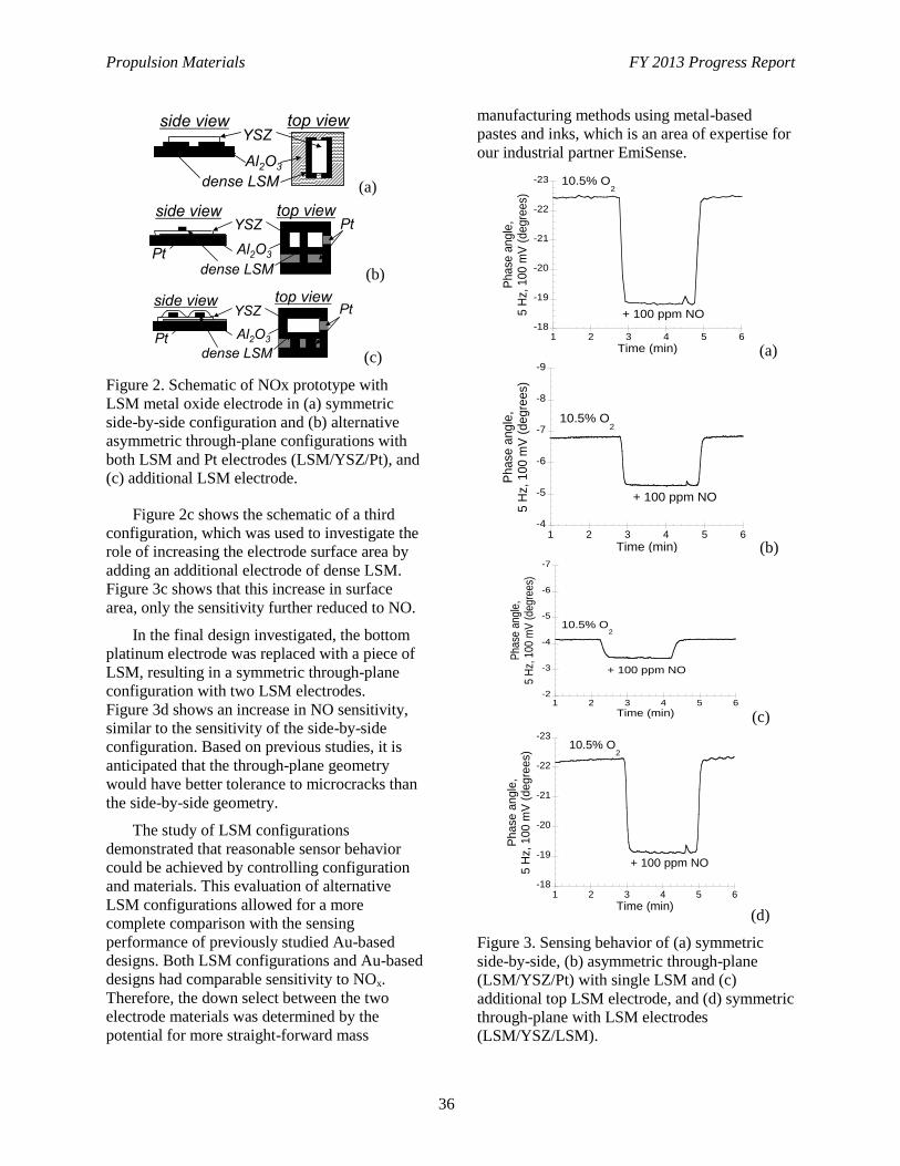
Propulsion Materials FY 2013 Progress Report
36
(a)
(b)
(c)
Figure 2. Schematic of NOx prototype with
LSM metal oxide electrode in (a) symmetric
side-by-side configuration and (b) alternative
asymmetric through-plane configurations with
both LSM and Pt electrodes (LSM/YSZ/Pt), and
(c) additional LSM electrode.
Figure 2c shows the schematic of a third
configuration, which was used to investigate the
role of increasing the electrode surface area by
adding an additional electrode of dense LSM.
Figure 3c shows that this increase in surface
area, only the sensitivity further reduced to NO.
In the final design investigated, the bottom
platinum electrode was replaced with a piece of
LSM, resulting in a symmetric through-plane
configuration with two LSM electrodes.
Figure 3d shows an increase in NO sensitivity,
similar to the sensitivity of the side-by-side
configuration. Based on previous studies, it is
anticipated that the through-plane geometry
would have better tolerance to microcracks than
the side-by-side geometry.
The study of LSM configurations
demonstrated that reasonable sensor behavior
could be achieved by controlling configuration
and materials. This evaluation of alternative
LSM configurations allowed for a more
complete comparison with the sensing
performance of previously studied Au-based
designs. Both LSM configurations and Au-based
designs had comparable sensitivity to NOx.
Therefore, the down select between the two
electrode materials was determined by the
potential for more straight-forward mass
manufacturing methods using metal-based
pastes and inks, which is an area of expertise for
our industrial partner EmiSense.
(a)
(b)
(c)
(d)
Figure 3. Sensing behavior of (a) symmetric
side-by-side, (b) asymmetric through-plane
(LSM/YSZ/Pt) with single LSM and (c)
additional top LSM electrode, and (d) symmetric
through-plane with LSM electrodes
(LSM/YSZ/LSM).
YSZ top view side view
dense LSM
Al2O3
YSZ top view side view
dense LSM
Al2O3
Pt
Pt
YSZ
dense LSM
Al2O3 Pt
Pt side view top view
-23
-22
-21
-20
-19
-181 2 3 4 5 6
New YSZ - Sample 3; 650C, 5 Hz, 100 mV, 1 day
Ph
ase
ang
le,
5 H
z, 1
00
mV
(de
gre
es)
Time (min)
10.5% O2
+ 100 ppm NO
-9
-8
-7
-6
-5
-41 2 3 4 5 6
Pt/YSZ/LSM (11.8.6) - Sample 1; 650C, 5 Hz, 100 mV, 1 day
Phase
angle
,5 H
z,
10
0 m
V (
deg
rees)
Time (min)
10.5% O2
+ 100 ppm NO
-7
-6
-5
-4
-3
-21 2 3 4 5 6
Pt/YSZ/LSM (double) (11.8.11) - Sample 1;650C, 100 mV, < 1 day
Pha
se a
ngl
e,
5 H
z, 1
00
mV
(d
egre
es)
Time (min)
10.5% O2
+ 100 ppm NO
-23
-22
-21
-20
-19
-181 2 3 4 5 6
LSM/YSZ/wideLSM (12.7.18) - Sample 1; 5 Hz, 100 mV, 1 day
Phase
angle
,5 H
z,
100 m
V (
deg
rees)
Time (min)
10.5% O2
+ 100 ppm NO
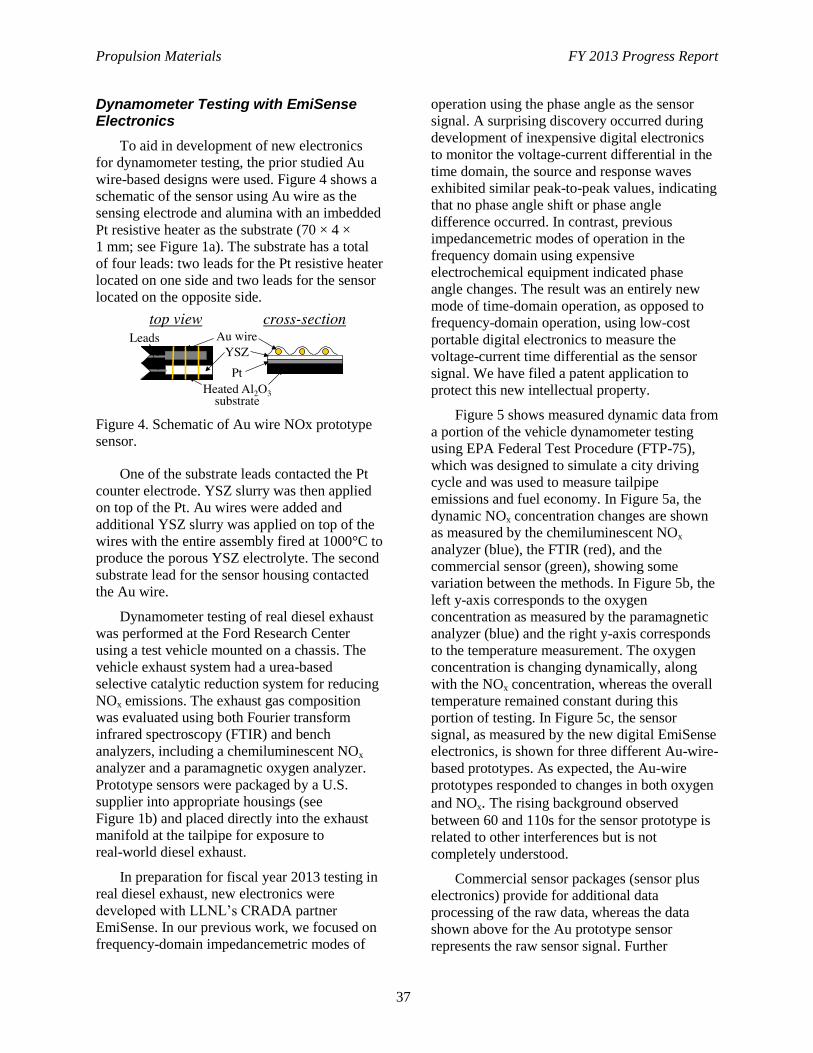
Propulsion Materials FY 2013 Progress Report
37
Dynamometer Testing with EmiSense Electronics
To aid in development of new electronics
for dynamometer testing, the prior studied Au
wire-based designs were used. Figure 4 shows a
schematic of the sensor using Au wire as the
sensing electrode and alumina with an imbedded
Pt resistive heater as the substrate (70 × 4 ×
1 mm; see Figure 1a). The substrate has a total
of four leads: two leads for the Pt resistive heater
located on one side and two leads for the sensor
located on the opposite side.
Figure 4. Schematic of Au wire NOx prototype
sensor.
One of the substrate leads contacted the Pt
counter electrode. YSZ slurry was then applied
on top of the Pt. Au wires were added and
additional YSZ slurry was applied on top of the
wires with the entire assembly fired at 1000°C to
produce the porous YSZ electrolyte. The second
substrate lead for the sensor housing contacted
the Au wire.
Dynamometer testing of real diesel exhaust
was performed at the Ford Research Center
using a test vehicle mounted on a chassis. The
vehicle exhaust system had a urea-based
selective catalytic reduction system for reducing
NOx emissions. The exhaust gas composition
was evaluated using both Fourier transform
infrared spectroscopy (FTIR) and bench
analyzers, including a chemiluminescent NOx
analyzer and a paramagnetic oxygen analyzer.
Prototype sensors were packaged by a U.S.
supplier into appropriate housings (see
Figure 1b) and placed directly into the exhaust
manifold at the tailpipe for exposure to
real-world diesel exhaust.
In preparation for fiscal year 2013 testing in
real diesel exhaust, new electronics were
developed with LLNL’s CRADA partner
EmiSense. In our previous work, we focused on
frequency-domain impedancemetric modes of
operation using the phase angle as the sensor
signal. A surprising discovery occurred during
development of inexpensive digital electronics
to monitor the voltage-current differential in the
time domain, the source and response waves
exhibited similar peak-to-peak values, indicating
that no phase angle shift or phase angle
difference occurred. In contrast, previous
impedancemetric modes of operation in the
frequency domain using expensive
electrochemical equipment indicated phase
angle changes. The result was an entirely new
mode of time-domain operation, as opposed to
frequency-domain operation, using low-cost
portable digital electronics to measure the
voltage-current time differential as the sensor
signal. We have filed a patent application to
protect this new intellectual property.
Figure 5 shows measured dynamic data from
a portion of the vehicle dynamometer testing
using EPA Federal Test Procedure (FTP-75),
which was designed to simulate a city driving
cycle and was used to measure tailpipe
emissions and fuel economy. In Figure 5a, the
dynamic NOx concentration changes are shown
as measured by the chemiluminescent NOx
analyzer (blue), the FTIR (red), and the
commercial sensor (green), showing some
variation between the methods. In Figure 5b, the
left y-axis corresponds to the oxygen
concentration as measured by the paramagnetic
analyzer (blue) and the right y-axis corresponds
to the temperature measurement. The oxygen
concentration is changing dynamically, along
with the NOx concentration, whereas the overall
temperature remained constant during this
portion of testing. In Figure 5c, the sensor
signal, as measured by the new digital EmiSense
electronics, is shown for three different Au-wire-
based prototypes. As expected, the Au-wire
prototypes responded to changes in both oxygen
and NOx. The rising background observed
between 60 and 110s for the sensor prototype is
related to other interferences but is not
completely understood.
Commercial sensor packages (sensor plus
electronics) provide for additional data
processing of the raw data, whereas the data
shown above for the Au prototype sensor
represents the raw sensor signal. Further
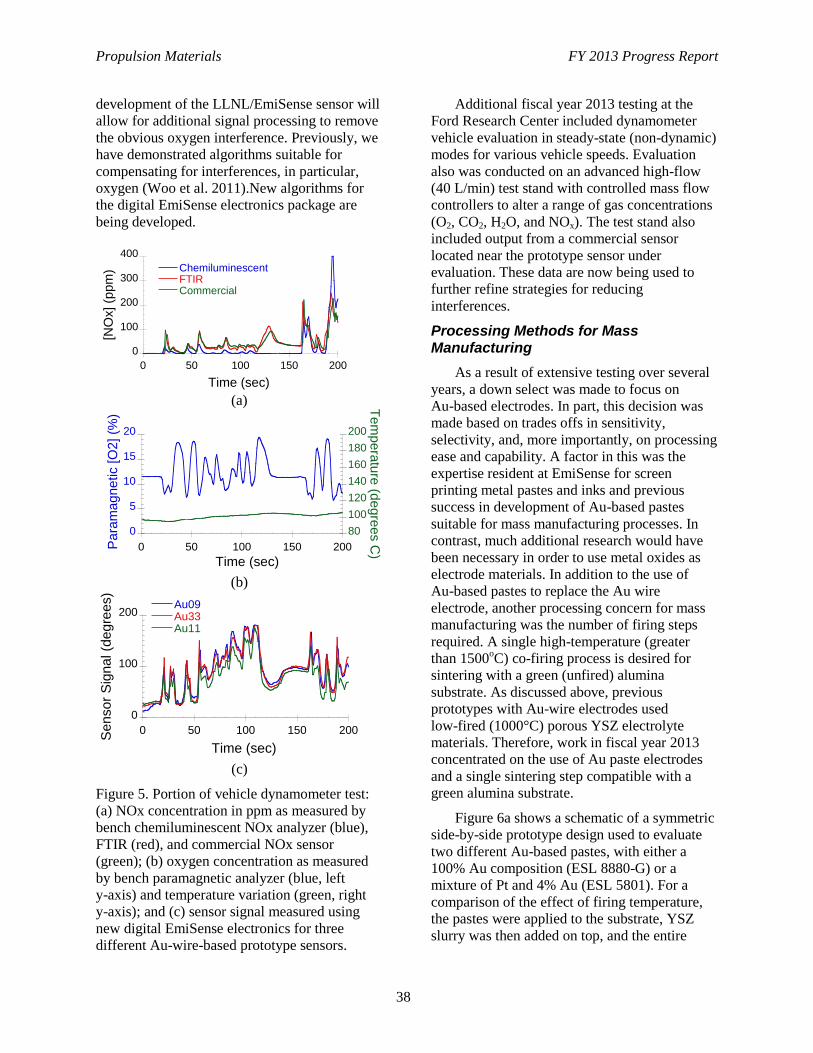
Propulsion Materials FY 2013 Progress Report
38
development of the LLNL/EmiSense sensor will
allow for additional signal processing to remove
the obvious oxygen interference. Previously, we
have demonstrated algorithms suitable for
compensating for interferences, in particular,
oxygen (Woo et al. 2011).New algorithms for
the digital EmiSense electronics package are
being developed.
(a)
(b)
(c)
Figure 5. Portion of vehicle dynamometer test:
(a) NOx concentration in ppm as measured by
bench chemiluminescent NOx analyzer (blue),
FTIR (red), and commercial NOx sensor
(green); (b) oxygen concentration as measured
by bench paramagnetic analyzer (blue, left
y-axis) and temperature variation (green, right
y-axis); and (c) sensor signal measured using
new digital EmiSense electronics for three
different Au-wire-based prototype sensors.
Additional fiscal year 2013 testing at the
Ford Research Center included dynamometer
vehicle evaluation in steady-state (non-dynamic)
modes for various vehicle speeds. Evaluation
also was conducted on an advanced high-flow
(40 L/min) test stand with controlled mass flow
controllers to alter a range of gas concentrations
(O2, CO2, H2O, and NOx). The test stand also
included output from a commercial sensor
located near the prototype sensor under
evaluation. These data are now being used to
further refine strategies for reducing
interferences.
Processing Methods for Mass Manufacturing
As a result of extensive testing over several
years, a down select was made to focus on
Au-based electrodes. In part, this decision was
made based on trades offs in sensitivity,
selectivity, and, more importantly, on processing
ease and capability. A factor in this was the
expertise resident at EmiSense for screen
printing metal pastes and inks and previous
success in development of Au-based pastes
suitable for mass manufacturing processes. In
contrast, much additional research would have
been necessary in order to use metal oxides as
electrode materials. In addition to the use of
Au-based pastes to replace the Au wire
electrode, another processing concern for mass
manufacturing was the number of firing steps
required. A single high-temperature (greater
than 1500oC) co-firing process is desired for
sintering with a green (unfired) alumina
substrate. As discussed above, previous
prototypes with Au-wire electrodes used
low-fired (1000°C) porous YSZ electrolyte
materials. Therefore, work in fiscal year 2013
concentrated on the use of Au paste electrodes
and a single sintering step compatible with a
green alumina substrate.
Figure 6a shows a schematic of a symmetric
side-by-side prototype design used to evaluate
two different Au-based pastes, with either a
100% Au composition (ESL 8880-G) or a
mixture of Pt and 4% Au (ESL 5801). For a
comparison of the effect of firing temperature,
the pastes were applied to the substrate, YSZ
slurry was then added on top, and the entire
0
100
200
300
400
0 50 100 150 200
ChemiluminescentFTIRCommercial
[NO
x] (p
pm
)
Time (sec)
0
5
10
15
20
80
100
120
140
160
180
200
0 50 100 150 200 Pa
ram
ag
netic [O
2] (%
)
Tem
pera
ture
(de
gre
es C
)
Time (sec)
0
100
200
0 50 100 150 200
Au09Au33Au11
Sensor
Sig
na
l (d
egre
es)
Time (sec)
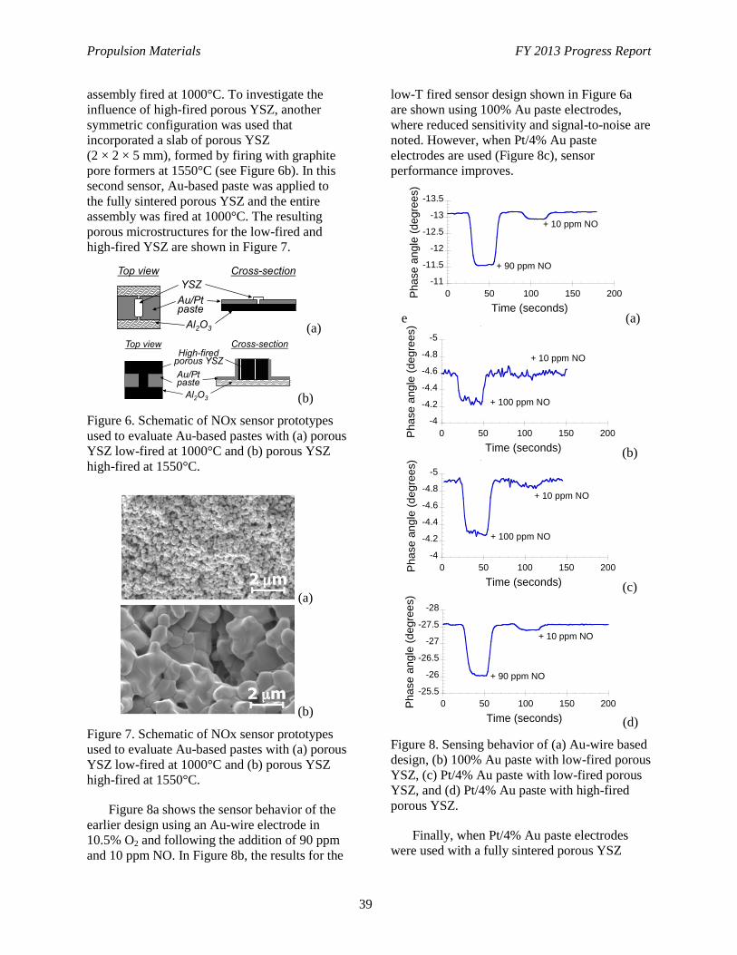
Propulsion Materials FY 2013 Progress Report
39
assembly fired at 1000°C. To investigate the
influence of high-fired porous YSZ, another
symmetric configuration was used that
incorporated a slab of porous YSZ
(2 × 2 × 5 mm), formed by firing with graphite
pore formers at 1550°C (see Figure 6b). In this
second sensor, Au-based paste was applied to
the fully sintered porous YSZ and the entire
assembly was fired at 1000°C. The resulting
porous microstructures for the low-fired and
high-fired YSZ are shown in Figure 7.
(a)
(b)
Figure 6. Schematic of NOx sensor prototypes
used to evaluate Au-based pastes with (a) porous
YSZ low-fired at 1000°C and (b) porous YSZ
high-fired at 1550°C.
(a)
(b)
Figure 7. Schematic of NOx sensor prototypes
used to evaluate Au-based pastes with (a) porous
YSZ low-fired at 1000°C and (b) porous YSZ
high-fired at 1550°C.
Figure 8a shows the sensor behavior of the
earlier design using an Au-wire electrode in
10.5% O2 and following the addition of 90 ppm
and 10 ppm NO. In Figure 8b, the results for the
low-T fired sensor design shown in Figure 6a
are shown using 100% Au paste electrodes,
where reduced sensitivity and signal-to-noise are
noted. However, when Pt/4% Au paste
electrodes are used (Figure 8c), sensor
performance improves.
e (a)
(b)
(c)
(d)
Figure 8. Sensing behavior of (a) Au-wire based
design, (b) 100% Au paste with low-fired porous
YSZ, (c) Pt/4% Au paste with low-fired porous
YSZ, and (d) Pt/4% Au paste with high-fired
porous YSZ.
Finally, when Pt/4% Au paste electrodes
were used with a fully sintered porous YSZ
Top view Cross-section
YSZ
Al2O3
Au/Pt paste
High-fired porous YSZ
Au/Pt paste
Top view Cross-section
Al2O3
-13.5
-13
-12.5
-12
-11.5
-11
0 50 100 150 200Pha
se a
ngle
(d
eg
ree
s)
Time (seconds)
10.5% O2, 50 Hz
+ 90 ppm NO
+ 10 ppm NO
-5
-4.8
-4.6
-4.4
-4.2
-4
0 50 100 150 200Pha
se a
ng
le (
de
gre
es)
Time (seconds)
10.5% O2, 100 Hz
+ 100 ppm NO
+ 10 ppm NO
-5
-4.8
-4.6
-4.4
-4.2
-4
0 50 100 150 200Pha
se a
ng
le (
de
gre
es)
Time (seconds)
10.5% O2, 20 Hz
+ 100 ppm NO
+ 10 ppm NO
-28
-27.5
-27
-26.5
-26
-25.5
0 50 100 150 200Pha
se
an
gle
(deg
ree
s)
Time (seconds)
10.5% O2, 50 Hz
+ 90 ppm NO
+ 10 ppm NO
Propulsion Materials FY 2013 Progress Report
40
electrolyte (design shown in Figure 6b), the
sensor performance was found to be very similar
in magnitude and signal-to-noise compared with
the Au-wire based design (shown in Figure 8a).
The results indicated the feasibility for using a
traditional screen-printing process for electrode
deposition, followed by a single step co-firing
manufacturing process.
Conclusions
Work in fiscal year 2013 focused on
continuing to work with the Ford Motor
Company and CRADA partner EmiSense to
improve sensor performance and to initiate
completion of the technology transfer to industry
for commercialization. The three
accomplishments this year included (1) down
select of materials to focus on Au and Pt-Au
electrodes; (2) development of a new portable
electronics package for data acquisition
fabricated using low-cost components; (3)
development of a voltage-current time
differential measurement strategy that has shown
improved results in vehicle dynamometer
testing; and (4) evaluation of processing
methods more suitable for mass manufacturing.
To address micro-crack growth and poor
sample-to-sample reproducibility for the
in-plane geometry, a through-plane geometry
was demonstrated. These results for LSM oxide
electrodes showed that improved sensor
behavior could be achieved by controlling
geometry and materials. The completed
evaluation of LSM configurations allowed for a
better comparison with the sensing performance
of Au-based designs and a subsequent electrode
materials down select. Because both materials
had comparable sensitivity to NOx, the Au-based
materials were chosen based on the potential for
more convenient mass manufacturing methods
using metal-based pastes and inks, which is an
area of particular expertise for EmiSense (the
LLNL technology licensee).
A new electronics package for data
acquisition was developed by EmiSense. A
serendipitous discovery showed that an entirely
new measurement strategy in time-domain gave
better results than frequency-domain operation,
which had been used in all previous studies. As
an added bonus, time-domain operation enabled
the use of lower cost electronic components.
Attention has been given to replacing early
prototype Au-wire electrode sensors with
materials more suitable for mass manufacturing.
To this end, Au-based and Pt-Au-based pastes
were explored. In addition, a final, single-step
sensor firing process was sought that used a
high-T fired porous YSZ pellet electrolyte. Prior
work focused on use of low-fired porous YSZ.
The processing steps are intended to be
compatible with firing temperatures of the
(green body) alumina substrates. From this
work, a Pt/4% Au paste composition was found
to have better performance than an Au-only
paste, and a design incorporating high-fired
porous YSZ with the Pt/4% Au paste electrodes
was found to have similar performance as earlier
Au-wire prototypes with low-fired YSZ. The
results indicated the feasibility for using a
traditional screen-printing process and
single-step co-firing routine for sensor
fabrication using either Au or Pt/Au paste
electrodes.
A major milestone for this past year was
filing of a patent to protect jointly developed
(LLNL and CRADA partner EmiSense)
intellectual property. The intellectual property
development and technology transfer activities
this past year are accelerating efforts to bring the
LLNL NOx sensor technology to
commercialization. We continue our
long-standing collaboration with Ford Motor
Company in this effort to test prototype sensors
in dynamometers.
References
Akbar, S., P. Dutta, and C. Lee, 2006, “High-
temperature ceramic gas sensors: a review,”
Int. J. Appl. Ceram. Technol., 3, 302.
Du Frane, W. L., L. Y. Woo, R. S. Glass, R. F.
Novak, and J. H. Visser, 2013, “Substrate
Effects on an Electrochemical NOx Sensor
Based on Porous Y2O3- Stabilized ZrO2
(YSZ) and Sr-doped LaMnO3 (LSM),” ECS
Transactions, 45, 3.
Fergus, J. W., 2007, “Materials for high
temperature electrochemical NOx gas
sensors,” cSens. Actuators, B, 121, 652.
Propulsion Materials FY 2013 Progress Report
41
Martin, L. P., L. Y. Woo, and R. S. Glass, 2007,
“Materials for high temperature
electrochemical NOx gas sensors,” J.
Electrochem. Soc., 154, J97.
Menil, F., V. Coillard, and C. Lucat, 2000,
“Critical review of nitrogen monoxide
sensors for exhaust gases of lean burn
engines,” Sensors and Actuators B, 67, 1.
Moos, R., 2005, “A brief overview on
automotive exhaust gas sensors based on
electroceramics,” Int. J. Appl. Ceram.
Technol., 2, 401.
Song, S.-W., L. P. Martin, R. S. Glass, E. P.
Murray, J. H. Visser, R. E. Soltis, R. F.
Novak, and D. J. Kubinski, 2006, “Aging
Studies of Sr-Doped LaCrO3/YSZ/Pt Cells
for an Electrochemical NOx Sensor,” J.
Electrochem. Soc., 153, H171.
Woo, L. Y., L. P. Martin, R. S. Glass, and R. J.
Gorte, 2007, “Impedance characterization of
a model Au/yttria-stabilized zirconia/Au
electrochemical cell in varying oxygen and
NOx concentrations,” J. Electrochem. Soc.,
154, J129.
Woo, L. Y., L. P. Martin, R. S. Glass, W. Wang,
S. Jung, R. J. Gorte, E. P. Murray, R. F.
Novak, and J. H. Visser, 2008, “Effect of
electrode composition and microstructure on
impedancemetric nitric oxide sensors based
on YSZ electrolyte,” J. Electrochem. Soc.,
155, J32.
Woo, L. Y., R. S. Glass, R. F. Novak, and J. H.
Visser, 2010, “Effect of electrode material
and design on sensitivity and selectivity for
high temperature impedancemetric NOx
sensors,” J. Electrochem. Soc., 157, J81.
Woo, L. Y., R. S. Glass, R. F. Novak, and J. H.
Visser, 2011, “Diesel engine dynamometer
testing of impedancemetric NOx sensors,”
Sensor Actuat. B-Chem., 157, 115.
Yamazoe, N., 2005, “Toward innovations of gas
sensor technology,” Sens. Actuators, B, 108,
2.
Zhuiykov, S. and N. Miura, 2007, “Development
of zirconia-based potentiometric NOx
sensors for automotive and energy industries
in the early 21st century: What are the
prospects for sensors?” Sens. Actuators, B,
121, 639.
Publications/Presentations/Patents
Du Frane, W. L., L. Y. Woo, R. S. Glass, R. F.
Novak, and J. H. Visser, 2013, “Substrate
Effects on Electrochemical NOx Sensor
Based on Porous Y2O3-Stabilized ZrO2
(YSZ) and Sr-doped LaMnO3 (LSM),” ECS
Transactions, 45 (14), 3–11.
Woo, L. Y., R. S. Glass, R. F. Novak, and J. H.
Visser, 2013, “Zirconia-electrolyte-based
impedancemetric sensors using Sr-doped
LaMnO3 (LSM) electrodes for measuring
NOx in combustion exhaust streams,” The
10th Pacific Rim Conference on Ceramic
and Glass Technology, in San Diego,
California, June 2–7, 2013.
New patent application (No. 14055562) entitled,
“Electrochemical Sensing Using Voltage-
Current Time Differential,” filed on
October 16, 2013.
Propulsion Materials FY 2013 Progress Report
42
Project 18518 – Materials for High-Efficiency Engines
Agreement 13329 – Design Optimization of Piezoceramic
Multilayer Actuators for Heavy-Duty Diesel Engine Fuel
Injectors
Hua-Tay Lin, Hong Wang, and Andrew A. Wereszczak
Ceramic Science and Technology Group
Oak Ridge National Laboratory
P.O. Box 2008, MS 6068
Oak Ridge, TN 37831-6068
Phone (865) 576-1169; fax: (865) 574-6098; e-mail: [email protected]
DOE Technology Manager: Jerry L. Gibbs
Phone (202) 586-1182; fax: (202) 586-1600; e-mail: [email protected]
ORNL Technical Advisor: J. Allen Haynes
Phone (865) 576-2894; fax: (865) 574-4913; e-mail: [email protected]
Contractor: Oak Ridge National Laboratory, Oak Ridge, Tennessee
Prime Contract No.: DE-AC05-00OR22725
Objectives
Apply established structural ceramic probabilistic design and reliability analysis to piezoelectric
multilayer actuators (PMLAs).
Generate required micromechanical property data on lead zirconate titanate (PZT) piezoceramics and
macromechanical property data on PMLAs for input into the design and reliability analysis of the
latter.
Identify minimum mechanical performance requirements for fuel injector PMLAs.
Adapt these strategies to improve the reliability of PMLAs that are candidates for use in diesel engine
fuel injectors.
Approach
Evaluate PMLA reliability under representative service conditions.
Link constituent piezoceramic micromechanical and PMLA macromechanical responses.
Accomplishments
Experimental study on the down-selected piezo stacks for heavy-duty diesel engine fuel injector has
been completed successfully by using low-profile stacks, namely 20/10-layer plate specimens
extracted from the prototype stacks.
The 20-layer specimens, with a range of resistances, were tested and characterized. The lifetime of
the specimens under the accelerated electric fatigue depends on the pre-existing condition.
The specimens that finished 108 cycles demonstrated a defined degradation trend during the cycle
tests. Some fluctuation was observed in the individual cycle test, and discrepancy of fatigue responses
also was observed between specimens.

Propulsion Materials FY 2013 Progress Report
43
Future Direction
Complete study of the effects of humidity and temperature (80% RH, 85C) on the mechanical
properties of down-selected PZT ceramics.
Complete study of cyclic fatigue of short PZT stacks in higher-temperature plus humidity
environment.
Propulsion Materials FY 2013 Progress Report
44
Introduction
The use of PMLAs as diesel fuel injectors
has the potential to reduce injector response
time, provide greater precision and control of the
fuel injection event, and reduce energy
consumption. Compared with conventional
solenoid operation of an injector, the alternative
use of a PMLA can enable precise rate shaping
of the entire injection cycle that accurately
controls injection timing and fuel quantity.
PMLA (or piezo-stack) fuel injectors contain a
solid-state ceramic actuator that converts electric
energy into linear motion, precisely controlling
the needle’s opening and closing. This capability
results in an engine with outstanding
performance, improved fuel economy, low
noise, and low emissions. However, even though
their use is very attractive for the reasons
mentioned, uncertainty continues about how
reliable piezo-actuated fuel injectors will be in
the challenging environment of a heavy-duty
vehicle diesel engine. Piezoelectric function is
the obvious primary function of PZT ceramic
PMLAs for fuel injectors; however, their
reliability may be a performance and life limiter
because the PZT ceramic within them is brittle,
lacks high strength, and may exhibit fatigue
susceptibility. This brittleness and relatively low
strength can be overcome with a proper
probabilistic component design methodology.
This project undertakes the reliability
characterization of candidate PMLAs used in
these fuel injectors and the piezoceramics used
in the PMLAs. Testing and characterization of
the piezo-stacks and piezoceramics have
continued based on recommendations from
Cummins, Inc.
Approaches
Characterization of PMLA
The objective of this work is to develop an
experimental approach for conducting
accelerated electric fatigue testing and, at the
same time, characterize the fatigue responses
and lifetime of candidate or down-selected
piezo-stacks. The database and understandings
generated in this study are to be applied by the
end users for optimizations of the design and
deployment of piezo-stacks for heavy-duty fuel
injection systems.
The down-selected piezo-stack
(manufactured by EPCOS) for heavy-duty
engine fuel injectors has dimensions of 12 × 12
× 54 mm (Figure 1). The rated capacitance is
16.15 mF. Testing stacks of this size presents
substantial challenges to the electronic systems
used to drive and control stacks. In addition, the
stacks are provided without encapsulation;
partial discharge near the surface of the stacks
can be easily induced during cycling.
The testing of the piezo-stacks was
conducted by using a piezodilatometer system
designed by Oak Ridge National Laboratory
(ORNL). The piezodilatometer system is
equipped with an electronic liquid, FC-40, to
control the partial discharge near the surface of
the stack specimens. Furthermore, testing of
EPCOS stacks has to use low profile stacks with
10 and 20-layer plates for the high-voltage
power supply to accommodate the electric
current requirement. The 10 and 20-layer plates
are structurally independent and compose
elements of the whole stack. Therefore, they can
be decomposed or structurally separated for this
study.
These 10 and 20-layer plates were provided
by Cummins, Inc. At first, the stacks were sorted
according to the soundness of the surface
condition. These specimens were then wired as
shown in Figure 1b and examined using a
voltmeter for electric resistance, then further
measured with an impedance analyzer (model
Solartron 1260) prior to the electric fatigue tests.
The impedance data were collected using a
50-mV amplitude over a frequency range of
10 mHz to 100 KHz and analyzed using an
equivalent electric circuit through curve fitting.
An RC element consisting of a parallel
connection of a capacitor C and a resistor R is
usually employed for analysis. Variations of R
and C values were observed from specimen to
specimen during this process. The specimens
with good electrode condition were selected for
the subsequent electric cycle tests.
The ORNL piezodilatometer was used in the
cycle test. Figure 2 shows the setup with a
specimen connected to the high-voltage power
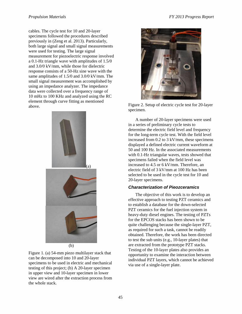
Propulsion Materials FY 2013 Progress Report
45
cables. The cycle test for 10 and 20-layer
specimens followed the procedures described
previously in (Zeng et al. 2013). Particularly,
both large signal and small signal measurements
were used for testing. The large signal
measurement for piezoelectric response involved
a 0.1-Hz triangle wave with amplitudes of 1.5/0
and 3.0/0 kV/mm, while those for dielectric
response consists of a 50-Hz sine wave with the
same amplitudes of 1.5/0 and 3.0/0 kV/mm. The
small signal measurement was accomplished by
using an impedance analyzer. The impedance
data were collected over a frequency range of
10 mHz to 100 KHz and analyzed using the RC
element through curve fitting as mentioned
above.
(a)
(b)
Figure 1. (a) 54-mm piezo multilayer stack that
can be decomposed into 10 and 20-layer
specimens to be used in electric and mechanical
testing of this project; (b) A 20-layer specimen
in upper view and 10-layer specimen in lower
view are wired after the extraction process from
the whole stack.
Figure 2. Setup of electric cycle test for 20-layer
specimen.
A number of 20-layer specimens were used
in a series of preliminary cycle tests to
determine the electric field level and frequency
for the long-term cycle test. With the field level
increased from 0.2 to 3 kV/mm, these specimens
displayed a defined electric current waveform at
50 and 100 Hz. In the associated measurements
with 0.1-Hz triangular waves, tests showed that
specimens failed when the field level was
increased to 4.5 or 6 kV/mm. Therefore, an
electric field of 3 kV/mm at 100 Hz has been
selected to be used in the cycle test for 10 and
20-layer specimens.
Characterization of Pieozceramics
The objective of this work is to develop an
effective approach to testing PZT ceramics and
to establish a database for the down-selected
PZT ceramics for the fuel injection system in
heavy-duty diesel engines. The testing of PZTs
for the EPCOS stacks has been shown to be
quite challenging because the single-layer PZT,
as required for such a task, cannot be readily
obtained. Therefore, the work has been directed
to test the sub units (e.g., 10-layer plates) that
are extracted from the prototype PZT stacks.
Testing of the 10-layer plates also provides an
opportunity to examine the interaction between
individual PZT layers, which cannot be achieved
via use of a single-layer plate.
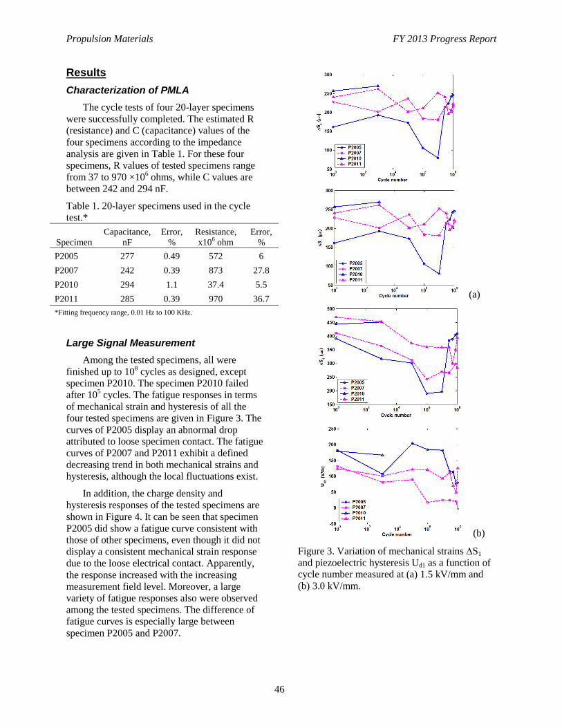
Propulsion Materials FY 2013 Progress Report
46
Results
Characterization of PMLA
The cycle tests of four 20-layer specimens
were successfully completed. The estimated R
(resistance) and C (capacitance) values of the
four specimens according to the impedance
analysis are given in Table 1. For these four
specimens, R values of tested specimens range
from 37 to 970 ×106 ohms, while C values are
between 242 and 294 nF.
Table 1. 20-layer specimens used in the cycle
test.*
Specimen
Capacitance,
nF
Error,
%
Resistance,
x106 ohm
Error,
%
P2005 277 0.49 572 6
P2007 242 0.39 873 27.8
P2010 294 1.1 37.4 5.5
P2011 285 0.39 970 36.7
*Fitting frequency range, 0.01 Hz to 100 KHz.
Large Signal Measurement
Among the tested specimens, all were
finished up to 108 cycles as designed, except
specimen P2010. The specimen P2010 failed
after 105 cycles. The fatigue responses in terms
of mechanical strain and hysteresis of all the
four tested specimens are given in Figure 3. The
curves of P2005 display an abnormal drop
attributed to loose specimen contact. The fatigue
curves of P2007 and P2011 exhibit a defined
decreasing trend in both mechanical strains and
hysteresis, although the local fluctuations exist.
In addition, the charge density and
hysteresis responses of the tested specimens are
shown in Figure 4. It can be seen that specimen
P2005 did show a fatigue curve consistent with
those of other specimens, even though it did not
display a consistent mechanical strain response
due to the loose electrical contact. Apparently,
the response increased with the increasing
measurement field level. Moreover, a large
variety of fatigue responses also were observed
among the tested specimens. The difference of
fatigue curves is especially large between
specimen P2005 and P2007.
(a)
(b)
Figure 3. Variation of mechanical strains S1
and piezoelectric hysteresis Ud1 as a function of
cycle number measured at (a) 1.5 kV/mm and
(b) 3.0 kV/mm.
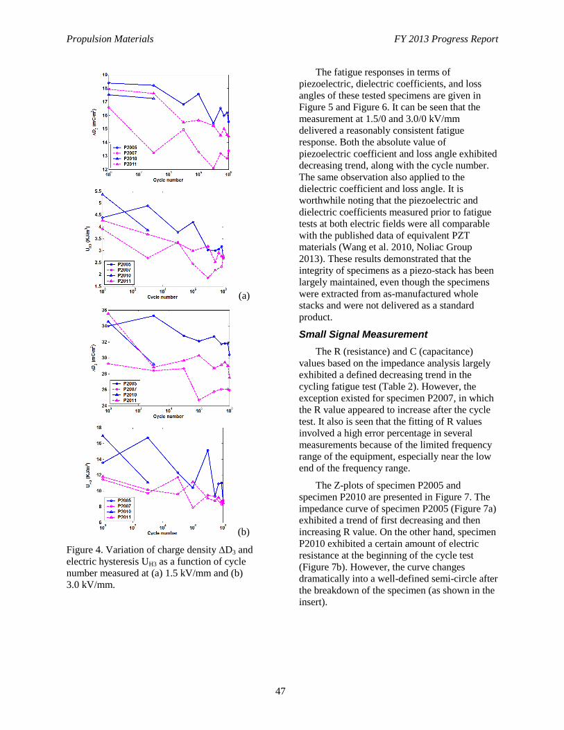
Propulsion Materials FY 2013 Progress Report
47
(a)
(b)
Figure 4. Variation of charge density D3 and
electric hysteresis UH3 as a function of cycle
number measured at (a) 1.5 kV/mm and (b)
3.0 kV/mm.
The fatigue responses in terms of
piezoelectric, dielectric coefficients, and loss
angles of these tested specimens are given in
Figure 5 and Figure 6. It can be seen that the
measurement at 1.5/0 and 3.0/0 kV/mm
delivered a reasonably consistent fatigue
response. Both the absolute value of
piezoelectric coefficient and loss angle exhibited
decreasing trend, along with the cycle number.
The same observation also applied to the
dielectric coefficient and loss angle. It is
worthwhile noting that the piezoelectric and
dielectric coefficients measured prior to fatigue
tests at both electric fields were all comparable
with the published data of equivalent PZT
materials (Wang et al. 2010, Noliac Group
2013). These results demonstrated that the
integrity of specimens as a piezo-stack has been
largely maintained, even though the specimens
were extracted from as-manufactured whole
stacks and were not delivered as a standard
product.
Small Signal Measurement
The R (resistance) and C (capacitance)
values based on the impedance analysis largely
exhibited a defined decreasing trend in the
cycling fatigue test (Table 2). However, the
exception existed for specimen P2007, in which
the R value appeared to increase after the cycle
test. It also is seen that the fitting of R values
involved a high error percentage in several
measurements because of the limited frequency
range of the equipment, especially near the low
end of the frequency range.
The Z-plots of specimen P2005 and
specimen P2010 are presented in Figure 7. The
impedance curve of specimen P2005 (Figure 7a)
exhibited a trend of first decreasing and then
increasing R value. On the other hand, specimen
P2010 exhibited a certain amount of electric
resistance at the beginning of the cycle test
(Figure 7b). However, the curve changes
dramatically into a well-defined semi-circle after
the breakdown of the specimen (as shown in the
insert).
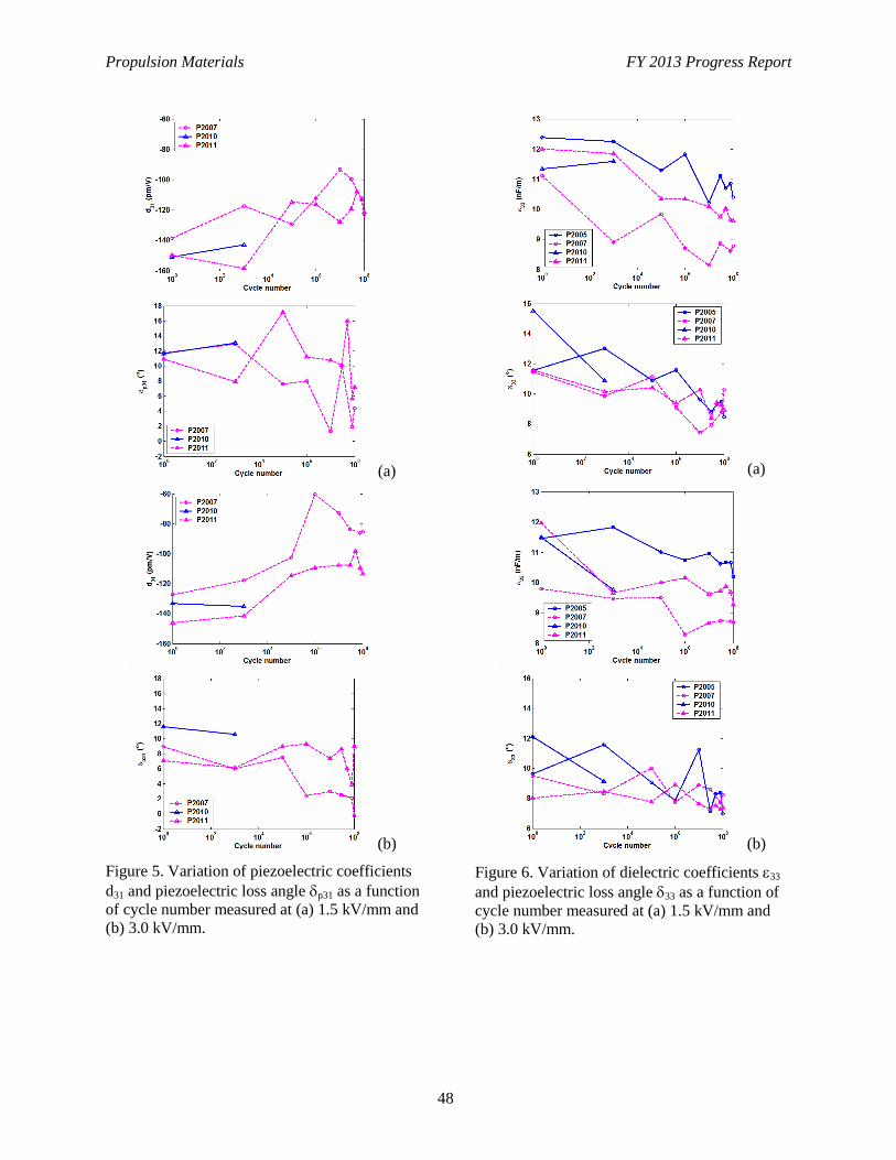
Propulsion Materials FY 2013 Progress Report
48
(a)
(b)
Figure 5. Variation of piezoelectric coefficients
d31 and piezoelectric loss angle p31 as a function
of cycle number measured at (a) 1.5 kV/mm and
(b) 3.0 kV/mm.
(a)
(b)
Figure 6. Variation of dielectric coefficients 33
and piezoelectric loss angle 33 as a function of
cycle number measured at (a) 1.5 kV/mm and
(b) 3.0 kV/mm.
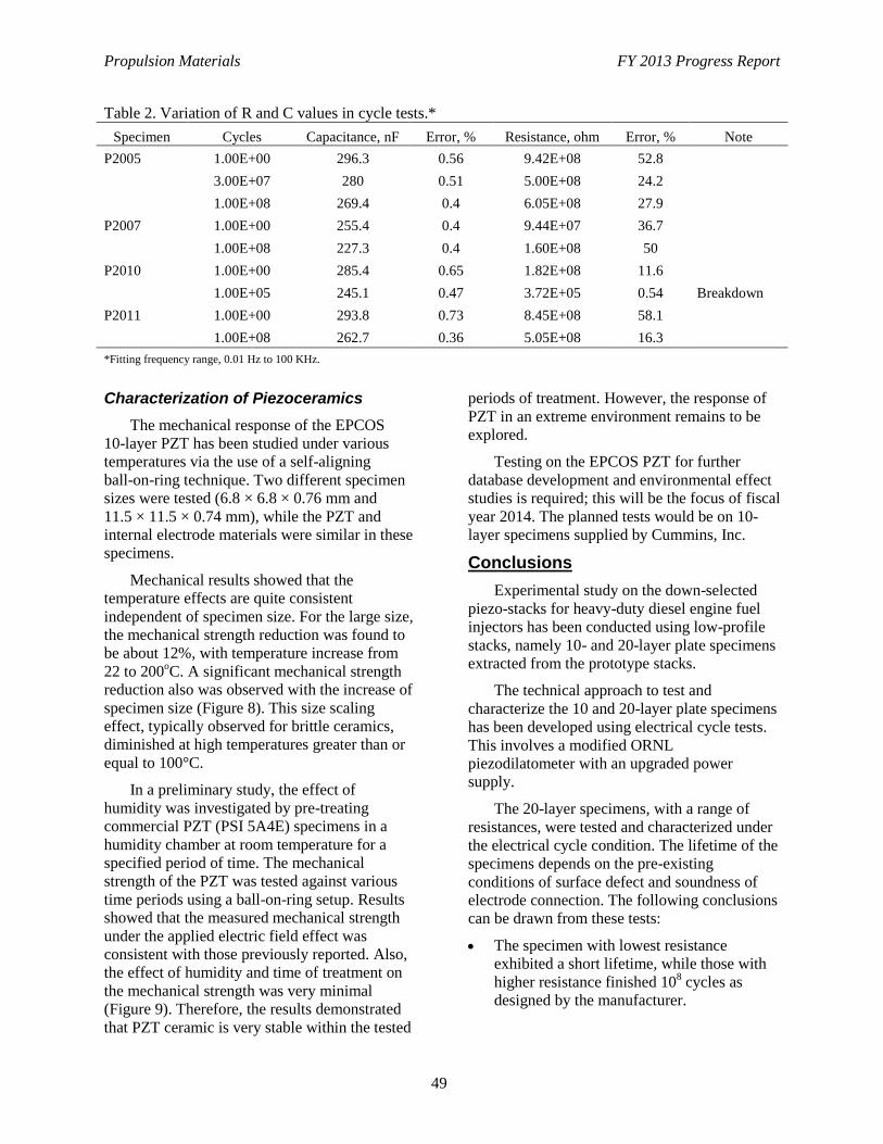
Propulsion Materials FY 2013 Progress Report
49
Table 2. Variation of R and C values in cycle tests.*
Specimen Cycles Capacitance, nF Error, % Resistance, ohm Error, % Note
P2005 1.00E+00 296.3 0.56 9.42E+08 52.8
3.00E+07 280 0.51 5.00E+08 24.2
1.00E+08 269.4 0.4 6.05E+08 27.9
P2007 1.00E+00 255.4 0.4 9.44E+07 36.7
1.00E+08 227.3 0.4 1.60E+08 50
P2010 1.00E+00 285.4 0.65 1.82E+08 11.6
1.00E+05 245.1 0.47 3.72E+05 0.54 Breakdown
P2011 1.00E+00 293.8 0.73 8.45E+08 58.1
1.00E+08 262.7 0.36 5.05E+08 16.3
*Fitting frequency range, 0.01 Hz to 100 KHz.
Characterization of Piezoceramics
The mechanical response of the EPCOS
10-layer PZT has been studied under various
temperatures via the use of a self-aligning
ball-on-ring technique. Two different specimen
sizes were tested (6.8 × 6.8 × 0.76 mm and
11.5 × 11.5 × 0.74 mm), while the PZT and
internal electrode materials were similar in these
specimens.
Mechanical results showed that the
temperature effects are quite consistent
independent of specimen size. For the large size,
the mechanical strength reduction was found to
be about 12%, with temperature increase from
22 to 200oC. A significant mechanical strength
reduction also was observed with the increase of
specimen size (Figure 8). This size scaling
effect, typically observed for brittle ceramics,
diminished at high temperatures greater than or
equal to 100°C.
In a preliminary study, the effect of
humidity was investigated by pre-treating
commercial PZT (PSI 5A4E) specimens in a
humidity chamber at room temperature for a
specified period of time. The mechanical
strength of the PZT was tested against various
time periods using a ball-on-ring setup. Results
showed that the measured mechanical strength
under the applied electric field effect was
consistent with those previously reported. Also,
the effect of humidity and time of treatment on
the mechanical strength was very minimal
(Figure 9). Therefore, the results demonstrated
that PZT ceramic is very stable within the tested
periods of treatment. However, the response of
PZT in an extreme environment remains to be
explored.
Testing on the EPCOS PZT for further
database development and environmental effect
studies is required; this will be the focus of fiscal
year 2014. The planned tests would be on 10-
layer specimens supplied by Cummins, Inc.
Conclusions
Experimental study on the down-selected
piezo-stacks for heavy-duty diesel engine fuel
injectors has been conducted using low-profile
stacks, namely 10- and 20-layer plate specimens
extracted from the prototype stacks.
The technical approach to test and
characterize the 10 and 20-layer plate specimens
has been developed using electrical cycle tests.
This involves a modified ORNL
piezodilatometer with an upgraded power
supply.
The 20-layer specimens, with a range of
resistances, were tested and characterized under
the electrical cycle condition. The lifetime of the
specimens depends on the pre-existing
conditions of surface defect and soundness of
electrode connection. The following conclusions
can be drawn from these tests:
The specimen with lowest resistance
exhibited a short lifetime, while those with
higher resistance finished 108 cycles as
designed by the manufacturer.
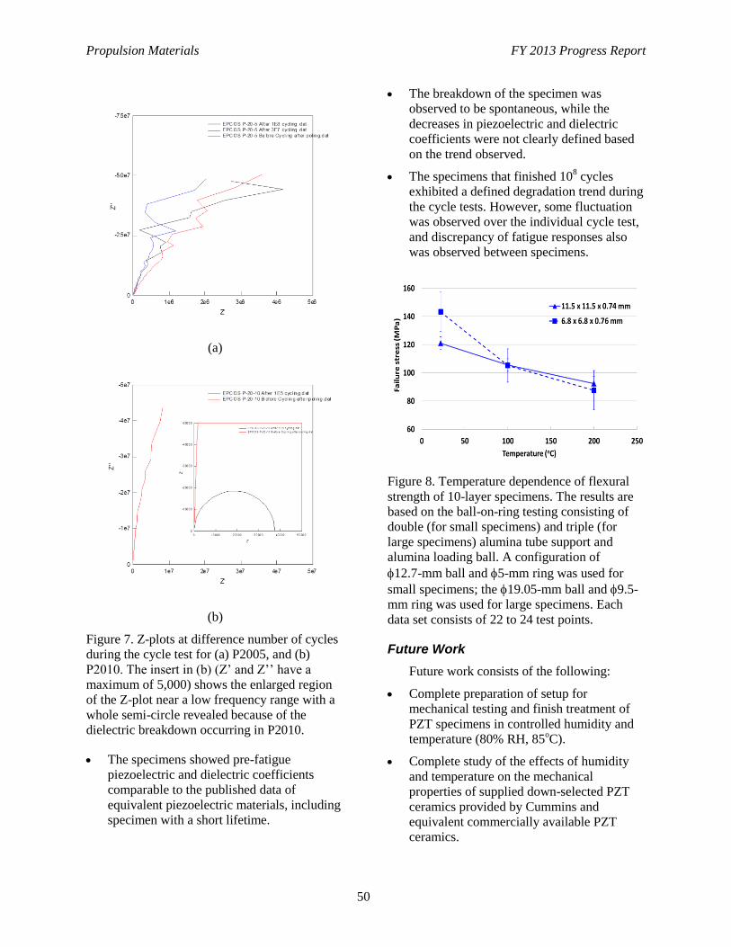
Propulsion Materials FY 2013 Progress Report
50
(a)
(b)
Figure 7. Z-plots at difference number of cycles
during the cycle test for (a) P2005, and (b)
P2010. The insert in (b) (Z’ and Z’’ have a
maximum of 5,000) shows the enlarged region
of the Z-plot near a low frequency range with a
whole semi-circle revealed because of the
dielectric breakdown occurring in P2010.
The specimens showed pre-fatigue
piezoelectric and dielectric coefficients
comparable to the published data of
equivalent piezoelectric materials, including
specimen with a short lifetime.
The breakdown of the specimen was
observed to be spontaneous, while the
decreases in piezoelectric and dielectric
coefficients were not clearly defined based
on the trend observed.
The specimens that finished 108 cycles
exhibited a defined degradation trend during
the cycle tests. However, some fluctuation
was observed over the individual cycle test,
and discrepancy of fatigue responses also
was observed between specimens.
Figure 8. Temperature dependence of flexural
strength of 10-layer specimens. The results are
based on the ball-on-ring testing consisting of
double (for small specimens) and triple (for
large specimens) alumina tube support and
alumina loading ball. A configuration of
12.7-mm ball and 5-mm ring was used for
small specimens; the 19.05-mm ball and 9.5-
mm ring was used for large specimens. Each
data set consists of 22 to 24 test points.
Future Work
Future work consists of the following:
Complete preparation of setup for
mechanical testing and finish treatment of
PZT specimens in controlled humidity and
temperature (80% RH, 85oC).
Complete study of the effects of humidity
and temperature on the mechanical
properties of supplied down-selected PZT
ceramics provided by Cummins and
equivalent commercially available PZT
ceramics.
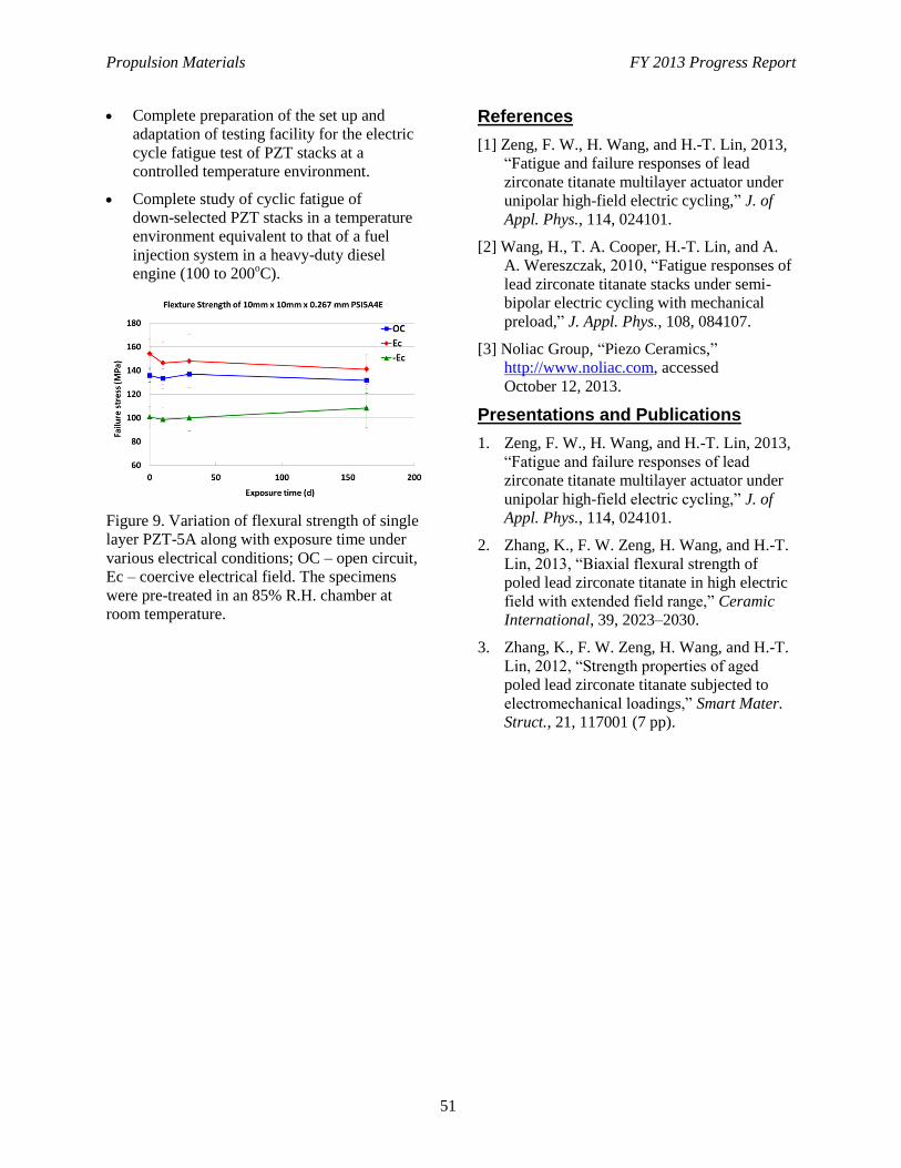
Propulsion Materials FY 2013 Progress Report
51
Complete preparation of the set up and
adaptation of testing facility for the electric
cycle fatigue test of PZT stacks at a
controlled temperature environment.
Complete study of cyclic fatigue of
down-selected PZT stacks in a temperature
environment equivalent to that of a fuel
injection system in a heavy-duty diesel
engine (100 to 200oC).
Figure 9. Variation of flexural strength of single
layer PZT-5A along with exposure time under
various electrical conditions; OC – open circuit,
Ec – coercive electrical field. The specimens
were pre-treated in an 85% R.H. chamber at
room temperature.
References
[1] Zeng, F. W., H. Wang, and H.-T. Lin, 2013,
“Fatigue and failure responses of lead
zirconate titanate multilayer actuator under
unipolar high-field electric cycling,” J. of
Appl. Phys., 114, 024101.
[2] Wang, H., T. A. Cooper, H.-T. Lin, and A.
A. Wereszczak, 2010, “Fatigue responses of
lead zirconate titanate stacks under semi-
bipolar electric cycling with mechanical
preload,” J. Appl. Phys., 108, 084107.
[3] Noliac Group, “Piezo Ceramics,”
http://www.noliac.com, accessed
October 12, 2013.
Presentations and Publications
1. Zeng, F. W., H. Wang, and H.-T. Lin, 2013,
“Fatigue and failure responses of lead
zirconate titanate multilayer actuator under
unipolar high-field electric cycling,” J. of
Appl. Phys., 114, 024101.
2. Zhang, K., F. W. Zeng, H. Wang, and H.-T.
Lin, 2013, “Biaxial flexural strength of
poled lead zirconate titanate in high electric
field with extended field range,” Ceramic
International, 39, 2023–2030.
3. Zhang, K., F. W. Zeng, H. Wang, and H.-T.
Lin, 2012, “Strength properties of aged
poled lead zirconate titanate subjected to
electromechanical loadings,” Smart Mater.
Struct., 21, 117001 (7 pp).
Propulsion Materials FY 2013 Progress Report
52
Project 18518 – Materials for High-Efficiency Engines
Agreement 17058 – Compact Potentiometric NOx Sensor
Dileep Singh
Argonne National Laboratory
9700 S. Cass Avenue
Argonne, IL 60439
Phone (630) 252-5009; fax: (630) 252-2785; e-mail: [email protected]
DOE Technology Manager: Jerry L. Gibbs
Phone (202) 586-1182; fax: (202) 586-1600; e-mail: [email protected]
Contractor: UChicago Argonne LLC
Prime Contract No.: DE AC03 06CH11357
Objectives
Use plastic joining technique to produce compact nitrous oxide (NOx) and bifunctional (NOx and O2)
potentiometric sensors with internal reference
Develop electronic conducting ceramic to replace the platinum (Pt) electrodes in the sensor
Develop technique to directly join the conducting ceramic to the yittria-stabilized zirconia body of the
sensor
Conduct tests to determine the range of NOx concentrations that can be sensed accurately.
Approach
Modification/optimization of the Pt/zeolite filter to increase the sensing concentration for NOx.
Accomplishments
Strong, pore-free joints have been made with various ceramics, cermets, intermetallics, composites,
and biomaterials, with and without various interlayers; the fracture occurs away from interface at the
region of maximum residual stress
Demonstrated that grains in SrTiO3 rotate during deformation
Research and Development 100 Award for oxygen sensor
Developed NOx sensor
Published 27 journal papers, three patents issued for plastic joining process, two patents issued for the
NOx and O2 sensors, and one patent issued on LSAM interconnect, with several companies having
expressed interest in the sensors.
Future Direction
The project was concluded in fiscal year 2011. However, additional effort was initiated to establish
the range of NOx concentrations that can be measured accurately when using the sensor. In the future,
optimization of filter material will be carried out to increase the upper limit for NOx concentration
sensing, which is required by heavy-duty engine manufacturers.
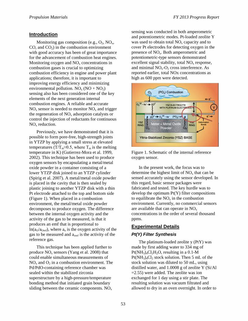
Propulsion Materials FY 2013 Progress Report
53
Introduction
Monitoring gas composition (e.g., O2, NOx,
CO, and CO2) in the combustion environment
with good accuracy has been of great importance
for the advancement of combustion heat engines.
Monitoring oxygen and NOx concentrations in
combustion gases is crucial to optimizing
combustion efficiency in engine and power plant
applications; therefore, it is important to
improving energy efficiency and minimizing
environmental pollution. NOx (NO + NO2)
sensing also has been considered one of the key
elements of the next generation internal
combustion engines. A reliable and accurate
NOx sensor is needed to monitor NOx and trigger
the regeneration of NOx adsorption catalysts or
control the injection of reductants for continuous
NOx reduction.
Previously, we have demonstrated that it is
possible to form pore-free, high-strength joints
in YTZP by applying a small stress at elevated
temperatures (T/Tm≈0.5, where Tm is the melting
temperature in K) (Gutierrez-Mora et al. 1999,
2002). This technique has been used to produce
oxygen sensors by encapsulating a metal/metal
oxide powder in a container consisting of a
lower YTZP disk joined to an YTZP cylinder
(Spirig et al. 2007). A metal/metal oxide powder
is placed in the cavity that is then sealed by
plastic joining to another YTZP disk with a thin
Pt electrode attached to the top and bottom side
(Figure 1). When placed in a combustion
environment, the metal/metal oxide powder
decomposes to produce oxygen. The difference
between the internal oxygen activity and the
activity of the gas to be measured, is that it
produces an emf that is proportional to
ln(aO/aOref), where ao is the oxygen activity of the
gas to be measured and aoref is the activity of the
reference gas.
This technique has been applied further to
produce NOx sensors (Yang et al. 2008) that
could enable simultaneous measurements of
NOx and O2 in a combustion environment. The
Pd/PdO-containing reference chamber was
sealed within the stabilized zirconia
superstructure by a high-pressure/temperature
bonding method that initiated grain boundary
sliding between the ceramic components. NOx
sensing was conducted in both amperometric
and potentiometric modes. Pt-loaded zeolite Y
was used to obtain total NOx capacity and to
cover Pt electrodes for detecting oxygen in the
presence of NOx. Both amperometric and
potentiometric-type sensors demonstrated
excellent signal stability, total NOx response,
and minimal NOx-O2 cross interference. As
reported earlier, total NOx concentrations as
high as 600 ppm were detected.
Figure 1. Schematic of the internal reference
oxygen sensor.
In the present work, the focus was to
determine the highest limit of NOx that can be
sensed accurately using the sensor developed. In
this regard, basic sensor packages were
fabricated and tested. The key hurdle was to
develop the optimum Pt(Y) filter compositions
to equilibrate the NOx in the combustion
environment. Currently, no commercial sensors
are available that can operate in NOx
concentrations in the order of several thousand
ppms.
Experimental Details
Pt(Y) Filter Synthesis
The platinum-loaded zeolite y (PtY) was
made by first adding water to 334 mg of
Pt(NH3)4Cl2H2O, resulting in a 0.1-M
Pt(NH3)4Cl2 stock solution. Then 5 mL of the
stock solution was diluted to 50 mL, using
distilled water, and 1.0008 g of zeolite Y (Si/Al
=2.55) were added. The zeolite was ion
exchanged for 1 day using a stir plate. The
resulting solution was vacuum filtrated and
allowed to dry in an oven overnight. In order to
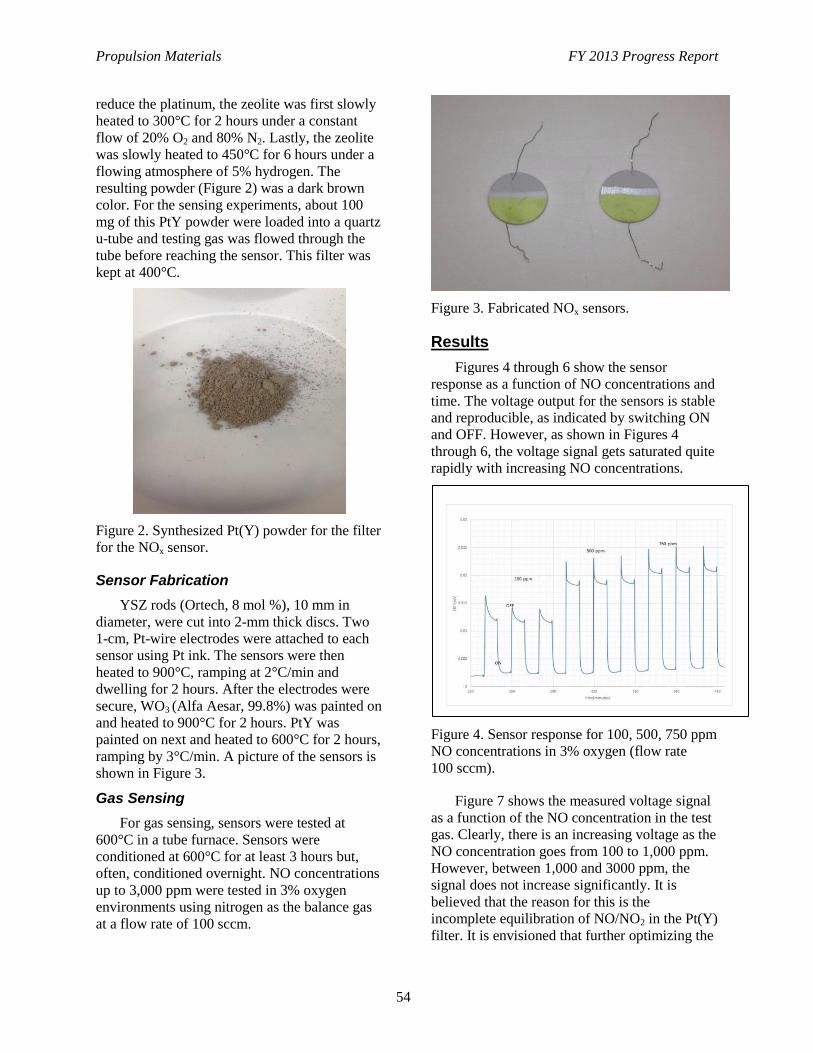
Propulsion Materials FY 2013 Progress Report
54
reduce the platinum, the zeolite was first slowly
heated to 300°C for 2 hours under a constant
flow of 20% O2 and 80% N2. Lastly, the zeolite
was slowly heated to 450°C for 6 hours under a
flowing atmosphere of 5% hydrogen. The
resulting powder (Figure 2) was a dark brown
color. For the sensing experiments, about 100
mg of this PtY powder were loaded into a quartz
u-tube and testing gas was flowed through the
tube before reaching the sensor. This filter was
kept at 400°C.
Figure 2. Synthesized Pt(Y) powder for the filter
for the NOx sensor.
Sensor Fabrication
YSZ rods (Ortech, 8 mol %), 10 mm in
diameter, were cut into 2-mm thick discs. Two
1-cm, Pt-wire electrodes were attached to each
sensor using Pt ink. The sensors were then
heated to 900°C, ramping at 2°C/min and
dwelling for 2 hours. After the electrodes were
secure, WO3 (Alfa Aesar, 99.8%) was painted on
and heated to 900°C for 2 hours. PtY was
painted on next and heated to 600°C for 2 hours,
ramping by 3°C/min. A picture of the sensors is
shown in Figure 3.
Gas Sensing
For gas sensing, sensors were tested at
600°C in a tube furnace. Sensors were
conditioned at 600°C for at least 3 hours but,
often, conditioned overnight. NO concentrations
up to 3,000 ppm were tested in 3% oxygen
environments using nitrogen as the balance gas
at a flow rate of 100 sccm.
Figure 3. Fabricated NOx sensors.
Results
Figures 4 through 6 show the sensor
response as a function of NO concentrations and
time. The voltage output for the sensors is stable
and reproducible, as indicated by switching ON
and OFF. However, as shown in Figures 4
through 6, the voltage signal gets saturated quite
rapidly with increasing NO concentrations.
Figure 4. Sensor response for 100, 500, 750 ppm
NO concentrations in 3% oxygen (flow rate
100 sccm).
Figure 7 shows the measured voltage signal
as a function of the NO concentration in the test
gas. Clearly, there is an increasing voltage as the
NO concentration goes from 100 to 1,000 ppm.
However, between 1,000 and 3000 ppm, the
signal does not increase significantly. It is
believed that the reason for this is the
incomplete equilibration of NO/NO2 in the Pt(Y)
filter. It is envisioned that further optimizing the
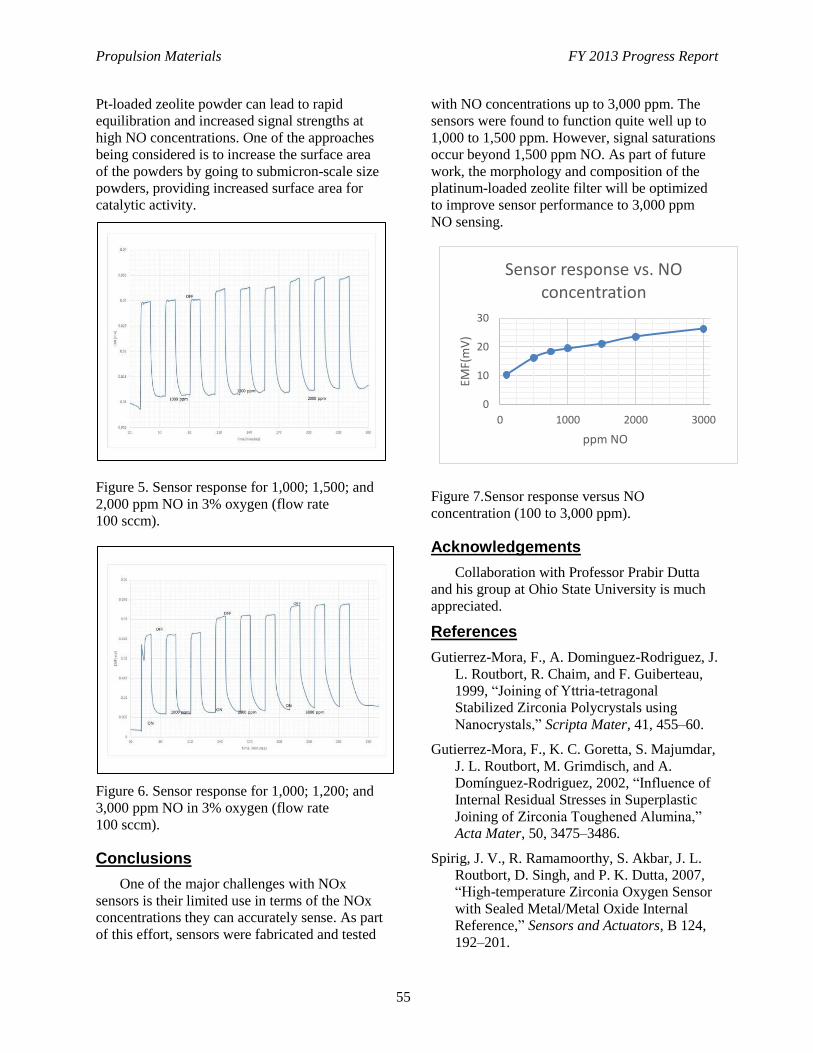
Propulsion Materials FY 2013 Progress Report
55
0
10
20
30
0 1000 2000 3000
EMF(
mV
)
ppm NO
Sensor response vs. NO concentration
Pt-loaded zeolite powder can lead to rapid
equilibration and increased signal strengths at
high NO concentrations. One of the approaches
being considered is to increase the surface area
of the powders by going to submicron-scale size
powders, providing increased surface area for
catalytic activity.
Figure 5. Sensor response for 1,000; 1,500; and
2,000 ppm NO in 3% oxygen (flow rate
100 sccm).
Figure 6. Sensor response for 1,000; 1,200; and
3,000 ppm NO in 3% oxygen (flow rate
100 sccm).
Conclusions
One of the major challenges with NOx
sensors is their limited use in terms of the NOx
concentrations they can accurately sense. As part
of this effort, sensors were fabricated and tested
with NO concentrations up to 3,000 ppm. The
sensors were found to function quite well up to
1,000 to 1,500 ppm. However, signal saturations
occur beyond 1,500 ppm NO. As part of future
work, the morphology and composition of the
platinum-loaded zeolite filter will be optimized
to improve sensor performance to 3,000 ppm
NO sensing.
Figure 7.Sensor response versus NO
concentration (100 to 3,000 ppm).
Acknowledgements
Collaboration with Professor Prabir Dutta
and his group at Ohio State University is much
appreciated.
References
Gutierrez-Mora, F., A. Dominguez-Rodriguez, J.
L. Routbort, R. Chaim, and F. Guiberteau,
1999, “Joining of Yttria-tetragonal
Stabilized Zirconia Polycrystals using
Nanocrystals,” Scripta Mater, 41, 455–60.
Gutierrez-Mora, F., K. C. Goretta, S. Majumdar,
J. L. Routbort, M. Grimdisch, and A.
Domínguez-Rodriguez, 2002, “Influence of
Internal Residual Stresses in Superplastic
Joining of Zirconia Toughened Alumina,”
Acta Mater, 50, 3475–3486.
Spirig, J. V., R. Ramamoorthy, S. Akbar, J. L.
Routbort, D. Singh, and P. K. Dutta, 2007,
“High-temperature Zirconia Oxygen Sensor
with Sealed Metal/Metal Oxide Internal
Reference,” Sensors and Actuators, B 124,
192–201.

Propulsion Materials FY 2013 Progress Report
56
Yang, J.-C., J. V. Spirig, D. Karweik, J. L.
Routbort, D. Singh, and P. K. Dutta, 2008,
“Compact electrochemical bifunctional
NOx/O2 sensors with metal/metal oxide
internal reference for high-temperature
applications,” Sensors and Actuators, B
131(2), 448–454, Patent issued.
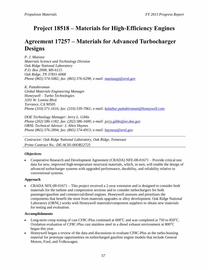
Propulsion Materials FY 2013 Progress Report
57
Project 18518 – Materials for High-Efficiency Engines
Agreement 17257 – Materials for Advanced Turbocharger
Designs
P. J. Maziasz
Materials Science and Technology Division
Oak Ridge National Laboratory
P.O. Box 2008, MS-6115
Oak Ridge, TN 37831-6068
Phone (865) 574-5082; fax: (865) 576-6298; e-mail: [email protected]
K. Pattabiraman
Global Materials Engineering Manager
Honeywell – Turbo Technologies
3201 W. Lomita Blvd.
Torrance, CA 90505
Phone (310) 571-1616; fax: (310) 539-7061; e-mail: [email protected]
DOE Technology Manager: Jerry L. Gibbs
Phone (202) 586-1182; fax: (202) 586-1600; e-mail: [email protected]
ORNL Technical Advisor: J. Allen Haynes
Phone (865) 576-2894; fax: (865) 574-4913; e-mail: [email protected]
Contractor: Oak Ridge National Laboratory, Oak Ridge, Tennessee
Prime Contract No.: DE-AC05-00OR22725
Objectives
Cooperative Research and Development Agreement (CRADA) NFE-08-01671 – Provide critical test
data for new, improved high-temperature structural materials, which, in turn, will enable the design of
advanced turbocharger systems with upgraded performance, durability, and reliability relative to
conventional systems.
Approach
CRADA NFE-08-01671 – This project received a 2-year extension and is designed to consider both
materials for the turbine and compression sections and to consider turbochargers for both
passenger/gasoline and commercial/diesel engines. Honeywell assesses and prioritizes the
components that benefit the most from materials upgrades or alloy development. Oak Ridge National
Laboratory (ORNL) works with Honeywell materials/component suppliers to obtain new materials
for testing and evaluation.
Accomplishments
Long-term creep testing of cast CF8C-Plus continued at 600oC and was completed at 750 to 850
oC.
Oxidation evaluation of CF8C-Plus cast stainless steel in a diesel exhaust environment at 800oC
began this year.
Honeywell began a review of the data and discussions to evaluate CF8C-Plus as the turbo-housing
material for prototype opportunities on turbocharged gasoline engine models that include General
Motors, Ford, and Volkswagen.

Propulsion Materials FY 2013 Progress Report
58
Future Direction
CRADA – Testing of CF8C-Plus for automotive turbocharger applications will continue and
discussions of prototyping opportunities will continue. Supporting the Honeywell commercialization
of CF8C-Plus for light-duty truck and automotive turbine housing applications is a priority.
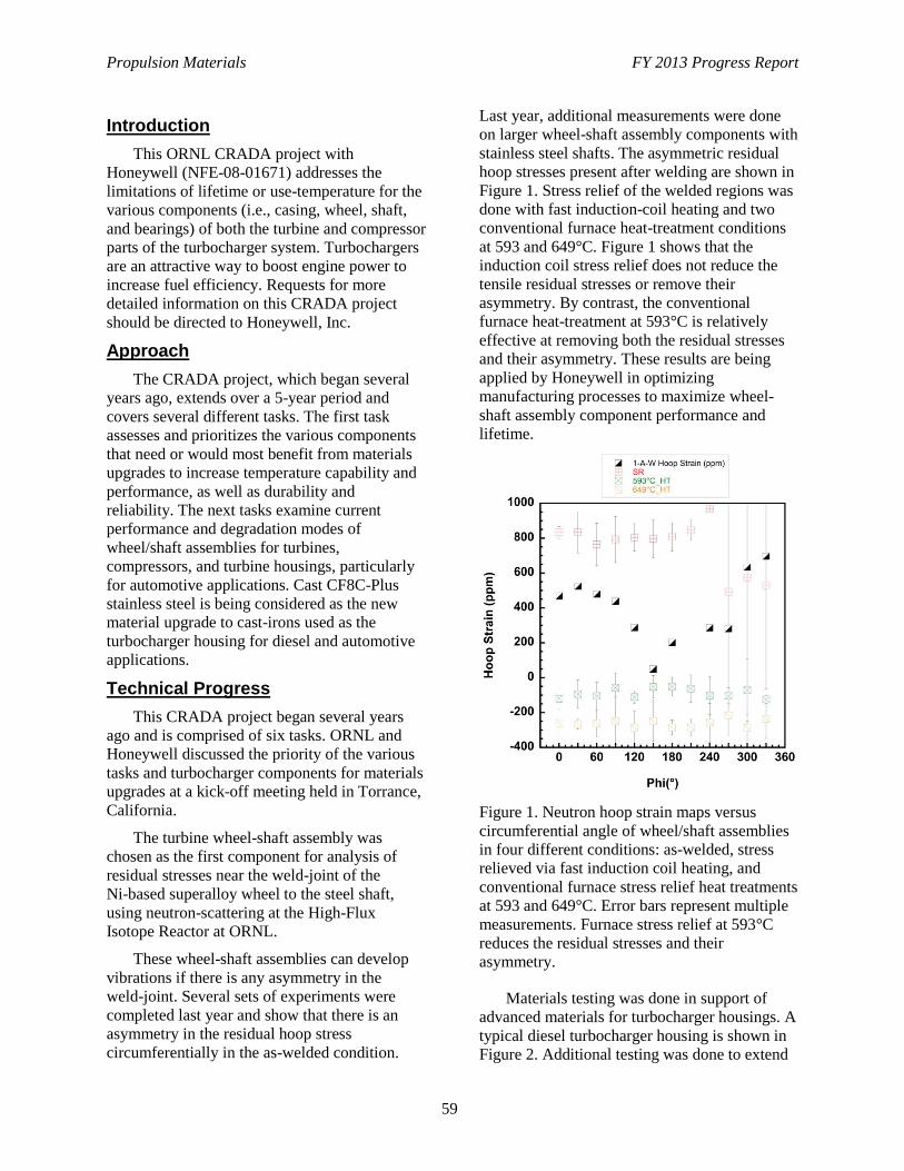
Propulsion Materials FY 2013 Progress Report
59
Introduction
This ORNL CRADA project with
Honeywell (NFE-08-01671) addresses the
limitations of lifetime or use-temperature for the
various components (i.e., casing, wheel, shaft,
and bearings) of both the turbine and compressor
parts of the turbocharger system. Turbochargers
are an attractive way to boost engine power to
increase fuel efficiency. Requests for more
detailed information on this CRADA project
should be directed to Honeywell, Inc.
Approach
The CRADA project, which began several
years ago, extends over a 5-year period and
covers several different tasks. The first task
assesses and prioritizes the various components
that need or would most benefit from materials
upgrades to increase temperature capability and
performance, as well as durability and
reliability. The next tasks examine current
performance and degradation modes of
wheel/shaft assemblies for turbines,
compressors, and turbine housings, particularly
for automotive applications. Cast CF8C-Plus
stainless steel is being considered as the new
material upgrade to cast-irons used as the
turbocharger housing for diesel and automotive
applications.
Technical Progress
This CRADA project began several years
ago and is comprised of six tasks. ORNL and
Honeywell discussed the priority of the various
tasks and turbocharger components for materials
upgrades at a kick-off meeting held in Torrance,
California.
The turbine wheel-shaft assembly was
chosen as the first component for analysis of
residual stresses near the weld-joint of the
Ni-based superalloy wheel to the steel shaft,
using neutron-scattering at the High-Flux
Isotope Reactor at ORNL.
These wheel-shaft assemblies can develop
vibrations if there is any asymmetry in the
weld-joint. Several sets of experiments were
completed last year and show that there is an
asymmetry in the residual hoop stress
circumferentially in the as-welded condition.
Last year, additional measurements were done
on larger wheel-shaft assembly components with
stainless steel shafts. The asymmetric residual
hoop stresses present after welding are shown in
Figure 1. Stress relief of the welded regions was
done with fast induction-coil heating and two
conventional furnace heat-treatment conditions
at 593 and 649°C. Figure 1 shows that the
induction coil stress relief does not reduce the
tensile residual stresses or remove their
asymmetry. By contrast, the conventional
furnace heat-treatment at 593°C is relatively
effective at removing both the residual stresses
and their asymmetry. These results are being
applied by Honeywell in optimizing
manufacturing processes to maximize wheel-
shaft assembly component performance and
lifetime.
Figure 1. Neutron hoop strain maps versus
circumferential angle of wheel/shaft assemblies
in four different conditions: as-welded, stress
relieved via fast induction coil heating, and
conventional furnace stress relief heat treatments
at 593 and 649°C. Error bars represent multiple
measurements. Furnace stress relief at 593°C
reduces the residual stresses and their
asymmetry.
Materials testing was done in support of
advanced materials for turbocharger housings. A
typical diesel turbocharger housing is shown in
Figure 2. Additional testing was done to extend
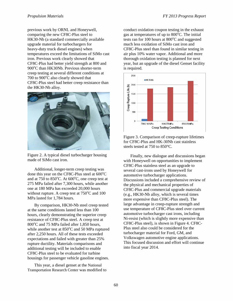
Propulsion Materials FY 2013 Progress Report
60
previous work by ORNL and Honeywell,
comparing the new CF8C-Plus steel to
HK30-Nb (a standard commercially available
upgrade material for turbochargers for
heavy-duty truck diesel engines) when
temperatures exceed the limitations of SiMo cast
iron. Previous work clearly showed that
CF8C-Plus had better yield strength at 800 and
900oC than HK30Nb. Previous shorter-term
creep testing at several different conditions at
700 to 900oC also clearly showed that
CF8C-Plus steel had better creep resistance than
the HK30-Nb alloy.
Figure 2. A typical diesel turbocharger housing
made of SiMo cast iron.
Additional, longer-term creep testing was
done this year on the CF8C-Plus steel at 600oC
and at 750 to 850oC. At 600
oC, one creep test at
275 MPa failed after 7,300 hours, while another
one at 180 MPa has exceeded 20,000 hours
without rupture. A creep test at 750oC and 100
MPa lasted for 1,784 hours.
By comparison, HK30-Nb steel creep tested
at the same conditions lasted less than 100
hours, clearly demonstrating the superior creep
resistance of CF8C-Plus steel. A creep test at
800oC and 75 MPa failed after 1,850 hours,
while another test at 850oC and 50 MPa ruptured
after 2,250 hours. All of these tests exceeded
expectations and failed with greater than 25%
rupture ductility. Materials comparisons and
additional testing will be included to enable
CF8C-Plus steel to be evaluated for turbine
housings for passenger vehicle gasoline engines.
This year, a diesel genset at the National
Transportation Research Center was modified to
conduct oxidation coupon testing in the exhaust
gas at temperatures of up to 800oC. The initial
tests ran for 100 hours at 800oC and suggested
much less oxidation of SiMo cast iron and
CF8C-Plus steel than found in similar testing in
air plus 10% water vapor. Additional and more
thorough oxidation testing is planned for next
year, but an upgrade of the diesel Genset facility
is required.
Figure 3. Comparison of creep-rupture lifetimes
for CF8C-Plus and HK-30Nb cast stainless
steels tested at 750 to 850°C.
Finally, new dialogue and discussions began
with Honeywell on opportunities to implement
CF8C-Plus stainless steel as an upgrade to
several cast-irons used by Honeywell for
automotive turbocharger applications.
Discussions included a comprehensive review of
the physical and mechanical properties of
CF8C-Plus and commercial upgrade materials
(e.g., HK30-Nb alloy, which is several times
more expensive than CF8C-Plus steel). The
large advantage in creep-rupture strength and
use temperature of CF8C-Plus steel over current
automotive turbocharger cast irons, including
Ni-resist (which is slightly more expensive than
CF8C-Plus steel), is shown in Figure 4. CF8C-
Plus steel also could be considered for the
turbocharger material for Ford, GM, and
Volkswagen automotive engine applications.
This focused discussion and effort will continue
into fiscal year 2014.
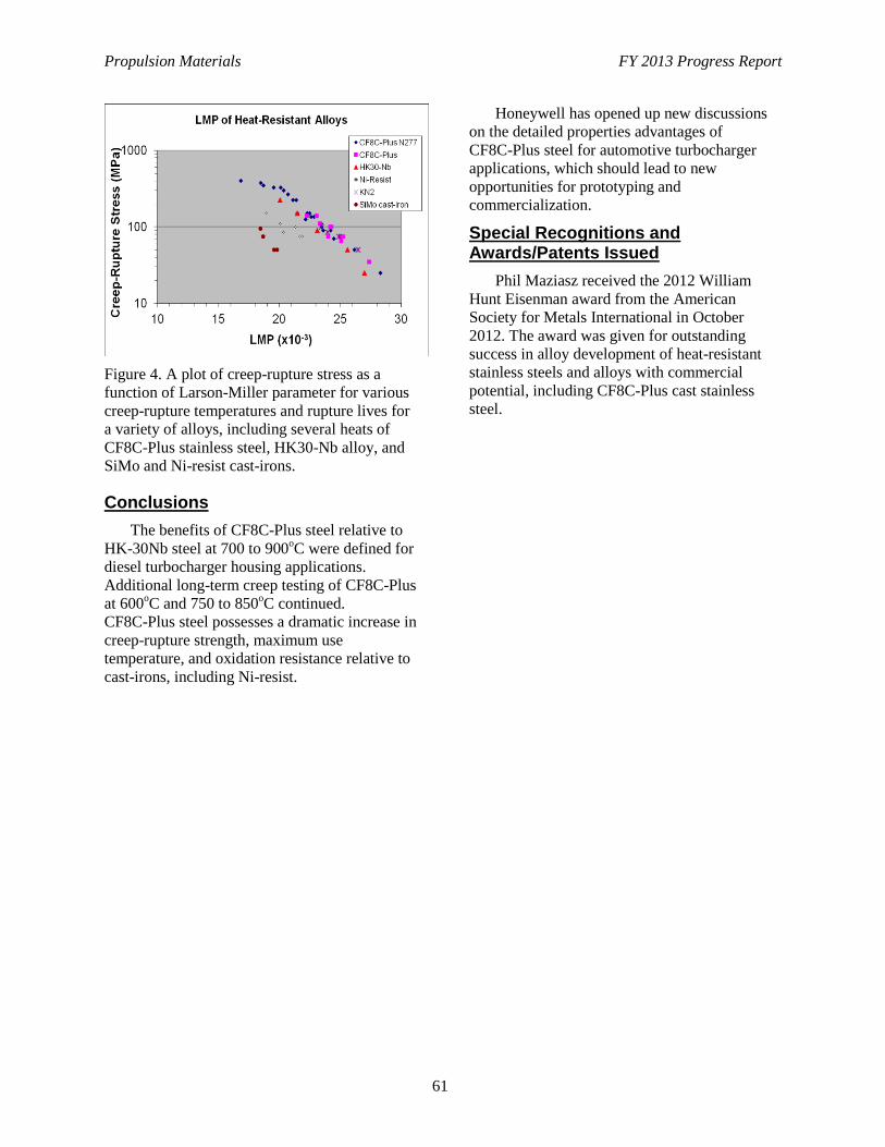
Propulsion Materials FY 2013 Progress Report
61
Figure 4. A plot of creep-rupture stress as a
function of Larson-Miller parameter for various
creep-rupture temperatures and rupture lives for
a variety of alloys, including several heats of
CF8C-Plus stainless steel, HK30-Nb alloy, and
SiMo and Ni-resist cast-irons.
Conclusions
The benefits of CF8C-Plus steel relative to
HK-30Nb steel at 700 to 900oC were defined for
diesel turbocharger housing applications.
Additional long-term creep testing of CF8C-Plus
at 600oC and 750 to 850
oC continued.
CF8C-Plus steel possesses a dramatic increase in
creep-rupture strength, maximum use
temperature, and oxidation resistance relative to
cast-irons, including Ni-resist.
Honeywell has opened up new discussions
on the detailed properties advantages of
CF8C-Plus steel for automotive turbocharger
applications, which should lead to new
opportunities for prototyping and
commercialization.
Special Recognitions and Awards/Patents Issued
Phil Maziasz received the 2012 William
Hunt Eisenman award from the American
Society for Metals International in October
2012. The award was given for outstanding
success in alloy development of heat-resistant
stainless steels and alloys with commercial
potential, including CF8C-Plus cast stainless
steel.
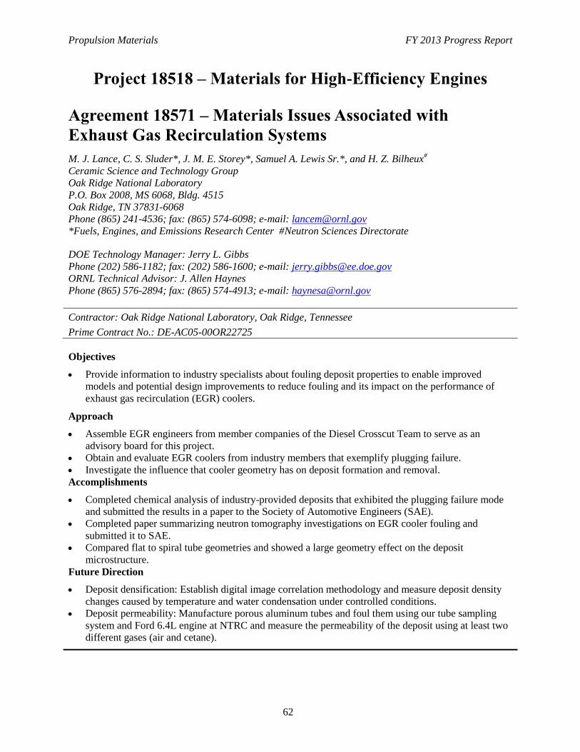
Propulsion Materials FY 2013 Progress Report
62
Project 18518 – Materials for High-Efficiency Engines
Agreement 18571 – Materials Issues Associated with
Exhaust Gas Recirculation Systems
M. J. Lance, C. S. Sluder*, J. M. E. Storey*, Samuel A. Lewis Sr.*, and H. Z. Bilheux#
Ceramic Science and Technology Group
Oak Ridge National Laboratory
P.O. Box 2008, MS 6068, Bldg. 4515
Oak Ridge, TN 37831-6068
Phone (865) 241-4536; fax: (865) 574-6098; e-mail: [email protected]
*Fuels, Engines, and Emissions Research Center #Neutron Sciences Directorate
DOE Technology Manager: Jerry L. Gibbs
Phone (202) 586-1182; fax: (202) 586-1600; e-mail: [email protected]
ORNL Technical Advisor: J. Allen Haynes
Phone (865) 576-2894; fax: (865) 574-4913; e-mail: [email protected]
Contractor: Oak Ridge National Laboratory, Oak Ridge, Tennessee
Prime Contract No.: DE-AC05-00OR22725
Objectives
Provide information to industry specialists about fouling deposit properties to enable improved
models and potential design improvements to reduce fouling and its impact on the performance of
exhaust gas recirculation (EGR) coolers.
Approach
Assemble EGR engineers from member companies of the Diesel Crosscut Team to serve as an
advisory board for this project.
Obtain and evaluate EGR coolers from industry members that exemplify plugging failure.
Investigate the influence that cooler geometry has on deposit formation and removal.
Accomplishments
Completed chemical analysis of industry-provided deposits that exhibited the plugging failure mode
and submitted the results in a paper to the Society of Automotive Engineers (SAE).
Completed paper summarizing neutron tomography investigations on EGR cooler fouling and
submitted it to SAE.
Compared flat to spiral tube geometries and showed a large geometry effect on the deposit
microstructure.
Future Direction
Deposit densification: Establish digital image correlation methodology and measure deposit density
changes caused by temperature and water condensation under controlled conditions.
Deposit permeability: Manufacture porous aluminum tubes and foul them using our tube sampling
system and Ford 6.4L engine at NTRC and measure the permeability of the deposit using at least two
different gases (air and cetane).
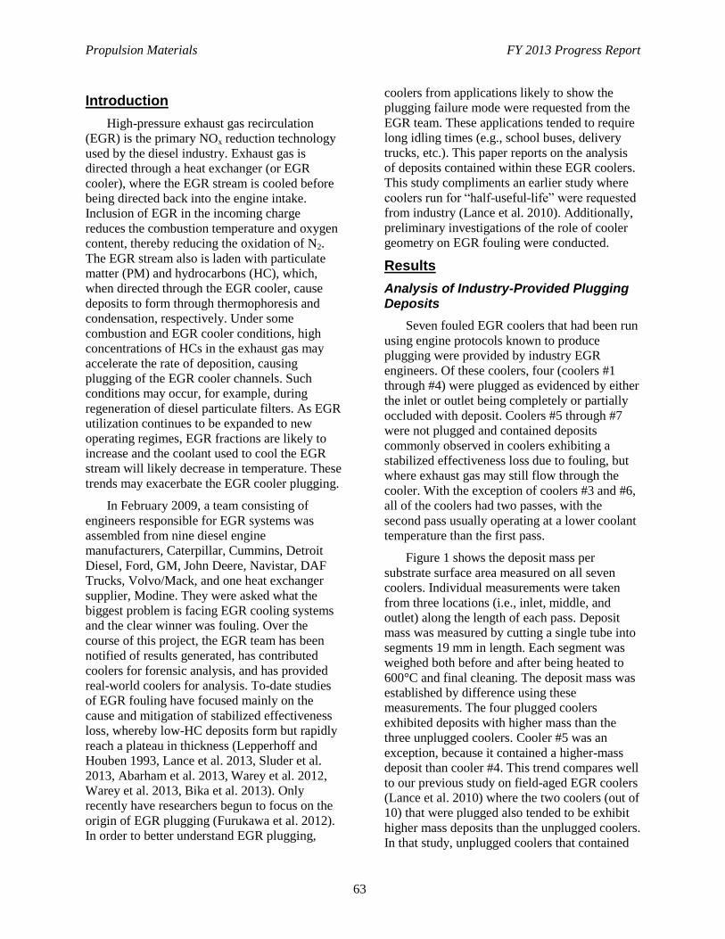
Propulsion Materials FY 2013 Progress Report
63
Introduction
High-pressure exhaust gas recirculation
(EGR) is the primary NOx reduction technology
used by the diesel industry. Exhaust gas is
directed through a heat exchanger (or EGR
cooler), where the EGR stream is cooled before
being directed back into the engine intake.
Inclusion of EGR in the incoming charge
reduces the combustion temperature and oxygen
content, thereby reducing the oxidation of N2.
The EGR stream also is laden with particulate
matter (PM) and hydrocarbons (HC), which,
when directed through the EGR cooler, cause
deposits to form through thermophoresis and
condensation, respectively. Under some
combustion and EGR cooler conditions, high
concentrations of HCs in the exhaust gas may
accelerate the rate of deposition, causing
plugging of the EGR cooler channels. Such
conditions may occur, for example, during
regeneration of diesel particulate filters. As EGR
utilization continues to be expanded to new
operating regimes, EGR fractions are likely to
increase and the coolant used to cool the EGR
stream will likely decrease in temperature. These
trends may exacerbate the EGR cooler plugging.
In February 2009, a team consisting of
engineers responsible for EGR systems was
assembled from nine diesel engine
manufacturers, Caterpillar, Cummins, Detroit
Diesel, Ford, GM, John Deere, Navistar, DAF
Trucks, Volvo/Mack, and one heat exchanger
supplier, Modine. They were asked what the
biggest problem is facing EGR cooling systems
and the clear winner was fouling. Over the
course of this project, the EGR team has been
notified of results generated, has contributed
coolers for forensic analysis, and has provided
real-world coolers for analysis. To-date studies
of EGR fouling have focused mainly on the
cause and mitigation of stabilized effectiveness
loss, whereby low-HC deposits form but rapidly
reach a plateau in thickness (Lepperhoff and
Houben 1993, Lance et al. 2013, Sluder et al.
2013, Abarham et al. 2013, Warey et al. 2012,
Warey et al. 2013, Bika et al. 2013). Only
recently have researchers begun to focus on the
origin of EGR plugging (Furukawa et al. 2012).
In order to better understand EGR plugging,
coolers from applications likely to show the
plugging failure mode were requested from the
EGR team. These applications tended to require
long idling times (e.g., school buses, delivery
trucks, etc.). This paper reports on the analysis
of deposits contained within these EGR coolers.
This study compliments an earlier study where
coolers run for “half-useful-life” were requested
from industry (Lance et al. 2010). Additionally,
preliminary investigations of the role of cooler
geometry on EGR fouling were conducted.
Results
Analysis of Industry-Provided Plugging Deposits
Seven fouled EGR coolers that had been run
using engine protocols known to produce
plugging were provided by industry EGR
engineers. Of these coolers, four (coolers #1
through #4) were plugged as evidenced by either
the inlet or outlet being completely or partially
occluded with deposit. Coolers #5 through #7
were not plugged and contained deposits
commonly observed in coolers exhibiting a
stabilized effectiveness loss due to fouling, but
where exhaust gas may still flow through the
cooler. With the exception of coolers #3 and #6,
all of the coolers had two passes, with the
second pass usually operating at a lower coolant
temperature than the first pass.
Figure 1 shows the deposit mass per
substrate surface area measured on all seven
coolers. Individual measurements were taken
from three locations (i.e., inlet, middle, and
outlet) along the length of each pass. Deposit
mass was measured by cutting a single tube into
segments 19 mm in length. Each segment was
weighed both before and after being heated to
600°C and final cleaning. The deposit mass was
established by difference using these
measurements. The four plugged coolers
exhibited deposits with higher mass than the
three unplugged coolers. Cooler #5 was an
exception, because it contained a higher-mass
deposit than cooler #4. This trend compares well
to our previous study on field-aged EGR coolers
(Lance et al. 2010) where the two coolers (out of
10) that were plugged also tended to be exhibit
higher mass deposits than the unplugged coolers.
In that study, unplugged coolers that contained
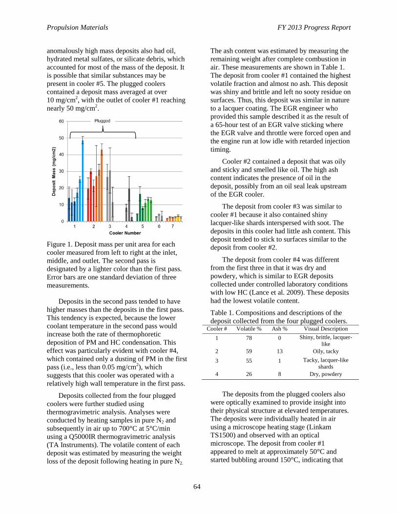
Propulsion Materials FY 2013 Progress Report
64
anomalously high mass deposits also had oil,
hydrated metal sulfates, or silicate debris, which
accounted for most of the mass of the deposit. It
is possible that similar substances may be
present in cooler #5. The plugged coolers
contained a deposit mass averaged at over
10 mg/cm2, with the outlet of cooler #1 reaching
nearly 50 mg/cm2.
Figure 1. Deposit mass per unit area for each
cooler measured from left to right at the inlet,
middle, and outlet. The second pass is
designated by a lighter color than the first pass.
Error bars are one standard deviation of three
measurements.
Deposits in the second pass tended to have
higher masses than the deposits in the first pass.
This tendency is expected, because the lower
coolant temperature in the second pass would
increase both the rate of thermophoretic
deposition of PM and HC condensation. This
effect was particularly evident with cooler #4,
which contained only a dusting of PM in the first
pass (i.e., less than 0.05 mg/cm2), which
suggests that this cooler was operated with a
relatively high wall temperature in the first pass.
Deposits collected from the four plugged
coolers were further studied using
thermogravimetric analysis. Analyses were
conducted by heating samples in pure N2 and
subsequently in air up to 700°C at 5°C/min
using a Q5000IR thermogravimetric analysis
(TA Instruments). The volatile content of each
deposit was estimated by measuring the weight
loss of the deposit following heating in pure N2.
The ash content was estimated by measuring the
remaining weight after complete combustion in
air. These measurements are shown in Table 1.
The deposit from cooler #1 contained the highest
volatile fraction and almost no ash. This deposit
was shiny and brittle and left no sooty residue on
surfaces. Thus, this deposit was similar in nature
to a lacquer coating. The EGR engineer who
provided this sample described it as the result of
a 65-hour test of an EGR valve sticking where
the EGR valve and throttle were forced open and
the engine run at low idle with retarded injection
timing.
Cooler #2 contained a deposit that was oily
and sticky and smelled like oil. The high ash
content indicates the presence of oil in the
deposit, possibly from an oil seal leak upstream
of the EGR cooler.
The deposit from cooler #3 was similar to
cooler #1 because it also contained shiny
lacquer-like shards interspersed with soot. The
deposits in this cooler had little ash content. This
deposit tended to stick to surfaces similar to the
deposit from cooler #2.
The deposit from cooler #4 was different
from the first three in that it was dry and
powdery, which is similar to EGR deposits
collected under controlled laboratory conditions
with low HC (Lance et al. 2009). These deposits
had the lowest volatile content.
Table 1. Compositions and descriptions of the
deposit collected from the four plugged coolers. Cooler # Volatile % Ash % Visual Description
1 78 0 Shiny, brittle, lacquer-
like
2 59 13 Oily, tacky
3 55 1 Tacky, lacquer-like
shards
4 26 8 Dry, powdery
The deposits from the plugged coolers also
were optically examined to provide insight into
their physical structure at elevated temperatures.
The deposits were individually heated in air
using a microscope heating stage (Linkam
TS1500) and observed with an optical
microscope. The deposit from cooler #1
appeared to melt at approximately 50°C and
started bubbling around 150°C, indicating that
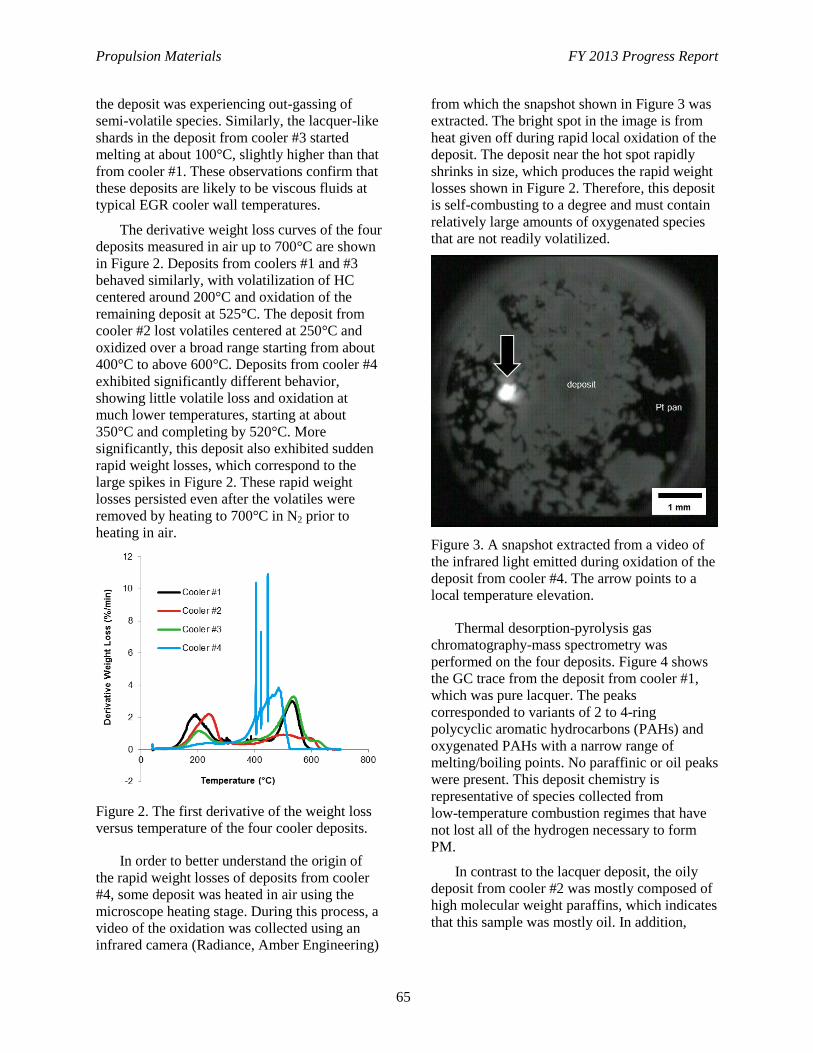
Propulsion Materials FY 2013 Progress Report
65
the deposit was experiencing out-gassing of
semi-volatile species. Similarly, the lacquer-like
shards in the deposit from cooler #3 started
melting at about 100°C, slightly higher than that
from cooler #1. These observations confirm that
these deposits are likely to be viscous fluids at
typical EGR cooler wall temperatures.
The derivative weight loss curves of the four
deposits measured in air up to 700°C are shown
in Figure 2. Deposits from coolers #1 and #3
behaved similarly, with volatilization of HC
centered around 200°C and oxidation of the
remaining deposit at 525°C. The deposit from
cooler #2 lost volatiles centered at 250°C and
oxidized over a broad range starting from about
400°C to above 600°C. Deposits from cooler #4
exhibited significantly different behavior,
showing little volatile loss and oxidation at
much lower temperatures, starting at about
350°C and completing by 520°C. More
significantly, this deposit also exhibited sudden
rapid weight losses, which correspond to the
large spikes in Figure 2. These rapid weight
losses persisted even after the volatiles were
removed by heating to 700°C in N2 prior to
heating in air.
Figure 2. The first derivative of the weight loss
versus temperature of the four cooler deposits.
In order to better understand the origin of
the rapid weight losses of deposits from cooler
#4, some deposit was heated in air using the
microscope heating stage. During this process, a
video of the oxidation was collected using an
infrared camera (Radiance, Amber Engineering)
from which the snapshot shown in Figure 3 was
extracted. The bright spot in the image is from
heat given off during rapid local oxidation of the
deposit. The deposit near the hot spot rapidly
shrinks in size, which produces the rapid weight
losses shown in Figure 2. Therefore, this deposit
is self-combusting to a degree and must contain
relatively large amounts of oxygenated species
that are not readily volatilized.
Figure 3. A snapshot extracted from a video of
the infrared light emitted during oxidation of the
deposit from cooler #4. The arrow points to a
local temperature elevation.
Thermal desorption-pyrolysis gas
chromatography-mass spectrometry was
performed on the four deposits. Figure 4 shows
the GC trace from the deposit from cooler #1,
which was pure lacquer. The peaks
corresponded to variants of 2 to 4-ring
polycyclic aromatic hydrocarbons (PAHs) and
oxygenated PAHs with a narrow range of
melting/boiling points. No paraffinic or oil peaks
were present. This deposit chemistry is
representative of species collected from
low-temperature combustion regimes that have
not lost all of the hydrogen necessary to form
PM.
In contrast to the lacquer deposit, the oily
deposit from cooler #2 was mostly composed of
high molecular weight paraffins, which indicates
that this sample was mostly oil. In addition,
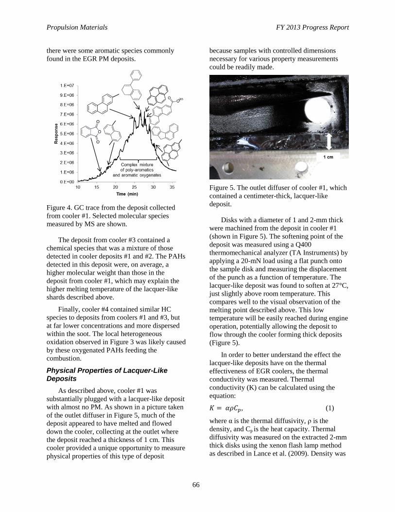
Propulsion Materials FY 2013 Progress Report
66
there were some aromatic species commonly
found in the EGR PM deposits.
Figure 4. GC trace from the deposit collected
from cooler #1. Selected molecular species
measured by MS are shown.
The deposit from cooler #3 contained a
chemical species that was a mixture of those
detected in cooler deposits #1 and #2. The PAHs
detected in this deposit were, on average, a
higher molecular weight than those in the
deposit from cooler #1, which may explain the
higher melting temperature of the lacquer-like
shards described above.
Finally, cooler #4 contained similar HC
species to deposits from coolers #1 and #3, but
at far lower concentrations and more dispersed
within the soot. The local heterogeneous
oxidation observed in Figure 3 was likely caused
by these oxygenated PAHs feeding the
combustion.
Physical Properties of Lacquer-Like Deposits
As described above, cooler #1 was
substantially plugged with a lacquer-like deposit
with almost no PM. As shown in a picture taken
of the outlet diffuser in Figure 5, much of the
deposit appeared to have melted and flowed
down the cooler, collecting at the outlet where
the deposit reached a thickness of 1 cm. This
cooler provided a unique opportunity to measure
physical properties of this type of deposit
because samples with controlled dimensions
necessary for various property measurements
could be readily made.
Figure 5. The outlet diffuser of cooler #1, which
contained a centimeter-thick, lacquer-like
deposit.
Disks with a diameter of 1 and 2-mm thick
were machined from the deposit in cooler #1
(shown in Figure 5). The softening point of the
deposit was measured using a Q400
thermomechanical analyzer (TA Instruments) by
applying a 20-mN load using a flat punch onto
the sample disk and measuring the displacement
of the punch as a function of temperature. The
lacquer-like deposit was found to soften at 27°C,
just slightly above room temperature. This
compares well to the visual observation of the
melting point described above. This low
temperature will be easily reached during engine
operation, potentially allowing the deposit to
flow through the cooler forming thick deposits
(Figure 5).
In order to better understand the effect the
lacquer-like deposits have on the thermal
effectiveness of EGR coolers, the thermal
conductivity was measured. Thermal
conductivity (K) can be calculated using the
equation:
, (1)
where α is the thermal diffusivity, ρ is the
density, and Cp is the heat capacity. Thermal
diffusivity was measured on the extracted 2-mm
thick disks using the xenon flash lamp method
as described in Lance et al. (2009). Density was
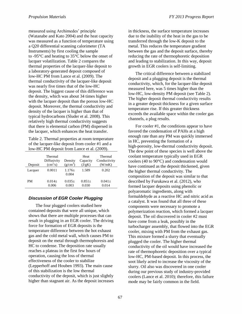
Propulsion Materials FY 2013 Progress Report
67
measured using Archimedes’ principle
(Watanabe and Kato 2004) and the heat capacity
was measured as a function of temperature using
a Q20 differential scanning calorimeter (TA
Instruments) by first cooling the sample
to -95°C and heating to 35°C below the onset of
lacquer volatilization. Table 2 compares the
thermal properties of the lacquer-like deposit to
a laboratory-generated deposit composed of
low-HC PM from Lance et al. (2009). The
thermal conductivity of the lacquer-like deposit
was nearly five times that of the low-HC
deposit. The biggest cause of this difference was
the density, which was about 34 times higher
with the lacquer deposit than the porous low-HC
deposit. Moreover, the thermal conductivity and
density of the lacquer is higher than that of
typical hydrocarbons (Sluder et al. 2008). This
relatively high thermal conductivity suggests
that there is elemental carbon (PM) dispersed in
the lacquer, which enhances the heat transfer.
Table 2. Thermal properties at room temperature
of the lacquer-like deposit from cooler #1 and a
low-HC PM deposit from Lance et al. (2009).
Deposit
Thermal
Diffusivity
(cm2/s)
Density
(g/cm3)
Heat
Capacity
(J/gK)
Thermal
Conductivity
(W/mK)
Lacquer 0.0011 1.176±
0.004
1.589 0.202
PM 0.014±
0.006
0.035±
0.003
0.851±
0.030
0.041±
0.014
Discussion of EGR Cooler Plugging
The four plugged coolers studied here
contained deposits that were all unique, which
shows that there are multiple processes that can
result in plugging in an EGR cooler. The driving
force for formation of EGR deposits is the
temperature difference between the hot exhaust
gas and the cold metal wall, which causes PM to
deposit on the metal through thermophoresis and
HC to condense. The deposition rate usually
reaches a plateau in the first few hours of
operation, causing the loss of thermal
effectiveness of the cooler to stabilize
(Lepperhoff and Houben 1993). The main cause
of this stabilization is the low thermal
conductivity of the deposit, which is just slightly
higher than stagnant air. As the deposit increases
in thickness, the surface temperature increases
due to the inability of the heat in the gas to be
transferred through the low-K deposit to the
metal. This reduces the temperature gradient
between the gas and the deposit surface, thereby
reducing the rate of thermophoretic deposition
and leading to stabilization. In this way, deposit
growth in EGR coolers is self-limiting.
The critical difference between a stabilized
deposit and a plugging deposit is the thermal
conductivity, which, for the lacquer-like deposit
measured here, was 5 times higher than the
low-HC, low-density PM deposit (see Table 2).
The higher deposit thermal conductivity results
in a greater deposit thickness for a given surface
temperature rise. If this greater thickness
exceeds the available space within the cooler gas
channels, a plug results.
For cooler #1, the conditions appear to have
favored the condensation of PAHs at a high
enough rate than any PM was quickly immersed
in HC, preventing the formation of a
high-porosity, low-thermal conductivity deposit.
The dew point of these species is well above the
coolant temperature typically used in EGR
coolers (40 to 90°C) and condensation would
have continued as the deposit thickened, given
the higher thermal conductivity. The
composition of the deposit was similar to that
described by Furukawa et al. (2012), who
formed lacquer deposits using phenolic or
polyaromatic ingredients, along with
formaldehyde as a reactive HC and nitric acid as
a catalyst. It was found that all three of these
components were necessary to promote a
polymerization reaction, which formed a lacquer
deposit. The oil discovered in cooler #2 must
have come from a leak, possibly in the
turbocharger assembly, that flowed into the EGR
cooler, mixing with PM from the exhaust gas.
This mixture formed a slurry that eventually
plugged the cooler. The higher thermal
conductivity of the oil would have increased the
rate of thermophoretic deposition over a typical
low-HC, PM-based deposit. In this process, the
soot likely acted to increase the viscosity of the
slurry. Oil also was discovered in one cooler
during our previous study of industry-provided
coolers (Lance et al. 2010); therefore, this failure
mode may be fairly common in the field.
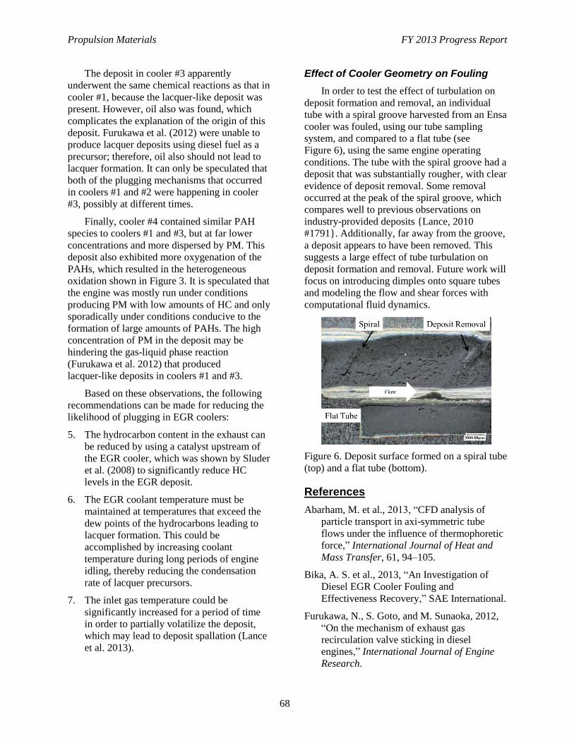
Propulsion Materials FY 2013 Progress Report
68
The deposit in cooler #3 apparently
underwent the same chemical reactions as that in
cooler #1, because the lacquer-like deposit was
present. However, oil also was found, which
complicates the explanation of the origin of this
deposit. Furukawa et al. (2012) were unable to
produce lacquer deposits using diesel fuel as a
precursor; therefore, oil also should not lead to
lacquer formation. It can only be speculated that
both of the plugging mechanisms that occurred
in coolers #1 and #2 were happening in cooler
#3, possibly at different times.
Finally, cooler #4 contained similar PAH
species to coolers #1 and #3, but at far lower
concentrations and more dispersed by PM. This
deposit also exhibited more oxygenation of the
PAHs, which resulted in the heterogeneous
oxidation shown in Figure 3. It is speculated that
the engine was mostly run under conditions
producing PM with low amounts of HC and only
sporadically under conditions conducive to the
formation of large amounts of PAHs. The high
concentration of PM in the deposit may be
hindering the gas-liquid phase reaction
(Furukawa et al. 2012) that produced
lacquer-like deposits in coolers #1 and #3.
Based on these observations, the following
recommendations can be made for reducing the
likelihood of plugging in EGR coolers:
5. The hydrocarbon content in the exhaust can
be reduced by using a catalyst upstream of
the EGR cooler, which was shown by Sluder
et al. (2008) to significantly reduce HC
levels in the EGR deposit.
6. The EGR coolant temperature must be
maintained at temperatures that exceed the
dew points of the hydrocarbons leading to
lacquer formation. This could be
accomplished by increasing coolant
temperature during long periods of engine
idling, thereby reducing the condensation
rate of lacquer precursors.
7. The inlet gas temperature could be
significantly increased for a period of time
in order to partially volatilize the deposit,
which may lead to deposit spallation (Lance
et al. 2013).
Effect of Cooler Geometry on Fouling
In order to test the effect of turbulation on
deposit formation and removal, an individual
tube with a spiral groove harvested from an Ensa
cooler was fouled, using our tube sampling
system, and compared to a flat tube (see
Figure 6), using the same engine operating
conditions. The tube with the spiral groove had a
deposit that was substantially rougher, with clear
evidence of deposit removal. Some removal
occurred at the peak of the spiral groove, which
compares well to previous observations on
industry-provided deposits {Lance, 2010
#1791}. Additionally, far away from the groove,
a deposit appears to have been removed. This
suggests a large effect of tube turbulation on
deposit formation and removal. Future work will
focus on introducing dimples onto square tubes
and modeling the flow and shear forces with
computational fluid dynamics.
Figure 6. Deposit surface formed on a spiral tube
(top) and a flat tube (bottom).
References
Abarham, M. et al., 2013, “CFD analysis of
particle transport in axi-symmetric tube
flows under the influence of thermophoretic
force,” International Journal of Heat and
Mass Transfer, 61, 94–105.
Bika, A. S. et al., 2013, “An Investigation of
Diesel EGR Cooler Fouling and
Effectiveness Recovery,” SAE International.
Furukawa, N., S. Goto, and M. Sunaoka, 2012,
“On the mechanism of exhaust gas
recirculation valve sticking in diesel
engines,” International Journal of Engine
Research.
Propulsion Materials FY 2013 Progress Report
69
International, A., 2013, “Standard Test Methods
for Density of Compacted or Sintered
Powder Metallurgy (PM) Products Using
Archimedes’ Principle,” ASTM
International: West Conshohocken, PA.
Lance, M. J. et al., 2009, “Direct Measurement
of EGR Cooler Deposit Thermal Properties
for Improved Understanding of Cooler
Fouling,” SAE International.
Lance, M. J. et al., 2010, “Characterization of
Field-Aged EGR Cooler Deposits,” SAE Int.
J. Engines, 3, (2), 126–136.
Lance, M. J. et al., 2013, “Microstructural
Analysis of Deposits on Heavy-Duty EGR
Coolers,” SAE International.
Lepperhoff, G. and M. Houben, 1993,
“Mechanisms of Deposit Formation in
Internal Combustion Engines and Heat
Exchangers,” SAE (931032).
Sluder, C. S. et al., 2008, “Hydrocarbons and
Particulate Matter in EGR Cooler Deposits:
Effects of Gas Flow Rate, Coolant
Temperature, and Oxidation Catalyst,” SAE
Int. J. Engines, 1, (1), 1196–1204.
Sluder, C. S. et al., 2013, “Removal of EGR
Cooler Deposit Material by Flow-Induced
Shear,” SAE Int. J. Engines, 6, (2),
999-1008.
Warey, A. et al., 2012, “A One-Dimensional
Model for Particulate Deposition and
Hydrocarbon Condensation in Exhaust Gas
Recirculation Coolers,” Aerosol Science and
Technology, 46, (2), 198–213.
Warey, A. et al., 2013, “Influence of water vapor
condensation on exhaust gas recirculation
cooler fouling,” International Journal of
Heat and Mass Transfer, 65, 807–816.
Watanabe, H. and H. Kato, 2004, “Thermal
conductivity and thermal diffusivity of
twenty-nine liquids: Alkenes, cyclic
(alkanes, alkenes, alkadienes, aromatics),
and deuterated hydrocarbons,” Journal of
Chemical and Engineering Data, 49, (4),
809–825.
Publications and Presentations
Published
Abarham, Mehdi, Parsa Zamankhan, John W.
Hoard, Dan Styles, C. Scott Sluder, John M.
E. Storey, Michael J. Lance, and Dennis
Assanis, 2013, “CFD analysis of particle
transport in axi-symmetric tube flows under
the influence of thermophoretic force,”
International Journal of Heat and Mass
Transfer, 61, 94–105.
Bilheux, H., K. Crawford, L. Walker, S. Voisin,
M. Kang, M. Harvey, B. Bailey, M. Phillips,
J. C. Bilheux, K. Berry, J. Anknera, J.
Warren, J. Nanda, S. Pannala, and M. Lance,
2013, “Neutron imaging at the Oak Ridge
National Laboratory: present and future
capabilities,” 7th International Topical
Meeting on Neutron Radiography, Physics
Procedia.
Lance, Michael J., John Storey, C. Scott Sluder,
Harry Meyer III, Brad Watkins, Michele
Kaiser, and Ponnaiyan Ayyappan, 2013,
“Microstructural Analysis of Deposits on
Heavy-Duty EGR Coolers,” SAE Technical
Paper 2013-01-1288.
Sluder, C. Scott, John Storey, Michael J. Lance,
and Teresa Barone, 2013,“Removal of EGR
Cooler Deposit Material by Flow-Induced
Shear,” SAE Technical Paper 2013-01-1292.
Storey, John M. E., C. Scott Sluder, Michael J.
Lance, Daniel J. Styles, Steven J. Simko,
2013, “Exhaust Gas Recirculation Cooler
Fouling in Diesel Applications:
Fundamental Studies of Deposit Properties
and Microstructure,” Heat Transfer
Engineering, 34, (8-9), 655–664.
Submitted
Lance, Michael J., John M. E. Storey, Samuel A.
Lewis, and C. Scott Sluder, 2013, “Analysis
of Lacquer Deposits and Plugging Found in
Field-Tested EGR Coolers,” SAE Paper
14HX-0057.
Lance, Michael J., Hassina Z. Bilheux, Jean-
Christophe Bilheux, Sophie Voisin, Joe
Stevenson, and C. Scott Sluder, 2013,
“Neutron Tomography of Exhaust Gas

Propulsion Materials FY 2013 Progress Report
70
Recirculation Cooler Deposits,” SAE Paper
14HX-0056.
Sluder, C. Scott, John M. E. Storey, and Michael
J. Lance, 2013, “Effectiveness
‘Stabilization’ and Plugging in EGR Cooler
Fouling” submitted to SAE International
Journal of Engines.
Sluder, C.S., J. M. E. Storey, and M. J. Lance,
2013, “Temperature and Thermal
Conductivity of Soot Deposits in EGR
Coolers: Measurements and Challenges,”
submitted to Heat Transfer Engineering.
Propulsion Materials FY 2013 Progress Report
71
Project 18518 – Materials for High-Efficiency Engines
Agreement 23284 – Friction Reduction Through Surface
Modification: Integrated Surface Texturing and Coating
Peter J. Blau
Oak Ridge National Laboratory
P.O. Box 2008, MS 6063
Oak Ridge, TN 37831-6068
Phone (865) 574-5377; fax: (865) 574-4913; e-mail: [email protected]
Stephen M. Hsu
George Washington University, Exploration Hall
20101 Academic Way
Ashburn, VA 20147
Phone (703) 726-8365; e-mail: [email protected]
DOE Technology Manager: Jerry L. Gibbs
Phone (202) 586-1182; fax: (202) 586-1600; e-mail: [email protected]
ORNL Technical Advisor: J. Allen Haynes
Phone (865) 576-2894; fax: (865) 574-4913; e-mail: [email protected]
Contractor: Oak Ridge National Laboratory, Oak Ridge, Tennessee
Prime Contract No.: DE-AC05-00OR22725
Objectives
To develop and compare surface engineering methods for applying friction-reducing, micro-scale
patterns (textures) to the sliding surfaces of diesel engine components.
To demonstrate the frictional benefits of applying surface texturing to curved surfaces like those on
piston rings, cam lobes, and connecting rod bearings.
To provide guidelines to engine makers on the application of engineered surfaces.
Approach
Fabricate and optimize integrated surface texture designs on diesel engine piston rings and curved
surfaces that simulate cam lobes and connecting rod bearing inserts.
Investigate surface texturing using micro-lithography and compression texturing.
Test for efficacy in friction reduction using laboratory tests, including ASTM standards.
Explore methods of preserving textures by using wear-resistant coatings.
Accomplishments
Published a literature review on the production and use of patterned surfaces to control friction and
wear behavior of a variety of lubricated interfaces and applications.
Demonstrated the ability to pattern curved piston ring surfaces and discovered an optimal shape factor
for achieving lowest friction with combined circular and elliptical dimples.
Developed a one-step method that forms curved bearing surfaces and textures them.

Propulsion Materials FY 2013 Progress Report
72
Future Direction
Apply coatings to protect textures from wear and maintain longer-term functionality.
Explore the feasibility of micromachining technology to create effective textures.
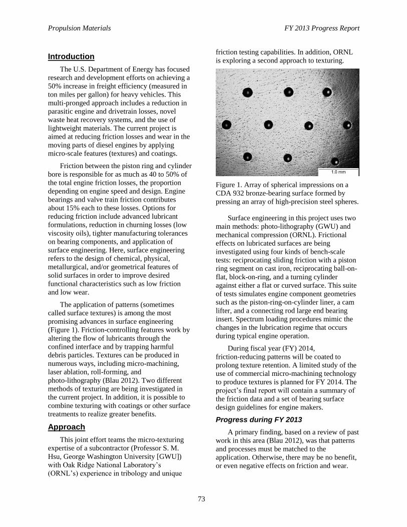
Propulsion Materials FY 2013 Progress Report
73
Introduction
The U.S. Department of Energy has focused
research and development efforts on achieving a
50% increase in freight efficiency (measured in
ton miles per gallon) for heavy vehicles. This
multi-pronged approach includes a reduction in
parasitic engine and drivetrain losses, novel
waste heat recovery systems, and the use of
lightweight materials. The current project is
aimed at reducing friction losses and wear in the
moving parts of diesel engines by applying
micro-scale features (textures) and coatings.
Friction between the piston ring and cylinder
bore is responsible for as much as 40 to 50% of
the total engine friction losses, the proportion
depending on engine speed and design. Engine
bearings and valve train friction contributes
about 15% each to these losses. Options for
reducing friction include advanced lubricant
formulations, reduction in churning losses (low
viscosity oils), tighter manufacturing tolerances
on bearing components, and application of
surface engineering. Here, surface engineering
refers to the design of chemical, physical,
metallurgical, and/or geometrical features of
solid surfaces in order to improve desired
functional characteristics such as low friction
and low wear.
The application of patterns (sometimes
called surface textures) is among the most
promising advances in surface engineering
(Figure 1). Friction-controlling features work by
altering the flow of lubricants through the
confined interface and by trapping harmful
debris particles. Textures can be produced in
numerous ways, including micro-machining,
laser ablation, roll-forming, and
photo-lithography (Blau 2012). Two different
methods of texturing are being investigated in
the current project. In addition, it is possible to
combine texturing with coatings or other surface
treatments to realize greater benefits.
Approach
This joint effort teams the micro-texturing
expertise of a subcontractor (Professor S. M.
Hsu, George Washington University [GWU])
with Oak Ridge National Laboratory’s
(ORNL’s) experience in tribology and unique
friction testing capabilities. In addition, ORNL
is exploring a second approach to texturing.
Figure 1. Array of spherical impressions on a
CDA 932 bronze-bearing surface formed by
pressing an array of high-precision steel spheres.
Surface engineering in this project uses two
main methods: photo-lithography (GWU) and
mechanical compression (ORNL). Frictional
effects on lubricated surfaces are being
investigated using four kinds of bench-scale
tests: reciprocating sliding friction with a piston
ring segment on cast iron, reciprocating ball-on-
flat, block-on-ring, and a turning cylinder
against either a flat or curved surface. This suite
of tests simulates engine component geometries
such as the piston-ring-on-cylinder liner, a cam
lifter, and a connecting rod large end bearing
insert. Spectrum loading procedures mimic the
changes in the lubrication regime that occurs
during typical engine operation.
During fiscal year (FY) 2014,
friction-reducing patterns will be coated to
prolong texture retention. A limited study of the
use of commercial micro-machining technology
to produce textures is planned for FY 2014. The
project’s final report will contain a summary of
the friction data and a set of bearing surface
design guidelines for engine makers.
Progress during FY 2013
A primary finding, based on a review of past
work in this area (Blau 2012), was that patterns
and processes must be matched to the
application. Otherwise, there may be no benefit,
or even negative effects on friction and wear.
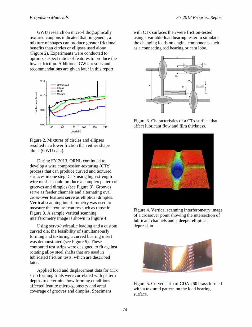
Propulsion Materials FY 2013 Progress Report
74
GWU research on micro-lithographically
textured coupons indicated that, in general, a
mixture of shapes can produce greater frictional
benefits than circles or ellipses used alone
(Figure 2). Experiments were conducted to
optimize aspect ratios of features to produce the
lowest friction. Additional GWU results and
recommendations are given later in this report.
40 80 120 160 200 2400.00
0.05
0.10
0.15
Fri
ctio
n c
oe
ffic
ien
t
Load (N)
Untextured
Ellipse
Circle
Mixture
Figure 2. Mixtures of circles and ellipses
resulted in a lower friction than either shape
alone (GWU data).
During FY 2013, ORNL continued to
develop a wire compression-texturing (CTx)
process that can produce curved and textured
surfaces in one step. CTx using high-strength
wire meshes could produce a complex pattern of
grooves and dimples (see Figure 3). Grooves
serve as feeder channels and alternating oval
cross-over features serve as elliptical dimples.
Vertical scanning interferometry was used to
measure the texture features such as those in
Figure 3. A sample vertical scanning
interferometry image is shown in Figure 4.
Using servo-hydraulic loading and a custom
curved die, the feasibility of simultaneously
forming and texturing a curved bearing insert
was demonstrated (see Figure 5). These
contoured test strips were designed to fit against
rotating alloy steel shafts that are used in
lubricated friction tests, which are described
later.
Applied load and displacement data for CTx
strip forming trials were correlated with pattern
depths to determine how forming conditions
affected feature micro-geometry and areal
coverage of grooves and dimples. Specimens
with CTx surfaces then were friction-tested
using a variable-load bearing tester to simulate
the changing loads on engine components such
as a connecting rod bearing or cam lobe.
Figure 3. Characteristics of a CTx surface that
affect lubricant flow and film thickness.
Figure 4. Vertical scanning interferometry image
of a crossover point showing the intersection of
lubricant channels and a deeper elliptical
depression.
Figure 5. Curved strip of CDA 260 brass formed
with a textured pattern on the load bearing
surface.
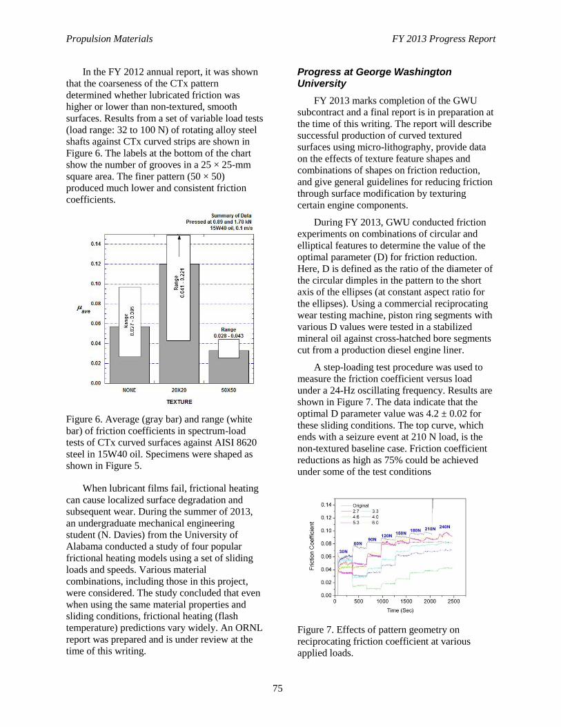
Propulsion Materials FY 2013 Progress Report
75
In the FY 2012 annual report, it was shown
that the coarseness of the CTx pattern
determined whether lubricated friction was
higher or lower than non-textured, smooth
surfaces. Results from a set of variable load tests
(load range: 32 to 100 N) of rotating alloy steel
shafts against CTx curved strips are shown in
Figure 6. The labels at the bottom of the chart
show the number of grooves in a 25 × 25-mm
square area. The finer pattern (50 × 50)
produced much lower and consistent friction
coefficients.
Figure 6. Average (gray bar) and range (white
bar) of friction coefficients in spectrum-load
tests of CTx curved surfaces against AISI 8620
steel in 15W40 oil. Specimens were shaped as
shown in Figure 5.
When lubricant films fail, frictional heating
can cause localized surface degradation and
subsequent wear. During the summer of 2013,
an undergraduate mechanical engineering
student (N. Davies) from the University of
Alabama conducted a study of four popular
frictional heating models using a set of sliding
loads and speeds. Various material
combinations, including those in this project,
were considered. The study concluded that even
when using the same material properties and
sliding conditions, frictional heating (flash
temperature) predictions vary widely. An ORNL
report was prepared and is under review at the
time of this writing.
Progress at George Washington University
FY 2013 marks completion of the GWU
subcontract and a final report is in preparation at
the time of this writing. The report will describe
successful production of curved textured
surfaces using micro-lithography, provide data
on the effects of texture feature shapes and
combinations of shapes on friction reduction,
and give general guidelines for reducing friction
through surface modification by texturing
certain engine components.
During FY 2013, GWU conducted friction
experiments on combinations of circular and
elliptical features to determine the value of the
optimal parameter (D) for friction reduction.
Here, D is defined as the ratio of the diameter of
the circular dimples in the pattern to the short
axis of the ellipses (at constant aspect ratio for
the ellipses). Using a commercial reciprocating
wear testing machine, piston ring segments with
various D values were tested in a stabilized
mineral oil against cross-hatched bore segments
cut from a production diesel engine liner.
A step-loading test procedure was used to
measure the friction coefficient versus load
under a 24-Hz oscillating frequency. Results are
shown in Figure 7. The data indicate that the
optimal D parameter value was 4.2 ± 0.02 for
these sliding conditions. The top curve, which
ends with a seizure event at 210 N load, is the
non-textured baseline case. Friction coefficient
reductions as high as 75% could be achieved
under some of the test conditions
Figure 7. Effects of pattern geometry on
reciprocating friction coefficient at various
applied loads.
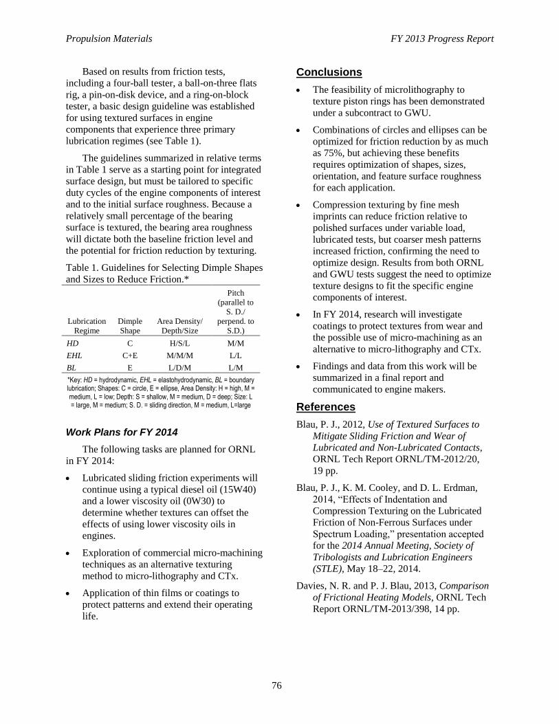
Propulsion Materials FY 2013 Progress Report
76
Based on results from friction tests,
including a four-ball tester, a ball-on-three flats
rig, a pin-on-disk device, and a ring-on-block
tester, a basic design guideline was established
for using textured surfaces in engine
components that experience three primary
lubrication regimes (see Table 1).
The guidelines summarized in relative terms
in Table 1 serve as a starting point for integrated
surface design, but must be tailored to specific
duty cycles of the engine components of interest
and to the initial surface roughness. Because a
relatively small percentage of the bearing
surface is textured, the bearing area roughness
will dictate both the baseline friction level and
the potential for friction reduction by texturing.
Table 1. Guidelines for Selecting Dimple Shapes
and Sizes to Reduce Friction.*
Lubrication
Regime
Dimple
Shape
Area Density/
Depth/Size
Pitch
(parallel to
S. D./
perpend. to
S.D.)
HD C H/S/L M/M
EHL C+E M/M/M L/L
BL E L/D/M L/M
*Key: HD = hydrodynamic, EHL = elastohydrodynamic, BL = boundary lubrication; Shapes: C = circle, E = ellipse, Area Density: H = high, M = medium, L = low; Depth: S = shallow, M = medium, D = deep; Size: L = large, M = medium; S. D. = sliding direction, M = medium, L=large
Work Plans for FY 2014
The following tasks are planned for ORNL
in FY 2014:
Lubricated sliding friction experiments will
continue using a typical diesel oil (15W40)
and a lower viscosity oil (0W30) to
determine whether textures can offset the
effects of using lower viscosity oils in
engines.
Exploration of commercial micro-machining
techniques as an alternative texturing
method to micro-lithography and CTx.
Application of thin films or coatings to
protect patterns and extend their operating
life.
Conclusions
The feasibility of microlithography to
texture piston rings has been demonstrated
under a subcontract to GWU.
Combinations of circles and ellipses can be
optimized for friction reduction by as much
as 75%, but achieving these benefits
requires optimization of shapes, sizes,
orientation, and feature surface roughness
for each application.
Compression texturing by fine mesh
imprints can reduce friction relative to
polished surfaces under variable load,
lubricated tests, but coarser mesh patterns
increased friction, confirming the need to
optimize design. Results from both ORNL
and GWU tests suggest the need to optimize
texture designs to fit the specific engine
components of interest.
In FY 2014, research will investigate
coatings to protect textures from wear and
the possible use of micro-machining as an
alternative to micro-lithography and CTx.
Findings and data from this work will be
summarized in a final report and
communicated to engine makers.
References
Blau, P. J., 2012, Use of Textured Surfaces to
Mitigate Sliding Friction and Wear of
Lubricated and Non-Lubricated Contacts,
ORNL Tech Report ORNL/TM-2012/20,
19 pp.
Blau, P. J., K. M. Cooley, and D. L. Erdman,
2014, “Effects of Indentation and
Compression Texturing on the Lubricated
Friction of Non-Ferrous Surfaces under
Spectrum Loading,” presentation accepted
for the 2014 Annual Meeting, Society of
Tribologists and Lubrication Engineers
(STLE), May 18–22, 2014.
Davies, N. R. and P. J. Blau, 2013, Comparison
of Frictional Heating Models, ORNL Tech
Report ORNL/TM-2013/398, 14 pp.
Propulsion Materials FY 2013 Progress Report
77
Project 18518 – Materials for High-Efficiency Engines
Agreement 23425 – Lightweight Heavy-Duty Engine
G. Muralidharan, A. Shyam, M. P. Brady, R. R. DeHoff, and T. R. Watkins
Materials Science and Technology Division
Oak Ridge National Laboratory
P.O. Box 2008
Oak Ridge, TN 37831-6068
Phone (865) 574-4281; fax: (865) 574-4357; e-mail: [email protected]
Roger England
Cummins Technical Center
1900 McKinley Ave.,
Columbus, IN 47201
Phone (812) 377-3135; e-mail: [email protected]
DOE Technology Manager: Jerry L. Gibbs
Phone (202) 586-1182; fax: (202) 586-1600; e-mail: [email protected]
ORNL Technical Advisor: J. Allen Haynes
Phone (865) 576-2894; fax: (865) 574-4913; e-mail: [email protected]
Contractor: Oak Ridge National Laboratory, Oak Ridge, Tennessee
Prime Contract No.: DE-AC05-00OR22725
Objectives
The primary focus of this project is to develop/identify alternate materials for heavy–duty diesel
engine exhaust manifolds and pistons that would enable improvements in high-temperature
capabilities of these components and facilitate improvements in brake thermal efficiency (BTE) and
power density.
Approach
Evaluation of component design, materials, and manufacturing process for selected components with
an impact on engine BTE.
Evaluation of alternate materials, materials testing, and component design modification.
Prototype component fabrication and testing.
Accomplishments
Constrained thermal fatigue tests have been completed on several candidate alloys for exhaust
manifolds.
Oxidation testing has been completed up to a period of 5,000 hours on several candidate alloys for
exhaust manifolds.
Coatings with lower thermal conductivity have been processed on 4,140 steel pistons.
Future Direction
Identify most promising alloy for exhaust manifold and cast trial component.
Identify candidate substrate-coating material combinations.
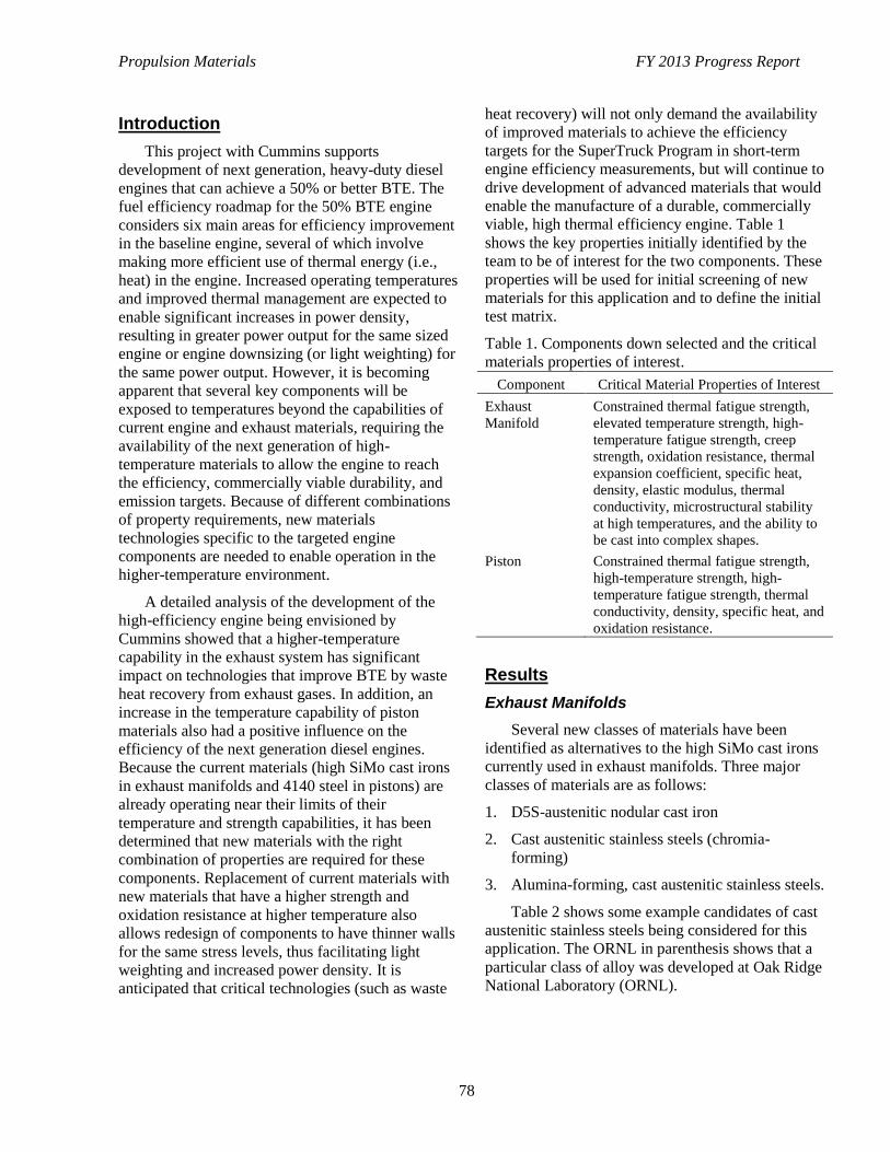
Propulsion Materials FY 2013 Progress Report
78
Introduction
This project with Cummins supports
development of next generation, heavy-duty diesel
engines that can achieve a 50% or better BTE. The
fuel efficiency roadmap for the 50% BTE engine
considers six main areas for efficiency improvement
in the baseline engine, several of which involve
making more efficient use of thermal energy (i.e.,
heat) in the engine. Increased operating temperatures
and improved thermal management are expected to
enable significant increases in power density,
resulting in greater power output for the same sized
engine or engine downsizing (or light weighting) for
the same power output. However, it is becoming
apparent that several key components will be
exposed to temperatures beyond the capabilities of
current engine and exhaust materials, requiring the
availability of the next generation of high-
temperature materials to allow the engine to reach
the efficiency, commercially viable durability, and
emission targets. Because of different combinations
of property requirements, new materials
technologies specific to the targeted engine
components are needed to enable operation in the
higher-temperature environment.
A detailed analysis of the development of the
high-efficiency engine being envisioned by
Cummins showed that a higher-temperature
capability in the exhaust system has significant
impact on technologies that improve BTE by waste
heat recovery from exhaust gases. In addition, an
increase in the temperature capability of piston
materials also had a positive influence on the
efficiency of the next generation diesel engines.
Because the current materials (high SiMo cast irons
in exhaust manifolds and 4140 steel in pistons) are
already operating near their limits of their
temperature and strength capabilities, it has been
determined that new materials with the right
combination of properties are required for these
components. Replacement of current materials with
new materials that have a higher strength and
oxidation resistance at higher temperature also
allows redesign of components to have thinner walls
for the same stress levels, thus facilitating light
weighting and increased power density. It is
anticipated that critical technologies (such as waste
heat recovery) will not only demand the availability
of improved materials to achieve the efficiency
targets for the SuperTruck Program in short-term
engine efficiency measurements, but will continue to
drive development of advanced materials that would
enable the manufacture of a durable, commercially
viable, high thermal efficiency engine. Table 1
shows the key properties initially identified by the
team to be of interest for the two components. These
properties will be used for initial screening of new
materials for this application and to define the initial
test matrix.
Table 1. Components down selected and the critical
materials properties of interest.
Component Critical Material Properties of Interest
Exhaust
Manifold
Constrained thermal fatigue strength,
elevated temperature strength, high-
temperature fatigue strength, creep
strength, oxidation resistance, thermal
expansion coefficient, specific heat,
density, elastic modulus, thermal
conductivity, microstructural stability
at high temperatures, and the ability to
be cast into complex shapes.
Piston Constrained thermal fatigue strength,
high-temperature strength, high-
temperature fatigue strength, thermal
conductivity, density, specific heat, and
oxidation resistance.
Results
Exhaust Manifolds
Several new classes of materials have been
identified as alternatives to the high SiMo cast irons
currently used in exhaust manifolds. Three major
classes of materials are as follows:
1. D5S-austenitic nodular cast iron
2. Cast austenitic stainless steels (chromia-
forming)
3. Alumina-forming, cast austenitic stainless steels.
Table 2 shows some example candidates of cast
austenitic stainless steels being considered for this
application. The ORNL in parenthesis shows that a
particular class of alloy was developed at Oak Ridge
National Laboratory (ORNL).
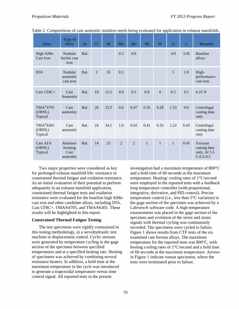
Propulsion Materials FY 2013 Progress Report
79
Table 2. Compositions of cast austenitic stainless steels being evaluated for application in exhaust manifolds.
Alloy
Type of
Alloy Fe Cr Ni Mn Mo Nb W Si C Remarks
High SiMo
Cast Iron
Nodular
ferritic cast
iron
Bal. 0.3 0.6 4.0 3.45 Baseline
alloys
D5S Nodular
austenitic
cast iron
Bal. 2 35 0.5 5 1.9 High-
performance
cast iron
Cast CF8C+ Cast
Austenitic
Bal. 19 12.5 4.0 0.3 0.8 0 0.5 0.1 0.25 N
TMA®4705
(ORNL)
Typical
Cast
austenitic
Bal. 26 23.5 0.6 0.47 0.35 0.28 1.33 0.6 Centrifugal
casting data
only
TMA®6301
(ORNL)
Typical
Cast
austenitic
Bal. 24 34.2 1.0 0.02 0.41 0.35 1.22 0.43 Centrifugal
casting data
only
Cast AFA
(ORNL)
Typical
Alumina-
forming
Cast
austenitic
Bal. 14 25 2 2 1 1 1 0.45 Vacuum
casting data
only, Al 3.5
C:0.2-0.5
Two major properties were considered as key
for prolonged exhaust manifold life: resistance to
constrained thermal fatigue and oxidation resistance.
As an initial evaluation of their potential to perform
adequately in an exhaust manifold application,
constrained thermal fatigue tests and oxidation
resistance were evaluated for the baseline high SiMo
cast iron and other candidate alloys, including D5S,
Cast CF8C+, TMA®4705, and TMA®6301. These
results will be highlighted in this report.
Constrained Thermal Fatigue Testing
The test specimens were rigidly constrained in
this testing methodology, in a servohydraulic test
machine in displacement control. Cyclic stresses
were generated by temperature cycling in the gage
section of the specimen between specified
temperatures and at a specified heating rate. Heating
of specimens was achieved by combining several
resistance heaters. In addition, a hold time at the
maximum temperature in the cycle was introduced
to generate a trapezoidal temperature versus time
control signal. All reported tests in the present
investigation had a maximum temperature of 800°C
and a hold time of 60 seconds at the maximum
temperature. Heating/ cooling rates of 1°C/second
were employed in the reported tests with a feedback
loop temperature controller (with proportional,
integrative, derivative, and PID control). Precise
temperature control (i.e., less than 5°C variation) in
the gage section of the specimen was achieved by a
Labview® software code. A high-temperature
extensometer was placed in the gage section of the
specimen and evolution of the stress and strain
signals with thermal cycling was continuously
recorded. The specimens were cycled to failure.
Figure 1 shows results from CTF tests of the six
examined cast ferrous alloys. The maximum
temperature for the reported tests was 800°C, with
heating cooling rates of 1°C/second and a hold time
of 60 seconds at the maximum temperature. Arrows
in Figure 1 indicate runout specimens, where the
tests were terminated prior to failure.
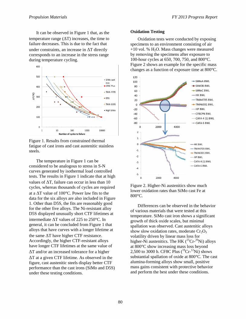
Propulsion Materials FY 2013 Progress Report
80
It can be observed in Figure 1 that, as the
temperature range (T) increases, the time to
failure decreases. This is due to the fact that
under constraints, an increase in T directly
corresponds to an increase in the stress range
during temperature cycling.
Figure 1. Results from constrained thermal
fatigue of cast irons and cast austenitic stainless
steels.
The temperature in Figure 1 can be
considered to be analogous to stress in S-N
curves generated by isothermal load controlled
tests. The results in Figure 1 indicate that at high
values of T, failure can occur in less than 10
cycles, whereas thousands of cycles are required
at a T value of 100°C. Power law fits to the
data for the six alloys are also included in Figure
1. Other than D5S, the fits are reasonably good
for the other five alloys. The Ni-resistant alloy
D5S displayed unusually short CTF lifetimes at
intermediate T values of 225 to 250°C. In
general, it can be concluded from Figure 1 that
alloys that have curves with a longer lifetime at
the same T have higher CTF resistance.
Accordingly, the higher CTF-resistant alloys
have longer CTF lifetimes at the same value of
T and/or an increased tolerance for a higher
T at a given CTF lifetime. As observed in the
figure, cast austenitic steels display better CTF
performance than the cast irons (SiMo and D5S)
under these testing conditions.
Oxidation Testing
Oxidation tests were conducted by exposing
specimens to an environment consisting of air
+10 vol. % H2O. Mass changes were measured
by removing the specimens after exposure to
100-hour cycles at 650, 700, 750, and 800°C.
Figure 2 shows an example for the specific mass
changes as a function of exposure time at 800°C.
Figure 2. Higher-Ni austenitics show much
lower oxidation rates than SiMo cast Fe at
800°C.
Differences can be observed in the behavior
of various materials that were tested at this
temperature. SiMo cast iron shows a significant
growth of thick oxide scales, but minimal
spallation was observed. Cast austenitic alloys
show slow oxidation rates, moderate Cr2O3
volatility driven by linear mass loss for
higher-Ni austenitics. The HK (25
Cr-20
Ni) alloys
at 800°C show increasing mass loss beyond
2,500 to 3000 h. CF8C Plus (19
Cr-12
Ni) shows
substantial spallation of oxide at 800°C. The cast
alumina-forming alloys show small, positive
mass gains consistent with protective behavior
and perform the best under these conditions.
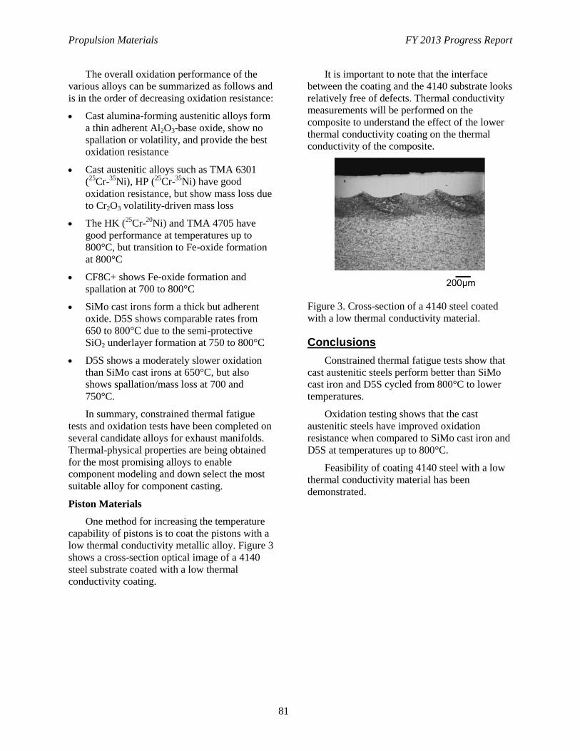
Propulsion Materials FY 2013 Progress Report
81
The overall oxidation performance of the
various alloys can be summarized as follows and
is in the order of decreasing oxidation resistance:
Cast alumina-forming austenitic alloys form
a thin adherent Al2O3-base oxide, show no
spallation or volatility, and provide the best
oxidation resistance
Cast austenitic alloys such as TMA 6301
(25
Cr-35
Ni), HP (25
Cr-35
Ni) have good
oxidation resistance, but show mass loss due
to Cr2O3 volatility-driven mass loss
The HK (25
Cr-20
Ni) and TMA 4705 have
good performance at temperatures up to
800°C, but transition to Fe-oxide formation
at 800°C
CF8C+ shows Fe-oxide formation and
spallation at 700 to 800°C
SiMo cast irons form a thick but adherent
oxide. D5S shows comparable rates from
650 to 800°C due to the semi-protective
SiO2 underlayer formation at 750 to 800°C
D5S shows a moderately slower oxidation
than SiMo cast irons at 650°C, but also
shows spallation/mass loss at 700 and
750°C.
In summary, constrained thermal fatigue
tests and oxidation tests have been completed on
several candidate alloys for exhaust manifolds.
Thermal-physical properties are being obtained
for the most promising alloys to enable
component modeling and down select the most
suitable alloy for component casting.
Piston Materials
One method for increasing the temperature
capability of pistons is to coat the pistons with a
low thermal conductivity metallic alloy. Figure 3
shows a cross-section optical image of a 4140
steel substrate coated with a low thermal
conductivity coating.
It is important to note that the interface
between the coating and the 4140 substrate looks
relatively free of defects. Thermal conductivity
measurements will be performed on the
composite to understand the effect of the lower
thermal conductivity coating on the thermal
conductivity of the composite.
Figure 3. Cross-section of a 4140 steel coated
with a low thermal conductivity material.
Conclusions
Constrained thermal fatigue tests show that
cast austenitic steels perform better than SiMo
cast iron and D5S cycled from 800°C to lower
temperatures.
Oxidation testing shows that the cast
austenitic steels have improved oxidation
resistance when compared to SiMo cast iron and
D5S at temperatures up to 800°C.
Feasibility of coating 4140 steel with a low
thermal conductivity material has been
demonstrated.
Propulsion Materials FY 2013 Progress Report
82
Project 18518 – Materials for High-Efficiency Engines
Agreement 23725 – Tailored Materials for Improved
Internal Combustion Engine Efficiency
Glenn J. Grant
Energy Materials and Manufacturing
Pacific Northwest National Laboratory
902 Battelle Blvd., K2-03
Richland, Washington 99356
Phone (509) 375-6890; fax: (509) 375-4448; e-mail: [email protected]
Blair E. Carlson
Manager, Lightweight Materials Processing
General Motors R&D
30500 Mound Rd
Warren, MI USA 48090
e-mail: [email protected]
Rajiv S. Mishra
University of North Texas
Professor, Department of Materials Science and Engineering
Site Director, NSF IUCRC for Friction-Stir Processing
1155 Union Circle #305310
Denton, Texas 76203-5017
Phone (940) 565-2316; fax (940) 565-4824
DOE Technology Manager: Jerry L. Gibbs
Phone (202) 586-1182; fax: (202) 586-1600; e-mail: [email protected]
Field Technical Manager: Dean Paxton
Phone (509) 375-2620; fax (509) 375-2186; e-mail: [email protected]
Contractor: Pacific Northwest National Laboratory
Prime Contract No.: DE-AC05-76RL01830
Objectives
To develop friction-stir processing (FSP) to tailor the properties of conventional, low-cost engine
materials (i.e., cast iron, alloy steels, and aluminum alloys) with the goal of increasing their
high-temperature performance, durability, and thermal properties.
To deploy FSP components that can enable energy-efficient combustion strategies, especially those
that will require higher peak combustion pressure or higher-temperature operation, where component
durability is the primary barrier to using the energy-efficient combustion strategy.
Approach (Including Partner/Collaborator and Path to Technology Transfer and Commercialization)
Develop surface-modification techniques, modified materials, and components. The project is a
collaboration with General Motors, with General Motors providing in-kind and materials
(i.e., aluminum castings, cylinder heads, engine components, and testing).
Propulsion Materials FY 2013 Progress Report
83
The project primarily is investigating FSP, a new technology that can produce functionally graded
surfaces with unique and tailored properties that will allow propulsion materials to withstand higher
temperatures and pressures without appreciably losing strength, hot hardness, or wear resistance, and
exhibit improved resistance to thermal fatigue.
FSP-treated components will be evaluated and tested by industry collaborators to demonstrate
efficiency benefits and potential commercial applications.
Accomplishments
Milestone: Demonstrate property improvements from FSP that can reach the following metrics
established by the project team: minimum two-fold improvement in fatigue life and 20%
improvement in average failure stress level at N cycles. This was completed and exceeded (an order-
of-magnitude improvement in fatigue life).
Milestone: Demonstrate consolidated FSP regions in aluminum and ferrous materials typical of
cylinder head, cylinder liner, block, crankshaft, rod, piston, and bearing materials on a subscale,
two-dimensional shape relevant to real part geometry (TRL 3 to 4 transition). This is on schedule.
Future Direction
Milestone: Demonstrate prototype part that can show durability advantage from FSP that allows high
peak combustion pressures (PCPs) and document energy savings potential. This is a future milestone.
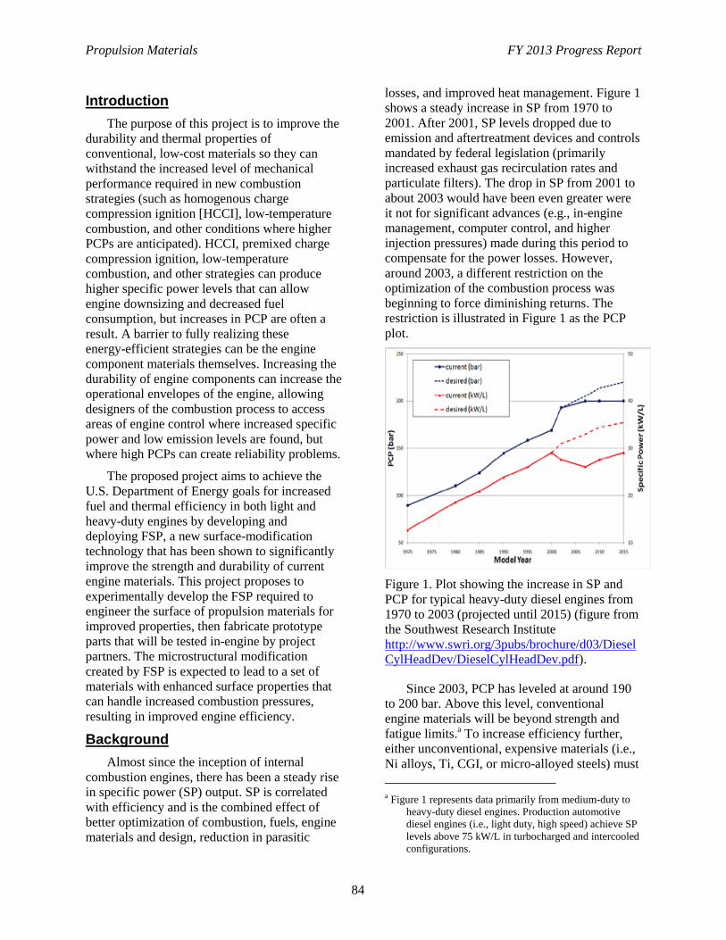
Propulsion Materials FY 2013 Progress Report
84
Introduction
The purpose of this project is to improve the
durability and thermal properties of
conventional, low-cost materials so they can
withstand the increased level of mechanical
performance required in new combustion
strategies (such as homogenous charge
compression ignition [HCCI], low-temperature
combustion, and other conditions where higher
PCPs are anticipated). HCCI, premixed charge
compression ignition, low-temperature
combustion, and other strategies can produce
higher specific power levels that can allow
engine downsizing and decreased fuel
consumption, but increases in PCP are often a
result. A barrier to fully realizing these
energy-efficient strategies can be the engine
component materials themselves. Increasing the
durability of engine components can increase the
operational envelopes of the engine, allowing
designers of the combustion process to access
areas of engine control where increased specific
power and low emission levels are found, but
where high PCPs can create reliability problems.
The proposed project aims to achieve the
U.S. Department of Energy goals for increased
fuel and thermal efficiency in both light and
heavy-duty engines by developing and
deploying FSP, a new surface-modification
technology that has been shown to significantly
improve the strength and durability of current
engine materials. This project proposes to
experimentally develop the FSP required to
engineer the surface of propulsion materials for
improved properties, then fabricate prototype
parts that will be tested in-engine by project
partners. The microstructural modification
created by FSP is expected to lead to a set of
materials with enhanced surface properties that
can handle increased combustion pressures,
resulting in improved engine efficiency.
Background
Almost since the inception of internal
combustion engines, there has been a steady rise
in specific power (SP) output. SP is correlated
with efficiency and is the combined effect of
better optimization of combustion, fuels, engine
materials and design, reduction in parasitic
losses, and improved heat management. Figure 1
shows a steady increase in SP from 1970 to
2001. After 2001, SP levels dropped due to
emission and aftertreatment devices and controls
mandated by federal legislation (primarily
increased exhaust gas recirculation rates and
particulate filters). The drop in SP from 2001 to
about 2003 would have been even greater were
it not for significant advances (e.g., in-engine
management, computer control, and higher
injection pressures) made during this period to
compensate for the power losses. However,
around 2003, a different restriction on the
optimization of the combustion process was
beginning to force diminishing returns. The
restriction is illustrated in Figure 1 as the PCP
plot.
Figure 1. Plot showing the increase in SP and
PCP for typical heavy-duty diesel engines from
1970 to 2003 (projected until 2015) (figure from
the Southwest Research Institute
http://www.swri.org/3pubs/brochure/d03/Diesel
CylHeadDev/DieselCylHeadDev.pdf).
Since 2003, PCP has leveled at around 190
to 200 bar. Above this level, conventional
engine materials will be beyond strength and
fatigue limits.a To increase efficiency further,
either unconventional, expensive materials (i.e.,
Ni alloys, Ti, CGI, or micro-alloyed steels) must
a Figure 1 represents data primarily from medium-duty to
heavy-duty diesel engines. Production automotive
diesel engines (i.e., light duty, high speed) achieve SP
levels above 75 kW/L in turbocharged and intercooled
configurations.
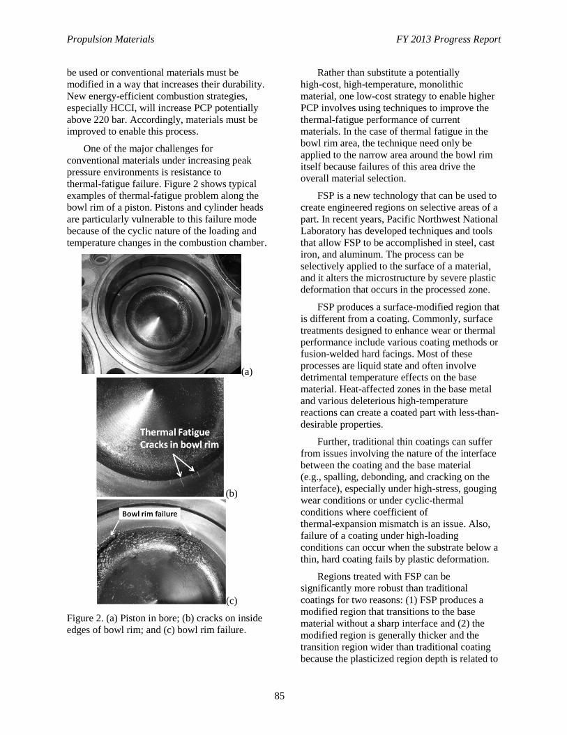
Propulsion Materials FY 2013 Progress Report
85
be used or conventional materials must be
modified in a way that increases their durability.
New energy-efficient combustion strategies,
especially HCCI, will increase PCP potentially
above 220 bar. Accordingly, materials must be
improved to enable this process.
One of the major challenges for
conventional materials under increasing peak
pressure environments is resistance to
thermal-fatigue failure. Figure 2 shows typical
examples of thermal-fatigue problem along the
bowl rim of a piston. Pistons and cylinder heads
are particularly vulnerable to this failure mode
because of the cyclic nature of the loading and
temperature changes in the combustion chamber.
(a)
(b)
(c)
Figure 2. (a) Piston in bore; (b) cracks on inside
edges of bowl rim; and (c) bowl rim failure.
Rather than substitute a potentially
high-cost, high-temperature, monolithic
material, one low-cost strategy to enable higher
PCP involves using techniques to improve the
thermal-fatigue performance of current
materials. In the case of thermal fatigue in the
bowl rim area, the technique need only be
applied to the narrow area around the bowl rim
itself because failures of this area drive the
overall material selection.
FSP is a new technology that can be used to
create engineered regions on selective areas of a
part. In recent years, Pacific Northwest National
Laboratory has developed techniques and tools
that allow FSP to be accomplished in steel, cast
iron, and aluminum. The process can be
selectively applied to the surface of a material,
and it alters the microstructure by severe plastic
deformation that occurs in the processed zone.
FSP produces a surface-modified region that
is different from a coating. Commonly, surface
treatments designed to enhance wear or thermal
performance include various coating methods or
fusion-welded hard facings. Most of these
processes are liquid state and often involve
detrimental temperature effects on the base
material. Heat-affected zones in the base metal
and various deleterious high-temperature
reactions can create a coated part with less-than-
desirable properties.
Further, traditional thin coatings can suffer
from issues involving the nature of the interface
between the coating and the base material
(e.g., spalling, debonding, and cracking on the
interface), especially under high-stress, gouging
wear conditions or under cyclic-thermal
conditions where coefficient of
thermal-expansion mismatch is an issue. Also,
failure of a coating under high-loading
conditions can occur when the substrate below a
thin, hard coating fails by plastic deformation.
Regions treated with FSP can be
significantly more robust than traditional
coatings for two reasons: (1) FSP produces a
modified region that transitions to the base
material without a sharp interface and (2) the
modified region is generally thicker and the
transition region wider than traditional coating
because the plasticized region depth is related to
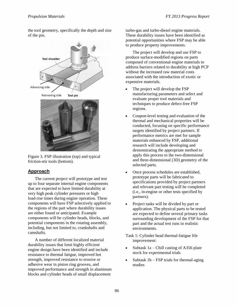
Propulsion Materials FY 2013 Progress Report
86
the tool geometry, specifically the depth and size
of the pin.
Figure 3. FSP illustration (top) and typical
friction-stir tools (bottom).
Approach
The current project will prototype and test
up to four separate internal engine components
that are expected to have limited durability at
very high peak cylinder pressures or high
load-rise times during engine operation. These
components will have FSP selectively applied to
the regions of the part where durability issues
are either found or anticipated. Example
components will be cylinder heads, blocks, and
potential components in the rotating assembly,
including, but not limited to, crankshafts and
camshafts.
A number of different localized material
durability issues that limit highly efficient
engine design have been identified and include
resistance to thermal fatigue, improved hot
strength, improved resistance to erosive or
adhesive wear in piston ring grooves, and
improved performance and strength in aluminum
blocks and cylinder heads of small displacement
turbo-gas and turbo-diesel engine materials.
These durability issues have been identified as
potential opportunities where FSP may be able
to produce property improvements.
The project will develop and use FSP to
produce surface-modified regions on parts
composed of conventional engine materials to
address barriers related to durability at high PCP
without the increased raw material costs
associated with the introduction of exotic or
expensive materials.
The project will develop the FSP
manufacturing parameters and select and
evaluate proper tool materials and
techniques to produce defect-free FSP
regions.
Coupon-level testing and evaluation of the
thermal and mechanical properties will be
conducted, focusing on specific performance
targets identified by project partners. If
performance metrics are met for sample
materials enhanced by FSP, additional
research will include developing and
demonstrating the appropriate method to
apply this process to the two-dimensional
and three-dimensional (3D) geometry of the
selected parts.
Once process schedules are established,
prototype parts will be fabricated to
specifications provided by project partners
and relevant part testing will be completed
(i.e., in-engine or other tests specified by
partners).
Project tasks will be divided by part or
application. The physical parts to be tested
are expected to define several primary tasks
surrounding development of the FSP for that
part and the actual test runs in realistic
environments.
Task 1: Cylinder head thermal-fatigue life
improvement:
Subtask 1a – Chill casting of A356 plate
stock for experimental trials
Subtask 1b – FSP trials for thermal-aging
studies
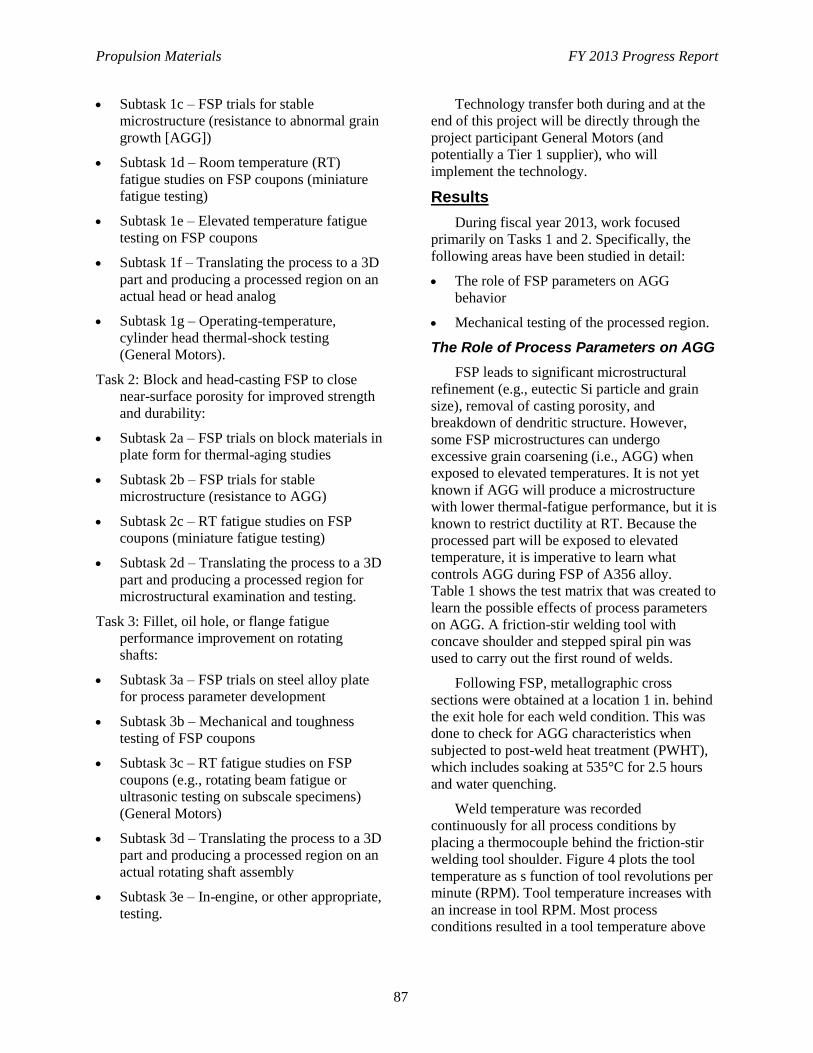
Propulsion Materials FY 2013 Progress Report
87
Subtask 1c – FSP trials for stable
microstructure (resistance to abnormal grain
growth [AGG])
Subtask 1d – Room temperature (RT)
fatigue studies on FSP coupons (miniature
fatigue testing)
Subtask 1e – Elevated temperature fatigue
testing on FSP coupons
Subtask 1f – Translating the process to a 3D
part and producing a processed region on an
actual head or head analog
Subtask 1g – Operating-temperature,
cylinder head thermal-shock testing
(General Motors).
Task 2: Block and head-casting FSP to close
near-surface porosity for improved strength
and durability:
Subtask 2a – FSP trials on block materials in
plate form for thermal-aging studies
Subtask 2b – FSP trials for stable
microstructure (resistance to AGG)
Subtask 2c – RT fatigue studies on FSP
coupons (miniature fatigue testing)
Subtask 2d – Translating the process to a 3D
part and producing a processed region for
microstructural examination and testing.
Task 3: Fillet, oil hole, or flange fatigue
performance improvement on rotating
shafts:
Subtask 3a – FSP trials on steel alloy plate
for process parameter development
Subtask 3b – Mechanical and toughness
testing of FSP coupons
Subtask 3c – RT fatigue studies on FSP
coupons (e.g., rotating beam fatigue or
ultrasonic testing on subscale specimens)
(General Motors)
Subtask 3d – Translating the process to a 3D
part and producing a processed region on an
actual rotating shaft assembly
Subtask 3e – In-engine, or other appropriate,
testing.
Technology transfer both during and at the
end of this project will be directly through the
project participant General Motors (and
potentially a Tier 1 supplier), who will
implement the technology.
Results
During fiscal year 2013, work focused
primarily on Tasks 1 and 2. Specifically, the
following areas have been studied in detail:
The role of FSP parameters on AGG
behavior
Mechanical testing of the processed region.
The Role of Process Parameters on AGG
FSP leads to significant microstructural
refinement (e.g., eutectic Si particle and grain
size), removal of casting porosity, and
breakdown of dendritic structure. However,
some FSP microstructures can undergo
excessive grain coarsening (i.e., AGG) when
exposed to elevated temperatures. It is not yet
known if AGG will produce a microstructure
with lower thermal-fatigue performance, but it is
known to restrict ductility at RT. Because the
processed part will be exposed to elevated
temperature, it is imperative to learn what
controls AGG during FSP of A356 alloy.
Table 1 shows the test matrix that was created to
learn the possible effects of process parameters
on AGG. A friction-stir welding tool with
concave shoulder and stepped spiral pin was
used to carry out the first round of welds.
Following FSP, metallographic cross
sections were obtained at a location 1 in. behind
the exit hole for each weld condition. This was
done to check for AGG characteristics when
subjected to post-weld heat treatment (PWHT),
which includes soaking at 535°C for 2.5 hours
and water quenching.
Weld temperature was recorded
continuously for all process conditions by
placing a thermocouple behind the friction-stir
welding tool shoulder. Figure 4 plots the tool
temperature as s function of tool revolutions per
minute (RPM). Tool temperature increases with
an increase in tool RPM. Most process
conditions resulted in a tool temperature above
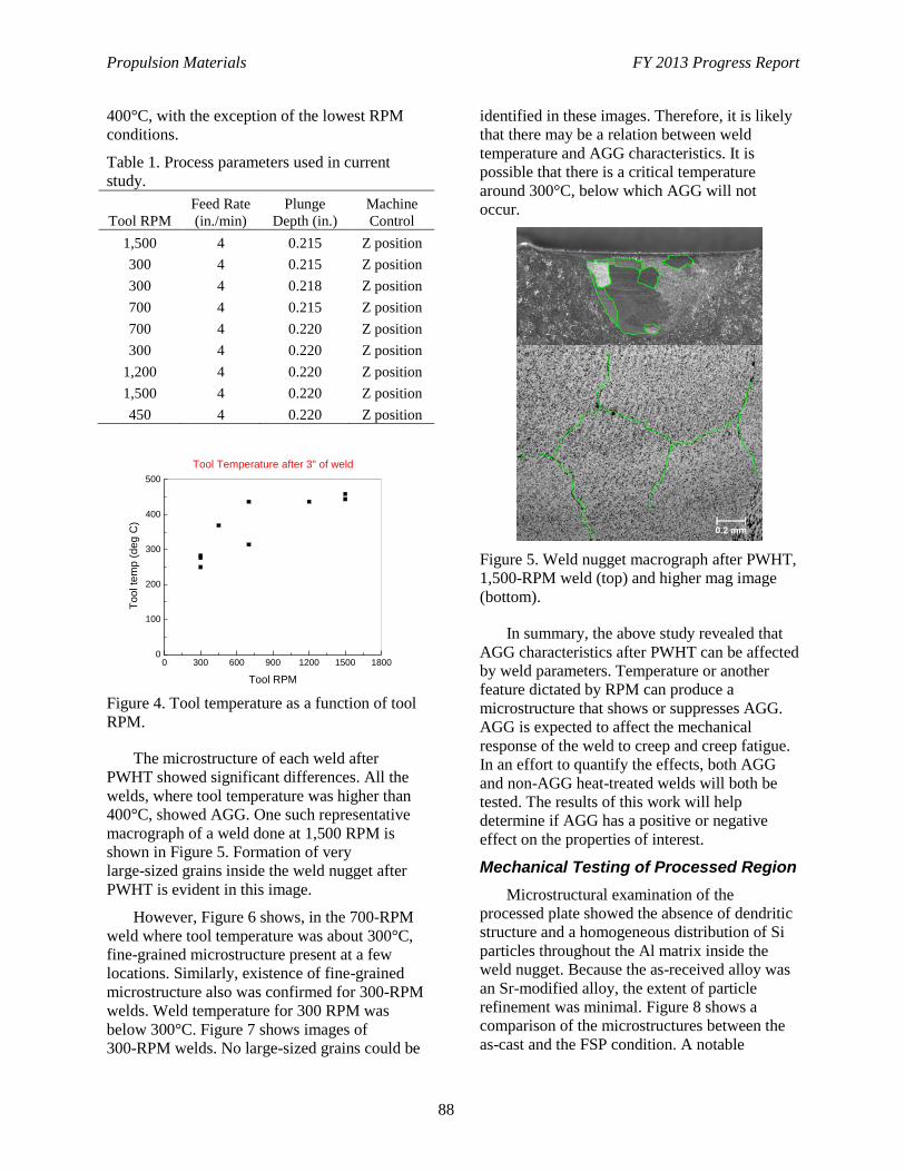
Propulsion Materials FY 2013 Progress Report
88
400°C, with the exception of the lowest RPM
conditions.
Table 1. Process parameters used in current
study.
Tool RPM
Feed Rate
(in./min)
Plunge
Depth (in.)
Machine
Control
1,500 4 0.215 Z position
300 4 0.215 Z position
300 4 0.218 Z position
700 4 0.215 Z position
700 4 0.220 Z position
300 4 0.220 Z position
1,200 4 0.220 Z position
1,500 4 0.220 Z position
450 4 0.220 Z position
Figure 4. Tool temperature as a function of tool
RPM.
The microstructure of each weld after
PWHT showed significant differences. All the
welds, where tool temperature was higher than
400°C, showed AGG. One such representative
macrograph of a weld done at 1,500 RPM is
shown in Figure 5. Formation of very
large-sized grains inside the weld nugget after
PWHT is evident in this image.
However, Figure 6 shows, in the 700-RPM
weld where tool temperature was about 300°C,
fine-grained microstructure present at a few
locations. Similarly, existence of fine-grained
microstructure also was confirmed for 300-RPM
welds. Weld temperature for 300 RPM was
below 300°C. Figure 7 shows images of
300-RPM welds. No large-sized grains could be
identified in these images. Therefore, it is likely
that there may be a relation between weld
temperature and AGG characteristics. It is
possible that there is a critical temperature
around 300°C, below which AGG will not
occur.
Figure 5. Weld nugget macrograph after PWHT,
1,500-RPM weld (top) and higher mag image
(bottom).
In summary, the above study revealed that
AGG characteristics after PWHT can be affected
by weld parameters. Temperature or another
feature dictated by RPM can produce a
microstructure that shows or suppresses AGG.
AGG is expected to affect the mechanical
response of the weld to creep and creep fatigue.
In an effort to quantify the effects, both AGG
and non-AGG heat-treated welds will both be
tested. The results of this work will help
determine if AGG has a positive or negative
effect on the properties of interest.
Mechanical Testing of Processed Region
Microstructural examination of the
processed plate showed the absence of dendritic
structure and a homogeneous distribution of Si
particles throughout the Al matrix inside the
weld nugget. Because the as-received alloy was
an Sr-modified alloy, the extent of particle
refinement was minimal. Figure 8 shows a
comparison of the microstructures between the
as-cast and the FSP condition. A notable
0 300 600 900 1200 1500 18000
100
200
300
400
500
To
ol te
mp (
deg
C)
Tool RPM
Tool Temperature after 3" of weld
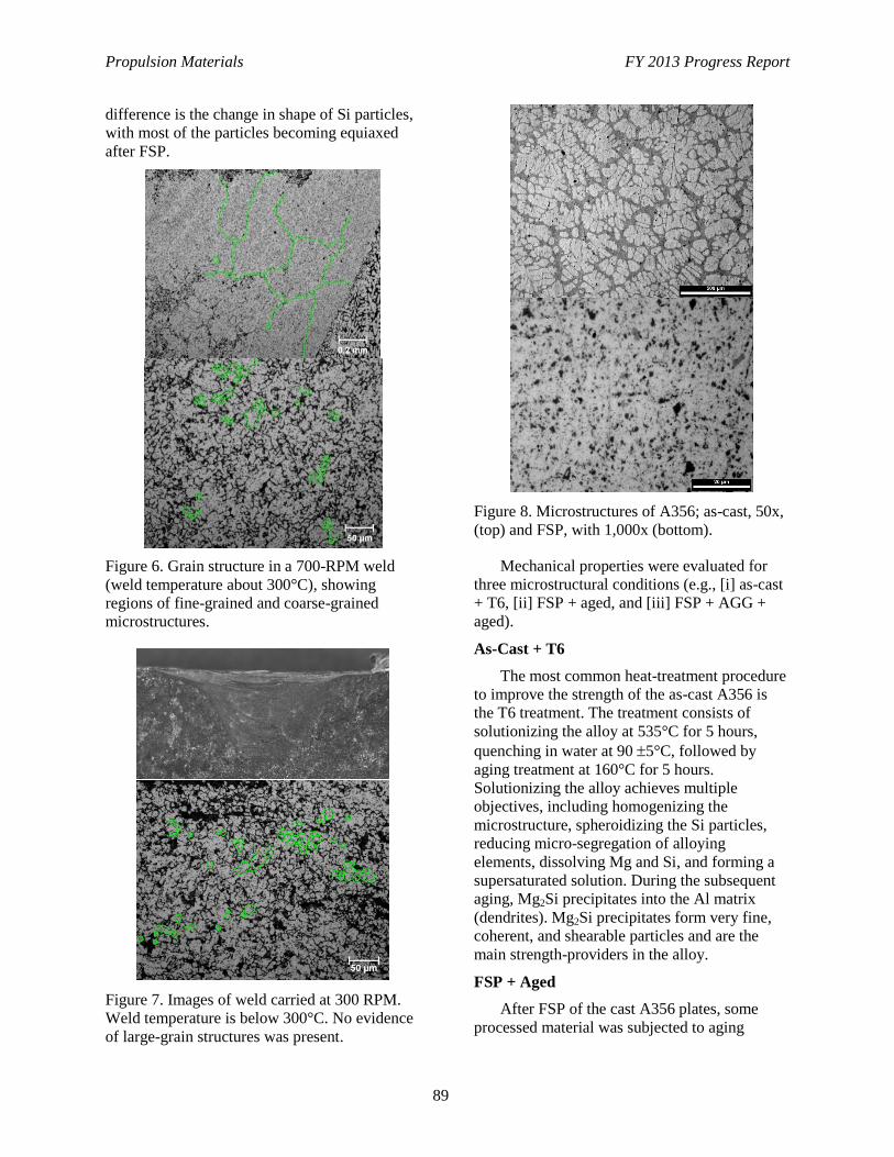
Propulsion Materials FY 2013 Progress Report
89
difference is the change in shape of Si particles,
with most of the particles becoming equiaxed
after FSP.
Figure 6. Grain structure in a 700-RPM weld
(weld temperature about 300°C), showing
regions of fine-grained and coarse-grained
microstructures.
Figure 7. Images of weld carried at 300 RPM.
Weld temperature is below 300°C. No evidence
of large-grain structures was present.
Figure 8. Microstructures of A356; as-cast, 50x,
(top) and FSP, with 1,000x (bottom).
Mechanical properties were evaluated for
three microstructural conditions (e.g., [i] as-cast
+ T6, [ii] FSP + aged, and [iii] FSP + AGG +
aged).
As-Cast + T6
The most common heat-treatment procedure
to improve the strength of the as-cast A356 is
the T6 treatment. The treatment consists of
solutionizing the alloy at 535°C for 5 hours,
quenching in water at 90 5°C, followed by
aging treatment at 160°C for 5 hours.
Solutionizing the alloy achieves multiple
objectives, including homogenizing the
microstructure, spheroidizing the Si particles,
reducing micro-segregation of alloying
elements, dissolving Mg and Si, and forming a
supersaturated solution. During the subsequent
aging, Mg2Si precipitates into the Al matrix
(dendrites). Mg2Si precipitates form very fine,
coherent, and shearable particles and are the
main strength-providers in the alloy.
FSP + Aged
After FSP of the cast A356 plates, some
processed material was subjected to aging
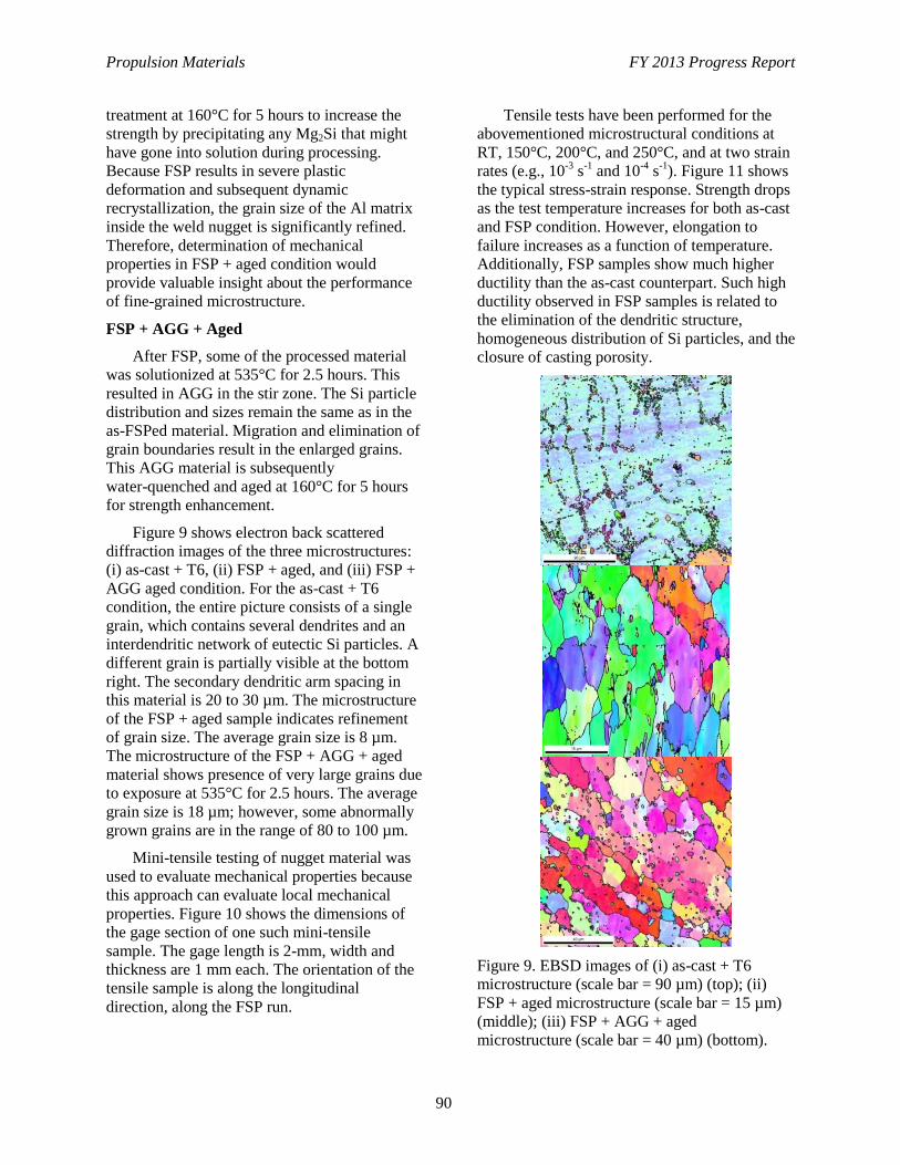
Propulsion Materials FY 2013 Progress Report
90
treatment at 160°C for 5 hours to increase the
strength by precipitating any Mg2Si that might
have gone into solution during processing.
Because FSP results in severe plastic
deformation and subsequent dynamic
recrystallization, the grain size of the Al matrix
inside the weld nugget is significantly refined.
Therefore, determination of mechanical
properties in FSP + aged condition would
provide valuable insight about the performance
of fine-grained microstructure.
FSP + AGG + Aged
After FSP, some of the processed material
was solutionized at 535°C for 2.5 hours. This
resulted in AGG in the stir zone. The Si particle
distribution and sizes remain the same as in the
as-FSPed material. Migration and elimination of
grain boundaries result in the enlarged grains.
This AGG material is subsequently
water-quenched and aged at 160°C for 5 hours
for strength enhancement.
Figure 9 shows electron back scattered
diffraction images of the three microstructures:
(i) as-cast + T6, (ii) FSP + aged, and (iii) FSP +
AGG aged condition. For the as-cast + T6
condition, the entire picture consists of a single
grain, which contains several dendrites and an
interdendritic network of eutectic Si particles. A
different grain is partially visible at the bottom
right. The secondary dendritic arm spacing in
this material is 20 to 30 µm. The microstructure
of the FSP + aged sample indicates refinement
of grain size. The average grain size is 8 µm.
The microstructure of the FSP + AGG + aged
material shows presence of very large grains due
to exposure at 535°C for 2.5 hours. The average
grain size is 18 µm; however, some abnormally
grown grains are in the range of 80 to 100 µm.
Mini-tensile testing of nugget material was
used to evaluate mechanical properties because
this approach can evaluate local mechanical
properties. Figure 10 shows the dimensions of
the gage section of one such mini-tensile
sample. The gage length is 2-mm, width and
thickness are 1 mm each. The orientation of the
tensile sample is along the longitudinal
direction, along the FSP run.
Tensile tests have been performed for the
abovementioned microstructural conditions at
RT, 150°C, 200°C, and 250°C, and at two strain
rates (e.g., 10-3
s-1
and 10-4
s-1
). Figure 11 shows
the typical stress-strain response. Strength drops
as the test temperature increases for both as-cast
and FSP condition. However, elongation to
failure increases as a function of temperature.
Additionally, FSP samples show much higher
ductility than the as-cast counterpart. Such high
ductility observed in FSP samples is related to
the elimination of the dendritic structure,
homogeneous distribution of Si particles, and the
closure of casting porosity.
Figure 9. EBSD images of (i) as-cast + T6
microstructure (scale bar = 90 µm) (top); (ii)
FSP + aged microstructure (scale bar = 15 µm)
(middle); (iii) FSP + AGG + aged
microstructure (scale bar = 40 µm) (bottom).
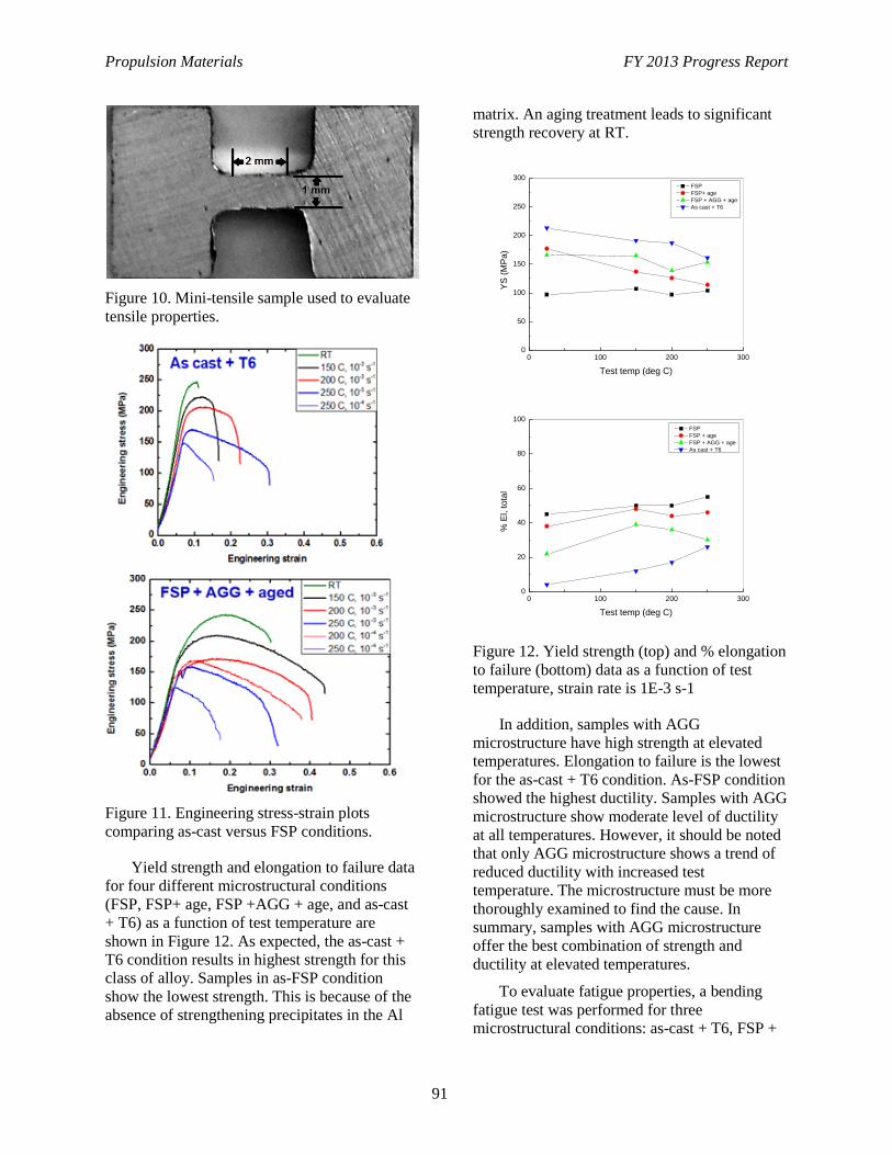
Propulsion Materials FY 2013 Progress Report
91
Figure 10. Mini-tensile sample used to evaluate
tensile properties.
Figure 11. Engineering stress-strain plots
comparing as-cast versus FSP conditions.
Yield strength and elongation to failure data
for four different microstructural conditions
(FSP, FSP+ age, FSP +AGG + age, and as-cast
+ T6) as a function of test temperature are
shown in Figure 12. As expected, the as-cast +
T6 condition results in highest strength for this
class of alloy. Samples in as-FSP condition
show the lowest strength. This is because of the
absence of strengthening precipitates in the Al
matrix. An aging treatment leads to significant
strength recovery at RT.
Figure 12. Yield strength (top) and % elongation
to failure (bottom) data as a function of test
temperature, strain rate is 1E-3 s-1
In addition, samples with AGG
microstructure have high strength at elevated
temperatures. Elongation to failure is the lowest
for the as-cast + T6 condition. As-FSP condition
showed the highest ductility. Samples with AGG
microstructure show moderate level of ductility
at all temperatures. However, it should be noted
that only AGG microstructure shows a trend of
reduced ductility with increased test
temperature. The microstructure must be more
thoroughly examined to find the cause. In
summary, samples with AGG microstructure
offer the best combination of strength and
ductility at elevated temperatures.
To evaluate fatigue properties, a bending
fatigue test was performed for three
microstructural conditions: as-cast + T6, FSP +
0 100 200 3000
50
100
150
200
250
300
YS
(M
Pa
)
Test temp (deg C)
FSP
FSP+ age
FSP + AGG + age
As cast + T6
0 100 200 3000
20
40
60
80
100
% E
l, t
ota
l
Test temp (deg C)
FSP
FSP + age
FSP + AGG + age
As cast + T6
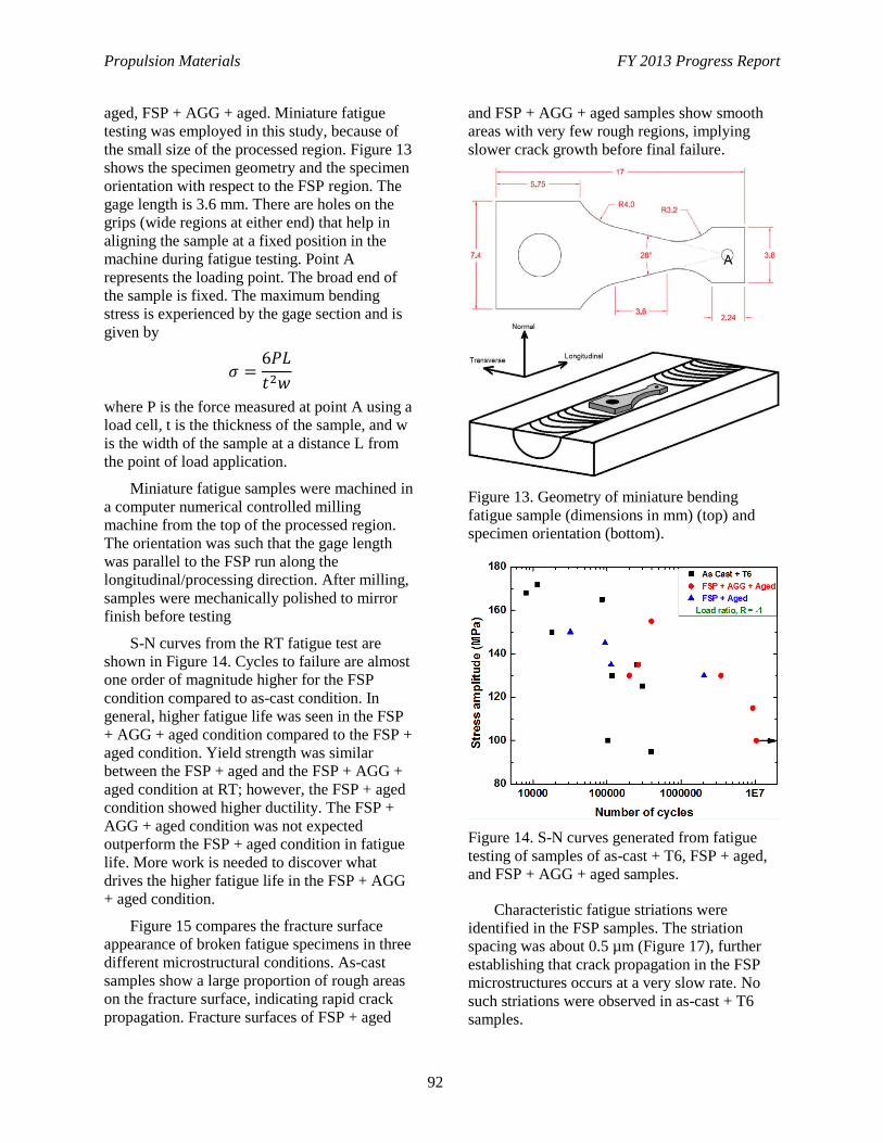
Propulsion Materials FY 2013 Progress Report
92
aged, FSP + AGG + aged. Miniature fatigue
testing was employed in this study, because of
the small size of the processed region. Figure 13
shows the specimen geometry and the specimen
orientation with respect to the FSP region. The
gage length is 3.6 mm. There are holes on the
grips (wide regions at either end) that help in
aligning the sample at a fixed position in the
machine during fatigue testing. Point A
represents the loading point. The broad end of
the sample is fixed. The maximum bending
stress is experienced by the gage section and is
given by
where P is the force measured at point A using a
load cell, t is the thickness of the sample, and w
is the width of the sample at a distance L from
the point of load application.
Miniature fatigue samples were machined in
a computer numerical controlled milling
machine from the top of the processed region.
The orientation was such that the gage length
was parallel to the FSP run along the
longitudinal/processing direction. After milling,
samples were mechanically polished to mirror
finish before testing
S-N curves from the RT fatigue test are
shown in Figure 14. Cycles to failure are almost
one order of magnitude higher for the FSP
condition compared to as-cast condition. In
general, higher fatigue life was seen in the FSP
+ AGG + aged condition compared to the FSP +
aged condition. Yield strength was similar
between the FSP + aged and the FSP + AGG +
aged condition at RT; however, the FSP + aged
condition showed higher ductility. The FSP +
AGG + aged condition was not expected
outperform the FSP + aged condition in fatigue
life. More work is needed to discover what
drives the higher fatigue life in the FSP + AGG
+ aged condition.
Figure 15 compares the fracture surface
appearance of broken fatigue specimens in three
different microstructural conditions. As-cast
samples show a large proportion of rough areas
on the fracture surface, indicating rapid crack
propagation. Fracture surfaces of FSP + aged
and FSP + AGG + aged samples show smooth
areas with very few rough regions, implying
slower crack growth before final failure.
Figure 13. Geometry of miniature bending
fatigue sample (dimensions in mm) (top) and
specimen orientation (bottom).
Figure 14. S-N curves generated from fatigue
testing of samples of as-cast + T6, FSP + aged,
and FSP + AGG + aged samples.
Characteristic fatigue striations were
identified in the FSP samples. The striation
spacing was about 0.5 µm (Figure 17), further
establishing that crack propagation in the FSP
microstructures occurs at a very slow rate. No
such striations were observed in as-cast + T6
samples.
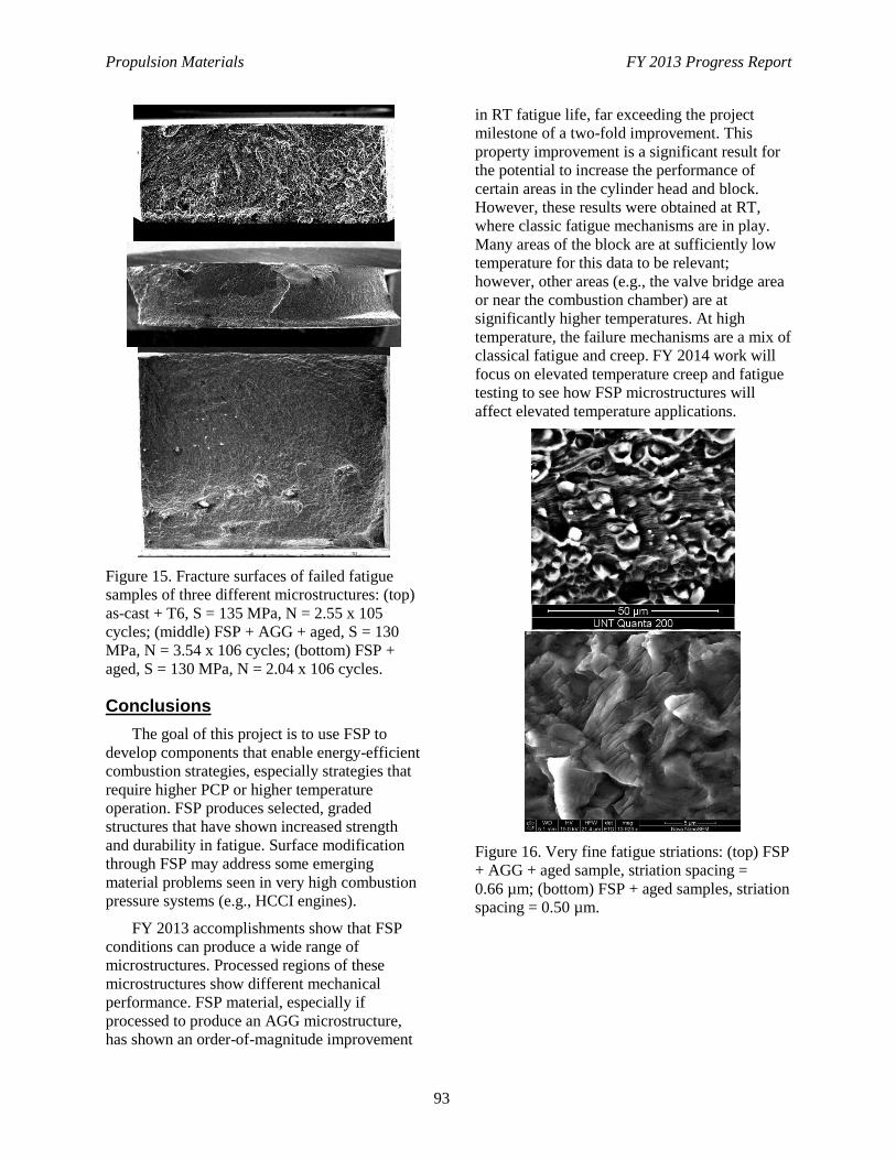
Propulsion Materials FY 2013 Progress Report
93
Figure 15. Fracture surfaces of failed fatigue
samples of three different microstructures: (top)
as-cast + T6, S = 135 MPa, N = 2.55 x 10⁵
cycles; (middle) FSP + AGG + aged, S = 130
MPa, N = 3.54 x 10⁶ cycles; (bottom) FSP +
aged, S = 130 MPa, N = 2.04 x 10⁶ cycles.
Conclusions
The goal of this project is to use FSP to
develop components that enable energy-efficient
combustion strategies, especially strategies that
require higher PCP or higher temperature
operation. FSP produces selected, graded
structures that have shown increased strength
and durability in fatigue. Surface modification
through FSP may address some emerging
material problems seen in very high combustion
pressure systems (e.g., HCCI engines).
FY 2013 accomplishments show that FSP
conditions can produce a wide range of
microstructures. Processed regions of these
microstructures show different mechanical
performance. FSP material, especially if
processed to produce an AGG microstructure,
has shown an order-of-magnitude improvement
in RT fatigue life, far exceeding the project
milestone of a two-fold improvement. This
property improvement is a significant result for
the potential to increase the performance of
certain areas in the cylinder head and block.
However, these results were obtained at RT,
where classic fatigue mechanisms are in play.
Many areas of the block are at sufficiently low
temperature for this data to be relevant;
however, other areas (e.g., the valve bridge area
or near the combustion chamber) are at
significantly higher temperatures. At high
temperature, the failure mechanisms are a mix of
classical fatigue and creep. FY 2014 work will
focus on elevated temperature creep and fatigue
testing to see how FSP microstructures will
affect elevated temperature applications.
Figure 16. Very fine fatigue striations: (top) FSP
+ AGG + aged sample, striation spacing =
0.66 µm; (bottom) FSP + aged samples, striation
spacing = 0.50 µm.
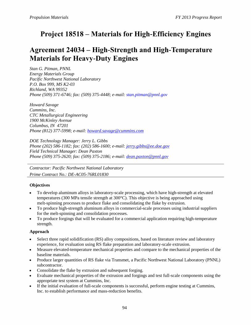
Propulsion Materials FY 2013 Progress Report
94
Project 18518 – Materials for High-Efficiency Engines
Agreement 24034 – High-Strength and High-Temperature
Materials for Heavy-Duty Engines
Stan G. Pitman, PNNL
Energy Materials Group
Pacific Northwest National Laboratory
P.O. Box 999, MS K2-03
Richland, WA 99352
Phone (509) 371-6746; fax: (509) 375-4448; e-mail: [email protected]
Howard Savage
Cummins, Inc.
CTC Metallurgical Engineering
1900 McKinley Avenue
Columbus, IN 47201
Phone (812) 377-5998; e-mail: [email protected]
DOE Technology Manager: Jerry L. Gibbs
Phone (202) 586-1182; fax: (202) 586-1600; e-mail: [email protected]
Field Technical Manager: Dean Paxton
Phone (509) 375-2620; fax: (509) 375-2186; e-mail: [email protected]
Contractor: Pacific Northwest National Laboratory
Prime Contract No.: DE-AC05-76RL01830
Objectives
To develop aluminum alloys in laboratory-scale processing, which have high-strength at elevated
temperatures (300 MPa tensile strength at 300°C). This objective is being approached using
melt-spinning processes to produce flake and consolidating the flake by extrusion.
To produce high-strength aluminum alloys in commercial-scale processes using industrial suppliers
for the melt-spinning and consolidation processes.
To produce forgings that will be evaluated for a commercial application requiring high-temperature
strength.
Approach
Select three rapid solidification (RS) alloy compositions, based on literature review and laboratory
experience, for evaluation using RS flake preparation and laboratory-scale extrusion.
Measure elevated-temperature mechanical properties and compare to the mechanical properties of the
baseline materials.
Produce larger quantities of RS flake via Transmet, a Pacific Northwest National Laboratory (PNNL)
subcontractor.
Consolidate the flake by extrusion and subsequent forging.
Evaluate mechanical properties of the extrusion and forgings and test full-scale components using the
appropriate test system at Cummins, Inc.
If the initial evaluation of full-scale components is successful, perform engine testing at Cummins,
Inc. to establish performance and mass-reduction benefits.

Propulsion Materials FY 2013 Progress Report
95
Accomplishments
Available RS alloys and an additional PNNL-developed alloy have been evaluated in laboratory-scale
extrusions followed by tensile testing. Results are favorable, but commercialization of the extrusion
and forging processes must be demonstrated.
RS flake was produced in commercial-scale quantities (about 600 lb) via Transmet and the flake
material has been canned and prepared for extrusion by a consolidation contractor.
Future Direction
Complete consolidation of the RS flake material by extrusion and subsequent forging. Characterize
the consolidated material using mechanical testing and metallographic methods and submit forgings
to Cummins, Inc. for evaluation. If the results of this evaluation are successful, perform engine testing
at Cummins, Inc.
Propulsion Materials FY 2013 Progress Report
96
Introduction
Aluminum alloys that possess strengths
approaching 300 MPa at 300°C have been
produced in small quantities by numerous
mechanical attrition (MA) methods. Although
MA can produce unique combinations of
properties, MA processing approaches have not
been able to meet the requirements for low-cost,
high-volume production. The purpose of this
project is to demonstrate that MA-type alloys
can be produced with adequate high-temperature
mechanical properties through development of a
low-cost, high-volume, rapid solidification (RS)
production process.
MA aluminum alloys with strengths
approaching 300 MPa at 300°C have been
produced by adding alloying elements with very
low solubility and that form intermetallic
dispersions (e.g., Fe, Ti, Cr, Mn, and Zr) in the
aluminum matrix. Milling cycles can require
hundreds of hours to adequately homogenize
these alloys, resulting in diminished ductility. In
the past, the Pacific Northwest National
Laboratory (PNNL) has worked with melt
spinning methods to produce RS alloys by using
a process that produces a low surface area
particulate (i.e., flake).
The RS flake can be consolidated by
elevated temperature extrusion. This project
intends to use the RS flake/extrusion process to
produce an aluminum alloy with increased
elevated temperature strength that can be used in
diesel engine service environments up to 300°C.
Approach
High-Strength and High-Temperature Aluminum Alloy Development
Evaluate the feasibility of producing Al-Fe
high-temperature alloys by two different RS
methods: RS flake and rotating cup processing
of powder particles (RS powder). The two
methods are known to have solidification rates
that differ by several orders of magnitude, with
the cooling rate for RS flake estimated at
106 degrees/second and the RS powder
estimated at 102 degrees/second. The RS powder
method was being evaluated in spite of the lower
solidification rate, because it is an established
high-volume RS process and because the coarser
shot particulate has some advantages in handling
and consolidation.
This evaluation has been completed and will
be discussed in a subsequent section of this
report. The melt spinning method was chosen
for use in the following steps:
1. Produce the RS alloy compositions using the
PNNL pilot flake system. The PNNL flake
melt spinning machine can produce limited
quantities of experimental alloys in the form
of rapidly solidified flake. The following
subtasks were initiated after producing
aluminum flake feedstock by melt spinning:
a. Conduct a comprehensive technology
review of prior high-temperature and
high-strength aluminum alloy
development, including alloys
developed by Allied Signal and
academic institutions.
b. Select three alloy compositions, two
similar to the early Allied Signal Al-Fe-
X compositions the third the
Al3Fe2Cr2Ti previously developed by
MA.
2. Consolidate flake materials at PNNL via
extrusion using laboratory-scale extrusion
tooling. Rapidly solidified flake will be
consolidated using the canning and indirect
extrusion process previously developed by
PNNL.
3. Measure elevated temperature mechanical
properties and compare them to the
mechanical properties of the baseline
materials. Conduct elevated temperature
tensile tests of sample materials to establish
temperature-strength behavior for the
materials.
4. Produce larger quantities of flake via
Transmet (a PNNL subcontractor) using the
production melt spinning system. The
down-selected alloy composition(s) will be
made into master alloy feedstock and
provided to Transmet for melt spinning into
rapidly solidified feedstock. Depending on
the alloy systems selected, quantities of
several hundred pounds are anticipated.
Propulsion Materials FY 2013 Progress Report
97
5. Consolidate the production flake by
degassing, canning, and hot isostatic
pressing, followed by extrusion.
Larger-billet diameters will be used, and
processing will simulate anticipated
full-scale production.
6. Test full-scale components using the
appropriate test system at Cummins, Inc.
Cummins, Inc. will select components that
will benefit from the high-temperature
aluminum properties and process the
materials supplied by PNNL into full-scale
test components.
7. If component testing is successful, perform
engine testing at Cummins, Inc. Use
established rig testing to establish
performance and mass-reduction benefits.
The primary deliverables for this project are
as follows:
Development and production of
high-temperature aluminum alloys by rapid
solidification
Characterization of the RS alloys and
baseline materials for elevated temperature
fatigue strength
Cost analysis of the process to produce
full-scale extrusions
Full-scale component testing to validate RS
alloy performance.
Results and Discussion
Work on this project began in May 2011,
conducted under a cooperative research and
development agreement (CRADA) between
Cummins, Inc. and PNNL. The first phase of the
effort has focused on identification of candidate
aluminum alloy systems that can provide higher
strengths (300 MPa) at elevated temperatures of
approximately 300oC and on evaluation of two
methods for producing RS feedstock: melt
spinning of flake and rotating cup processing of
powder particles. The work with melt spinning
is described next and a discussion of melt
spinning relative to rotating cup processing
follows.
A series of five alloy compositions were
evaluated using two different consolidation and
extrusion processes. All alloys contain Fe as a
key alloy addition, along with smaller additions
of silicon, Ti-Cr-V, and Mn. With the exception
of silicon, alloy additions were chosen for their
low solubility in aluminum and ability to form
stable second-phase particles. Evaluated alloy
compositions are listed in Table 1. The first two
alloys contain Si and V, while the aluminum-
iron-chrome/titanium (AFCT) alloy contains a
lower level of Fe, combined with higher weight
percentages of Cr and Ti. The aluminum-iron-
manganese (AFM) alloy was developed at
PNNL in earlier work.
The first three alloys (i.e., Al-12
Fe, Al-8.5
Fe,
and AFCT) have been previously produced in
small quantities and tensile tested at a range of
temperatures. Tensile strengths for these alloys
at 300°C have been reported in the 250 to
300 MPa range, close to or meeting the property
goals.
The processing steps that were selected for
this project include induction melting to produce
suitable feedstock alloys that approximate the
compositions of the alloys listed in Table 1,
analysis of actual compositions and the alloy
melting characteristics, induction re-melting of
the alloys, and melt spinning to rapidly produce
RS flake materials for subsequent processing.
Figure 1 shows the RS flake material and the
melt spinning equipment used to produce it.
The second focus of the project was
development of laboratory-scale extrusion
tooling to be used in the consolidation and
extrusion of the RS flake materials to produce a
wrought extruded rod. The extruded rod material
provides sufficient material for machining of
tensile specimens for room temperature and
elevated (300°C) tensile. Two processing
approaches were developed for preparing the RS
flake material for extrusion into the wrought rod
product. The first approach involved cold (room
temperature) pressing of the RS flake into an
aluminum can, followed by weld-sealing the can
under vacuum conditions. The sealed can was
heated and extruded to the rod product using a
19:1 extrusion ratio. In the second approach, the
canned flake was placed in a vacuum hot press
at 450°C and pressed to pre-consolidate the RS
flake to approximately 90% theoretical density.
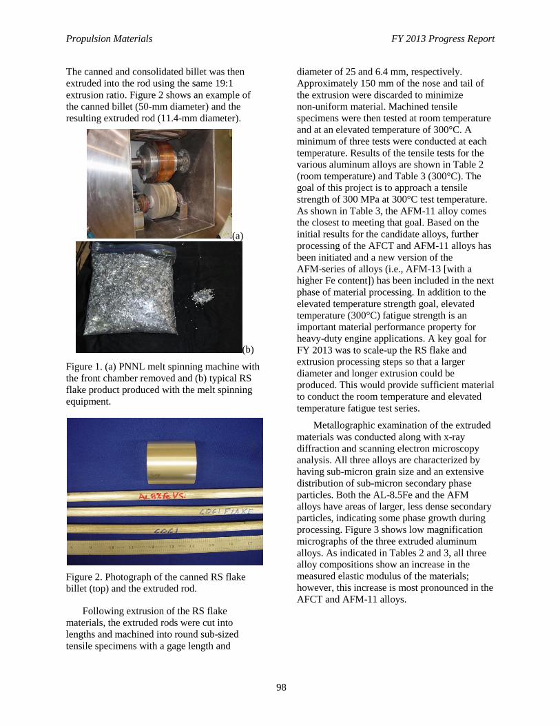
Propulsion Materials FY 2013 Progress Report
98
The canned and consolidated billet was then
extruded into the rod using the same 19:1
extrusion ratio. Figure 2 shows an example of
the canned billet (50-mm diameter) and the
resulting extruded rod (11.4-mm diameter).
(a)
(b)
Figure 1. (a) PNNL melt spinning machine with
the front chamber removed and (b) typical RS
flake product produced with the melt spinning
equipment.
Figure 2. Photograph of the canned RS flake
billet (top) and the extruded rod.
Following extrusion of the RS flake
materials, the extruded rods were cut into
lengths and machined into round sub-sized
tensile specimens with a gage length and
diameter of 25 and 6.4 mm, respectively.
Approximately 150 mm of the nose and tail of
the extrusion were discarded to minimize
non-uniform material. Machined tensile
specimens were then tested at room temperature
and at an elevated temperature of 300°C. A
minimum of three tests were conducted at each
temperature. Results of the tensile tests for the
various aluminum alloys are shown in Table 2
(room temperature) and Table 3 (300°C). The
goal of this project is to approach a tensile
strength of 300 MPa at 300°C test temperature.
As shown in Table 3, the AFM-11 alloy comes
the closest to meeting that goal. Based on the
initial results for the candidate alloys, further
processing of the AFCT and AFM-11 alloys has
been initiated and a new version of the
AFM-series of alloys (i.e., AFM-13 [with a
higher Fe content]) has been included in the next
phase of material processing. In addition to the
elevated temperature strength goal, elevated
temperature (300°C) fatigue strength is an
important material performance property for
heavy-duty engine applications. A key goal for
FY 2013 was to scale-up the RS flake and
extrusion processing steps so that a larger
diameter and longer extrusion could be
produced. This would provide sufficient material
to conduct the room temperature and elevated
temperature fatigue test series.
Metallographic examination of the extruded
materials was conducted along with x-ray
diffraction and scanning electron microscopy
analysis. All three alloys are characterized by
having sub-micron grain size and an extensive
distribution of sub-micron secondary phase
particles. Both the AL-8.5Fe and the AFM
alloys have areas of larger, less dense secondary
particles, indicating some phase growth during
processing. Figure 3 shows low magnification
micrographs of the three extruded aluminum
alloys. As indicated in Tables 2 and 3, all three
alloy compositions show an increase in the
measured elastic modulus of the materials;
however, this increase is most pronounced in the
AFCT and AFM-11 alloys.
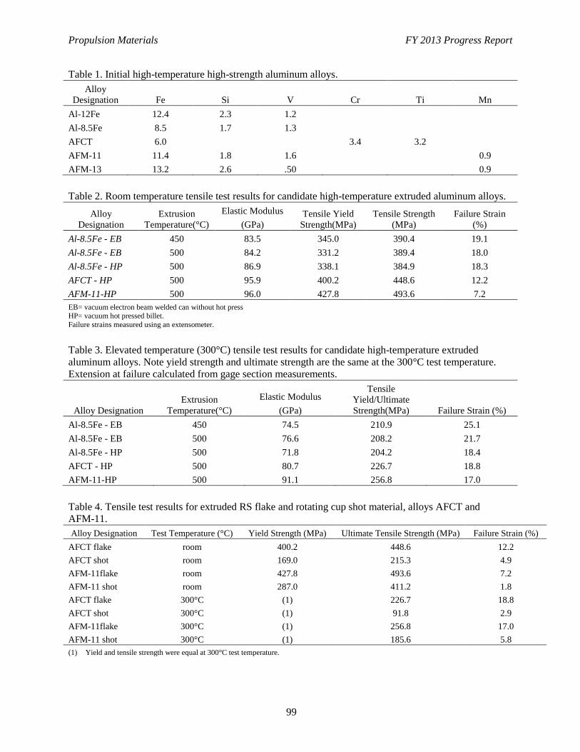
Propulsion Materials FY 2013 Progress Report
99
Table 1. Initial high-temperature high-strength aluminum alloys.
Alloy
Designation Fe Si V Cr Ti Mn
Al-12Fe 12.4 2.3 1.2
Al-8.5Fe 8.5 1.7 1.3
AFCT 6.0 3.4 3.2
AFM-11 11.4 1.8 1.6 0.9
AFM-13 13.2 2.6 .50 0.9
Table 2. Room temperature tensile test results for candidate high-temperature extruded aluminum alloys.
Alloy
Designation
Extrusion
Temperature(°C)
Elastic Modulus
(GPa)
Tensile Yield
Strength(MPa)
Tensile Strength
(MPa)
Failure Strain
(%)
Al-8.5Fe - EB 450 83.5 345.0 390.4 19.1
Al-8.5Fe - EB 500 84.2 331.2 389.4 18.0
Al-8.5Fe - HP 500 86.9 338.1 384.9 18.3
AFCT - HP 500 95.9 400.2 448.6 12.2
AFM-11-HP 500 96.0 427.8 493.6 7.2
EB= vacuum electron beam welded can without hot press HP= vacuum hot pressed billet.
Failure strains measured using an extensometer.
Table 3. Elevated temperature (300°C) tensile test results for candidate high-temperature extruded
aluminum alloys. Note yield strength and ultimate strength are the same at the 300°C test temperature.
Extension at failure calculated from gage section measurements.
Alloy Designation
Extrusion
Temperature(°C)
Elastic Modulus
(GPa)
Tensile
Yield/Ultimate
Strength(MPa) Failure Strain (%)
Al-8.5Fe - EB 450 74.5 210.9 25.1
Al-8.5Fe - EB 500 76.6 208.2 21.7
Al-8.5Fe - HP 500 71.8 204.2 18.4
AFCT - HP 500 80.7 226.7 18.8
AFM-11-HP 500 91.1 256.8 17.0
Table 4. Tensile test results for extruded RS flake and rotating cup shot material, alloys AFCT and
AFM-11.
Alloy Designation Test Temperature (°C) Yield Strength (MPa) Ultimate Tensile Strength (MPa) Failure Strain (%)
AFCT flake room 400.2 448.6 12.2
AFCT shot room 169.0 215.3 4.9
AFM-11flake room 427.8 493.6 7.2
AFM-11 shot room 287.0 411.2 1.8
AFCT flake 300°C (1) 226.7 18.8
AFCT shot 300°C (1) 91.8 2.9
AFM-11flake 300°C (1) 256.8 17.0
AFM-11 shot 300°C (1) 185.6 5.8
(1) Yield and tensile strength were equal at 300°C test temperature.
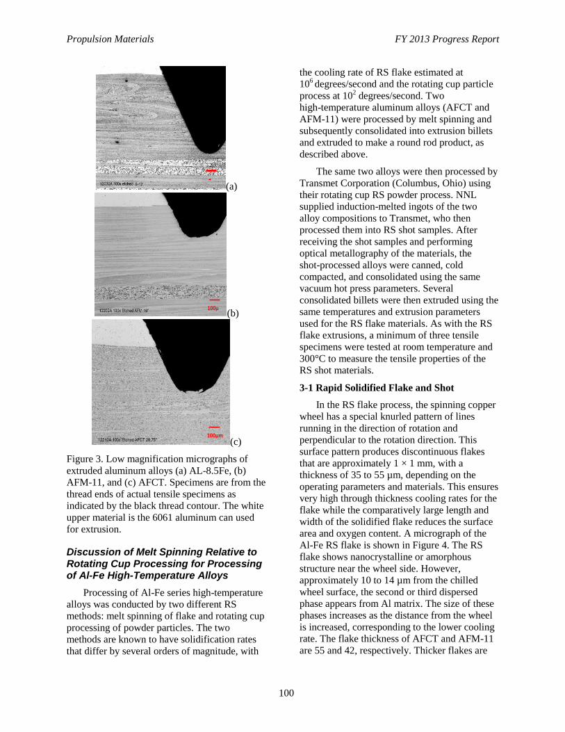
Propulsion Materials FY 2013 Progress Report
100
(a)
(b)
(c)
Figure 3. Low magnification micrographs of
extruded aluminum alloys (a) AL-8.5Fe, (b)
AFM-11, and (c) AFCT. Specimens are from the
thread ends of actual tensile specimens as
indicated by the black thread contour. The white
upper material is the 6061 aluminum can used
for extrusion.
Discussion of Melt Spinning Relative to Rotating Cup Processing for Processing of Al-Fe High-Temperature Alloys
Processing of Al-Fe series high-temperature
alloys was conducted by two different RS
methods: melt spinning of flake and rotating cup
processing of powder particles. The two
methods are known to have solidification rates
that differ by several orders of magnitude, with
the cooling rate of RS flake estimated at
106 degrees/second and the rotating cup particle
process at 102 degrees/second. Two
high-temperature aluminum alloys (AFCT and
AFM-11) were processed by melt spinning and
subsequently consolidated into extrusion billets
and extruded to make a round rod product, as
described above.
The same two alloys were then processed by
Transmet Corporation (Columbus, Ohio) using
their rotating cup RS powder process. NNL
supplied induction-melted ingots of the two
alloy compositions to Transmet, who then
processed them into RS shot samples. After
receiving the shot samples and performing
optical metallography of the materials, the
shot-processed alloys were canned, cold
compacted, and consolidated using the same
vacuum hot press parameters. Several
consolidated billets were then extruded using the
same temperatures and extrusion parameters
used for the RS flake materials. As with the RS
flake extrusions, a minimum of three tensile
specimens were tested at room temperature and
300°C to measure the tensile properties of the
RS shot materials.
3-1 Rapid Solidified Flake and Shot
In the RS flake process, the spinning copper
wheel has a special knurled pattern of lines
running in the direction of rotation and
perpendicular to the rotation direction. This
surface pattern produces discontinuous flakes
that are approximately 1 × 1 mm, with a
thickness of 35 to 55 µm, depending on the
operating parameters and materials. This ensures
very high through thickness cooling rates for the
flake while the comparatively large length and
width of the solidified flake reduces the surface
area and oxygen content. A micrograph of the
Al-Fe RS flake is shown in Figure 4. The RS
flake shows nanocrystalline or amorphous
structure near the wheel side. However,
approximately 10 to 14 µm from the chilled
wheel surface, the second or third dispersed
phase appears from Al matrix. The size of these
phases increases as the distance from the wheel
is increased, corresponding to the lower cooling
rate. The flake thickness of AFCT and AFM-11
are 55 and 42, respectively. Thicker flakes are
100µ
100µm
1
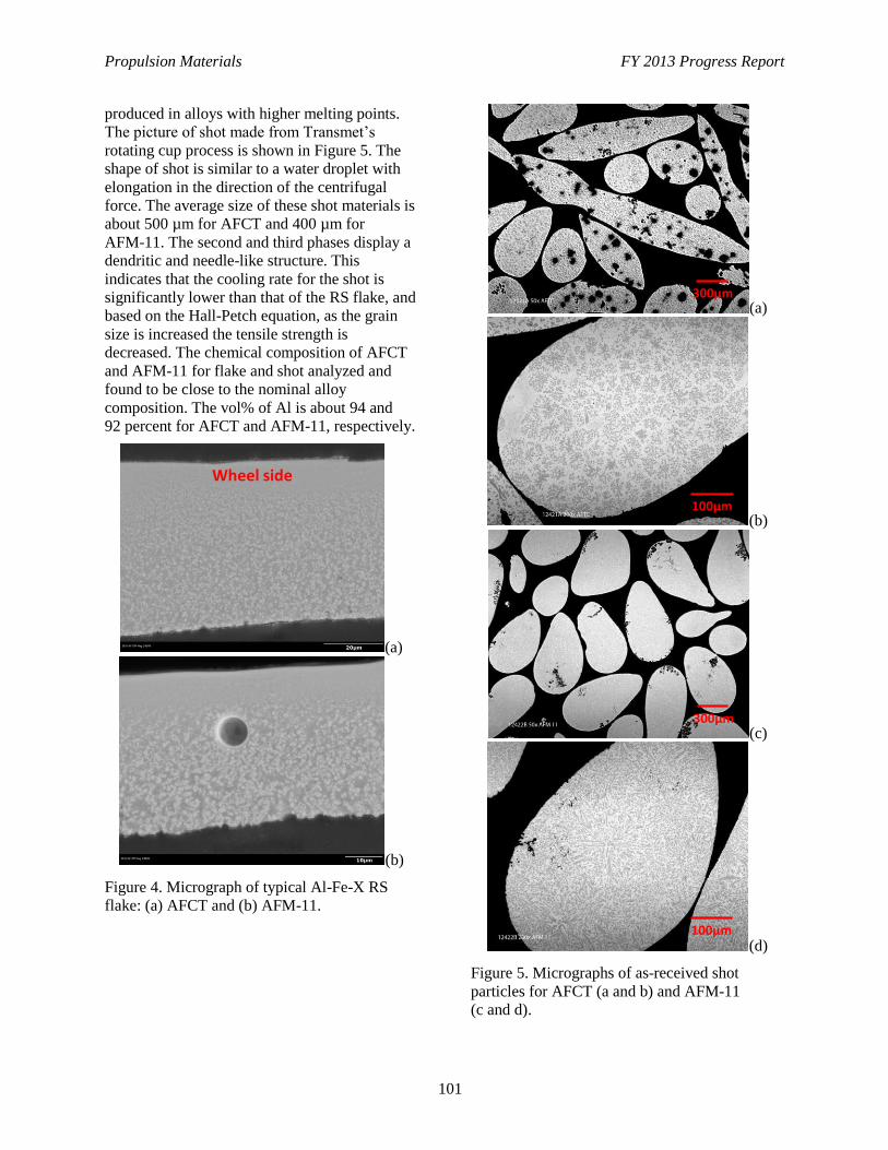
Propulsion Materials FY 2013 Progress Report
101
produced in alloys with higher melting points.
The picture of shot made from Transmet’s
rotating cup process is shown in Figure 5. The
shape of shot is similar to a water droplet with
elongation in the direction of the centrifugal
force. The average size of these shot materials is
about 500 µm for AFCT and 400 µm for
AFM-11. The second and third phases display a
dendritic and needle-like structure. This
indicates that the cooling rate for the shot is
significantly lower than that of the RS flake, and
based on the Hall-Petch equation, as the grain
size is increased the tensile strength is
decreased. The chemical composition of AFCT
and AFM-11 for flake and shot analyzed and
found to be close to the nominal alloy
composition. The vol% of Al is about 94 and
92 percent for AFCT and AFM-11, respectively.
(a)
(b)
Figure 4. Micrograph of typical Al-Fe-X RS
flake: (a) AFCT and (b) AFM-11.
(a)
(b)
(c)
(d)
Figure 5. Micrographs of as-received shot
particles for AFCT (a and b) and AFM-11
(c and d).
Wheel side
300µm
100µm
300µm
100µm
Propulsion Materials FY 2013 Progress Report
102
Tensile tests were conducted of extruded
flake material and extruded shot material at
room temperature and at 300°C. The results of
these tests are summarized in Table 4. Tensile
test results show that the flake extrusion has
significantly higher tensile strengths when
compared to the extruded shot material. The
extruded flake materials also display relatively
high elongations to failure, which would indicate
good consolidation during extrusion and a
stable, refined microstructure. Based on previous
microstructural characterization, RS flake
materials were observed to have a much finer
size and distribution of the secondary
intermetallic particles combined with occasional
bands of coarser particles. The slower cooling
rate and cast-like structure of the rotating cup
shot material appears to translate into fewer,
coarser intermetallic particles in the final
extruded product and, as a result, significantly
lower room temperature and elevated
temperature tensile strengths. It should be noted
that the AFM-11 shot extrusion shows
significantly better strengths than the AFCT shot
extrusion, particularly at the 300°C test
temperature. However, the tensile elongation of
extruded shot AFM-11 is quite low, particularly
compared to the AFM-11 flake extrusion.
Technology Transfer
By participating in this CRADA, Cummins,
Inc. will benefit by applying new technology to
improve the high-temperature performance and
life of engine combustion components,
air-handling systems, and emission-control
components. In addition, Cummins, Inc. benefits
by coupling its own engineering production
experience and know-how with the scientific
expertise and technical capabilities of PNNL
staff and U.S. Department of Energy national
laboratories to solve relevant problems that
benefit the industry and achieve DOE fuel
economy goals.
Conclusions
The High-Strength and High-Temperature
Aluminum Alloys for Heavy-Duty Engine
Applications Project started under a CRADA
(agreement) in May 2011. The early phase of
this project has evaluated potential
high-temperature, high-strength aluminum alloy
systems that can be produced by RS processing
and subsequent processing into extruded or
forged product forms. A group of candidate
alloys were selected for processing and
characterization, and feedstock melting methods
were developed. RS processing using the
PNNL/Transmet melt spinning equipment has
been completed. Laboratory-scale extrusion
tooling was designed and fabricated and the
tooling was used to consolidate flake materials
into extruded wrought aluminum alloy rods.
Extruded materials of the three alloy
compositions were machined into tensile test
specimens and tested at room temperature and at
an elevated temperature of 300°C. Test results
show that the AFCT and AFM-11 alloys have
higher tensile strengths at the 300°C test
temperature when compared with the Al-8.5Fe
alloy. Test results also show that the AFM-11
alloy has a tensile strength exceeding 250 MPa.
The FY 2014 project work will focus on the
AFCT and AFM alloys and on processing
methods to produce sufficient materials for
fatigue testing and engine-component
fabrication.
Propulsion Materials FY 2013 Progress Report
103
Project 18518 – Materials for High-Efficiency Engines
Agreement 25736 – Computational Design and Development
of a New, Lightweight Cast Alloy for Advanced Cylinder
Heads in High-Efficiency, Light-Duty Engines
Mike J. Walker
General Motors Research and Development Center
30500 Mound Road
Warren, MI 48090-9055
Phone (586) 651-3757; fax: (586) 986-9204; e-mail: [email protected]
Qigui Wang
General Motors Powertrain Division
823 Joslyn Ave
Pontiac MI 48340-2925
Phone (248) 762-6332; fax: (248) 857-4441; e-mail: [email protected]
DOE Technology Manager: Jerry L. Gibbs
Phone (202) 586-1182; fax: (202) 586-1600; e-mail: [email protected]
Field Technical Manager: Aaron Yocum
Phone (304) 285-4852; e-mail: [email protected]
Contractor: General Motors, LLC
Prime Contract No.: DE-EE0006082
Objectives
Develop a high-performance, lightweight, cast alloy that will provide significant improvement (i.e., at
least 25%) in both high-temperature strength and fatigue performance relative to the existing state-of-
the-art aluminum alloys used in engine applications (such as B319 or A356), with a similar material
density (less than 3 g/cm3).
Utilize Integrated Computational Materials Engineering (ICME) tools to design a new, lightweight
cast alloy with ideal multi-scale structures and minimal propensity to form casting defects (such as
porosity, oxides, and hot tearing).
Make a direct comparison of the measured microstructures, physical, and mechanical properties to the
predictions to validate and assess the current state-of-the-art and identification of gaps that exist for
these materials and ICME tools.
Develop comprehensive cost models to include materials production, component casting, heat
treatment, and machining costs for annual production runs up to 500,000 units of cylinder heads using
the new alloy.
The team’s goal is for the cost to be less than 105% of the cost of the same components made from
the current alloys.
Approach
Apply QuesTek’s iCMD™
approach and General Motor’s Virtual Cast Component Development
(VCCD) methodologies to accelerate development of cylinder head castings made from the new alloy
by a state-of-the-art semi-permanent mold sand casting process.
Propulsion Materials FY 2013 Progress Report
104
Cast heats at multiple project stages to produce test samples and castings.
Use traditional and the most advanced analytical characterization tools (such as Atom-Probe
Microscopy) to quantify the microstructure and material properties of these castings for comparison
with the predicted values and as a required input for both the design and the structural and durability
analyses of an engine component.
Conduct a casting trial on the production cylinder head castings to fully evaluate the capability of the
alloy and process to achieve the project’s stated goals.
Accomplishments
Defined a material requirement matrix based on Department of Energy FOA targets and engine
performance requirements to direct the alloy design.
Identified five alloy concepts. The alloy concepts are being studied and evaluated for their potential to
meet project targets in terms of room and high-temperature mechanical properties, fluidity, and hot
tearing resistance.
Produced multiple plate castings and evaluated the tensile properties from one of the alloy concepts.
Cast plates and button coupons to evaluate the properties of another alloy concept.
Future Direction
Identify a few more alloy concepts using DFT methods
Identify elements that can reduce coarsening of aging hardening precipitates in the existing concept
alloys using ICME methods.
Continue process simulation of plate castings with concept alloys and predicting casting defects and
mechanical properties, including fatigue.
Continue casting test samples and plates and conducting tests of fluidity, hot tearing, and shrinkage to
evaluate castability of concept alloys.
Validate simulation predictions with the most advanced experimental and analytical tools available.
Refine alloy concepts to more practical casting alloys.
Optimize alloy and process conditions and determine optimal alloy chemical tolerance limits.
Proceed to a full casting trial on the production engine head and evaluate tensile and fatigue
properties.
Develop cost models for alloy and head casting for a production level of up to 500,000/year.
Propulsion Materials FY 2013 Progress Report
105
Introduction
The U.S. Department of Energy: Energy
Efficiency and Renewable Energy Program is
targeting a 25% lighter powertrain by 2025 and
a 40% lighter powertrain by 2050. As a result,
the engine power density will be increased
significantly. This will result in higher exhaust
temperatures and a doubling of the cylinder peak
pressures by 2050. To meet these requirements
and achieve the stated goals, the properties of
the state-of-the-art materials (such as cast
aluminum alloys) must increase substantially.
Historically, it has taken about 10 years to
develop and implement a new alloy and it has
taken about 100 years to improve the
performance of a material such as cast aluminum
by 50%. Thus, traditional methods of
experimental trial and error are no longer
sufficient. Fortunately, both computational and
analytical methods have been vastly improved in
the last few decades. ICME and advanced
analytical tools (such as focused ion beam
microscope, high-resolution scanning
transmission electron microscope, and local
electron atom probe) instruments are now
available to accelerate the timeframe to develop
new alloys.
Approach
State-of-the-art ICME tools (such as first
principle calculations, computational
thermodynamic and kinetic models,
computational materials design, virtual casting
modules, and commercially available casting
process simulation, and structural and durability
analysis software) will be used to design a new,
lightweight cast alloy with ideal multi-scale
microstructures and a minimum tendency for
casting defects to achieve the desired
high-temperature strength and fatigue
performance requirements in complex castings.
The iCMD™
method for developing concepts,
modeling, validating, and progressing to a more
refined state has been selected as the approach
for this project. QuesTek’s proprietary iCMD™
platform is a core modeling software system that
integrates proprietary and commercial
mechanistic modeling tools to facilitate rapid
design and development of new materials (see
Figure 1).
General Motor’s VCCD Program uses
integrated state-of-the-art modeling and
simulation methodologies for cast aluminum
components, starting from computational alloy
and casting design, through casting and heat
treatment process modeling and multi-scale
defect and microstructure simulation, and
culminating in casting property and durability
prediction (see Figure 2).
Progress
At the first stage of the project, a material
requirement matrix was developed to guide alloy
development. The first generation of the matrix
was based on property requirements in the
original Department of Energy FOA, as well as
the best achievable properties of current alloys.
Improvements to the matrix were based on a
design for six sigma (DFSS) optimization. Input
variables for the finite element analysis included
coefficient of thermal expansion (CTE), thermal
conductivity, heat capacity, Young’s modulus,
and density. The analysis looked at the
temperature in the valve bridge area, deck face
flatness (distortion), mean and alternating
stresses on the flame, and water jacket sides of
the combustion chamber. The simulation
analysis looked at both the dual overhead cam
and overhead valve architectures.
In this first year of the project, five alloy
concepts have been identified. Phase diagram
simulations, diffusion calculations, heat
treatment studies, and porosity simulations have
been carried out on various alloys. Differential
scanning calorimetry, optical microscopy,
scanning electron microscopy, and local electron
atom probe have been utilized in
characterization of microstructure and
solidification sequences. Along with baseline
A356 and B319 alloys, “chill plate castings”
have been made of two of the concepts. These
chill plate castings are used to produce test
samples for tensile and fatigue testing and
microstructural analysis (Figure 3). The unique
chill plate castings have various values of
secondary dendrite arm spacing that cover the
cooling rates that the production cylinder heads
usually experience in casting. Cast buttons were
also produced.
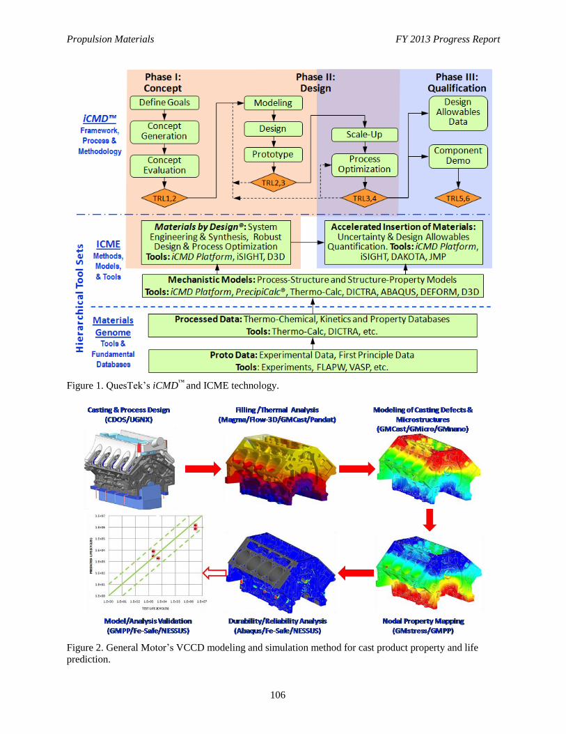
Propulsion Materials FY 2013 Progress Report
106
Figure 1. QuesTek’s iCMD™
and ICME technology.
Figure 2. General Motor’s VCCD modeling and simulation method for cast product property and life
prediction.
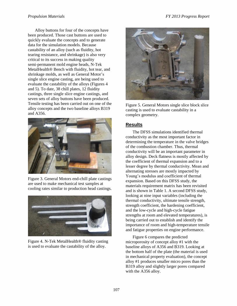
Propulsion Materials FY 2013 Progress Report
107
Alloy buttons for four of the concepts have
been produced. Those cast buttons are used to
quickly evaluate the concepts and to generate
data for the simulation models. Because
castability of an alloy (such as fluidity, hot
tearing resistance, and shrinkage) is also very
critical to its success in making quality
semi-permanent mold engine heads, N-Tek
MetalHealth® Bench with fluidity, hot tear, and
shrinkage molds, as well as General Motor’s
single slice engine casting, are being used to
evaluate the castability of the alloys (Figures 4
and 5). To date, 38 chill plates, 12 fluidity
castings, three single slice engine castings, and
seven sets of alloy buttons have been produced.
Tensile testing has been carried out on one of the
alloy concepts and the two baseline alloys B319
and A356.
Figure 3. General Motors end-chill plate castings
are used to make mechanical test samples at
cooling rates similar to production head castings.
Figure 4. N-Tek MetalHealth® fluidity casting
is used to evaluate the castability of the alloy.
Figure 5. General Motors single slice block slice
casting is used to evaluate castability in a
complex geometry.
Results
The DFSS simulations identified thermal
conductivity as the most important factor in
determining the temperature in the valve bridges
of the combustion chamber. Thus, thermal
conductivity will be an important parameter in
alloy design. Deck flatness is mostly affected by
the coefficient of thermal expansion and to a
lesser degree by thermal conductivity. Mean and
alternating stresses are mostly impacted by
Young’s modulus and coefficient of thermal
expansion. Based on this DFSS study, the
materials requirement matrix has been revisited
and is shown in Table 1. A second DFSS study,
looking at nine input variables (including the
thermal conductivity, ultimate tensile strength,
strength coefficient, the hardening coefficient,
and the low-cycle and high-cycle fatigue
strengths at room and elevated temperatures), is
being carried out to establish and identify the
importance of room and high-temperature tensile
and fatigue properties on engine performance.
Figure 6 compares the predicted
microporosity of concept alloy #1 with the
baseline alloys of A356 and B319. Looking at
the bottom half of the plate (the material is used
in mechanical property evaluation), the concept
alloy #1 produces smaller micro pores than the
B319 alloy and slightly larger pores compared
with the A356 alloy.
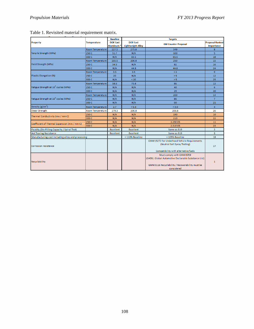
Propulsion Materials FY 2013 Progress Report
108
Table 1. Revisited material requirement matrix.
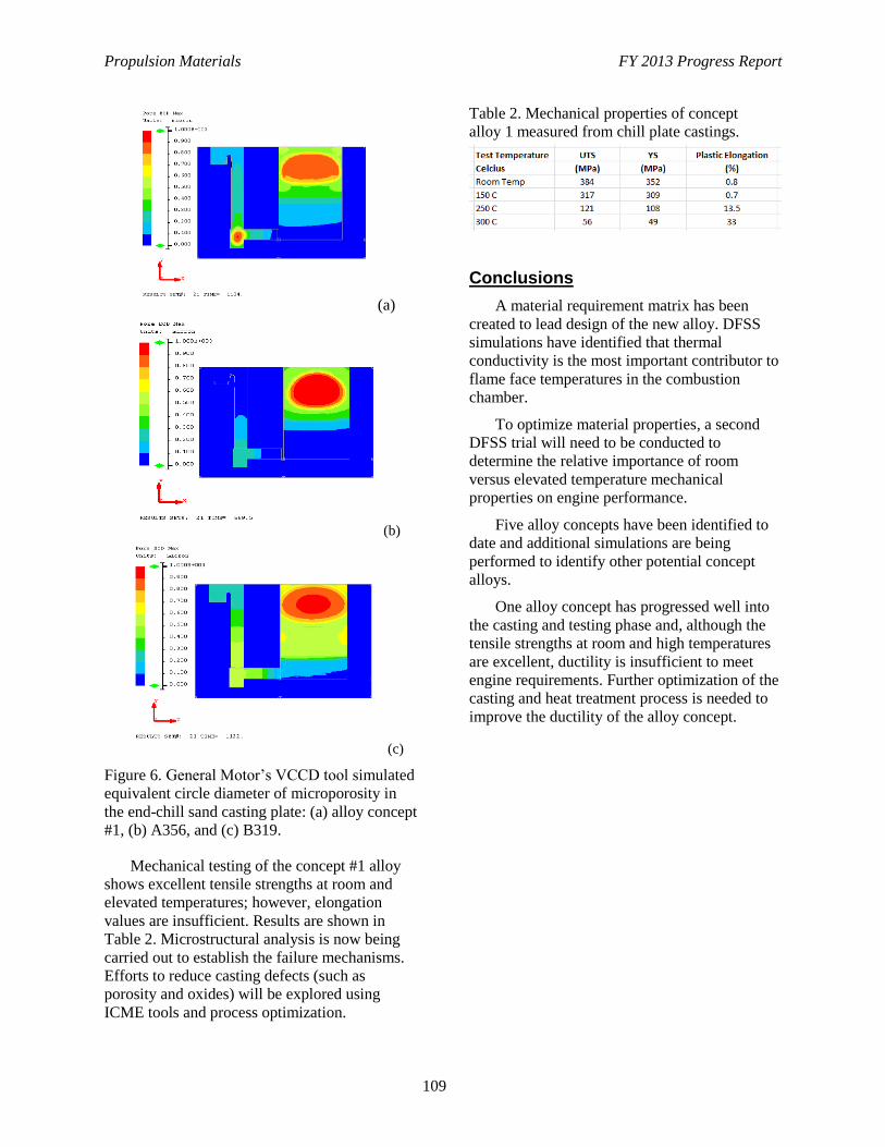
Propulsion Materials FY 2013 Progress Report
109
(a)
(b)
(c)
Figure 6. General Motor’s VCCD tool simulated
equivalent circle diameter of microporosity in
the end-chill sand casting plate: (a) alloy concept
#1, (b) A356, and (c) B319.
Mechanical testing of the concept #1 alloy
shows excellent tensile strengths at room and
elevated temperatures; however, elongation
values are insufficient. Results are shown in
Table 2. Microstructural analysis is now being
carried out to establish the failure mechanisms.
Efforts to reduce casting defects (such as
porosity and oxides) will be explored using
ICME tools and process optimization.
Table 2. Mechanical properties of concept
alloy 1 measured from chill plate castings.
Conclusions
A material requirement matrix has been
created to lead design of the new alloy. DFSS
simulations have identified that thermal
conductivity is the most important contributor to
flame face temperatures in the combustion
chamber.
To optimize material properties, a second
DFSS trial will need to be conducted to
determine the relative importance of room
versus elevated temperature mechanical
properties on engine performance.
Five alloy concepts have been identified to
date and additional simulations are being
performed to identify other potential concept
alloys.
One alloy concept has progressed well into
the casting and testing phase and, although the
tensile strengths at room and high temperatures
are excellent, ductility is insufficient to meet
engine requirements. Further optimization of the
casting and heat treatment process is needed to
improve the ductility of the alloy concept.
Propulsion Materials FY 2013 Progress Report
110
Project 18518 – Materials for High-Efficiency Engines
Agreement 25737 – ICME Guided Development of
Advanced Cast Aluminum Alloys for Automotive Engine
Applications
Melissa Hendra
Research and Innovation Center
Ford Motor Company
2101 Village Road
Dearborn, MI 48121
Phone (313) 594-4714; fax: (313) 845-7307; e-mail: [email protected]
DOE Technology Manager: Jerry L. Gibbs
Phone (202) 586-1182; fax: (202) 586-1600; e-mail: [email protected]
Field Technical Manager: Mei Li
Phone (313) 206-4219; fax: (313) 390-0514; e-mail: [email protected]
Contractor: Ford Motor Company, Dearborn, Michigan
Prime Contract No.: DE-EE0006020
Objectives
To develop a new class of advanced, cost-competitive aluminum casting alloys, providing a 25%
improvement in component strength relative to components made with A319 or A356 alloys using
sand and semi-permanent casting processes for high-performance engine applications.
To demonstrate the power of the Integrated Computational Materials Engineering (ICME) tools for
accelerating development of new materials and processing techniques, as well as to identify the gaps
in ICME capabilities.
To develop comprehensive cost models to ensure that components manufactured with these new
alloys do not exceed 110% of the cost using incumbent alloys A319 or A356.
Approach
Comprehensive literature review on the mechanical properties and strengthening mechanisms of
existing traditional state-of-the-art cast aluminum alloys in line with A319 and A356 alloys.
Propose candidate alloys compositions that are likely to maximize the strengthening effect of
precipitates, based on the existing qualitative knowledge in published literature and quantitative
trends generated by ICME tools.
Incorporate novel elements, at finely tuned levels, that could potentially enhance the high-temperature
mechanical properties based on existing results in literature.
Confirm the hypothesis by casting the materials and characterizing the mechanical properties.
Optimize the final composition, based on the mechanical properties and other property criteria
(castability).
Accomplishments
Cast eight candidate alloys with commercially relevant compositions and different levels of novel
elemental additions.

Propulsion Materials FY 2013 Progress Report
111
Characterize the room temperature and high-temperature (300°C) strength and ductility of candidate
alloys, which are close or better than the Department of Energy target.
Future Direction
Detailed characterization of the type, morphology, size, volume fraction, and growth kinetics of
precipitates observed in the candidate alloys via TEM.
Adjust the composition of the initially proposed alloy composition, based on the attained mechanical
testing results.
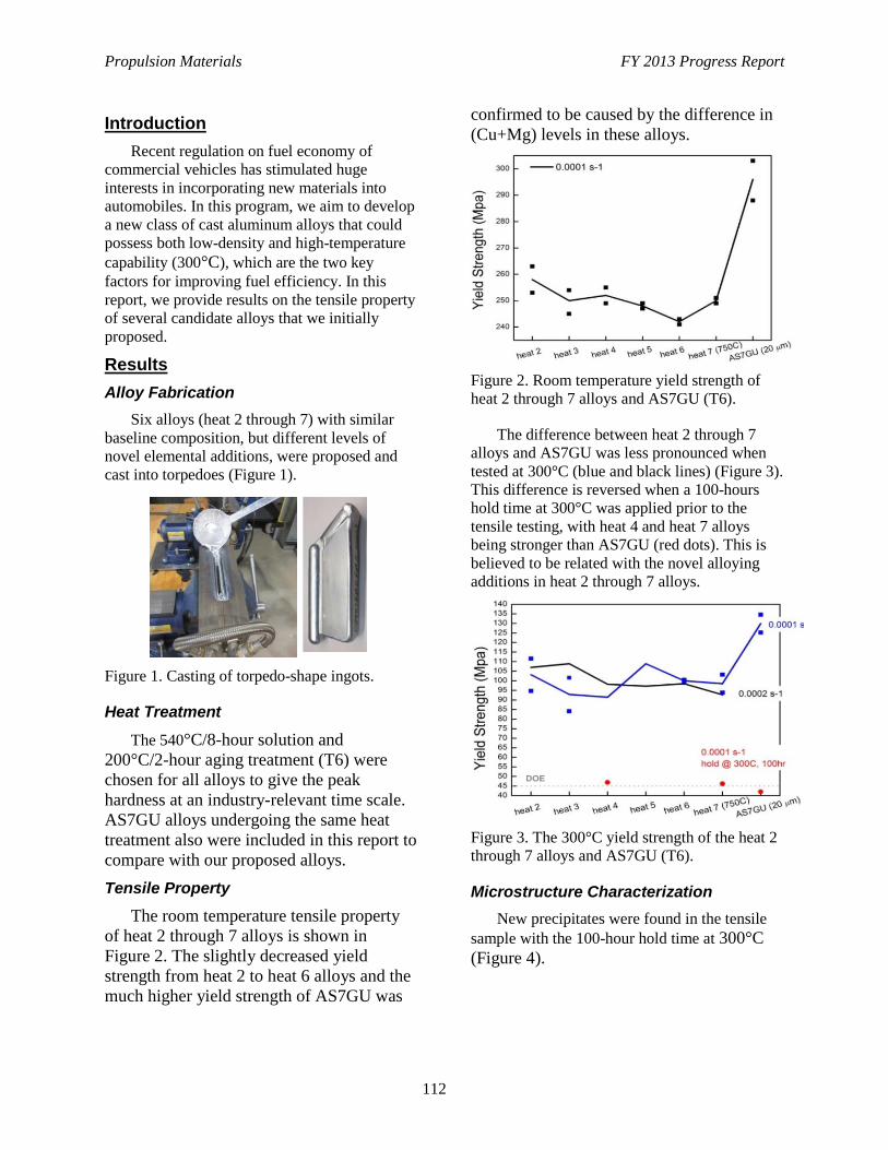
Propulsion Materials FY 2013 Progress Report
112
Introduction
Recent regulation on fuel economy of
commercial vehicles has stimulated huge
interests in incorporating new materials into
automobiles. In this program, we aim to develop
a new class of cast aluminum alloys that could
possess both low-density and high-temperature
capability (300°C), which are the two key
factors for improving fuel efficiency. In this
report, we provide results on the tensile property
of several candidate alloys that we initially
proposed.
Results
Alloy Fabrication
Six alloys (heat 2 through 7) with similar
baseline composition, but different levels of
novel elemental additions, were proposed and
cast into torpedoes (Figure 1).
Figure 1. Casting of torpedo-shape ingots.
Heat Treatment
The 540°C/8-hour solution and
200°C/2-hour aging treatment (T6) were
chosen for all alloys to give the peak
hardness at an industry-relevant time scale.
AS7GU alloys undergoing the same heat
treatment also were included in this report to
compare with our proposed alloys.
Tensile Property
The room temperature tensile property
of heat 2 through 7 alloys is shown in
Figure 2. The slightly decreased yield
strength from heat 2 to heat 6 alloys and the
much higher yield strength of AS7GU was
confirmed to be caused by the difference in
(Cu+Mg) levels in these alloys.
Figure 2. Room temperature yield strength of
heat 2 through 7 alloys and AS7GU (T6).
The difference between heat 2 through 7
alloys and AS7GU was less pronounced when
tested at 300°C (blue and black lines) (Figure 3).
This difference is reversed when a 100-hours
hold time at 300°C was applied prior to the
tensile testing, with heat 4 and heat 7 alloys
being stronger than AS7GU (red dots). This is
believed to be related with the novel alloying
additions in heat 2 through 7 alloys.
Figure 3. The 300°C yield strength of the heat 2
through 7 alloys and AS7GU (T6).
Microstructure Characterization
New precipitates were found in the tensile
sample with the 100-hour hold time at 300°C
(Figure 4).
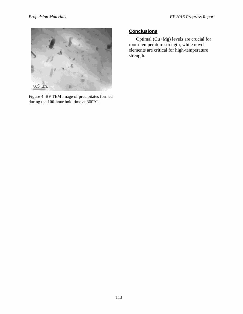
Propulsion Materials FY 2013 Progress Report
113
Figure 4. BF TEM image of precipitates formed
during the 100-hour hold time at 300°C.
Conclusions
Optimal (Cu+Mg) levels are crucial for
room-temperature strength, while novel
elements are critical for high-temperature
strength.
Propulsion Materials FY 2013 Progress Report
114
Project 18518 – Materials for High-Efficiency Engines
Agreement 26190 – High-Temperature Materials for
High-Efficiency Engines
G. Muralidharan and B. Pint
Materials Science and Technology Division
Oak Ridge National Laboratory
P.O. Box 2008,
Oak Ridge, TN 37831-6068
Phone (865) 574-4281; fax: (865) 574-4357; e-mail: [email protected]
DOE Technology Manager: Jerry L. Gibbs
Phone (202) 586-1182; fax: (202) 586-1600; e-mail: [email protected]
ORNL Technical Advisor: J. Allen Haynes
Phone (865) 576-2894; fax: (865) 574-4913; e-mail: [email protected]
Contractor: Oak Ridge National Laboratory, Oak Ridge, Tennessee
Prime Contract No.: DE-AC05-00OR22725
Objectives
Identify and catalog the materials property requirements for exhaust valves in next-generation, high-efficiency
engines.
Evaluate mechanical properties and oxidation resistance of leading, existing, nickel (Ni)-based alloys candidates
and alternate materials with the capability to operate at temperature up to 950°C.
Adopt integrated computational materials engineering-based techniques to develop alternate lower cost
Ni-based alloys for exhaust valve applications at temperatures up to 950ºC.
Approach
Mechanical property requirements required for operation at 950°C will be defined and the microstructure
required to achieve these properties will be identified.
Oxidation tests will be performed to understand the composition effects on oxidation behavior and establish
limits of critical elements.
A synergistic computational modeling and experimental evaluation approach, followed in the design of new
alloys for exhaust valve applications up to 870°C, will be refined and used to identify promising compositions
for service at 950ºC.
Trial heats of new compositions will be prepared, properties measured, and compositions refined in an iterative
manner.
Accomplishments
An initial assessment of the tensile properties of several Ni-based alloys at 950°C has been completed.
Oxidation behavior of several Ni-based alloys has been characterized at 800°C in air with 10% water vapor for
times up to 250 hours.
Future Direction
Understand the longer-term oxidation resistance behavior of candidate alloys and effect of alloying elements.
Understand the effect of microstructure and tensile properties at 950°C.
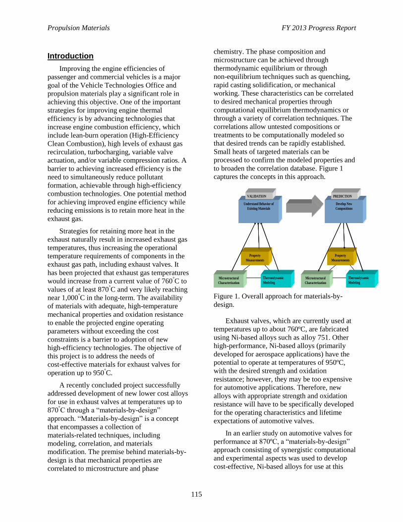
Propulsion Materials FY 2013 Progress Report
115
Introduction
Improving the engine efficiencies of
passenger and commercial vehicles is a major
goal of the Vehicle Technologies Office and
propulsion materials play a significant role in
achieving this objective. One of the important
strategies for improving engine thermal
efficiency is by advancing technologies that
increase engine combustion efficiency, which
include lean-burn operation (High-Efficiency
Clean Combustion), high levels of exhaust gas
recirculation, turbocharging, variable valve
actuation, and/or variable compression ratios. A
barrier to achieving increased efficiency is the
need to simultaneously reduce pollutant
formation, achievable through high-efficiency
combustion technologies. One potential method
for achieving improved engine efficiency while
reducing emissions is to retain more heat in the
exhaust gas.
Strategies for retaining more heat in the
exhaust naturally result in increased exhaust gas
temperatures, thus increasing the operational
temperature requirements of components in the
exhaust gas path, including exhaust valves. It
has been projected that exhaust gas temperatures
would increase from a current value of 760°C to
values of at least 870°C and very likely reaching
near 1,000°C in the long-term. The availability
of materials with adequate, high-temperature
mechanical properties and oxidation resistance
to enable the projected engine operating
parameters without exceeding the cost
constraints is a barrier to adoption of new
high-efficiency technologies. The objective of
this project is to address the needs of
cost-effective materials for exhaust valves for
operation up to 950°C.
A recently concluded project successfully
addressed development of new lower cost alloys
for use in exhaust valves at temperatures up to
870°C through a “materials-by-design”
approach. “Materials-by-design” is a concept
that encompasses a collection of
materials-related techniques, including
modeling, correlation, and materials
modification. The premise behind materials-by-
design is that mechanical properties are
correlated to microstructure and phase
chemistry. The phase composition and
microstructure can be achieved through
thermodynamic equilibrium or through
non-equilibrium techniques such as quenching,
rapid casting solidification, or mechanical
working. These characteristics can be correlated
to desired mechanical properties through
computational equilibrium thermodynamics or
through a variety of correlation techniques. The
correlations allow untested compositions or
treatments to be computationally modeled so
that desired trends can be rapidly established.
Small heats of targeted materials can be
processed to confirm the modeled properties and
to broaden the correlation database. Figure 1
captures the concepts in this approach.
Figure 1. Overall approach for materials-by-
design.
Exhaust valves, which are currently used at
temperatures up to about 760ºC, are fabricated
using Ni-based alloys such as alloy 751. Other
high-performance, Ni-based alloys (primarily
developed for aerospace applications) have the
potential to operate at temperatures of 950ºC,
with the desired strength and oxidation
resistance; however, they may be too expensive
for automotive applications. Therefore, new
alloys with appropriate strength and oxidation
resistance will have to be specifically developed
for the operating characteristics and lifetime
expectations of automotive valves.
In an earlier study on automotive valves for
performance at 870ºC, a “materials-by-design”
approach consisting of synergistic computational
and experimental aspects was used to develop
cost-effective, Ni-based alloys for use at this
Overall Technical Approach
Microstructural
Characterization
Property
Measurements
Thermodynamic
Modeling
Understand Behavior of
Existing Materials
VALIDATION
Microstructural
Characterization
Property
Measurements
Thermodynamic
Modeling
Develop New
Compositions
PREDICTION
Microstructural
Characterization
Property
Measurements
Thermodynamic
Modeling
Understand Behavior of
Existing Materials
VALIDATION
Microstructural
Characterization
Property
Measurements
Thermodynamic
Modeling
Understand Behavior of
Existing Materials
VALIDATION
Microstructural
Characterization
Property
Measurements
Thermodynamic
Modeling
Develop New
Compositions
PREDICTION
Microstructural
Characterization
Property
Measurements
Thermodynamic
Modeling
Develop New
Compositions
PREDICTION
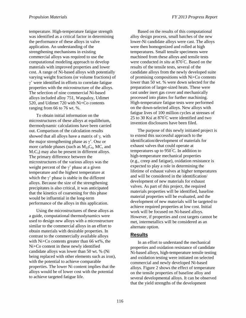
Propulsion Materials FY 2013 Progress Report
116
temperature. High-temperature fatigue strength
was identified as a critical factor in determining
the performance of these alloys in valve
application. An understanding of the
strengthening mechanisms in existing
commercial alloys was required to use the
computational modeling approach to develop
materials with improved properties and lower
cost. A range of Ni-based alloys with potentially
varying weight fractions (or volume fractions) of
’ were identified in efforts to correlate fatigue
properties with the microstructure of the alloys.
The selection of nine commercial Ni-based
alloys included alloy 751, Waspaloy, Udimet
520, and Udimet 720 with Ni+Co contents
ranging from 66 to 76 wt. %.
To obtain initial information on the
microstructures of these alloys at equilibrium,
thermodynamic calculations have been carried
out. Comparison of the calculation results
showed that all alloys have a matrix of with
the major strengthening phase as ’. One or
more carbide phases (such as M23C6, MC, and
M7C3) may also be present in different alloys.
The primary difference between the
microstructures of the various alloys was the
weight percent of the ’ phase at a given
temperature and the highest temperature at
which the ’ phase is stable in the different
alloys. Because the size of the strengthening
precipitates is also critical, it was anticipated
that the kinetics of coarsening for this phase
would be influential in the long-term
performance of the alloys in this application.
Using the microstructures of these alloys as
a guide, computational thermodynamics were
used to design new alloys with a microstructure
similar to the commercial alloys in an effort to
obtain materials with desirable properties. In
contrast to the commercially available alloys
with Ni+Co contents greater than 66 wt%, the
Ni+Co content in these newly identified
candidate alloys was lower than 50 wt. % (Ni
being replaced with other elements such as iron),
with the potential to achieve comparable
properties. The lower Ni content implies that the
alloys would be of lower cost with the potential
to achieve targeted fatigue life.
Based on the results of this computational
alloy design process, small batches of the new
lower-Ni candidate alloys were cast. The alloys
were then homogenized and rolled at high
temperatures. Small tensile specimens were
machined from these alloys and tensile tests
were conducted in situ at 870°C. Based on the
results of the tensile tests, several of the
candidate alloys from the newly developed suite
of promising compositions with Ni+Co contents
lower than 50 wt. % were down selected for the
preparation of larger-sized heats. These were
cast under inert gas cover and mechanically
processed into plates for further machining.
High-temperature fatigue tests were performed
on the down-selected alloys. New alloys with
fatigue lives of 100 million cycles at stresses of
25 to 30 Ksi at 870°C were identified and two
invention disclosures have been filed.
The purpose of this newly initiated project is
to extend this successful approach to the
identification/development of materials for
exhaust valves that could operate at
temperatures up to 950°C. In addition to
high-temperature mechanical properties
(e.g., creep and fatigue), oxidation resistance is
expected to play a role in determining the
lifetime of exhaust valves at higher temperatures
and will be considered in the identification/
development of new materials for exhaust
valves. As part of this project, the required
materials properties will be identified, baseline
material properties will be evaluated, and the
development of new materials will be targeted to
achieve required properties at low cost. Initial
work will be focused on Ni-based alloys.
However, if properties and cost targets cannot be
met, intermetallics will be considered as an
alternate option.
Results
In an effort to understand the mechanical
properties and oxidation resistance of candidate
Ni-based alloys, high-temperature tensile testing
and oxidation testing were initiated on selected
commercial and newly developed Ni-based
alloys. Figure 2 shows the effect of temperature
on the tensile properties of baseline alloy and
several developmental alloys. It can be observed
that the yield strengths of the development
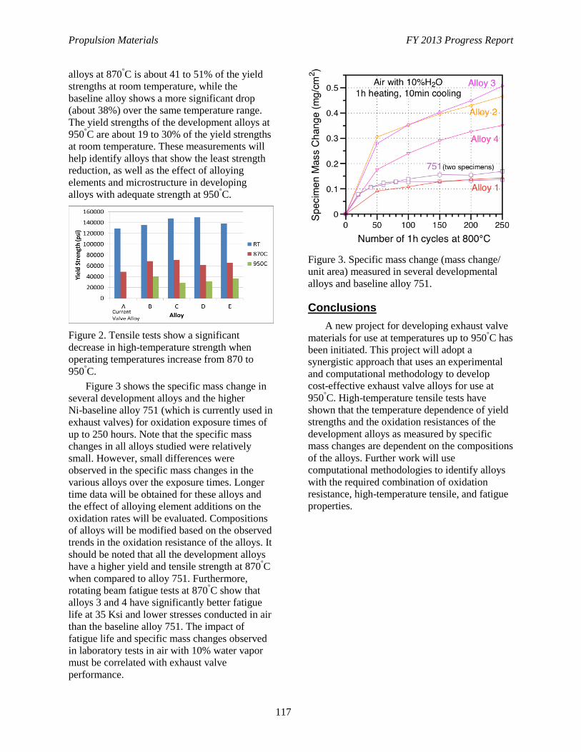
Propulsion Materials FY 2013 Progress Report
117
alloys at 870°C is about 41 to 51% of the yield
strengths at room temperature, while the
baseline alloy shows a more significant drop
(about 38%) over the same temperature range.
The yield strengths of the development alloys at
950°C are about 19 to 30% of the yield strengths
at room temperature. These measurements will
help identify alloys that show the least strength
reduction, as well as the effect of alloying
elements and microstructure in developing
alloys with adequate strength at 950°C.
Figure 2. Tensile tests show a significant
decrease in high-temperature strength when
operating temperatures increase from 870 to
950°C.
Figure 3 shows the specific mass change in
several development alloys and the higher
Ni-baseline alloy 751 (which is currently used in
exhaust valves) for oxidation exposure times of
up to 250 hours. Note that the specific mass
changes in all alloys studied were relatively
small. However, small differences were
observed in the specific mass changes in the
various alloys over the exposure times. Longer
time data will be obtained for these alloys and
the effect of alloying element additions on the
oxidation rates will be evaluated. Compositions
of alloys will be modified based on the observed
trends in the oxidation resistance of the alloys. It
should be noted that all the development alloys
have a higher yield and tensile strength at 870°C
when compared to alloy 751. Furthermore,
rotating beam fatigue tests at 870°C show that
alloys 3 and 4 have significantly better fatigue
life at 35 Ksi and lower stresses conducted in air
than the baseline alloy 751. The impact of
fatigue life and specific mass changes observed
in laboratory tests in air with 10% water vapor
must be correlated with exhaust valve
performance.
Figure 3. Specific mass change (mass change/
unit area) measured in several developmental
alloys and baseline alloy 751.
Conclusions
A new project for developing exhaust valve
materials for use at temperatures up to 950°C has
been initiated. This project will adopt a
synergistic approach that uses an experimental
and computational methodology to develop
cost-effective exhaust valve alloys for use at
950°C. High-temperature tensile tests have
shown that the temperature dependence of yield
strengths and the oxidation resistances of the
development alloys as measured by specific
mass changes are dependent on the compositions
of the alloys. Further work will use
computational methodologies to identify alloys
with the required combination of oxidation
resistance, high-temperature tensile, and fatigue
properties.

Propulsion Materials FY 2013 Progress Report
118
Project 18519 – Materials for Exhaust and Energy Recovery
Agreement 9130– Development of Materials Analysis Tools
for Studying NOx Adsorber Catalysts (CRADA with
Cummins Inc.)
Thomas R. Watkins, , Larry Allard, and Michael Lance
Oak Ridge National Laboratory
P.O. Box 2008, MS 6064
Oak Ridge, TN 37831-6068
Phone (865) 387-6472; fax: (865) 574-4913; e-mail: [email protected]
Krishna Kamasamudram and Aleksey Yezerets
Cummins Inc.
1900 McKinley Av., MC 50183
Columbus, IN 47201
Phone (812) 377-4935; fax: (812) 377-7226; e-mail: [email protected]
DOE Technology Manager: Jerry L. Gibbs
Phone (202) 586-1182; fax: (202) 586-1600; e-mail: [email protected]
ORNL Technical Advisor: J. Allen Haynes
Phone (865) 576-2894; fax: (865) 574-4913; e-mail: [email protected]
Contractor: Oak Ridge National Laboratory, Oak Ridge, Tennessee
Prime Contract No.: DE-AC05-00OR22725
Objectives
The objective of this effort is to produce a quantitative understanding of the process/product
interdependence leading to catalyst systems with improved final product quality, resulting in diesel
emission levels that meet the prevailing emission requirements.
Approach
Characterize lab-engine tested samples with x-ray diffraction, spectroscopy, and microscopy.
Correlate findings with Cummins, Inc. data and experience.
Accomplishments
Clusters of Pt atoms in pre-particle state were observed to form nanoparticles during hydrotreatment.
In-situ hydrothermal aging with HTXRD stage with gas-manifold system revealed catalyst is
structurally stable under modest temperatures and 2 to 4 v% water content atmosphere.
Future Direction
Quantify phases present in as-received and hydrothermally treated Cu-zeolite catalyst and quantify
the impact of hydrothermal aging temperature and time on the spatial distribution of copper species in
the Cu-zeolite and on platinum crystallite size and distribution.
Correlate the fundamental degradation mechanisms identified by Oak Ridge National Laboratory with
activity and selectivity in ammonia oxidation (evaluated at Cummins, Inc.) on select hydrothermally
treated ammonia oxidation catalysts.
Propulsion Materials FY 2013 Progress Report
119
Introduction
Commercial off-the-shelf aftertreatment
technologies are now available to meet the 2010
U.S. Environmental Protection Agency emission
requirements for diesel exhaust (40 CFR 86).
However, the performance of these technologies
and their integration with engine control systems
needs optimization. In particular, the catalytic
materials can change or age with exposure to
high temperatures and engine exhaust
conditions. Consequently, Cummins, Inc. is
working to understand the basic science
necessary to effectively utilize these catalyst
systems. Oak Ridge National Laboratory is
assisting with the materials characterization
effort. This report will focus on the study of
materials used in ammonia oxidation.
Urea is added to diesel exhaust to reduce
NOx to N2, as in selective catalytic reduction
(SCR). The ammonia reduces NOx to H2O and
N2.2 Excess ammonia is often needed, resulting
in NH3 escaping or “slip.” This slip is a concern
for sociability and environmental reasons.
Although not regulated, proactive steps are taken
to mitigate even small amounts of ammonia slip
by employing a selective oxidation catalyst.
Oxidation catalysts are usually present in
after treatment systems to oxidize ammonia that
is not being oxidized upstream by the SCR
catalysts. These oxidation catalysts ensure that
ammonia slip to ambient is minimal and are
referred to by several names: ammonia oxidation
(AMOX) catalysts, selective catalytic oxidation
catalysts, or ammonia slip catalysts. Candidate
catalysts are typically zeolite-based,
alumina-supported metal or alumina-supported
metal oxide catalysts. Hydrothermal conditions,
temperature, and water content strongly
influence the functioning of these catalysts by
changing or “aging” the catalytic materials.
These changes and their impact on performance
are not well understood.
Goals, Barriers, Relevance, and Integration
In the study area of the Vehicle
Technology’s Materials Technology
subprogram, the Propulsion Materials
Technology activity provides materials research
and development expertise to enable advanced
materials and supports the goals of several
Vehicle Technologies subprograms (EERE
2010). Within the Advanced Combustion Engine
research and development activity, one primary
research and development direction is to develop
aftertreatment technologies integrated with
combustion strategies for emissions compliance
and minimization of an efficiency penalty
(EERE 2010). Correspondingly, one goal is to,
by 2015, improve the fuel economy of light-duty
gasoline vehicles by 25% and of light-duty
diesel vehicles by 40%, compared to the
baseline 2009 gasoline vehicle. In support of
these, this project addresses four barriers related
to emission control (EERE 2010): lack of
cost-effective emission control, durability, cost
(e.g., precious metal content), and improving
market perception. This project is relevant to
this goal because as the understanding of the
material aging underlying AMOX catalyst
performance degradation increases, efficient and
durable AMOX with higher NOx conversion
efficiencies can be attained. This minimizes
constraints on engine-out NOx emissions and
allowing engines to be tuned for optimal fuel
efficiency, cost, and durability. This project
supports clean diesel, which increases
acceptance by the public. Larger acceptance, in
turn, results in larger percentages of conversion
to diesel, with the resulting reduction in
petroleum usage/dependency on foreign oil
(Hansen 2013, Ulrich 2013). Similarly, this
project also addresses three barriers related to
the Propulsion Materials Technology activity
itself (EERE 2010): changing internal
combustion engine combustion regimes, long
lead times for materials commercialization, and
costly precious metal content. This project is
integrated within the Vehicle Technologies
Office because it uses characterization tools
acquired and formerly maintained by the
High-Temperature Materials Laboratory
Program.
Approach
The main focus of the cooperative research
and development agreement in fiscal year 2013
was to continue characterization of a practically
relevant zeolite AMOX catalyst, which was
subjected to hydrothermal aging for lifetime
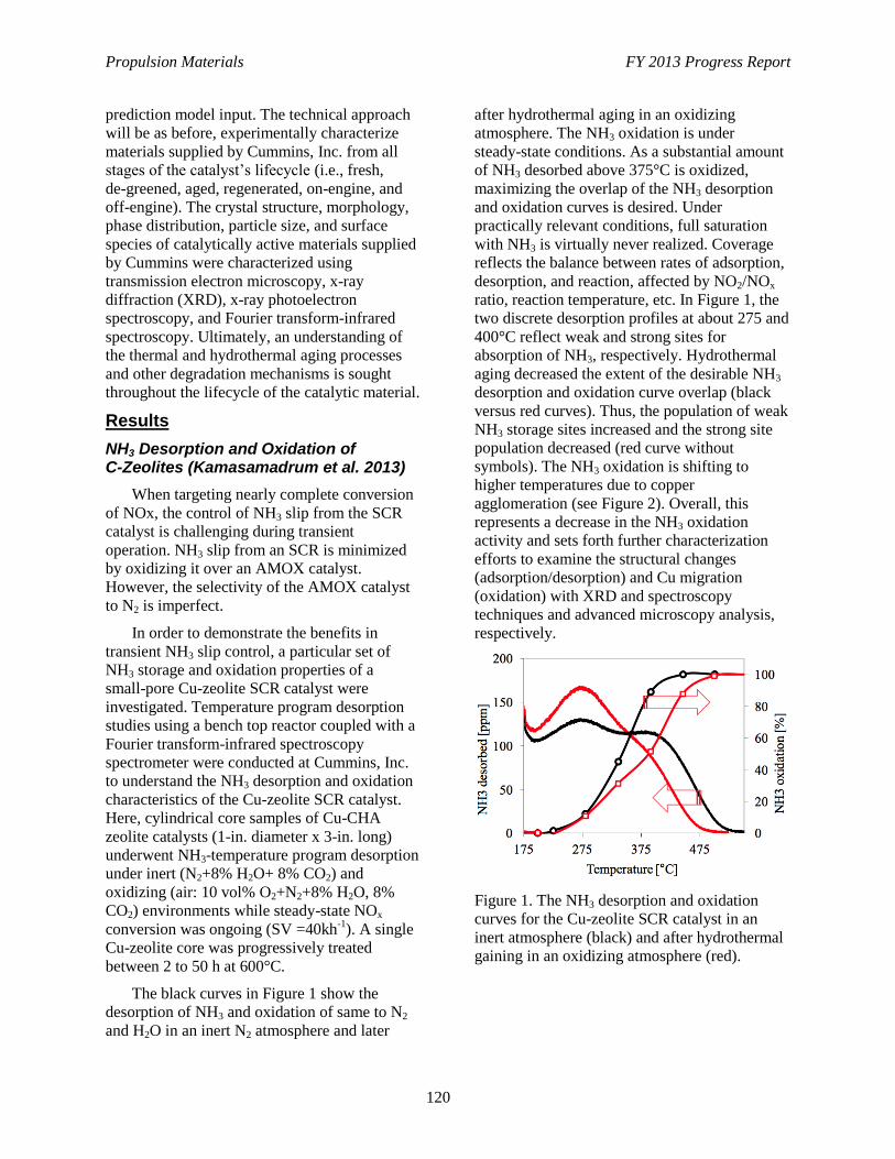
Propulsion Materials FY 2013 Progress Report
120
prediction model input. The technical approach
will be as before, experimentally characterize
materials supplied by Cummins, Inc. from all
stages of the catalyst’s lifecycle (i.e., fresh,
de-greened, aged, regenerated, on-engine, and
off-engine). The crystal structure, morphology,
phase distribution, particle size, and surface
species of catalytically active materials supplied
by Cummins were characterized using
transmission electron microscopy, x-ray
diffraction (XRD), x-ray photoelectron
spectroscopy, and Fourier transform-infrared
spectroscopy. Ultimately, an understanding of
the thermal and hydrothermal aging processes
and other degradation mechanisms is sought
throughout the lifecycle of the catalytic material.
Results
NH3 Desorption and Oxidation of C-Zeolites (Kamasamadrum et al. 2013)
When targeting nearly complete conversion
of NOx, the control of NH3 slip from the SCR
catalyst is challenging during transient
operation. NH3 slip from an SCR is minimized
by oxidizing it over an AMOX catalyst.
However, the selectivity of the AMOX catalyst
to N2 is imperfect.
In order to demonstrate the benefits in
transient NH3 slip control, a particular set of
NH3 storage and oxidation properties of a
small-pore Cu-zeolite SCR catalyst were
investigated. Temperature program desorption
studies using a bench top reactor coupled with a
Fourier transform-infrared spectroscopy
spectrometer were conducted at Cummins, Inc.
to understand the NH3 desorption and oxidation
characteristics of the Cu-zeolite SCR catalyst.
Here, cylindrical core samples of Cu-CHA
zeolite catalysts (1-in. diameter x 3-in. long)
underwent NH3-temperature program desorption
under inert (N2+8% H2O+ 8% CO2) and
oxidizing (air: 10 vol% O2+N2+8% H2O, 8%
CO2) environments while steady-state NOx
conversion was ongoing (SV =40kh-1
). A single
Cu-zeolite core was progressively treated
between 2 to 50 h at 600°C.
The black curves in Figure 1 show the
desorption of NH3 and oxidation of same to N2
and H2O in an inert N2 atmosphere and later
after hydrothermal aging in an oxidizing
atmosphere. The NH3 oxidation is under
steady-state conditions. As a substantial amount
of NH3 desorbed above 375°C is oxidized,
maximizing the overlap of the NH3 desorption
and oxidation curves is desired. Under
practically relevant conditions, full saturation
with NH3 is virtually never realized. Coverage
reflects the balance between rates of adsorption,
desorption, and reaction, affected by NO2/NOx
ratio, reaction temperature, etc. In Figure 1, the
two discrete desorption profiles at about 275 and
400°C reflect weak and strong sites for
absorption of NH3, respectively. Hydrothermal
aging decreased the extent of the desirable NH3
desorption and oxidation curve overlap (black
versus red curves). Thus, the population of weak
NH3 storage sites increased and the strong site
population decreased (red curve without
symbols). The NH3 oxidation is shifting to
higher temperatures due to copper
agglomeration (see Figure 2). Overall, this
represents a decrease in the NH3 oxidation
activity and sets forth further characterization
efforts to examine the structural changes
(adsorption/desorption) and Cu migration
(oxidation) with XRD and spectroscopy
techniques and advanced microscopy analysis,
respectively.
Figure 1. The NH3 desorption and oxidation
curves for the Cu-zeolite SCR catalyst in an
inert atmosphere (black) and after hydrothermal
gaining in an oxidizing atmosphere (red).
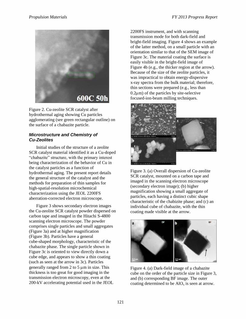
Propulsion Materials FY 2013 Progress Report
121
Figure 2. Cu-zeolite SCR catalyst after
hydrothermal aging showing Cu particles
agglomerating (see green rectangular outline) on
the surface of a chabazite particle.
Microstructure and Chemistry of Cu-Zeolites
Initial studies of the structure of a zeolite
SCR catalyst material identified it as a Cu-doped
“chabazite” structure, with the primary interest
being characterization of the behavior of Cu in
the catalyst particles as a function of
hydrothermal aging. The present report details
the general structure of the catalyst and the
methods for preparation of thin samples for
high-spatial-resolution microchemical
characterization using the JEOL 2200FS
aberration-corrected electron microscope.
Figure 3 shows secondary electron images
the Cu-zeolite SCR catalyst powder dispersed on
carbon tape and imaged in the Hitachi S-4800
scanning electron microscope. The powder
comprises single particles and small aggregates
(Figure 3a) and at higher magnification
(Figure 3b). Particles have a general
cube-shaped morphology, characteristic of the
chabazite phase. The single particle shown in
Figure 3c is oriented to view directly down a
cube edge, and appears to show a thin coating
(such as seen at the arrow in 3c). Particles
generally ranged from 2 to 5 m in size. This
thickness is too great for good imaging in the
transmission electron microscopy, even at the
200-kV accelerating potential used in the JEOL
2200FS instrument, and with scanning
transmission mode for both dark-field and
bright-field imaging. Figure 4 shows an example
of the latter method, on a small particle with an
orientation similar to that of the SEM image of
Figure 3c. The material coating the surface is
easily visible in the bright-field image of
Figure 4b (e.g., the thicker region at the arrow).
Because of the size of the zeolite particles, it
was impractical to obtain energy-dispersive
x-ray spectra from the bulk material; therefore,
thin sections were prepared (e.g., less than
0.2m) of the particles by site-selective
focused-ion-beam milling techniques.
Figure 3. (a) Overall dispersion of Cu-zeolite
SCR catalyst, mounted on a carbon tape and
imaged in the scanning electron microscope
(secondary electron image); (b) higher
magnification showing a small aggregate of
particles, each having a distinct cubic shape
characteristic of the chabizite phase; and (c) an
individual cube of chabazite, with the thin
coating made visible at the arrow.
Figure 4. (a) Dark-field image of a chabazite
cube on the order of the particle size in Figure 3,
and (b) corresponding BF image. The outer
coating determined to be AlOx is seen at arrow.
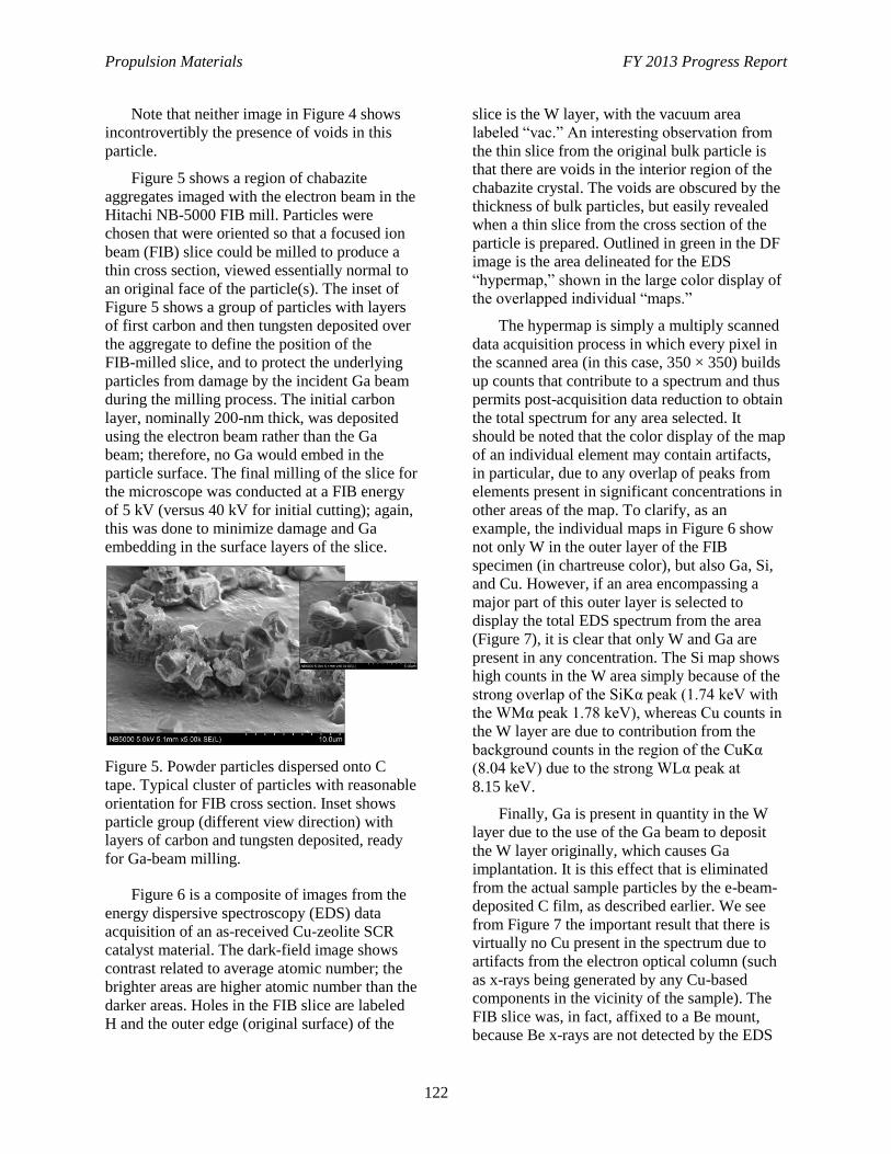
Propulsion Materials FY 2013 Progress Report
122
Note that neither image in Figure 4 shows
incontrovertibly the presence of voids in this
particle.
Figure 5 shows a region of chabazite
aggregates imaged with the electron beam in the
Hitachi NB-5000 FIB mill. Particles were
chosen that were oriented so that a focused ion
beam (FIB) slice could be milled to produce a
thin cross section, viewed essentially normal to
an original face of the particle(s). The inset of
Figure 5 shows a group of particles with layers
of first carbon and then tungsten deposited over
the aggregate to define the position of the
FIB-milled slice, and to protect the underlying
particles from damage by the incident Ga beam
during the milling process. The initial carbon
layer, nominally 200-nm thick, was deposited
using the electron beam rather than the Ga
beam; therefore, no Ga would embed in the
particle surface. The final milling of the slice for
the microscope was conducted at a FIB energy
of 5 kV (versus 40 kV for initial cutting); again,
this was done to minimize damage and Ga
embedding in the surface layers of the slice.
Figure 5. Powder particles dispersed onto C
tape. Typical cluster of particles with reasonable
orientation for FIB cross section. Inset shows
particle group (different view direction) with
layers of carbon and tungsten deposited, ready
for Ga-beam milling.
Figure 6 is a composite of images from the
energy dispersive spectroscopy (EDS) data
acquisition of an as-received Cu-zeolite SCR
catalyst material. The dark-field image shows
contrast related to average atomic number; the
brighter areas are higher atomic number than the
darker areas. Holes in the FIB slice are labeled
H and the outer edge (original surface) of the
slice is the W layer, with the vacuum area
labeled “vac.” An interesting observation from
the thin slice from the original bulk particle is
that there are voids in the interior region of the
chabazite crystal. The voids are obscured by the
thickness of bulk particles, but easily revealed
when a thin slice from the cross section of the
particle is prepared. Outlined in green in the DF
image is the area delineated for the EDS
“hypermap,” shown in the large color display of
the overlapped individual “maps.”
The hypermap is simply a multiply scanned
data acquisition process in which every pixel in
the scanned area (in this case, 350 × 350) builds
up counts that contribute to a spectrum and thus
permits post-acquisition data reduction to obtain
the total spectrum for any area selected. It
should be noted that the color display of the map
of an individual element may contain artifacts,
in particular, due to any overlap of peaks from
elements present in significant concentrations in
other areas of the map. To clarify, as an
example, the individual maps in Figure 6 show
not only W in the outer layer of the FIB
specimen (in chartreuse color), but also Ga, Si,
and Cu. However, if an area encompassing a
major part of this outer layer is selected to
display the total EDS spectrum from the area
(Figure 7), it is clear that only W and Ga are
present in any concentration. The Si map shows
high counts in the W area simply because of the
strong overlap of the SiKα peak (1.74 keV with
the WMα peak 1.78 keV), whereas Cu counts in
the W layer are due to contribution from the
background counts in the region of the CuKα
(8.04 keV) due to the strong WLα peak at
8.15 keV.
Finally, Ga is present in quantity in the W
layer due to the use of the Ga beam to deposit
the W layer originally, which causes Ga
implantation. It is this effect that is eliminated
from the actual sample particles by the e-beam-
deposited C film, as described earlier. We see
from Figure 7 the important result that there is
virtually no Cu present in the spectrum due to
artifacts from the electron optical column (such
as x-rays being generated by any Cu-based
components in the vicinity of the sample). The
FIB slice was, in fact, affixed to a Be mount,
because Be x-rays are not detected by the EDS
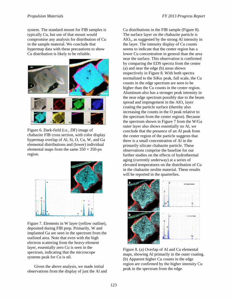
Propulsion Materials FY 2013 Progress Report
123
system. The standard mount for FIB samples is
typically Cu, but use of that mount would
compromise any analysis for distribution of Cu
in the sample material. We conclude that
hypermap data with these precautions to show
Cu distribution is likely to be reliable.
Figure 6. Dark-field (i.e., DF) image of
chabazite FIB cross section, with color display
hypermap overlap of Al, Si, O, Cu, W, and Ga
elemental distributions and (lower) individual
elemental maps from the same 350 × 350-px
region.
Figure 7. Elements in W layer (yellow outline),
deposited during FIB prep. Primarily, W and
implanted Ga are seen in the spectrum from the
outlined area. Note that even with the high
electron scattering from the heavy-element
layer, essentially zero Cu is seen in the
spectrum, indicating that the microscope
systems peak for Cu is nil.
Given the above analysis, we made initial
observations from the display of just the Al and
Cu distributions in the FIB sample (Figure 8).
The surface layer on the chabazite particle is
AlOx, as suggested by the strong Al intensity in
the layer. The intensity display of Cu counts
seems to indicate that the center region has a
lower Cu concentration in general than the area
near the surface. This observation is confirmed
by comparing the EDS spectra from the center
(a) and near the edge (b) areas shown
respectively in Figure 8. With both spectra
normalized to the SiK peak, full scale, the Cu
counts in the edge spectrum are seen to be
higher than the Cu counts in the center region.
Aluminum also has a stronger peak intensity in
the near edge spectrum possibly due to the beam
spread and impingement in the AlOx layer
coating the particle surface (thereby also
increasing the counts in the O peak relative to
the spectrum from the center region). Because
the spectrum shown in Figure 7 from the W/Ga
outer layer also shows essentially no Al, we
conclude that the presence of an Al peak from
the center region of the particle suggests that
there is a small concentration of Al in the
primarily silicate chabazite particle. These
observations comprise the baseline for our
further studies on the effects of hydrothermal
aging (currently underway) at a series of
elevated temperatures on the distribution of Cu
in the chabazite zeolite material. These results
will be reported in the quarterlies.
Figure 8. (a) Overlap of Al and Cu elemental
maps, showing Al primarily in the outer coating.
(b) Apparent higher Cu counts in the edge
region are confirmed by the higher intensity Cu
peak in the spectrum from the edge.
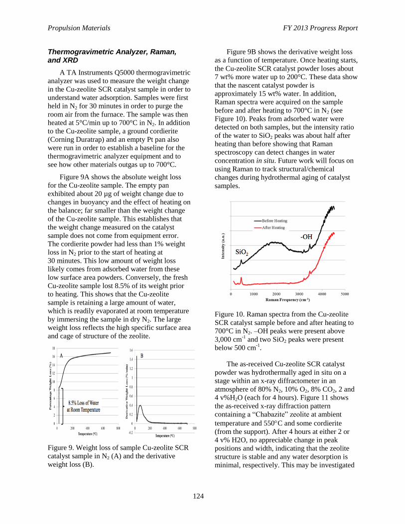
Propulsion Materials FY 2013 Progress Report
124
Thermogravimetric Analyzer, Raman, and XRD
A TA Instruments Q5000 thermogravimetric
analyzer was used to measure the weight change
in the Cu-zeolite SCR catalyst sample in order to
understand water adsorption. Samples were first
held in N2 for 30 minutes in order to purge the
room air from the furnace. The sample was then
heated at 5°C/min up to 700°C in N2. In addition
to the Cu-zeolite sample, a ground cordierite
(Corning Duratrap) and an empty Pt pan also
were run in order to establish a baseline for the
thermogravimetric analyzer equipment and to
see how other materials outgas up to 700°C.
Figure 9A shows the absolute weight loss
for the Cu-zeolite sample. The empty pan
exhibited about 20 µg of weight change due to
changes in buoyancy and the effect of heating on
the balance; far smaller than the weight change
of the Cu-zeolite sample. This establishes that
the weight change measured on the catalyst
sample does not come from equipment error.
The cordierite powder had less than 1% weight
loss in N2 prior to the start of heating at
30 minutes. This low amount of weight loss
likely comes from adsorbed water from these
low surface area powders. Conversely, the fresh
Cu-zeolite sample lost 8.5% of its weight prior
to heating. This shows that the Cu-zeolite
sample is retaining a large amount of water,
which is readily evaporated at room temperature
by immersing the sample in dry N2. The large
weight loss reflects the high specific surface area
and cage of structure of the zeolite.
Figure 9. Weight loss of sample Cu-zeolite SCR
catalyst sample in N2 (A) and the derivative
weight loss (B).
Figure 9B shows the derivative weight loss
as a function of temperature. Once heating starts,
the Cu-zeolite SCR catalyst powder loses about
7 wt% more water up to 200°C. These data show
that the nascent catalyst powder is
approximately 15 wt% water. In addition,
Raman spectra were acquired on the sample
before and after heating to 700°C in N2 (see
Figure 10). Peaks from adsorbed water were
detected on both samples, but the intensity ratio
of the water to SiO2 peaks was about half after
heating than before showing that Raman
spectroscopy can detect changes in water
concentration in situ. Future work will focus on
using Raman to track structural/chemical
changes during hydrothermal aging of catalyst
samples.
Figure 10. Raman spectra from the Cu-zeolite
SCR catalyst sample before and after heating to
700°C in N2. –OH peaks were present above
3,000 cm-1
and two SiO2 peaks were present
below 500 cm-1
.
The as-received Cu-zeolite SCR catalyst
powder was hydrothermally aged in situ on a
stage within an x-ray diffractometer in an
atmosphere of 80% N2, 10% O2, 8% CO2, 2 and
4 v%H2O (each for 4 hours). Figure 11 shows
the as-received x-ray diffraction pattern
containing a “Chabazite” zeolite at ambient
temperature and 550C and some cordierite
(from the support). After 4 hours at either 2 or
4 v% H2O, no appreciable change in peak
positions and width, indicating that the zeolite
structure is stable and any water desorption is
minimal, respectively. This may be investigated
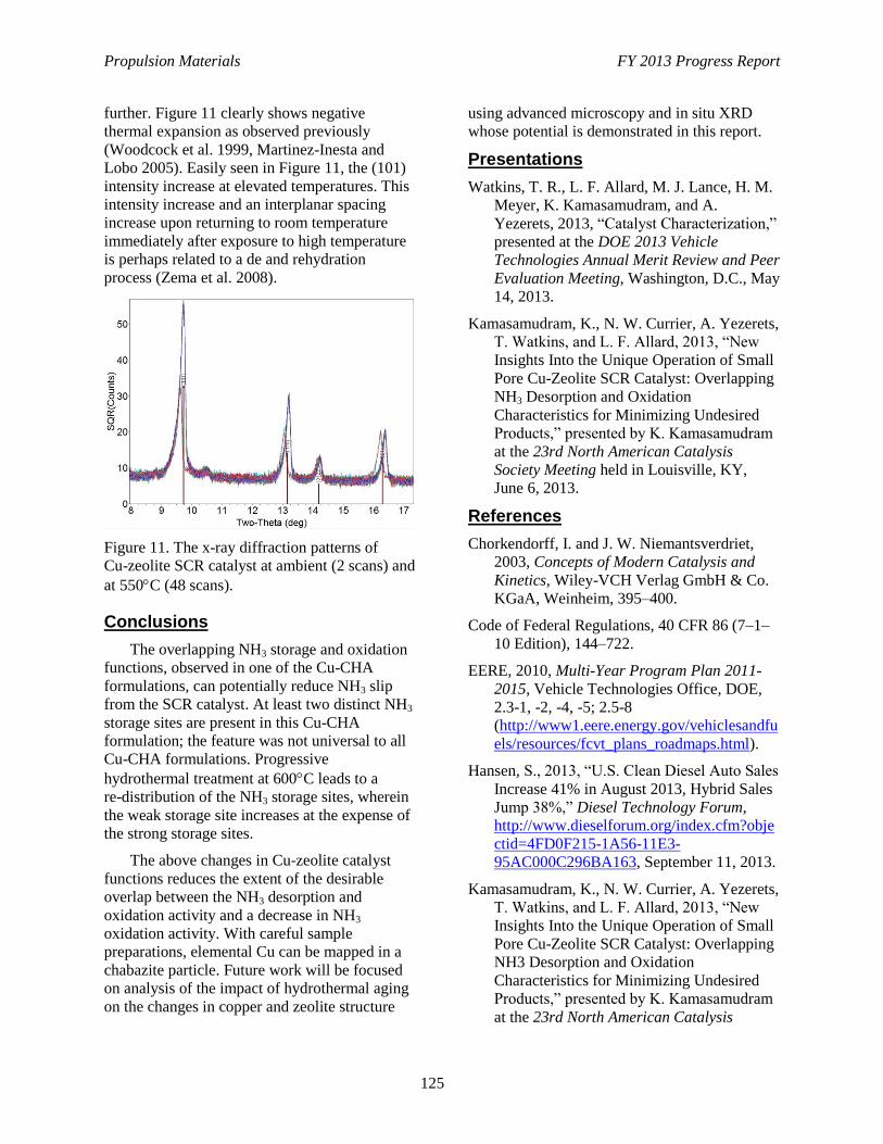
Propulsion Materials FY 2013 Progress Report
125
further. Figure 11 clearly shows negative
thermal expansion as observed previously
(Woodcock et al. 1999, Martinez-Inesta and
Lobo 2005). Easily seen in Figure 11, the (101)
intensity increase at elevated temperatures. This
intensity increase and an interplanar spacing
increase upon returning to room temperature
immediately after exposure to high temperature
is perhaps related to a de and rehydration
process (Zema et al. 2008).
Figure 11. The x-ray diffraction patterns of
Cu-zeolite SCR catalyst at ambient (2 scans) and
at 550C (48 scans).
Conclusions
The overlapping NH3 storage and oxidation
functions, observed in one of the Cu-CHA
formulations, can potentially reduce NH3 slip
from the SCR catalyst. At least two distinct NH3
storage sites are present in this Cu-CHA
formulation; the feature was not universal to all
Cu-CHA formulations. Progressive
hydrothermal treatment at 600C leads to a
re-distribution of the NH3 storage sites, wherein
the weak storage site increases at the expense of
the strong storage sites.
The above changes in Cu-zeolite catalyst
functions reduces the extent of the desirable
overlap between the NH3 desorption and
oxidation activity and a decrease in NH3
oxidation activity. With careful sample
preparations, elemental Cu can be mapped in a
chabazite particle. Future work will be focused
on analysis of the impact of hydrothermal aging
on the changes in copper and zeolite structure
using advanced microscopy and in situ XRD
whose potential is demonstrated in this report.
Presentations
Watkins, T. R., L. F. Allard, M. J. Lance, H. M.
Meyer, K. Kamasamudram, and A.
Yezerets, 2013, “Catalyst Characterization,”
presented at the DOE 2013 Vehicle
Technologies Annual Merit Review and Peer
Evaluation Meeting, Washington, D.C., May
14, 2013.
Kamasamudram, K., N. W. Currier, A. Yezerets,
T. Watkins, and L. F. Allard, 2013, “New
Insights Into the Unique Operation of Small
Pore Cu-Zeolite SCR Catalyst: Overlapping
NH3 Desorption and Oxidation
Characteristics for Minimizing Undesired
Products,” presented by K. Kamasamudram
at the 23rd North American Catalysis
Society Meeting held in Louisville, KY,
June 6, 2013.
References
Chorkendorff, I. and J. W. Niemantsverdriet,
2003, Concepts of Modern Catalysis and
Kinetics, Wiley-VCH Verlag GmbH & Co.
KGaA, Weinheim, 395–400.
Code of Federal Regulations, 40 CFR 86 (7–1–
10 Edition), 144–722.
EERE, 2010, Multi-Year Program Plan 2011-
2015, Vehicle Technologies Office, DOE,
2.3-1, -2, -4, -5; 2.5-8
(http://www1.eere.energy.gov/vehiclesandfu
els/resources/fcvt_plans_roadmaps.html).
Hansen, S., 2013, “U.S. Clean Diesel Auto Sales
Increase 41% in August 2013, Hybrid Sales
Jump 38%,” Diesel Technology Forum,
http://www.dieselforum.org/index.cfm?obje
ctid=4FD0F215-1A56-11E3-
95AC000C296BA163, September 11, 2013.
Kamasamudram, K., N. W. Currier, A. Yezerets,
T. Watkins, and L. F. Allard, 2013, “New
Insights Into the Unique Operation of Small
Pore Cu-Zeolite SCR Catalyst: Overlapping
NH3 Desorption and Oxidation
Characteristics for Minimizing Undesired
Products,” presented by K. Kamasamudram
at the 23rd North American Catalysis
Propulsion Materials FY 2013 Progress Report
126
Society Meeting held in Louisville, KY,
June 6, 2013.
Martínez-Iñesta M. M. and R. F. Lobo, 2005,
“Investigation of the Negative Thermal
Expansion Mechanism of Zeolite Chabazite
Using the Pair Distribution Function
Method,” J. Phys. Chem. B, 109, 9389.
Ulrich, L., 2013, “Fossil-Fuel Mileage Champ,”
New York Times,
http://www.nytimes.com/2013/07/21/autom
obiles/autoreviews/fossil-fuel-mileage-
champ.html?_r=0&pagewanted=all, July 9,
2013.
Woodcock D. A. et al., 1999, “Negative
Thermal Expansion in the Siliceous Zeolites
Chabazite and ITQ-4: A Neutron Powder
Diffraction Study,” Chem. Mater., 11, 2508.
Zema, M. et al., 2008, “Hydration/Dehydration
and Cation Migration Processes at High
Temperature in Zeolite Chabazite,” Chem.
Mater., 20, 5876.
Propulsion Materials FY 2013 Progress Report
127
Project 18519 – Materials for Exhaust and Energy Recovery
Agreement 10461 – Durability of Diesel Particulate Filters
(CRADA with Cummins, Inc.)
Thomas R. Watkins, Amit Shyam, Amit Pandey, and Hua-Tay Lin
Oak Ridge National Laboratory
P.O. Box 2008, MS 6064
Oak Ridge, TN 37831-6068
Phone (865) 387-6472; fax: (865) 574-3940; e-mail: [email protected]
Randall J. Stafford
Cummins, Inc.
1900 McKinley Av., MC 50183
Columbus, IN 47201
Phone (812) 377-3279; fax: (812) 377-7050; e-mail: [email protected]
DOE Technology Manager: Jerry L. Gibbs
Phone (202) 586-1182; fax: (202) 586-1600; e-mail: [email protected]
ORNL Technical Advisor: J. Allen Haynes
Phone (865) 576-2894; fax: (865) 574-4913; e-mail: [email protected]
Contractor: Oak Ridge National Laboratory, Oak Ridge, Tennessee
Prime Contract No.: DE-AC05-00OR22725
Objectives
To identify and implement test techniques to characterize the physical and mechanical properties of
ceramic substrates used as diesel particulate filters (DPFs), to identify the mechanisms responsible for
the progressive thermo-mechanical degradation and resultant fracture of DPFs, and to develop
analyses and provide data for simulation tools for predicting the long-term reliability and durability
for the DPFs under engine operating conditions.
Approach
Application of advanced characterization techniques to DPF ceramic substrates.
Refinement of DPF service lifetime prediction models based on characterization of field-returned
filters.
Accomplishments
Determined the origins of the load-dependent Young’s moduli and quantify the impact of the
microstructure on the moduli.
Completed characterization of the dynamic and static fatigue response of silicon carbide (SiC) DPFs.
Future Direction
Investigate the loading and unloading response of select DPF materials in tension.
Initiate characterization of the dynamic and static fatigue response under the temperature ranges
relevant to the engine operating conditions of a fourth alternate substrate material.
Initiate the determination of strength, fracture toughness, density/porosity/microstructure, and thermal
expansion of a fourth alternate substrate material.
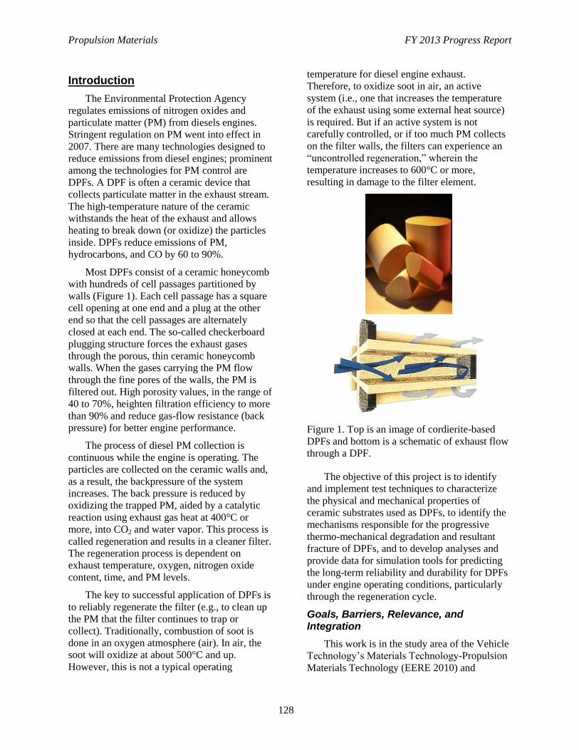
Propulsion Materials FY 2013 Progress Report
128
Introduction
The Environmental Protection Agency
regulates emissions of nitrogen oxides and
particulate matter (PM) from diesels engines.
Stringent regulation on PM went into effect in
2007. There are many technologies designed to
reduce emissions from diesel engines; prominent
among the technologies for PM control are
DPFs. A DPF is often a ceramic device that
collects particulate matter in the exhaust stream.
The high-temperature nature of the ceramic
withstands the heat of the exhaust and allows
heating to break down (or oxidize) the particles
inside. DPFs reduce emissions of PM,
hydrocarbons, and CO by 60 to 90%.
Most DPFs consist of a ceramic honeycomb
with hundreds of cell passages partitioned by
walls (Figure 1). Each cell passage has a square
cell opening at one end and a plug at the other
end so that the cell passages are alternately
closed at each end. The so-called checkerboard
plugging structure forces the exhaust gases
through the porous, thin ceramic honeycomb
walls. When the gases carrying the PM flow
through the fine pores of the walls, the PM is
filtered out. High porosity values, in the range of
40 to 70%, heighten filtration efficiency to more
than 90% and reduce gas-flow resistance (back
pressure) for better engine performance.
The process of diesel PM collection is
continuous while the engine is operating. The
particles are collected on the ceramic walls and,
as a result, the backpressure of the system
increases. The back pressure is reduced by
oxidizing the trapped PM, aided by a catalytic
reaction using exhaust gas heat at 400°C or
more, into CO2 and water vapor. This process is
called regeneration and results in a cleaner filter.
The regeneration process is dependent on
exhaust temperature, oxygen, nitrogen oxide
content, time, and PM levels.
The key to successful application of DPFs is
to reliably regenerate the filter (e.g., to clean up
the PM that the filter continues to trap or
collect). Traditionally, combustion of soot is
done in an oxygen atmosphere (air). In air, the
soot will oxidize at about 500°C and up.
However, this is not a typical operating
temperature for diesel engine exhaust.
Therefore, to oxidize soot in air, an active
system (i.e., one that increases the temperature
of the exhaust using some external heat source)
is required. But if an active system is not
carefully controlled, or if too much PM collects
on the filter walls, the filters can experience an
“uncontrolled regeneration,” wherein the
temperature increases to 600°C or more,
resulting in damage to the filter element.
Figure 1. Top is an image of cordierite-based
DPFs and bottom is a schematic of exhaust flow
through a DPF.
The objective of this project is to identify
and implement test techniques to characterize
the physical and mechanical properties of
ceramic substrates used as DPFs, to identify the
mechanisms responsible for the progressive
thermo-mechanical degradation and resultant
fracture of DPFs, and to develop analyses and
provide data for simulation tools for predicting
the long-term reliability and durability for DPFs
under engine operating conditions, particularly
through the regeneration cycle.
Goals, Barriers, Relevance, and Integration
This work is in the study area of the Vehicle
Technology’s Materials Technology-Propulsion
Materials Technology (EERE 2010) and
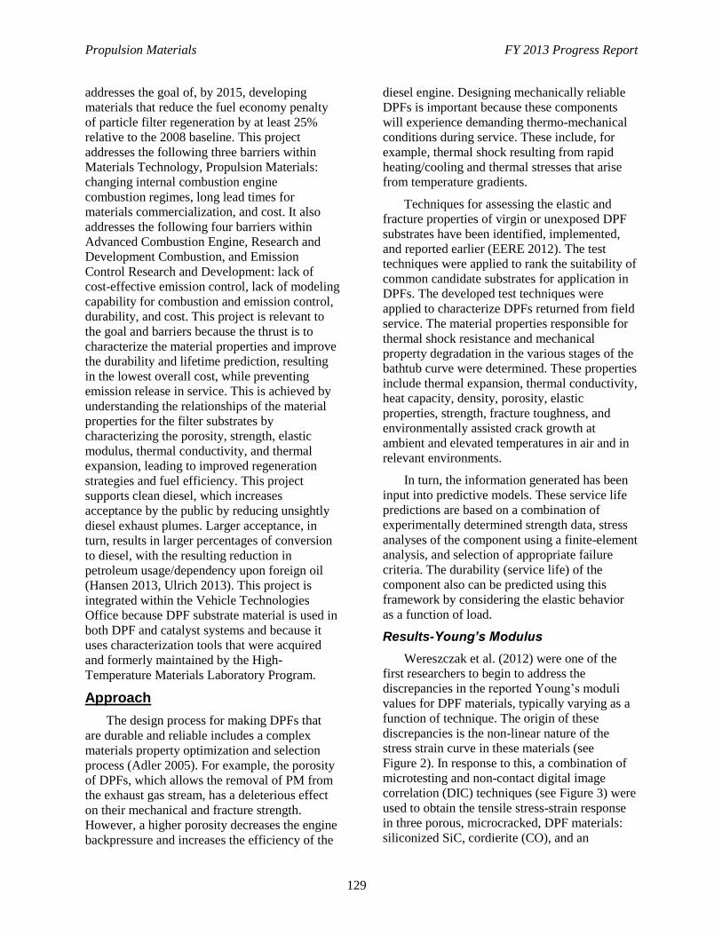
Propulsion Materials FY 2013 Progress Report
129
addresses the goal of, by 2015, developing
materials that reduce the fuel economy penalty
of particle filter regeneration by at least 25%
relative to the 2008 baseline. This project
addresses the following three barriers within
Materials Technology, Propulsion Materials:
changing internal combustion engine
combustion regimes, long lead times for
materials commercialization, and cost. It also
addresses the following four barriers within
Advanced Combustion Engine, Research and
Development Combustion, and Emission
Control Research and Development: lack of
cost-effective emission control, lack of modeling
capability for combustion and emission control,
durability, and cost. This project is relevant to
the goal and barriers because the thrust is to
characterize the material properties and improve
the durability and lifetime prediction, resulting
in the lowest overall cost, while preventing
emission release in service. This is achieved by
understanding the relationships of the material
properties for the filter substrates by
characterizing the porosity, strength, elastic
modulus, thermal conductivity, and thermal
expansion, leading to improved regeneration
strategies and fuel efficiency. This project
supports clean diesel, which increases
acceptance by the public by reducing unsightly
diesel exhaust plumes. Larger acceptance, in
turn, results in larger percentages of conversion
to diesel, with the resulting reduction in
petroleum usage/dependency upon foreign oil
(Hansen 2013, Ulrich 2013). This project is
integrated within the Vehicle Technologies
Office because DPF substrate material is used in
both DPF and catalyst systems and because it
uses characterization tools that were acquired
and formerly maintained by the High-
Temperature Materials Laboratory Program.
Approach
The design process for making DPFs that
are durable and reliable includes a complex
materials property optimization and selection
process (Adler 2005). For example, the porosity
of DPFs, which allows the removal of PM from
the exhaust gas stream, has a deleterious effect
on their mechanical and fracture strength.
However, a higher porosity decreases the engine
backpressure and increases the efficiency of the
diesel engine. Designing mechanically reliable
DPFs is important because these components
will experience demanding thermo-mechanical
conditions during service. These include, for
example, thermal shock resulting from rapid
heating/cooling and thermal stresses that arise
from temperature gradients.
Techniques for assessing the elastic and
fracture properties of virgin or unexposed DPF
substrates have been identified, implemented,
and reported earlier (EERE 2012). The test
techniques were applied to rank the suitability of
common candidate substrates for application in
DPFs. The developed test techniques were
applied to characterize DPFs returned from field
service. The material properties responsible for
thermal shock resistance and mechanical
property degradation in the various stages of the
bathtub curve were determined. These properties
include thermal expansion, thermal conductivity,
heat capacity, density, porosity, elastic
properties, strength, fracture toughness, and
environmentally assisted crack growth at
ambient and elevated temperatures in air and in
relevant environments.
In turn, the information generated has been
input into predictive models. These service life
predictions are based on a combination of
experimentally determined strength data, stress
analyses of the component using a finite-element
analysis, and selection of appropriate failure
criteria. The durability (service life) of the
component also can be predicted using this
framework by considering the elastic behavior
as a function of load.
Results-Young’s Modulus
Wereszczak et al. (2012) were one of the
first researchers to begin to address the
discrepancies in the reported Young’s moduli
values for DPF materials, typically varying as a
function of technique. The origin of these
discrepancies is the non-linear nature of the
stress strain curve in these materials (see
Figure 2). In response to this, a combination of
microtesting and non-contact digital image
correlation (DIC) techniques (see Figure 3) were
used to obtain the tensile stress-strain response
in three porous, microcracked, DPF materials:
siliconized SiC, cordierite (CO), and an
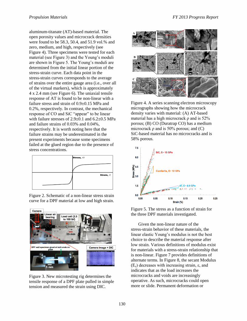
Propulsion Materials FY 2013 Progress Report
130
aluminum-titanate (AT)-based material. The
open porosity values and microcrack densities
were found to be 58.3, 50.4, and 51.9 vol.% and
zero, medium, and high, respectively (see
Figure 4). Three specimens were tested for each
material (see Figure 3) and the Young’s moduli
are shown in Figure 5. The Young’s moduli are
determined from the initial linear portion of the
stress-strain curve. Each data point in the
stress-strain curves corresponds to the average
of strains over the entire gauge area (i.e., over all
of the virtual markers), which is approximately
4 x 2.4 mm (see Figure 6). The uniaxial tensile
response of AT is found to be non-linear with a
failure stress and strain of 0.9±0.15 MPa and
0.2%, respectively. In contrast, the mechanical
response of CO and SiC “appear” to be linear
with failure stresses of 2.9±0.1 and 6.2±0.5 MPa
and failure strains of 0.03% and 0.04%,
respectively. It is worth noting here that the
failure strains may be underestimated in the
present experiments because some specimens
failed at the glued region due to the presence of
stress concentrations.
Figure 2. Schematic of a non-linear stress strain
curve for a DPF material at low and high strain.
Figure 3. New microtesting rig determines the
tensile response of a DPF plate pulled in simple
tension and measured the strain using DIC.
Figure 4. A series scanning electron microscopy
micrographs showing how the microcrack
density varies with material: (A) AT-based
material has a high microcrack ρ and is 52%
porous; (B) CO (Duratrap CO) has a medium
microcrack ρ and is 50% porous; and (C)
SiC-based material has no microcracks and is
58% porous.
Figure 5. The stress as a function of strain for
the three DPF materials investigated.
Given the non-linear nature of the
stress-strain behavior of these materials, the
linear elastic Young’s modulus is not the best
choice to describe the material response after
low strain. Various definitions of modulus exist
for materials with a stress-strain relationship that
is non-linear. Figure 7 provides definitions of
alternate terms. In Figure 8, the secant Modulus
(Es) decreases with increasing strain, ε, and
indicates that as the load increases the
microcracks and voids are increasingly
operative. As such, microcracks could open
more or slide. Permanent deformation or
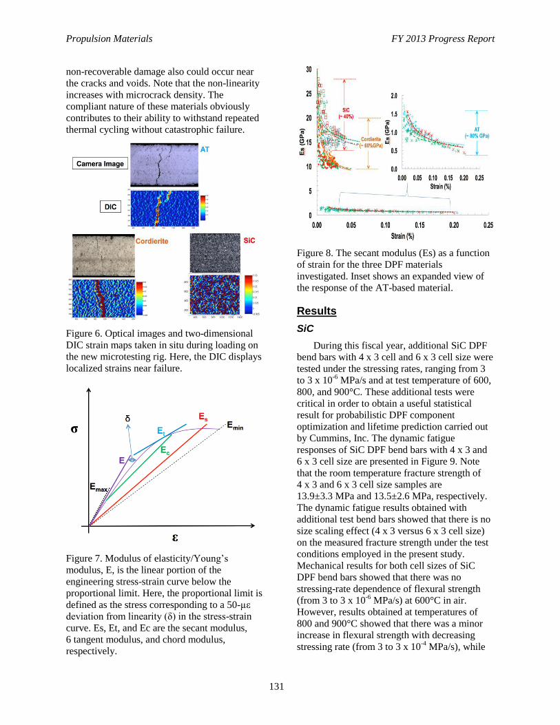
Propulsion Materials FY 2013 Progress Report
131
non-recoverable damage also could occur near
the cracks and voids. Note that the non-linearity
increases with microcrack density. The
compliant nature of these materials obviously
contributes to their ability to withstand repeated
thermal cycling without catastrophic failure.
Figure 6. Optical images and two-dimensional
DIC strain maps taken in situ during loading on
the new microtesting rig. Here, the DIC displays
localized strains near failure.
Figure 7. Modulus of elasticity/Young’s
modulus, E, is the linear portion of the
engineering stress-strain curve below the
proportional limit. Here, the proportional limit is
defined as the stress corresponding to a 50-µε
deviation from linearity (δ) in the stress-strain
curve. Es, Et, and Ec are the secant modulus,
6 tangent modulus, and chord modulus,
respectively.
Figure 8. The secant modulus (Es) as a function
of strain for the three DPF materials
investigated. Inset shows an expanded view of
the response of the AT-based material.
Results
SiC
During this fiscal year, additional SiC DPF
bend bars with 4 x 3 cell and 6 x 3 cell size were
tested under the stressing rates, ranging from 3
to 3 x 10⁻⁶
MPa/s and at test temperature of 600,
800, and 900°C. These additional tests were
critical in order to obtain a useful statistical
result for probabilistic DPF component
optimization and lifetime prediction carried out
by Cummins, Inc. The dynamic fatigue
responses of SiC DPF bend bars with 4 x 3 and
6 x 3 cell size are presented in Figure 9. Note
that the room temperature fracture strength of
4 x 3 and 6 x 3 cell size samples are
13.9±3.3 MPa and 13.5±2.6 MPa, respectively.
The dynamic fatigue results obtained with
additional test bend bars showed that there is no
size scaling effect (4 x 3 versus 6 x 3 cell size)
on the measured fracture strength under the test
conditions employed in the present study.
Mechanical results for both cell sizes of SiC
DPF bend bars showed that there was no
stressing-rate dependence of flexural strength
(from 3 to 3 x 10⁻⁶
MPa/s) at 600°C in air.
However, results obtained at temperatures of
800 and 900°C showed that there was a minor
increase in flexural strength with decreasing
stressing rate (from 3 to 3 x 10⁻⁴
MPa/s), while
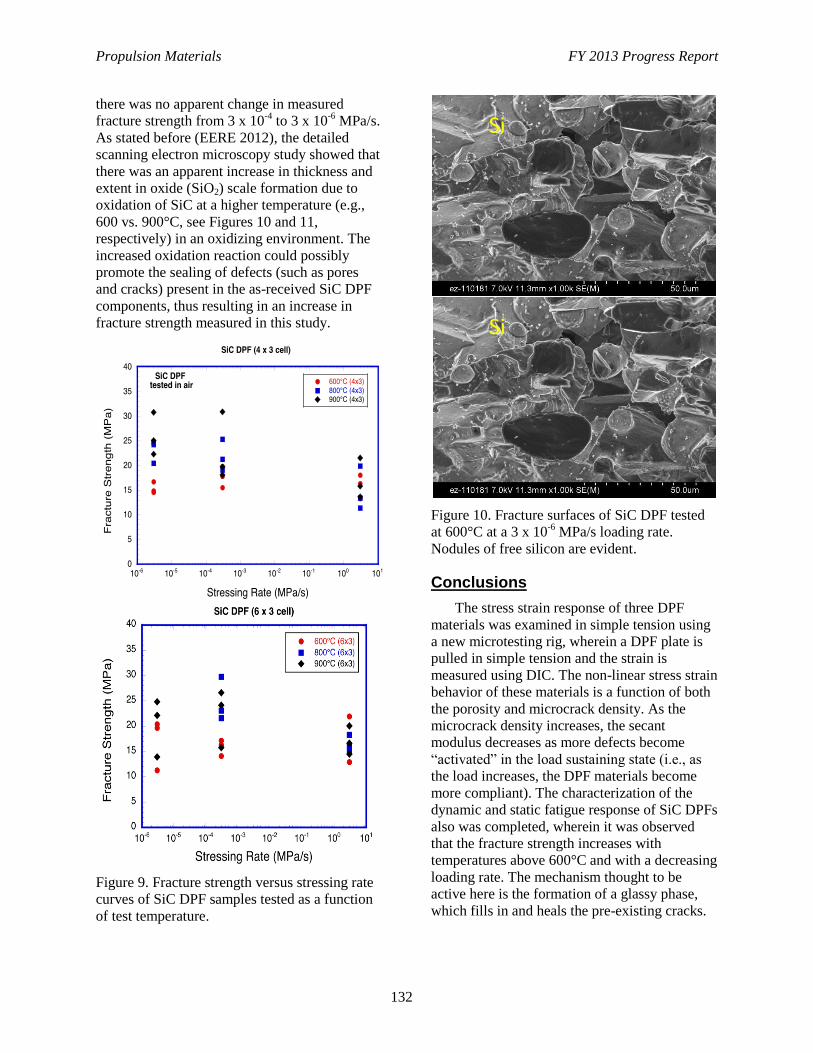
Propulsion Materials FY 2013 Progress Report
132
there was no apparent change in measured
fracture strength from 3 x 10⁻⁴
to 3 x 10⁻⁶
MPa/s.
As stated before (EERE 2012), the detailed
scanning electron microscopy study showed that
there was an apparent increase in thickness and
extent in oxide (SiO2) scale formation due to
oxidation of SiC at a higher temperature (e.g.,
600 vs. 900°C, see Figures 10 and 11,
respectively) in an oxidizing environment. The
increased oxidation reaction could possibly
promote the sealing of defects (such as pores
and cracks) present in the as-received SiC DPF
components, thus resulting in an increase in
fracture strength measured in this study.
Figure 9. Fracture strength versus stressing rate
curves of SiC DPF samples tested as a function
of test temperature.
Figure 10. Fracture surfaces of SiC DPF tested
at 600°C at a 3 x 10⁻⁶
MPa/s loading rate.
Nodules of free silicon are evident.
Conclusions
The stress strain response of three DPF
materials was examined in simple tension using
a new microtesting rig, wherein a DPF plate is
pulled in simple tension and the strain is
measured using DIC. The non-linear stress strain
behavior of these materials is a function of both
the porosity and microcrack density. As the
microcrack density increases, the secant
modulus decreases as more defects become
“activated” in the load sustaining state (i.e., as
the load increases, the DPF materials become
more compliant). The characterization of the
dynamic and static fatigue response of SiC DPFs
also was completed, wherein it was observed
that the fracture strength increases with
temperatures above 600°C and with a decreasing
loading rate. The mechanism thought to be
active here is the formation of a glassy phase,
which fills in and heals the pre-existing cracks.
Si
Si
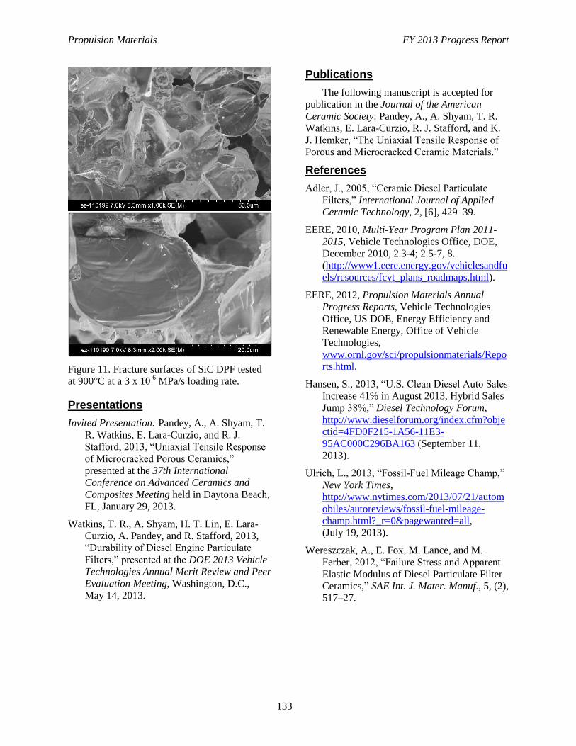
Propulsion Materials FY 2013 Progress Report
133
Figure 11. Fracture surfaces of SiC DPF tested
at 900°C at a 3 x 10⁻⁶
MPa/s loading rate.
Presentations
Invited Presentation: Pandey, A., A. Shyam, T.
R. Watkins, E. Lara-Curzio, and R. J.
Stafford, 2013, “Uniaxial Tensile Response
of Microcracked Porous Ceramics,”
presented at the 37th International
Conference on Advanced Ceramics and
Composites Meeting held in Daytona Beach,
FL, January 29, 2013.
Watkins, T. R., A. Shyam, H. T. Lin, E. Lara-
Curzio, A. Pandey, and R. Stafford, 2013,
“Durability of Diesel Engine Particulate
Filters,” presented at the DOE 2013 Vehicle
Technologies Annual Merit Review and Peer
Evaluation Meeting, Washington, D.C.,
May 14, 2013.
Publications
The following manuscript is accepted for
publication in the Journal of the American
Ceramic Society: Pandey, A., A. Shyam, T. R.
Watkins, E. Lara-Curzio, R. J. Stafford, and K.
J. Hemker, “The Uniaxial Tensile Response of
Porous and Microcracked Ceramic Materials.”
References
Adler, J., 2005, “Ceramic Diesel Particulate
Filters,” International Journal of Applied
Ceramic Technology, 2, [6], 429–39.
EERE, 2010, Multi-Year Program Plan 2011-
2015, Vehicle Technologies Office, DOE,
December 2010, 2.3-4; 2.5-7, 8.
(http://www1.eere.energy.gov/vehiclesandfu
els/resources/fcvt_plans_roadmaps.html).
EERE, 2012, Propulsion Materials Annual
Progress Reports, Vehicle Technologies
Office, US DOE, Energy Efficiency and
Renewable Energy, Office of Vehicle
Technologies,
www.ornl.gov/sci/propulsionmaterials/Repo
rts.html.
Hansen, S., 2013, “U.S. Clean Diesel Auto Sales
Increase 41% in August 2013, Hybrid Sales
Jump 38%,” Diesel Technology Forum,
http://www.dieselforum.org/index.cfm?obje
ctid=4FD0F215-1A56-11E3-
95AC000C296BA163 (September 11,
2013).
Ulrich, L., 2013, “Fossil-Fuel Mileage Champ,”
New York Times,
http://www.nytimes.com/2013/07/21/autom
obiles/autoreviews/fossil-fuel-mileage-
champ.html?_r=0&pagewanted=all,
(July 19, 2013).
Wereszczak, A., E. Fox, M. Lance, and M.
Ferber, 2012, “Failure Stress and Apparent
Elastic Modulus of Diesel Particulate Filter
Ceramics,” SAE Int. J. Mater. Manuf., 5, (2),
517–27.
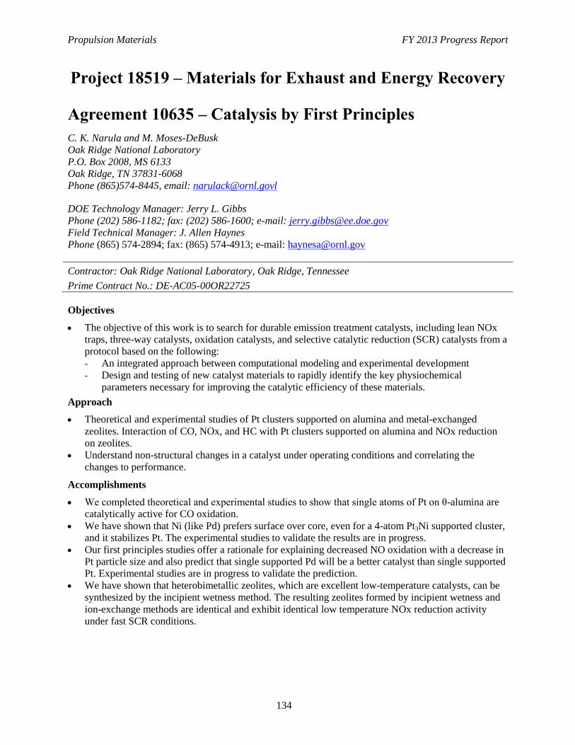
Propulsion Materials FY 2013 Progress Report
134
Project 18519 – Materials for Exhaust and Energy Recovery
Agreement 10635 – Catalysis by First Principles
C. K. Narula and M. Moses-DeBusk
Oak Ridge National Laboratory
P.O. Box 2008, MS 6133
Oak Ridge, TN 37831-6068
Phone (865)574-8445, email: [email protected]
DOE Technology Manager: Jerry L. Gibbs
Phone (202) 586-1182; fax: (202) 586-1600; e-mail: [email protected]
Field Technical Manager: J. Allen Haynes
Phone (865) 574-2894; fax: (865) 574-4913; e-mail: [email protected]
Contractor: Oak Ridge National Laboratory, Oak Ridge, Tennessee
Prime Contract No.: DE-AC05-00OR22725
Objectives
The objective of this work is to search for durable emission treatment catalysts, including lean NOx
traps, three-way catalysts, oxidation catalysts, and selective catalytic reduction (SCR) catalysts from a
protocol based on the following:
- An integrated approach between computational modeling and experimental development
- Design and testing of new catalyst materials to rapidly identify the key physiochemical
parameters necessary for improving the catalytic efficiency of these materials.
Approach
Theoretical and experimental studies of Pt clusters supported on alumina and metal-exchanged
zeolites. Interaction of CO, NOx, and HC with Pt clusters supported on alumina and NOx reduction
on zeolites.
Understand non-structural changes in a catalyst under operating conditions and correlating the
changes to performance.
Accomplishments
We completed theoretical and experimental studies to show that single atoms of Pt on θ-alumina are
catalytically active for CO oxidation.
We have shown that Ni (like Pd) prefers surface over core, even for a 4-atom Pt3Ni supported cluster,
and it stabilizes Pt. The experimental studies to validate the results are in progress.
Our first principles studies offer a rationale for explaining decreased NO oxidation with a decrease in
Pt particle size and also predict that single supported Pd will be a better catalyst than single supported
Pt. Experimental studies are in progress to validate the prediction.
We have shown that heterobimetallic zeolites, which are excellent low-temperature catalysts, can be
synthesized by the incipient wetness method. The resulting zeolites formed by incipient wetness and
ion-exchange methods are identical and exhibit identical low temperature NOx reduction activity
under fast SCR conditions.

Propulsion Materials FY 2013 Progress Report
135
Future Direction
Guided by our results, conduct synthesis and evaluation of new durable supported catalysts for lean
NOx catalysts and other systems (e.g., three-way catalysts and oxidation catalysts for diesel).
Focus on the low-temperature NOx catalyst that is effective, even under the standard NOx reduction
catalyst.
Scale up and preparation for engine testing of the CuFe-SSZ-13 catalyst as a low-temperature NOx
reduction catalyst for diesel engines.
Propulsion Materials FY 2013 Progress Report
136
Introduction
This research focuses on an integrated
approach between computational modeling and
experimental development, design, and testing
of new catalyst materials, which we believe will
rapidly identify the key physiochemical
parameters necessary for improving the catalytic
efficiency of these materials.
The typical solid catalyst consists of
nanoparticles on porous supports. The
development of new catalytic materials is still
dominated by trial and error methods, even
though the experimental and theoretical bases
for their characterization have improved
dramatically in recent years. Although it has
been successful, the empirical development of
catalytic materials is time consuming and
expensive and brings no guarantees of success.
Part of the difficulty is that most catalytic
materials are highly non-uniform and complex
and most characterization methods provide only
average structural data (Figure 1). Now, with
improved capabilities for synthesis of nearly
uniform catalysts, which offer the prospects of
high selectivity, combined with state-of-the
science characterization methods, we have a
compelling opportunity to markedly accelerate
the advancement of the science and technology
of catalysis.
Figure 1. Complexity of catalysis.
Computational approaches, on the other
hand, have been limited to examining processes
and phenomena using models that had been
greatly simplified in comparison to real
materials. This limitation was mainly a
consequence of limitations in computer
hardware and in the development of
sophisticated algorithms that are
computationally efficient. In particular,
experimental catalysis has not benefited from
the recent advances in high-performance
computing that enables more realistic
simulations (empirical and first-principles) of a
large ensemble of atoms, including the local
environment of a catalyst site in heterogeneous
catalysis. These types of simulations, when
combined with microscopic and spectroscopic
characterization of catalysts, can lead to a much
deeper understanding of the reaction chemistry
that is difficult to decipher from experimental
work alone.
Thus, a protocol to systematically find the
optimum catalyst can be developed that
combines the power of theory and experiments
for the atomistic design of catalytically active
sites and can translate the fundamental insights
gained from modeling directly to a complete
catalyst system that can be technically deployed.
Although it is computationally challenging,
the study of surface, nanometer-sized, metal
clusters may be accomplished by merging
state-of-the-art, density-functional-based,
electronic structure techniques and molecular
dynamic techniques. These techniques provide
accurate energetics, force, and electronic
information. Theoretical work must be based on
electronic-structure methods, opposed to more
empirical-based techniques; this provides
realistic energetics and direct electronic
information.
It is conceivable that “computationally
complex but experimentally simple” system can
be examined by both theoretical models and
experimental work to forecast improvements to
obtain optimum catalyst systems.
Approach
Theoretical modeling is based on DFT
studies of Pt group metals (i.e., Ni, Pd, and Pt)
supported on θ-alumina. The rationale for
choosing θ-alumina for the model is that the
distribution of platinum on γ-alumina and
θ-alumina and their CO oxidation activity is
identical. This led us to propose that Pt
TheoryTheory
StructureStructure
Fully
Formed
Catalyst
Fully
Formed
Catalyst
Com
ple
xity of cata
lysts
Ptx
OC, TWC,
LNT, SCR
etc.
CandidatesNew Catalyst
System
Rapid
Screening
TheoryTheory
StructureStructure
Fully
Formed
Catalyst
Fully
Formed
Catalyst
Com
ple
xity of cata
lysts
Ptx
OC, TWC,
LNT, SCR
etc.
CandidatesNew Catalyst
System
Rapid
Screening
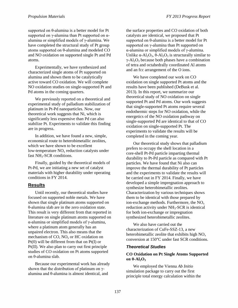
Propulsion Materials FY 2013 Progress Report
137
supported on θ-alumina is a better model for Pt
supported on γ-alumina than Pt supported on α-
alumina or simplified models of γ-alumina. We
have completed the structural study of Pt group
atoms supported on θ-alumina and modeled CO
and NO oxidation on supported single Pt and Pd
atoms.
Experimentally, we have synthesized and
characterized single atoms of Pt supported on
alumina and shown them to be catalytically
active toward CO oxidation. We will complete
NO oxidation studies on single-supported Pt and
Pd atoms in the coming quarters.
We previously reported on a theoretical and
experimental study of palladium stabilization of
platinum in Pt-Pd nanoparticles. Now, our
theoretical work suggests that Ni, which is
significantly less expensive than Pd can also
stabilize Pt. Experiments to validate this finding
are in progress.
In addition, we have found a new, simple,
economical route to heterobimetallic zeolites,
which we have shown to be excellent
low-temperature NOx reduction catalysts under
fast NH3-SCR conditions.
Finally, guided by the theoretical models of
Pt-Pd, we are initiating a new set of catalyst
materials with higher durability under operating
conditions in FY 2014.
Results
Until recently, our theoretical studies have
focused on supported noble metals. We have
shown that single platinum atoms supported on
θ-alumina slab are in the zero oxidation state.
This result is very different from that reported in
literature on single platinum atoms supported on
α-alumina or simplified models of γ-alumina,
where a platinum atom generally has an
unpaired electron. This also means that the
mechanism of CO, NOx or HC oxidation on
Pt(0) will be different from that on Pt(I) or
Pt(II). We also plan to carry out first principle
studies of CO oxidation on Pt atoms supported
on θ-alumina slab.
Because our experimental work has already
shown that the distribution of platinum on γ-
alumina and θ-alumina is almost identical, and
the surface properties and CO oxidation of both
catalysts are identical, we proposed that Pt
supported on θ-alumina is a better model for Pt
supported on γ-alumina than Pt supported on
α-alumina or simplified models of γ-alumina.
Unlike α-Al2O3, θ-Al2O3 is structurally similar to
γ-Al2O3 because both phases have a combination
of tetra and octahedrally coordinated Al atoms
and an fcc arrangement of the O ions.
We have completed our work on CO
oxidation on single supported Pt atoms and the
results have been published (DeBusk et al.
2013). In this report, we summarize our
theoretical study of NO oxidation on single
supported Pt and Pd atoms. Our work suggests
that single-supported Pt atoms require several
endothermic steps for NO oxidation, while the
energetics of the NO oxidation pathway on
single-supported Pd are identical to that of CO
oxidation on single-supported Pt. The
experiments to validate the results will be
completed in the coming year.
Our theoretical study shows that palladium
prefers to occupy the shell location in a
core-shell Pt-Pd particle imparting thermal
durability to Pt-Pd particle as compared with Pt
particles. We have found that Ni also can
improve the thermal durability of Pt particles
and the experiments to validate the results will
be carried out in FY 2014. Finally, we have
developed a simple impregnation approach to
synthesize heterobimetallic zeolites.
Characterization by various techniques shows
them to be identical with those prepared by
ion-exchange methods. Furthermore, the NOx
reduction activity under NH3-SCR is identical
for both ion-exchange or impregnation
synthesized heterobimetallic zeolites.
We also have carried out the
characterization of CuFe-SSZ-13, a new
heterobimetallic zeolite that exhibits high NOx
conversion at 150°C under fast SCR conditions.
Theoretical Studies
CO Oxidation on Pt Single Atoms Supported
on θ-Al2O3
We employed the Vienna Ab Initio
simulation package to carry out the first
principle total energy calculation within the
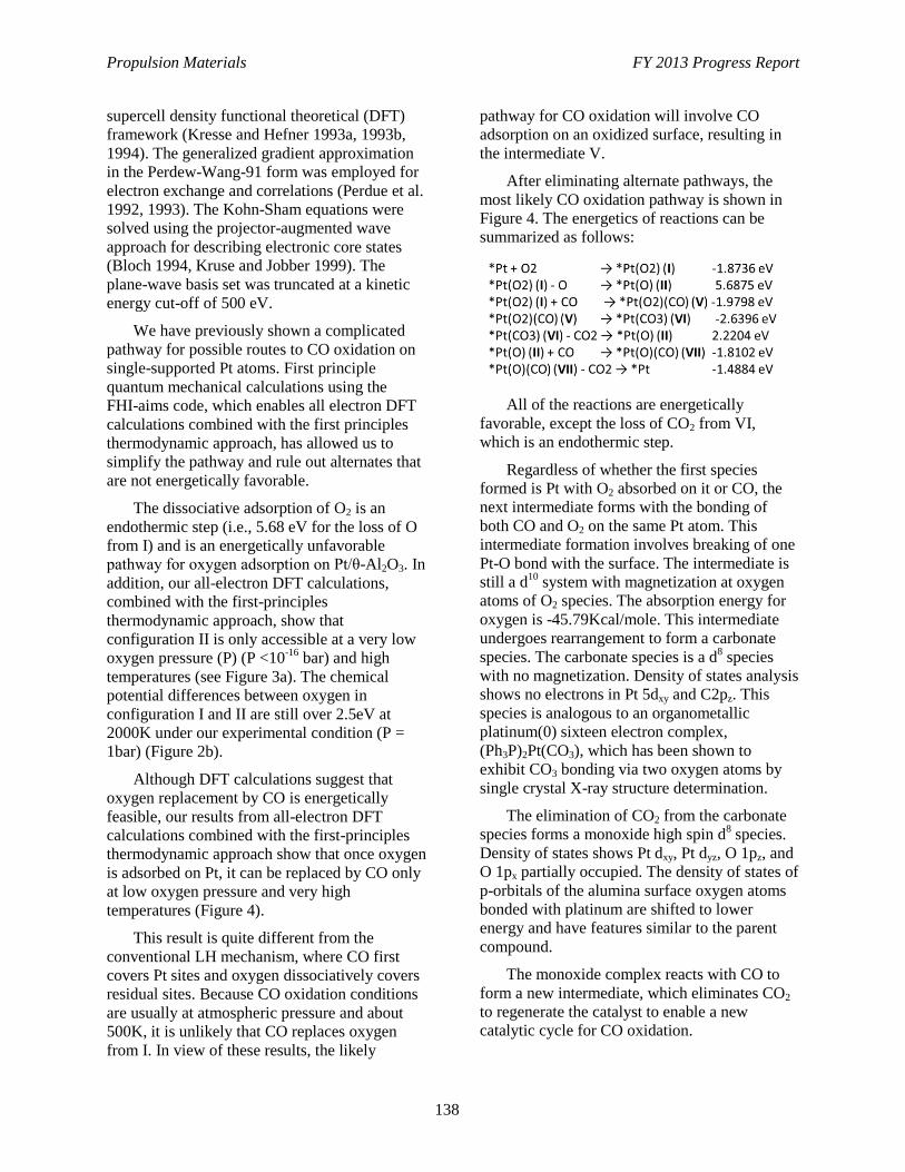
Propulsion Materials FY 2013 Progress Report
138
supercell density functional theoretical (DFT)
framework (Kresse and Hefner 1993a, 1993b,
1994). The generalized gradient approximation
in the Perdew-Wang-91 form was employed for
electron exchange and correlations (Perdue et al.
1992, 1993). The Kohn-Sham equations were
solved using the projector-augmented wave
approach for describing electronic core states
(Bloch 1994, Kruse and Jobber 1999). The
plane-wave basis set was truncated at a kinetic
energy cut-off of 500 eV.
We have previously shown a complicated
pathway for possible routes to CO oxidation on
single-supported Pt atoms. First principle
quantum mechanical calculations using the
FHI-aims code, which enables all electron DFT
calculations combined with the first principles
thermodynamic approach, has allowed us to
simplify the pathway and rule out alternates that
are not energetically favorable.
The dissociative adsorption of O2 is an
endothermic step (i.e., 5.68 eV for the loss of O
from I) and is an energetically unfavorable
pathway for oxygen adsorption on Pt/θ-Al2O3. In
addition, our all-electron DFT calculations,
combined with the first-principles
thermodynamic approach, show that
configuration II is only accessible at a very low
oxygen pressure (P) (P <10-16
bar) and high
temperatures (see Figure 3a). The chemical
potential differences between oxygen in
configuration I and II are still over 2.5eV at
2000K under our experimental condition (P =
1bar) (Figure 2b).
Although DFT calculations suggest that
oxygen replacement by CO is energetically
feasible, our results from all-electron DFT
calculations combined with the first-principles
thermodynamic approach show that once oxygen
is adsorbed on Pt, it can be replaced by CO only
at low oxygen pressure and very high
temperatures (Figure 4).
This result is quite different from the
conventional LH mechanism, where CO first
covers Pt sites and oxygen dissociatively covers
residual sites. Because CO oxidation conditions
are usually at atmospheric pressure and about
500K, it is unlikely that CO replaces oxygen
from I. In view of these results, the likely
pathway for CO oxidation will involve CO
adsorption on an oxidized surface, resulting in
the intermediate V.
After eliminating alternate pathways, the
most likely CO oxidation pathway is shown in
Figure 4. The energetics of reactions can be
summarized as follows:
All of the reactions are energetically
favorable, except the loss of CO2 from VI,
which is an endothermic step.
Regardless of whether the first species
formed is Pt with O2 absorbed on it or CO, the
next intermediate forms with the bonding of
both CO and O2 on the same Pt atom. This
intermediate formation involves breaking of one
Pt-O bond with the surface. The intermediate is
still a d10
system with magnetization at oxygen
atoms of O2 species. The absorption energy for
oxygen is -45.79Kcal/mole. This intermediate
undergoes rearrangement to form a carbonate
species. The carbonate species is a d8 species
with no magnetization. Density of states analysis
shows no electrons in Pt 5dxy and C2pz. This
species is analogous to an organometallic
platinum(0) sixteen electron complex,
(Ph3P)2Pt(CO3), which has been shown to
exhibit CO3 bonding via two oxygen atoms by
single crystal X-ray structure determination.
The elimination of CO2 from the carbonate
species forms a monoxide high spin d8 species.
Density of states shows Pt dxy, Pt dyz, O 1pz, and
O 1px partially occupied. The density of states of
p-orbitals of the alumina surface oxygen atoms
bonded with platinum are shifted to lower
energy and have features similar to the parent
compound.
The monoxide complex reacts with CO to
form a new intermediate, which eliminates CO2
to regenerate the catalyst to enable a new
catalytic cycle for CO oxidation.
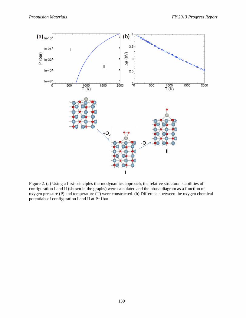
Propulsion Materials FY 2013 Progress Report
139
Figure 2. (a) Using a first-principles thermodynamics approach, the relative structural stabilities of
configuration I and II (shown in the graphs) were calculated and the phase diagram as a function of
oxygen pressure (P) and temperature (T) were constructed. (b) Difference between the oxygen chemical
potentials of configuration I and II at P=1bar.
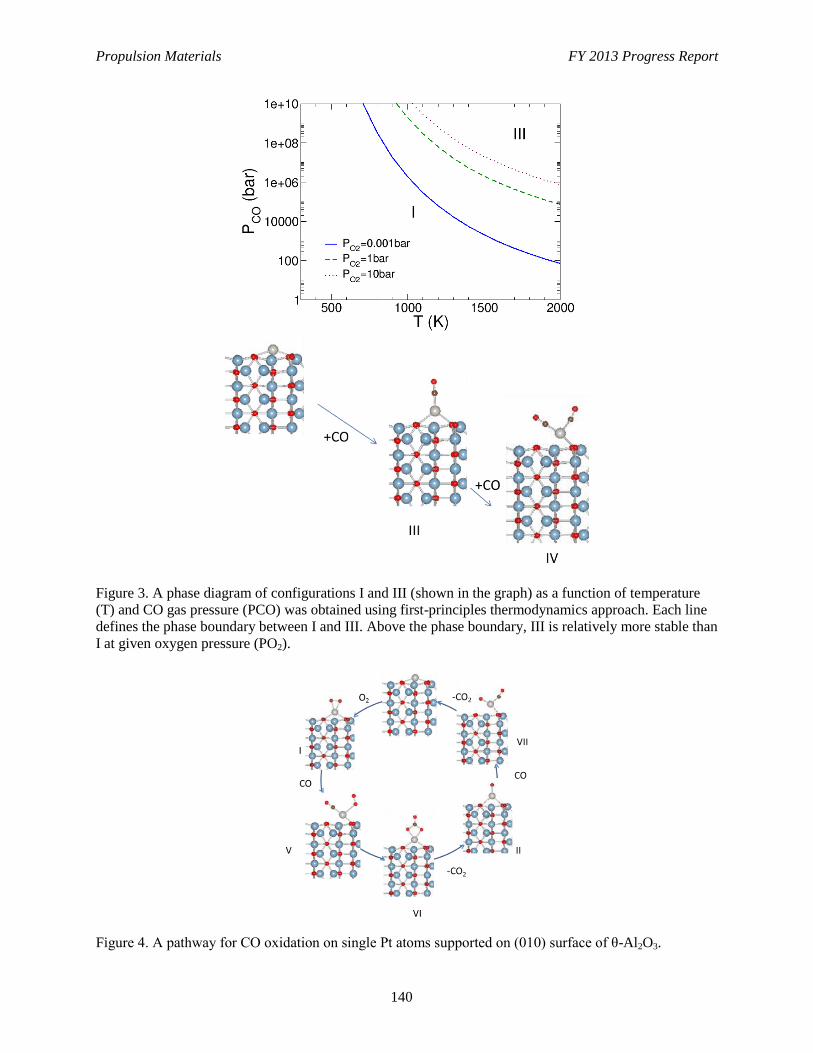
Propulsion Materials FY 2013 Progress Report
140
Figure 3. A phase diagram of configurations I and III (shown in the graph) as a function of temperature
(T) and CO gas pressure (PCO) was obtained using first-principles thermodynamics approach. Each line
defines the phase boundary between I and III. Above the phase boundary, III is relatively more stable than
I at given oxygen pressure (PO2).
Figure 4. A pathway for CO oxidation on single Pt atoms supported on (010) surface of θ-Al2O3.
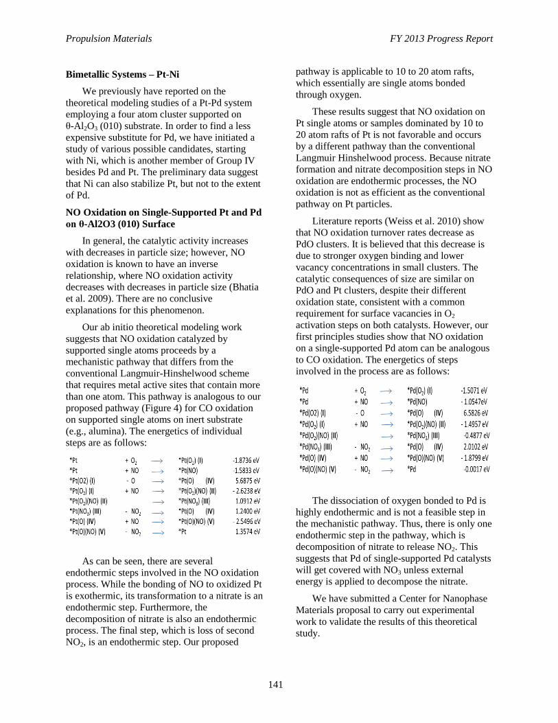
Propulsion Materials FY 2013 Progress Report
141
Bimetallic Systems – Pt-Ni
We previously have reported on the
theoretical modeling studies of a Pt-Pd system
employing a four atom cluster supported on
θ-Al2O3 (010) substrate. In order to find a less
expensive substitute for Pd, we have initiated a
study of various possible candidates, starting
with Ni, which is another member of Group IV
besides Pd and Pt. The preliminary data suggest
that Ni can also stabilize Pt, but not to the extent
of Pd.
NO Oxidation on Single-Supported Pt and Pd
on θ-Al2O3 (010) Surface
In general, the catalytic activity increases
with decreases in particle size; however, NO
oxidation is known to have an inverse
relationship, where NO oxidation activity
decreases with decreases in particle size (Bhatia
et al. 2009). There are no conclusive
explanations for this phenomenon.
Our ab initio theoretical modeling work
suggests that NO oxidation catalyzed by
supported single atoms proceeds by a
mechanistic pathway that differs from the
conventional Langmuir-Hinshelwood scheme
that requires metal active sites that contain more
than one atom. This pathway is analogous to our
proposed pathway (Figure 4) for CO oxidation
on supported single atoms on inert substrate
(e.g., alumina). The energetics of individual
steps are as follows:
As can be seen, there are several
endothermic steps involved in the NO oxidation
process. While the bonding of NO to oxidized Pt
is exothermic, its transformation to a nitrate is an
endothermic step. Furthermore, the
decomposition of nitrate is also an endothermic
process. The final step, which is loss of second
NO2, is an endothermic step. Our proposed
pathway is applicable to 10 to 20 atom rafts,
which essentially are single atoms bonded
through oxygen.
These results suggest that NO oxidation on
Pt single atoms or samples dominated by 10 to
20 atom rafts of Pt is not favorable and occurs
by a different pathway than the conventional
Langmuir Hinshelwood process. Because nitrate
formation and nitrate decomposition steps in NO
oxidation are endothermic processes, the NO
oxidation is not as efficient as the conventional
pathway on Pt particles.
Literature reports (Weiss et al. 2010) show
that NO oxidation turnover rates decrease as
PdO clusters. It is believed that this decrease is
due to stronger oxygen binding and lower
vacancy concentrations in small clusters. The
catalytic consequences of size are similar on
PdO and Pt clusters, despite their different
oxidation state, consistent with a common
requirement for surface vacancies in O2
activation steps on both catalysts. However, our
first principles studies show that NO oxidation
on a single-supported Pd atom can be analogous
to CO oxidation. The energetics of steps
involved in the process are as follows:
The dissociation of oxygen bonded to Pd is
highly endothermic and is not a feasible step in
the mechanistic pathway. Thus, there is only one
endothermic step in the pathway, which is
decomposition of nitrate to release NO2. This
suggests that Pd of single-supported Pd catalysts
will get covered with NO3 unless external
energy is applied to decompose the nitrate.
We have submitted a Center for Nanophase
Materials proposal to carry out experimental
work to validate the results of this theoretical
study.
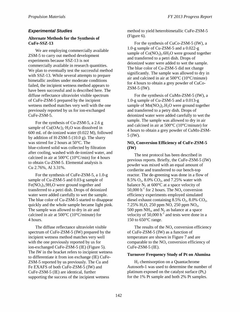
Propulsion Materials FY 2013 Progress Report
142
Experimental Studies
Alternate Methods for the Synthesis of
CuFe-SSZ-13
We are employing commercially available
ZSM-5 to carry out method development
experiments because SSZ-13 is not
commercially available in research quantities.
We plan to eventually test the successful method
with SSZ-13. While several attempts to prepare
bimetallic zeolites under moderate conditions
failed, the incipient wetness method appears to
have been successful and is described here. The
diffuse reflectance ultraviolet visible spectrum
of CuFe-ZSM-5 prepared by the incipient
wetness method matches very well with the one
previously reported by us for ion-exchanged
CuFe-ZSM-5.
For the synthesis of Cu-ZSM-5, a 2.6 g
sample of Cu(OAc)2·H2O was dissolved in
600 mL of de-ionized water (0.022 M), followed
by addition of H-ZSM-5 (10.0 g). The slurry
was stirred for 2 hours at 50°C. The
blue-colored solid was collected by filtration
after cooling, washed with de-ionized water, and
calcined in air at 500°C (10°C/min) for 4 hours
to obtain Cu-ZSM-5. Elemental analysis is
Cu 2.76%, Al 3.31%.
For the synthesis of CuFe-ZSM-5, a 1.0-g
sample of Cu-ZSM-5 and 0.03-g sample of
Fe(NO3)3.9H2O were ground together and
transferred to a petri dish. Drops of deionized
water were added carefully to wet the sample.
The blue color of Cu-ZSM-5 started to disappear
quickly and the whole sample became light pink.
The sample was allowed to dry in air and
calcined in air at 500°C (10°C/minute) for
4 hours.
The diffuse reflectance ultraviolet visible
spectrum of CuFe-ZSM-5 (IW) prepared by the
incipient wetness method matches very well
with the one previously reported by us for
ion-exchanged CuFe-ZSM-5 (IE) (Figure 5).
The IW in the bracket refers to incipient wetness
to differentiate it from ion exchange (IE) CuFe-
ZSM-5 reported by us previously. The Cu and
Fe EXAFS of both CuFe-ZSM-5 (IW) and
CuFe-ZSM-5 (IE) are identical, further
supporting the success of the incipient wetness
method to yield heterobimetallic CuFe-ZSM-5
(Figure 6).
For the synthesis of CuCo-ZSM-5 (IW), a
1.0-g sample of Cu-ZSM-5 and a 0.022-g
sample of Co(NO3)2.6H2O were ground together
and transferred to a petri dish. Drops of
deionized water were added to wet the sample.
The blue color of Cu-ZSM-5 did not change
significantly. The sample was allowed to dry in
air and calcined in air at 500°C (10°C/minute)
for 4 hours to obtain a grey powder of CuCo-
ZSM-5 (IW).
For the synthesis of CuMn-ZSM-5 (IW), a
1.0-g sample of Cu-ZSM-5 and a 0.013-g
sample of Mn(NO3)2.H2O were ground together
and transferred to a petry dish. Drops of
deionized water were added carefully to wet the
sample. The sample was allowed to dry in air
and calcined in air at 500°C (10°C/minute) for
4 hours to obtain a grey powder of CuMn-ZSM-
5 (IW).
NOx Conversion Efficiency of CuFe-ZSM-5
(IW)
The test protocol has been described in
previous reports. Briefly, the CuFe-ZSM-5 (IW)
powder was mixed with an equal amount of
cordierite and transferred to our bench-top
reactor. The de-greening was done in a flow of
8.5% O2, 8.0% CO2, and 7.25% water with
balance N2 at 600°C at a space velocity of
50,000 h-1
for 2 hours. The NOx conversion
efficiency experiments employed simulated
diesel exhaust containing 8.5% O2, 8.0% CO2,
7.25% H2O, 250 ppm NO, 250 ppm NO2,
500 ppm NH3, and N2 as balance at a space
velocity of 50,000 h-1
and tests were done in a
150 to 650°C range.
The results of the NOx conversion efficiency
of CuFe-ZSM-5 (IW) as a function of
temperature are shown in Figure 7 and are
comparable to the NOx conversion efficiency of
CuFe-ZSM-5 (IE).
Turnover Frequency Study of Pt on Alumina
H2 chemisorption on a Quantachrome
Autosorb-1 was used to determine the number of
platinum exposed on the catalyst surface (Pts)
for the 1% Pt sample and both 2% Pt samples.
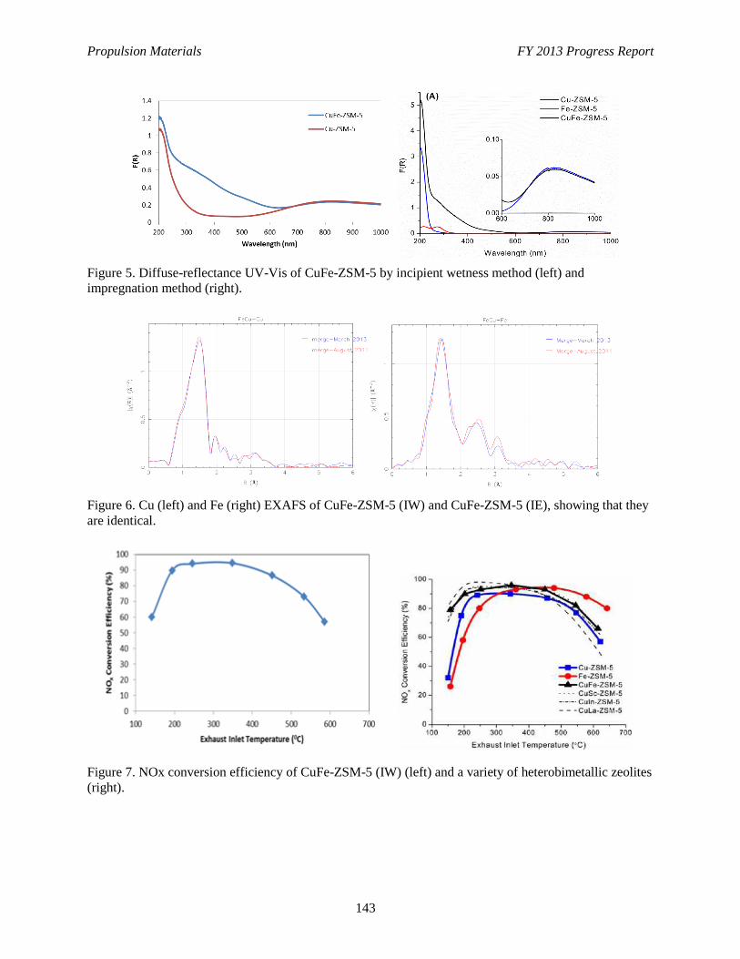
Propulsion Materials FY 2013 Progress Report
143
Figure 5. Diffuse-reflectance UV-Vis of CuFe-ZSM-5 by incipient wetness method (left) and
impregnation method (right).
Figure 6. Cu (left) and Fe (right) EXAFS of CuFe-ZSM-5 (IW) and CuFe-ZSM-5 (IE), showing that they
are identical.
Figure 7. NOx conversion efficiency of CuFe-ZSM-5 (IW) (left) and a variety of heterobimetallic zeolites
(right).
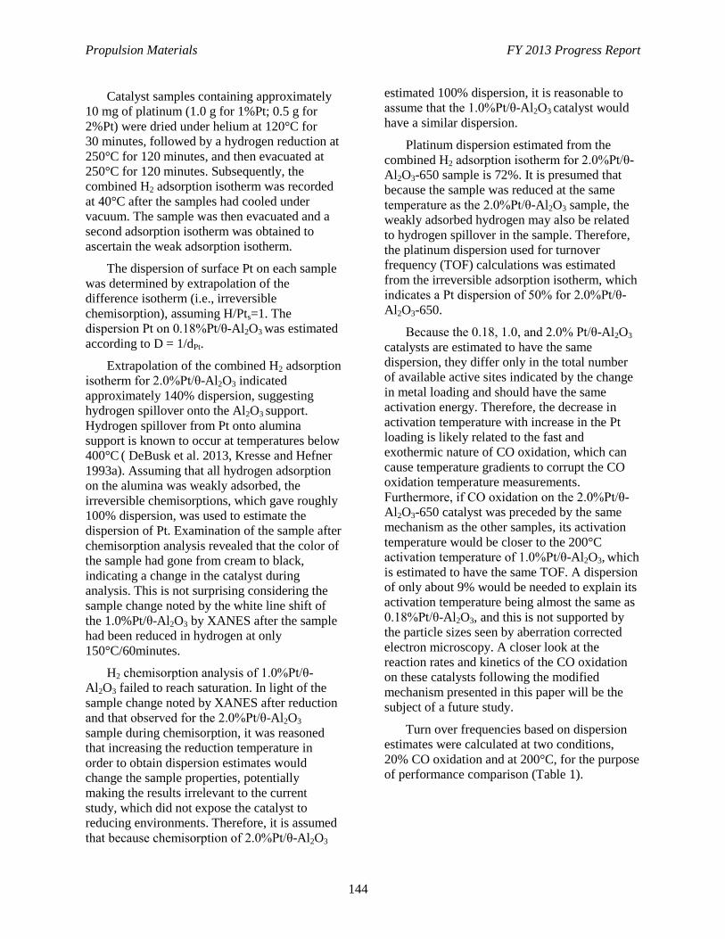
Propulsion Materials FY 2013 Progress Report
144
Catalyst samples containing approximately
10 mg of platinum (1.0 g for 1%Pt; 0.5 g for
2%Pt) were dried under helium at 120°C for
30 minutes, followed by a hydrogen reduction at
250°C for 120 minutes, and then evacuated at
250°C for 120 minutes. Subsequently, the
combined H2 adsorption isotherm was recorded
at 40°C after the samples had cooled under
vacuum. The sample was then evacuated and a
second adsorption isotherm was obtained to
ascertain the weak adsorption isotherm.
The dispersion of surface Pt on each sample
was determined by extrapolation of the
difference isotherm (i.e., irreversible
chemisorption), assuming H/Pts=1. The
dispersion Pt on 0.18%Pt/θ-Al2O3 was estimated
according to D = 1/dPt.
Extrapolation of the combined H2 adsorption
isotherm for 2.0%Pt/θ-Al2O3 indicated
approximately 140% dispersion, suggesting
hydrogen spillover onto the Al2O3 support.
Hydrogen spillover from Pt onto alumina
support is known to occur at temperatures below
400°C ( DeBusk et al. 2013, Kresse and Hefner
1993a). Assuming that all hydrogen adsorption
on the alumina was weakly adsorbed, the
irreversible chemisorptions, which gave roughly
100% dispersion, was used to estimate the
dispersion of Pt. Examination of the sample after
chemisorption analysis revealed that the color of
the sample had gone from cream to black,
indicating a change in the catalyst during
analysis. This is not surprising considering the
sample change noted by the white line shift of
the 1.0%Pt/θ-Al2O3 by XANES after the sample
had been reduced in hydrogen at only
150°C/60minutes.
H2 chemisorption analysis of 1.0%Pt/θ-
Al2O3 failed to reach saturation. In light of the
sample change noted by XANES after reduction
and that observed for the 2.0%Pt/θ-Al2O3
sample during chemisorption, it was reasoned
that increasing the reduction temperature in
order to obtain dispersion estimates would
change the sample properties, potentially
making the results irrelevant to the current
study, which did not expose the catalyst to
reducing environments. Therefore, it is assumed
that because chemisorption of 2.0%Pt/θ-Al2O3
estimated 100% dispersion, it is reasonable to
assume that the 1.0%Pt/θ-Al2O3 catalyst would
have a similar dispersion.
Platinum dispersion estimated from the
combined H2 adsorption isotherm for 2.0%Pt/θ-
Al2O3-650 sample is 72%. It is presumed that
because the sample was reduced at the same
temperature as the 2.0%Pt/θ-Al2O3 sample, the
weakly adsorbed hydrogen may also be related
to hydrogen spillover in the sample. Therefore,
the platinum dispersion used for turnover
frequency (TOF) calculations was estimated
from the irreversible adsorption isotherm, which
indicates a Pt dispersion of 50% for 2.0%Pt/θ-
Al2O3-650.
Because the 0.18, 1.0, and 2.0% Pt/θ-Al2O3
catalysts are estimated to have the same
dispersion, they differ only in the total number
of available active sites indicated by the change
in metal loading and should have the same
activation energy. Therefore, the decrease in
activation temperature with increase in the Pt
loading is likely related to the fast and
exothermic nature of CO oxidation, which can
cause temperature gradients to corrupt the CO
oxidation temperature measurements.
Furthermore, if CO oxidation on the 2.0%Pt/θ-
Al2O3-650 catalyst was preceded by the same
mechanism as the other samples, its activation
temperature would be closer to the 200°C
activation temperature of 1.0%Pt/θ-Al2O3, which
is estimated to have the same TOF. A dispersion
of only about 9% would be needed to explain its
activation temperature being almost the same as
0.18%Pt/θ-Al2O3, and this is not supported by
the particle sizes seen by aberration corrected
electron microscopy. A closer look at the
reaction rates and kinetics of the CO oxidation
on these catalysts following the modified
mechanism presented in this paper will be the
subject of a future study.
Turn over frequencies based on dispersion
estimates were calculated at two conditions,
20% CO oxidation and at 200°C, for the purpose
of performance comparison (Table 1).
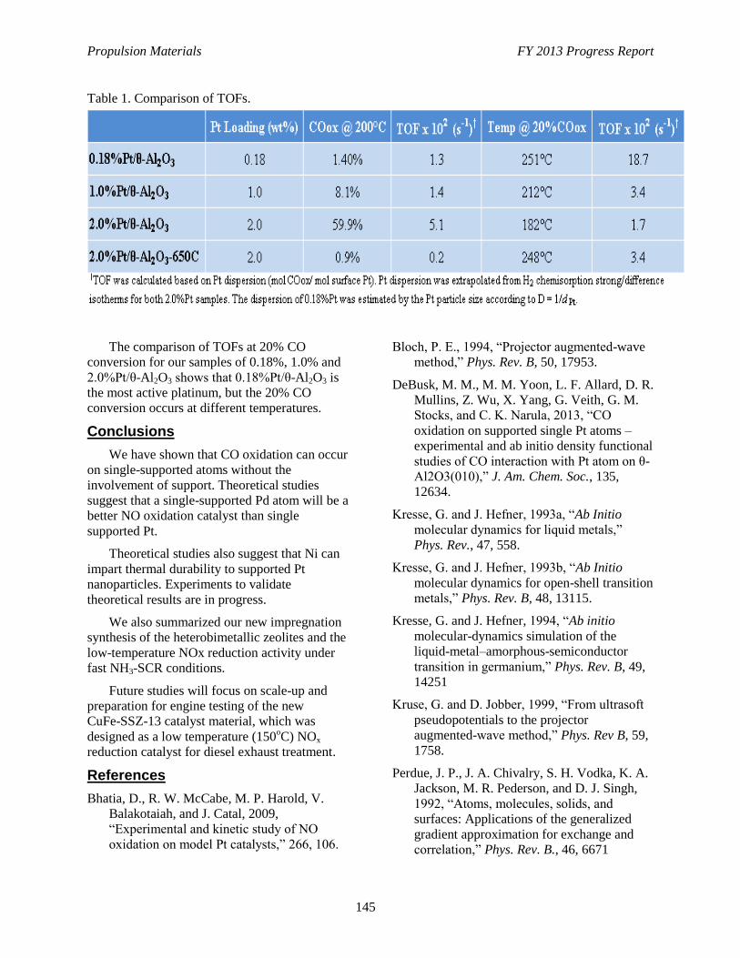
Propulsion Materials FY 2013 Progress Report
145
Table 1. Comparison of TOFs.
The comparison of TOFs at 20% CO
conversion for our samples of 0.18%, 1.0% and
2.0%Pt/θ-Al2O3 shows that 0.18%Pt/θ-Al2O3 is
the most active platinum, but the 20% CO
conversion occurs at different temperatures.
Conclusions
We have shown that CO oxidation can occur
on single-supported atoms without the
involvement of support. Theoretical studies
suggest that a single-supported Pd atom will be a
better NO oxidation catalyst than single
supported Pt.
Theoretical studies also suggest that Ni can
impart thermal durability to supported Pt
nanoparticles. Experiments to validate
theoretical results are in progress.
We also summarized our new impregnation
synthesis of the heterobimetallic zeolites and the
low-temperature NOx reduction activity under
fast NH3-SCR conditions.
Future studies will focus on scale-up and
preparation for engine testing of the new
CuFe-SSZ-13 catalyst material, which was
designed as a low temperature (150oC) NOx
reduction catalyst for diesel exhaust treatment.
References
Bhatia, D., R. W. McCabe, M. P. Harold, V.
Balakotaiah, and J. Catal, 2009,
“Experimental and kinetic study of NO
oxidation on model Pt catalysts,” 266, 106.
Bloch, P. E., 1994, “Projector augmented-wave
method,” Phys. Rev. B, 50, 17953.
DeBusk, M. M., M. M. Yoon, L. F. Allard, D. R.
Mullins, Z. Wu, X. Yang, G. Veith, G. M.
Stocks, and C. K. Narula, 2013, “CO
oxidation on supported single Pt atoms –
experimental and ab initio density functional
studies of CO interaction with Pt atom on θ-
Al2O3(010),” J. Am. Chem. Soc., 135,
12634.
Kresse, G. and J. Hefner, 1993a, “Ab Initio
molecular dynamics for liquid metals,”
Phys. Rev., 47, 558.
Kresse, G. and J. Hefner, 1993b, “Ab Initio
molecular dynamics for open-shell transition
metals,” Phys. Rev. B, 48, 13115.
Kresse, G. and J. Hefner, 1994, “Ab initio
molecular-dynamics simulation of the
liquid-metal–amorphous-semiconductor
transition in germanium,” Phys. Rev. B, 49,
14251
Kruse, G. and D. Jobber, 1999, “From ultrasoft
pseudopotentials to the projector
augmented-wave method,” Phys. Rev B, 59,
1758.
Perdue, J. P., J. A. Chivalry, S. H. Vodka, K. A.
Jackson, M. R. Pederson, and D. J. Singh,
1992, “Atoms, molecules, solids, and
surfaces: Applications of the generalized
gradient approximation for exchange and
correlation,” Phys. Rev. B., 46, 6671
Propulsion Materials FY 2013 Progress Report
146
Perdue, J. P., J. A. Chivalry, S. H. Vodka, K. A.
Jackson, M. R. Pederson, and D. J. Singh,
1993, “Erratum: Atoms, molecules, solids,
and surfaces: Applications of the
generalized gradient approximation for
exchange and correlation,” Phys. Rev. B.,
48, 4978.
Weiss, B. M., E. Iglesia, and J. Catal, 2010,
“Mechanism and site requirements for NO
oxidation on Pd catalysts,” 272, 74.
Presentations and Publications
DeBusk, M. M., M. Yoon, L. F. Allard, D. R.
Mullins, G. M. Stocks, X. Yang, Z. Wu, and
C. K. Narula, 2013, “CO oxidation on
supported single Pt atoms – experimental
and ab initio density functional studies of
CO interaction with Pt atom on θ-
Al2O3(010),” J. Am. Chem. Soc., 135,
12634-12645. This paper was discussed in
Research Highlights of Nature Chemistry,
2013, 5, 809.
Narula, C. K. and M. M. DeBusk, 2013,
“Catalysis by Design,” Encyclopedia of
Nanoscience and Nanotechnology, Taylor
Francis, New York (invited chapter,
accepted for publication).
Narula, C. K., L. F. Allard, M. M. DeBusk, D.
R. Mullins, G. M. Stocks, X. Yang, M.
Yoon, and Z. Wu, 2013, “Single atom
catalysis: CO oxidation on single Pt atoms
supported on θ-Al2O3(010) Surface,”
American Chemical Society Meeting, New
Orleans, PA, April 7-11, 2013.
Narula, C. K., L. F. Allard, M. M. DeBusk, D.
R. Mullins, G. M. Stocks, X. Yang, M.
Yoon, and Z. Wu, 2013, “Single atom
catalysis: CO oxidation on single Pt atoms
supported on θ-Al2O3(010) Surface,” North
American Catalysis Society Meeting,
Louisville, KY, June 2-7, 2013.
Yang, X., Z. Wu, M. M. DeBusk, D. R. Mullins,
S. M. Mahurin, R. A. Geiger, M. Kidder,
and C. K. Narula, 2012, “Heterometal
Incorporation of M-Exchanged Zeolties
enables low temperature catalytic activity of
NOx reduction,” J. Phys. Chem. C, 116,
23322.
Propulsion Materials FY 2013 Progress Report
147
Project 18519 – Materials for Exhaust and Energy Recovery
Agreement 19214 – Biofuels Impact on Diesel Particulate
Filters Durability
M. J. Lance, T. J. Toops*, E. J. Nafziger*, M. K. Ferber, and C. Xie*
Ceramic Science and Technology Group
Oak Ridge National Laboratory
P.O. Box 2008, MS 6068, Bldg. 4515
Oak Ridge, TN 37831-6068
Phone (865) 241-4536; fax: (865) 574-6098; e-mail: [email protected]
*Fuels, Engines, and Emissions Research Center
DOE Technology Manager: Jerry L. Gibbs
Phone (202) 586-1182; fax: (202) 586-1600; e-mail: [email protected]
ORNL Technical Advisor: J. Allen Haynes
Phone (865) 576-2894; fax: (865) 574-4913; e-mail: [email protected]
Contractor: Oak Ridge National Laboratory, Oak Ridge, Tennessee
Prime Contract No.: DE-AC05-00OR22725
Objectives
To characterize changes in the microstructure and material properties of diesel particulate filters
(DPFs) in exhaust gas produced by biodiesel blends.
Approach
Use a stationary generator to produce diesel exhaust for long-term 24/7 aging of DPFs in diesel and
biodiesel exhaust.
Attempt measurement of DPF sample under pure tension using an hourglass specimen design.
Characterize emission control devices aged in biodiesel exhaust provided by the National Renewable
Energy (NREL)/Ford/Manufacturers of Emission Controls Association (MECA) collaboration.
Accomplishments
Characterized the degradation mechanisms occurring in selective catalytic reduction (SCR) and diesel
oxidation catalyst (DOC) devices run with high levels on potassium doped in biodiesel fuel by NREL.
Completed 100-hour test of the Gen set at 800°C using a closed loop temperature control.
Future Direction
This project is ending, but will continue with an expanded focus (beyond DPFs) in Agreement 26463
– Biofuel Impact on Aftertreatment Devices.
Propulsion Materials FY 2013 Progress Report
148
Introduction
After collecting soot (from a 1.7-L
Mercedes-Benz engine fueled with biodiesel
blends) on uncatalyzed cordierite DPFs,
significant degradation of the DPFs was
observed following a 3-month period where the
DPFs resided in a can in a cabinet. No
degradation of the DPF run with ultra-low sulfur
diesel (ULSD) was found. In addition, after
burning the collected soot, the biodiesel soot had
cordierite and padding residue in amounts
roughly proportional to the biodiesel volume
percent in the fuel. This result suggested that
biodiesel may cause degradation of DPF
materials under some conditions. This project
has the objective of investigating this possibility
and the potential degradation mechanisms
resulting from biodiesel operation. More
recently, the scope of the project has broadened
to cover the potential deleterious effects of
biodiesel on the SCR device and DOC.
Biodiesel can be made from various
renewable sources (such as vegetable oil, animal
fat, or waste cooking oil) and is produced
through transesterification of the oil or fat with
methanol; this is a process that occurs in the
presence of a catalyst, typically sodium
hydroxide or potassium hydroxide. Following
production, residual amounts of sodium (Na) or
potassium (K) from the catalyst can be left
behind and are converted to oxides, sulfates,
hydroxides, or carbonates in the combustion
process and form an inorganic ash that can be
deposited onto the exhaust emission control
devices found in modern diesel engines. Alkali
metals are well known poisons for catalysts and
have been shown to negatively impact the
mechanical properties of ceramic substrates
(Williams et al. 2011). Furthermore, alkali metal
hydroxides (such as Na and K) are volatilized in
the presence of steam; therefore, they can
penetrate the catalyst washcoat or substrate.
To investigate the effect of biodiesel fuel on
DPF material degradation, a stationary generator
was purchased and set up to operate 24/7 using
different fuels. The exhaust is directed through a
DOC, and supplementary fuel is used to produce
an exotherm, heating the DPF to temperatures
typically experienced during regeneration.
Following exposure, the mechanical properties
of the DPF can be measured through bending
with ring-on-ring biaxial flexure of disks
(Wereszczak et al. 2012, Williams et al. 2013).
A new method, whereby a tensile load is applied
unaxially, was explored during the previous
fiscal year with mixed results.
The second approach to better understand
potential degradation mechanisms of emission
control devices in biodiesel exhaust is to obtain
aged samples from a collaboration with NREL,
the National Biodiesel Board, MECA, and Ford
Motor Company and is funded through the
Vehicle Technologies Office’s Fuels Program.
DPFs aged in biodiesel doped with 7, 14, and 28
ppm K were obtained and analyzed along with
the DOC and SCR devices. Our results show
that 28 ppm K is too aggressive a dopant level to
simulate long-term effects of biodiesel. Future
accelerated tests will use the 14 ppm dopant
level.
Results
Mechanical Properties of DPFs Tested Under Pure Tension
During fiscal year 2012, a methodology of
measuring mechanical properties of DPFs by
gripping the ends of a 1 × 3-in. sample at the
ends with epoxy was established. This method
has numerous advantages over our previously
used method of ring-on-ring biaxial flexure
(Wereszczak et al. 2012). Coupled with the
measurement of tensile elongation using contact
extensometers, the sought-after tensile testing
enables measurement of a continuous tensile
stress (tensile strain curve). Also, the load is
applied across a much larger volume of material
compared to the bending tests, which improves
the statistics of the measurements. Finally, the
fracture strength is less likely to be controlled by
the surface flaws generated during sample
machining because the load is applied uniformly
through the thickness of the specimen and not
with the maximum load just on the surface as
with flexural testing. Stress-strain curves
supported the biaxial flexure results; however,
failure always occurred near the epoxy (seen in
Figure 1), which suggests the epoxy may be
creating damage in the DPF during the curing
process. Figure 2 shows one of the DPF samples
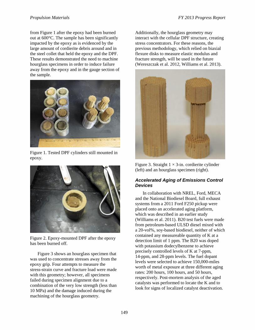
Propulsion Materials FY 2013 Progress Report
149
from Figure 1 after the epoxy had been burned
out at 600°C. The sample has been significantly
impacted by the epoxy as is evidenced by the
large amount of cordierite debris around and in
the steel collet that held the epoxy and the DPF.
These results demonstrated the need to machine
hourglass specimens in order to induce failure
away from the epoxy and in the gauge section of
the sample.
Figure 1. Tested DPF cylinders still mounted in
epoxy.
Figure 2. Epoxy-mounted DPF after the epoxy
has been burned off.
Figure 3 shows an hourglass specimen that
was used to concentrate stresses away from the
epoxy grip. Four attempts to measure the
stress-strain curve and fracture load were made
with this geometry; however, all specimens
failed during specimen alignment due to a
combination of the very low strength (less than
10 MPa) and the damage induced during the
machining of the hourglass geometry.
Additionally, the hourglass geometry may
interact with the cellular DPF structure, creating
stress concentrators. For these reasons, the
previous methodology, which relied on biaxial
flexure disks to measure elastic modulus and
fracture strength, will be used in the future
(Wereszczak et al. 2012, Williams et al. 2013).
Figure 3. Straight 1 × 3-in. cordierite cylinder
(left) and an hourglass specimen (right).
Accelerated Aging of Emissions Control Devices
In collaboration with NREL, Ford, MECA
and the National Biodiesel Board, full exhaust
systems from a 2011 Ford F250 pickup were
placed onto an accelerated aging platform,
which was described in an earlier study
(Williams et al. 2011). B20 test fuels were made
from petroleum-based ULSD diesel mixed with
a 20-vol%, soy-based biodiesel, neither of which
contained any measureable quantity of K at a
detection limit of 1 ppm. The B20 was doped
with potassium dodecylbenzene to achieve
precisely controlled levels of K at 7-ppm,
14-ppm, and 28-ppm levels. The fuel dopant
levels were selected to achieve 150,000-miles
worth of metal exposure at three different aging
rates: 200 hours, 100 hours, and 50 hours,
respectively. Post-mortem analysis of the aged
catalysts was performed to locate the K and to
look for signs of localized catalyst deactivation.
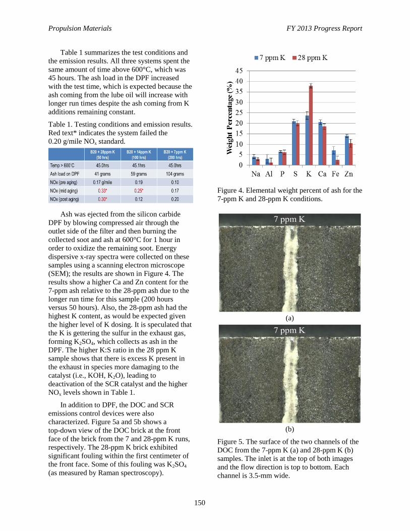
Propulsion Materials FY 2013 Progress Report
150
Table 1 summarizes the test conditions and
the emission results. All three systems spent the
same amount of time above 600°C, which was
45 hours. The ash load in the DPF increased
with the test time, which is expected because the
ash coming from the lube oil will increase with
longer run times despite the ash coming from K
additions remaining constant.
Table 1. Testing conditions and emission results.
Red text* indicates the system failed the
0.20 g/mile NOx standard.
Ash was ejected from the silicon carbide
DPF by blowing compressed air through the
outlet side of the filter and then burning the
collected soot and ash at 600°C for 1 hour in
order to oxidize the remaining soot. Energy
dispersive x-ray spectra were collected on these
samples using a scanning electron microscope
(SEM); the results are shown in Figure 4. The
results show a higher Ca and Zn content for the
7-ppm ash relative to the 28-ppm ash due to the
longer run time for this sample (200 hours
versus 50 hours). Also, the 28-ppm ash had the
highest K content, as would be expected given
the higher level of K dosing. It is speculated that
the K is gettering the sulfur in the exhaust gas,
forming K2SO4, which collects as ash in the
DPF. The higher K:S ratio in the 28 ppm K
sample shows that there is excess K present in
the exhaust in species more damaging to the
catalyst (i.e., KOH, K2O), leading to
deactivation of the SCR catalyst and the higher
NOx levels shown in Table 1.
In addition to DPF, the DOC and SCR
emissions control devices were also
characterized. Figure 5a and 5b shows a
top-down view of the DOC brick at the front
face of the brick from the 7 and 28-ppm K runs,
respectively. The 28-ppm K brick exhibited
significant fouling within the first centimeter of
the front face. Some of this fouling was K2SO4
(as measured by Raman spectroscopy).
Figure 4. Elemental weight percent of ash for the
7-ppm K and 28-ppm K conditions.
(a)
(b)
Figure 5. The surface of the two channels of the
DOC from the 7-ppm K (a) and 28-ppm K (b)
samples. The inlet is at the top of both images
and the flow direction is top to bottom. Each
channel is 3.5-mm wide.
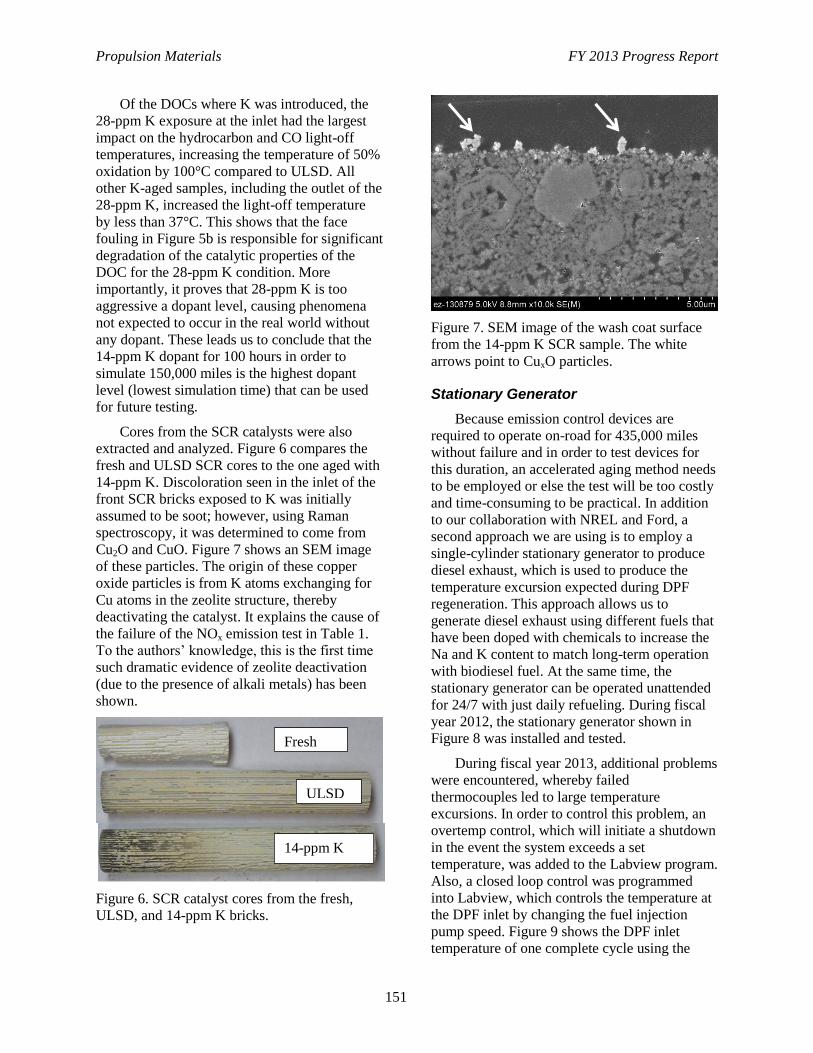
Propulsion Materials FY 2013 Progress Report
151
Of the DOCs where K was introduced, the
28-ppm K exposure at the inlet had the largest
impact on the hydrocarbon and CO light-off
temperatures, increasing the temperature of 50%
oxidation by 100°C compared to ULSD. All
other K-aged samples, including the outlet of the
28-ppm K, increased the light-off temperature
by less than 37°C. This shows that the face
fouling in Figure 5b is responsible for significant
degradation of the catalytic properties of the
DOC for the 28-ppm K condition. More
importantly, it proves that 28-ppm K is too
aggressive a dopant level, causing phenomena
not expected to occur in the real world without
any dopant. These leads us to conclude that the
14-ppm K dopant for 100 hours in order to
simulate 150,000 miles is the highest dopant
level (lowest simulation time) that can be used
for future testing.
Cores from the SCR catalysts were also
extracted and analyzed. Figure 6 compares the
fresh and ULSD SCR cores to the one aged with
14-ppm K. Discoloration seen in the inlet of the
front SCR bricks exposed to K was initially
assumed to be soot; however, using Raman
spectroscopy, it was determined to come from
Cu2O and CuO. Figure 7 shows an SEM image
of these particles. The origin of these copper
oxide particles is from K atoms exchanging for
Cu atoms in the zeolite structure, thereby
deactivating the catalyst. It explains the cause of
the failure of the NOx emission test in Table 1.
To the authors’ knowledge, this is the first time
such dramatic evidence of zeolite deactivation
(due to the presence of alkali metals) has been
shown.
Figure 6. SCR catalyst cores from the fresh,
ULSD, and 14-ppm K bricks.
Figure 7. SEM image of the wash coat surface
from the 14-ppm K SCR sample. The white
arrows point to CuxO particles.
Stationary Generator
Because emission control devices are
required to operate on-road for 435,000 miles
without failure and in order to test devices for
this duration, an accelerated aging method needs
to be employed or else the test will be too costly
and time-consuming to be practical. In addition
to our collaboration with NREL and Ford, a
second approach we are using is to employ a
single-cylinder stationary generator to produce
diesel exhaust, which is used to produce the
temperature excursion expected during DPF
regeneration. This approach allows us to
generate diesel exhaust using different fuels that
have been doped with chemicals to increase the
Na and K content to match long-term operation
with biodiesel fuel. At the same time, the
stationary generator can be operated unattended
for 24/7 with just daily refueling. During fiscal
year 2012, the stationary generator shown in
Figure 8 was installed and tested.
During fiscal year 2013, additional problems
were encountered, whereby failed
thermocouples led to large temperature
excursions. In order to control this problem, an
overtemp control, which will initiate a shutdown
in the event the system exceeds a set
temperature, was added to the Labview program.
Also, a closed loop control was programmed
into Labview, which controls the temperature at
the DPF inlet by changing the fuel injection
pump speed. Figure 9 shows the DPF inlet
temperature of one complete cycle using the
Fresh
ULSD
14-ppm K
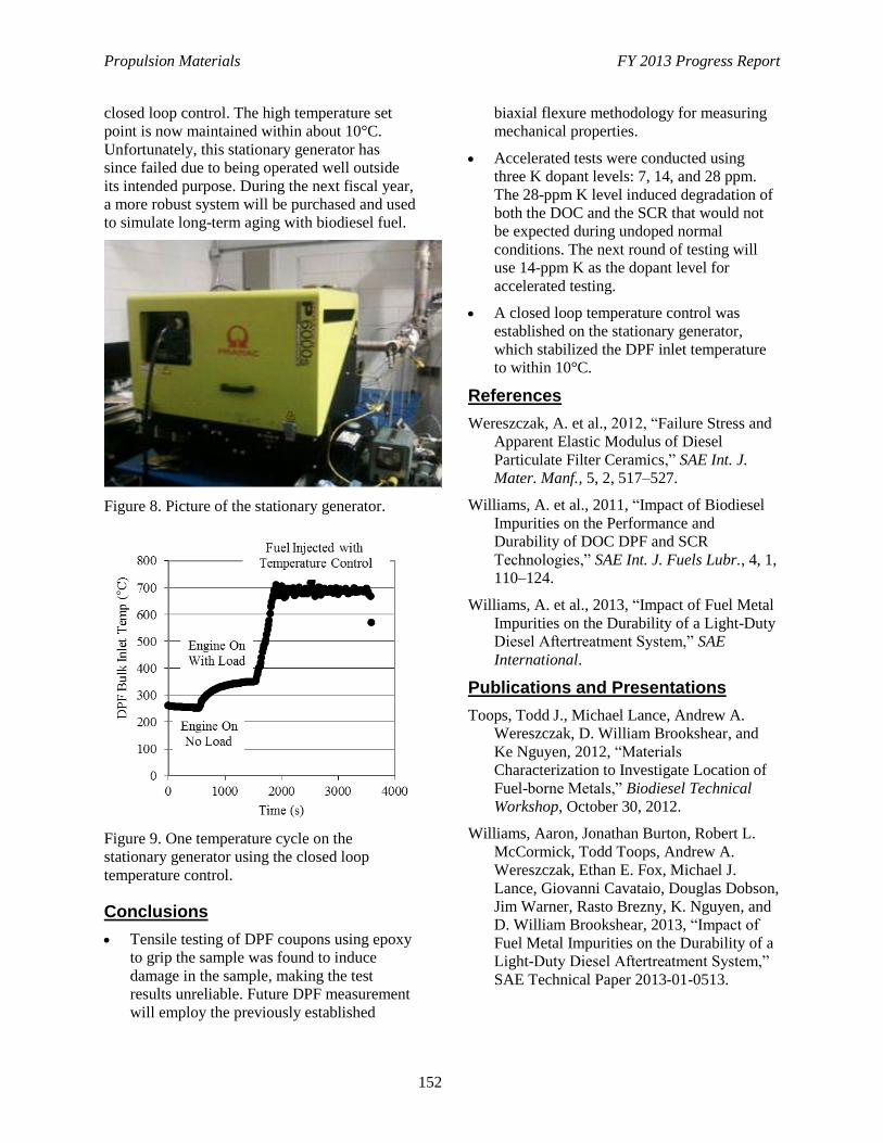
Propulsion Materials FY 2013 Progress Report
152
closed loop control. The high temperature set
point is now maintained within about 10°C.
Unfortunately, this stationary generator has
since failed due to being operated well outside
its intended purpose. During the next fiscal year,
a more robust system will be purchased and used
to simulate long-term aging with biodiesel fuel.
Figure 8. Picture of the stationary generator.
Figure 9. One temperature cycle on the
stationary generator using the closed loop
temperature control.
Conclusions
Tensile testing of DPF coupons using epoxy
to grip the sample was found to induce
damage in the sample, making the test
results unreliable. Future DPF measurement
will employ the previously established
biaxial flexure methodology for measuring
mechanical properties.
Accelerated tests were conducted using
three K dopant levels: 7, 14, and 28 ppm.
The 28-ppm K level induced degradation of
both the DOC and the SCR that would not
be expected during undoped normal
conditions. The next round of testing will
use 14-ppm K as the dopant level for
accelerated testing.
A closed loop temperature control was
established on the stationary generator,
which stabilized the DPF inlet temperature
to within 10°C.
References
Wereszczak, A. et al., 2012, “Failure Stress and
Apparent Elastic Modulus of Diesel
Particulate Filter Ceramics,” SAE Int. J.
Mater. Manf., 5, 2, 517–527.
Williams, A. et al., 2011, “Impact of Biodiesel
Impurities on the Performance and
Durability of DOC DPF and SCR
Technologies,” SAE Int. J. Fuels Lubr., 4, 1,
110–124.
Williams, A. et al., 2013, “Impact of Fuel Metal
Impurities on the Durability of a Light-Duty
Diesel Aftertreatment System,” SAE
International.
Publications and Presentations
Toops, Todd J., Michael Lance, Andrew A.
Wereszczak, D. William Brookshear, and
Ke Nguyen, 2012, “Materials
Characterization to Investigate Location of
Fuel-borne Metals,” Biodiesel Technical
Workshop, October 30, 2012.
Williams, Aaron, Jonathan Burton, Robert L.
McCormick, Todd Toops, Andrew A.
Wereszczak, Ethan E. Fox, Michael J.
Lance, Giovanni Cavataio, Douglas Dobson,
Jim Warner, Rasto Brezny, K. Nguyen, and
D. William Brookshear, 2013, “Impact of
Fuel Metal Impurities on the Durability of a
Light-Duty Diesel Aftertreatment System,”
SAE Technical Paper 2013-01-0513.
Propulsion Materials FY 2013 Progress Report
153
Awards
The Oak Ridge National Laboratory, NREL,
and Ford team were recognized as
“Researcher(s) of the Year” at the 2012
Biodiesel Technical Workshop.
Todd J. Toops and Michael J. Lance (Oak
Ridge National Laboratory), Aaron Williams
(NREL), and Giovanni Cavataio (Ford) were
recognized for their collaborative effort to
investigate the impact of trace metal impurities
(Na, K, and Ca) on the end-of-life functionality
and mechanical properties of emissions control
devices. This effort focused on the light-duty
application and employed the Ford
aftertreatment system that includes a
DOC/SCR/DPF arrangement.
The long-term introduction of the metal
impurities and the evaluation of the entire
aftertreatment system on an FTP drive cycle was
performed at NREL, the evaluation of the
performance of the individual devices and
sections were performed at Ford, and the
characterization of the metals location and
chemical nature were performed at Oak Ridge
National Laboratory and the University of
Tennessee-Knoxville. The team was able to
show that the aftertreatment system was durable
and able to meet the 2010 emissions standards at
150,000 miles (based on equivalent metal
exposure and thermal cycling), but that some
deactivation did occur of both the DOC and the
front of the SCR relative to the base case, such
that stricter emissions regulations or further
exposure may result in failed emissions
standards.
Propulsion Materials FY 2013 Progress Report
154
Project 18519 – Materials for Exhaust and Energy Recovery
Agreement 26462 – International Characterization Methods
H. Wang
Materials Science and Technology Division
Oak Ridge National Laboratory
P.O. Box 2008, MS 6064, Bldg. 4515
Oak Ridge, TN 37831-6068
Phone (865) 576-5074; fax: (865) 574-3940; e-mail: [email protected]
DOE Technology Manager: Jerry L. Gibbs
Phone (202) 586-1182; fax: (202) 586-1600; e-mail: [email protected]
ORNL Technical Advisor: J. Allen Haynes
Phone (865) 576-2894; fax: (865) 574-4913; e-mail: [email protected]
Contractor: Oak Ridge National Laboratory, Oak Ridge, Tennessee
Prime Contract No.: DE-AC05-00OR22725
Objectives
Conduct international round-robin studies on materials characterization methods and develop
standard testing procedures.
Conduct international round-robin studies on energy conversion devices for vehicles and develop
standard testing methods and procedures.
Approach
International Round-Robin Study of High-Temperature Bulk Thermoelectric (2013 through
2014): Lead the International Energy Agency (IEA)-AMT annex to conduct and complete an
international round-robin study on high-temperature bulk thermoelectrics. The identified n-type
half-heusler material will be circulated among the participating laboratories in five countries. All
properties (i.e. thermal conductivity, electrical conductivity, and Seebeck coefficient) needed for ZT
calculation will be tested form 300 to 800K. The results will be summarized and published to promote
standardization of transport property measurements.
Reliability of Low-Dimensional Thermoelectric Materials Measurements (2014): Following the
bulk materials study, the IEA annex will organize an international study to evaluate the reliability of
transport properties of low-dimensional materials. Past studies on thin film and nano-wire
thermoelectrics will be reviewed and evaluated on measurement technique and data analysis. The
potential of low-dimensional materials in applications and materials development will be accessed.
Survey Efficiency Testing of Energy Conversion Devices (2013 through 2014): The IEA annex will
conduct a study of the current state-of-the-art methods for determining energy conversion efficiency
of thermoelectric devices for vehicle applications. An intentional collaboration will be coordinated by
Oak Ridge National Laboratory to assess the efficiency testing system in each participating laboratory
and the published results in the literature. This is a preliminary study for the follow-on IEA efforts to
evaluate and standardize efficiency testing methods for advanced vehicle energy conversion
materials.
Propulsion Materials FY 2013 Progress Report
155
Accomplishments
This new project started late in the fourth quarter of fiscal year 2013, with limited accomplishments
thus far:
- High-temperature, round-robin studies on the half-heusler completed in NPL (UK). The tests will
complete in the first quarter of fiscal year 2014 and will be analyzed in the second and third
quarters.
- A survey of thermoelectric conversion efficiency testing was completed in collaboration with
Marlow Industries, GM R&D, Fraunhofer IPM (Germany), and AIST (Japan)
Future Direction
After conclusion of the IEA study on thermoelectric materials, the annex will focus on evaluating the
efficiency of energy conversion devices (such as thermoelectric and other propulsion materials)
beyond fiscal year 2014. Efforts will include international round-robin studies of devices and
development of testing standards.
Presentation
Wang, H. “Thermoelectric Module Efficiency Tests –A Survey,” at the 30th International
Thermoelectric Conference (ICT2013), Kobe, Japan, June 30 – July 4, 2013.
Publication
Wang, H., R. McCarty, J. R. Salvador, J. Konig, and A. Yamamoto, 2013, “Thermoelectric Module
Efficiency Tests –A Survey,” submitted to Journal of Electronic Materials, July 2013.
Propulsion Materials FY 2013 Progress Report
156
Project 18519 – Materials for Exhaust and Energy Recovery
Agreement 26463 – Biofuel Impact on Aftertreatment
Devices
M. J. Lance, T. J. Toops*, E. J. Nafziger*, and C. Xie*
Ceramic Science and Technology Group
Oak Ridge National Laboratory
P.O. Box 2008, MS 6068, Bldg. 4515
Oak Ridge, TN 37831-6068
Phone (865) 241-4536; fax: (865) 574-6098; e-mail: [email protected]
* Fuels, Engines, and Emissions Research Center, ORNL
DOE Technology Manager: Jerry L. Gibbs
Phone (202) 586-1182; fax: (202) 586-1600; e-mail: [email protected]
ORNL Technical Advisor: J. Allen Haynes
Phone (865) 576-2894; fax: (865) 574-4913; e-mail: [email protected]
Contractor: Oak Ridge National Laboratory, Oak Ridge, Tennessee
Prime Contract No.: DE-AC05-00OR22725
Objectives
Characterize selective catalytic reduction, diesel oxidation catalyst, and diesel particulate filter devices
following exposure to elevated levels of metal contaminants present in biodiesel; this is done to identify
the deactivation and degradation mechanisms that may occur in emissions control devices operated with
biodiesel fuel.
Approach
Use state-of-the-art characterization tools within the High-Temperature Materials Laboratory to analyze
the degradation mechanisms occurring in emissions control devices that had underwent accelerated aging
in biodiesel received from our collaboration with Ford, the National Renewable Energy Laboratory
(NREL), the Manufacturers of Emission Controls Association, and the National Biodiesel Board.
Establish an accelerated aging methodology using an ORNL stationary diesel generator.
Accomplishments
This new project started late in the fourth quarter of fiscal year 2013 and builds on a previous project
focused solely on biofuel impact on diesel particulate filters.
Obtained and installed a micro-X-ray fluorescence system, which will be used to characterize the chemical
composition of the catalyst systems.
Future Direction
Phase three testing, which will employ a heavy-duty engine and have cordierite diesel particulate filters,
will commence soon at NREL; aged emission control devices will be studied to better understand
degradation mechanisms.
A new stationary generator will be purchased and installed at the National Transportation Research Center
and will be used to conduct targeted aging studies of emission control devices.
Propulsion Materials FY 2013 Progress Report
157
Expected Benefits/Background
To enable renewable fuels to displace
petroleum, it is critical to evaluate their
compatibility with emissions control devices.
Biodiesel fuel is known to contain elevated
alkaline (Na and K) and alkaline earth (Ca)
metal levels left over from the processing
methods of these fuels. These metallic fuel
contaminants are converted to oxides, sulfates,
hydroxides, or carbonates in the combustion
process to form an inorganic ash that can be
deposited onto the exhaust emission control
devices found in modern diesel engines. Alkali
metals are well known poisons for catalysts and
have been shown to negatively impact the
mechanical properties of ceramic substrates.
Furthermore, alkali metal hydroxides (such as
Na and K) are volatilized in the presence of
steam; therefore, they can penetrate the catalyst
washcoat or substrate.
We are collaborating with Ford, NREL, the
Manufacturers of Emission Controls
Association, and the National Biodiesel Board to
characterize accelerated biodiesel-aged
specimens. Using a testing protocol developed at
Ford, full-production exhaust systems will be
aged at NREL with biodiesel fuel doped with
metal species in order to determine if there will
be increased degradation of the emission control
devices when operated with 20 vol% biodiesel
compared to ultra-low sulfur diesel. Samples
will be characterized using tools and techniques
at the High-Temperature Materials Laboratory at
ORNL, such as scanning electron microscopy,
energy dispersive x-ray spectroscopy, x-ray
fluorescence, x-ray diffraction, Raman
spectroscopy, and thermogravimetry.
Long-term, low-cost testing of materials in
real diesel engine exhaust was established
through a previous annual operating plan at the
National Transportation Research Center) using
a stationary diesel generator (gen-set). A second
genset will be added this fiscal year which will
be better suited for testing conditions necessary
for these samples. This genset can be run
unattended overnight with different fuels,
enabling low-cost testing without the use of an
entire test-cell and full-scale diesel engine.
Accelerated aging with alkaline (Na or K)
doping of biodiesel fuel will be conducted with
the genset for targeted testing of some samples
to further specify the effect of metal impurities
on emission control device performance.
The expected benefit of this project is to
identify the poisoning mechanisms of alkali
metals by tracking local chemical changes in the
washcoat or substrate using high-resolution
probes (both electron and photon). With this
information, we will be able to make
recommendations to industry regarding the fuel
composition and operating conditions necessary
to ensure the same lifetime of emission control
devices operated with B20 that they currently
have with ultra-low sulfur diesel.
Propulsion Materials FY 2013 Progress Report
158
Project 18865 – Application-Specific Materials Simulation,
Characterization, and Synthesis
Agreement 9105 – Ultra-High Resolution Electron
Microscopy for Characterization of Catalyst
Microstructures and Reaction Mechanisms
L. F. Allard, W. C. Bigelow*, M. B. Katz*, S. Zhang*, X-Q. Pan*, G. Graham***, A. Drews**, D. P.
Nackashi***, and J. Damiano***
Oak Ridge National Laboratory
P.O. Box 2008, MS 6064
Oak Ridge, TN 37831-6068
* Materials Science and Technology, University of Michigan, Ann Arbor, Michigan
** Ford Research Laboratory, Dearborn, Michigan
*** Protochips, Inc., Raleigh, North Carolina
DOE Technology Manager: Jerry L. Gibbs
Phone (202) 586-1182; fax: (202) 586-1600; e-mail: [email protected]
ORNL Technical Advisor: J. Allen Haynes
Phone (865) 576-2894; fax: (865) 574-4913; e-mail: [email protected]
Contractor: Oak Ridge National Laboratory, Oak Ridge, Tennessee
Prime Contract No.: DE-AC05-00OR22725
Objectives
Develop and utilize new in situ techniques for ultra-high resolution imaging of catalytic materials in
gaseous environments to study the reduction of NOx emissions in diesel and automotive exhaust
systems.
Approach
Partner with Protochips, Inc. to expand capabilities for in situ reaction studies with a unique gas-cell
reactor system for the aberration-corrected electron microscope. Develop a Gen 4 gas cell holder
design and beta-test commercial version of the computer-controlled gas manifold system.
Continue current studies of experimental “self-regenerating catalysts” (based on precious
metal/perovskite structure materials) for NOx reduction applications, with the goal of understanding
the mechanisms of metal dissolution into the lattice, and then re-extrusion to form surface catalytic
species in redox cycling experiments.
Accomplishments
Methods for direct characterization of the temperature behavior of the Protochips AduroTM
heater for
the Gen 3 gas cell holder as a function of gas pressure and flow conditions were developed and
utilized to allow more accurate gas-reaction studies.
Completion of in situ reaction studies of Pt and Rh-doped perovskite self-regenerating catalysts
contributed to this year’s defense of the PhD thesis for Michael Katz, with whom we worked closely
for the past 3 years.
Propulsion Materials FY 2013 Progress Report
159
Contributed ultra high-resolution microscopy results for further publications in the area of “single-
atom catalysis” studies (e.g., with Dr. C. Narula and colleagues, publishing in J. of the American
Chemical Soc).
Future Direction
Initiate new studies of self-regenerating catalyst materials with Prof. X. Pan and graduate student
Shuyi Zhang, concentrating on the Ba-Ce-Pt perovskite with a much finer support particle size.
Complete introduction of new Gen 4 gas-cell reactor specimen holder and the commercial version of
the computer-controlled gas manifold system. Utilize the Gen 4 system for self-regenerating catalyst
studies.
Resume “single-atom-catalysis” studies, adding a new thrust toward understanding “low-temperature
reactivity” for automotive emission catalysts, in collaboration with colleagues from the University of
New Mexico.
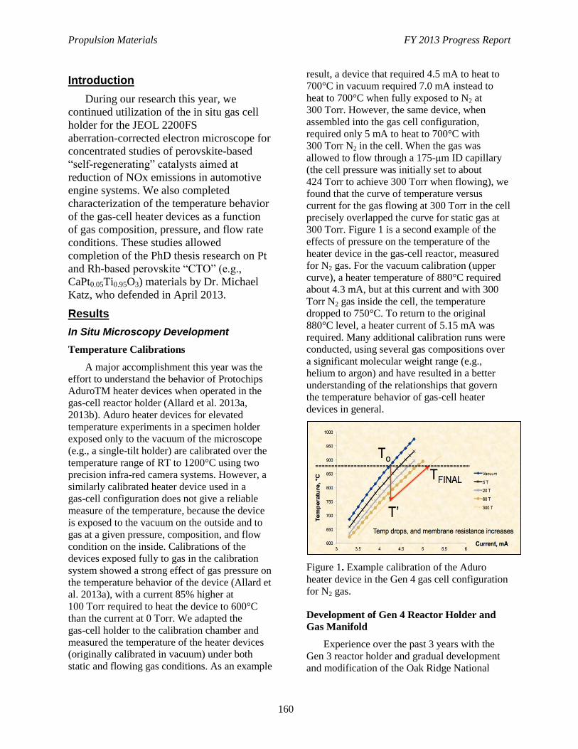
Propulsion Materials FY 2013 Progress Report
160
Introduction
During our research this year, we
continued utilization of the in situ gas cell
holder for the JEOL 2200FS
aberration-corrected electron microscope for
concentrated studies of perovskite-based
“self-regenerating” catalysts aimed at
reduction of NOx emissions in automotive
engine systems. We also completed
characterization of the temperature behavior
of the gas-cell heater devices as a function
of gas composition, pressure, and flow rate
conditions. These studies allowed
completion of the PhD thesis research on Pt
and Rh-based perovskite “CTO” (e.g.,
CaPt0.05Ti0.95O3) materials by Dr. Michael
Katz, who defended in April 2013.
Results
In Situ Microscopy Development
Temperature Calibrations
A major accomplishment this year was the
effort to understand the behavior of Protochips
AduroTM heater devices when operated in the
gas-cell reactor holder (Allard et al. 2013a,
2013b). Aduro heater devices for elevated
temperature experiments in a specimen holder
exposed only to the vacuum of the microscope
(e.g., a single-tilt holder) are calibrated over the
temperature range of RT to 1200°C using two
precision infra-red camera systems. However, a
similarly calibrated heater device used in a
gas-cell configuration does not give a reliable
measure of the temperature, because the device
is exposed to the vacuum on the outside and to
gas at a given pressure, composition, and flow
condition on the inside. Calibrations of the
devices exposed fully to gas in the calibration
system showed a strong effect of gas pressure on
the temperature behavior of the device (Allard et
al. 2013a), with a current 85% higher at
100 Torr required to heat the device to 600°C
than the current at 0 Torr. We adapted the
gas-cell holder to the calibration chamber and
measured the temperature of the heater devices
(originally calibrated in vacuum) under both
static and flowing gas conditions. As an example
result, a device that required 4.5 mA to heat to
700°C in vacuum required 7.0 mA instead to
heat to 700°C when fully exposed to N2 at
300 Torr. However, the same device, when
assembled into the gas cell configuration,
required only 5 mA to heat to 700°C with
300 Torr N2 in the cell. When the gas was
allowed to flow through a 175-μm ID capillary
(the cell pressure was initially set to about
424 Torr to achieve 300 Torr when flowing), we
found that the curve of temperature versus
current for the gas flowing at 300 Torr in the cell
precisely overlapped the curve for static gas at
300 Torr. Figure 1 is a second example of the
effects of pressure on the temperature of the
heater device in the gas-cell reactor, measured
for N2 gas. For the vacuum calibration (upper
curve), a heater temperature of 880°C required
about 4.3 mA, but at this current and with 300
Torr N2 gas inside the cell, the temperature
dropped to 750°C. To return to the original
880°C level, a heater current of 5.15 mA was
required. Many additional calibration runs were
conducted, using several gas compositions over
a significant molecular weight range (e.g.,
helium to argon) and have resulted in a better
understanding of the relationships that govern
the temperature behavior of gas-cell heater
devices in general.
Figure 1. Example calibration of the Aduro
heater device in the Gen 4 gas cell configuration
for N2 gas.
Development of Gen 4 Reactor Holder and
Gas Manifold
Experience over the past 3 years with the
Gen 3 reactor holder and gradual development
and modification of the Oak Ridge National
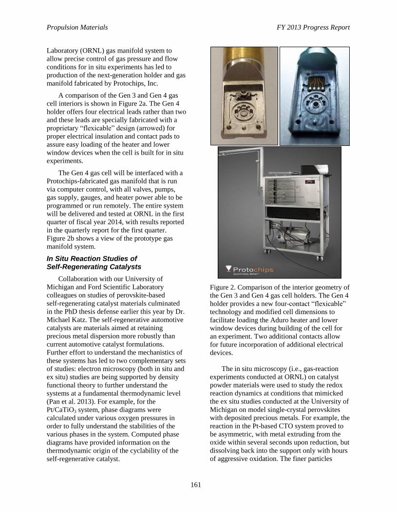
Propulsion Materials FY 2013 Progress Report
161
Laboratory (ORNL) gas manifold system to
allow precise control of gas pressure and flow
conditions for in situ experiments has led to
production of the next-generation holder and gas
manifold fabricated by Protochips, Inc.
A comparison of the Gen 3 and Gen 4 gas
cell interiors is shown in Figure 2a. The Gen 4
holder offers four electrical leads rather than two
and these leads are specially fabricated with a
proprietary “flexicable” design (arrowed) for
proper electrical insulation and contact pads to
assure easy loading of the heater and lower
window devices when the cell is built for in situ
experiments.
The Gen 4 gas cell will be interfaced with a
Protochips-fabricated gas manifold that is run
via computer control, with all valves, pumps,
gas supply, gauges, and heater power able to be
programmed or run remotely. The entire system
will be delivered and tested at ORNL in the first
quarter of fiscal year 2014, with results reported
in the quarterly report for the first quarter.
Figure 2b shows a view of the prototype gas
manifold system.
In Situ Reaction Studies of Self-Regenerating Catalysts
Collaboration with our University of
Michigan and Ford Scientific Laboratory
colleagues on studies of perovskite-based
self-regenerating catalyst materials culminated
in the PhD thesis defense earlier this year by Dr.
Michael Katz. The self-regenerative automotive
catalysts are materials aimed at retaining
precious metal dispersion more robustly than
current automotive catalyst formulations.
Further effort to understand the mechanistics of
these systems has led to two complementary sets
of studies: electron microscopy (both in situ and
ex situ) studies are being supported by density
functional theory to further understand the
systems at a fundamental thermodynamic level
(Pan et al. 2013). For example, for the
Pt/CaTiO3 system, phase diagrams were
calculated under various oxygen pressures in
order to fully understand the stabilities of the
various phases in the system. Computed phase
diagrams have provided information on the
thermodynamic origin of the cyclability of the
self-regenerative catalyst.
Figure 2. Comparison of the interior geometry of
the Gen 3 and Gen 4 gas cell holders. The Gen 4
holder provides a new four-contact “flexicable”
technology and modified cell dimensions to
facilitate loading the Aduro heater and lower
window devices during building of the cell for
an experiment. Two additional contacts allow
for future incorporation of additional electrical
devices.
The in situ microscopy (i.e., gas-reaction
experiments conducted at ORNL) on catalyst
powder materials were used to study the redox
reaction dynamics at conditions that mimicked
the ex situ studies conducted at the University of
Michigan on model single-crystal perovskites
with deposited precious metals. For example, the
reaction in the Pt-based CTO system proved to
be asymmetric, with metal extruding from the
oxide within several seconds upon reduction, but
dissolving back into the support only with hours
of aggressive oxidation. The finer particles
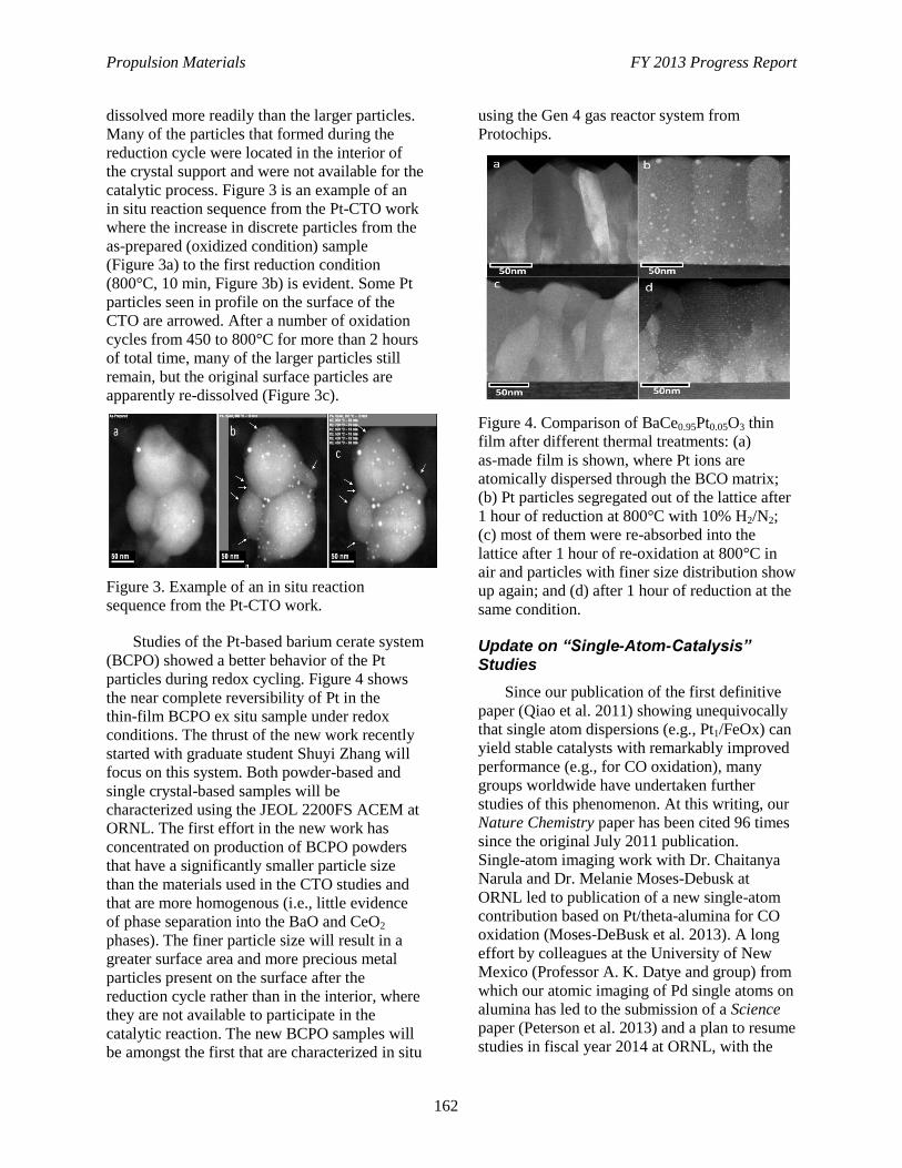
Propulsion Materials FY 2013 Progress Report
162
dissolved more readily than the larger particles.
Many of the particles that formed during the
reduction cycle were located in the interior of
the crystal support and were not available for the
catalytic process. Figure 3 is an example of an
in situ reaction sequence from the Pt-CTO work
where the increase in discrete particles from the
as-prepared (oxidized condition) sample
(Figure 3a) to the first reduction condition
(800°C, 10 min, Figure 3b) is evident. Some Pt
particles seen in profile on the surface of the
CTO are arrowed. After a number of oxidation
cycles from 450 to 800°C for more than 2 hours
of total time, many of the larger particles still
remain, but the original surface particles are
apparently re-dissolved (Figure 3c).
Figure 3. Example of an in situ reaction
sequence from the Pt-CTO work.
Studies of the Pt-based barium cerate system
(BCPO) showed a better behavior of the Pt
particles during redox cycling. Figure 4 shows
the near complete reversibility of Pt in the
thin-film BCPO ex situ sample under redox
conditions. The thrust of the new work recently
started with graduate student Shuyi Zhang will
focus on this system. Both powder-based and
single crystal-based samples will be
characterized using the JEOL 2200FS ACEM at
ORNL. The first effort in the new work has
concentrated on production of BCPO powders
that have a significantly smaller particle size
than the materials used in the CTO studies and
that are more homogenous (i.e., little evidence
of phase separation into the BaO and CeO2
phases). The finer particle size will result in a
greater surface area and more precious metal
particles present on the surface after the
reduction cycle rather than in the interior, where
they are not available to participate in the
catalytic reaction. The new BCPO samples will
be amongst the first that are characterized in situ
using the Gen 4 gas reactor system from
Protochips.
Figure 4. Comparison of BaCe0.95Pt0.05O3 thin
film after different thermal treatments: (a)
as-made film is shown, where Pt ions are
atomically dispersed through the BCO matrix;
(b) Pt particles segregated out of the lattice after
1 hour of reduction at 800°C with 10% H2/N2;
(c) most of them were re-absorbed into the
lattice after 1 hour of re-oxidation at 800°C in
air and particles with finer size distribution show
up again; and (d) after 1 hour of reduction at the
same condition.
Update on “Single-Atom-Catalysis” Studies
Since our publication of the first definitive
paper (Qiao et al. 2011) showing unequivocally
that single atom dispersions (e.g., Pt1/FeOx) can
yield stable catalysts with remarkably improved
performance (e.g., for CO oxidation), many
groups worldwide have undertaken further
studies of this phenomenon. At this writing, our
Nature Chemistry paper has been cited 96 times
since the original July 2011 publication.
Single-atom imaging work with Dr. Chaitanya
Narula and Dr. Melanie Moses-Debusk at
ORNL led to publication of a new single-atom
contribution based on Pt/theta-alumina for CO
oxidation (Moses-DeBusk et al. 2013). A long
effort by colleagues at the University of New
Mexico (Professor A. K. Datye and group) from
which our atomic imaging of Pd single atoms on
alumina has led to the submission of a Science
paper (Peterson et al. 2013) and a plan to resume
studies in fiscal year 2014 at ORNL, with the
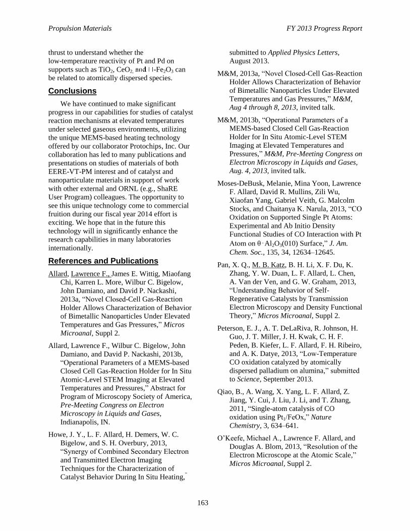
Propulsion Materials FY 2013 Progress Report
163
thrust to understand whether the
low-temperature reactivity of Pt and Pd on
supports such as TiO2, CeO2, -Fe2O3 can
be related to atomically dispersed species.
Conclusions
We have continued to make significant
progress in our capabilities for studies of catalyst
reaction mechanisms at elevated temperatures
under selected gaseous environments, utilizing
the unique MEMS-based heating technology
offered by our collaborator Protochips, Inc. Our
collaboration has led to many publications and
presentations on studies of materials of both
EERE-VT-PM interest and of catalyst and
nanoparticulate materials in support of work
with other external and ORNL (e.g., ShaRE
User Program) colleagues. The opportunity to
see this unique technology come to commercial
fruition during our fiscal year 2014 effort is
exciting. We hope that in the future this
technology will in significantly enhance the
research capabilities in many laboratories
internationally.
References and Publications
Allard, Lawrence F., James E. Wittig, Miaofang
Chi, Karren L. More, Wilbur C. Bigelow,
John Damiano, and David P. Nackashi,
2013a, “Novel Closed-Cell Gas-Reaction
Holder Allows Characterization of Behavior
of Bimetallic Nanoparticles Under Elevated
Temperatures and Gas Pressures,” Micros
Microanal, Suppl 2.
Allard, Lawrence F., Wilbur C. Bigelow, John
Damiano, and David P. Nackashi, 2013b,
“Operational Parameters of a MEMS-based
Closed Cell Gas-Reaction Holder for In Situ
Atomic-Level STEM Imaging at Elevated
Temperatures and Pressures,” Abstract for
Program of Microscopy Society of America,
Pre-Meeting Congress on Electron
Microscopy in Liquids and Gases,
Indianapolis, IN.
Howe, J. Y., L. F. Allard, H. Demers, W. C.
Bigelow, and S. H. Overbury, 2013,
“Synergy of Combined Secondary Electron
and Transmitted Electron Imaging
Techniques for the Characterization of
Catalyst Behavior During In Situ Heating,”
submitted to Applied Physics Letters,
August 2013.
M&M, 2013a, “Novel Closed-Cell Gas-Reaction
Holder Allows Characterization of Behavior
of Bimetallic Nanoparticles Under Elevated
Temperatures and Gas Pressures,” M&M,
Aug 4 through 8, 2013, invited talk.
M&M, 2013b, “Operational Parameters of a
MEMS-based Closed Cell Gas-Reaction
Holder for In Situ Atomic-Level STEM
Imaging at Elevated Temperatures and
Pressures,” M&M, Pre-Meeting Congress on
Electron Microscopy in Liquids and Gases,
Aug. 4, 2013, invited talk.
Moses-DeBusk, Melanie, Mina Yoon, Lawrence
F. Allard, David R. Mullins, Zili Wu,
Xiaofan Yang, Gabriel Veith, G. Malcolm
Stocks, and Chaitanya K. Narula, 2013, “CO
Oxidation on Supported Single Pt Atoms:
Experimental and Ab Initio Density
Functional Studies of CO Interaction with Pt
Atom on θ‑Al2O3(010) Surface,” J. Am.
Chem. Soc., 135, 34, 12634–12645.
Pan, X. Q., M. B. Katz, B. H. Li, X. F. Du, K.
Zhang, Y. W. Duan, L. F. Allard, L. Chen,
A. Van der Ven, and G. W. Graham, 2013,
“Understanding Behavior of Self-
Regenerative Catalysts by Transmission
Electron Microscopy and Density Functional
Theory,” Micros Microanal, Suppl 2.
Peterson, E. J., A. T. DeLaRiva, R. Johnson, H.
Guo, J. T. Miller, J. H. Kwak, C. H. F.
Peden, B. Kiefer, L. F. Allard, F. H. Ribeiro,
and A. K. Datye, 2013, “Low-Temperature
CO oxidation catalyzed by atomically
dispersed palladium on alumina,” submitted
to Science, September 2013.
Qiao, B., A. Wang, X. Yang, L. F. Allard, Z.
Jiang, Y. Cui, J. Liu, J. Li, and T. Zhang,
2011, “Single-atom catalysis of CO
oxidation using Pt1/FeOx,” Nature
Chemistry, 3, 634–641.
O’Keefe, Michael A., Lawrence F. Allard, and
Douglas A. Blom, 2013, “Resolution of the
Electron Microscope at the Atomic Scale,”
Micros Microanal, Suppl 2.
Propulsion Materials FY 2013 Progress Report
164
Suntivich, J., Z. Wu, C. E. Carlton, J. Kim, B.
Han, S. W. Lee, N. Bonnet, N. Marzani, L.
F. Allard, H. A. Gasteiger, K. Hamad-
Schifferli, and Y. Shao-horn, 2013, “Surface
Composition Tuning of Au–Pt Bimetallic
Nanoparticles for Enhanced Carbon
Monoxide and Methanol Electro-oxidation,”
J. Am. Chem. Soc., 135, 21, 7985–7991.
Communications/Visits/Travel
Larry Allard presented an invited talk, “In-
Situ Atomic-level Electron Microscopy of
Catalysts at Elevated Temperatures and
Pressures, via Innovative Closed-Cell Reactor
Specimen Holder Technology,” at a bi-annual
corporate retreat sponsored by ExxonMobil Co.
The workshop comprised three extended invited
talks (Prof. Fabio Ribeiro, Purdue University,
and Dr. Gabriel Vieth, ORNL) on topics
involving catalytic science, with significant
discussion amongst the 70 company scientists
from both domestic and international
ExxonMobil corporate research laboratories.
ExxonMobil and ORNL currently are processing
a work for others project that is expected to start
in January 2014, based on this visit.
Status of Milestones
On schedule.
Propulsion Materials FY 2013 Progress Report
165
Project 18865 – Application-Specific Materials Simulation,
Characterization, and Synthesis
Agreement 14957 – Modeling of Thermoelectrics
A. A. Wereszczak, H. Wang, and M. K. Ferber
Materials Science and Technology Division
Oak Ridge National Laboratory
P.O. Box 2008, MS 6068, Bldg. 4515
Oak Ridge, TN 37831-6068
Phone (865) 576-1169; fax: (865) 574-6098; e-mail: [email protected]
J. Sharp, R. McCarty, A. Thompson, and M. Gilley
Marlow Industries, Inc.
10451 Vista Park Road
Dallas, TX 75238-1645
Phone (214) 342-4287; e-mail: [email protected]
DOE Technology Manager: Jerry L. Gibbs
Phone (202) 586-1182; fax: (202) 586-1600; e-mail: [email protected]
ORNL Technical Advisor: J. Allen Haynes
Phone (865) 576-2894; fax: (865) 574-4913; e-mail: [email protected]
Contractor: Oak Ridge National Laboratory, Oak Ridge, Tennessee
Prime Contract No.: DE-AC05-00OR22725
Objectives
Non-Cooperative Research and Development Agreement (CRADA) subproject: Measure
thermomechanical and thermophysical properties of candidate thermoelectric (TE) materials
(TEMats) for waste heat recovery to advance TEMats and devices (TEDs).
CRADA subproject: Support Marlow with their development and testing of high-temperature TEMats
and TEDs.
Approach
Non-CRADA subproject: Develop characterization test methods that will benefit the TEs and TEDs
manufacturing and end-user communities.
CRADA subproject: Measure properties of proprietary Marlow materials and provide development
support.
Accomplishments
Non-CRADA subproject: Seebeck coefficients and electrical resistivities were measured by numerous
laboratories as part of a round-robin study and interlaboratory variability was assessed. The
laboratories measured equivalent Seebeck coefficients; however, there was variability in the
measured electrical resistivities.
CRADA subproject: Performed testing of Marlow TEMats and supportive evaluation and mechanical
test modeling of their TEDs and the constituents used in them.

Propulsion Materials FY 2013 Progress Report
166
Future Direction
Non-CRADA subproject: Measure properties of additional high-temperature capable TEMats and
provide supportive characterization research and development to support the improvement of TEMats
and TED modeling.
CRADA subproject: Perform thermomechanical and thermophysical property measurements of
proprietary Marlow TEMats and assist in development of Marlow TEDs.
The non-CRADA and CRADA projects are scheduled to complete in the first quarter of fiscal
year (FY) 2014.
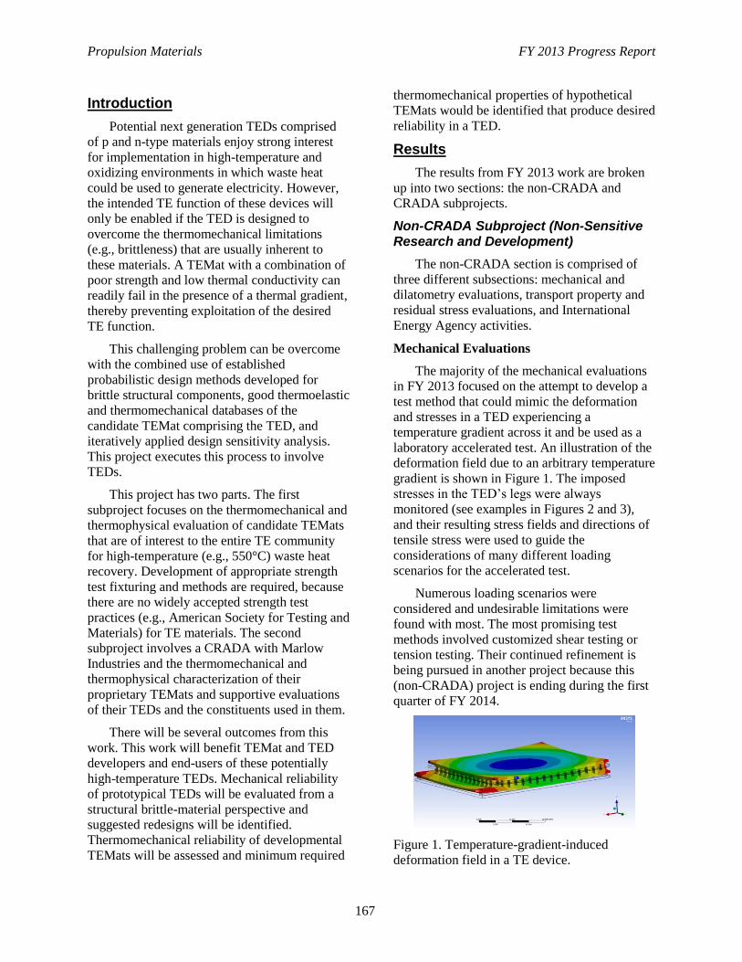
Propulsion Materials FY 2013 Progress Report
167
Introduction
Potential next generation TEDs comprised
of p and n-type materials enjoy strong interest
for implementation in high-temperature and
oxidizing environments in which waste heat
could be used to generate electricity. However,
the intended TE function of these devices will
only be enabled if the TED is designed to
overcome the thermomechanical limitations
(e.g., brittleness) that are usually inherent to
these materials. A TEMat with a combination of
poor strength and low thermal conductivity can
readily fail in the presence of a thermal gradient,
thereby preventing exploitation of the desired
TE function.
This challenging problem can be overcome
with the combined use of established
probabilistic design methods developed for
brittle structural components, good thermoelastic
and thermomechanical databases of the
candidate TEMat comprising the TED, and
iteratively applied design sensitivity analysis.
This project executes this process to involve
TEDs.
This project has two parts. The first
subproject focuses on the thermomechanical and
thermophysical evaluation of candidate TEMats
that are of interest to the entire TE community
for high-temperature (e.g., 550°C) waste heat
recovery. Development of appropriate strength
test fixturing and methods are required, because
there are no widely accepted strength test
practices (e.g., American Society for Testing and
Materials) for TE materials. The second
subproject involves a CRADA with Marlow
Industries and the thermomechanical and
thermophysical characterization of their
proprietary TEMats and supportive evaluations
of their TEDs and the constituents used in them.
There will be several outcomes from this
work. This work will benefit TEMat and TED
developers and end-users of these potentially
high-temperature TEDs. Mechanical reliability
of prototypical TEDs will be evaluated from a
structural brittle-material perspective and
suggested redesigns will be identified.
Thermomechanical reliability of developmental
TEMats will be assessed and minimum required
thermomechanical properties of hypothetical
TEMats would be identified that produce desired
reliability in a TED.
Results
The results from FY 2013 work are broken
up into two sections: the non-CRADA and
CRADA subprojects.
Non-CRADA Subproject (Non-Sensitive Research and Development)
The non-CRADA section is comprised of
three different subsections: mechanical and
dilatometry evaluations, transport property and
residual stress evaluations, and International
Energy Agency activities.
Mechanical Evaluations
The majority of the mechanical evaluations
in FY 2013 focused on the attempt to develop a
test method that could mimic the deformation
and stresses in a TED experiencing a
temperature gradient across it and be used as a
laboratory accelerated test. An illustration of the
deformation field due to an arbitrary temperature
gradient is shown in Figure 1. The imposed
stresses in the TED’s legs were always
monitored (see examples in Figures 2 and 3),
and their resulting stress fields and directions of
tensile stress were used to guide the
considerations of many different loading
scenarios for the accelerated test.
Numerous loading scenarios were
considered and undesirable limitations were
found with most. The most promising test
methods involved customized shear testing or
tension testing. Their continued refinement is
being pursued in another project because this
(non-CRADA) project is ending during the first
quarter of FY 2014.
Figure 1. Temperature-gradient-induced
deformation field in a TE device.
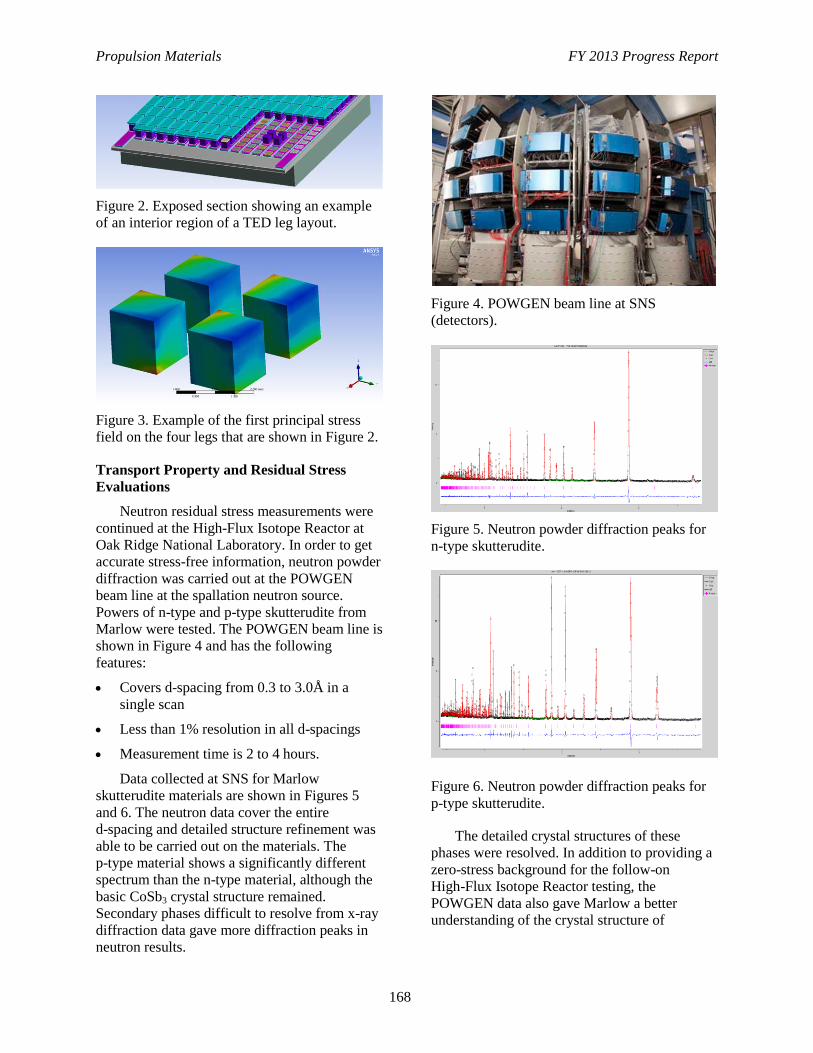
Propulsion Materials FY 2013 Progress Report
168
Figure 2. Exposed section showing an example
of an interior region of a TED leg layout.
Figure 3. Example of the first principal stress
field on the four legs that are shown in Figure 2.
Transport Property and Residual Stress
Evaluations
Neutron residual stress measurements were
continued at the High-Flux Isotope Reactor at
Oak Ridge National Laboratory. In order to get
accurate stress-free information, neutron powder
diffraction was carried out at the POWGEN
beam line at the spallation neutron source.
Powers of n-type and p-type skutterudite from
Marlow were tested. The POWGEN beam line is
shown in Figure 4 and has the following
features:
Covers d-spacing from 0.3 to 3.0Å in a
single scan
Less than 1% resolution in all d-spacings
Measurement time is 2 to 4 hours.
Data collected at SNS for Marlow
skutterudite materials are shown in Figures 5
and 6. The neutron data cover the entire
d-spacing and detailed structure refinement was
able to be carried out on the materials. The
p-type material shows a significantly different
spectrum than the n-type material, although the
basic CoSb3 crystal structure remained.
Secondary phases difficult to resolve from x-ray
diffraction data gave more diffraction peaks in
neutron results.
Figure 4. POWGEN beam line at SNS
(detectors).
Figure 5. Neutron powder diffraction peaks for
n-type skutterudite.
Figure 6. Neutron powder diffraction peaks for
p-type skutterudite.
The detailed crystal structures of these
phases were resolved. In addition to providing a
zero-stress background for the follow-on
High-Flux Isotope Reactor testing, the
POWGEN data also gave Marlow a better
understanding of the crystal structure of
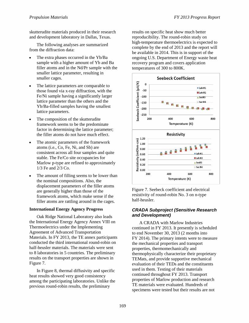
Propulsion Materials FY 2013 Progress Report
169
skutterudite materials produced in their research
and development laboratory in Dallas, Texas.
The following analyses are summarized
from the diffraction data:
The extra phases occurred in the Yb/Ba
sample with a higher amount of Yb and Ba
filler atoms and in the Nd/Pr sample with the
smaller lattice parameter, resulting in
smaller cages.
The lattice parameters are comparable to
those found via x-ray diffraction, with the
Fe/Ni sample having a significantly larger
lattice parameter than the others and the
Yb/Ba-filled samples having the smallest
lattice parameters.
The composition of the skutterudite
framework seems to be the predominate
factor in determining the lattice parameter;
the filler atoms do not have much effect.
The atomic parameters of the framework
atoms (i.e., Co, Fe, Ni, and Sb) are
consistent across all four samples and quite
stable. The Fe/Co site occupancies for
Marlow p-type are refined to approximately
1/3 Fe and 2/3 Co.
The amount of filling seems to be lower than
the nominal compositions. Also, the
displacement parameters of the filler atoms
are generally higher than those of the
framework atoms, which make sense if the
filler atoms are rattling around in the cages.
International Energy Agency Progress
Oak Ridge National Laboratory also leads
the International Energy Agency Annex VIII on
Thermoelectrics under the Implementing
Agreement of Advanced Transportation
Materials. In FY 2013, the TE annex participants
conducted the third international round-robin on
half-heusler materials. The materials were sent
to 8 laboratories in 5 countries. The preliminary
results on the transport properties are shown in
Figure 7.
In Figure 8, thermal diffusivity and specific
heat results showed very good consistency
among the participating laboratories. Unlike the
previous round-robin results, the preliminary
results on specific heat show much better
reproducibility. The round-robin study on
high-temperature thermoelectrics is expected to
complete by the end of 2013 and the report will
be available in 2014. This is in support of the
ongoing U.S. Department of Energy waste heat
recovery program and covers application
temperatures of 300 to 800K.
Figure 7. Seebeck coefficient and electrical
resistivity of round-robin No. 3 on n-type
half-heusler.
CRADA Subproject (Sensitive Research and Development)
A CRADA with Marlow Industries
continued in FY 2013. It presently is scheduled
to end November 30, 2013 (2 months into
FY 2014). The primary intents were to measure
the mechanical properties and transport
properties, thermomechanically and
thermophysically characterize their proprietary
TEMats, and provide supportive mechanical
evaluation of their TEDs and the constituents
used in them. Testing of their materials
continued throughout FY 2013. Transport
properties of Marlow production and research
TE materials were evaluated. Hundreds of
specimens were tested but their results are not
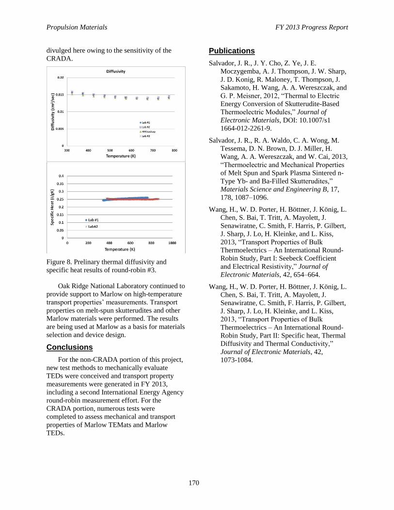
Propulsion Materials FY 2013 Progress Report
170
divulged here owing to the sensitivity of the
CRADA.
Figure 8. Prelinary thermal diffusivity and
specific heat results of round-robin #3.
Oak Ridge National Laboratory continued to
provide support to Marlow on high-temperature
transport properties’ measurements. Transport
properties on melt-spun skutterudites and other
Marlow materials were performed. The results
are being used at Marlow as a basis for materials
selection and device design.
Conclusions
For the non-CRADA portion of this project,
new test methods to mechanically evaluate
TEDs were conceived and transport property
measurements were generated in FY 2013,
including a second International Energy Agency
round-robin measurement effort. For the
CRADA portion, numerous tests were
completed to assess mechanical and transport
properties of Marlow TEMats and Marlow
TEDs.
Publications
Salvador, J. R., J. Y. Cho, Z. Ye, J. E.
Moczygemba, A. J. Thompson, J. W. Sharp,
J. D. Konig, R. Maloney, T. Thompson, J.
Sakamoto, H. Wang, A. A. Wereszczak, and
G. P. Meisner, 2012, “Thermal to Electric
Energy Conversion of Skutterudite-Based
Thermoelectric Modules,” Journal of
Electronic Materials, DOI: 10.1007/s1
1664-012-2261-9.
Salvador, J. R., R. A. Waldo, C. A. Wong, M.
Tessema, D. N. Brown, D. J. Miller, H.
Wang, A. A. Wereszczak, and W. Cai, 2013,
“Thermoelectric and Mechanical Properties
of Melt Spun and Spark Plasma Sintered n-
Type Yb- and Ba-Filled Skutterudites,”
Materials Science and Engineering B, 17,
178, 1087–1096.
Wang, H., W. D. Porter, H. Böttner, J. König, L.
Chen, S. Bai, T. Tritt, A. Mayolett, J.
Senawiratne, C. Smith, F. Harris, P. Gilbert,
J. Sharp, J. Lo, H. Kleinke, and L. Kiss,
2013, “Transport Properties of Bulk
Thermoelectrics – An International Round-
Robin Study, Part I: Seebeck Coefficient
and Electrical Resistivity,” Journal of
Electronic Materials, 42, 654–664.
Wang, H., W. D. Porter, H. Böttner, J. König, L.
Chen, S. Bai, T. Tritt, A. Mayolett, J.
Senawiratne, C. Smith, F. Harris, P. Gilbert,
J. Sharp, J. Lo, H. Kleinke, and L. Kiss,
2013, “Transport Properties of Bulk
Thermoelectrics – An International Round-
Robin Study, Part II: Specific heat, Thermal
Diffusivity and Thermal Conductivity,”
Journal of Electronic Materials, 42,
1073-1084.
Propulsion Materials FY 2013 Progress Report
171
Project 18865 – Application-Specific Materials Simulation,
Characterization, and Synthesis
Agreement 15529 – Erosion of Materials by Nanofluids
Dileep Singh
Argonne National Laboratory
9700 S. Cass Avenue
Argonne, IL 60439
Phone (630) 252-5009; fax: (630) 252-2785; e-mail: [email protected]
DOE Technology Manager: Jerry L. Gibbs
Phone (202) 586-1182; fax: (202) 586-1600; e-mail: [email protected]
Contractor: UChicago Argonne LLC
Prime Contract No.: DE AC03 06CH11357
Objectives
Determine if the use of fluids containing a variety of nanoparticles results in erosive damage to
radiator materials and coolant pumps
Determine figures of merit for use of nanofluids for cooling power electronics
Measure pumping power of nanofluids in a real system and compare results to theoretical calculations
Determine if nanofluids will clog a pumping system.
Approach
Characterize the thermal conductivity, viscosity, and heat transfer of various nanofluids
Use surfactants and/or adjustments of pH to lower the viscosity of nanofluids
Conduct experiments to study erosive damage, clogging of nanofluids, and power for pumping
various nanofluids in a real system.
Accomplishments
Designed, built, and calibrated a new erosion apparatus to measure wear in an automotive water pump
and the torque required to pump nanofluids
No significant erosive damage has been observed in the cast aluminum pump impeller and no erosion
has been observed for aluminum target material
The measured pumping power agrees with the power calculated using single-phase parameters based
on measured values of the nanofluids
Developed stable graphene-based nanofluids for power electronics with enhanced thermal
performance
Clogging test equipment was built and tested over the long term, using the graphitic nanofluids
12 papers were published in peer-review publications and 2 patent applications were filed.
Future Direction
The project on erosion of nanofluids ended in fiscal year 2011. However, efforts were redirected to
develop nanofluids for cooling of power electronics for hybrid electric vehicles and to evaluate
fouling of channels with the developed nanofluids.
Propulsion Materials FY 2013 Progress Report
172
Introduction
Many industrial technologies face the
challenge of thermal management. With
ever-increasing thermal loads due to trends
toward greater power output for engines and
exhaust gas recirculation for diesel engines,
cooling is a crucial issue in transportation. The
conventional approach for increasing cooling
rates is use of extended surfaces such as fins and
microchannels. Reducing radiator size will
reduce the frontal area, which will reduce the
aerodynamic drag. However, current radiator
designs have already stretched these approaches
to their limits. Therefore, an urgent need exists
for new and innovative concepts to achieve
ultra-high-performance cooling. Nanofluids
seem to show enormous potential as coolant for
radiators. The literature provides many examples
of increased fluid thermal conductivity by
adding nanoparticles (see review by Yu et al.
2008). Enhanced thermal conductivity could
lead to enhanced heat transfer. A computational
fluid dynamics calculation of a Cummins,
500-hp, diesel engine using an ideal nanofluid as
coolant has shown that the radiator size could be
reduced by 5% (Saripella et al. 2007), which
would reduce weight and size and aerodynamic
drag.
In order for the enhanced thermal
conductivity to be utilized, it must be shown that
liquid erosion of typical radiator materials will
be tolerable and that the increased pumping
power resulting from higher viscosity will not
exceed the gain in parasitic energy losses from
enhanced cooling. Furthermore nanofluids
cannot clog the pumping system. If nanofluids
result in excessive erosive wear, clog the
pumping system, or require very high increased
pumping power, they cannot be used. Therefore,
the Vehicle Technologies Office funds an
investigation of liquid erosion of radiator
materials, clogging, and pumping power using
nanofluids.
During the past year, graphene-based
nanofluids were developed and characterized for
their thermophysical properties and fouling
behavior in small channels. It has been shown
that nanofluids’ (Timofeeva 2011)high level of
enhancement in thermal conductivity can be
achieved with either addition of metallic or high
aspect ratio graphitic nanoparticles. Metallic
nanoparticles do not perform well because of
their propensity to oxidize and agglomerate.
However, carbon nanomaterials show 200 to
300% increases in thermal conductivity with
carbon nanotubes (Sastry et al. 2008, Choi et al.
2001) and graphene oxides (Yu et al. 2010,
2011). These dramatic increases in thermal
conductivity of nanofluids are most likely due to
the unique nature of anisotropic carbon
nanomaterials, which allows engagement of
multiple heat transfer mechanisms in
suspensions (i.e., effective medium theory,
percolation, and plasmon resonances).
The drawback of carbonaceous nanofluids
with high aspect ratio particles is very high
viscosity (up to 3 orders of magnitude higher
than viscosity of the base fluid). These viscosity
increases result in pumping power penalties that
are higher than the benefits in thermal
conductivity of suspensions.
The focus has been on developing
grapheme-based nanofluids with enhanced
thermal conductivities and a minimal increase in
viscosities. Subsequently, focus also has been on
conducting fouling experiments with optimized
nanofluid formulations.
Experimental Details and Results
Three commercial grades of graphene
nanoparticles (A, B, and C) were obtained and
dispersed in ethylene glycol/water. Surface
functionalization of graphene particles was done
prior to dispersion. Surface functionalization
leads to electrostatic stabilization of the particles
and, at the same time, provides thermal
conductivity of the fluid by a percolation
mechanism. Figure 1 shows the scanning
electron microscopy images of the three
functionalized graphite nanoparticles.
The effect of GnP surface functionalization
of the thermo-physical properties of nanofluids
were compared for unmodified GnP and f-GnP
at 5 wt% loadings (Figures 2 and 3). One can see
that the highest increases in thermal conductivity
were achieved in C grade, followed by B grade
and A grade, provided the smallest thermal
conductivity increases. The observed
enhancements are well beyond the effective
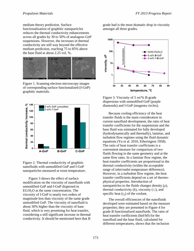
Propulsion Materials FY 2013 Progress Report
173
medium theory prediction. Surface
functionalization of graphitic nanoparticles
reduces the thermal conductivity enhancements
across all grades by 30 to 50% of analogous GnP
suspensions. However, the increases in thermal
conductivity are still way beyond the effective
medium prediction, reaching 75 to 85% above
the base fluid at about 2.25 vol. %.
Figure 1. Scanning electron microscopy images
of corresponding surface functionalized (f-GnP)
graphitic materials.
Figure 2. Thermal conductivity of graphitic
nanofluids with unmodified GnP and f-GnP
nanoparticles measured at room temperature.
Figure 3 shows the effect of surface
modification on the viscosity of nanofluids with
unmodified GnP and f-GnP dispersed in
EG/H2O at the same concentration. The
viscosity of f-GnP is nearly two orders of
magnitude less than viscosity of the same grade
unmodified GnP. The viscosity of nanofluid is
about 30% higher than the viscosity of base
fluid, which is very promising for heat transfer,
considering a still significant increase in thermal
conductivity. It should be mentioned here that B
grade had is the most dramatic drop in viscosity
amongst all three grades.
Figure 3. Viscosity of 5 wt/% B-grade
dispersions with unmodified GnP (purple
diamonds) and f-GnP (magenta circles).
Because cooling efficiency of the heat
transfer fluids is the main consideration in
current nanofluid development, the ratio of heat
transfer coefficients for the suspensions and the
base fluid was estimated for fully developed
(hydrodynamically and thermally), laminar, and
turbulent flow regimes using the fluid dynamic
equations (Yu et al. 2010, Etherington 1958).
The ratio of heat transfer coefficients is a
convenient measure for comparison of two
fluids flowing in the same geometry and at the
same flow rates. In a laminar flow regime, the
heat transfer coefficients are proportional to the
thermal conductivity (within the acceptable
range of inlet/outlet temperature difference).
However, in a turbulent flow regime, the heat
transfer coefficients depend on a set of thermo-
physical properties. Introduction of
nanoparticles to the fluids changes density (ρ),
thermal conductivity (k), viscosity ( ), and
specific heat (cp) of the coolant.
The overall efficiencies of the nanofluids
developed were estimated based on the measure
properties; they are presented in Figure 4 for
grade B functionalized nanofluids. The ratio of
heat transfer coefficients (hnf/h0) for the
nanofluid and the base fluid, calculated for
different temperatures, shows that the inclusion
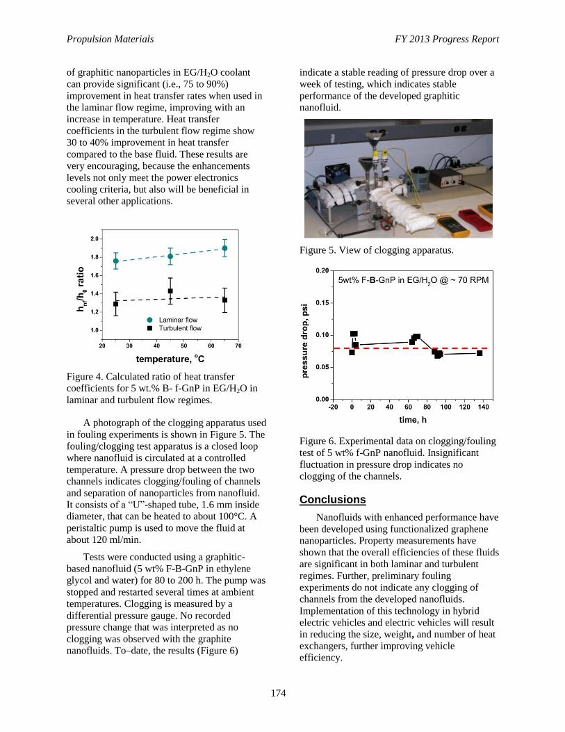
Propulsion Materials FY 2013 Progress Report
174
of graphitic nanoparticles in EG/H2O coolant
can provide significant (i.e., 75 to 90%)
improvement in heat transfer rates when used in
the laminar flow regime, improving with an
increase in temperature. Heat transfer
coefficients in the turbulent flow regime show
30 to 40% improvement in heat transfer
compared to the base fluid. These results are
very encouraging, because the enhancements
levels not only meet the power electronics
cooling criteria, but also will be beneficial in
several other applications.
Figure 4. Calculated ratio of heat transfer
coefficients for 5 wt.% B- f-GnP in EG/H2O in
laminar and turbulent flow regimes.
A photograph of the clogging apparatus used
in fouling experiments is shown in Figure 5. The
fouling/clogging test apparatus is a closed loop
where nanofluid is circulated at a controlled
temperature. A pressure drop between the two
channels indicates clogging/fouling of channels
and separation of nanoparticles from nanofluid.
It consists of a “U”-shaped tube, 1.6 mm inside
diameter, that can be heated to about 100°C. A
peristaltic pump is used to move the fluid at
about 120 ml/min.
Tests were conducted using a graphitic-
based nanofluid (5 wt% F-B-GnP in ethylene
glycol and water) for 80 to 200 h. The pump was
stopped and restarted several times at ambient
temperatures. Clogging is measured by a
differential pressure gauge. No recorded
pressure change that was interpreted as no
clogging was observed with the graphite
nanofluids. To–date, the results (Figure 6)
indicate a stable reading of pressure drop over a
week of testing, which indicates stable
performance of the developed graphitic
nanofluid.
Figure 5. View of clogging apparatus.
Figure 6. Experimental data on clogging/fouling
test of 5 wt% f-GnP nanofluid. Insignificant
fluctuation in pressure drop indicates no
clogging of the channels.
Conclusions
Nanofluids with enhanced performance have
been developed using functionalized graphene
nanoparticles. Property measurements have
shown that the overall efficiencies of these fluids
are significant in both laminar and turbulent
regimes. Further, preliminary fouling
experiments do not indicate any clogging of
channels from the developed nanofluids.
Implementation of this technology in hybrid
electric vehicles and electric vehicles will result
in reducing the size, weight, and number of heat
exchangers, further improving vehicle
efficiency.
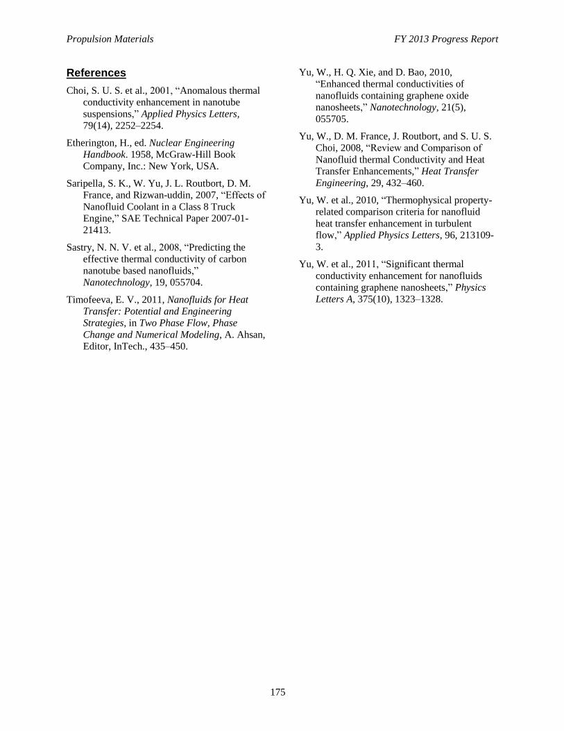
Propulsion Materials FY 2013 Progress Report
175
References
Choi, S. U. S. et al., 2001, “Anomalous thermal
conductivity enhancement in nanotube
suspensions,” Applied Physics Letters,
79(14), 2252–2254.
Etherington, H., ed. Nuclear Engineering
Handbook. 1958, McGraw-Hill Book
Company, Inc.: New York, USA.
Saripella, S. K., W. Yu, J. L. Routbort, D. M.
France, and Rizwan-uddin, 2007, “Effects of
Nanofluid Coolant in a Class 8 Truck
Engine,” SAE Technical Paper 2007-01-
21413.
Sastry, N. N. V. et al., 2008, “Predicting the
effective thermal conductivity of carbon
nanotube based nanofluids,”
Nanotechnology, 19, 055704.
Timofeeva, E. V., 2011, Nanofluids for Heat
Transfer: Potential and Engineering
Strategies, in Two Phase Flow, Phase
Change and Numerical Modeling, A. Ahsan,
Editor, InTech., 435–450.
Yu, W., H. Q. Xie, and D. Bao, 2010,
“Enhanced thermal conductivities of
nanofluids containing graphene oxide
nanosheets,” Nanotechnology, 21(5),
055705.
Yu, W., D. M. France, J. Routbort, and S. U. S.
Choi, 2008, “Review and Comparison of
Nanofluid thermal Conductivity and Heat
Transfer Enhancements,” Heat Transfer
Engineering, 29, 432–460.
Yu, W. et al., 2010, “Thermophysical property-
related comparison criteria for nanofluid
heat transfer enhancement in turbulent
flow,” Applied Physics Letters, 96, 213109-
3.
Yu, W. et al., 2011, “Significant thermal
conductivity enhancement for nanofluids
containing graphene nanosheets,” Physics
Letters A, 375(10), 1323–1328.
Propulsion Materials FY 2013 Progress Report
176
Project 18865 – Application-Specific Materials Simulation,
Characterization, and Synthesis
Agreement 16308 – Thermoelectrics Theory and Structure
D.J. Singh
Materials Science and Technology Division
Oak Ridge National Laboratory
P.O. Box 2008, MS 6056
Oak Ridge, TN 37831-6068
Phone (865) 241-1944; fax: (865) 574-7659; e-mail: [email protected]
DOE Technology Manager: Jerry L. Gibbs
Phone (202) 586-1182; fax: (202) 586-1600; e-mail: [email protected]
ORNL Technical Advisor: J. Allen Haynes
Phone (865) 576-2894; fax: (865) 574-4913; e-mail: [email protected]
Contractor: Oak Ridge National Laboratory, Oak Ridge, Tennessee
Prime Contract No.: DE-AC05-00OR22725
Objectives
Find ways to optimize existing thermoelectric materials and discover new families of
high-performance thermoelectrics for waste heat recovery applications using modern, science-based
materials design strategies.
Find low-cost materials that have high thermoelectric figures of merit and are suitable for vehicular
applications.
Approach
First principles calculations, based on quantum mechanics, are used to calculate the electronic
structure and thermoelectric properties of materials.
Boltzmann transport equations are solved to obtain electrical transport properties.
Vibrational properties are investigated and mechanisms for thermal conductivity reduction are
assessed.
Accomplishments
Found that an entire family of alkaline earth plumbide semiconductors (Ca2Pb, Sr2Pb, and Ba2Pb)
may exhibit good thermoelectric performance, for both p-type and n-type, at a range of temperatures
from room temperature (suitable for heating and cooling applications) to 900K (suitable for exhaust
waste heat recovery).
Found that a corresponding family of environmentally friendly stannide semiconductors (Ca2Sn,
Sr2Sn, and Ba2Sn) may also show good thermoelectric performance at elevated temperatures.
Found that the chalcogenide semiconductor PbS may show ZT values as high as 1.7 to 2.0 for both
p-type and n-type at elevated temperatures.
Identified acoustic impedance mismatch scattering as the agent of thermal conductivity reduction in
nanostructured thermoelectrics and proposed a nanostructuring “figure-of-merit” for the likely
efficacy of such scattering.
Identified low-dimensional electronic structures, which can exist even in electrically isotropic
materials, as a potential paradigm for high thermoelectric performance.

Propulsion Materials FY 2013 Progress Report
177
Future Direction
Identify new, high-performance, low-cost thermoelectric compositions suitable for vehicular
applications such as exhaust waste heat recovery and cabin heating/cooling.
Calculate doping level dependence of thermoelectric properties to guide optimization of existing
materials.
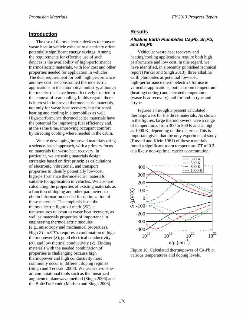
Propulsion Materials FY 2013 Progress Report
178
Introduction
The use of thermoelectric devices to convert
waste heat in vehicle exhaust to electricity offers
potentially significant energy savings. Among
the requirements for effective use of such
devices is the availability of high-performance
thermoelectric materials, with low cost and other
properties needed for application in vehicles.
The dual requirement for both high performance
and low cost has constrained thermoelectric
applications in the automotive industry, although
thermoelectrics have been effectively inserted in
the context of seat cooling. In this regard, there
is interest in improved thermoelectric materials,
not only for waste heat recovery, but for zonal
heating and cooling in automobiles as well.
High-performance thermoelectric materials have
the potential for improving fuel efficiency and,
at the same time, improving occupant comfort
by directing cooling where needed in the cabin.
We are developing improved materials using
a science-based approach, with a primary focus
on materials for waste heat recovery. In
particular, we are using materials design
strategies based on first principles calculations
of electronic, vibrational, and transport
properties to identify potentially low-cost,
high-performance thermoelectric materials
suitable for application in vehicles. We also are
calculating the properties of existing materials as
a function of doping and other parameters to
obtain information needed for optimization of
these materials. The emphasis is on the
thermoelectric figure of merit (ZT) at
temperatures relevant to waste heat recovery, as
well as materials properties of importance in
engineering thermoelectric modules
(e.g., anisotropy and mechanical properties).
High ZT=S2T/ requires a combination of high
thermopower (S), good electrical conductivity
(), and low thermal conductivity (). Finding
materials with the needed combination of
properties is challenging because high
thermopower and high conductivity most
commonly occur in different doping regimes
(Singh and Terasaki 2008). We use state-of-the-
art computational tools such as the linearized
augmented planewave method (Singh 2006) and
the BoltzTraP code (Madsen and Singh 2006).
Results
Alkaline Earth Plumbides Ca2Pb, Sr2Pb, and Ba2Pb
Vehicular waste heat recovery and
heating/cooling applications require both high
performance and low cost. In this regard, we
have identified, in a recently published technical
report (Parker and Singh 2013), three alkaline
earth plumbides as potential low-cost,
high-performance thermoelectrics for use in
vehicular applications, both at room temperature
(heating/cooling) and elevated temperature
(waste heat recovery) and for both p-type and
n-type.
Figures 1 through 3 present calculated
thermopowers for the three materials. As shown
in the figures, large thermopowers have a range
of temperatures from 300 to 800 K and as high
as 1000 K, depending on the material. This is
important given that the only experimental study
(Russell and Klein 1961) of these materials
found a significant room temperature ZT of 0.2
at a likely non-optimal carrier concentration.
Figure 10. Calculated thermopower of Ca2Pb at
various temperatures and doping levels.
1018
1019
1020
1021
n/p (cm-3
)
0
100
200
300
400
-100
-200
-300
-400
S (
mV
/K)
300 K500 K800 K1000 K
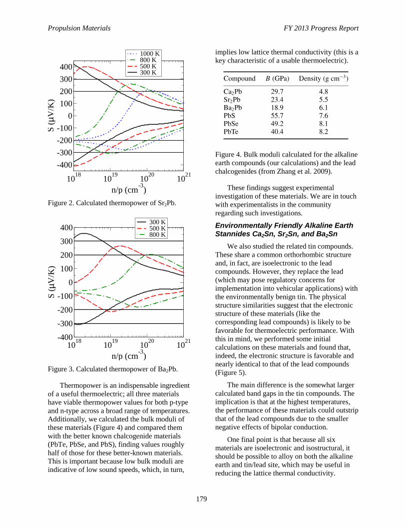
Propulsion Materials FY 2013 Progress Report
179
Figure 2. Calculated thermopower of Sr2Pb.
Figure 3. Calculated thermopower of Ba2Pb.
Thermopower is an indispensable ingredient
of a useful thermoelectric; all three materials
have viable thermopower values for both p-type
and n-type across a broad range of temperatures.
Additionally, we calculated the bulk moduli of
these materials (Figure 4) and compared them
with the better known chalcogenide materials
(PbTe, PbSe, and PbS), finding values roughly
half of those for these better-known materials.
This is important because low bulk moduli are
indicative of low sound speeds, which, in turn,
implies low lattice thermal conductivity (this is a
key characteristic of a usable thermoelectric).
Figure 4. Bulk moduli calculated for the alkaline
earth compounds (our calculations) and the lead
chalcogenides (from Zhang et al. 2009).
These findings suggest experimental
investigation of these materials. We are in touch
with experimentalists in the community
regarding such investigations.
Environmentally Friendly Alkaline Earth Stannides Ca2Sn, Sr2Sn, and Ba2Sn
We also studied the related tin compounds.
These share a common orthorhombic structure
and, in fact, are isoelectronic to the lead
compounds. However, they replace the lead
(which may pose regulatory concerns for
implementation into vehicular applications) with
the environmentally benign tin. The physical
structure similarities suggest that the electronic
structure of these materials (like the
corresponding lead compounds) is likely to be
favorable for thermoelectric performance. With
this in mind, we performed some initial
calculations on these materials and found that,
indeed, the electronic structure is favorable and
nearly identical to that of the lead compounds
(Figure 5).
The main difference is the somewhat larger
calculated band gaps in the tin compounds. The
implication is that at the highest temperatures,
the performance of these materials could outstrip
that of the lead compounds due to the smaller
negative effects of bipolar conduction.
One final point is that because all six
materials are isoelectronic and isostructural, it
should be possible to alloy on both the alkaline
earth and tin/lead site, which may be useful in
reducing the lattice thermal conductivity.
1018
1019
1020
1021
n/p (cm-3
)
0
100
200
300
400
-100
-200
-300
-400
S (
mV
/K)
1000 K800 K500 K300 K
1018
1019
1020
1021
n/p (cm-3
)
0
100
200
300
400
-100
-200
-300
-400
S (
mV
/K)
300 K500 K800 K
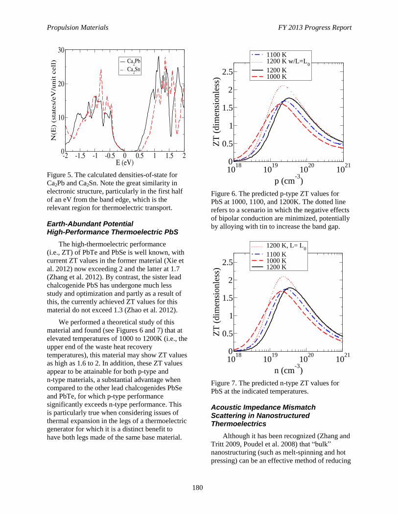
Propulsion Materials FY 2013 Progress Report
180
Figure 5. The calculated densities-of-state for
Ca2Pb and Ca2Sn. Note the great similarity in
electronic structure, particularly in the first half
of an eV from the band edge, which is the
relevant region for thermoelectric transport.
Earth-Abundant Potential High-Performance Thermoelectric PbS
The high-thermoelectric performance
(i.e., ZT) of PbTe and PbSe is well known, with
current ZT values in the former material (Xie et
al. 2012) now exceeding 2 and the latter at 1.7
(Zhang et al. 2012). By contrast, the sister lead
chalcogenide PbS has undergone much less
study and optimization and partly as a result of
this, the currently achieved ZT values for this
material do not exceed 1.3 (Zhao et al. 2012).
We performed a theoretical study of this
material and found (see Figures 6 and 7) that at
elevated temperatures of 1000 to 1200K (i.e., the
upper end of the waste heat recovery
temperatures), this material may show ZT values
as high as 1.6 to 2. In addition, these ZT values
appear to be attainable for both p-type and
n-type materials, a substantial advantage when
compared to the other lead chalcogenides PbSe
and PbTe, for which p-type performance
significantly exceeds n-type performance. This
is particularly true when considering issues of
thermal expansion in the legs of a thermoelectric
generator for which it is a distinct benefit to
have both legs made of the same base material.
Figure 6. The predicted p-type ZT values for
PbS at 1000, 1100, and 1200K. The dotted line
refers to a scenario in which the negative effects
of bipolar conduction are minimized, potentially
by alloying with tin to increase the band gap.
Figure 7. The predicted n-type ZT values for
PbS at the indicated temperatures.
Acoustic Impedance Mismatch Scattering in Nanostructured Thermoelectrics
Although it has been recognized (Zhang and
Tritt 2009, Poudel et al. 2008) that “bulk”
nanostructuring (such as melt-spinning and hot
pressing) can be an effective method of reducing
1018
1019
1020
1021
p (cm-3
)
0
0.5
1
1.5
2
2.5
ZT
(d
imen
sio
nle
ss)
1100 K1200 K w/L=L
0
1200 K1000 K
1018
1019
1020
1021
n (cm-3
)
0
0.5
1
1.5
2
2.5
ZT
(dim
ensi
onle
ss)
1200 K, L= L0
1100 K1000 K1200 K
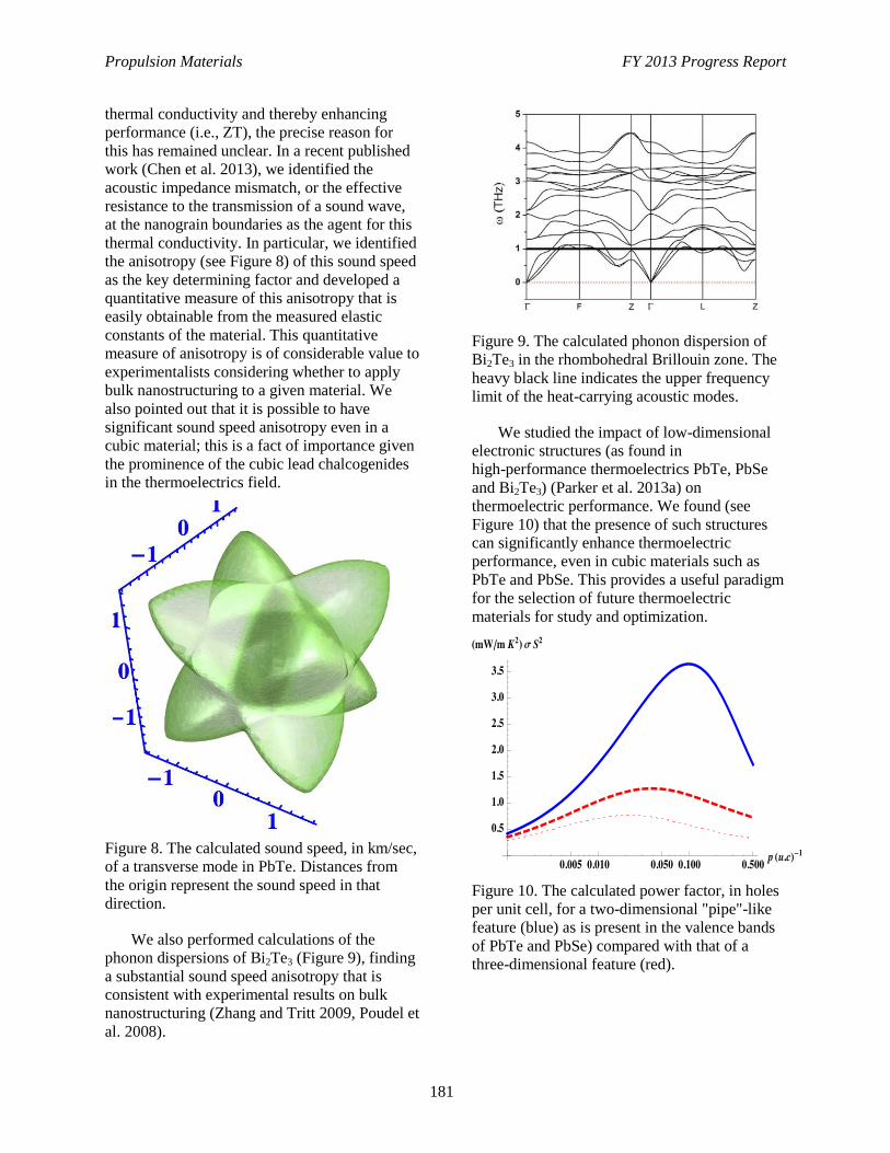
Propulsion Materials FY 2013 Progress Report
181
thermal conductivity and thereby enhancing
performance (i.e., ZT), the precise reason for
this has remained unclear. In a recent published
work (Chen et al. 2013), we identified the
acoustic impedance mismatch, or the effective
resistance to the transmission of a sound wave,
at the nanograin boundaries as the agent for this
thermal conductivity. In particular, we identified
the anisotropy (see Figure 8) of this sound speed
as the key determining factor and developed a
quantitative measure of this anisotropy that is
easily obtainable from the measured elastic
constants of the material. This quantitative
measure of anisotropy is of considerable value to
experimentalists considering whether to apply
bulk nanostructuring to a given material. We
also pointed out that it is possible to have
significant sound speed anisotropy even in a
cubic material; this is a fact of importance given
the prominence of the cubic lead chalcogenides
in the thermoelectrics field.
Figure 8. The calculated sound speed, in km/sec,
of a transverse mode in PbTe. Distances from
the origin represent the sound speed in that
direction.
We also performed calculations of the
phonon dispersions of Bi2Te3 (Figure 9), finding
a substantial sound speed anisotropy that is
consistent with experimental results on bulk
nanostructuring (Zhang and Tritt 2009, Poudel et
al. 2008).
Figure 9. The calculated phonon dispersion of
Bi2Te3 in the rhombohedral Brillouin zone. The
heavy black line indicates the upper frequency
limit of the heat-carrying acoustic modes.
We studied the impact of low-dimensional
electronic structures (as found in
high-performance thermoelectrics PbTe, PbSe
and Bi2Te3) (Parker et al. 2013a) on
thermoelectric performance. We found (see
Figure 10) that the presence of such structures
can significantly enhance thermoelectric
performance, even in cubic materials such as
PbTe and PbSe. This provides a useful paradigm
for the selection of future thermoelectric
materials for study and optimization.
Figure 10. The calculated power factor, in holes
per unit cell, for a two-dimensional "pipe"-like
feature (blue) as is present in the valence bands
of PbTe and PbSe) compared with that of a
three-dimensional feature (red).
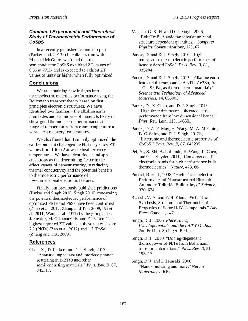
Propulsion Materials FY 2013 Progress Report
182
Combined Experimental and Theoretical Study of Thermoelectric Performance of CoSbS
In a recently published technical report
(Parker et al. 2013b) in collaboration with
Michael McGuire, we found that the
semiconductor CoSbS exhibited ZT values of
0.35 at 773K and is expected to exhibit ZT
values of unity or higher when fully optimized.
Conclusions
We are obtaining new insights into
thermoelectric materials performance using the
Boltzmann transport theory based on first
principles electronic structures. We have
identified two families – the alkaline earth
plumbides and stannides – of materials likely to
show good thermoelectric performance at a
range of temperatures from room temperature to
waste heat recovery temperatures.
We also found that if suitably optimized, the
earth-abundant chalcogenide PbS may show ZT
values from 1.6 to 2 at waste heat recovery
temperatures. We have identified sound speed
anisotropy as the determining factor in the
effectiveness of nanostructuring in reducing
thermal conductivity and the potential benefits
to thermoelectric performance of
low-dimensional electronic features.
Finally, our previously published predictions
(Parker and Singh 2010, Singh 2010) concerning
the potential thermoelectric performance of
optimized PbTe and PbSe have been confirmed
(Zhao et al. 2012, Zhang and Tritt 2009, Pei et
al. 2011, Wang et al. 2011) by the groups of G.
J. Snyder, M. G Kanatzidis, and Z. F. Ren. The
highest reported ZT values in these materials are
2.2 (PbTe) (Zao et al. 2012) and 1.7 (PbSe)
(Zhang and Tritt 2009).
References
Chen, X., D. Parker, and D. J. Singh, 2013,
“Acoustic impedance and interface phonon
scattering in Bi2Te3 and other
semiconducting materials,” Phys. Rev. B, 87,
045317.
Madsen, G. K. H. and D. J. Singh, 2006,
“BoltzTraP: A code for calculating band-
structure dependent quantities,” Computer
Physics Communications, 175, 67.
Parker, D. and D. J. Singh, 2010, “High-
temperature thermoelectric performance of
heavily doped PbSe,” Phys. Rev. B, 81,
035204.
Parker, D. and D. J. Singh, 2013, “Alkaline earth
lead and tin compounds Ae2Pb, Ae2Sn, Ae
= Ca, Sr, Ba, as thermoelectric materials,”
Science and Technology of Advanced
Materials, 14, 055003.
Parker, D., X. Chen, and D. J. Singh, 2013a,
“High three dimensional thermoelectric
performance from low dimensional bands,”
Phys. Rev. Lett., 110, 146601.
Parker, D. A. F. May, H. Wang, M. A. McGuire,
B. C. Sales, and D. J. Singh, 2013b,
“Electronic and thermoelectric properties of
CoSbS,” Phys. Rev. B, 87, 045205.
Pei, Y., X. Shi, A. LaLonde, H. Wang, L. Chen,
and G. J. Snyder, 2011, “Convergence of
electronic bands for high performance bulk
thermoelectrics,” Nature, 473, 66.
Poudel, B. et al., 2008, “High-Thermoelectric
Performance of Nanostructured Bismuth
Antimony Telluride Bulk Alloys,” Science,
320, 634.
Russell, V. A. and P. H. Klein, 1961, “The
Synthesis, Structure and Thermoelectric
Properties of Some II-IV Compounds,” Adv.
Ener. Conv., 1, 147.
Singh, D. J., 2006, Planewaves,
Pseudopotentials and the LAPW Method,
2nd Edition, Springer, Berlin.
Singh, D. J., 2010, “Doping-dependent
thermopower of PbTe from Boltzmann
transport calculations,” Phys. Rev. B, 81,
195217.
Singh, D. J. and I. Terasaki, 2008,
“Nanostructuring and more,” Nature
Materials, 7, 616.
Propulsion Materials FY 2013 Progress Report
183
Wang, H., Y. Pei, A. D. LaLonde, and G. J.
Snyder, 2011, “Heavily doped p-Type PbSe
with high thermoelectric performance: an
alternative for PbTe,” Adv. Mat., 23, 1366.
Xie, W., X. Tang, Y. Yan, K. Biswas, J. He, I.
D. Blum, C-I Wu, T. P. Hogan, D. N
Seidman, V. P. Dravid, and M. G.
Kanatzidis, 2012, “High-performance bulk
thermoelectrics with all-scale hierarchical
architectures,” Nature, 489, 414.
Zhang, Q. and T. M. Tritt, 2009, “Unique
nanostructures and enhanced thermoelectric
performance of melt-spun BiSbTe alloys,”
Appl. Phys. Lett., 94, 102111.
Zhang, Y., X. Ke, C. Chen, J. Yang, and P. R. C.
Kent, 2009, “Thermodynamic properties of
PbTe, PbSe, and PbS: First-principles
study,” Phys. Rev. B, 80, 024304.
Zhang, Q., F. Cao, W. Liu, K. Lukas, B. Yu, S.
Chen, C. Opeil, D. Broido, G. Chen, and Z.
Ren, 2012, “Heavy Doping and Band
Engineering by Potassium to Improve the
Thermoelectric Figure of Merit in p-Type
PbTe, PbSe, and PbTe1−ySey,” J. Am.
Chem. Soc., 134, 10031.
Zhao, L. D., J. He, C.-I. Wu, T. P. Hogan, X.
Zhou, C. Uher, V. P. Dravid, and M. G.
Kanatzidis, 2012, “Thermoelectrics with
Earth Abundant Elements: High
Performance p-type PbS Nanostructured
with SrS and CaS,” J. Am. Chem. Soc., 134,
7902.
Propulsion Materials FY 2013 Progress Report
184
Project 18865 – Application-Specific Materials Simulation,
Characterization, and Synthesis
Agreement 26391 – Applied ICME for New Propulsion
Materials
D. J. Singh
Materials Science and Technology Division
Oak Ridge National Laboratory
P.O. Box 2008, MS 6064, Bldg. 4515
Oak Ridge, TN 37831-6068
Phone (865) 241-1944; fax: (865) 574-7659; e-mail: [email protected]
DOE Technology Manager: Jerry L. Gibbs
Phone (202) 586-1182; fax: (202) 586-1600; e-mail: [email protected]
ORNL Technical Advisor: J. Allen Haynes
Phone (865) 576-2894; fax: (865) 574-4913; e-mail: [email protected]
Contractor: Oak Ridge National Laboratory, Oak Ridge, Tennessee
Prime Contract No.: DE-AC05-00OR22725
Objectives
Develop and demonstrate integrated computational materials engineering (ICME) approaches applicable to
propulsion materials needed for improving the energy efficiency of vehicles.
Find new, rare earth–free, permanent, magnetic materials for use in electric motors.
Identify and develop durable, supported catalysts to treat exhaust at lower temperatures than currently possible.
Find low-cost, high-performance thermoelectric materials for waste heat recovery and cabin climate control.
Identify high-performance piezoelectric materials for precisely controlled high-pressure fuel injection.
Approach
Perform first principles calculations of the structure and properties of perovskite oxides related to Pb(Zr,Ti)O3
(PZT), along with synthesis and characterization of perovskite oxides with feedback between theory and
experiment to optimize properties.
Perform synthesis and magnetic measurements for potential high-performance ferromagnets, including Fe3P-
based, Co23Hf6-based, and related materials and first principles calculations of magnetization and anisotropy as
a function of composition to guide magnet optimization.
Use an integrated approach with computational modeling and experimental development, design, and testing of
new catalyst materials.
Perform Boltzmann transport calculations of thermoelectric properties.
Accomplishments
Completed initial down select of modified pseudoternary perovskite compositions based on Pb(Zr,Ti)O3.
Initiated experimental study of Fe3P-based and Co23Hf6-based materials as potential high-performance magnets.
Future Direction
Development and use of ICME approaches for propulsion materials.
Identification of practical high-performance, rare earth–free, permanent magnet materials; durable,
low-temperature catalysts; high-performance thermoelectrics; and advanced piezoelectric materials.
Propulsion Materials FY 2013 Progress Report
185
Introduction
The goal of meeting vehicle efficiency
targets will benefit from and, in some cases,
critically depends on development of advanced
materials. However, traditional approaches to
materials discovery and development are time
consuming, with pathways from recognition of a
need to deployment of a new material often
taking many years. The need for better
approaches for materials development has been
recognized in recent initiatives, including the
Materials Genome Initiative and Materials by
Design activities. One approach that has been
proposed in the context of applied materials is
Integrated Computational Materials Engineering
(ICME). This involves integration and feedback
between computation, theory, and experiment.
This project has the overarching goal of
developing and demonstrating ICME tools
applied to propulsion materials and specific
materials challenges that are addressed.
This project addresses barriers in four areas
using modern materials discovery approaches,
including integrated computational materials
engineering. (1) Practical piezoelectrics with
higher performance are needed for fuel injectors
to enable high-efficiency, emissions-compliant,
advanced combustion engines. (2) Rare earth-
free, high-energy product, permanent magnets
are needed to have a sufficient supply of
material for electric propulsion in vehicles.
(3) High-figure–of-merit thermoelectric
materials will enable combustion engine waste
heat recovery and efficient electric vehicle
climate control. (4) Low-temperature-supported
catalysts are needed for emission treatment in
advanced engines. The goal is to identify
practical materials that reduce petroleum
dependence by enabling higher efficiency
vehicle propulsion. Specifically, in the context
of electric vehicles, identify rare earth-free
permanent magnets that can replace Nd2Fe17B-
type material in electric drive motors and
thermoelectrics that enable vehicle climate
control with reduced electric load. Likewise, in
the context of efficient combustion engine
vehicles, identify supported catalysts for exhaust
treatment, high-performance piezoelectrics for
advanced fuel injection and thermoelectric
materials for waste heat recovery.
The overall approach is collaborative, using
a combination of theory and experiment to
identify new useful materials.
Permanent Magnets
We will investigate under-studied, known
materials and examine new compounds in rare
earth-free chemical systems that have the
potential to produce strong permanent magnets
with operating temperatures above room
temperature.
Major breakthroughs in the field of
permanent magnet materials require the
discovery and development of new classes of
advanced magnetic materials. We will focus on
complex materials with anisotropic crystal
structures and use heavy transition metals
(e.g., Hf, Ta, W, and Mo) to provide the spin
orbit coupling that is provided by rare earths in
conventional permanent magnets. We will make
use of theory to get trends that will help identify
synthesis targets. We will apply Oak Ridge
National Laboratories world-class capabilities in
materials synthesis, characterization, processing,
and modeling to promising chemical systems
and compounds with high concentrations of
magnetic three-dimensional transition metals in
combination with heavy transition metals and/or
other light elements.
Catalysts
We will use an integrated approach with
computational modeling and experimental
development, design, and testing of new catalyst
materials. This will enable rapid identification of
the key physiochemical parameters necessary for
improving the catalytic efficiency at low
temperatures. Improvements in engines and
combustion strategies are resulting in lowering
exhaust temperatures, thus necessitating the
need for catalysts that can treat exhaust at lower
temperatures than currently possible. The results
will have direct impact on the optimal design,
low-temperature performance, and durability of
supported catalysts employed in emission
treatment, including lean NOx catalysts,
three-way catalysts, oxidation catalysts, and lean
NOx traps.
Propulsion Materials FY 2013 Progress Report
186
Thermoelectrics
We will use density functional-based first
principles methods to obtain thermoelectric
properties of materials. We will calculate the
electronic and vibrational properties of existing
and notional thermoelectric compounds. These
will provide input for transport calculations
using a computer code developed by Oak Ridge
National Laboratory in collaboration with
Aarhus University. These will provide
quantitative predictions of thermoelectric
properties and their variation with chemical
composition.
Trends will be identified and used to suggest
other compositions to be tested by detailed
calculations. A specific emphasis will be on
materials that are potentially low cost. We will
especially emphasize alternatives to
tellurium-containing compounds (such as PbTe
and Bi2Te3) because tellurium is a very rare
element and, as such, its low availability is a
barrier to widespread application in vehicles.
Piezoelectrics
The currently used material is a perovskite
lead that contains ceramic of composition
PbZrxTi1-xO3 with x near 0.5 and is known as
PZT. There are three technical issues that need
to be addressed: (a) maximum strain – this is the
relative length change under practical electric
fields and determines the length of the piezo-
stack needed; (2) actuation force; and (3)
temperature stability and operating temperature
range.
We will use first principles calculations to
identify new, higher performance piezoelectric
materials. High-performance piezoelectrics are
ferroelectric materials near morphotropic phase
boundaries. The focus of our work will be on
identification of morphotropic phase boundary
perovskites with performance better than PZT.
Prior work shows that certain types of
disorder can be useful in this context; we will
use this strategy to find new materials. The
materials parameters that address the barriers
above are (a) lattice distortion at the
morphotropic phase boundary (maximum
actuation); (b) ferroelectric polarization and
(c) ferroelectric Curie temperature at the
morphotropic phase boundary. The initial focus
will be on perovskite structure oxides with low
cost that may have larger lattice distortion at a
morphotropic phase boundary and adequate
Curie temperature for application. We will
calculate the properties of the phases in relation
to PZT.
Results
This is a new project that started in the
fourth quarter of fiscal year 2013. The following
summarizes the results obtained during this
period.
We selected materials based on Fe3P and
Co23Hf6 as starting points for potential high-
performance permanent magnets. We also
selected materials for study as potential
thermoelectrics, focusing on the need for both
low cost and high performance.
We did preliminary screens to identify what
perovskite alloys, based on PZT, might be most
promising for investigation. We selected an
initial strategy based on increasing the
ferroelectric polarization by incorporating
Bismuth perovskites, specifically alloys related
to (Na,Bi)TiO3 and Bi(Zn,Ti)O3. We also
designed computational cells that will be used
for the first principles investigation of the alloys
of these with PZT.
We have shown that CuFe-SSZ-13 is an
excellent catalyst capable of converting 80%
NOx at 150°C under fast selective catalytic
reduction conditions of simulated lean emission.
Our focus is two-fold: (1) prepare for engine
testing of CuFe-SSZ-13 and (2) explore new
catalysts that can function effectively at low
temperatures under standard selective catalytic
reduction conditions.
For supported catalysts, we have previously
shown that single supported Pt atoms are
catalytically active, and we have proposed a new
mechanism to explain the catalytic activity for
CO oxidation. We are focusing on exploring NO
oxidation on single supported catalysts. First
principles modeling results suggest that single
supported Pt will not be a good NO oxidation
catalyst, while single-supported Pd will be an
effective NO oxidation catalyst. Experimental
work is in progress to validate the results. This

Propulsion Materials FY 2013 Progress Report
187
will enable us to selectively prepare a
low-temperature catalyst that can effectively
treat stoichiometric emissions.
Conclusions
We are developing and demonstrating ICME
strategies for propulsion materials development
as applied to four key materials challenges.
These are rare earth-free permanent magnetic
materials for electric motors, high-performance
piezoelectrics for fuel injectors, thermoelectrics
for waste heat recovery, and cabin climate
control and low-temperature catalysts for
emissions treatment.
Propulsion Materials FY 2013 Progress Report
188
Project 18865 – Application-Specific Materials Simulation, Characterization, and Synthesis
Agreement 26464 – Materials Characterization and
Evaluation
J.A. Haynes
Materials Science and Technology Division
Oak Ridge National Laboratory
P.O. Box 2008, MS 6056
Oak Ridge, TN 37831-6056
Phone (865) 576-2894; fax: (865) 574-4913; e-mail: [email protected]
DOE Technology Manager: Jerry L. Gibbs
Phone (202) 586-1182; fax: (202) 586-1600; e-mail: [email protected]
ORNL Technical Advisor: J. Allen Haynes
Phone (865) 576-2894; fax: (865) 574-4913; e-mail: [email protected]
Contractor: Oak Ridge National Laboratory, Oak Ridge, Tennessee
Prime Contract No.: DE-AC05-00OR22725
Objectives
Facilitate support and coverage for the critical characterization facilities at Oak Ridge National
Laboratory (ORNL) that support VT research goals. This effort is necessary due to the absence of
direct support for the suite of equipment formerly supported by the High-Temperature Materials
Laboratory program.
Evaluate materials needs and support strategies related to emerging, high-efficiency propulsion
trends, including needs related to higher-temperature engine materials and natural gas-fired and dual
fuel engines.
Provide field management support for the propulsion materials activities at ORNL.
Approach
Identify and monitor all critical materials characterization and testing facilities at ORNL necessary to
accomplish VT materials research objectives for fiscal year 2014 and beyond; fill gaps where
necessary and possible within budget limits to ensure all instruments have adequate funding and
maintenance.
Explore natural gas-related materials issues within advanced powertrains.
Evaluate needs and opportunities for higher-temperature materials and low-cost coating systems.
Accomplishments
Identification of critical materials characterization and testing facilities within the High-Temperature
Materials Laboratory and the existing support and maintenance plans for each.
Facilitation of instrument support contracts, user costs, and maintenance plans for fiscal year 2014
with the Materials Analysis and Characterization group.
Acquired an x-ray fluorescence unit for characterization of after-treatment devices.
Initiated high-temperature, instrumented oxidation testing (gen-set) of high-temperature alloys in
diesel exhaust.

Propulsion Materials FY 2013 Progress Report
189
Future Direction
Facilitation of a more durable gen-set unit for testing high-temperature alloys and coatings in diesel
exhaust at controlled temperatures.
Continued support of characterization and testing facilities at ORNL.
Propulsion Materials FY 2013 Progress Report
190
Introduction
This project, which began late in the fourth
quarter of fiscal year 2013, will provide field
management support for propulsion materials
activities at ORNL, as well as evaluation of
materials needs and strategies related to selected
emerging propulsion trends. Much of the
propulsion materials and other vehicle
technologies efforts at ORNL rely heavily on
state-of-the-art characterization facilities in the
Materials Science and Technology Division.
These project-critical characterization
instruments, such as the aberration-corrected
transmission electron microscopes, focused ion
beam mill, electron probe microanalyzer,
scanning electron microscopes, and the x-ray
photoelectron spectroscopy system, require
extensive maintenance and support. This project
will support gaps in instrument maintenance
needs and will ensure that adequate support
remains available to keep key instruments in
operating condition and projects on schedule.
The project also will begin to evaluate
strategies for long-term support of high-cost,
state-of-the-art characterization tools at ORNL
that are necessary to enable VT to continue to
support world-class transportation materials
research. This effort is necessary due to the
absence of direct support for the suite of
equipment formerly supported by the
High-Temperature Materials Laboratory Program.
The project also will seek to identify and
engage emerging needs and opportunities related
to advanced powertrain materials. One emerging
trend that has potential to impact propulsion
materials is the rapidly increasing use of natural
gas–fired heavy-duty engines for applications
other than buses and local waste hauling. This
project will survey industry and others to
evaluate whether there are materials needs and
trends related to the emerging increase in natural
gas-fired heavy-duty truck engines. Retrofitting
or replacing diesel engines with natural gas-fired
engines or dual fuel engines is an increasing
trend due to the low cost and wide availability of
natural gas in the United States, which is
resulting from the natural gas shale drilling
boom.
Natural gas is cheaper and burns cleaner
than diesel (although with lower energy density)
and is abundantly available domestically.
Therefore, fleets are able to reduce fuel costs,
improve emissions, and ensure better fuel cost
stability by switching to natural gas, even
though the initial capital investment is higher for
natural gas-fired vehicles and the fuel
distribution infrastructure is currently very
limited. However, because of the driving force
of lower fuel costs, there has been a significant
recent increase in heavy truck fleets partially
converting to natural gas use. For example,
United Postal Service reports that it is increasing
its fleet of liquefied natural gas vehicles from
112 to over 800 in 2013, hoping to make
liquefied natural gas vehicles the majority of its
new acquisitions within 2 years. Shell Energy,
Pilot Travel Centers, Clean Energy Fuels, and
ENN have built or are building hundreds of new
natural gas fueling stations along major routes in
the United States. Cummins executives have
been quoted in the press as stating that their
projections show that natural gas could capture
as much as 10% of the heavy-duty truck market
in the United States in the next 5 years. On the
other hand, original equipment manufacturers
have indicated that potential materials-related
concerns and opportunities exist related to
natural gas use for reciprocating engines, which
include, but are not limited to, catalyst systems,
spark ignition, sulfur effects, acids, higher
combustion and peak temperatures than diesel,
and tribological issues with rings, liners, and
valves.
Another emerging trend that will
significantly impact powertrain materials over
the next decade is increasing engine
temperatures. One of the primary goals for the
transportation industry, and for Energy
Efficiency and Renewable Energy, is to achieve
unprecedented increases in engine efficiency
over the next decade. For example, the VT
Multi-Year Program Plan set a goal of
increasing the thermal efficiency of heavy truck
engines by 30%, whereas in 2012, new
Corporate Average Fuel Economy standards of
54.5 mpg by 2025 (a 99% increase over the
2011 standard of 27.3 mpg) were announced.
Propulsion Materials FY 2013 Progress Report
191
As escalating efficiency demands continue
to drive vehicle technologies, some advanced
gasoline, diesel, and natural gas reciprocating
engine designs will require increasing pressures
and elevated engine and exhaust temperatures.
Eventual maximum temperatures between 900
and 1000°C are anticipated, requiring new
classes of automotive materials with
significantly improved high-temperature
mechanical properties and advanced oxidation
and corrosion resistance. The projected
temperatures above 900°C move into the realm
of structural materials used for gas turbine
engines. However, the automotive industry faces
much more severe cost restrictions than the
power generation or aircraft industries.
Direct adoption of high-temperature turbine
materials for automotive applications will be
difficult; therefore, lower-cost versions of these
materials will have to be developed, likely
resulting in further reduction of their inherent
oxidation/corrosion resistance in order to retain
adequate strength. The aircraft industry
addressed the design balance of needing both
high-temperature structural integrity and
corrosion resistance by aggressively developing
a diverse suite of protective high-temperature
coatings for hot section alloys. Such an approach
allowed the use of stronger materials with lower
oxidation/corrosion resistance, or in some cases,
lower cost structural materials at higher
temperatures. However, similar coatings systems
presently do not exist for reciprocating engines,
because previous design temperatures have not
required their presence.
In this project, we will begin to evaluate the
potential for low-cost, high-temperature,
protective coating materials to enable affordable,
higher-temperature structural materials for next
generation reciprocating engines and exhaust
systems operating above 760°C and up to
950°C.
The proposed new effort would leverage
ORNL’s expertise in both coatings and
high-temperature structural materials to identify
the potential protective coating or coating/alloy
systems capable of increasing the allowable
operating temperature and/or improving the life
time of current and future high-temperature
engine and exhaust materials. Preliminary
experiments to evaluate oxidation behavior of
candidate higher-temperature alloys at 800°C in
actual diesel exhaust were initiated using a
diesel generator set.
Results
A characterization support plan has been
created to support the critical instruments in the
materials science division at ORNL. An x-ray
fluorescence unit has been acquired from
another division. The unit is being repaired and
installed to provide improved evaluation of
after-treatment materials. Visits were made to
two heavy-duty diesel engine manufacturers,
with discussions including their natural
gas-related materials needs. Preliminary
experiments to evaluate oxidation behavior of
candidate higher-temperature alloys at 800°C in
actual diesel exhaust were initiated using an
instrumented diesel generator set. These results
are intended to provide a method of more
accurately linking accelerated laboratory
oxidation tests in air and water vapor to actual
engine exhaust results for both alloys and
coatings.
Conclusions
This new project started late in the fourth
quarter of fiscal year 2013 and provides field
management support, facilitation of
characterization instrumentation and support,
and technical evaluation of higher-temperature
materials.

Propulsion Materials FY 2013 Progress Report
192


