Embed Size (px)
Citation preview

Read This First
Tips on using these plans.
These Proto-Form construction plans were formerly sold only in printed format. This resulted in a much higher purchase price and almost 4 lbs of paper used. Offering them in digital format allows me to sell them cheaper and you only need to print them if and when you intend to build the machine. Here are some suggestions for using the information contained on this disc.
Warning
This information is protected under copyright law and is to be used
only for building one or more machines for the original purchaser. It is illegal to share or reproduce this information in any way, for any other reason. No kidding,.. copyright infringement is very serious and easy to enforce. All of these documents have your unique customer number embedded inside and can be traced back to the purchaser. DO NOT attempt to sell or share this information.
Please be aware that the plans show the installation and use of the old
“Cal-Rod” based heating element kits that have been discontinued. The new “Fast heat” oven kits will function exactly the same. They are also much cheaper and easier to build. Open the file titled “Oven Kit Update” and review before beginning construction. That file will explain what sections of the plans to disregard, and also how to install the new elements.
If you do start construction of this machine, I highly recommend that you
take this disc to a copy center such as Kinko’s that can print all of the files on this disc. Take it somewhere that can print letter and legal size documents, color copies and large format 24x36 inch copies. If you want to save money, at the very least, print the photo pages, letter and legal size drawings and cut lists. You could then read the assembly manual on your computer and have the printed drawings and photo’s handy while reading. The large 24 x 36 size drawings and supplements can either be printed or viewed on screen.
The parts lists and cut list show all parts for all three size machines with all
options. You will need to review the plans first and choose the size and options you want before ordering parts. You do not need every part on all the lists.
For technical help please call Doug Walsh at (248) 391-2974 Or e-mail to [email protected]
Prepared exclusively for Paul Freedman ([email protected]) Transaction: 0033780774
Table of Contents
Section 1 - FastHeat instructions
Section 2 - Plans changes for new elements
Section 3 - Assembly manual
Section 4 - Parts, wood and steel cutlists
Section 5 - 36 color pictures
Section 6 - 8.5 x 11 drawings
Section 7 - 11 x 17 drawings
Section 8 - 24 x 36 drawings
Suppliment 1 - Enlarge your machine
Suppliment 2 - Two stage vacuum system
“Fast Heat” heating element kits
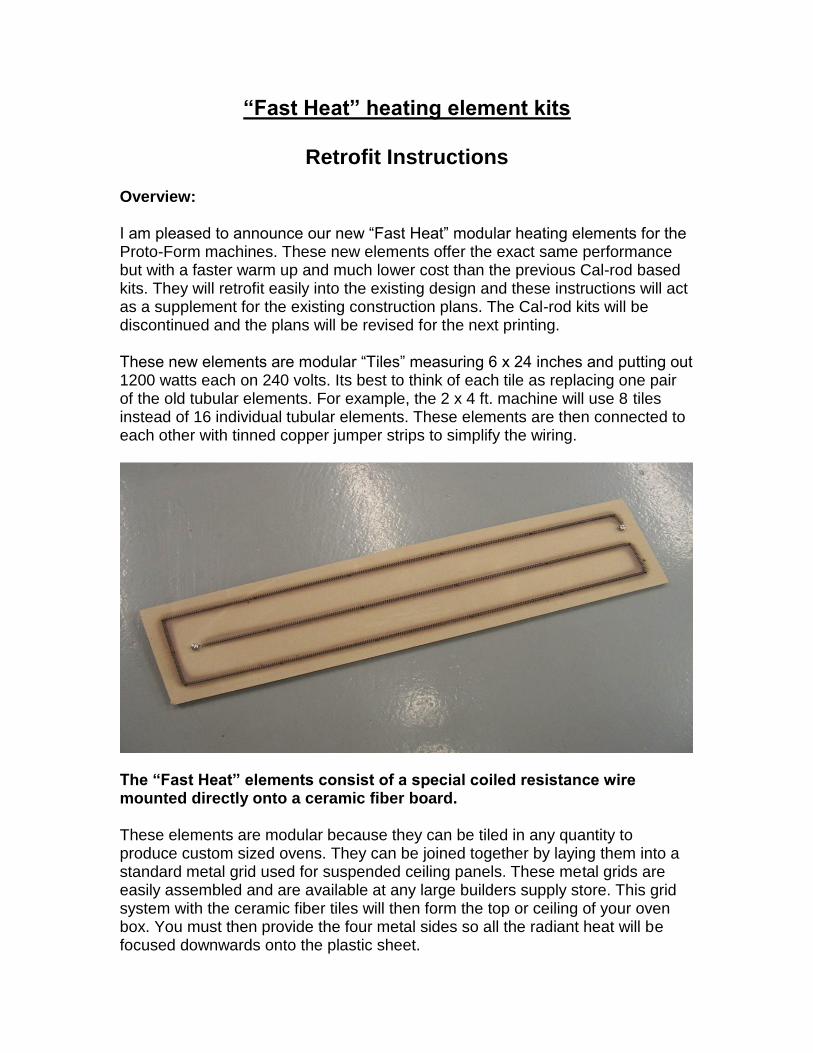
Retrofit Instructions Overview: I am pleased to announce our new “Fast Heat” modular heating elements for the Proto-Form machines. These new elements offer the exact same performance but with a faster warm up and much lower cost than the previous Cal-rod based kits. They will retrofit easily into the existing design and these instructions will act as a supplement for the existing construction plans. The Cal-rod kits will be discontinued and the plans will be revised for the next printing. These new elements are modular “Tiles” measuring 6 x 24 inches and putting out 1200 watts each on 240 volts. Its best to think of each tile as replacing one pair of the old tubular elements. For example, the 2 x 4 ft. machine will use 8 tiles instead of 16 individual tubular elements. These elements are then connected to each other with tinned copper jumper strips to simplify the wiring.
The “Fast Heat” elements consist of a special coiled resistance wire mounted directly onto a ceramic fiber board. These elements are modular because they can be tiled in any quantity to produce custom sized ovens. They can be joined together by laying them into a standard metal grid used for suspended ceiling panels. These metal grids are easily assembled and are available at any large builders supply store. This grid system with the ceramic fiber tiles will then form the top or ceiling of your oven box. You must then provide the four metal sides so all the radiant heat will be focused downwards onto the plastic sheet.
Plans Changes The Proto-Form construction plans show how to install the Old style tubular element oven kits, this supplement will show you how to retrofit the new “Fast Heat” elements into an existing machine or a new build. You should remove or disregard the following sections of your construction plans that pertain to the old even kits. Make the following changes to the instruction manual: Disregard or cross out the paragraphs dealing with the “Oven Cover Box” in Chapter 5, pages 5-2 and 5-3. Remove all eight pages of Chapter 7 from the binder. You can print this supplement and put in the binder instead if you wish. The wiring diagrams at the end of Chapter 10 are still good, just remember that the new 6 x 24 element tiles will replace two of the old tubular elements. For example, the old 2 x 4 ft. kit used 16 tubular elements at 600 watts each. The same oven will now use 8 of the new 6 x 24 inch elements at 1200 watts each. Just make sure the new oven box is grounded to the chassis.
Changes to Drawings Remove or disregard drawings numbered: 01A (small drawing), 05B, 06B, and 16B (large drawings)
Color photographs Disregard photos 3, 16, 19, 20, 21, and 22
Parts and Cut Lists “Wood Parts List” , cross out all three items listed for the oven cover. This supplement will describe how to make a simpler low profile vented cover. “Misc. Parts List” cross out the 7th item down listed as “1/8 x 1 inch wide aluminum strip”. Also you will only need half as much of the “galvanized wire mesh listed just above it. For example 2, 3 or 4 ft, instead of 4,6 or 8 ft. depending one the size you are building. The “Electrical Parts list” has no changes and the new oven kits will still come with the high temp wiring, connectors, and bus bars needed for installation.
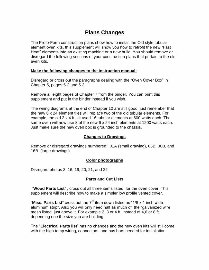
Retrofit Instructions The old oven box was a large 5 sided fabrication that was difficult for many people to make. The new oven uses a simpler design that uses metal building studs used for house construction. By cutting 45 degree “V” notches and bending, you can quickly make a shallow four sided frame and mount the ceiling grid with elements on top to form your oven box.
. The galvanized metal framing studs measure 3.75 in. x 1.25 in. and are made from thin sheet metal. You can cut a notch with hand snips where you want it to bend. The inside dimensions of your box should match the plastic sheet size, example 24 x 36 inches. The metal studs are sold in 8 ft. lengths so you may need to join more than one corner together depending on the size you make?
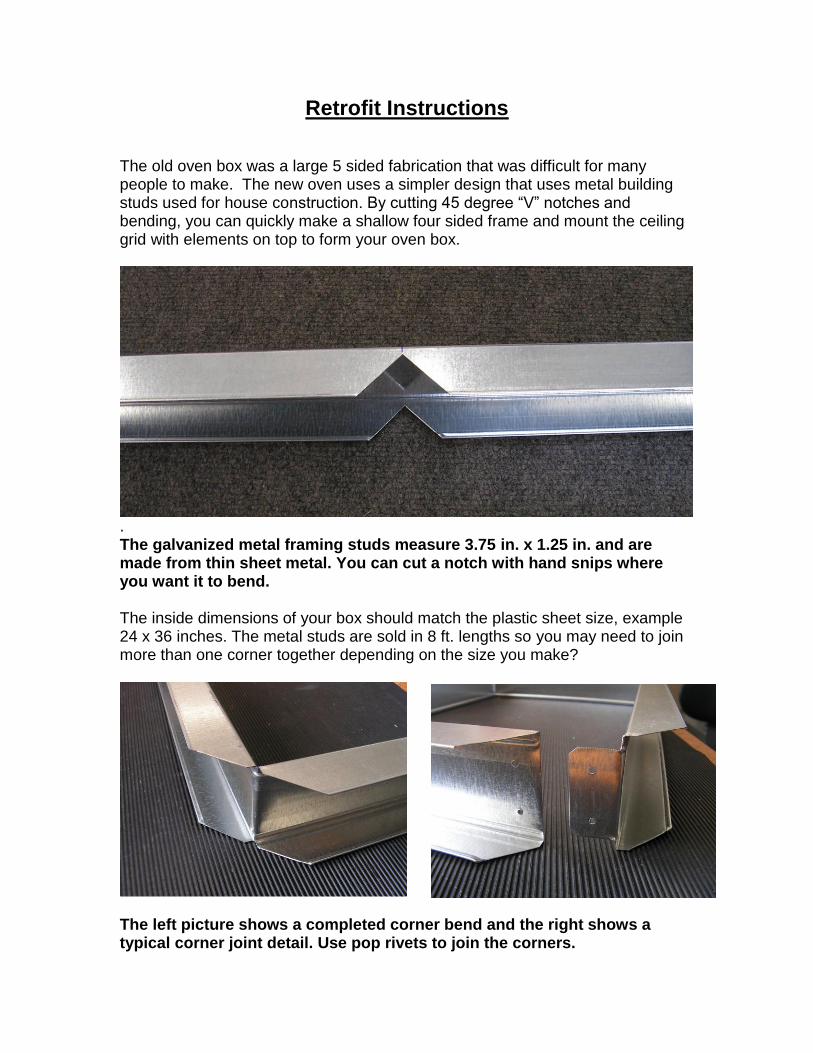
The left picture shows a completed corner bend and the right shows a typical corner joint detail. Use pop rivets to join the corners.
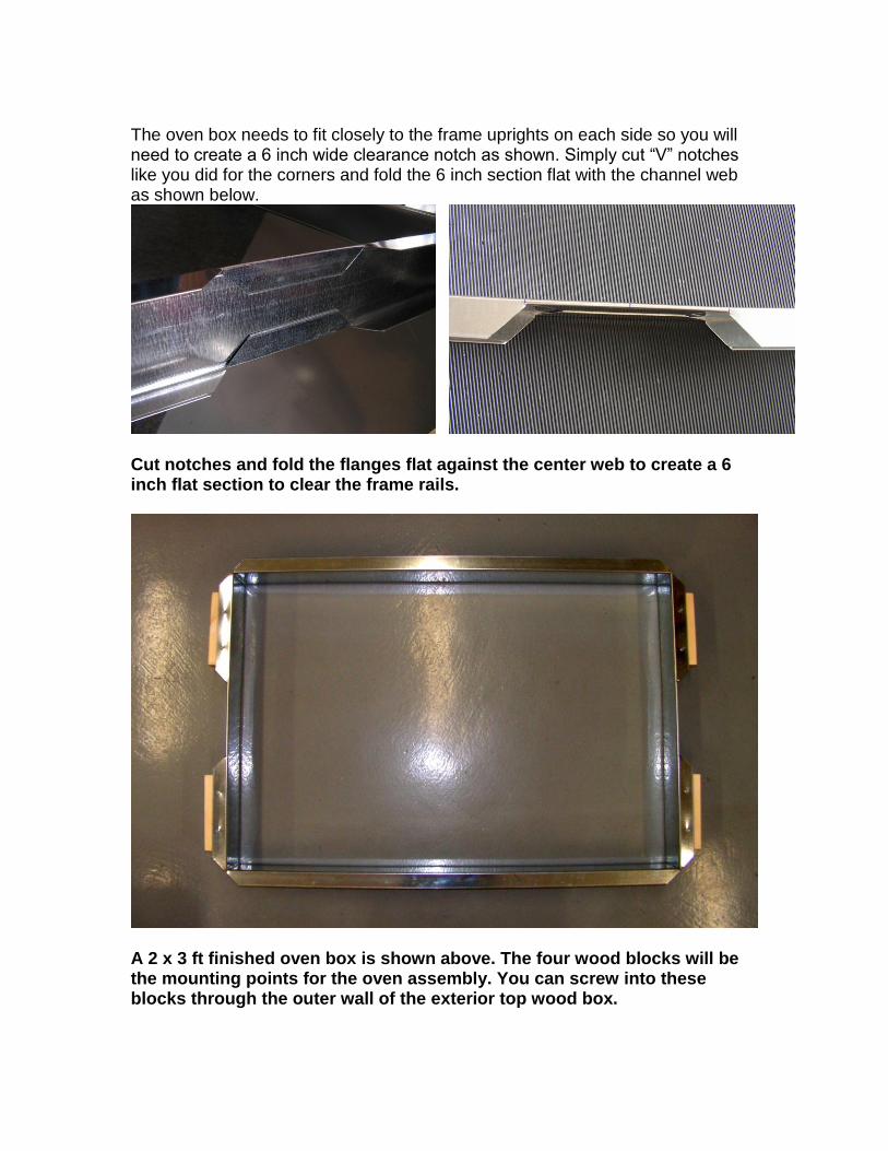
The oven box needs to fit closely to the frame uprights on each side so you will need to create a 6 inch wide clearance notch as shown. Simply cut “V” notches like you did for the corners and fold the 6 inch section flat with the channel web as shown below.
Cut notches and fold the flanges flat against the center web to create a 6 inch flat section to clear the frame rails.
A 2 x 3 ft finished oven box is shown above. The four wood blocks will be the mounting points for the oven assembly. You can screw into these blocks through the outer wall of the exterior top wood box.
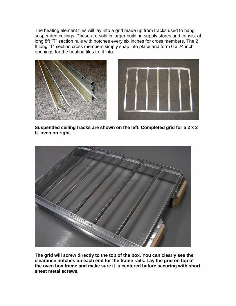
The heating element tiles will lay into a grid made up from tracks used to hang suspended ceilings. These are sold in larger building supply stores and consist of long 8ft “T” section rails with notches every six inches for cross members. The 2 ft long “T” section cross members simply snap into place and form 6 x 24 inch openings for the heating tiles to fit into.
Suspended ceiling tracks are shown on the left. Completed grid for a 2 x 3 ft. oven on right.
The grid will screw directly to the top of the box. You can clearly see the clearance notches on each end for the frame rails. Lay the grid on top of the oven box frame and make sure it is centered before securing with short sheet metal screws.
Assemble the modular elements.
Kit Contents – Each individual heating element kit contains the following parts:
1- 6 x 24 inch high temp ceramic fiber board
1- Pre-measured nichrome wire coil, 1200 watts 230 volts
18 - Stainless steel cotter pins to mount element
2 sets - Stainless steel terminal screw, nuts and washers
2 - Tinned copper jumper strips
1 - Template for drilling holes.
2 – copper set screw terminals Note: Proto-Form retrofit kits will also contain the necessary high temp wire and connectors to reach your contactors
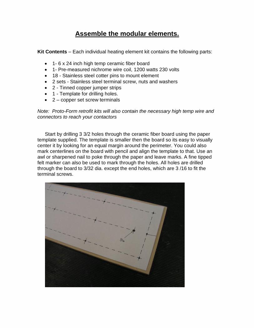
Start by drilling 3 3/2 holes through the ceramic fiber board using the paper template supplied. The template is smaller then the board so its easy to visually center it by looking for an equal margin around the perimeter. You could also mark centerlines on the board with pencil and align the template to that. Use an awl or sharpened nail to poke through the paper and leave marks. A fine tipped felt marker can also be used to mark through the holes. All holes are drilled through the board to 3/32 dia. except the end holes, which are 3 /16 to fit the terminal screws.
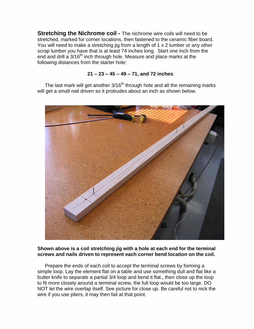
Stretching the Nichrome coil - The nichrome wire coils will need to be
stretched, marked for corner locations, then fastened to the ceramic fiber board. You will need to make a stretching jig from a length of 1 x 2 lumber or any other scrap lumber you have that is at least 74 inches long. Start one inch from the end and drill a 3/16th inch through hole. Measure and place marks at the following distances from the starter hole:
21 – 23 – 45 – 49 – 71, and 72 inches.
The last mark will get another 3/16th through hole and all the remaining marks
will get a small nail driven so it protrudes about an inch as shown below.
Shown above is a coil stretching jig with a hole at each end for the terminal screws and nails driven to represent each corner bend location on the coil.
Prepare the ends of each coil to accept the terminal screws by forming a simple loop. Lay the element flat on a table and use something dull and flat like a butter knife to separate a partial 3/4 loop and bend it flat., then close up the loop to fit more closely around a terminal screw, the full loop would be too large. DO NOT let the wire overlap itself. See picture for close up. Be careful not to nick the wire if you use pliers, it may then fail at that point.
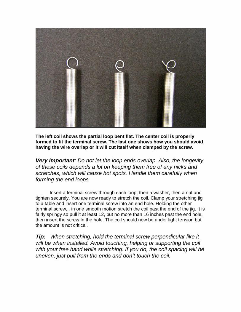
The left coil shows the partial loop bent flat. The center coil is properly formed to fit the terminal screw. The last one shows how you should avoid having the wire overlap or it will cut itself when clamped by the screw.
Very Important: Do not let the loop ends overlap. Also, the longevity of these coils depends a lot on keeping them free of any nicks and scratches, which will cause hot spots. Handle them carefully when forming the end loops
Insert a terminal screw through each loop, then a washer, then a nut and
tighten securely. You are now ready to stretch the coil. Clamp your stretching jig to a table and insert one terminal screw into an end hole. Holding the other terminal screw,.. in one smooth motion stretch the coil past the end of the jig. It is fairly springy so pull it at least 12, but no more than 16 inches past the end hole, then insert the screw In the hole. The coil should now be under light tension but the amount is not critical.
Tip: When stretching, hold the terminal screw perpendicular like it will be when installed. Avoid touching, helping or supporting the coil with your free hand while stretching. If you do, the coil spacing will be uneven, just pull from the ends and don’t touch the coil.
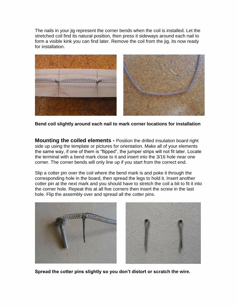
The nails in your jig represent the corner bends when the coil is installed. Let the stretched coil find its natural position, then press it sideways around each nail to form a visible kink you can find later. Remove the coil from the jig, its now ready for installation.
Bend coil slightly around each nail to mark corner locations for installation
Mounting the coiled elements - Position the drilled insulation board right
side up using the template or pictures for orientation. Make all of your elements the same way, if one of them is “flipped”, the jumper strips will not fit later. Locate the terminal with a bend mark close to it and insert into the 3/16 hole near one corner. The corner bends will only line up if you start from the correct end. Slip a cotter pin over the coil where the bend mark is and poke it through the corresponding hole in the board, then spread the legs to hold it. Insert another cotter pin at the next mark and you should have to stretch the coil a bit to fit it into the corner hole. Repeat this at all five corners then insert the screw in the last hole. Flip the assembly over and spread all the cotter pins.
Spread the cotter pins slightly so you don’t distort or scratch the wire.
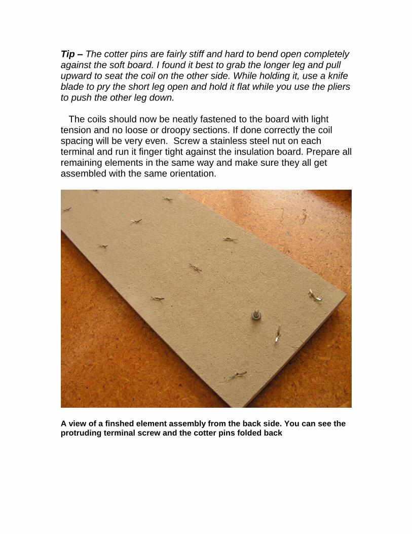
Tip – The cotter pins are fairly stiff and hard to bend open completely against the soft board. I found it best to grab the longer leg and pull upward to seat the coil on the other side. While holding it, use a knife blade to pry the short leg open and hold it flat while you use the pliers to push the other leg down. The coils should now be neatly fastened to the board with light tension and no loose or droopy sections. If done correctly the coil spacing will be very even. Screw a stainless steel nut on each terminal and run it finger tight against the insulation board. Prepare all remaining elements in the same way and make sure they all get assembled with the same orientation.
A view of a finshed element assembly from the back side. You can see the protruding terminal screw and the cotter pins folded back
Mounting the New Oven assembly
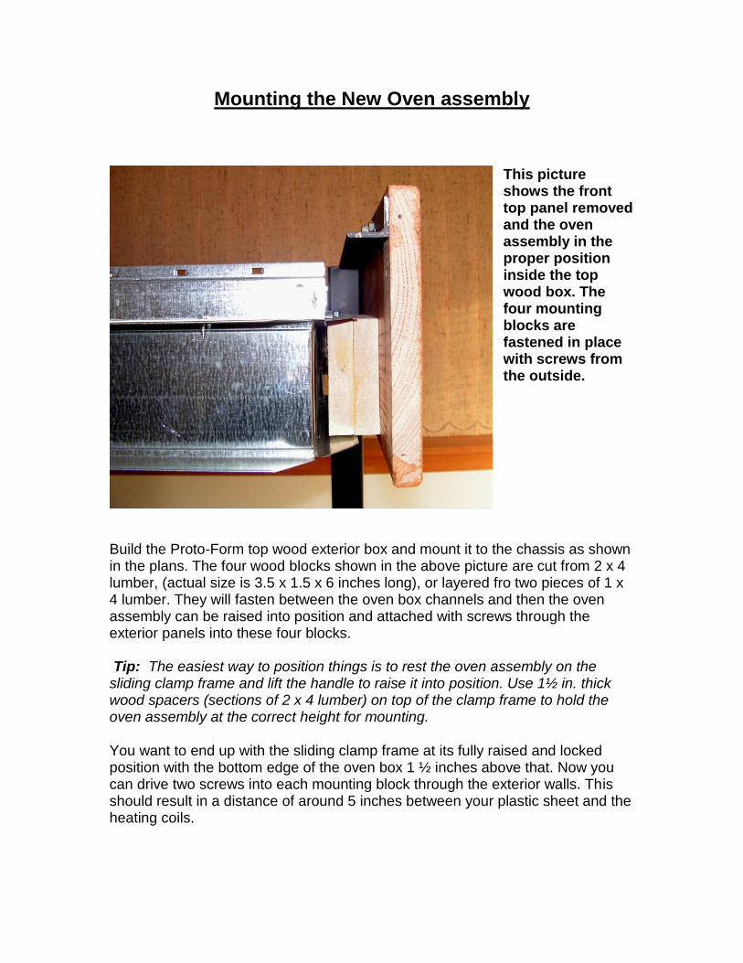
This picture shows the front top panel removed and the oven assembly in the proper position inside the top wood box. The four mounting blocks are fastened in place with screws from the outside.
Build the Proto-Form top wood exterior box and mount it to the chassis as shown in the plans. The four wood blocks shown in the above picture are cut from 2 x 4 lumber, (actual size is 3.5 x 1.5 x 6 inches long), or layered fro two pieces of 1 x 4 lumber. They will fasten between the oven box channels and then the oven assembly can be raised into position and attached with screws through the exterior panels into these four blocks. Tip: The easiest way to position things is to rest the oven assembly on the sliding clamp frame and lift the handle to raise it into position. Use 1½ in. thick wood spacers (sections of 2 x 4 lumber) on top of the clamp frame to hold the oven assembly at the correct height for mounting. You want to end up with the sliding clamp frame at its fully raised and locked position with the bottom edge of the oven box 1 ½ inches above that. Now you can drive two screws into each mounting block through the exterior walls. This should result in a distance of around 5 inches between your plastic sheet and the heating coils.
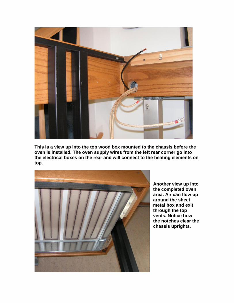
This is a view up into the top wood box mounted to the chassis before the oven is installed. The oven supply wires from the left rear corner go into the electrical boxes on the rear and will connect to the heating elements on top.
Another view up into the completed oven area. Air can flow up around the sheet metal box and exit through the top vents. Notice how the notches clear the chassis uprights.
Installing the heating element tiles
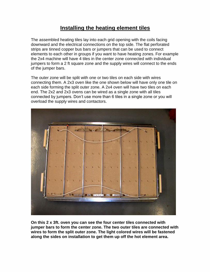
The assembled heating tiles lay into each grid opening with the coils facing downward and the electrical connections on the top side. The flat perforated strips are tinned copper bus bars or jumpers that can be used to connect elements to each other in groups if you want to have heating zones. For example the 2x4 machine will have 4 tiles in the center zone connected with individual jumpers to form a 2 ft square zone and the supply wires will connect to the ends of the jumper bars. The outer zone will be split with one or two tiles on each side with wires connecting them. A 2x3 oven like the one shown below will have only one tile on each side forming the split outer zone. A 2x4 oven will have two tiles on each end. The 2x2 and 2x3 ovens can be wired as a single zone with all tiles connected by jumpers. Don’t use more than 6 tiles in a single zone or you will overload the supply wires and contactors.
On this 2 x 3ft. oven you can see the four center tiles connected with jumper bars to form the center zone. The two outer tiles are connected with wires to form the split outer zone. The light colored wires will be fastened along the sides on installation to get them up off the hot element area.
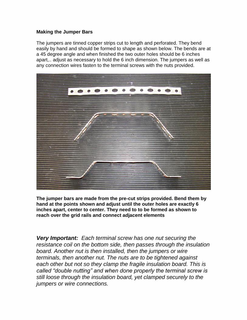
Making the Jumper Bars The jumpers are tinned copper strips cut to length and perforated. They bend easily by hand and should be formed to shape as shown below. The bends are at a 45 degree angle and when finished the two outer holes should be 6 inches apart,.. adjust as necessary to hold the 6 inch dimension. The jumpers as well as any connection wires fasten to the terminal screws with the nuts provided.
The jumper bars are made from the pre-cut strips provided. Bend them by hand at the points shown and adjust until the outer holes are exactly 6 inches apart, center to center. They need to to be formed as shown to reach over the grid rails and connect adjacent elements
Very Important: Each terminal screw has one nut securing the resistance coil on the bottom side, then passes through the insulation board. Another nut is then installed, then the jumpers or wire terminals, then another nut. The nuts are to be tightened against each other but not so they clamp the fragile insulation board. This is called “double nutting” and when done properly the terminal screw is still loose through the insulation board, yet clamped securely to the jumpers or wire connections.
Wiring your Oven Kit
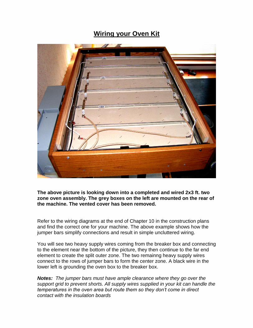
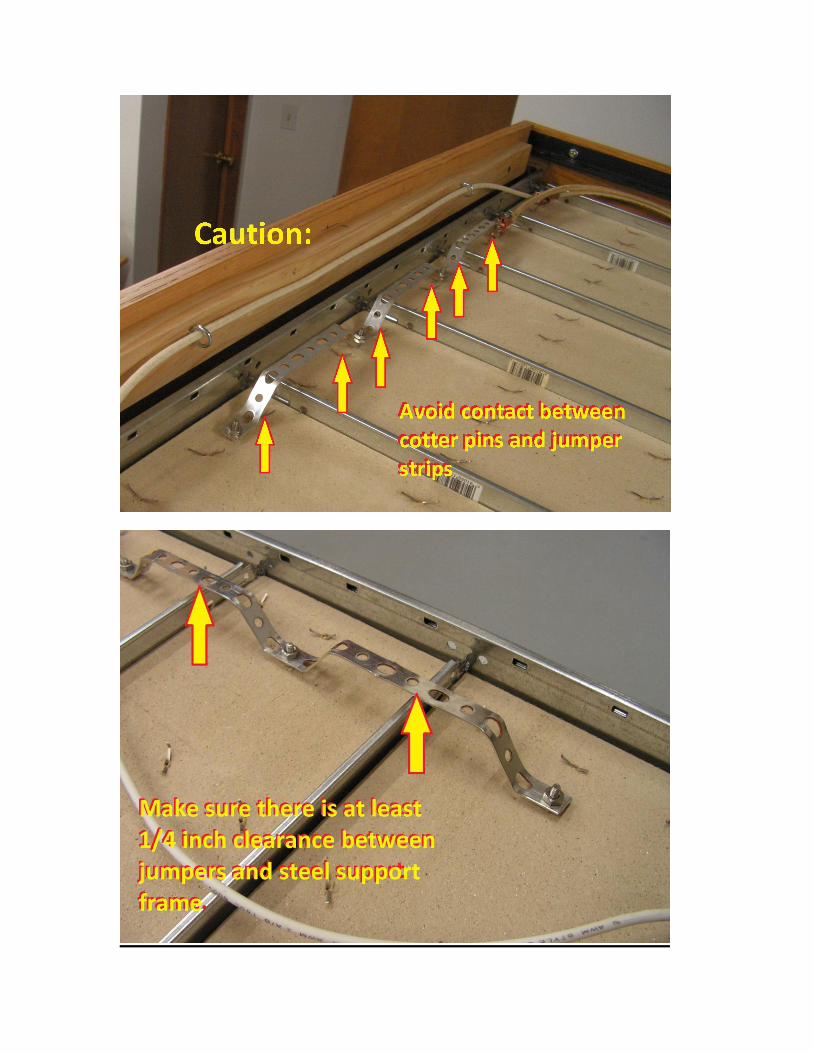
The above picture is looking down into a completed and wired 2x3 ft. two zone oven assembly. The grey boxes on the left are mounted on the rear of the machine. The vented cover has been removed. Refer to the wiring diagrams at the end of Chapter 10 in the construction plans and find the correct one for your machine. The above example shows how the jumper bars simplify connections and result in simple uncluttered wiring. You will see two heavy supply wires coming from the breaker box and connecting to the element near the bottom of the picture, they then continue to the far end element to create the split outer zone. The two remainng heavy supply wires connect to the rows of jumper bars to form the center zone. A black wire in the lower left is grounding the oven box to the breaker box. Notes: The jumper bars must have ample clearance where they go over the support grid to prevent shorts. All supply wires supplied in your kit can handle the temperatures in the oven area but route them so they don’t come in direct contact with the insulation boards
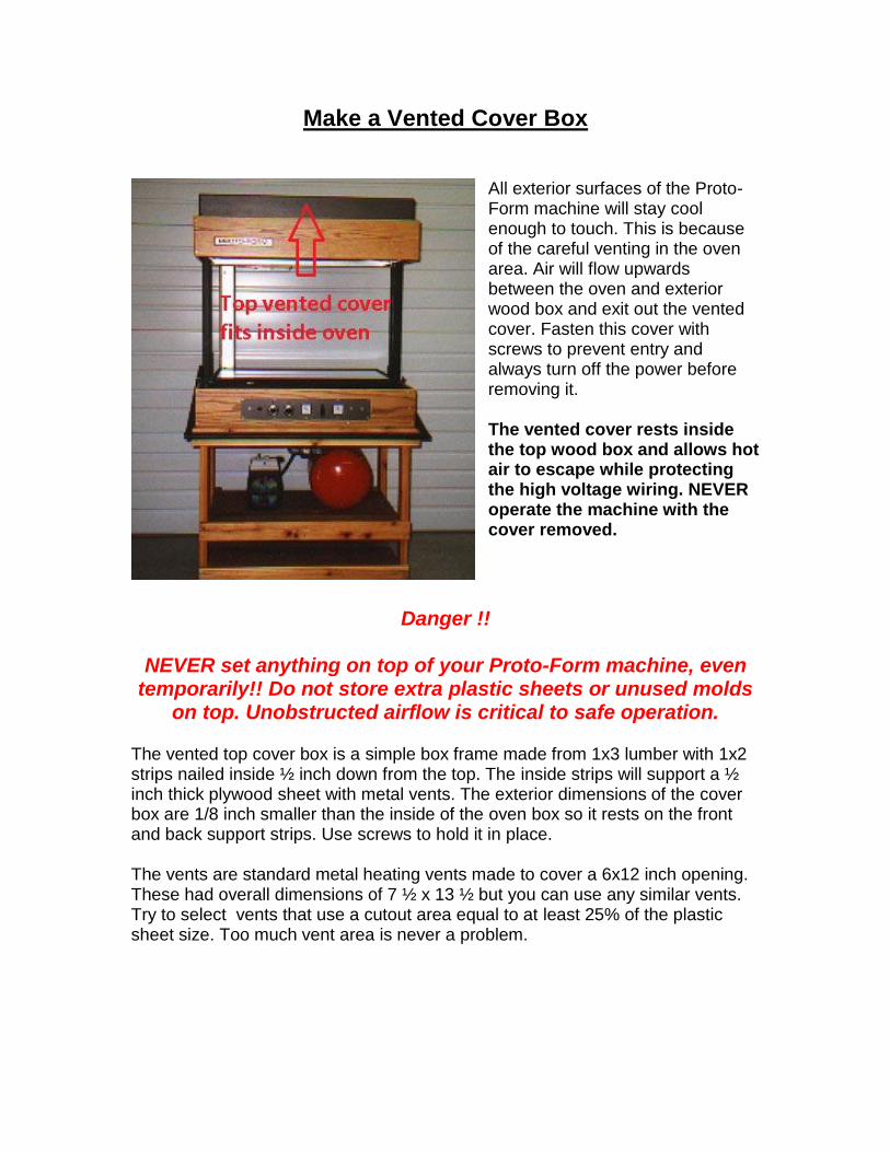
Make a Vented Cover Box
All exterior surfaces of the Proto-Form machine will stay cool enough to touch. This is because of the careful venting in the oven area. Air will flow upwards between the oven and exterior wood box and exit out the vented cover. Fasten this cover with screws to prevent entry and always turn off the power before removing it. The vented cover rests inside the top wood box and allows hot air to escape while protecting the high voltage wiring. NEVER operate the machine with the cover removed.
Danger !!
NEVER set anything on top of your Proto-Form machine, even temporarily!! Do not store extra plastic sheets or unused molds
on top. Unobstructed airflow is critical to safe operation.
The vented top cover box is a simple box frame made from 1x3 lumber with 1x2 strips nailed inside ½ inch down from the top. The inside strips will support a ½ inch thick plywood sheet with metal vents. The exterior dimensions of the cover box are 1/8 inch smaller than the inside of the oven box so it rests on the front and back support strips. Use screws to hold it in place. The vents are standard metal heating vents made to cover a 6x12 inch opening. These had overall dimensions of 7 ½ x 13 ½ but you can use any similar vents. Try to select vents that use a cutout area equal to at least 25% of the plastic sheet size. Too much vent area is never a problem.
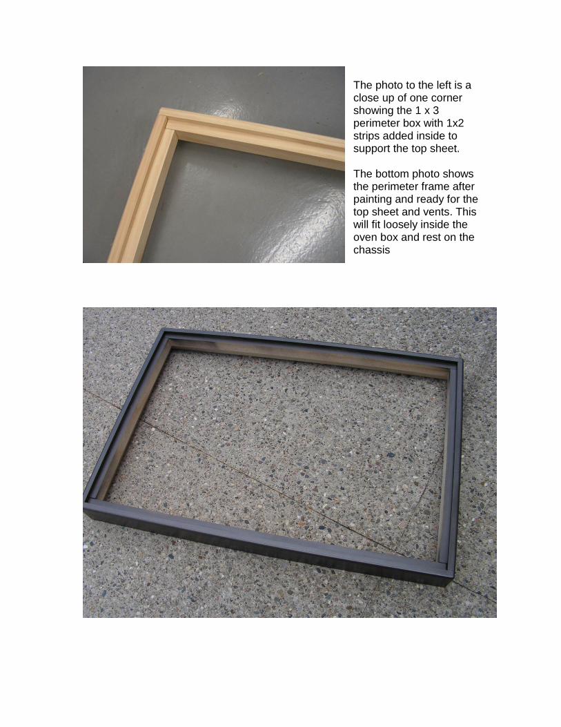
The photo to the left is a close up of one corner showing the 1 x 3 perimeter box with 1x2 strips added inside to support the top sheet. The bottom photo shows the perimeter frame after painting and ready for the top sheet and vents. This will fit loosely inside the oven box and rest on the chassis
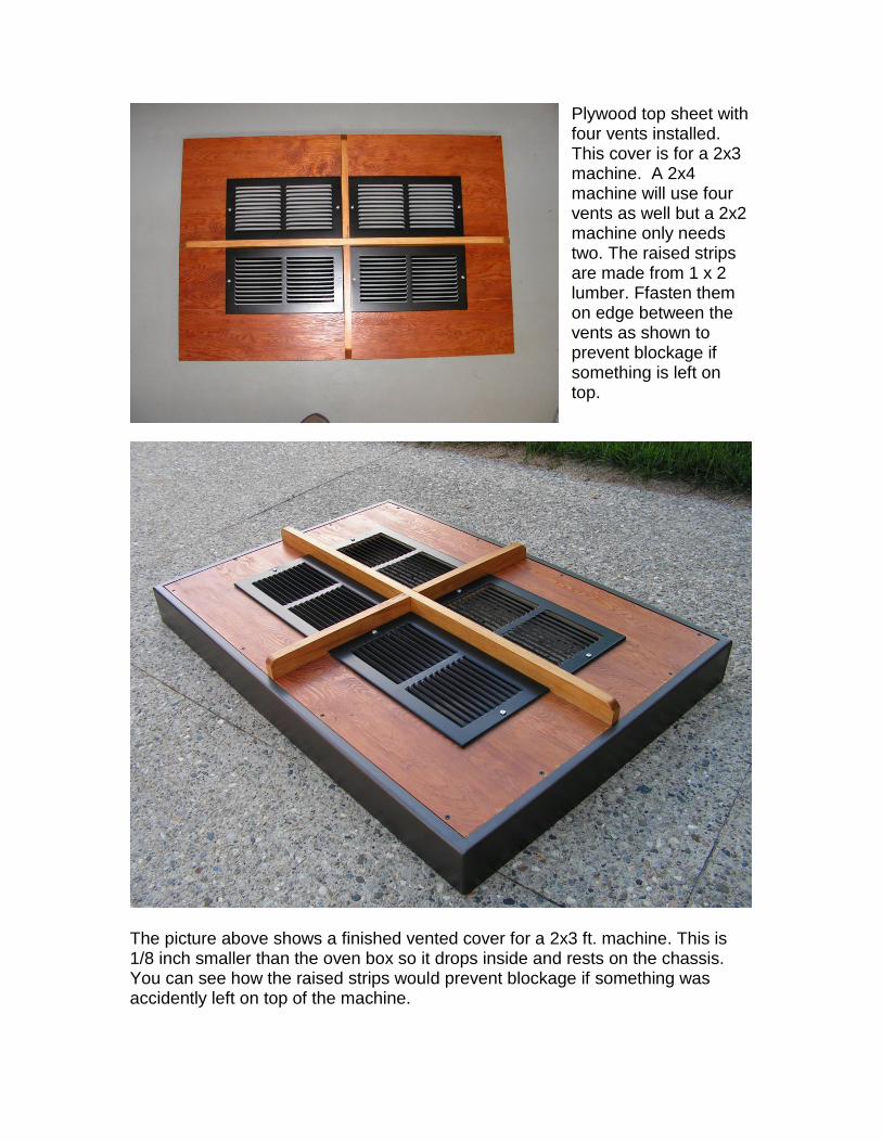
Plywood top sheet with four vents installed. This cover is for a 2x3 machine. A 2x4 machine will use four vents as well but a 2x2 machine only needs two. The raised strips are made from 1 x 2 lumber. Ffasten them on edge between the vents as shown to prevent blockage if something is left on top.
The picture above shows a finished vented cover for a 2x3 ft. machine. This is 1/8 inch smaller than the oven box so it drops inside and rests on the chassis. You can see how the raised strips would prevent blockage if something was accidently left on top of the machine.

Adding a Timer Switch
The Proto-Form machine has been around for a very long time now with no reported failures that I am aware of. However I’ve still spent sleepless nights worrying about safety issues, and even though I am not an engineer, I have sought help and advice whenever I wasn’t sure. The electrical system just scares me. We are unleashing a tremendous amount of heat so I’ve been conservative with temperature ratings of materials and have done extended bake tests. I bought an expensive infra-red laser temp gun and ran the machine far longer than is reasonable while taking measurements. I did this figuring someone would forget to turn it off despite the bright red pilot lights. I try to anticipate how people will operate these machines but have heard of them being used in ways I never dreamed of. I warned against extended run times as in pre-heating molds and drying plastic sheets, but I also hear about people curing paints and epoxies and even warming a thanksgiving turkey under the oven. I think I’ve done a great job in managing the heat by adding a switch to turn off the oven when the plastic is lowered, and adding an outlet for fans. All exterior surfaces stay cool, and when built and used as designed it is a very safe machine. The process of vacuum forming only requires the heat to be on for a short time per cycle. With the low thermal mass and fast warm up, there’s really no reason it should be left on more than that. By replacing the main power switch with a 15 minute timer you have a second line of defense against forgetfulness or misuse. Please consider this a mandatory upgrade, for only a few dollars it’s the cheapest insurance policy you will ever buy.
This is a standard 15 minute spring wound timer that operates on 120 volts and fits a standard switch receptacle. Use it to replace your main power switch for an extra layer of safety.
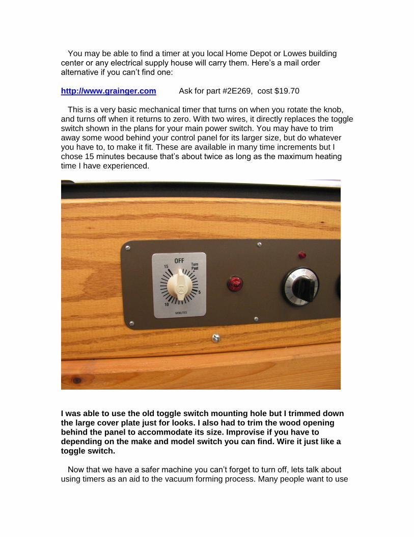
You may be able to find a timer at you local Home Depot or Lowes building center or any electrical supply house will carry them. Here’s a mail order alternative if you can’t find one: http://www.grainger.com Ask for part #2E269, cost $19.70 This is a very basic mechanical timer that turns on when you rotate the knob, and turns off when it returns to zero. With two wires, it directly replaces the toggle switch shown in the plans for your main power switch. You may have to trim away some wood behind your control panel for its larger size, but do whatever you have to, to make it fit. These are available in many time increments but I chose 15 minutes because that’s about twice as long as the maximum heating time I have experienced.
I was able to use the old toggle switch mounting hole but I trimmed down the large cover plate just for looks. I also had to trim the wood opening behind the panel to accommodate its size. Improvise if you have to depending on the make and model switch you can find. Wire it just like a toggle switch. Now that we have a safer machine you can’t forget to turn off, lets talk about using timers as an aid to the vacuum forming process. Many people want to use

them as an indicator of when the plastic is ready to form. I often argue that watching for sheet sag is a much better indicator because the heating cycle gets shorter as your mold, machine, and even the room heat up. Having said that, the Proto-Form is better than most because its low thermal mass lets it stabilize at a given temperature earlier so its more consistent. If you are forming repetitive parts give it a try, some people like using timers. I still prefer to form when the plastic sags a pre-determined amount.
Operating the oven
These “Fast Heat” elements reach full heat in less than a minute but its still a good idea to pre-warm the whole oven area by raising the empty clamp frame and setting the timer for 2-3 minutes before loading the first plastic sheet. When ready to form, my suggestion is to simply spin the timer knob so its on by any amount longer than the time needed to heat the plastic. Typically this can vary from less than 30 seconds for thin sheets to over 5 minutes for thick stuff. Watch for sag and form the plastic when ready. The oven will automatically turn off anyway when the clamp frame is lowered because of the internal micro switch on the clamp frame. If you are only doing one part, the timer will ”time out” and you’re done, other wise, re-set the timer and repeat the cycle. If the phone rings or you get distracted, the timer will turn off even if you forget.

Plans Changes
The Proto-Form construction plans show how to install the Old style tubular element oven kits. In order to retrofit the new “Fast Heat” elements into an existing machine or a new build. You should remove or disregard the following sections of your construction plans that pertain to the old even kits. The new “Fast Heat” elements will include a CD with new instructions. See the following pages for information on how to purchase the new oven kits. Make the following changes to the instruction manual: Disregard or cross out the paragraphs dealing with the “Oven Cover Box” in Chapter 5, pages 5-2 and 5-3. Remove all eight pages of Chapter 7 from the binder. You can print this supplement and put in the binder instead if you wish. The wiring diagrams at the end of Chapter 10 are still good, just remember that the new 6 x 24 element tiles will replace two of the old tubular elements. For example, the old 2 x 4 ft. kit used 16 tubular elements at 600 watts each. The same oven will now use 8 of the new 6 x 24 inch elements at 1200 watts each. Just make sure the new oven box is grounded to the chassis.
Changes to Drawings Remove or disregard drawings numbered: 01A (small drawing), 05B, 06B, and 16B (large drawings)
Color photographs Disregard photos 3, 16, 19, 20, 21, and 22
Parts and Cut Lists “Wood Parts List” , cross out all three items listed for the oven cover. This supplement will describe how to make a simpler low profile vented cover. “Misc. Parts List” cross out the 7th item down listed as “1/8 x 1 inch wide aluminum strip”. Also you will only need half as much of the “galvanized wire mesh listed just above it. For example 2, 3 or 4 ft, instead of 4,6 or 8 ft. depending one the size you are building. The “Electrical Parts list” has no changes and the new oven kits will still come with the high temp wiring, connectors, and bus bars needed for installation.
Proto-Form “Fast Heat” heating element kits
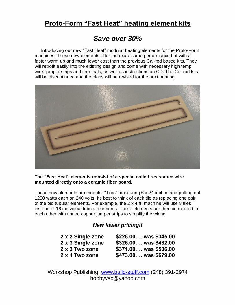
Save over 30% Introducing our new “Fast Heat” modular heating elements for the Proto-Form machines. These new elements offer the exact same performance but with a faster warm up and much lower cost than the previous Cal-rod based kits. They will retrofit easily into the existing design and come with necessary high temp wire, jumper strips and terminals, as well as instructions on CD. The Cal-rod kits will be discontinued and the plans will be revised for the next printing.
The “Fast Heat” elements consist of a special coiled resistance wire mounted directly onto a ceramic fiber board. These new elements are modular “Tiles” measuring 6 x 24 inches and putting out 1200 watts each on 240 volts. Its best to think of each tile as replacing one pair of the old tubular elements. For example, the 2 x 4 ft. machine will use 8 tiles instead of 16 individual tubular elements. These elements are then connected to each other with tinned copper jumper strips to simplify the wiring.
New lower pricing!!
2 x 2 Single zone $226.00…. was $345.00 2 x 3 Single zone $326.00…. was $482.00 2 x 3 Two zone $371.00…. was $536.00 2 x 4 Two zone $473.00…. was $679.00
Workshop Publishing, www.build-stuff.com (248) 391-2974 [email protected]

The Proto-Form oven kits consist of 4,6,or 8 heating tiles (depending on size plus the necessary high temperature 8 gauge wire and set screw terminals. These elements are supplied in kit form with pre-cut ceramic fiber board, nichrome heating coil and hardware. You must use the supplied template and drill the mounting holes, then stretch the coil and fasten to the board with the hardware provided. Adjacent tiles are connected with the pre-punched jumper strips.
Frequently Asked Questions
“Cal-Rod” tubular style vs coiled wire elements.
Do these work as well as the old Cal-Rod based oven kits?
These are functionally identical but they heat up faster and are much cheaper. They fit in the same place with the same heat output and power consumption.
How long does a coiled Nichrome element last?
Not really sure!,.. I’ve been selling this type of coiled element for my Hobby-Vac machines since 1996 with no reported failures yet. How long does a toaster last, I’ve got one that’s 20 years old? If assembled carefully with no nicks in the wire and not subjected to repeated movement or vibration, they last very long and are cheap to replace.
Are these elements safe?
Not if you touch them, but neither is an open flame or burner on your stove. The oven box is grounded so a broken wire will trip a breaker if it touches something metal. Treat it like you would any appliance. Use common sense, don’t modify the design and follow the instructions carefully.
Are they more work to install?
About the same as the old oven kits, you will spend more time assembling the elements, but the oven box is much easier to make. No special skills required, just follow instructions.
They look kind of cheap, why didn’t you use something cool like Quartz tubes or ceramic panel elements? The short answer is cost vs benefit. A coiled resistance element is far cheaper than all other options and if designed correctly, functions the same. Remember, ALL electric heaters have the same nichrome wire hidden inside somewhere.
Can I just use “Hardi-backer” cement board from Home Depot? The ceramic fiber board in these kits can handle 1800 degrees and direct contact with the heating coil. Tile backer boards look similar but are cement based and only rated for a few hundred degrees. They won’t burn but they will crack!
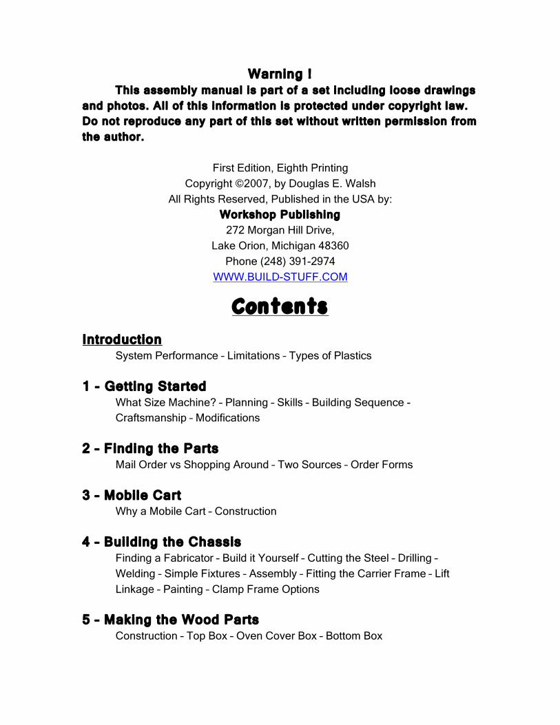
Warning ! This assembly manual is part of a set including loose drawings
and photos. Al l of this information is protected under copyright law. Do not reproduce any part of this set without wri tten permission from the author.
First Edition, Eighth Printing
Copyright ©2007, by Douglas E. Walsh All Rights Reserved, Published in the USA by:
Workshop Publishing 272 Morgan Hill Drive,
Lake Orion, Michigan 48360 Phone (248) 391-2974
WWW.BUILD-STUFF.COM
Contents
Introduction System Performance – Limitations – Types of Plastics 1 - Getting Started What Size Machine? – Planning – Skills – Building Sequence - Craftsmanship – Modifications 2 – Finding the Parts Mail Order vs Shopping Around – Two Sources – Order Forms 3 – Mobile Cart Why a Mobile Cart – Construction 4 – Building the Chassis Finding a Fabricator – Build it Yourself – Cutting the Steel – Drilling –
Welding – Simple Fixtures – Assembly – Fitting the Carrier Frame – Lift Linkage – Painting – Clamp Frame Options
5 – Making the Wood Parts Construction – Top Box – Oven Cover Box – Bottom Box
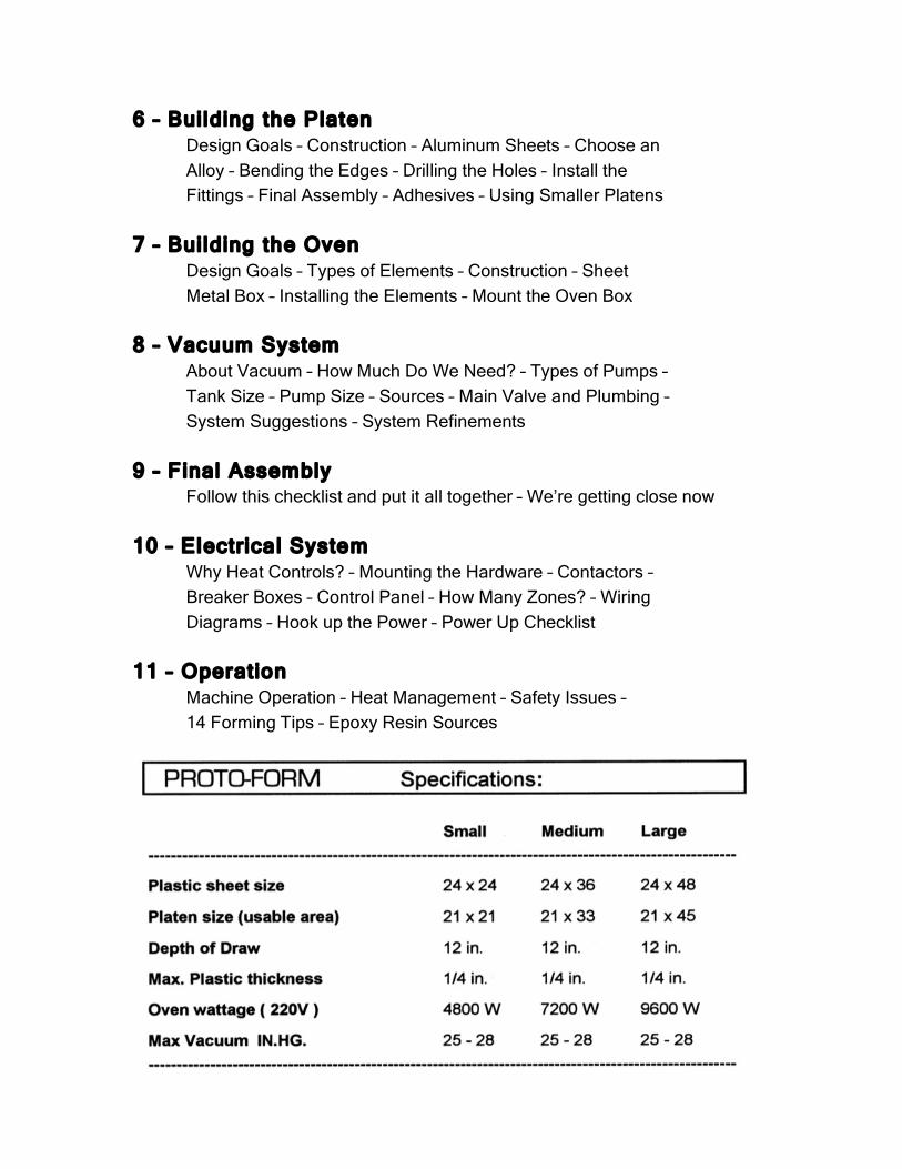
6 – Building the Platen Design Goals – Construction – Aluminum Sheets – Choose an Alloy – Bending the Edges – Drilling the Holes – Install the Fittings – Final Assembly – Adhesives – Using Smaller Platens 7 – Building the Oven Design Goals – Types of Elements – Construction – Sheet Metal Box – Installing the Elements – Mount the Oven Box 8 – Vacuum System About Vacuum – How Much Do We Need? – Types of Pumps – Tank Size – Pump Size – Sources – Main Valve and Plumbing – System Suggestions – System Refinements 9 – Final Assembly Follow this checklist and put it all together – We’re getting close now 10 – Electrical System Why Heat Controls? – Mounting the Hardware – Contactors – Breaker Boxes – Control Panel – How Many Zones? – Wiring Diagrams – Hook up the Power – Power Up Checklist 11 – Operation Machine Operation – Heat Management – Safety Issues – 14 Forming Tips – Epoxy Resin Sources
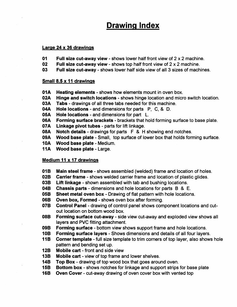
Drawing Index
Large 24 x 36 drawings
01 Full size cut-away view - shows lower half front view of 2 x 2 machine. 02 Full size cut-away view - shows top half front view of 2 x 2 machine. 03 Full size cut-away - shows lower half side view of all 3 sizes of machines.
Small 8.S x 11 drawings
01A Heating elements - shows how elements mount in oven box. 02A Hinge and switch locations - shows hinge location and micro switch location. 03A Tabs - drawings of all three tabs needed for this machine. 04A Hole locations - and dimensions for parts P, C, & D. OSA Hole locations - and dimensions for part L. 06A Forming surface brackets - brackets that hold forming surface to base plate. 07A Linkage pivot tubes - parts for lift linkage. 08A Notch details - drawings for parts F & H showing end notches. 09A Wood base plate - Small, top surface of lower box that holds forming surface. 10A Wood base plate - Medium. 11A Wood base plate - Large.
Medium 11 x 17 drawings
01 B Main steel frame - shows assembled (welded) frame and location of holes. 02B Carrier frame - shows welded carrier frame and location of plastic glides. 03B Lift linkage - shown assembled with tab and bushing locations. 04B Chassis parts - dimensions and hole locations for parts B & E. OSB Sheet metal oven box - Drawing of flat pattern with hole locations. 06B Oven box, Formed - shows oven box after forming. 07B Control Panel - drawing of control panel shows component locations and cut
out location on bottom wood box. 08B Forming surface cut-away - side view cut-away and exploded view shows all
layers and PVC fitting attachment. 09B Forming surface - bottom view shows support frame and hole locations. 10B Forming surface layers - Shows dimensions and details of all four layers. 11 B Comer template - full size template to trim corners of top layer, also shows hole
pattern and bending set up. 12B Mobile cart - front and side view 13B Mobile cart - view of top frame and lower shelves. 14B Top Box - drawing of top wood box that goes around oven. 1SB Bottom box - shows notches for linkage and support strips for base plate 16B Oven Cover - cut-away drawing of oven cover box with vented top

Introduction
I wish I had a nickel for every homebuilt vacuum forming machine ever made. My experiences over the years publishing a book and manufacturing small machines has made me aware of the vast number of people who have tried to re-invent the vacuum forming machine just because it looked so dam simple. This most often results in poor to average performance and an endless series of modifications to make it work better. Historically this process of invention always takes longer and costs more than you thought it WOUld. Keep in mind that most people have to climb the learning curve all by themselves because there is virtually no printed information on the subject.
I sympathize with those people because I'm one of them. I hate to buy anything I can build myself, and I too got sucked into the deceptive simplicity of building my own machines. But I am a stubborn person, and after I got past the short term need for vacuum forming, I remained fascinated and kept trying to make it work even better. Now after many years of gathering information and learning from experience I am introducing the Proto-Form machine for those people who like to build things and save money.
The fact that you are reading this means you already did some homework, and you know that vacuum forming is an easy and fast way to make plastic parts with low tooling costs. You probably have at least a basic understanding of the process whereby you heat a sheet of plastic until it is soft and suck it down over a pattern until it cools, and you probably did a little shopping to see what eqUipment is available and were shocked at how much you have to pay to get such simple results.
Some businesses can justify the high cost of a new commercial machine, but many more only need the capability occasionally for product development or lower volume production. In these instances there are basically three choices: 1 -Find a used machine. 2 -Build your own machine. 3 -Don't get a machine at all, just find someone else to make parts for you.
Introduction
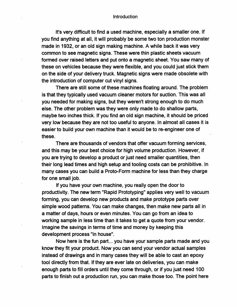
It's very difficult to find a used machine, especially a smaller one. If you find anything at all, it will probably be some two ton production monster made in 1932, or an old sign making machine. A while back it was very common to see magnetic signs. These were thin plastic sheets vacuum formed over raised letters and put onto a magnetic sheet. You saw many of these on vehicles because they were flexible, and you could just stick them on the side of your delivery truck. Magnetic signs were made obsolete with the introduction of computer cut vinyl signs.
There are still some of these machines floating around. The problem is that they typically used vacuum cleaner motors for suction. This was all you needed for making signs, but they weren't strong enough to do much else. The other problem was they were only made to do shallow parts, maybe two inches thick. If you find an old sign machine, it should be priced very low because they are not too useful to anyone. In almost all cases it is easier to build your own machine than it would be to re-engineer one of these.
There are thousands of vendors that offer vacuum forming services, and this may be your best choice for high volume production. However, if you are trying to develop a product or just need smaller quantities, then their long lead times and high setup and tooling costs can be prohibitive. In many cases you can build a Proto-Form machine for less than they charge for one small job.
If you have your own machine, you really open the door to productivity. The new term "Rapid Prototyping" applies very well to vacuum forming, you can develop new products and make prototype parts over simple wood patterns. You can make changes, then make new parts all in a matter of days, hours or even minutes. You can go from an idea to working sample in less time than it takes to get a quote from your vendor. Imagine the savings in terms of time and money by keeping this development process "in house".
Now here is the fun part ... you have your sample parts made and you know they fit your product. Now you can send your vendor actual samples instead of drawings and in many cases they will be able to cast an epoxy tool directly from that. If they are ever late on deliveries, you can make enough parts to fill orders until they come through, or if you just need 100 parts to finish out a production run, you can make those too. The point here
Introduction
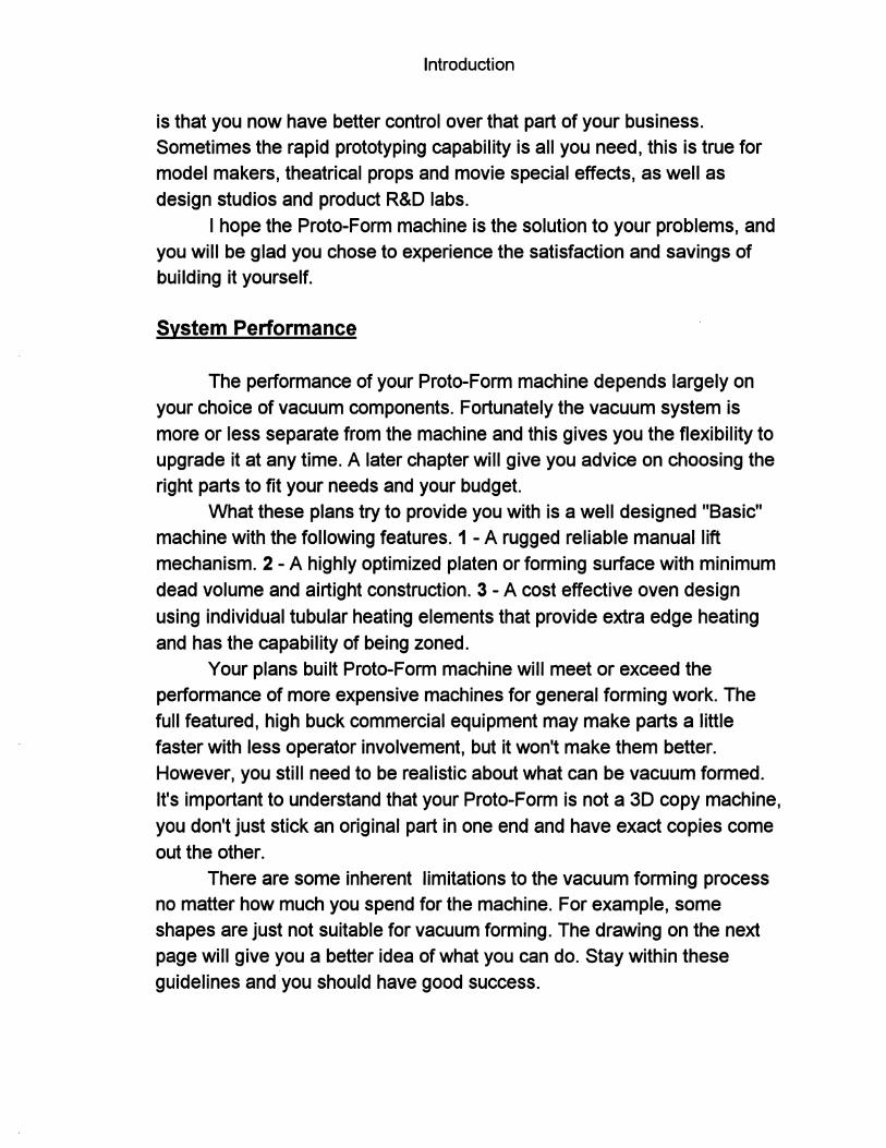
is that you now have better control over that part of your business. Sometimes the rapid prototyping capability is all you need, this is true for model makers, theatrical props and movie special effects, as well as design studios and product R&D labs.
I hope the Proto-Form machine is the solution to your problems, and you will be glad you chose to experience the satisfaction and savings of building it yourself.
System Performance
The performance of your Proto-Form machine depends largely on your choice of vacuum components. Fortunately the vacuum system is more or less separate from the machine and this gives you the flexibility to upgrade it at any time. A later chapter will give you advice on choosing the right parts to fit your needs and your budget.
What these plans try to provide you with is a well designed "Basic" machine with the following features. 1 - A rugged reliable manual lift mechanism. 2 - A highly optimized platen or forming surface with minimum dead volume and airtight construction. 3 - A cost effective oven design using individual tubular heating elements that provide extra edge heating and has the capability of being zoned.
Your plans built Proto-Form machine will meet or exceed the performance of more expensive machines for general forming work. The full featured, high buck commercial equipment may make parts a little faster with less operator involvement, but it won't make them better. However, you still need to be realistic about what can be vacuum formed. It's important to understand that your Proto-Form is not a 3D copy machine, you don't just stick an original part in one end and have exact copies come out the other.
There are some inherent limitations to the vacuum forming process no matter how much you spend for the machine. For example, some shapes are just not suitable for vacuum forming. The drawing on the next page will give you a better idea of what you can do. Stay within these guidelines and you should have good success.
/- - - - - -,' / ,
/ , 1 / ), 12in.
/ 0 , 1 /00, / Platen Front View I ,
/ ? 1
x x OK
Too Deep' Too Tall
/ /
/
/ /
/\. / ,
/ ,
Side View
, , , , , r: --- ----, c--
OK
OK
Ha~ ~ • Easy
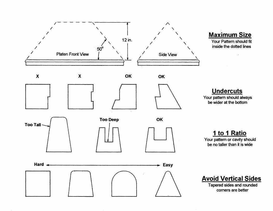
Maximum Size, Your Pattern should fit inside the dotted lines
Undercuts Your pattem should always
be wider at the bottom
1 to 1 Ratio Your pattem or cavity should
be no taller than it is wide
Avoid Vertical Sides Tapered sides and rounded
comers are better
Introduction
Vacuum Forming Limitations
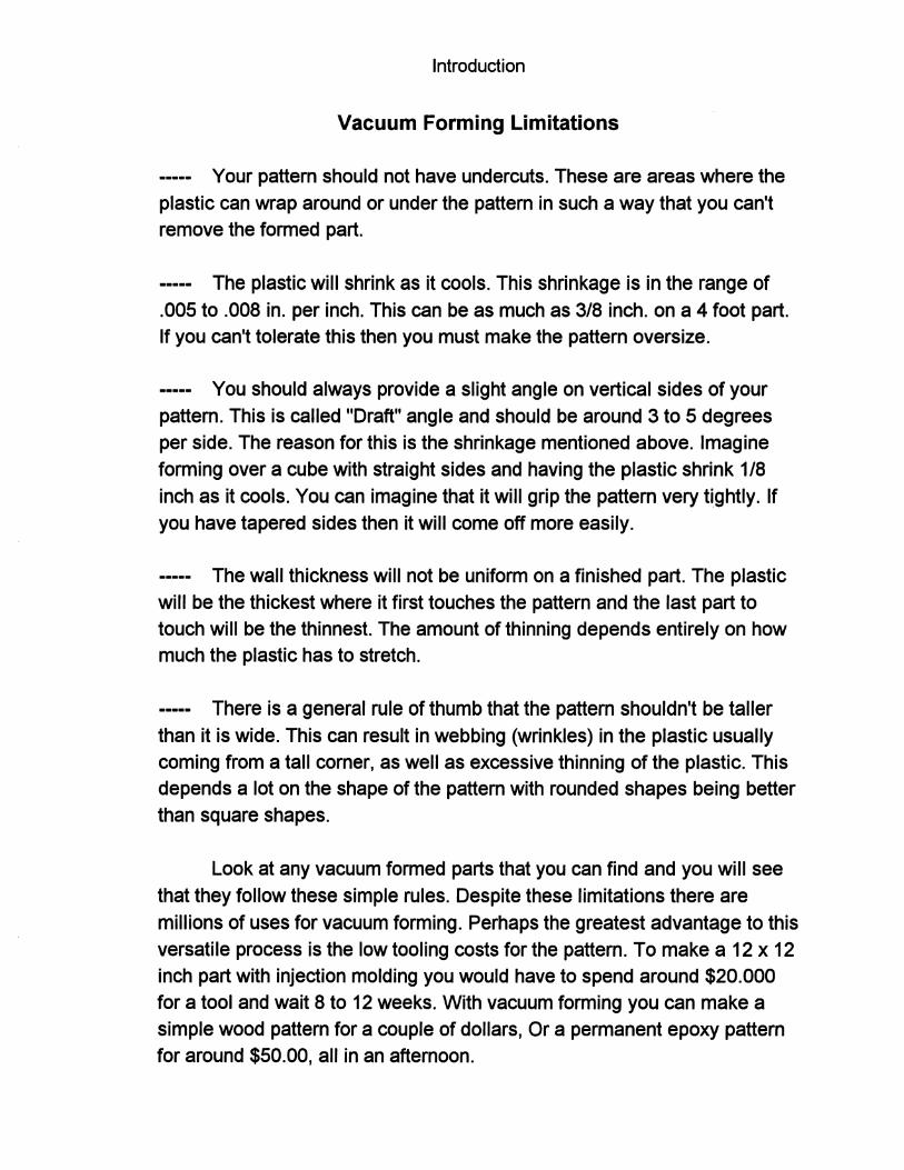
Your pattern should not have undercuts. These are areas where the plastic can wrap around or under the pattern in such a way that you can't remove the formed part.
----- The plastic will shrink as it cools. This shrinkage is in the range of .005 to .008 in. per inch. This can be as much as 3/8 inch. on a 4 foot part. If you can't tolerate this then you must make the pattern oversize.
----- You should always provide a slight angle on vertical sides of your pattern. This is called "Draft" angle and should be around 3 to 5 degrees per side. The reason for this is the shrinkage mentioned above. Imagine forming over a cube with straight sides and having the plastic shrink 1/8 inch as it cools. You can imagine that it will grip the pattern very tightly. If you have tapered sides then it will come off more easily.
----- The wall thickness will not be uniform on a finished part. The plastic will be the thickest where it first touches the pattern and the last part to touch will be the thinnest. The amount of thinning depends entirely on how much the plastic has to stretch.
----- There is a general rule of thumb that the pattern shouldn't be taller than it is wide. This can result in webbing (wrinkles) in the plastic usually coming from a tall corner, as well as excessive thinning of the plastic. This depends a lot on the shape of the pattern with rounded shapes being better than square shapes.
Look at any vacuum formed parts that you can find and you will see that they follow these simple rules. Despite these limitations there are millions of uses for vacuum forming. Perhaps the greatest advantage to this versatile process is the low tooling costs for the pattern. To make a 12 x 12 inch part with injection molding you would have to spend around $20.000 for a tool and wait 8 to 12 weeks. With vacuum forming you can make a simple wood pattern for a couple of dollars, Or a permanent epoxy pattern for around $50.00, all in an afternoon.

Introduction
You can vacuum form a wide variety of plastics, as long as they get soft when their hot. These are called thermoplastics and include the common ones listed below as well as others:
ASS Acrylic PVC Styrene Polycarbonate Butyrate
Polyethelene Polypropylene PET-G
If you are not sure of the suitability of a particular part for vacuum forming, you can show it to a commercial vacuum forming company for their opinion. After a while you will develop a feel for what can and can't be
done.
Chapter 1
Getting Started
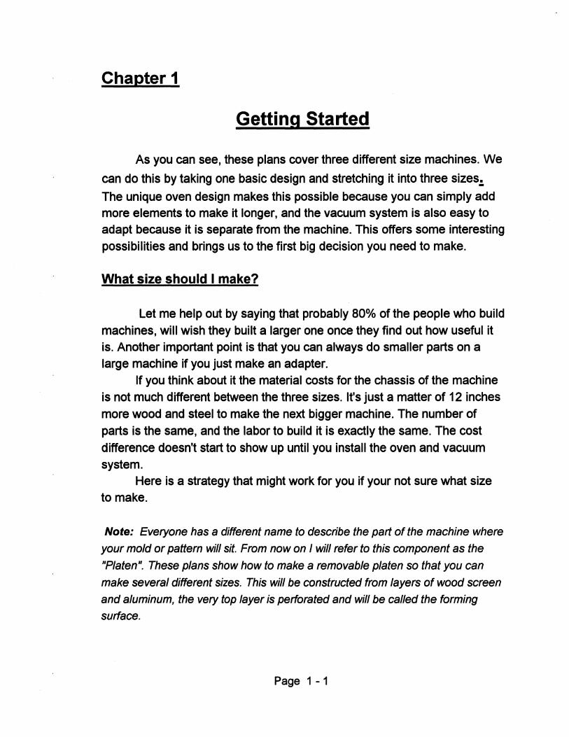
As you can see, these plans cover three different size machines. We
can do this by taking one basic design and stretching it into three sizes.:.
The unique oven design makes this possible because you can simply add more elements to make it longer, and the vacuum system is also easy to adapt because it is separate from the machine. This offers some interesting
possibilities and brings us to the first big decision you need to make.
What size should I make?
Let me help out by saying that probably 80% of the people who build
machines, will wish they built a larger one once they find out how useful it is. Another important point is that you can always do smaller parts on a large machine if you just make an adapter.
If you think about it the material costs for the chassis of the machine is not much different between the three sizes. It's just a matter of 12 inches more wood and steel to make the next bigger machine. The number of
parts is the same, and the labor to build it is exactly the same. The cost
difference doesn't start to show up until you install the oven and vacuum system.
Here is a strategy that might work for you if your not sure what size to make.
Note: Everyone has a different name to describe the part of the machine where
your mold or pattern will sit. From now on I will refer to this component as the
"Platen". These plans show how to make a removable platen so that you can
make several different sizes. This will be constructed from layers of wood screen
and aluminum, the very top layer is perforated and will be called the forming
surface.
Page 1 -1
Chapter 1 - Getting Started
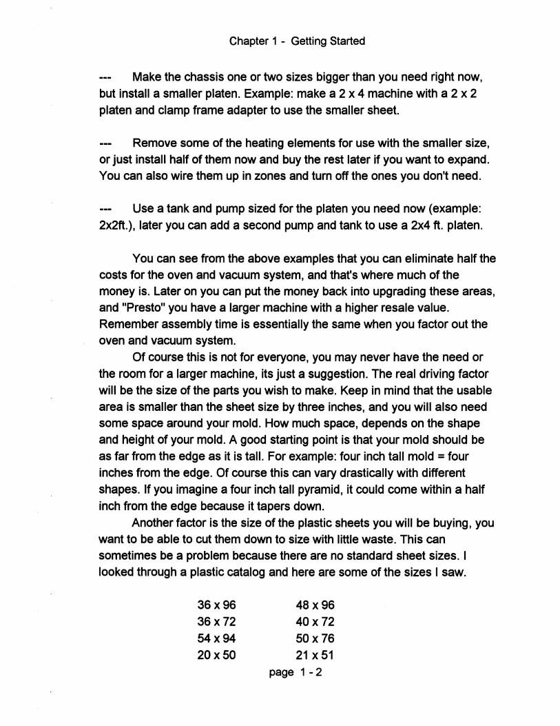
Make the chassis one or two sizes bigger than you need right now,
but install a smaller platen. Example: make a 2 x 4 machine with a 2 x 2 platen and clamp frame adapter to use the smaller sheet.
Remove some of the heating elements for use with the smaller size, or just install half of them now and buy the rest later if you want to expand. You can also wire them up in zones and tum off the ones you don't need.
Use a tank and pump sized for the platen you need now (example:
2x2ft.) , later you can add a second pump and tank to use a 2x4 ft. platen.
You can see from the above examples that you can eliminate half the costs for the oven and vacuum system, and that's where much of the money is. Later on you can put the money back into upgrading these areas, and "Presto" you have a larger machine with a higher resale value. Remember assembly time is essentially the same when you factor out the oven and vacuum system.
Of course this is not for everyone, you may never have the need or
the room for a larger machine, its just a suggestion. The real driving factor will be the size of the parts you wish to make. Keep in mind that the usable area is smaller than the sheet size by three inches, and you will also need some space around your mold. How much space, depends on the shape and height of your mold. A good starting point is that your mold should be
as far from the edge as it is tall. For example: four inch tall mold = four inches from the edge. Of course this can vary drastically with different shapes. If you imagine a four inch tall pyramid, it could come within a half
inch from the edge because it tapers down.
Another factor is the size of the plastic sheets you will be buying, you want to be able to cut them down to size with little waste. This can sometimes be a problem because there are no standard sheet sizes. I looked through a plastic catalog and here are some of the sizes I saw.
36x96
36x72
54x94
20x50
48x96
40x72
50x76 21 x51
page 1 - 2
Chapter 1 - Getting Started
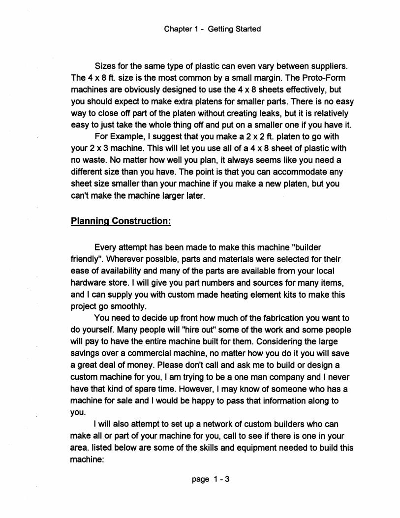
Sizes for the same type of plastic can even vary between suppliers. The 4 x 8 ft. size is the most common by a small margin. The Proto-Form machines are obviously designed to use the 4 x 8 sheets effectively, but
you should expect to make extra platens for smaller parts. There is no easy way to close off part of the platen without creating leaks, but it is relatively easy to just take the whole thing off and put on a smaller one if you have it.
For Example, I suggest that you make a 2 x 2 ft. platen to go with your 2 x 3 machine. This will let you use all of a 4 x 8 sheet of plastic with no waste. No matter how well you plan, it always seems like you need a
different size than you have. The point is that you can accommodate any sheet size smaller than your machine if you make a new platen, but you
can't make the machine larger later.
Planning Construction:
Every attempt has been made to make this machine "builder friendly". Wherever possible, parts and materials were selected for their ease of availability and many of the parts are available from your local
hardware store. I will give you part numbers and sources for many items,
and I can supply you with custom made heating element kits to make this project go smoothly.
You need to decide up front how much of the fabrication you want to do yourself. Many people will "hire out" some of the work and some people will pay to have the entire machine built for them. Considering the large savings over a commercial machine, no matter how you do it you will save a great deal of money. Please don't call and ask me to build or design a
custom machine for you, I am trying to be a one man company and I never
have that kind of spare time. However, I may know of someone who has a machine for sale and I would be happy to pass that information along to you.
I will also attempt to set up a network of custom builders who can make all or part of your machine for you, call to see if there is one in your
area. listed below are some of the skills and equipment needed to build this machine:
page 1 - 3
Chapter 1 - Getting Started
Skills
Welding Metalworking Woodworking Electrical Sheet metal fabrication Basic assembly
Equipment
Welder Metal cutting saw and Drill Table saw Wire strippers and Crimpers Tin snips Basic hand tools
Don't let anything above scare you, things are broken down into logical groups so that you can do what you want and get help with the rest. The only area that I think everyone should get a little help with is the electrical wiring, even if you feel qualified please have a certified electrician look over the finished job just for safety's sake.
A few notes about this manual:
Remember, These plans show you how to build three different size machines, but it is actually the same machine stretched into three sizes. The areas affected most by changing the size are the vacuum system and electrical wiring. Most of the drawings and photographs depict the medium size machine (2 x 3 ft.), so yours may look longer or shorter depending on which size you make.
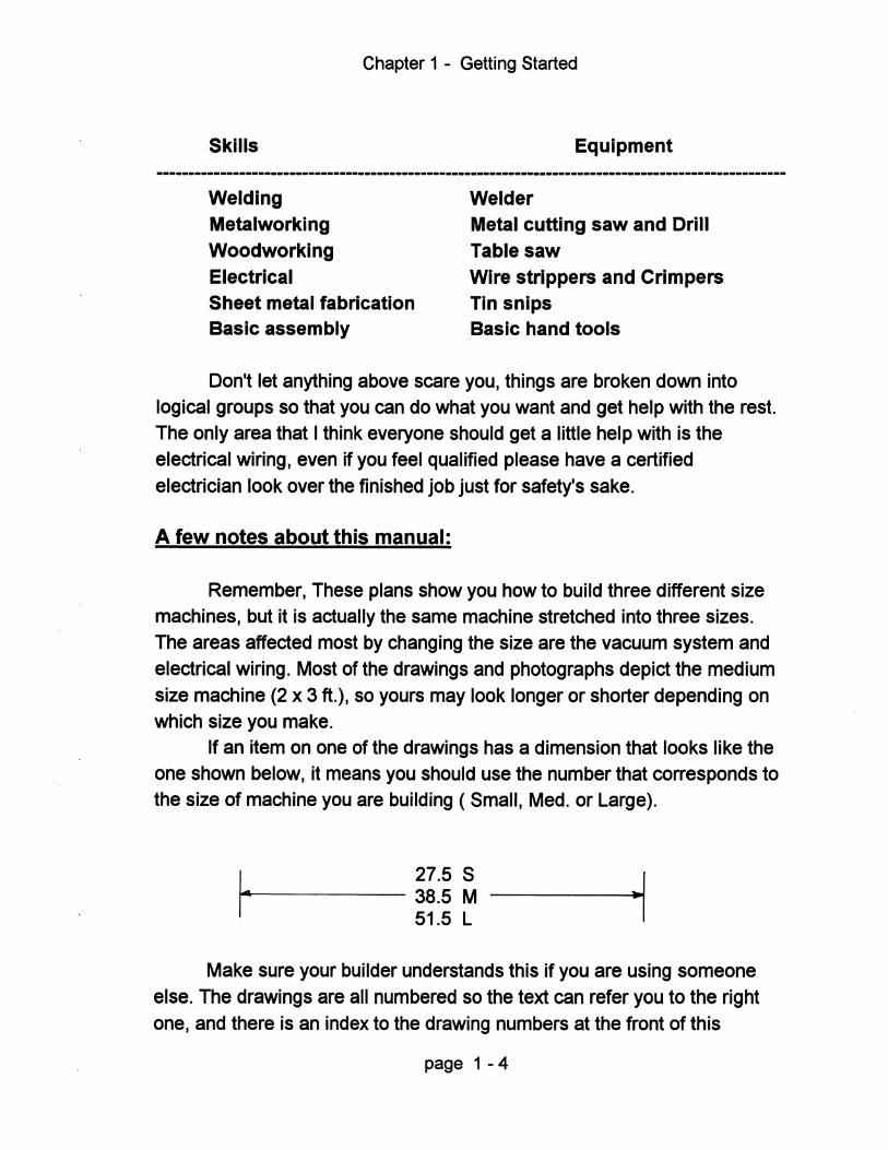
If an item on one of the drawings has a dimension that looks like the one shown below, it means you should use the number that corresponds to the size of machine you are building ( Small, Med. or Large).
I 27.5 S 14 .. ----- 38.5 M
51.5 L
Make sure your builder understands this if you are using someone else. The drawings are all numbered so the text can refer you to the right one, and there is an index to the drawing numbers at the front of this
page 1 - 4
Chapter 1 - Getting Started
manual. There are also some photo pages included with many detail shots of the actual machine. I suggest that you look over the photo's first so you have a good mental image while you are reading the text.
You may notice some colored pages at the back of some chapters. These will contain revisions or supplements, If yours has none, then the plans are up to date. I only send these out if there is a change or correction in the middle of a printing run. If your plans have no colored pages, don't worry about it.
You will see helpful "Tips:" thrown in wherever they seem appropriate. They will be in Italics, and may be directly related to construction, or just interesting bits of knowledge. There may also be supplements at the back of a chapter that contain new information or revisions, and these will also be a unique color. It's possible that you could receive supplements in the mail if any changes are made. Always check the back of each chapter for colored pages before you build anything.
This manual is in a ring binder so it lays flat, but also so you can take out pages and send them out to have parts made if you need to. I suggest that you have copies made in case they don't come back. The pages are only printed on one side so it is easy to insert any revisions into the appropriate place and it gives you plenty of room to keep notes.
Each chapter will begin with an overview of the skills required as well as some very detailed advice on how to find a good vendor if you choose not to make those parts yourself. Whenever parts are needed, I will give you part numbers from two of the largest commercial mail order sources as well as complete specifications so you can find the parts locally or make substitutions if you have to. You can save countless hours chasing parts if you just use the shopping list provided and order everything from these sources.
Follow a sequence:
I suggest you follow the sequence in these plans to build your machine. Some decisions have to be made first that will affect construction later, and it always works best if some parts are fitted to other-parts. For example, if you build the wood boxes first, then the metal frame, there is a good chance that they won't fit together because of normal building
page 1 - 5
Chapter 1 - Getting Started
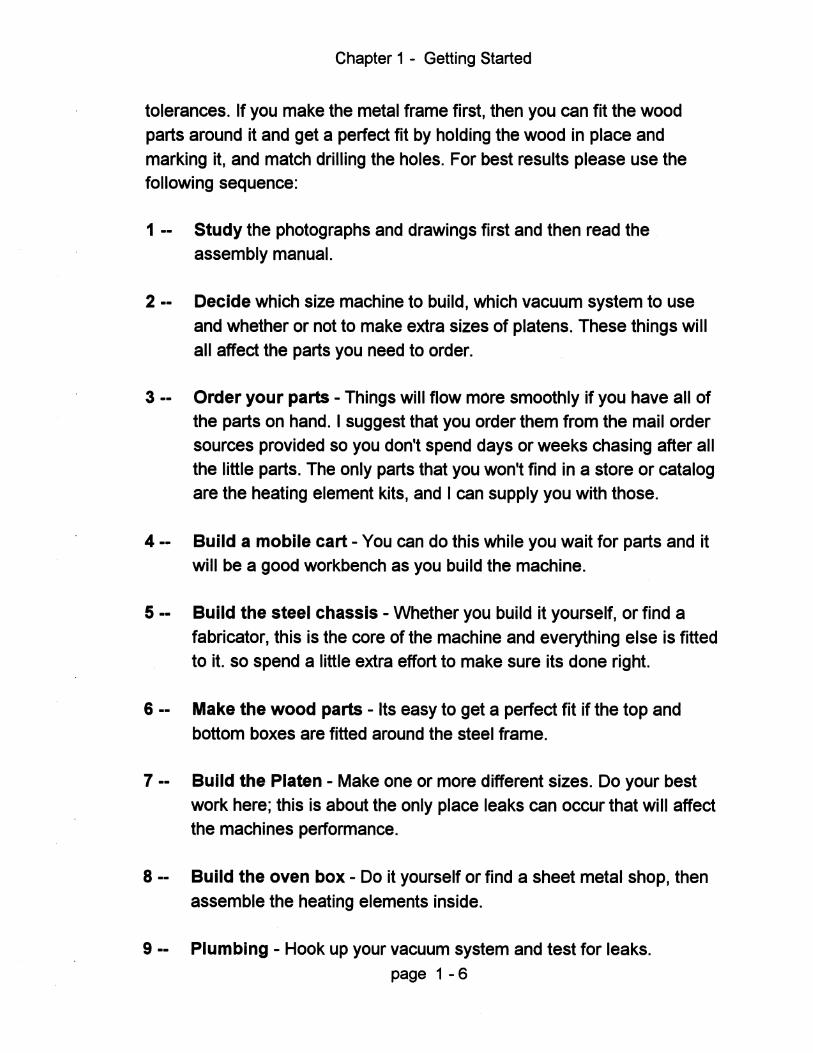
tolerances. If you make the metal frame first, then you can fit the wood parts around it and get a perfect fit by holding the wood in place and marking it, and match drilling the holes. For best results please use the following sequence:
1 -- Study the photographs and drawings first and then read the assembly manual.
2 -- Decide which size machine to build, which vacuum system to use and whether or not to make extra sizes of platens. These things will all affect the parts you need to order.
3 -- Order your parts - Things will flow more smoothly if you have all of the parts on hand. I suggest that you order them from the mail order sources provided so you don't spend days or weeks chasing after all the little parts. The only parts that you won't find in a store or catalog are the heating element kits, and I can supply you with those.
4 -- Build a mobile cart - You can do this while you wait for parts and it will be a good workbench as you build the machine.
5 -- Build the steel chassis - Whether you build it yourself, or find a fabricator, this is the core of the machine and everything else is fitted to it. so spend a little extra effort to make sure its done right.
6 -- Make the wood parts - Its easy to get a perfect fit if the top and bottom boxes are fitted around the steel frame.
7 -- Build the Platen - Make one or more different sizes. Do your best work here; this is about the only place leaks can occur that will affect the machines performance.
8 -- Build the oven box - Do it yourself or find a sheet metal shop, then assemble the heating elements inside.
9 -- Plumbing - Hook up your vacuum system and test for leaks. page 1 - 6
Chapter 1 - Getting Started
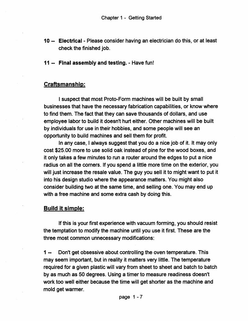
10 -- Electrical - Please consider having an electrician do this, or at least check the finished job.
11 -- Final assembly and testing. - Have funl
Craftsmanship:
I suspect that most Proto-Form machines will be built by small businesses that have the necessary fabrication capabilities, or know where to find them. The fact that they can save thousands of dollars, and use employee labor to build it doesn't hurt either. Other machines will be built by individuals for use in their hobbies, and some people will see an opportunity to build machines and sell them for profit.
In any case, I always suggest that you do a nice job of it. It may only cost $25.00 more to use solid oak instead of pine for the wood boxes, and it only takes a few minutes to run a router around the edges to put a nice radius on all the corners. If you spend a little more time on the exterior, you will just increase the resale value. The guy you sell it to might want to put it into his design studio where the appearance matters. You might also consider building two at the same time, and selling one. You may end up with a free machine and some extra cash by doing this.
Build it simple:
If this is your first experience with vacuum forming, you should resist the temptation to modify the machine until you use it first. These are the three most common unnecessary modifications:
1 -- Don't get obsessive about contrOlling the oven temperature. This may seem important, but in reality it matters very little. The temperature required for a given plastiC will vary from sheet to sheet and batch to batch by as much as 50 degrees. USing a timer to measure readiness doesn't work too well either because the time will get shorter as the machine and mold get warmer.
page 1 -7
Chapter 1 - Getting Started
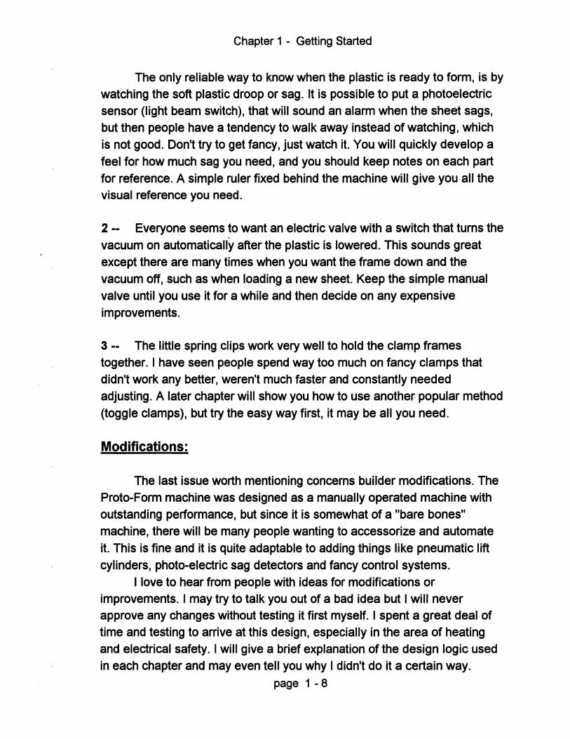
The only reliable way to know when the plastic is ready to form, is by watching the soft plastic droop or sag. It is possible to put a photoelectric sensor (light beam switch), that will sound an alarm when the sheet sags, but then people have a tendency to walk away instead of watching, which is not good. Don't try to get fancy, just watch it. You will quickly develop a feel for how much sag you need, and you should keep notes on each part for reference. A simple ruler fixed behind the machine will give you all the visual reference you need.
2 •• Everyone seems to want an electric valve with a switch that turns the vacuum on automatically after the plastic is lowered. This sounds great except there are many times when you want the frame down and the vacuum off, such as when loading a new sheet. Keep the simple manual valve until you use it for a while and then decide on any expensive improvements.
3 •• The little spring clips work very well to hold the clamp frames together. I have seen people spend way too much on fancy clamps that didn't work any better, weren't much faster and constantly needed adjusting. A later chapter will show you how to use another popular method (toggle clamps), but try the easy way first, it may be all you need.
Modifications:
The last issue worth mentioning concerns builder modifications. The Proto-Form machine was designed as a manually operated machine with outstanding performance, but since it is somewhat of a "bare bones" machine, there will be many people wanting to accessorize and automate it. This is fine and it is quite adaptable to adding things like pneumatic lift cylinders, photo-electric sag detectors and fancy control systems.
I love to hear from people with ideas for modifications or improvements. I may try to talk you out of a bad idea but I will never approve any changes without testing it first myself. I spent a great deal of time and testing to arrive at this design, especially in the area of heating and electrical safety. I will give a brief explanation of the design logic used in each chapter and may even tell you why I didn't do it a certain way.
page 1 - 8

Chapter 1 - Getting Started
Please call if you need help understanding the plans but beyond the information printed here, I can offer no advice on modifications or offer design help for those people inventing their own machines.
Technical Support: (248) 391-2974
Please call between 9 AM. and 9 PM. EST. and have your questions
ready in advance. If I am busy or unavailable, Leave a clear message and specify a good time for me to call back. I am sometimes able to return calls in the evenings.
page 1 - 9
Chapter 2
Finding The Parts
Some people will build a machine just because they always wanted
one or they enjoy a good project. They will make a hobby out of it and take
their time to scrounge for parts. The satisfaction of building it is almost as important as having it. At the other extreme many people will build it simply because they want to save money, and they want to finish it fast because they have a need for it right now.
I tried to keep both groups of people in mind when I created these plans. My goal was to provide enough information so a person could find suitable parts by scrounging around, and I tried to offer advice on short cuts
and alternate methods wherever possible. This should help the "Hobby"
people keep costs down. I am trying to help the "Fast Build" group by sourcing most of the parts from two large mail order companies, and both groups should appreciate saving time with the heating element kits I offer. This gives you the choice of pinching pennies and shopping for the best deal on every little part, or simply making one Fax or phone call to order it all at once.
The companies I chose are McMaster-Carr Supply Co and Grainger.
I think they are the largest suppliers to commercial customers in north
America. Their catalogs are both over 3000 pages. The two parts lists will show the part numbers from these companies and also other places you may find that part.
You will find two "Parts Lists" a "Wood Cut List" and a "Steel Cut List" in a pocket at the front of this binder. The wood and steel cut lists show the actual dimensions of all the parts you need to cut, use this as guide when ordering materials and check the appropriate chapters for
notes on material selection. The parts lists will give part numbers for most
of the other components. There are separate lists for vacuum pumps and tanks in chapter 8, you should read that chapter to select those components before ordering any parts.
Page 2 - 1
Chapter 2 - Finding the Parts
Notes:
-- If you will be making extra smaller platens, be sure to order more wood, aluminum sheet, screen and steel angle to get the job done.
-- All items included in our oven kits are not on any parts list. This kit is a "must have" item and includes custom elements that I purchase in large quantities as well as the hard to find Hi-Temp wire, custom bus bars and all hardware. These oven kits are only available to people who purchased plans because it is optimized to work with these machines.
If you decide to fit another type of heating element such as quartz tubes or radiant panels, you are on your own. I can not offer any advice or assistance on custom ovens due to lack of testing.
-- Some items are not on the shopping list at all. These include small hardware such as screws, nails, air fittings and electrical terminals. Everyone's machine will be a little different depending on where you get all the components from, so you will have to work out these minor details. The text will usually make recommendations when possible.
If you are in a big hurry or merely anxious to get to work, I suggest the following approach to ordering parts.
1 - Decide whether to order the steel yourself, or let your steel fabricator or welding shop supply it.
2 - Buy your wood at the local lumber store. Its safe to make the mobile
cart while you are waiting for other parts, but don't build the top and bottom
boxes until the chassis is finished. This way you can fit the wood parts around the steel.
3 - Look over the parts list and buy any parts you can find easily from local
stores. Then Fax or phone your order in for the remaining parts.
Page 2 - 2
Chapter 2 - Finding the Parts
4 - Order the oven kit, vacuum pump and tank, or if you are on a tight budget, these items can wait until later because they won't be needed until final assembly.
About McMaster-Carr and Grainger
If you are going to take the express route and order these items from either company, (highly recommended) then there are a few things you should be aware of. First of all I don't get a commission for helping them sell parts, I am suggesting this option only because I just got done wasting countless hours chasing small parts for the prototype machines. If you value your time at all, just make one Fax or phone call and all of your parts will show up in a few days. The cost of shipping will most likely be offset by the fuel you save from not driving around, and if you order from out of state, there should be no sales tax.
McMaster-Carr offers service that is second to none. Most items are shipped the same day, and they rarely have back orders despite the 320.000 parts they carry. They also handle returns and mis-ordered items in a friendly professional manner. I apologize if I am starting to sound like a commercial, but I am really impressed by this company. Grainger is another giant company, their catalog is over 4000 pages, they specialize more in electrical and plumbing type supplies and also offer excellent service.
Now here's the catch ( you knew it was coming), Their prices are full retail, this means that items typically cost 5 -10% more than the lowest prices you will find at those giant hardware superstores. The other catch is that they only sell to businesses and their jumbo catalogs are sometimes hard to get, you will probably have to order first before they send you one.
How to Order Many of you will already have an account with these companies. but
if you are a private individual (non business), don't worry, just fill out the blank order form at the end of this chapter and Fax, mail, or call it in. You will need to invent a company name and make up a purchase order number to be convincing, but its OK to use your home address as long as its not an apartment or P.O. box. Specify C.O.D. and pay the UPS driver when it
Page 2 - 3

Chapter 2 - Finding the Parts
arrives, or fill in your credit card number. Be sure to include your name and phone number in case there is a problem with the order.
Transfer the quantity, description and part numbers from the main parts list to the blank order form for items you couldn't find locally. As far as they know you look like a business and this would be a decent size order so there won't be any problem. You can also call in the order and read the part numbers to them, this way they can tell you if it is in stock and what the current price is. One last caution, they don't have a minimum order, but if your first order is very small (maybe under $50.00), then they may ask more questions about the status of your business. After you are in their computer then $10.00 orders are no problem and you will get the next catalog too.
Here are the phone numbers and addresses for the two companies mentioned above:
McMaster Carr Supply Co .• Call the location nearest you or find them on the web at www.mcmaster.com
P.O. Box 740100 Atlanta Ga. 30374-0100 Ph # (404) 346-7000 Fax # (404) 349-9091
P.O. Box 94930 Cleveland, OH. 44101-4930 Ph # (330) 995-5500 Fax# (330) 995-9600
P.O. Box 4355 Chicago, IL. 60680-4355 Ph # (630) 833-0300 Fax # (603) 834-9427
P.O. Box 440 New Brunswick, NJ. 08903-0440 Ph # (908) 329-3200 Fax # (908) 329-3772
P.O Box 54960 Los Angeles, CA. 90054-0960 Ph # (562) 692-5911 Fax # (562) 695-2323
Grainger - They have a zillion branch locations, call for the one nearest you. (248) 585-4100 or try them on the web at: www.gralnger.com
Page 2 -4
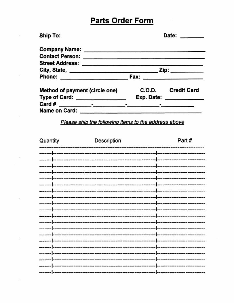
Parts Order Form
Ship To: Date:
Company Name: Contact Person: Street Address: City, State, Phone:
_____________ Zip: ____ _
--------------------------Method of payment (circle one) Type of Card: Card # Name on Card:
Fax:
C.O.D. Credit Card Exp. Date:
Please ship the following items to the address above
Quantity Description Part #
-------1-----------------------------------------------------------1----------------------------------1-----------------------------------------------------------1----------------------------------1-----------------------------------------------------------1----------------------------------1-----------------------------------------------------------1----------------------------------1-----------------------------------------------------------1----------------------------------1-----------------------------------------------------------1----------------------------------1-----------------------------------------------------------1----------------------------------1-----------------------------------------------------------1----------------------------------1-----------------------------------------------------------1----------------------------------1-----------------------------------------------------------1----------------------------------1-----------------------------------------------------------1----------------------------------1-----------------------------------------------------------1----------------------------------1-----------------------------------------------------------1----------------------------------1-----------------------------------------------------------1----------------------------------1-----------------------------------------------------------1----------------------------------1-----------------------------------------------------------1----------------------------------1-----------------------------------------------------------1----------------------------------1-----------------------------------------------------------1----------------------------------1-----------------------------------------------------------1----------------------------------1-----------------------------------------------------------1---------------------------

Parts Order Form (cont.)
Quantity Description Part # -----------------------------------------------------------------------------------------------------1-----------------------------------------------------------1----------------------------------1-----------------------------------------------------------1----------------------------------1-----------------------------------------------------------1----------------------------------1-----------------------------------------------------------1----------------------------------1-----------------------------------------------------------1----------------------------------1-----------------------------------------------------------1----------------------------------1-----------------------------------------------------------1----------------------------------1-----------------------------------------------------------1----------------------------------1-----------------------------------------------------------1----------------------------------1-----------------------------------------------------------1----------------------------------1-----------------------------------------------------------1----------------------------------1-----------------------------------------------------------1----------------------------------1-----------------------------------------------------------1----------------------------------1-----------------------------------------------------------1----------------------------------1-----------------------------------------------------------1----------------------------------1-----------------------------------------------------------1----------------------------------1-----------------------------------------------------------1----------------------------------1-----------------------------------------------------------1----------------------------------1-----------------------------------------------------------1----------------------------------1-----------------------------------------------------------1----------------------------------1-----------------------------------------------------------1----------------------------------1-----------------------------------------------------------1----------------------------------1-----------------------------------------------------------1----------------------------------1-----------------------------------------------------------1----------------------------------1-----------------------------------------------------------1----------------------------------1-----------------------------------------------------------1----------------------------------1-----------------------------------------------------------1----------------------------------1-----------------------------------------------------------1----------------------------------1-----------------------------------------------------------I~---------------------------------1-----------------------------------------------------------1---------------------------
Chapter 3
Mobile Cart
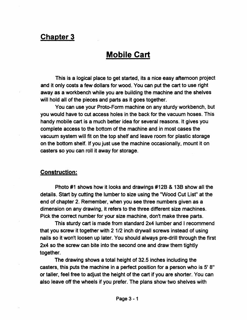
This is a logical place to get started, its a nice easy afternoon project and it only costs a few dollars for wood. You can put the cart to use right away as a workbench while you are building the machine and the shelves will hold all of the pieces and parts as it goes together.
You can use your Proto-Form machine on any sturdy workbench, but you would have to cut access holes in the back for the vacuum hoses. This handy mobile cart is a much better idea for several reasons. It gives you
complete access to the bottom of the machine and in most cases the vacuum system will fit on the top shelf and leave room for plastiC storage on the bottom shelf. If you just use the machine occasionally, mount it on casters so you can roll it away for storage.
Construction:
Photo #1 shows how it looks and drawings #128 & 138 show all the
details. Start by cutting the lumber to size using the "Wood Cut List" at the end of chapter 2. Remember, when you see three numbers given as a dimension on any drawing, it refers to the three different size machines. Pick the correct number for your size machine, don't make three parts.
This sturdy cart is made from standard 2x4 lumber and I recommend that you screw it together with 2 1/2 inch drywall screws instead of using nails so it won't loosen up later. You should always pre-drill through the first
2x4 so the screw can bite into the second one and draw them tightly
together. The drawing shows a total height of 32.5 inches including the
casters, this puts the machine in a perfect position for a person who is 5' 8" or taller, feel free to adjust the height of the cart if you are shorter. You can
also leave off the wheels if you prefer. The plans show two shelves with
Page 3-1
Chapter 3 - Mobile cart
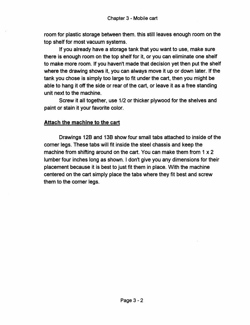
room for plastic storage between them. this still leaves enough room on the
top shelf for most vacuum systems. If you already have a storage tank that you want to use, make sure
there is enough room on the top shelf for it, or you can eliminate one shelf to make more room. If you haven't made that decision yet then put the shelf where the drawing shows it, you can always move it up or down later. If the tank you chose is Simply too large to fit under the cart, then you might be able to hang it off the side or rear of the cart, or leave it as a free standing
unit next to the machine. Screw it all together, use 112 or thicker plywood for the shelves and
paint or stain it your favorite color.
Attach the machine to the cart
Drawings 128 and 138 show four small tabs attached to inside of the corner legs. These tabs will fit inside the steel chassis and keep the machine from shifting around on the cart. You can make them from 1 x 2
lumber four inches long as shown. I don't give you any dimensions for their placement because it is best to just fit them in place. With the machine centered on the cart simply place the tabs where they fit best and screw them to the corner legs.
Page 3 - 2
Chapter 4
Building the Chassis
Design Goals - The foundation for this machine is a welded steel chassis. The design has been optimized to meet the following goals:
Easy to build - Only two sizes of angle and square tubing and one round tube with a few simple bushings and tabs. All tubing is cut off square with no tricky angle cuts. The number of drilled holes is kept to a minimum. No machined parts or close tolerance work required, and you can check alignment with a carpenters square during welding. The carrier frame uses plastic glides that can be shimmed to adjust for building tolerances.
Easy to Use - A manual lift linkage raises the plastic up to the oven. The linkage is designed to lift easily and lock in the up position for heating, while providing plenty of leverage when pushed downward. The carrier frame slides on simple plastic glides with no metal to metal contact. Operation is smooth and quiet with no lubrication needed.
Finding a Fabricator
If you are not equipped to cut and weld steel, you can have someone else do it for you. Look in the yellow pages and you will find many companies that offer steel fabrication services, but some are better suited than others. Look for one that does most of their work with light gauge steel and is used to doing precision work.
You want to avoid places that fabricate structural steel for building construction. They are used to welding large rusty beams where plus or minus 1/2 in. tolerance is good enough. The next step up would be a small welding shop that builds things like boat trailers and other items primarily out of angle iron and square tubing. This is better but some shops may still be a little bit crude for what we need.
An excellent choice would be a shop that builds parts for aircraft or race cars. They would be more accustomed to working with thin tubing and
Page 4-1
Chapter 4 - Building the Chassis
more likely to build it accurately. Look under automobile racing in the yellow pages or ask around at the speed shops where you can find a good chassis builder. In any case visit the shops to get a quote, you will quickly see whether its a clean professional operation, or if its a cold dark shop with a dirt floor.
Even if you send this work out to be done, read a little farther so you understand the different ways to cut and weld steel. This way you can ask intelligent questions when you are shopping. See if they can order the steel for you to save you the trouble and expense of buying too much. Many fabrication shops will have these common sizes in stock.
Build it Yourself
This would be the cheapest and for some people the most fun way to go. Many businesses have suitable fabrication capabilities and this is a relatively easy project, so lets get started.
Order the Steel
If you have never ordered steel for your business, look in the yellow pages for sources. The steel sizes we need can sometimes be found at larger hardware stores. While this is convenient, it is much more expensive and you need to avoid galvanized steel because it is dangerous to weld. If you order from a steel distributor, ask if they have cold rolled square tubing (C.R.) instead of hot rolled (H.R.). This is not a big deal, it just means the surface is usually clean and silver instead of black and dirty.
In case you don't know, raw steel is not pretty stuff, it either comes to you very greasy and dirty or very rusty and dirty. Expect to spend some
time cleaning it up before use. Steel comes in lengths usually 12 to 20 feet long, so you will most likely have to buy more than you need. If you order in less than full sections, the cutting charge otten costs more than the metal you didn't buy. The distributor may be willing to deliver it for an extra charge, and some will cut it in half for free so you can fit it into your vehicle. I wouldn't ask them to cut all of the pieces to size for you, their equipment
hardly ever cuts square and their people are usually not very careful.
Page 4-2
Chapter 4 - Building the Chassis
Tips: - Be sure to get more angle iron for the clamp frame adapters if you will be making extra smaller platens. - The 1 1/4 0.0. tube used for the lift linkage handle is the best choice, but it may be hard to find or too expensive to buy a long piece of it. You can also substitute 1 inch EMT electrical conduit. If you buy a standard 10ft. length of conduit, you will have enough left over to use for the electrical wires, but you must grind off the zinc coating before welding. The 1 1/4 in. tube would be a little bigger and thicker and result in a stiffer feel for the lift linkage, but the conduit works OK especially for the two smaller machines. You will notice some twisting on the large machine if you pick up the handle from one end instead of from the middle.
Cutting the Steel
There are a number of ways to cut steel. some good and some bad. here's how they rate:
Hacksaw - This is the worst choice. it can be done but you will wear out one arm and its difficult to do accurately. You should cut the parts a little long and use a stationary disc sander to trim and square up the ends.
Bandsaw - Like a long continuous hack saw blade. this machine cuts efficiently but with only poor to fair accuracy. Some machines are called horizontal band saws and they clamp the steel in a vise and feed down automatically. They cut pretty straight. but not always square. A vertical band saw is one where the operator feeds the metal by hand and follows a scribed line. This can be more accurate depending on the operator. With either machine the cut can be acceptable. but it's still wise to cut oversize and clean up the ends on a disc sander.
Chop Saw - These use a thin fast spinning abrasive blade to grind through the steel. They are very noisy and throw a shower of sparks. but they cut fast and are relatively inexpensive so all fabricators have them. They leave
Page 4-3
Chapter 4 - Building the Chassis
a smooth cut but not always accurate or square, so its still best to finish off with a disc sander.
Cold Cut Saw - Sometimes called cold saws or just chop saws, they look similar the abrasive saw described above but they use a slow turning steel blade with teeth. These give you the cleanest, straightest cuts and you don't need to clean up the end with a disc sander. Try to find a fabricator with one on these saws.
Drilling the Steel
There are only two choices here, but one is much less fun than the other.
Hand Drilling - Use a portable drill and sharp drill bits. Always use cutting oil and center punch the holes first. None of the hole locations are very critical and you can do it this way, but it won't be a pleasant job.
Drill Press - This machine feeds the drill bit down when you pull on a handle and is much faster. You should still center punch the holes first and use cutting oil. You can assume that all steel fabricators have this machine.
Welding
Here again there are several choices rated from worst to best. I'll try not to bore you with details, but there are some Significant differences worth noting.
Arc Welding - Uses a stick electrode, these make sparks and smoke, and require a lot of skill to use. A layer of slag covers the weld and must be chipped away. There is always a lot of splatter to grind off and its difficult to weld thin metal this way.
Gas Welding - Good for thin metal but very slow and requires much skill. Best suited to the home fabricator because the equipment is affordable
Page 4-4
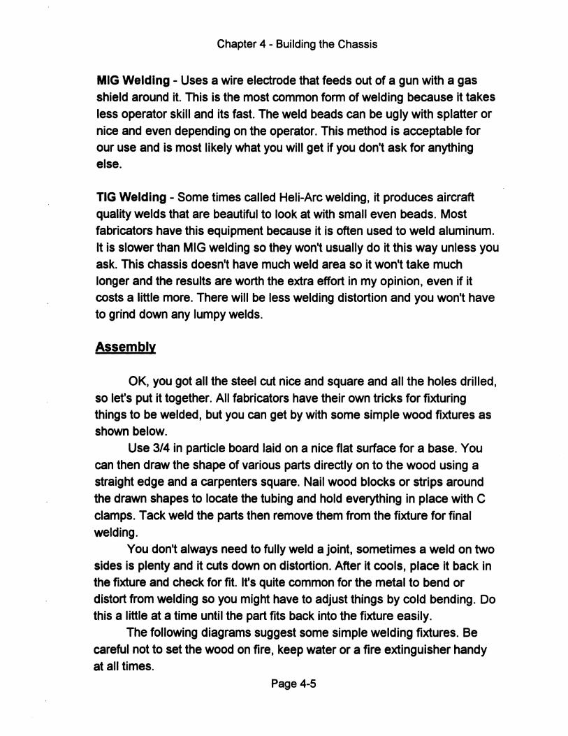
Chapter 4 - Building the Chassis
MIG Welding - Uses a wire electrode that feeds out of a gun with a gas shield around it. This is the most common form of welding because it takes
less operator skill and its fast. The weld beads can be ugly with splatter or
nice and even depending on the operator. This method is acceptable for our use and is most likely what you will get if you don't ask for anything else.
TIG Welding - Some times called Heli-Arc welding, it produces aircraft quality welds that are beautiful to look at with small even beads. Most fabricators have this equipment because it is often used to weld aluminum.
It is slower than MIG welding so they won't usually do it this way unless you ask. This chassis doesn't have much weld area so it won't take much longer and the results are worth the extra effort in my opinion, even if it costs a little more. There will be less welding distortion and you won't have to grind down any lumpy welds.
Assembly
OK, you got all the steel cut nice and square and all the holes drilled, so let's put it together. All fabricators have their own tricks for fixturing things to be welded, but you can get by with some simple wood fixtures as shown below.
Use 3/4 in particle board laid on a nice flat surface for a base. You can then draw the shape of various parts directly on to the wood using a straight edge and a carpenters square. Nail wood blocks or strips around
the drawn shapes to locate the tubing and hold everything in place with C
clamps. Tack weld the parts then remove them from the fixture for final welding.
You don't always need to fully weld a jOint, sometimes a weld on two sides is plenty and it cuts down on distortion. After it cools, place it back in the fixture and check for fit. It's quite common for the metal to bend or distort from welding so you might have to adjust things by cold bending. Do this a little at a time until the part fits back into the fixture easily.
The following diagrams suggest some simple welding fixtures. Be
careful not to set the wood on fire, keep water or a fire extinguisher handy at all times.
Page 4-5
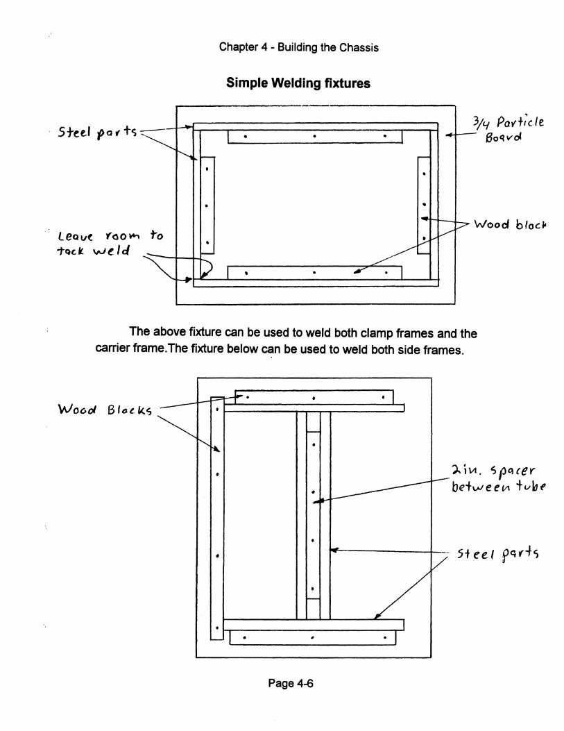
. 5tet.r 'Po t tc;
LeQv( f'ao~
TQC.t W~ lei
~
to
--
....
~ pot--•
•
• t--
D -r
Chapter 4 - Building the Chassis
Simple Welding fixtures
-~
3/'1 POv't,c./e I • • • I - 8oQvoC
~
•
• l~
10'/ P
v-~-
Wood blocfl
I , • I' • I
The above fixture can be used to weld both clamp frames and the carrier frame.The fixture below can be used to weld both side frames.
...... --I-" I-" •
~ f'.
" •
•
• ,-I •
•
t--
•
• .... ~
•
• l"-
#
Page 4-6
• 1
~
-
/ J
• 1
f.--
-.-.
?.iVl. spc,{er bet"" e e ttl tv 11 t
5teel f~(-+s
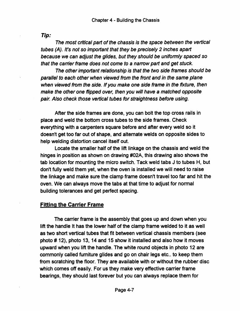
Chapter 4 - Building the Chassis
Tip: The most critical part of the chassis is the space between the vertical
tubes (A). It's not so important that they be precisely 2 inches apart because we can adjust the glides, but they should be uniformly spaced so that the carrier frame does not come to a narrow part and get stuck.
The other important relationship is that the two side frames should be parallel to each other when viewed from the front and in the same plane when viewed from the side. If you make one side frame in the fixture, then make the other one flipped over, then you will have a matched opposite pair. Also check those vertical tubes for straightness before using.
After the side frames are done, you can bolt the top cross rails in place and weld the bottom cross tubes to the side frames. Check everything with a carpenters square before and after every weld so it doesn't get too far out of shape, and alternate welds on opposite sides to help welding distortion cancel itself out.
Locate the smaller half of the lift linkage on the chassis and weld the hinges in position as shown on drawing #02A, this drawing also shows the tab location for mounting the micro switch. Tack weld tabs J to tubes H, but don't fully weld them yet, when the oven is installed we will need to raise the linkage and make sure the clamp frame doesn't travel too far and hit the oven. We can always move the tabs at that time to adjust for normal building tolerances and get perfect spacing.
Fitting the Carrier Frame
The carrier frame is the assembly that goes up and down when you lift the handle It has the lower half of the clamp frame welded to it as well as two short vertical tubes that fit between vertical chassis members (see photo # 12), photo 13, 14 and 15 show it installed and also how it moves upward when you lift the handle. The white round objects in photo 12 are commonly called furniture glides and go on chair legs etc .. to keep them from scratching the floor. They are available with or without the rubber disc which comes off easily. For us they make very effective carrier frame bearings, they should last forever but you can always replace them for
Page 4-7
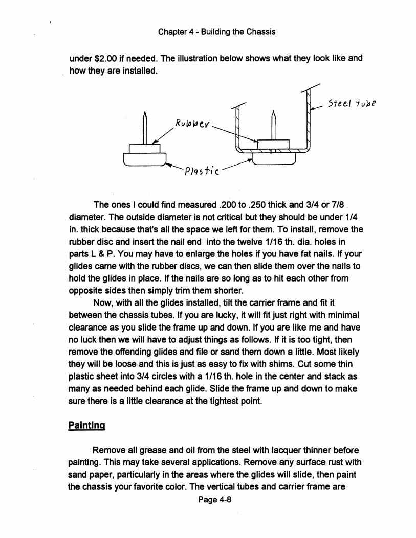
Chapter 4 - Building the Chassis
under $2.00 if needed. The illustration below shows what they look like and how they are installed.
5tee..1 iv~e
The ones I could find measured .200 to .250 thick and 3/4 or 7/8 . diameter. The outside diameter is not critical but they should be under 1/4 in. thick because that's all the space we left for them. To install, remove the rubber disc and insert the nail end into the twelve 1/16 tho dia. holes in parts L & P. You may have to enlarge the holes if you have fat nails. If your glides came with the rubber discs, we can then slide them over the nails to hold the glides in place. If the nails are so long as to hit each other from opposite sides then simply trim then:'l shorter.
Now, with all the glides installed, tilt the carrier frame and fit it between the chassis tubes. If you are lucky, it will fit just right with minimal clearance as you slide the frame up and down. If you are like me and have no luck then we will have to adjust things as follows. If it is too tight, then remove the offending glides and file or sand them down a little. Most likely they will be loose and this is just as easy to fix with shims. Cut some thin plastic sheet into 3/4 circles with a 1/16 tho hole in the center and stack as many as needed behind each glide. Slide the frame up and down to make sure there is a little clearance at the tightest point.
Painting
Remove all grease and oil from the steel with lacquer thinner before painting. This may take several applications. Remove any surface rust with sand paper, particularly in the areas where the glides will slide, then paint the chassis your favorite color. The vertical tubes and carrier frame are
Page 4-8
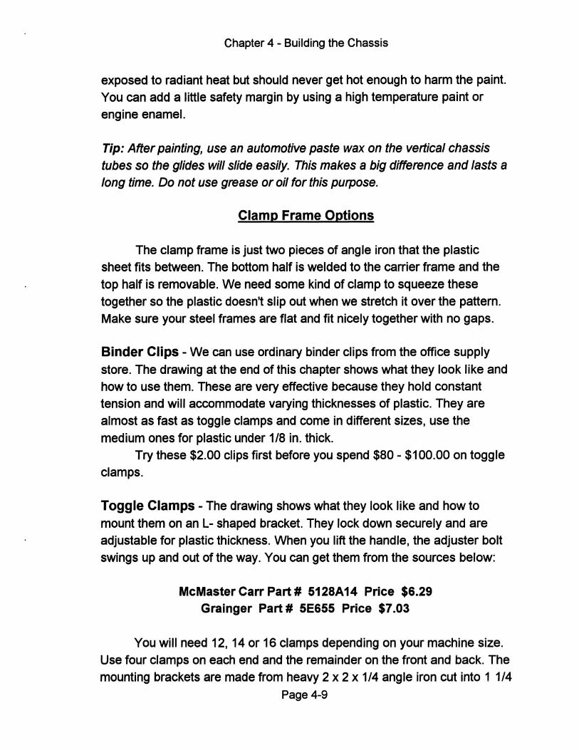
Chapter 4 - Building the Chassis
exposed to radiant heat but should never get hot enough to harm the paint.
You can add a little safety margin by using a high temperature paint or
engine enamel.
Tip: After painting, use an automotive paste wax on the vertical chassis tubes so the glides will slide easily. This makes a big difference and lasts a long time. Do not use grease or oil for this purpose.
Clamp Frame Options
The clamp frame is just two pieces of angle iron that the plastic sheet fits between. The bottom half is welded to the carrier frame and the
top half is removable. We need some kind of clamp to squeeze these
together so the plastic doesn't slip out when we stretch it over the pattern. Make sure your steel frames are flat and fit nicely together with no gaps.
Binder Clips - We can use ordinary binder clips from the office supply
store. The drawing at the end of this chapter shows what they look like and how to use them. These are very effective because they hold constant tension and will accommodate varying thicknesses of plastic. They are almost as fast as toggle clamps and come in different sizes, use the
medium ones for plastic under 118 in. thick. Try these $2.00 clips first before you spend $80 - $100.00 on toggle
clamps.
Toggle Clamps - The drawing shows what they look like and how to
mount them on an L- shaped bracket. They lock down securely and are
adjustable for plastic thickness. When you lift the handle, the adjuster bolt swings up and out of the way. You can get them from the sources below:
McMaster Carr Part # 5128A14 Price $6.29 Grainger Part # 5E655 Price $7.03
You will need 12, 14 or 16 clamps depending on your machine size. Use four clamps on each end and the remainder on the front and back. The
mounting brackets are made from heavy 2 x 2 x 1/4 angle iron cut into 1 1/4 Page 4-9
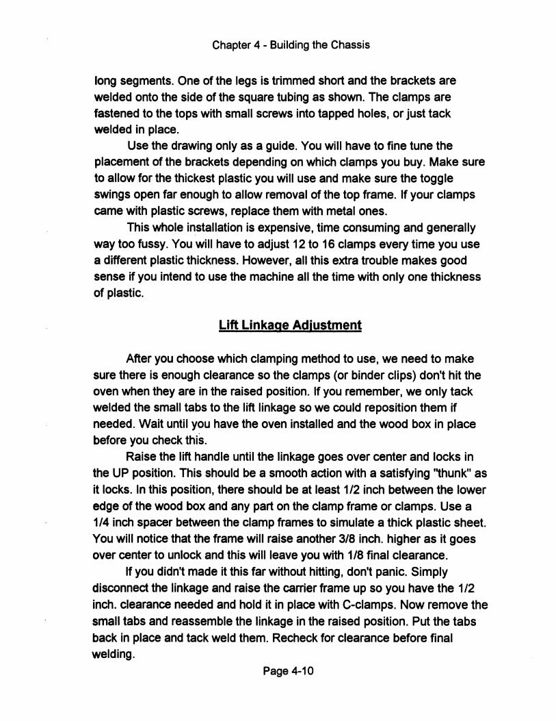
Chapter 4 - Building the Chassis
long segments. One of the legs is trimmed short and the brackets are welded onto the side of the square tubing as shown. The clamps are fastened to the tops with small screws into tapped holes, or just tack welded in place.
Use the drawing only as a guide. You will have to fine tune the placement of the brackets depending on which clamps you buy. Make sure to allow for the thickest plastic you will use and make sure the toggle swings open far enough to allow removal of the top frame. If your clamps came with plastic screws, replace them with metal ones.
This whole installation is expensive, time consuming and generally way too fussy. You will have to adjust 12 to 16 clamps every time you use a different plastiC thickness. However, all this extra trouble makes good sense if you intend to use the machine all the time with only one thickness of plastiC.
Lift Linkage Adjustment
After you choose which clamping method to use, we need to make sure there is enough clearance so the clamps (or binder clips) don't hit the oven when they are in the raised position. If you remember, we only tack welded the small tabs to the lift linkage so we could reposition them if needed. Wait until you have the oven installed and the wood box in place before you check this.
Raise the lift handle until the linkage goes over center and locks in the UP position. This should be a smooth action with a satisfying ''thunk'' as
it locks. In this position, there should be at least 1/2 inch between the lower
edge of the wood box and any part on the clamp frame or clamps. Use a 1/4 inch spacer between the clamp frames to simulate a thick plastiC sheet. You will notice that the frame will raise another 3/8 inch. higher as it goes over center to unlock and this will leave you with 1/8 final clearance.
If you didn't made it this far without hitting, don't panic. Simply disconnect the linkage and raise the carrier frame up so you have the 1/2 inch. clearance needed and hold it in place with C-clamps. Now remove the
small tabs and reassemble the linkage in the raised position. Put the tabs
back in place and tack weld them. Recheck for clearance before final welding.
Page 4-10
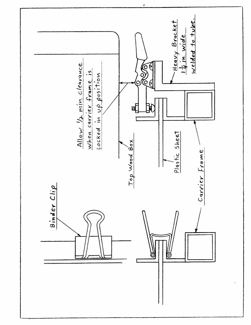
#
"--
~ ~ ~ v er ~
t1:)
1;) \\l ~ V\
.~ -+-'" 0--0...
I \,)
~ . -5
~ f-0
. -~ ~ tf
U
Chapter 5
Making the Wood Parts
The wood parts used in this machine are primarily non structural, except for the forming surface. This means they are used mostly to cover the parts inside. If your business works with sheet metal you can make your boxes out of that material instead, but I chose wood because it's cheap and easy to work with.
It pays to do a nice job on the wood parts because they are so visible. Nicely finished oak will greatly enhance the appearance and resale value of your machine.
Tips: - With 5 -10,000 watts of heat near by, the wood can get dried out and warp after a while. This would be similar to leaving it out in the hot sun all day. A good choice would be a nice stable hardwood such as oak or maple. - Since you will need a router to radius the edges of the forming surface, why not use it to round off all of the exterior comers. I did this to the prototype (see pictures) and it got a lot of compliments.
I think this is the only machine at any price that is attractive enough to put in an office setting or a nice design studio. The cost difference between pine and oak is probably only $25.00, so splurge a little, this is a great place to show off your wood working skills.
Construction
I tried to use standard width lumber wherever possible (1x2, 2x4, 1x8 etc .. ) The ends are all square cuts with no fancy jOints. The oven cover box is the only part you really need a table saw for. The height is 4 1/2 so you will have to cut down a 1x6, and a table saw (or router) can be used to cut the groove for the pegboard. Let's look at each part separately and go through the construction.
Page 5-1
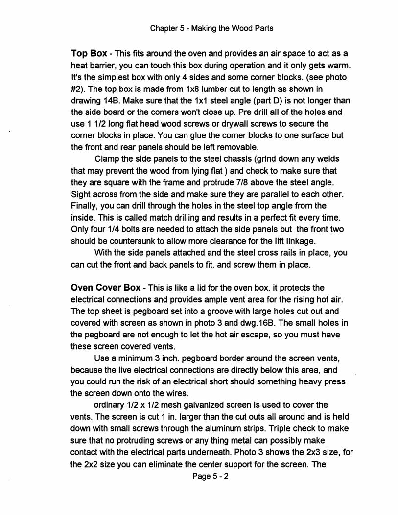
Chapter 5 - Making the Wood Parts
Top Box - This fits around the oven and provides an air space to act as a heat barrier, you can touch this box during operation and it only gets warm. It's the simplest box with only 4 sides and some corner blocks. (see photo #2). The top box is made from 1x81umber cut to length as shown in drawing 14B. Make sure that the 1x1 steel angle (part 0) is not longer than the side board or the corners won't close up. Pre drill all of the holes and use 1 1/2 long flat head wood screws or drywall screws to secure the corner blocks in place. You can glue the corner blocks to one surface but the front and rear panels should be left removable.
Clamp the side panels to the steel chassis (grind down any welds that may prevent the wood from lying flat) and check to make sure that they are square with the frame and protrude 7/8 above the steel angle. Sight across from the side and make sure they are parallel to each other. Finally, you can drill through the holes in the steel top angle from the inside. This is called match drilling and results in a perfect fit every time. Only four 1/4 bolts are needed to attach the side panels but the front two should be countersunk to allow more clearance for the lift linkage.
With the side panels attached and the steel cross rails in place, you can cut the front and back panels to fit. and screw them in place.
Oven Cover Box - This is like a lid for the oven box, it protects the electrical connections and provides ample vent area for the rising hot air. The top sheet is pegboard set into a groove with large holes cut out and covered with screen as shown in photo 3 and dwg.1SB. The small holes in the pegboard are not enough to let the hot air escape, so you must have these screen covered vents.
Use a minimum 3 inch. pegboard border around the screen vents, because the live electrical connections are directly below this area, and you could run the risk of an electrical short should something heavy press the screen down onto the wires.
ordinary 1/2 x 1/2 mesh galvanized screen is used to cover the vents. The screen is cut 1 in. larger than the cut outs all around and is held down with small screws through the aluminum strips. Triple check to make sure that no protruding screws or any thing metal can possibly make contact with the electrical parts underneath. Photo 3 shows the 2x3 size, for the 2x2 size you can eliminate the center support for the screen. The
Page 5 - 2
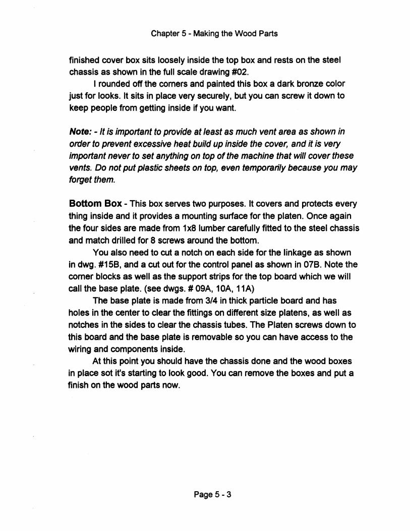
Chapter 5 - Making the Wood Parts
finished cover box sits loosely inside the top box and rests on the steel chassis as shown in the full scale drawing #02.
I rounded off the comers and painted this box a dark bronze color just for looks. It sits in place very securely. but you can screw it down to keep people from getting inside if you want.
Note: - It is important to provide at least as much vent area as shown in order to prevent excessive heat build up inside the cover, and it is very important never to set anything on top of the machine that will cover these vents. Do not put plastic sheets on top, even temporarily because you may forget them.
Bottom Box - This box serves two purposes. It covers and protects every thing inside and it provides a mounting surface for the platen. Once again the four sides are made from 1 x8 lumber carefully fitted to the steel chassis and match drilled for 8 screws around the bottom.
You also need to cut a notch on each side for the linkage as shown in dwg. #158. and a cut out for the control panel as shown in 078. Note the comer blocks as well as the support strips for the top board which we will call the base plate. (see dwgs. # 09A. 10A. 11A)
The base plate is made from 3/4 in thick particle board and has holes in the center to clear the fittings on different size platens. as well as notches in the sides to clear the chassis tubes. The Platen screws down to this board and the base plate is removable so you can have access to the wiring and components inside.
At this point you should have the chassis done and the wood boxes in place sot it's starting to look good. You can remove the boxes and put a finish on the wood parts now.
Page 5 - 3
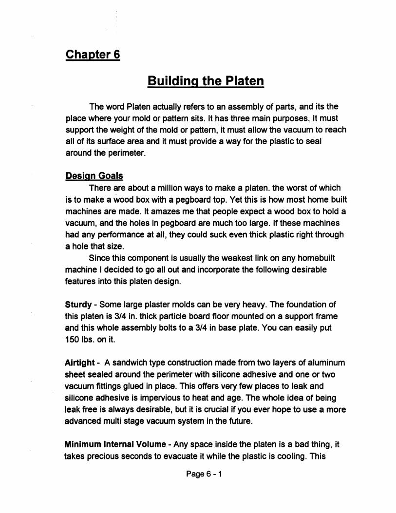
Chapter 6
Building the Platen
The word Platen actually refers to an assembly of parts, and its the place where your mold or pattern sits. It has three main purposes, It must support the weight of the mold or pattern, it must allow the vacuum to reach all of its surface area and it must provide a way for the plastic to seal around the perimeter.
Design Goals There are about a million ways to make a platen. the worst of which
is to make a wood box with a pegboard top. Yet this is how most home built machines are made. It amazes me that people expect a wood box to hold a vacuum, and the holes in pegboard are much too large. If these machines had any performance at all, they could suck even thick plastic right through a hole that size.
Since this component is usually the weakest link on any home built machine I decided to go all out and incorporate the following desirable features into this platen design.
Sturdy - Some large plaster molds can be very heavy. The foundation of this platen is 3/4 in. thick particle board floor mounted on a support frame and this whole assembly bolts to a 3/4 in base plate. You can easily put 150Ibs.onit.
AIrtight - A sandwich type construction made from two layers of aluminum sheet sealed around the perimeter with silicone adhesive and one or two vacuum fittings glued in place. This offers very few places to leak and silicone adhesive is impervious to heat and age. The whole idea of being leak free is always deSirable, but it is crucial if you ever hope to use a more advanced multi stage vacuum system in the future.
Minimum Internal Volume - Any space inside the platen is a bad thing, it takes precious seconds to evacuate it while the plastic is cooling. This
Page 6-1
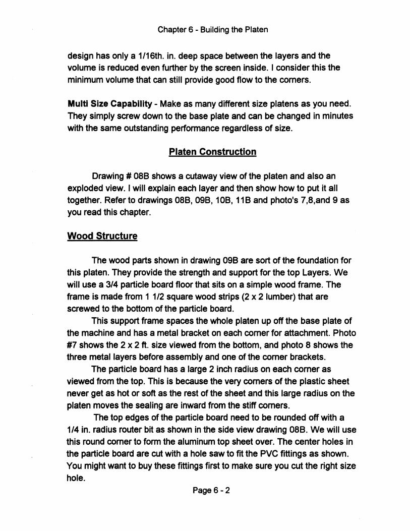
Chapter 6 - Building the Platen
design has only a 1/16th. in. deep space between the layers and the volume is reduced even further by the screen inside. I consider this the minimum volume that can still provide good flow to the comers.
Multi Size Capability - Make as many different size platens as you need. They simply screw down to the base plate and can be changed in minutes with the same outstanding performance regardless of size.
Platen Construction
Drawing # OB8 shows a cutaway view of the platen and also an exploded view. I will explain each layer and then show how to put it all together. Refer to drawings OB8, 098, 108, 118 and photo's 7,B,and 9 as you read this chapter.
Wood Structure
The wood parts shown in drawing 098 are sort of the foundation for this platen. They provide the strength and support for the top Layers. We will use a 3/4 particle board floor that sits on a simple wood frame. The frame is made from 1 1/2 square wood strips (2 x 2 lumber) that are screwed to the bottom of the particle board.
This support frame spaces the whole platen up off the base plate of the machine and has a metal bracket on each comer for attachment. Photo #7 shows the 2 x 2 ft. size viewed from the bottom, and photo B shows the three metal layers before assembly and one of the comer brackets.
The particle board has a large 2 inch radius on each comer as viewed from the top. This is because the very comers of the plastic sheet never get as hot or soft as the rest of the sheet and this large radius on the platen moves the sealing are inward from the stiff comers.
The top edges of the particle board need to be rounded off with a 1/4 in. radius router bit as shown in the side view drawing OB8. We will use this round comer to form the aluminum top sheet over. The center holes in the particle board are cut with a hole saw to fit the PVC fittings as shown. You might want to buy these fittings first to make sure you cut the right size hole.
Page 6-2
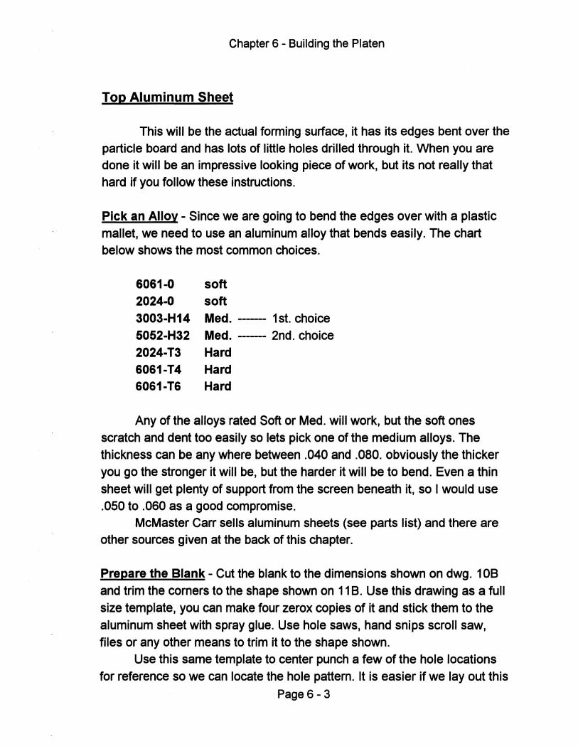
Chapter 6 - Building the Platen
Top Aluminum Sheet
This will be the actual forming surface, it has its edges bent over the particle board and has lots of little holes drilled through it. When you are done it will be an impressive looking piece of work, but its not really that hard if you follow these instructions.
Pick an Alloy - Since we are going to bend the edges over with a plastic
mallet, we need to use an aluminum alloy that bends easily. The chart below shows the most common choices.
6061·0 soft 2024·0 soft 3003·H14 Med. ------ 1st. choice 5052·H32 Med. ------- 2nd. choice 2024·T3 Hard 6061·T4 Hard 6061·T6 Hard
Any of the alloys rated Soft or Med. will work, but the soft ones scratch and dent too easily so lets pick one of the medium alloys. The thickness can be any where between .040 and .080. obviously the thicker you go the stronger it will be, but the harder it will be to bend. Even a thin
sheet will get plenty of support from the screen beneath it, so I would use .050 to .060 as a good compromise.
McMaster Carr sells aluminum sheets (see parts list) and there are other sources given at the back of this chapter.
Prepare the Blank - Cut the blank to the dimensions shown on dwg. 10B and trim the comers to the shape shown on 11 B. Use this drawing as a full
size template, you can make four zerox copies of it and stick them to the aluminum sheet with spray glue. Use hole saws, hand snips scroll saw,
files or any other means to trim it to the shape shown. Use this same template to center punch a few of the hole locations
for reference so we can locate the hole pattern. It is easier if we layout this
Page 6 - 3
Chapter 6 - Building the Platen
pattern now before the edges are bent up. The holes are laid out on a one inch grid, but they stop short of the edge so there is a smooth border for the plastic to seal to. Measure and draw a grid with a felt tipped marker using the holes you punched as a reference. You don't need to center punch all of these holes, its pretty easy to drill on a mark when you are using small drill bits.
Tip: A short cut for laying out the hole pattern would be to use a piece of
1/4 in thick pegboard as a template. The holes are spaced one inch apart like we need and you can center punch right through them. Grind a 1/4 in dia. rod to a pOint SO it will fit into the holes. When you are done you can use this pegboard for the oven cover box.
Bending the edges
After the forming surface blank is all trimmed and the hole pattern is marked, we can bend the edges over the wood form. You may want to start with the smallest platen if you are doing several sizes, this will give you a chance to perfect the technique. You should also hold off on drilling the little holes until you are satisfied with your bending job.
Holding the Blank - We need to clamp the top aluminum sheet over the particle board for bending, as shown in dwg. 11 B. Do this before you glue the bottom sheet down. Use big C-clamps over a strip of wood to prevent scratching and do it near the edge of a sturdy workbench or table. The grid you laid out should be on the bottom, against the wood.
It helps if you draw some refrence lines on the aluminum sheet so you can see that its centered over the particle board, and periodicaly check to make sure it doesn't shift while you are bending the edges. Use a lot of clamps and move them around as neccessary
Page 6 - 4
Chapter 6 - Building the Platen
Tip: It is always a good idea to mark an X in one comer of the sheet and on the wood so these pieces stay oriented during construction. After you bend the edges, it will always fit better if you line up the marks.
Bending - Use a hard rubber or plastiC hammer, never a steel one. If done correctly there will be absolutely no marks on the aluminum after bending. Practice on a scrap if you want, or just start off slowly. You want to work your way along one side using many light taps spaced close together. It should take at least four passes and many finish taps to smooth it out.
Work the comers about halfway down when doing the sides and then finish them up last. It will make sense now why we trimmed the aluminum
comers this way so there is no excess metal to form. Here are some of the most common mistakes when bending:
Wrong Hammer - A plastiC faced hammer is perfect, some rubber ones
are too soft for the final bending and steel will cause unSightly dents.
Bending too fast - Be patient, bend it over gradually and make at least
four passes with a lot of light taps. If you bend too much at one time, it stretches out the metal.
Insufficient clamping - Clamp a board on top of the sheet close to the
bend area, this forces the bend to happen at the comer and keeps the rest of the sheet flat. Use enough C-clamps to hold securely, even if you have to move them as you proceed along the side.
Be patient, its amazing how well this works if you take your time. When you have the sides and corners folded down neatly, remove the aluminum from the wood so you can drill the holes.
Drilling the Holes
I am not going to lie to you, this part of the job is just plain boring
(pun intended). We will have to drill and de burr hundreds of little holes. It
Page 6 - 5
Chapter 6 - Building the Platen
helps if you can watch TV or listen to music to take your mind off the drudgery. Follow these steps and you will be done before you know it.
Put the aluminum sheet down on newspaper or cardboard to prevent scratches. It is not necessary to center punch each hole, but if you do, don't do it so hard that you dent the sheet.
How to Drill- Buy some new, sharp 1/16 tho dia. drill bits. They should be high speed steel (HSS), or cobalt but never carbon steel. You will probably go through three or four of them due to breakage. A drill press would be the
easy way to do this job, but if you have to drill the holes by hand use a portable drill that spins at least 1200 RPM.
A cordless drill would be a lot lighter and more convenient but you will need two batteries so you can drill non-stop. This might be a good excuse to buy a cordless drill if you don't have one.
Tip: You want to drill from the bottom side for one very good reason. The
drill will leave a small bUff on the side you are drilling from and a huge bUff on the other side. If we start from the backside of the sheet, we can just leave the small bUff inside where it won't hurt anything. The other bUff is too large to be left anywhere so we have to remove it no matter what. At least this way we only remove half the burrs.
Always use cutting oil when drilling or the bit will load up with chips. Almost any oil will do but WD-40 works great. Put some oil in a small shallow container such as a bottle cap and dip the drill bit into it before each hole. Use a piece of scrap wood under the aluminum so you don't drill
holes in your workbench. Put the drill bit on the mark and drill straight through, you will soon get a feel for how hard to pUSh. It only takes a very light touch and the aluminum drills very easy. Change the drill bit as soon as you think its slowing down or if the burr gets larger.
Remove the Burrs - By now you know what I mean by leaving large burrs.
Obviously these things have to be removed but resist the temptation to use a file or sandpaper, that will just make a mess. Use a larger drill bit, around
Page 6 - 6
Chapter 6 - Building the Platen
1/4 in. and spin it between your fingers You will see that these burrs come of fairly easily.
You can slip a piece of rubber tubing over the drill and continue to use your fingers, or you can use the power drill. Actually a cordless screwdriver works best for this because they are light and they spin slowly. If you use a portable drill, run it at a slower speed and use a light touch so it doesn't dig in.
When you are done you will have quite a lot of work into this aluminum sheet, but it should last forever. Drill some 1/16 tho dia. holes though the side flanges about 6 inches apart as shown, we will drive nails through these to hold it all together during final assembly.
Bottom Aluminum Sheet
This bottom layer is just a flat sheet with no bends, so it can be any aluminum alloy you can find. You should avoid using a steel sheet because it will expand at a different rate than the aluminum top sheet and may stress the adhesive bond between them. A thickness of .040 to .060 should be all you need here.
Drawing 108 shows the dimensions for this sheet as well as the corner radius needed. Center the aluminum sheet on the particle board ( it should be smaller) and draw a line around it for reference. Apply contact cement to both pieces, let it dry and press them together. Use the lines you drew as a guide and position it carefully before letting it touch because contact cement grabs and you won't get a second chance to reposition it.
Tip: There are two basic kinds of contact cements. The water based kind
commonly found in hardware stores is safer to use but not very good. The second type is a solvent based glue, these are getting harder to find in stores. They stink like hell, and are much more aggressive.
The contact cement called out on the parts list is called Pliobond 30. I think Goodyear makes it and it is the good kind ( it smells real bad), and it has a higher temperature rating than most others. This glue joint is not very critical, but it is exposed to some heat. I think any solvent based contact cement will work fine but use the Pliobond if you can find it.
Page 6-7
Chapter 6 - Building the Platen
If you don't want to mess with this step, you can take the parts to any place that makes kitchen counter tops. They will have special equipment for spraying contact cement and they are used to gluing down sheets of laminate. You could actually use a sheet of counter top material (Formica) in place of the aluminum sheet, but it is actually more expensive than aluminum and not as durable. It does make sense however if you are making smaller platens and can use the sink cutouts that they often throw away.
Install the PVC Fitting
This fitting goes through a hole in the particle board and seals directly to the bottom aluminum sheet as shown in dwg. 088. The important thing here is to seal it to the aluminum sheet. Wait until you have the PVC fitting before you cut the hole because the fittings can vary in size quite a bit. If there are any raised ridges or letters on the end of the fitting, file them off so there is a good flat surface to glue to the aluminum sheet. The dark bold line on the drawing represents the silicone rubber adhesive. Use the same adhesive for the perimeter of the platen.
After the bottom aluminum sheet is glued down to the particle board, drill a 1/4 in. hole in the location where you want each fitting to go. The 2 x 2 ft. and smaller platens will only need one hole in the center, while the larger platens will need two holes as shown. The 1/4 in. pilot hole goes through both layers. Use a 1 1/4 hole saw from the top to just cut through the aluminum sheet, it's OK to cut into the wood a little. Now flip it over and use a larger hole saw (measure your PVC fitting for the correct size) to cut through the wood until you just barely touch the aluminum, be careful so you don't go too far. If you are using a formica laminate instead of the bottom aluminum sheet, be very careful not to cut into the formica
Remove the wood plug and clean off any wood and adhesive left on the exposed aluminum (or formica) flange inside the hole. We need to glue the PVC fitting into this hole as shown in dwg. 088, It's OK if the fitting fits a little loosely. We will use a silicone rubber adhesive for this and also as a perimeter seal between the sheets. You should buy the silicone in a cartridge that fits a standard caulking gun.
Page 6 - 8
Chapter 6 - Building the Platen
Tip: Choose this silicone adhesive carefully. There are a lot of products at
the hardware store that are used for caulking around the house, and they say things like" siliconized" or "silicone based". You need to find one that says 1 00% silicone. Pure silicone can handle very high temperatures and never gets hard, but it's a little more expensive.
While any pure silicone will work, some are formulated for better adhesion to certain materials. I tried the one specified in the parts list and it is an excellent choice because it is low odor, non corrosive, and it bonds well to aluminum and plastiC. It is GE 6700 series and comes in different colors.
Wipe the PVC fitting and the aluminum flange with lacquer thinner so
the silicone will get a good bond. Again, the important area to seal is between the PVC and the aluminum flange, so put a bead of silicone there first, then spread some around the inside of the hole. Push the fitting in and
apply a bead around the base of the fitting for support. leave it to cure for 24 hours.
Cut out the Screen
Trim a piece of 1/2 in. mesh galvanized screen to the dimensions shown on dwg. 10B, and radius the corners. This screen spaces the
aluminum sheets apart and allows the vacuum to travel side ways through its weave to get to the corners. Bend the screen if necessary so it lays as flat as possible. This type of screen is sometimes referred to as "Hardware Cloth"
Tip: The outside of the wood frame and the edge of the particle board will
be visible after the platen is assembled. You may choose to paint or stain these areas now, or leave them bare wood. The photo's show it painted black.
Page 6 - 9
Chapter 6 - Building the Platen
Final Assembly
At this point you should have the particle board wood floor attached to the support frame and the bottom aluminum sheet and PVC fittings glued in place. The screen should be cut to size, the top sheet has the four sides nicely folded over and you just got done drilling a zillion holes in it. Take a break you look tired, then stop stalling and put this thing together.
Take one last look at drawing 088, if it doesn't look like yours, go fix
something. We will use the same silicone adhesive that you used for the PVC fitting (see earlier ''Tips''). Clean the bond area on both aluminum sheets with lacquer thinner to remove all cutting oils and other contaminants.
Lay the forming surface (aluminum sheet with holes) top side down on a nice flat part of the floor so you can kneel on it later. Use news paper to prevent scratches. Lay the screen on the inside of the forming surface and center it over the hole pattern leaving an even border around the outside for the adhesive. It would be a good idea to hold it in place with a
few small pieces of tape through the mesh, this way it won't shift out of position at a bad time, otherwise just be careful so you don't bump·it during assembly. Put some small nails and a hammer where you can reach them.
After assembly, you will need to hammer these small nails through the sides of the aluminum top sheet into the particle board. Did you remember to drill the holes for the nails?
Glue it together - Apply a uniform bead of silicone adhesive to the bottom
aluminum sheet around the perimeter. Make sure you put it in the right place (see dwg. 088). Make the bead 1/4 to 3/8 dia. with no gaps bubbles,
or thin spots, don't wait too long to assemble it or the adhesive will start to skin over.
Flip the whole assembly over so the adhesive is facing down and carefully fit it into the forming surface, If you marked these parts with an X
for orientation, line them up now. Press down evenly to spread the adhesive and then kneel on it while driving small nails through the side flanges into the wood. Try not to take your weight off it until the nails are in place to hold everything. Leave it undisturbed for 24 hrs until the adhesive
cures.
Page 6 -10
Chapter 6 - Building the Platen
Tip: Once you press the parts together, don't let them separate again
before nailing. This may destroy the integnty of the glue jOint and cause leaks. This chance is remote but there is no way to fix it afterwards so if this happens, the prudent thing to do is to wipe off the glue and try again.
After the silicone has cured, attach the four comer brackets and stand back to admire your work.
Using Smaller Platens
The smaller platens mount to the base plate just like the large one,
but you will have to make a clamp frame adapter to use the smaller sheets.
See photo #17 for an example of this.
This clamp frame adapter is made from 3/4 in. angle iron just like the larger one. the two piece frame is held together with spring clips and
the top half is a simple rectangle the same size as the plastic sheet. The
bottom frame has extension legs that reach out to fit inside the large lower
clamp frame. If you look closely you will see 1/4 in. steel nuts welded
inside the ends of each leg. These nuts line up with holes you will drill in
the large clamp frame. (lower half)
You will have to attach the adapter frame inside the large frame with
allen head screws because there won't be enough room for regular hex head bolts. Screw the smaller platen down to the base plate and you are ready to form smaller sheets.
Tip: Which ever platen size you use, it will screw down to the base plate.
Make sure it is centered inside the clamp frame before drilling the screw holes. You can use wood screws, but these will strip out after a while. A
better idea is to use threaded inserts, some times called propeller nuts or Tee nuts. They fit into a slightly larger drilled hole in the base plate and provide durable steel threads to screw a bolt into.
Page 6 -11
Chapter 6 - Building the Platen
Additional Sources for Aluminum Sheets
Ask them for a catalog or have them Fax you the appropriate information
Aircraft Spruce and Specialty Co. (800) 824-1930
Wicks Aircraft Supply (800) 221-9425
Airparts Inc. (800) 800-3229
Page 6 -12
Chapter 7
Building the Oven
You already made the top wood box that surrounds the oven, this chapter deals with the oven itself, including the sheet metal box and heating element installation. There are many types of heating elements that can be used for vacuum forming, and they all have their pro's and con's.
From talking with many customers over the years, I learned that they often have very strong opinions about the best type of heater, and there will undoubtedly be those who second guess my choice. You don't need to read this but I feel compelled to give you an overview of the situation and comment on some of the more obvious choices.
Do we want even heating? - The answer is No!.. We do want the sheet to heat evenly, but that requires very uneven heat output from our heater, and the reason is commonly referred to as edge losses. To put it simply, the clamp frame draws heat out of the sheet, resulting in stiff comers and edges. We can't eliminate this problem, but we can reduce it to acceptable levels in several ways.
Heat it Faster - I made this rule up just now, but it makes perfect sense. If the clamp frame is drawing 3 units of heat per hour out of the plastic sheet, and the oven is only heating at a rate of 6 units per hour, then the edges are getting 50% less heat. If we heat at a rate of 12 units per hour, then the edges see 25% less heat which is much better. There are limits to how aggressively we can heat some plastics, but in general terms we want to heat fairly quickly.
Enlarge the oven - It is common practice to have the heating elements extend 3 inches or more past the sheet on all sides. This helps the problem, but its hard to package an oversize oven in some designs and its terribly inefficient. For example: a 2 x 2 ft. oven equals 576 square inches, but if you add 3 inches all around it jumps to 900 square inches of heated area, wasting a lot of electricity.
Page 7-1
Chapter 7 - Building the Oven
Redistribute the heat - This is the smart way to do it. You can put more
heat just where its needed, less in the center and more on the edges. This can be done with separate zones, or by adding supplemental heat where its needed. You can do this without making the oven grossly oversize.
Types of heating elements
Please note that all methods discussed here deal with infra-red heating and there is a certain amount of tuning involved to get the heater output (wavelength) to match the absorption characteristics of the plastiC. Aside from the edge loss problem, this is why most home built machines don't work as well as they could.
I will give a brief description of several types of heating elements, but since the theme of this Proto-Form machine is "High performance at Low cost", only two of these choices seem appropriate, and one is clearly superior.
Flat Panel Hea~ers - Larger, usually custom made panels made from a
dense insulation material with nichrome wire embedded inside and a black face that emits heat very evenly. These heaters can also be made with a
perimeter zone or multiple zones. They heat up kind of slow but provide for
a nice clean installation, are very efficient and very long lasting. The disadvantage is that they are about double the cost of Cal rod type elements and when one zone burns out you must replace the whole panel.
Quartz Elements - These are multiple straight glass tubes with nichrome
wire inside. They heat up and cool down almost instantly and are very efficient. Best suited for high volume production because they can be cycled on and off to save electriCity. Disadvantages for us are the cost and
packaging problems. These tubes can not be bent and they have a cold section on each end that does not heat. This would result in an excessively wide oven box that would interfere with our lift linkage and they would still
require supplemental edge heating, they are also fragile.
Page 7 - 2
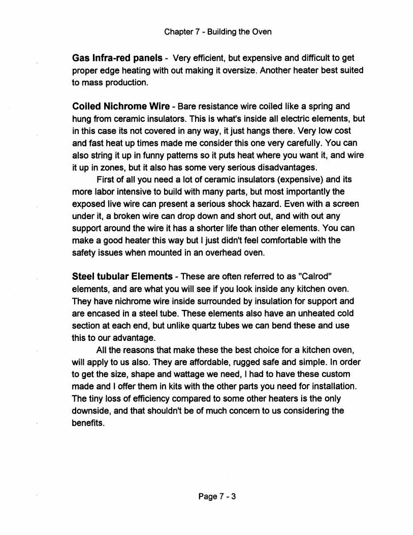
Chapter 7 - Building the Oven
Gas Infra-red panels - Very efficient, but expensive and difficult to get
proper edge heating with out making it oversize. Another heater best suited to mass production.
Coiled Nichrome Wire - Bare resistance wire coiled like a spring and
hung from ceramic insulators. This is what's inside all electric elements, but in this case its not covered in any way, it just hangs there. Very low cost
and fast heat up times made me consider this one very carefully. You can also string it up in funny patterns so it puts heat where you want it, and wire it up in zones, but it also has some very serious disadvantages.
First of all you need a lot of ceramic insulators (expensive) and its more labor intensive to build with many parts, but most importantly the
exposed live wire can present a serious shock hazard. Even with a screen under it, a broken wire can drop down and short out, and with out any support around the wire it has a shorter life than other elements. You can
make a good heater this way but I just didn't feel comfortable with the
safety issues when mounted in an overhead oven.
Steel tubular Elements - These are often referred to as "Calrod"
elements, and are what you will see if you look inside any kitchen oven. They have nichrome wire inside surrounded by insulation for support and are encased in a steel tube. These elements also have an unheated cold section at each end, but unlike quartz tubes we can bend these and use
this to our advantage. All the reasons that make these the best choice for a kitchen oven,
will apply to us also. They are affordable, rugged safe and simple. In order to get the size, shape and wattage we need, I had to have these custom made and I offer them in kits with the other parts you need for installation.
The tiny loss of efficiency compared to some other heaters is the only downside, and that shouldn't be of much concern to us considering the benefits.
Page 7 - 3
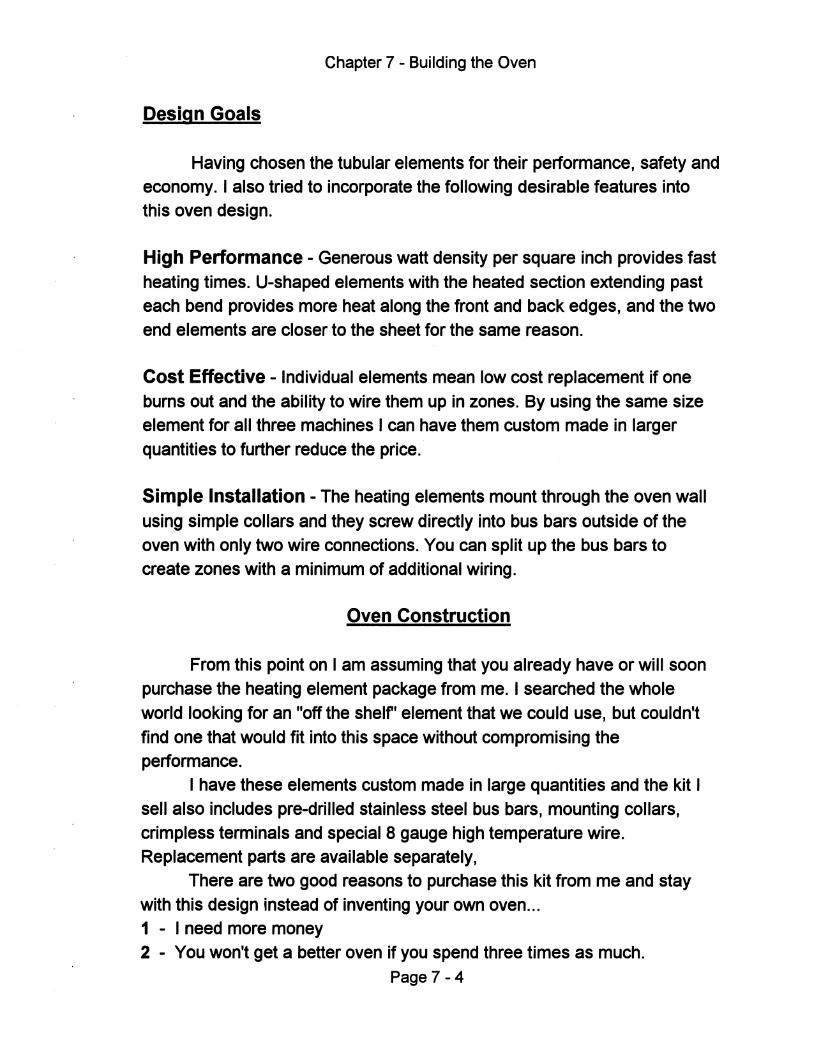
Chapter 7 - Building the Oven
Design Goals
Having chosen the tubular elements for their performance, safety and economy. I also tried to incorporate the following desirable features into this oven design.
High Performance - Generous watt density per square inch provides fast heating times. U-shaped elements with the heated section extending past each bend provides more heat along the front and back edges, and the two end elements are closer to the sheet for the same reason.
Cost Effective - Individual elements mean low cost replacement if one burns out and the ability to wire them up in zones. By using the same size element for all three machines I can have them custom made in larger quantities to further reduce the price.
Simple Installation - The heating elements mount through the oven wall using simple collars and they screw directly into bus bars outside of the oven with only two wire connections. You can split up the bus bars to create zones with a minimum of additional wiring.
Oven Construction
From this point on I am assuming that you already have or will soon purchase the heating element package from me. I searched the whole world looking for an "off the shelf' element that we could use, but couldn't find one that would fit into this space without compromising the performance.
I have these elements custom made in large quantities and the kit I sell also includes pre-drilled stainless steel bus bars, mounting collars, crimpless terminals and special 8 gauge high temperature wire. Replacement parts are available separately,
There are two good reasons to purchase this kit from me and stay with this design instead of inventing your own oven ... 1 - I need more money 2 - You won't get a better oven if you spend three times as much.
Page 7 - 4
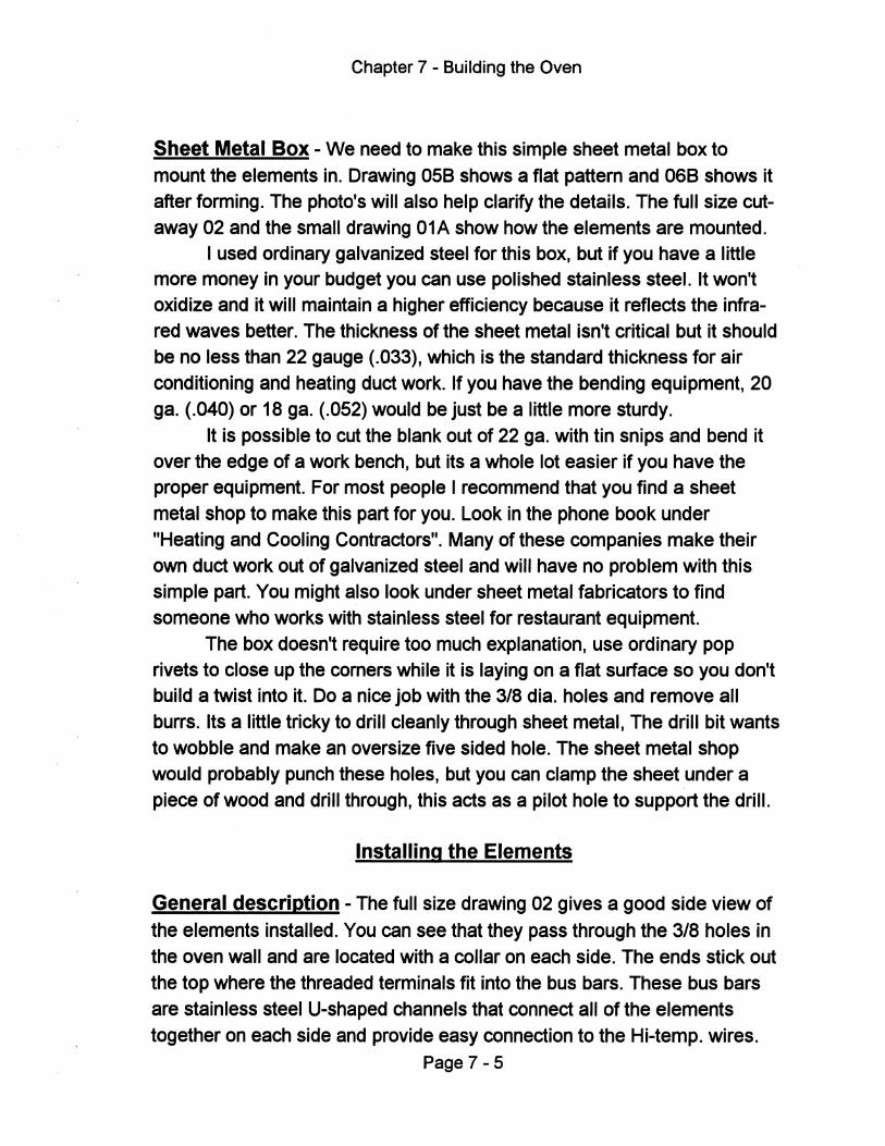
Chapter 7 - Building the Oven
Sheet Metal Box - We need to make this simple sheet metal box to mount the elements in. Drawing 058 shows a flat pattern and 068 shows it after forming. The photo's will also help clarify the details. The full size cutaway 02 and the small drawing 01A show how the elements are mounted.
I used ordinary galvanized steel for this box, but if you have a little more money in your budget you can use polished stainless steel. It won't oxidize and it will maintain a higher efficiency because it reflects the infrared waves better. The thickness of the sheet metal isn't critical but it should be no less than 22 gauge (.033), which is the standard thickness for air conditioning and heating duct work. If you have the bending equipment, 20 gao (.040) or 18 gao (.052) would be just be a little more sturdy.
It is possible to cut the blank out of 22 gao with tin snips and bend it over the edge of a work bench, but its a whole lot easier if you have the proper equipment. For most people I recommend that you find a sheet metal shop to make this part for you. Look in the phone book under "Heating and Cooling Contractors". Many of these companies make their own duct work out of galvanized steel and will have no problem with this simple part. You might also look under sheet metal fabricators to find someone who works with stainless steel for restaurant equipment.
The box doesn't require too much explanation, use ordinary pop rivets to close up the comers while it is laying on a flat surface so you don't build a twist into it. Do a nice job with the 3/8 dia. holes and remove all burrs. Its a little tricky to drill cleanly through sheet metal, The drill bit wants to wobble and make an oversize five sided hole. The sheet metal shop would probably punch these holes, but you can clamp the sheet under a piece of wood and drill through, this acts as a pilot hole to support the drill.
Installing the Elements
General description - The full size drawing 02 gives a good side view of the elements installed. You can see that they pass through the 3/8 holes in the oven wall and are located with a collar on each side. The ends stick out the top where the threaded terminals fit into the bus bars. These bus bars are stainless steel U-shaped channels that connect all of the elements together on each side and provide easy connection to the Hi-temp. wires.
Page 7 - 5
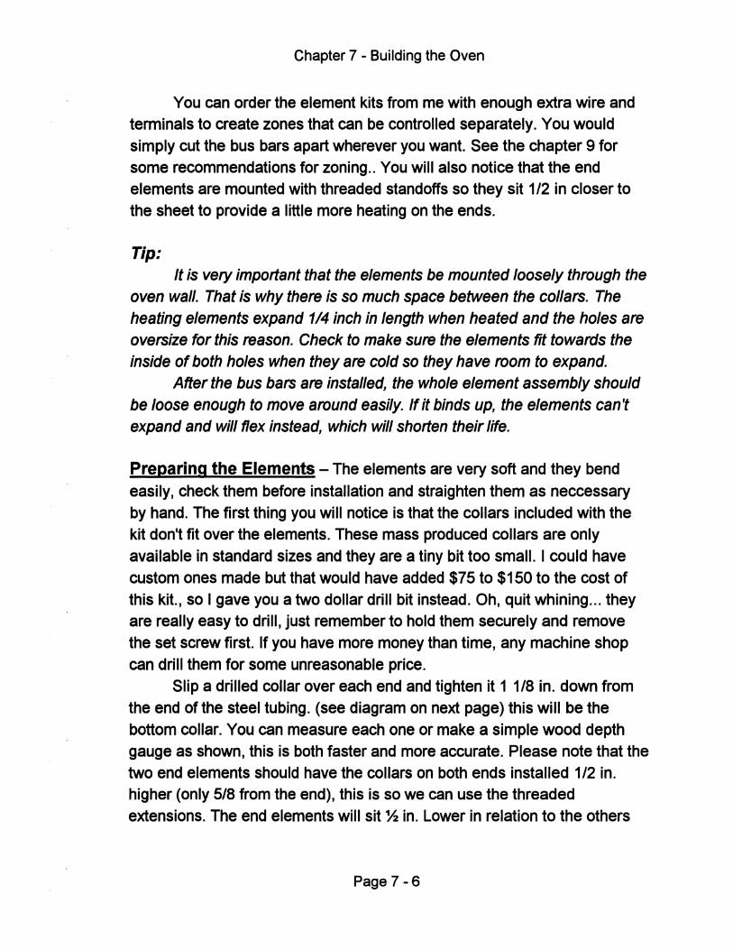
Chapter 7 - Building the Oven
You can order the element kits from me with enough extra wire and terminals to create zones that can be controlled separately. You would simply cut the bus bars apart wherever you want. See the chapter 9 for some recommendations for zoning .. You will also notice that the end elements are mounted with threaded standoffs so they sit 1/2 in closer to the sheet to provide a little more heating on the ends.
Tip: It is very important that the elements be mounted loosely through the
oven wall. That is why there is so much space between the collars. The heating elements expand 1/4 inch in length when heated and the holes are oversize for this reason. Check to make sure the elements fit towards the inside of both holes when they are cold so they have room to expand.
After the bus bars are installed, the whole element assembly should be loose enough to move around easily. If it binds up, the elements can't expand and will flex instead, which will shorten their life.
Preparing the Elements - The elements are very soft and they bend easily, check them before installation and straighten them as neccessary by hand. The first thing you will notice is that the collars included with the kit don't fit over the elements. These mass produced collars are only available in standard sizes and they are a tiny bit too small. I could have custom ones made but that would have added $75 to $150 to the cost of this kit., so I gave you a two dollar drill bit instead. Oh, quit whining ... they are really easy to drill, just remember to hold them securely and remove the set screw first. If you have more money than time, any machine shop can drill them for some unreasonable price.
Slip a drilled collar over each end and tighten it 1 1/8 in. down from the end of the steel tubing. (see diagram on next page) this will be the bottom collar. You can measure each one or make a simple wood depth gauge as shown, this is both faster and more accurate. Please note that the two end elements should have the collars on both ends installed 1/2 in. higher (only 5/8 from the end), this is so we can use the threaded extensions. The end elements will sit % in. Lower in relation to the others
Page 7-6
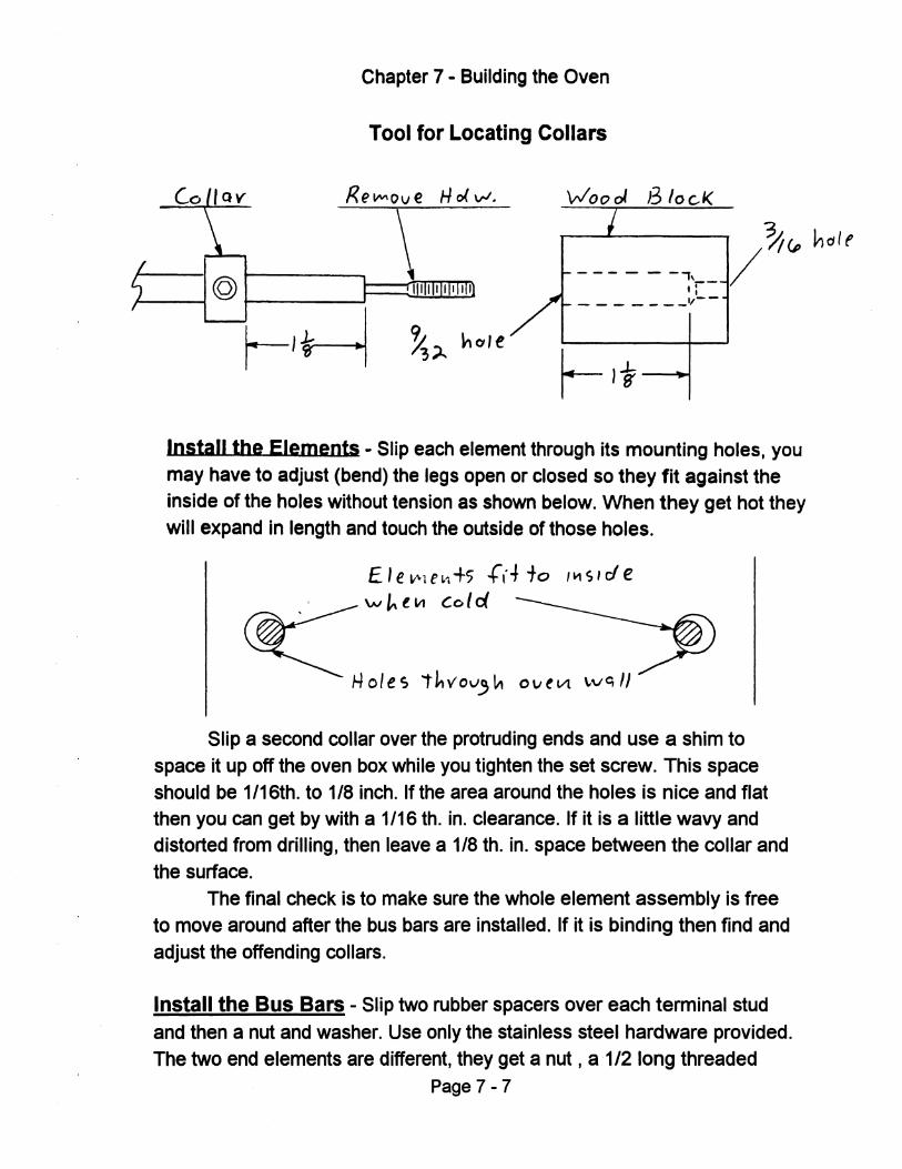
Chapter 7 - Building the Oven
Tool for Locating Collars
J3 10 c.1(
- -- - - -" .r-- - - - - - _11--
Install the Elements - Slip each element through its mounting holes, you may have to adjust (bend) the legs open or closed so they fit against the inside of the holes without tension as shown below. When they get hot they will expand in length and touch the outside of those holes.
E Ie Lt"l e L1 +s .rd' to I ~ S , r1 e \.oJ ~ t VI Co ( d
Slip a second collar over the protruding ends and use a shim to space it up off the oven box while you tighten the set screw. This space should be 1/16th. to 1/8 inch. If the area around the holes is nice and flat then you can get by with a 1/16 tho in. clearance. If it is a little wavy and distorted from drilling, then leave a 1/8 tho in. space between the collar and the surface.
The final check is to make sure the whole element assembly is free to move around after the bus bars are installed. If it is binding then find and adjust the offending collars.
Install the Bus Bars - Slip two rubber spacers over each terminal stud and then a nut and washer. Use only the stainless steel hardware provided. The two end elements are different, they get a nut, a ·1/2 long threaded
Page 7-7
Chapter 7 - Building the Oven
threaded extension, and then a washer. This should bring them up to the same level as the others. (see blueprint # 02)
The bus bar should fit over all of the terminals without any stress. Use them in full lengths or cut them into sections for zoning. If you do this, remove a one inch section so there is no chance the cut ends can touch each other. To finish off install another washer and nut on each stud.
Important Note:
The rubber spacers supplied with the kit are made from a special high temperature silicone rubber, don't substitute any thing else. You will
use two spacers per end or four per element as show in dwg. 01A
1 - Lightly tighten the bottom nut against the rubber spacers with your
fingers only. You don't need to compress them
2 - Hold the bottom nut with a wrench so it won't turn, and tighten the top
nut with a socket or nut driver, these are small nuts, so don't over tighten
them or the studs can break. Remember not to compress the rubber spacers.
3 - Now shake the bus bar and make sure all of the elements move freely.
Mount the Oven Box to the Chassis - The oven box screws to the top
cross rails (part E), and the cross rails bolt to the chassis. Place the 1 x 1 angle iron on the side of the oven box 1 1/2 in. from the top edge as shown
on dwg. 02. Make sure it is centered, then match drill through the 1/4 in. holes in the steel angle. Use 114 bolts from the inside and lock washers and nuts on the outside.
This whole assembly can now rest on the chassis upper side rails where they attach with 114 nuts and bolts. When the oven box is installed, its lower edge should be even with the bottom of the wood box that surrounds it, and the oven cover should fit nicely on top
Page 7 - 8
Chapter 8
Vacuum System
The type of vacuum system described in this chapter is sort of the industry standard and it only requires a short explanation, (see diagram on the next page). You simply close the main valve and evacuate the tank with your pump. When you are ready to form, just open the valve to dump the
vacuum through your platen. It sounds and looks simple, but its rea.llY a series of compromises
regarding the size of the components. I will take you through the selection process and at the end I will show you some simple refinements to make it even more user friendly, but first lets start with some basic information
about vacuum.
Vacuum - what is it and how much do I need?
Vacuum is just the absence of air. Most people don't know this but the air all around us is pressurized to almost 15 PSI. We are literally walking around in a sea of atmospheric pressure and we don't feel it
because our bodies are also pressurized. If you put your cat in a vacuum it would explode because of its internal pressure, (Don't do this - everyone knows cats go in the microwave ). When we vacuum form, we aren't so much pulling the plastic down, we are actually pushing it down with
atmospheric pressure. Vacuum is usually rated in inches of water or inches of mercury, In
either case vacuum is used to lift a column of fluid in a tube, and more vacuum will lift it higher. Mercury is 13.6 times heavier than water so
obviously it won't lift as high. I will use inches of mercury from now on when I refer to vacuum levels, it is abbreviated IN.HG., lets' just call it "inches" so I don't have to type that a million times. Keep in mind that if you see a pump rated in inches of water, they usually do this for sales appeal because the number looks better (higher).
Since vacuum is related to atmospheric pressure, we are limited to a maximum of around 30 inches at sea level. You can't get much more than
Page 8-1
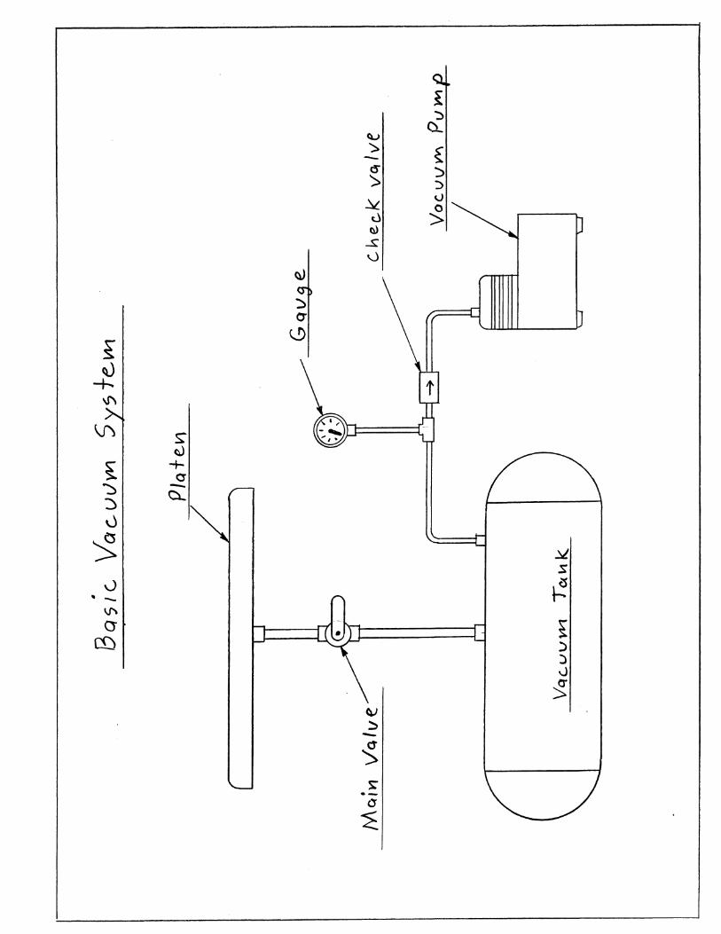
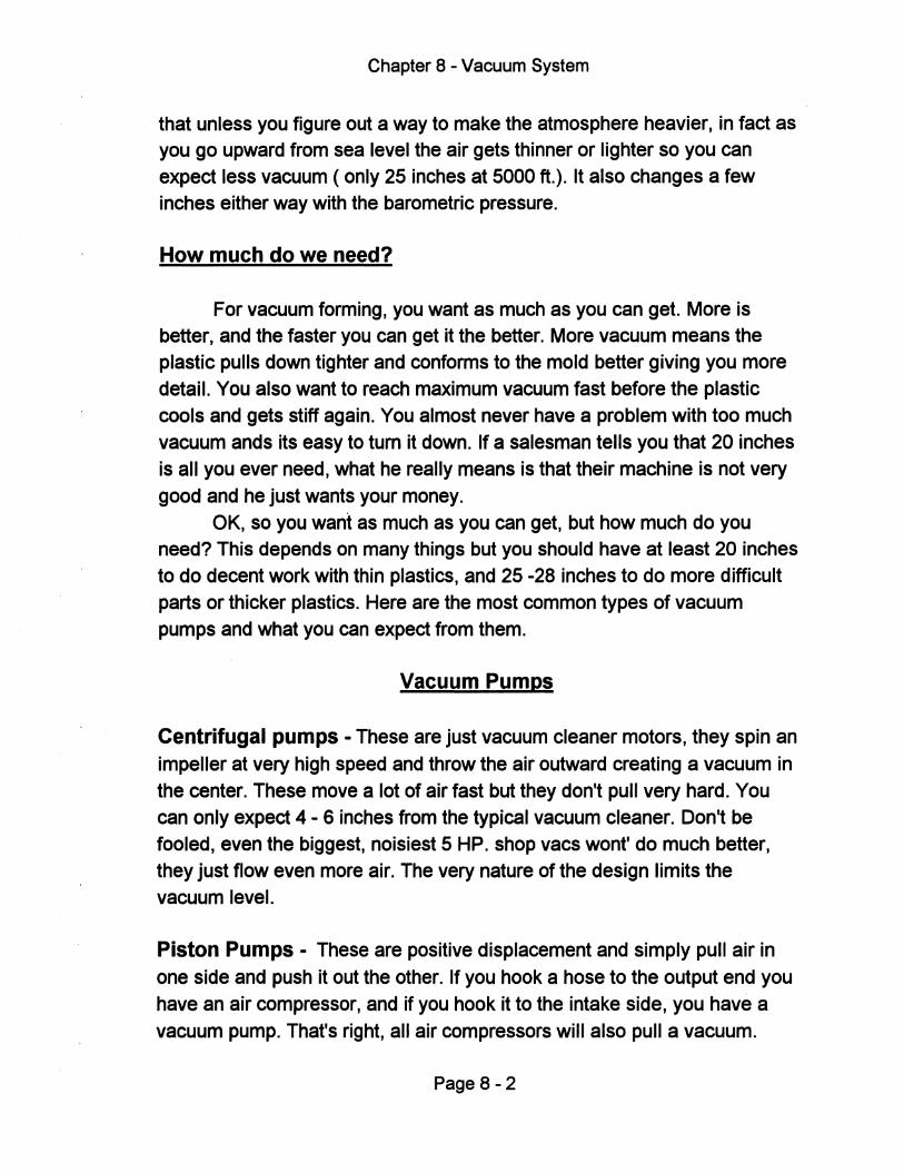
Chapter 8 - Vacuum System
that unless you figure out a way to make the atmosphere heavier, in fact as you go upward from sea level the air gets thinner or lighter so you can expect less vacuum (only 25 inches at 5000 ft.). It also changes a few inches either way with the barometric pressure.
How much do we need?
For vacuum forming, you want as much as you can get. More is better, and the faster you can get it the better. More vacuum means the plastic pulls down tighter and conforms to the mold better giving you more detail. You also want to reach maximum vacuum fast before the plastic cools and gets stiff again. You almost never have a problem with too much vacuum ands its easy to tum it down. If a salesman tells you that 20 inches is all you ever need, what he really means is that their machine is not very good and he just wants your money.
OK, so you want as much as you can get, but how much do you need? This depends on many things but you should have at least 20 inches to do decent work with thin plastics, and 25 -28 inches to do more difficult parts or thicker plastics. Here are the most common types of vacuum pumps and what you can expect from them.
Vacuum Pumps
Centrifugal pumps - These are just vacuum cleaner motors, they spin an impeller at very high speed and throw the air outward creating a vacuum in the center. These move a lot of air fast but they don't pull very hard. You can only expect 4 - 6 inches from the typical vacuum cleaner. Don't be fooled, even the biggest, noisiest 5 HP. shop vacs wont' do much better, they just flow even more air. The very nature of the design limits the vacuum level.
Piston Pumps - These are positive displacement and simply pull air in one side and push it out the other. If you hook a hose to the output end you have an air compressor, and if you hook it to the intake side, you have a vacuum pump. That's right, all air compressors will also pull a vacuum.
Page 8 - 2
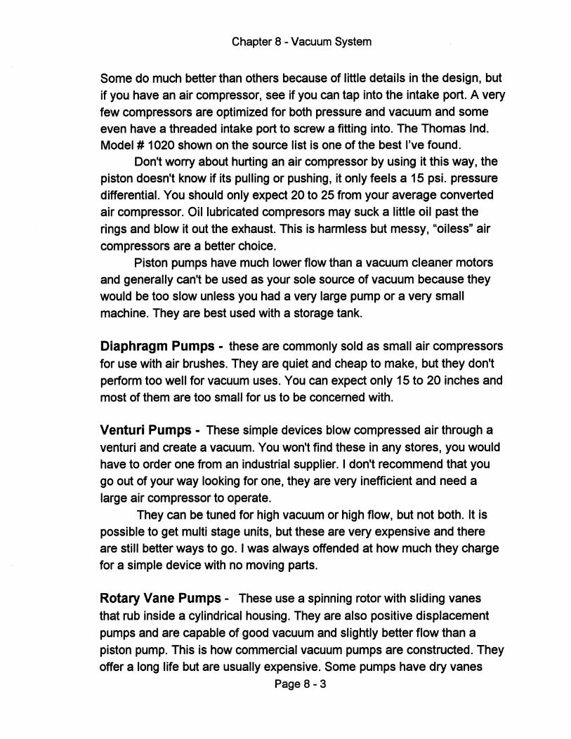
Chapter 8 - Vacuum System
Some do much better than others because of little details in the design, but if you have an air compressor, see if you can tap into the intake port. A very few compressors are optimized for both pressure and vacuum and some even have a threaded intake port to screw a fitting into. The Thomas Ind. Model # 1020 shown on the source list is one of the best I've found.
Don't worry about hurting an air compressor by using it this way, the piston doesn't know if its pulling or pushing, it only feels a 15 psi. pressure differential. You should only expect 20 to 25 from your average converted air compressor. Oil lubricated compresors may suck a little oil past the rings and blow it out the exhaust. This is harmless but messy, "oiless" air compressors are a better choice.
Piston pumps have much lower flow than a vacuum cleaner motors and generally can't be used as your sole source of vacuum because they would be too slow unless you had a very large pump or a very small machine. They are best used with a storage tank.
Diaphragm Pumps - these are commonly sold as small air compressors for use with air brushes. They are quiet and cheap to make, but they don't perform too well for vacuum uses. You can expect only 15 to 20 inches and most of them are too small for us to be concerned with.
Venturi Pumps - These simple devices blow compressed air through a venturi and create a vacuum. You won't find these in any stores, you would have to order one from an industrial supplier. I don't recommend that you go out of your way looking for one, they are very inefficient and need a large air compressor to operate.
They can be tuned for high vacuum or high flow, but not both. It is possible to get multi stage units, but these are very expensive and there are still better ways to go. I was always offended at how much they charge for a simple device with no moving parts.
Rotary Vane Pumps - These use a spinning rotor with sliding vanes that rub inside a cylindrical housing. They are also positive displacement pumps and are capable of good vacuum and slightly better flow than a piston pump. This is how commercial vacuum pumps are constructed. They offer a long life but are usually expensive. Some pumps have dry vanes
Page 8 - 3
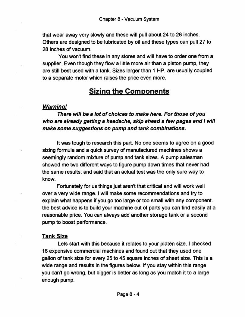
Chapter 8 - Vacuum System
that wear away very slowly and these will pull about 24 to 26 inches. Others are designed to be lubricated by oil and these types can pull 27 to
28 inches of vacuum. You won't find these in any stores and will have to order one from a
supplier. Even though they flow a little more air than a piston pump, they are still best used with a tank. Sizes larger than 1 HP. are usually coupled
to a separate motor which raises the price even more.
Sizing the Components
Warning! There will be a lot of choices to make here. For those of you
who are already getting a headache, skip ahead a few pages and I will make some suggestions on pump and tank combinations.
It was tough to research this part. No one seems to agree on a good
sizing formula and a quick survey of manufactured machines shows a
seemingly random mixture of pump and tank sizes. A pump salesman showed me two different ways to figure pump down times that never had the same results, and said that an actual test was the only sure way to know.
Fortunately for us things just aren't that critical and will work well over a very wide range. I will make some recommendations and try to explain what happens if you go too large or too small with any component. the best advice is to build your machine out of parts you can find easily at a
reasonable price. You can always add another storage tank or a second
pump to boost performance.
Tank Size Lets start with this because it relates to your platen size. I checked
16 expensive commercial machines and found out that they used one gallon of tank size for every 25 to 45 square inches of sheet size. This is a
wide range and results in the figures below. If you stay within this range you can't go wrong, but bigger is better as long as you match it to a large
enough pump.
Page 8-4
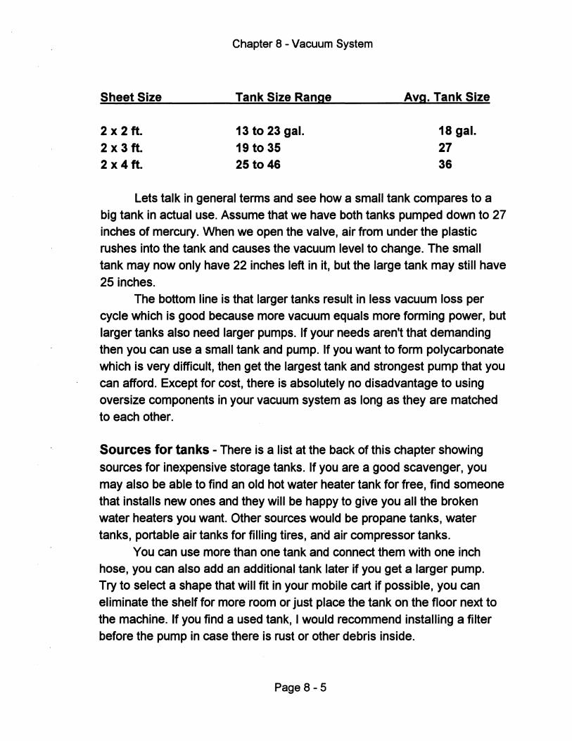
Sheet Size
2 x 2 ft. 2 x 3 ft. 2 x 4 ft.
Chapter 8 - Vacuum System
Tank Size Range
13 to 23 gal. 19 to 35 25 to 46
Avg. Tank Size
18 gal. 27 36
Lets talk in general terms and see how a small tank compares to a big tank in actual use. Assume that we have both tanks pumped down to 27 inches of mercury. When we open the valve, air from under the plastiC rushes into the tank and causes the vacuum level to change. The small tank may now only have 22 inches left in it, but the large tank may still have 25 inches.
The bottom line is that larger tanks result in less vacuum loss per cycle which is good because more vacuum equals more forming power, but larger tanks also need larger pumps. If your needs aren't that demanding then you can use a small tank and pump. If you want to form polycarbonate which is very difficult, then get the largest tank and strongest pump that you can afford. Except for cost, there is absolutely no disadvantage to using oversize components in your vacuum system as long as they are matched to each other.
Sources for tanks - There is a list at the back of this chapter showing sources for inexpensive storage tanks. If you are a good scavenger, you may also be able to find an old hot water heater tank for free, find someone that installs new ones and they will be happy to give you all the broken water heaters you want. Other sources would be propane tanks, water tanks, portable air tanks for filling tires, and air compressor tanks.
You can use more than one tank and connect them with one inch hose, you can also add an additional tank later if you get a larger pump. Try to select a shape that will fit in your mobile cart if possible, you can eliminate the shelf for more room or just place the tank on the floor next to the machine. If you find a used tank, I would recommend installing a filter before the pump in case there is rust or other debris inside.
Page 8 - 5
Chapter 8 - Vacuum System
Tip: Keep the tank close to the machine to reduce flow losses from long
hoses, but more importantly keep the hose between the main valve and the platen as short as possible. The pump can mount on the cart or on top of the tank like an air compressor.
Use only heavy duty tanks that were intended to hold air or water pressure. Don't try to use other containers such as plastic, glass or metal drums or fuel tanks, because you will most likely suck them flat, and make sure they are clean and dry with no flammable or corrosive fumes inside.
Pump Size
Once you found a suitable tank, you need to find a pump large enough to evacuate it in a reasonable amount of time and be able to pull a good strong vacuum. The pump needs to fit the following basic requirements:
1 • High Vacuum level - Try to find a pump that will pull at least 25 inches because we will lose some when we open the valve. 27 to 28 inches is better, and 29 inches is outstanding. Remember, the vacuum level provides the forming power, more vacuum will just mean more detail in the formed part.
2 • Good Flow - When you turn on the pump, the vacuum level in the tank will drop quickly at first, then get very slow as it reaches its maximum vacuum. That last inch could take as long as the first 20 inches. Pick a pump size that will pull down to a reasonable vacuum (25 plus) in less than 3 minutes to avoid over working the pump. This refers to the initial pump down time. The recovery time between parts will be much quicker because the pump only has to replace what was used.
3 • Reasonable cost - Generally the more expensive pumps will last longer, but if you don't use the machine for production you can take advantage of the low cost piston pumps, or use a smaller pump and live with the slower pump down times.
Page 8 - 6
•
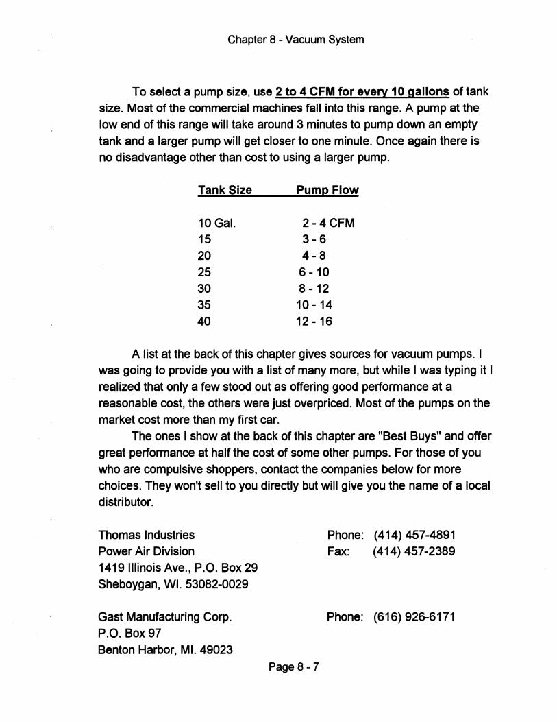
Chapter 8 - Vacuum System
To select a pump size, use 2 to 4 CFM for every 10 gallons of tank size. Most of the commercial machines fall into this range. A pump at the low end of this range will take around 3 minutes to pump down an empty
tank and a larger pump will get closer to one minute. Once again there is no disadvantage other than cost to using a larger pump.
Tank Size Pump Flow
10 Gal. 2 - 4 CFM 15 3-6 20 4-8 25 6 - 10 30 8 -12 35 10 - 14 40 12 - 16
A list at the back of this chapter gives sources for vacuum pumps. I was going to provide you with a list of many more, but while I was typing it I
realized that only a few stood out as offering good performance at a reasonable cost, the others were just overpriced. Most of the pumps on the market cost more than my first car.
The ones I show at the back of this chapter are "Best Buys" and offer
great performance at half the cost of some other pumps. For those of you
who are compulsive shoppers, contact the companies below for more choices. They won't sell to you directly but will give you the name of a local distributor.
Thomas Industries Power Air Division 1419 Illinois Ave., P.O. Box 29 Sheboygan, WI. 53082-0029
Gast Manufacturing Corp.
P.O. Box 97 Benton Harbor, MI. 49023
Page 8-7
Phone: (414) 457-4891 Fax: (414) 457-2389
Phone: (616) 926-6171
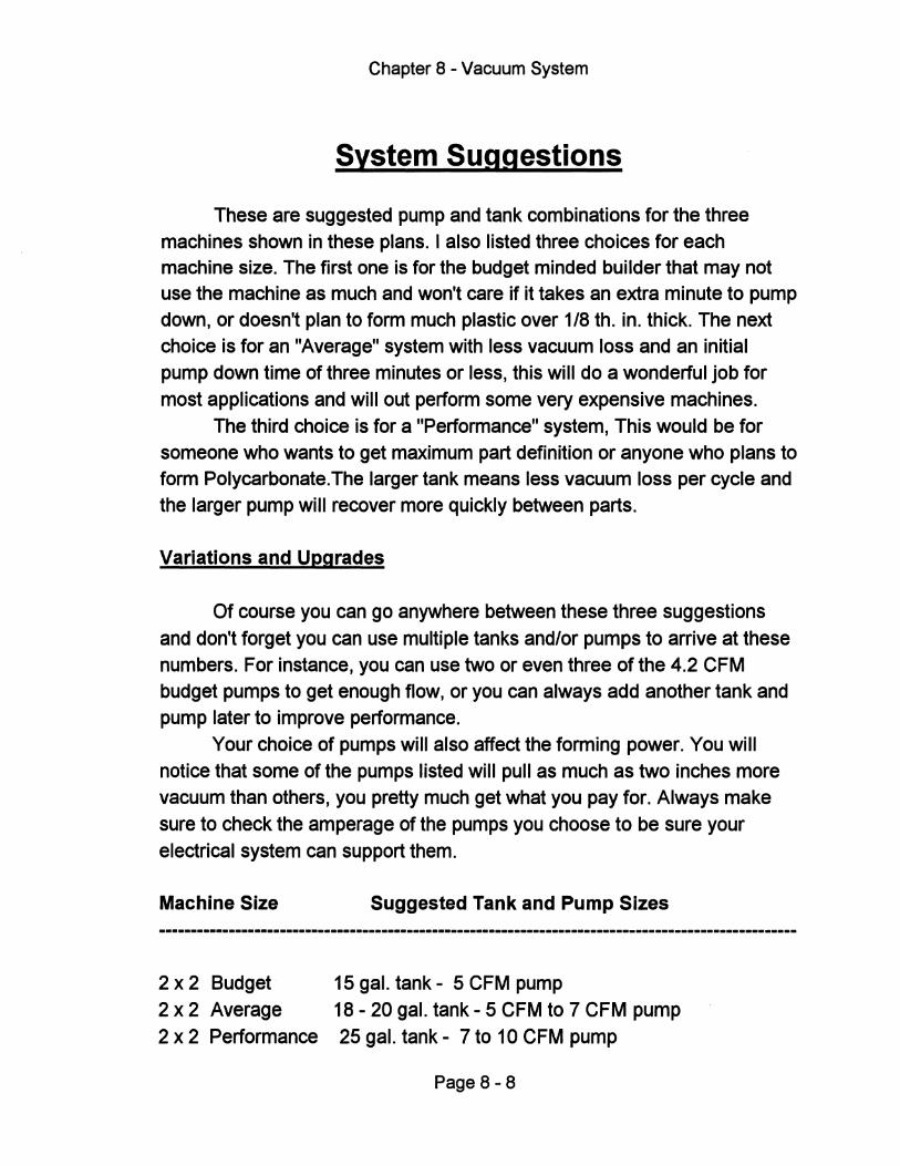
Chapter 8 - Vacuum System
System Suggestions
These are suggested pump and tank combinations for the three machines shown in these plans. I also listed three choices for each machine size. The first one is for the budget minded builder that may not use the machine as much and won't care if it takes an extra minute to pump down, or doesn't plan to form much plastic over 1/8 tho in. thick. The next choice is for an "Average" system with less vacuum loss and an initial pump down time of three minutes or less, this will do a wonderful job for
most applications and will out perform some very expensive machines.
The third choice is for a "Performance" system, This would be for someone who wants to get maximum part definition or anyone who plans to form Polycarbonate.The larger tank means less vacuum loss per cycle and the larger pump will recover more quickly between parts.
Variations and Upgrades
Of course you can go anywhere between these three suggestions
and don't forget you can use multiple tanks and/or pumps to arrive at these numbers. For instance, you can use two or even three of the 4.2 CFM budget pumps to get enough flow, or you can always add another tank and pump later to improve performance.
Your choice of pumps will also affect the forming power. You will notice that some of the pumps listed will pull as much as two inches more vacuum than others, you pretty much get what you pay for. Always make
sure to check the amperage of the pumps you choose to be sure your electrical system can support them.
Machine Size
2 x 2 Budget 2 x 2 Average
2 x 2 Performance
Suggested Tank and Pump Sizes
15 gal. tank - 5 CFM pump 18 - 20 gal. tank - 5 CFM to 7 CFM pump
25 gal. tank - 7 to 10 CFM pump
Page 8 - 8
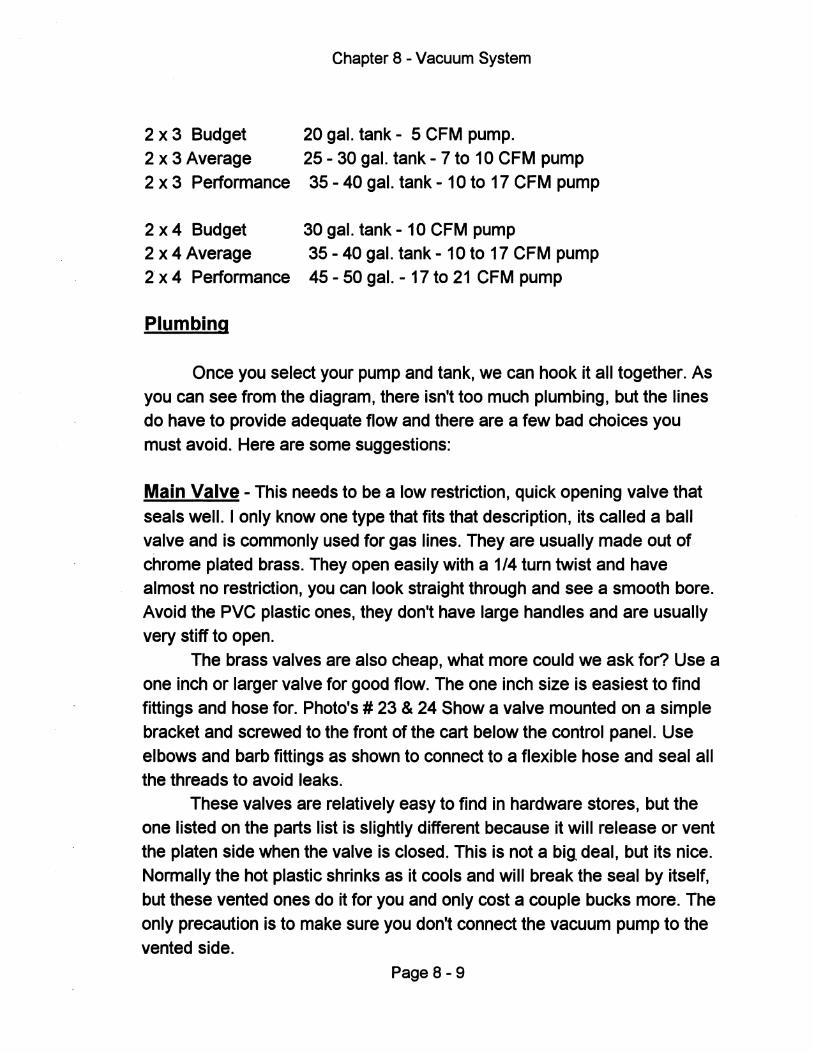
Chapter 8 - Vacuum System
2 x 3 Budget 20 gal. tank - 5 CFM pump. 2 x 3 Average 25 - 30 gal. tank - 7 to 10 CFM pump 2 x 3 Performance 35 - 40 gal. tank - 10 to 17 CFM pump
2 x 4 Budget 30 gal. tank - 10 CFM pump 2 x 4 Average 35 - 40 gal. tank - 10 to 17 CFM pump 2 x 4 Performance 45 - 50 gal. - 17 to 21 CFM pump
Plumbing
Once you select your pump and tank, we can hook it all together. As you can see from the diagram, there isn't too much plumbing, but the lines do have to provide adequate flow and there are a few bad choices you must avoid. Here are some suggestions:
Main Valve - This needs to be a low restriction, quick opening valve that
seals well. I only know one type that fits that description, its called a ball valve and is commonly used for gas lines. They are usually made out of chrome plated brass. They open easily with a 1/4 turn twist and have almost no restriction, you can look straight through and see a smooth bore. Avoid the PVC plastic ones, they don't have large handles and are usually very stiff to open.
The brass valves are also cheap, what more could we ask for? Use a one inch or larger valve for good flow. The one inch size is easiest to find fittings and hose for. Photo's # 23 & 24 Show a valve mounted on a simple bracket and screwed to the front of the cart below the control panel. Use elbows and barb fittings as shown to connect to a flexible hose and seal all the threads to avoid leaks.
These valves are relatively easy to find in hardware stores, but the one listed on the parts list is slightly different because it will release or vent the platen side when the valve is closed. This is not a bi[ deal, but its nice. Normally the hot plastic shrinks as it cools and will break the seal by itself, but these vented ones do it for you and only cost a couple bucks more. The only precaution is to make sure you don't connect the vacuum pump to the vented side.
Page 8 - 9
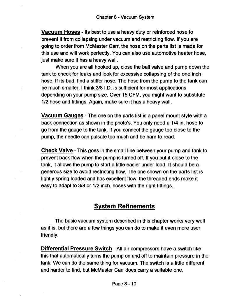
Chapter 8 - Vacuum System
Vacuum Hoses - Its best to use a heavy duty or reinforced hose to prevent it from collapsing under vacuum and restricting flow. If you are going to order from McMaster Carr, the hose on the parts list is made for this use and will work perfectly. You can also use automotive heater hose, just make sure it has a heavy wall.
When you are all hooked up, close the ball valve and pump down the tank to check for leaks and look for excessive collapsing of the one inch hose. If its bad, find a stiffer hose. The hose from the pump to the tank can be much smaller, I think 3/8 1.0. is sufficient for most applications depending on your pump size. Over 15 CFM, you might want to substitute 1/2 hose and fittings. Again, make sure it has a heavy wall.
Vacuum Gauges - The one on the parts list is a panel mount style with a back connection as shown in the photo's. You only need a 1/4 in. hose to go from the gauge to the tank. If you connect the gauge too close to the pump, the needle can pulsate too much and be hard to read.
Check Valve - This goes in the small line between your pump and tank to prevent back flow when the pump is turned off. If you put it close to the tank, it allows the pump to start a little easier under load. It should be a generous size to avoid restricting flow. The one shown on the parts list is lightly spring loaded and has excellent flow, the threaded ends make it easy to adapt to 3/8 or 1/2 inch. hoses with the right fittings.
System Refinements
The basic vacuum system described in this chapter works very well as it is, but there are a few things you can do to make it even more user friendly.
Differential Pressure Switch - All air compressors have a switch like this that automatically turns the pump on and off to maintain pressure in the tank. We can do the same thing for vacuum. The switch is a little different and harder to find, but McMaster Carr does carry a suitable one.
Page 8 -10
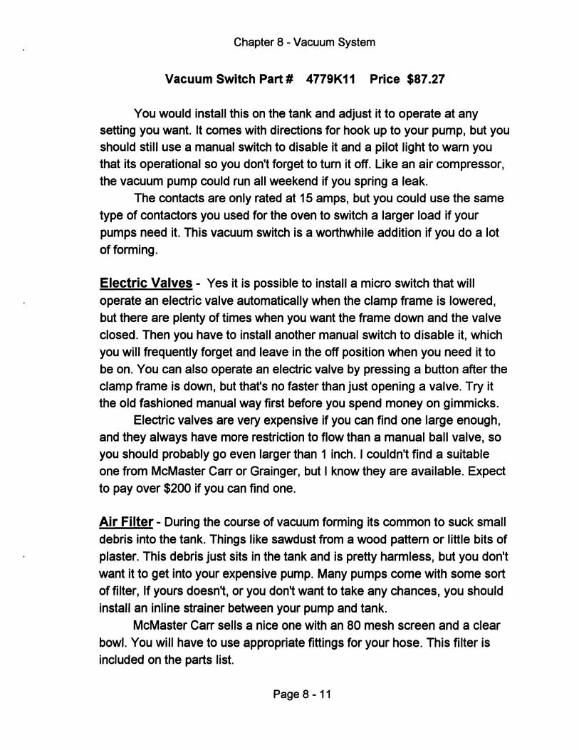
Chapter 8 - Vacuum System
Vacuum Switch Part # 4779K11 Price $87.27
You would install this on the tank and adjust it to operate at any setting you want. It comes with directions for hook up to your pump, but you should still use a manual switch to disable it and a pilot light to wam you that its operational so you don't forget to tum it off. Like an air compressor, the vacuum pump could run all weekend if you spring a leak.
The contacts are only rated at 15 amps, but you could use the same type of contactors you used for the oven to switch a larger load if your pumps need it. This vacuum switch is a worthwhile addition if you do a lot of forming.
Electric Valves - Yes it is possible to install a micro switch that will operate an electric valve automatically when the clamp frame is lowered, but there are plenty of times when you want the frame down and the valve closed. Then you have to install another manual switch to disable it, which you will frequently forget and leave in the off position when you need it to be on. You can also operate an electric valve by pressing a button after the clamp frame is down, but that's no faster than just opening a valve. Try it the old fashioned manual way first before you spend money on gimmicks.
Electric valves are very expensive if you can find one large enough, and they always have more restriction to flow than a manual ball valve, so you should probably go even larger than 1 inch. I couldn't find a suitable one from McMaster Carr or Grainger, but I know they are available. Expect to pay over $200 if you can find one.
Air Filter - During the course of vacuum forming its common to suck small debris into the tank. Things like sawdust from a wood pattem or little bits of plaster. This debris just sits in the tank and is pretty harmless, but you don't want it to get into your expensive pump. Many pumps come with some sort of filter, If yours doesn't, or you don't want to take any chances, you should install an inline strainer between your pump and tank.
McMaster Carr sells a nice one with an 80 mesh screen and a clear bowl. You will have to use appropriate fittings for your hose. This filter is included on the parts list.
Page 8 -11
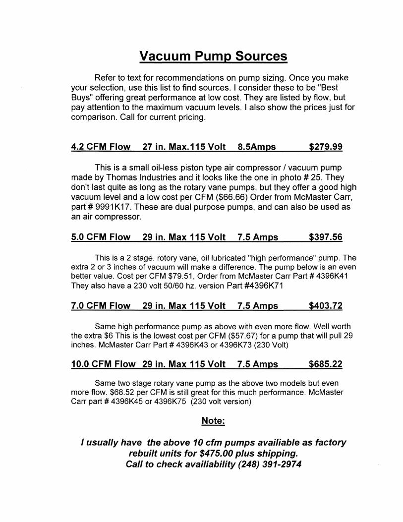
Vacuum Pump Sources
Refer to text for recommendations on pump sizing. Once you make your selection, use this list to find sources. I consider these to be "Best Buys" offering great performance at low cost. They are listed by flow, but pay attention to the maximum vacuum levels. I also show the prices just for comparison. Call for current pricing.
4.2 CFM Flow 27 in. Max.115 Volt 8.5Amps $279.99
This is a small oil-less piston type air compressor I vacuum pump made by Thomas Industries and it looks like the one in photo # 25. They don't last quite as long as the rotary vane pumps, but they offer a good high vacuum level and a low cost per CFM ($66.66) Order from McMaster Carr, part # 9991 K17. These are dual purpose pumps, and can also be used as an air compressor.
5.0 CFM Flow 29 in. Max 115 Volt 7.5 Amps $397.56
This is a 2 stage. rotory vane, oil lubricated "high performance" pump. The extra 2 or 3 inches of vacuum will make a difference. The pump below is an even better value. Cost per CFM $79.51, Order from McMaster Carr Part # 4396K41 They also have a 230 volt 50/60 hz. version Part #4396K71
7.0 CFM Flow 29 in. Max 115 Volt 7.5 Amps $403.72
Same high performance pump as above with even more flow. Well worth the extra $6 This is the lowest cost per CFM ($57.67) for a pump that will pull 29 inches. McMaster Carr Part # 4396K43 or 4396K73 (230 Volt)
10.0 CFM Flow 29 in. Max 115 Volt 7.5 Amps $685.22
Same two stage rotary vane pump as the above two models but even more flow. $68.52 per CFM is still great for this much performance. McMaster Carr part # 4396K45 or 4396K75 (230 volt version)
Note:
I usually have the above 10 cfm pumps availiable as factory rebuilt units for $475.00 plus shipping. .
Call to check availiability (248) 391-2974

10.0 CFM Flow 26 in. Max 115/230 volt 12.2/6.1 Amps $524.00
Rotary vane pump should give long life, but since it is a dry type, the maximum vacuum level is only 26 inches. If you don't need maximum forming power, this is a lot of flow for the price. Cost per CFM is $52.40 Order from Grainger Part # 4F742
17 CFM Flow 27 in. Max 115/230 Volt $865.00
Long life dry type rotory vane pump with separate 1 HP. motor. You must assemble the motor to the pump. This is a lot of flow and good vacuum level at a reasonable price. Cost per CFM $50.88. Order from Grainger part # 7Z778
21 CFM Flow 27 in. Max 115/230 Volt $938.50
Same as above only bigger with 1 1/2 HP. motor and lower cost per CFM ($44.69). order from Grainger Part # 7Z782
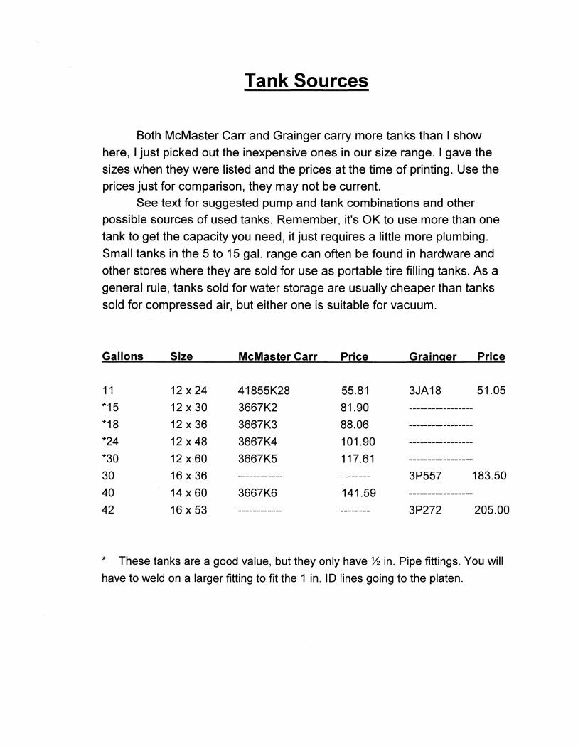
Tank Sources
Both McMaster Carr and Grainger carry more tanks than I show here, I just picked out the inexpensive ones in our size range. I gave the
sizes when they were listed and the prices at the time of printing. Use the prices just for comparison, they may not be current.
See text for suggested pump and tank combinations and other possible sources of used tanks. Remember, it's OK to use more than one
tank to get the capacity you need, it just requires a little more plumbing.
Small tanks in the 5 to 15 gal. range can often be found in hardware and
other stores where they are sold for use as portable tire filling tanks. As a
general rule, tanks sold for water storage are usually cheaper than tanks
sold for compressed air, but either one is suitable for vacuum.
Gallons Size McMaster Carr Price Grainger Price
11 12 x 24 41855K28 55.81 3JA18 51.05
*15 12 x 30 3667K2 81.90 -----------------*18 12 x 36 3667K3 88.06 -----------------*24 12 x 48 3667K4 101.90 -----------------*30 12 x 60 3667K5 117.61 -----------------30 16 x 36 ------------ -------- 3P557 183.50
40 14 x60 3667K6 141.59 -----------------42 16 x 53 ------------ -------- 3P272 205.00
* These tanks are a good value, but they only have % in. Pipe fittings. You will
have to weld on a larger fitting to fit the 1 in. 10 lines going to the platen.
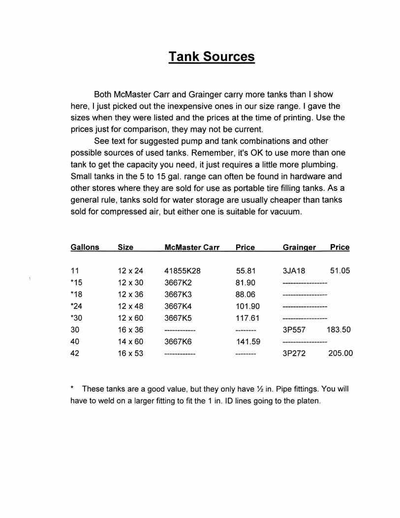
Tank Sources
Both McMaster Carr and Grainger carry more tanks than I show here, I just picked out the inexpensive ones in our size range. I gave the sizes when they were listed and the prices at the time of printing. Use the prices just for comparison, they may not be current.
See text for suggested pump and tank combinations and other possible sources of used tanks. Remember, it's OK to use more than one tank to get the capacity you need, it just requires a little more plumbing. Small tanks in the 5 to 15 gal. range can often be found in hardware and other stores where they are sold for use as portable tire filling tanks. As a general rule, tanks sold for water storage are usually cheaper than tanks sold for compressed air, but either one is suitable for vacuum.
Gallons Size McMaster Carr Price Grainger Price
11 12 x 24 41855K28 55.81 3JA18 51.05
*15 12 x 30 3667K2 81.90 -----------------*18 12 x 36 3667K3 88.06 -----------------*24 12 x48 3667K4 101.90 -----------------*30 12 x 60 3667K5 117.61 -----------------30 16 x 36 ------------ -------- 3P557 183.50
40 14 x 60 3667K6 141.59 -----------------42 16 x 53 ------------ -------- 3P272 205.00
* These tanks are a good value, but they only have % in. Pipe fittings. You will
have to weld on a larger fitting to fit the 1 in. I D lines going to the platen.
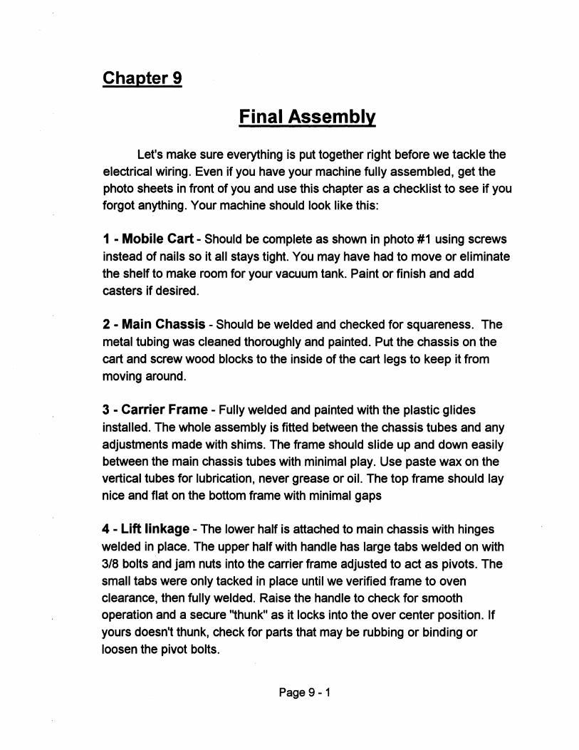
Chapter 9
Final Assembly
Let's make sure everything is put together right before we tackle the electrical wiring. Even if you have your machine fully assembled, get the photo sheets in front of you and use this chapter as a checklist to see if you forgot anything. Your machine should look like this:
1 - Mobile Cart - Should be complete as shown in photo #1 using screws instead of nails so it all stays tight. You may have had to move or eliminate the shelf to make room for your vacuum tank. Paint or finish and add casters if desired.
2 - Main Chassis - Should be welded and checked for squareness. The metal tubing was cleaned thoroughly and painted. Put the chassis on the cart and screw wood blocks to the inside of the cart legs to keep it from moving around.
3 - Carrier Frame - Fully welded and painted with the plastiC glides installed. The whole assembly is fitted between the chassis tubes and any adjustments made with shims. The frame should slide up and down easily between the main chassis tubes with minimal play. Use paste wax on the vertical tubes for lubrication, never grease or oil. The top frame should lay nice and flat on the bottom frame with minimal gaps
4 - Lift linkage - The lower half is attached to main chassis with hinges welded in place. The upper half with handle has large tabs welded on with 3/8 bolts and jam nuts into the carrier frame adjusted to act as pivots. The small tabs were only tacked in place until we verified frame to oven clearance, then fully welded. Raise the handle to check for smooth operation and a secure ''thunk'' as it locks into the over center position. If yours doesn't thunk, check for parts that may be rubbing or binding or loosen the pivot bolts.
Page 9-1
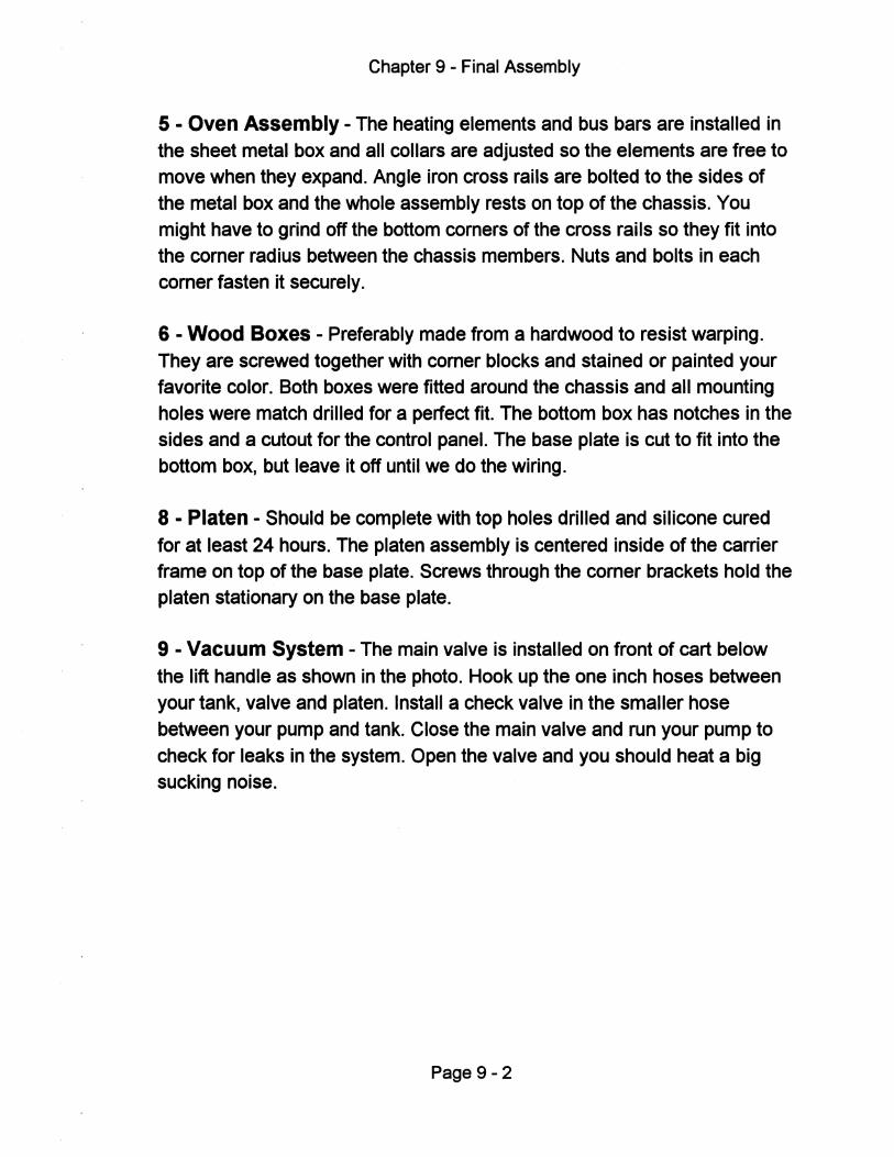
Chapter 9 - Final Assembly
5 - Oven Assembly - The heating elements and bus bars are installed in the sheet metal box and all collars are adjusted so the elements are free to move when they expand. Angle iron cross rails are bolted to the sides of the metal box and the whole assembly rests on top of the chassis. You might have to grind off the bottom corners of the cross rails so they fit into the corner radius between the chassis members. Nuts and bolts in each corner fasten it securely.
6 - Wood Boxes - Preferably made from a hardwood to resist warping. They are screwed together with corner blocks and stained or painted your favorite color. Both boxes were fitted around the chassis and all mounting holes were match drilled for a perfect fit. The bottom box has notches in the sides and a cutout for the control panel. The base plate is cut to fit into the bottom box, but leave it off until we do the wiring.
8 - Platen - Should be complete with top holes drilled and silicone cured for at least 24 hours. The platen assembly is centered inside of the carrier frame on top of the base plate. Screws through the corner brackets hold the platen stationary on the base plate.
9 - Vacuum System - The main valve is installed on front of cart below the lift handle as shown in the photo. Hook up the one inch hoses between your tank, valve and platen. Install a check valve in the smaller hose between your pump and tank. Close the main valve and run your pump to check for leaks in the system. Open the valve and you should heat a big sucking noise.
Page 9-2

Chapter 10
Electrical System
This part of the project scares me the most, but I am not afraid for myself. I am downright fearless around high voltage because I respect it and I am careful, so we along just fine. Most people are the same way, but I am terrified that someone with little knowledge and even less respect for electricity will try to wire up their machine just from my description.
Its time for a little honesty here. I am Just not qualified to teach anyone how to do electrical wiring. It was hard for me to say that because I am supposed to be the expert here. So, be honest with your self now, If you wouldn't be comfortable wiring up a machine like this without any instructions at all, then you probably shouldn't do it without qualified help. Do not assume that you can just follow these directions and not have to know what you are doing. Take responsibility for having this done right.
I did my own wiring job the way I do everything else, with periods of deep thought mixed with careful research and I asked a lot of dumb questions. The results are what you see here. For safety's sake, my final advice is to use this information only as a guide. Do the work yourself if you are qualified, or get help if your not.
Oven Control Basics
Wiring up the oven is the biggest part of this job, before we get started lets review the different ways to control an ovens output and turn it on and off.
Do we even need temperature control? - No, we don't really need it but most people just seem to want it. For a simple manual machine such as this, you just expose the plastic to radiant heat and wait for it to sag or droop. The amount of sag is a perfect indicator of readiness.
Why not use a timer? - This is very popular and it almost works. If the heat output is constant, why not just vary the exposure time? Hey, this
Page 10-1
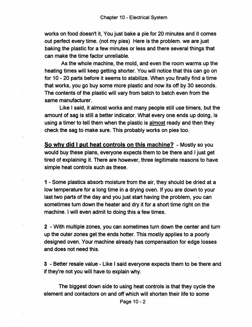
Chapter 10 - Electrical System
works on food doesn't it, You just bake a pie for 20 minutes and it comes out perfect every time. (not my pies) Here is the problem. we are just baking the plastic for a few minutes or less and there several things that can make the time factor unreliable.
As the whole machine, the mold, and even the room warms up the heating times will keep getting shorter. You will notice that this can go on for 10 - 20 parts before it seems to stabilize. When you finally find a time that works, you go buy some more plastic and now its off by 30 seconds. The contents of the plastic will vary from batch to batch even from the same manufacturer.
Like I said, it almost works and many people still use timers, but the amount of sag is still a better indicator. What every one ends up dOing, is using a timer to tell them when the plastic is almost ready and then they check the sag to make sure. This probably works on pies too.
So why did I put heat controls on this machine? - Mostly so you would buy these plans, everyone expects them to be there and I just get tired of explaining it. There are however, three legitimate reasons to have simple heat controls such as these.
1 - Some plastics absorb moisture from the air, they should be dried at a I'ow temperature for a long time in a drying oven. If you are down to your last two parts of the day and you just start having the problem, you can sometimes tum down the heater and dry it for a short time right on the machine. I will even admit to doing this a few times.
2 - With multiple zones, you can sometimes tum down the center and tum up the outer zones get the ends hotter. This mostly applies to a poorly designed oven. Your machine already has compensation for edge losses and does not need this.
3 - Better resale value - Like I said everyone expects them to be there and if they're not you will have to explain why.
The biggest down side to using heat controls is that they cycle the element and contactors on and off which will shorten their life to some
Page 10 - 2

Chapter 10 - Electrical System
extent. My advice is to build the oven without heat controls first and just watch for the amount of sheet sag. The last chapter will give you some other tips and ideas on how to know when the plastic is ready to form.
Tip: You can simply replace the heat controls with a toggle switch for
each zone as shown in all of the wiring diagrams. If you do want to use them, the heat controls shown in the photo's can be purchased at any appliance parts store. they are called infinite switches and are used for kitchen oven top burners. They are not shown on the parts list.
Mfg. by Robertshaw part # 5500-103 110 volt
Power Relays - Regardless of whether you use a simple heat control or
just a toggle switch to control the oven, we still need to use a power relay. A typical switch can handle about 15 amps. but the oven is a much larger load of 25 to 45 amps so we need a relay in between them. These use your low amperage switch to energize a coil that closes a set of larger contacts. This has the added advantage of letting you put the switch farther away, while the relay remains close to the oven with nice short wires.
The only two types of relays that we should be concerned with are:
General purpose contactors - These come in different amp. ratings and are mechanical relays as described above. They are cheap and usually
rated at 100,000 cycles at full load or 500,000 cycles at 2/3 load. This fits our needs perfectly and is what's specified on the parts list. These contactors are available in many amp. ratings, but the 40 amp. size is very common and therefore has a lower price than many of the others. We will
use these for all zones with 12 elements or less.
Mercury Relays - These use mercury inside instead of mechanical contacts so they last much longer, but they are about twice the price. If you
use a heat control often and it cycles on and off a lot you might consider
upgrading to these if you wear out the contactors.
Page 10 - 3
Chapter 10 - Electrical System
Put all the Hardware in Place Before we can hook up any wires, we need to mount all of the
components. The photo's show where everything is mounted and I will describe each component individually.
Breaker Box - We can treat this machine like its a little house and run
separate fused circuits to everything inside. This is not only safe but it is easy because we can use ordinary residential wiring components to do it. We need a circuit breaker box with the following specifications:
Surface Mount - A flush mount type has an extra flange around the front
for mounting in a wall. We need to mount on the surface.
100 Amp. - While a 70 amp. box will work with the 2 x 2 machine, I suggest
using the 100 amp. box for all because it has more circuits.
Fixed Lug - This means it has no main breaker. This will be used as a sub panel, you will need a large breaker on the main panel that feeds this one.
Six Circuits - The small, machine only needs four but its nice to have more
The following Breaker Boxes fit these requirements
Manufacturer Part # comments
Square D "Homeline" series HOM 612L 1005 Good, Cheap - 6 circuits
Square D "00" series 00816L 1005 Better - 8 circuits
General Electric TL412C Best, small - 8 circuits
Use photo # 30 as a reference and screw the breaker box to the back
of the top wood box. Make sure the neutral strip is grounded inside the box. Ground the breaker and relay boxes to the chassis with an 8 gao wire. Cut a hole for the oven wires to pass through as shown in the lower right corner.
Page 10 - 4
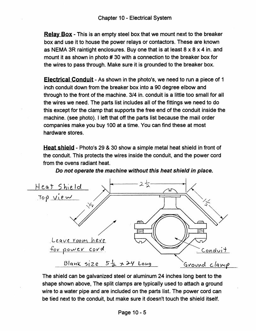
Chapter 10 - Electrical System
Relay Box - This is an empty steel box that we mount next to the breaker
box and use it to house the power relays or contactors. These are known as NEMA 3R raintight enclosures. Buy one that is at least 8 x 8 x 4 in. and
mount it as shown in photo # 30 with a connection to the breaker box for the wires to pass through. Make sure it is grounded to the breaker box.
Electrical Conduit - As shown in the photo's, we need to run a piece of 1
inch conduit down from the breaker box into a 90 degree elbow and through to the front of the machine. 3/4 in. conduit is a little too small for all
the wires we need. The parts list includes all of the fittings we need to do
this except for the clamp that supports the free end of the conduit inside the
machine. (see photo). I left that off the parts list because the mail order companies make you buy 100 at a time. You can find these at most hardware stores.
Heat shield - Photo's 29 & 30 show a simple metal heat shield in front of
the conduit. This protects the wires inside the conduit, and the power cord
from the ovens radiant heat. Do not operate the machine without this heat shield in place.
Heq't Sbie.ld ~--- .2 ~--------...t
.:j~
~/ _ ~ e.~_\L_e Y 00 VVl ~ eve +'0 v r- 0 vJ e. v Co '(Ji, _
Bttl\11( si ze 5 ~ 1-- ')-'( LG'-'9
The shield can be galvanized steel or aluminum 24 inches long bent to the
shape shown above, The split clamps are typically used to attach a ground
wire to a water pipe and are included on the parts list. The power cord can be tied next to the conduit, but make sure it doesn't touch the shield itself.
Page 10 - 5
Chapter 10 - Electrical System
Micro Switch - This switch mounts through the hole on Tab - S, as shown on dwg. # 02A. Its not visible in the photo's because I added it at the last minute. It would be located below the electrical conduit in photo's # 28 & 31, and will actuate when the linkage arm is raised. The whole idea is that it should tum the oven off when the carrier frame is lowered, even if the oven switch is on. Don't be tempted to eliminate this switch.
The switch listed on the parts list and shown in the drawing is a nice industrial unit rated at 15 amps. You won't find one like this at Radio Shack, mail order it or try an electrical supply store. Wire it in series with the oven toggle switch or heat control. Use the two screw terminals marked COM (common) and NO (normally open). The NC terminal is unused. Cover all electrical connections with tape.
Control Panel - See 07B for a drawing of a typical two zone panel with temperature controls, and the hole in the wood box that it fits over. Its a good idea to collect all of the switches and parts before you drill the panel. The drawing calls for .060 aluminum, but it can be thicker or thinner, or even steel depending on what you might have. Run a 12 gao ground wire from the panel to the chassis for safety.
Before you make your control panel, you need to decide how many zones your oven will have and whether or not to use heat controls as discussed earlier. One zone means the entire oven is either on or off. Two zones means there is a center zone and a split outer zone and they can be switched on or off independently.
The idea is that you can save electricity by switching off the outer zone to heat a smaller sheet in the center. This is another feature that people just want to have on their machines but it rarely makes financial sense. Keep in mind that it costs around $100.00 to add another zone and if you are only going to use it occasionally then it is far cheaper to just waste a few cents worth of electricity when you do a smaller sheet of plastiC with the whole oven on. I recommend that you start with one zone and add another one later if you really need it. The exception is the 2 x 4 machine, which needs two zones to keep the wires, contactors and breakers down to a reasonable size.
Page 10 - 6
Chapter 10 - Electrical System
Control Panel Options
The left side of the panel can be changed depending on the configuration of your oven, but it is very important that a pilot light be lit whenever any part of the oven is turned on.
2 Zone with Heat Controls - Make the panel exactly as shown in the drawing. You will need all three pilot lights because the two small ones could be in the Off cycle at any given time and you need the large pilot light to tell you the oven is energized.
2 Zone with Switches - you just need one toggle switch and one large pilot light for each zone, (four holes in a row).
1 Zone with Heat Control - Same as two zone but eliminate one heat control and small pilot. Keep main oven switch and large pilot.
1 Zone with Switch - Only one toggle switch and one pilot light are needed.
Types of Switches -All toggle switches should be of good quality and rated for 15 amps.
at 120 volts, except for the vacuum switch. This one should be rated for 20 amps. because we are using a slightly larger circuit here for the vacuum pump. See notes regarding the vacuum pump circuit for more information.
Make a safety Cover - Since the internal workings of this machine are
accessible from below, and the outlet for the vacuum pump is mounted inSide, we need to cover the wiring. There will be times when you want to reach up inside the machine to plug in your vacuum pump and you must not be able to touch any of the live wires. Make a very simple sheet metal cover as shown in photo # 32. It's held in place by the bolts on the lower chassis member, and the bent leg rests on top of the 1 x 2 wood strip. You may have to cut a hole as shown for the vacuum hose to reach the gauge. Make sure none of the electrical connections can touch this metal cover and never operate the machine with out it in place.
Page 10-7
Chapter 10 - Electrical System
Misc. Hardware - We will need a 120 volt double outlet receptacle mounted on the rear of the machine for the fans to plug into, and another one inside the machine for the vacuum pumps. (see photo # 28) These are
sometimes called "Handy Boxes" and are available at most hardware stores. Make sure to ground these receptacles to the chassis.
Wiring Your Machine
Before we get started, lets go over some basic rules of wiring:
1 - For safety's sake always have an electrician look over your wiring
before connecting it to the main panel, do not assume the information in this manual is correct. Take responsibility for having it checked before use!
2 - For 110 volt circuits, always use a black wire from the breaker to any
switches, and from the switches to the load itself. Always use a white wire from the ground strip inside the breaker box directly to the load. This must be a continuous unbroken connection, never put a switch or breaker in the
white wire. Use a green wire only for grounding.
3 - Make sure all metal parts of the machine are grounded to the breaker
box in some way, usually through the chassis. Use an 8 gao wire to ground
the chassis itself to the box.
4 - Grounding: Make sure that the neutral or ground terminal strip
inside the breaker box is actually grounded to the box itself! Do not assume that it is! Your particular box may come with a separate
green screw that is to be used for this purpose. Read the fine print inside the cover for directions and check inside the shipping box to look for this
screw. This ground connection must be substantial and able to carry the full amp. rating of the breaker box. Check with an electrician if you are not sure.
Page 10 - 8
Chapter 10 - Electrical System
Let's get to work
Now that we have all the components in place let's connect them with wires. You will be bringing 220 volts single phase power (3 wire circuit) into your machine from a 2 pole breaker in your main service panel, This breaker is sized to protect the wires going to your machine and can be used as an emergency disconnect. Make sure you clearly mark which one it is. You can tum off this breaker in the future, if you need to service your machine. Do all of your wiring inside the machine first, so the electrician can look it over before applying power.
The smaller breakers we will install in the machine, are there to protect each individual circuit. Read through the following descriptions of each circuit before you wire it. Later, I will recommend a size for your main breaker, but let your electrician determine the size of the main feed wires because distance will be a factor here.
Wiring Diagrams
Select the wiring diagrams that apply to your machine and remove the rest. You can store the extras in the back of the binder so you don't refer to them by mistake. Here are some additional comments:
Vacuum Pump circuit - This first diagram applies to all machines. It is 110 volts so it uses a single pole breaker. This is a 20 amp. circuit and is sufficient for most vacuum pumps. Be sure to check the amp. rating on the pump to make sure you do not exceed this. If you will be using two pumps, make sure they don't exceed 20 amps combined. If they do, simply add another identical circuit so you will have a separate breaker and toggle switch for each pump. Make sure to ground the outlet box to the chassis.
Auxiliary Circuit - This will run the fans and power the contactor coils. The contactors only draw a tiny amount so most of it is left over to run the fans. You can also use this circuit for any small accessories you add later. Again, make sure you ground the outlet box to the chassis.
Page 10 - 9
Chapter 10 - Electrical System
Oven Circuits - Find the wiring diagram that applies to you and move the others to the back of the binder to avoid confusion. Remember all of the 120 volt circuits (15 & 20 amp.) can use standard TFFN 12 gao stranded wire (90 e), and all 220 volt circuits (up to 40 amp.) will use 8 gao wire.
The wires going from the contactors to the oven elements must have a high temperature rating of at least 250 degrees centigrade (495 F). Type TGGT wire is one example of this. You won't find this wire in any stores, it must be ordered from a distributor or manufacturer and they usually don't like to sell small quantities. I buy this wire in large rolls and supply it with the oven kits I sell. The 8 gao wires going from the contactors to the circuit breaker don't need to be high temp. and can be standard TFFN, but TGGT will work here also.
Custom Zones - The wiring diagrams show the most logical choices for zone sizes. If you have a very specific need to form an odd size sheet you can adjust the size of the zones from what I have shown. The chart below shows what breaker size to use for a given number of elements in each zone. Observe the following rules when you create custom sized zones:
1 - Use no less than 4 elements for the outer zone (2 per side), because you need that short section of bus bar to support them.
2 - Use no more than 12 elements in one zone, any more and you would be over the 40 amp. limit for the 8 gao wires supplied with the oven kit, and you would need a larger contactor.
3 - The center and outer zone configuration is preferred. If you make left and right zones, you must put your mold off center and this may cause the lift linkage to bind up when pushed down.
4 - Use 40 amp. contactors for everything. These must be the most common size because they don't cost any more than smaller ones and larger ones are much more expensive.
Page 10 -10
Chapter 10 - Electrical System
5 - Use only 40 amp. or smaller circuit breakers for the oven because
these are sized to protect the 8 gao wires supplied with the oven kits.
Use this chart to select a circuit breaker for a custom sized zone.
No. of Elements Watts Ames Breaker size 4 2400 11 15 6 3600 16.4 20 8 4800 21.8 25 - 30 10 6000 27.3 30 12 7200 32.7 40
Oven Circuit Descriptions
2 x 2 Oven with One Zone - A very simple circuit. Note the pilot light that
comes on when the contactor is energized. This reminds you to tum the oven off when you are done. Use a neon or LED pilot light for long life. Remember, the auxiliary circuit also powers the fans and can be used for other accessories you may add later.
2 x 2 Oven with Two Zones - You will notice that we still use one 30
amp. breaker to protect the whole oven, but we split the bus bars and added another contactor to create zones. We also added another switch and pilot light for the second zone.
You can see how the outer zone is split in two and the two halves are connected with high temp. wire. The center zone shown can heat a 12 x 24 inch sheet.
2 x 3 Oven with One Zone - Exactly the same as the 2 x 2 machine
except we have 4 more heating elements and a larger 40 amp. circuit breaker.
Page 10 -11
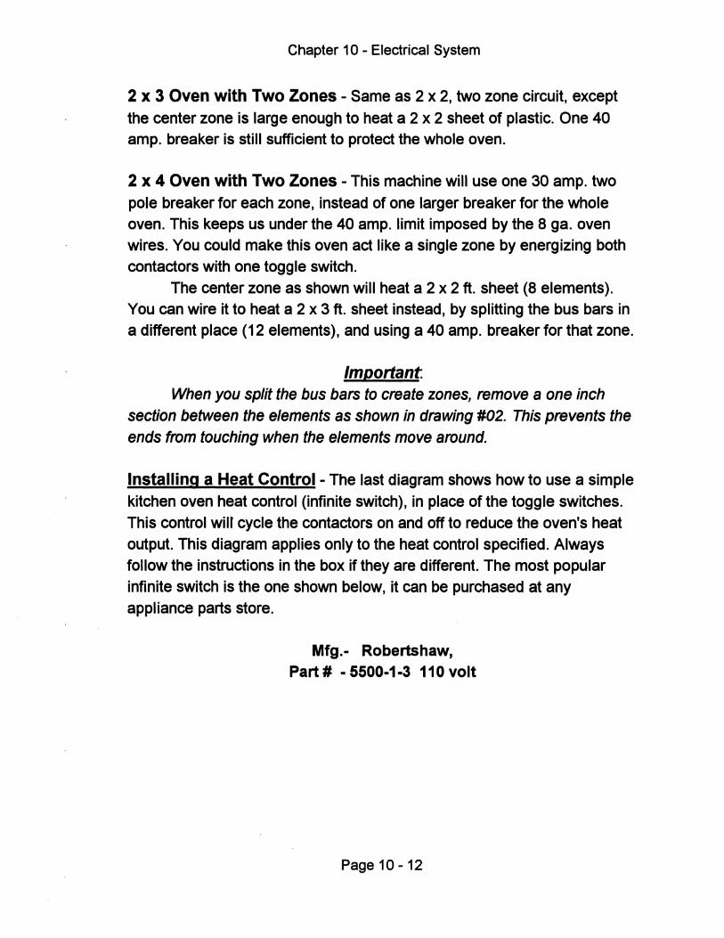
Chapter 10 - Electrical System
2 X 3 Oven with Two Zones - Same as 2 x 2, two zone circuit, except
the center zone is large enough to heat a 2 x 2 sheet of plastic. One 40 amp. breaker is still sufficient to protect the whole oven.
2 x 4 Oven with Two Zones - This machine will use one 30 amp. two
pole breaker for each zone, instead of one larger breaker for the whole oven. This keeps us under the 40 amp. limit imposed by the 8 gao oven wires. You could make this oven act like a single zone by energizing both contactors with one toggle switch.
The center zone as shown will heat a 2 x 2 ft. sheet (8 elements). You can wire it to heat a 2 x 3 ft. sheet instead, by splitting the bus bars in a different place (12 elements), and using a 40 amp. breaker for that zone.
Important When you split the bus bars to create zones, remove a one inch
section between the elements as shown in drawing #02. This prevents the ends from touching when the elements move around.
Installing a Heat Control - The last diagram shows how to use a simple
kitchen oven heat control (infinite switch), in place of the toggle switches. This control win cycle the contactors on and off to reduce the oven's heat output. This diagram applies only to the heat control specified. Always follow the instructions in the box if they are different. The most popular infinite switch is the one shown below, it can be purchased at any appliance parts store.
Mfg.- Robertshaw, Part # - 5500-1-3 110 volt
Page 10 -12
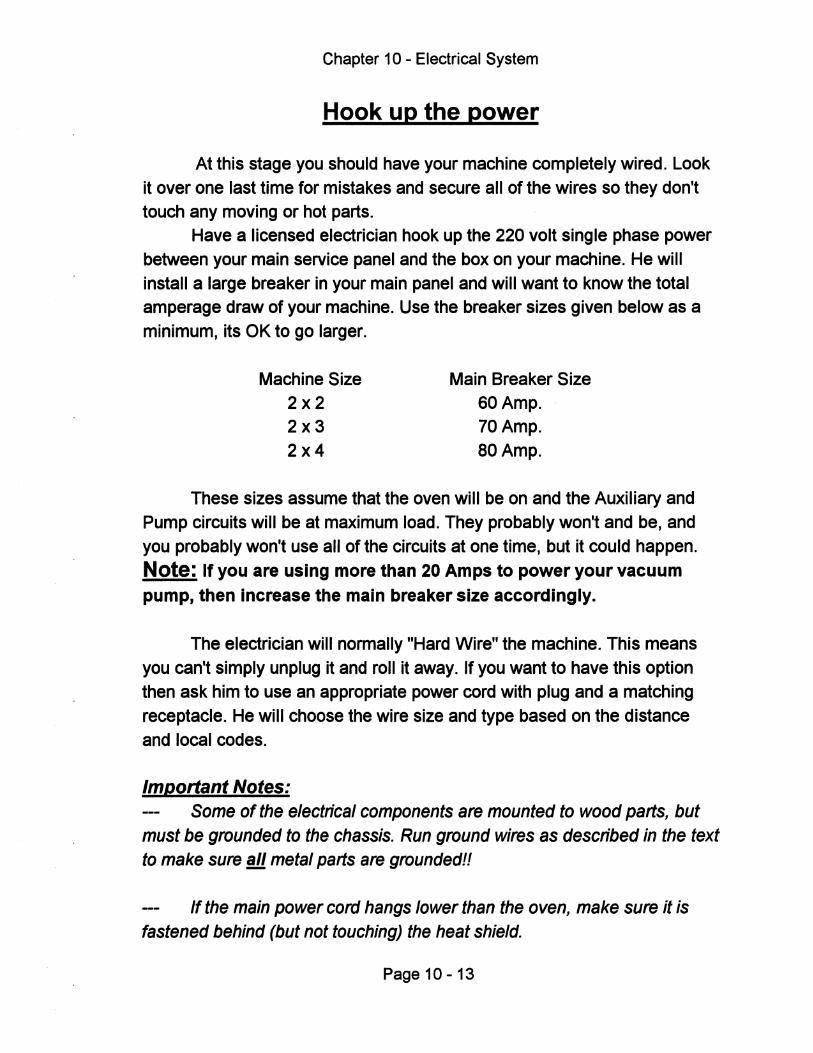
Chapter 10 - Electrical System
Hook up the power
At this stage you should have your machine completely wired. Look it over one last time for mistakes and secure all of the wires so they don't touch any moving or hot parts.
Have a licensed electrician hook up the 220 volt single phase power between your main service panel and the box on your machine. He will install a large breaker in your main panel and will want to know the total amperage draw of your machine. Use the breaker sizes given below as a minimum, its OK to go larger.
Machine Size 2x2 2x3 2x4
Main Breaker Size SO Amp. 70 Amp. aOAmp.
These sizes assume that the oven will be on and the Auxiliary and Pump circuits will be at maximum load. They probably won't and be, and you probably won't use all of the circuits at one time, but it could happen. Note: If you are using more than 20 Amps to power your vacuum pump, then increase the main breaker size accordingly.
The electrician will normally "Hard Wire" the machine. This means you can't simply unplug it and roll it away. If you want to have this option then ask him to use an appropriate power cord with plug and a matching receptacle. He will choose the wire size and type based on the distance and local codes.
Important Notes: Some of the electrical components are mounted to wood parts, but
must be grounded to the chassis. Run ground wires as described in the text to make sure !ll. metal parts are grounded!!
If the main power cord hangs lower than the oven, make sure it is fastened behind (but not touching) the heat shield.
Page 10 -13
Chapter 10 - Electrical System
Power Up Checklist
1 - Tum off all of the breakers on the machine itself.
2 - Tum on the large breaker at the service panel, this brings power up to the machine.
3 - Tum on the 15 Amp. circuit breaker and test the Auxiliary circuit by plugging in a fan, then tum it on and off with the toggle switch. Raise the clamp frame and tum on the oven switches, you should hear a loud click as the contactor coils are energized, and the oven pilot light should come on. The heating elements will not get hot at this time.
4 - Tum on the 20 Amp. breaker and plug in your vacuum pump to check for proper operation.
5 - Tum on the two pole oven breakers and see if the heating elements get hot. The clamp frame must be raised and the Auxiliary circuit must be on for this to happen. The main oven pilot light should always come on when heating, and if you chose to use heat controls, the small pilot lights should come on to indicate when the oven cycles on and off.
6 - Lower the clamp frame and the oven elements should tum off. The small pilot lights will tum off if you have heat controls, but the main oven pilot will remain on until you tum off the oven switch.
Tip: If pOSSible, go through this checklist while the electrician is still there
and have him do a final amperage check for each circuit. He can do this by clipping a probe around individual wires in your breaker box and measuring the actual load. I consider this last step essential, even if you hire an electrician only for this reason, then I would consider it cheap insurance.
Page 10 -14
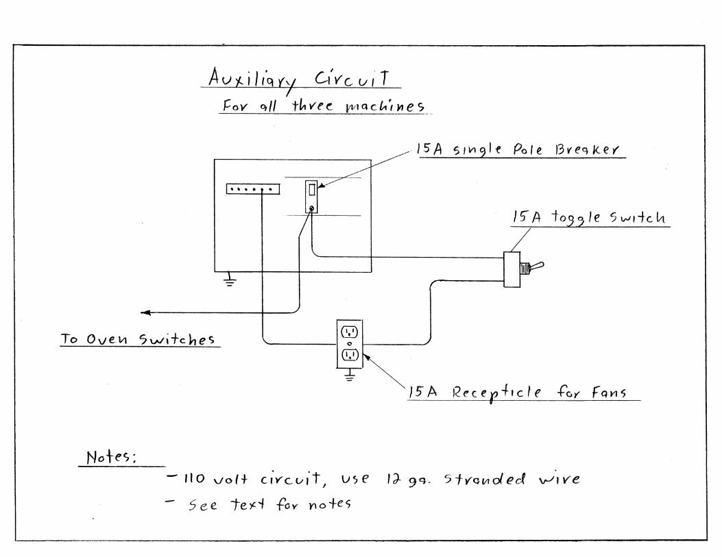
A u 'h il,'q '(,-I el'V c u ,. T I
':011' 0,/1 t!" v e ~ l/V1 Q C t.', ~ e s
- 15 A S I VI 9 1 f Po' e 13 V' eq kef
I"-~ [[jf?"~
, Z to" ~ If' 5 ",de '" /
....L L--
~
Q;2) \. I 0 I ~ To 0 \Ie. 111 7 Wl +c l-J e c;
(Q)
T
} 5 A I~ e c e r -I- , c I e -to)" F Q VI S
Notes' • - rI 0 \./oft c.iYc.uit I us e IJ- 9 q · 5 fYClIloi ect v--'I ve
- 5 e e te)C'" foy YI 0 +es
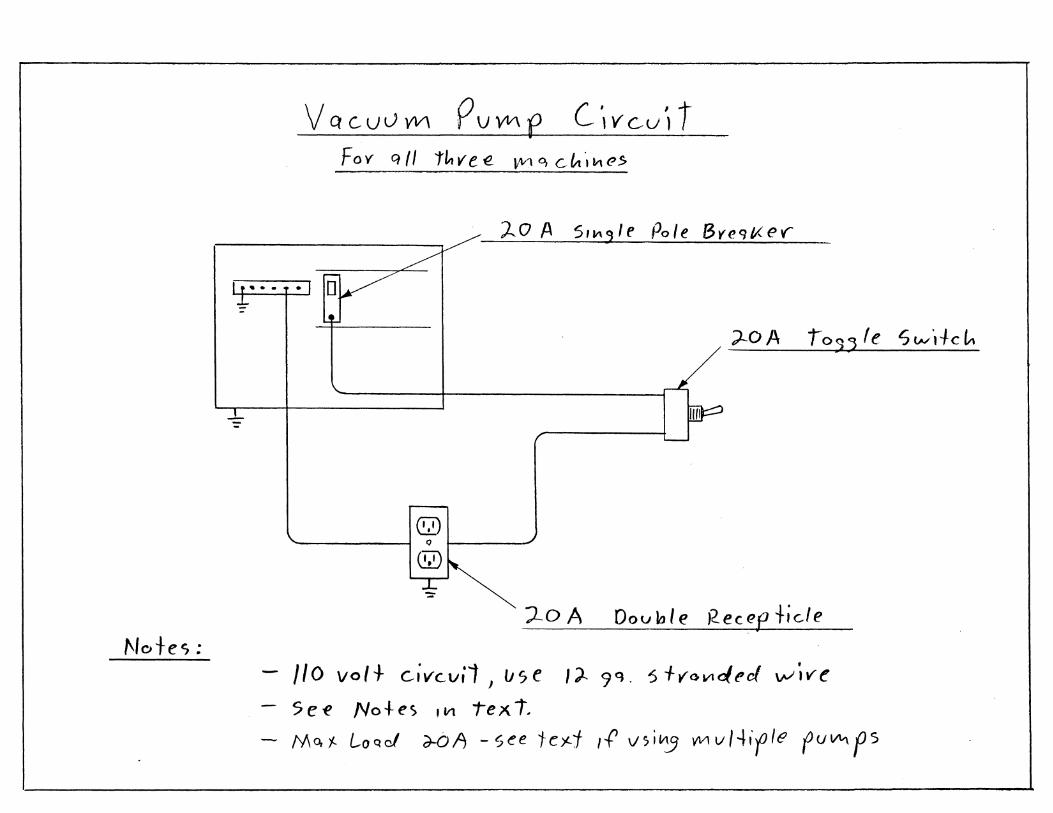
Notes:
VQCUVVVI PVVVle C1VGU'lt
F 0 y q 1/ tLt ve -e ~'\Il 0, C ~ ',,,,, e $
).... 0 A 5, It\ <) I e Po Ie By (! q f,( e .,.
,)-OA ro:;, Ie SW1+c~
@) '- IQI "
W
:LoA Oov~le Kecep+ic.le •
/10 volt Givc.vil J use I;).. 9 Q , 5 fVGV1</.ed \JV'ive
5 e e No + e s ,Vl t"e x t. M 0, f.. La 0. cI d-O A - see 1- c )£. j If v) i ~ '(VI v 14, fIe f U """ f 5
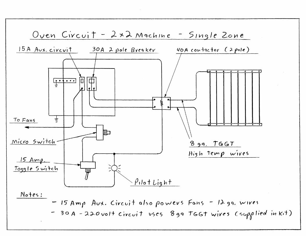
o v e, V) C ,'y c.. v i t - J-"'j.. '). 1'/\ q c. L--r 1111 e 5 I VI q I e 20 VI e
J 5 A Av"J.... c...ivc.vit 30A ;L port By-eo, kev _\ J
Lf? A (OJt1-l clC .. t~r (;). fo'~ )
_\
if" \_. 'I~ " . . - . . .
... ... , J---- \
J.. -To ]::Or~s
~ -.----. . . -.- . -.~-,
tyI;CfO $W;+CIA~~ <D 2Q. TGrGT ,
tli, h ieLMl' wIves 15" AlMp.
105,11' S ,,.':d-c I" ~ r ~ ~~ , "-
'-. P,lo t L..-i,!1 + Notes:
15/l.YfIl(J Au'/.-. C,vc:ui+ also (JovJevs F()lt1S - I)" 9Q , \IV"ve~
- 30 A - :l.;)...Ovo/+ Civc.uit \)ses S 9 q IGb1" "";r't"~ Csuff lieJ ;(;1 k'.i)
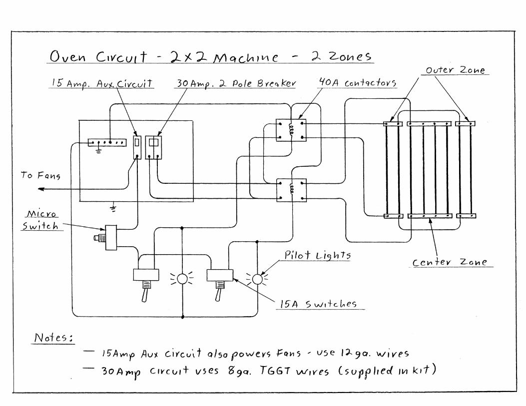
o v e.V\ C I V CUI t - ).. i-. J- N\ q C, lit , V\ e ).. 2-01/1 e S Oui'e.Y- LO/.-le
'-fOA Cclll7-QC toYS 15 A~.p. Au~tc.uir 30 A .... p. ;).. Pole S ~e~ kef'
..... - - / .r+ · • · r:t::=P
\ / Fl·t .. I);;?
""
To FQI15
-I MICYO
5 w ~ + c- h :-r---...r-L----/ o::ffijj
L-
Notes;
( " >- I. ~
~ I.
Pilot L.i hi:;;
::O~ .".. "
15A Sw,+c..L-tes
• • I I. , \
Ce1t\+ev z'oltle
l'A~'f Au'/. c..ifcu,t Q/sopowevs t:CU1S ... use 1;)...9 0 . \Vives
30APIr CfY((j,t V$es 39Q • T66T w,ves (suPf',ecl'lIJ kIt)
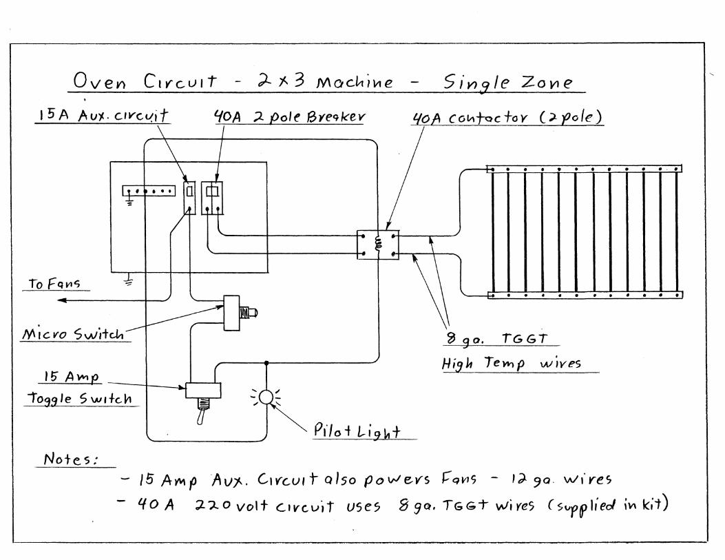
Oven elY"CUIt ;).. j.. 3 M CI cltt i \II e 5 i V} .9 I e Z 0 V1 e
I 5 A Auf.,. c.'vc~i t l..fC?A ;2. pole 13yeqkev I{o A c ot.-,toc +0 Y (). eo Ie ) \ \-1
If r .. 'I\i 1m • • • • • • • • • • •
" I. ~ :1 c \ ,
To F q VIS -J::
Z, 90. iGGT
•• ••••••••
M;cvo Switcl,~1WP Hi:1 it T e Ytl P \AI ; yes
1;- AWl" I I
-i I lon' e S \AI I fen , ! ::~" '" "-
PI" 0 i /, i 9 k t ..... "'-------
Note. s: - 15 A '/'tIt (JA v J... G I Y G u, t Q 150 P () vJ e v s ~ q ~ S - ,;:) 9 a· w .. ye s
- '-10 A ;l.?,O volt C.IVC,t/.t USe5 8 9Q , TGGT wires (s"P6lI;eol;\I\ k;t)
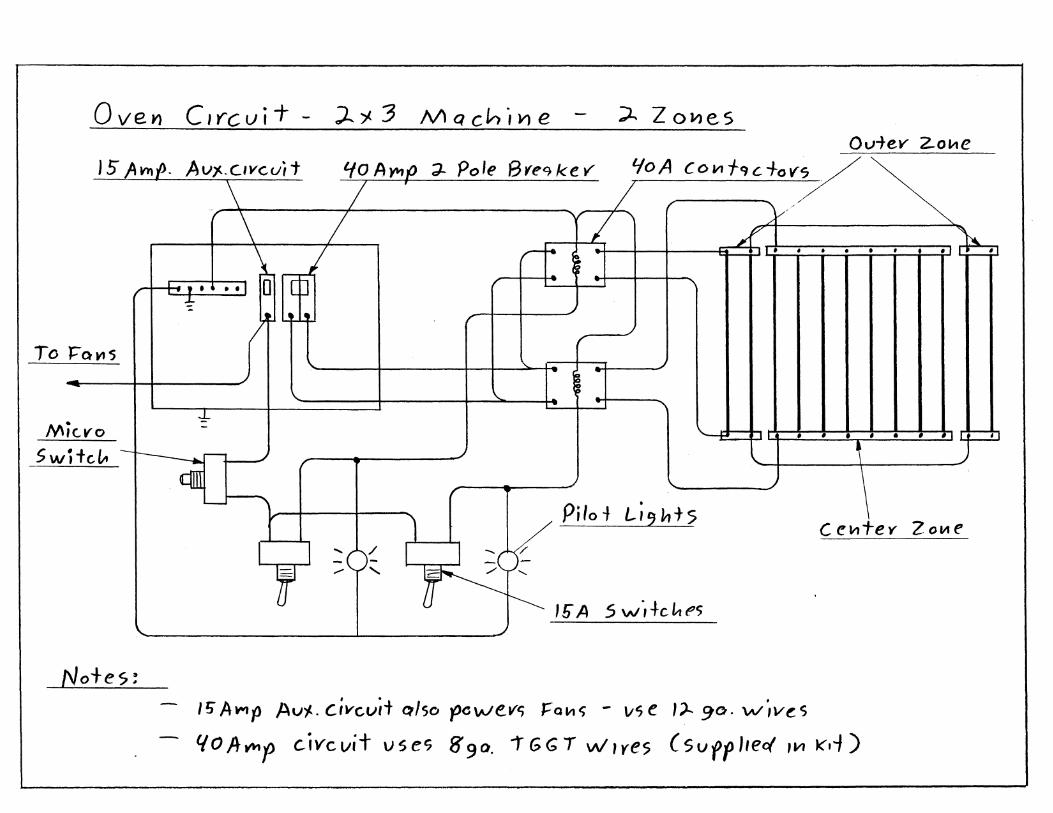
Oven C'Y"'cuii- - )..'j. 3 Mach"IYle :A Z oJl)es
To
M
5w
/'
~Q~5
-• KVO
j+d,., -
Notes!
Ov-tev 2.o~e
- /~ -
! ./ -
,/
-
/ \-,/' \ ~7 ~
(/1 f\ / L T. • • , , • , • ;--I-- s~ In? ~ ...... "\ ...c""'J 0 ttJ -.f
r) L...!.tJ --'
/'
\.. '-I
.. ./
\. i)
• ""\ \
-4-!.J .c , • /I '---I: , , •
~ J
-
\. J ~ r- ~
-- t--
\ '--~ Qill . '---
""" - Pilot '-'2h+5 Cell1Tey ZOllle v :: [' J:::V I .....
-
.... ~ /!i A .s ,,,/,fcl-tes J ,/
/; A.",p Au'/-.. civcvit Cllso r>cwevt; J:"QII1~ - vse 1)" 90. W",v~s
lfOAY"Ip c.ivcvit useS 890. t"GGT WIye5 (svfP',eq' ,VI Kd)
~
,.
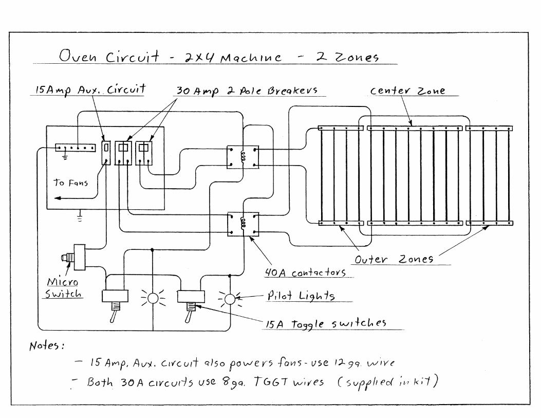
Ov e lit C. ; v cui -I- - ;;.. j.. L/ !'11 q c.lA , IA e 'J- 2-0Vl es
15 A 'Mp Av'! .. C;l'"(.uit
~ 30 I+.".P ;).. Po} ~ Jjreqke vs
d cevt1ev z..oltte ,
// -H: • • ~ ••• -!It • • ,I , i..'..
ri+r 1 .. 1 ~ ~rci r . ~ I- .
./ 10 Fq~5
--1 -. ~ .
rI----..I
~ '~j · l • • • • • I · l • , .~; . . . . . . , ~ ...: . ,
Ov1e.V
" L..]--.,PiI. 0 + Li 2 '" 15
•
N'iIC'fO S WI k/" es S I.Jj h/" 15 A i 03? Ie
ZOVle9
. qO A c.olll+qC -fa y S ___ _
Noie'J : - 15" /iVVlP, Av')i. Clvcu/T q)so fowev5 [oVls-lIse 1')...99. vv·,ve
- Bath 3() A clvcur-)5 liSe. g:J Q , TuG T Vv~ .... e.s (svffll ec( ;Id /<;1 )
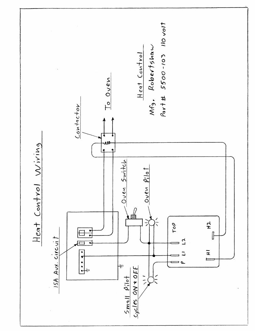
+--0 ~
0 -:3 -0
is r"
>. .s -t- I,!\ 0
-t-......
S 0 "> 0
$ u ~
~ 0 ~
.,.... 0 ~ ") 0- ct
'"" ~
0 ::t: +\ ... .). ~ () ~ -t-
+ ~ ~
u ~ (j
-;-$ c
'-.,.\
~
'>-. - -5:,'
5 0
-+- +-
'S 0 -V\
. -Q ).
S' S
+ ~ ~ "";> ';)
~ 0 0
0 \.)
/
+ 5
-/ "- 0.. ri
~ ~
':t:
.:r: .+-. c-<
::> ..J
0 ~ • --.I :3:. v
• Q...
'" ~ • \\
~ II
~ +- /
C
'- " <:';l.
Chapter 11
Operation
Congratulations I
Stand back for a minute to admire your work, then treat yourself to a
nice dinner. By building this yourself, you just saved enough money to for a Caribbean cruise and a used car. When you get back let's try this thing out.
Machine Operation
Lets go through the process step by step to make a typical part, the
whole cycle will only take a few minutes.
Get Set Up Pick an easy plastic such as styrene for your first try and find a
suitable test pattern. Avoid undercuts and read the forming tips at the end
of this section for other mold related ideas. Operate the machine in a warm room with adequate ventilation and
avoid drafts that could cause uneven heating. The machine should have at
least 18 inches of clearance all around and 36 inches of clearance on top. Make sure nothing is covering the top vents and there are no flammable
liquids near by. With 5 -10.000 watts of heating going on, you should always have a fire extinguisher handy.
Plug one or two ordinary house fans into the outlet box in back and
set them on a workbench or table at the right height so they blow across the platen. The fans will operate from a switch on the front panel.
Evacuate the tank Close the main valve and pump down the tank as far as you want,
then turn the pump off. It should hold this vacuum and is now in stand by mode.
Page 11 - 1
Chapter 11- Final Assembly
Pre - Heat the oven - Tum on the main oven switch, then raise the clamp frame up to trip the micro switch and tum the oven on. The elements will get warm and heat up the metal oven box and clamp frame. This warm up period should only take two or three minutes. Do not exceed five minutes without a plastic sheet in place because the lower carrier frame glides are exposed directly to the heat and could melt. Get your plastic sheet and pattern ready while you are waiting.
you can leave your pattern on the platen during this time to warm it up if needed. Some molds such as plaster and metal have a lot of thermal mass and need to be warmed up so they don't cool the plastic before it is formed.
Important
Do Not use this machine to dry out plaster molds, cure epoxy, get a sun tan or anyth~ng else that requires the oven to be on for an extended period. The oven is very intense and is designed to be used in cycles, on for a few minutes then off between parts. See the note on heat management at the end of this manual.
Load the Plastic Lower the carrier frame and put your plastic sheet between the
clamp frames. Secure it with binder clips or toggle clamps. Use gloves because the metal parts will be warm. The micro switch turned the oven off when you lowered it, so load the sheet fairly quickly before the oven cools down too much. Raise the handle again to tum the oven on and start the heating cycle.
Heating the Plastic Watch the plastic as it heats. Do not walk away or answer the
phone, because some plastics heat very fast. You want to watch for it to start sagging in the middle. It will first expand and bulge downward, then it will get wavy and finally pull tight as it gets soft. After this point you can expect it to start sagging.
Some plastics sag fast and will go all the way to the platen if you let them, others are very reluctant to sag and behave more like a rubber sheet.
Page 11 - 2
Chapter 11- Final Assembly
You can poke at it with your finger to test its softness. Let it sag far enough to approximate the volume of your pattern, but if you go too far it will form wrinkles or webs in the finished part. If left too long the plastic can bum and possibly ignite.
Remember ... Never take your eyes off the oven while it is onl
It is easy to sight across the bottom of the clamp frame and see the sag. You can attach a ruler to the back of the wood box for visual reference, but in a short time you will quickly develop a feel for when the plastic is ready. I encourage you to keep a notebook of your results so the next time will be easier.
Forming Your plastic is soft, the vacuum tank is charged and all that's left is
the fun part. By now there is probably a crowd standing around, so tell them not to blink because this happens fast.
In one smooth motion lower the handle and push down to stretch the plastic over your pattern. You won't have to push very hard, but make sure it is bottomed out as you reach down and quickly open the valve ... I told you it was fast. Keep light pressure downward and tum on the fans. The plastic Cools very quickly, you can poke it with your fingers to see when the comers get firm so you can't make a dent with your finger nail.
Close the vacuum valve and let the pressure bleed down. Remove the clamps and take out the finished part, the pattern will most likely come with it. You will have to flex the plastic, tap on it and occasionally scream and yell to get the pattern to fall out.
Repeat the Cycle If you are doing another part, load a new sheet and raise the handle
to start heating again. Recharge the vacuum tank if needed and put your pattern in place for another try.
Shutting Down the Machine When you are done, shut off the main oven switch and lower the
carrier frame. This disables the oven in two ways, so even if the switch is Page 11 - 3
Chapter 11- Final Assembly
bumped, the oven won't turn on until the handle is fully raised. As a last safeguard the pilot light will come on to warn that it will get hot.
If you are using an automatic switch for the pump , be sure to turn off the manual switch to disable it so it won't cycle on and off if it develops a leak. The pilot light should indicate when the pump has power.
Heat Management
If you are just doing a few parts, then heat build up is not a concern, but if you are going to make parts all day long then you should have a strategy to cope with it. Never forget that you are unleashing a lot of energy
when the oven is turned on. This would be comparable to running an arc welder continuously. Aside from the obvious high cost of electricity, there are other reasons to use the oven Only during that part of the cycle when it is actually needed.
When a plastic sheet is in the clamp frame, it acts as a shield by absorbing the heat into itself and protecting everything below it. That's why we limit our warm-up times ( without plastic) to 2 or 3 minutes With out that shield the intense heat could possibly melt the plastic glides or cause other damage. If you leave the oven on .between parts while you are doing other
things, Your pattern and even the machine itself has to absorb all that heat. Although it is not healthy, it is unlikely to cause immediate damage to the machine but your pattern may not fare as well.
A wood or epoxy pattern will survive many forming cycles, but if you let it bake unprotected it can be damaged. metal is the only material that is not affected to some degree by excessive heat. By having the oven turn off,
when the plastic is lowered and using fans, we not only save a lot of electricity but we protect the pattern and machine from long term damage.
Remember ... The oven is not meant for continuous use. Under normal operation, it is never on for more than about 5 minutes and it is off during the forming cycle. Do not use this machine for any other use that requires the oven to run continuously.
Page 11 - 4
Chapter 11- Final Assembly
Safety Considerations
I won't bore you with this section, I tried to mix the safety messages in throughout the manual so you wouldn't notice them, but I am almost done now and here are a few more worth mentioning.
-- Always wear safety glasses when reading this manual... I just wanted to see if you were paying attention.
-- Never operate this machine in the bath tUb .. Ok now I'm sure.
-- Some plastics give off toxic fumes, especially when they are over heated. Ask you plastic distributor if there is any thing to worry about when you buy the plastic. They are required to supply you with material safety data sheets on request.
-- Keep an appropriate fire extinguisher handy just in case ..
-- Find out where the main power disconnect is that supplies your machine. If there is any emergency, shut off the power.
-- Never leave the machine when the oven is operating, I know I said this before, but its important.
-- Use pilot lights on the vacuum and oven circuits so you remember to turn them off when you are done.
-- Use a minimum clearance to combustibles of 18 inches on all sides and 36 inches above. Never set anything on top of the oven or block the vents.
-- Don't Micro-wave your cat, I was just kidding when I said that.
Page 11 - 5
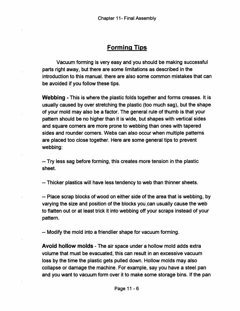
Chapter 11- Final Assembly
Forming Tips
Vacuum forming is very easy and you should be making successful parts right away, but there are some limitations as described in the introduction to this manual. there are also some common mistakes that can
be avoided if you follow these tips.
Webbing - This is where the plastic folds together and forms creases. It is
usually caused by over stretching the plastic (too much sag), but the shape of your mold may also be a factor. The general rule of thumb is that your pattern should be no higher than it is wide, but shapes with vertical sides
and square corners are more prone to webbing than ones with tapered sides and rounder corners. Webs can also occur when multiple patterns are placed too close together. Here are some general tips to prevent
webbing:
-- Try less sag before forming, this creates more tension in the plastic sheet.
-- Thicker plastics will have less tendency to web than thinner sheets.
-- Place scrap blocks of wood on either side of the area that is webbing, by
varying the size and position of the blocks you ,can usually cause the web to flatten out or at least trick it into webbing off your scraps instead of your
pattern.
-- Modify the mold into a friendlier shape for vacuum forming.
Avoid hollow molds - The air space under a hollow mold adds extra
volume that must be evacuated, this can result in an excessive vacuum
loss by the time the plastic gets pulled down. Hollow molds may also collapse or damage the machine. For example, say you have a steel pan and you want to vacuum form over it to make some storage bins. If the pan
Page 11 - 6
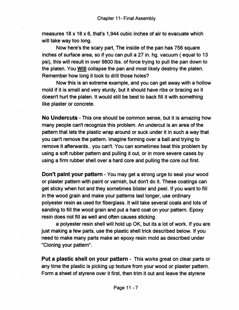
Chapter 11- Final Assembly
measures 18 x 18 x 6, that's 1,944 cubic inches of air to evacuate which will take way too long.
Now here's the scary part, The inside of the pan has 756 square inches of surface area, so if you can pull a 27 in. hg. vacuum (equal to 13 psi), this will result in over 9800 Ibs. of force trying to pull the pan down to the platen. You Will collapse the pan and most likely destroy the platen.
Remember how long it took to drill those holes? Now this is an extreme example, and you can get away with a hollow
mold if it is small and very sturdy, but it should have ribs or bracing so it doesn't hurt the platen. It would still be best to back fill it with something
like plaster or concrete.
No Undercuts - This one should be common sense, but it is amazing how
many people can't recognize this problem. An undercut is an area of the pattern that lets the plastic wrap around or suck under it in such a way that
you can't remove the pattern. Imagine forming over a ball and trying to remove it afterwards .. you can't. You can sometimes beat this problem by using a soft rubber pattern and pulling it out, or in more severe cases by
using a firm rubber shell over a hard core and pulling the core out first.
Don't paint your pattern - You may get a strong urge to seal your wood
or plaster pattern with paint or varnish, but don't do it. These coatings can get sticky when hot and they sometimes blister and peel. If you want to fill
in the wood grain and make your patterns last longer, use ordinary polyester resin as used for fiberglass. It will take several coats and lots of sanding to fill the wood grain and put a hard coat on your pattern. Epoxy resin does not fill as well and often causes sticking.
a polyester resin shell will hold up OK, but its a lot of work. If you are just making a few parts, use the plastic shell trick described below. If you need to make many parts make an epoxy resin mold as described under
"Cloning your pattern".
Put a plastic shell on your pattern - This works great on clear parts or
any time the plastic is picking up texture from your wood or plaster pattern.
Form a sheet of styrene over it first, then trim it out and leave the styrene
Page 11 -7
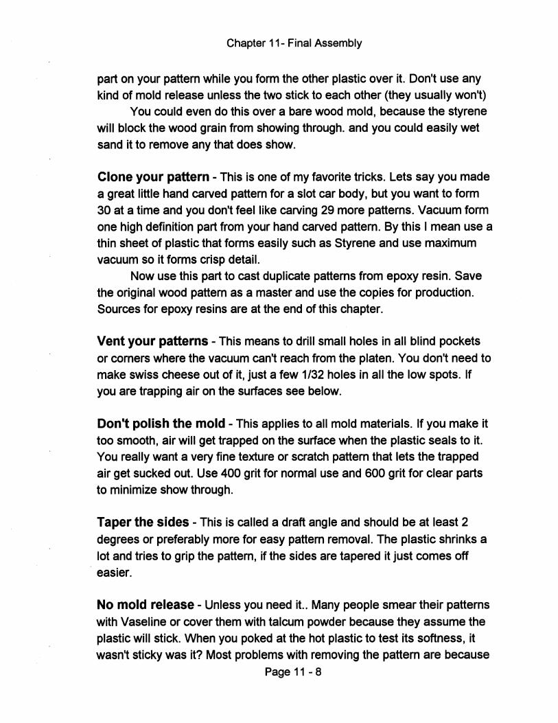
Chapter 11- Final Assembly
part on your pattern while you form the other plastic over it. Don't use any kind of mold release unless the two stick to each other (they usually won't)
You could even do this over a bare wood mold, because the styrene will block the wood grain from showing through. and you could easily wet sand it to remove any that does show.
Clone your pattern - This is one of my favorite tricks. Lets say you made a great little hand carved pattern for a slot car body, but you want to form 30 at a time and you don't feel like carving 29 more patterns. Vacuum form one high definition part from your hand carved pattern. By this I mean use a thin sheet of plastic that forms easily such as Styrene and use maximum vacuum so it forms crisp detail.
Now use this part to cast duplicate patterns from epoxy resin. Save the original wood pattern as a master and use the copies for production. Sources for epoxy resins are at the end of this chapter.
Vent your patterns - This means to drill small holes in all blind pockets or comers where the vacuum can't reach from the platen. You don't need to make swiss cheese out of it, just a few 1/32 holes in all the low spots. If you are trapping air on the surfaces see below.
Don't polish the mold - This applies to all mold materials. If you make it too smooth, air will get trapped on the surface when the plastic seals to it. You really want a very fine texture or scratch pattern that lets the trapped air get sucked out. Use 400 grit for normal use and 600 grit for clear parts to minimize show through.
Taper the sides - This is called a draft angle and should be at least 2 degrees or preferably more for easy pattern removal. The plastic shrinks a lot and tries to grip the pattern, if the sides are tapered it just comes off easier.
No mold release - Unless you need it., Many people smear their patterns with Vaseline or cover them with talcum powder because they assume the plastic will stick. When you poked at the hot plastic to test its softness, it wasn't sticky was it? Most problems with removing the pattern are because
Page 11 - 8
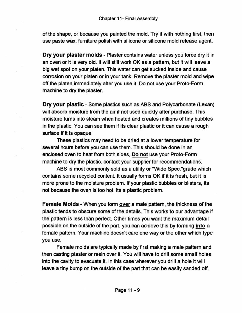
Chapter 11- Final Assembly
of the shape, or because you painted the mold. Try it with nothing first, then use paste wax, furniture polish with silicone or silicone mold release agent.
Dry your plaster molds - Plaster contains water unless you force dry it in
an oven or it is very old. It will still work OK as a pattern, but it will leave a big wet spot on your platen. This water can get sucked inside and cause
corrosion on your platen or in your tank. Remove the plaster mold and wipe off the platen immediately after you use it. Do not use your Proto-Form machine to dry the plaster.
Dry your plastic - Some plastics such as ABS and Polycarbonate (Lexan)
will absorb moisture from the air if not used quickly after purchase. This moisture turns into steam when heated and creates millions of tiny bubbles
in the plastic. You can see them if its clear plastic or it can cause a rough surface if it is opaque.
These plastics may need to be dried at a lower temperature for several hours before you can use them. This should be done in an enclosed oven to heat from both sides, Do not use your Proto-Form
machine to dry the plastic. contact your supplier for recommendations. ABS is most commonly sold as a utility or "Wide Spec. "grade which
contains some recycled content. It usually forms OK if it is fresh, but it is
more prone to the moisture problem. If your plastic bubbles or blisters, its not because the oven is too hot, its a plastic problem.
Female Molds - When you form ~ a male pattern, the thickness of the
plastic tends to obscure some of the details. This works to our advantage if the pattern is less than perfect. Other times you want the maximum detail possible on the outside of the part, you can achieve this by forming into a
female pattern. Your machine doesn't care one way or the other which type you use.
Female molds are typically made by first making a male pattern and then casting plaster or resin over it. You will have to drill some small holes into the cavity to evacuate it. In this case wherever you drill a hole it will
leave a tiny bump on the outside of the part that can be easily sanded off.
Page 11 - 9
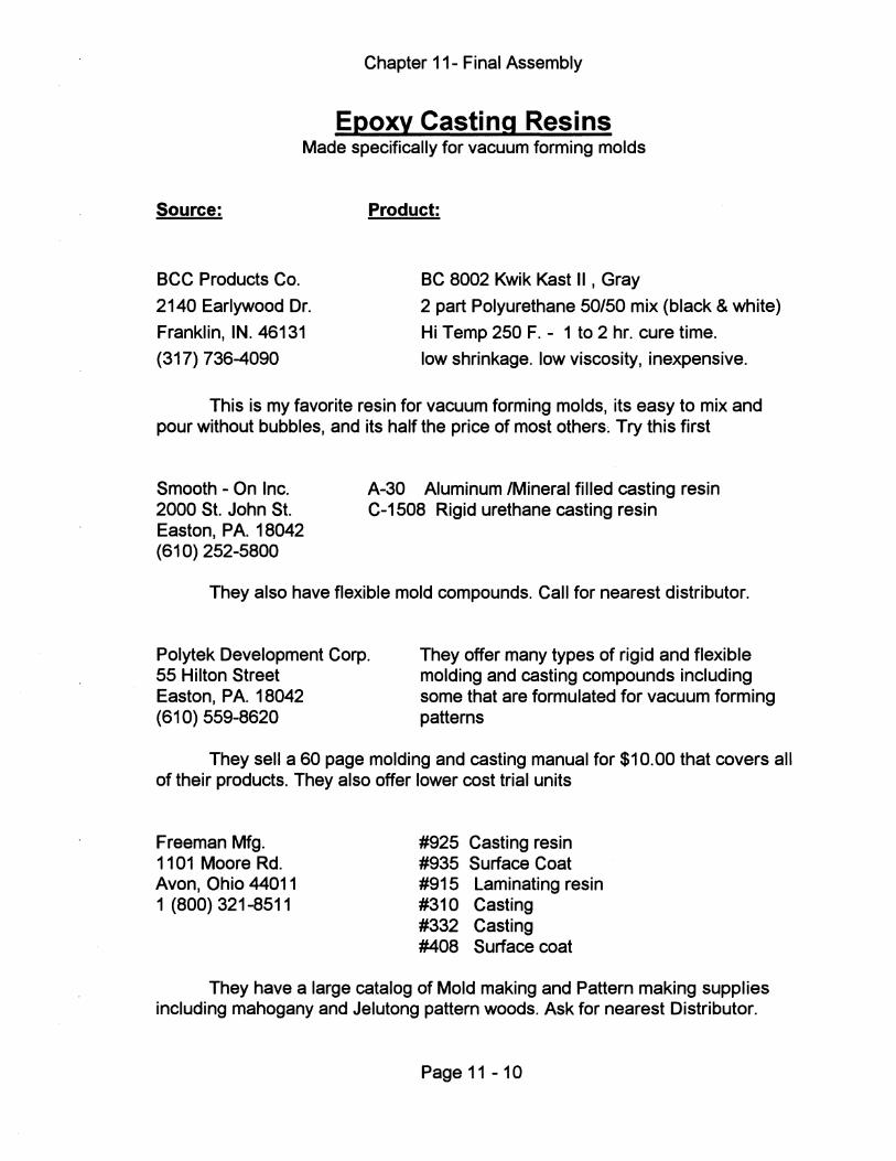
Chapter 11- Final Assembly
Epoxy Casting Resins Made specifically for vacuum forming molds
Source:
BCC Products Co.
2140 Earlywood Dr.
Franklin, IN. 46131
(317) 736-4090
Product:
BC 8002 Kwik Kast II , Gray
2 part Polyurethane 50/50 mix (black & white)
Hi Temp 250 F. - 1 to 2 hr. cure time.
low shrinkage. low viscosity, inexpensive.
This is my favorite resin for vacuum forming molds, its easy to mix and pour without bubbles, and its half the price of most others; Try this first
Smooth - On Inc. 2000 St. John St. Easton, P A. 18042 (610) 252-5800
A-30 Aluminum IMineral filled casting resin C-1508 Rigid urethane casting resin
They also have flexible mold compounds. Call for nearest distributor.
Polytek Development Corp. 55 Hilton Street Easton, PA. 18042 (610) 559-8620
They offer many types of rigid and flexible molding and casting compounds including some that are formulated for vacuum forming patterns
They sell a 60 page molding and casting manual for $10.00 that covers all of their products. They also offer lower cost trial units
Freeman Mfg. 1101 Moore Rd. Avon, Ohio 44011 1 (800) 321-8511
#925 Casting resin #935 Surface Coat #915 Laminating resin #310 Casting #332 Casting #408 Surface coat
They have a large catalog of Mold making and Pattern making supplies including mahogany and Jelutong pattern woods. Ask for nearest Distributor.
Page 11 -10
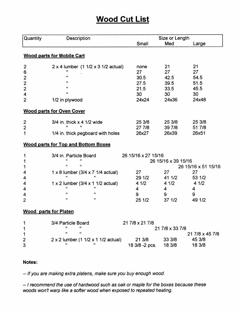
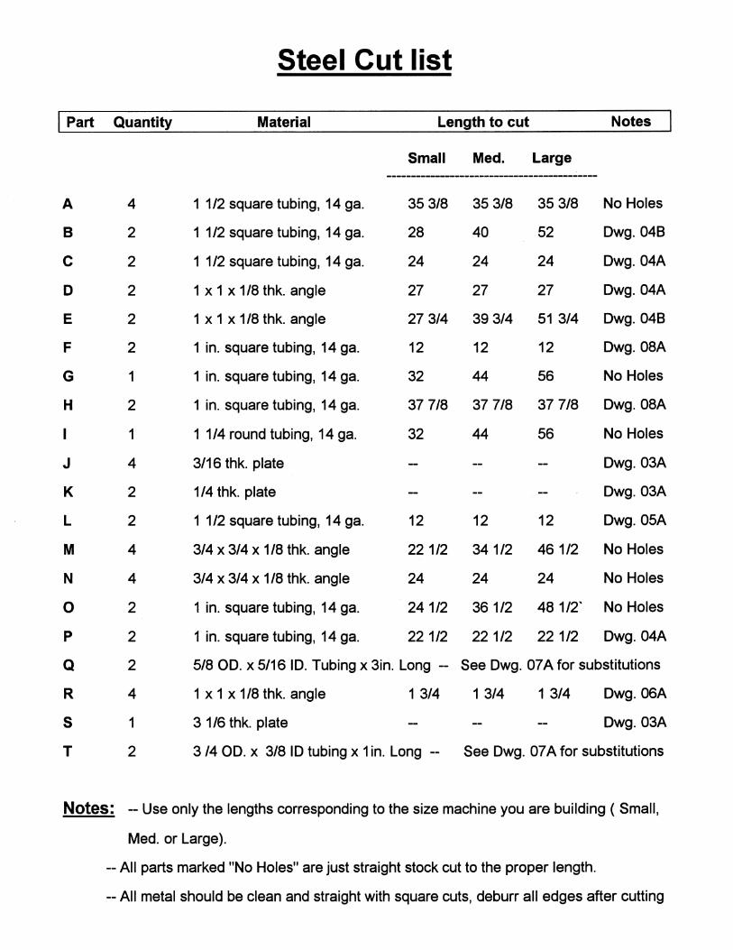

.
Qua
ntity
P
art
Des
crip
tion
Sou
rces
for P
arts
s
M
L
McM
aste
r Car
r G
rain
ger
Oth
er S
ourc
es
1
1
1
100
Am
p fix
ed lu
g, s
urfa
ce m
ount
bre
aker
box
69
14K
33
1052
1 H
dw. S
tore
- E
lect
rical
sup
ply
stor
e 1
0
2
30 A
mp
2 po
le c
ircui
t bre
aker
69
225K
76
1035
4 H
dw. S
tore
- E
lect
rical
sup
ply
stor
e 0
1
0 40
Am
p 2
pole
circ
uit b
reak
er
6922
5K77
10
356
Hdw
. Sto
re -
Ele
ctric
al s
uppl
y st
ore
1
1
1
15 A
mp
sing
le p
ole
circ
uit b
reak
er
6922
5K71
10
340
Hdw
. Sto
re -
Ele
ctric
al s
uppl
y s
tore
1
1
1
20
Am
p si
ngle
pol
e ci
rcui
t bre
aker
69
225K
72
1034
2 H
dw. S
tore
- E
lect
rical
sup
ply
stor
e 1
1
1
S
teel
ele
ctric
al e
nclo
sure
- to
hou
se o
ven
con
tact
ors
7506
5K13
3A
910
Hdw
. Sto
re -
Ele
ctric
al s
uppl
y st
ore
5 ft.
5 ft
. 5
ft.
1 in
ch E
MT
elec
trica
l con
duit
Hdw
. Sto
re -
Ele
ctric
al s
uppl
y st
ore
1
1
1
90 d
egre
e co
ndui
t elb
ow
7154
K73
5X
C56
H
dw. S
tore
- E
lect
rical
sup
ply
stor
e 3
3 3
Con
duit
end
fittin
gs
7150
K36
5X
C14
H
dw. S
tore
- E
lect
rical
sup
ply
stor
e 1
1
1
1i
nch
EM
T cl
amp
Hdw
. Sto
re -
Ele
ctric
al s
uppl
y st
ore
1
2 2
Ove
n co
ntac
tors
- 2
pole
- 12
0 vo
lt co
il
- 40
res
istiv
e am
ps
6564
K75
5 12
0V co
il 58
112
Ele
ctric
al s
uppl
y st
ore
20ft.
40f
t. 40
ft.
12 g
auge
stra
nded
wire
- B
lue
7124
5K4
- Blu
e H
dw. S
tore
- E
lect
rical
sup
ply
stor
e 30
ft.
30ft.
30f
t. 12
gau
ge s
trand
ed w
ire -
Bla
ck
7124
5K4
- Bla
ck
Hdw
. Sto
re -
Ele
ctric
al s
uppl
y st
ore
30ft
. 30
ft. 3
0ft.
12 g
auge
str
ande
d w
ire - W
hite
71
245K
4 - W
hite
H
dw. S
tore
- E
lect
rical
sup
ply
stor
e 1
1
1
15
Am
p du
plex
rece
ptac
le -
grou
nded
71
59K3
52
836
Hdw
. Sto
re -
Ele
ctric
al s
uppl
y st
ore
1
1
1
20 A
mp
dupl
ex re
cept
acle
- gr
ound
ed
7159
K4
5283
7 H
dw. S
tore
- E
lect
rical
sup
ply
stor
e 2
2 2
Han
dy b
ox -
to h
ouse
rec
epta
cles
71
695K
21
6XC
56
Hdw
. Sto
re - E
lect
rical
sup
ply
sto
re
2 2
2 R
ecep
tacl
e co
vers
71
695K
23
4A24
1 .
Hdw
. Sto
re -
Ele
ctric
al s
uppl
y st
ore
2 2
2 15
Am
p to
ggle
sw
itch
- SP
ST
80
01K
51
2X48
8 H
dw. S
tore
- E
lect
rical
sup
ply
stor
e 1
1
1
20
Am
p to
ggle
sw
itch
- SP
ST
80
01K
52
2X63
3 H
dw. S
tore
- E
lect
rical
sup
ply
stor
e 1
1
1
M
icro
sw
itch
- but
ton
styl
e 15
Am
p 70
90K
49
6X28
6 E
lect
rical
sue
ely
stor
e 1
1
1
P
ilot
light
- re
d
1514
K6
Rad
io S
hack
272
-710
2
1
2
2 P
ilot l
ight
s - y
ello
w
Rad
io S
hack
272
-707
2
2
Infin
ite s
witc
hes
-ove
n he
at
cont
rols
A
pplia
nce
parts
sto
re -
See
text
2
2 2
Gro
und
clam
p - t
o m
ount
hea
t shi
eld
on c
ondu
it 75
99K
71
Hdw
. Sto
re -
Ele
ctric
al s
uool
y st
ore
Par
ts L
ist
- E
lect
rical
Par
ts

Q
uant
ity
Des
crip
tion
Sou
rces
For
Par
ts
s M
L
M
cMas
ter C
arr
Gra
inge
r O
ther
Sou
rces
2 0
0 A
lum
inum
top
and
botto
m s
heet
s fo
r 2 x
2 p
late
n 88
895K
54
Airp
arts
Inc.
- S
ee te
xt
0 2
0 A
lum
inum
top
and
botto
m s
heet
s fo
r 2 x
3 p
late
n 89
73K
66
Airp
arts
lnc.
- S
ee te
xt
0 0
2 A
lum
inum
top
and
botto
m s
heet
s fo
r 2 x
4 p
late
n 88
895K
64
Airp
arts
Inc.
- S
ee te
xt
1
1
1
Alu
min
um s
heet
for c
ontro
l pa
nel
8973
K77
A
irpar
ts In
c. -
See
text
1
1
1
P
liobo
nd 3
0 co
ntac
t adh
esiv
e - 1
quar
t 74
68A
41
Hdw
. Sto
re -
see
text
4
ft. 6
ft.
8 ft.
1/
2 x
1/2
galv
aniz
ed w
ire m
esh
- 24
inch
es w
ide
Hdw
. Sto
re
8 ft.
12
ft 14
ft
1/8
in. t
hick
x 1
in. w
ide
alum
inum
str
ip
Hdw
. Sto
re
1
1
1
1in.
NP
T ch
rom
e pl
ated
bra
ss b
all v
alve
46
28K
85
6258
0 H
dw. S
tore
4
6 6
1 in
. mal
e N
PT
to 1
in. b
arb
fittin
g 52
18K
27
3LZ9
3 H
dw. S
tore
0
2 2
1 in
. bar
b te
e fit
ting
4831
5K63
H
dw. S
tore
2
2 2
1 in.
NP
T 9
0 de
gree
elb
ows f
or b
all v
alve
44
605K
136
SP
462
Hdw
. Sto
re
1
1
1
Vac
uum
gau
ge 2
in. d
ia. p
anel
mou
nt 1
/4 N
PT
back
fitti
ng
4002
K24
1X
547
1
1
1 3/
8 ba
rb to
1/4
NP
T fe
mal
e fitt
ing
5346
K35
H
dw. S
tore
1
1
1
3/
8 ba
rb te
e fit
ting
4455
5K13
9 H
dw. S
tore
3
ft. 7
ft.
9 ft.
1 i
nch
I.D. v
acuu
m h
ose
- See
Tex
t for
alte
rnat
es
5293
K38
H
dw. S
tore
- se
e te
xt
1
1
1
Che
ck v
alve
- go
es b
etw
een
pum
p an
d ta
nk -
All
size
s 46
835K
32
1
2 2
PV
C c
oupl
er -
1in.
NP
T - f
or p
late
n 45
96K
54
Hdw
. Sto
re
4 4
4 2
in. d
ia. s
wiv
el c
aste
r - h
ard
plas
tic ty
pe
7815
5T41
2G
016
Hdw
. Sto
re
12
12
12
Pla
stic
furn
iture
slid
es -
3/4/
dia
x 1
/4 th
ick
- nai
l on
type
25
13T1
6 H
dw. S
tore
1
1
1
S
ilicon
e ad
hesi
ve -
See
Tex
t 75
47A
68
Hdw
. Sto
re -
See
text
2
2 2
U b
olts
to h
old
mai
n va
lve
- 1 1
/2 in
I.D
. - 5
/16
-18
dia.
H
dw. S
tore
2
2 2
Hin
ges
for l
ift lin
kage
- 2
x 2
- .10
0 th
ick
- .20
0 pi
n - S
ee te
xt
1617
5A16
S
J041
H
dw. S
tore
- se
e te
xt
4 4
4 P
rope
ller n
uts
- 1/4
-20
- use
as
thre
aded
inse
rts fo
r bas
e pl
ate
Hdw
. Sto
re
1 1
1 ln
line
filte
r for
vac
uum
pum
p 98
775K
11 8
0 m
esh
Par
ts L
ist
- M
isc.
Par
ts
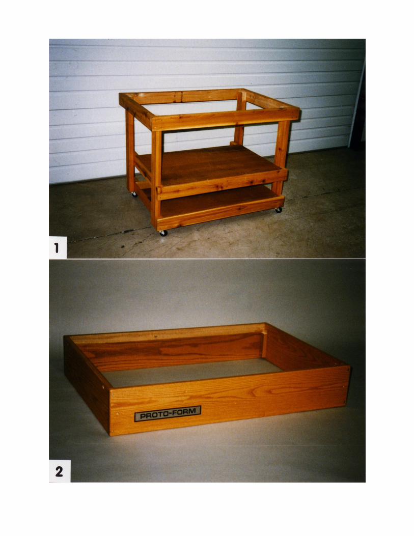
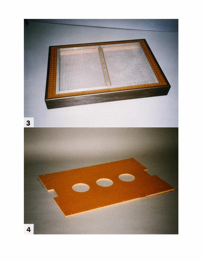
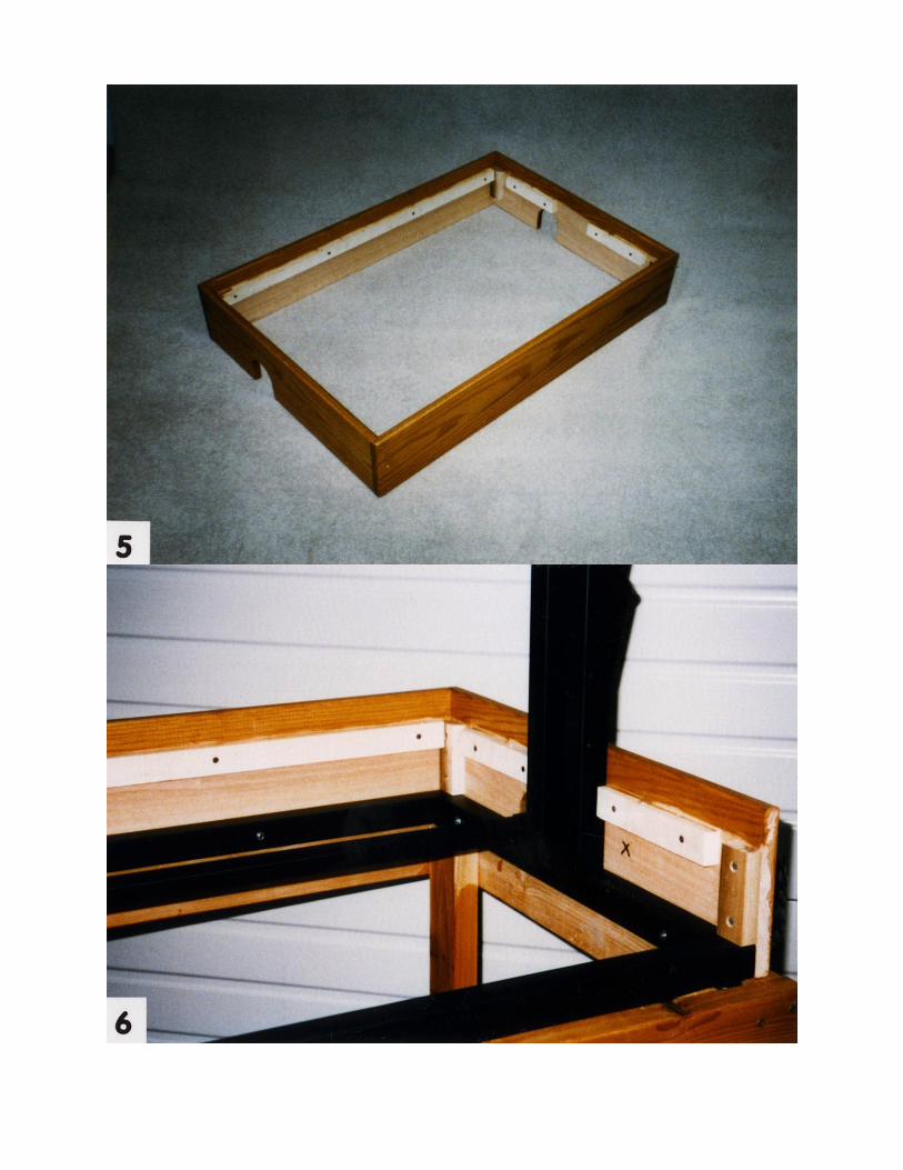
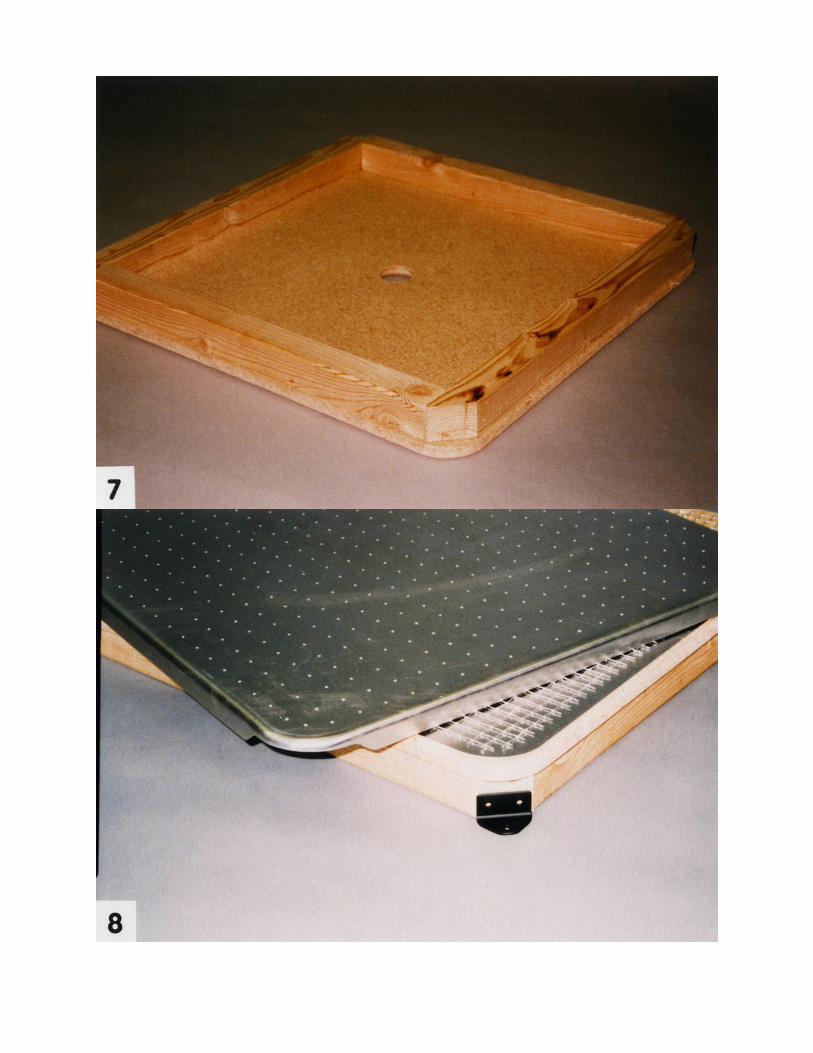
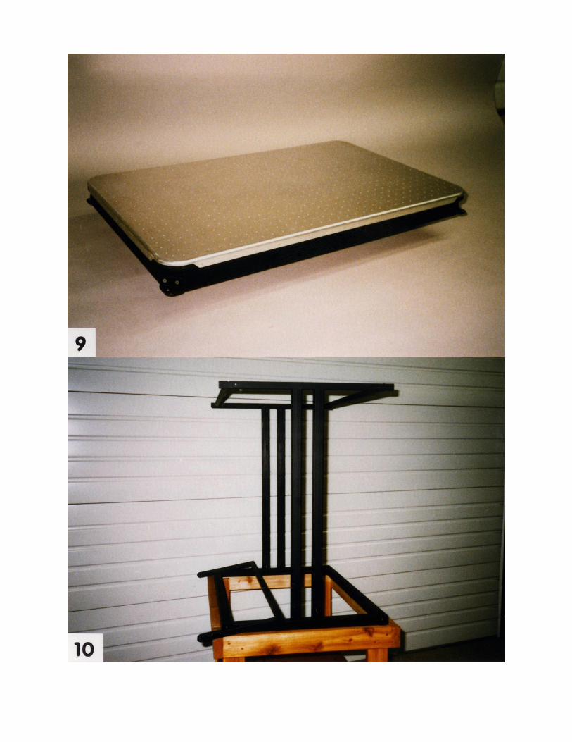
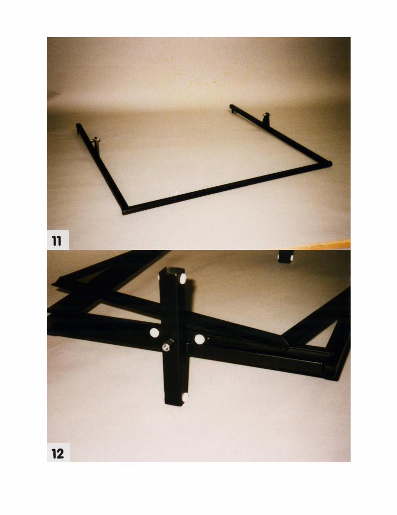
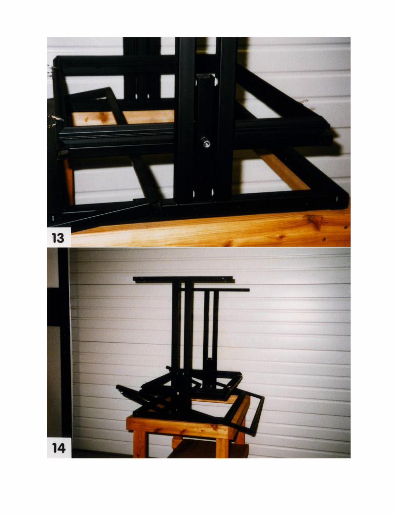
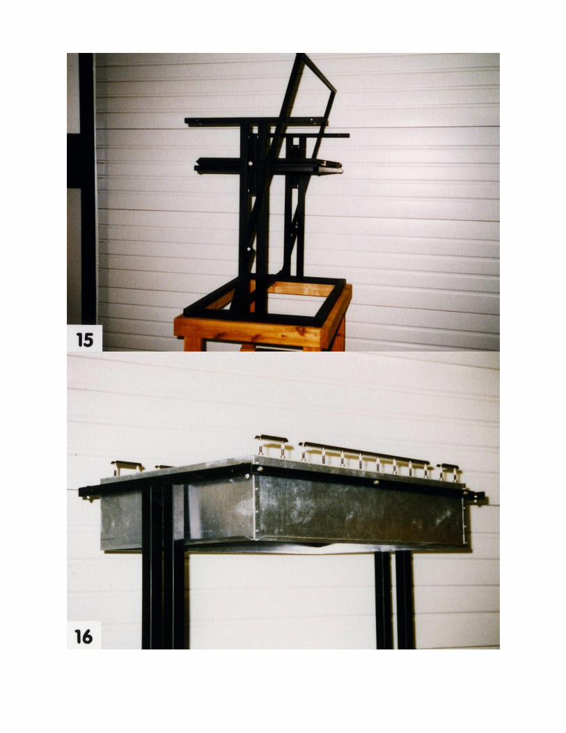
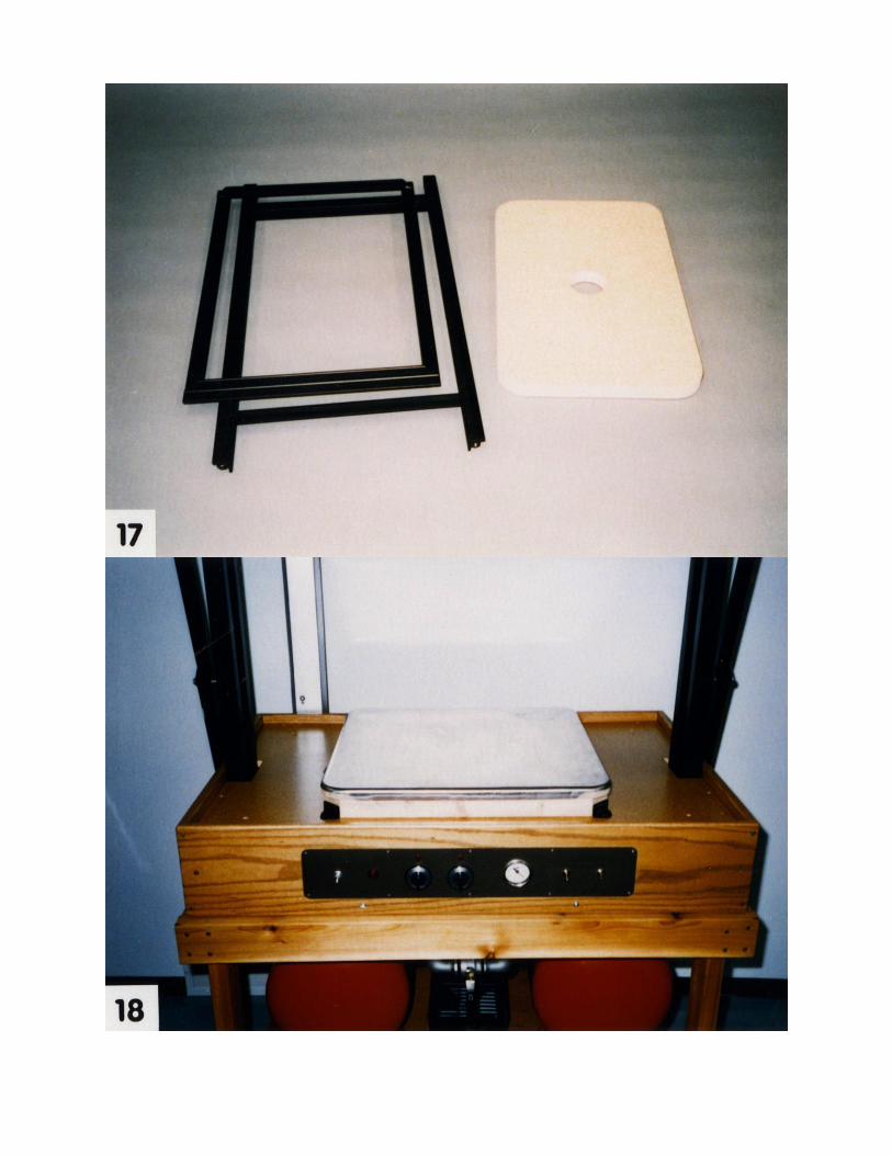
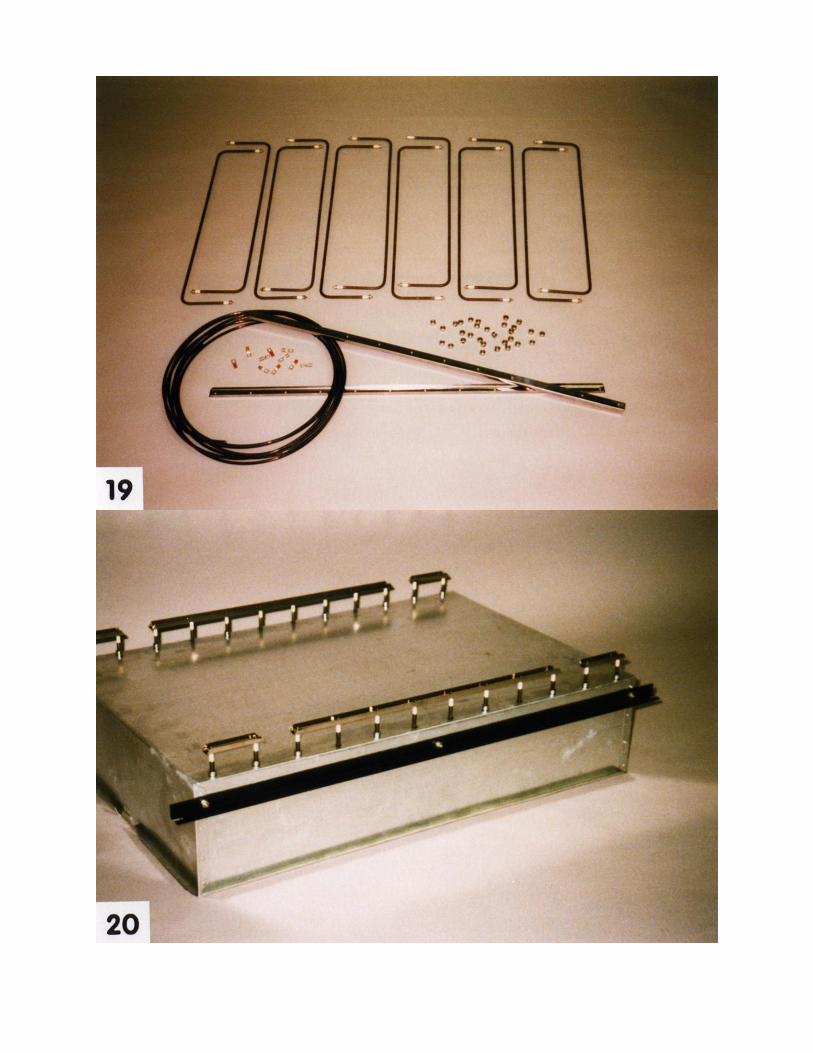
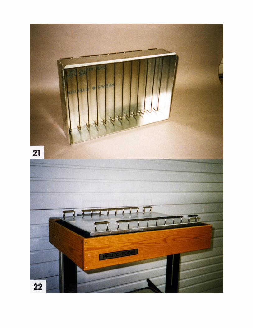
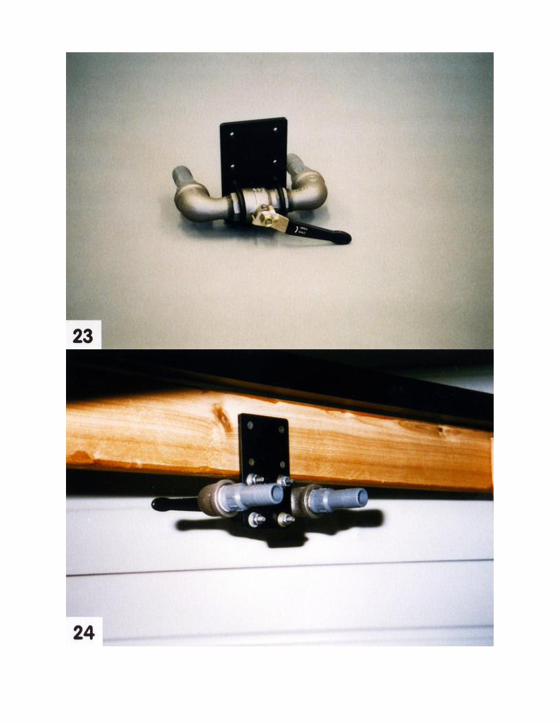
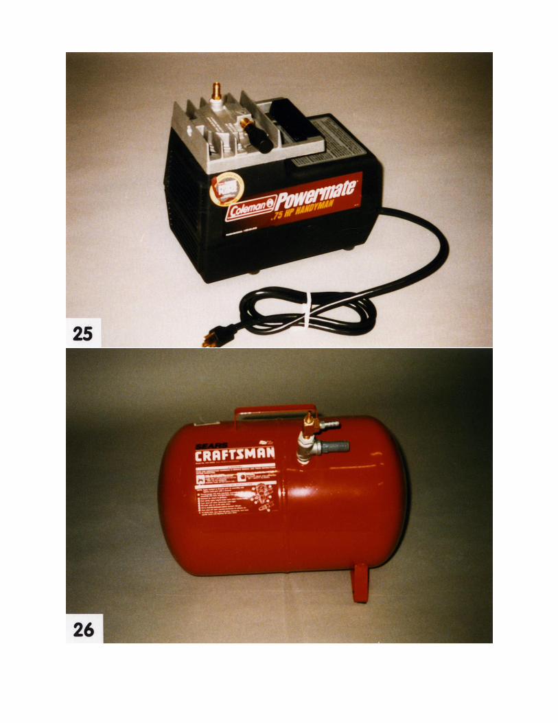
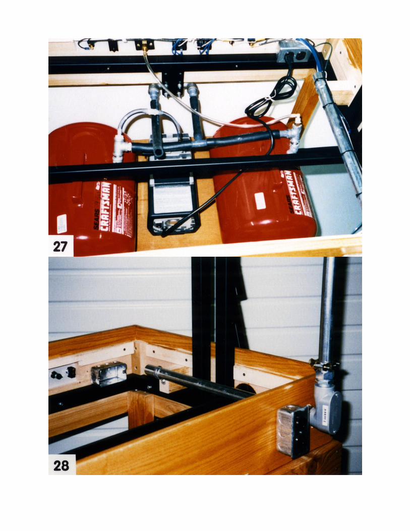
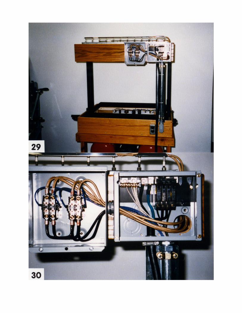

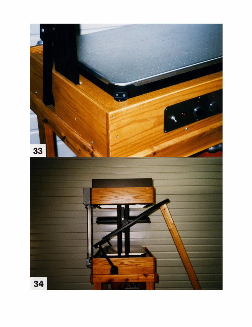
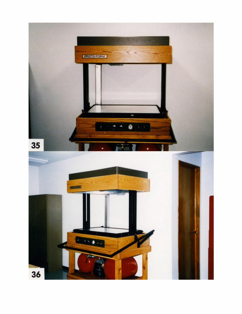
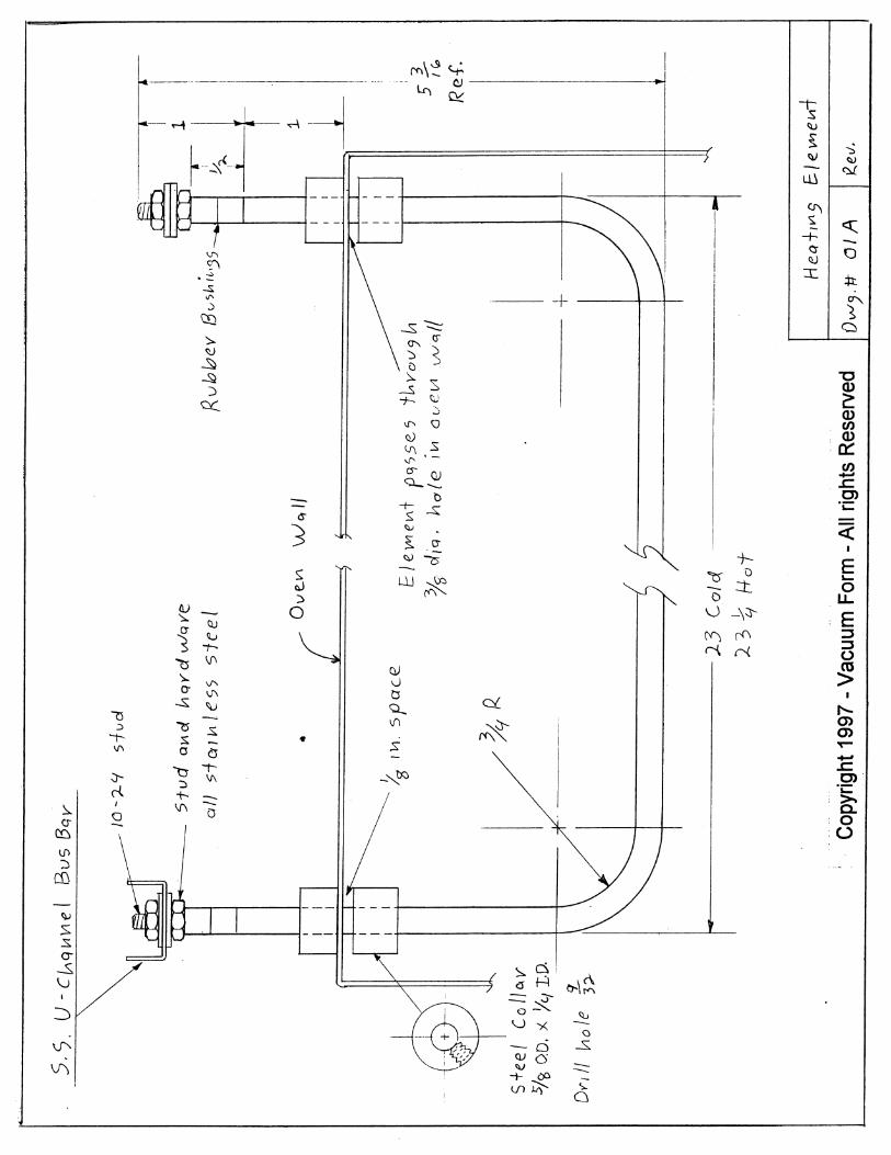
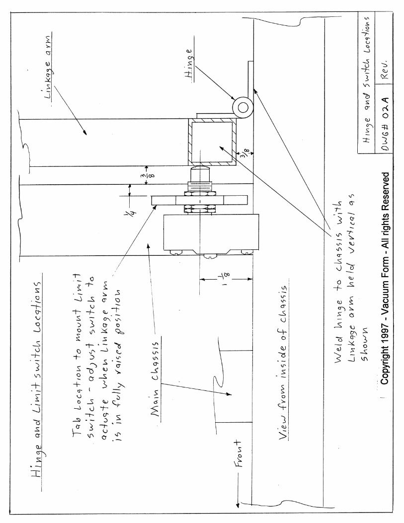
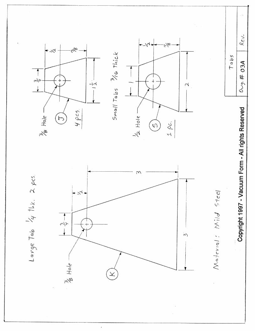
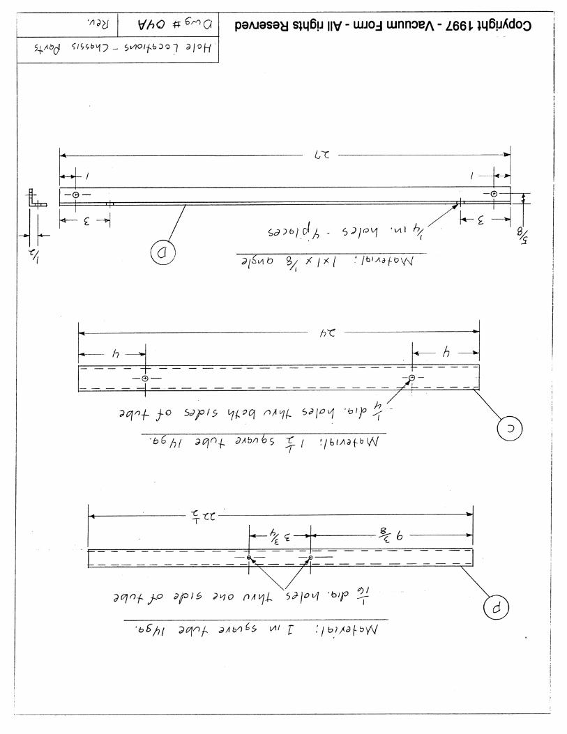
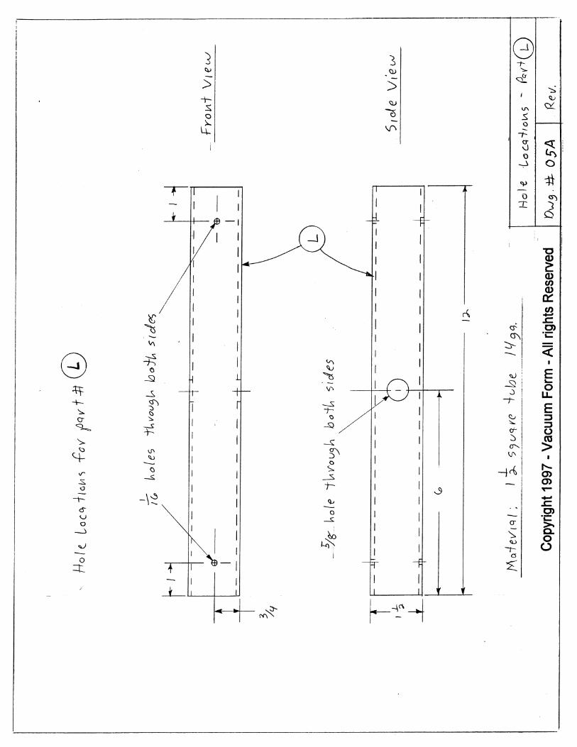
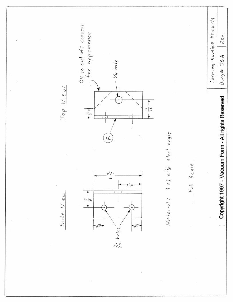
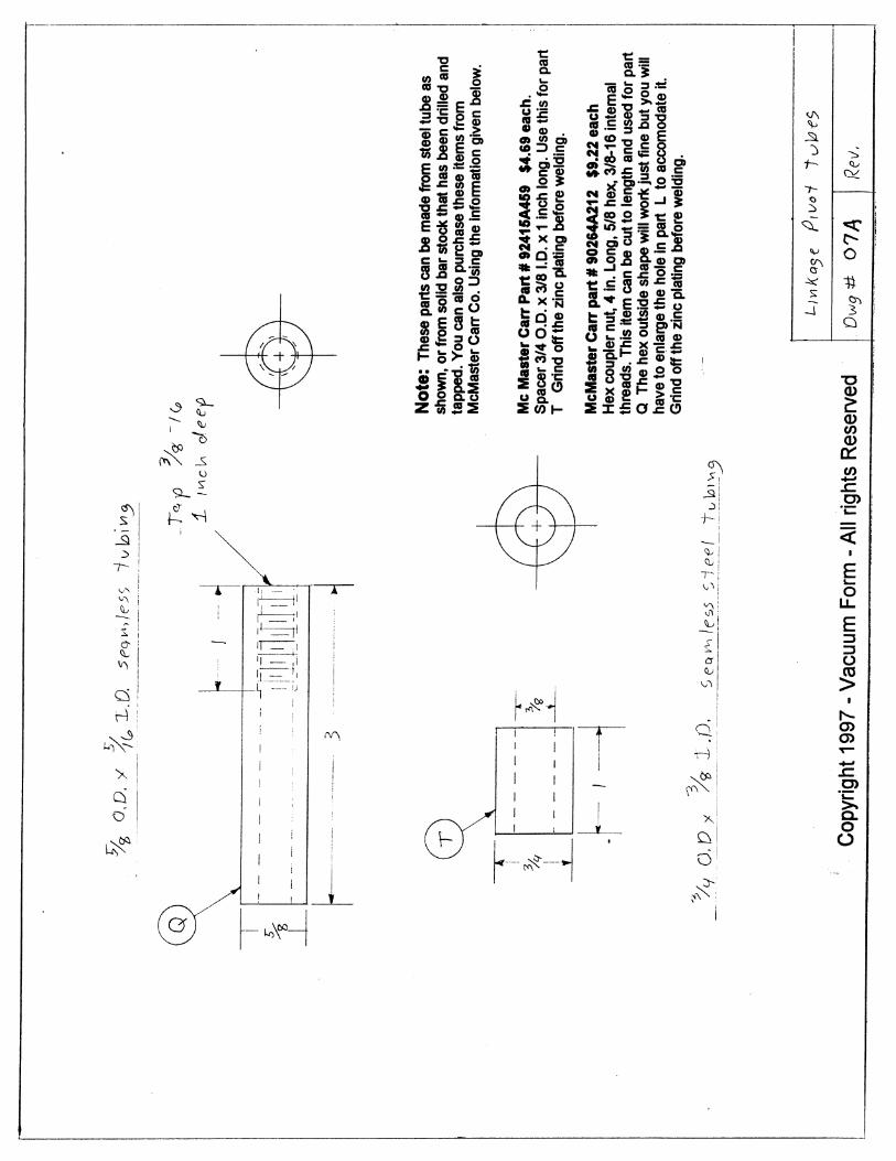
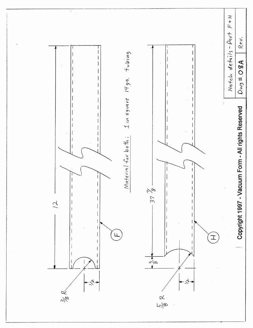
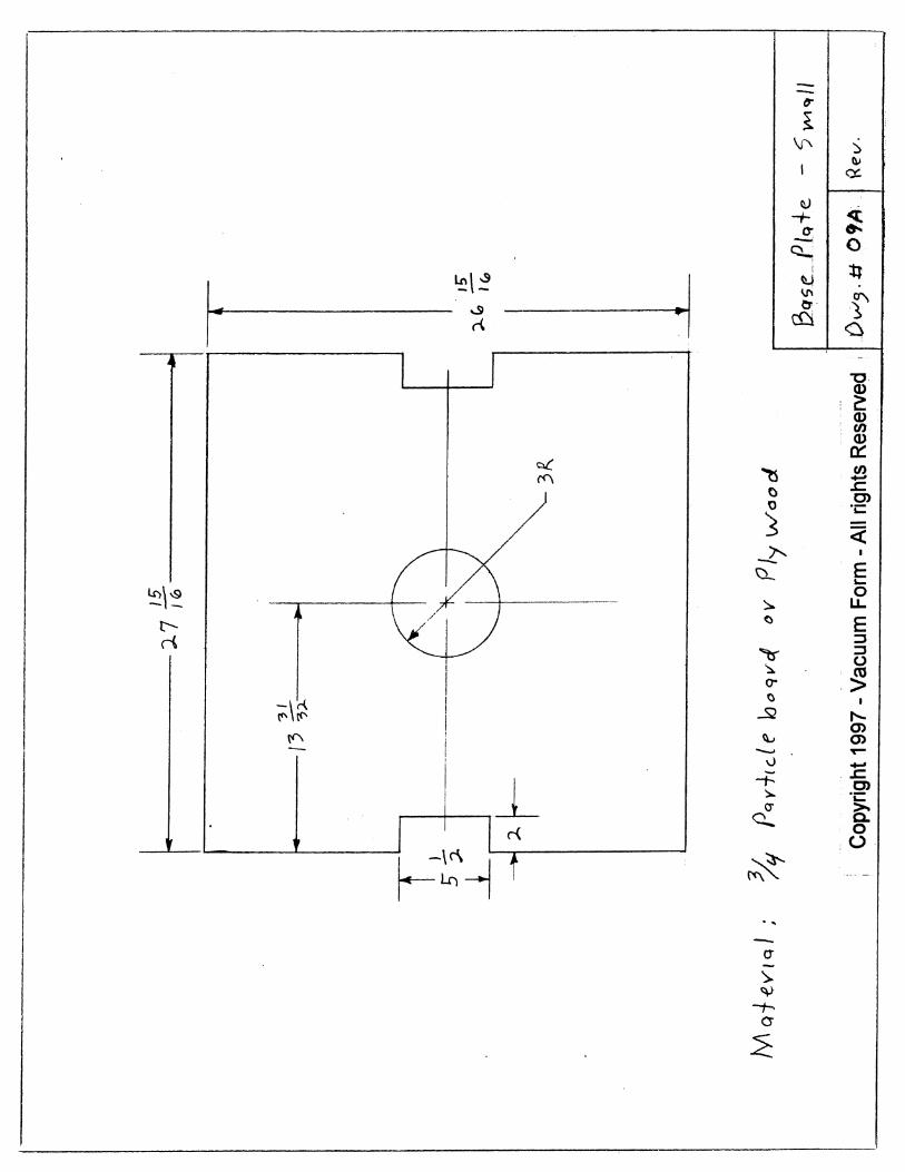
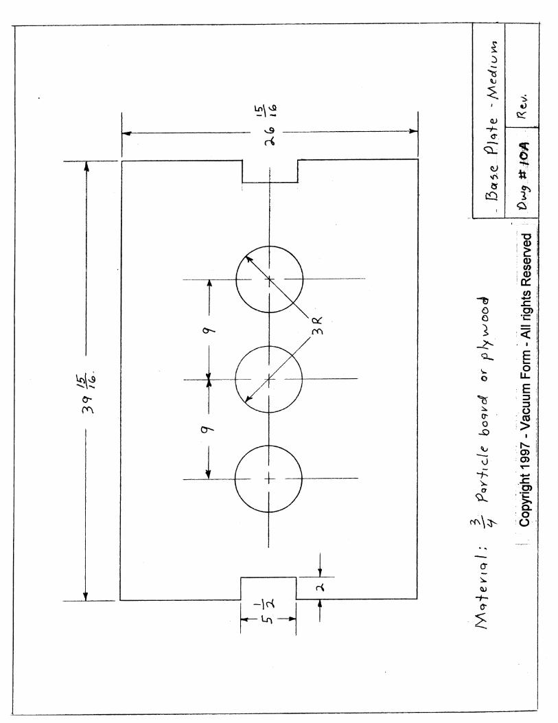
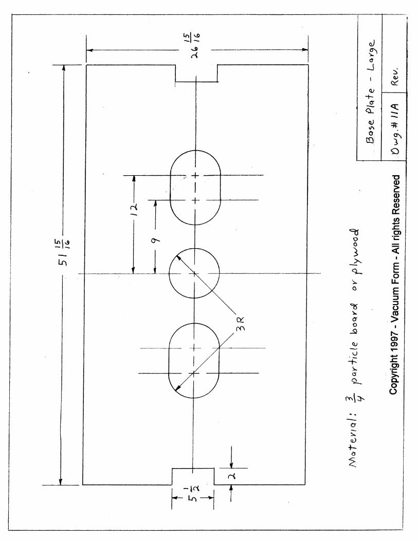
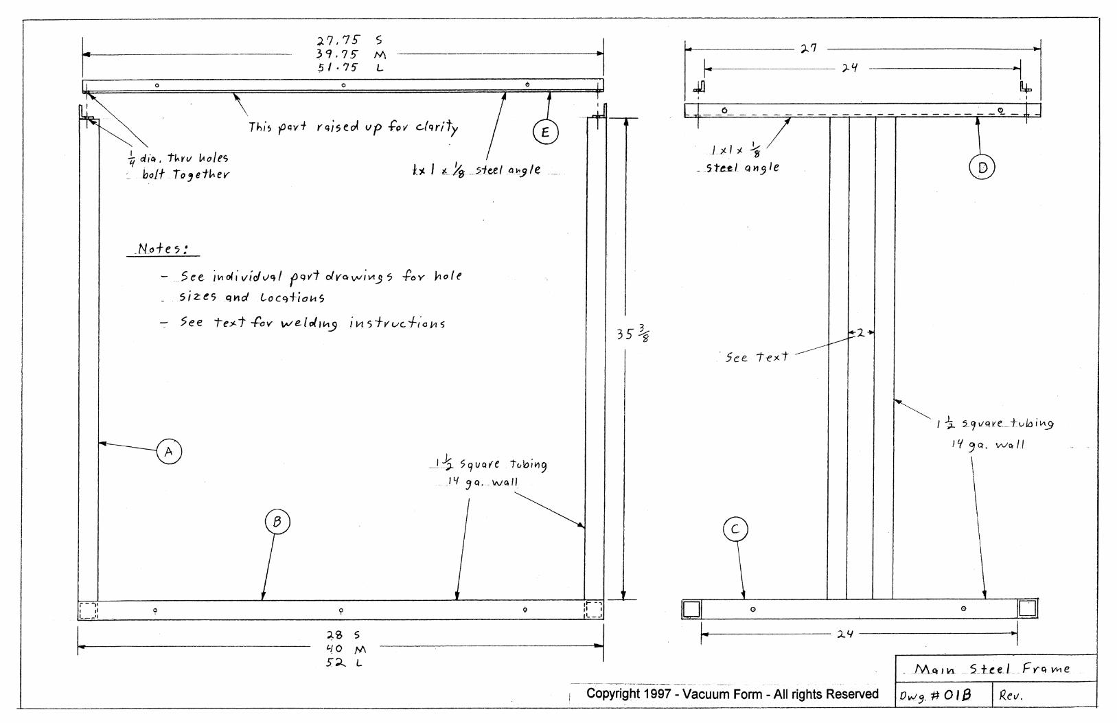
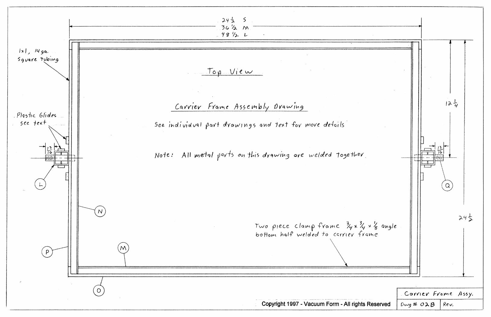
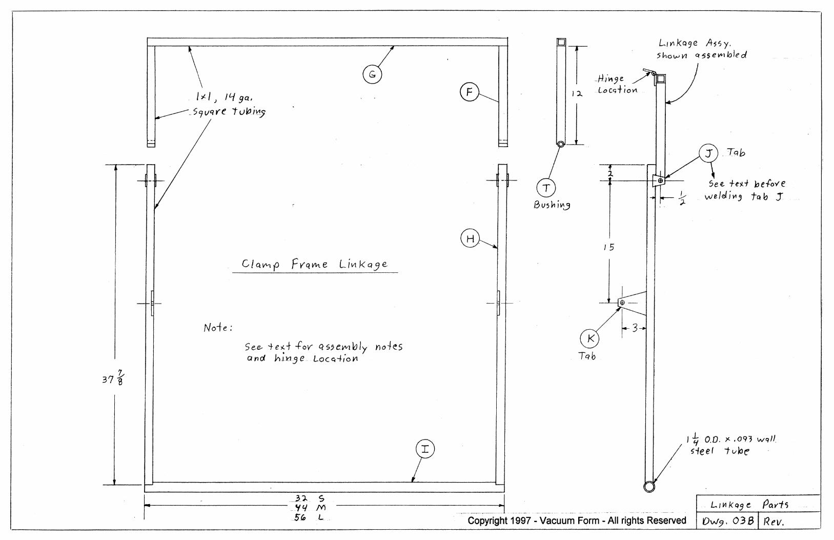
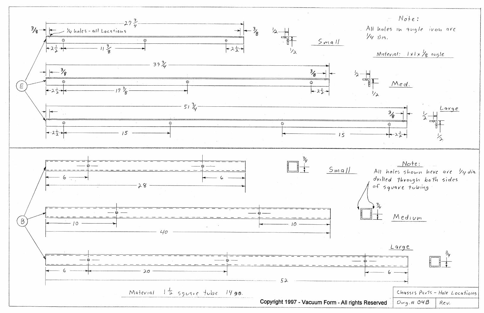
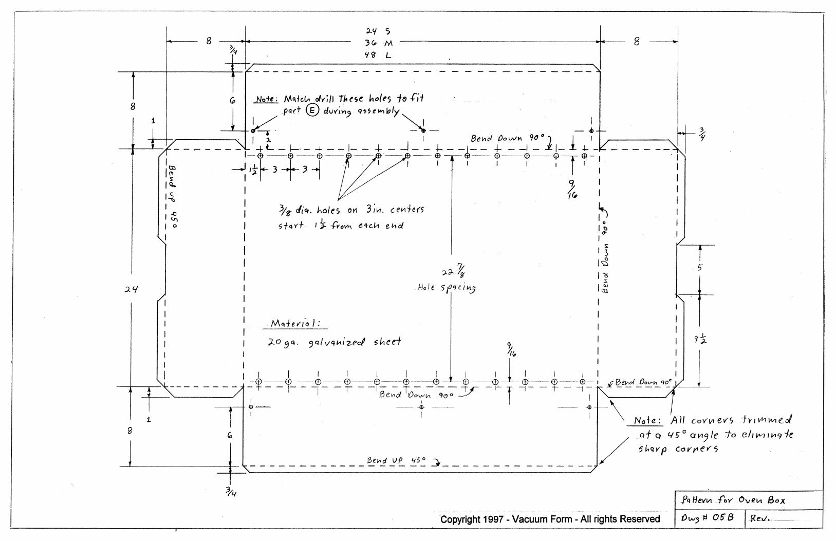
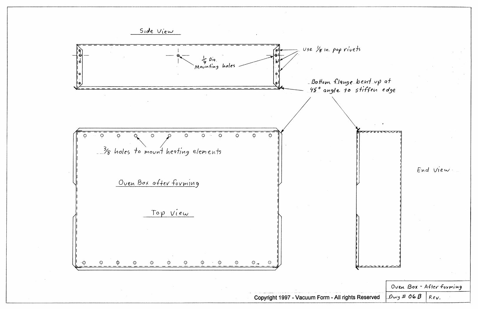
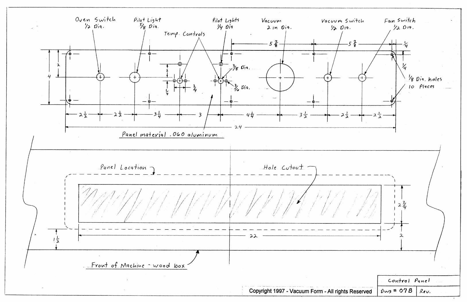
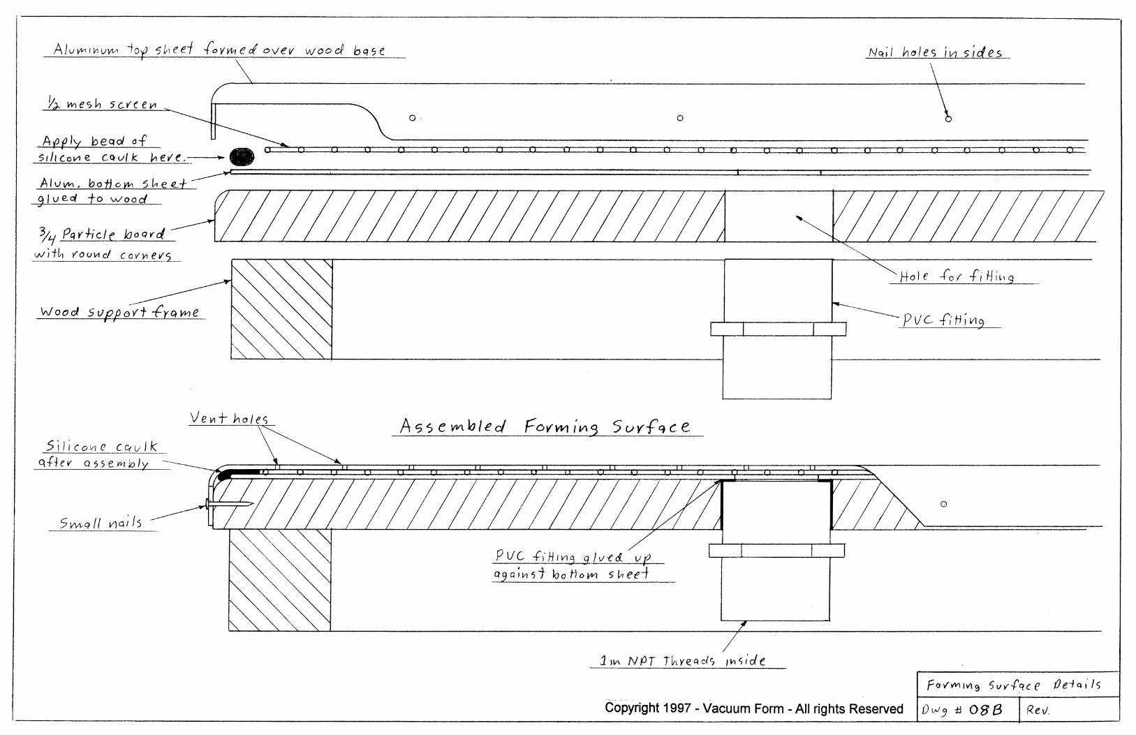
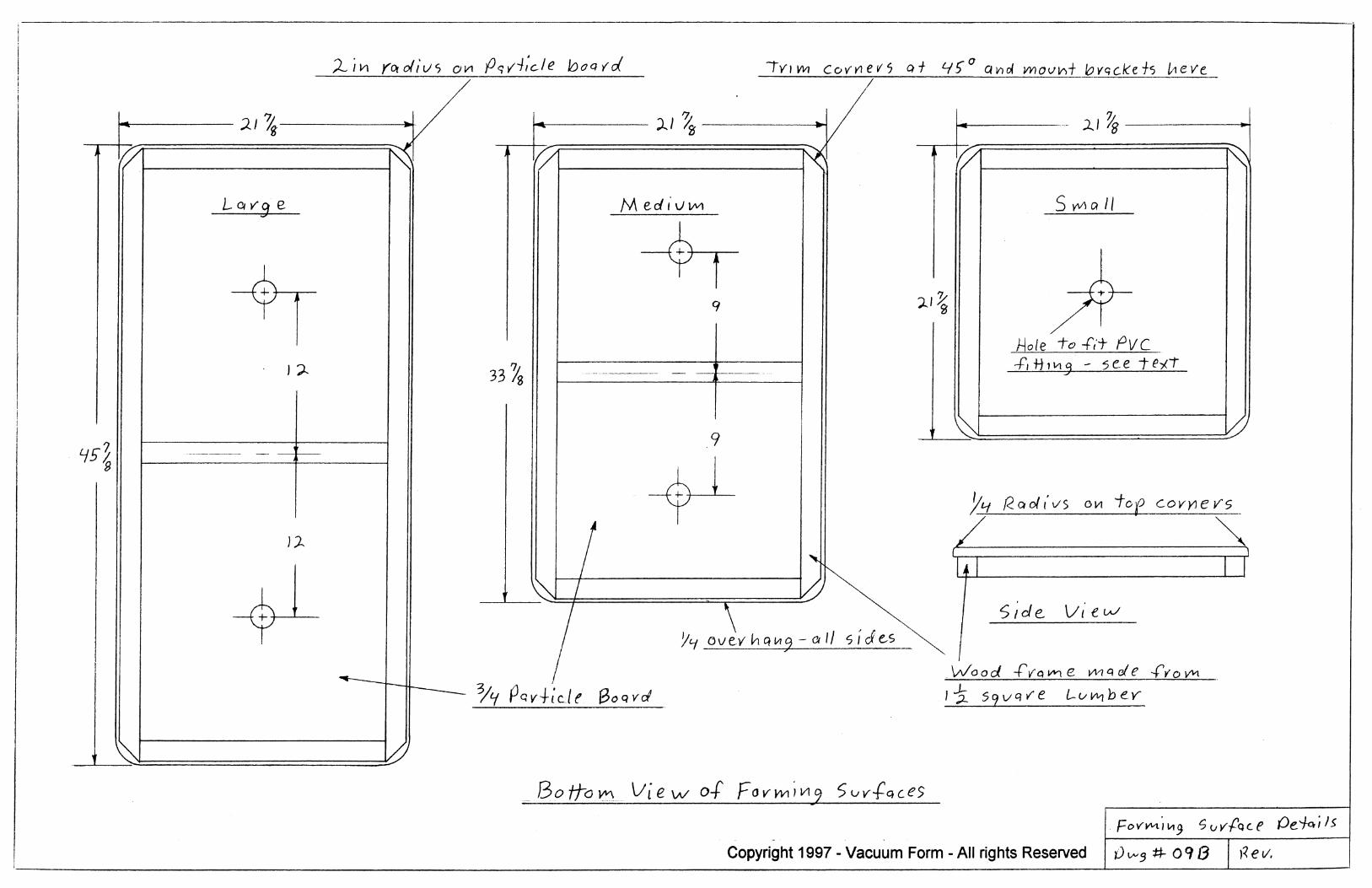
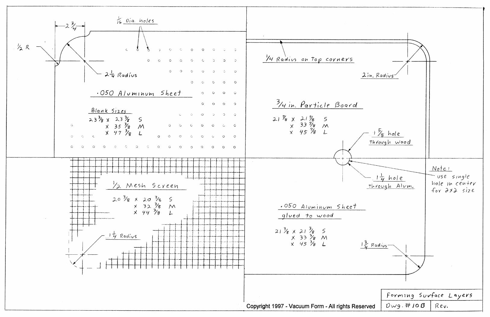
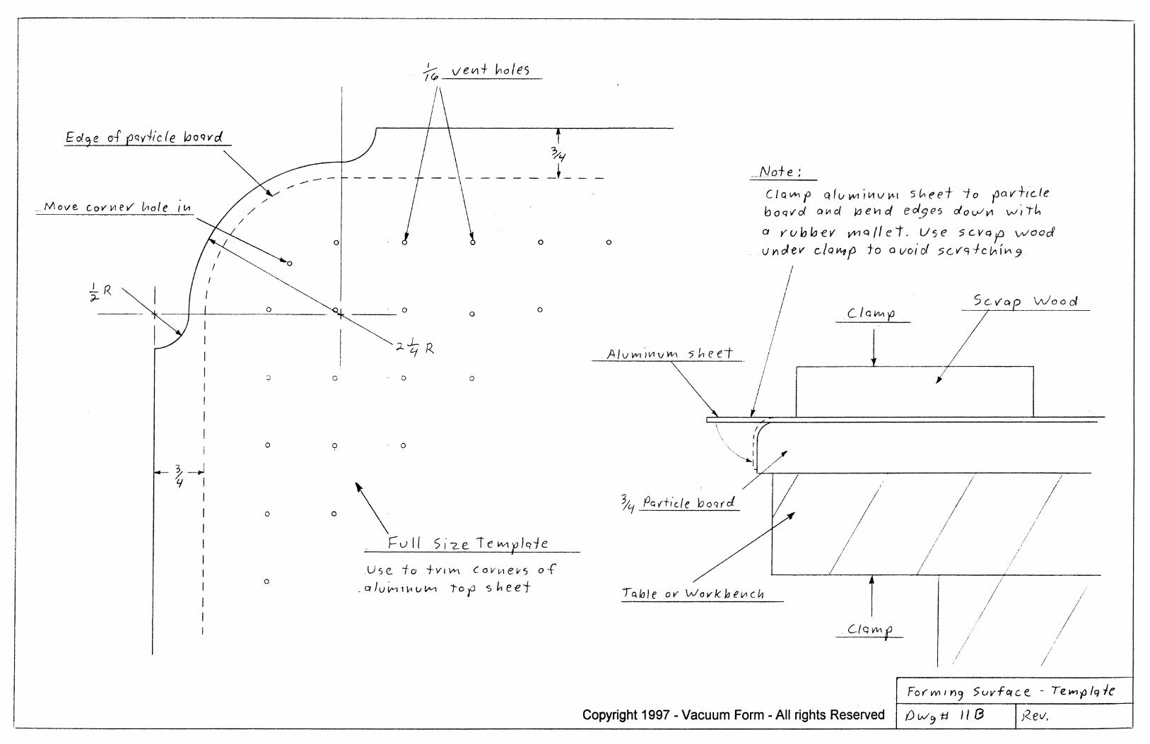
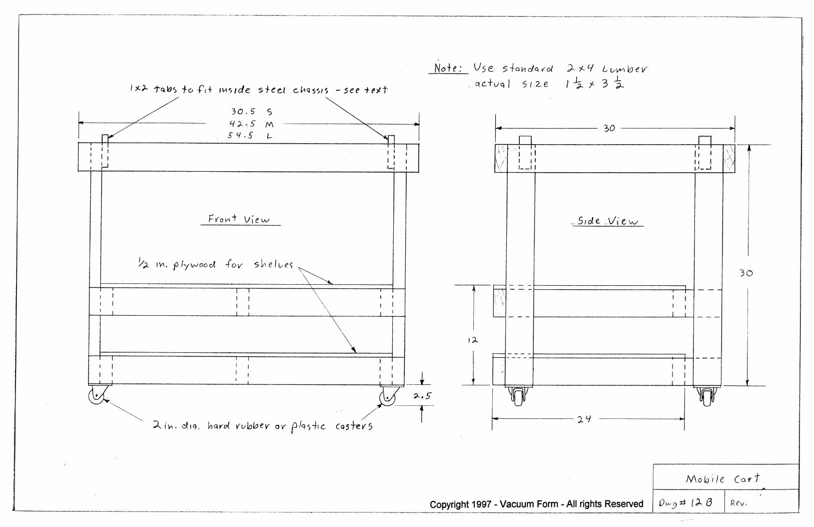
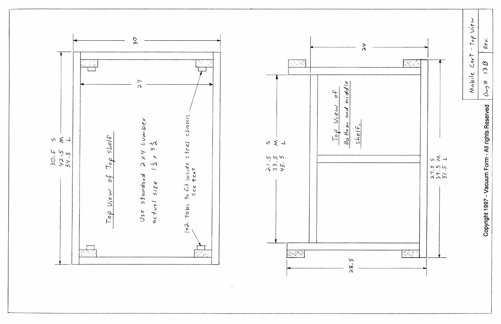
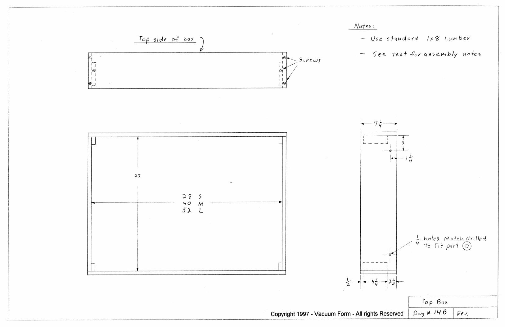
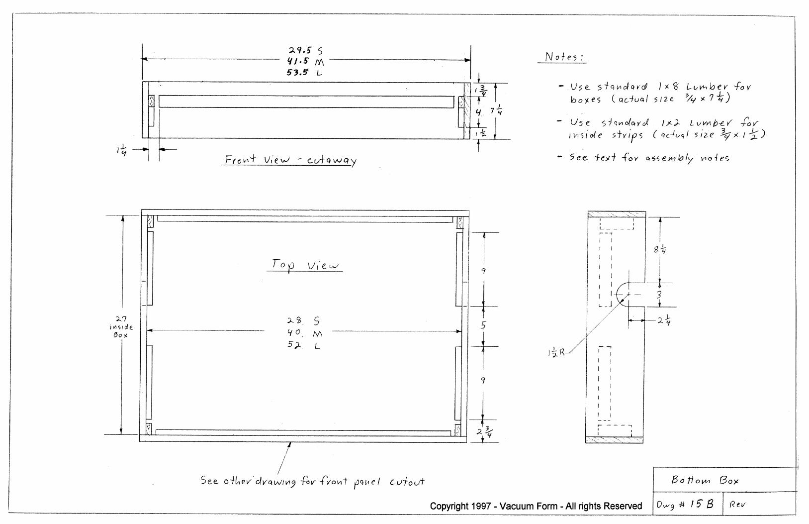
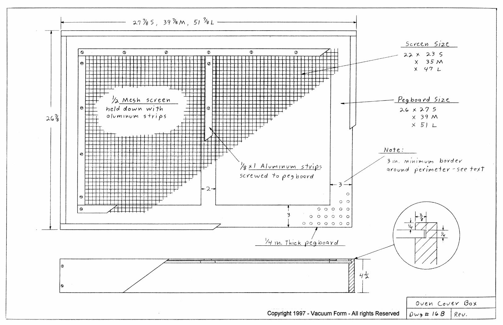
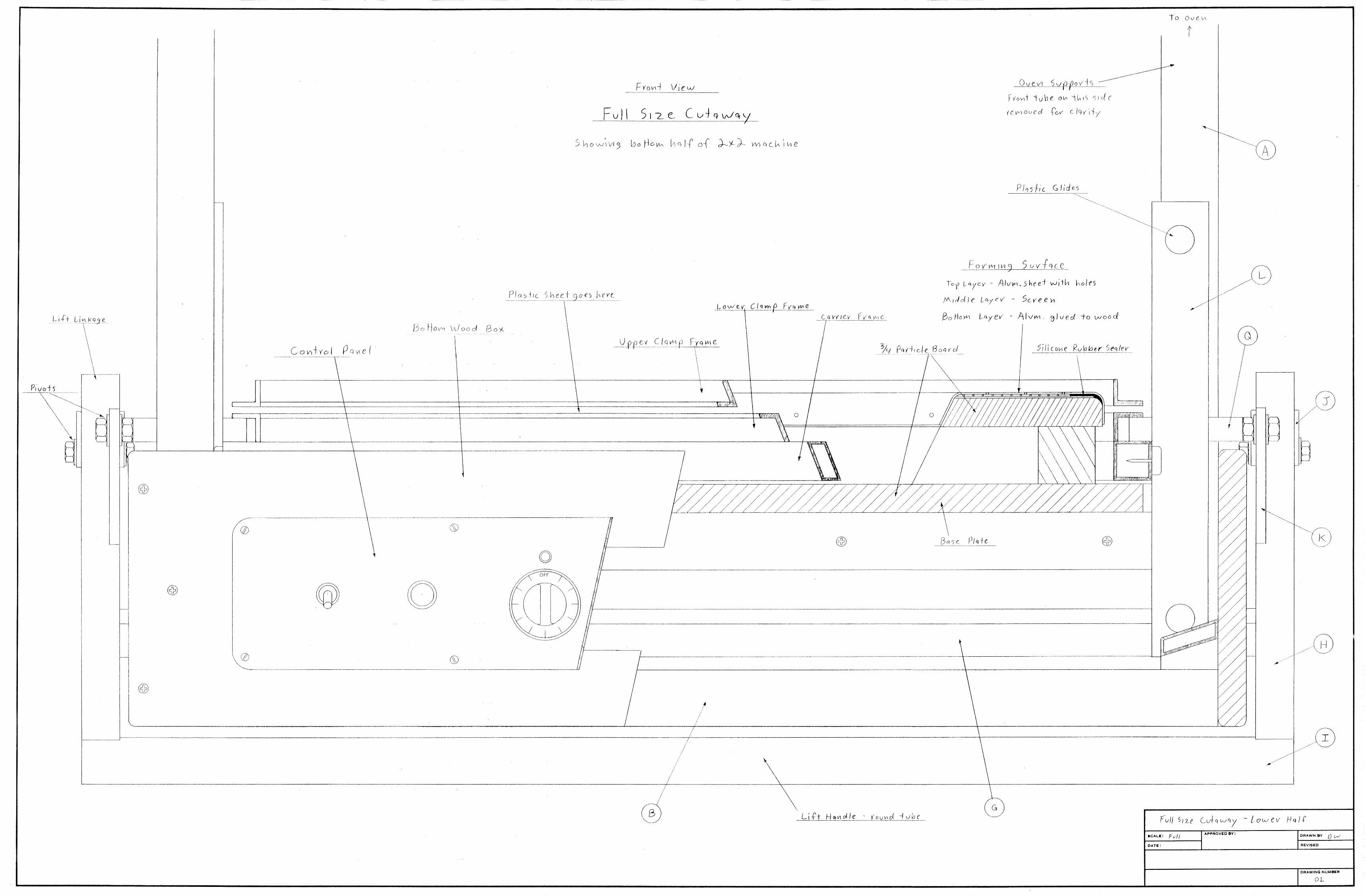
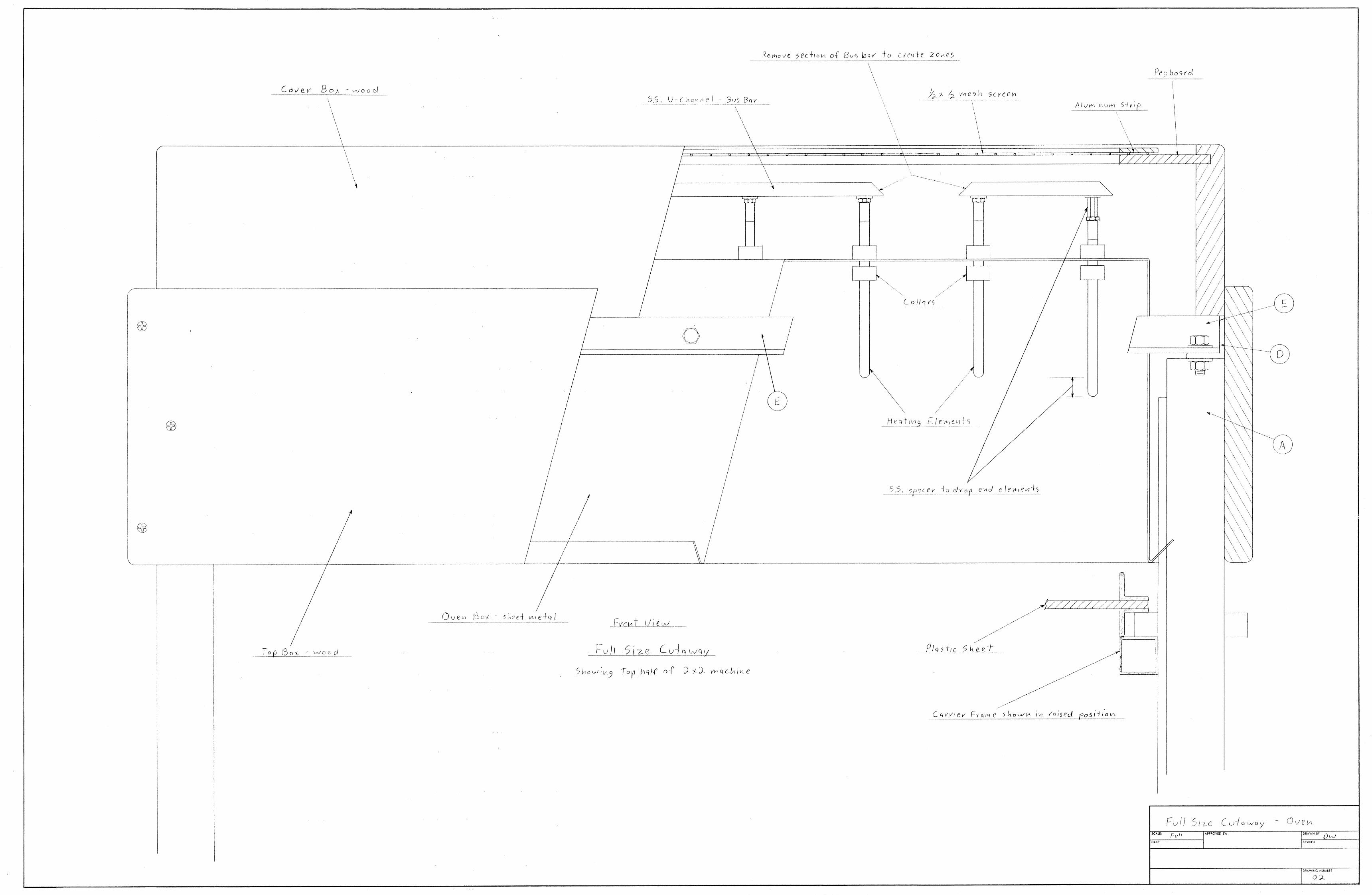
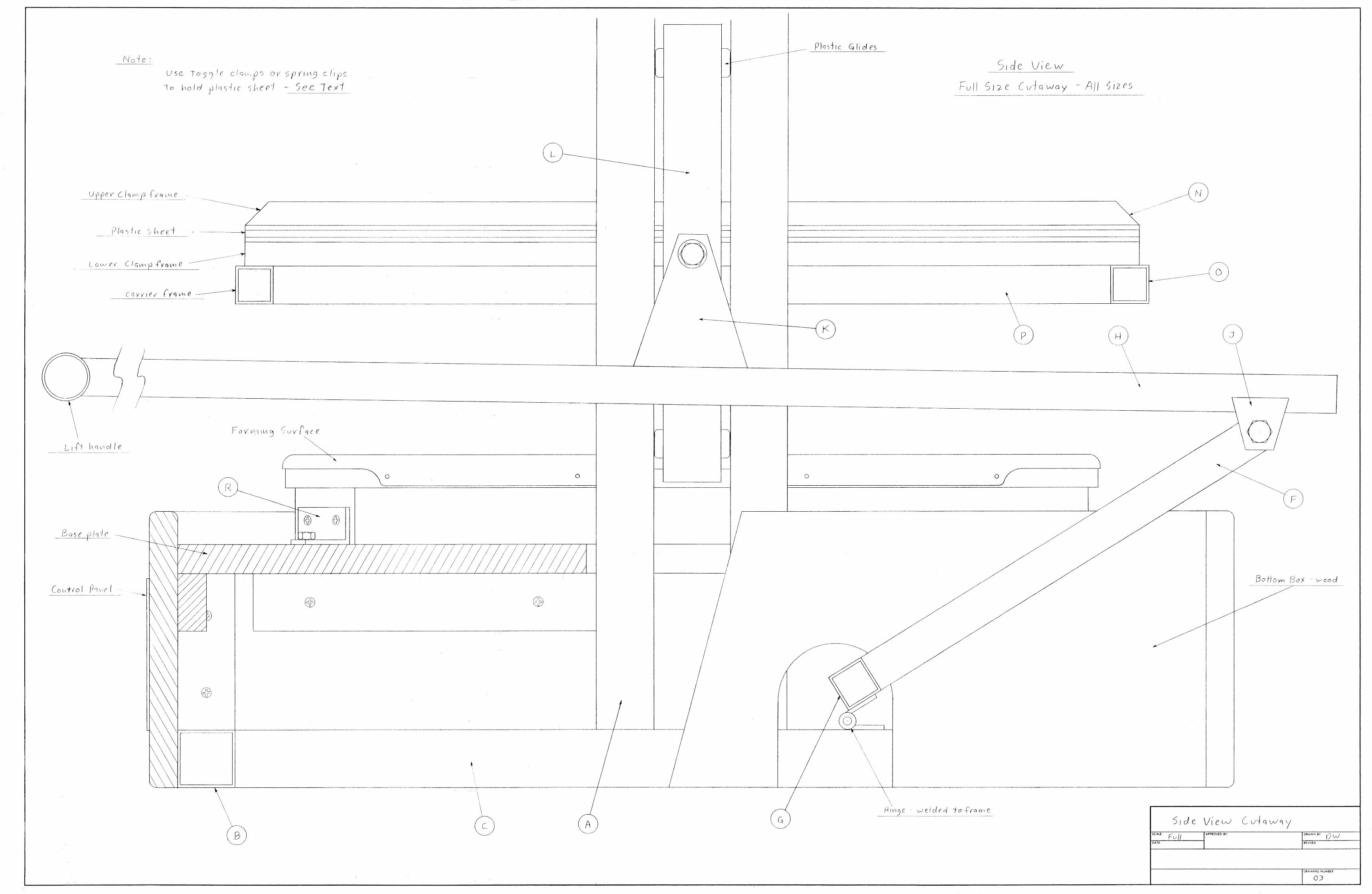

Bonus Supplement # 1
Enlarging your Proto-Form Machine
I chose 2x4 ft. as the maximum size for the Proto-Form construction plans because it was large enough to be useful to many people, but small enough that it was a practical do it yourself project. This is about the maximum size where you can still use a manual lift mechanism, and the machine needs less than 100 amps at 220 volts, so it could be used in any small business and even most houses without expensive electrical service upgrades. I always knew however, that many people would need a larger machine, and since I am the only one in the world offering construction plans, I get a lot of requests to help enlarge the design. Unfortunately, I have to resist giving specific advice about modifications I haven't tested. These Proto-Form machines were developed and reworked many times over several years. In other words, if you change too many things then you will have to work out the bugs like I did. The fact remains that these construction plans are a good starting point and many people will modify or enlarge the machine to fit their needs. The following information is all the help I can offer without building and testing everything myself. The sources in particular should be very helpful.
Enlarging the Proto-Form Oven
These elements operate at the proper infra-red wavelength for use with
plastics and it requires no temperature controls. This oven is optimized for this machine, you will be hard pressed to improve on it's performance no matter how much you spend. The oven design can be made longer by simply adding more elements to the end. You can also increase the width by another 2 ft. by adding a scond row of heating elements. The same suspended ceiling grid can be use if supported well enough to handle the final weight of the elements. The same jumpers can be used to connect elements in groups of no more than six. This will allow the use of 8 gauge TGGT wire and a 40 amp breaker and contactor for each zone.
Tips: -- You may have to rethink the entire electrical system including wire sizes, contactors and breakers if any zone exceeds six elements or 7200 watts or you go with 3 ohase power. Don't guess at this stuff, ask an electrician! -- Use only TGGT rated wire in the oven area. -- Don’t even think about trying to run these heating elements on 120 volts -- The high temperature board used with the fast heat elements is very special stuff. I have to buy 2000 lbs from outside the US to get the best material. Do not substitute similar looking materials. These boards can handle 1800 degrees.
While there are other materials, the density and thermal mass will be different and will adversly affect the infr red wavelength. -- Any attempt to substitute wire type, length or gauge will throw everything off and require a re-design.
Other oven Designs You are on your own here, there are many other types of heating elements, some have better efficiency or longer life but they all cost much more. Beware of free advice found on the internet about homebuilt oven designs. They always disregard proper design procedure and you are lucky if they just perform poorly.
You may also consider looking at some commercial machines in the size range you need. If you can copy their design so you will benefit from the "trial and error" development they went through. You may even be able to buy parts from them. Plastics will absorb infra-red heat best at certain wavelengths or temperatures, and your elements should be designed to fit this requirement. If the salesman doesn't grasp this concept, keep shopping.
Oven Controls The Proto-Form machine uses mechanical contactors and no temperature controls for cost reasons, but there is a whole world of other options available at very high prices. You can easily double the cost of your machine with fancy controls. If an oven is properly designed and tuned, you don't really need any controls. I think most ovens are thrown together and then forced to work properly with over priced electronics. For instance, if you get the watt density and infra-red wavelength right then you don't need to control the temperature. Be aware that when a salesman helps you select components, he will usually go with more watt density and zones to make sure it works and then fine tune it with expensive controls. This is because he doesn't have the luxury of trial and error. Some people just like to turn knobs and prefer to have adjustability. The most cost effective improvement you can make is to substitute mercury relays for the mechanical contactors. These are about double the cost but have a much longer life.
Modifying the Chassis
Sorry, I'm not much help here either. If you stray too far from the construction plans, you will have to re-think almost every part. Depending on the size, you could probably just increase tubing sizes and reinforce things a bit, but you will almost certainly have to abandon the manual lift mechanism and use some kind of power assist if you go much larger The challenge here is to move the clamp frame fast enough and with a fair amount of force near the bottom, all while keeping the clamp frame level.
You will need to transport the plastic in around 1 or 2 seconds to keep it from cooling. If you are forming deep draws in thicker plastics, You will need a fair amount of force to stretch the plastic sheet. There are no rules for this, just trial and error. If your mold is not in the center of the table, the frame will have a strong tendency to cock and possibly jam, so its important to keep the frame level as it moves.
Tips: -- You might consider some kind of mechanical drive with a gear motor, chain and sprockets. This would guarantee alignment. -- You might be able to use hydraulics with special valving to synchronize two cylinders, one on each side. -- I doubt if pneumatics would be appropriate because air is compressible and would result in a springy action, with difficulty synchronizing the two cylinders. If you come up with a good system, please call me and I will share it with other builders.
Enlarging the Vacuum System The information in the plans can be scaled up with good results. Increase the size of all components, including tank, pump, valve, hoses etc.. You can verify your choices by checking commercial equipment of the same size. Component sizing depends partly on your application, there is no avoiding the trial and error process here!
Enlarging the Platen The plans show an excellent low volume platen that can be scaled up to any size, and you can make extra ones for smaller sheets. The whole platen is removable so you can use your own special tooling if needed. You will have to use multiple fittings on the bottom to distribute vacuum over the larger area.
Vacuum Components The construction plans gives sources for vacuum pumps up to 21 CFM., as well as storage tanks, you can use multiple pumps and tanks or order larger ones if needed. The same chapter also gives the names of two large maunfactures of vacuum pumps.
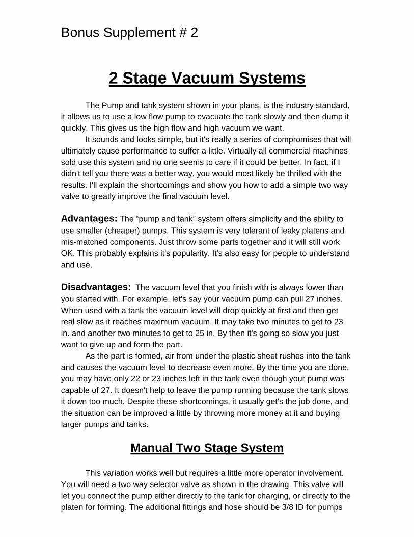
Bonus Supplement # 2
2 Stage Vacuum Systems
The Pump and tank system shown in your plans, is the industry standard,
it allows us to use a low flow pump to evacuate the tank slowly and then dump it
quickly. This gives us the high flow and high vacuum we want.
It sounds and looks simple, but it's really a series of compromises that will
ultimately cause performance to suffer a little. Virtually all commercial machines
sold use this system and no one seems to care if it could be better. In fact, if I
didn't tell you there was a better way, you would most likely be thrilled with the
results. I'll explain the shortcomings and show you how to add a simple two way
valve to greatly improve the final vacuum level.
Advantages: The “pump and tank” system offers simplicity and the ability to
use smaller (cheaper) pumps. This system is very tolerant of leaky platens and
mis-matched components. Just throw some parts together and it will still work
OK. This probably explains it's popularity. It's also easy for people to understand
and use.
Disadvantages: The vacuum level that you finish with is always lower than
you started with. For example, let's say your vacuum pump can pull 27 inches.
When used with a tank the vacuum level will drop quickly at first and then get
real slow as it reaches maximum vacuum. It may take two minutes to get to 23
in. and another two minutes to get to 25 in. By then it's going so slow you just
want to give up and form the part.
As the part is formed, air from under the plastic sheet rushes into the tank
and causes the vacuum level to decrease even more. By the time you are done,
you may have only 22 or 23 inches left in the tank even though your pump was
capable of 27. It doesn't help to leave the pump running because the tank slows
it down too much. Despite these shortcomings, it usually get's the job done, and
the situation can be improved a little by throwing more money at it and buying
larger pumps and tanks.
Manual Two Stage System
This variation works well but requires a little more operator involvement.
You will need a two way selector valve as shown in the drawing. This valve will
let you connect the pump either directly to the tank for charging, or directly to the
platen for forming. The additional fittings and hose should be 3/8 ID for pumps
up to around 10 CFM, and 1/2in. ID. For pumps over 10 CFM. The ball valve and
it's plumbing remain the same as before. McMaster Carr Co. has some selector
valves that will work well. These can mount on the pump or on the front panel.
You will have to get the appropriate barb fittings to fit your hoses.
3/8in ID. Part # 46095K43 $27.85 or 1/2in. ID. Part# 46095K44 $29.89
Your vacuum pump will now have a second small hose that needs to tap
in anywhere between the ball valve and platen. You can use a tee fitting at the
platen as shown, or a tee fitting at the ball valve. Use which ever method results
in shorter hoses. It's very important to keep internal hose volumes low for
fast response time.
Operation of Manual System
1 -- Move the selector valve to the tank position and close the ball valve. Run the
pump to evacuate the tank. The tank is only acting as the first stage now and you
don't need as much vacuum, 15 to 20 inches is plenty. In fact, you could even
use a smaller tank. Turn the pump off and move the selector valve to the “platen”
position, this traps vacuum in the tank.
2 -- When the plastic is ready to form, turn on the pump and leave it running
while you lower the clamp frame.
3 -- When the plastic seals to the platen, open the ball valve for about one
second and then close it. this action removes most of the air and then leaves the
pump connected directly to the platen so it can pull it's full rated vacuum. If you
don't close the ball valve then the second stage won’t work. Now the pump can
pull directly against the plastic without the tank in the circuit. Provided there are
no leaks, it will finish off at it’s maximum vacuum level.
Advantages: The addition of this simple selector valve improves the
performance of any tank type system by increasing the final vacuum level. You
can also use a smaller tank if you recharge it more frequently. You can use the
second stage all the time or just when you need it.
Disadvantages: A little more operator involvement. Your vacuum system
must also be leak free and the hoses should be kept short for best results.


