Embed Size (px)
Citation preview
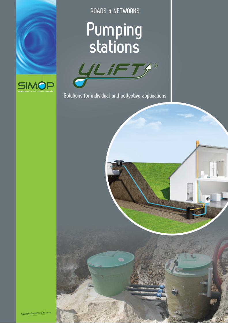
Pumping stations
Solutions for individual and collective applications
ROADS & NETWORKS
SIMOP 10 rue Richedoux 50480 SAINTE-MÈRE-ÉGLISE – FRANCE – Tel. +33 (0)2 33 95 88 00 – Fax +33 (0)2 33 21 50 75www.simop.fr – e-mail: [email protected] document. All dimensions (in mm) are provided for reference only and are subject to change without prior notice.
SIMOP 10 rue Richedoux 50480 SAINTE-MÈRE-ÉGLISE – FRANCE – Tel. +33 (0)2 33 95 88 00 – Fax +33 (0)2 33 21 50 75www.simop.fr – e-mail: [email protected]
Non-contractual document. All dimensions (in mm) are provided for reference only and are subject to change without prior notice. 32
Rotational moulded partRotational moulding
Maxylift pumping stationFilament winding
OUR PRODUCT ADVANTAGES
40 YEARS' EXPERIENCE IN R&D
SIMOP is a leading company with international coverage and 35 years of expertise. Our design department continuously strives to be at the cutting edge of new technology, relying on a strong innovative spirit. Our extensive R&D work allows us to continually upgrade our existing product line, market reliable and sustainable solutions that contribute to improving the environment and patenting processes..
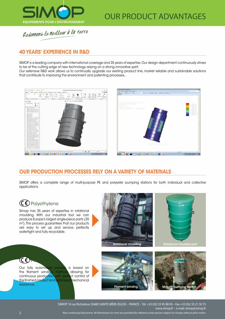
OUR PRODUCTION PROCESSES RELY ON A VARIETY OF MATERIALS
SIMOP offers a complete range of multi-purpose PE and polyester pumping stations for both individual and collective applications.
PolyethyleneSimop has 35 years of expertise in rotational moulding. With our industrial tool we can produce Europe's largest single-piece parts (35 m3). This process guarantees that our products are easy to set up and service, perfectly watertight and fully recyclable.
PolyesterOur fully automated process is based on the filament winding method, allowing for continuous production with perfect control of the finished product and optimised mechanical resistance.
SIMOP 10 rue Richedoux 50480 SAINTE-MÈRE-ÉGLISE – FRANCE – Tel. +33 (0)2 33 95 88 00 – Fax +33 (0)2 33 21 50 75www.simop.fr – e-mail: [email protected] document. All dimensions (in mm) are provided for reference only and are subject to change without prior notice.
SIMOP 10 rue Richedoux 50480 SAINTE-MÈRE-ÉGLISE – FRANCE – Tel. +33 (0)2 33 95 88 00 – Fax +33 (0)2 33 21 50 75www.simop.fr – e-mail: [email protected]
Non-contractual document. All dimensions (in mm) are provided for reference only and are subject to change without prior notice. 32
4
OUR PRODUCT ADVANTAGES
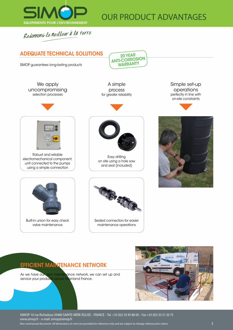
EFFICIENT MAINTENANCE NETWORKAs we have our own maintenance network, we can set up and service your products across Mainland France.
We apply uncompromising
selection processes
Simple set-up operations
perfectly in line with on-site constraints
A simple process
for greater reliability
Easy drilling on site using a hole saw
and seal (included)
Robust and reliable electromechanical component,
unit connected to the pumps using a simple connection
Built-in union for easy check valve maintenance
Sealed connectors for easier maintenance operations
ADEQUATE TECHNICAL SOLUTIONS
SIMOP guarantees long-lasting products
20 YEARANTI-CORROSION
WARRANTY
SIMOP 10 rue Richedoux 50480 SAINTE-MÈRE-ÉGLISE – FRANCE – Tel. +33 (0)2 33 95 88 00 – Fax +33 (0)2 33 21 50 75www.simop.fr – e-mail: [email protected] document. All dimensions (in mm) are provided for reference only and are subject to change without prior notice.
SIMOP 10 rue Richedoux 50480 SAINTE-MÈRE-ÉGLISE – FRANCE – Tel. +33 (0)2 33 95 88 00 – Fax +33 (0)2 33 21 50 75www.simop.fr – e-mail: [email protected]
Non-contractual document. All dimensions (in mm) are provided for reference only and are subject to change without prior notice. 54
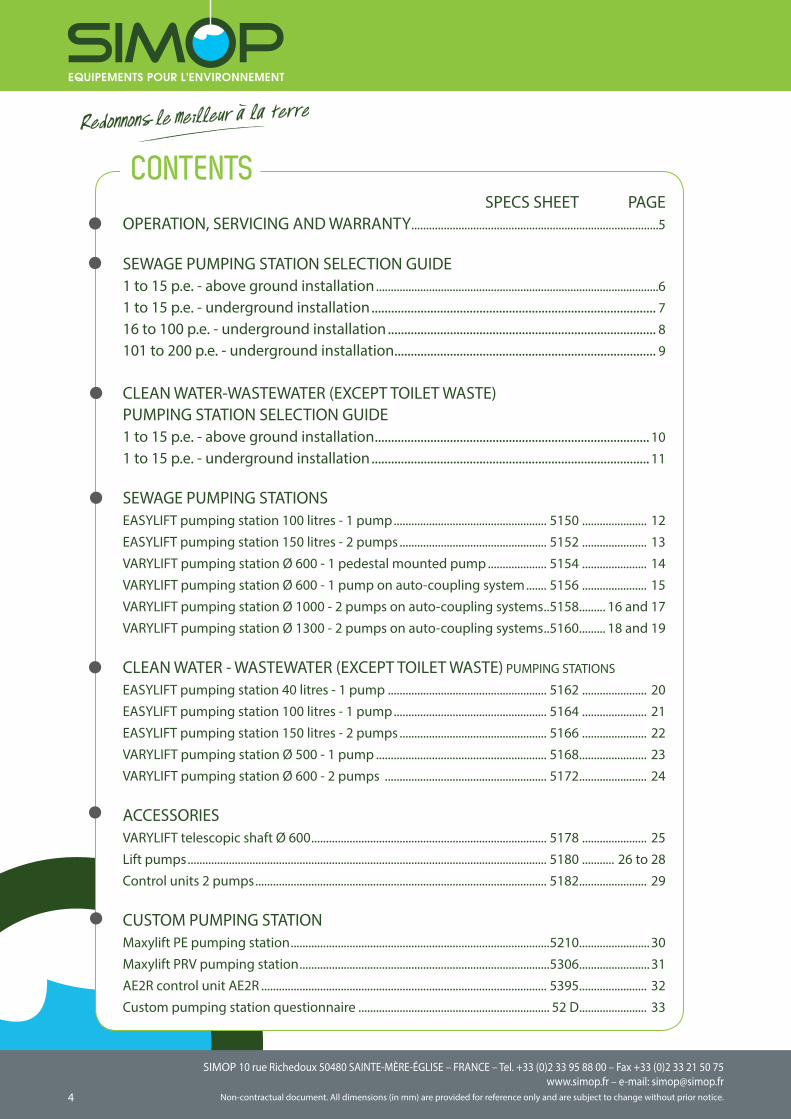
CONTENTS SPECS SHEET PAGEOPERATION, SERVICING AND WARRANTY ....................................................................................5
SEWAGE PUMPING STATION SELECTION GUIDE1 to 15 p.e. - above ground installation ................................................................................................61 to 15 p.e. - underground installation ....................................................................................... 716 to 100 p.e. - underground installation .................................................................................. 8101 to 200 p.e. - underground installation ................................................................................ 9 CLEAN WATER-WASTEWATER (EXCEPT TOILET WASTE) PUMPING STATION SELECTION GUIDE1 to 15 p.e. - above ground installation .................................................................................... 101 to 15 p.e. - underground installation ..................................................................................... 11
SEWAGE PUMPING STATIONSEASYLIFT pumping station 100 litres - 1 pump .................................................... 5150 ...................... 12EASYLIFT pumping station 150 litres - 2 pumps .................................................. 5152 ...................... 13VARYLIFT pumping station Ø 600 - 1 pedestal mounted pump .................... 5154 ...................... 14VARYLIFT pumping station Ø 600 - 1 pump on auto-coupling system ....... 5156 ...................... 15VARYLIFT pumping station Ø 1000 - 2 pumps on auto-coupling systems ..5158 ......... 16 and 17VARYLIFT pumping station Ø 1300 - 2 pumps on auto-coupling systems ..5160 ......... 18 and 19
CLEAN WATER - WASTEWATER (EXCEPT TOILET WASTE) PUMPING STATIONS
EASYLIFT pumping station 40 litres - 1 pump ...................................................... 5162 ...................... 20EASYLIFT pumping station 100 litres - 1 pump .................................................... 5164 ...................... 21EASYLIFT pumping station 150 litres - 2 pumps .................................................. 5166 ...................... 22VARYLIFT pumping station Ø 500 - 1 pump .......................................................... 5168 ....................... 23VARYLIFT pumping station Ø 600 - 2 pumps ....................................................... 5172 ....................... 24
ACCESSORIESVARYLIFT telescopic shaft Ø 600 ................................................................................ 5178 ...................... 25Lift pumps .......................................................................................................................... 5180 ........... 26 to 28Control units 2 pumps ................................................................................................... 5182 ....................... 29
CUSTOM PUMPING STATIONMaxylift PE pumping station ........................................................................................5210 ........................30Maxylift PRV pumping station .....................................................................................5306 ........................31AE2R control unit AE2R ................................................................................................. 5395 ....................... 32Custom pumping station questionnaire ................................................................. 52 D ....................... 33
SIMOP 10 rue Richedoux 50480 SAINTE-MÈRE-ÉGLISE – FRANCE – Tel. +33 (0)2 33 95 88 00 – Fax +33 (0)2 33 21 50 75www.simop.fr – e-mail: [email protected] document. All dimensions (in mm) are provided for reference only and are subject to change without prior notice.
SIMOP 10 rue Richedoux 50480 SAINTE-MÈRE-ÉGLISE – FRANCE – Tel. +33 (0)2 33 95 88 00 – Fax +33 (0)2 33 21 50 75www.simop.fr – e-mail: [email protected]
Non-contractual document. All dimensions (in mm) are provided for reference only and are subject to change without prior notice. 54
The tank has a 20 year anti-corrosion warranty and the pump has a 1-year anti-corrosion warranty running from the invoice date. The warranty is subject to assembly and maintenance conditions.
Warranty
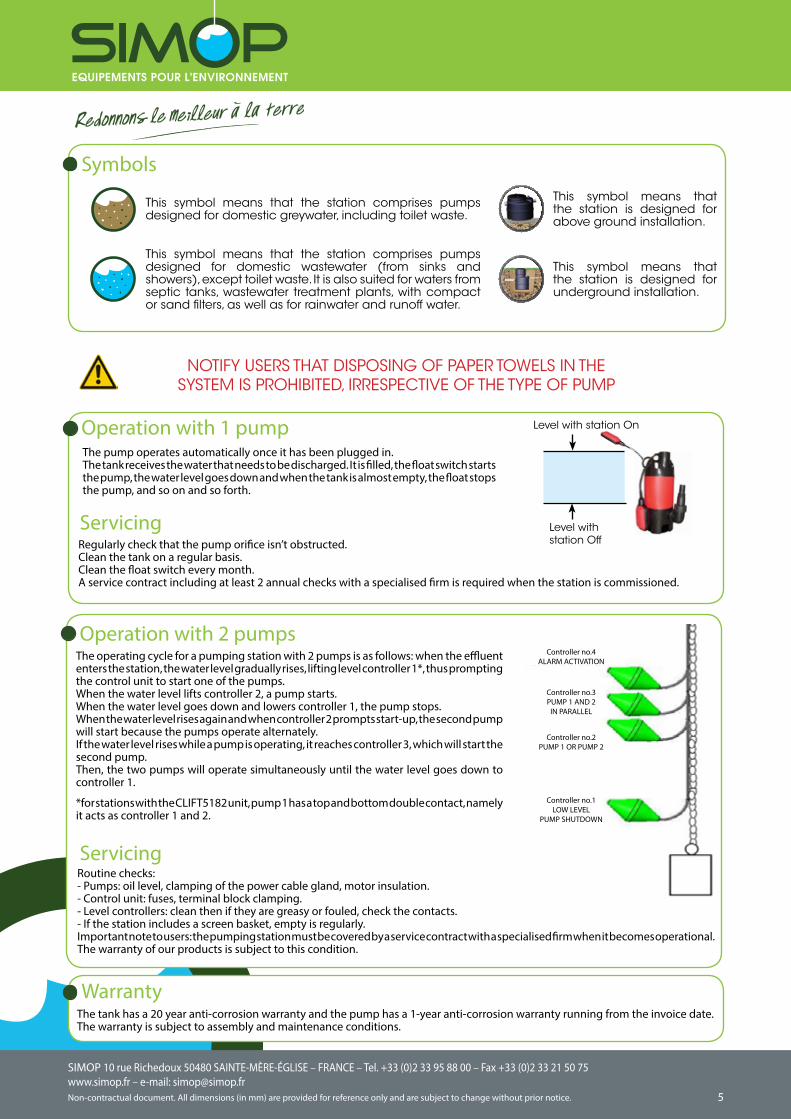
Symbols
Level with station On
Level with station Off
NOTIFY USERS THAT DISPOSING OF PAPER TOWELS IN THE SYSTEM IS PROHIBITED, IRRESPECTIVE OF THE TYPE OF PUMP
This symbol means that the station comprises pumps designed for domestic greywater, including toilet waste.
This symbol means that the station comprises pumps designed for domestic wastewater (from sinks and showers), except toilet waste. It is also suited for waters from septic tanks, wastewater treatment plants, with compact or sand filters, as well as for rainwater and runoff water.
This symbol means that the station is designed for above ground installation.
This symbol means that the station is designed for underground installation.
Servicing
Operation with 1 pump
Regularly check that the pump orifice isn’t obstructed. Clean the tank on a regular basis. Clean the float switch every month.A service contract including at least 2 annual checks with a specialised firm is required when the station is commissioned.
The pump operates automatically once it has been plugged in.The tank receives the water that needs to be discharged. It is filled, the float switch starts the pump, the water level goes down and when the tank is almost empty, the float stops the pump, and so on and so forth.
Operation with 2 pumpsThe operating cycle for a pumping station with 2 pumps is as follows: when the effluent enters the station, the water level gradually rises, lifting level controller 1*, thus prompting the control unit to start one of the pumps.When the water level lifts controller 2, a pump starts.When the water level goes down and lowers controller 1, the pump stops.When the water level rises again and when controller 2 prompts start-up, the second pump will start because the pumps operate alternately.If the water level rises while a pump is operating, it reaches controller 3, which will start the second pump.Then, the two pumps will operate simultaneously until the water level goes down to controller 1.
*for stations with the CLIFT5182 unit, pump 1 has a top and bottom double contact, namely it acts as controller 1 and 2.
ServicingRoutine checks:- Pumps: oil level, clamping of the power cable gland, motor insulation.- Control unit: fuses, terminal block clamping.- Level controllers: clean then if they are greasy or fouled, check the contacts. - If the station includes a screen basket, empty is regularly.Important note to users: the pumping station must be covered by a service contract with a specialised firm when it becomes operational. The warranty of our products is subject to this condition.
Controller no.1LOW LEVEL
PUMP SHUTDOWN
Controller no.2PUMP 1 OR PUMP 2
Controller no.3PUMP 1 AND 2
IN PARALLEL
Controller no.4ALARM ACTIVATION
SIMOP 10 rue Richedoux 50480 SAINTE-MÈRE-ÉGLISE – FRANCE – Tel. +33 (0)2 33 95 88 00 – Fax +33 (0)2 33 21 50 75www.simop.fr – e-mail: [email protected] document. All dimensions (in mm) are provided for reference only and are subject to change without prior notice.
SIMOP 10 rue Richedoux 50480 SAINTE-MÈRE-ÉGLISE – FRANCE – Tel. +33 (0)2 33 95 88 00 – Fax +33 (0)2 33 21 50 75www.simop.fr – e-mail: [email protected]
Non-contractual document. All dimensions (in mm) are provided for reference only and are subject to change without prior notice. 76
13__
12__
11__
10__
9__
8__
7__
6__
5__
4__
3__
2__
1__
SELECTION 2
SELECTION 3SELECTION 3
0 5 10 20 30 40 50 60 70 80 90 100 ml
SELECTION 1
SELECTION 2
SELECTION 1
SELECTION 2
SELECTION 3
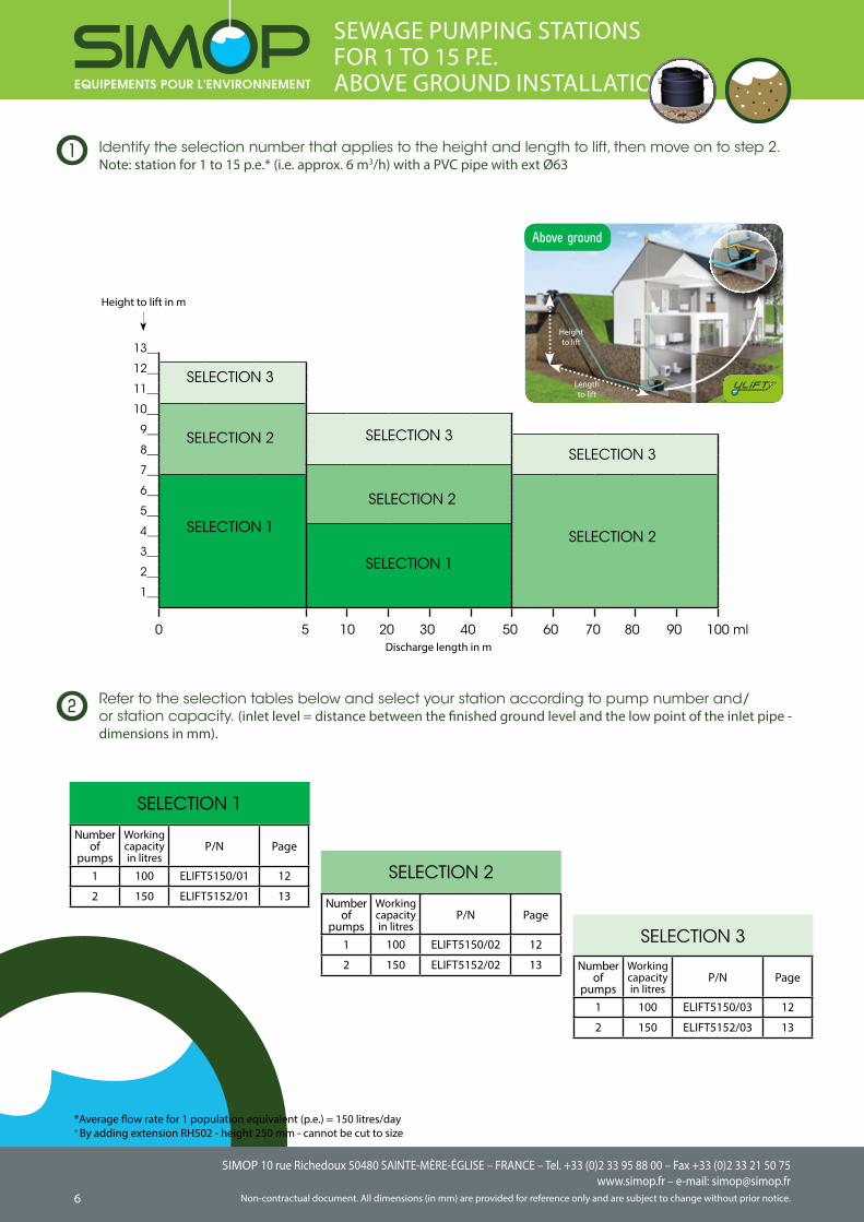
SEWAGE PUMPING STATIONS FOR 1 TO 15 P.E.ABOVE GROUND INSTALLATION
1
Above ground
Height to lift
Length to lift
Number of
pumps
Working capacity in litres
P/N Page
1 100 ELIFT5150/01 12
2 150 ELIFT5152/01 13
SELECTION 1
SELECTION 3
SELECTION 2
2
Discharge length in m
Number of
pumps
Working capacity in litres
P/N Page
1 100 ELIFT5150/02 12
2 150 ELIFT5152/02 13 Number of
pumps
Working capacity in litres
P/N Page
1 100 ELIFT5150/03 12
2 150 ELIFT5152/03 13
Height to lift in m
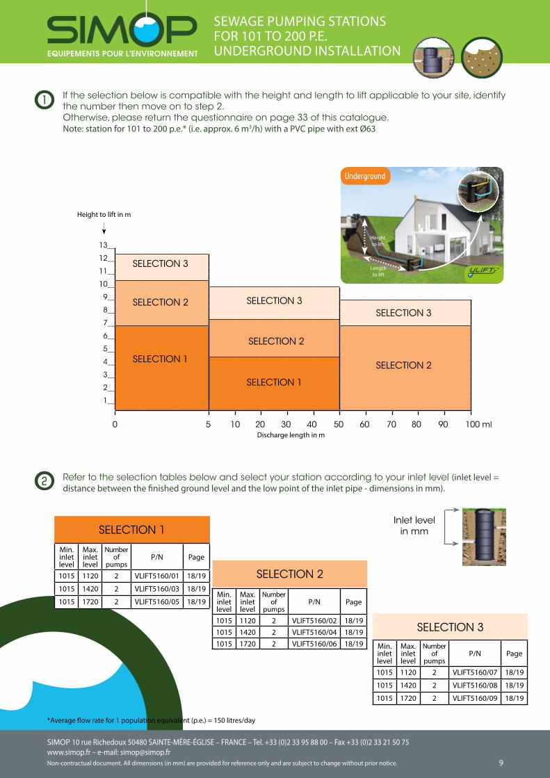
Identify the selection number that applies to the height and length to lift, then move on to step 2. Note: station for 1 to 15 p.e.* (i.e. approx. 6 m3/h) with a PVC pipe with ext Ø63
*Average flow rate for 1 population equivalent (p.e.) = 150 litres/day+ By adding extension RH502 - height 250 mm - cannot be cut to size
Refer to the selection tables below and select your station according to pump number and/or station capacity. (inlet level = distance between the finished ground level and the low point of the inlet pipe - dimensions in mm).
SIMOP 10 rue Richedoux 50480 SAINTE-MÈRE-ÉGLISE – FRANCE – Tel. +33 (0)2 33 95 88 00 – Fax +33 (0)2 33 21 50 75www.simop.fr – e-mail: [email protected] document. All dimensions (in mm) are provided for reference only and are subject to change without prior notice.
SIMOP 10 rue Richedoux 50480 SAINTE-MÈRE-ÉGLISE – FRANCE – Tel. +33 (0)2 33 95 88 00 – Fax +33 (0)2 33 21 50 75www.simop.fr – e-mail: [email protected]
Non-contractual document. All dimensions (in mm) are provided for reference only and are subject to change without prior notice. 76
Min. inlet level
Max. inlet level
Number of
pumpsP/N Page
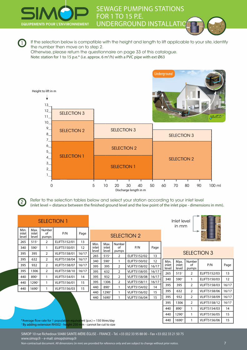
265 515+ 2 ELIFT5152/01 13
340 590+ 1 ELIFT5150/01 12
395 395 2 VLIFT5158/01 16/17
395 632 2 VLIFT5158/04 16/17
395 932 2 VLIFT5158/07 16/17
395 1306 2 VLIFT5158/10 16/17
440 890+ 1 VLIFT5154/01 14
440 1290+ 1 VLIFT5156/01 15
440 1690+ 1 VLIFT5156/03 15
SELECTION 1
Min. inlet level
Max. inlet level
Number of
pumpsP/N Page
265 515+ 2 ELIFT5152/03 13
340 590+ 1 ELIFT5150/03 12
395 395 2 VLIFT5158/03 16/17
395 632 2 VLIFT5158/06 16/17
395 932 2 VLIFT5158/09 16/17
395 1306 2 VLIFT5158/12 16/17
440 890+ 1 VLIFT5154/03 14
440 1290+ 1 VLIFT5156/05 15
440 1690+ 1 VLIFT5156/06 15
SELECTION 3
Min. inlet level
Max. inlet level
Number of
pumpsP/N Page
265 515+ 2 ELIFT5152/02 13340 590+ 1 ELIFT5150/02 12395 395 2 VLIFT5158/02 16/17395 632 2 VLIFT5158/05 16/17395 932 2 VLIFT5158/08 16/17395 1306 2 VLIFT5158/11 16/17440 890+ 1 VLIFT5154/02 14440 1290+ 1 VLIFT5156/02 15440 1690+ 1 VLIFT5156/04 15
SELECTION 2
SEWAGE PUMPING STATIONSFOR 1 TO 15 P.E.UNDERGROUND INSTALLATION
2
Inlet levelin mm
1
13__
12__
11__
10__
9__
8__
7__
6__
5__
4__
3__
2__
1__
SELECTION 2
SELECTION 3SELECTION 3
0 5 10 20 30 40 50 60 70 80 90 100 ml
SELECTION 1
SELECTION 2
SELECTION 1
SELECTION 2
SELECTION 3
Discharge length in m
Height to lift
Length to lift
Underground
Refer to the selection tables below and select your station according to your inlet level (inlet level = distance between the finished ground level and the low point of the inlet pipe - dimensions in mm).
If the selection below is compatible with the height and length to lift applicable to your site, identify the number then move on to step 2. Otherwise, please return the questionnaire on page 33 of this catalogue.Note: station for 1 to 15 p.e.* (i.e. approx. 6 m3/h) with a PVC pipe with ext Ø63
*Average flow rate for 1 population equivalent (p.e.) = 150 litres/day+ By adding extension RH502 - height 250 mm - cannot be cut to size
Height to lift in m
SIMOP 10 rue Richedoux 50480 SAINTE-MÈRE-ÉGLISE – FRANCE – Tel. +33 (0)2 33 95 88 00 – Fax +33 (0)2 33 21 50 75www.simop.fr – e-mail: [email protected] document. All dimensions (in mm) are provided for reference only and are subject to change without prior notice.
SIMOP 10 rue Richedoux 50480 SAINTE-MÈRE-ÉGLISE – FRANCE – Tel. +33 (0)2 33 95 88 00 – Fax +33 (0)2 33 21 50 75www.simop.fr – e-mail: [email protected]
Non-contractual document. All dimensions (in mm) are provided for reference only and are subject to change without prior notice. 98
Min. inlet level
Max. inlet level
Number of
pumpsP/N Page
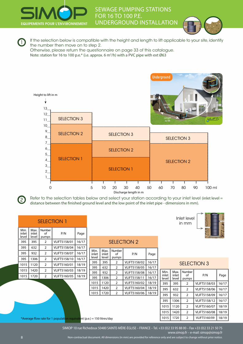
395 395 2 VLIFT5158/01 16/17
395 632 2 VLIFT5158/04 16/17
395 932 2 VLIFT5158/07 16/17
395 1306 2 VLIFT5158/10 16/17
1015 1120 2 VLIFT5160/01 18/19
1015 1420 2 VLIFT5160/03 18/19
1015 1720 2 VLIFT5160/05 18/19
Min. inlet level
Max. inlet level
Number of
pumpsP/N Page
395 395 2 VLIFT5158/02 16/17395 632 2 VLIFT5158/05 16/17395 932 2 VLIFT5158/08 16/17395 1306 2 VLIFT5158/11 16/17
1015 1120 2 VLIFT5160/02 18/191015 1420 2 VLIFT5160/04 18/191015 1720 2 VLIFT5160/06 18/19
SEWAGE PUMPING STATIONSFOR 16 TO 100 P.E.UNDERGROUND INSTALLATION
Refer to the selection tables below and select your station according to your inlet level (inlet level = distance between the finished ground level and the low point of the inlet pipe - dimensions in mm).
2
If the selection below is compatible with the height and length to lift applicable to your site, identify the number then move on to step 2. Otherwise, please return the questionnaire on page 33 of this catalogue.Note: station for 16 to 100 p.e.* (i.e. approx. 6 m3/h) with a PVC pipe with ext Ø63
1
*Average flow rate for 1 population equivalent (p.e.) = 150 litres/day
Inlet levelin mm
Min. inlet level
Max. inlet level
Number of
pumpsP/N Page
395 395 2 VLIFT5158/03 16/17
395 632 2 VLIFT5158/06 16/17
395 932 2 VLIFT5158/09 16/17
395 1306 2 VLIFT5158/12 16/17
1015 1120 2 VLIFT5160/07 18/19
1015 1420 2 VLIFT5160/08 18/19
1015 1720 2 VLIFT5160/09 18/19
13__
12__
11__
10__
9__
8__
7__
6__
5__
4__
3__
2__
1__
SELECTION 2
SELECTION 3
Height to lift in m
SELECTION 3
0 5 10 20 30 40 50 60 70 80 90 100 ml
SELECTION 1
SELECTION 2
SELECTION 1
SELECTION 2
SELECTION 3
SELECTION 1
SELECTION 2
SELECTION 3
Discharge length in m
Underground
Height to lift
Length to lift
SIMOP 10 rue Richedoux 50480 SAINTE-MÈRE-ÉGLISE – FRANCE – Tel. +33 (0)2 33 95 88 00 – Fax +33 (0)2 33 21 50 75www.simop.fr – e-mail: [email protected] document. All dimensions (in mm) are provided for reference only and are subject to change without prior notice.
SIMOP 10 rue Richedoux 50480 SAINTE-MÈRE-ÉGLISE – FRANCE – Tel. +33 (0)2 33 95 88 00 – Fax +33 (0)2 33 21 50 75www.simop.fr – e-mail: [email protected]
Non-contractual document. All dimensions (in mm) are provided for reference only and are subject to change without prior notice. 98
SELECTION 1
Min. inlet level
Max. inlet level
Number of
pumpsP/N Page
1015 1120 2 VLIFT5160/01 18/19
1015 1420 2 VLIFT5160/03 18/19
1015 1720 2 VLIFT5160/05 18/19Min. inlet level
Max. inlet level
Number of
pumpsP/N Page
1015 1120 2 VLIFT5160/02 18/191015 1420 2 VLIFT5160/04 18/191015 1720 2 VLIFT5160/06 18/19
SEWAGE PUMPING STATIONSFOR 101 TO 200 P.E.UNDERGROUND INSTALLATION
Refer to the selection tables below and select your station according to your inlet level (inlet level = distance between the finished ground level and the low point of the inlet pipe - dimensions in mm).
2
If the selection below is compatible with the height and length to lift applicable to your site, identify the number then move on to step 2. Otherwise, please return the questionnaire on page 33 of this catalogue.Note: station for 101 to 200 p.e.* (i.e. approx. 6 m3/h) with a PVC pipe with ext Ø63
1
*Average flow rate for 1 population equivalent (p.e.) = 150 litres/day
Inlet levelin mm
Height to lift
Length to lift
Min. inlet level
Max. inlet level
Number of
pumpsP/N Page
1015 1120 2 VLIFT5160/07 18/19
1015 1420 2 VLIFT5160/08 18/19
1015 1720 2 VLIFT5160/09 18/19
13__
12__
11__
10__
9__
8__
7__
6__
5__
4__
3__
2__
1__
SELECTION 2
SELECTION 3
Height to lift in m
SELECTION 3
0 5 10 20 30 40 50 60 70 80 90 100 ml
SELECTION 1
SELECTION 2
SELECTION 1
SELECTION 2
SELECTION 3
SELECTION 2
SELECTION 3
Discharge length in m
Underground
SIMOP 10 rue Richedoux 50480 SAINTE-MÈRE-ÉGLISE – FRANCE – Tel. +33 (0)2 33 95 88 00 – Fax +33 (0)2 33 21 50 75www.simop.fr – e-mail: [email protected] document. All dimensions (in mm) are provided for reference only and are subject to change without prior notice.
SIMOP 10 rue Richedoux 50480 SAINTE-MÈRE-ÉGLISE – FRANCE – Tel. +33 (0)2 33 95 88 00 – Fax +33 (0)2 33 21 50 75www.simop.fr – e-mail: [email protected]
Non-contractual document. All dimensions (in mm) are provided for reference only and are subject to change without prior notice. 1110
CLEAN WATER - WASTEWATER (EXCEPT TOILET WASTE) PUMPING STATIONS FOR 1 TO 15 P.E.ABOVE GROUND INSTALLATION
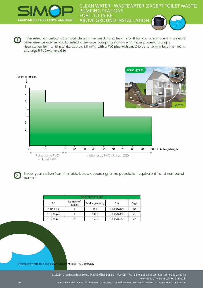
If the selection below is compatible with the height and length to lift for your site, move on to step 2, otherwise we advise you to select a sewage pumping station with more powerful pumps.Note: station for 1 to 15 p.e.* (i.e. approx. 1.9 m3/h) with a PVC pipe with ext. Ø40 up to 10 m in length or 100 ml discharge if PVC with ext. Ø50
1
8__
7__
6__
5__
4__
3__
2__
1__
0 5 10 20 30 40 50 60 70 80 90 100 ml discharge lengtht
SELECTION TABLE
P.E. Number of pumps Working capacity P/N Page
1 TO 7 p.e. 1 40 L ELIFT5162/01 20
1 TO 15 p.e. 1 100 L ELIFT5164/01 21
1 TO 15 p.e. 2 150 L ELIFT5166/01 22
if discharge PVC with ext. Ø50if discharge PVC with ext. Ø40
Height to lift in m
*Average flow rate for 1 population equivalent (p.e.) = 150 litres/day
Height to lift
Length to lift
Select your station from the table below according to the population equivalent* and number of pumps.2
Above ground
SIMOP 10 rue Richedoux 50480 SAINTE-MÈRE-ÉGLISE – FRANCE – Tel. +33 (0)2 33 95 88 00 – Fax +33 (0)2 33 21 50 75www.simop.fr – e-mail: [email protected] document. All dimensions (in mm) are provided for reference only and are subject to change without prior notice.
SIMOP 10 rue Richedoux 50480 SAINTE-MÈRE-ÉGLISE – FRANCE – Tel. +33 (0)2 33 95 88 00 – Fax +33 (0)2 33 21 50 75www.simop.fr – e-mail: [email protected]
Non-contractual document. All dimensions (in mm) are provided for reference only and are subject to change without prior notice. 1110
CLEAN WATER - WASTEWATER (EXCEPT TOILET WASTE) PUMPING STATIONS FOR 1 TO 15 P.E.UNDERGROUND INSTALLATION
1
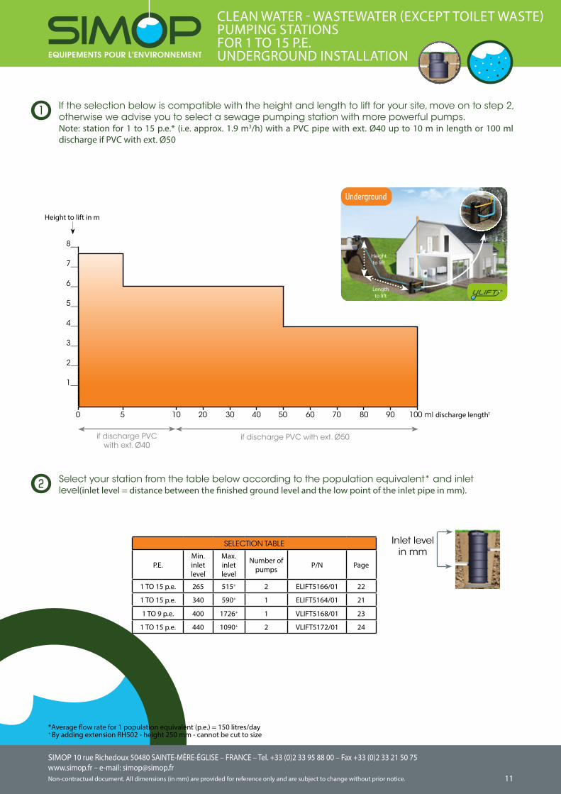
SELECTION TABLE
P.E.Min. inlet level
Max. inlet level
Number of pumps P/N Page
1 TO 15 p.e. 265 515+ 2 ELIFT5166/01 22
1 TO 15 p.e. 340 590+ 1 ELIFT5164/01 21
1 TO 9 p.e. 400 1726+ 1 VLIFT5168/01 23
1 TO 15 p.e. 440 1090+ 2 VLIFT5172/01 24
If the selection below is compatible with the height and length to lift for your site, move on to step 2, otherwise we advise you to select a sewage pumping station with more powerful pumps.Note: station for 1 to 15 p.e.* (i.e. approx. 1.9 m3/h) with a PVC pipe with ext. Ø40 up to 10 m in length or 100 ml discharge if PVC with ext. Ø50
8__
7__
6__
5__
4__
3__
2__
1__
if discharge PVC with ext. Ø40
if discharge PVC with ext. Ø50
*Average flow rate for 1 population equivalent (p.e.) = 150 litres/day+ By adding extension RH502 - height 250 mm - cannot be cut to size
Inlet levelin mm
Height to lift
Length to lift
Select your station from the table below according to the population equivalent* and inlet level(inlet level = distance between the finished ground level and the low point of the inlet pipe in mm). 2
Height to lift in m
Underground
0 5 10 20 30 40 50 60 70 80 90 100 ml discharge lengtht
SIMOP 10 rue Richedoux 50480 SAINTE-MÈRE-ÉGLISE – FRANCE – Tel. +33 (0)2 33 95 88 00 – Fax +33 (0)2 33 21 50 75www.simop.fr – e-mail: [email protected] document. All dimensions (in mm) are provided for reference only and are subject to change without prior notice.
SIMOP 10 rue Richedoux 50480 SAINTE-MÈRE-ÉGLISE – FRANCE – Tel. +33 (0)2 33 95 88 00 – Fax +33 (0)2 33 21 50 75www.simop.fr – e-mail: [email protected]
Non-contractual document. All dimensions (in mm) are provided for reference only and are subject to change without prior notice. 1312
5150
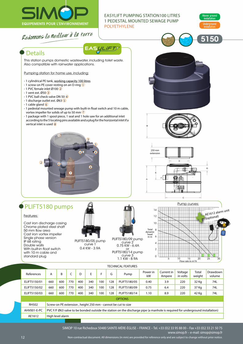
This station pumps domestic wastewater, including toilet waste. Also compatible with rainwater applications.
Pumping station for home use, including:
- 1 cylindrical PE tank, working capacity 100 litres- 1 screw-on PE cover resting on an O-ring 1- 1 PVC female inlet Ø100 2- 1 vent ext. Ø50 3- 1 PVC ball check valve DN 50 4- 1 discharge outlet ext. Ø63 5- 1 cable gland 6- 1 pedestal mounted sewage pump with built-in float switch and 10 m cable,
vortex impeller for solids of up to 50 mm 7
- 1 package with 1 spool piece, 1 seal and 1 hole saw for an additional inlet according to the 5 locating pins available and a plug for the horizontal inlet if a vertical inlet is used 8
Details
Underground installation
Above ground installation
TECHNICAL FEATURES
1
2
3
4
5
6
7
8
8
References A B C D E F G Pump Power in kW
Current in Ampere
Voltage in volts
Totalweight
Drawdownvolume
ELIFT5150/01 660 600 770 400 340 100 128 PLIFT5180/05 0.40 3.9 220 32 Kg 74L
ELIFT5150/02 660 600 770 400 340 100 128 PLIFT5180/09 0.75 6.4 220 37 Kg 74L
ELIFT5150/03 660 600 770 400 340 100 128 PLIFT5180/14 1.10 8.9 220 42 Kg 74L
OPTIONS
RH502 Screw-on PE extension , height 250 mm - cannot be cut to size
AHV001-E-PC PVC F/F Ø63 valve to be bonded outside the station on the discharge pipe (a manhole is required for underground installation)
AE1612 High level alarm
Features:
Cast iron discharge casing Chrome plated steel shaft50 mm flow areaCast iron vortex impellerSingle phase versionIP 68 ratingDouble wallsWith built-in float switchwith 10 m cable and standard plug
PLIFT5180 pumps
PLIFT5180/05 pumpcurve 1
0.4 KW - 3.9A
PLIFT5180/09 pump curve 2
0.75 KW - 6.4Aor
PLIFT5180/14 pump curve 3
1.1 KW - 8.9A
Pump curves:
AE1612 alarm unit
(optional)
Flow rate in m3/h5 10 15 20 25 30
14
12
10
8
6
4
2
0
Total dynamic
headin m
EASYLIFT PUMPING STATION100 LITRES1 PEDESTAL MOUNTED SEWAGE PUMPPOLYETHYLENE
250 mm extension
SIMOP 10 rue Richedoux 50480 SAINTE-MÈRE-ÉGLISE – FRANCE – Tel. +33 (0)2 33 95 88 00 – Fax +33 (0)2 33 21 50 75www.simop.fr – e-mail: [email protected] document. All dimensions (in mm) are provided for reference only and are subject to change without prior notice.
SIMOP 10 rue Richedoux 50480 SAINTE-MÈRE-ÉGLISE – FRANCE – Tel. +33 (0)2 33 95 88 00 – Fax +33 (0)2 33 21 50 75www.simop.fr – e-mail: [email protected]
Non-contractual document. All dimensions (in mm) are provided for reference only and are subject to change without prior notice. 1312
Underground installation
Above ground installation
5152
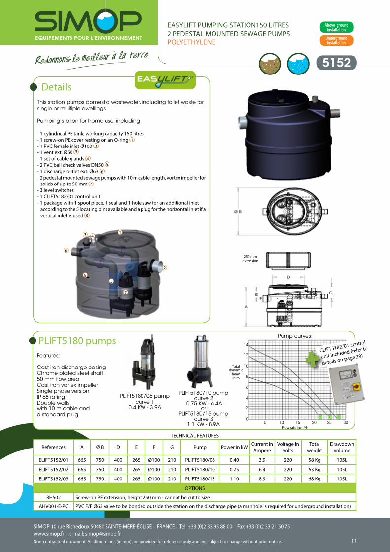
This station pumps domestic wastewater, including toilet waste for single or multiple dwellings.
Pumping station for home use, including:
- 1 cylindrical PE tank, working capacity 150 litres- 1 screw-on PE cover resting on an O-ring 1- 1 PVC female inlet Ø100 2- 1 vent ext. Ø50 3
- 1 set of cable glands 4- 2 PVC ball check valves DN50 5 - 1 discharge outlet ext. Ø63 6- 2 pedestal mounted sewage pumps with 10 m cable length, vortex impeller for
solids of up to 50 mm 7- 3 level switches- 1 CLIFT5182/01 control unit - 1 package with 1 spool piece, 1 seal and 1 hole saw for an additional inlet
according to the 5 locating pins available and a plug for the horizontal inlet if a vertical inlet is used 8
Details
References A Ø B D E F G Pump Power in kW Current in Ampere
Voltage in volts
Totalweight
Drawdownvolume
ELIFT5152/01 665 750 400 265 Ø100 210 PLIFT5180/06 0.40 3.9 220 58 Kg 105L
ELIFT5152/02 665 750 400 265 Ø100 210 PLIFT5180/10 0.75 6.4 220 63 Kg 105L
ELIFT5152/03 665 750 400 265 Ø100 210 PLIFT5180/15 1.10 8.9 220 68 Kg 105L
OPTIONS
RH502 Screw-on PE extension, height 250 mm - cannot be cut to size
AHV001-E-PC PVC F/F Ø63 valve to be bonded outside the station on the discharge pipe (a manhole is required for underground installation)
TECHNICAL FEATURES
1
2
3 4
5
6
7
8
Features:
Cast iron discharge casing Chrome plated steel shaft50 mm flow areaCast iron vortex impellerSingle phase versionIP 68 ratingDouble wallswith 10 m cable and a standard plug
PLIFT5180 pumps
PLIFT5180/06 pump curve 1
0.4 KW - 3.9A
PLIFT5180/10 pump curve 2
0.75 KW - 6.4Aor
PLIFT5180/15 pump curve 3
1.1 KW - 8.9A
Pump curves:
CLIFT5182/01 control
unit included (refer to
details on page 29)
5 10 15 20 25 30
14
12
10
8
6
4
2
0
Total dynamic
headin m
EASYLIFT PUMPING STATION150 LITRES2 PEDESTAL MOUNTED SEWAGE PUMPSPOLYETHYLENE
250 mm extension
Flow rate in m3/h
SIMOP 10 rue Richedoux 50480 SAINTE-MÈRE-ÉGLISE – FRANCE – Tel. +33 (0)2 33 95 88 00 – Fax +33 (0)2 33 21 50 75www.simop.fr – e-mail: [email protected] document. All dimensions (in mm) are provided for reference only and are subject to change without prior notice.
SIMOP 10 rue Richedoux 50480 SAINTE-MÈRE-ÉGLISE – FRANCE – Tel. +33 (0)2 33 95 88 00 – Fax +33 (0)2 33 21 50 75www.simop.fr – e-mail: [email protected]
Non-contractual document. All dimensions (in mm) are provided for reference only and are subject to change without prior notice. 1514
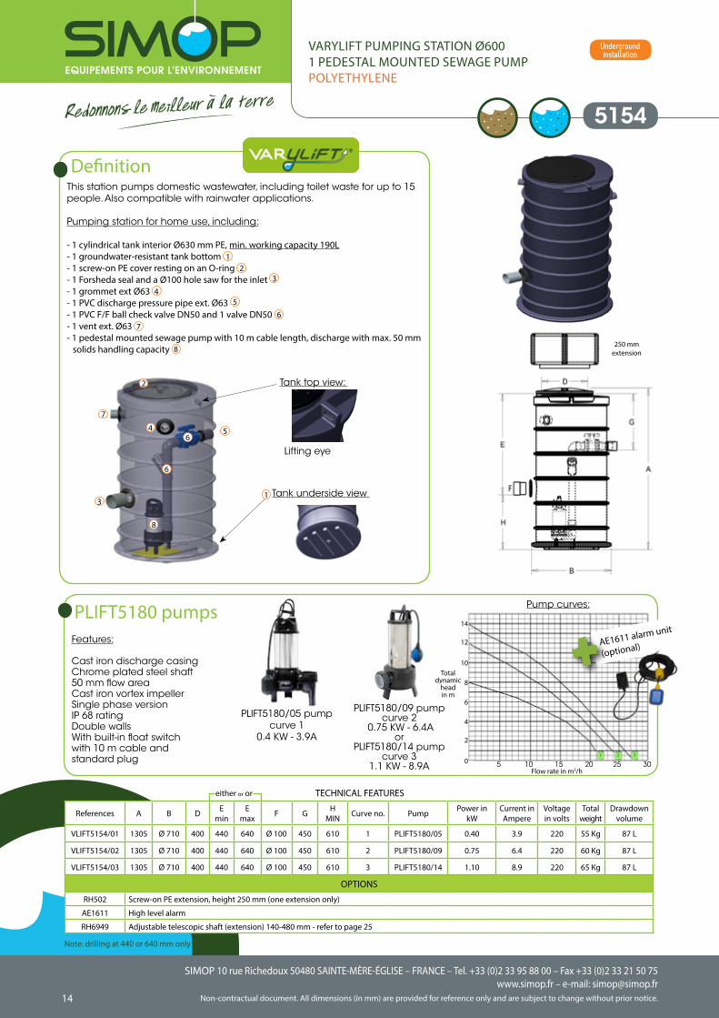
This station pumps domestic wastewater, including toilet waste for up to 15 people. Also compatible with rainwater applications.
Pumping station for home use, including:
- 1 cylindrical tank interior Ø630 mm PE, min. working capacity 190L- 1 groundwater-resistant tank bottom 1- 1 screw-on PE cover resting on an O-ring 2- 1 Forsheda seal and a Ø100 hole saw for the inlet 3
- 1 grommet ext Ø63 4- 1 PVC discharge pressure pipe ext. Ø63 5
- 1 PVC F/F ball check valve DN50 and 1 valve DN50 6- 1 vent ext. Ø63 7- 1 pedestal mounted sewage pump with 10 m cable length, discharge with max. 50 mm
solids handling capacity 8
5154
VARYLIFT PUMPING STATION Ø6001 PEDESTAL MOUNTED SEWAGE PUMPPOLYETHYLENE
Definition
References A B D Emin
Emax F G H
MIN Curve no. Pump Power in kW
Current in Ampere
Voltage in volts
Totalweight
Drawdownvolume
VLIFT5154/01 1305 Ø 710 400 440 640 Ø 100 450 610 1 PLIFT5180/05 0.40 3.9 220 55 Kg 87 L
VLIFT5154/02 1305 Ø 710 400 440 640 Ø 100 450 610 2 PLIFT5180/09 0.75 6.4 220 60 Kg 87 L
VLIFT5154/03 1305 Ø 710 400 440 640 Ø 100 450 610 3 PLIFT5180/14 1.10 8.9 220 65 Kg 87 L
OPTIONS
RH502 Screw-on PE extension, height 250 mm (one extension only)
AE1611 High level alarm
RH6949 Adjustable telescopic shaft (extension) 140-480 mm - refer to page 25
TECHNICAL FEATURES
Features:
Cast iron discharge casing Chrome plated steel shaft50 mm flow areaCast iron vortex impellerSingle phase versionIP 68 ratingDouble wallsWith built-in float switchwith 10 m cable and standard plug
PLIFT5180 pumps
PLIFT5180/05 pumpcurve 1
0.4 KW - 3.9A
PLIFT5180/09 pump curve 2
0.75 KW - 6.4Aor
PLIFT5180/14 pump curve 3
1.1 KW - 8.9A
Pump curves:
Tank top view:
Tank underside view
Lifting eye
1
2
3
4 5
6
7
8
6
AE1611 alarm unit
(optional)
14
12
10
8
6
4
2
0
Note: drilling at 440 or 640 mm only
either or or
Underground installation
Flow rate in m3/h5 10 15 20 25 30
Total dynamic
headin m
250 mm extension
SIMOP 10 rue Richedoux 50480 SAINTE-MÈRE-ÉGLISE – FRANCE – Tel. +33 (0)2 33 95 88 00 – Fax +33 (0)2 33 21 50 75www.simop.fr – e-mail: [email protected] document. All dimensions (in mm) are provided for reference only and are subject to change without prior notice.
SIMOP 10 rue Richedoux 50480 SAINTE-MÈRE-ÉGLISE – FRANCE – Tel. +33 (0)2 33 95 88 00 – Fax +33 (0)2 33 21 50 75www.simop.fr – e-mail: [email protected]
Non-contractual document. All dimensions (in mm) are provided for reference only and are subject to change without prior notice. 1514
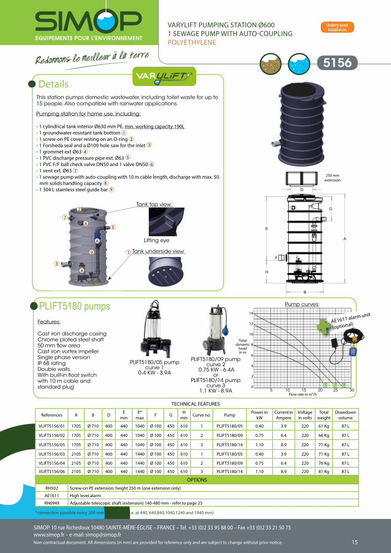
5156
VARYLIFT PUMPING STATION Ø6001 SEWAGE PUMP WITH AUTO-COUPLINGPOLYETHYLENE
This station pumps domestic wastewater, including toilet waste for up to 15 people. Also compatible with rainwater applications.
Pumping station for home use, including:
- 1 cylindrical tank interior Ø630 mm PE, min. working capacity 190L- 1 groundwater-resistant tank bottom 1- 1 screw-on PE cover resting on an O-ring 2- 1 Forsheda seal and a Ø100 hole saw for the inlet 3
- 1 grommet ext Ø63 4- 1 PVC discharge pressure pipe ext. Ø63 5
- 1 PVC F/F ball check valve DN50 and 1 valve DN50 6- 1 vent ext. Ø63 7- 1 sewage pump with auto-coupling with 10 m cable length, discharge with max. 50
mm solids handling capacity 8
- 1 304 L stainless steel guide bar 9
Details
References A B D Emin
E*max F G H
min Curve no. Pump Power in kW
Current in Ampere
Voltage in volts
Totalweight
Drawdownvolume
VLIFT5156/01 1705 Ø 710 400 440 1040 Ø 100 450 610 1 PLIFT5180/05 0.40 3.9 220 61 Kg 87 L
VLIFT5156/02 1705 Ø 710 400 440 1040 Ø 100 450 610 2 PLIFT5180/09 0.75 6.4 220 66 Kg 87 L
VLIFT5156/05 1705 Ø 710 400 440 1040 Ø 100 450 610 3 PLIFT5180/14 1.10 8.9 220 71 Kg 87 L
VLIFT5156/03 2105 Ø 710 400 440 1440 Ø 100 450 610 1 PLIFT5180/05 0.40 3.9 220 71 Kg 87 L
VLIFT5156/04 2105 Ø 710 400 440 1440 Ø 100 450 610 2 PLIFT5180/09 0.75 6.4 220 76 Kg 87 L
VLIFT5156/06 2105 Ø 710 400 440 1440 Ø 100 450 610 3 PLIFT5180/14 1.10 8.9 220 81 Kg 87 L
OPTIONS
RH502 Screw-on PE extension, height 250 m (one extension only)
AE1611 High level alarm
RH6949 Adjustable telescopic shaft (extension) 140-480 mm - refer to page 25
TECHNICAL FEATURES
Tank top view:
Tank underside view
Lifting eye
1
2
3
45
6
7
8
9
Features:
Cast iron discharge casing Chrome plated steel shaft50 mm flow areaCast iron vortex impellerSingle phase versionIP 68 ratingDouble wallsWith built-in float switchwith 10 m cable and standard plug
PLIFT5180 pumps
PLIFT5180/05 pumpcurve 1
0.4 KW - 3.9A
PLIFT5180/09 pump curve 2
0.75 KW - 6.4Aor
PLIFT5180/14 pump curve 3
1.1 KW - 8.9A
Pump curves:
AE1611 alarm unit
(optional)
14
12
10
8
6
4
2
0
*connection possible every 200 mm from E min. (i.e. at 440, 640,840,1040,1240 and 1440 mm)
Underground installation
Flow rate in m3/h5 10 15 20 25 30
Total dynamic
headin m
250 mm extension
SIMOP 10 rue Richedoux 50480 SAINTE-MÈRE-ÉGLISE – FRANCE – Tel. +33 (0)2 33 95 88 00 – Fax +33 (0)2 33 21 50 75www.simop.fr – e-mail: [email protected] document. All dimensions (in mm) are provided for reference only and are subject to change without prior notice.
SIMOP 10 rue Richedoux 50480 SAINTE-MÈRE-ÉGLISE – FRANCE – Tel. +33 (0)2 33 95 88 00 – Fax +33 (0)2 33 21 50 75www.simop.fr – e-mail: [email protected]
Non-contractual document. All dimensions (in mm) are provided for reference only and are subject to change without prior notice. 1716
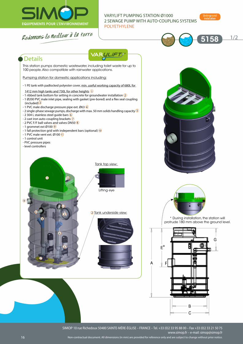
This station pumps domestic wastewater, including toilet waste for up to 100 people. Also compatible with rainwater applications.
Pumping station for domestic applications including:
- 1 PE tank with padlocked polyester cover, min. useful working capacity of 680L for
1412 mm high tanks and 730L for other heights 1- 1 ribbed tank bottom for setting in concrete for groundwater installation 2- 1 Ø200 PVC male inlet pipe, sealing with gasket (pre-bored) and a flex seal coupling
(included) 3
- 1 PVC male discharge pressure pipe ext. Ø63 4- 2 single-phase sewage pumps, discharge with max. 50 mm solids handling capacity 5
- 2 304 L stainless steel guide bars 6- 2 cast iron auto-coupling brackets 7- 2 PVC F/F ball valves and valves DN50 8
- 1 grommet ext Ø100 9
- 1 fall protection grid with independent bars (optional) 10
- 1 PVC male vent ext. Ø100 11
- 1 control unit - PVC pressure pipes- level controllers
5158
VARYLIFT PUMPING STATION Ø10002 SEWAGE PUMP WITH AUTO-COUPLING SYSTEMSPOLYETHYLENE
Details
1/2
9
* During installation, the station will protrude 180 mm above the ground level.
*
9
Tank underside view:
Tank top view:
Lifting eye
1
234
5
6
7
8
10
11
Underground installation
SIMOP 10 rue Richedoux 50480 SAINTE-MÈRE-ÉGLISE – FRANCE – Tel. +33 (0)2 33 95 88 00 – Fax +33 (0)2 33 21 50 75www.simop.fr – e-mail: [email protected] document. All dimensions (in mm) are provided for reference only and are subject to change without prior notice.
SIMOP 10 rue Richedoux 50480 SAINTE-MÈRE-ÉGLISE – FRANCE – Tel. +33 (0)2 33 95 88 00 – Fax +33 (0)2 33 21 50 75www.simop.fr – e-mail: [email protected]
Non-contractual document. All dimensions (in mm) are provided for reference only and are subject to change without prior notice. 1716
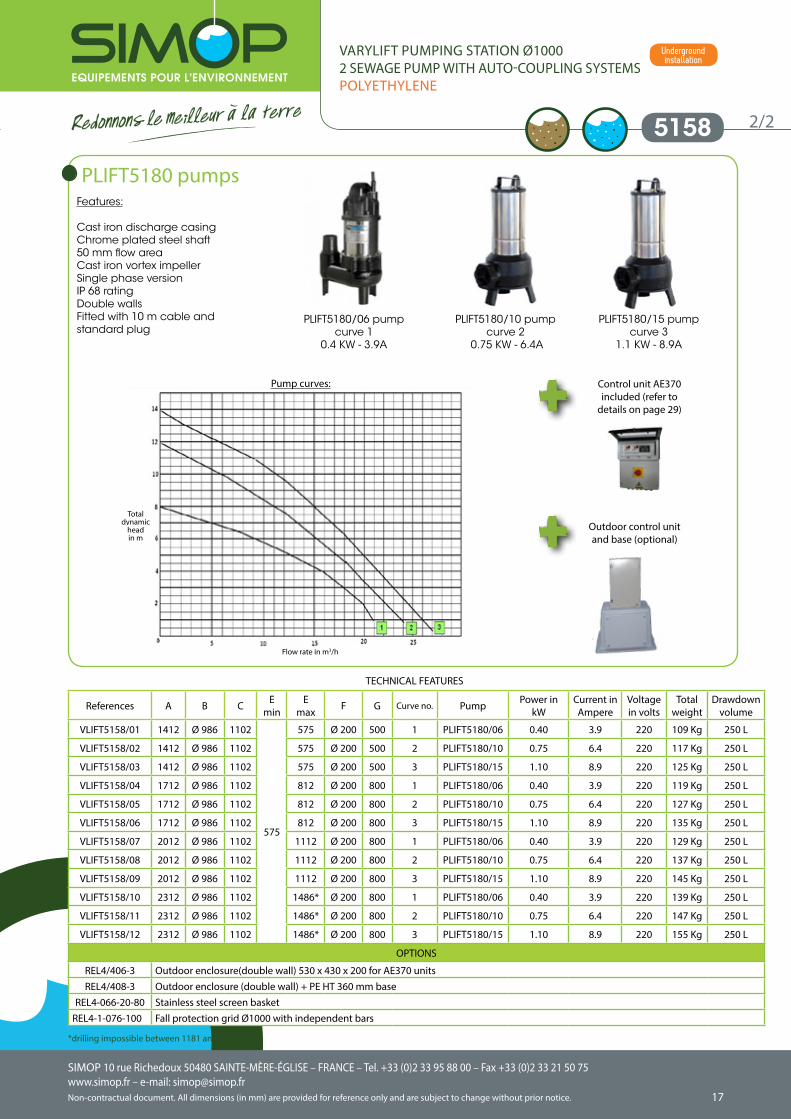
Features:
Cast iron discharge casing Chrome plated steel shaft50 mm flow areaCast iron vortex impellerSingle phase versionIP 68 ratingDouble wallsFitted with 10 m cable and standard plug
1/2 5158 2/2
VARYLIFT PUMPING STATION Ø10002 SEWAGE PUMP WITH AUTO-COUPLING SYSTEMSPOLYETHYLENE
References A B C Emin
Emax F G Curve no. Pump Power in
kWCurrent in Ampere
Voltage in volts
Totalweight
Drawdownvolume
VLIFT5158/01 1412 Ø 986 1102
575
575 Ø 200 500 1 PLIFT5180/06 0.40 3.9 220 109 Kg 250 L
VLIFT5158/02 1412 Ø 986 1102 575 Ø 200 500 2 PLIFT5180/10 0.75 6.4 220 117 Kg 250 L
VLIFT5158/03 1412 Ø 986 1102 575 Ø 200 500 3 PLIFT5180/15 1.10 8.9 220 125 Kg 250 L
VLIFT5158/04 1712 Ø 986 1102 812 Ø 200 800 1 PLIFT5180/06 0.40 3.9 220 119 Kg 250 L
VLIFT5158/05 1712 Ø 986 1102 812 Ø 200 800 2 PLIFT5180/10 0.75 6.4 220 127 Kg 250 L
VLIFT5158/06 1712 Ø 986 1102 812 Ø 200 800 3 PLIFT5180/15 1.10 8.9 220 135 Kg 250 L
VLIFT5158/07 2012 Ø 986 1102 1112 Ø 200 800 1 PLIFT5180/06 0.40 3.9 220 129 Kg 250 L
VLIFT5158/08 2012 Ø 986 1102 1112 Ø 200 800 2 PLIFT5180/10 0.75 6.4 220 137 Kg 250 L
VLIFT5158/09 2012 Ø 986 1102 1112 Ø 200 800 3 PLIFT5180/15 1.10 8.9 220 145 Kg 250 L
VLIFT5158/10 2312 Ø 986 1102 1486* Ø 200 800 1 PLIFT5180/06 0.40 3.9 220 139 Kg 250 L
VLIFT5158/11 2312 Ø 986 1102 1486* Ø 200 800 2 PLIFT5180/10 0.75 6.4 220 147 Kg 250 L
VLIFT5158/12 2312 Ø 986 1102 1486* Ø 200 800 3 PLIFT5180/15 1.10 8.9 220 155 Kg 250 L
OPTIONS
REL4/406-3 Outdoor enclosure(double wall) 530 x 430 x 200 for AE370 unitsREL4/408-3 Outdoor enclosure (double wall) + PE HT 360 mm base
REL4-066-20-80 Stainless steel screen basketREL4-1-076-100 Fall protection grid Ø1000 with independent bars
TECHNICAL FEATURES
PLIFT5180 pumps
Pump curves:
PLIFT5180/06 pumpcurve 1
0.4 KW - 3.9A
PLIFT5180/10 pump curve 2
0.75 KW - 6.4A
PLIFT5180/15 pump curve 3
1.1 KW - 8.9A
Control unit AE370 included (refer to
details on page 29)
Outdoor control unit and base (optional)
*drilling impossible between 1181 and 1485 mm
Underground installation
Flow rate in m3/h
Total dynamic
headin m
SIMOP 10 rue Richedoux 50480 SAINTE-MÈRE-ÉGLISE – FRANCE – Tel. +33 (0)2 33 95 88 00 – Fax +33 (0)2 33 21 50 75www.simop.fr – e-mail: [email protected] document. All dimensions (in mm) are provided for reference only and are subject to change without prior notice.
SIMOP 10 rue Richedoux 50480 SAINTE-MÈRE-ÉGLISE – FRANCE – Tel. +33 (0)2 33 95 88 00 – Fax +33 (0)2 33 21 50 75www.simop.fr – e-mail: [email protected]
Non-contractual document. All dimensions (in mm) are provided for reference only and are subject to change without prior notice. 1918
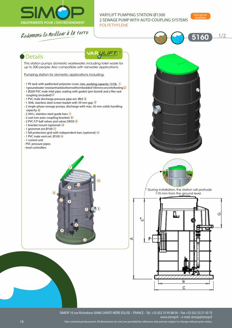
This station pumps domestic wastewater, including toilet waste for up to 200 people. Also compatible with rainwater applications.
Pumping station for domestic applications including:
- 1 PE tank with padlocked polyester cover, min. working capacity 1310L 1- 1 groundwater-resistant tank bottom with embedded 100 mm concrete footing 2- 1 Ø200 PVC male inlet pipe, sealing with gasket (pre-bored) and a flex seal
coupling (included) 3
- 1 PVC male discharge pressure pipe ext. Ø63 4- 1 304L stainless steel screen basket with 39 mm gap 5
- 2 single-phase sewage pumps, discharge with max. 50 mm solids handling capacity 6
- 2 304 L stainless steel guide bars 7- 2 cast iron auto-coupling brackets 8
- 2 PVC F/F ball valves and valves DN50 9
- 1 bracket mount (optional) 10
- 1 grommet ext Ø100 11
- 1 fall protection grid with independent bars (optional) 12
- 1 PVC male vent ext. Ø100 13
- 1 control unit- PVC pressure pipes- level controllers
5160
VARYLIFT PUMPING STATION Ø13002 SEWAGE PUMP WITH AUTO-COUPLING SYSTEMSPOLYETHYLENE
Details
1/2
* During installation, the station will protrude 110 mm from the ground level.
*
1
2
3
4
5
6
7
8
9
10
11
12
13
Underground installation
SIMOP 10 rue Richedoux 50480 SAINTE-MÈRE-ÉGLISE – FRANCE – Tel. +33 (0)2 33 95 88 00 – Fax +33 (0)2 33 21 50 75www.simop.fr – e-mail: [email protected] document. All dimensions (in mm) are provided for reference only and are subject to change without prior notice.
SIMOP 10 rue Richedoux 50480 SAINTE-MÈRE-ÉGLISE – FRANCE – Tel. +33 (0)2 33 95 88 00 – Fax +33 (0)2 33 21 50 75www.simop.fr – e-mail: [email protected]
Non-contractual document. All dimensions (in mm) are provided for reference only and are subject to change without prior notice. 1918
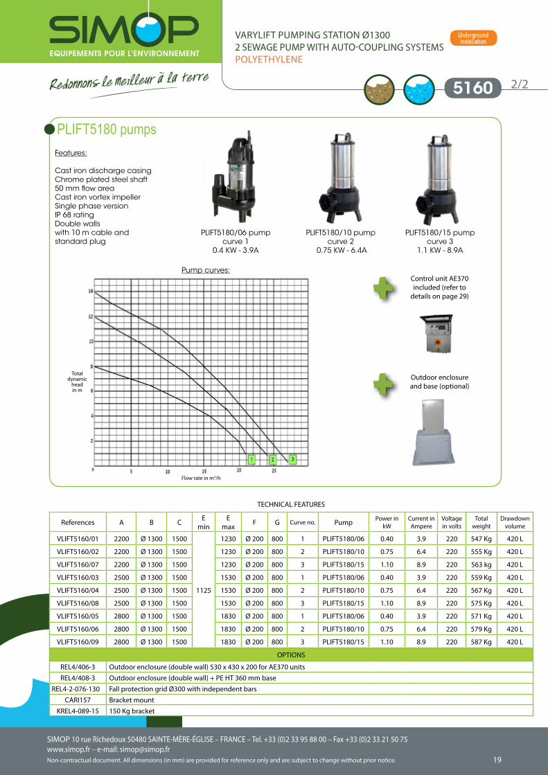
Features:
Cast iron discharge casing Chrome plated steel shaft50 mm flow areaCast iron vortex impellerSingle phase versionIP 68 ratingDouble wallswith 10 m cable and standard plug
1/2
References A B C Emin
Emax F G Curve no. Pump Power in
kWCurrent in Ampere
Voltage in volts
Totalweight
Drawdownvolume
VLIFT5160/01 2200 Ø 1300 1500
1125
1230 Ø 200 800 1 PLIFT5180/06 0.40 3.9 220 547 Kg 420 L
VLIFT5160/02 2200 Ø 1300 1500 1230 Ø 200 800 2 PLIFT5180/10 0.75 6.4 220 555 Kg 420 L
VLIFT5160/07 2200 Ø 1300 1500 1230 Ø 200 800 3 PLIFT5180/15 1.10 8.9 220 563 kg 420 L
VLIFT5160/03 2500 Ø 1300 1500 1530 Ø 200 800 1 PLIFT5180/06 0.40 3.9 220 559 Kg 420 L
VLIFT5160/04 2500 Ø 1300 1500 1530 Ø 200 800 2 PLIFT5180/10 0.75 6.4 220 567 Kg 420 L
VLIFT5160/08 2500 Ø 1300 1500 1530 Ø 200 800 3 PLIFT5180/15 1.10 8.9 220 575 Kg 420 L
VLIFT5160/05 2800 Ø 1300 1500 1830 Ø 200 800 1 PLIFT5180/06 0.40 3.9 220 571 Kg 420 L
VLIFT5160/06 2800 Ø 1300 1500 1830 Ø 200 800 2 PLIFT5180/10 0.75 6.4 220 579 Kg 420 L
VLIFT5160/09 2800 Ø 1300 1500 1830 Ø 200 800 3 PLIFT5180/15 1.10 8.9 220 587 Kg 420 L
OPTIONS
REL4/406-3 Outdoor enclosure (double wall) 530 x 430 x 200 for AE370 unitsREL4/408-3 Outdoor enclosure (double wall) + PE HT 360 mm base
REL4-2-076-130 Fall protection grid Ø300 with independent barsCARI157 Bracket mount
KREL4-089-15 150 Kg bracket
TECHNICAL FEATURES
5160 2/2
VARYLIFT PUMPING STATION Ø13002 SEWAGE PUMP WITH AUTO-COUPLING SYSTEMSPOLYETHYLENE
PLIFT5180 pumps
PLIFT5180/06 pumpcurve 1
0.4 KW - 3.9A
PLIFT5180/10 pump curve 2
0.75 KW - 6.4A
PLIFT5180/15 pump curve 3
1.1 KW - 8.9A
Control unit AE370 included (refer to
details on page 29)
Outdoor enclosure and base (optional)
Pump curves:
Underground installation
Flow rate in m3/h
Total dynamic
headin m
SIMOP 10 rue Richedoux 50480 SAINTE-MÈRE-ÉGLISE – FRANCE – Tel. +33 (0)2 33 95 88 00 – Fax +33 (0)2 33 21 50 75www.simop.fr – e-mail: [email protected] document. All dimensions (in mm) are provided for reference only and are subject to change without prior notice.
SIMOP 10 rue Richedoux 50480 SAINTE-MÈRE-ÉGLISE – FRANCE – Tel. +33 (0)2 33 95 88 00 – Fax +33 (0)2 33 21 50 75www.simop.fr – e-mail: [email protected]
Non-contractual document. All dimensions (in mm) are provided for reference only and are subject to change without prior notice. 2120
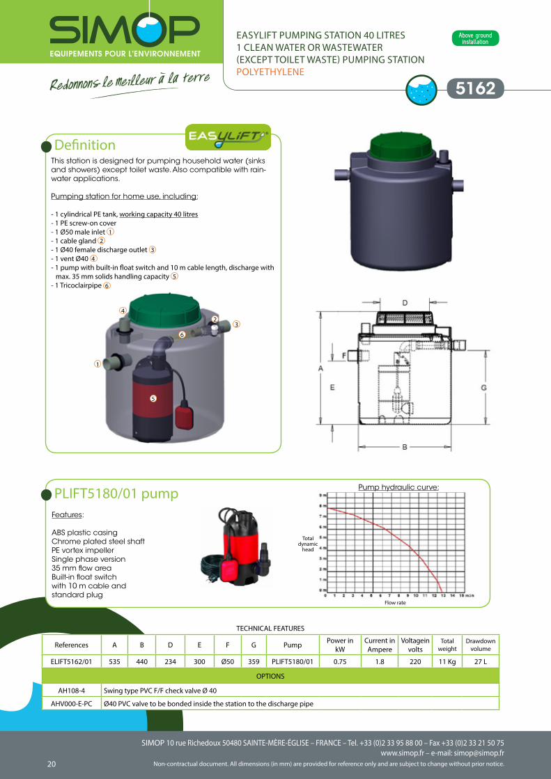
Features:
ABS plastic casingChrome plated steel shaftPE vortex impellerSingle phase version35 mm flow areaBuilt-in float switchwith 10 m cable and standard plug
5162
EASYLIFT PUMPING STATION 40 LITRES1 CLEAN WATER OR WASTEWATER (EXCEPT TOILET WASTE) PUMPING STATIONPOLYETHYLENE
This station is designed for pumping household water (sinks and showers) except toilet waste. Also compatible with rain-water applications.
Pumping station for home use, including:
- 1 cylindrical PE tank, working capacity 40 litres- 1 PE screw-on cover- 1 Ø50 male inlet 1- 1 cable gland 2- 1 Ø40 female discharge outlet 3- 1 vent Ø40 4- 1 pump with built-in float switch and 10 m cable length, discharge with
max. 35 mm solids handling capacity 5- 1 Tricoclairpipe 6
Definition
References A B D E F G Pump Power in kW
Current in Ampere
Voltage in volts
Totalweight
Drawdownvolume
ELIFT5162/01 535 440 234 300 Ø50 359 PLIFT5180/01 0.75 1.8 220 11 Kg 27 L
OPTIONS
AH108-4 Swing type PVC F/F check valve Ø 40
AHV000-E-PC Ø40 PVC valve to be bonded inside the station to the discharge pipe
TECHNICAL FEATURES
PLIFT5180/01 pump Pump hydraulic curve:
1
3
4
5
6
2
Above ground installation
Flow rate
Total dynamic
head
SIMOP 10 rue Richedoux 50480 SAINTE-MÈRE-ÉGLISE – FRANCE – Tel. +33 (0)2 33 95 88 00 – Fax +33 (0)2 33 21 50 75www.simop.fr – e-mail: [email protected] document. All dimensions (in mm) are provided for reference only and are subject to change without prior notice.
SIMOP 10 rue Richedoux 50480 SAINTE-MÈRE-ÉGLISE – FRANCE – Tel. +33 (0)2 33 95 88 00 – Fax +33 (0)2 33 21 50 75www.simop.fr – e-mail: [email protected]
Non-contractual document. All dimensions (in mm) are provided for reference only and are subject to change without prior notice. 2120
Features:
ABS plastic casingChrome plated steel shaftPE vortex impellerSingle phase version35 mm flow areaBuilt-in float switchwith 10 m cable and a standard plug
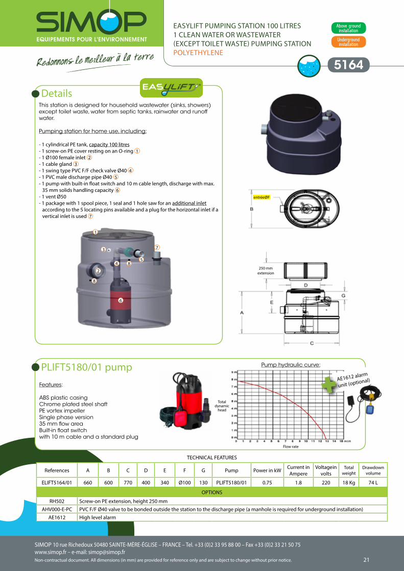
5164
EASYLIFT PUMPING STATION 100 LITRES1 CLEAN WATER OR WASTEWATER (EXCEPT TOILET WASTE) PUMPING STATIONPOLYETHYLENE
This station is designed for household wastewater (sinks, showers) except toilet waste, water from septic tanks, rainwater and runoff water.
Pumping station for home use, including:
- 1 cylindrical PE tank, capacity 100 litres- 1 screw-on PE cover resting on an O-ring 1- 1 Ø100 female inlet 2- 1 cable gland 3- 1 swing type PVC F/F check valve Ø40 4- 1 PVC male discharge pipe Ø40 5- 1 pump with built-in float switch and 10 m cable length, discharge with max.
35 mm solids handling capacity 6- 1 vent Ø50 - 1 package with 1 spool piece, 1 seal and 1 hole saw for an additional inlet
according to the 5 locating pins available and a plug for the horizontal inlet if a vertical inlet is used 7
Details
References A B C D E F G Pump Power in kW Current in Ampere
Voltage in volts
Totalweight
Drawdownvolume
ELIFT5164/01 660 600 770 400 340 Ø100 130 PLIFT5180/01 0.75 1.8 220 18 Kg 74 L
OPTIONS
RH502 Screw-on PE extension, height 250 mmAHV000-E-PC PVC F/F Ø40 valve to be bonded outside the station to the discharge pipe (a manhole is required for underground installation)
AE1612 High level alarm
TECHNICAL FEATURES
PLIFT5180/01 pump Pump hydraulic curve:
1
2
3
45
6
8
8
7
AE1612 alarm
unit (optional)
Underground installation
Above ground installation
250 mm extension
entrée Ø F
Flow rate
Total dynamic
head
SIMOP 10 rue Richedoux 50480 SAINTE-MÈRE-ÉGLISE – FRANCE – Tel. +33 (0)2 33 95 88 00 – Fax +33 (0)2 33 21 50 75www.simop.fr – e-mail: [email protected] document. All dimensions (in mm) are provided for reference only and are subject to change without prior notice.
SIMOP 10 rue Richedoux 50480 SAINTE-MÈRE-ÉGLISE – FRANCE – Tel. +33 (0)2 33 95 88 00 – Fax +33 (0)2 33 21 50 75www.simop.fr – e-mail: [email protected]
Non-contractual document. All dimensions (in mm) are provided for reference only and are subject to change without prior notice. 2322
Features:
ABS plastic casingChrome plated steel shaftPE vortex impellerSingle phase version35 mm flow areaBuilt-in float switchFitted with 10 m cable and standard plug
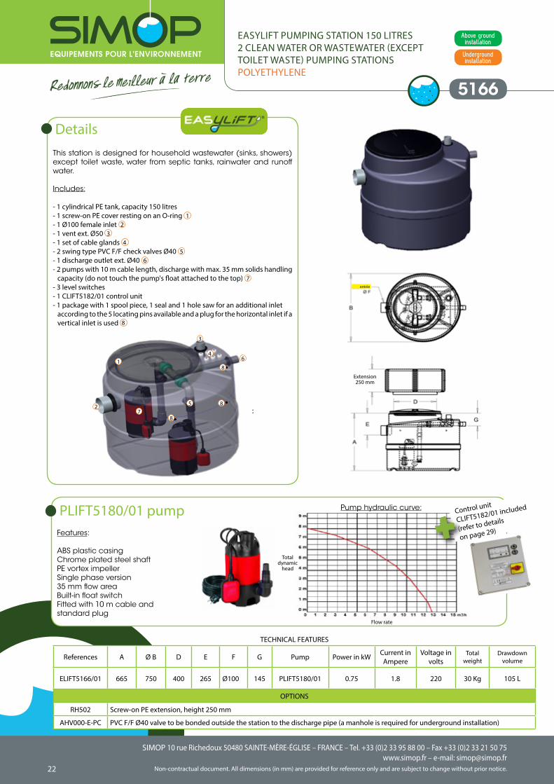
5166
EASYLIFT PUMPING STATION 150 LITRES2 CLEAN WATER OR WASTEWATER (EXCEPT TOILET WASTE) PUMPING STATIONSPOLYETHYLENE
This station is designed for household wastewater (sinks, showers) except toilet waste, water from septic tanks, rainwater and runoff water.
Includes:
- 1 cylindrical PE tank, capacity 150 litres- 1 screw-on PE cover resting on an O-ring 1- 1 Ø100 female inlet 2- 1 vent ext. Ø50 3- 1 set of cable glands 4- 2 swing type PVC F/F check valves Ø40 5- 1 discharge outlet ext. Ø40 6- 2 pumps with 10 m cable length, discharge with max. 35 mm solids handling
capacity (do not touch the pump's float attached to the top) 7- 3 level switches- 1 CLIFT5182/01 control unit- 1 package with 1 spool piece, 1 seal and 1 hole saw for an additional inlet
according to the 5 locating pins available and a plug for the horizontal inlet if a vertical inlet is used 8
Details
References A Ø B D E F G Pump Power in kW Current in Ampere
Voltage in volts
Totalweight
Drawdownvolume
ELIFT5166/01 665 750 400 265 Ø100 145 PLIFT5180/01 0.75 1.8 220 30 Kg 105 L
OPTIONS
RH502 Screw-on PE extension, height 250 mm
AHV000-E-PC PVC F/F Ø40 valve to be bonded outside the station to the discharge pipe (a manhole is required for underground installation)
TECHNICAL FEATURES
1
2
3
4
5
6
7
8
8
8
PLIFT5180/01 pump Pump hydraulic curve: Control unit
CLIFT5182/01 included
(refer to details
on page 29)
Underground installation
Above ground installation
Flow rate
Total dynamic
head
Extension 250 mm
entrée
SIMOP 10 rue Richedoux 50480 SAINTE-MÈRE-ÉGLISE – FRANCE – Tel. +33 (0)2 33 95 88 00 – Fax +33 (0)2 33 21 50 75www.simop.fr – e-mail: [email protected] document. All dimensions (in mm) are provided for reference only and are subject to change without prior notice.
SIMOP 10 rue Richedoux 50480 SAINTE-MÈRE-ÉGLISE – FRANCE – Tel. +33 (0)2 33 95 88 00 – Fax +33 (0)2 33 21 50 75www.simop.fr – e-mail: [email protected]
Non-contractual document. All dimensions (in mm) are provided for reference only and are subject to change without prior notice. 2322
Control unit
CLIFT5182/01 included
(refer to details
on page 29)Features:
ABS plastic casingChrome plated steel shaftPE vortex impellerSingle phase version35 mm flow areaBuilt-in float switchwith 10 m cable and standard plug
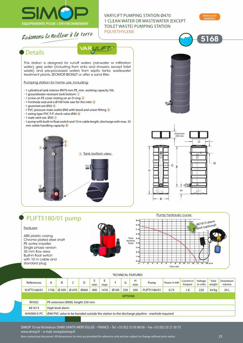
5168
VARYLIFT PUMPING STATION Ø470 1 CLEAN WATER OR WASTEWATER (EXCEPT TOILET WASTE) PUMPING STATIONPOLYETHYLENE
This station is designed for runoff waters (rainwater or infiltration water), grey water (including from sinks and showers, except toilet waste) and pre-processed waters from septic tanks, wastewater treatment plants, ZEOMOP, BIONUT or after a sand filter.
Pumping station for home use, including:
- 1 cylindrical tank interior Ø470 mm PE, min. working capacity 50L- 1 groundwater-resistant tank bottom 1- 1 screw-on PE cover resting on an O-ring 2- 1 Forsheda seal and a Ø100 hole saw for the inlet 3- 1 grommet ext Ø50 4- 1 PVC pressure male outlet Ø40 with bend and union fitting 5- 1 swing type PVC F/F check valve Ø40 6- 1 male vent ext. Ø50 7- 1 pump with built-in float switch and 10 m cable length, discharge with max. 35
mm solids handling capacity 8
Details
References A B C D Emin
Emax F G H
min Pump Power in kW Current in Ampere
Voltage in volts
Totalweight
Drawdownvolume
VLIFT5168/01 1736 Ø 509 Ø 470 Ø400 400 1476 Ø100 250 260 PLIFT5180/01 0.75 1.8 220 34 Kg 34 L
OPTIONS
RH502 PE extension Ø400, height 250 mm
AE1613 High level alarm
AHV000-E-PC Ø40 PVC valve to be bonded outside the station to the discharge pipeline - manhole required
TECHNICAL FEATURES
PLIFT5180/01 pump AE1613 alarm
unit (optional)
Tank bottom view: 1
2
3
45
6
7
8
Extension 250 mm
Pump hydraulic curve:
Underground installation
Flow rate
Total dynamic
head
SIMOP 10 rue Richedoux 50480 SAINTE-MÈRE-ÉGLISE – FRANCE – Tel. +33 (0)2 33 95 88 00 – Fax +33 (0)2 33 21 50 75www.simop.fr – e-mail: [email protected] document. All dimensions (in mm) are provided for reference only and are subject to change without prior notice.
SIMOP 10 rue Richedoux 50480 SAINTE-MÈRE-ÉGLISE – FRANCE – Tel. +33 (0)2 33 95 88 00 – Fax +33 (0)2 33 21 50 75www.simop.fr – e-mail: [email protected]
Non-contractual document. All dimensions (in mm) are provided for reference only and are subject to change without prior notice. 2524
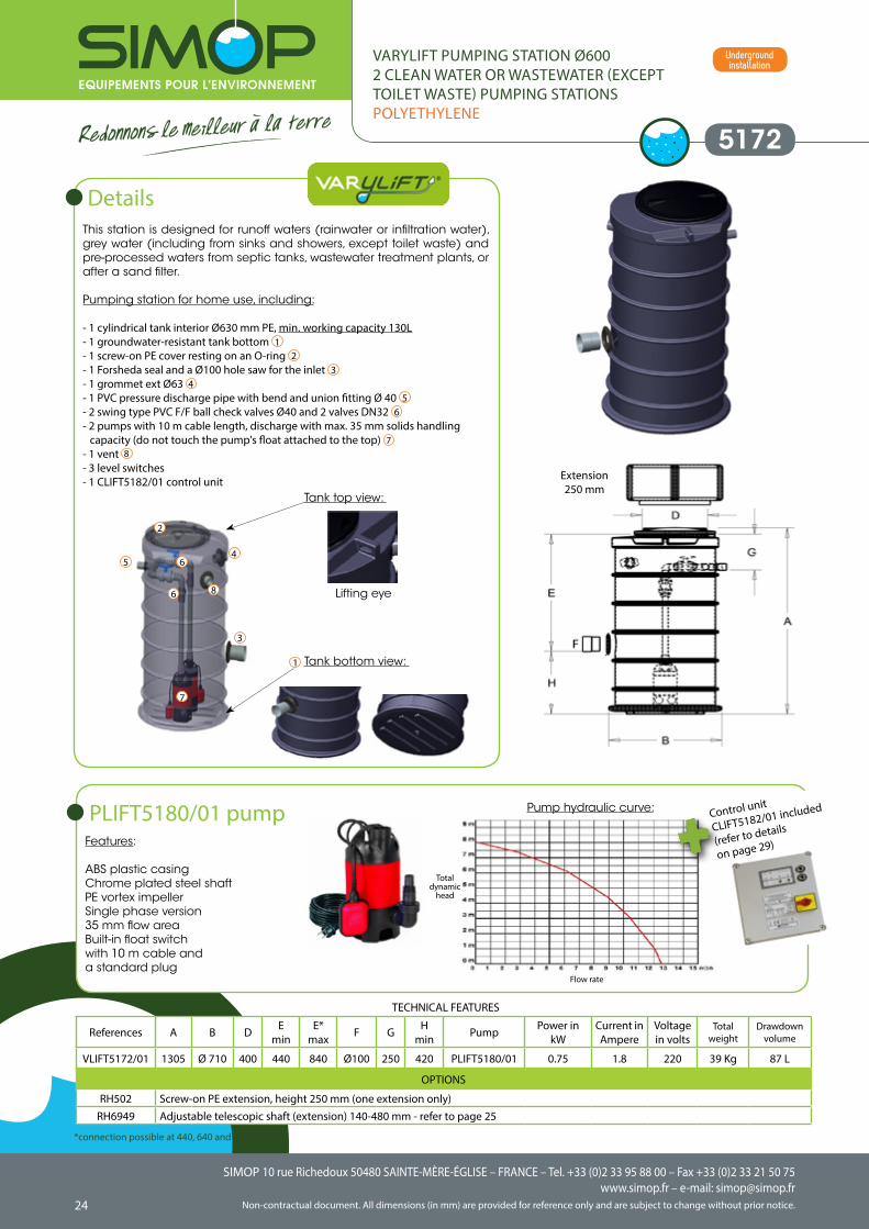
This station is designed for runoff waters (rainwater or infiltration water), grey water (including from sinks and showers, except toilet waste) and pre-processed waters from septic tanks, wastewater treatment plants, or after a sand filter.
Pumping station for home use, including:
- 1 cylindrical tank interior Ø630 mm PE, min. working capacity 130L- 1 groundwater-resistant tank bottom 1- 1 screw-on PE cover resting on an O-ring 2- 1 Forsheda seal and a Ø100 hole saw for the inlet 3- 1 grommet ext Ø63 4- 1 PVC pressure discharge pipe with bend and union fitting Ø 40 5- 2 swing type PVC F/F ball check valves Ø40 and 2 valves DN32 6- 2 pumps with 10 m cable length, discharge with max. 35 mm solids handling
capacity (do not touch the pump's float attached to the top) 7- 1 vent 8
- 3 level switches- 1 CLIFT5182/01 control unit
5172
VARYLIFT PUMPING STATION Ø6002 CLEAN WATER OR WASTEWATER (EXCEPT TOILET WASTE) PUMPING STATIONSPOLYETHYLENE
Details
References A B D Emin
E*max F G H
min Pump Power in kW
Current in Ampere
Voltage in volts
Totalweight
Drawdownvolume
VLIFT5172/01 1305 Ø 710 400 440 840 Ø100 250 420 PLIFT5180/01 0.75 1.8 220 39 Kg 87 L
OPTIONS
RH502 Screw-on PE extension, height 250 mm (one extension only)RH6949 Adjustable telescopic shaft (extension) 140-480 mm - refer to page 25
TECHNICAL FEATURES
Tank bottom view:
Tank top view:
Lifting eye
1
2
3
45
6
6
7
8
Features:
ABS plastic casingChrome plated steel shaftPE vortex impellerSingle phase version35 mm flow areaBuilt-in float switchwith 10 m cable and a standard plug
PLIFT5180/01 pump Pump hydraulic curve: Control unit
CLIFT5182/01 included
(refer to details
on page 29)
*connection possible at 440, 640 and 840 mm
Underground installation
Flow rate
Total dynamic
head
Extension 250 mm
SIMOP 10 rue Richedoux 50480 SAINTE-MÈRE-ÉGLISE – FRANCE – Tel. +33 (0)2 33 95 88 00 – Fax +33 (0)2 33 21 50 75www.simop.fr – e-mail: [email protected] document. All dimensions (in mm) are provided for reference only and are subject to change without prior notice.
SIMOP 10 rue Richedoux 50480 SAINTE-MÈRE-ÉGLISE – FRANCE – Tel. +33 (0)2 33 95 88 00 – Fax +33 (0)2 33 21 50 75www.simop.fr – e-mail: [email protected]
Non-contractual document. All dimensions (in mm) are provided for reference only and are subject to change without prior notice. 2524
5178
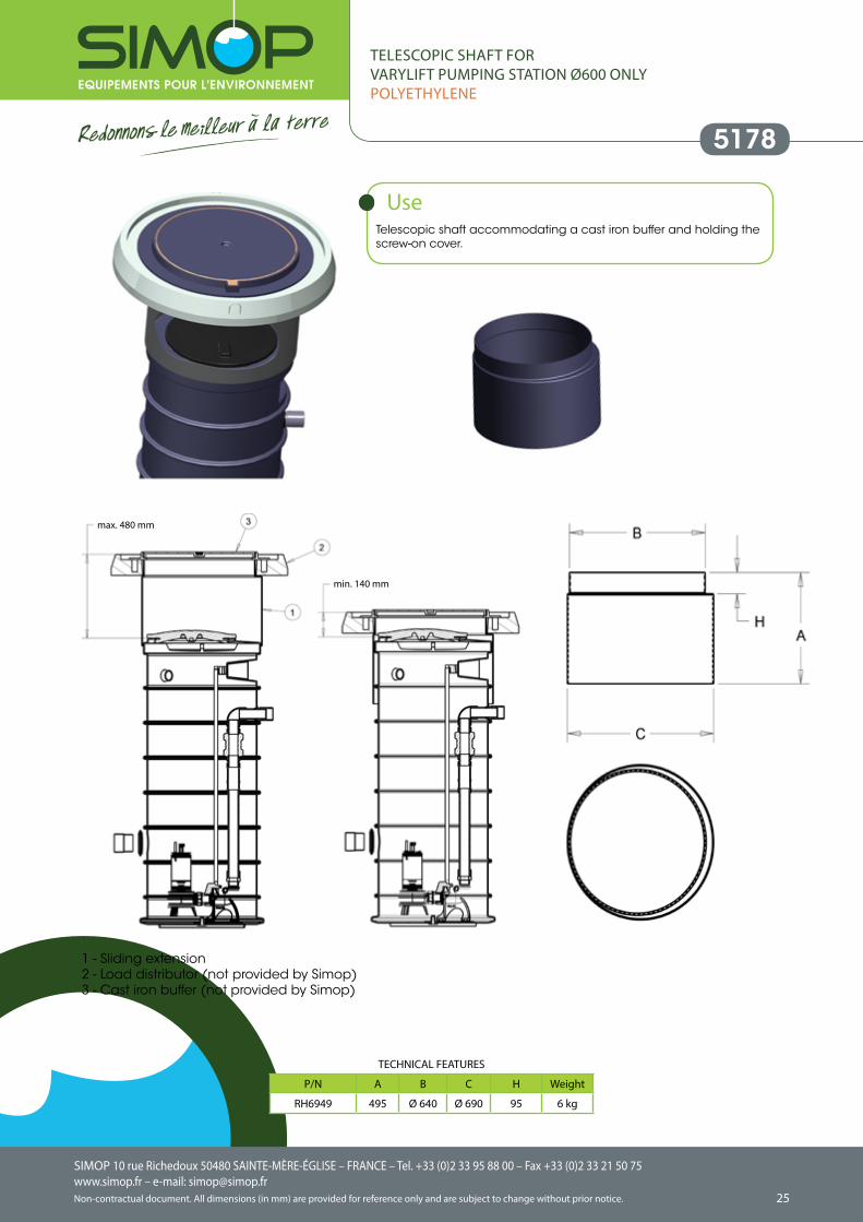
TELESCOPIC SHAFT FORVARYLIFT PUMPING STATION Ø600 ONLYPOLYETHYLENE
Telescopic shaft accommodating a cast iron buffer and holding the screw-on cover.
Use
P/N A B C H Weight
RH6949 495 Ø 640 Ø 690 95 6 kg
1 - Sliding extension2 - Load distributor (not provided by Simop)3 - Cast iron buffer (not provided by Simop)
TECHNICAL FEATURES
mm
mm
max. 480 mm
min. 140 mm
SIMOP 10 rue Richedoux 50480 SAINTE-MÈRE-ÉGLISE – FRANCE – Tel. +33 (0)2 33 95 88 00 – Fax +33 (0)2 33 21 50 75www.simop.fr – e-mail: [email protected] document. All dimensions (in mm) are provided for reference only and are subject to change without prior notice.
SIMOP 10 rue Richedoux 50480 SAINTE-MÈRE-ÉGLISE – FRANCE – Tel. +33 (0)2 33 95 88 00 – Fax +33 (0)2 33 21 50 75www.simop.fr – e-mail: [email protected]
Non-contractual document. All dimensions (in mm) are provided for reference only and are subject to change without prior notice. 2726
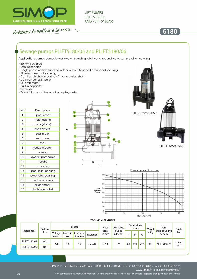
Sewage pumps PLIFT5180/05 and PLIFT5180/06Application: pumps domestic wastewater, including toilet waste, ground water, sump and for watering.
• 50 mm flow area• with 10 m cable• Single-phase version supplied with or without float and a standardised plug• Stainless steel motor casing• Cast iron discharge casing - Chrome plated shaft• Cast iron vortex impeller• Oil-bath motor• Built-in capacitor• Two walls• Adaptation possible on auto-coupling system
TECHNICAL FEATURES
References Built-in float
Motor Flowarea
in mm
Dischargeoutlet
in Inches
Dimensions in mm Weight
in Kg
P/N auto-coupling
system
Guide barVoltage
in voltsPower in
kWCurrent in Ampere Insulation A B C
PLIFT5180/05 Yes220 0.4 3.9 class B Ø 50 2’’ 396 121 222 12 ALIFT5180/20 1 bar
Ø 1’’PLIFT5180/06 No
A
No. Description
1 upper cover
2 motor casing
3 motor (stator)
4 shaft (rotor)
5 seal plate
6 seal cover
7 seal
8 vortex impeller
9 volute
10 Power supply cable
11 handle
12 capacitor
13 upper roller bearing
14 lower roller bearing
15 mechanical seal
16 oil chamber
17 discharge outlet
Pump hydraulic curve:
PLIFT5180/05 PUMP
5180
LIFT PUMPS PLIFT5180/05 AND PLIFT5180/06
PLIFT5180/06 PUMP1
2
3
4
5
67
89
11
12
13
14
1516
17
10
BC
Flow rate in m3/h
Total dynamic
head
SIMOP 10 rue Richedoux 50480 SAINTE-MÈRE-ÉGLISE – FRANCE – Tel. +33 (0)2 33 95 88 00 – Fax +33 (0)2 33 21 50 75www.simop.fr – e-mail: [email protected] document. All dimensions (in mm) are provided for reference only and are subject to change without prior notice.
SIMOP 10 rue Richedoux 50480 SAINTE-MÈRE-ÉGLISE – FRANCE – Tel. +33 (0)2 33 95 88 00 – Fax +33 (0)2 33 21 50 75www.simop.fr – e-mail: [email protected]
Non-contractual document. All dimensions (in mm) are provided for reference only and are subject to change without prior notice. 2726
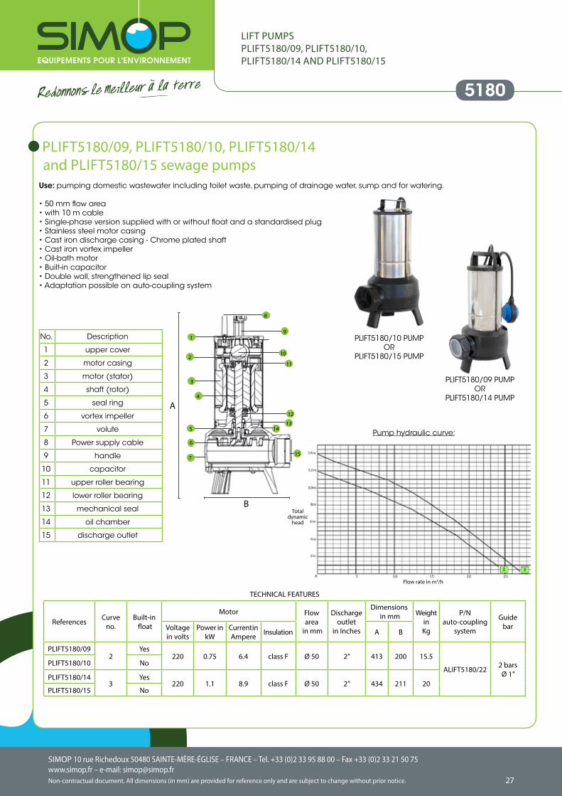
PLIFT5180/09, PLIFT5180/10, PLIFT5180/14 and PLIFT5180/15 sewage pumps
Use: pumping domestic wastewater including toilet waste, pumping of drainage water, sump and for watering.
• 50 mm flow area• with 10 m cable• Single-phase version supplied with or without float and a standardised plug• Stainless steel motor casing• Cast iron discharge casing - Chrome plated shaft• Cast iron vortex impeller• Oil-bath motor• Built-in capacitor• Double wall, strengthened lip seal• Adaptation possible on auto-coupling system
TECHNICAL FEATURES
References Curve no.
Built-in float
Motor Flowarea
in mm
Dischargeoutlet
in Inches
Dimensions in mm Weight
in Kg
P/N auto-coupling
system
Guide barVoltage
in voltsPower in
kWCurrent in Ampere Insulation A B
PLIFT5180/092
Yes220 0.75 6.4 class F Ø 50 2’’ 413 200 15.5
ALIFT5180/22 2 bars Ø 1’’
PLIFT5180/10 No
PLIFT5180/143
Yes220 1.1 8.9 class F Ø 50 2’’ 434 211 20
PLIFT5180/15 No
5180
LIFT PUMPSPLIFT5180/09, PLIFT5180/10, PLIFT5180/14 AND PLIFT5180/15
No. Description
1 upper cover
2 motor casing
3 motor (stator)
4 shaft (rotor)
5 seal ring
6 vortex impeller
7 volute
8 Power supply cable
9 handle
10 capacitor
11 upper roller bearing
12 lower roller bearing
13 mechanical seal
14 oil chamber
15 discharge outlet
Pump hydraulic curve:
PLIFT5180/09 PUMPOR
PLIFT5180/14 PUMP
PLIFT5180/10 PUMPOR
PLIFT5180/15 PUMP
1
2
3
4
5
7
8
9
10
11
12
1314
15
A
B
6
Flow rate in m3/h
Total dynamic
head
SIMOP 10 rue Richedoux 50480 SAINTE-MÈRE-ÉGLISE – FRANCE – Tel. +33 (0)2 33 95 88 00 – Fax +33 (0)2 33 21 50 75www.simop.fr – e-mail: [email protected] document. All dimensions (in mm) are provided for reference only and are subject to change without prior notice.
SIMOP 10 rue Richedoux 50480 SAINTE-MÈRE-ÉGLISE – FRANCE – Tel. +33 (0)2 33 95 88 00 – Fax +33 (0)2 33 21 50 75www.simop.fr – e-mail: [email protected]
Non-contractual document. All dimensions (in mm) are provided for reference only and are subject to change without prior notice. 2928
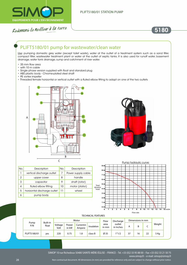
PLIFT5180/01 STATION PUMP
Use: pumping domestic grey water (except toilet waste), water at the outlet of a treatment system such as a sand filter, compact filter, wastewater treatment plant or water at the outlet of septic tanks. It is also used for runoff water, basement drainage, water tank drainage, sump and catchment of river water.
• 35 mm flow area• with 10 m cable• Single phase version supplied with float and standard plug• ABS plastic body - Chrome-plated steel shaft• PE vortex impeller• Threaded female horizontal or vertical outlet with a fluted elbow fitting to adapt on one of the two outlets
TECHNICAL FEATURES
PumpP/N
Built-in float
Motor Flowarea
in mm
Dischargeoutlet
in Inches
Dimensions in mmWeightVoltage
VoltPower in kW
Current in Ampere Insulation A B C
PLIFT5180/01 yes 220 0.75 1.8 class B Ø 35 1’’1/2 37 16 22 5 Kg
PLIFT5180/01 pump for wastewater/clean water
Pump hydraulic curve:
No. Description No. Description
1 vertical discharge outlet 7 Power supply cable
2 upper cover 8 handle
3 capacitor 9 shaft (rotor)
4 fluted elbow fitting 10 motor (stator)
5 horizontal discharge outlet 11 wheel
6 pump body
7
2
1
3
4
6
9
10
11
5
8
A
CB
5180
Flow rate
Total dynamic
head
SIMOP 10 rue Richedoux 50480 SAINTE-MÈRE-ÉGLISE – FRANCE – Tel. +33 (0)2 33 95 88 00 – Fax +33 (0)2 33 21 50 75www.simop.fr – e-mail: [email protected] document. All dimensions (in mm) are provided for reference only and are subject to change without prior notice.
SIMOP 10 rue Richedoux 50480 SAINTE-MÈRE-ÉGLISE – FRANCE – Tel. +33 (0)2 33 95 88 00 – Fax +33 (0)2 33 21 50 75www.simop.fr – e-mail: [email protected]
Non-contractual document. All dimensions (in mm) are provided for reference only and are subject to change without prior notice. 2928
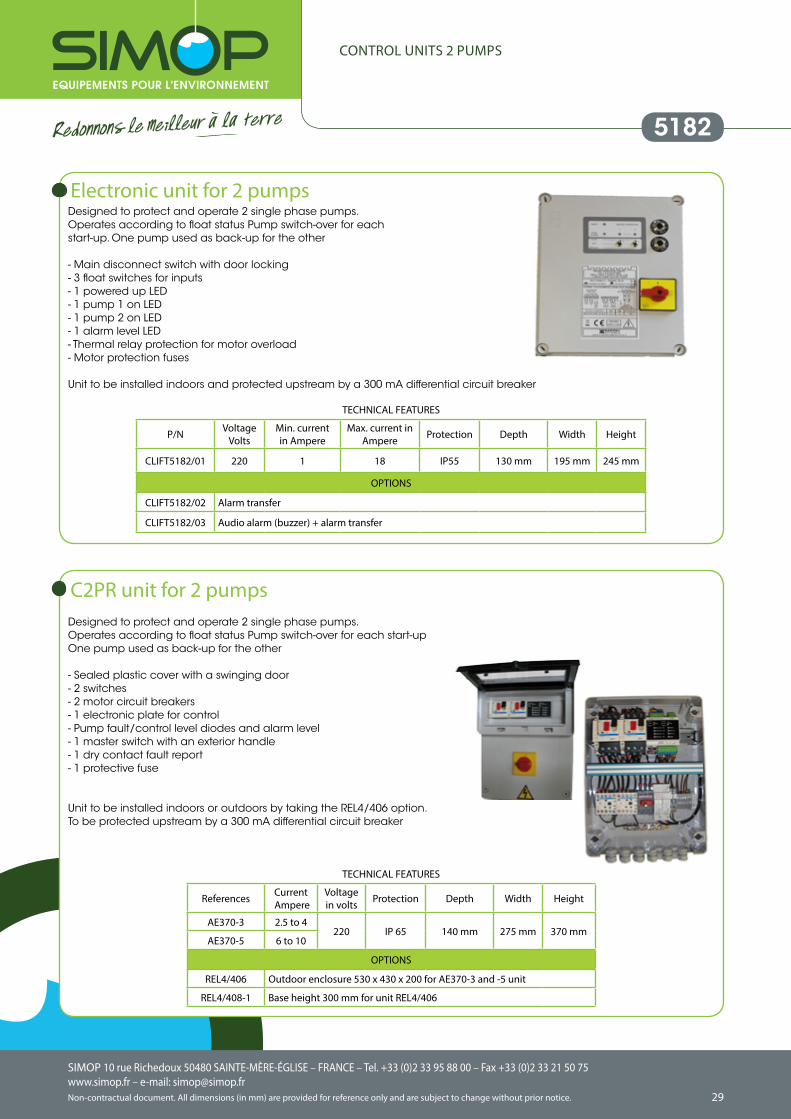
CONTROL UNITS 2 PUMPS
Designed to protect and operate 2 single phase pumps. Operates according to float status Pump switch-over for eachstart-up. One pump used as back-up for the other
- Main disconnect switch with door locking- 3 float switches for inputs- 1 powered up LED- 1 pump 1 on LED- 1 pump 2 on LED- 1 alarm level LED- Thermal relay protection for motor overload- Motor protection fuses
Unit to be installed indoors and protected upstream by a 300 mA differential circuit breaker
TECHNICAL FEATURES
P/N VoltageVolts
Min. current in Ampere
Max. current in Ampere Protection Depth Width Height
CLIFT5182/01 220 1 18 IP55 130 mm 195 mm 245 mm
OPTIONS
CLIFT5182/02 Alarm transfer
CLIFT5182/03 Audio alarm (buzzer) + alarm transfer
Electronic unit for 2 pumps
Designed to protect and operate 2 single phase pumps. Operates according to float status Pump switch-over for each start-up One pump used as back-up for the other
- Sealed plastic cover with a swinging door- 2 switches- 2 motor circuit breakers- 1 electronic plate for control- Pump fault/control level diodes and alarm level- 1 master switch with an exterior handle- 1 dry contact fault report- 1 protective fuse
Unit to be installed indoors or outdoors by taking the REL4/406 option.To be protected upstream by a 300 mA differential circuit breaker
TECHNICAL FEATURES
References Current Ampere
Voltage in volts Protection Depth Width Height
AE370-3 2.5 to 4220 IP 65 140 mm 275 mm 370 mm
AE370-5 6 to 10
OPTIONS
REL4/406 Outdoor enclosure 530 x 430 x 200 for AE370-3 and -5 unit
REL4/408-1 Base height 300 mm for unit REL4/406
C2PR unit for 2 pumps
5182
SIMOP 10 rue Richedoux 50480 SAINTE-MÈRE-ÉGLISE – FRANCE – Tel. +33 (0)2 33 95 88 00 – Fax +33 (0)2 33 21 50 75www.simop.fr – e-mail: [email protected] document. All dimensions (in mm) are provided for reference only and are subject to change without prior notice.
SIMOP 10 rue Richedoux 50480 SAINTE-MÈRE-ÉGLISE – FRANCE – Tel. +33 (0)2 33 95 88 00 – Fax +33 (0)2 33 21 50 75www.simop.fr – e-mail: [email protected]
Non-contractual document. All dimensions (in mm) are provided for reference only and are subject to change without prior notice. 3130
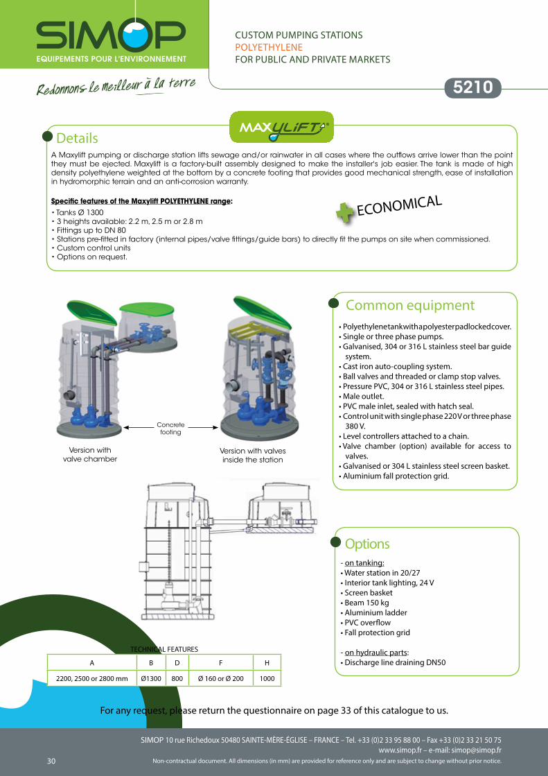
CUSTOM PUMPING STATIONSPOLYETHYLENEFOR PUBLIC AND PRIVATE MARKETS
A Maxylift pumping or discharge station lifts sewage and/or rainwater in all cases where the outflows arrive lower than the point they must be ejected. Maxylift is a factory-built assembly designed to make the installer's job easier. The tank is made of high density polyethylene weighted at the bottom by a concrete footing that provides good mechanical strength, ease of installation in hydromorphic terrain and an anti-corrosion warranty.
Specific features of the Maxylift POLYETHYLENE range: • Tanks Ø 1300• 3 heights available: 2.2 m, 2.5 m or 2.8 m• Fittings up to DN 80• Stations pre-fitted in factory (internal pipes/valve fittings/guide bars) to directly fit the pumps on site when commissioned. • Custom control units• Options on request.
Details
Version withvalve chamber
Version with valvesinside the station
Concrete footing
ECONOMICAL
A B D F H
2200, 2500 or 2800 mm Ø1300 800 Ø 160 or Ø 200 1000
TECHNICAL FEATURES
• Polyethylene tank with a polyester padlocked cover.• Single or three phase pumps.• Galvanised, 304 or 316 L stainless steel bar guide
system.• Cast iron auto-coupling system.• Ball valves and threaded or clamp stop valves.• Pressure PVC, 304 or 316 L stainless steel pipes.• Male outlet.• PVC male inlet, sealed with hatch seal.• Control unit with single phase 220 V or three phase
380 V.• Level controllers attached to a chain.• Valve chamber (option) available for access to
valves.• Galvanised or 304 L stainless steel screen basket.• Aluminium fall protection grid.
Common equipment
- on tanking:• Water station in 20/27• Interior tank lighting, 24 V• Screen basket• Beam 150 kg• Aluminium ladder• PVC overflow• Fall protection grid
- on hydraulic parts:• Discharge line draining DN50
Options
For any request, please return the questionnaire on page 33 of this catalogue to us.
5210
SIMOP 10 rue Richedoux 50480 SAINTE-MÈRE-ÉGLISE – FRANCE – Tel. +33 (0)2 33 95 88 00 – Fax +33 (0)2 33 21 50 75www.simop.fr – e-mail: [email protected] document. All dimensions (in mm) are provided for reference only and are subject to change without prior notice.
SIMOP 10 rue Richedoux 50480 SAINTE-MÈRE-ÉGLISE – FRANCE – Tel. +33 (0)2 33 95 88 00 – Fax +33 (0)2 33 21 50 75www.simop.fr – e-mail: [email protected]
Non-contractual document. All dimensions (in mm) are provided for reference only and are subject to change without prior notice. 3130
Common equipment
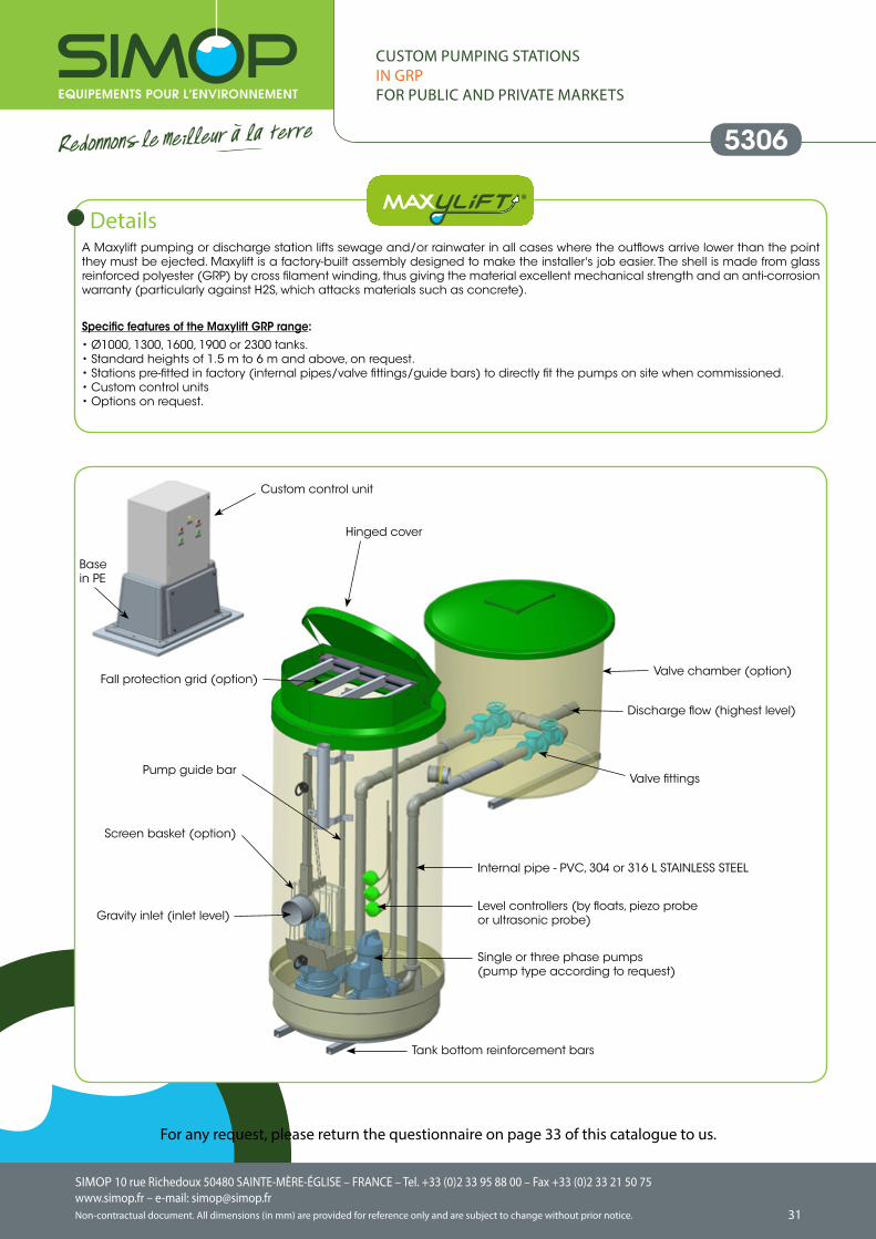
CUSTOM PUMPING STATIONSIN GRPFOR PUBLIC AND PRIVATE MARKETS
A Maxylift pumping or discharge station lifts sewage and/or rainwater in all cases where the outflows arrive lower than the point they must be ejected. Maxylift is a factory-built assembly designed to make the installer's job easier. The shell is made from glass reinforced polyester (GRP) by cross filament winding, thus giving the material excellent mechanical strength and an anti-corrosion warranty (particularly against H2S, which attacks materials such as concrete).
Specific features of the Maxylift GRP range: • Ø1000, 1300, 1600, 1900 or 2300 tanks.• Standard heights of 1.5 m to 6 m and above, on request.• Stations pre-fitted in factory (internal pipes/valve fittings/guide bars) to directly fit the pumps on site when commissioned. • Custom control units• Options on request.
Basein PE
Custom control unit
Valve chamber (option)
Hinged cover
Single or three phase pumps (pump type according to request)
Internal pipe - PVC, 304 or 316 L STAINLESS STEEL
Gravity inlet (inlet level)
Screen basket (option)
Fall protection grid (option)
Level controllers (by floats, piezo probe or ultrasonic probe)
Pump guide barValve fittings
Discharge flow (highest level)
Tank bottom reinforcement bars
Details
For any request, please return the questionnaire on page 33 of this catalogue to us.
5306
SIMOP 10 rue Richedoux 50480 SAINTE-MÈRE-ÉGLISE – FRANCE – Tel. +33 (0)2 33 95 88 00 – Fax +33 (0)2 33 21 50 75www.simop.fr – e-mail: [email protected] document. All dimensions (in mm) are provided for reference only and are subject to change without prior notice.
SIMOP 10 rue Richedoux 50480 SAINTE-MÈRE-ÉGLISE – FRANCE – Tel. +33 (0)2 33 95 88 00 – Fax +33 (0)2 33 21 50 75www.simop.fr – e-mail: [email protected]
Non-contractual document. All dimensions (in mm) are provided for reference only and are subject to change without prior notice. 3332
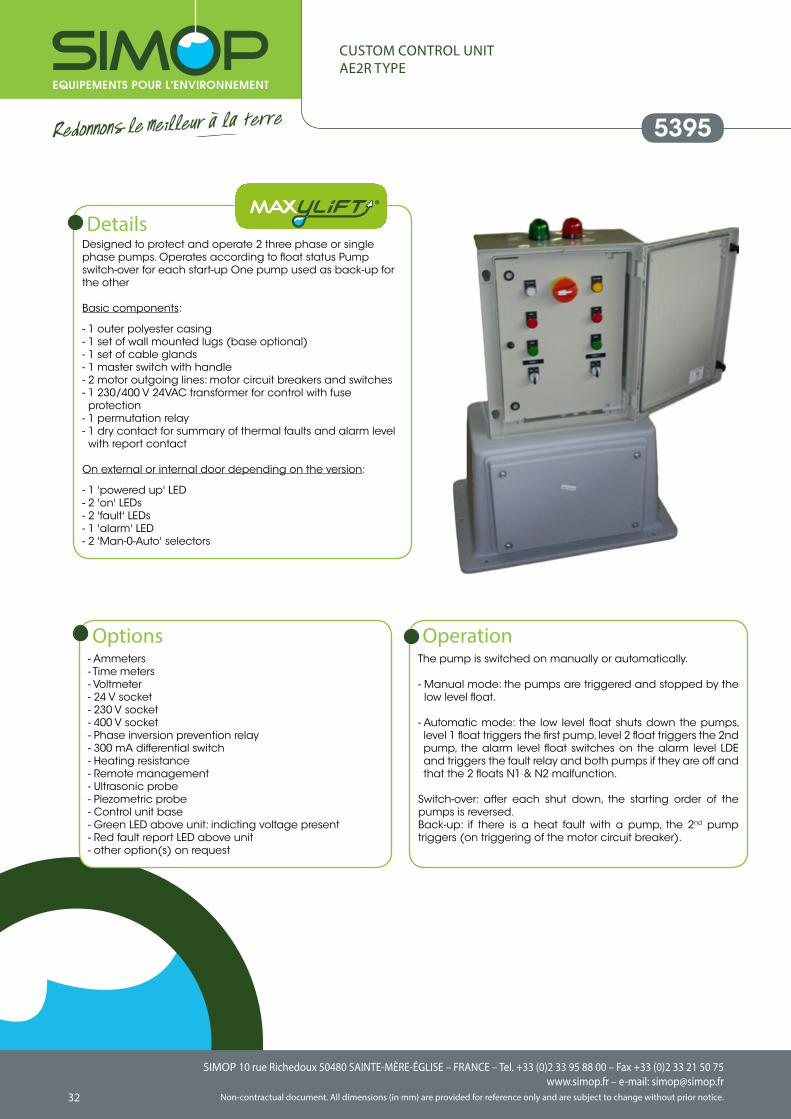
CUSTOM CONTROL UNITAE2R TYPE
Designed to protect and operate 2 three phase or single phase pumps. Operates according to float status Pump switch-over for each start-up One pump used as back-up for the other
Basic components:
- 1 outer polyester casing- 1 set of wall mounted lugs (base optional)- 1 set of cable glands- 1 master switch with handle- 2 motor outgoing lines: motor circuit breakers and switches- 1 230/400 V 24VAC transformer for control with fuse protection
- 1 permutation relay- 1 dry contact for summary of thermal faults and alarm level with report contact
On external or internal door depending on the version:
- 1 'powered up' LED- 2 'on' LEDs- 2 'fault' LEDs- 1 'alarm' LED- 2 'Man-0-Auto' selectors
Details
The pump is switched on manually or automatically.
- Manual mode: the pumps are triggered and stopped by the low level float.
- Automatic mode: the low level float shuts down the pumps, level 1 float triggers the first pump, level 2 float triggers the 2nd pump, the alarm level float switches on the alarm level LDE and triggers the fault relay and both pumps if they are off and that the 2 floats N1 & N2 malfunction.
Switch-over: after each shut down, the starting order of the pumps is reversed.Back-up: if there is a heat fault with a pump, the 2nd pump triggers (on triggering of the motor circuit breaker).
Operation- Ammeters- Time meters- Voltmeter- 24 V socket- 230 V socket- 400 V socket- Phase inversion prevention relay- 300 mA differential switch- Heating resistance- Remote management- Ultrasonic probe- Piezometric probe- Control unit base- Green LED above unit: indicting voltage present - Red fault report LED above unit- other option(s) on request
Options
5395
SIMOP 10 rue Richedoux 50480 SAINTE-MÈRE-ÉGLISE – FRANCE – Tel. +33 (0)2 33 95 88 00 – Fax +33 (0)2 33 21 50 75www.simop.fr – e-mail: [email protected] document. All dimensions (in mm) are provided for reference only and are subject to change without prior notice.
SIMOP 10 rue Richedoux 50480 SAINTE-MÈRE-ÉGLISE – FRANCE – Tel. +33 (0)2 33 95 88 00 – Fax +33 (0)2 33 21 50 75www.simop.fr – e-mail: [email protected]
Non-contractual document. All dimensions (in mm) are provided for reference only and are subject to change without prior notice. 3332
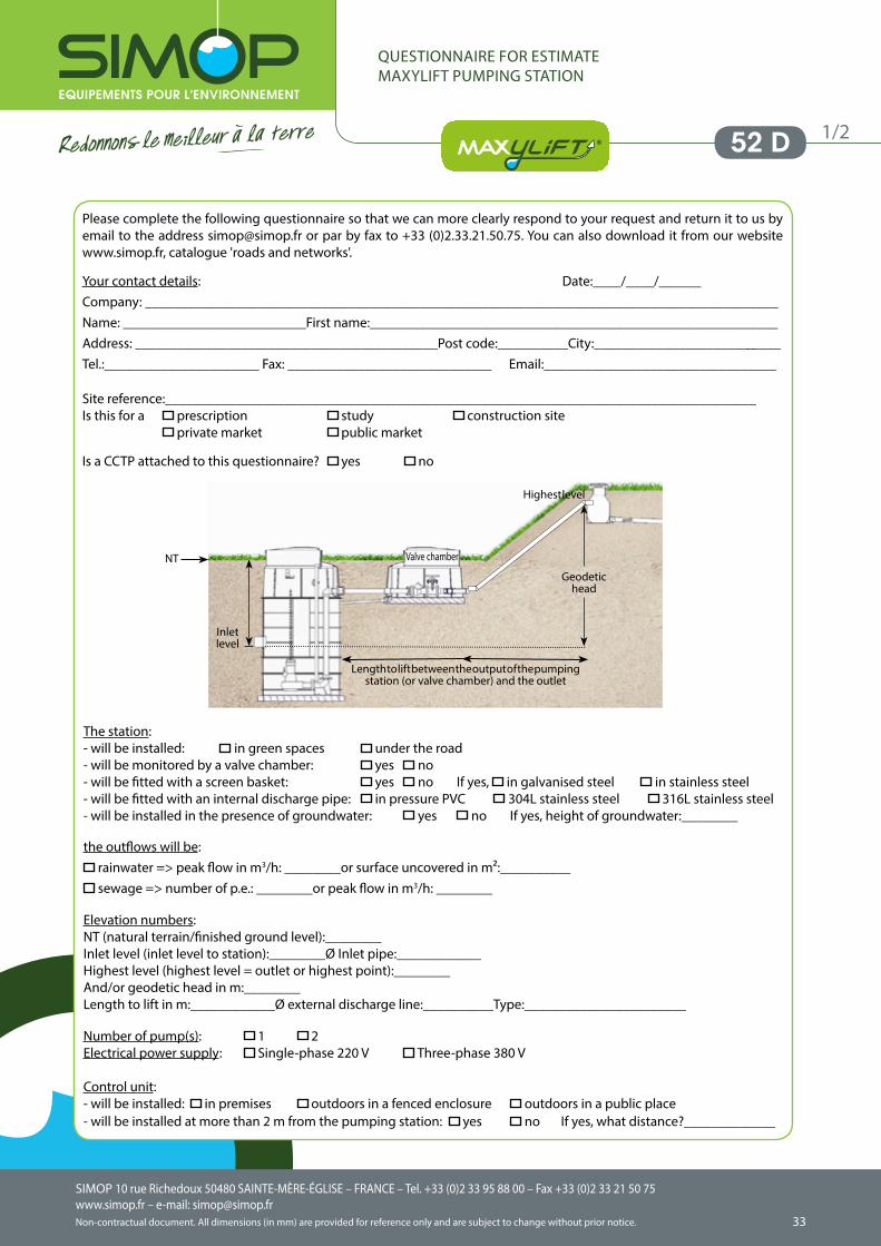
QUESTIONNAIRE FOR ESTIMATE MAXYLIFT PUMPING STATION
52 D
The station: - will be installed: in green spaces under the road- will be monitored by a valve chamber: yes no - will be fitted with a screen basket: yes no If yes, in galvanised steel in stainless steel- will be fitted with an internal discharge pipe: in pressure PVC 304L stainless steel 316L stainless steel- will be installed in the presence of groundwater: yes no If yes, height of groundwater:________
the outflows will be: rainwater => peak flow in m3/h: ________or surface uncovered in m²:__________ sewage => number of p.e.: ________or peak flow in m3/h: ________
Elevation numbers: NT (natural terrain/finished ground level):________ Inlet level (inlet level to station):________Ø Inlet pipe:____________ Highest level (highest level = outlet or highest point):________ And/or geodetic head in m:________ Length to lift in m:____________Ø external discharge line:__________Type:_______________________
Number of pump(s): 1 2 Electrical power supply: Single-phase 220 V Three-phase 380 V Control unit: - will be installed: in premises outdoors in a fenced enclosure outdoors in a public place - will be installed at more than 2 m from the pumping station: yes no If yes, what distance?_____________
Inlet level
NT
Geodetichead
Highest level
Length to lift between the output of the pumping station (or valve chamber) and the outlet
Valve chamber
1/2
Please complete the following questionnaire so that we can more clearly respond to your request and return it to us by email to the address [email protected] or par by fax to +33 (0)2.33.21.50.75. You can also download it from our website www.simop.fr, catalogue 'roads and networks'. Your contact details: Date:____/____/______Company: __________________________________________________________________________________________Name: __________________________First name:__________________________________________________________Address: ___________________________________________Post code:__________City:___________________________Tel.:______________________ Fax: _____________________________ Email:_________________________________
Site reference:____________________________________________________________________________________Is this for a prescription study construction site private market public market
Is a CCTP attached to this questionnaire? yes no
SIMOP 10 rue Richedoux 50480 SAINTE-MÈRE-ÉGLISE – FRANCE – Tel. +33 (0)2 33 95 88 00 – Fax +33 (0)2 33 21 50 75www.simop.fr – e-mail: [email protected] document. All dimensions (in mm) are provided for reference only and are subject to change without prior notice.
SIMOP 10 rue Richedoux 50480 SAINTE-MÈRE-ÉGLISE – FRANCE – Tel. +33 (0)2 33 95 88 00 – Fax +33 (0)2 33 21 50 75www.simop.fr – e-mail: [email protected]
Non-contractual document. All dimensions (in mm) are provided for reference only and are subject to change without prior notice. 3534
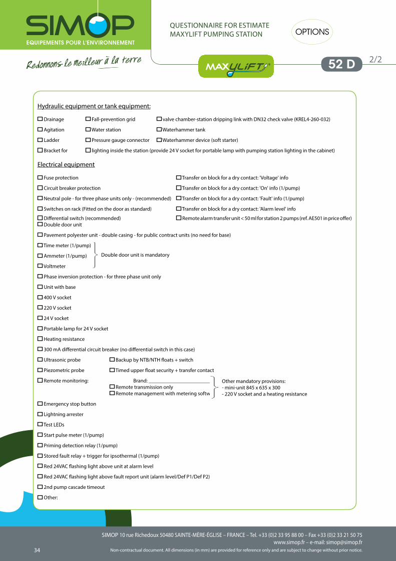
Hydraulic equipment or tank equipment:
Drainage Fall-prevention grid valve chamber-station dripping link with DN32 check valve (KREL4-260-032)
Agitation Water station Waterhammer tank
Ladder Pressure gauge connector Waterhammer device (soft starter)
Bracket for lighting inside the station (provide 24 V socket for portable lamp with pumping station lighting in the cabinet)
Electrical equipment
Fuse protection Transfer on block for a dry contact: 'Voltage' info
Circuit breaker protection Transfer on block for a dry contact: 'On' info (1/pump)
Neutral pole - for three phase units only - (recommended) Transfer on block for a dry contact: 'Fault' info (1/pump)
Switches on rack (Fitted on the door as standard) Transfer on block for a dry contact: 'Alarm level' info
Differential switch (recommended) Remote alarm transfer unit < 50 ml for station 2 pumps (ref. AE501 in price offer) Double door unit
Pavement polyester unit - double casing - for public contract units (no need for base)
Time meter (1/pump)
Ammeter (1/pump)
Voltmeter
Phase inversion protection - for three phase unit only
Unit with base
400 V socket
220 V socket
24 V socket
Portable lamp for 24 V socket
Heating resistance
300 mA differential circuit breaker (no differential switch in this case)
Ultrasonic probe Backup by NTB/NTH floats + switch
Piezometric probe Timed upper float security + transfer contact
Remote monitoring: Brand: _______________________ Remote transmission only Remote management with metering software
Emergency stop button
Lightning arrester
Test LEDs
Start pulse meter (1/pump)
Priming detection relay (1/pump)
Stored fault relay + trigger for ipsothermal (1/pump)
Red 24VAC flashing light above unit at alarm level
Red 24VAC flashing light above fault report unit (alarm level/Def P1/Def P2)
2nd pump cascade timeout
Other:
QUESTIONNAIRE FOR ESTIMATE MAXYLIFT PUMPING STATION
52 D
Double door unit is mandatory
Other mandatory provisions:- mini-unit 845 x 635 x 300- 220 V socket and a heating resistance
OPTIONS
2/2
SIMOP 10 rue Richedoux 50480 SAINTE-MÈRE-ÉGLISE – FRANCE – Tel. +33 (0)2 33 95 88 00 – Fax +33 (0)2 33 21 50 75www.simop.fr – e-mail: [email protected] document. All dimensions (in mm) are provided for reference only and are subject to change without prior notice.
SIMOP 10 rue Richedoux 50480 SAINTE-MÈRE-ÉGLISE – FRANCE – Tel. +33 (0)2 33 95 88 00 – Fax +33 (0)2 33 21 50 75www.simop.fr – e-mail: [email protected]
Non-contractual document. All dimensions (in mm) are provided for reference only and are subject to change without prior notice. 3534
NOTES:
PUMPING STATIONS
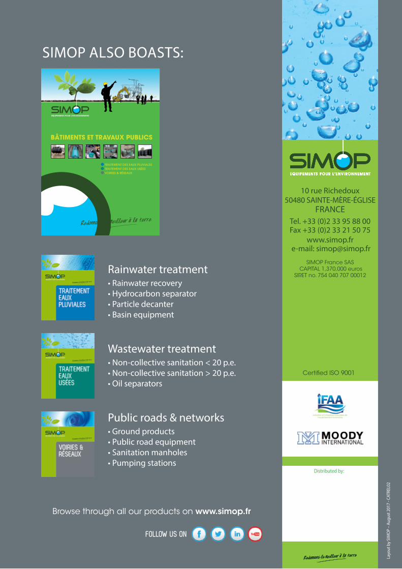
Layo
ut b
y SI
MO
P –
Augu
st 2
017
- CAT
REL0
2
Distributed by:
10 rue Richedoux50480 SAINTE-MÈRE-ÉGLISE
FRANCETel. +33 (0)2 33 95 88 00 Fax +33 (0)2 33 21 50 75
www.simop.fr e-mail: [email protected]
SIMOP France SAS CAPITAL 1,370,000 euros
SIRET no. 754 040 707 00012
Certified ISO 9001
Rainwater treatment• Rainwater recovery• Hydrocarbon separator• Particle decanter• Basin equipment
Wastewater treatment• Non-collective sanitation < 20 p.e.• Non-collective sanitation > 20 p.e.• Oil separators
Public roads & networks• Ground products• Public road equipment • Sanitation manholes • Pumping stations
SIMOP ALSO BOASTS:
TRAITEMENT DES EAUX PLUVIALES TRAITEMENT DES EAUX USÉES VOIRIES & RÉSEAUX
BÂTIMENTS ET TRAVAUX PUBLICS
Browse through all our products on www.simop.fr
FOLLOW US ON


