Embed Size (px)
Citation preview
QNAP Turbo NAS
Software User Manual
(Version: 4.0)
This manual is applicable to the following Turbo NAS models: TS-110, TS-112, TS-112P, TS-119,TS-119P+, TS-119P II, TS-120, TS-121, TS-210, TS-212, TS-212-E, TS-212P, TS-219, TS-219P,TS-219P+, TS-219P II, TS-220, TS-221, TS-239 Pro, TS-239 Pro II, TS-239 Pro II+, TS-259 Pro,TS-259 Pro+, TS-410, TS-410U, TS-412, TS-412U, TS-419P, TS-419P+, TS-419P II, TS-419U,TS-419U+, TS-419U II, TS-420, TS-420U, TS-421, TS-421U, TS-439 Pro, TS-439 Pro II, TS-439Pro II+, TS-439U-RP/SP, TS-459 Pro, TS-459 Pro II, TS-459 Pro+, TS-459U-RP/SP,TS-459U-RP+/SP+, TS-509 Pro, TS-559 Pro, TS-559 Pro+, TS-559 Pro II, TS-639 Pro, TS-659Pro, TS-659 Pro+, TS-659 Pro II, TS-809 Pro, TS-809U-RP, TS-859 Pro, TS-859U-RP+, TS-859Pro+, TS-859U-RP, SS-439 Pro, SS-839 Pro, HS-210.
© 2013 QNAP Systems, Inc. All Rights Reserved.
2
Table of Contents
................................................................................................................51. Notice
.............................................................................................................. 61.1 Legal Notice and Disclaimer
.............................................................................................................. 81.2 Regulatory Notice
.............................................................................................................. 121.3 Symbols in this Document
.............................................................................................................. 131.4 Safety Information and Precautions
................................................................................................................142. Getting Started
.............................................................................................................. 152.1 Hardware Installation
................................................................................................................................ 162.1.1 Hard Disk Drive Compatibility List
................................................................................................................................ 172.1.2 Checking System Status
.............................................................................................................. 212.2 Software Installation
................................................................................................................................ 222.2.1 Online Installation
................................................................................................................................ 352.2.2 Cloud Installation
................................................................................................................................ 442.2.3 CD Installation
.............................................................................................................. 452.3 Getting Utilities
.............................................................................................................. 482.4 Connecting to NAS Shared Folders
................................................................................................................................ 492.4.1 Connecting to NAS shared folders in Windows
................................................................................................................................ 542.4.2 Connecting to NAS shared folders in Mac or Linux
.............................................................................................................. 612.5 Connecting to NAS by Web Browser
.............................................................................................................. 632.6 Migrating from Old NAS
................................................................................................................663. QTS Basics and Desktop
.............................................................................................................. 673.1 Introducing QTS
.............................................................................................................. 713.2 Using QTS Desktop
................................................................................................................874. System Settings
.............................................................................................................. 884.1 General Settings
.............................................................................................................. 964.2 Storage Manager
................................................................................................................................ 974.2.1 Volume Management
................................................................................................................................ 1014.2.2 RAID Management
................................................................................................................................ 1244.2.3 Hard Disk S.M.A.R.T
................................................................................................................................ 1254.2.4 Encrypted File System
................................................................................................................................ 1364.2.5 iSCSI
........................................................................................................................ 1374.2.5.1 Portal Management
........................................................................................................................ 1454.2.5.2 Target Management
........................................................................................................................ 1714.2.5.3 Advanced ACL
........................................................................................................................ 1744.2.5.4 LUN Backup
................................................................................................................................ 2014.2.6 Virtual Disk
.............................................................................................................. 2064.3 Network
.............................................................................................................. 2314.4 Security
3
.............................................................................................................. 2344.5 Hardware
.............................................................................................................. 2404.6 Power
.............................................................................................................. 2454.7 Notification
.............................................................................................................. 2484.8 Firmware Update
.............................................................................................................. 2524.9 Backup/Restore
.............................................................................................................. 2544.10 External Device
................................................................................................................................ 2554.10.1 External Storage
................................................................................................................................ 2654.10.2 USB Printer
........................................................................................................................ 2704.10.2.1 Windows 7
........................................................................................................................ 2754.10.2.2 Windows XP
........................................................................................................................ 2774.10.2.3 Mac OS 10.6
........................................................................................................................ 2804.10.2.4 Mac OS 10.5
........................................................................................................................ 2854.10.2.5 Mac OS 10.4
........................................................................................................................ 2894.10.2.6 Linux (Ubuntu 10.10)
................................................................................................................................ 2944.10.3 UPS
.............................................................................................................. 3014.11 System Status
.............................................................................................................. 3084.12 System Logs
................................................................................................................3145. Privilege Settings
.............................................................................................................. 3155.1 Users
.............................................................................................................. 3315.2 User Groups
.............................................................................................................. 3335.3 Shared Folders
.............................................................................................................. 3695.4 Quota
.............................................................................................................. 3715.5 Domain Security
................................................................................................................................ 3735.5.1 Joining NAS to Active Directory (Windows Server 2003/2008)
................................................................................................................................ 3845.5.2 Connecting NAS to an LDAP Directory
................................................................................................................3906. Network Services
.............................................................................................................. 3916.1 Win/Mac/NFS
.............................................................................................................. 4006.2 FTP
.............................................................................................................. 4036.3 Telnet/SSH
.............................................................................................................. 4046.4 SNMP Settings
.............................................................................................................. 4066.5 Service Discovery
.............................................................................................................. 4086.6 Network Recycle Bin
.............................................................................................................. 4106.7 Qsync
................................................................................................................4337. Applications
.............................................................................................................. 4347.1 Station Manager
.............................................................................................................. 4427.2 iTunes Server
.............................................................................................................. 4447.3 DLNA Media Server
.............................................................................................................. 4467.4 Media Library
.............................................................................................................. 4517.5 Web Server
................................................................................................................................ 4727.5.1 Virtual Host
4
.............................................................................................................. 4767.6 LDAP Server
.............................................................................................................. 4807.7 VPN Service
.............................................................................................................. 4967.8 MySQL Server
.............................................................................................................. 4987.9 Syslog Server
.............................................................................................................. 5057.10 Antivirus
.............................................................................................................. 5167.11 RADIUS Server
.............................................................................................................. 5207.12 TFTP Server
................................................................................................................5228. QNAP Applications
.............................................................................................................. 5238.1 Backup Station
................................................................................................................................ 5248.1.1 Backup Server
................................................................................................................................ 5338.1.2 Remote Replication
................................................................................................................................ 5578.1.3 Cloud Backup
................................................................................................................................ 5648.1.4 External Backup
.............................................................................................................. 5848.2 myQNAPcloud Service
.............................................................................................................. 6078.3 File Station
.............................................................................................................. 6338.4 Photo Station
.............................................................................................................. 6488.5 Music Station
.............................................................................................................. 6558.6 Multimedia Station
.............................................................................................................. 6838.7 Download Station
.............................................................................................................. 7028.8 HD Station
.............................................................................................................. 7248.9 Surveillance Station
.............................................................................................................. 7348.10 App Center
................................................................................................................7429. Use the LCD Panel
................................................................................................................74810. GNU GENERAL PUBLIC LICENSE

5
1. Notice
Legal Notice and Disclaimer
Regulatory Notice
Symbols in this Document
Safety Information and Precautions
6
8
12
13
6
1.1 Legal Notice and Disclaimer
Thank you for choosing QNAP products! This user manual provides detailed instructions
of using the Turbo NAS (network-attached storage). Please read carefully and start to
enjoy the powerful functions of the Turbo NAS!
The Turbo NAS is hereafter referred to as the NAS.
This manual provides the description of all the functions of the Turbo NAS. The
product you purchased may not support certain functions dedicated to specific
models.
Legal Notices
All the features, functionality, and other product specifications are subject to change
without prior notice or obligation. Information contained herein is subject to change
without notice.
QNAP and the QNAP logo are trademarks of QNAP Systems, Inc. All other brands and
product names referred to are trademarks of their respective holders.
Further, the ® or ™ symbols are not used in the text.
Disclaimer
Information in this document is provided in connection with QNAP® products. No license,
express or implied, by estoppels or otherwise, to any intellectual property rights is
granted by this document. Except as provided in QNAP's terms and conditions of sale for
such products, QNAP Assumes no liability whatsoever, and QNAP disclaims any express or
implied warranty, relating to sale and/or use of QNAP products including liability or
warranties relating to fitness for a particular purpose, merchantability, or infringement of
any patent, copyright or other intellectual property right.
QNAP products are not intended for use in medical, life saving, life sustaining, critical
control or safety systems, or in nuclear facility applications.
In no event shall QNAP Systems, Inc. (QNAP) liability exceed the price paid for the
product from direct, indirect, special, incidental, or consequential damages resulting from
the use of the product, its accompanying software, or its documentation. QNAP makes
no warranty or representation, expressed, implied, or statutory, with respect to its
7
products or the contents or use of this documentation and all accompanying software,
and specifically disclaims its quality, performance, merchantability, or fitness for any
particular purpose. QNAP reserves the right to revise or update its products, software, or
documentation without obligation to notify any individual or entity.
Back up the system periodically to avoid any potential data loss. QNAP disclaims any
responsibility of all sorts of data loss or recovery.
Should you return any components of the NAS package for refund or maintenance, make
sure they are carefully packed for shipping. Any form of damages due to improper
packaging will not be compensated.
QNAP, QNAP logo, QTS, myQNAPcloud and VioStor are trademarks or registered
trademarks of QNAP Systems, Inc. or its subsidiaries. Other names and brands may be
claimed as the property of others.
8
1.2 Regulatory Notice
FCC Notice
QNAP NAS comply with different FCC compliance classes. Please refer the Appendix for
details. Once the class of the device is determined, refer to the following corresponding
statement.
=================================================================
FCC Class A Notice
This device complies with Part 15 of the FCC Rules. Operation is subject to the following
two conditions:
1. This device may not cause harmful interference.
2. This device must accept any interference received, including interference that may
cause undesired operation.
Note: This equipment has been tested and found to comply with the limits for a Class A
digital device, pursuant to Part 15 of the FCC Rules. These limits are designed to provide
reasonable protection against harmful interference when the equipment is operated in a
commercial environment. This equipment generates, uses, and can radiate radio
frequency energy, and if not installed and used in accordance with the instruction
manual, may cause harmful interference to radio communications. Operation of this
equipment in a residential area is likely to cause harmful interference, in which case the
user will be required to correct the interference at his own expense.
Modifications: Any modifications made to this device that are not approved by QNAP
Systems, Inc. may void the authority granted to the user by the FCC to operate this
equipment.
FCC Class B Notice
This device complies with Part 15 of the FCC Rules. Operation is subject to the following
two conditions:
1. This device may not cause harmful interference.
2. This device must accept any interference received, including interference that may
cause undesired operation.
9
Note: This equipment has been tested and found to comply with the limits for a Class B
digital device, pursuant to Part 15 of the FCC Rules. These limits are designed to provide
reasonable protection against harmful interference in a residential installation. This
equipment generates, uses, and can radiate radio frequency energy and, if not installed
and used in accordance with the instructions, may cause harmful interference to radio
communications. However, there is no guarantee that interference will not occur in a
particular installation. If this equipment does cause harmful interference to radio or
television reception, which can be determined by turning the equipment off and on, the
user is encouraged to try to correct the interference by one or more of the following
measures:
Reorient or relocate the receiving antenna.
Increase the separation between the equipment and receiver.
Connect the equipment into an outlet on a circuit different from that to which the
receiver is connected.
Consult the dealer or an experienced radio/television technician for help.
Modifications: Any modifications made to this device that are not approved by QNAP
Systems, Inc. may void the authority granted to the user by the FCC to operate this
equipment.
10
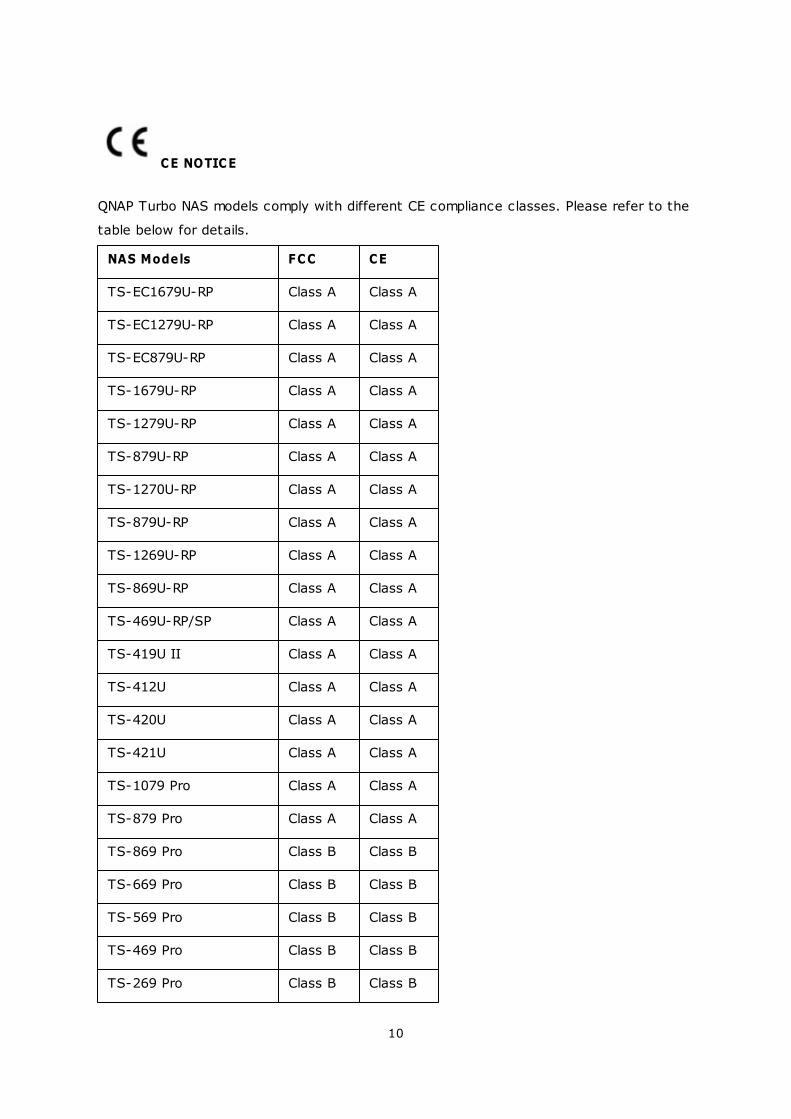
CE NOTICE
QNAP Turbo NAS models comply with different CE compliance classes. Please refer to the
table below for details.
NAS Models FCC CE
TS-EC1679U-RP Class A Class A
TS-EC1279U-RP Class A Class A
TS-EC879U-RP Class A Class A
TS-1679U-RP Class A Class A
TS-1279U-RP Class A Class A
TS-879U-RP Class A Class A
TS-1270U-RP Class A Class A
TS-879U-RP Class A Class A
TS-1269U-RP Class A Class A
TS-869U-RP Class A Class A
TS-469U-RP/SP Class A Class A
TS-419U II Class A Class A
TS-412U Class A Class A
TS-420U Class A Class A
TS-421U Class A Class A
TS-1079 Pro Class A Class A
TS-879 Pro Class A Class A
TS-869 Pro Class B Class B
TS-669 Pro Class B Class B
TS-569 Pro Class B Class B
TS-469 Pro Class B Class B
TS-269 Pro Class B Class B
11
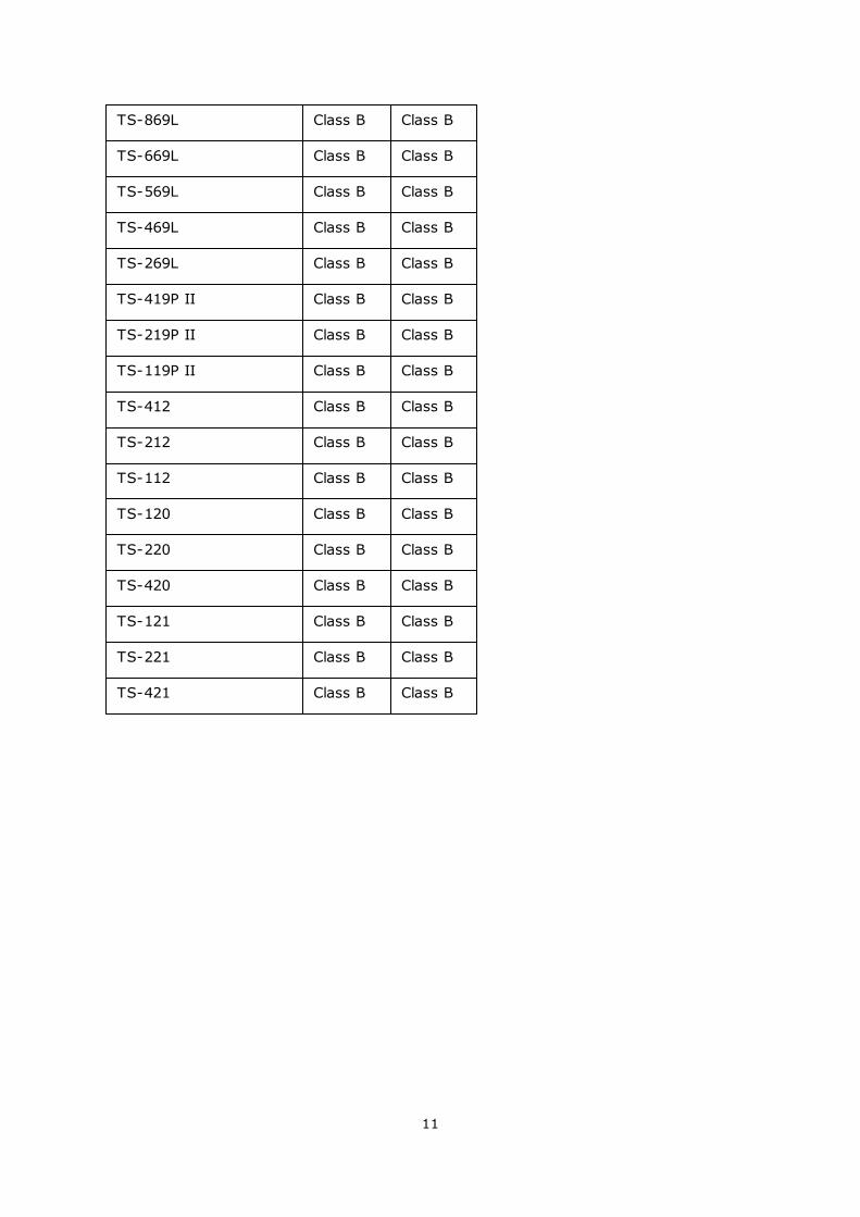
TS-869L Class B Class B
TS-669L Class B Class B
TS-569L Class B Class B
TS-469L Class B Class B
TS-269L Class B Class B
TS-419P II Class B Class B
TS-219P II Class B Class B
TS-119P II Class B Class B
TS-412 Class B Class B
TS-212 Class B Class B
TS-112 Class B Class B
TS-120 Class B Class B
TS-220 Class B Class B
TS-420 Class B Class B
TS-121 Class B Class B
TS-221 Class B Class B
TS-421 Class B Class B
12
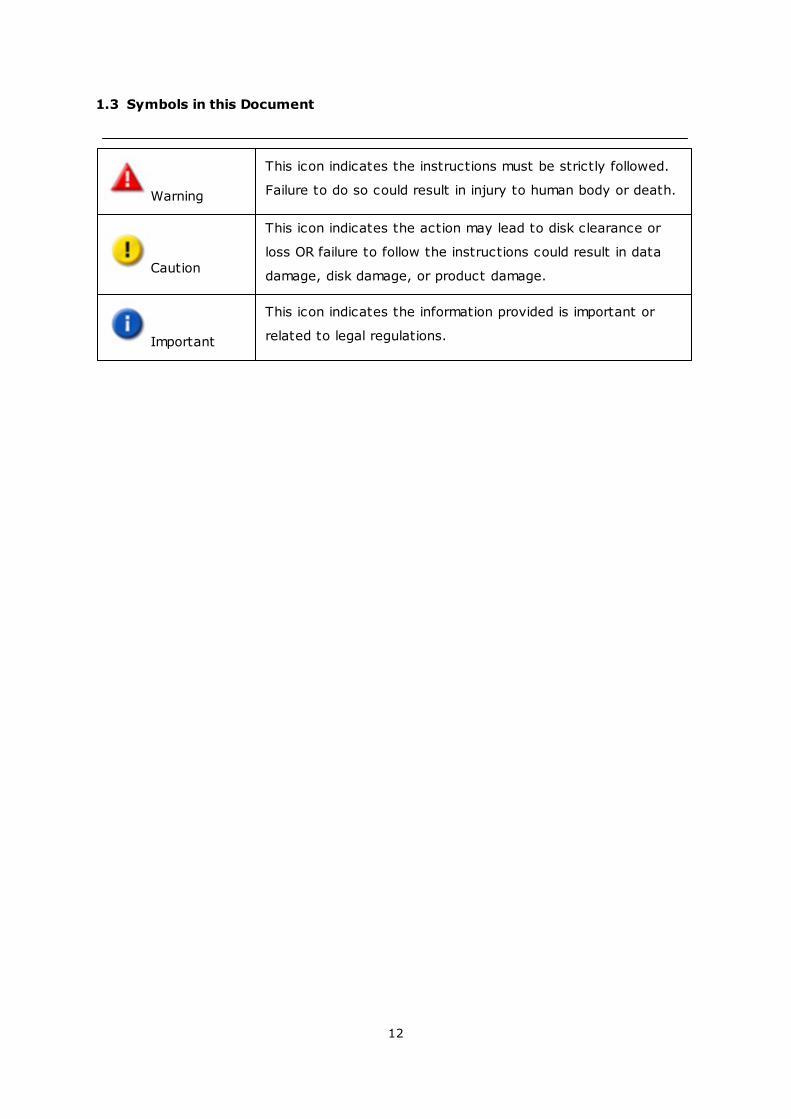
1.3 Symbols in this Document
Warning
This icon indicates the instructions must be strictly followed.
Failure to do so could result in injury to human body or death.
Caution
This icon indicates the action may lead to disk clearance or
loss OR failure to follow the instructions could result in data
damage, disk damage, or product damage.
Important
This icon indicates the information provided is important or
related to legal regulations.
13
1.4 Safety Information and Precautions
1. The NAS can operate normally in the temperature of 0ºC–40ºC and relative
humidity of 0%–95%. Please make sure the environment is well-ventilated.
2. The power cord and devices connected to the NAS must provide correct supply
voltage (100W, 90–264V).
3. Do not place the NAS in direct sunlight or near chemicals. Make sure the
temperature and humidity of the environment are in optimized level.
4. Unplug the power cord and all the connected cables before cleaning. Wipe the NAS
with a dry towel. Do not use chemical or aerosol to clean the NAS.
5. Do not place any objects on the NAS during normal system operations and to avoid
overheat.
6. Use the flat head screws in the product package to lock the hard disk drives in the
NAS when installing the hard drives for proper operation.
7. Do not place the NAS near any liquid.
8. Do not place the NAS on any uneven surface to avoid falling off and damage.
9. Make sure the voltage is correct in your location when using the NAS. If unsure,
please contact the distributor or the local power supply company.
10. Do not place any object on the power cord.
11. Do not attempt to repair the NAS in any occasions. Improper disassembly of the
product may expose you to electric shock or other risks. For any enquiries, please
contact the distributor.
12. The chassis (also known as rack mount) NAS models should only be installed in the
server room and maintained by the authorized server manager or IT administrator.
The server room is locked by key or keycard access and only certified staff is
allowed to enter the server room.
Warning:
Danger of explosion if battery is incorrectly replaced. Replace only with the
same or equivalent type recommended by the manufacturer. Dispose of used
batteries according to the manufacturer’s instructions.
Do NOT touch the fan inside the system to avoid serious injuries.
14
2. Getting Started
New NAS users are advised to follow the steps below one by one to complete their NAS
installation. For users who already own a QNAP NAS and would like to move the data to a
new QNAP NAS, please refer to Migrating from Old NAS for detailed instructions.
For New NAS Users:
Hardware Installation
Software Installation
Getting Utilities
Connecting to the Shared Folders
Connecting to the NAS by Web Browser
For Existing NAS Users:
Migrating from Old NAS
63
15
21
45
48
61
63
15
2.1 Hardware Installation
After unpacking the NAS from the package, please first follow the instructions below to
install your hardware:
1. Install the hard drives. Please also make sure that the hard drives (HDDs) that you
use are compatible with the NAS. Go to the Hard Disk Drive Compatibility List
section for more details.
2. Connect the QNAP NAS to the same network as your PC and power it on. During
your installation process, please pay attention to LEDs and alarm buzzers to make
sure that the NAS functions properly. Go to the Checking System Status
section for details.
Note: The steps above are also illustrated in the Quick Installation Guide (QIG) that
can be found in the product package or QNAP website (http://start.qnap.com).
16
17
16
2.1.1 Hard Disk Drive Compatibility List
Hard Disk Drive Compatibility List
This product works with 2.5-inch and 3.5-inch SATA hard disk drives and/or solid-state
drives (SSD) from major hard drive brands. For the compatible hard disks, please check
the compatibility list on QNAP website (http://www.qnap.com/compatibility).
Important: QNAP disclaims any responsibility for product damage/malfunction or
data loss/recovery due to misuse or improper installation of hard disks in any
occasions for any reasons.
Caution: Note that if you install a hard drive (new or used) which has never
been installed on the NAS before, the hard drive will be formatted and
partitioned automatically and all the disk data will be cleared.
17
2.1.2 Checking System Status
LED Display & System Status Overview
LED Colour LED Status Description
System
Status
Red/
Green
Flashes green and
red alternately every
0.5 sec
1) The hard disk drive on the NAS is
being formatted.
2) The NAS is being initialized.
3) The system firmware is being
updated.
4) RAID rebuilding is in process.
5) Online RAID capacity expansion is in
process.
6) Online RAID level migration is in
process.
Red
1) The hard disk drive is invalid.
2) The disk volume has reached its full
capacity.
3) The disk volume is going to be full.
4) The system fan is out of function
(TS-119 does not support smart
fan).
5) An error occurs when accessing
(read/write) the disk data.
6) A bad sector is detected on the hard
disk drive.
7) The NAS is in degraded read-only
mode (2 member hard drives fail in a
RAID 5 or RAID 6 configuration, the
disk data can still be read).
8) (Hardware self-test error).
Flashes red every
0.5 sec
The NAS is in degraded mode (one
member hard drive fails in RAID 1, RAID 5
or RAID 6 configuration).
Flashes green every
0.5 sec
1) The NAS is starting up.
2) The NAS is not configured.
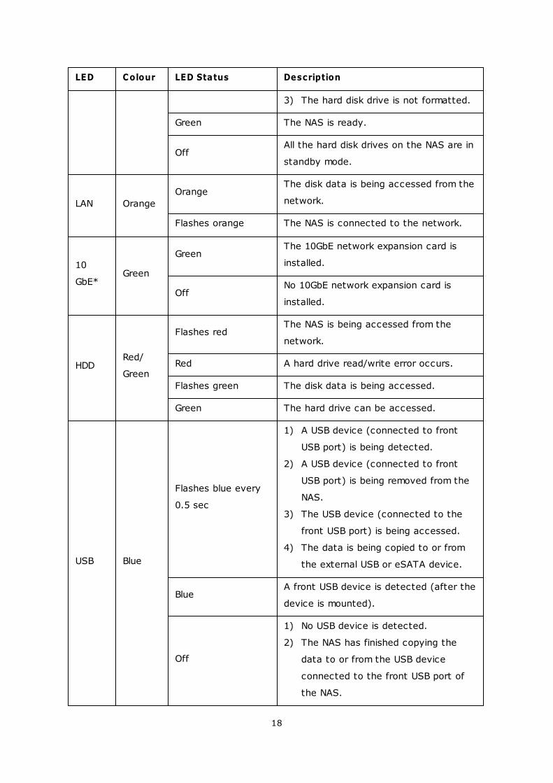
18
LED Colour LED Status Description
3) The hard disk drive is not formatted.
Green The NAS is ready.
OffAll the hard disk drives on the NAS are in
standby mode.
LAN Orange
OrangeThe disk data is being accessed from the
network.
Flashes orange The NAS is connected to the network.
10
GbE*Green
GreenThe 10GbE network expansion card is
installed.
OffNo 10GbE network expansion card is
installed.
HDDRed/
Green
Flashes redThe NAS is being accessed from the
network.
Red A hard drive read/write error occurs.
Flashes green The disk data is being accessed.
Green The hard drive can be accessed.
USB Blue
Flashes blue every
0.5 sec
1) A USB device (connected to front
USB port) is being detected.
2) A USB device (connected to front
USB port) is being removed from the
NAS.
3) The USB device (connected to the
front USB port) is being accessed.
4) The data is being copied to or from
the external USB or eSATA device.
BlueA front USB device is detected (after the
device is mounted).
Off
1) No USB device is detected.
2) The NAS has finished copying the
data to or from the USB device
connected to the front USB port of
the NAS.

19
LED Colour LED Status Description
eSATA*
*Orange
Flashes The eSATA device is being accessed.
Off No eSATA device can be detected.
*The 10 GbE network expansion function is only supported by the TS-470 Pro, TS-670
Pro, TS-870 Pro, TS-870U-RP, TS-879 Pro, TS-1079 Pro, TS-879U-RP, TS-1270U-RP,
TS-1279U-RP, TS-EC879U-RP, and TS-EC1279U-RP.
**TS-210, TS-212, TS-219, TS-439U-SP/RP, TS-809 Pro, TS-809U-RP do not support
eSATA port.
20
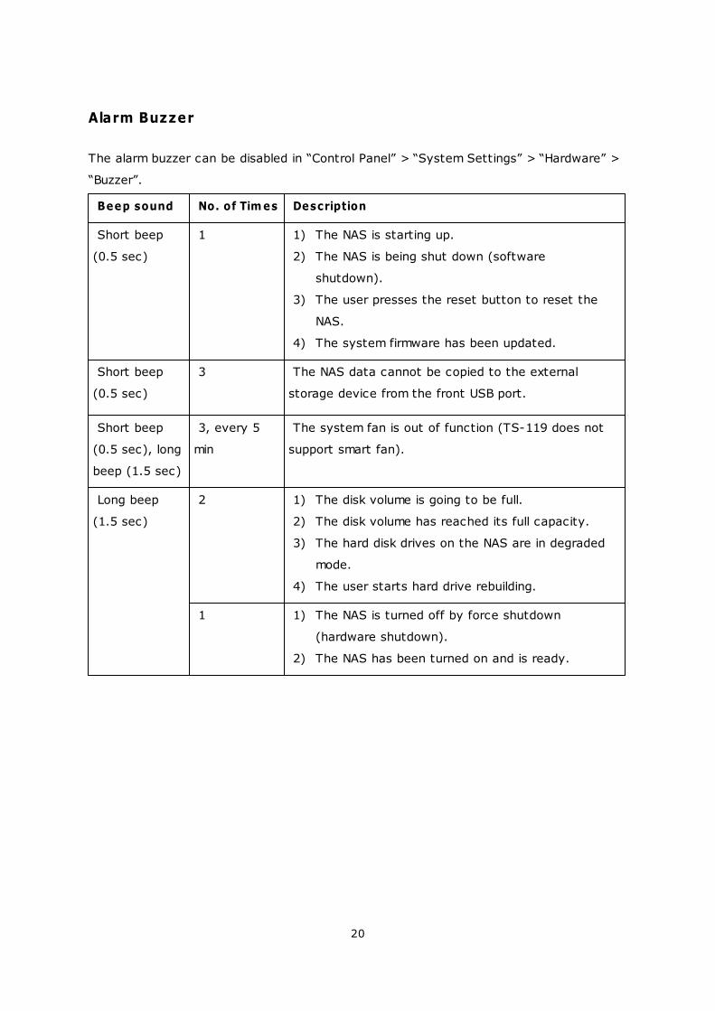
Alarm Buzzer
The alarm buzzer can be disabled in “Control Panel” > “System Settings” > “Hardware” >
“Buzzer”.
Beep sound No. of Tim es Description
Short beep
(0.5 sec)
1 1) The NAS is starting up.
2) The NAS is being shut down (software
shutdown).
3) The user presses the reset button to reset the
NAS.
4) The system firmware has been updated.
Short beep
(0.5 sec)
3 The NAS data cannot be copied to the external
storage device from the front USB port.
Short beep
(0.5 sec), long
beep (1.5 sec)
3, every 5
min
The system fan is out of function (TS-119 does not
support smart fan).
Long beep
(1.5 sec)
2 1) The disk volume is going to be full.
2) The disk volume has reached its full capacity.
3) The hard disk drives on the NAS are in degraded
mode.
4) The user starts hard drive rebuilding.
1 1) The NAS is turned off by force shutdown
(hardware shutdown).
2) The NAS has been turned on and is ready.
21
2.2 Software Installation
After installing the NAS hardware, proceed to software installation. There are three
approaches for software installation:
1. Online Installation
2. Cloud Installation
3. CD Installation
Online installation and cloud installation are available for all new NAS models, while CD
installation is only for certain models (please check your package content and see if the
installation CD is available.) All users are encouraged to use cloud and online installation
if possible. For all problems encountered in the installation process, please contact our
technical support department (http://www.qnap.com/support.)
22
35
44
22
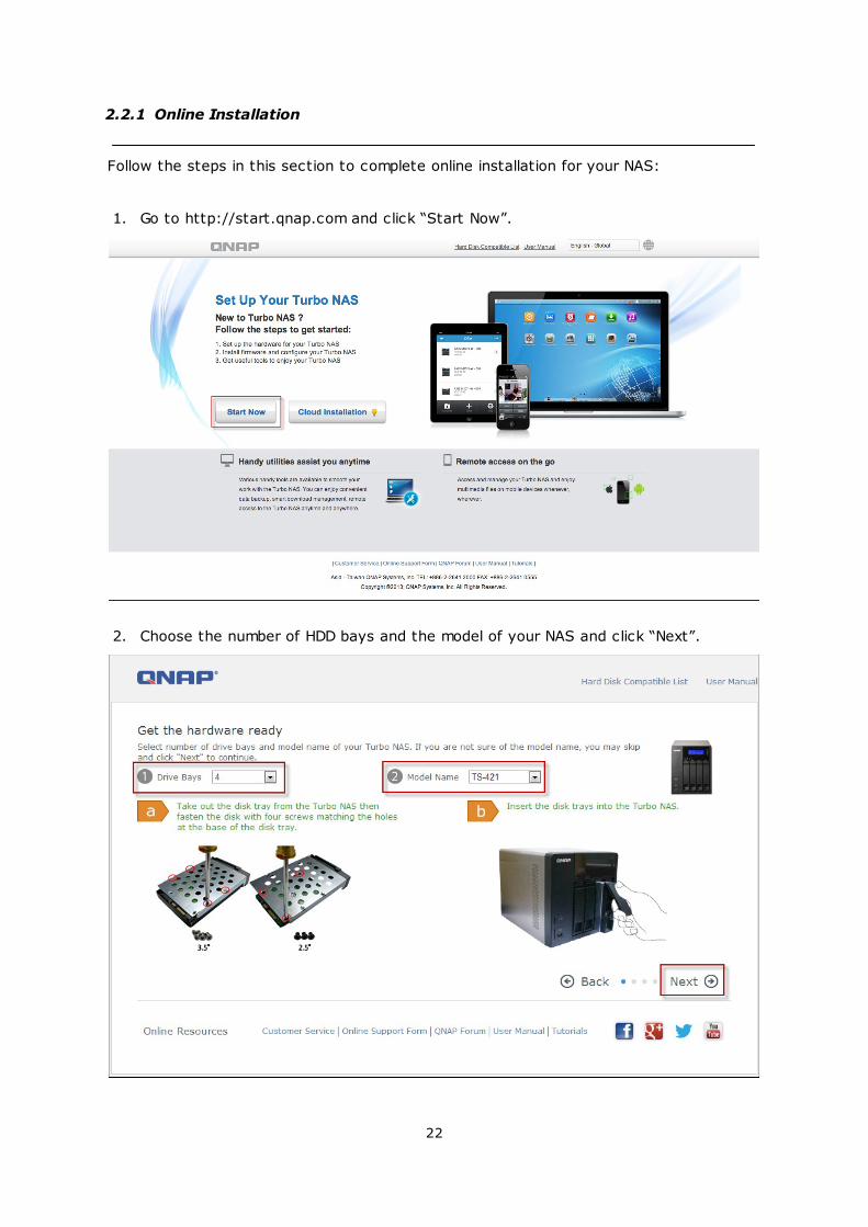
2.2.1 Online Installation
Follow the steps in this section to complete online installation for your NAS:
1. Go to http://start.qnap.com and click “Start Now”.
2. Choose the number of HDD bays and the model of your NAS and click “Next”.
23
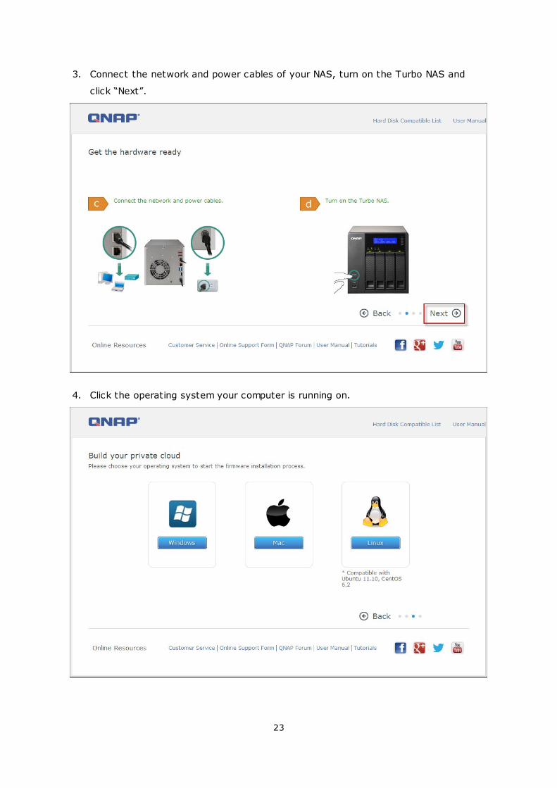
3. Connect the network and power cables of your NAS, turn on the Turbo NAS and
click “Next”.
4. Click the operating system your computer is running on.
24
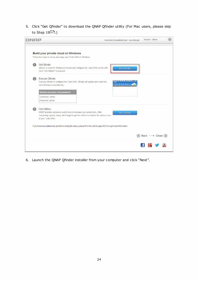
5. Click “Get Qfinder” to download the QNAP Qfinder utility (For Mac users, please skip
to Step 19 .)
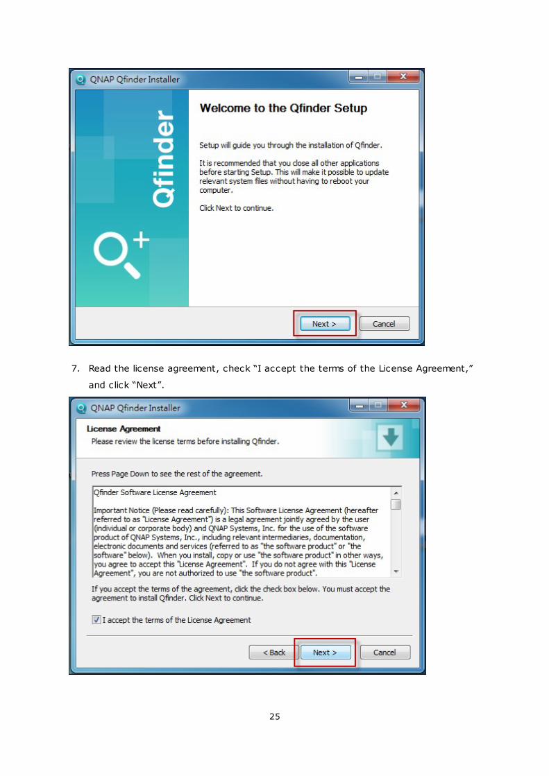
6. Launch the QNAP Qfinder installer from your computer and click “Next”.
31
25
7. Read the license agreement, check “I accept the terms of the License Agreement,”
and click “Next”.
26
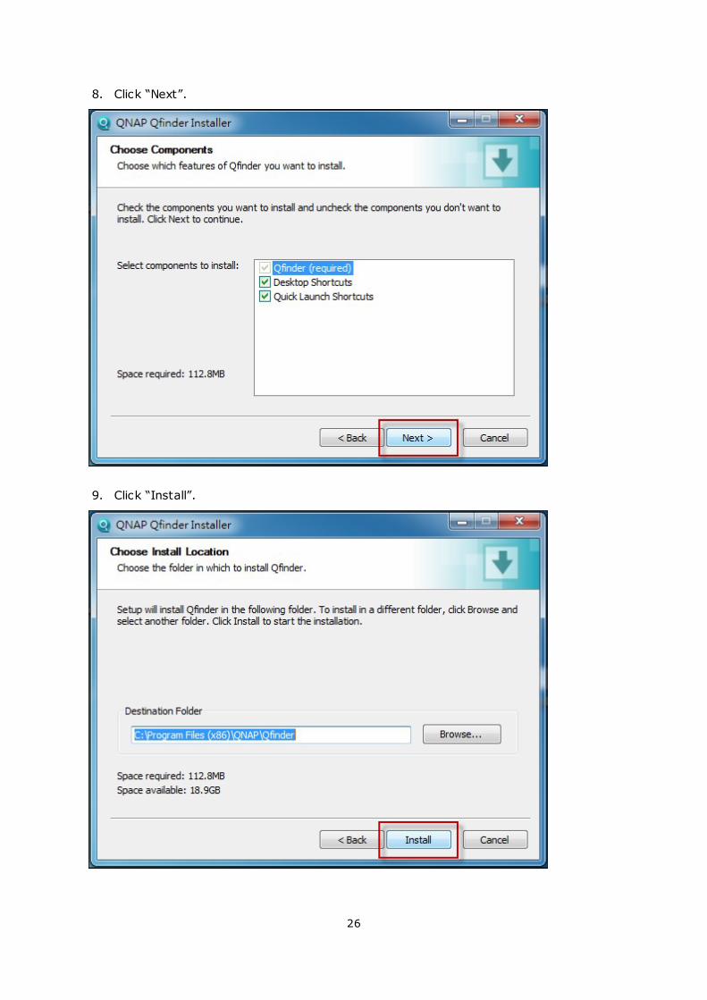
8. Click “Next”.
9. Click “Install”.
27
10. Click “Finish”.
11. Launch the QNAP Qfinder from your desktop.
28
12. The Quick Setup Wizard will be launched automatically. Please confirm that the IP
address shown up on the dialog window matches the Turbo NAS you are trying to
configure (please check the MAC address from the QNAP Qfinder and its
corresponding IP address.) Click “Yes” to configure your Turbo NAS.
13. Click “Quick Setup”.
14. Install a hard drive on your Turbo NAS if you have not already done so and click
“Detect Again”.
29
15. Confirm the setup details and click “Next”.
16. The wizard will proceed to finish the installation process.
30
17. Click “Finish” to complete the installation process and open the NAS login page.
31
18. Key in the user ID and password entered in the “Confirm the setup information”
page.
19. Click “Get Qfinder” to download the QNAP Qfinder utility (Steps 19 to 23 are for
Mac users.)
20. Install the QNAP Qfinder.
32
21. Execute the QNAP Qfinder and connect to the NAS.
33
22. Start the Web Installation step.
34
23. Key in the user ID and password entered in the “Confirm the setup information”
page.
35
2.2.2 Cloud Installation
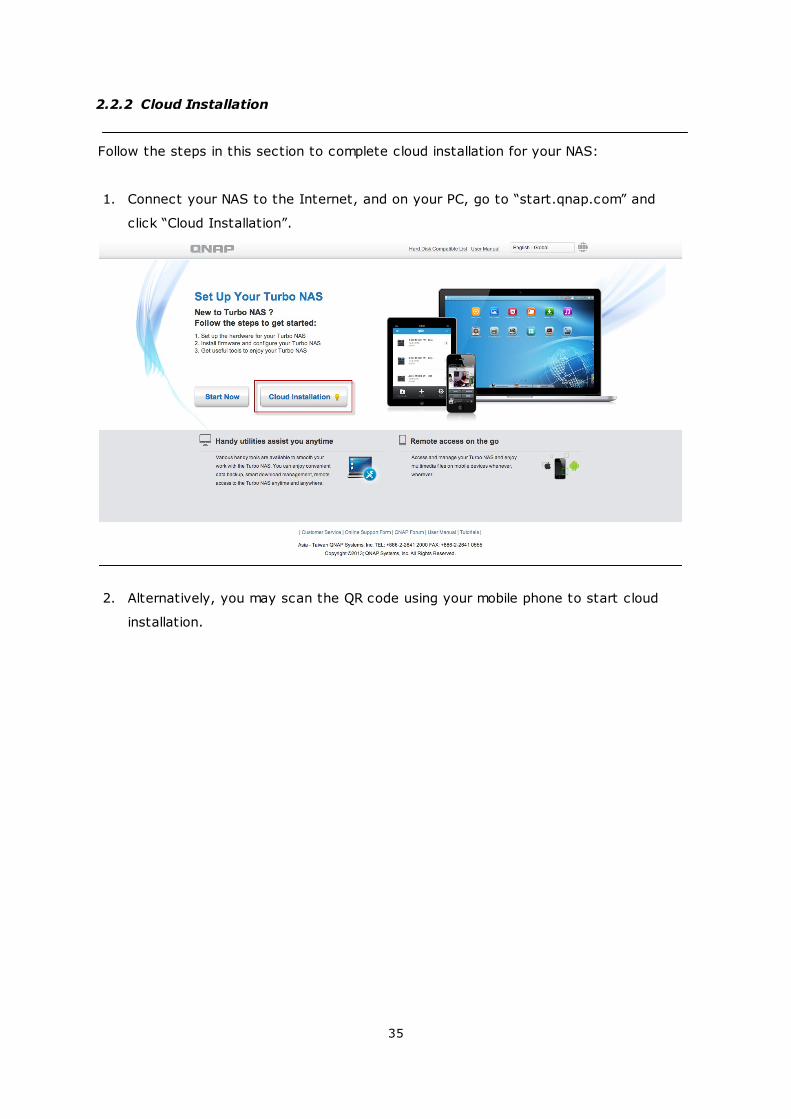
Follow the steps in this section to complete cloud installation for your NAS:
1. Connect your NAS to the Internet, and on your PC, go to “start.qnap.com” and
click “Cloud Installation”.
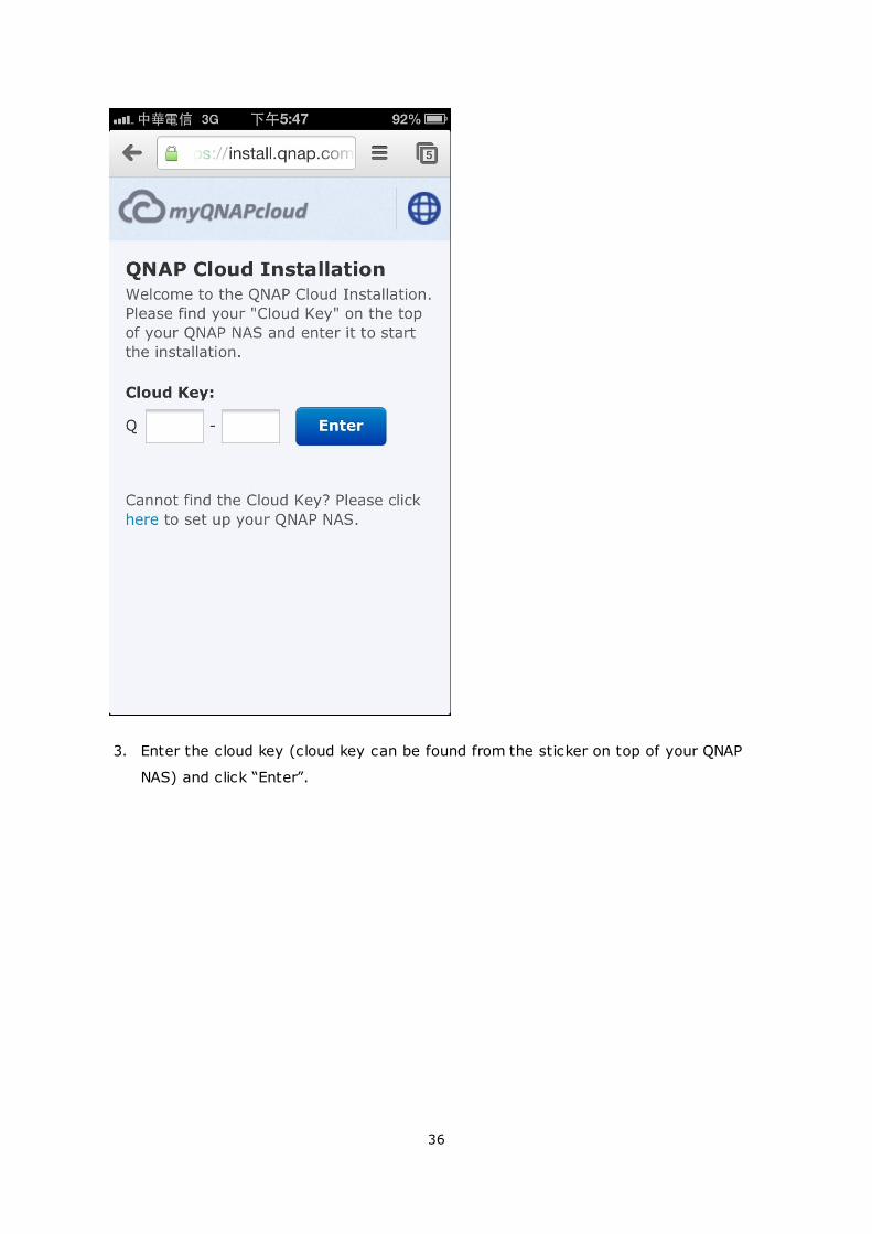
2. Alternatively, you may scan the QR code using your mobile phone to start cloud
installation.
36
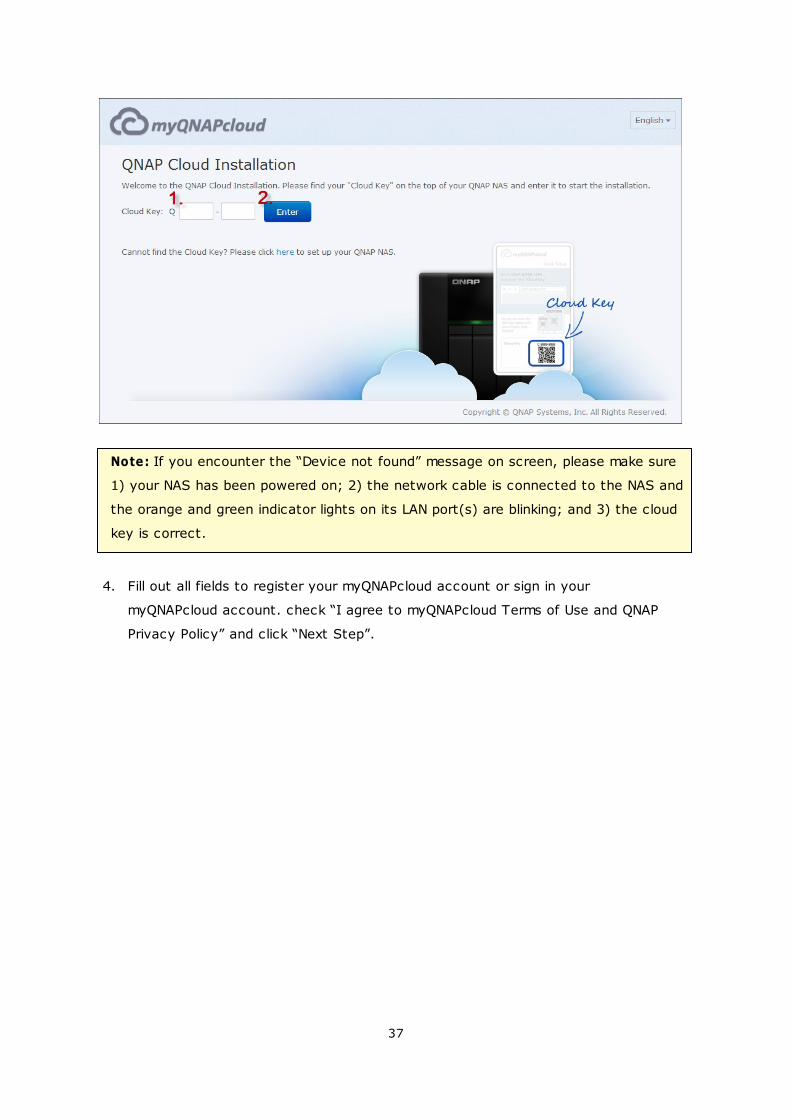
3. Enter the cloud key (cloud key can be found from the sticker on top of your QNAP
NAS) and click “Enter”.
37
Note: If you encounter the “Device not found” message on screen, please make sure
1) your NAS has been powered on; 2) the network cable is connected to the NAS and
the orange and green indicator lights on its LAN port(s) are blinking; and 3) the cloud
key is correct.
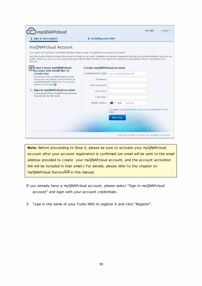
4. Fill out all fields to register your myQNAPcloud account or sign in your
myQNAPcloud account. check “I agree to myQNAPcloud Terms of Use and QNAP
Privacy Policy” and click “Next Step”.
38
Note: Before proceeding to Step 4, please be sure to activate your myQNAPcloud
account after your account registration is confirmed (an email will be sent to the email
address provided to create your myQNAPcloud account, and the account activation
link will be included in that email.) For details, please refer to the chapter on
myQNAPcloud Service in this manual.
If you already have a myQNAPcloud account, please select “Sign in myQNAPcloud
account” and login with your account credentials.
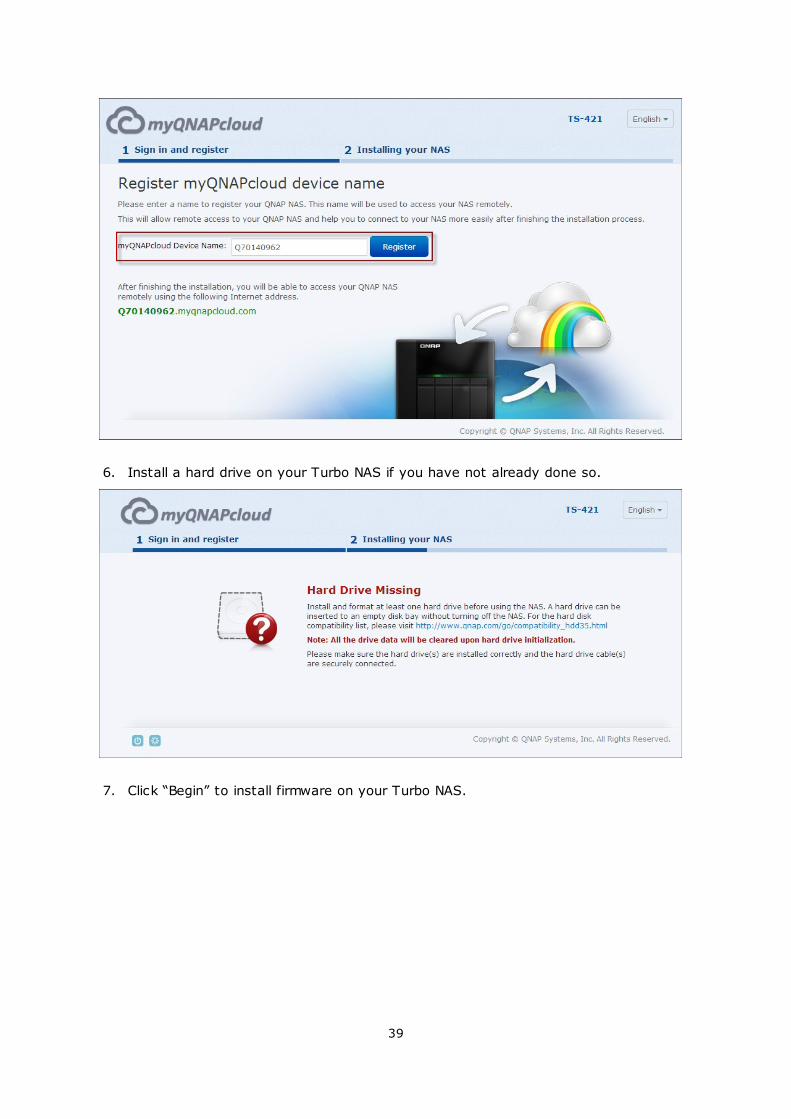
5. Type in the name of your Turbo NAS to register it and click “Register”.
584
39
6. Install a hard drive on your Turbo NAS if you have not already done so.
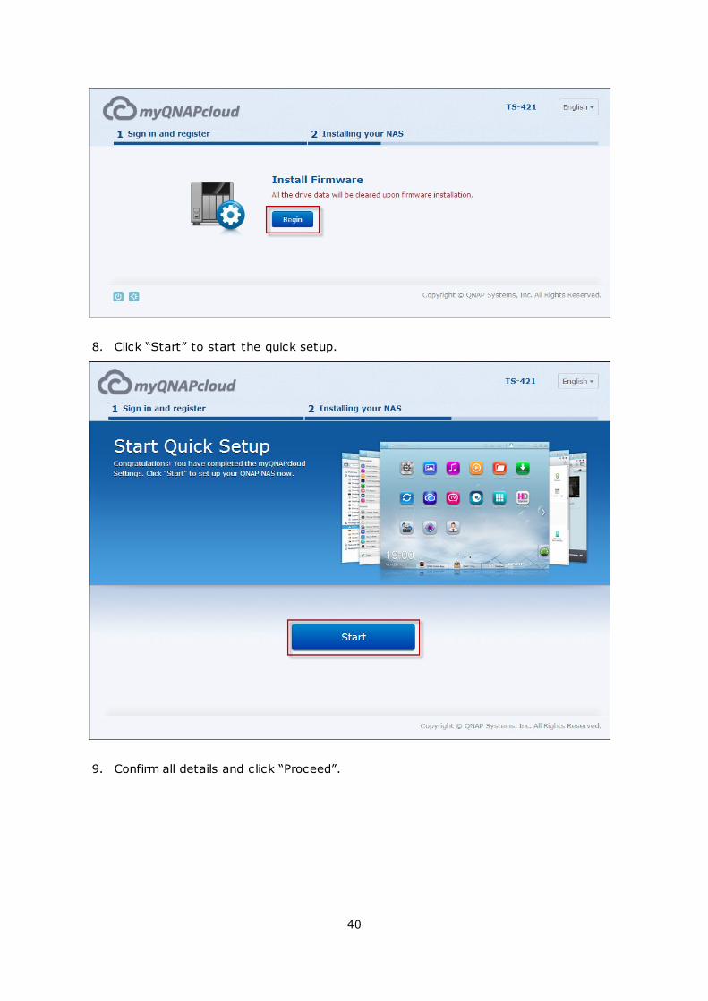
7. Click “Begin” to install firmware on your Turbo NAS.
40
8. Click “Start” to start the quick setup.
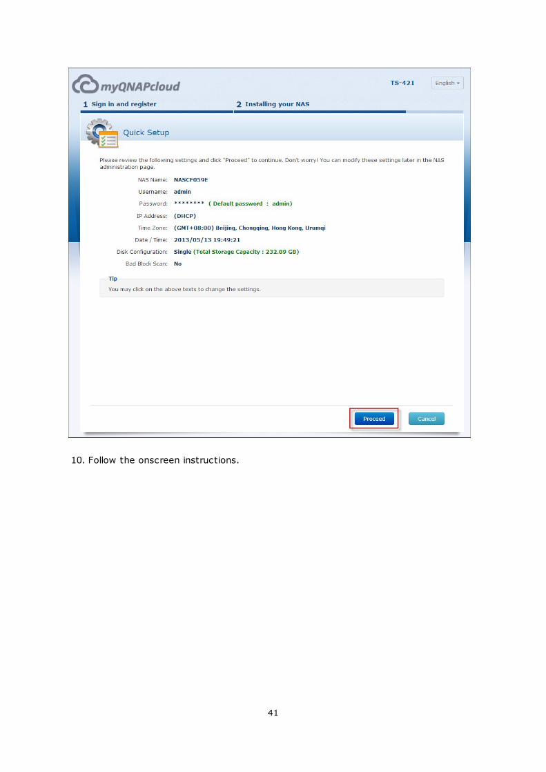
9. Confirm all details and click “Proceed”.
41
10. Follow the onscreen instructions.
42
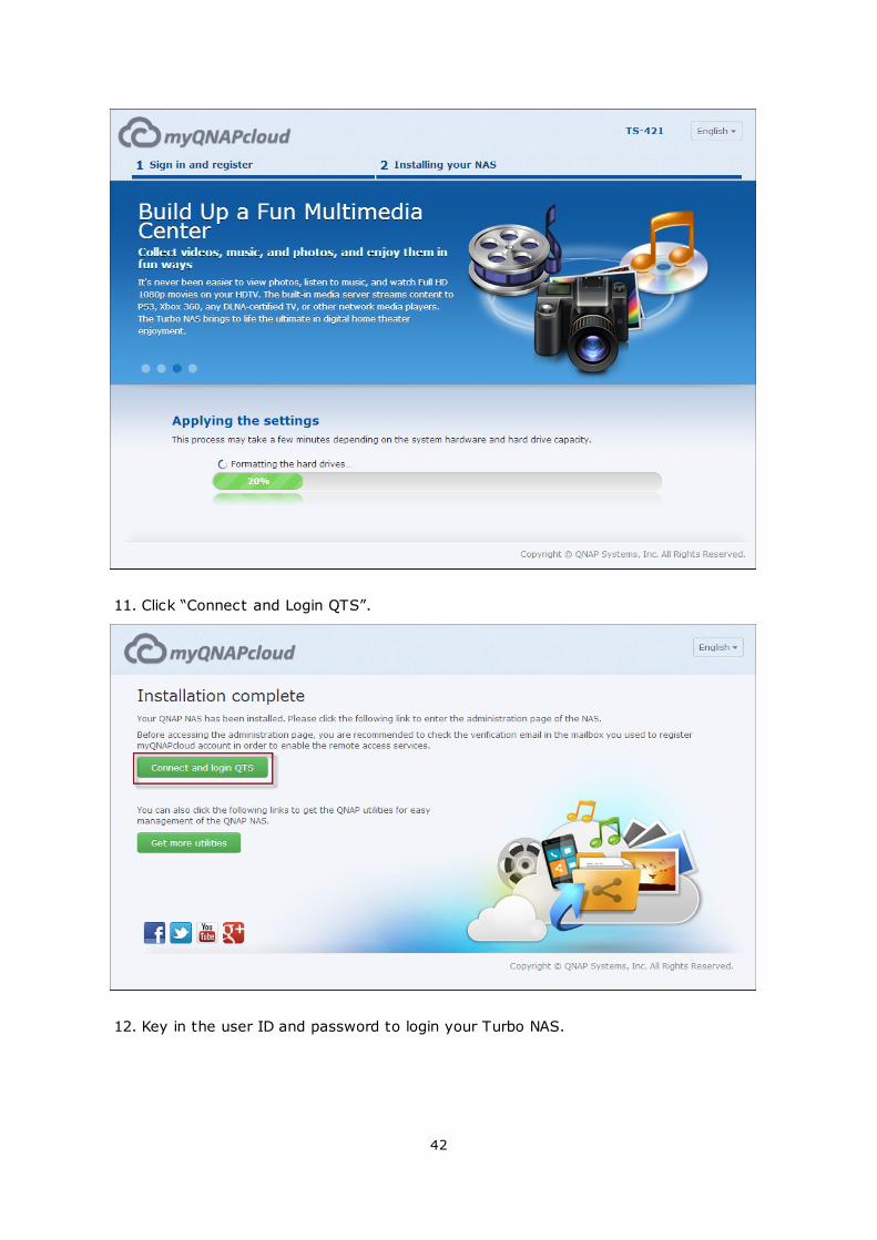
11. Click “Connect and Login QTS”.
12. Key in the user ID and password to login your Turbo NAS.
43
44
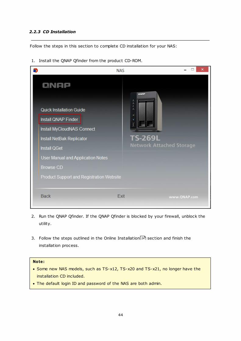
2.2.3 CD Installation
Follow the steps in this section to complete CD installation for your NAS:
1. Install the QNAP Qfinder from the product CD-ROM.
2. Run the QNAP Qfinder. If the QNAP Qfinder is blocked by your firewall, unblock the
utility.
3. Follow the steps outlined in the Online Installation section and finish the
installation process.
Note:
Some new NAS models, such as TS-x12, TS-x20 and TS-x21, no longer have the
installation CD included.
The default login ID and password of the NAS are both admin.
24
45
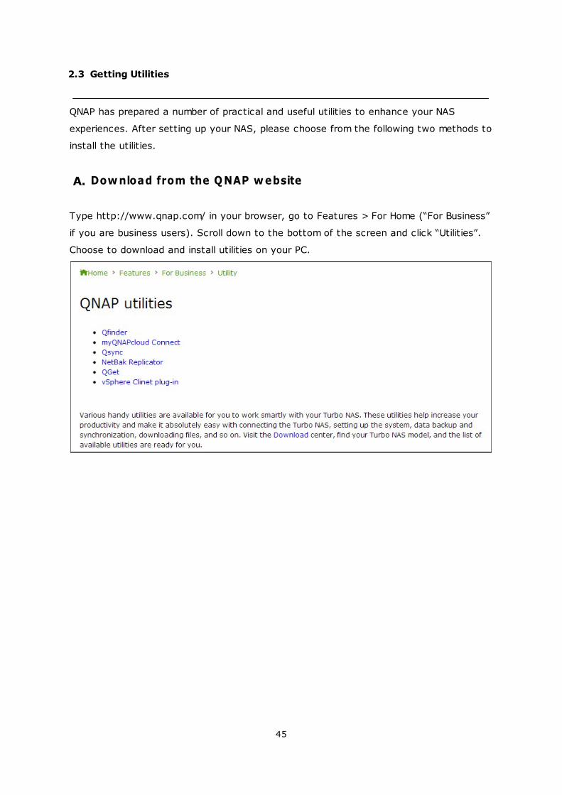
2.3 Getting Utilities
QNAP has prepared a number of practical and useful utilities to enhance your NAS
experiences. After setting up your NAS, please choose from the following two methods to
install the utilities.
A. Download from the QNAP website
Type http://www.qnap.com/ in your browser, go to Features > For Home (“For Business”
if you are business users). Scroll down to the bottom of the screen and click “Utilities”.
Choose to download and install utilities on your PC.
46
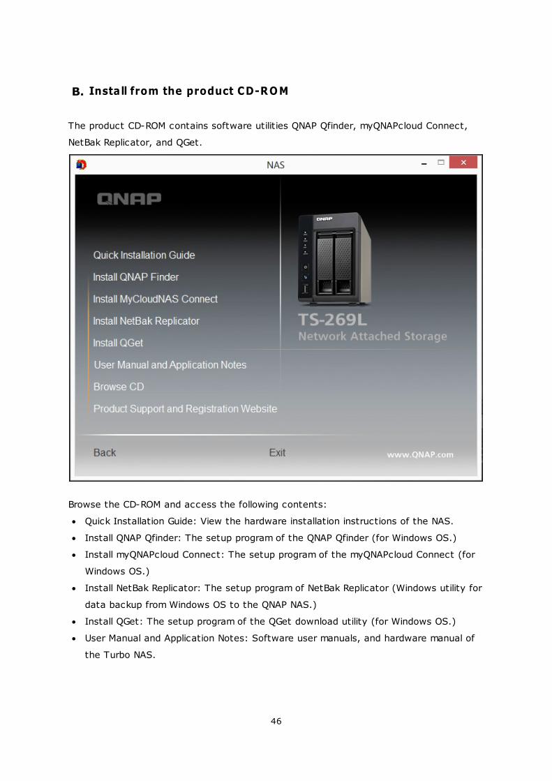
B. Install from the product CD-ROM
The product CD-ROM contains software utilities QNAP Qfinder, myQNAPcloud Connect,
NetBak Replicator, and QGet.
Browse the CD-ROM and access the following contents:
Quick Installation Guide: View the hardware installation instructions of the NAS.
Install QNAP Qfinder: The setup program of the QNAP Qfinder (for Windows OS.)
Install myQNAPcloud Connect: The setup program of the myQNAPcloud Connect (for
Windows OS.)
Install NetBak Replicator: The setup program of NetBak Replicator (Windows utility for
data backup from Windows OS to the QNAP NAS.)
Install QGet: The setup program of the QGet download utility (for Windows OS.)
User Manual and Application Notes: Software user manuals, and hardware manual of
the Turbo NAS.

47

48
2.4 Connecting to NAS Shared Folders
Connecting to NAS shared folders in Windows
Connecting to NAS shared folders in Mac or Linux
49
54
49
2.4.1 Connecting to NAS shared folders in Windows
For Windows operating systems, there are two methods to connect to shared folders of
the NAS:
A. QNAP Qfinder
B. My Network Places or Run
A. Connect to the shared folders of the NAS by using the QNAP
Qfinder:
1. Launch the QNAP Qfinder. Select the NAS detected and then click “Map Network
Drive”.
2. Select a shared folder on the NAS to be mapped as a network drive and click “Map
Network Drive”.
49
53
50
3. Enter the username and password to connect to the NAS and click “OK”.
4. Select a drive in the OS to map the folder chosen in Step 2 and click “Finish”.
51
5. The mapped folder will appear when opening the File Explorer.
52
Note: Alternatively, you can use the Storage Plug & Connect Wizard to connect NAS
shared folders. The steps: 1) Launch the QNAP Qfinder; 2) Select Storage Plug &
Connect under Connect; 3) Check Login with username and password” and enter
username and password; 4) Click a NAS shared folder; and 5) Click “Map the Network
Drive” on top of the screen.
53
B. Connect to the shared folders of the NAS by using My Network
Places or Run
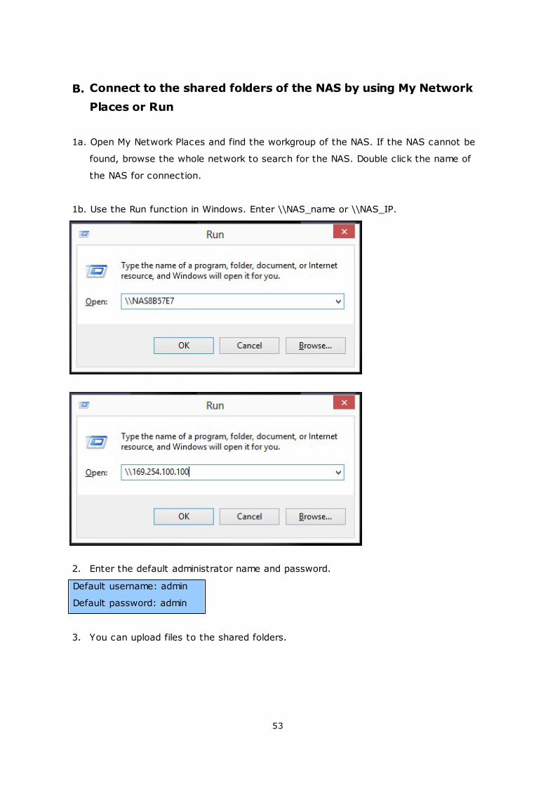
1a. Open My Network Places and find the workgroup of the NAS. If the NAS cannot be
found, browse the whole network to search for the NAS. Double click the name of
the NAS for connection.
1b. Use the Run function in Windows. Enter \\NAS_name or \\NAS_IP.
2. Enter the default administrator name and password.
Default username: admin
Default password: admin
3. You can upload files to the shared folders.
54
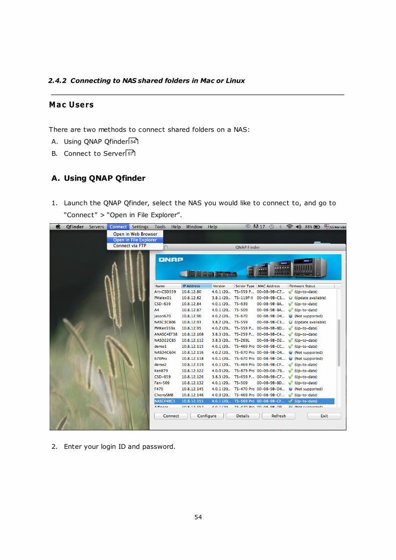
2.4.2 Connecting to NAS shared folders in Mac or Linux
Mac Users
There are two methods to connect shared folders on a NAS:
A. Using QNAP Qfinder
B. Connect to Server
A. Using QNAP Qfinder
1. Launch the QNAP Qfinder, select the NAS you would like to connect to, and go to
“Connect” > “Open in File Explorer”.
2. Enter your login ID and password.
54
57

55
3. Select the folder you want to mount and click “OK”.
4. The folder is mounted.

56
57
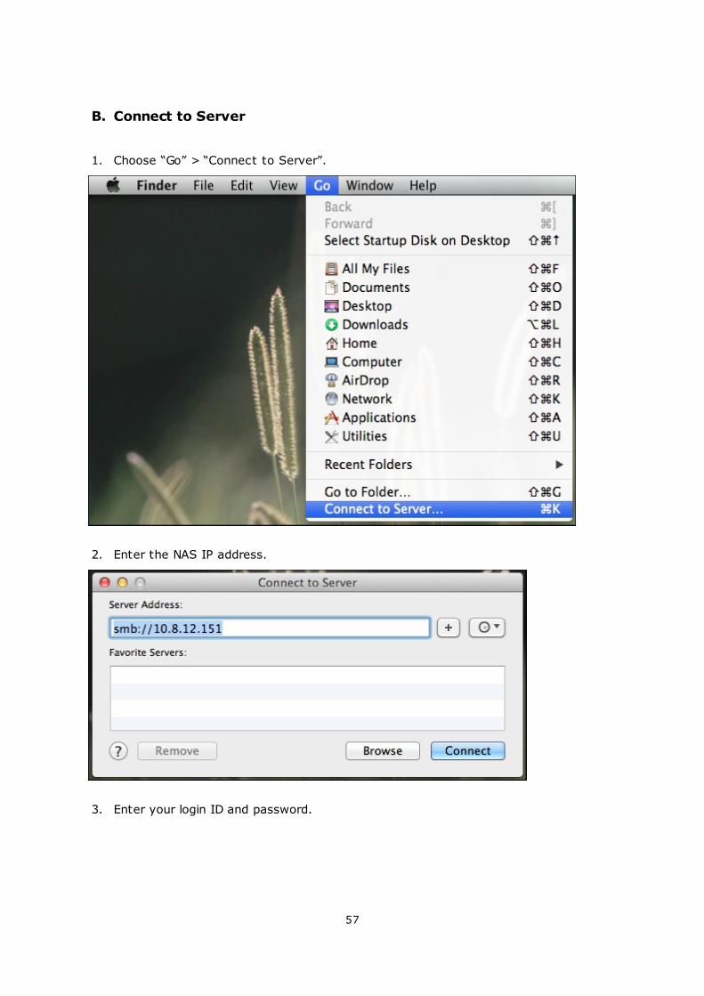
B. Connect to Server
1. Choose “Go” > “Connect to Server”.
2. Enter the NAS IP address.
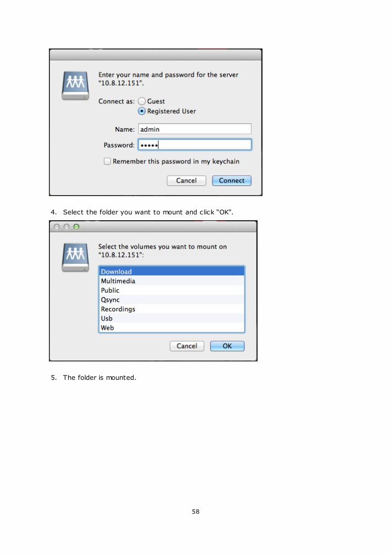
3. Enter your login ID and password.
58
4. Select the folder you want to mount and click “OK”.
5. The folder is mounted.
59
60
Linux Users
On Linux, run the following command:
m ount -t nfs <NAS IP>:/<Shared Folder Nam e> <Directory to Mount>
For example, if the IP address of the NAS is 192.168.0.1, to connect to the shared folder
“public” under the /mnt/pub directory, use the following command:
m ount -t nfs 192.168.0.1:/public /m nt/pub
Note: You must login as the “root” user to initiate the above command.
Login the NAS with the specified user ID, use the mounted directory to connect to the
shared folders.
61
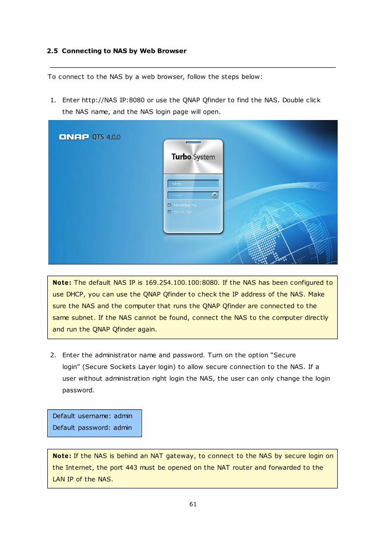
2.5 Connecting to NAS by Web Browser
To connect to the NAS by a web browser, follow the steps below:
1. Enter http://NAS IP:8080 or use the QNAP Qfinder to find the NAS. Double click
the NAS name, and the NAS login page will open.
Note: The default NAS IP is 169.254.100.100:8080. If the NAS has been configured to
use DHCP, you can use the QNAP Qfinder to check the IP address of the NAS. Make
sure the NAS and the computer that runs the QNAP Qfinder are connected to the
same subnet. If the NAS cannot be found, connect the NAS to the computer directly
and run the QNAP Qfinder again.
2. Enter the administrator name and password. Turn on the option “Secure
login” (Secure Sockets Layer login) to allow secure connection to the NAS. If a
user without administration right login the NAS, the user can only change the login
password.
Default username: admin
Default password: admin
Note: If the NAS is behind an NAT gateway, to connect to the NAS by secure login on
the Internet, the port 443 must be opened on the NAT router and forwarded to the
LAN IP of the NAS.
62
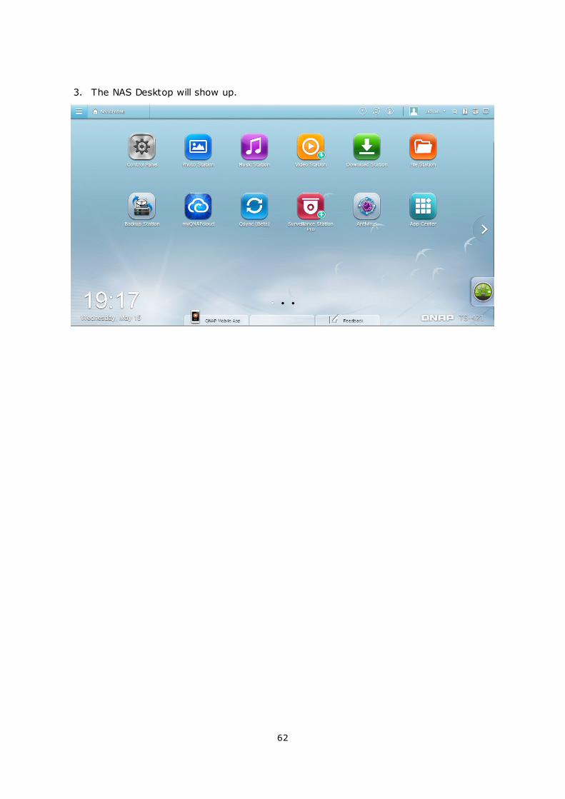
3. The NAS Desktop will show up.
63
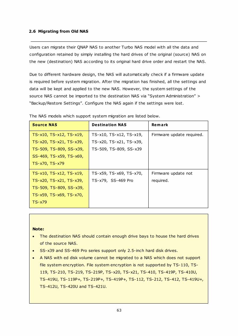
2.6 Migrating from Old NAS
Users can migrate their QNAP NAS to another Turbo NAS model with all the data and
configuration retained by simply installing the hard drives of the original (source) NAS on
the new (destination) NAS according to its original hard drive order and restart the NAS.
Due to different hardware design, the NAS will automatically check if a firmware update
is required before system migration. After the migration has finished, all the settings and
data will be kept and applied to the new NAS. However, the system settings of the
source NAS cannot be imported to the destination NAS via “System Administration” >
“Backup/Restore Settings”. Configure the NAS again if the settings were lost.
The NAS models which support system migration are listed below.
Source NAS Destination NAS Rem ark
TS-x10, TS-x12, TS-x19,
TS-x20, TS-x21, TS-x39,
TS-509, TS-809, SS-x39,
SS-469, TS-x59, TS-x69,
TS-x70, TS-x79
TS-x10, TS-x12, TS-x19,
TS-x20, TS-x21, TS-x39,
TS-509, TS-809, SS-x39
Firmware update required.
TS-x10, TS-x12, TS-x19,
TS-x20, TS-x21, TS-x39,
TS-509, TS-809, SS-x39,
TS-x59, TS-x69, TS-x70,
TS-x79
TS-x59, TS-x69, TS-x70,
TS-x79, SS-469 Pro
Firmware update not
required.
Note:
The destination NAS should contain enough drive bays to house the hard drives
of the source NAS.
SS-x39 and SS-469 Pro series support only 2.5-inch hard disk drives.
A NAS with ed disk volume cannot be migrated to a NAS which does not support
file system encryption. File system encryption is not supported by TS-110, TS-
119, TS-210, TS-219, TS-219P, TS-x20, TS-x21, TS-410, TS-419P, TS-410U,
TS-419U, TS-119P+, TS-219P+, TS-419P+, TS-112, TS-212, TS-412, TS-419U+,
TS-412U, TS-420U and TS-421U.
64
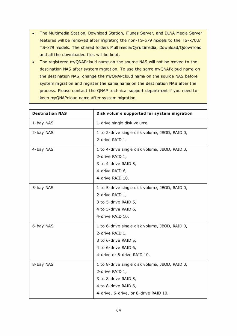
The Multimedia Station, Download Station, iTunes Server, and DLNA Media Server
features will be removed after migrating the non-TS-x79 models to the TS-x70U/
TS-x79 models. The shared folders Multimedia/Qmultimedia, Download/Qdownload
and all the downloaded files will be kept.
The registered myQNAPcloud name on the source NAS will not be moved to the
destination NAS after system migration. To use the same myQNAPcloud name on
the destination NAS, change the myQNAPcloud name on the source NAS before
system migration and register the same name on the destination NAS after the
process. Please contact the QNAP technical support department if you need to
keep myQNAPcloud name after system migration.
Destination NAS Disk volum e supported for system m igration
1-bay NAS 1-drive single disk volume
2-bay NAS 1 to 2-drive single disk volume, JBOD, RAID 0,
2-drive RAID 1.
4-bay NAS 1 to 4-drive single disk volume, JBOD, RAID 0,
2-drive RAID 1,
3 to 4-drive RAID 5,
4-drive RAID 6,
4-drive RAID 10.
5-bay NAS 1 to 5-drive single disk volume, JBOD, RAID 0,
2-drive RAID 1,
3 to 5-drive RAID 5,
4 to 5-drive RAID 6,
4-drive RAID 10.
6-bay NAS 1 to 6-drive single disk volume, JBOD, RAID 0,
2-drive RAID 1,
3 to 6-drive RAID 5,
4 to 6-drive RAID 6,
4-drive or 6-drive RAID 10.
8-bay NAS 1 to 8-drive single disk volume, JBOD, RAID 0,
2-drive RAID 1,
3 to 8-drive RAID 5,
4 to 8-drive RAID 6,
4-drive, 6-drive, or 8-drive RAID 10.
65
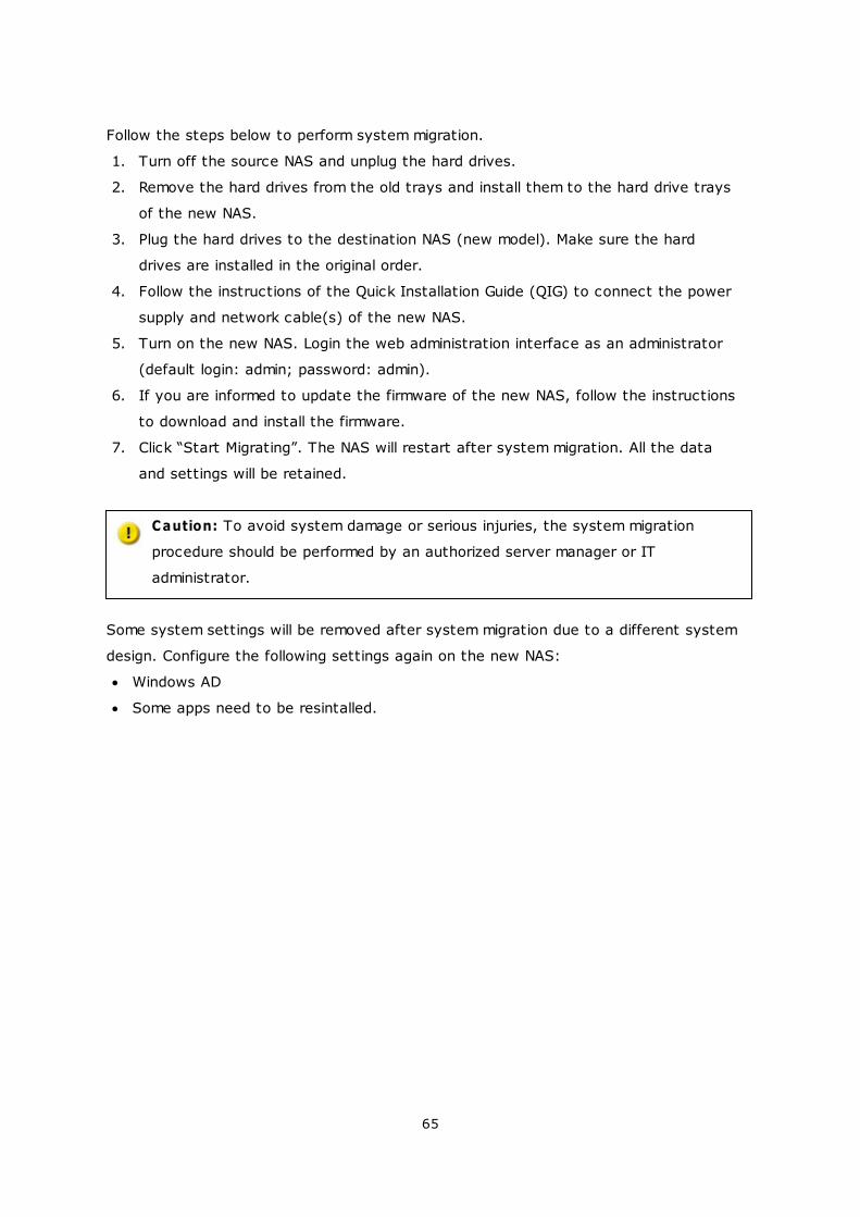
Follow the steps below to perform system migration.
1. Turn off the source NAS and unplug the hard drives.
2. Remove the hard drives from the old trays and install them to the hard drive trays
of the new NAS.
3. Plug the hard drives to the destination NAS (new model). Make sure the hard
drives are installed in the original order.
4. Follow the instructions of the Quick Installation Guide (QIG) to connect the power
supply and network cable(s) of the new NAS.
5. Turn on the new NAS. Login the web administration interface as an administrator
(default login: admin; password: admin).
6. If you are informed to update the firmware of the new NAS, follow the instructions
to download and install the firmware.
7. Click “Start Migrating”. The NAS will restart after system migration. All the data
and settings will be retained.
Caution: To avoid system damage or serious injuries, the system migration
procedure should be performed by an authorized server manager or IT
administrator.
Some system settings will be removed after system migration due to a different system
design. Configure the following settings again on the new NAS:
Windows AD
Some apps need to be resintalled.

66
3. QTS Basics and Desktop
Introducing QTS
Using QTS Desktop
67
71
67
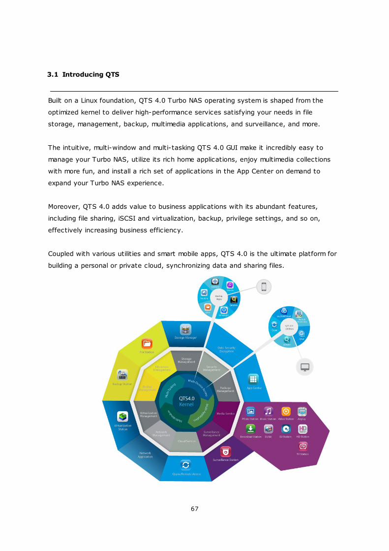
3.1 Introducing QTS
Built on a Linux foundation, QTS 4.0 Turbo NAS operating system is shaped from the
optimized kernel to deliver high-performance services satisfying your needs in file
storage, management, backup, multimedia applications, and surveillance, and more.
The intuitive, multi-window and multi-tasking QTS 4.0 GUI make it incredibly easy to
manage your Turbo NAS, utilize its rich home applications, enjoy multimedia collections
with more fun, and install a rich set of applications in the App Center on demand to
expand your Turbo NAS experience.
Moreover, QTS 4.0 adds value to business applications with its abundant features,
including file sharing, iSCSI and virtualization, backup, privilege settings, and so on,
effectively increasing business efficiency.
Coupled with various utilities and smart mobile apps, QTS 4.0 is the ultimate platform for
building a personal or private cloud, synchronizing data and sharing files.

68
*Click the figure above to check for more details.
69
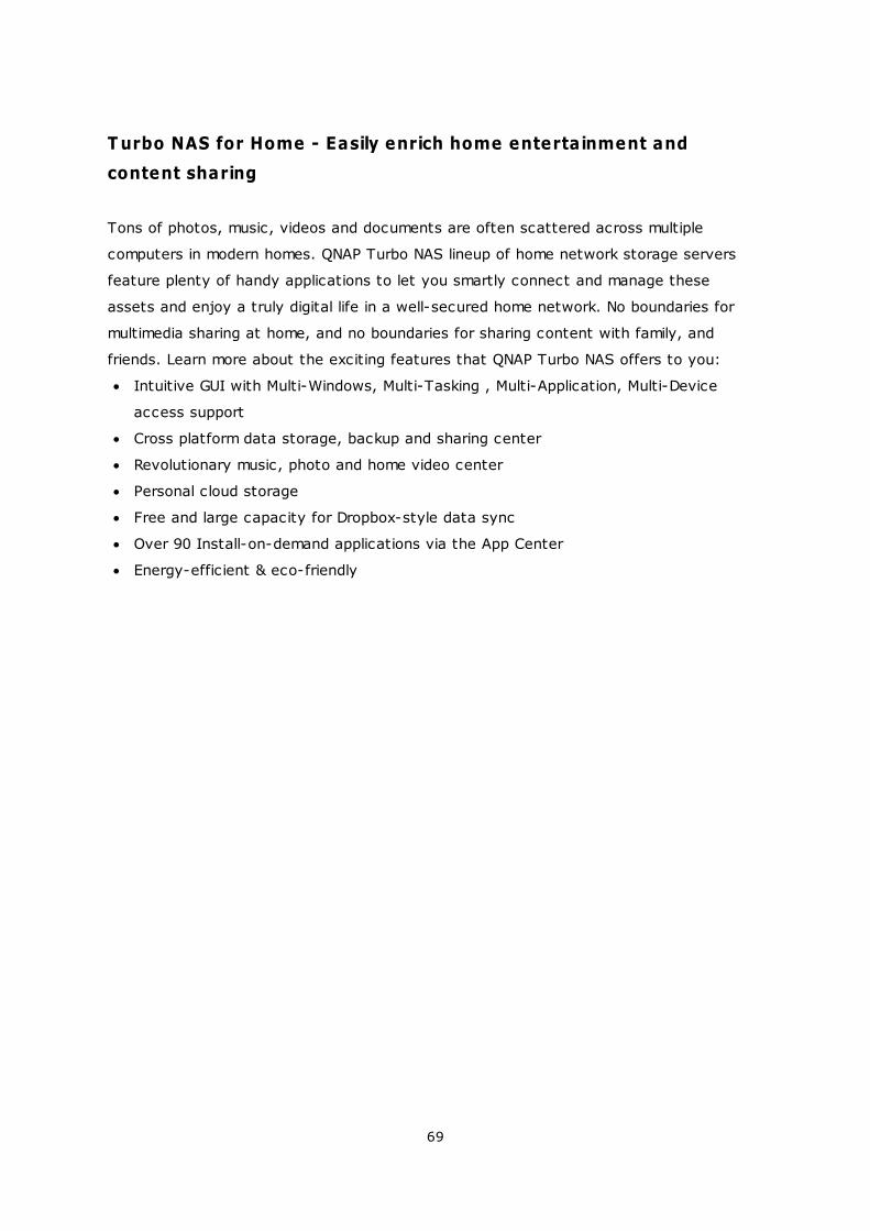
T urbo NAS for Home - Easily enrich home entertainment and
content sharing
Tons of photos, music, videos and documents are often scattered across multiple
computers in modern homes. QNAP Turbo NAS lineup of home network storage servers
feature plenty of handy applications to let you smartly connect and manage these
assets and enjoy a truly digital life in a well-secured home network. No boundaries for
multimedia sharing at home, and no boundaries for sharing content with family, and
friends. Learn more about the exciting features that QNAP Turbo NAS offers to you:
Intuitive GUI with Multi-Windows, Multi-Tasking , Multi-Application, Multi-Device
access support
Cross platform data storage, backup and sharing center
Revolutionary music, photo and home video center
Personal cloud storage
Free and large capacity for Dropbox-style data sync
Over 90 Install-on-demand applications via the App Center
Energy-efficient & eco-friendly
70
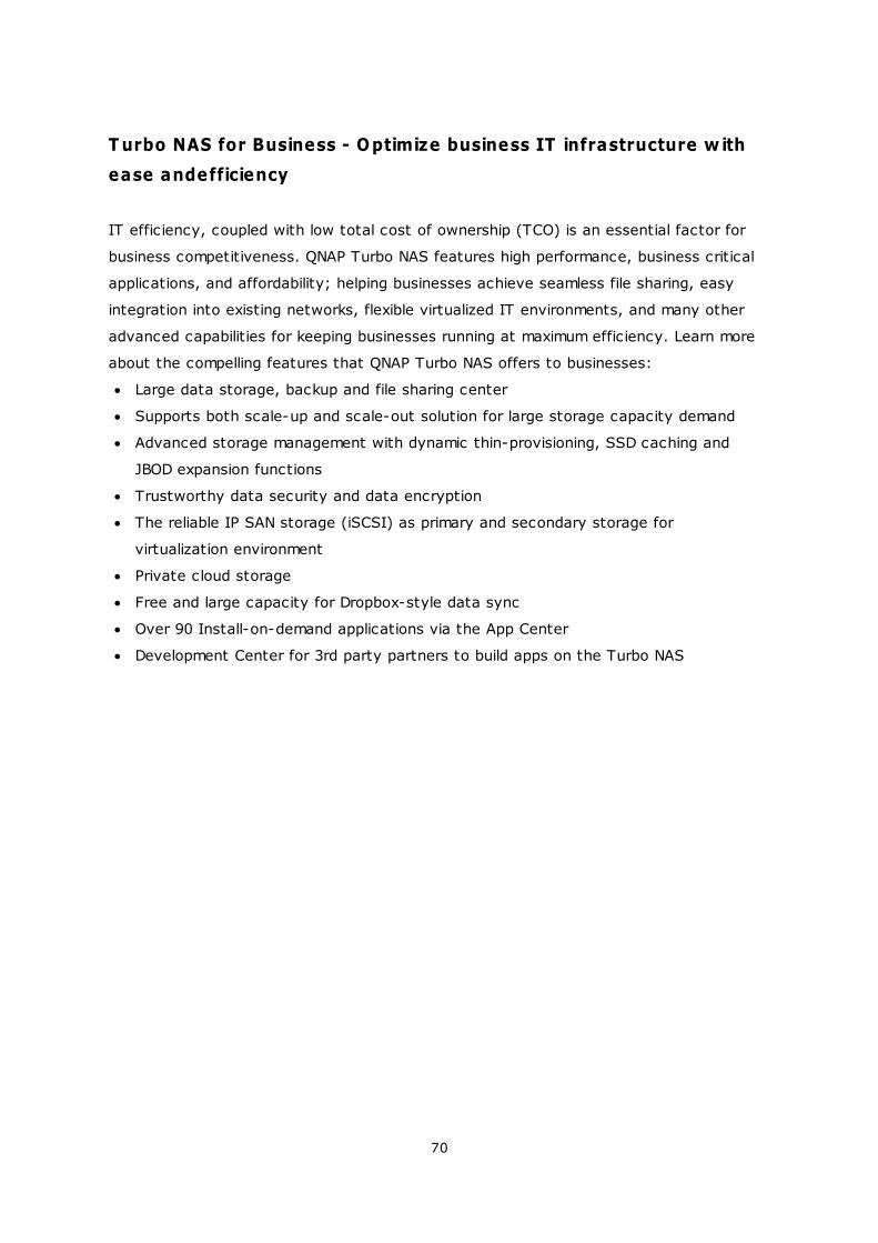
T urbo NAS for Business - Optimize business IT infrastructure w ith
ease andefficiency
IT efficiency, coupled with low total cost of ownership (TCO) is an essential factor for
business competitiveness. QNAP Turbo NAS features high performance, business critical
applications, and affordability; helping businesses achieve seamless file sharing, easy
integration into existing networks, flexible virtualized IT environments, and many other
advanced capabilities for keeping businesses running at maximum efficiency. Learn more
about the compelling features that QNAP Turbo NAS offers to businesses:
Large data storage, backup and file sharing center
Supports both scale-up and scale-out solution for large storage capacity demand
Advanced storage management with dynamic thin-provisioning, SSD caching and
JBOD expansion functions
Trustworthy data security and data encryption
The reliable IP SAN storage (iSCSI) as primary and secondary storage for
virtualization environment
Private cloud storage
Free and large capacity for Dropbox-style data sync
Over 90 Install-on-demand applications via the App Center
Development Center for 3rd party partners to build apps on the Turbo NAS
71
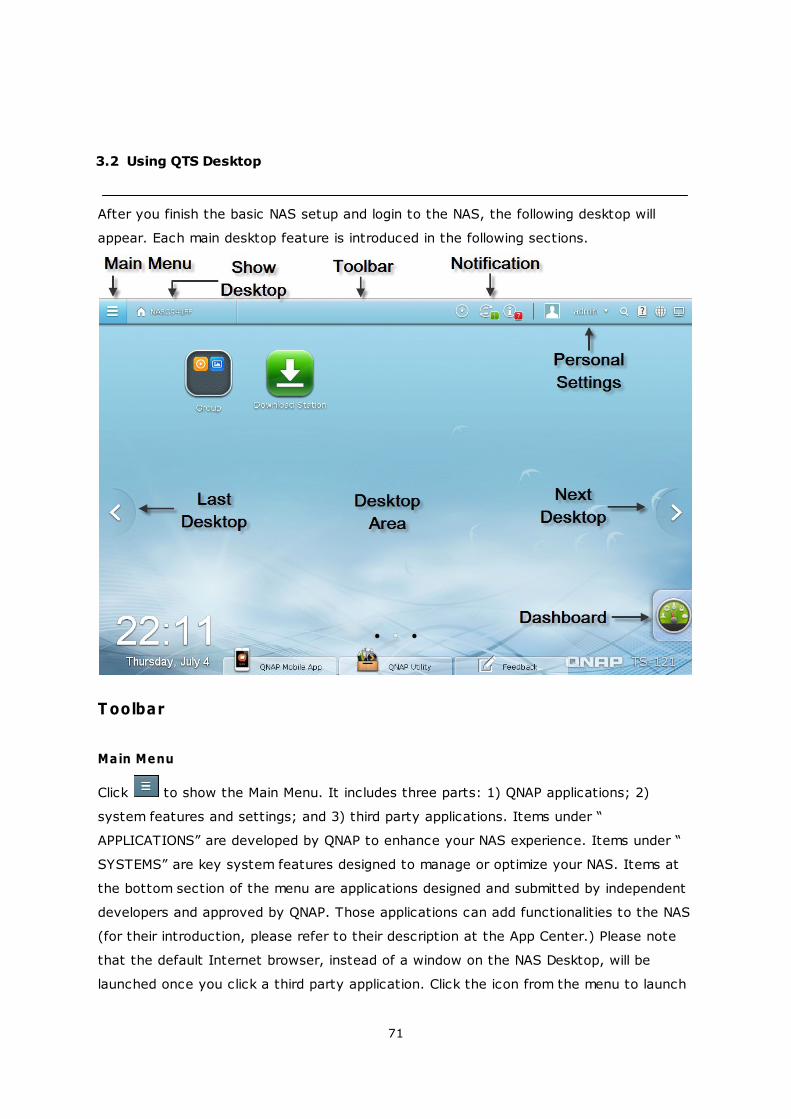
3.2 Using QTS Desktop
After you finish the basic NAS setup and login to the NAS, the following desktop will
appear. Each main desktop feature is introduced in the following sections.
T oolbar
Main Menu
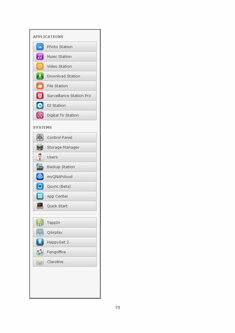
Click to show the Main Menu. It includes three parts: 1) QNAP applications; 2)
system features and settings; and 3) third party applications. Items under “
APPLICATIONS” are developed by QNAP to enhance your NAS experience. Items under “
SYSTEMS” are key system features designed to manage or optimize your NAS. Items at
the bottom section of the menu are applications designed and submitted by independent
developers and approved by QNAP. Those applications can add functionalities to the NAS
(for their introduction, please refer to their description at the App Center.) Please note
that the default Internet browser, instead of a window on the NAS Desktop, will be
launched once you click a third party application. Click the icon from the menu to launch

72
the selected application.
73
74
Show Desktop
Click to minimize or restore all open windows and show the desktop.
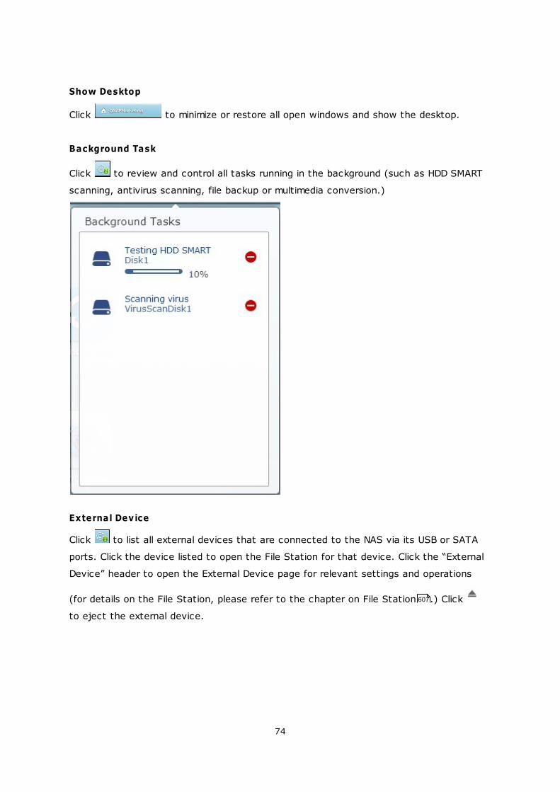
Background Task
Click to review and control all tasks running in the background (such as HDD SMART
scanning, antivirus scanning, file backup or multimedia conversion.)
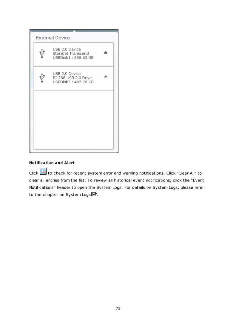
External Device
Click to list all external devices that are connected to the NAS via its USB or SATA
ports. Click the device listed to open the File Station for that device. Click the “External
Device” header to open the External Device page for relevant settings and operations
(for details on the File Station, please refer to the chapter on File Station .) Click
to eject the external device.
607
75
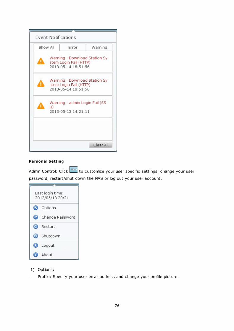
Notification and Alert
Click to check for recent system error and warning notifications. Click “Clear All” to
clear all entries from the list. To review all historical event notifications, click the “Event
Notifications” header to open the System Logs. For details on System Logs, please refer
to the chapter on System Logs . 308
76
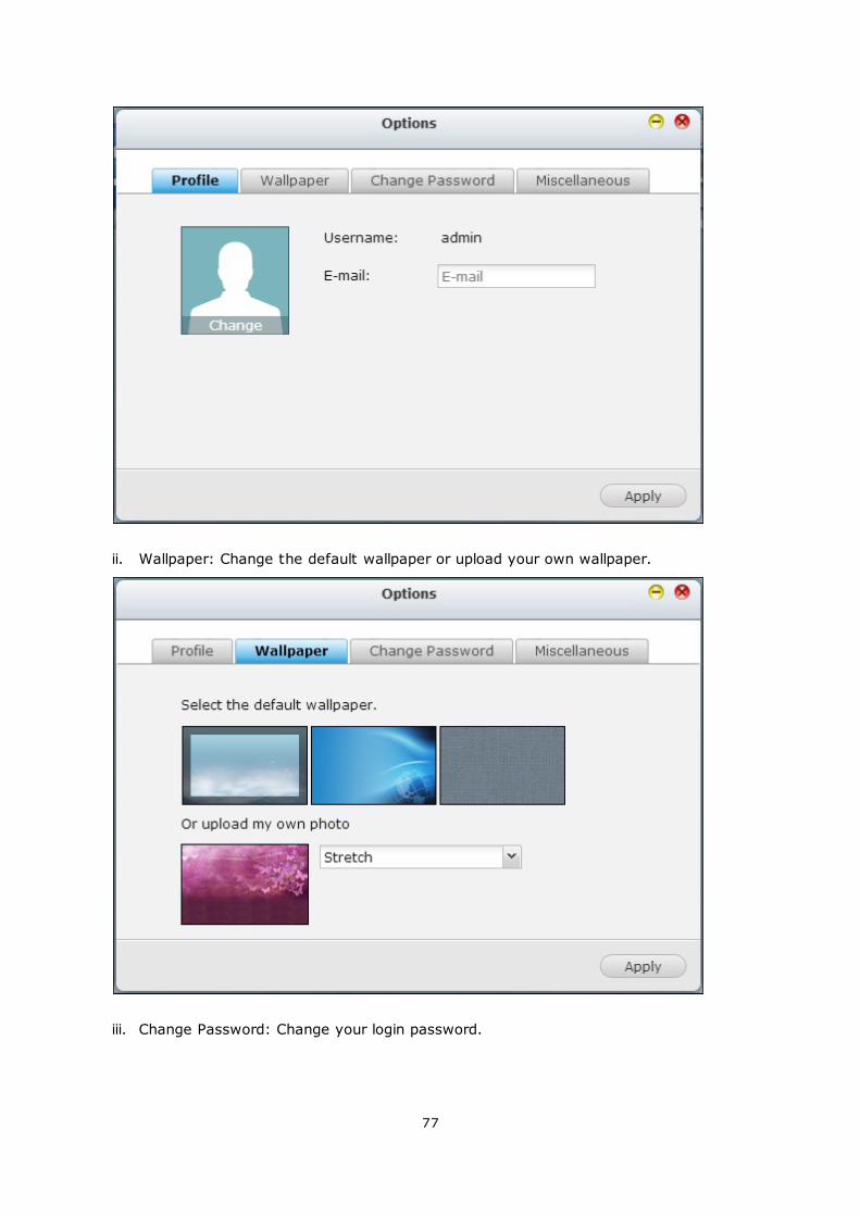
Personal Setting
Admin Control: Click to customize your user specific settings, change your user
password, restart/shut down the NAS or log out your user account.
1) Options:
i. Profile: Specify your user email address and change your profile picture.
77
ii. Wallpaper: Change the default wallpaper or upload your own wallpaper.
iii. Change Password: Change your login password.
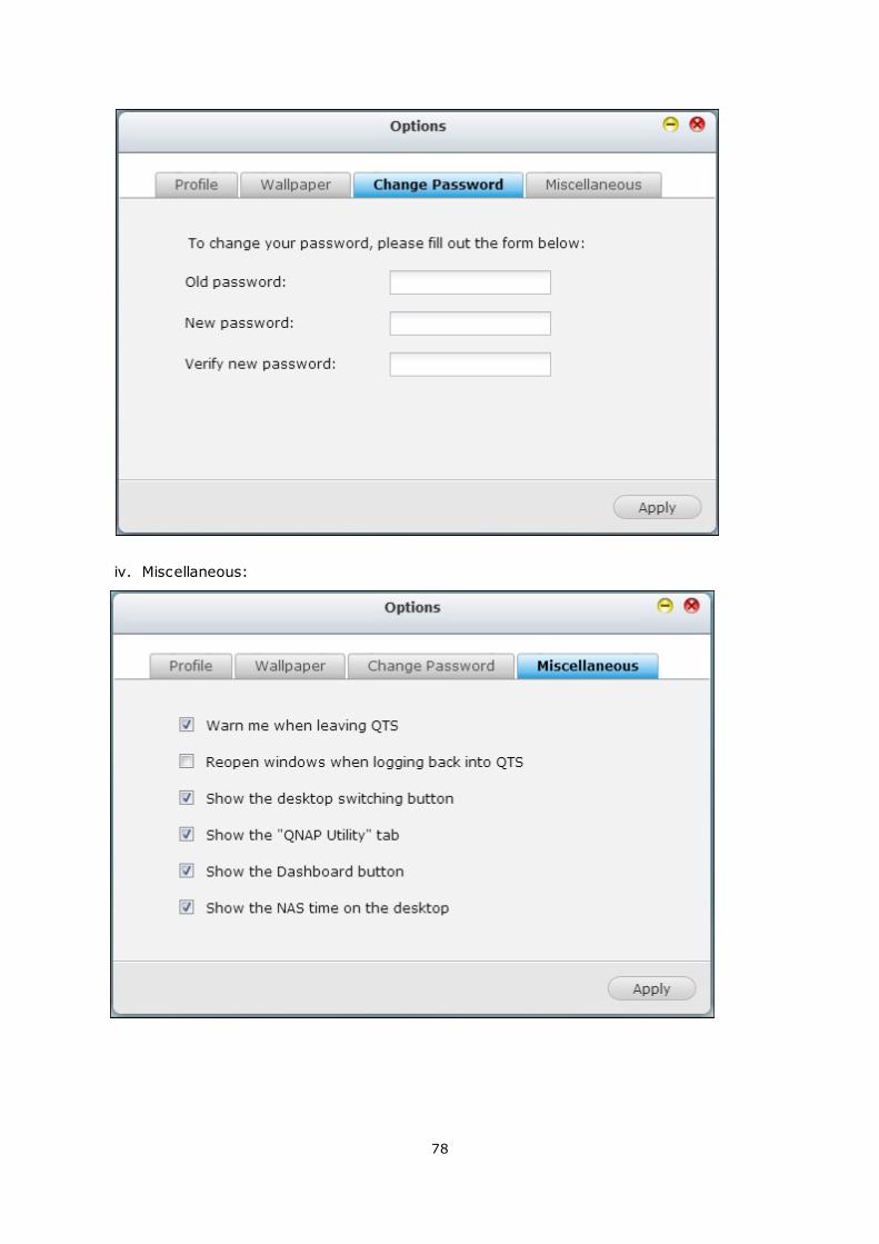
78
iv. Miscellaneous:
79
Warn me when leaving QTS: Check this option, and users will be prompted for
confirmation each time they leave the QTS Desktop (such as clicking the back icon (
) in the browser or close the browser ( ). It is advised to check
this option.
Reopen windows when logging back into QTS: Check this option, and all the current
desktop settings (such as the “windows opened before your logout”) will be kept
after you login the NAS the next time.
Show the desktop switching button: Check this option to hide the next desktop
button ( ) and last desktop button ( ) and only display them when you move your
mouse cursor close to the buttons.
Show the “QNAP Utility” tab: Check this option to show the “QNAP Mobile App”, “
QNAP Utility” and “Feedback” tabs at the bottom of the Desktop.
Show the Dashboard button: If you would like to hide the Dashboard button ( ) at
the bottom right side of the NAS Desktop, uncheck this option.
Show the NAS time on the desktop: If you prefer not to show the NAS time at
bottom left side of the desktop, uncheck this option.
Change Password: Click this button to change your login password.
2) Restart: Click this button to restart your NAS.
3) Shutdown: Click this button to shut down your NAS.
4) Logout: Click this button to log yourself out.
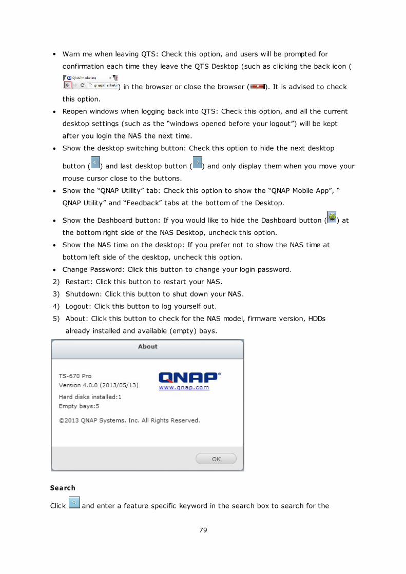
5) About: Click this button to check for the NAS model, firmware version, HDDs
already installed and available (empty) bays.
Search
Click and enter a feature specific keyword in the search box to search for the
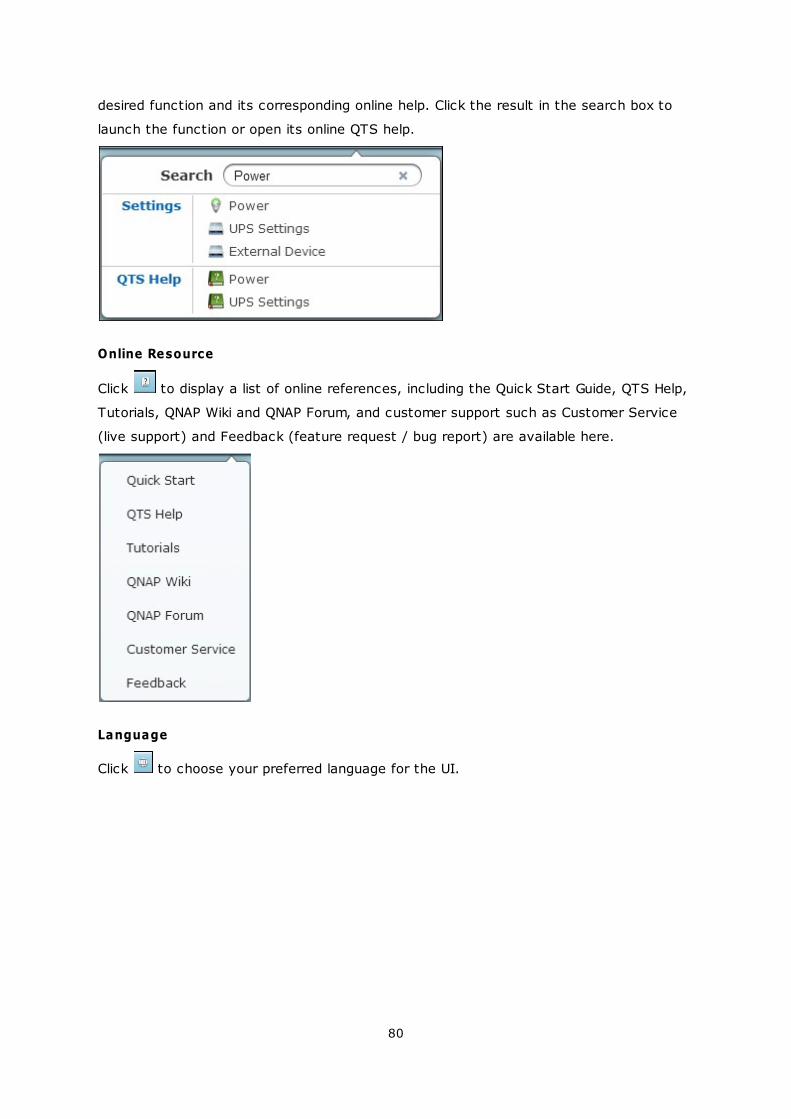
80
desired function and its corresponding online help. Click the result in the search box to
launch the function or open its online QTS help.
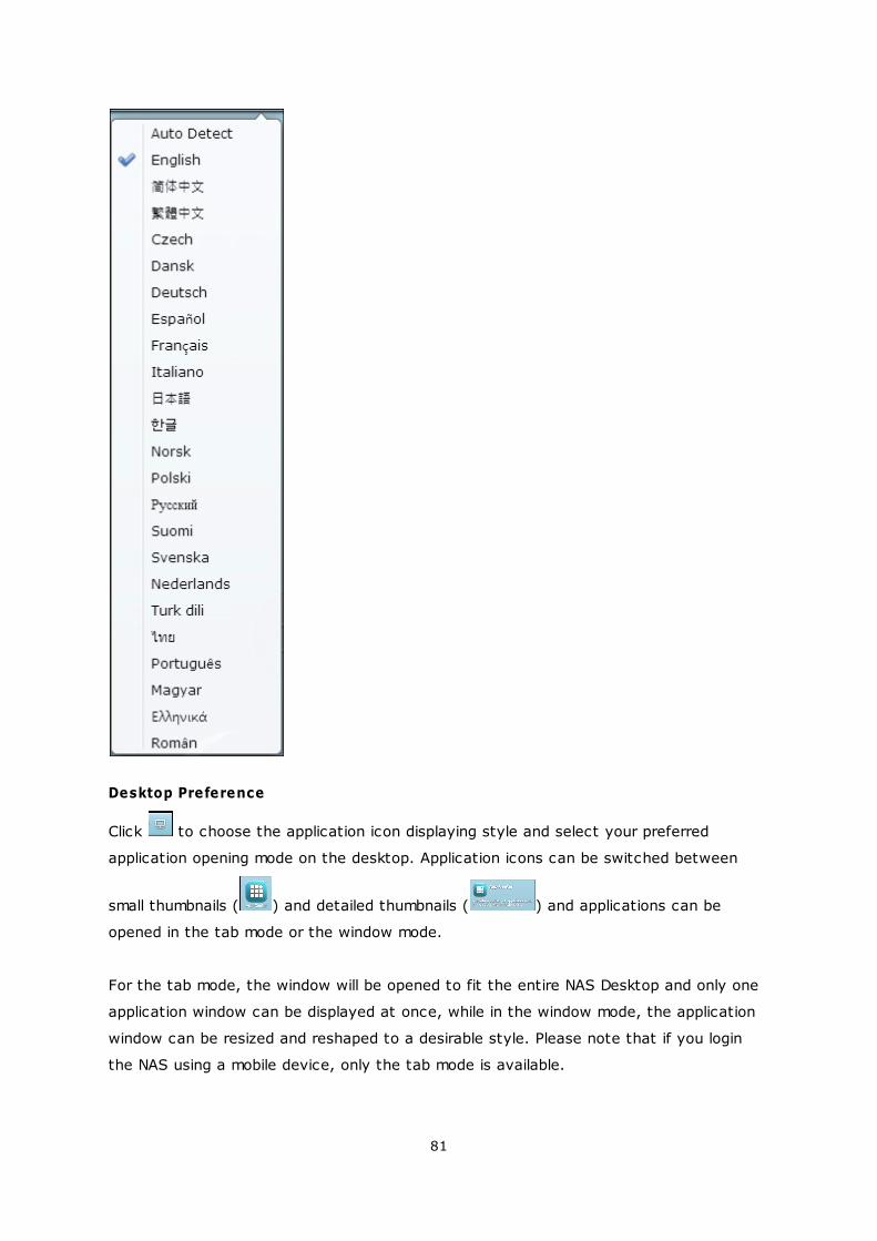
Online Resource
Click to display a list of online references, including the Quick Start Guide, QTS Help,
Tutorials, QNAP Wiki and QNAP Forum, and customer support such as Customer Service
(live support) and Feedback (feature request / bug report) are available here.
Language
Click to choose your preferred language for the UI.
81
Desktop Preference
Click to choose the application icon displaying style and select your preferred
application opening mode on the desktop. Application icons can be switched between
small thumbnails ( ) and detailed thumbnails ( ) and applications can be
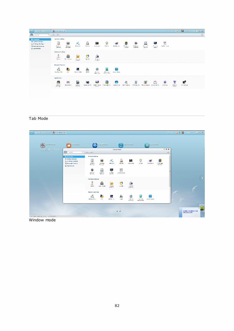
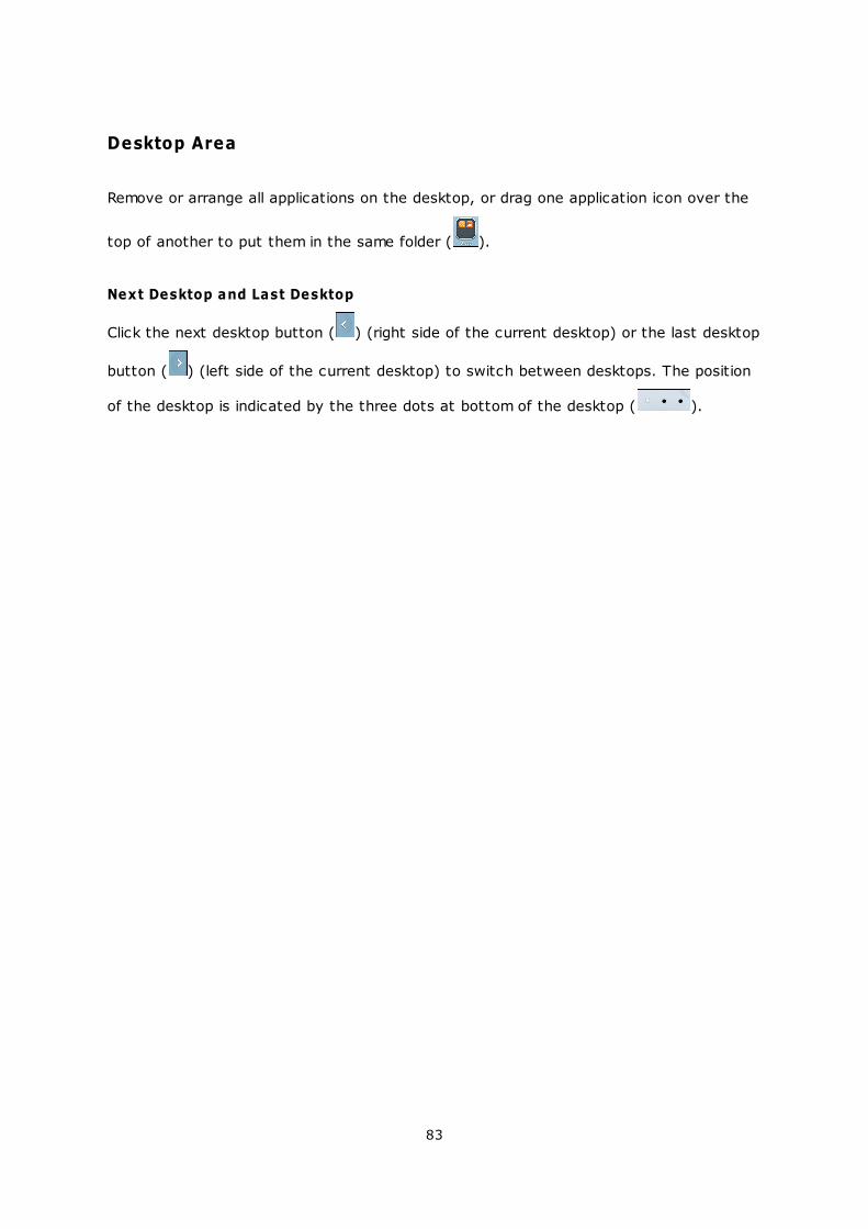
opened in the tab mode or the window mode.
For the tab mode, the window will be opened to fit the entire NAS Desktop and only one
application window can be displayed at once, while in the window mode, the application
window can be resized and reshaped to a desirable style. Please note that if you login
the NAS using a mobile device, only the tab mode is available.
82
Tab Mode
Window mode
83
Desktop Area
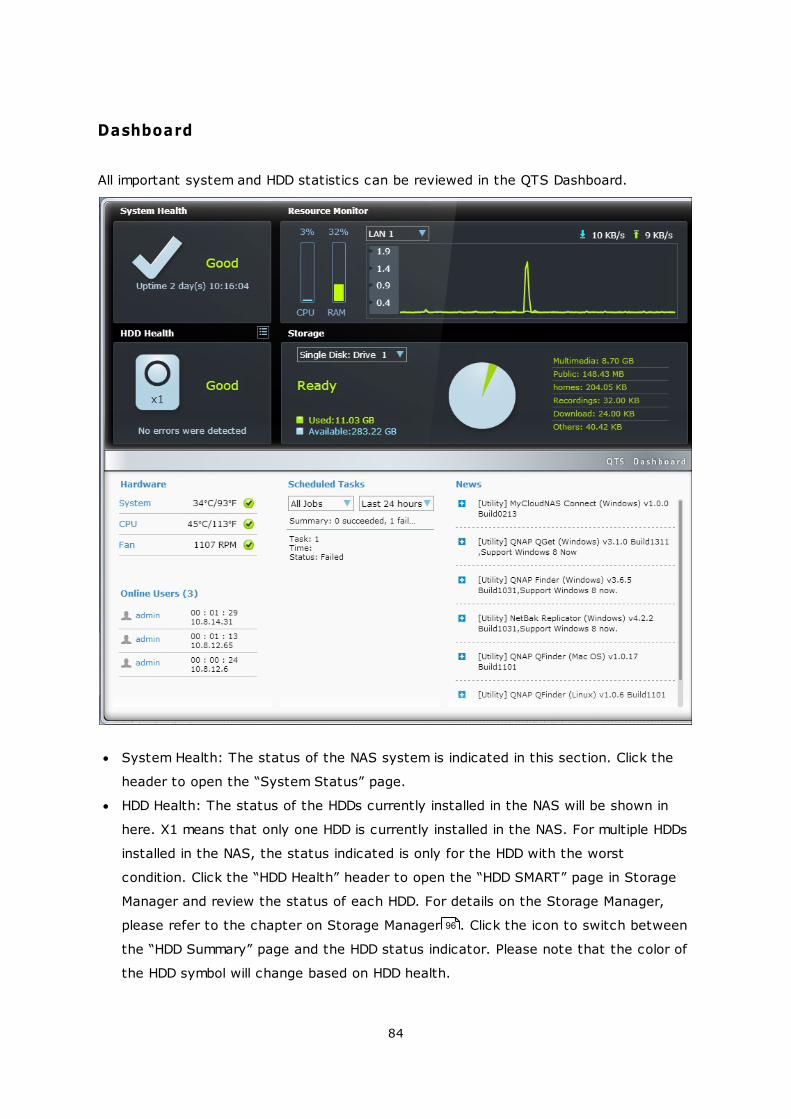
Remove or arrange all applications on the desktop, or drag one application icon over the
top of another to put them in the same folder ( ).
Next Desktop and Last Desktop
Click the next desktop button ( ) (right side of the current desktop) or the last desktop
button ( ) (left side of the current desktop) to switch between desktops. The position
of the desktop is indicated by the three dots at bottom of the desktop ( ).
84
Dashboard
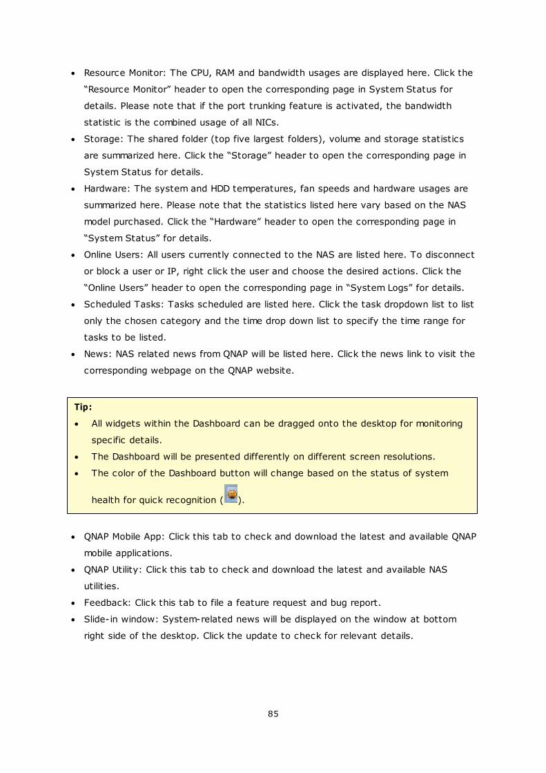
All important system and HDD statistics can be reviewed in the QTS Dashboard.
System Health: The status of the NAS system is indicated in this section. Click the
header to open the “System Status” page.
HDD Health: The status of the HDDs currently installed in the NAS will be shown in
here. X1 means that only one HDD is currently installed in the NAS. For multiple HDDs
installed in the NAS, the status indicated is only for the HDD with the worst
condition. Click the “HDD Health” header to open the “HDD SMART” page in Storage
Manager and review the status of each HDD. For details on the Storage Manager,
please refer to the chapter on Storage Manager . Click the icon to switch between
the “HDD Summary” page and the HDD status indicator. Please note that the color of
the HDD symbol will change based on HDD health.
96
85
Resource Monitor: The CPU, RAM and bandwidth usages are displayed here. Click the
“Resource Monitor” header to open the corresponding page in System Status for
details. Please note that if the port trunking feature is activated, the bandwidth
statistic is the combined usage of all NICs.
Storage: The shared folder (top five largest folders), volume and storage statistics
are summarized here. Click the “Storage” header to open the corresponding page in
System Status for details.
Hardware: The system and HDD temperatures, fan speeds and hardware usages are
summarized here. Please note that the statistics listed here vary based on the NAS
model purchased. Click the “Hardware” header to open the corresponding page in
“System Status” for details.
Online Users: All users currently connected to the NAS are listed here. To disconnect
or block a user or IP, right click the user and choose the desired actions. Click the
“Online Users” header to open the corresponding page in “System Logs” for details.
Scheduled Tasks: Tasks scheduled are listed here. Click the task dropdown list to list
only the chosen category and the time drop down list to specify the time range for
tasks to be listed.
News: NAS related news from QNAP will be listed here. Click the news link to visit the
corresponding webpage on the QNAP website.
Tip:
All widgets within the Dashboard can be dragged onto the desktop for monitoring
specific details.
The Dashboard will be presented differently on different screen resolutions.
The color of the Dashboard button will change based on the status of system
health for quick recognition ( ).
QNAP Mobile App: Click this tab to check and download the latest and available QNAP
mobile applications.
QNAP Utility: Click this tab to check and download the latest and available NAS
utilities.
Feedback: Click this tab to file a feature request and bug report.
Slide-in window: System-related news will be displayed on the window at bottom
right side of the desktop. Click the update to check for relevant details.
86
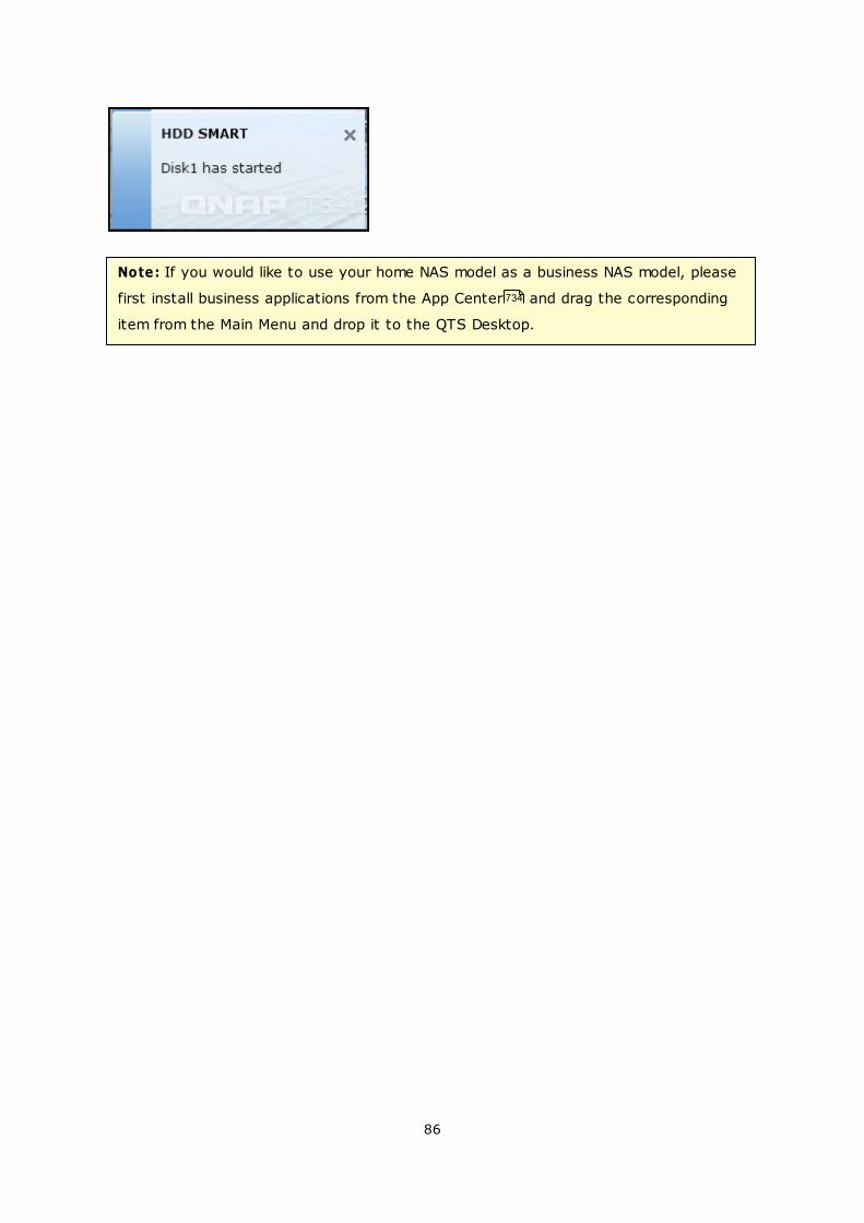
Note: If you would like to use your home NAS model as a business NAS model, please
first install business applications from the App Center and drag the corresponding
item from the Main Menu and drop it to the QTS Desktop.
734
87
4. System Settings
General Settings
Storage_Manager
Network
Security
Hardware
Power
Notification
Firmware Update
Backup/Restore
External_Device
System_Status
System Logs
88
96
206
231
234
240
245
248
252
254
301
308
88
4.1 General Settings
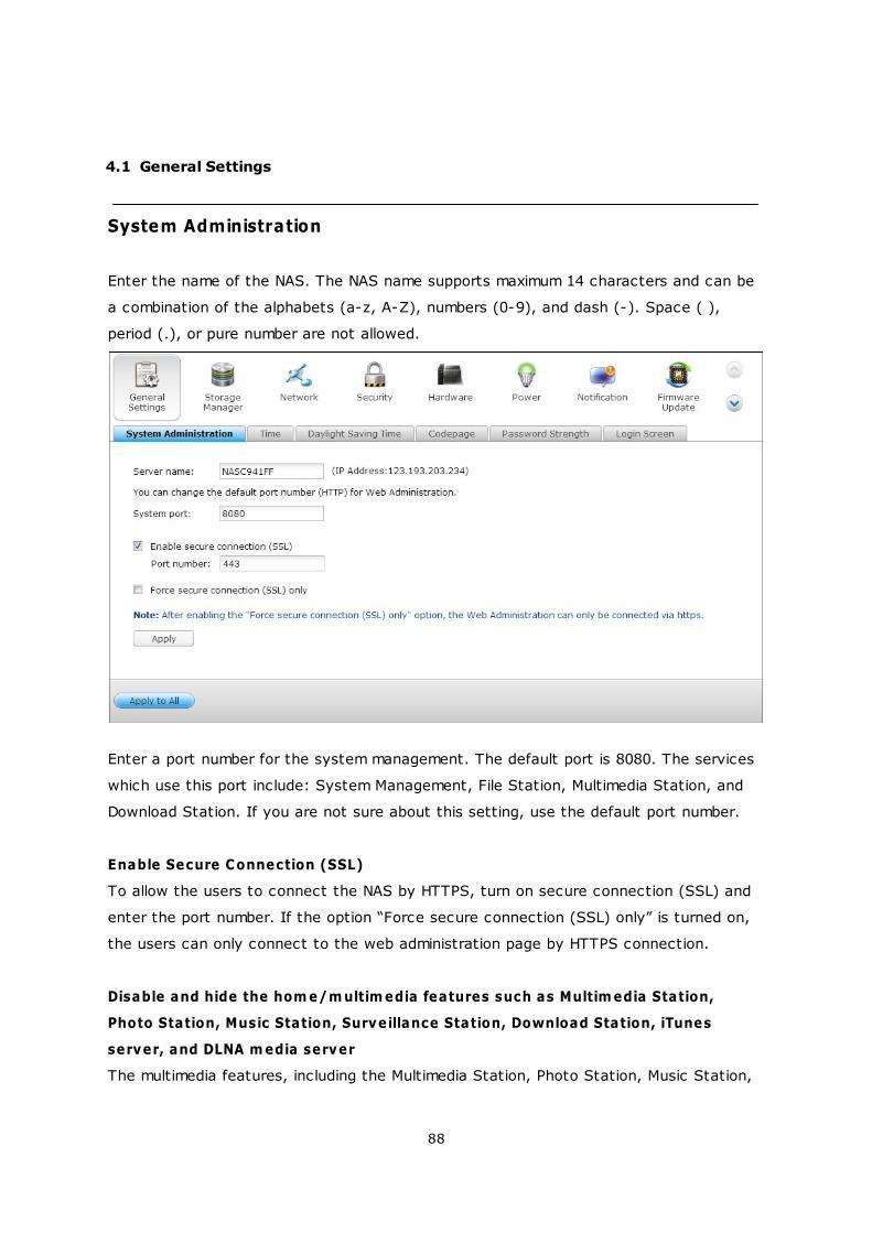
System Administration
Enter the name of the NAS. The NAS name supports maximum 14 characters and can be
a combination of the alphabets (a-z, A-Z), numbers (0-9), and dash (-). Space ( ),
period (.), or pure number are not allowed.
Enter a port number for the system management. The default port is 8080. The services
which use this port include: System Management, File Station, Multimedia Station, and
Download Station. If you are not sure about this setting, use the default port number.
Enable Secure Connection (SSL)
To allow the users to connect the NAS by HTTPS, turn on secure connection (SSL) and
enter the port number. If the option “Force secure connection (SSL) only” is turned on,
the users can only connect to the web administration page by HTTPS connection.
Disable and hide the hom e/m ultim edia features such as Multim edia Station,
Photo Station, Music Station, Surveillance Station, Download Station, iTunes
server, and DLNA m edia server
The multimedia features, including the Multimedia Station, Photo Station, Music Station,
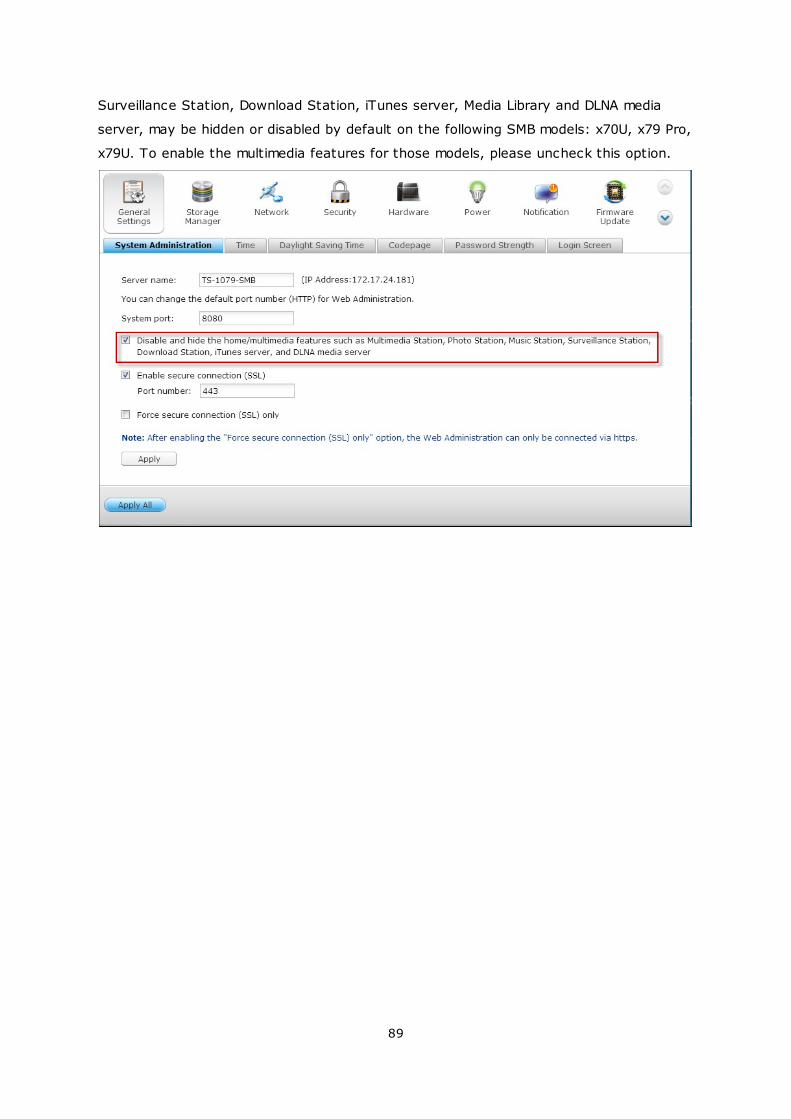
89
Surveillance Station, Download Station, iTunes server, Media Library and DLNA media
server, may be hidden or disabled by default on the following SMB models: x70U, x79 Pro,
x79U. To enable the multimedia features for those models, please uncheck this option.
90
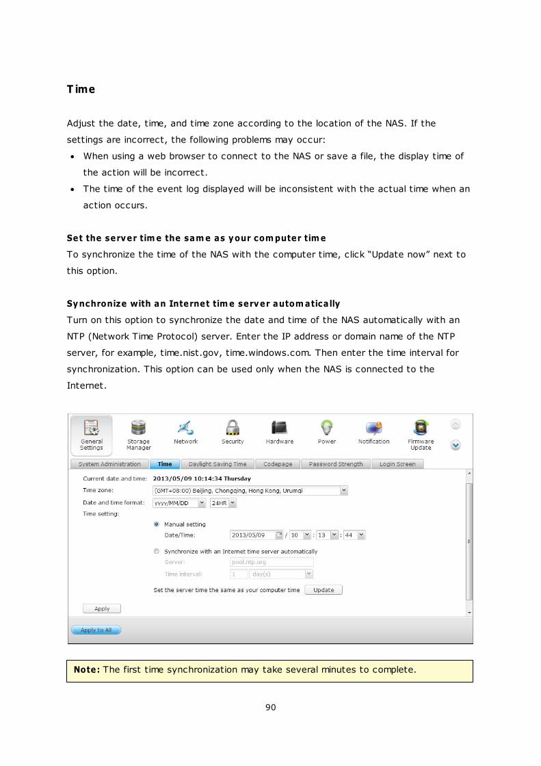
T ime
Adjust the date, time, and time zone according to the location of the NAS. If the
settings are incorrect, the following problems may occur:
When using a web browser to connect to the NAS or save a file, the display time of
the action will be incorrect.
The time of the event log displayed will be inconsistent with the actual time when an
action occurs.
Set the server tim e the sam e as your com puter tim e
To synchronize the time of the NAS with the computer time, click “Update now” next to
this option.
Synchronize with an Internet tim e server autom atically
Turn on this option to synchronize the date and time of the NAS automatically with an
NTP (Network Time Protocol) server. Enter the IP address or domain name of the NTP
server, for example, time.nist.gov, time.windows.com. Then enter the time interval for
synchronization. This option can be used only when the NAS is connected to the
Internet.
Note: The first time synchronization may take several minutes to complete.
91
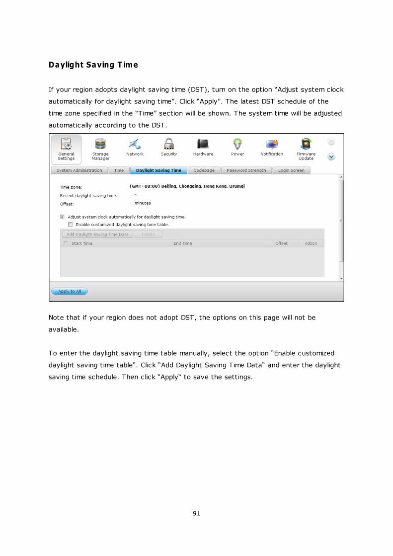
Daylight Saving T ime
If your region adopts daylight saving time (DST), turn on the option “Adjust system clock
automatically for daylight saving time”. Click “Apply”. The latest DST schedule of the
time zone specified in the “Time” section will be shown. The system time will be adjusted
automatically according to the DST.
Note that if your region does not adopt DST, the options on this page will not be
available.
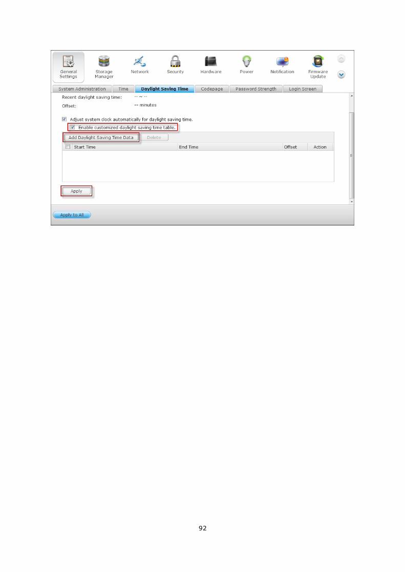
To enter the daylight saving time table manually, select the option “Enable customized
daylight saving time table“. Click “Add Daylight Saving Time Data“ and enter the daylight
saving time schedule. Then click “Apply“ to save the settings.
92
93
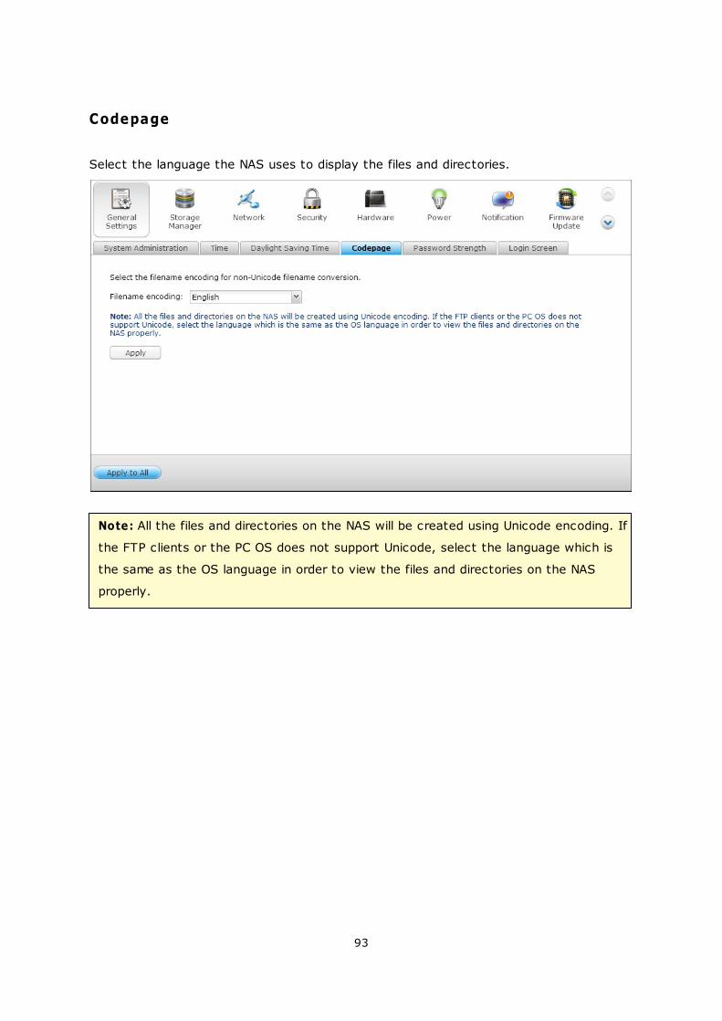
Codepage
Select the language the NAS uses to display the files and directories.
Note: All the files and directories on the NAS will be created using Unicode encoding. If
the FTP clients or the PC OS does not support Unicode, select the language which is
the same as the OS language in order to view the files and directories on the NAS
properly.
94
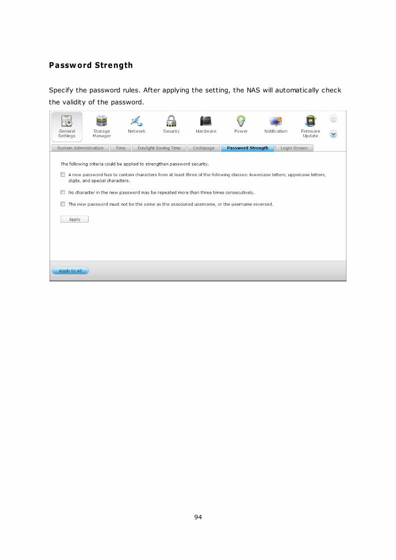
Password Strength
Specify the password rules. After applying the setting, the NAS will automatically check
the validity of the password.
95
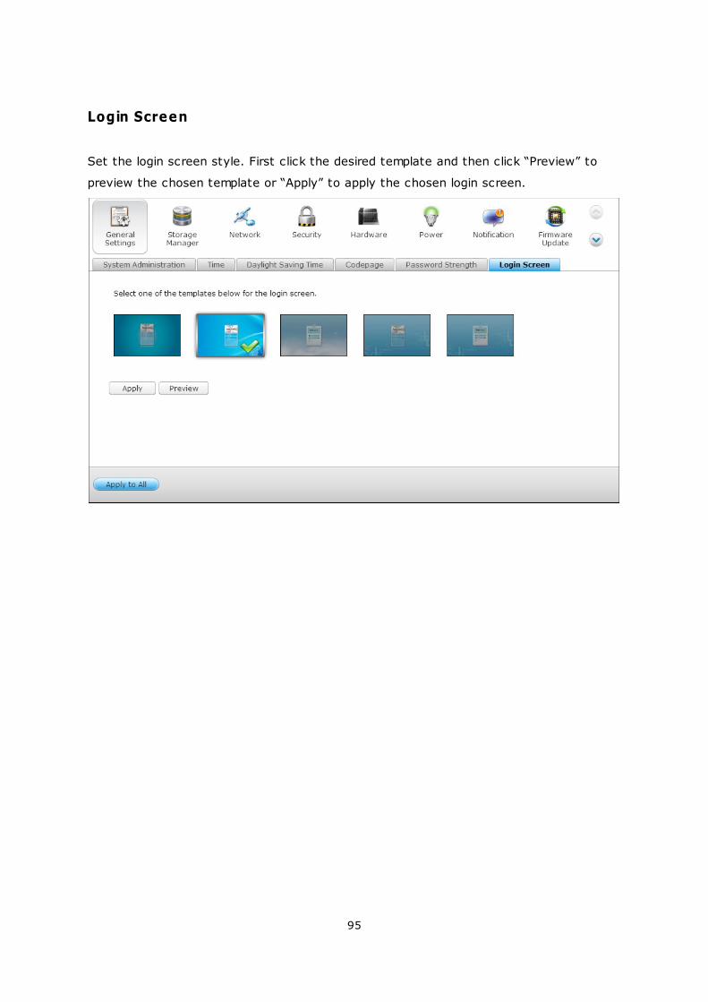
Login Screen
Set the login screen style. First click the desired template and then click “Preview” to
preview the chosen template or “Apply” to apply the chosen login screen.

96
4.2 Storage Manager
Volume Management
RAID Management
Hard Disk S.M.A.R.T
Encrypted File System
iSCSI
Virtual Disk
97
101
124
125
136
201
97
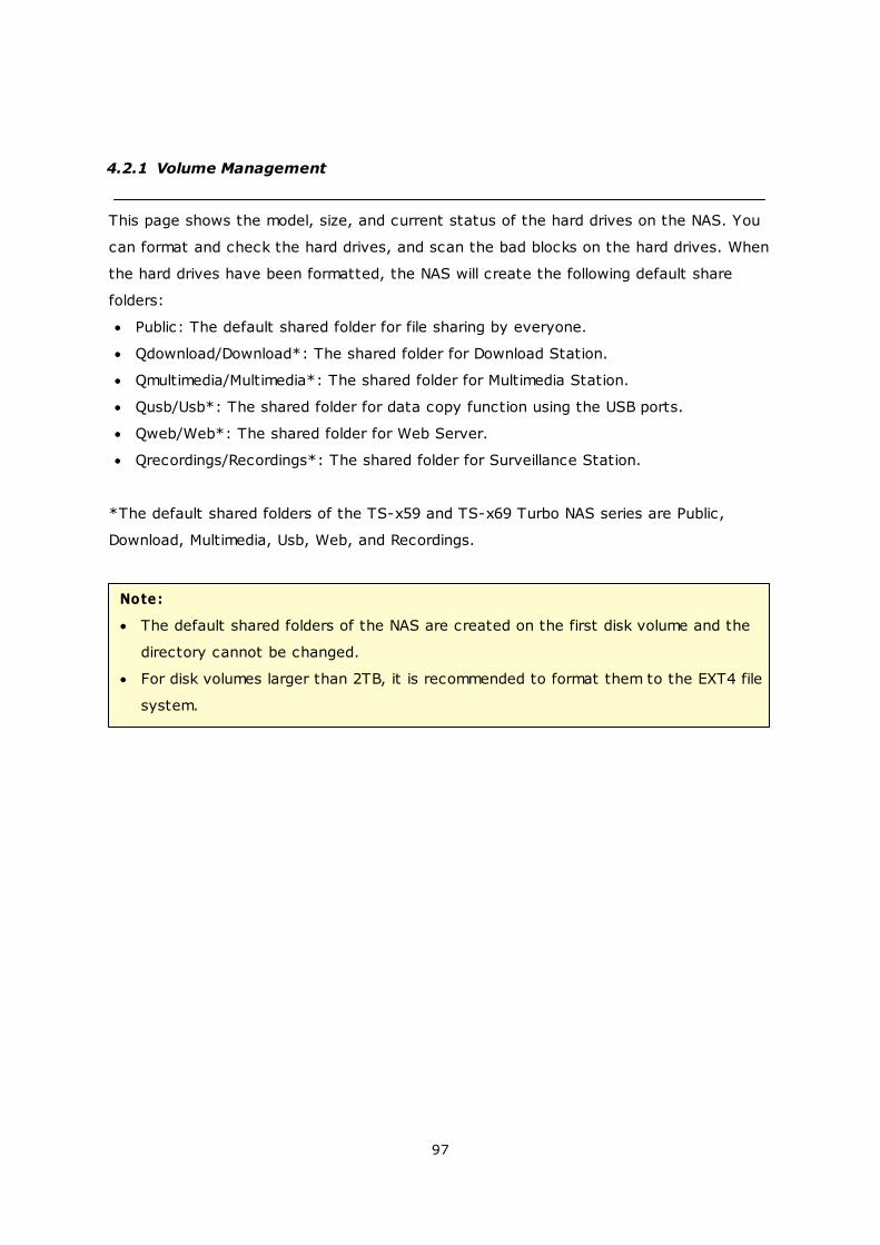
4.2.1 Volume Management
This page shows the model, size, and current status of the hard drives on the NAS. You
can format and check the hard drives, and scan the bad blocks on the hard drives. When
the hard drives have been formatted, the NAS will create the following default share
folders:
Public: The default shared folder for file sharing by everyone.
Qdownload/Download*: The shared folder for Download Station.
Qmultimedia/Multimedia*: The shared folder for Multimedia Station.
Qusb/Usb*: The shared folder for data copy function using the USB ports.
Qweb/Web*: The shared folder for Web Server.
Qrecordings/Recordings*: The shared folder for Surveillance Station.
*The default shared folders of the TS-x59 and TS-x69 Turbo NAS series are Public,
Download, Multimedia, Usb, Web, and Recordings.
Note:
The default shared folders of the NAS are created on the first disk volume and the
directory cannot be changed.
For disk volumes larger than 2TB, it is recommended to format them to the EXT4 file
system.
98
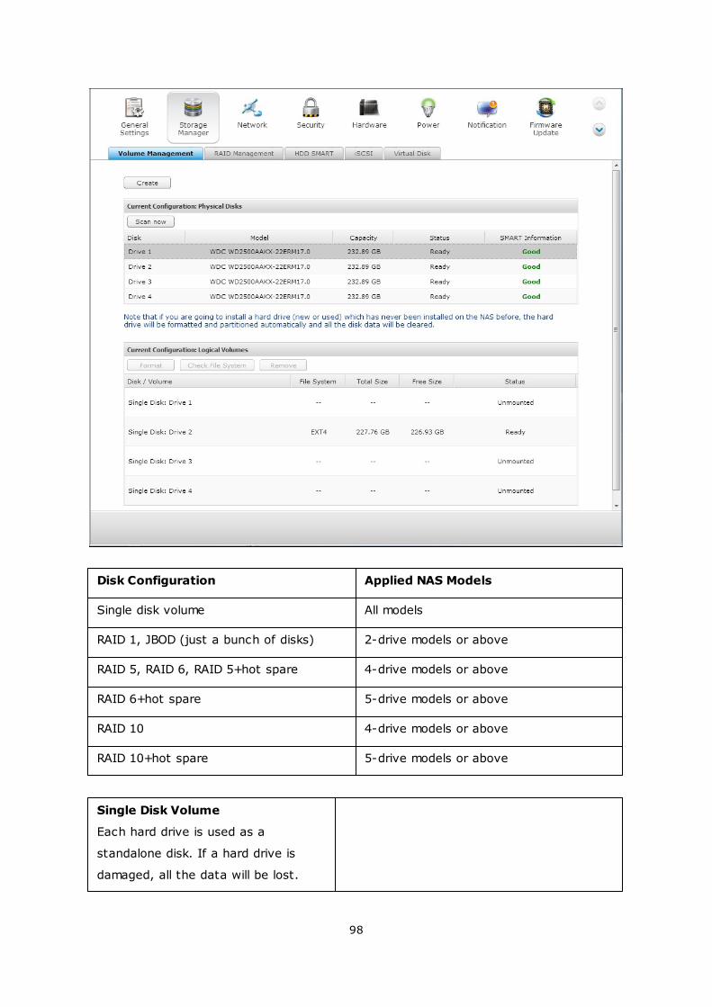
Disk Configuration Applied NAS Models
Single disk volume All models
RAID 1, JBOD (just a bunch of disks) 2-drive models or above
RAID 5, RAID 6, RAID 5+hot spare 4-drive models or above
RAID 6+hot spare 5-drive models or above
RAID 10 4-drive models or above
RAID 10+hot spare 5-drive models or above
Single Disk Volume
Each hard drive is used as a
standalone disk. If a hard drive is
damaged, all the data will be lost.
99
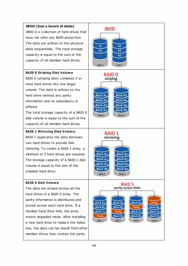
JBOD (Just a bunch of disks)
JBOD is a collection of hard drives that
does not offer any RAID protection.
The data are written to the physical
disks sequentially. The total storage
capacity is equal to the sum of the
capacity of all member hard drives.
RAID 0 Striping Disk Volum e
RAID 0 (striping disk) combines 2 or
more hard drives into one larger
volume. The data is written to the
hard drive without any parity
information and no redundancy is
offered.
The total storage capacity of a RAID 0
disk volume is equal to the sum of the
capacity of all member hard drives.
RAID 1 Mirroring Disk Volum e
RAID 1 duplicates the data between
two hard drives to provide disk
mirroring. To create a RAID 1 array, a
minimum of 2 hard drives are required.
The storage capacity of a RAID 1 disk
volume is equal to the size of the
smallest hard drive.
RAID 5 Disk Volum e
The data are striped across all the
hard drives in a RAID 5 array. The
parity information is distributed and
stored across each hard drive. If a
member hard drive fails, the array
enters degraded mode. After installing
a new hard drive to replace the failed
one, the data can be rebuilt from other
member drives that contain the parity
100
information.
To create a RAID 5 disk volume, a
minimum of 3 hard drives are required.
The storage capacity of a RAID 5 array
is equal to (N-1) * (size of smallest
hard drive). N is the number of hard
drives in the array.
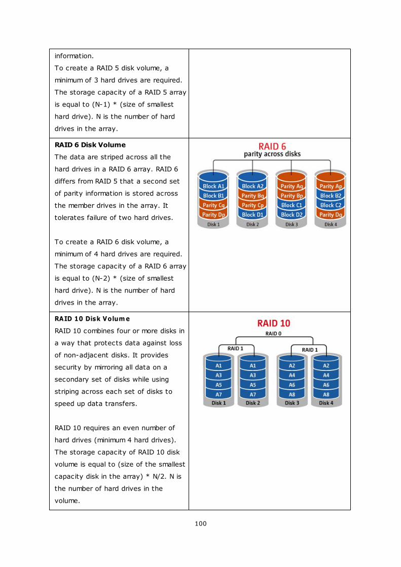
RAID 6 Disk Volume
The data are striped across all the
hard drives in a RAID 6 array. RAID 6
differs from RAID 5 that a second set
of parity information is stored across
the member drives in the array. It
tolerates failure of two hard drives.
To create a RAID 6 disk volume, a
minimum of 4 hard drives are required.
The storage capacity of a RAID 6 array
is equal to (N-2) * (size of smallest
hard drive). N is the number of hard
drives in the array.
RAID 10 Disk Volum e
RAID 10 combines four or more disks in
a way that protects data against loss
of non-adjacent disks. It provides
security by mirroring all data on a
secondary set of disks while using
striping across each set of disks to
speed up data transfers.
RAID 10 requires an even number of
hard drives (minimum 4 hard drives).
The storage capacity of RAID 10 disk
volume is equal to (size of the smallest
capacity disk in the array) * N/2. N is
the number of hard drives in the
volume.
101
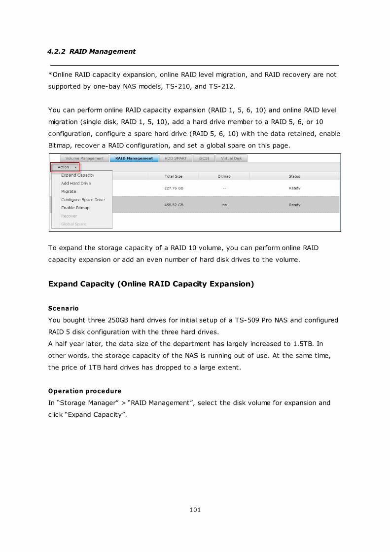
4.2.2 RAID Management
*Online RAID capacity expansion, online RAID level migration, and RAID recovery are not
supported by one-bay NAS models, TS-210, and TS-212.
You can perform online RAID capacity expansion (RAID 1, 5, 6, 10) and online RAID level
migration (single disk, RAID 1, 5, 10), add a hard drive member to a RAID 5, 6, or 10
configuration, configure a spare hard drive (RAID 5, 6, 10) with the data retained, enable
Bitmap, recover a RAID configuration, and set a global spare on this page.
To expand the storage capacity of a RAID 10 volume, you can perform online RAID
capacity expansion or add an even number of hard disk drives to the volume.
Expand Capacity (Online RAID Capacity Expansion)
Scenario
You bought three 250GB hard drives for initial setup of a TS-509 Pro NAS and configured
RAID 5 disk configuration with the three hard drives.
A half year later, the data size of the department has largely increased to 1.5TB. In
other words, the storage capacity of the NAS is running out of use. At the same time,
the price of 1TB hard drives has dropped to a large extent.
Operation procedure
In “Storage Manager” > “RAID Management”, select the disk volume for expansion and
click “Expand Capacity”.
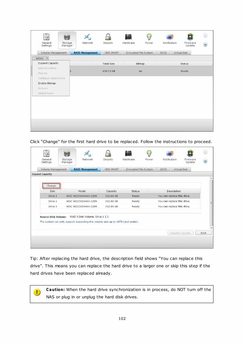
102
Click “Change” for the first hard drive to be replaced. Follow the instructions to proceed.
Tip: After replacing the hard drive, the description field shows “You can replace this
drive”. This means you can replace the hard drive to a larger one or skip this step if the
hard drives have been replaced already.
Caution: When the hard drive synchronization is in process, do NOT turn off the
NAS or plug in or unplug the hard disk drives.
103
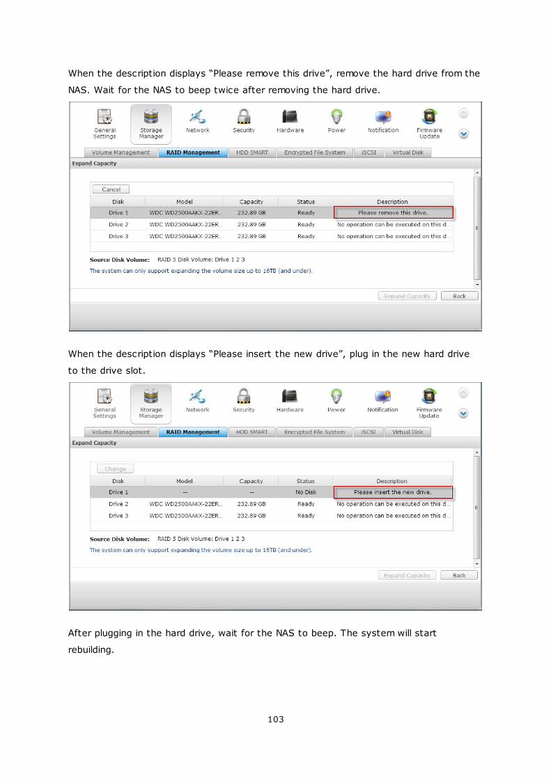
When the description displays “Please remove this drive”, remove the hard drive from the
NAS. Wait for the NAS to beep twice after removing the hard drive.
When the description displays “Please insert the new drive”, plug in the new hard drive
to the drive slot.
After plugging in the hard drive, wait for the NAS to beep. The system will start
rebuilding.
104
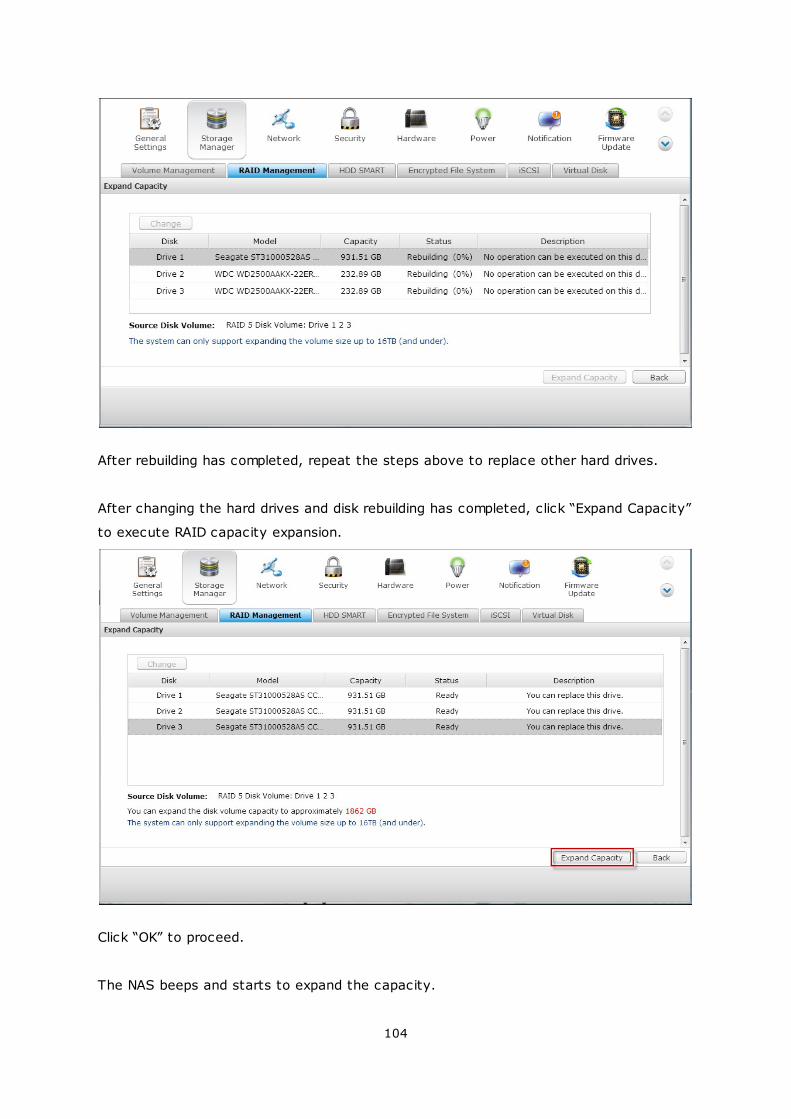
After rebuilding has completed, repeat the steps above to replace other hard drives.
After changing the hard drives and disk rebuilding has completed, click “Expand Capacity”
to execute RAID capacity expansion.
Click “OK” to proceed.
The NAS beeps and starts to expand the capacity.
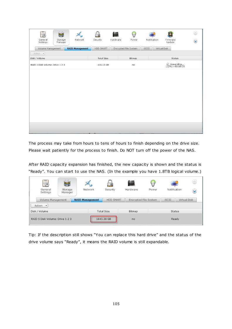
105
The process may take from hours to tens of hours to finish depending on the drive size.
Please wait patiently for the process to finish. Do NOT turn off the power of the NAS.
After RAID capacity expansion has finished, the new capacity is shown and the status is
“Ready”. You can start to use the NAS. (In the example you have 1.8TB logical volume.)
Tip: If the description still shows “You can replace this hard drive” and the status of the
drive volume says “Ready”, it means the RAID volume is still expandable.
106
Migrate (Online RAID Level Migration)
During the initial setup of the TS-509 Pro, you bought a 250GB hard drive and configured
it as single disk. The TS-509 Pro is used as a file server for data sharing among the
departments.
After a half year, more and more important data are saved on the TS-509 Pro. There is a
rising concern for hard drive damage and data loss. Therefore, you planned to upgrade
the disk configuration to RAID 5.
You can install one hard drive for setting up the TS-509 Pro and upgrade the RAID level
of the NAS with online RAID level migration in the future. The migration process can be
done without turning off the NAS. All the data will be retained.
You can do the following with online RAID level migration:
Migrate the system from single disk to RAID 1, RAID 5, RAID 6 or RAID 10
Migrate the system from RAID 1 to RAID 5, RAID 6 or RAID 10
Migrate the system from RAID 5 with 3 hard drives to RAID 6
You need to:
Prepare a hard drive of the same or larger capacity as an existing drive in the RAID
configuration.
Execute RAID level migration (migrate the system from single disk mode to RAID 5
with 4 hard drives).
Go to “Storage Manager” > “Volume Management”. The current disk volume configuration
displayed on the page is single disk (the capacity is 250GB).
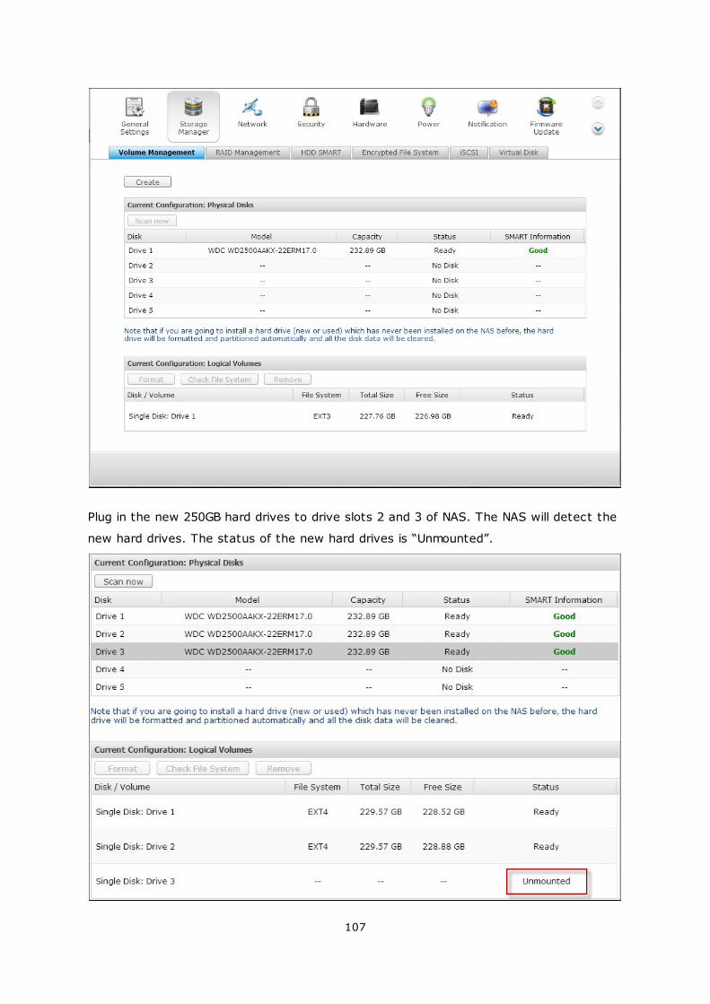
107
Plug in the new 250GB hard drives to drive slots 2 and 3 of NAS. The NAS will detect the
new hard drives. The status of the new hard drives is “Unmounted”.
108
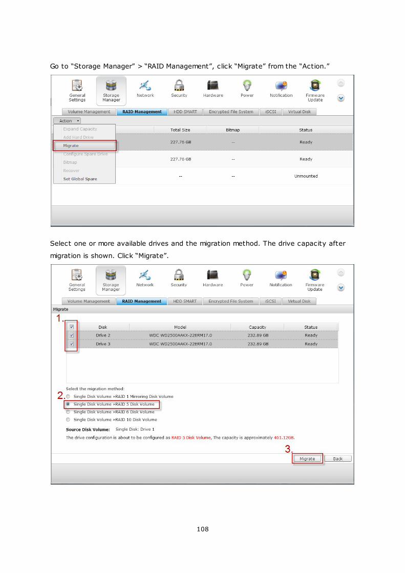
Go to “Storage Manager” > “RAID Management”, click “Migrate” from the “Action.”
Select one or more available drives and the migration method. The drive capacity after
migration is shown. Click “Migrate”.
109
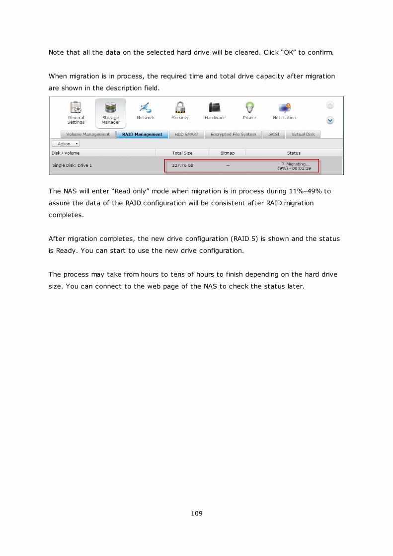
Note that all the data on the selected hard drive will be cleared. Click “OK” to confirm.
When migration is in process, the required time and total drive capacity after migration
are shown in the description field.
The NAS will enter “Read only” mode when migration is in process during 11%–49% to
assure the data of the RAID configuration will be consistent after RAID migration
completes.
After migration completes, the new drive configuration (RAID 5) is shown and the status
is Ready. You can start to use the new drive configuration.
The process may take from hours to tens of hours to finish depending on the hard drive
size. You can connect to the web page of the NAS to check the status later.
110
Use Online RAID Capacity Expansion and Online RAID Level Migration
Scenario
You had a tight schedule to set up a file server and an FTP server. However, you had
only one 250GB hard drive. Therefore, you set up the TS-509 Pro with the single disk
configuration.
The original plan was to set up a 3TB RAID 5 network data center with the TS-509 Pro.
You now plan to upgrade the disk configuration of the TS-509 Pro to RAID 5 and expand
the total storage capacity to 3TB with all the original data retained after the hard drives
are purchased.
Execute online RAID level migration to migrate the system from single disk to RAID 5. The
total storage capacity will be 750GB, RAID 5 (with one 250GB hard drive and three 1TB
hard drives, the disk usage will be 250GB*4 for RAID 5). You can refer to the previous
step for the operation procedure.
Execute online RAID capacity expansion to replace the 250GB hard drive with a new 1TB
hard drive, and then expand the logical volume from 750GB to 3TB of RAID 5. You can
refer to the previous step for the operation procedure.
111
Add a hard drive
Follow the steps below to add a hard drive member to a RAID 5 or RAID 6 disk
configuration.
1. Make sure the status of the RAID 5 or RAID 6 configuration is “Ready”.
2. Install a hard drive on the NAS. If you have a hard drive which has already been
formatted as single disk volume on the NAS, you can add this hard drive to the
RAID 5 or RAID 6 configuration. You are recommended to use hard disk drives of
the same storage capacity for the RAID configuration.
3. Select the RAID 5 or RAID 6 configuration on the “RAID Management” page and
click “Add Hard Drive”.
4. Select the new hard drive member. The total drive capacity after adding the drive
will be shown. Click “Add Hard Drive.”
5. All the data on the new hard drive member will be deleted during this process. The
data on the original RAID 5 or RAID 6 configuration will be retained. Click “OK”. The
NAS will beep twice.
To add hard drives member to a RAID 10 disk volume, repeat the above steps. Note that
you need to add an even number of hard disk drives to a RAID 10 volume. The
storage capacity of the RAID 10 volume will increase upon successful configuration.
This process may take a few hours to tens of hours to complete depending on the
number and the size of the hard drive. Please wait patiently for the process to finish. Do
NOT turn off the NAS during this process. You can use a RAID configuration of larger
capacity after the process.
112
Configure Spare Drive
You can add a spare drive to or remove a spare drive from a RAID 5, 6, or 10
configuration.
Follow the steps below to use this feature.
1. Make sure the status of the RAID 5, 6, 10 configuration is “Ready”.
2. Install a hard drive on the NAS. If you have a hard drive which has already been
formatted as single disk volume on the NAS, you can configure this hard drive as
the spare drive. You are recommended to use hard disk drives of the same storage
capacity for the RAID configuration.
3. Select the RAID volume and click “Configure Spare Drive.”
4. To add a spare drive to the selected configuration, select the hard drive and click
“Configure Spare Drive.” To remove a spare drive, unselect the spare drive and
click “Configure Spare Drive.”
5. All the data on the selected hard drive will be deleted. Click “OK” to proceed.
The original data on the RAID 5, 6, or 10 disk volume will be retained. After the
configuration completes, the status of the disk volume will become “Ready”.
Note: A hot spare drive must be removed from the disk volume before executing the
following action:
Online RAID capacity expansion
Online RAID level migration
Adding a hard drive member to a RAID 5, RAID 6 or RAID 10 volume
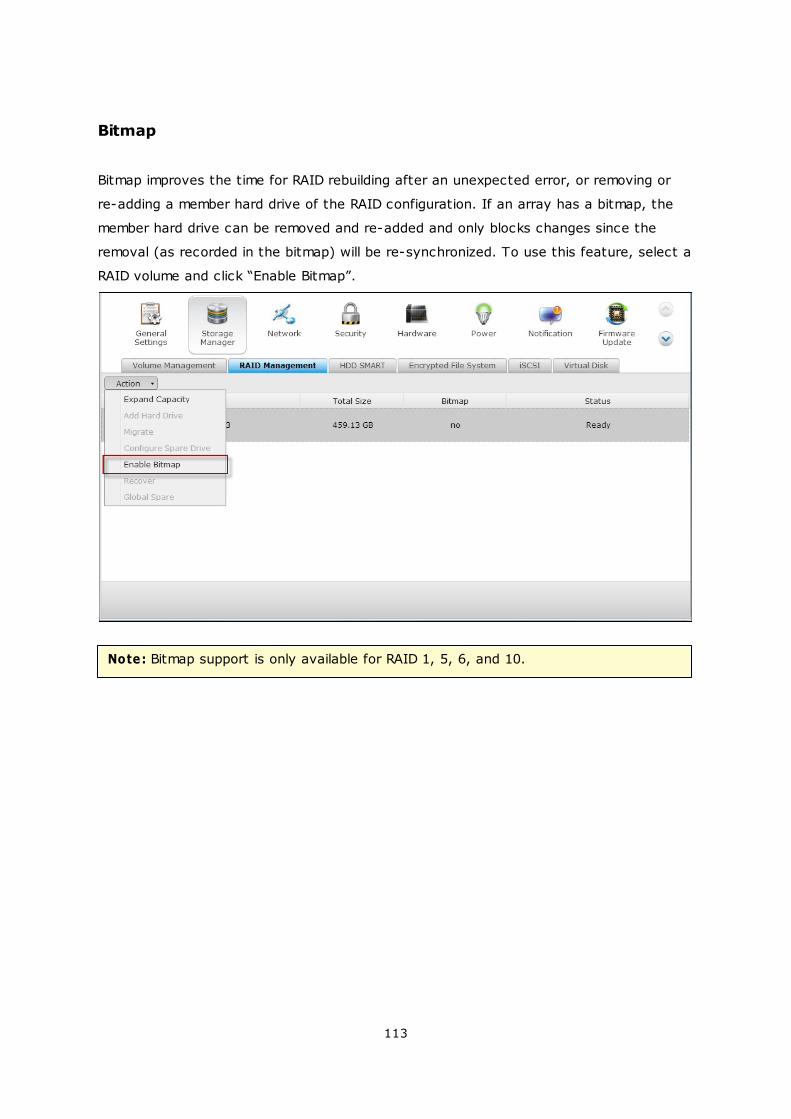
113
Bitmap
Bitmap improves the time for RAID rebuilding after an unexpected error, or removing or
re-adding a member hard drive of the RAID configuration. If an array has a bitmap, the
member hard drive can be removed and re-added and only blocks changes since the
removal (as recorded in the bitmap) will be re-synchronized. To use this feature, select a
RAID volume and click “Enable Bitmap”.
Note: Bitmap support is only available for RAID 1, 5, 6, and 10.
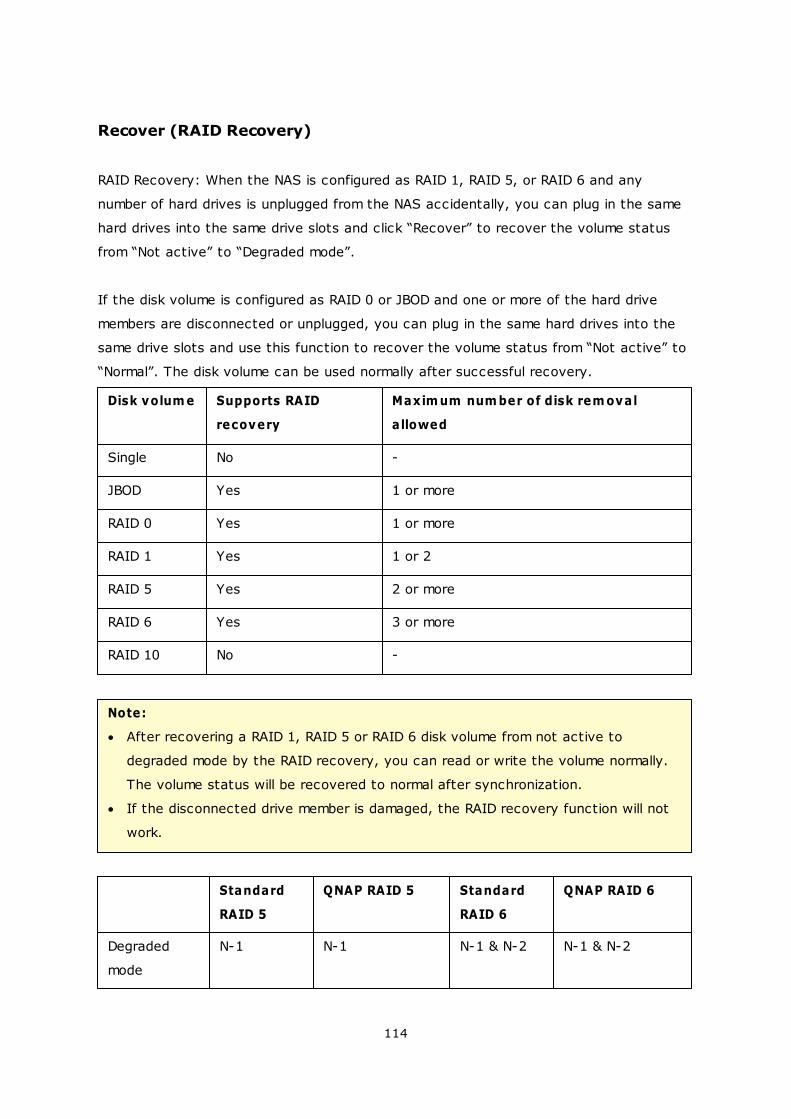
114
Recover (RAID Recovery)
RAID Recovery: When the NAS is configured as RAID 1, RAID 5, or RAID 6 and any
number of hard drives is unplugged from the NAS accidentally, you can plug in the same
hard drives into the same drive slots and click “Recover” to recover the volume status
from “Not active” to “Degraded mode”.
If the disk volume is configured as RAID 0 or JBOD and one or more of the hard drive
members are disconnected or unplugged, you can plug in the same hard drives into the
same drive slots and use this function to recover the volume status from “Not active” to
“Normal”. The disk volume can be used normally after successful recovery.
Disk volum e Supports RAID
recovery
Maxim um num ber of disk rem oval
allowed
Single No -
JBOD Yes 1 or more
RAID 0 Yes 1 or more
RAID 1 Yes 1 or 2
RAID 5 Yes 2 or more
RAID 6 Yes 3 or more
RAID 10 No -
Note:
After recovering a RAID 1, RAID 5 or RAID 6 disk volume from not active to
degraded mode by the RAID recovery, you can read or write the volume normally.
The volume status will be recovered to normal after synchronization.
If the disconnected drive member is damaged, the RAID recovery function will not
work.
Standard
RAID 5
QNAP RAID 5 Standard
RAID 6
QNAP RAID 6
Degraded
mode
N-1 N-1 N-1 & N-2 N-1 & N-2
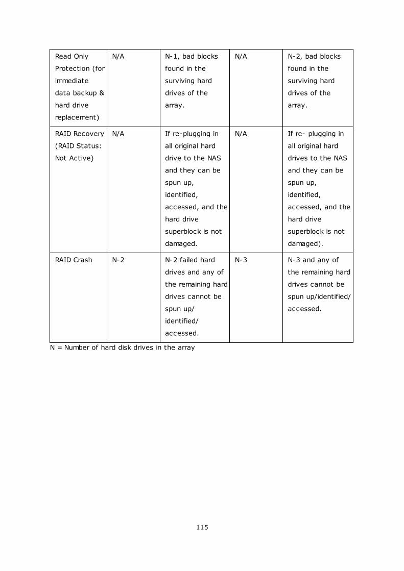
115
Read Only
Protection (for
immediate
data backup &
hard drive
replacement)
N/A N-1, bad blocks
found in the
surviving hard
drives of the
array.
N/A N-2, bad blocks
found in the
surviving hard
drives of the
array.
RAID Recovery
(RAID Status:
Not Active)
N/A If re-plugging in
all original hard
drive to the NAS
and they can be
spun up,
identified,
accessed, and the
hard drive
superblock is not
damaged.
N/A If re- plugging in
all original hard
drives to the NAS
and they can be
spun up,
identified,
accessed, and the
hard drive
superblock is not
damaged).
RAID Crash N-2 N-2 failed hard
drives and any of
the remaining hard
drives cannot be
spun up/
identified/
accessed.
N-3 N-3 and any of
the remaining hard
drives cannot be
spun up/identified/
accessed.
N = Number of hard disk drives in the array
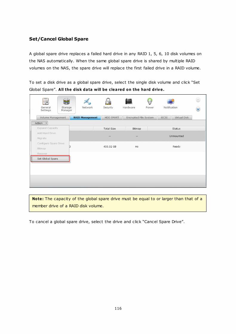
116
Set/Cancel Global Spare
A global spare drive replaces a failed hard drive in any RAID 1, 5, 6, 10 disk volumes on
the NAS automatically. When the same global spare drive is shared by multiple RAID
volumes on the NAS, the spare drive will replace the first failed drive in a RAID volume.
To set a disk drive as a global spare drive, select the single disk volume and click “Set
Global Spare”. All the disk data will be cleared on the hard drive.
Note: The capacity of the global spare drive must be equal to or larger than that of a
member drive of a RAID disk volume.
To cancel a global spare drive, select the drive and click “Cancel Spare Drive”.
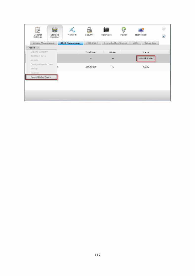
117
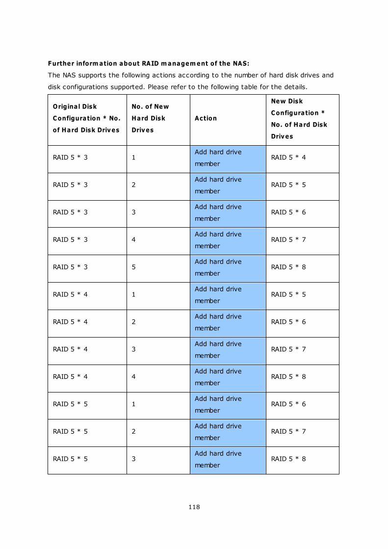
118
Further inform ation about RAID m anagem ent of the NAS:
The NAS supports the following actions according to the number of hard disk drives and
disk configurations supported. Please refer to the following table for the details.
Original Disk
Configuration * No.
of Hard Disk Drives
No. of New
Hard Disk
Drives
Action
New Disk
Configuration *
No. of Hard Disk
Drives
RAID 5 * 3 1Add hard drive
memberRAID 5 * 4
RAID 5 * 3 2Add hard drive
memberRAID 5 * 5
RAID 5 * 3 3Add hard drive
memberRAID 5 * 6
RAID 5 * 3 4Add hard drive
memberRAID 5 * 7
RAID 5 * 3 5Add hard drive
memberRAID 5 * 8
RAID 5 * 4 1Add hard drive
memberRAID 5 * 5
RAID 5 * 4 2Add hard drive
memberRAID 5 * 6
RAID 5 * 4 3Add hard drive
memberRAID 5 * 7
RAID 5 * 4 4Add hard drive
memberRAID 5 * 8
RAID 5 * 5 1Add hard drive
memberRAID 5 * 6
RAID 5 * 5 2Add hard drive
memberRAID 5 * 7
RAID 5 * 5 3Add hard drive
memberRAID 5 * 8
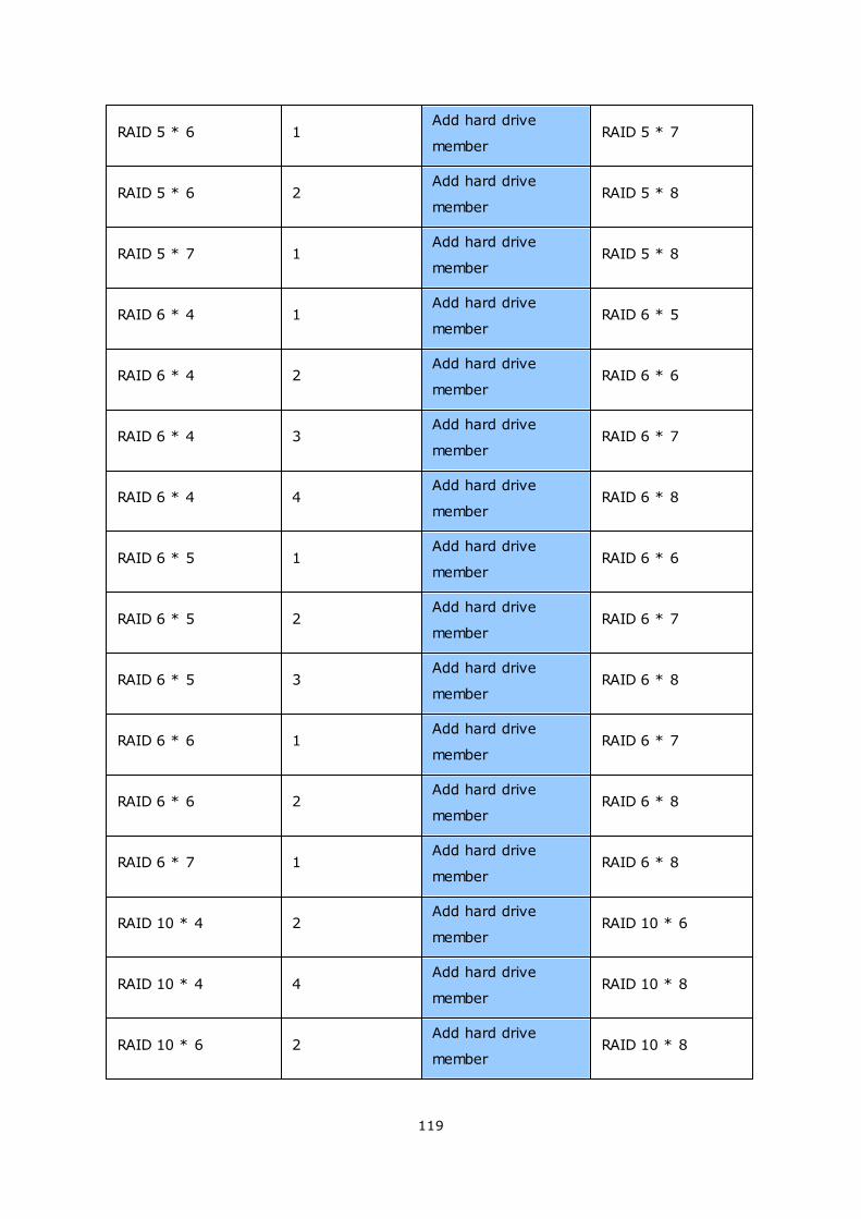
119
RAID 5 * 6 1Add hard drive
memberRAID 5 * 7
RAID 5 * 6 2Add hard drive
memberRAID 5 * 8
RAID 5 * 7 1Add hard drive
memberRAID 5 * 8
RAID 6 * 4 1Add hard drive
memberRAID 6 * 5
RAID 6 * 4 2Add hard drive
memberRAID 6 * 6
RAID 6 * 4 3Add hard drive
memberRAID 6 * 7
RAID 6 * 4 4Add hard drive
memberRAID 6 * 8
RAID 6 * 5 1Add hard drive
memberRAID 6 * 6
RAID 6 * 5 2Add hard drive
memberRAID 6 * 7
RAID 6 * 5 3Add hard drive
memberRAID 6 * 8
RAID 6 * 6 1Add hard drive
memberRAID 6 * 7
RAID 6 * 6 2Add hard drive
memberRAID 6 * 8
RAID 6 * 7 1Add hard drive
memberRAID 6 * 8
RAID 10 * 4 2Add hard drive
memberRAID 10 * 6
RAID 10 * 4 4Add hard drive
memberRAID 10 * 8
RAID 10 * 6 2Add hard drive
memberRAID 10 * 8
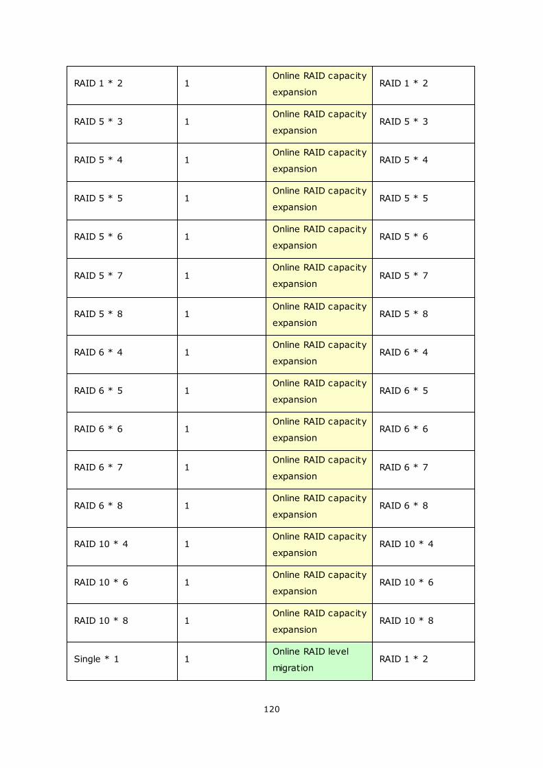
120
RAID 1 * 2 1Online RAID capacity
expansionRAID 1 * 2
RAID 5 * 3 1Online RAID capacity
expansionRAID 5 * 3
RAID 5 * 4 1Online RAID capacity
expansionRAID 5 * 4
RAID 5 * 5 1Online RAID capacity
expansionRAID 5 * 5
RAID 5 * 6 1Online RAID capacity
expansionRAID 5 * 6
RAID 5 * 7 1Online RAID capacity
expansionRAID 5 * 7
RAID 5 * 8 1Online RAID capacity
expansionRAID 5 * 8
RAID 6 * 4 1Online RAID capacity
expansionRAID 6 * 4
RAID 6 * 5 1Online RAID capacity
expansionRAID 6 * 5
RAID 6 * 6 1Online RAID capacity
expansionRAID 6 * 6
RAID 6 * 7 1Online RAID capacity
expansionRAID 6 * 7
RAID 6 * 8 1Online RAID capacity
expansionRAID 6 * 8
RAID 10 * 4 1Online RAID capacity
expansionRAID 10 * 4
RAID 10 * 6 1Online RAID capacity
expansionRAID 10 * 6
RAID 10 * 8 1Online RAID capacity
expansionRAID 10 * 8
Single * 1 1Online RAID level
migrationRAID 1 * 2
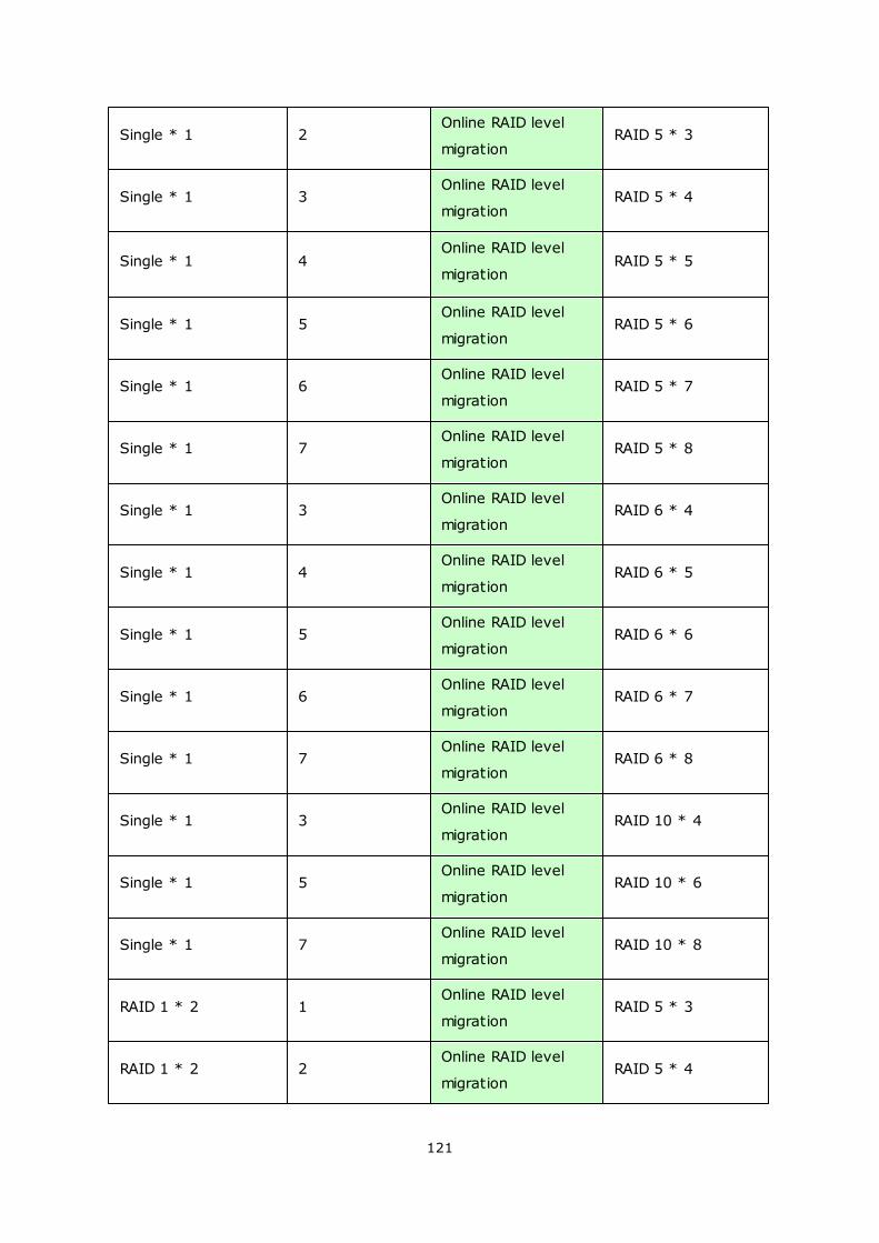
121
Single * 1 2Online RAID level
migrationRAID 5 * 3
Single * 1 3Online RAID level
migrationRAID 5 * 4
Single * 1 4Online RAID level
migrationRAID 5 * 5
Single * 1 5Online RAID level
migrationRAID 5 * 6
Single * 1 6Online RAID level
migrationRAID 5 * 7
Single * 1 7Online RAID level
migrationRAID 5 * 8
Single * 1 3Online RAID level
migrationRAID 6 * 4
Single * 1 4Online RAID level
migrationRAID 6 * 5
Single * 1 5Online RAID level
migrationRAID 6 * 6
Single * 1 6Online RAID level
migrationRAID 6 * 7
Single * 1 7Online RAID level
migrationRAID 6 * 8
Single * 1 3Online RAID level
migrationRAID 10 * 4
Single * 1 5Online RAID level
migrationRAID 10 * 6
Single * 1 7Online RAID level
migrationRAID 10 * 8
RAID 1 * 2 1Online RAID level
migrationRAID 5 * 3
RAID 1 * 2 2Online RAID level
migrationRAID 5 * 4
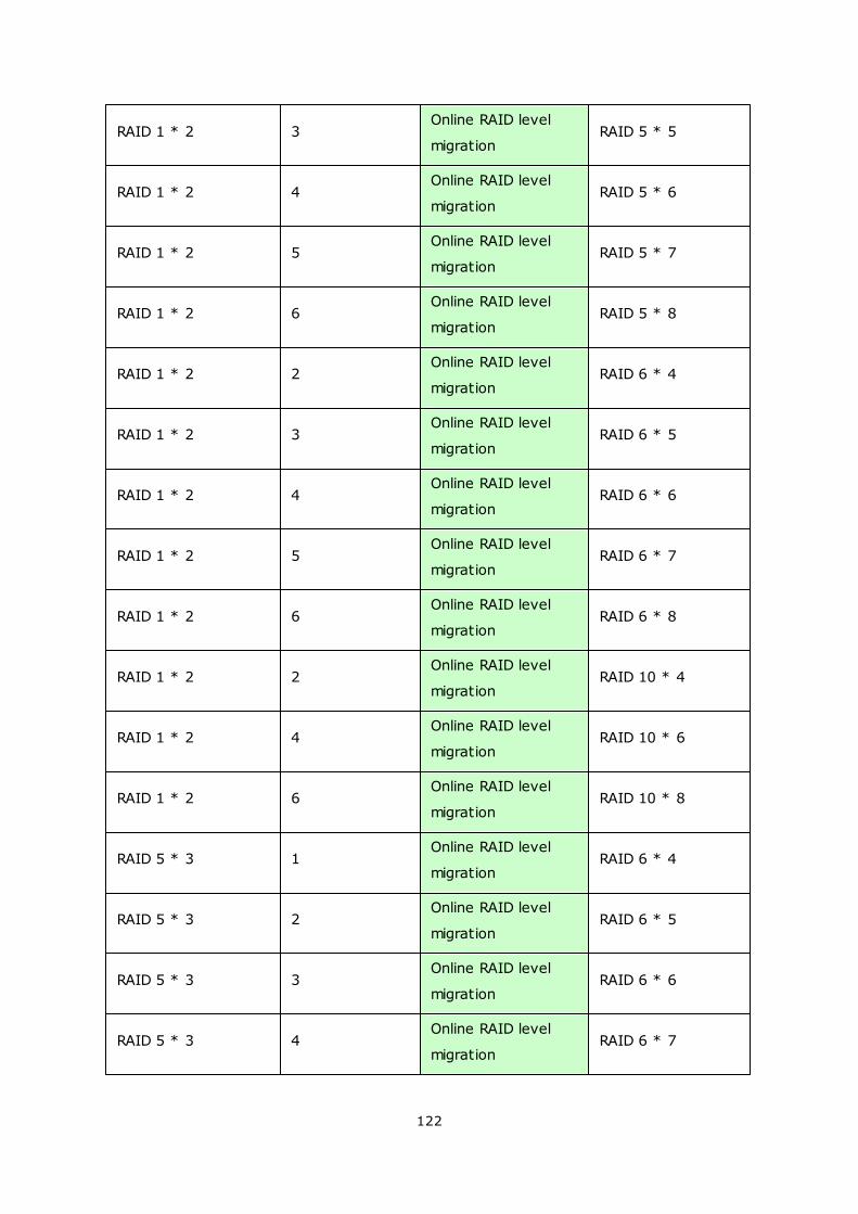
122
RAID 1 * 2 3Online RAID level
migrationRAID 5 * 5
RAID 1 * 2 4Online RAID level
migrationRAID 5 * 6
RAID 1 * 2 5Online RAID level
migrationRAID 5 * 7
RAID 1 * 2 6Online RAID level
migrationRAID 5 * 8
RAID 1 * 2 2Online RAID level
migrationRAID 6 * 4
RAID 1 * 2 3Online RAID level
migrationRAID 6 * 5
RAID 1 * 2 4Online RAID level
migrationRAID 6 * 6
RAID 1 * 2 5Online RAID level
migrationRAID 6 * 7
RAID 1 * 2 6Online RAID level
migrationRAID 6 * 8
RAID 1 * 2 2Online RAID level
migrationRAID 10 * 4
RAID 1 * 2 4Online RAID level
migrationRAID 10 * 6
RAID 1 * 2 6Online RAID level
migrationRAID 10 * 8
RAID 5 * 3 1Online RAID level
migrationRAID 6 * 4
RAID 5 * 3 2Online RAID level
migrationRAID 6 * 5
RAID 5 * 3 3Online RAID level
migrationRAID 6 * 6
RAID 5 * 3 4Online RAID level
migrationRAID 6 * 7

123
RAID 5 * 3 5Online RAID level
migrationRAID 6 * 8
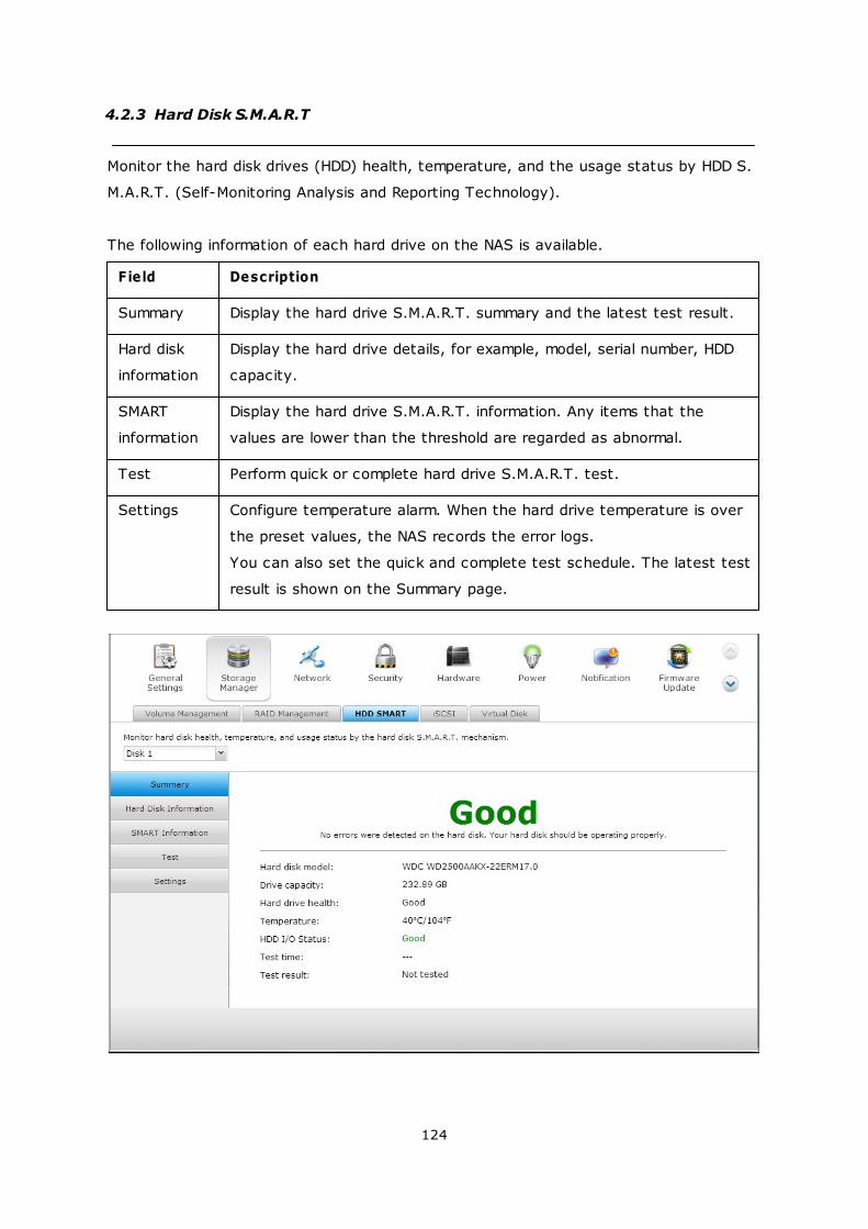
124
4.2.3 Hard Disk S.M.A.R.T
Monitor the hard disk drives (HDD) health, temperature, and the usage status by HDD S.
M.A.R.T. (Self-Monitoring Analysis and Reporting Technology).
The following information of each hard drive on the NAS is available.
Field Description
Summary Display the hard drive S.M.A.R.T. summary and the latest test result.
Hard disk
information
Display the hard drive details, for example, model, serial number, HDD
capacity.
SMART
information
Display the hard drive S.M.A.R.T. information. Any items that the
values are lower than the threshold are regarded as abnormal.
Test Perform quick or complete hard drive S.M.A.R.T. test.
Settings Configure temperature alarm. When the hard drive temperature is over
the preset values, the NAS records the error logs.
You can also set the quick and complete test schedule. The latest test
result is shown on the Summary page.
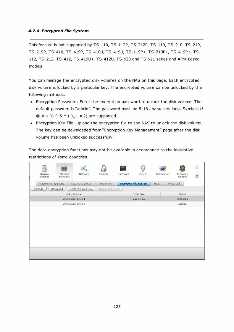
125
4.2.4 Encrypted File System
This feature is not supported by TS-110, TS-112P, TS-212P, TS-119, TS-210, TS-219,
TS-219P, TS-410, TS-419P, TS-410U, TS-419U, TS-119P+, TS-219P+, TS-419P+, TS-
112, TS-212, TS-412, TS-419U+, TS-412U, TS-x20 and TS-x21 series and ARM-Based
models.
You can manage the encrypted disk volumes on the NAS on this page. Each encrypted
disk volume is locked by a particular key. The encrypted volume can be unlocked by the
following methods:
Encryption Password: Enter the encryption password to unlock the disk volume. The
default password is “admin”. The password must be 8-16 characters long. Symbols (!
@ # $ % ^ & * ( )_+ = ?) are supported.
Encryption Key File: Upload the encryption file to the NAS to unlock the disk volume.
The key can be downloaded from “Encryption Key Management” page after the disk
volume has been unlocked successfully.
The data encryption functions may not be available in accordance to the legislative
restrictions of some countries.
126
How to use the data encryption feature on QNAP Turbo NAS
The disk volumes on the NAS can be encrypted with 256-bit AES encryption for data
breach protection. The encrypted disk volumes can only be mounted for normal read/
write access with the authorized password. The encryption feature protects the
confidential data from unauthorized access even if the hard drives or the entire NAS
were stolen.
About AES encryption:
In cryptography, the Advanced Encryption Standard (AES) is an encryption standard
adopted by the U.S. government. The standard comprises three block ciphers, AES-128,
AES-192 and AES-256 […]. Each AES cipher has a 128-bit block size, with key sizes of
128, 192 and 256 bits, respectively. The AES ciphers have been analyzed extensively
and are now used worldwide. (Source: http://en.wikipedia.org/wiki/
Advanced_Encryption_Standard)
The AES volume-based encryption is applicable only to specific QNAP NAS models.
Please refer to the comparison table at: http://www.qnap.com/images/products/
comparison/Comparison_NAS.html
Before you start
Please beware of the following before using the data encryption feature of the NAS.
The encryption feature of the NAS is volume-based. A volume can be a single disk, a
JBOD configuration, or a RAID array.
Select whether or not to encrypt a disk volume before it is created on the NAS. In
other words, you will not be able to encrypt a volume after it has been created
unless the disk volume is initialized. Note that initializing a disk volume will clear all
the disk data.
The encryption on the disk volume cannot be removed without initialization. To
remove the encryption on the disk volume, you have to initialize the disk volume and
all the data will be cleared.
Keep the encryption password or key safe. If you forgot the password or lost the
encryption key, the data cannot be accessed anymore.
Before you start, read the instructions carefully and strictly adhere to the
instructions.
Create a new encrypted disk volum e with new hard drives
If the NAS has been installed, to create a new encrypted disk volume by installing new
hard drives on the NAS, follow the steps below:
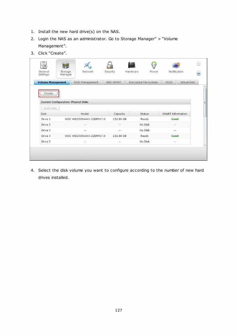
127
1. Install the new hard drive(s) on the NAS.
2. Login the NAS as an administrator. Go to Storage Manager” > “Volume
Management”.
3. Click “Create”.
4. Select the disk volume you want to configure according to the number of new hard
drives installed.
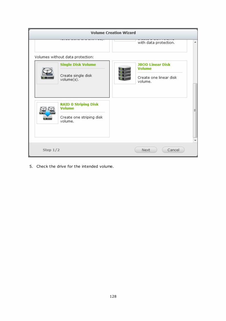
128
5. Check the drive for the intended volume.
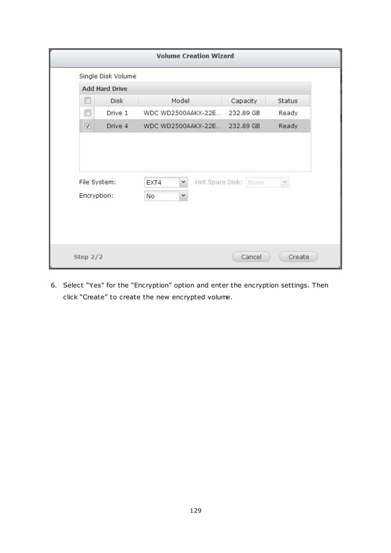
129
6. Select “Yes” for the “Encryption” option and enter the encryption settings. Then
click “Create” to create the new encrypted volume.
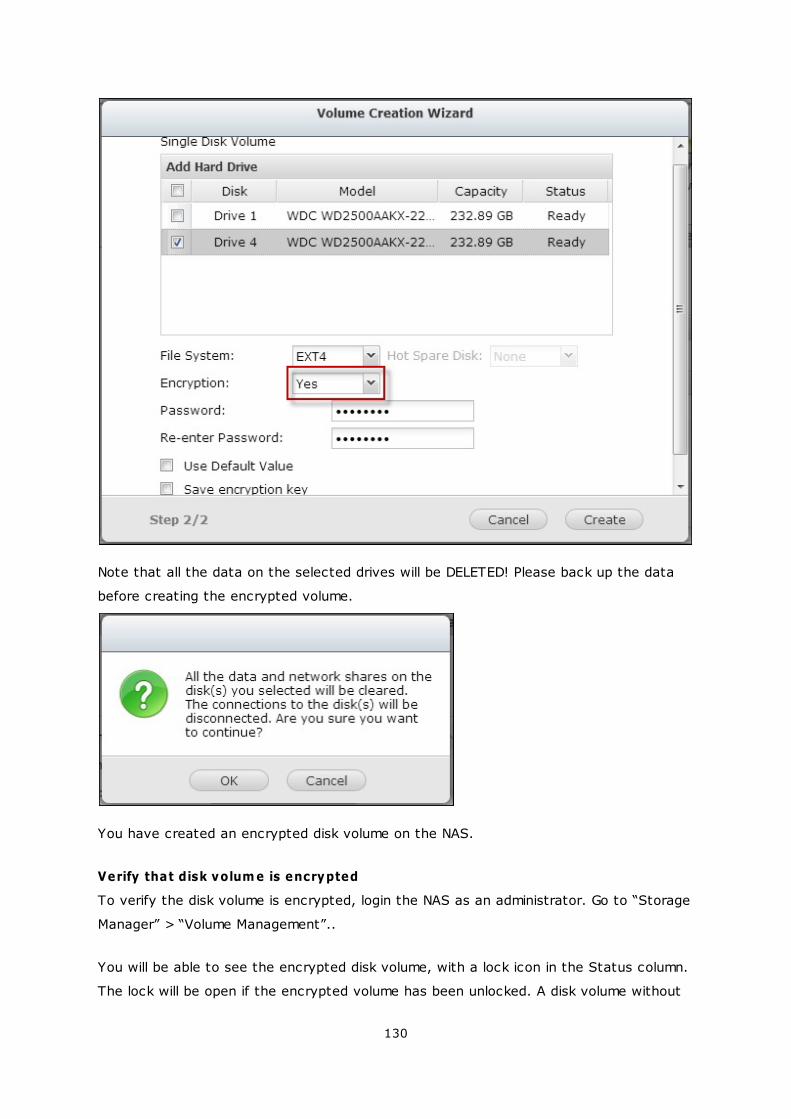
130
Note that all the data on the selected drives will be DELETED! Please back up the data
before creating the encrypted volume.
You have created an encrypted disk volume on the NAS.
Verify that disk volum e is encrypted
To verify the disk volume is encrypted, login the NAS as an administrator. Go to “Storage
Manager” > “Volume Management”..
You will be able to see the encrypted disk volume, with a lock icon in the Status column.
The lock will be open if the encrypted volume has been unlocked. A disk volume without
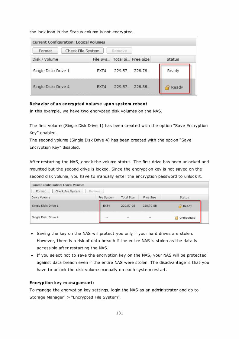
131
the lock icon in the Status column is not encrypted.
Behavior of an encrypted volum e upon system reboot
In this example, we have two encrypted disk volumes on the NAS.
The first volume (Single Disk Drive 1) has been created with the option “Save Encryption
Key” enabled.
The second volume (Single Disk Drive 4) has been created with the option “Save
Encryption Key” disabled.
After restarting the NAS, check the volume status. The first drive has been unlocked and
mounted but the second drive is locked. Since the encryption key is not saved on the
second disk volume, you have to manually enter the encryption password to unlock it.
Saving the key on the NAS will protect you only if your hard drives are stolen.
However, there is a risk of data breach if the entire NAS is stolen as the data is
accessible after restarting the NAS.
If you select not to save the encryption key on the NAS, your NAS will be protected
against data breach even if the entire NAS were stolen. The disadvantage is that you
have to unlock the disk volume manually on each system restart.
Encryption key m anagem ent:
To manage the encryption key settings, login the NAS as an administrator and go to
Storage Manager” > “Encrypted File System”.
132
There are four options to manage the encryption key:
Change the encryption key
Download the encryption key file
Remove the saved key
Save the encryption key on the NAS
Change the encryption key: Input your old encryption password and input the new
password. (Note that after the password is changed, any previously exported keys
will not be working anymore. You have to download the new encryption key if
necessary, see below).
Download Encryption Key File: Input the encryption password to download the
encryption key file. Downloading the encryption key file will allow you to save the
encryption key in a file. The file is also encrypted and can be used to unlock a
volume, without knowing the real password (see “unlock a disk volume manually”
below). Please save the encryption key file in a secure place!
Remove Saved Key: Remove saved keys with this option.
Save Encryption Key: Save the encryption key on the NAS for automatic unlocking
and mounting the encrypted disk volume when the NAS restarts.
Unlock a disk volum e m anually
To unlock a volume, login the NAS as an administrator. Go to “Storage Manager” >
“Encrypted File System”.
You will be able to see your encrypted volumes and their status: locked or unlocked.
133
To unlock your volume, first click “Unlock this device”.
Choose to either input the encryption password, or use the encryption key file that has
been exported previously.
134
If the encryption password or the key file is correct, the volume will be unlocked and
become available.
135

136
4.2.5 iSCSI
Portal Management
Target Management
Advanced ACL
LUN Backup
137
145
171
174
137
4.2.5.1 Portal Management
The NAS supports built-in iSCSI (Internet Small Computer System Interface) service for
server clustering and virtualized environments.
iSCSI Configuration
The NAS supports built-in iSCSI service. To use this function, follow the steps below:
1. Install an iSCSI initiator on the computer (Windows PC, Mac, or Linux).
2. Enable iSCSI Target Service on the NAS and create an iSCSI target.
3. Run the iSCSI initiator and connect to the iSCSI target (NAS).
4. After successful logon, format the iSCSI target (disk volume). You can start to use
the disk volume on the NAS as a virtual drive on the computer.
In between the relationship of your computer and the storage device, the computer is
called an initiator because it initiates the connection to the device, which is called a
target.
Note: It is suggested NOT to connect to the same iSCSI target with two different
clients (iSCSI initiators) at the same time, because this may lead to data damage or
disk damage.
138
iSCSI Quick Configuration Wizard
A maximum of 256 iSCSI targets and LUNs can be created. For example, if you create
100 targets on the NAS, the maximum number of LUNs you can create is 156. Multiple
LUNs can be created for each target. However, the maximum number of concurrent
connections to the iSCSI targets supported by the NAS varies depending on the network
infrastructure and the application performance. Too many concurrent connections may
slow down the performance of the NAS.
Follow the steps below to configure the iSCSI target service on the NAS.
1. Under the “Portal Management” tab enable iSCSI target service. Apply the
settings.
2. Go to the “Target Management” tab and create iSCSI targets on the NAS. If you
have not created any iSCSI targets, the Quick Installation Wizard will automatically
be launched and prompt users to create iSCSI targets and LUNs (Logical unit
number). Click “OK”.
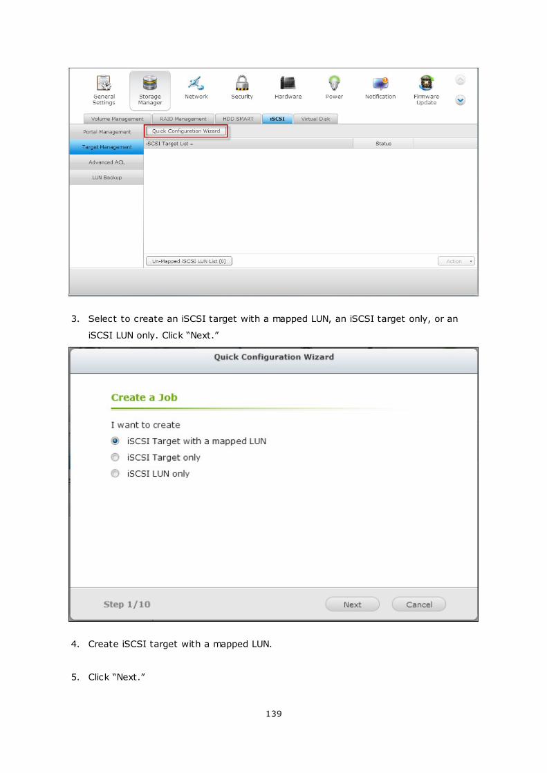
139
3. Select to create an iSCSI target with a mapped LUN, an iSCSI target only, or an
iSCSI LUN only. Click “Next.”
4. Create iSCSI target with a mapped LUN.
5. Click “Next.”
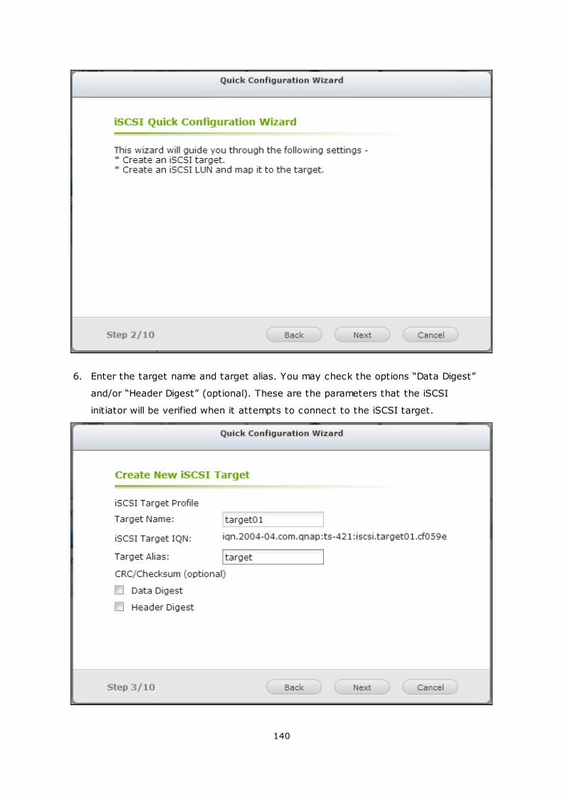
140
6. Enter the target name and target alias. You may check the options “Data Digest”
and/or “Header Digest” (optional). These are the parameters that the iSCSI
initiator will be verified when it attempts to connect to the iSCSI target.
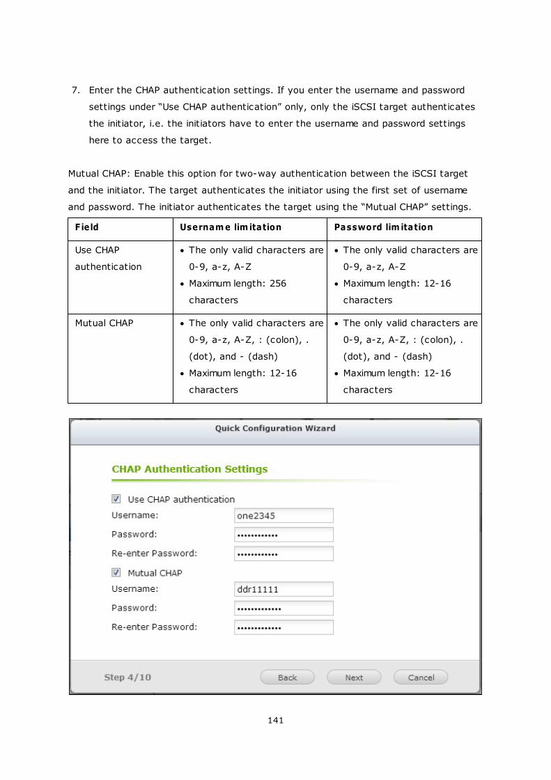
141
7. Enter the CHAP authentication settings. If you enter the username and password
settings under “Use CHAP authentication” only, only the iSCSI target authenticates
the initiator, i.e. the initiators have to enter the username and password settings
here to access the target.
Mutual CHAP: Enable this option for two-way authentication between the iSCSI target
and the initiator. The target authenticates the initiator using the first set of username
and password. The initiator authenticates the target using the “Mutual CHAP” settings.
Field Usernam e lim itation Password lim itation
Use CHAP
authentication
The only valid characters are
0-9, a-z, A-Z
Maximum length: 256
characters
The only valid characters are
0-9, a-z, A-Z
Maximum length: 12-16
characters
Mutual CHAP The only valid characters are
0-9, a-z, A-Z, : (colon), .
(dot), and - (dash)
Maximum length: 12-16
characters
The only valid characters are
0-9, a-z, A-Z, : (colon), .
(dot), and - (dash)
Maximum length: 12-16
characters
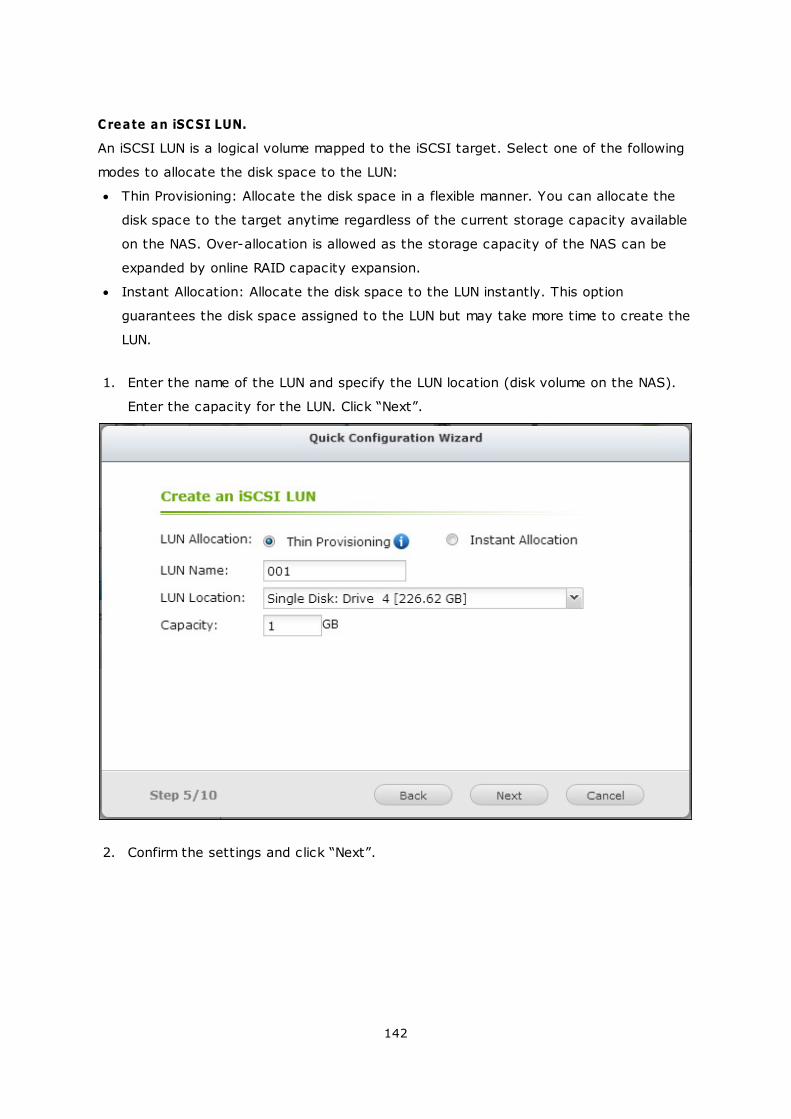
142
Create an iSCSI LUN.
An iSCSI LUN is a logical volume mapped to the iSCSI target. Select one of the following
modes to allocate the disk space to the LUN:
Thin Provisioning: Allocate the disk space in a flexible manner. You can allocate the
disk space to the target anytime regardless of the current storage capacity available
on the NAS. Over-allocation is allowed as the storage capacity of the NAS can be
expanded by online RAID capacity expansion.
Instant Allocation: Allocate the disk space to the LUN instantly. This option
guarantees the disk space assigned to the LUN but may take more time to create the
LUN.
1. Enter the name of the LUN and specify the LUN location (disk volume on the NAS).
Enter the capacity for the LUN. Click “Next”.
2. Confirm the settings and click “Next”.
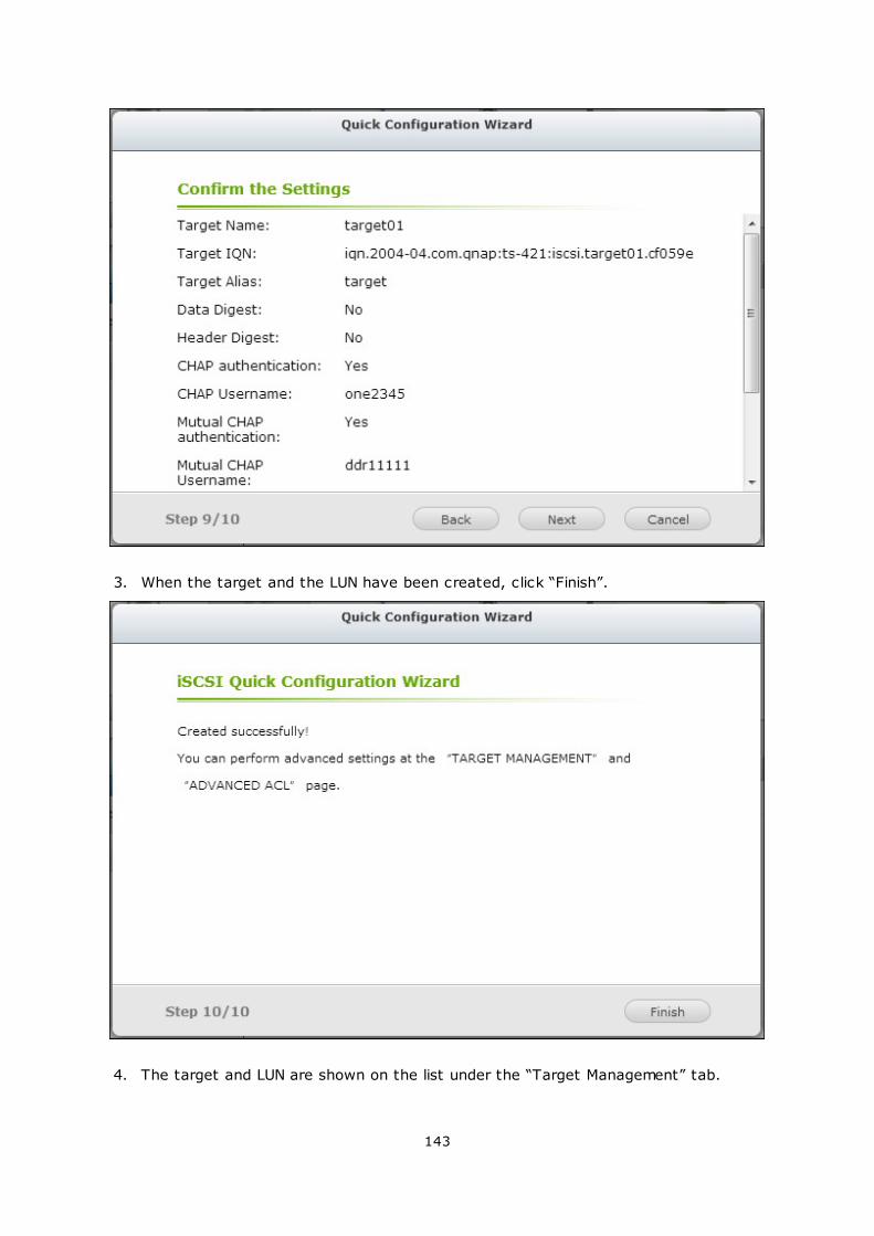
143
3. When the target and the LUN have been created, click “Finish”.
4. The target and LUN are shown on the list under the “Target Management” tab.
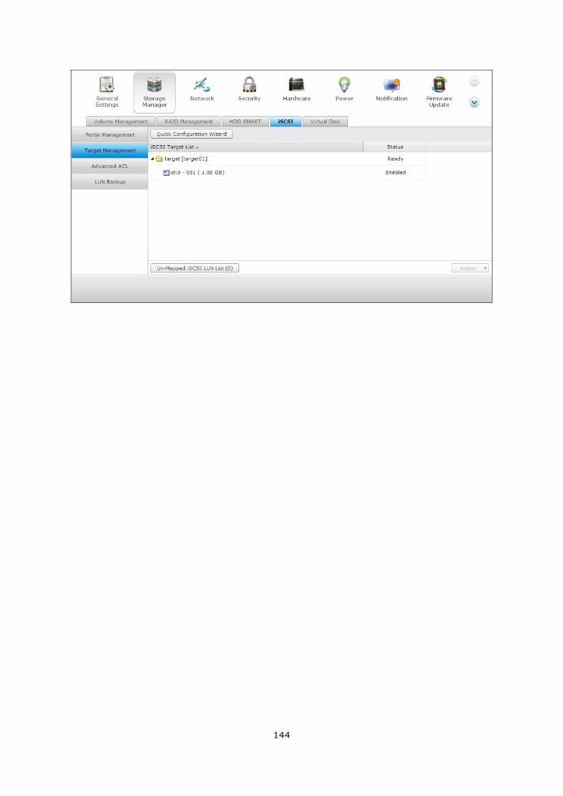
144
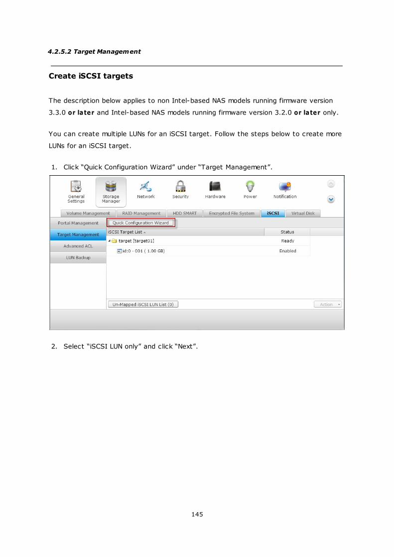
145
4.2.5.2 Target Management
Create iSCSI targets
The description below applies to non Intel-based NAS models running firmware version
3.3.0 or later and Intel-based NAS models running firmware version 3.2.0 or later only.
You can create multiple LUNs for an iSCSI target. Follow the steps below to create more
LUNs for an iSCSI target.
1. Click “Quick Configuration Wizard” under “Target Management”.
2. Select “iSCSI LUN only” and click “Next”.
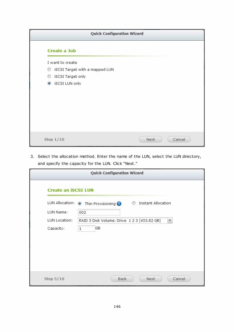
146
3. Select the allocation method. Enter the name of the LUN, select the LUN directory,
and specify the capacity for the LUN. Click “Next.”
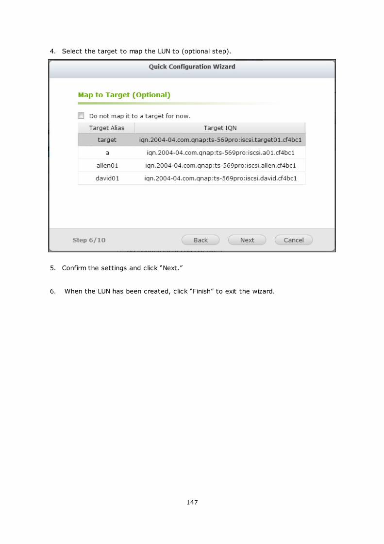
147
4. Select the target to map the LUN to (optional step).
5. Confirm the settings and click “Next.”
6. When the LUN has been created, click “Finish” to exit the wizard.
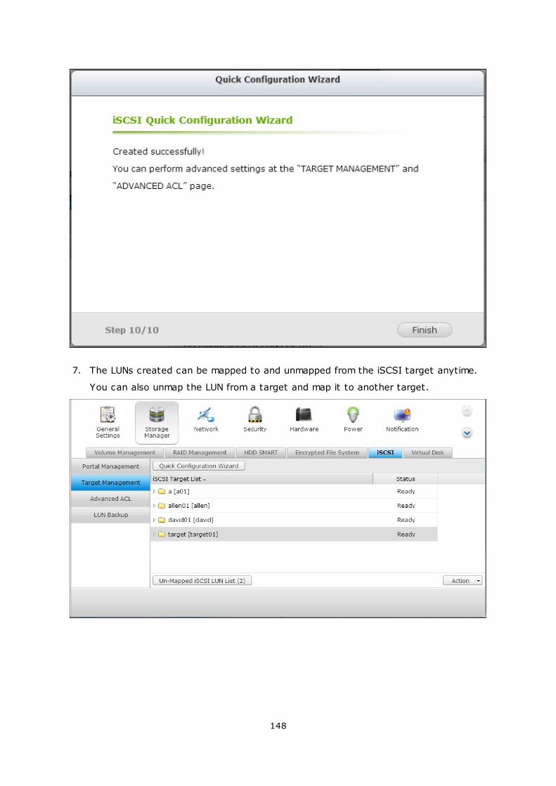
148
7. The LUNs created can be mapped to and unmapped from the iSCSI target anytime.
You can also unmap the LUN from a target and map it to another target.
149
Item Status Description
iSCSI target Ready The iSCSI target is ready but no
initiator has connected to it yet.
Connected The iSCSI target has been connected
by an initiator.
Disconnected The iSCSI target has been
disconnected.
Offline The iSCSI target has been
deactivated and cannot be connected
by the initiator.
LUN Enabled The LUN is active for connection and
is visible to authenticated initiators.
Disabled The LUN is inactive and is invisible to
the initiators.
Button Description
Deactivate a ready or connected target. Note that the connection from the
initiators will be removed.
Activate an offline target.
150
Modify the target settings: target alias, CHAP information, and checksum
settings.
Modify the LUN settings: LUN allocation, name, disk volume directory, etc.
Delete an iSCSI target. All the connections will be removed.
Disable an LUN. All the connections will be removed.
Enable an LUN.
Unmap the LUN from the target. Note that you must disable the LUN first
before unmapping the LUN. When you click this button, the LUN will be
moved to “Un-Mapped iSCSI LUN List”.
Map the LUN to an iSCSI target. This option is only available on the “Un-
Mapped iSCSI LUN List”.
View the connection status of an iSCSI target.
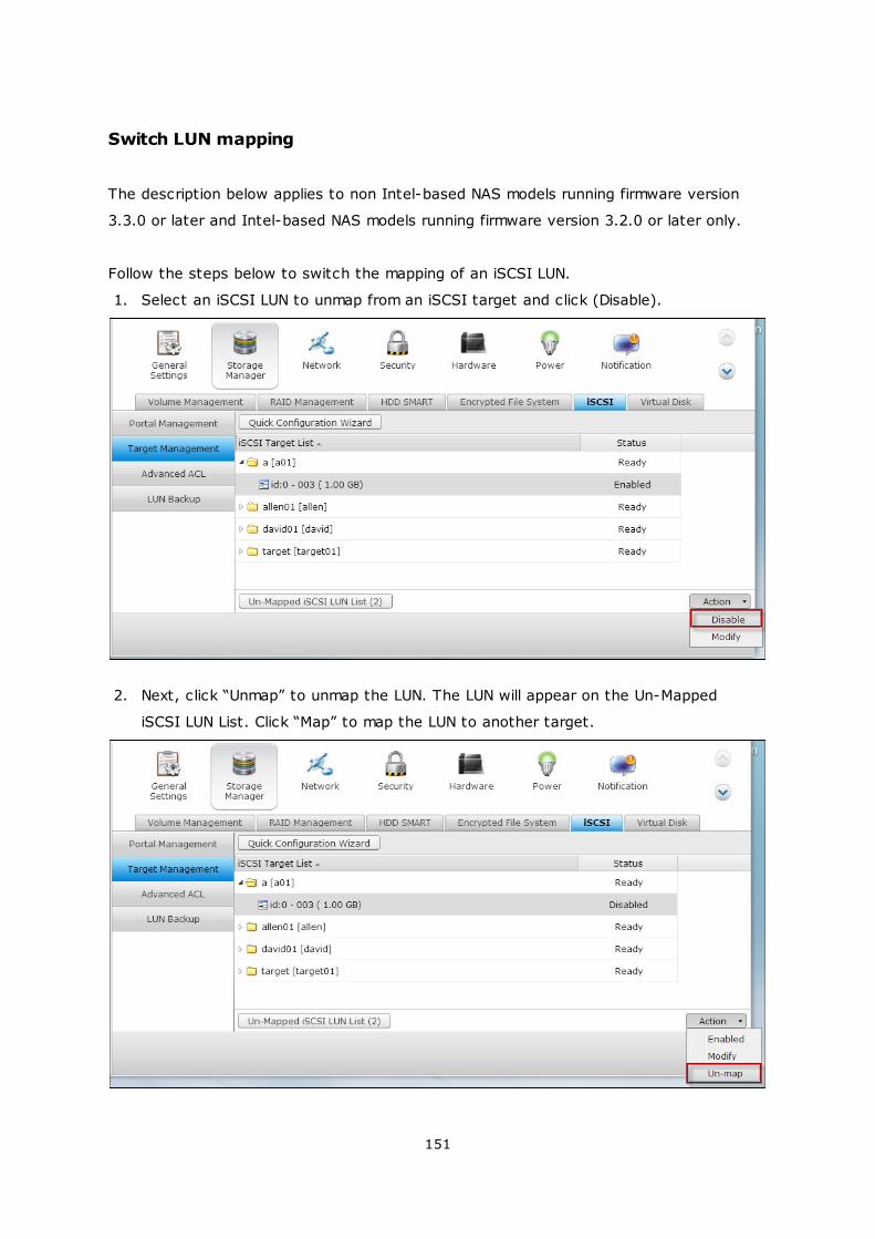
151
Switch LUN mapping
The description below applies to non Intel-based NAS models running firmware version
3.3.0 or later and Intel-based NAS models running firmware version 3.2.0 or later only.
Follow the steps below to switch the mapping of an iSCSI LUN.
1. Select an iSCSI LUN to unmap from an iSCSI target and click (Disable).
2. Next, click “Unmap” to unmap the LUN. The LUN will appear on the Un-Mapped
iSCSI LUN List. Click “Map” to map the LUN to another target.
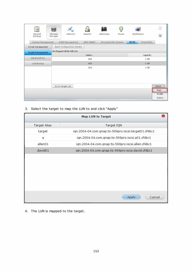
152
3. Select the target to map the LUN to and click “Apply”
4. The LUN is mapped to the target.
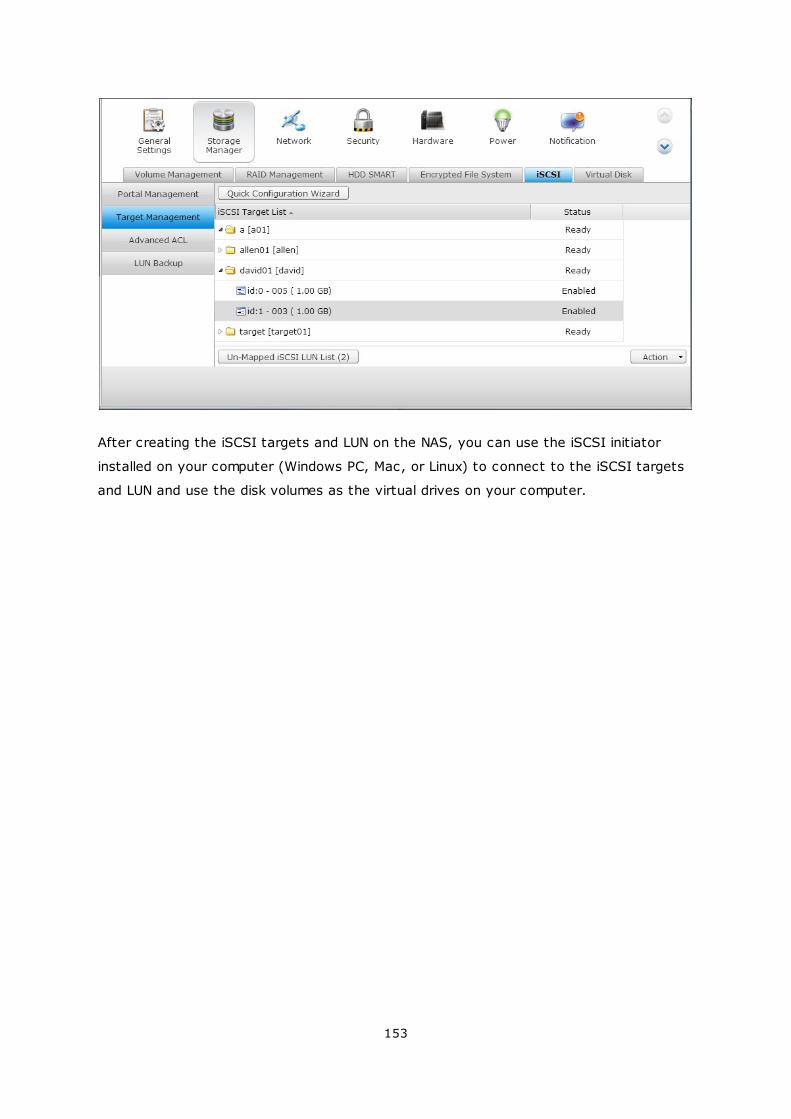
153
After creating the iSCSI targets and LUN on the NAS, you can use the iSCSI initiator
installed on your computer (Windows PC, Mac, or Linux) to connect to the iSCSI targets
and LUN and use the disk volumes as the virtual drives on your computer.
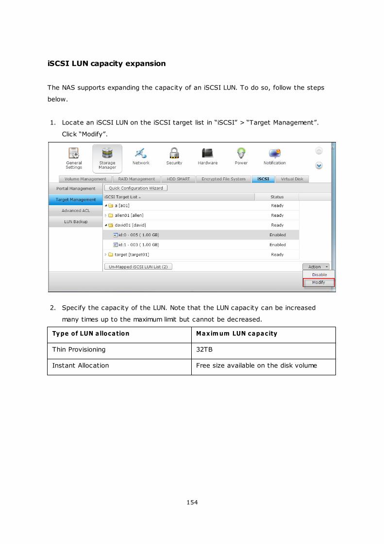
154
iSCSI LUN capacity expansion
The NAS supports expanding the capacity of an iSCSI LUN. To do so, follow the steps
below.
1. Locate an iSCSI LUN on the iSCSI target list in “iSCSI” > “Target Management”.
Click “Modify”.
2. Specify the capacity of the LUN. Note that the LUN capacity can be increased
many times up to the maximum limit but cannot be decreased.
Type of LUN allocation Maxim um LUN capacity
Thin Provisioning 32TB
Instant Allocation Free size available on the disk volume
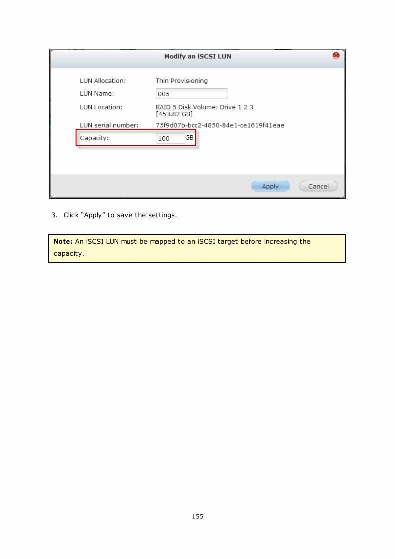
155
3. Click “Apply” to save the settings.
Note: An iSCSI LUN must be mapped to an iSCSI target before increasing the
capacity.
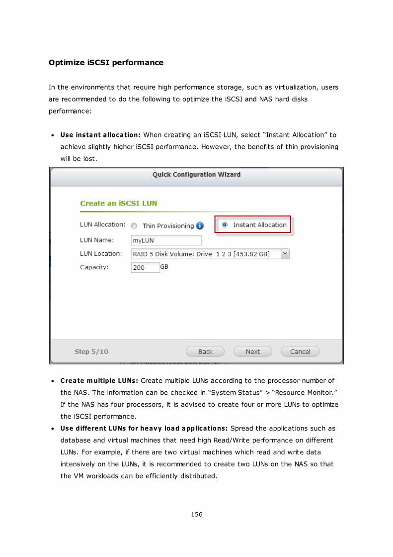
156
Optimize iSCSI performance
In the environments that require high performance storage, such as virtualization, users
are recommended to do the following to optimize the iSCSI and NAS hard disks
performance:
Use instant allocation: When creating an iSCSI LUN, select “Instant Allocation” to
achieve slightly higher iSCSI performance. However, the benefits of thin provisioning
will be lost.
Create m ultiple LUNs: Create multiple LUNs according to the processor number of
the NAS. The information can be checked in “System Status” > “Resource Monitor.”
If the NAS has four processors, it is advised to create four or more LUNs to optimize
the iSCSI performance.
Use different LUNs for heavy load applications: Spread the applications such as
database and virtual machines that need high Read/Write performance on different
LUNs. For example, if there are two virtual machines which read and write data
intensively on the LUNs, it is recommended to create two LUNs on the NAS so that
the VM workloads can be efficiently distributed.
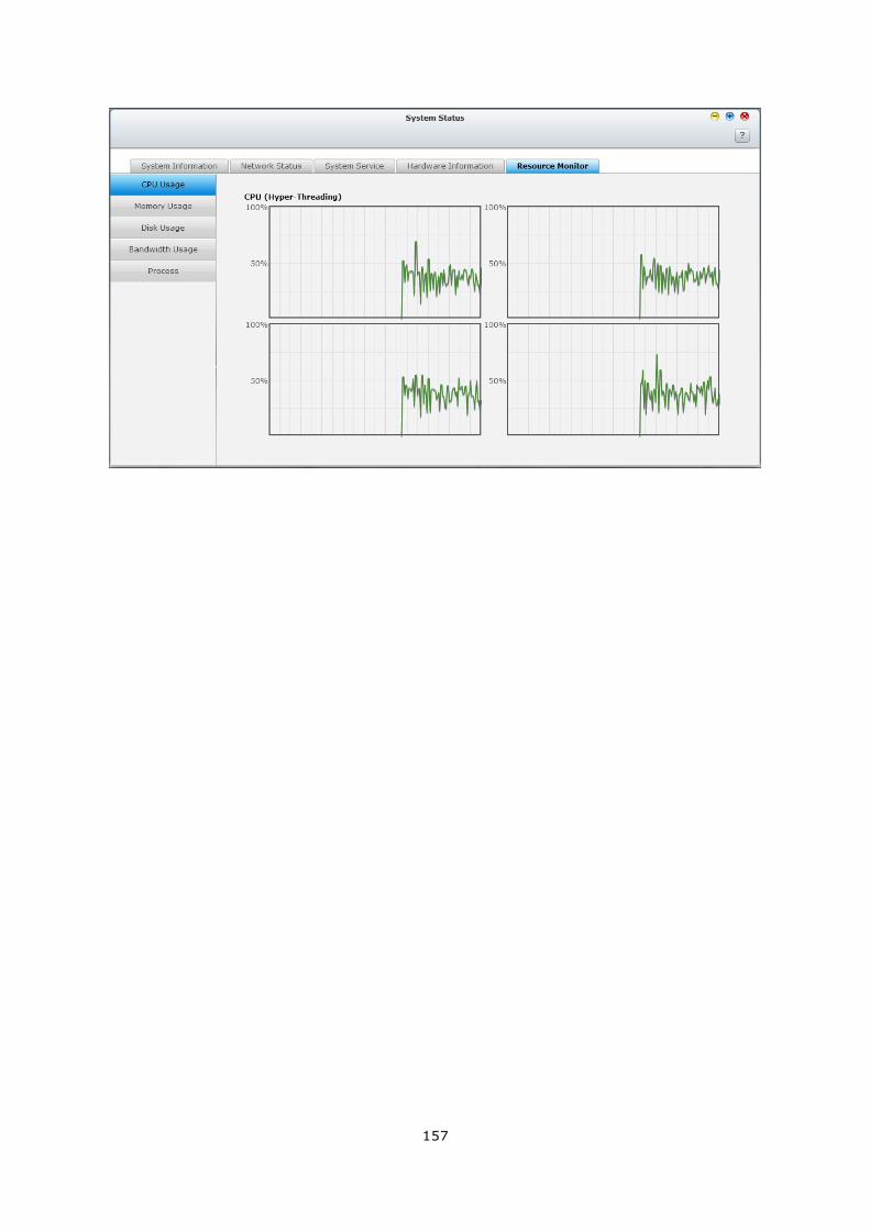
157
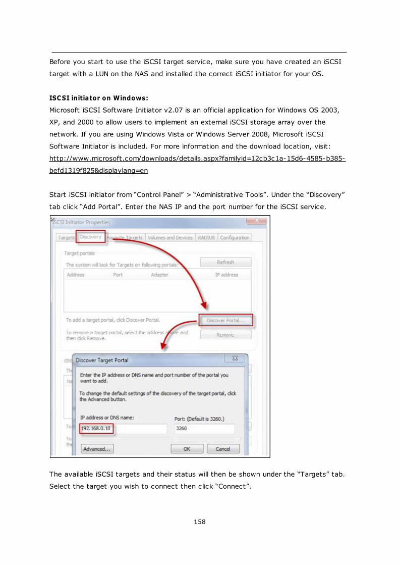
158
Before you start to use the iSCSI target service, make sure you have created an iSCSI
target with a LUN on the NAS and installed the correct iSCSI initiator for your OS.
ISCSI initiator on Windows:
Microsoft iSCSI Software Initiator v2.07 is an official application for Windows OS 2003,
XP, and 2000 to allow users to implement an external iSCSI storage array over the
network. If you are using Windows Vista or Windows Server 2008, Microsoft iSCSI
Software Initiator is included. For more information and the download location, visit:
http://www.microsoft.com/downloads/details.aspx?familyid=12cb3c1a-15d6-4585-b385-
befd1319f825&displaylang=en
Start iSCSI initiator from “Control Panel” > “Administrative Tools”. Under the “Discovery”
tab click “Add Portal”. Enter the NAS IP and the port number for the iSCSI service.
The available iSCSI targets and their status will then be shown under the “Targets” tab.
Select the target you wish to connect then click “Connect”.
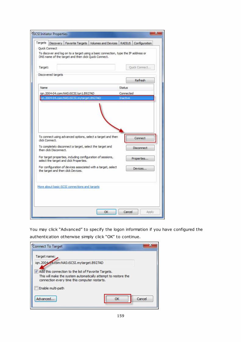
159
You may click “Advanced” to specify the logon information if you have configured the
authentication otherwise simply click “OK” to continue.
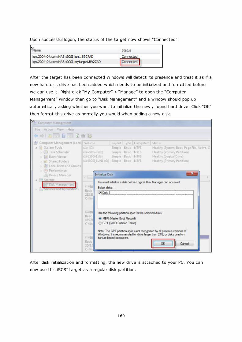
160
Upon successful logon, the status of the target now shows “Connected”.
After the target has been connected Windows will detect its presence and treat it as if a
new hard disk drive has been added which needs to be initialized and formatted before
we can use it. Right click “My Computer” > “Manage” to open the “Computer
Management” window then go to “Disk Management” and a window should pop up
automatically asking whether you want to initialize the newly found hard drive. Click “OK”
then format this drive as normally you would when adding a new disk.
After disk initialization and formatting, the new drive is attached to your PC. You can
now use this iSCSI target as a regular disk partition.
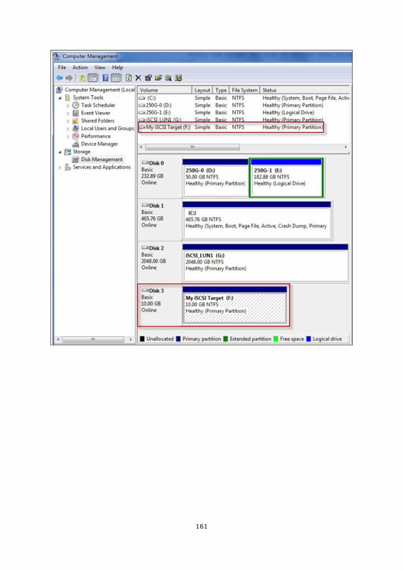
161
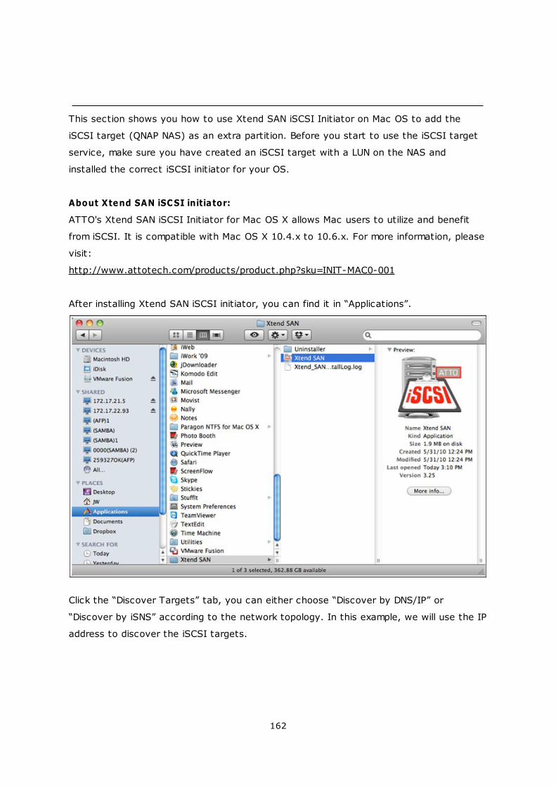
162
This section shows you how to use Xtend SAN iSCSI Initiator on Mac OS to add the
iSCSI target (QNAP NAS) as an extra partition. Before you start to use the iSCSI target
service, make sure you have created an iSCSI target with a LUN on the NAS and
installed the correct iSCSI initiator for your OS.
About Xtend SAN iSCSI initiator:
ATTO's Xtend SAN iSCSI Initiator for Mac OS X allows Mac users to utilize and benefit
from iSCSI. It is compatible with Mac OS X 10.4.x to 10.6.x. For more information, please
visit:
http://www.attotech.com/products/product.php?sku=INIT-MAC0-001
After installing Xtend SAN iSCSI initiator, you can find it in “Applications”.
Click the “Discover Targets” tab, you can either choose “Discover by DNS/IP” or
“Discover by iSNS” according to the network topology. In this example, we will use the IP
address to discover the iSCSI targets.
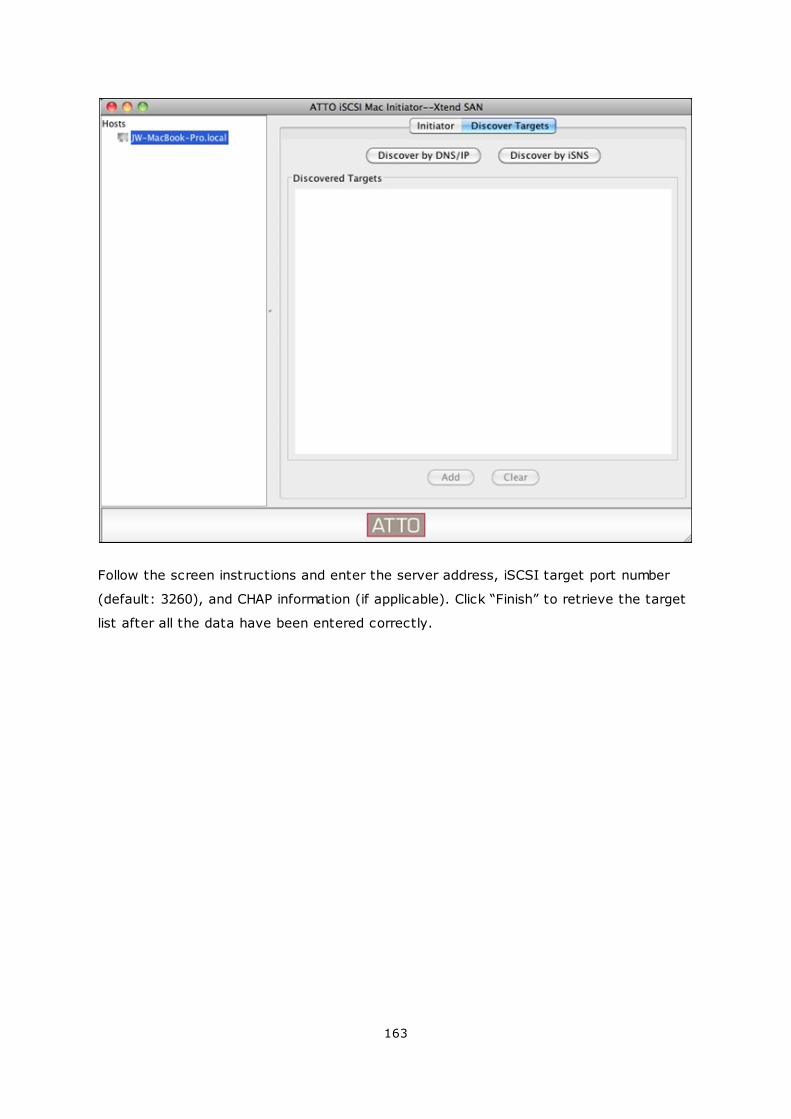
163
Follow the screen instructions and enter the server address, iSCSI target port number
(default: 3260), and CHAP information (if applicable). Click “Finish” to retrieve the target
list after all the data have been entered correctly.
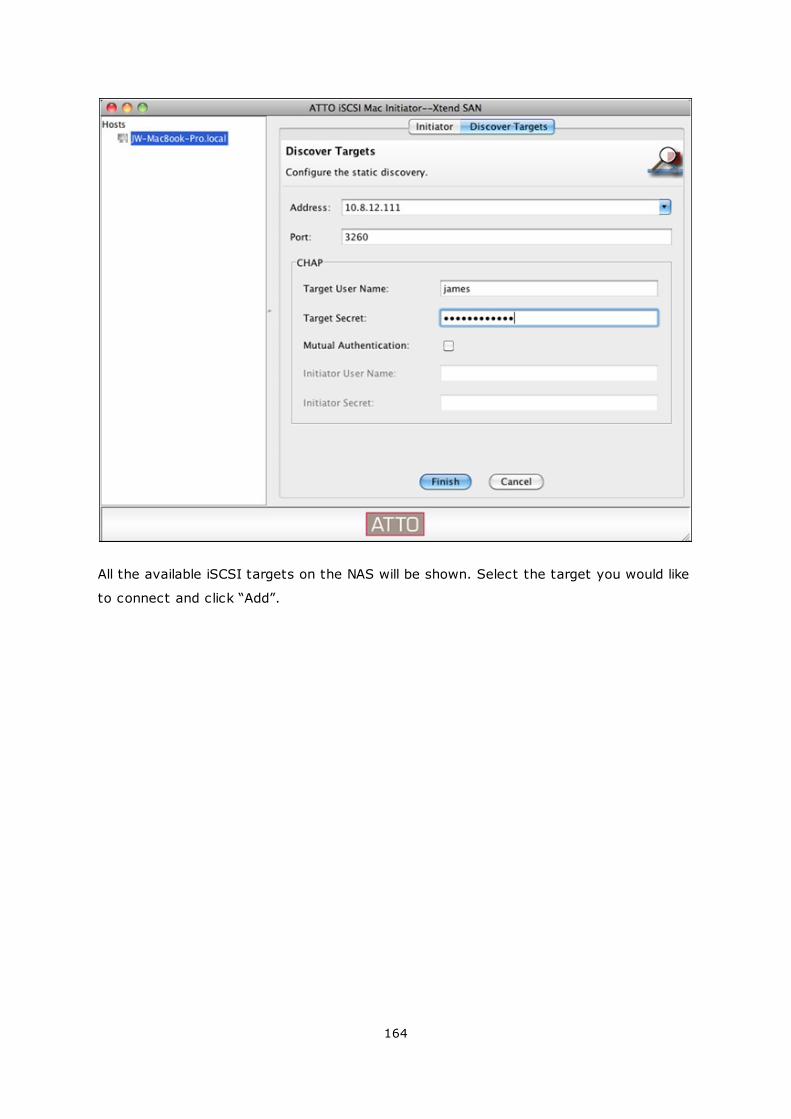
164
All the available iSCSI targets on the NAS will be shown. Select the target you would like
to connect and click “Add”.
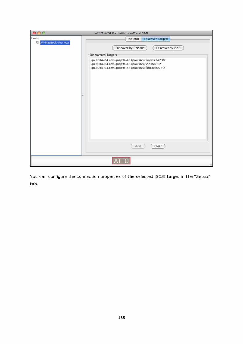
165
You can configure the connection properties of the selected iSCSI target in the “Setup”
tab.
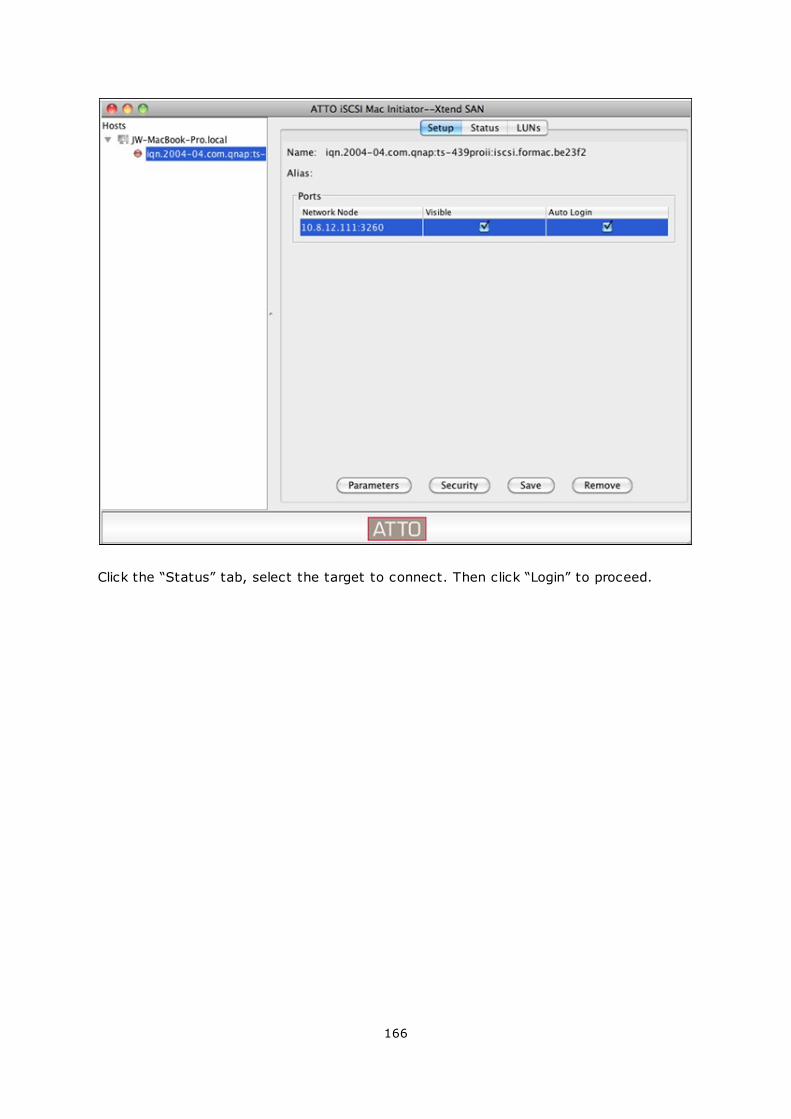
166
Click the “Status” tab, select the target to connect. Then click “Login” to proceed.
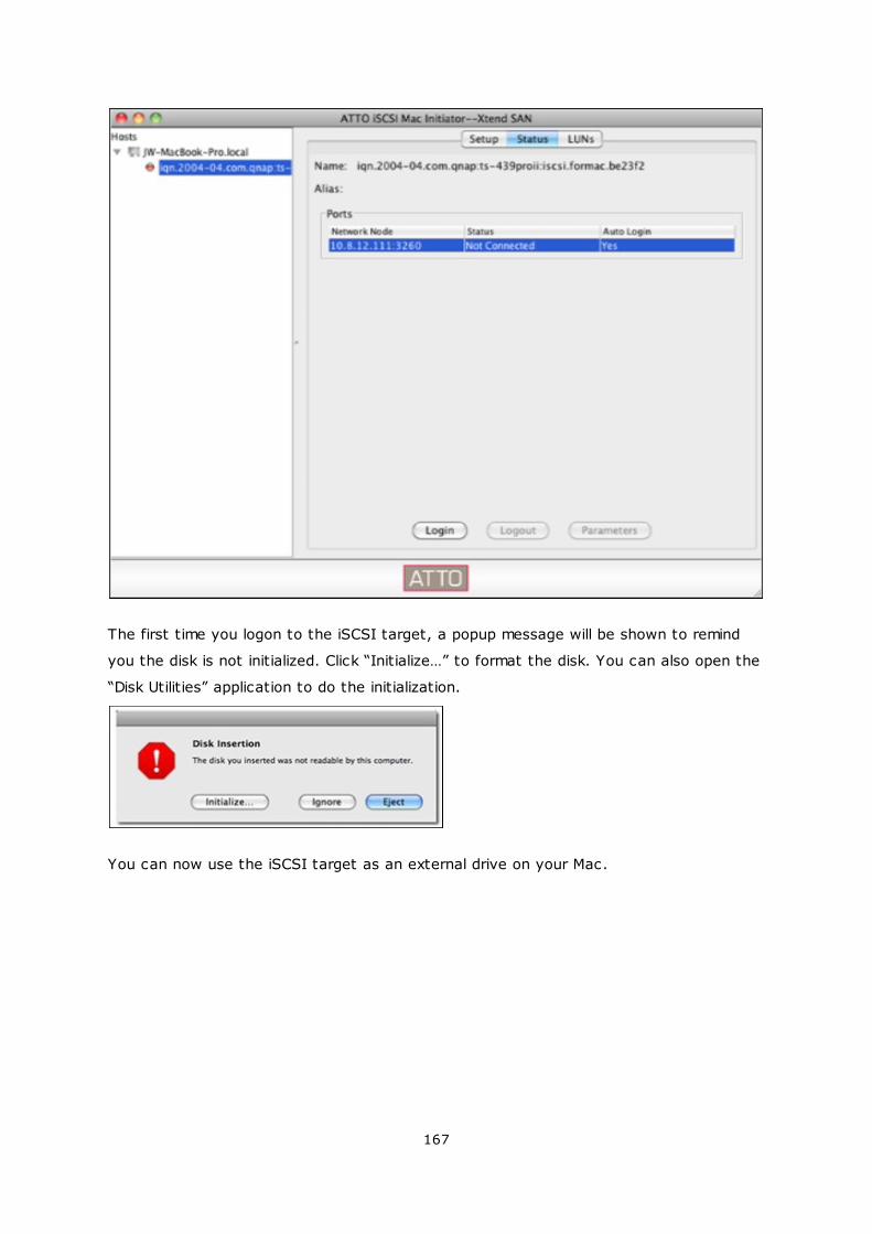
167
The first time you logon to the iSCSI target, a popup message will be shown to remind
you the disk is not initialized. Click “Initialize…” to format the disk. You can also open the
“Disk Utilities” application to do the initialization.
You can now use the iSCSI target as an external drive on your Mac.

168
169
This section shows you how to use Linux Open-iSCSI Initiator on Ubuntu to add the
iSCSI target (QNAP NAS) as an extra partition. Before you start to use the iSCSI target
service, make sure you have created an iSCSI target with a LUN on the NAS and
installed the correct iSCSI initiator for your OS.
About Linux Open-iSCSI Initiator
The Linux Open-iSCSI Initiator is a built-in package in Ubuntu 8.04 LTS (or later). You
can connect to an iSCSI volume at a shell prompt with just a few commands. More
information about Ubuntu is available at http://www.ubuntu.com and for information and
download location of Open-iSCSI, please visit: http://www.open-iscsi.org
Note: Snapshot LUNs are not supported by the Linux Open-iSCSI Initiator.
Before you start
Install the open-iscsi package. The package is also known as the Linux Open-iSCSI
Initiator.
# sudo apt-get install open-iscsi
Now follow the steps below to connect to an iSCSI target (QNAP NAS) with Linux Open-
iSCSI Initiator.
You may need to modify the iscsid.conf for CHAP logon information, such as node.
session.auth.username & node.session.auth.password.
# vi /etc/iscsi/iscsid.conf
Save and close the file, then restart the open-iscsi service.
# /etc/init.d/open-iscsi restart
Discover the iSCSI targets on a specific host (the QNAP NAS in this example), for
example, 10.8.12.31 with default port 3260.
# iscsiadm -m discovery -t sendtargets -p 10.8.12.31:3260
Check the available iSCSI node(s) to connect.
# iscsiadm -m node
** You can delete the node(s) you do not want to connect to when the service is on
with the following command:
# iscsiadm -m node --op delete --targetname THE_TARGET_IQN
170
Restart open-iscsi to login all the available nodes.
# /etc/init.d/open-iscsi restart
You should be able to see the login message as below:
Login session [iface: default, target: iqn.2004-04.com:NAS:iSCSI.ForUbuntu.B9281B,
portal: 10.8.12.31,3260] [ OK ]
Check the device status with dmesg.
# dmesg | tail
Enter the following command to create a partition, /dev/sdb is the device name.
# fdisk /dev/sdb
Format the partition.
# mkfs.ext3 /dev/sdb1
Mount the file system.
# mkdir /mnt/iscsi
# mount /dev/sdb1 /mnt/iscsi/
You can test the I/O speed using the following command.
# hdparm -tT /dev/sdb1
Below are some “iscsiadm” related commands.
Discover the targets on the host:
# iscsiadm -m discovery --type sendtargets --portal HOST_IP
Login a target:
# iscsiadm –m node --targetname THE_TARGET_IQN --login
Logout a target:
# iscsiadm –m node --targetname THE_TARGET_IQN --logout
Delete a Target:
# iscsiadm –m node --op delete --targetname THE_TARGET_IQN
171
4.2.5.3 Advanced ACL
The description below applies to non Intel-based NAS models running firmware version
3.3.0 or later and Intel-based NAS models running firmware version 3.2.0 or later only.
You can create LUN masking policy to configure the permission of the iSCSI initiators
which attempt to access the LUN mapped to the iSCSI targets on the NAS. To use this
feature, click “Add a Policy” under “Advanced ACL”.
Enter the policy name, the initiator IQN, and assign the access right for each LUN
created on the NAS.
Read-only: The connected initiator can only read the data from the LUN.
Read/Write: The connected initiator has read and write access right to the LUN.
Deny Access: The LUN is invisible to the connected initiator.
172
If no LUN masking policy is specified for a connected iSCSI initiator, the default policy will
be applied. The system default policy allows read and write access from all the
connected iSCSI initiators. You can click “Edit” to edit the default policy.
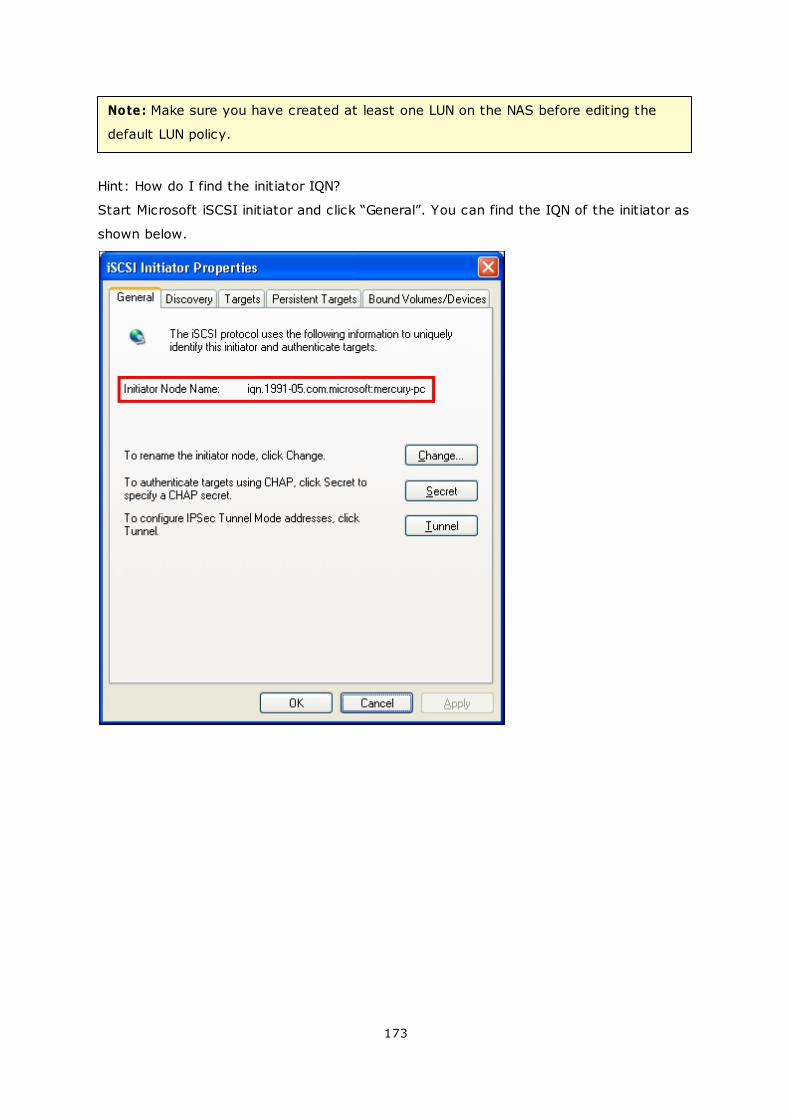
173
Note: Make sure you have created at least one LUN on the NAS before editing the
default LUN policy.
Hint: How do I find the initiator IQN?
Start Microsoft iSCSI initiator and click “General”. You can find the IQN of the initiator as
shown below.
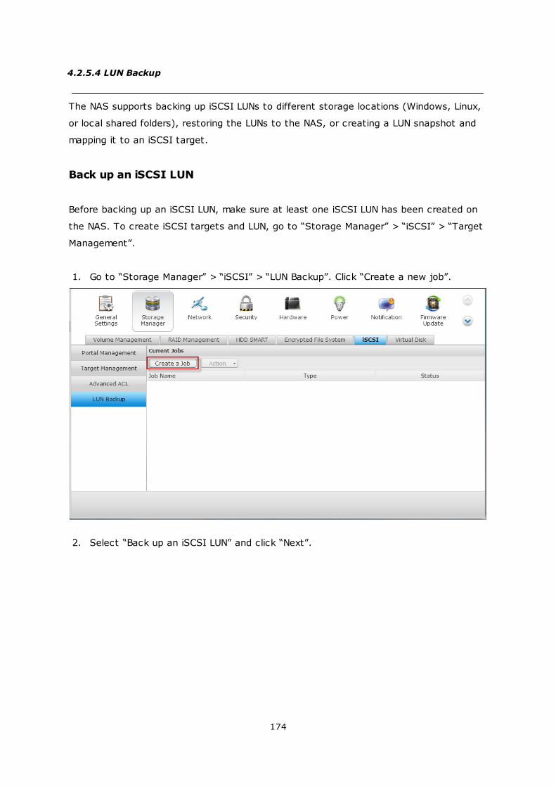
174
4.2.5.4 LUN Backup
The NAS supports backing up iSCSI LUNs to different storage locations (Windows, Linux,
or local shared folders), restoring the LUNs to the NAS, or creating a LUN snapshot and
mapping it to an iSCSI target.
Back up an iSCSI LUN
Before backing up an iSCSI LUN, make sure at least one iSCSI LUN has been created on
the NAS. To create iSCSI targets and LUN, go to “Storage Manager” > “iSCSI” > “Target
Management”.
1. Go to “Storage Manager” > “iSCSI” > “LUN Backup”. Click “Create a new job”.
2. Select “Back up an iSCSI LUN” and click “Next”.

175
3. Select the source LUN for backup. If an online LUN is selected, the NAS will create
a point-in-time snapshot for the LUN automatically.
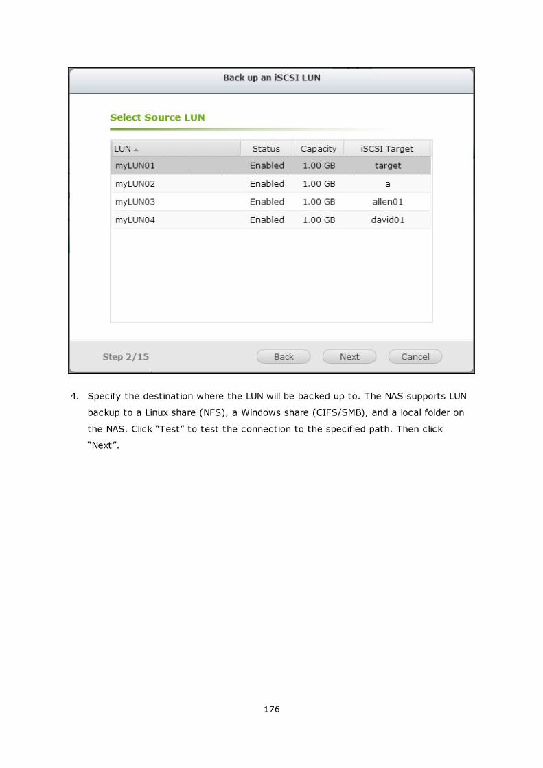
176
4. Specify the destination where the LUN will be backed up to. The NAS supports LUN
backup to a Linux share (NFS), a Windows share (CIFS/SMB), and a local folder on
the NAS. Click “Test” to test the connection to the specified path. Then click
“Next”.
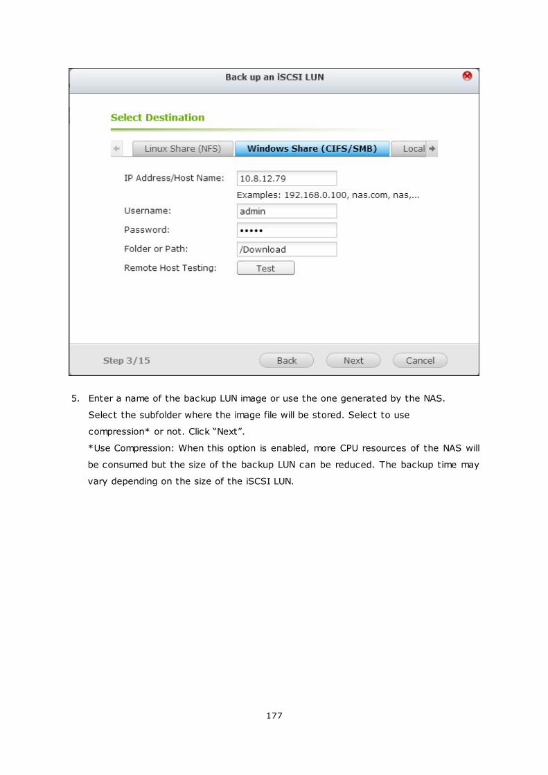
177
5. Enter a name of the backup LUN image or use the one generated by the NAS.
Select the subfolder where the image file will be stored. Select to use
compression* or not. Click “Next”.
*Use Compression: When this option is enabled, more CPU resources of the NAS will
be consumed but the size of the backup LUN can be reduced. The backup time may
vary depending on the size of the iSCSI LUN.
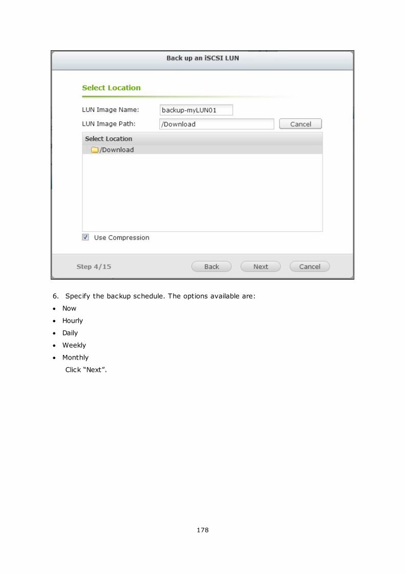
178
6. Specify the backup schedule. The options available are:
Now
Hourly
Daily
Weekly
Monthly
Click “Next”.
179
7. The settings will be shown. Enter a name for the job or use the one generated by
the NAS. Click “Next.”
180
8. Click “Finish” to exit.
181
9. The backup job is shown on the list.
Button Description
Start the job immediately.
Stop the running job.
Edit the job settings.
View the job status and logs.
182
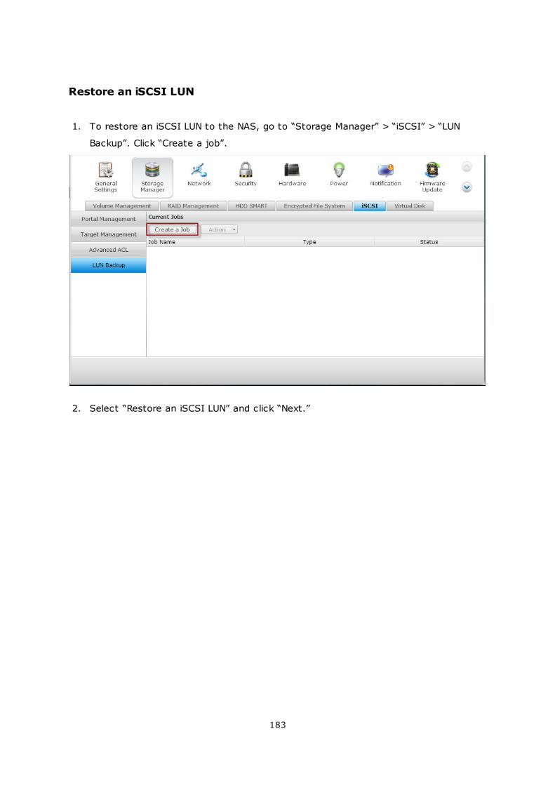
183
Restore an iSCSI LUN
1. To restore an iSCSI LUN to the NAS, go to “Storage Manager” > “iSCSI” > “LUN
Backup”. Click “Create a job”.
2. Select “Restore an iSCSI LUN” and click “Next.”
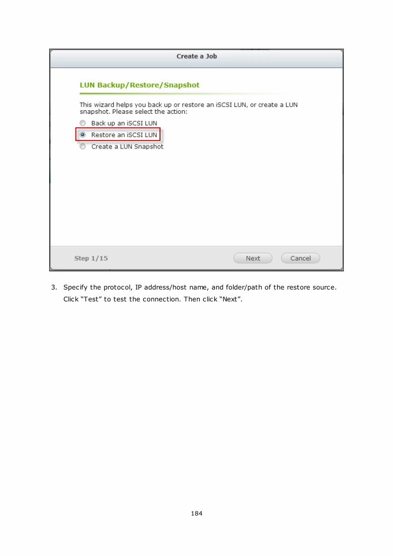
184
3. Specify the protocol, IP address/host name, and folder/path of the restore source.
Click “Test” to test the connection. Then click “Next”.
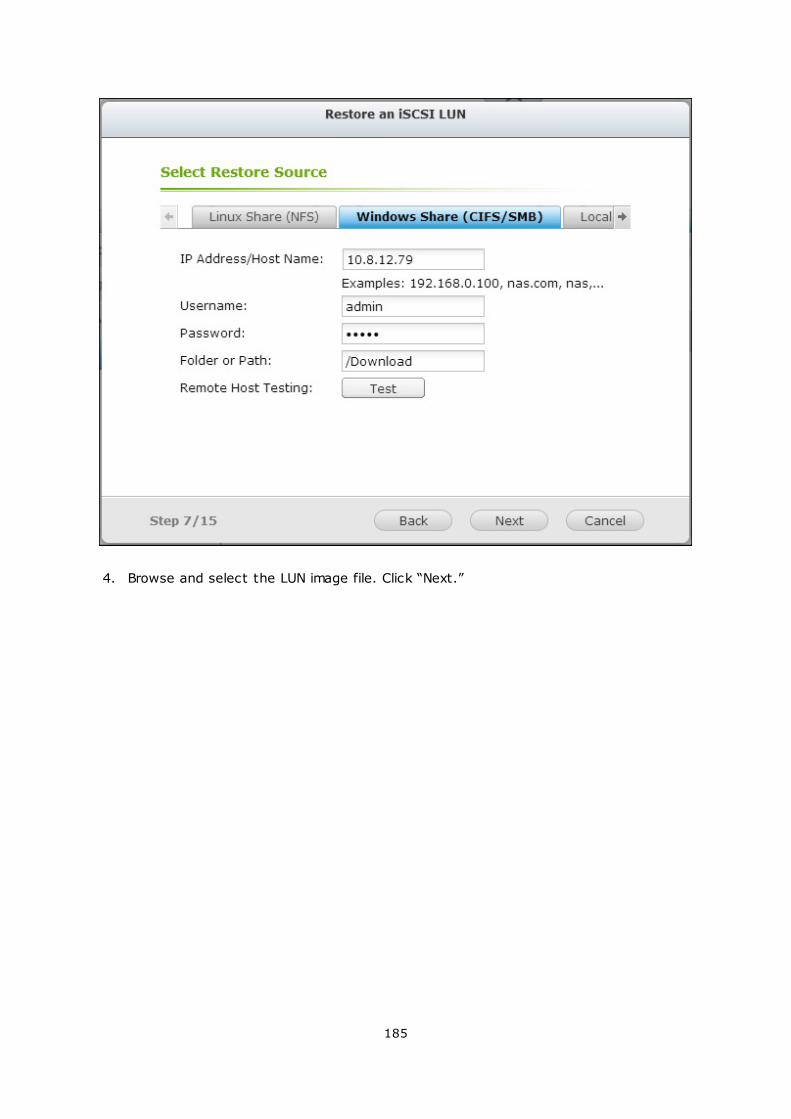
185
4. Browse and select the LUN image file. Click “Next.”
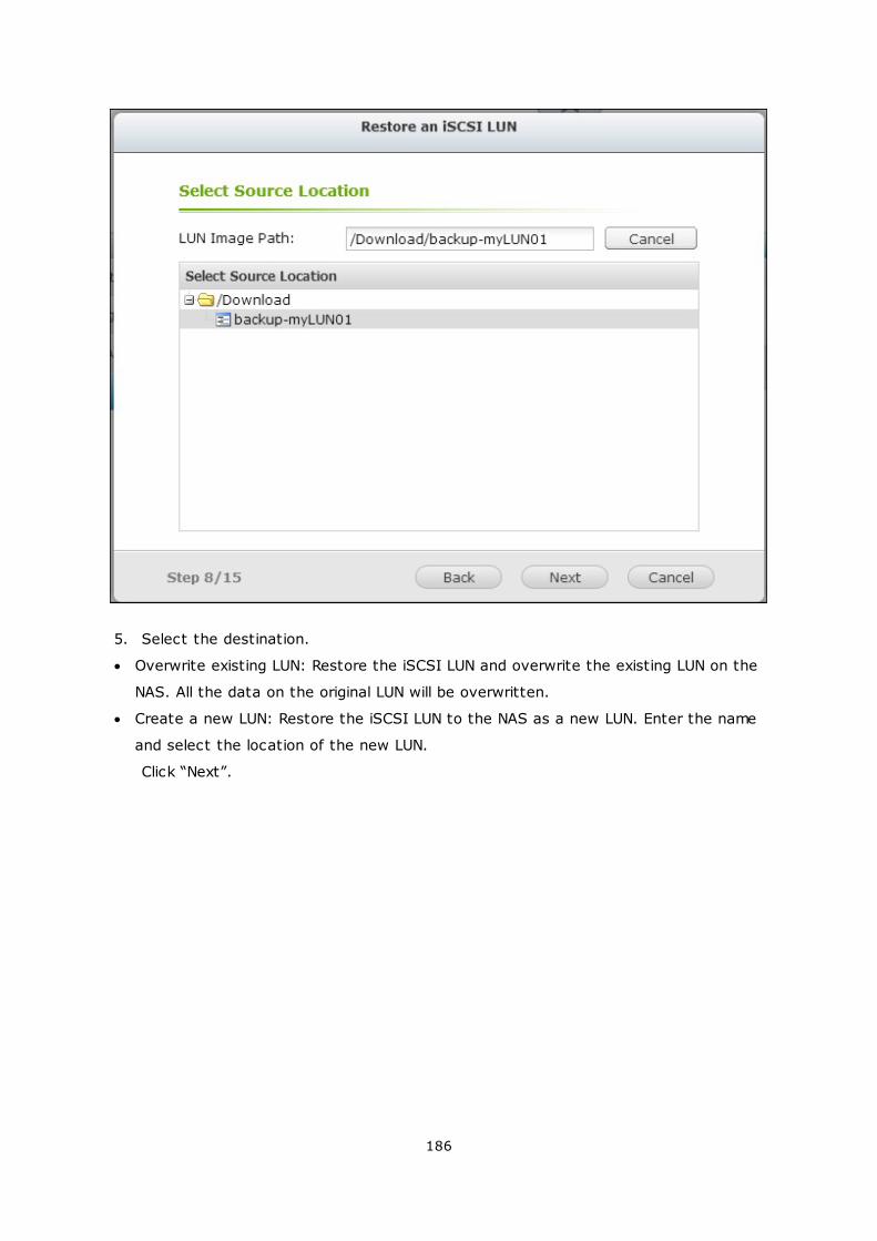
186
5. Select the destination.
Overwrite existing LUN: Restore the iSCSI LUN and overwrite the existing LUN on the
NAS. All the data on the original LUN will be overwritten.
Create a new LUN: Restore the iSCSI LUN to the NAS as a new LUN. Enter the name
and select the location of the new LUN.
Click “Next”.
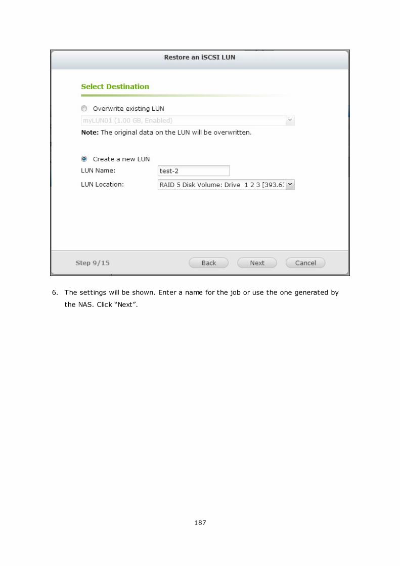
187
6. The settings will be shown. Enter a name for the job or use the one generated by
the NAS. Click “Next”.
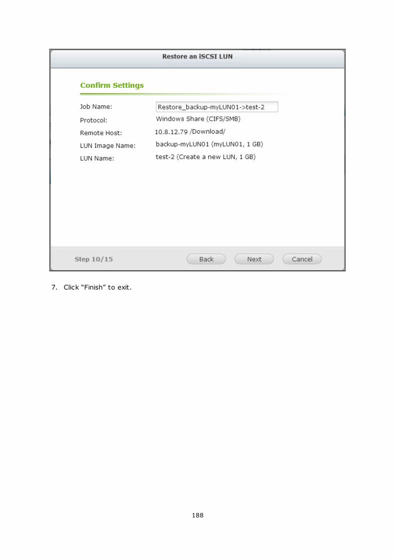
188
7. Click “Finish” to exit.
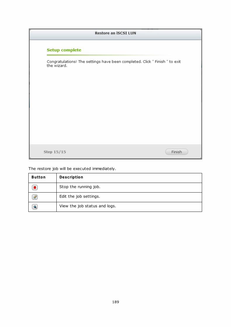
189
The restore job will be executed immediately.
Button Description
Stop the running job.
Edit the job settings.
View the job status and logs.
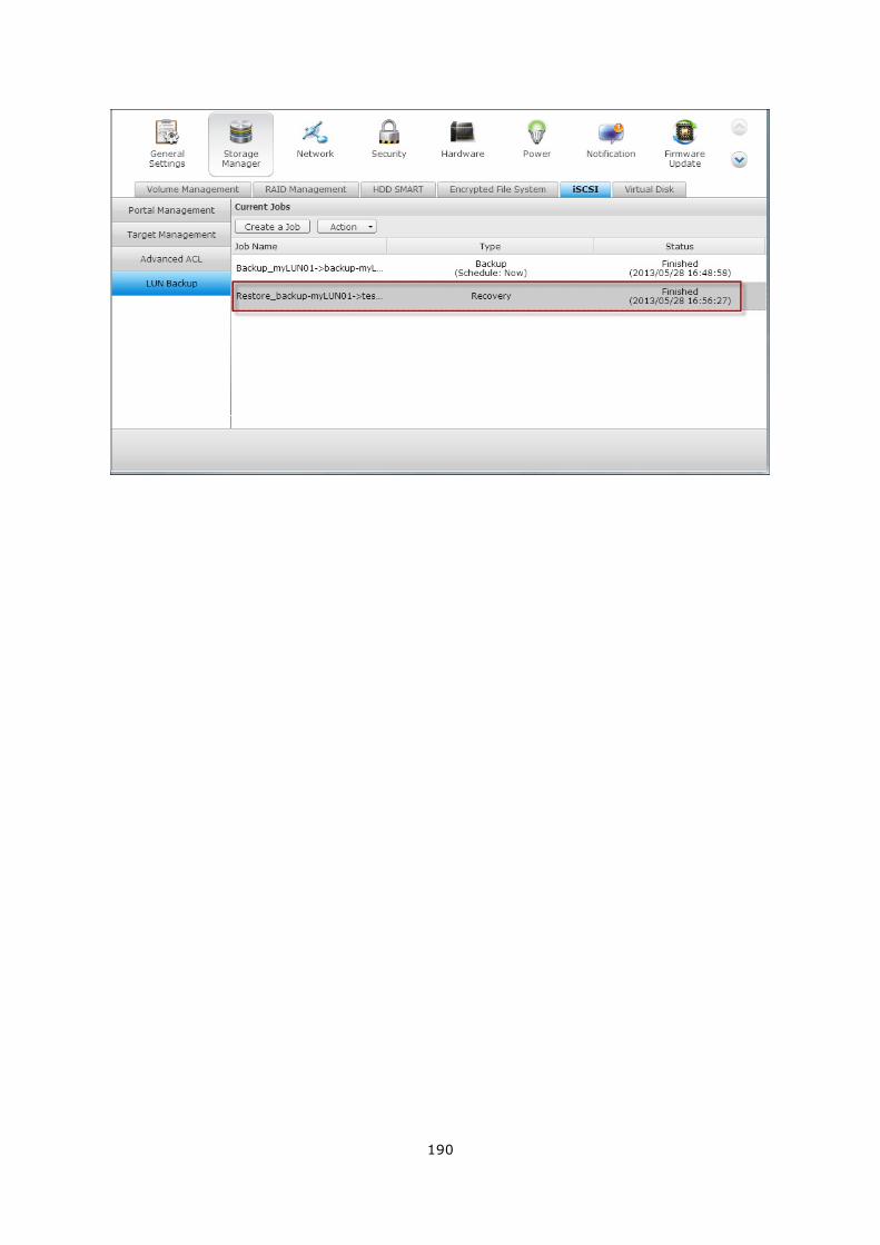
190
191
Create an iSCSI LUN Snapshot
Before creating an iSCSI LUN snapshot, make sure at least one iSCSI LUN and one iSCSI
target has been created on the NAS. To create iSCSI targets and LUN, go to “Storage
Manager” > “iSCSI” > “Target Management”.
1. To create an iSCSI LUN snapshot, go to “Storage Manager” > “iSCSI” > “LUN
Backup”. Click “Create a job”.
2. Select “Create a LUN Snapshot” and click “Next”.

192
3. Select an iSCSI LUN on the NAS. Only one snapshot can be created for each iSCSI
LUN. Click “Next”.
193
4. Enter a name for the LUN snapshot or use the one generated by the NAS. Select
an iSCSI target where the LUN snapshot is mapped to. Click “Next”. The LUN
snapshot must be mapped to another iSCSI target different from the original one.
194
5. Specify the snapshot schedule and the snapshot duration. The snapshot will be
removed automatically when the snapshot duration is reached.
195
6. The settings will be shown. Enter a name for the job or use the one generated by
the NAS. Click “Next”.

196
7. Click “Finish” to exit.
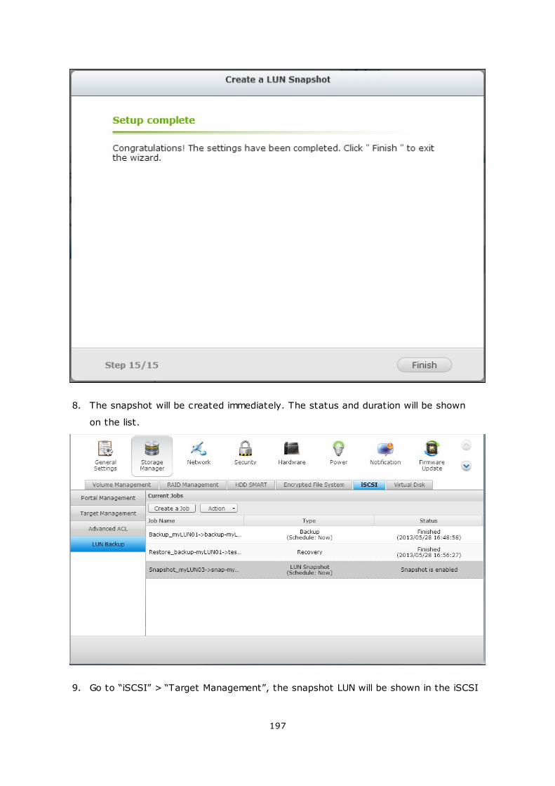
197
8. The snapshot will be created immediately. The status and duration will be shown
on the list.
9. Go to “iSCSI” > “Target Management”, the snapshot LUN will be shown in the iSCSI
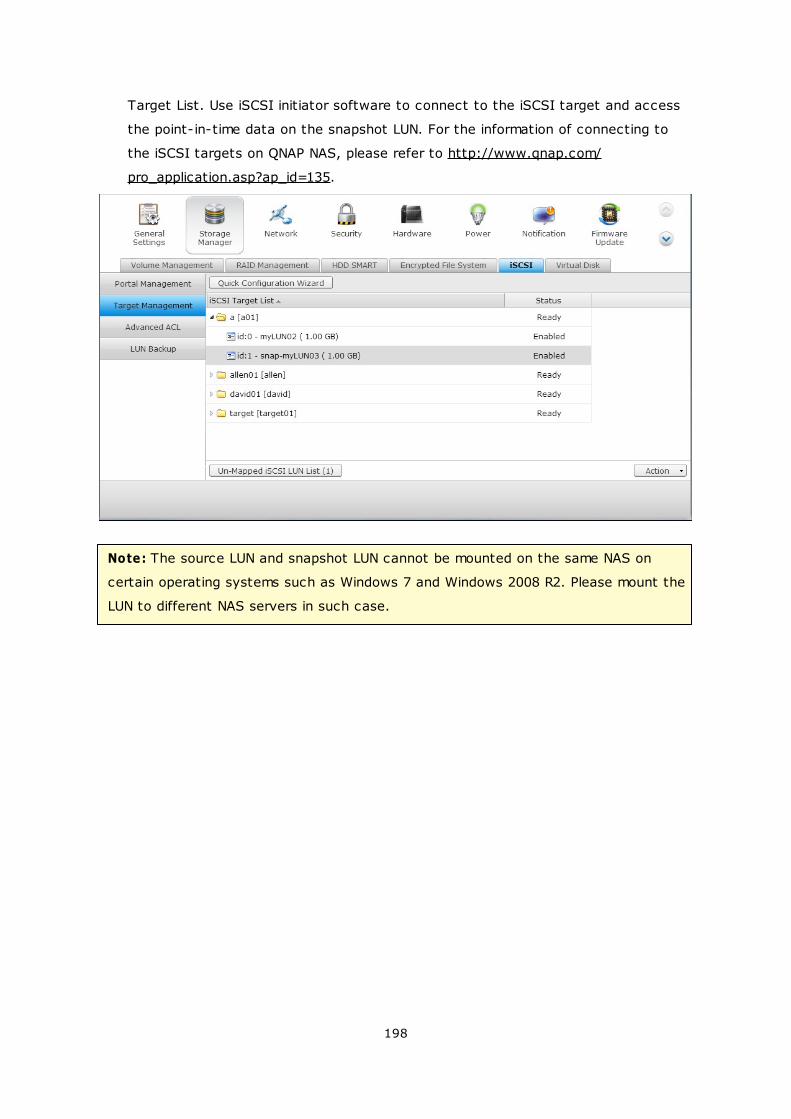
198
Target List. Use iSCSI initiator software to connect to the iSCSI target and access
the point-in-time data on the snapshot LUN. For the information of connecting to
the iSCSI targets on QNAP NAS, please refer to http://www.qnap.com/
pro_application.asp?ap_id=135.
Note: The source LUN and snapshot LUN cannot be mounted on the same NAS on
certain operating systems such as Windows 7 and Windows 2008 R2. Please mount the
LUN to different NAS servers in such case.
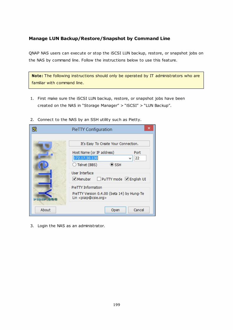
199
Manage LUN Backup/Restore/Snapshot by Command Line
QNAP NAS users can execute or stop the iSCSI LUN backup, restore, or snapshot jobs on
the NAS by command line. Follow the instructions below to use this feature.
Note: The following instructions should only be operated by IT administrators who are
familiar with command line.
1. First make sure the iSCSI LUN backup, restore, or snapshot jobs have been
created on the NAS in “Storage Manager” > “iSCSI” > “LUN Backup”.
2. Connect to the NAS by an SSH utility such as Pietty.
3. Login the NAS as an administrator.
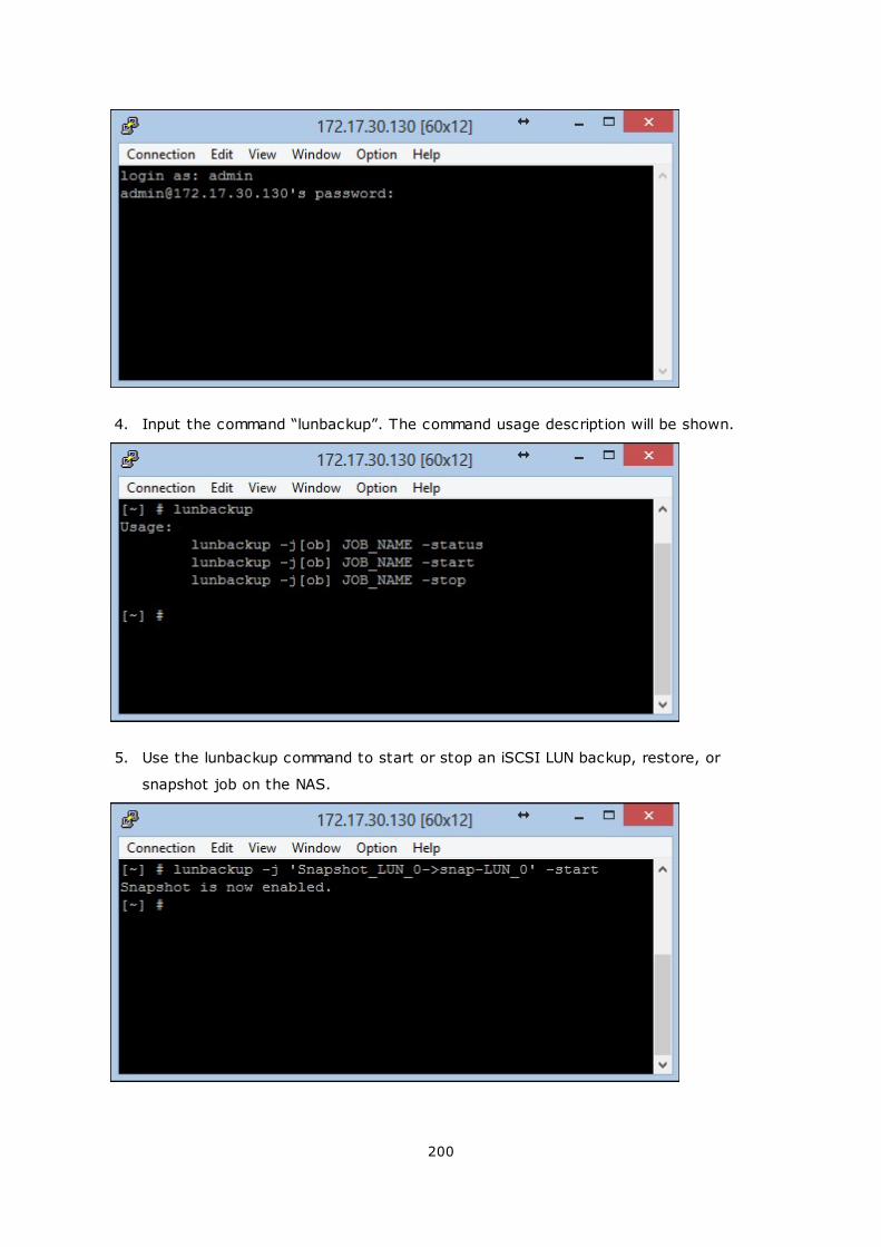
200
4. Input the command “lunbackup”. The command usage description will be shown.
5. Use the lunbackup command to start or stop an iSCSI LUN backup, restore, or
snapshot job on the NAS.
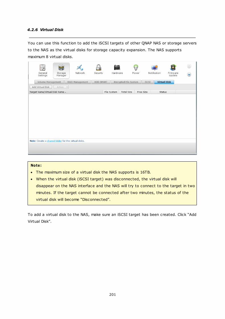
201
4.2.6 Virtual Disk
You can use this function to add the iSCSI targets of other QNAP NAS or storage servers
to the NAS as the virtual disks for storage capacity expansion. The NAS supports
maximum 8 virtual disks.
Note:
The maximum size of a virtual disk the NAS supports is 16TB.
When the virtual disk (iSCSI target) was disconnected, the virtual disk will
disappear on the NAS interface and the NAS will try to connect to the target in two
minutes. If the target cannot be connected after two minutes, the status of the
virtual disk will become “Disconnected”.
To add a virtual disk to the NAS, make sure an iSCSI target has been created. Click “Add
Virtual Disk”.
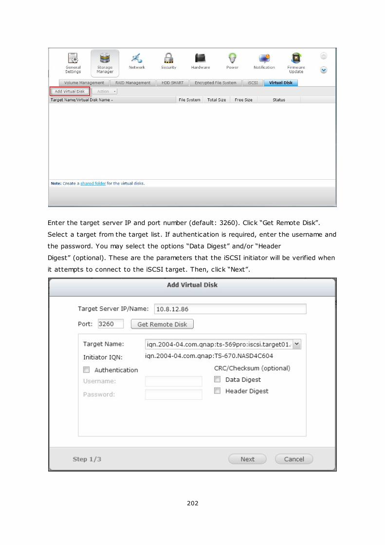
202
Enter the target server IP and port number (default: 3260). Click “Get Remote Disk”.
Select a target from the target list. If authentication is required, enter the username and
the password. You may select the options “Data Digest” and/or “Header
Digest” (optional). These are the parameters that the iSCSI initiator will be verified when
it attempts to connect to the iSCSI target. Then, click “Next”.
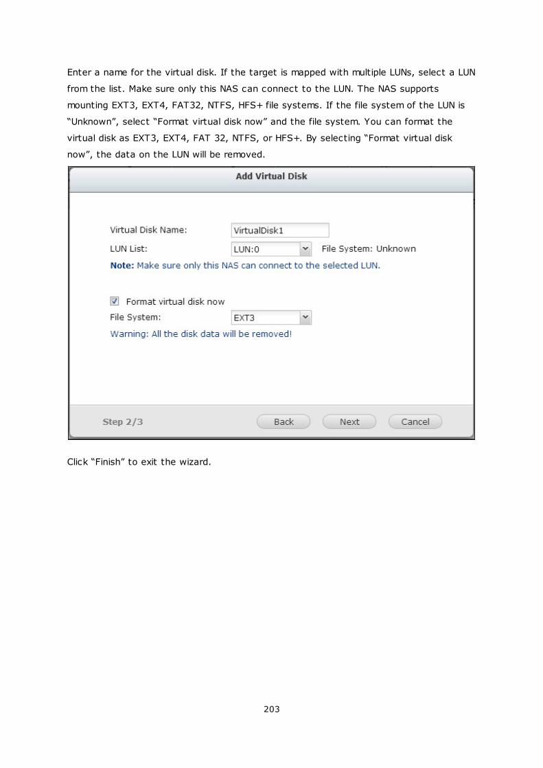
203
Enter a name for the virtual disk. If the target is mapped with multiple LUNs, select a LUN
from the list. Make sure only this NAS can connect to the LUN. The NAS supports
mounting EXT3, EXT4, FAT32, NTFS, HFS+ file systems. If the file system of the LUN is
“Unknown”, select “Format virtual disk now” and the file system. You can format the
virtual disk as EXT3, EXT4, FAT 32, NTFS, or HFS+. By selecting “Format virtual disk
now”, the data on the LUN will be removed.
Click “Finish” to exit the wizard.
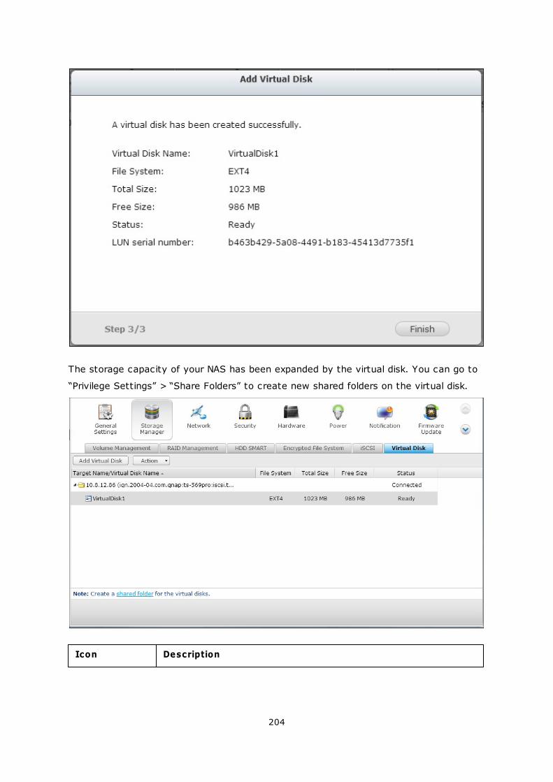
204
The storage capacity of your NAS has been expanded by the virtual disk. You can go to
“Privilege Settings” > “Share Folders” to create new shared folders on the virtual disk.
Icon Description
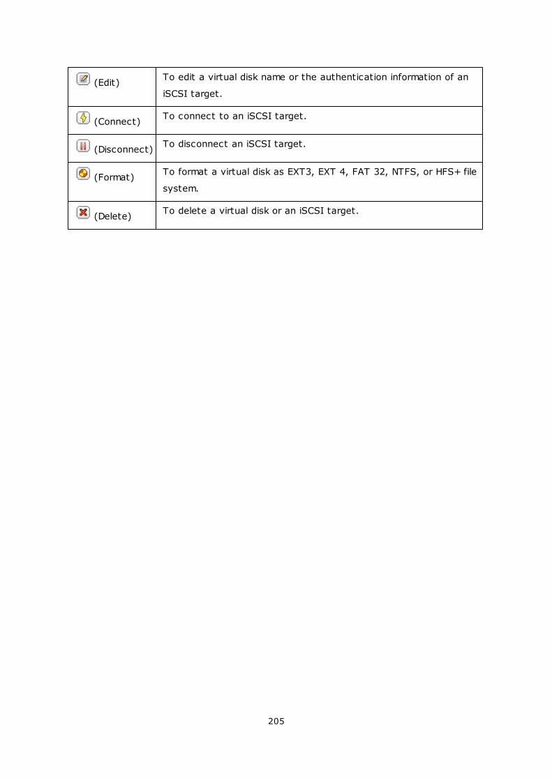
205
(Edit)To edit a virtual disk name or the authentication information of an
iSCSI target.
(Connect)To connect to an iSCSI target.
(Disconnect)To disconnect an iSCSI target.
(Format)To format a virtual disk as EXT3, EXT 4, FAT 32, NTFS, or HFS+ file
system.
(Delete)To delete a virtual disk or an iSCSI target.
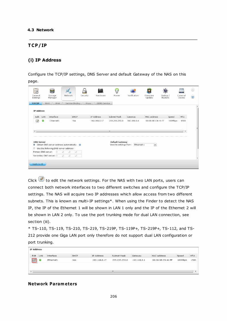
206
4.3 Network
T CP/IP
(i) IP Address
Configure the TCP/IP settings, DNS Server and default Gateway of the NAS on this
page.
Click to edit the network settings. For the NAS with two LAN ports, users can
connect both network interfaces to two different switches and configure the TCP/IP
settings. The NAS will acquire two IP addresses which allow access from two different
subnets. This is known as multi-IP settings*. When using the Finder to detect the NAS
IP, the IP of the Ethernet 1 will be shown in LAN 1 only and the IP of the Ethernet 2 will
be shown in LAN 2 only. To use the port trunking mode for dual LAN connection, see
section (iii).
* TS-110, TS-119, TS-210, TS-219, TS-219P, TS-119P+, TS-219P+, TS-112, and TS-
212 provide one Giga LAN port only therefore do not support dual LAN configuration or
port trunking.
Network Parameters
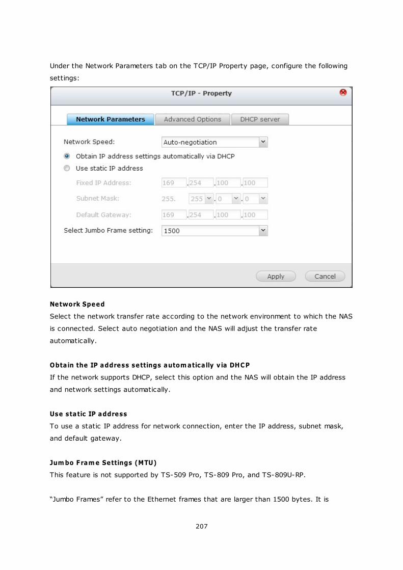
207
Under the Network Parameters tab on the TCP/IP Property page, configure the following
settings:
Network Speed
Select the network transfer rate according to the network environment to which the NAS
is connected. Select auto negotiation and the NAS will adjust the transfer rate
automatically.
Obtain the IP address settings autom atically v ia DHCP
If the network supports DHCP, select this option and the NAS will obtain the IP address
and network settings automatically.
Use static IP address
To use a static IP address for network connection, enter the IP address, subnet mask,
and default gateway.
Jum bo Fram e Settings (MTU)
This feature is not supported by TS-509 Pro, TS-809 Pro, and TS-809U-RP.
“Jumbo Frames” refer to the Ethernet frames that are larger than 1500 bytes. It is
208
designed to enhance Ethernet networking throughput and reduce the CPU utilization of
large file transfers by enabling more efficient larger payloads per packet.
Maximum Transmission Unit (MTU) refers to the size (in bytes) of the largest packet that
a given layer of a communications protocol can transmit.
The NAS uses standard Ethernet frames: 1500 bytes by default. If the network
appliances support Jumbo Frame setting, select the appropriate MTU value for the
network environment. The NAS supports 4074, 7418, and 9000 bytes for MTU.
Note: The Jumbo Frame setting is valid in Gigabit network environment only. All the
network appliances connected must enable Jumbo Frame and use the same MTU value.
Advanced Options
A Virtual LAN (VLAN) is a group of hosts which communicate as if they were attached to
the same broadcast domain even if they were located in different physical locations. The
NAS can be joined to a VLAN and configured as a backup storage of other devices on the
same VLAN.
To join the NAS to a VLAN, select “Enable VLAN” and enter the VLAN ID (a value
between 0 and 4094). Please keep the VLAN ID safe and make sure the client devices
are able to join the VLAN. If you forgot the VLAN ID and were not able to connect to the
NAS, you would need to press the reset button of the NAS to reset the network
settings. Once the NAS is reset, the VLAN feature will be disabled. If the NAS supports
two Gigabit LAN ports and only one network interface is configured to enable VLAN, you
may also connect to the NAS via the other network interface.
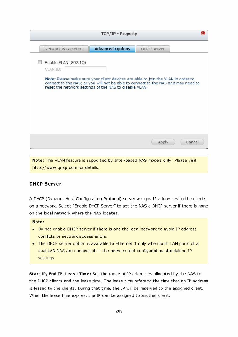
209
Note: The VLAN feature is supported by Intel-based NAS models only. Please visit
http://www.qnap.com for details.
DHCP Server
A DHCP (Dynamic Host Configuration Protocol) server assigns IP addresses to the clients
on a network. Select “Enable DHCP Server” to set the NAS a DHCP server if there is none
on the local network where the NAS locates.
Note:
Do not enable DHCP server if there is one the local network to avoid IP address
conflicts or network access errors.
The DHCP server option is available to Ethernet 1 only when both LAN ports of a
dual LAN NAS are connected to the network and configured as standalone IP
settings.
Start IP, End IP, Lease Tim e: Set the range of IP addresses allocated by the NAS to
the DHCP clients and the lease time. The lease time refers to the time that an IP address
is leased to the clients. During that time, the IP will be reserved to the assigned client.
When the lease time expires, the IP can be assigned to another client.
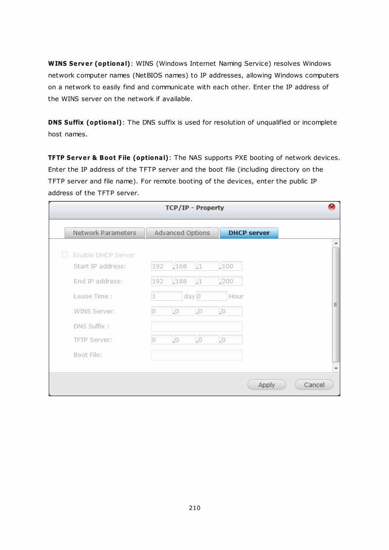
210
WINS Server (optional): WINS (Windows Internet Naming Service) resolves Windows
network computer names (NetBIOS names) to IP addresses, allowing Windows computers
on a network to easily find and communicate with each other. Enter the IP address of
the WINS server on the network if available.
DNS Suffix (optional): The DNS suffix is used for resolution of unqualified or incomplete
host names.
TFTP Server & Boot F ile (optional): The NAS supports PXE booting of network devices.
Enter the IP address of the TFTP server and the boot file (including directory on the
TFTP server and file name). For remote booting of the devices, enter the public IP
address of the TFTP server.
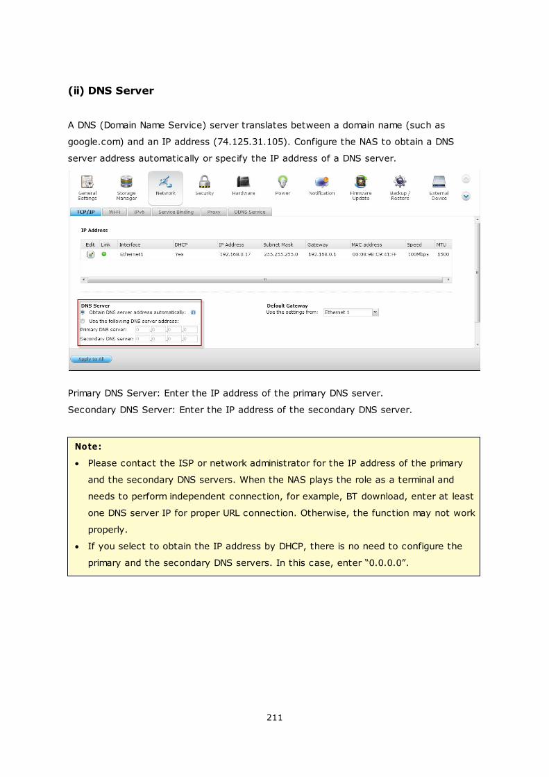
211
(ii) DNS Server
A DNS (Domain Name Service) server translates between a domain name (such as
google.com) and an IP address (74.125.31.105). Configure the NAS to obtain a DNS
server address automatically or specify the IP address of a DNS server.
Primary DNS Server: Enter the IP address of the primary DNS server.
Secondary DNS Server: Enter the IP address of the secondary DNS server.
Note:
Please contact the ISP or network administrator for the IP address of the primary
and the secondary DNS servers. When the NAS plays the role as a terminal and
needs to perform independent connection, for example, BT download, enter at least
one DNS server IP for proper URL connection. Otherwise, the function may not work
properly.
If you select to obtain the IP address by DHCP, there is no need to configure the
primary and the secondary DNS servers. In this case, enter “0.0.0.0”.
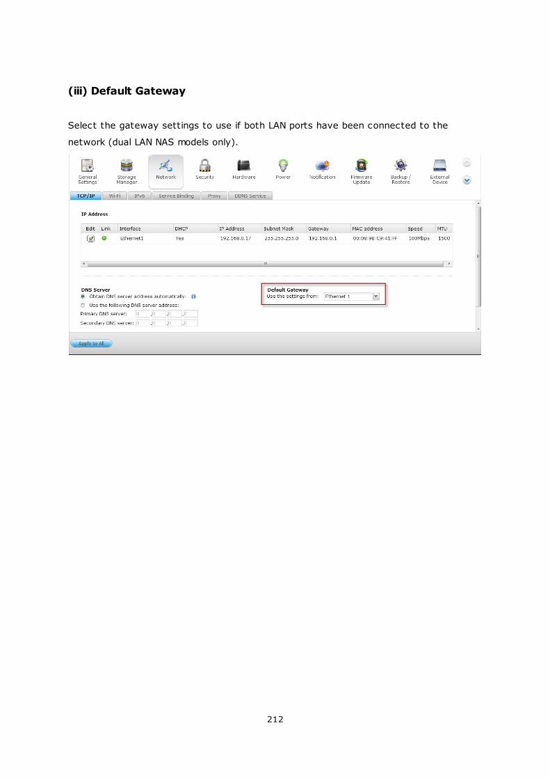
212
(iii) Default Gateway
Select the gateway settings to use if both LAN ports have been connected to the
network (dual LAN NAS models only).
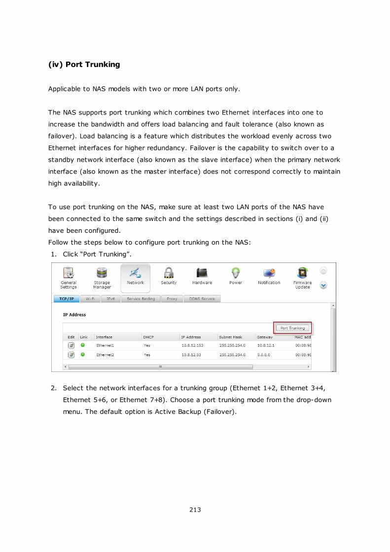
213
(iv) Port Trunking
Applicable to NAS models with two or more LAN ports only.
The NAS supports port trunking which combines two Ethernet interfaces into one to
increase the bandwidth and offers load balancing and fault tolerance (also known as
failover). Load balancing is a feature which distributes the workload evenly across two
Ethernet interfaces for higher redundancy. Failover is the capability to switch over to a
standby network interface (also known as the slave interface) when the primary network
interface (also known as the master interface) does not correspond correctly to maintain
high availability.
To use port trunking on the NAS, make sure at least two LAN ports of the NAS have
been connected to the same switch and the settings described in sections (i) and (ii)
have been configured.
Follow the steps below to configure port trunking on the NAS:
1. Click “Port Trunking”.
2. Select the network interfaces for a trunking group (Ethernet 1+2, Ethernet 3+4,
Ethernet 5+6, or Ethernet 7+8). Choose a port trunking mode from the drop-down
menu. The default option is Active Backup (Failover).
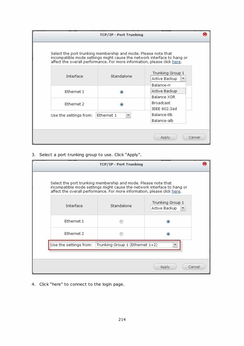
214
3. Select a port trunking group to use. Click “Apply”.
4. Click “here” to connect to the login page.
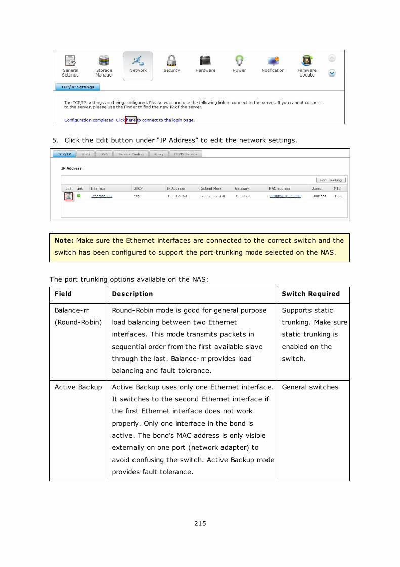
215
5. Click the Edit button under “IP Address” to edit the network settings.
Note: Make sure the Ethernet interfaces are connected to the correct switch and the
switch has been configured to support the port trunking mode selected on the NAS.
The port trunking options available on the NAS:
Field Description Switch Required
Balance-rr
(Round-Robin)
Round-Robin mode is good for general purpose
load balancing between two Ethernet
interfaces. This mode transmits packets in
sequential order from the first available slave
through the last. Balance-rr provides load
balancing and fault tolerance.
Supports static
trunking. Make sure
static trunking is
enabled on the
switch.
Active Backup Active Backup uses only one Ethernet interface.
It switches to the second Ethernet interface if
the first Ethernet interface does not work
properly. Only one interface in the bond is
active. The bond's MAC address is only visible
externally on one port (network adapter) to
avoid confusing the switch. Active Backup mode
provides fault tolerance.
General switches
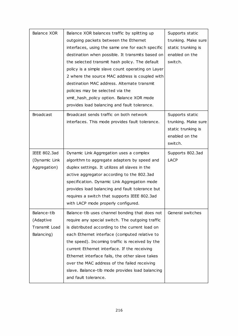
216
Balance XOR Balance XOR balances traffic by splitting up
outgoing packets between the Ethernet
interfaces, using the same one for each specific
destination when possible. It transmits based on
the selected transmit hash policy. The default
policy is a simple slave count operating on Layer
2 where the source MAC address is coupled with
destination MAC address. Alternate transmit
policies may be selected via the
xmit_hash_policy option. Balance XOR mode
provides load balancing and fault tolerance.
Supports static
trunking. Make sure
static trunking is
enabled on the
switch.
Broadcast Broadcast sends traffic on both network
interfaces. This mode provides fault tolerance.
Supports static
trunking. Make sure
static trunking is
enabled on the
switch.
IEEE 802.3ad
(Dynamic Link
Aggregation)
Dynamic Link Aggregation uses a complex
algorithm to aggregate adapters by speed and
duplex settings. It utilizes all slaves in the
active aggregator according to the 802.3ad
specification. Dynamic Link Aggregation mode
provides load balancing and fault tolerance but
requires a switch that supports IEEE 802.3ad
with LACP mode properly configured.
Supports 802.3ad
LACP
Balance-tlb
(Adaptive
Transmit Load
Balancing)
Balance-tlb uses channel bonding that does not
require any special switch. The outgoing traffic
is distributed according to the current load on
each Ethernet interface (computed relative to
the speed). Incoming traffic is received by the
current Ethernet interface. If the receiving
Ethernet interface fails, the other slave takes
over the MAC address of the failed receiving
slave. Balance-tlb mode provides load balancing
and fault tolerance.
General switches
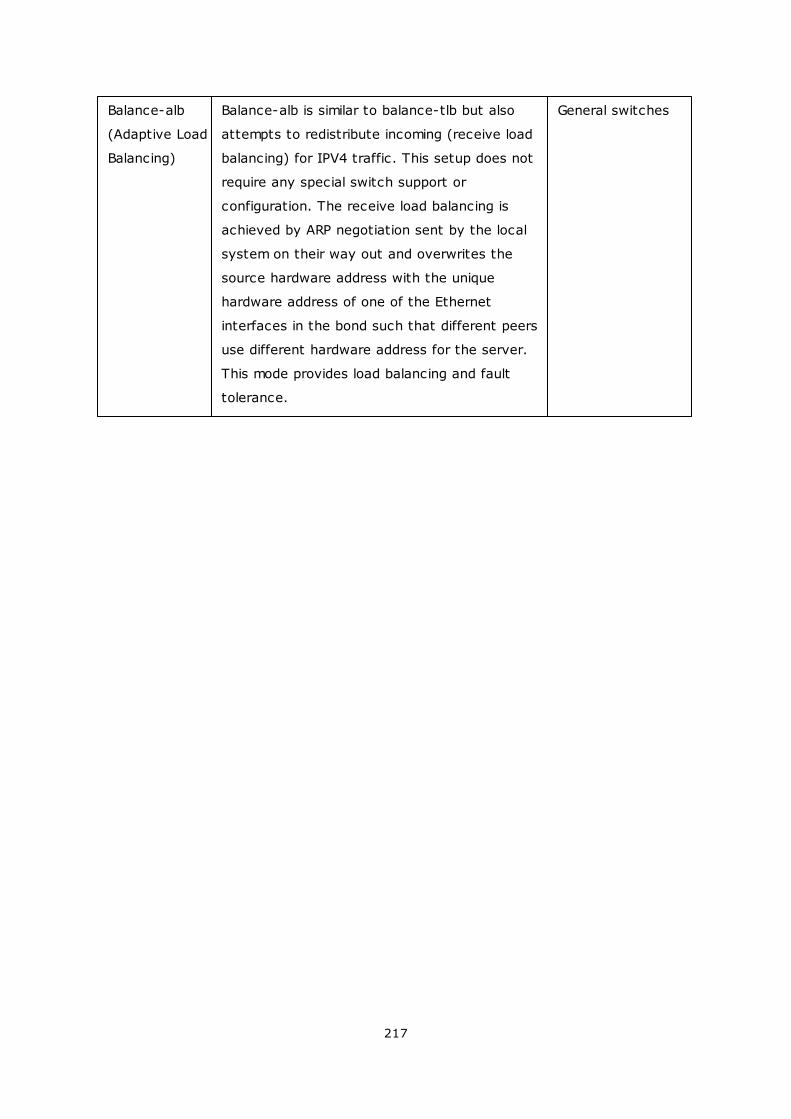
217
Balance-alb
(Adaptive Load
Balancing)
Balance-alb is similar to balance-tlb but also
attempts to redistribute incoming (receive load
balancing) for IPV4 traffic. This setup does not
require any special switch support or
configuration. The receive load balancing is
achieved by ARP negotiation sent by the local
system on their way out and overwrites the
source hardware address with the unique
hardware address of one of the Ethernet
interfaces in the bond such that different peers
use different hardware address for the server.
This mode provides load balancing and fault
tolerance.
General switches
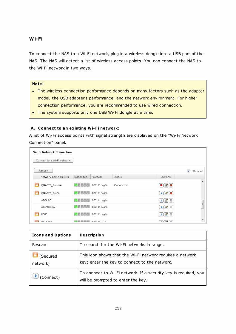
218
Wi-Fi
To connect the NAS to a Wi-Fi network, plug in a wireless dongle into a USB port of the
NAS. The NAS will detect a list of wireless access points. You can connect the NAS to
the Wi-Fi network in two ways.
Note:
The wireless connection performance depends on many factors such as the adapter
model, the USB adapter's performance, and the network environment. For higher
connection performance, you are recommended to use wired connection.
The system supports only one USB Wi-Fi dongle at a time.
A. Connect to an existing Wi-F i network:
A list of Wi-Fi access points with signal strength are displayed on the “Wi-Fi Network
Connection” panel.
Icons and Options Description
Rescan To search for the Wi-Fi networks in range.
(Secured
network)
This icon shows that the Wi-Fi network requires a network
key; enter the key to connect to the network.
(Connect)To connect to Wi-Fi network. If a security key is required, you
will be prompted to enter the key.
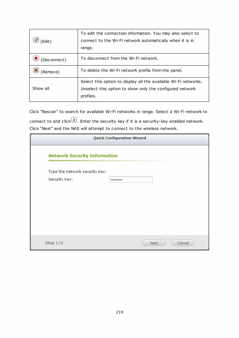
219
(Edit)
To edit the connection information. You may also select to
connect to the Wi-Fi network automatically when it is in
range.
(Disconnect) To disconnect from the Wi-Fi network.
(Remove) To delete the Wi-Fi network profile from the panel.
Show all
Select this option to display all the available Wi-Fi networks.
Unselect this option to show only the configured network
profiles.
Click “Rescan” to search for available Wi-Fi networks in range. Select a Wi-Fi network to
connect to and click . Enter the security key if it is a security-key enabled network.
Click “Next” and the NAS will attempt to connect to the wireless network.
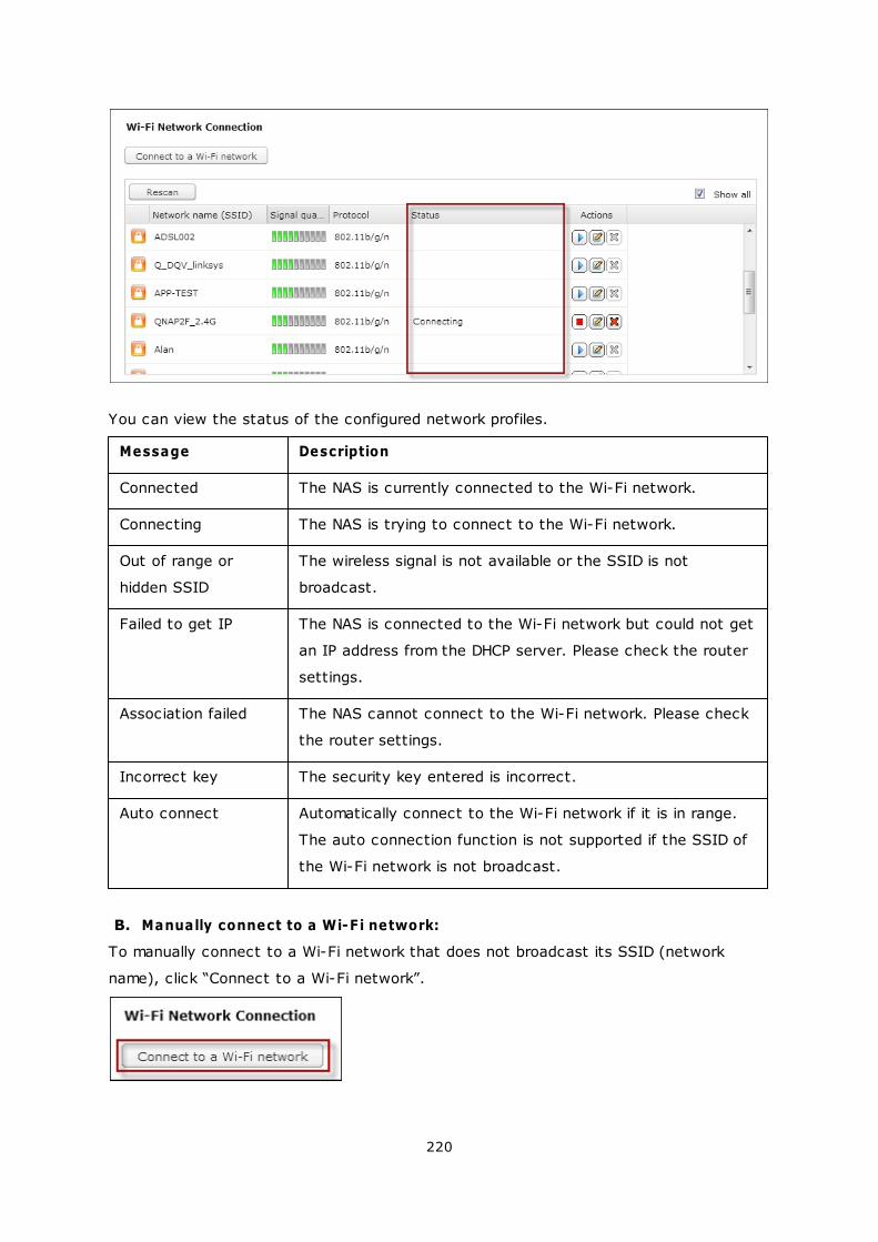
220
You can view the status of the configured network profiles.
Message Description
Connected The NAS is currently connected to the Wi-Fi network.
Connecting The NAS is trying to connect to the Wi-Fi network.
Out of range or
hidden SSID
The wireless signal is not available or the SSID is not
broadcast.
Failed to get IP The NAS is connected to the Wi-Fi network but could not get
an IP address from the DHCP server. Please check the router
settings.
Association failed The NAS cannot connect to the Wi-Fi network. Please check
the router settings.
Incorrect key The security key entered is incorrect.
Auto connect Automatically connect to the Wi-Fi network if it is in range.
The auto connection function is not supported if the SSID of
the Wi-Fi network is not broadcast.
B. Manually connect to a Wi-F i network:
To manually connect to a Wi-Fi network that does not broadcast its SSID (network
name), click “Connect to a Wi-Fi network”.
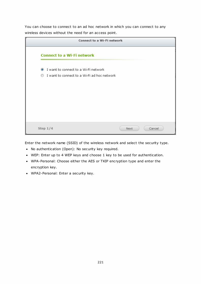
221
You can choose to connect to an ad hoc network in which you can connect to any
wireless devices without the need for an access point.
Enter the network name (SSID) of the wireless network and select the security type.
No authentication (Open): No security key required.
WEP: Enter up to 4 WEP keys and choose 1 key to be used for authentication.
WPA-Personal: Choose either the AES or TKIP encryption type and enter the
encryption key.
WPA2-Personal: Enter a security key.
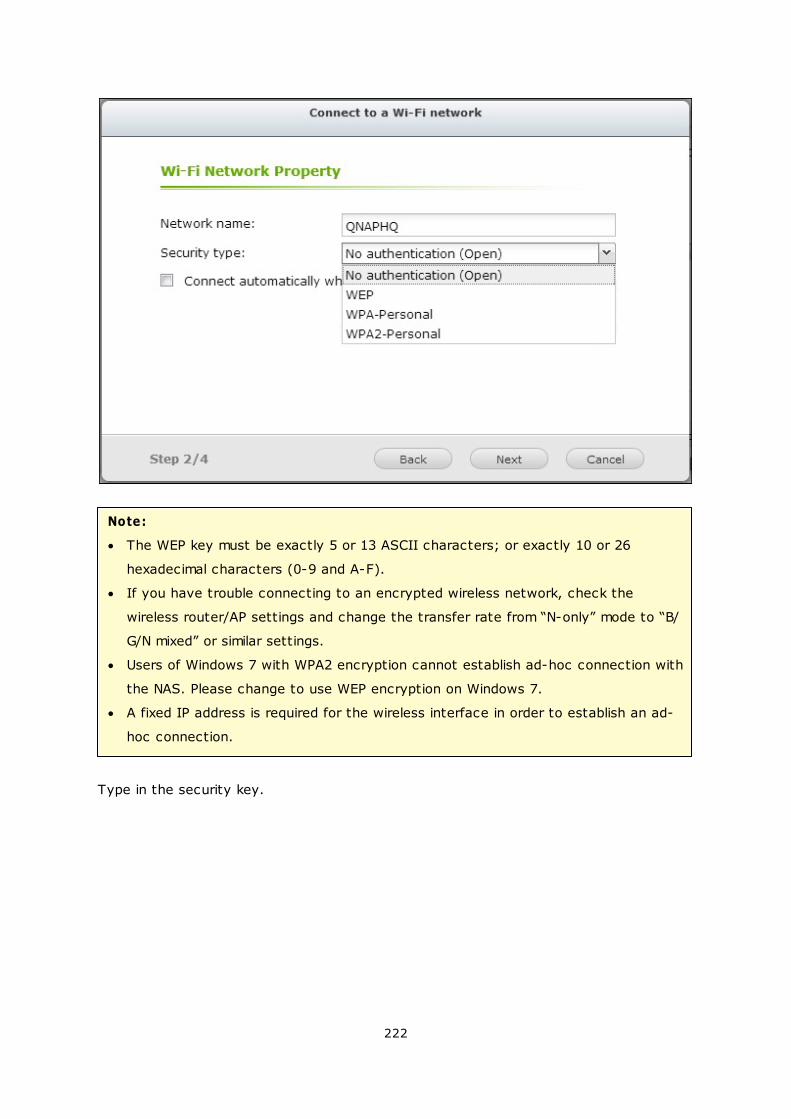
222
Note:
The WEP key must be exactly 5 or 13 ASCII characters; or exactly 10 or 26
hexadecimal characters (0-9 and A-F).
If you have trouble connecting to an encrypted wireless network, check the
wireless router/AP settings and change the transfer rate from “N-only” mode to “B/
G/N mixed” or similar settings.
Users of Windows 7 with WPA2 encryption cannot establish ad-hoc connection with
the NAS. Please change to use WEP encryption on Windows 7.
A fixed IP address is required for the wireless interface in order to establish an ad-
hoc connection.
Type in the security key.
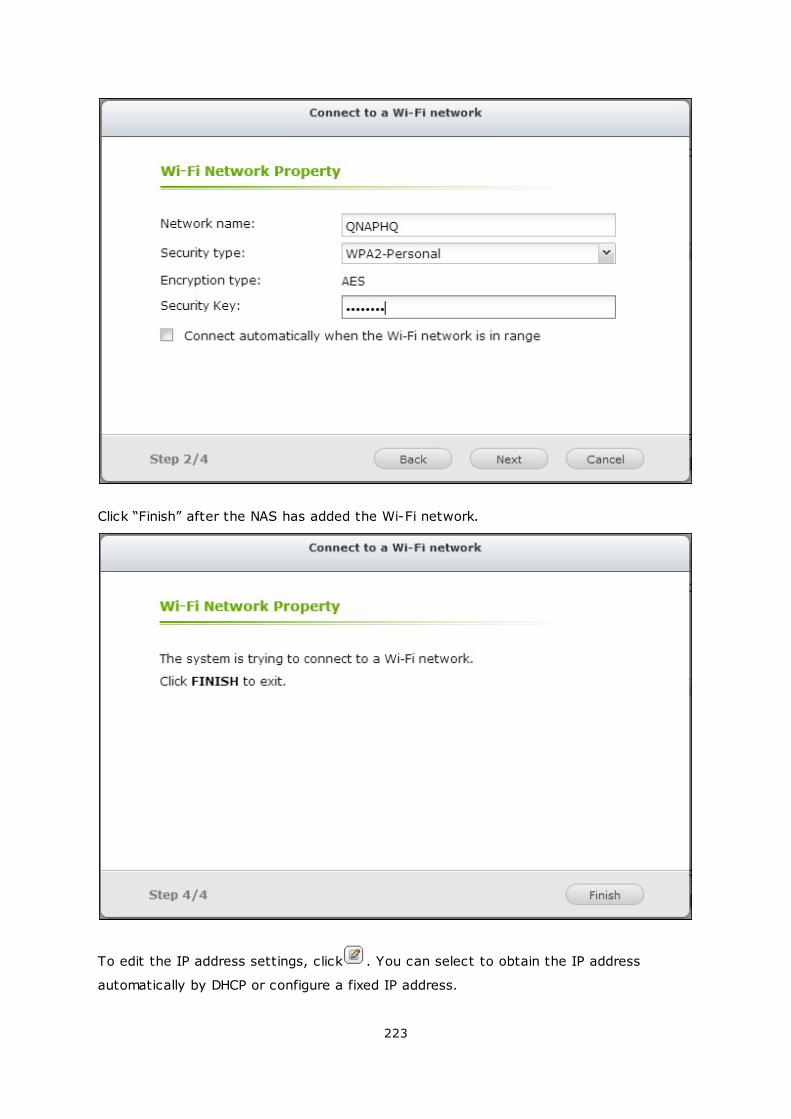
223
Click “Finish” after the NAS has added the Wi-Fi network.
To edit the IP address settings, click . You can select to obtain the IP address
automatically by DHCP or configure a fixed IP address.
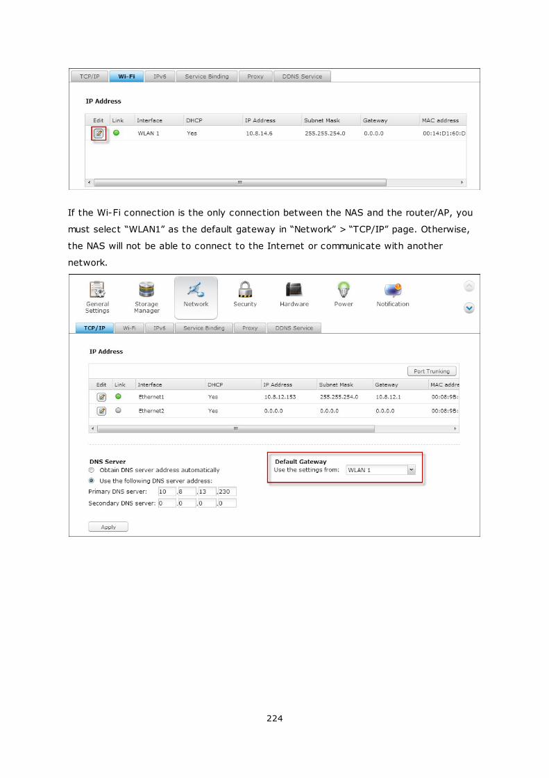
224
If the Wi-Fi connection is the only connection between the NAS and the router/AP, you
must select “WLAN1” as the default gateway in “Network” > “TCP/IP” page. Otherwise,
the NAS will not be able to connect to the Internet or communicate with another
network.
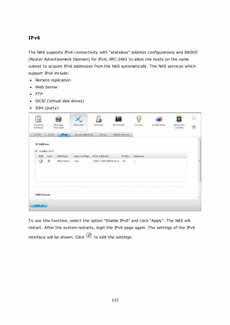
225
IPv6
The NAS supports IPv6 connectivity with “stateless” address configurations and RADVD
(Router Advertisement Daemon) for IPv6, RFC 2461 to allow the hosts on the same
subnet to acquire IPv6 addresses from the NAS automatically. The NAS services which
support IPv6 include:
Remote replication
Web Server
FTP
iSCSI (Virtual disk drives)
SSH (putty)
To use this function, select the option “Enable IPv6” and click “Apply”. The NAS will
restart. After the system restarts, login the IPv6 page again. The settings of the IPv6
interface will be shown. Click to edit the settings.
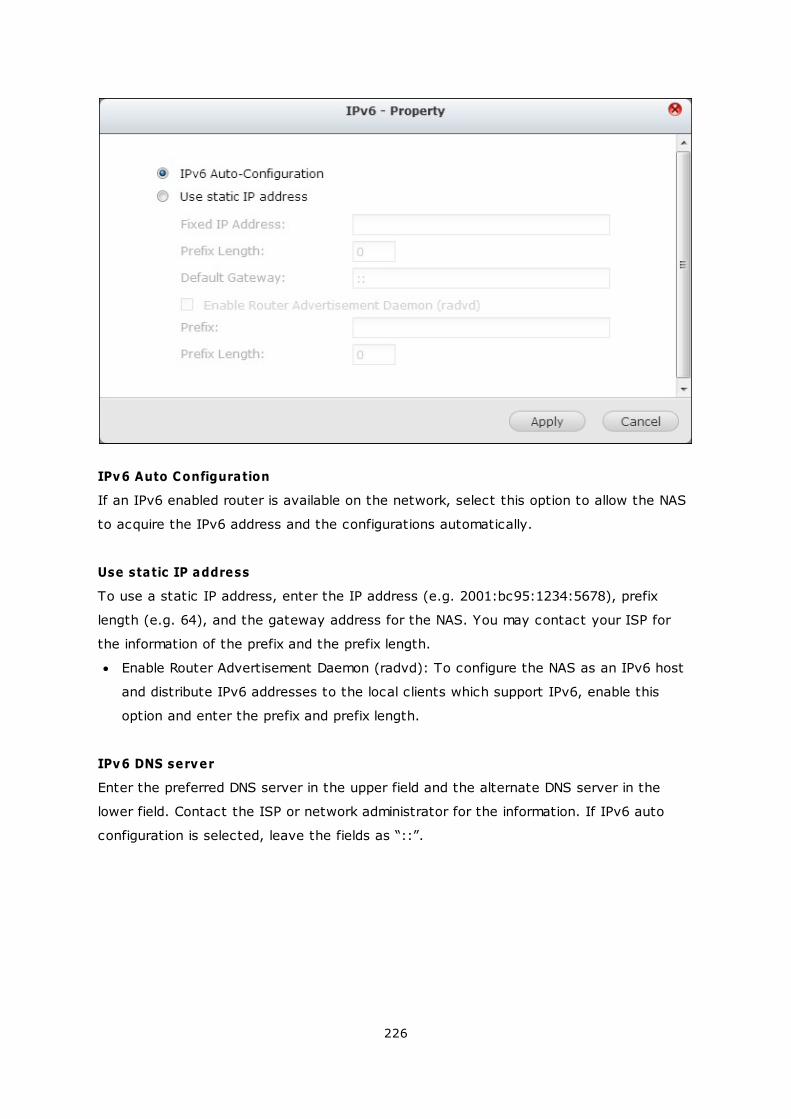
226
IPv6 Auto Configuration
If an IPv6 enabled router is available on the network, select this option to allow the NAS
to acquire the IPv6 address and the configurations automatically.
Use static IP address
To use a static IP address, enter the IP address (e.g. 2001:bc95:1234:5678), prefix
length (e.g. 64), and the gateway address for the NAS. You may contact your ISP for
the information of the prefix and the prefix length.
Enable Router Advertisement Daemon (radvd): To configure the NAS as an IPv6 host
and distribute IPv6 addresses to the local clients which support IPv6, enable this
option and enter the prefix and prefix length.
IPv6 DNS server
Enter the preferred DNS server in the upper field and the alternate DNS server in the
lower field. Contact the ISP or network administrator for the information. If IPv6 auto
configuration is selected, leave the fields as “::”.
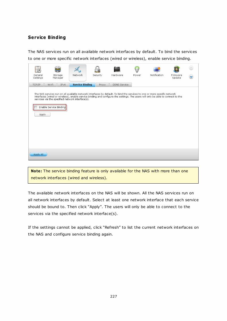
227
Service Binding
The NAS services run on all available network interfaces by default. To bind the services
to one or more specific network interfaces (wired or wireless), enable service binding.
Note: The service binding feature is only available for the NAS with more than one
network interfaces (wired and wireless).
The available network interfaces on the NAS will be shown. All the NAS services run on
all network interfaces by default. Select at least one network interface that each service
should be bound to. Then click “Apply”. The users will only be able to connect to the
services via the specified network interface(s).
If the settings cannot be applied, click “Refresh” to list the current network interfaces on
the NAS and configure service binding again.
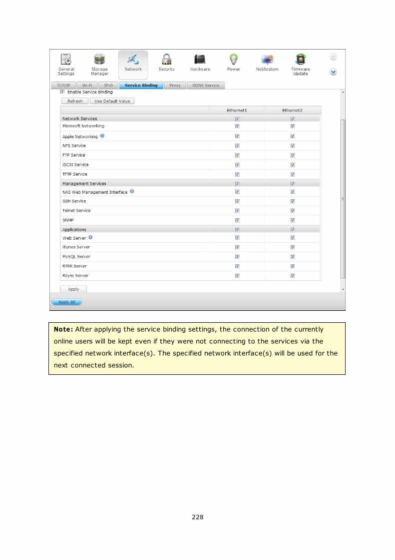
228
Note: After applying the service binding settings, the connection of the currently
online users will be kept even if they were not connecting to the services via the
specified network interface(s). The specified network interface(s) will be used for the
next connected session.
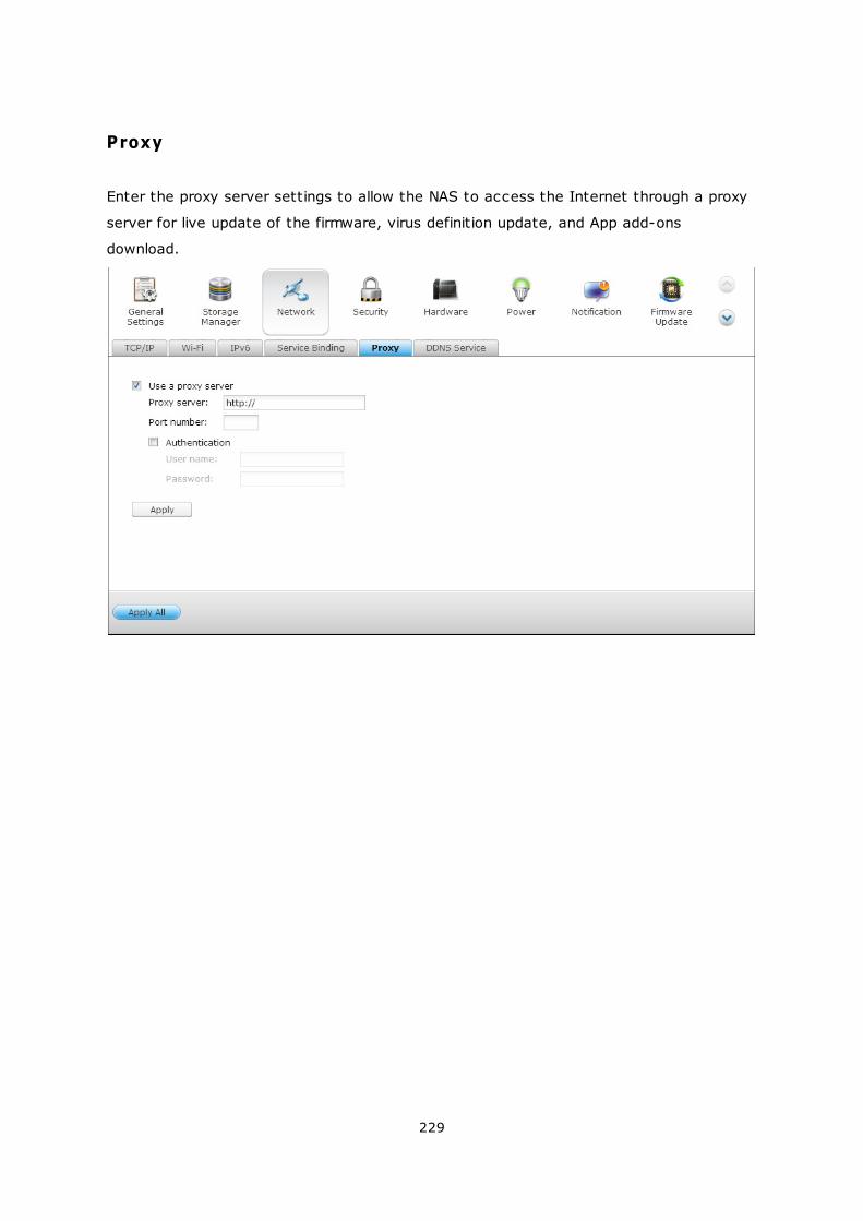
229
Proxy
Enter the proxy server settings to allow the NAS to access the Internet through a proxy
server for live update of the firmware, virus definition update, and App add-ons
download.
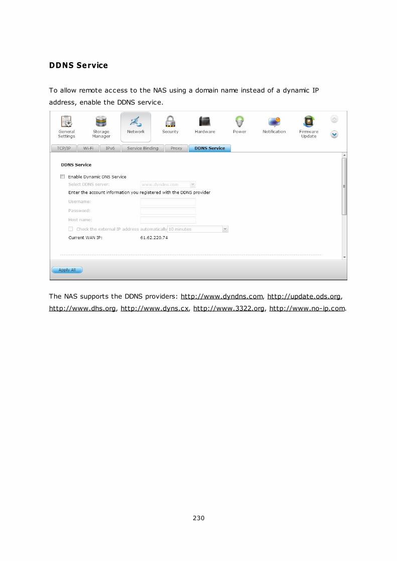
230
DDNS Service
To allow remote access to the NAS using a domain name instead of a dynamic IP
address, enable the DDNS service.
The NAS supports the DDNS providers: http://www.dyndns.com, http://update.ods.org,
http://www.dhs.org, http://www.dyns.cx, http://www.3322.org, http://www.no-ip.com.
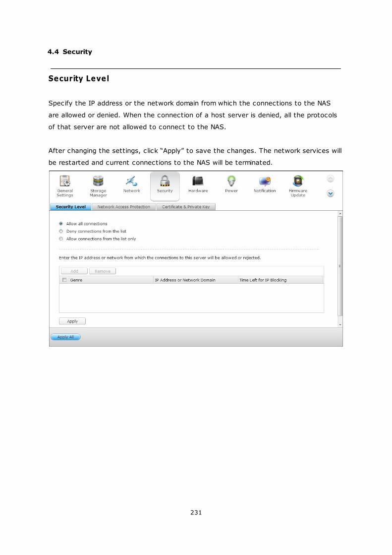
231
4.4 Security
Security Level
Specify the IP address or the network domain from which the connections to the NAS
are allowed or denied. When the connection of a host server is denied, all the protocols
of that server are not allowed to connect to the NAS.
After changing the settings, click “Apply” to save the changes. The network services will
be restarted and current connections to the NAS will be terminated.
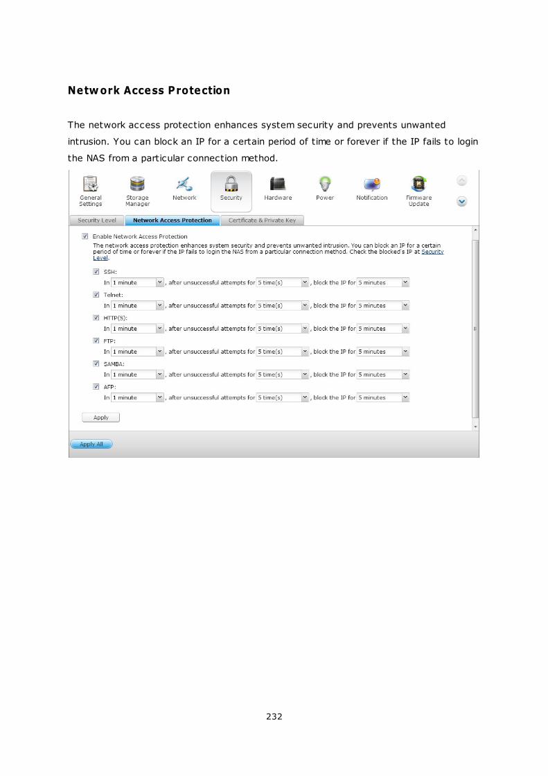
232
Network Access Protection
The network access protection enhances system security and prevents unwanted
intrusion. You can block an IP for a certain period of time or forever if the IP fails to login
the NAS from a particular connection method.
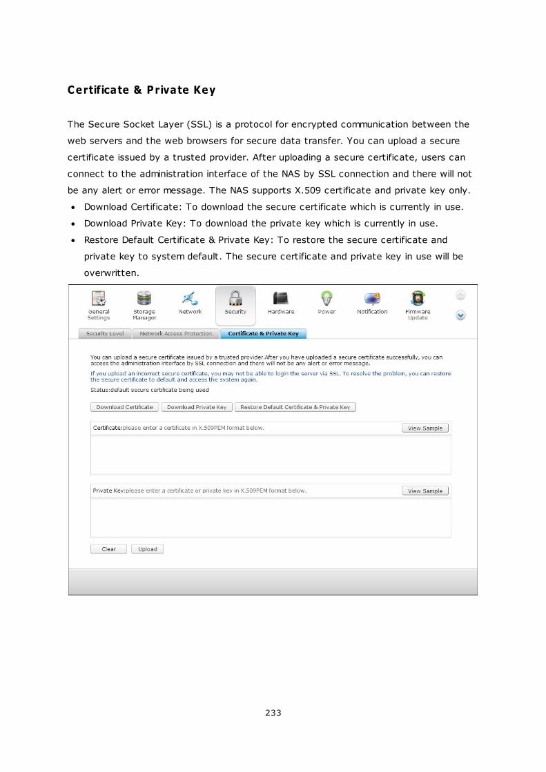
233
Certificate & Private Key
The Secure Socket Layer (SSL) is a protocol for encrypted communication between the
web servers and the web browsers for secure data transfer. You can upload a secure
certificate issued by a trusted provider. After uploading a secure certificate, users can
connect to the administration interface of the NAS by SSL connection and there will not
be any alert or error message. The NAS supports X.509 certificate and private key only.
Download Certificate: To download the secure certificate which is currently in use.
Download Private Key: To download the private key which is currently in use.
Restore Default Certificate & Private Key: To restore the secure certificate and
private key to system default. The secure certificate and private key in use will be
overwritten.
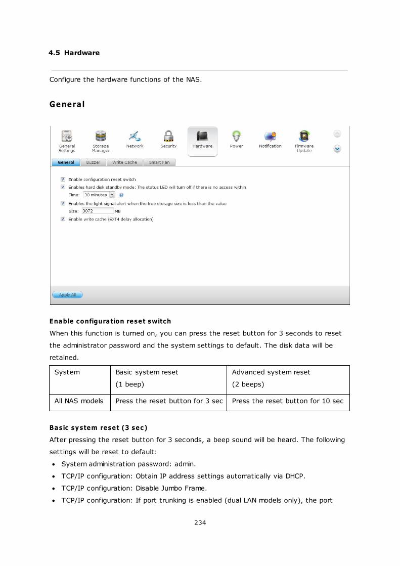
234
4.5 Hardware
Configure the hardware functions of the NAS.
General
Enable configuration reset switch
When this function is turned on, you can press the reset button for 3 seconds to reset
the administrator password and the system settings to default. The disk data will be
retained.
System Basic system reset
(1 beep)
Advanced system reset
(2 beeps)
All NAS models Press the reset button for 3 sec Press the reset button for 10 sec
Basic system reset (3 sec)
After pressing the reset button for 3 seconds, a beep sound will be heard. The following
settings will be reset to default:
System administration password: admin.
TCP/IP configuration: Obtain IP address settings automatically via DHCP.
TCP/IP configuration: Disable Jumbo Frame.
TCP/IP configuration: If port trunking is enabled (dual LAN models only), the port
235
trunking mode will be reset to “Active Backup (Failover)”.
System port: 8080 (system service port).
Security level: Low (Allow all connections).
LCD panel password: (blank)*.
VLAN will be disabled.
Service binding: All NAS services run on all available network interfaces.
*This feature is only provided by the NAS models with LCD panels. Please visit http://
www.qnap.com for details.
Advanced system reset (10 sec)
After pressing the reset button for 10 seconds, you will hear two beeps at the third and
the tenth seconds. The NAS will reset all the system settings to default as it does by
the web-based system reset in “Administration” > “Restore to Factory Default” except all
the data are reserved. The settings such as the users, user groups, and the shared
folders previously created will be cleared. To retrieve the old data after advanced
system reset, create the same shared folders on the NAS and the data will be accessible
again.
Enable hard disk standby m ode
This option allows the hard drives on the NAS to enter standby mode if there is no disk
access within the specified period.
Enable light signal alert when the free size of SATA disk is less than the value:
The status LED flashes red and green when this option is turned on and the free space
of the SATA hard drive is less than the value. The valid range of the value is 1-51200
MB.
Enable write cache (EXT4 only)
If the disk volume of the NAS is formatted as EXT4, turn on this option for higher write
performance. Note that an unexpected system shutdown may lead to incomplete data
transfer when data write is in process. This option will be turned off when any of the
following services is enabled: Download Station, MySQL service, user quota, and
Surveillance Station. You are recommended to turn this option off if the NAS is set as a
shared storage in a virtualized or clustered environment.
Enable warning alert for redundant power supply on the web-based interface:
If two power supply units (PSU) are installed on the NAS and connected to the power
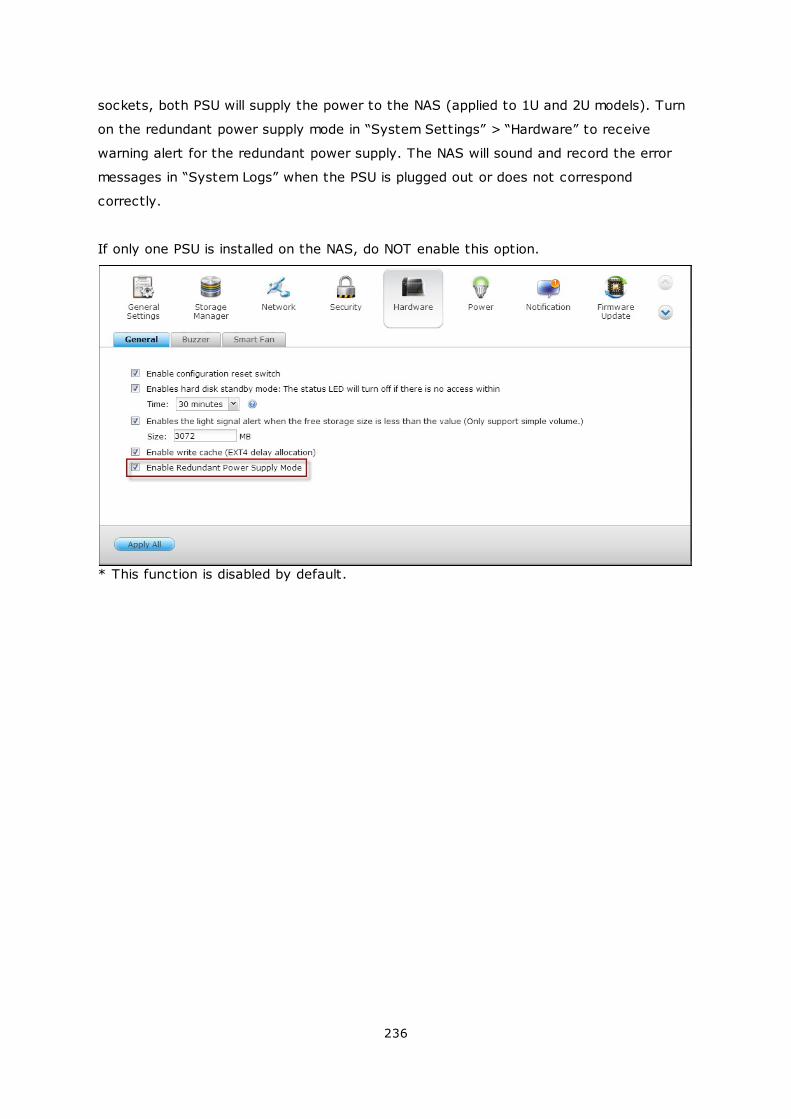
236
sockets, both PSU will supply the power to the NAS (applied to 1U and 2U models). Turn
on the redundant power supply mode in “System Settings” > “Hardware” to receive
warning alert for the redundant power supply. The NAS will sound and record the error
messages in “System Logs” when the PSU is plugged out or does not correspond
correctly.
If only one PSU is installed on the NAS, do NOT enable this option.
* This function is disabled by default.
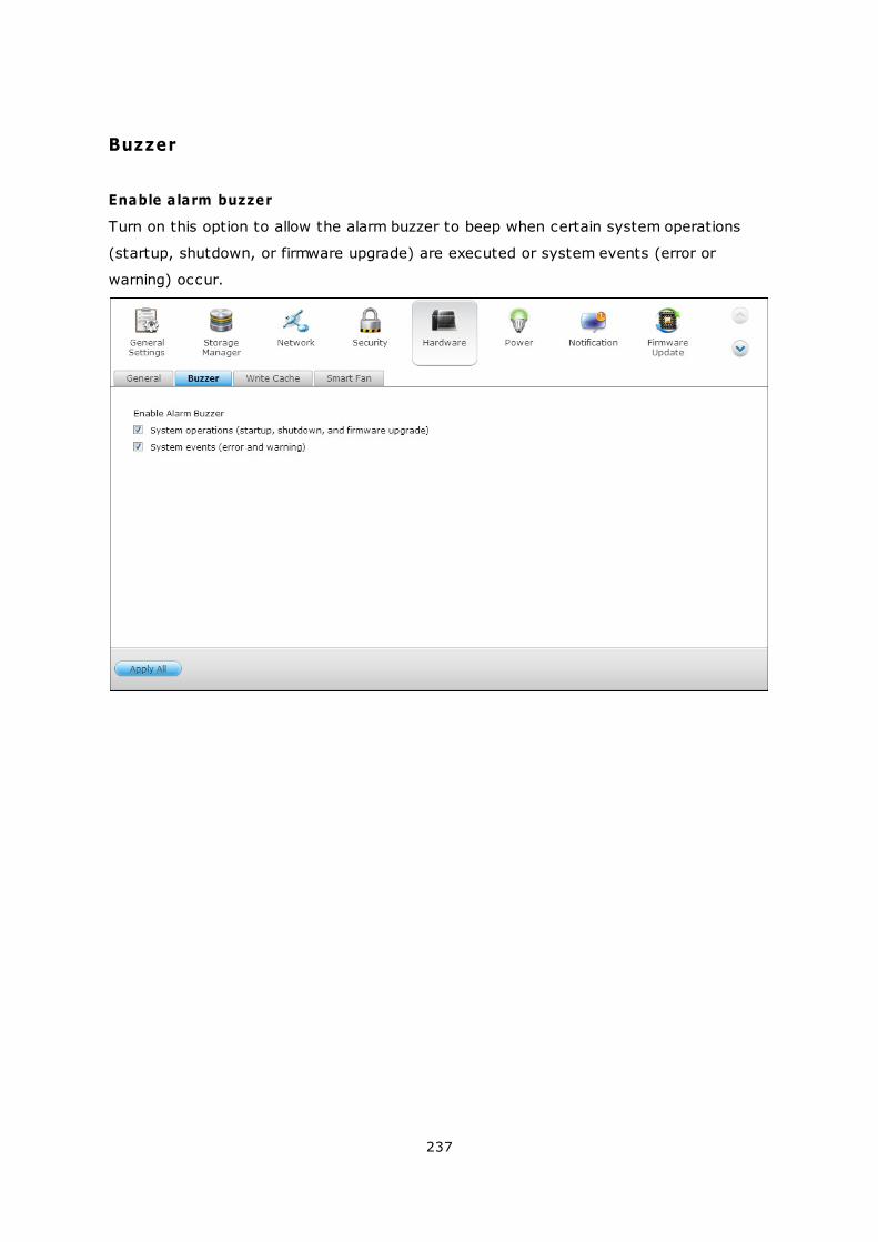
237
Buzzer
Enable alarm buzzer
Turn on this option to allow the alarm buzzer to beep when certain system operations
(startup, shutdown, or firmware upgrade) are executed or system events (error or
warning) occur.
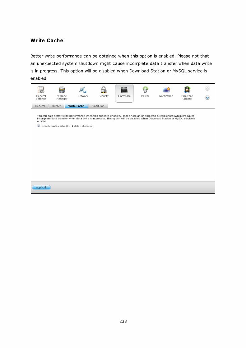
238
Write Cache
Better write performance can be obtained when this option is enabled. Please not that
an unexpected system shutdown might cause incomplete data transfer when data write
is in progress. This option will be disabled when Download Station or MySQL service is
enabled.
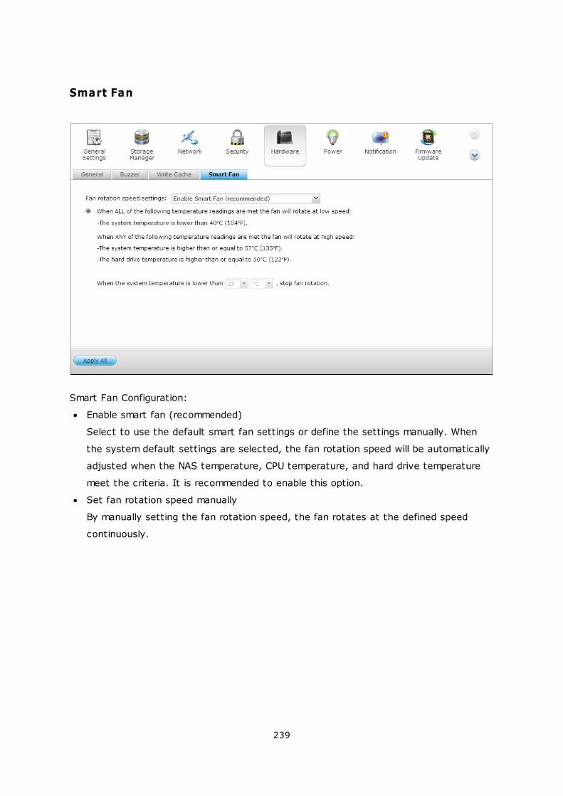
239
Smart Fan
Smart Fan Configuration:
Enable smart fan (recommended)
Select to use the default smart fan settings or define the settings manually. When
the system default settings are selected, the fan rotation speed will be automatically
adjusted when the NAS temperature, CPU temperature, and hard drive temperature
meet the criteria. It is recommended to enable this option.
Set fan rotation speed manually
By manually setting the fan rotation speed, the fan rotates at the defined speed
continuously.
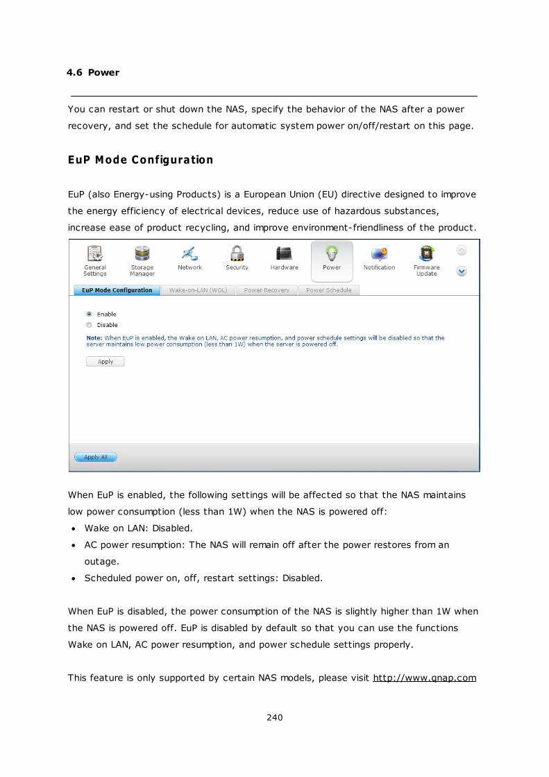
240
4.6 Power
You can restart or shut down the NAS, specify the behavior of the NAS after a power
recovery, and set the schedule for automatic system power on/off/restart on this page.
EuP Mode Configuration
EuP (also Energy-using Products) is a European Union (EU) directive designed to improve
the energy efficiency of electrical devices, reduce use of hazardous substances,
increase ease of product recycling, and improve environment-friendliness of the product.
When EuP is enabled, the following settings will be affected so that the NAS maintains
low power consumption (less than 1W) when the NAS is powered off:
Wake on LAN: Disabled.
AC power resumption: The NAS will remain off after the power restores from an
outage.
Scheduled power on, off, restart settings: Disabled.
When EuP is disabled, the power consumption of the NAS is slightly higher than 1W when
the NAS is powered off. EuP is disabled by default so that you can use the functions
Wake on LAN, AC power resumption, and power schedule settings properly.
This feature is only supported by certain NAS models, please visit http://www.qnap.com

241
for details.
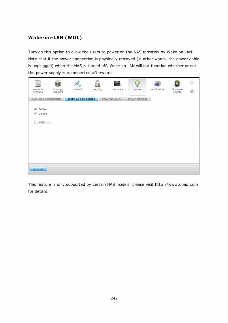
242
Wake-on-LAN (WOL)
Turn on this option to allow the users to power on the NAS remotely by Wake on LAN.
Note that if the power connection is physically removed (in other words, the power cable
is unplugged) when the NAS is turned off, Wake on LAN will not function whether or not
the power supply is reconnected afterwards.
This feature is only supported by certain NAS models, please visit http://www.qnap.com
for details.
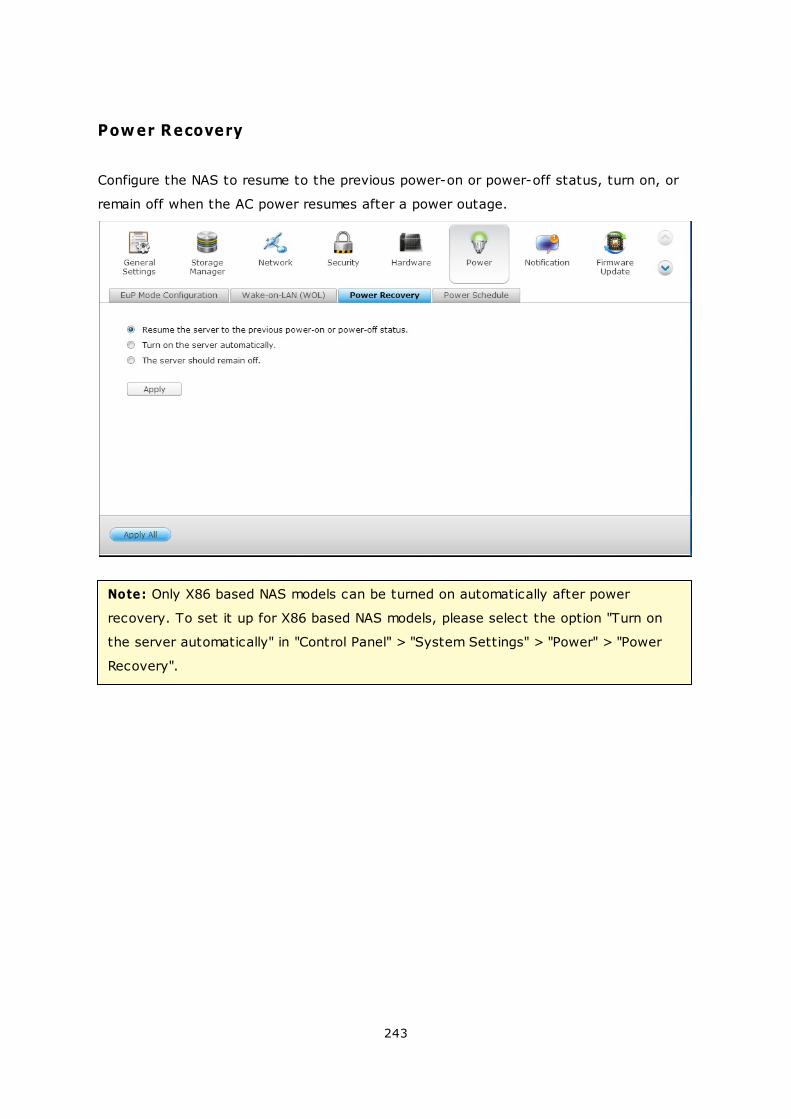
243
Power Recovery
Configure the NAS to resume to the previous power-on or power-off status, turn on, or
remain off when the AC power resumes after a power outage.
Note: Only X86 based NAS models can be turned on automatically after power
recovery. To set it up for X86 based NAS models, please select the option "Turn on
the server automatically" in "Control Panel" > "System Settings" > "Power" > "Power
Recovery".
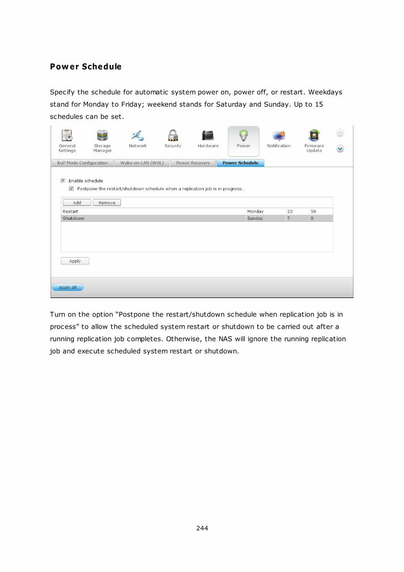
244
Power Schedule
Specify the schedule for automatic system power on, power off, or restart. Weekdays
stand for Monday to Friday; weekend stands for Saturday and Sunday. Up to 15
schedules can be set.
Turn on the option “Postpone the restart/shutdown schedule when replication job is in
process” to allow the scheduled system restart or shutdown to be carried out after a
running replication job completes. Otherwise, the NAS will ignore the running replication
job and execute scheduled system restart or shutdown.
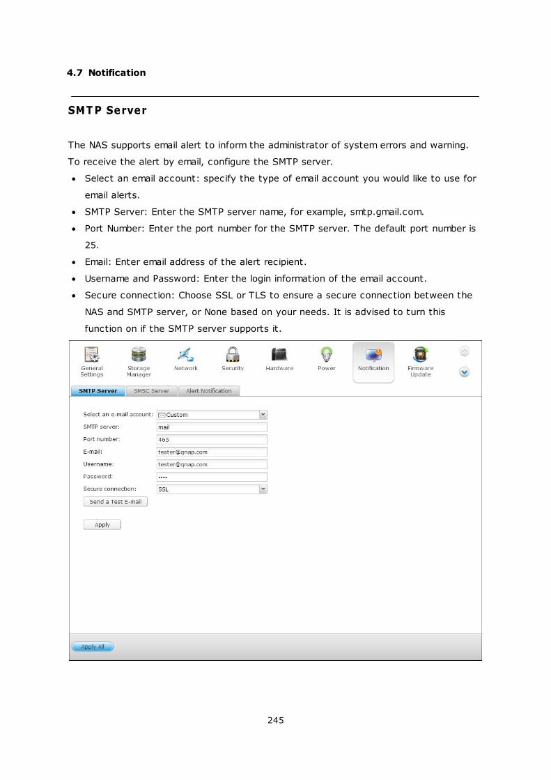
245
4.7 Notification
SMT P Server
The NAS supports email alert to inform the administrator of system errors and warning.
To receive the alert by email, configure the SMTP server.
Select an email account: specify the type of email account you would like to use for
email alerts.
SMTP Server: Enter the SMTP server name, for example, smtp.gmail.com.
Port Number: Enter the port number for the SMTP server. The default port number is
25.
Email: Enter email address of the alert recipient.
Username and Password: Enter the login information of the email account.
Secure connection: Choose SSL or TLS to ensure a secure connection between the
NAS and SMTP server, or None based on your needs. It is advised to turn this
function on if the SMTP server supports it.
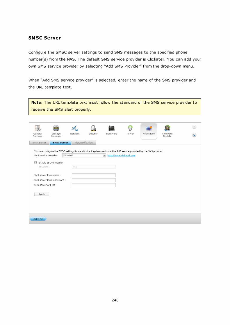
246
SMSC Server
Configure the SMSC server settings to send SMS messages to the specified phone
number(s) from the NAS. The default SMS service provider is Clickatell. You can add your
own SMS service provider by selecting “Add SMS Provider” from the drop-down menu.
When “Add SMS service provider” is selected, enter the name of the SMS provider and
the URL template text.
Note: The URL template text must follow the standard of the SMS service provider to
receive the SMS alert properly.
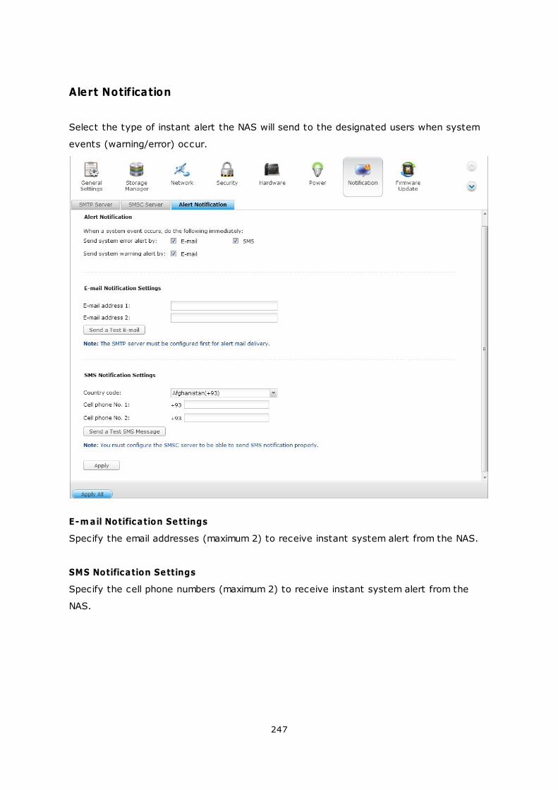
247
Alert Notification
Select the type of instant alert the NAS will send to the designated users when system
events (warning/error) occur.
E-m ail Notification Settings
Specify the email addresses (maximum 2) to receive instant system alert from the NAS.
SMS Notification Settings
Specify the cell phone numbers (maximum 2) to receive instant system alert from the
NAS.
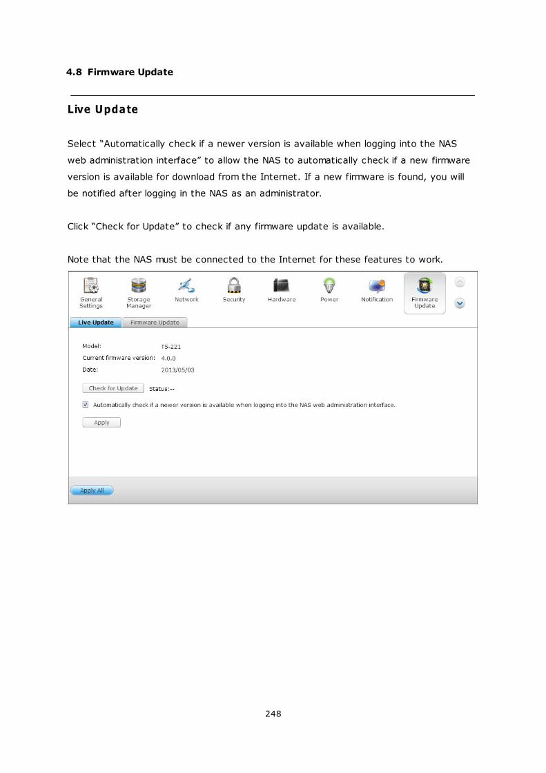
248
4.8 Firmware Update
Live Update
Select “Automatically check if a newer version is available when logging into the NAS
web administration interface” to allow the NAS to automatically check if a new firmware
version is available for download from the Internet. If a new firmware is found, you will
be notified after logging in the NAS as an administrator.
Click “Check for Update” to check if any firmware update is available.
Note that the NAS must be connected to the Internet for these features to work.
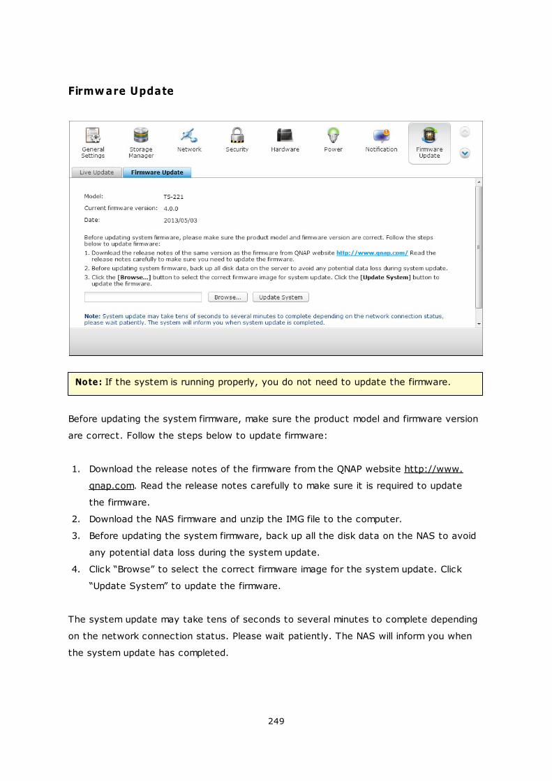
249
Firmware Update
Note: If the system is running properly, you do not need to update the firmware.
Before updating the system firmware, make sure the product model and firmware version
are correct. Follow the steps below to update firmware:
1. Download the release notes of the firmware from the QNAP website http://www.
qnap.com. Read the release notes carefully to make sure it is required to update
the firmware.
2. Download the NAS firmware and unzip the IMG file to the computer.
3. Before updating the system firmware, back up all the disk data on the NAS to avoid
any potential data loss during the system update.
4. Click “Browse” to select the correct firmware image for the system update. Click
“Update System” to update the firmware.
The system update may take tens of seconds to several minutes to complete depending
on the network connection status. Please wait patiently. The NAS will inform you when
the system update has completed.
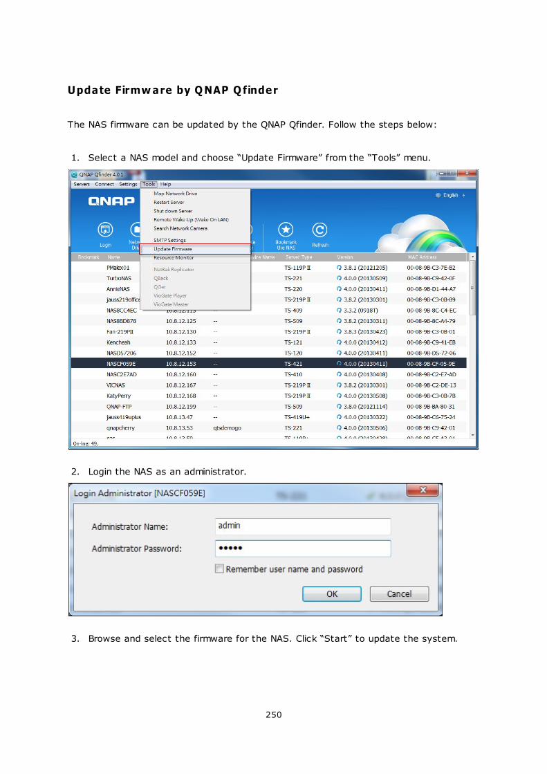
250
Update Firmware by QNAP Qfinder
The NAS firmware can be updated by the QNAP Qfinder. Follow the steps below:
1. Select a NAS model and choose “Update Firmware” from the “Tools” menu.
2. Login the NAS as an administrator.
3. Browse and select the firmware for the NAS. Click “Start” to update the system.
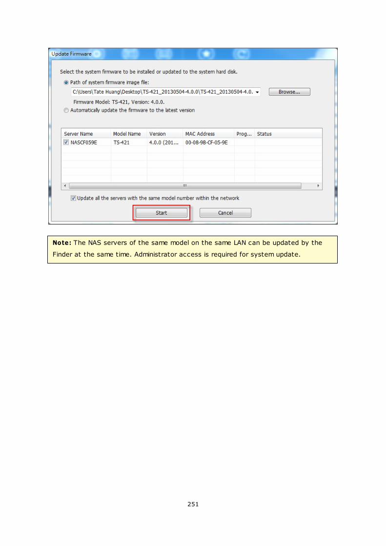
251
Note: The NAS servers of the same model on the same LAN can be updated by the
Finder at the same time. Administrator access is required for system update.
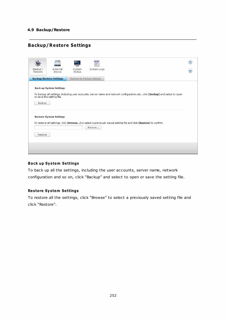
252
4.9 Backup/Restore
Backup/Restore Settings
Back up System Settings
To back up all the settings, including the user accounts, server name, network
configuration and so on, click “Backup” and select to open or save the setting file.
Restore System Settings
To restore all the settings, click “Browse” to select a previously saved setting file and
click “Restore”.
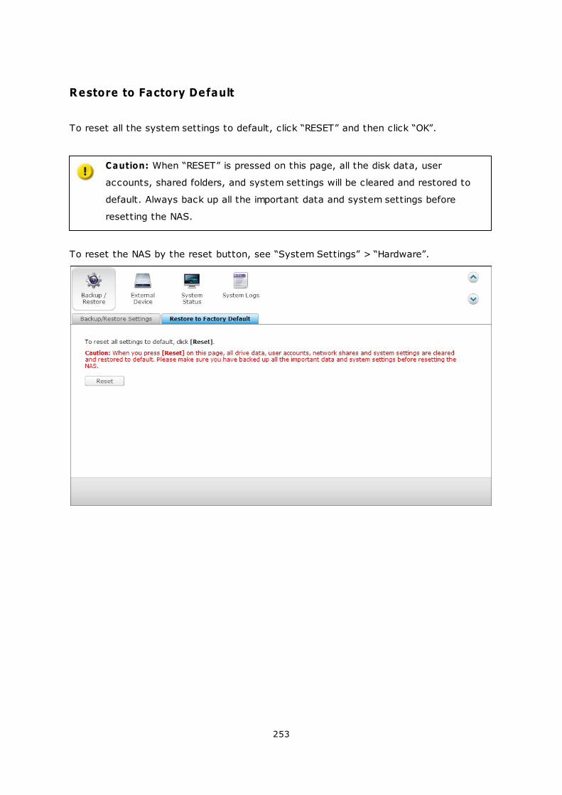
253
Restore to Factory Default
To reset all the system settings to default, click “RESET” and then click “OK”.
Caution: When “RESET” is pressed on this page, all the disk data, user
accounts, shared folders, and system settings will be cleared and restored to
default. Always back up all the important data and system settings before
resetting the NAS.
To reset the NAS by the reset button, see “System Settings” > “Hardware”.

254
4.10 External Device
External Storage
USB Printer
UPS
255
265
294
255
4.10.1 External Storage
The NAS supports external USB and eSATA storage devices* for backup and data
storage. Connect the external storage device to a USB or an eSATA interface of the
NAS, when the device is successfully detected, the details will be shown on this page.
Storage Information
Select a storage device and click Storage Information to check for its details.
*The number of USB and eSATA interfaces supported varies by models. Please refer to
http://www.qnap.com for details.

256
It may take tens of seconds for the NAS server to detect the external USB or eSATA
device successfully. Please wait patiently.
257
Format
The external storage device can be formatted as EXT3, EXT4, FAT32, NTFS, or HFS+
(Mac only) file system. Click “Format” and select the option from the drop-down menu.
The NAS supports external drive encryption. To encrypt an external storage device, click
“Encryption”. Select the encryption method: AES 128-, 192- or 256-bit and enter the
password (8-16 characters). Select “Save encryption key” to save the password in a
hidden location on a hard drive of the NAS. The NAS will unlock the encrypted external
storage device automatically every time the device is connected. Click Format to
proceed.
Click “OK” and all the data will be cleared.
The device will be “Ready” after disk initialization.
258
Note: For disk volumes larger than 2TB, it is recommended to format them to the
EXT4, NTFS, or HFS+ file system.
259
Eject
“Eject” offers two different options. “Disconnect disk partition” allows you to remove a
single disk partition or a disk drive in a multi-drive enclosure. “Remove device” allows you
to disconnect external storage devices without the risk of losing any data when the
device is removed.
First choose a device to eject, click “Eject” and then to disconnect the disk partition or
remove the device.
260
Encryption management
If an external storage device is encrypted by the NAS, the button “Encryption
Management” will appear. Click this button to manage the encryption password/key, or
lock or unlock the device.
Lock the device
Note: The external storage device cannot be locked if a real-time or scheduled backup
job is running on the device. To disable the backup job, go to “Control Panel” >
“Applications” > “Backup Station” > “External Drive”.
1. To lock an encrypted external storage device, click “Encryption Management”.
2. Select “Lock this device” and click “Next”.
3. Click “Next” to lock the device.
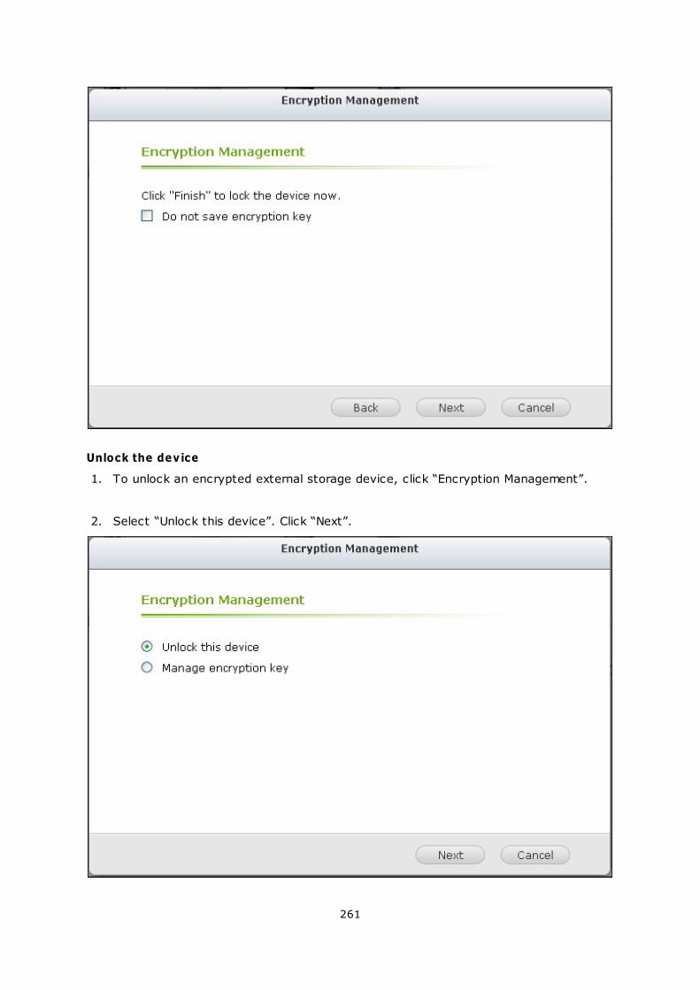
261
Unlock the device
1. To unlock an encrypted external storage device, click “Encryption Management”.
2. Select “Unlock this device”. Click “Next”.
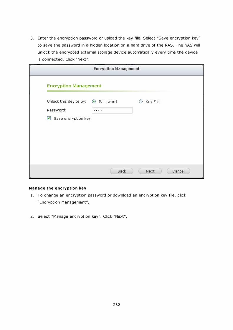
262
3. Enter the encryption password or upload the key file. Select “Save encryption key”
to save the password in a hidden location on a hard drive of the NAS. The NAS will
unlock the encrypted external storage device automatically every time the device
is connected. Click “Next”.
Manage the encryption key
1. To change an encryption password or download an encryption key file, click
“Encryption Management”.
2. Select “Manage encryption key”. Click “Next”.
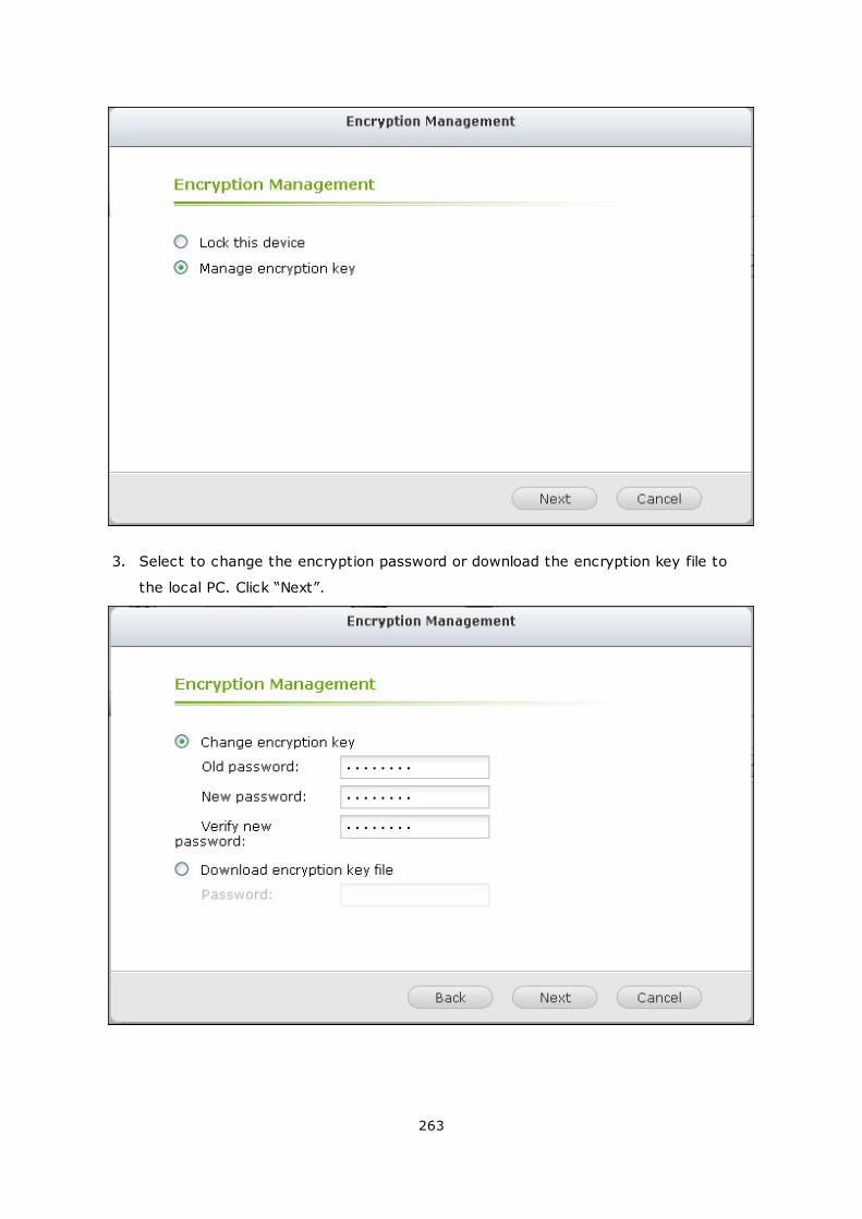
263
3. Select to change the encryption password or download the encryption key file to
the local PC. Click “Next”.
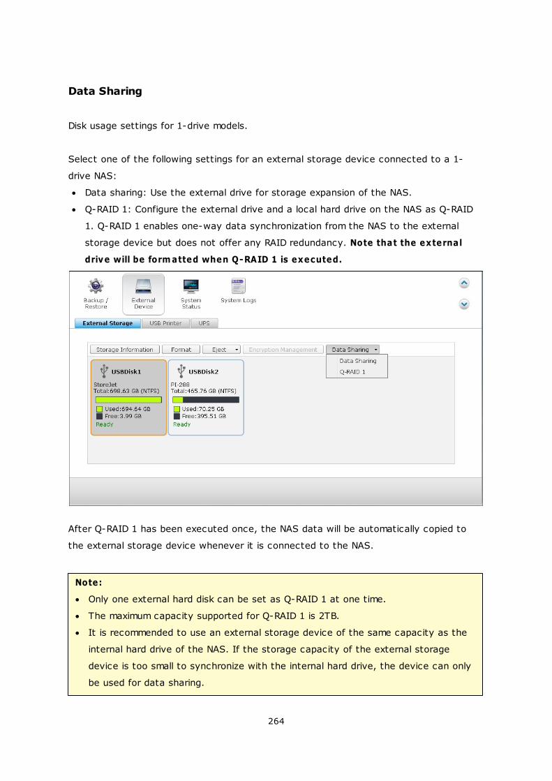
264
Data Sharing
Disk usage settings for 1-drive models.
Select one of the following settings for an external storage device connected to a 1-
drive NAS:
Data sharing: Use the external drive for storage expansion of the NAS.
Q-RAID 1: Configure the external drive and a local hard drive on the NAS as Q-RAID
1. Q-RAID 1 enables one-way data synchronization from the NAS to the external
storage device but does not offer any RAID redundancy. Note that the external
drive will be form atted when Q-RAID 1 is executed.
After Q-RAID 1 has been executed once, the NAS data will be automatically copied to
the external storage device whenever it is connected to the NAS.
Note:
Only one external hard disk can be set as Q-RAID 1 at one time.
The maximum capacity supported for Q-RAID 1 is 2TB.
It is recommended to use an external storage device of the same capacity as the
internal hard drive of the NAS. If the storage capacity of the external storage
device is too small to synchronize with the internal hard drive, the device can only
be used for data sharing.
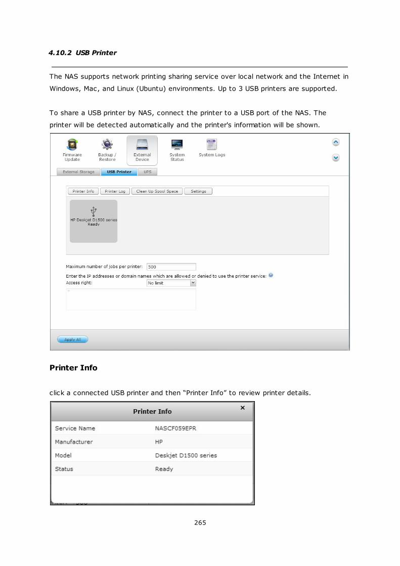
265
4.10.2 USB Printer
The NAS supports network printing sharing service over local network and the Internet in
Windows, Mac, and Linux (Ubuntu) environments. Up to 3 USB printers are supported.
To share a USB printer by NAS, connect the printer to a USB port of the NAS. The
printer will be detected automatically and the printer's information will be shown.
Printer Info
click a connected USB printer and then “Printer Info” to review printer details.
266
Note:
Please connect a USB printer to the NAS after the software configuration is
completed.
The NAS does not support multifunction printer.
The file name display on the printer job table is only available for printer jobs sent
via IPP (Internet Printing Protocol) connection.
For the information of the supported USB printer models, please visit http://www.
qnap.com
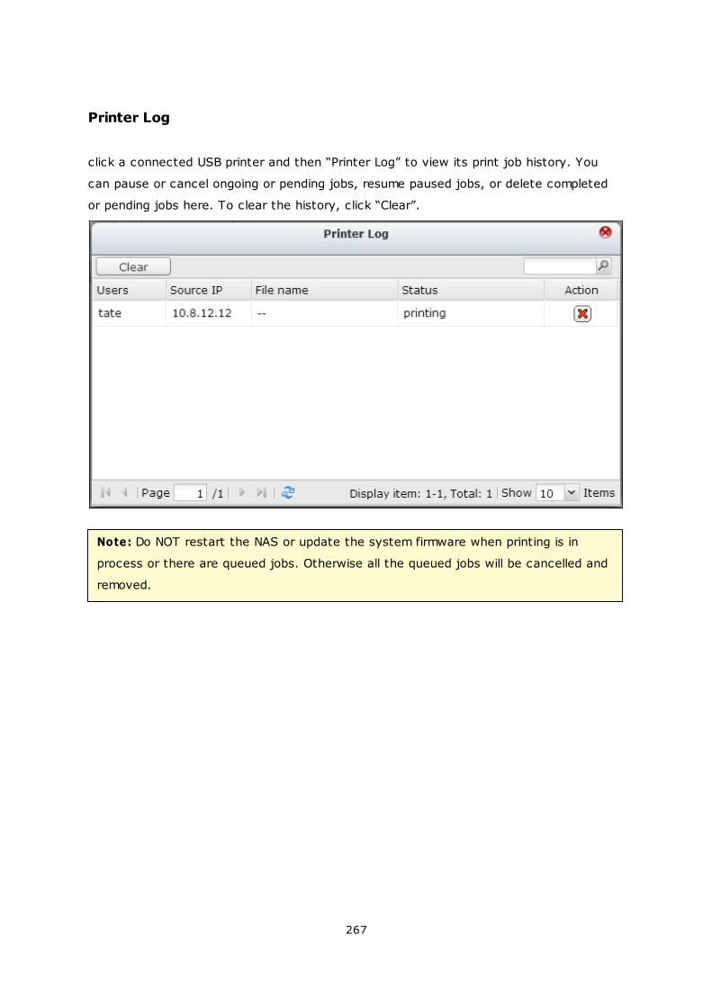
267
Printer Log
click a connected USB printer and then “Printer Log” to view its print job history. You
can pause or cancel ongoing or pending jobs, resume paused jobs, or delete completed
or pending jobs here. To clear the history, click “Clear”.
Note: Do NOT restart the NAS or update the system firmware when printing is in
process or there are queued jobs. Otherwise all the queued jobs will be cancelled and
removed.
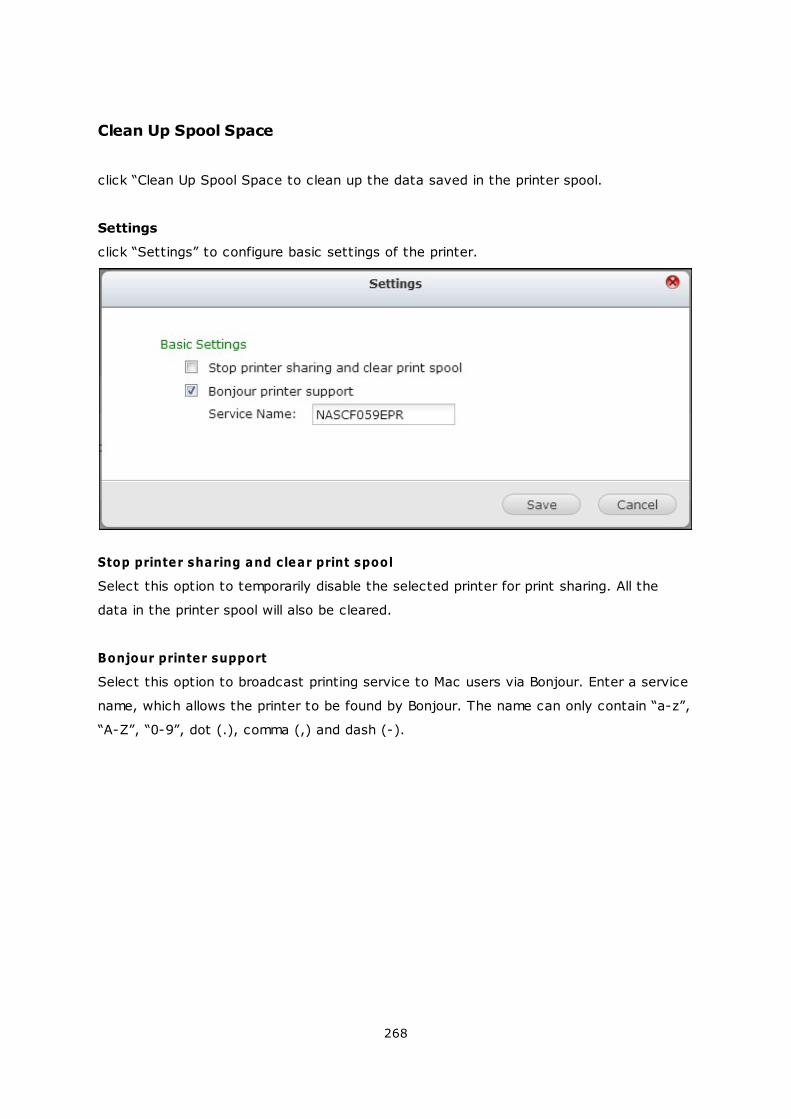
268
Clean Up Spool Space
click “Clean Up Spool Space to clean up the data saved in the printer spool.
Settings
click “Settings” to configure basic settings of the printer.
Stop printer sharing and clear print spool
Select this option to temporarily disable the selected printer for print sharing. All the
data in the printer spool will also be cleared.
Bonjour printer support
Select this option to broadcast printing service to Mac users via Bonjour. Enter a service
name, which allows the printer to be found by Bonjour. The name can only contain “a-z”,
“A-Z”, “0-9”, dot (.), comma (,) and dash (-).
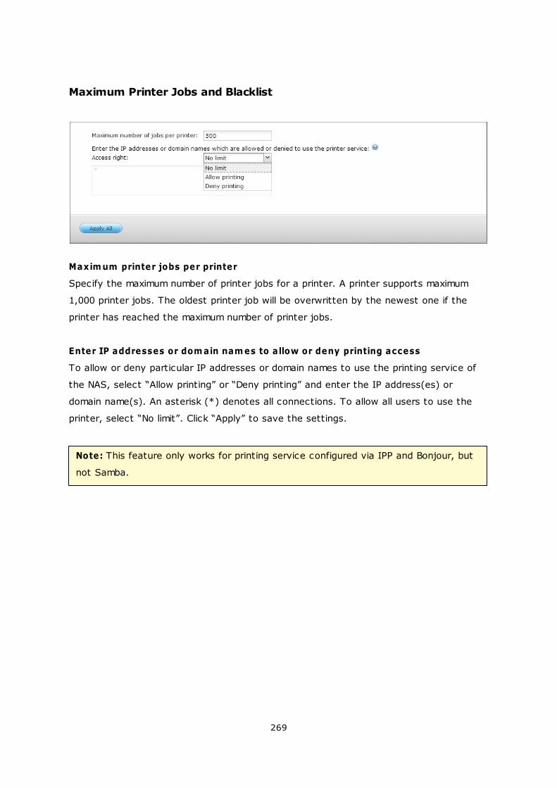
269
Maximum Printer Jobs and Blacklist
Maxim um printer jobs per printer
Specify the maximum number of printer jobs for a printer. A printer supports maximum
1,000 printer jobs. The oldest printer job will be overwritten by the newest one if the
printer has reached the maximum number of printer jobs.
Enter IP addresses or dom ain nam es to allow or deny printing access
To allow or deny particular IP addresses or domain names to use the printing service of
the NAS, select “Allow printing” or “Deny printing” and enter the IP address(es) or
domain name(s). An asterisk (*) denotes all connections. To allow all users to use the
printer, select “No limit”. Click “Apply” to save the settings.
Note: This feature only works for printing service configured via IPP and Bonjour, but
not Samba.
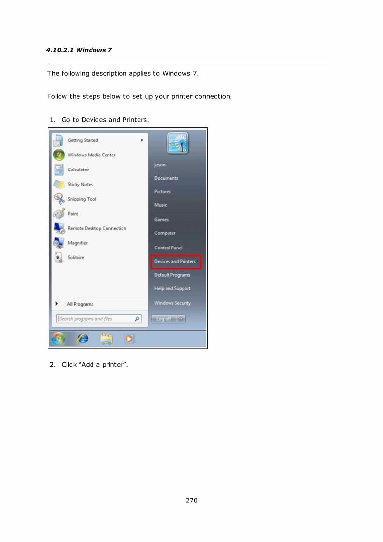
270
4.10.2.1 Windows 7
The following description applies to Windows 7.
Follow the steps below to set up your printer connection.
1. Go to Devices and Printers.
2. Click “Add a printer”.
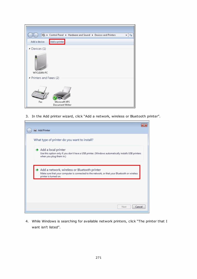
271
3. In the Add printer wizard, click “Add a network, wireless or Bluetooth printer”.
4. While Windows is searching for available network printers, click “The printer that I
want isn't listed”.
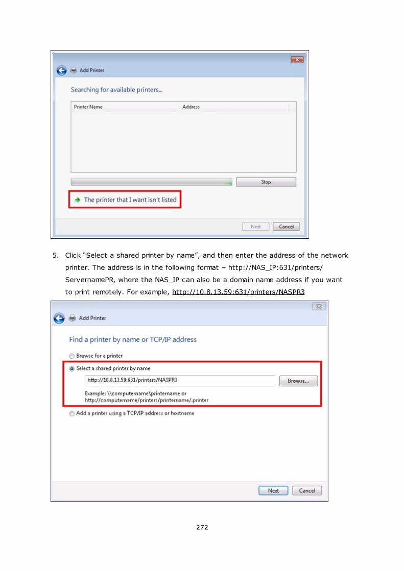
272
5. Click “Select a shared printer by name”, and then enter the address of the network
printer. The address is in the following format – http://NAS_IP:631/printers/
ServernamePR, where the NAS_IP can also be a domain name address if you want
to print remotely. For example, http://10.8.13.59:631/printers/NASPR3
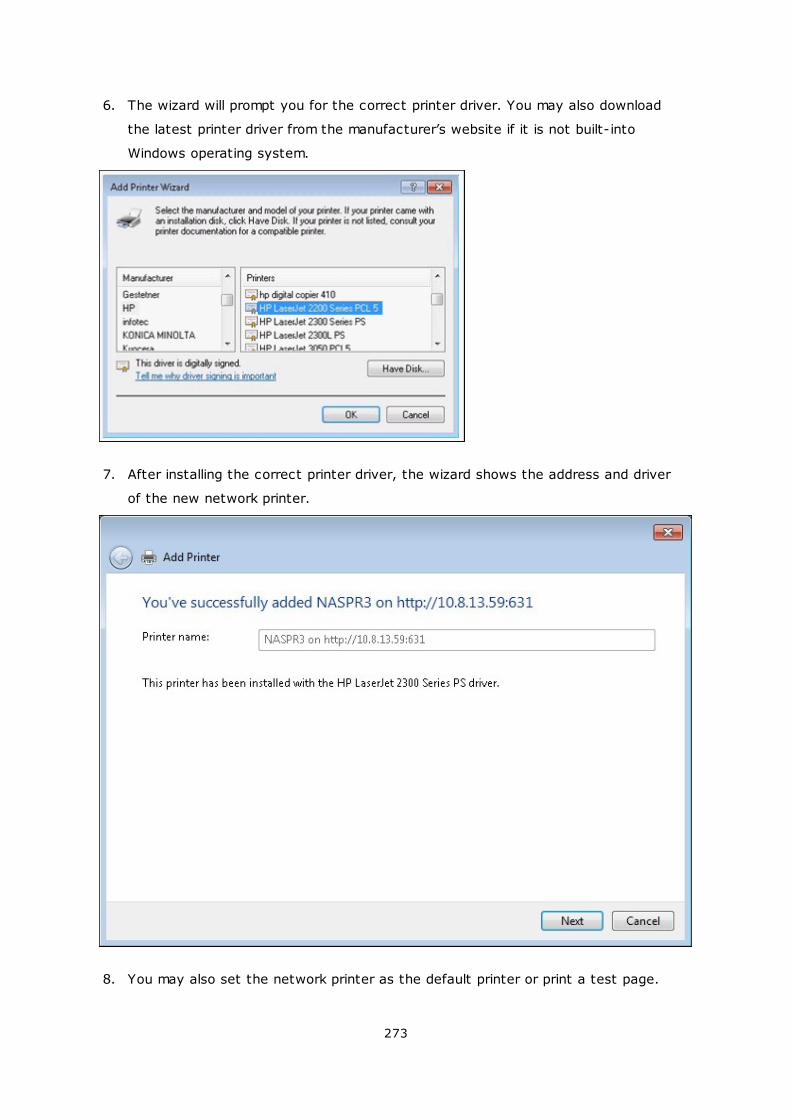
273
6. The wizard will prompt you for the correct printer driver. You may also download
the latest printer driver from the manufacturer’s website if it is not built-into
Windows operating system.
7. After installing the correct printer driver, the wizard shows the address and driver
of the new network printer.
8. You may also set the network printer as the default printer or print a test page.
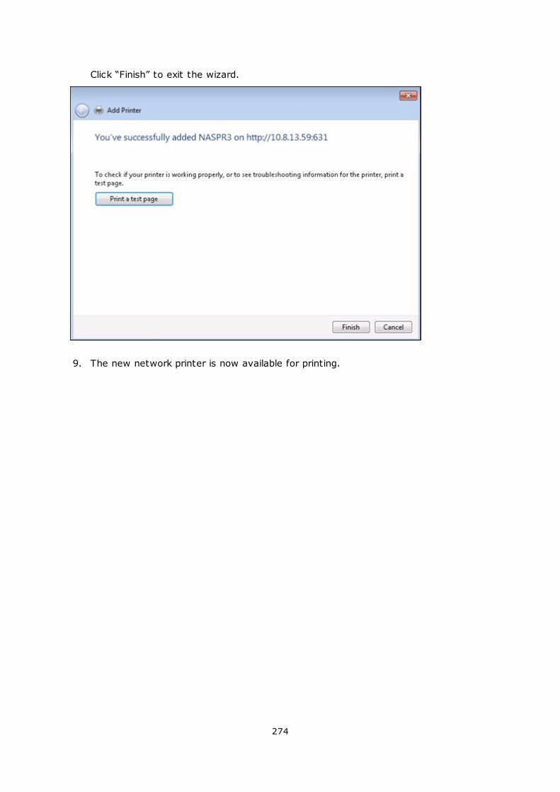
274
Click “Finish” to exit the wizard.
9. The new network printer is now available for printing.
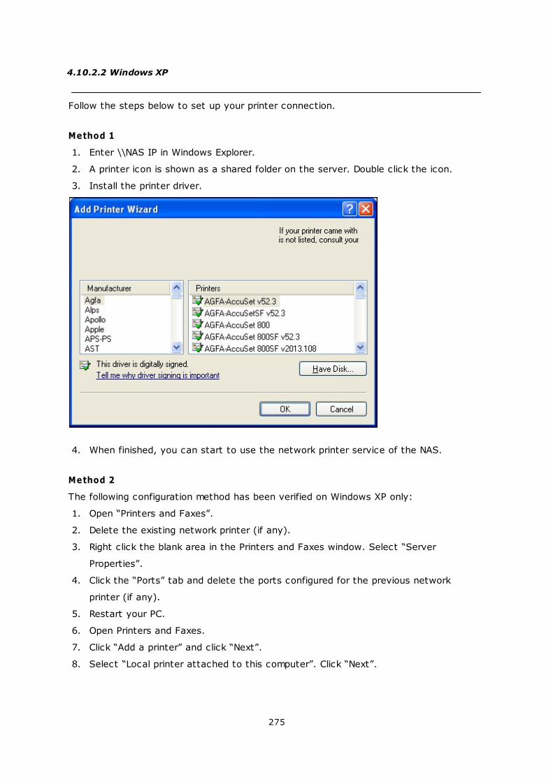
275
4.10.2.2 Windows XP
Follow the steps below to set up your printer connection.
Method 1
1. Enter \\NAS IP in Windows Explorer.
2. A printer icon is shown as a shared folder on the server. Double click the icon.
3. Install the printer driver.
4. When finished, you can start to use the network printer service of the NAS.
Method 2
The following configuration method has been verified on Windows XP only:
1. Open “Printers and Faxes”.
2. Delete the existing network printer (if any).
3. Right click the blank area in the Printers and Faxes window. Select “Server
Properties”.
4. Click the “Ports” tab and delete the ports configured for the previous network
printer (if any).
5. Restart your PC.
6. Open Printers and Faxes.
7. Click “Add a printer” and click “Next”.
8. Select “Local printer attached to this computer”. Click “Next”.

276
9. Click “Create a new port” and select “Local Port” from the drop-down menu. Click
“Next”.
10. Enter the port name. The format is \\NAS IP\NAS namepr, for example, NAS IP=
192.168.1.1, NAS name= myNAS, the link is \\192.168.1.1\myNASpr.
11. Install the printer driver.
12. Print a test page.
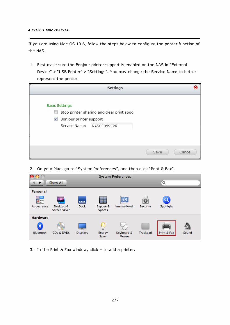
277
4.10.2.3 Mac OS 10.6
If you are using Mac OS 10.6, follow the steps below to configure the printer function of
the NAS.
1. First make sure the Bonjour printer support is enabled on the NAS in “External
Device” > “USB Printer” > “Settings”. You may change the Service Name to better
represent the printer.
2. On your Mac, go to “System Preferences”, and then click “Print & Fax”.
3. In the Print & Fax window, click + to add a printer.
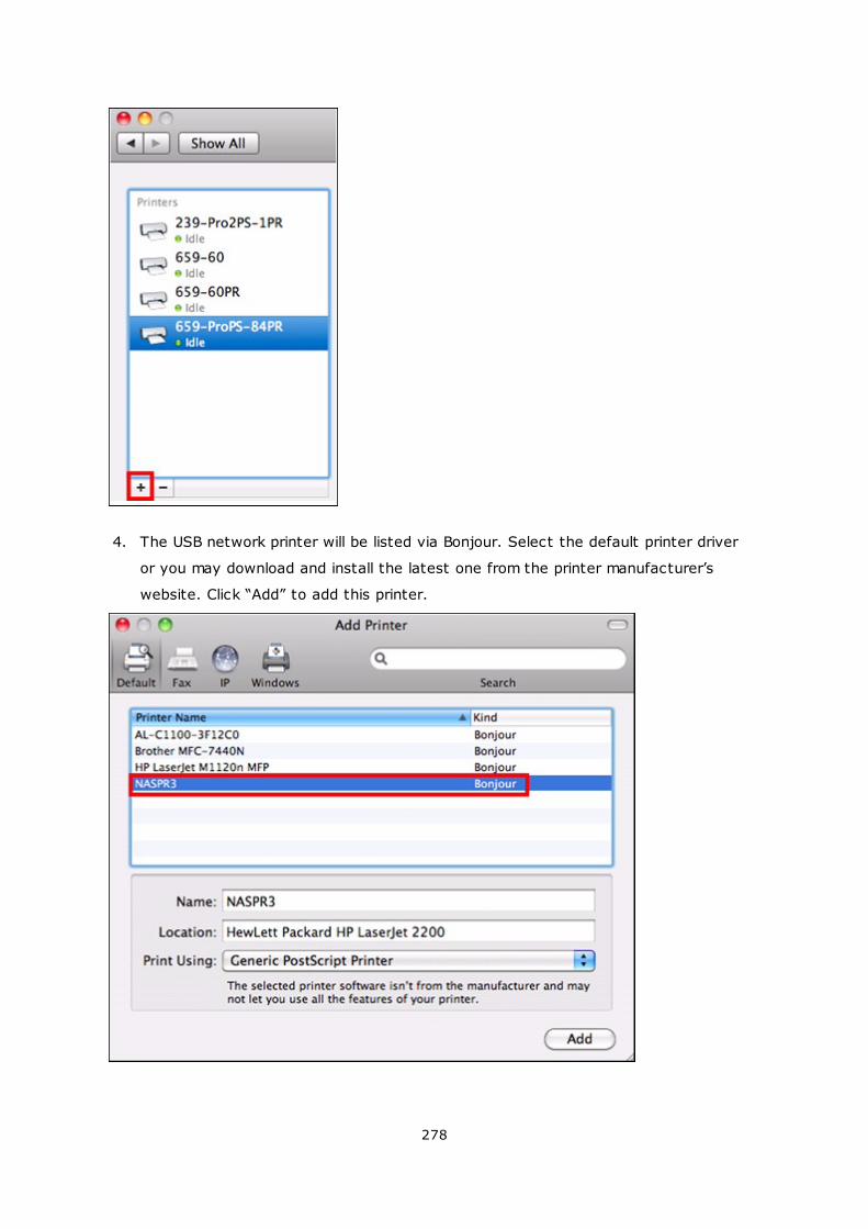
278
4. The USB network printer will be listed via Bonjour. Select the default printer driver
or you may download and install the latest one from the printer manufacturer’s
website. Click “Add” to add this printer.
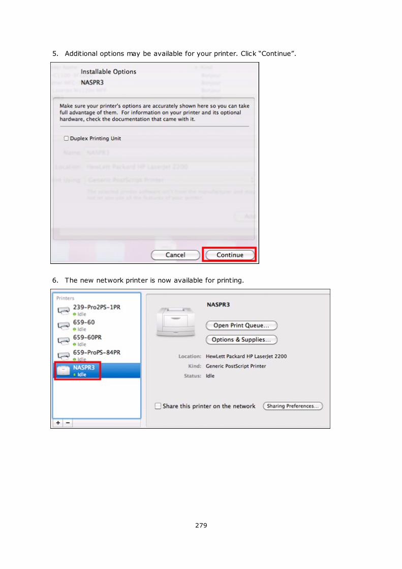
279
5. Additional options may be available for your printer. Click “Continue”.
6. The new network printer is now available for printing.
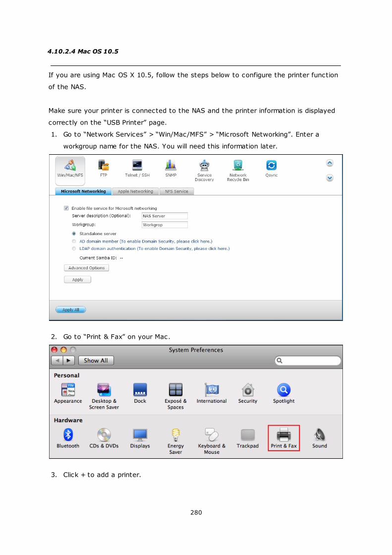
280
4.10.2.4 Mac OS 10.5
If you are using Mac OS X 10.5, follow the steps below to configure the printer function
of the NAS.
Make sure your printer is connected to the NAS and the printer information is displayed
correctly on the “USB Printer” page.
1. Go to “Network Services” > “Win/Mac/MFS” > “Microsoft Networking”. Enter a
workgroup name for the NAS. You will need this information later.
2. Go to “Print & Fax” on your Mac.
3. Click + to add a printer.
281
4. Select the NAS workgroup and find the printer name.
282
5. Enter the username and password to login the printer server on the NAS.
6. Select the printer driver.
283
7. After installing the printer driver correctly, you can start to use the printer.
284
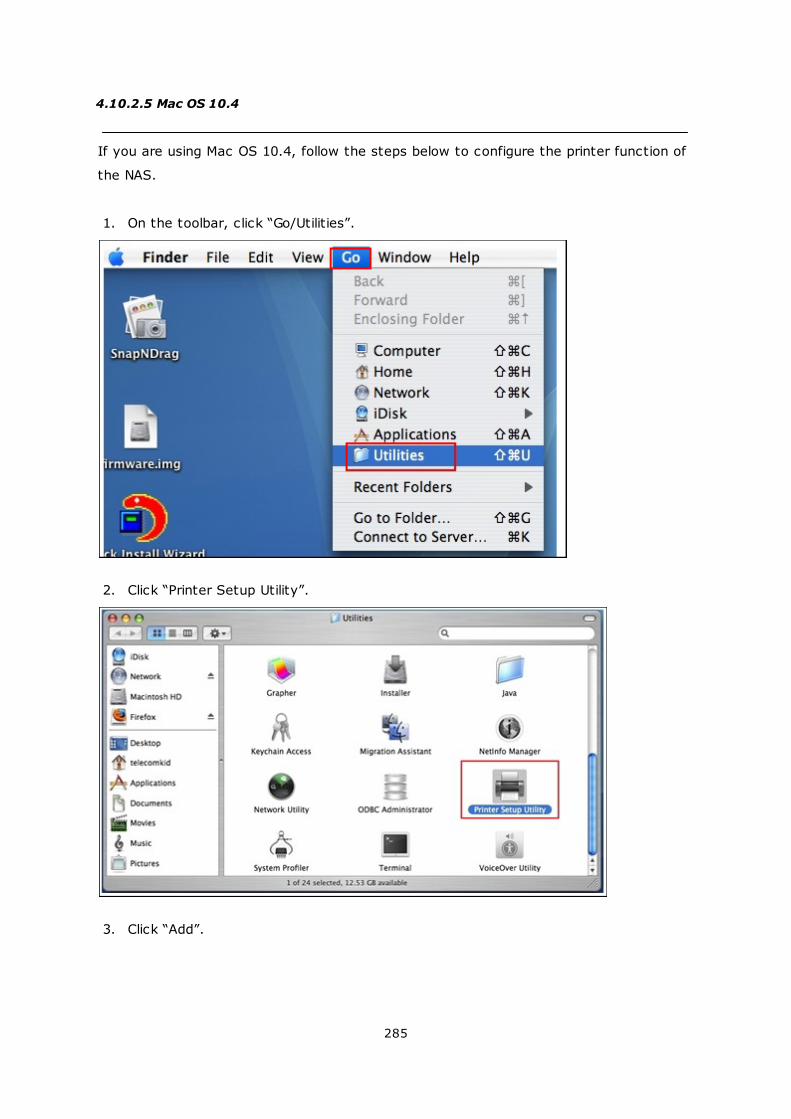
285
4.10.2.5 Mac OS 10.4
If you are using Mac OS 10.4, follow the steps below to configure the printer function of
the NAS.
1. On the toolbar, click “Go/Utilities”.
2. Click “Printer Setup Utility”.
3. Click “Add”.
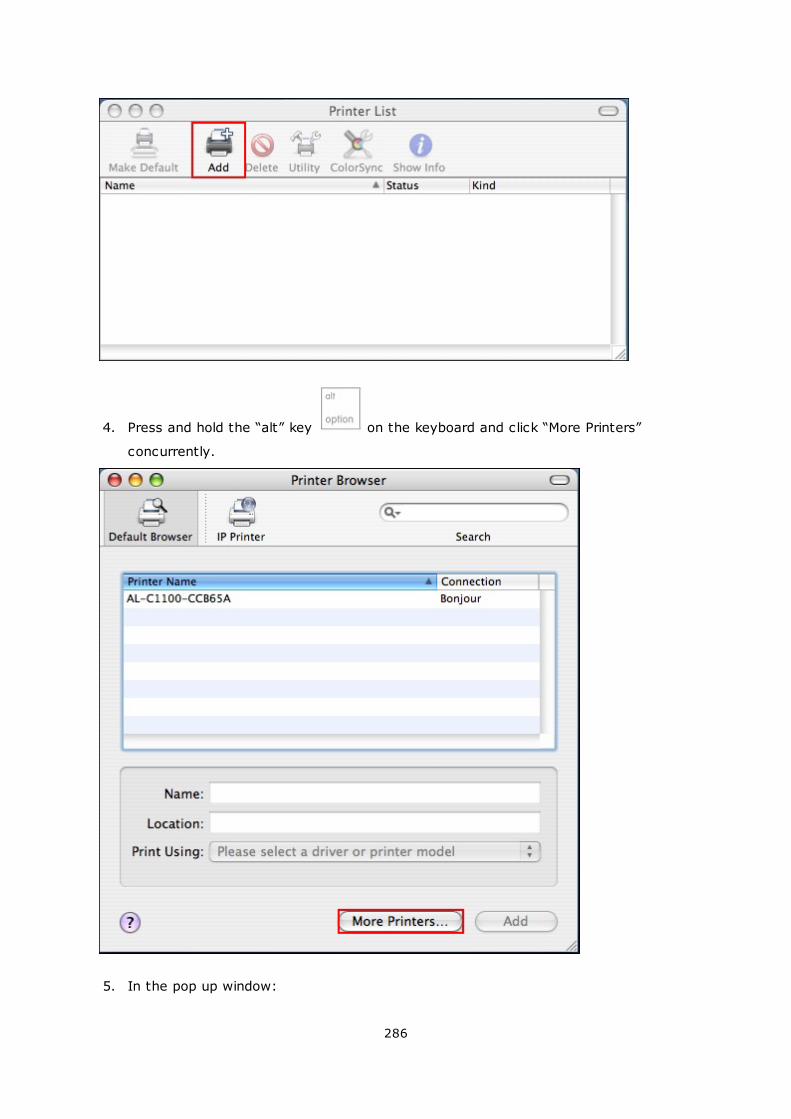
286
4. Press and hold the “alt” key on the keyboard and click “More Printers”
concurrently.
5. In the pop up window:
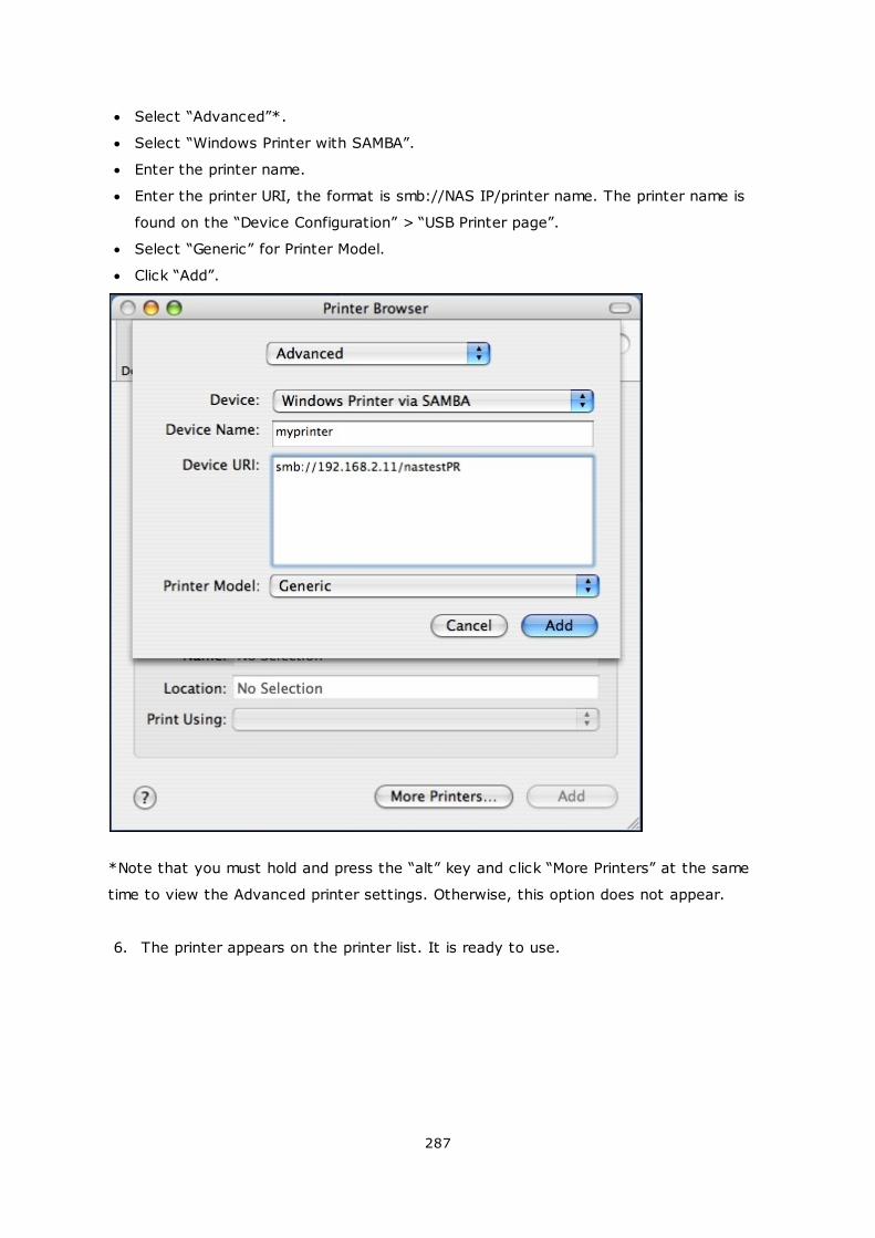
287
Select “Advanced”*.
Select “Windows Printer with SAMBA”.
Enter the printer name.
Enter the printer URI, the format is smb://NAS IP/printer name. The printer name is
found on the “Device Configuration” > “USB Printer page”.
Select “Generic” for Printer Model.
Click “Add”.
*Note that you must hold and press the “alt” key and click “More Printers” at the same
time to view the Advanced printer settings. Otherwise, this option does not appear.
6. The printer appears on the printer list. It is ready to use.
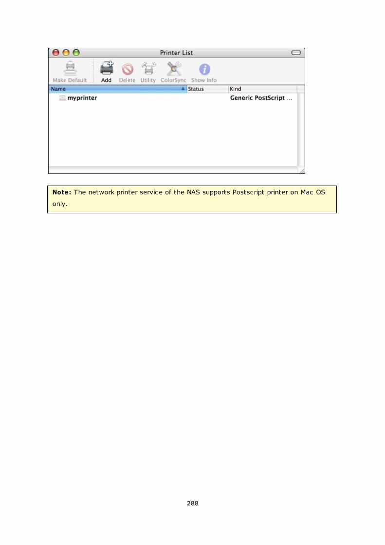
288
Note: The network printer service of the NAS supports Postscript printer on Mac OS
only.
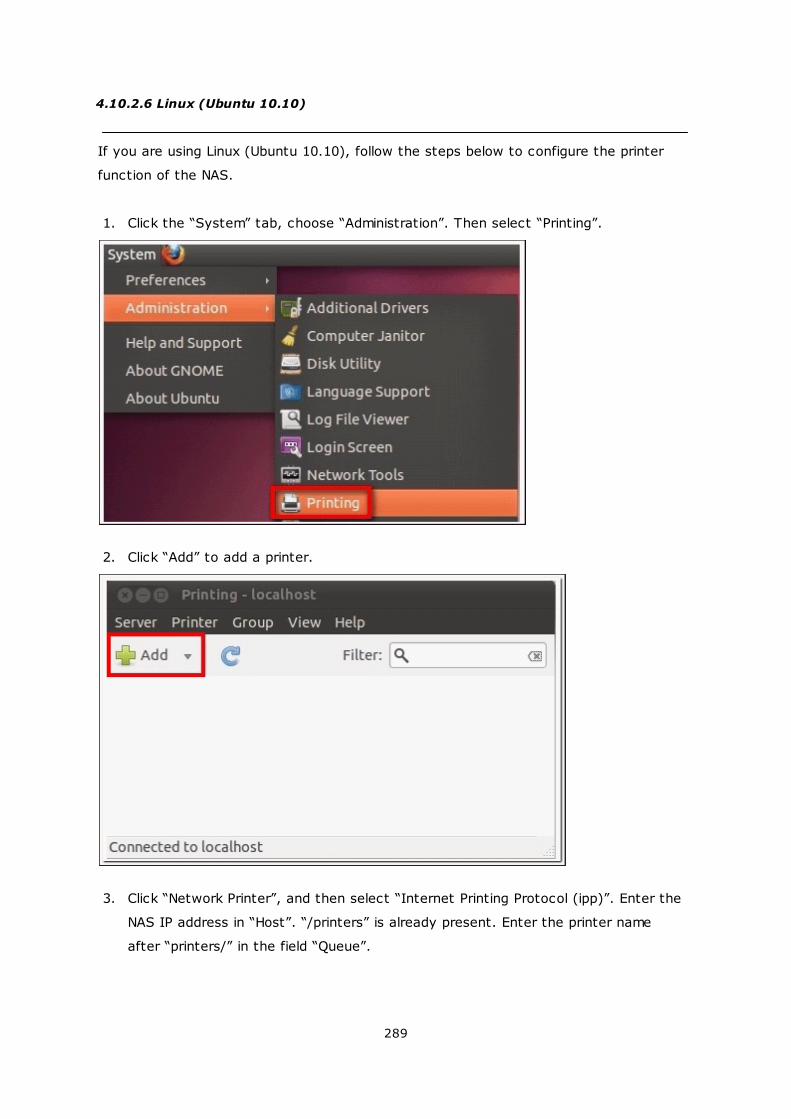
289
4.10.2.6 Linux (Ubuntu 10.10)
If you are using Linux (Ubuntu 10.10), follow the steps below to configure the printer
function of the NAS.
1. Click the “System” tab, choose “Administration”. Then select “Printing”.
2. Click “Add” to add a printer.
3. Click “Network Printer”, and then select “Internet Printing Protocol (ipp)”. Enter the
NAS IP address in “Host”. “/printers” is already present. Enter the printer name
after “printers/” in the field “Queue”.
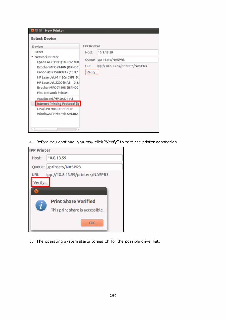
290
4. Before you continue, you may click “Verify” to test the printer connection.
5. The operating system starts to search for the possible driver list.
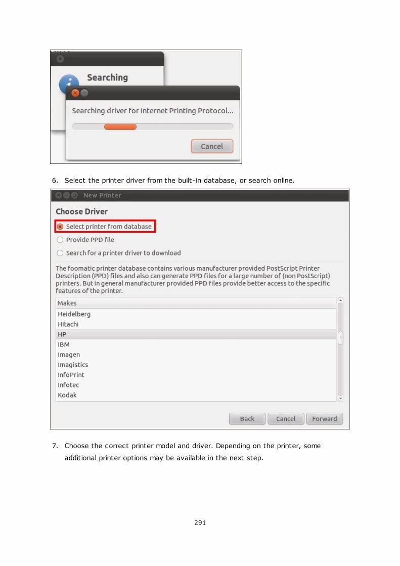
291
6. Select the printer driver from the built-in database, or search online.
7. Choose the correct printer model and driver. Depending on the printer, some
additional printer options may be available in the next step.
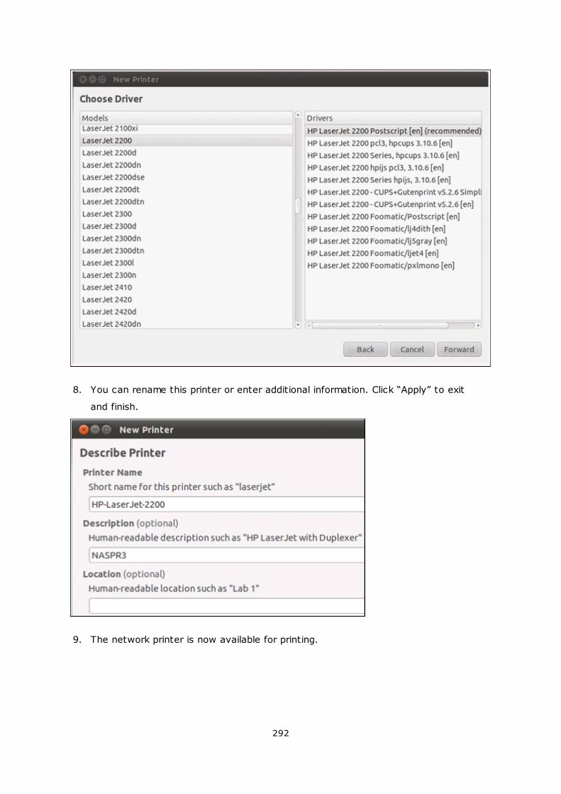
292
8. You can rename this printer or enter additional information. Click “Apply” to exit
and finish.
9. The network printer is now available for printing.
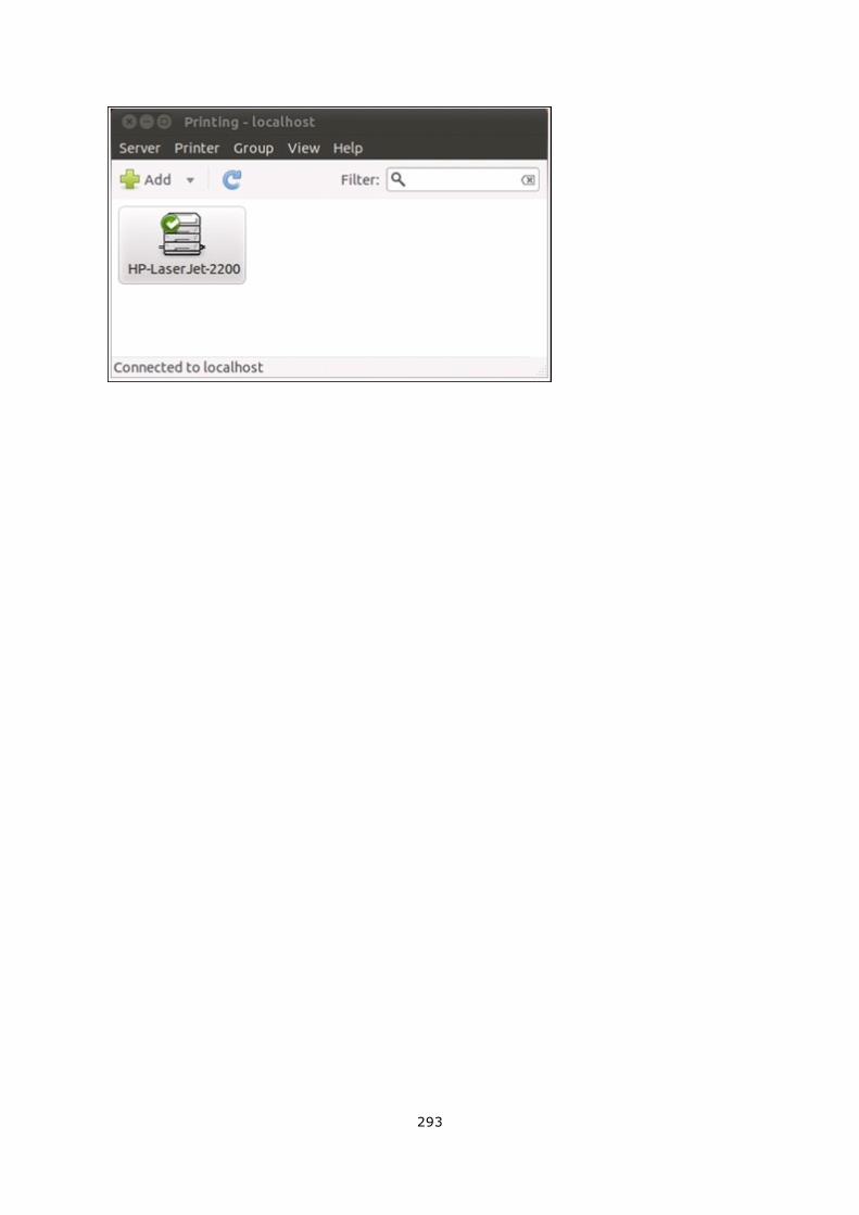
293
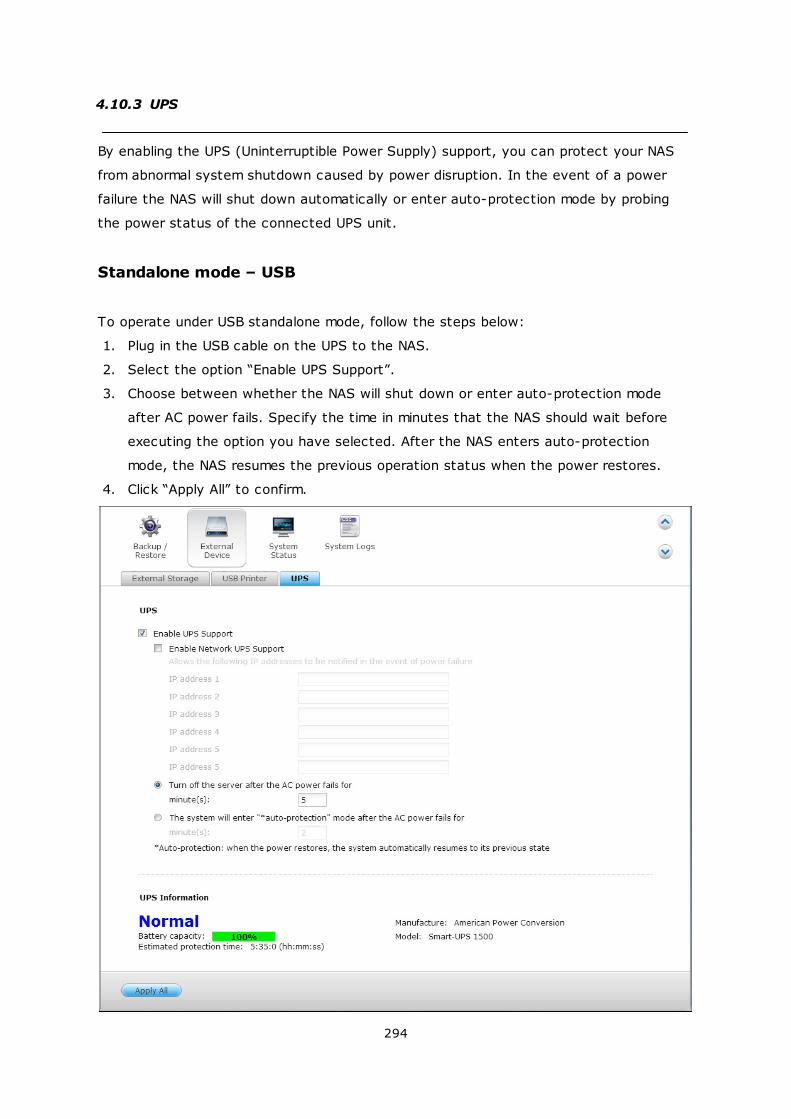
294
4.10.3 UPS
By enabling the UPS (Uninterruptible Power Supply) support, you can protect your NAS
from abnormal system shutdown caused by power disruption. In the event of a power
failure the NAS will shut down automatically or enter auto-protection mode by probing
the power status of the connected UPS unit.
Standalone mode – USB
To operate under USB standalone mode, follow the steps below:
1. Plug in the USB cable on the UPS to the NAS.
2. Select the option “Enable UPS Support”.
3. Choose between whether the NAS will shut down or enter auto-protection mode
after AC power fails. Specify the time in minutes that the NAS should wait before
executing the option you have selected. After the NAS enters auto-protection
mode, the NAS resumes the previous operation status when the power restores.
4. Click “Apply All” to confirm.
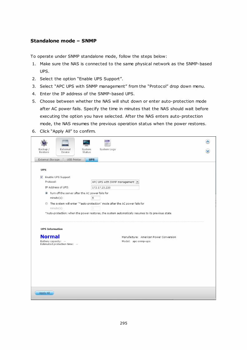
295
Standalone mode – SNMP
To operate under SNMP standalone mode, follow the steps below:
1. Make sure the NAS is connected to the same physical network as the SNMP-based
UPS.
2. Select the option “Enable UPS Support”.
3. Select “APC UPS with SNMP management” from the “Protocol” drop down menu.
4. Enter the IP address of the SNMP-based UPS.
5. Choose between whether the NAS will shut down or enter auto-protection mode
after AC power fails. Specify the time in minutes that the NAS should wait before
executing the option you have selected. After the NAS enters auto-protection
mode, the NAS resumes the previous operation status when the power restores.
6. Click “Apply All” to confirm.
296
Network master mode
A network UPS master is responsible for communicating with network UPS slaves on the
same physical network about critical power status. To set up your NAS with UPS as
network master mode, plug in the USB cable on the UPS to the NAS and follow the steps
below:
1. Make sure the NAS (the “UPS master”) is connected to the same physical network
as the network UPS slaves.
2. Select the option “Enable UPS Support”.
3. Click “Enable network UPS Support”. This option appears only when your NAS is
connected to the UPS by a USB cable.
4. Choose between whether the NAS will shut down or enter auto-protection mode
after AC power fails. Specify the time in minutes that the NAS should wait before
executing the option you have selected. After the NAS enters auto-protection
mode, the NAS resumes the previous operation status when the power restores.
5. Enter the “IP address” of other network UPS slaves to be notified in the event of
power failure.
6. Click “Apply All” to confirm and continue the setup for the NAS systems which
operate in network slave mode below.
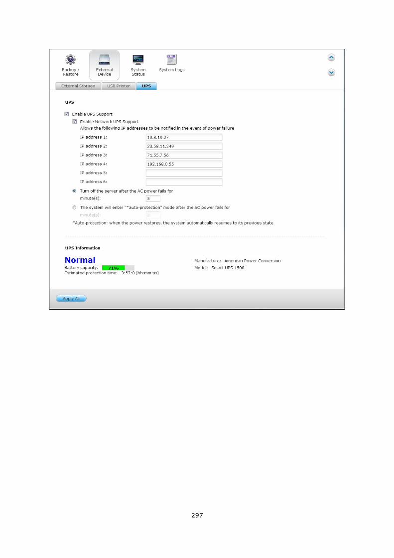
297
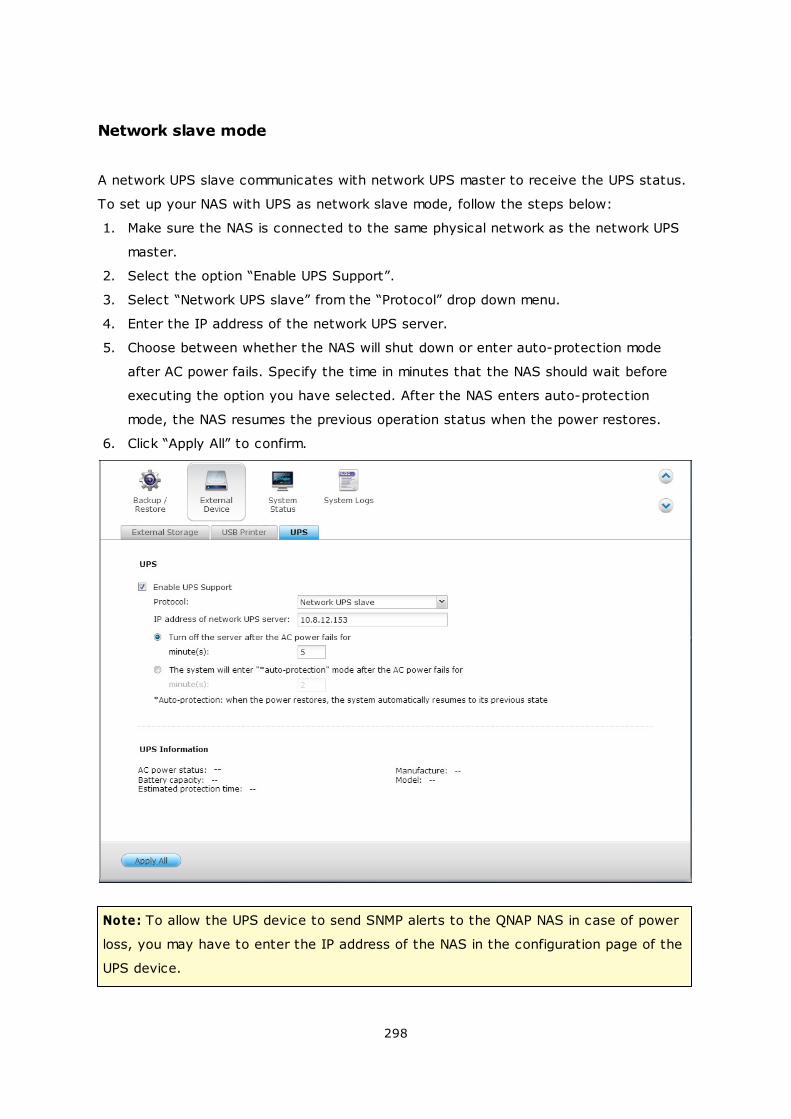
298
Network slave mode
A network UPS slave communicates with network UPS master to receive the UPS status.
To set up your NAS with UPS as network slave mode, follow the steps below:
1. Make sure the NAS is connected to the same physical network as the network UPS
master.
2. Select the option “Enable UPS Support”.
3. Select “Network UPS slave” from the “Protocol” drop down menu.
4. Enter the IP address of the network UPS server.
5. Choose between whether the NAS will shut down or enter auto-protection mode
after AC power fails. Specify the time in minutes that the NAS should wait before
executing the option you have selected. After the NAS enters auto-protection
mode, the NAS resumes the previous operation status when the power restores.
6. Click “Apply All” to confirm.
Note: To allow the UPS device to send SNMP alerts to the QNAP NAS in case of power
loss, you may have to enter the IP address of the NAS in the configuration page of the
UPS device.
299
Behavior of the UPS feature of the NAS
In case of power loss and power recovery, the events will be logged in the “System
Event Logs”.
During a power loss, the NAS will wait for the specified time you enter in the “UPS
Settings” before powering off or entering auto-protection mode.
If the power restores before the end of the waiting time, the NAS will remain in operation
and cancel its power-off or auto-protection action.
Once the power restores:
If the NAS is in auto-protection mode, it will resume to normal operation.
If the NAS is powered off, it will remain off.
Difference between auto-protection m ode and power-off m ode
Mode Advantage Disadvantage
Auto-protection
mode
The NAS resumes after power
recovery.
If the power outage lasts until
the UPS is turned off, the NAS
may suffer from abnormal
shutdown.
Power-off mode The NAS will be shut down
properly.
The NAS will remain off after
the power recovery. Manual
power on of the NAS is
required.
If the power restores after the NAS has been shut down and before the UPS device is
powered off, you may power on the NAS by Wake on LAN* (if your NAS and UPS device
both support Wake on LAN and Wake on LAN is enabled on the NAS).
*This feature is not supported by TS-110, TS-119, TS-210, TS-219, TS-219P, TS-410,
TS-419P, TS-410U, TS-419U, TS-112, TS-212, TS-412, TS-412U. Please visit http://
www.qnap.com for details.
If the power restores after both the NAS and the UPS have been shut down, the NAS will
react according to the settings in “System Settings” > “Power Recovery”.
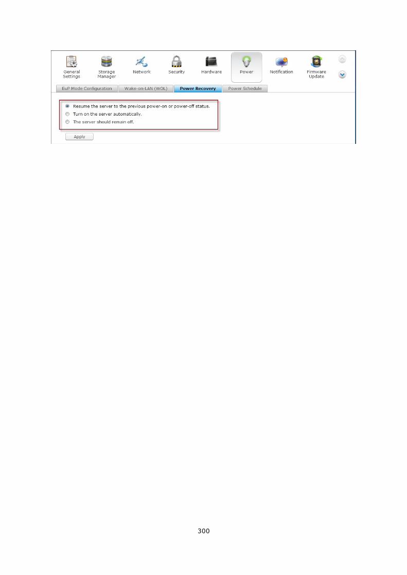
300
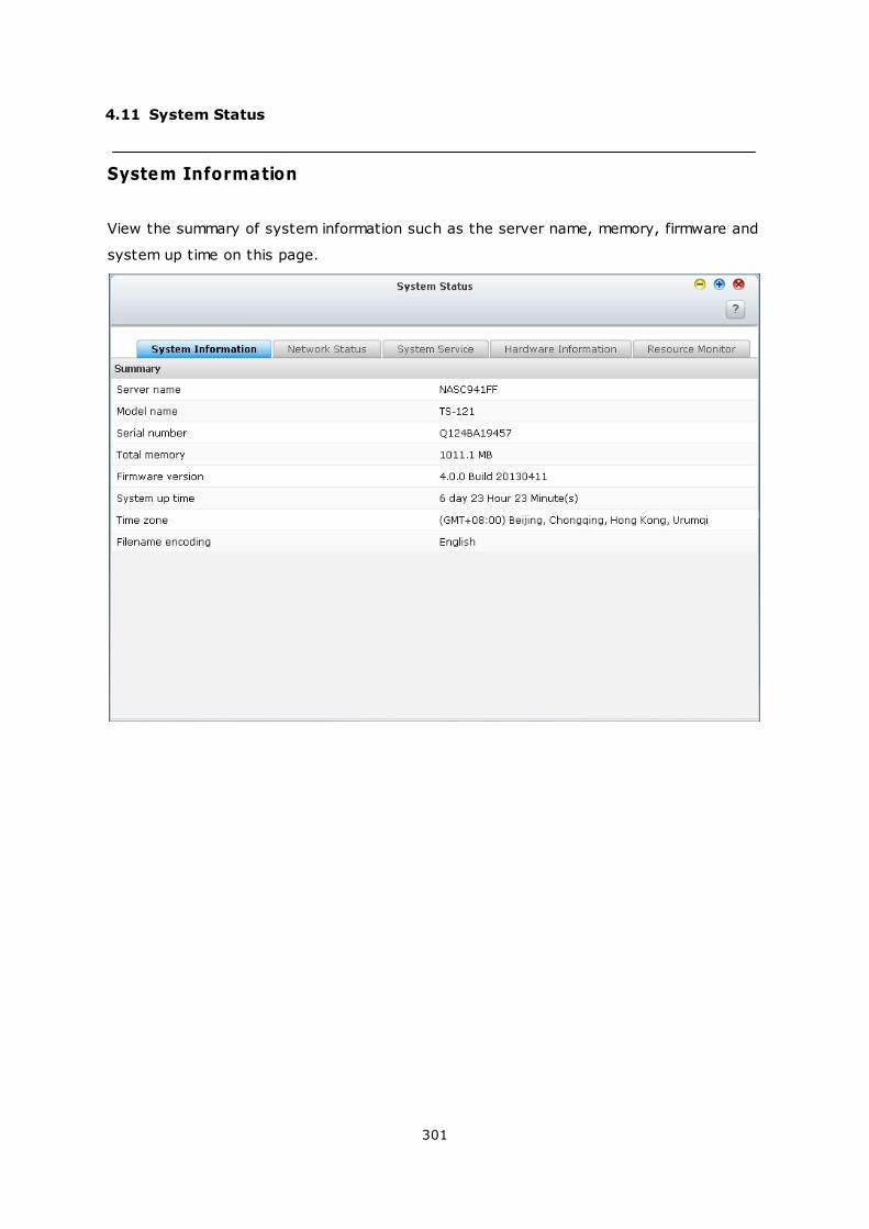
301
4.11 System Status
System Information
View the summary of system information such as the server name, memory, firmware and
system up time on this page.
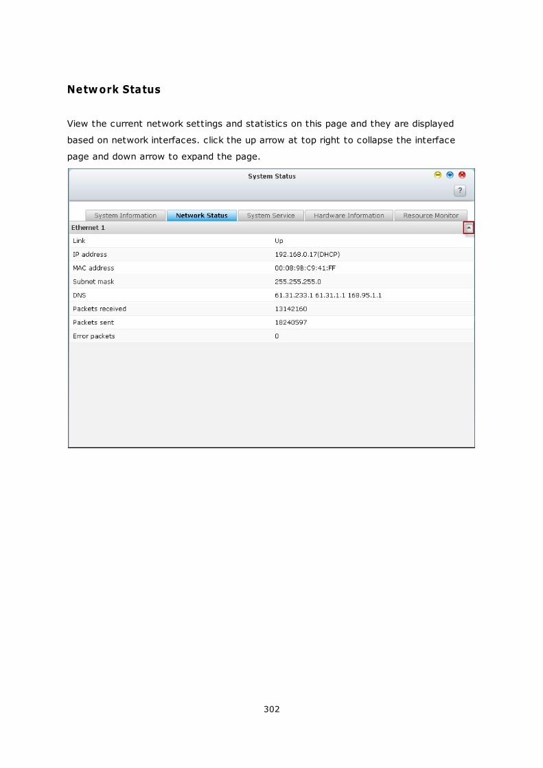
302
Network Status
View the current network settings and statistics on this page and they are displayed
based on network interfaces. click the up arrow at top right to collapse the interface
page and down arrow to expand the page.
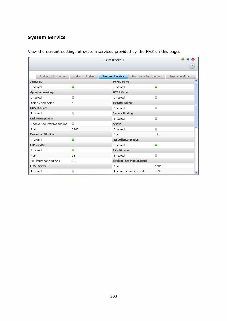
303
System Service
View the current settings of system services provided by the NAS on this page.
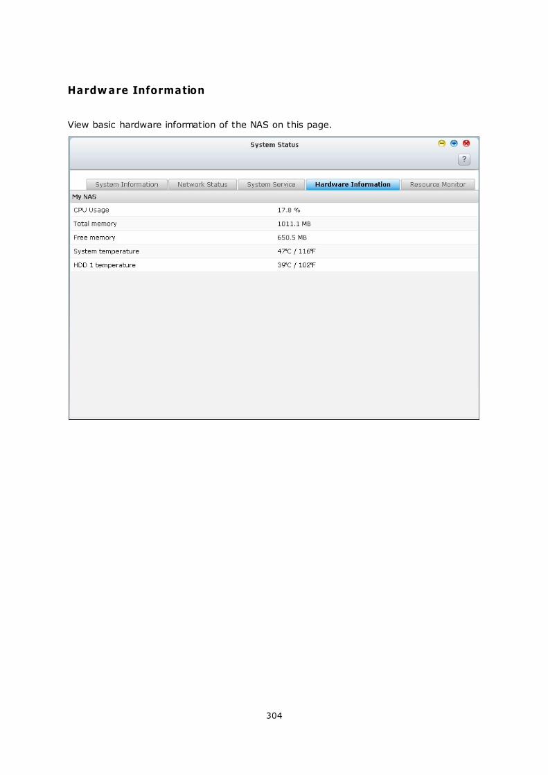
304
Hardware Information
View basic hardware information of the NAS on this page.
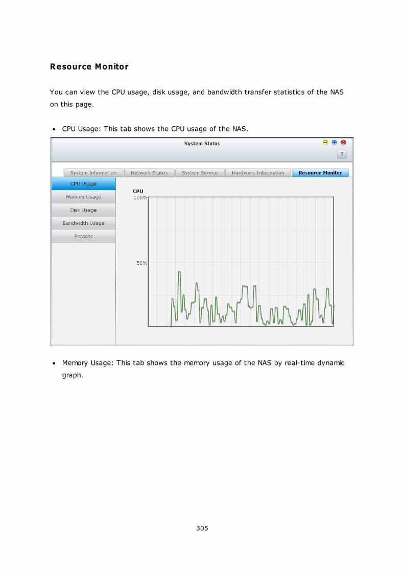
305
Resource Monitor
You can view the CPU usage, disk usage, and bandwidth transfer statistics of the NAS
on this page.
CPU Usage: This tab shows the CPU usage of the NAS.
Memory Usage: This tab shows the memory usage of the NAS by real-time dynamic
graph.
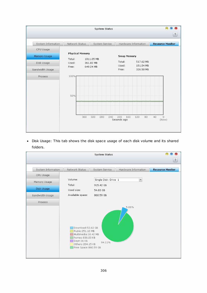
306
Disk Usage: This tab shows the disk space usage of each disk volume and its shared
folders.
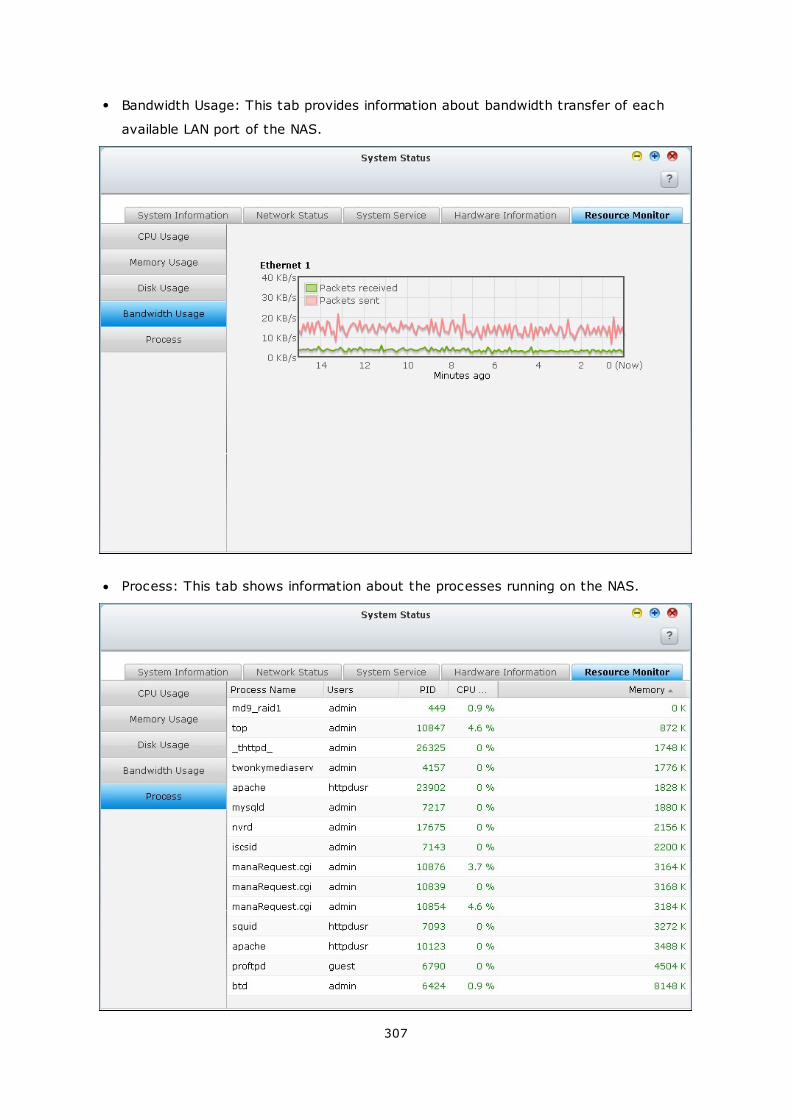
307
Bandwidth Usage: This tab provides information about bandwidth transfer of each
available LAN port of the NAS.
Process: This tab shows information about the processes running on the NAS.
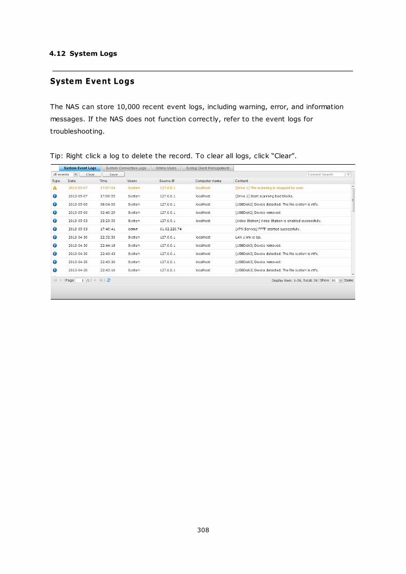
308
4.12 System Logs
System Event Logs
The NAS can store 10,000 recent event logs, including warning, error, and information
messages. If the NAS does not function correctly, refer to the event logs for
troubleshooting.
Tip: Right click a log to delete the record. To clear all logs, click “Clear”.
309
System Connection Logs
The NAS supports recording HTTP, FTP, Telnet, SSH, AFP, SAMBA, and iSCSI
connections. Click “Options” to select the connection type to be logged. The file transfer
performance can be slightly affected when this feature is turned on.
Tip: Right click a log and select to delete the record or block the IP and select how long
the IP should be blocked. To clear all the logs, click “Clear”.
Start Logging: Turn on this option to archive the connection logs. The NAS generates a
CSV file automatically and saves it to a specified folder when the number of logs reaches
the upper limit.
310
The file-level access logs are available on this page. The NAS will record the logs when
users access, create, delete, move, or rename any files or folders via the connection
type specified in “Options”. To disable this feature, click “Stop logging”.
311
Online Users
The information of the on-line users connecting to the NAS by networking services is
shown on this page.
Tip: Right click a log to disconnect the IP connection and block the IP.
312
Syslog Client Management
Syslog is a standard for forwarding the log messages on an IP network. Turn on this
option to save the event logs and connection logs to a remote Syslog server.
When converting the connection logs into a CSV file, the connection type and action will
be number coded. Please refer to the table below for the code meaning.
Connection type codes Action codes
0 - UNKNOWN
1 - SAMBA
2 - FTP
3 - HTTP
4 - NFS
5 - AFP
6 - TELNET
7 - SSH
8 - ISCSI
0 - UNKNOWN
1 - DEL
2 - READ
3 - WRITE
4 - OPEN
5 - MKDIR
6 - NFSMOUNT_SUCC
7 - NFSMOUNT_FAIL
8 - RENAME
9 - LOGIN_FAIL
10 - LOGIN_SUCC
11 - LOGOUT
12 - NFSUMOUNT
13 - COPY
14 - MOVE
15 - ADD
313
Advanced Log Search
Advanced log search is provided to search for system event logs, system connection
logs and online users based on user preferences. First, specify the log type, users,
computer name, date range and source IP and click “Search” to search for the desired
logs or reset to list all logs.
Please note that for online users, only the source IP and Computer name can be
specified.

314
5. Privilege Settings
Users
User Groups
Share Folders
Quota
Domain Security
315
331
333
369
371
315
5.1 Users
The NAS has created the following users by default:
admin: The administrator “admin” has full access to system administration and all
shared folders. It cannot be deleted.
guest: This is a built-in user and will not be displayed on the “User Management”
page. A guest does not belong to any user group. The login password is “guest”.
anonymous: This is a built-in user and will not be shown on the “User Management”
page. When you connect to the server by FTP, you can use this name to login.
The number of users you can create on the NAS varies according to the NAS models. If
your NAS models are not listed, please visit http://www.qnap.com for details.
Maxim um num ber of
users
NAS m odels
1,024 TS-110, TS-210
2,048 TS-112, TS-119, TS-119P+, TS-212, TS-219P+, TS-410,
TS-239 Pro II+, TS-259 Pro+
4,096 TS-412, TS-419P+, TS-410U, TS-419U, TS-412U, TS-
419U+, SS-439 Pro, SS-839 Pro, TS-439 Pro II+, TS-459U-
RP/SP, TS-459U-RP+/SP+, TS-459 Pro+, TS-459 Pro II, TS-
559 Pro+, TS-559 Pro II, TS-659 Pro+, TS-659 Pro II, TS-
859 Pro+, TS-859U-RP, TS-859U-RP+, TS-809 Pro, TS-
809U-RP, TS-879 Pro, TS-1079 Pro, TS-879U-RP, TS-
EC879U-RP, TS-1279U-RP, TS-EC1279U-RP
The following information is required to create a new user:
Username: The username is case-insensitive and supports multi-byte characters,
such as Chinese, Japanese, Korean, and Russian. The maximum length is 32
characters. The invalid characters are: " / \ [ ] : ; | = , + * ? < > ` '
Password: The password is case-sensitive and supports maximum 16 characters. It is
recommended to use a password of at least 6 characters.
316
317
Create a User
To create a user on the NAS, click “Create a User”.
Follow the instructions of the wizard to complete the details.
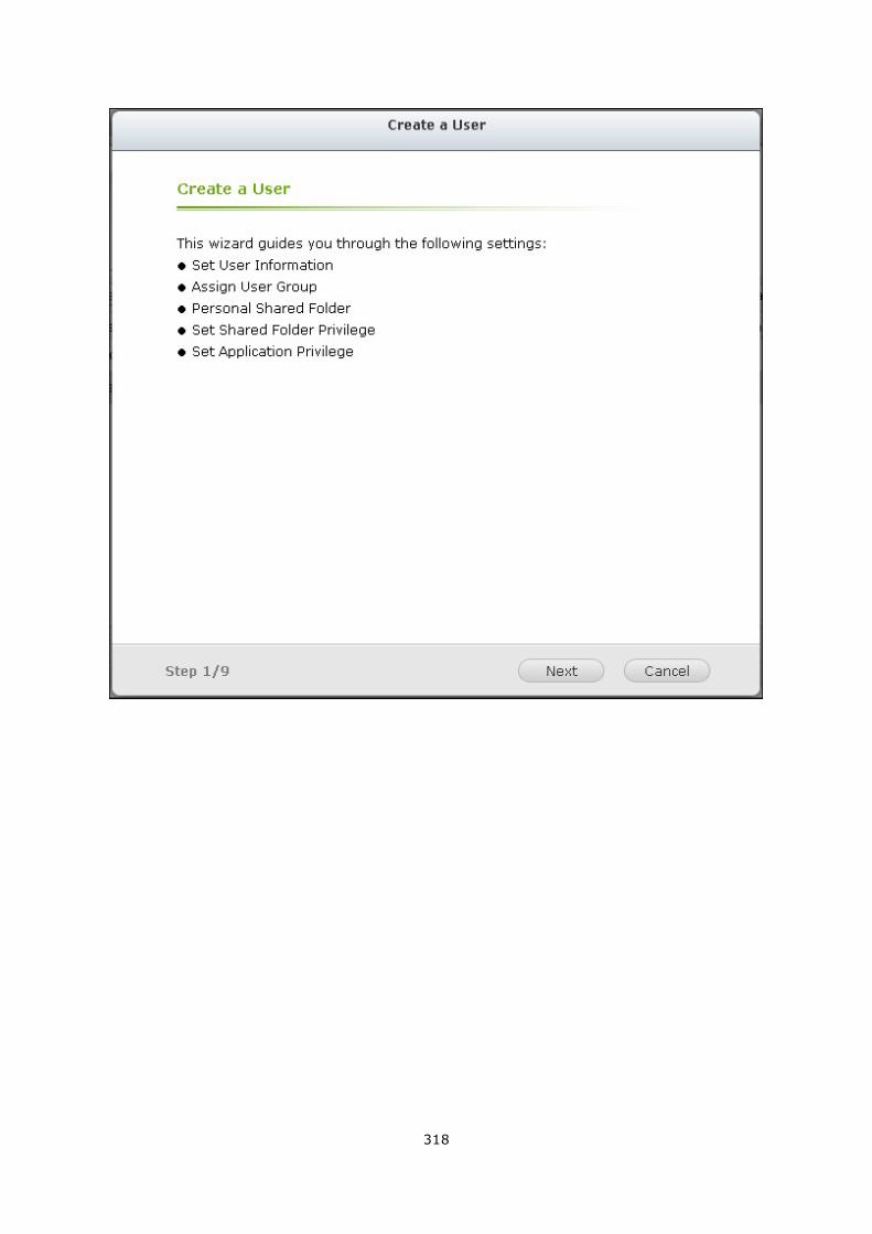
318
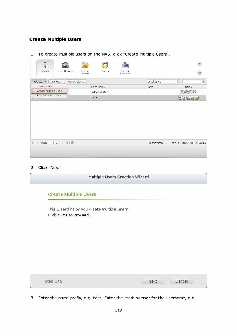
319
Create Multiple Users
1. To create multiple users on the NAS, click “Create Multiple Users”.
2. Click “Next”.
3. Enter the name prefix, e.g. test. Enter the start number for the username, e.g.
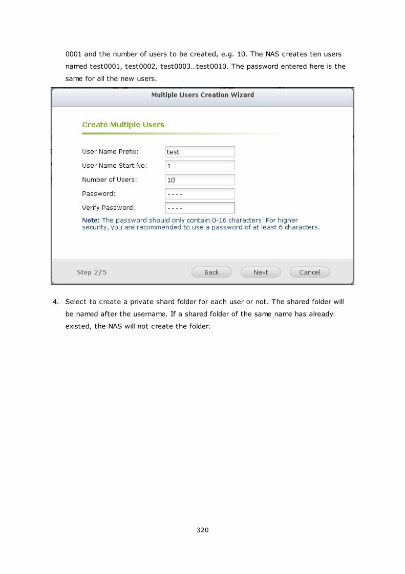
320
0001 and the number of users to be created, e.g. 10. The NAS creates ten users
named test0001, test0002, test0003…test0010. The password entered here is the
same for all the new users.
4. Select to create a private shard folder for each user or not. The shared folder will
be named after the username. If a shared folder of the same name has already
existed, the NAS will not create the folder.
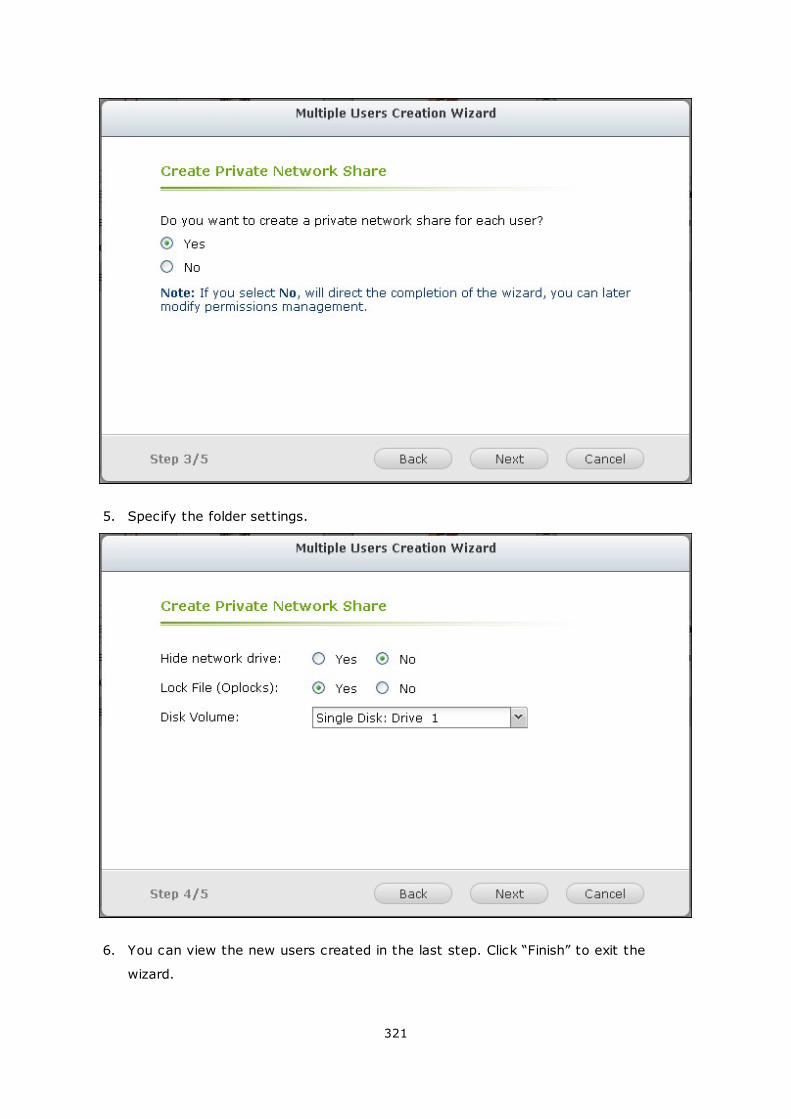
321
5. Specify the folder settings.
6. You can view the new users created in the last step. Click “Finish” to exit the
wizard.
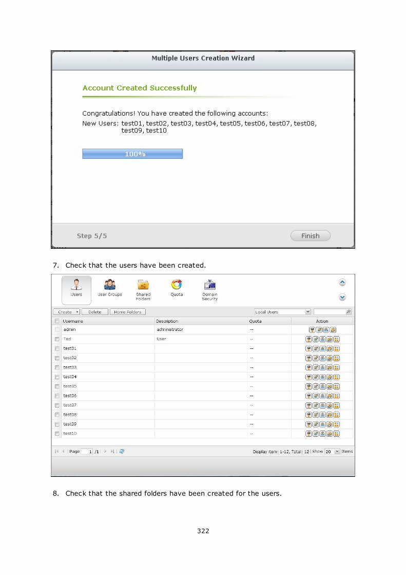
322
7. Check that the users have been created.
8. Check that the shared folders have been created for the users.
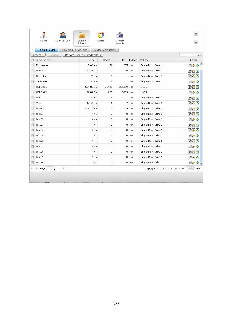
323
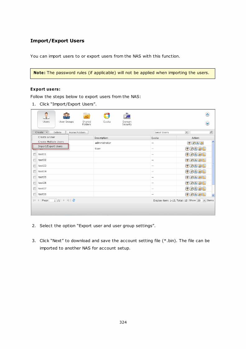
324
Import/Export Users
You can import users to or export users from the NAS with this function.
Note: The password rules (if applicable) will not be applied when importing the users.
Export users:
Follow the steps below to export users from the NAS:
1. Click “Import/Export Users”.
2. Select the option “Export user and user group settings”.
3. Click “Next” to download and save the account setting file (*.bin). The file can be
imported to another NAS for account setup.
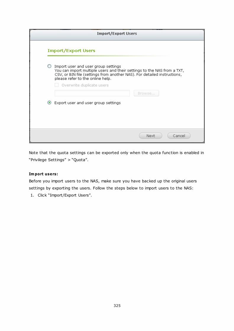
325
Note that the quota settings can be exported only when the quota function is enabled in
“Privilege Settings” > “Quota”.
Im port users:
Before you import users to the NAS, make sure you have backed up the original users
settings by exporting the users. Follow the steps below to import users to the NAS:
1. Click “Import/Export Users”.
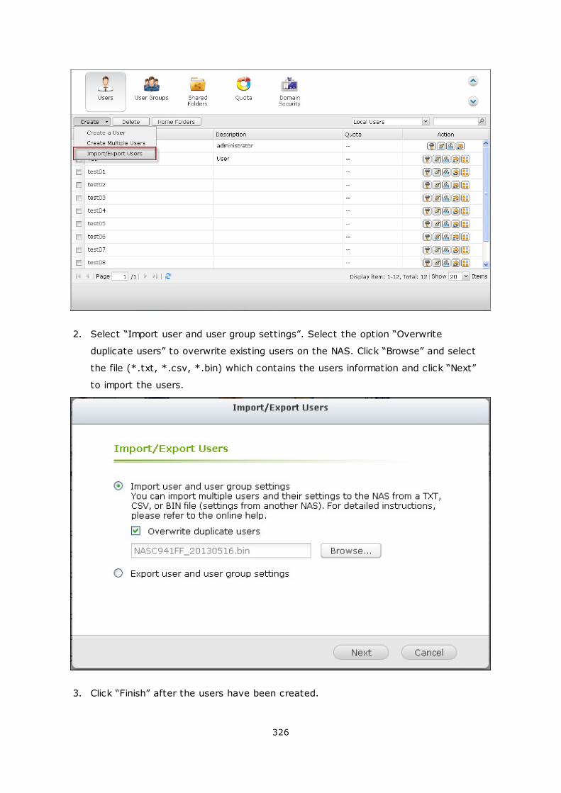
326
2. Select “Import user and user group settings”. Select the option “Overwrite
duplicate users” to overwrite existing users on the NAS. Click “Browse” and select
the file (*.txt, *.csv, *.bin) which contains the users information and click “Next”
to import the users.
3. Click “Finish” after the users have been created.
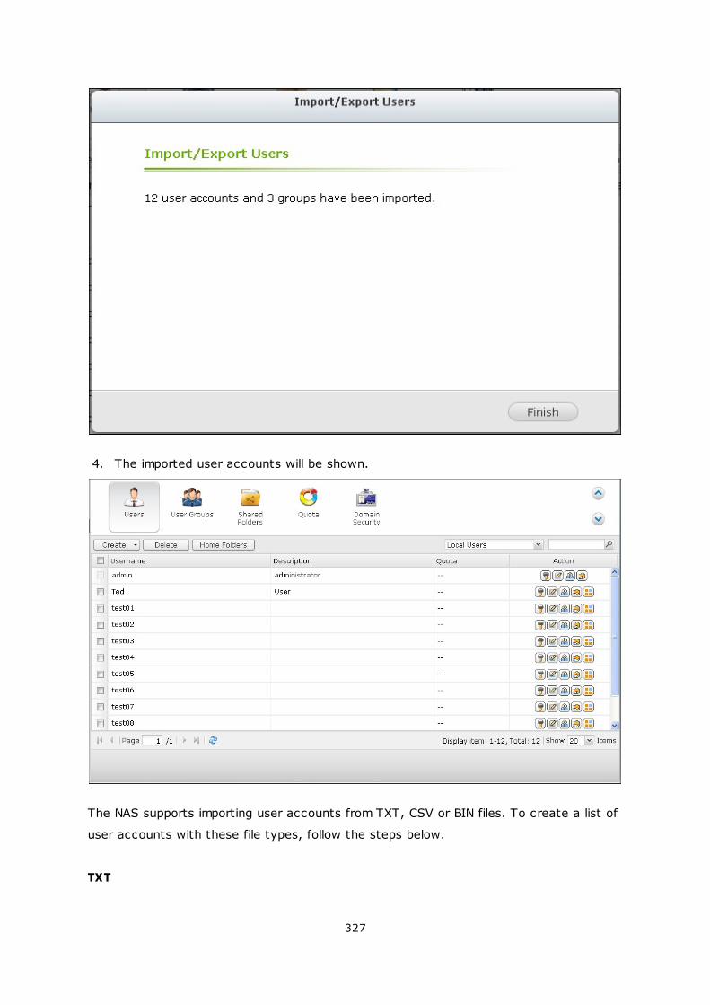
327
4. The imported user accounts will be shown.
The NAS supports importing user accounts from TXT, CSV or BIN files. To create a list of
user accounts with these file types, follow the steps below.
TXT
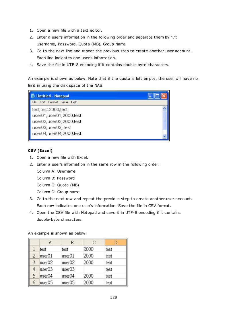
328
1. Open a new file with a text editor.
2. Enter a user's information in the following order and separate them by “,”:
Username, Password, Quota (MB), Group Name
3. Go to the next line and repeat the previous step to create another user account.
Each line indicates one user's information.
4. Save the file in UTF-8 encoding if it contains double-byte characters.
An example is shown as below. Note that if the quota is left empty, the user will have no
limit in using the disk space of the NAS.
CSV (Excel)
1. Open a new file with Excel.
2. Enter a user's information in the same row in the following order:
Column A: Username
Column B: Password
Column C: Quota (MB)
Column D: Group name
3. Go to the next row and repeat the previous step to create another user account.
Each row indicates one user's information. Save the file in CSV format.
4. Open the CSV file with Notepad and save it in UTF-8 encoding if it contains
double-byte characters.
An example is shown as below:

329
BIN (Exported from the NAS)
The BIN file is exported from a QNAP NAS. It contains information including username,
password, quota, and user group. The quota setting can be exported only when the
quota function is enabled in “Privilege Settings” > “Quota”.
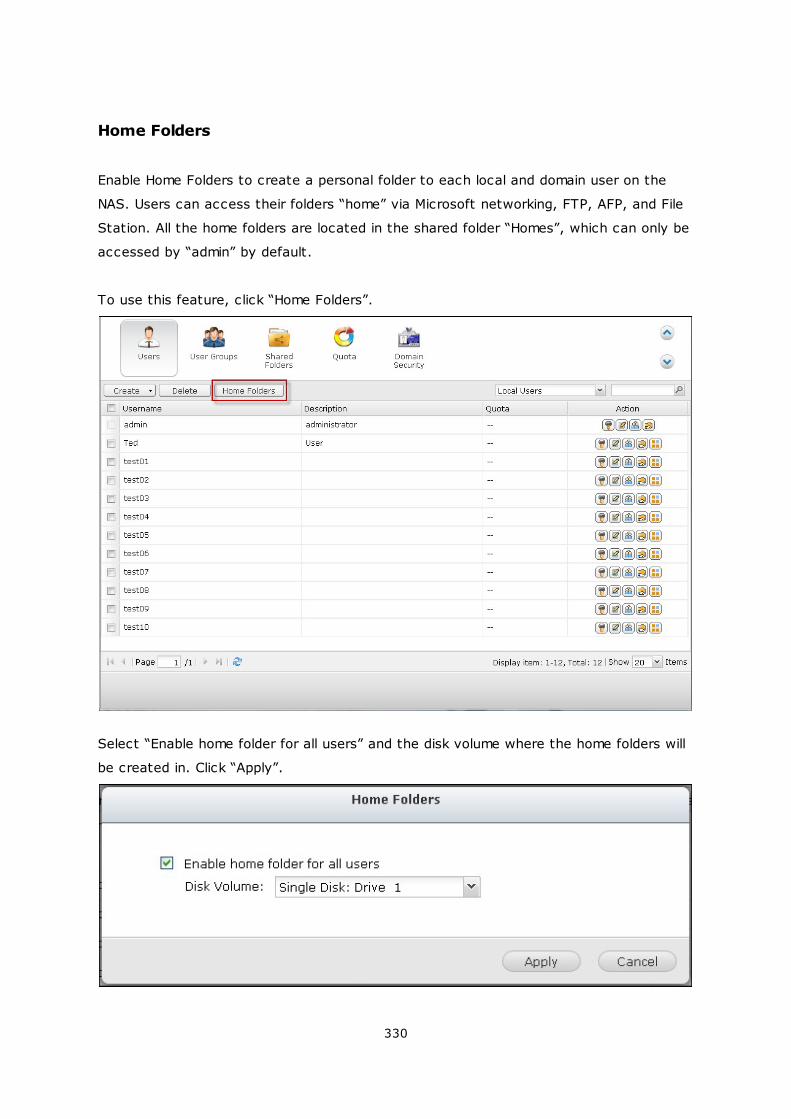
330
Home Folders
Enable Home Folders to create a personal folder to each local and domain user on the
NAS. Users can access their folders “home” via Microsoft networking, FTP, AFP, and File
Station. All the home folders are located in the shared folder “Homes”, which can only be
accessed by “admin” by default.
To use this feature, click “Home Folders”.
Select “Enable home folder for all users” and the disk volume where the home folders will
be created in. Click “Apply”.
331
5.2 User Groups
A user group is a collection of users with the same access right to the files or folders.
The NAS has created the following user groups by default:
administrators: All the members in this group have the administration right of the
NAS. This group cannot be deleted.
everyone: All the registered users belong to everyone group. This group cannot be
deleted.
The number of user groups you can create on the NAS varies according to the NAS
models. If your NAS models are not listed, please visit http://www.qnap.com for details.
Maxim um num ber of
user groups
NAS m odels
128 TS-110, TS-210
256 TS-112, TS-119, TS-119P+, TS-212, TS-219P+, TS-410,
TS-239 Pro II+, TS-259 Pro+
512 TS-412, TS-419P+, TS-410U, TS-419U, TS-412U, TS-
419U+, SS-439 Pro, SS-839 Pro, TS-439 Pro II+, TS-
459U-RP/SP, TS-459U-RP+/SP+, TS-459 Pro+, TS-459 Pro
II, TS-559 Pro+, TS-559 Pro II, TS-659 Pro+, TS-659 Pro
II, TS-859 Pro+, TS-859U-RP, TS-859U-RP+, TS-809 Pro,
TS-809U-RP, TS-879 Pro, TS-1079 Pro, TS-879U-RP, TS-
EC879U-RP, TS-1279U-RP, TS-EC1279U-RP
A group name must not exceed 256 characters. It is case-insensitive and supports
double-byte characters, such as Chinese, Japanese, and Korean, except the following
ones: " / \ [ ] : ; | = , + * ? < > ` '
332
333
5.3 Shared Folders
Shared Folders
You can create multiple shared folders on the NAS and specify the access rights of the
users and user groups to the shares.
The number of shared folders you can create on the NAS varies according to the NAS
models. If your NAS models are not listed, please visit http://www.qnap.com for details.
Maximum number of
shared folders
NAS models
256 TS-110, TS-210, TS-112, TS-119, TS-119P+, TS-212,
TS-219P+, TS-x20, TS-x21, TS-410, TS-239 Pro II+,
TS-259 Pro+
512 TS-412, TS-419P+, TS-410U, TS-419U, TS-412U, TS-
419U+, SS-439 Pro, SS-839 Pro, TS-439 Pro II+, TS-
459U-RP/SP, TS-459U-RP+/SP+, TS-459 Pro+, TS-459
Pro II, TS-559 Pro+, TS-559 Pro II, TS-659 Pro+, TS-
659 Pro II, TS-859 Pro+, TS-859U-RP, TS-859U-RP+,
TS-809 Pro, TS-809U-RP, TS-x70, TS-879 Pro, TS-
1079 Pro, TS-879U-RP, TS-EC879U-RP, TS-1279U-RP,
TS-EC1279U-RP
On the folder list, you can view the current data size, number of sub-folders and files
created in the shared folder, and the folder status (hidden or not).
334
1. To create a shared folder, click Create > “Shared Folder”.
2. Click “Next”.
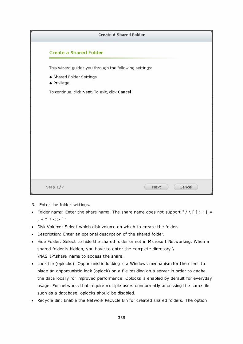
335
3. Enter the folder settings.
Folder name: Enter the share name. The share name does not support " / \ [ ] : ; | =
, + * ? < > ` '
Disk Volume: Select which disk volume on which to create the folder.
Description: Enter an optional description of the shared folder.
Hide Folder: Select to hide the shared folder or not in Microsoft Networking. When a
shared folder is hidden, you have to enter the complete directory \
\NAS_IP\share_name to access the share.
Lock file (oplocks): Opportunistic locking is a Windows mechanism for the client to
place an opportunistic lock (oplock) on a file residing on a server in order to cache
the data locally for improved performance. Oplocks is enabled by default for everyday
usage. For networks that require multiple users concurrently accessing the same file
such as a database, oplocks should be disabled.
Recycle Bin: Enable the Network Recycle Bin for created shared folders. The option
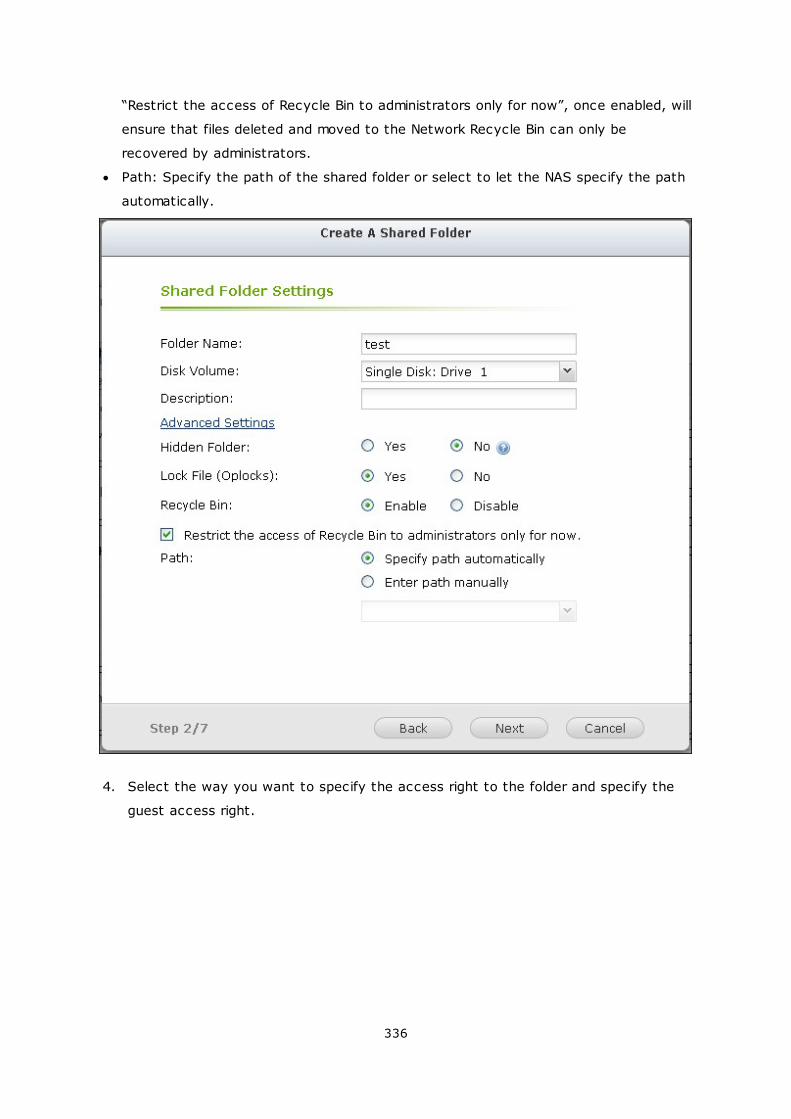
336
“Restrict the access of Recycle Bin to administrators only for now”, once enabled, will
ensure that files deleted and moved to the Network Recycle Bin can only be
recovered by administrators.
Path: Specify the path of the shared folder or select to let the NAS specify the path
automatically.
4. Select the way you want to specify the access right to the folder and specify the
guest access right.
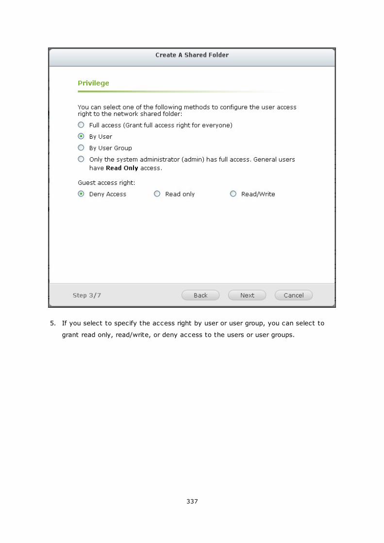
337
5. If you select to specify the access right by user or user group, you can select to
grant read only, read/write, or deny access to the users or user groups.
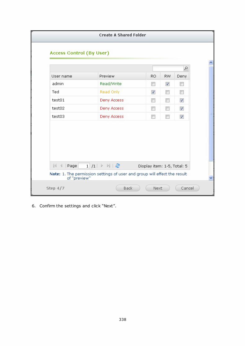
338
6. Confirm the settings and click “Next”.
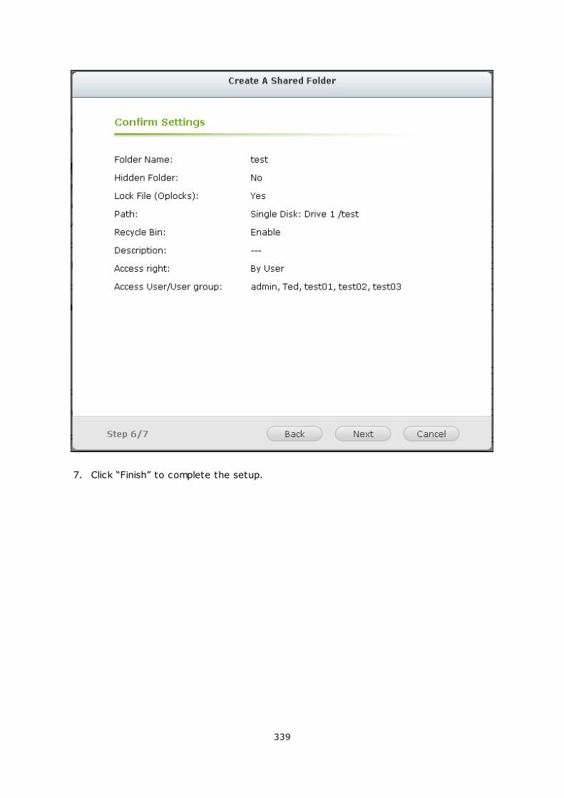
339
7. Click “Finish” to complete the setup.
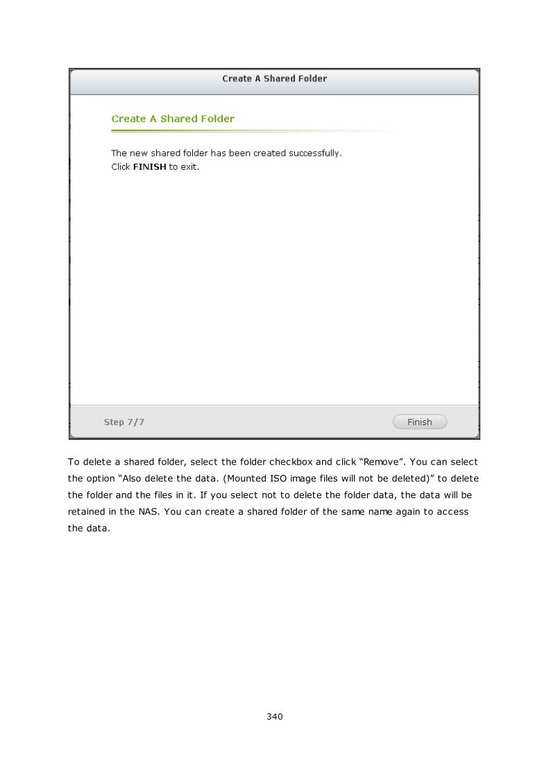
340
To delete a shared folder, select the folder checkbox and click “Remove”. You can select
the option “Also delete the data. (Mounted ISO image files will not be deleted)” to delete
the folder and the files in it. If you select not to delete the folder data, the data will be
retained in the NAS. You can create a shared folder of the same name again to access
the data.
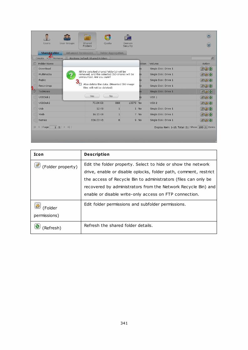
341
Icon Description
(Folder property)Edit the folder property. Select to hide or show the network
drive, enable or disable oplocks, folder path, comment, restrict
the access of Recycle Bin to administrators (files can only be
recovered by administrators from the Network Recycle Bin) and
enable or disable write-only access on FTP connection.
(Folder
permissions)
Edit folder permissions and subfolder permissions.
(Refresh)Refresh the shared folder details.
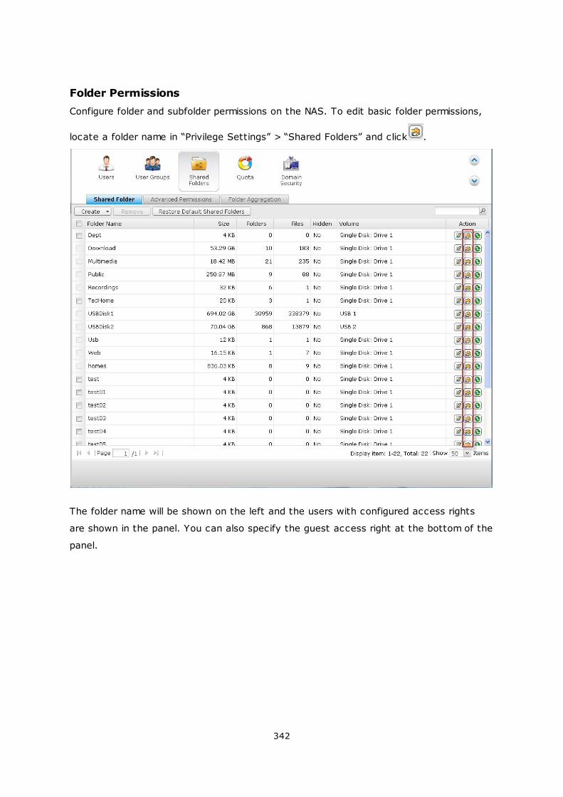
342
Folder Permissions
Configure folder and subfolder permissions on the NAS. To edit basic folder permissions,
locate a folder name in “Privilege Settings” > “Shared Folders” and click .
The folder name will be shown on the left and the users with configured access rights
are shown in the panel. You can also specify the guest access right at the bottom of the
panel.
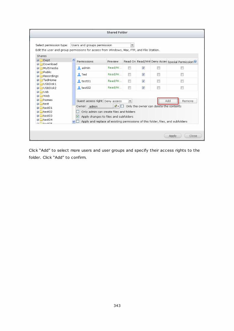
343
Click “Add” to select more users and user groups and specify their access rights to the
folder. Click “Add” to confirm.
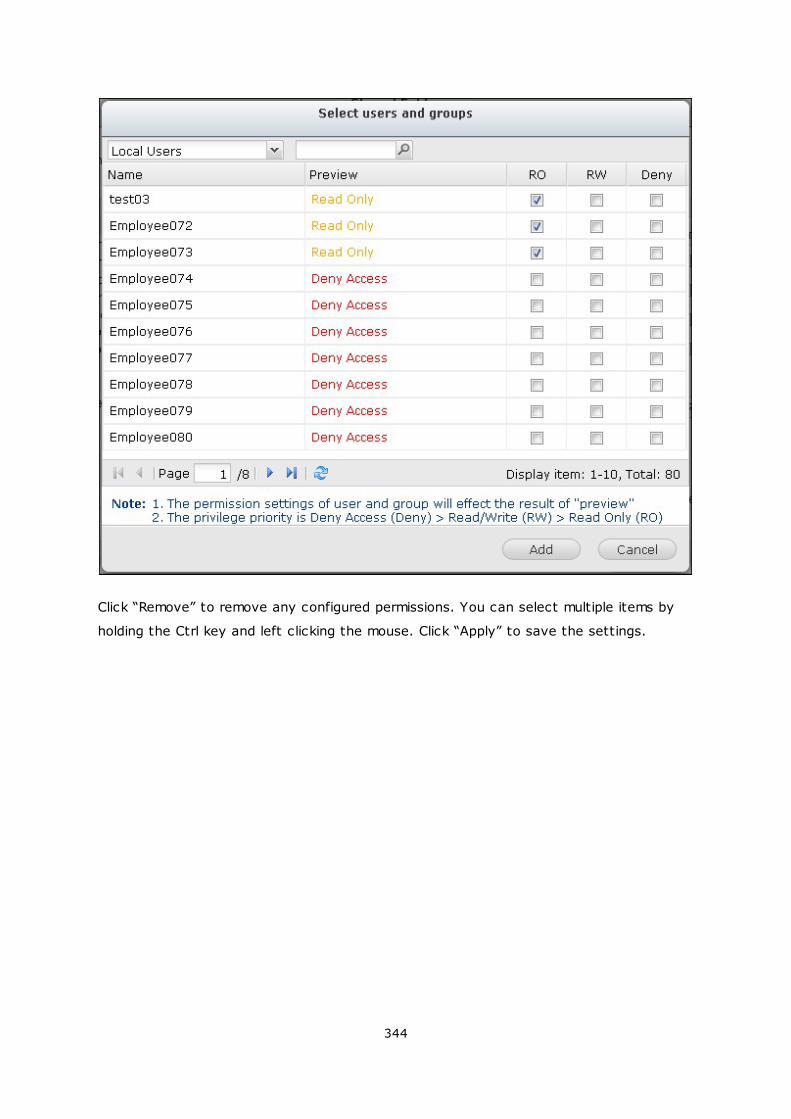
344
Click “Remove” to remove any configured permissions. You can select multiple items by
holding the Ctrl key and left clicking the mouse. Click “Apply” to save the settings.
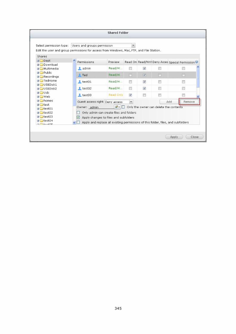
345
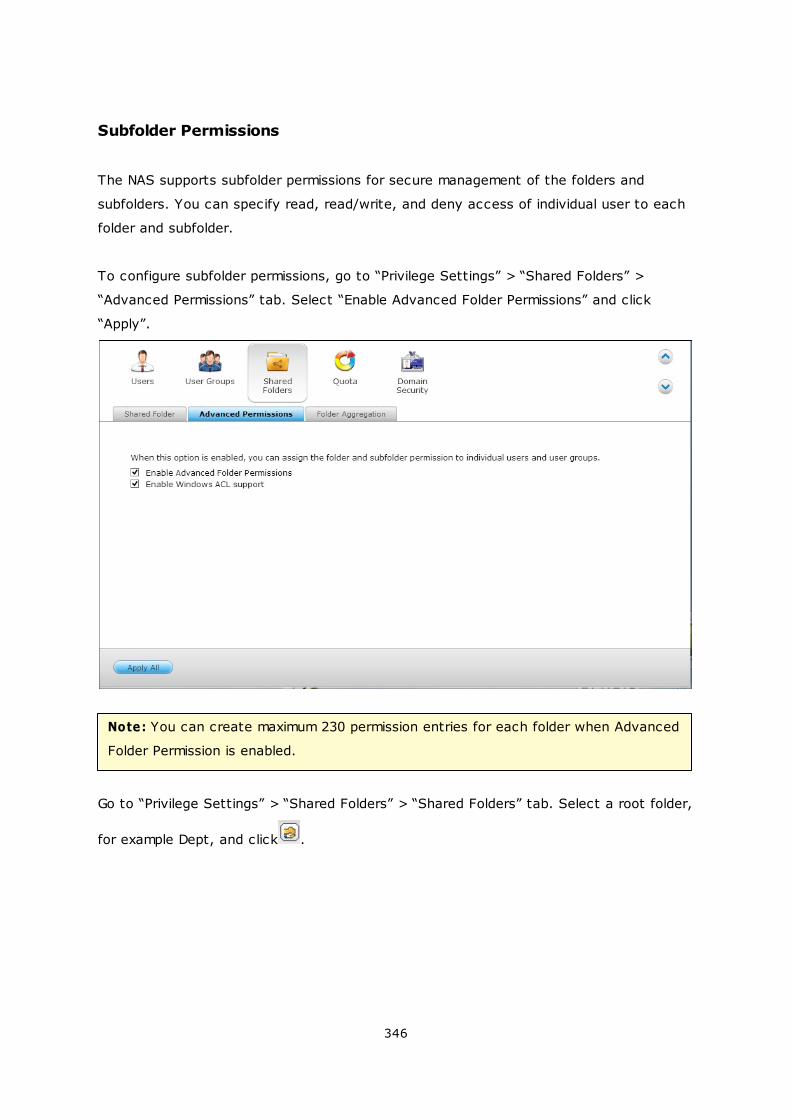
346
Subfolder Permissions
The NAS supports subfolder permissions for secure management of the folders and
subfolders. You can specify read, read/write, and deny access of individual user to each
folder and subfolder.
To configure subfolder permissions, go to “Privilege Settings” > “Shared Folders” >
“Advanced Permissions” tab. Select “Enable Advanced Folder Permissions” and click
“Apply”.
Note: You can create maximum 230 permission entries for each folder when Advanced
Folder Permission is enabled.
Go to “Privilege Settings” > “Shared Folders” > “Shared Folders” tab. Select a root folder,
for example Dept, and click .
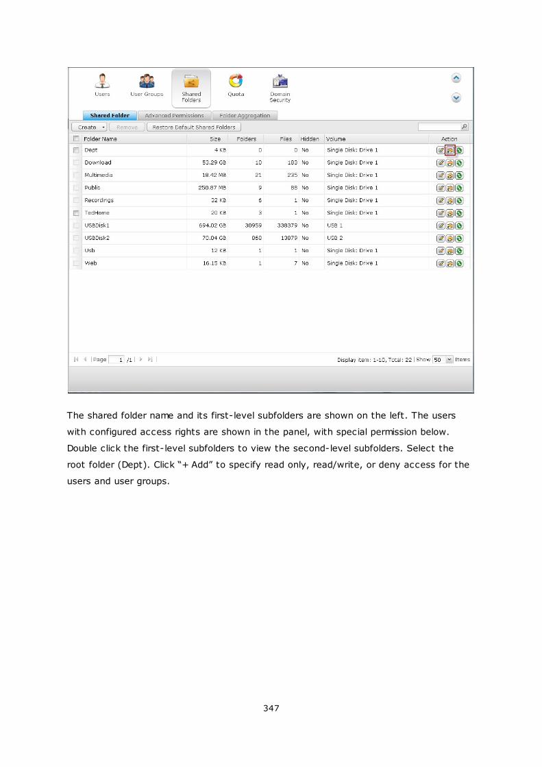
347
The shared folder name and its first-level subfolders are shown on the left. The users
with configured access rights are shown in the panel, with special permission below.
Double click the first-level subfolders to view the second-level subfolders. Select the
root folder (Dept). Click “+ Add” to specify read only, read/write, or deny access for the
users and user groups.
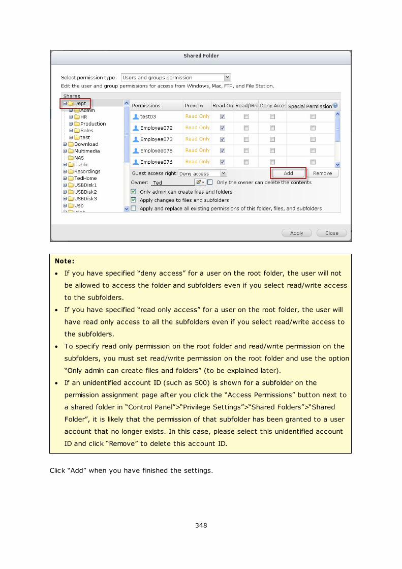
348
Note:
If you have specified “deny access” for a user on the root folder, the user will not
be allowed to access the folder and subfolders even if you select read/write access
to the subfolders.
If you have specified “read only access” for a user on the root folder, the user will
have read only access to all the subfolders even if you select read/write access to
the subfolders.
To specify read only permission on the root folder and read/write permission on the
subfolders, you must set read/write permission on the root folder and use the option
“Only admin can create files and folders” (to be explained later).
If an unidentified account ID (such as 500) is shown for a subfolder on the
permission assignment page after you click the “Access Permissions” button next to
a shared folder in “Control Panel”>“Privilege Settings”>“Shared Folders”>“Shared
Folder”, it is likely that the permission of that subfolder has been granted to a user
account that no longer exists. In this case, please select this unidentified account
ID and click “Remove” to delete this account ID.
Click “Add” when you have finished the settings.
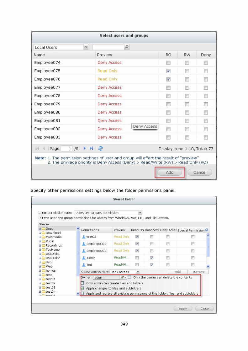
349
Specify other permissions settings below the folder permissions panel.
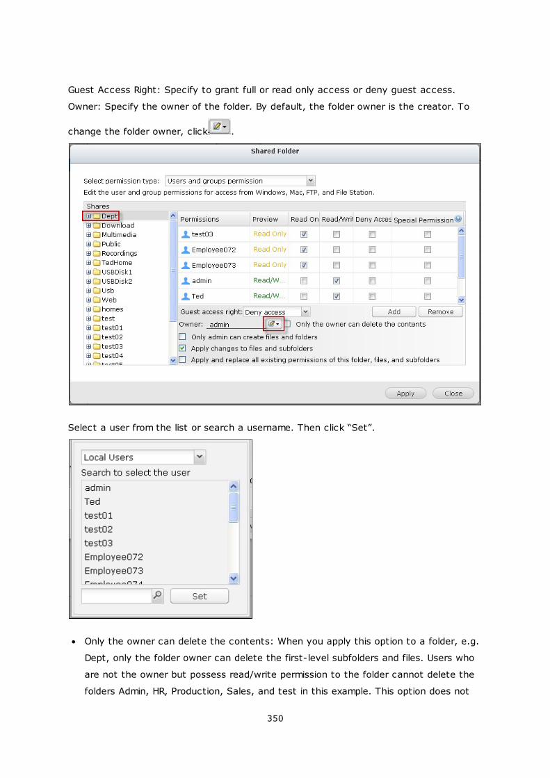
350
Guest Access Right: Specify to grant full or read only access or deny guest access.
Owner: Specify the owner of the folder. By default, the folder owner is the creator. To
change the folder owner, click .
Select a user from the list or search a username. Then click “Set”.
Only the owner can delete the contents: When you apply this option to a folder, e.g.
Dept, only the folder owner can delete the first-level subfolders and files. Users who
are not the owner but possess read/write permission to the folder cannot delete the
folders Admin, HR, Production, Sales, and test in this example. This option does not
351
apply to the subfolders of the selected folder even if the options “Apply changes to
files and subfolders” and “Apply and replace all existing permissions of this folder,
files, and subfolders” are selected.
Only admin can create files and folders: This option is only available for root folders.
Select this option to allow admin to create first-level subfolders and files in the
selected folder only. For example, in the folder “Dept”, only admin can create files
and subfolders Admin, HR, Production, and so on. Other users with read/write access
to Dept can only create files and folders in the second and lower-level subfolders
such as Admin01, Admin02, HR1, and HR2.
Apply changes to files and subfolders: Apply permissions settings except owner
protection and root folder write protection settings to all the files and subfolders
within the selected folder. These settings include new users, deleted users, modified
permissions, and folder owner. The options “Only the owner can delete the contents”
and “Only admin can create files and folders” will not be applied to subfolders.
Apply and replace all existing permissions of this folder, files, and subfolders: Select
this option to override all previously configured permissions of the selected folder and
its files and subfolders except owner protection and root folder write protection
settings. The options “Only the owner can delete the contents” and “Only admin can
create files and folders” will not be applied to subfolders.
352
Special Permission: This option is only available for root folders. Select this option
and choose between “Read only” or “Read/Write” to allow a user to access to all the
contents of a folder irrespectively of the pre-configured permissions. A user with
special permission will be identified as “admin” when he/she connects to the folder via
Microsoft Networking. If you have granted special permission with “Read/Write”
access to the user, the user will have full access and is able to configure the folder
permissions on Windows. Note that all the files created by this user belong to
“admin”. Since “admin” does not have quota limit on the NAS, the number and size of
the files created by users with special permission will not be limited by their pre-
configured quota settings. This option should be used for administrative and backup
tasks only.
After changing the permissions, click “Apply” and then “YES” to confirm.
353
354
Microsoft Networking Host Access Control
The NAS folders can be accessed via Samba connection (Windows) by default. You can
specify the IP addresses and hosts which are allowed to access the NAS via Microsoft
Networking. Click .
Select “Microsoft Networking host access” from the dropdown menu on top of the page.
355
Specify the allowed IP addresses and host names. The following IP address and host
name are used as example here:
IP address 192.168.12.12
192.168.*.*
Host name dnsname.domain.local
*.domain.local
click “Add” to enter the IP address and host name and then “Apply”.
Wildcard characters
You can enter wildcard characters in an IP address or host name entry to represent
unknown characters.
Asterisk (*)
Use an asterisk (*) as a substitute for zero or more characters. For example, if you enter
*.domain.local, the following items are included:
a.domain.local
cde.domain.local
test.domain.local

356
Question m ark (?)
Use a question mark (?) as a substitute for only one character. For example, test?.
domain.local includes the following:
test1.domain.local
test2.domain.local
testa.domain.local
When you use wildcard characters in a valid host name, dot (.) is included in wildcard
characters. For example, when you enter *.example.com, “one.example.com” and “one.
two.example.com” are included.
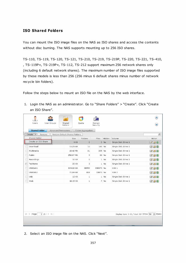
357
ISO Shared Folders
You can mount the ISO image files on the NAS as ISO shares and access the contents
without disc burning. The NAS supports mounting up to 256 ISO shares.
TS-110, TS-119, TS-120, TS-121, TS-210, TS-219, TS-219P, TS-220, TS-221, TS-410,
, TS-119P+, TS-219P+, TS-112, TS-212 support maximum 256 network shares only
(including 6 default network shares). The maximum number of ISO image files supported
by these models is less than 256 (256 minus 6 default shares minus number of network
recycle bin folders).
Follow the steps below to mount an ISO file on the NAS by the web interface.
1. Login the NAS as an administrator. Go to “Share Folders” > “Create”. Click “Create
an ISO Share”.
2. Select an ISO image file on the NAS. Click “Next”.
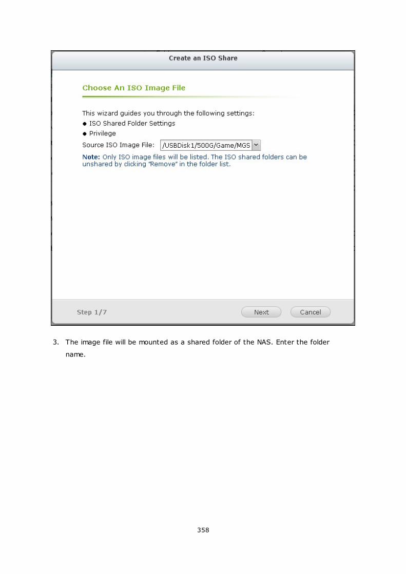
358
3. The image file will be mounted as a shared folder of the NAS. Enter the folder
name.
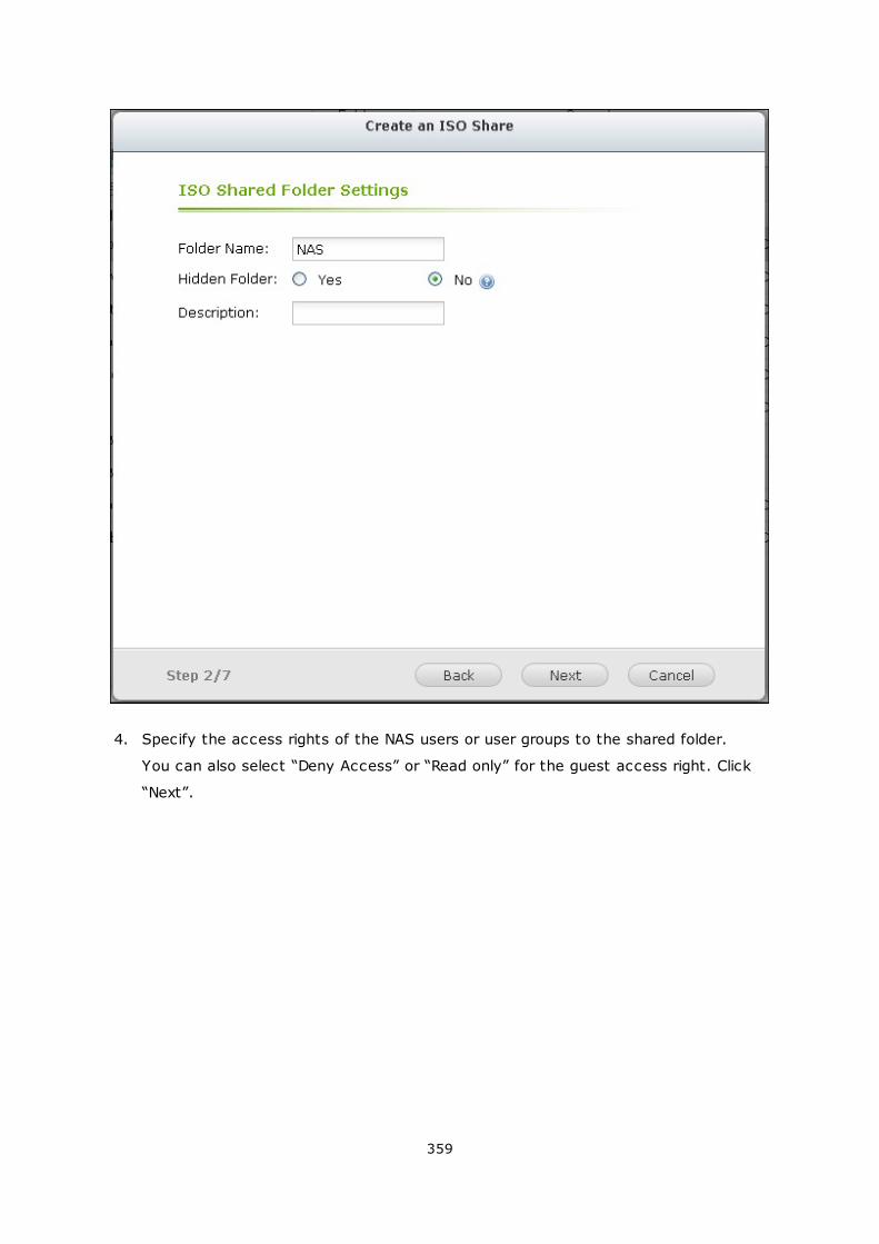
359
4. Specify the access rights of the NAS users or user groups to the shared folder.
You can also select “Deny Access” or “Read only” for the guest access right. Click
“Next”.
360
5. Confirm the settings and click “Next”.
361
6. Click “Finish”.
362
7. After mounting the image file, you can specify the access rights of the users over
different network protocols such as SMB, AFP, NFS, and WebDAV by clicking the
Access Permission icon in the “Action” column.
363
The NAS supports mounting ISO image files by the File Station. Please refer to the
chapter on File Station for details.
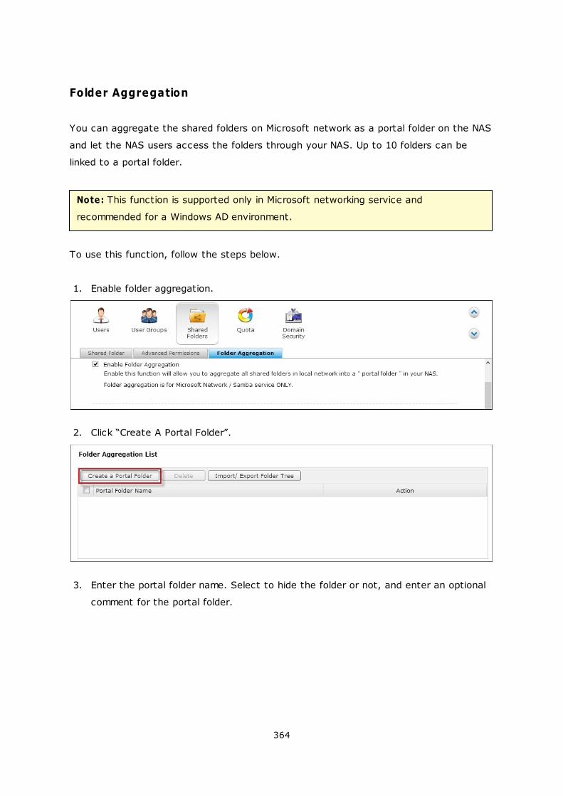
364
Folder Aggregation
You can aggregate the shared folders on Microsoft network as a portal folder on the NAS
and let the NAS users access the folders through your NAS. Up to 10 folders can be
linked to a portal folder.
Note: This function is supported only in Microsoft networking service and
recommended for a Windows AD environment.
To use this function, follow the steps below.
1. Enable folder aggregation.
2. Click “Create A Portal Folder”.
3. Enter the portal folder name. Select to hide the folder or not, and enter an optional
comment for the portal folder.
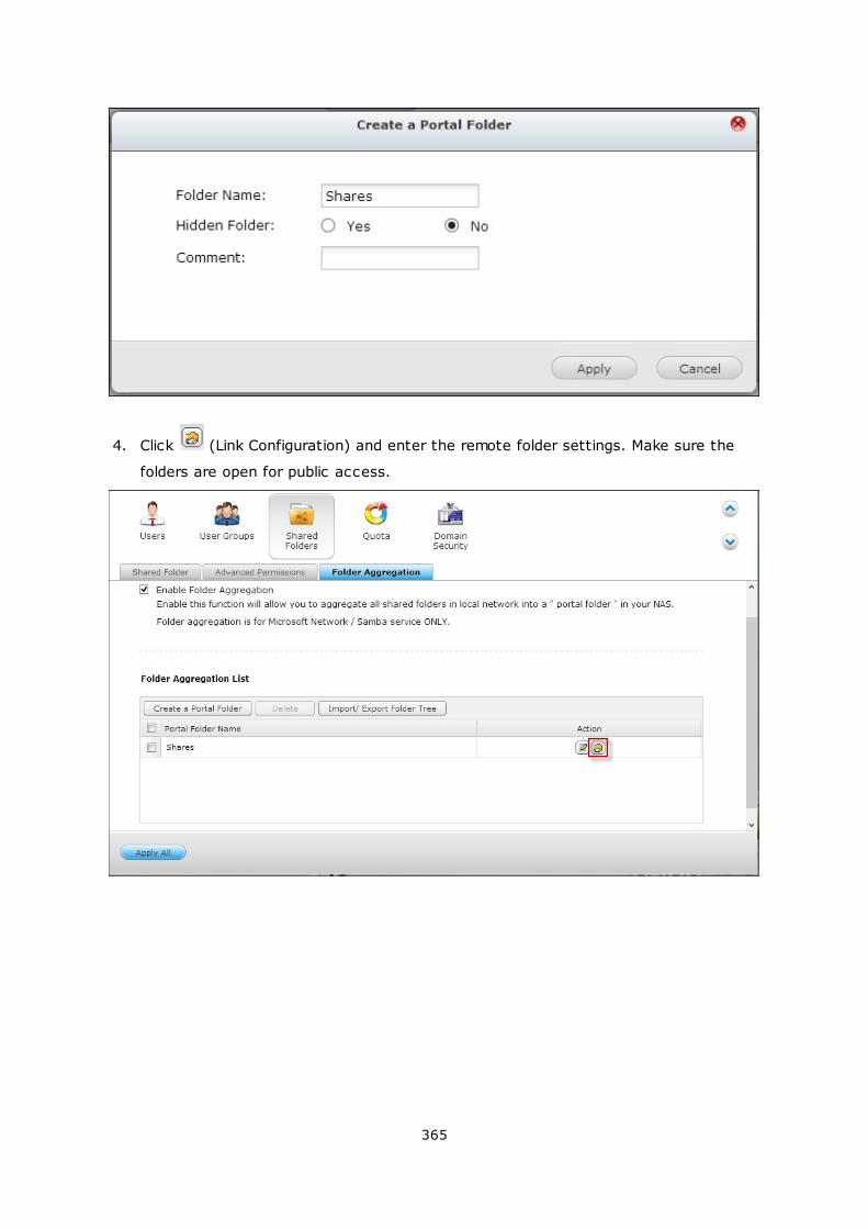
365
4. Click (Link Configuration) and enter the remote folder settings. Make sure the
folders are open for public access.
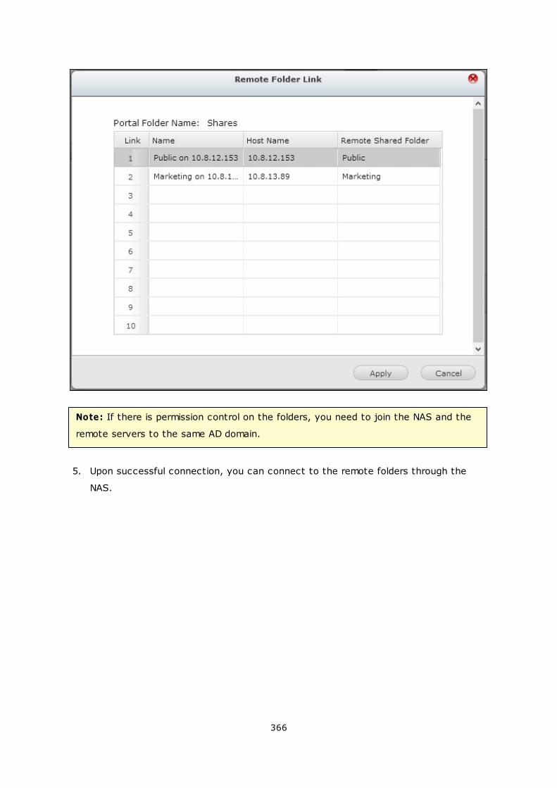
366
Note: If there is permission control on the folders, you need to join the NAS and the
remote servers to the same AD domain.
5. Upon successful connection, you can connect to the remote folders through the
NAS.
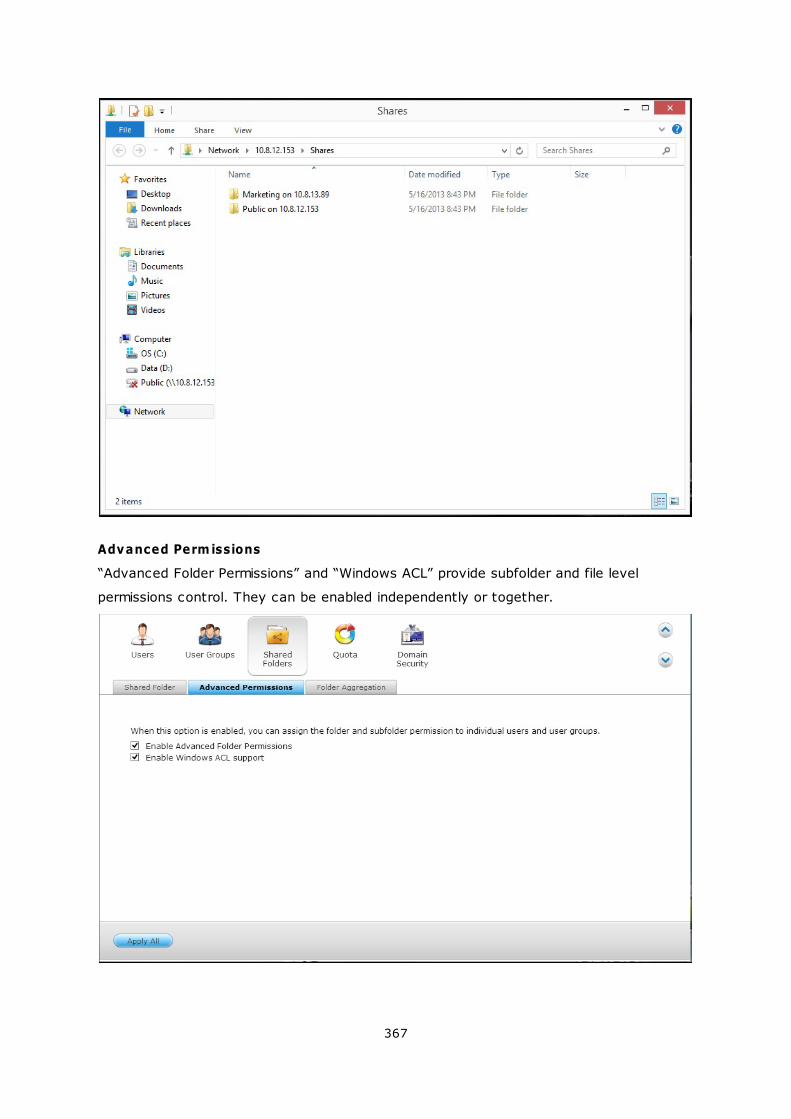
367
Advanced Perm issions
“Advanced Folder Permissions” and “Windows ACL” provide subfolder and file level
permissions control. They can be enabled independently or together.
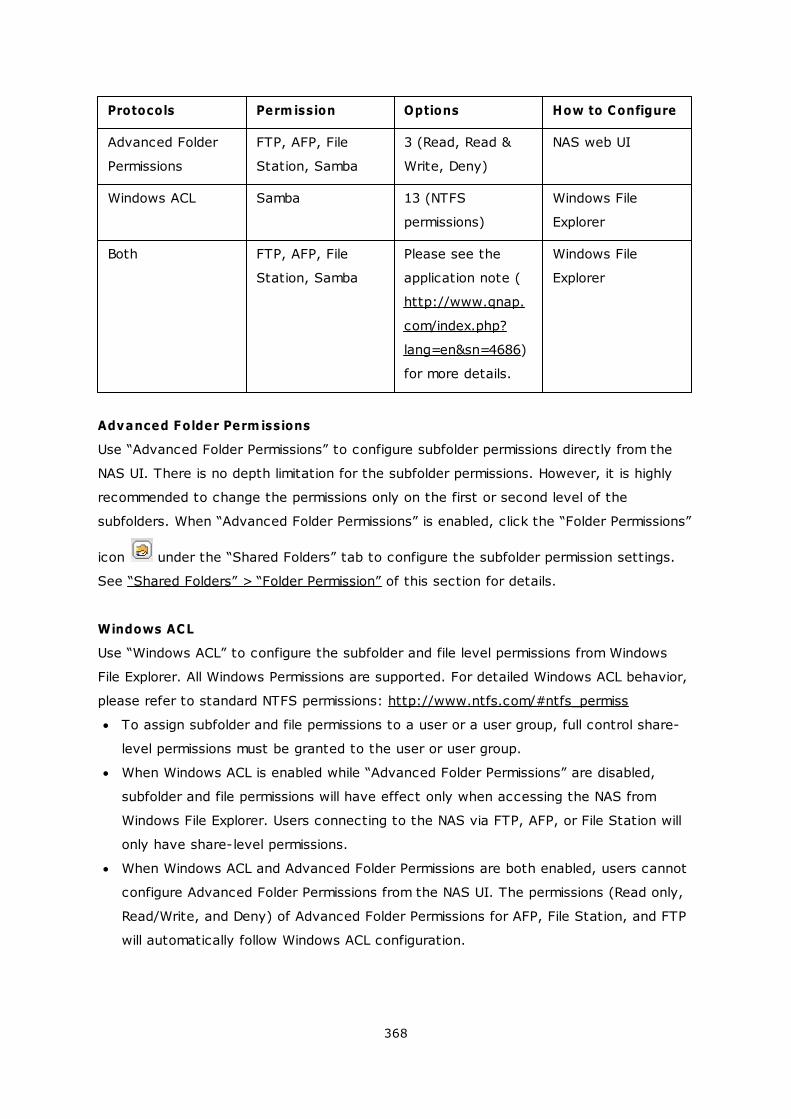
368
Protocols Perm ission Options How to Configure
Advanced Folder
Permissions
FTP, AFP, File
Station, Samba
3 (Read, Read &
Write, Deny)
NAS web UI
Windows ACL Samba 13 (NTFS
permissions)
Windows File
Explorer
Both FTP, AFP, File
Station, Samba
Please see the
application note (
http://www.qnap.
com/index.php?
lang=en&sn=4686)
for more details.
Windows File
Explorer
Advanced Folder Perm issions
Use “Advanced Folder Permissions” to configure subfolder permissions directly from the
NAS UI. There is no depth limitation for the subfolder permissions. However, it is highly
recommended to change the permissions only on the first or second level of the
subfolders. When “Advanced Folder Permissions” is enabled, click the “Folder Permissions”
icon under the “Shared Folders” tab to configure the subfolder permission settings.
See “Shared Folders” > “Folder Permission” of this section for details.
Windows ACL
Use “Windows ACL” to configure the subfolder and file level permissions from Windows
File Explorer. All Windows Permissions are supported. For detailed Windows ACL behavior,
please refer to standard NTFS permissions: http://www.ntfs.com/#ntfs_permiss
To assign subfolder and file permissions to a user or a user group, full control share-
level permissions must be granted to the user or user group.
When Windows ACL is enabled while “Advanced Folder Permissions” are disabled,
subfolder and file permissions will have effect only when accessing the NAS from
Windows File Explorer. Users connecting to the NAS via FTP, AFP, or File Station will
only have share-level permissions.
When Windows ACL and Advanced Folder Permissions are both enabled, users cannot
configure Advanced Folder Permissions from the NAS UI. The permissions (Read only,
Read/Write, and Deny) of Advanced Folder Permissions for AFP, File Station, and FTP
will automatically follow Windows ACL configuration.
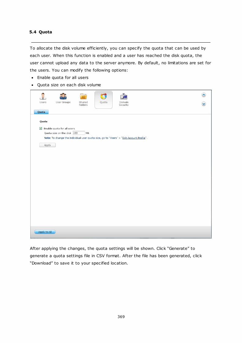
369
5.4 Quota
To allocate the disk volume efficiently, you can specify the quota that can be used by
each user. When this function is enabled and a user has reached the disk quota, the
user cannot upload any data to the server anymore. By default, no limitations are set for
the users. You can modify the following options:
Enable quota for all users
Quota size on each disk volume
After applying the changes, the quota settings will be shown. Click “Generate” to
generate a quota settings file in CSV format. After the file has been generated, click
“Download” to save it to your specified location.
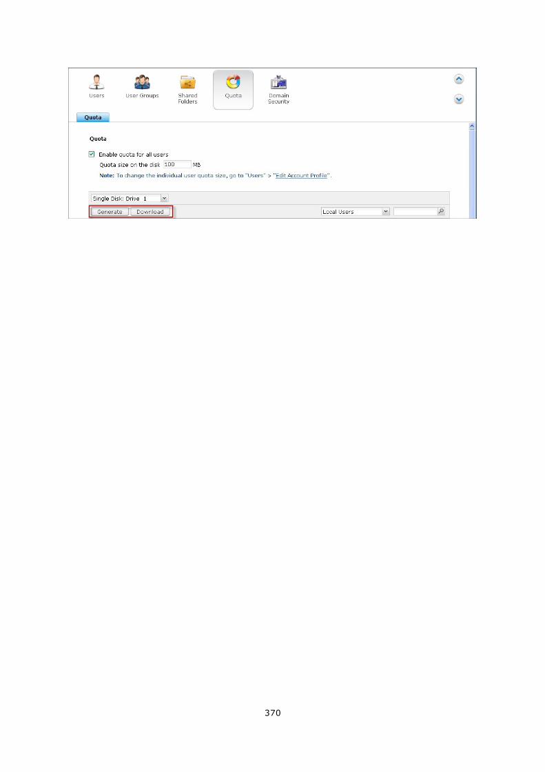
370
371
5.5 Domain Security
The NAS supports user authentication by local access right management, Microsoft
Active Directory (Windows Server 2003/2008/2012), and Lightweight Directory Access
Protocol (LDAP) directory. By joining the NAS to an Active Directory or a LDAP directory,
the AD or LDAP users can access the NAS using their own accounts without extra user
account setup on the NAS.
No domain security
Only the local users can access the NAS.
Active Directory authentication (domain members)
Join the NAS to an Active Directory. The domain users can be authenticated by the NAS.
After joining the NAS to an AD domain, both the local NAS users and AD users can
access the NAS via the following protocols/services:
Samba (Microsoft Networking)
AFP
FTP
File Station
LDAP authentication
Connect the NAS to an LDAP directory. The LDAP users can be authenticated by the
NAS. After connecting the NAS to an LDAP directory, either the local NAS users or the
LDAP users can be authenticated to access the NAS via Samba (Microsoft Networking).
Both the local NAS users and LDAP users can access the NAS via the following protocols/
services:
AFP
FTP
File Station
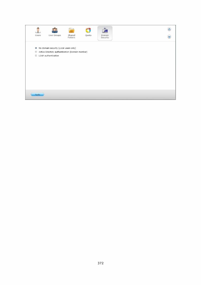
372
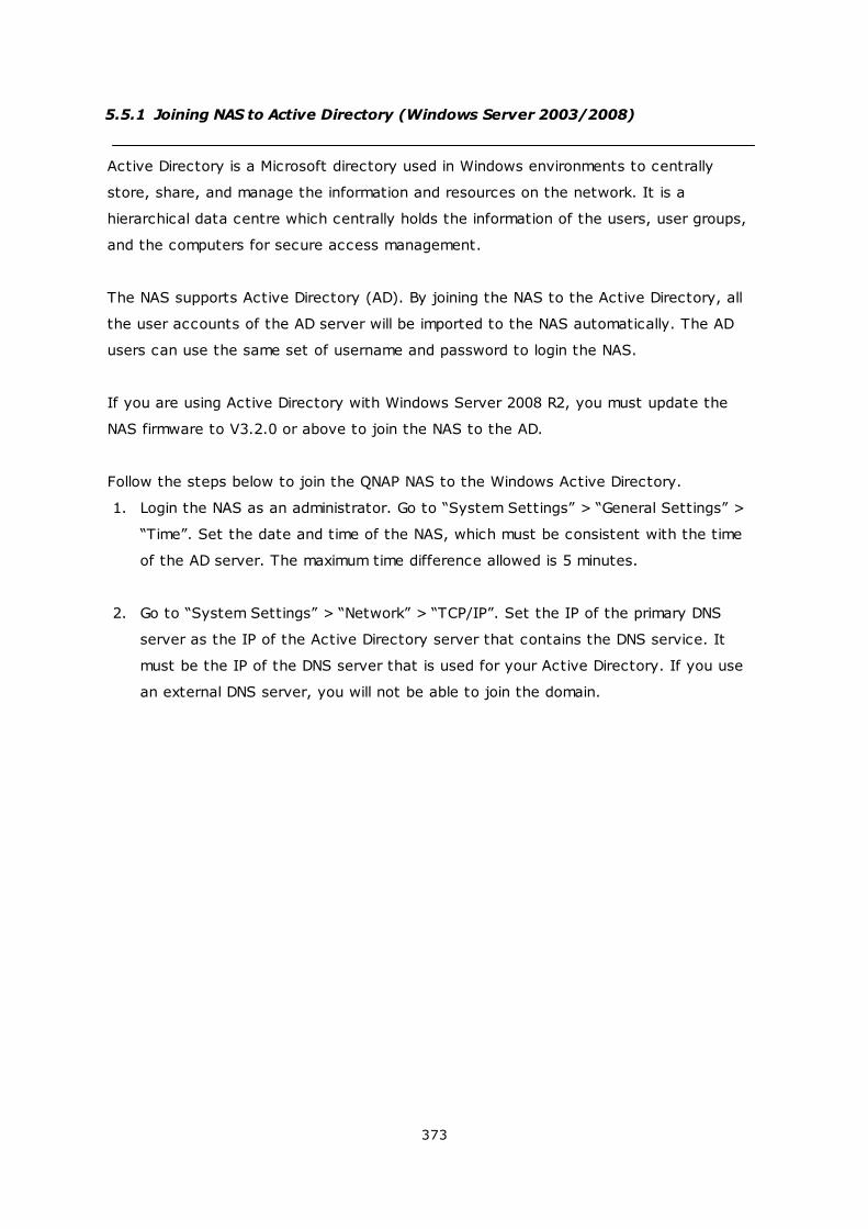
373
5.5.1 Joining NAS to Active Directory (Windows Server 2003/2008)
Active Directory is a Microsoft directory used in Windows environments to centrally
store, share, and manage the information and resources on the network. It is a
hierarchical data centre which centrally holds the information of the users, user groups,
and the computers for secure access management.
The NAS supports Active Directory (AD). By joining the NAS to the Active Directory, all
the user accounts of the AD server will be imported to the NAS automatically. The AD
users can use the same set of username and password to login the NAS.
If you are using Active Directory with Windows Server 2008 R2, you must update the
NAS firmware to V3.2.0 or above to join the NAS to the AD.
Follow the steps below to join the QNAP NAS to the Windows Active Directory.
1. Login the NAS as an administrator. Go to “System Settings” > “General Settings” >
“Time”. Set the date and time of the NAS, which must be consistent with the time
of the AD server. The maximum time difference allowed is 5 minutes.
2. Go to “System Settings” > “Network” > “TCP/IP”. Set the IP of the primary DNS
server as the IP of the Active Directory server that contains the DNS service. It
must be the IP of the DNS server that is used for your Active Directory. If you use
an external DNS server, you will not be able to join the domain.
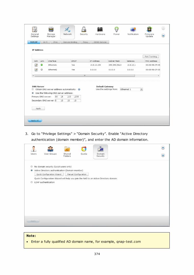
374
3. Go to “Privilege Settings” > “Domain Security”. Enable “Active Directory
authentication (domain member)”, and enter the AD domain information.
Note:
Enter a fully qualified AD domain name, for example, qnap-test.com

375
The AD user entered here must have the administrator access right to the AD
domain.
WINS Support: If you are using a WINS server on the network and the workstation
is configured to use that WINS server for name resolution, you must set up the
WINS server IP on the NAS (use the specified WINS server.)
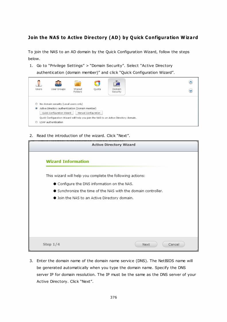
376
Join the NAS to Active Directory (AD) by Quick Configuration Wizard
To join the NAS to an AD domain by the Quick Configuration Wizard, follow the steps
below.
1. Go to “Privilege Settings” > “Domain Security”. Select “Active Directory
authentication (domain member)” and click “Quick Configuration Wizard”.
2. Read the introduction of the wizard. Click “Next”.
3. Enter the domain name of the domain name service (DNS). The NetBIOS name will
be generated automatically when you type the domain name. Specify the DNS
server IP for domain resolution. The IP must be the same as the DNS server of your
Active Directory. Click “Next”.
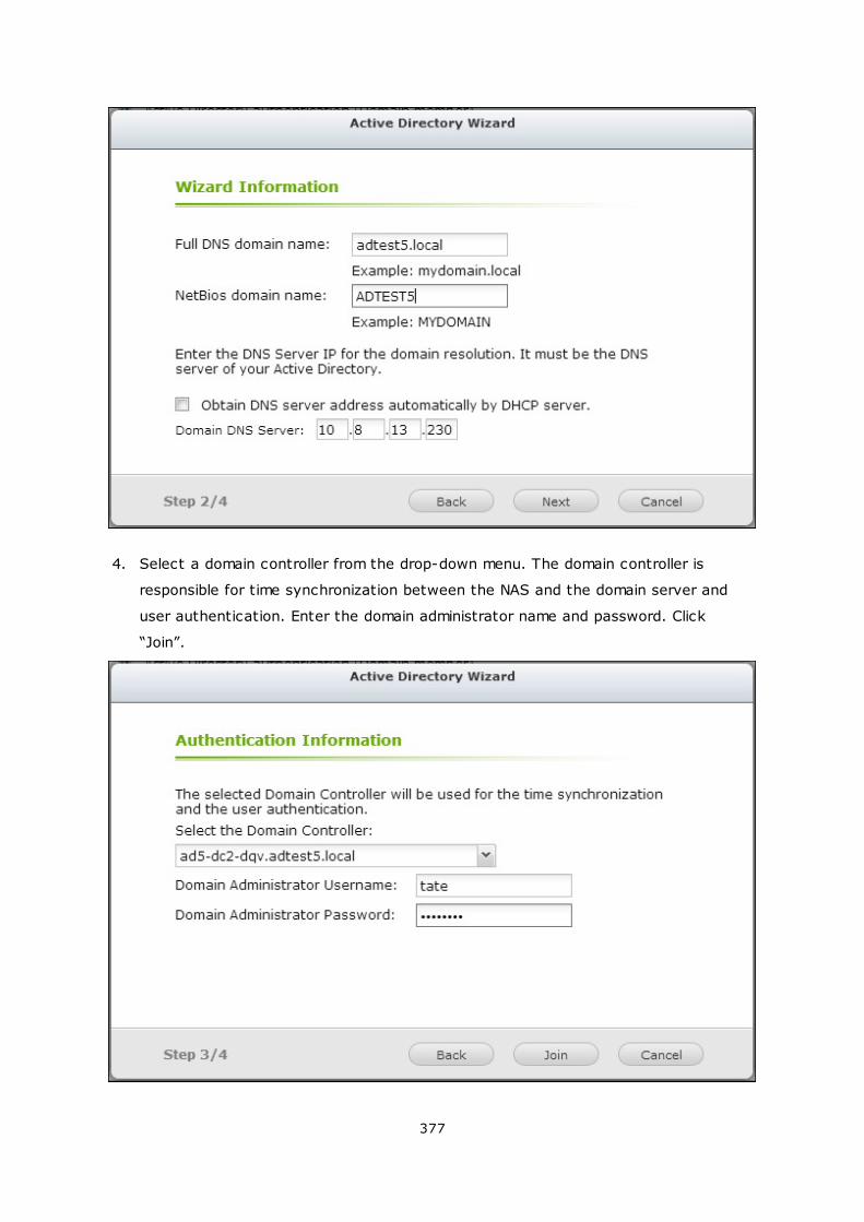
377
4. Select a domain controller from the drop-down menu. The domain controller is
responsible for time synchronization between the NAS and the domain server and
user authentication. Enter the domain administrator name and password. Click
“Join”.
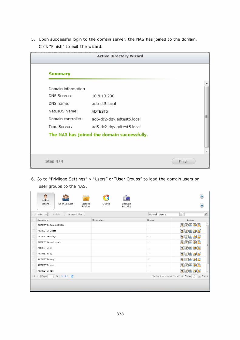
378
5. Upon successful login to the domain server, the NAS has joined to the domain.
Click “Finish” to exit the wizard.
6. Go to “Privilege Settings” > “Users” or “User Groups” to load the domain users or
user groups to the NAS.
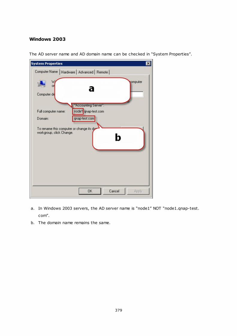
379
Windows 2003
The AD server name and AD domain name can be checked in “System Properties”.
a. In Windows 2003 servers, the AD server name is “node1” NOT “node1.qnap-test.
com”.
b. The domain name remains the same.
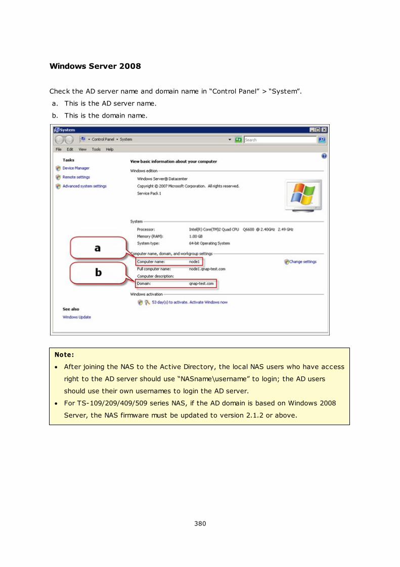
380
Windows Server 2008
Check the AD server name and domain name in “Control Panel” > “System”.
a. This is the AD server name.
b. This is the domain name.
Note:
After joining the NAS to the Active Directory, the local NAS users who have access
right to the AD server should use “NASname\username” to login; the AD users
should use their own usernames to login the AD server.
For TS-109/209/409/509 series NAS, if the AD domain is based on Windows 2008
Server, the NAS firmware must be updated to version 2.1.2 or above.
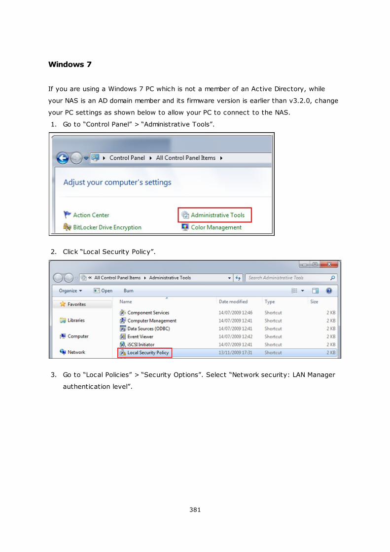
381
Windows 7
If you are using a Windows 7 PC which is not a member of an Active Directory, while
your NAS is an AD domain member and its firmware version is earlier than v3.2.0, change
your PC settings as shown below to allow your PC to connect to the NAS.
1. Go to “Control Panel” > “Administrative Tools”.
2. Click “Local Security Policy”.
3. Go to “Local Policies” > “Security Options”. Select “Network security: LAN Manager
authentication level”.
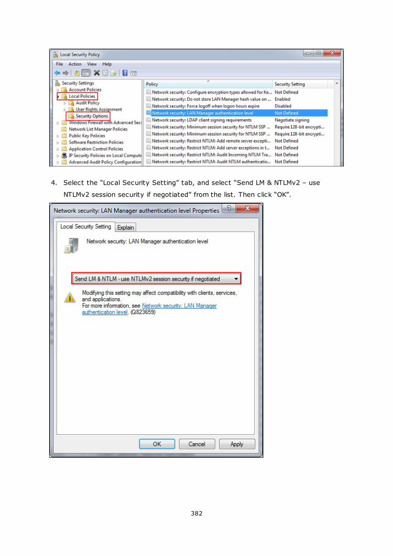
382
4. Select the “Local Security Setting” tab, and select “Send LM & NTLMv2 – use
NTLMv2 session security if negotiated” from the list. Then click “OK”.
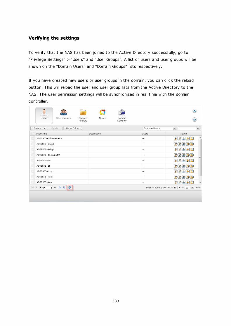
383
Verifying the settings
To verify that the NAS has been joined to the Active Directory successfully, go to
“Privilege Settings” > “Users” and “User Groups”. A list of users and user groups will be
shown on the “Domain Users” and “Domain Groups” lists respectively.
If you have created new users or user groups in the domain, you can click the reload
button. This will reload the user and user group lists from the Active Directory to the
NAS. The user permission settings will be synchronized in real time with the domain
controller.
384
5.5.2 Connecting NAS to an LDAP Directory
LDAP stands for Lightweight Directory Access Protocol. It is a directory that can store
the information of all the users and groups in a centralized server. Using LDAP, the
administrator can manage the users in the LDAP directory and allow the users to connect
to multiple NAS servers with the same username and password.
This feature is intended for administrator and users who have some knowledge about
Linux servers, LDAP servers, and Samba. An LDAP server which is up and running is
required when using the LDAP feature of the QNAP NAS.
Required information/settings:
The LDAP server connection and authentication information
The LDAP structure, where the users and groups are stored
The LDAP server security settings
Follow the steps below to connect the QNAP NAS to an LDAP directory.
1. Login the web interface of the NAS as an administrator.
2. Go to “Privilege Settings” > “Domain Security”. By default, the option “No domain
security” is enabled. That means only the local NAS users can connect to the NAS.
3. Select “LDAP authentication” and complete the settings.
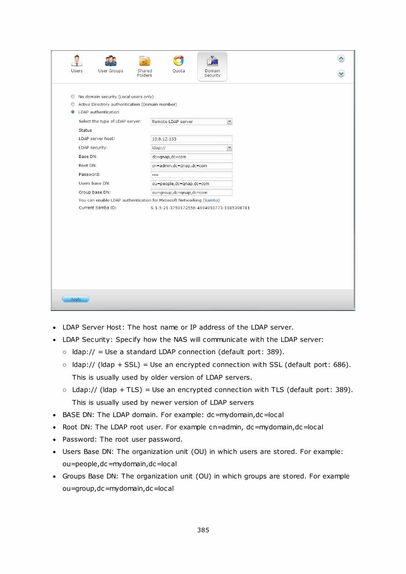
385
LDAP Server Host: The host name or IP address of the LDAP server.
LDAP Security: Specify how the NAS will communicate with the LDAP server:
o ldap:// = Use a standard LDAP connection (default port: 389).
o ldap:// (ldap + SSL) = Use an encrypted connection with SSL (default port: 686).
This is usually used by older version of LDAP servers.
o Ldap:// (ldap + TLS) = Use an encrypted connection with TLS (default port: 389).
This is usually used by newer version of LDAP servers
BASE DN: The LDAP domain. For example: dc=mydomain,dc=local
Root DN: The LDAP root user. For example cn=admin, dc=mydomain,dc=local
Password: The root user password.
Users Base DN: The organization unit (OU) in which users are stored. For example:
ou=people,dc=mydomain,dc=local
Groups Base DN: The organization unit (OU) in which groups are stored. For example
ou=group,dc=mydomain,dc=local
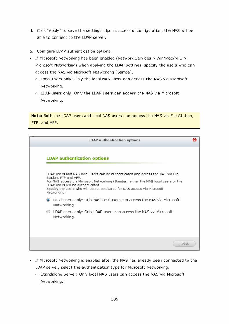
386
4. Click “Apply” to save the settings. Upon successful configuration, the NAS will be
able to connect to the LDAP server.
5. Configure LDAP authentication options.
If Microsoft Networking has been enabled (Network Services > Win/Mac/NFS >
Microsoft Networking) when applying the LDAP settings, specify the users who can
access the NAS via Microsoft Networking (Samba).
o Local users only: Only the local NAS users can access the NAS via Microsoft
Networking.
o LDAP users only: Only the LDAP users can access the NAS via Microsoft
Networking.
Note: Both the LDAP users and local NAS users can access the NAS via File Station,
FTP, and AFP.
If Microsoft Networking is enabled after the NAS has already been connected to the
LDAP server, select the authentication type for Microsoft Networking.
o Standalone Server: Only local NAS users can access the NAS via Microsoft
Networking.
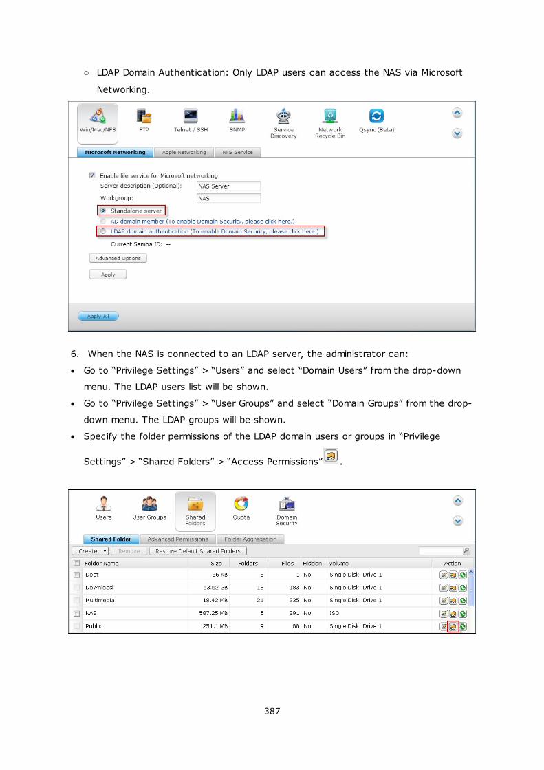
387
o LDAP Domain Authentication: Only LDAP users can access the NAS via Microsoft
Networking.
6. When the NAS is connected to an LDAP server, the administrator can:
Go to “Privilege Settings” > “Users” and select “Domain Users” from the drop-down
menu. The LDAP users list will be shown.
Go to “Privilege Settings” > “User Groups” and select “Domain Groups” from the drop-
down menu. The LDAP groups will be shown.
Specify the folder permissions of the LDAP domain users or groups in “Privilege
Settings” > “Shared Folders” > “Access Permissions” .
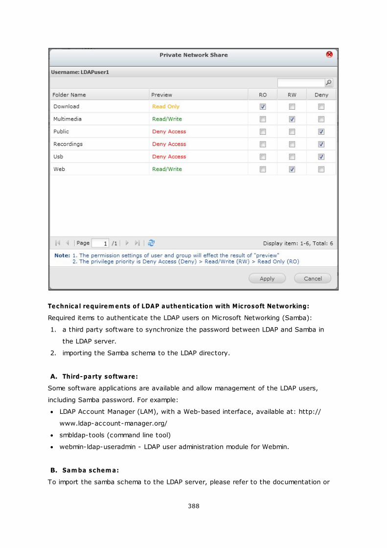
388
Technical requirem ents of LDAP authentication with Microsoft Networking:
Required items to authenticate the LDAP users on Microsoft Networking (Samba):
1. a third party software to synchronize the password between LDAP and Samba in
the LDAP server.
2. importing the Samba schema to the LDAP directory.
A. Third-party software:
Some software applications are available and allow management of the LDAP users,
including Samba password. For example:
LDAP Account Manager (LAM), with a Web-based interface, available at: http://
www.ldap-account-manager.org/
smbldap-tools (command line tool)
webmin-ldap-useradmin - LDAP user administration module for Webmin.
B. Sam ba schem a:
To import the samba schema to the LDAP server, please refer to the documentation or
389
FAQ of the LDAP server.
The samba.schema file is required and can be found in the directory examples/LDAP in
the Samba source distribution.
Example for open-ldap in the Linux server where the LDAP server is running (it can be
different depending on the Linux distribution):
Copy the samba schema:
zcat /usr/share/doc/samba-doc/examples/LDAP/samba.schema.gz > /etc/ldap/schema/
samba.schema
Edit /etc/ldap/slapd.conf (openldap server configuration file) and make sure the following
lines are present in the file:
include /etc/ldap/schema/samba.schema
include /etc/ldap/schema/cosine.schema
include /etc/ldap/schema/inetorgperson.schema
include /etc/ldap/schema/nis.schema
Configuration exam ples:
The following are some configuration examples. They are not mandatory and need to be
adapted to match the LDAP server configuration:
1. Linux OpenLDAP Server
Base DN: dc=qnap,dc=com
Root DN: cn=admin,dc=qnap,dc=com
Users Base DN: ou=people,dc=qnap,dc=com
Groups Base DN: ou=group,dc=qnap,dc=com
2. Mac Open Directory Server
Base DN: dc=macserver,dc=qnap,dc=com
Root DN: uid=root,cn=users,dc=macserver,dc=qnap,dc=com
Users Base DN: cn=users,dc=macserver,dc=qnap,dc=com
Groups Base DN: cn=groups,dc=macserver,dc=qnap,dc=com
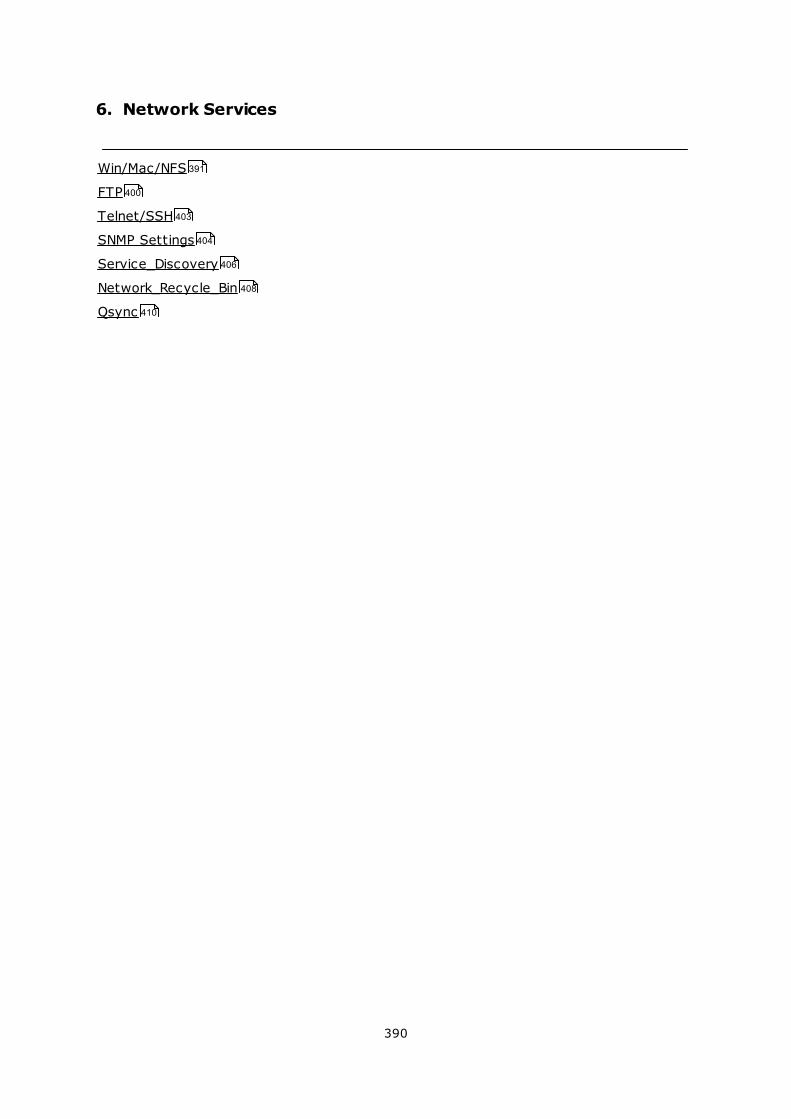
390
6. Network Services
Win/Mac/NFS
FTP
Telnet/SSH
SNMP Settings
Service_Discovery
Network_Recycle_Bin
Qsync
391
400
403
404
406
408
410
391
6.1 Win/Mac/NFS
Microsoft Networking
To allow access to the NAS on Microsoft Windows Network, enable file service for
Microsoft networking. Specify also how the users will be authenticated.
Standalone Server
Use local users for authentication. The NAS will use the local user accounts information
(created in “Privilege Settings” > “Users”) to authenticate the users who access the
NAS.
Server Description (optional): Describe the NAS so that the users can easily identify
the server on Microsoft Network.
Workgroup: Specify the workgroup to which the NAS belongs. A workgroup name
supports up to 15 characters but cannot contain: " + = / \ : | * ? < > ; [ ] % , `
AD Dom ain Mem ber
Use Microsoft Active Directory (AD) to authenticate the users. To use this option, enable
Active Directory authentication in “Privilege Settings” > “Domain Security” and join the
NAS to an Active Directory.
LDAP Dom ain Authentication
Use Lightweight Directory Access Protocol (LDAP) directory to authenticate the users.
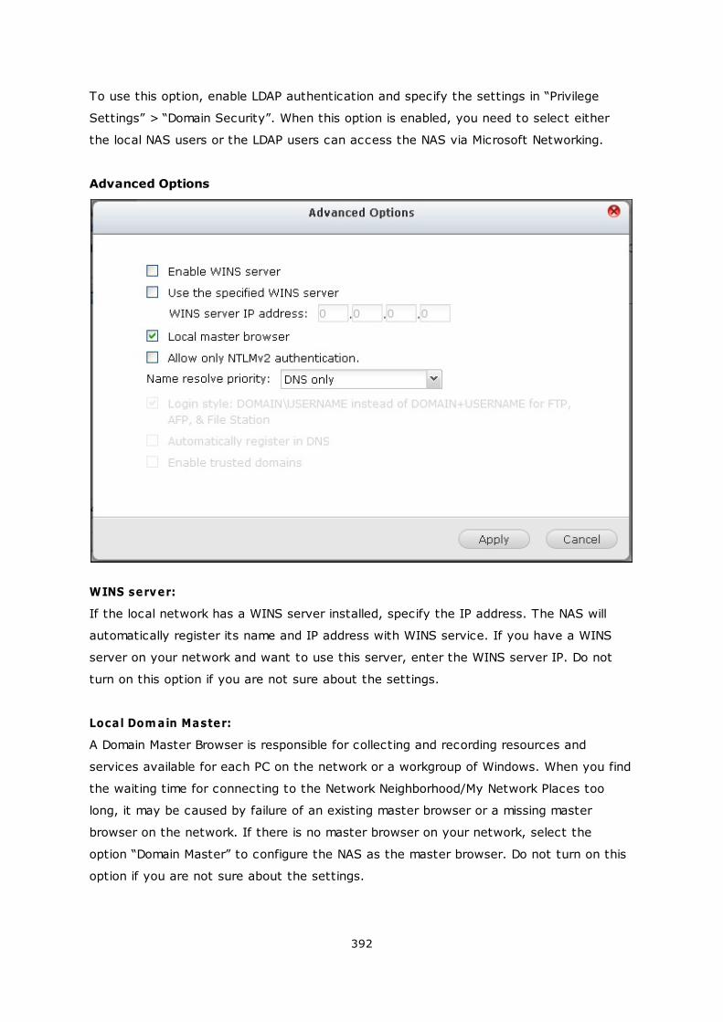
392
To use this option, enable LDAP authentication and specify the settings in “Privilege
Settings” > “Domain Security”. When this option is enabled, you need to select either
the local NAS users or the LDAP users can access the NAS via Microsoft Networking.
Advanced Options
WINS server:
If the local network has a WINS server installed, specify the IP address. The NAS will
automatically register its name and IP address with WINS service. If you have a WINS
server on your network and want to use this server, enter the WINS server IP. Do not
turn on this option if you are not sure about the settings.
Local Dom ain Master:
A Domain Master Browser is responsible for collecting and recording resources and
services available for each PC on the network or a workgroup of Windows. When you find
the waiting time for connecting to the Network Neighborhood/My Network Places too
long, it may be caused by failure of an existing master browser or a missing master
browser on the network. If there is no master browser on your network, select the
option “Domain Master” to configure the NAS as the master browser. Do not turn on this
option if you are not sure about the settings.
393
Allow only NTLMv2 authentication:
NTLMv2 stands for NT LAN Manager version 2. When this option is turned on, login to the
shared folders by Microsoft Networking will be allowed only with NTLMv2 authentication.
If the option is turned off, NTLM (NT LAN Manager) will be used by default and NTLMv2
can be negotiated by the client. The default setting is disabled.
Nam e resolution priority :
You can select to use DNS server or WINS server to resolve client host names from IP
addresses. When you set up your NAS to use a WINS server or to be a WINS server, you
can choose to use DNS or WINS first for name resolution. When WINS is enabled, the
default setting is “Try WINS then DNS”. Otherwise, DNS will be used for name resolution
by default.
Login style: DOMAIN\USERNAME instead of DOMAIN+USERNAME for FTP, AFP, and File
Station
In an Active Directory environment, the default login formats for the domain users are:
Windows shares: domain\username
FTP: domain+username
File Station: domain+username
AFP: domain+username
When you turn on this option, the users can use the same login name format
(domain\username) to connect to the NAS via AFP, FTP, and File Station.
Autom atically register in DNS: When this option is turned on and the NAS is joined to
an Active Directory, the NAS will register itself automatically in the domain DNS server.
This will create a DNS host entry for the NAS in the DNS server. If the NAS IP is
changed, the NAS will automatically update the new IP in the DNS server.
Enable trusted dom ains: Select this option to load the users from trusted Active
Directory domains and specify their access permissions to the NAS in “Privilege Settings”
> “Shared Folders”. (The domain trusts are set up in Active Directory only, not on the
NAS.)
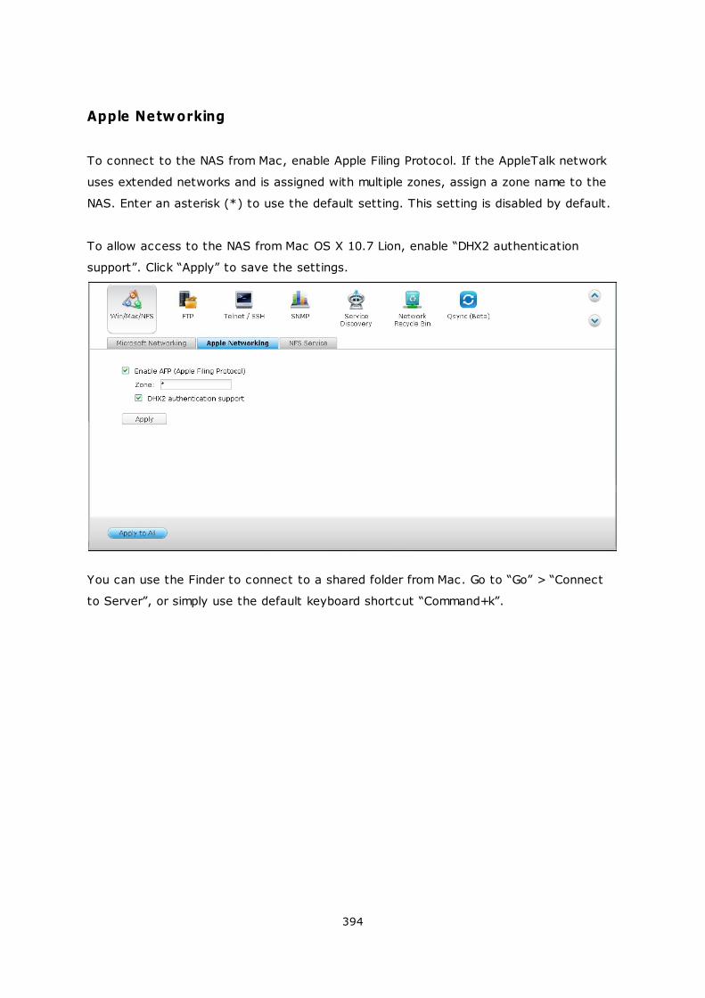
394
Apple Networking
To connect to the NAS from Mac, enable Apple Filing Protocol. If the AppleTalk network
uses extended networks and is assigned with multiple zones, assign a zone name to the
NAS. Enter an asterisk (*) to use the default setting. This setting is disabled by default.
To allow access to the NAS from Mac OS X 10.7 Lion, enable “DHX2 authentication
support”. Click “Apply” to save the settings.
You can use the Finder to connect to a shared folder from Mac. Go to “Go” > “Connect
to Server”, or simply use the default keyboard shortcut “Command+k”.
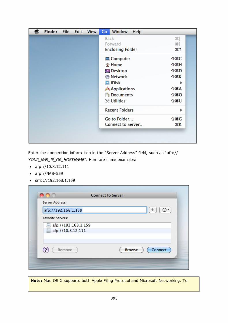
395
Enter the connection information in the “Server Address” field, such as “afp://
YOUR_NAS_IP_OR_HOSTNAME”. Here are some examples:
afp://10.8.12.111
afp://NAS-559
smb://192.168.1.159
Note: Mac OS X supports both Apple Filing Protocol and Microsoft Networking. To

396
connect to the NAS via Apple Filing Protocol, the server address should start with
“afp://”. To connect to the NAS via Microsoft Networking, please use “smb://”.
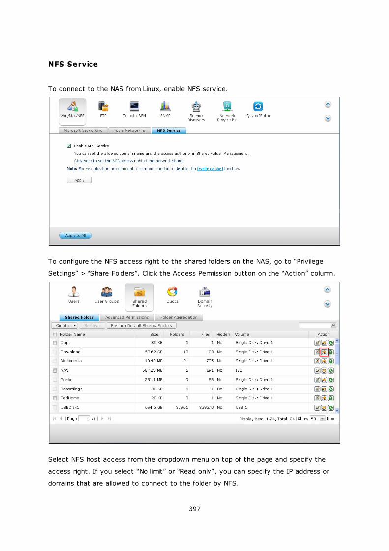
397
NFS Service
To connect to the NAS from Linux, enable NFS service.
To configure the NFS access right to the shared folders on the NAS, go to “Privilege
Settings” > “Share Folders”. Click the Access Permission button on the “Action” column.
Select NFS host access from the dropdown menu on top of the page and specify the
access right. If you select “No limit” or “Read only”, you can specify the IP address or
domains that are allowed to connect to the folder by NFS.
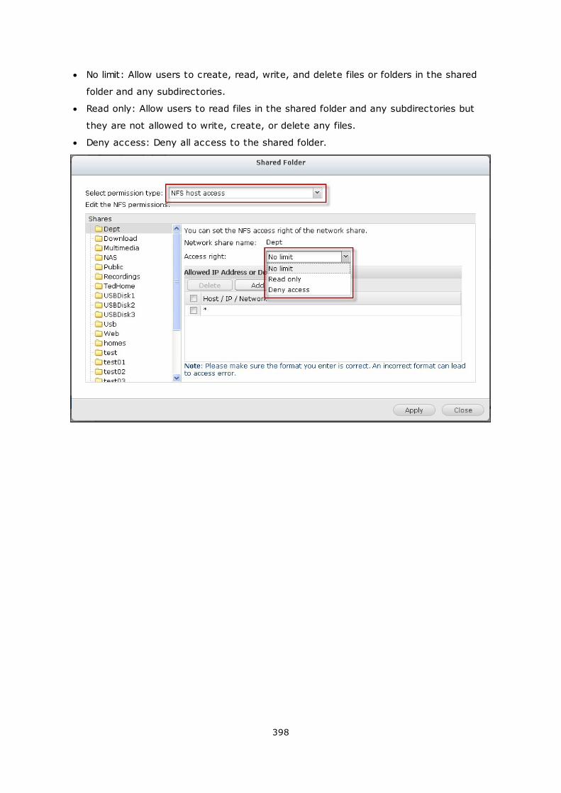
398
No limit: Allow users to create, read, write, and delete files or folders in the shared
folder and any subdirectories.
Read only: Allow users to read files in the shared folder and any subdirectories but
they are not allowed to write, create, or delete any files.
Deny access: Deny all access to the shared folder.
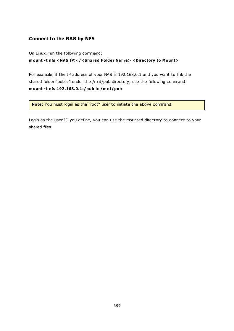
399
Connect to the NAS by NFS
On Linux, run the following command:
m ount -t nfs <NAS IP>:/<Shared Folder Nam e> <Directory to Mount>
For example, if the IP address of your NAS is 192.168.0.1 and you want to link the
shared folder “public” under the /mnt/pub directory, use the following command:
m ount -t nfs 192.168.0.1:/public /m nt/pub
Note: You must login as the “root” user to initiate the above command.
Login as the user ID you define, you can use the mounted directory to connect to your
shared files.
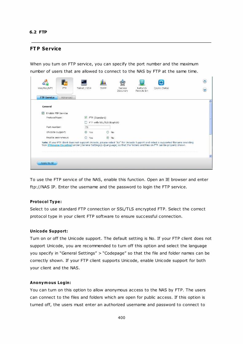
400
6.2 FTP
FT P Service
When you turn on FTP service, you can specify the port number and the maximum
number of users that are allowed to connect to the NAS by FTP at the same time.
To use the FTP service of the NAS, enable this function. Open an IE browser and enter
ftp://NAS IP. Enter the username and the password to login the FTP service.
Protocol Type:
Select to use standard FTP connection or SSL/TLS encrypted FTP. Select the correct
protocol type in your client FTP software to ensure successful connection.
Unicode Support:
Turn on or off the Unicode support. The default setting is No. If your FTP client does not
support Unicode, you are recommended to turn off this option and select the language
you specify in “General Settings” > “Codepage” so that the file and folder names can be
correctly shown. If your FTP client supports Unicode, enable Unicode support for both
your client and the NAS.
Anonym ous Login:
You can turn on this option to allow anonymous access to the NAS by FTP. The users
can connect to the files and folders which are open for public access. If this option is
turned off, the users must enter an authorized username and password to connect to

401
the server.
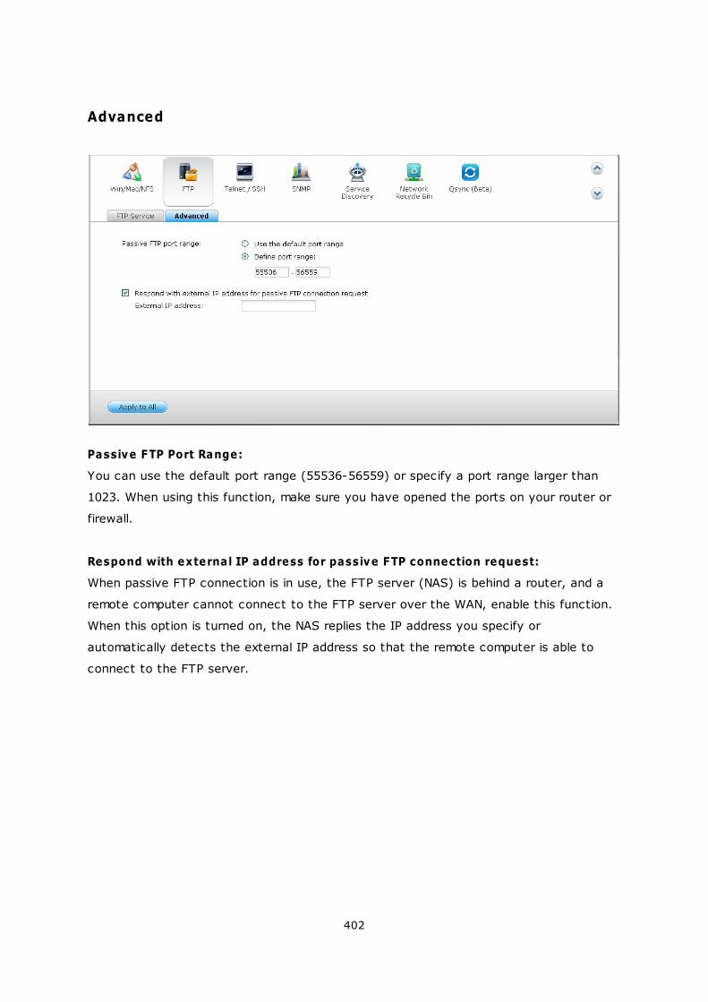
402
Advanced
Passive FTP Port Range:
You can use the default port range (55536-56559) or specify a port range larger than
1023. When using this function, make sure you have opened the ports on your router or
firewall.
Respond with external IP address for passive FTP connection request:
When passive FTP connection is in use, the FTP server (NAS) is behind a router, and a
remote computer cannot connect to the FTP server over the WAN, enable this function.
When this option is turned on, the NAS replies the IP address you specify or
automatically detects the external IP address so that the remote computer is able to
connect to the FTP server.

403
6.3 Telnet/SSH
Turn on this option to connect to the NAS by Telnet or SSH encrypted connection (only
the “admin” account can login remotely). Use Telnet or SSH connection clients, for
example, putty for connection. Make sure the specified ports have been opened on the
router or firewall.
To use SFTP (known as SSH File Transfer Protocol or Secure File Transfer Protocol),
make sure the option “Allow SSH connection” has been turned on.
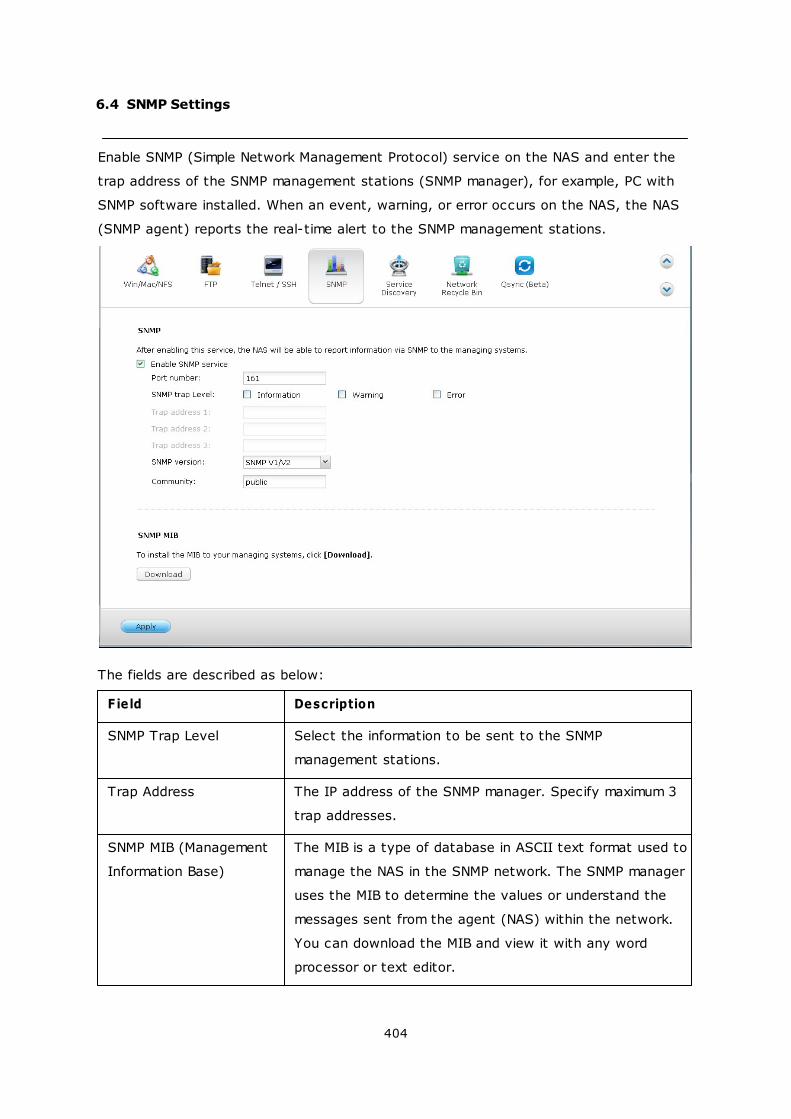
404
6.4 SNMP Settings
Enable SNMP (Simple Network Management Protocol) service on the NAS and enter the
trap address of the SNMP management stations (SNMP manager), for example, PC with
SNMP software installed. When an event, warning, or error occurs on the NAS, the NAS
(SNMP agent) reports the real-time alert to the SNMP management stations.
The fields are described as below:
Field Description
SNMP Trap Level Select the information to be sent to the SNMP
management stations.
Trap Address The IP address of the SNMP manager. Specify maximum 3
trap addresses.
SNMP MIB (Management
Information Base)
The MIB is a type of database in ASCII text format used to
manage the NAS in the SNMP network. The SNMP manager
uses the MIB to determine the values or understand the
messages sent from the agent (NAS) within the network.
You can download the MIB and view it with any word
processor or text editor.
405
Community (SNMP V1/V2) An SNMP community string is a text string that acts as a
password. It is used to authenticate messages that are
sent between the management station and the NAS. The
community string is included in every packet that is
transmitted between the SNMP manager and the SNMP
agent.
SNMP V3 The NAS supports SNMP version 3. Specify the
authentication and privacy settings if available.
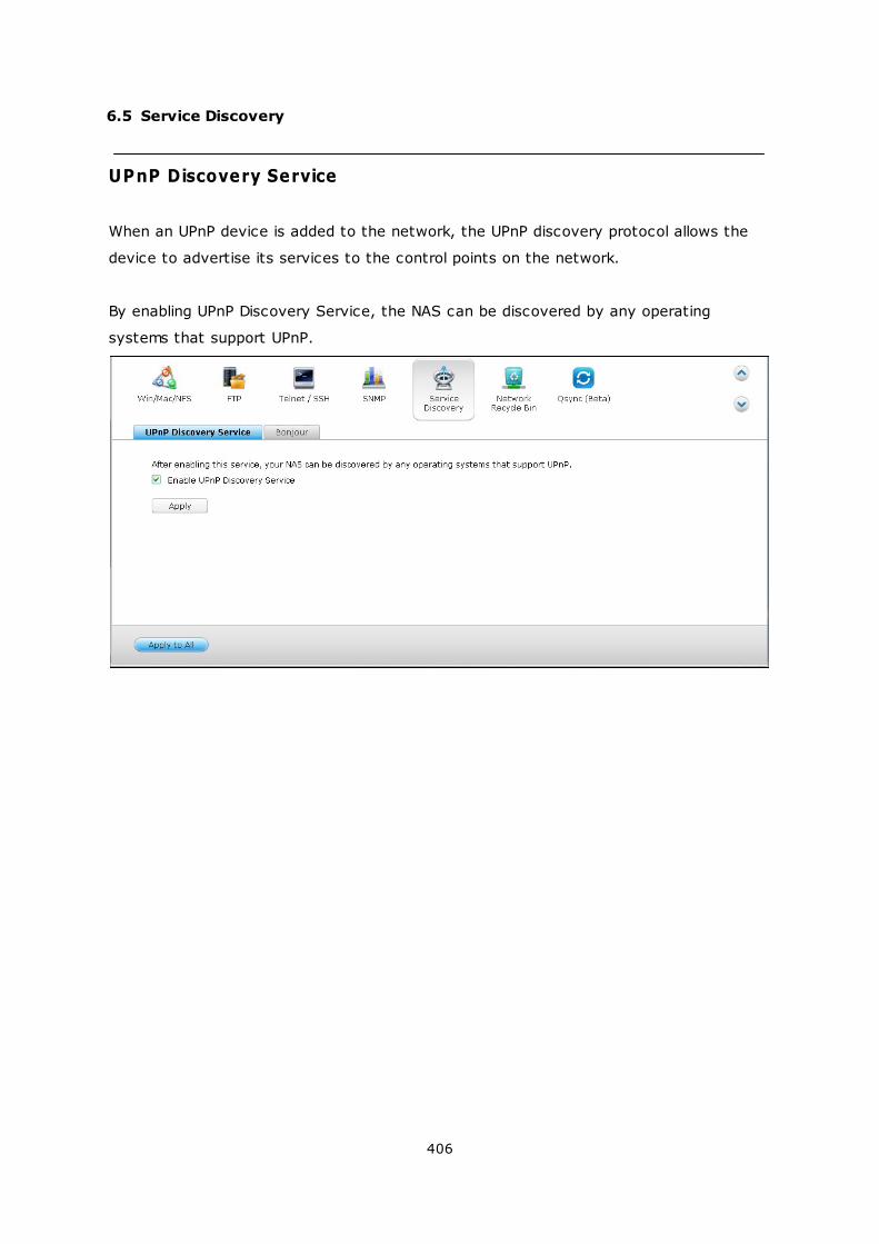
406
6.5 Service Discovery
UPnP Discovery Service
When an UPnP device is added to the network, the UPnP discovery protocol allows the
device to advertise its services to the control points on the network.
By enabling UPnP Discovery Service, the NAS can be discovered by any operating
systems that support UPnP.
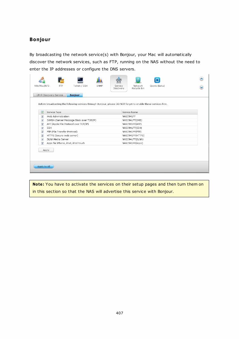
407
Bonjour
By broadcasting the network service(s) with Bonjour, your Mac will automatically
discover the network services, such as FTP, running on the NAS without the need to
enter the IP addresses or configure the DNS servers.
Note: You have to activate the services on their setup pages and then turn them on
in this section so that the NAS will advertise this service with Bonjour.
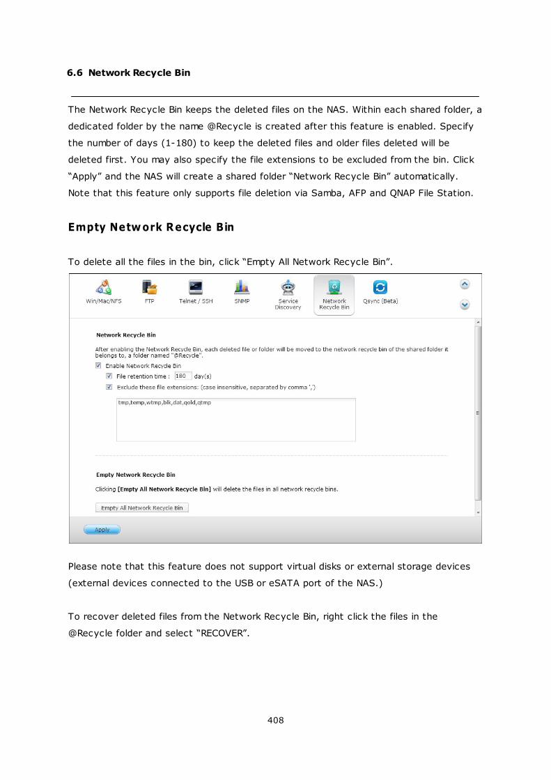
408
6.6 Network Recycle Bin
The Network Recycle Bin keeps the deleted files on the NAS. Within each shared folder, a
dedicated folder by the name @Recycle is created after this feature is enabled. Specify
the number of days (1-180) to keep the deleted files and older files deleted will be
deleted first. You may also specify the file extensions to be excluded from the bin. Click
“Apply” and the NAS will create a shared folder “Network Recycle Bin” automatically.
Note that this feature only supports file deletion via Samba, AFP and QNAP File Station.
Empty Network Recycle Bin
To delete all the files in the bin, click “Empty All Network Recycle Bin”.
Please note that this feature does not support virtual disks or external storage devices
(external devices connected to the USB or eSATA port of the NAS.)
To recover deleted files from the Network Recycle Bin, right click the files in the
@Recycle folder and select “RECOVER”.
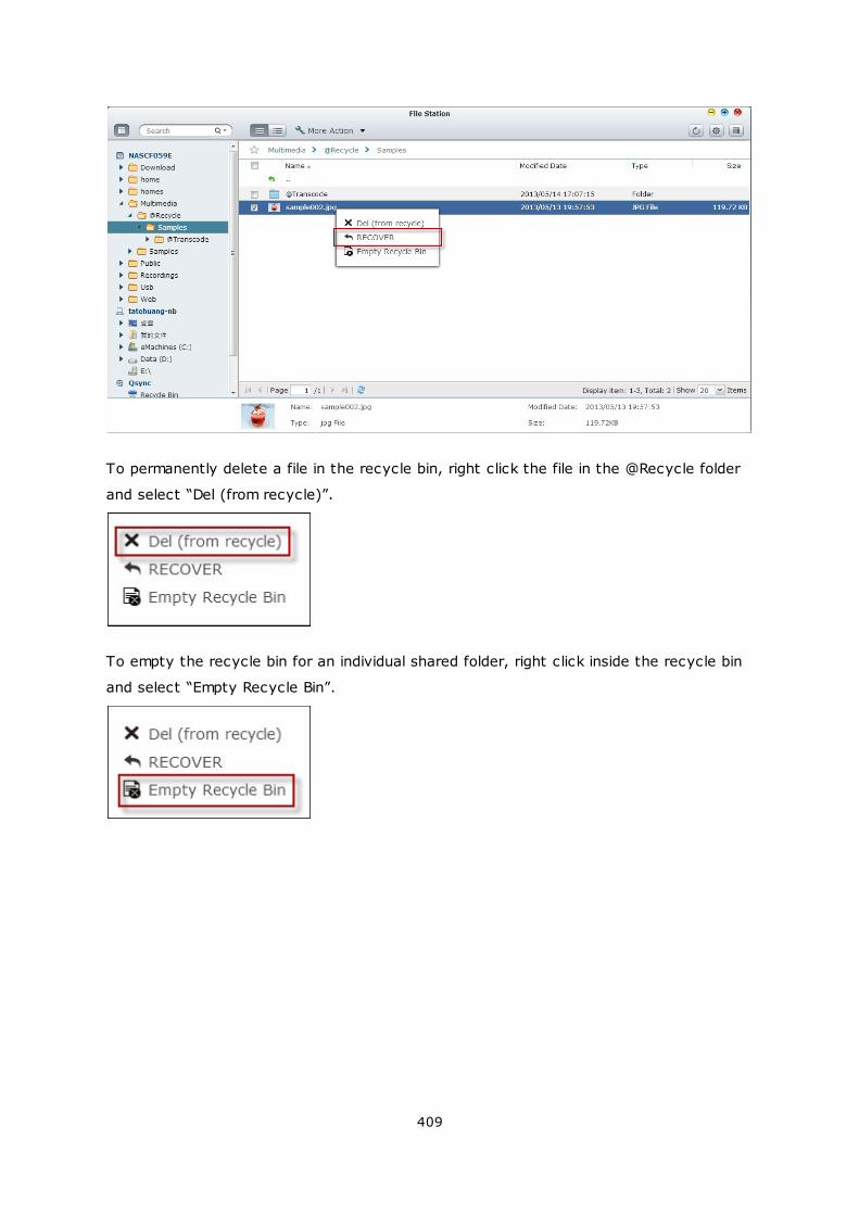
409
To permanently delete a file in the recycle bin, right click the file in the @Recycle folder
and select “Del (from recycle)”.
To empty the recycle bin for an individual shared folder, right click inside the recycle bin
and select “Empty Recycle Bin”.
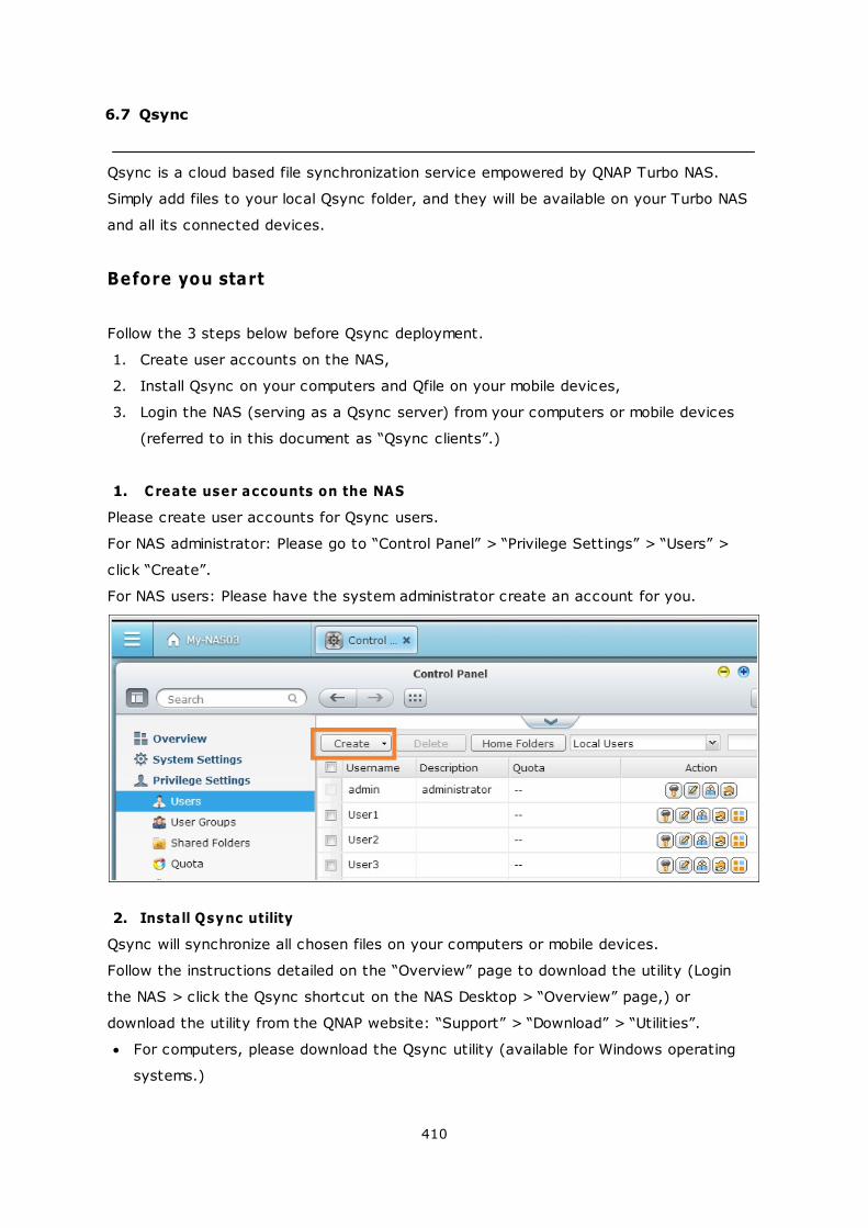
410
6.7 Qsync
Qsync is a cloud based file synchronization service empowered by QNAP Turbo NAS.
Simply add files to your local Qsync folder, and they will be available on your Turbo NAS
and all its connected devices.
Before you start
Follow the 3 steps below before Qsync deployment.
1. Create user accounts on the NAS,
2. Install Qsync on your computers and Qfile on your mobile devices,
3. Login the NAS (serving as a Qsync server) from your computers or mobile devices
(referred to in this document as “Qsync clients”.)
1. Create user accounts on the NAS
Please create user accounts for Qsync users.
For NAS administrator: Please go to “Control Panel” > “Privilege Settings” > “Users” >
click “Create”.
For NAS users: Please have the system administrator create an account for you.
2. Install Qsync utility
Qsync will synchronize all chosen files on your computers or mobile devices.
Follow the instructions detailed on the “Overview” page to download the utility (Login
the NAS > click the Qsync shortcut on the NAS Desktop > “Overview” page,) or
download the utility from the QNAP website: “Support” > “Download” > “Utilities”.
For computers, please download the Qsync utility (available for Windows operating
systems.)
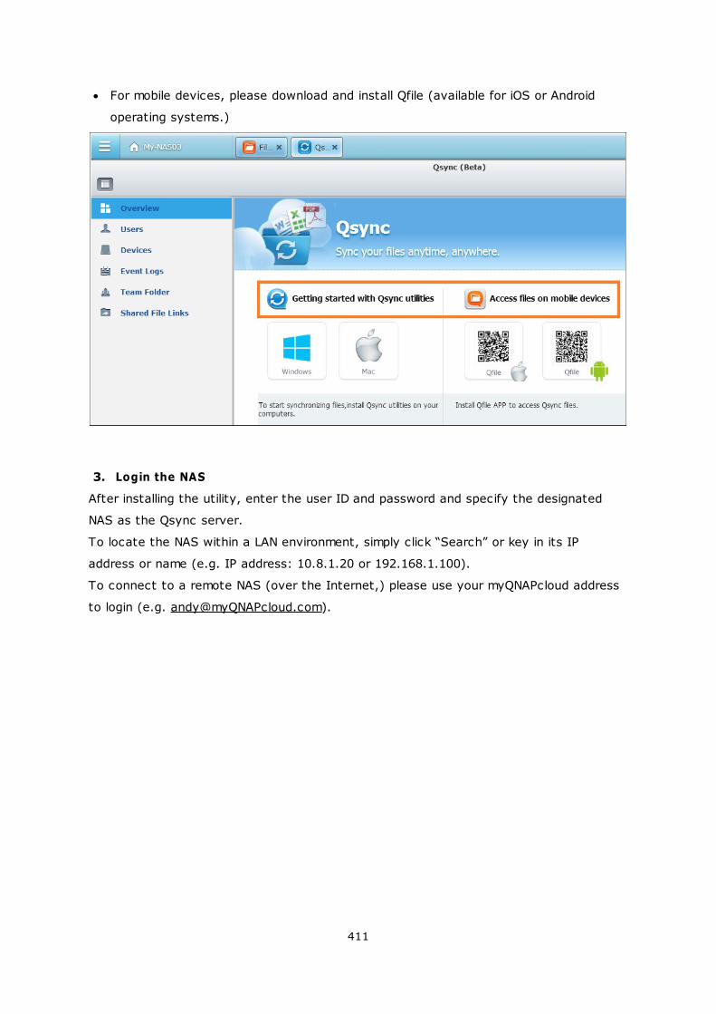
411
For mobile devices, please download and install Qfile (available for iOS or Android
operating systems.)
3. Login the NAS
After installing the utility, enter the user ID and password and specify the designated
NAS as the Qsync server.
To locate the NAS within a LAN environment, simply click “Search” or key in its IP
address or name (e.g. IP address: 10.8.1.20 or 192.168.1.100).
To connect to a remote NAS (over the Internet,) please use your myQNAPcloud address
to login (e.g. [email protected]).
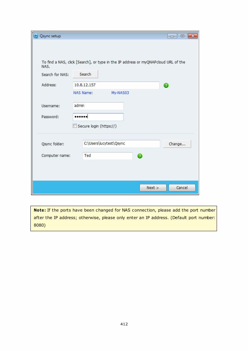
412
Note: If the ports have been changed for NAS connection, please add the port number
after the IP address; otherwise, please only enter an IP address. (Default port number:
8080)
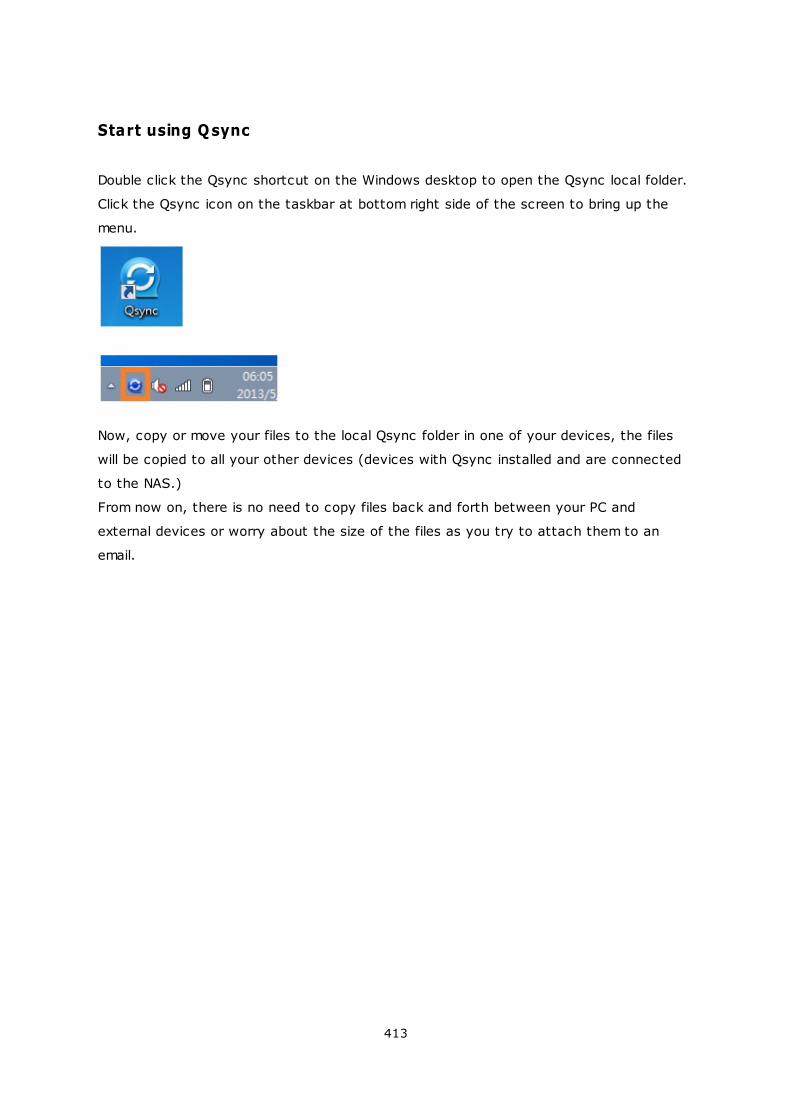
413
Start using Qsync
Double click the Qsync shortcut on the Windows desktop to open the Qsync local folder.
Click the Qsync icon on the taskbar at bottom right side of the screen to bring up the
menu.
Now, copy or move your files to the local Qsync folder in one of your devices, the files
will be copied to all your other devices (devices with Qsync installed and are connected
to the NAS.)
From now on, there is no need to copy files back and forth between your PC and
external devices or worry about the size of the files as you try to attach them to an
email.
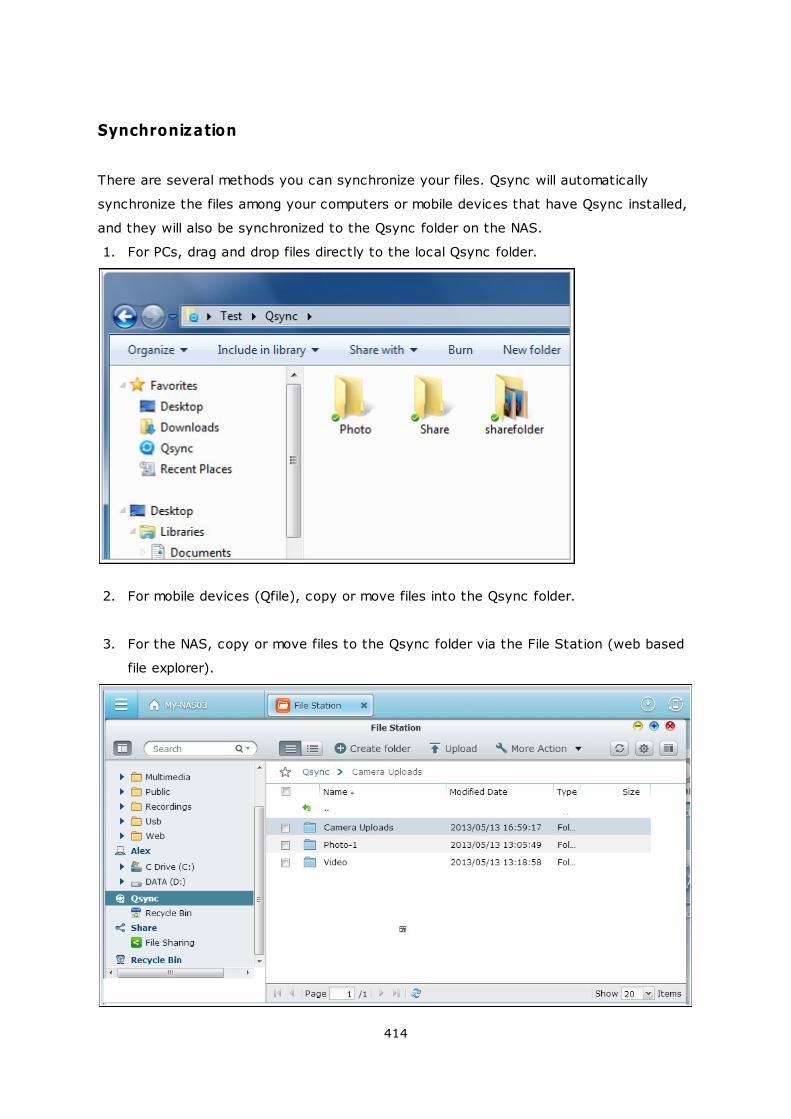
414
Synchronization
There are several methods you can synchronize your files. Qsync will automatically
synchronize the files among your computers or mobile devices that have Qsync installed,
and they will also be synchronized to the Qsync folder on the NAS.
1. For PCs, drag and drop files directly to the local Qsync folder.
2. For mobile devices (Qfile), copy or move files into the Qsync folder.
3. For the NAS, copy or move files to the Qsync folder via the File Station (web based
file explorer).
415
Note:
If files are “dragged and dropped” to the Qsync folder, they will be moved to the
Qsync folder, instead of being copied into the folder, if the files and the Qsync
folder are on the same disk drive. The behavior is the same as the Windows File
Explore.
The maximum size of a single file that Qsync can transmit is 50GB in a LAN.
Qsync does not support SAMBA, FTP or AFP for files access. Please access files
using the File Station or Qsync.
Qfile can only synchronize the file list and does not download the files to a mobile
device. Please download the files when you need them.
Offline editing
You can browse and edit your files offline, and once your device is online, Qsync will
synchronize the files you edited offline for you automatically.
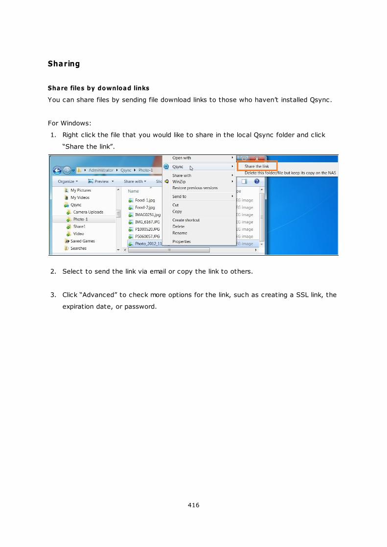
416
Sharing
Share files by download links
You can share files by sending file download links to those who haven’t installed Qsync.
For Windows:
1. Right click the file that you would like to share in the local Qsync folder and click
“Share the link”.
2. Select to send the link via email or copy the link to others.
3. Click “Advanced” to check more options for the link, such as creating a SSL link, the
expiration date, or password.
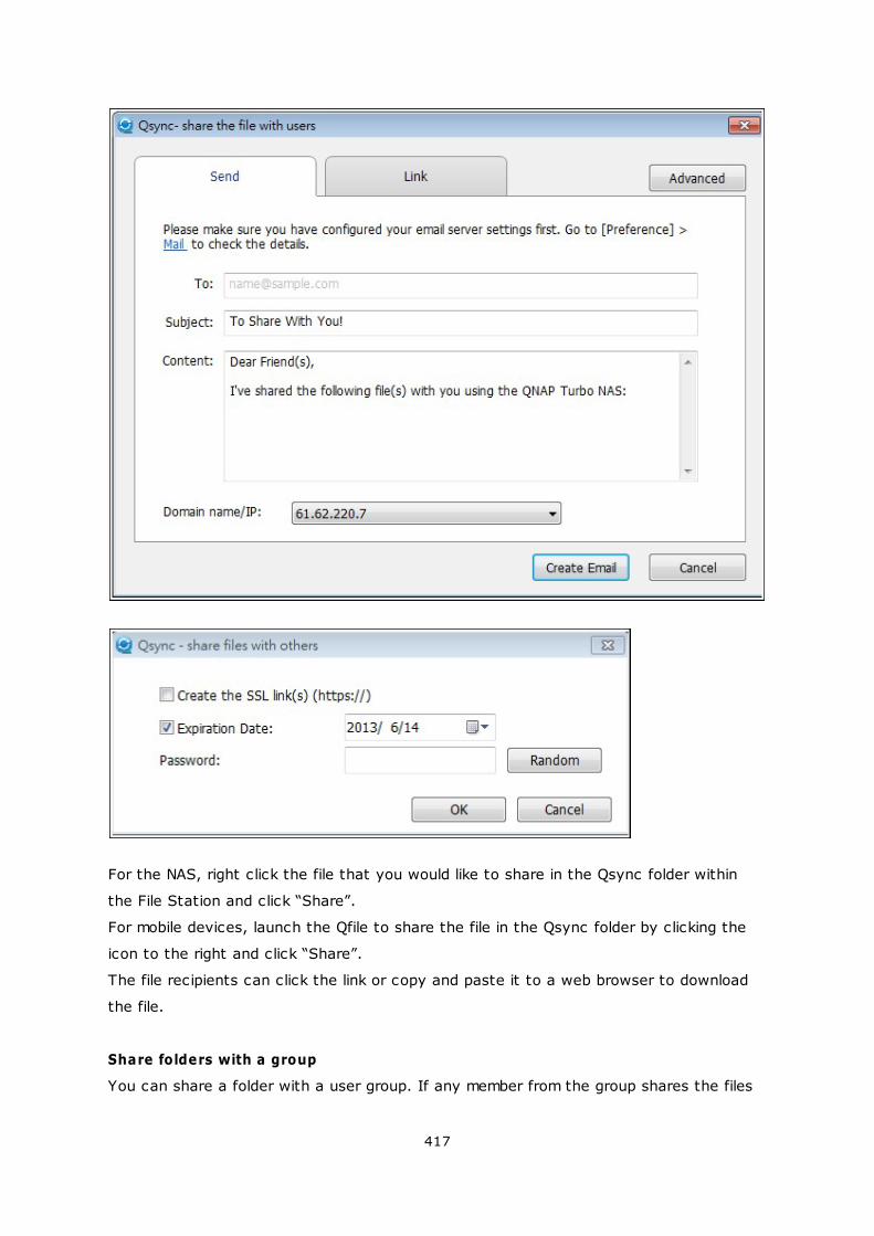
417
For the NAS, right click the file that you would like to share in the Qsync folder within
the File Station and click “Share”.
For mobile devices, launch the Qfile to share the file in the Qsync folder by clicking the
icon to the right and click “Share”.
The file recipients can click the link or copy and paste it to a web browser to download
the file.
Share folders with a group
You can share a folder with a user group. If any member from the group shares the files
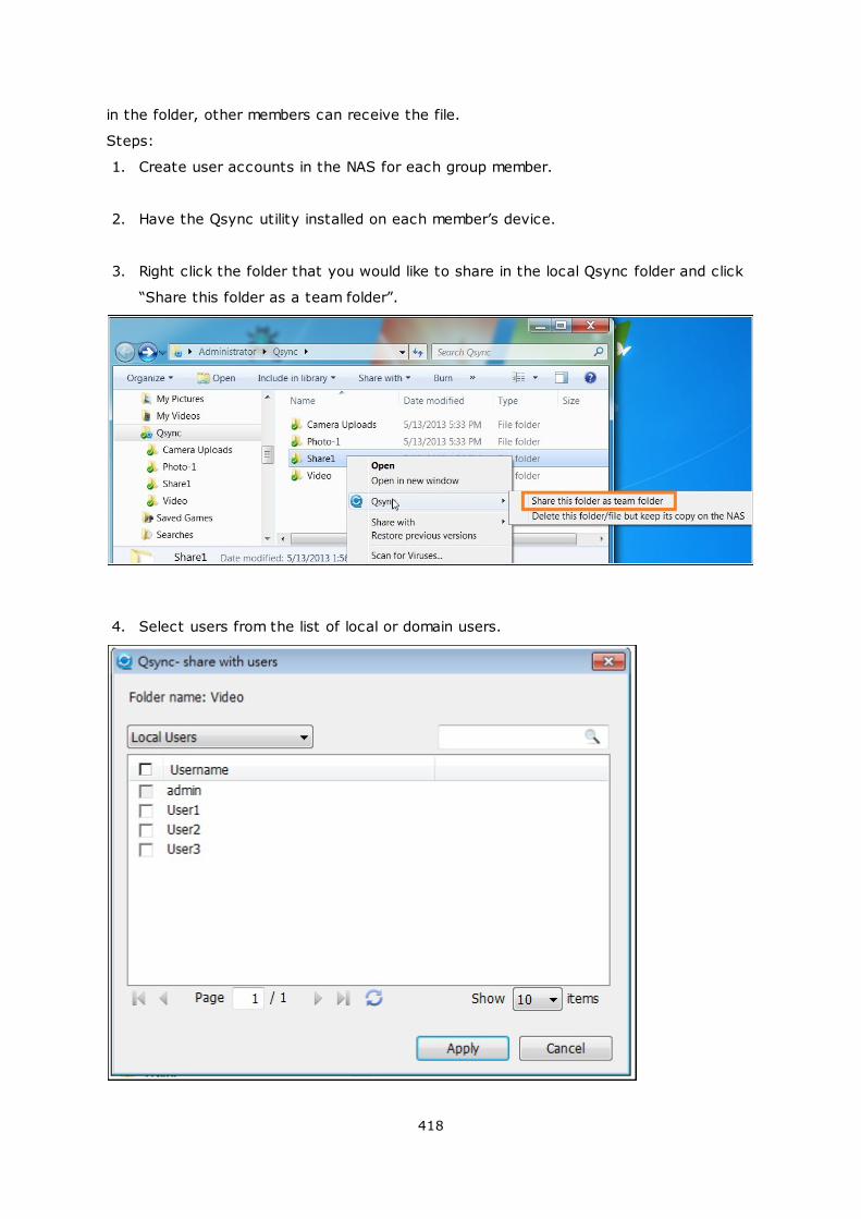
418
in the folder, other members can receive the file.
Steps:
1. Create user accounts in the NAS for each group member.
2. Have the Qsync utility installed on each member’s device.
3. Right click the folder that you would like to share in the local Qsync folder and click
“Share this folder as a team folder”.
4. Select users from the list of local or domain users.

419
All members in the group will receive a file sharing invitation. Once accepted, the group
members can start to access this shared folder.
Note:
The team folder will only take effect after users you send the invitation to accept
the invitation.
Users cannot share the team folders which are shared from others again.
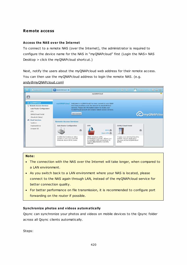
420
Remote access
Access the NAS over the Internet
To connect to a remote NAS (over the Internet), the administrator is required to
configure the device name for the NAS in “myQNAPcloud” first (Login the NAS> NAS
Desktop > click the myQNAPcloud shortcut.)
Next, notify the users about the myQNAPcloud web address for their remote access.
You can then use the myQNAPcloud address to login the remote NAS. (e.g.
Note:
The connection with the NAS over the Internet will take longer, when compared to
a LAN environment.
As you switch back to a LAN environment where your NAS is located, please
connect to the NAS again through LAN, instead of the myQNAPcloud service for
better connection quality.
For better performance on file transmission, it is recommended to configure port
forwarding on the router if possible.
Synchronize photos and v ideos autom atically
Qsync can synchronize your photos and videos on mobile devices to the Qsync folder
across all Qsync clients automatically.
Steps:
421
1. Install Qfile on your mobile devices by following instructions outlined in the Qsync
page on the NAS or find it on the App Store.
2. Launch Qfile.
3. Click “Settings” on the bottom right side of the screen.
4. Scroll down and look for “Auto upload from photo gallery” and click “Set up now”.
5. Select a NAS to upload photos and videos to.
6. Select the folder.
7. Select “Use default setting” ( /Qsync/Camera Uploads) or select “Set up manually”
to set the path.
8. Select if you want to upload all photos from the photo gallery immediately.
9. You can check the checkbox “Limit to Wi-Fi” to upload files through Wi-Fi and avoid
possible expenses associated with the 3G usage.
10. The uploaded files will be synchronized to the Camera Uploads folder under the
Qsync folder on Qsync client devices.

422
Note: If files uploaded before are deleted from the Camera Uploads folder, Qfile will not
upload those copies in the photo library again.
423
Synchronization management
Click the Qsync icon on the taskbar to see the management functions:
1. Add files and view the synchronization result on the NAS:
i. Open the Qsync folder: Open the Qsync folder to add files,
ii. View files by the web browser: Open the File Station (web based file explorer)
and browse files in the Qsync folder on the NAS.
2. Control synchronization progress:
i. Pause syncing / Resume syncing: Click to pause or resume file synchronization,
ii. Sync with NAS now: Force Qsync to scan again and refresh the
synchronization list.
3. Information for syncing and sharing:
i. Sharing & File Update Center
a. File Update Center: List the file or folder update logs.
424
b. Sharing Center: List the folders or files shared with others. Users can
choose to accept or decline the team folders. However, users cannot share
team folders that are shared by others.
ii. Recently changed files: List the recently updated files.
4. Preference:
i. General:
a. Link Status: Show the current status. Click “Logout” to change users.
b. Network Recycle Bin: Browse or recover files deleted from the Qsync folder.
425
ii. Sync:
a. Selective Synchronization: Select the folder to synchronize to the
computers.
b. Do not remove any files on the NAS when synchronizing: You can remove
files within the local Qsync folder, and files deleted from your computer will
not be synchronized with the NAS. The NAS still keeps copies of the
deleted files.
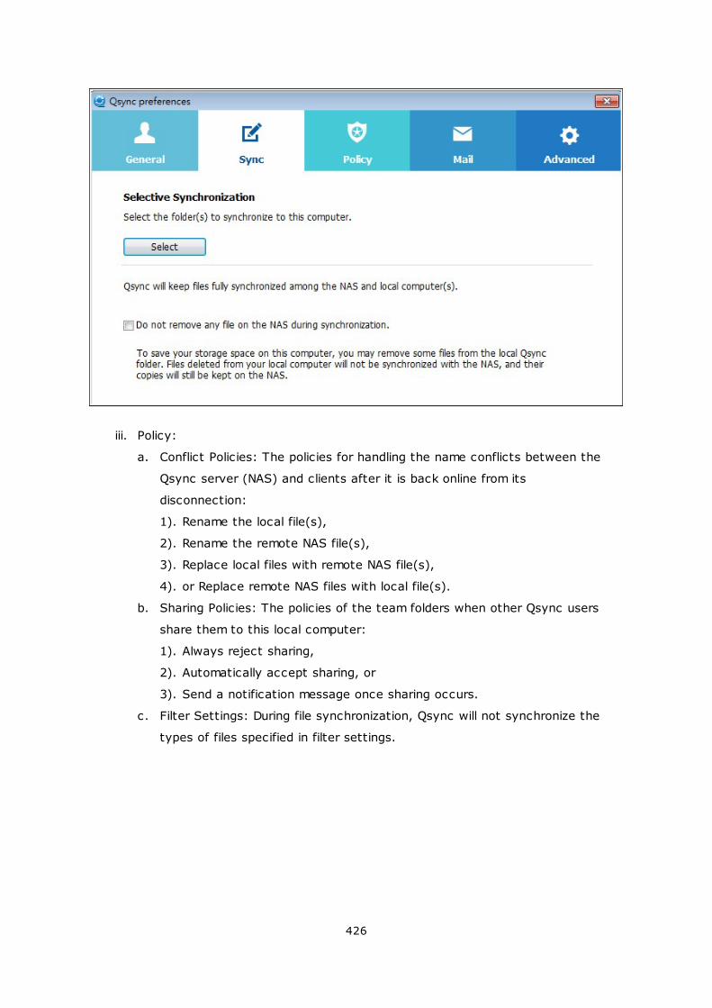
426
iii. Policy:
a. Conflict Policies: The policies for handling the name conflicts between the
Qsync server (NAS) and clients after it is back online from its
disconnection:
1). Rename the local file(s),
2). Rename the remote NAS file(s),
3). Replace local files with remote NAS file(s),
4). or Replace remote NAS files with local file(s).
b. Sharing Policies: The policies of the team folders when other Qsync users
share them to this local computer:
1). Always reject sharing,
2). Automatically accept sharing, or
3). Send a notification message once sharing occurs.
c. Filter Settings: During file synchronization, Qsync will not synchronize the
types of files specified in filter settings.
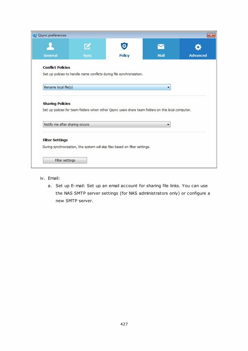
427
iv. Email:
a. Set up E-mail: Set up an email account for sharing file links. You can use
the NAS SMTP server settings (for NAS administrators only) or configure a
new SMTP server.
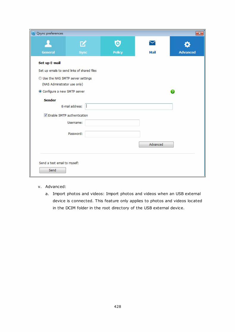
428
v. Advanced:
a. Import photos and videos: Import photos and videos when an USB external
device is connected. This feature only applies to photos and videos located
in the DCIM folder in the root directory of the USB external device.
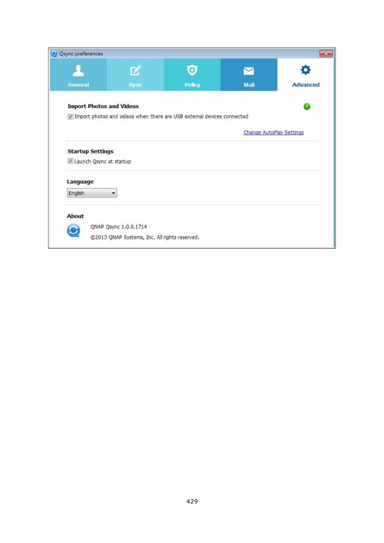
429
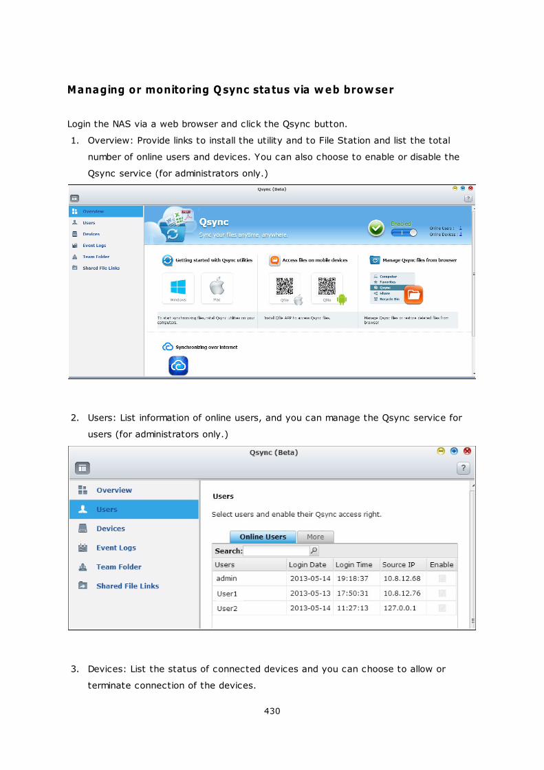
430
Managing or monitoring Qsync status via web browser
Login the NAS via a web browser and click the Qsync button.
1. Overview: Provide links to install the utility and to File Station and list the total
number of online users and devices. You can also choose to enable or disable the
Qsync service (for administrators only.)
2. Users: List information of online users, and you can manage the Qsync service for
users (for administrators only.)
3. Devices: List the status of connected devices and you can choose to allow or
terminate connection of the devices.
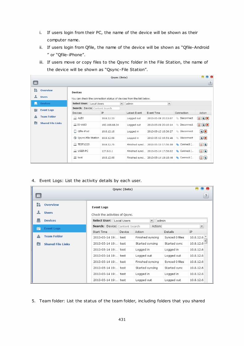
431
i. If users login from their PC, the name of the device will be shown as their
computer name.
ii. If users login from Qfile, the name of the device will be shown as “Qfile-Android
” or “Qfile-iPhone”.
iii. If users move or copy files to the Qsync folder in the File Station, the name of
the device will be shown as “Qsync-File Station”.
4. Event Logs: List the activity details by each user.
5. Team folder: List the status of the team folder, including folders that you shared
432
and are shared by others.
6. Shared File Links: List the status of shared links.
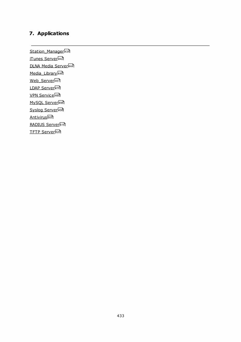
433
7. Applications
Station_Manager
iTunes Server
DLNA Media Server
Media_Library
Web_Server
LDAP Server
VPN Service
MySQL Server
Syslog Server
Antivirus
RADIUS Server
TFTP Server
434
442
444
446
451
476
480
496
498
505
516
520
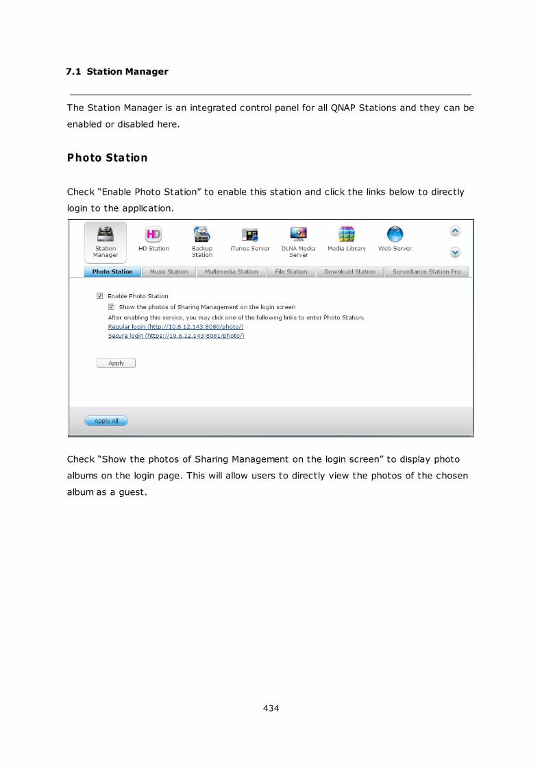
434
7.1 Station Manager
The Station Manager is an integrated control panel for all QNAP Stations and they can be
enabled or disabled here.
Photo Station
Check “Enable Photo Station” to enable this station and click the links below to directly
login to the application.
Check “Show the photos of Sharing Management on the login screen” to display photo
albums on the login page. This will allow users to directly view the photos of the chosen
album as a guest.
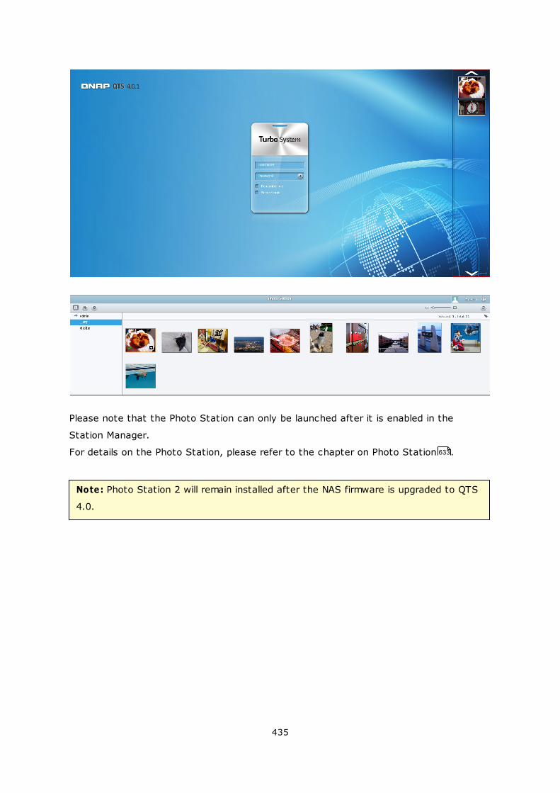
435
Please note that the Photo Station can only be launched after it is enabled in the
Station Manager.
For details on the Photo Station, please refer to the chapter on Photo Station .
Note: Photo Station 2 will remain installed after the NAS firmware is upgraded to QTS
4.0.
633
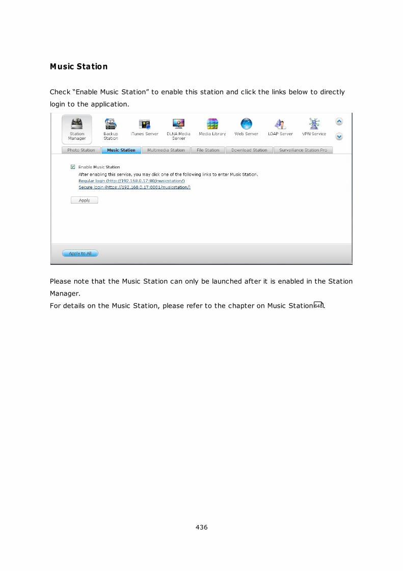
436
Music Station
Check “Enable Music Station” to enable this station and click the links below to directly
login to the application.
Please note that the Music Station can only be launched after it is enabled in the Station
Manager.
For details on the Music Station, please refer to the chapter on Music Station . 648
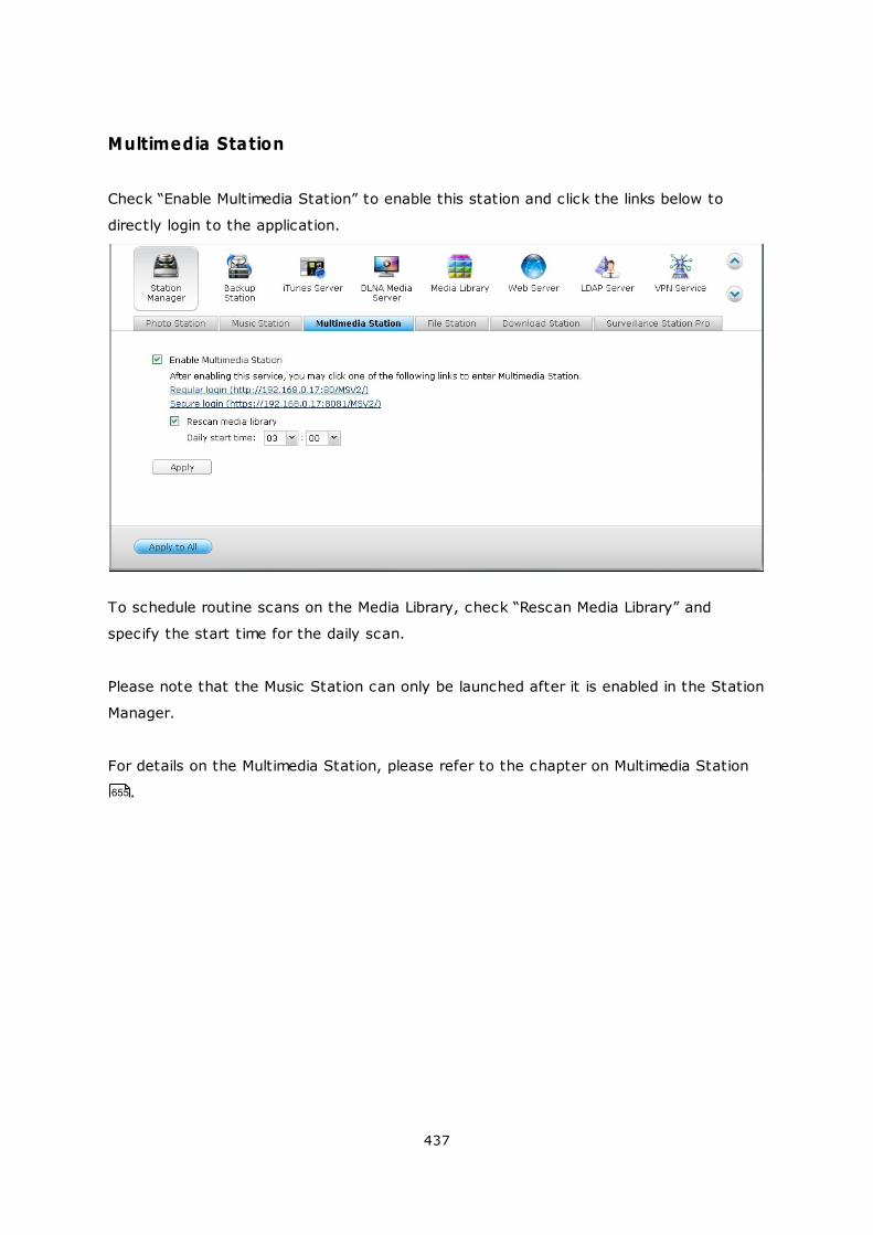
437
Multimedia Station
Check “Enable Multimedia Station” to enable this station and click the links below to
directly login to the application.
To schedule routine scans on the Media Library, check “Rescan Media Library” and
specify the start time for the daily scan.
Please note that the Music Station can only be launched after it is enabled in the Station
Manager.
For details on the Multimedia Station, please refer to the chapter on Multimedia Station
. 655
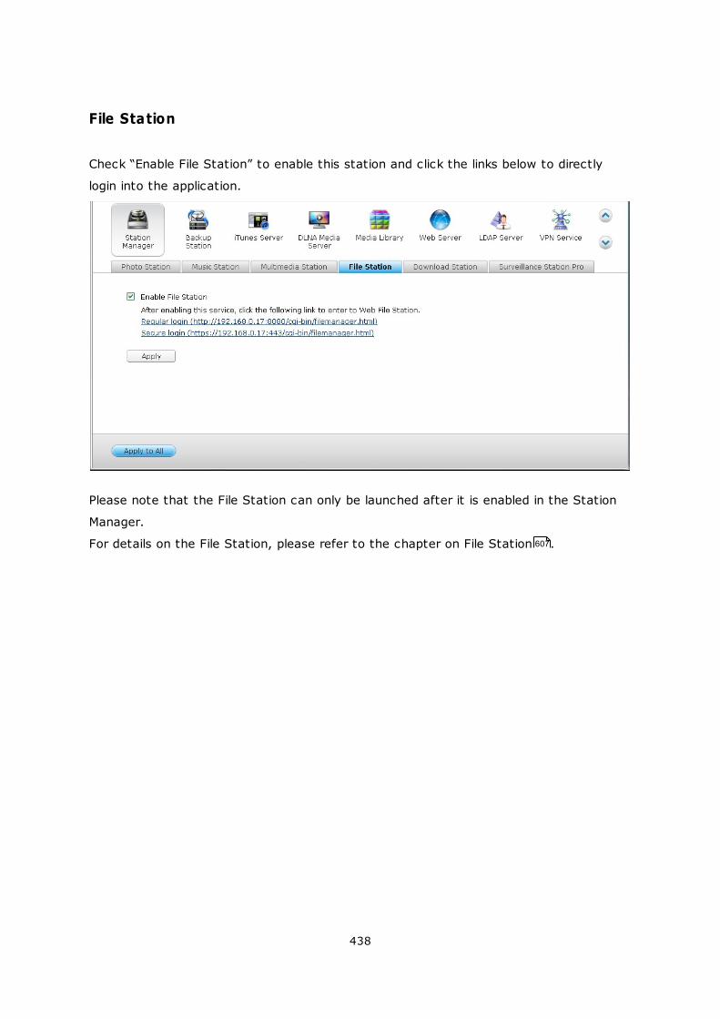
438
File Station
Check “Enable File Station” to enable this station and click the links below to directly
login into the application.
Please note that the File Station can only be launched after it is enabled in the Station
Manager.
For details on the File Station, please refer to the chapter on File Station . 607
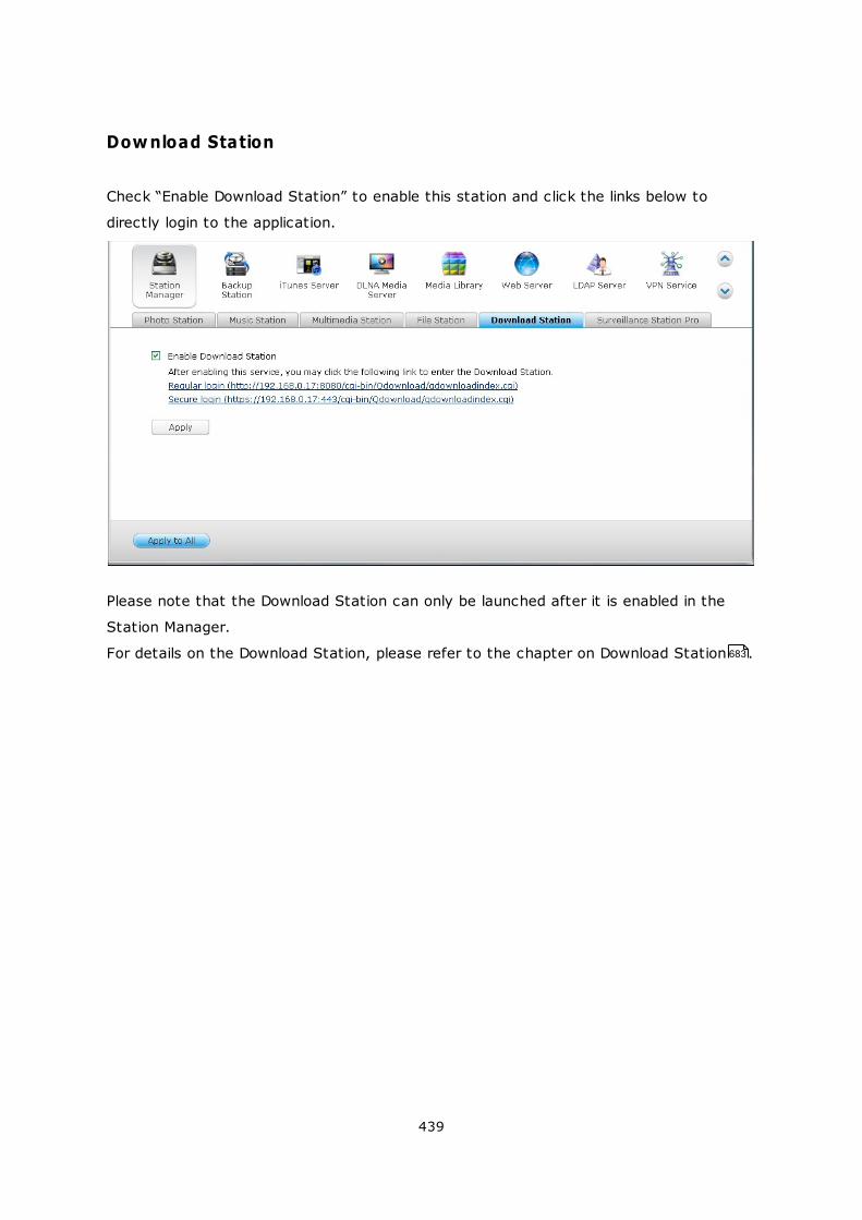
439
Download Station
Check “Enable Download Station” to enable this station and click the links below to
directly login to the application.
Please note that the Download Station can only be launched after it is enabled in the
Station Manager.
For details on the Download Station, please refer to the chapter on Download Station .683
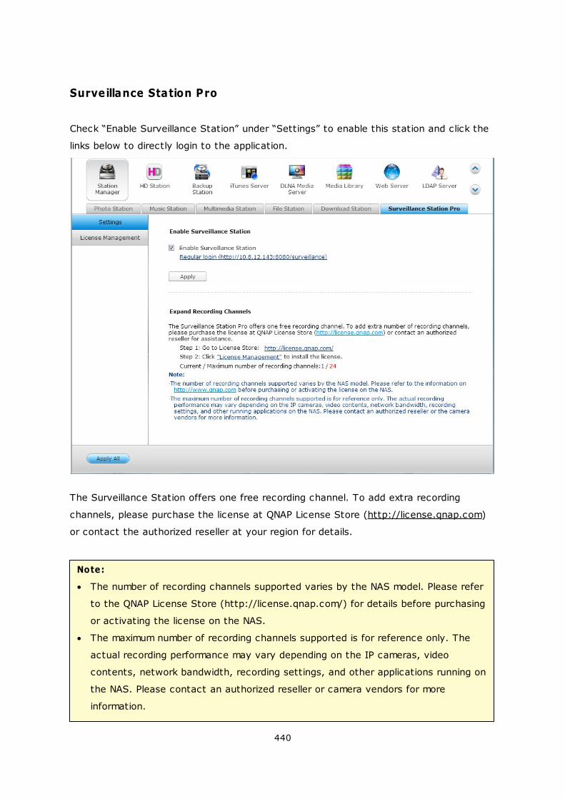
440
Surveillance Station Pro
Check “Enable Surveillance Station” under “Settings” to enable this station and click the
links below to directly login to the application.
The Surveillance Station offers one free recording channel. To add extra recording
channels, please purchase the license at QNAP License Store (http://license.qnap.com)
or contact the authorized reseller at your region for details.
Note:
The number of recording channels supported varies by the NAS model. Please refer
to the QNAP License Store (http://license.qnap.com/) for details before purchasing
or activating the license on the NAS.
The maximum number of recording channels supported is for reference only. The
actual recording performance may vary depending on the IP cameras, video
contents, network bandwidth, recording settings, and other applications running on
the NAS. Please contact an authorized reseller or camera vendors for more
information.
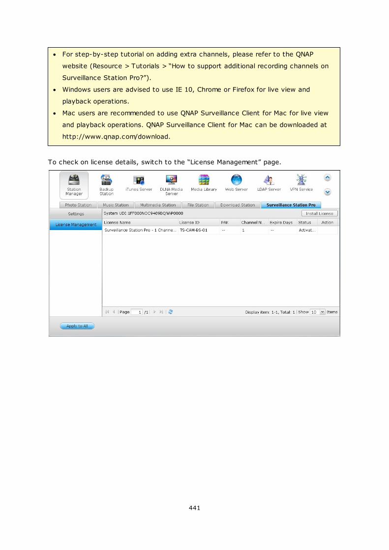
441
For step-by-step tutorial on adding extra channels, please refer to the QNAP
website (Resource > Tutorials > “How to support additional recording channels on
Surveillance Station Pro?”).
Windows users are advised to use IE 10, Chrome or Firefox for live view and
playback operations.
Mac users are recommended to use QNAP Surveillance Client for Mac for live view
and playback operations. QNAP Surveillance Client for Mac can be downloaded at
http://www.qnap.com/download.
To check on license details, switch to the “License Management” page.
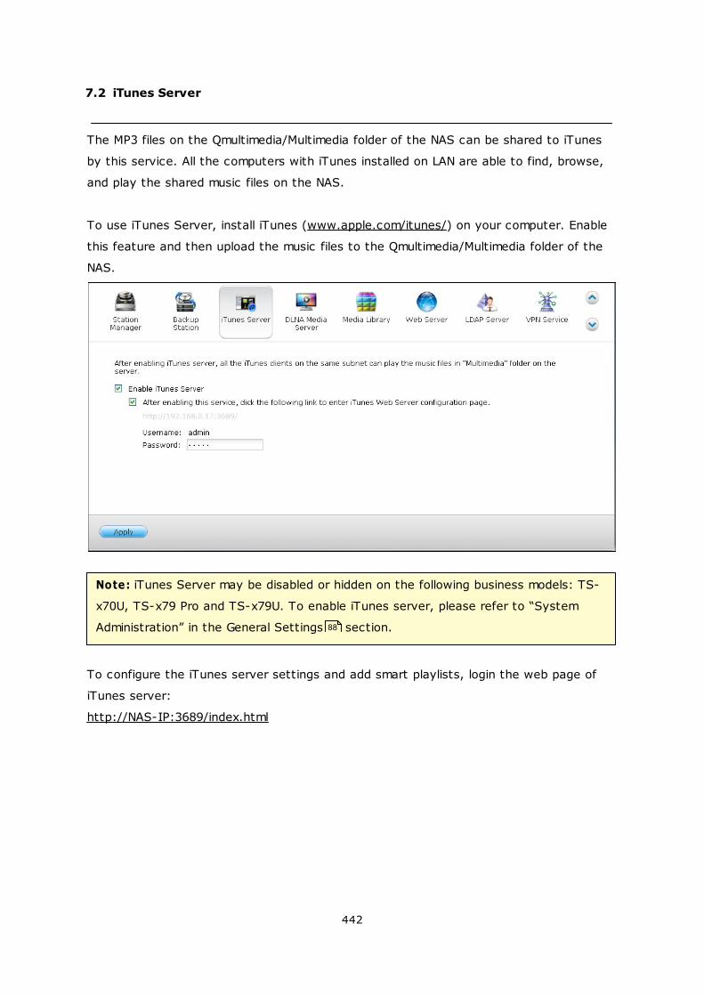
442
7.2 iTunes Server
The MP3 files on the Qmultimedia/Multimedia folder of the NAS can be shared to iTunes
by this service. All the computers with iTunes installed on LAN are able to find, browse,
and play the shared music files on the NAS.
To use iTunes Server, install iTunes (www.apple.com/itunes/) on your computer. Enable
this feature and then upload the music files to the Qmultimedia/Multimedia folder of the
NAS.
Note: iTunes Server may be disabled or hidden on the following business models: TS-
x70U, TS-x79 Pro and TS-x79U. To enable iTunes server, please refer to “System
Administration” in the General Settings section.
To configure the iTunes server settings and add smart playlists, login the web page of
iTunes server:
http://NAS-IP:3689/index.html
88
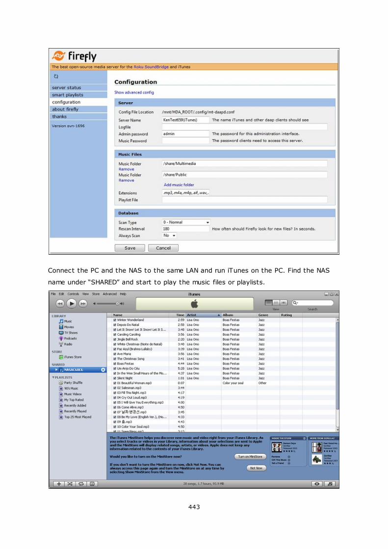
443
Connect the PC and the NAS to the same LAN and run iTunes on the PC. Find the NAS
name under “SHARED” and start to play the music files or playlists.
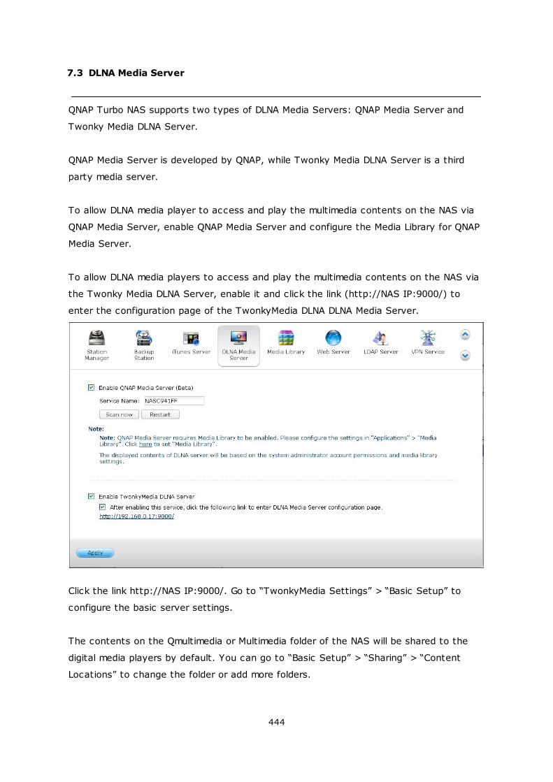
444
7.3 DLNA Media Server
QNAP Turbo NAS supports two types of DLNA Media Servers: QNAP Media Server and
Twonky Media DLNA Server.
QNAP Media Server is developed by QNAP, while Twonky Media DLNA Server is a third
party media server.
To allow DLNA media player to access and play the multimedia contents on the NAS via
QNAP Media Server, enable QNAP Media Server and configure the Media Library for QNAP
Media Server.
To allow DLNA media players to access and play the multimedia contents on the NAS via
the Twonky Media DLNA Server, enable it and click the link (http://NAS IP:9000/) to
enter the configuration page of the TwonkyMedia DLNA DLNA Media Server.
Click the link http://NAS IP:9000/. Go to “TwonkyMedia Settings” > “Basic Setup” to
configure the basic server settings.
The contents on the Qmultimedia or Multimedia folder of the NAS will be shared to the
digital media players by default. You can go to “Basic Setup” > “Sharing” > “Content
Locations” to change the folder or add more folders.
445
After configuring the settings, you can upload MP3, photos, or video files to the specified
folders on the NAS.
Note: If you upload multimedia files to the default folder but the files are not shown on
Media Player, click “Rescan content directories” or “Restart server” on the Media
Server configuration page.
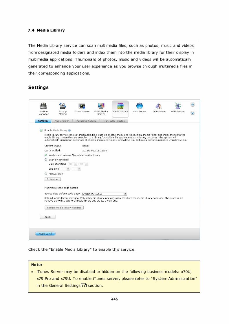
446
7.4 Media Library
The Media Library service can scan multimedia files, such as photos, music and videos
from designated media folders and index them into the media library for their display in
multimedia applications. Thumbnails of photos, music and videos will be automatically
generated to enhance your user experience as you browse through multimedia files in
their corresponding applications.
Settings
Check the “Enable Media Library” to enable this service.
Note:
iTunes Server may be disabled or hidden on the following business models: x70U,
x79 Pro and x79U. To enable iTunes server, please refer to “System Administration”
in the General Settings section. 88
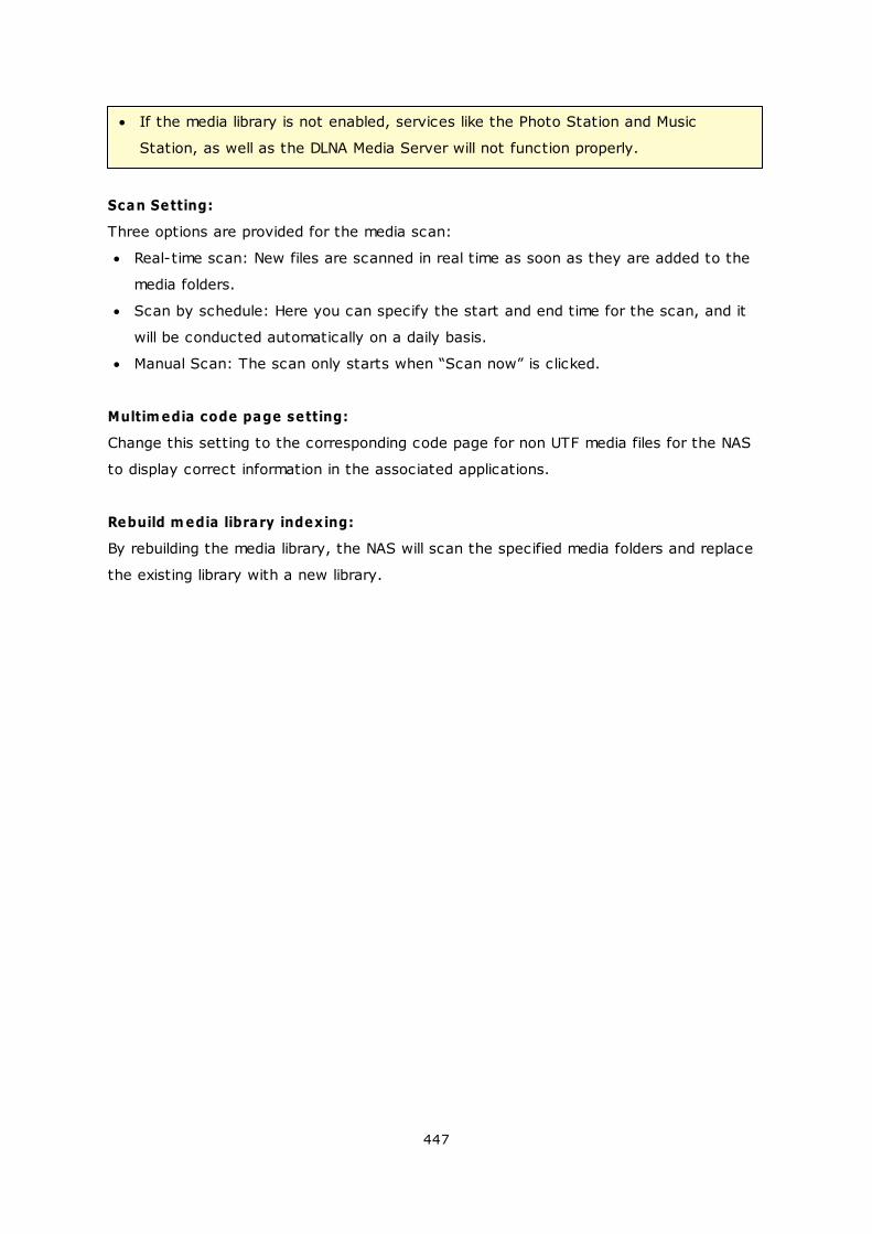
447
If the media library is not enabled, services like the Photo Station and Music
Station, as well as the DLNA Media Server will not function properly.
Scan Setting:
Three options are provided for the media scan:
Real-time scan: New files are scanned in real time as soon as they are added to the
media folders.
Scan by schedule: Here you can specify the start and end time for the scan, and it
will be conducted automatically on a daily basis.
Manual Scan: The scan only starts when “Scan now” is clicked.
Multim edia code page setting:
Change this setting to the corresponding code page for non UTF media files for the NAS
to display correct information in the associated applications.
Rebuild m edia library indexing:
By rebuilding the media library, the NAS will scan the specified media folders and replace
the existing library with a new library.
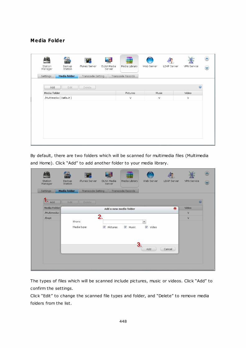
448
Media Folder
By default, there are two folders which will be scanned for multimedia files (Multimedia
and Home). Click “Add” to add another folder to your media library.
The types of files which will be scanned include pictures, music or videos. Click “Add” to
confirm the settings.
Click “Edit” to change the scanned file types and folder, and “Delete” to remove media
folders from the list.
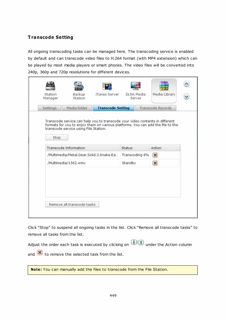
449
T ranscode Setting
All ongoing transcoding tasks can be managed here. The transcoding service is enabled
by default and can transcode video files to H.264 format (with MP4 extension) which can
be played by most media players or smart phones. The video files will be converted into
240p, 360p and 720p resolutions for different devices.
Click “Stop” to suspend all ongoing tasks in the list. Click “Remove all transcode tasks” to
remove all tasks from the list.
Adjust the order each task is executed by clicking on under the Action column
and to remove the selected task from the list.
Note: You can manually add the files to transcode from the File Station.
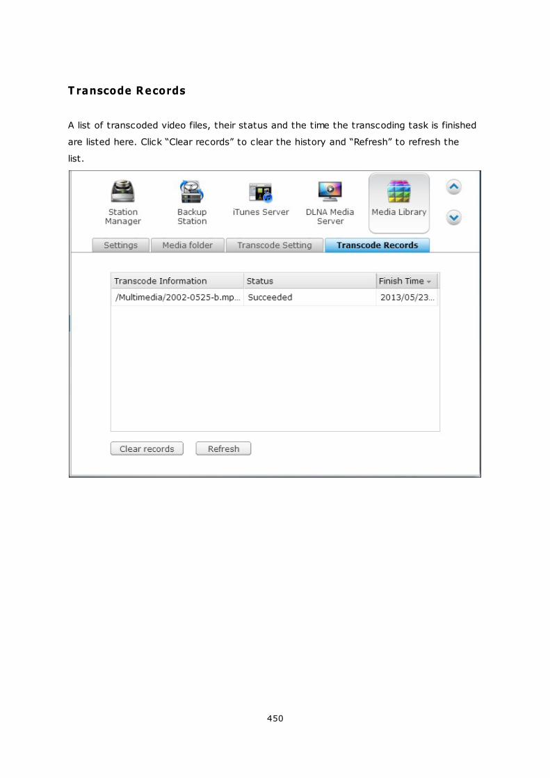
450
T ranscode Records
A list of transcoded video files, their status and the time the transcoding task is finished
are listed here. Click “Clear records” to clear the history and “Refresh” to refresh the
list.
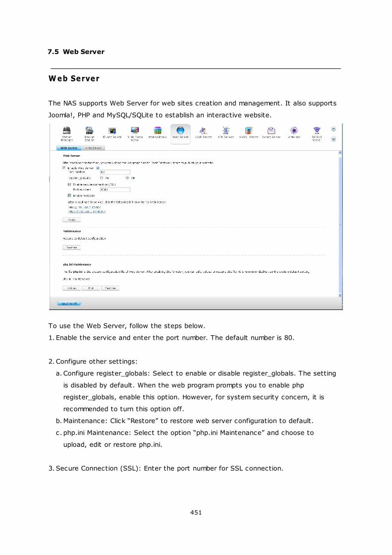
451
7.5 Web Server
Web Server
The NAS supports Web Server for web sites creation and management. It also supports
Joomla!, PHP and MySQL/SQLite to establish an interactive website.
To use the Web Server, follow the steps below.
1. Enable the service and enter the port number. The default number is 80.
2. Configure other settings:
a. Configure register_globals: Select to enable or disable register_globals. The setting
is disabled by default. When the web program prompts you to enable php
register_globals, enable this option. However, for system security concern, it is
recommended to turn this option off.
b.Maintenance: Click “Restore” to restore web server configuration to default.
c. php.ini Maintenance: Select the option “php.ini Maintenance” and choose to
upload, edit or restore php.ini.
3. Secure Connection (SSL): Enter the port number for SSL connection.
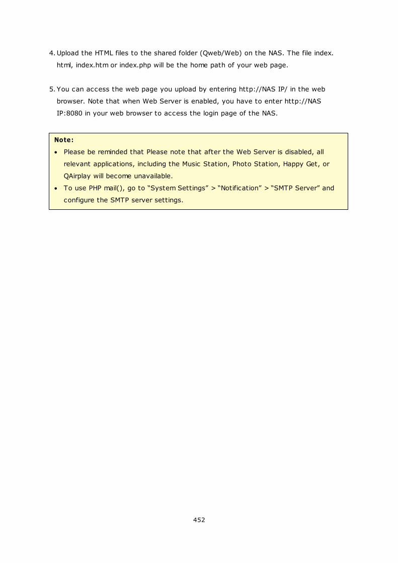
452
4.Upload the HTML files to the shared folder (Qweb/Web) on the NAS. The file index.
html, index.htm or index.php will be the home path of your web page.
5. You can access the web page you upload by entering http://NAS IP/ in the web
browser. Note that when Web Server is enabled, you have to enter http://NAS
IP:8080 in your web browser to access the login page of the NAS.
Note:
Please be reminded that Please note that after the Web Server is disabled, all
relevant applications, including the Music Station, Photo Station, Happy Get, or
QAirplay will become unavailable.
To use PHP mail(), go to “System Settings” > “Notification” > “SMTP Server” and
configure the SMTP server settings.
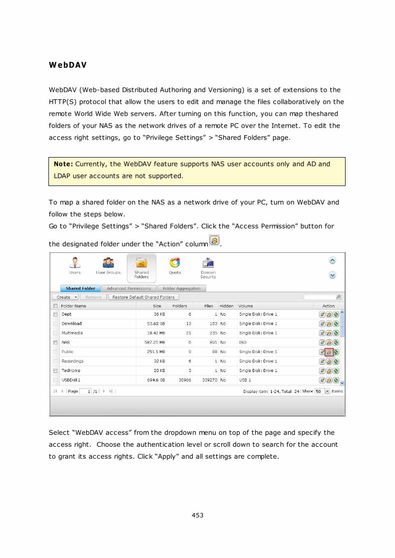
453
WebDAV
WebDAV (Web-based Distributed Authoring and Versioning) is a set of extensions to the
HTTP(S) protocol that allow the users to edit and manage the files collaboratively on the
remote World Wide Web servers. After turning on this function, you can map theshared
folders of your NAS as the network drives of a remote PC over the Internet. To edit the
access right settings, go to “Privilege Settings” > “Shared Folders” page.
Note: Currently, the WebDAV feature supports NAS user accounts only and AD and
LDAP user accounts are not supported.
To map a shared folder on the NAS as a network drive of your PC, turn on WebDAV and
follow the steps below.
Go to “Privilege Settings” > “Shared Folders”. Click the “Access Permission” button for
the designated folder under the “Action” column .
Select “WebDAV access” from the dropdown menu on top of the page and specify the
access right. Choose the authentication level or scroll down to search for the account
to grant its access rights. Click “Apply” and all settings are complete.
454
Next, mount the shared folders of the NAS as the shared folders on your operating
systems by WebDAV.
455
Windows XP:
1. Right click “My Computer” and select “Map Network Drive…”
2. Click “Sign up for online storage or connect to a network server”.
3. Select “Choose another network location”.
456
4. Enter the URL of your NAS with the folder name. Note that you should put a “#” key
at the end of the URL. Click “Next”. Format: http://NAS_IP_or_HOST_NAME/
SHARE_FOLDER_NAME/#
457
5. Enter the username and password which has the WebDAV access right to connect
to the folder.
6. Type a name for this network place.
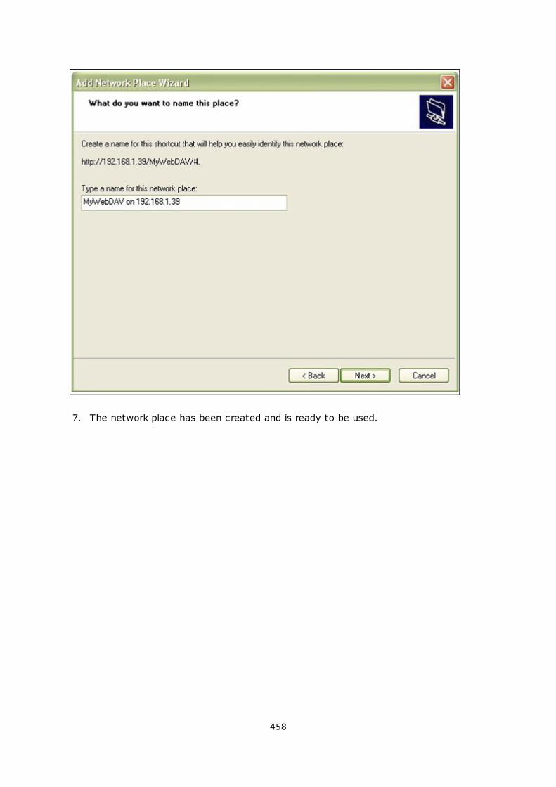
458
7. The network place has been created and is ready to be used.
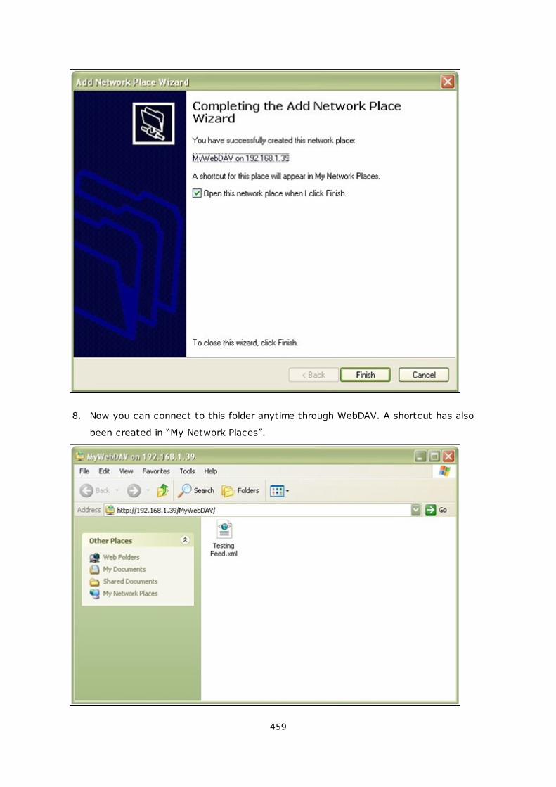
459
8. Now you can connect to this folder anytime through WebDAV. A shortcut has also
been created in “My Network Places”.
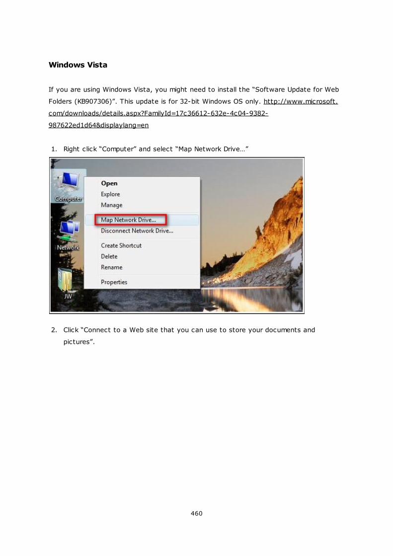
460
Windows Vista
If you are using Windows Vista, you might need to install the “Software Update for Web
Folders (KB907306)”. This update is for 32-bit Windows OS only. http://www.microsoft.
com/downloads/details.aspx?FamilyId=17c36612-632e-4c04-9382-
987622ed1d64&displaylang=en
1. Right click “Computer” and select “Map Network Drive…”
2. Click “Connect to a Web site that you can use to store your documents and
pictures”.
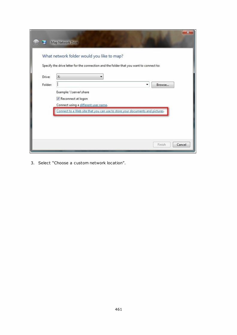
461
3. Select “Choose a custom network location”.
462
4. Enter the URL of your NAS with the folder name.
Format: http://NAS_IP_or_HOST_NAME/SHARE_FOLDER_NAME
463
5. Enter the username and password which has the WebDAV access right to connect
to this folder.
6. Type a name for this network location.
464
7. The Web folder has been successfully created.
465
8. You can locate the web folder in the “Network Location” section in “Computer”.
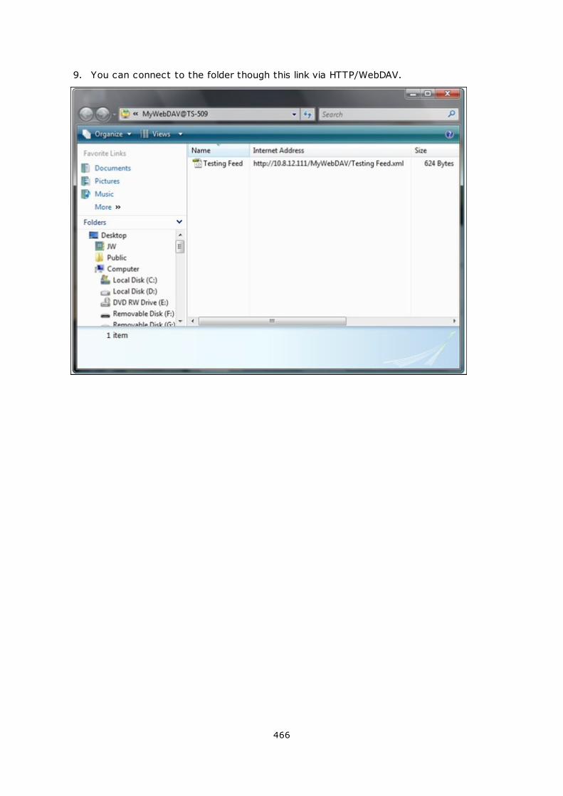
466
9. You can connect to the folder though this link via HTTP/WebDAV.
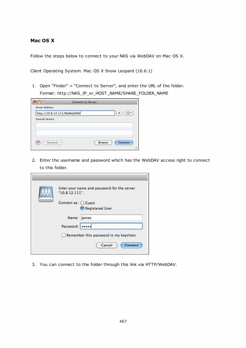
467
Mac OS X
Follow the steps below to connect to your NAS via WebDAV on Mac OS X.
Client Operating System: Mac OS X Snow Leopard (10.6.1)
1. Open “Finder” > “Connect to Server”, and enter the URL of the folder.
Format: http://NAS_IP_or_HOST_NAME/SHARE_FOLDER_NAME
2. Enter the username and password which has the WebDAV access right to connect
to this folder.
3. You can connect to the folder through this link via HTTP/WebDAV.
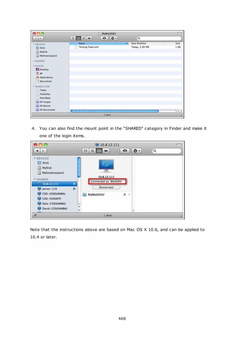
468
4. You can also find the mount point in the “SHARED” category in Finder and make it
one of the login items.
Note that the instructions above are based on Mac OS X 10.6, and can be applied to
10.4 or later.
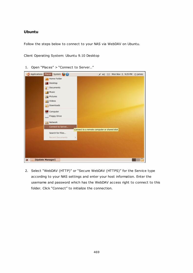
469
Ubuntu
Follow the steps below to connect to your NAS via WebDAV on Ubuntu.
Client Operating System: Ubuntu 9.10 Desktop
1. Open “Places” > “Connect to Server…”
2. Select “WebDAV (HTTP)” or “Secure WebDAV (HTTPS)” for the Service type
according to your NAS settings and enter your host information. Enter the
username and password which has the WebDAV access right to connect to this
folder. Click “Connect” to initialize the connection.
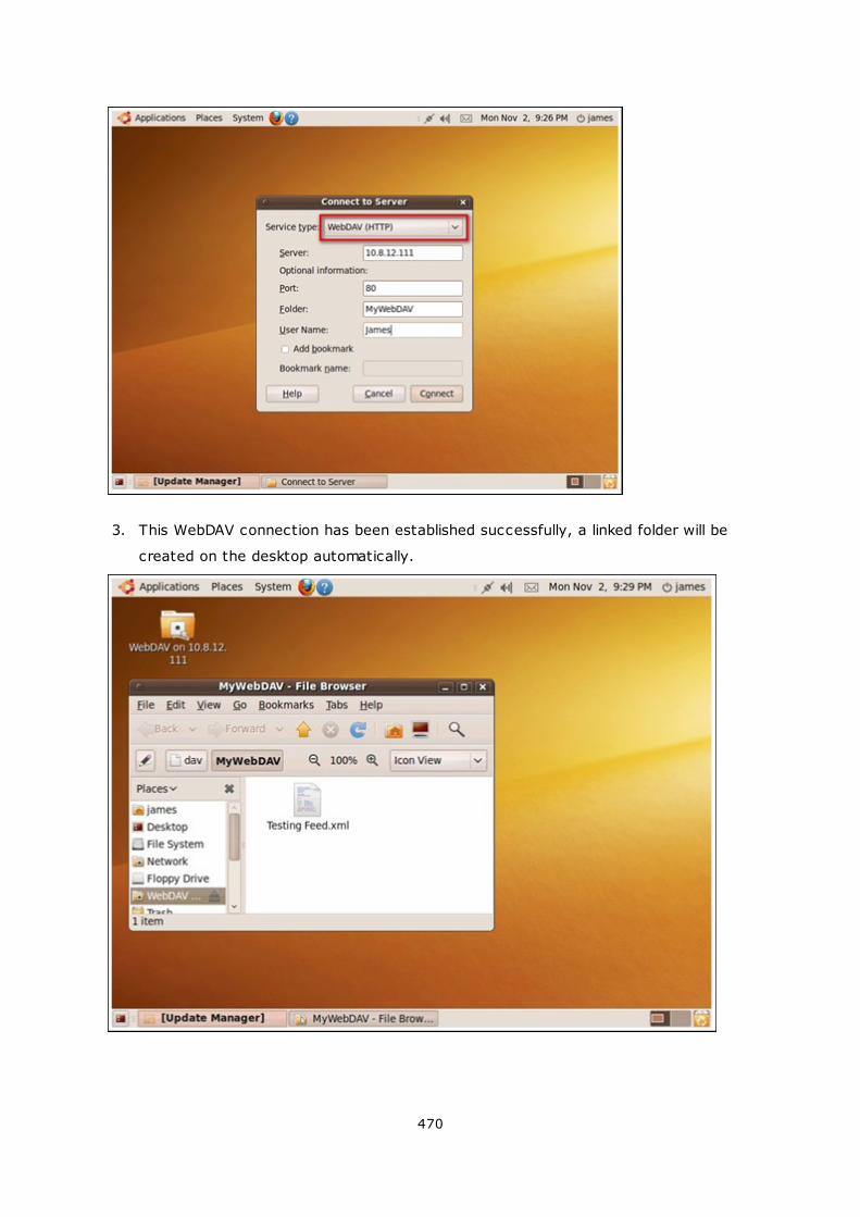
470
3. This WebDAV connection has been established successfully, a linked folder will be
created on the desktop automatically.
471
MySQL Management
Install phpMyAdmin software and save the program files in the Web or Qweb share of the
NAS. You can change the folder name and connect to the database by entering the URL
in the browser.
Note: The default username of MySQL is “root”. The password is “admin”. Please
change your root password immediately after logging in to the phpMyAdmin
management interface.
SQLite Managem ent
Follow the steps below or refer to the INSTALL file in the downloaded SQLiteManager-*.
tar.gz? to install SQLiteManager.
1. Unpack the downloaded file SQLiteManager-*.tar.gz.
2. Upload the unpacked folder SQLiteManager-* to \\NAS IP\Web\ or \\NASIP\Qweb.
3. Open a web browser and go to http://NAS IP/SQLiteManager-*/.
?: The symbol “*” refers to the version number of SQLiteManager.
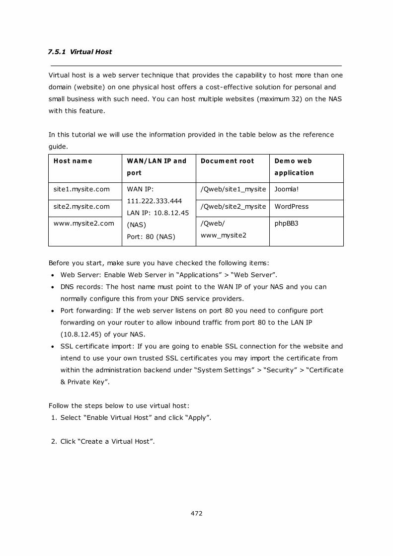
472
7.5.1 Virtual Host
Virtual host is a web server technique that provides the capability to host more than one
domain (website) on one physical host offers a cost-effective solution for personal and
small business with such need. You can host multiple websites (maximum 32) on the NAS
with this feature.
In this tutorial we will use the information provided in the table below as the reference
guide.
Host nam e WAN/LAN IP and
port
Docum ent root Dem o web
application
site1.mysite.com WAN IP:
111.222.333.444
LAN IP: 10.8.12.45
(NAS)
Port: 80 (NAS)
/Qweb/site1_mysite Joomla!
site2.mysite.com /Qweb/site2_mysite WordPress
www.mysite2.com /Qweb/
www_mysite2
phpBB3
Before you start, make sure you have checked the following items:
Web Server: Enable Web Server in “Applications” > “Web Server”.
DNS records: The host name must point to the WAN IP of your NAS and you can
normally configure this from your DNS service providers.
Port forwarding: If the web server listens on port 80 you need to configure port
forwarding on your router to allow inbound traffic from port 80 to the LAN IP
(10.8.12.45) of your NAS.
SSL certificate import: If you are going to enable SSL connection for the website and
intend to use your own trusted SSL certificates you may import the certificate from
within the administration backend under “System Settings” > “Security” > “Certificate
& Private Key”.
Follow the steps below to use virtual host:
1. Select “Enable Virtual Host” and click “Apply”.
2. Click “Create a Virtual Host”.
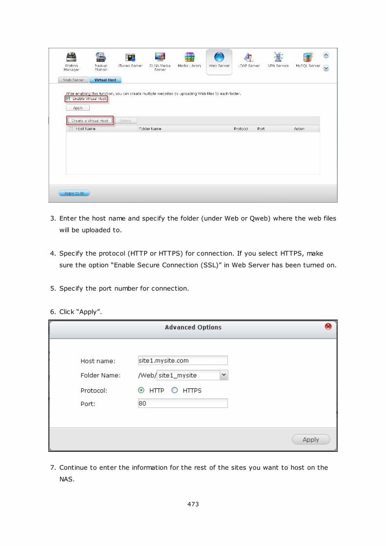
473
3. Enter the host name and specify the folder (under Web or Qweb) where the web files
will be uploaded to.
4. Specify the protocol (HTTP or HTTPS) for connection. If you select HTTPS, make
sure the option “Enable Secure Connection (SSL)” in Web Server has been turned on.
5. Specify the port number for connection.
6. Click “Apply”.
7. Continue to enter the information for the rest of the sites you want to host on the
NAS.
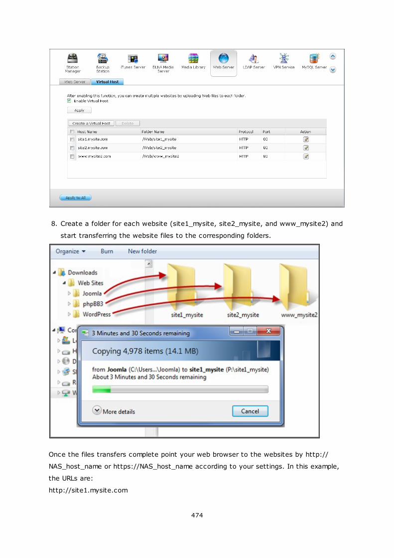
474
8. Create a folder for each website (site1_mysite, site2_mysite, and www_mysite2) and
start transferring the website files to the corresponding folders.
Once the files transfers complete point your web browser to the websites by http://
NAS_host_name or https://NAS_host_name according to your settings. In this example,
the URLs are:
http://site1.mysite.com

475
http://site2.mysite.com
http://www.mysite2.com
You should see the Joomla!, phpBB3, and WordPress web pages, respectively.
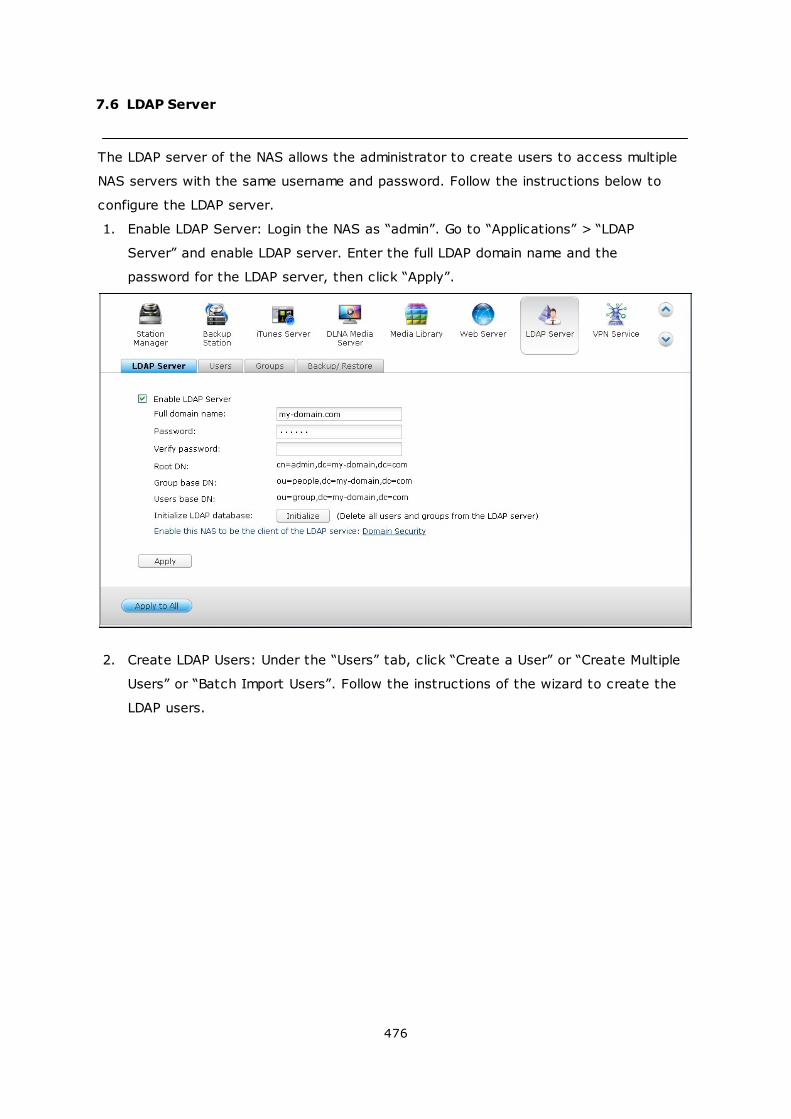
476
7.6 LDAP Server
The LDAP server of the NAS allows the administrator to create users to access multiple
NAS servers with the same username and password. Follow the instructions below to
configure the LDAP server.
1. Enable LDAP Server: Login the NAS as “admin”. Go to “Applications” > “LDAP
Server” and enable LDAP server. Enter the full LDAP domain name and the
password for the LDAP server, then click “Apply”.
2. Create LDAP Users: Under the “Users” tab, click “Create a User” or “Create Multiple
Users” or “Batch Import Users”. Follow the instructions of the wizard to create the
LDAP users.
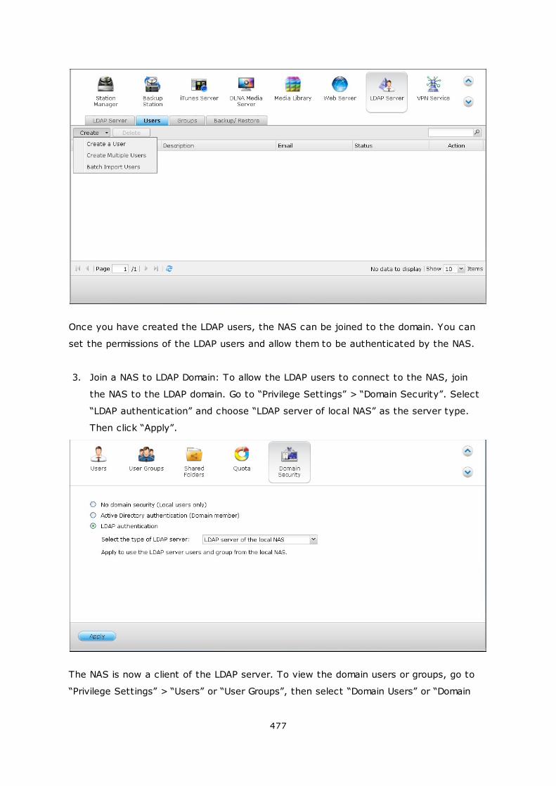
477
Once you have created the LDAP users, the NAS can be joined to the domain. You can
set the permissions of the LDAP users and allow them to be authenticated by the NAS.
3. Join a NAS to LDAP Domain: To allow the LDAP users to connect to the NAS, join
the NAS to the LDAP domain. Go to “Privilege Settings” > “Domain Security”. Select
“LDAP authentication” and choose “LDAP server of local NAS” as the server type.
Then click “Apply”.
The NAS is now a client of the LDAP server. To view the domain users or groups, go to
“Privilege Settings” > “Users” or “User Groups”, then select “Domain Users” or “Domain
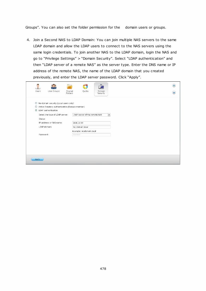
478
Groups”. You can also set the folder permission for the domain users or groups.
4. Join a Second NAS to LDAP Domain: You can join multiple NAS servers to the same
LDAP domain and allow the LDAP users to connect to the NAS servers using the
same login credentials. To join another NAS to the LDAP domain, login the NAS and
go to “Privilege Settings” > “Domain Security”. Select “LDAP authentication” and
then “LDAP server of a remote NAS” as the server type. Enter the DNS name or IP
address of the remote NAS, the name of the LDAP domain that you created
previously, and enter the LDAP server password. Click “Apply”.
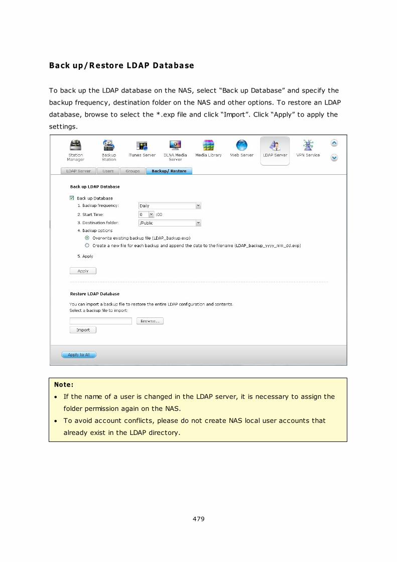
479
Back up/Restore LDAP Database
To back up the LDAP database on the NAS, select “Back up Database” and specify the
backup frequency, destination folder on the NAS and other options. To restore an LDAP
database, browse to select the *.exp file and click “Import”. Click “Apply” to apply the
settings.
Note:
If the name of a user is changed in the LDAP server, it is necessary to assign the
folder permission again on the NAS.
To avoid account conflicts, please do not create NAS local user accounts that
already exist in the LDAP directory.
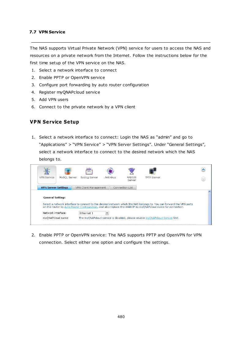
480
7.7 VPN Service
The NAS supports Virtual Private Network (VPN) service for users to access the NAS and
resources on a private network from the Internet. Follow the instructions below for the
first time setup of the VPN service on the NAS.
1. Select a network interface to connect
2. Enable PPTP or OpenVPN service
3. Configure port forwarding by auto router configuration
4. Register myQNAPcloud service
5. Add VPN users
6. Connect to the private network by a VPN client
VPN Service Setup
1. Select a network interface to connect: Login the NAS as “admin” and go to
“Applications” > “VPN Service” > “VPN Server Settings”. Under “General Settings”,
select a network interface to connect to the desired network which the NAS
belongs to.
2. Enable PPTP or OpenVPN service: The NAS supports PPTP and OpenVPN for VPN
connection. Select either one option and configure the settings.
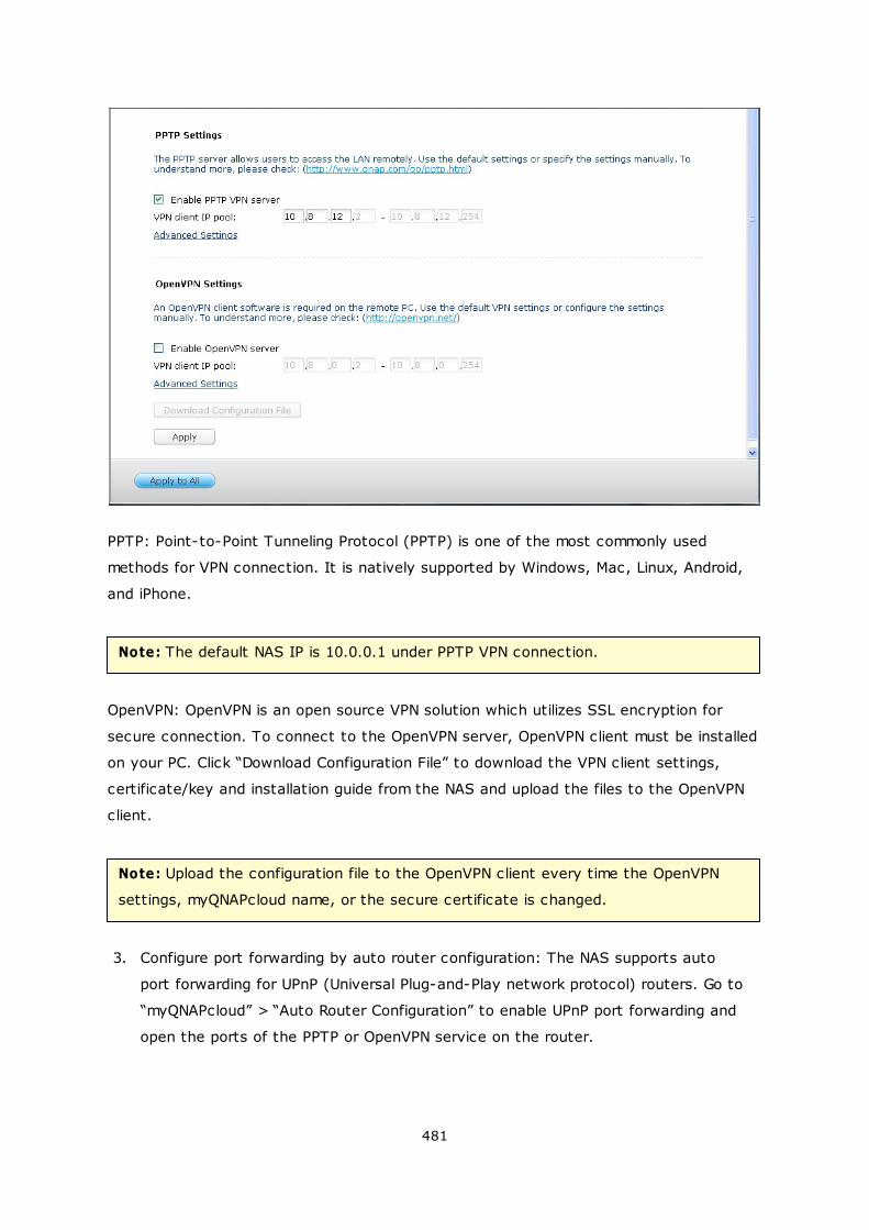
481
PPTP: Point-to-Point Tunneling Protocol (PPTP) is one of the most commonly used
methods for VPN connection. It is natively supported by Windows, Mac, Linux, Android,
and iPhone.
Note: The default NAS IP is 10.0.0.1 under PPTP VPN connection.
OpenVPN: OpenVPN is an open source VPN solution which utilizes SSL encryption for
secure connection. To connect to the OpenVPN server, OpenVPN client must be installed
on your PC. Click “Download Configuration File” to download the VPN client settings,
certificate/key and installation guide from the NAS and upload the files to the OpenVPN
client.
Note: Upload the configuration file to the OpenVPN client every time the OpenVPN
settings, myQNAPcloud name, or the secure certificate is changed.
3. Configure port forwarding by auto router configuration: The NAS supports auto
port forwarding for UPnP (Universal Plug-and-Play network protocol) routers. Go to
“myQNAPcloud” > “Auto Router Configuration” to enable UPnP port forwarding and
open the ports of the PPTP or OpenVPN service on the router.
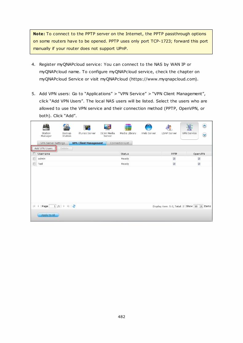
482
Note: To connect to the PPTP server on the Internet, the PPTP passthrough options
on some routers have to be opened. PPTP uses only port TCP-1723; forward this port
manually if your router does not support UPnP.
4. Register myQNAPcloud service: You can connect to the NAS by WAN IP or
myQNAPcloud name. To configure myQNAPcloud service, check the chapter on
myQNAPcloud Service or visit myQNAPcloud (https://www.myqnapcloud.com).
5. Add VPN users: Go to “Applications” > “VPN Service” > “VPN Client Management”,
click “Add VPN Users”. The local NAS users will be listed. Select the users who are
allowed to use the VPN service and their connection method (PPTP, OpenVPN, or
both). Click “Add”.
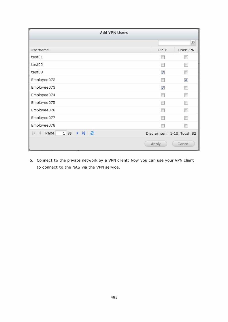
483
6. Connect to the private network by a VPN client: Now you can use your VPN client
to connect to the NAS via the VPN service.
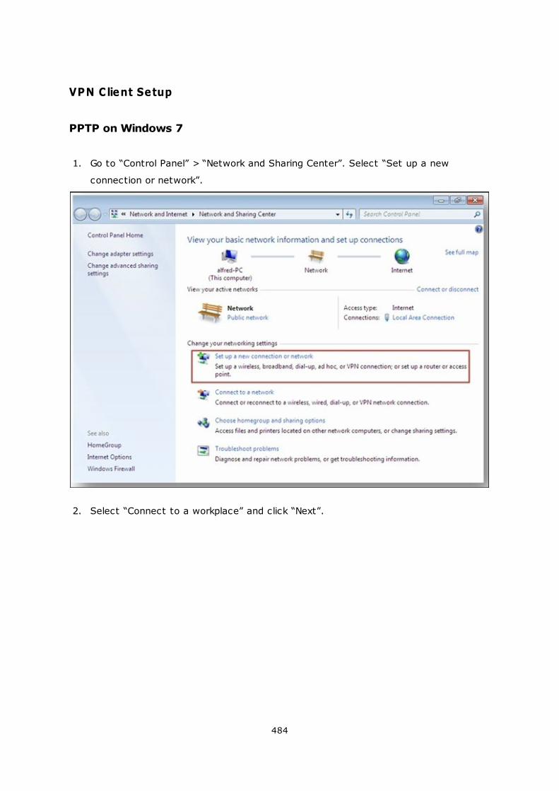
484
VPN Client Setup
PPTP on Windows 7
1. Go to “Control Panel” > “Network and Sharing Center”. Select “Set up a new
connection or network”.
2. Select “Connect to a workplace” and click “Next”.
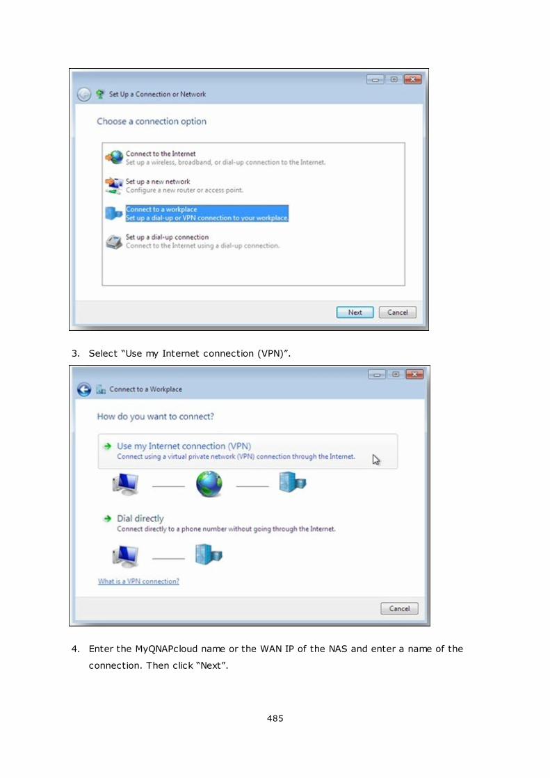
485
3. Select “Use my Internet connection (VPN)”.
4. Enter the MyQNAPcloud name or the WAN IP of the NAS and enter a name of the
connection. Then click “Next”.
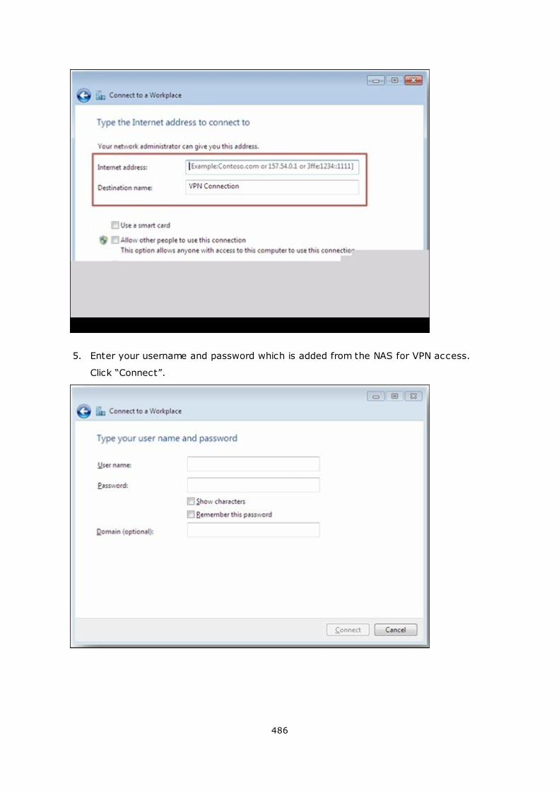
486
5. Enter your username and password which is added from the NAS for VPN access.
Click “Connect”.
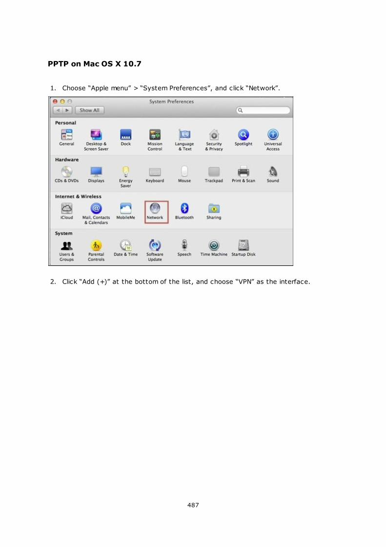
487
PPTP on Mac OS X 10.7
1. Choose “Apple menu” > “System Preferences”, and click “Network”.
2. Click “Add (+)” at the bottom of the list, and choose “VPN” as the interface.
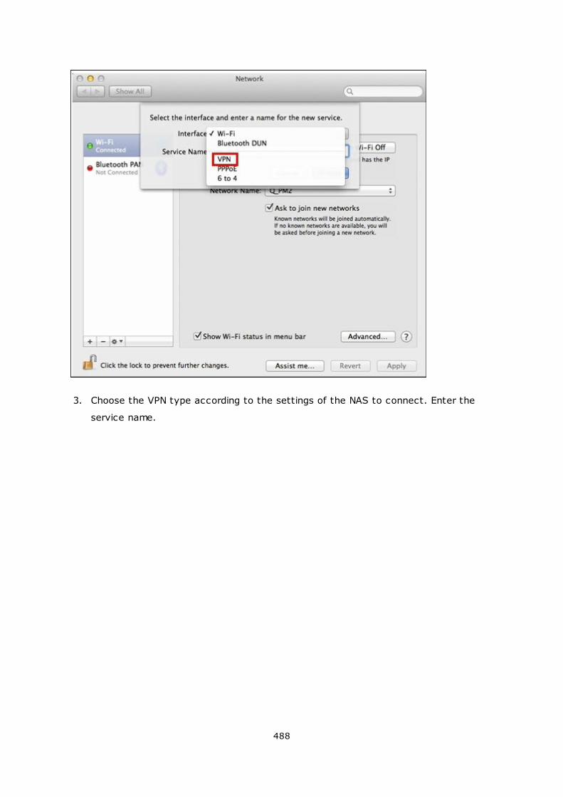
488
3. Choose the VPN type according to the settings of the NAS to connect. Enter the
service name.
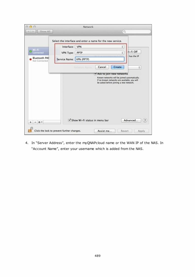
489
4. In “Server Address”, enter the myQNAPcloud name or the WAN IP of the NAS. In
“Account Name”, enter your username which is added from the NAS.
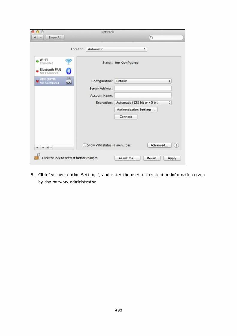
490
5. Click “Authentication Settings”, and enter the user authentication information given
by the network administrator.
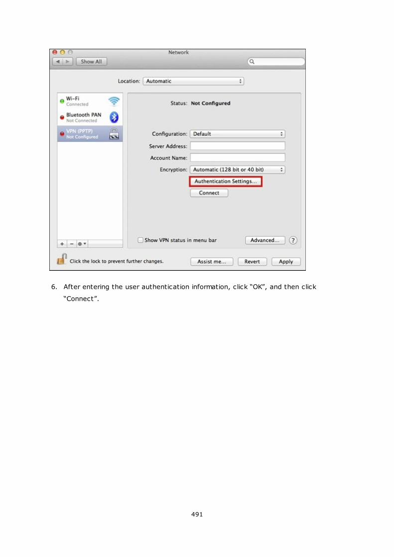
491
6. After entering the user authentication information, click “OK”, and then click
“Connect”.
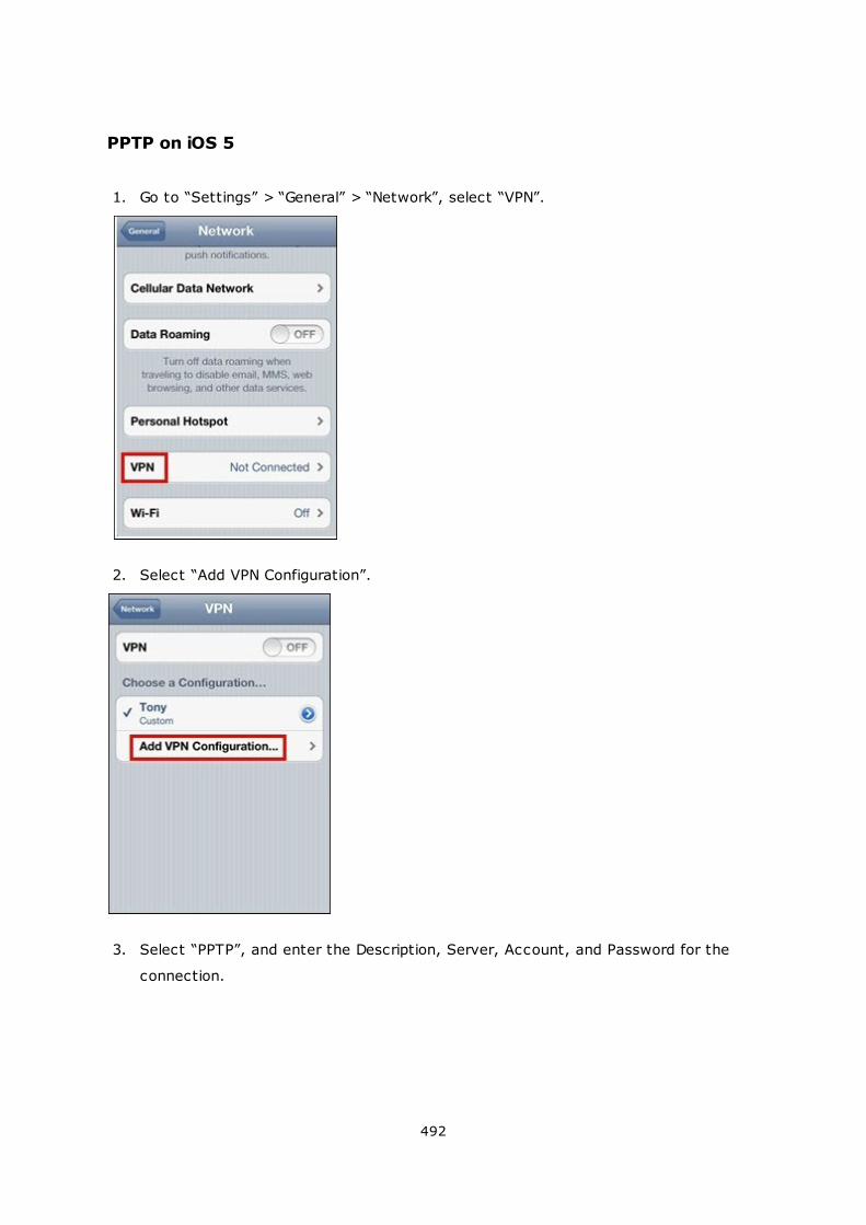
492
PPTP on iOS 5
1. Go to “Settings” > “General” > “Network”, select “VPN”.
2. Select “Add VPN Configuration”.
3. Select “PPTP”, and enter the Description, Server, Account, and Password for the
connection.
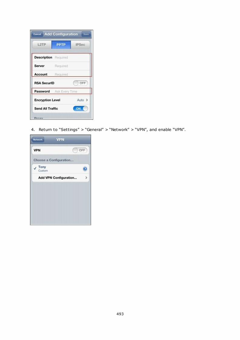
493
4. Return to “Settings” > “General” > “Network” > “VPN”, and enable “VPN”.
494
OpenVPN on Windows
1. Download OpenVPN from http://openvpn.net/index.php/open-source/downloads.
html
2. Install OpenVPN client on Windows. The default installation directory is C:\Program
Files\OpenVPN.
3. Run OpenVPN GUI as administrator.
4. Download OpenVPN configuration file and certificate from the NAS (“Applications” >
“VPN Service” > “VPN Server Settings” > “OpenVPN Settings”)
5. Edit openvpn.ovpn and replace “OPENVPN_SERVER_IP” with the OpenVPN server IP.
6. Put “ca.crt” and “openvpn.ovpn” into the configuration folder under OpenVPN
configuration subdirectory (C:\Program Files\OpenVPN\config).
Note: If the OpenVPN client is running on Windows 7, add the firewall rules in the
advanced settings of OpenVPN.
OpenVPN on Linux
1. Download OpenVPN from http://openvpn.net/index.php/open-source/downloads.
htm
2. Install OpenVPN client on Linux.
3. Download OpenVPN configuration file and certificate from the NAS (“Applications” >
“VPN Service” > “VPN Server Settings” > “OpenVPN Settings”).
4. Edit openvpn.ovpn and replace “OPENVPN_SERVER_IP” with OpenVPN server IP.
5. Put “ca.crt” and “openvpn.ovpn” into the configuration folder under OpenVPN
configuration subdirectory.
495
6. Run OpenVPN.
OpenVPN on Mac
1. Download the disk image of OpenVPN client from http://code.google.com/p/
tunnelblick/
2. Launch Tunnelblick.
3. Download OpenVPN configuration file and certificate from the NAS (“Applications” >
“VPN Service” > “VPN Server Settings” > “OpenVPN Settings”).
4. Edit openvpn.ovpn and replace OPENVPN_SERVER_IP (alfred.myqnapnas.com) with
OpenVPN server IP.
5. Put “ca.crt” and “openvpn.ovpn” into the configuration folder under OpenVPN
configuration subdirectory.
6. Run OpenVPN.
496
7.8 MySQL Server
Note: To use this feature on the TS-x39/509/809 series, please update the system
firmware with the image file enclosed in the product CD or download the latest system
firmware from http://www.qnap.com.
You can enable MySQL Server as the website database.
Enable TCP/IP Networking:
You can enable this option to configure MySQL server of the NAS as a database server
of another web server in remote site through Internet connection. When you disable this
option, your MySQL server will only be configured as local database server for the web
server of the NAS.
After enabling remote connection, assign a port for the remote connection service of
MySQL server. The default port is 3306.
After the first-time installation of the NAS, a folder phpMyAdmin is created in the Qweb/
Web network folder. You can enter http://NAS IP/phpMyAdmin/ in the web browser to
enter the phpMyAdmin page and manage the MySQL database.
Note:
Do not delete the phpMyAdmin folder. You can rename this folder but the link on the
MySQL server page will not be updated. To connect to the renamed folder, you can
enter the link http://NAS IP/renamed folder in the web browser.
The phpMyAdmin folder is created after the first-time installation. When you update
the firmware, the folder remains unchanged.
Database Maintenance:
Reset root password: Execute this function to reset the password of MySQL root as
“admin”.
Re-initialize database: Execute this function to delete all the data on MySQL
database.
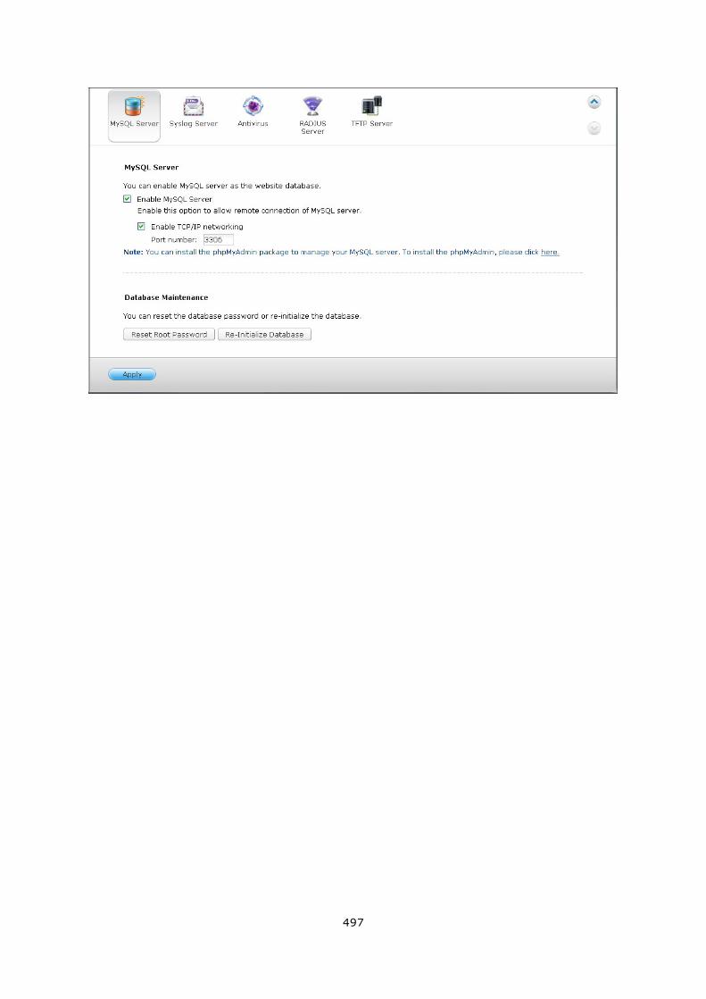
497
498
7.9 Syslog Server
Server Settings
To configure the NAS as a Syslog server and allow it to receive Syslog messages from
the clients, enable Syslog Server. Select the protocols (TCP and/or UDP) the NAS uses
to receive Syslog messages. Specify the port numbers if necessary or use the default
port number 514. Click “Apply” to save the settings. After enabling the NAS as a Syslog
server, enter the NAS IP as the Syslog server IP on the Syslog clients to receive the
Syslog messages from them.
Log Settings
Specify the maximum log size (1-100 MB) of the Syslog messages, the location (NAS
shared folder) to which the logs will be saved, and the file name. Once the logs have
reached the maximum size, the log file will be automatically archived and renamed with
the archive date as MyLogFile_yyyy_mm_dd, for example MyLogFile_2011_12_31. If
multiple log files are archived on the same day, the file will be named as
MyLogFile_yyyy_mm_dd.[number]. For example, MyLogFile_2011_12_31.1,
MyLogFile_2011_12_31.2, and so on. Click “Apply” to save the settings.
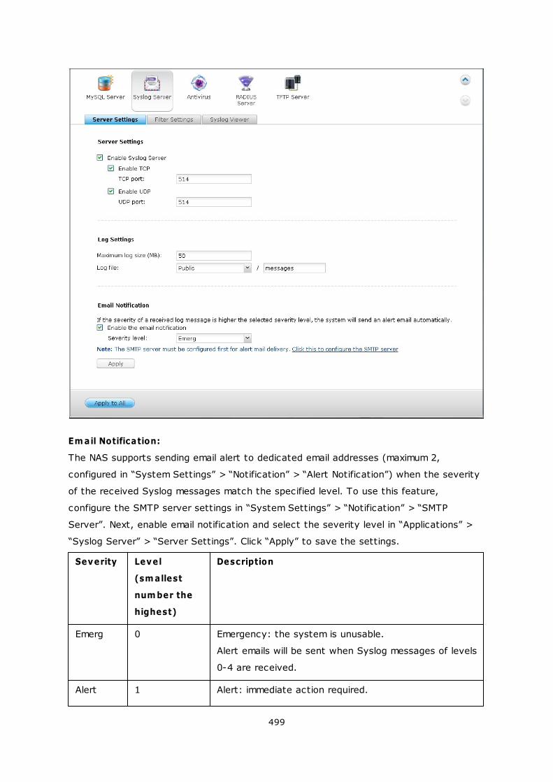
499
Em ail Notification:
The NAS supports sending email alert to dedicated email addresses (maximum 2,
configured in “System Settings” > “Notification” > “Alert Notification”) when the severity
of the received Syslog messages match the specified level. To use this feature,
configure the SMTP server settings in “System Settings” > “Notification” > “SMTP
Server”. Next, enable email notification and select the severity level in “Applications” >
“Syslog Server” > “Server Settings”. Click “Apply” to save the settings.
Severity Level
(sm allest
num ber the
highest)
Description
Emerg 0 Emergency: the system is unusable.
Alert emails will be sent when Syslog messages of levels
0-4 are received.
Alert 1 Alert: immediate action required.
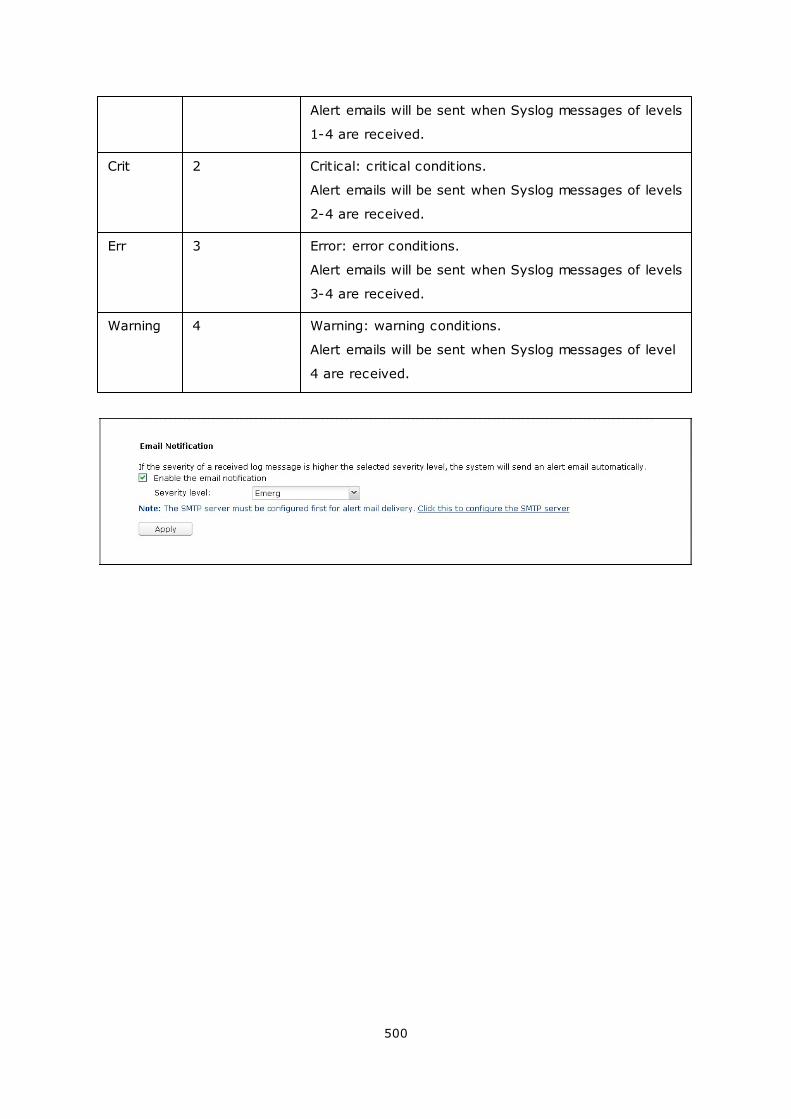
500
Alert emails will be sent when Syslog messages of levels
1-4 are received.
Crit 2 Critical: critical conditions.
Alert emails will be sent when Syslog messages of levels
2-4 are received.
Err 3 Error: error conditions.
Alert emails will be sent when Syslog messages of levels
3-4 are received.
Warning 4 Warning: warning conditions.
Alert emails will be sent when Syslog messages of level
4 are received.
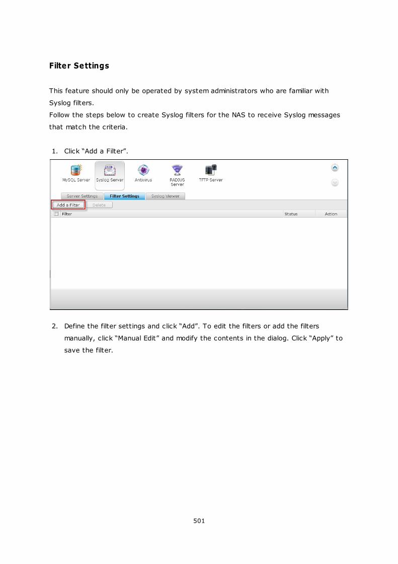
501
Filter Settings
This feature should only be operated by system administrators who are familiar with
Syslog filters.
Follow the steps below to create Syslog filters for the NAS to receive Syslog messages
that match the criteria.
1. Click “Add a Filter”.
2. Define the filter settings and click “Add”. To edit the filters or add the filters
manually, click “Manual Edit” and modify the contents in the dialog. Click “Apply” to
save the filter.
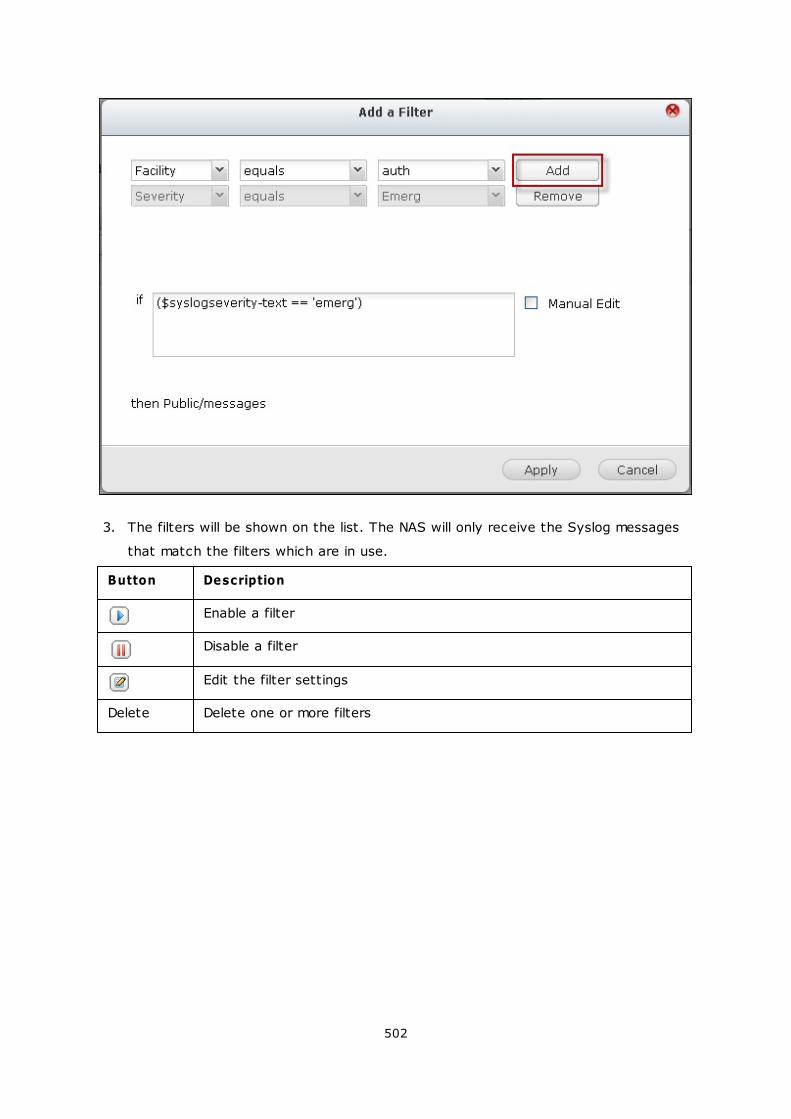
502
3. The filters will be shown on the list. The NAS will only receive the Syslog messages
that match the filters which are in use.
Button Description
Enable a filter
Disable a filter
Edit the filter settings
Delete Delete one or more filters
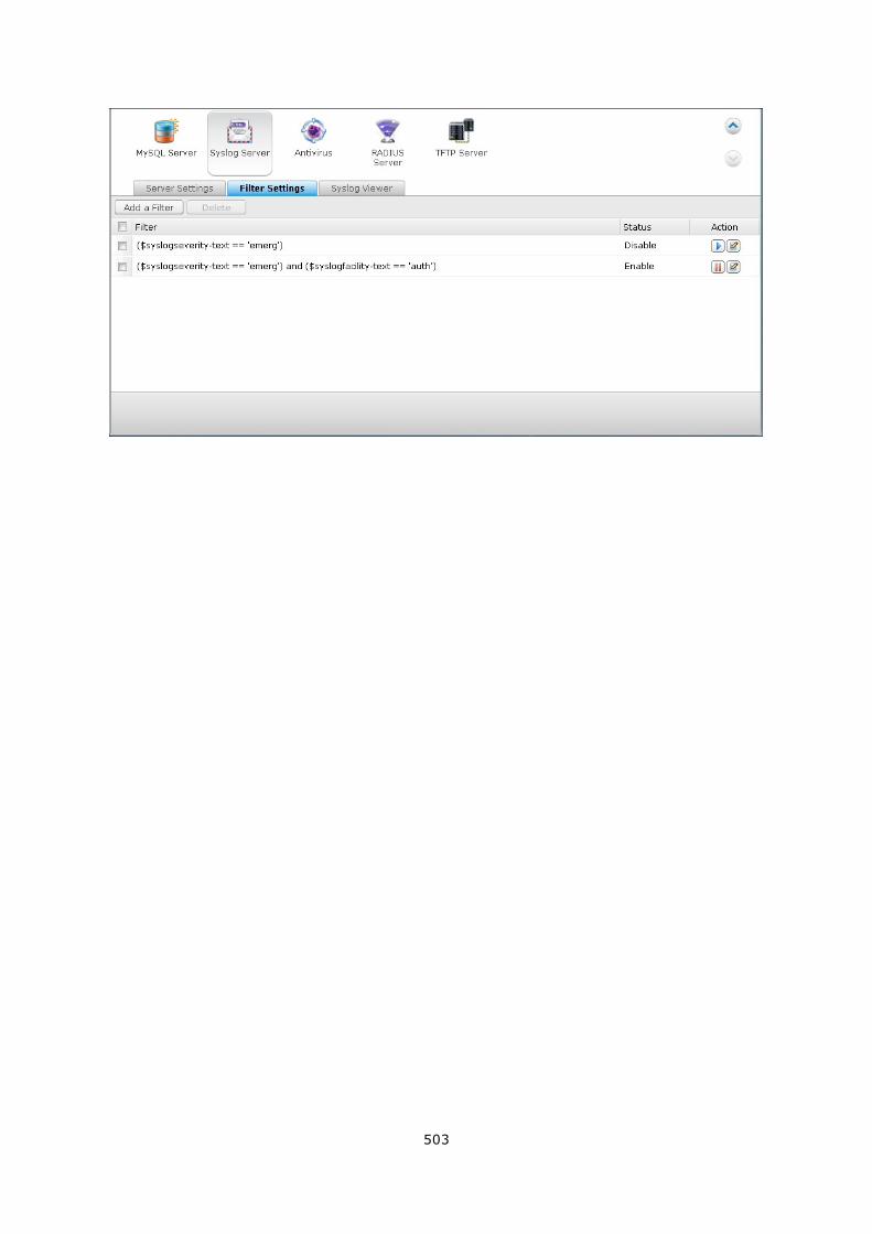
503
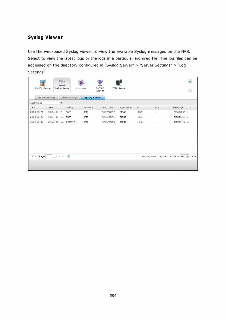
504
Syslog Viewer
Use the web-based Syslog viewer to view the available Syslog messages on the NAS.
Select to view the latest logs or the logs in a particular archived file. The log files can be
accessed on the directory configured in “Syslog Server” > “Server Settings” > “Log
Settings”.
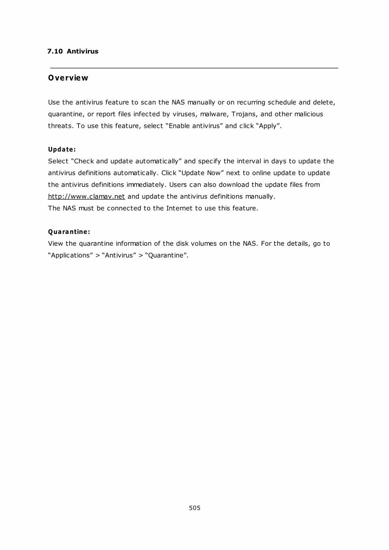
505
7.10 Antivirus
Overview
Use the antivirus feature to scan the NAS manually or on recurring schedule and delete,
quarantine, or report files infected by viruses, malware, Trojans, and other malicious
threats. To use this feature, select “Enable antivirus” and click “Apply”.
Update:
Select “Check and update automatically” and specify the interval in days to update the
antivirus definitions automatically. Click “Update Now” next to online update to update
the antivirus definitions immediately. Users can also download the update files from
http://www.clamav.net and update the antivirus definitions manually.
The NAS must be connected to the Internet to use this feature.
Quarantine:
View the quarantine information of the disk volumes on the NAS. For the details, go to
“Applications” > “Antivirus” > “Quarantine”.
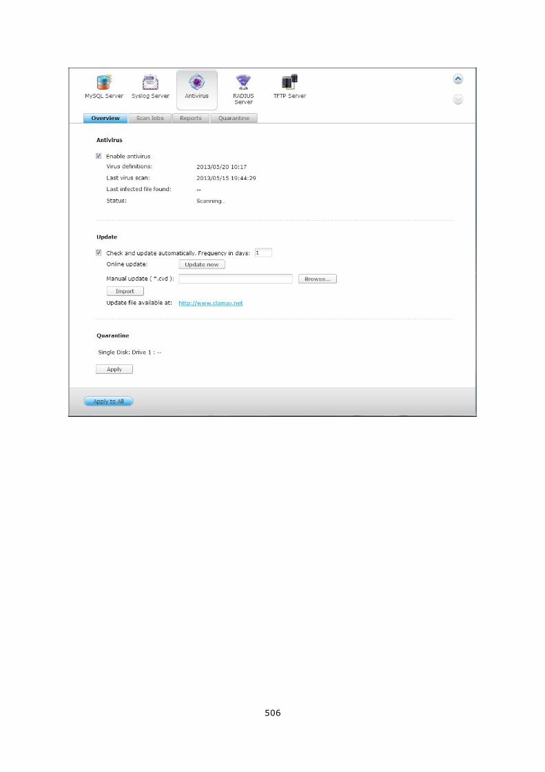
506
507
Scan Jobs
The NAS supports manual and scheduled scanning of all or specific shared folders. Up to
64 schedules can be created and maximum 5 scan jobs can run concurrently. To create
a scan job, follow the steps below.
1. Go to “Applications” > “Antivirus” > “Scan Jobs”. Click “Add a Scan Job”.
2. Enter the job name and select the shared folders to scan. To scan a specific
shared folder, select the share and click “Add”.
508
3. Multiple shared folders can be selected. To remove a shared folder, click next to
the share name. Click “Next”.
509
4. Define the schedule for the scan job. Click “Next”.
5. Select to scan all the files in the shared folder(s) or quick scan to scan only
potentially dangerous files. Select “Exclude files or folders” and specify a file, a
folder, or a file extension to be excluded from the virus scan. Separate each entry
by a space in the same line or enter one entry per line. For example:
/Public/testfile.txt
/Download
*.log
*.exe *.com
*.txt
Click “Next”.
510
6. Enable other scan options:
Specify the maximum file size (1-4096 MB) allowed for scanning.
To scan compressed files in the shared folder(s), enable “Scan compressed files”.
Specify the maximum amount of data (1-4096 MB) in an archive file for scanning if
applicable.
To scan MS Office and Mac Office files, RTF, PDF, and HTML files, select “Deep scan
for document files”.
Click “Next”.
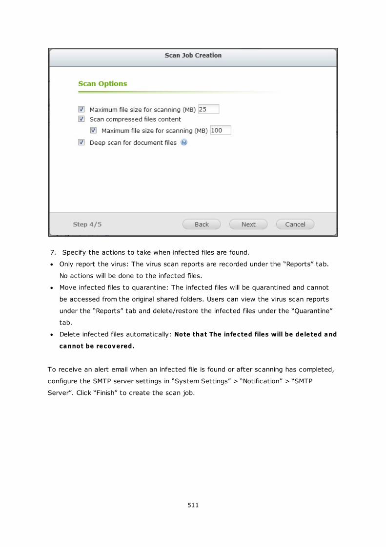
511
7. Specify the actions to take when infected files are found.
Only report the virus: The virus scan reports are recorded under the “Reports” tab.
No actions will be done to the infected files.
Move infected files to quarantine: The infected files will be quarantined and cannot
be accessed from the original shared folders. Users can view the virus scan reports
under the “Reports” tab and delete/restore the infected files under the “Quarantine”
tab.
Delete infected files automatically: Note that The infected files will be deleted and
cannot be recovered.
To receive an alert email when an infected file is found or after scanning has completed,
configure the SMTP server settings in “System Settings” > “Notification” > “SMTP
Server”. Click “Finish” to create the scan job.
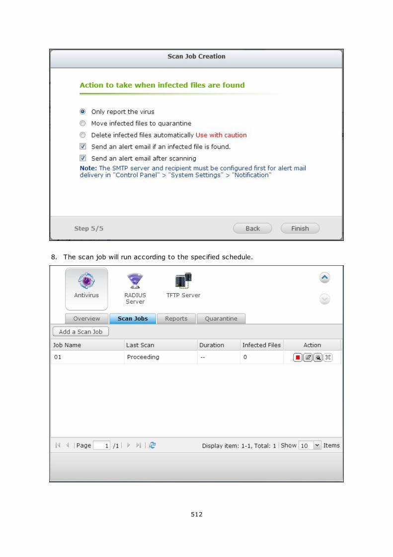
512
8. The scan job will run according to the specified schedule.

513
Button Description
Run the scan job now.
Stop the scan job.
Edit the scan job settings.
Download the last virus scan summary. The file can be opened by a text
editor, such as WordPad.
Delete the scan job.
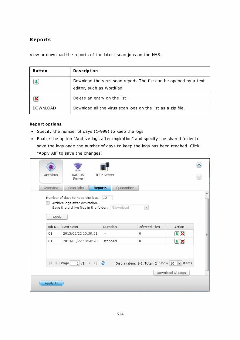
514
Reports
View or download the reports of the latest scan jobs on the NAS.
Button Description
Download the virus scan report. The file can be opened by a text
editor, such as WordPad.
Delete an entry on the list.
DOWNLOAD Download all the virus scan logs on the list as a zip file.
Report options
Specify the number of days (1-999) to keep the logs
Enable the option “Archive logs after expiration” and specify the shared folder to
save the logs once the number of days to keep the logs has been reached. Click
“Apply All” to save the changes.
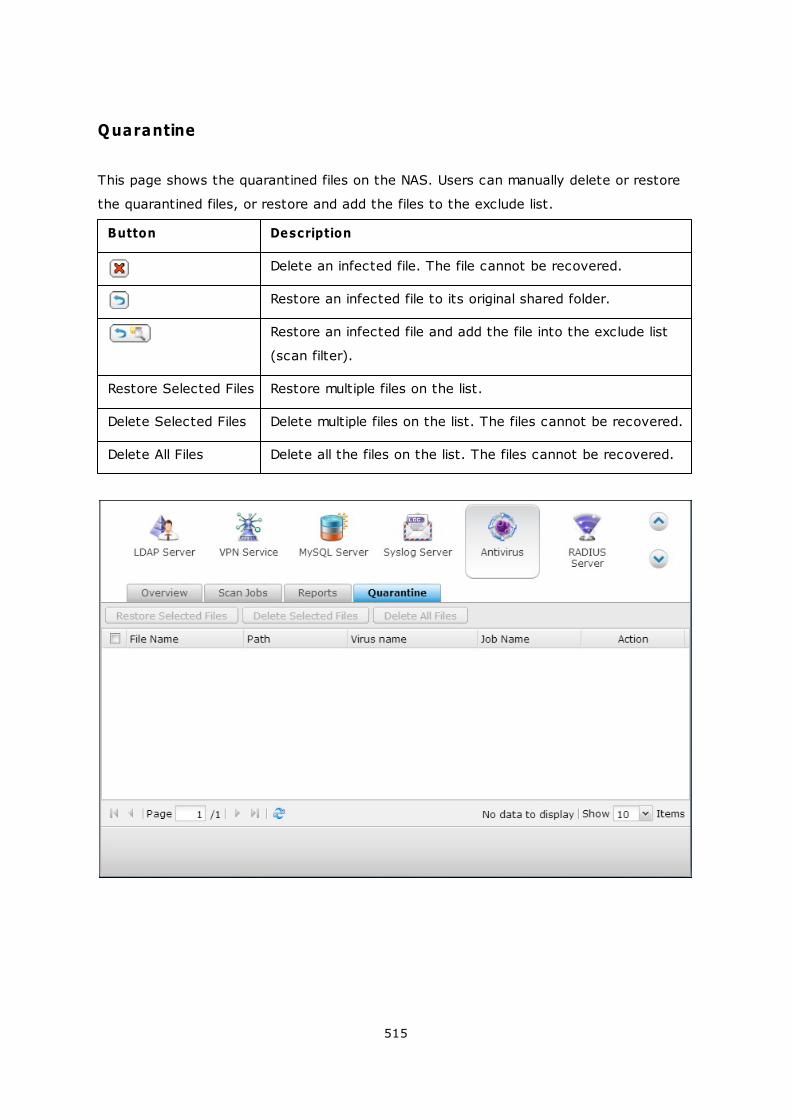
515
Quarantine
This page shows the quarantined files on the NAS. Users can manually delete or restore
the quarantined files, or restore and add the files to the exclude list.
Button Description
Delete an infected file. The file cannot be recovered.
Restore an infected file to its original shared folder.
Restore an infected file and add the file into the exclude list
(scan filter).
Restore Selected Files Restore multiple files on the list.
Delete Selected Files Delete multiple files on the list. The files cannot be recovered.
Delete All Files Delete all the files on the list. The files cannot be recovered.
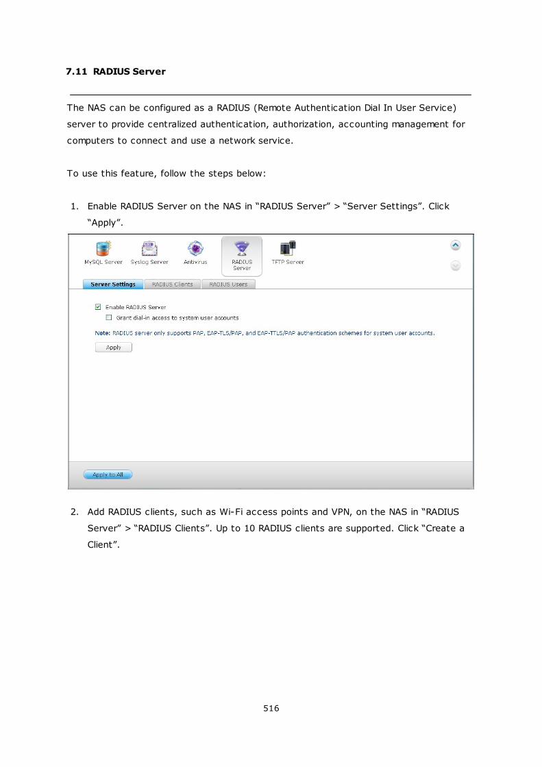
516
7.11 RADIUS Server
The NAS can be configured as a RADIUS (Remote Authentication Dial In User Service)
server to provide centralized authentication, authorization, accounting management for
computers to connect and use a network service.
To use this feature, follow the steps below:
1. Enable RADIUS Server on the NAS in “RADIUS Server” > “Server Settings”. Click
“Apply”.
2. Add RADIUS clients, such as Wi-Fi access points and VPN, on the NAS in “RADIUS
Server” > “RADIUS Clients”. Up to 10 RADIUS clients are supported. Click “Create a
Client”.

517
3. Enter the client information and click “Apply”.
4. The clients are shown on the list.
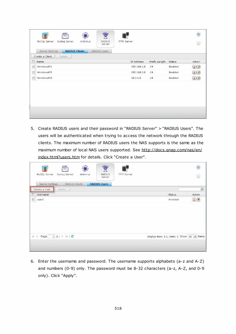
518
5. Create RADIUS users and their password in “RADIUS Server” > “RADIUS Users”. The
users will be authenticated when trying to access the network through the RADIUS
clients. The maximum number of RADIUS users the NAS supports is the same as the
maximum number of local NAS users supported. See http://docs.qnap.com/nas/en/
index.html?users.htm for details. Click “Create a User”.
6. Enter the username and password. The username supports alphabets (a-z and A-Z)
and numbers (0-9) only. The password must be 8-32 characters (a-z, A-Z, and 0-9
only). Click “Apply”.
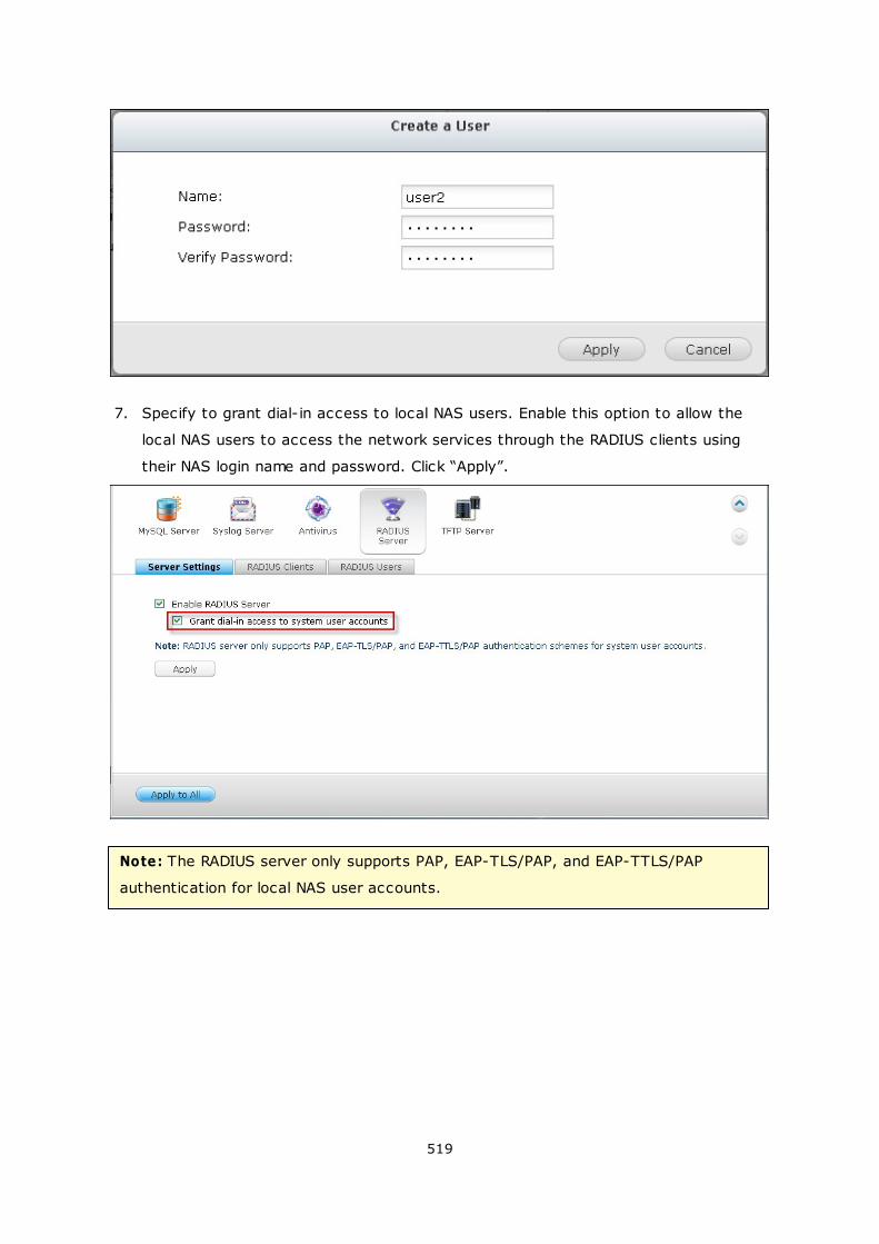
519
7. Specify to grant dial-in access to local NAS users. Enable this option to allow the
local NAS users to access the network services through the RADIUS clients using
their NAS login name and password. Click “Apply”.
Note: The RADIUS server only supports PAP, EAP-TLS/PAP, and EAP-TTLS/PAP
authentication for local NAS user accounts.
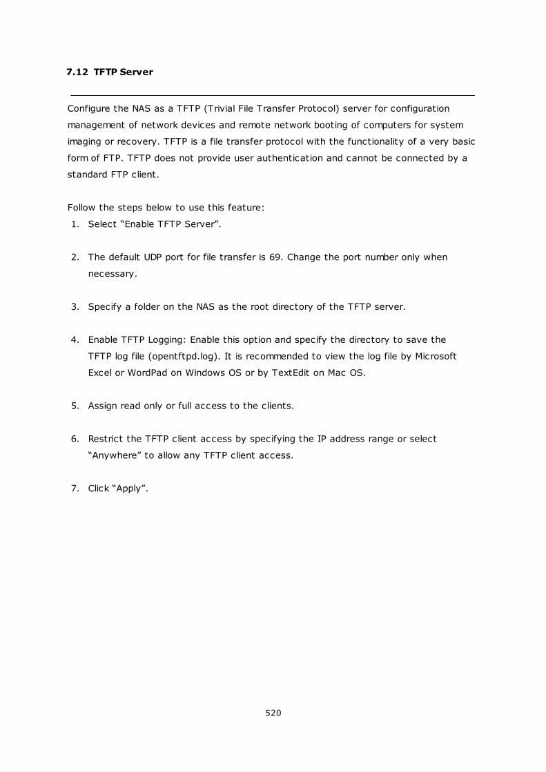
520
7.12 TFTP Server
Configure the NAS as a TFTP (Trivial File Transfer Protocol) server for configuration
management of network devices and remote network booting of computers for system
imaging or recovery. TFTP is a file transfer protocol with the functionality of a very basic
form of FTP. TFTP does not provide user authentication and cannot be connected by a
standard FTP client.
Follow the steps below to use this feature:
1. Select “Enable TFTP Server”.
2. The default UDP port for file transfer is 69. Change the port number only when
necessary.
3. Specify a folder on the NAS as the root directory of the TFTP server.
4. Enable TFTP Logging: Enable this option and specify the directory to save the
TFTP log file (opentftpd.log). It is recommended to view the log file by Microsoft
Excel or WordPad on Windows OS or by TextEdit on Mac OS.
5. Assign read only or full access to the clients.
6. Restrict the TFTP client access by specifying the IP address range or select
“Anywhere” to allow any TFTP client access.
7. Click “Apply”.
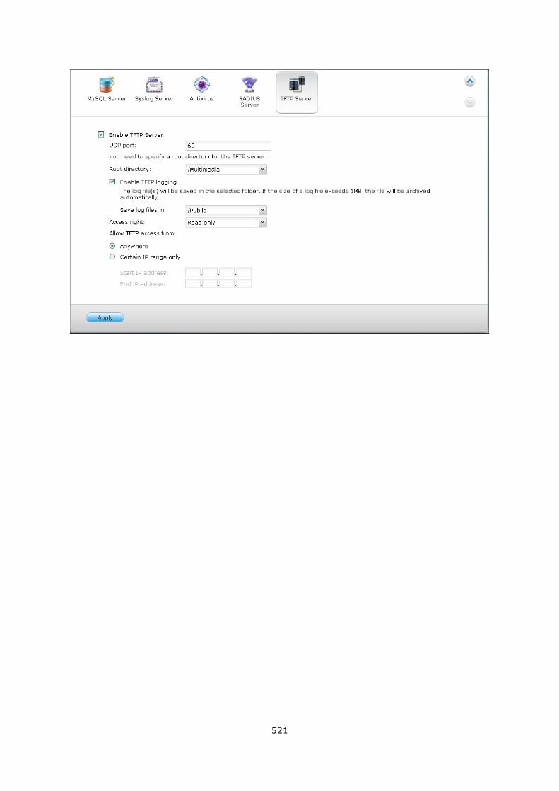
521
522
8. QNAP Applications
Backup_Station
myQNAPcloud_Service
File_Station
Photo_Station
Music_Station
Multimedia_Station
Download_Station
HD_Station
Surveillance_Station
App_Center
523
584
607
633
648
655
683
702
724
734

523
8.1 Backup Station
Backup Server
Remote Replication
Cloud Backup
External Backup
524
533
557
564
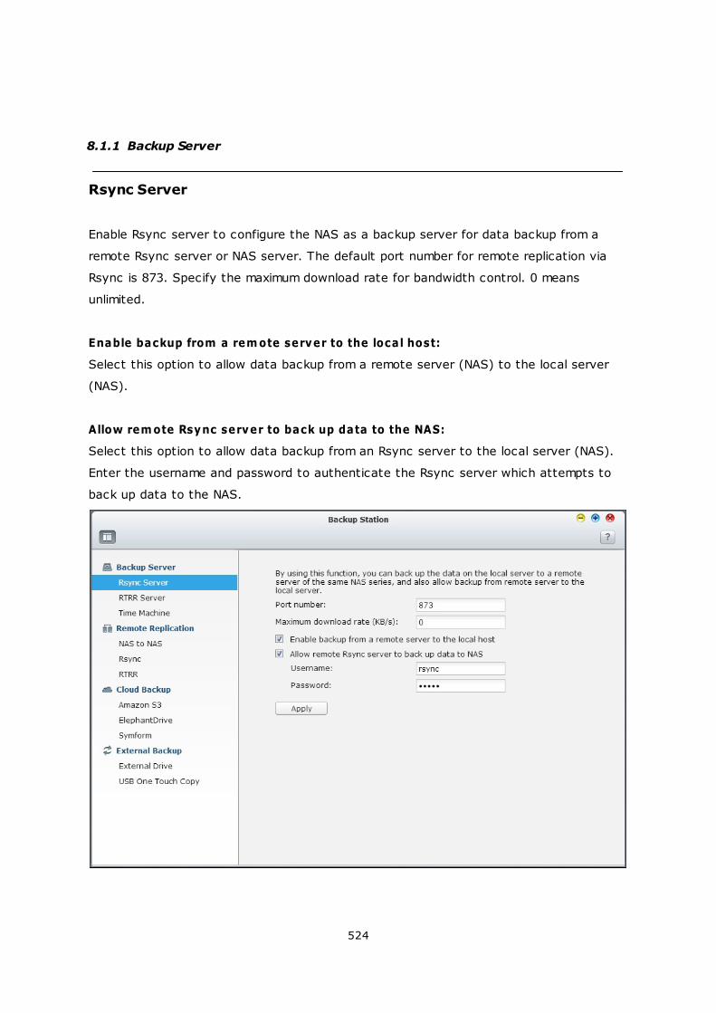
524
8.1.1 Backup Server
Rsync Server
Enable Rsync server to configure the NAS as a backup server for data backup from a
remote Rsync server or NAS server. The default port number for remote replication via
Rsync is 873. Specify the maximum download rate for bandwidth control. 0 means
unlimited.
Enable backup from a rem ote server to the local host:
Select this option to allow data backup from a remote server (NAS) to the local server
(NAS).
Allow rem ote Rsync server to back up data to the NAS:
Select this option to allow data backup from an Rsync server to the local server (NAS).
Enter the username and password to authenticate the Rsync server which attempts to
back up data to the NAS.
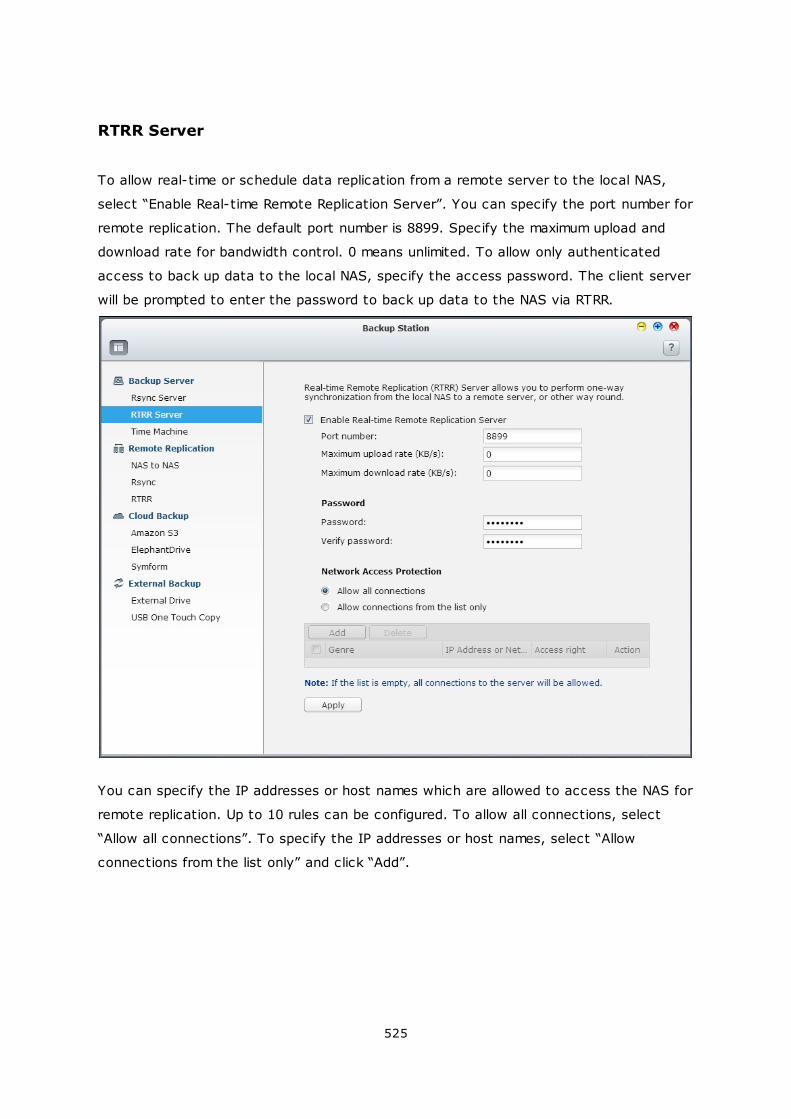
525
RTRR Server
To allow real-time or schedule data replication from a remote server to the local NAS,
select “Enable Real-time Remote Replication Server”. You can specify the port number for
remote replication. The default port number is 8899. Specify the maximum upload and
download rate for bandwidth control. 0 means unlimited. To allow only authenticated
access to back up data to the local NAS, specify the access password. The client server
will be prompted to enter the password to back up data to the NAS via RTRR.
You can specify the IP addresses or host names which are allowed to access the NAS for
remote replication. Up to 10 rules can be configured. To allow all connections, select
“Allow all connections”. To specify the IP addresses or host names, select “Allow
connections from the list only” and click “Add”.
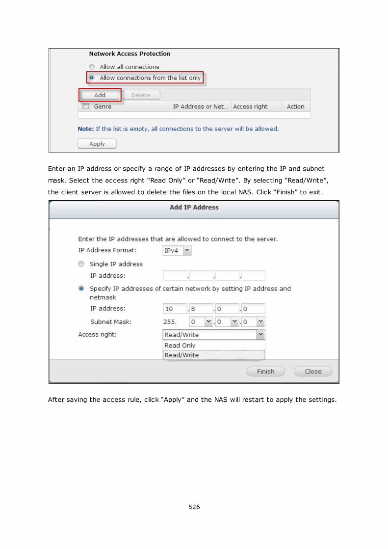
526
Enter an IP address or specify a range of IP addresses by entering the IP and subnet
mask. Select the access right “Read Only” or “Read/Write”. By selecting “Read/Write”,
the client server is allowed to delete the files on the local NAS. Click “Finish” to exit.
After saving the access rule, click “Apply” and the NAS will restart to apply the settings.
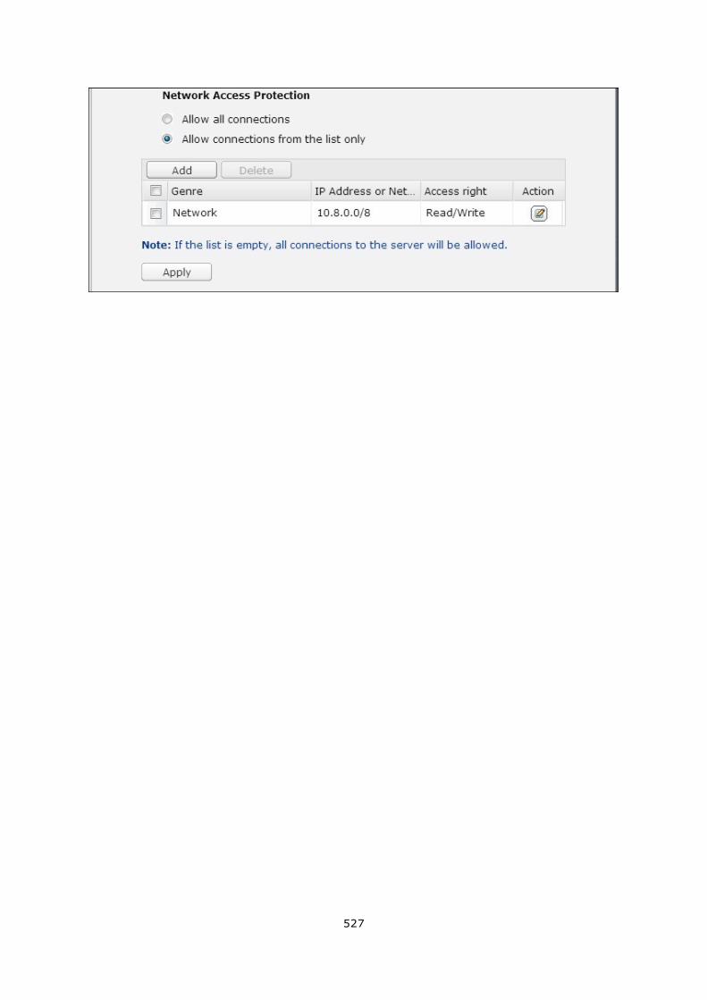
527
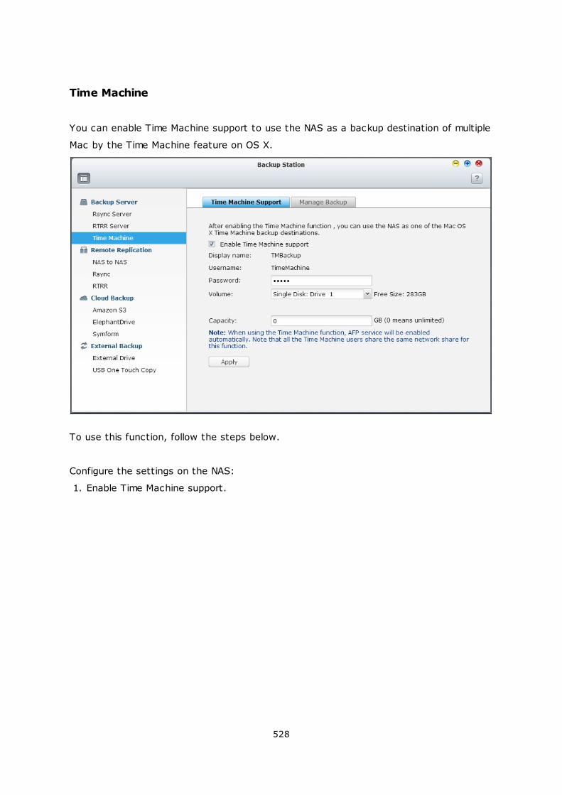
528
Time Machine
You can enable Time Machine support to use the NAS as a backup destination of multiple
Mac by the Time Machine feature on OS X.
To use this function, follow the steps below.
Configure the settings on the NAS:
1. Enable Time Machine support.
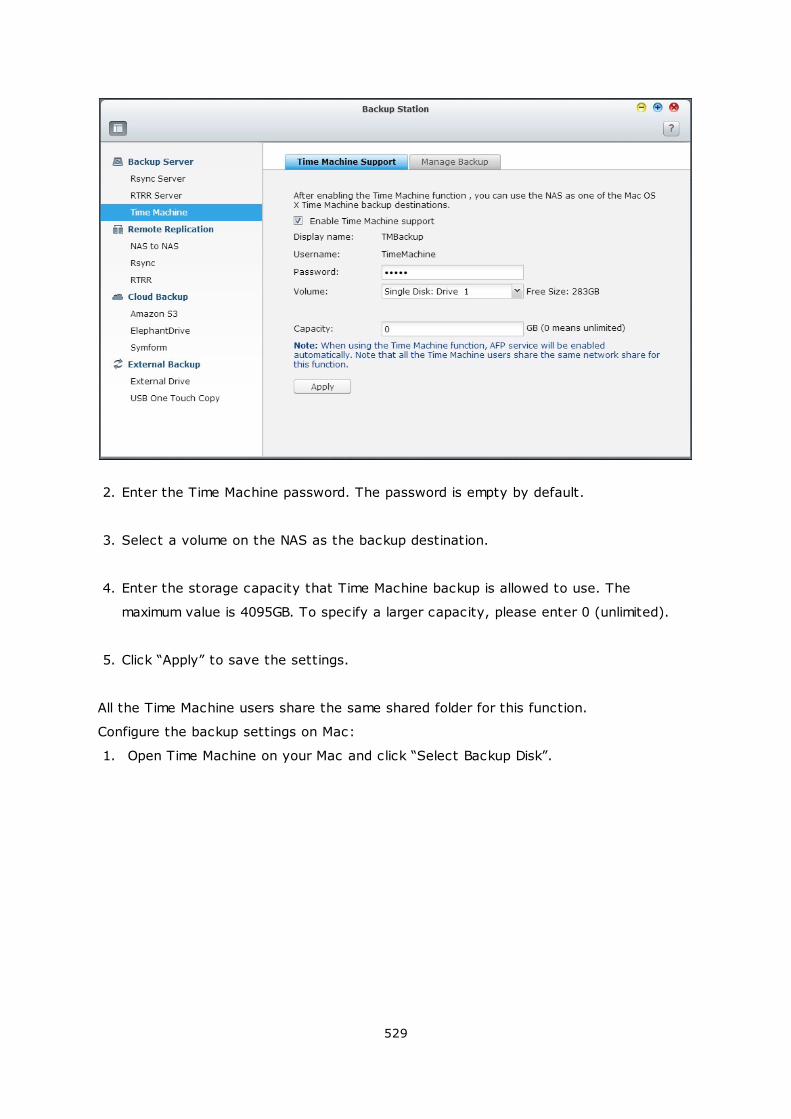
529
2. Enter the Time Machine password. The password is empty by default.
3. Select a volume on the NAS as the backup destination.
4. Enter the storage capacity that Time Machine backup is allowed to use. The
maximum value is 4095GB. To specify a larger capacity, please enter 0 (unlimited).
5. Click “Apply” to save the settings.
All the Time Machine users share the same shared folder for this function.
Configure the backup settings on Mac:
1. Open Time Machine on your Mac and click “Select Backup Disk”.
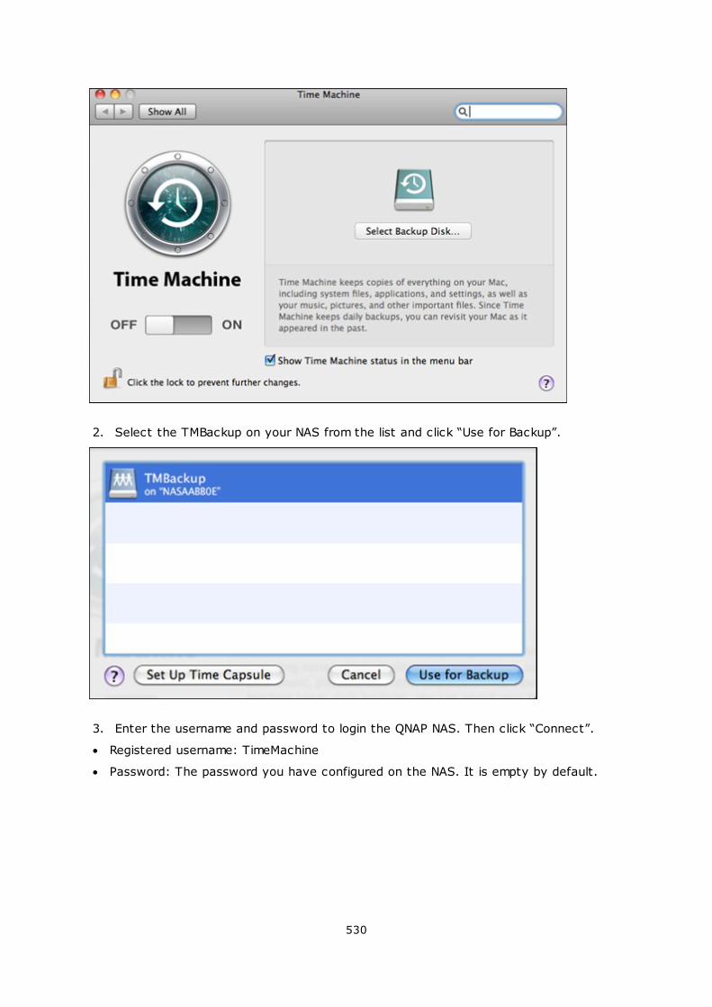
530
2. Select the TMBackup on your NAS from the list and click “Use for Backup”.
3. Enter the username and password to login the QNAP NAS. Then click “Connect”.
Registered username: TimeMachine
Password: The password you have configured on the NAS. It is empty by default.
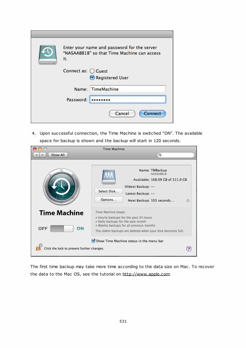
531
4. Upon successful connection, the Time Machine is switched “ON”. The available
space for backup is shown and the backup will start in 120 seconds.
The first time backup may take more time according to the data size on Mac. To recover
the data to the Mac OS, see the tutorial on http://www.apple.com.
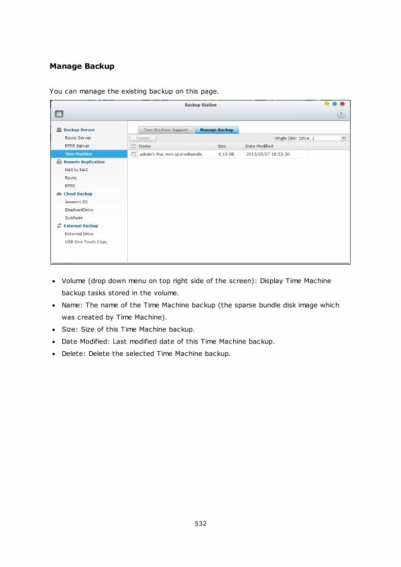
532
Manage Backup
You can manage the existing backup on this page.
Volume (drop down menu on top right side of the screen): Display Time Machine
backup tasks stored in the volume.
Name: The name of the Time Machine backup (the sparse bundle disk image which
was created by Time Machine).
Size: Size of this Time Machine backup.
Date Modified: Last modified date of this Time Machine backup.
Delete: Delete the selected Time Machine backup.
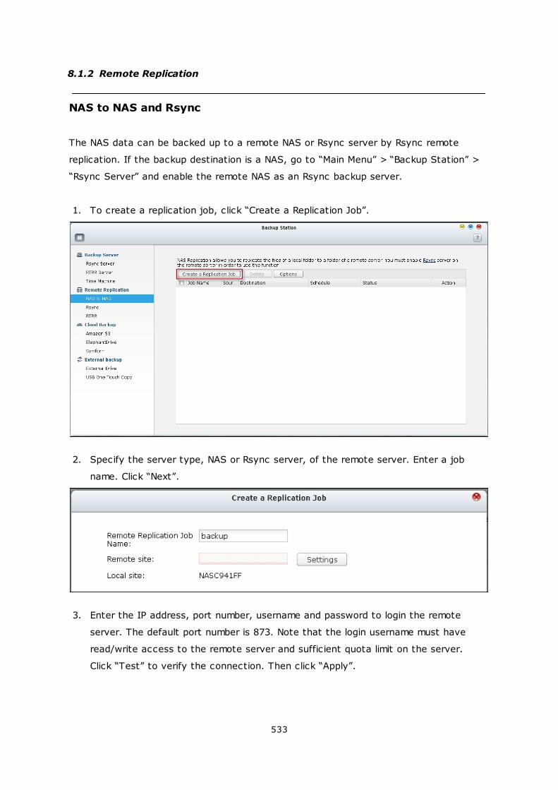
533
8.1.2 Remote Replication
NAS to NAS and Rsync
The NAS data can be backed up to a remote NAS or Rsync server by Rsync remote
replication. If the backup destination is a NAS, go to “Main Menu” > “Backup Station” >
“Rsync Server” and enable the remote NAS as an Rsync backup server.
1. To create a replication job, click “Create a Replication Job”.
2. Specify the server type, NAS or Rsync server, of the remote server. Enter a job
name. Click “Next”.
3. Enter the IP address, port number, username and password to login the remote
server. The default port number is 873. Note that the login username must have
read/write access to the remote server and sufficient quota limit on the server.
Click “Test” to verify the connection. Then click “Apply”.
534
4. Specify the local folder by clicking the Source folder box. After expanding and
locating the folder, double click the folder to set it as the directory where the data
will be replicated from.
535
5. Specify the destination folder Destination folder box. Locate the folder in the folder
tree and double click the folder to set it as the directory where the data will be
replicated to. And, click “Add” to add this pair of replication folders.
Note: The order of selecting the source and destination folders can be changed. The
above is just an example.
6. Click “Backup frequency” to configure the backup frequency.
536
Select to replicate the data immediately or specify the backup schedule.
7. Specify other options as follows for the remote replication job by clicking the
“Options” button and click “Apply”.
537
Enable encryption: Select this option to execute encrypted remote replication. Note
that you must turn on “Allow SSH connection” in “Network Services > “Telnet/SSH”
and specify the same port number for SSH and encrypted remote replication.
Activate file compression: Turn on this option to allow file compression during the
data transfer process. This option is recommended for low bandwidth environment or
remote replication over WAN.
Perform incremental replication: When this option is turned on, after the first-time
replication, the NAS will only back up the files that have been changed since the last
backup. The files of the same name, size, and modified time will not be copied again.
You are recommended to turn on this option for the replication job which will be
executed for more than once in order to shorten the backup time.
Delete extra files on remote destination: Select the option to synchronize the source
data with the destination data (one-way synchronization). Extra files on the
destination will be deleted. Source data will remain unchanged.
Handle sparse files efficiently: A sparse file is a type of computer file that contains
large blocks of zero-byte data. Turning on this option may reduce the time required
for remote replication.
8. Click “Apply”. If you select the “Execute backup immediately” option, the replication
task will start at once. Otherwise, it will be performed according to your schedule.
Note that the job is recursive. Do not turn off the local NAS and the remote server
when remote replication is running.
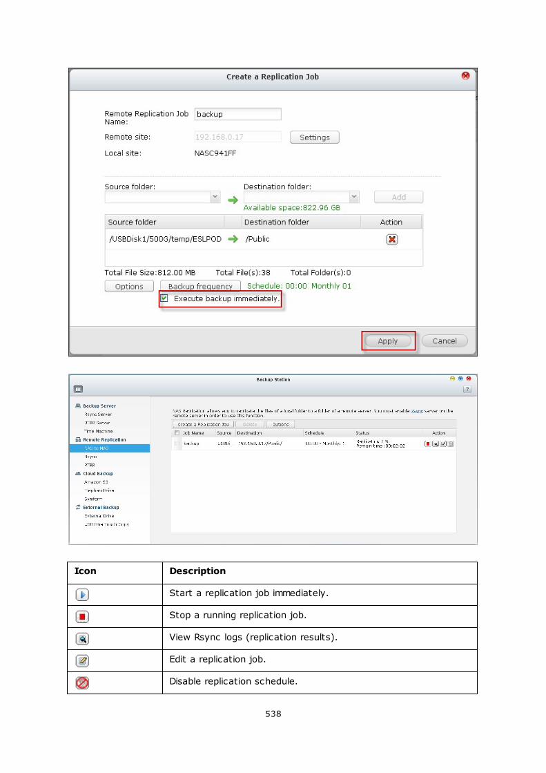
538
Icon Description
Start a replication job immediately.
Stop a running replication job.
View Rsync logs (replication results).
Edit a replication job.
Disable replication schedule.
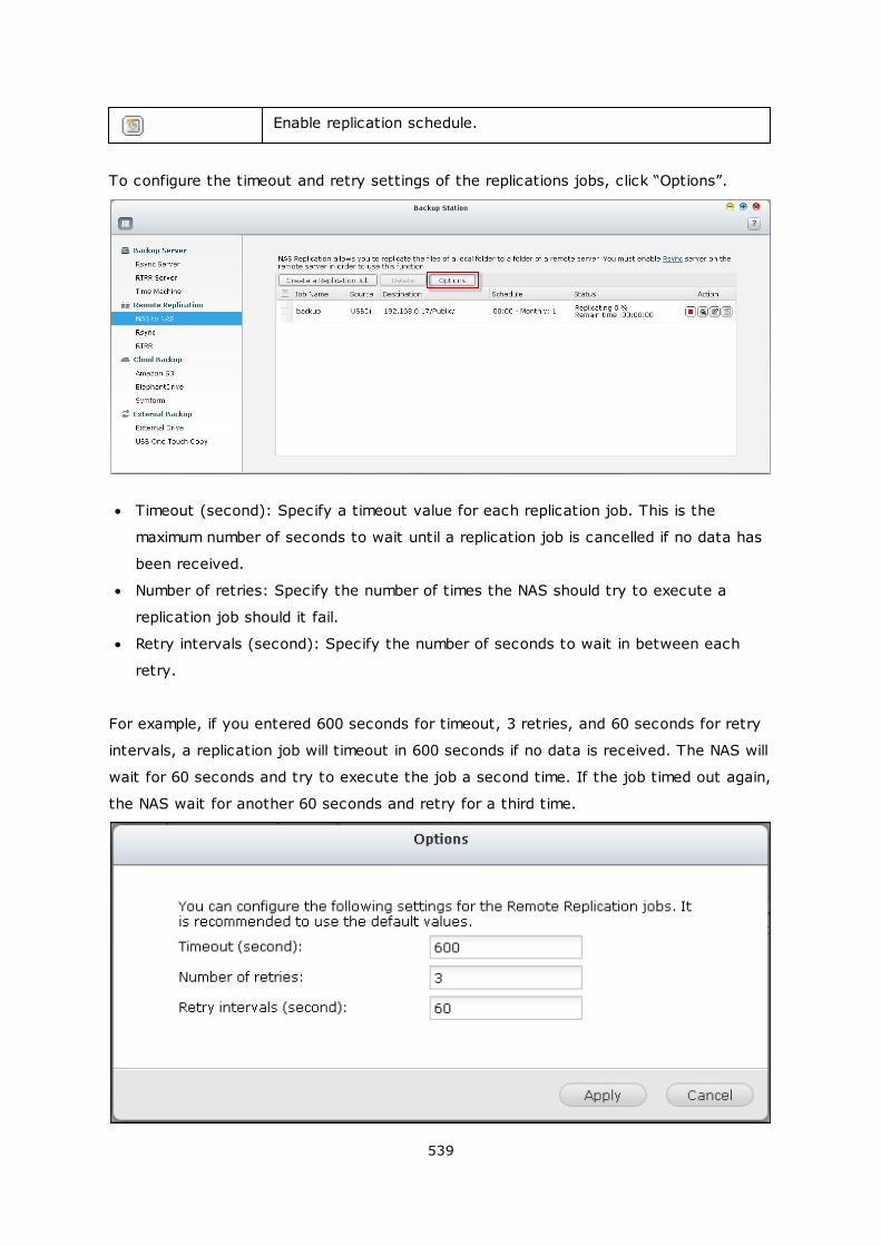
539
Enable replication schedule.
To configure the timeout and retry settings of the replications jobs, click “Options”.
Timeout (second): Specify a timeout value for each replication job. This is the
maximum number of seconds to wait until a replication job is cancelled if no data has
been received.
Number of retries: Specify the number of times the NAS should try to execute a
replication job should it fail.
Retry intervals (second): Specify the number of seconds to wait in between each
retry.
For example, if you entered 600 seconds for timeout, 3 retries, and 60 seconds for retry
intervals, a replication job will timeout in 600 seconds if no data is received. The NAS will
wait for 60 seconds and try to execute the job a second time. If the job timed out again,
the NAS wait for another 60 seconds and retry for a third time.
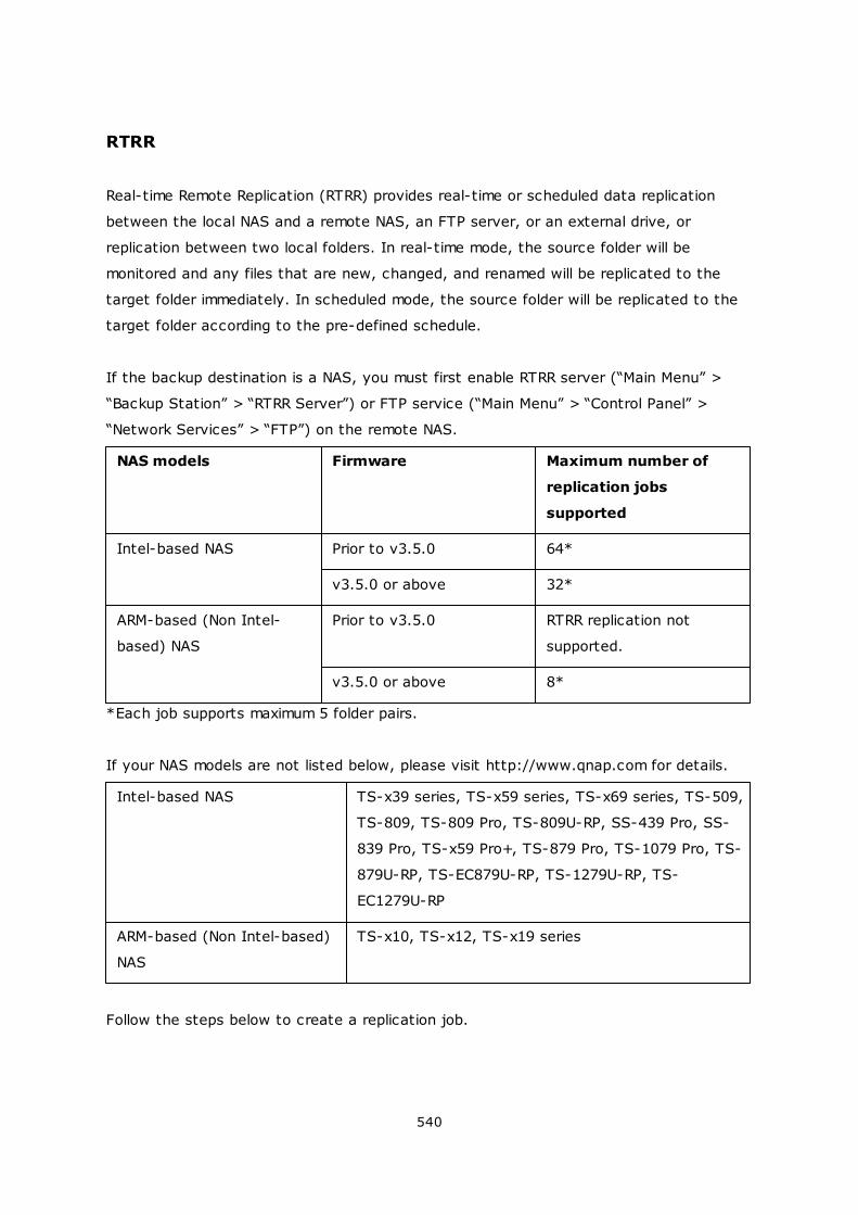
540
RTRR
Real-time Remote Replication (RTRR) provides real-time or scheduled data replication
between the local NAS and a remote NAS, an FTP server, or an external drive, or
replication between two local folders. In real-time mode, the source folder will be
monitored and any files that are new, changed, and renamed will be replicated to the
target folder immediately. In scheduled mode, the source folder will be replicated to the
target folder according to the pre-defined schedule.
If the backup destination is a NAS, you must first enable RTRR server (“Main Menu” >
“Backup Station” > “RTRR Server”) or FTP service (“Main Menu” > “Control Panel” >
“Network Services” > “FTP”) on the remote NAS.
NAS models Firmware Maximum number of
replication jobs
supported
Intel-based NAS Prior to v3.5.0 64*
v3.5.0 or above 32*
ARM-based (Non Intel-
based) NAS
Prior to v3.5.0 RTRR replication not
supported.
v3.5.0 or above 8*
*Each job supports maximum 5 folder pairs.
If your NAS models are not listed below, please visit http://www.qnap.com for details.
Intel-based NAS TS-x39 series, TS-x59 series, TS-x69 series, TS-509,
TS-809, TS-809 Pro, TS-809U-RP, SS-439 Pro, SS-
839 Pro, TS-x59 Pro+, TS-879 Pro, TS-1079 Pro, TS-
879U-RP, TS-EC879U-RP, TS-1279U-RP, TS-
EC1279U-RP
ARM-based (Non Intel-based)
NAS
TS-x10, TS-x12, TS-x19 series
Follow the steps below to create a replication job.
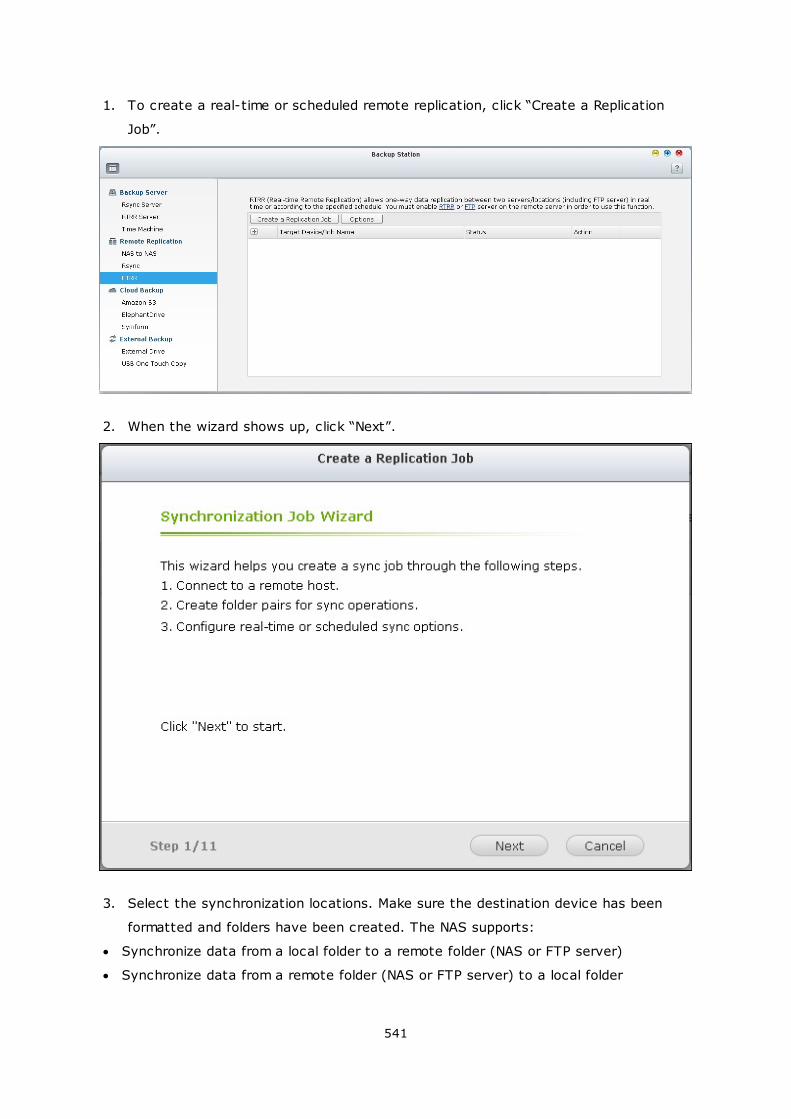
541
1. To create a real-time or scheduled remote replication, click “Create a Replication
Job”.
2. When the wizard shows up, click “Next”.
3. Select the synchronization locations. Make sure the destination device has been
formatted and folders have been created. The NAS supports:
Synchronize data from a local folder to a remote folder (NAS or FTP server)
Synchronize data from a remote folder (NAS or FTP server) to a local folder
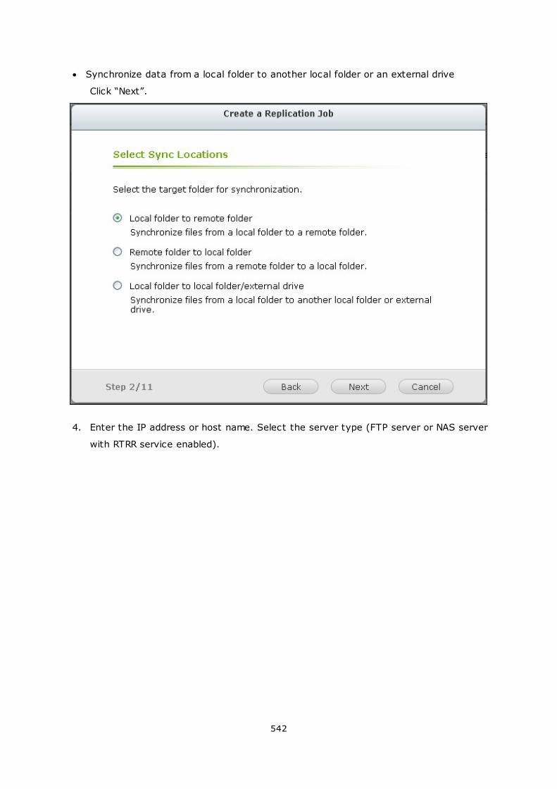
542
Synchronize data from a local folder to another local folder or an external drive
Click “Next”.
4. Enter the IP address or host name. Select the server type (FTP server or NAS server
with RTRR service enabled).
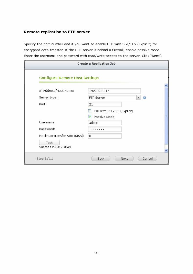
543
Remote replication to FTP server
Specify the port number and if you want to enable FTP with SSL/TLS (Explicit) for
encrypted data transfer. If the FTP server is behind a firewall, enable passive mode.
Enter the username and password with read/write access to the server. Click “Next”.
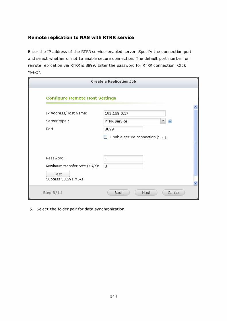
544
Remote replication to NAS with RTRR service
Enter the IP address of the RTRR service-enabled server. Specify the connection port
and select whether or not to enable secure connection. The default port number for
remote replication via RTRR is 8899. Enter the password for RTRR connection. Click
“Next”.
5. Select the folder pair for data synchronization.
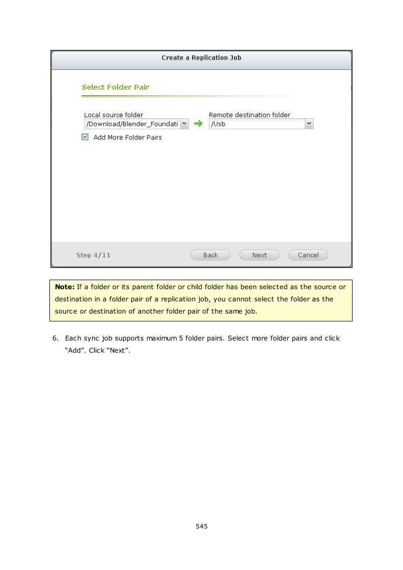
545
Note: If a folder or its parent folder or child folder has been selected as the source or
destination in a folder pair of a replication job, you cannot select the folder as the
source or destination of another folder pair of the same job.
6. Each sync job supports maximum 5 folder pairs. Select more folder pairs and click
“Add”. Click “Next”.
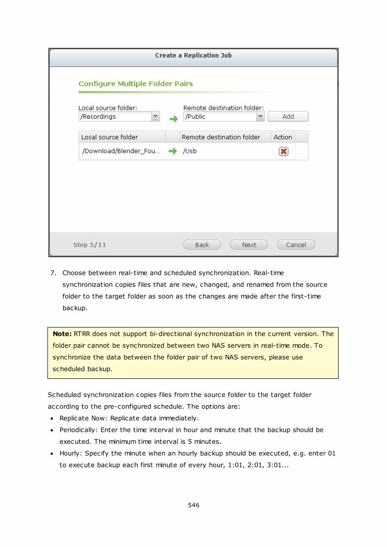
546
7. Choose between real-time and scheduled synchronization. Real-time
synchronization copies files that are new, changed, and renamed from the source
folder to the target folder as soon as the changes are made after the first-time
backup.
Note: RTRR does not support bi-directional synchronization in the current version. The
folder pair cannot be synchronized between two NAS servers in real-time mode. To
synchronize the data between the folder pair of two NAS servers, please use
scheduled backup.
Scheduled synchronization copies files from the source folder to the target folder
according to the pre-configured schedule. The options are:
Replicate Now: Replicate data immediately.
Periodically: Enter the time interval in hour and minute that the backup should be
executed. The minimum time interval is 5 minutes.
Hourly: Specify the minute when an hourly backup should be executed, e.g. enter 01
to execute backup each first minute of every hour, 1:01, 2:01, 3:01...
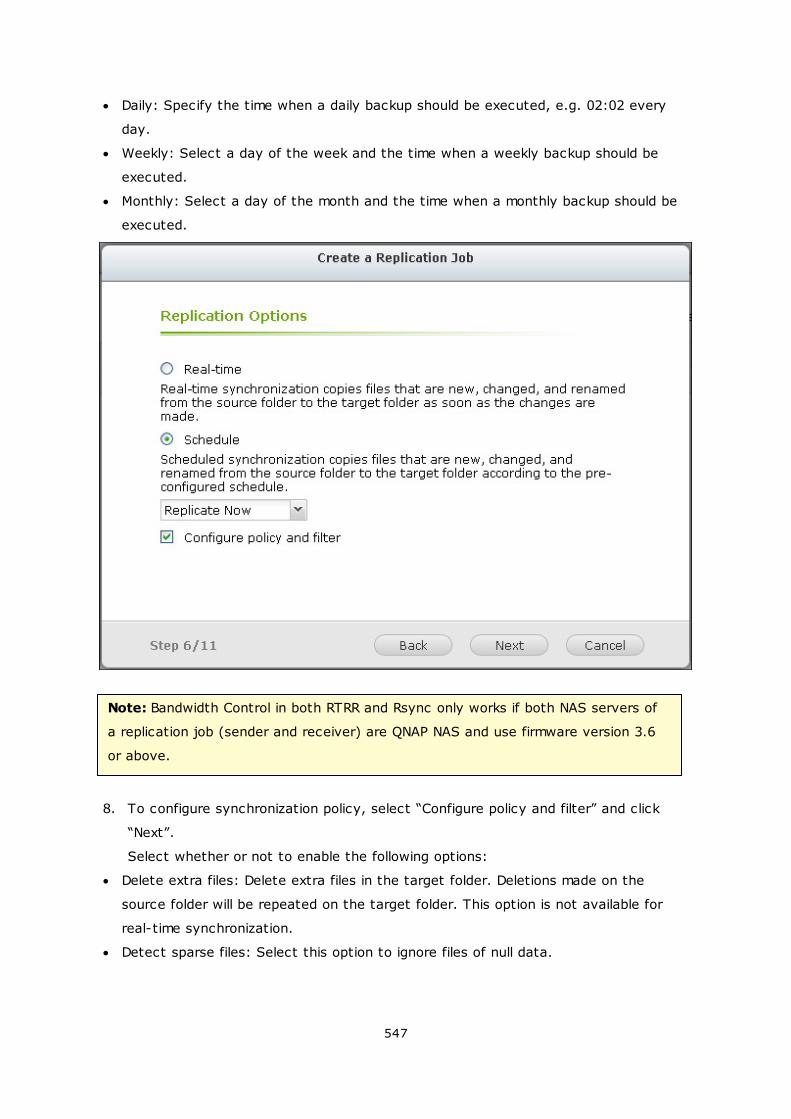
547
Daily: Specify the time when a daily backup should be executed, e.g. 02:02 every
day.
Weekly: Select a day of the week and the time when a weekly backup should be
executed.
Monthly: Select a day of the month and the time when a monthly backup should be
executed.
Note: Bandwidth Control in both RTRR and Rsync only works if both NAS servers of
a replication job (sender and receiver) are QNAP NAS and use firmware version 3.6
or above.
8. To configure synchronization policy, select “Configure policy and filter” and click
“Next”.
Select whether or not to enable the following options:
Delete extra files: Delete extra files in the target folder. Deletions made on the
source folder will be repeated on the target folder. This option is not available for
real-time synchronization.
Detect sparse files: Select this option to ignore files of null data.
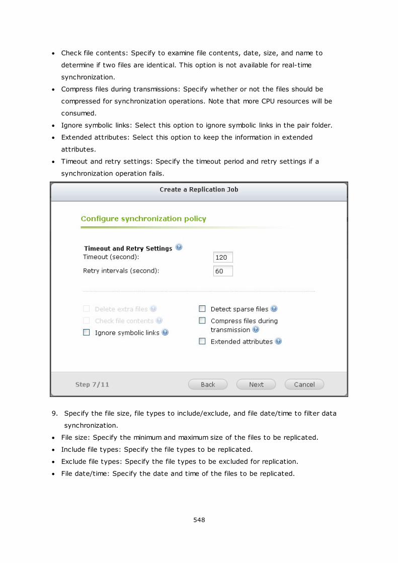
548
Check file contents: Specify to examine file contents, date, size, and name to
determine if two files are identical. This option is not available for real-time
synchronization.
Compress files during transmissions: Specify whether or not the files should be
compressed for synchronization operations. Note that more CPU resources will be
consumed.
Ignore symbolic links: Select this option to ignore symbolic links in the pair folder.
Extended attributes: Select this option to keep the information in extended
attributes.
Timeout and retry settings: Specify the timeout period and retry settings if a
synchronization operation fails.
9. Specify the file size, file types to include/exclude, and file date/time to filter data
synchronization.
File size: Specify the minimum and maximum size of the files to be replicated.
Include file types: Specify the file types to be replicated.
Exclude file types: Specify the file types to be excluded for replication.
File date/time: Specify the date and time of the files to be replicated.
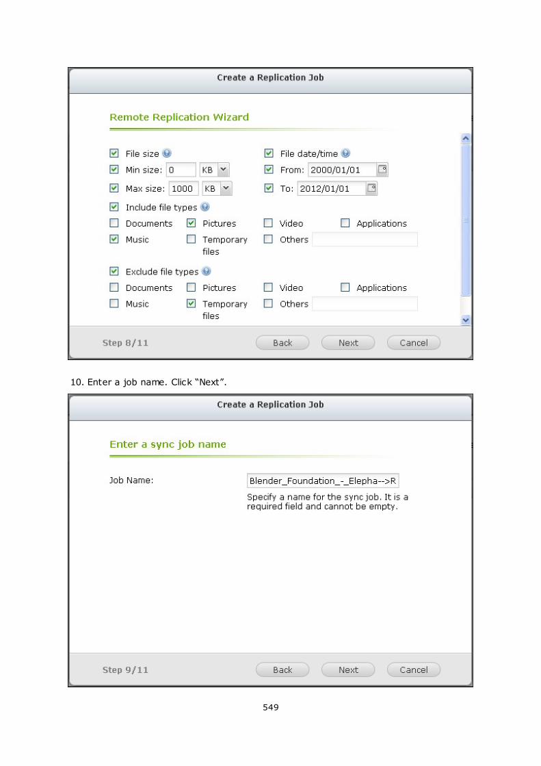
549
10. Enter a job name. Click “Next”.
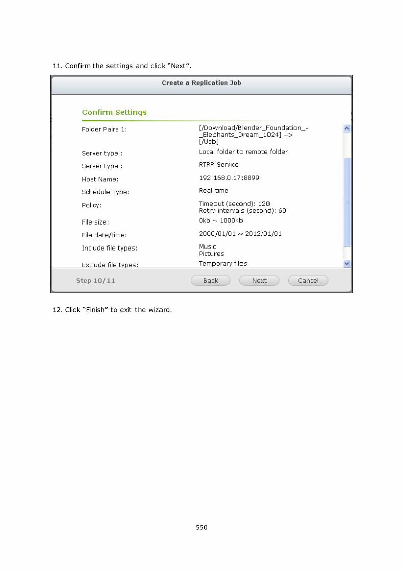
550
11. Confirm the settings and click “Next”.
12. Click “Finish” to exit the wizard.
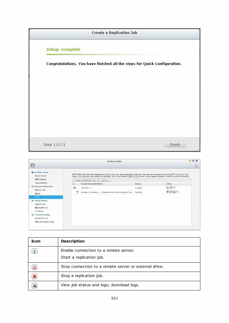
551
Icon Description
Enable connection to a remote server.
Start a replication job.
Stop connection to a remote server or external drive.
Stop a replication job.
View job status and logs; download logs.
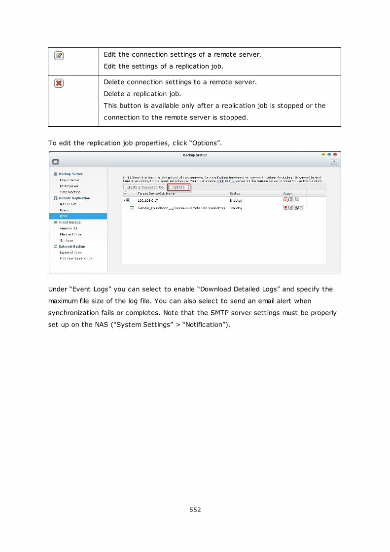
552
Edit the connection settings of a remote server.
Edit the settings of a replication job.
Delete connection settings to a remote server.
Delete a replication job.
This button is available only after a replication job is stopped or the
connection to the remote server is stopped.
To edit the replication job properties, click “Options”.
Under “Event Logs” you can select to enable “Download Detailed Logs” and specify the
maximum file size of the log file. You can also select to send an email alert when
synchronization fails or completes. Note that the SMTP server settings must be properly
set up on the NAS (“System Settings” > “Notification”).
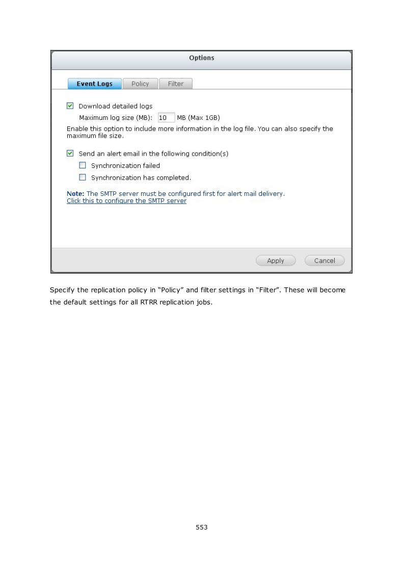
553
Specify the replication policy in “Policy” and filter settings in “Filter”. These will become
the default settings for all RTRR replication jobs.
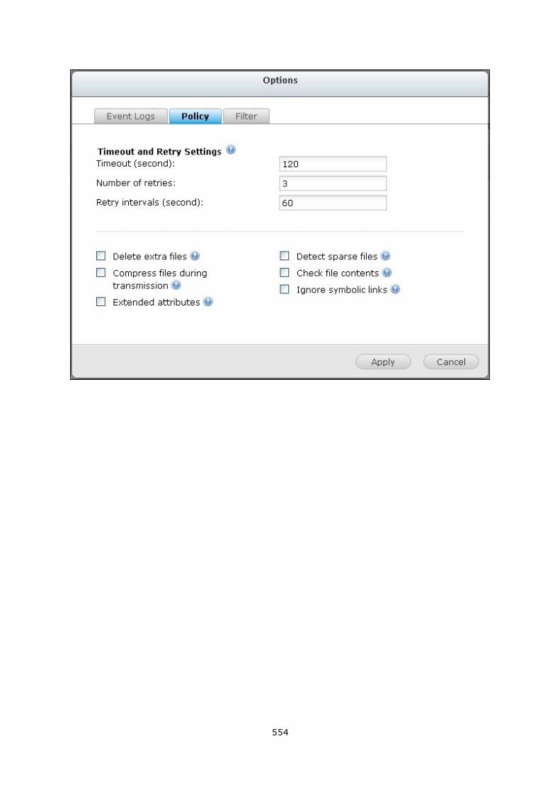
554
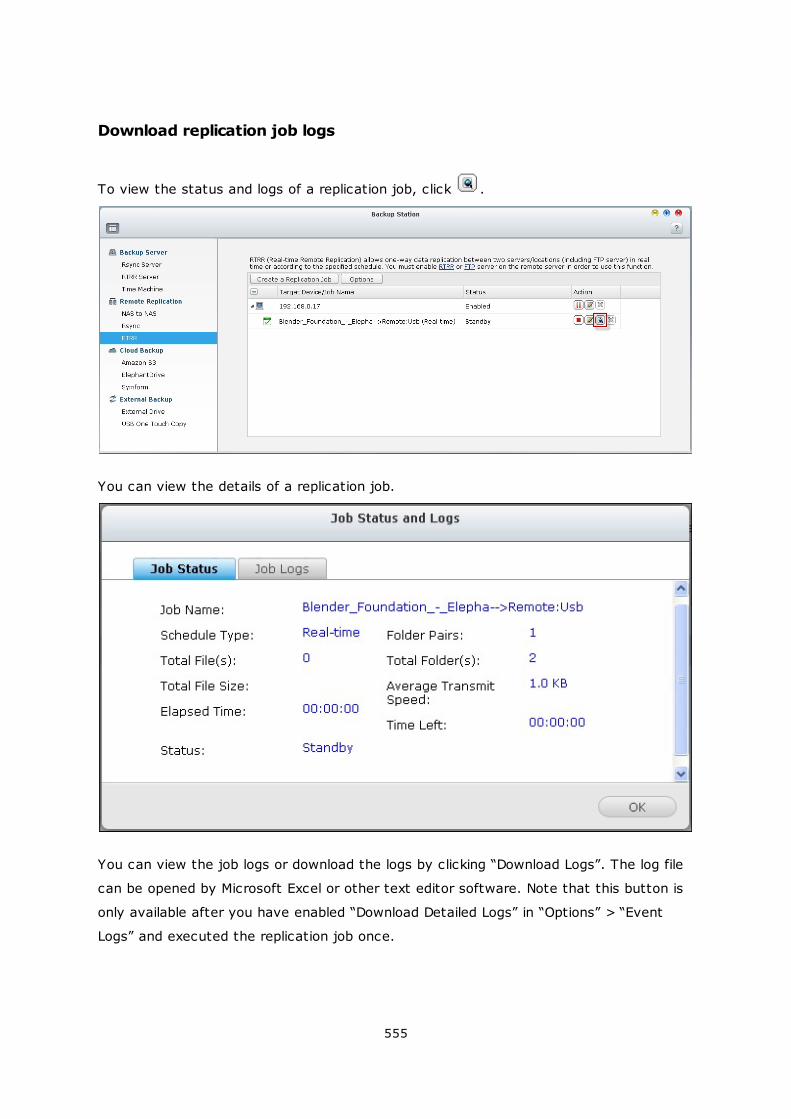
555
Download replication job logs
To view the status and logs of a replication job, click .
You can view the details of a replication job.
You can view the job logs or download the logs by clicking “Download Logs”. The log file
can be opened by Microsoft Excel or other text editor software. Note that this button is
only available after you have enabled “Download Detailed Logs” in “Options” > “Event
Logs” and executed the replication job once.
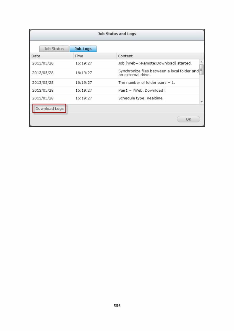
556
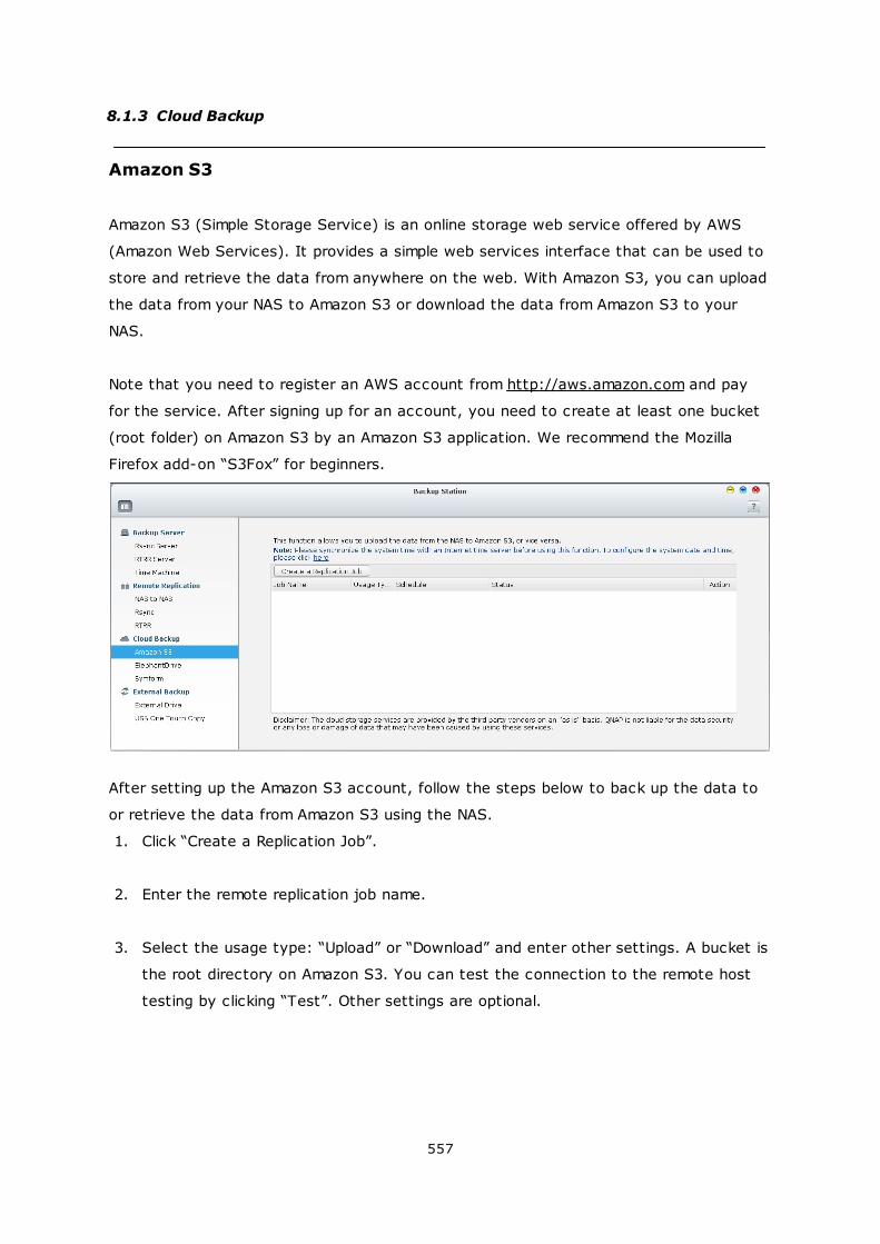
557
8.1.3 Cloud Backup
Amazon S3
Amazon S3 (Simple Storage Service) is an online storage web service offered by AWS
(Amazon Web Services). It provides a simple web services interface that can be used to
store and retrieve the data from anywhere on the web. With Amazon S3, you can upload
the data from your NAS to Amazon S3 or download the data from Amazon S3 to your
NAS.
Note that you need to register an AWS account from http://aws.amazon.com and pay
for the service. After signing up for an account, you need to create at least one bucket
(root folder) on Amazon S3 by an Amazon S3 application. We recommend the Mozilla
Firefox add-on “S3Fox” for beginners.
After setting up the Amazon S3 account, follow the steps below to back up the data to
or retrieve the data from Amazon S3 using the NAS.
1. Click “Create a Replication Job”.
2. Enter the remote replication job name.
3. Select the usage type: “Upload” or “Download” and enter other settings. A bucket is
the root directory on Amazon S3. You can test the connection to the remote host
testing by clicking “Test”. Other settings are optional.
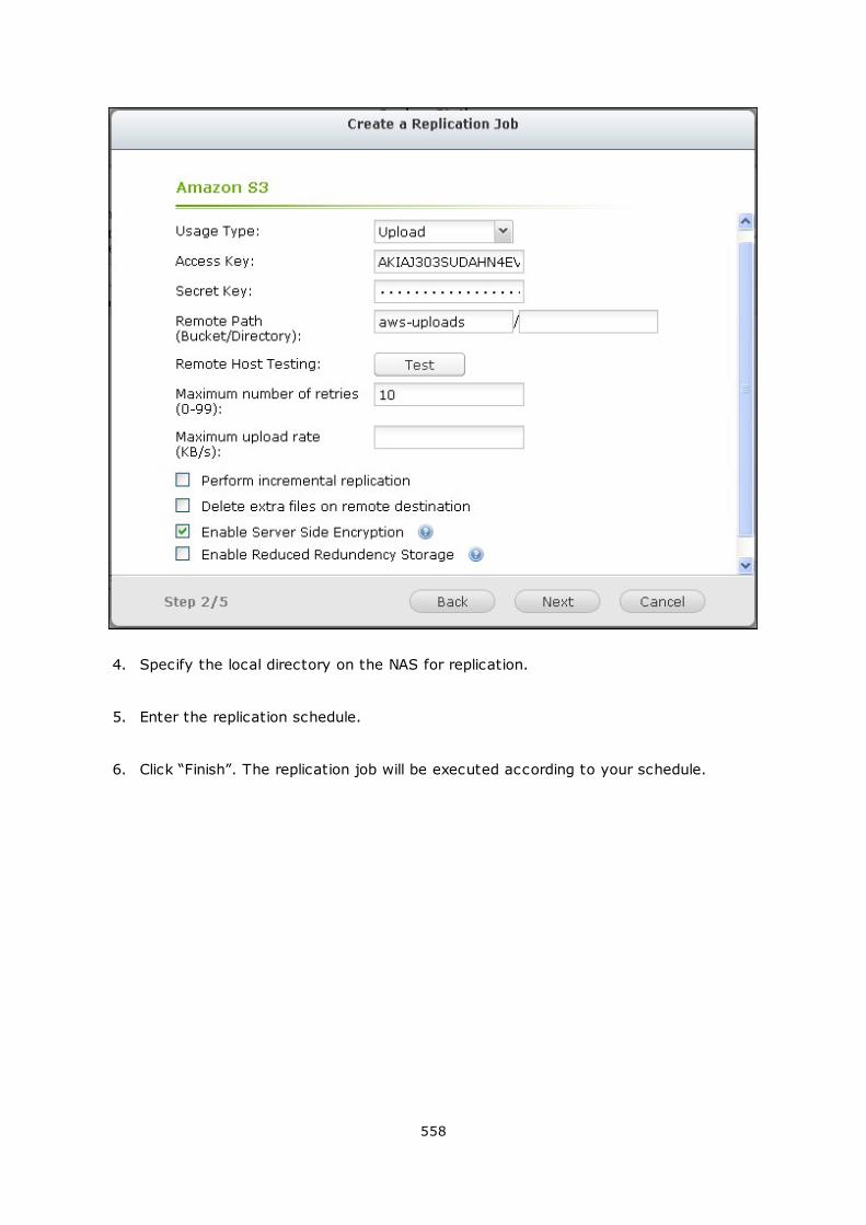
558
4. Specify the local directory on the NAS for replication.
5. Enter the replication schedule.
6. Click “Finish”. The replication job will be executed according to your schedule.
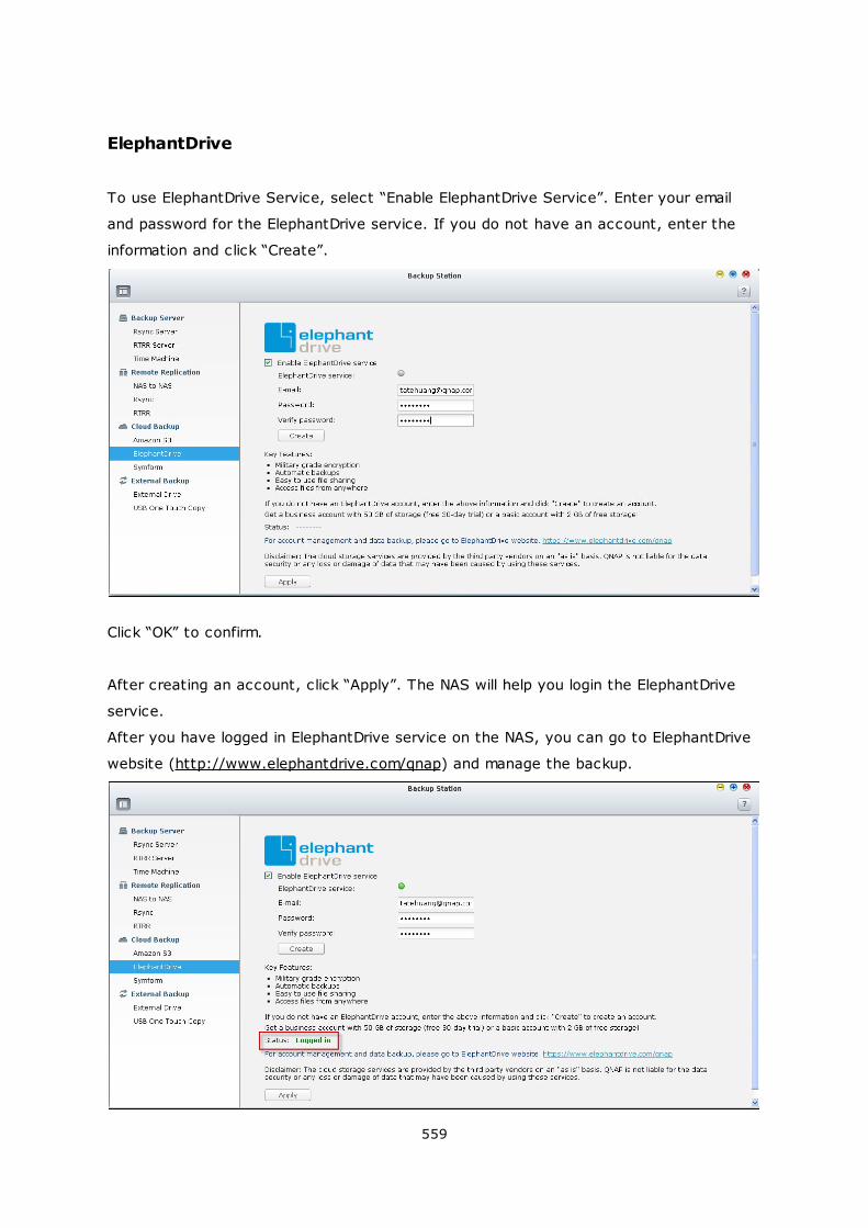
559
ElephantDrive
To use ElephantDrive Service, select “Enable ElephantDrive Service”. Enter your email
and password for the ElephantDrive service. If you do not have an account, enter the
information and click “Create”.
Click “OK” to confirm.
After creating an account, click “Apply”. The NAS will help you login the ElephantDrive
service.
After you have logged in ElephantDrive service on the NAS, you can go to ElephantDrive
website (http://www.elephantdrive.com/qnap) and manage the backup.
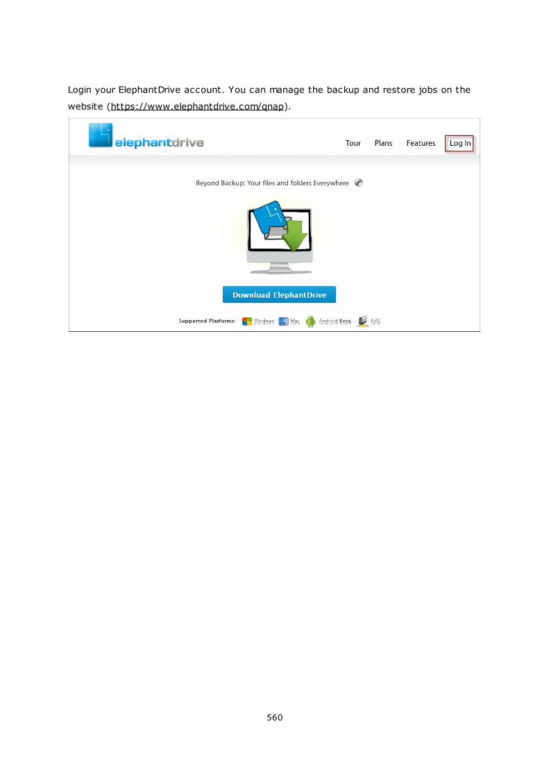
560
Login your ElephantDrive account. You can manage the backup and restore jobs on the
website (https://www.elephantdrive.com/qnap).
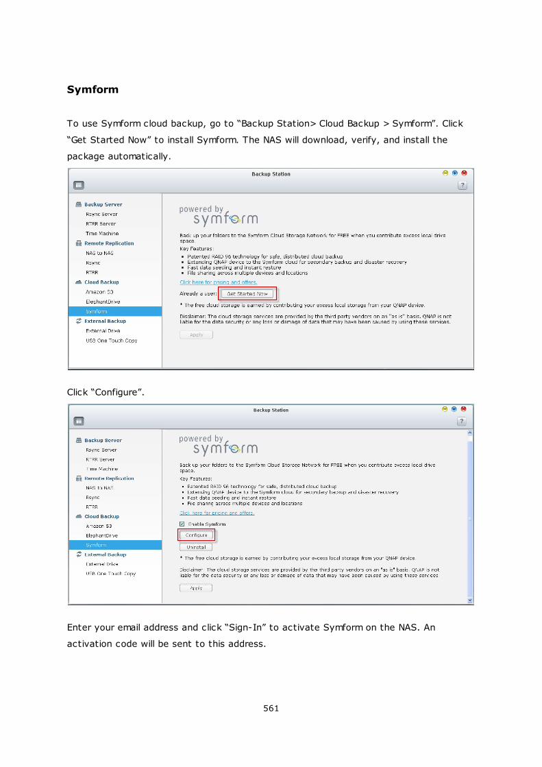
561
Symform
To use Symform cloud backup, go to “Backup Station> Cloud Backup > Symform”. Click
“Get Started Now” to install Symform. The NAS will download, verify, and install the
package automatically.
Click “Configure”.
Enter your email address and click “Sign-In” to activate Symform on the NAS. An
activation code will be sent to this address.
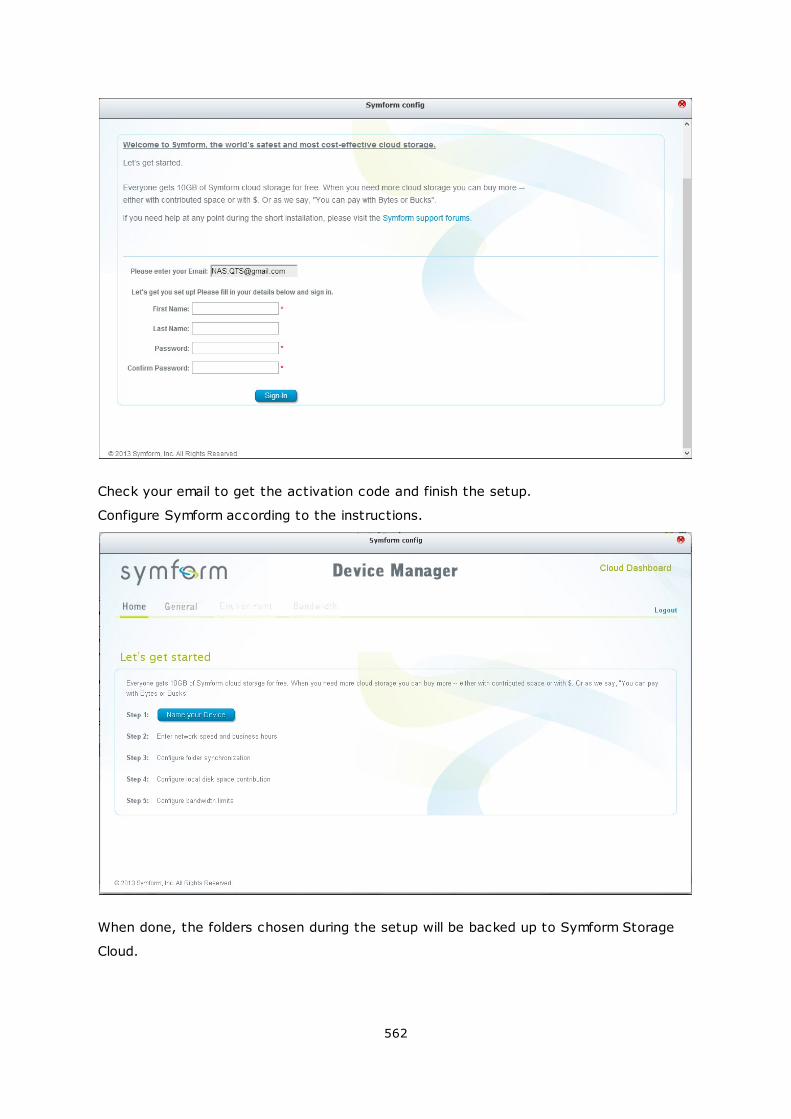
562
Check your email to get the activation code and finish the setup.
Configure Symform according to the instructions.
When done, the folders chosen during the setup will be backed up to Symform Storage
Cloud.
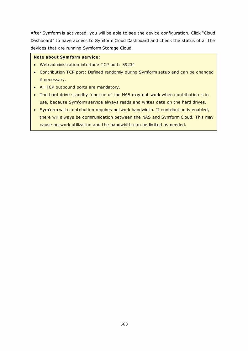
563
After Symform is activated, you will be able to see the device configuration. Click “Cloud
Dashboard” to have access to Symform Cloud Dashboard and check the status of all the
devices that are running Symform Storage Cloud.
Note about Sym form serv ice:
Web administration interface TCP port: 59234
Contribution TCP port: Defined randomly during Symform setup and can be changed
if necessary.
All TCP outbound ports are mandatory.
The hard drive standby function of the NAS may not work when contribution is in
use, because Symform service always reads and writes data on the hard drives.
Symform with contribution requires network bandwidth. If contribution is enabled,
there will always be communication between the NAS and Symform Cloud. This may
cause network utilization and the bandwidth can be limited as needed.
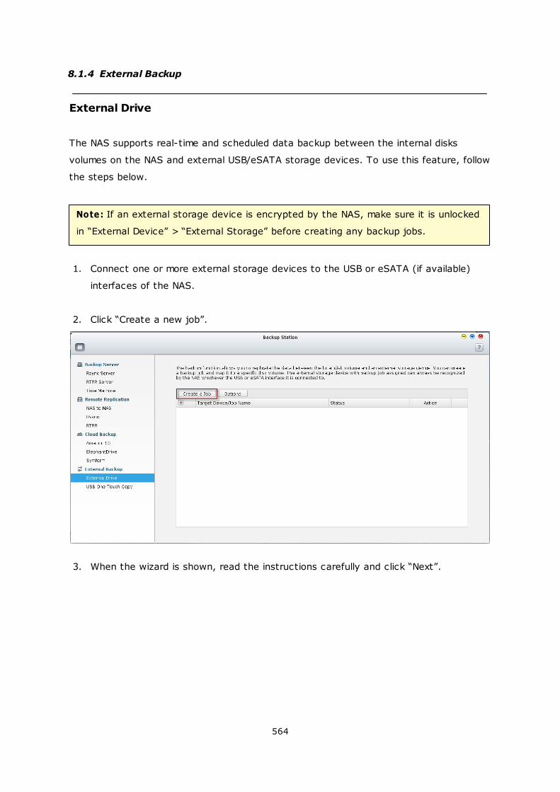
564
8.1.4 External Backup
External Drive
The NAS supports real-time and scheduled data backup between the internal disks
volumes on the NAS and external USB/eSATA storage devices. To use this feature, follow
the steps below.
Note: If an external storage device is encrypted by the NAS, make sure it is unlocked
in “External Device” > “External Storage” before creating any backup jobs.
1. Connect one or more external storage devices to the USB or eSATA (if available)
interfaces of the NAS.
2. Click “Create a new job”.
3. When the wizard is shown, read the instructions carefully and click “Next”.
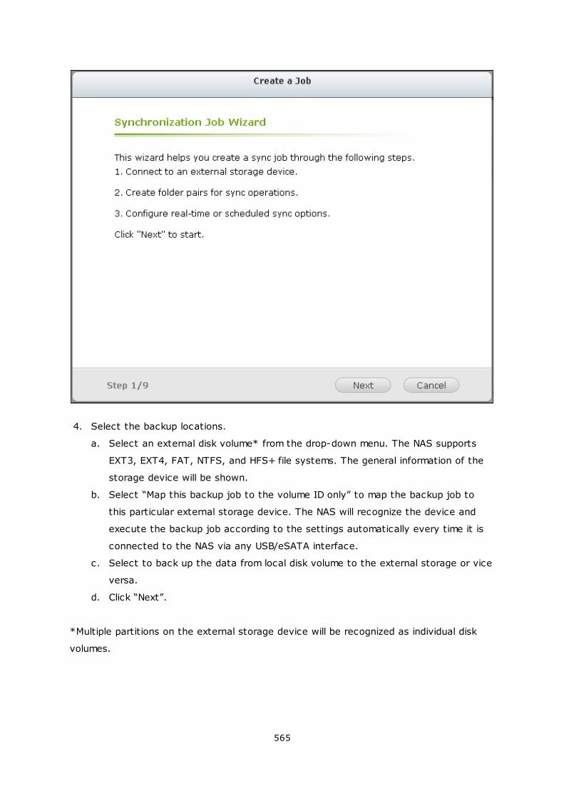
565
4. Select the backup locations.
a. Select an external disk volume* from the drop-down menu. The NAS supports
EXT3, EXT4, FAT, NTFS, and HFS+ file systems. The general information of the
storage device will be shown.
b. Select “Map this backup job to the volume ID only” to map the backup job to
this particular external storage device. The NAS will recognize the device and
execute the backup job according to the settings automatically every time it is
connected to the NAS via any USB/eSATA interface.
c. Select to back up the data from local disk volume to the external storage or vice
versa.
d. Click “Next”.
*Multiple partitions on the external storage device will be recognized as individual disk
volumes.
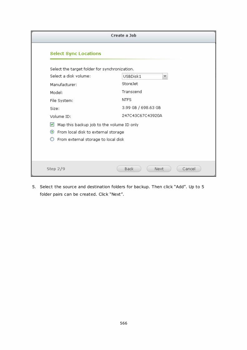
566
5. Select the source and destination folders for backup. Then click “Add”. Up to 5
folder pairs can be created. Click “Next”.
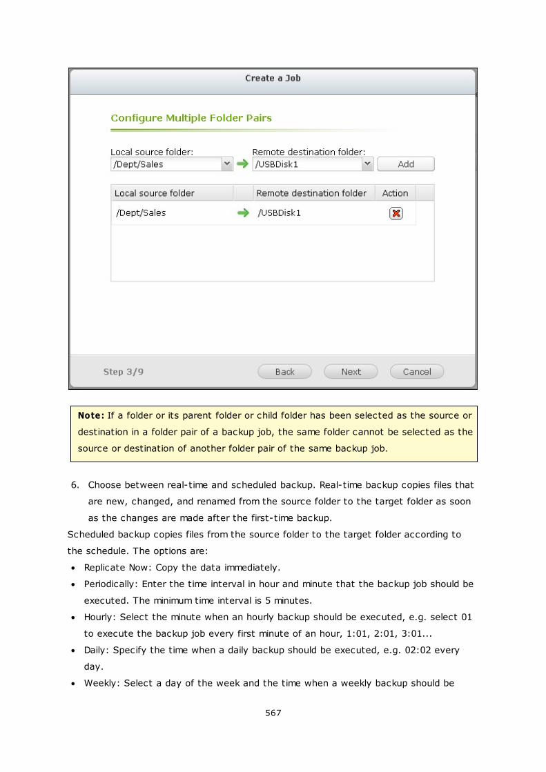
567
Note: If a folder or its parent folder or child folder has been selected as the source or
destination in a folder pair of a backup job, the same folder cannot be selected as the
source or destination of another folder pair of the same backup job.
6. Choose between real-time and scheduled backup. Real-time backup copies files that
are new, changed, and renamed from the source folder to the target folder as soon
as the changes are made after the first-time backup.
Scheduled backup copies files from the source folder to the target folder according to
the schedule. The options are:
Replicate Now: Copy the data immediately.
Periodically: Enter the time interval in hour and minute that the backup job should be
executed. The minimum time interval is 5 minutes.
Hourly: Select the minute when an hourly backup should be executed, e.g. select 01
to execute the backup job every first minute of an hour, 1:01, 2:01, 3:01...
Daily: Specify the time when a daily backup should be executed, e.g. 02:02 every
day.
Weekly: Select a day of the week and the time when a weekly backup should be
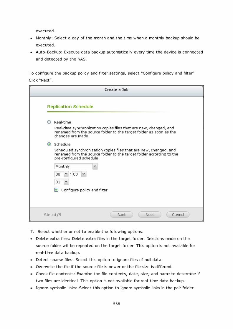
568
executed.
Monthly: Select a day of the month and the time when a monthly backup should be
executed.
Auto-Backup: Execute data backup automatically every time the device is connected
and detected by the NAS.
To configure the backup policy and filter settings, select “Configure policy and filter”.
Click “Next”.
7. Select whether or not to enable the following options:
Delete extra files: Delete extra files in the target folder. Deletions made on the
source folder will be repeated on the target folder. This option is not available for
real-time data backup.
Detect sparse files: Select this option to ignore files of null data.
Overwrite the file if the source file is newer or the file size is different
Check file contents: Examine the file contents, date, size, and name to determine if
two files are identical. This option is not available for real-time data backup.
Ignore symbolic links: Select this option to ignore symbolic links in the pair folder.
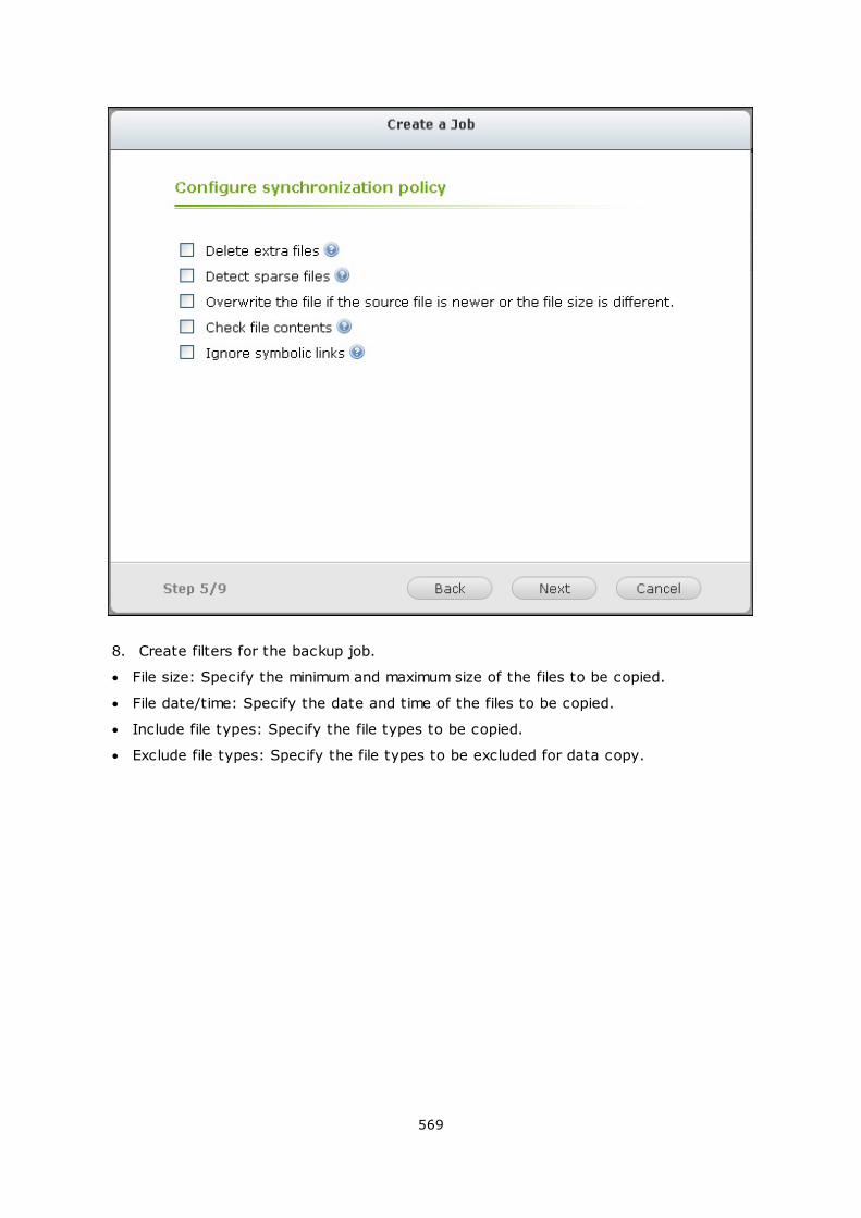
569
8. Create filters for the backup job.
File size: Specify the minimum and maximum size of the files to be copied.
File date/time: Specify the date and time of the files to be copied.
Include file types: Specify the file types to be copied.
Exclude file types: Specify the file types to be excluded for data copy.
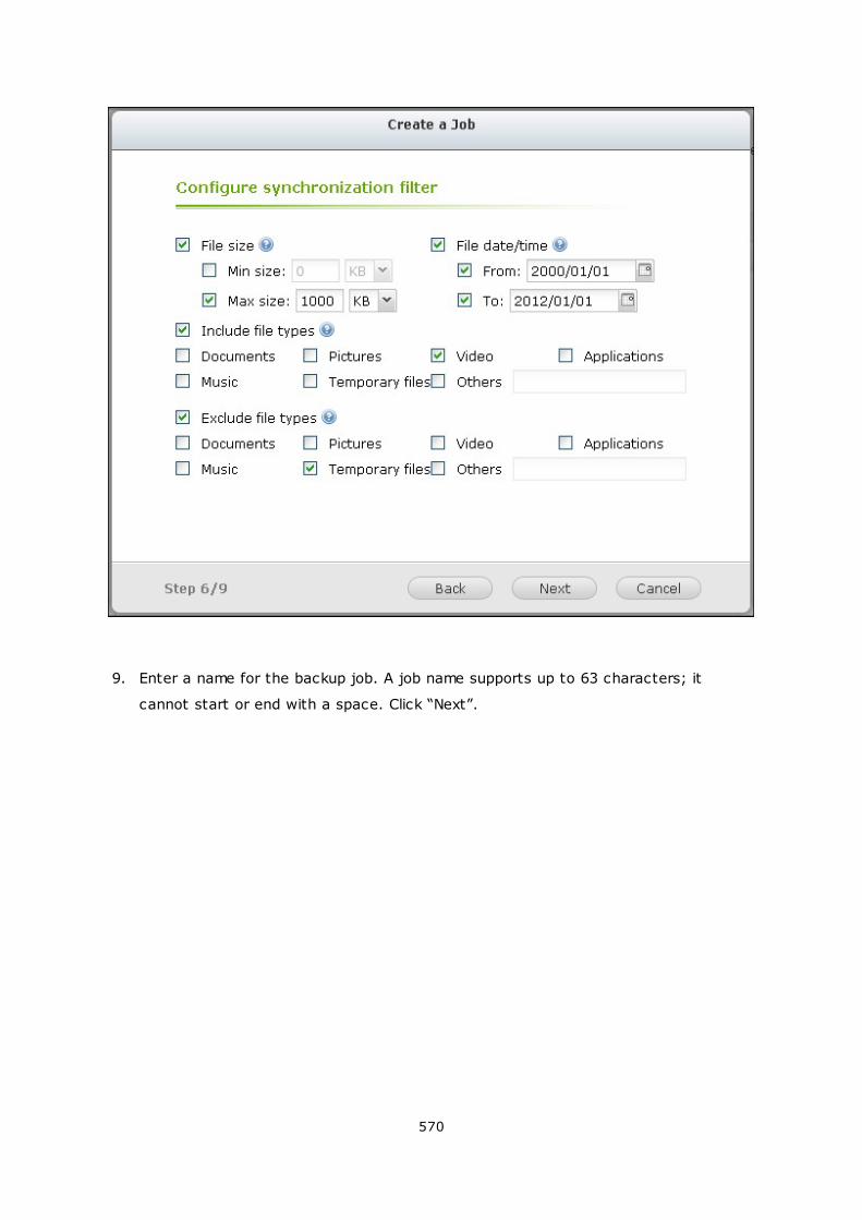
570
9. Enter a name for the backup job. A job name supports up to 63 characters; it
cannot start or end with a space. Click “Next”.
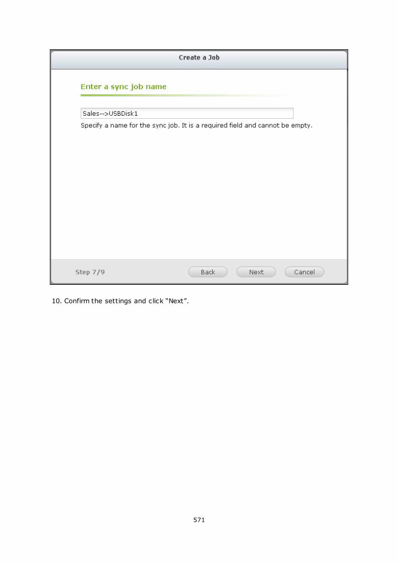
571
10. Confirm the settings and click “Next”.
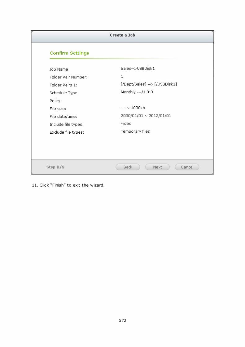
572
11. Click “Finish” to exit the wizard.
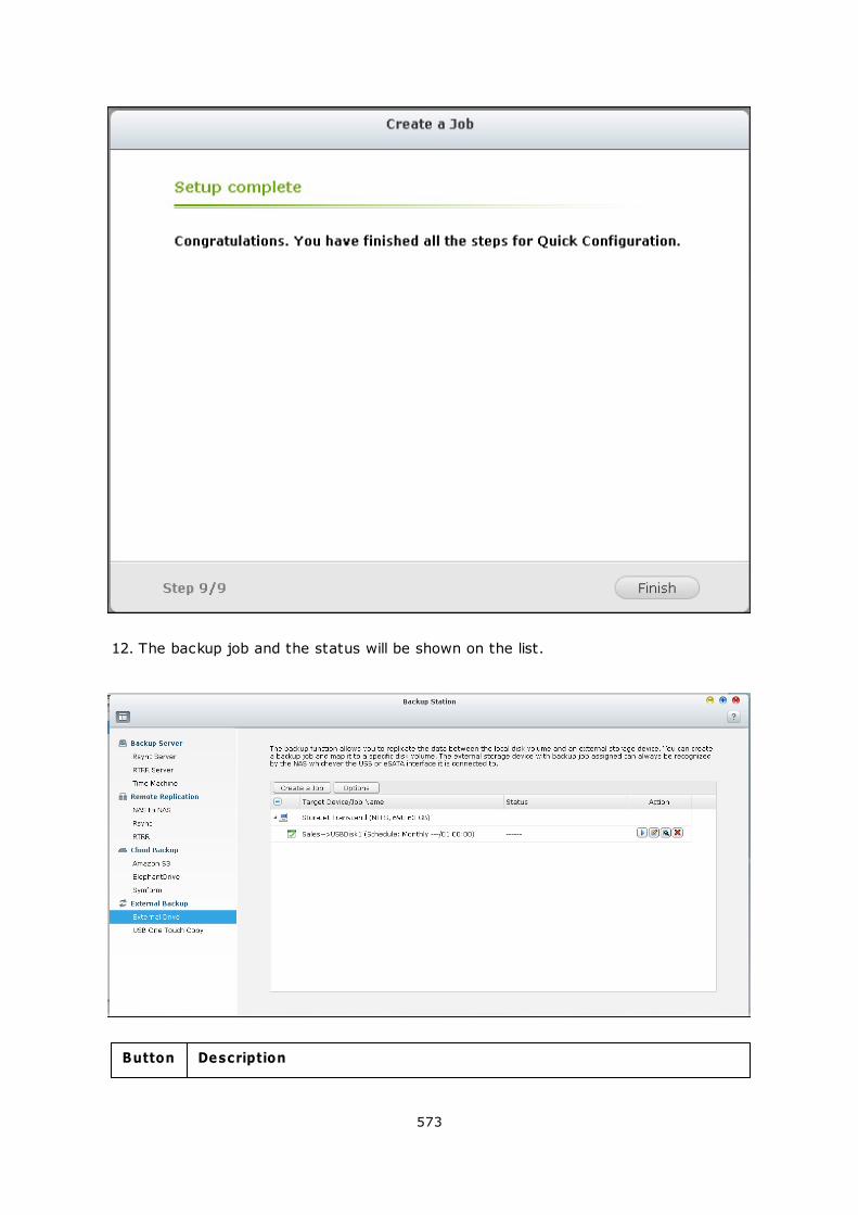
573
12. The backup job and the status will be shown on the list.
Button Description
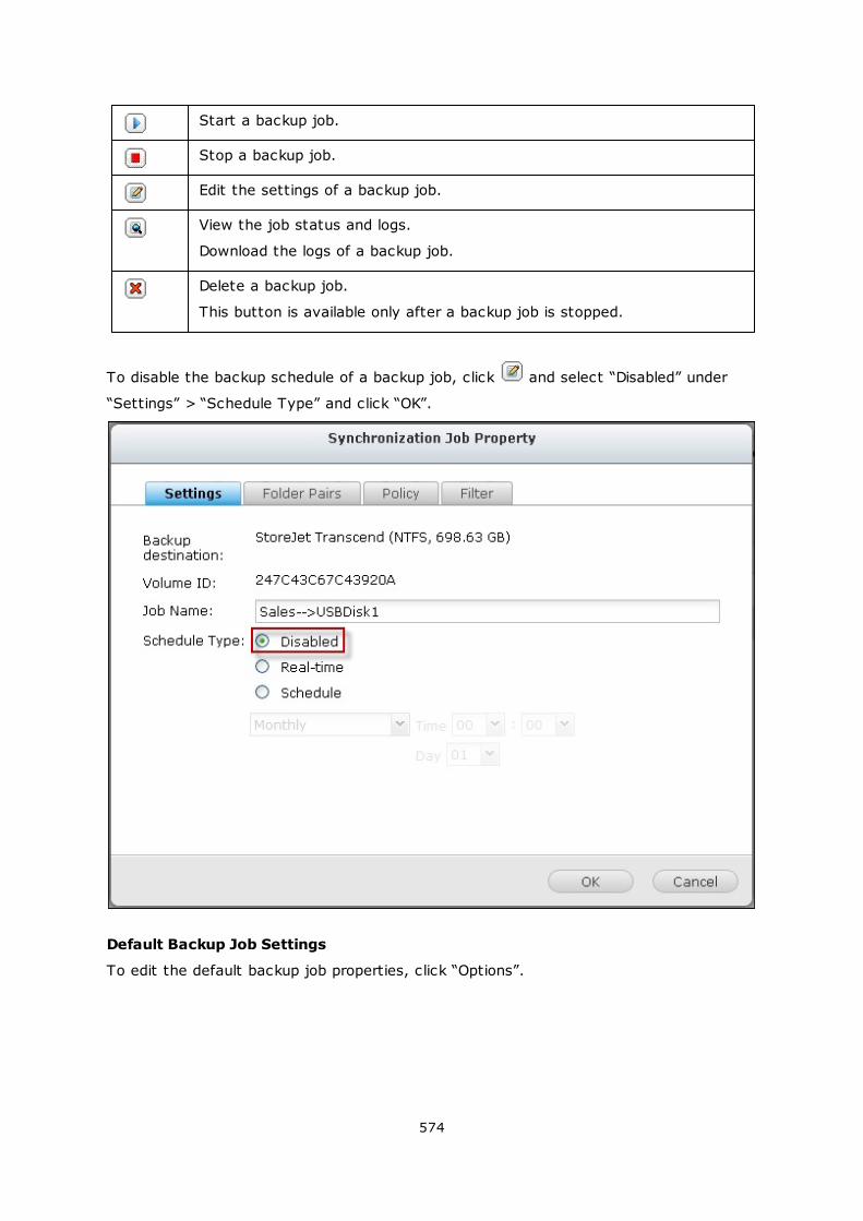
574
Start a backup job.
Stop a backup job.
Edit the settings of a backup job.
View the job status and logs.
Download the logs of a backup job.
Delete a backup job.
This button is available only after a backup job is stopped.
To disable the backup schedule of a backup job, click and select “Disabled” under
“Settings” > “Schedule Type” and click “OK”.
Default Backup Job Settings
To edit the default backup job properties, click “Options”.
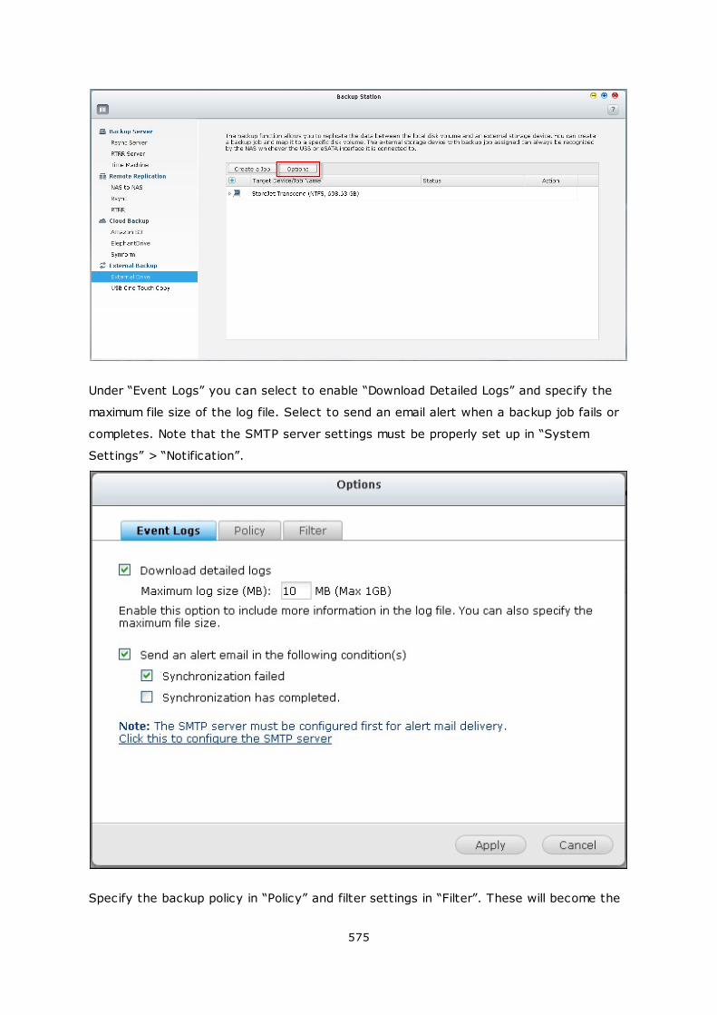
575
Under “Event Logs” you can select to enable “Download Detailed Logs” and specify the
maximum file size of the log file. Select to send an email alert when a backup job fails or
completes. Note that the SMTP server settings must be properly set up in “System
Settings” > “Notification”.
Specify the backup policy in “Policy” and filter settings in “Filter”. These will become the
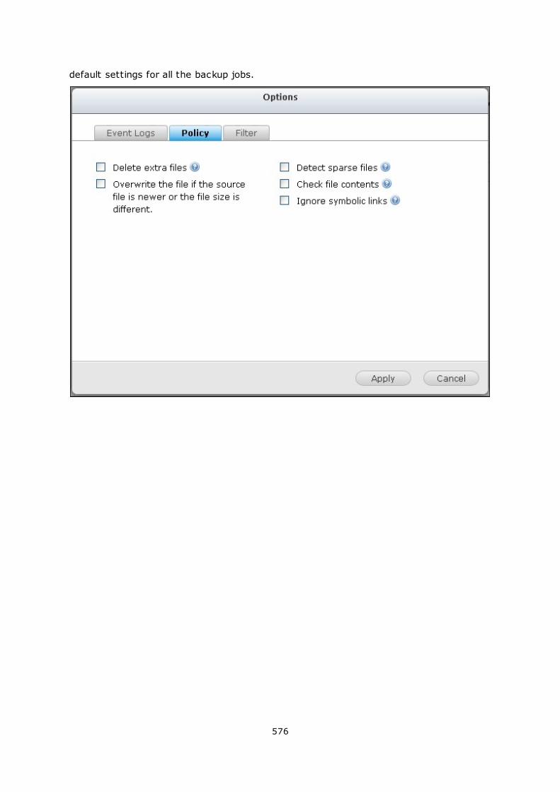
576
default settings for all the backup jobs.
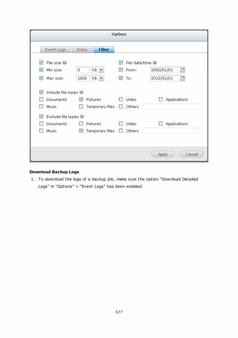
577
Download Backup Logs
1. To download the logs of a backup job, make sure the option “Download Detailed
Logs” in “Options” > “Event Logs” has been enabled.
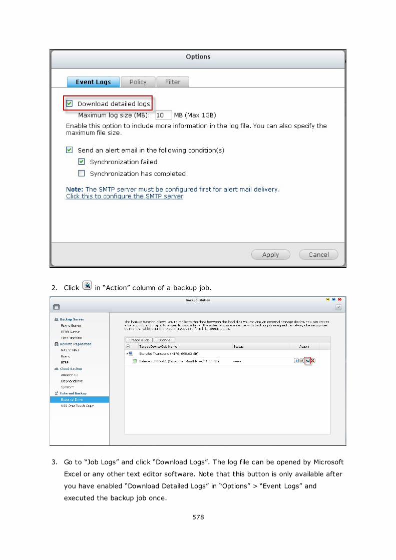
578
2. Click in “Action” column of a backup job.
3. Go to “Job Logs” and click “Download Logs”. The log file can be opened by Microsoft
Excel or any other text editor software. Note that this button is only available after
you have enabled “Download Detailed Logs” in “Options” > “Event Logs” and
executed the backup job once.
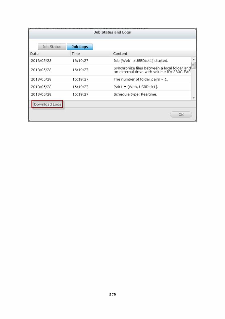
579
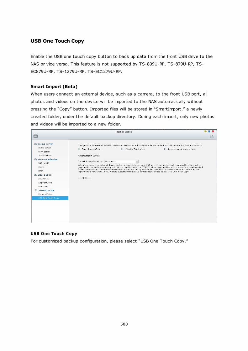
580
USB One Touch Copy
Enable the USB one touch copy button to back up data from the front USB drive to the
NAS or vice versa. This feature is not supported by TS-809U-RP, TS-879U-RP, TS-
EC879U-RP, TS-1279U-RP, TS-EC1279U-RP.
Smart Import (Beta)
When users connect an external device, such as a camera, to the front USB port, all
photos and videos on the device will be imported to the NAS automatically without
pressing the “Copy” button. Imported files will be stored in “SmartImport,” a newly
created folder, under the default backup directory. During each import, only new photos
and videos will be imported to a new folder.
USB One Touch Copy
For customized backup configuration, please select “USB One Touch Copy.”

581
Backup direction: From the front USB drive to the NAS or vice versa.
Backup method:
A. Create directory: A new directory will be created on the destination and the
source data will be copied to this directory. The new directory will be named as
the backup date (YYYYMMDD). If there are two or more backups on the same day,
the directory will be named with YYYYMMDD-1, YYYYMMDD-2... and so on.
B. Copy: Back up data to the destination share. If the same file exists, the
destination file will be overwritten.
C. Synchronize: Back up data to the destination share and clear the redundant files.
If the same file exists, the destination file will be overwritten.
Note: If there are multiple partitions on the source storage device, a new folder will
be created for each partition on the destination as the backup folder. The backup
folder will be named with the backup date and the partition number, YYYYMMDD-1 for
partition 1, YYYYMMDD-2 for partition 2... and so on. If the source storage device
contains only one partition, the backup folder will be named as YYYYMMDD only.
Handle sparse files efficiently: A sparse file is a type of computer file that contains
large blocks of zero-byte data. Turn on this option may reduce the time required for
backup.
Source and destination folders: Specify the folder pairs for backup and click “Add”.
582
Maximum 9 folder pairs can be added.
Options: Click “Options” to set up notification of the backup jobs by email, SMS, or
instant messaging (IM).
Unmount the front USB drive manually: When enabled, users can press the Copy
button for about 8–10 seconds until the USB LED light turns off and remove the front
USB drive from the NAS.
Enable the alarm buzzer:
1. One short beep: Backup has started.
2. Two short beeps: The front USB drive is being unmounted.
Data copy using front USB port
The NAS supports instant data copy backup from the external USB device to the NAS or
the other way round by the front one touch copy button. To use this function, follow
the steps below:
1. Make sure a hard drive is installed and formatted on the NAS. The default shared
folder Qusb/Usb has been created.
2. Turn on the NAS.
3. Configure the behavior of the Copy button on “Backup Station” > “USB One Touch
Copy” page.
4. Connect the USB device, for example, digital camera or flash, to the front USB port
of the NAS.
5. Press the Copy button once. The data will be copied according to your settings on
the NAS.
Note: Incremental backup is used for this feature. After the first time data backup,
the NAS only copies the changed files since the last backup.
Caution: Files are copied from the source to the destination. Extra files on the
destination will be deleted; files of the same names will be overwritten by the
source. Source data will remain unchanged.
As an external storage drive
When an external device is connected to the front USB port, it will be identified as an
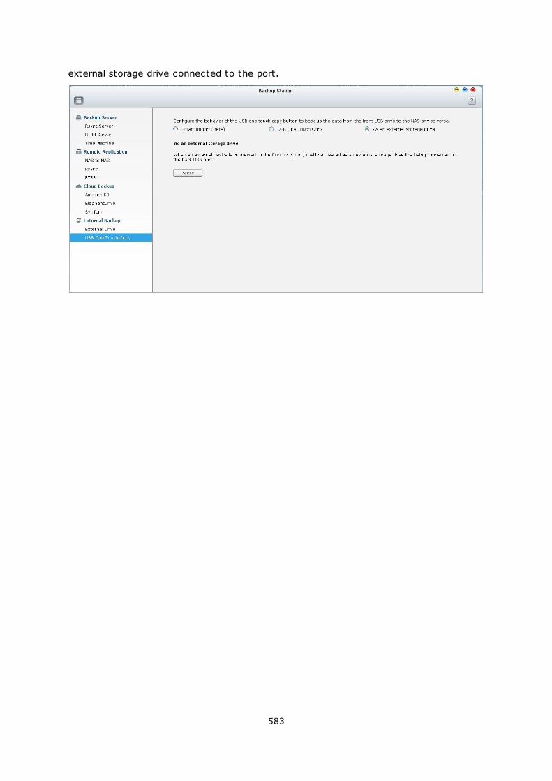
583
external storage drive connected to the port.
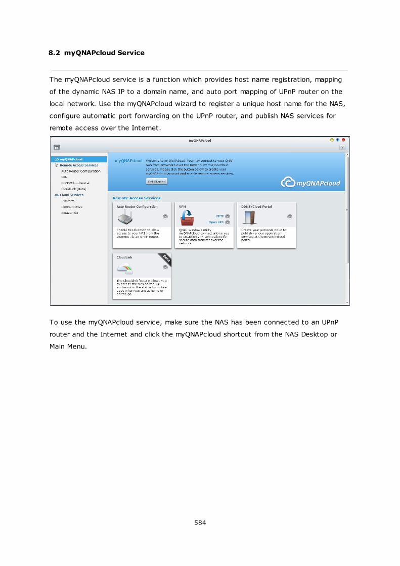
584
8.2 myQNAPcloud Service
The myQNAPcloud service is a function which provides host name registration, mapping
of the dynamic NAS IP to a domain name, and auto port mapping of UPnP router on the
local network. Use the myQNAPcloud wizard to register a unique host name for the NAS,
configure automatic port forwarding on the UPnP router, and publish NAS services for
remote access over the Internet.
To use the myQNAPcloud service, make sure the NAS has been connected to an UPnP
router and the Internet and click the myQNAPcloud shortcut from the NAS Desktop or
Main Menu.
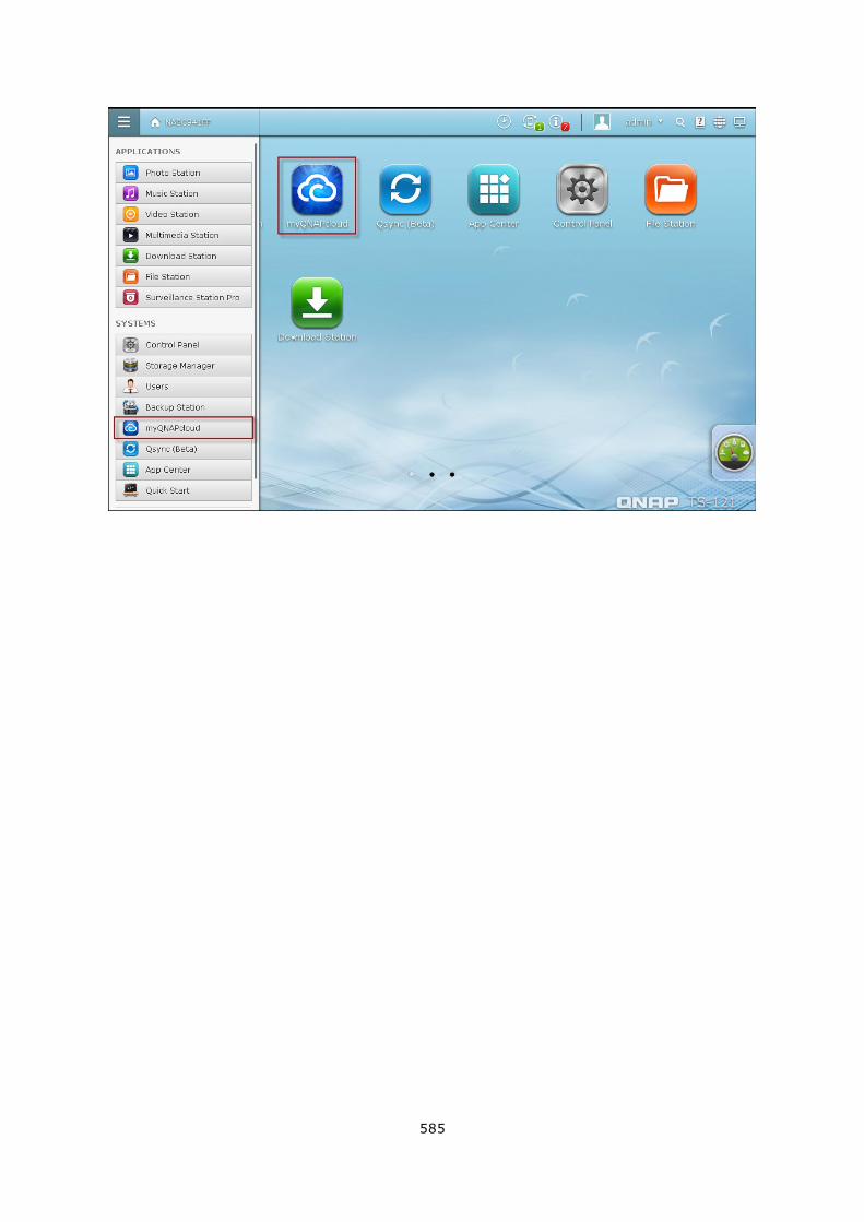
585
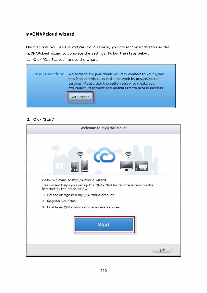
586
myQNAPcloud w izard
The first time you use the myQNAPcloud service, you are recommended to use the
myQNAPcloud wizard to complete the settings. Follow the steps below:
1. Click “Get Started” to use the wizard.
2. Click “Start”.
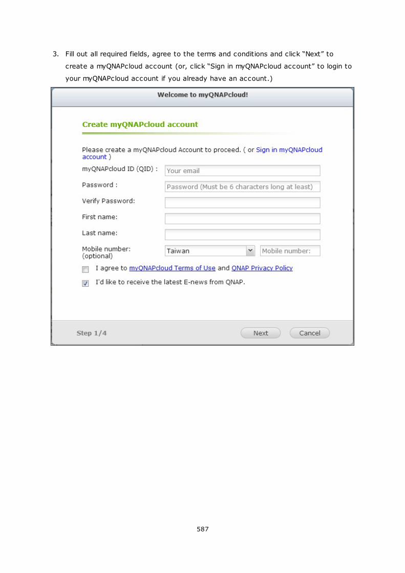
587
3. Fill out all required fields, agree to the terms and conditions and click “Next” to
create a myQNAPcloud account (or, click “Sign in myQNAPcloud account” to login to
your myQNAPcloud account if you already have an account.)
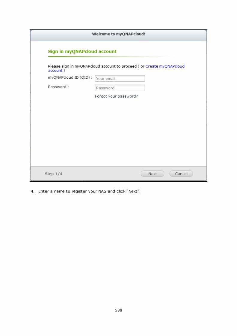
588
4. Enter a name to register your NAS and click “Next”.
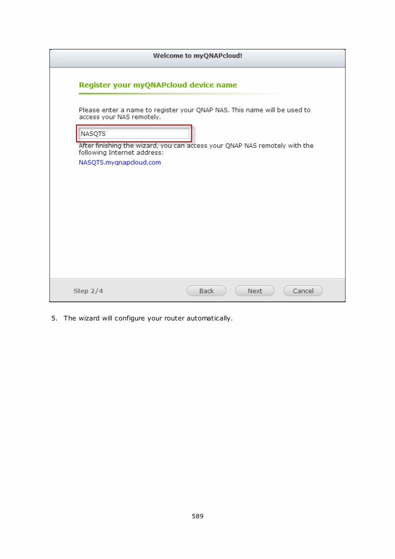
589
5. The wizard will configure your router automatically.
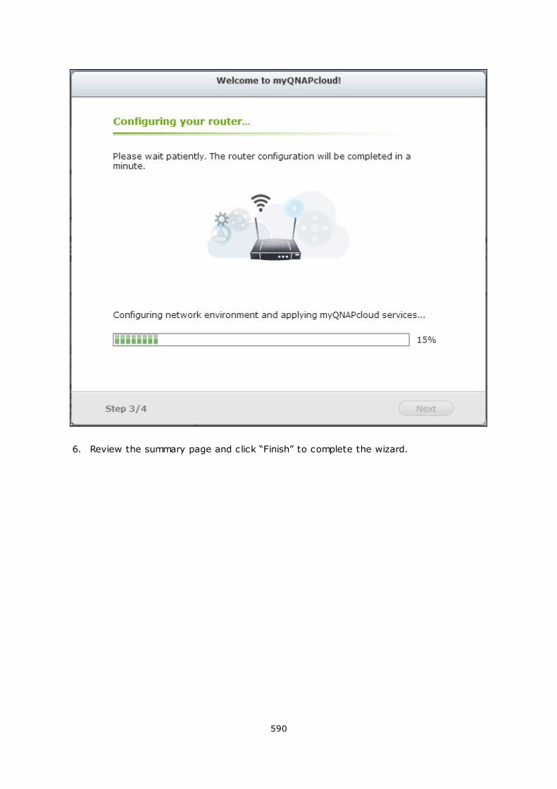
590
6. Review the summary page and click “Finish” to complete the wizard.
591
7. If any of the settings is unsuccessful, follow the instructions provided to
troubleshoot the issues. After the wizard is finished, a confirmation email will be sent
to the email account specified. Click “Confirm Registration” from the email and
proceed to complete the registration process.
592
593
Manage and configure your myQNAPcloud account
Click “Manage myQNAPcloud Account” on top of the page after launching myQNAPcloud
or log into your account at http://www.myqnapcloud.com.
Click your login ID next to the “Enter device name” box and select “My Devices” from the
drop down menu to review your device details, including the name, DDNS address, LAN
and WAN IP.
594
Or, select “My Account” to check your profile, change your password and monitor your
account activity.
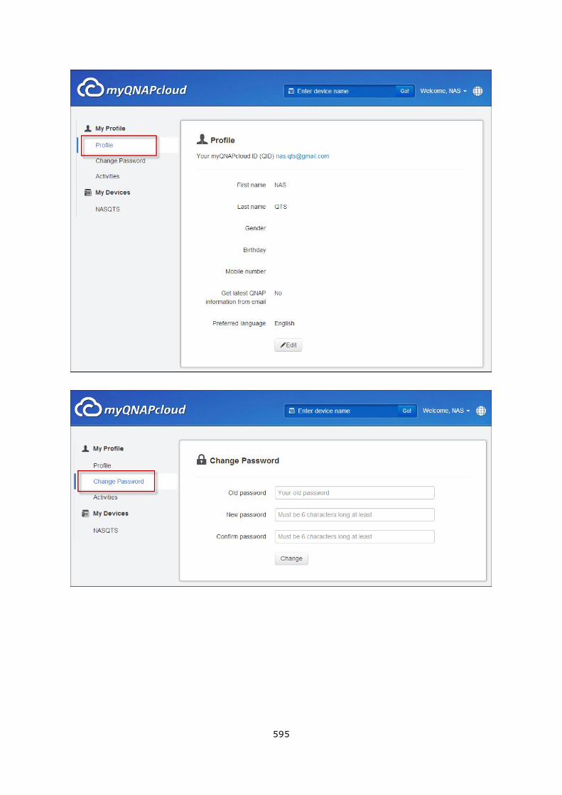
595
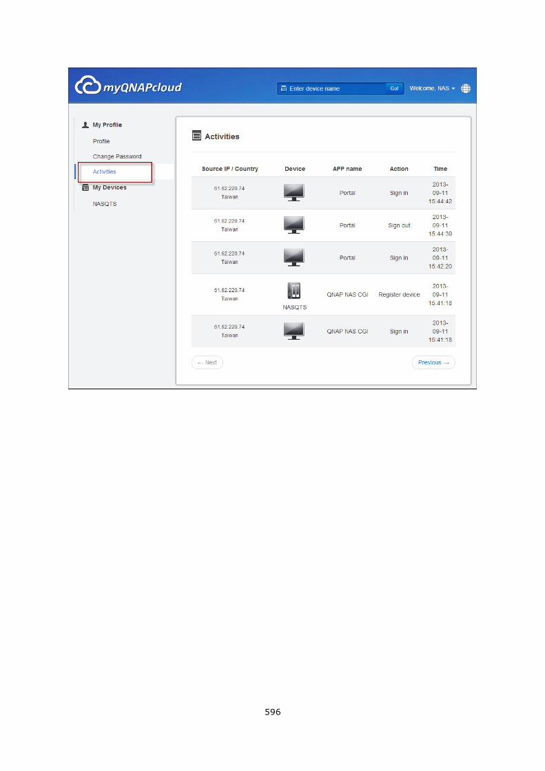
596
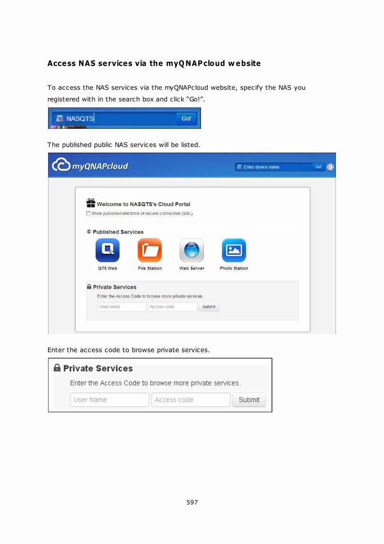
597
Access NAS services via the myQNAPcloud website
To access the NAS services via the myQNAPcloud website, specify the NAS you
registered with in the search box and click “Go!”.
The published public NAS services will be listed.
Enter the access code to browse private services.
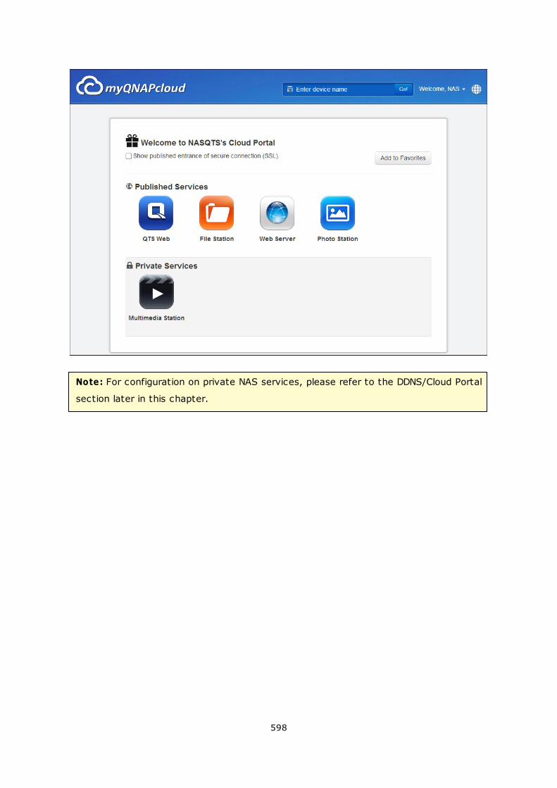
598
Note: For configuration on private NAS services, please refer to the DDNS/Cloud Portal
section later in this chapter.
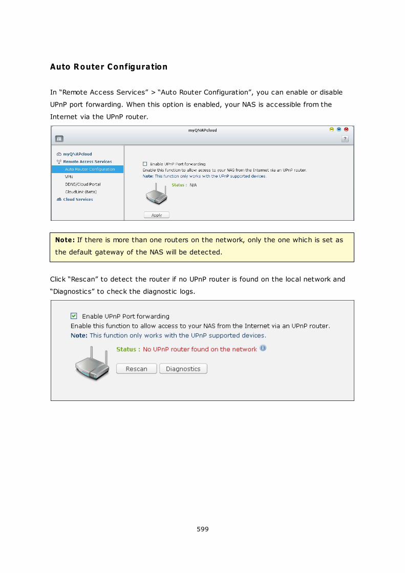
599
Auto Router Configuration
In “Remote Access Services” > “Auto Router Configuration”, you can enable or disable
UPnP port forwarding. When this option is enabled, your NAS is accessible from the
Internet via the UPnP router.
Note: If there is more than one routers on the network, only the one which is set as
the default gateway of the NAS will be detected.
Click “Rescan” to detect the router if no UPnP router is found on the local network and
“Diagnostics” to check the diagnostic logs.
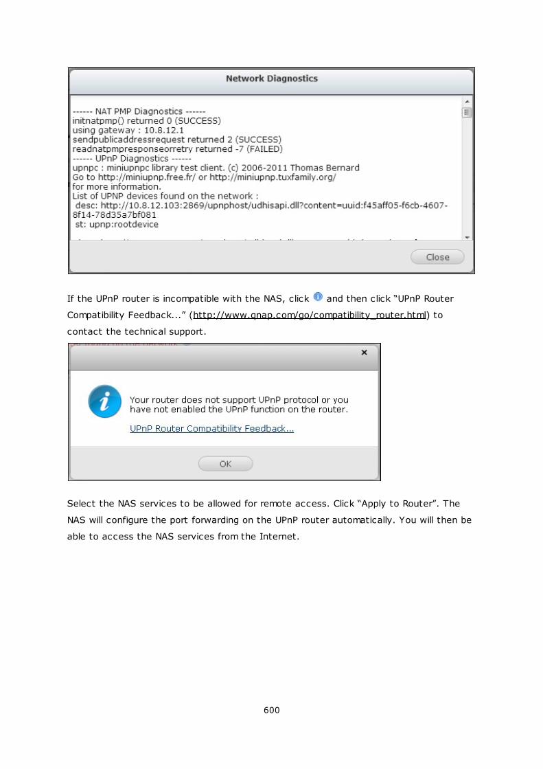
600
If the UPnP router is incompatible with the NAS, click and then click “UPnP Router
Compatibility Feedback...” (http://www.qnap.com/go/compatibility_router.html) to
contact the technical support.
Select the NAS services to be allowed for remote access. Click “Apply to Router”. The
NAS will configure the port forwarding on the UPnP router automatically. You will then be
able to access the NAS services from the Internet.
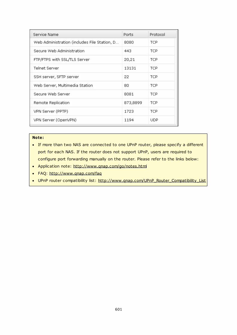
601
Note:
If more than two NAS are connected to one UPnP router, please specify a different
port for each NAS. If the router does not support UPnP, users are required to
configure port forwarding manually on the router. Please refer to the links below:
Application note: http://www.qnap.com/go/notes.html
FAQ: http://www.qnap.com/faq
UPnP router compatibility list: http://www.qnap.com/UPnP_Router_Compatibility_List
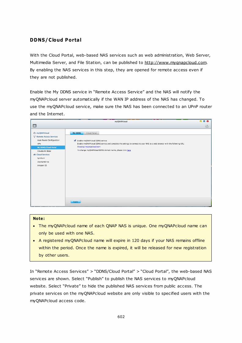
602
DDNS/Cloud Portal
With the Cloud Portal, web-based NAS services such as web administration, Web Server,
Multimedia Server, and File Station, can be published to http://www.myqnapcloud.com.
By enabling the NAS services in this step, they are opened for remote access even if
they are not published.
Enable the My DDNS service in “Remote Access Service” and the NAS will notify the
myQNAPcloud server automatically if the WAN IP address of the NAS has changed. To
use the myQNAPcloud service, make sure the NAS has been connected to an UPnP router
and the Internet.
Note:
The myQNAPcloud name of each QNAP NAS is unique. One myQNAPcloud name can
only be used with one NAS.
A registered myQNAPcloud name will expire in 120 days if your NAS remains offline
within the period. Once the name is expired, it will be released for new registration
by other users.
In “Remote Access Services” > “DDNS/Cloud Portal” > “Cloud Portal”, the web-based NAS
services are shown. Select “Publish” to publish the NAS services to myQNAPcloud
website. Select “Private” to hide the published NAS services from public access. The
private services on the myQNAPcloud website are only visible to specified users with the
myQNAPcloud access code.
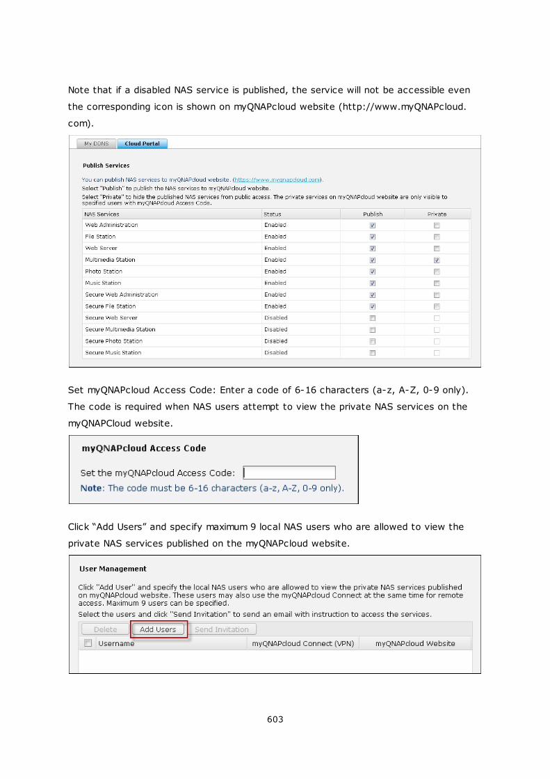
603
Note that if a disabled NAS service is published, the service will not be accessible even
the corresponding icon is shown on myQNAPcloud website (http://www.myQNAPcloud.
com).
Set myQNAPcloud Access Code: Enter a code of 6-16 characters (a-z, A-Z, 0-9 only).
The code is required when NAS users attempt to view the private NAS services on the
myQNAPCloud website.
Click “Add Users” and specify maximum 9 local NAS users who are allowed to view the
private NAS services published on the myQNAPcloud website.
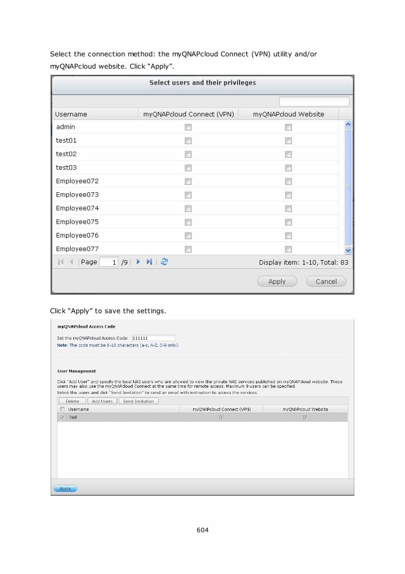
604
Select the connection method: the myQNAPcloud Connect (VPN) utility and/or
myQNAPcloud website. Click “Apply”.
Click “Apply” to save the settings.
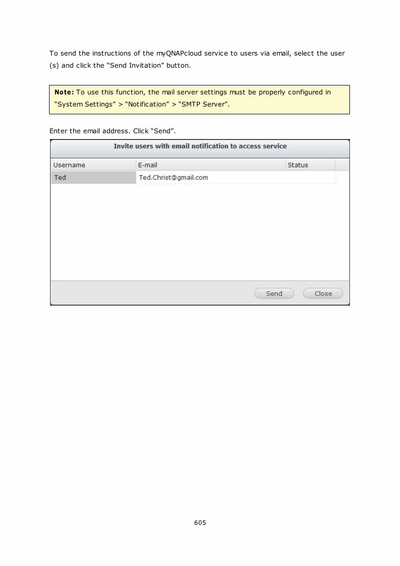
605
To send the instructions of the myQNAPcloud service to users via email, select the user
(s) and click the “Send Invitation” button.
Note: To use this function, the mail server settings must be properly configured in
“System Settings” > “Notification” > “SMTP Server”.
Enter the email address. Click “Send”.
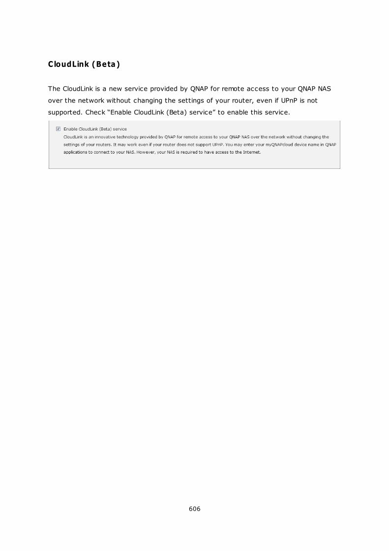
606
CloudLink (Beta)
The CloudLink is a new service provided by QNAP for remote access to your QNAP NAS
over the network without changing the settings of your router, even if UPnP is not
supported. Check “Enable CloudLink (Beta) service” to enable this service.
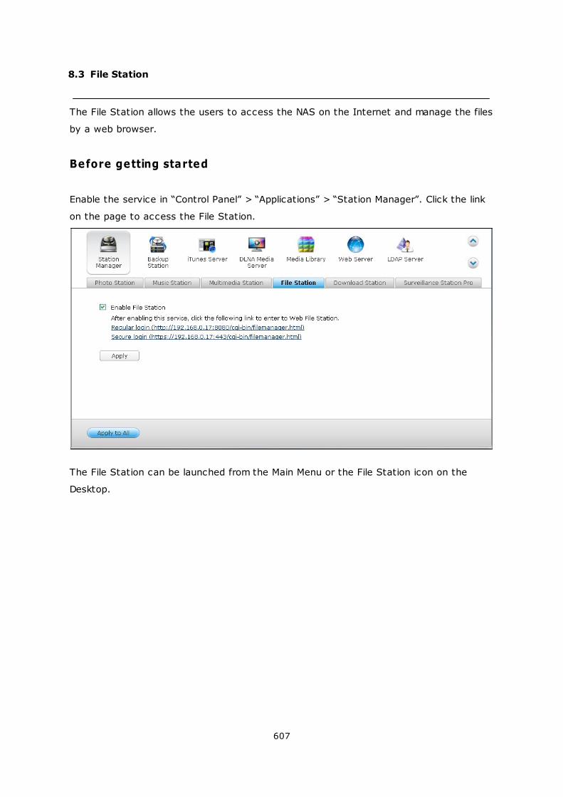
607
8.3 File Station
The File Station allows the users to access the NAS on the Internet and manage the files
by a web browser.
Before getting started
Enable the service in “Control Panel” > “Applications” > “Station Manager”. Click the link
on the page to access the File Station.
The File Station can be launched from the Main Menu or the File Station icon on the
Desktop.
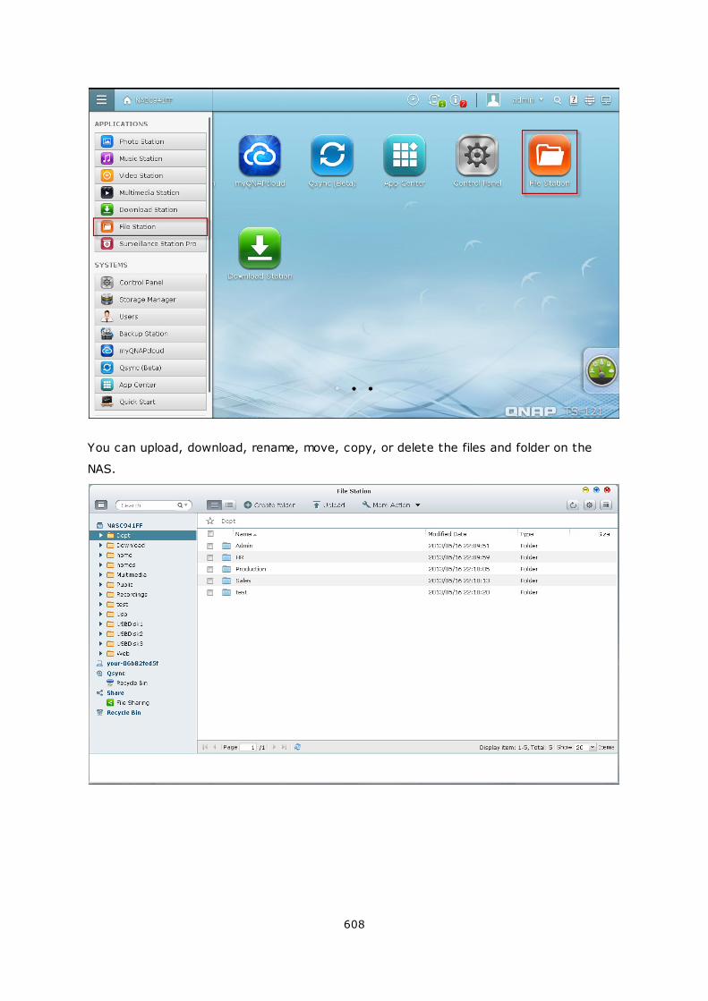
608
You can upload, download, rename, move, copy, or delete the files and folder on the
NAS.
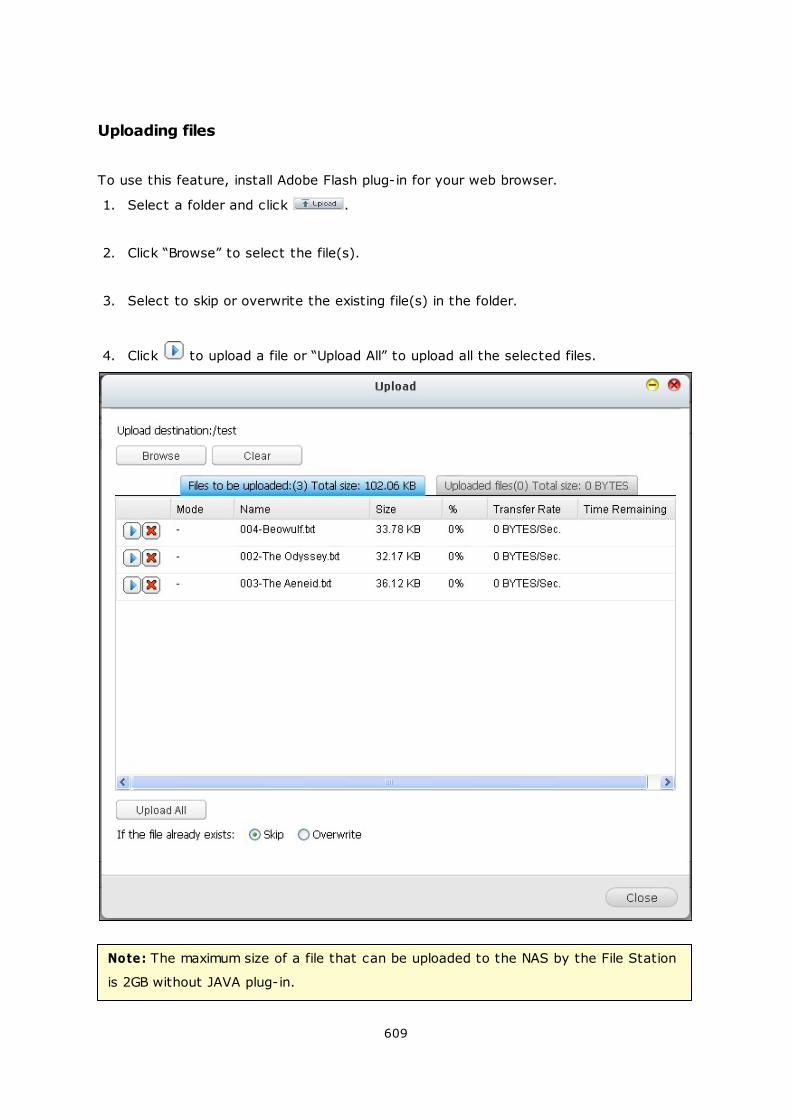
609
Uploading files
To use this feature, install Adobe Flash plug-in for your web browser.
1. Select a folder and click .
2. Click “Browse” to select the file(s).
3. Select to skip or overwrite the existing file(s) in the folder.
4. Click to upload a file or “Upload All” to upload all the selected files.
Note: The maximum size of a file that can be uploaded to the NAS by the File Station
is 2GB without JAVA plug-in.
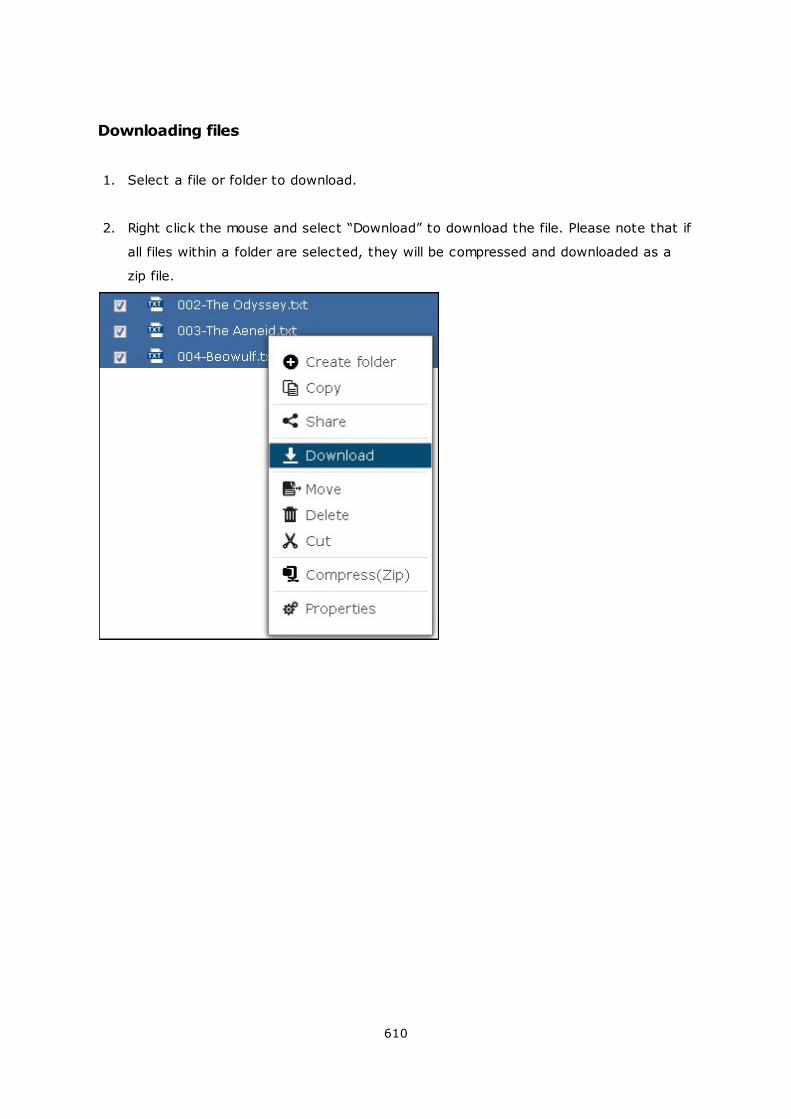
610
Downloading files
1. Select a file or folder to download.
2. Right click the mouse and select “Download” to download the file. Please note that if
all files within a folder are selected, they will be compressed and downloaded as a
zip file.

611
Creating folders
1. Select a shared folder or folder in which you want to create a new folder.
2. Click .
3. Enter the name of the new folder and click “OK”.
612
Renaming files or folders:
1. Select a file or folder to rename.
2. Right click the mouse and select “Rename” to rename the file.
3. Enter the new file or folder name and click “OK”.
613
Copying files or folders
1. Select the files or folders to copy.
2. Click .
3. Click the destination folder.
4. Click and confirm to copy the files or folders.
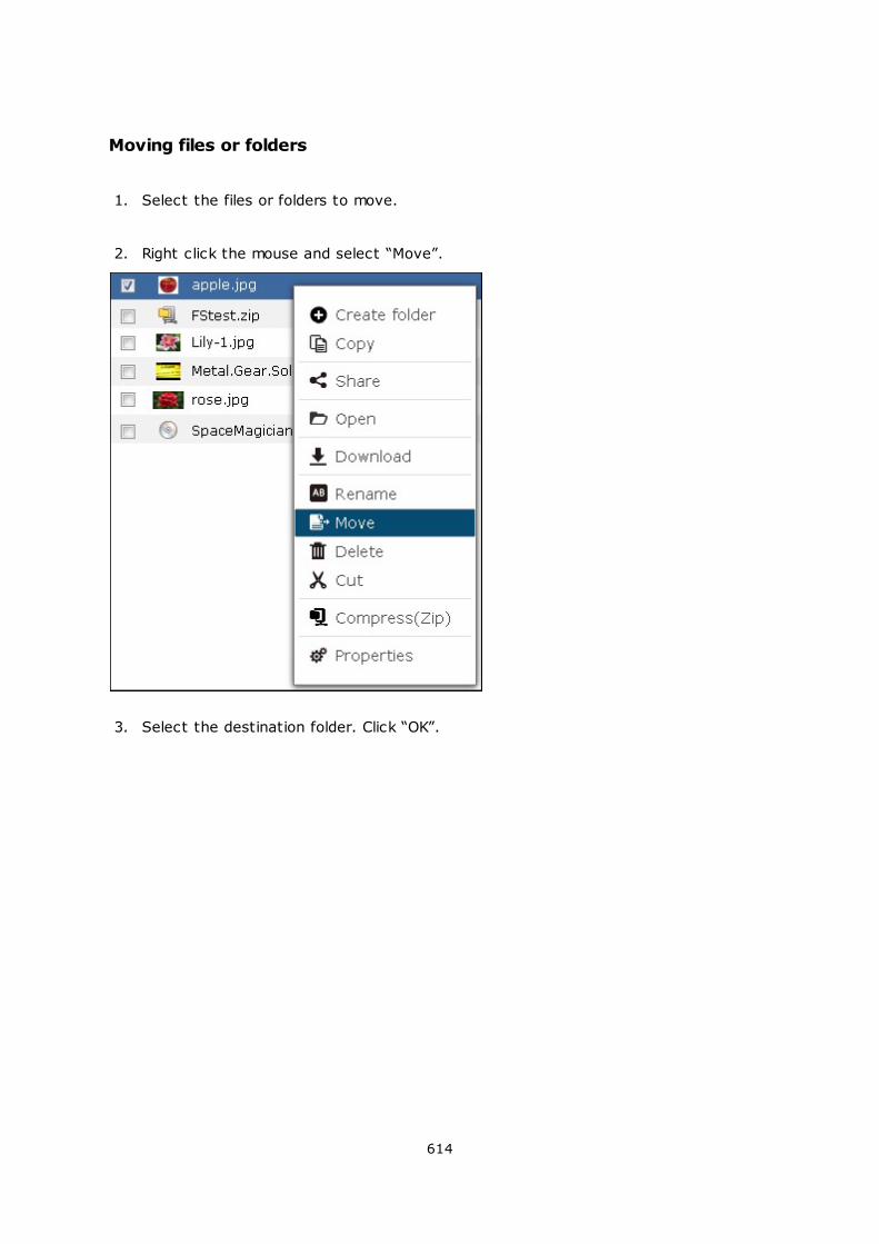
614
Moving files or folders
1. Select the files or folders to move.
2. Right click the mouse and select “Move”.
3. Select the destination folder. Click “OK”.
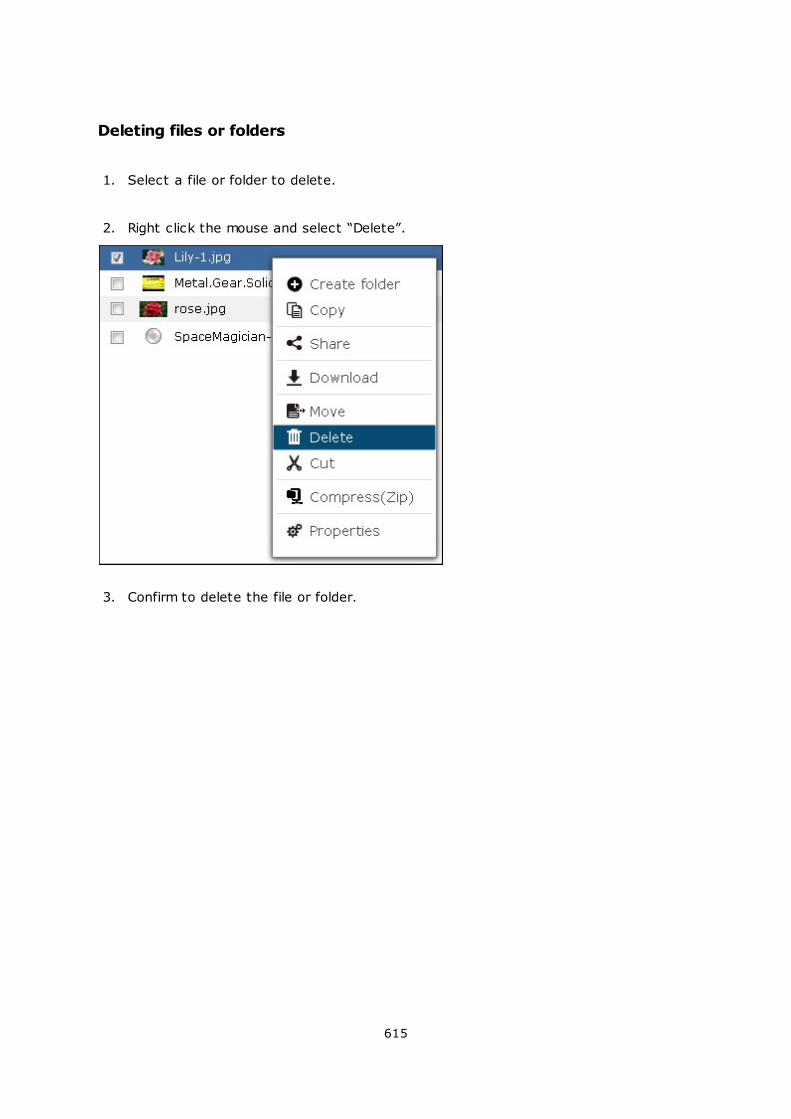
615
Deleting files or folders
1. Select a file or folder to delete.
2. Right click the mouse and select “Delete”.
3. Confirm to delete the file or folder.

616
Transcoding files
1. Select a media file.
2. Right click the mouse and select “Add to Transcode”.
3. Confirm to transcode the file.
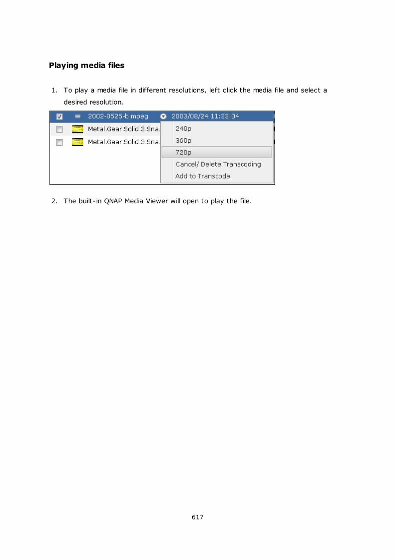
617
Playing media files
1. To play a media file in different resolutions, left click the media file and select a
desired resolution.
2. The built-in QNAP Media Viewer will open to play the file.
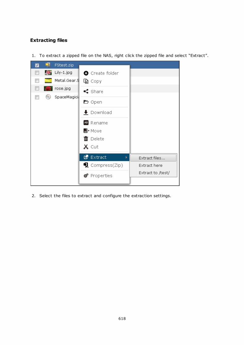
618
Extracting files
1. To extract a zipped file on the NAS, right click the zipped file and select “Extract”.
2. Select the files to extract and configure the extraction settings.
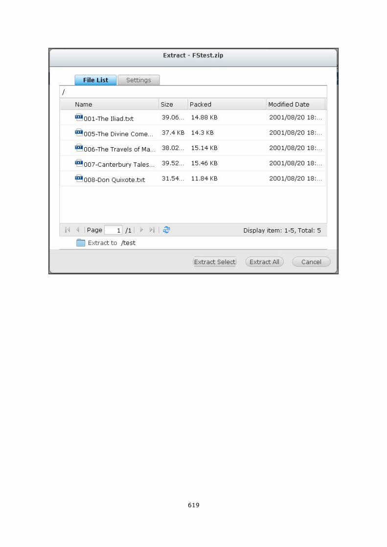
619
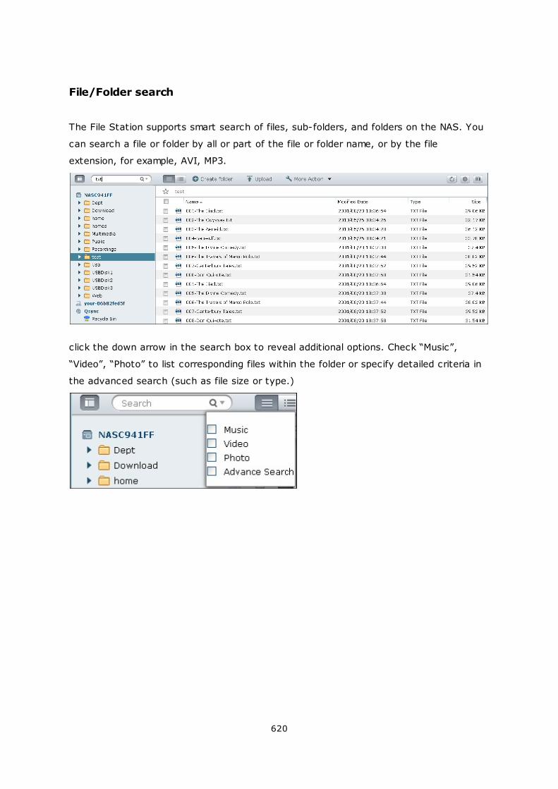
620
File/Folder search
The File Station supports smart search of files, sub-folders, and folders on the NAS. You
can search a file or folder by all or part of the file or folder name, or by the file
extension, for example, AVI, MP3.
click the down arrow in the search box to reveal additional options. Check “Music”,
“Video”, “Photo” to list corresponding files within the folder or specify detailed criteria in
the advanced search (such as file size or type.)
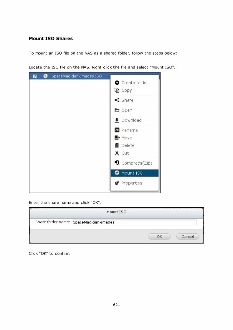
621
Mount ISO Shares
To mount an ISO file on the NAS as a shared folder, follow the steps below:
Locate the ISO file on the NAS. Right click the file and select “Mount ISO”.
Enter the share name and click “OK”.
Click “OK” to confirm.
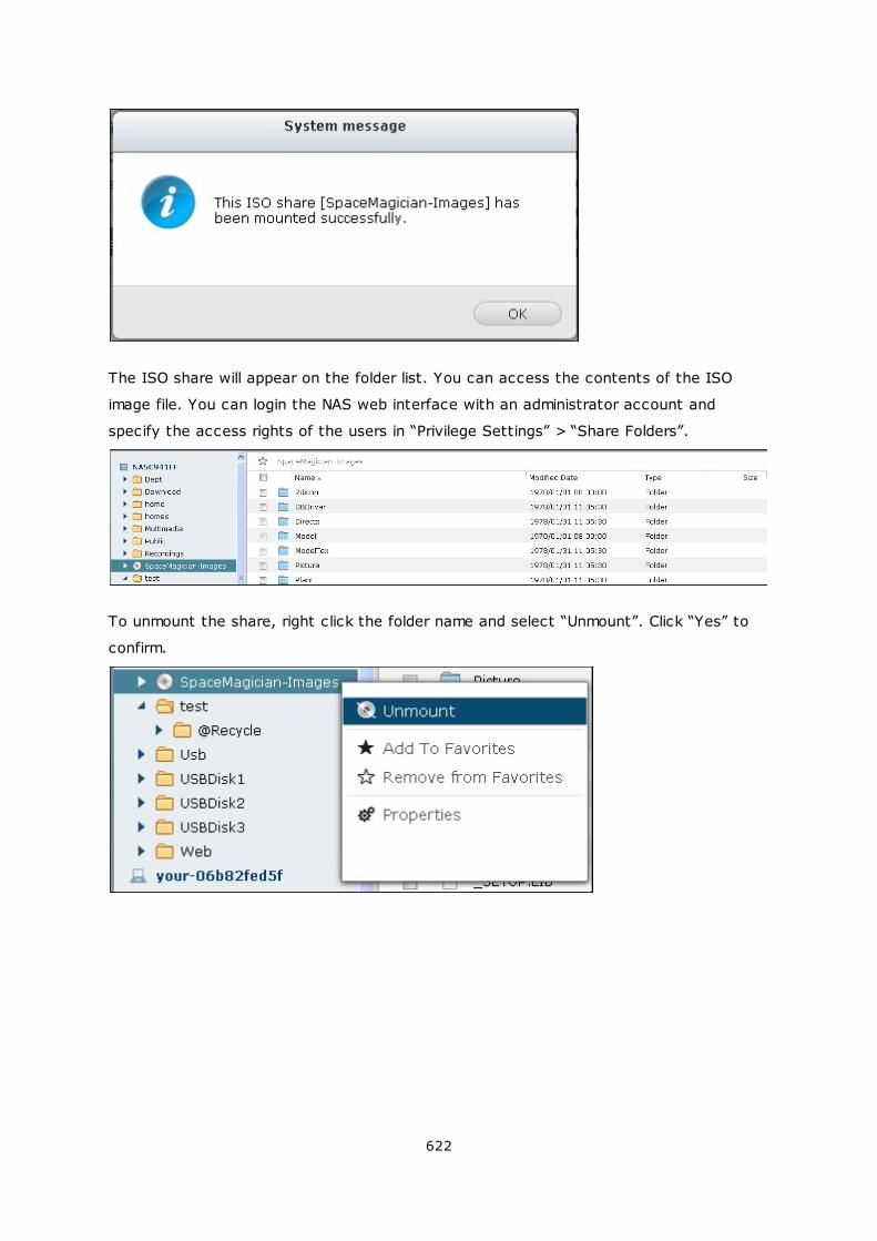
622
The ISO share will appear on the folder list. You can access the contents of the ISO
image file. You can login the NAS web interface with an administrator account and
specify the access rights of the users in “Privilege Settings” > “Share Folders”.
To unmount the share, right click the folder name and select “Unmount”. Click “Yes” to
confirm.
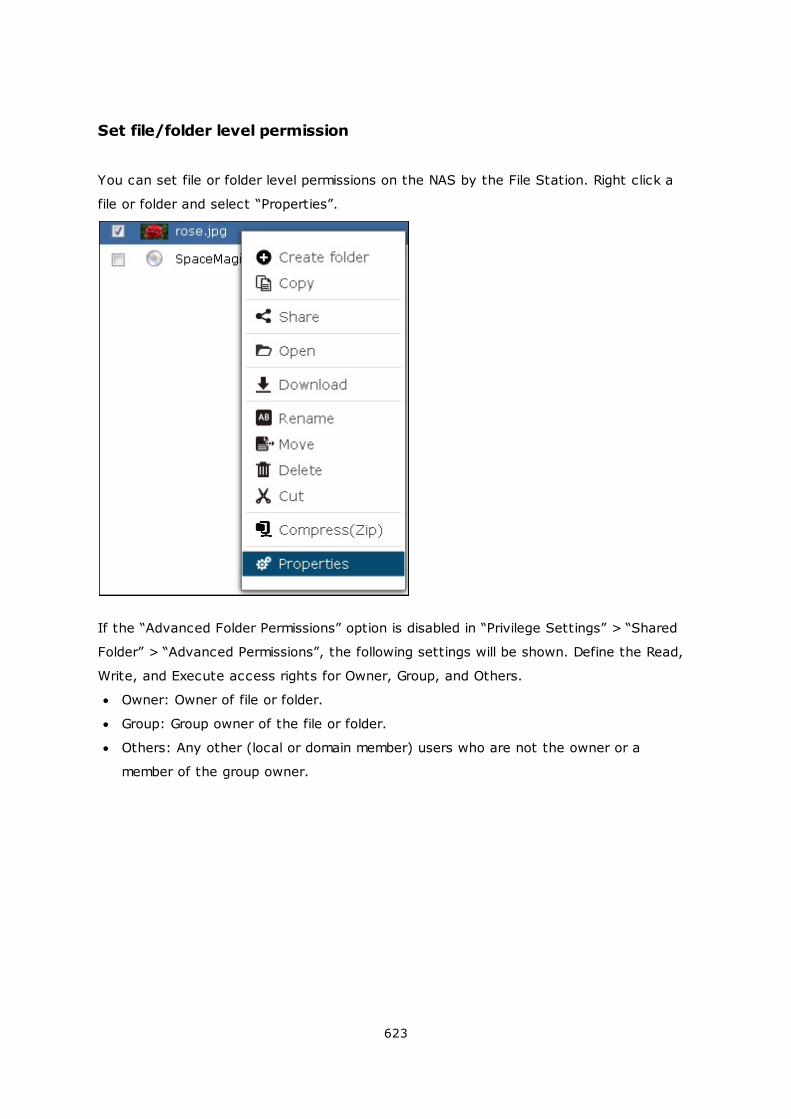
623
Set file/folder level permission
You can set file or folder level permissions on the NAS by the File Station. Right click a
file or folder and select “Properties”.
If the “Advanced Folder Permissions” option is disabled in “Privilege Settings” > “Shared
Folder” > “Advanced Permissions”, the following settings will be shown. Define the Read,
Write, and Execute access rights for Owner, Group, and Others.
Owner: Owner of file or folder.
Group: Group owner of the file or folder.
Others: Any other (local or domain member) users who are not the owner or a
member of the group owner.
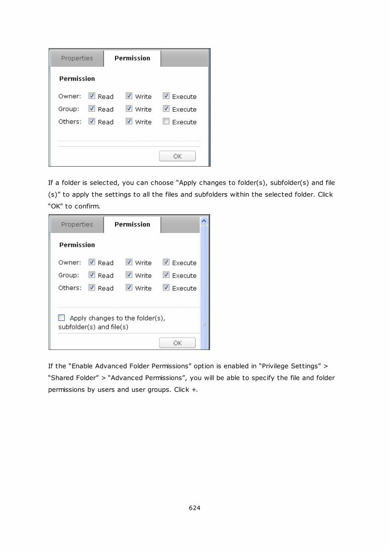
624
If a folder is selected, you can choose “Apply changes to folder(s), subfolder(s) and file
(s)” to apply the settings to all the files and subfolders within the selected folder. Click
“OK” to confirm.
If the “Enable Advanced Folder Permissions” option is enabled in “Privilege Settings” >
“Shared Folder” > “Advanced Permissions”, you will be able to specify the file and folder
permissions by users and user groups. Click +.
625
Select the users and user groups and specify the Read and Write rights. Click “Add”.
626
To remove the permissions on the list, select the user(s) or user group(s) and click -.
627
You can also define the file and folder owner by clicking . Select a user from the list
or search a username. Then click “Set”.
The following options are available for folder permission settings. You are recommended
628
to configure folder permissions and subfolder permissions in “Privilege Settings” > “Shared
Folders”.
Only the owner can delete the contents: When you apply this option to a folder, the
first-level subfolders and files can be deleted only by their owner.
Only admin can create files and folders: When you apply this option to a folder, only
administrators can create files or folders.
Apply changes to files and subfolders: Apply changed permissions settings except
owner protection to all the files and subfolders within the selected folder. The option
“Only the owner can delete the contents” will not be applied to subfolders.
Apply and replace all existing permissions of this folder, files, and subfolders: Select
this option to override all previously configured permissions of the selected folder and
its files and subfolders except owner protection. The option “Only the owner can
delete the contents” will not be applied to subfolders.
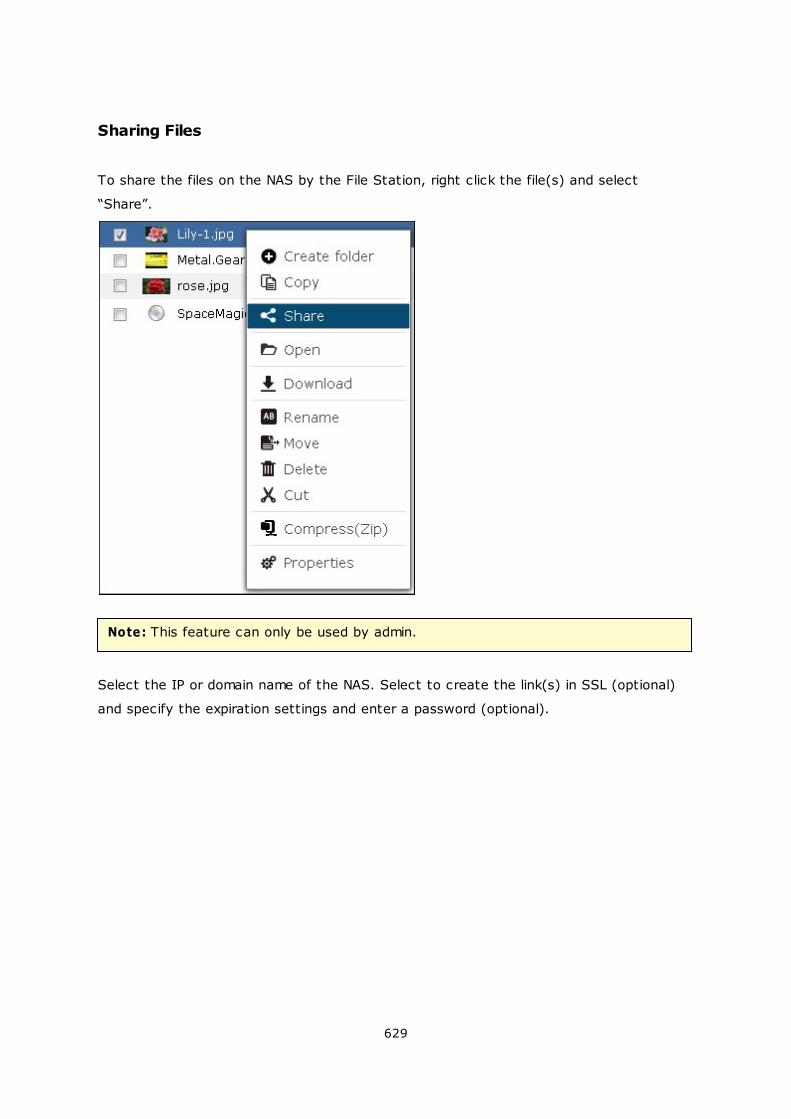
629
Sharing Files
To share the files on the NAS by the File Station, right click the file(s) and select
“Share”.
Note: This feature can only be used by admin.
Select the IP or domain name of the NAS. Select to create the link(s) in SSL (optional)
and specify the expiration settings and enter a password (optional).
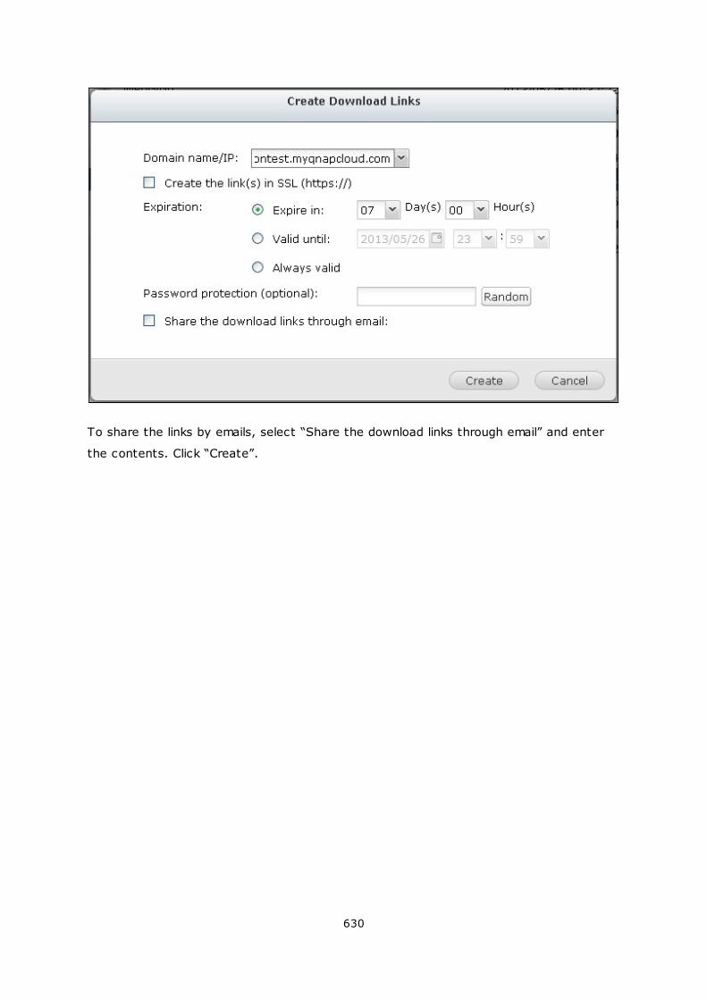
630
To share the links by emails, select “Share the download links through email” and enter
the contents. Click “Create”.
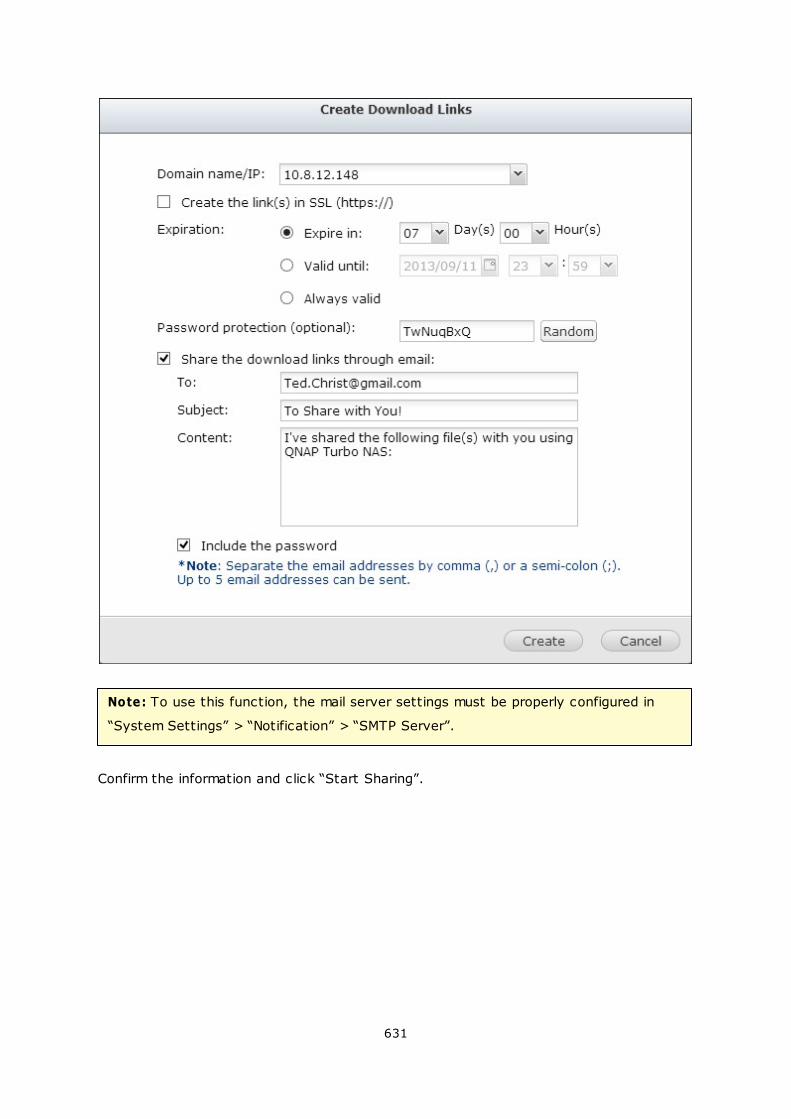
631
Note: To use this function, the mail server settings must be properly configured in
“System Settings” > “Notification” > “SMTP Server”.
Confirm the information and click “Start Sharing”.
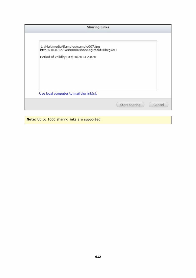
632
Note: Up to 1000 sharing links are supported.
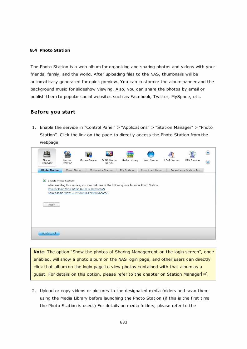
633
8.4 Photo Station
The Photo Station is a web album for organizing and sharing photos and videos with your
friends, family, and the world. After uploading files to the NAS, thumbnails will be
automatically generated for quick preview. You can customize the album banner and the
background music for slideshow viewing. Also, you can share the photos by email or
publish them to popular social websites such as Facebook, Twitter, MySpace, etc.
Before you start
1. Enable the service in “Control Panel” > “Applications” > “Station Manager” > “Photo
Station”. Click the link on the page to directly access the Photo Station from the
webpage.
Note: The option “Show the photos of Sharing Management on the login screen”, once
enabled, will show a photo album on the NAS login page, and other users can directly
click that album on the login page to view photos contained with that album as a
guest. For details on this option, please refer to the chapter on Station Manager .
2. Upload or copy videos or pictures to the designated media folders and scan them
using the Media Library before launching the Photo Station (if this is the first time
the Photo Station is used.) For details on media folders, please refer to the
96
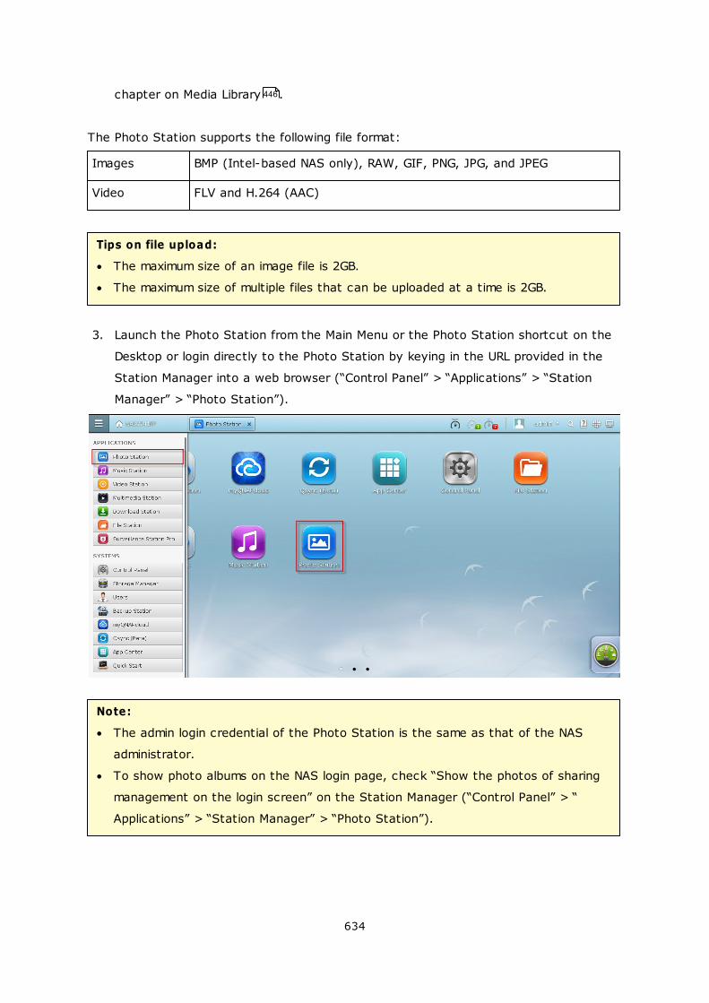
634
chapter on Media Library .
The Photo Station supports the following file format:
Images BMP (Intel-based NAS only), RAW, GIF, PNG, JPG, and JPEG
Video FLV and H.264 (AAC)
Tips on file upload:
The maximum size of an image file is 2GB.
The maximum size of multiple files that can be uploaded at a time is 2GB.
3. Launch the Photo Station from the Main Menu or the Photo Station shortcut on the
Desktop or login directly to the Photo Station by keying in the URL provided in the
Station Manager into a web browser (“Control Panel” > “Applications” > “Station
Manager” > “Photo Station”).
Note:
The admin login credential of the Photo Station is the same as that of the NAS
administrator.
To show photo albums on the NAS login page, check “Show the photos of sharing
management on the login screen” on the Station Manager (“Control Panel” > “
Applications” > “Station Manager” > “Photo Station”).
446
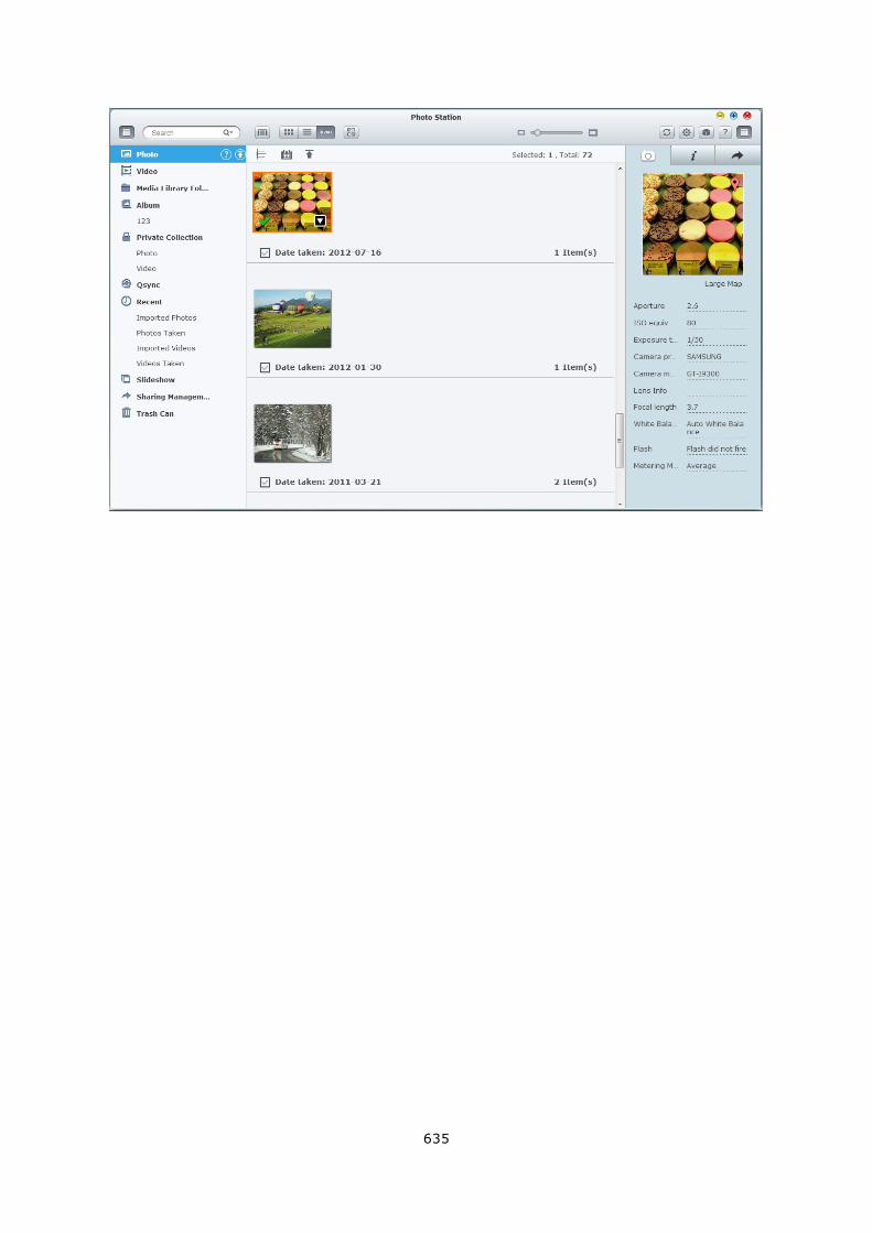
635
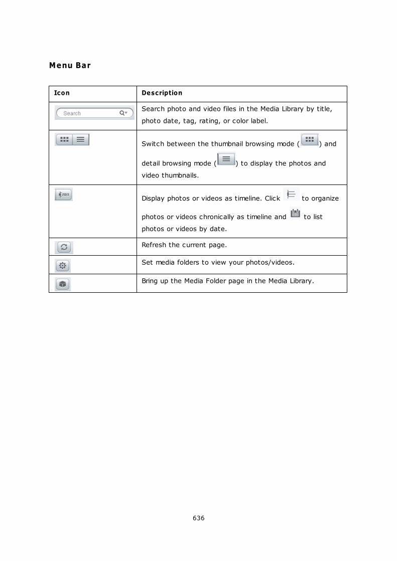
636
Menu Bar
Icon Description
Search photo and video files in the Media Library by title,
photo date, tag, rating, or color label.
Switch between the thumbnail browsing mode ( ) and
detail browsing mode ( ) to display the photos and
video thumbnails.
Display photos or videos as timeline. Click to organize
photos or videos chronically as timeline and to list
photos or videos by date.
Refresh the current page.
Set media folders to view your photos/videos.
Bring up the Media Folder page in the Media Library.
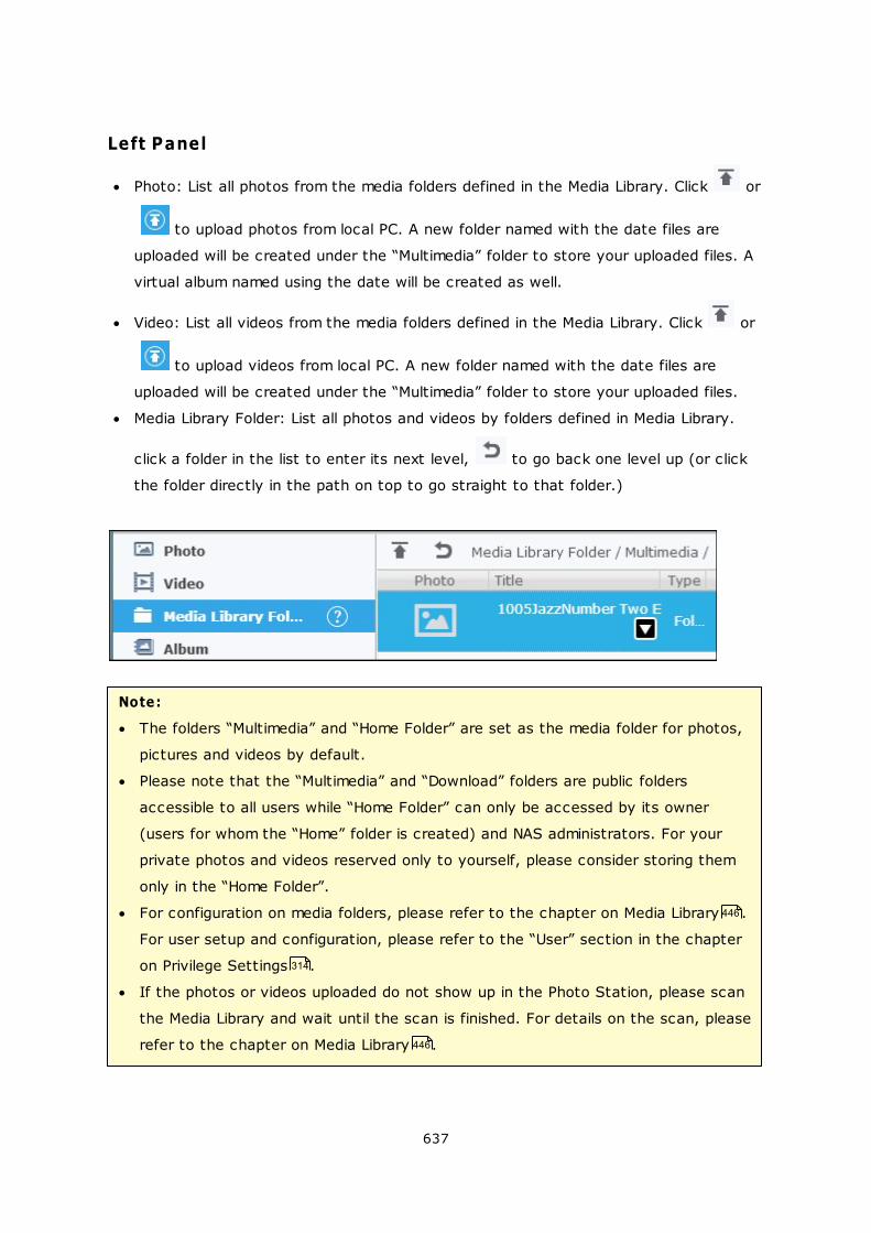
637
Left Panel
Photo: List all photos from the media folders defined in the Media Library. Click or
to upload photos from local PC. A new folder named with the date files are
uploaded will be created under the “Multimedia” folder to store your uploaded files. A
virtual album named using the date will be created as well.
Video: List all videos from the media folders defined in the Media Library. Click or
to upload videos from local PC. A new folder named with the date files are
uploaded will be created under the “Multimedia” folder to store your uploaded files.
Media Library Folder: List all photos and videos by folders defined in Media Library.
click a folder in the list to enter its next level, to go back one level up (or click
the folder directly in the path on top to go straight to that folder.)
Note:
The folders “Multimedia” and “Home Folder” are set as the media folder for photos,
pictures and videos by default.
Please note that the “Multimedia” and “Download” folders are public folders
accessible to all users while “Home Folder” can only be accessed by its owner
(users for whom the “Home” folder is created) and NAS administrators. For your
private photos and videos reserved only to yourself, please consider storing them
only in the “Home Folder”.
For configuration on media folders, please refer to the chapter on Media Library .
For user setup and configuration, please refer to the “User” section in the chapter
on Privilege Settings .
If the photos or videos uploaded do not show up in the Photo Station, please scan
the Media Library and wait until the scan is finished. For details on the scan, please
refer to the chapter on Media Library .
446
314
446
638
Album: List all virtual albums. Click to add an album. Note that all entries listed
under an album are only links to the physical files. This can effectively conserve your
NAS storage space. Right click an album to rename or to download that album. Click
to delete an album.
Private Collection: the “Photo” under “Private Collection” lists all photos in the
“Home” folder, while the “Video” lists all videos in the “Home” folder. Click to add
an album. Note that, unlike album, all entries listed under an album are physical files.
So, when a file is dragged and dropped to the album under “Private Collection”, that
file is moved to that album. Right click an album to rename, download, remove, or add
it to sharing management. Click to delete an album.
Recent: Include photos and videos recently imported (within a month) from local
device or taken with a camera or recording device.
Slideshow: List all slideshows. Click to add a slideshow. Drag and drop photos to
add them to a slideshow. Right click a slideshow to rename or download that
slideshow. Click to delete a slideshow. click a slideshow and then on top to
play that slideshow.
Sharing management: List all photos, videos, albums and slideshows already shared
using the sharing feature in the right panel. Right click an entry, a menu will show up
and choose to download, email, publish and share that entry from the menu (refer to
the Sharing feature in the right panel later in this chapter for details). Click to
delete a slideshow.
Trash Can: All photos and videos deleted can be found here and right click the
deleted item in the Trash Can to recover or permanently delete them. Note that only
deleted physical files (instead of virtual links) will show up in the trash can.
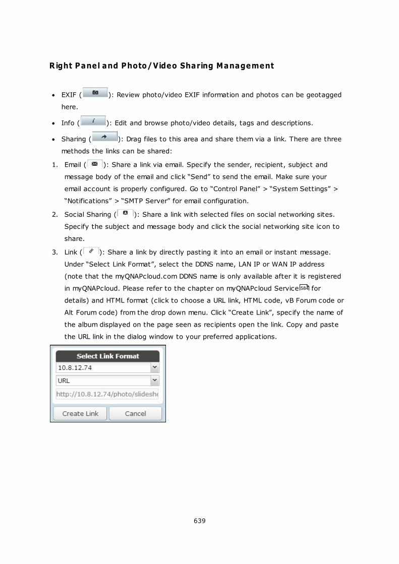
639
Right Panel and Photo/Video Sharing Management
EXIF ( ): Review photo/video EXIF information and photos can be geotagged
here.
Info ( ): Edit and browse photo/video details, tags and descriptions.
Sharing ( ): Drag files to this area and share them via a link. There are three
methods the links can be shared:
1. Email ( ): Share a link via email. Specify the sender, recipient, subject and
message body of the email and click “Send” to send the email. Make sure your
email account is properly configured. Go to “Control Panel” > “System Settings” >
“Notifications” > “SMTP Server” for email configuration.
2. Social Sharing ( ): Share a link with selected files on social networking sites.
Specify the subject and message body and click the social networking site icon to
share.
3. Link ( ): Share a link by directly pasting it into an email or instant message.
Under “Select Link Format”, select the DDNS name, LAN IP or WAN IP address
(note that the myQNAPcloud.com DDNS name is only available after it is registered
in myQNAPcloud. Please refer to the chapter on myQNAPcloud Service for
details) and HTML format (click to choose a URL link, HTML code, vB Forum code or
Alt Forum code) from the drop down menu. Click “Create Link”, specify the name of
the album displayed on the page seen as recipients open the link. Copy and paste
the URL link in the dialog window to your preferred applications.
584
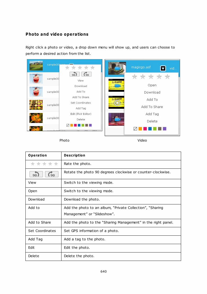
640
Photo and video operations
Right click a photo or video, a drop down menu will show up, and users can choose to
perform a desired action from the list.
Photo Video
Operation Description
Rate the photo.
Rotate the photo 90 degrees clockwise or counter-clockwise.
View Switch to the viewing mode.
Open Switch to the viewing mode.
Download Download the photo.
Add to Add the photo to an album, “Private Collection”, “Sharing
Management” or “Slideshow”.
Add to Share Add the photo to the “Sharing Management” in the right panel.
Set Coordinates Set GPS information of a photo.
Add Tag Add a tag to the photo.
Edit Edit the photo.
Delete Delete the photo.
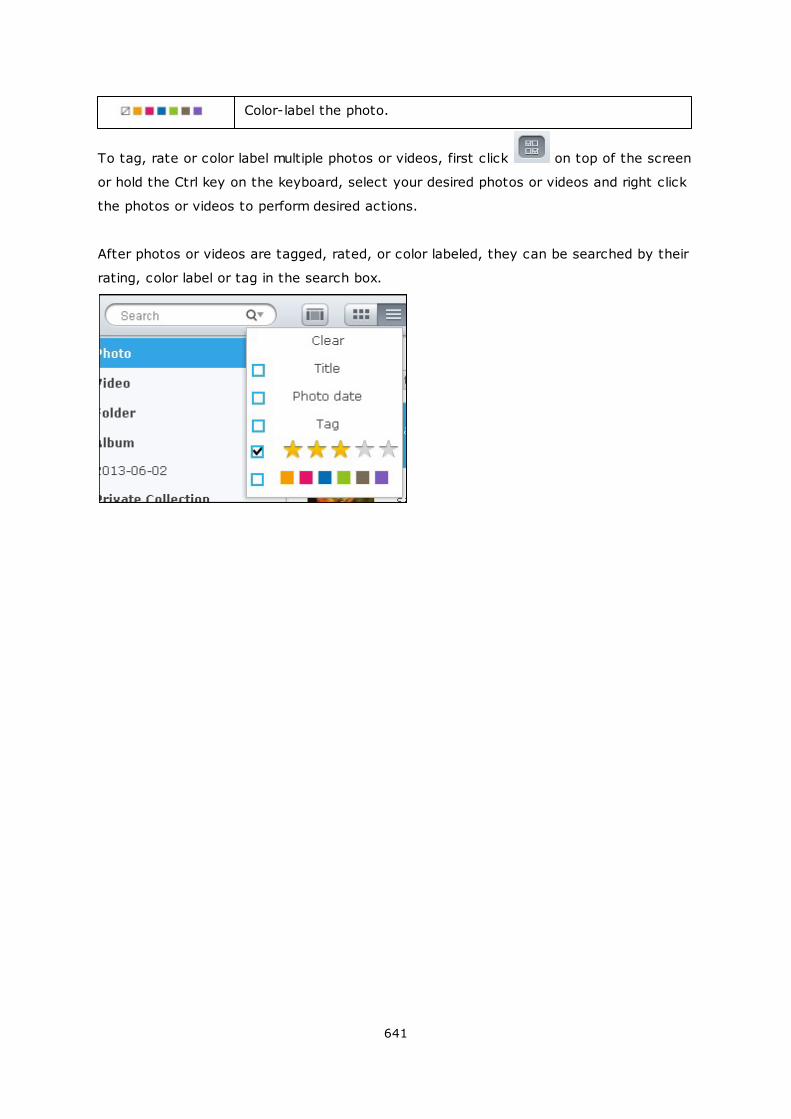
641
Color-label the photo.
To tag, rate or color label multiple photos or videos, first click on top of the screen
or hold the Ctrl key on the keyboard, select your desired photos or videos and right click
the photos or videos to perform desired actions.
After photos or videos are tagged, rated, or color labeled, they can be searched by their
rating, color label or tag in the search box.
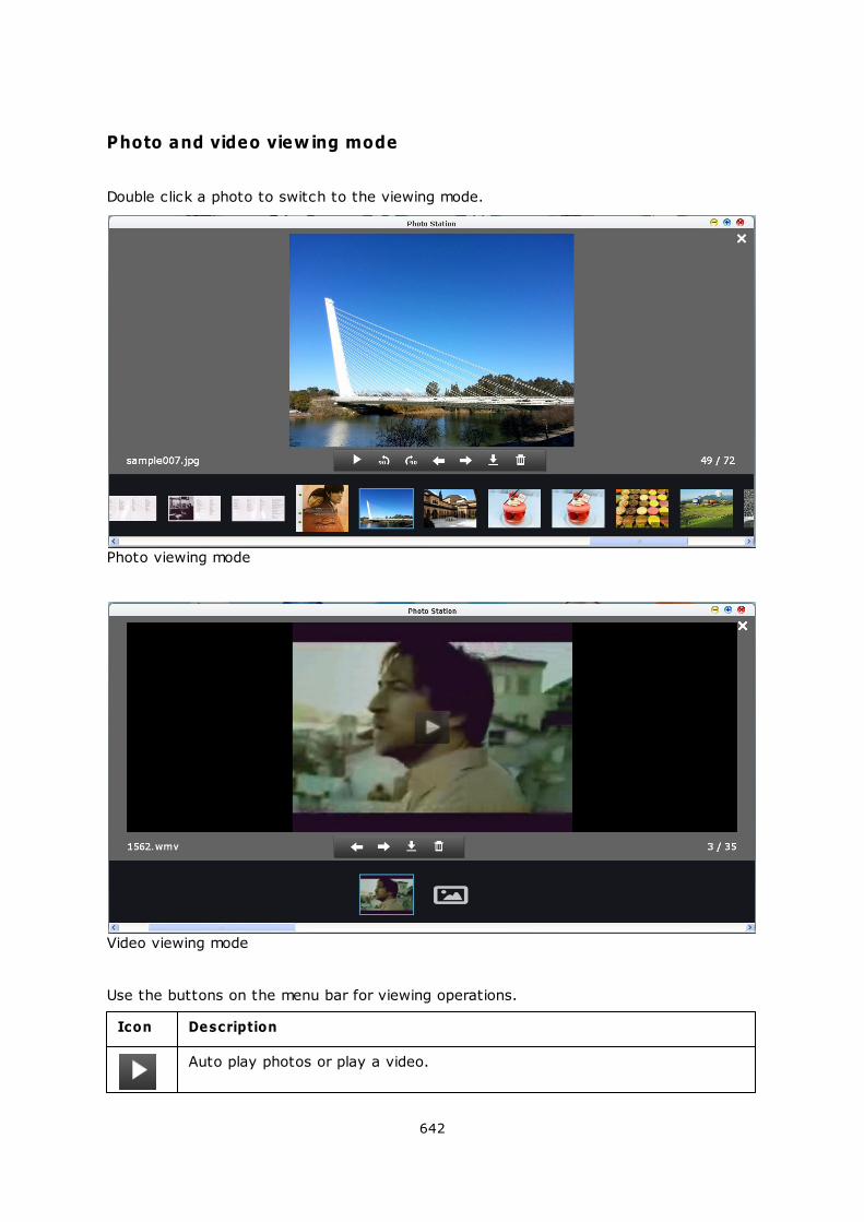
642
Photo and video view ing mode
Double click a photo to switch to the viewing mode.
Photo viewing mode
Video viewing mode
Use the buttons on the menu bar for viewing operations.
Icon Description
Auto play photos or play a video.
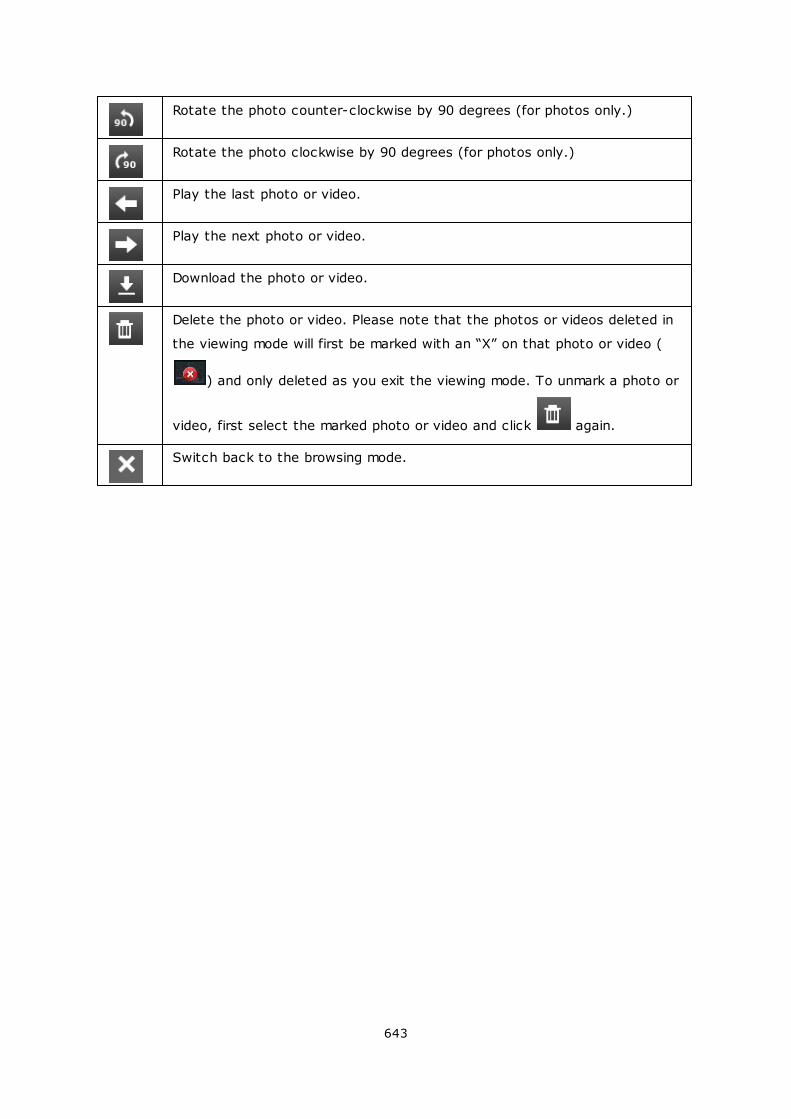
643
Rotate the photo counter-clockwise by 90 degrees (for photos only.)
Rotate the photo clockwise by 90 degrees (for photos only.)
Play the last photo or video.
Play the next photo or video.
Download the photo or video.
Delete the photo or video. Please note that the photos or videos deleted in
the viewing mode will first be marked with an “X” on that photo or video (
) and only deleted as you exit the viewing mode. To unmark a photo or
video, first select the marked photo or video and click again.
Switch back to the browsing mode.
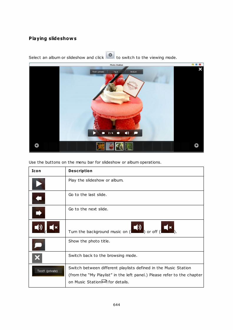
644
Playing slideshows
Select an album or slideshow and click to switch to the viewing mode.
Use the buttons on the menu bar for slideshow or album operations.
Icon Description
Play the slideshow or album.
Go to the last slide.
Go to the next slide.
/ Turn the background music on ( ) or off ( ).
Show the photo title.
Switch back to the browsing mode.
Switch between different playlists defined in the Music Station
(from the “My Playlist” in the left panel.) Please refer to the chapter
on Music Station for details. 648

645
Set a different slide transition effect.
Set the slide speed.
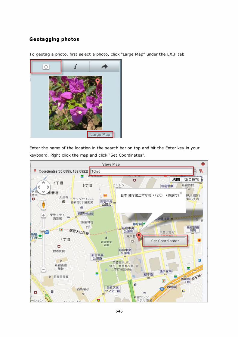
646
Geotagging photos
To geotag a photo, first select a photo, click “Large Map” under the EXIF tab.
Enter the name of the location in the search bar on top and hit the Enter key in your
keyboard. Right click the map and click “Set Coordinates”.

647
Media Library and Privacy Settings
Photo and video files in the Photo Station are listed according to shared folder privileges
(media folders) and settings in the Media Library. Photos and videos stored in the media
shared folders are only visible after the files are detected and scanned by the Media
Library. Users can store the files in their /home folder to hide them from other users. For
details on media folder settings, please refer to the chapter on Media Library . 446
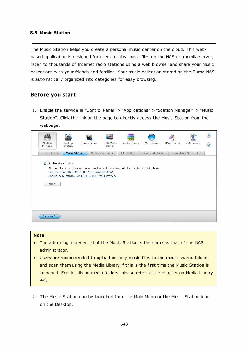
648
8.5 Music Station
The Music Station helps you create a personal music center on the cloud. This web-
based application is designed for users to play music files on the NAS or a media server,
listen to thousands of Internet radio stations using a web browser and share your music
collections with your friends and families. Your music collection stored on the Turbo NAS
is automatically organized into categories for easy browsing.
Before you start
1. Enable the service in “Control Panel” > “Applications” > “Station Manager” > “Music
Station”. Click the link on the page to directly access the Music Station from the
webpage.
Note:
The admin login credential of the Music Station is the same as that of the NAS
administrator.
Users are recommended to upload or copy music files to the media shared folders
and scan them using the Media Library if this is the first time the Music Station is
launched. For details on media folders, please refer to the chapter on Media Library
.
2. The Music Station can be launched from the Main Menu or the Music Station icon
on the Desktop.
446
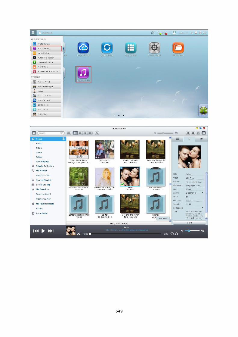
649
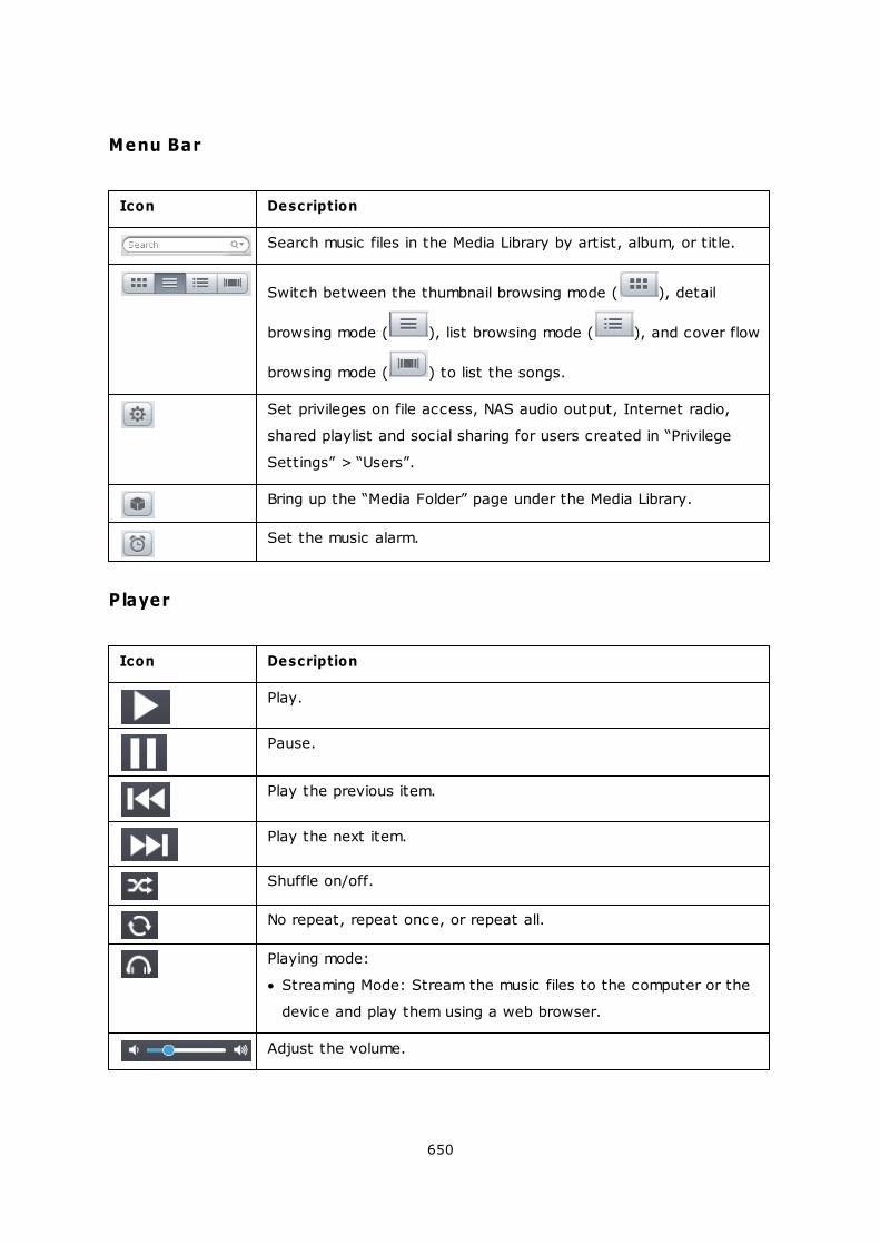
650
Menu Bar
Icon Description
Search music files in the Media Library by artist, album, or title.
Switch between the thumbnail browsing mode ( ), detail
browsing mode ( ), list browsing mode ( ), and cover flow
browsing mode ( ) to list the songs.
Set privileges on file access, NAS audio output, Internet radio,
shared playlist and social sharing for users created in “Privilege
Settings” > “Users”.
Bring up the “Media Folder” page under the Media Library.
Set the music alarm.
Player
Icon Description
Play.
Pause.
Play the previous item.
Play the next item.
Shuffle on/off.
No repeat, repeat once, or repeat all.
Playing mode:
Streaming Mode: Stream the music files to the computer or the
device and play them using a web browser.
Adjust the volume.
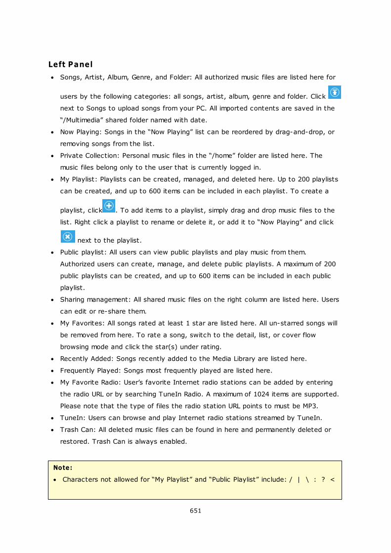
651
Left Panel
Songs, Artist, Album, Genre, and Folder: All authorized music files are listed here for
users by the following categories: all songs, artist, album, genre and folder. Click
next to Songs to upload songs from your PC. All imported contents are saved in the
“/Multimedia” shared folder named with date.
Now Playing: Songs in the “Now Playing” list can be reordered by drag-and-drop, or
removing songs from the list.
Private Collection: Personal music files in the “/home” folder are listed here. The
music files belong only to the user that is currently logged in.
My Playlist: Playlists can be created, managed, and deleted here. Up to 200 playlists
can be created, and up to 600 items can be included in each playlist. To create a
playlist, click . To add items to a playlist, simply drag and drop music files to the
list. Right click a playlist to rename or delete it, or add it to “Now Playing” and click
next to the playlist.
Public playlist: All users can view public playlists and play music from them.
Authorized users can create, manage, and delete public playlists. A maximum of 200
public playlists can be created, and up to 600 items can be included in each public
playlist.
Sharing management: All shared music files on the right column are listed here. Users
can edit or re-share them.
My Favorites: All songs rated at least 1 star are listed here. All un-starred songs will
be removed from here. To rate a song, switch to the detail, list, or cover flow
browsing mode and click the star(s) under rating.
Recently Added: Songs recently added to the Media Library are listed here.
Frequently Played: Songs most frequently played are listed here.
My Favorite Radio: User’s favorite Internet radio stations can be added by entering
the radio URL or by searching TuneIn Radio. A maximum of 1024 items are supported.
Please note that the type of files the radio station URL points to must be MP3.
TuneIn: Users can browse and play Internet radio stations streamed by TuneIn.
Trash Can: All deleted music files can be found in here and permanently deleted or
restored. Trash Can is always enabled.
Note:
Characters not allowed for “My Playlist” and “Public Playlist” include: / | \ : ? <

652
> * " ' and $.
Entries under “Recently Added” are listed based on the time they are scanned by
the Media Library.
The Music Station only supports the following file formats: MP3, OGG, WAV, AIFF,
AU, FLAC, M4A and APE.
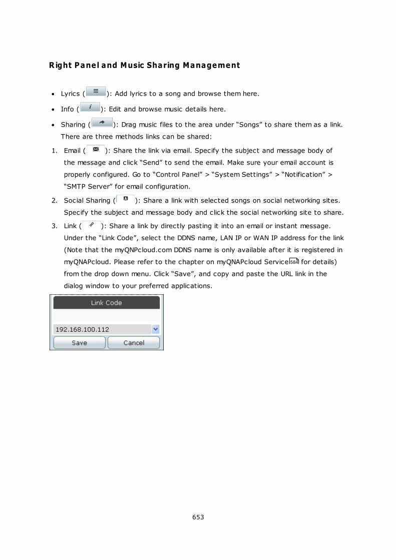
653
Right Panel and Music Sharing Management
Lyrics ( ): Add lyrics to a song and browse them here.
Info ( ): Edit and browse music details here.
Sharing ( ): Drag music files to the area under “Songs” to share them as a link.
There are three methods links can be shared:
1. Email ( ): Share the link via email. Specify the subject and message body of
the message and click “Send” to send the email. Make sure your email account is
properly configured. Go to “Control Panel” > “System Settings” > “Notification” >
“SMTP Server” for email configuration.
2. Social Sharing ( ): Share a link with selected songs on social networking sites.
Specify the subject and message body and click the social networking site to share.
3. Link ( ): Share a link by directly pasting it into an email or instant message.
Under the “Link Code”, select the DDNS name, LAN IP or WAN IP address for the link
(Note that the myQNPcloud.com DDNS name is only available after it is registered in
myQNAPcloud. Please refer to the chapter on myQNAPcloud Service for details)
from the drop down menu. Click “Save”, and copy and paste the URL link in the
dialog window to your preferred applications.
584
654
Media Library and Privacy Settings
Music files in the Music Station are listed according to shared folder privileges (media
folders) and settings in the Media Library. Music files stored in the shared folders are only
visible to users who have “Read/Write” or “Read Only” privileges to those shared folders,
and after the music files are detected and scanned by the Media Library. Users can store
music files in their “/home” folder to hide them from other users. For details on the media
folder settings, please refer to the chapter on Media Library .
Note:
Initially, shared folders are accessible to all users. To configure shared folder
privileges for each shared folder, please go to “Control Panel” > “Privilege
Settings” > “Users”.
Advanced Folder Permissions are not supported.
Go to “Control Panel” > “Applications” > “Media Library” for detailed settings in
the Media Library.
For configuration on the Media Library and privilege settings, please refer to the
chapter on Media Library .
446
446
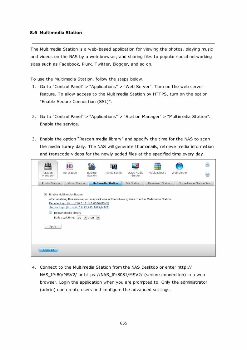
655
8.6 Multimedia Station
The Multimedia Station is a web-based application for viewing the photos, playing music
and videos on the NAS by a web browser, and sharing files to popular social networking
sites such as Facebook, Plurk, Twitter, Blogger, and so on.
To use the Multimedia Station, follow the steps below.
1. Go to “Control Panel” > “Applications” > “Web Server”. Turn on the web server
feature. To allow access to the Multimedia Station by HTTPS, turn on the option
“Enable Secure Connection (SSL)”.
2. Go to “Control Panel” > “Applications” > “Station Manager” > “Multimedia Station”.
Enable the service.
3. Enable the option “Rescan media library” and specify the time for the NAS to scan
the media library daily. The NAS will generate thumbnails, retrieve media information
and transcode videos for the newly added files at the specified time every day.
4. Connect to the Multimedia Station from the NAS Desktop or enter http://
NAS_IP:80/MSV2/ or https://NAS_IP:8081/MSV2/ (secure connection) in a web
browser. Login the application when you are prompted to. Only the administrator
(admin) can create users and configure the advanced settings.
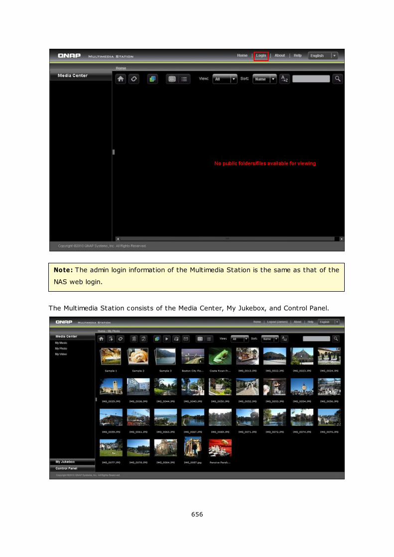
656
Note: The admin login information of the Multimedia Station is the same as that of the
NAS web login.
The Multimedia Station consists of the Media Center, My Jukebox, and Control Panel.
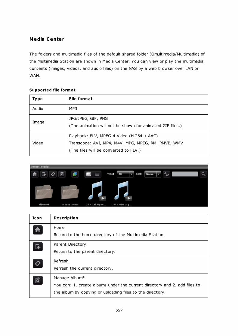
657
Media Center
The folders and multimedia files of the default shared folder (Qmultimedia/Multimedia) of
the Multimedia Station are shown in Media Center. You can view or play the multimedia
contents (images, videos, and audio files) on the NAS by a web browser over LAN or
WAN.
Supported file form at
Type File form at
Audio MP3
ImageJPG/JPEG, GIF, PNG
(The animation will not be shown for animated GIF files.)
Video
Playback: FLV, MPEG-4 Video (H.264 + AAC)
Transcode: AVI, MP4, M4V, MPG, MPEG, RM, RMVB, WMV
(The files will be converted to FLV.)
Icon Description
Home
Return to the home directory of the Multimedia Station.
Parent Directory
Return to the parent directory.
Refresh
Refresh the current directory.
Manage Album*
You can: 1. create albums under the current directory and 2. add files to
the album by copying or uploading files to the directory.
658
Set Album Cover*
You can set up the album cover for each album/directory by specifying one
photo in the album/directory.
Cooliris
Browse your photos in 3-dimensional way with Cooliris. You need to install
the Cooliris plug-in for the web browser.
Slide Show
Start the slide show. You can set up the photo frame, background music,
and animation in the slide show mode.
Publish*
Publish the chosen photos (max. 5 photos) to popular social networking
sites: Twitter, Facebook, MySpace, Plurk, Windows Live, or Blogger. Note
that the album must be set to public (Control Panel > Set Folder Public)
before it can be published, and the Multimedia Station must be accessible
from the Internet. It is suggested to set up the DDNS for the NAS before
using this feature.
Email*
Send photos (max. 5 photos) to friends by emails. Note that you have to
set up the SMTP server in the NAS administration console before using this
feature.
Thumbnails
Browse the files in thumbnail view (default).
Details
Browse the files in detailed view. It supports the functions: Open, Rename,
Delete, Download, and Full Image View.
Sort
Sort the files alphabetically in ascending or descending order.
Search
Search files within the current directory.
*These features can only be operated by the administrator.
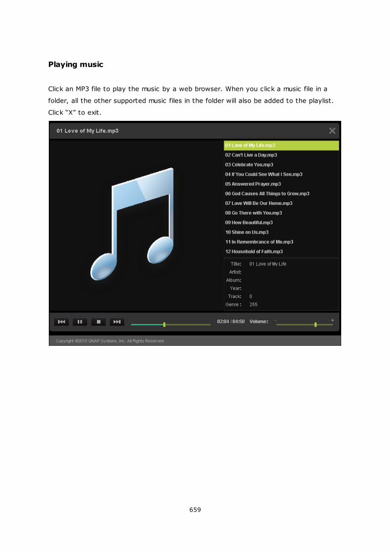
659
Playing music
Click an MP3 file to play the music by a web browser. When you click a music file in a
folder, all the other supported music files in the folder will also be added to the playlist.
Click “X” to exit.
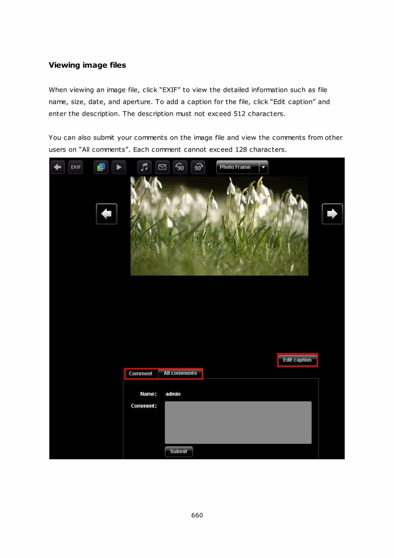
660
Viewing image files
When viewing an image file, click “EXIF” to view the detailed information such as file
name, size, date, and aperture. To add a caption for the file, click “Edit caption” and
enter the description. The description must not exceed 512 characters.
You can also submit your comments on the image file and view the comments from other
users on “All comments”. Each comment cannot exceed 128 characters.
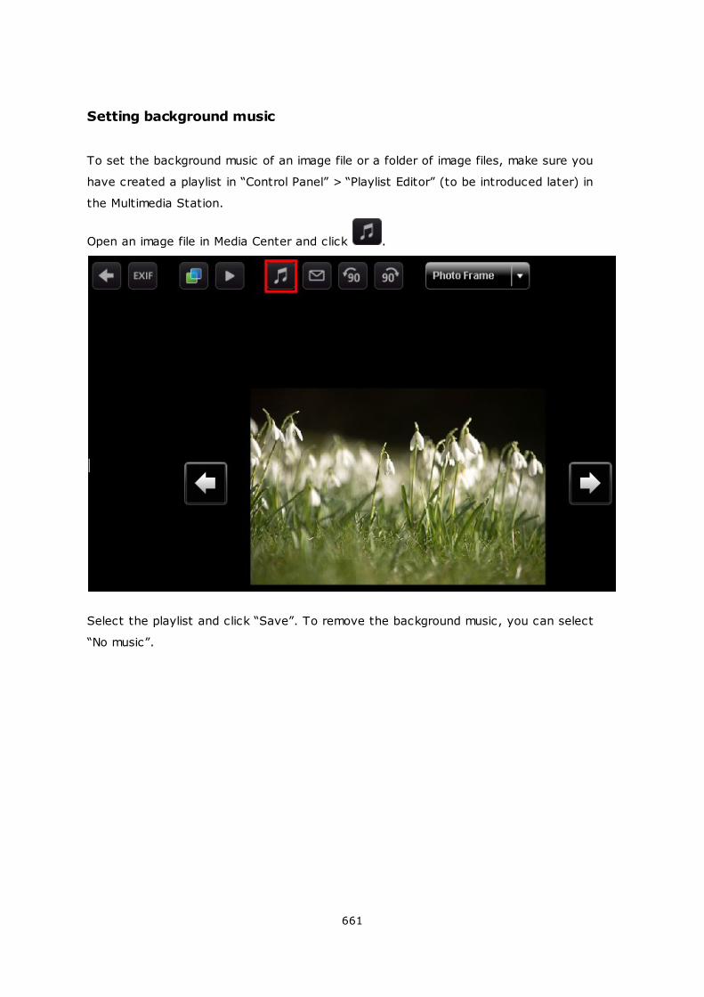
661
Setting background music
To set the background music of an image file or a folder of image files, make sure you
have created a playlist in “Control Panel” > “Playlist Editor” (to be introduced later) in
the Multimedia Station.
Open an image file in Media Center and click .
Select the playlist and click “Save”. To remove the background music, you can select
“No music”.
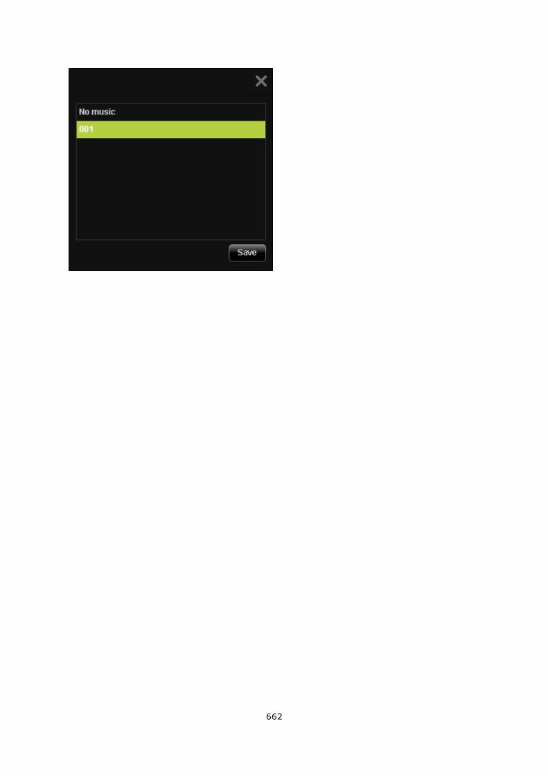
662
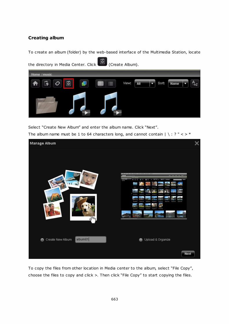
663
Creating album
To create an album (folder) by the web-based interface of the Multimedia Station, locate
the directory in Media Center. Click (Create Album).
Select “Create New Album” and enter the album name. Click “Next”.
The album name must be 1 to 64 characters long, and cannot contain | \ : ? " < > *
To copy the files from other location in Media center to the album, select “File Copy”,
choose the files to copy and click >. Then click “File Copy” to start copying the files.
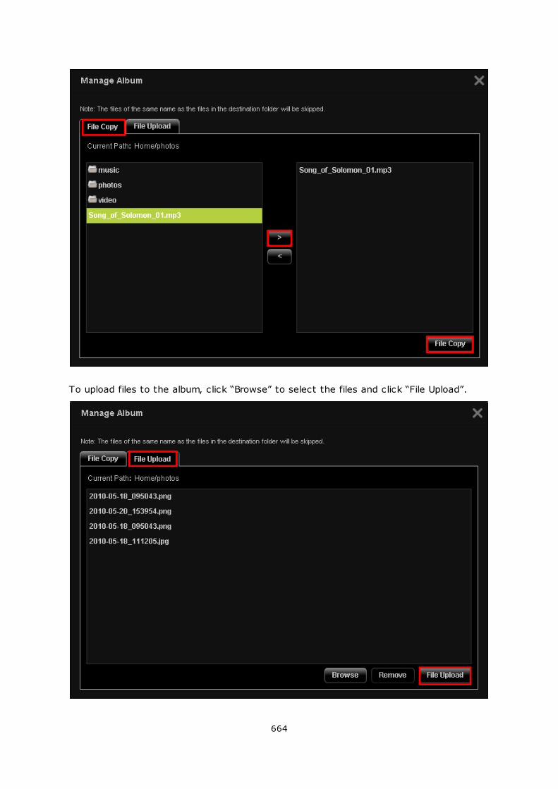
664
To upload files to the album, click “Browse” to select the files and click “File Upload”.
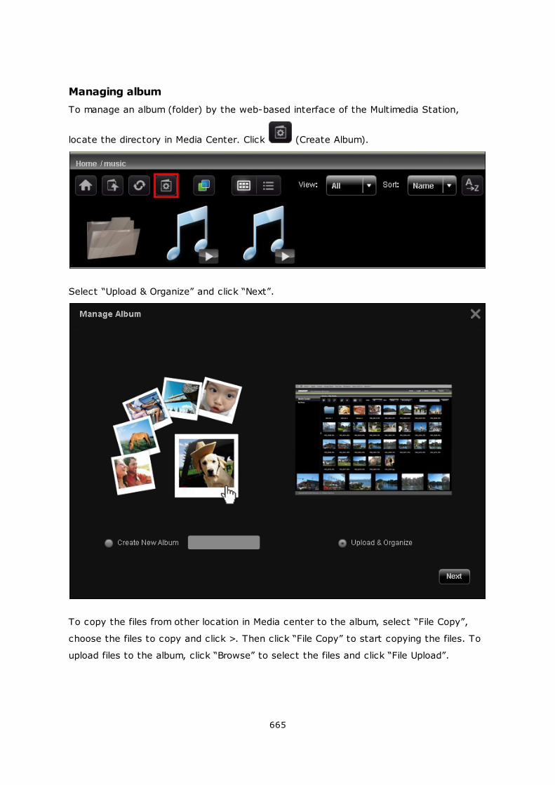
665
Managing album
To manage an album (folder) by the web-based interface of the Multimedia Station,
locate the directory in Media Center. Click (Create Album).
Select “Upload & Organize” and click “Next”.
To copy the files from other location in Media center to the album, select “File Copy”,
choose the files to copy and click >. Then click “File Copy” to start copying the files. To
upload files to the album, click “Browse” to select the files and click “File Upload”.
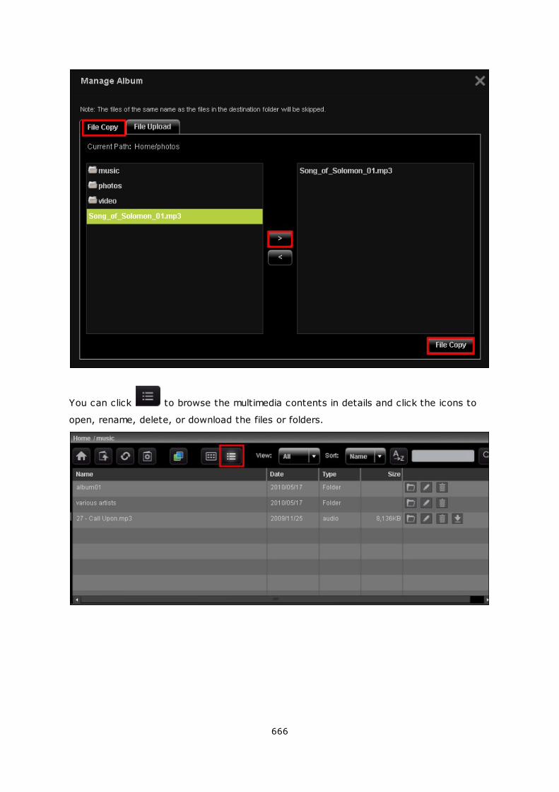
666
You can click to browse the multimedia contents in details and click the icons to
open, rename, delete, or download the files or folders.
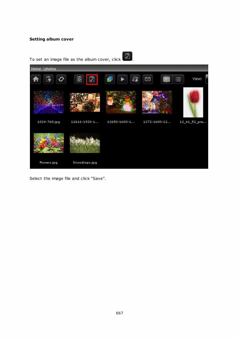
667
Setting album cover
To set an image file as the album cover, click .
Select the image file and click “Save”.
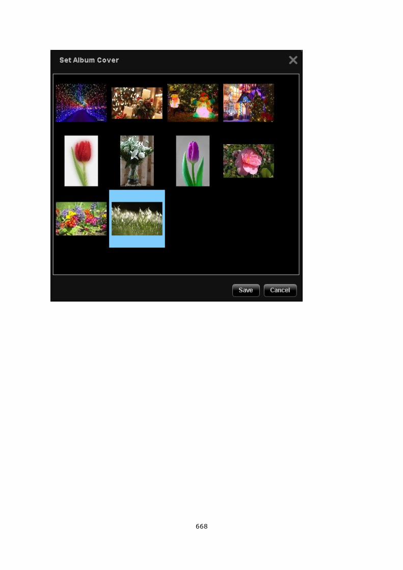
668
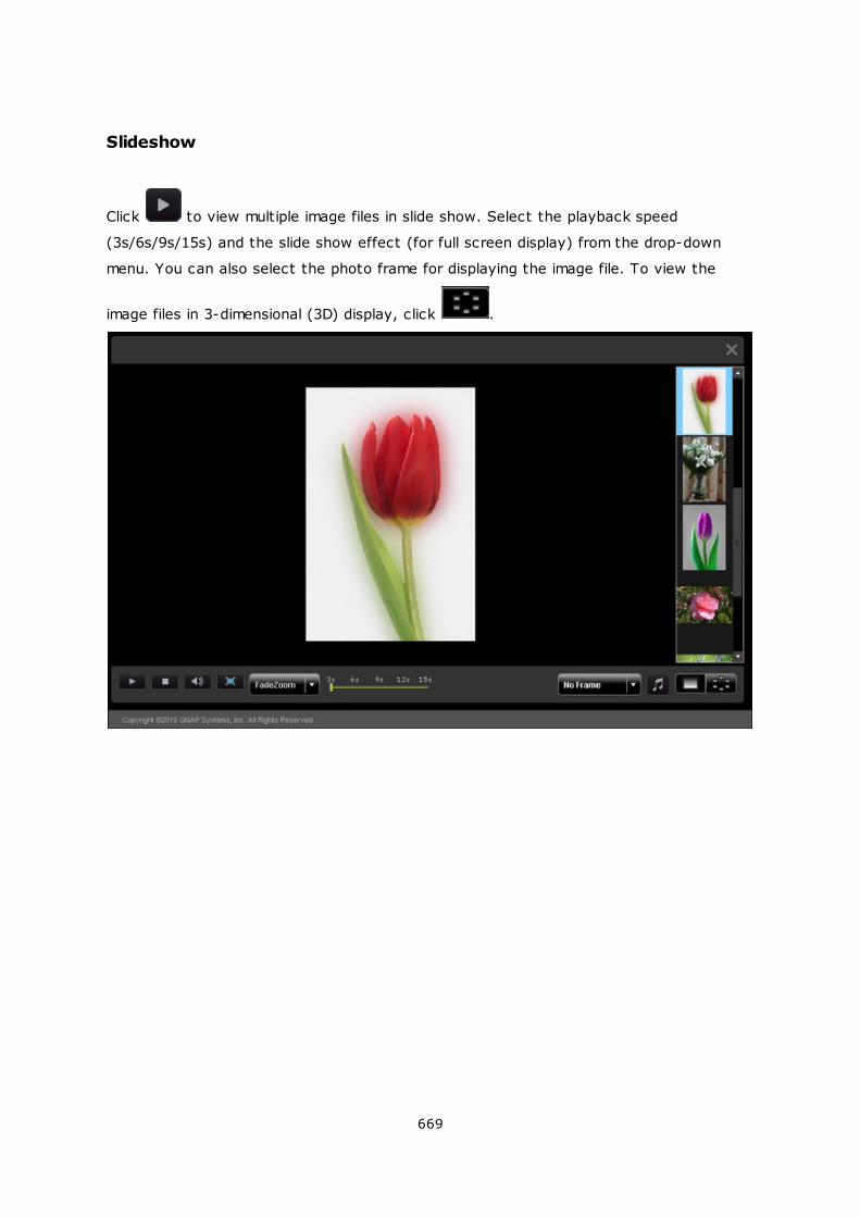
669
Slideshow
Click to view multiple image files in slide show. Select the playback speed
(3s/6s/9s/15s) and the slide show effect (for full screen display) from the drop-down
menu. You can also select the photo frame for displaying the image file. To view the
image files in 3-dimensional (3D) display, click .
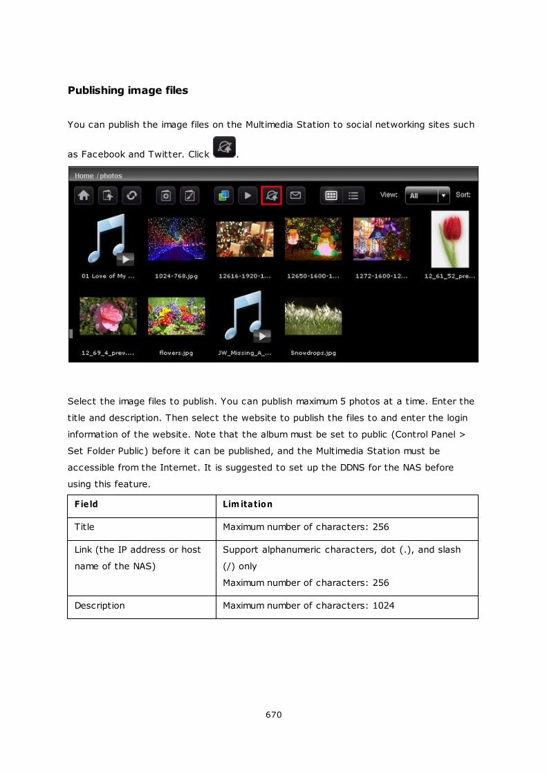
670
Publishing image files
You can publish the image files on the Multimedia Station to social networking sites such
as Facebook and Twitter. Click .
Select the image files to publish. You can publish maximum 5 photos at a time. Enter the
title and description. Then select the website to publish the files to and enter the login
information of the website. Note that the album must be set to public (Control Panel >
Set Folder Public) before it can be published, and the Multimedia Station must be
accessible from the Internet. It is suggested to set up the DDNS for the NAS before
using this feature.
Field Lim itation
Title Maximum number of characters: 256
Link (the IP address or host
name of the NAS)
Support alphanumeric characters, dot (.), and slash
(/) only
Maximum number of characters: 256
Description Maximum number of characters: 1024
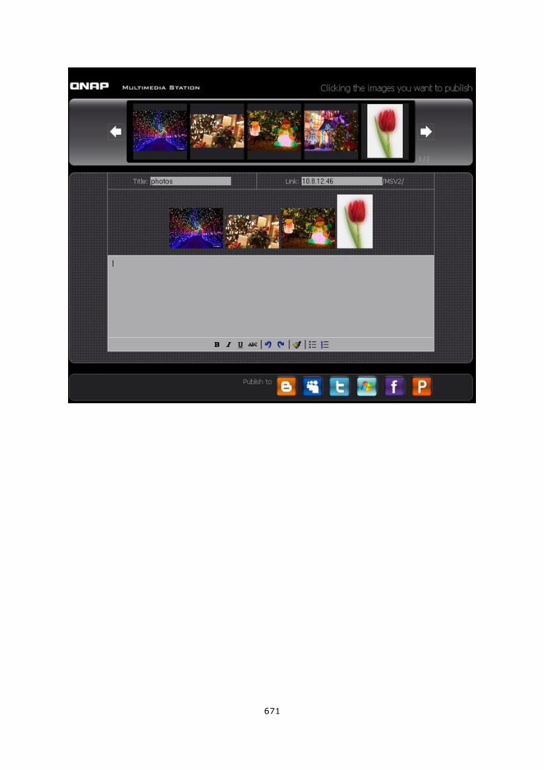
671
672
Emailing image files
To email the image files, make sure SMTP server settings have been correctly configured
on the NAS. Click .
Enter the information and click “Send”.
Field Lim itation
Subject Maximum number of characters: 128
My Name The name only supports alphabets (A-Z and a-z),
numbers (0-9), dash (-), and underscore (_)
My Email Maximum number of characters: 128
Friend's Name Maximum number of characters: 128
Friend's Email Maximum number of characters: 128
Message Maximum number of characters: 1024
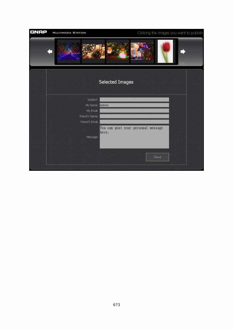
673
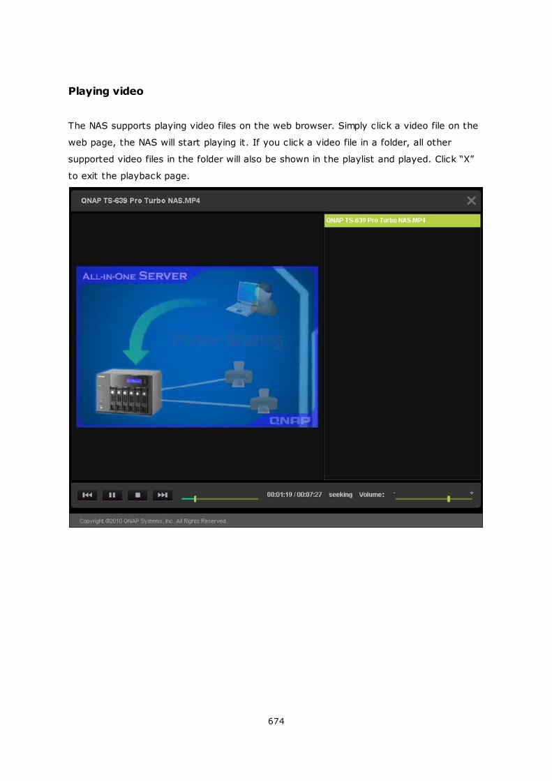
674
Playing video
The NAS supports playing video files on the web browser. Simply click a video file on the
web page, the NAS will start playing it. If you click a video file in a folder, all other
supported video files in the folder will also be shown in the playlist and played. Click “X”
to exit the playback page.
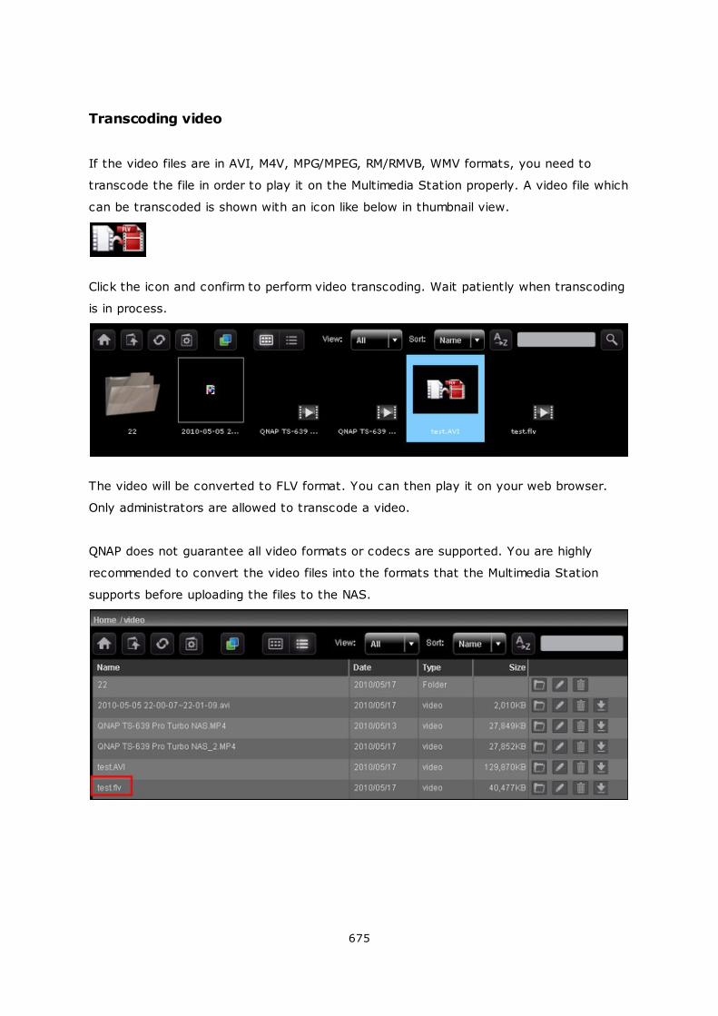
675
Transcoding video
If the video files are in AVI, M4V, MPG/MPEG, RM/RMVB, WMV formats, you need to
transcode the file in order to play it on the Multimedia Station properly. A video file which
can be transcoded is shown with an icon like below in thumbnail view.
Click the icon and confirm to perform video transcoding. Wait patiently when transcoding
is in process.
The video will be converted to FLV format. You can then play it on your web browser.
Only administrators are allowed to transcode a video.
QNAP does not guarantee all video formats or codecs are supported. You are highly
recommended to convert the video files into the formats that the Multimedia Station
supports before uploading the files to the NAS.
676
My Jukebox
You can create playlists of music files and play them in My Jukebox. The album art and
its information will be read from the ID3 tag automatically if applicable.
To create or edit your own playlist for My Jukebox, go to “Control Panel” > “Playlist
Editor”. Note that only the administrators can edit the playlists. The playlists in My
Jukebox will be shared with all the users of the Multimedia Station.
Control Panel
User Management:
You can create multiple user accounts on the Multimedia Station. Note that the user
accounts created here are different from the system accounts you create on NAS
(Privilege Settings> Users). Click “Add User” to create a user. The maximum number of
users the Multimedia Station supports is 128, including “admin”.
Enter the user information. The username only supports alphabets (A-Z and a-z),
numbers (0-9), dash (-), and underscore (_). The username cannot exceed 32
characters.
Specify whether or not the user is an administrator and the folders that the user can or
cannot access. Click “Save”. Note that the password must be 1 to 16 characters long. It
can only contain A-Z, a-z, 0-9, -, !, @, #, $, %, _.
677
The users are shown on the list. You can edit the user information, delete the user, or
change the login password. Note that the default account “admin” cannot be deleted.
678
Changing Password
You can change the administrator password in this section. The password must be 1 to
16 characters long. The password can only contain A-Z, a-z, 0-9, -, !, @, #, $, %, _.
Playlist Editor
To create a playlist, enter Playlist Editor. Select an existing playlist from the drop down
menu or click “Add” to create a playlist.
Next, select the music files from the left column (folders on the Multimedia Station) and
click > to add the files to the playlist. Click “Save” and then “Close”.
After creating the playlist, you can play it in My Jukebox.
Maximum number of characters in a
playlist
24
Maximum number of songs in a playlist 512
Maximum number of playlists 128
679
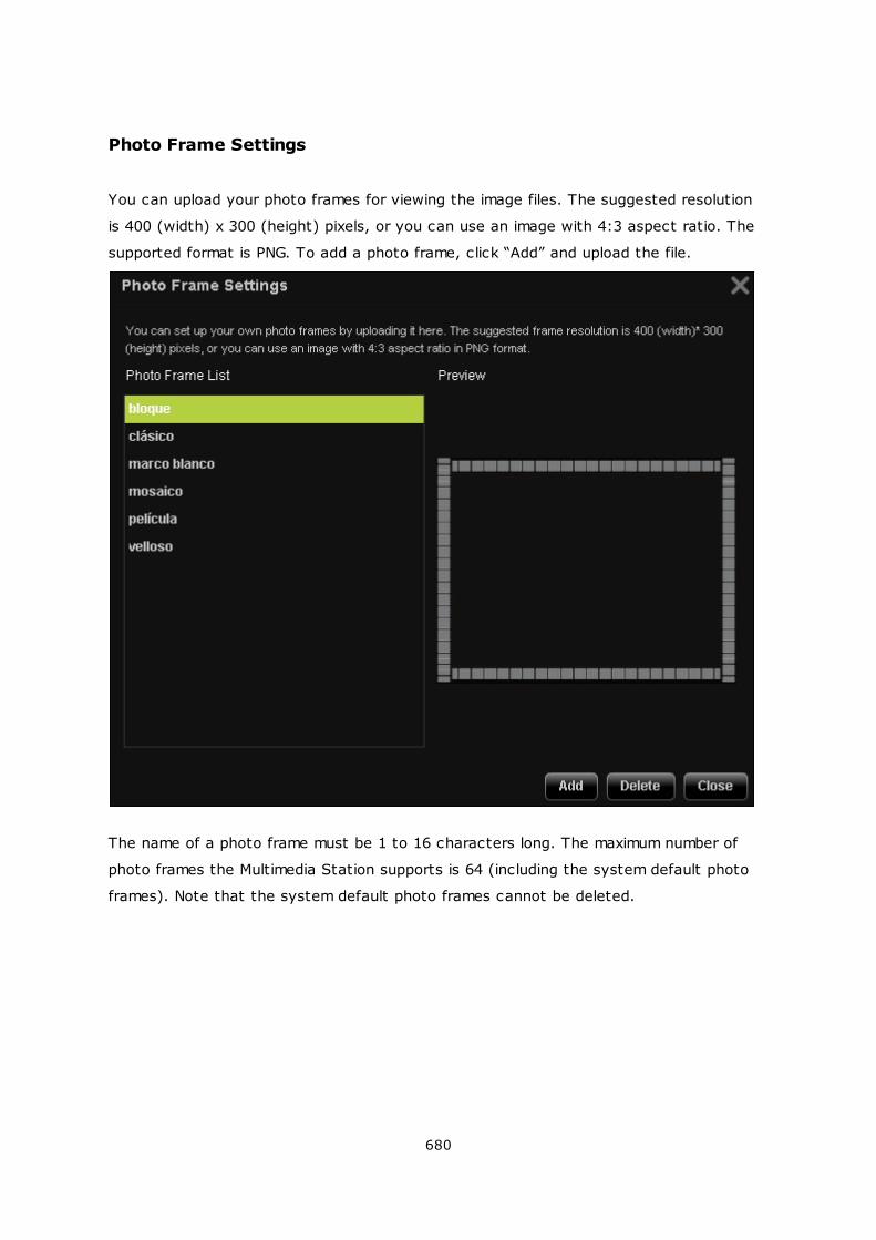
680
Photo Frame Settings
You can upload your photo frames for viewing the image files. The suggested resolution
is 400 (width) x 300 (height) pixels, or you can use an image with 4:3 aspect ratio. The
supported format is PNG. To add a photo frame, click “Add” and upload the file.
The name of a photo frame must be 1 to 16 characters long. The maximum number of
photo frames the Multimedia Station supports is 64 (including the system default photo
frames). Note that the system default photo frames cannot be deleted.
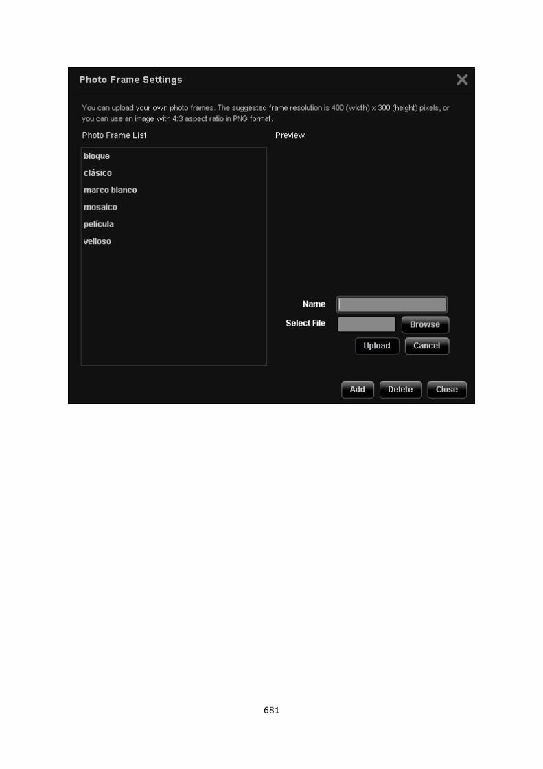
681
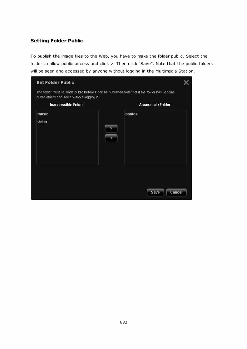
682
Setting Folder Public
To publish the image files to the Web, you have to make the folder public. Select the
folder to allow public access and click >. Then click “Save”. Note that the public folders
will be seen and accessed by anyone without logging in the Multimedia Station.
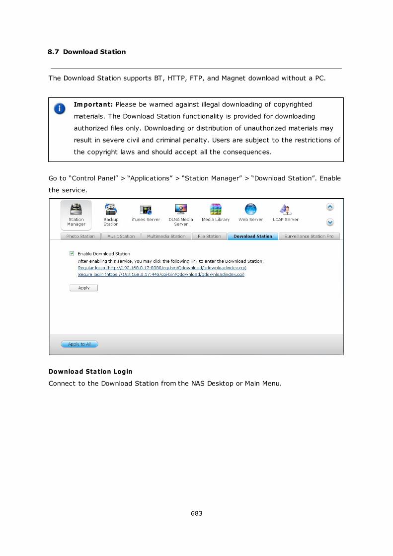
683
8.7 Download Station
The Download Station supports BT, HTTP, FTP, and Magnet download without a PC.
Im portant: Please be warned against illegal downloading of copyrighted
materials. The Download Station functionality is provided for downloading
authorized files only. Downloading or distribution of unauthorized materials may
result in severe civil and criminal penalty. Users are subject to the restrictions of
the copyright laws and should accept all the consequences.
Go to “Control Panel” > “Applications” > “Station Manager” > “Download Station”. Enable
the service.
Download Station Login
Connect to the Download Station from the NAS Desktop or Main Menu.
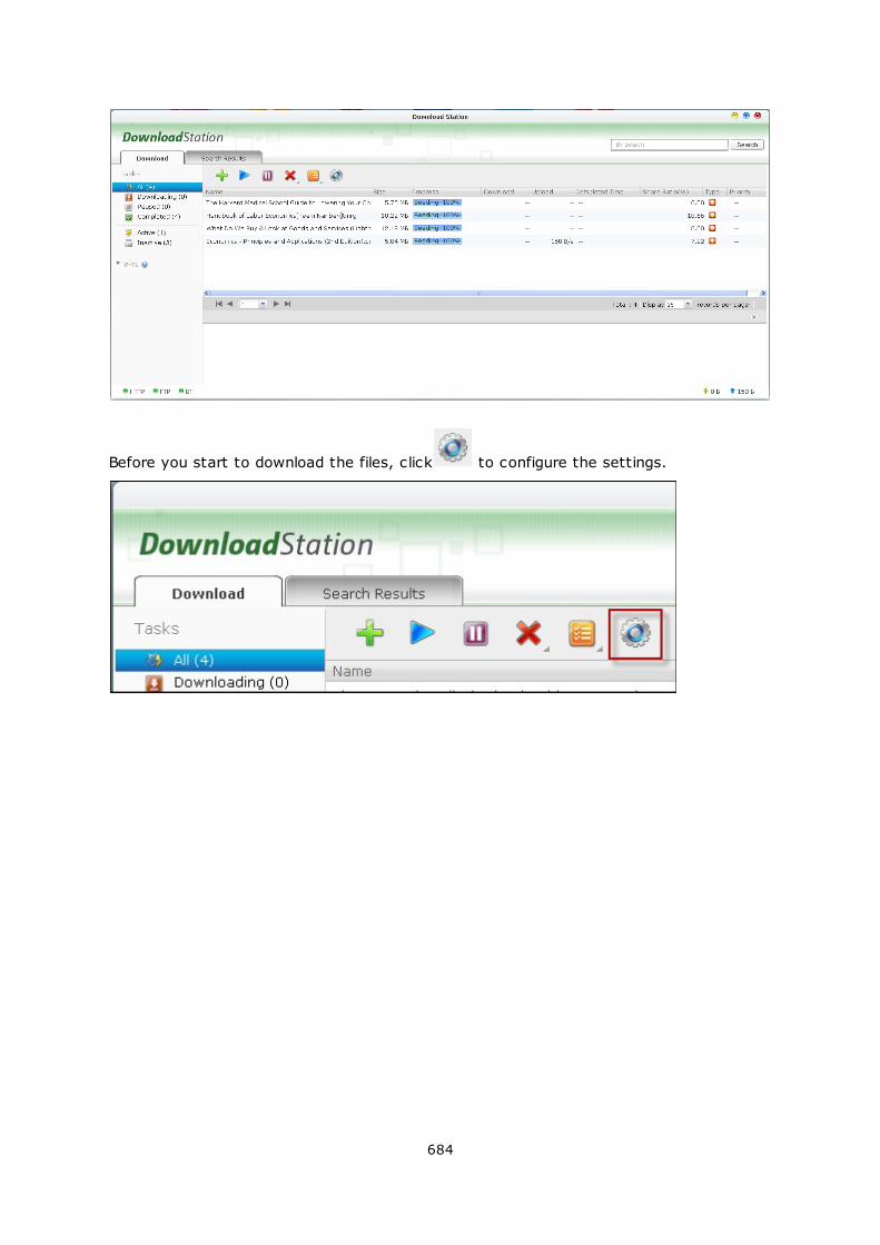
684
Before you start to download the files, click to configure the settings.
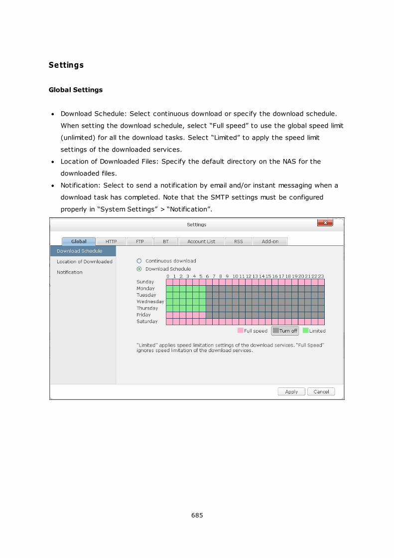
685
Settings
Global Settings
Download Schedule: Select continuous download or specify the download schedule.
When setting the download schedule, select “Full speed” to use the global speed limit
(unlimited) for all the download tasks. Select “Limited” to apply the speed limit
settings of the downloaded services.
Location of Downloaded Files: Specify the default directory on the NAS for the
downloaded files.
Notification: Select to send a notification by email and/or instant messaging when a
download task has completed. Note that the SMTP settings must be configured
properly in “System Settings” > “Notification”.
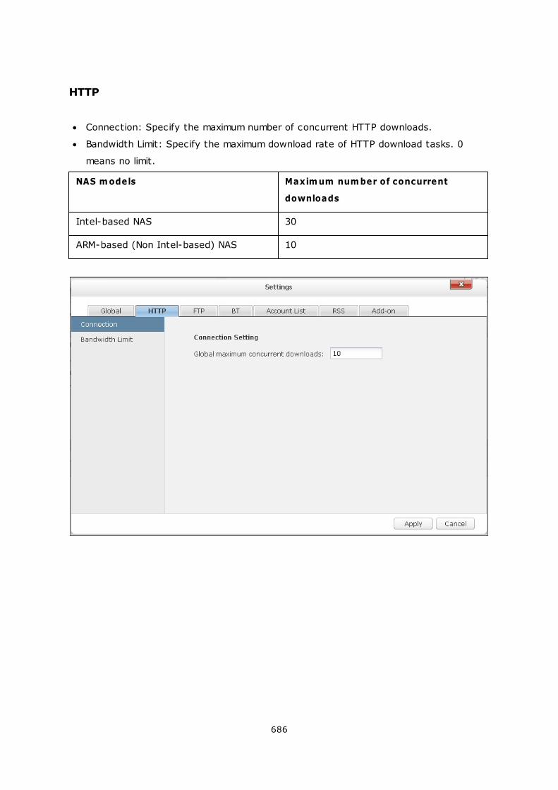
686
HTTP
Connection: Specify the maximum number of concurrent HTTP downloads.
Bandwidth Limit: Specify the maximum download rate of HTTP download tasks. 0
means no limit.
NAS m odels Maxim um num ber of concurrent
downloads
Intel-based NAS 30
ARM-based (Non Intel-based) NAS 10
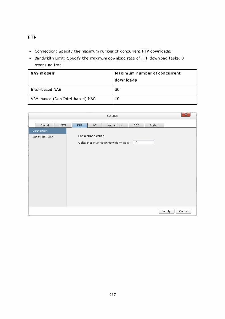
687
FTP
Connection: Specify the maximum number of concurrent FTP downloads.
Bandwidth Limit: Specify the maximum download rate of FTP download tasks. 0
means no limit.
NAS m odels Maxim um num ber of concurrent
downloads
Intel-based NAS 30
ARM-based (Non Intel-based) NAS 10
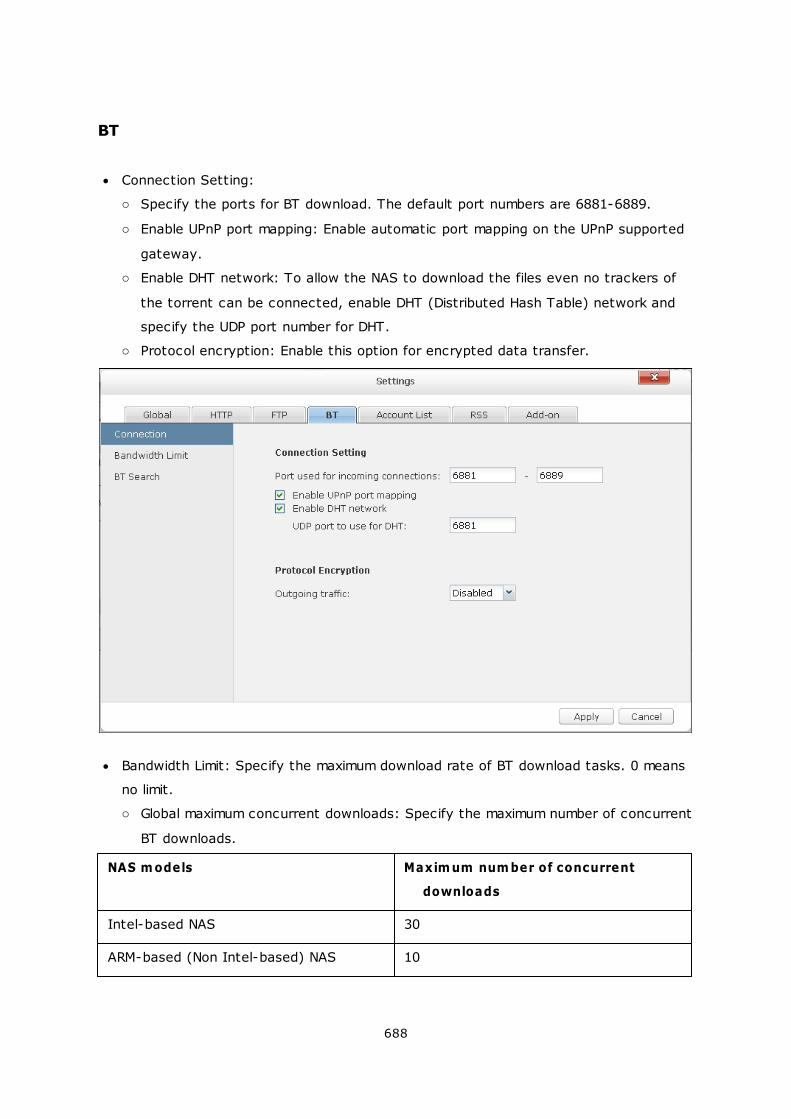
688
BT
Connection Setting:
o Specify the ports for BT download. The default port numbers are 6881-6889.
o Enable UPnP port mapping: Enable automatic port mapping on the UPnP supported
gateway.
o Enable DHT network: To allow the NAS to download the files even no trackers of
the torrent can be connected, enable DHT (Distributed Hash Table) network and
specify the UDP port number for DHT.
o Protocol encryption: Enable this option for encrypted data transfer.
Bandwidth Limit: Specify the maximum download rate of BT download tasks. 0 means
no limit.
o Global maximum concurrent downloads: Specify the maximum number of concurrent
BT downloads.
NAS m odels Maxim um num ber of concurrent
downloads
Intel-based NAS 30
ARM-based (Non Intel-based) NAS 10
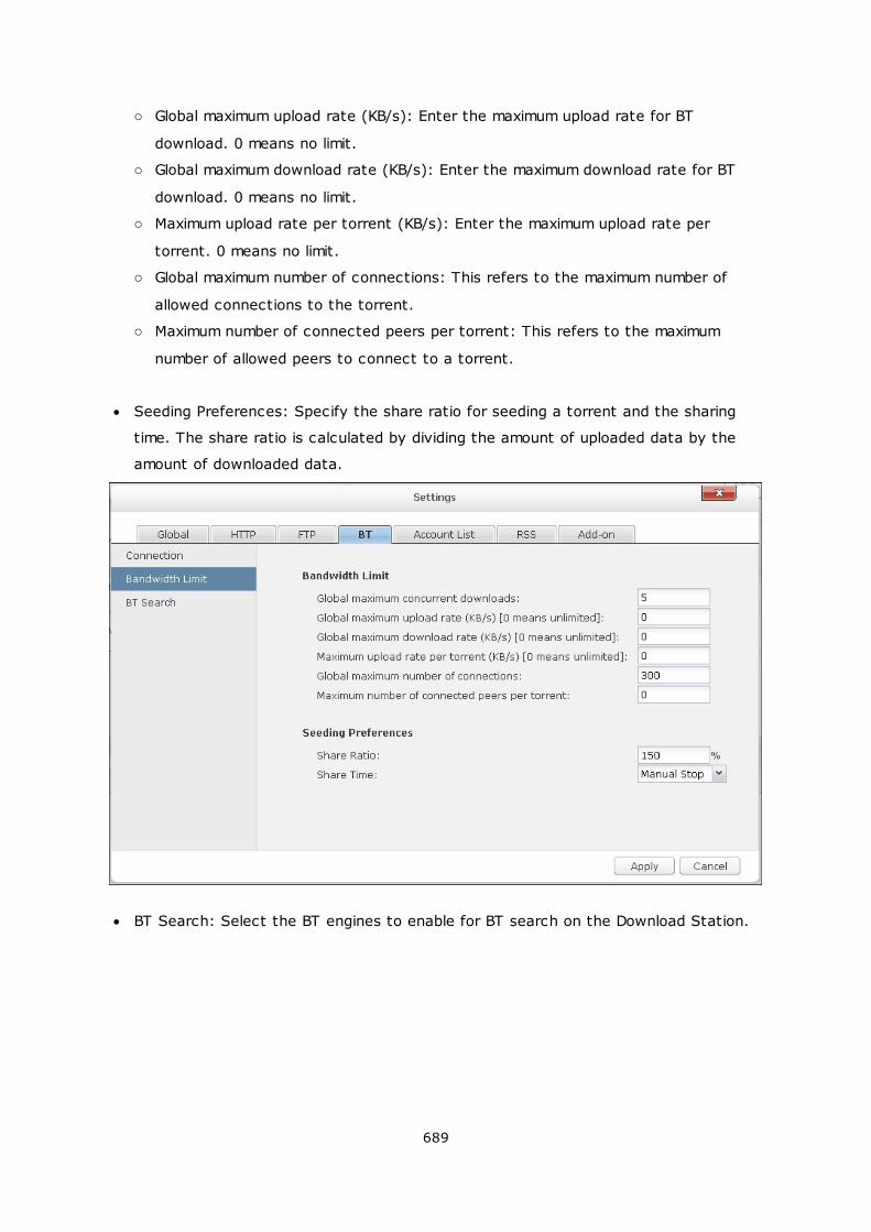
689
o Global maximum upload rate (KB/s): Enter the maximum upload rate for BT
download. 0 means no limit.
o Global maximum download rate (KB/s): Enter the maximum download rate for BT
download. 0 means no limit.
o Maximum upload rate per torrent (KB/s): Enter the maximum upload rate per
torrent. 0 means no limit.
o Global maximum number of connections: This refers to the maximum number of
allowed connections to the torrent.
o Maximum number of connected peers per torrent: This refers to the maximum
number of allowed peers to connect to a torrent.
Seeding Preferences: Specify the share ratio for seeding a torrent and the sharing
time. The share ratio is calculated by dividing the amount of uploaded data by the
amount of downloaded data.
BT Search: Select the BT engines to enable for BT search on the Download Station.
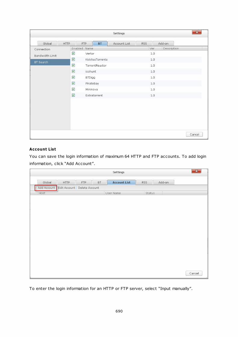
690
Account List
You can save the login information of maximum 64 HTTP and FTP accounts. To add login
information, click “Add Account”.
To enter the login information for an HTTP or FTP server, select “Input manually”.
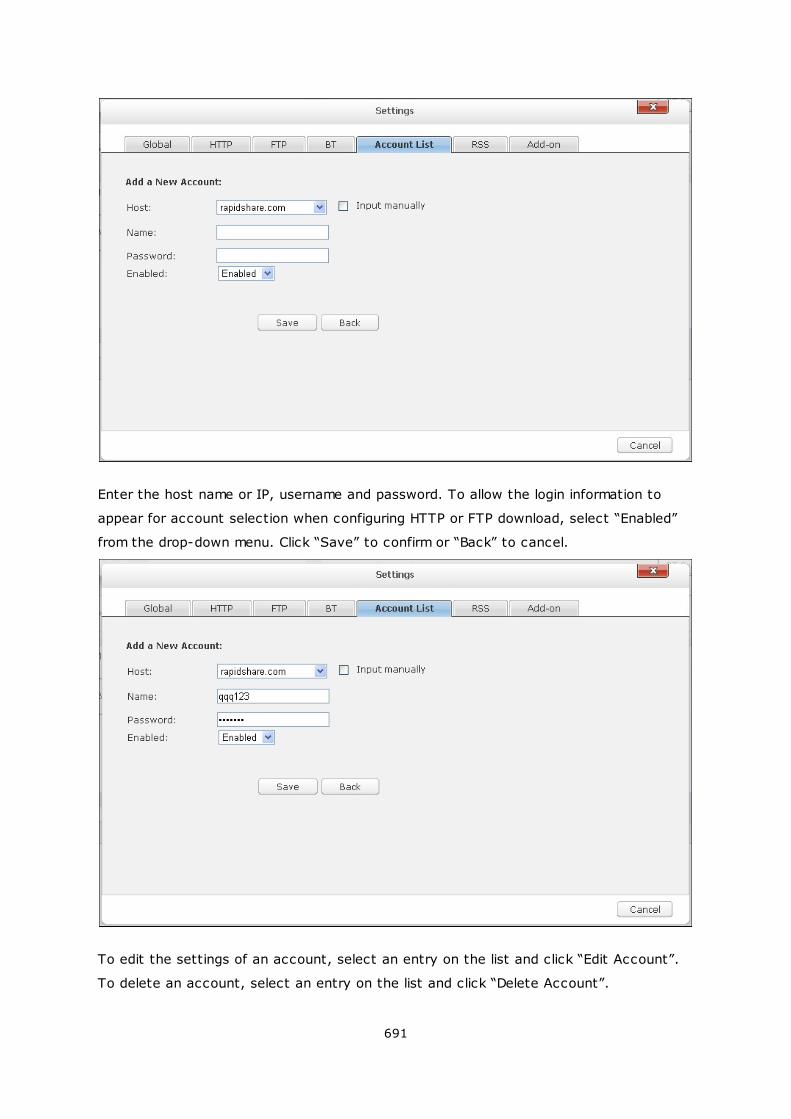
691
Enter the host name or IP, username and password. To allow the login information to
appear for account selection when configuring HTTP or FTP download, select “Enabled”
from the drop-down menu. Click “Save” to confirm or “Back” to cancel.
To edit the settings of an account, select an entry on the list and click “Edit Account”.
To delete an account, select an entry on the list and click “Delete Account”.
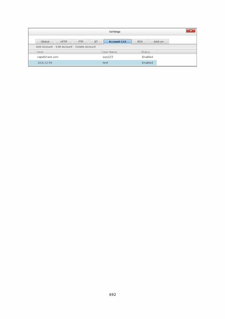
692
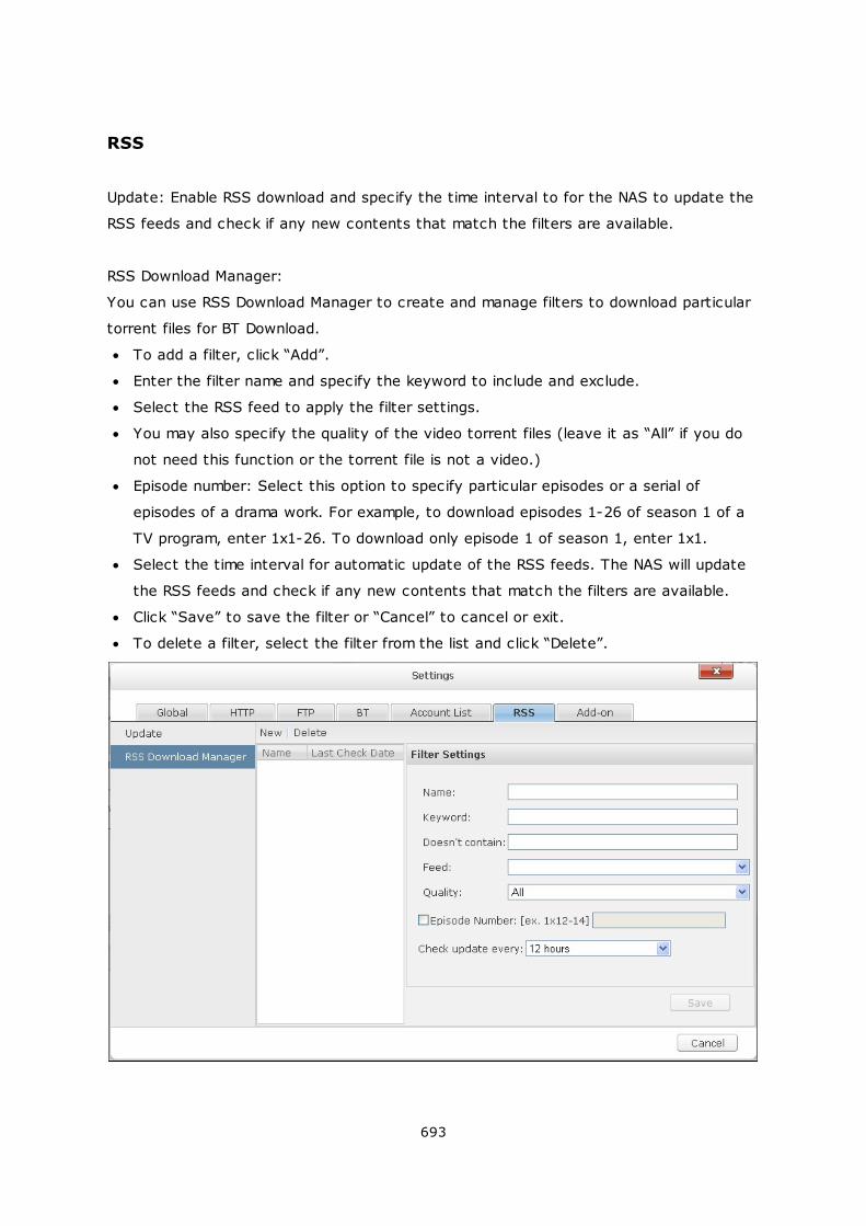
693
RSS
Update: Enable RSS download and specify the time interval to for the NAS to update the
RSS feeds and check if any new contents that match the filters are available.
RSS Download Manager:
You can use RSS Download Manager to create and manage filters to download particular
torrent files for BT Download.
To add a filter, click “Add”.
Enter the filter name and specify the keyword to include and exclude.
Select the RSS feed to apply the filter settings.
You may also specify the quality of the video torrent files (leave it as “All” if you do
not need this function or the torrent file is not a video.)
Episode number: Select this option to specify particular episodes or a serial of
episodes of a drama work. For example, to download episodes 1-26 of season 1 of a
TV program, enter 1x1-26. To download only episode 1 of season 1, enter 1x1.
Select the time interval for automatic update of the RSS feeds. The NAS will update
the RSS feeds and check if any new contents that match the filters are available.
Click “Save” to save the filter or “Cancel” to cancel or exit.
To delete a filter, select the filter from the list and click “Delete”.

694
Add-on
To download the YouTube videos by the HappyGet add-on to the NAS, enable the
website subscription service. For more details, please see the application note: http://
www.qnap.com/en/index.php?sn=5319&lang=en
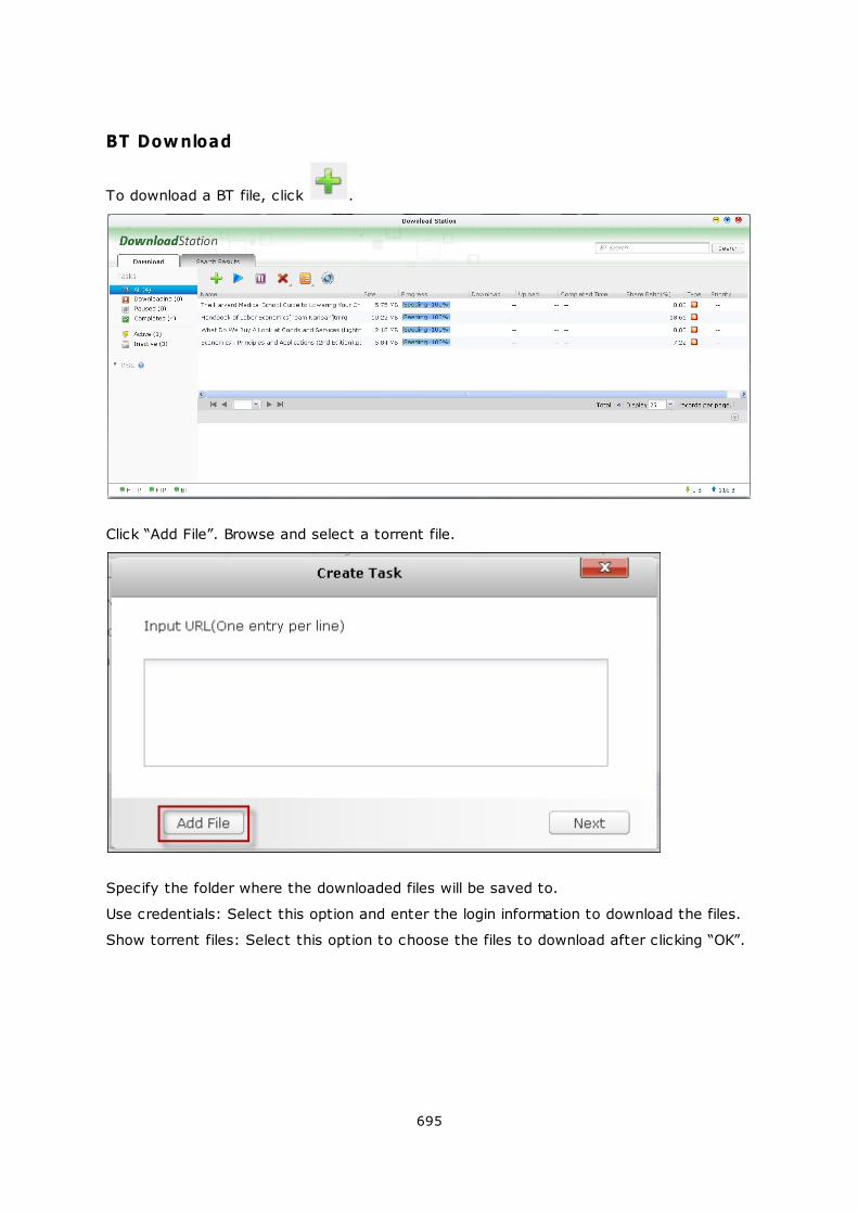
695
BT Download
To download a BT file, click .
Click “Add File”. Browse and select a torrent file.
Specify the folder where the downloaded files will be saved to.
Use credentials: Select this option and enter the login information to download the files.
Show torrent files: Select this option to choose the files to download after clicking “OK”.
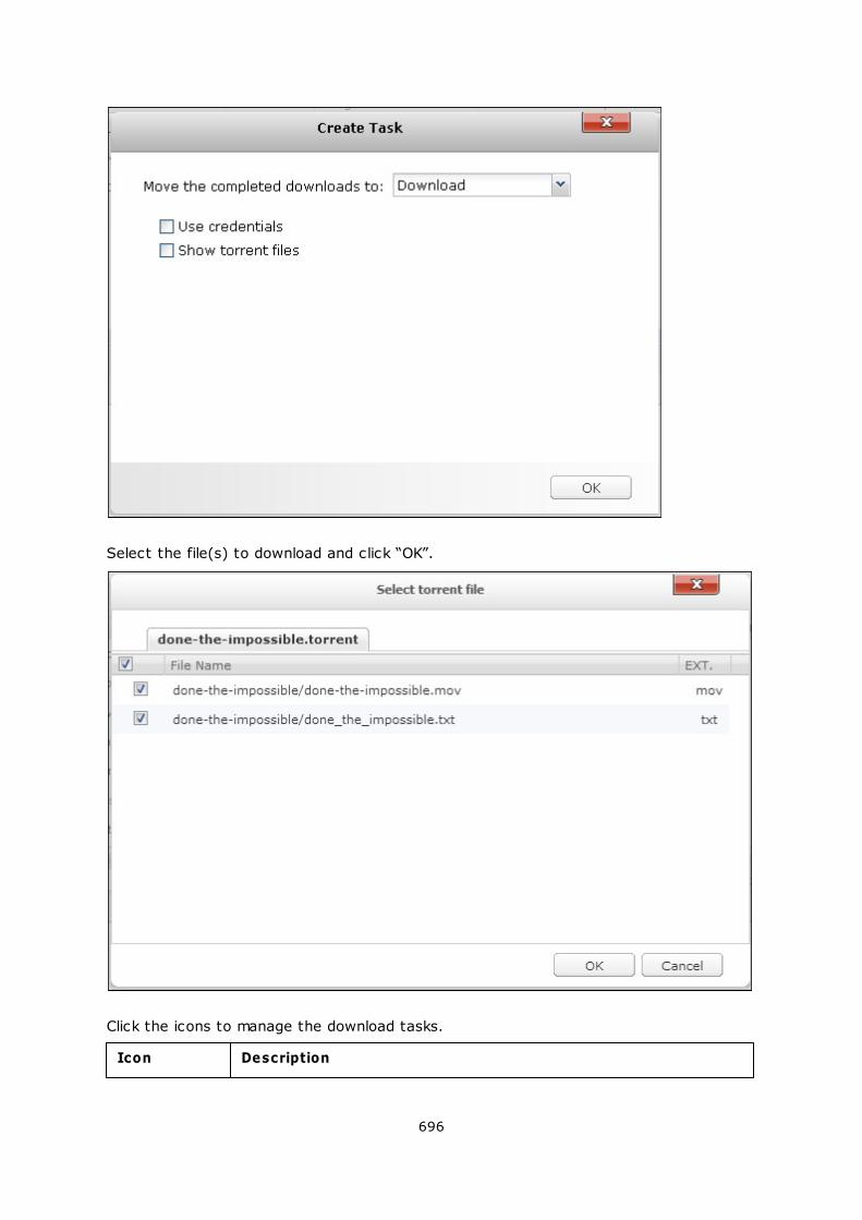
696
Select the file(s) to download and click “OK”.
Click the icons to manage the download tasks.
Icon Description
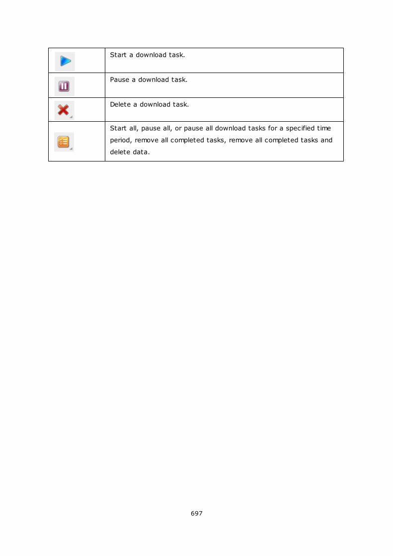
697
Start a download task.
Pause a download task.
Delete a download task.
Start all, pause all, or pause all download tasks for a specified time
period, remove all completed tasks, remove all completed tasks and
delete data.
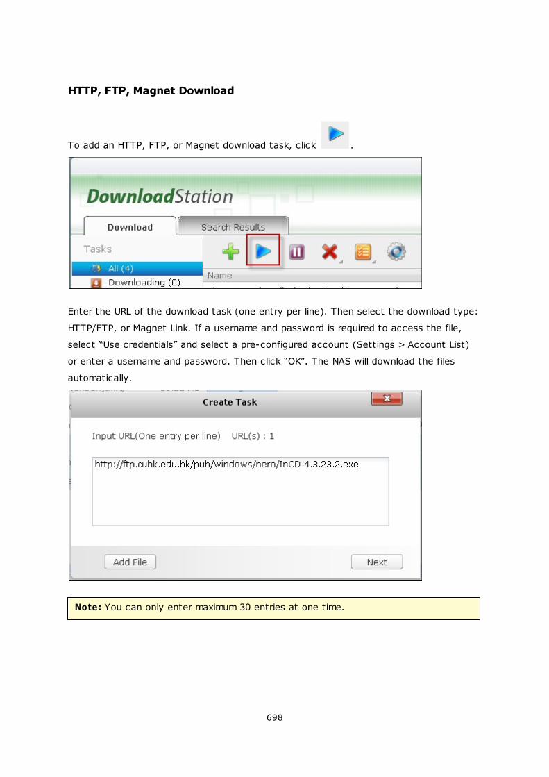
698
HTTP, FTP, Magnet Download
To add an HTTP, FTP, or Magnet download task, click .
Enter the URL of the download task (one entry per line). Then select the download type:
HTTP/FTP, or Magnet Link. If a username and password is required to access the file,
select “Use credentials” and select a pre-configured account (Settings > Account List)
or enter a username and password. Then click “OK”. The NAS will download the files
automatically.
Note: You can only enter maximum 30 entries at one time.
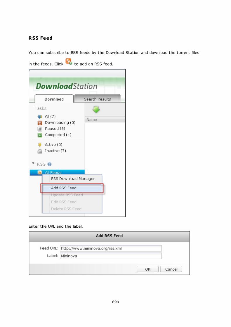
699
RSS Feed
You can subscribe to RSS feeds by the Download Station and download the torrent files
in the feeds. Click to add an RSS feed.
Enter the URL and the label.
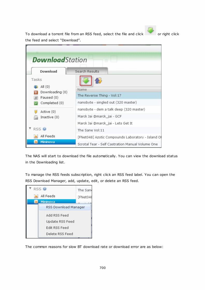
700
To download a torrent file from an RSS feed, select the file and click or right click
the feed and select “Download”.
The NAS will start to download the file automatically. You can view the download status
in the Downloading list.
To manage the RSS feeds subscription, right click an RSS feed label. You can open the
RSS Download Manager, add, update, edit, or delete an RSS feed.
The common reasons for slow BT download rate or download error are as below:
701
1. The torrent file has expired, the peers have stopped sharing this file, or there is
error in the file.
2. The NAS has configured to use fixed IP but DNS server is not configured, or DNS
server fails.
3. Set the maximum number of simultaneous downloads as 3-5 for the best download
rate.
4. The NAS is located behind NAT router. The port settings have led to slow BT
download rate or no response. You may try the following means to solve the
problem:
a. Open the BT port range on NAT router manually. Forward these ports to the
LAN IP of the NAS.
b. The new NAS firmware supports UPnP NAT port forwarding. If your NAT router
supports UPnP, enable this function on the NAT. Then enable UPnP NAT port
forwarding of the NAS. The BT download rate should be enhanced.
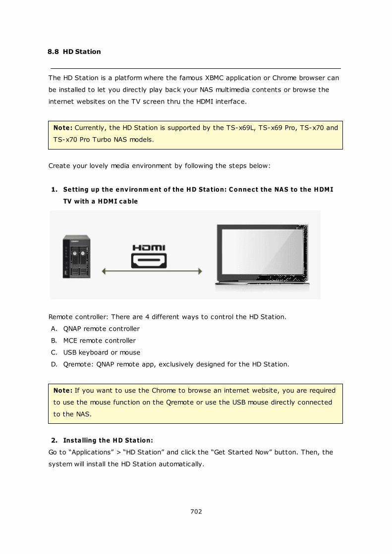
702
8.8 HD Station
The HD Station is a platform where the famous XBMC application or Chrome browser can
be installed to let you directly play back your NAS multimedia contents or browse the
internet websites on the TV screen thru the HDMI interface.
Note: Currently, the HD Station is supported by the TS-x69L, TS-x69 Pro, TS-x70 and
TS-x70 Pro Turbo NAS models.
Create your lovely media environment by following the steps below:
1. Setting up the environm ent of the HD Station: Connect the NAS to the HDMI
TV with a HDMI cable
Remote controller: There are 4 different ways to control the HD Station.
A. QNAP remote controller
B. MCE remote controller
C. USB keyboard or mouse
D. Qremote: QNAP remote app, exclusively designed for the HD Station.
Note: If you want to use the Chrome to browse an internet website, you are required
to use the mouse function on the Qremote or use the USB mouse directly connected
to the NAS.
2. Installing the HD Station:
Go to “Applications” > “HD Station” and click the “Get Started Now” button. Then, the
system will install the HD Station automatically.
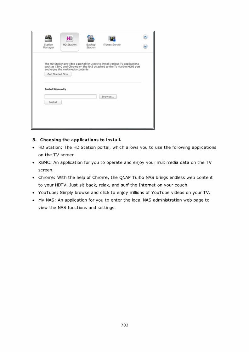
703
3. Choosing the applications to install.
HD Station: The HD Station portal, which allows you to use the following applications
on the TV screen.
XBMC: An application for you to operate and enjoy your multimedia data on the TV
screen.
Chrome: With the help of Chrome, the QNAP Turbo NAS brings endless web content
to your HDTV. Just sit back, relax, and surf the Internet on your couch.
YouTube: Simply browse and click to enjoy millions of YouTube videos on your TV.
My NAS: An application for you to enter the local NAS administration web page to
view the NAS functions and settings.
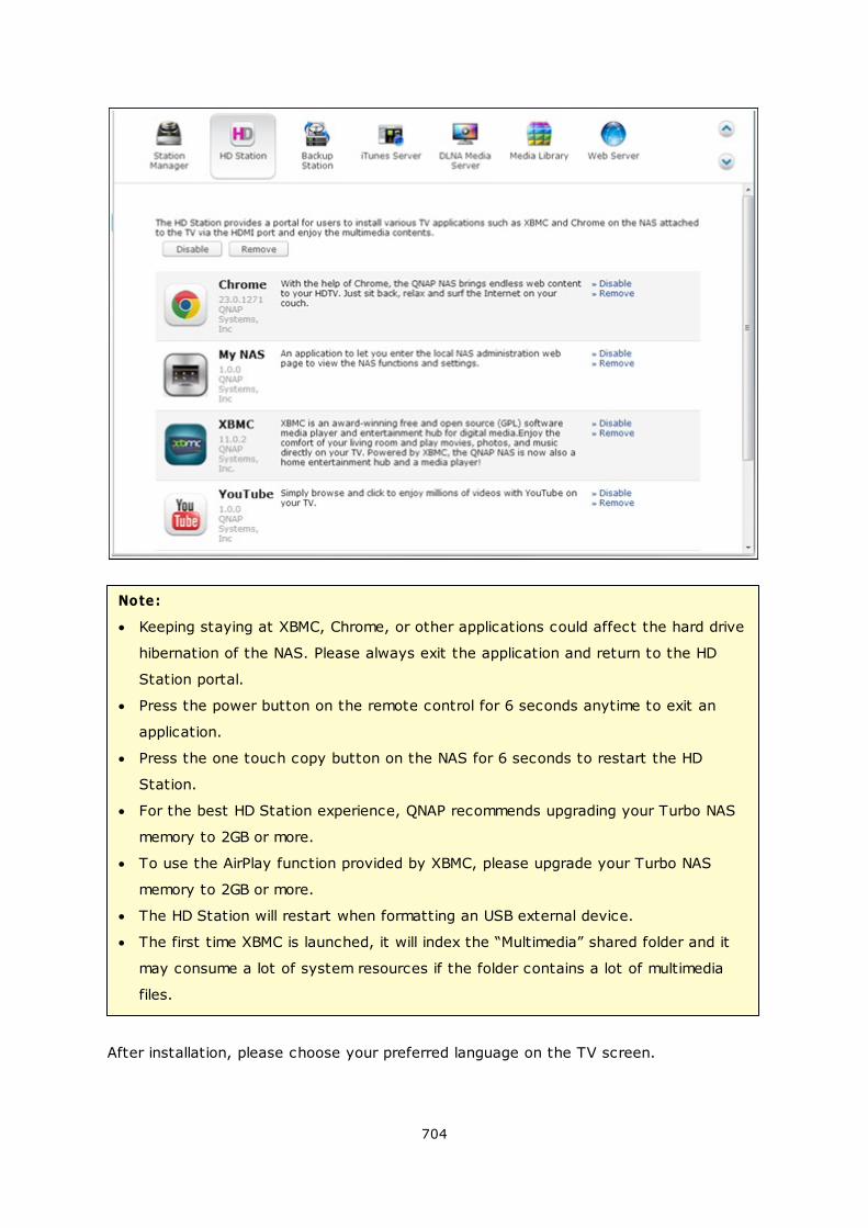
704
Note:
Keeping staying at XBMC, Chrome, or other applications could affect the hard drive
hibernation of the NAS. Please always exit the application and return to the HD
Station portal.
Press the power button on the remote control for 6 seconds anytime to exit an
application.
Press the one touch copy button on the NAS for 6 seconds to restart the HD
Station.
For the best HD Station experience, QNAP recommends upgrading your Turbo NAS
memory to 2GB or more.
To use the AirPlay function provided by XBMC, please upgrade your Turbo NAS
memory to 2GB or more.
The HD Station will restart when formatting an USB external device.
The first time XBMC is launched, it will index the “Multimedia” shared folder and it
may consume a lot of system resources if the folder contains a lot of multimedia
files.
After installation, please choose your preferred language on the TV screen.
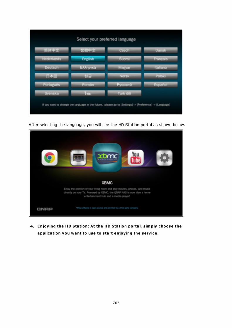
705
After selecting the language, you will see the HD Station portal as shown below.
4. Enjoying the HD Station: At the HD Station portal, sim ply choose the
application you want to use to start enjoying the serv ice.
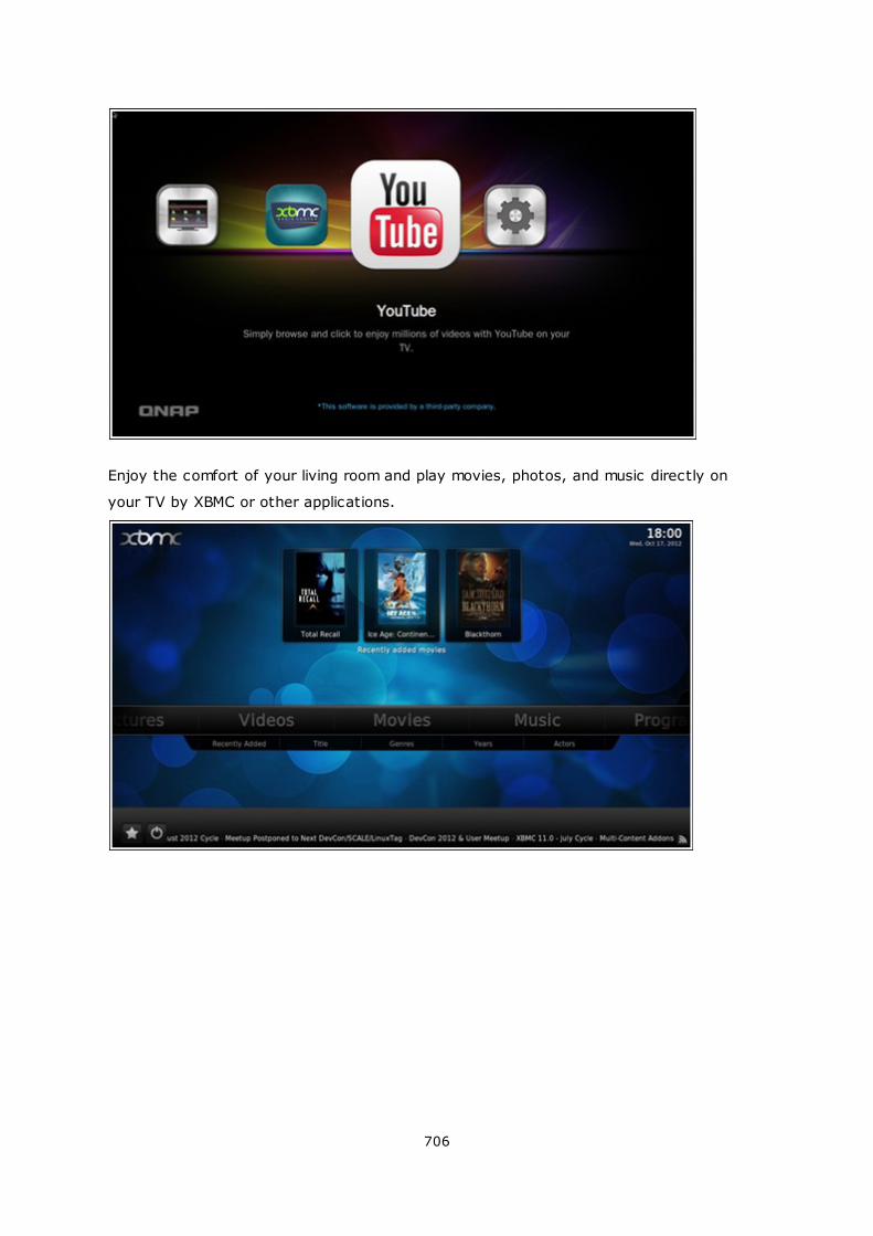
706
Enjoy the comfort of your living room and play movies, photos, and music directly on
your TV by XBMC or other applications.
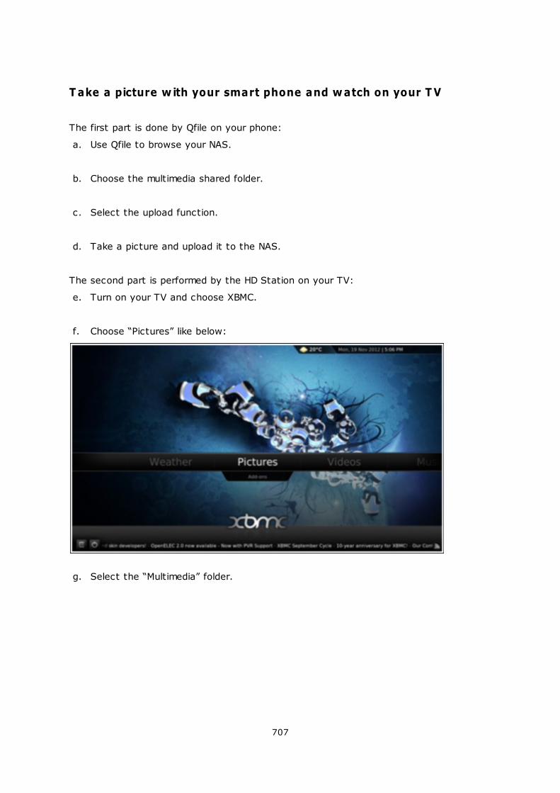
707
T ake a picture w ith your smart phone and watch on your T V
The first part is done by Qfile on your phone:
a. Use Qfile to browse your NAS.
b. Choose the multimedia shared folder.
c. Select the upload function.
d. Take a picture and upload it to the NAS.
The second part is performed by the HD Station on your TV:
e. Turn on your TV and choose XBMC.
f. Choose “Pictures” like below:
g. Select the “Multimedia” folder.
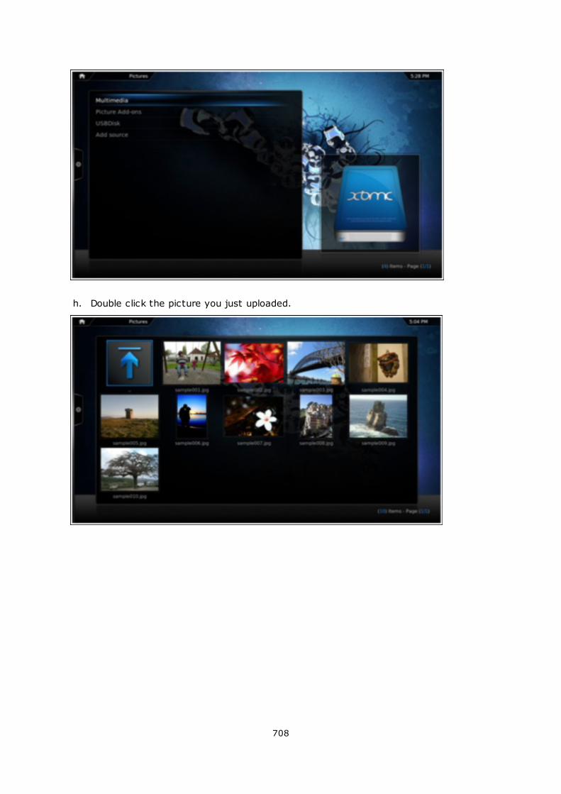
708
h. Double click the picture you just uploaded.
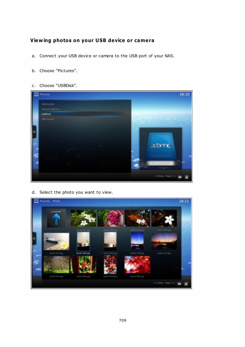
709
View ing photos on your USB device or camera
a. Connect your USB device or camera to the USB port of your NAS.
b. Choose “Pictures”.
c. Choose “USBDisk”.
d. Select the photo you want to view.
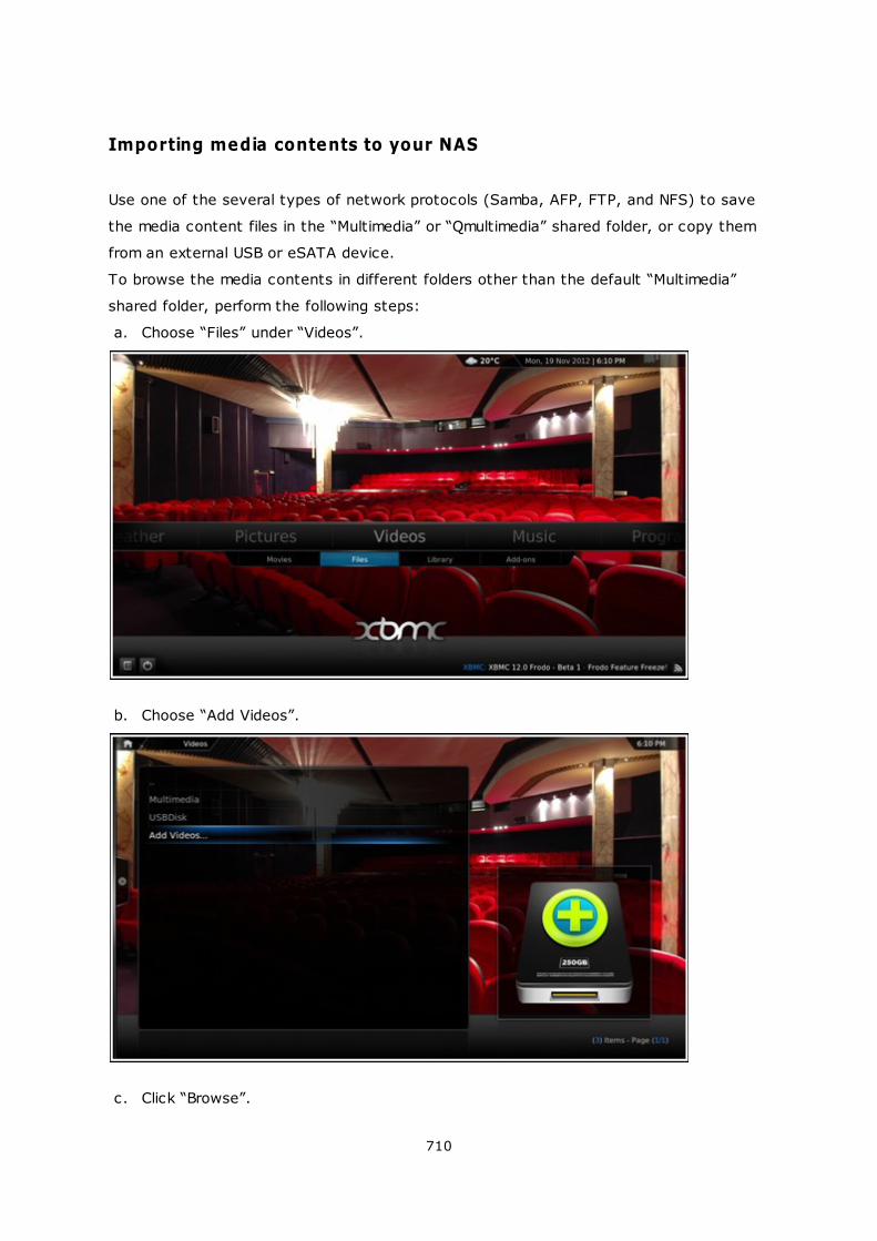
710
Importing media contents to your NAS
Use one of the several types of network protocols (Samba, AFP, FTP, and NFS) to save
the media content files in the “Multimedia” or “Qmultimedia” shared folder, or copy them
from an external USB or eSATA device.
To browse the media contents in different folders other than the default “Multimedia”
shared folder, perform the following steps:
a. Choose “Files” under “Videos”.
b. Choose “Add Videos”.
c. Click “Browse”.
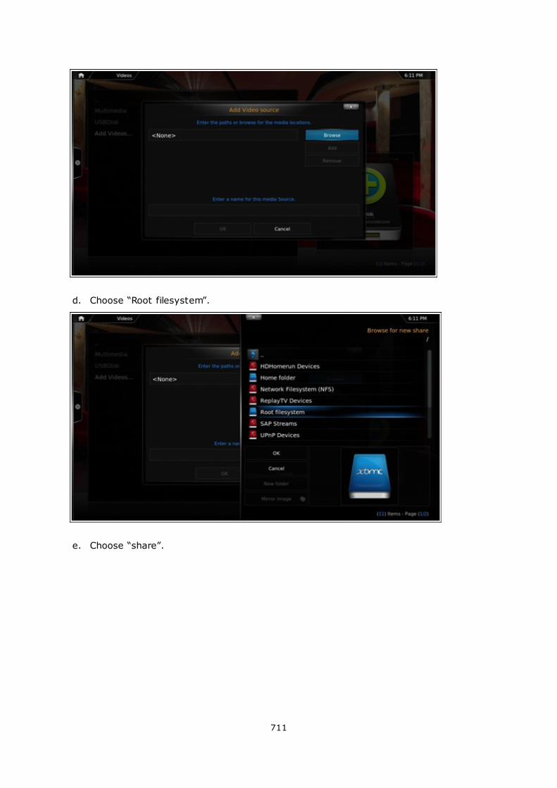
711
d. Choose “Root filesystem”.
e. Choose “share”.
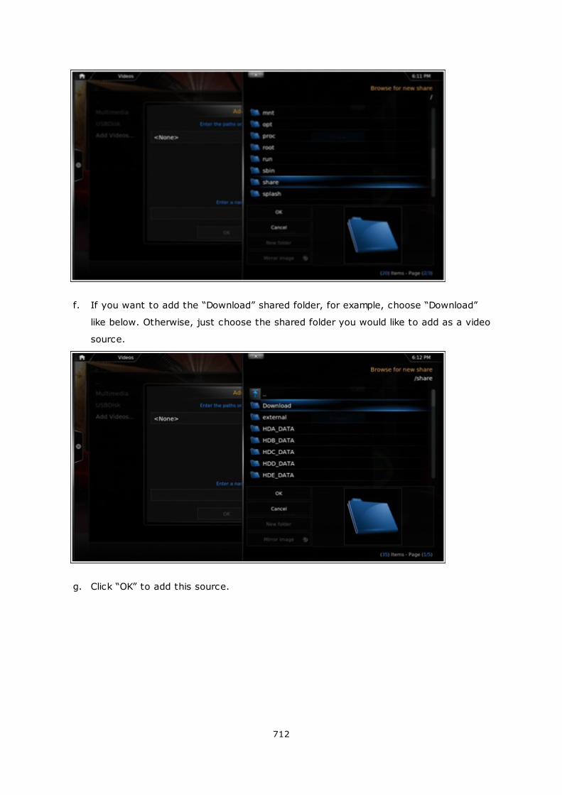
712
f. If you want to add the “Download” shared folder, for example, choose “Download”
like below. Otherwise, just choose the shared folder you would like to add as a video
source.
g. Click “OK” to add this source.
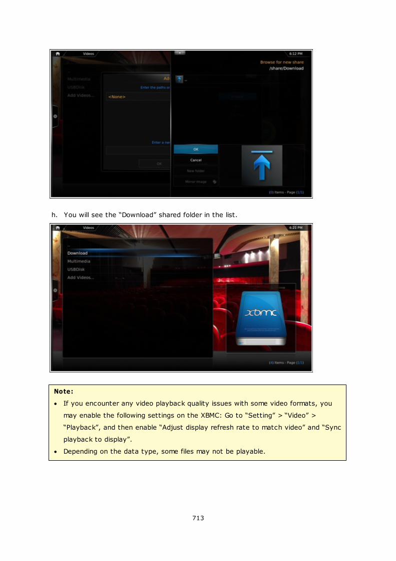
713
h. You will see the “Download” shared folder in the list.
Note:
If you encounter any video playback quality issues with some video formats, you
may enable the following settings on the XBMC: Go to “Setting” > “Video” >
“Playback”, and then enable “Adjust display refresh rate to match video” and “Sync
playback to display”.
Depending on the data type, some files may not be playable.
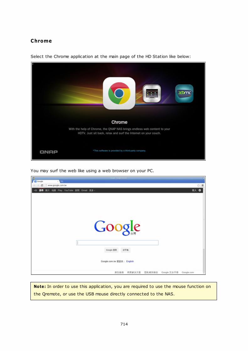
714
Chrome
Select the Chrome application at the main page of the HD Station like below:
You may surf the web like using a web browser on your PC.
Note: In order to use this application, you are required to use the mouse function on
the Qremote, or use the USB mouse directly connected to the NAS.
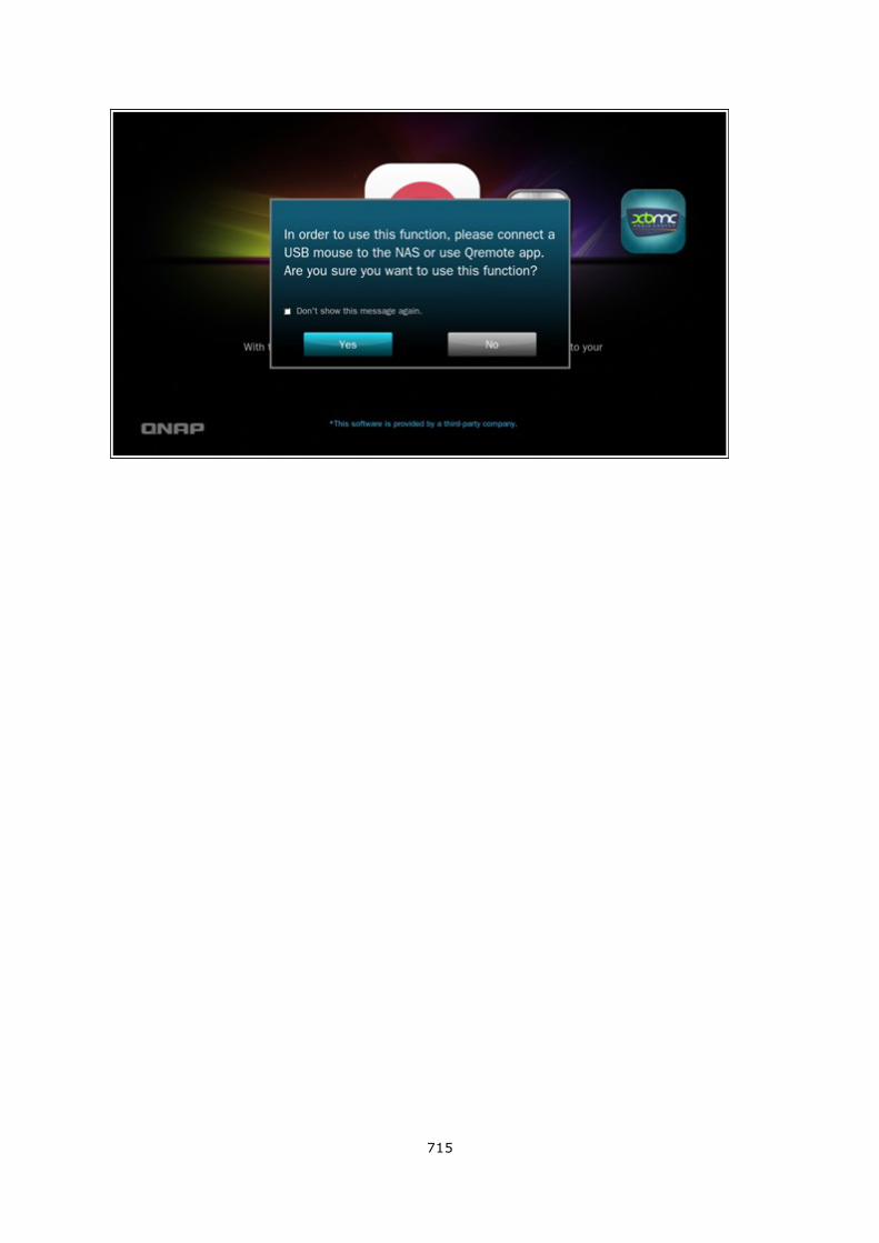
715
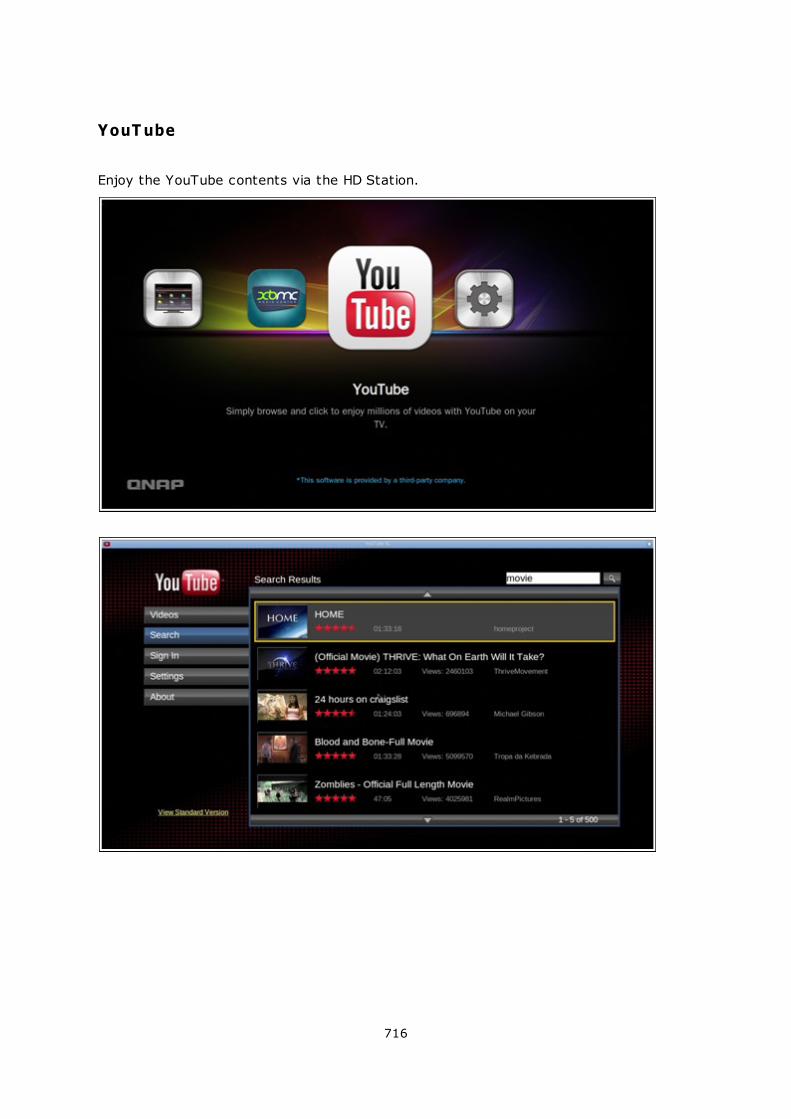
716
YouT ube
Enjoy the YouTube contents via the HD Station.
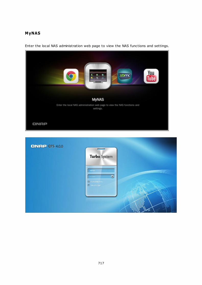
717
MyNAS
Enter the local NAS administration web page to view the NAS functions and settings.
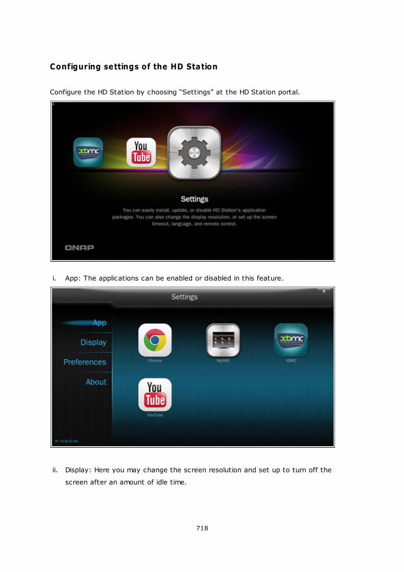
718
Configuring settings of the HD Station
Configure the HD Station by choosing “Settings” at the HD Station portal.
i. App: The applications can be enabled or disabled in this feature.
ii. Display: Here you may change the screen resolution and set up to turn off the
screen after an amount of idle time.
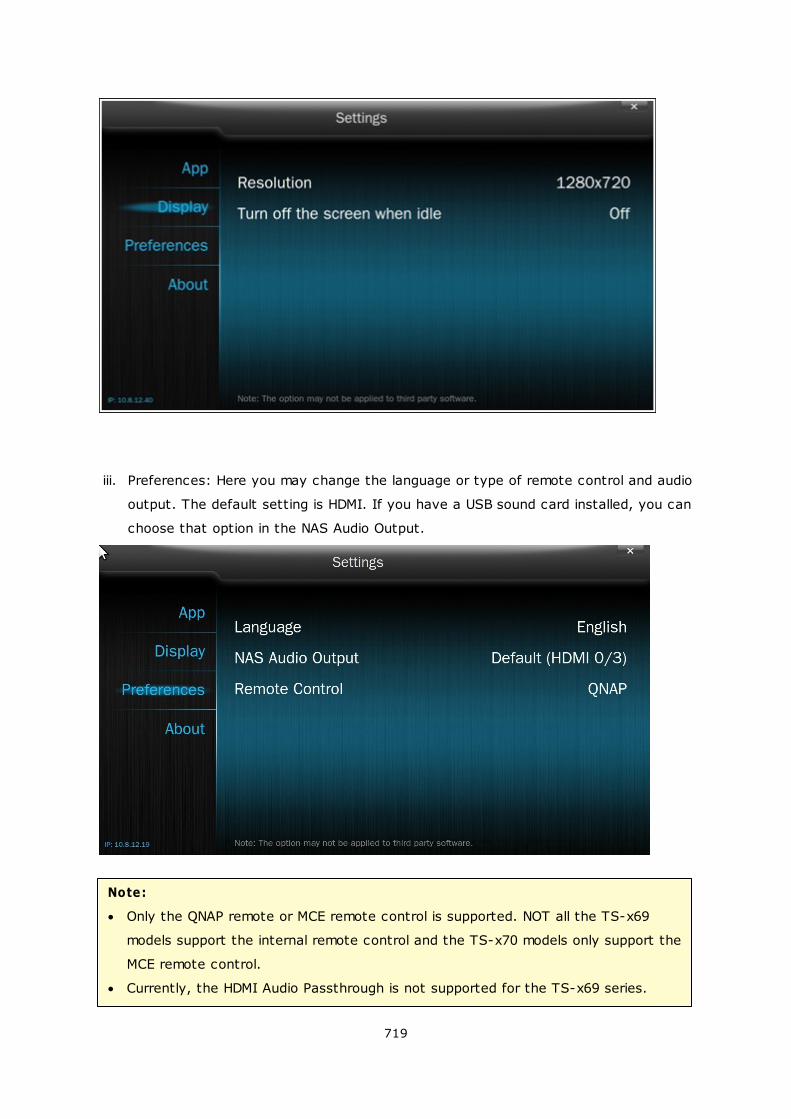
719
iii. Preferences: Here you may change the language or type of remote control and audio
output. The default setting is HDMI. If you have a USB sound card installed, you can
choose that option in the NAS Audio Output.
Note:
Only the QNAP remote or MCE remote control is supported. NOT all the TS-x69
models support the internal remote control and the TS-x70 models only support the
MCE remote control.
Currently, the HDMI Audio Passthrough is not supported for the TS-x69 series.

720
Remote Control Mappings

721
RM-IR001
Remote
Control
Action MCE
Remote
Control
XBMC
Function
HD Station
Power Power 1 N/A Power 1 Power menu
Mute 2 OK Mute 13 Mute
Number 0,1,2,3,4,5
,6,7,8,9
3 OK 0,1,2,3,4,5,
6,7,8,9
18 0,1,2,3,4,5,6
,7,8,9
Vol+, Vol- 4 OK Vol+, Vol- 12 Vol+, Vol-
List/Icon 5 N/A View mode
Search 6 N/A
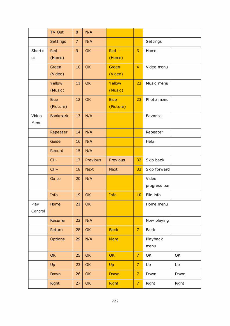
722
TV Out 8 N/A
Settings 7 N/A Settings
Shortc
ut
Red -
(Home)
9 OK Red -
(Home)
3 Home
Green
(Video)
10 OK Green
(Video)
4 Video menu
Yellow
(Music)
11 OK Yellow
(Music)
22 Music menu
Blue
(Picture)
12 OK Blue
(Picture)
23 Photo menu
Video
Menu
Bookmark 13 N/A Favorite
Repeater 14 N/A Repeater
Guide 16 N/A Help
Record 15 N/A
CH- 17 Previous Previous 32 Skip back
CH+ 18 Next Next 33 Skip forward
Go to 20 N/A Video
progress bar
Info 19 OK Info 10 File info
Play
Control
Home 21 OK Home menu
Resume 22 N/A Now playing
Return 28 OK Back 7 Back
Options 29 N/A More Playback
menu
OK 25 OK OK 7 OK OK
Up 23 OK Up 7 Up Up
Down 26 OK Down 7 Down Down
Right 27 OK Right 7 Right Right
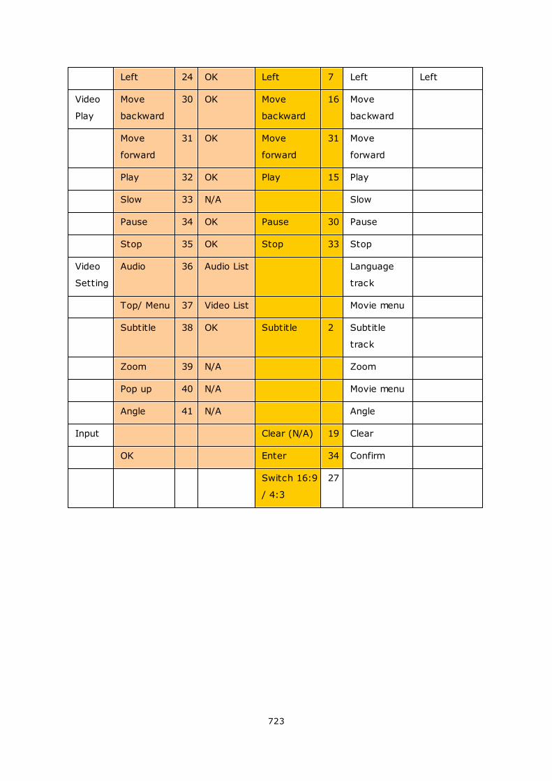
723
Left 24 OK Left 7 Left Left
Video
Play
Move
backward
30 OK Move
backward
16 Move
backward
Move
forward
31 OK Move
forward
31 Move
forward
Play 32 OK Play 15 Play
Slow 33 N/A Slow
Pause 34 OK Pause 30 Pause
Stop 35 OK Stop 33 Stop
Video
Setting
Audio 36 Audio List Language
track
Top/ Menu 37 Video List Movie menu
Subtitle 38 OK Subtitle 2 Subtitle
track
Zoom 39 N/A Zoom
Pop up 40 N/A Movie menu
Angle 41 N/A Angle
Input Clear (N/A) 19 Clear
OK Enter 34 Confirm
Switch 16:9
/ 4:3
27
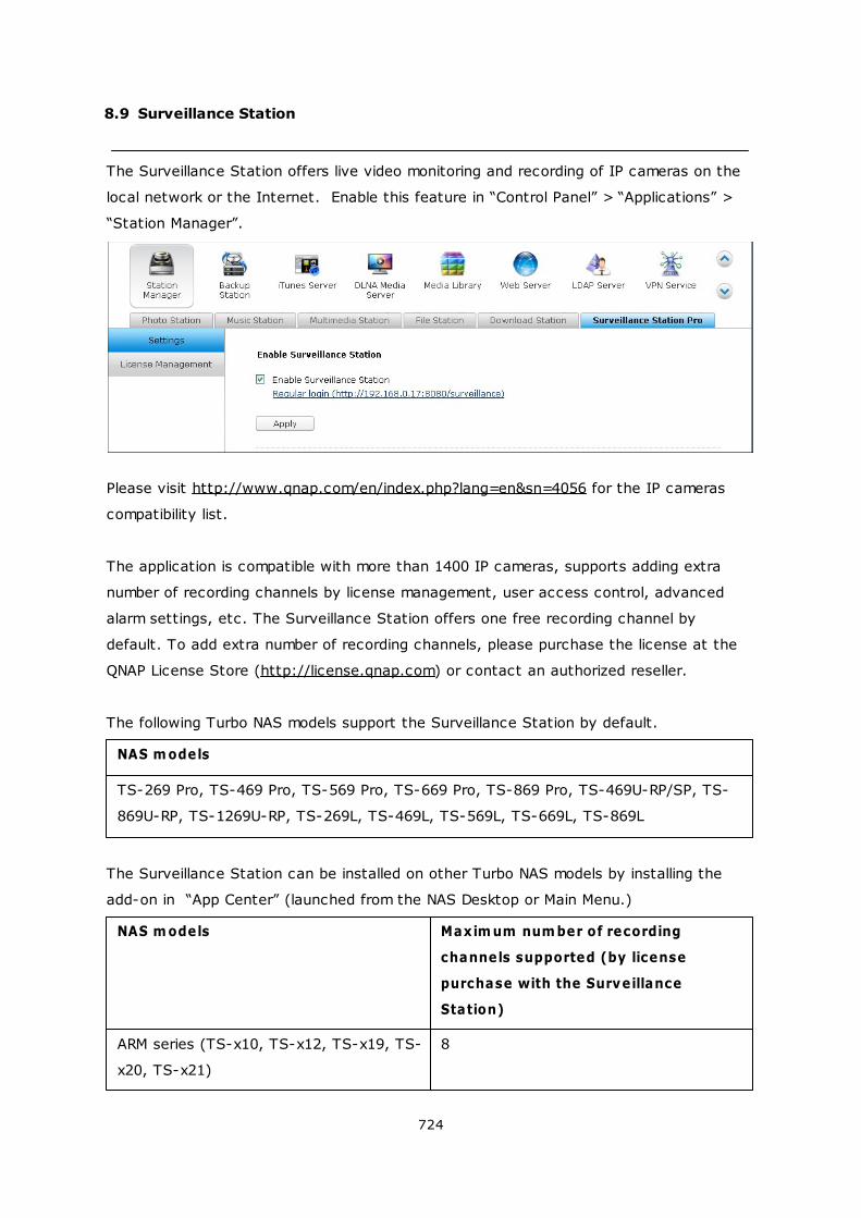
724
8.9 Surveillance Station
The Surveillance Station offers live video monitoring and recording of IP cameras on the
local network or the Internet. Enable this feature in “Control Panel” > “Applications” >
“Station Manager”.
Please visit http://www.qnap.com/en/index.php?lang=en&sn=4056 for the IP cameras
compatibility list.
The application is compatible with more than 1400 IP cameras, supports adding extra
number of recording channels by license management, user access control, advanced
alarm settings, etc. The Surveillance Station offers one free recording channel by
default. To add extra number of recording channels, please purchase the license at the
QNAP License Store (http://license.qnap.com) or contact an authorized reseller.
The following Turbo NAS models support the Surveillance Station by default.
NAS m odels
TS-269 Pro, TS-469 Pro, TS-569 Pro, TS-669 Pro, TS-869 Pro, TS-469U-RP/SP, TS-
869U-RP, TS-1269U-RP, TS-269L, TS-469L, TS-569L, TS-669L, TS-869L
The Surveillance Station can be installed on other Turbo NAS models by installing the
add-on in “App Center” (launched from the NAS Desktop or Main Menu.)
NAS m odels Maxim um num ber of recording
channels supported (by license
purchase with the Surveillance
Station)
ARM series (TS-x10, TS-x12, TS-x19, TS-
x20, TS-x21)
8

725
x86 series (TS-x39, TS-x59, TS-x69, TS-
x70 Pro, SS-x39, SS-469 Pro)
16
TS-x70U, TS-x79 series 40
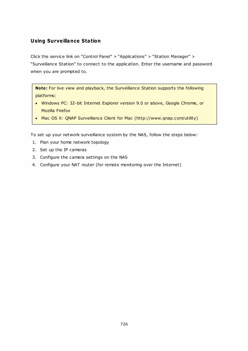
726
Using Surveillance Station
Click the service link on “Control Panel” > “Applications” > “Station Manager” >
“Surveillance Station” to connect to the application. Enter the username and password
when you are prompted to.
Note: For live view and playback, the Surveillance Station supports the following
platforms:
Windows PC: 32-bit Internet Explorer version 9.0 or above, Google Chrome, or
Mozilla Firefox
Mac OS X: QNAP Surveillance Client for Mac (http://www.qnap.com/utility)
To set up your network surveillance system by the NAS, follow the steps below:
1. Plan your home network topology
2. Set up the IP cameras
3. Configure the camera settings on the NAS
4. Configure your NAT router (for remote monitoring over the Internet)
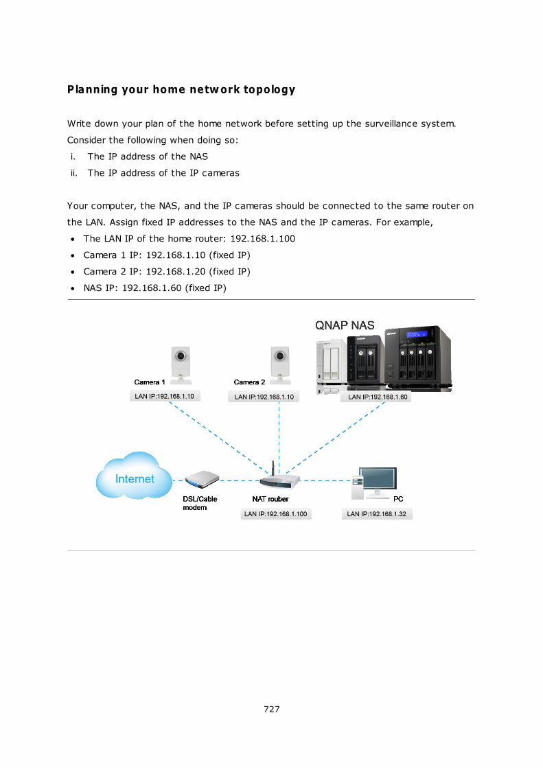
727
Planning your home network topology
Write down your plan of the home network before setting up the surveillance system.
Consider the following when doing so:
i. The IP address of the NAS
ii. The IP address of the IP cameras
Your computer, the NAS, and the IP cameras should be connected to the same router on
the LAN. Assign fixed IP addresses to the NAS and the IP cameras. For example,
The LAN IP of the home router: 192.168.1.100
Camera 1 IP: 192.168.1.10 (fixed IP)
Camera 2 IP: 192.168.1.20 (fixed IP)
NAS IP: 192.168.1.60 (fixed IP)
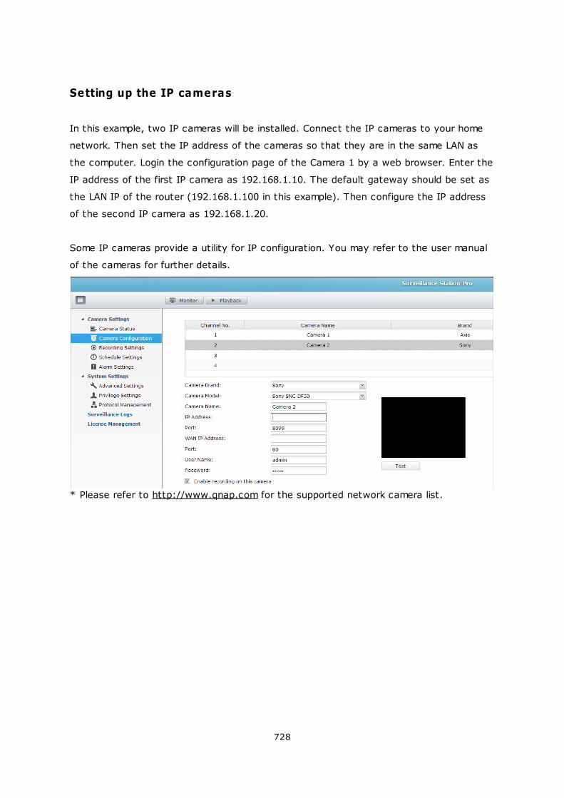
728
Setting up the IP cameras
In this example, two IP cameras will be installed. Connect the IP cameras to your home
network. Then set the IP address of the cameras so that they are in the same LAN as
the computer. Login the configuration page of the Camera 1 by a web browser. Enter the
IP address of the first IP camera as 192.168.1.10. The default gateway should be set as
the LAN IP of the router (192.168.1.100 in this example). Then configure the IP address
of the second IP camera as 192.168.1.20.
Some IP cameras provide a utility for IP configuration. You may refer to the user manual
of the cameras for further details.
* Please refer to http://www.qnap.com for the supported network camera list.
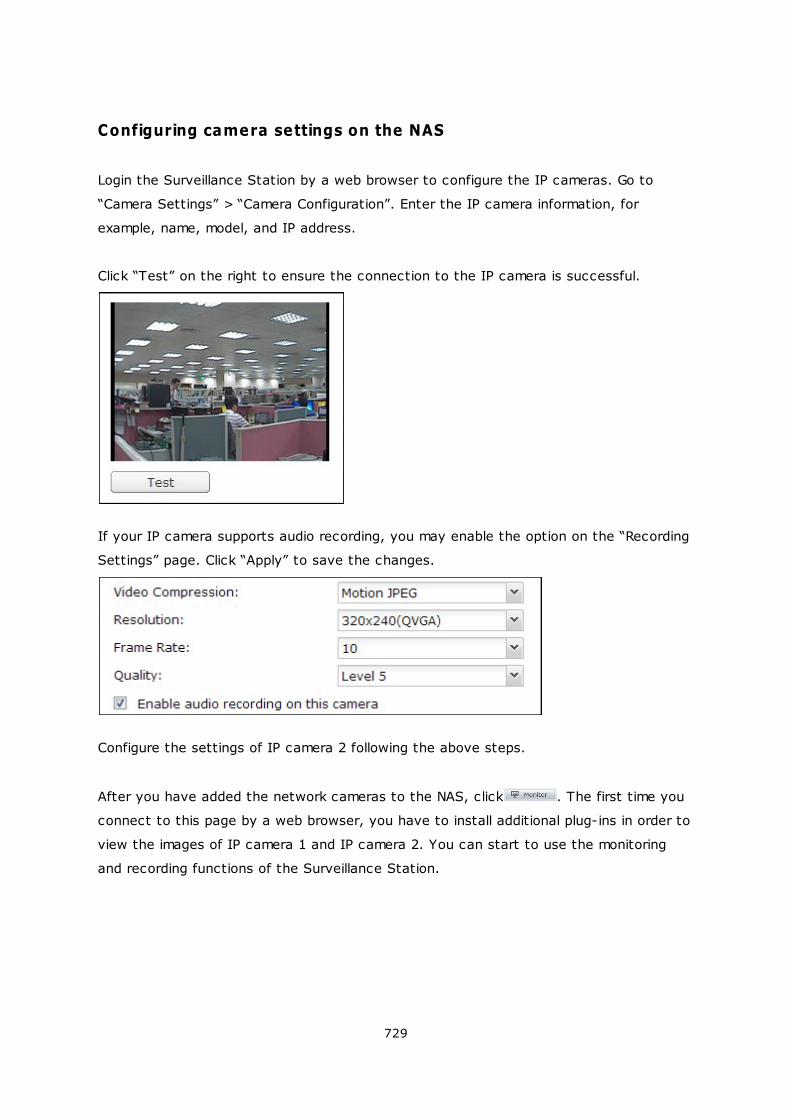
729
Configuring camera settings on the NAS
Login the Surveillance Station by a web browser to configure the IP cameras. Go to
“Camera Settings” > “Camera Configuration”. Enter the IP camera information, for
example, name, model, and IP address.
Click “Test” on the right to ensure the connection to the IP camera is successful.
If your IP camera supports audio recording, you may enable the option on the “Recording
Settings” page. Click “Apply” to save the changes.
Configure the settings of IP camera 2 following the above steps.
After you have added the network cameras to the NAS, click . The first time you
connect to this page by a web browser, you have to install additional plug-ins in order to
view the images of IP camera 1 and IP camera 2. You can start to use the monitoring
and recording functions of the Surveillance Station.
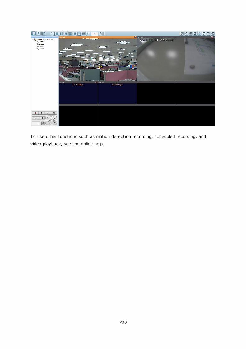
730
To use other functions such as motion detection recording, scheduled recording, and
video playback, see the online help.
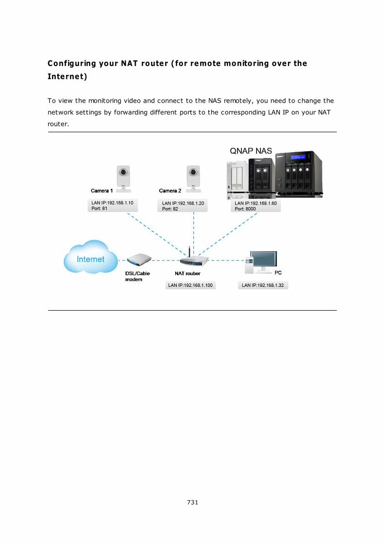
731
Configuring your NAT router (for remote monitoring over the
Internet)
To view the monitoring video and connect to the NAS remotely, you need to change the
network settings by forwarding different ports to the corresponding LAN IP on your NAT
router.
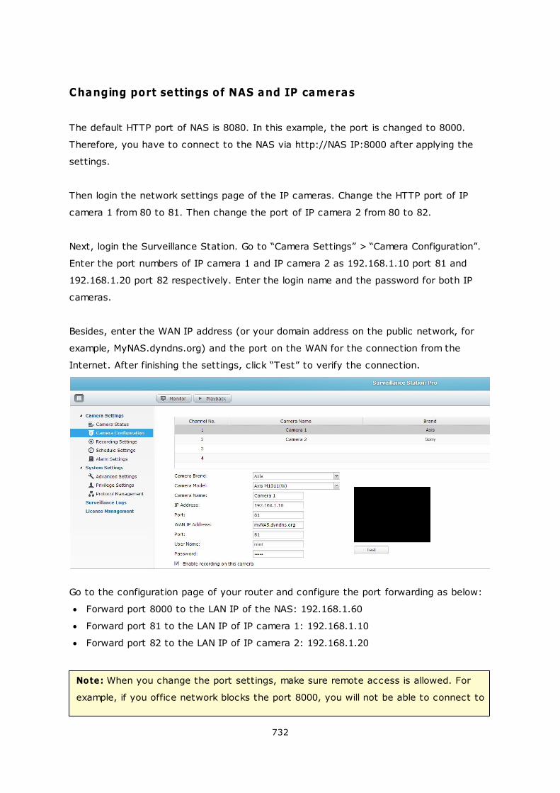
732
Changing port settings of NAS and IP cameras
The default HTTP port of NAS is 8080. In this example, the port is changed to 8000.
Therefore, you have to connect to the NAS via http://NAS IP:8000 after applying the
settings.
Then login the network settings page of the IP cameras. Change the HTTP port of IP
camera 1 from 80 to 81. Then change the port of IP camera 2 from 80 to 82.
Next, login the Surveillance Station. Go to “Camera Settings” > “Camera Configuration”.
Enter the port numbers of IP camera 1 and IP camera 2 as 192.168.1.10 port 81 and
192.168.1.20 port 82 respectively. Enter the login name and the password for both IP
cameras.
Besides, enter the WAN IP address (or your domain address on the public network, for
example, MyNAS.dyndns.org) and the port on the WAN for the connection from the
Internet. After finishing the settings, click “Test” to verify the connection.
Go to the configuration page of your router and configure the port forwarding as below:
Forward port 8000 to the LAN IP of the NAS: 192.168.1.60
Forward port 81 to the LAN IP of IP camera 1: 192.168.1.10
Forward port 82 to the LAN IP of IP camera 2: 192.168.1.20
Note: When you change the port settings, make sure remote access is allowed. For
example, if you office network blocks the port 8000, you will not be able to connect to
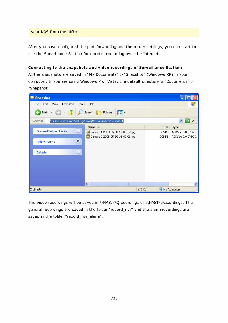
733
your NAS from the office.
After you have configured the port forwarding and the router settings, you can start to
use the Surveillance Station for remote monitoring over the Internet.
Connecting to the snapshots and v ideo recordings of Surveillance Station:
All the snapshots are saved in “My Documents” > “Snapshot” (Windows XP) in your
computer. If you are using Windows 7 or Vista, the default directory is “Documents” >
“Snapshot”.
The video recordings will be saved in \\NASIP\Qrecordings or \\NASIP\Recordings. The
general recordings are saved in the folder “record_nvr” and the alarm recordings are
saved in the folder “record_nvr_alarm”.
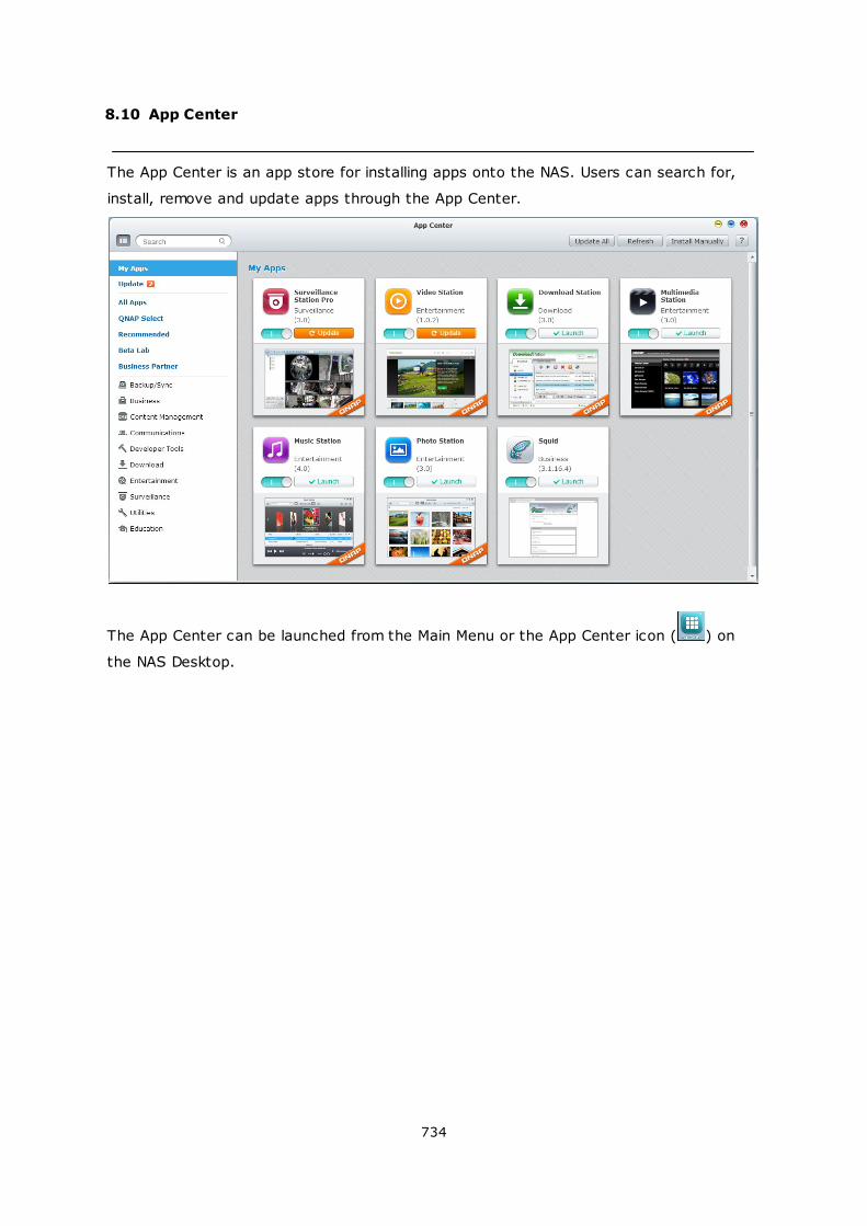
734
8.10 App Center
The App Center is an app store for installing apps onto the NAS. Users can search for,
install, remove and update apps through the App Center.
The App Center can be launched from the Main Menu or the App Center icon ( ) on
the NAS Desktop.
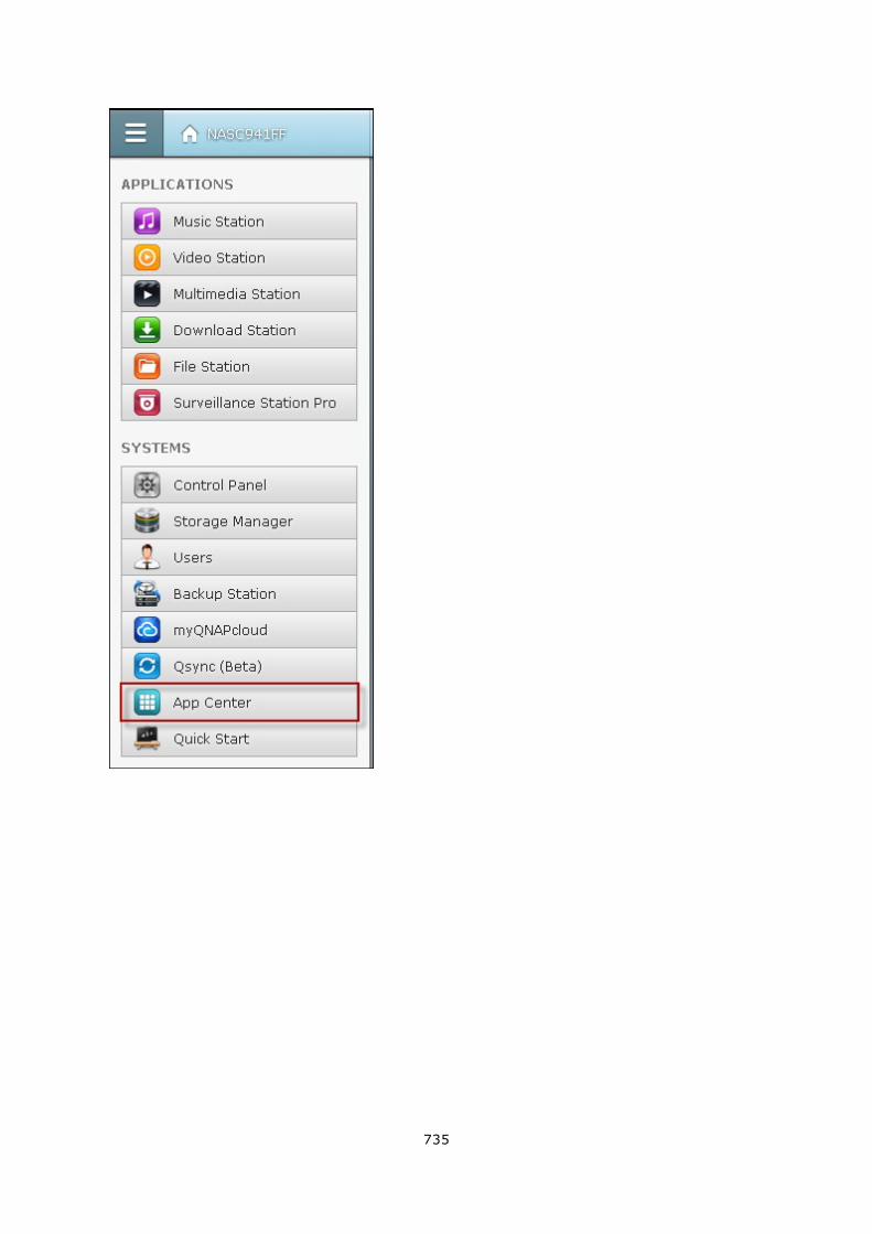
735
736
Browsing and searching for apps
Apps are classified into categories listed in the left panel:
My Apps: List apps that have been installed on the NAS. Note that the number
shown next to the category name is the number of app updates available now.
All Apps: List all apps that can be installed on the NAS.
QNAP Select: List apps developed by QNAP.
Recommended: List apps recommended by QNAP (they could be developed by QNAP
or third party developers.)
Beta Lab: List beta apps for your first-hand experiences.
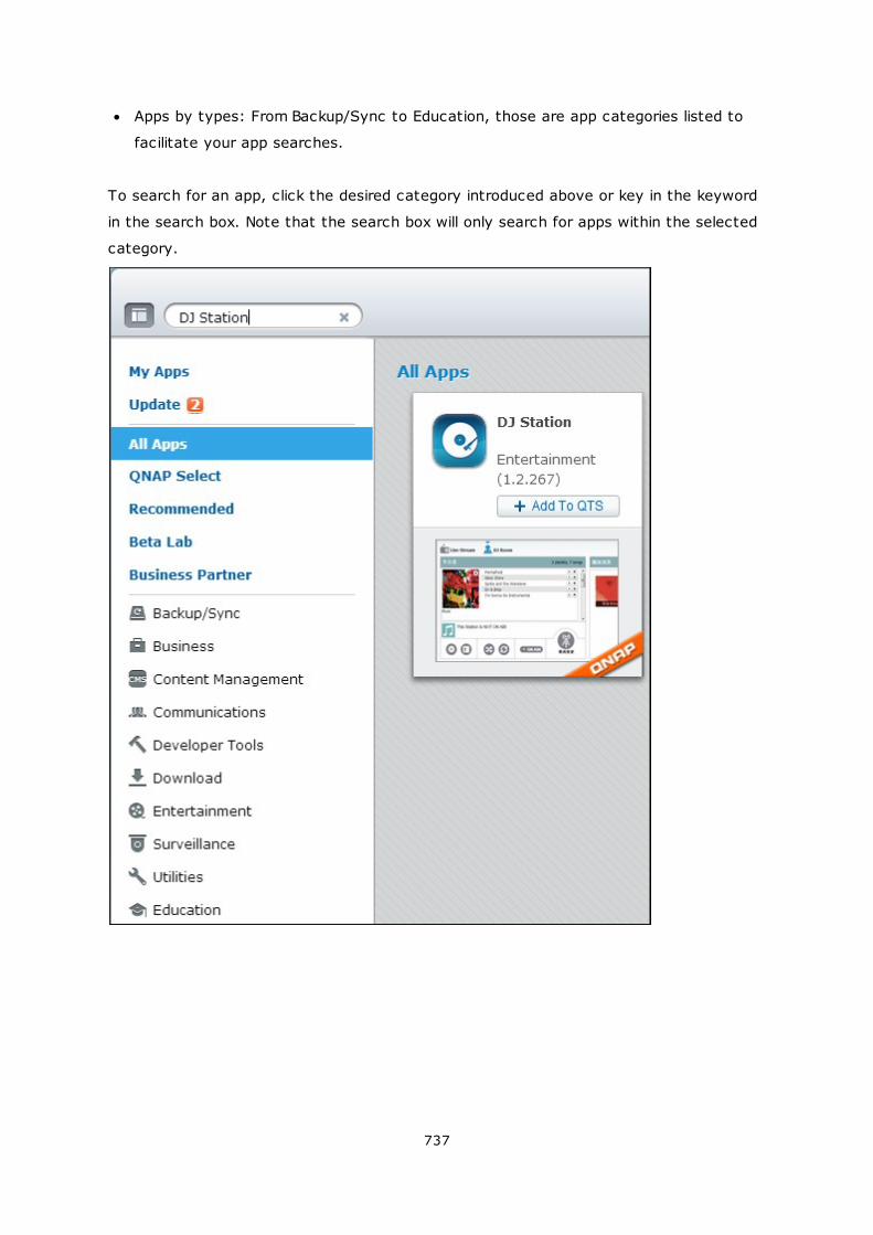
737
Apps by types: From Backup/Sync to Education, those are app categories listed to
facilitate your app searches.
To search for an app, click the desired category introduced above or key in the keyword
in the search box. Note that the search box will only search for apps within the selected
category.
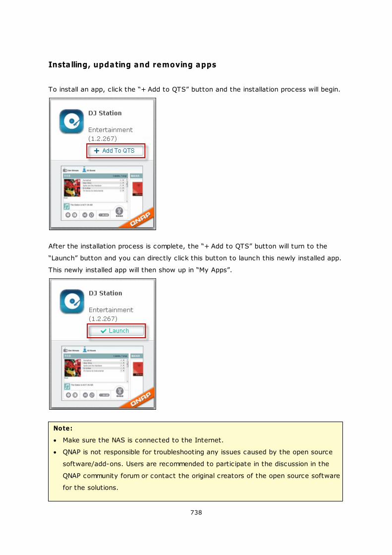
738
Installing, updating and removing apps
To install an app, click the “+ Add to QTS” button and the installation process will begin.
After the installation process is complete, the “+ Add to QTS” button will turn to the
“Launch” button and you can directly click this button to launch this newly installed app.
This newly installed app will then show up in “My Apps”.
Note:
Make sure the NAS is connected to the Internet.
QNAP is not responsible for troubleshooting any issues caused by the open source
software/add-ons. Users are recommended to participate in the discussion in the
QNAP community forum or contact the original creators of the open source software
for the solutions.
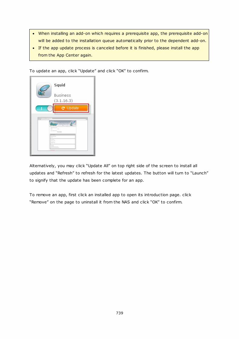
739
When installing an add-on which requires a prerequisite app, the prerequisite add-on
will be added to the installation queue automatically prior to the dependent add-on.
If the app update process is canceled before it is finished, please install the app
from the App Center again.
To update an app, click “Update” and click “OK” to confirm.
Alternatively, you may click “Update All” on top right side of the screen to install all
updates and “Refresh” to refresh for the latest updates. The button will turn to “Launch”
to signify that the update has been complete for an app.
To remove an app, first click an installed app to open its introduction page. click
“Remove” on the page to uninstall it from the NAS and click “OK” to confirm.
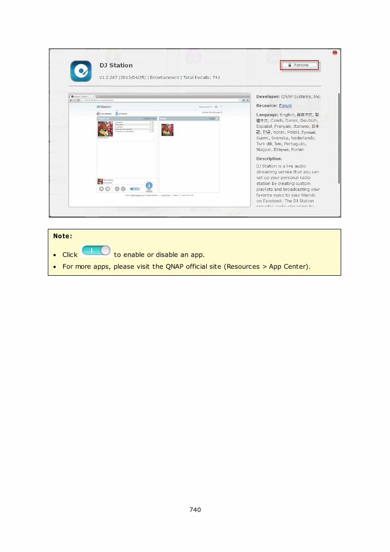
740
Note:
Click to enable or disable an app.
For more apps, please visit the QNAP official site (Resources > App Center).
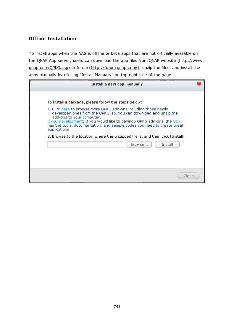
741
Offline Installation
To install apps when the NAS is offline or beta apps that are not officially available on
the QNAP App server, users can download the app files from QNAP website (http://www.
qnap.com/QPKG.asp) or forum (http://forum.qnap.com/), unzip the files, and install the
apps manually by clicking “Install Manually” on top right side of the page.
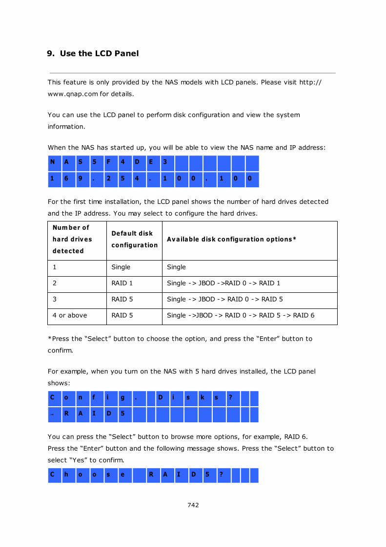
742
9. Use the LCD Panel
This feature is only provided by the NAS models with LCD panels. Please visit http://
www.qnap.com for details.
You can use the LCD panel to perform disk configuration and view the system
information.
When the NAS has started up, you will be able to view the NAS name and IP address:
N A S 5 F 4 D E 3
1 6 9 . 2 5 4 . 1 0 0 . 1 0 0
For the first time installation, the LCD panel shows the number of hard drives detected
and the IP address. You may select to configure the hard drives.
Num ber of
hard drives
detected
Default disk
configurationAvailable disk configuration options*
1 Single Single
2 RAID 1 Single -> JBOD ->RAID 0 -> RAID 1
3 RAID 5 Single -> JBOD -> RAID 0 -> RAID 5
4 or above RAID 5 Single ->JBOD -> RAID 0 -> RAID 5 -> RAID 6
*Press the “Select” button to choose the option, and press the “Enter” button to
confirm.
For example, when you turn on the NAS with 5 hard drives installed, the LCD panel
shows:
C o n f i g . D i s k s ?
R A I D 5
You can press the “Select” button to browse more options, for example, RAID 6.
Press the “Enter” button and the following message shows. Press the “Select” button to
select “Yes” to confirm.
C h o o s e R A I D 5 ?
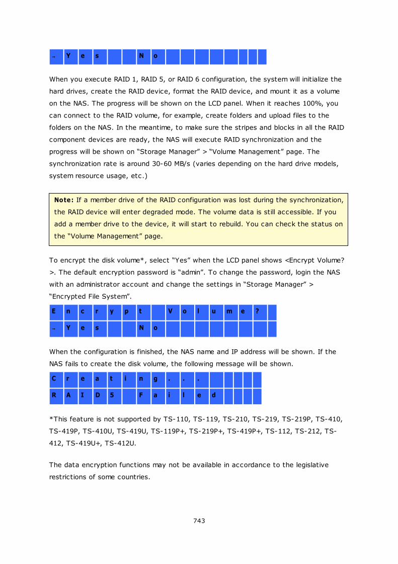
743
Y e s N o
When you execute RAID 1, RAID 5, or RAID 6 configuration, the system will initialize the
hard drives, create the RAID device, format the RAID device, and mount it as a volume
on the NAS. The progress will be shown on the LCD panel. When it reaches 100%, you
can connect to the RAID volume, for example, create folders and upload files to the
folders on the NAS. In the meantime, to make sure the stripes and blocks in all the RAID
component devices are ready, the NAS will execute RAID synchronization and the
progress will be shown on “Storage Manager” > “Volume Management” page. The
synchronization rate is around 30-60 MB/s (varies depending on the hard drive models,
system resource usage, etc.)
Note: If a member drive of the RAID configuration was lost during the synchronization,
the RAID device will enter degraded mode. The volume data is still accessible. If you
add a member drive to the device, it will start to rebuild. You can check the status on
the “Volume Management” page.
To encrypt the disk volume*, select “Yes” when the LCD panel shows <Encrypt Volume?
>. The default encryption password is “admin”. To change the password, login the NAS
with an administrator account and change the settings in “Storage Manager” >
“Encrypted File System”.
E n c r y p t V o l u m e ?
Y e s N o
When the configuration is finished, the NAS name and IP address will be shown. If the
NAS fails to create the disk volume, the following message will be shown.
C r e a t i n g . . .
R A I D 5 F a i l e d
*This feature is not supported by TS-110, TS-119, TS-210, TS-219, TS-219P, TS-410,
TS-419P, TS-410U, TS-419U, TS-119P+, TS-219P+, TS-419P+, TS-112, TS-212, TS-
412, TS-419U+, TS-412U.
The data encryption functions may not be available in accordance to the legislative
restrictions of some countries.
744
View system information by the LCD panel
When the LCD panel shows the NAS name and IP address, you may press the “Enter”
button to enter the Main Menu. The Main Menu consists of the following items:
1. TCP/IP
2. Physical disk
3. Volume
4. System
5. Shut down
6. Reboot
7. Password
8. Back
TCP/IP
In TCP/IP, you can view the following options:
1. LAN IP Address
2. LAN Subnet Mask
3. LAN Gateway
4. LAN PRI. DNS
5. LAN SEC. DNS
6. Enter Network Settings
Network Settings – DHCP
Network Settings – Static IP*
Network Settings – BACK
7. Back to Main Menu
* In Network Settings – Static IP, you can configure the IP address, subnet m ask,
gateway, and DNS of LAN 1 and LAN 2.
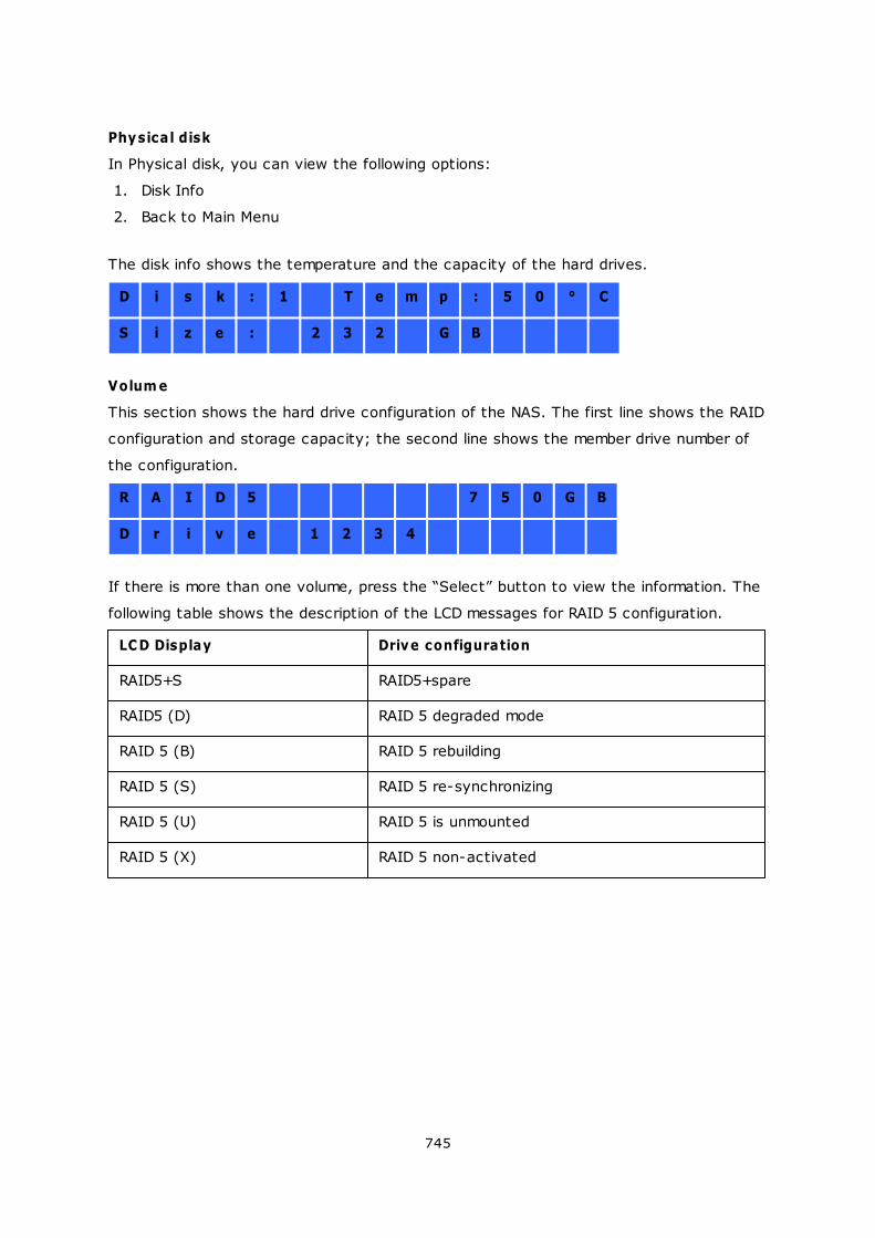
745
Physical disk
In Physical disk, you can view the following options:
1. Disk Info
2. Back to Main Menu
The disk info shows the temperature and the capacity of the hard drives.
D i s k : 1 T e m p : 5 0 ° C
S i z e : 2 3 2 G B
Volum e
This section shows the hard drive configuration of the NAS. The first line shows the RAID
configuration and storage capacity; the second line shows the member drive number of
the configuration.
R A I D 5 7 5 0 G B
D r i v e 1 2 3 4
If there is more than one volume, press the “Select” button to view the information. The
following table shows the description of the LCD messages for RAID 5 configuration.
LCD Display Drive configuration
RAID5+S RAID5+spare
RAID5 (D) RAID 5 degraded mode
RAID 5 (B) RAID 5 rebuilding
RAID 5 (S) RAID 5 re-synchronizing
RAID 5 (U) RAID 5 is unmounted
RAID 5 (X) RAID 5 non-activated
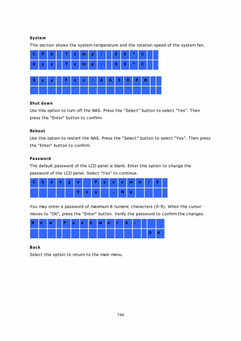
746
System
This section shows the system temperature and the rotation speed of the system fan.
C P U T e m p : 5 0 ° C
S y s T e m p : 5 5 ° C
S y s F a n : 8 6 5 R P M
Shut down
Use this option to turn off the NAS. Press the “Select” button to select “Yes”. Then
press the “Enter” button to confirm.
Reboot
Use this option to restart the NAS. Press the “Select” button to select “Yes”. Then press
the “Enter” button to confirm.
Password
The default password of the LCD panel is blank. Enter this option to change the
password of the LCD panel. Select “Yes” to continue.
C h a n g e P a s s w o r d
Y e s N o
You may enter a password of maximum 8 numeric characters (0-9). When the cursor
moves to “OK”, press the “Enter” button. Verify the password to confirm the changes.
N e w P a s s w o r d :
O K
Back
Select this option to return to the main menu.
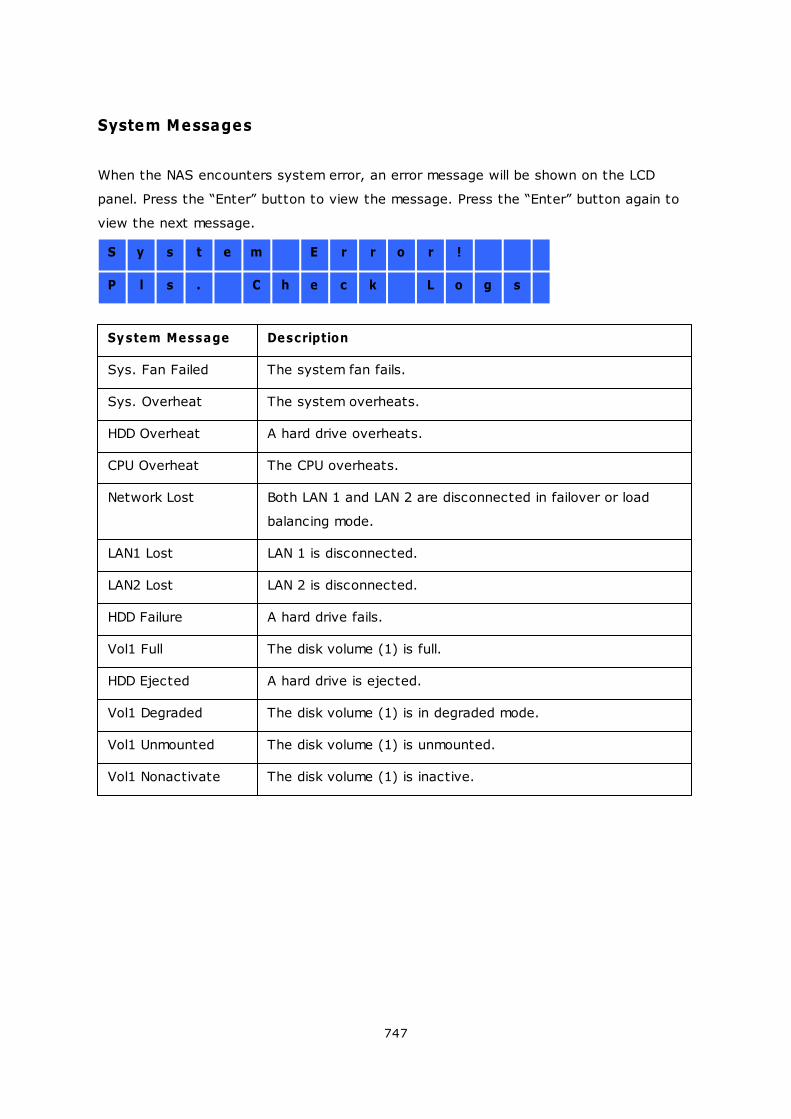
747
System Messages
When the NAS encounters system error, an error message will be shown on the LCD
panel. Press the “Enter” button to view the message. Press the “Enter” button again to
view the next message.
S y s t e m E r r o r !
P l s . C h e c k L o g s
System Message Description
Sys. Fan Failed The system fan fails.
Sys. Overheat The system overheats.
HDD Overheat A hard drive overheats.
CPU Overheat The CPU overheats.
Network Lost Both LAN 1 and LAN 2 are disconnected in failover or load
balancing mode.
LAN1 Lost LAN 1 is disconnected.
LAN2 Lost LAN 2 is disconnected.
HDD Failure A hard drive fails.
Vol1 Full The disk volume (1) is full.
HDD Ejected A hard drive is ejected.
Vol1 Degraded The disk volume (1) is in degraded mode.
Vol1 Unmounted The disk volume (1) is unmounted.
Vol1 Nonactivate The disk volume (1) is inactive.

748
10. GNU GENERAL PUBLIC LICENSE
Version 3, 29 June 2007
Copyright © 2007 Free Software Foundation, Inc. <http://fsf.org/>
Everyone is permitted to copy and distribute verbatim copies of this license document,
but changing it is not allowed.
Preamble
The GNU General Public License is a free, copyleft license for software and other kinds of
works.
The licenses for most software and other practical works are designed to take away your
freedom to share and change the works. By contrast, the GNU General Public License is
intended to guarantee your freedom to share and change all versions of a program--to
make sure it remains free software for all its users. We, the Free Software Foundation,
use the GNU General Public License for most of our software; it applies also to any other
work released this way by its authors. You can apply it to your programs, too.
When we speak of free software, we are referring to freedom, not price. Our General
Public Licenses are designed to make sure that you have the freedom to distribute copies
of free software (and charge for them if you wish), that you receive source code or can
get it if you want it, that you can change the software or use pieces of it in new free
programs, and that you know you can do these things.
To protect your rights, we need to prevent others from denying you these rights or
asking you to surrender the rights. Therefore, you have certain responsibilities if you
distribute copies of the software, or if you modify it: responsibilities to respect the
freedom of others.
For example, if you distribute copies of such a program, whether gratis or for a fee, you
must pass on to the recipients the same freedoms that you received. You must make
sure that they, too, receive or can get the source code. And you must show them these
terms so they know their rights.
Developers that use the GNU GPL protect your rights with two steps: (1) assert
copyright on the software, and (2) offer you this License giving you legal permission to
749
copy, distribute and/or modify it.
For the developers' and authors' protection, the GPL clearly explains that there is no
warranty for this free software. For both users' and authors' sake, the GPL requires that
modified versions be marked as changed, so that their problems will not be attributed
erroneously to authors of previous versions.
Some devices are designed to deny users access to install or run modified versions of the
software inside them, although the manufacturer can do so. This is fundamentally
incompatible with the aim of protecting users' freedom to change the software. The
systematic pattern of such abuse occurs in the area of products for individuals to use,
which is precisely where it is most unacceptable. Therefore, we have designed this
version of the GPL to prohibit the practice for those products. If such problems arise
substantially in other domains, we stand ready to extend this provision to those domains
in future versions of the GPL, as needed to protect the freedom of users.
Finally, every program is threatened constantly by software patents. States should not
allow patents to restrict development and use of software on general-purpose
computers, but in those that do, we wish to avoid the special danger that patents
applied to a free program could make it effectively proprietary. To prevent this, the GPL
assures that patents cannot be used to render the program non-free.
The precise terms and conditions for copying, distribution and modification follow.
TERMS AND CONDITIONS
0. Definitions.
'This License' refers to version 3 of the GNU General Public License.
'Copyright' also means copyright-like laws that apply to other kinds of works, such as
semiconductor masks.
'The Program' refers to any copyrightable work licensed under this License. Each licensee
is addressed as 'you'. 'Licensees' and 'recipients' may be individuals or organizations.
To 'modify' a work means to copy from or adapt all or part of the work in a fashion
requiring copyright permission, other than the making of an exact copy. The resulting
work is called a 'modified version' of the earlier work or a work 'based on' the earlier work.
A 'covered work' means either the unmodified Program or a work based on the Program.
750
To 'propagate' a work means to do anything with it that, without permission, would make
you directly or secondarily liable for infringement under applicable copyright law, except
executing it on a computer or modifying a private copy. Propagation includes copying,
distribution (with or without modification), making available to the public, and in some
countries other activities as well.
To 'convey' a work means any kind of propagation that enables other parties to make or
receive copies. Mere interaction with a user through a computer network, with no
transfer of a copy, is not conveying.
An interactive user interface displays 'Appropriate Legal Notices' to the extent that it
includes a convenient and prominently visible feature that (1) displays an appropriate
copyright notice, and (2) tells the user that there is no warranty for the work (except to
the extent that warranties are provided), that licensees may convey the work under this
License, and how to view a copy of this License. If the interface presents a list of user
commands or options, such as a menu, a prominent item in the list meets this criterion.
1. Source Code.
The 'source code' for a work means the preferred form of the work for making
modifications to it. 'Object code' means any non-source form of a work.
A 'Standard Interface' means an interface that either is an official standard defined by a
recognized standards body, or, in the case of interfaces specified for a particular
programming language, one that is widely used among developers working in that
language.
The 'System Libraries' of an executable work include anything, other than the work as a
whole, that (a) is included in the normal form of packaging a Major Component, but
which is not part of that Major Component, and (b) serves only to enable use of the
work with that Major Component, or to implement a Standard Interface for which an
implementation is available to the public in source code form. A 'Major Component', in this
context, means a major essential component (kernel, window system, and so on) of the
specific operating system (if any) on which the executable work runs, or a compiler used
to produce the work, or an object code interpreter used to run it.
The 'Corresponding Source' for a work in object code form means all the source code
needed to generate, install, and (for an executable work) run the object code and to
modify the work, including scripts to control those activities. However, it does not
include the work's System Libraries, or general-purpose tools or generally available free
751
programs which are used unmodified in performing those activities but which are not part
of the work. For example, Corresponding Source includes interface definition files
associated with source files for the work, and the source code for shared libraries and
dynamically linked subprograms that the work is specifically designed to require, such as
by intimate data communication or control flow between those subprograms and other
parts of the work.
The Corresponding Source need not include anything that users can regenerate
automatically from other parts of the Corresponding Source.
The Corresponding Source for a work in source code form is that same work.
2. Basic Permissions.
All rights granted under this License are granted for the term of copyright on the
Program, and are irrevocable provided the stated conditions are met. This License
explicitly affirms your unlimited permission to run the unmodified Program. The output
from running a covered work is covered by this License only if the output, given its
content, constitutes a covered work. This License acknowledges your rights of fair use
or other equivalent, as provided by copyright law.
You may make, run and propagate covered works that you do not convey, without
conditions so long as your license otherwise remains in force. You may convey covered
works to others for the sole purpose of having them make modifications exclusively for
you, or provide you with facilities for running those works, provided that you comply with
the terms of this License in conveying all material for which you do not control copyright.
Those thus making or running the covered works for you must do so exclusively on your
behalf, under your direction and control, on terms that prohibit them from making any
copies of your copyrighted material outside their relationship with you.
Conveying under any other circumstances is permitted solely under the conditions stated
below. Sublicensing is not allowed; section 10 makes it unnecessary.
3. Protecting Users' Legal Rights From Anti-Circumvention Law.
No covered work shall be deemed part of an effective technological measure under any
applicable law fulfilling obligations under article 11 of the WIPO copyright treaty adopted
on 20 December 1996, or similar laws prohibiting or restricting circumvention of such
measures.
When you convey a covered work, you waive any legal power to forbid circumvention of
752
technological measures to the extent such circumvention is effected by exercising rights
under this License with respect to the covered work, and you disclaim any intention to
limit operation or modification of the work as a means of enforcing, against the work's
users, your or third parties' legal rights to forbid circumvention of technological
measures.
4. Conveying Verbatim Copies.
You may convey verbatim copies of the Program's source code as you receive it, in any
medium, provided that you conspicuously and appropriately publish on each copy an
appropriate copyright notice; keep intact all notices stating that this License and any
non-permissive terms added in accord with section 7 apply to the code; keep intact all
notices of the absence of any warranty; and give all recipients a copy of this License
along with the Program.
You may charge any price or no price for each copy that you convey, and you may offer
support or warranty protection for a fee.
5. Conveying Modified Source Versions.
You may convey a work based on the Program, or the modifications to produce it from
the Program, in the form of source code under the terms of section 4, provided that you
also meet all of these conditions:
a) The work must carry prominent notices stating that you modified it, and giving a
relevant date.
b) The work must carry prominent notices stating that it is released under this License
and any conditions added under section 7. This requirement modifies the requirement in
section 4 to 'keep intact all notices'.
c) You must license the entire work, as a whole, under this License to anyone who
comes into possession of a copy. This License will therefore apply, along with any
applicable section 7 additional terms, to the whole of the work, and all its parts,
regardless of how they are packaged. This License gives no permission to license the
work in any other way, but it does not invalidate such permission if you have separately
received it.
d) If the work has interactive user interfaces, each must display Appropriate Legal
Notices; however, if the Program has interactive interfaces that do not display
Appropriate Legal Notices, your work need not make them do so.
A compilation of a covered work with other separate and independent works, which are
not by their nature extensions of the covered work, and which are not combined with it
such as to form a larger program, in or on a volume of a storage or distribution medium,
753
is called an 'aggregate' if the compilation and its resulting copyright are not used to limit
the access or legal rights of the compilation's users beyond what the individual works
permit. Inclusion of a covered work in an aggregate does not cause this License to apply
to the other parts of the aggregate.
6. Conveying Non-Source Forms.
You may convey a covered work in object code form under the terms of sections 4 and
5, provided that you also convey the machine-readable Corresponding Source under the
terms of this License, in one of these ways:
a) Convey the object code in, or embodied in, a physical product (including a physical
distribution medium), accompanied by the Corresponding Source fixed on a durable
physical medium customarily used for software interchange.
b) Convey the object code in, or embodied in, a physical product (including a physical
distribution medium), accompanied by a written offer, valid for at least three years and
valid for as long as you offer spare parts or customer support for that product model, to
give anyone who possesses the object code either (1) a copy of the Corresponding
Source for all the software in the product that is covered by this License, on a durable
physical medium customarily used for software interchange, for a price no more than
your reasonable cost of physically performing this conveying of source, or (2) access to
copy the Corresponding Source from a network server at no charge.
c) Convey individual copies of the object code with a copy of the written offer to
provide the Corresponding Source. This alternative is allowed only occasionally and
noncommercially, and only if you received the object code with such an offer, in accord
with subsection 6b.
d) Convey the object code by offering access from a designated place (gratis or for a
charge), and offer equivalent access to the Corresponding Source in the same way
through the same place at no further charge. You need not require recipients to copy
the Corresponding Source along with the object code. If the place to copy the object
code is a network server, the Corresponding Source may be on a different server
(operated by you or a third party) that supports equivalent copying facilities, provided
you maintain clear directions next to the object code saying where to find the
Corresponding Source. Regardless of what server hosts the Corresponding Source, you
remain obligated to ensure that it is available for as long as needed to satisfy these
requirements.
e) Convey the object code using peer-to-peer transmission, provided you inform other
peers where the object code and Corresponding Source of the work are being offered to
the general public at no charge under subsection 6d.
754
A separable portion of the object code, whose source code is excluded from the
Corresponding Source as a System Library, need not be included in conveying the object
code work.
A 'User Product' is either (1) a 'consumer product', which means any tangible personal
property which is normally used for personal, family, or household purposes, or (2)
anything designed or sold for incorporation into a dwelling. In determining whether a
product is a consumer product, doubtful cases shall be resolved in favor of coverage. For
a particular product received by a particular user, 'normally used' refers to a typical or
common use of that class of product, regardless of the status of the particular user or of
the way in which the particular user actually uses, or expects or is expected to use, the
product. A product is a consumer product regardless of whether the product has
substantial commercial, industrial or non-consumer uses, unless such uses represent the
only significant mode of use of the product.
'Installation Information' for a User Product means any methods, procedures,
authorization keys, or other information required to install and execute modified versions
of a covered work in that User Product from a modified version of its Corresponding
Source. The information must suffice to ensure that the continued functioning of the
modified object code is in no case prevented or interfered with solely because
modification has been made.
If you convey an object code work under this section in, or with, or specifically for use
in, a User Product, and the conveying occurs as part of a transaction in which the right
of possession and use of the User Product is transferred to the recipient in perpetuity or
for a fixed term (regardless of how the transaction is characterized), the Corresponding
Source conveyed under this section must be accompanied by the Installation
Information. But this requirement does not apply if neither you nor any third party retains
the ability to install modified object code on the User Product (for example, the work has
been installed in ROM).
The requirement to provide Installation Information does not include a requirement to
continue to provide support service, warranty, or updates for a work that has been
modified or installed by the recipient, or for the User Product in which it has been
modified or installed. Access to a network may be denied when the modification itself
materially and adversely affects the operation of the network or violates the rules and
protocols for communication across the network.
Corresponding Source conveyed, and Installation Information provided, in accord with
755
this section must be in a format that is publicly documented (and with an implementation
available to the public in source code form), and must require no special password or key
for unpacking, reading or copying.
7. Additional Terms.
'Additional permissions' are terms that supplement the terms of this License by making
exceptions from one or more of its conditions. Additional permissions that are applicable
to the entire Program shall be treated as though they were included in this License, to
the extent that they are valid under applicable law. If additional permissions apply only
to part of the Program, that part may be used separately under those permissions, but
the entire Program remains governed by this License without regard to the additional
permissions.
When you convey a copy of a covered work, you may at your option remove any
additional permissions from that copy, or from any part of it. (Additional permissions may
be written to require their own removal in certain cases when you modify the work.) You
may place additional permissions on material, added by you to a covered work, for which
you have or can give appropriate copyright permission.
Notwithstanding any other provision of this License, for material you add to a covered
work, you may (if authorized by the copyright holders of that material) supplement the
terms of this License with terms:
a) Disclaiming warranty or limiting liability differently from the terms of sections 15 and 16
of this License; or
b) Requiring preservation of specified reasonable legal notices or author attributions in
that material or in the Appropriate Legal Notices displayed by works containing it; or
c) Prohibiting misrepresentation of the origin of that material, or requiring that modified
versions of such material be marked in reasonable ways as different from the original
version; or
d) Limiting the use for publicity purposes of names of licensors or authors of the material;
or
e) Declining to grant rights under trademark law for use of some trade names,
trademarks, or service marks; or
f) Requiring indemnification of licensors and authors of that material by anyone who
conveys the material (or modified versions of it) with contractual assumptions of liability
to the recipient, for any liability that these contractual assumptions directly impose on
those licensors and authors.
All other non-permissive additional terms are considered 'further restrictions' within the
756
meaning of section 10. If the Program as you received it, or any part of it, contains a
notice stating that it is governed by this License along with a term that is a further
restriction, you may remove that term. If a license document contains a further
restriction but permits relicensing or conveying under this License, you may add to a
covered work material governed by the terms of that license document, provided that
the further restriction does not survive such relicensing or conveying.
If you add terms to a covered work in accord with this section, you must place, in the
relevant source files, a statement of the additional terms that apply to those files, or a
notice indicating where to find the applicable terms.
Additional terms, permissive or non-permissive, may be stated in the form of a separately
written license, or stated as exceptions; the above requirements apply either way.
8. Termination.
You may not propagate or modify a covered work except as expressly provided under
this License. Any attempt otherwise to propagate or modify it is void, and will
automatically terminate your rights under this License (including any patent licenses
granted under the third paragraph of section 11).
However, if you cease all violation of this License, then your license from a particular
copyright holder is reinstated (a) provisionally, unless and until the copyright holder
explicitly and finally terminates your license, and (b) permanently, if the copyright holder
fails to notify you of the violation by some reasonable means prior to 60 days after the
cessation.
Moreover, your license from a particular copyright holder is reinstated permanently if the
copyright holder notifies you of the violation by some reasonable means, this is the first
time you have received notice of violation of this License (for any work) from that
copyright holder, and you cure the violation prior to 30 days after your receipt of the
notice.
Termination of your rights under this section does not terminate the licenses of parties
who have received copies or rights from you under this License. If your rights have been
terminated and not permanently reinstated, you do not qualify to receive new licenses
for the same material under section 10.
9. Acceptance Not Required for Having Copies.
You are not required to accept this License in order to receive or run a copy of the
757
Program. Ancillary propagation of a covered work occurring solely as a consequence of
using peer-to-peer transmission to receive a copy likewise does not require acceptance.
However, nothing other than this License grants you permission to propagate or modify
any covered work. These actions infringe copyright if you do not accept this License.
Therefore, by modifying or propagating a covered work, you indicate your acceptance of
this License to do so.
10. Automatic Licensing of Downstream Recipients.
Each time you convey a covered work, the recipient automatically receives a license
from the original licensors, to run, modify and propagate that work, subject to this
License. You are not responsible for enforcing compliance by third parties with this
License.
An 'entity transaction' is a transaction transferring control of an organization, or
substantially all assets of one, or subdividing an organization, or merging organizations. If
propagation of a covered work results from an entity transaction, each party to that
transaction who receives a copy of the work also receives whatever licenses to the work
the party's predecessor in interest had or could give under the previous paragraph, plus
a right to possession of the Corresponding Source of the work from the predecessor in
interest, if the predecessor has it or can get it with reasonable efforts.
You may not impose any further restrictions on the exercise of the rights granted or
affirmed under this License. For example, you may not impose a license fee, royalty, or
other charge for exercise of rights granted under this License, and you may not initiate
litigation (including a cross-claim or counterclaim in a lawsuit) alleging that any patent
claim is infringed by making, using, selling, offering for sale, or importing the Program or
any portion of it.
11. Patents.
A 'contributor' is a copyright holder who authorizes use under this License of the Program
or a work on which the Program is based. The work thus licensed is called the
contributor's 'contributor version'.
A contributor's 'essential patent claims' are all patent claims owned or controlled by the
contributor, whether already acquired or hereafter acquired, that would be infringed by
some manner, permitted by this License, of making, using, or selling its contributor
version, but do not include claims that would be infringed only as a consequence of
further modification of the contributor version. For purposes of this definition, 'control'
includes the right to grant patent sublicenses in a manner consistent with the
758
requirements of this License.
Each contributor grants you a non-exclusive, worldwide, royalty-free patent license
under the contributor's essential patent claims, to make, use, sell, offer for sale, import
and otherwise run, modify and propagate the contents of its contributor version.
In the following three paragraphs, a 'patent license' is any express agreement or
commitment, however denominated, not to enforce a patent (such as an express
permission to practice a patent or covenant not to sue for patent infringement). To
'grant' such a patent license to a party means to make such an agreement or
commitment not to enforce a patent against the party.
If you convey a covered work, knowingly relying on a patent license, and the
Corresponding Source of the work is not available for anyone to copy, free of charge and
under the terms of this License, through a publicly available network server or other
readily accessible means, then you must either (1) cause the Corresponding Source to
be so available, or (2) arrange to deprive yourself of the benefit of the patent license for
this particular work, or (3) arrange, in a manner consistent with the requirements of this
License, to extend the patent license to downstream recipients. 'Knowingly relying'
means you have actual knowledge that, but for the patent license, your conveying the
covered work in a country, or your recipient's use of the covered work in a country,
would infringe one or more identifiable patents in that country that you have reason to
believe are valid.
If, pursuant to or in connection with a single transaction or arrangement, you convey, or
propagate by procuring conveyance of, a covered work, and grant a patent license to
some of the parties receiving the covered work authorizing them to use, propagate,
modify or convey a specific copy of the covered work, then the patent license you grant
is automatically extended to all recipients of the covered work and works based on it.
A patent license is 'discriminatory' if it does not include within the scope of its coverage,
prohibits the exercise of, or is conditioned on the non-exercise of one or more of the
rights that are specifically granted under this License. You may not convey a covered
work if you are a party to an arrangement with a third party that is in the business of
distributing software, under which you make payment to the third party based on the
extent of your activity of conveying the work, and under which the third party grants, to
any of the parties who would receive the covered work from you, a discriminatory patent
license (a) in connection with copies of the covered work conveyed by you (or copies
made from those copies), or (b) primarily for and in connection with specific products or
759
compilations that contain the covered work, unless you entered into that arrangement,
or that patent license was granted, prior to 28 March 2007.
Nothing in this License shall be construed as excluding or limiting any implied license or
other defenses to infringement that may otherwise be available to you under applicable
patent law.
12. No Surrender of Others' Freedom.
If conditions are imposed on you (whether by court order, agreement or otherwise) that
contradict the conditions of this License, they do not excuse you from the conditions of
this License. If you cannot convey a covered work so as to satisfy simultaneously your
obligations under this License and any other pertinent obligations, then as a
consequence you may not convey it at all. For example, if you agree to terms that
obligate you to collect a royalty for further conveying from those to whom you convey
the Program, the only way you could satisfy both those terms and this License would be
to refrain entirely from conveying the Program.
13. Use with the GNU Affero General Public License.
Notwithstanding any other provision of this License, you have permission to link or
combine any covered work with a work licensed under version 3 of the GNU Affero
General Public License into a single combined work, and to convey the resulting work.
The terms of this License will continue to apply to the part which is the covered work,
but the special requirements of the GNU Affero General Public License, section 13,
concerning interaction through a network will apply to the combination as such.
14. Revised Versions of this License.
The Free Software Foundation may publish revised and/or new versions of the GNU
General Public License from time to time. Such new versions will be similar in spirit to the
present version, but may differ in detail to address new problems or concerns.
Each version is given a distinguishing version number. If the Program specifies that a
certain numbered version of the GNU General Public License 'or any later version' applies
to it, you have the option of following the terms and conditions either of that numbered
version or of any later version published by the Free Software Foundation. If the Program
does not specify a version number of the GNU General Public License, you may choose
any version ever published by the Free Software Foundation.
If the Program specifies that a proxy can decide which future versions of the GNU
General Public License can be used, that proxy's public statement of acceptance of a

760
version permanently authorizes you to choose that version for the Program.
Later license versions may give you additional or different permissions. However, no
additional obligations are imposed on any author or copyright holder as a result of your
choosing to follow a later version.
15. Disclaimer of Warranty.
THERE IS NO WARRANTY FOR THE PROGRAM, TO THE EXTENT PERMITTED BY APPLICABLE
LAW. EXCEPT WHEN OTHERWISE STATED IN WRITING THE COPYRIGHT HOLDERS AND/OR
OTHER PARTIES PROVIDE THE PROGRAM 'AS IS' WITHOUT WARRANTY OF ANY KIND,
EITHER EXPRESSED OR IMPLIED, INCLUDING, BUT NOT LIMITED TO, THE IMPLIED
WARRANTIES OF MERCHANTABILITY AND FITNESS FOR A PARTICULAR PURPOSE. THE
ENTIRE RISK AS TO THE QUALITY AND PERFORMANCE OF THE PROGRAM IS WITH YOU.
SHOULD THE PROGRAM PROVE DEFECTIVE, YOU ASSUME THE COST OF ALL NECESSARY
SERVICING, REPAIR OR CORRECTION.
16. Limitation of Liability.
IN NO EVENT UNLESS REQUIRED BY APPLICABLE LAW OR AGREED TO IN WRITING WILL
ANY COPYRIGHT HOLDER, OR ANY OTHER PARTY WHO MODIFIES AND/OR CONVEYS THE
PROGRAM AS PERMITTED ABOVE, BE LIABLE TO YOU FOR DAMAGES, INCLUDING ANY
GENERAL, SPECIAL, INCIDENTAL OR CONSEQUENTIAL DAMAGES ARISING OUT OF THE
USE OR INABILITY TO USE THE PROGRAM (INCLUDING BUT NOT LIMITED TO LOSS OF
DATA OR DATA BEING RENDERED INACCURATE OR LOSSES SUSTAINED BY YOU OR THIRD
PARTIES OR A FAILURE OF THE PROGRAM TO OPERATE WITH ANY OTHER PROGRAMS),
EVEN IF SUCH HOLDER OR OTHER PARTY HAS BEEN ADVISED OF THE POSSIBILITY OF
SUCH DAMAGES.
17. Interpretation of Sections 15 and 16.
If the disclaimer of warranty and limitation of liability provided above cannot be given
local legal effect according to their terms, reviewing courts shall apply local law that
most closely approximates an absolute waiver of all civil liability in connection with the
Program, unless a warranty or assumption of liability accompanies a copy of the Program
in return for a fee.
END OF TERMS AND CONDITIONS

761


