Embed Size (px)
Citation preview

Huawei Technologies Co., Ltd.
Issue: 02Date: 2021-06-30
FusionModule500 Smart Mini Data Center
Quick Guide (02116382)
1 Copyright © Huawei Technologies Co., Ltd. 2021. All rights reserved.
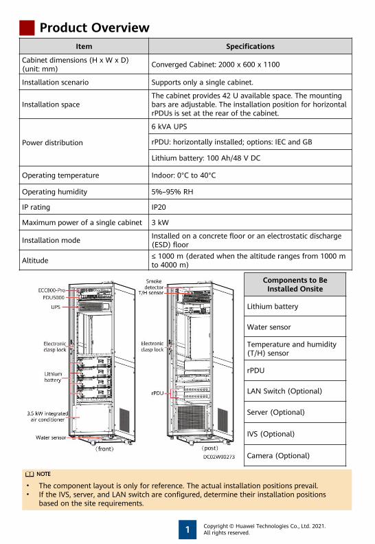
Product OverviewItem Specifications
Cabinet dimensions (H x W x D) (unit: mm)
Converged Cabinet: 2000 x 600 x 1100
Installation scenario Supports only a single cabinet.
Installation spaceThe cabinet provides 42 U available space. The mounting bars are adjustable. The installation position for horizontal rPDUs is set at the rear of the cabinet.
Power distribution
6 kVA UPS
rPDU: horizontally installed; options: IEC and GB
Lithium battery: 100 Ah/48 V DC
Operating temperature Indoor: 0°C to 40°C
Operating humidity 5%–95% RH
IP rating IP20
Maximum power of a single cabinet 3 kW
Installation mode Installed on a concrete floor or an electrostatic discharge (ESD) floor
Altitude ≤ 1000 m (derated when the altitude ranges from 1000 m to 4000 m)
Components to Be Installed Onsite
Lithium battery
Water sensor
Temperature and humidity (T/H) sensor
rPDU
LAN Switch (Optional)
Server (Optional)
IVS (Optional)
Camera (Optional)
• The component layout is only for reference. The actual installation positions prevail.• If the IVS, server, and LAN switch are configured, determine their installation positions
based on the site requirements.
2
Hardware Installation
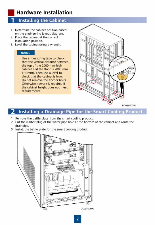
1 Installing the Cabinet
1. Determine the cabinet position based on the engineering layout diagram.
2. Place the cabinet at the correct installation position.
3. Level the cabinet using a wrench.
• Use a measuring tape to check that the vertical distance between the top of the 2000 mm high cabinet and the floor is 2000 mm (+3 mm). Then use a level to check that the cabinet is level.
• Do not remove the anchor bolts. Otherwise, rework is required if the cabinet height does not meet requirements.
2 Installing a Drainage Pipe for the Smart Cooling Product1. Remove the baffle plate from the smart cooling product.2. Cut the rubber plug of the water pipe hole at the bottom of the cabinet and route the
drainpipe. 3. Install the baffle plate for the smart cooling product.
3
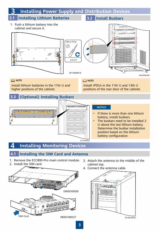
1. Push a lithium battery into the cabinet and secure it.
3 Installing Power Supply and Distribution Devices3.1 Installing Lithium Batteries 12.13.2 Install Busbars
3.3 (Optional) Installing Busbars
• If there is more than one lithium battery, install busbars.
• The busbars need to be installed 2 U above the last lithium battery. Determine the busbar installation position based on the lithium battery configuration.
Install lithium batteries in the 11th U and higher positions of the cabinet.
Install rPDUs in the 11th U and 13th U positions of the rear door of the cabinet.
4 Installing Monitoring Devices
4.1 Installing the SIM Card and Antenna
3. Attach the antenna to the middle of the cabinet top.
4. Connect the antenna cable.
1. Remove the ECC800-Pro main control module.2. Install the SIM card.
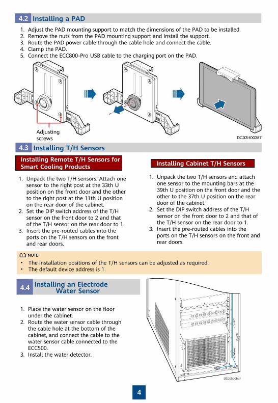
4.2 Installing a PAD
1. Adjust the PAD mounting support to match the dimensions of the PAD to be installed.2. Remove the nuts from the PAD mounting support and install the support.3. Route the PAD power cable through the cable hole and connect the cable.4. Clamp the PAD.5. Connect the ECC800-Pro USB cable to the charging port on the PAD.
Adjusting screws
4
4.3 Installing T/H Sensors
1. Unpack the two T/H sensors. Attach one sensor to the right post at the 33th U position on the front door and the other to the right post at the 11th U position on the rear door of the cabinet.
2. Set the DIP switch address of the T/H sensor on the front door to 2 and that of the T/H sensor on the rear door to 1.
3. Insert the pre-routed cables into the ports on the T/H sensors on the front and rear doors.
• The installation positions of the T/H sensors can be adjusted as required.• The default device address is 1.
Installing Remote T/H Sensors for Smart Cooling Products Installing Cabinet T/H Sensors
1. Unpack the two T/H sensors and attach one sensor to the mounting bars at the 39th U position on the front door and the other to the 37th U position on the rear door of the cabinet.
2. Set the DIP switch address of the T/H sensor on the front door to 2 and that of the T/H sensor on the rear door to 1.
3. Insert the pre-routed cables into the ports on the T/H sensors on the front and rear doors.
4.4 Installing an Electrode Water Sensor
1. Place the water sensor on the floor under the cabinet.
2. Route the water sensor cable through the cable hole at the bottom of the cabinet, and connect the cable to the water sensor cable connected to the ECC500.
3. Install the water detector.
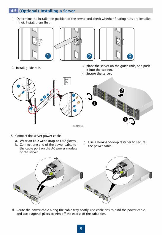
4.5 (Optional) Installing a Server
1. Determine the installation position of the server and check whether floating nuts are installed. If not, install them first.
5
2. Install guide rails. 3. place the server on the guide rails, and push it into the cabinet.
4. Secure the server.
5. Connect the server power cable.
a. Wear an ESD wrist strap or ESD gloves.b. Connect one end of the power cable to
the cable port on the AC power module of the server.
c. Use a hook-and-loop fastener to secure the power cable.
d. Route the power cable along the cable tray neatly, use cable ties to bind the power cable, and use diagonal pliers to trim off the excess of the cable ties.
6
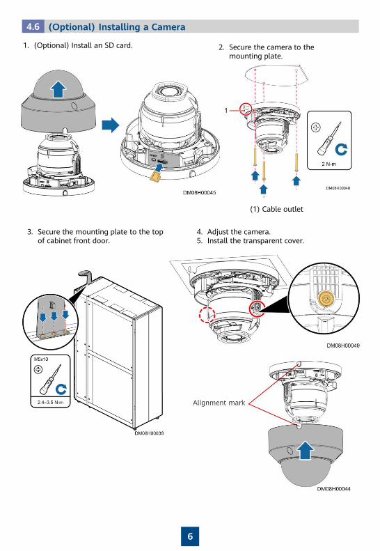
4.6 (Optional) Installing a Camera
1. (Optional) Install an SD card. 2. Secure the camera to the mounting plate.
(1) Cable outlet
4. Adjust the camera.5. Install the transparent cover.
3. Secure the mounting plate to the top of cabinet front door.
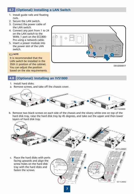
4.7 (Optional) Installing a LAN Switch1. Install guide rails and floating
nuts.2. Secure the LAN switch.3. Connect the power cable of
the LAN switch.4. Connect any port from 1 to 24
on the LAN switch to the WAN_1 port on the ECC800-Pro using a network cable.
5. Insert a power module into the power slot of the LAN switch.
It is recommended that the LAN switch be installed in the 35th U position of the cabinet. You can adjust the position based on the site requirements.
7
4.8 (Optional) Installing an IVS1800
1. Install hard disks.a. Remove screws, and take off the chassis cover.
b. Remove two black screws on each side of the chassis and the silvery white one on top of the hard disk tray, raise the hard disk tray by 45 degrees, and take out the upper and then lower layers of hard disk tray.
c. Place the hard disks with ports facing upwards and align the screw holes on the hard disk tray with the hard disks and fasten the screws.
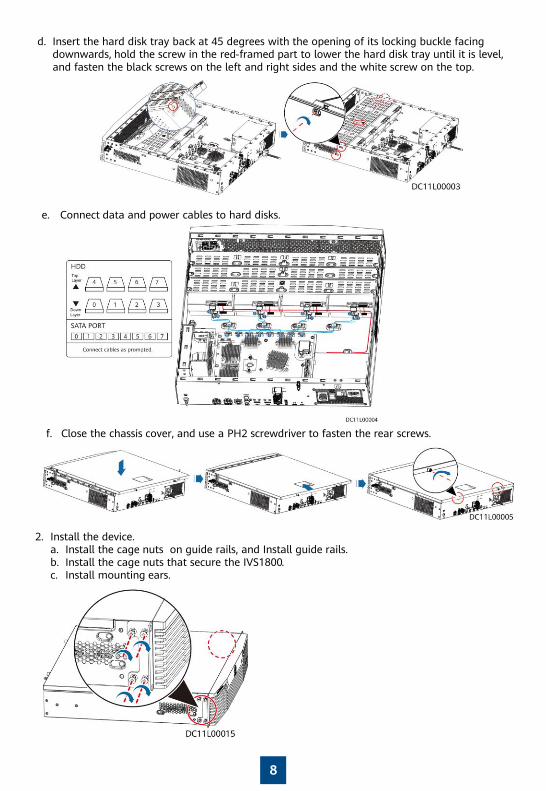
d. Insert the hard disk tray back at 45 degrees with the opening of its locking buckle facing downwards, hold the screw in the red-framed part to lower the hard disk tray until it is level, and fasten the black screws on the left and right sides and the white screw on the top.
e. Connect data and power cables to hard disks.
8
f. Close the chassis cover, and use a PH2 screwdriver to fasten the rear screws.
2. Install the device.a. Install the cage nuts on guide rails, and Install guide rails.b. Install the cage nuts that secure the IVS1800.c. Install mounting ears.
8
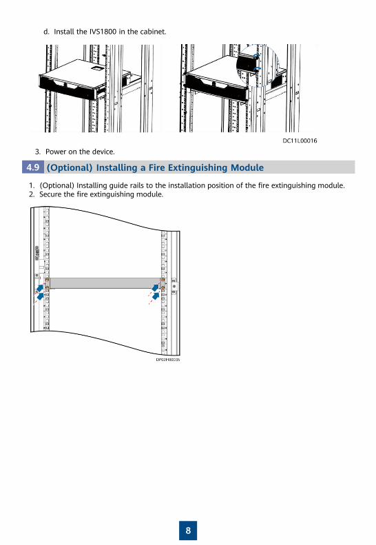
d. Install the IVS1800 in the cabinet.
3. Power on the device.
4.9 (Optional) Installing a Fire Extinguishing Module
1. (Optional) Installing guide rails to the installation position of the fire extinguishing module.2. Secure the fire extinguishing module.
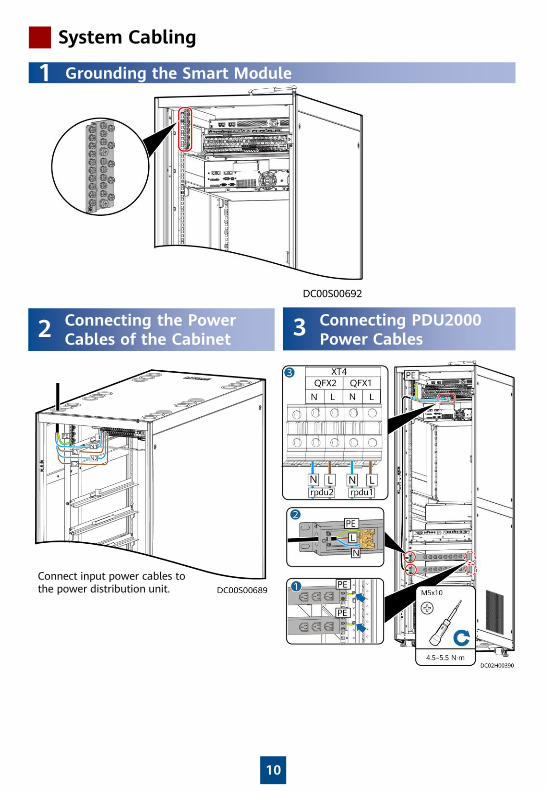
System Cabling
10
1 Grounding the Smart Module
2 Connecting the Power Cables of the Cabinet 3 Connecting PDU2000
Power Cables
Connect input power cables to the power distribution unit.
11
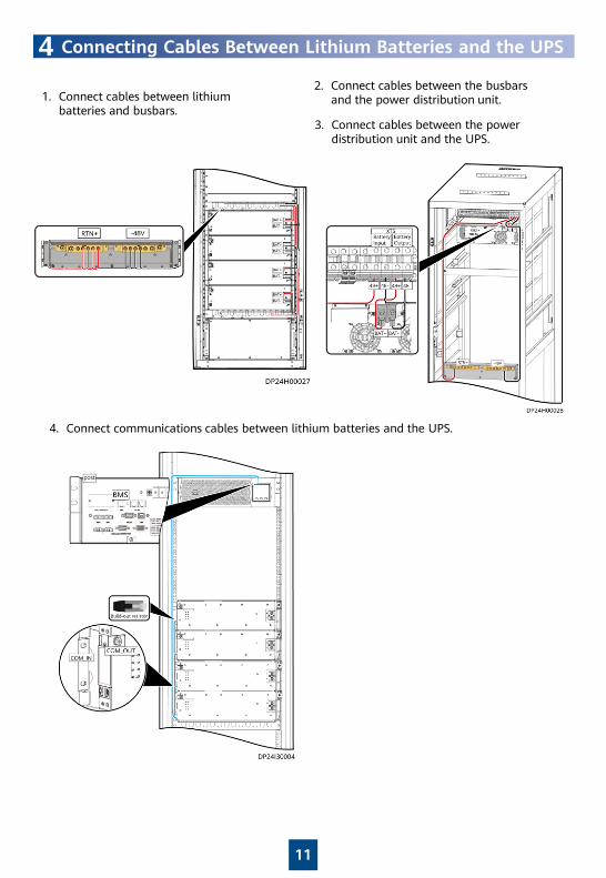
4 Connecting Cables Between Lithium Batteries and the UPS
1. Connect cables between lithium batteries and busbars.
2. Connect cables between the busbarsand the power distribution unit.
3. Connect cables between the power distribution unit and the UPS.
4. Connect communications cables between lithium batteries and the UPS.
12
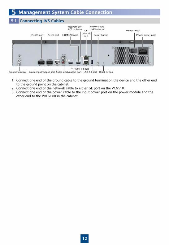
Connecting IVS Cables5.1
1. Connect one end of the ground cable to the ground terminal on the device and the other end to the ground point on the cabinet.
2. Connect one end of the network cable to either GE port on the VCN510.3. Connect one end of the power cable to the input power port on the power module and the
other end to the PDU2000 in the cabinet.
5 Management System Cable Connection
13
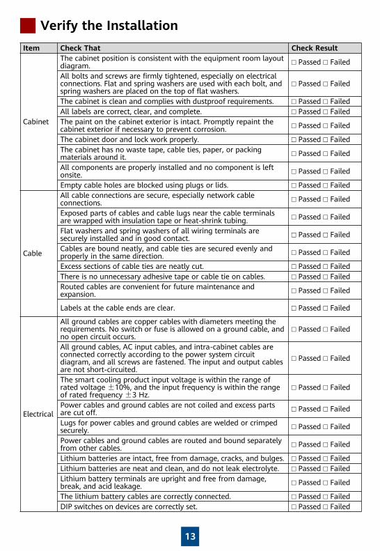
Verify the Installation
Item Check That Check Result
Cabinet
The cabinet position is consistent with the equipment room layout diagram. □ Passed □ Failed
All bolts and screws are firmly tightened, especially on electrical connections. Flat and spring washers are used with each bolt, and spring washers are placed on the top of flat washers.
□ Passed □ Failed
The cabinet is clean and complies with dustproof requirements. □ Passed □ FailedAll labels are correct, clear, and complete. □ Passed □ FailedThe paint on the cabinet exterior is intact. Promptly repaint the cabinet exterior if necessary to prevent corrosion. □ Passed □ Failed
The cabinet door and lock work properly. □ Passed □ FailedThe cabinet has no waste tape, cable ties, paper, or packing materials around it. □ Passed □ Failed
All components are properly installed and no component is left onsite. □ Passed □ Failed
Empty cable holes are blocked using plugs or lids. □ Passed □ Failed
Cable
All cable connections are secure, especially network cable connections. □ Passed □ Failed
Exposed parts of cables and cable lugs near the cable terminals are wrapped with insulation tape or heat-shrink tubing. □ Passed □ Failed
Flat washers and spring washers of all wiring terminals are securely installed and in good contact. □ Passed □ Failed
Cables are bound neatly, and cable ties are secured evenly and properly in the same direction. □ Passed □ Failed
Excess sections of cable ties are neatly cut. □ Passed □ FailedThere is no unnecessary adhesive tape or cable tie on cables. □ Passed □ FailedRouted cables are convenient for future maintenance and expansion. □ Passed □ Failed
Labels at the cable ends are clear. □ Passed □ Failed
Electrical
All ground cables are copper cables with diameters meeting the requirements. No switch or fuse is allowed on a ground cable, and no open circuit occurs.
□ Passed □ Failed
All ground cables, AC input cables, and intra-cabinet cables are connected correctly according to the power system circuit diagram, and all screws are fastened. The input and output cables are not short-circuited.
□ Passed □ Failed
The smart cooling product input voltage is within the range of rated voltage ±10%, and the input frequency is within the range of rated frequency ±3 Hz.
□ Passed □ Failed
Power cables and ground cables are not coiled and excess parts are cut off. □ Passed □ Failed
Lugs for power cables and ground cables are welded or crimped securely. □ Passed □ Failed
Power cables and ground cables are routed and bound separately from other cables. □ Passed □ Failed
Lithium batteries are intact, free from damage, cracks, and bulges. □ Passed □ FailedLithium batteries are neat and clean, and do not leak electrolyte. □ Passed □ FailedLithium battery terminals are upright and free from damage, break, and acid leakage. □ Passed □ Failed
The lithium battery cables are correctly connected. □ Passed □ FailedDIP switches on devices are correctly set. □ Passed □ Failed
14
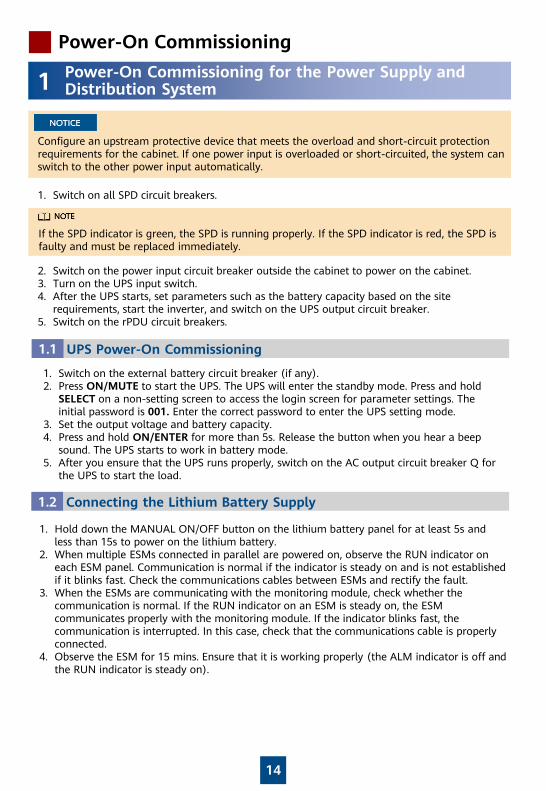
Power-On Commissioning
1 Power-On Commissioning for the Power Supply and Distribution System
1. Switch on all SPD circuit breakers.
Configure an upstream protective device that meets the overload and short-circuit protection requirements for the cabinet. If one power input is overloaded or short-circuited, the system can switch to the other power input automatically.
If the SPD indicator is green, the SPD is running properly. If the SPD indicator is red, the SPD is faulty and must be replaced immediately.
2. Switch on the power input circuit breaker outside the cabinet to power on the cabinet.3. Turn on the UPS input switch.4. After the UPS starts, set parameters such as the battery capacity based on the site
requirements, start the inverter, and switch on the UPS output circuit breaker.5. Switch on the rPDU circuit breakers.
UPS Power-On Commissioning1.1
1. Switch on the external battery circuit breaker (if any).2. Press ON/MUTE to start the UPS. The UPS will enter the standby mode. Press and hold
SELECT on a non-setting screen to access the login screen for parameter settings. The initial password is 001. Enter the correct password to enter the UPS setting mode.
3. Set the output voltage and battery capacity.4. Press and hold ON/ENTER for more than 5s. Release the button when you hear a beep
sound. The UPS starts to work in battery mode.5. After you ensure that the UPS runs properly, switch on the AC output circuit breaker Q for
the UPS to start the load.
Connecting the Lithium Battery Supply1.2
1. Hold down the MANUAL ON/OFF button on the lithium battery panel for at least 5s and less than 15s to power on the lithium battery.
2. When multiple ESMs connected in parallel are powered on, observe the RUN indicator on each ESM panel. Communication is normal if the indicator is steady on and is not established if it blinks fast. Check the communications cables between ESMs and rectify the fault.
3. When the ESMs are communicating with the monitoring module, check whether the communication is normal. If the RUN indicator on an ESM is steady on, the ESM communicates properly with the monitoring module. If the indicator blinks fast, the communication is interrupted. In this case, check that the communications cable is properly connected.
4. Observe the ESM for 15 mins. Ensure that it is working properly (the ALM indicator is off and the RUN indicator is steady on).
15
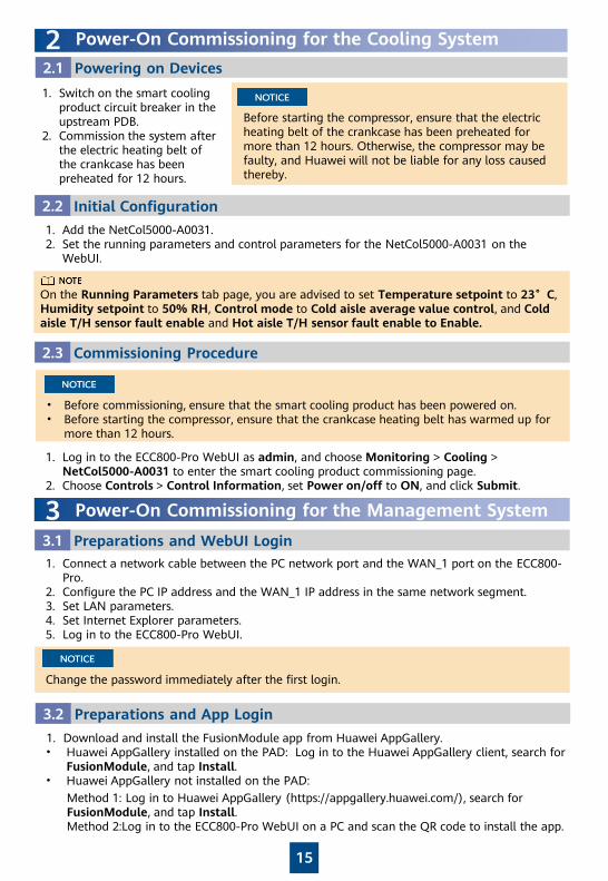
2 Power-On Commissioning for the Cooling System
1. Switch on the smart cooling product circuit breaker in the upstream PDB.
2. Commission the system after the electric heating belt of the crankcase has been preheated for 12 hours.
Before starting the compressor, ensure that the electric heating belt of the crankcase has been preheated for more than 12 hours. Otherwise, the compressor may be faulty, and Huawei will not be liable for any loss caused thereby.
Powering on Devices2.1
1. Add the NetCol5000-A0031.2. Set the running parameters and control parameters for the NetCol5000-A0031 on the
WebUI.
Initial Configuration2.2
On the Running Parameters tab page, you are advised to set Temperature setpoint to 23°C, Humidity setpoint to 50% RH, Control mode to Cold aisle average value control, and Cold aisle T/H sensor fault enable and Hot aisle T/H sensor fault enable to Enable.
• Before commissioning, ensure that the smart cooling product has been powered on.• Before starting the compressor, ensure that the crankcase heating belt has warmed up for
more than 12 hours.
Commissioning Procedure2.3
1. Log in to the ECC800-Pro WebUI as admin, and choose Monitoring > Cooling >NetCol5000-A0031 to enter the smart cooling product commissioning page.
2. Choose Controls > Control Information, set Power on/off to ON, and click Submit.
3 Power-On Commissioning for the Management System
Preparations and WebUI Login3.1
Change the password immediately after the first login.
1. Connect a network cable between the PC network port and the WAN_1 port on the ECC800-Pro.
2. Configure the PC IP address and the WAN_1 IP address in the same network segment.3. Set LAN parameters.4. Set Internet Explorer parameters.5. Log in to the ECC800-Pro WebUI.
Preparations and App Login3.2
1. Download and install the FusionModule app from Huawei AppGallery.• Huawei AppGallery installed on the PAD: Log in to the Huawei AppGallery client, search for
FusionModule, and tap Install.• Huawei AppGallery not installed on the PAD:
Method 1: Log in to Huawei AppGallery (https://appgallery.huawei.com/), search for FusionModule, and tap Install.Method 2:Log in to the ECC800-Pro WebUI on a PC and scan the QR code to install the app.
16
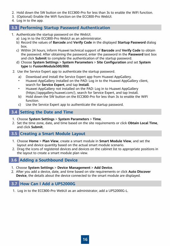
Performing Startup Password Authentication3.3
1. Authenticate the startup password on the WebUI.a) Log in to the ECC800-Pro WebUI as an administrator.b) Record the values of Barcode and Verify Code in the displayed Startup Password dialog
box.c) Within 24 hours, inform Huawei technical support of Barcode and Verify Code to obtain
the password. After obtaining the password, enter the password in the Password text box and click Submit to complete the authentication of the startup password.
d) Choose System Settings > System Parameters > Site Configuration and set System type to FusionModule500/800.
2. Hold down the SW button on the ECC800-Pro for less than 3s to enable the WiFi function.3. (Optional) Enable the WiFi function on the ECC800-Pro WebUI.4. Log in to the app.
2. Use the Service Expert app to authenticate the startup password.
a) Download and install the Service Expert app from Huawei AppGallery.• Huawei AppGallery installed on the PAD: Log in to the Huawei AppGallery client,
search for Service Expert, and tap Install. • Huawei AppGallery not installed on the PAD: Log in to Huawei AppGallery
(https://appgallery.huawei.com/), search for Service Expert, and tap Install.b) Hold down the SW button on the ECC800-Pro for less than 3s to enable the WiFi
function.c) Use the Service Expert app to authenticate the startup password.
Creating a Smart Module Layout3.5
1. Choose Home > Plan View, create a smart module in Smart Module View, and set the layout and device quantity based on the actual smart module scenario.
2. Drag the icons of registered devices and devices on the cabinet list to appropriate positions in the layout to create a smart module plan view.
Setting the Date and Time3.4
1. Choose System Settings > System Parameters > Time.2. Set the time zone, date, and time based on the site requirements or click Obtain Local Time,
and click Submit.
Adding a Southbound Device3.6
1. Choose System Settings > Device Management > Add Device.2. After you add a device, date, and time based on site requirements or click Auto Discover
Device, the details about the device connected to the smart module are displayed.
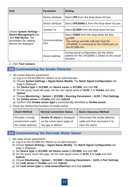
How Can I Add a UPS2000G3.7
1. Log in to the ECC800-Pro WebUI as an administrator, add a UPS2000G-L.
17
2. Click Test Connect.
Path Parameter Setting
Choose System Settings > Device Management and click Add Device. The parameters for adding devices are displayed.
Device attribute Select UPS from the drop-down list box.
Device attribute Select UPS2000G-L from the drop-down list box.
Connect To Select ECC800 from the drop-down list box.
Communications Port
Select COM4 from the drop-down list box.
Device AddressDuring actual configuration, set the device address for the UPS2000G-L based on the actual situation.
The setting example indicates that the UPS2000G is connected to the COM4 port on the ECC800-Pro.
Commissioning the Smoke DSetector3.8
1. Set smoke detector parameters.a) Log in to the ECC800-Pro WebUI as an administrator.b) Choose System Settings > Signal Name Modify. The Batch Signal Configuration tab
page is displayed.c) Set Device type to ECC800, set Device name to ECC800, and click OK.d) On the query result tab page, set the new signal name of AI/DI_1 to Smoke and click
Submit.e) Choose Monitoring > System > ECC800 > Running Parameters > AI/DI_1 Port Settings.f) Set Smoke sensor to Enable and click Submit.g) Confirm that Smoke sensor type is automatically identified as Smoke sensor.
2. Check the monitoring functions of smoke sensor.
Check Method Normal Connection Status Alarm Clearance Method
Simulate a smoky environment under the smoke detector.
Smoke DI alarm is displayed on the active alarm page of the app or WebUI.
Disconnect the smoke detector cable and then reconnect it to clear the alarm.
Commissioning the Electrode Water Sensor3.9
1. Set water sensor parameters.a) Log in to the ECC800-Pro WebUI as an administrator.b) Choose System Settings > Signal Name Modify. The Batch Signal Configuration tab
page is displayed.c) Set Device type to ECC800, set Device name to ECC800, and click OK.d) On the query result tab page, set the new signal name of AI/DI_2 to Leak and click
Submit.e) Choose Monitoring > System > ECC800 > Running Parameters > AI/DI_2 Port Settings.f) Set Leak sensor to Enable and click Submit.g) Set Leak sensor type to Leak sensor(Electroc) and click Submit.
18
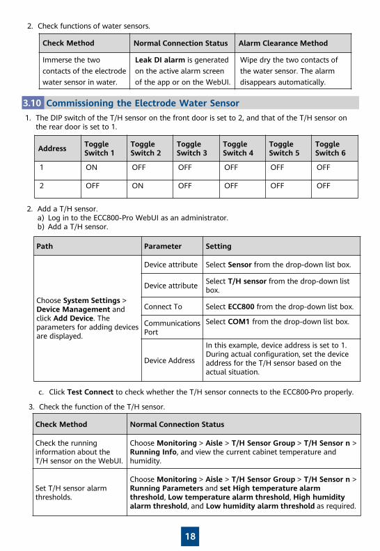
2. Check functions of water sensors.
Check Method Normal Connection Status Alarm Clearance Method
Immerse the two contacts of the electrode water sensor in water.
Leak DI alarm is generated on the active alarm screen of the app or on the WebUI.
Wipe dry the two contacts of the water sensor. The alarm disappears automatically.
Commissioning the Electrode Water Sensor3.10
1. The DIP switch of the T/H sensor on the front door is set to 2, and that of the T/H sensor on the rear door is set to 1.
2. Add a T/H sensor.a) Log in to the ECC800-Pro WebUI as an administrator.b) Add a T/H sensor.
Address Toggle Switch 1
Toggle Switch 2
Toggle Switch 3
Toggle Switch 4
Toggle Switch 5
Toggle Switch 6
1 ON OFF OFF OFF OFF OFF
2 OFF ON OFF OFF OFF OFF
Path Parameter Setting
Choose System Settings > Device Management and click Add Device. The parameters for adding devices are displayed.
Device attribute Select Sensor from the drop-down list box.
Device attribute Select T/H sensor from the drop-down list box.
Connect To Select ECC800 from the drop-down list box.
Communications Port
Select COM1 from the drop-down list box.
Device Address
In this example, device address is set to 1. During actual configuration, set the device address for the T/H sensor based on the actual situation.
c. Click Test Connect to check whether the T/H sensor connects to the ECC800-Pro properly.
3. Check the function of the T/H sensor.
Check Method Normal Connection Status
Check the running information about the T/H sensor on the WebUI.
Choose Monitoring > Aisle > T/H Sensor Group > T/H Sensor n > Running Info, and view the current cabinet temperature and humidity.
Set T/H sensor alarm thresholds.
Choose Monitoring > Aisle > T/H Sensor Group > T/H Sensor n > Running Parameters and set High temperature alarm threshold, Low temperature alarm threshold, High humidityalarm threshold, and Low humidity alarm threshold as required.
19
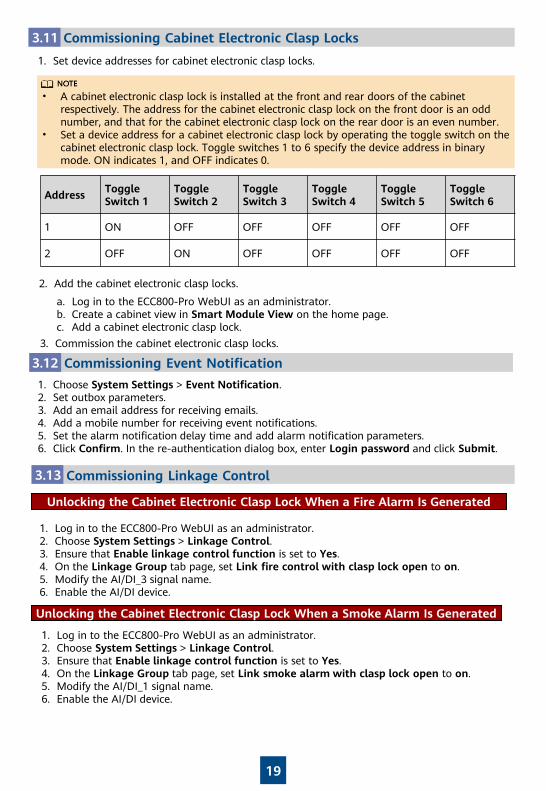
Commissioning Cabinet Electronic Clasp Locks3.11
1. Set device addresses for cabinet electronic clasp locks.
• A cabinet electronic clasp lock is installed at the front and rear doors of the cabinet respectively. The address for the cabinet electronic clasp lock on the front door is an odd number, and that for the cabinet electronic clasp lock on the rear door is an even number.
• Set a device address for a cabinet electronic clasp lock by operating the toggle switch on the cabinet electronic clasp lock. Toggle switches 1 to 6 specify the device address in binary mode. ON indicates 1, and OFF indicates 0.
Commissioning Event Notification3.12
1. Choose System Settings > Event Notification.2. Set outbox parameters.3. Add an email address for receiving emails.4. Add a mobile number for receiving event notifications.5. Set the alarm notification delay time and add alarm notification parameters.6. Click Confirm. In the re-authentication dialog box, enter Login password and click Submit.
Address Toggle Switch 1
Toggle Switch 2
Toggle Switch 3
Toggle Switch 4
Toggle Switch 5
Toggle Switch 6
1 ON OFF OFF OFF OFF OFF
2 OFF ON OFF OFF OFF OFF
2. Add the cabinet electronic clasp locks.
a. Log in to the ECC800-Pro WebUI as an administrator.b. Create a cabinet view in Smart Module View on the home page.c. Add a cabinet electronic clasp lock.
3. Commission the cabinet electronic clasp locks.
3.13 Commissioning Linkage Control
1. Log in to the ECC800-Pro WebUI as an administrator.2. Choose System Settings > Linkage Control.3. Ensure that Enable linkage control function is set to Yes.4. On the Linkage Group tab page, set Link smoke alarm with clasp lock open to on.5. Modify the AI/DI_1 signal name.6. Enable the AI/DI device.
Unlocking the Cabinet Electronic Clasp Lock When a Smoke Alarm Is Generated
1. Log in to the ECC800-Pro WebUI as an administrator.2. Choose System Settings > Linkage Control.3. Ensure that Enable linkage control function is set to Yes.4. On the Linkage Group tab page, set Link fire control with clasp lock open to on.5. Modify the AI/DI_3 signal name.6. Enable the AI/DI device.
Unlocking the Cabinet Electronic Clasp Lock When a Fire Alarm Is Generated
20
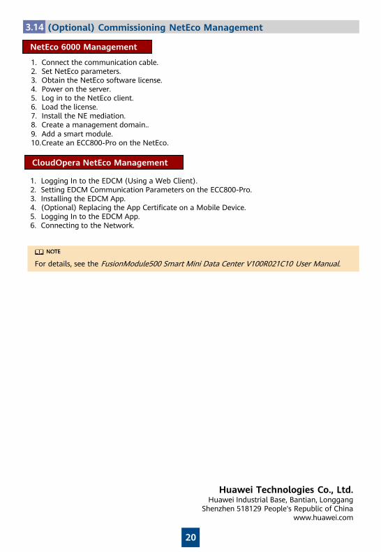
3.14 (Optional) Commissioning NetEco Management
NetEco 6000 Management
1. Connect the communication cable.2. Set NetEco parameters.3. Obtain the NetEco software license.4. Power on the server.5. Log in to the NetEco client.6. Load the license.7. Install the NE mediation.8. Create a management domain..9. Add a smart module.10.Create an ECC800-Pro on the NetEco.
For details, see the FusionModule500 Smart Mini Data Center V100R021C10 User Manual.
CloudOpera NetEco Management
1. Logging In to the EDCM (Using a Web Client).2. Setting EDCM Communication Parameters on the ECC800-Pro.3. Installing the EDCM App.4. (Optional) Replacing the App Certificate on a Mobile Device.5. Logging In to the EDCM App.6. Connecting to the Network.
Huawei Technologies Co., Ltd.Huawei Industrial Base, Bantian, Longgang
Shenzhen 518129 People's Republic of Chinawww.huawei.com
DO/12V
AIDI_1 AIDI_2
AIDI_3RF_Z4GSW
COM1/AIDI_4
COM2/AIDI_5
COM3/12V WAN1 LAN1/POE
LAN2/POEWAN2COM4/CAN
WLAN
USB
HUAWEI
......
L
1 13 14
XT2UPS OutputUPS Input QFX4 QFX3 QFX2 QFX1
52
N LN L
XT1Main Input
L15 1611 1276
N8
A/C
N L
XT3 XT4
N L N L N L N
XT5Battery Input Battery Output
BAT_In+ BAT_In- BAT_Out+ BAT_Out-
3 4
N LFU
N ECC
1 2 3 4
QFX5
9 10
N L17 18
RTN+
02
-48V
COM4/CAN
RS485
AI/DI_1WAN_1
COM3/12V
USB
4G
COM1/AIDI_4
COM2/AIDI_5
RS485_OUT RS485_INRS485_IN
BMS
AI/DI_2
RS485_IN RS485_OUT RS485_IN
GE1
RS485_INRS485_OUTRS485_IN
BMS
AI/DI_3
UPS
SPD
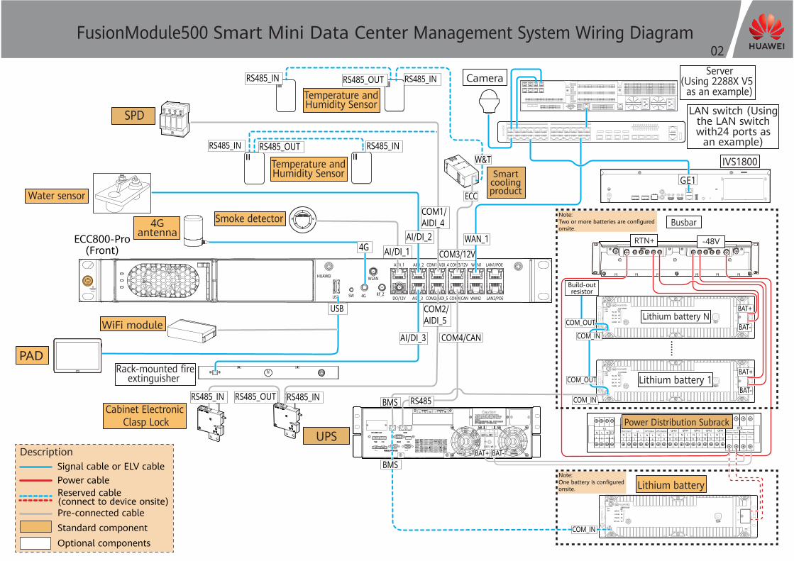
FusionModule500 Smart Mini Data Center Management System Wiring Diagram
Camera
COM_OUT
COM_IN
COM_IN
Build-outresistor
Lithium battery 1
Lithium battery NCOM_OUT
BAT+ BAT-
Note: Two or more batteries are configuredonsite.
COM_IN
Note: One battery is configuredonsite.
Power Distribution Subrack
BAT+
BAT-
BAT+
BAT-
Signal cable or ELV cablePower cable
Rack-mounted fireextinguisher
Smartcoolingproduct
Pre-connected cable
Busbar
Reserved cable(connect to device onsite)
Optional componentsStandard component
PAD
Temperature and Humidity Sensor
Temperature and Humidity Sensor
Smoke detector4GantennaECC800-Pro
(Front)
Water sensor
WiFi module
Cabinet Electronic Clasp Lock
Lithium battery
IVS1800
Server(Using 2288X V5 as an example)
LAN switch (Usingthe LAN switchwith24 ports as
an example)
Description
ECC
W&T


