Embed Size (px)
Citation preview
Quick Guide
WITTUR Lift Drive WLD 302
www.wittur.com
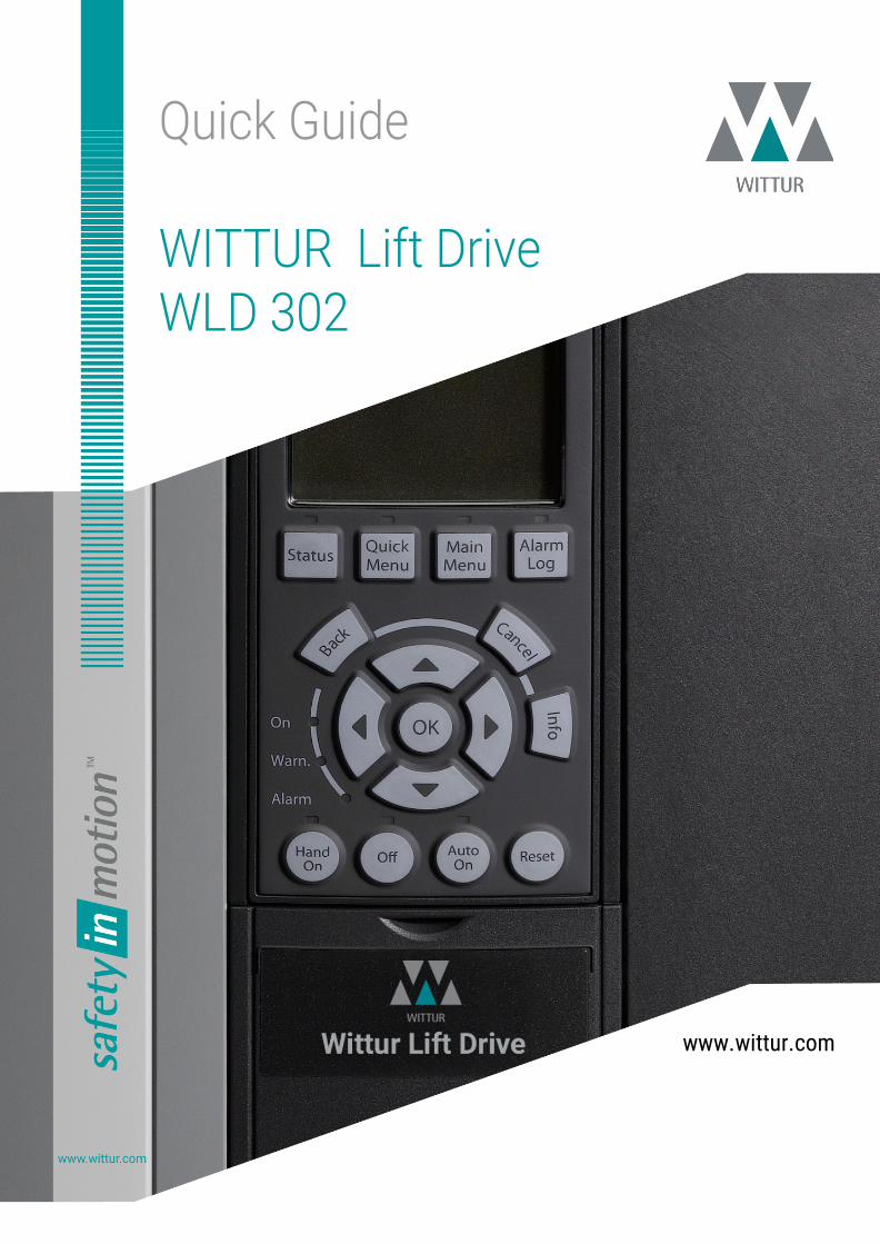
1 Inhalt 1 Introduction ................................................................................................... 7
Qualified Personnel ............................................................................................. 7 Additional Resources .......................................................................................... 7 Symbols used in this document ............................................................................ 7
2 Safety ........................................................................................................... 8 High voltage ...................................................................................................... 8 Unintended start ................................................................................................ 8 Discharge time .................................................................................................. 8 Mechanical Holding Brake .................................................................................... 8 Crane, Lifts and Hoists ........................................................................................ 8 Motor-generated Over-voltage ............................................................................. 8 Back-EMF from PM motor operation ...................................................................... 9 Safe Stop .......................................................................................................... 9
3 Installation ..................................................................................................... 9 Ingress protection .............................................................................................. 9 Frequency Converter and motor pre-installation check list ..................................... 10 Mechanical Installation Cooling .......................................................................... 10 Lifting ............................................................................................................. 10 Mounting ......................................................................................................... 10 Tightening Torques ........................................................................................... 11 Electrical Installation ........................................................................................ 11 Wiring isolation ................................................................................................ 11 Wire Type and Ratings ...................................................................................... 12 Earth (Grounding) ............................................................................................ 12 Leakage Current .............................................................................................. 12 Using RCDs ..................................................................................................... 13
Grounding Using Shielded Cable...................................................................... 13 Motor connection ............................................................................................. 13 Back-EMF from PM motor .................................................................................. 14 Brake Resistor ................................................................................................. 14 Environment .................................................................................................... 14 Schematic drawing, examples ............................................................................ 15
Schematic Lift Drive LD302 ............................................................................ 15 Schematic Lift Controller MCO 361 .................................................................. 16 Location Terminals ........................................................................................ 17
Examples ........................................................................................................ 18 Operation with Motor Contactors K1 and K2 ..................................................... 18 Operation without Motor Contactors ................................................................ 19
Quick Guide Wittur Lift Drive WLD302
Wittur Lift Drive WLD 302, GM.8.4286.EN; Rev. 07. May 2020
3
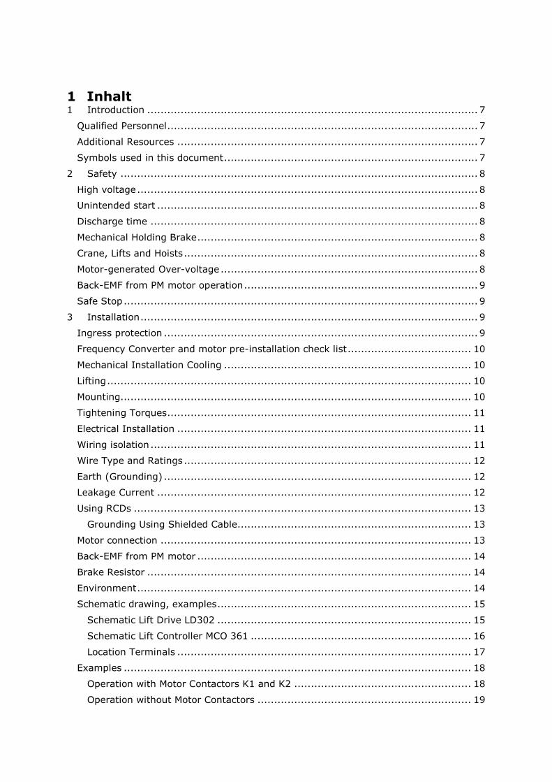
Encoder Connections on Terminal X55, Examples ................................................. 19 Incremental TTL Encoder, 5V, Supplied by MCO 361 .......................................... 19 Incremental TTL Encoder, 5V, external Power supply ......................................... 20 Absolute Encoder, 24V, single turn SSI/Endat, Supplied by MCO 361 ................... 20
4 Programming ................................................................................................ 21 Local Control Panel ........................................................................................... 21
Display functional group C, Navigation ............................................................. 23 Restoring Default Settings ................................................................................. 24
Manual Initialization ...................................................................................... 24 Main Menu ...................................................................................................... 24
Parameter groups overview ............................................................................ 25 Parameter overview ......................................................................................... 26
5 Commissioning ............................................................................................. 29 Guideline for simple and fast setup ..................................................................... 29 Commissioning using Quick Menu ....................................................................... 29 Setting Language ............................................................................................. 30 Setting up motor data....................................................................................... 30 Setting up motor data by motor number ............................................................. 30 Update Quick Menu .......................................................................................... 30 Setup Motor Construction .................................................................................. 30 Update Quick Menu .......................................................................................... 31 Setup motor data for asynchronous motor .......................................................... 31 Setup motor data for PM motor .......................................................................... 31 Setting up incremental encoder data .................................................................. 32 Setting up Mechanical data ................................................................................ 32 Predefined Comfort Settings .............................................................................. 32 Setting up control source .................................................................................. 33 Setting up control type ..................................................................................... 33 Setting up special functions ............................................................................... 33 Setting up in- and outputs ................................................................................. 33
6 Functional descriptions .................................................................................. 33 Automatic motor adaptation, AMA ...................................................................... 33 Motor adaption description ................................................................................ 34 AMA at standstill .............................................................................................. 34 AMA during operation ....................................................................................... 34 Mechanical Brake Control .................................................................................. 35 Speeds, Acceleration, Jerks ............................................................................... 36
Quick Guide Wittur Lift Drive WLD302
Wittur Lift Drive WLD 302, GM.8.4286.EN; Rev. 07. May 2020
4
Speeds ........................................................................................................... 36 Overview of the motion profile ........................................................................... 36 Linearstart ...................................................................................................... 37 Predefined Comfort Settings .............................................................................. 37 Deceleration distance ....................................................................................... 37 Speed PID controller ......................................................................................... 38 Speed controller settings at start ....................................................................... 38 Speed controller settings during operation .......................................................... 38 Control sources P19-66 ..................................................................................... 39 Operation with serial bus DCP3 and DCP4 ........................................................... 39 Connections .................................................................................................... 39 Data readouts .................................................................................................. 39 DCP4 settings .................................................................................................. 39 Operation with Can Open DSP417 ...................................................................... 40 Connections .................................................................................................... 40 Speed setting .................................................................................................. 40 Data readouts .................................................................................................. 40 Position mode .................................................................................................. 41 Operation with absolute encoder (SSI/EnDat/BISS-C)........................................... 41 Operation with UPS, Evacuation mode ................................................................ 42 Load direction .................................................................................................. 42 UPS Mode ....................................................................................................... 42 Operation VVC+ open loop for induction motors ................................................... 42 Extended Settings ............................................................................................ 43 Simple Control ................................................................................................. 43 Dir=V0 ........................................................................................................... 44 Softstop at dir=0 ............................................................................................. 44 Short floor function .......................................................................................... 44 UPS operation in light load direction ................................................................... 45
Terminal X59.1 – X59.7 ................................................................................. 45 Monitoring functionalities .................................................................................. 46 Monitoring of brake feedback due to DIN EN 81-20 .............................................. 46 Test instruction for the installation: .................................................................... 47 Monitoring of the governor feedback contact ....................................................... 47 Monitoring of motor contactors .......................................................................... 48 Monitoring of STO ............................................................................................ 50 Standby function .............................................................................................. 50
Quick Guide Wittur Lift Drive WLD302
Wittur Lift Drive WLD 302, GM.8.4286.EN; Rev. 07. May 2020
5
Test run mode ................................................................................................. 50 Gear ratio test function ..................................................................................... 50 Safety gear release function .............................................................................. 50 Alarm log ........................................................................................................ 50 Alarm log of the drive ....................................................................................... 50 Alarm log of the Lift controller ........................................................................... 51
7 Operation ..................................................................................................... 51 Startup ........................................................................................................... 51 Test ................................................................................................................ 51 Car direction .................................................................................................... 51 Uncontrolled movement (With absolute encoder) ................................................. 51 Start-error or Track-error or accelerates unexpected or does not move ................... 52 Encoder function .............................................................................................. 52 Encoder Auto tuning P19-03 .............................................................................. 52 Encoder pulses ................................................................................................ 52
Noise or vibrations during acceleration or deceleration (low frequency) ................ 52 Noise during operation ...................................................................................... 53 Optimization .................................................................................................... 53 Start Behavior ................................................................................................. 53 Controller behavior during operation ................................................................... 54 Parameters for Stop behavior ............................................................................ 54
8 Troubleshooting ............................................................................................ 54 High Motor current on asynchronous motors ........................................................ 54 High motor current on PM motors....................................................................... 54 Motor noise or drive noise at motoric operation .................................................... 54 Motor noise, encoder failures, unstable operation ................................................. 55 Earth fault alarm at start ................................................................................... 55 Sporadic A38 during operation ........................................................................... 55
9 Appendix...................................................................................................... 56 Wiring Examples with Parameter setup ............................................................... 56 Mode 0, digital, low speed priority ...................................................................... 56 Mode 0, digital, low speed priority ...................................................................... 57 Mode 0, 24V control signals to lift controller used ................................................. 58 Mode 0, digital, low speed priority ...................................................................... 59 Mode 1, digital, high speed priority ..................................................................... 60 Mode 1, slow speed direction ............................................................................. 61 Mode 4, binary 1 .............................................................................................. 62
Quick Guide Wittur Lift Drive WLD302
Wittur Lift Drive WLD 302, GM.8.4286.EN; Rev. 07. May 2020
6
Mode 6, binary 2 .............................................................................................. 63 Mode 7, digital, low speed priority, direction priority down .................................... 64 Mode 8, HTL-encoder, digital 1, direction priority up ............................................. 65 Bus controlled /DCP3/DCP4 ............................................................................... 67 Monitoring of motor contactors .......................................................................... 68 Monitoring of motor contactors .......................................................................... 69 Monitoring brake feedback 1, normal open contacts ............................................. 70 Monitoring brake feedback 2, normal closed contacts ........................................... 71 Start and Stop Sequences ................................................................................. 72 Drive Motor Database ....................................................................................... 73 Messages ........................................................................................................ 73 Warnings and Alarms ........................................................................................ 73
Warnings and Alarms in P 19-81 ..................................................................... 73 Further Warnings and Alarms ............................................................................ 79
Quick Guide Wittur Lift Drive WLD302
Wittur Lift Drive WLD 302, GM.8.4286.EN; Rev. 07. May 2020
7
1 Introduction This manual is a guideline for using Danfoss frequency converter series, Lift Drive LD 302, Automation Drive FC 302 regarding design, installation, wiring and parameterization. Fundamental knowledge about elevators and frequency converters are essential. Fundamental knowledge is not a part of the manual. For elevators and the use of frequency converter, the national and local regulations and safety requirements must be complied. Regarding handling and use of frequency converters it is recommended additional to read and understand the available literature for Automation Drive FC 300 and Lift Drive LD 302 to be able to work with the system safely and professionally, particularly observe the hints and cautionary remarks.
Qualified Personnel Only qualified personnel should carry out Installation, commissioning and maintenance of the frequency converter. Qualified personnel are trained personnel who are authorized to fit, install, commission, ground and label equipment, systems, and circuits in accordance with the standards for safety technology and who are familiar with the safety concepts of automation engineering. Additionally, the personnel must be familiar with all the instructions and safety measures described in supplemental publications and manuals are available from Danfoss. They must have suitable safety equipment and be trained in first aid.
Additional Resources Other resources are available to understand advanced frequency converter functions and programming. Supplemental publications and manuals are available from Danfoss: Operating Instructions VLT® Automation Drive Design Guide, VLT® Automation Drive Programming Guide VLT® Automation Drive Operating Instructions VLT® Lift Drive LD 302 See for listings: http://www.danfoss.com/BusinessAreas/DrivesSolutions/Documentations/VLT+Technical+Documentation.htm
Symbols used in this document The following symbols are used in this manual.
Indicates a potentially hazardous situation which, if not avoided, could result in death or serious injury.
Indicates a potentially hazardous situation which, if not avoided, may result in minor or moderate injury. It may also be used to alert against unsafe practices.
Indicates a situation that may result in equipment or property-damage-only accidents.
Indicates highlighted information that should be regarded with attention to avoid mistakes or operate equipment at less than optimal performance.
Quick Guide Wittur Lift Drive WLD302
Wittur Lift Drive WLD 302, GM.8.4286.EN; Rev. 07. May 2020
8
2 Safety
High voltage Frequency converters are connected to hazardous mains voltages. Extreme care should be taken to protect against shock. Only trained personnel familiar with electronic equipment should install, start, or maintain this equipment.
Unintended start When the frequency converter is connected to the AC mains, the motor may be started by means of an external switch, a serial bus command, an input reference signal, or a cleared fault condition. Use appropriate cautions to guard against an unintended start.
Discharge time Frequency converters contain DC-link capacitors that can remain charged even when the frequency converter is not powered. To avoid electrical hazards, disconnect AC mains, any permanent magnet type motors, and any remote DC link power supplies, including battery backups, UPS and DC-link connections to other frequency converters. Wait for the capacitors to fully discharge before performing any service or repair work. The amount of wait time is listed in the Discharge Time table. Failure to wait the specified time after power has been removed before doing service or repair could result in death or serious injury.
Discharge Time table Power range [kW] Minimum waiting time
[min] 0.37–7.5 4 11–90 15 High voltage may be present even when the warning LED indicator lights are off.
Mechanical Holding Brake A mechanical holding brake mounted directly on the motor shaft normally performs static braking. In some applications, the static holding torque is working as static holding of the motor shaft (usually synchronous permanent motors). A holding brake is either controlled by a PLC or directly by a digital output from the frequency converter (relay or solid state).
When the holding brake is included in a safety chain: The frequency converter cannot provide a safe control of a mechanical brake. A redundancy circuitry for the brake control must be included in the total installation.
Crane, Lifts and Hoists The controlling of external brakes must always have a redundant system. The frequency converter can in no circumstances be the primary safety circuit. Comply with relevant standards. It is recommended to disable protection mode in hoisting applications.
Motor-generated Over-voltage The voltage in the intermediate circuit is increased when the motor acts as a generator.
Quick Guide Wittur Lift Drive WLD302
Wittur Lift Drive WLD 302, GM.8.4286.EN; Rev. 07. May 2020
9
Back-EMF from PM motor operation If coasted at high rpm the PM motor back-EMF may potentially exceed the maximum voltage tolerance of the frequency converter and cause damage. If it is possible that the motor may overspeed then it is recommended to equip a brake resistor.
Safe Stop After installation and before first operation, perform a commissioning test of an installation or application, using Safe Stop. Perform the test again after each modification of the installation or application involving the Safe Stop.
A passed commissioning test is mandatory after first installation and after each change to the safety installation. The Safe Stop function can be used for asynchronous, synchronous and permanent magnet motors. Two faults can occur in the power semiconductor of the frequency converter. When using synchronous or permanent magnet motors a residual rotation can result from the faults. The rotation can be calculated to Angle = 360/(Number of Poles). The application using synchronous or permanent magnet motors must take this residual rotation into consideration and ensure that it does not pose a safety risk. This situation is not relevant for asynchronous motors.
3 Installation Installation Site Check List
• The frequency converter relies on the ambient air for cooling. Observe the limitations on ambient air temperature for optimal operation.
• Ensure that the installation location has sufficient support strength to mount the frequency converter.
• Keep the manual, drawings, and diagrams accessible for detailed installation and operation instructions. It is important that the manual is available for equipment operators.
• Locate equipment as near to the motor as possible. Keep motor cables as short as possible.
• Check the motor characteristics for actual tolerances. • Ensure that the ingress protection rating of the frequency converter is suitable for
the installation environment. IP55 (NEMA 12) or IP66 (NEMA 4) enclosures may be necessary.
Ingress protection IP54, IP55 and IP66 ratings can only be guaranteed if the unit is properly closed. • Ensure that all cable glands and unused holes for glands are properly sealed • Ensure that the unit cover is properly closed.
Device damage through contamination. Do not leave the frequency converter uncovered. For “spark-free” installations according to European Agreement concerning International Carriage of Dangerous Goods by Inland Waterways (ADN_2011 ###), refer to VLT® Automation Drive FC 300 Design Guide.
Quick Guide Wittur Lift Drive WLD302
Wittur Lift Drive WLD 302, GM.8.4286.EN; Rev. 07. May 2020
10
Frequency Converter and motor pre-installation check list • Compare the model number of unit on the nameplate to what was ordered to verify
the proper equipment. • Ensure each of the following are rated for same voltage:
Mains (power), Frequency converter and Motor • Ensure that the frequency converter output current rating is equal to or greater than
motor full load current for peak motor performance. Motor size and frequency converter power must match for proper overload protection. If frequency converter rating is less than motor, full motor output cannot be achieved.
Mechanical Installation Cooling • To provide cooling airflow, mount the unit to a solid flat surface or to the optional
back plate. • Top and bottom clearance for air cooling must be provided. Generally, 100-225 mm
(4-10 in) is required. See specification for clearance requirements.
• Improper mounting can result in overheating and reduced performance. • Derating for temperatures starting between 40 °C (104 °F) and 50 °C (122 °F) and
elevation 1000 m (3300 ft) above sea level must be considered. See the equipment Design Guide for detailed information.
Lifting • Check the weight of the unit to determine a safe lifting method. • Ensure that the lifting device is suitable for the task. • If necessary, plan for a hoist, crane, or forklift with the appropriate rating to move
the unit. • For lifting, use hoist rings on the unit, when provided.
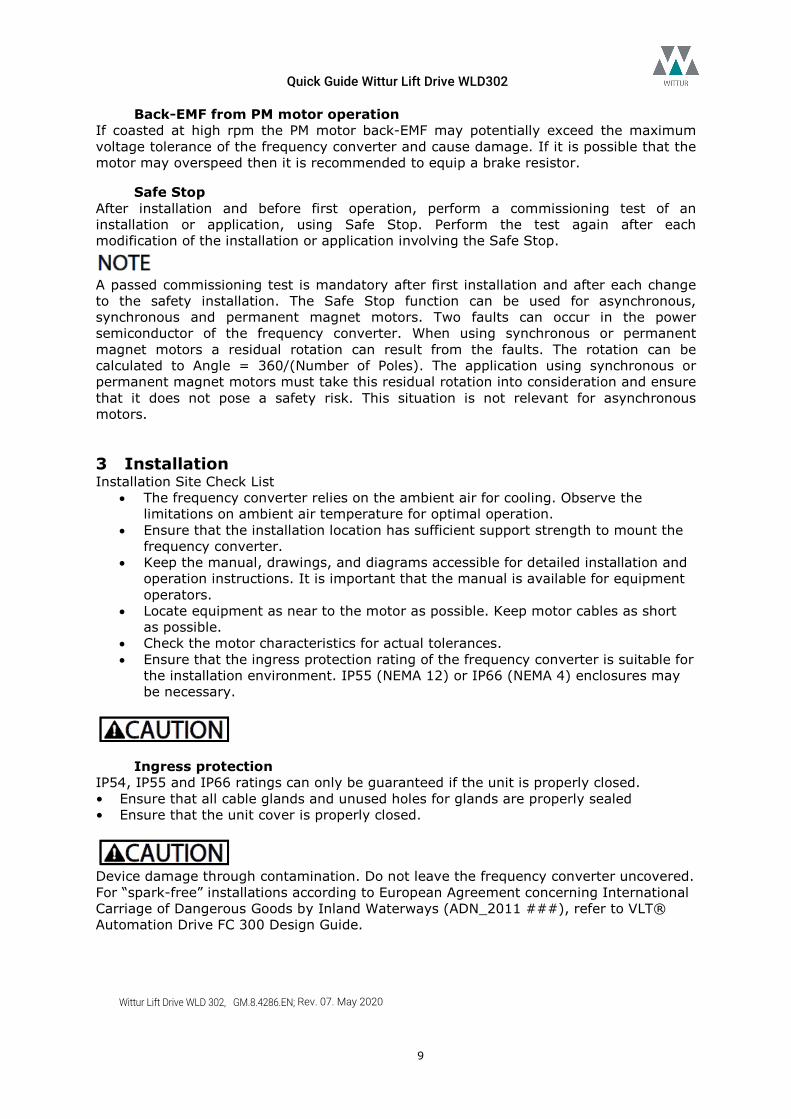
Mounting • Mount the unit vertically. • The frequency converter allows side by side Installation. • Ensure that the strength of the mounting location will support the unit weight. • Mount the unit to a solid flat surface or to the optional back plate to provide cooling
airflow. • Improper mounting can result in overheating and reduced performance. • Use the slotted mounting holes on the unit for wall mounting, when provided.
Illustration: Proper Mounting with Back Plate
Item A is a back plate properly installed for required airflow to cool the unit.
Back plate is needed when mounted on railings.
Quick Guide Wittur Lift Drive WLD302
Wittur Lift Drive WLD 302, GM.8.4286.EN; Rev. 07. May 2020
11
Tightening Torques Connection Tightening Torques for proper tightening must be complied with specification.
Electrical Installation Requirements
EQUIPMENT HAZARD! Rotating shafts and electrical equipment can be hazardous. All electrical work must conform to national and local electrical codes. It is strongly recommended that installation, start up, and maintenance be performed only by trained and qualified personnel. Failure to follow these guidelines could result in death or serious injury.
Wiring isolation Run input power, motor wiring and control wiring in three separate metallic conduits or use separated shielded cable for high frequency noise isolation. Failure to isolate power, motor and control wiring could result in less than optimum frequency converter and associated equipment performance. • For your safety, comply with the following requirements. Electronic controls
equipment is connected to hazardous mains voltage. Extreme care should be taken to protect against electrical hazards when applying power to the unit.
• Run motor cables from multiple frequency converters separately. Induced voltage from output motor cables run together can charge equipment capacitors even with the equipment turned off and locked out. Overload and Equipment Protection.
• An electronically activated function within the frequency converter provides overload protection for the motor. The overload calculates the level of increase to activate timing for the trip (controller output stop) function. The higher the current draw, the quicker the trip response. The overload provides Class 20 motor protection. See Warnings and Alarms for details on the trip function.
• Because the motor wiring carries high frequency current, it is important that wiring for mains, motor power, and control are run separately. Use metallic conduit or separated shielded wire. Failure to isolate power, motor, and control wiring could result in less than optimum equipment performance.
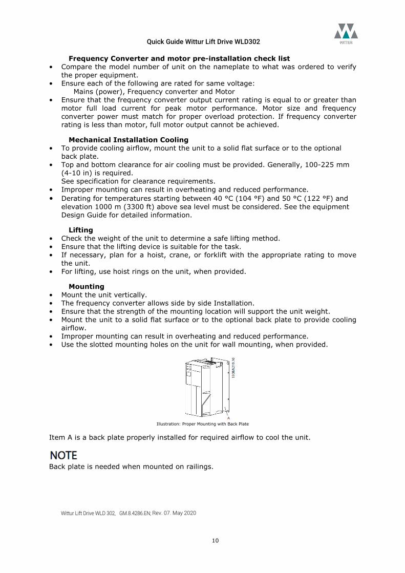
• All frequency converters must be provided with short-circuit and over-current protection. Input fusing is required to provide this protection, see Illustration. If not factory supplied, fuses must be provided by the installer as part of installation.
Refer the maximum fuse ratings in Fuse Specifications.
Illustration: Frequency Converter Fuses
Quick Guide Wittur Lift Drive WLD302
Wittur Lift Drive WLD 302, GM.8.4286.EN; Rev. 07. May 2020
12
Wire Type and Ratings • All wiring must comply with local and national regulations regarding cross-section
and ambient temperature requirements.
• Danfoss recommends that all power connections be made with a minimum 75 °C rated copper wire.
• Refer the Power-dependent Specifications for recommended wire sizes.
Earth (Grounding) Requirements
GROUNDING HAZARD! For operator safety, it is important to ground the frequency converter properly in accordance with national and local electrical codes as well as instructions contained within these instructions. Ground currents are higher than 3,5 mA. Failure to ground the frequency converter properly could result in death or serious injury.
It is the responsibility of the user or certified electrical installer to ensure correct grounding (earthing) of the equipment in accordance with national and local electrical codes and standards. • Follow all local and national electrical codes to ground electrical equipment properly. • Proper protective grounding for equipment with ground currents higher than 3,5 mA
must be established, see Leakage Current (>3,5 mA). • A dedicated ground wire is required for input power, motor power and control wiring. • Use the clamps provided with on the equipment for proper ground connections. • Do not ground one frequency converter to another in a “daisy chain” fashion. • Keep the ground wire connections as short as possible. • Use of high-strand wire to reduce electrical noise is recommended. • Follow motor manufacturer wiring requirements.
Leakage Current Follow national and local codes regarding protective earthing of equipment with a leakage current > 3.5 mA. Frequency converter technology implies high frequency switching at high power. This will generate a leakage current in the earth connection. A fault current in the frequency converter at the output power terminals might contain a DC component which can charge the filter capacitors and cause a transient earth current. The earth leakage current depends on various system configurations including RFI filtering, screened motor cables, and frequency converter power. EN/IEC61800-5-1 (Power Drive System Product Standard) requires special care if the leakage current exceeds 3.5 mA. Earth grounding must be reinforced in one of the following ways: • Earth ground wire of at least 10 mm². • Two separate earth ground wires both complying with the dimensioning rules. See EN 60364-5-54 § 543.7 for further information.
Quick Guide Wittur Lift Drive WLD302
Wittur Lift Drive WLD 302, GM.8.4286.EN; Rev. 07. May 2020
13
Using RCDs Where residual current devices (RCDs), also known as earth leakage circuit breakers (ELCBs), are used, comply with the following: Use RCDs of type B only which are capable of detecting AC and DC currents. Use RCDs with an inrush delay to prevent faults due to transient earth currents. Dimension RCDs according to the system configuration and environmental considerations.
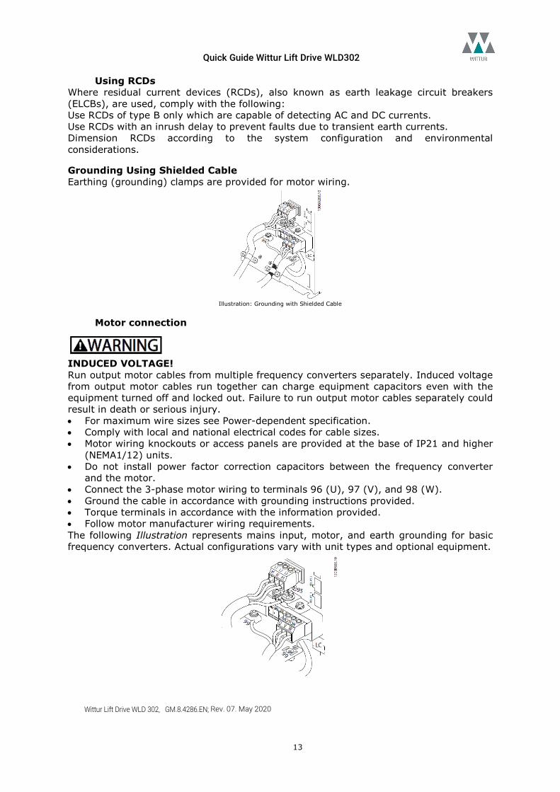
Grounding Using Shielded Cable Earthing (grounding) clamps are provided for motor wiring.
Illustration: Grounding with Shielded Cable
Motor connection
INDUCED VOLTAGE! Run output motor cables from multiple frequency converters separately. Induced voltage from output motor cables run together can charge equipment capacitors even with the equipment turned off and locked out. Failure to run output motor cables separately could result in death or serious injury. • For maximum wire sizes see Power-dependent specification. • Comply with local and national electrical codes for cable sizes. • Motor wiring knockouts or access panels are provided at the base of IP21 and higher
(NEMA1/12) units. • Do not install power factor correction capacitors between the frequency converter
and the motor. • Connect the 3-phase motor wiring to terminals 96 (U), 97 (V), and 98 (W). • Ground the cable in accordance with grounding instructions provided. • Torque terminals in accordance with the information provided. • Follow motor manufacturer wiring requirements. The following Illustration represents mains input, motor, and earth grounding for basic frequency converters. Actual configurations vary with unit types and optional equipment.
Quick Guide Wittur Lift Drive WLD302
Wittur Lift Drive WLD 302, GM.8.4286.EN; Rev. 07. May 2020
14
Illustration: Example of Motor, Mains and Earth Wiring
Back-EMF from PM motor
PM motors produce voltage when the rotor shaft is turned. The generated voltage is fed back into the connected frequency converter. When the voltage level is high enough, the motor can generate enough energy to power up the frequency converter, even when it is disconnected from mains. To avoid PM motor produced voltage when the rotor shaft is turned and for maintenance work on frequency converter and PM motor it is recommended to take care the following safety precautions.
• Disconnect PM motor from frequency converter. • Short circuit of the motor winding. • Block motor shaft against movement.
Frequency Converter powered on, at Disconnected Mains if PM motor shaft turns.
Brake Resistor
The user is responsible for the compliance of the specification for installation and operation of a braking resistor on the drive. To handle higher demands by generatoric braking a brake resistor is necessary. Using a brake resistor ensures that the energy is absorbed in the brake resistor and not in the frequency converter. For more detailed information concerning brake resistor usage, selection, installation, wiring, cabling see the Brake Resistor Design Guide.
Monitoring the brake power is not a safety function; a thermal switch is required for that purpose. The brake resistor circuit is not earth leakage protected. Do not touch the brake resistor as it can get very hot while/after braking. The brake resistor must be placed in a secure environment to avoid fire risk.
Environment Equipment containing electrical components may not be disposed of together with domestic waste. It must be separately collected with electrical and electronic waste according to local and currently valid legislation.
Quick Guide Wittur Lift Drive WLD302
Wittur Lift Drive WLD 302, GM.8.4286.EN; Rev. 07. May 2020
15
Schematic drawing, examples
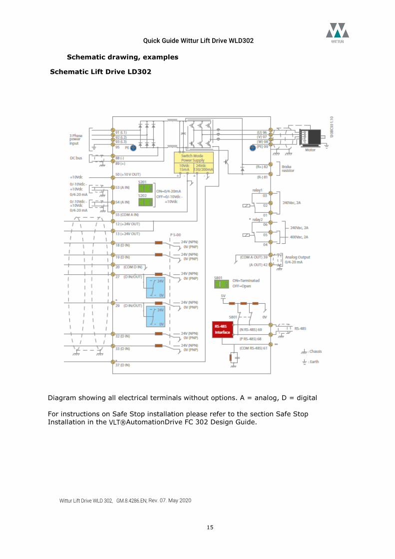
Schematic Lift Drive LD302
Diagram showing all electrical terminals without options. A = analog, D = digital For instructions on Safe Stop installation please refer to the section Safe Stop Installation in the VLT®AutomationDrive FC 302 Design Guide.
Quick Guide Wittur Lift Drive WLD302
Wittur Lift Drive WLD 302, GM.8.4286.EN; Rev. 07. May 2020
16
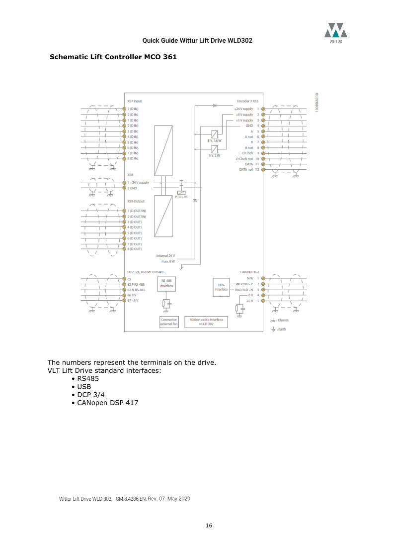
Schematic Lift Controller MCO 361
The numbers represent the terminals on the drive. VLT Lift Drive standard interfaces:
• RS485 • USB • DCP 3/4 • CANopen DSP 417
Quick Guide Wittur Lift Drive WLD302
Wittur Lift Drive WLD 302, GM.8.4286.EN; Rev. 07. May 2020
17
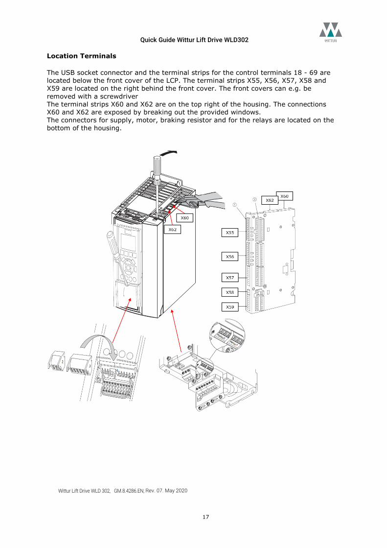
Location Terminals The USB socket connector and the terminal strips for the control terminals 18 - 69 are located below the front cover of the LCP. The terminal strips X55, X56, X57, X58 and X59 are located on the right behind the front cover. The front covers can e.g. be removed with a screwdriver The terminal strips X60 and X62 are on the top right of the housing. The connections X60 and X62 are exposed by breaking out the provided windows. The connectors for supply, motor, braking resistor and for the relays are located on the bottom of the housing.
Quick Guide Wittur Lift Drive WLD302
Wittur Lift Drive WLD 302, GM.8.4286.EN; Rev. 07. May 2020
18
Examples
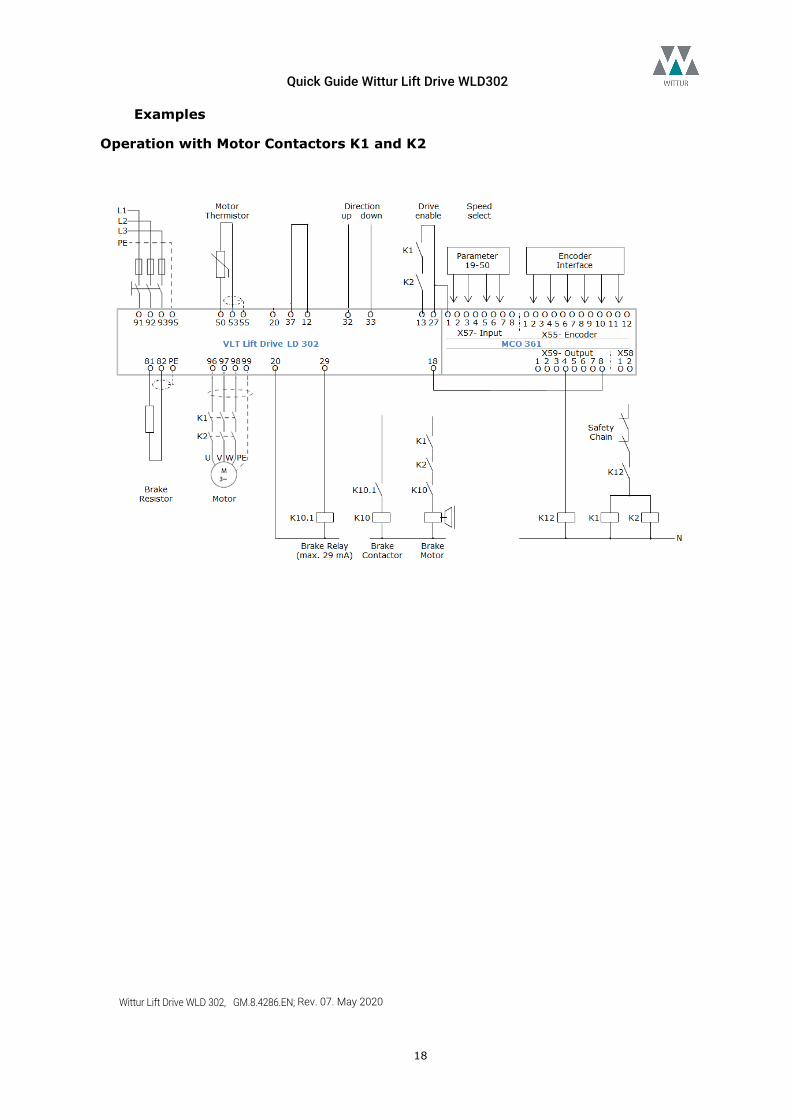
Operation with Motor Contactors K1 and K2
Quick Guide Wittur Lift Drive WLD302
Wittur Lift Drive WLD 302, GM.8.4286.EN; Rev. 07. May 2020
19
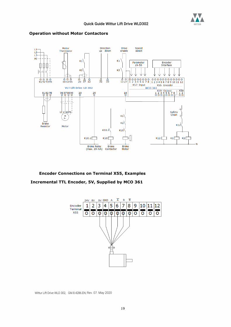
Operation without Motor Contactors
Encoder Connections on Terminal X55, Examples
Incremental TTL Encoder, 5V, Supplied by MCO 361
Quick Guide Wittur Lift Drive WLD302
Wittur Lift Drive WLD 302, GM.8.4286.EN; Rev. 07. May 2020
20
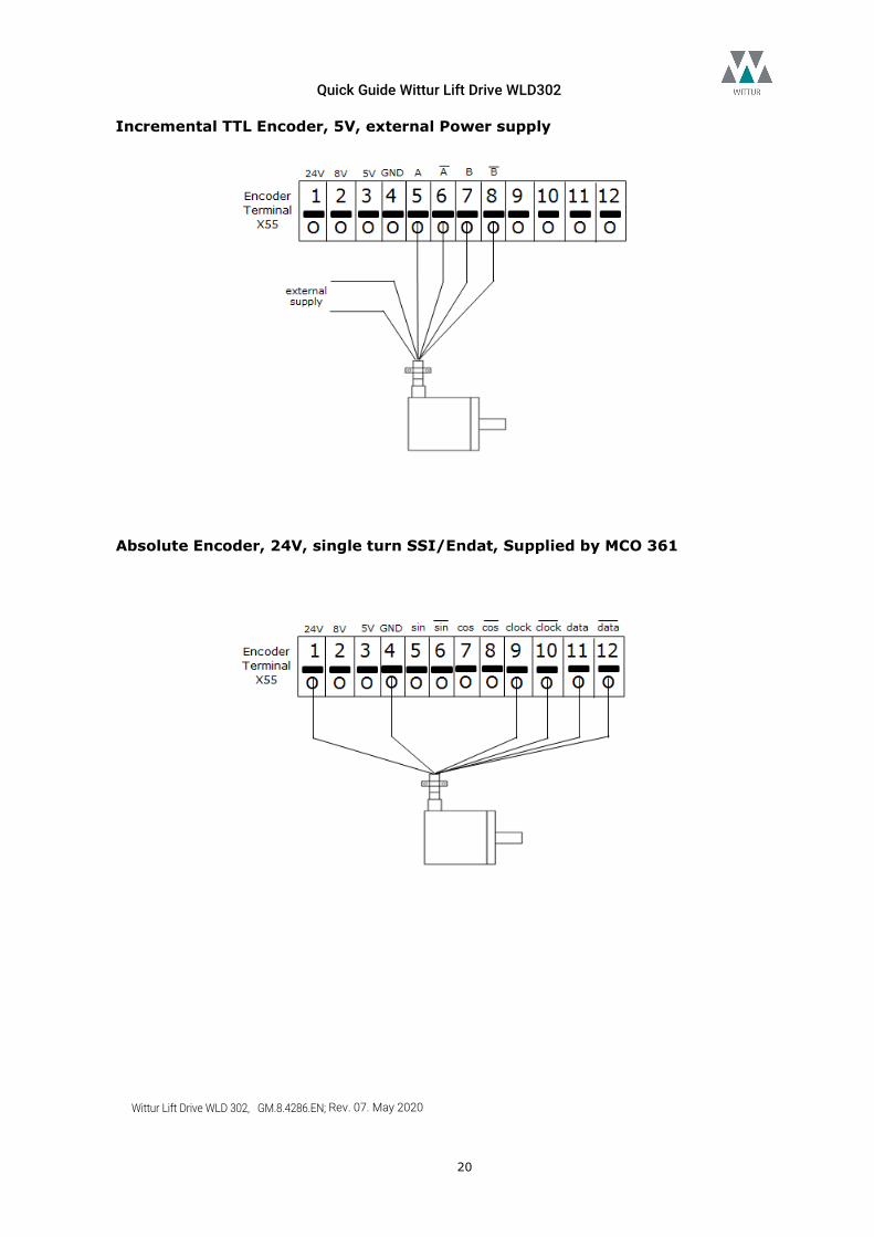
Incremental TTL Encoder, 5V, external Power supply
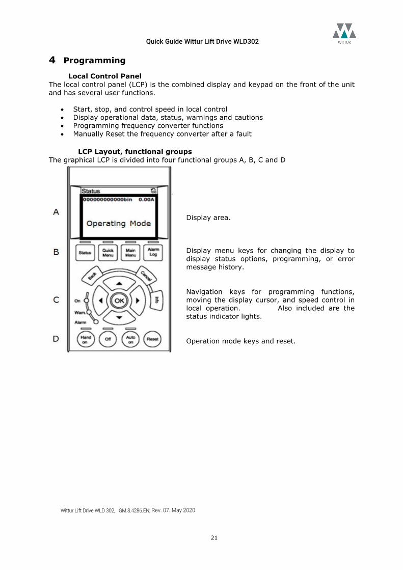
Absolute Encoder, 24V, single turn SSI/Endat, Supplied by MCO 361
Quick Guide Wittur Lift Drive WLD302
Wittur Lift Drive WLD 302, GM.8.4286.EN; Rev. 07. May 2020
21
4 Programming Local Control Panel
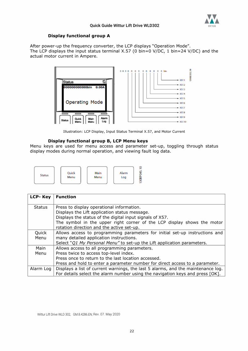
The local control panel (LCP) is the combined display and keypad on the front of the unit and has several user functions.
• Start, stop, and control speed in local control • Display operational data, status, warnings and cautions • Programming frequency converter functions • Manually Reset the frequency converter after a fault
LCP Layout, functional groups
The graphical LCP is divided into four functional groups A, B, C and D Display area. Display menu keys for changing the display to display status options, programming, or error message history. Navigation keys for programming functions, moving the display cursor, and speed control in local operation. Also included are the status indicator lights. Operation mode keys and reset.
Quick Guide Wittur Lift Drive WLD302
Wittur Lift Drive WLD 302, GM.8.4286.EN; Rev. 07. May 2020
22
Display functional group A After power-up the frequency converter, the LCP displays “Operation Mode”. The LCP displays the input status terminal X.57 (0 bin=0 V/DC, 1 bin=24 V/DC) and the actual motor current in Ampere.
Illustration: LCP Display, Input Status Terminal X.57, and Motor Current
Display functional group B, LCP Menu keys Menu keys are used for menu access and parameter set-up, toggling through status display modes during normal operation, and viewing fault log data.
LCP- Key
Function
Status
Press to display operational information. Displays the Lift application status message. Displays the status of the digital input signals of X57. The symbol in the upper right corner of the LCP display shows the motor rotation direction and the active set-up.
Quick Menu
Allows access to programming parameters for initial set-up instructions and many detailed application instructions. Select “Q1 My Personal Menu” to set-up the Lift application parameters.
Main Menu
Allows access to all programming parameters. Press twice to access top-level index. Press once to return to the last location accessed. Press and hold to enter a parameter number for direct access to a parameter.
Alarm Log
Displays a list of current warnings, the last 5 alarms, and the maintenance log. For details select the alarm number using the navigation keys and press [OK].
Quick Guide Wittur Lift Drive WLD302
Wittur Lift Drive WLD 302, GM.8.4286.EN; Rev. 07. May 2020
23
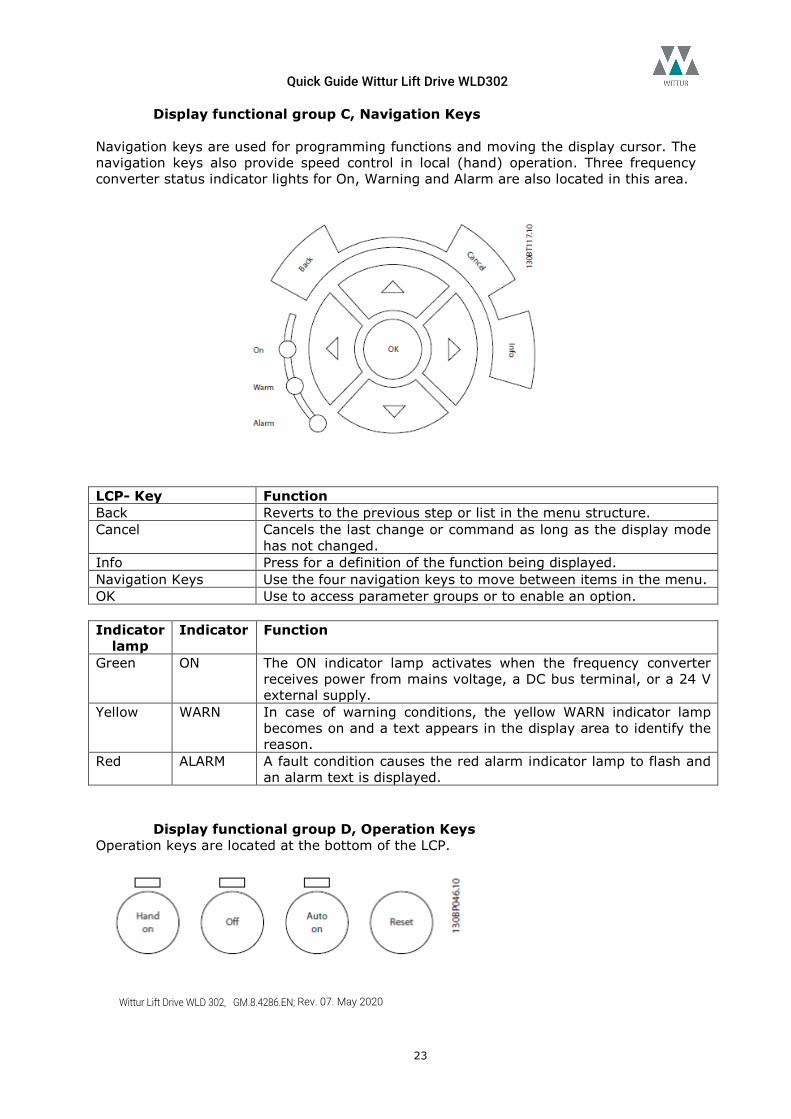
Display functional group C, Navigation Keys Navigation keys are used for programming functions and moving the display cursor. The navigation keys also provide speed control in local (hand) operation. Three frequency converter status indicator lights for On, Warning and Alarm are also located in this area.
LCP- Key Function Back Reverts to the previous step or list in the menu structure. Cancel Cancels the last change or command as long as the display mode
has not changed. Info Press for a definition of the function being displayed. Navigation Keys Use the four navigation keys to move between items in the menu. OK Use to access parameter groups or to enable an option. Indicator
lamp Indicator Function
Green ON The ON indicator lamp activates when the frequency converter receives power from mains voltage, a DC bus terminal, or a 24 V external supply.
Yellow WARN In case of warning conditions, the yellow WARN indicator lamp becomes on and a text appears in the display area to identify the reason.
Red ALARM A fault condition causes the red alarm indicator lamp to flash and an alarm text is displayed.
Display functional group D, Operation Keys Operation keys are located at the bottom of the LCP.
Quick Guide Wittur Lift Drive WLD302
Wittur Lift Drive WLD 302, GM.8.4286.EN; Rev. 07. May 2020
24
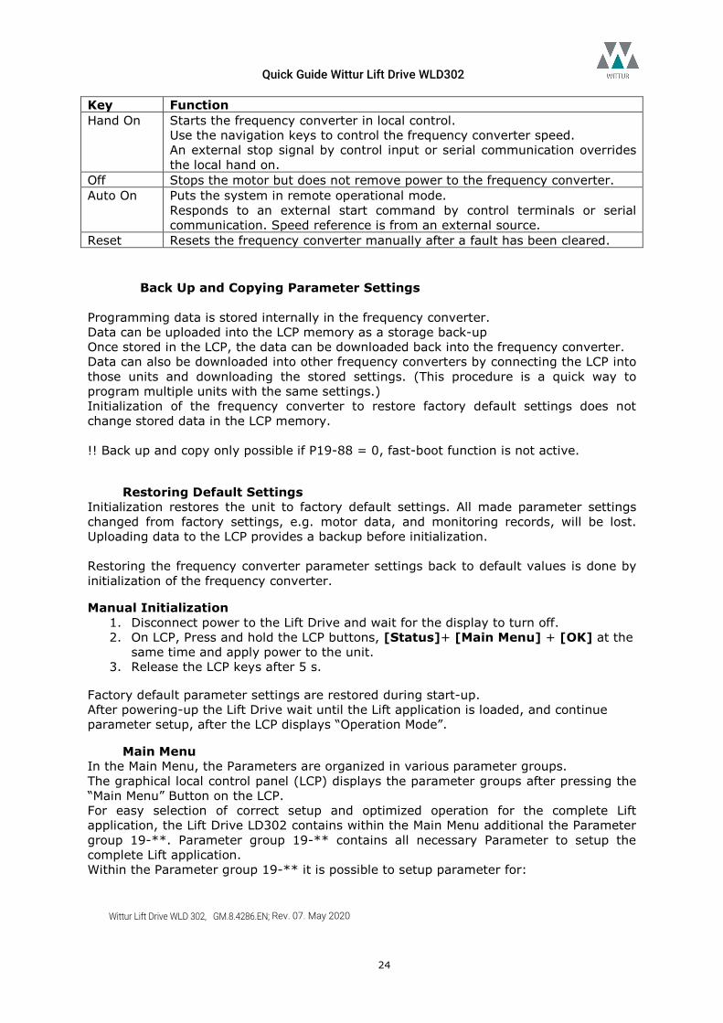
Key Function Hand On Starts the frequency converter in local control.
Use the navigation keys to control the frequency converter speed. An external stop signal by control input or serial communication overrides the local hand on.
Off Stops the motor but does not remove power to the frequency converter. Auto On Puts the system in remote operational mode.
Responds to an external start command by control terminals or serial communication. Speed reference is from an external source.
Reset Resets the frequency converter manually after a fault has been cleared.
Back Up and Copying Parameter Settings Programming data is stored internally in the frequency converter. Data can be uploaded into the LCP memory as a storage back-up Once stored in the LCP, the data can be downloaded back into the frequency converter. Data can also be downloaded into other frequency converters by connecting the LCP into those units and downloading the stored settings. (This procedure is a quick way to program multiple units with the same settings.) Initialization of the frequency converter to restore factory default settings does not change stored data in the LCP memory. !! Back up and copy only possible if P19-88 = 0, fast-boot function is not active.
Restoring Default Settings Initialization restores the unit to factory default settings. All made parameter settings changed from factory settings, e.g. motor data, and monitoring records, will be lost. Uploading data to the LCP provides a backup before initialization. Restoring the frequency converter parameter settings back to default values is done by initialization of the frequency converter.
Manual Initialization 1. Disconnect power to the Lift Drive and wait for the display to turn off. 2. On LCP, Press and hold the LCP buttons, [Status]+ [Main Menu] + [OK] at the
same time and apply power to the unit. 3. Release the LCP keys after 5 s.
Factory default parameter settings are restored during start-up. After powering-up the Lift Drive wait until the Lift application is loaded, and continue parameter setup, after the LCP displays “Operation Mode”.
Main Menu In the Main Menu, the Parameters are organized in various parameter groups. The graphical local control panel (LCP) displays the parameter groups after pressing the “Main Menu” Button on the LCP. For easy selection of correct setup and optimized operation for the complete Lift application, the Lift Drive LD302 contains within the Main Menu additional the Parameter group 19-**. Parameter group 19-** contains all necessary Parameter to setup the complete Lift application. Within the Parameter group 19-** it is possible to setup parameter for:
Quick Guide Wittur Lift Drive WLD302
Wittur Lift Drive WLD 302, GM.8.4286.EN; Rev. 07. May 2020
25
- electrical Lift Components. E.g. Lift Motor, Encoder, mechanical Brake, … - mechanical Lift components. E.g. Ratio, Suspension, Traction, … - requirement concerning Lift dynamic and comfort. E.g. Lift speed, motion profile, …
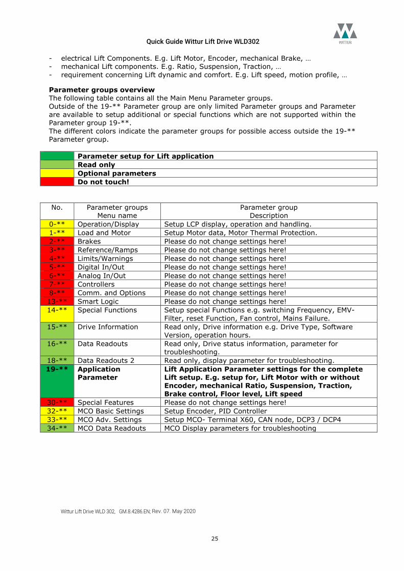
Parameter groups overview The following table contains all the Main Menu Parameter groups. Outside of the 19-** Parameter group are only limited Parameter groups and Parameter are available to setup additional or special functions which are not supported within the Parameter group 19-**. The different colors indicate the parameter groups for possible access outside the 19-** Parameter group.
Parameter setup for Lift application Read only Optional parameters Do not touch!
No. Parameter groups
Menu name Parameter group
Description 0-** Operation/Display Setup LCP display, operation and handling. 1-** Load and Motor Setup Motor data, Motor Thermal Protection. 2-** Brakes Please do not change settings here! 3-** Reference/Ramps Please do not change settings here!
4-** Limits/Warnings Please do not change settings here! 5-** Digital In/Out Please do not change settings here! 6-** Analog In/Out Please do not change settings here!
7-** Controllers Please do not change settings here! 8-** Comm. and Options Please do not change settings here! 13-** Smart Logic Please do not change settings here! 14-** Special Functions Setup special Functions e.g. switching Frequency, EMV-
Filter, reset Function, Fan control, Mains Failure. 15-** Drive Information Read only, Drive information e.g. Drive Type, Software
Version, operation hours. 16-** Data Readouts Read only, Drive status information, parameter for
troubleshooting. 18-** Data Readouts 2 Read only, display parameter for troubleshooting. 19-** Application
Parameter Lift Application Parameter settings for the complete Lift setup. E.g. setup for, Lift Motor with or without Encoder, mechanical Ratio, Suspension, Traction, Brake control, Floor level, Lift speed
30-** Special Features Please do not change settings here! 32-** MCO Basic Settings Setup Encoder, PID Controller 33-** MCO Adv. Settings Setup MCO- Terminal X60, CAN node, DCP3 / DCP4 34-** MCO Data Readouts MCO Display parameters for troubleshooting
Quick Guide Wittur Lift Drive WLD302
Wittur Lift Drive WLD 302, GM.8.4286.EN; Rev. 07. May 2020
26
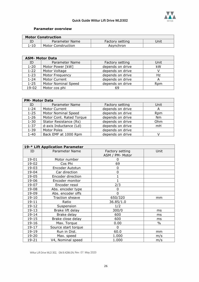
Parameter overview Motor Construction
ID Parameter Name Factory setting Unit 1-10 Motor Construction Asynchron
ASM- Motor Data
ID Parameter Name Factory setting Unit 1-20 Motor Power [kW] depends on drive kW 1-22 Motor Voltage depends on drive V 1-23 Motor Frequency depends on drive Hz 1-24 Motor Current depends on drive A 1-25 Motor Nominal Speed depends on drive Rpm 19-02 Motor cos phi 69
PM- Motor Data
ID Parameter Name Factory setting Unit 1-24 Motor Current depends on drive A 1-25 Motor Nominal Speed depends on drive Rpm 1-26 Motor Cont. Rated Torque depends on drive Nm 1-30 Stator Resistance (Rs) depends on drive Ohm 1-37 d-axis Inductance (Ld) depends on drive mH 1-39 Motor Poles depends on drive 1-40 Back EMF at 1000 Rpm depends on drive V
19-* Lift Application Parameter
ID Parameter Name Factory setting ASM / PM- Motor
Unit
19-01 Motor number 0 19-02 Cos Phi 69 19-03 Encoder Autotun 0 19-04 Car direction 0 19-05 Encoder direction 1 19-06 Encoder monitor 1 19-07 Encoder resol 2/3 19-08 Abs. encoder type 0 19-09 Abs. encoder offs 0 19-10 Traction sheave 650/320 mm 19-11 Ratio 36.85/1.0 19-12 Suspension 1/2 19-13 Brake lift delay 300/0 ms 19-14 Brake delay 600 ms 19-15 Brake close delay 600 ms 19-16 Max. Torque 0.00 % 19-17 Source start torque 0 19-19 Run in Dist. 60.0 mm 19-20 Max. speed 1.000 m/s 19-21 V4, Nominal speed 1.000 m/s
Quick Guide Wittur Lift Drive WLD302
Wittur Lift Drive WLD 302, GM.8.4286.EN; Rev. 07. May 2020
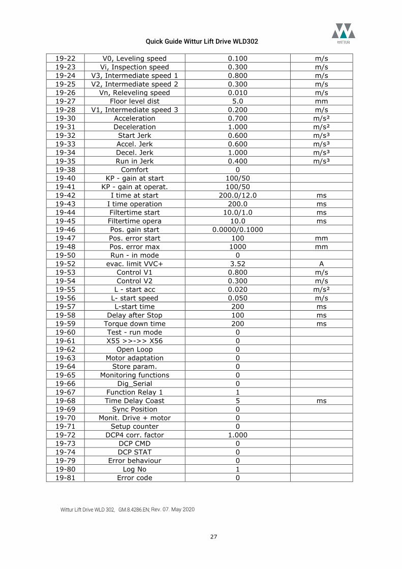
27
19-22 V0, Leveling speed 0.100 m/s 19-23 Vi, Inspection speed 0.300 m/s 19-24 V3, Intermediate speed 1 0.800 m/s 19-25 V2, Intermediate speed 2 0.300 m/s 19-26 Vn, Releveling speed 0.010 m/s 19-27 Floor level dist 5.0 mm 19-28 V1, Intermediate speed 3 0.200 m/s 19-30 Acceleration 0.700 m/s² 19-31 Deceleration 1.000 m/s² 19-32 Start Jerk 0.600 m/s³ 19-33 Accel. Jerk 0.600 m/s³ 19-34 Decel. Jerk 1.000 m/s³ 19-35 Run in Jerk 0.400 m/s³ 19-38 Comfort 0 19-40 KP - gain at start 100/50 19-41 KP - gain at operat. 100/50 19-42 I time at start 200.0/12.0 ms 19-43 I time operation 200.0 ms 19-44 Filtertime start 10.0/1.0 ms 19-45 Filtertime opera 10.0 ms 19-46 Pos. gain start 0.0000/0.1000 19-47 Pos. error start 100 mm 19-48 Pos. error max 1000 mm 19-50 Run - in mode 0 19-52 evac. limit VVC+ 3.52 A 19-53 Control V1 0.800 m/s 19-54 Control V2 0.300 m/s 19-55 L - start acc 0.020 m/s² 19-56 L- start speed 0.050 m/s 19-57 L-start time 200 ms 19-58 Delay after Stop 100 ms 19-59 Torque down time 200 ms 19-60 Test - run mode 0 19-61 X55 >>->> X56 0 19-62 Open Loop 0 19-63 Motor adaptation 0 19-64 Store param. 0 19-65 Monitoring functions 0 19-66 Dig_Serial 0 19-67 Function Relay 1 1 19-68 Time Delay Coast 5 ms 19-69 Sync Position 0 19-70 Monit. Drive + motor 0 19-71 Setup counter 0 19-72 DCP4 corr. factor 1.000 19-73 DCP CMD 0 19-74 DCP STAT 0 19-79 Error behaviour 0 19-80 Log No 1 19-81 Error code 0
Quick Guide Wittur Lift Drive WLD302
Wittur Lift Drive WLD 302, GM.8.4286.EN; Rev. 07. May 2020
28
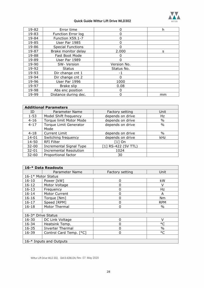
19-82 Error time 0 h 19-83 Function Error log 0 19-84 Function X59.1-7 0 19-85 User Par 1985 0 19-86 Special Functions 0 19-87 Brake monitor delay 2.000 s 19-88 Fast Boot Mode 0 19-89 User Par 1989 0 19-90 SW- Version Version No. 19-92 Status Status No. 19-93 Dir change cnt 1 -1 19-94 Dir change cnt 2 0 19-96 User Par 1996 1000 19-97 Brake slip 0.08 19-98 Abs enc position 0 19-99 Distance during dec. 0 mm
Additional Parameters
ID Parameter Name Factory setting Unit 1-53 Model Shift frequency depends on drive Hz 4-16 Torque limit Motor Mode depends on drive % 4-17 Torque Limit Generator
Mode depends on drive %
4-18 Current Limit depends on drive % 14-01 Switching frequency depends on drive kHz 14-50 RFI Filter [1] On 32-00 Incremental Signal Type [1] RS-422 (5V TTL) 32-01 Incremental Resolution 1024 32-60 Proportional factor 30
16-* Data Readouts
Parameter Name Factory setting Unit 16-1* Motor Status 16-10 Power [kW] 0 kW 16-12 Motor Voltage 0 V 16-13 Frequency 0 Hz 16-14 Motor Current 0 A 16-16 Torque [Nm] 0 Nm 16-17 Speed [RPM] 0 RPM 16-18 Motor Thermal 0 % 16-3* Drive Status 16-30 DC Link Voltage 0 V 16-34 Heatsink Temp. 0 °C 16-35 Inverter Thermal 0 % 16-39 Control Card Temp. [°C] 0 °C 16-* Inputs and Outputs
Quick Guide Wittur Lift Drive WLD302
Wittur Lift Drive WLD 302, GM.8.4286.EN; Rev. 07. May 2020
29
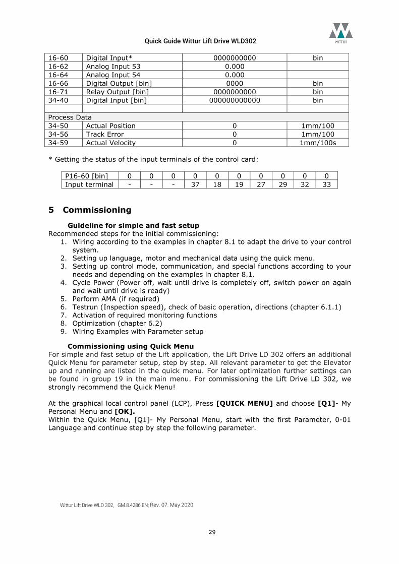
16-60 Digital Input* 0000000000 bin 16-62 Analog Input 53 0.000 16-64 Analog Input 54 0.000 16-66 Digital Output [bin] 0000 bin 16-71 Relay Output [bin] 0000000000 bin 34-40 Digital Input [bin] 000000000000 bin Process Data 34-50 Actual Position 0 1mm/100 34-56 Track Error 0 1mm/100 34-59 Actual Velocity 0 1mm/100s * Getting the status of the input terminals of the control card:
P16-60 [bin] 0 0 0 0 0 0 0 0 0 0 Input terminal - - - 37 18 19 27 29 32 33
5 Commissioning
Guideline for simple and fast setup Recommended steps for the initial commissioning:
1. Wiring according to the examples in chapter 8.1 to adapt the drive to your control system.
2. Setting up language, motor and mechanical data using the quick menu. 3. Setting up control mode, communication, and special functions according to your
needs and depending on the examples in chapter 8.1. 4. Cycle Power (Power off, wait until drive is completely off, switch power on again
and wait until drive is ready) 5. Perform AMA (if required) 6. Testrun (Inspection speed), check of basic operation, directions (chapter 6.1.1) 7. Activation of required monitoring functions 8. Optimization (chapter 6.2) 9. Wiring Examples with Parameter setup
Commissioning using Quick Menu For simple and fast setup of the Lift application, the Lift Drive LD 302 offers an additional Quick Menu for parameter setup, step by step. All relevant parameter to get the Elevator up and running are listed in the quick menu. For later optimization further settings can be found in group 19 in the main menu. For commissioning the Lift Drive LD 302, we strongly recommend the Quick Menu! At the graphical local control panel (LCP), Press [QUICK MENU] and choose [Q1]- My Personal Menu and [OK]. Within the Quick Menu, [Q1]- My Personal Menu, start with the first Parameter, 0-01 Language and continue step by step the following parameter.
Quick Guide Wittur Lift Drive WLD302
Wittur Lift Drive WLD 302, GM.8.4286.EN; Rev. 07. May 2020
30
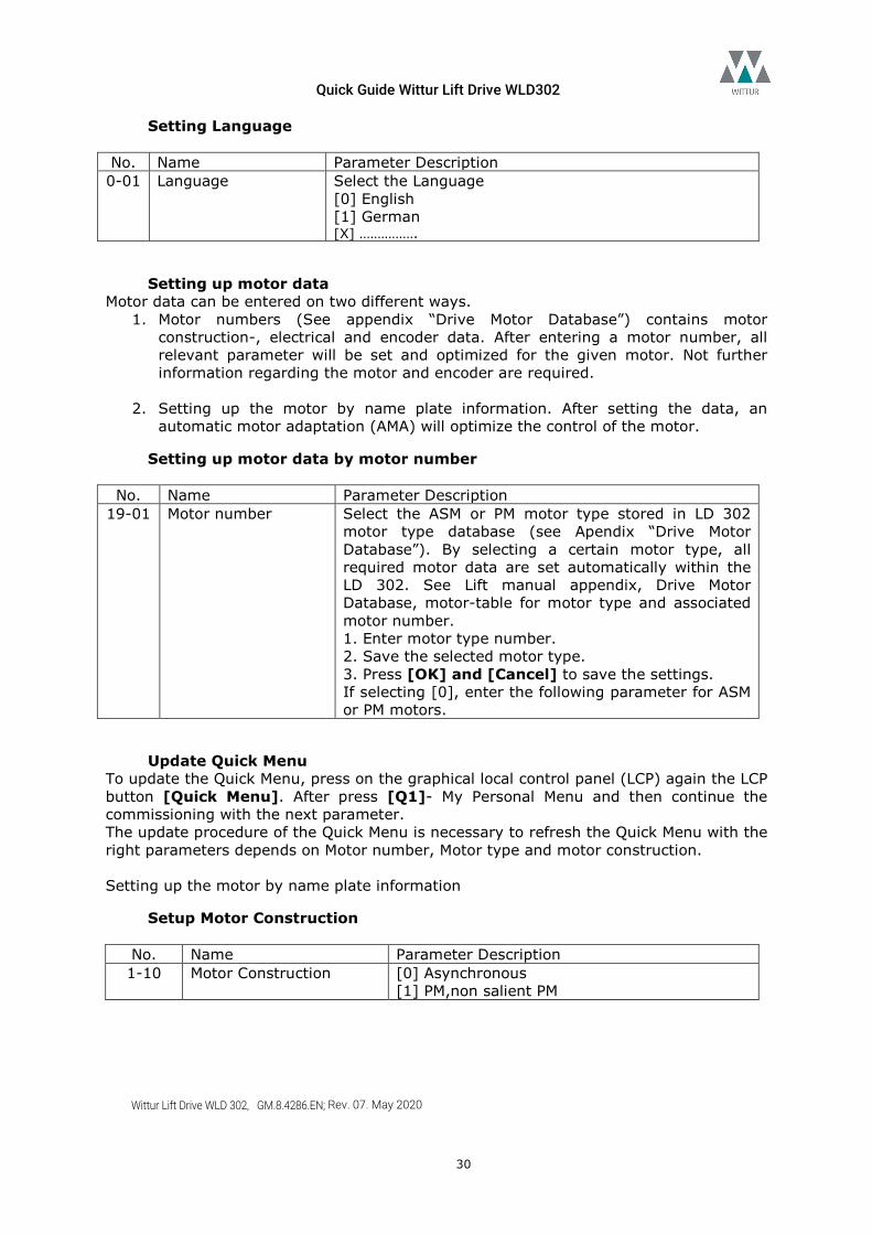
Setting Language No. Name Parameter Description 0-01 Language Select the Language
[0] English [1] German [X] …………….
Setting up motor data Motor data can be entered on two different ways.
1. Motor numbers (See appendix “Drive Motor Database”) contains motor construction-, electrical and encoder data. After entering a motor number, all relevant parameter will be set and optimized for the given motor. Not further information regarding the motor and encoder are required.
2. Setting up the motor by name plate information. After setting the data, an
automatic motor adaptation (AMA) will optimize the control of the motor.
Setting up motor data by motor number
No. Name Parameter Description 19-01 Motor number Select the ASM or PM motor type stored in LD 302
motor type database (see Apendix “Drive Motor Database”). By selecting a certain motor type, all required motor data are set automatically within the LD 302. See Lift manual appendix, Drive Motor Database, motor-table for motor type and associated motor number. 1. Enter motor type number. 2. Save the selected motor type. 3. Press [OK] and [Cancel] to save the settings. If selecting [0], enter the following parameter for ASM or PM motors.
Update Quick Menu To update the Quick Menu, press on the graphical local control panel (LCP) again the LCP button [Quick Menu]. After press [Q1]- My Personal Menu and then continue the commissioning with the next parameter. The update procedure of the Quick Menu is necessary to refresh the Quick Menu with the right parameters depends on Motor number, Motor type and motor construction. Setting up the motor by name plate information
Setup Motor Construction
No. Name Parameter Description 1-10 Motor Construction [0] Asynchronous
[1] PM,non salient PM
Quick Guide Wittur Lift Drive WLD302
Wittur Lift Drive WLD 302, GM.8.4286.EN; Rev. 07. May 2020
31
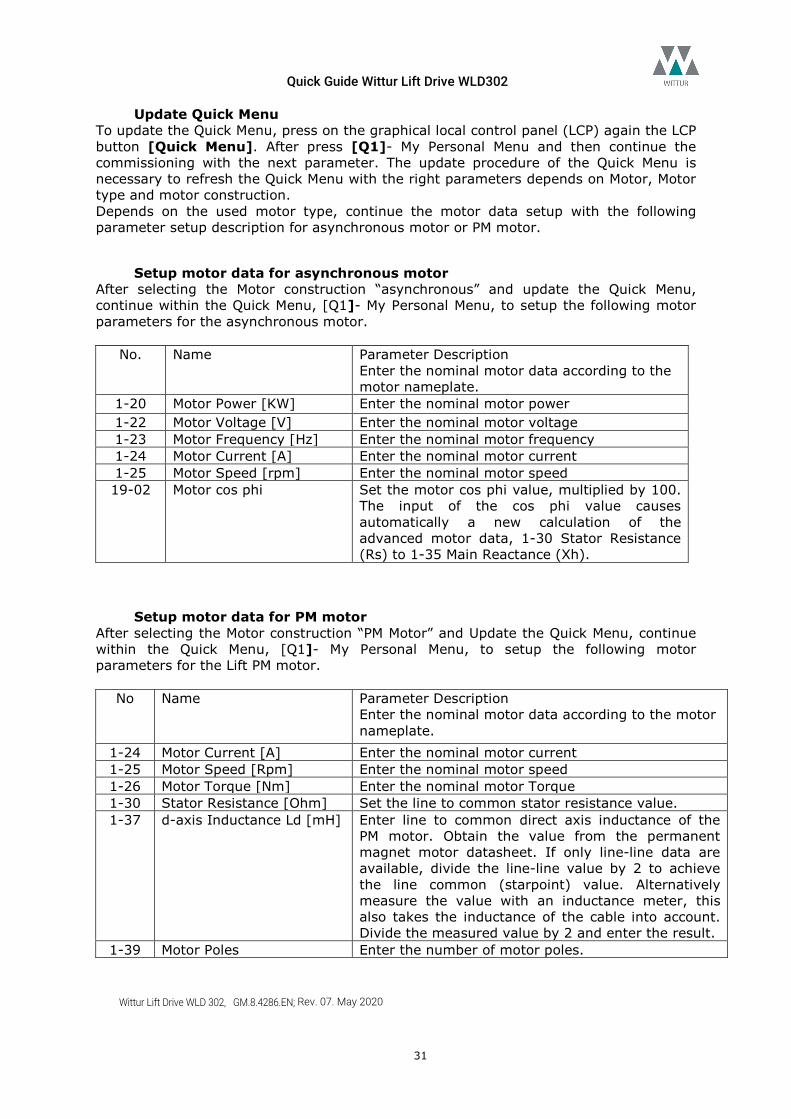
Update Quick Menu To update the Quick Menu, press on the graphical local control panel (LCP) again the LCP button [Quick Menu]. After press [Q1]- My Personal Menu and then continue the commissioning with the next parameter. The update procedure of the Quick Menu is necessary to refresh the Quick Menu with the right parameters depends on Motor, Motor type and motor construction. Depends on the used motor type, continue the motor data setup with the following parameter setup description for asynchronous motor or PM motor.
Setup motor data for asynchronous motor After selecting the Motor construction “asynchronous” and update the Quick Menu, continue within the Quick Menu, [Q1]- My Personal Menu, to setup the following motor parameters for the asynchronous motor.
No. Name Parameter Description Enter the nominal motor data according to the motor nameplate.
1-20 Motor Power [KW] Enter the nominal motor power 1-22 Motor Voltage [V] Enter the nominal motor voltage 1-23 Motor Frequency [Hz] Enter the nominal motor frequency 1-24 Motor Current [A] Enter the nominal motor current 1-25 Motor Speed [rpm] Enter the nominal motor speed 19-02 Motor cos phi Set the motor cos phi value, multiplied by 100.
The input of the cos phi value causes automatically a new calculation of the advanced motor data, 1-30 Stator Resistance (Rs) to 1-35 Main Reactance (Xh).
Setup motor data for PM motor After selecting the Motor construction “PM Motor” and Update the Quick Menu, continue within the Quick Menu, [Q1]- My Personal Menu, to setup the following motor parameters for the Lift PM motor.
No Name Parameter Description Enter the nominal motor data according to the motor nameplate.
1-24 Motor Current [A] Enter the nominal motor current 1-25 Motor Speed [Rpm] Enter the nominal motor speed 1-26 Motor Torque [Nm] Enter the nominal motor Torque 1-30 Stator Resistance [Ohm] Set the line to common stator resistance value. 1-37 d-axis Inductance Ld [mH] Enter line to common direct axis inductance of the
PM motor. Obtain the value from the permanent magnet motor datasheet. If only line-line data are available, divide the line-line value by 2 to achieve the line common (starpoint) value. Alternatively measure the value with an inductance meter, this also takes the inductance of the cable into account. Divide the measured value by 2 and enter the result.
1-39 Motor Poles Enter the number of motor poles.
Quick Guide Wittur Lift Drive WLD302
Wittur Lift Drive WLD 302, GM.8.4286.EN; Rev. 07. May 2020
32
1-40 Back EMF at 1000rpm [V] If Back-EMF is only available at motor nominal speed, it can be calculated as follows: Example: Back- EMF 320V at 1800rpm. Back- EMF=(320V/1800)*1000=178V
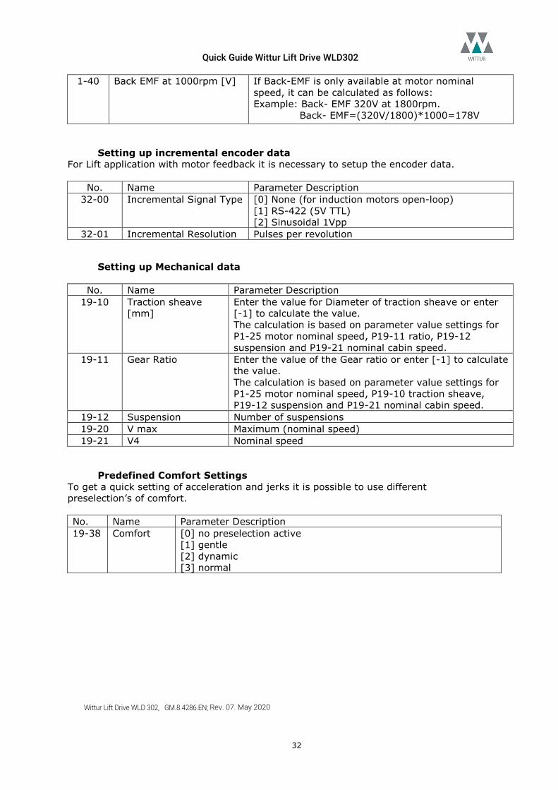
Setting up incremental encoder data For Lift application with motor feedback it is necessary to setup the encoder data.
No. Name Parameter Description 32-00 Incremental Signal Type [0] None (for induction motors open-loop)
[1] RS-422 (5V TTL) [2] Sinusoidal 1Vpp
32-01 Incremental Resolution Pulses per revolution
Setting up Mechanical data
No. Name Parameter Description 19-10 Traction sheave
[mm] Enter the value for Diameter of traction sheave or enter [-1] to calculate the value. The calculation is based on parameter value settings for P1-25 motor nominal speed, P19-11 ratio, P19-12 suspension and P19-21 nominal cabin speed.
19-11 Gear Ratio Enter the value of the Gear ratio or enter [-1] to calculate the value. The calculation is based on parameter value settings for P1-25 motor nominal speed, P19-10 traction sheave, P19-12 suspension and P19-21 nominal cabin speed.
19-12 Suspension Number of suspensions 19-20 V max Maximum (nominal speed) 19-21 V4 Nominal speed
Predefined Comfort Settings To get a quick setting of acceleration and jerks it is possible to use different preselection’s of comfort. No. Name Parameter Description 19-38 Comfort [0] no preselection active
[1] gentle [2] dynamic [3] normal
Quick Guide Wittur Lift Drive WLD302
Wittur Lift Drive WLD 302, GM.8.4286.EN; Rev. 07. May 2020
33
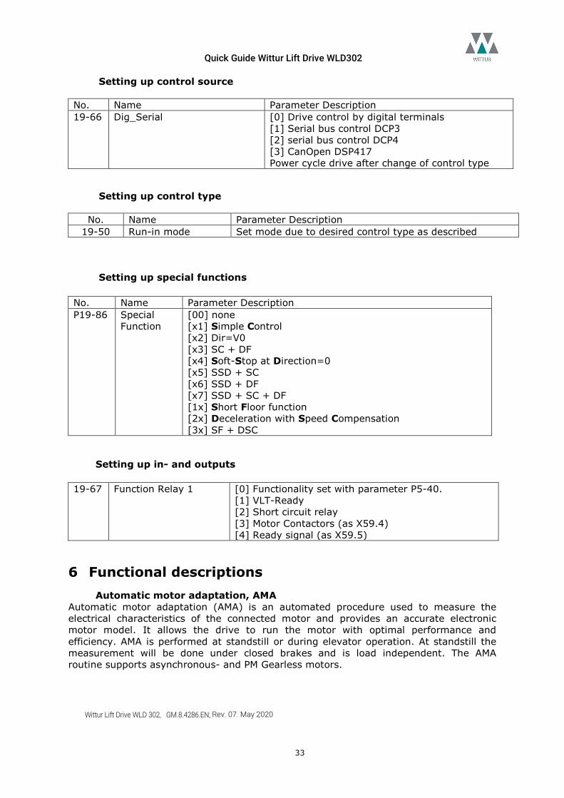
Setting up control source No. Name Parameter Description 19-66 Dig_Serial [0] Drive control by digital terminals
[1] Serial bus control DCP3 [2] serial bus control DCP4 [3] CanOpen DSP417 Power cycle drive after change of control type
Setting up control type
No. Name Parameter Description 19-50 Run-in mode Set mode due to desired control type as described
Setting up special functions
No. Name Parameter Description P19-86 Special
Function [00] none [x1] Simple Control [x2] Dir=V0 [x3] SC + DF [x4] Soft-Stop at Direction=0 [x5] SSD + SC [x6] SSD + DF [x7] SSD + SC + DF [1x] Short Floor function [2x] Deceleration with Speed Compensation [3x] SF + DSC
Setting up in- and outputs 19-67 Function Relay 1 [0] Functionality set with parameter P5-40.
[1] VLT-Ready [2] Short circuit relay [3] Motor Contactors (as X59.4) [4] Ready signal (as X59.5)
6 Functional descriptions Automatic motor adaptation, AMA
Automatic motor adaptation (AMA) is an automated procedure used to measure the electrical characteristics of the connected motor and provides an accurate electronic motor model. It allows the drive to run the motor with optimal performance and efficiency. AMA is performed at standstill or during elevator operation. At standstill the measurement will be done under closed brakes and is load independent. The AMA routine supports asynchronous- and PM Gearless motors.
Quick Guide Wittur Lift Drive WLD302
Wittur Lift Drive WLD 302, GM.8.4286.EN; Rev. 07. May 2020
34
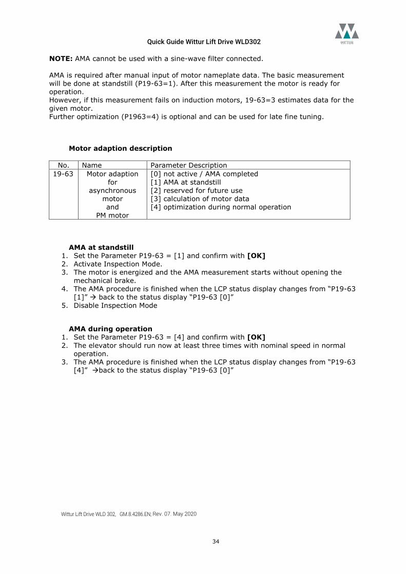
NOTE: AMA cannot be used with a sine-wave filter connected. AMA is required after manual input of motor nameplate data. The basic measurement will be done at standstill (P19-63=1). After this measurement the motor is ready for operation. However, if this measurement fails on induction motors, 19-63=3 estimates data for the given motor. Further optimization (P1963=4) is optional and can be used for late fine tuning.
Motor adaption description
No. Name Parameter Description 19-63 Motor adaption
for asynchronous
motor and
PM motor
[0] not active / AMA completed [1] AMA at standstill [2] reserved for future use [3] calculation of motor data [4] optimization during normal operation
AMA at standstill 1. Set the Parameter P19-63 = [1] and confirm with [OK] 2. Activate Inspection Mode. 3. The motor is energized and the AMA measurement starts without opening the
mechanical brake. 4. The AMA procedure is finished when the LCP status display changes from “P19-63
[1]” back to the status display “P19-63 [0]” 5. Disable Inspection Mode
AMA during operation 1. Set the Parameter P19-63 = [4] and confirm with [OK] 2. The elevator should run now at least three times with nominal speed in normal
operation. 3. The AMA procedure is finished when the LCP status display changes from “P19-63
[4]” back to the status display “P19-63 [0]”
Quick Guide Wittur Lift Drive WLD302
Wittur Lift Drive WLD 302, GM.8.4286.EN; Rev. 07. May 2020
35
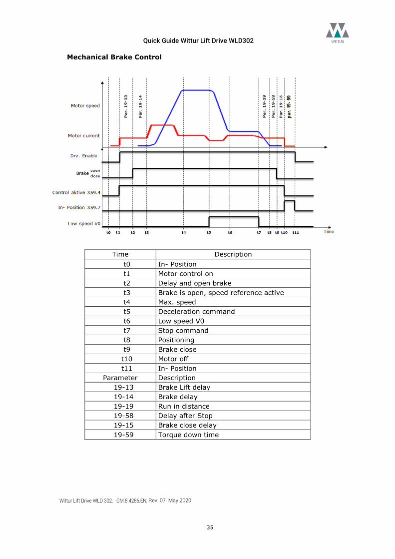
Mechanical Brake Control
Time Description t0 In- Position t1 Motor control on t2 Delay and open brake t3 Brake is open, speed reference active t4 Max. speed t5 Deceleration command t6 Low speed V0 t7 Stop command t8 Positioning t9 Brake close t10 Motor off t11 In- Position
Parameter Description 19-13 Brake Lift delay 19-14 Brake delay 19-19 Run in distance 19-58 Delay after Stop 19-15 Brake close delay 19-59 Torque down time
Quick Guide Wittur Lift Drive WLD302
Wittur Lift Drive WLD 302, GM.8.4286.EN; Rev. 07. May 2020
36
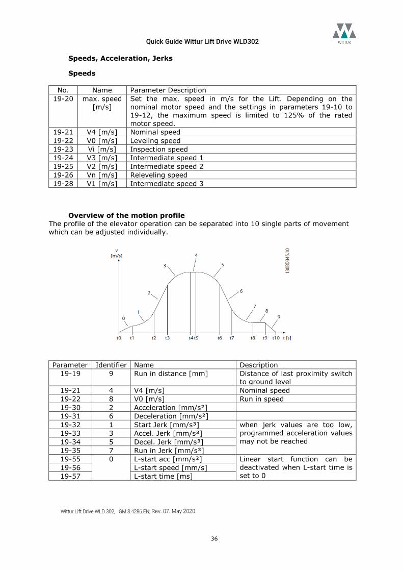
Speeds, Acceleration, Jerks
Speeds
No. Name Parameter Description 19-20 max. speed
[m/s] Set the max. speed in m/s for the Lift. Depending on the nominal motor speed and the settings in parameters 19-10 to 19-12, the maximum speed is limited to 125% of the rated motor speed.
19-21 V4 [m/s] Nominal speed 19-22 V0 [m/s] Leveling speed 19-23 Vi [m/s] Inspection speed 19-24 V3 [m/s] Intermediate speed 1 19-25 V2 [m/s] Intermediate speed 2 19-26 Vn [m/s] Releveling speed 19-28 V1 [m/s] Intermediate speed 3
Overview of the motion profile The profile of the elevator operation can be separated into 10 single parts of movement which can be adjusted individually.
Parameter Identifier Name Description
19-19 9 Run in distance [mm] Distance of last proximity switch to ground level
19-21 4 V4 [m/s] Nominal speed 19-22 8 V0 [m/s] Run in speed 19-30 2 Acceleration [mm/s²] 19-31 6 Deceleration [mm/s²] 19-32 1 Start Jerk [mm/s³] when jerk values are too low,
programmed acceleration values may not be reached
19-33 3 Accel. Jerk [mm/s³] 19-34 5 Decel. Jerk [mm/s³] 19-35 7 Run in Jerk [mm/s³] 19-55 0 L-start acc [mm/s²] Linear start function can be
deactivated when L-start time is set to 0
19-56 L-start speed [mm/s] 19-57 L-start time [ms]
Quick Guide Wittur Lift Drive WLD302
Wittur Lift Drive WLD 302, GM.8.4286.EN; Rev. 07. May 2020
37
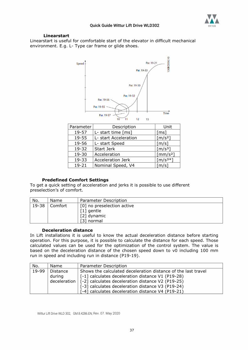
Linearstart Linearstart is useful for comfortable start of the elevator in difficult mechanical environment. E.g. L- Type car frame or glide shoes.
Parameter Description Unit
19-57 L- start time [ms] [ms] 19-55 L- start Acceleration [m/s²] 19-56 L- start Speed [m/s] 19-32 Start Jerk [m/s³] 19-30 Acceleration [mm/s²] 19-33 Acceleration Jerk [m/s³*] 19-21 Nominal Speed, V4 [m/s]
Predefined Comfort Settings To get a quick setting of acceleration and jerks it is possible to use different preselection’s of comfort. No. Name Parameter Description 19-38 Comfort [0] no preselection active
[1] gentle [2] dynamic [3] normal
Deceleration distance In Lift installations it is useful to know the actual deceleration distance before starting operation. For this purpose, it is possible to calculate the distance for each speed. Those calculated values can be used for the optimization of the control system. The value is based on the deceleration distance of the chosen speed down to v0 including 100 mm run in speed and including run in distance (P19-19). No. Name Parameter Description 19-99 Distance
during deceleration
Shows the calculated deceleration distance of the last travel [-1] calculates deceleration distance V1 (P19-28) [-2] calculates deceleration distance V2 (P19-25) [-3] calculates deceleration distance V3 (P19-24) [-4] calculates deceleration distance V4 (P19-21)
Quick Guide Wittur Lift Drive WLD302
Wittur Lift Drive WLD 302, GM.8.4286.EN; Rev. 07. May 2020
38
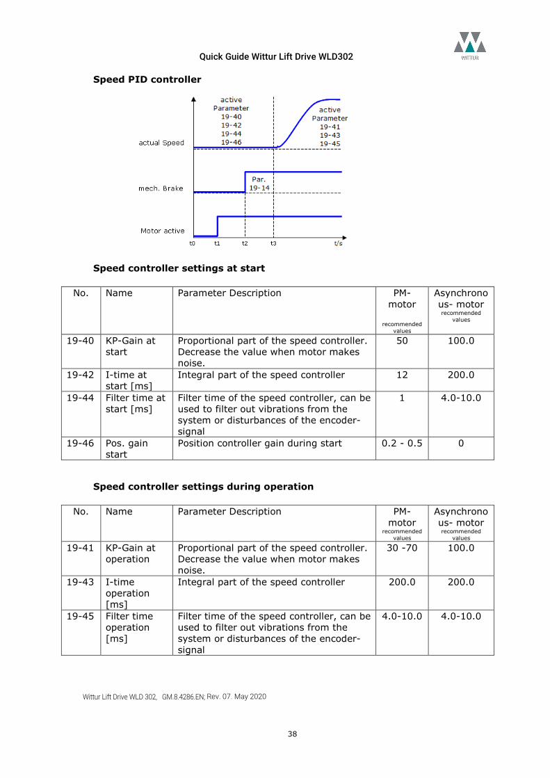
Speed PID controller
Speed controller settings at start
No. Name Parameter Description PM- motor
recommended
values
Asynchronous- motor recommended
values
19-40 KP-Gain at start
Proportional part of the speed controller. Decrease the value when motor makes noise.
50 100.0
19-42 I-time at start [ms]
Integral part of the speed controller 12 200.0
19-44 Filter time at start [ms]
Filter time of the speed controller, can be used to filter out vibrations from the system or disturbances of the encoder-signal
1 4.0-10.0
19-46 Pos. gain start
Position controller gain during start 0.2 - 0.5 0
Speed controller settings during operation
No. Name Parameter Description PM- motor
recommended values
Asynchronous- motor recommended
values 19-41 KP-Gain at
operation Proportional part of the speed controller. Decrease the value when motor makes noise.
30 -70 100.0
19-43 I-time operation [ms]
Integral part of the speed controller 200.0 200.0
19-45 Filter time operation [ms]
Filter time of the speed controller, can be used to filter out vibrations from the system or disturbances of the encoder-signal
4.0-10.0 4.0-10.0
Quick Guide Wittur Lift Drive WLD302
Wittur Lift Drive WLD 302, GM.8.4286.EN; Rev. 07. May 2020
39
Control sources P19-66 No. Name Parameter Description 19-66 Dig_Serial [0] Drive control by digital terminals
[1] Serial bus control DCP3 [2] serial bus control DCP4 [3] Can Open DSP417 Power cycle drive after change of control type
Operation with serial bus DCP3 and DCP4 The drive supports the serial Lift protocol DCP3 and DCP4. Due to this protocol all necessary signals and information will be transferred by the serial bus. As a matter to the fact the wiring of the input control signals for direction and speed can be reduced.
Connections Terminal block Terminal number MCO
X60
CS Chip Select 62 RXD/TXD P 63 RXD/TXD N 66 0V 67 5V
Data readouts No. Name Parameter Description 19-73 BUS CMD Display parameter for DCP command byte and
selected speed from Lift controller. Use Lift drive setup tool for logging.
1974 BUS STAT Display parameter for DCP status byte and extended status to Lift controller. Use Lift drive setup tool for logging.
DCP4 settings In DCP4 the motor encoder shall be aligned to the shaft encoder. For this reason, the Lift controller transmits the actual shaft encoder position to the drive after each movement. The distance deviation is displayed in P19-69 Sync Position. To align motor encoder with shaft encoder the deviation in P19-69 shall be entered manually in P19-72 Position corr. factor. No. Name Parameter Description 19-69 Sync Position Position deviation actualized after each
movement of the drive. If value is out of range 0.950-1.050 (5%) a failure will be generated. Check parameters of mechanical settings in drive and Lift controller. Displayed value shall be entered in P19-72.
19-72 Position corr. factor Value adapts the mechanic settings of the Lift
Quick Guide Wittur Lift Drive WLD302
Wittur Lift Drive WLD 302, GM.8.4286.EN; Rev. 07. May 2020
40
drive to the shaft encoder. Only when P19-72 is aligned with 19-69 an optimum approach at floor level is possible.
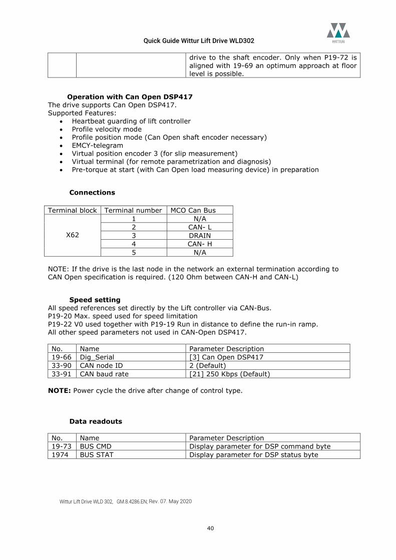
Operation with Can Open DSP417 The drive supports Can Open DSP417. Supported Features:
• Heartbeat guarding of lift controller • Profile velocity mode • Profile position mode (Can Open shaft encoder necessary) • EMCY-telegram • Virtual position encoder 3 (for slip measurement) • Virtual terminal (for remote parametrization and diagnosis) • Pre-torque at start (with Can Open load measuring device) in preparation
Connections
Terminal block Terminal number MCO Can Bus
X62
1 N/A 2 CAN- L 3 DRAIN 4 CAN- H 5 N/A
NOTE: If the drive is the last node in the network an external termination according to CAN Open specification is required. (120 Ohm between CAN-H and CAN-L)
Speed setting All speed references set directly by the Lift controller via CAN-Bus. P19-20 Max. speed used for speed limitation P19-22 V0 used together with P19-19 Run in distance to define the run-in ramp. All other speed parameters not used in CAN-Open DSP417. No. Name Parameter Description 19-66 Dig_Serial [3] Can Open DSP417 33-90 CAN node ID 2 (Default) 33-91 CAN baud rate [21] 250 Kbps (Default)
NOTE: Power cycle the drive after change of control type.
Data readouts No. Name Parameter Description 19-73 BUS CMD Display parameter for DSP command byte 1974 BUS STAT Display parameter for DSP status byte
Quick Guide Wittur Lift Drive WLD302
Wittur Lift Drive WLD 302, GM.8.4286.EN; Rev. 07. May 2020
41
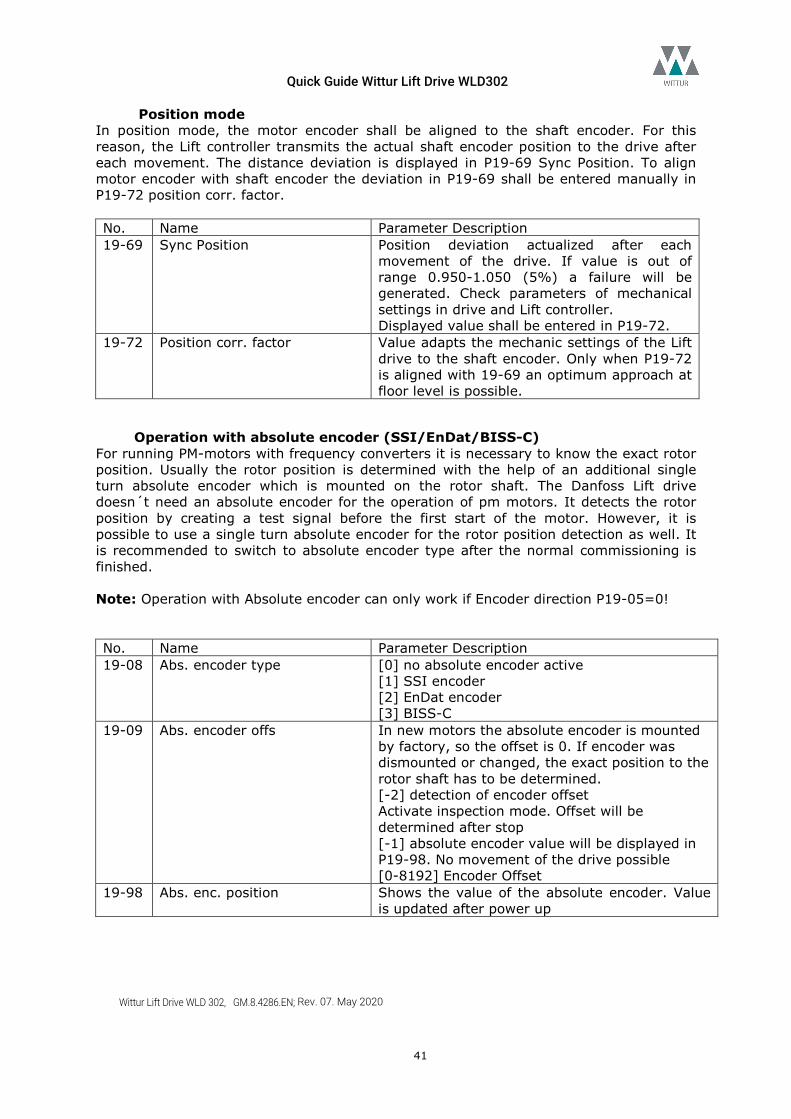
Position mode In position mode, the motor encoder shall be aligned to the shaft encoder. For this reason, the Lift controller transmits the actual shaft encoder position to the drive after each movement. The distance deviation is displayed in P19-69 Sync Position. To align motor encoder with shaft encoder the deviation in P19-69 shall be entered manually in P19-72 position corr. factor. No. Name Parameter Description 19-69 Sync Position Position deviation actualized after each
movement of the drive. If value is out of range 0.950-1.050 (5%) a failure will be generated. Check parameters of mechanical settings in drive and Lift controller. Displayed value shall be entered in P19-72.
19-72 Position corr. factor Value adapts the mechanic settings of the Lift drive to the shaft encoder. Only when P19-72 is aligned with 19-69 an optimum approach at floor level is possible.
Operation with absolute encoder (SSI/EnDat/BISS-C) For running PM-motors with frequency converters it is necessary to know the exact rotor position. Usually the rotor position is determined with the help of an additional single turn absolute encoder which is mounted on the rotor shaft. The Danfoss Lift drive doesn´t need an absolute encoder for the operation of pm motors. It detects the rotor position by creating a test signal before the first start of the motor. However, it is possible to use a single turn absolute encoder for the rotor position detection as well. It is recommended to switch to absolute encoder type after the normal commissioning is finished. Note: Operation with Absolute encoder can only work if Encoder direction P19-05=0! No. Name Parameter Description 19-08 Abs. encoder type [0] no absolute encoder active
[1] SSI encoder [2] EnDat encoder [3] BISS-C
19-09 Abs. encoder offs In new motors the absolute encoder is mounted by factory, so the offset is 0. If encoder was dismounted or changed, the exact position to the rotor shaft has to be determined. [-2] detection of encoder offset Activate inspection mode. Offset will be determined after stop [-1] absolute encoder value will be displayed in P19-98. No movement of the drive possible [0-8192] Encoder Offset
19-98 Abs. enc. position Shows the value of the absolute encoder. Value is updated after power up
Quick Guide Wittur Lift Drive WLD302
Wittur Lift Drive WLD 302, GM.8.4286.EN; Rev. 07. May 2020
42
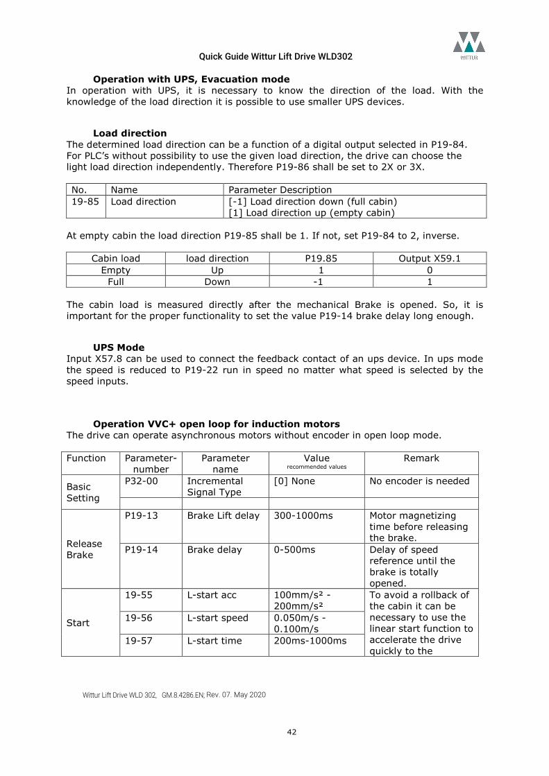
Operation with UPS, Evacuation mode In operation with UPS, it is necessary to know the direction of the load. With the knowledge of the load direction it is possible to use smaller UPS devices.
Load direction The determined load direction can be a function of a digital output selected in P19-84. For PLC’s without possibility to use the given load direction, the drive can choose the light load direction independently. Therefore P19-86 shall be set to 2X or 3X. No. Name Parameter Description 19-85 Load direction [-1] Load direction down (full cabin)
[1] Load direction up (empty cabin) At empty cabin the load direction P19-85 shall be 1. If not, set P19-84 to 2, inverse.
Cabin load load direction P19.85 Output X59.1 Empty Up 1 0
Full Down -1 1 The cabin load is measured directly after the mechanical Brake is opened. So, it is important for the proper functionality to set the value P19-14 brake delay long enough.
UPS Mode Input X57.8 can be used to connect the feedback contact of an ups device. In ups mode the speed is reduced to P19-22 run in speed no matter what speed is selected by the speed inputs.
Operation VVC+ open loop for induction motors The drive can operate asynchronous motors without encoder in open loop mode. Function Parameter-
number Parameter
name Value
recommended values Remark
Basic Setting
P32-00 Incremental Signal Type
[0] None No encoder is needed
Release Brake
P19-13 Brake Lift delay 300-1000ms Motor magnetizing time before releasing the brake.
P19-14 Brake delay 0-500ms Delay of speed reference until the brake is totally opened.
Start
19-55 L-start acc 100mm/s² - 200mm/s²
To avoid a rollback of the cabin it can be necessary to use the linear start function to accelerate the drive quickly to the
19-56 L-start speed 0.050m/s -0.100m/s
19-57 L-start time 200ms-1000ms
Quick Guide Wittur Lift Drive WLD302
Wittur Lift Drive WLD 302, GM.8.4286.EN; Rev. 07. May 2020
43
minimum speed.
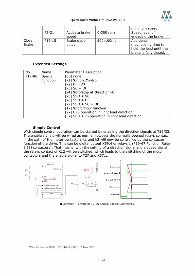
Close Brake
P2-21 Activate brake speed
0-300 rpm Speed level of engaging the brake.
P19-15 Brake close delay
300-100ms Additional magnetizing time to hold the load until the brake is fully closed.
Extended Settings No. Name Parameter Description P19-86 Special
Function [00] none [x1] Simple Control [x2] Dir=V0 [x3] SC + DF [x4] Soft-Stop at Direction=0 [x5] SSD + SC [x6] SSD + DF [x7] SSD + SC + DF [1x] Short Floor function [2x] UPS operation in light load direction [3x] SF + UPS operation in light load direction
Simple Control With simple control operation can be started by enabling the direction signals at T32/33. The enable signals will be wired as normal however the normally opened relays contact in the path of the motor contactors k1 and k2 will now be controlled by the contactor function of the drive. This can be digital output X59.4 or relays 1 (P19-67 Function Relay 1 [3] contactors). That means, with the setting of a direction signal and a speed signal the relays contact of K12 will be switched, which leads to the switching of the motor contactors and the enable signal to T27 and X57.1.
Illustration: Parameter 19-86 Enable Simple Control=[0]
Quick Guide Wittur Lift Drive WLD302
Wittur Lift Drive WLD 302, GM.8.4286.EN; Rev. 07. May 2020
44
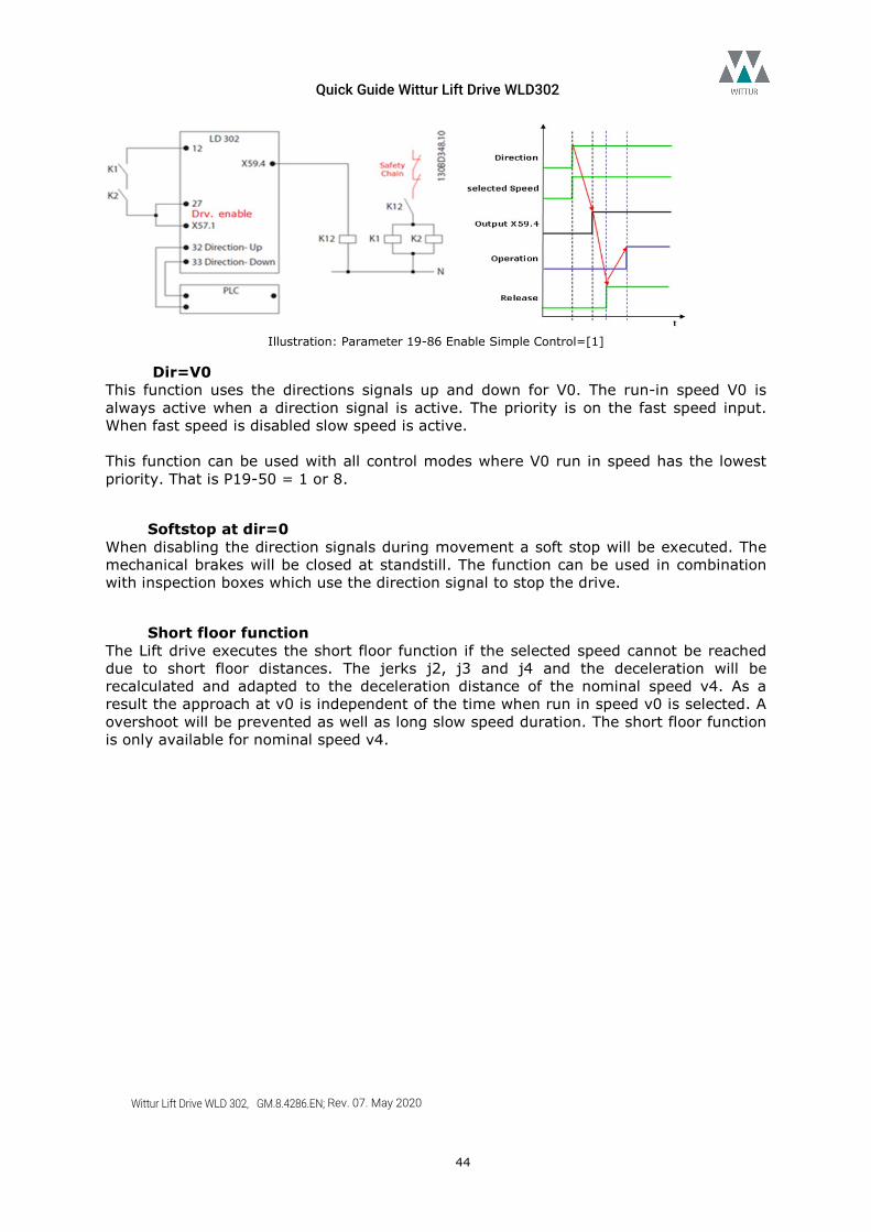
Illustration: Parameter 19-86 Enable Simple Control=[1]
Dir=V0 This function uses the directions signals up and down for V0. The run-in speed V0 is always active when a direction signal is active. The priority is on the fast speed input. When fast speed is disabled slow speed is active. This function can be used with all control modes where V0 run in speed has the lowest priority. That is P19-50 = 1 or 8.
Softstop at dir=0 When disabling the direction signals during movement a soft stop will be executed. The mechanical brakes will be closed at standstill. The function can be used in combination with inspection boxes which use the direction signal to stop the drive.
Short floor function The Lift drive executes the short floor function if the selected speed cannot be reached due to short floor distances. The jerks j2, j3 and j4 and the deceleration will be recalculated and adapted to the deceleration distance of the nominal speed v4. As a result the approach at v0 is independent of the time when run in speed v0 is selected. A overshoot will be prevented as well as long slow speed duration. The short floor function is only available for nominal speed v4.
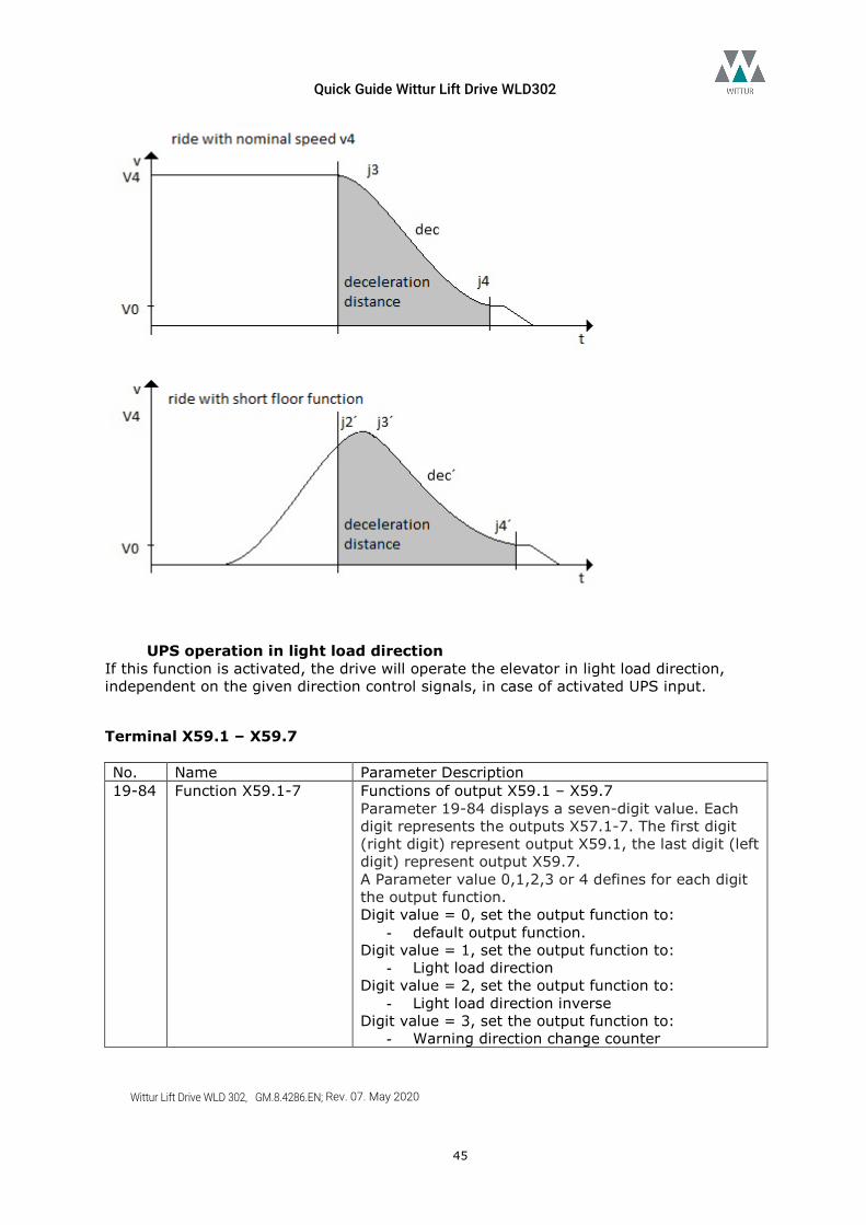
Quick Guide Wittur Lift Drive WLD302
Wittur Lift Drive WLD 302, GM.8.4286.EN; Rev. 07. May 2020
45
UPS operation in light load direction If this function is activated, the drive will operate the elevator in light load direction, independent on the given direction control signals, in case of activated UPS input.
Terminal X59.1 – X59.7 No. Name Parameter Description 19-84 Function X59.1-7 Functions of output X59.1 – X59.7
Parameter 19-84 displays a seven-digit value. Each digit represents the outputs X57.1-7. The first digit (right digit) represent output X59.1, the last digit (left digit) represent output X59.7. A Parameter value 0,1,2,3 or 4 defines for each digit the output function. Digit value = 0, set the output function to:
- default output function. Digit value = 1, set the output function to:
- Light load direction Digit value = 2, set the output function to:
- Light load direction inverse Digit value = 3, set the output function to:
- Warning direction change counter
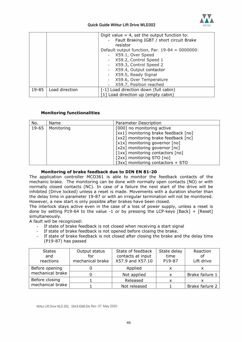
Quick Guide Wittur Lift Drive WLD302
Wittur Lift Drive WLD 302, GM.8.4286.EN; Rev. 07. May 2020
46
Digit value = 4, set the output function to: - Fault Braking IGBT / short circuit Brake
resistor Default output function, Par. 19-84 = 0000000:
- X59.1, Over Speed - X59.2, Control Speed 1 - X59.3, Control Speed 2 - X59.4, Output contactor - X59.5, Ready Signal - X59.6, Over Temperature - X59.7, Position reached
19-85 Load direction [-1] Load direction down (full cabin) [1] Load direction up (empty cabin)
Monitoring functionalities No. Name Parameter Description 19-65 Monitoring [000] no monitoring active
[xx1] monitoring brake feedback [no] [xx2] monitoring brake feedback [nc] [x1x] monitoring governor [no] [x2x] monitoring governor [nc] [1xx] monitoring contactors [no] [2xx] monitoring STO [no] [3xx] monitoring contactors + STO
Monitoring of brake feedback due to DIN EN 81-20 The application controller MCO361 is able to monitor the feedback contacts of the mechanic brake. The monitoring can be done with normally open contacts (NO) or with normally closed contacts (NC). In case of a failure the next start of the drive will be inhibited (Drive locked) unless a reset is made. Movements with a duration shorter than the delay time in parameter 19-87 or with an irregular termination will not be monitored. However, a new start is only possible after brakes have been closed. The interlock stays active even in the case of a loss of power supply, unless a reset is done by setting P19-64 to the value -1 or by pressing the LCP-keys [Back] + [Reset] simultaneously. A fault will be recognized:
- If state of brake feedback is not closed when receiving a start signal - If state of brake feedback is not opened before closing the brake. - If state of brake feedback is not closed after closing the brake and the delay time
(P19-87) has passed
States and
reactions
Output status for
mechanical brake
State of feedback contacts at input X57.9 and X57.10
State delay time
P19-87
Reaction of
Lift drive
Before opening mechanical brake
0 Applied x x 0 Not applied x Brake failure 1
Before closing mechanical brake
1 Released x x 1 Not released 1 Brake failure 2
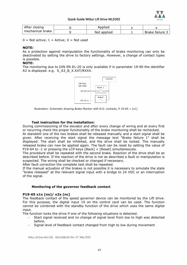
Quick Guide Wittur Lift Drive WLD302
Wittur Lift Drive WLD 302, GM.8.4286.EN; Rev. 07. May 2020
47
After closing mechanical brake
0 Applied x x 0 Not applied 1 Brake failure 3
0 = Not active; 1 = Active; X = Not used NOTE: As a protection against manipulation the functionality of brake monitoring can only be deactivated by setting the drive to factory settings. However, a change of contact types is possible. NOTE: The monitoring due to DIN EN 81-20 is only available if in parameter 19-90 the identifier A3 is displayed. e.g. S_A3_B_X.XXT/RXXX.
Illustration: Schematic drawing Brake Monitor with N.O. contacts, P 19-65 = [x1]
Test instruction for the installation: During commissioning of the elevator and after every change of wiring and at every first or recurring check the proper functionality of the brake monitoring shall be rechecked. At standstill one of the two brakes shall be released manually and a start signal shall be given. After receiving the start signal the message text “Brake failure 1” shall be displayed. The start shall be inhibited, and the drive shall be locked. The manually released brake can now be applied again. The fault can be reset by setting the value of P19-64 to -1 or pressing the LCP-keys [Back] + [Reset] simultaneously. The procedure shall be repeated with the second brake. Reaction of the drive shall be as described before. If the reaction of the drive is not as described a fault or manipulation is suspected. The wiring shall be checked or changed if necessary. After fault correction the complete test shall be repeated. If the manual actuation of the brakes is not possible it is necessary to simulate the state “brake released” at the relevant signal input with a bridge to 24 VDC or an interruption of the signal.
Monitoring of the governor feedback contact P19-65 x1x [no]/ x2x [nc] The feedback contact of the speed governor device can be monitored by the Lift drive. For this purpose, the digital input 19 on the control card can be used. The function cannot be combined with the standby function of the drive which uses the same digital input. The function locks the drive if one of the following situations is detected.
- Start signal received and no change of signal level from low to high was detected before.
- Signal level of feedback contact changed from high to low during movement
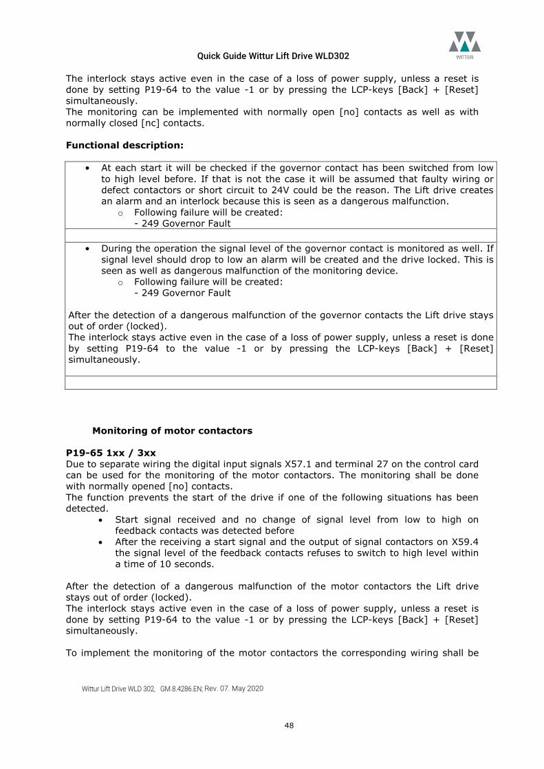
Quick Guide Wittur Lift Drive WLD302
Wittur Lift Drive WLD 302, GM.8.4286.EN; Rev. 07. May 2020
48
The interlock stays active even in the case of a loss of power supply, unless a reset is done by setting P19-64 to the value -1 or by pressing the LCP-keys [Back] + [Reset] simultaneously. The monitoring can be implemented with normally open [no] contacts as well as with normally closed [nc] contacts. Functional description:
• At each start it will be checked if the governor contact has been switched from low to high level before. If that is not the case it will be assumed that faulty wiring or defect contactors or short circuit to 24V could be the reason. The Lift drive creates an alarm and an interlock because this is seen as a dangerous malfunction.
o Following failure will be created: - 249 Governor Fault
• During the operation the signal level of the governor contact is monitored as well. If
signal level should drop to low an alarm will be created and the drive locked. This is seen as well as dangerous malfunction of the monitoring device.
o Following failure will be created: - 249 Governor Fault
After the detection of a dangerous malfunction of the governor contacts the Lift drive stays out of order (locked). The interlock stays active even in the case of a loss of power supply, unless a reset is done by setting P19-64 to the value -1 or by pressing the LCP-keys [Back] + [Reset] simultaneously.
Monitoring of motor contactors P19-65 1xx / 3xx Due to separate wiring the digital input signals X57.1 and terminal 27 on the control card can be used for the monitoring of the motor contactors. The monitoring shall be done with normally opened [no] contacts. The function prevents the start of the drive if one of the following situations has been detected.
• Start signal received and no change of signal level from low to high on feedback contacts was detected before
• After the receiving a start signal and the output of signal contactors on X59.4 the signal level of the feedback contacts refuses to switch to high level within a time of 10 seconds.
After the detection of a dangerous malfunction of the motor contactors the Lift drive stays out of order (locked). The interlock stays active even in the case of a loss of power supply, unless a reset is done by setting P19-64 to the value -1 or by pressing the LCP-keys [Back] + [Reset] simultaneously. To implement the monitoring of the motor contactors the corresponding wiring shall be
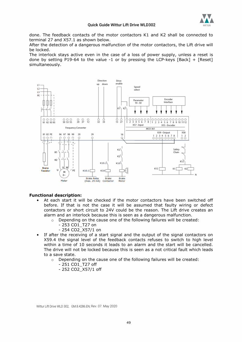
Quick Guide Wittur Lift Drive WLD302
Wittur Lift Drive WLD 302, GM.8.4286.EN; Rev. 07. May 2020
49
done. The feedback contacts of the motor contactors K1 and K2 shall be connected to terminal 27 and X57.1 as shown below. After the detection of a dangerous malfunction of the motor contactors, the Lift drive will be locked. The interlock stays active even in the case of a loss of power supply, unless a reset is done by setting P19-64 to the value -1 or by pressing the LCP-keys [Back] + [Reset] simultaneously.
Functional description:
• At each start it will be checked if the motor contactors have been switched off before. If that is not the case it will be assumed that faulty wiring or defect contactors or short circuit to 24V could be the reason. The Lift drive creates an alarm and an interlock because this is seen as a dangerous malfunction.
o Depending on the cause one of the following failures will be created: - 253 CO1_T27 on - 254 CO2_X57/1 on
• If after the receiving of a start signal and the output of the signal contactors on X59.4 the signal level of the feedback contacts refuses to switch to high level within a time of 10 seconds it leads to an alarm and the start will be cancelled. The drive will not be locked because this is seen as a not critical fault which leads to a save state.
o Depending on the cause one of the following failures will be created: - 251 CO1_T27 off - 252 CO2_X57/1 off
Quick Guide Wittur Lift Drive WLD302
Wittur Lift Drive WLD 302, GM.8.4286.EN; Rev. 07. May 2020
50
Monitoring of STO P19-65 2xx / 3xx With this function the STO (Safe Torque Of) can be monitored. This ensures the detection of wrong connections during installation at every start. This function is only relevant at operation without motor contactors. In case a failure is detected, alarm number 259 (STO T37 on) will be created and the drive is locked. The interlock stays active even in the case of a loss of power supply, unless a reset is done by setting P19-64 to the value -1 or by pressing the LCP-keys [Back] + [Reset] simultaneously.
Standby function The function can decrease the power consumption of the drive when no operation is needed. All digital outputs and all relays will be switched of. If the control card temperature exceeds 56 °C degrees, the fan will be started with a reduced speed of 50%. Standby function can be activated with input terminal 19 or by DCP telegram. If digital inputs are used to control the drive the standby function cannot be combined with the governor monitoring function.
Test run mode 19-60 Test run mode [1] Gear ratio test function. The drive moves one
revolution of the traction sheave. Can be used to check mechanic settings. [2] Fang Release function. Applies torque shocks to release cabin from mechanic fang device.
Gear ratio test function Parameter 19-60 = 1. After start in inspection mode the drive will be started with slow speed. After one revolution of the traction sheave the motor will be stopped. Adjust the gear ration new if the traction shave does not exactly turn one revolution.
Safety gear release function Parameter 19-60 =2. After start in inspection mode the mechanic brake will be opened, and periodic torque shocks will be applied to the motor to release the mechanic fang. This function is only allowed for start direction Up. The function will be disabled automatically after the cabin has moved 100mm or after stopping the drive by control signal.
Alarm log
Alarm log of the drive The Alarm log of the drive can be reached by pressing [Alarm Log]. The alarm log shows a list of the last 5 alarms of the drive. To get additional information, select the alarm with the arrow keys and press [OK]. To get the exact information about the occurrence of the alarm, the alarm time can be compared with the operating hours of the drive in P15-00. Example: P15-50 = 345 h, alarm log time: 1217075s = 338 h 4min 35 s The alarm occurred 7h 55min 25 s ago.
Quick Guide Wittur Lift Drive WLD302
Wittur Lift Drive WLD 302, GM.8.4286.EN; Rev. 07. May 2020
51
Alarm log of the Lift controller No. Name Parameter Description 19-80 Log No Error log of the Lift-controller MCO361. Select the
last errors of the Lift application by entering values from 1-10.
19-81
Error code Error code of the selected log-number in [19-80
19-82 Error time Error time of the selected log-number in [19-80] 19-83 Function Error log [0] Default: logging of errors
[1] Reset error log [2] logging of errors and warnings
7 Operation Startup
After setting up the drive as described in chapter “Initial commissioning”, the drive is ready to start operation. However, depending on the mechanical system further adaptations can be necessary. Please follow in case of unexpected behavior the instructions below.
Test As first step after programming the drive it is highly recommended to test the basic operation in inspection mode with reduced speed. In case of unintended behavior please follow the instructions in the next sup- chapters.
Car direction In case Motor runs controlled, but in wrong direction, the reference can be adjusted to the mechanical system:
No. Name Parameter Description 19-04 Car direction [0] normal direction
[1] direction inverted
Uncontrolled movement (With absolute encoder) In case of used absolute encoder, the motor shall be connected U-V-W to the drive terminal U-V-W in the right order. If this is double checked, a wrong encoder offset can lead to an uncontrolled movement. Please make sure that P19-05 is set to 0. The encoder offset can be measured with P19-09. No. Name Parameter Description 19-09 Abs. encoder offs In new motors the absolute encoder is mounted
by factory, so the offset is 0. If encoder was dismounted or changed, the exact position to the rotor shaft shall be determined. [-2] detection of encoder offset Activate inspection mode. Offset will be determined after stop [-1] absolute encoder value will be displayed in P19-98. No movement of the drive possible [0-8192] Encoder Offset
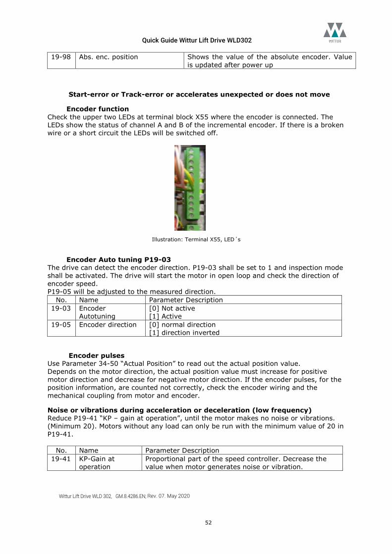
Quick Guide Wittur Lift Drive WLD302
Wittur Lift Drive WLD 302, GM.8.4286.EN; Rev. 07. May 2020
52
19-98 Abs. enc. position Shows the value of the absolute encoder. Value is updated after power up
Start-error or Track-error or accelerates unexpected or does not move
Encoder function Check the upper two LEDs at terminal block X55 where the encoder is connected. The LEDs show the status of channel A and B of the incremental encoder. If there is a broken wire or a short circuit the LEDs will be switched off.
Illustration: Terminal X55, LED´s
Encoder Auto tuning P19-03 The drive can detect the encoder direction. P19-03 shall be set to 1 and inspection mode shall be activated. The drive will start the motor in open loop and check the direction of encoder speed. P19-05 will be adjusted to the measured direction.
No. Name Parameter Description 19-03 Encoder
Autotuning [0] Not active [1] Active
19-05 Encoder direction [0] normal direction [1] direction inverted
Encoder pulses Use Parameter 34-50 “Actual Position” to read out the actual position value. Depends on the motor direction, the actual position value must increase for positive motor direction and decrease for negative motor direction. If the encoder pulses, for the position information, are counted not correctly, check the encoder wiring and the mechanical coupling from motor and encoder.
Noise or vibrations during acceleration or deceleration (low frequency) Reduce P19-41 “KP – gain at operation”, until the motor makes no noise or vibrations. (Minimum 20). Motors without any load can only be run with the minimum value of 20 in P19-41.
No. Name Parameter Description
19-41 KP-Gain at operation
Proportional part of the speed controller. Decrease the value when motor generates noise or vibration.
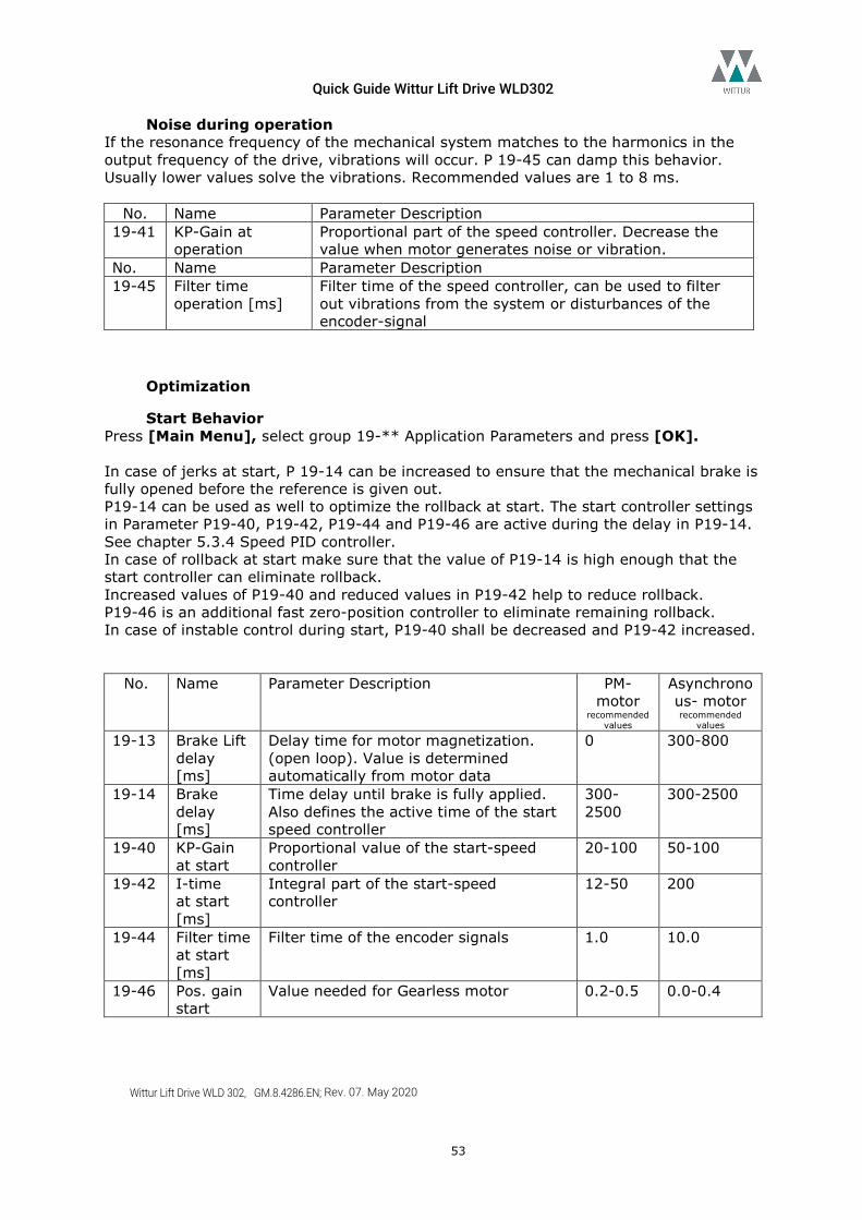
Quick Guide Wittur Lift Drive WLD302
Wittur Lift Drive WLD 302, GM.8.4286.EN; Rev. 07. May 2020
53
Noise during operation If the resonance frequency of the mechanical system matches to the harmonics in the output frequency of the drive, vibrations will occur. P 19-45 can damp this behavior. Usually lower values solve the vibrations. Recommended values are 1 to 8 ms.
No. Name Parameter Description
19-41 KP-Gain at operation
Proportional part of the speed controller. Decrease the value when motor generates noise or vibration.
No. Name Parameter Description 19-45 Filter time
operation [ms] Filter time of the speed controller, can be used to filter out vibrations from the system or disturbances of the encoder-signal
Optimization
Start Behavior Press [Main Menu], select group 19-** Application Parameters and press [OK]. In case of jerks at start, P 19-14 can be increased to ensure that the mechanical brake is fully opened before the reference is given out. P19-14 can be used as well to optimize the rollback at start. The start controller settings in Parameter P19-40, P19-42, P19-44 and P19-46 are active during the delay in P19-14. See chapter 5.3.4 Speed PID controller. In case of rollback at start make sure that the value of P19-14 is high enough that the start controller can eliminate rollback. Increased values of P19-40 and reduced values in P19-42 help to reduce rollback. P19-46 is an additional fast zero-position controller to eliminate remaining rollback. In case of instable control during start, P19-40 shall be decreased and P19-42 increased.
No. Name Parameter Description PM- motor
recommended values
Asynchronous- motor recommended
values 19-13 Brake Lift
delay [ms]
Delay time for motor magnetization. (open loop). Value is determined automatically from motor data
0 300-800
19-14 Brake delay [ms]
Time delay until brake is fully applied. Also defines the active time of the start speed controller
300-2500
300-2500
19-40 KP-Gain at start
Proportional value of the start-speed controller
20-100 50-100
19-42 I-time at start [ms]
Integral part of the start-speed controller
12-50 200
19-44 Filter time at start [ms]
Filter time of the encoder signals 1.0 10.0
19-46 Pos. gain start
Value needed for Gearless motor 0.2-0.5 0.0-0.4
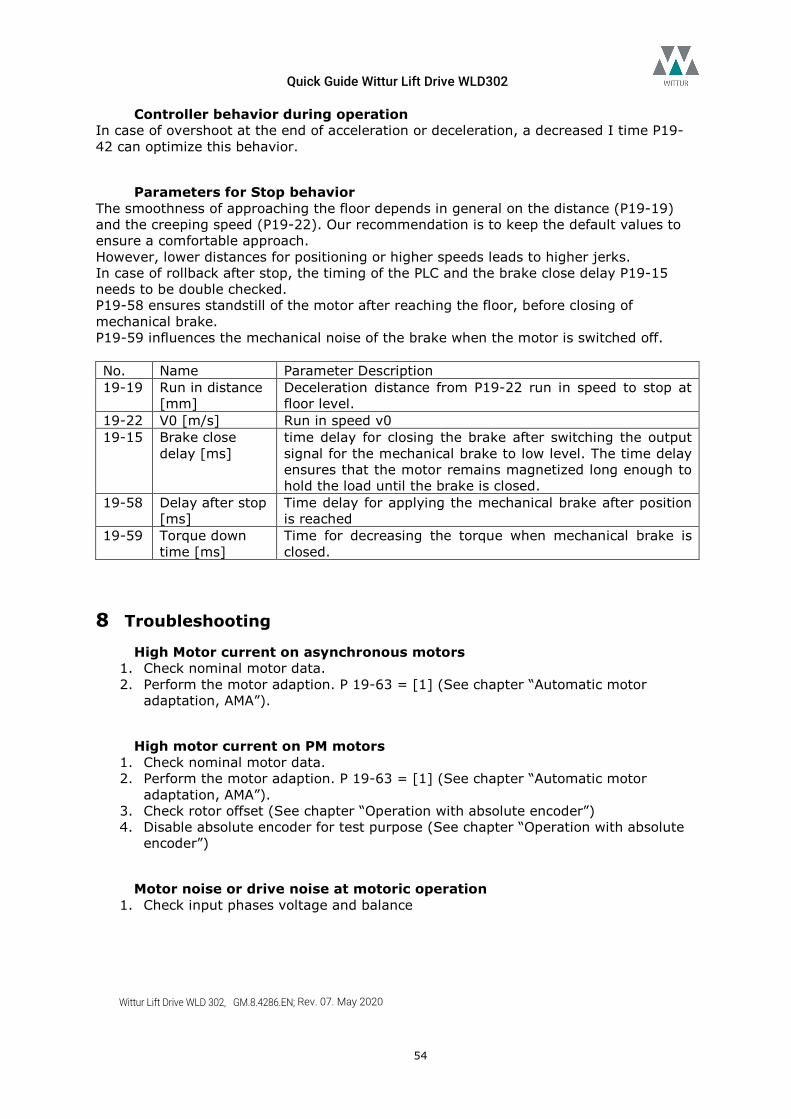
Quick Guide Wittur Lift Drive WLD302
Wittur Lift Drive WLD 302, GM.8.4286.EN; Rev. 07. May 2020
54
Controller behavior during operation In case of overshoot at the end of acceleration or deceleration, a decreased I time P19-42 can optimize this behavior.
Parameters for Stop behavior The smoothness of approaching the floor depends in general on the distance (P19-19) and the creeping speed (P19-22). Our recommendation is to keep the default values to ensure a comfortable approach. However, lower distances for positioning or higher speeds leads to higher jerks. In case of rollback after stop, the timing of the PLC and the brake close delay P19-15 needs to be double checked. P19-58 ensures standstill of the motor after reaching the floor, before closing of mechanical brake. P19-59 influences the mechanical noise of the brake when the motor is switched off. No. Name Parameter Description 19-19 Run in distance
[mm] Deceleration distance from P19-22 run in speed to stop at floor level.
19-22 V0 [m/s] Run in speed v0 19-15 Brake close
delay [ms] time delay for closing the brake after switching the output signal for the mechanical brake to low level. The time delay ensures that the motor remains magnetized long enough to hold the load until the brake is closed.
19-58 Delay after stop [ms]
Time delay for applying the mechanical brake after position is reached
19-59 Torque down time [ms]
Time for decreasing the torque when mechanical brake is closed.
8 Troubleshooting High Motor current on asynchronous motors
1. Check nominal motor data. 2. Perform the motor adaption. P 19-63 = [1] (See chapter “Automatic motor
adaptation, AMA”).
High motor current on PM motors 1. Check nominal motor data. 2. Perform the motor adaption. P 19-63 = [1] (See chapter “Automatic motor
adaptation, AMA”). 3. Check rotor offset (See chapter “Operation with absolute encoder”) 4. Disable absolute encoder for test purpose (See chapter “Operation with absolute
encoder”)
Motor noise or drive noise at motoric operation 1. Check input phases voltage and balance
Quick Guide Wittur Lift Drive WLD302
Wittur Lift Drive WLD 302, GM.8.4286.EN; Rev. 07. May 2020
55
Motor noise, encoder failures, unstable operation 1. Check shielding of motor and encoder cables (See chapter installation)
Earth fault alarm at start 1. Check for mismatch between mains and motor connection.
Sporadic A38 during operation 1. Doublecheck shielding of control signal cables, e.g. motor thermistor. Use PLC or
external device for monitoring of motor thermistor. Check for EMC interference suppressor.
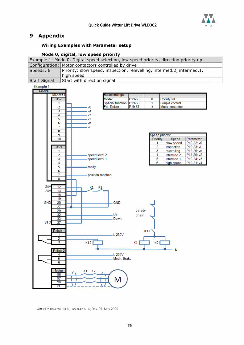
Quick Guide Wittur Lift Drive WLD302
Wittur Lift Drive WLD 302, GM.8.4286.EN; Rev. 07. May 2020
56
9 Appendix
Wiring Examples with Parameter setup
Mode 0, digital, low speed priority Example 1: Mode 0, Digital speed selection, low speed priority, direction priority up Configuration: Motor contactors controlled by drive Speeds: 6 Priority: slow speed, inspection, relevelling, intermed.2, intermed.1,
high speed Start Signal: Start with direction signal
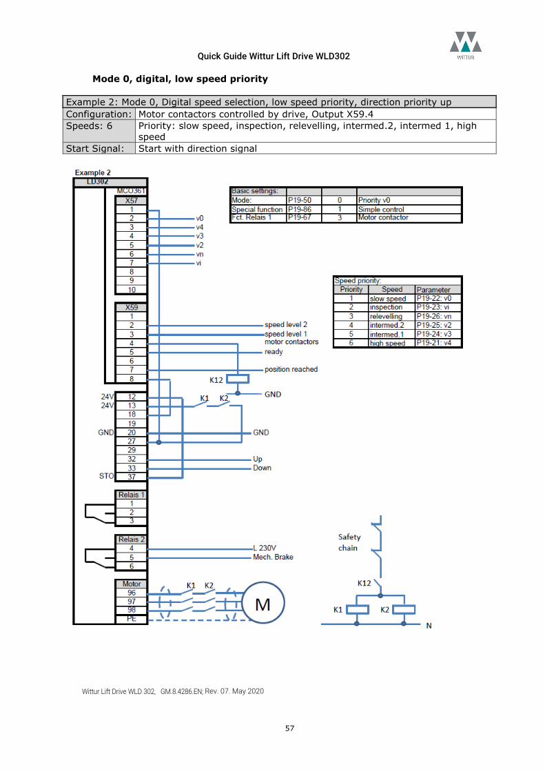
Quick Guide Wittur Lift Drive WLD302
Wittur Lift Drive WLD 302, GM.8.4286.EN; Rev. 07. May 2020
57
Mode 0, digital, low speed priority Example 2: Mode 0, Digital speed selection, low speed priority, direction priority up Configuration: Motor contactors controlled by drive, Output X59.4 Speeds: 6 Priority: slow speed, inspection, relevelling, intermed.2, intermed 1, high
speed Start Signal: Start with direction signal
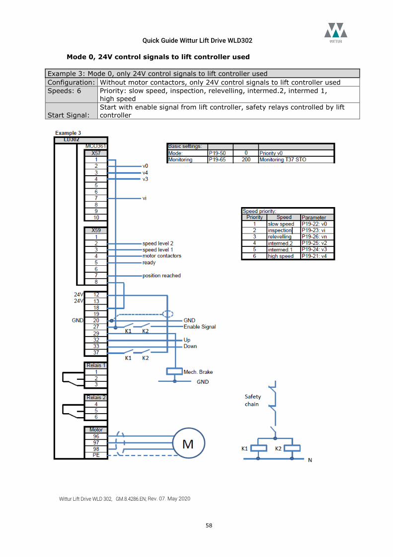
Quick Guide Wittur Lift Drive WLD302
Wittur Lift Drive WLD 302, GM.8.4286.EN; Rev. 07. May 2020
58
Mode 0, 24V control signals to lift controller used Example 3: Mode 0, only 24V control signals to lift controller used Configuration: Without motor contactors, only 24V control signals to lift controller used Speeds: 6 Priority: slow speed, inspection, relevelling, intermed.2, intermed 1,
high speed
Start Signal: Start with enable signal from lift controller, safety relays controlled by lift controller
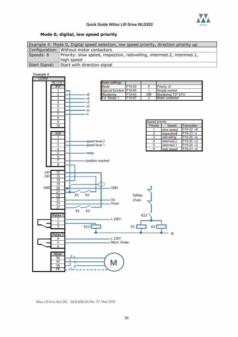
Quick Guide Wittur Lift Drive WLD302
Wittur Lift Drive WLD 302, GM.8.4286.EN; Rev. 07. May 2020
59
Mode 0, digital, low speed priority Example 4: Mode 0, Digital speed selection, low speed priority, direction priority up Configuration: Without motor contactors Speeds: 6 Priority: slow speed, inspection, relevelling, intermed.2, intermed.1,
high speed Start Signal: Start with direction signal
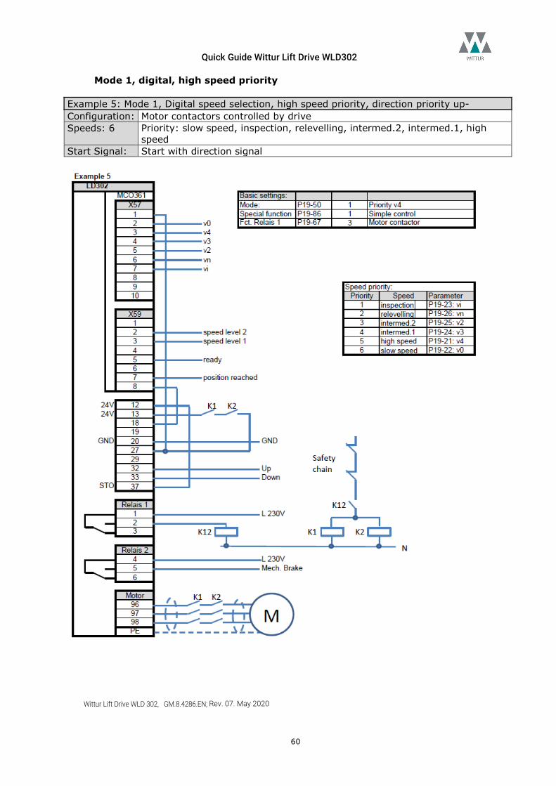
Quick Guide Wittur Lift Drive WLD302
Wittur Lift Drive WLD 302, GM.8.4286.EN; Rev. 07. May 2020
60
Mode 1, digital, high speed priority Example 5: Mode 1, Digital speed selection, high speed priority, direction priority up- Configuration: Motor contactors controlled by drive Speeds: 6 Priority: slow speed, inspection, relevelling, intermed.2, intermed.1, high
speed Start Signal: Start with direction signal
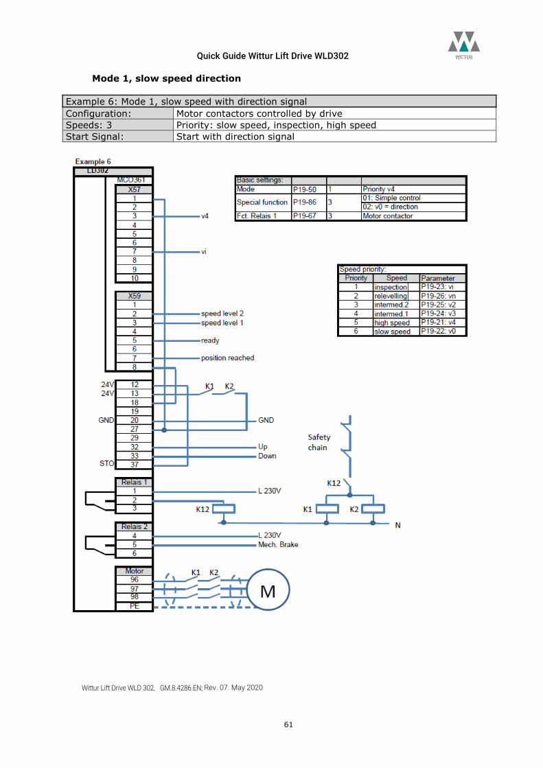
Quick Guide Wittur Lift Drive WLD302
Wittur Lift Drive WLD 302, GM.8.4286.EN; Rev. 07. May 2020
61
Mode 1, slow speed direction Example 6: Mode 1, slow speed with direction signal Configuration: Motor contactors controlled by drive Speeds: 3 Priority: slow speed, inspection, high speed Start Signal: Start with direction signal
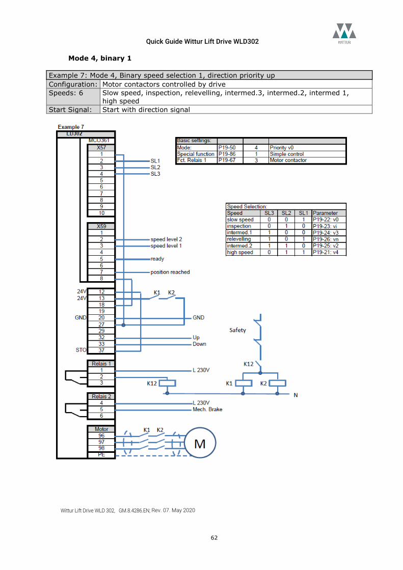
Quick Guide Wittur Lift Drive WLD302
Wittur Lift Drive WLD 302, GM.8.4286.EN; Rev. 07. May 2020
62
Mode 4, binary 1 Example 7: Mode 4, Binary speed selection 1, direction priority up Configuration: Motor contactors controlled by drive Speeds: 6 Slow speed, inspection, relevelling, intermed.3, intermed.2, intermed 1,
high speed Start Signal: Start with direction signal
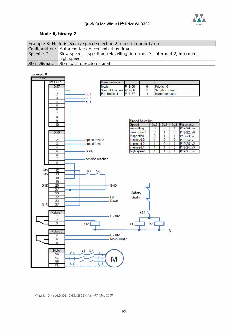
Quick Guide Wittur Lift Drive WLD302
Wittur Lift Drive WLD 302, GM.8.4286.EN; Rev. 07. May 2020
63
Mode 6, binary 2 Example 8: Mode 6, Binary speed selection 2, direction priority up Configuration: Motor contactors controlled by drive Speeds: 7 Slow speed, inspection, relevelling, intermed.3, intermed.2, intermed.1,
high speed Start Signal: Start with direction signal
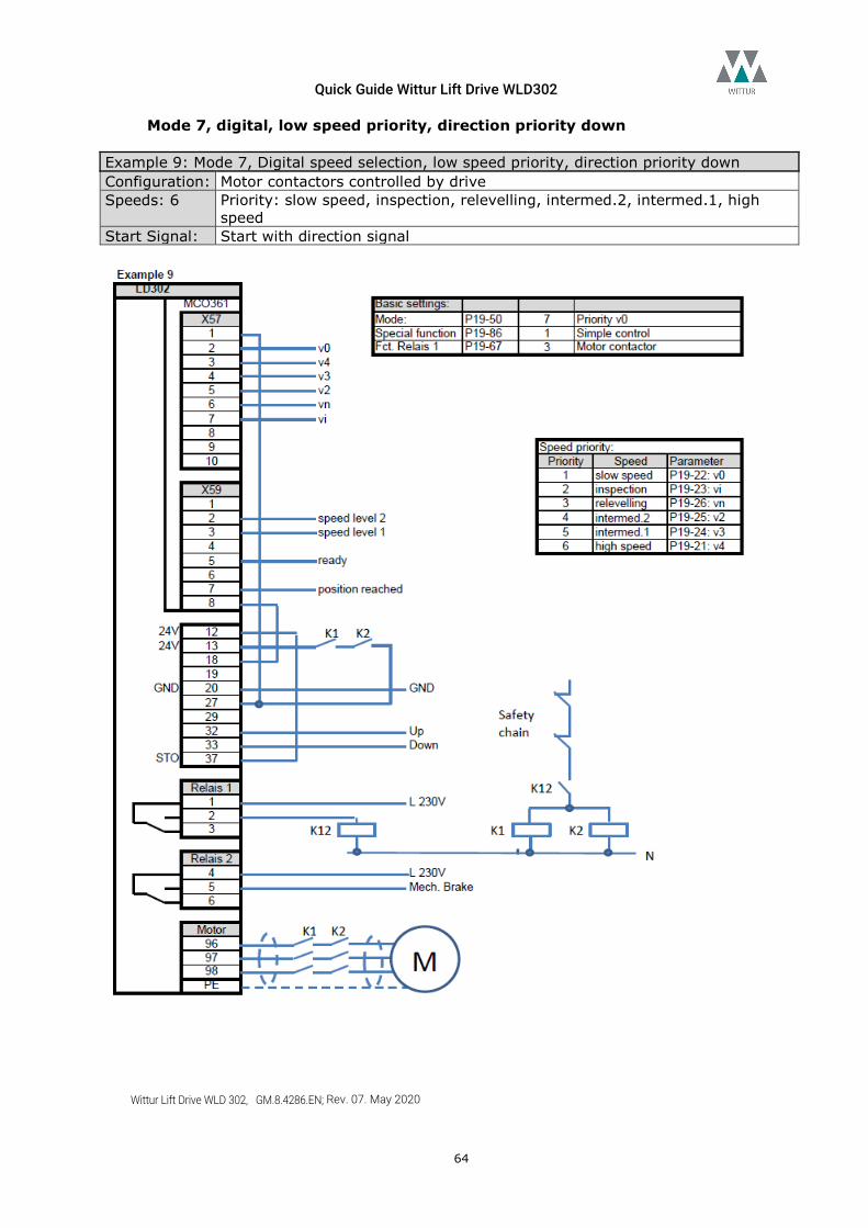
Quick Guide Wittur Lift Drive WLD302
Wittur Lift Drive WLD 302, GM.8.4286.EN; Rev. 07. May 2020
64
Mode 7, digital, low speed priority, direction priority down Example 9: Mode 7, Digital speed selection, low speed priority, direction priority down Configuration: Motor contactors controlled by drive Speeds: 6 Priority: slow speed, inspection, relevelling, intermed.2, intermed.1, high
speed Start Signal: Start with direction signal
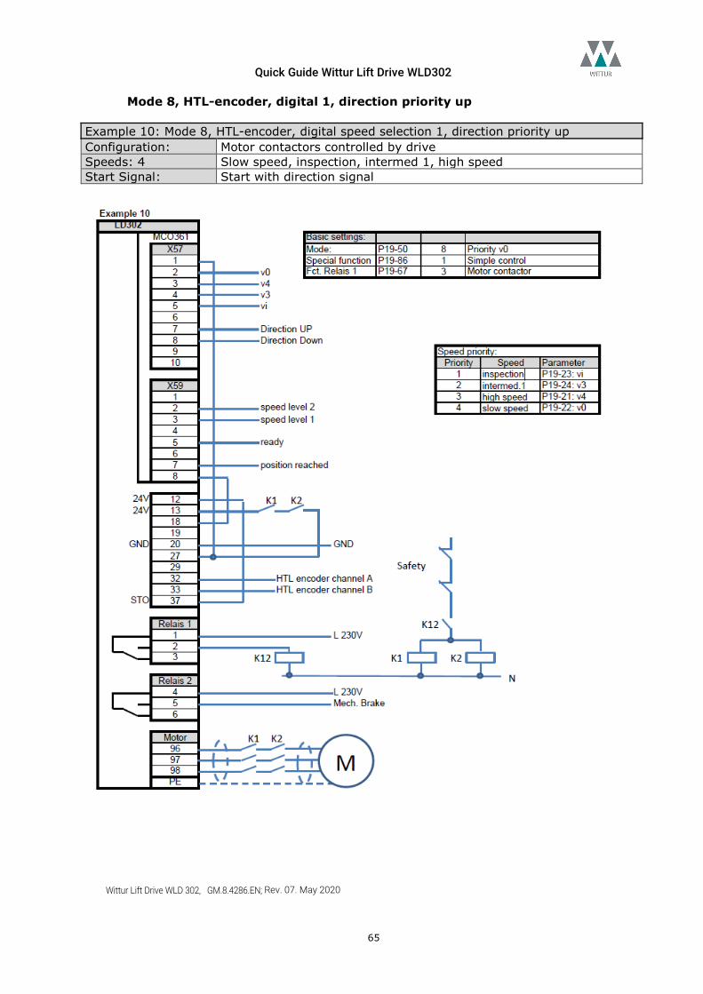
Quick Guide Wittur Lift Drive WLD302
Wittur Lift Drive WLD 302, GM.8.4286.EN; Rev. 07. May 2020
65
Mode 8, HTL-encoder, digital 1, direction priority up Example 10: Mode 8, HTL-encoder, digital speed selection 1, direction priority up Configuration: Motor contactors controlled by drive Speeds: 4 Slow speed, inspection, intermed 1, high speed Start Signal: Start with direction signal
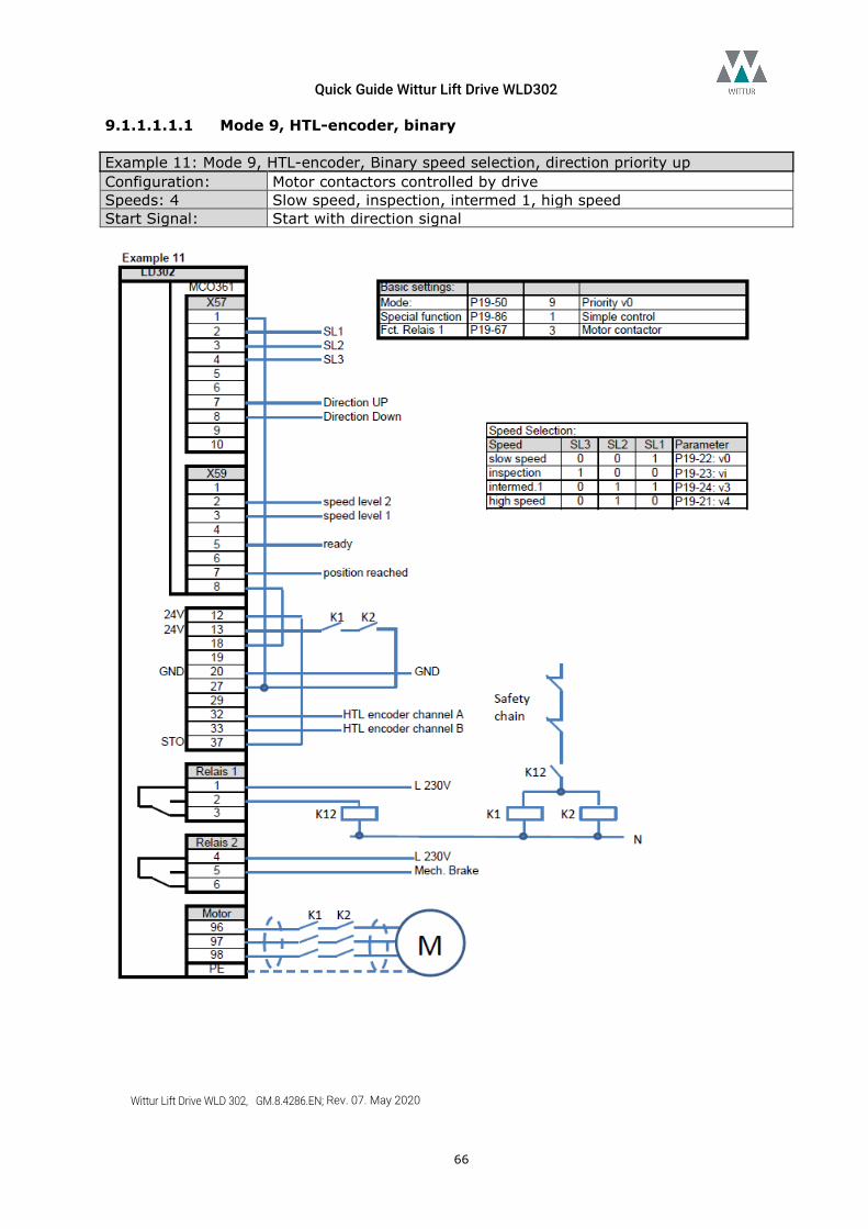
Quick Guide Wittur Lift Drive WLD302
Wittur Lift Drive WLD 302, GM.8.4286.EN; Rev. 07. May 2020
66
9.1.1.1.1.1 Mode 9, HTL-encoder, binary Example 11: Mode 9, HTL-encoder, Binary speed selection, direction priority up Configuration: Motor contactors controlled by drive Speeds: 4 Slow speed, inspection, intermed 1, high speed Start Signal: Start with direction signal
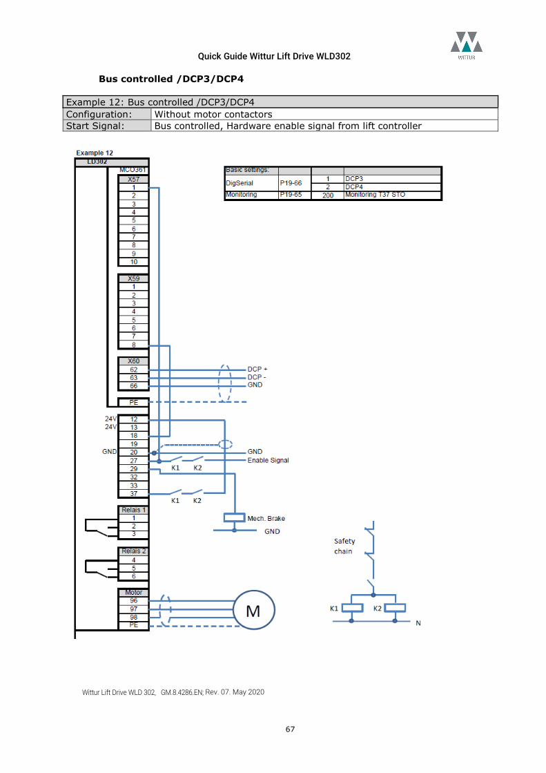
Quick Guide Wittur Lift Drive WLD302
Wittur Lift Drive WLD 302, GM.8.4286.EN; Rev. 07. May 2020
67
Bus controlled /DCP3/DCP4 Example 12: Bus controlled /DCP3/DCP4 Configuration: Without motor contactors Start Signal: Bus controlled, Hardware enable signal from lift controller
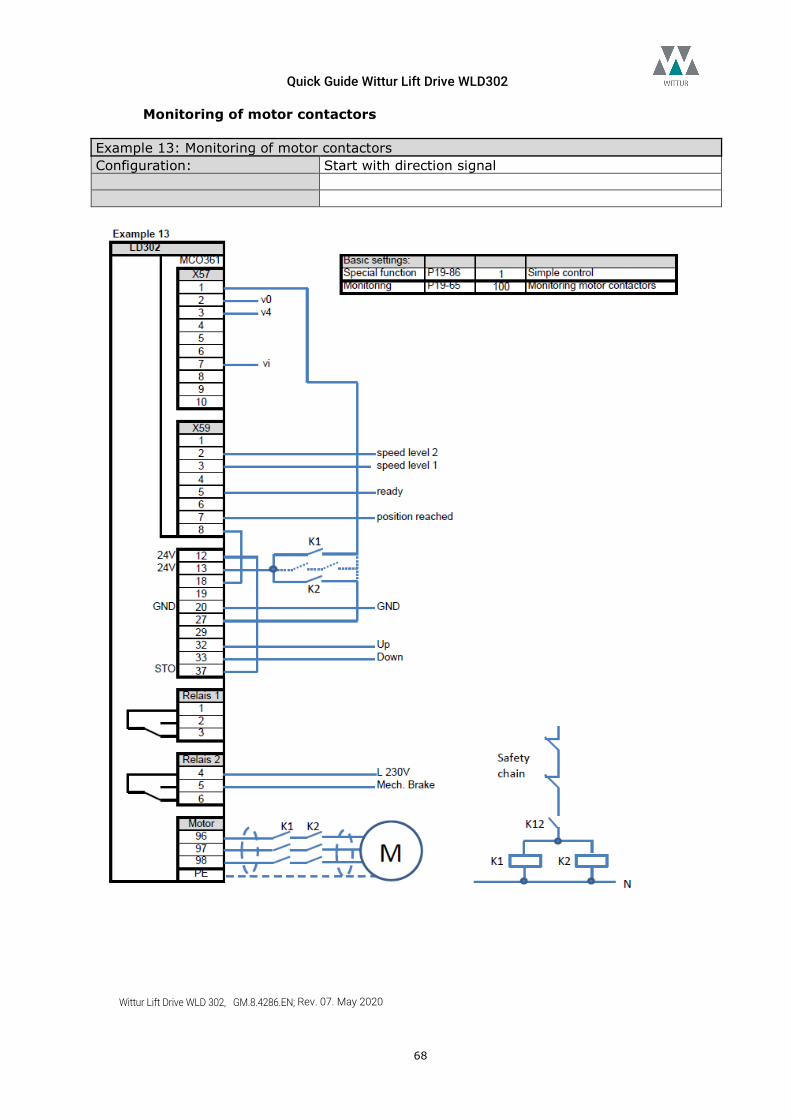
Quick Guide Wittur Lift Drive WLD302
Wittur Lift Drive WLD 302, GM.8.4286.EN; Rev. 07. May 2020
68
Monitoring of motor contactors Example 13: Monitoring of motor contactors Configuration: Start with direction signal
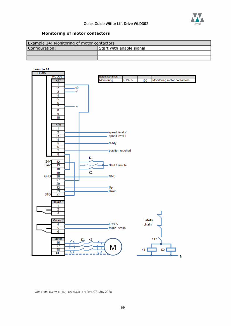
Quick Guide Wittur Lift Drive WLD302
Wittur Lift Drive WLD 302, GM.8.4286.EN; Rev. 07. May 2020
69
Monitoring of motor contactors Example 14: Monitoring of motor contactors Configuration: Start with enable signal
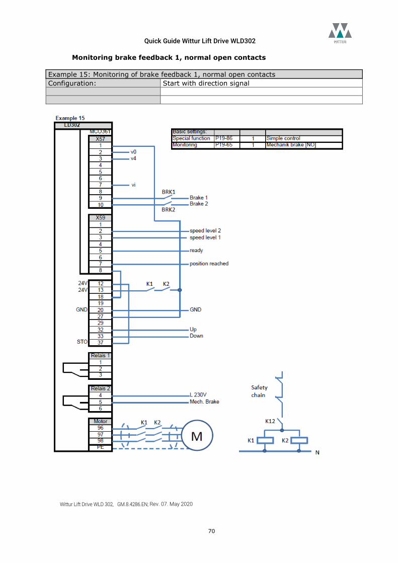
Quick Guide Wittur Lift Drive WLD302
Wittur Lift Drive WLD 302, GM.8.4286.EN; Rev. 07. May 2020
70
Monitoring brake feedback 1, normal open contacts Example 15: Monitoring of brake feedback 1, normal open contacts Configuration: Start with direction signal
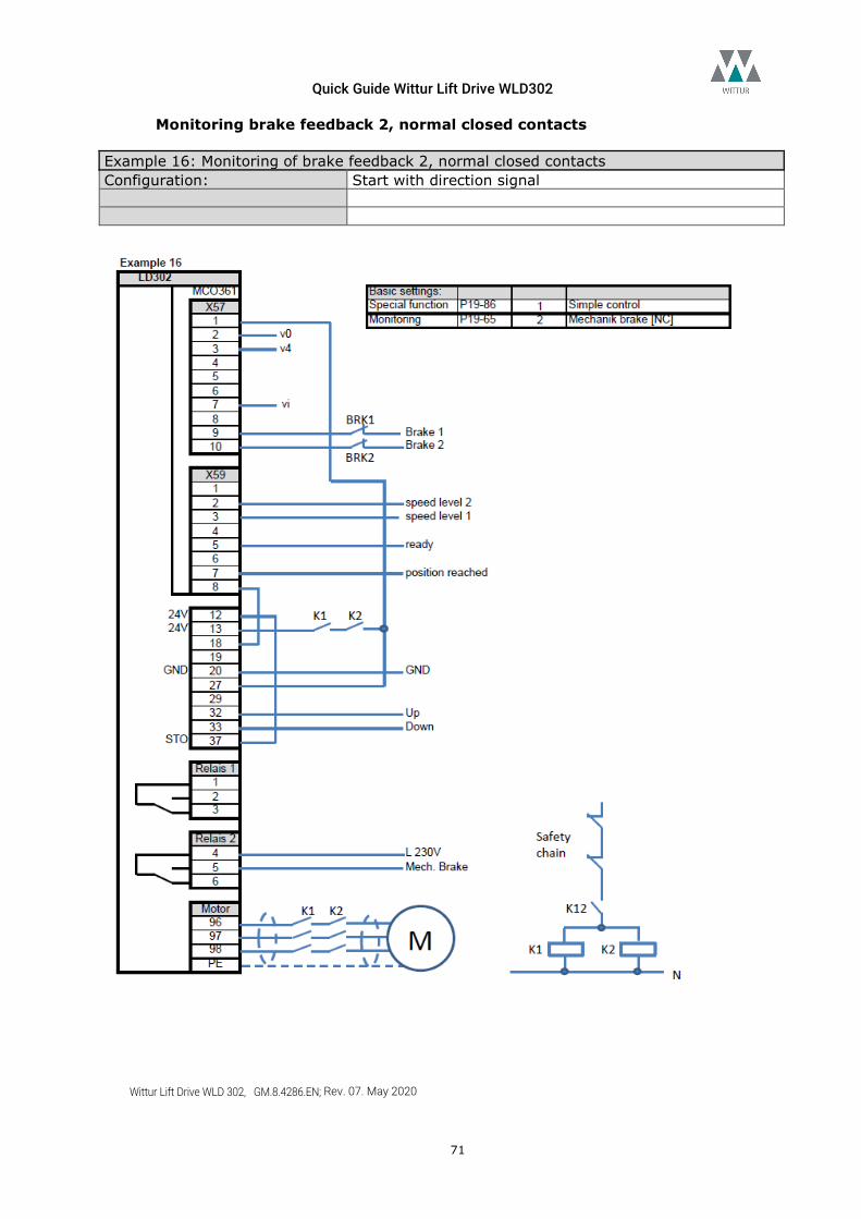
Quick Guide Wittur Lift Drive WLD302
Wittur Lift Drive WLD 302, GM.8.4286.EN; Rev. 07. May 2020
71
Monitoring brake feedback 2, normal closed contacts Example 16: Monitoring of brake feedback 2, normal closed contacts Configuration: Start with direction signal
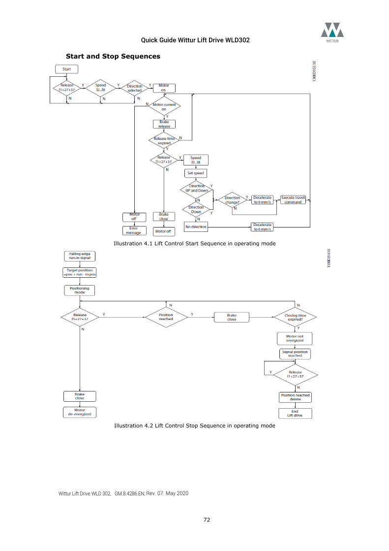
Quick Guide Wittur Lift Drive WLD302
Wittur Lift Drive WLD 302, GM.8.4286.EN; Rev. 07. May 2020
72
Start and Stop Sequences
Illustration 4.1 Lift Control Start Sequence in operating mode
Illustration 4.2 Lift Control Stop Sequence in operating mode
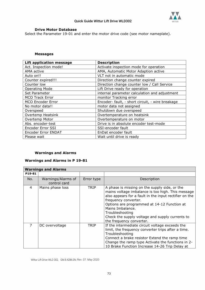
Quick Guide Wittur Lift Drive WLD302
Wittur Lift Drive WLD 302, GM.8.4286.EN; Rev. 07. May 2020
73
Drive Motor Database Select the Parameter 19-01 and enter the motor drive code (see motor nameplate).
Messages Lift application message Description Act. Inspection mode! Activate inspection mode for operation AMA active AMA, Automatic Motor Adaption active Auto on!! VLT not in automatic mode Counter expired!!! Direction change counter expired Counter low Direction change counter low / Call Service Operating Mode Lift Drive ready for operation Set Parameter internal parameter calculation and adjustment MCO Track Error monitor Tracking error MCO Encoder Error Encoder- fault, - short circuit, - wire breakage No motor data!! motor data not assigned Overspeed Shutdown due overspeed Overtemp Heatsink Overtemperature on heatsink Overtemp Motor Overtemperature on motor Abs. encoder-test Drive is in absolute encoder test-mode Encoder Error SSI SSI-encoder fault Encoder Error ENDAT EnDat encoder fault Please wait Wait until drive is ready
Warnings and Alarms
Warnings and Alarms in P 19-81 Warnings and Alarms P19-81 No. Warnings/Alarms of
control card Error type Description
4 Mains phase loss TRIP A phase is missing on the supply side, or the mains voltage imbalance is too high. This message also appears for a fault in the input rectifier on the frequency converter. Options are programmed at 14-12 Function at Mains Imbalance. Troubleshooting Check the supply voltage and supply currents to the frequency converter.
7 DC overvoltage TRIP If the intermediate circuit voltage exceeds the limit, the frequency converter trips after a time. Troubleshooting Connect a brake resistor Extend the ramp time Change the ramp type Activate the functions in 2-10 Brake Function Increase 14-26 Trip Delay at
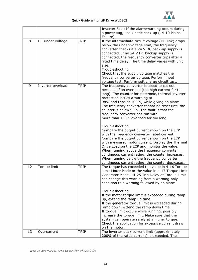
Quick Guide Wittur Lift Drive WLD302
Wittur Lift Drive WLD 302, GM.8.4286.EN; Rev. 07. May 2020
74
Inverter Fault If the alarm/warning occurs during a power sag, use kinetic back-up (14-10 Mains Failure)
8 DC under voltage TRIP If the intermediate circuit voltage (DC link) drops below the under-voltage limit, the frequency converter checks if a 24 V DC back-up supply is connected. If no 24 V DC backup supply is connected, the frequency converter trips after a fixed time delay. The time delay varies with unit size. Troubleshooting Check that the supply voltage matches the frequency converter voltage. Perform input voltage test. Perform soft charge circuit test.
9 Inverter overload TRIP The frequency converter is about to cut out because of an overload (too high current for too long). The counter for electronic, thermal inverter protection issues a warning at 98% and trips at 100%, while giving an alarm. The frequency converter cannot be reset until the counter is below 90%. The fault is that the frequency converter has run with more than 100% overload for too long. Troubleshooting Compare the output current shown on the LCP with the frequency converter rated current. Compare the output current shown on the LCP with measured motor current. Display the Thermal Drive Load on the LCP and monitor the value. When running above the frequency converter continuous current rating, the counter increases. When running below the frequency converter continuous current rating, the counter decreases.
12 Torque limit TRIP The torque has exceeded the value in 4-16 Torque Limit Motor Mode or the value in 4-17 Torque Limit Generator Mode. 14-25 Trip Delay at Torque Limit can change this warning from a warning-only condition to a warning followed by an alarm. Troubleshooting If the motor torque limit is exceeded during ramp up, extend the ramp up time. If the generator torque limit is exceeded during ramp down, extend the ramp down time. If torque limit occurs while running, possibly increase the torque limit. Make sure that the system can operate safely at a higher torque. Check the application for excessive current draw on the motor.
13 Overcurrent TRIP The inverter peak current limit (approximately 200% of the rated current) is exceeded. The
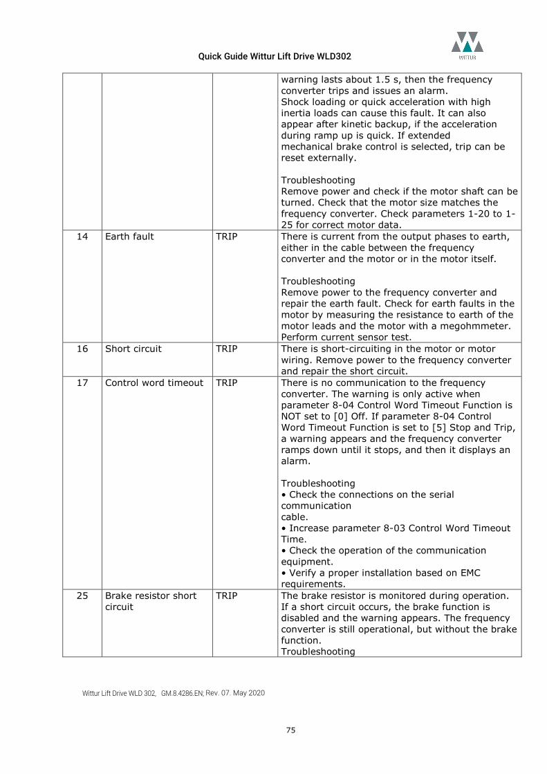
Quick Guide Wittur Lift Drive WLD302
Wittur Lift Drive WLD 302, GM.8.4286.EN; Rev. 07. May 2020
75
warning lasts about 1.5 s, then the frequency converter trips and issues an alarm. Shock loading or quick acceleration with high inertia loads can cause this fault. It can also appear after kinetic backup, if the acceleration during ramp up is quick. If extended mechanical brake control is selected, trip can be reset externally. Troubleshooting Remove power and check if the motor shaft can be turned. Check that the motor size matches the frequency converter. Check parameters 1-20 to 1-25 for correct motor data.
14 Earth fault TRIP There is current from the output phases to earth, either in the cable between the frequency converter and the motor or in the motor itself. Troubleshooting Remove power to the frequency converter and repair the earth fault. Check for earth faults in the motor by measuring the resistance to earth of the motor leads and the motor with a megohmmeter. Perform current sensor test.
16 Short circuit TRIP There is short-circuiting in the motor or motor wiring. Remove power to the frequency converter and repair the short circuit.
17 Control word timeout TRIP There is no communication to the frequency converter. The warning is only active when parameter 8-04 Control Word Timeout Function is NOT set to [0] Off. If parameter 8-04 Control Word Timeout Function is set to [5] Stop and Trip, a warning appears and the frequency converter ramps down until it stops, and then it displays an alarm. Troubleshooting • Check the connections on the serial communication cable. • Increase parameter 8-03 Control Word Timeout Time. • Check the operation of the communication equipment. • Verify a proper installation based on EMC requirements.
25 Brake resistor short circuit
TRIP The brake resistor is monitored during operation. If a short circuit occurs, the brake function is disabled and the warning appears. The frequency converter is still operational, but without the brake function. Troubleshooting
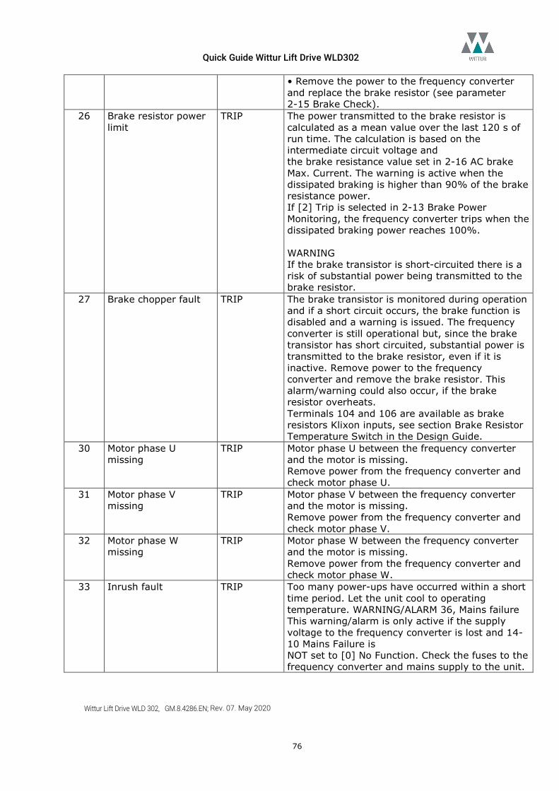
Quick Guide Wittur Lift Drive WLD302
Wittur Lift Drive WLD 302, GM.8.4286.EN; Rev. 07. May 2020
76
• Remove the power to the frequency converter and replace the brake resistor (see parameter 2-15 Brake Check).
26 Brake resistor power limit
TRIP The power transmitted to the brake resistor is calculated as a mean value over the last 120 s of run time. The calculation is based on the intermediate circuit voltage and the brake resistance value set in 2-16 AC brake Max. Current. The warning is active when the dissipated braking is higher than 90% of the brake resistance power. If [2] Trip is selected in 2-13 Brake Power Monitoring, the frequency converter trips when the dissipated braking power reaches 100%. WARNING If the brake transistor is short-circuited there is a risk of substantial power being transmitted to the brake resistor.
27 Brake chopper fault TRIP The brake transistor is monitored during operation and if a short circuit occurs, the brake function is disabled and a warning is issued. The frequency converter is still operational but, since the brake transistor has short circuited, substantial power is transmitted to the brake resistor, even if it is inactive. Remove power to the frequency converter and remove the brake resistor. This alarm/warning could also occur, if the brake resistor overheats. Terminals 104 and 106 are available as brake resistors Klixon inputs, see section Brake Resistor Temperature Switch in the Design Guide.
30 Motor phase U missing
TRIP Motor phase U between the frequency converter and the motor is missing. Remove power from the frequency converter and check motor phase U.
31 Motor phase V missing
TRIP Motor phase V between the frequency converter and the motor is missing. Remove power from the frequency converter and check motor phase V.
32 Motor phase W missing
TRIP Motor phase W between the frequency converter and the motor is missing. Remove power from the frequency converter and check motor phase W.
33 Inrush fault TRIP Too many power-ups have occurred within a short time period. Let the unit cool to operating temperature. WARNING/ALARM 36, Mains failure This warning/alarm is only active if the supply voltage to the frequency converter is lost and 14-10 Mains Failure is NOT set to [0] No Function. Check the fuses to the frequency converter and mains supply to the unit.
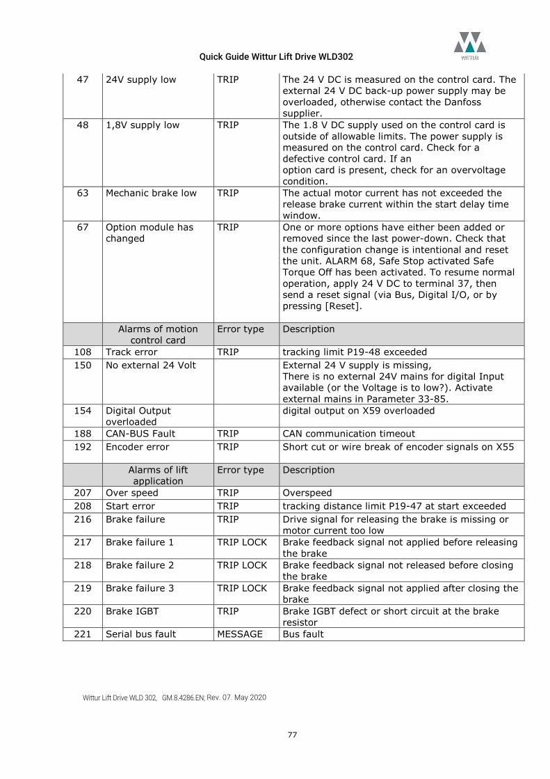
Quick Guide Wittur Lift Drive WLD302
Wittur Lift Drive WLD 302, GM.8.4286.EN; Rev. 07. May 2020
77
47 24V supply low TRIP The 24 V DC is measured on the control card. The external 24 V DC back-up power supply may be overloaded, otherwise contact the Danfoss supplier.
48 1,8V supply low TRIP The 1.8 V DC supply used on the control card is outside of allowable limits. The power supply is measured on the control card. Check for a defective control card. If an option card is present, check for an overvoltage condition.
63 Mechanic brake low TRIP The actual motor current has not exceeded the release brake current within the start delay time window.
67 Option module has changed
TRIP One or more options have either been added or removed since the last power-down. Check that the configuration change is intentional and reset the unit. ALARM 68, Safe Stop activated Safe Torque Off has been activated. To resume normal operation, apply 24 V DC to terminal 37, then send a reset signal (via Bus, Digital I/O, or by pressing [Reset].
Alarms of motion control card
Error type Description
108 Track error TRIP tracking limit P19-48 exceeded 150 No external 24 Volt External 24 V supply is missing,
There is no external 24V mains for digital Input available (or the Voltage is to low?). Activate external mains in Parameter 33-85.
154 Digital Output overloaded
digital output on X59 overloaded
188 CAN-BUS Fault TRIP CAN communication timeout 192 Encoder error TRIP Short cut or wire break of encoder signals on X55
Alarms of lift
application Error type Description
207 Over speed TRIP Overspeed 208 Start error TRIP tracking distance limit P19-47 at start exceeded 216 Brake failure TRIP Drive signal for releasing the brake is missing or
motor current too low 217 Brake failure 1 TRIP LOCK Brake feedback signal not applied before releasing
the brake 218 Brake failure 2 TRIP LOCK Brake feedback signal not released before closing
the brake 219 Brake failure 3 TRIP LOCK Brake feedback signal not applied after closing the
brake 220 Brake IGBT TRIP Brake IGBT defect or short circuit at the brake
resistor 221 Serial bus fault MESSAGE Bus fault
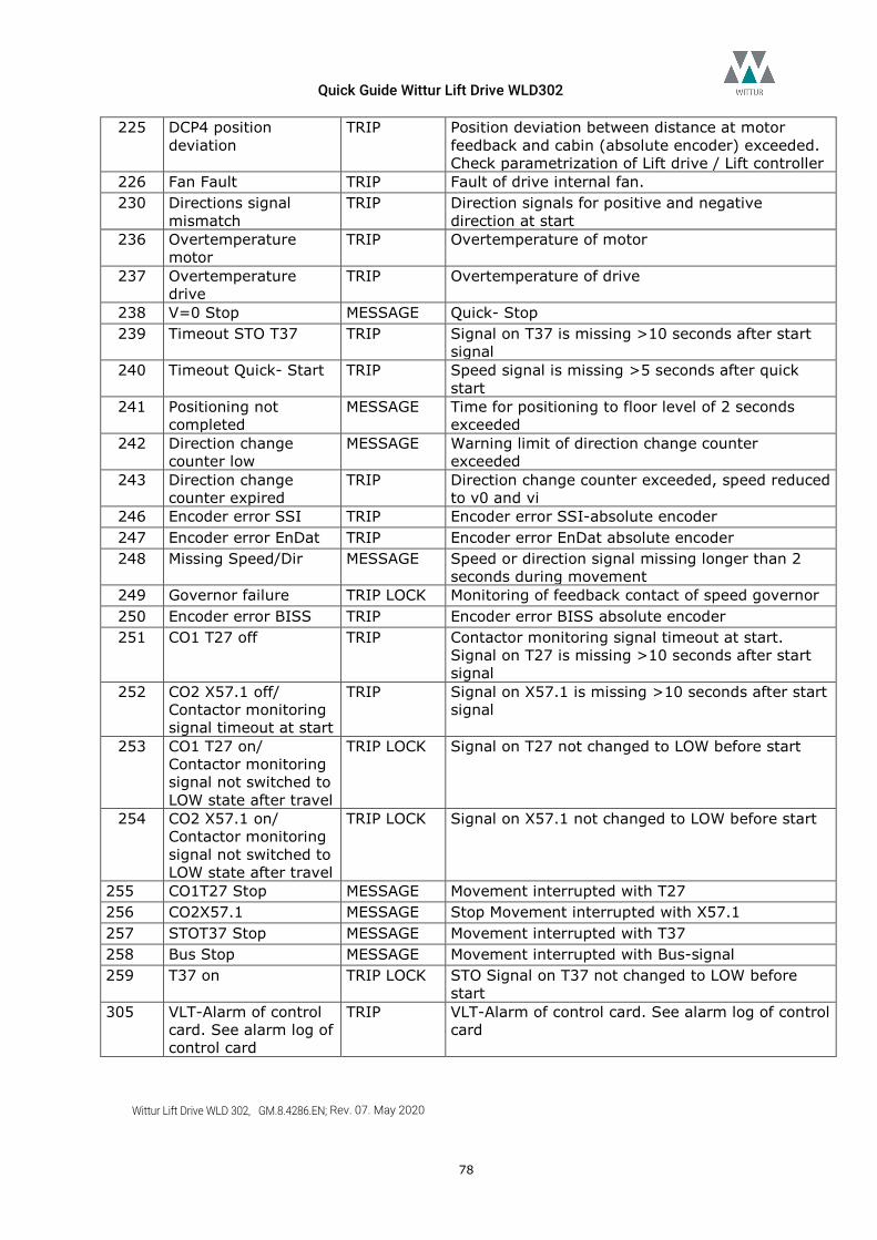
Quick Guide Wittur Lift Drive WLD302
Wittur Lift Drive WLD 302, GM.8.4286.EN; Rev. 07. May 2020
78
225 DCP4 position deviation
TRIP Position deviation between distance at motor feedback and cabin (absolute encoder) exceeded. Check parametrization of Lift drive / Lift controller
226 Fan Fault TRIP Fault of drive internal fan. 230 Directions signal
mismatch TRIP Direction signals for positive and negative
direction at start 236 Overtemperature
motor TRIP Overtemperature of motor
237 Overtemperature drive
TRIP Overtemperature of drive
238 V=0 Stop MESSAGE Quick- Stop 239 Timeout STO T37 TRIP Signal on T37 is missing >10 seconds after start
signal 240 Timeout Quick- Start TRIP Speed signal is missing >5 seconds after quick
start 241 Positioning not
completed MESSAGE Time for positioning to floor level of 2 seconds
exceeded 242 Direction change
counter low MESSAGE Warning limit of direction change counter
exceeded 243 Direction change
counter expired TRIP Direction change counter exceeded, speed reduced
to v0 and vi 246 Encoder error SSI TRIP Encoder error SSI-absolute encoder 247 Encoder error EnDat TRIP Encoder error EnDat absolute encoder 248 Missing Speed/Dir MESSAGE Speed or direction signal missing longer than 2
seconds during movement 249 Governor failure TRIP LOCK Monitoring of feedback contact of speed governor 250 Encoder error BISS TRIP Encoder error BISS absolute encoder 251 CO1 T27 off TRIP Contactor monitoring signal timeout at start.
Signal on T27 is missing >10 seconds after start signal
252 CO2 X57.1 off/ Contactor monitoring signal timeout at start
TRIP Signal on X57.1 is missing >10 seconds after start signal
253 CO1 T27 on/ Contactor monitoring signal not switched to LOW state after travel
TRIP LOCK Signal on T27 not changed to LOW before start
254 CO2 X57.1 on/ Contactor monitoring signal not switched to LOW state after travel
TRIP LOCK Signal on X57.1 not changed to LOW before start
255 CO1T27 Stop MESSAGE Movement interrupted with T27 256 CO2X57.1 MESSAGE Stop Movement interrupted with X57.1 257 STOT37 Stop MESSAGE Movement interrupted with T37 258 Bus Stop MESSAGE Movement interrupted with Bus-signal 259 T37 on TRIP LOCK STO Signal on T37 not changed to LOW before
start 305 VLT-Alarm of control
card. See alarm log of control card
TRIP VLT-Alarm of control card. See alarm log of control card
Quick Guide Wittur Lift Drive WLD302
Wittur Lift Drive WLD 302, GM.8.4286.EN; Rev. 07. May 2020
79
Further Warnings and Alarms WARNING 1, 10 Volts low The control card voltage is below 10 V from terminal 50. Remove some of the load from terminal 50, as the 10 V supply is overloaded. Max. 15 mA or minimum 590 Ω. A short circuit in a connected potentiometer or improper wiring of the potentiometer can cause this condition. Troubleshooting Remove the wiring from terminal 50. If the warning clears, the problem is with the wiring. If the warning does not clear, replace the control card. WARNING/ALARM 2, Live zero error This warning or alarm only appears if programmed in 6-01 Live Zero Timeout Function. The signal on one of the analog inputs is less than 50% of the minimum value programmed for that input. Broken wiring or faulty device sending the signal can cause this condition. Troubleshooting Check connections on all the analog input terminals. Control card terminals 53 and 54 for signals, terminal 55 common. MCB 101 terminals 11 and 12 for signals, terminal 10 common. MCB 109 terminals 1, 3, 5 for signals, terminals 2, 4, 6 common). Check that the frequency converter programming and switch settings match the analog signal type. Perform Input Terminal Signal Test. WARNING/ALARM 3, No motor No motor has been connected to the output of the frequency converter. WARNING 5, DC link voltage high The intermediate circuit voltage (DC) is higher than the high-voltage warning limit. The limit is dependent on the frequency converter voltage rating. The unit is still active. WARNING 6, DC link voltage low The intermediate circuit voltage (DC) is lower than the low voltage warning limit. The limit is dependent on the frequency converter voltage rating. The unit is still active. WARNING/ALARM 10, Motor overload temperature According to the electronic thermal protection (ETR), the motor is too hot. Select whether the frequency converter issues a warning or an alarm when the counter reaches 100% in 1-90 Motor Thermal Protection. The fault occurs when the motor runs with more than 100% overload for too long. Troubleshooting Check for motor overheating. Check if the motor is mechanically overloaded. Check that the motor current set in 1-24 Motor Current is correct. Ensure that Motor data in parameters 1-20 to 1-25 are set correctly. If an external fan is in use, check in 1-91 Motor, External Fan that it is selected. Running AMA in 1-29 Automatic Motor Adaptation (AMA) tunes the frequency converter to the motor more accurately and reduces thermal loading.
Quick Guide Wittur Lift Drive WLD302
Wittur Lift Drive WLD 302, GM.8.4286.EN; Rev. 07. May 2020
80
WARNING/ALARM 11, Motor thermistor over temp The thermistor might be disconnected. Select whether the frequency converter issues a warning or an alarm in 1-90 Motor Thermal Protection. Troubleshooting Check for motor overheating. Check if the motor is mechanically overloaded. Check that the thermistor is connected correctly between either terminal 53 or 54 (analog voltage input) and terminal 50 (+10 V supply). Also check that the terminal switch for 53 or 54 is set for voltage. Check that 1-93 Thermistor Source selects terminal 53 or 54. When using digital inputs 18 or 19, check that the thermistor is connected correctly between either terminal 18 or 19 (digital input PNP only) and terminal 50. If a KTY Sensor is used, check for correct connection between terminals 54 and 55. If using a thermal switch or thermistor, check that the programming if 1-93 Thermistor Resource matches sensor wiring. If using a KTY Sensor, check the programming of 1-95 KTY Sensor Type, 1-96 KTY Thermistor Resource and 1-97 KTY Threshold level match sensor wiring. ALARM 15, Hardware mismatch A fitted option is not operational with the present control board hardware or software. Record the value of the following parameters and contact your Danfoss supplier: 15-40 FC Type 15-41 Power Section 15-42 Voltage 15-43 Software Version 15-45 Actual Typecode String 15-49 SW ID Control Card 15-50 SW ID Power Card 15-60 Option Mounted 15-61 Option SW Version (for each option slot) WARNING/ALARM 22, Hoist mechanical brake Report value shows what kind it is. 0 = The torque ref. was not reached before time-out. 1 = There was no brake feedback before time-out. WARNING 23, Internal fan fault The fan warning function is an extra protective function that checks if the fan is running/mounted. The fan warning can be disabled in 14-53 Fan Monitor ([0] Disabled). Troubleshooting Check fan resistance. Check soft charge fuses. WARNING 24, External fan fault The fan warning function is an extra protective function that checks if the fan is running/mounted. The fan warning can be disabled in 14-53 Fan Monitor ([0] Disabled). Troubleshooting Check fan resistance. Check soft charge fuses. WARNING 25, Brake resistor short circuit The brake resistor is monitored during operation. If a short circuit occurs, the brake function is disabled and the warning appears. The frequency converter is still operational but without the brake function. Remove power to the frequency converter and replace the brake resistor (see 2-15 Brake Check).
Quick Guide Wittur Lift Drive WLD302
Wittur Lift Drive WLD 302, GM.8.4286.EN; Rev. 07. May 2020
81
WARNING/ALARM 28, Brake check failed The brake resistor is not connected or not working. Check 2-15 Brake Check. ALARM 29, Heatsink temp. The maximum temperature of the heatsink has been exceeded. The temperature fault resets when the temperature falls below a defined heatsink temperature. The trip and reset points are different based on the frequency converter power size. Troubleshooting Check for the following conditions.
• Ambient temperature too high. • Motor cable too long. • Incorrect airflow clearance above and below the frequency converter. • Blocked airflow around the frequency converter. • Damaged heatsink fan. • Dirty heatsink.
For the D, E, and F enclosures, this alarm is based on the temperature measured by the heat sink sensor mounted inside the IGBT modules. For the F enclosures, the thermal sensor in the rectifier module can also cause this alarm. Troubleshooting
• Check fan resistance. • Check soft charge fuses. • IGBT thermal sensor.
ALARM 38, Internal fault When an internal fault occurs, a code number is displayed. Troubleshooting
• Cycle power • Check that the option is properly installed • Check for loose or missing wiring
It may be necessary to contact your Danfoss supplier or service department. Note the code number for further troubleshooting directions. ALARM 39, Heatsink sensor No feedback from the heatsink temperature sensor. The signal from the IGBT thermal sensor is not available on the power card. The problem could be on the power card, on the gate drive card, or the ribbon cable between the power card and gate drive card. WARNING 40, Overload of digital output terminal 27 Check the load connected to terminal 27 or remove short circuit connection. Check 5-00 Digital I/O Mode and 5-01 Terminal 27 Mode. WARNING 41, Overload of digital output terminal 29 Check the load connected to terminal 29 or remove short circuit connection. Check 5-00 Digital I/O Mode and 5-02 Terminal 29 Mode.
Quick Guide Wittur Lift Drive WLD302
Wittur Lift Drive WLD 302, GM.8.4286.EN; Rev. 07. May 2020
82
WARNING 49, Speed limit When the speed is not within the specified range in 4-11 Motor Speed Low Limit [RPM] and 4-13 Motor Speed High Limit [RPM], the frequency converter shows a warning. When the speed is below the specified limit in 1-86 Trip Speed Low [RPM] (except when starting or stopping), the frequency converter trips. ALARM 50, AMA calibration failed Contact your Danfoss supplier or Danfoss Service Department. ALARM 51, AMA check Unom and Inom The settings for motor voltage, motor current and motor power are wrong. Check the settings in parameters 1-20 to 1-25. ALARM 52, AMA low Inom The motor current is too low. Check the settings. ALARM 53, AMA motor too big The motor is too big for the AMA to operate. ALARM 54, AMA motor too small The motor is too small for the AMA to operate. ALARM 55, AMA parameter out of range The parameter values of the motor are outside of the acceptable range. AMA cannot run. ALARM 56, AMA interrupted by user The user has interrupted the AMA. ALARM 57, AMA internal fault Try to restart AMA again a number of times, until the AMA is carried out. NOTE: Repeated runs may heat the motor to a level where the resistance Rs and Rr are increased. In most cases, however, this is not critical. ALARM 58, AMA Internal fault Contact your Danfoss supplier. WARNING 59, Current limit The current is higher than the value in 4-18 Current Limit. Ensure that Motor data in parameters 1-20 to 1-25 are set correctly. Possibly increase the current limit. Be sure that the system can operate safely at a higher limit. WARNING 62, Output frequency at maximum limit The output frequency is higher than the value set in 4-19 Max Output Frequency. ALARM 64, Voltage Limit The load and speed combination demands a motor voltage higher than the actual DC link voltage. WARNING/ALARM 65, Control card over temperature The cut-out temperature of the control card is 80 °C. Troubleshooting
• Check that the ambient operating temperature is within limits • Check for clogged filters • Check fan operation • Check the control card
WARNING 66, Heatsink temperature low The frequency converter is too cold to operate. This warning is based on the temperature sensor in the IGBT module. Increase the ambient temperature of the unit. Also, a trickle amount of current can be supplied to the frequency converter whenever the motor is stopped by setting 2-00 DC Hold/Preheat Current at 5% and 1-80 Function at Stop
Quick Guide Wittur Lift Drive WLD302
Wittur Lift Drive WLD 302, GM.8.4286.EN; Rev. 07. May 2020
83
Troubleshooting The heatsink temperature measured as 0° C could indicate that the temperature sensor is defective, causing the fan speed to increase to the maximum. If the sensor wire between the IGBT and the gate drive card is disconnected, this warning would result. Also, check the IGBT thermal sensor. ALARM 69, Power card temperature The temperature sensor on the power card is either too hot or too cold. Troubleshooting Check the operation of the door fans. Check that the filters for the door fans are not blocked. Check that the gland plate is properly installed on IP21/IP 54 (NEMA 1/12) frequency converters. ALARM 70, Illegal FC configuration The control card and power card are incompatible. To check compatibility, contact your supplier with the type code of the unit from the nameplate and the part numbers of the cards. WARNING 76, Power unit setup The required number of power units does not match the detected number of active power units. WARNING 77, Reduced power mode This warning indicates that the frequency converter is operating in reduced power mode (i.e. less than the allowed number of inverter sections). This warning is generated on power cycle when the frequency converter is set to run with fewer inverters and remains on. ALARM 79, Illegal power section configuration The scaling card is the incorrect part number or not installed. Also, MK102 connector on the power card could not be installed. ALARM 80, Drive initialized to default value Parameter settings are initialized to default settings after a manual reset. To clear the alarm, reset the unit.
![Blood Crossmatch\277\351\322\302 [Compatibility Mode]](https://img.pdfslide.net/doc/110x75/631ad8c20255356abc08d9ab/blood-crossmatch277351322302-compatibility-mode.jpg)