Embed Size (px)
Citation preview
Quick Start Guide00825-0600-4026, Rev AA
March 2016
Rosemount™ 5400 Level Transmitter
Mounting Instructions for Parabolic Antenna
March 2016Quick Start Guide
1.0 About this guideThis Quick Start Guide provides mechanical installation instructions for the Rosemount 5402 Level Transmitter with parabolic antenna.
For information about electrical installation and configuration, refer to the Rosemount 5400 Series Quick Start Guide (document number 00825-0100-4026).
Failure to follow safe installation and service guidelines could result in death or serious injury. Make sure the transmitter is installed by qualified personnel and in accordance with applicable code of
practice. Use the equipment only as specified in this Quick Start Guide and the Reference Manual. Failure to do so
may impair the protection provided by the equipment. Any substitution of non-authorized parts or repair, other than exchanging the complete transmitter head
or antenna assembly, may jeopardize safety and is prohibited.
Explosions could result in death or serious injury. Verify that the operating environment of the transmitter is consistent with the appropriate hazardous
locations specifications. To prevent ignition of flammable or combustible atmospheres, disconnect power before servicing. Before connecting a Field Communicator in an explosive atmosphere, make sure the instruments in the
loop are installed in accordance with intrinsically safe or non-incendive field wiring practices. To avoid process leaks, only use O-rings designed to seal with the corresponding flange adapter. Do not remove the transmitter while in operation.
Electrical shock can result in death or serious injury. Avoid contact with the leads and terminals. High voltage that may be present on leads can cause electrical
shock. Make sure the main power to the Rosemount 5400 Level Transmitter is off and the lines to any other
external power source are disconnected or not powered while wiring the transmitter. Ground device on non-metallic tanks (e.g. fiberglass tanks) to prevent electrostatic charge build-up.
ContentsParabolic antenna overview . . . . . . . . . . . . . . . . . . . . . . . . . . . . . . . . . . . . . . . . . . . . . . . . . . . . . . . . page 3Mount the flanged version . . . . . . . . . . . . . . . . . . . . . . . . . . . . . . . . . . . . . . . . . . . . . . . . . . . . . . . . . page 4Mount the welded version . . . . . . . . . . . . . . . . . . . . . . . . . . . . . . . . . . . . . . . . . . . . . . . . . . . . . . . . . page 6Mount the threaded version . . . . . . . . . . . . . . . . . . . . . . . . . . . . . . . . . . . . . . . . . . . . . . . . . . . . . . page 13Adjust inclination of antenna . . . . . . . . . . . . . . . . . . . . . . . . . . . . . . . . . . . . . . . . . . . . . . . . . . . . . . page 19
2
Quick Start GuideMarch 2016
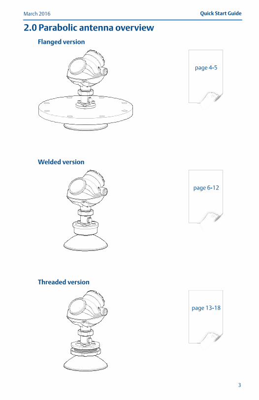
2.0 Parabolic antenna overviewFlanged version
Welded version
Threaded version
page 4-5
page 6-12
page 13-18
3
March 2016Quick Start Guide
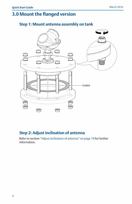
3.0 Mount the flanged version
Step 1: Mount antenna assembly on tank
Step 2: Adjust inclination of antennaRefer to section “Adjust inclination of antenna” on page 19 for further information.
Gasket
4
Quick Start GuideMarch 2016
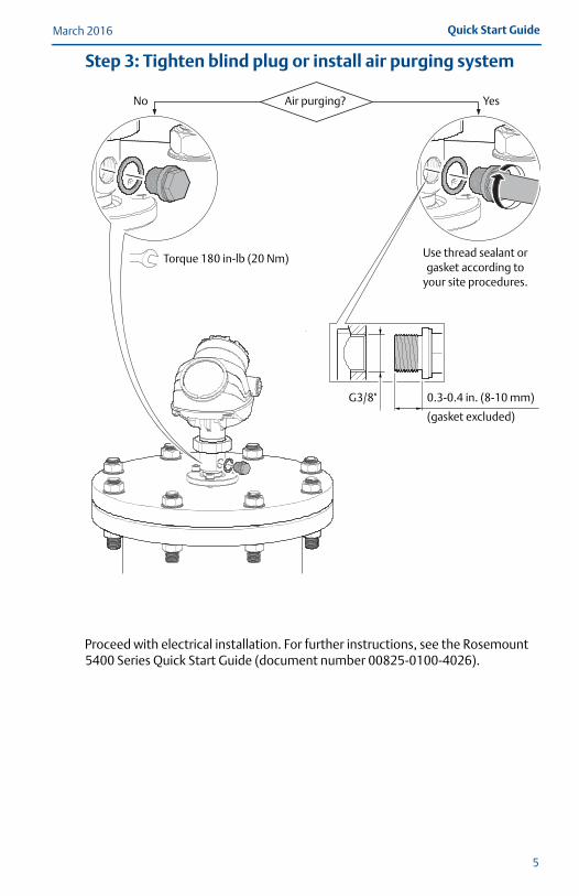
Step 3: Tighten blind plug or install air purging system
Proceed with electrical installation. For further instructions, see the Rosemount 5400 Series Quick Start Guide (document number 00825-0100-4026).
G3/8"
Air purging?No Yes
0.3-0.4 in. (8-10 mm)
(gasket excluded)
Torque 180 in-lb (20 Nm) Use thread sealant or gasket according to
your site procedures.
5
March 2016Quick Start Guide
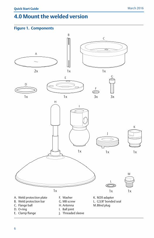
4.0 Mount the welded version
Figure 1. Components
A. B.C.D.E.
Weld protection plateWeld protection barFlange ballO-ringClamp flange
F.G.H.I.J.
WasherM8 screwAntennaBall jointThreaded sleeve
K.L.M.
M20 adapterG3/8" bonded sealBlind plug
2x 1x 1x
1x
1x 1x 1x
1x
1x
3x 3x
A
BC
D
E
F
G
I
H
1x
K
1x
J
L
M
6
Quick Start GuideMarch 2016
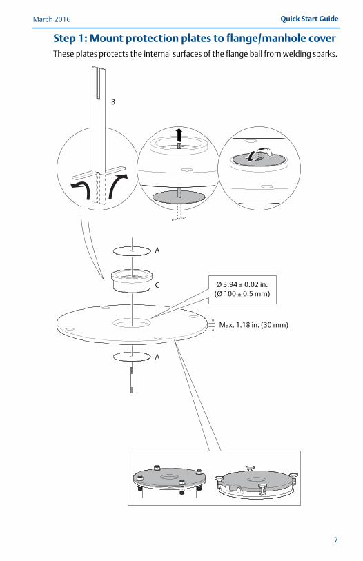
Step 1: Mount protection plates to flange/manhole coverThese plates protects the internal surfaces of the flange ball from welding sparks.
Ø 3.94 ± 0.02 in.(Ø 100 ± 0.5 mm)
A
C
B
A
Max. 1.18 in. (30 mm)
7
March 2016Quick Start Guide
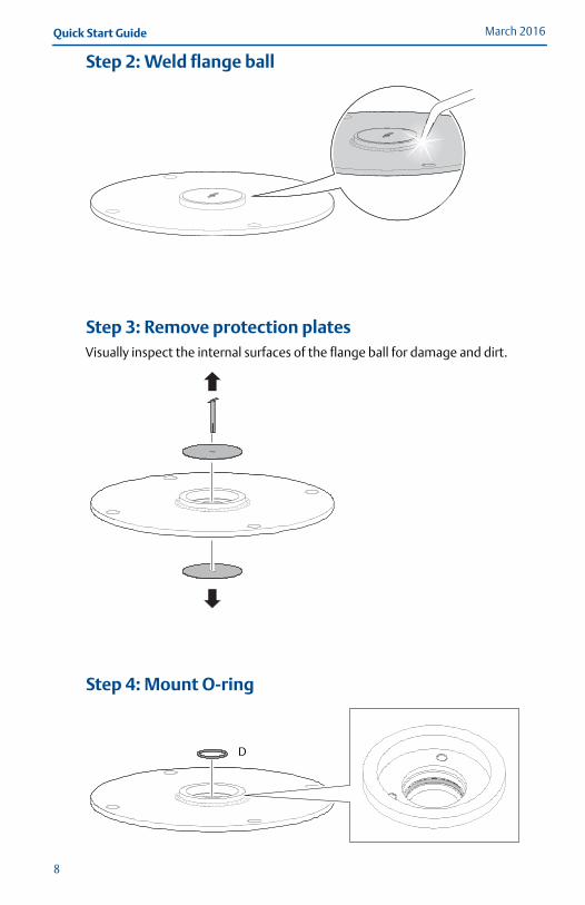
Step 2: Weld flange ball
Step 3: Remove protection platesVisually inspect the internal surfaces of the flange ball for damage and dirt.
Step 4: Mount O-ring
D
8
Quick Start GuideMarch 2016
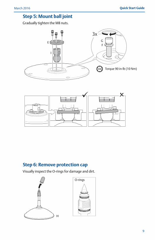
Step 5: Mount ball jointGradually tighten the M8 nuts.
Step 6: Remove protection capVisually inspect the O-rings for damage and dirt.
M8 Torque 90 in-lb (10 Nm)
FGE
I
O-rings
H
9
March 2016Quick Start Guide
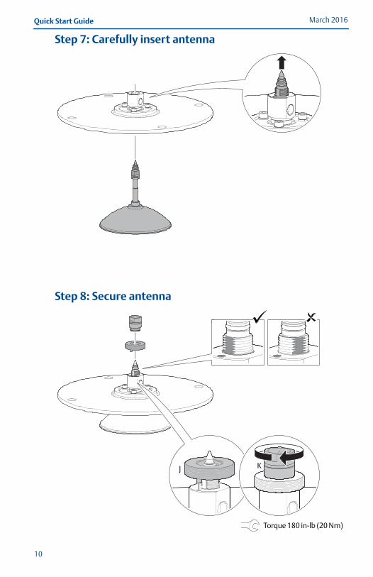
Step 7: Carefully insert antenna
Step 8: Secure antenna
J K
Torque 180 in-lb (20 Nm)
10
Quick Start GuideMarch 2016
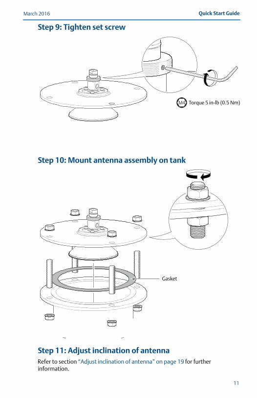
Step 9: Tighten set screw
Step 10: Mount antenna assembly on tank
Step 11: Adjust inclination of antennaRefer to section “Adjust inclination of antenna” on page 19 for further information.
M4 Torque 5 in-lb (0.5 Nm)
Gasket
11
March 2016Quick Start Guide
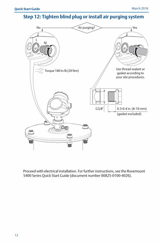
Step 12: Tighten blind plug or install air purging system
Proceed with electrical installation. For further instructions, see the Rosemount 5400 Series Quick Start Guide (document number 00825-0100-4026).
G3/8"
Air purging?No Yes
0.3-0.4 in. (8-10 mm)
(gasket excluded)
Torque 180 in-lb (20 Nm) Use thread sealant or gasket according to
your site procedures.
LM
12
Quick Start GuideMarch 2016
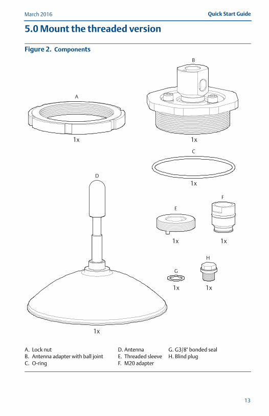
5.0 Mount the threaded version
Figure 2. Components
A. B.C.
Lock nutAntenna adapter with ball jointO-ring
D.E.F.
AntennaThreaded sleeveM20 adapter
G.H.
G3/8" bonded sealBlind plug
2x
1x 1x
1x
1x
1x 1x
A
B
C
D
1x
F
1x
E
G
H
13
March 2016Quick Start Guide
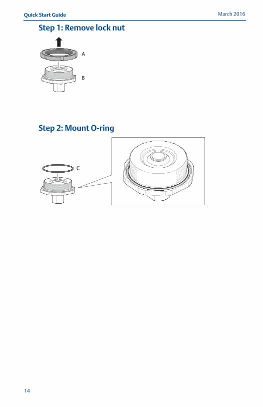
Step 1: Remove lock nut
Step 2: Mount O-ring
A
B
C
14
Quick Start GuideMarch 2016
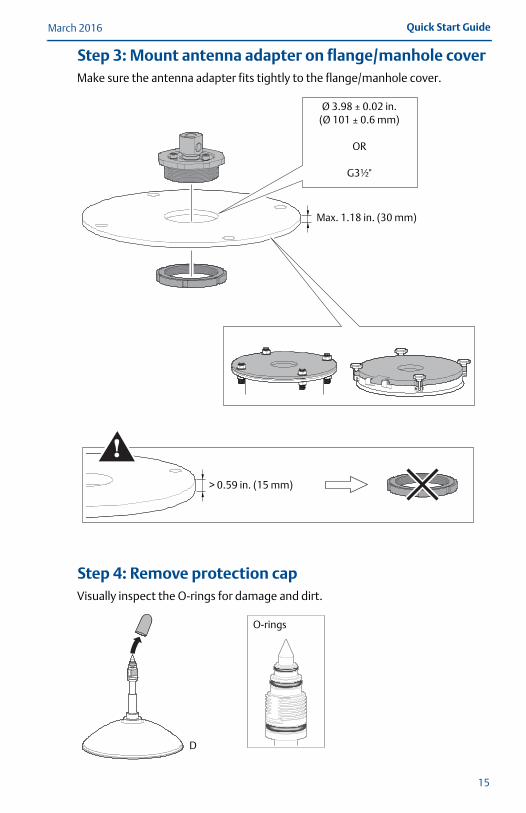
Step 3: Mount antenna adapter on flange/manhole coverMake sure the antenna adapter fits tightly to the flange/manhole cover.
Step 4: Remove protection capVisually inspect the O-rings for damage and dirt.
Ø 3.98 ± 0.02 in.(Ø 101 ± 0.6 mm)
OR
G3½"
Max. 1.18 in. (30 mm)
> 0.59 in. (15 mm)
O-rings
D
15
March 2016Quick Start Guide
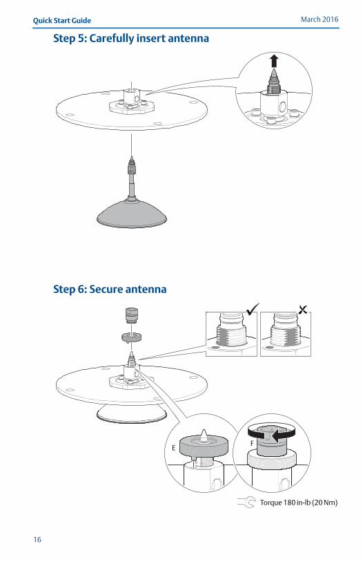
Step 5: Carefully insert antenna
Step 6: Secure antenna
EF
Torque 180 in-lb (20 Nm)
16
Quick Start GuideMarch 2016
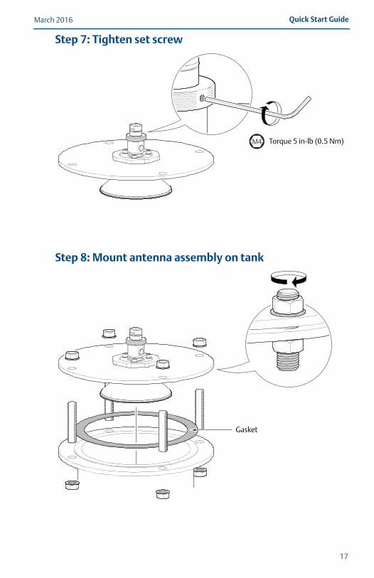
Step 7: Tighten set screw
Step 8: Mount antenna assembly on tank
M4 Torque 5 in-lb (0.5 Nm)
Gasket
17
March 2016Quick Start Guide
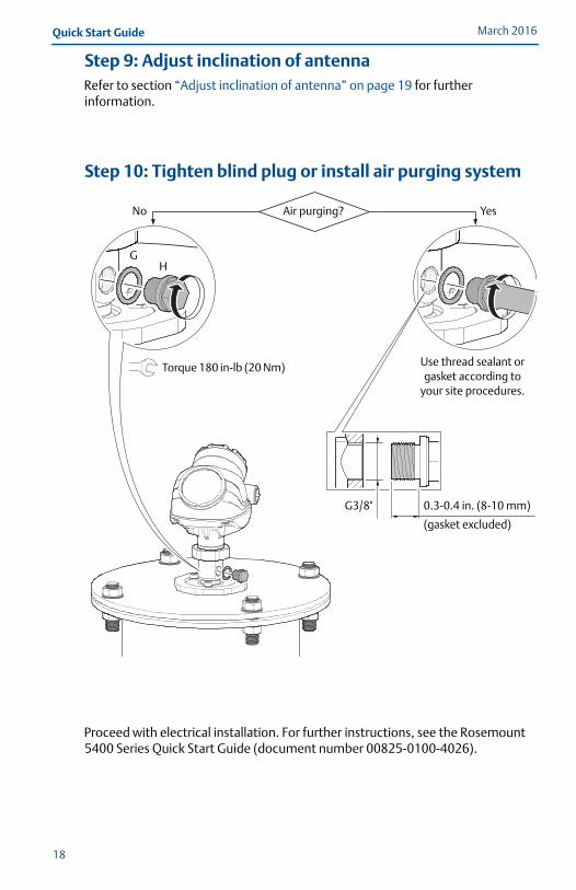
Step 9: Adjust inclination of antennaRefer to section “Adjust inclination of antenna” on page 19 for further information.
Step 10: Tighten blind plug or install air purging system
Proceed with electrical installation. For further instructions, see the Rosemount 5400 Series Quick Start Guide (document number 00825-0100-4026).
G3/8"
Air purging?No Yes
0.3-0.4 in. (8-10 mm)
(gasket excluded)
Torque 180 in-lb (20 Nm) Use thread sealant or gasket according to
your site procedures.
GH
18
Quick Start GuideMarch 2016
6.0 Adjust inclination of antenna
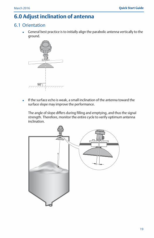
6.1 Orientation General best practice is to initially align the parabolic antenna vertically to the
ground.
If the surface echo is weak, a small inclination of the antenna toward the surface slope may improve the performance.
The angle of slope differs during filling and emptying, and thus the signal strength. Therefore, monitor the entire cycle to verify optimum antenna inclination.
90°
19
March 2016Quick Start Guide
6.2 Procedure
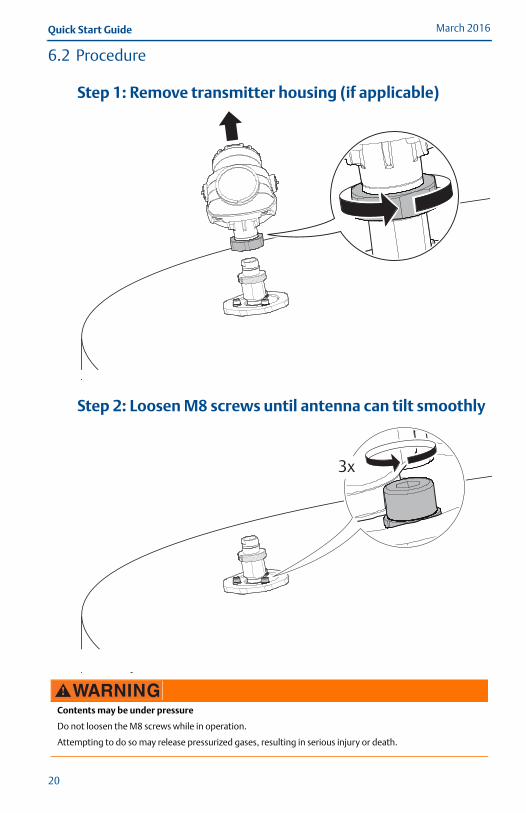
Step 1: Remove transmitter housing (if applicable)
Step 2: Loosen M8 screws until antenna can tilt smoothly
Contents may be under pressure
Do not loosen the M8 screws while in operation.
Attempting to do so may release pressurized gases, resulting in serious injury or death.
20
March 2016Quick Start Guide
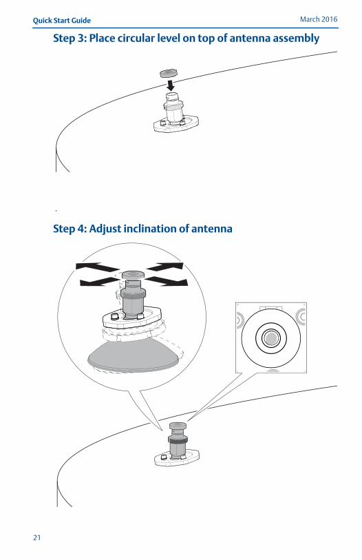
Step 3: Place circular level on top of antenna assembly
Step 4: Adjust inclination of antenna
21
March 2016Quick Start Guide
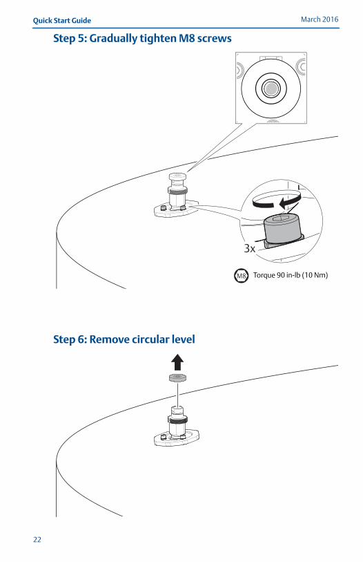
Step 5: Gradually tighten M8 screws
Step 6: Remove circular level
M8 Torque 90 in-lb (10 Nm)
22
Quick Start GuideMarch 2016
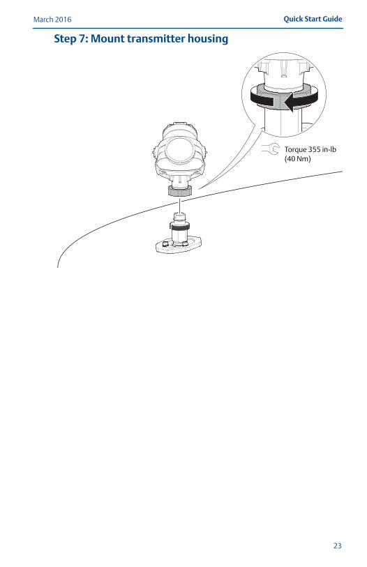
Step 7: Mount transmitter housing
Torque 355 in-lb (40 Nm)
23

Global HeadquartersEmerson Process Management 6021 Innovation Blvd.Shakopee, MN 55379, USA
+1 800 999 9307 or +1 952 906 8888+1 952 949 7001 [email protected]
North America Regional OfficeEmerson Process Management 8200 Market Blvd.Chanhassen, MN 55317, USA
+1 800 999 9307 or +1 952 906 8888
+1 952 949 7001
Latin America Regional OfficeEmerson Process Management 1300 Concord Terrace, Suite 400Sunrise, FL 33323, USA
+1 954 846 5030
+1 954 846 5121
[email protected]/company/Emerson-Process-Management
Twitter.com/Rosemount_News
Facebook.com/Rosemount
Youtube.com/user/RosemountMeasurement
Google.com/+RosemountMeasurement
Standard Terms and Conditions of Sale can be found at Emerson.com/en-us/pages/Terms-of-Use.aspxThe Emerson logo is a trademark and service mark of Emerson Electric Co.Rosemount and the Rosemount logotype are trademarks of Emerson Process Management.All other marks are the property of their respective owners.© 2016 Emerson Process Management. All rights reserved.
Europe Regional OfficeEmerson Process Management Europe GmbHNeuhofstrasse 19a P.O. Box 1046CH 6340 BaarSwitzerland
+41 (0) 41 768 6111
+41 (0) 41 768 6300
Asia Pacific Regional OfficeEmerson Process Management Asia Pacific Pte Ltd1 Pandan CrescentSingapore 128461
+65 6777 8211
+65 6777 0947 [email protected]
Middle East and Africa Regional OfficeEmerson Process Management Emerson FZE P.O. Box 17033,Jebel Ali Free Zone - South 2Dubai, United Arab Emirates
+971 4 8118100
+971 4 [email protected]
Quick Start Guide00825-0600-4026, Rev AA
March 2016
*00825-0600-4026*


