Embed Size (px)
Citation preview
Física de la Tierra ISSN: 0214-4557 2002, 14, 127-159
Física de la Tierra 127 2002, 14, 127-159
Global adjustment for the Gravity Calibration Line Madrid-Valle de los Caidos.
R. Vieira, A. G. Camacho and E. Ortíz Instituto de Astronomía y Geodesia (CSIC-UCM)
Facultad de CC. Matemáticas, Ciudad Universitaria, 28040 Madrid
ABSTRACT A gravity difference of 121 mGal is to be found on the Madrid-Valle de los Caídos gravimetric calibration line, which is formed by 16 stations and streches 60 km from Madrid to the north-western mountains. The line includes two absolute gravity stations, one in each terminal zone and both repeatedly observed (1989, 1992, 1994, 1997) by absolute meter, giving an absolute scale reference. Moreover, large continuous gravity records in each terminal zone provide empirical models for tidal response. This paper gives additional details about the calibration line and presents the adjustment process carried out for the gravity data bank obtained from 1979 with a total of 16 relative meters. Adjusted gravity values for the stations of the line are obtained with a standard deviation of around 7 µGal. Furthermore, the fit process provides instrumental parameters such as drift factors, scale factor and recording jumps for the meters in question. 1. INTRODUCTION
Relative gravimeters, which are used almost exclusively in gravimetric field work and main research projects, require regular checking of their so-called instrumental “constants”. These constants are usually measured on calibration lines, which are traverses of stations whose gravity values are known, to a given precision. From the observation with the gravimeters that have to be calibrated, and by using pertinent mathematical calculations and adjustments, we can determine the coefficients or constants to be applied to that observations.
Vieira et al. Global adjustment for the gravity calibration line …
Física de la Tierra 2002, 14, 126-159
128
Calibration lines are classified into different types, depending on the width of the corresponding gravity range and the precision with which the g values have been determined at their stations. The lines with a very wide measurement range are those where a strong gravity change exists between their extreme stations, and where one can check that the instrument works properly throughout that measurement range. One example is the Spanish calibration line of the Instituto Geográfico Nacional (IGN - National Geographical Institute), which runs from the north of the Iberian Peninsula in Santander, on the shores of the Cantabrian Sea, to the south in Motril (Granada) near the Mediterranean Sea (Alonso, 1976). Its stations are distributed all along the line at very different latitudes and also at different altitudes, because it passes through several mountain ranges. It is well-known that latitude and altitude are the two main parameters that govern gravity changes. The precision of these wide-ranging lines is not usually better than 10-6 m·sec-2, sufficient for most gravimetric work. However, certain gravity applications require better and more accurate observations. When properly calibrated, the precision of modern relative gravimeters can range between 10-
7 and 10-8 m·s-2. However, the level of precision and resolution of the calibration lines used to test the instruments must be equal to or better than the level required in the experiments (Torge et al. 1988, Torge 1989.). These lines are the high-precision calibration lines with stations with a gravity determined to a precision of 10-8 m·sec-2, which is why they are also known as microgal lines (1gal = 10-2 m·sec-2).
The Madrid-Valle de los Caídos line was designed and observed for the first time in 1978, as a consequence of the precision gravimetry, earth tide and instrumentation research, that the Institute of Astronomy and Geodesy (IAG) began conducting at the start of the 1970s (Vieira and Camacho, 1988). The initial idea was to take advantage of the gravity difference existing between the two Madrid and Valle de los Caídos gravimetric tide stations, the slope of the hill upon which the Monumental Cross is located and even the ascent inside the Cross (Vieira et al. 1994) The structure of the Cross, which is vertical, symmetric and easy to model from the mathematical viewpoint, and measures more than 150 metres from top to bottom, made of reinforced cement and hollow inside, meaning that one can reach the top either by walking up the steps or in the lift, makes it perfect for installing a high precision calibration line inside it. As a matter of fact, the first observations included traverses inside the Cross, although later, due to operating difficulties, it was decided to limit the line to points of easy access. Therefore, the stations inside the cross are now only used to study the dynamic behaviour of the structure of the Cross itself.
Vieira et al. Global adjustment for the gravity calibration line …
Física de la Tierra 2002, 14, 126-159
129
The start of the line was set at the IAG gravimetry laboratory pillar in Madrid and two intermediate points were selected between the origin station and the entrance to the Valle de los Caídos. These two intermediate points were the Pozuelo and Villalba railway stations, both points of the National Gravimetric Network. However, due to the problems posed by railway traffic, these stations have been removed from the current configuration of the calibration line. In collaboration with the IGN, the altitudes of the eleven stations inside the Valle de los Caídos were measured using high-precision levelling techniques, starting at the nail of NAPH 323, located on the Guadarrama-El Escorial road, at the entrance to the Valle. This point forms part of the line's stations.
In 1989 the IAG began collaborating closely with the Institute of Geodesy of Helsinki (Finland), as a result of which the Finnish absolute gravimeter was used to make regular absolute observations of the gravity in the Valle de los Caídos and at the IAG's facilities in the Faculty of Physical Sciences and Mathematics of Madrid Complutense University (Makinen et al. 1990). In 1992 the IAG moved to its current site, in the new Mathematical Sciences building, where the new absolute gravimetry pillar was built in the basement. Since then, all the observations have been made at this new pillar. At the Valle de los Caídos station, the first absolute determination was made in 1989, directly on the floor of the gravimetry room, and subsequently a pillar was built directly on the granite rock bed of the subsoil. This pillar is actually a double concentric pillar especially designed and built for absolute gravimeters. Its unique configuration means that the support structure of the gravimeter's interferometric optics can be kept separate from the support structure of the mechanical part, preventing the optical part from suffering the vibrations caused when the system's moving mass drops and stops. Since the first measurement in 1989, which is not considered in the g value calculations, three more observations have been with the same instrument in 1992, 1994 and 1997. In March 1998, a fifth absolute observation was made with the new FG5 instrument of the Institute für Angewandte Geodäsie in Frankfurt (Germany)
The Valle de los Caídos observations were carried out at the two-storey building known as the “Casa del Ingeniero”, which the National Heritage Authority transferred in 1988 to the IAG, who fitted it out as the Fundamental Absolute Gravimetry Laboratory. The observation pillars were built and the ventilation and thermostat control systems were installed on the ground floor of this building, which is located near the Valle de los Caídos staff housing estate, but a sufficient distance from houses, roads and any other source of possible disturbance and which, as explained above, is built on a very thick
Vieira et al. Global adjustment for the gravity calibration line …
Física de la Tierra 2002, 14, 126-159
130
granite base. This point, very close to points SS-4 and SS-5 of the line, was connected to the line by repeated gravimetric and high-precision levelling observations.
Nowadays the Madrid-Valle de los Caídos high-precision calibration line is one of the best calibration lines in existence. With a range of around 120 x10-5m.sec-2, it has been observed in nearly 30 experiments with 16 relative gravimeters of different models and brands, although almost all LaCoste Romberg. The 14 basic stations and the two ancillary stations, located nearby and outside the two Absolute Gravimetry laboratories in Madrid and the Valle de los Caídos, are linked by high-precision levelling. Located at each end of the line are permanent gravimetric tide stations and regular gravity observations are made using absolute techniques (Vieira, 1980; Vieira et al, 1992). These gravimetric tide stations permits the use of empirical models for the major correction generated by the periodical gravity variations due to the astronomical potential effect (Camacho and Vieira, 1990). These empirical models are all the more important due to the existence of a strong oceanic effect, of the order of 10% of the sign, even in a zone, like the one where the calibration line is located, in the middle of the Iberian Peninsula and almost 400 kilometres from the nearest coast.
The gravity vertical gradient has been measured at the IAG-Madrid and Valle de los Caídos absolute gravimetric tide stations, using several relative gravimeters and the gradient ladder especially designed for this research. This system can be used to make gravity observations all along the vertical line, every 30 centimetres, from the gravimetric pillar signalling nail to 1.80m above the nail. The gravity gradient value is very important for referring the absolute observation, made at the absolute gravimeter drop chamber reference level, to a point on the surface of the observation pillar that is marked with a levelling nail.
Regular absolute gravity measurements, in places that are classified as of great geological stability, such as the Guadarrama mountains, not only allow us to verify such stability and therefore its excellent conditions for this type of observation, but these observed values can be used to establish the gravity scale as accurately as possible.
Another essential requirement of a gravimetric calibration line is that all its stations must be easily accessible. The Madrid-Valle de los Caídos line meets this requirement because all its points can be reached by car via excellent motorways and roads. The 14 main stations can be observed in one day. However, the objective is to calibrate instruments, so the outward and return traverses* should be repeated as often as necessary, so ideally two days of field observation are required. Permanent gravity stations have been installed
Vieira et al. Global adjustment for the gravity calibration line …
Física de la Tierra 2002, 14, 126-159
131
at either end of the line, in buildings especially equipped for these experiments, so the gravimeters can be left properly stationed, with thermostat control, all night long.
The need and usefulness of calibration lines has been highlighted over the years, mainly by methodological advances in interpreting observations in high precision and resolution gravimetric research, in the fields of geodesy, geophysics, archaeology, engineering, etc. If a gravimeter calibration table has 5 significant decimal digits, for example 1.00020, as occurs with the LaCoste Romberg gravimeters, a variation of one unit of the last order, i.e., 1.00021, would mean that one could commit a gravity value error of approximately 20x 10-8 m sec-2, in other words 20 microgals, which is greater than the instrumental error of the precise gravity observations made with this type of instrument. This means that, when microgravimetry research is involved, the last figure of the calibration table must be significant and that given the mechanical characteristics of present spring gravimeters, whatever the model, its calibration constants must be tested periodically. For instance, gravity studies for volcanic monitoring search for small relative changes (some tens of microgal) between points located usually on a topographic surface with large slopes. Therefore the meter scale factor should be tested carefully, both before and after the observation campaign, by observing a calibration line with known gravity values (not very different from those of the application purpose). 2. ABSOLUTE GRAVITY VALUES
The Calibration Line includes two absolute gravity stations: Pilar-IAG and Valle-Absoluta (see Table 1), located at either ends. Both have been subject to absolute determinations, carried out in 1989, 1992, 1994 and 1997 with the JILA nº 5 of the Finnish Geodetic Institute (Vieira et, al., 1991, Makinen et al. 1990). Table 2 shows the values obtained after applying the following corrections:
- gravity tides (local models) - atmospheric load and attraction - pole motion and Earth rotation (from I.E.R.S. bulletin) - laser wave offset - frequency counter offset - height of instrument centre
Vieira et al. Global adjustment for the gravity calibration line …
Física de la Tierra 2002, 14, 126-159
132
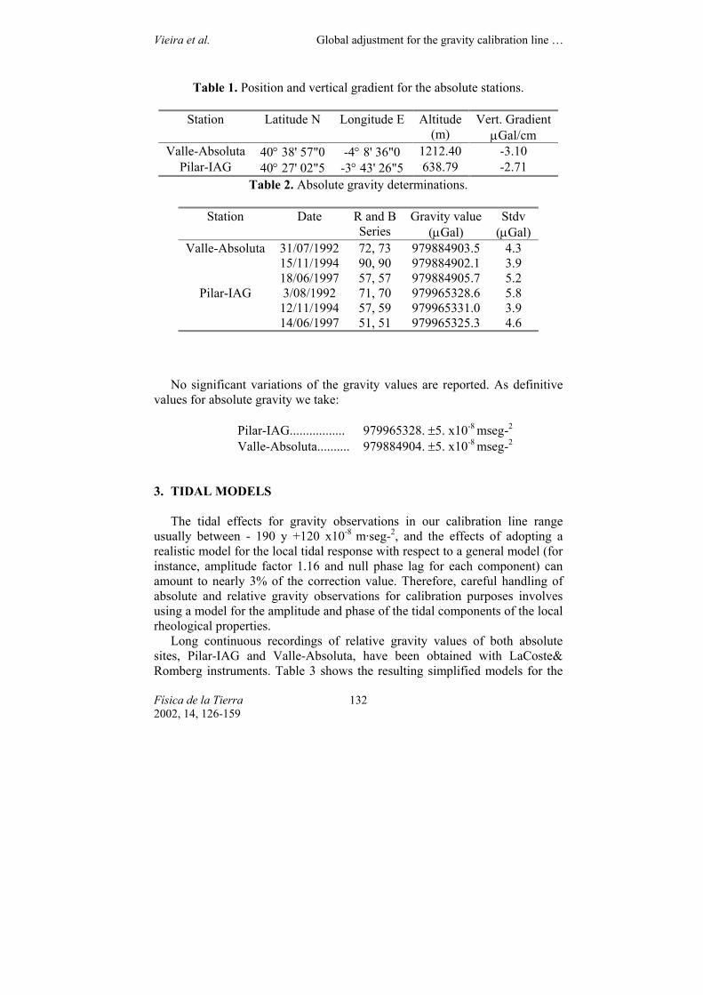
Table 1. Position and vertical gradient for the absolute stations.
Station Latitude N Longitude E Altitude (m)
Vert. Gradient µGal/cm
Valle-Absoluta 40° 38' 57"0 -4° 8' 36"0 1212.40 -3.10 Pilar-IAG 40° 27' 02"5 -3° 43' 26"5 638.79 -2.71
Table 2. Absolute gravity determinations.
Station Date R and B Series
Gravity value (µGal)
Stdv (µGal)
31/07/1992 72, 73 979884903.5 4.3 15/11/1994 90, 90 979884902.1 3.9
Valle-Absoluta
18/06/1997 57, 57 979884905.7 5.2 3/08/1992 71, 70 979965328.6 5.8
12/11/1994 57, 59 979965331.0 3.9 Pilar-IAG
14/06/1997 51, 51 979965325.3 4.6
No significant variations of the gravity values are reported. As definitive values for absolute gravity we take:
Pilar-IAG................. 979965328. ±5. x10-8 mseg-2 Valle-Absoluta.......... 979884904. ±5. x10-8 mseg-2
3. TIDAL MODELS
The tidal effects for gravity observations in our calibration line range usually between - 190 y +120 x10-8 m·seg-2, and the effects of adopting a realistic model for the local tidal response with respect to a general model (for instance, amplitude factor 1.16 and null phase lag for each component) can amount to nearly 3% of the correction value. Therefore, careful handling of absolute and relative gravity observations for calibration purposes involves using a model for the amplitude and phase of the tidal components of the local rheological properties.
Long continuous recordings of relative gravity values of both absolute sites, Pilar-IAG and Valle-Absoluta, have been obtained with LaCoste& Romberg instruments. Table 3 shows the resulting simplified models for the
Vieira et al. Global adjustment for the gravity calibration line …
Física de la Tierra 2002, 14, 126-159
133
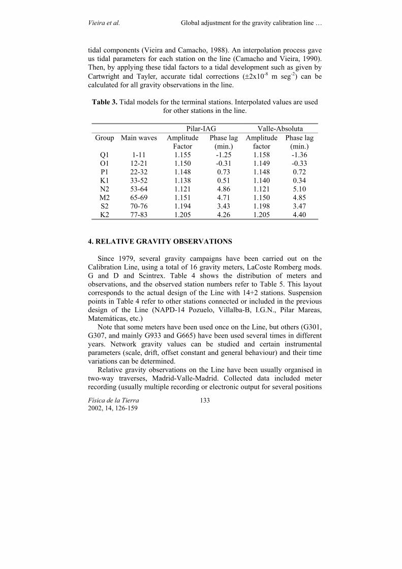
tidal components (Vieira and Camacho, 1988). An interpolation process gave us tidal parameters for each station on the line (Camacho and Vieira, 1990). Then, by applying these tidal factors to a tidal development such as given by Cartwright and Tayler, accurate tidal corrections (±2x10⁻⁸ m seg-2) can be calculated for all gravity observations in the line.
Table 3. Tidal models for the terminal stations. Interpolated values are used
for other stations in the line.
Pilar-IAG Valle-Absoluta Group Main waves Amplitude
Factor Phase lag
(min.) Amplitude
factor Phase lag
(min.) Q1 1-11 1.155 -1.25 1.158 -1.36 O1 12-21 1.150 -0.31 1.149 -0.33 P1 22-32 1.148 0.73 1.148 0.72 K1 33-52 1.138 0.51 1.140 0.34 N2 53-64 1.121 4.86 1.121 5.10 M2 65-69 1.151 4.71 1.150 4.85 S2 70-76 1.194 3.43 1.198 3.47 K2 77-83 1.205 4.26 1.205 4.40
4. RELATIVE GRAVITY OBSERVATIONS
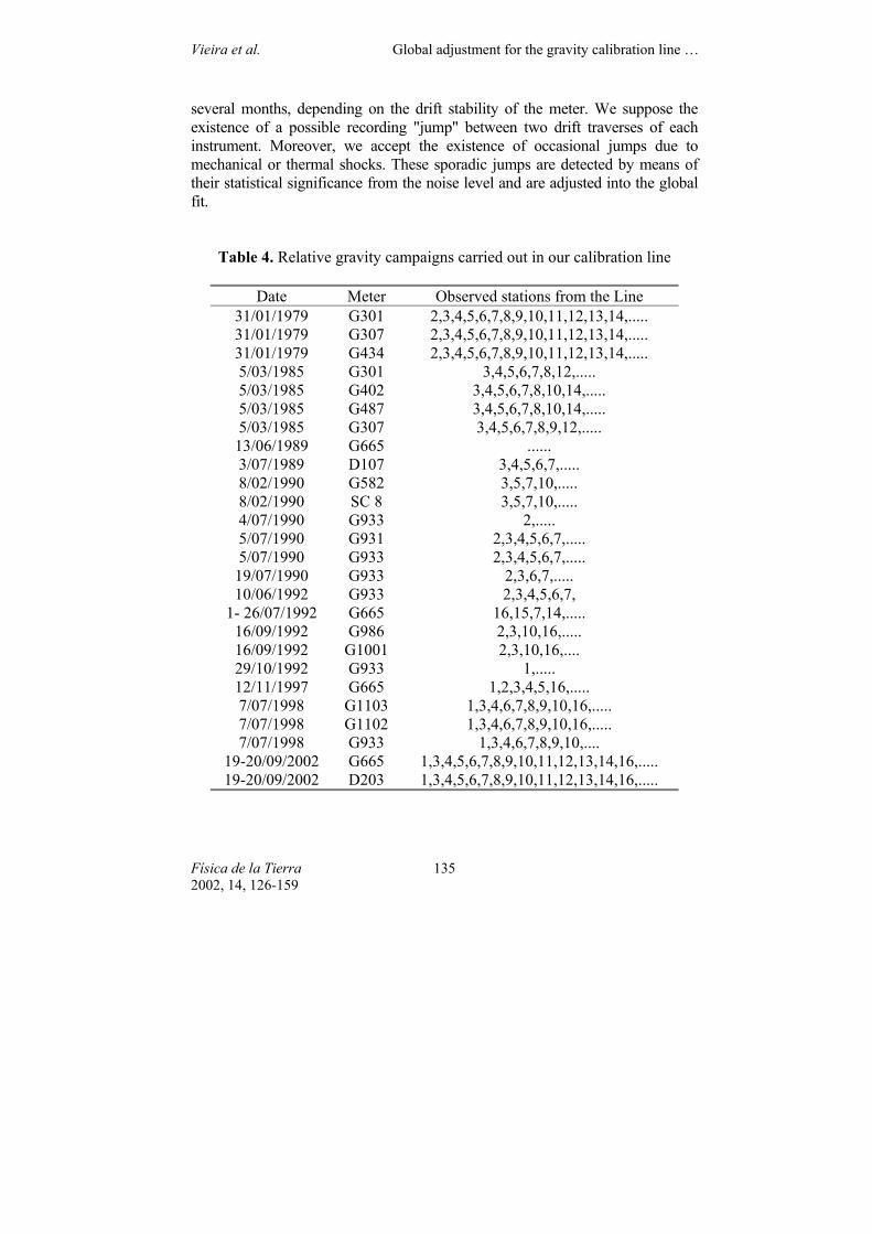
Since 1979, several gravity campaigns have been carried out on the Calibration Line, using a total of 16 gravity meters, LaCoste Romberg mods. G and D and Scintrex. Table 4 shows the distribution of meters and observations, and the observed station numbers refer to Table 5. This layout corresponds to the actual design of the Line with 14+2 stations. Suspension points in Table 4 refer to other stations connected or included in the previous design of the Line (NAPD-14 Pozuelo, Villalba-B, I.G.N., Pilar Mareas, Matemáticas, etc.)
Note that some meters have been used once on the Line, but others (G301, G307, and mainly G933 and G665) have been used several times in different years. Network gravity values can be studied and certain instrumental parameters (scale, drift, offset constant and general behaviour) and their time variations can be determined.
Relative gravity observations on the Line have been usually organised in two-way traverses, Madrid-Valle-Madrid. Collected data included meter recording (usually multiple recording or electronic output for several positions
Vieira et al. Global adjustment for the gravity calibration line …
Física de la Tierra 2002, 14, 126-159
134
on the meter dial), time, height of meter above the mark nail and atmospheric pressure. The reduction process was:
- Determination of local sensitivity for the electronic output device for meters with this reading system. Sensitivity value is calculated by comparing the electronic output for several positions of the dial at the same station. - Determination of local dispersion for the readings included for each station. - Change of the reading values from meter units to gravity units by means of usual calibration values for the meters. - Tidal correction by using a tide development, as given by Cartwright and Tayler with 484 waves (Cartwright and Tayler, 1971; Cartwright and Edden 1973), and applying the former model of realistic local response for amplitudes and phase lags. - Correction for atmospheric pressure effect (about -0.3 µGal/mbar), load and attraction, with respect to a standard atmosphere. Correction for pole motion and Earth rotation (usually ranging from -3 to 3 µGal) - Correction for different heights of the meter above the mark nail, using a local value for vertical gravity gradient, when possible, or a general one (-3.0 µGal/cm).
The reduction process gives us a collection of relative gravity data for
several meters and times, corresponding to the same stations, as well as absolute values for the terminal stations. This is followed by a further fit process to estimate the best gravity values and to determine several additional parameters for instrumental behaviour. Finally, values for the accuracy of data and adjusted parameters can be also obtained. 4. FIT MODEL FOR GRAVITY OBSERVATIONS IN THE LINE.
The following is a process for global adjustment of gravity networks, which permits a simultaneous fit of observations from different times, with different meters and qualities, determining linear drifts, locating and determining punctual recording jumps and determining instrumental parameters for scale and offset. This fit includes the absolute observations for the network.
Let us suppose several gravity observations made upon the same gravity network, at several times and with different meters. For each meter, i, we consider observations collected and gathered in "traverses" characterised by a common drift. These traverses can correspond to several hours, several days or
Vieira et al. Global adjustment for the gravity calibration line …
Física de la Tierra 2002, 14, 126-159
135
several months, depending on the drift stability of the meter. We suppose the existence of a possible recording "jump" between two drift traverses of each instrument. Moreover, we accept the existence of occasional jumps due to mechanical or thermal shocks. These sporadic jumps are detected by means of their statistical significance from the noise level and are adjusted into the global fit.
Table 4. Relative gravity campaigns carried out in our calibration line
Date Meter Observed stations from the Line 31/01/1979 G301 2,3,4,5,6,7,8,9,10,11,12,13,14,..... 31/01/1979 G307 2,3,4,5,6,7,8,9,10,11,12,13,14,..... 31/01/1979 G434 2,3,4,5,6,7,8,9,10,11,12,13,14,..... 5/03/1985 G301 3,4,5,6,7,8,12,..... 5/03/1985 G402 3,4,5,6,7,8,10,14,..... 5/03/1985 G487 3,4,5,6,7,8,10,14,..... 5/03/1985 G307 3,4,5,6,7,8,9,12,..... 13/06/1989 G665 ...... 3/07/1989 D107 3,4,5,6,7,..... 8/02/1990 G582 3,5,7,10,..... 8/02/1990 SC 8 3,5,7,10,..... 4/07/1990 G933 2,..... 5/07/1990 G931 2,3,4,5,6,7,..... 5/07/1990 G933 2,3,4,5,6,7,..... 19/07/1990 G933 2,3,6,7,..... 10/06/1992 G933 2,3,4,5,6,7,
1- 26/07/1992 G665 16,15,7,14,..... 16/09/1992 G986 2,3,10,16,..... 16/09/1992 G1001 2,3,10,16,.... 29/10/1992 G933 1,..... 12/11/1997 G665 1,2,3,4,5,16,..... 7/07/1998 G1103 1,3,4,6,7,8,9,10,16,..... 7/07/1998 G1102 1,3,4,6,7,8,9,10,16,..... 7/07/1998 G933 1,3,4,6,7,8,9,10,....
19-20/09/2002 G665 1,3,4,5,6,7,8,9,10,11,12,13,14,16,..... 19-20/09/2002 D203 1,3,4,5,6,7,8,9,10,11,12,13,14,16,.....
Vieira et al. Global adjustment for the gravity calibration line …
Física de la Tierra 2002, 14, 126-159
136
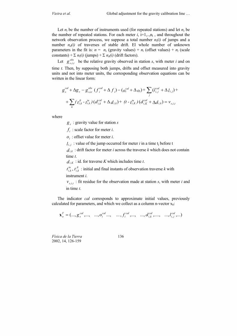
Let ni be the number of instruments used (for repeated stations) and let ns be the number of repeated stations. For each meter i, i=1,..,ni , and throughout the network observation process, we suppose a total number nl(i) of jumps and a number nd(i) of traverses of stable drift. El whole number of unknown parameters in the fit is: n = ns (gravity values) + ni (offset values) + ni (scale constants) + Σ nl(i) (jumps) + Σ nd(i) (drift factors).
Let obstisg ,, be the relative gravity observed in station s, with meter i and on
time t. Then, by supposing both jumps, drifts and offset measured into gravity units and not into meter units, the corresponding observation equations can be written in the linear form:
tiskical
Kiin
Kikicalki
k
inki
fiki
jji
caljii
calii
cali
obsti,s,s
cals
vdd )t-(t + dd )t-t(
+ ll + oo ff g gg
,,,,,,,,,
,,
)()(
)()()(
=∆+∆++
∆+∆+−∆+−∆+
∑
∑
where
sg : gravity value for station s
if : scale factor for meter i.
io : offset value for meter i. l ji, : value of the jump occurred for meter i in a time tj before t d ki, : drift factor for meter i across the traverse k which does not contain time t. d Ki, : id. for traverse K which includes time t.
fiki
inki tt ,, , : initial and final instants of observation traverse k with
instrument i. tisv ,, : fit residue for the observation made at station s, with meter i and
in time t.
The indicator cal corresponds to approximate initial values, previously calculated for parameters, and which we collect as a column n-vector x0:
,...)...,,....,...,,...,,......,...,,...,(..., ,,cal
jicalki
cali
cali
cals
To ld f og=x
Vieira et al. Global adjustment for the gravity calibration line …
Física de la Tierra 2002, 14, 126-159
137
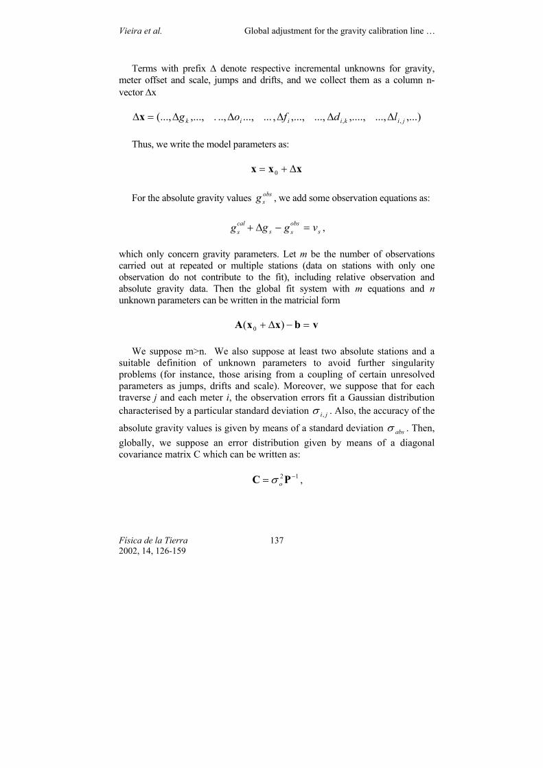
Terms with prefix ∆ denote respective incremental unknowns for gravity, meter offset and scale, jumps and drifts, and we collect them as a column n-vector ∆x
,...)...,,....,...,,...,,......,..,.,...,(..., ,, jikiiik ld f og ∆∆∆∆∆=∆x
Thus, we write the model parameters as:
xxx ∆+= 0
For the absolute gravity values obssg , we add some observation equations as:
sobsss
cals v g gg =−∆+ ,
which only concern gravity parameters. Let m be the number of observations carried out at repeated or multiple stations (data on stations with only one observation do not contribute to the fit), including relative observation and absolute gravity data. Then the global fit system with m equations and n unknown parameters can be written in the matricial form
vbxxA =−∆+ )( 0
We suppose m>n. We also suppose at least two absolute stations and a suitable definition of unknown parameters to avoid further singularity problems (for instance, those arising from a coupling of certain unresolved parameters as jumps, drifts and scale). Moreover, we suppose that for each traverse j and each meter i, the observation errors fit a Gaussian distribution characterised by a particular standard deviation ji ,σ . Also, the accuracy of the
absolute gravity values is given by means of a standard deviation absσ . Then, globally, we suppose an error distribution given by means of a diagonal covariance matrix C which can be written as:
12 −= PC oσ ,
Vieira et al. Global adjustment for the gravity calibration line …
Física de la Tierra 2002, 14, 126-159
138
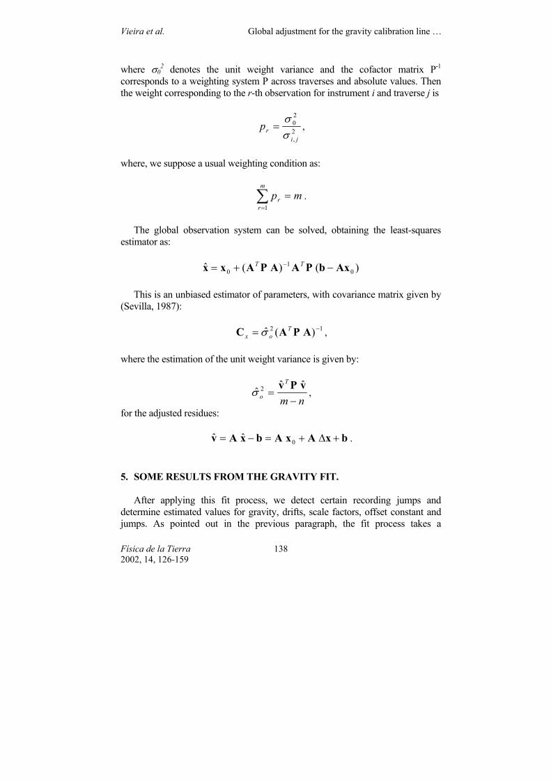
where σ02 denotes the unit weight variance and the cofactor matrix P-1
corresponds to a weighting system P across traverses and absolute values. Then the weight corresponding to the r-th observation for instrument i and traverse j is
2,
20
jirp
σσ
= ,
where, we suppose a usual weighting condition as:
mpm
rr =∑
=1.
The global observation system can be solved, obtaining the least-squares
estimator as:
)()(ˆ 01
0 AxbPAAPAxx −+= − TT
This is an unbiased estimator of parameters, with covariance matrix given by (Sevilla, 1987):
12 )(ˆ −= APAC Tox σ ,
where the estimation of the unit weight variance is given by:
nm
T
o −=
vPv ˆˆˆ 2σ ,
for the adjusted residues:
bxAxAbxAv +∆+=−= 0ˆˆ . 5. SOME RESULTS FROM THE GRAVITY FIT.
After applying this fit process, we detect certain recording jumps and determine estimated values for gravity, drifts, scale factors, offset constant and jumps. As pointed out in the previous paragraph, the fit process takes a
Vieira et al. Global adjustment for the gravity calibration line …
Física de la Tierra 2002, 14, 126-159
139
weighting system according to estimated variances of the traverses (and the absolute values). Then the process takes several iterations (about ten) detecting new jumps and providing a stable solution (no more significant jumps and no further changes in the parameters).
To obtain a general solution, we consider that observations made with the same meter, but made several years apart, come from different meters. For instance, the G307 meter was used in two campaigns, in 1979 and 1985. Therefore we consider that the 1979 campaign was carried out with G307A and the 1985 campaign with G307B, and so on.
We also adopt a general approach to the distribution of traverses (stable drift). Once the jumps are detected, we initially suppose that they are associated with drift changes. Therefore, a large number of traverses is obtained. Then we group adjacent traverses (with same meter) with similar drift factors (or not solved enough factors) into larger definitive traverses.
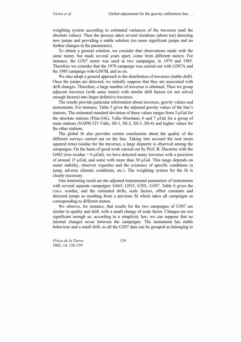
The results provide particular information about traverses, gravity values and instruments. For instance, Table 5 gives the adjusted gravity values of the line’s stations. The estimated standard deviation of these values ranges from 5 µGal for the absolute stations (Pilar-IAG, Valle-Absoluta), 6 and 7 µGal for a group of main stations (NAPH-323 Valle, SS-1, SS-2, SS-3, SS-4) and higher values for the other stations.
The global fit also provides certain conclusions about the quality of the different surveys carried out on the line. Taking into account the root mean squared (rms) residue for the traverses, a large disparity is observed among the campaigns. On the basis of good work carried out by Prof. B. Ducarme with the G402 (rms residue = 6 µGal), we have detected many traverses with a precision of around 15 µGal, and some with more than 30 µGal. This range depends on meter stability, observer expertise and the existence of specific conditions (a jump, adverse climatic conditions, etc.). The weighting system for the fit is clearly necessary.
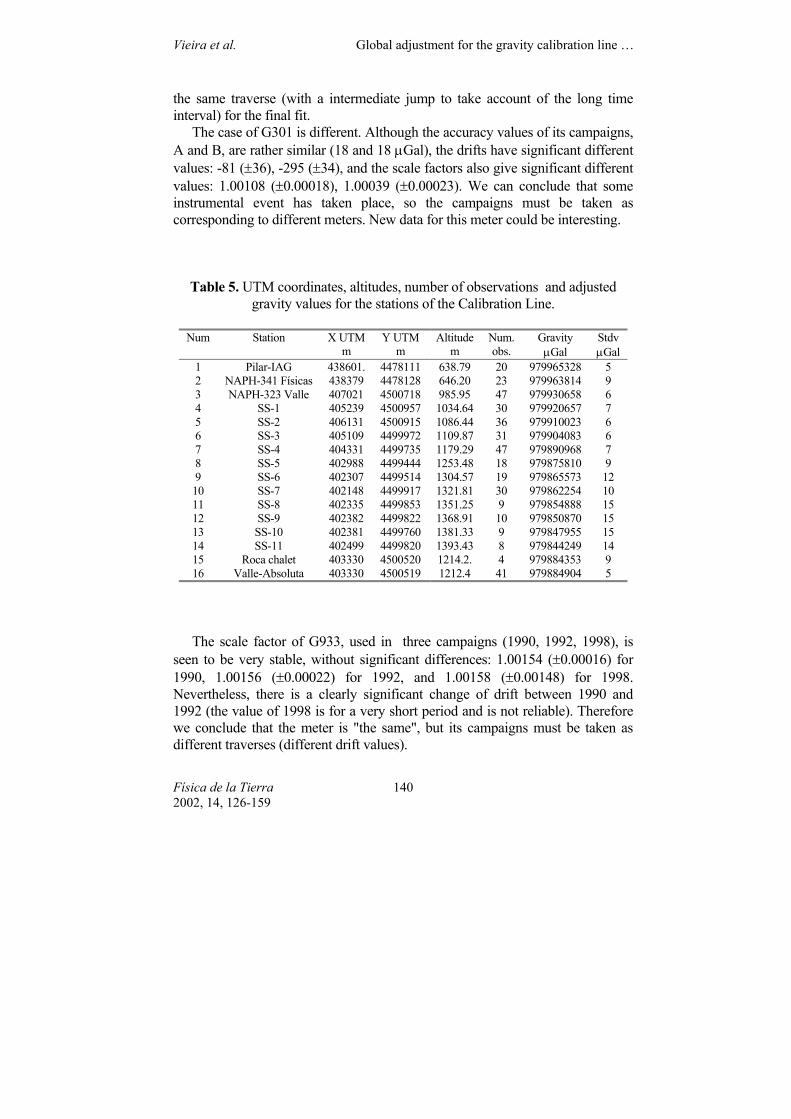
One interesting result are the adjusted instrumental parameters of instruments with several separate campaigns: G665, G933, G301, G307. Table 6 gives the r.m.s. residue, and the estimated drifts, scale factors, offset constants and detected jumps as resulting from a previous fit which takes all campaigns as corresponding to different meters.
We observe, for instance, that results for the two campaigns of G307 are similar in quality and drift, with a small change of scale factor. Changes are not significant enough so, according to a simplicity law, we can suppose that no internal changes occur between the campaigns. The instrument has stable behaviour and a small drift, so all the G307 data can be grouped as belonging to
Vieira et al. Global adjustment for the gravity calibration line …
Física de la Tierra 2002, 14, 126-159
140
the same traverse (with a intermediate jump to take account of the long time interval) for the final fit.
The case of G301 is different. Although the accuracy values of its campaigns, A and B, are rather similar (18 and 18 µGal), the drifts have significant different values: -81 (±36), -295 (±34), and the scale factors also give significant different values: 1.00108 (±0.00018), 1.00039 (±0.00023). We can conclude that some instrumental event has taken place, so the campaigns must be taken as corresponding to different meters. New data for this meter could be interesting.
Table 5. UTM coordinates, altitudes, number of observations and adjusted gravity values for the stations of the Calibration Line.
Num Station X UTM
m Y UTM
m Altitude
m Num. obs.
Gravity µGal
Stdv µGal
1 Pilar-IAG 438601. 4478111 638.79 20 979965328 5 2 NAPH-341 Físicas 438379 4478128 646.20 23 979963814 9 3 NAPH-323 Valle 407021 4500718 985.95 47 979930658 6 4 SS-1 405239 4500957 1034.64 30 979920657 7 5 SS-2 406131 4500915 1086.44 36 979910023 6 6 SS-3 405109 4499972 1109.87 31 979904083 6 7 SS-4 404331 4499735 1179.29 47 979890968 7 8 SS-5 402988 4499444 1253.48 18 979875810 9 9 SS-6 402307 4499514 1304.57 19 979865573 12 10 SS-7 402148 4499917 1321.81 30 979862254 10 11 SS-8 402335 4499853 1351.25 9 979854888 15 12 SS-9 402382 4499822 1368.91 10 979850870 15 13 SS-10 402381 4499760 1381.33 9 979847955 15 14 SS-11 402499 4499820 1393.43 8 979844249 14 15 Roca chalet 403330 4500520 1214.2. 4 979884353 9 16 Valle-Absoluta 403330 4500519 1212.4 41 979884904 5
The scale factor of G933, used in three campaigns (1990, 1992, 1998), is seen to be very stable, without significant differences: 1.00154 (±0.00016) for 1990, 1.00156 (±0.00022) for 1992, and 1.00158 (±0.00148) for 1998. Nevertheless, there is a clearly significant change of drift between 1990 and 1992 (the value of 1998 is for a very short period and is not reliable). Therefore we conclude that the meter is "the same", but its campaigns must be taken as different traverses (different drift values).
Vieira et al. Global adjustment for the gravity calibration line …
Física de la Tierra 2002, 14, 126-159
141
Table 6. Instrumental parameters and rms residues for meters G665, G933, G301, G307, taking each campaign as corresponding to a particular meter (A, B,
C, D). Meter Campaign Resid.
µGal Drift
µGal/day Stdv
µGal/day Offset µGal
Stdv µGal
Scale Factor
Stdv
A (1979) 18 -81 36 983569089 13 1.00108 0.00018 G301 B (1985) 18 -295 34 983567545 14 1.00039 0.00023 A (1979) 28 40 54 983606751 16 1.00088 0.00020 G307 B (1985) 27 37 50 983605895 19 1.00132 0.00032 A (1990) 14 137 26 983435730 13 1.00154 0.00016 B (1992) 12 -123 29 983427917 11 1.00156 0.00022
G933
C (1998) 12 -210 1231 983148925 12 1.00158 0.00148 A (1989) 12 -811 41 983517052 13 1.00164 0.00018 B (1992) 36 -53 20 983542072 14 0.99888 0.00018 C (1997) 13 -121 45 983460112 13 1.00082 0.00020
G665
D (2002) 33 -90 20 983401631 18 1.00036 0.00023
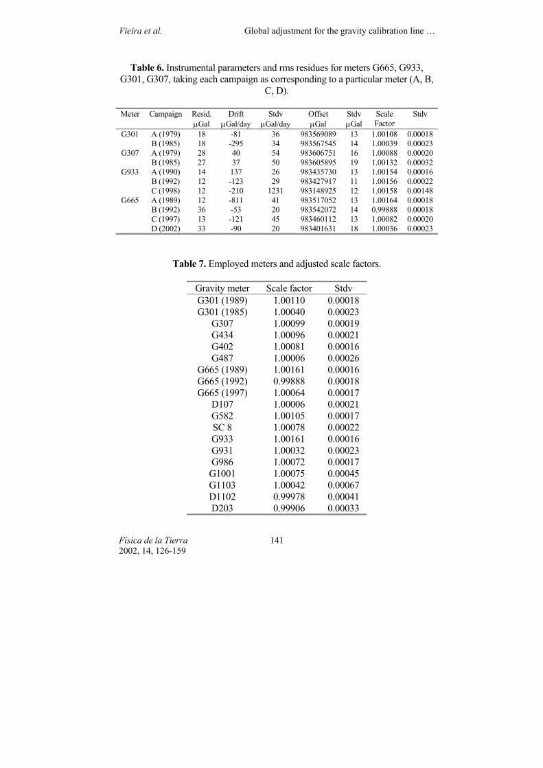
Table 7. Employed meters and adjusted scale factors.
Gravity meter Scale factor Stdv G301 (1989) 1.00110 0.00018 G301 (1985) 1.00040 0.00023
G307 1.00099 0.00019 G434 1.00096 0.00021 G402 1.00081 0.00016 G487 1.00006 0.00026
G665 (1989) 1.00161 0.00016 G665 (1992) 0.99888 0.00018 G665 (1997) 1.00064 0.00017
D107 1.00006 0.00021 G582 1.00105 0.00017 SC 8 1.00078 0.00022 G933 1.00161 0.00016 G931 1.00032 0.00023 G986 1.00072 0.00017 G1001 1.00075 0.00045 G1103 1.00042 0.00067 D1102 0.99978 0.00041 D203 0.99906 0.00033
Vieira et al. Global adjustment for the gravity calibration line …
Física de la Tierra 2002, 14, 126-159
142
Finally, a significant change in behaviour is observed in the case of G665. There are clear changes of drift factor and scale factor from 1989 to 1992 and from 1992 to 1997, but not so clear from 1997 to 2002. The main changes correspond to known events in the life of the meter (installation of a feedback system). It should also be noted that this instrument is highly prone to jumps.
Table 7 shows the results for the scale factor of all instruments used in the line (separating the values when a change of behaviour of the meter is clearly detected). 6. CONCLUSIONS
The Madrid-Valle de los Caídos Calibration Line is an interesting tool for testing gravity meters. It includes 16 stations located close to a main road (A-6) and monumented with mark nails. The line is about 60 km long, its altitude variation is 753 m and the maximum gravity difference is 121 mGal. The line includes two absolute stations, Pilar-IAG (Madrid, Ciudad Universitaria) and Valle-Absoluta (house inside Valle de los Caídos), located in each terminal zone. Both absolute stations are monumented with suitable installations (indoor pillars, power supply, heat control) and have been repeatedly observed (1989, 1992, 1994, 1997 by JILAG n.5 of the Finnish Geodetic Institute). The precision of the absolute values is about 5 µGal. Moreover, numerous tidal records are available for both terminal areas, permitting a good tidal response model for tidal reductions.
The line has been repeatedly observed with a total of 16 meters and offers gravity values (Table 5) with a precision ranging from 6 µGal to the absolute stations, 7 µGal to the main stations and higher values for the rest.
A two-way traverse (Madrid-Valle-Madrid) can be completed with one or two days of field work. Working carefully to obtain data with a standard deviation precision of 10 µGal, a final scale factor for the meter could be obtained with a standard deviation of about 0.0002 and an offset constant with standard deviation of about 14 µGal. ACKNOWLEDGEMENTS.
The gravity stations in the Valle de los Caídos zone, and mainly the absolute station Valle Absoluta, are located in an area run by the National Heritage Board, which helps with their maintenance. The absolute measurements were accomplished with the meter JILA n.5, in collaboration with the Finnish Geodetic Institute. The tidal records come from results of several research projects carried out by our institution.
Vieira et al. Global adjustment for the gravity calibration line …
Física de la Tierra 2002, 14, 126-159
143
REFERENCES ALONSO, F., (1976): «Presentación de la Primera Edición de los Mapas Gravimétricos de la
Peninsula Ibérica. Red Gravimétrica Fundamental española 1973 (RGFE-73). Línea de Calibración Gravimétrica española 1975 (LCGE-75)», Comunicaciones IIª Asamblea de Geodesia y Geofísica, I, 197-211 Madrid.
CAMACHO, A. G. AND VIEIRA, R. (1990): «Predicción de la corrección de marea en la Peninsula Iberica», Física de la Tierra, 2, 87-110.
CARTWRIGHT, D. E. AND TAYLER, R. J. (1971): «New Computation of the Tide generating Potential», Roy. Astr. Soc. Geophys. Jour., 23, 45-74
CARTWRIGHT, D. E. AND EDDEN, A. C. (1973): «Corrected Tables of Tidal Harmonics», Roy. Astr. Soc. Geophys. Jour., 3, 253-264.
MAKINEN, J., VIEIRA, R., CAMACHO, A. G. AND SEVILLA, M. J. (1990): «Absolute gravity measurements in Madrid», Bureau Grav. Intern. Paris, Bull. Inf., 67, 168-172.
SEVILLA, M. J. (1987): «Colocación mínimos cuadrados», 99-139, IV Curso de Geodesia Superior. Cursos y Seminarios. Instituto de Astronomía y Geodesia. Madrid..
TORGE, W., SEVILLA, M. J. AND VIEIRA, R. (1988): «Mareas Terrestres y Fundamentos, Métodos y Problemas de la Gravimetría», Curso de Geodesia Superior, ISBN 84-87488-01-3 4. 1-301.
TORGE, W. (1989): Gravimetry , Edit. De Gruyter, Berlin. VIEIRA, R. (1980): «Tidal gravity profile across the Iberian Penninsula», Comptes Rendus
J.L.G. Conseil Europe, 39, 5-7. 1979. Publs. Sem. Astron. Geodesia, nº 112. VIEIRA, R., AND CAMACHO, A. G. (1988): «Correcciones de las medidas gravimétricas, por
efecto de mareas, obtenida a partir de las observaciones efectuadas en la Red Ibérica», Rev. Geofísica, 44, 119-128.
VIEIRA, R., MAKINEN, J., CAMACHO, A. G. AND SEVILLA, M. J. (1991): «Observaciones absolutas de la gravedad en España», Revista de Geofísica, 47, 197-204.
VIEIRA, R., CAMACHO, A. G., TORO, C. AND MONTESINOS, F. G. (1992): «A calibration gravimetric lines between Madrid and Valle de los Caidos stations», Comptes Rendus J.L.G. Conseil Europe, 73, 18-25.
VIEIRA, R., CAMACHO, A. G., TORO, C., MONTESINOS, F. G., ARNOSO, J. AND MAKINEN, J. (1994): «Línea de calibración Madrid-Valle. Observaciones de gravedad absolutas», Conf. Inter. Geodesia y Cartografía. Maracaibo (Venezuela) ISBN:84-87.488-05-6, I, 275-286.
Vieira et al. Global adjustment for the gravity calibration line …
Física de la Tierra 2002, 14, 126-159
144
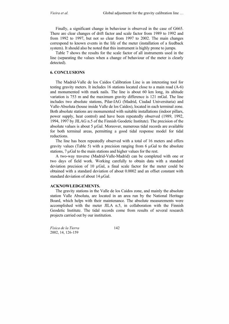
Annex . Description, coordinates, altitude, gravity value, sketch and photo for the stations of the calibration line Madrid-Valle de los Caidos.
CALIBRATION GRAVIMETRIC LINE MADRID–VALLE DE LOS CAIDOS
STATION: PILAR IAG - FACULTAD DE CIENCIAS MATEMÁTICAS Φ: 40º27'02" N λ: 3º43'26" W h: 638.791 m g: 979965.328 mgal LOCATION: Instituto de Astronomía y Geodesia (CSIC-UCM), Facultad de Ciencias Matemáticas, Ciudad Universitaria (Madrid). RESEÑA: situada sobre el pilar de observación gravimétrica, en el Laboratorio de Astronomía y Geodesia, en el lado Este del sótano –2 (sala S-226C) de la Facultad de Ciencias Matemáticas. DESCRIPTION: located on the gravimetric observation pillar, in the Astronomy and Geodesy Laboratory, on the eastern side of basement –2 (room S-226C) of the Faculty of Mathematical Sciences.
Stations Diff (mGaL) 1 PILAR-IAG 2 NAPH-341 FÍS. 3 NAPH-323 VAL. 4 SS-1 5 SS-2 6 SS-3 7 SS-4 8 SS-5 9 SS-6 10 SS-7 11 SS-8 12 SS-9 13 SS-10 14 SS-11 15 CHALE-ROCA 16 VALLE-ABSOL
0.000 1.514
34.670 44.671 55.305 61.245 74.360 89.518 99.755
103.074 110.440 114.458 117.373 121.079 80.975 80.424
Vieira et al. Global adjustment for the gravity calibration line …
Física de la Tierra 2002, 14, 126-159
145
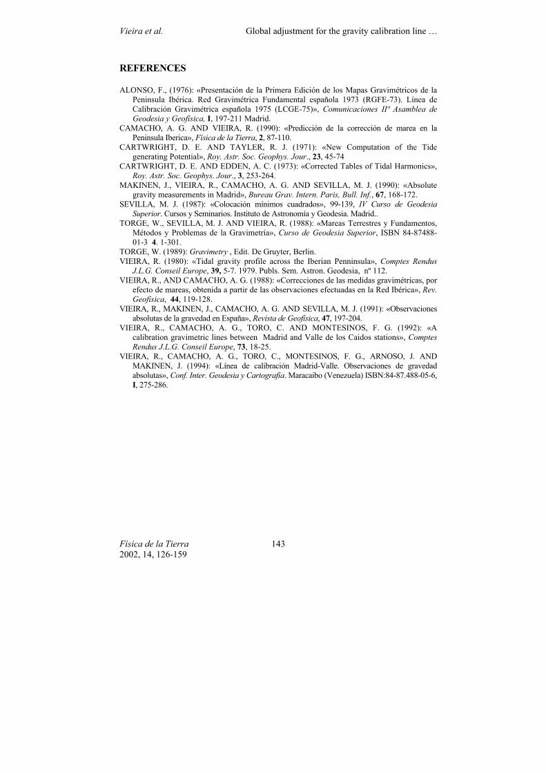
CALIBRATION GRAVIMETRIC LINE MADRID–VALLE DE LOS CAIDOS
STATION: NAPH – 341 Físicas Φ: 40º27'03" N λ: 3º43'36" W h: 646.200 m g: 979963.814 mgal LOCATION: Facultad de Ciencias Físicas, Ciudad Universitaria (Madrid) DESCRIPTION: nail NAPH-341 of the National Geodetic Levelling Network, located on the first step of the staircase leading to the School of Physical Sciences, on the left side of the main door. RESEÑA: clavo de la Red Nacional de Nivelación Geodésica NAPH-341 situado sobre el primer peldaño de las escaleras de acceso a la Facultad de Ciencias Físicas, al lado izquierdo de la puerta de entrada principal.
Stations Diff (mGaL) 1 PILAR-IAG 2 NAPH-341 FÍS. 3 NAPH-323 VAL. 4 SS-1 5 SS-2 6 SS-3 7 SS-4 8 SS-5 9 SS-6 10 SS-7 11 SS-8 12 SS-9 13 SS-10 14 SS-11 15 CHALE-ROCA 16 VALLE-ABSOL
-1.514 0.000
33.156 43.157 53.791 59.731 72.846 88.004 98.241
101.560 108.926 112.944 115.859 119.565 80.424 78.910
Vieira et al. Global adjustment for the gravity calibration line …
Física de la Tierra 2002, 14, 126-159
146
CALIBRATION GRAVIMETRIC LINE MADRID–VALLE DE LOS CAIDOS
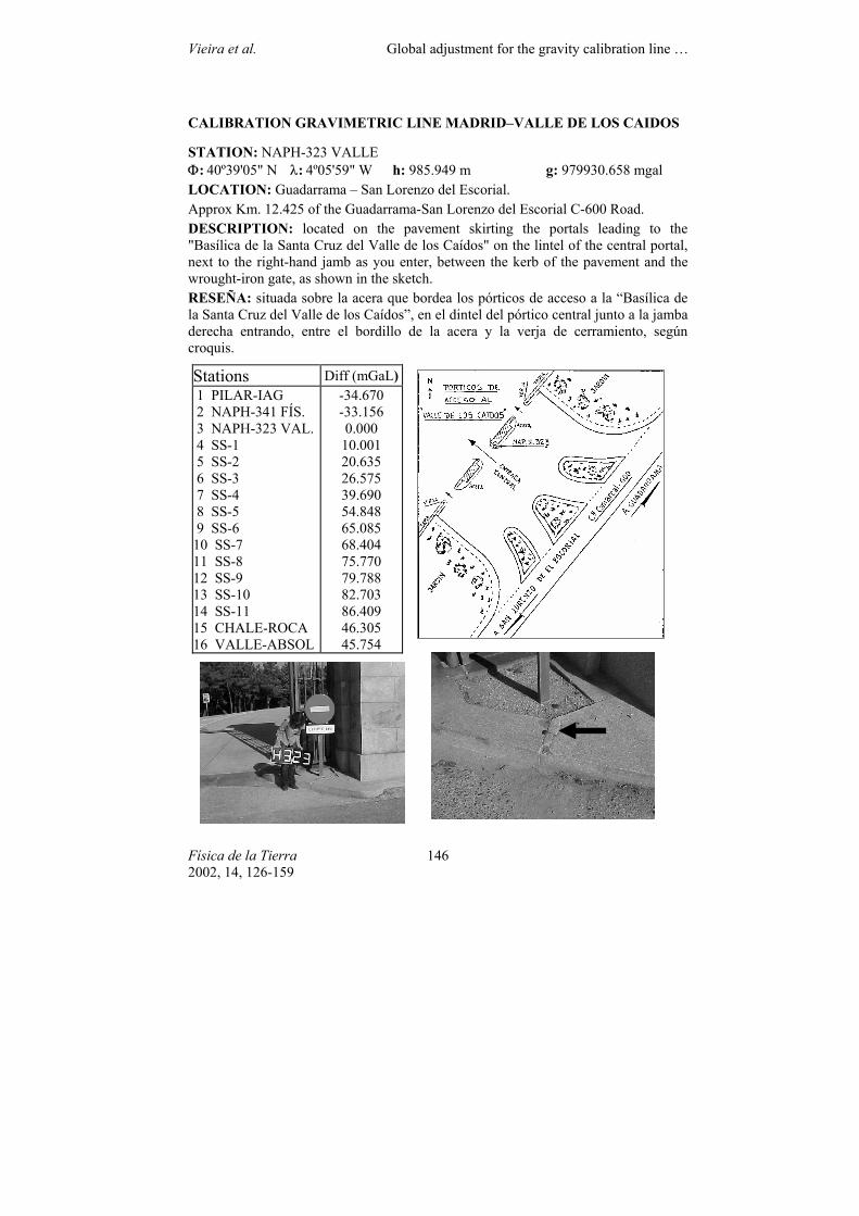
STATION: NAPH-323 VALLE Φ: 40º39'05" N λ: 4º05'59" W h: 985.949 m g: 979930.658 mgal LOCATION: Guadarrama – San Lorenzo del Escorial. Approx Km. 12.425 of the Guadarrama-San Lorenzo del Escorial C-600 Road. DESCRIPTION: located on the pavement skirting the portals leading to the "Basílica de la Santa Cruz del Valle de los Caídos" on the lintel of the central portal, next to the right-hand jamb as you enter, between the kerb of the pavement and the wrought-iron gate, as shown in the sketch. RESEÑA: situada sobre la acera que bordea los pórticos de acceso a la “Basílica de la Santa Cruz del Valle de los Caídos”, en el dintel del pórtico central junto a la jamba derecha entrando, entre el bordillo de la acera y la verja de cerramiento, según croquis.
Stations Diff (mGaL) 1 PILAR-IAG 2 NAPH-341 FÍS. 3 NAPH-323 VAL. 4 SS-1 5 SS-2 6 SS-3 7 SS-4 8 SS-5 9 SS-6 10 SS-7 11 SS-8 12 SS-9 13 SS-10 14 SS-11 15 CHALE-ROCA 16 VALLE-ABSOL
-34.670 -33.156 0.000
10.001 20.635 26.575 39.690 54.848 65.085 68.404 75.770 79.788 82.703 86.409 46.305 45.754
Vieira et al. Global adjustment for the gravity calibration line …
Física de la Tierra 2002, 14, 126-159
147
CALIBRATION GRAVIMETRIC LINE MADRID–VALLE DE LOS CAIDOS
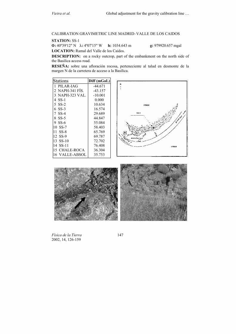
STATION: SS-1 Φ: 40º39'12" N λ: 4º07'15" W h: 1034.643 m g: 979920.657 mgal LOCATION: Ramal del Valle de los Caídos. DESCRIPTION: on a rocky outcrop, part of the embankment on the north side of the Basilica access road. RESEÑA: sobre una afloración rocosa, perteneciente al talud en desmonte de la margen N de la carretera de acceso a la Basílica.
Stations Diff (mGaL) 1 PILAR-IAG 2 NAPH-341 FÍS. 3 NAPH-323 VAL. 4 SS-1 5 SS-2 6 SS-3 7 SS-4 8 SS-5 9 SS-6 10 SS-7 11 SS-8 12 SS-9 13 SS-10 14 SS-11 15 CHALE-ROCA 16 VALLE-ABSOL
-44.671 -43.157 -10.001 0.000
10.634 16.574 29.689 44.847 55.084 58.403 65.769 69.787 72.702 76.408 36.304 35.753
Vieira et al. Global adjustment for the gravity calibration line …
Física de la Tierra 2002, 14, 126-159
148
CALIBRATION GRAVIMETRIC LINE MADRID–VALLE DE LOS CAIDOS
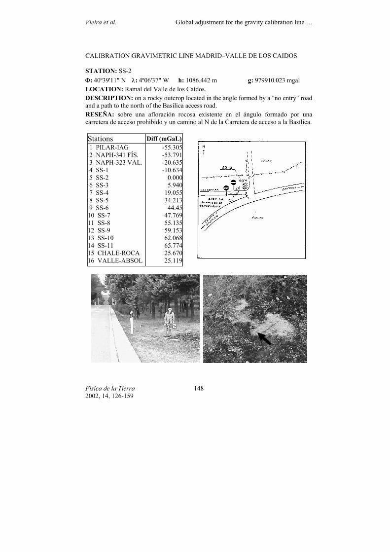
STATION: SS-2 Φ: 40º39'11" N λ: 4º06'37" W h: 1086.442 m g: 979910.023 mgal LOCATION: Ramal del Valle de los Caídos. DESCRIPTION: on a rocky outcrop located in the angle formed by a "no entry" road and a path to the north of the Basilica access road. RESEÑA: sobre una afloración rocosa existente en el ángulo formado por una carretera de acceso prohibido y un camino al N de la Carretera de acceso a la Basílica.
Stations Diff (mGaL) 1 PILAR-IAG 2 NAPH-341 FÍS. 3 NAPH-323 VAL. 4 SS-1 5 SS-2 6 SS-3 7 SS-4 8 SS-5 9 SS-6 10 SS-7 11 SS-8 12 SS-9 13 SS-10 14 SS-11 15 CHALE-ROCA 16 VALLE-ABSOL
-55.305-53.791-20.635-10.634
0.0005.940
19.05534.21344.45
47.76955.13559.15362.06865.77425.67025.119
Vieira et al. Global adjustment for the gravity calibration line …
Física de la Tierra 2002, 14, 126-159
149
CALIBRATION GRAVIMETRIC LINE MADRID–VALLE DE LOS CAIDOS
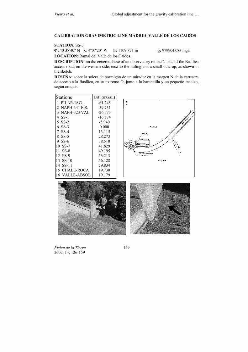
STATION: SS-3 Φ: 40º38'40" N λ: 4º07'20" W h: 1109.871 m g: 979904.083 mgal LOCATION: Ramal del Valle de los Caídos. DESCRIPTION: on the concrete base of an observatory on the N side of the Basilica access road, on the western side, next to the railing and a small outcrop, as shown in the sketch. RESEÑA: sobre la solera de hormigón de un mirador en la margen N de la carretera de acceso a la Basílica, en su extremo O, junto a la barandilla y un pequeño macizo, según croquis.
Stations Diff (mGaL) 1 PILAR-IAG 2 NAPH-341 FÍS. 3 NAPH-323 VAL. 4 SS-1 5 SS-2 6 SS-3 7 SS-4 8 SS-5 9 SS-6 10 SS-7 11 SS-8 12 SS-9 13 SS-10 14 SS-11 15 CHALE-ROCA 16 VALLE-ABSOL
-61.245 -59.731 -26.575 -16.574 -5.940 0.000
13.115 28.273 38.510 41.829 49.195 53.213 56.128 59.834 19.730 19.179
Vieira et al. Global adjustment for the gravity calibration line …
Física de la Tierra 2002, 14, 126-159
150
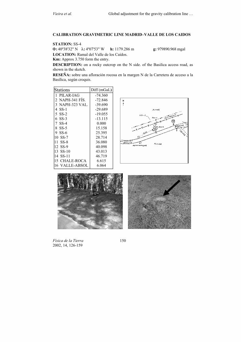
CALIBRATION GRAVIMETRIC LINE MADRID–VALLE DE LOS CAIDOS
STATION: SS-4 Φ: 40º38'32" N λ: 4º07'53" W h: 1179.286 m g: 979890.968 mgal LOCATION: Ramal del Valle de los Caídos. Km: Approx 3.750 form the entry. DESCRIPTION: on a rocky outcrop on the N side. of the Basilica access road, as shown in the sketch. RESEÑA: sobre una afloración rocosa en la margen N de la Carretera de acceso a la Basílica, según croquis.
Stations Diff (mGaL) 1 PILAR-IAG 2 NAPH-341 FÍS. 3 NAPH-323 VAL. 4 SS-1 5 SS-2 6 SS-3 7 SS-4 8 SS-5 9 SS-6 10 SS-7 11 SS-8 12 SS-9 13 SS-10 14 SS-11 15 CHALE-ROCA 16 VALLE-ABSOL
-74.360 -72.846 -39.690 -29.689 -19.055 -13.115 0.000
15.158 25.395 28.714 36.080 40.098 43.013 46.719 6.615 6.064
Vieira et al. Global adjustment for the gravity calibration line …
Física de la Tierra 2002, 14, 126-159
151
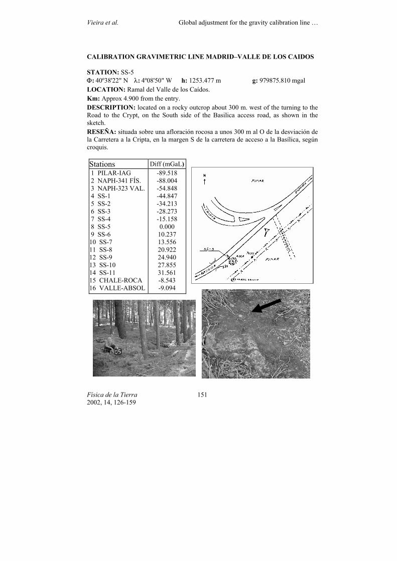
CALIBRATION GRAVIMETRIC LINE MADRID–VALLE DE LOS CAIDOS
STATION: SS-5 Φ: 40º38'22" N λ: 4º08'50" W h: 1253.477 m g: 979875.810 mgal LOCATION: Ramal del Valle de los Caídos. Km: Approx 4.900 from the entry. DESCRIPTION: located on a rocky outcrop about 300 m. west of the turning to the Road to the Crypt, on the South side of the Basilica access road, as shown in the sketch. RESEÑA: situada sobre una afloración rocosa a unos 300 m al O de la desviación de la Carretera a la Cripta, en la margen S de la carretera de acceso a la Basílica, según croquis.
Stations Diff (mGaL) 1 PILAR-IAG 2 NAPH-341 FÍS. 3 NAPH-323 VAL. 4 SS-1 5 SS-2 6 SS-3 7 SS-4 8 SS-5 9 SS-6 10 SS-7 11 SS-8 12 SS-9 13 SS-10 14 SS-11 15 CHALE-ROCA 16 VALLE-ABSOL
-89.518 -88.004 -54.848 -44.847 -34.213 -28.273 -15.158 0.000
10.237 13.556 20.922 24.940 27.855 31.561 -8.543 -9.094
Vieira et al. Global adjustment for the gravity calibration line …
Física de la Tierra 2002, 14, 126-159
152
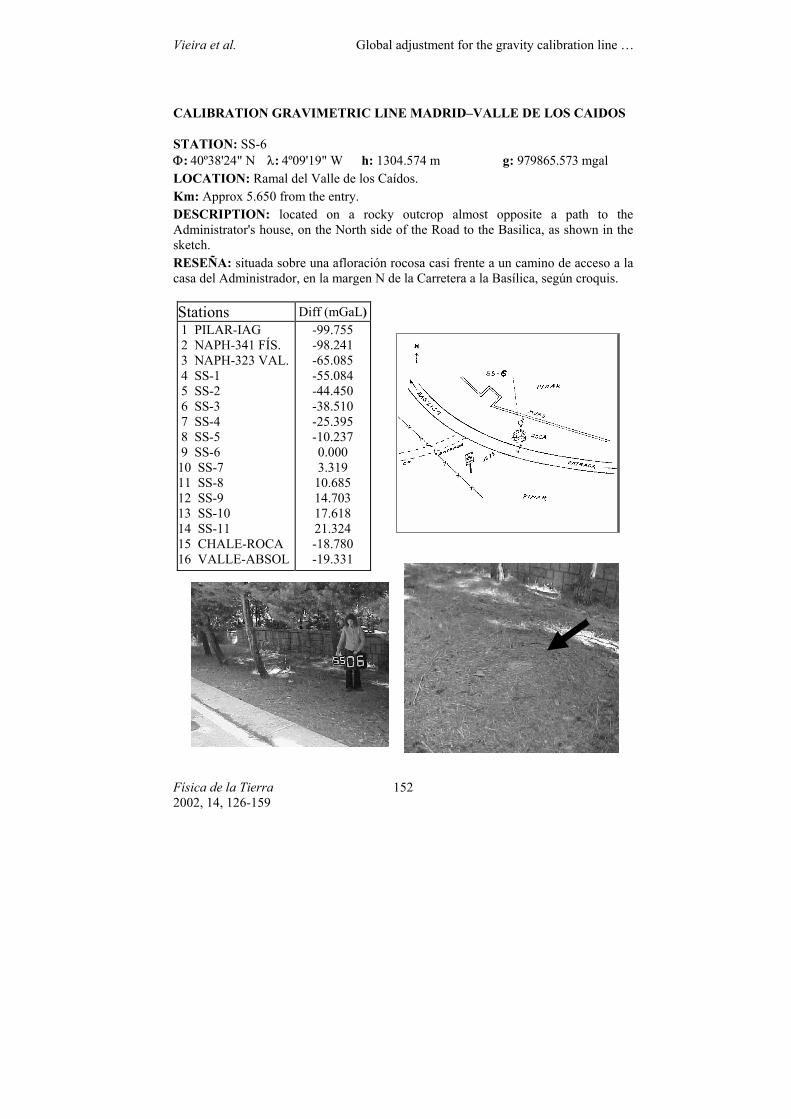
CALIBRATION GRAVIMETRIC LINE MADRID–VALLE DE LOS CAIDOS
STATION: SS-6 Φ: 40º38'24" N λ: 4º09'19" W h: 1304.574 m g: 979865.573 mgal LOCATION: Ramal del Valle de los Caídos. Km: Approx 5.650 from the entry. DESCRIPTION: located on a rocky outcrop almost opposite a path to the Administrator's house, on the North side of the Road to the Basilica, as shown in the sketch. RESEÑA: situada sobre una afloración rocosa casi frente a un camino de acceso a la casa del Administrador, en la margen N de la Carretera a la Basílica, según croquis.
Stations Diff (mGaL) 1 PILAR-IAG 2 NAPH-341 FÍS. 3 NAPH-323 VAL. 4 SS-1 5 SS-2 6 SS-3 7 SS-4 8 SS-5 9 SS-6 10 SS-7 11 SS-8 12 SS-9 13 SS-10 14 SS-11 15 CHALE-ROCA 16 VALLE-ABSOL
-99.755 -98.241 -65.085 -55.084 -44.450 -38.510 -25.395 -10.237 0.000 3.319
10.685 14.703 17.618 21.324 -18.780 -19.331
Vieira et al. Global adjustment for the gravity calibration line …
Física de la Tierra 2002, 14, 126-159
153
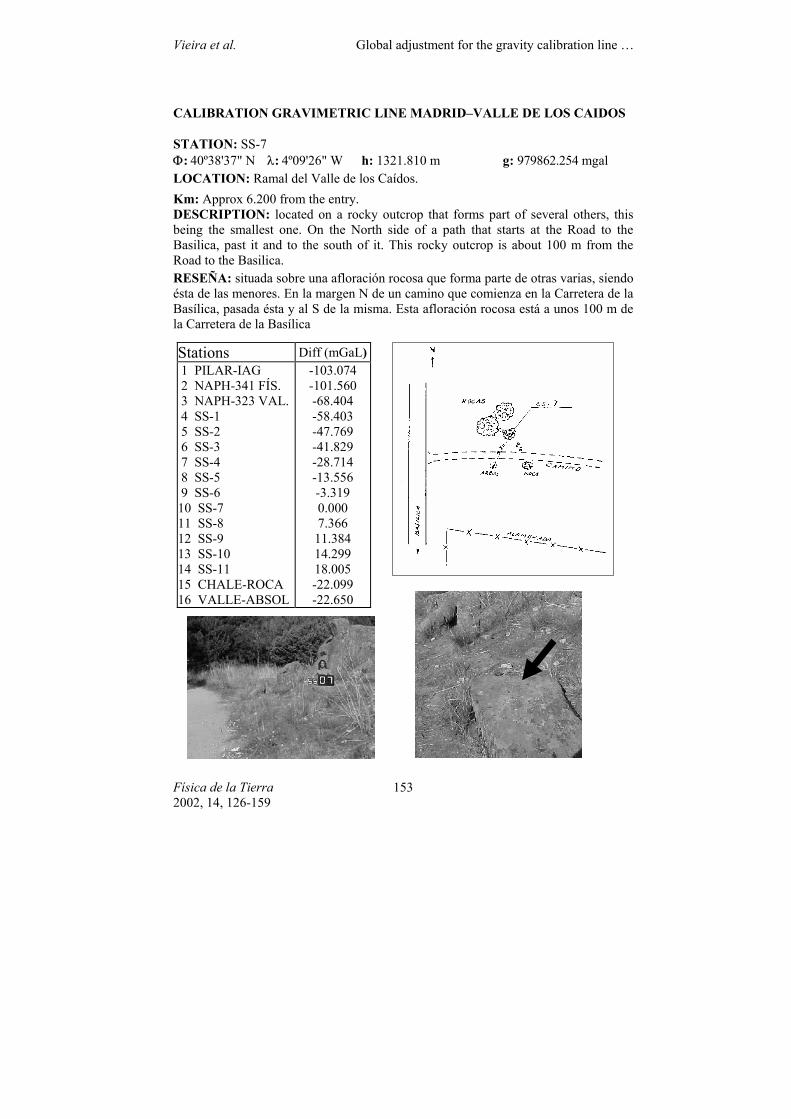
CALIBRATION GRAVIMETRIC LINE MADRID–VALLE DE LOS CAIDOS
STATION: SS-7 Φ: 40º38'37" N λ: 4º09'26" W h: 1321.810 m g: 979862.254 mgal LOCATION: Ramal del Valle de los Caídos. Km: Approx 6.200 from the entry. DESCRIPTION: located on a rocky outcrop that forms part of several others, this being the smallest one. On the North side of a path that starts at the Road to the Basilica, past it and to the south of it. This rocky outcrop is about 100 m from the Road to the Basilica. RESEÑA: situada sobre una afloración rocosa que forma parte de otras varias, siendo ésta de las menores. En la margen N de un camino que comienza en la Carretera de la Basílica, pasada ésta y al S de la misma. Esta afloración rocosa está a unos 100 m de la Carretera de la Basílica
Stations Diff (mGaL) 1 PILAR-IAG 2 NAPH-341 FÍS. 3 NAPH-323 VAL. 4 SS-1 5 SS-2 6 SS-3 7 SS-4 8 SS-5 9 SS-6 10 SS-7 11 SS-8 12 SS-9 13 SS-10 14 SS-11 15 CHALE-ROCA 16 VALLE-ABSOL
-103.074 -101.560 -68.404 -58.403 -47.769 -41.829 -28.714 -13.556 -3.319 0.000 7.366
11.384 14.299 18.005 -22.099 -22.650
Vieira et al. Global adjustment for the gravity calibration line …
Física de la Tierra 2002, 14, 126-159
154
CALIBRATION GRAVIMETRIC LINE MADRID–VALLE DE LOS CAIDOS
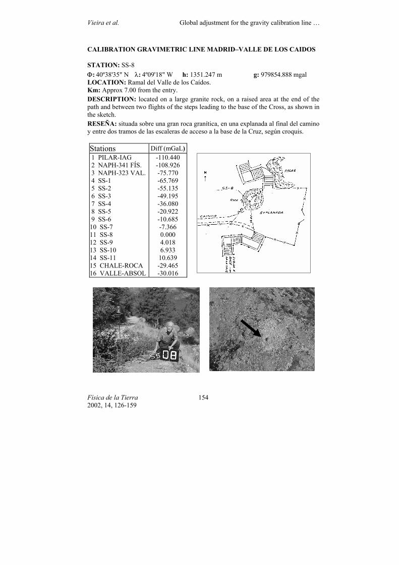
STATION: SS-8 Φ: 40º38'35" N λ: 4º09'18" W h: 1351.247 m g: 979854.888 mgal LOCATION: Ramal del Valle de los Caídos. Km: Approx 7.00 from the entry. DESCRIPTION: located on a large granite rock, on a raised area at the end of the path and between two flights of the steps leading to the base of the Cross, as shown in the sketch. RESEÑA: situada sobre una gran roca granítica, en una explanada al final del camino y entre dos tramos de las escaleras de acceso a la base de la Cruz, según croquis.
Stations Diff (mGaL) 1 PILAR-IAG 2 NAPH-341 FÍS. 3 NAPH-323 VAL. 4 SS-1 5 SS-2 6 SS-3 7 SS-4 8 SS-5 9 SS-6 10 SS-7 11 SS-8 12 SS-9 13 SS-10 14 SS-11 15 CHALE-ROCA 16 VALLE-ABSOL
-110.440 -108.926 -75.770 -65.769 -55.135 -49.195 -36.080 -20.922 -10.685 -7.366 0.000 4.018 6.933
10.639 -29.465 -30.016
Vieira et al. Global adjustment for the gravity calibration line …
Física de la Tierra 2002, 14, 126-159
155
CALIBRATION GRAVIMETRIC LINE MADRID–VALLE DE LOS CAIDOS
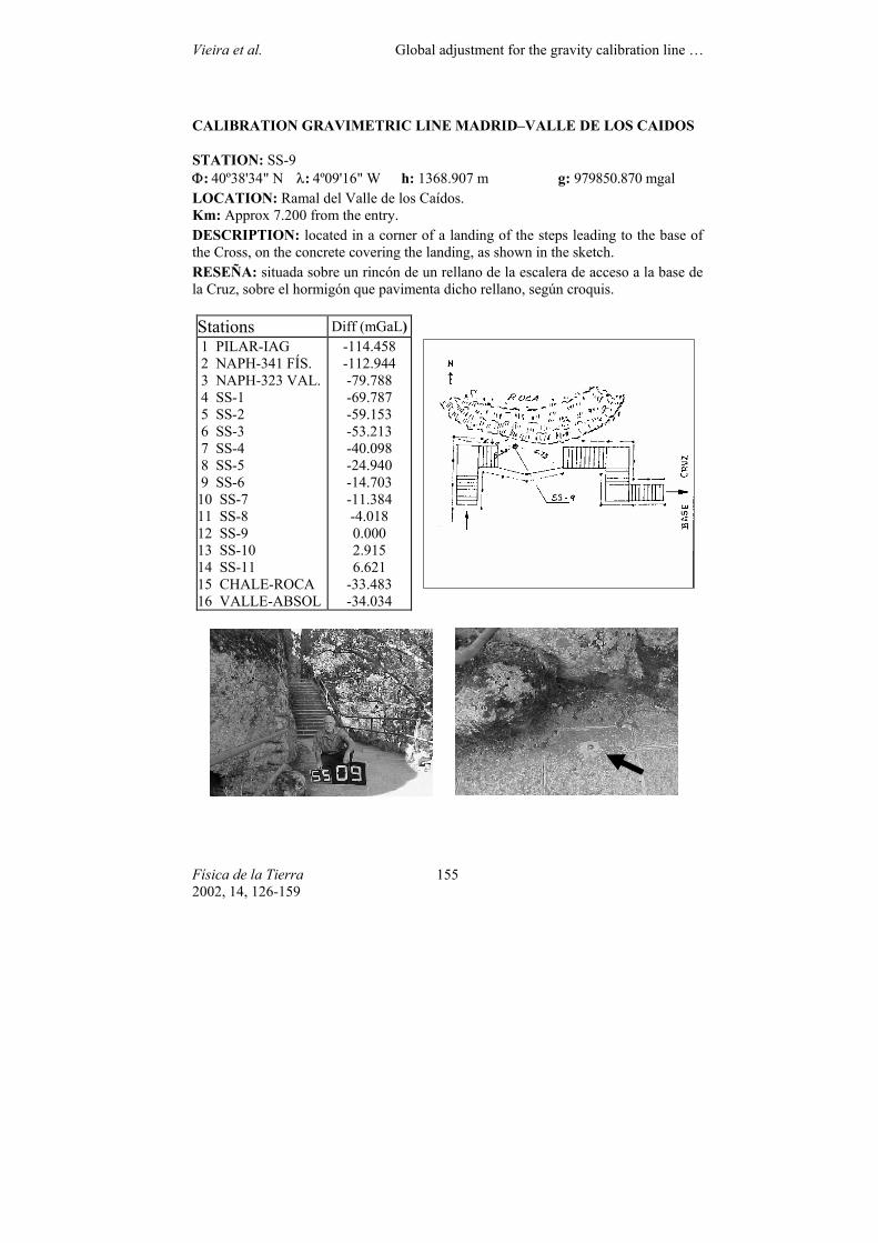
STATION: SS-9 Φ: 40º38'34" N λ: 4º09'16" W h: 1368.907 m g: 979850.870 mgal LOCATION: Ramal del Valle de los Caídos. Km: Approx 7.200 from the entry. DESCRIPTION: located in a corner of a landing of the steps leading to the base of the Cross, on the concrete covering the landing, as shown in the sketch. RESEÑA: situada sobre un rincón de un rellano de la escalera de acceso a la base de la Cruz, sobre el hormigón que pavimenta dicho rellano, según croquis.
Stations Diff (mGaL) 1 PILAR-IAG 2 NAPH-341 FÍS. 3 NAPH-323 VAL. 4 SS-1 5 SS-2 6 SS-3 7 SS-4 8 SS-5 9 SS-6 10 SS-7 11 SS-8 12 SS-9 13 SS-10 14 SS-11 15 CHALE-ROCA 16 VALLE-ABSOL
-114.458 -112.944 -79.788 -69.787 -59.153 -53.213 -40.098 -24.940 -14.703 -11.384 -4.018 0.000 2.915 6.621
-33.483 -34.034
Vieira et al. Global adjustment for the gravity calibration line …
Física de la Tierra 2002, 14, 126-159
156
CALIBRATION GRAVIMETRIC LINE MADRID–VALLE DE LOS CAIDOS
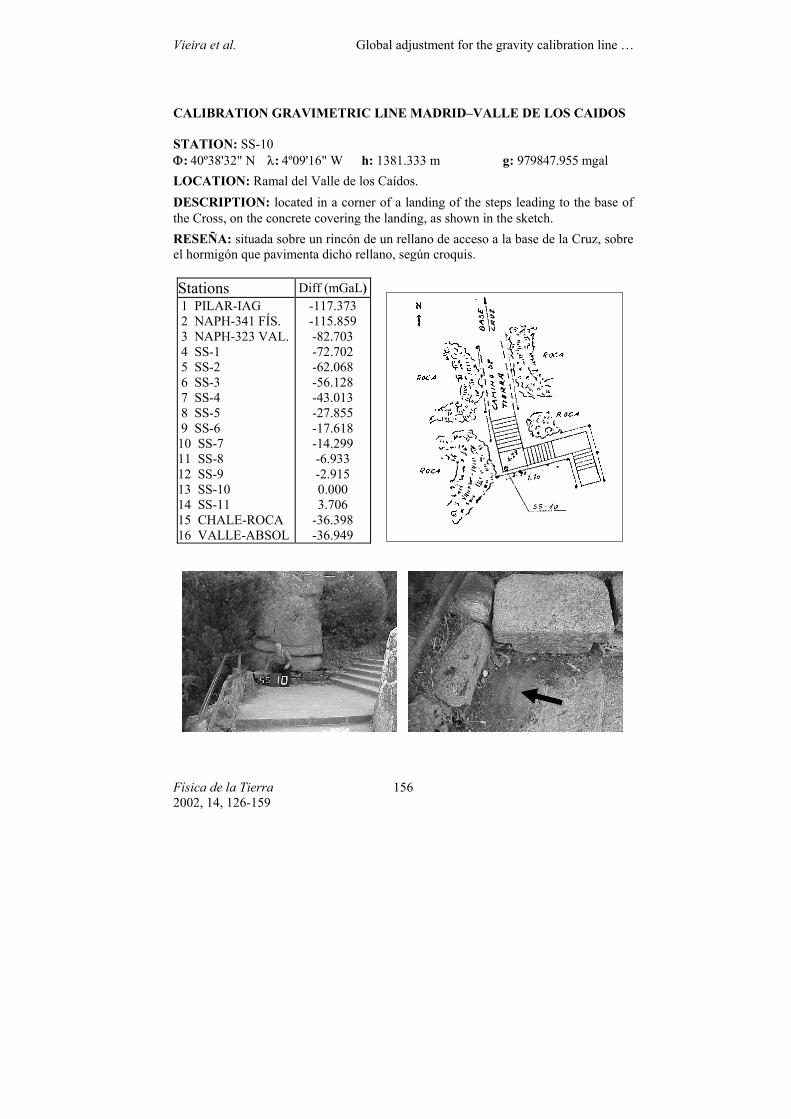
STATION: SS-10 Φ: 40º38'32" N λ: 4º09'16" W h: 1381.333 m g: 979847.955 mgal LOCATION: Ramal del Valle de los Caídos. DESCRIPTION: located in a corner of a landing of the steps leading to the base of the Cross, on the concrete covering the landing, as shown in the sketch. RESEÑA: situada sobre un rincón de un rellano de acceso a la base de la Cruz, sobre el hormigón que pavimenta dicho rellano, según croquis.
Stations Diff (mGaL) 1 PILAR-IAG 2 NAPH-341 FÍS. 3 NAPH-323 VAL. 4 SS-1 5 SS-2 6 SS-3 7 SS-4 8 SS-5 9 SS-6 10 SS-7 11 SS-8 12 SS-9 13 SS-10 14 SS-11 15 CHALE-ROCA 16 VALLE-ABSOL
-117.373 -115.859 -82.703 -72.702 -62.068 -56.128 -43.013 -27.855 -17.618 -14.299 -6.933 -2.915 0.000 3.706
-36.398 -36.949
Vieira et al. Global adjustment for the gravity calibration line …
Física de la Tierra 2002, 14, 126-159
157
CALIBRATION GRAVIMETRIC LINE MADRID–VALLE DE LOS CAIDOS
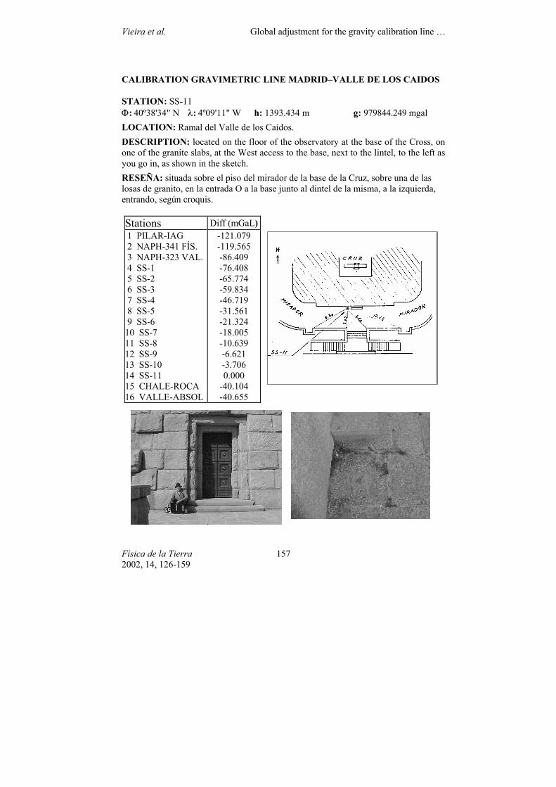
STATION: SS-11 Φ: 40º38'34" N λ: 4º09'11" W h: 1393.434 m g: 979844.249 mgal LOCATION: Ramal del Valle de los Caídos. DESCRIPTION: located on the floor of the observatory at the base of the Cross, on one of the granite slabs, at the West access to the base, next to the lintel, to the left as you go in, as shown in the sketch. RESEÑA: situada sobre el piso del mirador de la base de la Cruz, sobre una de las losas de granito, en la entrada O a la base junto al dintel de la misma, a la izquierda, entrando, según croquis.
Stations Diff (mGaL) 1 PILAR-IAG 2 NAPH-341 FÍS. 3 NAPH-323 VAL. 4 SS-1 5 SS-2 6 SS-3 7 SS-4 8 SS-5 9 SS-6 10 SS-7 11 SS-8 12 SS-9 13 SS-10 14 SS-11 15 CHALE-ROCA 16 VALLE-ABSOL
-121.079 -119.565 -86.409 -76.408 -65.774 -59.834 -46.719 -31.561 -21.324 -18.005 -10.639 -6.621 -3.706 0.000
-40.104 -40.655
Vieira et al. Global adjustment for the gravity calibration line …
Física de la Tierra 2002, 14, 126-159
158
CALIBRATION GRAVIMETRIC LINE MADRID–VALLE DE LOS CAIDOS
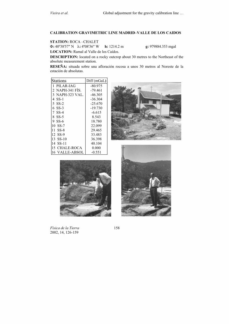
STATION: ROCA –CHALET Φ: 40º38'57" N λ: 4º08'36" W h: 1214.2 m g: 979884.353 mgal LOCATION: Ramal al Valle de los Caídos. DESCRIPTION: located on a rocky outcrop about 30 metres to the Northeast of the absolute measurement station. RESEÑA: situada sobre una afloración rocosa a unos 30 metros al Noreste de la estación de absolutas.
Stations Diff (mGaL) 1 PILAR-IAG 2 NAPH-341 FÍS. 3 NAPH-323 VAL. 4 SS-1 5 SS-2 6 SS-3 7 SS-4 8 SS-5 9 SS-6 10 SS-7 11 SS-8 12 SS-9 13 SS-10 14 SS-11 15 CHALE-ROCA 16 VALLE-ABSOL
-80.975 -79.461 -46.305 -36.304 -25.670 -19.730 -6.615 8.543
18.780 22.099 29.465 33.483 36.398 40.104 0.000 -0.551
Vieira et al. Global adjustment for the gravity calibration line …
Física de la Tierra 2002, 14, 126-159
159
CALIBRATION GRAVIMETRIC LINE MADRID–VALLE DE LOS CAIDOS
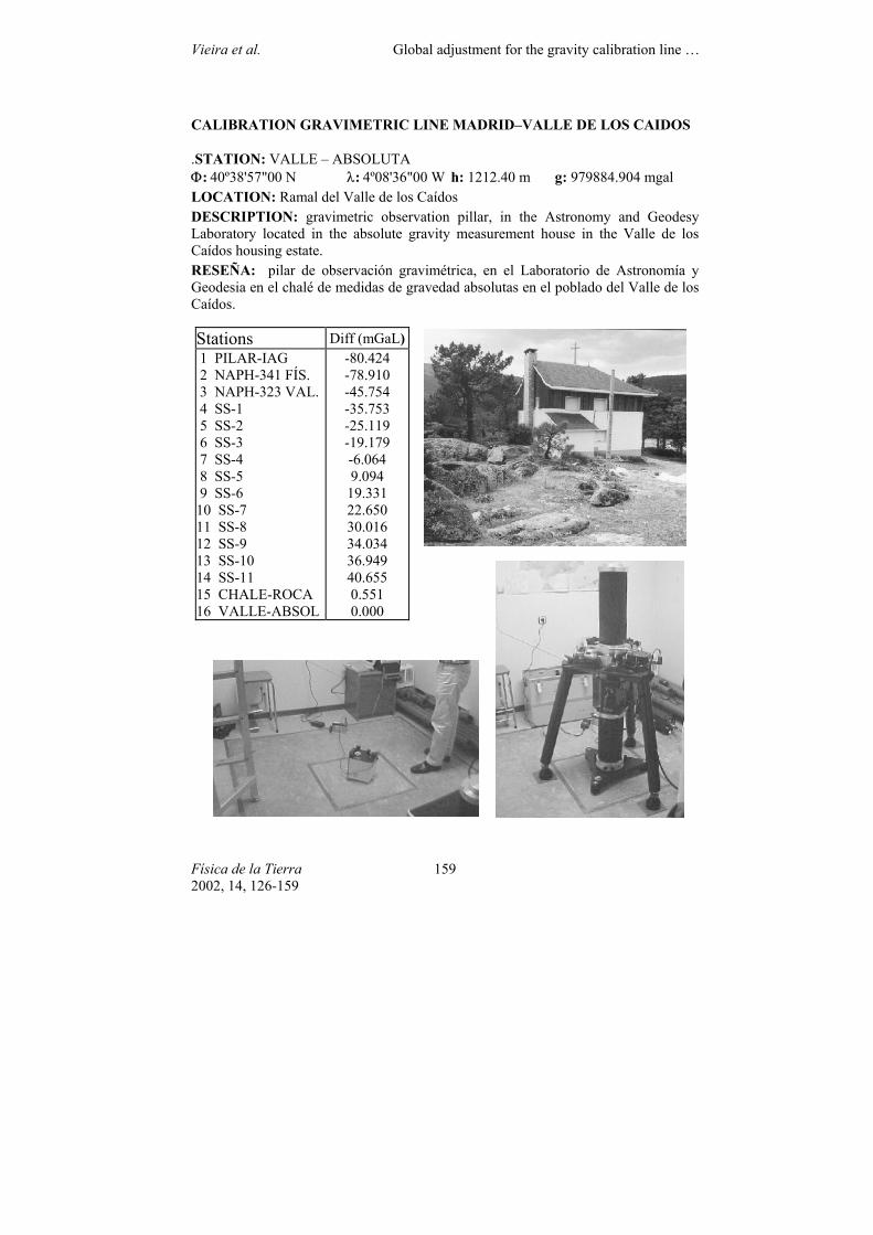
.STATION: VALLE – ABSOLUTA Φ: 40º38'57"00 N λ: 4º08'36"00 W h: 1212.40 m g: 979884.904 mgal LOCATION: Ramal del Valle de los Caídos DESCRIPTION: gravimetric observation pillar, in the Astronomy and Geodesy Laboratory located in the absolute gravity measurement house in the Valle de los Caídos housing estate. RESEÑA: pilar de observación gravimétrica, en el Laboratorio de Astronomía y Geodesia en el chalé de medidas de gravedad absolutas en el poblado del Valle de los Caídos.
Stations Diff (mGaL) 1 PILAR-IAG 2 NAPH-341 FÍS. 3 NAPH-323 VAL. 4 SS-1 5 SS-2 6 SS-3 7 SS-4 8 SS-5 9 SS-6 10 SS-7 11 SS-8 12 SS-9 13 SS-10 14 SS-11 15 CHALE-ROCA 16 VALLE-ABSOL
-80.424 -78.910 -45.754 -35.753 -25.119 -19.179 -6.064 9.094
19.331 22.650 30.016 34.034 36.949 40.655 0.551 0.000