Embed Size (px)
Citation preview

lable at ScienceDirect
High Energy Density Physics 7 (2011) 130e140
Contents lists avai
High Energy Density Physics
journal homepage: www.elsevier .com/locate/hedp
Review
Radiative effects in radiative shocks in shock tubes
R.P. Drake a,*, F.W. Doss a, R.G. McClarren b, M.L. Adams b, N. Amato b, D. Bingham c, C.C. Chou a,C. DiStefano a, K. Fidkowski a, B. Fryxell a, T.I. Gombosi a, M.J. Grosskopf a, J.P. Holloway a, B. van der Holst a,C.M. Huntington a, S. Karni a, C.M. Krauland a, C.C. Kuranz a, E. Larsen a, B. van Leer a, B. Mallick b,D. Marion a, W. Martin a, J.E. Morel b, E.S. Myra a, V. Nair a, K.G. Powell a, L. Rauchwerger b, P. Roe a,E. Rutter a, I.V. Sokolov a, Q. Stout a, B.R. Torralva a, G. Toth a, K. Thornton a, A.J. Visco a
aUniversity of Michigan, Ann Arbor, MI 48109, USAb Texas A&M University, College Station, TX, USAc Simon Fraser University, Vancouver, British Columbia, Canada
a r t i c l e i n f o
Article history:Received 7 March 2011Accepted 7 March 2011Available online 21 March 2011
Keywords:Radiative shocksLaboratory astrophysicsRadiation transferShock waves
* Corresponding author.E-mail address: [email protected] (R.P. Drake).
1574-1818/$ e see front matter � 2011 Elsevier B.V.doi:10.1016/j.hedp.2011.03.005
a b s t r a c t
Using modern high-energy-density facilities it is straightforward to produce radiative shock waves inwhich the transfer of energy by radiation controls the hydrodynamic structure of the system. Some ofthese experiments use shock tubes. This paper discusses such experiments, with an emphasis on thesimple physical relations that determine the primary features of such shocks and on the details andimpact of radiative energy transfer in such systems. Notable aspects include the creation of high-densityshocked layers, the flow of radiative energy toward regions of higher energy density, and the creation ofsecondary shocks by ablation of the tube walls ahead of the primary shock front. Simulations of one suchexperimental system are also shown.
� 2011 Elsevier B.V. All rights reserved.
1. Introduction
Radiative shocks abound in the universe, being present when-ever shocked matter becomes hot enough that radiative energytransfer changes the structure of the shock. The shock wave thatcauses a star to explode following core-collapse is radiative, both asit propagates through and as it emerges from the star [1,2]. Theejecta from supernovae can itself develop into a radiative shock[4,5] and also can drive radiative shocks into dense matter [3,4].Aging supernova remnants eventually enter a radiative phase [6].Clumps of material propagating up astrophysical jets alsomay driveradiative shocks [7]. All these shock waves are said to propagateinto unshocked, “upstream” matter and to produce shocked,“downstream”matter. The radiation heats thematerial ahead of theincrease in density produced by the shock wave, creating a regiondescribed as a “radiative precursor”.
With the advent of experimental facilities that produce high-energy-density conditions, laboratory studies of radiative shockshave become an active area of research. Many of these experiments
All rights reserved.
[8e30] have used an energy source to launch a non-radiativeplasma piston that drives a radiative shock wave in a gas or a foamwhose density is � 1 g=cm3. Such shock waves can be produced inshock tubes, where the intent is to limit the lateral expansion of theshocked material and thus to sustain the shock strength. Our focushere will be on shock waves in shock tubes under conditions thatallow observation of the shocked matter. Some other laboratoryradiative shocks are produced when a plasma expanding froma surface drives a radiative shock [31e34]. In yet other cases, localdeposition of energy produces shock waves that exhibit radiativeeffects [35e38].
Theoretical studies of radiative shocks date to the 1950s [39,40],and have developed further in parallel with increasing computa-tional capability. Various regimes of radiative shocks have beenidentified [16,41], depending on how readily the radiation escapesthe shocked material and on the ratio of radiation pressure tomaterial pressure. Most theoretical research [42e52] has addressedthe evolution of steady shock waves under “optically thick”conditions, in which the extent of the system is many mean freepaths for the thermal radiation so that the radiation is deeplytrapped in the material. Some theoretical research has addressedthe behavior of shock waves under “optically thin” conditions, inwhich the radiation readily escapes from the shocked matter

0.2 0.6
1.5
1.25
0.3125
0.2625
Be (20 m)
Polyimide (25 m)
Acrylic
Gold (50 m)
Xenon (1.1 atm)
Fig. 2. Details of the interior portion of a standard radiative shock target. The layer ofgold exists to retard the progress of the laser-driven shock at radii outside the shocktube. Nominal dimensions are given in mm.
R.P. Drake et al. / High Energy Density Physics 7 (2011) 130e140 131
[53e56]. Recent theoretical work [57] has also addressed theexperimentally more relevant case in which the shocked matter isoptically thick while the unshocked matter is optically thin.
In the following, Section 2 discusses the fundamental, “back ofthe envelope” description of this type of radiative shock in a specificconfiguration that we have studied extensively. Section 3 thendiscusses the axial structure of these shocks showing that theirfinal compressed density is determined fundamentally by energybalance. Next, Section 4 discusses the radiation transfer withinthese shocks. The hot, optically thin layer they produce createsunusual features in both the density structure and the transfer ofradiation. Following this, Section 5 discusses the effects of theradiation from the hot, shocked matter on the shock-tube wallsahead of the shock front. This interaction produces a complex flowwhose features may be used to diagnose some of the properties ofthe system. Section 6 summarizes our work to simulate thebehavior of such shocks and shows results of such simulations. Wewill not discuss here our related work to evaluate the predictivecapability of the simulation code in the context of these radiativeshocks [58,59]. Following this, Section 7 concludes the paper.
2. Fundamental elements of driven radiative shocks
Fig. 1 shows photographs of two laser targets used in ourlaboratory studies of radiative shocks. These targets are assembledat the University of Michigan, where precision machining tech-niques are used to assure correct target orientation [60]. This hasproven essential to obtain shocked layers that are not significantlytilted with respect to the shock tube. The two targets shown in thefigure have the same inner details and produce nearly identicalradiative shocks; the differences in target structure relate to thediagnostics used for specific experiments. Here we discuss theinner details and resulting properties of one specific case of sucha target. Fig. 2 shows the essential details of our standard targets.We have used similar targets for an extensive sequence of experi-mental campaigns [12,16,19,22,23,26,28e30].
Ten laser beams from the Omega laser facility [62] irradiatea 20 mm thick Be disk with 0.35 mm-wavelength light, whose“critical density” of free electrons, below which the light is
Fig. 1. Laser targets used to produce radiative shocks. In the target on the left, one cansee the Be disk. Here the lasers would enter from above. Some components are labeled.Other lasers strike the x-ray foil to produce x-rays for a diagnostic; the wire provides itwith a spatial fiducial. To irradiate the target on the right, the laser beams enter theconical acrylic shield, from the upper left. The shock tube in the target on the right isthe small object extending toward the lower right. Fiducial grids are attached to it. Thewedges of gold attached to the acrylic cone protect the ungated imaging diagnostic[61] from emissions from the laser-produced plasma.
absorbed, is 8.9 � 1021 cm�3. The duration of the (flat-topped) laserpulse is 1 ns, with 4 kJ of energy on an w800 mm diameter spot, sothat the irradiance is w7 � 1014 W/cm2 ¼ w7 � 1021 ergs/s/cm2.Most of the energy is absorbed, so the absorbed energy fluence in1 ns is w7 � 1012 ergs/cm2. Some of the absorbed laser energy istransported by electron heat conduction to high density, where itablates the dense material. The corresponding pressure ofw50 Mbars, which is w5 � 1013 dynes cm�2, first drives a shockwave through the Be disk for w500 ps and then accelerates theshocked material for the remainder of the laser pulse.
The purpose of shocking and then accelerating the Be is toproduce a high-velocity piston that will drive a shock wave downthe Xe tube. The “hydrodynamic efficiency” of the conversion fromlaser energy to kinetic energy is around 10%, giving a kinetic energyfluence of 7 � 1011 ergs/cm2. In round numbers, the energy isabsorbed below critical density, half of it goes up to solid densitywhere the ablation occurs, removing about 20% of the target mass,corresponding to a 20% rocket efficiency for the energy reachingthat density. The implied kinetic energy fluence of w7 � 1011 ergs/cm2 is carried by what was initially about 16 mmof Be at 1.8 g/cm�3,giving an areal mass density of w3 � 10�3 g/cm2 a thus an initialvelocity of vw 2� 107 cm/s (200 km/s). Simulations and long-termobservations suggest that the average velocity of the Be plasma isnever quite this high, but that the leading edge of the expanding Beplasma can cause the shock to reachw200 km/s for a brief period oftime. The average shock velocity over 26 ns is observed to remainabove 100 km/s.
The “piston”of Beplasmadrives a strong-shockwave through theXe. One can infer from basic strong-shock relations [63] some of theproperties of the shocked Xe. The initial xenon gas density is

R.P. Drake et al. / High Energy Density Physics 7 (2011) 130e140132
r ¼ 0.0065 g/cc, so the post-shock Xe pressure iswrv2w2�1012dynes/cm2¼2Mbars. The initial shockheatinggoesinto the ions, so the initial ion temperature is kBTiiw0:1Ampv
2, withatomic mass A¼ 131 and proton massmp, with Boltzmann constantkB ¼ 1.6 � 10�12 ergs/eV, so Tii w 2 keV. The factor of 0.1 is approx-imate and depends in detail upon the ionization and effective pol-ytropic index. Fig. 3 shows an example of the shock structureobserved at 26 ns; it can provide a geometric reference for thefollowing discussion.
The dynamics near the shock front and the ionization arecomplex. The density jump at the shock front occurs on a spatialscale of less than 10 ioneion mean free paths. This corresponds toa w0.1 femtosecond timescale. The energy exchange betweenelectrons and ions is a few times slower than this, and the energyfrom each ion is shared with Z electrons, where Z is the averageionization. One can estimate the resulting electron temperature, Tes,and Z using the Saha equation [63], assuming that radiative lossesare unimportant on this timescale. This is an oversimplification:radiative lossesmatter but are not dominant [23]. One canwrite theresulting equation for Z as
Z ¼ffiffiffiffiffiffiffiffiffiffikBTeEH
s ffiffiffiffiffiffiffiffiffiffiffiffiffiffiffiffiffiffiffiffiffiffiffiffiffiffiffiffiffiffiffiffiffiffiffiffiffiffiffiffiffiffiffiffiffiffiffiln
"1ne
14a3o
�kBTepEH
�3=2#vuut � 1
2; (1)
in which ne is the electron density, ao ¼ 5.29 � 10�9 cm is the Bohrradius, EH is the ionization potential of hydrogen, and one hasassumed equal statistical weights of adjacent ionization states. Forthe present problem, one has Te ¼ Tes ¼ Tii=ðZ þ 1Þ and ne ¼ niZ,where the ion density is ni, from which one has
Z ¼ 19:7
ffiffiffiffiffiffiffiffiffiffiffiffiffiffiffiffiffiffiffiffiffiffiffiffiffiffiffiffiffiffiffiffiffiffiffiffiffiffiffiffiffiffiffiffiffiffiffiffiffiffiffiffiffiffiffiffiffiffiffiffiffiffiffiffiffiffiffiffiffiffiffiffiffiffiffiffiffiffiffiTii
ðZ þ 1Þ
"1þ 0:19ln
1024T3=2ii
ðZ þ 1Þ3=2Zni
!#vuut � 12; (2)
with Tii in keV and ni in units of cm�3. Such amodel, with Tii¼ 2 keVand ni ¼ 2 � 1020 cm�3, gives Z ¼ 10.3 and Tes ¼ 180 eV.
However, energy balance implies that this cannot be the finalstate. The energy flux available to create the radiative and materialenergy fluxes produced by the shock is the incoming kinetic energyflux seen from the shock frame (a frame of reference in which theshock is stationary). This energy source is wrv3/2, which is
Fig. 3. Radiographic image of one of our base radiative shocks at 26 ns. The shock ismoving from left to right within the shock tube, whose walls are expanding behind theshock. Above and below the shock tube, respectively, are structures for intensitycalibration and spatial calibration. The radiograph was obtained using Hea emissionfrom a backlit-pinhole V source [28].
w3 � 1019 ergs/cm2/s for the present case. If the final state of theshocked material, which rapidly becomes optically thick, were toemit radiation at a 180 eV temperature, then sT4
esw1021 ergs=cm2=s,about 30 times larger than the incoming kinetic energy flux. Herethe Stefan Boltzmann constant s is w105 W/cm2/eV4 ¼ 1012 ergs/cm2/s/eV4. The implication is that theactual radiationemissionmustbemuch less than sT4es for this initial value of Tes Instead, theremustbe an optically thin cooling layer (of optical depth s) through whichthe temperature declines to a final value Tf. The emission from thiscooling layer is thenwssT4es in the upstream direction.
In the absence of any radiation that escapes from the shockedmaterial downstream of the cooling layer and of any final down-stream flux of material energy, one would have 2ssT4
es ¼ rv3=2,where the factor of 2 is because the cooling layer emits equally inboth directions. This would give swð1=2Þ�ð1=30Þ based on theprevious paragraph. In fact s is smaller than this because there isradiation that escapes from by the downstream shocked matter,and there is some final downstream flux of material energy. In thelimit that the shocked material can be taken to be semi-infinite,there must be no net radiation flux within the downstream mate-rial, so the downstream radiation flux from the cooling layer mustequal the upstream flux from the final state. This impliesssT4
es ¼ sT4f . Because the cooling layer radiates equally in both
directions, and the radiation from the final state flows nearlyunimpeded through it, the radiation leaving the shocked matter inthe upstream direction is approximately ssT4
es þ sT4f ¼ 2sT4f .
Assuming that the downstream material energy flux is negligibleone can estimate the final temperature by setting2sT4f ¼ rv3=2w3�1019 ergs=cm2=s. This implies with the aboveTfw 60 eV. The case of a semi-infinite downstream region is treatedin detail by McClarren et al. [57], who confirm the results of thesimple analysis just given.
For the specific case here, based on the Rosseland mean opacity,the mean free path of the radiation in the shocked Xe is several mmand the final Xe density is w25 times the initial density, so that asthe shock wave travels a few mm the optical depth of the shockedXe layer reaches tens. Radiation hydrodynamic simulations in 1Dsuggest that about 50% of the incident energy flux is radiated backupstream, about 20% of it is radiated downstream from thedownstream boundary of the shocked layer, and about 30% of it iscarried downstream as material energy.
Returning to simple arguments, in the face of the cooling causedby the radiative energy losses, the density of the shocked Xe mustincrease to balance the ram pressure of the incoming flow as seenin the shock frame. For an initial and final mass density ro and rf,respectively, this implies rf RTfwrov
2, so that the compression isrf =ro ¼ v2=ðRTf Þ, where R is the gas constant, given approximatelyby R ¼ ðZ þ 1ÞkB=ðAmpÞ. Substituting values from the numbersgiven above, one finds a compression of 80. Using a velocity cor-responding to times of observation, one obtains a compression near40, which is also consistent with values from 1D simulations. Thecompression seen by line-integrated measurements near 13 ns [29]is nearer to 20; it is unclear at present whether this is because theshocked layer has been wrinkled by instabilities or because someother effect limits the compression.
The radiation striking the wall of the shock tube just ahead ofthe primary shock corresponds to roughly the irradiance of a 60 eVblackbody (being w2sT4f over about p sr). This is w1012 W/cm2
(w1019 ergs/s/cm2), which is sufficient to ionize the wall materialand produce a plasma expansion from the wall. This plasmaexpansion in turn drives a “wall shock” into the Xe, as is discussedfurther below in Section 5. These wall shocks in turn interact withthe primary shock, and the Xe that first enters a wall shock ends upmoving more slowly than the primary shock, so that it producesa shell of entrained Xe that trails the primary shock.

Table 1Energies in radiative shocks on Omega.
Laser Energy 4000 JBe Kinetic energy 400 JShock frame kinetic energy 40 JForward radiated energy 20 J
R.P. Drake et al. / High Energy Density Physics 7 (2011) 130e140 133
One can see several of the above elements in the radiographicimage of Fig. 3. The dark regionwithin the shock tube shows wherethe shocked Xe is. The primary shock is the vertical boundary,which has traveled 3.4 mm in 26 ns, corresponding to an averagevelocity of 130 km/s. The shell of entrained, shocked Xe is evident;it produces the limb-darkened features near the shock tube walland to the left of the primary shock. Near the shock-tube axis, thedarkest zone corresponds to the accumulated Xe that has beenshocked only by the primary shock. This region is clearly less than200 mm thick, and thus corresponds to a compression above 17. Inaddition, the region of accumulated Xe appears to be clustered nearthe tube axis; we comment further on this in Section 6 below. Tothe right of the primary shock, the wall shock is clearly visible asa dark, curved feature extending from the wall to the kink in theprimary shock. The comparatively bright triangle of materialbetween this kink and the shock tube is expanded plastic materialfrom the wall; the plastic is more transparent to the diagnosticx-rays than is the Xe gas.
The final observations we will make in this section concern theprecursor region in the Xe. First consider heating of this region.Photons at 60 eV have an energy of w10�10 ergs, so the upstreamphoton flux is w3 � 1029 photons/cm2/s. The incoming ion flux isrv=ðAmpÞw1027 ions =cm2=s. The implication is that there are morethan enough photons to ionize and heat the gas before the shockreaches it. This does not however guarantee that such ionizationwill happen. In actual experiments in shock tubes, the photon fluxdecays as photons escape laterally, with a spatial scale of order theshock-tube radius rst. In the specific experiment we have beendiscussing, rst is w300 mm. Since only a fraction of a percent of thephoton flux is required to ionize all the incoming atoms, therequirement is that the photon mean free path must not be muchmore than about 100 times rst. In the present case the mean freepath is about a third of rst, so the precursor will be ionized.
Second consider the energy flux carried back through thedensity jump in consequence of heating of the precursor region. Ifthis energy flux were large, then the simple arguments given abovewhich ignored it would become less accurate. For Z w 10 ata temperature of 60 eV, the thermal energy flux carried to the shockfront by the inflowing matter is w1027 ions /cm2/s � 11 particlesper ion � 10�10 ergs w1018 ergs/cm2/s. This is a few percent of theincident kinetic energy flux and upstream radiation flux. This iswhy the thermal energy in the precursor can be ignored to a firstapproximation. The story regarding radiation emission from theprecursor is more complex. In experiments [15,25] using Xe gas atdensities below 1 mg/cm3, the radiation mean free path in theprecursor is large compared to the scale of the heated precursorregion so emission from the precursor is definitely negligible. In ourexperiments discussed here, the 2D simulations below find that thescale of the decrease of sT4
e in the precursor is w100 mm. This isdetermined by radial energy losses; 1D simulations show muchflatter precursor profiles. The radiation mean free path in theprecursor is of the same order, also beingw100 mm. Thus, althoughthe radiation does escape readily in the region upstream of theshock front, there is likely to be some “recycling” of the radiativeenergy back through the shock front. However, this will remainsmall enough to be a secondary effect.
The approximate energies involved here are summarized inTable 1. The kinetic energy flowing into the shock is overw10 ns atan average energyfluxofwhalf the early-time value estimate above.
3. Shock structure
We turn now to a more detailed discussion of the axial structurein the shocked layer. There is an interplay of energy flow by radi-ative transfer and hydrodynamic evolution of the fluid. Treating the
system as one-dimensional, the shock as a steady shock, and thematerial as a polytropic gas with index g, the conservation of mass,momentum, and energy in the shock frame imply
ru ¼ �rous; (3)
ru2 þ p ¼ ��rous
�uþ p ¼ rou
2s þ po; and (4)
FR þg
g� 1puþ ru3
2¼ �rou
3s
2� g
g� 1pous þ FRo; (5)
respectively, in which the shock velocity is us > 0 but the upstreamflow proceeds in the negative direction, mass density is r, the flowvelocity is u, the pressure is p, and the (rightward) radiation energyflux is FR. We designate any arbitrary point in the flow with noindex, using indices o for the initial state, f for the final state, i forthe state immediately downstream of the density jump, andotherwise as appropriate. In the third of these equations, the right-hand side represents the energy flux incident on the shock fromupstream, and based on the arguments from Section 2 we knowthat po is small by comparison to the post-shock pressure. However,po does turn out to affect the final state as is described below. Inaddition, herewemake the idealized assumption that the electron-ion equilibration happens rapidly by comparison to any radiativecooling, so that the material has only one temperature, T.
We define the normalized pressure as pn ¼ p=ðrou2s Þ, thenormalized specific pressure (proportional to specific thermalenergy) as RTn ¼ RT=u2s , where R is the gas constant (here assumedto be constant for simplicity) so p ¼ rRT, and the normalizedradiation flux as FRn ¼ 2FR=ðrou3s Þ. Defining the inverse compres-sion, h ¼ ro/r, Eqs. 3e5 imply that
pn ¼ ð1� hÞ þ pon; (6)
RTn ¼ hð1� hÞ þ ponh; and (7)
FRn � FRon ¼ �1þ 2gg� 1
ðh� ponð1� hÞÞ � gþ 1g� 1
h2: (8)
These equations illustrate a remarkable feature of radiativeshocks: the structure of all the parameters is tightly coupled so thatany one of h, pn, RTn and (FRn � FRon) implies all the others. Nomatter what the details of the radiation transport may be, theycannot independently set the temperature and the density in thesystem.
The structure of the right-hand side of the energy equation inthis group is of interest, and is shown in Fig. 4 for pon ¼ 0. Thedensity jump at the shock front moves the system to the left of themaximum of this curve. In the idealized case of a semi-infinitedownstream region, the local radiation flux FRn approaches zeroand the maximum density of the shocked material corresponds tothe value of h for (FRn � FRon) ¼ �FRon. In this case the densitychanges rapidly in the cooling layer (which must be optically thinas discussed in Section 2) and then soon reaches a final, constantvalue in the downstream final state. This idealized case is discussedin detail in [57].
One can also connect the argument of Section 2 regardingenergy balance to these equations. There is some definite

0.0 0.2 0.4 0.6 0.8 1.0
1.0
0.5
0.0
-0.5
-1.0
Inverse compression ( o/ )
(x
ul
fn
oi
ta
id
aR
FnRF-
noR
)
Fig. 4. The net rightward radiation flux is a deterministic function of the inversecompression, h ¼ ro/r. Shown for g ¼ 4/3.
R.P. Drake et al. / High Energy Density Physics 7 (2011) 130e140134
connection between the radiative fluxes in the system and thetemperature. The exact form of this connection may vary. For anoptically thick, constant-density downstream region the upstreamradiation flux from this final state must be FRf ¼ sT4
f , connectingEqs. 7 and 8. The arguments of Section 2 then still apply, so that theescaping rightward energy flux is FRo ¼ 2sT4
f . In addition, forstrong radiative shocks the upstream medium tends to heat untilTo w Tf so RTf w pon and from Eq. 7 one finds hf w RTf . With thisconnection, Eqs. 7 and 8 can then be solved to find
hf ¼ 12
ffiffiffiffiffiffiffiffiffiffiffiffiffiffiffiffiffiffiffiffiffiffiffiffiffiffiffiffiffiffiffiffiffiffiffiffiffiffiffiffiffiffiffiffi8Q þ 1
p � 1Q
s; (9)
where the normalized shock strength is Q ¼ 2su5s =ðroR4Þ, whichfor typical experiments is quite large (w105), and hfwð2QÞ�1=4. ForQ w 105 one finds rf w 20ro, which is in the ballpark of otherestimates.
In themore typical case for experiments, the downstream regionis not semi-infinite and the shock is only quasi-steady and is slowlydecelerating. The density still increases rapidly through the coolinglayer, but there are two competingeffects in the downstream region.First, some radiation escapes the left boundary. This causes FRn topass through zero and reach some final negative value FRLn. Theeffect of this is to cause the density to increase slowly through theoptically thickdownstreamregionas the system follows the curve inFig. 4. Second, the deceleration causes the ram pressure to decreasewith time so that material that has been shocked expands anddecreases in density. Depending on the competition betweendeceleration and leftward energy loss, it would not be surprising tosee either a positive or a negative gradient in the density of theshocked layer of a given experimental system.
Another element of actual experiments is that the shockedmaterial is not initially optically thick. So long as such material isoptically thin it will continue to cool and to increase in density.However, once the material becomes optically thick, which willhappen after the shock has propagated w100 mm in the Omegaexperiments or w1 mm in experiments such as those of [15] usinglower gas pressures, the final density and temperature will bedetermined by the energy balance considerations discussed above.In consequence, the initial layer of shocked material may reacha final state that is denser than that of the material that is shockedlater. One sees this effect at times in simulations, but no experimentyet has had the resolution to look for it.
The result of the dynamics just discussed is that these systemsproduce a relatively thin layer of dense material that is deceler-ating. One might anticipate that such a layer would be subject tothe sort of instabilities described by Vishniac [64] and by Ott [65].However, the shocked layer in present-day experimental systems isnot so thin that the assumptions of these theories apply. To find
a modified theory that is relevant to shocked, decelerating layers offinite thickness one must instead consider how the transversewaves on the shock front couple to the gravity waves on the rearsurface of the shocked layer. This has been undertaken by Doss et al.[66], who find growing modes under experimental conditions.These may explain the structure observed in the experimentalshock waves.
4. Radiation transport
It is remarkable that so much of the behavior of these shocks, aselucidated in Section 3, does not depend upon the details of theradiation transport. However, the detailed structure of the shockedmaterial does depend upon the radiation transport, and the radi-ation transport turns out to have some challenging and interestingaspects. We discuss these here.
The problem for a complete theory of these shocks is to findequations that enable a precise determination of FR in the fluidequations. One evidently cannot use an equilibrium diffusionmodel, as the cooling layer is a zone in which the transport is notdiffusive and the radiation and matter are not in equilibrium. Tounderstand the issues with other models, it is helpful to start withthe radiative transfer equation written here as
1cvIRvt
þ vIRvs
¼Z
khðBn � InÞdnþZ
snðJn � InÞdn; (10)
inwhich the radiation intensity (energy flux per sr) is IR, the path ofthe radiation is describedby s, c is the speedof light, and the integralsare over all frequencies n. Within the integrals, the subscript n indi-cates spectral dependence with units as appropriate. The functionsinvolved are the absorption opacity kn, the scattering opacity sn, thespectral thermal intensity (the Planck function) Bv, the spectralradiation intensity Iv, and the mean of the spectral intensity over allsolid angle, Jv. This equation is written in the geometric-optics limit,which is relevant to radiative shocks, and under the assumption thatthe scattering is elastic and isotropic. It canbeviewed fundamentallyas a kinetic equation for the photons. We will ignore the time-dependent term because the radiation reaches steady state instan-taneously on the timescales of material motion.
Assuming only isotropic, elastic scattering and steady state, thezeroth moment over angle of the radiative transfer equation gives
vFR=vz ¼ 4pkPðB� JRÞ (11)
in one dimension, inwhich the thermal intensity is B, JR is the meanradiation intensity averaged over all solid angle, JR ¼ R
4pIRdU=ð4pÞ,
with radiation intensity (energy flux per sr) IR, and Planck meanopacity kP, with units of inverse length and assumed as usual to beaccurate for JR in addition to B. For isotropic radiation, this equationdescribes the radiation-matter energy exchange in textbook non-equilibrium-diffusion models. To close the full set of equations,however, one still needs anadditional constrainton JR. Averycommonapproach is to use a (single-group or multigroup) diffusion modelbased on the steady state, non-relativistic first moment in photondirection of the radiation transfer equation for isotropic emission,
vpRvz
¼ �c
cFR; (12)
in which c is an averaged opacity typically approximated as the Ros-seland mean opacity, c is the speed of light, and pR is the scalar radi-ation pressure. A common way to avoid introducing yet anothervariableandrequiringyetanotherequation forclosure is towork in theEddingtondiffusionapproximation,writingpR ¼ fEER ¼ fEð4=cÞJR, inwhich ER is the radiation energy density. Eq. 12 then becomes
R.P. Drake et al. / High Energy Density Physics 7 (2011) 130e140 135
4pfEvJRvz
¼ �cFR; (13)
where the Eddington factor fE is assumed to be constant and is 1/3for an isotropic radiation intensity distribution and 1 for a beamlikeone. Eq. 13, combined with Eq. 11, closes the system of equations.This provides a sensible approach to finding the structure of anyregion that is many optical depths in extent, which assures that theradiation intensity distribution is nearly isotropic.
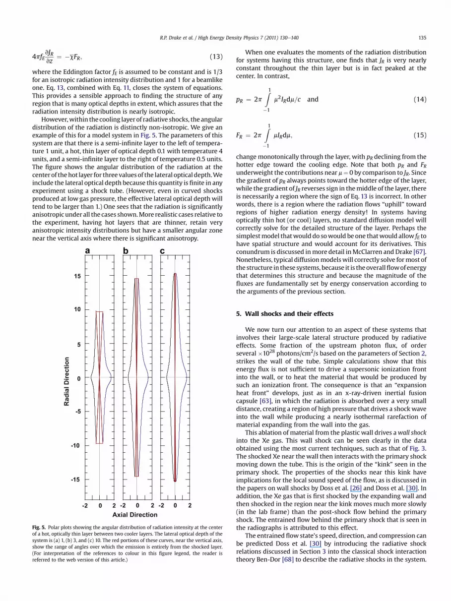
However,within the cooling layerof radiative shocks, the angulardistribution of the radiation is distinctly non-isotropic. We give anexample of this for a model system in Fig. 5. The parameters of thissystem are that there is a semi-infinite layer to the left of tempera-ture 1 unit, a hot, thin layer of optical depth 0.1 with temperature 4units, and a semi-infinite layer to the right of temperature 0.5 units.The figure shows the angular distribution of the radiation at thecenterof thehot layer for three valuesof the lateral optical depth.Weinclude the lateral optical depth because this quantity is finite in anyexperiment using a shock tube. (However, even in curved shocksproduced at low gas pressure, the effective lateral optical depth willtend to be larger than 1.) One sees that the radiation is significantlyanisotropic under all the cases shown.More realistic cases relative tothe experiment, having hot layers that are thinner, retain veryanisotropic intensity distributions but have a smaller angular zonenear the vertical axis where there is significant anisotropy.
-15
-10
-5
0
5
10
15
-2 0 2 -2 0 2 -2 0 2
Axial Direction
Rad
ial D
irectio
n
a b c
Fig. 5. Polar plots showing the angular distribution of radiation intensity at the centerof a hot, optically thin layer between two cooler layers. The lateral optical depth of thesystem is (a) 1, (b) 3, and (c) 10. The red portions of these curves, near the vertical axis,show the range of angles over which the emission is entirely from the shocked layer.(For interpretation of the references to colour in this figure legend, the reader isreferred to the web version of this article.)
When one evaluates the moments of the radiation distributionfor systems having this structure, one finds that JR is very nearlyconstant throughout the thin layer but is in fact peaked at thecenter. In contrast,
pR ¼ 2pZ1�1
m2IRdm=c and (14)
FR ¼ 2pZ1�1
mIRdm; (15)
change monotonically through the layer, with pR declining from thehotter edge toward the cooling edge. Note that both pR and FRunderweight the contributions near m¼ 0 by comparison to JR. Sincethe gradient of pR always points toward the hotter edge of the layer,while the gradient of JR reverses sign in themiddle of the layer, thereis necessarily a regionwhere the sign of Eq. 13 is incorrect. In otherwords, there is a region where the radiation flows “uphill” towardregions of higher radiation energy density! In systems havingoptically thin hot (or cool) layers, no standard diffusion model willcorrectly solve for the detailed structure of the layer. Perhaps thesimplestmodel thatwoulddo sowould be one thatwould allow fE tohave spatial structure and would account for its derivatives. Thisconundrum is discussed inmore detail inMcClarren and Drake [67].Nonetheless, typical diffusionmodelswill correctly solve formost ofthe structure in these systems, because it is theoverallflowof energythat determines this structure and because the magnitude of thefluxes are fundamentally set by energy conservation according tothe arguments of the previous section.
5. Wall shocks and their effects
We now turn our attention to an aspect of these systems thatinvolves their large-scale lateral structure produced by radiativeeffects. Some fraction of the upstream photon flux, of orderseveral �1028 photons/cm2/s based on the parameters of Section 2,strikes the wall of the tube. Simple calculations show that thisenergy flux is not sufficient to drive a supersonic ionization frontinto the wall, or to heat the material that would be produced bysuch an ionization front. The consequence is that an “expansionheat front” develops, just as in an x-ray-driven inertial fusioncapsule [63], in which the radiation is absorbed over a very smalldistance, creating a region of high pressure that drives a shockwaveinto the wall while producing a nearly isothermal rarefaction ofmaterial expanding from the wall into the gas.
This ablation of material from the plastic wall drives awall shockinto the Xe gas. This wall shock can be seen clearly in the dataobtained using the most current techniques, such as that of Fig. 3.The shocked Xe near thewall then interacts with the primary shockmoving down the tube. This is the origin of the “kink” seen in theprimary shock. The properties of the shocks near this kink haveimplications for the local sound speed of the flow, as is discussed inthe papers on wall shocks by Doss et al. [26] and Doss et al. [30]. Inaddition, the Xe gas that is first shocked by the expanding wall andthen shocked in the region near the kink moves much more slowly(in the lab frame) than the post-shock flow behind the primaryshock. The entrained flow behind the primary shock that is seen inthe radiographs is attributed to this effect.
The entrained flow state’s speed, direction, and compression canbe predicted Doss et al. [30] by introducing the radiative shockrelations discussed in Section 3 into the classical shock interactiontheory Ben-Dor [68] to describe the radiative shocks in the system.

R.P. Drake et al. / High Energy Density Physics 7 (2011) 130e140136
Fig. 6 shows graphically the procedure by which the entrained flowstate is obtained. The plot is in the space of shock pressure-deflection polars, in which one may qualitatively compare theshape of the non-radiative (usual) wall shock and the (unusual,concave) radiative shocks. The shock polars describe possible statesof flow passing through (1) the primary radiative shock of thesystem and (2) the wall shock and, subsequently, the deflectedradiative shock between the kink and the wall. The pressure andflow deflections must be equivalent in these two cases, though theoverall speed and other state variables may be different and canalso be found through this method. Accordingly, in Fig. 6, theentrained flow state is the leftmost intersection of two of the shockpolars. The predictions of this angle using this method match wellwith the data.
6. Simulation of driven radiative shocks
Our Center for Radiative Shock Hydrodynamics has been fundedto model these experimental radiative shocks and to assess thepredictive capability of the model. To do this, we have modified theEulerian, adaptive BATSRUS numerical simulation code [69e71],which solves a nonlinear system of conservation laws and has goodparallel scaling. The equations can be written as
vWvt
þ ðV$GÞT ¼ S; (16)
whereW and S are state and source vectors, while G a flux dyad. Fora given problem, all quantities are normalized with the help ofphysical quantities appropriate to the problem. The physicalquantities include time t, position vector r, mass density, bulk flowvelocity, total pressure, and total fluid internal energy density e. Forthe work on radiative shocks, we take
W ¼
0BB@
rru
eþ 12ru2
ee
1CCA; (17)
Fig. 6. Shock polars showing the locus of possible flow states achievable by passingthrough shocks in the space of pressure P (relative to upstream pressure) and flowdirection q (relative to axial flow). The polars shown are conditioned on themeasurement (right red marker) of flow immediately downstream of the wall shockand are used to predict the state of the entrained flow immediately downstream of thekink leftmost intersection of “radiative shock” and “deflected radiative shock” polars,with the measurement (left red marker and error bars) of this angle. The data shownon this plot comes from Omega Shot 52665, calculated with g ¼ 1.55 and a primaryshock speed of 110 km/sec. (For interpretation of the references to colour in this figurelegend, the reader is referred to the web version of this article.)
0 ruruuþ pI
1
G ¼ BB@u�eþ 1
2ru2 þ p
�uee
CCA; and (18)
S ¼
0BB@
0�Srm
V:ðCeVTeÞ � SreSe
1CCA: (19)
Here ee is the internal energy density of the electron fluid. Thisinternal energy affects the other hydrodynamic variables onlyindirectly through heat or radiation transport. The source vector Sinvolves the radiation-electron momentum exchange term Srm, theradiation-electron energy exchange term Sre, and electron heatconduction. We designate the code run with these specific equa-tions as CRASH.
In CRASH we treat the radiation implicitly and in steady state,reflecting the reality that the radiation reaches steady state ona timescale much faster than that of the hydrodynamic evolution.Fundamentally, we integrate the radiation transfer equation givenabove over some number of frequency photon groups (typically30), and solve a flux-limited radiation diffusion equation for eachphoton group. Then we integrate over the groups to obtain the netsource terms needed by the state equations just given. Specifically,one finds Sre by integrating the radiation transfer equation over allsolid angle and one finds Srm by taking the first moment of thisequation with direction of propagation. In S the coefficient ofelectron heat conduction is Ce. We ignore gravity, as is appropriatefor the present application. Note that as usual in radiation hydro-dynamics the electrons are assumed to be sufficiently coupled tothe ions that the two species move together on average, althoughtheir temperatures may differ as a result of the differences inheating and cooling mechanisms for the two species. The electronsare heated or cooled by compression, heat conduction, radiation,and collisional energy exchange with ions. The electron heat sourceinvolves the electron pressure pe and ion temperature Ti, and isgiven by
Se ¼ �peV$uþ V$ðCeVTeÞ � ðSre � Srm$uÞ þ rkBðTi � TeÞAmpsei
;
(20)
where mp is the nucleon mass, A the atomic weight, kB is theBoltzmann constant, and sei is the electroneion energy exchangetimescale.
These equations require equation-of-state (EOS) relationshipsbetween e and p; these also involve Ti and Te and depend upon theaverage charge state Z of the ions. To date we have assumed equi-librium Equation-of-State (EOS) and ionization relations, derivedfrom standard relations of statistical physics and from atomic dataand accounting for the behavior of electrons as Fermions [72]. Wethen can write e ¼ eðp; rÞ, Te ¼ Te(p, p), and Z ¼ Z(p, p). The coeffi-cients Ce and sei in the source terms, and the pressure, internalenergy, and temperature of the ions are then functions of knownparameters. The approach to material identity involves trackinga level-set function for each material. Each cell is identified withonly a single material (there are no mixed cells), relying uponadaptive mesh resolution (AMR) to obtain adequate accuracy in thisaspect. We likewise model the opacities self-consistently, based onthe same statistical models and atomic data. As is discussed inSokolov [72], this approach is an optimum one if one intends toquantify the uncertainties in the simulations, in spite of the factthat more ad hoc methods may provide the potential to tune theresults to better approximate some specific experimental data.

R.P. Drake et al. / High Energy Density Physics 7 (2011) 130e140 137
We are at present implementing a “laser package” to account forlaser energy deposition in a self-consistent way within a singlesimulation. In our work to date, however, we have used a two-dimensional, Lagrangian, radiation hydrodynamic code namedHyades [73] to evaluate the laser energy deposition and thebehavior of the experimental system until the end of the laser pulseat 1.1 ns. At that time, we have mapped the Hyades output onto theEulerian grid of CRASH and have run the evolution of the systemout to the observation times of various experiments (up to 26 ns).The CRASH code is run in 2Dwith a reflecting boundary on the tubeaxis and outflow boundary conditions at other boundaries.
Fig. 7 shows a representative output of our current simulations.This simulation was run in 2D with an effective resolution of4800 � 480 using two levels of mesh refinement, 30 radiationgroups from 0.1 eV to 20 keV, and all the physics discussed abovesave for the laser package. The coloring of the upper left plot showsthe material identity while the black lines show the locationswhere the mesh is dynamically refined, which are near materialinterfaces and the shock. Thematerials present on axis are Be (blue)and Xe (black). The wall includes gold (yellow), acrylic (red), andpolyimide (green). One can see in the density plot (upper right) thatthe polyimide portion of the wall is thin; in the simulation theregion outside this wall is modeled as polyimide at low density. Inthe density plot one can see the dense Xe in the primary shock andthe wall shock ahead of the primary shock. One can also see theentrained Xe extending near the radial wall. In the density andother variables, one can see shocked Xematerial clustering near theaxis and protruding beyond the average position of the primaryshock; we comment on this further below.
In the X velocity plot, one can see that at this time the highestvelocity fluid is in the material near the shock and that the veryhighest velocity is in the protrusion near the axis. The Y velocity
Fig. 7. Output at 13 ns of CRASH for the radiative shock experiment described in Section 2. Eaproviding the scale. All plots are functions of axial distance (X) and radial distance (R) as in
shows that material having the highest outward velocity is flowingoutward along the shock away from the axis while at smaller radiithere is some material flowing toward the axis. All the radialvelocities are small compared to the fastest axial velocity, as oneexpects. Both the electron and ion temperature show the localizedtemperature spike in the cooling layer just behind the shock front,discussed in Section 2. Note that the scales are different. They allowone to see that the FWHM of the ion temperature spike is smallerthan that of the electron temperature spike, as one expects. Thequantity shown as radiation temperature is based on the totalradiation energy density obtained by integrating over the energygroups. Because the cooling layer is optically thin there is no spikein the radiation temperature. This temperature decreases upstreamof the shock because of the loss of radiative energy into the walls,causing the ablation that creates the wall shock.
In the pressure plot at the lower right, one can likewise see thelayer of high pressure at the primary shock and the much lowerpressure associated with the wall shock. When one examines theevolution of the system in time, one finds that during the first fewns, the expansion of the wall material drives a radially inwardpressure pulse. This pressure pushes Be material to the axis,creating a pressure spike there that is connected with the emer-gence of material through the primary shock front near the axis. Inthe experimental data at this time (13 ns) there is no sign ofa concentration of material near the axis or of any materialprotruding through the primary shock. This protrusion has been anenduring feature to date of simulations using CRASH initialized byHyades, but has never yet been observed in the physical data.Extensive tests showed that numerical causes did not produce thiseffect and that it does not change significantly in three dimensionalsimulations. By modifying material properties such as the plasticopacity one can eliminate it, but this typically also eliminates the
ch plot shows a color map of the quantity designated above the plot, with the color bardicated, with distances given in microns.

Fig. 8. CRASH simulations of potential x-ray-driven experiments at Omega (170 eV)and NIF (300 eV). (a) and (b) show density and electron temperature for a 170 eV x-raydrive on a 30 mm Be disk, at 13 ns. (c) and (d) show density and electron temperaturefor a 300 eV x-ray drive on a 55 mm Be disk, at 5 ns. Both simulations had 1200 � 120resolution. All plots are functions of axial distance (X) and radial distance (R) asindicated, with distances given in mm.
R.P. Drake et al. / High Energy Density Physics 7 (2011) 130e140138
wall shock. It remains unclear at the present writing whether thisdifference between code and data is due to the conditions estab-lished by Hyades or to insufficient fidelity in CRASH. Both codes usemultigroup diffusion radiation transport, which will tend to deposittoo much energy in the wall. Comparison with results using theCRASH laser package will better illuminate the origins of thisdifference. In addition, note that in the radiograph of Fig. 3 at 26 ns,one does see a concentration of shocked Xe near the axis. This
suggests that an impulse directed toward the axismay be present inthe experiment, even if much weaker than predicted by thesimulations.
An alternative use of CRASH, that does not require input fromany other code, is to model systems driven by thermal x-rays. Onecan find conditions that produce a primary shock and a wall shockwithout producing material that protrudes through the primaryshock through the axis. One can even do this in a way that placesthe primary shock at the location where it is observed in theexperiments, although this proves to delicately depend on thedetails. The first two panels in Fig. 8 show the density and electrontemperature for this case. One can see the thin, hot, cooling layer inthe electron temperature, the primary shock in the density, and thewall shocks in both panels. The characteristic shock velocity for thiscase is w150 km/s. The overall morphology seen is very similar tothat shown in the laser-driven experiments of Fig. 3. One can alsomodel systems with much larger shock velocities, as might beobtained on NIF. This case is shown in the bottom two panels ofFig. 8. The characteristic shock velocity for this case is w300 km/s.Here the wall shocks have converged on the axis, leading to a jet ofBe and Xe that protrudes ahead of them.
The CRASH code has also proven useful in modeling potentialnew experiments designed to produce radiative reverse shocks, bycausing a sufficiently fast flowing plasma to impact a solid surface.Issues include what diameter to make the shock tube and whatradial structures will work best near the location of impact. Weused CRASH to model this system, arriving at a design that workedwell.
7. Conclusions
In the present paper we have discussed aspects of radiativeshocks in shock tubes. Simple estimates of this dynamics revealmany of the properties found by more complex theories andsimulations, including the creation of an optically thin cooling layer,of a dense shell of shocked material, and of secondary shocks fromthe tube wall ahead of the primary shock. In these systems, thekinetic energy entering the shock front provides the energy sourcefor the behavior of the shock. However, blackbody radiation at theimmediate postshock temperature would severely violate energybalance, and in response to this the system forms a cooling layer, ofvery small optical depth, through which the shocked matter coolsto a viable final state by radiating a significant fraction of theincoming energy. A simple analysis of these dynamics and theenergy balance establishes factor-of-two estimates of the finaltemperature and maximum compression.
At a next level of detail, theoretical models of the one-dimen-sional behavior reveal more clearly how aspects of the system areconnected. Examination of the fluid equations shows that the fluidcan access only unique states in which all of density, velocity,temperature, pressure, and radiation flux are determined. Aconsequence is that radiation transport cannot independentlycontrol any of these variables. For example, different models ofradiation transport cannot change the density and temperaturevalues that correspond to some specific net radiation flux. A closerexamination of the radiation transport finds a remarkable propertyof these shocks, which is that an Eddington diffusion model withfixed Eddington factor cannot correctly model the radiation trans-port, because the relation between the pressure gradient and thegradient of mean radiation intensity changes sign within thecooling layer while the radiation flux does not change sign. Fortu-nately for simulations, the errors introduced in the present contextbecause of this are small.
The radiation from the primary shock ablates the shock-tubewall ahead of it, causing expansion of the wall material that drives

R.P. Drake et al. / High Energy Density Physics 7 (2011) 130e140 139
a wall shock into the Xe gas in the tube. This wall shock interacts inturn with the primary shock, creating a deflected shock and a slip-stream interface that divides shocked Xe having different proper-ties. The angles among these shocks can serve as a diagnostic ofsome local plasma parameters. In addition, the Xe shocked by thewall shock ends up moving more slowly than the Xe that firststrikes the primary shock, creating an entrained shell of Xe behindthe primary shock.
We have simulated our base experimental system using animplementation of our code, designated CRASH, that solvesconservation equations in which the hydrodynamics is treatedexplicitly while the radiation and electron heat conduction aretreated implicitly. These simulations reproduce the qualitativedetails of the system anticipated from the fundamental analysisand provide an evaluation for the structure of the cooling layer, thestructure of the radiatively heated precursor ahead of the primaryshock, and the detailed behavior of the walls that cannot beobtained from simple estimates. The simulations produce effectsnear the axis of the shock tube that are not observed in theexperiments; their origin remains under exploration.
In future work, we intend to extend this type of experimentalsystem to work with structures that are inherently three dimen-sional, such as elliptical shock tubes. This will create a morecomplex interplay of radiation and hydrodynamics andwill providedemanding tests of three dimensional radiation hydrodynamicsimulations. We also intend to continue the work with radiativereverse shocks mentioned briefly above. Beyond that, it would be ofparticular interest to develop an experimental system in which theinherent errors in typical Eddington diffusion models of opticallythin hot or cool layers had substantial consequences.
Acknowledgments
This work was funded by the Predictive Sciences AcademicAlliances Program in DOE/NNSA-ASC via grant DEFC52-08NA28616, by the DOE/NNSA-DS and DOE/SC-OFES Joint Programin High-Energy-Density Laboratory Plasmas, grant number DE-FG52-09NA29548, by the National Laser User Facility Program,grant number DE-FG52-09NA29034, by previous DOE grants andcontracts, and by the University of Michigan.
References
[1] D.D. Ryutov, R.P. Drake, J. Kane, E. Liang, B.A. Remington, M. Wood-Vasey,Similarity criteria for the laboratory simulation of supernova hydrodynamics,Astrophys. J. 518 (1999) 821.
[2] L. Ensman, A. Burrows, Shock breakout in sn 1987a, Astrophys. J. 393 (1992)742e755.
[3] C. Fransson, P. Lundqvist, R.A. Chevalier, Circumstellar interaction in sn 1993j,Astrophys. J. 461 (1996) 993e1008.
[4] T.K. Nymark, C. Fransson, C. Kozma, X-ray emission from radiative shocks intype ii supernovae, Astron. Astrophyhs 449 (2006) 171e192.
[5] K.J. Borkowski, J.M. Blondin, R. McCray, X-rays from the impact of sn1987awith its circumstellar ring, Astrophys. J. 477 (1997) 281e293.
[6] J.M. Blondin, E.B. Wright, K.J. Borkowski, S.P. Reynolds, Transition to theradiative phase in supernova remnants, Astrophys. J. 500 (1998) 342e354.
[7] B. Reipurth, J. Bally, Herbig-haro flows: probes of early stellar evolution, Ann.Rev. Astron, Astrophys 39 (2001) 403e455.
[8] J.C. Bozier, G. Thiell, J.P. Le-Breton, S. Azra, M. Decroisette, D. Schirmann,Experimental observation of the radiative wave generated in xenon by a laser-driven supercritical shock, Phys. Rev. Lett. 57 (1986) 1304e1307.
[9] P.A. Keiter, R.P. Drake, T.S. Perry, H.F. Robey, B.A. Remington, C.A. Iglesias,R.J. Wallace, J. Knauer, Observation of a hydrodynamically-driven, radiative-precursor shock, Phys. Rev. Lett. 89 (2002) 1e4 165003/.
[10] M. Koenig, A. Benuzzi-Mounaix, N. Grandjouan, V. Malka, S. Bouquet, X.Fleury, B. Marchet, C. Stehle, S. Leygnac, C. Michaut, J.P. Chieze, D. Batani, E.Henry, T. Hall, Radiative shock experiment using high power laser, in: M.D.Furnish, Y. Horie, N.N. Thadhani (Eds.), Shock Compression of CondensedMatter 2001, vol. 620, pt. 2 of AIP Conference Proceedings, American Instituteof Physics, New York, Atlanta, Georgia, USA, 2002, pp. 1367e1370.
[11] X. Fleury, S. Bouquet, C. Stehl, M. Koenig, D. Batani, A. Benuzzi-Mounaix,J.P. Chize, N. Grandjouan, J. Grenier, T. Hall, E. Henry, J.P. Lafon, S. Leygnac,V. Malka, B. Marchet, H. Merdji, C. Michaut, F. Thais, A laser experiment forstudying radiative shocks in astrophysics, Laser Part, Beams20 (2002) 263e268.
[12] A.B. Reighard, R.P. Drake, K.K. Danneberg, D.J. Kremer, T.S. Perry,B.A. Remington, R.J. Wallace, D.D. Ryutov, J. Greenough, J. Knauer, T. Boehly,S. Bouquet, A. Calder, R. Rosner, B. Fryxell, D. Arnett, M. Koenig,N. Grandjouan, Collapsing radiative shocks in xenon gas on the omega laser.in: B.A. Hammel, D.D. Meyerhofer, J. Meyer-ter Vehn, H. Azechi (Eds.), InertialFusion and Science Applications. American Nuclear Society, New York, Mon-terey, CA, 2003, pp. 950e953.
[13] L. Boireau, C. Clique, S. Bouquet, Radiative shocks in low-pressure gases. in:B.A. Hammel, D.D. Meyerhofer, J. Meyer-ter Vehn, H. Azechi (Eds.), InertialFusion Science and Applications. American Nuclear Society, New York, Mon-terey, CA, 2003, pp. 966e969.
[14] T.W.L. Sanford, R.C. Mock, S.A. Slutz, D.L. Peterson, Length scaling of dynamic-hohlraum axial radiation, Phys. Plasmas 10 (2003) 4790e4799.
[15] S. Bouquet, C. Stehl, M. Koenig, J.P. Chize, A. Benuzzi-Mounaix, D. Batani,S. Leygnac, X. Fleury, H. Merdji, C. Michaut, F. Thais, N. Grandjouan, T. Hall,E. Henry, V. Malka, J.P.J. Lafon, Observations of laser driven supercriticalradiative shock precursors, Phys. Rev. Lett. 92 (2004) 225001e225004.
[16] R.P. Drake, Radiative shocks in astrophysics and the laboratory, Astrophys.Space Sci. 298 (2005) 49e59.
[17] M. Koenig, T. Vinci, A. Benuzzi-Mounaix, S. Lepape, N. Ozaki, S. Bouquet,L. Boireau, S. Leygnac, C. Michaut, C. Stehle, J.P. Chieze, D. Batani, T. Hall,K. Tanaka, M. Yoshida, Radiative shock experiments at luli, Astrophys. SpaceSci. 298 (2005) 69e74.
[18] T. Vinci, M. Koenig, A. Benuzzi-Mounaix, L. Boireau, S. Bouquet, S. Leygnac,C. Michaut, C. Stehle, O. Peyrusse, D. Batani, Density and temperaturemeasurements on laser generated radiative shocks, Astrophys. Space Sci. 298(2005) 333e336.
[19] A.B. Reighard, R.P. Drake, K.K. Dannenberg, D.J. Kremer, E.C. Harding,D.R. Leibrandt, S.G. Glendinning, T.S. Perry, B.A. Remington, J. Greenough,J. Knauer, T. Boehly, S. Bouquet, L. Boireau, M. Koenig, T. Vinci, Collapsingradiative shocks in xenon on the omega laser, Phys. Plasma 13 (2006) 082901.
[20] T. Vinci, M. Koenig, A. Benuzzi-Mounaix, C. Michaut, L. Boireau, S. Leygnac,S. Bouquet, O. Peyrusse, D. Batani, Temperature and electron densitymeasurements on laser driven radiative shocks, Phys. Plasma 13 (2006)010702.
[21] M. Koenig, T. Vinci, A. Benuzzi-Mounaix, N. Ozaki, A. Ravasio, M.R.l. Glohaec,L. Boireau, C. Michaut, S. Bouquet, S. Atzeni, A. Schiavi, O. Peyrusse, D. Batani,Radiative shocks: An opportunity to study laboratory astrophysics, Phys.Plasmas 13 (2006) 056504.
[22] A.B. Reighard, R.P. Drake, J.E. Mucino, J.P. Knauer, M. Busquet, Planar radiativeshock experiments and their comparison to simulations, Phys. Plasma 14(2007) 056504e056508.
[23] A.B. Reighard, R.P. Drake, The formation of a cooling layer in a partiallyoptically thick shock, Astrophys, Space Sci. 307 (2007) 121e125.
[24] C. Michaut, T. Vinci, L. Boireau, M. Koenig, S. Bouquet, A. Benuzzi-Mounaix,N. Osaki, G. Herpe, E. Falize, B. Loupias, S. Atzeni, Theoretical and experimentalstudies of radiative shocks, Astrophys. Space Sci. 307 (2007) 159e164.
[25] M. Busquet, E. Audit, M. Gonzalez, C. Stehle, F. Thais, O. Acef, D. Bauduin,P. Barroso, B. Rus, M. Kozlova, J. Polan, T. Mocek, Effect of lateral radiativelosses on radiative shock propagation, High Energy Density Phys. 3 (2007)8e11.
[26] F.W. Doss, H.F. Robey, R.P. Drake, C.C. Kuranz, Wall shocks in high-energy-density shock tube experiments, Phys. Plasma 16 (2009) 112705.
[27] M. Gonzalez, E. Audit, C. Stehle, 2d numerical study of the radiation influenceon shock structure relevant to laboratory astrophysics, A&A 497 (2009)27e34.
[28] F.W. Doss, R.P. Drake, C.C. Kuranz, Repeatability in radiative shock tubeexperiments, High Energy Density Phys. 6 (2010) 157e161.
[29] F.W. Doss, C.C. Kuranz, R.P. Drake, Statistical inference in the presence of aninclination effect in laboratory radiative shock experiments, Astrophys, SpaceSci (2011) in press.
[30] F.W. Doss, R.P. Drake, E.S. Myra, Oblique radiative shocks, including theirinteractions with non-radiative polytropic shocks, Physics of Plasmas, inpress.
[31] J. Grun, J. Stamper, C. Manka, J. Resnick, R. Burris, J. Crawford, B.H. Ripin,Instability of taylor-sedov blast waves propagating through a uniform gas,Phys. Rev. Lett. 66 (1991) 2738e2741.
[32] J.M. Laming, J. Grun, Dynamical overstability of radiative blast waves: Theatomic physics of shock stability,, Phys. Rev. Lett. 89 (2002) 125002e125005.
[33] J.F. Hansen, M.J. Edwards, D.H. Froula, A.D. Edens, G. Gregori, T. Ditmire,Secondary shock formation in xenon-nitrogen mixtures, Physic. Plasma 13(2006).
[34] J.F. Hansen, M.J. Edwards, D.H. Froula, A.D. Edens, G. Gregori, T. Ditmire,Laboratory observation of secondary shock formation ahead of a stronglyradiative blast wave, Astrophys. Space Sci. 307 (2007) 219e225.
[35] M.J. Edwards, A.J. MacKinnon, J. Zweiback, K. Shigemori, D.D. Ryutov,A.M. Rubenchik, K.A. Keitlty, E. Liang, B.A. Remington, T. Ditmire, Investigationof ultrafast laser-driven radiative blast waves, Phys. Rev. Lett. 87 (2001)085004e1e085004e4.
[36] A.S. Moore, E.T. Gumbrell, J. Lazarus, M. Hohenberger, J.S. Robinson,R.A. Smith, T.J.A. Plant, D.R. Symes, M. Dunne, Full-trajectory diagnosis of
R.P. Drake et al. / High Energy Density Physics 7 (2011) 130e140140
laser-driven radiative blast waves in search of thermal plasma instabilities,Phys. Rev. Lett. 100 (2008).
[37] M. Hohenberger, D.R. Symes, J. Lazarus, H.W. Doyle, R.E. Carley, A.S. Moore,E.T. Gumbrell, M.M. Notley, R.J. Clarke, M. Dunne, R.A. Smith, Observation ofa velocity domain cooling instability in a radiative shock, Phys. Rev. Lett. 105(2010).
[38] D.R. Symes, M. Hohenberger, J. Lazarus, J. Osterhoff, A.S. Moore, R.R. Faustlin,A.D. Edens, H.W. Doyle, R.E. Carley, A. Marocchino, J.P. Chittenden,A.C. Bernstein, E.T. Gumbrell, M. Dunne, R.A. Smith, T. Ditmire, Investigationsof laser-driven radiative blast waves in clustered gases, High Energy DensityPhys. 6 (2010) 274e279.
[39] I.B. Zel'dovich, Shock waves of large amplitude in air, Soviet Phys. JETP 5(1957) 919.
[40] Y.P. Raizer, On the structure of the front of strong shock waves in gases, SovietPhys. JETP 5 (1957) 1242e1248.
[41] C. Michaut, E. Falize, C. Cavet, S. Bouquet, M. Koenig, T. Vinci, A. Reighard,R.P. Drake, Classification of and recent research involving radiative shocks,Astrophys. Space Sci. 322 (2009) 77e84.
[42] Y.B. Zeldovich, Y.P. Razier, Physics of Shock Waves and High-temperatureHydrodynamic Phenomena. Academic Press, New York, dover, 2002, vol.1edition, 1966.
[43] D. Mihalas, B. Weibel-Mihalas, Foundations of Radiation Hydrodynamics.Oxford University Press, Oxford, dover, 1999, vol. 1edition, 1984.
[44] A.V. Farnsworth, J.H. Clarke, Radiatively and collisionally structured shockwaves exhibiting large emission-convection ratio, Phys. Fluids 14 (1971)1352e1360.
[45] R.I. Klein, R.F. Stein, W. Kalkofen, Radiative shock dynamics. i. the Lymancontinuum, Astrophys. J. 205 (1976) 499e519.
[46] R.I. Klein, R.F. Stein, W. Kalkofen, Radiative shock dynamics. II. Hydrogencontinua, Astrophys. J. 220 (1978) 1024e1040.
[47] E. Bertschinger, On the structure and stability of radiative shock waves,Astrophys. J. 304 (1986) 154e177.
[48] S. Bouquet, R. Teyssier, J.P. Chieze, Analytical study and structure ofa stationary radiative shock, Astrophys, J. Suppl. 127 (2000) 245e252.
[49] R.P. Drake, Theory of radiative shocks in optically thick media, Phys. Plasma14 (2007a) 043301e043310.
[50] R.P. Drake, Energy balance and structural regimes of radiative shocks inoptically thick media, IEEE Trans. Plasma Sci. 35 (2007) 171e180.
[51] R.B. Lowrie, R.M. Rauenzahn, Radiative shock solutions in the equilibriumdiffusion limit, Shock Waves 16 (2007) 445e453.
[52] R.B. Lowrie, J.D. Edwards, Radiative shock solutions with grey nonequilibriumdiffusion, Shock Waves 18 (2008) 129e143.
[53] R.A. Chevalier, J.C. Theys, Optically thin radiating shock waves and theformation of density inhomogeneities, Astrophys. J. 195 (1975) 53e60.
[54] F.H. Shu, The Physics of Astrophysics: Gas Dynamics. University ScienceBooks, Mill Valley, CA, 1992, vol. II.
[55] R.A. Chevalier, J.N. Imamura, Linear-analysis of an oscillatory instability ofradiative shock-waves, Astrophys. J. 261 (1982) 543e549.
[56] D.E. Innes, J.R. Giddings, S.A.E.G. Falle, Dynamical models of radiative shocks,II. Unsteady shocks, MNRAS 226 (1987) 67e93.
[57] R.G. McClarren, R.P. Drake, M.L. Adams, J.E. Morel, J.P. Holloway, Theory ofradiative shocks in the mixed, optically thick-thin case, Phys. Plasma 17(2010) 093301.
[58] J.P. Holloway, D. Bingham, C.C. Chou, F.W. Doss, R.P. Drake, B. Fryxell,M.J. Grosskopf, B.v.d. Holst, B. Mallick, R.G. McClarren, A. Mukherjee, V. Nair,K.G. Powell, D. Ryu, I. Sokolov, G. Toth, Z. Zhang, Predictive modeling ofa radiative shock system, Reliab. Eng. Syst. Saf., in press.
[59] R.G. McClarren, D. Ryu, R.P. Drake, M.J. Grosskopf, D. Bingham, C.C. Chou, B.Fryxell, B.v.d. Holst, J.P. Holloway, C.C. Kuranz, B. Mallick, E. Rutter,B.R. Torralva, A physics informed emulator for laser-driven radiating shocksimulations, Reliab. Eng. Syst. Saf., in press.
[60] M.J. Grosskopf, D.C. Marion, R.P. Drake, C.C. Kuranz, F.W. Doss, A.J. Visco,C.M. Huntington, C.A. Krauland, C.A. Di Stefano, E.C. Harding, Target fabrica-tion at the University of Michigan, Fus. Sci. Technol 59 (2011) 250e256.
[61] C.C. Kuranz, B.E. Blue, R.P. Drake, H.F. Robey, J.F. Hansen, J.P. Knauer,M.J. Grosskopf, C. Krauland, D.C. Marion, Dual, orthogonal, backlit pinholeradiography in omega experiments, Rev. Sci. Inst 77 (2006) 1e4 10E327.
[62] T.R. Boehly, R.S. Craxton, T.H. Hinterman, J.H. Kelly, T.J. Kessler, S.A. Kumpman,S.A. Letzring, R.L. McCrory, S.F.B. Morse, W. Seka, S. Skupsky, J.M. Soures,C.P. Verdon, The upgrade to the omega laser system,, Rev. Sci. Intsr 66 (1995)508e510.
[63] R.P. Drake, High Energy Density Physics: Fundamentals, Inertial Fusion andExperimental Astrophysics. Springer, Verlag, 2006.
[64] E.T. Vishniac, The dynamic and gravitational instabilities of spherical shocks,Astrophys. J. 274 (1983) 152e167.
[65] E. Ott, Nonlinear evolution of the Rayleigh-Taylor instability of a thin layer,Phys. Rev. Lett. 29 (1972) 1429e1432.
[66] F.W. Doss, Structure in Radiative Shock Experiemnts, Ph.D. thesis, Universityof Michigan, 2011.
[67] R.G. McClarrenR.P. Drake, Radiative transfer in the cooling layer of a radiatingshock, J. Quant. Spectrosc. Radiat. Transf 111 (2010) 2095e2105.
[68] G. Ben-Dor, Shock Wave Reflection Phenomena, second ed., Springer, 2007[69] K.G. Powell, P.L. Roe, T.J. Linde, T.I. Gombosi, D.L.D. Zeeuv, A solution-adaptive
upwind scheme for ideal magnetohydrodynamics,, J. Comput. Phys. 154(1999) 284e309.
[70] G. Toth, D. Kovacs, K.C. Hansen, T.I. Gombosi, Three-dimensional MHDsimulations of the magnetosphere of Uranus, J. Geophys. Res.-Space Phys. 109(2004) 0148e0227 A11210.
[71] B. van der Holst, G. Toth, I.V. Sokolov, K.G. Powell, J.P. Holloway, E.S. Myra, Q.Stout, M.L. Adams, J.E. Morel, R.P. Drake, A block-adaptive-mesh code forradiative shock hydrodynamics: Implementation and verification, Astrophys.J. Suppl. Ser., in press.
[72] I.V. Sokolov, R.P. Drake, A trivially correct model for equations of state andopacities, High Energy Density Phys., in preparation.
[73] J.T. Larsen, S.M. Lane, Hyades: a plasma hydrodynamics code for dense plasmastudies, J. Quant. Spectrosc. Radiat. Transf 51 (1994) 179e186.


