Embed Size (px)
Citation preview
IOWA MOLD TOOLING CO., INC.
P.O. Box 189Garner, IA 50438Tel: 641.923.3711
Fax: 641.923.2424www.imt.com
RCL 5300Error Codes
Manual 99906489
Revised: July 23, 2019
Copyright © 2019 Iowa Mold Tooling Co., Inc.All rights reserved
No part of this publication may be reproduced, stored in a retrieval system, or transmitted in any form or by any means, electronic, mechanical, photocopying, recording or otherwise without the prior written permission of Iowa Mold Tooling Co., Inc.
Iowa Mold Tooling Co., Inc. is an Oshkosh Corporation Company
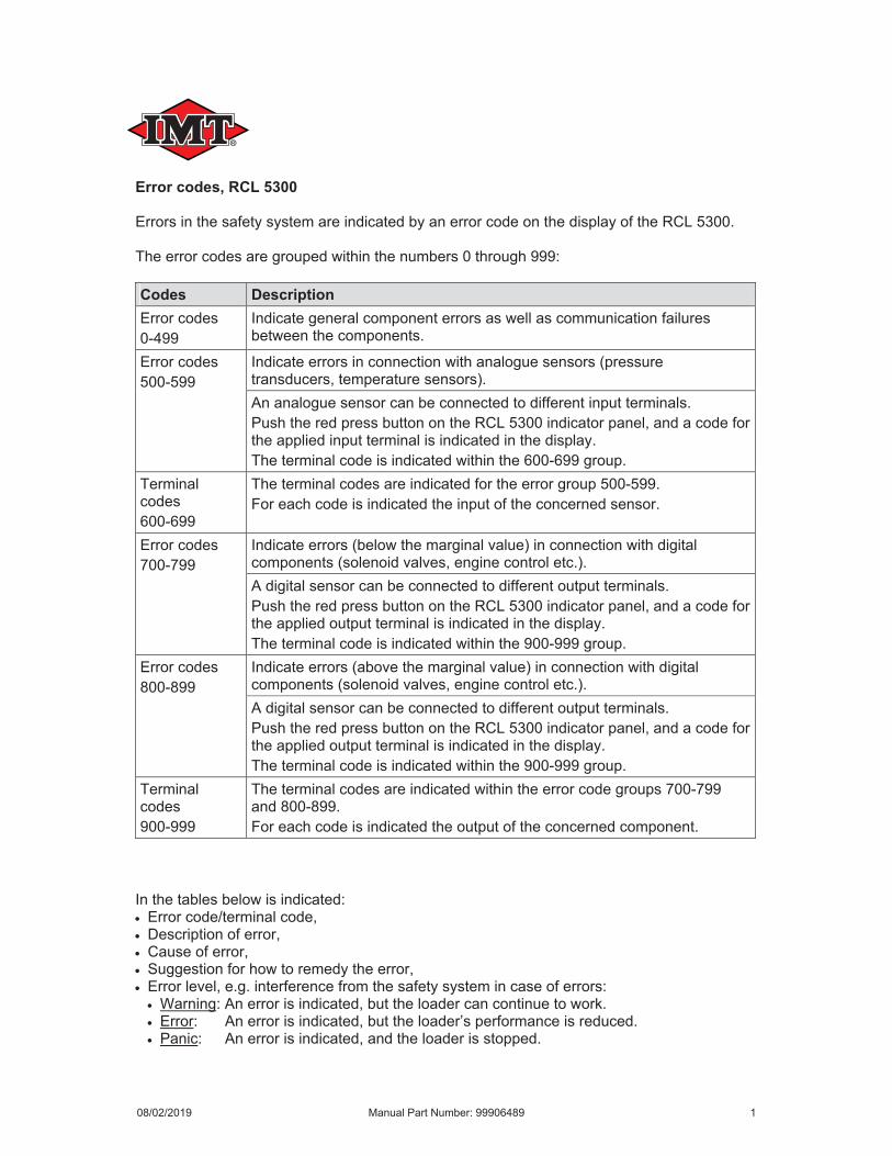
Error codes, RCL 5300
Codes Description
08/02/2019 Manual Part Number: 99906489 1
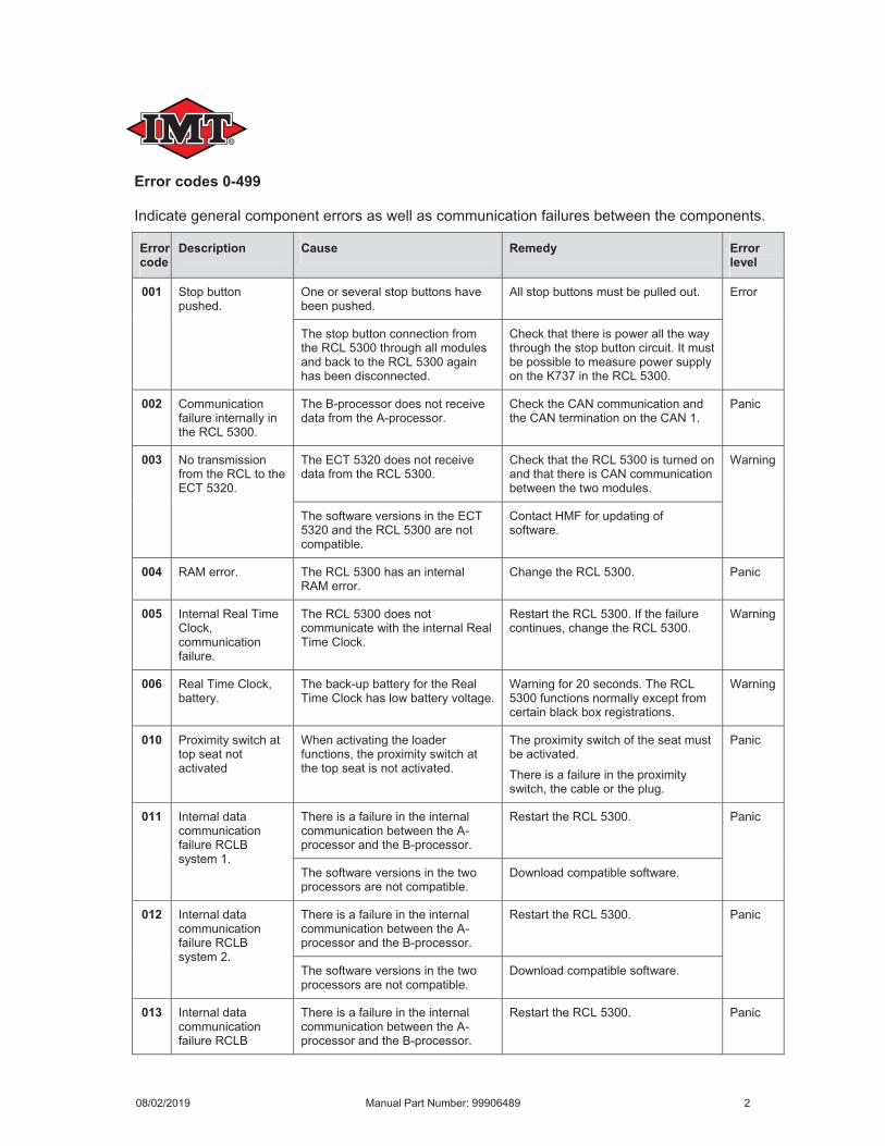
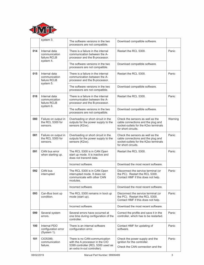
Error codes 0-499
Error code
Description Cause Remedy Error level
001
002
003
004
005
006
010
011
012
013
08/02/2019 Manual Part Number: 99906489 2
014
015
016
080
081
091
092
093
099
100
101
08/02/2019 Manual Part Number: 99906489 3
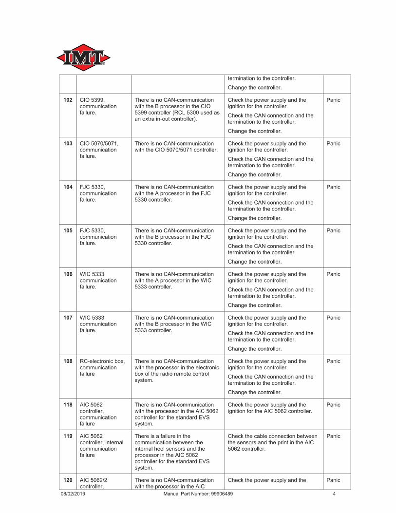
102
103
104
105
106
107
108
118
119
120
08/02/2019 Manual Part Number: 99906489 4
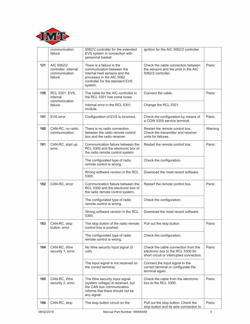
121
150
151
180
181
182
183
184
185
186
08/02/2019 Manual Part Number: 99906489 5
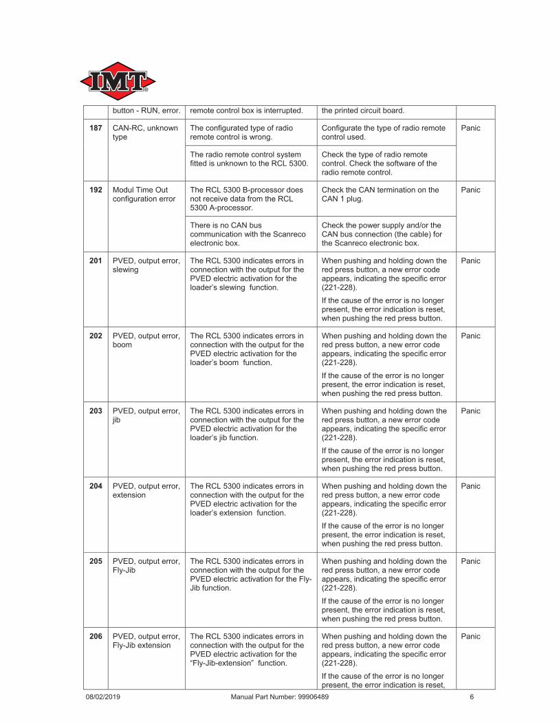
187
192
201
202
203
204
205
206
08/02/2019 Manual Part Number: 99906489 6
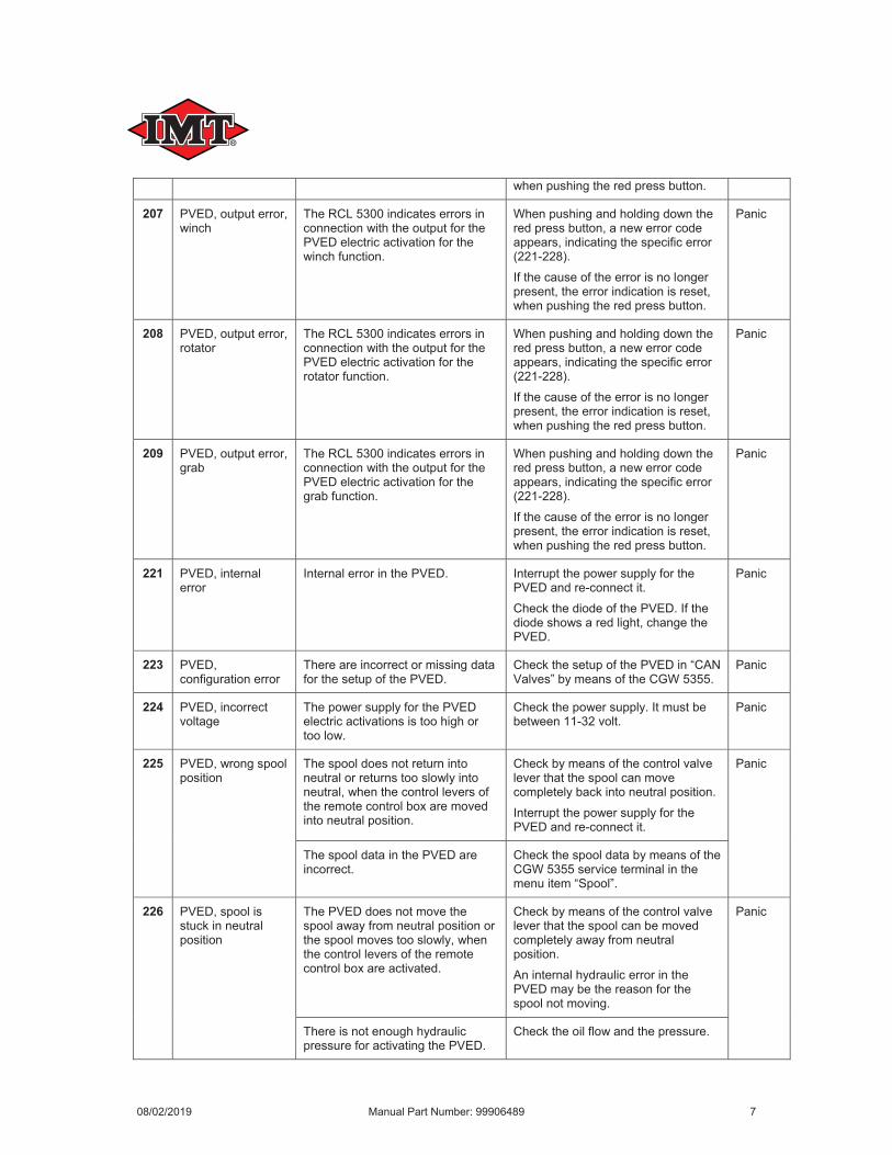
207
208
209
221
223
224
225
226
08/02/2019 Manual Part Number: 99906489 7
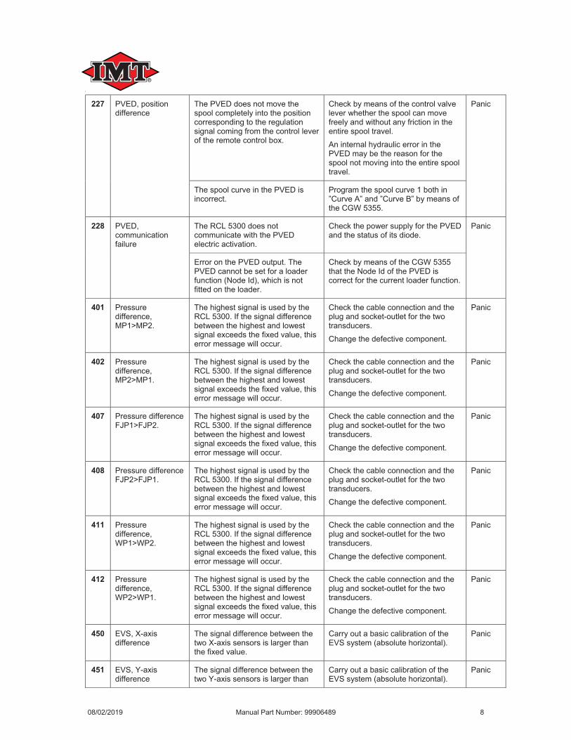
227
228
401
402
407
408
411
412
450
451
08/02/2019 Manual Part Number: 99906489 8
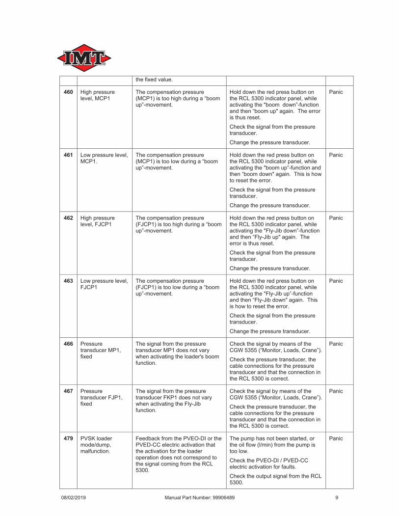
460
461
462
463
466
467
479
08/02/2019 Manual Part Number: 99906489 9
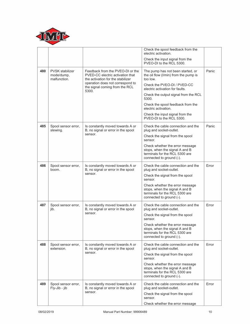
480
485
486
487
488
489
08/02/2019 Manual Part Number: 99906489 10
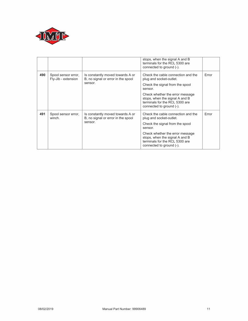
490
491
08/02/2019 Manual Part Number: 99906489 11
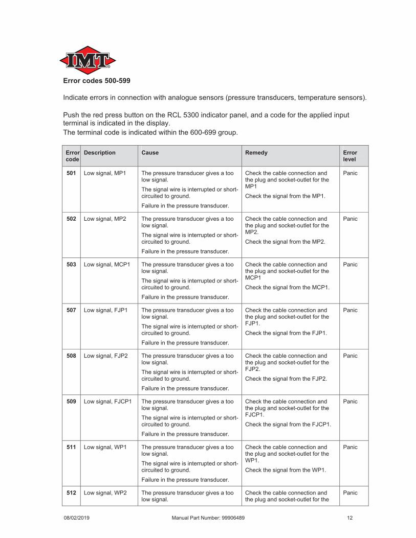
Error codes 500-599
Error code
Description Cause Remedy Error level
501
502
503
507
508
509
511
512
08/02/2019 Manual Part Number: 99906489 12
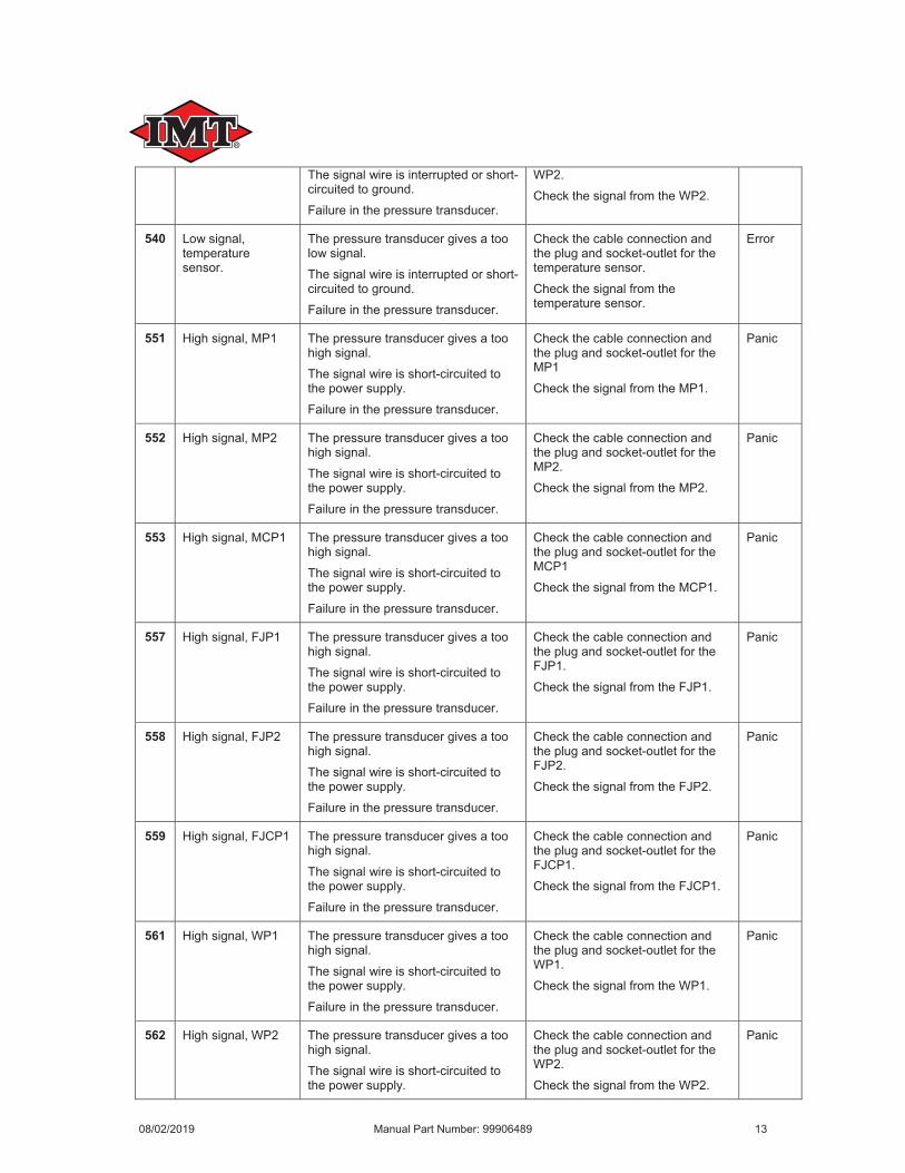
540
551
552
553
557
558
559
561
562
08/02/2019 Manual Part Number: 99906489 13
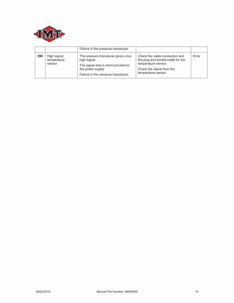
590
08/02/2019 Manual Part Number: 99906489 14
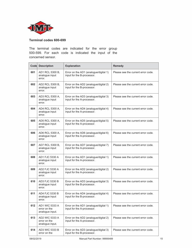
Terminal codes 600-699
Code Description Explanation Remedy
601
602
603
604
605
606
607
608
609
610
611
612
613
614
08/02/2019 Manual Part Number: 99906489 15
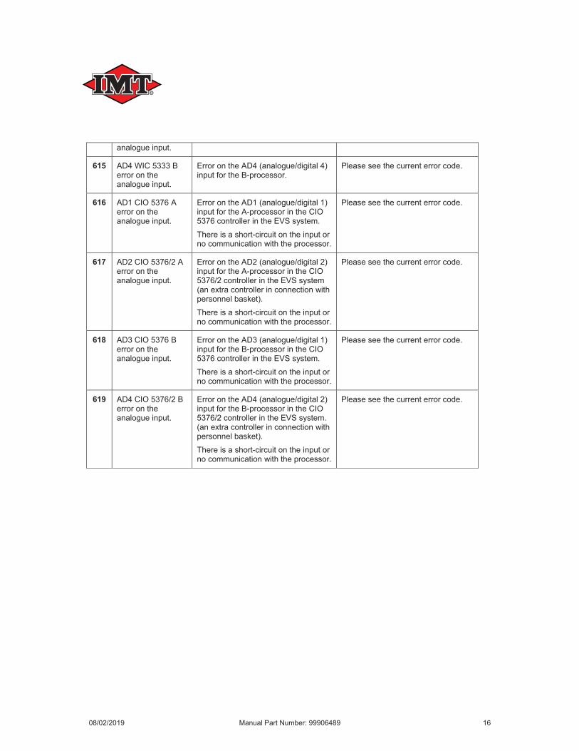
615
616
617
618
619
08/02/2019 Manual Part Number: 99906489 16
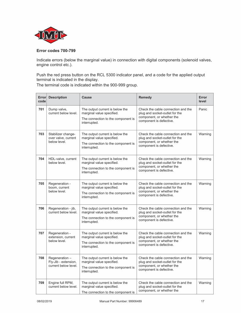
Error codes 700-799
Error code
Description Cause Remedy Error level
701
703
704
705
706
707
708
709
08/02/2019 Manual Part Number: 99906489 17
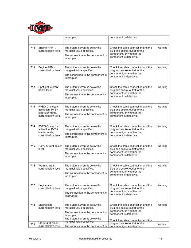
710
711
712
713
714
715
716
717
718
733
08/02/2019 Manual Part Number: 99906489 18
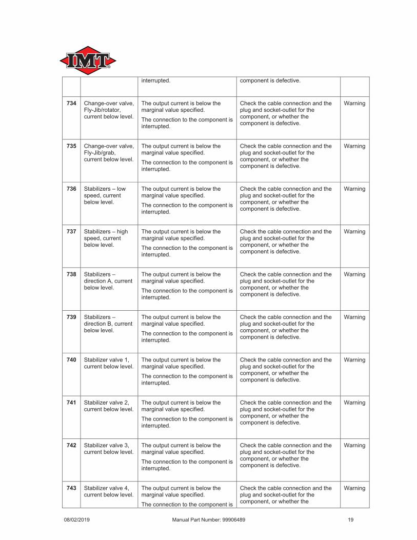
734
735
736
737
738
739
740
741
742
743
08/02/2019 Manual Part Number: 99906489 19

744
745
746
747
748
749
750
751
752
753
08/02/2019 Manual Part Number: 99906489 20
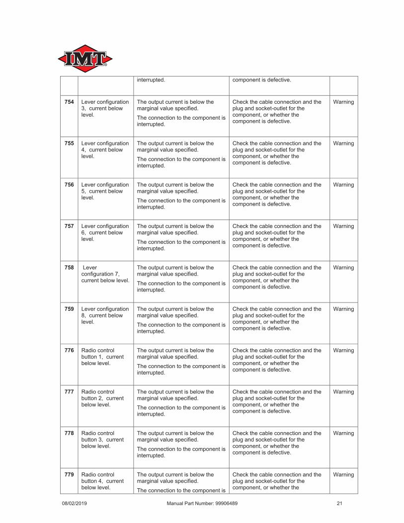
754
755
756
757
758
759
776
777
778
779
08/02/2019 Manual Part Number: 99906489 21

780
781
782
783
784
785
786
787
788
789
08/02/2019 Manual Part Number: 99906489 22
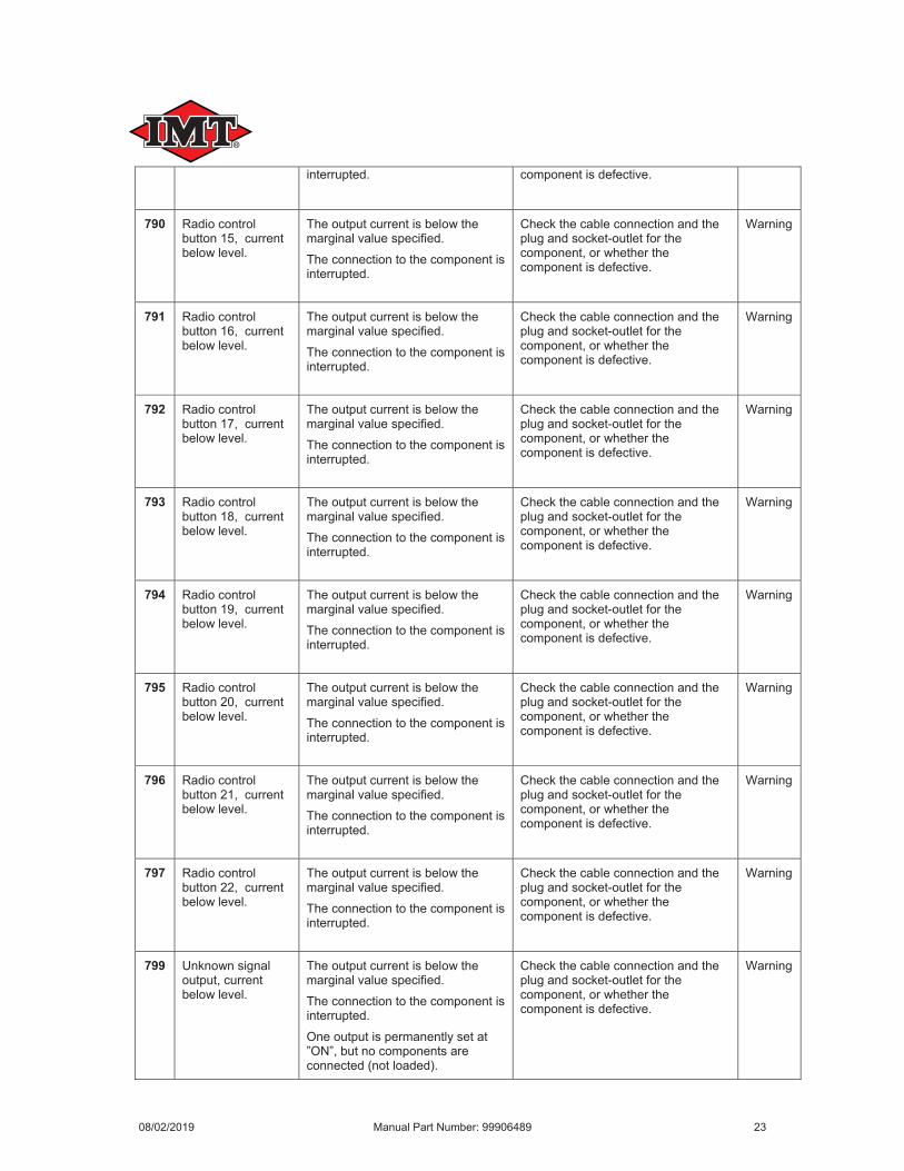
790
791
792
793
794
795
796
797
799
08/02/2019 Manual Part Number: 99906489 23
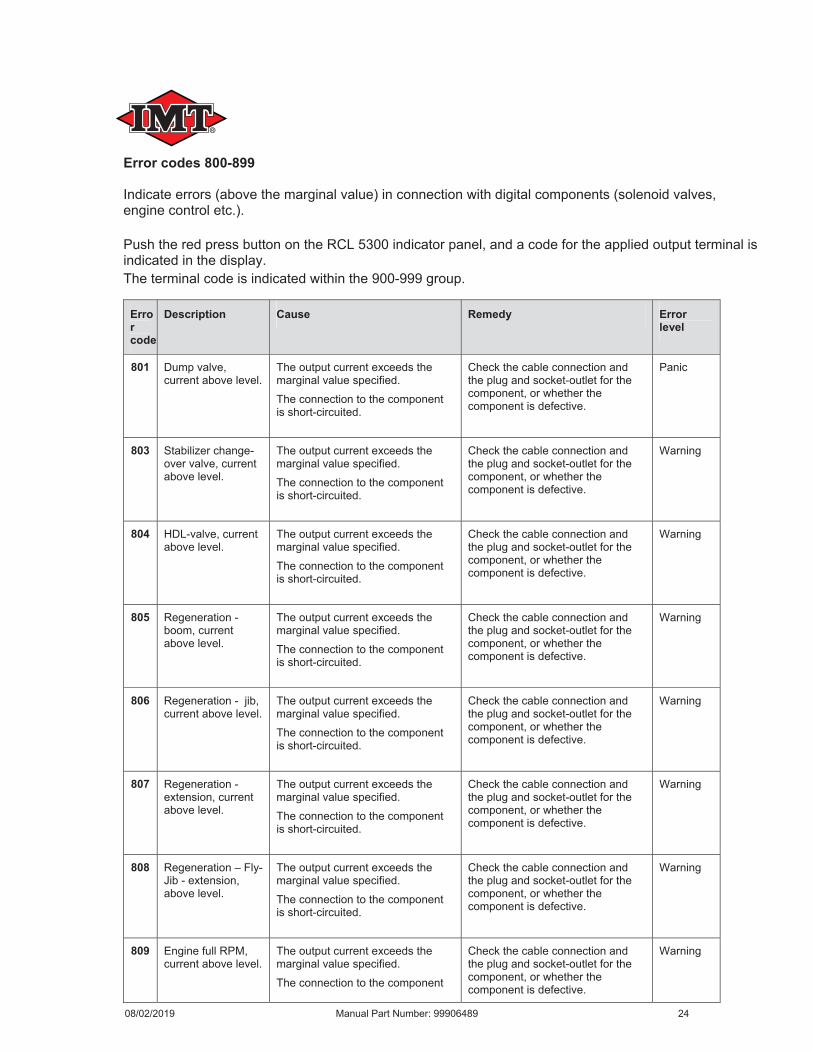
Error codes 800-899
Error code
Description Cause Remedy Error level
801
803
804
805
806
807
808
809
08/02/2019 Manual Part Number: 99906489 24
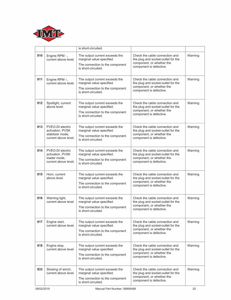
810
811
812
813
814
815
816
817
818
833
08/02/2019 Manual Part Number: 99906489 25

836
837
838
839
840
841
842
843
844
845
08/02/2019 Manual Part Number: 99906489 26
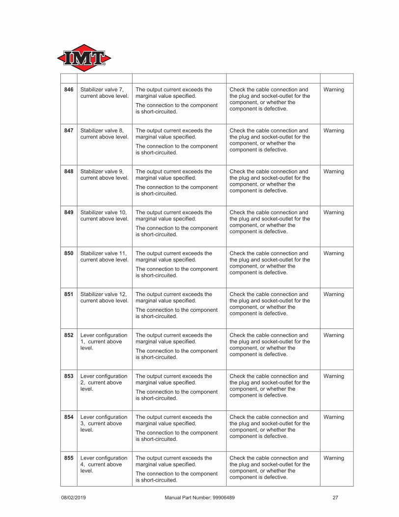
846
847
848
849
850
851
852
853
854
855
08/02/2019 Manual Part Number: 99906489 27
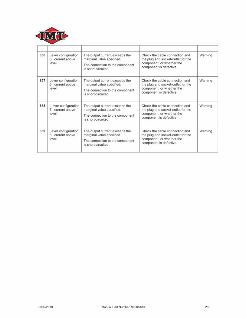
856
857
858
859
08/02/2019 Manual Part Number: 99906489 28
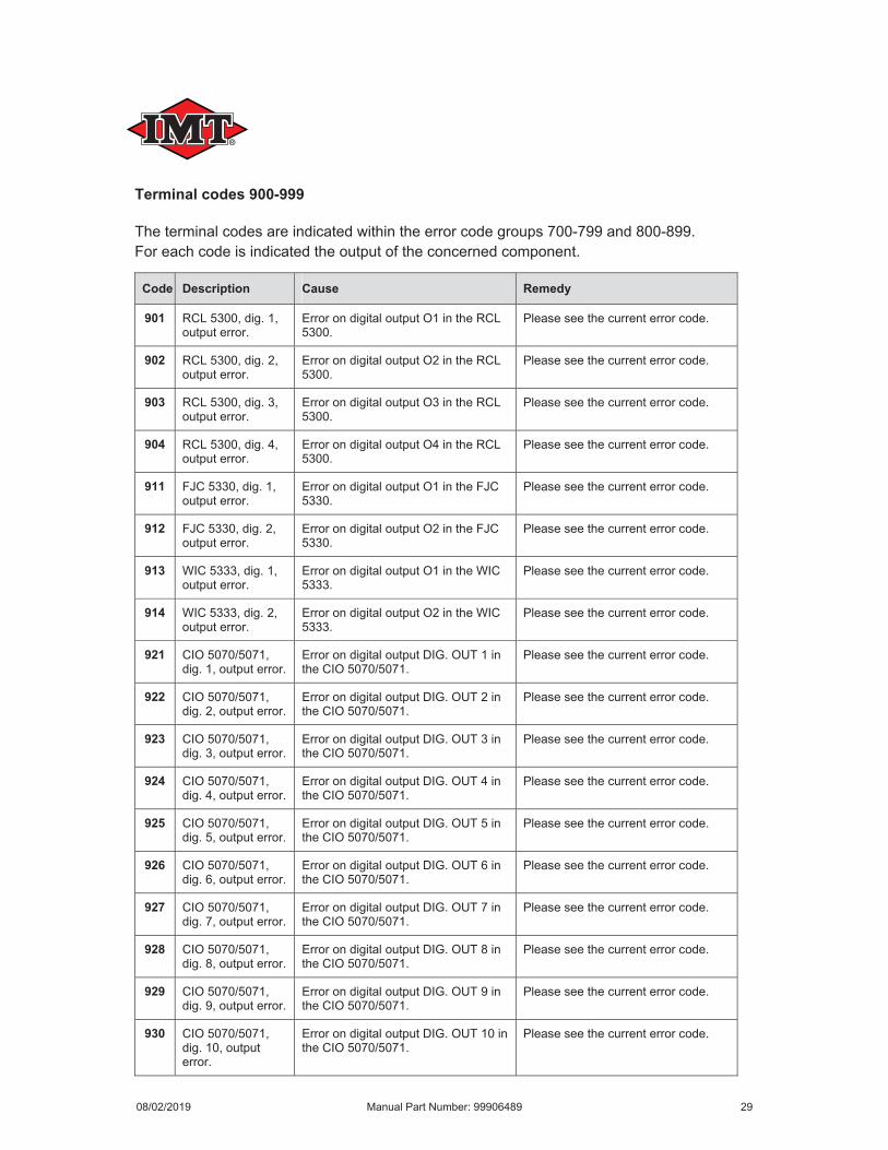
Terminal codes 900-999
Code Description Cause Remedy
901
902
903
904
911
912
913
914
921
922
923
924
925
926
927
928
929
930
08/02/2019 Manual Part Number: 99906489 29
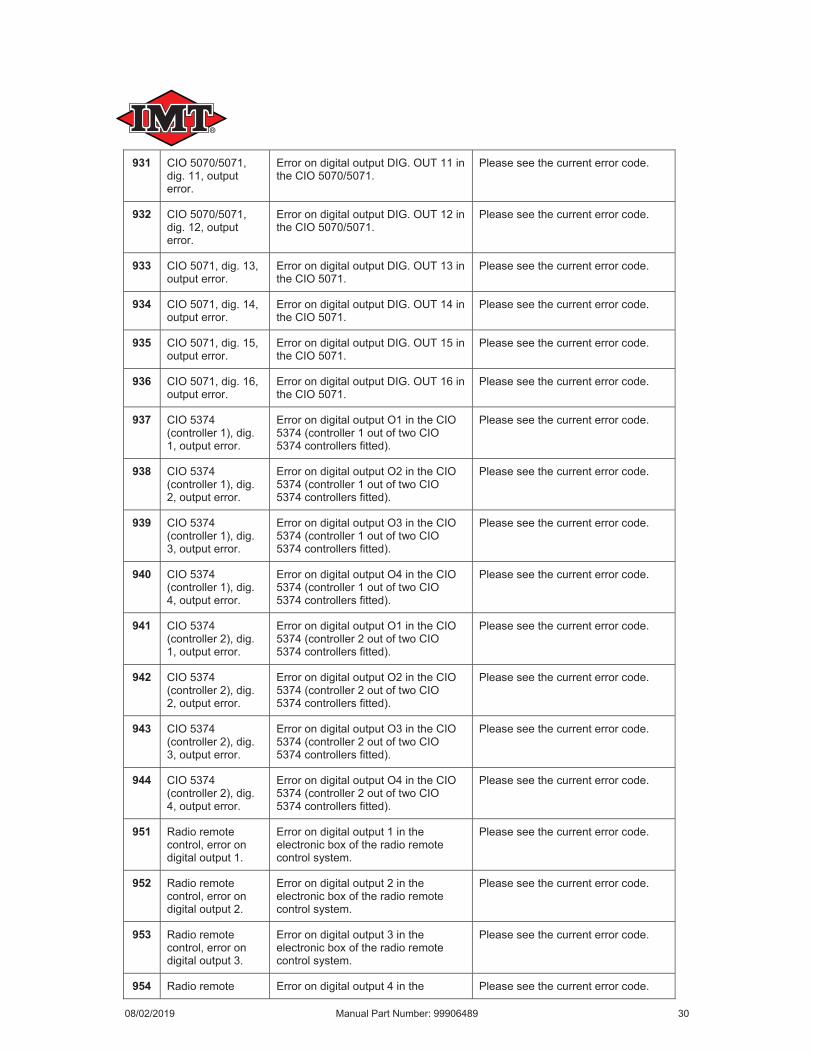
931
932
933
934
935
936
937
938
939
940
941
942
943
944
951
952
953
954
08/02/2019 Manual Part Number: 99906489 30
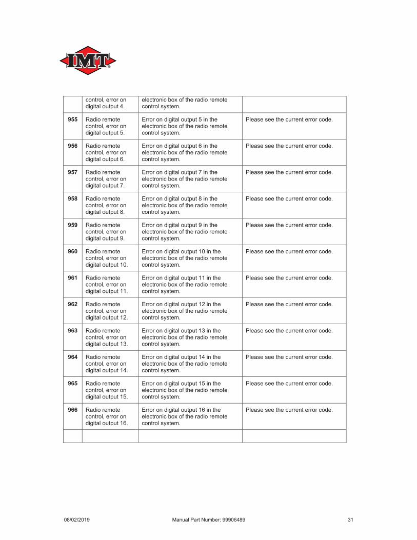
955
956
957
958
959
960
961
962
963
964
965
966
08/02/2019 Manual Part Number: 99906489 31
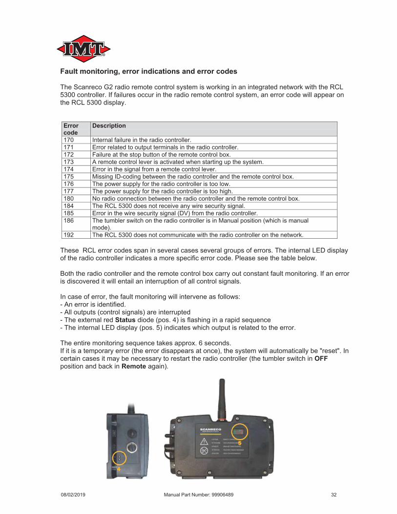
Fault monitoring, error indications and error codes The Scanreco G2 radio remote control system is working in an integrated network with the RCL 5300 controller. If failures occur in the radio remote control system, an error code will appear on the RCL 5300 display.
Error code
Description
170 Internal failure in the radio controller.171 Error related to output terminals in the radio controller.172 Failure at the stop button of the remote control box.173 A remote control lever is activated when starting up the system.174 Error in the signal from a remote control lever.175 Missing ID-coding between the radio controller and the remote control box.176 The power supply for the radio controller is too low.177 The power supply for the radio controller is too high.180 No radio connection between the radio controller and the remote control box.184 The RCL 5300 does not receive any wire security signal.185 Error in the wire security signal (DV) from the radio controller.186 The tumbler switch on the radio controller is in Manual position (which is manual
mode).192 The RCL 5300 does not communicate with the radio controller on the network.
These RCL error codes span in several cases several groups of errors. The internal LED display of the radio controller indicates a more specific error code. Please see the table below.
Both the radio controller and the remote control box carry out constant fault monitoring. If an error is discovered it will entail an interruption of all control signals.
In case of error, the fault monitoring will intervene as follows:- An error is identified.- All outputs (control signals) are interrupted- The external red Status diode (pos. 4) is flashing in a rapid sequence- The internal LED display (pos. 5) indicates which output is related to the error.
The entire monitoring sequence takes approx. 6 seconds.If it is a temporary error (the error disappears at once), the system will automatically be "reset". In certain cases it may be necessary to restart the radio controller (the tumbler switch in OFFposition and back in Remote again).
08/02/2019 Manual Part Number: 99906489 32
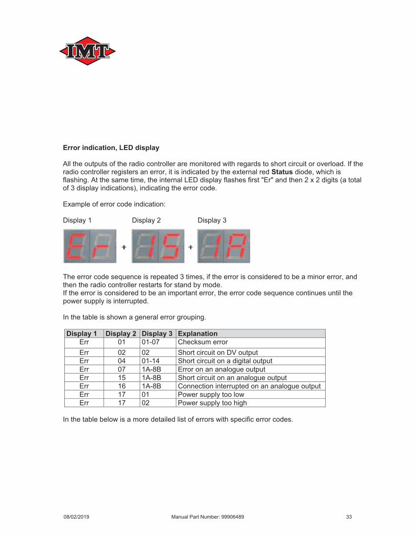
Error indication, LED display
All the outputs of the radio controller are monitored with regards to short circuit or overload. If the radio controller registers an error, it is indicated by the external red Status diode, which is flashing. At the same time, the internal LED display flashes first "Er" and then 2 x 2 digits (a total of 3 display indications), indicating the error code.
Example of error code indication:
Display 1 Display 2 Display 3
The error code sequence is repeated 3 times, if the error is considered to be a minor error, and then the radio controller restarts for stand by mode.If the error is considered to be an important error, the error code sequence continues until the power supply is interrupted.
In the table is shown a general error grouping.
Display 1 Display 2 Display 3 ExplanationErr 01 01-07 Checksum errorErr 02 02 Short circuit on DV outputErr 04 01-14 Short circuit on a digital outputErr 07 1A-8B Error on an analogue outputErr 15 1A-8B Short circuit on an analogue outputErr 16 1A-8B Connection interrupted on an analogue outputErr 17 01 Power supply too lowErr 17 02 Power supply too high
In the table below is a more detailed list of errors with specific error codes.
08/02/2019 Manual Part Number: 99906489 33


