Embed Size (px)
Citation preview
2300 N. Jog Road, West Palm Beach, FL 33411 Phone: (561) 233-5100 * Fax: (561) 233-5020 * www.discover.pbcgov.org/
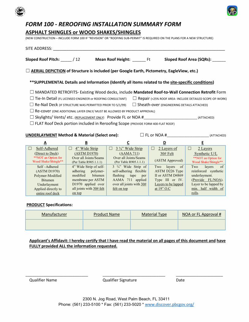
FORM 100 - REROOFING INSTALLATION SUMMARY FORM ASPHALT SHINGLES or WOOD SHAKES/SHINGLES (NEW CONSTRUCTION – INCLUDE FORM 100 IF “REVISION” OR “ROOFING SUB-PERMIT” IS REQUIRED ON THE PLANS FOR A NEW STRUCTURE)
SITE ADDRESS: _____________________________________________________________________________
Sloped Roof Pitch: _____ / 12 Mean Roof Height: ______ Ft Sloped Roof Area (SQRs): ______
☐ AERIAL DEPICTION of Structure is included (per Google Earth, Pictometry, EagleView, etc.)
**SUPPLEMENTAL Details and Information (Identify all items related to the site-specific conditions)
☐ MANDATED RETROFITS- Existing Wood decks, include Mandated Roof-to-Wall Connection Retrofit Form☐ Tie-In Detail (FL LICENSED ENGINEER or ROOFING CONSULTANT) ☐ Repair (<25% ROOF AREA- INCLUDE DETAILED SCOPE-OF-WORK)
☐ Re-Nail Deck (IF STRUCTURE WAS PERMITTED PRIOR TO 5/1/99) ☐ Sheath-over (ENGINEERING DETAILS ATTACHED)
☐ Re-cover (ONE ADDITIONAL LAYER ONLY/ MUST BE ALLOWED BY PRODUCT APPROVAL)
☐ Skylights/ Vents/ etc. (REPLACEMENT ONLY) Provide FL or NOA #_________________________________ (ATTACHED)
☐ FLAT Roof Deck portion included in Reroofing Scope (PROVIDE FORM 400-FLAT ROOF)
UNDERLAYMENT Method & Material (Select one): ☐ FL or NOA #__________________________ (ATTACHED)
A B C D E ☐ Self-Adhered
(Direct to Deck)**NOT an Option for
Wood Shake/Shingle**
☐ 4” Wide Strip(ASTM D1970)
Over all Joints/Seams (Per Table R905.1.1.1)
☐ 3 ¾” Wide Strip(AAMA 711)
Over all Joints/Seams (Per Table R905.1.1.1)
☐ 2 Layers of30# Felt
(ASTM Approved)
☐ 2 LayersSynthetic U/L
**NOT an Option forWood Shake/Shingle**
Self –Adhered (ASTM D1970)
Polymer-Modified Bitumen
Underlayment Applied directly to
entire roof deck
4” Wide Strip of self-adhering polymer-modified bitumen membrane per ASTM D1970 applied over all joints with 30# felt on top
3 ¾” Wide Strip of self-adhering flexible flashing tape per AAMA 711 applied over all joints with 30# felt on top
Two layers of ASTM D226 Type II or ASTM D4869 Type III or IV. Layers to be lapped at 19” O.C
Two layers of reinforced synthetic underlayment. (Provide FL/NOA). Layer to be lapped by min. half width of rolls.
PRODUCT Specifications:
Manufacturer Product Name Material Type NOA or FL Approval #
Applicant’s Affidavit: I hereby certify that I have read the material on all pages of this document and have FULLY provided ALL the information requested.
____________________________ ____________________________ _____________________ Qualifier Name Qualifier Signature Date
2300 N. Jog Road, West Palm Beach, FL 33411 Phone: (561) 233-5100 * Fax: (561) 233-5020 * www.discover.pbcgov.org/
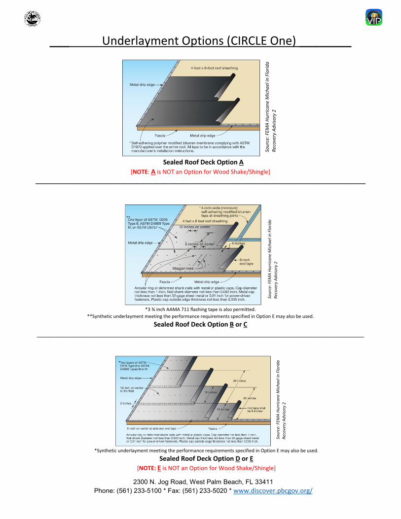
___ Underlayment Options (CIRCLE One) ________
Sealed Roof Deck Option A [NOTE: A is NOT an Option for Wood Shake/Shingle]
_____________________________________________________________________________________________________
*3 ¾ inch AAMA 711 flashing tape is also permitted.**Synthetic underlayment meeting the performance requirements specified in Option E may also be used.
Sealed Roof Deck Option B or C ___________________________________________________________________________________________
*Synthetic underlayment meeting the performance requirements specified in Option E may also be used.
Sealed Roof Deck Option D or E [NOTE: E is NOT an Option for Wood Shake/Shingle]
**
*
2300 N. Jog Road, West Palm Beach, FL 33411 Phone: (561) 233-5100 * Fax: (561) 233-5020 * www.discover.pbcgov.org/
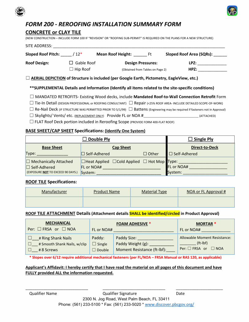
FORM 200 - REROOFING INSTALLATION SUMMARY FORM CONCRETE or CLAY TILE (NEW CONSTRUCTION – INCLUDE FORM 100 IF “REVISION” OR “ROOFING SUB-PERMIT” IS REQUIRED ON THE PLANS FOR A NEW STRUCTURE)
SITE ADDRESS: _____________________________________________________________________________
Sloped Roof Pitch: _____ / 12* Mean Roof Height: ______ Ft Sloped Roof Area (SQRs): ______
Roof Design: ☐ Gable Roof Design Pressures: LPZ: _____________ ☐ Hip Roof (Obtained from Tables on Page 2) HPZ: _____________
☐ AERIAL DEPICTION of Structure is included (per Google Earth, Pictometry, EagleView, etc.)
**SUPPLEMENTAL Details and Information (Identify all items related to the site-specific conditions)
☐ MANDATED RETROFITS- Existing Wood decks, include Mandated Roof-to-Wall Connection Retrofit Form☐ Tie-In Detail (DESIGN PROFESSIONAL or ROOFING CONSULTANT) ☐ Repair (<25% ROOF AREA- INCLUDE DETAILED SCOPE-OF-WORK)
☐ Re-Nail Deck (IF STRUCTURE WAS PERMITTED PRIOR TO 5/1/99) ☐ Battens (Engineering may be required if fasteners not in Approval)
☐ Skylights/ Vents/ etc. (REPLACEMENT ONLY) Provide FL or NOA #__________________________________ (ATTACHED)
☐ FLAT Roof Deck portion included in Reroofing Scope (PROVIDE FORM 400-FLAT ROOF)
BASE SHEET/CAP SHEET Specifications: (Identify One System)
☐ Double Ply ☐ Single Ply
Base Sheet Type: ______________
Cap Sheet ☐ Self-Adhered ☐ Other
Direct-to-Deck ☐ Self-Adhered
☐ Mechanically Attached☐ Self-Adhered(EXPOSURE NOT TO EXCEED 90 DAYS.)
☐Heat Applied ☐Cold Applied ☐ Hot MopFL or NOA# __________________________System: _____________________________
Type: ______________________ FL or NOA# _________________ System: ____________________
ROOF TILE Specifications:
Manufacturer Product Name Material Type NOA or FL Approval #
ROOF TILE ATTACHMENT Details (Attachment details SHALL be identified/circled in Product Approval)
MECHANICAL Per: ☐ FRSA or ☐ NOA
FOAM ADHESIVE * FL or NOA# ___________________________
MORTAR * FL or NOA# _____________
☐___# Ring Shank Nails☐___ # Smooth Shank Nails, w/clip☐___ # 8 Screws
Paddy: ☐ Single☐ Double
Paddy Size: ________________ Paddy Weight (g): ___________ Moment Resistance (ft-lbf):____
Allowable Moment Resistance: ________ (ft-lbf) Per: ☐ FRSA or ☐ NOA
* Slopes over 6/12 require additional mechanical fasteners (per FL/NOA – FRSA Manual or RAS 120, as applicable)
Applicant’s Affidavit: I hereby certify that I have read the material on all pages of this document and have FULLY provided ALL the information requested.
____________________________ ____________________________ _____________________ Qualifier Name Qualifier Signature Date
2300 N. Jog Road, West Palm Beach, FL 33411 Phone: (561) 233-5100 * Fax: (561) 233-5020 * www.discover.pbcgov.org/
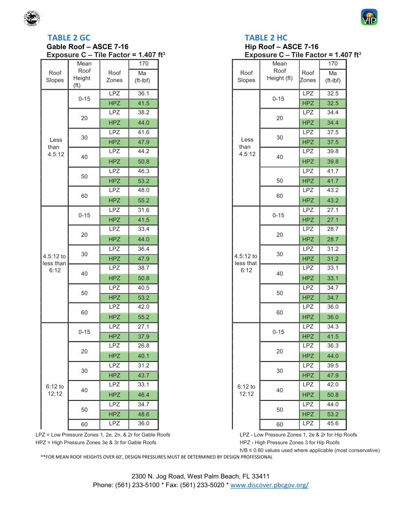
TABLE 2 GC TABLE 2 HC Gable Roof – ASCE 7-16 Hip Roof – ASCE 7-16 Exposure C – Tile Factor = 1.407 ft3 Exposure C – Tile Factor = 1.407 ft3
**FOR MEAN ROOF HEIGHTS OVER 60’, DESIGN PRESSURES MUST BE DETERMINED BY DESIGN PROFESSIONAL
Roof Slopes
Mean Roof
Height (ft)
Roof Zones
170 Roof
Slopes
Mean Roof
Height (ft) Roof
Zones
170 Ma
(ft-lbf) Ma
(ft-lbf)
Less than 4.5:12
0-15LPZ 36.1
Less than 4.5:12
0-15LPZ 32.5
HPZ 41.5 HPZ 32.5
20 LPZ 38.2
20 LPZ 34.4
HPZ 44.0 HPZ 34.4
30 LPZ 41.6
30 LPZ 37.5
HPZ 47.9 HPZ 37.5
40 LPZ 44.2
40 LPZ 39.8
HPZ 50.8 HPZ 39.8
50 LPZ 46.3
50 LPZ 41.7
HPZ 53.2 HPZ 41.7
60 LPZ 48.0
60 LPZ 43.2
HPZ 55.2 HPZ 43.2
4.5:12 to less than
6:12
0-15LPZ 31.6
4.5:12 to less that
6:12
0-15LPZ 27.1
HPZ 41.5 HPZ 27.1
20 LPZ 33.4
20 LPZ 28.7
HPZ 44.0 HPZ 28.7
30 LPZ 36.4
30 LPZ 31.2
HPZ 47.9 HPZ 31.2
40 LPZ 38.7
40 LPZ 33.1
HPZ 50.8 HPZ 33.1
50 LPZ 40.5
50 LPZ 34.7
HPZ 53.2 HPZ 34.7
60 LPZ 42.0
60 LPZ 36.0
HPZ 55.2 HPZ 36.0
6:12 to 12:12
0-15LPZ 27.1
6:12 to 12:12
0-15LPZ 34.3
HPZ 37.9 HPZ 41.5
20 LPZ 26.8
20 LPZ 36.3
HPZ 40.1 HPZ 44.0
30 LPZ 31.2
30 LPZ 39.5
HPZ 43.7 HPZ 47.9
40 LPZ 33.1
40 LPZ 42.0
HPZ 46.4 HPZ 50.8
50 LPZ 34.7
50 LPZ 44.0
HPZ 48.6 HPZ 53.2
60 LPZ 36.0 60 LPZ 45.6
LPZ = Low Pressure Zones 1, 2e, 2n, & 2r for Gable Roofs HPZ = High Pressure Zones 3e & 3r for Gable Roofs
LPZ - Low Pressure Zones 1, 2e & 2r for Hip Roofs HPZ - High Pressure Zones 3 for Hip Roofs h/B ≤ 0.80 values used where applicable (most conservative)
2300 N. Jog Road, West Palm Beach, FL 33411 Phone: (561) 233-5100 * Fax: (561) 233-5020 * www.discover.pbcgov.org/
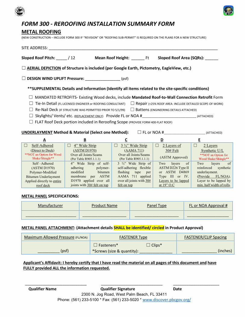
FORM 300 - REROOFING INSTALLATION SUMMARY FORM METAL ROOFING (NEW CONSTRUCTION – INCLUDE FORM 300 IF “REVISION” OR “ROOFING SUB-PERMIT” IS REQUIRED ON THE PLANS FOR A NEW STRUCTURE)
SITE ADDRESS: _____________________________________________________________________________
Sloped Roof Pitch: _____ / 12 Mean Roof Height: ______ Ft Sloped Roof Area (SQRs): ______
☐ AERIAL DEPICTION of Structure is included (per Google Earth, Pictometry, EagleView, etc.)
☐ DESIGN WIND UPLIFT Pressure: ________________ (psf)
**SUPPLEMENTAL Details and Information (Identify all items related to the site-specific conditions)
☐ MANDATED RETROFITS- Existing Wood decks, include Mandated Roof-to-Wall Connection Retrofit Form☐ Tie-In Detail (FL LICENSED ENGINEER or ROOFING CONSULTANT) ☐ Repair (<25% ROOF AREA- INCLUDE DETAILED SCOPE-OF-WORK)
☐ Re-Nail Deck (IF STRUCTURE WAS PERMITTED PRIOR TO 5/1/99) ☐ Battens (ENGINEERING DETAILS ATTACHED)
☐ Skylights/ Vents/ etc. (REPLACEMENT ONLY) Provide FL or NOA #__________________________________ (ATTACHED)
☐ FLAT Roof Deck portion included in Reroofing Scope (PROVIDE FORM 400-FLAT ROOF)
UNDERLAYMENT Method & Material (Select one Method): ☐ FL or NOA #__________________________ (ATTACHED)
A B C D E ☐ Self-Adhered
(Direct to Deck)**NOT an Option for Wood
Shake/Shingle**
☐ 4” Wide Strip(ASTM D1970)
Over all Joints/Seams (Per Table R905.1.1.1)
☐ 3 ¾” Wide Strip(AAMA 711)
Over all Joints/Seams (Per Table R905.1.1.1)
☐ 2 Layers of30# Felt
(ASTM Approved)
☐ 2 LayersSynthetic U/L
**NOT an Option forWood Shake/Shingle**
Self –Adhered (ASTM D1970)
Polymer-Modified Bitumen Underlayment
Applied directly to entire roof deck
4” Wide Strip of self-adhering polymer-modified bitumen membrane per ASTM D1970 applied over all joints with 30# felt on top
3 ¾” Wide Strip of self-adhering flexible flashing tape per AAMA 711 applied over all joints with 30# felt on top
Two layers of ASTM D226 Type II or ASTM D4869 Type III or IV. Layers to be lapped at 19” O.C
Two layers of reinforced synthetic underlayment. (Provide FL/NOA). Layer to be lapped by min. half width of rolls.
METAL PANEL SPECIFICATIONS:
Manufacturer Product Name Panel Type FL or NOA Approval #
_______________________ ____________________ ____________________ ___________________
METAL PANEL ATTACHMENT: (Attachment details SHALL be identified/ circled in Product Approval)
Maximum Allowed Pressure (FL/NOA) FASTENER Type FASTENER/CLIP Spacing
__________ (psf) ☐ Fasteners* ☐ Clips*
*Screws (size & quantity): _______________ ________________ (inches)
Applicant’s Affidavit: I hereby certify that I have read the material on all pages of this document and have FULLY provided ALL the information requested.
____________________________ ____________________________ _____________________ Qualifier Name Qualifier Signature Date
2300 N. Jog Road, West Palm Beach, FL 33411 Phone: (561) 233-5100 * Fax: (561) 233-5020 * www.discover.pbcgov.org/
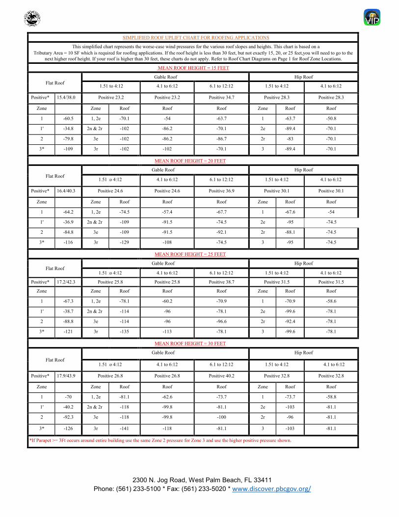
SIMPLIFIED ROOF UPLIFT CHART FOR ROOFING APPLICATIONS
This simplified chart represents the worse-case wind pressures for the various roof slopes and heights. This chart is based on a Tributary Area = 10 SF which is required for roofing applications. If the roof height is less than 30 feet, but not exactly 15, 20, or 25 feet,you will need to go to the
next higher roof height. If your roof is higher than 30 feet, these charts do not apply. Refer to Roof Chart Diagrams on Page 1 for Roof Zone Locations.
MEAN ROOF HEIGHT = 15 FEET
Flat Roof Gable Roof Hip Roof
1.51 to 4:12 4.1 to 6:12 6.1 to 12:12 1.51 to 4:12 4.1 to 6:12
Positive* 15.4/38.0 Positive 23.2 Positive 23.2 Positive 34.7 Positive 28.3 Positive 28.3
Zone Zone Roof Roof Roof Zone Roof Roof
1 -60.5 1, 2e -70.1 -54 -63.7 1 -63.7 -50.8
1' -34.8 2n & 2r -102 -86.2 -70.1 2e -89.4 -70.1
2 -79.8 3e -102 -86.2 -86.7 2r -83 -70.1
3* -109 3r -102 -102 -70.1 3 -89.4 -70.1
MEAN ROOF HEIGHT = 20 FEET
Flat Roof Gable Roof Hip Roof
1.51 to 4:12 4.1 to 6:12 6.1 to 12:12 1.51 to 4:12 4.1 to 6:12
Positive* 16.4/40.3 Positi ve 24.6 Positive 24.6 Positive 36.9 Positive 30.1 Positive 30.1
Zone Zone Roof Roof Roof Zone Roof Roof
1 -64.2 1, 2e -74.5 -57.4 -67.7 1 -67.6 -54
1' -36.9 2n & 2r -109 -91.5 -74.5 2e -95 -74.5
2 -84.8 3e -109 -91.5 -92.1 2r -88.1 -74.5
3* -116 3r -129 -108 -74.5 3 -95 -74.5
MEAN ROOF HEIGHT = 25 FEET
Flat Roof Gable Roof Hip Roof
1.51 to 4:12 4.1 to 6:12 6.1 to 12:12 1.51 to 4:12 4.1 to 6:12
Positive* 17.2/42.3 Positi ve 25.8 Positive 25.8 Positive 38.7 Positive 31.5 Positive 31.5
Zone Zone Roof Roof Roof Zone Roof Roof
1 -67.3 1, 2e -78.1 -60.2 -70.9 1 -70.9 -58.6
1' -38.7 2n & 2r -114 -96 -78.1 2e -99.6 -78.1
2 -88.8 3e -114 -96 -96.6 2r -92.4 -78.1
3* -121 3r -135 -113 -78.1 3 -99.6 -78.1
MEAN ROOF HEIGHT = 30 FEET
Flat Roof Gable Roof Hip Roof
1.51 to 4:12 4.1 to 6:12 6.1 to 12:12 1.51 to 4:12 4.1 to 6:12
Positive* 17.9/43.9 Positi ve 26.8 Positive 26.8 Positive 40.2 Positive 32.8 Positive 32.8
Zone Zone Roof Roof Roof Zone Roof Roof
1 -70 1, 2e -81.1 -62.6 -73.7 1 -73.7 -58.8
1' -40.2 2n & 2r -118 -99.8 -81.1 2e -103 -81.1
2 -92.3 3e -118 -99.8 -100 2r -96 -81.1
3* -126 3r -141 -118 -81.1 3 -103 -81.1
*If Parapet >= 3Ft occurs around entire building use the same Zone 2 pressure for Zone 3 and use the higher positive pressure shown.

2300 N. Jog Road, West Palm Beach, FL 33411 Phone: (561) 233-5100 * Fax: (561) 233-5020 * www.discover.pbcgov.org/
___ Underlayment Options (CIRCLE One) ________
Sealed Roof Deck Option A [NOTE: A is NOT an Option for Wood Shake/Shingle]
_____________________________________________________________________________________________________
*3 ¾ inch AAMA 711 flashing tape is also permitted.**Synthetic underlayment meeting the performance requirements specified in Option E may also be used.
Sealed Roof Deck Option B or C ___________________________________________________________________________________________
*Synthetic underlayment meeting the performance requirements specified in Option E may also be used.
Sealed Roof Deck Option D or E [NOTE: E is NOT an Option for Wood Shake/Shingle]
**
*
2300 N. Jog Road, West Palm Beach, FL 33411 Phone: (561) 233-5100 * Fax: (561) 233-5020 * www.discover.pbcgov.org/
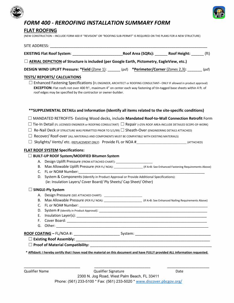
FORM 400 - REROOFING INSTALLATION SUMMARY FORM FLAT ROOFING (NEW CONSTRUCTION – INCLUDE FORM 400 IF “REVISION” OR “ROOFING SUB-PERMIT” IS REQUIRED ON THE PLANS FOR A NEW STRUCTURE)
SITE ADDRESS: ___________________________________________________________________________
EXISTING Flat Roof System: ________________________Roof Area (SQRs): ______ Roof Height: ______ (ft)
☐ AERIAL DEPICTION of Structure is included (per Google Earth, Pictometry, EagleView, etc.)
DESIGN WIND UPLIFT Pressure: *Field (Zone 1): ______ (psf) *Perimeter/Corner (Zones 2,3): _______ (psf)
TESTS/ REPORTS/ CALCUATIONS☐ Enhanced Fastening Specifications (FL ENGINEER, ARCHITECT or ROOFING CONSULTANT– ONLY IF allowed in product approval)
EXCEPTION: Flat roofs not over 400 ft2,, maximum 4” on center each way fastening of tin-tagged base sheets within 4 ft. of roof edges may be specified by the contractor or owner-builder.
**SUPPLEMENTAL DETAILs and Information (Identify all items related to the site-specific conditions)
☐ MANDATED RETROFITS- Existing Wood decks, include Mandated Roof-to-Wall Connection Retrofit Form☐ Tie-In Detail (FL LICENSED ENGINEER or ROOFING CONSULTANT) ☐ Repair (<25% ROOF AREA-INCLUDE DETAILED SCOPE-OF-WORK)
☐ Re-Nail Deck (IF STRUCTURE WAS PERMITTED PRIOR TO 5/1/99) ☐ Sheath-Over (ENGINEERING DETAILS ATTACHED)
☐ Recover/ Roof-over (ALL MATERIALS AND COMPONENTS MUST BE COMPATIBLE WITH EXISTING MATERIALS)
☐ Skylights/ Vents/ etc. (REPLACEMENT ONLY) Provide FL or NOA #_________________________________ (ATTACHED)
FLAT ROOF SYSTEM Specifications: ☐ BUILT-UP ROOF System/MODIFIED Bitumen System
A. Design Uplift Pressure (FROM ATTACHED CHART): ________________________
B. Max Allowable Uplift Pressure (PER FL/ NOA): ___________________ (If A>B: See Enhanced Fastening Requirements Above)
C. FL or NOA# Number:_______________________________________________________________D. System & Components (Identify in Product Approval or Provide Additional Specifications):
(ie: Insulation Layers/ Cover Board/ Ply Sheets/ Cap Sheet/ Other)
☐ SINGLE-Ply SystemA. Design Pressure (SEE ATTACHED CHART): _________________________
B. Max Allowable Pressure (PER FL/ NOA): _________________________ (If A>B: See Enhanced Nailing Requirements Above)
C. FL or NOA# Number: ________________________________________________________________D. System # (Identify in Product Approval): ______________________________________________________E. Insulation Layer(s): _________________________________________________________________F. Cover Board: ______________________________________________________________________G. Other: ____________________________________________________________________________
ROOF COATING – FL/NOA #: ______________________ System: ____________________________________ ☐ Existing Roof Assembly: ________________________________________________________________☐ Proof of Material Compatibility: __________________________________________________________
* Affidavit: I hereby certify that I have read the material on this document and have FULLY provided ALL information requested.
____________________________ ____________________________ _____________________ Qualifier Name Qualifier Signature Date
2300 N. Jog Road, West Palm Beach, FL 33411 Phone: (561) 233-5100 * Fax: (561) 233-5020 * www.discover.pbcgov.org/
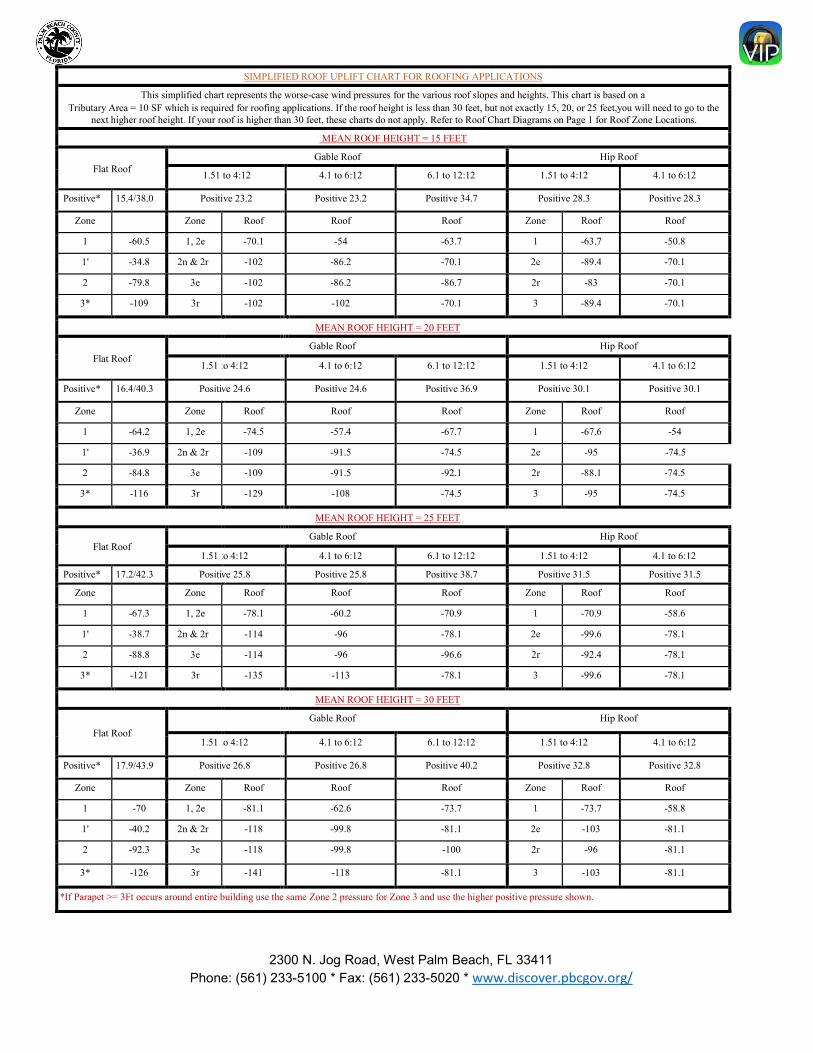
SIMPLIFIED ROOF UPLIFT CHART FOR ROOFING APPLICATIONS
This simplified chart represents the worse-case wind pressures for the various roof slopes and heights. This chart is based on a Tributary Area = 10 SF which is required for roofing applications. If the roof height is less than 30 feet, but not exactly 15, 20, or 25 feet,you will need to go to the
next higher roof height. If your roof is higher than 30 feet, these charts do not apply. Refer to Roof Chart Diagrams on Page 1 for Roof Zone Locations.
MEAN ROOF HEIGHT = 15 FEET
Flat Roof Gable Roof Hip Roof
1.51 to 4:12 4.1 to 6:12 6.1 to 12:12 1.51 to 4:12 4.1 to 6:12
Positive* 15.4/38.0 Positive 23.2 Positive 23.2 Positive 34.7 Positive 28.3 Positive 28.3
Zone Zone Roof Roof Roof Zone Roof Roof
1 -60.5 1, 2e -70.1 -54 -63.7 1 -63.7 -50.8
1' -34.8 2n & 2r -102 -86.2 -70.1 2e -89.4 -70.1
2 -79.8 3e -102 -86.2 -86.7 2r -83 -70.1
3* -109 3r -102 -102 -70.1 3 -89.4 -70.1
MEAN ROOF HEIGHT = 20 FEET
Flat Roof Gable Roof Hip Roof
1.51 to 4:12 4.1 to 6:12 6.1 to 12:12 1.51 to 4:12 4.1 to 6:12
Positive* 16.4/40.3 Positi ve 24.6 Positive 24.6 Positive 36.9 Positive 30.1 Positive 30.1
Zone Zone Roof Roof Roof Zone Roof Roof
1 -64.2 1, 2e -74.5 -57.4 -67.7 1 -67.6 -54
1' -36.9 2n & 2r -109 -91.5 -74.5 2e -95 -74.5
2 -84.8 3e -109 -91.5 -92.1 2r -88.1 -74.5
3* -116 3r -129 -108 -74.5 3 -95 -74.5
MEAN ROOF HEIGHT = 25 FEET
Flat Roof Gable Roof Hip Roof
1.51 to 4:12 4.1 to 6:12 6.1 to 12:12 1.51 to 4:12 4.1 to 6:12
Positive* 17.2/42.3 Positi ve 25.8 Positive 25.8 Positive 38.7 Positive 31.5 Positive 31.5
Zone Zone Roof Roof Roof Zone Roof Roof
1 -67.3 1, 2e -78.1 -60.2 -70.9 1 -70.9 -58.6
1' -38.7 2n & 2r -114 -96 -78.1 2e -99.6 -78.1
2 -88.8 3e -114 -96 -96.6 2r -92.4 -78.1
3* -121 3r -135 -113 -78.1 3 -99.6 -78.1
MEAN ROOF HEIGHT = 30 FEET
Flat Roof Gable Roof Hip Roof
1.51 to 4:12 4.1 to 6:12 6.1 to 12:12 1.51 to 4:12 4.1 to 6:12
Positive* 17.9/43.9 Positi ve 26.8 Positive 26.8 Positive 40.2 Positive 32.8 Positive 32.8
Zone Zone Roof Roof Roof Zone Roof Roof
1 -70 1, 2e -81.1 -62.6 -73.7 1 -73.7 -58.8
1' -40.2 2n & 2r -118 -99.8 -81.1 2e -103 -81.1
2 -92.3 3e -118 -99.8 -100 2r -96 -81.1
3* -126 3r -141 -118 -81.1 3 -103 -81.1
*If Parapet >= 3Ft occurs around entire building use the same Zone 2 pressure for Zone 3 and use the higher positive pressure shown.
U:\Building Administration\badmin1\PPM's\PPM's - 2020 FBC -DW\PBO-94
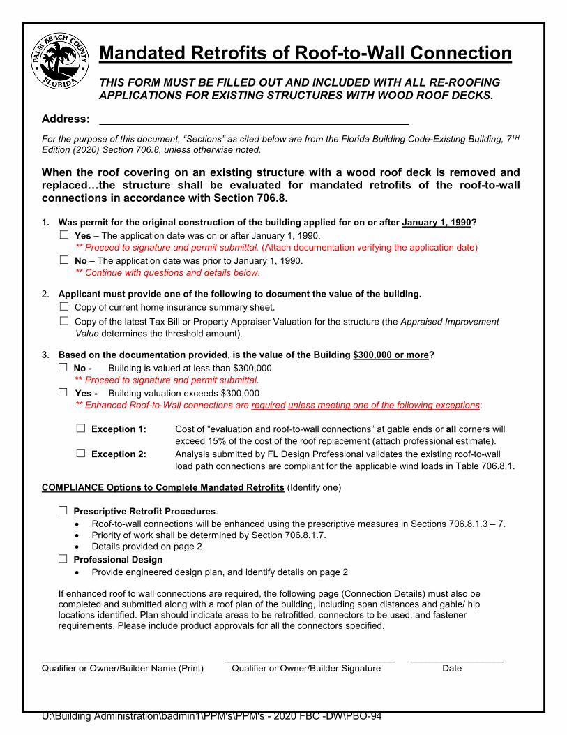
Mandated Retrofits of Roof-to-Wall Connection THIS FORM MUST BE FILLED OUT AND INCLUDED WITH ALL RE-ROOFING APPLICATIONS FOR EXISTING STRUCTURES WITH WOOD ROOF DECKS.
Address: For the purpose of this document, “Sections” as cited below are from the Florida Building Code-Existing Building, 7TH Edition (2020) Section 706.8, unless otherwise noted.
When the roof covering on an existing structure with a wood roof deck is removed and replaced…the structure shall be evaluated for mandated retrofits of the roof-to-wall connections in accordance with Section 706.8.
1. Was permit for the original construction of the building applied for on or after January 1, 1990?☐ Yes – The application date was on or after January 1, 1990.
** Proceed to signature and permit submittal. (Attach documentation verifying the application date)☐ No – The application date was prior to January 1, 1990.
** Continue with questions and details below.
2. Applicant must provide one of the following to document the value of the building.☐ Copy of current home insurance summary sheet.☐ Copy of the latest Tax Bill or Property Appraiser Valuation for the structure (the Appraised Improvement
Value determines the threshold amount).
3. Based on the documentation provided, is the value of the Building $300,000 or more?☐ No - Building is valued at less than $300,000
** Proceed to signature and permit submittal.☐ Yes - Building valuation exceeds $300,000
** Enhanced Roof-to-Wall connections are required unless meeting one of the following exceptions:
☐ Exception 1: Cost of “evaluation and roof-to-wall connections” at gable ends or all corners will exceed 15% of the cost of the roof replacement (attach professional estimate).
☐ Exception 2: Analysis submitted by FL Design Professional validates the existing roof-to-wall load path connections are compliant for the applicable wind loads in Table 706.8.1.
COMPLIANCE Options to Complete Mandated Retrofits (Identify one)
☐ Prescriptive Retrofit Procedures.• Roof-to-wall connections will be enhanced using the prescriptive measures in Sections 706.8.1.3 – 7.• Priority of work shall be determined by Section 706.8.1.7.• Details provided on page 2
☐ Professional Design• Provide engineered design plan, and identify details on page 2
If enhanced roof to wall connections are required, the following page (Connection Details) must also be completed and submitted along with a roof plan of the building, including span distances and gable/ hip locations identified. Plan should indicate areas to be retrofitted, connectors to be used, and fastener requirements. Please include product approvals for all the connectors specified.
______________________________ _________________________________ __________________ Qualifier or Owner/Builder Name (Print) Qualifier or Owner/Builder Signature Date
U:\Building Administration\badmin1\PPM's\PPM's - 2020 FBC -DW\PBO-94
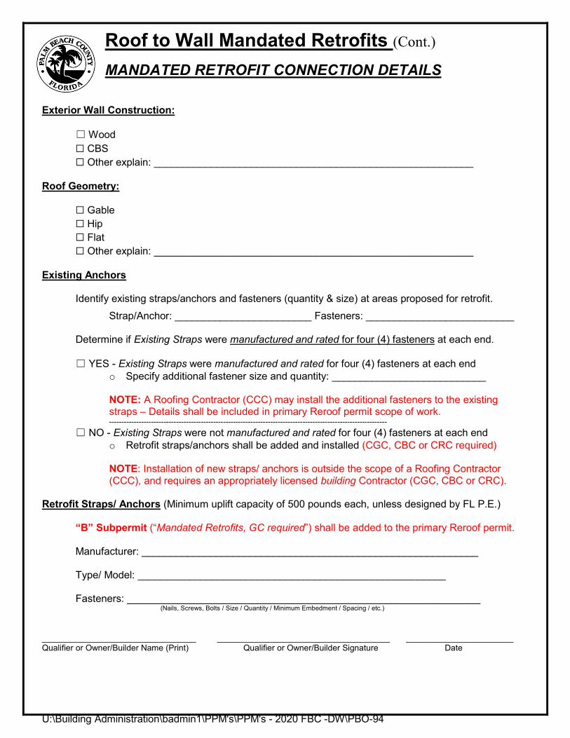
Roof to Wall Mandated Retrofits (Cont.) MANDATED RETROFIT CONNECTION DETAILS
Exterior Wall Construction:
☐ Wood☐ CBS☐ Other explain: ________________________________________________________
Roof Geometry:
☐ Gable☐ Hip☐ Flat☐ Other explain: ________________________________________________________
Existing Anchors
Identify existing straps/anchors and fasteners (quantity & size) at areas proposed for retrofit. Strap/Anchor: ________________________ Fasteners: __________________________
Determine if Existing Straps were manufactured and rated for four (4) fasteners at each end.
☐ YES - Existing Straps were manufactured and rated for four (4) fasteners at each endo Specify additional fastener size and quantity: ___________________________
NOTE: A Roofing Contractor (CCC) may install the additional fasteners to the existing straps – Details shall be included in primary Reroof permit scope of work. ----------------------------------------------------------------------------------------------------------------
☐ NO - Existing Straps were not manufactured and rated for four (4) fasteners at each endo Retrofit straps/anchors shall be added and installed (CGC, CBC or CRC required)
NOTE: Installation of new straps/ anchors is outside the scope of a Roofing Contractor (CCC), and requires an appropriately licensed building Contractor (CGC, CBC or CRC).
Retrofit Straps/ Anchors (Minimum uplift capacity of 500 pounds each, unless designed by FL P.E.)
“B” Subpermit (“Mandated Retrofits, GC required”) shall be added to the primary Reroof permit.
Manufacturer: ___________________________________________________________
Type/ Model: ______________________________________________________
Fasteners: ______________________________________________________________ (Nails, Screws, Bolts / Size / Quantity / Minimum Embedment / Spacing / etc.)
_________________________________ _____________________________________ _______________________ Qualifier or Owner/Builder Name (Print) Qualifier or Owner/Builder Signature Date


