Embed Size (px)
Citation preview

Specialized circulation in the World of Tomorrow . . .
ARCHITECTURAL
RECORD

BUILDING NEWS
40
Open air exhibits at the Venezuelan Pavilion and the Edward G. Budd Company are both provided with shade, but in each case a different structural means is used. Venezuela's wooden umbrellas (above) are hung from cantilevered steel beams; the Budd Company uses the stressed-skin principle for its stainless-steel umbrellas (leftl. This is perhaps the first actual application of the stressed-skin construction principle to building design.
ARCHITECTURAL RECORD

NEW YORK FAIR: FLEXIBILITY, CIRCULATION, LIGHT CONTROL
Co'.\'SPICLOCS at this year's "Universitv of Flushing Meadow" are three problems "hi"h cut a!'ross the design of almost all building types--flexible organization of laq!e areas, maximum control of both natural and artificial light, and easy handling of large crowds. The l;uildings at the Fair offer a great varietv of solutions to some or all of thf'sc problems; the ones shown hPrewith solve them in noteworthv fashion. Th~ most flexible organization of
space oc!'urs \\hf're there are neither walls nor columns: realizing this the designprs of both the Budd and Venezuelan Pxhibits have borrowed the umbrella with its singlf' \·ertical support I fal'ing page I. The same gf'neral principle in the Ameril'an Radiator Exhibit I top, right I and the Swedish PaYilion I bottom, right I led to omission of as many walls and columns as possible. In the French Pavilion, on the other hand I p. 42). flexibilitv has been achieved mechanically to vield open, partially 01wn, or enclosed spa!'e.
Venezuelan Pavilion: Skidmore and Owings, architects, John Moss, associate architect; Budd and American Radiator Exhibits: Voorhees, Walker, Foley, and Smith, architects; Swedish Pavilion: Sven Markelius, architect, Pomerance and Breines, associate architects.
AUGUST 1939
Open on three sides, the American Radiator Exhibit uses waterproof shower curtains for atmospheric control, sewer pipes for columns, radiators for decoration.
Sweden's Pavilion is built around a court onto which most of its exhibits open.
BUILDING NEWS
41

The French Pavilion's terraced restaurant has sliding glass panels which can be adjusted to meet climatic conditions. In cool weather, panels are placed to cut off prevailing winds {top}; in warm weather, terrace is entirely open (bottom), glass panels stored in chambers at each side. Expert and Patout, architects; D. Berninger, resident architect.
BUILDING NEWS
42
ARCHITECTURAL RECORD

NEW YORK FAIR: CIRCULATION
General Motors circulation is complex: visitors dismount from the moving platform which travels through the "Futurama" (top}; an exhibit hall (bottom) reached by stairway, escalator, and ramp. Norman Bel-Geddes, designer.
AUGUST 193~ BUILDING NEWS
43

ation in the Traffic segreg
I . an Pavilion has an . he Yugos av1 The ramp in t
NEWS BUILDING
44
easy slope;
motors I below. flow free y
' arent size. the buildings app h increases . ht s ape
~9""-e'g CT U RA l
ARCHITE RECORD

NEW YORK FAIR: CIRCULATION
Yugoslav Pavilion: Ernest Weissmann, architect; Pomerance and Breines, associates. Irish Pavilion: Michael Scott, architect. Glass Center: Shreve, Lamb, and Harmon, architects. Westinghouse Exhibit: Skidmore and Owings, architects; John Moss, associate.
The Glass Center features treads of toughened glass on metal stringers.
AUGUST 1939
Ireland's reinforced concrete spiral stair has treads cantilevered from central spine.
Similar in principle to Ireland's stairway 1s this stair at the Westinghouse Exhibit.
BUILDING NEWS
45

BUILDING NEWS
46
NEW YORK FAIR ~ LIGHT CONTRCl
Considerable variety in light control is displayed at the Fair. Here are three noteworthy solutions: a cellular panel attached to the outer wall of the Brazilian Pavilion (top) is designed to keep out direct sun rays; ample light is admitted and the inside temperat ure is thus reduced. An extensive use of awnings on the Irish Pavilion (center) protects the interior from direct sunlight and glare. The corner rooms of the hotel on General Motors' "Street of Tomorrow" (bottom) have adjustable vertical metal fins .
Brazilian Pavilion; Lucio Costa, Oscar N. Soares, architects: Italian Pavilion; Michele Busiri-Vici, architect: Argentine Pavilion; Armando d'Ans, architect.
ARCHITECT U RA L R ECORD

All light sources are recessed along the perimeter of this suspended ceiling in the Italian Pavilion's circular cocktail lounge.
Fluoresce,.,+ tubular lamps, mounted side by side, are spiraled around the central post in a General Motors' salesroom.
AUGUST 1939
Argentina displays its art under glareless artificial and natural light from glass louvered sides of suspended ceiling.
BUILDING NEWS
47

TELEVISED OPERATIONS MAKE HISTORY IN NEW YORK HOSPITAL
Israel Zion Hospital
Diagram showing relative location of operating room (A) where operations were televised, auditorium (B) where students saw them.
Over the operating table hang an iconoscope and a microphone.
BU I LD I NG NEWS
48
LOUIS PARKER
Engineer
DEVELOPMENT OF telecasting on any national scale has so far proved difficult because of technical problems, high costs, and the exacting technique involved. Experimentation, however, is being pushed forward in two directions: toward a communication system which will compete with and possibly supplant radio and movie; and toward specific installations for utilitarian purposes.
This latter development had a notably successful beginning in the recent installation by the American Television Corpora tion in Israel Zion Hospital in ew York City which permits more than 150 medical students to watch a surgeon perform a delicate operation. The audience wa grouped about six viewing screens in the training-school auditorium more than 500 feet from the operating room. These viewing units, each with a 9 by 101/2-in. screen accommodating 20 to 30 spectators, were con· nected by coaxial cable to an automatic televi ion camera, suspended with its lighting equipment and a microphone over the operating table.
This installation allowed a large audience for the first time to watch an opera tion at close range and to hear the surgeon' instructive comment. (A similar arrangement was suggested-with an entirely optical method-in the proj-
-. .......... f COAXIAL CABLE
I 1 J
The operation is televised while in another building
ARCHIT ECTURAL RECORD

ect for a hospital in Lille, France, by Paul Nelson.) It is claimed that this practical test of television will renilutionize the study of surgery, showing by actual example methods which would take years to piece together from distant views, blackboard and textbook illustrations. In theory, at least, this installation makes obsolete the operating room theater, since even the best theater provides only an inadequate view for a small number of observers. The image on the kinescope screen, although smalL is, as Alva ] ohnston points out in an article in the Saturday Evening Post, "relatively larger than the figures on a movie screen are to spectators in the gallery."
In the Israel Zion Hospital the equipment used consisted of the following clements:
The ico11osco11e, im-ented by Dr. Zworykin, an essential part of the telens10n camera. It contains a light-sensitive plate on whil'h the scene to be televised is focused. A fine jet of electrons sweeps across the plate in a pattern of 441 horizontal lines; and, by a method too complex to be detailed here, lights and shadows are translated into impulses of corresponding intensities. The plate is completely scanned 30 times per second, the entire action being electronic, not mechanicaL
The coaxial cable consists of a hollow tube with a central wire, the assembh acting as an ethereal speaking tube, dirPcting and carrying multiple Pleetrirnl impulses simultaneously and protecting them from interference from stray impulses set up by various kinds of ele!'trical equipment. The !'able used in the hospital installation was "'X in. in di-
.. J I I I J I I
••• the students watch and listen
AUGUST 1939
ameter, cost about 20 cents per foot. Radio-transmitted television (without the !'oaxial cable I is as yet highly subject to interference, causing rapid scrambling of the image. The range of this type of television is approximately 40 miles, but there have been many cases of erratic distant reception.
The kinescope, a funnel-shaped cathode ray tube. is the heart of the telens10n receiver. Here, a fine ray of electrons, produced in the neck of the tube, is caused to play 011 a fluorescent screen at the large end of the tube. Contact of the beam with the fluorescent substance produces a spot of light which varies in intensity according to the strength of the rel'eived electrical impulse. Sweeping across the screen in 441 lines. synl'hronized with the heam in the iconoscope, the kinescope beam thus reproduces the lights and shadows which formed the original image focused on the plate of the iconoscope.
The only parts of this telecasting equipment which are ordinarily subject to renewal are the tubes; both types have a guaranteed life of 500 hours and often last several thousand hours in actual use. The iconoscope costs $6.')0.00 and the 12-in. cathode ray tube, $4(i.OO. The hospital installation described required 800 watts A.C., stepped up to 6,000 volts and rectified to D.C. for the camera. The six Kinets or viewing units required a total of 1.100 watts.
Television requires a brightly illuminated scene. The minimum illumination is some,,·here around l.'i fuotcandles. In the hospitaL proper lighting required four .100-watt lamps with water-filters I not water-jackets) to re-
move heat-causing infrared rays and, incidentally, to improve color rendition. The lighting problem requires highspeed lenses in the camera. Those used had a speed of f2.9 which limited the depth of focus in this case to about 12 in. without refocusing the camera. In other words, the surgeon's hands would go out of focus as he lifted them toward the camera more than 12 in. from the plane of sharp fol'us. The iconoscope is highly sensitive to red and infrared, while the human eye is most sensitive to green. This causes distortion of color values: for example, violet appears black, and red appears light. Surfaces which reflect bright spots of light also cause trouble, as they do in photography, and a camera angle must be selected to avoid them when possible.
Countless educational uses suggest themselves wherever experiments or processes should be demonstrated to an audience.
Equipment somewhat similar to that in Israel Zion Hospital was installed in a large New York Department store to show by television merchandise and models from other parts of the building. This was supplemented by televised motion pictures.
Methods are being perfected to permit projection of televised images on larger sneens. The present small size is ahout the normal size of the pictures we see in books and periodicals, to which our eyes are accustomed. Television in full color is predicted by some, discounted by others, who point to the small percentage of motion pictures in color. It would have undoubted scientific. artistic, and educational value.
In six viewing screens students saw 9 by I Olfi-in. images of a Caesarean (top, right) and an appendectomy (bottom)
BUILDING NEWS
49

WINNERS OF SMITHSONIAN CALLERY OF ART COMPETITION
:........:....:
Of'" fLJ!YATIC)H 1"00~ ~ MM.L
I. Upper gallery 10. Dressing rooms 2. Library II. Un excavated 3. Reading tl!rrace 4. Auditorium 12. Parking
13. Future extension 5. Loading 14. Pool 6. Receiving 15. Exhibitions 7. Work area 16. Auditorium 8. Outdoor exhibition 17. Stage 9. Lecture room
I .
05 ~0· 1_J~J TlTI~
l ~j.-:----.-t. - IJ· -t· • 1@lm~ ... riL~.1. ~ ~
\~ ~ T.;'i "J• - ·I ~-~~-~
----- --- -
.....,__ @)
! · I ~-'- ~ '--·· ~
'l· "" T-' .. .. l ® ~ r -., '
.o.& ' ·~ ,
r . \ \
t N
- ... -- _J'~------~ g
FIRST PRIZE: Elie\ Saarinen. " ... especially appropriate in its re lat io.i to th3 site. It offers a remarkable clarity of composition in mass and a restraint and dignity in expression ... especially suitable for a building ... on the Washington Mall."
THE WI ER of the Smithsonian Galler y of Ar.t Competition. chosen from among the ten final contestants who survived the preliminary contest, were announced on June 28. First prize
BUILDING NEWS
50
of 7.500 was awarded to Eli el Saarinen. econd prize of $3,500 was awarded to Percival Goodman . (The remaining eight contestants will receive 1,000 each. ) Of these two
ARCHITECT UR A L RECORD

j
· .... •:
I. Balcony 13. 2. Reception room 3. Library 14. 4. Stacks and files 15. 5. Reserve exhibition 16.
6. space Upper pa rt of ga 1- 17. lery 18.
7. Outdoor exhibition 19. 20.
8. Understage 21. 9. Dressing rooms 22.
10. Orchestra 23. 11. Rest rooms 24. 12. Work area and 25.
superintendent
i~
Temporary and per-ma nent stage Service court U nexcavated Future storage
Parking ;: . ~ Outdoor exhibition Stage Auditorium . 10.
GYB Lecture room Entra nee lobby Ex'hibition space Offices Future reserve ex-hibition
i;.. -~~r
,'.".'""· .• ·-.·."V'."-'•'"':'-' ...... :";~
' '' i
:.... ... -.', ,,
.-
·.->·
---· '"--~; 1 ----.... ----'-- - -- --,
0 ' @: L..
._,__.,,..........,_~ .. - t .......... - N
' ' . -- ~ j r
:f .
J.' I, I' ,.
,~---
·11 _J d
------------====--===== __ ::::::_ .=,~=-= ... =. ==:=:;::=:::; __ =. :::::J __
SECOND PRIZE: Percival Goodman. " ... commended by jury for the thorough study given to the organization of the elements of the plan .... The peculiar excellence of this design lies in its consistency throughout and its remarkable plasticity."
designs. the report of the jun of award declares: "Both offer simple, direct solutions in which all facilities are adequately provided for and in which the relation of part to part is
AUGUST 1939
correct. In hoth desip1s the location of exhibition spaces on the first floor and the immediate accessihility of these spaces to the entrances is commended."
BUILDING NEWS
51

WINNERS OF THIRD PRIZES
J. Mitchell, D. Ritchey. " ... admirable scheme, but galleries too narrow, work areas unnecessarily broken up."
G. H. Perkins. " ... well organized; faults are 2nd floor access to auditorium, excessive work-area lengths."
P. Cret. " ... admired for presentation. Court impairs flexibility of galleries and ... functioning of work areas."
E. D. Stone. " ... excellent grouping; introduction of overdeveloped circulation elements ... impairs flexibility."
' t••••••••••"'1,,,; ::... ____ _ ....., '
P. L. Goodwin. " ... well organized; auditorium rn center ... results rn ... congestion in circulation."
Peter and Stubbins. "Unification of elements ..• considered excellent; .•. the two courts are ... useles~."
[l E. Noyes, R. Kennedy. " •.. compact plan; design unusually straightforward; ... elevations unsatisfactory."
H. F. Manning, D. W. Carlson. " ... well organized galleries; ... complication of working areas a defect."
BUILDING NEWS ARCHITECTURAL RECORD
52.

ATLANTA, CA.: LOCAL TRADITION ADAPTED TO MODERN REQUIREMENTS
LINTON H. YOUNG, Architect
Tms RESIDE:'ICE for Mr. and Mrs. Thomas P. Hinman follo\1,local tradition in style and spaciousness of interior planning. Although the house occupies the greater portion of a relatively small city lot, any effect of crowding is arnided by landscap· ing. All main rooms face west except the dining room, whil'h opens to the east on the garden at the rear. Reminiscent of older Southern Colonial houses is the connecting porch between kitchen and service wing. The house is of frame construction on concrete foundations. The exterior is brick Yeneer painted white; base and pilasters on the front are of stucco. also painted white. Windows are double and triple hung \\~ith white pine wood sash. Insulation 14-in. rockwool) is used in the ceiling of the second floor only. The interior finish is plaster on steel lath. painted in some rooms. papered in others; trim is of white pine, molded and plain. Floors are of sdect white oak. Heating is by a gas-fired furnace.
AUGUST 1939 BUILDING NEWS
53

CEORCIA RESIDENCE
Entrance hall and stair Library
GARAGE !C.O,llj
, -b.. ~- ?
First floor
BUILDING NEWS
54
I
I
PORCH ,~
BED RO:IM LL=1 ( -;i_:_"' =--F1 ... ,
BEO ROOM
BEDROOM
Second floor
ARCHITECTURAL RECORD

Living room
Dining room Kitchen
AUGUST 1939 BUILDING NEWS
55

BUILDING NEWS
56
MA
FURN
GARAGE
Ground floor
ARCHITECTUR A L RECOR D

OPEN PLAN, CLASS WALL CIVE TWO-FAMILY DWELLINC MAXIMUM LICHT
RICHARD NEUTRA, Architect
OTTO WINKLER, Collaborator
SITU A TED ON A SJ\IALL city lot I 25 feet wide I in San Francisco, this two-flat dwelling for Dr. William Schiff and Dr. Ernest W olfes obtains ample light from an extensive use of glass on the front (south I wall. For privacy, non-transparent glass is used up to the bottom of the \'cnts; above this leveL clear glass is used. The venetian blinds in the living rooms are of white spring steeL The main entrance is on the ground floor; on the same leveL opening into the garden, is a servant's room with bath and kitchenette. On the second and third floor are the two flats, identical in plan except for the latter's penthouse. The connecting space between dining and living rooms is 10 ft. wide and is used as a den; this arrangement makes for a plan that is more open than usual. Walls of white Sanitas contribute lightness to the interior. Floors, except in dining rooms, kitchens, and pent room, are of oak. The pentroom has a large deck whil'h overlooks the yacht harbor, the Golden Gate Bridge, and the Palace of Fine Arts, sole survivor of San Francisco's 1915 Exposition. A composite chassis of steel and wood constitutes the structure of the dwelling. The south wall is glass; the north wall is of cement plaster; and the east and west walls have redwood siding. All exposed doors, soffits, steel sash, and sheet metal work arP aluminum painted: all other woodwork is white.
I ROOM - BED ROOM BED ROOM BED ROOM
CV-.1. LIV ING ~~~~~
L 1 YING ~.............O•---~~-'·~-"---
' ' l _________________________ l
st floor Seco;1d floor
AUGUST 1939
I
DECK
MASTER BED ROOM 1
Third floor
, I !
Stairway leading to second floor
Second floor landing; den beyond
BUILDING NEWS
57
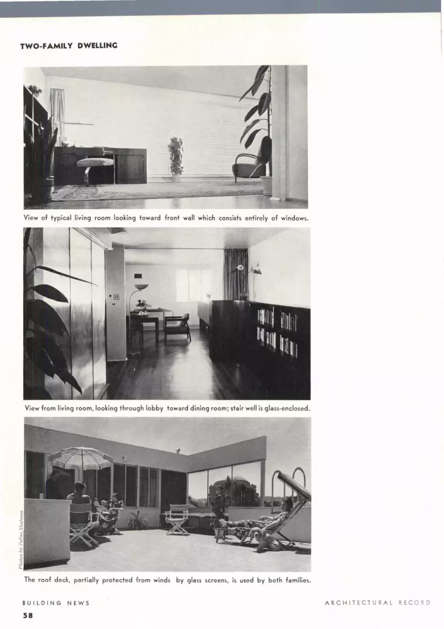
TWO-FAMILY DWELLING
View of typical living room looking toward front wall which consists entirely of windows.
View from living room, looking through lobby toward dining room; stair well is glass-enclosed.
The roof deck, partially protected from winds by glass screens , is used by both families.
BUILDING NEWS ARCHIT ECTURAL REC ORD
58

• rtA1111 · •
. . _ . r-_:--'-:.., . • • . , : CONCEAUO llGHT : • • • •
CURV!O f LUSH llOOA I 1--+--+----+--t---+---t I
SHfLVlS } ~~~ = -=·1 1--+---<~>-+-!LOC-K+--+--<1
11---l--+--t--t---t--tl
D i [JlUSH ,___~ 01\AWfRS-.. - l)()()R
r-T T- ==== >--- OPEN -
F==----1--11·--,___ _ _c;;;:;;:::::~ l ' TOllPACl
0 3
DR551ri6 ROOM
J1 I I I
0 z 3 4
1. HERVEY PARKE CLARK Architect
JAMES KEMBLE MILLS Decorat or
5 feet
I 5 feet
THE FOCAL POI T in thi unit is the dressing table, with its plaleglass top and free-standing tri pie mirror. Gia s block was used lo give privacy, and a horizontall yhinged window above eye level for ventilation. A flu sh ceilin (Y light over the center of the table provides artificial illuminati on. Dressing table, cabinet , and wardrobes are of wood painted white. The walls are of white plaster with stencilled design in geranium ; the ceiling is pla ter painted geranium red. The same color scheme i repeated in the round stool.
NEW DWELLING UNITS

NEW DWELLINC UNITS: DRESSINC
CllWI! Mll!OI
i tlfHISINi 6W) '°"t[I
I
0 3 ftet
BUILDING NEWS
60
Cc1~nr mow Sll tlll TUU .110 Slflm
AIOI!. )
Section
2. ROY BLASS
Architect
Co VE IE TLY SIT ATED for access from bedroom and bath. thi dres, · ing unit features a built-in triple mirror with an unu ual lighting in-tallation. Behind the sand-blasted
ring in the central mirror are six ockets for regular lamp which
produce a oft glareless light. The dressing table ha a mirror top; the curved shelves below swing out for easy acces to toilet articles. All woodwork has a beige enamel fin i h ; hardware i chrome. The chair i uphol tered in a coar e wool fabric, slate gra y in color; legs are beige enamel. Th rug is deep rose.
Materials and equipment Li ghting : ce iling, olar Li ght Co. Mirrors: Pitt burgh Plate Gia o. Rug: Twi stweave, Bi gelow- anford Carpet (n.
BATH
0 DRESSING ROOM
jQ i] , , , , , m ROOM 0 I Z 3 4 feet Plan
ARCHITEC T UR AL RECORD

J; ALDEN B. DOW, Architect
I N THIS DRESSING UN IT the principal materials used are glass and Louisiana red cypress. Instead of the usual horizontal table top for toilet articles, a series of shelves is used along one side of the large mirror; a metal support in the corner holds the shelves in place. Ample light is obtained from above by lamps sel in sockets behind a wooden beam, and from below by lamps installed under a frosted-glass shelf (see detail ). The only colors used in the room other than the wood itself are the red upholstery on the stoo l and the green in the carpel.
A UGUS T 1939
Ll6KJ POCKET
WOOD Stt [LV[S
MIRROR
IAHAL ~UPPORT
PLATE GLASS SHELF
TOE SPAC[----<-H
Section 1-I ----+----+-------!
0
Plan
POCKET SHELVLS
MIRP.OR ..)' cm
DRESSINu ROOM
CASES
HALL 0 2. 3 4
3 feet
B[D
ROON
feet
BUILDING NEWS
61

NEW DWELLINC UNITS: DRESSINC
4 . A. KIMBEL & SON, INC., Decorators
A EXT ENSIVE USE of mirrors increases the apparent size of thi s dressing unit which is combined with a bathing unit. Of particular interest is the lighting : overhead lighting is recessed in the several stages of the domed ceiling, and can be controlled as to intensity. ln additi on to thi s there are tubular lights on each side of the dressing table, the top and front of which are fa ced with mirrors. The onl y color note in the room is the antique blue-green tile fl oor.
Materials and equipment Mirrors : Gotham Glass Co. Plumbing fixtures : Cra ne Co. Me1a l happs : Charle Arc11l a ri11s. T ile: M ueller Mo aic Co. Tubul ar li ghts: E. F . Ca ld well.
BU ILDING NEWS ARCH IT EC T UR AL R E CORD
61.

5. JOSEPH ARONSON, Designer
THAT A DRESSING UNIT does not necessarily need to be a separate room is evidenced by this example which utilizes one corner of a bedroom. Installed between two columns is a full-l ength mirror; adjacent to this is a chest of drawers which provides a table top as well as storage space. Walls and woodwork are of plaster painted off-white; the fl oor is covered with fawncolored carpet. The chest ha an off-white lacquer fini sh ; the stool has off-white lacquered legs and a coverin g of dark blue chevron mohair.
Materials and equipment Mirror: National Mirror Work . Carpel : Gotham Carpet Co. Upholstery on stool : F. Schumacher & Co. Li ght fixture: des igned by Joseph Aronson ; Lumiline li ght, General E lectric Co.
A UGUST 1939
-
-WOOi PAfj[l
MI RIOR
UHILINI -
= = ~~ 4 feel
Elevation
-~~~~---'--------
Ml!W!
0
4 ft!! Plan
BUILDING NEWS
63

NEW DWELLINC UNITS : DRESSINC
6. WILLIAM FRIEDMAN & HILDE REISS, Designers
OF PARTICULAR I TEREST is the integration of thi s dre ing unit with the headboard of the beds. Although designed as one piece of furniture, the various parts are separate, so that they can be moved easily. Zebra-wood veneer is used through· out, except for the tops of the dressing table, wardrobe, and headboard, which are of cork. The chair has Zebra-wood legs, and is upholstered in a deep blue-green basket weave cotton to match the bedspread. Lighting fixtures h ave satin chrome-fini sh shades.
Materials and equipment Furni ture: specially designed by W. Fri edman and H . Reis ; executed by Cummings and Engbert. Upholster y: Howard and Schaeffer . Li ghting fixtures : The Egli e Co.
B UILDING N E WS
64
Cl.
HALL
--11 J I I II I I 0 I Z 3 4 5 fe,t
r BED ROOM
Plan Section
ARCHITECTURAL RECORD

7. KENNETH DAY, Architect
T1rn MA I PEAT RE or this dres ing unit is its arrangement for fl ex ible lighting. founted on each or the adju table wing of the triple mirror are two separatel y con
trolled tubular li ghts with adju table metal refl ecto rs. The dressing unit is placed at a 45° angle against a corner of the room where the in ide of the hipped roof rorms the ceiling; since the intersection of this plane with a vertica l plane would give a triangular effect. the central mirror was designed Lo follow this line. The built-in table and drawers are of lacq uered white maple. except for the dresser top and window sills which are varni hed.
Materials and equipment .\I irrors: copper-backed, Libbey-Owens- Ford. Furniture: specially de igned by architect ; executed hy Erik Jans on, Inc. Lighting: dull-chrome reAectors. Henry Hagert; Lumiline lamps, General Fleclric Co.
AUGUST 1939
!Ofl
D
Plan
!URUU
!INCH
lfOROOM
[ BAIH
HALL
I I I I I I O f 2 3 4 5 rett
BUILDING NEWS
65

NEW DWELLINC UNITS: DRESSINC
I
Longitudinal section Latitudinal section
BUILDING NEWS
66
a. HERBERT SPIGEL
Architect
This compact dress ing table i con-trucled of metal, glass, and bird's-eye
maple_ The table top is of glass sel in stainles lee!; legs are also slainless sleel. The chest co n ists of lwo parts: a comparlment for toilet articles and a nal drawer for jewelry; and smaller drawer for handkerchiefs_ gloves, etc. The open lop of the che t are fini heel in lea ther. The tubular light have adjustable metal shade .
Materials and equipment Table top: Herculite, Pittsb urgh Plate Clas Co. Lighting: Lumiline, Genera! Electric
o. Ouoman and rug; 1adame 1ajeska.
9 . TORBEN MULLER
Designer
THE DE:SIG FOR lhis dressing table i uch that lhe top can be closed to keep
toilet article entirely dustproof. The tra ys are of aluminum and are all remova ble for cleaning or for u e elsewhere. Provision is made, b y varying the shape of these trays, for taking ca re of all lypes of dressing accoulremenl : on lhe left are drawers for clean ing-Li s ucs and jewelry; on the right i a deep space for Lall bottles. The central portion is for comb and bru h, jar , manicure set, etc. Attached lo lhc top of the frame is a tubular li ght. The frame is 11,4 -in. metal; the table can be of enameled wood or melal.
ARCHITECT U RAL RECORD
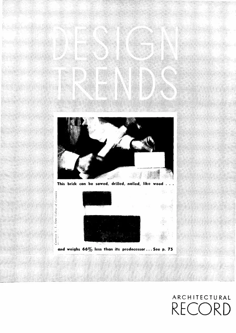
sawed, drilled, nailed, like wood . . .
G L
and weighs 66% less than its predecessor ... See p. 75
ARCH IT EC TU RA L
RECORD

LANDSCAPE DESIG by CARRET ECKBO
DANIEL U. KILEY JAMES C. ROSE
HOW CAN MAN MOST CONSTRUCTIVELY USE HIS LEISURE?
What phys ical accommodations are essentia l to his recreation? How
shall they be designed? In their first study IAR, 4 / 39 , pp. 70-77), the
authors explored such questions relative to the urban environment;
this study covers the rural scene; the final one-scheduled for an
early issue of ARCHITECTURAL RECORD-will analyze the primeval.
"THERE IS A sentimentalism in America about ' the country' as a place to live," says Mr. Will W. Alexander in a r on rural housing. "Fresh ai mind of many of our pe larly city people-is ught of as a sati factory ubs · e for a decent income, whol educatio opportunities, and everythi e ' hich the city dwellers think
a neces ary .... " uch a romantic attitude is all too apparent among American designer , who fail to see that the "old wirnrning hole" needs lifeguards and pure water, that the baseball field need illumination, or that the farm bo may be quite as interested in aviation or theatricals as his city cou in. On th other hand, there is the danger that-once recognizing these need - the building or landscape designer (becau e of hi own urban background and experience) will uncritically apply urban de ign tandard to a mral problem.
The irreduceable requisite of any succe sful planning is that the forms developed will direct the flow of energy in the most economic and productive pattern. This is the criterion in the design of the power dam, the automobile, and the modern cotton field: it hould also hold in landscape and building design, where the energy and vitality directed is that of human being . But to organize the rural areas into the most producti ve pattern require an intimate knowledge of th characteristics, rh ythm, and potentialitie of rural life. For if it i true that people differ little in the fundamental living need of food, shelter , work, and play (regardless of the locality in which they live), it is equally true that the physical aspects of that locality (its topography, fertility, acce sibility, exploitation, and tindu -trialization ) influence and condition the extent to which, and the method by which, it can be adapted to the needs of it people.
Homesteading and the rugged individuali m of the pioneers determined the general characteristics of the rural scene. Thi ystem necessitated staking out claims and living in rela tive isolation to defend and improve the e claims.
DESIGN TREN DS A RC H I TECTU R A L RECORD
68

M THE RURA
The family became the social and recreational unit, supplemented by the school and church in the village which grew up for trading purposes. But, as Mr. David Cushman Coyle has pointed out, with changing technology and local depletion of mine, forest, and soil, we find a new type of rural population which no longer fits into the pattern of living developed by the pioneer. Recent surveys show:
1. Mechanization of agriculture has cut in half the man labor required per bushel of wheat in 1919. In one county of we tern Kansas, it is cut to one quarter.
2. The nation's supply of farm land is steadily decreasing. The National Resources Board reports that as a result of soil erosion, 35,000,000 acres of farm land have been made entirely unfit for cultivation, while another 125,-000,000 acres have had topsoil largely removed. A good deal of land to be inherited by farm youth is practically worthless, and will be abandoned.
3. In spite of decreasing birth rate, we have a large surplus of rural youth in proportion to farms available, and our expanding farm population is squeezed within a shrinking area of farm land. In 1920, for example, 160,-000 farmers died or reached the age of 65; and in the same year, 337,000 farm boys reached the age of 18. In 1930, the surplus of boys with no prospect was 201,000. Vital statistics indicate that with the decrease in infant mortality, this surplus will increase.
4. The present and future farmer is also the victim of an accumulating drain of money from the farm to the city. He sells in a city market controlled by the buyer, and buys in a city market controlled by the seller. The farm youth is educated in rural district , and then .finds it n ecessary to migrate to the city to make a living. Dr. 0. E. Baker, of the U. S. Department of Agriculture, estimates that this movement of population from 1920 to 1930 carried to the city human values that had cost over 12,000,000,000 dollars in private and public cash spent by rural districts.
5. The exhaustion of the farmland in some areas-such as Oklahoma or
AUGU ST 1939
ENVIRO MENT FARM ALL OTHER
rm]QQ~~Q~ (I !!.~~~
Low incomes handicap rural youth.
LOCAL ROADS are the first essential to any rural recreational system-good roads which provide quick, year-round , and economical access to recreation.
RURAL HOUSING is not only substandard technically but so scattered as seriously to impede the development of vigorous community recreation.
RECREATIONAL TYPES of primary importance in the rural environment are those which emphasize group activity-the farmer has solitude enough.
DES I GN TR EN DS
69

ROADS: The specialization in automotive transportation has led to a similar specialization in road design-the parkway (top), the trunk highway, the "freeway" (center). But these are of only secondary interest to the ruralite; most necessary to him is a good system of local-access roads (bottom) to carry him to school, to church, to market, and to play.
DESIGN TRENDS
70
~ansas-and the simultaneous development of a highly mechanized agriculture in others-California, Texas, or Florida, for example-has meanwhile given birth to a new rural phenomenon -the migratory agricultural workers. This group constitutes a quite special and pressing problem over and above that of the rural population generally.
Special characteristics of rural life
What do such trends as those listed above impl; in the design of rural recreational systems? A recognition of the facts that first and foremost the country must be redesigned for country people-i.e., neither from the viewpoint of nor for the benefit of the urbanite. Second, in view of constantly changing social and economic conditions, that such systems should provide a plastic and flexible environment for both local and migratory farmers. Third, that such systems should be closely integrated with both urban and primeval areas, providing the greatest possible intercommunication between all three. Finally, that the following special and fairly constant factors of rural life be recognized:
1. The periods during which recreational facilities can be used bv most rural inhabitants are more seasonal than daily. Whereas the city worker usually has a certain number of hours each day with a summer I or winter I vacation of short duration, the farmer has a majority of free time during "·inter months. This implies an emphasis on enclosed and roofed facilities.
2. Since rural labor is largely physical, and requires the use of the larger muscular system, it is reasonable to supply facilities for recreation which afford experience which is physically, mentally, and psychologicah· different from the major labor experience. i. e .. folk dancing, swimming, arts and crafts, dramatic production, folk pagentry, etc.
3. The present relative isolation of farm families and dependance upon automotive transportation make it desirable for the entire family to seek recreation at one time. This places emphasis on the schooL church, and country park as centers for recreation. and requires facilities for participation hv all age and sex groups at one time. .
4. Since the rnobilc fraternity has become such an important part of the rural scene, special facilities are necessary for the migratory laborers, the tourists, and the vacationists. It is necessary to provide for these groups, and integrate their activities with those of
ARCHITECTURAL RECORD

the more permanent residents without destroying the economic and social balance. The need here is for multiple-use and flexihility in design with particular emphasis on a >'\stem integrated with the high\rn\. sh on' front. waterways, and spots of sl'eni<'. natural. and historic as well as s<'ientifi<' interest.
Thus it <'all lw >'een that rural reneation is based 011 an entireh different set of conditions than urban. and it C'an be approal'hed only by detailed study of specific local requirements in their relation to the region. In general. one can sav that whereas in the l'ities the need is for moff free space I del'entralization I. the rural need is for more intensive use of less space I concentration I to permit and provide for the social intf'gration of a widch distributed population. But thf' latter does not imph mere urbanization of the country any more than tlH' former means mere ruralization of the <'itv .. ,,
Roads are first
The first and 1110st essential element of anv rural reneational environment will nffes:-arih lw an adequate highway svstem. Yet. despite the gigantic advances in highway construction in the past decade, the fact remains that most rural communitif's are without a road system adequate for their needs. Cunscioush or otherwise. the majorit\ of federal and stat!' construction is designed to facilitatP C'ommunication between one city and the next. "With the by-pass or through-high\rn\ prin<'iple on the one hand. and the freeway or border-control pri n!'iple on the other, we have the tool;.: to adapt our future network to meet rPneational need;.: ... hut that is only part of the highway problem. There are still the problems of local al'!'ess and touring .... \\-e must not onh provide good trunk-highway access. hut also good local-a!'cess roads. These local roads must :-erYe directly the various cities. towns, and villages; and must open up recreational lands."<H'
Consolidated communities mean better recreation
Closeh allied with the problem of transportation is that of rural housing. As long as the traditional pattern remains-thinlv scattered houses, one to each farm-it is quite possible that a genuineh satisfactory reneational environment will not be evolved. In this
:?-See "Landscape Design and the Urban Environ~ ment" by Eckbo. Kiley, and Rose, ARCHITECTURAL RECORD, May 1939, pp. 70-71.
**From a paper by Roland B. Greely read at the Outdoer Recreation Conference, Amherst, Mass. March 11. 1939.
AUGUST 1939
HOUSING: Although designed for landless migrants, the physical
organization of many of FSA's western projects is something the farmer may well envy (top). If multiple or row-housing (center) is strange to American rural traditions, there is the possibility of grouping singlefamily houses into tight communities with outlying farms (bottom).
DESIGN TRENDS
71

RECREATIONAL TYPES: Since the "major labor experience" of the farmer is manual and much of it lonely, it is not surprising to find the "get-together" an American institution. Whether for singing, dancing, baseball, or theatricals, the emphasis is on group activity, competition. The need for trained organizing and supervising personnel is at least as great as in the city where such personnel is a recognized necessity.
DESIGN TRENDS
72
connection, it is interesting to note how quickly social integration has followed physical integration in the new towns by TV A, FSA, and in the Greenbelt towns of the former Resettlement Administration. As a matter of fad. lPading agricultural economists art> ad1 ocating a similar consolidation-the rt'grouping of farmers into villages from whil'h they can work their land within a radius of S to 10 miles of them. I Th is t\ pe of village is of course prevalent in Europe and in isolated spots of America I. There is already a general trend towards consolidation and reorganization of schools and school districts. And the recent western projects of the Farm Securitv Administration-while of course designed for the landless migrantsclearly indicate the phi sic al adrnntage:of a similar concentration of housing facilities.
What types of recreation are required?
WP A research reveals that the average rural community needs provision for the following types of recreation:
1. Crafts and visual arts, graphic and plastic. (These might well be organized around the rapidly developing sciem·p and manual arts curricula in most rural high schools.)
2. Recreational music, including outdoor concerts, popular orchestras, group singing, etc.
3. Dancing-ballroom, folk. social square, tap, ballet, etc.
4. Recreational drama, including marionettes and puppets, pla) s, motion pictures, pageants, festivals, etc. The outdoor theater is recommended as an ideal form; it also encourages children in their own improvisations.
5. Childrens' play center, including such equipment as slides, horizontal bars, swings, see-saws, trapezes, marble courts, sand box (preferably adjacent to the wading pool with an island where children can play and sail boa ls I.
6. Sports and athletics I conditioned by the major labor), including baseball, softball, football, basketball, tennis, archery, horseshoe pitching. swimming and water sports, snow and ice sports, hiking, camping, and nature study.
7. Other adivities and special events: picnics require an area of several acres with outdoor fireplaces, harbecue pits, wood supply, and provisions for waste disposal (can also serve as a wayside camp for motorist I. Occasional field days, community nights, agricultural fairs, carnivals, traveling circuses can 01Tupy the largest free area used for sports at different seasons.
ARCHITECTURAL RECORD

What sort of facilities are implied?
All these activities require special equipment centering around the district school, rural park, or other location designed to serve the rural inhabitants rather than the urban overflow. The usefulness is multiplied by complete and well designed flood lighting, since most outdoor activities come in the summer -precisely when the majority of rural inhabitants are busiest during the day.
Although there is perhaps no single form which meets so well the various needs of the rural community, the outdoor theater has never been satisfactorily reinterpreted as a present day recreational form in its own right. Developed as an integral part of the rural park, and in a dynamic, three-dimensional pattern, it provides for almost constant use by all age groups. Actual productions require the assistance of practically all types of craftsmanship which are physicaly, mentally, and psychologically different from the major labor experience. With stages at different levels, following the natural contours, and seats ingeniously arranged to accommodate both large and small audiences (top, right) ; with the present perfection of sound amplification; and with "scene-shifting" by spotlights instead of curtains, a type as flexible as the auditorium without its expense or intricacy is achieved. Its utility is as flexible as its organization, since it accommodates both large and small productions, festivals, pageantry, improvisations, summer-theatre groups, exhibitions, meetings, picnics, and talks.
Many opportunities are overlooked, by sticking too closely to arbitrary and static concepts of receational planning. For example, the local airport is a form which deserves attention because of the interest and activity which surrounds it. Already a center of Sunday afternoon interest for many an American farm family, it orients the rural population to a larger social concept of the world outside, as well as satisfying the characteristic American interest in the technical. The same thing might be said about the old canal, the abandoned railroad engine, and the automobile junk pile-all of which hold an endless fascination for small children.~'
*Recently, a recreational expert, showing some distinguished visitors in Washington the advanced planning of children's play areas in one of the greenbelt towns, was somewhat chagrined to find them quite deserted. But, as they started back to Washington, they passed the town's children playing on a dump used for fill along the roadway. One of the ladies of the party turned to the exvert and inquired brightly: "And I suppose you will plan something for these children, too?"
AUGUST 1939
RECREATIONAL AREAS: Recognition of rural recreational needs is too recent to permit of much agreement as to design standards. An Alabama airport (bottom) has been designed to include a club house, golf course, athletic field, and tennis courts; an outdoor theater in North Carolina is already famous for its folk festivals; and Mr. Rose has designed an outdoor theater in which multiple stages surround the audience. permitting great flexibility of use, elimination of elaborate equipment_
DESIGN TRENDS
73

DESIGN: The alleged "romantic informality" of the countryside is not borne out by the fields themselves. Here the face of nature is being quite as consciously reorganized by man for his increased welfare as in the city. These fields (top) do nor "blend" with nature-they are in great contrast with it. Whence, then, the theory that landscape and building design must go rustic in the rural areas?
DESIGN TRENDS
74
Towards scientific landscape design
With the exception of urban infringement in the form of summer colonies, tourist camps and hotels, and commercial recreational facilities designed mainly for the use of urban motorists, little provision for recreation exists outside America's cities. Indeed, urban invasion-in the form of commercialized amusements, billboards, suburbanization and the "naturalism" of "preserving rural beauty" by screening out rural slums with a parkway-prevents an indigenous and biological development of rural beauty. It is thus that we handicap ourselves with a static and inflexible environment, and lose the opportunity of developing forms which express the needs of the people and the qualities of the region.
This is particularly unfortunate as concerns landscape design. The country is thought of as a restorative for the exhausted city dweller, and a land of plenty for the farmer. When help is offered by well-meaning urban societies it is, as often as not, "for the preservation of rural beauties" which look well on a post card. Another group is afraid of destroying the "delightful informality" by intelligent and straightforward reorganization of nature for the use of man. They resort to "rustic" bridges, and "colonial" cottages which will "blend" with nature. Obviously this point of view can be held only by those who do not live on the land.
We may as well accept the fact that man's activities change and dominate the landscape; it does not follow that they should spoil it. Writing on the redesign of the American landscape, Paul B. Sears has said_,_: "Not only must the scientist of the future work in awareness of social and economic processes, but he must clear a further hurdle. . . . The scientist must be aware of the relation of his task to the field of aesthetics. What is right and economical and in balance is in general satisfying. Not the least important symptom of the present decay of the American landscape is its appalling ugliness. . . . The landscape of the United States, with its two billions of acres for a potential population of one hundred and fifty million, or even two hundred million, can be made a place of plenty, permanance, and beauty. But this most assuredly cannot be done without the aid of science. Nor can such aid be rendered by men of science unaware of the task which confronts them."
*"Science and the New Landscape," Harper's M"gazine, July 1939, page 207.
ARCHITECTURAL RECORD

CLAY PRODUCTS IN MO DERN BUILDING DESIGN
, '
AUGUST 1939
In this study, third in a series on the subject of recent trends in building materials, Mr. Hansen traces the main lines of current development in clay products and indicates the new potentialities inherent in one of man's oldest and most important building materials .
By JAMES H. HANSEN
THE FIRST 6,000 YEAHS of the hi tory of clay products in architecture is easily summarized: together with wood and stone, it shared a three-way monopoly of the field. It was only in the latter half of the nineteenth cen tury that new materials and then new structural systems began seriously to threaten the upremacy of brick and tile. In this
co untry, the last decades of the century saw first the introduction of tructural steel and then the rapid expansion of steel framing. Meanwhile, in England, a group of enterprising engineers, experimenting with the possibility of reinforci ng brick ma onry, discovered that a mortar of Portland cement gave greater strength in brick beams. This simultaneous di scover y of reinfor ed brick masonry and Portland cemen t was overlooked by the brick industry. Yet it was only a step for the next experimenter to eliminate the brick from the beam en tirely, and arrive at what we know today as reinforced concrete. Soon to follow was the structural concrete frame; and thus began the "confused" phase of clay products history.
That such a description is well-merited is obvious when we analyze the developments of the period- thi ck, heavy walls of load-carrying type were suddenly placed on beams and columnsthe design of which was, to a large extent, controlled by the weight of these same walls; meaningless non-supporting
DESIG N TR E N DS
75

CLAY PRODUCTS: Physical Properties
Fig. I. Reinforced brick slab, 3% in. by 2 ft. 8 in. by 8 ft. 0 in., with load of 397 lbs. per sq. ft. Reinforcing members are six %-in. round bars placed longitudinally 1fi in. from bottom of slab.
Fig. 2. Reinforced tile beam and slab, designed for a load of 50 lbs. per sq. ft., with i 80 lbs. per sq. ft. Similar tests ran up to 720 lbs. per sq. ft.
~ 4000 :t
~3000 ~ "' ~ 2000
"' ~ ~I 000
·~ t:.. 5
u 0 0
1 I \ I
I '\\r-..... I
I b
'i ,.,, --
I I I o Bm Bnck Piers -
I •12m Brick Piers 0 6m Diamefer Cylinders
I'<...... - Brick Masonry
I Concrete Cyh"nders --p---r-1--1---
4 6 8 10 Ratio, Height to Thickness,~
I
12
0000·" :ii ~ ,;
8000~-
s 60001
8 £
40001
·~
2000 i Fig. 3. How shape affects strength of specimen.
DESIGN TRENDS
76
Expressed in pounds per square inch Com- Modulus Modulus
pressive Tensile of of Elas-Strength Strength Rupture ticity
Bricks 2,000-33,000 50-1,000 150-2,500 400,000-Average 7,500 200 800 5,000,000
Brick masonry. Up to 4,000 Up to 120 Up to 150 300,000-3,000,000
Tile Gross end area I ,000-15,000 Net end area .. 1,500-30,000 Maximum Gross side area. 700- 6,000 3,000,000
Tile masonry End construction Up to 900 Side construction 400
Table I. Showing disparity between unit and wall strengths.
Expressed in pounds per square inch Unit Strength Mortar Strength Wall Strength Source
Cured Cured Brick Dry Wet
17,600 1,390 3,220 3,374 (I)* 2,670 465 640 1,040 (I) 5, 124 1,847 2,696 1,402 (2)t
Tile Net end area
9510 500 (1) Gross end area
3540 465 640 (I) Gross side area
1590 275 (I) * "Structural Properties of Six Masonry Wall Constructions'' by Herbert L. Whittemore, Ambrose H. Stang, and Douglas E. Parsons, Report BMS-5 of the U. S. Dept. of Commerce. t "Effect of Shape of Specimen on the Apparent Compressive Strength of Brick Masonry" by W. J. Krefeld. Report of Committee C-15. Appendix 363, Proceedings of the Forty-first Annual Meeting of the American Society for Testing Materials, Vol. 38, 1938.
Table 2. Recent tests on specimen walls 8 ft. high.
Expressed in pounds per square inch
Type of stress
Compression Extreme fibre stress 1n bending ...
Direct compression on ~e~ .............. . Shear
No web reinforcement With web reinforcement, taking entire shear ....... .
Bond (Deformed bars) Vertical ..... Horizontal
Modulus of electricity E Modulus of rigidity G
(Modulus of Elasticity in shear).
1 C-1f2L-41f2S 1 C-41/iS Mortar Cement Grout
400
300
25
50
60 80
1,200,000
480,000
500
400
30
60
60 80
\ ,500,000
600,000
Table 4. Uniform Building Code for reinforced brickwork.
ARCHITECTURAL RECORD

arches; elaborate piers and buttresses for which steel did the real work; etc., etc. In other words, this was the transition stage between the bearing wall and the skeleton frame, with the construction habits of the former superimposed on the latter.
Today there is accumulating evidence that a third-and functional-phase is arriving, which will see structural clay products frankly and efficiently solving the construction problems of the day with little or no recourse to trite imitation of the feats of a glorious past.
It is not surprising that there has been so much confusion and bad practice in the design and use of clay products. In contrast, the orderly development and exploitation of recently developed materials appears extraordinary -new materials which did not carry with them the burden of tradition and tht centuries-old habits of use. New requirements brought forth these specialized materials, but little attention "as paid to similar possibilities in the most common material-clay.
Here, then, lay the real problem for those interested in structural clay products, which long preceded testing machines, and were regulated by archaic traditional assumption. The problem has been to determine-after 6,000 years of use-the characteristics of the material and exploit its advantages scientifically. This problem has been faced after a long delay. As the study proceeds, we find a rather surprising and confusing array of data, which when compared with popular assumptions is little short of amusing. We find on analysis that burnt-clay products rank either at the top, or very near the top, of many of the scales ordinarily used to measure the value of building materials.
Analyzing performance of clay products
Analysis of the relative values of building materials must always be qualified by the further question: relative to what? Clay products have often suffered from such incomplete analyses. For example, in the case of insulation against heat flow, comparisons have been made between purely insulating materials and multi-purpose structural materials such as clay products. As logical would be the comparison of the one lineal foot of 4-in. brick masonry capable of sustaining a load of 100,000 lbs. to the infinite amount of insulation material necessary to carry the same load. ~-o attempt will be made to detail their properties here, but the reader
AUGUST 1939
is asked to name for himself building materials which will come through fire with as little damage as unit clay masonry; which have given evidence of equal resistance to decades of exposure; which are as effective against sound penetration; which have as little volume change or plastic flow.
So common are some of these misconceptions about structural clay products that brick and tile masonry is seldom stressed to more than 100 lbs. per sq. in., and most building codes limit tile to around 100 lbs. per sq. in., and brick to 225 lbs. per sq. in. Yet all laboratory tests indicate that even under ordinary conditions and using ordinary materials, the ultimate compressive strength of brick and tile masonry is much greater than the above (See Tables 1 and 2.)
Unfortunately the use of clay products in masonry construction has been the responsibility of several groupsmanufacturer, architect, builder, and the various specialists. The consequence has been a tremendous variation in results-even though most of these variations are above the safe requirements of construction practice. On the other hand, there are deficiencies inherent in unit clay masonry which must be overcome if this method of construction is to continue in wide use. These disadvantages-water penetration, effiorescence, excessive weight, lack of tensile strength, intricate dimensional calculations, and costly job installation -are being carefully studied and some progress made on their elimination. In general, this progress takes place at three distinct qualitative levels: ( 1) improvements in the use of standard clay units in standard masonry assernblies-i.e., improvement of mortar joint, elimination of moisture, etc.; (2) development of new clay units and new masonry assemblies for larger unit size, greater strength, less weight, etc.; ( 3) development of entirely new processing methods-i.e., rolling and annealing of red-hot molten clays, chemical (instead of fire) curing of clay products, etc.-for highly specialized use.
Improvements in use of standard units
Cutting through all problems of masonry construction is the one of jointing. Until recently the clay-products industry has left this problem in the hands of other people. The result has been most confusing, and the data available-furnished in the main by proponents of one mixture or another-is so contradictory
that the industry has been put on a spot. A thorough investigation of the problem is now in progress. Pending its conclusion, the clay products industry has presented the following recon~mendations for mortars:
Mix by Volume Cement Lime Sand Recommended Use
Minimum expected mortar strength. lbs. per SQ. in.
6 General use 600
2 9 f Unexposed l 200 (Non-load bearing) rReinforced brickl lmasonry, ex-I
l/4 j treme loads, ex-( 1,500 I posure, sewers. I Letc. J
It is probable, however, that the difference between all the customarily recommended mixes are again variations above a satisfactory minimum under normal circumstances. The main trouble is that few of the mixes actually used follow the recommended formul~e and are seldom used in the manner prescribed for them. For this reason, it appears that the real solution to the jointing problem will be found in some manner that eliminates dependence on job manufacture. Certainly it seems strange that since mortar joints have always been the most vulnerable spot in masonry construction, no change or improvement has been made in them in hundreds of years.
Closely linked up to the problem of mortar control is that of efflorescence. The origin of all effiorescing salts is not as yet known. Indications are that some of them are formed after the building is up, due to chemical reactions with air-borne gases, etc. A simple test called the Wick test will help eliminate most of the salts in the beginning, however. This involves setting samples of the brick to be used on end in each of six pans. Into the pans is then poured, to a depth of about 1h in.: ( 1) distilled water; ( 2) distilled water and the cement; ( 3) distilled water and the lime; ( 4) distilled water and the sand; ( 5) mixing water to be used; ( 6) actual mortar combinations proposed. The water is replenished for five days to prevent drying. If effiorescing salts are present in any of the materials or combination of materials, they should appear upon drying. Then, by a process of elimination, salt-free materials can be selected.*
*Mortar and clay-products engineers working independently on this problem have recently come to the conclusion that joint effort is necessary. Consequently, a joint committee composed of members from ASTM committees C-15 (masonry units) and C-J 2 (mortars) has been appointed. From this it seems certain that tests similar to the above will be written into ASTM specifications for the various materials in the near future.
DESIGN TRENDS
77

CLAY PRODUCTS: New Assemblies
Fig. 4. Simplest of all advances in ordinary brick masonry is this hollow wall construction. Although boasting some advantages, moisture can still penetrate via headers.
rig. 6. Reinforced brick adds potentialities to the field of small-unit masonry construction, particularly valuable where unusual stresses necessitate structural flexibility.
DESIGN TRENDS
78
Fig. 5. Moisture penetration is eliminated, strength unimpaired by Cavity Wall construction. Tied by 1/4 -in. steel rods, outer 4 in. serves as surfacing, inner carries load.
Fig. 7. Increasing variety of shapes in hollow tile yield possibility of prefabricated reinforced members. Typical unit employed (top) in prefabricated beams (bottom).
ARCHITECTURAL RECORD

lmpr-oved pedor-mance from cavity walls
Extensive research indicates that moisture-proof walls can be made with almost any reasonable selection of bricks and mortar and reasonably competent workmanship; but job conditions are such as to cause failure in both respects. Facing this fact and realizing that job conditions are beyond its control, the clay-products industry has, aside from publishing general recommendations, introduced a new method of construction designed to overcome these job defects. This method is Cavity Wall construction (Fig. 5), consisting of two 4-in. (greater if loads demand) walls which, except for l/1 -in. steel ties, are completely separated by a 2-in. air space. Moisture or water penetrating the outer 4 in. can go nowhere except down and out again, thus leaving the inner section dry. The load is, except for the roof, carried only by the inner 4 in. of masonry. This forms a truly functional arrangement of clay masonry. The inner 4 in. is, under average conditions surrounding two-story residence construction, capable of sustaining 25 times the load to which it is subjected, and the outer 4 in. forms a durable protective skin. The result is a much more eflicient organization of the same quantity of brick or tile than usual. Cavity walls, aside from a load-carrying capacity almost equal to a solid wall, offer considerably greater protection against dampness, and yield better heat-transmission coefficients.
Reinfor-ced br-ick and tile
The use of steel rods in ordinary brick and tile masonry is so logical and has been so thoroughly investigated that it is surprising so little use has been made of them. Similar in theory to reinforced concrete-the design formulae are almost the same-there are many situations in which they can effectively and economically compete with reinforced concrete and steel. When walls are built of masonry it is a simple matter to transform the masonry above an opening from a dead load on a steel or concrete beam, into a functioning beam that will carry not only itself but the floor loads also. Using the same quantities of bricks and mortar, it becomes only a matter of balancing the cost of temporary centering and reinforcing rods against the cost of a steel beam and bearing plates to determine whether it pays or not. The writer recently utilized this principle of Cavity Wall construction over 11-ft_ openings by the
AUGUST 1939
simple expedient of using 22 in. of the wall as a beam, spacing %-in. rods at required distances, and filling the cavity with mortar to that height. Keinforced brick floor slabs, just emerging from the laboratory stage (Fig. 1), also give promise of economical and satisfactory performance.
Complete regulations for the use of reinforced brick masonry are included in the Uniform Building Code on the Pacific Coast. Earthquakes aroused engineers in that territory to the necessity of reinforcing unit masonry, and the result has been very successful. Complete structural frame and walls are regularly built of reinforced brick masonry in that area (Fig. 6) .
The variation in the method of laying the units indicates that our habit of cross bonding bricks is open to question. Groutlock (reinforced brick) masonry uses no headers. A wall similar to the cavity wall is built with horizontal and vertical reinforcing rods placed in the cavity, which is poured full of grout as the work progresses. Such brick walls are the strongest ever built. Furthermore, in most load tests on plain brick masonry the headers were always the first to break, thus throwing a sudden load on half the wall, causing final failure through a shock simliar to impact. The elimination of headers will also reduce the tendency for water to penetrate, since at all points in the wall the moisture will be faced with two surfaces to break through. It takes longer for water to penetrate an 8-in. assembly of brick, mortar, and brick than 8 in. of the same brick alone, or 8 in. of the same mortar.
Reinforced hollow tile beams and lintels are of course more widely known. Enterprising producers in the mid-west are now marketing precast reinforced tile beams up to 22-ft. spans in competition with other fireproof floors. Advantages claimed for them are good strength-weight ratios and great reduction in volume change, which has caused defects in masonry construction when concrete floor and roof were poured against the walls (Fig. 7).
Standar-dization of units needed
Commencing with a cored rectangular hollow tile unit, the industry now produces dozens of shapes and types of hollow tile for various uses. The latest improvements, in which more attention was paid to use and handling, have been most successful. A broader use would no doubt be made of such hollow
units were there not such a variety to choose from-causing confusion and variations in installation technique and results. Many of these shapes were developed to avoid patent trouble, and it seems that a greater use of hollow tile as a whole would result from the general scrapping of patent rights-many of which have not been profitable to the holder. This would permit concentration on a few of the best type, and greater standardization of construction practice.
Double-size brick are now popular in some sections and the trend towards large slabs and "stave" tiles is described below I Figs. 10, 11) . The gradual increase in the size of glazed products has been most noticeable. A few years ago brick-size glazed ware formed half or more of the output-today larger units notably 5 by 12 in. or 8 hy 16 in. play the dominant role-both for interior and exterior use. Lower in cost, and with a greater variety of shape and color and increasingly high standards of performance, glazed brick and tile are readily finding new uses. Simpler processes, which permit the use of glazes on the more common clays and shales, are making it possible to use this material more generally. Light-weight acoustical tile, with suitable finishes, having sound absorption factors of 20% or more, are now commercially produced.
New for-ms hold gr-eat pr-omise
Further variation in shape and assembly is illustrated in Rhombrix, introduced recently in England (Fig. 9). Here the traditional shape of bricks was discarded in an attempt to make walls stronger and more flexible, and to achieve greater moisture resistance by the use of rhomboid shapes instead of rectangular. Another variation, the TightW all brick, is being offered in this country (Fig. 8). Working on the correct assumption that most leaks through walls occur because of faulty vertical joints, a slotted brick-which provides greater space in which to make the vertical joint-was devised. The advantages claimed are that vertical joints, made by pushing mortar down into the slot and between the bricks after the bricks are placed, instead of making vertical and horizontal joints at the same time, result in better adhesion and tighter work.
Changes in both shape of unit and method of erection have been used on the construction of the Belgian Building at the World's Fair (Fig. 10) in
DESIGN TRENDS
79

CLAY PRODUCTS: New Forms
Fig. 8. The new "Tightwall" brick provides slotted ends for improved vertical joint. Claimed for this brick are better adhesion and tighter work.
Fig. I 0. Use of light clay units as a nonstructural surfacing medium exploits inherent resistance to weather and fire, thermal and acoustical insulation.
DESIGN TRENDS
80
2
~.~ ..... · ... \.
-~ -- -· . . --~ ,/ - ~ / ---.
i : I
Fig. 9. Abandoning the rectangle, England's new "Rhombrix" claims increased strength and moisture resi£• tance, with greater flexibility in use.
Fig. I I. Use of large, load-bearing clay units and elimination of mortar joint yields efficient and economical construction system in this new silo.
which clay slabs 2 by 18 by 24 in. are hung on light steel cross members and later caulked up with a mastic.
One of the most interesting uses of these new types of clay units is in the "tile-stave" silo construction, now being very successfully employed in the midwest (Fig. 111 . Here the mortar is dispensed with, since it is claimed silage acids have a harmful effect on the cements. Hollow tile "staves" 4 by 12 by 24 in. are set on end in beds of asphaltic mastic, and the continuous vertical joint is insulated with strips of redwood caulked with mastic. The whole circular construction is then tied in place with hoops of galvanized steel rods and tightened to form a rigid structure. Advantages claimed for this method of silo construction are greater durability, strength, and insulation, as well as greater protection against acids, fire, frost, and defects in appearance.
New processing methods ahead
Perhaps the most stimulating possibilities of all lie in the introduction of entirely new methods for processing the clay itself.
Laboratory experiments in moulding and rolling red-hot clays into various shapes indicate a radically different method of clay-products manufacture. After the shapes are moulded they are annealed at high temperatures, the result being a product which does not shrink after forming, and is considerably lighter in weight. The lack of shrinkage and warping make it possible to form very thin clay slabs, judging from the few samples of 4 by 8 by ,Ys-in. slabs that were successfully made. The use of large thin clay slabs for durable surfacing of other materials is the goal. This treatment should make it possible to incorporate tensile steel rods into the unit itself. Thus, there is a real prospect of prefabricated reinforced clay beams, columns, and wall units-of large size and good strength-weight ratio.
The substitution of chemical treatment for fire treatment of clays has also been accomplished, and the experimental units so produced show remarkable possibilities. If somewhat lacking in durability, they have greater flexibility for use in interior and unexposed situations.
The making of porous bodies is still more or less in the laboratory stage. There are, however, some encouraging reports from that quarter. Clay bodies weighing only 2 to 3 lbs. per cu. ft. have been made-which show possibilities as insulating material as well as raw material for further processing.
ARCHITECTURAL RECORD

CURRENT TRENDS OF BUILDINC COSTS Cemplled by Clyde Shute, Maaager, Statistical and Research Division, f. W. Dodge Corporation, from data collected by E. H. Boeckh b Associates, Inc.
CURVES INDICATE trend of the combined material and labor costs in the field of residential frame construction. The base line, 100, represents the U. S. average for 1926-1929 for residential frame construction.
both this year and last. B ( ~-:5
95 = 0.158. ) Conversely it may
be said that costs in B are approximately 14% lower than m
Tabular information gives cost index numbers for the nine common classes of construction. The base, 100, in each of the nine classes represents the U. S. average for 1926-1929 for each particular group. The tables show the index numbers for the month for
Cost comparisons, as percentage differences for any particular class of construction, are possible between localities or periods within the same city by a simple process of dividing the difference between the two index numbers by one of them. For example: if index for city A is 110 and index for city B is 95 (both indexes for A and B must be for the same class of construction), then costs in A are approximately 16% higher than in
(
110-95 ) A -~~ = 0.136.
Similar cost comparisons, however, cannot be made between different classes of construction since the index numbers for each class of construction relate to a different U. S. average for 1926-1929.
CONSTRUCTION COST INDEX U. S. average, including materials and labor, for 1926 - 1929 equals I 00.
ATLANTA July'38 July'39 150~-----.---r--.,.----.---r--r---r--..--------r----.----,
Residences 140 l---+-+----1--+--+---+--+--t---+-----t fro me ______ _ 82.2 83.3 130 Brick _______ _ 85.3 86.5
120 Apartments 11 O Br. & Wood __ 85.9 86.4 100 Br. & Cone._ __
Br & Steel __ _ 96.4 94.8 96.8 94.5
80.0 81.1 87.9 88.9 98.5 93.3 97.8 97.2
BALTIMORE July'38 July'39 150.----r-.,.----.---,---..---,--..,.---,---,-r-------,---,.---,
140 1----+-+-----+--+--+----+--+---J--t-----t Re;;~~:~~~----11 92.1 93.2 130 Brick _______ _ 95.0 95.0
120 l---+-+----1--+--+----+---+-1----l--l.A_p_a~rtm_e_n~ts_I __
11 o t----+--+---i--+----1---+--+--- +---+-----1 Br. & Wood__ 94.3 95.6 Br & Cone.___ 98.6 , 100.2
100 ~ Br & Steel___ 98.6 : 100.0
90 Comm. & Fact. 80 frame________ 91.8 93.7 70 1---+-+--t--+--+----+--+-·--+--+---J Br. & Wood__ 95.9 , 96.8
Br. & Cone.___ 99.0 ~ 101.3 60 l----l---1-----1--+--+----+-+----l--+-----I Br. & S tee I ___ 1 00.6 i 1 03. 1 50L--'---'--L_,..,.,.,~-'---'---'--.J...--'--..__ ____ _.__-'---~
'36 '37 '38 ":;9ALF JULY AUG SEPT. OCT. NOV DEC
BIRMINGHAM 150 1401---+-+----l--+--+----+-+----l--+-----I 1301-----+-+-----+--+--+----+~-
120 1----1---1-----1--+--+
ll 0 l---+-4---+--l--t---+---t--t---t----I 100
90
80
70
Residences frame _______ I Brick ________
Apartments Br. & Wood __ Br. & Cone. ___ Br. & Steel ___
Comm. & Fact. Frame ________ :
July'38 July'39
86.4 87.7 89.6 90.8
90.3 91.4 96.5 96.2 93.6 96.3
83.l 84.4 93.7 94.9
601---+--l----+--+--+---+--+----l--+----l 50L__J___1--L_,..,.,.,L--'---'---'--.J...---'--..__-----'----~
'36 '37 '38 1".;9ALF JULY AUG. SEPT. OCT. NOV. DEC
Br. & Wood __ j
Br. & Cone.. __ 96.5 %.0 Br. & Steel __ 96.3 95.3
BOSTON 150 140
130
120
110 100
90 80
70
60 50
'36 '37 '38 "'.3H9ALF JUL'' AUG SEPT. OCT. NOV. DEC
AUGUST 1939
July'38 July'39
--.~--
Apartments Br & Wood__ I 07.2 109 1 Br & 113.9 I 115.8 Br & t 11.3 ! 112.8
Comm. & Fact. frame_____ 103.0 1045 Br. & Wood .. 108.4 110.9 Br. & Cone ___ t 15.3 118.3 Br. & Steel ____ , 115.8 117.2
CHICAGO 150.----r-.,.----.---,---..-----,.--.,.---.,.---r----,r-------,----.-~
140t---+--+-----+--+--+---+--+--+--+----I 1301----t---t---t--+--+----t---t---t--+---J
1201-----r--i---·-- ---~---t--l-__;f---1--~::-:::::;=-:~--t--r----1
llO t=~~··i==····t:=t1=t=1=!j 100 .•••••.
90t---+--+-----+--+---+---+--+---+--+----lt-------+------t-----l 80t---+--+-----+--+--+---+--+--+--+----I 70t---+--+-----+--+--+---+--+--+--t----I 60t----t---r---t--+--+----t---t---t--+---J so~~-~~-.,.,.~-~~-~--'-~~~-----+----'---'
'36 '37 '38 1".;;lF JULY AUG. SEPT. OCT. NOV. DEC
CINCINNATI 150
140 130 120
110
100
90
80 70
60 50
II= ~ --
~ ~-
36 '37 '38 1".;;" JULY AUG SEPT. OCT. NOV. DEC.
CLEVELAND 150
140 130
120
110 100
90 80 70 60
50
• : -
--
'36 '37 '38 1".;;" JULY AUG SEPT. OCT. NOV. DEC.
July'38 July'3>
Residences Frame _______ 98.6 103.3 Brick ________ 102.3 106.4
Apartments Br. & Wood __ 102.1 105.9 Br. & Cone._ __ 112.2 114.9 Br. & Steel ___ 108.6 110.9
Comm. & Fact. Frame ________ 98.0 103.0 Br. & Wood __ , 104.3 107.3 Br. & Cone. 1 114.3 118.3 Br. & Steel_::: J 112.7 ; 114.0
July'38 July'39
Residences I I frame _______ 1 105.9 i 106.0 Brick ________ 109.9 i 109.7
Apartments I
Br. & Wood __ 109.6 109.3 Br. & Cone._ __ 116.4 116.0 Br. & Steel ___ 113.5 113.2
Comm. & Fact. Frame ________ 106.7 107.1 Br. & Wood __ 110.4 109.9 Br. & Cone._ __ 119.5 119.l Br. & Steel ____ 118.7 118.4
DALLAS July'38 July'39 150,----,--,----,---.-,.------,--,----c--,----r---.,.----,------,
Residences I 1
140 t----+--t-- - -·-- -·· frame_______ 91.91' 93.2 130 ~ --t---t--+---t-- - -·· ___ ,_ Brick________ 93.0 94.7
110 !----+--+----+ Br & Wood__ 93.5 95.8 120 ~---.,.- - Apartments I 1·
10900 lllll!llllf:::::~:::i-==l===~=t==l==l-~JB~r~&'_jtCo~n~c~-~--j_9~8~.5;_+_~9~7~.8~ Br & Steel 98.5 1
99.6
Comm. & Fact. I 80 t----+--r----t--+--r---t---t----t--+----t from e ________ 1 91 .4 ' 92.5 70 - -+--+---+--+---le---+--+---+-+-- Br. & Wood__ 93.9
1
95.2 60 1-----r----t--+--r---t---t----t--+----t Br. & Co nc._ __ I 98.2 98.7 so~~i-~~-.,.,.~-~~~~~~~~~-Br_._&_S_te_e_l ______ ~I· l_o_o._3--'-1_01_.3~
'36 '37 '38 1".;;LF JULY AUG. SEPT. OCT. NOV. DEC.
DESIGN TRENDS
81

DENVER 150
140
130
120
110
100 ~ 90 80
70 60
-
50 '36 '37 '38 1 ".~tLF JULY AUG. SEPT. OCT. NOV. DEC.
DETROIT 150
140
130
120
110
100
90 80
70
60
50
~ '36 '37 '38 1''.;;LF JULY AUG. SEPT. OCT. NOV. DEC.
KANSAS CITY. 150
140
130
120
110
100
90 80
70
60
50
~
'36 '37 '38 1".;;LF JULY AUG. SEPT. OCT. NOV. DEC.
LOS ANGELES 150
140
130
120
110 100
90
80
70
60
~ ··-
50 '36 '37 '38 ht HALF JULY AUG. SEPT. OCT. NOV. DEC.
'39
MINNEAPOLIS 150
140
130
120
110 100
90 80
70
60
50 '36 '37 '38 1".;;lf JULY AUG SEPT. OCT. NOV. DEC.
NEW ORLEANS 150
140
130
120
110
100
91
81
71
60
50
--== I I
'36 '37 '38 "'.;;lf JULY AUG. SEPT. OCT. NOV. DEC
DESIGN TRENDS
82
Residences Frame _______ Brick ________
Apartments Br. & Wood __ Br. & Cone. ___ Br. & Steel ___
Comm. & Fact. Frame ________
Br. & Wood __ Br. & Cone. ___ Br. & Steel_ ___
Residences Frame _______ Brick ________
Apartments Br. & Wood __ Br. & Cone. ___ Br. & Steel ___
Comm. & Fact. Frame ________ Br. & Wood __ Br. & Cone. ___ Br. & Steel ____
Residences Frame _______ Brick ________
Apartments Br. & Wood __ Br. & Cone. ___ Br. & Steel ___
Comm. & Fact. Frame ________ Br. & Wood __ Br. & Cone._ __ Br. & Steel_ ___
Residences frame _______ Brick ________
Apartments Br. & Wood __ Br. & Cone. ___ Br. & Steel ___
Comm. & Fact. Frame ________ Br. & Wood __ Br. & Cone. ___ Br. & Steel_ ___
Residences Frame _______ Brick ________
Apartments Br. & Wood __ Br. & Cone. ___ Br. & Steel_ __
Comm. & Fact. Frame ________ Br. & Wood __ Br. & Cone. ___ Br. & Steel_ ___
Residences Frame _______ Brick ________
Apartments Br. & Wood __ Br. & Cone. ___ Br. & Steel ___
·Comm. & Fact. Frame ________ Br. & Wood __ Br. & Cone. ___ Br. & Steel__ __
July'38 July'39
109.2 111.9 110.0 111.4
105.3 110.6 114.8 115.3 113.2 114.0
111.3 114.4 107.0 108.7 116.l 116.6 106.8 116.4
July'38 July'39
96.3 98.2 100.8 102.0
IOI.I 102.3 108.4 108.0 107.2 107.l
96.0 97.8 103.0 103.7 110.l 109.3 112.0 110.9
July'38 July'39
101.2 104.0 107.2 109.5
107.0 109.3 117.8 118.l 114.8 115.2
100.5 103.0 110.4 112.7 121.2 121.5 119.0 120.1
July'38 July'39
87.8 95.8 94.3 97.5
94.7 97.8 102.3 104.0 103.9 105.2
92.2 95.4 93.8 97.2
102.3 105.5 105.9 106.5
July'38 July'39
100.5 101.6 106.5 104.8
103.2 104.0 112.9 113.6 110.6 110.7
101.3 102.3 102.9 103.5 116.6 117.2 114.4 114.5
July'38 July'39
86.8 88.6 87.9 90.4
89.1 91.3 92.9 96.0 96.2 98.6
85.5 87.8 89.6 91.8 92.0 96.l 96.6 99.l
NEW YORK 150
140
130
120
110
100
90
80
70
60
50
~ ~
'36 '37 '38 1".;;lf JULY AUG. SEPT. OCT. NOV. DEC.
PHILADELPHIA 150
140
130
120
110
100
90 80
70
60
50 '36 '37 '38 1".;;lf JULY AUG. SEPT. OCT. NOV. DEC.
PITTSBURGH 150
140
130
120
110
100
90
80
70
60
50
~ -{ )
'36 '37 '38 1".;;lf JULY AUG. SEPT. OCT. NOV. DEC.
ST. LOUIS 150
140
130
120
110
100
90 80
70
60
50
- ~ -'36 '37 '38 t".~tlf JULY AUG. SEPT. OCT. NOV. DEC.
SAN FRANCISCO 150
140
130
120
110
100
90
80
70
60
50 '36 '37 '38 1".;;lf JULY AUG. SEPT. OCT. NOV. DEC.
SEATTLE 150
140
130
120
110
100
90 80
70 60
50
~ '36 '37 '38 t".;;lf JULY AUG. SEPT. OCT. NOV. DEC
July'38 July'39
Residences Frame _______ 119.3 122.l Brick ________ 121.l 123.6
Apartments Br. & Wood __ 119.5 122.6 Br. & Cone. ___ 128.2 130.9 Br. & Steel ___ 123.8 126.l
Comm. & Fact. Frame ________ 122.7 125.3 Br. & Wood __ 116.3 120.l Br. & Cone. ___ 130.3 133.8 Br. & Steel ____ 128.1 130.2
July'38 July'39
Residences . \ frame _______ 93.9 99.l Brick ________ 98.4 102.3
Apartments Br. & Wood __ 98.5 102.8 Br. & Cone. __ 105.3 105.6 Br. & Steel 102.7 104.4
Comm. & Fact. Frame ________ 91.3 97.6 Br. & Wood __ 102.5 105.2 Br. & Cone. ___ 107.9 106.8 Br. & Steel ____ 105.0 106.0
July'38 July'39
Residences Frame _______ 113.2 113.8 Brick ________ 1168 117.3
Apartments Br. & Wood __ 115.l 115.6 Br. & Cone. ___ 117.2 117.5 Br. & Steel ___ 113.8 114.2
Comm. & Fact. I Frame________ 113.4 114.1 Br. & Wood__ 116.0 116.4 Br. & Conc._ __ 1119.0 119.1 Br. & Steel____ 117.3 117.2
July'3S July'39
Residences I Frame _______ l 03.3 1· 105.4 Brick ________ 107.4 108.9
Apartme'nts Br. & Wood __ 107.3 108.6 Br. & Cone. ___ 118.3 118.3 Br. & Steel ___ 115.8 115.7
Comm. & Fact. I
Frame ________ 113.31105.9
Br. & Wood __ 108.3 l 09.4 Br. & Cone._ __ 119.6 119.6 Br. & Steel ____ 119.4 118.2
July'38 July'39
Residences Frame _______ 97.5 98.7 Brick ________ 105.4 104.7
Apartments Br. & Wood __ 102.3 104.3 Br. & Cone. ___ 116.0 116.8 Br. & Steel ___ 112.5 113.5
Comm. & Fact. Frame ________ 95.9 97.1 Br. & Wood __ 105.9 107.2 Br. & Cane._ __ 120.9 121.2 Br. & Steel ____ 116.2 114.4
July'38 July'39
Residences Frame _______ 95.4 96.0 Brick ________ 103.4 103.8'
Apartments Br. & Wood __ 103.0 103.\ Br. & Cone._ __ 119.9 118.5 Br. & Steel ___ 115.6 114.l
Comm. & Fact. Frame ________ 92.8 93.7 Br. & Wood __ 107.8 107.8 Br. & Cone. ___ 126.2 124.5 Br. & Steel ____ 120.4 117.0
ARCHITECTURAL RECORD
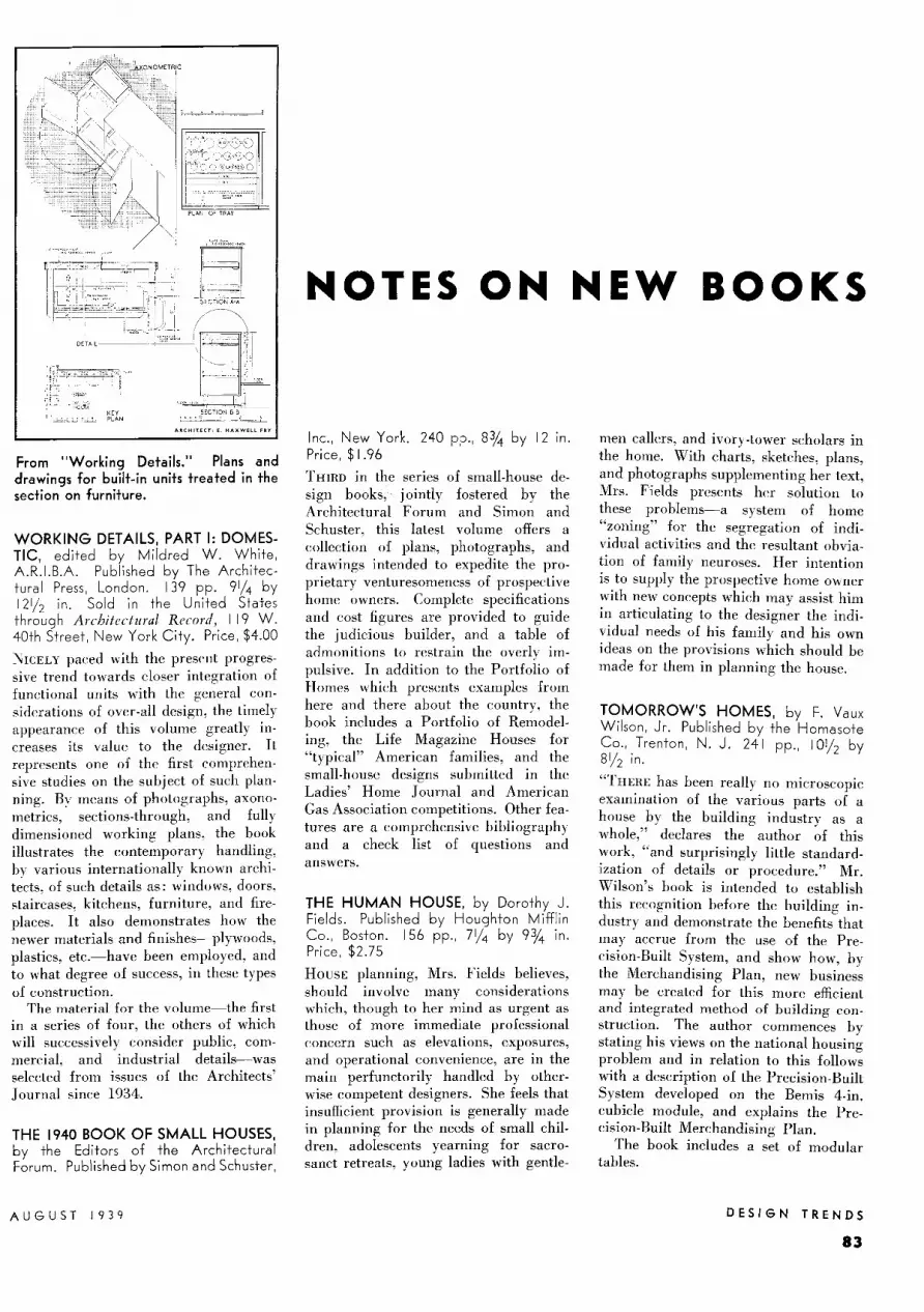
From "Working Details." Plans and drawings for built-in units treated in the section on furniture.
WORKING DETAILS, PART I: DOMESTIC, edited by Mildred W. White, A.R.l.B.A. Published by The Architectural Press, London. 139 pp. 91/4 by 12112 in. Sold in the United States through Architectural Record, I 19 W. 40th Street, New York City. Price, $4.00
NICELY paced with the present progressive trend towards closer integration of functional units with the general considerations of over-all design, the timely appearance of this volume greatly increases its value to the designer. It represents one of the first comprehensive studies on the subject of such planning. By means of photographs, axonometrics, sections-through, and fully dimensioned working plans, the book illustrates the contemporary handling, by various internationally known archit~cts, of such details as: windows, doors, staircases, kitchens, furniture, and fireplaces. It also demonstrates how the newer materials and finishes-plywoods, plastics, etc.-have been employed, and to what degree of success, in these types of construction.
The material for the volume-the first in a series of four, the others of which will successively consider public, commercial, and industrial details-was selected from issues of the Architects' Journal since 1934.
THE 1940 BOOK OF SMALL HOUSES, by the Editors of the Architectural Forum. Published by Simon and Schuster,
AUGUST 1939
NOTES ON NEW BOOKS
Inc., New York. 240 pp., 8% by 12 in. Price, $1.96
THIRD in the series of small-house design books, jointly fostered by the Architectural Forum and Simon and Schuster, this latest volume offers a collection of plans, photographs, and drawings intended to expedite the proprietary venturesomeness of prospective home owners. Complete specifications and cost figures are provided to guide the judicious builder, and a table of admonitions to restrain the overly impulsive. In addition to the Portfolio of Homes which presents examples from here and there about the country, the book includes a Portfolio of Remodeling, the Life Magazine Houses for "typical" American families, and the small-house designs submitted in the Ladies' Home Journal and American Gas Association competitions. Other features are a comprehensive bibliography and a check list of questions and answers.
THE HUMAN HOUSE, by Dorothy J. Fields. Published by Houghton Mifflin Co., Boston. 156 pp., 71/4 by 93/,i in. Price, $2.75
HousE planning, Mrs. Fields believes, should involve many considerations which, though to her mind as urgent as those of more immediate professional concern such as elevations, exposures, and operational convenience, are in the main perfunctorily handled by otherwise competent designers. She feels that insufficient provision is generally made in planning for the needs of small children, adolescents yearning for sacrosanct retreats, young ladies with gentle-
men callers, and ivory-tower scholars in the home. With charts, sketches, plans, and photographs supplementing her text, Mrs. Fields presents her solution to these problems-a system of home "zoning" for the segregation of individual activities and the resultant obviation of family neuroses. Her intention is to supply the prospective home owner with new concepts which may assist him in articulating to the designer the individual needs of his family and his own ideas on the provisions which should be made for them in planning the house.
TOMORROW'S HOMES, by F. Vaux Wilson, Jr. Published by the Homasote Co., Trenton, N. J. 241 pp., 10112 by 8112 in.
"THERE has been really no microscopic examination of the various parts of a house by the building industry as a whole," declares the author of this work, "and surprisingly little standardization of details or procedure." Mr. Wilson's book is intended to establish this recognition before the building industry and demonstrate the benefits that may accrue from the use of the Precision-Built System, and show how, by the Merchandising Plan, new business may be created for this more efficient and integrated method of building construction. The author commences by stating his views on the national housing problem and in relation to this follows with a description of the Precision-Built System developed on the Bemis 4-in. cubicle module, and explains the Precision-Built Merchandising Plan.
The book includes a set of modular tables.
DESIGN TRENDS
83

THE GRADUSTAT I
THERMOSTAT THAT INAUGURATES
I I c:;r r f/U?@ ~ ~ 4CC14JtaC1f tmd R~M
To its many contributions to the pneumatic con
trol field, Minneapolis-Honeywell now adds its
new pneumatic thermostat-the Gradustat. Styled
by Henry Dreyfus, the Gradustat is as modern in
its performance as is its design. It uses air only
when changing positions of valves or dampers. This
reduces the size of the compressor required by
approximately 80"/o and increases capacity so that
each Graduslal can control a far greater number
of units. The famous Helmet Seal construction pro-
!eels working parts against tampering, foreign mat-
ter, or corrosion, and insures long, frouble-free serv-
ice. Truly, the Gradustat brings an entirely new
degree of accuracy and responsiveness to pneu-
matic control. Minneapolis-Honeywell Regulator
Company, 2804 Fourth Ave. S., Minneapolis, Minn.
Helmet Seal Construction Adiustable Throttling Range
Greater Sensitivity Increased Capacity
Smaller Compressor Required
m1nnEAPOLIS-HODEYWELL {j~,fc~~

FORTHCOMING ISSUES: 1939 -September, Apartment Hauses: October, Thea~ers: November, Houses: December, Hospitals. PRECEDING ISSUES: 1939 - July, Houses: June, Factories: May, Houses: April, Retail Stores: March, Housing Developments: February, Elementary Schools: January, Restaurants.

Exterior and typical interiors of the Kensington Junior High School in Montgomery County, Md., near Washington, D. C., the first unit of a 25-acre community school development. According to plans of Rhees E. Burkett, architect, the site will ultimately contain two other academic buildings, a group of related "cottage laboratories", a separate gymnasium, and complete outdoor recreation facilities for student and community use.
The following material dealing with advanced standards of high school design
is complementary to data published in the February 1939 Building Types
section on Elementary Schools. Both sub jects were compiled from research
data made available through the courtesy of Teachers' College of Columbia
University. Particular acknowledgment is hereby made to Dr. N. L.
Engelhardt, Professor of Education, and to Stanton Leggett, Graduate
Fel low, for their active help in the preparation of thi s material. Credit and
thanks are al so due to Dr. N. L. Engelhardt, Jr ., and to educationa l research
workers, school administrators, and architects who, although too numerous to
list individually, have generously contributed to the variety of information
contained in the following pages.
BUIL D IN G TY PES
86
Modern High-School Plant Design . 87-88
Ti me-Save r Stan dards Data ... . . 89-103
Ad ministrat ive Areas . . . . . . . . . . . 89-91 Classroo ms . . . . . . . . . . . . . . . . . . . . 92-94 Sh ops 95- 97 Home Trai ni ng Areas. . ..... 98-99 Recrea tion-Indoor ........ . ... 100-- 101 Rec reatio n-Outdoor .. . . ...... I 02-103
Case Stu dies .... . ... . ... . 104- 118
Eastmont Jun io r High School. East-mont, Calif. . . . . ...... . .. .. I 04-1 05
Springfi e ld Hig h School, Spring-fi e ld , Te nn ....... ..... . ...... 106- 108
Ni les Township Community Hig h School, Niles Twp., 11 1 ...... .. . 109- 112
Scarsdale Hig h School, Scarsda le, N. Y. . . . . . . . . . . . . . . . . . . 113- 115
Ea st Sen ior Hig h School, Rockfo rd , Ill. ......... .. . . .... 11 6-118
ARCHITECTURAL RECORD
MODERN HICH-SCHOOL P
PRE- COLLEG E educational sys t em throughout Lh e country are currently on the threshold of important evolutiona ry developments. On the basis of educati onal experiments and such survey as Lhe Regents Inquiry into the ew York tale education system (r eported in the recently publi hed " Educalion for merican Life," by Dr. Luther Gulick), policies are being formulated which are unique wilh re peel to pre -enll y accepted educational concepts.
These poli ies embody the principle of integrating educational activity with the democra tic ideal in this country. Thus. Lh e) look forward to the Lime ' hen schola Li e education will be commo nl y recognized a the most potent haping force. not only of a sludent
populati on. but of the community of which such population is a part. And beca use Lhi s new concept is alread emerging into a practi cal program with well-defined and far -reaching value , it ha an immedia te bearing upon the oluti on to current school design problems.
trong fo rces have been, and are being. instrumental in forming uch new educational policies and in developing requiremenls which conditi on the modern school-building plant. Many are linked to ocial and economic changessuch matter as population trends and problems of nati onal and regional economy, which have lately been grave concerns of Lhe ational Resource Commiltee. Others have developed from the changing ocial patterns that have brought the Civili an C on e r vati o n Corps, Lh e Work Progre Admini -tra ti on, the Ialional Youth Admini -trali on, and other such agencies inlo focus as educational instrumentaliti e . All are linked with the ever more apparent need for providing our national youlh wilh an educational background which will serve as a more immediately practical tool fo r adult life. ln combina ti on. Lh ey constitute a sort of prism th rough which educators have viewed the component parl of our pre ent educa li onal systems_ and by means of which they are fo rmulating new policies which are alread y influencing developmenl of high-school pr ogram and plants in a ll part of the country.
A RCHITECTURAL R ECORD
Expre eel technically, fr om the curriculum point of view, the new policy recommended by advanced educators involves an S-K-6-4-4·::· program , in contradistinction Lo the commonly accepted K-6-3-3" program which, m il elf, marked an advance from the primary-grammar-high-school program which was commonl y accepted in this co untry as late as 1915.
Applied to the high-school plant, Lhis new program confronts the designer wilh a three-fold problem: a. of providing a wide range of educalional faciliti es for children from 12 to 16 year of age and including the grades from 7 lo 10, in an intermediate school ; b. of providing a more advanced type of in tructi onal facilities for ) outh from 16 to 20, in a seco ndary chool to include grades 11 to 14; and. c. of providing facilities adequale for adult educational programs and general ommunity activities of both instructi onal and recreational character.
Analysis will show that facilitie for intermediate and secondary schools o erlap to a certain extent. Therefore, provision of indi idual plants for each school group will normally cl pend upon the fin ancial support involved and the organizalion of a chool di Lrict. In so me case , a single plant can meet the triple set of requirement indicated al ove. In other instances, Lhe de igner ma be concerned wilh the provision of intermediate and secondary facilitie in separate plants, in both of which provision for adult and community facilities are desirable.
Because of thi overlapping characLeri tic, material in the foll owing pages ha been presented under headings applicable to both inlermedi ate and secondary classificati ons, as nexible aids in solving the local problems with which a designer may be confronted.
* N S-K-6-4-4 implies a year or two of nursery school, one year o f kindergarten , six years of primary and upper elementary school, four years o f intermediate school , and fo ur years of secondary school. The termino logy is advanced. ..in termediate" including what have been know n as g rades 7 to 10 inclusive: the "secondary" inc lud ing the last two years of present high -school work and additional years fo r terminal courses, or for the;se corresponding to the presen t junior-college program.
The K-6-3-3 pro!?ram is the familiar kin dergarten . elementary, junior and senior high school progression.
~NT DESICN
It should be borne in mind, however. that the -K-6-4-4 program is an educational organization that embrace the de irabiliLy of educational plant de-igned specifically for the schola ti c
categoric implied in the de ignalion. In the February 1939 issue of the Record appeared a " Building Types" tud y on the Lype of elementary chools which would logically be a part of thi program. The stud y in thi s issue treats high- chool plant from generall y Lhe ame point of view. Ther efore, to com
plement informalion in the fo rmer stud y, it is de irable to touch generally on what educators regard as an ideal high-school plant organizati on.
Inte rme diate schoo l. This is isioned as a community school to provide, within an area of from 15 to 40 acres, the type of instrucli onal facilities which will develop an integrali on of scholastic work wilh the life of both home and community. This implies a plant in which clas room regimentation gives way lo a more informal experi ence program in which the teacher , in the role of advisor. encourages pupils in independent thought and action.
The plant mu t provide an exten ion of the " learnin o- by doin o-" principle which is increasingly being accepted as an important part of the elementar yschool curri culum. The formal classor home-room will Lend to be supplanted by the instructional suite combining a recitation and lecture area, with one or more ' orkrooms, library, storage and mechanical facilities in the form of "general educational laboratori es." dministration areas will expand to include facilities for lay organizations, for the increa ingly important health ervice. and for student activities and government. Increa ing stress will be laid on industri al arls and crafts ; and shops adaptable for use by adults. as well as by student , are necessary.
Equally nece sary will be the recreational facilities of auditorium and gymnasium. each planned to prov ide a wide range of u e for both students and adults. Out-of-doors educa tion is al o important and the plot will necessarily include areas for use b children's and adults' non-scholastic organizati ons.
BUILDING TYPES
87

Secondary School. Because the secondary school is regarded by advanced educa tors as a place where wide educational opportunity may develop youths into re ourceful members of a democratic community, it is visioned as a regional educational center of the campus type. An area of 50 to 100 acres may include a number of school buildings and complete provision of outdoor recreation facil ities for students and adults. In general. provisions of the secondary-school plant will be comparable in type to those of a mall, wellequipped college. Buildings and landscape, however, will be developed particularly to serve as a community cen ter as well as an attractive and efficien t plant for a well-rounded curriculum.
A in the intermediate school, an edu ca tional experience program will permit tudents to prepare themselve accord
ing to their abilities and interests for a productive adult existence. This suggests emphasis on industrial arts and indicates a major need for shops full y equipped for instruction and practice in such activities as wood- and metalworking, printing, automobile and airplane mechanics, etc. Social and physical sciences will be increasingly taught in laboratory suites similar to the "general educa tion labora torv" of the intermediate school, but embodying a larger number of in tructional units integrated within a separa te area.
The administration unit is of special importance. It must provide facilities adequate for personnel and vocational guidance, health service and instruction, studen t and communi ty activities, and the cooperative development of varied educational programs by co mmunity organizations, educational administrators, and the studen ts themselves. To meet these needs, suites of offices and conference rooms may be located centrally with respect to other school buildings ~nd to the community.
Concerning indoor recreation, the community ed uca tional cen ter should embrace an audi torium which, in effect, will become a community theater, complete with stage-craft and service areas and provisions for both legi timate and
moving-picture productions. Logically included will be rooms for orchestra and instrument practi ce, for theatrical rehearsals and club meetings. Also desirable is space for both tudent and communi ty gatherings such as dance and banquet , which suggests a multipurpose hall adjacent to kitchen, pantry, and storage areas.
The gymnasium will be developed as a complete physical recreational plant, patterned after a collegiate field house and adaptable to a wide range of a thletic activities including group activitie which can be enjoyed by adults, as well as by youths.
Outdoor facilities may follow the general pattern of the intermediate school with the addition of play areas such as full- size ha eball and football fields, hockey rink, a swimming pool, etc.
The foregoing paragraphs outline what progressive educators regard as ideal. But they reflect only the trend of present practice in educational plant design. In a number of progres ive communiti e a start has been made toward thi ideal, however; and, therefore, designers cannot ignore either the concept which implies the need for such educational plants, the scope of the plants themselves, or the increasing necessity that they be integrated with comm unity interests and activities.
Bibliography General Educational Poli cies Commission: Th e Unique Fun ction oj Education in American Democracy <1937); The Pnrposes of Education in American Democracy (1937) ; The Stmcture and Administration of Education in American Democracy ( 1938) ; Social ervices and the Schools ( 1939). a lion al Educat ion Associat ion, Washington , D. C. Enge lhardt. Fred and Overn, A. V. Secondary Education: Prin ciples and Practices. D. A ppleton-C nlury Company, 1937. Everell, . The Community School. D. Appl eton-Century Company, 1938. Harap, Henry (Ed itor). The Changing Ciirriculum. D. Appleton-Century Company, 1937. Hopkins, L. Thomas. Integration: Its Meaning and Application. D. Applelon-Cenlur; Company, 1937. Langfitt, R. E. ; Cyr, F. W.; and Newsom,
. Willi am. The Small High School at Work. Ameri can Book Compa ny, 1936. Strayer, G. D. ; Engelhardt, N. L.; et al.
A R eport of the Snrvey of the Schools of St. Louis, Mo. Bureau of Publications, Teachers' College, Columbia Uni versily, 1939. American As ociation of School AdminislraLor . Schools in Small Communities. evenleent h Yearbook, 1939. Washington, D. C.
ewsom, N. William and Langfill, Roy Emer on. Administrative Practices in Large High
chools. American Book Company, 1939.
Junior High Schools Baldwin, J. W. Classroom and Equipment Requirements for the New Social Studies. Eleventh Yearbook, American chool and Univers ity, 1939. 470 Fourth Avenue, ew York, N. Y. Engelhardt, . L. Standards for Junior High School Buildings. Bureau of Publication , Teachers' Co llege, Col umbia Un ivers it y, 1932. Holy, T . C. and Arnold, W. E. Standards for the Evaluation. of School Buildings, Bureau of Educational Resea1·cl1, Ohio Stale University, Monographs, No. 20, 1936.
1ati onal Council on choolhou e Construc-tion. Proceedings, Fifteenth Annual Al eeting, Cohunbus, 0. , 1937; and Proceedings, Sixteenth Annual Meeting, Frankfort, Ky., 1938. Ray L. Hamon, Secretary, George Peabody College, ashville, Tenn. Pringl e, Ralph W. The Junior High School. McGraw-Hill Book Company, 1937.
Loneman, 1erle A. and Broady, Knule 0. Supplementary Standards fo r the Small Twelve-Grade School Building. University of
ebraska, Lincoln, Nebr., 1939. Review of Educational Re earch. The School Plant and Equipment. October 1938.
Senior High Schools
Campbell, Harold G. All the Children. ForLi elh Annual Reporl of the uperintendent of chools, City of ew York, 1939. Donovan , John J. and Others. School Architecture: Principles and Practices. Macmillan , 1921. Minnucci, Gaelano. cuole. (Printed in llaly). May be ecured through The Architectural Book Publishing Co., ew York, Y., 1936. American Council on Education, A Study of Lhe. School Buildings and Equipment. 744 Jackson Place, Washington, D. C., April, 1939, Series 1, Volume III, No. 8. Strayer, G. D. and Engelhardt, . L. Standards /o r High School Buildings. Bureau of Publi ca tions, Teachers' College, Columbia
niversily. The American School and University. Eleventh Annual Edition, 1939. American School P ubli shing Corporation, 470 Fo u1·th Avenue,
ew York Cily. Special Report Submilled wi th Lhe Thirlyninlh Ann ual Report of the Superin tendent of Schools, City of New York, School Year 1937-1938. Vocational High Schools: Trends and Forecasts.
EDITORIAL NOTE: Time-Saver Standards data on pages 89 to 103 , inclusive , suggest the advanced standards which progressive educators regard as desirable to the well-rounded development of an expanded educational program. Various factors of a local situa tion may prevent development of an ideal school plant, however ; and , therefore, this material should be re garded primarily as a flexible basis for solution of cur-
rent design problems rather than a series of specific recommendations. Tabulations, text , and diagrams, developed from a number of widespread surveys, reflect the consensus of advanced educational thought ; plans and photographic illustrations report the manner and extent to which these suggestions for advanced standards have already been adopted in a numbe r of recent school designs.
BUIL DI N G T YP E S ARCHITECTURAL RECORD
88

DESICN DATA FOR SCHOLASTIC UNITS: administrative, classroom,
shop, home-training, and recreational areas adaptable to intermediate and secondary schools.
ADMINISTRATIVE
Private office, and Business Manager's office, Fresno, Cal., school-system Administration Building; Franklin and Kump, architects.
Public and secretarial space, Junior-Senior H. S., New London, Tex.; Preston M. Geren, architect.
Curriculum planning: picture files and movie screen in Visual Education Department, Fresno Administration Building.
ADMINISTRATIVE officers are responsible for providing, with the cooperation of the entire educational staff, the best possible environment for each child in the school; and for encouraging effective community-school relationships. In view of the trend toward democratic evolution of school programs and curricula, administrative areas are becoming cooperative planning and research areas.
Size of the school and the importance attached locallv to various functions will determine nur~ber of workers, range of activities, and space to be provided. To maintain efficiently the usefulness of an
ARCHITECTURAL RECORD
expensive plant, school administration should be flexible, easily adaptable to changing conditions; spaces should be responsive to new demands. Community relations: While school principals have the major responsibility for the effective functioning of the entire school, community relations constitute a large portion of their work. This includes: direction of adult education, provision for community study excursions, cooperation and integration of the activities of community-school associations, parent and public education work. Principals may have co-workers dele-
gated, such as assistant principal, and director of adult education. Personnel work: Attempts are made to discover each child's problems, potentialities, interests, and goals. The school then attempts to provide proper environment for each child. There is a tendency to turn this work over to professionally qualified teachers, assisted by specialists: doctors, dentists, oculists, psychologists, psychiatrists, and vocationalguidance experts. Employment offices are becoming integral parts of administrative suites. Number and variety of such specialists may vary with the size
BUILDING TYPES
89

ADMINISTRATIVE AREAS (continued)
STUDENT
ACTIVITIES
HEALTH SERVICE POSSIBLE
~--~-----~-__,EN~~~NCE PERSONNEL
TEACHER GUIDANCE SPECIALISTS GUIDANCE
MEN WOMEN
TOILET TOILET
TEACHERS'
CONF. ROOMS
MEDICAL ~RVICE
AND INSTRUCTION
TOIL. ~~~~~$ TOIL
WORK LABORATORY
LIBRARY
DIRECTOR
STORAGE
CURRICULUM PLANNING
i,, .lllllL Jill ...
NURSE
AND
STAlllS VISITING EMPLOY. PSYCH'L·
C06NF. TEACHERS OFFICE OGIST
INTER~ t---~--r----;
VIEW BOOTHS
VOCATIONAL
READING
LAY ASSOCIATIONS
STORAGE
STORAGE
DIRECTOR
AND STAIRS
ADULT EDUCATION
WORK SPACE
AOULT ACTIVITIES
UPPER PART OF AUDITORIU M
PROJECTION BOOTH
JS .. , ii!iillii•
Schematic diag ram, showing relationship and approximate space proportions of administrative are as. Importance of centralized files, containing data on students and adults, as well as business administration , is stressed.
!ill '11 "" '"" ' rswm lllt +" "i"i*" - l.O~ "fR S
Jli1E1'• ''ff~l~VJill '--sens-_ ~
Administrative area of Mt. Pleasant Ave. Senior High School , Providence, R. I., Erik Andersen, architect and deputy superintendent of schools. An existing exampie conta inin g many of the areas diagrammed above. Large conference rooms may be used , if necessary, for lay adult meetings.
GUIDANCE CLASS GUIDANCE ROOM
0 5 !O •5 20 t!1
of the school ; all are to some degree necessary.
Social welfare: Visiting teachers ga ther knowledge of home environment of each child ; and aid in reli eving distressing home conditions so far as school resources, working with other community agencies, allow.
Health services consist of frequent examinations, follow-ups when needed, diagnosis, general emergency work, and, in some cases, treatment. Loca ti on of the school may make it advan tageous to insta ll community health clinics.
BUILDING TYPES
90
PUBLIC SPACE
(,£.NERAL CHIC[ l~
Curriculum planning is closely related to personnel work. Courses of study, formerly fixed and inAexible, are now recognized as constantly in need of change. Experience and stud y of teachers, coupled wi th kn owledge of children's changing needs as determined by the personnel workers, are vital elemen ts. A director of curriculum study is desirable in many schools.
Student activities (often called "extracurricular") ha ve proven of such value that in many cases they are incorporated in the regular school curriculum. Stu-
PRINCIPAL CONFERENCE
dent governmen t, club , and school publi cations require space in which students ca n inaugurate and carry through activities.
Business adm inistration, including clerical and secretarial facilitie , may profitably be cen tralized a much as is con istent with efficien t functioning of the school. Centralized Jiles (record of school children and possibly adults) have been found valuable aids.
Francis, T .1 and Deal, G . V ., Executive Offices for a Large H igh School, July 1938, p. 532. Engelhardt, N . L., Standards for Junior High Sc/mo/ /J11ildi11gs, pp. 144-150.
ARCHITECTURAL RECORD

TIME-SAVER STANDARDS
SUGGESTED AREAS (in sq. ft.) SUGGESTED AREAS (in sq. ft.)
Acceptable Acceptable SPACES Min. Avg.
Usual Max. SUGGESTED EQUIPMENT SPACES Min. Avg.
Usual Max. SUGGESTED EQUIPMENT
Principal office
Health Services (continued)
250 300 400 Flat-topped desk, chair, table, upholstered chairs, files, outside and house telephone, 40 lin. ft. shelves, closet.
medical 350 400 500 Surgeon's sink, septic bowls, examination table and chair, instrument cabinet, sterilizer, sanitary waste cabinet, doctor's desk and chair, stool and sink.
toilet 12
gen'! office. 600
Adult education
director 250
work . . . 600
conference 300
P. T. A... 200
Personnel Guidance
director . . . 200
empl. office 200
interviews 120
reading 80
20
1000
300
800
400
300
300
300
150
150
30
1400
400
1000
450
350
350
350
150
400
Telephone switch boa rd, counter, files, cash drawers, 34"x 60" desk, typewriter ( I per sec'y), vault, chairs, radio.
See "Typical Office Equipment."
Counter, desks, typewriters, mimeograph.
Tables, chairs, portable blackboard.
See "Typical Office Equipment."
Desk, chairs, storage cabinets, files. Chairs, tables, files, magazine racks, min. of 150 !in. ft. shelves.
dental
dressing
rest
toilets
Curriculum
director
work lab.
Student Activity
100
20
200
20
250
600
work 600
conference 200
150
24
400
30
300
800
800
400
200
24
450
40
350
1000
1000
500
Dental chair, instrument cabinet, dentist's light, lavatory, desk, record cabinet, table.
Seat and clothes hanger, toilet facilities.
Cots, chairs, toilet facilities.
See "Typical Office Equipment."
Desks, chairs, storage cabnets 12"xl2"x24" (I per teacher), 40 lin. ft. shelves, easy chairs, magazine rack, files.
Desks, chairs, tables, files.
Tables, 10 to 20 chairs.
vstg. tchrs.
psycho!.
40
266
60
320
80
370
See "interviews. 1
'
3 to 5 booths.
TYPICAL OFFICE EQUIPMENT
Item
Desks Student Guidance
director ... 250 300 350 See "Typical Office Equipment."
Swivel ch cir
Chairs
conference
case conf ..
80
300
100
400
100
450
Desk, 2 to 4 chairs. Tables
Tables, 10 chairs, 12 sq. ft. blackboard, 24 sq. ft. bulletin board, files.
Wastebasket
Filing cabinets
Storage cabinets
Book shelves
Telephone-outside
Health Services
nurse 220 330
waiting .. 125 150
380
300
Chairs, desk, couch, screen, files, floor scale, weight scales, sink, medicine cabinet, table.
Chairs, couch, table, hat tree.
house
Closet
Principal's office requires direct access to adult conference room, secretarial space, and corridor. Secretarial, or business office: Counter separating waiting space and work space is preferably approximately 42 in. high, 28 in. wide, with files, drawers, and shelves built in as needed. Incorporating a desk and telephone switchboard in the counter permits the telephone clerk to give information to inquirers without leaving the desk. The entire space requires artificial lighting to provide an intensity of 20 footcandles at work levels, and adequate natural light· ing such as that obtained from an en· tire wall devoted to windows. Acoustic treatment of ceilings and resilient floor· ing materials are desirable. Supplies
ARCHITECTURAL RECORD
may be stored on a lower floor, with access by stairs or a dumbwaiter.
Adult education offices are often used at night. Files are preferably combined with the central filing system.
Curriculum planning: More elaborate plants than are here contemplated in· elude library reference rooms, addition· al conference rooms, and teachers' recreation rooms.
Personnel area: Teacher-student conference room may have an independent waiting room, or the general public space may be used. Nearness to central files is important.
Health services: Extent of community facilities provided may modify the re-
Acceptable Minimum Average
I
2
10 cu. ft.
40 lin. ft.
I
I
4
5
30 cu. ft.
60 lin. ft.
I
Usual Maximum
2 2
5 2 2 8
60 cu. ft.
70 lin. ft.
2 2
quirements tabulated above. Special attention to design and finish is necessary for sanitation. For eye testing, a space 22 ft. long (min. I is needed. Waiting space may be combined with nurse's office. and ought to have a direct community entrance. A maximum of natural lighting is essential in medical and dental spaces. Rest rooms may have subdued lighting ( .5 to 8 footcandles).
Location of the entire administrative unit is preferably central, near public entrances and main corridors. Outdoor circulation is preferably routed away from administrative· unit windows; a desirable degree of seclusion may be obtained by proper landscape planning.
BUILDING TYPES
91

CLASSROOMS
BUILDING TYPES
92
Learning by doing: activity program in progress in an English classroom, Junior-Senior High School, New London, Tex. Preston M. Geren, architect.
Library, also in New London JuniorSenior High School, for both cooperative research and study. Note reading alcove in rear.
Commercial classroom, same school: office conditions are simulated by substituting commercial equipment for typical classroom furniture. Note acoustic ceiling.
ARCHITECTURAL RECORD

WORK CENTER
Ill
CLASS
READING
LABOR A-TORY
SHOP
S ~~GE r: 4 5 [~6~!
COMMUNITY STUDY AND ANALYSIS
MUSEUM EXHIBIT
FOR SCHOOL AND
ROOF
. JO 8 GENERAL EDUCATION
LABORATORY ~H+±+~~~11
COMMUNITY
"i~iHii~ ~ ~ ~ ~ ~ u ,
ARlf a WORK MUSIC
CENTER II
LIBRA,RY CENTER
TEACHERS' RM STAIRS, TOILETSJ
ENGUSH
TIME-SAVER STANDARDS
HOME ARTS Space relationships for CENTER modern general-educa-z
- ti on laboratory units z - for study of the social <
FINE ARTS <r sciences. Diagram at & MUSIC CENTER I- the left indicates re-
...J quirements for a com-< paratively small unit, z
PHYSICAL CULTURE
0 reasonably limited in CENTER I- scope. Workrooms
< only partially indicat-" 0 ed are intended to
SHOP > have similar functions CENTER
to those shown in full.
tSTAIRSANDTO
LOCKERS--
'": ; 11111:::: mwr
ASSEMBLY ROOM
ENGLISH
6. Lights 7. Bulletin board
13. Dark room 14. Chart cabinet
Above: Activity classroom layout for teaching English, Mt. Pleasant Ave. High School, Providence, R. I.; Erik Andersen, architect. Assembly room becomes a laboratory-theater, used also for visual education.
I. File cabinet 8. Bookcases and 15. 2. Chart case drawers 16. 3. Bookshelves and 9. Platform 17.
magazine racks 10. Folding pa rti-4. Blackboard ti on 18. 5. Proiection II. Counter 19.
screen 12. Mimeograph
CHANGES IN curricular standards affect school programs in two related wavs. The first is due to the basic social program, a series of experiences in cooperative living which mav reasonablv he expected to face people in adult life. Second, the socially oriented curriculum places increasing emphasis, particularhin higher grades (secondary I • upon development and stimulation of strong individual interests. Some of these. toward thP Pnd of the school program. merge with vocational training.
Direction of social programs may he cletermine<l hy joint action of pupils anrl lf'achers. Thereafter. the group nrn\
move into a work or experience centPr. Part of the work center may house shop and laboratory activities: models, tPsts. ancl experiments. Tests made in laboratorv areas may serve as guides in other
ARCHITECTURAL RECORD
Clay modelling Tools Cabinet mak-ing Metal working Paint bench
Left: General-education unit, Senior High School, Beacon, N. Y.; Tooker and Marsh, architects. Note the divisible theater-discussionlaboratory central area.
sections. Art and music areas may be utilized to illustrate influence of art on modern life, and satisfy creative energies.
The discussion center serves for presentation of results of anah ses, and as exhibit and demonstration space. Audiovisual aids can be used here.
Tabulations on the following page indicate requirements for general education units into which experience programs are incorporated to varying degrees. Recitation-discussion types provide for substantial advances over "classrooms" as commonly accepted in the restricted sense; discussion-activity types are intended to include a medium degree of pupil activity; experienceprogram types provide full realization of the discussion - activity - experience ideal.
Classroom units ought to have, where possible, direct exits to outdoor classrooms, yet need lo be segregated from noisy outdoor areas. Except in very large schools, distance from au<litoria is not of special importance, ex!'ept that circulation requires study to prevent loss of time caused by congestion. Al· though classroom book collections are required, individual research and motivated reading necessitate integration of library and classroom an~as. Satisfactory classroom orientation, in order of desirability, has been found to be southeast, east, west, or south.
Engelhardt, N L., Better Classroom Provisions for Hit,h School Work, American School and University, 1937. pp, 263-267.
Wrightstone, J. W., Classroom Facilities for the Prof(ressive ,\'choo/, American School and University, 1937, PP- 268-272.
Engelhardt, N. L., Jr.. Unit Planning, /J': Classrooms, American Architect, April 1937, pp. 101-109~
BUILDING TYPES
93

CLASSROOMS (continued)
Classroom; Richard Neutra, architect
" REC ITATION - DISCUSSION " GROUP
Acceptable Usual SPACES Min. Avg. Max. FQUIPME NT Amount
Classroomf Chairs 30-40
total area Tables (4 seats) 8-10
(sq . ft.) . . 660 704 770 Teachers' chairs 1-2
pupils per rm . 20-25 30 40 Teachers' desk I Easy chairs
area per pupil* 22 23.4 25.6 (reading alcove) 1-3
Auxiliary spaces Magazi ne rack I Chart & map rack I
storage Teachers' files 1-4 (cu. ft .) . 125 170 250 Screen (visual aid) I
reading alcove Motion-picture (sq. ft . ) . . . . 64 100 176 machine stand
book shelves Blackboard (sq. ft.) 20-60 ( lin. ft.) . 30 50 60 Bulletin-As much as possible
" DISCUSSIO N - ACT! VITY" GROUP
Acceptable Usual SPACES Min. Avg. Max. EQU IPMENT Amount
Classroomf Chairs 25-40
total area Tables (4 seats) 8- 10
(sq . ft.) .... 704 828 1200 Teachers' chairs 1-3
pupils per rm. 20-25 30 35-40 Work benches 1-3 Sink 1-2
area per pupil* 23.4 27.6 40 Clay modelinq table I
Auxiliary spaces Experiment table
(acid-proof top) I workroom Magazi ne rack I
(sq. ft.) j. 176 230 360 Chart& map rack I reading alcove Teachers' files 1-3
(sq. ft.) . . . 64 100 176 Screen (visual aidl I stage (sq. ft.) j 140 252 352 M~tion-picture & lantern-
teacher's office sl ide machine sta nd I EPsels 1-3 (sq. ft.) 100 100 150 Display cases 1-3
book shelves Aquarium I ( lin. ft.) . . .. 40 55 70 Growing bed I
storage Blackboard (sq. ft.) 20-60 I cu. ft. J . . 200 320 400 Bulletin-As much as possible
Science room; Preston Geren, architect
" EXPERIE NCE PROGRAM " GROUP
SPACES
Disc ussio nt
pupil s per rm . total area
(sq. ft.) . . seating area
per pupil (sq . ft.) .. ..
Auxiliary
(discussion) stage area
Acce11table Min . Avg.
25 30
616 736
10 10
Usual Max.
35
864
10
EQUIPME NT Amount
Tablet arm chairs 30-40
Movable platforms (3'xl lh'x6') 2-6
Exhibit cases 2-5
Exhibit tables 2-5
Demonstration table
Sink
Motion-picture & lanternslide sc reen I
18-30 Blackboard (sq ft . ) (sq. ft.) j.. 140 288 396
exh ibi tion . . as much space as ava ilab le Bulletin board as much as storage space permits
I cu . ft.) . . . 80 I 00 140 Window blinds, I per window
Work C enter• Reading area pupils per rm. 25 30 35 Tables 2-4 total area Chairs 4-8
(sq. ft.) .. 875 1200 1800 Easy chairs 1-3 area per pupil * Magazine racks I
(sq. ft . I .. 29 40 60 Newspaper rack I storage cubicles 25 30 35 Book shelves
EQUIPME NT Amount ( lin. ft.) 50-125
Laboratory-shop H ome training (see Science tables 2-5
pages 98-99) Work benches 2-3 Arts and music Stools (lab.) 6-10
A rt tables 1-3 Aquarium I Chairs 4 - 10 Animal cages 1.2 Ea sels 1-3 Growing table I Drawing o r drafting Sinks 1-3
table 1-2 Fire extinguisher (lab.) I Clay modeling tab le I Storage (cu. ft.) Radio-phonograph I -science materials 40-90 Piano I -shop materials 48 Storage (cu . ft.) 70-150 -tool cabinet I
*Legal minimum in many states is 15-16 sq. ft. per pupil. t Desirable width for classrooms and work rooms, based on li ghting and similar factors , ranges from 22-24 ft. Length is variable. Most practical stage depth: 14-18 ft.; width variable. •Practical width for work center: 25-30 ft .; length variable.
Environment: atural lighting from two or three sides becomes desirable as "experience" programs develop, and as greater room widths and Aexibility of arrangement become important. Iatural illumination may be controlled
by tran lucent shades, blinds, draperies; or by exterior awnings or permanent canopies. Glare from r efl ective outdoor
surfaces is to be avoided. Use of visual aids (movie ) requires provision for darkening rooms. Glareless artificial lighting, which supplies 20 footcandles at working levels, is essential. Interior rows of fixtures may be independently circuited. Automatic ( photo-electric) control is avai lable.
are similar to those for Elementary Schools (AR. February 1939 ) . Sound control, as provided by aco u ticall y treated ceilings, is desirable in "activity" classrooms; in work areas, absorption not lower than 50 % is needed. Gas, elec tri c. hot and cold water outlets are required for the various work centers and activity programs. Hea ting and ventilating requirement
BUILDING TYPES ARCHITECTURAL RECORD
94

SHOPS TIME-SAVER STANDARDS
Drafting and woodworking shops, Wichita High School North, Wichita, Kan.; Glen H. Thomas, architect
l:'I I;';DUSTRIAL ARTS curricula, emphasis may be placed not only on vocational training as a means of integrating students with their environment, but is also being increasingly placed upon the necessitv for broad educational foundations .in terms of present-day life. Training in industrial arts can contribute to wise use of leisure time by stimulating creative impulses, arousing the desire for skill, and consequently developing gocd work habits and attitudes. Another function is that of teaching appreciation of design and construction, and of human interrelationships.
ARCHITECTURAL RECORD
As applied to high schools, industrial arts curricula are preferably not planned for specialization in early (or intermediate l grades. An enriched program integrated with other fields of learning is here more important. In higher (secondary) grades, specialization may be introduced. Pupil adjustment here needs constant attention. To avoid waste, types of courses may be based on surveys of local vocational opportunities. Thus, in a rural community, shops may not only be smaller, but may offer agricultural training which would be out of place in urban districts. In addition, shops may
be planned for community use, both vocational and avocational; courses may be correspondingly broadened and intensified.
Plant: Rectangular spaces have proven most economical for equipment layout. All portions of the area are preferably easily visible from any point within it. Independent buildings, or separate wings, segregated from quiet areas, are desirable. Ease of access to storage space and large project areas, and entrances for adult use, are important. Independent service facilities a!"e highly desirable.
BUILDING TYPES
95

SHOPS (continued)
I. 2. 3. 4. 5. b. 7.
PROJ ECT STORAGE
FINIS HI NG ROOM
Grinder Drill Vise bench Shears Anvil Roll Brake
FORGE ANO
FOUNDR Y
9. Double benches
10. B e n ch drill
II . Enamel furnace
12. Grinder
PRESS ROOM
KIL N
14. Milling machine
15. Shaper lb. FI o o r
lathe 17. La t h e
bench
ENTRANCi
LARGE PROJE CTS
BLUEPRINTING ANO
PHOT OGRAPHY
19. Bandsaw 20. Jointer
TOlLETS ANO
WASHROOM
LO CKERS
l'LANNLNG CENTER
DRAFTING
READING CONFERENCE
21. Circular saw 22. Glue pot 23. Type setting 24. Comp. stone 25.. Press
Diagrammatic representation of shop facilities considered essential to a complete unit, showing space relationships and approximately proportional areas. Selection of specific shop types, laboratories, etc., depends on local considerations: vocational opportunities, type of school, as discussed in preceding text.
CONFERENCE - WOODWORKING SCIENCE SfCT 8 GEN'L SECT
-0 cmdm ~ '° 097"09" crnom:, .~ ,= .. ,.
8. Desk 13 . Hacksaw 18. Oil grinder 2b. Sink ....... Rural laboratory-shop designed by Thomas Francis , Superintendent of Schools, Lackawanna County, Pa.
I. Dairy-equip-ment cases
2. Laboratory table 3. Magazine rack 4. Wiring booth 5. Jigsaw b. Harness bench 7. Vise bench 8. Concrete mixing 9. Ba ndsaw
I 0. Jointer 11 . Tool cases 12. Drill press
Urban shop unit , Mt. Pleasant Ave. Senior High School, Providence, R. I., Erik Andersen , architect. 13. Forge 14. Auto bench
Planning center: space is needed for discussion, conference, reading, research, drawing, design, and drafting. Quiet is essential; hence the room should be segregated from noisier shop activities. Soundproof partitions are desirable. Good natural and artificial lighting is required.
Woodworking: Floors may be of such materials as end-grain wood blocks, wood block tile, or maple floor ing. Equipment ought to be arranged so as to provide direct routing of materials through the machinery in the order in which machines will be used. Machinery is preferably placed to eliminate possibility of acciden ts in travel aisles, with danger zones clearly marked.
BUILDING TYPES
96
Ceramics shop is preferably close to woodworking area. The kiln is usually in a separate space, with highly fireresistive walls, heat insulation, and special ventilation.
Metal work: Floor finish, in general metal-working areas, is similar to that in woodworking spaces. Fire-resistive flooring is needed in forge, welding, and fo undry units; earth or unfinished concrete is desirable in casting room to prevent spread of spilled molten metal. Foundries and forges need special ventilation. This is one of the noisiest areas of the shop. Machines such as forges may be isolated from the general construction; or soundproof par ti tions, and ceiling and wall absorptive treatment,
may prove sati factoq.
Printing and graphic: arts: To eliminate noise transmission the area in which presses are installed should be separated from the general shop by soundproof parti ti ons. For presses. wooden floors with concrete ba es, reinforced to reduce vibration, are desirable.
Instructor's room: I t is essential that the instructor have a clear, unobstructed view of a major portion of the work area . The room is devoted to study, planning, and individ ual conferences.
Tool rooms may have partitions of wire netting. Central location is desirable.
ARCHITECTURAL RECORD

GENERAL AREAS
Acceptable Min. Avg.
Usual Max. EQUIPMENT Amount SPECIAL AREAS
---------------------------~-~
Total area
(sq. ft.) 1200 2100
Height (ft.) I 2 14-15
Planning center
(sq. ft.). 200 600
Instructor's office 80 140
General storage. 300 400
Tool room 36 100
4000* 3-15 Drawing tables
(2'6"x4') Conference table
( 3'x6') depends Chairs
I I 0-30 40-75
1-2 1-3
on room Book shelves (lin. ft.) size Files
1000
225
625
225
Blackboard panels Bulletin board as much as
Desk Chairs Locker Files
space permits I
2-3 I
Bookcase ( lin. ft.) Sink Pipe rack for lumber Shelving
40-70 I
Ceramics
Leatherwork
Textiles and crafts
Electrical work
Radio
Printing
TIME-SAVER STANDARDS
EQUIPMENT
Kiln, clay bin, drip pan, plastic bin, casting table, pottery wheels, marble slab, spray gun
Special craft equipment, storage
Looms, spinning equipment, tables, chairs, rug frame, sink, dye-storage cabinet
Wall benches with vises, switchboards, motor
Batteries, radio benches, test panels
Layout table, presses, paper cutter, stitcher, type cabinets, proof press, utility table, imposing-table rule case, galleys, stock cabinet
Locker space,
including
circulation:
area per pupil
(sq. ft. I
Racks and cabinets Lockers
12"xl2"x72" per pupil per 2 pupils
Etching, linoleum-block printing, bookbinding
Linoleum-block printing press, etching press, acid bath and acid storage, benches
Project storage (sq. ft.). 60
Fiinishing room. 80
Dark room
(blueprints, photog.) 40
SPECIAL AREAS
Woodworking
5
100
200
80
6
140
400
100
I 4"x I 4"x72" Metal-stain and
varnish wall case Metal-covered table Electric qluepot Fuming vat Metal container for oil waste Fire extinguisher Washing basin Drying shelves Fume exhaust hood Blueprint wash basin Blueprinting machine Blueprint press Enlarger Printer Sinks Dryer
EQUIPMENT
Workbenches, planer, band saw, jointer, lathes, circular saw, grinder
Farm mechanics
Metal workMachine
Metal work-Welding, forging, and foundry
Metal workAutomobile mechanics
Metal work-Sheet and Bench
Large projects
*3000 sq. ft. is usual desirable maximum area when not more than one teacher is normally present in shop. Cement work, bricklaying
General storage space requires direct access from an outside driveway, and is preferably planned for ease of handling large stock. Indoor direct access to milling machines, etc., is desirable. Flexibility of shelving is important.
Lockers may be in a separate room, in groups about the shop, or in special alcoves. Box (filing) lockers, with independent clothing facilities, are also used, sometimes under hench tops. Lavatories may be provided, one for each 10 pupils in the shop at one time.
Project storage may be in large lockers, shelves, etc., perhaps on a mezzanme over part of the shop space.
Project finishing requires good natural and artificial lighting, and special ven-
ARCHITECTURAL RECORD
tilation. Dust-proofness is essential.
General data: Heating and ventilating by mechanical systems is advisable; 1 to 12 cu. ft. per minute per sq. ft. of floor area is recom mendC'd by the l\'. Y. Commission on Ventilation. Air washing is desirable. Common heating range is from 65 to 68F, supplied by recessed or hung units. Local control of special ventilation equipment (forge, foundry, welding, dust-removal, etc.) permits economical operation.
Lightin {!, (natural) is considered hest when available from two or three sides. Control, as furnished by light-colored venetian blinds, is necessary. Drafting rooms require north light. Artificial light which delivers 20 footcandles on general work areas. or 30 to 50 foot!'andles for precision work or drafting,
Similar to automobile space
Engine lathes, (individual engine driven) drill press, bench qrinder, shaper, miller
Welding benches, molding bench and pan, bench furnace, brassmelting furnace, forge, anvil
Auto entrance with 9' wide ramp, chain hoist. motor blocks, tool grinder, elechical drill, valve grinder
Utility benches with vises, gas and electric outlets; heavy general bench equipped for soldering; layout bench; bar folder; circular shear; squarinq she.ars;
furnace, ':>olJerir1u iron heater; acid stora~e _,
Accommod,,tions for airplanes, gliders, boacs. stage scenery, etc.; chairs
Storage, rr.ixing. and work space
is found satisfactory. Light sources shielded from view are preferred.
Sound and vibration control is essential. In the general shop, treatment providing 50'/o sound absorption is currPntly considered advisahlP.
Services (gas, e!Pctricity. compressed air J require outlds so distributed as to 1wrmit flexihilitv in arranging machinPry. Electricity wired in separatelyfused multiple circuits, through a central panel. prevents disruption of service. Hot and cold water taps are desirable throughout the shop area.
Pease, H., General /11dustrial Arts Laboratory, Industrial Arts and Vocational Education, March, 1938, pp. 124-127. Warner, William, Studies in School Shop Planning, Industrial Arts and Vocational Education, February, 1934, pp. 31-38.
Whitehead, Willis, Pla1111iu.t; and Equipment Industrial Arts Laboratories, American School and University, 1939, pp. 508-518.
BUILDING TYPES
97

HOME TRAININC
CHILO DEVELOPMENT DEPARTMENT
'P ~
Left, model living room and, right, foods laboratory containing four unit kitchens, Dean High School, Gouverneur, N. Y.; D. Kenneth Sargent, architect.
Clothing room, Wichita High School North, Wichita, Kan., showing machines, cutting tables, color charts, corkboard, blackboard, magazine racks, ironing board, and instructor's desk.
ROOF CLOTHING
F:rst and second floors, Home Training Unit, Will Rogers High School, Tulsa, Okla.; Leon B. Senter and Joseph R. Koberling, associated architects. The child development department contains a complete nursery school, with observation space, similar to those studied in the February 1939 Architectural Record.
BUILDING TYPES ARCHITECTURAL RECORD
98
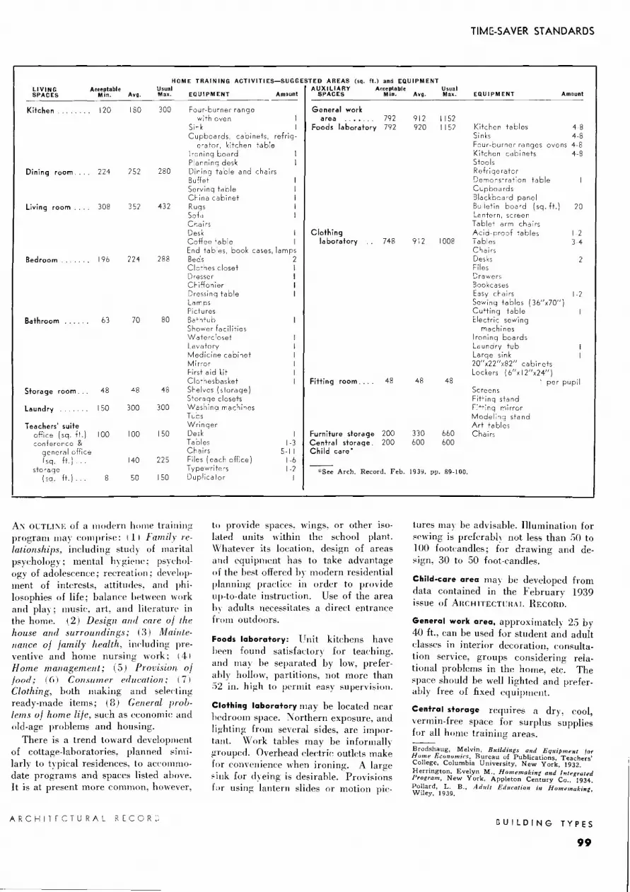
TIM[;-SAVER STANDARDS
HOME TRAINING ACTIVITIES-SUGGESTED AREAS (sq. ft.) and EQUIPMENT LIVING Acceptable Usual AUXILIARY Ar:ceptable Usual SPACES Min. Avg. Max. EQUIPMENT Amount SPACES Min. Avg. Max. EQUIPMENT Amount
Kitchen 120 180 300 Four-burner range General work with oven area 792 912 1152
Sink Foods laboratory 792 920 I 152 Kitchen tables 4-8 Cupboards, ca bi nets, refrig- Sinks 4-8
erator, kitchen table Four-burner ranges, ovens 4-8 Ironing board Kitchen cabinets 4-8 Planning desk Stools
Dining room 224 252 280 Dining table and chairs Refrigerator Buffet Demonstration table Serving table Cupboards China cabinet Blackboard panel
Living room 308 352 432 Rugs Bulletin board I sq. ft. l 20 Sofa Lantern, screen
Chairs Tablet arm chairs Desk Clothing Acid-proof tables 1-2 Coffee table laboratory 748 912 1008 Tables 3 4 End tables, book cases, lamps Chairs
Bedroom 196 224 288 Beds 2 Desks 2 Clothes closet I Files Dresser I Drawers Chiffonier I Bookcases Dressing table I Easy chairs -2 Lamps Sewing tables I 36"x70") Pictures Cutting table
Bathroom ...... 63 70 80 Bathtub Electric sewing Shower facilities machines Watercloset Ironing boards Lavatory Laundry tub Medicine cabinet Large sink Mirror 20"x22"x82" cabinets First aid kit Lockers ( 6"x I 2"x24") Clothesbasket Fitting room .... 48 48 48 I per pupil
Storage room. 48 48 48 Shelves (storage) Screens Storage closets Fitting stand
Laundry 150 300 300 Washing machines Fitting mirror Tubs Modeling stand
Teachers suite Wringer Art tables office (sq. ft.) 100 JOO 150 Desk I Furniture storage 200 330 660 Chairs conference & Tables 1-3 Central storage. 200 600 600
general office Chairs 5-1 I Child care* /sq. ft.) 140 225 Files (each office) 1-6
storage Typewriters 1-2 *See Arch. Record, Feb. 1939, pp. 89-100. (sq. ft.) . 50 150 Duplicator 8
A:\ OCTLl:\E of a modern home trainin;.: program may comprise: 111 Family relationships, including study of marital psychology; mental hvgiene; psvehology of adolescence; recreation; development of interests, attitudes, and philosophies of life; balance between work and play; music, art, and literature in the home. ( 2) Design and care of the house and surroundings; 13) Maintenance of family health, including preventive and home nursing work; 14 I Home management; (5) Provision of food; ( (i) ConsumPr Prlucation; 171 Clothing, both making and selecting ready-made items; ( 8) General problems of home life, such as economic and old-age problems and housing.
There is a trend toward development of cottage-laboratories, planned similarly to typical residences, to accommodate programs and spaces listed above. It is at present more common, however,
ARCHITECTURAL RECORC
I
to provide spaces, wings, or other isolated units "~ithin the school plant. \Vhatever its location, design of areas and equipment has to take advantage of the best offered In- modern residential planning practice in order to provide up-to-date instruction. Use of the area h~- adults necessitates a direct entrance from outdoors.
Foods laboratory: Unit kitchens have hPen found satisfactory for teaching, and may be separated by low, preferably hollow, partitions, not more than .')2 in. high to pnmit easy supervision.
Clothing laboratory may be located near hedroom space. Northern exposure, and lighting from several sides, are important. Work tables may be informally grouped. Overhead electric outlets make for convenience when ironing. A large 'ink for dveing is desirable. Provisions hr using lantern slides or motion pie-
lures may be advisable. Illumination for sewing is preferably not less than .SO to 100 footcandles; for drawing and design, 30 to 50 foot-candles.
Child-care area may be developed from data contained in the February 1939 issue of ARCHITECTCRAL RECORD.
General work area, approximately 2.) by 40 ft., can be used for student and adult classes in interior decoration, consultation service, groups considering relational problems in the home, etc. The space should be well lighted and preferably free of fixed equipment.
Central storage requires a dry, cool, vermin-free space for surplus supplies for all home training areas.
Brodshaug, IV!elvin, Buildings and Equipment for Home Economics, Bureau of Publications, Teachers' College, Columbia University, New York, 1932. Herrington, Evelyn M .. Homemaking and Integrated Program, New York, Appleton Century Co., 1934. Pollard, L. B., Adult Education i1I HomPmaking Wiley, 1939. '
GUILDING TYPES
99

RECREA TION-lndoor
I . Boys' locker room 2. Boys shower I. Foyer
3. Boys' drying room ' 2. Tickets ,r-ll~llllJV~8L£ ! STo\NDAll_oS~
3. Gymnasium 4. Instructors '
5 . Boys team <fF,.IN(~ corridor room r GURfAIN
6. Rubbing room 4. Gymnasium
7. Foyer 4 5. Boys' visiting team '
8. Girls' locker room ' 6. Showers
9. Girls' showers ' 7. Drying room
10. Instructors \...___:,_ ~ .. O~BL( + ST .... o .. ;os-:. ...... ..i 8. Toilets
11. Girls' team room 9. Girls' visiting team
12 , 13 . Storage, janitor 10. Showers 14, 15. Toilets II . Toilet
Basement 16. Storage First floor 12. Storage
All plans on thi s page are at the same scale
Gymnasium wing, Spaulding High School, Rochester, N. H.; C . R. Whitche r, architect. Curtain is used in gymnasium to partition off space when necessary. Removable posts serve to delimit basketball space; but area is not designed solely for basketball.
Mezzanine
I. Auditorium 2. Orchestra pit 3. Stage 4. Band room
and stage storage
5. Storage 6. Music room 7. Instrument
storage 8. Girls 9. Boys
10. Practice room 11. Uniform room 12. Boys' dressing
room
13 . Girls' dress-ing room
14. Organ chamber
First floor
Basement
Auditorium wing , Mt. Pleasant Ave. High School, Providence, R. I.; Erik Andersen, architect.
BUILDING TYPES
100
~
First floor
I. Printing 2. Finishing 3. General shop 4. Art 5. Crafts 6. Girls 7. Boys 8. Women 9. Storage
10. Conference and guidance
11 . Boys' locke rs 12 . Boys ' showers 13 . Drying room
,.
14. Physical in- 26. Foyer structor 27. Vault
15. Light court 28. Principal 16. Girls' lockers 29. Dental oper-17. Girls' showe rs ating 18. Drying room 30. Nurse 19. Phy sic a I in- 31 . Examination
structor 32. Dressing 20. Gymnasium 33 . Visiting nurse 21 . Apparatus 34. Waiting room 22. Playroom 35. Doctor's room 23. Stage 36. Bicycles 24. Terrace 37. Shipping and 25. Auditorium receiving
Areas for both community and school use are grouped in a common wing in the Lawrence School, Hartford, Conn.; Carl J. Malmfeldt, architect. First floor contains administrative and shop units, as well as gymnasium and auditorium; two types of healt h services are contained in first floor and basement.
ARCHITECTURAL RECORD
d f" '
J5

TIME-SAVER STANDARDS
AUDITORIUM AREAS Acceptable Minimum Average Usual Maximum PHYSICAL RECREATION AREAS (so. ft.) Acceptable Minimum Average Usual Maximum
Swimming pool*
Beginners pool*
Fieldhouset
Basketball
Volleyball
Indoor baseball
Tennis (I doubles court)
Corrective gym
Boxing, wrestling
Apparatus storage
Instructor's office
Court games
handball court
squash court
badminton (per court).
Additional areas
fencing (each lane)
bowling (per alley)
social dancing
go If cage
archery range
1500
600
5000
600
600
200
64
2625
1000
6000 3000
I 0,000 7200
800
1000
400
120
800 1080 1800
165 792
as desired
400 I 1.700
9900
1250
2000
400
300
AUDITORIUM
Seating ca pa city Area per seat (sq. ft.). Stage dimensions (feet)
Depth Width (including wings). Proscenium width Proscenium height.
Orchestra space. Projection room (sq. ft.)
2 projectors only. Additional equipment ... Sound amplifier .. Sound generator Rewind room (if required)
Check room (sq. ft.). Box office (sq. ft.) Workshop-area
-height Costume preparation area. Dramatics classroom area.
Practice stage area.
MUSIC ROOMS Instrumental rooms, etc ..
Area per player. Chorus room
Area per student Practice rooms
I instrument Piano and I instrument 2 pianos or small ensemble,
200-300 61h-7
18 44 25 12
600 8-10
30-35 90
30-35 15
1000 to 1200
50 120 50 18
Approx. 20-30 ft. between seats and stage
I lcli
40 1500 may 750
1000 200
1500
1000
48
100 50 30 25 25
600 60
2000 be 12-20 ft. 1n
1000 1200 300
2400 10
2000 6
80
100
2500-3000 height
1000 2000
300
3500
3000
*Pool area only, given in table; end and side runways required. Exact dimensions and specifications for competitive diving and swimming are available from National Recreation Association; see also American Architect & Architecture, August, 1937. tGymnasia of the "traditional" type range in area from 2400 to 5400 sq. ft., with spectator space in balconies, or provided through use of portable or folding bleachers.
or storage Instrument storage Office or offices Music appreciation room
INTERPRETIVE DANCING
CLUB & LOUNGE ROOMS
350 350 200 600
500 250
1000 1500
120 500 250
1500
Physical education. Modern educators consider that indoor physical education plants should house not only the gymnasium planned primarily for basketball. but also: a certain proportion of l"Olll
munity and school health service fa<"ilities; provision for games in which all school children (rather than onh the teams) may partake; and provisions for a maximum of general conHnunil\ use.
Colleges and some few secondan· schools have met this situation by providing large open spaces, similar to field houses, instead of gymnasia. Cost of such apparatus as parallel bars, din1bing ropes, etc., is considered to prohibit their installation, in view of tlwir limited use. Swimming pools. on the other hand, being usable by the entire school and community, are c-unsidered a good investment.
Field-house construction may be as simple as is desired. Finish, in the usual sense. may be omitted on the interior; floors may be of a day. sand, and sawdust mixture, with portable
ARCHITECTURAL RECORD
\rnoden floors for indoor tennis and basketball. Exact layouts and equipment for the activities listed above are obtainable from the National Hecreation As:;oc:iation, and from various sport associations or manufacturers.
Auditorium design has become increasingly complicated as its use by school and comm unity has expanded. From the point of view of safety, the auditorium is preferably located on the ground floor, with direct access to outdoors, and suflicient exits to permit emptying in t\1 o minutes. Regulations of local and national codes should be complied with. Steps in aisles are preferably eliminated in favor of ramps; and the stage requires exits and a fire-curtain.
l n respect to natural ventilation and lighting, school auditoria differ from professional theaters in that natural lighting is often both allowable and desirable. For natural ventilation, bilateral exposure is preferable; umlateral fenestration is a minimum.
(see text)
l-se by school children require" an entrance from the building's main travel corridor; avoidance of traflic congestion necessitates careful planning of corridors and doors. ~-itudy of- stagecraft, music, the dance, and speech arts require laboratory and similar spaces specifirnl-1 y planned and equipped. Location requires isolation, as for instance in an indc·pendent wing.
For community use, public entrances independent of school entrances are required for access to auditorium. workshops, and all areas in which. public participation is expected. For data on seating and sight lines see American Architect and Arc-hitecture. July, 1931. For information 011 acoustic treatment and equipment consult AR, July 1938, and October 1939.
Blair, Herbert, Physical Education Facilities for the ll.Jodenz Junior and Sf'nior High School, A. S. Barnes and Co., New York, 1939. Luehring, Fred W., Su;immin~ Puul Standards New York, A. S. Barnes and Co., 1939. ' Cochrane. Blake, The School Auditorium: A Culture Center, School Executive, June 1938, pp. 469-472. Ebey,_ George W., The P~anning of the School Stage, American School and University, 1939. pp. 304-311.
BUILDING TYPES
101

RECREATION-Outdoor
Photo of model and plan at right show two stages in development of outdoor areas for the Arlington Heights High School, Fort Worth , Tex. , designed by a local organization with Hare and Hare, landscape architects, as consultants. Grassed and surfaced play areas , amph itheater, and park space are provided.
' 90 v ~ Q 85
w 80 I ~75 i-/ ~
ff fo% i
0 100 200
0
0 '· r' .__
SC HOOL
AGRICULTURAL AREA
Proposed outdoor physical education and recreation development, Cassadaga Valley Central School, N. Y.; Thomas Lyon White and Leonard G. Wheeler , architects and consultants . In addition to game areas , spaces for picnics, Boy and Girl Scouts , outdoor theater, outdoor classrooms, and agricultural practice are all provided.
BU ILDING TY PE S ARCHITECTURAL RECORD
102.

BASEBALL For INTERMED.SCHOOL For ADULTS Standard dimensions Accept. Usual A"cept. Usual TRACK and (feet unless other·
SOFTBALL Min. Avg. Max. Min. Avg. Max. FIELD' wise noted)
Baseball Broad jump
side of diamond runway length 90-120 I ft. I 75 82 32 90 pit 5 x 15 to 30
honne plate to take-off board from pit (adult) I 0-12
outfield limits (children) 5-6 I ft. I 200 250 300
home plate to High jump
backstop I ft. I . 40 60 75 80 90 runway radius 35 pit 14 x 12
pitcher's box to between standards 12 home plate I ft. I 45 52 60'6" Pole vault
\st and 3rd base runway 4 x 100 lines to specla- pit 14 x 12 tors' stand I ft. I 60 75 between standards 12
Total Area I sq. ft. I 62.500 97,500 Shotput, weight throw
diam. throwing Softball
circle 7 side of diamond throwing radius 50 60
I ft. I 45 45 60
home plate to Discus throw
playing field diam. throwing limirs (ft.) 125 200 circle 8 ft. 21h in.
pitcher to honne throwinq radius
I ft. I" 120 plate 30 35 35 40
(a iris) I woccen) Javelin throw
Total Are'l (sq. : •. 22' 500 50 000 space needed 200 x 70
*For track dimensions, see text. i·Standard shooting distances: 30, 40, 50, 60, 70, 80, 100 yds. :190° arc
As \\ITH indoor J"C'LTeational area~.
probability of use ll\ the l'0111111unity as a whole is a factor in desil!ninl! outdoor areas for schools.
Buildi11r:; settinr:;s"· are planned to eliminate actiYe pla, in this arPa. Broad walks are U:"ed to a('('DI11n1<Hlate hean. concentrated trafliC'. and are plal'ed along natural linl's of trm·d to avoid formation of paths across l!rass areas.
Parki11r:; facilities. where space 1s limited. !'onsist of HI-ft. sPLhacks 011
bordering street l'urhs for hl'ad-in parking. Where room is m ailahle, pavPd areas 60 ft. wide for double-row head-in parking arc l'onsidl'rcd desirable. Sen -ice drives for various building units lead direct! v to spal'es servl'd.
Grass play fields are hordncd where possible with fences .S or (> ft. high set
*Much of this data is based on experience of the Fort Worth, Tex., school ~rounds planning committee, consisting of R. C. Morrison, director: Eugene H. Carter, landscape architect; Hare and Hare, landscape architects and consultants; anrl. others.
ARCHITECTURAL RECORD
hack at least 1.5 ft. from :"lrcet \\alb and screpned from outside view by planting. Fence prevents children from running into streets. Top fence rails are used for sprinkler systems for watering shrubber~. Underground hose con11e1·tions, so plaC'ed that not more than 1.)0 ft. of hose is needed to reaC'h any por· Lion of the field, are used in l!rass areas. Field sizes are controlled IH natural t·onditions, but at least one softball spa<'e is desirable in each developnwnt. Finish l!rades ranl!c from 1.1:! to 21 ~ r;-; slo pPs.
Hard-surfaced areas arc pa,·ed with <'Oncrete or asphalt. for tennis, vollev lialL quoits. badn1i11ton, l'l<'., and are extremely popular for community use. Crades are best developed lo a maximum slope of 17'.
Park areas, with shaded lawns and vistas, are developed where space permits, to provide a needed and appreciated respite from l'ongested urban Ii fe.
Practice _fi,elds, includinl! areas for
TIME-SAVER STANDARDS
SQ. ft. unless otherwise noted
OTHER For INTERMED. GAME AREAS SCHOOL For ADULTS
Archeryt max. length
I ft. I 450 450 min. width
I ft. I 50 50
Badminton 1800 1800
Basketball
men 3650 6000
women 3600 5500
Clock golf 700 700
Deck tennis 1300 1300
Field hockey 37,500 57,600-73,500
Football ~lot usually 75,000 advisable
Handball 1320 1320
Horseshoes 600 600
Shuffleboard 570 570
Soccer 30,000 86,400
Speed ball 36,400 68,400
Tennis per court 7200 7200
Touch foot bull 39000 54,500
Volleyball 2800 3100
with throwing circle at center.
football fields, tral'k and field games, have "turtle-hack" grading with a rise of approximately 1 ft. 6 in. through the !'enter. Fields used only for practice may have a l'onstanl diagonal l /o slope.
Amplzi1lzeaters are induded where possible, with stages large enough to accommodate graduating classes, for t·onmrnnity gatherings, theatrical performances. etc. Seats nun be. as in Fort Worth, cypress with t:oncrete supports. Lighting systems for night performances are provided. An aYerage 10~{ slope was found satisfactory.
Game areas. Dimensions and lavouts llHI\ be ohtained from the .'\ational RPcreation Association and from sports association and sporting goods llHlllU
facturers. See also AR, June 1931.
Lamar, Emil, The Athletic Plaut, McGraw Hill Book Co., New York, 193'.
Butler, George D., The New Piny Areas, A. S. Barnes, New York, N. Y .. 1938.
Hill, C. S., and Taylor, A. D., Principles Governin~ the Landuape Deve/opmeut of Grf)unds for Educatio:z:il Institutions, American School and University, 1939, pp 203-215.
BUILDING TYPES
103

BUILDINCS DUPLICATED FOR TWO JUNIOR HICH SCHOOLS
JJ '-------==-
Plot plans: above, Eastmont; below, Monte bello
L___ _J
BUIL D IN G T Y PES
104
EASTMONT and MONTEBELLO JUNIOR HICH SCHOOLS,
MONTEBELLO, CALIFORNIA T. C. KISTNER, architect
IDENTICAL INTERIOR building layo uts are used in both schools. One set of building plans was prepared. In both case , the "campu " type of development, with independent one-story buildings for various departments, was used , and laid out for a planned expansion proo-ram. All but one of the building have reinforced concrete walls and flo or , with wood-framed partitions and roofs. The exception , the cafeteria-a sembly unit, is wood frame, stuccoed, on a concrete floor. Arcade connecting building have teel pipe columns and metal roof decks.
In classroom, administration, and cafeteriaassembly building , fl oors are asphalt tile, upper walls and ceiling are acoustic pla ter on metal lath. Jn shops, showers, and lockers. fl oors are cement. Wood i lead-and-oil stained. with aluminum powder added to reduce raw color. and with flat varnish fini sh. Artificial classroom lighting is adequate to provide 15 footcandle throughout. Windows are screened awning-type ash wi th venetian blinds. Heating is by gas radiators except in cafeteria-assembly buildings, where circulating ga furnace are u ed.
ARCHITECTURAL RECORD

WOOD SHOP -~ ~~~~~Li __J
Present shop unit
Present cafeteria-assembly unit; sewing room is to be added.
Girls' shower and locker unit
-~J, .. ,~ :::" ~.-1 "°°"' 1110040' • _ __.~_-1:!.. 11C•TC. 1
Boys' shower and locker unit
Ground fl
A RCHITECTURAL RECOR D
CHITEC
-
CASE STUDIES
Top, view of ''campus"; lower, cafeteria-assembly room, used also as study hall and community room. Stage space is available on platform by drawing a cyclorama
curtain to hide library shelving.
Cl.ASS CU.SS
Classroom unit
CLASS
[~ GENERAL SCIENCE
Administration unit
BUILDING TYPES
105
107
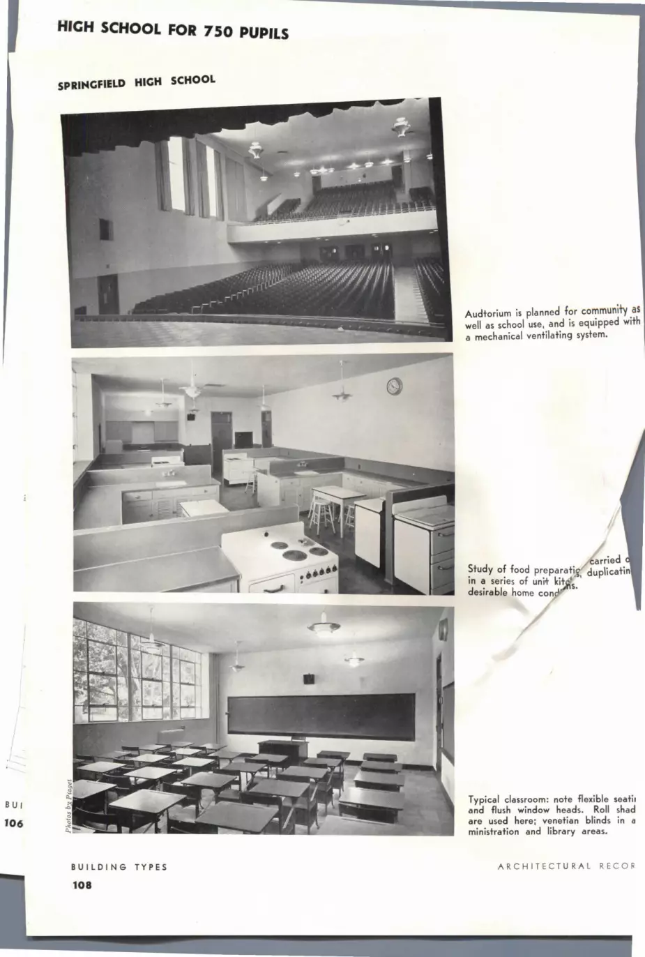
HICH SCHOOL FOR 7 50 PUPILS
SPRINGFIELD HIGH SCHOOL
I
I
BU I
10 6
BUILDING TYPES
Audtorium is planned for community as well as school use, and is equipped with a mechanical ventilating system.
carried Study of food preparati. duplicatin in a series of uni+ kit ' desirable home con s.
Typical classroom: note flexible seati1 and flush window heads. Roll shad are used here; venetian blinds in a ministration and library areas.
ARCHIT ECTURA L RECOR
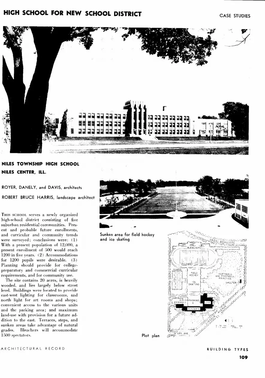
HICH SCHOOL FOR NEW SCHOOL DISTRICT
NILES TOWNSHIP HICH SCHOOL
NILES CENTER, ILL.
ROYER, DAN ELY, and DAVIS, architects
ROBERT BRUCE HARRIS, landscape architect
THIS SCHOOL serves a newly organized high-school district consisting of five suburban residential communities. Present and probable future enrollments, and curricular and community trends were surveyed; conclusions were: ( 1) With a present population of 12,000, a present enrollment of 500 would reach 1200 in five years. (2) Accommodations for 1200 pupils were desirable. ( 3) Planning should provide for collegepreparatory and commercial curricular requirements, and for community use.
The site contains 20 acres, is heavily wooded, and lies largely below street level. Buildings were located to provide east-west lighting for classrooms, and north light for art rooms and shops; convenient access to the various units and the parking area; and maximum land-use with provision for a future addition to the east. Terraces, steps, and sunken areas take advantage of natural grades. Bleachers will accommodate 1500 spectators.
ARCHITECTURAL RECORD
Sunken area for field hockey and ice skating
Plot plan
CASE STUDIES
BUILDING TYPES
109

NILES TOWNSHIP HICH SCHOOL
EACH OF THE three units in this building may be isolated hv clo:;ing gates at thl' ends of the central portion; this arrangement facilitates use of any unit after regular school hours. 111 the administrative group is a sound-<"ontrol room whiL·h houses a switl"hboard and operator for a two-way public address system used for announcements, replies, radio pn;grams and recordings used in teal"hing, musical-chime class-dismissal signals, and gymnasium and shop bells. Teachers' wardrobe lockers are contained in teachers' rest rooms rather than in classrooms.
jF:' '21']' .. ---(J\ MUSIC ~
~ ROOM II
ME::'HAf.,.(AL DflAWING
' I
I. 2. 3. 4. 5. b. 7.
8. 9.
10. I I. 12. 13. 14. 15.
Check room Ticket booth Principal Mimeograph Sound control Ass't principal Administrative assistant Office Spray room Kiln Supplies Practice Office Examination Instructor
First floor: Community room (auditorium) and library wing is at the north; administrative-academic unit in the center; gymnasium-shop, or noisy unit, to the south. Boys' gymnasium is 68 by I 00 ft.; girls' is 50 by 78 ft. and is convertible into a stage. Folding bleachers on this floor accommodate 300 spectators; when used as an auditorium, 1,800 may be seated.
I. Dressing and storage
2. Teachers' dining 3. Rest room 4. Receiving 5. Shower 6. Visiting team 7. Home team 8. Rubbing room 9. Girls' rest
I 0. Matron I I. Suits and towels 12. Fan room 13. Storage 14. Office 15. Grounds equip-
ment
Basement cafeteria accommodates 500. Odors are drawn off by an independent ventilating system. Locker rooms are intended for use of both pool and gymnasium occupants. Girls' lockers are so placed that addition of a few metal panels and curtains forms dressing booths. Pool is 30 by 75 ft., and has bleachers for 250 spectators.
BUILDING TYPES ARCHITECTURAL RECORD
110

CASE STUDIES
I
I. Conference room 2. Work room 3. Librarian 4. Teachers' room 5. Schoo! store
Second floor: Over the library conference rooms are located clubrooms; over the librarian's space is the stack room. Folding partition between boys' and girls' gymnasia may be slid to any of the three cyclorama positions shown in the plan of the girls' gymnasium, thus forming stages of varying depths.
,-
r-ill-- .. I- . ~-- ~- -1--~ ~--t :-G __ GEN SCIENCE ' Bl~)' OGY 2
u ~·· SCIENCE ' ~
[
~'~R -Atl BIO~OGY CLASS l ECTVRE CLASS · __
WORK R'-' ·
- I lllt I • .-- I --=:I_• I 1 •• ' I • I I ...--------. I .Iii I
Third floor contains the science and home-training divisions of the academic unit. unit kitchens and a practice dining room. Biology growing room is high-ceilinged.
ARCHITECTURAL 'RECORD
I ---,
L_ J
I. Storage 2. Dark room
Foods laboratory contains a series of
BUILDING TYPES
111

NILES TOWNSHIP HICH SCHOOL (continued)
BUILDING TYPES
112
Library, looking from balcony, below which are conference rooms. Charging desk (upper right) is at main entrance.
Foods laboratory, arranged in units, has a practice dining room adjoining.
Chemistry laboratory, one of the few areas where equipment is not movable.
ARCHITECTURAL RECORD
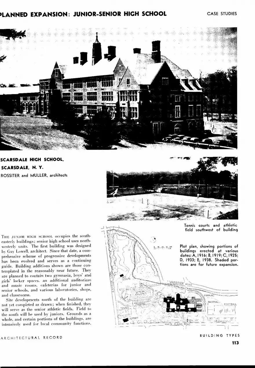
»LANNED EXPANSION: JUNIOR-SENIOR HICH SCHOOL
SCARSDALE HIGH SCHOOL,
SCARSDALE, N. Y.
ROSSITER and MULLER, architects
THE .JU'\JOR HIGH SCHOOL OC('Upies the southeaster!~- buildings; senior high school uses northwesterh· units. The first building was designed b, Gm. Lowell, architect. Since that date, a comp~ehe~sive scheme of progressive developments has been evolved and serves as a continuing guide. Building additions shown are those contemplated in the reasonably near future. They are planned to contain two gymnasia, boys' and girls' locker spaces. an additional auditorium and music rooms. cafeterias for junior and senior schools, and various laboratories, shops, and classrooms.
Site developments north of the building are not yet completed as drawn; when finished, they will serve as the senior athletic fields. Field to the south will ht> used by juniors. Grounds as a whole, and certain portions of the buildings, are intensivelv used for local community function:-.
ARCHITECTURAL RECORD
CASE STUDIES
Tennis courts and athletic field southwest of building
Plot plan, showing portions of buildings erected at various dates: A. 1916; B, 1919; C, 1925; D, 1933; E, 1938. Shaded portions are for future expansion.
- -------, . i I
BUILDING TYPES
113

SCARSDALE HICH SCHOOL
,~~~" ru .... .l.i. ...... 1 i i - -
i
I. Boys' showers 8. Waiting 2. Boys drying room
room 9. Boys rest 3. Girls' showers room 4. Girls' drying 10. Girls re st
room room 5. Physical di rec- II. Nurse's of-
tor fice b. Home team 12. Dishwashing 7. Visiting team 13. Conference
room
First floor: gymnasium and appurtenance.s constitute only part of the projected physical-education plant. Use of a folding partition here introduces a certain amount of flexibility. Throughout the school, pupils' lockers are grouped in conveniently located rooms rather than along corridor walls.
BUILDING TYPES
114
I. Field-machine room
2. Kitchen help 3. Office 4. Supplies 5. Dishwashing 6. Girls' Dean 7. Boys' Dean 8. Teachers' work
room 9. Waiting roo'Tl
o 'c 'c •o •o >O ; __ ' .---: ___:_::____]
10. Vault 11. Principal's
office 12. Secretary 13. 0 rchestra
pit 14. Te a c hers'
lockers I 5. R e c e iv in g
roc,m
Ground floor is built into hillside; building services are concentrated in basement areas. Location of auditorium, cafeteria, and services for both adjacent to main entrance increases their usefulness to the community as a whole.
ARCHITECTURAL RECORD

(-~
l~_J ;::;J L- I I I
CASE STUDIES
I. Principal's office
2. Secretary 3. Waiting 4. Office 5. Book storage
and work 6. Pantry and
storage 7. Preparation
room 8. Science re
search laboratory
9. Dark room I 0. Print room
Second floor contains a series of education units consisting of classrooms, research centers, work rooms or laboratories, and conference rooms. As the plan has expanded, room uses have changed; biology laboratories occupy space once given over to a combination assembly-study hall.
PLANS SHOWN on these two pages require study in relation to the complete program as projected. For instance, what may appear to be physical-education facilities inadequate for a school of this size will eventually be increased to ample prov1s10ns. Attention has been concentrated on those portions of the plant which local authorities considered to be of prime importance; other activities are somewhat restricted until funds for building become available.
This type of planning in a series of steps, all keyed to a master plan, is suitable for many communities; and may, in some cases, be the only way in which a maximum of up-todate facilities can be secured. In order to achieve such a maximum of usefulness, flexibility of the master plan is highly important. Otherwise it becomes impossible to keep abreast of advances in educational theories; and changing uses, to which certain earlier portions of the buildings may be put, are poorly accommodated.
To point a single example of such flexibility for changing use, the small bay projecting from the biology laboratory space on the second floor had limited usefulness when these two rooms constituted assemblv space. Now, however, the bay houses an aquarium, germinating bed, soil bins, etc.
ARCHITECTURAL RECORD
MUS'C ROOM
I. Practice room 2. M us i ca I - i n -
strument storage
3. Office 4. Storage 5. Project room 6. Supplies
Third floor contains art, music, and commercial units segregated to avoid conflict with other types of spaces.
BUILDING TYPES
115

COMMUNITY HICH SCHOOL FOR INDUSTRIAL TOWN
Perspective
EAST SEMIOR HIGH SCHOOL, ROCKFORD, ILLIMOIS
@.,., .. ,,., ..
A, Auditorium; B, Administration; C, Physical education; D, Shops; E, Boiler house
GILBERT A. JOHNSON, architect; WILLIS W. HUBBARD, consultant
UMIT A: Auditorium, community room, instruction area
First floor: Arrangement of community · room and auditorium, with connecting stages, is noteworthy. So also is allocation of space for speech and English study, which may use auditoria as laboratories.
Ground floor: use of grades permits use of lobby as an entrance to both community room and cafeteria for public purposes. Lobby may also serve as stage entrance.
BUILDING TYPES
116
UPPER PART OF STAGE
~~C??'d±I
~ ART llJc:RA~rU
Third floor contains a complete arts-and-crafts unit. In the crafts room are contained a kiln for firing pottery, a work-bench, and a sink, as well as storage cabinets and cases.
Second floor: Stage is completely equipped with fly gallery, grids, and lighting necessities. Legend: I, instructor's office; 2, practice rooms; 3, music room.
ARCHITECTURAL RECORD

ROCKFORD being an industrial town, this school is planned with emphasis on commercial, vocational, and home training. However, prov1s1ons for other studies are by no means neglected. The school's estimated capacity is 2000.
Since a maximum of adult education is carried on in communities like Rockford, rather complete facilities for this type of work are included. Segregation of the auditorium and community room is obtained by placing them in a separate wing; physical education and shop units, where noise is unavoidable, are likewise placed in independent wings. Land available did not permit development of parks and similar recreational areas; but, even so, inclusion of uch a unit as tennis courts marks an advance over the type of land-planning formerly considered adequate. Parking space, with direct access to auditorium and
UNIT B: Administrative, commercial, and laboratory areas
1. W ome n t e a che rs 2. W o rkroom
o L I BRARY
3. De an 4. Ass' t prin cipal 5. Boo ks 6. Vau lt 7. Public space 8. Prin ci pal 9. C o nfe re nce
10. Offi ce and wo rk 11 . Radio
ENGLISH I 2. Nurse 13 . Girls 14. Boys 15. Waiting 16. Employme nt
-'"""'""""--''---' '---' '-- 17. Te a c he rs' wo rk
First floor houses business administrative , guidance , employment, and health units, as well as a study-library-conference group , English classrooms, and teachers' workrooms.
l\ RC HlTECT U RAL REC ORD
SHORT• HANO
TYPE· WRITING
BOOKKEEPING
SHORT· HAND
STUDY HALL
1. Me n tea che rs 2. Stores 3. Janito r cl oset 4. Offi ce pra ct ice 5. Te a che rs' wo rk
Second floor English classrooms are grouped closely to similar classrooms in Unit A. Besides commercial instruction areas , rooms are provided for practical office training.
CASE STUDIES
shop wings, and to athletic fields, is also only a short distance from the econdary entrance which serves both administrative-classroom and physical education units.
Almost all of those areas, for which suggested standards are presented on previou pages of this study, are included in East Senior High chool.
implicity of planning, integration of the various well-defined units, and free circulation attained by use of wide connecting corridors, are all worthy of study. The gymnasium (see page 118) is of a size which will accommodate not only basketball, but al o other indoor sports in which a great number of students may participate; audience facilities, arrangements for the band to take part in indoor athleti functions, and eparate gymna ia for girls and for
corrective work, are also provided.
BIOLOGY
MATHE· MA TICS
I. Preparation room
2. Store room 3. Pla nt room 4. W o rkroom 5. Tea che rs' wo rk 6. Dark room
Third floor contains science laboratories grouped about a common lecture, or discussion , room, which has facilities for preparing the slides used there for visual instruction.
BUILDING TYPES
117

EAST SENIOR HICH SCHOOL
UNIT C: Physical education, shops, home training
PAINT SHOP
DRAFTING ROOM
First floor illustrates I. Equ ipment 6. Office
separation of physical 2. Coach 7. Uniforms 3. Drying room 8. Rifl es
education department 4. Instructor 9. Visiting team from other areas. 5. Storage
SWITCH· TRANS· BOARD FORMER
Ground floor is principally service area .
UNIT D: Shops
J
10 2~ l.O_••-~
BUILDING TYPES
118
BAND BOX
i.JPPER PART OF GYMNASIUM
Third floor: Instrument storage rooms linoleum-covered shelving.
have wood
CORRECTIVE GYMNASIUM
GYMNASIUM
CORRECTIVE GYMNASIUM
Second floor cont a ins a home training department.
I . Practice rooms 2. Dressing room 3. Orchestra
storage 4. Band storage
I . Instructor 2. Fitting room 3. Pantry and
linen dryer
BAND ROOM
GIRLS PHYSICAL EDUCATION
5. Wardrobe 6. Equipm ent 7. Examination 8. Office
4. Model kitchen 5. Storage 6. Blueprint room 7. Supplies
Shop building is one story high, and follows closely principles outlined on pages 95 to 97. The corridor connects drafting and planning areas in Unit C with instructor's conference room and individual shops in this unit. Washrooms have factory-type circular wash fountains .
ARCHITECTURAL RECORD